ce6502-notes.pdf - Shree Sathyam College of Engineering ...
62
0 UNIT – I TWO MARKS QUESTIONS AND ANSWERS Necessary to compute deflections in structures Computation of deflection of structures is necessary for the following reasons: (i) If the deflection of a structure is more than the permissible, the structure will not look aesthetic and will cause psychological upsetting of thje occupants. (ii) Excessive deflection may cause cracking in the materials attached to the structure. For example, if the deflection of a floor beam is excessive, the floor finishes and partition walls supported on the beam may get cracked and unserviceable. Cambering technique, in structures Cambering is a technique applied on site, in which a slight upward curve is made in the structure / beams during construction, so that it will straighten out and attain the straight shape during loading. This will considerably reduce the downward deflection that may occur at later stages. Four methods used for the computation of deflections in structures. (i) Virtual work method – Dummy unit load method (ii) Strain energy method (iii) Willot Mohr diagram method (iv) Method of elastic weights Difference between strain energy method and unit load method in the determination of deflection of structures. In strain energy method, an imaginary load P is applied at the point where the deflection is desired to be determined. P is equated to Zero in the final step and the deflection is obtained. In unit load method, an unit load (instead of P) is applied at the point where the deflection is desired. Assumptions made in the unit load method Assumptions made in unit load method are 1. The external and internal forces are in equilibrium 2. Supports are rigid and no movement is possible. 3. The material is strained well within elastic limit. Equation that is used for the determination of deflection at a given point i in beams and frames. Deflection at a point i is given by, l M x m x dx i EI Where M x = moment at a section X due to the applied loads Page 2 of 21 SSCET
-
Upload
khangminh22 -
Category
Documents
-
view
0 -
download
0
Transcript of ce6502-notes.pdf - Shree Sathyam College of Engineering ...
0
UNIT – I
TWO MARKS QUESTIONS AND ANSWERS
Necessary to compute deflections in structures
Computation of deflection of structures is necessary for the following
reasons:
(i) If the deflection of a structure is more than the permissible, the structure will
not look aesthetic and will cause psychological upsetting of thje occupants.
(ii) Excessive deflection may cause cracking in the materials attached to the
structure. For example, if the deflection of a floor beam is excessive, the floor finishes
and partition walls supported on the beam may get cracked and unserviceable.
Cambering technique, in structures
Cambering is a technique applied on site, in which a slight upward curve is made in the structure / beams during construction, so that it will straighten out
and attain the straight shape during loading. This will considerably reduce the
downward deflection that may occur at later stages.
Four met h od s u s ed f o r the co mpu ta t i on o f d e f l e c t i o n s i n structures.
(i) Virtual work method – Dummy unit load method (ii) Strain energy method
(iii) Willot Mohr diagram method
(iv) Method of elastic weights
Difference between strain energy method and unit load method in the
determination of deflection of structures.
In strain energy method, an imaginary load P is applied at the point
where the deflection is desired to be determined. P is equated to Zero in the final step
and the deflection is obtained.
In unit load method, an unit load (instead of P) is applied at the point
where the deflection is desired.
Assumptions made in the unit load method
Assumptions made in unit load method are 1. The external and internal forces are in equilibrium
2. Supports are rigid and no movement is possible.
3. The material is strained well within elastic limit.
Equation that is used for the determination of deflection at a given point i in
beams and frames.
Deflection at a point i is given by, l
M
x mx dx i
EI
Where Mx = moment at a section X due to the applied loads
Page 2 of 21
SSCET

Mx = moment at a section X due to unit load applied at the point i and
in the direction of the desired dicplacement
EI = flexural rigidity
Principle of Virtual work.
It states that the work done on a structure by external loads is equal to the
internal energy stored in a structure (Ue = Ui)
Work of external loads = work of internal loads
Strain energy stored in a rod of length l and axial rigidity AE
to an axial force P Strain energy stored
P2
L
U= --------
2AE
Virtual work.
The term virtual work means the work done by a real force acting through a virtual displacement or a virtual force acting through a real displacement.
The virtual work is not a real quantity but an imaginary one.
Procedure involved in the deflection of pin jointed plane frames.
1. Virtual forces k: Remove all the real loads from the truss. Place a unit load on the truss at the joint and in the direction of the desired displacement. Use
the method of joints or the method of sections and calculate the internal forces k in
each member of the truss.
2. Real forces F: These forces arre caused only by the real loads acting
on the truss. Use the method of sections or the method of joints to determine the forces
F in each member.
3. Virtual work equation: Apply the equation of virtual work, to
determine the desired displacement.
In the truss shown in fig. no load acts. The member AB gets 4mm too short. The
cross sectional area of each member is A = 300 mm2
and E = 200 GPa. Determine the vertical displacement of joint C.
Solution:
Virtual forces, k:
Page 3 of 21
SSCET

0
0
Since the vertical displacement of joint C is required, a vertical
force of 1 KN is applied at C. The force k in each member is determined as below:
By symmetry, RA = RB = ½
Joint A: ∑V = 0 gives
KAC cos 36º 52’ + ½ = 0
KAC = 0.625 kN (comp) ∑H = 0 gives kAB + kAC cos 53º 08’ = 0
kAB = 0.375 kN (tensile)
Joint B: ∑V = 0 gives
KBC cos 36º 52’ + ½ = 0
KBC = 0.625 kN (comp) Member AB undergoes a deformation, ∆L = 0.004 m
∆ = ∑(k.∆L)
(∆C)V = (0.375) (-0.004) + 0 +0 = -0.0015m = -1.5 mm
The negative sign indicates that joint C displaced upward, i.e. opposite to the 1 kN vertical load.
Using the method of virtual work, determine the vertical displacement of point
B of the beam shown in fig. Take E = 2x 10⁵
MPa and I = 825x 107
mm4.
Solution:
l
mMdx ∆ =
EI
Virtual moment, m. Remove the external load. Apply a unit vertical load at B.
Consider a section XX at a distance x from B.
m = -1 * x (Hogging moment)
Real moment, M. Using the same x co-ordinate, the internal moment (due to the
given loading) M is formulated as,
M = -25. *.x2/2
M = -12.5x2
Virtual work equation. l
mMdx (∆B)V =
EI
Page 4 of 21
SSCET

4
0
12
(1* x)(12.5x 2 )dx 12
12.5x 3
=
0 EI
12
dx
0 EI
4
= 12.5x
12.5x12
64800
EIx4 EIx4 EI
=
2 *108
64800
x825x105
0.0393m (or)
39.3 mm
Hence the vertical displacement of point B = 39.3 mm
Table shows the lengths and deformations of the members of the cantilever truss,
shown in fig. Construct a Williot’ diagram and tabulate the displacement of
nodes.
Member Length (mm) Elongation (mm)
AC 6225 15.0
AD 4242 4.0
BD 4242 -10.5
DC 4242 -12.0
Solution: Fig. shows the Willot’s diagram of displacements. Table shows the
displacements
Node Displacements (mm)
X Y
C -15.0 -47.6
D -5.2 -11.5
Page 5 of 21
SSCET

1. Determine the vertical displacement of joint C of the steel truss shown in
fig. The cross sectional area of each member is A = 400 mm2
and E = 2*105
N/mm2.
Solution:
∆ = kFL
AE Virtual forces k. Remove all the (external) loads and apply a unit vertical force
at joint C of the truss. Analyze the truss using the method of joints.
Take moments about D, VA x 9-1 x3 =0
VA x 9 = 1*3, VA = 1/3 kN VD = Total load – VA = 1-1/3 = 2/3 kN
Joint A: Initially assume all forces to be tensile.
V 0
k AF cos 45 1/ 3 0
k AF cos 45 1/ 3
1
gives
k AF 3 cos 45
0.47 kN
k AF 0.471 kNcomp
H 0 gives
k AF cos 45 k AB 0
(0.471) cos 45 k AB 0
k AB 0.333kN (tensile )
Joint F :
H 0
gives
Page 6 of 21
SSCET

kFA cos 45º + kFE = 0
kFA cos 45º + kFE = - kFA cos 45º = -0.471*cos45º= - 0.333 kN
kFE = 0.333kN (comp)
V 0
kFA cos 45º - kFB = 0
gives
kFA cos 45º = kFB
0.471 cos 45º = kFB
kFB = 0.333 kN (tensile)
Joint B:
V 0
gives
KBE cos 45º + kFB = 0
k k BF
0.333
0.471
BE cos 45 cos 45
k BE
0.471 kN (comp)
H 0 gives
Joint C:
V 0
kBC – kBA + kBE cos 45º = 0
kBC = kBA - kBE cos 45º = 0.333 – (-0.471) cos 45º
kBC = 0.666 kN (tensile)
gives
KCE – 1 = 0
KCE + I kN (tensile)
H 0 gives
kCD - kCB = 0
kCD = kCB = 0.666 kCD = 0.666 kN (tensile)
Joint D:
H 0
gives
kDE cos45º + kDC = 0
kDE = - kDC / cos45º
= -0.666 / cos 45º = -0.942
kDE = 0.942 kN (comp)
Real Forces F: The real forces in the members due to the given system of
external loads are calculated using the method of joints.
Page 7 of 21
SSCET

By symmetry
RA = RD =
Total
Load
2
50 kN
Joint A: Initially assume all forces to be tensile.
V 0
FAF
cos 45 50 0
gives
FAF 50 / cos 45 70.71 kN
FAF 70.71 kNcomp
H 0 gives
FAF cos 45 FAB 0
(70.71) cos 45 FAB 0
FAB 50 kN(tensile )
Joint F :
H 0
gives
FFA cos 45º + FFE = 0
FFA cos 45º + FFE = - FFA cos 45º = -70.71*cos45º= -50 kN
FFE = -50 kN (comp)
V 0
FFA cos 45º - FFB = 0
gives
FFA cos 45º = FFB
70.71 cos 45º = FFB
FFB = 50 kN (tensile)
Joint B:
V 0
gives
FBE cos 45º + FFB -50 = 0
FBE cos 45º = - FBF + 50 = - 50 +50 = 0 FBE = 0S
H 0 gives
Joint C:
FBC – FBA + FBE cos 45º = 0
FBC + 0 -50 = 0 FBC = 50 kN (tensile)
Page 8 of 21
SSCET

V 0 gives
FCE – 50 = 0
FCE = 50 kN (tensile)
H 0 gives
FCD - FCB = 0
FCD = FCB = 50 FCD = 50 kN (tensile)
Joint D:
H 0
gives
FDE cos45º + FDC = 0
FDE = - FDC / cos45º = -50/ cos 45º = -70.71 kN
FDE = 70.71 kN (comp)
Virtual – Work Equation:
∆ = kFL
AE
AF = BE =DE = 32 3
2 4.243 m
S.No Member k F (kN) L (m) kFL (kN m)
1 AF -0.471 -70.71 4.243 141.311
2 FE -0.333 -50.00 3.00 49.950
3 ED -0.942 -70.71 4.243 282.621
4 DC 0.666 50.00 3.00 99.900
5 CB 0.666 50.00 3.00 99.900
6 BA 0.333 50.00 3.00 49.950
7 FB 0.333 50.00 3.00 49.950
8 BE -0.471 0.00 4.243 0.00
9 EC 1.000 50.00 3.00 150.00
kFL 923.582
kFL 923.582 *10002 Nmm
(C )V
kFL
AE
923.582 *10002
= 400 * 2 *10
5
11.54 mm
Vertical displacement of joint C = 11.54 mm (downward)
2. Using the principle of virtual work, determine the vertical and horizontal
deflection components of joint C of the truss in fig. A = 150*10-6
m2
and E =
200*106
kN/m2
Page 9 of 21
SSCET

Solution:
∆ = kFL
AE
truss.
Virtual Forces, kh (for horizontal displacement at C)
Remove the real (external load) and apply a unit horizontal force at C of the
H 0 gives , HA = 1 kN
(CC1)/x = tan 50º
CC1
= x tan 50º = (3-x) tan 40º
X = (3-x) tan 40º / tan 50º
X = 2.112 – 0.704x X = 1.239 m
(3-x) = 3.0-1.239 = 1.761 m
CC1
= 1.239*tan 50º = 1.477 m
AC =
BC =
(1.239) 2 (1.477)
2
(1.761) 2 (1.477)
2
1.928 m
2.298 m
Taking moment about A,
VB * 3 -1 * 1.477 = 0
VB = 0.492 kN VA = 0.492 kN
Joint A:
V 0 gives
KAC cos40º - 0.492 = 0
KAC = 0.492/cos40º = 0.642 kN (tensile)
H 0 gives
kAC cos50º + kAB – 1 = 0
0.642 cos 50º + kAB -1 = 0 kAB = 0.587 kN(tensile)
Joint C:
V 0
gives
kCA cos 40º + kCB cos 50º = 0
kCB = 0.765 kN (comp) Virtual forces kv : (for vertical displacement at C)
Remove the real (external load) and apply a unit vertical force at C of the truss.
Taking moment about B, ’
VA *3-1*1.761 = 0 ’
VA = 0.587 kN
V’
B = 1-0.587 = 0.413 Kn
Page 10 of 21
SSCET

k h FL
kv FL
Joint A:
V 0
gives
KAC cos40º +0.587 = 0
KAC = -0.587/cos40º = -0.766 kN (comp)
H 0 gives
kAC cos50º + kAB = 0
kAB = 0.492 kN(tensile)
Joint C:
V 0
gives
0.766 cos 40º - 1 - kCB cos 50º = 0
kCB = 0.643 kN (comp)
Real Forces F: The real forces in the members due to the given external load are
calculated as below:
The only given force is of magnitude 150 kN and applied at C vertically.
Therefore the forces in the members will be 150 times the kV values.
FAB = 0.492 * 150 = 73.8 kN (tensile) FAC = 0.766 * 150 = 114.9 kN (comp) FCB = 0.643 * 150 = 96.45 kN (comp)
Virtual – Work Equation:
∆ = kFL
AE
S.No Member kH KV F (kN) L(m) FkHL FkVL
1 AB 0.587 0.492 73.8 3.0 129.962 108.929
2 AC 0.642 -0.766 -114.9 1.928 -142.22 169.693
3 CB -0.765 -0.643 -96.45 2.298 169.556 142.516
∑ 157.298 421.135
Horizontal deflection of point C = (∆C)h = AE
= 157.298 / (200 * 106
* 150 * 10-6
) = 0.00524 m = 5.24 mm
Vertical deflection of point C = (∆C)v = AE
= 421.135 / (200 * 106
* 150 * 10-6
) = 0.14 m = 14 mm
Page 11 of 21
SSCET

3. Determine the vertical and horizontal displacements of the point C of the pin-
jointed frame shown in fig. The cross sectional area of AB is 100 sqmm and of AC
and BC 150 mm2
each. E= 2 x 10 5
N/mm2. (By unit load method)
Sol:
The vertical and horizontal deflections of the joint C are given by
PuL
V AE
H
Pu ' L
AE
A) Stresses due to External Loading:
AC =
Reaction:
32 4
2 5m
RA = -3/4 RB = 3/4
Sin θ = 3/5 = 0.6; Cos θ = 4/5 = 0.8
Resolving vertically at the joint C, we get
6 = PAC cos θ + PBC sin θ
Resolving horizontally at the joint C, we get
PAC cos θ = PBC sin θ; PAC = PBC
PAC sin θ + PBC sin θ = 6 2 PAC sin θ = 6
PAC = 6/sin θ = 6/2 x 0.6 = 5 KN (tension)
PAC = PBC = 5 KN (tension)
Resolving horizontally at the joint C, we get
PAB = PAC cos θ
PAB = 5 cos θ ; PAB = 5 x 0.8
PAB = 4 KN (comp)
B) Stresses due to unit vertical load at C:
Apply unit vertical load at C. The Stresses in each member will be 1/6 than of
those obtained due to external load.
u AC u BC 5 / 6
u AB 4 / 6 2 / 3
Page 12 of 21
SSCET

C) Stresses due to unit horizontal load at C:
Assume the horizontal load towards left as shown in fig.
Resolving vertically at the joint C, we get
uCA 'sin uCB
'sin
uCA ' uCB ' Resolving horizontally at the joint C, we get
uCB ' cos uCA ' cos 1
uCB ' cos uCB ' cos 1
2uCB ' cos 1
uCB ' 1
2 cos
1 2x0.8
5 / 8KN (tension )
uCA ' 5 / 8KN
uCA ' 5 / 8KN (comp)
Resolving horizontally at the joint B, we get
u AB ' u BC ' cos
u AB ' 5 / 8x0.8 0.5KN
u AB ' 0.5KN (comp)
Member Length(L) mm
Area
(mm)2
P(KN) U (kN) PUL/A U’(KN) PU’L/A
AB 8000 100 -4 -2/3 640/3 -1/2 160
BC 5000 150 5 5/6 2500/18 5/8 2500/24
CA 5000 150 5 5/6 2500/18 -5/8 2500/24
E = 2 X 10⁵
n/mm2= 200 KN/m
2
v Pul AE
491
2.45mm 200
h pu' l
160
0.8mm AE 200
Page 13 of 21
SSCET

8
0
4. Using the principle of least work, analyze the portal frame shown in Fig.
Sol: The support is hinged. Since there are two equations at each supports. They are HA,
VA, HD, and VD. The available equilibrium equation is three.
(i.e.) M 0, H 0, V 0 .
The structure is statically indeterminate to first degree. Let us treat the horizontal H
( ) at A as redundant. The horizontal reaction at D will evidently be = (3-H) ( ). By taking moments at D, we get
(VA x 3) + H (3-2) + (3 x 1) (2 – 1.5) – (6 x 2) = 0
VA = 3.5 – H/3 VD = 6 – VA = 2.5 + H/3
By the theorem of minimum strain energy,
U 0
H
U U U U AB
H
BE H
CE H
DC 0 H
(1)For member AB: Taking A as the origin.
2
M 1.x
2
H .x
M x
H 3
U AB
H
1
EI M
M dx
H
1 3 x 2
Hx x dx EI
0 2 3
1 Hx3 x 4
EI 3 0
1 9H 10.12
EI
(2) For the member BE: Taking B as the origin.
Page 14 of 21
SSCET

0
0
1
0
0
M H x 3 3 x 1 1.5 3.5 H
x
3
M 3H
Hx 4.5 3.5x
3
M x 3
H 3 1
U BE
H
1
EI
M M dx
H
1 1
3H 4.5 3.5x Hx
3 x dx
EI 0 3 3
1 1 Hx
9H 13.5 10.5x Hx Hx 1.5x 1.67 x 2
2
dx EI 9
1 1 Hx
9H 13.5 12x 2Hx 1.67 x 2
2
dx EI 9
1 9Hx 13.5x 6x
2 Hx
2 0.389x
3 Hx
3
EI 27 0
1 2 H 9H 13.5 6
EI H 0.389
27
1 9H 7.9
EI
(3) For the member CE: Taking C as the origin
M (3 H ) x2 (2.5 H
) x 3
Hx3
M 6 2H 2.5x 3
2
U CE 1
M M
H
1 2
EI H
Hx
x
= 6 2H 2.5x 2
EI 0 3 3
Page 15 of 21
SSCET

0
0 0
2 2
1 2 Hx
2 12 4H 5x 6.67Hx 2x 6.67Hx 0.833x 2 dx
EI 0 9
1 2 Hx
2 12 4H 3x 13.34Hx 2x 0.833x 2 dx
EI 0 9
= 1
(10.96H - 15.78) EI
(4) For the member DC:
Taking D as the origin
M 3 H x 3x Hx
M x
x
U DC
H
1 2
EI
M M
dx H
1 2
EI
3x Hxxdx 1
2
EI
3x 2 Hx
2 dx
1 3x 3 Hx3
dx 1 3
Hx3
EI 3
3 0
x EI
dx 3 0
= 1
(2.67H -8) EI
Subs the values
U 0
H 1/EI (9-10.2) + (8.04H-7.9) + (10.96H-15.78) + (-8+2.67H) = 0
30.67H = 41.80
H = 1.36 KN
Hence VA = 3.5 - H/3 = 3.5 - 1.36/3 = 3.05 KN
VD = 2.5 + H/3 = 2.5 + 1.36/3 = 2.95 KN
MA= MD =0
MB = (-1 x 32)/2 + (1.36 x 3) = -0.42 KN –m
MC = - (3-H) 2 = - (3-1.36)2 =-3.28KNm
Page 16 of 21
SSCET

0
0
5. A simply supported beam of span 6m is subjected to a concentrated load of 45
KN at 2m from the left support. Calculate the deflection under the load point.
Take E = 200 x 106
KN/m2
and I = 14 x 10-6
m4.
Solution:
Taking moments about B.
VA x 6 – 45 x 4=0
VA x 6 -180 = 0 VA = 30 KN VB = Total Load – VA = 15 KN
Virtual work equation:
L
mMdx
c V EI
Apply unit vertical load at c instead of 45 KN
RA x 6-1 x 4 =0
RA = 2/3 KN RB = Total load –RA = 1/3 KN
Virtual Moment:
Consider section between AC
M1 = 2/3 X1 [limit 0 to 2]
Section between CB
M2 = 2/3 X2-1 (X2-2 ) [limit 2 to 6 ]
Real Moment:
The internal moment due to given loading
M1= 30 x X1
M2 = 30 x X2 -45 (X2 -2)
2
m M dx
6 m M dx
1 1 1 2 2 2 c V
EI 2 EI
Page 17 of 21
SSCET

1
20x1
1
2 2
2
2
2 1
3 6
2
2x
2
1 30x 6 x2
x2 230x 45x 2
3
0 EI
1 2
dx1
6 2
3
2 EI
dx2
EI 3
x2 x2 230x2 45x2 90dx2
0 2
1 2 6
x
20x 2 EI
2 15x2 90dx2
3 1
0 2 6
2 2
20x EI
0 2
5x2 30x2 30x2 180dx2
1 20x
5x 3
60x 3
EI
1 2
3 0 3
2 180x 2 2
20 8
1 5 3 3 2 2
= 6 2 306 2 1806 21EI 3 EI 3
1 53.33 346.67 960 720
EI
160
EI
160
200x106 x14x10 6
0.0571 m
(or)
57.1 mm
The deflection under the load = 57.1 mm
6. Using the method of virtual work, determine the horizontal displacement of
support D of the frame shown in fig. The values of I are indicated along the
members. Take E = 200 x 106
KN/m2
and I = 300 x 10-6
m4.
Page 18 of 21
SSCET

0
(∆ ) =
x 2
Solution: l
M ∆ = m
EI dx
Virtual moments, m. Remove the external load and apply a unit load in the
horizontal direction at d. the support reactions and internal virtual moments are
computed as under.
(Sign for moments: Left clockwise +ve: Right clockwise +ve)
m1 = 1.x1 limits 0 to 2 m
m2 = 1.(2+x2 ) limits 0 to 2 m
m3 = 1.x3 limits 0 to 4 m
m4 = 1X4 limits 0 to 5 m
Real moments, M. Due to the given loading, the support reactions and real moments
are computed as under.
H 0 gives HA = 50 kN (←)
Taking moments about A,
VD x 5 – 50 x 2 = 0
VD = 50 x 2/5 = 20 kN (↑)
V 0 gives
VA = 20 kN (↓)
M 1 = 50 X x1
M 2 = 50 X (2 + x2) – 50 X x2 = 100 kNm M 3 = 0 M 4 = 20 X x4
Virtual Work Equation:
mMdx D h
EI 2
(1.x )(50x )dx
2 1(2 x
)(100)dx
4
(1* x
) * 0dx 1 1
0 EI
1 0
2 2 3 3
Ei 0
EI 5
(1* 4)(20 * x
4 )dx4
0 EI
1 = 50
3 2
1
200x 100x 2
2 2
40x
2
4
5
EI
3 0 2 0 2 0
= 1/EI (1333.33 +600 +500) = 1233.33/EI
=1233.33/ 200*106
*300 *10-6
= 0.02056m = 20.56 mm
Horizontal displacement of support D, (∆D)h = 20.56 mm (→)
Page 19 of 21
SSCET

0
7. Using the method of virtual work, determine the horizontal displacement of
support D of the frame shown in fig. The values of I are indicated along the
members. Take E = 200 x 106
KN/m2
and I = 4 x 10⁻⁶
m4.
Solution:
l
mMdx ∆ = EI
Virtual moments, m. Remove the external load and apply unit horizontal load
at C. The support reactions and internal virtual moments are computed as shown.
H 0 gives HA= 1 kN (←)
Taking moments about C, VA *4 + 1* 5 = 0 4VA = -5 VA = -5/4 = - 12.5 i.e. VA = 1.25 kN (↓)
V 0 gives
VC = 1.25 kN (↑)
M1 = 1.x1 (x1 varies from 0 to 2.5 m)
M2 = 1.x2 (x2 varies from 2.5 to 5.0 m)
M3 = 1.25x3(x3 varies from 0 to 4 m)
Real moments. Due to the given external loading, the support react ions and
real moments are computed as shown below.
H 0 gives HA= 30 kN (←)
Taking moments about A, RA *4 - 10* 4 * 4/2 – 30 * 2.5 = 0
4RC = 80+75 = 155 RC = 38.75 kN RA = Total load – RC = 10*4 – 38.75 = 1.25 kN M1 = = 30*x1 (x1 varies from 0 to 2.5) M2 = 30x2 – 30(x2 – 2.5) (x2 varies from 2.5 to 5)
Page 20 of 21
SSCET

(∆ ) =
4
2
Virtual Work Equation:
mMdx C h
EI
2.5
(1.x )(30x )dx
(1.x
)30x
30( x
2.5) 1 1
0 EI
1 2 2 2
EI dx2
(1.25x3 )(38.75x3 5x3
0 EI
)dx3
x 3 2.5
x 2 5.0
x 3 4
x 4
= 30
1
75
2
1 48.44 3
6.25 3
EI 3 0
EI 2 2.5
EI 3 4 0
1
= 156.26 75 52
2.52 48.44
x43 6.25
x44
EI 2 3 4
(∆C)h = 86.512
2 *108 * 4 *106
0.108 m
108 mm
Horizontal displacement of point C = 108 mm
Page 21 of 21
SSCET

CLASSICAL METHODS (FOR V – SEMESTER)
Sri Vidya College of Engineering and Technology,Virudhunagar CourseMaterial(Lecture Notes)
CE2401& DRCBMS UNIT-2 Page 1 of 20
CE6501- STRUCTURAL ANALYSIS –
UNIT – III (ARCHES)
SVCET
SSCET

ARCH
An arch is defined as a curved girder, having convexity upwards and supported at its ends.
The supports must effectively arrest displacements in the vertical
and horizontal directions. Only then there will be arch action.
Linear arch
If an arch is to take loads, say W1, W2, and W3 and a vector
diagram and funicular polygon are plotted as shown; the funicular polygon is known as the linear arch or theoretical arch.
The polar distance ‘ot’ represents the horizontal thrust.
The links AC, CD, DE and EB will br under compression and there
will be no bending moment. If an arch of this shape ACDEB is provided,
there will be no bending moment.
Eddy’s theorem.
Eddy’s theorem states that “The bending moment at any section of an arch is proportional to the vertical intercept between the linear arch (or
theoretical arch) and the center line of the actual arch”.
BMx = ordinate O2 O3 * scale factor
Sri Vidya College of Engineering and Technology,Virudhunagar CourseMaterial(Lecture Notes)
CE2401& DRCBMS UNIT-2 Page 2 of 20
SVCET
SSCET
Degree of static indeterminacy of a three hinged parabolic arch For a three-hinged parabolic arch, the degree of static indeterminacy is
zero. It is statically determinate.
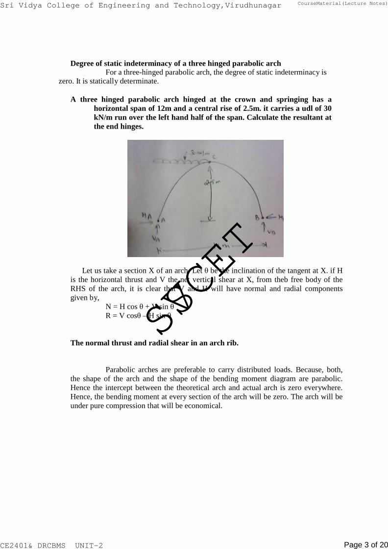
A three hinged parabolic arch hinged at the crown and springing has a
horizontal span of 12m and a central rise of 2.5m. it carries a udl of 30
kN/m run over the left hand half of the span. Calculate the resultant at
the end hinges.
Let us take a section X of an arch. Let θ be the inclination of the tangent at X. if H
is the horizontal thrust and V the net vertical shear at X, from theb free body of the
RHS of the arch, it is clear that V and H will have normal and radial components
given by,
N = H cos θ + V sin θ
R = V cosθ – H sin θ
The normal thrust and radial shear in an arch rib.
Parabolic arches are preferable to carry distributed loads. Because, both,
the shape of the arch and the shape of the bending moment diagram are parabolic.
Hence the intercept between the theoretical arch and actual arch is zero everywhere.
Hence, the bending moment at every section of the arch will be zero. The arch will be
under pure compression that will be economical.
Sri Vidya College of Engineering and Technology,Virudhunagar CourseMaterial(Lecture Notes)
CE2401& DRCBMS UNIT-2 Page 3 of 20
SVCET
SSCET

Difference between the basic action of an arch and a suspension cable An arch is essentially a compression member, which can also take
bending moments and shears. Bending moment and shears will be absent if the arch is
parabolic and the loading uniformly distributed.
A cable can take only tension. A suspension bridge will therefore
have a cable and a stiffening girder. The girder will take the bending moment and
shears in the bridge and the cable, only tension.
Because of the thrust in cables and arches, the bending moments
are considerably reduced.
If the load on the girder in uniform. The bridge will have only
cable tension and no bending moment on the girder.
Under what conditions will the bending moment in an arch be zero
throughout The bending moment in an arch throughout the span will be zero, if
(i) The arch is parabolic and
(ii) The arch carries udl throughout the span
A three-hinged semicircular arch carries a point load of 100 kN at the crown.
The radius of the arch is 4m. Find the horizontal reactions at the supports.
VA = VB = 50 kN
Sri Vidya College of Engineering and Technology,Virudhunagar CourseMaterial(Lecture Notes)
CE2401& DRCBMS UNIT-2 Page 4 of 20
SVCET
SSCET

Equating the moment about C to Zero, VA * 4 – H*4 = 0
H = VA
Horizontal reaction, H = 50 kN
A three-hinged semicircular arch of radius 10m carries a udl of 2 kN/m over
the span. Determine the horizontal and vertical reactions at the
supports.
Determine H, VA and VB in the semicircular arch shown in fig
Sri Vidya College of Engineering and Technology,Virudhunagar CourseMaterial(Lecture Notes)
CE2401& DRCBMS UNIT-2 Page 5 of 20
SVCET
SSCET

Equating moments about A to Zero,
VB * 12 – 12 * 9 = 0;
VB = 9 kN and VA = 3 kN Equating moments to the left of C to zero,
H = VA = 3 kN; H= 3 kN
Distinguish between two hinged and three hinged arches.
SI.NO Two hinged arches Three hinged arches
1. Statically indeterminate to first degree
Statically determinate
2. Might develop temperature stresses. Increase in temperature causes increases in central rise. No stresses
3. Structurally more efficient. Easy to analyse. But, in construction,
the central hinge may involve additional
expenditure.
4. Will develop stresses due to sinking of supports
Since this is determinate, no stresses due to support sinking
Rib – shorting in the case of arches. In a 2-hinged arch, the normal thrust, which is a compressive force
along the axis of the arch, will shorten then rib of the arch. This is turn will release
part of the horizontal thrust.
Normally, this effect is not considered in the analysis (in the case
of two hinged arches). Depending upon the important of the work we can either take
into account or omit the effect of rib shortening. This will be done by considering (or
omitting) strain energy due to axial compression along with the strain energy due to
bending in evaluating H.
Effect of yielding of support in the case of an arch.
Yielding of supports has no effect in the case of a 3 hinged arch which is determinate. These displacements must be taken into account when we analyse 2
hinged or fixed arches as under
U H instead of
H
zero
U
VA
VA
instead of
zero
Here U is the strain energy of the arch ∆H and ∆VA are the displacements
due to yielding of supports.
Sri Vidya College of Engineering and Technology,Virudhunagar CourseMaterial(Lecture Notes)
CE2401& DRCBMS UNIT-2 Page 6 of 20
SVCET
SSCET

A three-hinged parabolic arch has a horizontal span of 36m with a central rise of
6m. A point load of 40 kN moves across the span from the left to the
right. What is the absolute maximum positive bending moment that wills
occur in the arch
Sri Vidya College of Engineering and Technology,Virudhunagar CourseMaterial(Lecture Notes)
CE2401& DRCBMS UNIT-2 Page 7 of 20
SVCET
SSCET

For a single concentrated load moving from one end to the
other, Absolute maximum positive bending moment
= 0.096wl = 0.096*40 * 36=138.24 kNm
This occurs at 0.211 l = 0.211 * 36 = 7.596 m from the ends.
Absolute maximum positive bending moment = 138.24 kNm at 7.596 m from
the ends.
A 3 hinged arch of span 40m and rise 8m carries concentrated loads of
200 kN and 150 kN at a distance of 8m and 16m from the left end and
an udl of
50 kN/m on the right half of the span. Find the horizontal thrust.
Solution:
(a) Vertical reactions VA and VB :
Taking moments about A,
200(8) + 150(16) + 50 * 20 * (20 + 20/2) – VB (40)
= 0 1600 + 2400 + 30000 – 40 VB = 0
VB= = 850 kN VA = Total load – VB = 200 + 150 + 50 * 20 – 850 = 500 kN
(b) Horizontal thrust (H)
Taking moments about C,
-H x 8 + VA (20) – 200 (20 – 8) – 150 (20 – 16) = 0
-8H + 500 * 20 – 200 (12) – 150 (4) = 0 H =
875 kN
A parabolic 3-hinged arch carries a udl of 30kN/m on the left half of the
span. It has a span of 16m and central rise of 3m. Determine the
resultant reaction at supports. Find the bending moment, normal
thrust and radial shear at xx, and 2m from left support.
Solution:
Sri Vidya College of Engineering and Technology,Virudhunagar CourseMaterial(Lecture Notes)
CE2401& DRCBMS UNIT-2 Page 8 of 20
SVCET
SSCET

A = A
V 2 2
(1) Reaction at A nd B;
(i) Vertical components of reactions;
Taking moments about A,
-VB (16) + 30 x 82
/2 = 0 - VB (16) + 30 * 32 = 0
VB = 60 kN VA = Total load – VB = 30 * 8 – 60 kN VA = 180 kN
(ii) Horizontal components of reactions at A and
Taking moments about the crown point C,
VA * 8 – 30 * 8 * 8/2 – HA * yc = 0
180 * 8 -30 *32 = HA *3 HA = 160 kN
HB = HA = since H 0
HB = 160 kN
(iii) Resultants reactions at A and B;
RA = V 2 H
2
(180) 2 (160)
2
240.83 kN
RB = B H B = (60)
2 (160)
2 170.88 kN
(2) Bending moment at x = 2m from A:
Bending moment = VA (2) – 30 * 2 *1 – HA(y) -----------(1)
Where, y = Rise of the arch at x = 2m from ‘A’:
support
For parabolic arches, y 4r
* x(l x) at a distance of ‘x’ from thje l
2
Where, r = rise of the arch at Crown Point = 3m
y 4 * 3
* 2(16 2) (16)
2
Sri Vidya College of Engineering and Technology,Virudhunagar CourseMaterial(Lecture Notes)
CE2401& DRCBMS UNIT-2 Page 9 of 20
SVCET
SSCET

2
Substitute in (1)y = 1.3125 m at x = 2m from ‘A’.
Bending moment at x = 2m from A = 180 (2) – 30 * 2 * 1 – 160 * 1.3125
Bending moment at xx = 90 kNm
(3) Radial shear force at x = 2m from A
Shear force, RX = Vx cos θ – H sin θ
Where, V = Net vertical shear force at x = 2m from A
= VA - w (2) = 180 – 30 * 2
V = 120 kN
H = Horizontal shear force = 160 kN
tan 1 4r
(l 2x)
l 2
tan 1 4 * 3
(16)
θ = 29º21’
(16 2(2))
R = 120 cos 29º21’ – 160 sin 29º21’
R = 26.15 kN
(4) Normal thrust at x = 2m from A:
Normal thrust PN = Vx sinθ + H cos θ = 120 sin 29º21’ + 160 cos 29º21’ PN = 198.28 kN.
A parabolic 3-hinged arch carries loads as shown in fig. Determine the
resultant reactions at supports. Find the bending moment, normal thrust
and radial shear at D, 5m from A. What is the maximum bending moment
Solution:
(1)Reaction at supports: (RA and RB)
(i) Vertical components of RA and RB : (VA and VB)
Taking moments about A,
20 * 3 + 30 (7) + 25 * 10 * (10 +10/2) – VB *(20) = 0 VB = 201 kN VA = Total load – VB = 20 + 30 + 25 * 10 -201 VA = 99 kN
Sri Vidya College of Engineering and Technology,Virudhunagar CourseMaterial(Lecture Notes)
CE2401& DRCBMS UNIT-2 Page 10 of 20
SVCET
SSCET

side of ‘C’,
(ii) Horizontal thrust (H):
Taking moments about the crown point C, considering the right
-VB (20/2) + H (5) + 25 * 10 *5 = 0
-201 * (20/2) + 5 H + 1250 + 0 H = 125 kN
(iii) Resultant reactions RA and RB ;
tan 1 VA
A H
tan 1
99
152
324'30".6
Sri Vidya College of Engineering and Technology,Virudhunagar CourseMaterial(Lecture Notes)
CE2401& DRCBMS UNIT-2 Page 11 of 20
SVCET
SSCET

RA = H 2 V
2 A (152)
2 (99)
2 181.39 kN
RB =
H 2 V
2 B
(152) 2 (201)
2
252 kN
tan 1 VB
B H
tan 1 201
5254'9".86 152
2. Bending moment, normal thrust and radial shear force (at D):
(i) y 4r
x(l x) D
l 2
4 * 5
(20) 2
* 5(20 5)
yD = 3.75 m
BMD = VA (5) – HyD – 20 (5-3) = 99(5) – 152yD – 20(2) = 495 – 152 (3.75) -40
BMD = -115 kNm
(ii) Slope of the arch at D,
dy
tan dx D
1 4r
tan l
2
(l 2x)
tan 1 4 * 5 (20 2 * 5)
(20) 2
θ = 26º33’55”.18
(iii) Normal thrust
P = V sin θ + H cos θ
V = Net beam shear force = VA – 20
V = 99 – 20 = 79 kN Substitute in (iii) P = 79 sin θ + 152 cos θ = 179.28 kN
(iv) Radial shear force
F = V cos θ – H sin θ
F = 79 cos θ – 152 sin θ = 2.683 kN
3. Maximum Bending Moment in CB:
Considering a section xx at a distance of ‘x’ m from ‘B’
BMxx = 254KNM
Sri Vidya College of Engineering and Technology,Virudhunagar CourseMaterial(Lecture Notes)
CE2401& DRCBMS UNIT-2 Page 12 of 20
SVCET
SSCET

DEPARTMENT OF CIVIL ENGINEERING
SRI VIDYA COLLEGE OF ENGINEERING AND TECHNOLOGY
A 3-hinged arch is circular, 25 m in span with a central rise of 5m. It is loaded
with a concentrated load of 10 kN at 7.5m from the left hand hinge.
Find the
(a) Horizontal thrust
(b) Reaction at each end hinge
(c) Bending moment under the load
Solution:
Vertical reactions VA and VB:
Taking moments about A, 10(7.5) – VB (25) = 0
VB = 3 kN VA = Total load – VB = 10 -3 = 7 kN
1. Horizontal thrust (H):
Taking moments about C
Sri Vidya College of Engineering and Technology,Virudhunagar CourseMaterial(Lecture Notes)
CE2401& DRCBMS UNIT-2 Page 13 of 20
SVCET
SSCET

Sri Vidya College of Engineering and Technology,Virudhunagar CourseMaterial(Lecture Notes)
CE2401& DRCBMS UNIT-2 Page 14 of 20
SVCET
SSCET

V A
V B
A three hinged circular arch of span 16m and rise 4m is subjected to two point
loads of 100 kN and 80 kN at the left and right quarter span points
respectively. Find the reactions at supports. Find also the bending
moment, radial shear and normal thrust at 6m from left support.
Solution:
(a) Reaction at A and B:
(i) Vertical components of reactions at A and B:
Taking moment about A,
100 (4) + 80(12) – VB(16) = 0 VB = 85 kN. VA = Total load - VB = (100+80)-85 VA = 95 kN.
b. Horizontal components of reactions at A and B; Taking moments about the crone points C
VA(8) -H(YC) - 100(4) = 0
95 (8) – H (yC ) – 100 (4) = 0 H = 90 kN
(iii) Resultant reactions at A and B:
RA = 2 H
2
952
902
130.86 kN
RB = 2 H
2 85
2 90
2 123.79 kN
Sri Vidya College of Engineering and Technology,Virudhunagar CourseMaterial(Lecture Notes)
CE2401& DRCBMS UNIT-2 Page 15 of 20
SVCET
SSCET

(b) Bending moment at 6m from the left support:
In fig. ∆OEF is a right-angled triangle
To find the radius R,
l *
l
y (2R y )
2 2 c c
yc = 4 : L = 16 Therefore R = 10 m
To find y at x = 2m from center:
∆OEF is a right-angled triangle
R2
= (R – 4 + y )2
+ 22
Y2
+ 12 y – 60 =0
By solving this equ
Y = 3.8m at x = 2m from center
Bending moment = VA (6) – HA (y) – 100 (2)
= 95 (6 ) – 90y -100 (2) BM = 28 kNm
(c) Radial shear force ‘F’ :
From fig.
tan 1 2
OE
tan 1
2
6 y
tan 1
2
6 3.8
1132'
R = V cos θ - H sin θ
V = net shear force at x = 6m from A
= VA -100 = 95 – 100 = -5 kN
H = 90 kN
R = -5 cos (11º32’) – 90 sin (11º32’) = - 22.895 R = -22.89 kN
(D) Normal Thrust (at x = 6m from A) N = V sin θ + H cos θ N = -5 sin (11º32’) + 90 cos (11º32’) = -87.17 kN
Sri Vidya College of Engineering and Technology,Virudhunagar CourseMaterial(Lecture Notes)
CE2401& DRCBMS UNIT-2 Page 16 of 20
SVCET
SSCET

2
A symmetrical three hinged parabolic arch of span 40m and rise 8m carries
an udl of 30 kN/m over left of the span. The hinges are provided at these
supports and at the center of the arch. Calculate the reactions at the
supports. Also calculate the bending moment, radial shear, normal thrust
at distance of 10 m from the left support.
Solution:
(1) Reactions at the supports:
(i) Vertical components;
Taking moments about A, 2
30 * (20)
2
VB
* (40) 0
Vertical component of RB, VB = 150 kN VA = Total load – VB = 30 * 20 – 150 = 450 kN
(iii) Horizontal components
Taking moments about the crown, ‘C’,
l 20 VA H A ( yc ) 30 * 20 * 0
2
450(20) H
2
(8) 30 * (20)
0 A
2
H A 375
H 0
kN
; H A H B 0
(iii) Reaction RA and RB :
Sri Vidya College of Engineering and Technology,Virudhunagar CourseMaterial(Lecture Notes)
CE2401& DRCBMS UNIT-2 Page 17 of 20
SVCET
SSCET

V 2 2
RA = A H A
2
(450) 2
2
(375) 2
2
585.77 kN
2
RB = VB H B (150) (375) 403.89 kN
(2) Bending moment at 10 m from A:
y 4r
x(l x) l
2
y 4 * 8
(40) 2
*10(40 10)
y 6m at 10m from A.
Bending moment = VA
(10) H ( y) 30 *10 * 10
A 2
= 450(10) – 375y – 30 (50)
BMxx = 3000 -375y
BMxx = 3000 – 375 (6) BM at 10m = 750 kNm
(3)Radial shear force at x = 10m:
R = Radial shear force = V cos θ – H sin θ Where, V = Net vertical shear force at x = 10m from A
H = Horizontal thrust.
tan 1 4r l
2
(l 2 x)
tan dy
d 4r x(l x)
dx
tan 4r
l 2
dx l 2
(l 2x)
tan 1
4 * 8 (40 2(10))
(40) 2
θ = 21º 48’
V = VA – wl/4 = 450 – 30* 10
Radial shear force, R = V cos θ – H sin θ
R = 150 cos 21º 48’ – 375 sin 21º48’
R = 0
Sri Vidya College of Engineering and Technology,Virudhunagar CourseMaterial(Lecture Notes)
CE2401& DRCBMS UNIT-2 Page 18 of 20
SVCET
SSCET

(4) Normal thrust at x = 10m from ‘A’: Normal thrust, N = V sin θ + H cos θ = 150 sin 21º48’ + 375 cos 21θ 48’
N = 403.89 kN
A parabolic 3-hinged arch of span ‘l’ is subjected to an u.d.l of w/m run over
the entire span. Find the horizontal thrust and bending moment at any
section XX.
Solution:
(a) Reactions (Vertical) at the supports: As the loading is symmetrical, vertical reactions at A and B are equal
VA = VB = Total load/2 = wl/2
(b) Horizontal thrust: Taking moments about the crown point C,
2
w l
VA (
l
) 2
2
2
H yc 0
wl *
l
2 2
wl 2
4 * 2
H ( yc ) 0
wl 2
4
wl 2
8
H ( yc ) 0
2
H ( yc ) wl 8
2
H wl 8 yc
(c) Bending moment at xx;
M x VA ( x)
wx 2
2
Hyx
Since the arch is parabolic,
Sri Vidya College of Engineering and Technology,Virudhunagar CourseMaterial(Lecture Notes)
CE2401& DRCBMS UNIT-2 Page 19 of 20
SVCET
SSCET

2
2 2
4 yc
y l
2
x(l x)
2 2
M wl
x w
x 2
wl . wl
. 4 yc .x(l x)
x
2 2 8 yc 8 yc l
wlx
wx
wxl
wx 0
2 2 2 2
Sri Vidya College of Engineering and Technology,Virudhunagar CourseMaterial(Lecture Notes)
CE2401& DRCBMS UNIT-2 Page 20 of 20
SVCET
SSCET

DEPARTMENT OF CIVIL ENGINEERING
CE6501- STRUCTURAL ANALYSIS – CLASSICAL METHOD
(FOR V – SEMESTER)
UNIT - II
Sri Vidya College of Engineering and Technology,Virudhunagar CourseMaterial(Lecture Notes)
CE2401& DRCBMS UNIT-2 Page 1 of 22
SVCET
SSCET

TWO MARKS QUESTIONS AND
ANSWERS
Influence lines
An influence line is a graph showing, for any given beam frame or truss, the
variation of any force or displacement quantity (such as shear force, bending
moment, tension, deflection) for all positions of a moving unit load as it crosses the
structure from one end to the other.
Uses of influence line diagram (i) Influence lines are very useful in the quick determination of reactions,
shear force, bending moment or similar functions at a given section
under any given system of moving loads and
(ii) Influence lines are useful in determining the load position to cause
maximum value of a given function in a structure on which load
positions can vary.
A simply supported beam of span 10m carries a udl of 20 kN/m over its central
4m length. With the help of influence line diagram, find the shear force
at 3m from the left support.
x
3 0.3
l 10
(l x)
7 l 10
0.7
Shear force at X = intensity of udl x area of udl below the udl
= 20 * (0.7 0.3)
2 * 4 40 kN
UNIT – II
Sri Vidya College of Engineering and Technology,Virudhunagar CourseMaterial(Lecture Notes)
CE2401& DRCBMS UNIT-2 Page 2 of 22
SVCET
SSCET

Muller – Bresalu principle. Muller – Bresalu principle states that, if we want to sketch the
influence line for any force quantity (like thrust, shear, reaction, support
moment or bending moment) in a structure,
(i) we remove from the structure the restraint to that force quantity
(ii) we apply on the remaining structure a unit displacement
corresponding to that forces quantity.
For the two member determine bent in fig. sketch the influence line for VA.
If we deftly apply Muller – Breslau to the problem, we can first remove
support A and push A up by unit distance. Since the angle at B will remain unchanged,
our unit displacement will result in a rigid body rotation of θ (=1/4 radian) about C. So
the column CB will also have a horizontal displacement. (For the part AB, the diagram
is just the influence line diagram for shear in a S.S beam)
The diagram for BC must be understood to be the influence of horizontal loads on
the column on RA.
principle on which indirect model analysis is based
The indirect model analysis is based on the Muller Bresalu principle. Muller Breslau principle has lead to simple method of using models
of structures to get the influence lines for force quantities like bending moments, support
moments, reactions, internal shears, thrusts, etc.
To get the influence line for any force quantity (i) remove the
restraint due to the force, (ii) apply a unit displacement in the direction of the force.
Sri Vidya College of Engineering and Technology,Virudhunagar CourseMaterial(Lecture Notes)
CE2401& DRCBMS UNIT-2 Page 3 of 22
SVCET
SSCET

Begg’s deformeter Begg’s deformeter is a device to carry out indirect model analysis on
structures. It has the facility to apply displacement corresponding to moment, shear
or thrust at any desired point in the model. In addition, it provides facility to
measure accurately the consequent displacements all over the model.
‘dummy length’ in models tested with Begg’s deformeter.
Dummy length is the additional length (of about 10 to 12 mm) left at the extremities of the model to enable any desired connection to be made with the
gauges.
Three types of connections possible with the model used with
Begg’s deformeter. (i) Hinged connection (ii) Fixed connection
(iii) Floating connection
Use of a micrometer microscope in model analysis with Begg’s
deformeter Micrometer microscope is an instrument used to measure the displacements of
any point in the x and y directions of a model during tests with Begg’s deformeter.
Name the types of rolling loads for which the absolute maximum bending
moment occurs at the mid span of a beam. Types of rolling loads:
(i) Single concentrated load
(ii) Udl longer than the span
(iii) Udl shorter than the span
Absolute maximum bending moment in a beam When a given load system moves from one end to the other end of a
girder, depending upon the position of the load, there will be a maximum
bending moment for every section. The maximum of these maximum bending
moments will usually occur near or at the mid span. This maximum of
maximum bending moment is called the absolute maximum bending moment,
Mmaxmax.
The portal frame in fig. is hinged at D and is on rollers at A. Sketch the
influence line for bending moment at B.
To get the influence line diagram for MB, we shall introduce a hinge
at B (and remove the resistance to bending moment). Now we get a unit rotation
between BA and BC at B.
BC cannot rotate since column CD will prevent the rotation. BA would rotate freely (with zero moment). For θ =1 at B, displacement at A = 3m. The
displaced position shows the influence line for MB as shown in fig.
Sri Vidya College of Engineering and Technology,Virudhunagar CourseMaterial(Lecture Notes)
CE2401& DRCBMS UNIT-2 Page 4 of 22
SVCET
SSCET

A single rolling load of 100 kN moves on a girder of span 20m. (a)
Construct the influence lines for (i) shear force and (ii) bending moment for
a section 5m from the left support. (b) Construct the influence lines for
points at which the maximum shears and maximum bending moment
develop. Determine these values.
Solution:
(a) To find maximum shear force and bending moment at 5m from the left support:
For the ILD for shear,
IL ordinate to the right of D = l x
20 5 0.75
l 20
For the IL for bending moment, IL ordinate at D =
x(l x)
5 *15 3.75 m
l 20
(i) Maximum positive shear force
By inspection of the ILD for shear force, it is evident that maximum positive shear force occurs when the load is placed just to the right of D.
Maximum positive shear force = load * ordinate = 100 * 7.5
At D, SFmax + = 75 kN.
(ii) Maximum negative shear force
Maximum negative shear force occurs when the load is placed just to
the left D. Maximum negative shear force = load * ordinate = 100 * 0.25
At D, SFmax = -25 kN.
Sri Vidya College of Engineering and Technology,Virudhunagar CourseMaterial(Lecture Notes)
CE2401& DRCBMS UNIT-2 Page 5 of 22
SVCET
SSCET

(iii) Maximum bending moment
Maximum bending moment occurs when the load is placed on the
section D itself.
Maximum bending moment = load * ordinate = 100 * 3.75 = 375 kNm
(b) Maximum positive shear force will occur at A. Maximum negative shear
force will occur at B. Maximum bending moment will occur at mid span.
The ILs are sketched in fig.
(i) Positive shear force
Maximum positive shear force occurs when the load is placed at A. Maximum positive shear force = load * ordinate = 100*1
SFmaxmax + = 100 kN
(ii) Negative shear force
Maximum negative shear force occurs when the load is placed at B.
Maximum negative shear force = load * ordinate = 100 * (-1)
SFmaxmax = - 100 kN
(iii) Maximum bending moment
Maximum bending moment occurs when the load is at mid span Maximum bending moment = load * ordinate = 100 * 5 = 500 kNm
Sri Vidya College of Engineering and Technology,Virudhunagar CourseMaterial(Lecture Notes)
CE2401& DRCBMS UNIT-2 Page 6 of 22
SVCET
SSCET

1 1
Draw the ILD for shear force and bending moment for a section at 5m from
the left hand support of a simply supported beam, 20m long. Hence,
calculate the maximum bending moment and shear force at the section, due
to a uniformly distributed rolling load of length 8m and intensity 10 kN/m
run.(Apr/May 05)
Solution:
(a) Maximum bending moment: Maximum bending moment at a D due to a udl shorter than the span
occurs when the section divides the load in the same ratio as it divides the
span.
In the above fig. A1 D
AD
0.25,
A D 2M , B D 6M
Ordinates:
B1 D BD
Ordinate under A1 = (3.75/5)*3 = 2.25
Ordinate under B1 = (3.75/15)*9 = 2.25 Maximum bending moment = Intensity of load * Area of ILd under the load
= 10 * (3.75 2.25) * 8
2 At D, Mmax = 240 kNm
Sri Vidya College of Engineering and Technology,Virudhunagar CourseMaterial(Lecture Notes)
CE2401& DRCBMS UNIT-2 Page 7 of 22
SVCET
SSCET

(b) Maximum positive shear force
Maximum positive shear force occurs when the tail of the UDL is at D
as it traverses from left to right.
Ordinate under B1 = 0.75
15
* (15 8) 0.35
Maximum positive shear force = Intensity of load * Area of ILD under load
= 10 * (0.75 0.35) * 8
2 SFmax = + 44 kNm
(c) Maximum negative shear force
Maximum negative shear force occurs when the head of the UDL is at D as it traverses from left to right.
Maximum negative shear force = Intensity of load * Area of ILD under the load
= 10(1/2*0.25*5)
Negative SFmax = 6.25 kN.
Sri Vidya College of Engineering and Technology,Virudhunagar CourseMaterial(Lecture Notes)
CE2401& DRCBMS UNIT-2 Page 8 of 22
SVCET
SSCET

Two point loads of 100 kN and 200 kN spaced 3m apart cross a girder of span
15m from left to right with the 100 kN load loading. Draw the
influence line for shear force and bending moment and find the value of
maximum shear force and bending moment at a section, 6m from the left
hand support. Also, find the absolute maximum moment due to the given
load system.
Solution:
(a) Maximum bending moment
Max. Ordinate of ILD = x(l x)
6 * 9 3.6 m
l 15 Maximum bending moment at D occurs under the critical load. This load,
when it moves from left to right of ‘D’ changes the sign of Lr, the differential loading rate,
where,
Lr Wleft
x
Wrig ht
l x Now, let us try with 200 kN load. Firstly, keep this 200 kN load to the left of ‘D’.
Lr Wleft
x
Wrig ht
l x =
200 6
100
9
22.22
(ve)
Sri Vidya College of Engineering and Technology,Virudhunagar CourseMaterial(Lecture Notes)
CE2401& DRCBMS UNIT-2 Page 9 of 22
SVCET
SSCET

Moving this load to the right of ‘D’,
Lr Wleft
x
Wrig ht
l x =
0
6
300
9
33.33
(ve)
Since, the sign of Lr changes, the 200 kN load is critical. The maximum bending
moment occurs at D when this 200 kN load is placed at D.
Ordinate under 100 kN load = 3.6
* 6 2.4 9
Maximum bending moment = (load * ordinate) 200 * 3.6 100 * 2.4
(b) Maximum shear force:
(i) Positive shear force Fig. shows the load position for the absolute maximum positive shera force.
If the load train is moved to the left, the positive contribution due to the bigger (160 kN)
load is lost and a negative contribution is obtained.
If the load train moves to the right, the ordinates under to the loads decrease.
Hence, the indicated load position is the critical one.
Ordinate under 200 kN load = 0.6
Ordinate under 100 kN load = 0.6
0.4 9
Maximum positive shear force = 200 (0.6) + 100 (0.4)
SFmax = + 160 kN.
Sri Vidya College of Engineering and Technology,Virudhunagar CourseMaterial(Lecture Notes)
CE2401& DRCBMS UNIT-2 Page 10 of 22
SVCET
SSCET

(ii) Negative shear force
Trying with 100 kN load, first keep this 100 kN load to the left of D. Then move this load
to the right of ‘D’ by 3m. If the value of the shear increment Si is a negative value, it
includes a decrease in negative shear force.
S Wc
i l
W1 300 * 3
100 40(ve) 15
Hence, the negative shear force decreases when this load train is moved to the right
of ‘D’. Hence, to get maximum shear force, this 100 kN load should be kept just to the left
of D.
Ordinate under 100 kN load = 0.4
Ordinate under 200 kN load = 0.4
* 3 0.2 6
Maximum negative shear force = 100*0.4 + 200*0.2 = 80
SFmax = - 80 kN
(c) Absolute maximum bending moment (i) Resultant of the loads
Taking moments about 200 kN load,
100*3 = R.x, R = 300 kN. X = 1.0 m
Absolute maximum bending moment occurs under the load which is
nearer to the resultant ‘R’. The critical position is when the resultant ‘R’
and the load are at equal distance from the centre of span © .
Distance of this 200 kN from C = Distance of ‘R’ from c.
Sri Vidya College of Engineering and Technology,Virudhunagar CourseMaterial(Lecture Notes)
CE2401& DRCBMS UNIT-2 Page 11 of 22
SVCET
SSCET

Maximum ordinate of ILD (i.e) ordinate under 200 kN load =
Ordinate under 100 kN load = (3.733*6)/9 =2.489 m
x(l x) 3.733 m
l
Absolute maximum bending moment, Mmaxmax = (load * Dis tan ce)
= 200 * 3.733 + 100*2.489 = 995.5 kNm
A train of 5 wheel loads crosses a simply supported beam of span 22.5 m.
Using influence lines, calculate the maximum positive and negative shear
forces at mid span and absolute maximum bending moment anywhere in
the span.(Nov/Dec 05)
Solution:
(a) Maximum shear force
(i) Positive shear force
To determine the load position to get the maximum positive shear force, let us keep
all the loads to the right of C. Then move W1 load to the left of ‘C’ by 2.5 m. if the
sign of shear increments Si is negative, it will indicate that W1 shall be retained at C.
Sri Vidya College of Engineering and Technology,Virudhunagar CourseMaterial(Lecture Notes)
CE2401& DRCBMS UNIT-2 Page 12 of 22
SVCET
SSCET

Wc
S i l
W1
W = Total load on the span = 120 + 160 +400 + 260 +240 = 1182 kN.
C = Distance through which the load train is moved = 2.5 m
S 1180 * 2.5
120 11.11 (ve) i
22.5 Since Si is positive, the shear force increases due to thr shifting of W1 to the left of C.
Again, let us move W2 to the left of C by 2.5 m to check whether the shera force
further increases or not.
S Wc
i l
W2 1180 * 2.5
160 28.89 22.5
(ve)
Since Si is negative, it undicates that to get maximum positive shear force, W2 should
stay just right of C.
Ordinate of ILD
0.5 * (11.25 2.5) 0.39
Ordinate under W1 = 11.25
Ordinate under W2 = 22.5 11.25
22.5
0.5
Ordinate under W3 = 0.5
11.25
* 8.75 0.39
Ordinate under W4 = 0.5
11.25
* 3.25 0.28
Ordinate under W5 = 0.5
11.25
* 3.75 0.17
Maximum positive shear force = (laodxordinate)
= 120 (-0.39) + 160 (0.5) +400 (0.39) +260(0.28) + 240 (0.17)
At C , SFmax + = 302.8 kN.
ii) Negative shear force
Sri Vidya College of Engineering and Technology,Virudhunagar CourseMaterial(Lecture Notes)
CE2401& DRCBMS UNIT-2 Page 13 of 22
SVCET
SSCET

To determine the position of loads to get the maximum negative shear force, move the
loads one by one to the right of C and computer the value of Si.If Si becomes negative it
will indicate a decrease in negative shear force due to that movement.
First let us move the leading W5 to the right of C by 2.5 m and calculate Si
Si= Wd
W5
l
W5 = 240 kN; d = 2.5 m
Si = 1180x2.5
22.5
240 108.89(ve)
Since Si is –ve it indicates that W5 should stay just to the left of C.
Ordinates of ILD:
Ordinate under W5 = x
11.25 l 22.5
0.5
Ordinate under W4 = 0.5
11.25
x(11.25 2.5) 0.39
Ordinate under W3 = 0.5
11.25
x(11.25 5.0) 0.278
Ordinate under W2 = 0.5
11.25
x(11.25 7.5) 0.167
Ordinate under W1 = 0.5
11.25
x(11.25 10) 0.056
Sri Vidya College of Engineering and Technology,Virudhunagar CourseMaterial(Lecture Notes)
CE2401& DRCBMS UNIT-2 Page 14 of 22
SVCET
SSCET

Maximum negative shear force at C = 240(-0.5)+260(-0.39)+(400(-0.278) +160(-0.167)
+120(-0.056)
Fmax = 366.04 kN.
b) Absolute maximum bending moment
i) Position of resultant of all loads
Taking moments about W1, 120(0)+160(2.5)+400(5.0)+260(7.5)+240(10.0) =R. x
R = 1180kN
x = 5,72m from W1
ii) Location of absolute maximum bending moment Absolute maximum bending moment occurs under the load, which is nearest to the
resultant ‘R’.(In this problem W3 is nearest to the resultant ‘R’).The distance between C
and R and the distance between C and W3 shall be equal.
Distance between R and center of span(C) = ½ (0.72) =0.36 m In this fig. Shows the IL for bending moment at the critical spot D, 10.89 m fro A.
Sri Vidya College of Engineering and Technology,Virudhunagar CourseMaterial(Lecture Notes)
CE2401& DRCBMS UNIT-2 Page 15 of 22
SVCET
SSCET

Ordinates of ILD:
Maximum ordinate of ILD
(i.e) Ordinate under W3 = x(l x)
l
10.89(22.5 10.39) 22.5
5.62
Ordinate under W2 = 5.62
10.89
x8.39 4.33
Ordinate under W1 = 5.62
10.89
x5.89 3.04
Ordinate under W4 = 5.62
11.61
x9.11 4.41
Ordinate under W5 = 5.62
11.61
x6.61 3.20
Absolute maximum bending moment =120 (3.04)+160(4.33)+400(5.62)+260(4.41)+
240 (3.2)
Mmax max = 5220.2 kN.m
5) A girder a span of 18mis simply supported at the ends. It is traversed by a train of
loads as shown in fig. The 50 kN load loading. Find the maximum bending moment
which can occur (i) under the 200 kN load (ii) Under 50 kN load, using influence line
diagrams.
Sri Vidya College of Engineering and Technology,Virudhunagar CourseMaterial(Lecture Notes)
CE2401& DRCBMS UNIT-2 Page 16 of 22
SVCET
SSCET

Solution
: a) Maximum bending
moment
i) Under 200 kN
loads. To get the maximum bending moment under W3 the resultant R and W3 should be at equal
distances from the center of the span C.For that the point of action of resultant R should
be determined first.
a) Resultant of loads:
R = 450
kN
Taking moments about
W4
200(3) +100 (3+2) +50(3 +2+3) = 450 x
x = 3.33 from W4
b) Bending moment under 200 kN load
Distance between C and 200 kN load = Distance between C and R = 0.33/2 = 0.165 m.
Ordiantes of ILD :
ILD under W3 = x(l x)
l
X= 8.335m
l-x = 18-8.835 = 9.165 m
ILD under W3 = 8.835 * 9.1365
18
4.50 m
ILD under W4 = 4.5 * 5.835
8.835
2.97 m
ILD under W2 = 4.5 * (3 4.165)
9.165
3.52 m
ILD under W1 = 4.5 * 4.165 9.165
Sri Vidya College of Engineering and Technology,Virudhunagar CourseMaterial(Lecture Notes)
CE2401& DRCBMS UNIT-2 Page 17 of 22
SVCET
SSCET

CE2302–STRUCTURAL ANALYSIS-I/UNIT III
21
2.05 m
Bending moment under the 200 kN load
= 200 (4.5) + 100 (2.97) + 100 (3.52) +50 (2.05) = 1651.5 kNm. (ii) Bending moment under the load 50 kN load
To get the maximum bending moment under W1 , W2 and R must be at equal
distances from the centre of span ©. Distance between C and R = Distance between C and
W1 = ½ (2 – 0.33 + 3) = ½ (4.67) = 2.335 m
Sri Vidya College of Engineering and Technology,Virudhunagar CourseMaterial(Lecture Notes)
CE2401& DRCBMS UNIT-2 Page 18 of 22
SVCET
SSCET

Ordinates of ILD:
ILD under W1 = x(l x)
l
11.335 * 6.665 18
4.20 m
ILD under W2 = x(l x)
l
4.2 * 8.335 11.335
3.09 m
ILD under W3 = x(l x)
l
4.2 * 6.335 11.335
2.35 m
ILD under W4 = x(l x)
l
4.2 * 3.335 11.335
1.24 m
Bending moment under the load 50 kN load
= 4.2 (50) + 3.09 (100) +2.35 (200) +1.24 (100) = 1113 kN m.
6.Draw the I.L for reaction at B and for the support moment MA at A for the
propped cantilever in fig. Compute the I.L ordinates at 1.5 m intervals.
Solution:
Remove the restraint due to RB (remove support B)
Apply a unit displacement (upward).
unit load applied at B.
When RB = 1, then YXB is the displacement at section x due to
Mx = -EI d
2 y
dx 2
RB .x 1.x : d 2 y
EI dx 2
x
Sri Vidya College of Engineering and Technology,Virudhunagar CourseMaterial(Lecture Notes)
CE2401& DRCBMS UNIT-2 Page 19 of 22
SVCET
SSCET

2
EI dy
x
dx 2
x 3
C1
EIy C1 x C1
6
At x= 12, y = 0, dy/dx = 0
Hence , C1 = 72, C2 = -576
1 x 2
YXB = EI
6
72x 576
YBB (at x = 0 ) = 576
EI
When we plot this against x, we get the I.L for RB.
Xm
0
1.5
3
4.5
6
7.5
9
10.5
12
RB
1
0.814
0.632
0.463
0.312
0.184
0.085
0.022
0.00
Fig. is the influence line diagram for RB.
Sri Vidya College of Engineering and Technology,Virudhunagar CourseMaterial(Lecture Notes)
CE2401& DRCBMS UNIT-2 Page 20 of 22
SVCET
SSCET

To get the I.L for MA have to
(i) Introduce a hinge at A and
(ii) We have to apply a unit rotation at A. Instead we will apply a unit moment at A
find the general displacement at any x from B. We will then divide the
displacement by the actual rotation at A.
M A 1
RB RA 1/12
2
Due to M EI d y
x
x dx
2 12
dy x2
Ei dx
C1
24
Sri Vidya College of Engineering and Technology,Virudhunagar CourseMaterial(Lecture Notes)
CE2401& DRCBMS UNIT-2 Page 21 of 22
SVCET
SSCET

The ordinates of the I.L.D for MA at 1.5 m intervals are tabulated below.
X
0
1.5
3.0
4.5
6.0
7.5
9.0
10.5
12.0
ILD
0.0
-0.738
-1.406
-1.934
-2.250
-2.285
-1.960
-1.230
0.0
7. In a simply supported girder AB of span 2om, determine the maximum
bending moment and maximum shear force at a section 5m from A, due to
the passage of a uniformly distributed load of intensity 20 kN/m, longer
than the span.
Solution:
(i) Maximum bending moment
Since the udl is longer than the , the criterion for maximum bending
moment at a section is that the whole span should be loaded as shown in fig.
(ii) Maximum shear force
Maximum negative shear force at a section occurs when the
head of the load reaches the section ((i.e. when the left portion AX is loaded and right
portion XB is empty)
(iii) Maximum positive shear force:
Maximum positive shear force occurs at X when the tail of the
load is at X as it moves from left to right. (i.e. AX is empty and the portion XB is loaded)
Maximum positive shear force = RA
Sri Vidya College of Engineering and Technology,Virudhunagar CourseMaterial(Lecture Notes)
CE2401& DRCBMS UNIT-2 Page 22 of 22
SVCET
SSCET