CCGS Henry Larsen Annual Drydocking and refit
312
Page 1 of 312 CCGS Henry Larsen Annual Drydocking and refit Canadian Coast Guard Vessel Support Services Atlantic Region PO Box 5667 St. John’s, Newfoundland and Labrador A1C 5X1 F6855-210004 April 7 th to July 21st
-
Upload
khangminh22 -
Category
Documents
-
view
3 -
download
0
Transcript of CCGS Henry Larsen Annual Drydocking and refit

Page 1 of 312
CCGS Henry Larsen
Annual Drydocking and refit Canadian Coast Guard
Vessel Support Services Atlantic Region PO Box 5667
St. John’s, Newfoundland and Labrador A1C 5X1
F6855-210004 April 7th to July 21st

Page 2 of 312
TABLE OF CONTENTS
1. SHIP'S PARTICULARS ...................................................................................................... 5
2. PREAMBLE .......................................................................................................................... 6
3. INTENT ................................................................................................................................. 6
4. MANUFACTURER’S RECOMMENDATIONS .............................................................. 6
5. TESTING AND RECORDS................................................................................................. 6
6. WORKMANSHIP................................................................................................................. 6
7. FACILITIES ......................................................................................................................... 6
8. MATERIALS AND SUBSTITUTIONS ............................................................................. 7
9. REMOVALS ......................................................................................................................... 7
10. EXPOSURE AND PROTECTION OF EQUIPMENT ..................................................... 7
11. LIGHTING AND VENTILATION ..................................................................................... 7
12. CLEANLINESS .................................................................................................................... 7
13. ASBESTOS ............................................................................................................................ 7
14. ENTRY INTO ENCLOSED SPACES ................................................................................ 9
15. SUSPENSION OF WORK ................................................................................................... 9
16. HOTWORK........................................................................................................................... 9
17. LOCKOUT AND TAGOUT PROCEDURES ................................................................... 9
18. PAINTING........................................................................................................................... 10
19. LEAD ................................................................................................................................... 10
20. WELDING ........................................................................................................................... 13
21. SMOKING ........................................................................................................................... 14
22. RESTRICTED AREAS ...................................................................................................... 14
23. ELECTRICAL STANDARDS ........................................................................................... 14
24. DRAWINGS ........................................................................................................................ 14
25. TRANSDUCERS................................................................................................................. 15
26. OWNER’S REPRESENTATIVE ...................................................................................... 15
27. REGULATORY AUTHORITY INSPECTIONS ............................................................ 15
28. WASTE OIL PRODUCTS ................................................................................................. 15
29. WHMIS ................................................................................................................................ 15
30. SAFETY ANNEX................................................................................................................ 15
31. CONTRACTOR BASIC FAMILIARIZATION AND PJSA ......................................... 16

Page 3 of 312
SPECIFICATION ITEMS ......................................................................................................... 21
HD-01 :PRODUCTION CHART AND SUBCONTRACTOR ALLOWANCES ................. 22
HD-02 : PRE-REFIT SAFETY MEETING ............................................................................. 24
HD-03: SERVICES ..................................................................................................................... 26
HD-04 : SEA TRIALS ................................................................................................................ 33
HD-05 : DRYDOCKING ........................................................................................................... 34
HD-06 : DOCKING PLUGS ..................................................................................................... 37
HD-07 : HULL BUTTS AND SEAMS ...................................................................................... 39
HD-08 : HULL COATING ........................................................................................................ 41
HD-09 : SEA WATER VENT PIPE REPLACEMENTS ...................................................... 46
HD-10: POTABLE WATER TANKS ....................................................................................... 53
HD-11 : VOID SPACES ............................................................................................................. 59
HD-12 : AUXILIARY MACHINERY SPACE TANK TOP COATINGS ............................ 64
HD-13 : BALLAST TANK INSPECTION AND COATING ................................................ 67
HD-14 : SEA BAY/SEA CHEST ANODES ............................................................................. 72
HD-15 : INSTALLATION OF SPLIT AIR CONDITIONERS ............................................ 77
HD-16: MULTIBEAM INSTALL ............................................................................................ 95
HD - 17: HULL SURVEY ........................................................................................................ 132
HD-18 : CHAIN LOCKER SURVEY ..................................................................................... 145
HD-19 : HEELING TANKS SURVEY ................................................................................... 149
HD-20 : FUEL OIL TANKS SURVEY ................................................................................... 154
HD-21 : SEABAY SEACHEST COATING ........................................................................... 157
HD-22 : BUBBLER PIPING REPAIR ................................................................................... 160
HD-23 : ANCHORS AND CHAINS SURVEY ...................................................................... 163
H-01 : LIFEBOATS/DAVITS ANNUAL INSPECTION ...................................................... 166
H-02 : CARGO HATCHES REPAIR .................................................................................... 169
H-03 : HELICOPTER FUELING SYSTEM MAINTENANCE .......................................... 173
H-04 : LIFERAFTS .................................................................................................................. 176
H-05 : ACCOMMODATION HVAC CLEANING ............................................................... 177
H-06 : ACCOMMODATION WASHROOM EXHAUST DUCT CLEANING ................ 179
H-07 : GALLEY RANGE HOOD AND EXHAUST FAN TRUNKING ............................. 181
H-08 : LAUNDRY DRYER EXHAUST DUCTWORK CLEANING ................................ 183

Page 4 of 312
H-09 : SEWAGE SYSTEM ...................................................................................................... 185
H-10: FIXED FM 200 AND CO2 SMOTHERING SYSTEM INSPECTION .................... 189
H-11 : HANGAR FIRE FIGHTING FOAM REPLACEMENT .......................................... 196
H - 12 : FIRE DETECTION SYSTEMS ................................................................................ 199
H-13 : SENIOR ENGINEER’S CABIN REPAIRS ............................................................... 202
H-14 : MCR FLOORING ........................................................................................................ 205
E-01 : PORT AND STBD STERNSEAL ................................................................................ 209
E-02 : TAILSHAFT BEARING WEARDOWN PORT AND STBD ................................... 211
E-03 : PORT AND STBD SHAFT SURVEY ......................................................................... 213
E-04 : PORT TAILSHAFT PILGRIM NUT RENEWAL .................................................... 221
E-05 : DIESEL FUEL PURIFIER PIPING MODIFICATION ........................................... 226
E-06: RELIEF VALVE CERTIFICATION ........................................................................... 230
E-07: ANNUAL REFRIGERATION SYSTEMS INSPECTION ........................................ 233
E-08 : MACHINERY SPACE BILGE CLEANING ............................................................. 235
E-09 : THERMAL FLUID UNITS MAINTENANCE .......................................................... 237
E-10 : BUBBLER COMPRESSOR INSTALL ...................................................................... 239
E-11 : PORT WINDLASS BRAKE BAND REPAIR ............................................................ 262
E-12 : BUBBLER CHECK VALVES REPLACEMENT ..................................................... 265
E-13 : BUBBLER VALVE OVERHAUL ............................................................................... 268
E-14: STEERING GEAR HYDRAULICS OVERHAUL ..................................................... 272
E-15 : SURVEY MAIN ENGINE LUBE OIL COOLERS ................................................... 275
E-16 : INCINERATOR REFRACTORY REPLACEMENT ............................................... 278
L-01 : MACHINERY SPACE FAN OVERHAULS .............................................................. 281
L-02 : TV DISTRIBUTION REPLACEMENT ..................................................................... 286
L-03: SEATEL TVRO INSTALL ........................................................................................... 305
L-04 : STEERING GEAR MOTOR OVERHAULS ............................................................. 310

Preamble
Page 5 of 312
1. SHIP'S PARTICULARS Length O.A.: 99.80 m Length B.P.: 93.80 m Breadth Overall: 19.78 m Depth Moulded: 8.08 Mean Draft, Extreme: 7.24 m Displacement, Extreme: 8290 tonnes Displacement, Docking: 6800 tonnes

Preamble
Page 6 of 312
2. PREAMBLE
3. INTENT This specification outlines the work required for the 2021 Docking and annual refit of CCGS Henry Larsen . The period of work is April 7th –July 21st , 2021. All work specified herein and all repairs, inspections and renewals are to be carried out to the satisfaction of the Owner's Representative and, where applicable, the attending Transport Canada Ship Safety Surveyor. Unless otherwise specifically stated, the Owner's Representative is the Chief Engineer.
4. MANUFACTURER’S RECOMMENDATIONS The overhaul and installation of all machinery and equipment specified herein shall be as per the manufacturer’s applicable instructions, drawings and specifications. The surface preparation, ambient limitations and coating applications shall be as per the manufacturer’s instructions and specifications.
5. TESTING AND RECORDS
All test results, calibrations, measurements and readings are to be recorded. All tests are to be witnessed by the Inspection Authority, Technical Authority and where required, Transport Canada Marine Safety. The Contractor is responsible for contacting TC-MS when their presence is required for inspections or testing. The Contractor shall advise the Technical Authority in every case when Marine Safety arrives onsite for inspection of vessel’s equipments or structure. The recorded test results, calibrations, measurements and readings from the entire refit specification shall be provided in 3 typewritten binded reports on 8.5” X 11” paper. The binded reports shall be tabbed as per table of contents in the refit specification. The binded reports shall be provided to the Chief Engineer prior to the end of refit. The Contractor shall also provide reports/measurements/readings per individual specification item within the timeline indicated to the Chief Engineer.
6. WORKMANSHIP The contractor shall use fully qualified, certified and competent tradesmen and supervision to ensure a uniform high level of workmanship as judged by normally accepted shipbuilding standards and to the Owner’s satisfaction.
7. FACILITIES Quotation shall include all of the necessary labor and equipment required for the erection of access staging, rigging, lighting, tugs, pilotage, necessary cranage and line handling.

Preamble
Page 7 of 312
8. MATERIALS AND SUBSTITUTIONS All material shall be supplied by the contractor and all materials shall be new and unused unless otherwise specified. All replacement material in the form of jointing, packing, insulation, small hardware, oils, lubricants, cleaning solvents, preservatives, paints, coatings, etc., shall be in accordance with the equipment manufacturer’s drawings, manuals or instructions. Where no particular item is specified, or where substitution must be made, the Owner’s representative must approve all material offered.
9. REMOVALS Any items of equipment to be removed and subsequently reinstalled in order to carry out work specified or for access to carry out the work specified, shall be jointly inspected for damages prior to removal by both the contractor and Owner’s representative.
10. EXPOSURE AND PROTECTION OF EQUIPMENT The contractor shall provide adequate temporary protection for any equipment or areas affected by this refit. The contractor shall take proper precautions to maintain in a proper state of preservation any machinery, equipment, fittings, stores or items of outfit which might become damaged by exposure, movement of materials, sand grit or shot blasting, airborne particles from sand, grit or shot blasting, welding grinding, burning, gouging, painting or airborne particles of paint. Any damage shall be the responsibility of the contractor. Government furnished equipment and materials shall be received by the contractor and stored in a secure warehouse or storeroom having a controlled environment appropriate to the equipment as per the manufacturer’s instructions.
11. LIGHTING AND VENTILATION Temporary lighting and/or temporary ventilation required by the contractor to carry out any item of this specification shall be supplied, installed and maintained in a safe working condition by the contractor and removed upon the completion of work.
12. CLEANLINESS The contractor shall at all times, maintain the work areas in which his personnel have access in a clean condition and free from debris. Upon completion of this refit, the contractor shall ensure that the vessel is in a clean condition, free from all foreign material in any system or location placed there as a result of this refit. The contractor shall provide adequate temporary protection for any equipment or areas affected by this refit. The contractor shall dispose of any and all oil and water residue, which accumulates in the machinery space bilges as a result of any refit work detailed in this specification.
13. ASBESTOS Any and all insulation materials shall be asbestos free and approved for the required application. CGG has identified the presence of various nonfriable asbestos materials in the CCGS Henry Larsen. An asbestos inventory report showing the locations and amounts of these materials is available for viewing from the Asbestos Coordinator (AC)or their designate.

Preamble
Page 8 of 312
Statement of Work (include detailed location information i.e. frame number, compartment etc.)
The attached Contractor Notification And Acknowledgement Form is to be completed and signed by the Contractor and delivered to the Asbestos Coordinator (AC) before any work commences. The Contractor is responsible to ensure the Contractor’s workers and sub-contractors and subcontractor’s workers are aware of the presence of various non-friable asbestos materials in the CCGS Henry Larsen and inform the AC before undertaking any work described in the Contractor Notification and Acknowledgement Form.

Preamble
Page 9 of 312
14. ENTRY INTO ENCLOSED SPACES The contractor shall abide by the Coast Guard Enclosed Space Entry Policy. The policy is listed in the Coast Guard’s Safety Management System, section 7.B.3. Entry certificates shall clearly state the type of work permitted and shall be renewed as required by the regulations. Additional copies of these certificates shall be posted in conspicuous locations for the information of ship and contractor personnel. A fire zone shall be established and naked lights shall not be used within this zone until “gas-free” certification has been issued. The Contractor is to ensure that any work carried out in confined spaces as defined by the Canada Labor Code Part II and complies fully with all provisions of the code. A number of spaces onboard the vessel are designated as Enclosed Spaces; these spaces are to be entered only under safe and controlled circumstances. The Contractor shall have in place an Enclosed Space Entry Permit system, equal to or better than the procedure contained in the Coast Guard’s Safety Management System, section 7.B.3. Ship’s breathing apparatus and EEBD’s are not to be used except in an emergency.
15. SUSPENSION OF WORK The Technical Authority reserves the right to suspend work immediately when that work is being performed in contravention of the Coast Guard’s Safety Management System. Work shall be allowed to resume when the Technical Authority, in consultation with the Contractor and PWGSC, is satisfied that the agreed-upon procedures are in place and being adhered to.
16. HOTWORK Any item of work involving the use of heat in its execution requires that the contractor advise the owner’s representative prior to starting such heating and upon its completion. The contractor shall be responsible for maintaining a competent and properly equipped fire watch during and for one full hour after all hotwork. The fire watch shall be arranged such that all sides of surfaces being worked on are visible and accessible. The contractor shall provide sufficient suitable fire extinguishers and a fire watch during any such heating and until the work has cooled. Ship’s extinguishers shall not be used except in an emergency. The Contractor shall abide by the Coast Guard Hotwork Policy. The policy is listed in the Coast Guard’s Safety Management System , section 7.B.4. The contractor shall be responsible to ensure the contractor’s personnel including any subcontractors shall follow the policy.
17. LOCKOUT AND TAGOUT PROCEDURES 1. The Contractor shall be responsible to protect persons working onboard the vessel while working on or near shipboard systems and equipment from accidental exposure to:
a. electrical currents b. hydraulic c. pneumatic d. gas or stem pressure and vacuum e. high temperatures f. cryogenic temperatures g. radio frequency emissions

Preamble
Page 10 of 312
h. potentially reactive chemicals i. stored mechanical energy j. equipment actuation
2. The contractor, under the supervision of the Chief Engineer and or the Electrical Officer, shall be responsible for the Lockout and Tagout of equipment and systems listed in the specification. 3. The Contractor shall supply and install all locks and tags and shall complete the Lockout Tagout Log sheet provided by the Vessel. 4. The Contractor shall remove all locks and tags and complete the Lockout Tagout Log sheet provided by the Vessel.
18. PAINTING All new and disturbed steelwork that will not be on the underwater wetted surface of the ship's hull is to be protected with two coats of Contractor supplied primer. Unless otherwise stated in the individual specification item, the primer is to be International Paints, Interplate Zinc Silicate NQA262/NQA026 red. The paint is to be applied as per the manufacturer's instructions on their respective product data sheets. Finish coats are described in individual specification items.
19. LEAD The Contractor is to note that CCG ships have been painted with lead based paints in the past and as a result some of the Contractor’s processes may be affected. See attached: The most current lead survey performed by Pinchin Leblanc titled ” 246837 Lead Sampling Letter CCGS Henry Larsen CCG Oct 8 2019.pdf”, “ 71930331_PBP additional Lead Sampling Letter CCGS Henry Larsen CCG Dec 6 2019.pdf” and “10930 Pinchin Ltd - Lead in Paint Report - Mar 9, 2020” will be made available to all contractors. Workplace Controls Contractor must take precautions to mitigate the potential lead hazard that can result from processes such as welding, burning, grinding, gouging, power tooling, chipping and other work that can disturb the paint when lead is present in any quantity. In general, the presence of known or suspected hazards in the workplace requires that risk assessments based on work activity and site conditions be completed and controls implemented to reduce risks to an acceptable level by the Contractor. Controls for lead include:
removal of the hazard where prudent, engineering controls such as encapsulation, administrative controls such as management plans, training and familiarization,
procedures and safe work instructions, appropriate use of personal protective equipment (PPE) where work is to be performed
that may expose workers to hazardous materials. Controls for paint containing lead in the workplace start with awareness of the possible presence of lead, especially in older coatings. Safe work instructions should be followed that focus on

Preamble
Page 11 of 312
limiting the spread or inhalation or ingestion of lead dust, both during the removal of paint from surfaces and during the clean-up of waste. Required Actions to Address Coatings that Contain Lead Note: It must be presumed that older/existing coatings on CCG vessels contain lead and,
until proven otherwise, appropriate actions and precautions must be taken for any work that will disturb these coatings.
The following actions must be undertaken to identify potential hazards at the earliest possible time and to minimize the risk of exposure. 1. When work that disturbs the paint is undertaken in-house, or when paint is inadvertently disturbed, appropriate actions need to be taken. In general, as a minimum, to minimize risk of lead exposure, , the following actions must be taken:
Determine if the paint contains lead. If the paint contains lead, or if it is not possible to test in advance of undertaking the work, assume that the paint contains lead;
Assess the risk in accordance with section 7.A.1 of the Fleet Safety and Security Manual;
Isolate the area undergoing work; Use PPE that is appropriate for the type of disturbance, eg., disposable coveralls,
gloves, Work Line Respirator with a Full Face Piece, or ½ face respirator with P100 filters;
Implement hygiene measures, such as frequent wet cleaning, to ensure that the dust does not migrate beyond the work zone. If a vacuum cleaner must be used in the clean-up, use a HEPA type; do not use compressed air to clean-up dust.
Shut down forced ventilation to the area and cover vents, if deemed necessary; Wash hands, face and any other exposed parts of the body just after exiting the
affected area; Dispose of contaminated disposable coveralls, gloves, plastic or other materials used
to contain the area or used in the cleanup. Put waste into secure containers or sealed impermeable plastic bags, labelled as lead-containing waste and dispose of such following federal, provincial, and local regulations; and
Implement quality control measures to ensure isolation of the areas undergoing work and that adjacent areas do not become contaminated.
2. Unless a vessel’s coatings have been proven lead free, prior to the initiation of contracted work that would disturb the coatings in any CCG vessel, such as welding, grinding, gouging, powertooling, chipping or any other work that could generate airborne lead hazards, the coatings that will be disturbed must be summed to contain lead and work be planned accordingly. If a coating that contains lead is present, prior to proceeding with work that would disturb it, the Contractor must ensure the lead abatement meets Provincial Occupational Health and Safety Regulations for all facets of the work including containment, removal, decontamination, final cleaning of the CG asset and disposal. There are several methods for the removal of lead containing coatings including:
Manual scraping or sanding using non-powered hand tools – practical for small areas only
Power tools with dust collection systems and HEPA filters

Preamble
Page 12 of 312
Chemical gel or paste removal Laser ablation Induction ablation High pressure water jet Abrasive blasting Dry ice blasting
Note: Heat gun paint removal would be practical for small areas only but is not
recommended given a risk of lead vapor with the potential increase of risk to workers.
3. As a minimum the Contractor must take the following measures when working in areas with coatings that contain lead:
perform a risk assessment to identify work site safety hazards and to mitigate associated risks.
fully contain the areas where lead abatement is taking place as appropriate to the situation to reduce the possibility of lead being dispersed throughout the ship. Forced air ventilation systems must be turned off and shipboard vents sealed in the areas that would be affected by the work. Provide full enclosures with HEPA-filtered mechanical ventilation, kept under negative pressure. Check for damage (eg, rips) in the enclosure daily, and repair immediately.
post warning signs and mark off the work area. restrict access to essential personnel only. remove coatings using an approved method that minimizes airborne particulates. The
Contractor must use techniques that do not spread lead dust or fumes, such as chemical stripping, laser ablation, induction stripping, vacuum-shrouded hand tools or vacuum blasting. It is noted that alternate methods can have different associated hazards that must be managed. For example, chemical stripping agents also contain potentially harmful substances and must be used with care. Mechanical removal through sanding or grinding may produce more air born lead dust.
clean up to prevent dust from spreading at least once each day. Put waste into secure containers or sealed impermeable plastic bags, Bags and containers must be labelled as lead-containing waste and disposed of following applicable regulations. Use HEPA vacuum cleaners in the clean-up.
after completing work, wait at least 1 day to let any dust settle if an internal space and then do a final clean-up. Wet wipe all surfaces, do not rinse the materials used to wipe the surfaces down the drain or pour contaminated water down the drain, and put the materials used for cleaning the surfaces as well as the plastic used to contain the area in sealed plastic bags for disposal.
Contractor shall appropriately decontaminate personnel, PPE and equipment and follow Provincial Regulations for appropriate disposal.
Implement quality control measures to ensure isolation of the areas undergoing work and that adjacent areas do not become contaminated.

Preamble
Page 13 of 312
20. WELDING
A. Steel Structures i. All welding contractors shall be certified by the CWB to CSA Standard W47.1
Division 1 or 2 for new construction and work packages other than new construction.
B. Aluminum Structures i. All welding contractors shall be certified by the CWB to CSA Standard W47.2
Division 1 or 2 for new construction and work packages other than new construction.
C. Welding Procedures i. All welding procedure specifications and/or welding procedure data sheets shall
be reviewed and approved by CCG prior to use.
D. Welding Personnel i. All welding personnel shall be approved by the CWB prior to their commencing
any welding work.
E. Limitations Prior to Commencing Welding Work i. All Contractors shall submit their welding personnel qualification records and
approved welding procedures to the Delegated Representative prior to commencing any welding work.
F. Governing Standards for Welding i. For structural steels > 3 mm in thickness, welding shall meet the requirements of
CSA Standards W47.1 and W59, except as modified by this Specification.
ii. For structural aluminum > 3 mm in thickness, welding shall meet the requirements of CSA Standards W47.2 and W59.2, except as modified by this Specification.
G. Inspections i. All welds shall be visually examined along 100% of their length for correct size,
profile and the presence of visible defects. Unacceptable conditions or defects shall be repaired to the satisfaction of the Delegated Representative.
ii. Full penetration welds shall be selectively sampled. Radiographic inspection shall
be used for full penetration groove welds in butt joints. Ultrasonic inspection shall be used for full penetration groove welds in tee and corner joints.
iii. Fillet welds shall be selectively sampled by liquid penetrant and/or magnetic
particle inspection. H. Acceptance Criterion
i. The visual inspection acceptance criterion shall be in accordance with Clauses 5.11 and 6.29.1 of AWS D1.6

Preamble
Page 14 of 312
ii. The liquid penetrant inspection acceptance criterion shall be in accordance with
Clauses 6.7.6 and 6.29.4 of AWS D1.6. iii. The magnetic particle inspection acceptance criterion shall be in accordance with
Clauses 6.7.7 and 6.29.2 of AWS D1.6
iv. The radiographic inspection acceptance criterion shall be in accordance with Clauses 6.9, 6.10 and 6.29.2 of AWS D1.6.
v. The ultrasonic inspection acceptance criterion shall be in accordance with Clause
6, Part “C” and Clause 6.29.3 of AWS D1.6.
21. SMOKING The Public Service Smoking Policy forbids smoking in all Government ships in areas inside the ship where shipyard personnel will be working. The contractor shall inform shipyard workers of this policy and ensure that it is complied with.
22. RESTRICTED AREAS The following areas are out of bounds to shipyard personnel except to perform work as required by the specifications: all cabins, offices, Wheelhouse, Control Room, Engineer’s office, public washrooms, cafeteria, dining room and lounge areas.
23. ELECTRICAL STANDARDS Any electrical installations or renewals shall be in accordance with the latest editions of the following marine standards:
A. TP 127E-TC Marine Safety Electrical Standards. B. IEEE Standard 45 - Recommended Practice for Electrical Installation on Shipboard
If any cable installed within this contract is found to be damaged, shorted or opened as a result of the manner of installation, the entire length of cable shall be replaced and installed at no cost to the Department. Plastic tie-wraps may be used to secure wiring in panels or junction boxes only.
24. DRAWINGS All drawings and drawing revisions that the contractor is requested to do in the execution of this contract shall be of a quality equal to that of the drawings that are requested to be updated. For example, drawings that have been lettered and dimensioned in a professional manner shall not be updated using freehand. Prints and reproductions that a contractor is required to provide shall be made on one piece of paper. Sign off and acceptance of jobs will not occur until any and all drawings are updated to the satisfaction of the Owner’s representative.

Preamble
Page 15 of 312
25. TRANSDUCERS The contractor shall not paint the transducers and all transducers shall be afforded the necessary protection during hull cleaning, blasting, burning, welding and coating operations.
26. OWNER’S REPRESENTATIVE Throughout this document, there is made reference to the Owner’s Representative. For the purpose of this document, the Owner’s representative is defined as the Chief Engineer of the Vessel.
27. Regulatory Authority Inspections The Contractor shall confirm a schedule of inspections with the regulatory authority (ABS) for all work described in this specification and shall be responsible for calling them when inspections are required and for ensuring the work is credited by the regulatory authority in the Chief Engineer’s ‘Hull and Machinery Survey Book’. The contractor shall ensure the Chief Engineer is informed when the regulating authority is onsite such that the Chief Engineer can witness the inspections by the regulating authority. Notwithstanding any errors, omissions, discrepancies, duplication or lack of clarity in these project requirements, it shall be the responsibility of the Contractor to ensure that the execution of the work specified herein is to the satisfaction of the Technical Authority and the Inspection Authority. Inspection of any item by the Technical Authority does not substitute for any required inspection by Transport Canada Marine Safety (TC-MS) or by the Inspection Authority.
28. Waste Oil Products Disposal of waste oil products shall be carried out by the Contractor, or subcontractor, who has been licensed by provincial authorities for the disposal of petroleum products. Copies of certificates must be produced upon request. This must be in accordance with the Coast Guard Policy for Handling Fuel, Oil, and Waste Oil Products, which is part of the Fleet Safety Manual, section 7.E.1. a copy of which is in the attached safety annex.
29. WHMIS The contractor shall provide current MSDS sheets for any WHMIS-controlled products used onboard or around the vessel at the start of the work period before the products are used. This includes at the minimum MSDS sheets for any solvents, cleaners, chemicals, coatings and blasting grits to be used. Any neutralizing chemicals or specialized protective equipment required shall be provided by the Contractor at all times these WHMIS-controlled products are onboard the vessel.
30. SAFETY ANNEX Prior to the pre-refit meeting, the successful contractor is to provide his company Safety Plan pertaining to this contract and addressing the CCG Safety regulations and the Canada Labour Code in place. The contractor shall comply with the work requirements as outlined in the Canada Labour Code and applicable provincial regulations.

Preamble
Page 16 of 312
The contractor shall note that Canadian Coast Guard ships are presently working under the ISM code and each ship has a Fleet Safety Manual onboard. The Fleet Safety Manual will be adhered to when contract work involves CCG personnel and any other Public Service Employee during the contract period. Following are the listings of the applicable work instructions:
FSSM Procedures Title
1.0 Safety Management System 7.A.10 Vessel Specific - Asbestos Management Plan 7.A.12 Potable Water Quality 7.B.2. Fall Protection 7.B.3 Entry into Confined spaces 7.B.4 Hotwork 7.B.5 Lockout and Tagout 7.B.6 Electrical Safety – energized Circuits 7.E.1 Handling petroleum Products 7.E.5 Handling, Storage & Disposal of Hazardous
Material 7.E.6 Handling and Discharge – Solid Waste 7.E.8 Use of Hydrocarbons 10.A.6 Paint and Other Coatings 10.A.7 Contractor Safety and Security
** Note*** 1) The contractor shall maintain a log recording all personnel entering confined
spaces. The log shall record times of entry, departure and names of all persons involved.
2) The contractor is to ensure that their rescue equipment and breathing apparatus is aboard ship as stated in the contractor’s safety plan.
31. Contractor Basic Familiarization and PJSA The Contractor shall ensure that they disclose any pertinent information, agree to follow all applicable laws, and comply with the requirements of the FSSM; and in particular that Contractor’s employees and/or subcontractors engaged in general housekeeping, maintenance and/or repair activities must not commence work until they have received the familiarization contained in Annex B and completed a pre-job safety assessment (PJSA).
A. The Contractor will arrange with the vessel for a Contractor Basic Safety Familiarization for the Contractor’s supervisory staff to be given by Coast Guard

Preamble
Page 17 of 312
before any work commences. The familiarization will consist of a basic tour of the vessel in locations where the Contractor will be working.
B. Following the initial Contractor Basic Safety Familiarization it will be the
Contractor’s responsibility to provide the Contractor’s workers and any subcontractors and the subcontractors workers with a Contractor Basic Safety Familiarization.
C. The Contractor will ensure completed copies of all Contractor Basic Safety
Familiarization forms are provided to Coast Guard.
D. The Contractor is to ensure the Contractor’s workers and any subcontractors and the subcontractors workers complete a pre-job safety assessment (PJSA). The Contractor’s or subcontractors own PJSA may be used provided it meets the requirements of the attached PJSA.
E. The Contractor will ensure completed copies of all PJSA forms are provided to
Coast Guard. DELIVERABLES: Completed Contractor Basic Safety Familiarization forms. Completed Pre Job Safety Assessments (PJSA) forms

Preamble
Page 18 of 312

Preamble
Page 19 of 312

Preamble
Page 20 of 312

Page 21 of 312
Specification items

HD - 01 : PRODUCTION CHART AND SUBCONTRACTOR ALLOWANCES
Page 22 of 312
Spec item #: H-01 SPECIFICATION ABS Field # N/A HD-01 :PRODUCTION CHART AND SUBCONTRACTOR ALLOWANCES
Part 1: SCOPE:
1.1 The intent of this item is to provide a means for tracking the progress of the refit.
Part 2: REFERENCES: N/A Part 3: TECHNICAL DESCRIPTION: 3.1 The successful Contractor shall supply three copies of a detailed bar chart showing the planned work schedule for the ship's refit. This bar chart shall show, for each spec. item, the start date, the manpower loading, the duration and the completion date. The chart is also to highlight any critical paths.
3.2 The production chart shall be updated weekly or for each production meeting to reflect the actual production on the refit and changes to the anticipated completion dates of each individual item.
3.3 The production chart shall clearly indicate the arrival/departure dates of any Subcontractors/Field Service Representatives. 3.4 The production chart shall include the status and production on each 1379 arising. 3.5 Three copies of the production chart shall be given to the Chief Engineer the day prior to each Production Meeting. A copy shall be emailed to the Project Authority, [email protected] the day prior as well.
3.6 A copy of the original bar chart shall be provided via email to the PWGSC contracting Officer and Project Authority before the close of business on the day of the ships arrival at the Contractors premises. Subcontractors with Allowances 3.7 The Contractor shall provide a weekly update of the hours billed by the subcontractors along with their hourly rates. 3.8 The results shall be tabulated in an excel spreadsheet clearly indicating the Subcontractor, date(s), hours worked and hourly rate for the hours worked. 3.9 The update is to be emailed to, Contracting Officer and Project Authority the day prior to the weekly scheduled Progress Meeting.

HD - 01 : PRODUCTION CHART AND SUBCONTRACTOR ALLOWANCES
Page 23 of 312
Part 4: PROOF OF PERFORMANCE: N/A Part 5: DELIVERABLES
5.1 Contractor shall provide a weekly production chart and excel spreadsheet for subcontractor
allowances every week on the timelines indicated.

HD - 02 : PRE-REFIT SAFETY MEETING
Page 24 of 312
Spec item #: HD-02 SPECIFICATION ABS Field # N/A
HD-02 : PRE-REFIT SAFETY MEETING Part 1: SCOPE: The intent of this specification shall be to have a Pre-Refit Safety Meeting with the Contractor to discuss and agree on the methodology to be used by the Contractor and vessel to meet the requirements of the Canada Labour Code and Canadian Coast Guard Fleet Safety and Security Manual with regard to Safety during the refit period. Part 2: REFERENCES: Standards Canada Labour Code
Canadian Coast Guard Fleet Safety and Security Manual
Owner Furnished Equipment The contractor shall supply all materials, equipment, and parts required to perform the specified work unless otherwise stated. Part 3: TECHNICAL DESCRIPTION:
3.1 Prior to the pre-refit meeting, the successful contractor is to provide his company
Safety Plan pertaining to this contract and addressing the CCG Safety regulations
and the Canada Labour Code in place.
3.2 The contractor shall comply with the work requirements as outlined in the Canada
Labour Code and applicable provincial regulations.
3.3 The contractor shall note that Canadian Coast Guard ships are presently working
under the ISM code and each ship has a Fleet Safety Manual onboard. The Fleet
Safety Manual will be adhered to when contract work involves CCG personnel
and any other Public Service Employee during the contract period. Following are
the listings of the applicable work instructions:

HD - 02 : PRE-REFIT SAFETY MEETING
Page 25 of 312
FSSM Procedures Title 1.0 Safety Management System 7.A.10 Vessel Specific - Asbestos Management Plan 7.A.12 Potable Water Quality 7.B.2. Fall Protection 7.B.3 Entry into Confined spaces 7.B.4 Hotwork 7.B.5 Lockout and Tagout 7.B.6 Electrical Safety – energized Circuits 7.E.1 Handling petroleum Products 7.E.5 Handling, Storage & Disposal of Hazardous
Material 7.E.6 Handling and Discharge – Solid Waste 7.E.8 Use of Hydrocarbons 10.A.6 Paint and Other Coatings 10.A.7 Contractor Safety and Security
3.4 Prior to any work beginning the Contractor’s Safety person and Coast Guard Safety Person representatives including Coast Guard Loss Prevention, the technical authority, Commanding Officer will meet to agree on how the requirements will be met and how the paperwork will be handled.
3.5 This will include but may not be limited to the items listed above.
3.6 All work is to be to the satisfaction of the Chief Engineer.
Part 4: PROOF OF PERFORMANCE: Inspection
All work shall be completed to the satisfaction of the Chief Engineer. Part 5: DELIVERABLES:
Completed Safety Management Systems forms delivered to Chief Engineer.

HD - 03 : Services
Page 26 of 312
Spec item #: HD-03 SPECIFICATION ABS Field # N/A
HD-03: SERVICES
The following services are to be supplied and connected to the vessel in drydock and
afloat during the refit period and disconnected upon leaving. The Contractor is to supply
all material to point of onboard connection. The Contractor's quote is to include all
cranage/scaffolding required for connection/disconnection. The Contractor will be
responsible for any additional connections required as a result of the ship being shifted
between berths and to the drydock. Global and daily rates are to be quoted.
The bid price is to be broken down by item.
.1 Berthing: During refit, while not in dock, vessel to be berthed at Contractor's wharf at a
safe and secure berth with adequate water at extreme low tide to ensure that the vessel
will not touch bottom.
i. Contractor is to include in quote all costs for initial tying up, any
movement of the vessel during refit and letting go of lines from
Contractor's wharf on departure of vessel from yard upon completion of
refit.
ii. The contractor is to note that once the refit starts the vessel cannot move
or turn around under her own power.
.2 Gangways: Labour and services to be supplied to rig and supply on board two (2)
gangways while in drydock, complete with safety nets and handrails. While alongside,
one (1) gangway is required. Gangways are to be maintained safe and structurally
suitable for the passage of ship’s crew and workmen as per MOSH Regulations, Section
2.

HD - 03 : Services
Page 27 of 312
i. Gangways to be well lighted at night.
ii. The gangways are to be at opposite ends of the vessel as directed by the
Commanding Officer.
.3 Potable Fresh Water: Potable water shall be supplied through a fresh water filling line
with a pressure reducing valve and pressure gauge at the ship's fresh water filling
connection located on the Upper Deck, frame 29, port or stbd side.
i. Approximately eight cubic meters of fresh water per day shall be
provided.
ii. Contractor to supply any fresh water used for cleaning, testing or flushing
of tanks as required by the specification in addition.
iii. The contractor is to provide test results from within the past month
indicating that the water meets provincial drinking water standards before
the connection is made to the vessel.
.4 Fire Main: Water shall be supplied to the vessel's fire main system at a pressure of 550
kPa (80 psi) and be continuous 24 hours per day, using two (2) hoses. The hoses shall be
connected to the ship's international shore connection located on the Upper Deck, frame
100 (port and starboard side).
i. A pressure reducing valve with pressure gauge shall be fitted before the
shore connection valve on board the ship.
ii. Water flow shall be sufficient such that fully opening any 2 fire station
hoses on the ship will result in no noticeable reduction in flow.
.5 Cooling Water Connections: While the ship is in drydock, the Contractor is to connect
and fit three (3) 38mm (1½") dia. cooling water connection hoses, to the Central Cooling

HD - 03 : Services
Page 28 of 312
System. One supply hose to be connected to the 1-1/2” SW connection located at the
P&S Fuelling Stations, Upper Deck. Another supply hose is to be run between the 1-1/2”-
3-way changeover valve located on the Portside AG1 Room (labeled Drydock Central
Cooling Supply) and the 2-1/2” inlet valve located in way of AG1 Stbd, side. An outlet
hose is to be run from the Central Cooling plate coolers outlet piping to overboard in the
most convenient location.
i. Pressure to be supplied through a pressure reducing valve with gauge at
350 kPa (50 psi).
ii. Hoses to be removed ashore upon completion of drydocking.
iii. Flow rate 2.5 m3 per hour for 60m3 per day
.6 Sewage Connection: a 100mm diameter sewage overboard discharge, located at frame 85
starboard side, requires to have a connection pipe welded to the shell with hose attached
on free end to lead sewage away from the ship's side to Contractor's sewage outlet.
.7 Oily Bilge Water: Contractor to quote on removing from ship's bilges approximately
twenty cubic meters of oil/water mixture. Quote unit cost for each additional cubic meter.
For estimation purposes, quote as 25% oil, and 75% water.
i. This item is to be adjusted up or down upon proof of invoice. The
quantities in this item are for the vessel’s requirements and are not to be
included with the Contractor’s requirements for completion of items in
this specification.
ii. Contractor to provide identity of firm(s) licensed for pumping and disposal
of waste oil.
.8 Electrical Shore Power: Shore power facilities to be supplied to ship through two
parallel fed 600 VAC, 60 hz.,3 ph., 400 ampere cables fed from a single minimum 800

HD - 03 : Services
Page 29 of 312
amp source. Contractor supplied cables and fittings are to be used. Cables to be spliced
into two (2) owner supplied female shore power plugs and insulated. Cables and
connections are to be Megger tested prior to hook up. Plugs to be connected to two (2)
male plugs at the shore power connection box on the aft end of the Upper Deck.
i. Contractor to quote for supplying 8,100 KW hours per day times (X) the
number of days scheduled for refit. Contractor to quote KWH unit rate for
adjustment purposes.
ii. Upon completion of refit and removal of shore power, the plugs are to be
disconnected from cables and turned over to the ship’s Electrical Officer.
iii. Pigtails on plugs are not to be cut when disconnecting from shore power
cables.
iv. Meter readings to be taken from the ship's shore power meter located in
the Control Room. Meter readings to be recorded by the Contractor and
the ship's Electrical Officer at the time of connection and disconnection.
v. Contractor is advised that the ship requires shore power from the starting
date to the completion date of the contract. The power quoted is for the
vessel’s own use.
vi. The contractor is to provide prior to the closing of bids, written proof of
capability of providing shore power requirements as stated in the
specification for the duration of the drydock period.
vii. NOTE: If Contractor is supplying power to the ship by means of a diesel
generator set on the dock, contractor is responsible for any watchkeeping
personnel or fuel for the generator unit.

HD - 03 : Services
Page 30 of 312

HD - 03 : Services
Page 31 of 312
.9 Garbage Removal: Garbage containers of 215 cu. ft. (6 m3_) minimum capacity shall be
provided and used. Contractor to remove garbage from work areas on the ship on a daily
basis. This includes all sludge and scale from tank cleaning. The Contractor is
responsible for provision of suitable containers and any costs associated with waste
disposal regulations that may be in place. The Contractor is to advise of any such
provincial or federal regulations or practices at the Pre-Refit Meeting.
i. Cost of cranage and haulage to be included in quotation. Garbage
container to be placed in a suitable location agreed upon by the Contractor
and the Chief Engineer.
Contractor to include garbage removal ever day for the length of contract with day rate
for adjustment purposes.
.10 Deck Protection: Alleyways throughout the ship including the Wheelhouse and all
stairways shall be covered with (3mm) masonite panels or a suitable alternative (Flame
Retardant Magafilm 15LS-FR, or equal. Contact: Milrail Inc., 1812 Gagnon, Lachine,
Quebec, H8T 3M6, Tel. (514)633-8710).
i. All edges and joints are to be securely taped down. Any deck coverings
damaged during the course of the refit are to be replaced.
ii. Areas to be covered:
1. Main Deck: starting at frame 30 up to frame 165, both sides including all
cross alleyways and cabin entranceways, excluding Galley, Crew's Cafeteria
and Pantry area. Total area = 200 sq. m. (2150 sq. ft.).
2. Upper Deck: starting at frame 121 up to frame 139, both sides and
including all cross alleyways and Engineer's Office. Total area = 117 sq. m.
(1264 sq. ft.).

HD - 03 : Services
Page 32 of 312
3. Boat Deck: starting at frame 121 to frame 139, both sides and cross
alleyways. Total area = 31 sq. m. (336 sq. ft.).
4. Officers' Deck: starting at frame 121 up to frame 139 both sides and cross
alleyway. Total area = 28 sq. m. (305 sq. ft.).
5. Navigation Bridge Deck: Starting at frame 113 to frame 149 including
complete carpeted area of Wheelhouse and passageway to Special
Navigation Room. Total area = 100 sq. m. (1100 sq. ft.).
6. Stairways: Total area = 40 sq. m. (430 sq. ft.).
7. Cabins: Contractor to quote on covering the decks in six cabins:
Commanding Officer, Chief Engineer, Senior Engineer, Senior Electrician,
Chief Officer and Spare Cabin. Total area for cabins = 35 sq. m.
iii. Contractor to quote a unit price per square meter for adjustment purposes.
iv. All deck coverings are to be removed from the ship and taken ashore on
completion of work. Contractor to ensure all tape marks on deck caused by
securing protective coverings to deck are cleaned from all decks and stairs.
.11 Cranage: Crane and operator usage for vessel's purpose; quote for 50 lifts and unit cost
per lift. Also quote hourly rate for services of crane, operator and spotter. Adjustments
to total number of lifts will be by 1379 action.

HD - 04 : Sea Trials
Page 33 of 312
Spec item #: HD-04 SPECIFICATION ABS Field # N/A
HD-04 : SEA TRIALS
Part 1: SCOPE:
The intent of this item is to provide for a test of worked on equipment under operational
conditions.
Part 2: REFERENCES: Specification items
Part 3: TECHNICAL DESCRIPTION:
3.1 On completion of all specification items, sea trials will be carried out as a functional test
of the ship's propulsion and other systems.
3.2 PWGSC Acceptance form 1205 will indicate any deficiencies prior to sea trials to be
updated to include any defects found thereafter. Final payment will not be completed
until the deficiencies are addressed.
Part 4: PROOF OF PERFORMANCE:
4.1 Sea trials will last a minimum of four (4) hours.
4.2 Trials will contain ahead and astern movements at various power levels.
4.3 Trials will be carried out to the satisfaction of the Chief Engineer. Acceptance will not be
signed off by CCG until these trials are successfully completed.
4.4 The Contractor is to have sufficient supervisory staff on board, during these trials to
witness the operation of machinery which he has worked on during this refit.
Part 5: DELIVERABLES 5.1 The Contractor shall provide a report of the readings and findings during the seal trial
period.

HD-05 DRYDOCKING
Page 34 of 312
Spec item #: HD-05 SPECIFICATION ABS Field # N/A
HD-05 : DRYDOCKING
Part 1: SCOPE: 1.1 The intent of this specification is for the contractor to provide all required services to dock
and undock the vessel including all tugs, and handling of ships lines.
Part 2: REFERENCES: 2.1 Docking Plan 13-0078-01 2.2 Vessel Particulars:
Length O.A. 99.80 m
Length B.P. 93.80 m
Breadth Overall 19.78 m
Depth Moulded 8.08 m
Mean Draft, Extreme 7.24 m
Displacement, Extreme 8290 tonnes
Displacement, Docking 6800 tonnes
Part 3: TECHNICAL DESCRIPTION: 3.1 A docking and a blocking plan are available on board the vessel, and can be made available
prior to the vessel docking. Contractor will be responsible to ensure drawing is returned to vessel upon completion of work.
3.2 Drydocking is to take place within 7 days upon the ship arriving at the shipyard to
commence refit.
3.3 Contractor to prepare blocks and necessary shoring to maintain true alignment of the vessel's hull and machinery throughout the drydocking period. Contractor to dock and undock vessel and allow sufficient laydays to perform both the work described in this specification with reasonable time allowance to deal with any work arisings. Contractor is to quote total number of laydays and unit cost per layday.
3.4 The vessel is to be docked so that all docking plugs, transducers, anodes and sea inlet
grids are clear and accessible. A minimum clearance of 4' (1.22 m) is to be available below the keel. If any hull fittings are covered, the Contractor is responsible for all

HD-05 DRYDOCKING
Page 35 of 312
labour and materials required for making alternative arrangements to drain tanks and/or move blocks to gain access to areas of specified work.
3.5 The Contractor shall be responsible for the safe transfer of the ship from its pre-docking
berth or location onto its docking blocks. During docking, radio contact is to be maintained between the vessel's Commanding Officer and the Contractor's Docking Master. The Contractor is to include in his bid, tug and/or pilotage, and ice clearing services as required. All costs for line handling and Qualified Docking Master are the responsibility of the contractor.
3.6 The Contractor must provide a ground cable between the vessel and the dock while the vessel is docked as per ABS Ship Safety Bulletin 6/89.
3.7 The Contractor shall supply the services of a diver to confirm that the vessel is settling
evenly on the bilge and keel blocks.
3.8 Within four hours of docking, the underwater hull up to the Main Deck level (8.08m above keel) including rudder and rudder trunk are to be cleaned by Hydro-blast (high pressure water blast, 5000 psi minimum) to remove all marine growth, loose material and salt deposition.
3.9 Prior to commencing hydro blasting, all hull mounted equipment and openings are to be
fully protected. 3.10 Prior to docking, all tanks on vessel to be sounded and contents recorded. Copy to be
signed by the ship's Commanding Officer, the Chief Engineer and Contractor's Docking Master.
3.11 On docking, all tanks emptied to be listed, and copies held by Contractor and Chief
Engineer. 3.12 At undocking, all tanks to be refilled to obtain same draft and trim as at docking, and
condition agreed by the Docking Master, the ship's Commanding Officer and the Chief Engineer.
3.10 During undocking, the Contractor is to have sufficient personnel in attendance to standby
any sea connections, stern tubes, seachests, etc. that were opened up during the drydocking period to correct any deficiencies that may arise.
3.13 The Contractor is not to remove or transfer any tank contents without first discussing same
with the Chief Engineer. At least four hours notice is to be given.
Part 4: PROOF OF PERFORMANCE:

HD-05 DRYDOCKING
Page 36 of 312
4.1 All work to be completed to the satisfaction of the Chief Engineer and attending TC/MS Inspector.
Part 5: DELIVERABLES: 5.1

HD-06 DOCKING PLUGS
Page 37 of 312
Spec item #: H-06 SPECIFICATION ABS Field # N/A
HD-06 : DOCKING PLUGS
Part 1: SCOPE: 1.1 The intent of this specification is to remove and replace various docking plugs while the
vessel is on drydock.
Part 2: REFERENCES:
2.1 Docking Plan 13-0078-01
Part 3: TECHNICAL DESCRIPTION: 3.1 Contractor shall remove the following docking plugs to drain water accumulation. All
docking plugs removed shall be tagged immediately after removal, stored in a suitable container and given to the Chief Officer. A ship's Officer is to be present when docking plugs are removed and reinstalled. Location of plugs are shown on docking plan:
a) Discharge Sea Bay (Fr. 84, centerline); b) Suction Sea Bay (Fr. 87, centerline); c) Fore Peak Tk. (Fr. 185); d) Aft Peak Tk (Fr G) e) Aft. Heeling Tk. (Fr. 90, port and starboard); f) Fwd. Stability Tk (Fr.140 P & S) g) Aft Stability Tank (Fr.127 P & S) h) Fwd Heeling Tk. Fr. 109 centerline) i) Fwd. Trim (Fr. 176) j) Aft Trim Tank (Fr. 16)
3.2 Note: Docking plugs for water ballast and void tanks are 25mm (1") square recessed.
Docking plugs for fuel oil/lube oil tanks are 19mm (3/4") square recessed. 3.3 After tanks have been drained, and at the direction of the Chief Engineer, all docking plugs
are to be installed using new sealing thread and white lead. Tap to be run over threads in hole. Docking plug threads to be cleaned on a lathe if required. Contractor to quote on thread cleaning 6 docking plugs in lathe. No docking plugs are to be removed from water ballast tanks until tanks have been pumped as low as possible by ship's personnel.
3.4 Any docking plugs removed will require openings to be temporarily filled with wood plugs during operations such as sandblasting, painting, etc. which could cause contamination of tanks to occur.

HD-06 DOCKING PLUGS
Page 38 of 312
3.5 All docking plugs removed are to be reinstalled before undocking using new seals. Once plugs are reinstalled plugs are to be vacuum tested to ensure a proper seal. All vacuum testing to be witnessed and verified by the Chief Engineer.
Part 4: PROOF OF PERFORMANCE: 4.1 All work to be completed to the satisfaction of the Chief Engineer. 4.2 Docking plugs shall be verified in place by Chief Engineer prior to the vessel being
floated.
Part 5: DELIVERABLES: 5.1 N/A

HD-07 HULL BUTTS AND SEAMS
Page 39 of 312
Spec item #: HD-07 SPECIFICATION ABS Field # N/A
HD-07 : HULL BUTTS AND SEAMS
Part 1: SCOPE: 1.1 The Hull plate welding butts and seams to be repaired will be determined at the time of the
hull survey by the ABS representative and the Chief Engineer.
Part 2: REFERENCES: 2.1 Shell Expansion Drawing 12-0016-01 2.2 Shell Expansion Drawing 12-0016-02 2.3 Specification item to be completed in conjunction with Hull coating specification. 2.4 Welding shall be in accordance with the Canadian Coast Guard Welding Specifications for
Ferrous Materials, Revision 4. (TP6151 E) 2.5 The Contractor shall be currently certified by the Canadian Welding Bureau (CWB) in
accordance with CWB 47.1 latest revision Division I, II or III at the time of bid closing. 2.6 The Contractor shall provide a current letter of validation from the CWB indicating
compliance with standard CSA W47.1, Division I, II or III. (latest revision) 2.7 The Contractor may be required to provide approved procedure data sheets for each type of
joint and welding position that will be involved in this refit.
2.8 The Contractor may be required to supply a current Welders Certification for each individual welder that will be involved in this refit.
Part 3: TECHNICAL DESCRIPTION: 3.1 The Contractor is to be responsible for all inspections and is to consult with ABS, prior to
commencement of work, to determine an inspection schedule; at each inspection point, the Contractor is to advise the Owner’s representative, in advance, to allow his/her attendance.
3.2 After the contractor has pressure washed the hull the Chief Engineer, ABS inspector and a
contractor representative shall inspect the hull butts and seams. All seams and butts selected for repair are to be marked.
3.3 Seams and butts selected for repair are to be marked, cleaned to sound metal by air arc or
grinding and brought up to original level by approved welding techniques and materials 3.4 The Contractor is to bid on 1000 linear feet of gouging and 1000 feet of grinding and a unit
cost for each. Amount of gouging and grinding will be adjusted by 1379 action.

HD-07 HULL BUTTS AND SEAMS
Page 40 of 312
3.5 Contractor to use suitable welding rods and welding procedure for Grade EH-36 steel.
Contractor to bid on 5000 bead feet of weld. Contractor to provide a rate per bead foot of welding for adjustment purposes.
3.6 Butts and seams falling in way of any fuel tanks will require fuel tank to be gas freed and
certified safe for hot work. If required this will be addressed by PWGSC 1379 action.
3.7 Butts and seams falling in ballast/void tanks that are painted will require interior paint work to be touched up in way of damage. This will be addressed by PWGSC 1379 action.
3.8 Following any seam repairs the surface profile must be prepared for hull coating as per The
Hull coating specification item.
3.9 The Contractor is to include the cost of 5 non-destructive tests on the new welds; these tests will be as directed by the attending ABS Surveyor. The Contractor shall provide a unit cost for each additional x-ray and the cost shall include travel expenses for the NDT testing company.
Part 4: PROOF OF PERFORMANCE:
4.1 All work to be completed to the satisfaction of the Chief Engineer and attending TC/MS Inspector.
Part 5: DELIVERABLES: 5.1 N/A

HD-08 HULL COATING
Page 41 of 312
Spec item #: HD-08 SPECIFICATION ABS Field # N/A
HD-08 : HULL COATING
1 SCOPE:
1.1 The intent of this specification is to repair and coat the vessel’s underwater and above water
hull. 1.2 This item is to be completed in conjunction with the following: Drydocking
Part 2: REFERENCES: 2.1
Drawing Number Description Electronic Number 13-0072-01 General Arrangement Profile 12-0016-02 Shell Expansion (Fore) 12-0016-01 Shell Expansion (Aft)
Part 3: TECHNICAL DESCRIPTION: 3.1 Within four hours of docking, the underwater hull up to the Main Deck level (8.08m above
keel) including rudder and rudder trunk are to be cleaned by Hydro-blast (high pressure water blast, 5000 psi minimum) to remove all marine growth, loose material and salt deposition.
3.2 Prior to commencing hydro blasting, all hull mounted equipment and openings are to be fully protected.
3.3 All staging, cranage, screens, heaters and other environmental control equipment, lighting and any other support services, equipment and material necessary to perform the tasks set out in this specification shall be supplied by the Contractor.
3.4 Contractor shall include hoarding in the vessel to carry out the paint application as per Manufacturer guidelines. The Contractor will also take into account protection for lead abatement procedures while hull blasting in in progress. The contractor will ensure that all openings into the vessel ( doorways, hatches, natural vents, forced ventilation) are secured to prevent ingress of sandblasting dust into the vessel. All ventilation will be shut down prior to sandblasting. The contractor will perform inspection with the Chief Engineer prior to blasting to ensure adequate protection. The contractor must clean all debris from sand blasting from vessel surfaces above and below the waterline after all sandblasting is completed. All debris to be disposed of as required by provincial regulations. The

HD-08 HULL COATING
Page 42 of 312
contractor will include any necessary heating to ensure the coating manufacturers recommended ambient conditions and surface conditions are achieved during coating and cure times. Contractor to include cost of 4 lead tests. Contractor to include $50,000.00 allowance for lead abatement including waste disposal.
3.5 Suitable storage facilities for the materials and equipment shall be provided close to the work site. These facilities shall be maintained at a temperature recommended by the paint manufacturer as necessary to ensure ease of preparation and application of the paint.
3.6 The area to be dealt with is 2700 m². After completion of cleaning the underwater area is to be inspected for loose paint and bare areas.
3.7 The above water hull from the waterline to the top of the bulwarks, 1120m² is to be cleaned by high pressure wash to remove all loose rust and peeling coatings.
3.8 After completion of Hydro-blast entire hull area is to be inspected by the Chief Engineer, NACE Inspector and the attending TC Marine Safety Inspector.
3.9 Entire hull area as referenced in 3.6 is to be abrasive grit blasted using screened slag to sspc-sp-7 standard (Brush Off Blast) to remove all loose material and to provide necessary surface profile to allow for proper bonding of new coating to existing material.
3.10 After completion of sweep blast, areas of bare steel shall be abrasive grit blasted to SSPC-SP-10 (Near White) standard. Contractor is to bid upon 810 m² for blasting bare steel to SSPC-SP-10. If oxidation occurs between blasting and application of the coating, the surface must be re-blasted to the specified surface preparation standard. Edges of intact hull coating bordering on bare areas are to be feathered back to a minimum of 15 cm. Surface profile is to have a minimum roughness of 3 mils.
3.11 Contractor is to quote a unit cost per square meter for blasting bare steel to near white metal condition for adjustment purposes.
3.12 The Contractor shall ensure that no damage, unnecessary cleaning or repairs, result from abrasive blasting and/or the application of coatings. Grit used for blast cleaning shall not be permitted to enter into any part of the vessel. The Contractor is to ensure that each and every opening into the vessel where sand or grit may gain ingress and cause damage shall be suitably protected, including the following: a) stern tubes; b) sea bays, sea chests; c) all overboard discharge valves; d) 3 main engine air intake plenums; e) engine room supply & exhaust fans; f) tank vents (note - caution to be used on any tanks that are being cleaned and vented during this time); g) rudder gland in rudder trunk void.

HD-08 HULL COATING
Page 43 of 312
3.13 Measures shall also be taken to ensure that application of coatings does not take place to surfaces or equipment other than those areas specified, and that any inlets or discharges in the shell shall not be blocked by the coating. All deck machinery shall be protected against grit, dust and coatings where necessary.
3.14 The Contractor shall plug deck scuppers and discharges or take any measures necessary to prevent water or other liquids from contaminating the areas of plating being coated or prepared for coating.
3.15 The following are to be suitably protected against damage during cleaning of the hull, abrasive blasting and application of new coatings. The Contractor will be responsible for repair/replacement of any damaged items at the Contractor’s expense to the satisfaction of the Owner's Representative.
3.16 All hull mounted equipment including: a) anodes (4), b) reference electrodes (2), c) echo sounders (2), d) speed log (1),
3.17 The area around the four impressed current anodes, (approx. 3 metre diameter each) is to be blasted to the required Sa 2-1/2. These areas then shall have a stripe coat of Inerta 160 or equivalent applied of 300 microns dft to fair the hull to as near as practicable to the face of the anode. This area is then to be covered as per the rest of the hull as detailed in the specification.
3.18 Contractor to renew missing fairing compound in way of port and starboard echo sounder transducer mounts. (Fr. 132, port and starboard) before start of hull painting. Fairing compound to be compatible with existing compound and refinished surface to be made as smooth as possible to minimize surface irregularities. Fairing compound to be completely cured before being painted. Coating Application – Underwater Hull Area
3.19 All bare areas of steel between the keel and the deep load water line are to be coated with one
coat of Intershield 163 Inerta 160 Black, 20 mils DFT.
3.20 Similarly all bare areas in the bow area, between the deep load water line at frame 170 to the upper edge of the anchor pocket and around the stem to the same position on the opposite side, are to be coated with one coat of Intershield 163 Inerta 160 Red at 20 mils DFT Minimum.
3.21 Contractor to bid on touching up 810m² (30%) of bare hull. Contractor is to provide a unit cost per square meter for applying one touch up coat of Intershield 163 Inerta 160 at 20 mils DFT minimum.

HD-08 HULL COATING
Page 44 of 312
3.22 After application of touch up to bare areas, the entire underwater hull areas referenced in 3.21 is to be coated with one full coat of Intershield 163 Inerta 160 Black to achieve 10 mils DFT minimum.
3.23 Upon completion of underwater hull full coat, the Contractor is to apply a full coat of Intershield 163 Inerta 160 Red from the waterline to 100 cm above the waterline to achieve a DFT of 10 mils minimum. Contractor is to apply coating to fair straight line above and below the waterline along the hull’s waterline.
3.24 Similarly, the stem area as detailed in Section 3.22, the Contractor is to apply a full coat of Intershield 163 Inerta 160 Red to achieve a DFT of 10 mils minimum. Coating Application Above the Waterline
3.25 The contractor is to bid on preparing the area to be repaired to a minimum SSPC-SP-10 by abrasive cleaning. Feather or chip back surrounding area to a sound edge. Ensure that the area is clean and dry prior to application of Interprime 198. Overlap the primer onto existing coatings by approximately 2-3cm.
3.26 For bidding purposes quote on 10% of area from the load waterline to the top of the bulwarks, (112 m²). Contractor is to quote on applying two coats of contractor supplied primer to the bare areas. The first coat is to be Interprime CPA 098 Grey, the second being Interprime 099 Red.
3.27 A further two coats of Intersheen 579 Acrylic Topcoat (CG Hull Red) is to be applied, the first to coat the primed 112 m² and the second to coat the total area from the load waterline to the top of the bulwarks. Total area 1120 m².
3.28 In addition the contractor is to apply one coat of Intersheen White 579 top coat to the following hull markings:
.1 Ship’s name P&S, Bow & Stern
.2 Draft and Load lines, P&S
.3 Thruster and Propeller Symbols, P&S
.4 Government Identification Logos, P&S (to use ship supplied stencils)
Note: The contractor is to clean and re-crate the vessel’s stencils upon completion of the work. Loss or damage too stencils are solely the responsibility of the Contractor to immediately replace.
3.29 The Contractor shall remove from the vessel all traces of sand and/or grit used for blast cleaning. He shall be responsible for ensuring that the hull is clear and clean, prior to, during and immediately after the application of the coating

HD-08 HULL COATING
Page 45 of 312
Part 4: PROOF OF PERFORMANCE: 4.1 Coast Guard will be retaining the services of an independent consultant to verify that the
surface preparation, coating storage, coating preparation and application are as per this specification and the manufacturer’s instruction.
4.2 Payment for the consultant will be directly by Coast Guard outside of this contract.
4.3 The Contractor will provide the services of a manlift for inspections for CCG personnel
(including CCG Nace inspector) for 10 hours with a per hour cost to be used for adjustment purposes. The Contractor will supply man lift operator and contractor supplied safety harness for the NACE inspector and CCG personnel.
4.4 The Contractor is to allow safe and ready access to the consultant to all areas of work under this specification including storage, and mixing areas as the consultant deems necessary for the purpose of verifying that the surface preparation and coating storage, preparation, and application are as per the specification.
4.5 NACE Inspector will be required to inspect the all components for surface preparation
and for each of the applications of the coating system including environmental conditions, equipment, mixing and application processes. It is the contractors responsibility to arrange for the NACE inspector to be present at the required times to inspect the preparation and applications. Coating at each stage will also be to the satisfaction of the chief engineer or designate.
4.6 After completion of cleaning the underwater area is to be inspected for loose paint
and bare areas. 4.7 After completion of sweep blast and prior to blasting of bare metal areas, Contractor
Representative, Chief Engineer or his delegate and NACE Inspector will inspect the vessel’s hull to determine actual bare areas of the hull for appropriate adjustment of the bid price. All work to be to the satisfaction of the Chief Engineer.

HD-09 SEA WATER VENT PIPE REPLACEMENTS
Page 46 of 312
Spec item #: H-09 SPECIFICATION ABS Field #
HD-09 : SEA WATER VENT PIPE REPLACEMENTS
Part 1: SCOPE: 1.1 The intention of this specification is for the Contractor to remove and replace all of the
ships fitted sea water vent pipes in their entirety. 1.2 This scope of work is to be coordinated with the sea bay and sea chest specification.
Part 2: REFERENCES: 2.1 Guidance Drawings/Nameplate Data
2.1.1 Diagram Vents and Soundings 22-0733-01 (1/2)
2.1.2 Diagram Vents and Soundings 22-0733-02 (2/2)
2.1.3 Machinery Arrangement Plan 1525 A/B Elevation Port Side 23-0600-01 sheet 1/6
2.1.4 Machinery Arrangement Plan at Lower Deck Elevation Stbd Side 23-0600-03 sheet 2/6
2.2 Standards
2.2.1 The vessel is ISM compliant and all work must be performed using this format. This includes permits to perform hot work, work aloft, fall arrest, confined space entry, lock-out tag-out, and pre job safety procedures.
2.3 Regulations
2.3.1 This ship is regulated by ABS and subjected to inspection and compliance by
ABS inspector. All repairs and maintenance performed must be to the satisfaction of the attending ABS inspector.
2.3.2 All Marine Occupational Safety and Health Regulations apply for the duration of this task and procedures outlined in the Fleet Safety Manual apply.
2.3.3 All pipes and valves that are worked on below the water line are considered to be submerged and are to be Lloyds or ABS approved and certified.
2.4 Owner Furnished Equipment
2.4.1 The contractor shall supply all materials, equipment, and parts required to
perform the specified work unless otherwise stated. 2.4.2

HD-09 SEA WATER VENT PIPE REPLACEMENTS
Page 47 of 312
Part 3: TECHNICAL DESCRIPTION: 3.1 General
3.1.1. The contractor will replace in its entirety the sea water vent pipes from the end of
the pipes on the exterior deck / hull down to the various sea chests. Contractor to include $10,000.00 allowance for asbestos abatement to be adjusted as required by 1379
3.1.2. The contractor will supply and install all new schedule 80 ERW steel ASTM A 53 Grade A hot dipped galvanized pipe and fittings.
3.1.3. The contractor will note that galvanizing products are not acceptable in diesel fuel
supply systems. The contractor will ensure that the galvanizing is only applied to the internals of the new pipes. In this case, the pipe sections inside the diesel fuel tanks will have Galvatech 2000 applied to the internals of the pipes. The Galvatech 2000 will be applied as per the manufacturer’s instructions including surface preparation. For clarity, the external surface of the vent pipes and associated fittings are to not have any coating applied to the external surfaces. For clarity, in respect to the sea water vent pipes that pass through the diesel fuel tanks, all sections other than noted in 3.1.3 will be hot dipped galvanized.
3.1.4. The contractor will note that sea water vent pipes passing through the port and
stbd sea chests are to only have the galvanizing applied to the inside of the pipes. The external area of the pipes will be coated as per the sea bay and sea chest specification. The contractor will ensure that the galvanizing is only applied to the internals of the new pipes as they pass through the sea chests. In this case, the pipe sections inside the diesel fuel tanks will have Galvatech 2000 applied to the internals of the pipes. The Galvatech 2000 will be applied as per the manufacturer’s instructions including surface preparation. For clarity, the external surface of the vent pipes and associated fittings are to be coated as per the sea chest coating spec including surface preparation and coating application and the contractor will price this spec item accordingly. For clarity, in respect to the sea water vent pipes that pass through the sea chests, all sections other than noted in 3.1.4 will be hot dipped galvanized.
3.1.5. The contractor will ensure that the galvanizing on the inside of the new pipes is not to be damaged by welding.
3.1.6. The contractor will note that each of the deck penetrations are continuously
welded. 3.1.7. The contractor will ensure that this scope of work is completed such that this
would be considered a like for like replacement.

HD-09 SEA WATER VENT PIPE REPLACEMENTS
Page 48 of 312
3.1.8. The contractor will note that there are sections of the vent pipes transit through fuel tanks 2 wing port and 5 wing stbd. The contractor will price this scope of work accordingly to clean, certify for hot work, confined space requirements, and to inspect and test the fuel tanks to the satisfaction of the Chief Engineer and the ABS Surveyor for Division 3 credit. For clarity, these tanks will be addressed as per the diesel fuel tank specification noted separately.
3.1.9. The contractor will note that there are sections of the vent pipes that pass through the accommodation; bulkheads and deckheads etc are interference items and will bid accordingly.
3.1.10. The contractor will note that access to the outboard fuel tank penetration from the aft sea chest into #2 wing port fuel tank is extremely limited and it may be necessary for the contractor to drain down the thermal fluid system and remove the thermal fluid pipes as interference items. Upon completion of the sea water vent pipes the contractor will refill the thermal fluid system and vent the air out and prove no leaks. The contractor will bid this specification to include draining the thermal fluid system, dismantling the interference items, refilling the thermal fluid system, venting, and proving operational and leak free.
3.1.11. The contractor will note that access to the outboard fuel tank penetration from the port inlet sea bay vent to #5 wing port diesel fuel tank is extremely limited and it may be necessary for the contractor to drain down the thermal fluid system and remove the thermal fluid pipes as interference items. Additionally, the hydraulic tubing in way of the vent pipe may require removal for access. The contractor will be aware that this hydraulic system is used for the sewage system as well as the hydraulic bubbler valves noted in separate specifications so the contractor will ensure that the hydraulic system is only isolated long enough to cap off the tubing and then make the hydraulics operational. The contractor will install hydraulic caps temporarily over the ends of all disconnected fittings to prevent contamination of the components and tubing. Upon completion the contractor will reinstall and ensure that there are no hydraulic leaks. Upon completion of the sea water vent pipes the contractor will refill the thermal fluid system and vent the air out and prove no leaks. The contractor will bid this specification to include draining the thermal fluid system, dismantling the interference items, refilling the thermal fluid system, venting, and proving operational and leak free.
3.1.12. The contractor will supply and install all new grade 8 nuts bolts and washers with Marine Grade anti seize to all threads before installing. For clarity, none of the removed fasteners are to be reused.
3.1.13. Any work performed outside of this will be through 1379.

HD-09 SEA WATER VENT PIPE REPLACEMENTS
Page 49 of 312
3.1.14. All valves and piping are to be tested and shall be water tight when the ship is refloated.
3.1.15. The contractor will note that the sea water strainer vent pipes are not indicated on
drawings 22-0733-01 (1/2) or 22-0733-02 (2/2) and no drawing could be found reflecting these pipes.
3.1.16. The contractor will carry out this renewal as per drawings 22-0733-01 (1/2) or 22-0733-02 (2/2).
3.1.17. Due to difficulty in measuring the pipes as installed and in particular inside the various diesel fuel tanks, the material listing has been increased from the easily visible. Excess unused materials will be given to the Chief Engineer for ships stock at the end of refit.
3.1.18. Due to the complexity of this scope of work, which is complicated by the physical locations, the contractor is advised to assess this complete spec item closely and bid accordingly.
3.2 Location
3.2.1. There is one sea chest vent originating in the propulsion motor room port side, three sea chest vents originating in the auxiliary machinery space, two inlet sea bay vents originating in the auxiliary machinery space, two discharge sea bay vent originating in the auxiliary machinery space, one sea chest vent originating in the crews lounge, one sea chest vent originating in the second cooks cabin, one sea water strainer vent on the port side originating in the auxiliary machinery space, and one sea water strainer vent on the stbd side originating in the auxiliary machinery space.
3.3 Materials to be supplied by the contractor:
Port sea chest (box) vent pipe; pipe number 26 on dwg 22-0733-01 and 22-0733-02
30 feet of 6 inch schedule 80 pipe from the deck in cabin 133 to the end of the gooseneck on the main deck.
Quantity: 6 X 90 degree Victaulic elbows, 6 inch schedule 80 Quantity: one goose neck vent on main deck, schedule 80
STBD sea chest (box) vent; pipe number 27 on dwg 22-0733-01 and 22-0733-02
30 feet of 6 inch schedule 80 pipe from deck in crew lounge to the end of the gooseneck on the main deck.
Quantity: 6 X 90 degree Victaulic elbows, 6 inch schedule 80 Quantity: one goose neck vent on main deck, schedule 80
Inlet sea bay vent pipe port; pipe number 28 on dwg 22-0733-01 and 22-0733-02
40 feet of 6 inch pipe from forward bilge in the engine room to deckhead at the main deck

HD-09 SEA WATER VENT PIPE REPLACEMENTS
Page 50 of 312
Quantity: 6 X 90 degree Victaulic elbow, 4 inch Quantity: one goose neck vent on main deck
Inlet sea bay vent pipe stbd; pipe number 29 on dwg 22-0733-01 and 22-0733-02
50 feet of 6 inch pipe from forward bilge in the engine room to deckhead at the main deck
Quantity: 4 X 90 degree Victaulic elbow, 6 inch Quantity: 4 X 45 degree Victaulic elbow, 6 inch Quantity: one goose neck vent on main deck
Discharge sea bay vent pipe port; pipe number 30 on dwg 22-0733-01 and 22-0733-02
50 feet of 6 inch pipe from forward bilge in the engine room to deckhead at the main deck
Quantity: 4 X 90 degree Victaulic elbow, 6 inch Quantity: 4 X 45 degree Victaulic elbow, 6 inch Welded 1 inch schedule 80 nipple where the port sea water strainer vent line
connects. 1 welded 90 degree elbow and flange on the opposite side. The access for this
pipe is very limited also and the contractor will assess closely and price accordingly.
Quantity: one goose neck vent on main deck Discharge sea bay vent pipe stbd; pipe number 31 on dwg 22-0733-01 and 22-0733-02
50 feet of 6 inch pipe from forward bilge in the engine room to deckhead at the main deck
Quantity: 4 X 90 degree Victaulic elbow, 6 inch Quantity 4 X 45 degree Victaulic elbow 6 inch Welded 2 inch schedule 80 nipple outboard of the stbd distiller where the
backflush of the Culligan filter connects. Welded 1 inch schedule 80 nipple where the stbd sea water strainer vent line
connects. Quantity: one goose neck vent on main deck
Aft sea chest vent; pipe number 127 on dwg 22-0733-01 and 22-0733-02
60 feet of 3 inch pipe from forward bilge in the engine room to deckhead at the main deck
Quantity: 4 X 90 degree Victaulic elbow, 3 inch Quantity: one continuously welded pipe from the main deck to the bulwarks. The
contractor will note that this section of pipe is heat traced. Distiller sea chest vent; pipe number 128 on dwg 22-0733-01 and 22-0733-02
60 feet of 3 inch pipe from forward bilge in the engine room to deckhead at the main deck
Quantity: 4 X 90 degree Victaulic elbow, 3 inch

HD-09 SEA WATER VENT PIPE REPLACEMENTS
Page 51 of 312
Quantity: one continuously welded pipe from the main deck to the bulwarks. The contractor will note that this section of pipe is heat traced.
Port sea water strainer vent pipe
60 feet of 1 inch schedule 80 galvanized pipe Quantity: Eight X 90 degree elbows, schedule 80, galvanized pipe Quantity two: 1 inch Bronze NPT globe valves Quantity: Six X 45 degree elbows, schedule 80, galvanized pipe Quantity: Three Tee’s, schedule 80, galvanized pipe Quantity: Three 1 inch couplings, schedule 80, galvanized pipe Quantity: Three 1 inch unions, schedule 80, galvanized pipe
Stbd sea water strainer vent pipe
60 feet of 1 inch schedule 80 galvanized pipe Quantity: Eight X 90 degree elbows, schedule 80, galvanized pipe Quantity two: 1 inch Bronze NPT globe valves Quantity: Four 45 degree elbows, schedule 80, galvanized pipe Quantity: Four 1 inch couplings, schedule 80, galvanized pipe Quantity: Four 1 inch unions, schedule 80, galvanized pipe
3.4 Interferences
3.2.1. Contractor is responsible for the identification of interference items, their temporary removal, storage, and refitting to vessel.
3.2.2. The Contractor will be responsible for the installation of work platforms or scaffolding needed to execute the spec.
Part 4: PROOF OF PERFORMANCE: 4.1 Inspection
4.1.1. All work shall be completed to the satisfaction of the Chief Engineer and attending ABS Surveyor.
4.1.2. The affected tanks and replaced pipe will be inspected to the satisfaction of the Chief Engineer and the ABS Surveyor for Survey credit.
4.2 Testing
4.2.1. The contractor will hydro test each of the replaced vents to the satisfaction of the Chief Engineer and the ABS Surveyor.
4.2.2 The valves and pipes are to be leak free when the ship is refloated and any leaks will be repaired at the Contractor’s expense.
4.2.3 The contractor will pressure test the affected diesel fuel tanks to the satisfaction of the Chief Engineer and the ABS Surveyor for survey credit.

HD-09 SEA WATER VENT PIPE REPLACEMENTS
Page 52 of 312
4.3 Certification N/A
Part 5: DELIVERABLES: 5.1 Drawings/Reports 5.1.1 5.2 Spares
N/A
5.3 Training N/A
5.4 Manuals N/A

HD-10 : Potable Water Tanks
Page 53 of 312
Spec item #: H-10 SPECIFICATION ABS Field # HD-10: Potable Water tanks
Part 1: SCOPE: 1.1 The intent of this item is to clean, inspect, hydro test, coat, super-chlorinate, and obtain ABS
credit for the Potable Water Tanks.
1.2 The areas where the integrity of the coating has been broken or removed, must be power tooled cleaned bare and a coating of epoxy applied.
Part 2: REFERENCES: 2.1 Guidance Drawings/Nameplate Data
2.1.1 Tank Location. Capacity m3 Field No Port Domestic Tank Fr 13 - 27 95 3L008 Stbd Domestic Tank Fr 13 - 27 80 3L009 2.1.2
Drawing Number Description DRAWN/MODIFIED BY 13-079-01 Capacity Plan
15-0206-01 W.T. hatches and Manholes
2.2 Standards
2.2.1 The Contractor shall consider the potable water spaces as holding spaces for consumable water and care must be taken to follow all procedures outlined to ensure no introduction of VOC’s or other contaminants not permitted in the Canadian Guidelines to acceptable drinking water.
2.2.2 The Contractor shall be aware that strict procedures are available in the Fleet
Safety Manual and at no times will any deviation be permitted. 2.2.3 The Contractor shall be aware that the water quality will be tested by a laboratory
once all work is completed and super chlorination has been performed and adequate flushing has taken place. Only when acceptable results are returned, will the water be considered safe to drink. The Contractor will be responsible for removing any VOC’s or contaminants identified in the testing and for chlorinating again if any bacteria is identified in the tanks.

HD-10 : Potable Water Tanks
Page 54 of 312
2.3 Regulations 2.3.1 This ship is regulated by ABS and Transport Canada and all work and repairs
must be completed to the latest codes and will be subjected to the inspection of the attending surveyor, who will ensure it meets current regulations.
2.4 Owner Furnished Equipment
2.4.3 The contractor shall supply all materials, equipment, and parts required to
perform the specified work unless otherwise stated.
Part 3: TECHNICAL DESCRIPTION: General
3.1 The Potable Water Tanks are considered confined spaces under the Coast Guard Safety
Management System.
3.2 Coast Guard will be retaining the services of an independent consultant to verify that the surface preparation and coating; storage, preparation, and application and curing are as per this specification and coating manufacturer’s specifications and manufacturer’s Application Guidelines.
3.3 Payment for the NACE Inspector will be directly by Coast Guard outside of this contract
3.4 The Contractor shall arrange scheduling of ABS surveyors as required.
3.5 Tank Manhole Locations
Fresh Water Tank Port Helicopter Fuel Pump Room and Aft
Cofferdam
Fresh Water Tank Stbd Helicopter Fuel Pump Room and Aft
Cofferdam
3.6 The ship’s crew will pump the tanks until there is no suction remaining and the Contractor shall remove the residual.
3.7 All vents and transducers and related equipment are to be blanked or otherwise protected prior to and during cleaning, blasting and painting activity.
3.8 Contractor will pump out the water from each tank and any water accumulated during the cleaning and flushing periods. Contractor to bid on unit price for each cubic meter of water supplied and removed from tank.

HD-10 : Potable Water Tanks
Page 55 of 312
3.9 All contractor personnel shall be outfitted with appropriate disposable work clothing and
protective safety boot covers (contractor supplied) to be worn at all times within these tanks. The admission of contaminants to the tank internals shall be minimized in this fashion due to worker activity within these tanks.
3.10 All internal surfaces of the tanks are to be H.P. water blasted clean (min 3,000 psi fresh water) and wiped clean. All surfaces are to be cleaned of all loose paint, scale, salt deposits, dirt and any other debris. All debris to be removed from tanks and disposed of ashore.
3.11 Hold for inspection of tanks by owner’s representative and CG retained consultant and ABS surveyor prior to further cleaning. The amount of areas (square meters) of bare steel to be power tool cleaning will be determined at this point. For bidding purposes, the Contractor shall bid on 30 square meters per tank or 60 square meters in total. The Contractor shall provide a cost per square meter for additional power tooling and coating for 1379 action.
3.12 All areas of bare steel in tanks are to be power tool cleaned to minimum SSPC-SP 3.
3.13 Tanks are to be thoroughly cleaned and wiped down to remove any and all grit, dirt, debris, and any other solid or liquid contamination that may be present, prior to coating application.
3.14 Hold for inspection of tanks by owner’s representative and NACE Inspector prior to coating. The NACE inspector shall be provided the coating plan and time lines to be available.
3.15 All disturbed areas shall be coated with one coat to 3-5 mils DFT of Royal Coatings EasyPrime or equivalent to all prepared steel.
3.16 Any sharp edges within the prepared areas shall be stripe coated with EasyFlex.
3.17 Apply one top coat of Royal Coatings EasyFlex to all primed areas to a thickness of 8-12 mils DFT. Runs and sags in the applied coating should be left alone. Contractor is to note that Easyflex grey is NOT compatible with potable water systems.
3.18 Allow the coating to cure for a minimum of 48 hours @ 20ºC or above. At lower temperatures let cure for a minimum of 72 hours.
3.19 Following application the coating is to be allowed to cure fully with appropriate climate conditions as per the manufacturer’s instructions.
3.20 The Contractor is to take and record the climatic conditions daily and ensure the required climatic conditions are maintained during the curing period.

HD-10 : Potable Water Tanks
Page 56 of 312
3.21 Following the curing process hold for inspection of tanks by owner’s representative and NACE Inspector.
3.22 The Contractor shall prove the tank sounding pipes / tank inlets and outlets and pump suction strainers are free in the presence of the Chief Engineer or delegate.
3.23 The tank level transducers are to be proven operational in the presence of the Chief Engineer or delegate.
3.24 The Contractor is to disassemble the tanks vent heads from each tank, clean and lay out the components for inspection by ABS Surveyor and the Chief Engineer.
3.25 Following inspection the vent heads are to be reassembled in good order using anti-seizing compound on all fastener threads and new gaskets.
3.26 Hold for inspection of tanks by owner’s representative prior to closing up.
3.27 The tanks are to be closed up in good order, using new ¼” neoprene gaskets on all manholes. All fasteners are to be coated with an approved anti-seize compound.
3.28 Vent heads to be replaced in good order. All fasteners are to be coated with an approved anti-seize compound
3.5 Location
3.2.1. Potable water tanks are located on the lower decks between frames 12 and 28.
3.6 Interferences
3.2.1. Contractor is responsible for the identification of interference items, their temporary removal, storage and refitting to vessel.
Part 4: PROOF OF PERFORMANCE: 4.1 Inspection
4.1.3. All work shall be completed to the satisfaction of the Chief Engineer, NACE
Inspector, and attending ABS Inspector.
4.2 Testing
4.2.1 All Inspections by owner’s representative and CG retained consultant and ABS surveyor as detailed above.

HD-10 : Potable Water Tanks
Page 57 of 312
4.2.2 NACE inspector will be required to inspect the all components for surface preparation and for each of the applications of the coating system including environmental, equipment, mixing and application processes. It is the contractors responsibility to arrange for the NACE inspector to be present at the required times to inspect the preparation and applications. Coating at each stage will also be to the satisfaction of the chief engineer or designate.
4.2.3. The Contractor is to hydrostatically test the tanks to the satisfaction of the
attending ABS surveyor, and the Chief Engineer.
4.2.4. All tank vents and level transducers are to be proven operational in the presence of the Chief Engineer or delegate .
4.2.5. The Contractor shall use an independent laboratory that has been accredited for
the purpose of testing water quality to super chlorinate (disinfect) the tanks and ship’s potable water distribution system as per procedure set out in the Fleet Safety Manual 7.F.12 Potable Water Quality, Section 3.5 Disinfection para (b). Contractor shall then dispose of the super chlorinated water in the tank as per applicable provincial regulations.
4.2.6. The Contractor shall refill and drain the tanks with fresh water two (2) more times
for flushing of the tanks and must include the water cost in the bid price.
4.2.7. The Contractor shall re-fill the tanks with fresh water for the final time.
4.2.8. The contractor shall use an independent laboratory that has been accredited for the purpose of testing water quality to take a sample of water from each of the potable water tanks and test as per the testing parameters (28) set out in the Fleet Safety Manual 7.F.12 Potable Water Quality sect 3.6 para (g).
4.2.9. Laboratory results showing Acceptable values from the Guidelines for Canadian
Drinking Water Quality (http://www.hc-sc.gc.ca/ewh-semt/water-eau/drink-potab/guide/index-eng.php )
4.3 Certification N/A
Part 5: DELIVERABLES: 5.1 Drawings/Reports
5.1.1 The Contractor shall provide the Chief Engineer with report in both electronic (.pdf) and hardcopy formats of the Contractors work outlining the surface area power tool cleaned, quantity of coatings applied, record of climatic conditions during application and curing and any alterations / repairs made prior to the acceptance of this item.

HD-10 : Potable Water Tanks
Page 58 of 312
5.1.2 The Contractor shall retain a sample from each batch lot of coatings applied in a
small sample jar that shall be provided to the Chief Engineer upon completion of each coating to be monitored during the curing process and analyzed in the event contaminants or VOC’s are detected in the laboratory testing. Each sample must be clearly marked with the date, time and location they are applied.
5.1.3 The Contractor shall provide the Chief Engineer with a completed copy of all
Safety Management System forms and permits for this item. 5.1.4 The Contractor shall provide the Chief Engineer with a report in both electronic
(.pdf) and hardcopy formats of the Laboratory results showing Acceptable values from the Guidelines for Canadian Drinking Water Quality
5.1.5 The Contractor will provide written proof of ABS survey credit for the tanks
utilizing ABS Survey Record book upon the completion of the work. ABS Survey Record Book will be provided to the successful Contractor by the Chief Engineer.
5.2 Spares
N/A
5.3 Training N/A
5.4 Manuals N/A

HD-11 VOID SPACES
Page 59 of 312
Spec item #: H-11 SPECIFICATION ABS Field # 3L004/05
HD-11 : VOID SPACES
Part 1: SCOPE: 1.1 The intent of this item is to clean, inspect, coat and obtain ABS credit for the Void
Spaces.
1.2 Coast Guard will be retaining the services of an independent consultant to verify that the surface preparation and coating; storage, preparation, and application are as per this specification and coating manufacturer’s specifications i.e. NACE Inspector.
1.3 Payment for the consultant will be directly by Coast Guard outside of this contract.
1.4 The Contractor shall arrange scheduling of ABS surveyors as required.
Part 2: REFERENCES: 2.1 Guidance Drawings/Nameplate Data
2.1.1 Name Location Capacity M3 Field No
No 1 Void WB Tank Stbd Fr 18-30 105.94 m3 3L004
No 1 Void WB Tank Port Fr 18-30 105.36 m3 3L005
2.4.4 36.2.2 Drawings
Drawing Number Description Electronic Number
13-079-01 Capacity Plan
15-0206-01 W.T. hatches and Manholes
22-0733-01 sht 1 and 2 Vents and Sounding Arrgt
23-0834-01 Arrangement Bilge High Level Alarms
General Arrgt Upper Deck & Forecastle Vent Locations
65411001
2.2 Standards

HD-11 VOID SPACES
Page 60 of 312
2.2.1 The vessel is ISM compliant and all work must be performed using this format. This includes permits to perform hot work, work aloft, fall arrest, confined space entry, lock-out tag-out, and pre job safety procedures.
2.3 Regulations
2.3.1 This ship is regulated by ABS and subjected to inspection and compliance by ABS
inspector. All repairs and maintenance performed must be to the satisfaction of the attending ABS inspector.
2.3.2 All Marine Occupational Safety and Health Regulations apply for the duration of this task and procedures outlined in the Fleet Safety Manual apply.
2.4 Owner Furnished Equipment
2.4.5 The contractor shall supply all materials, equipment, and parts required to
perform the specified work unless otherwise stated.
Part 3: TECHNICAL DESCRIPTION: 3.1 General
3.1.1. Manhole Locations
No 1 Void WB Tank Stbd Prop Mtr Room aft bulkhead. No 1 Void WB Tank Port Prop Mtr Room aft bulkhead.
3.1.2. All vents and transducers and related equipment are to be blanked or otherwise protected prior to and during cleaning, blasting and painting activity.
3.1.3. All internal surfaces of the void spaces are to be high pressure water washed (min 3,000 psi fresh water) with a mixture of 50:1 Holdtight 102® Solution from Vapcor Inc.(contractor supplied) or equivalent. This action will de-salinate all surfaces and prevent flash rusting, while removing all loose deposits to allow viewing of tank/coating condition. The Contractor will be responsible for removal and disposal of all cleaning water, sludge and debris generated by cleaning process.
3.1.4. Hold for inspection of tanks by owner’s representative and CG retained consultant
and ABS surveyor prior to further cleaning. The amount of areas (square meters) of bare steel to be abrasive blasted will be determined at this point.
3.1.5. All areas of bare steel in tanks are to be abrasive blast cleaned to minimum SSPC-SP6 (ISO 8501-1:1988). The Contractor will be responsible for removal and disposal of all debris generated by abrasive blast process.

HD-11 VOID SPACES
Page 61 of 312
3.1.6. For bidding purposes: The Contractor is to bid the percentages of total areas as described and provide a unit cost/ m2 for adjustment of blast and coating requirement.
3.1.7. #1 Void port and stbd. The stbd #1 void is used as a bilge retention tank The
surface area in each void space is 745 m2. The Contractor is quote on blast cleaning 50% or 373 m2 in each void.
3.1.8. Hold for inspection of void spaces by owner’s representative and CG retained
consultant prior to coating. 3.1.9. The entire surface of the void spaces is to be treated with Royal coatings Easy
Prep or equivalent as per the manufacturer’s data sheet. Then high pressure water washed (min 3,000 psi fresh water). This will etch the surfaces and prepare the intact existing epoxy coatings for re-coating.
3.1.10. If flash rusted to worse than Grade HB2M (refer to International Hydro-blasting
Standards) between blasting and application of coatings, the surface will be re-blasted to the specified standard.
3.1.11. All areas of bare metal are to be given (1) coat of WASSER MC-Miozinc 100 as
per paint manufacturer's instructions for mixing, ventilation, application and precautions at 3 to 5 mils D.F.T.
3.1.12. Hold for inspection of void spaces by owner’s representative and CG retained
consultant prior to re-coating. 3.1.13. An intermediate coat of WASSER MC-Tar 100 Red is to be applied to 100% of
the void space surface at 5 to 7 mils D.F.T33.3.20 3.1.14. Hold for inspection of void spaces by owner’s representative and CG retained
consultant. 3.1.15. A final coat of WASSER MC-Ballast Coat beige is to be applied to 100% of the
void space surface at 4 mils D.F.T. 33.3.22 Hold for inspection of void spaces by owner’s representative and CG retained consultant.
3.1.16. Strum boxes to have strainers cleaned and replaced in good order. Strum box wells to be cleaned of all dirt and debris.
3.1.17. The void spaces level transducers are to be proven operational in the presence of the Chief Engineer or delegate.
3.1.18. Hold for inspection of void spaces by owner’s representative prior to closing up.

HD-11 VOID SPACES
Page 62 of 312
3.1.19. The contractor is to disassemble the void spaces vent heads from each tank, clean and lay out the components for inspection by ABS Surveyor and the Chief Engineer.
3.1.20. Following inspection the vent heads are to be reassembled in good order using
anti-seizing compound on all fastener threads. 3.1.21. Void spaces to be closed up in good order, using new ¼” neoprene gaskets on all
manholes. All fasteners are to be coated with an approved anti-seize compound. Power tools are not to be used to tighten the manhole fasteners.
3.1.22. Vent heads to be replaced in good order following Hydro-testing. All fasteners
are to be coated with an approved anti-seize compound. 3.7 Location
3.8 Interferences
3.2.1. Contractor is responsible for the identification of interference items, their temporary removal, storage, and refitting to vessel.
Part 4: PROOF OF PERFORMANCE: 4.1 Inspection
4.1.4. Inspections by owner’s representative and CG retained consultant and ABS surveyor as detailed above.
4.1.5. NACE inspector will be required to inspect the all components for surface
preparation and for each of the applications of the coating system including enviromentals, equipment, mixing and application processes. It is the contractors responsibility to arrange for the NACE inspector to be present at the required times to inspect the preparation and applications. Coating at each stage will also be to the satisfaction of the chief engineer or designate.All work shall be completed to the satisfaction of the Chief Engineer.
4.2 Testing 4.2.1 Hydrostatic and/or air test as required by ABS. 4.2.2 The Contractor is to quote separately the cost of each of the following:

HD-11 VOID SPACES
Page 63 of 312
4.2.3 The Contractor is to hydrostatically test the void spaces to the satisfaction of the
attending ABS surveyor, and the Chief Engineer. Void spaces to be pumped dry
and water disposed of by the Contractor upon completion of test.
4.2.4 The Contractor is to perform an air test on all void spaces using an open ended
manometer to the satisfaction of the ABS surveyor and the Chief Engineer.
4.2.5 All void space vents and bilge level alarms are to be proven operational in the
presence of the Chief Engineer or delegate.
4.3 Certification 4.3.1 ABS credit for Void Spaces.
Part 5: DELIVERABLES: 5.1 Drawings/Reports 5.1.1 The Contractor shall provide the Chief Engineer with a report in both electronic
(.pdf) and hardcopy formats of the Contractors work outlining the surface area
abrasive blasted, quantity of coatings applied, and any alterations / repairs made
prior to the acceptance of this item.
5.1.2 The Contractor shall provide the Chief Engineer with a completed copy of all
Safety Management System forms and permits for this item.
5.1.3 The Contractor shall provide the Chief Engineer with a typewritten report in both
electronic (.pdf) and hardcopy formats of the NDT testing on any required access
openings.
5.1.4 The Contractor will provide written proof of ABS survey credit for the tanks
utilizing ABS Survey Record book upon the completion of the work. ABS Survey
Record Book will be provided to the successful Contractor by the Chief Engineer.
5.2 Spares
N/A
5.3 Training N/A
5.4 Manuals N/A

HD-12: Auxiliary Machinery Space Tank Top coatings
Page 64 of 312
Spec item #: H-12 SPECIFICATION ABS Field # N/A
HD-12 : Auxiliary Machinery Space Tank Top coatings
Part 1: SCOPE: 1.1 The intent of this item is that the contractor removes the existing tank top coating in the
auxiliary machinery space and renew.
Part 2: REFERENCES: 2.1 FSM Hot Work Permit
2.2 Royal Coatings EasyPrime Provisional Data Sheet
2.3 Royal Coatings EasyFlex Provisional Data Sheet
2.4 Machinery Arrangement Plan DWG: 23-0600-01 sheet 1/6
Part 3: TECHNICAL DESCRIPTION: 3.1 Prior to starting this scope of work, the contractor will meet with the vessel Chief Engineer
and the owner supplied NACE Inspector to go over in detail this specification item to
ensure there is no misunderstanding.
3.2 All materials and consumables will be the responsibility of the contractor.
3.3 The contractor will ensure that all equipment is sealed off so that it is protected from the
by-products of this scope of work.
3.4 The contractor will supply and install sufficient extraction fans and dust collection to
protect the area. The by-products of this work will be disposed of as required by provincial
regulations.
3.5 The contractor will note that the area to be dealt with is the complete tank top area in the
auxiliary machinery space between frame 61 and 89.
3.6 The area included in the port to stbd direction is up the #5 port and #5 stbd fuel tanks 1
foot.
3.7 The contractor will note that the insulation in way of the 1 foot vertical section on #5 port
and #5 stbd does have Asbestos Containing Weathershield applied and will need to be
remediated. This Asbestos Remediation will be covered by 1379 on proof of invoice.
Contractor to include $6k for asbestos abatement to be adjusted by 1379. The records for
the Asbestos Remediation will be submitted to the Chief Engineer.

HD-12: Auxiliary Machinery Space Tank Top coatings
Page 65 of 312
3.8 New insulation will be Rockwool Searox SL620 insulation or equivalent.
3.9 The contractor will install new Searox SL620 as per the original insulation by currently
certified Journeyperson insulators.
3.10 The contractor will renew the coatings up 1 foot on each of the vertical pipe supports,
pump supports, bedding, foundation, bracket, etc. For clarity, this line item means that all
components and structure will be prepared and coated one foot from all horizontal areas.
3.11 The contractor will note that the condition of the tank top coating is poor.
3.12 The contractor will note that there is a great deal of residual oil, salt, sea water, fresh
water, dirt, garbage, pieces of steel, wrenches, etc that will need to be removed and will
bid accordingly. Contractor to include $20,000.00 for lead abatement.
3.13 The contractor will note that the CCG will be supplying the services of an independent
NACE Inspector to look after our interests. It is the responsibility of the contractor to
coordinate with the CCG supplied NACE Inspector such that the NACE Inspector will
witness all stages and areas being worked.
3.14 The contractor will ensure that the surface preparation, coating, and drying is as per the
Royal Coatings procedures.
3.15 The area of the deck has been measured as 197m2
3.16 The area of the supports and beddings has been measured as 22 m2.
3.17 The total actual measured is 219 m2.
3.18 Allowing for a 25% buffer, the total area to be renewed is 274 m2.
3.19 All surfaces to be cleaned to SSPC-SP1 Solvent Cleaning Standard
3.20 Surfaces to be prepared to the following standards: (a) If Blasting – SSPC-SP10. Ensure
all edges are feathered back to a sound coating with no lifting edges. Abrade all
surrounding surfaces that will require painting to SSPC-SP7, (b) If Power tooling – SSPC-
SP11 power tool cleaning to bare steel.
3.21 The contractor will apply Royal Coatings EasyPrep as the first coat
3.22 The contractor will apply royal Coatings EasyPrime as the second coat.
3.23 The contractor will apply Royal Coatings EasyFlex as the third coat.
3.24 The contractor will apply all coatings as per the manufacturer’s instructions.

HD-12: Auxiliary Machinery Space Tank Top coatings
Page 66 of 312
3.25 With regard to Dry Film Thickness (DFT), application instructions and environmental
conditions will be as per manufacturer data sheets. If brush and roller application is chosen
method, allow for subsequent coats to ensure proper Dry film Thickness is achieved for
each of the 1st, 2nd, and 3rd coats.
3.26 The contractor will note that the amount of manpower required will be significant and is
recommended to take their time during the viewing and carry out a thorough assessment.
Part 4: PROOF OF PERFORMANCE: 4.1 All work to be completed to the satisfaction of the owner supplied NACE Inspector and the
Chief Engineer.
Part 5: DELIVERABLES: 5.1 The contractor will supply a type written report confirming the surface preparation, atmospheric conditions prior to coating application, the substrate conditions prior to coating, and the DFT per coat.

HD-13: BALLAST TANK INSPECTION AND COATING
Page 67 of 312
Spec item #: HD-13 SPECIFICATION ABS Field # 3L001/049/057 HD-13 : BALLAST TANK INSPECTION AND COATING
Part 1: SCOPE: 1.1 The intent of this item is to clean, inspect, coat and obtain ABS credit for the Ballast
Tanks listed below.
1.2 The Contractor shall remove the penetrations through the deck in the steering gear compartment and place an insert in the tank top. The contractor shall install blind flanges to the valves to prevent accidental opening of these and spilling in the future.
1.3 The ballast tanks are considered a confined space under the Coast Guard Safety Management System.
1.4 Coast Guard will be retaining the services of NACE Inspector to verify that the surface
preparation and coating; storage, preparation, and application are as per this specification and coating manufacturer’s specifications. Payment for the consultant will be directly by Coast Guard outside of this contract.
1.5 The Contractor shall arrange scheduling of TCMS surveyors as required.
Part 2: REFERENCES: 2.1 Guidance Drawings/Nameplate Data
Tank Surface area
Capacity M3 Location Field Number
Fwd Trim Tank 1088 155 175-189 3L049 Fwd Peak Tank Wb 1794 205 184-stem 3L051 Aft Peak 556 83 Stern -0 3L001
Tank Manhole Locations
Fwd Trim Tank Bubbler V/V Manifold Compt, Fwd Bhead Fore Peak Tank Bubbler Compt, fwd bulkhead port & stbd Aft Peak Tank Steering gear Compt
Drawing Number Description Electronic Number
13-0079-01 Capacity Plan
15-0206-01 WT hatches and Manholes
22-0729-01 Thermal Fluid Heating System
12-0006 Aft End Framing 607

HD-13: BALLAST TANK INSPECTION AND COATING
Page 68 of 312
2.2 Standards
2.2.1 The vessel is ISM compliant and all work must be performed using this format. This includes permits to perform hot work, work aloft, fall arrest, confined space entry, lock-out tag-out, and pre job safety procedures.
2.3 Regulations
2.3.1 This ship is regulated by ABS and subjected to inspection and compliance by ABS inspector. All repairs and maintenance performed must be to the satisfaction of the attending ABS inspector.
2.3.2 All Marine Occupational Safety and Health Regulations apply for the duration of this task and procedures outlined in the Fleet Safety Manual apply.
2.3 Owner Furnished Equipment
2.4.6 The contractor shall supply all materials, equipment, and parts required to
perform the specified work unless otherwise stated.
Part 3: TECHNICAL DESCRIPTION: 3.1 General
3.2 All tank vents and transducers and related equipment are to be blanked or
otherwise protected prior to and during cleaning, blasting and painting activity. 3.3 All internal surfaces of the ballast tanks are to be high pressure water washed (min
3,000 psi fresh water) with a mixture of 50:1 Holdtight 102® Solution from Vapcor Inc.(contractor supplied) or equivalent . This action will de-salinate all surfaces and prevent flash rusting, while removing all loose deposits to allow viewing of tank/coating condition. The Contractor will be responsible for removal and disposal of all cleaning water, sludge and debris generated by cleaning process. All debris to be removed from tanks and disposed of ashore.
3.4 Hold for inspection of tanks by owner’s representative and CG retained consultant
and ABS surveyor prior to further cleaning. The amount of areas (square meters) of bare steel to be abrasive blasted will be determined at this point.
3.5 All areas of bare steel in tanks are to be abrasive blast cleaned to minimum SSPC-
SP6 (ISO 8501-1:1988). The Contractor will be responsible for removal and disposal of all debris generated by abrasive blast process.
For Bidding Purposes: The Contractor is to bid the percentages of total areas as described
and provide a unit cost/ m2 for adjustment of blast and coating requirement.

HD-13: BALLAST TANK INSPECTION AND COATING
Page 69 of 312
3.6 Forepeak Tank 3.7 The tank has two distinct sections: the area above the stringer and the area below,
which wraps under the chain lockers. 3.8 The surface above the stringer is 718 m2. The Contractor is to quote on blast
cleaning 50% of this area. 3.9 The surface below the stringer is 1076 m2. The Contractor is to quote on blast
cleaning 100% of this area. 3.10 Forward Trim Tank 3.11 The Contractor is to quote on blast cleaning 100% of this tank. 3.12 Aft Peak Tank 3.13 The Contractor is to quote on blast cleaning 30% of this tank. 3.14 Hold for inspection of tanks by owner’s representative and CG retained consultant
prior to coating. 3.15 The entire surface of the tanks is to be treated with Royal coatings Easy Prep or
equivalent as per the manufacturer’s data sheet. Then high pressure water washed (min 3,000 psi fresh water). This will etch the surfaces and prepare the intact existing epoxy coatings for re-coating.
3.16 Hold for inspection of tanks by owner’s representative and CG retained consultant
prior to coating. 3.17 If flash rusted to worse than Grade HB2M (refer to International Hydro-blasting
Standards) between blasting and application of coating, the surface will be re-blasted to the specified standard.
3.18 All areas of bare metal are to be given (1) coat of WASSER MC-Miozinc 100 or
equivalent as per paint manufacturer's instructions for mixing, ventilation, application and precautions at 3 to 5 mils D.F.T.
3.19 Hold for inspection of tanks by owner’s representative and CG retained consultant
prior to re-coating. 3.20 An intermediate coat of WASSER MC-Tar 100 Red or equivalent is to be applied to
100% of the void space surface at 5 to 7 mils D.F.T. 3.21 Hold for inspection of tanks by owner’s representative and CG retained consultant.

HD-13: BALLAST TANK INSPECTION AND COATING
Page 70 of 312
3.22 A final coat of WASSER MC-Ballast Coat beige or equivalent is to be applied to
100% of the void space surface at 4 mils D.F.T.
3.23 Hold for inspection of void spaces by owner’s representative and CG retained
consultant.
3.24 The tank level transducers are to be proven operational in the presence of the Chief
Engineer or delegate.
3.25 Hold for inspection of tanks by owner’s representative prior to closing up.
3.26 The contractor is to disassemble the tank vent heads from each tank, clean and lay
out the components for inspection by ABS Surveyor and the Chief Engineer.
3.27 Following inspection the tank vent heads are to be reassembled in good order using
anti-seizing compound on all fastener threads.
3.28 Tanks to be closed up in good order, using new ¼” neoprene gaskets on all
manholes. All fasteners are to be coated with an approved anti-seize compound.
3.29 Vent heads to be replaced in good order following hydro-testing. All fasteners are to
be coated with an approved anti-seize compound
4 Proof of Performance
4.1 Inspections
4.1.1 Inspections by owner’s representative and CG retained consultant and ABS
surveyor as detailed above. 4.1.2 NACE inspector will be required to inspect the all components for surface
preparation and for each of the applications of the coating system including enviromentals, equipment, mixing and application processes. It is the contractors responsibility to arrange for the NACE inspector to be present at the required times to inspect the preparation and applications. Coating at each stage will also be to the satisfaction of the chief engineer or designate.
4.2 Testing/Trials
4.2.1 Hydrostatic and/or air test as required by TCMS. 4.2.2 The Contractor is to quote separately the cost of each of the following: 4.2.3 The Contractor is to hydrostatically test the tanks to the satisfaction of the
attending ABS surveyor, and the Chief Engineer. Tanks to be pumped dry and water disposed of by the Contractor upon completion of test.

HD-13: BALLAST TANK INSPECTION AND COATING
Page 71 of 312
4.2.4 The Contractor is to perform an air test on all tanks using an open ended manometer to the satisfaction of the ABS surveyor and the Chief Engineer.
4.2.5 All tank vents and transducers are to be proven operational.
4.3 Certification
4.3.1 ABS credit for Ballast Tanks.
5 Deliverables
5.1 Documentation (Reports/Drawings/Manuals)
5.1.1 The Contractor shall provide the Chief Engineer with a typewritten report in both
electronic (.pdf) and hardcopy formats of the Contractors work outlining the surface area abrasive blasted, quantity of coatings applied, and any alterations / repairs made prior to the acceptance of this item.
5.1.2 The Contractor shall provide the Chief Engineer with a completed copy of all
Safety Management System forms and permits for this item. 5.1.3 The Contractor shall provide the Chief Engineer with a typewritten report in both
electronic (.pdf) and hardcopy formats of the NDT testing on any required access
openings.
5.1.4 The Contractor will provide written proof of ABS survey credit for the tanks
utilizing ABS Survey Record book upon the completion of the work. ABS Survey
Record Book will be provided to the successful Contractor by the Chief Engineer.
5.2 Spares
5.2.1 N/A.
5.3 Training
5.3.1 N/A

HD-14 SEA BAY/SEA CHEST ANODES
Page 72 of 312
Spec item #: HD-14 SPECIFICATION ABS Field # N/A
HD-14 : SEA BAY/SEA CHEST ANODES
1.1 The intent of this specification is to replace the anodes in the sea bays and sea chest. 1.1 This item is to be completed in conjunction with the following
Sea Bays and Chest cleaning and Coating.
Part 2: REFERENCES:
2.1 Equipment Data
Bay/Chest Location Field # Size
Main Sea Chest, port Fr. 83 to 89 3L026 2.5
Main Sea Chest, Stbd Fr. 83 to 89 3L025 2.5
Distiller Sea Chest, Stbd Fr. 80 to 81 3L022 0.9
Sea Chest Aft Port Fr. 59 to 61 3L019 1.5
Main Suction Sea Bay Fr. 86 to 89 3L024 19.0
Discharge Sea Bay Fr. 83 to 86 3L023 19.0
Part 3: TECHNICAL DESCRIPTION: 3.1 Contractor shall supply all equipment, enclosures, ventilation, staging, chain falls,
craneage, slings, and shackles necessary to perform the work. All lifting equipment shall be appropriate for the expected duties, and be accompanied by current certification indicating, or be permanently marked as to being, of a safe working load for the expected duties.
3.2 The sea bay/sea chests are considered confined spaces under the Safety Management System.
3.3 This item deals with 10 kg sacrificial anodes that will be contractor supplied and trap corrosion and marine growth anodes that will be owner supplied. The Contractor is to quote on replacement of thirty four -10 kg sacrificial zinc anodes. Quote unit cost per anode including installation.
3.4 The Contractor to also quote on replacement of ten (10)trap corrosion and ten (10)marine growth anodes (Owner supply). Anodes are fitted in the aft sea bay, port and starboard sea boxes and suction sea chest.
3.5 Trap Corrosion and Marine Growth anodes are fitted as follows:

HD-14 SEA BAY/SEA CHEST ANODES
Page 73 of 312
Aft sea bay: 4 anodes (2 marine growth, 2 trap corrosion); Port sea box: 8 anodes (4 marine growth, 4 trap corrosion); Stbd sea box: 8 anodes (4 marine growth, 4 trap corrosion);
3.6 The Contractor is to remove the 3 existing Cathelco panels in the auxiliary machinery space and install the new CCG supplied single Marelco panel. Panel to be located in same location as upper panel in picture below. Existing feed, cabling and glands to be re-used. All cabling to be labeled prior to removal. Contractor to modify existing mounting arrangement to suit new panel.
Existing Cathelco Panel
3.7

HD-14 SEA BAY/SEA CHEST ANODES
Page 74 of 312
New Marelco Panel
3.8
3.9 New anodes and panel are to be installed under the direction of a Service Representative from EMCS Industries Ltd. The service representative will be the responsibility of the Contractor. Contractor to include an allowance of $5000 for travel and per diems for the FSR, to be adjusted by 1379 upon proof of invoice. Contractor to also include 5, 8hr days on site with 4 days travel at the contractors posted rates. All hours to be supported by signed timesheet .
Contact: Gabrielle Alonso EMCS Industries Ltd Major Accounts Manager Unit 5, 10114 McDonald Park Road, North Saanich, BC, V8L 5X8 T: 250.656.5366 ext 200 | C: 250.661.5383 |F: 250.656.5344 | E: [email protected]

HD-14 SEA BAY/SEA CHEST ANODES
Page 75 of 312
3.10 With the ship’s Electrical Officer the contractor is to ensure the Lockout/Tagout is in place. The contractor is to supply his/her own locks and tags but complete the vessel’s Lockout/Tagout procedure.
3.11 Prior to the removal of any anode, the cables terminated within the anode safety cap shall be mechanically disconnected, NOT CUT. Connections are presently bolted together and taped.
3.12 Prior to installation of new anodes, the mounting surface is to be cleaned completely of any corrosion and dirt and dried to ensure a watertight seal.
3.13 The anodes are to be installed as per mounting instructions attached. Contractor to fabricate and install required number of spacer rings to fit over new diameter of securing bolt. The mounting bolt on each anode is to be torqued to a minimum value of 110 ft-lbs. A new insulating spacer is required to be fabricated and installed between the ships hull and the anode by the contractor for each anode being replaced. Insulators are approximately four inches in diameter and one and one half inch thick. Exact measurements to be verified upon installation.
3.14 Electrical connection of the anode lead and control power cable is with a nut and bolt. Connections are to be tight and clean. A suitable compound electrical tape shall be used to bind the connection with a final binding of vinyl electrical tape to ensure waterproof integrity. When installing bent anodes or anodes exceeding 30Kg, use two nuts to secure anode hanging bolt.
3.15 Anode cofferdams are to be filled with a petroleum jelly upon completion. New 'O'-rings (Contractor supply), 2 per anode are to be installed in the replaced anode safety caps and a suitable anti-seize compound used on threads of safety caps prior to installing and tightening.
3.16 10 kg sacrificial zinc anodes in Port & Stbd. sea boxes and suction and discharge sea bays are fitted as follows:
3.17
Suction Seabay 10 anodes
Discharge Seabay 10 anodes
Port Sea Chest 6 anodes
Starboard Sea Chest 6 anodes
Distiller Sea chest 1 anode
Seachest aft port 1 anode

HD-14 SEA BAY/SEA CHEST ANODES
Page 76 of 312
3.18 All anode supports and areas affected by welding to be coated as per the coating specification.
3.19 Any manhole covers removed to facilitate the removal and installation of new anodes to be replaced in good order using 1/4" neoprene gaskets and anti-seizing compound on the threads
3.20 Any dirt and debris from cleaning of sea bays, sea chests to be removed from ship’s bilges and disposed of ashore.
Part 4: PROOF OF PERFORMANCE: 4.1 The completed installation is to be functionally tested during sea trials to the satisfaction of
the Chief Engineer. Upon undocking all anode glands are to be proven free from leaks. All leaks to be repaired by contractor.
Part 5: DELIVERABLES: 5.1 Commissioning report from EMCS industries Ltd

HD-15 Installation of Split Air Conditioners
Page 77 of 312
Spec item #: HD-15 SPECIFICATION ABS Field # N/A
HD-15 : Installation of Split Air Conditioners H-XX CCGS Henry Larsen Installation of Split Air
Conditioners Reference 217-049 Revision 3 November 29, 2019
Canadian Coast Guard – Marine Engineering Ottawa, Canada

HD-15 Installation of Split Air Conditioners
Contents
Page Number
Page 78 of 312
PART 100 - GENERAL 79 100.1 Description 79
102. DEFINITIONS 79
102.1 Organizations 79
102.2 Terminology 80
102.3 Abbreviations 80
102.4 Language and Units 81
103. SERVICE CONDITIONS 81
104. REGULATION AND CLASSIFICATION 82
106.5 Deviation from Design Documents 82
115. DOCUMENTS 83
120.5 Cleanliness 84
120.6 Safety 84
125. INSPECTION AND SURVEY 85
126. WARRANTY 85
150. TESTS AND TRIALS 86
PART 200 - STRUCTURE 86 201. CONSTRUCTION 86
201.5 Workmanship 86
201.7 Welding 87
205. CONSTRUCTION MATERIALS 88
PART 300 - OUTFIT AND FURNISHINGS 88 380. PAINTINGS AND COATINGS 88
380.1 General 88
380.2 Surface Preparation 88
380.3 Painting, Quality Control 89
380.4 Application Procedures 89
380.5 Paint Schedule 90
PART 800 – DOMESTIC SYSTEMS 90 815. AIR CONDITIONING 90
NOTE: THIS SPECIFICATION IS BASED ON A STANDARD NUMERIC FORMAT. NOT ALL NUMBERS ARE NECESSARILY ALLOCATED IN THIS SPECIFICATION, ONLY THOSE LISTED IN THE TABLE OF CONTENTS.
* * *

HD-15: Installation of Split Air Conditioners
Page 79 of 312
Technical Specification CCGS Henry Larsen
Installation of Split Air Conditioners
-
- PART 100 - GENERAL
100.1 Description
This specification covers work to be completed onboard the CCGS Henry Larsen during its dry-docking work period to install new split type air conditioners in several compartments. The equipment to be installed includes installation of dedicated “mini-split” air conditioners in the radio room, electronics room, and ICS room. This specification is intended as an instruction to the Contractor, and as such, it is written in the positive imperative voice. Provide all material required, including any material required to complete the work which is not explicitly identified in specification or drawings Perform all work to the satisfaction of the approval authorities, and consistent with good shipbuilding practice where standards are not applicable.
- 102. DEFINITIONS
102.1 Organizations
Owner Canadian Coast Guard
Contractor The organization or business selected to perform the work
Owner’s representative - A person or organization selected by Owner to represent them in the

HD-15: Installation of Split Air Conditioners
Page 80 of 312
Shipyard during construction of this vessel
Contact: Pearse Flynn Naval Architect Marine Engineering-Integrated Technical Services Canadian Coast Guard 200 Kent Street, 7th Floor, Ottawa, ON, K1A 0E6 tel: (343) 548-0907email: [email protected]
Flag State. - Canada
Class Society - American Bureau of Shipping
102.2 Terminology
Equal considered equal to the specified materials or equipment in terms of: availability of spare parts/service, efficiency, performance, reliability, service life, size, weight. Approval from the CCG is required if the Contractor wishes to deviate from any of the specified materials or methods. Contractor must present factual evidence to support the claim that a component qualifies as "equal" to any indicated in the Specification. The Owner will make the final determination of equipment considered as "equal" to specified materials or equipment
Good Shipbuilding Practice
designs, applications, and procedures proven successful through long term in similar vessels engaged in comparable service
102.3 Abbreviations
ANSI American National Standards Institute

HD-15: Installation of Split Air Conditioners
Page 81 of 312
ASME American Society of Mechanical Engineers
ASTM American Standard for Testing and Materials
CSA Canadian Standards Association
CCG Canadian Coast Guard
ECDIS Electronic Chart Display Information System
GPS Global Positioning System
HVAC Heating, Ventilation, and Air Conditioning
IACS International Association of Classification Societies
IMO International Maritime Organization
ISO International Standards Organization
OFE Owner Furnished Equipment
SNAME Society of Naval Architects and Marine Engineers
TBD To Be Determined
-
102.4 Language and Units
Drawings, reports, specification, manuals
English
Labels and nameplates English
Units SI metric units
-
-
- 103. SERVICE CONDITIONS
Ambient air temperature All materials supplied and work carried out by the Contractor shall be adequate to meet service conditions of outside air temperature of -25 °C to +35 °C
All materials supplied and work carried out by the Contractor shall be adequate to meet service conditions of wind velocity of 50 knots

HD-15: Installation of Split Air Conditioners
Page 82 of 312
- 104. REGULATION AND CLASSIFICATION
All work shall be in accordance with the Standards as applicable, including (but not limited to):
- SOLAS, International Convention for the Safety Of Life At Sea
- 2008 IS Code – International Code on Intact Stability, 2008 CSA W47.1-03, Certification of Companies for Fusion Welding of Steel
- CSA W59-03, Welded Steel Construction (Metal Arc Welding)
- CSA 28, Canada Shipping Act - Hull Construction Regulations
- CSA 33, Canada Shipping Act – Marine Machinery Regulations
- CSA 29, Canada Shipping Act - Hull Inspection Regulations
- CSA 57, Canada Shipping Act – Safe Working Practices Regulations
- MOSHR, Canada Labour Code – Marine Occupational Safety and Health Regulations
- Provincial Occupational Safety and Health Regulations, for the province where the work is performed
- IACS No. 47 Shipbuilding and Repair Quality Standard (1996) Part B – Repair Quality Standard for Existing Ships
- TP 127E, Transport Canada Marine Safety – Ship Electrical Standards
- IEEE STD 45 – 1998 Recommended Practice for Shipboard Electrical Installations
- Canadian Coast Guard Welding Specification EKME#3049715v3A
- Note: In case of conflict between any of these standards, then the most stringent requirements will prevail.
106.5 Deviation from Design Documents
-
Prior to commencement of the work obtain Owner's Representative approval of a standard Contractor form for processing Requests for Changes (including claims for extras and credits)

HD-15: Installation of Split Air Conditioners
Page 83 of 312
which will be used for all changes throughout the building contract Notify the Owner's Representative, Class, and National Authorities as applicable of any
proposed departures from the Specification, Drawings or other Documents, whether in principle or detail, and obtain approvals before committing such changes
Provide cost and schedule impact quotations in writing for all Requests for Changes by the Owner or by the Contractor.
Obtain approvals of Requests for Changes in the form of a Change Order before commencing any work related to the change(s).
Implement all Change Orders following the terms and conditions of the Contract. -
- 115. DOCUMENTS
As Built Drawings - Update installation drawing of equipment provided with this Specification to “As-Built” status
- Update existing ship’s drawings that are affected by this work to “As-Built” status
- Provide PDF copies of drawings to Owner’s Representative for review
- Provide Final copies of drawings in PDF and Autocad format to Owner’s Representative
- - Use CCG CAD Standards. No restrictions as to drawing use shall be identified nor implied. The Contractor is bound by and is to follow the requirements of the CCG “Specification for Electronic Technical Data Deliverables”. All electronic files shall be unprotected with full editing available to the reader.
Vendor documents Provide the Owner’s Representative with the original copies of complete instruction manuals, drawings, and other documents for all items of machinery, electrical and electronic equipment, and mechanical equipment installed
Make photocopies of manufacturer’s documents for shop/installation purposes to preserve and protect the original documents

HD-15: Installation of Split Air Conditioners
Page 84 of 312
Project Drawings - 81500 HVAC Equipment Arrangement
120. PRODUCTION
120.5 Cleanliness
In addition to cleaning of steel surfaces, maintain a clean and tidy condition during construction and outfitting and thoroughly clean any spaces which were affected by Contractor’s work.
Take proper precautions to protect any machinery, equipment, fittings, stores or items of outfit which might become damaged by exposure, movement of materials, paint, sand, grit or shot blasting, airborne particles from sand, grit or shot blasting, welding, grinding, burning, gouging and painting
Repair any damage or replace any equipment damaged caused by the Contractor or by improper storage
Ensure all spaces, compartments and areas of ship affected by Contractor’s work are left as least as clean as they were found
Do not allow any Contractor personnel to smoke on the ship Do not eat meals aboard the ship unless approved by Owner’s
Representative Do not use ship’s washrooms unless approved by Owner’s Representative Do not enter any ship’s cabins, offices, bridge, control room, mess, or
lounge areas except to perform the work required by this specification
120.6 Safety
Ensure safe working conditions exist in workshops and at the ship Provide adequate guardrails. If required, provide ladders, gangplanks
and bridges of adequate strength, and secure against shifting Provide adequate lighting and temporary ventilation where required Keep the site orderly and free from obstruction and hazards Comply with all requirements of DFO 5737 CCGS FLEET SAFETY
MANUAL applicable to dry-docking and repair work Bidders shall include with their bids the name and qualifications of
their Safety Manager or Supervisor who will ensure that these requirements for workplace safety are met
All conditions, stipulations etc. listed in apply to any Sub-Contractors employed by the Contractor to carry out any work for this Contract
The Contractor shall supply the Project Officer with Marine Chemist's Certificates in accordance with TCMS TP 3177E before any cleaning, painting or hot work is commenced in confined spaces. Certificates shall

HD-15: Installation of Split Air Conditioners
Page 85 of 312
clearly state the type of work permitted and shall be renewed as required by the regulations
Provide copies of confined space and fall protection certificates to Project Officer for all workers engaged in this work
Contractor will provide all equipment and personnel for confined space entry including air testing, rigging, ventilation, and rescue teams
Include all costs for transportation, rigging, staging, slinging, cranage, garbage removals, oily waste removal, hazardous waste removal, and installations of parts and equipment such as may be required to carry out the work
Supply all tools required to perform the work Advise the Project Officer prior to starting any hot work Provide sufficient suitable fire extinguishers and a fire watch during any
hot work and until the work has cooled Do not use Ship's fire extinguishers except in an emergency
- 125. INSPECTION AND SURVEY -
Keep Owner's Representative fully informed of progress of all work so timely inspection may be carried out
Failure of Owner's Representative to discover a defect during construction will not relieve Contractor of their responsibility to complete work in a satisfactory manner, and to comply with applicable regulations and standards and the Contract requirements
Failure to give notification does not absolve the Contractor of the responsibility of providing the Owner’s Representative with the opportunity to inspect any item
The construction of the vessel will be inspected under various authorities including Transport Canada Marine Safety (TCMS), Lloyds Register, however, the ultimate responsibility for acceptance rests with the Owner’s Representative
Provide an inspection and test plan of all completed work Submit a written report of all tests including any original field notes and
photographs
- 126. WARRANTY
Refer to Contract

HD-15: Installation of Split Air Conditioners
Page 86 of 312
- 150. TESTS AND TRIALS
Provide Owner's Representative with at least 24 hours notice of tests Arrange for witnessing of all testing required by Class and Regulatory
Agencies Perform a comprehensive set of tests and trials throughout the
construction and/or upon completion of vessel to satisfy the following:
- Satisfy Regulatory Authorities vessel and all systems and equipment are fit for purpose, and in compliance with all applicable regulations
- Prove that execution of all work is in accordance with the Specification
- Carry out trials on all items of newly installed equipment to ensure that they are functioning correctly and that the items of equipment and related infrastructure (cabling, conduit, etc.) are correctly installed and are functioning as per their intended purpose.
- Perform trials on any mechanical or electrical items of outfit that may have been disturbed or disconnected during the modifications have to demonstrate they have been properly reconnected and are fully operational, as well as being fully compliant with all applicable codes
- PART 200 - STRUCTURE
- 201. CONSTRUCTION
201.5 Workmanship
Provide compensation as approved in writing by Owner's Representative and Class where it is necessary to cut holes or openings in structural members for pipes, cables, access, or other purposes or where indicated by Drawings
Preserve hull structural integrity. Refer any questions involving such integrity to the Design Agent
Neatly and carefully execute all plate edges and holes burned in structure.
Make all cuts regular in outline without notches. Openings burnt in shell, deck, or other main strength

HD-15: Installation of Split Air Conditioners
Page 87 of 312
members to be circular or have well- rounded corners. Grind edges of all structure creating smooth and bullnosed
edges to retain coatings Remove all erection clips or bridges and grind any
projections smooth. Removal of material from plate to be avoided, but if occurring, fill with weld deposit. Grind such locations flush and smooth where exposed to view inside or out
Provide limber holes, typically 50 mm radius, to achieve total drainage to lowest point of compartment or tank if existing limber holes are blocked by new work
201.7 Welding
Prepare and fair all plate edges before welding Where stress concentrations may arise at corners, edges,
and terminals, continue welding runs around the joint for a distance of at least 38 mm
At intersections of new hull plating to existing weld seams, cut back seams 150mm from corners or cross joints. Re-weld with beveled full penetration welds
Leave finished work clean and smooth with all projections and rough welds chipped flush and ground smooth
Ensure surfaces of all parts to be welded are clean, dry, and free from rust, scale, and grease
Use double continuous fillet welds on internal structures Provide sound, and uniform welds substantially free from
slag inclusion and porosity. Take care to ensure thorough penetration and fusion; avoid undercutting. Before a sealing run is applied to a butt weld, expose the clean metal of the original root run
Cut out and re-weld all welds not meeting these conditions Follow a welding sequence to eliminate as far as practicable
any "locked in" stresses or objectionable distortion in structure
Ensure certification by the Canadian Welding Bureau in accordance with Standard W47.1-03 "Certification of Companies for Fusion Welding of Steel Structures," Division 1, 2.1 or 2.2.
Work to the current version of CCG Welding Specification EKME#3049715
Prior to commencing modifications, supply welding engineer stamped welding procedures, specifications and supporting weld procedure data sheets for the grades of

HD-15: Installation of Split Air Conditioners
Page 88 of 312
material, thickness range, processes and positions of welding required to undertake the work
Provide list of CWB qualified welders being assigned to the work and copies of supporting qualification cards
Use welding materials according to CSA W59-13 Welded Steel Construction
- 205. CONSTRUCTION MATERIALS
stainless steel - ASTM 304/316L
aluminum - 5086-H116 plates, 6061-T6 shapes or equal
steel - Minor brackets, supports, not part of hull structure, ASTM A36 mild steel
painting - See Section 380
-
-
- PART 300 - OUTFIT AND FURNISHINGS
- 380. PAINTINGS AND COATINGS 380.1 General
Carry out surface preparation, application techniques and conditions, drying between coats, coverage, mixing instructions, etc., in strict accordance with paint manufacturer's instructions
Follow standard CCG Painting Specification Document air and surface temperatures and dew point during each painting process to
demonstrate compliance with manufacturer's requirements Touch-up or repaint soiled, damaged, or missed areas to approval of Owner's
Representative Take care in the application of final coats to ensure furnishings and fittings are protected
from excess spray paint and, in particular, give special consideration to electronic or other equipment liable to more serious damage due to excess spray
Contractors schedule must allow sufficient weather related delays for painting due to the time of the refit project
380.2 Surface Preparation

HD-15: Installation of Split Air Conditioners
Page 89 of 312
For exposed bare steel: clean, descale by sandblasting to SSPC-SP6 (ISO 8501-1:1988) and degrease metal surfaces
Contractor to include $5,000.00 for lead abatement to be adjusted by 1379 as required with proof of invoice
Remove all blast debris Inform Owner's Representative when surface preparation is to be put in hand, and obtain
approval of paint manufacturer's representative of same prior to painting 380.3 Painting, Quality Control
Retain a paint manufacturer's representative for field service inspection and guidance and to produce and maintain a preparation and coating quality control program during the work in collaboration with, and to approval of Owner's Representative, including:
o recommendations regarding product selection and application o check on surface preparation o check on application equipment and procedures o check of each coat before application of subsequent coat o check on dry film thickness as each coat is applied o submission of interim and final painting reports to Owner's Representative
Painting reports will comprise a record of inspections and observations of time and date of application, film thickness, ambient conditions, quantities used, and any general remarks, within two working days of application
Verify and document the specified dry thickness of each coat by approved means Make good any deficiencies below recommended film thickness by additional coats, or
recoating as required 380.4 Application Procedures
Apply all coatings in strict accordance with manufacturer's instructions Apply each coat evenly and uniformly without spray or brush marks, "curtains",
"holidays", or other defects Take care when painting perforated or expanded sheathing, perforated liners, screens of
ventilator intakes, etc., to ensure holes are not clogged with paint Do not paint the following:
bearings bronze pins electrical insulation and fittings electrical or electronic control panels floorplates gaskets gearing grease fittings machined surfaces Monel metal fittings nameplates

HD-15: Installation of Split Air Conditioners
Page 90 of 312
packing pump shafts screw threads stainless steel strainers universal joints valve stems in general, all working parts zinc anodes
380.5 Paint Schedule Areas with existing coatings adjacent to new steel:
wire brush or mechanical prep by sanding 1 coat of WASSER MC-Tar 100 Red 5 to 7 mils D.F.T
2 coat TOPCOAT compatible with existing paint systems
New steel used in fabrication:
sandblast to SSPC-SP10 Apply Pre-weld primer to all new steel used in fabrication Ensure priming coats used as pre-weld primer are non-toxic to welders and do not detract
from quality of weld Wire brush areas of excess weld primer in way of welds to eliminate porosity due to
excess primer thickness 1 coat of WASSER MC-Tar 100 Red 5 to 7 mils D.F.T
2 coat TOPCOAT compatible with existing paint systems
Exterior HVAC Equipment:
HVAC equipment installed on the exterior of the vessel must be supplied with a Marine coating in order to prevent corrosion. Contrator to confirm coating type with Owner’s Representative prior to application.
- PART 800 – DOMESTIC SYSTEMS
- 815. AIR CONDITIONING
-

HD-15: Installation of Split Air Conditioners
Page 91 of 312
Outdoor Units
- Install two multi-zone, split air conditioning outdoor units to fit under starboard access platform aft of wheelhouse, as shown on drawing
- Contractor to include $17,000.00 allowance for the purchase of the Mini-splits with proof of invoice to be adjusted to actual cost. Brand and model specifications to be approved by CCG prior to purchase
- Select units that will fit the space allocated and within manufacturer’s guidelines for ventilation and clearance from obstructions
- Outdoor units must provide heating and cooling at outside air temperatures of -25 °C
- Outdoor units must be provided with de-icing heaters
- Provide units with 14 kW total/48,000 BTU/hr nominal cooling capacity
- Some restriction of operating capability is permitted at lowest ambient outdoor temperatures
- The two outdoor units are fully redundant and not interconnected
- Each unit serves three indoor units in three rooms
- Bolt units to foundation with stainless steel bolts sized to suit unit mounting holes
- Weld a steel foundation of 50x25x6 angle to raise unit off deck. Provide drain slots or mouse holes to allow drainage
- To protect cables and refrigerant pipe exposed on deck from crew shovelling ice/snow, weld flat bar coamings on either side of cables and pipe
- Slope horizontal coamings slightly away from bulkhead so they do not trap water

HD-15: Installation of Split Air Conditioners
Page 92 of 312
- Prime and paint foundation and protective coaming
Figure 1 - Location of Outdoor units – beneath access platform
Outdoor Unit Covers - Provide an individual fabric cover for each outdoor unit
- Fabricate cover from white 22 oz vinyl coated polyester fabric suitable for outdoor use
- Use V-92/90 Tex size polyester (or thicker) grade thread
- Cover shall be open on the bottom with a doubled 50mm wide hem.
- Sew a fabric label marked with approximately 20mm high, Red lettering “REMOVE BEFORE OPERATING” to each of the four sides of cover
- Install #3 nickel plated spur grommets at about 250mm intervals along bottom perimeter to lash cover in place

HD-15: Installation of Split Air Conditioners
Page 93 of 312
Indoor Units - Install two wall mounted indoor cooling units (fan cooled evaporator) in each of: radio room, electronics room, and ICS room, located as per drawing
- Remove joiner lining in way of unit to weld supports to steel bulkheads unless unit can be safely affixed to joiner system
- Prime and paint brackets to match existing deck paint system but at minimum 1 coat of epoxy primer and 2 coats topcoat
- Units will be provided with remote controls
- Mount brackets for remote control in close proximity to units
- Cooling Capacities are as follows: 3 kW radio room, 3.5 kW ICS room, 7.5 kW electronics room (14 kW total, 48,000 BTU/hr)
- fit drain hoses through external bulkhead fittings located at navigation deck level
Piping - Connect outdoor units to three indoor units with copper refrigerant piping with suitable water and fire tight cable glands at deck and bulkhead penetrations
- Insulate piping with closed cell foam sleeves. Avoid use of split type sleeves where possible
- Support piping at regular intervals using existing structure or piping supports where possible
Commissioning - Vacuum purge copper piping and fill with refrigerant by licensed HVAC technician
Electrical cable installation - Use existing cable trays or supports where possible
- Secure cables to wireways at intervals required by TP127E/Lloyds Register

HD-15: Installation of Split Air Conditioners
Page 94 of 312
- Use armoured cables or cables in threaded metal conduit in areas were cables are exposed to mechanical damage
- Use TP 127E approved marine cables
- Penetrate decks and bulkheads using existing cable transits where possible
- For new penetration use approved new water and/or firetight glands based on the requirements of the penetration
- Tag all cables with metal circuit identifying markers
- Terminate cables with approved fittings
- Megger test all power cables before energizing
- Power for the units will be 220V, single phase 30amp each. Contractor will source power for one unit from P201 (double fan room) and the other from P207 (electronics equipment room). P207 will require a new 30A breaker to be installed in a spare slot.
* * *

Reference [Number]
Page 95. Rev. [No.]
Contents
Page Number
Page 95 of 312
Spec item #: HD-16 SPECIFICATION ABS Field # N/A
HD-16: MULTIBEAM INSTALL
H-XX CCGS Henry Larsen Installation of Multi-Beam
Sounder Reference 217-049 Revision 6 January 14, 2020
Canadian Coast Guard – Marine Engineering Ottawa, Canada

Reference [Number]
Page 96. Rev. [No.]
Contents
Page Number
Page 96 of 312
PART 100 - GENERAL 98 100.1 Description 98
102. DEFINITIONS 99
102.1 Organizations 99
102.2 Terminology 100
102.3 Abbreviations 100
102.4 Language and Units 101
103. SERVICE CONDITIONS 101
104. REGULATION AND CLASSIFICATION 101
115. DOCUMENTS 103
120.5 Cleanliness 105
120.6 Safety 105
125. INSPECTION AND SURVEY 107
126. WARRANTY 108
150. TESTS AND TRIALS 108
PART 200 - STRUCTURE 111 201. CONSTRUCTION 111
201.5 Workmanship 111
201.7 Welding and Weld Examination 111
205. CONSTRUCTION MATERIALS 116
PART 300 - OUTFIT AND FURNISHINGS 117 380. PAINTINGS AND COATINGS 117
380.1 General 117
380.2 Surface Preparation 117
380.3 Painting, Quality Control 117
380.4 Application Procedures 118
380.5 Paint Schedule 119
PART 900 – CONTROL, COMMUNICATION, AND NAVIGATION 121 920. NAVIGATION AIDS 121
920.1 Echo Sounder Installation 121
920.2 Vessel Coordinate Survey 131
NOTE: THIS SPECIFICATION IS BASED ON A STANDARD NUMERIC FORMAT. NOT ALL NUMBERS ARE NECESSARILY ALLOCATED IN THIS SPECIFICATION, ONLY THOSE LISTED IN THE TABLE OF CONTENTS.

HD-16: Multibeam Install
Page 97 of 312
* * *

HD-16 : MULTIBEAM INSTALL
Page 98 of 312
Technical Specification CCGS Henry Larsen
Installation of Multi-Beam Sounder
-
- PART 100 - GENERAL
100.1 Description
This specification covers work to be completed onboard the CCGS Henry Larsen during its dry-docking work period to install a multi-beam echo sounder. The equipment to be installed includes: • Kongsberg EM 302 multi beam sounder transducers
(1 degree transmit and 2 degree receive) • Kongsberg EM 302 transceiver and processing unit • Kongsberg EM 302 Hydrographic Workstation and remote display • Applanix POS MV 320 with inertial sensor and GPS antennas • AML Micro SV water Sound Velocity Meter(s) This specification is intended as an instruction to the Contractor, and as such, it is written in the positive imperative voice. Overall Work Summary: Install the multibeam transmit (Tx) transducer array within the portside #2 double bottom void and the receiver (Rx) transducer array within the transverse double bottom cofferdam underneath the forward end of the generator room compartment. Enclose the transducer arrays with structural casings integrated into the existing ship structure to form watertight boundaries. Protect transducers by installing Kongsberg acoustic ice windows. Install transceiver processing unit and its uninterruptable power supply (UPS) within room #181, which is located outboard portside main deck level.

HD-16 : MULTIBEAM INSTALL
Page 99 of 312
Install three large structural stainless steel conduits for the transducer casings to the main deck level. These are used to run cabling from the arrays to the transceiver. Install auxiliary power, sensors and cabling to connect components including the GPS and Inertial sensors, the processors and hydrographic work station. Install new Sound Velocity Sensors in a separate pipe connection tapped off Receiver transducer conduit. Relocate an existing echo sounder that would interfere with transmitter array. Provide all material required, including any material required to complete the work which is not explicitly identified in specification or drawings Perform all work to the satisfaction of the approval authorities, and consistent with good shipbuilding practice where standards are not applicable.
- 102. DEFINITIONS
102.1 Organizations
Owner Canadian Coast Guard
Contractor The organization or business selected to perform the work
Owner’s representative - A person or organization selected by Owner to represent them in the Shipyard during construction of this vessel
Contact: Lindsay Fyfe Marine Engineering-Integrated Technical Services Canadian Coast Guard

HD-16 : MULTIBEAM INSTALL
Page 100 of 312
200 Kent Street, 7th Floor, Station 7W Ottawa, ON, K1A 0E6 cell: (613)-698-5306 email [email protected]
Administration. - Canada
Class - American Bureau of Shipping
102.2 Terminology
Equal considered equal to the specified materials or equipment in terms of: availability of spare parts/service, efficiency, performance, reliability, service life, size, weight. Approval from the CCG is required if the Contractor wishes to deviate from any of the specified materials or methods. Contractor must present factual evidence to support the claim that a component qualifies as "equal" to any indicated in the Specification. The Owner will make the final determination of equipment considered as "equal" to specified materials or equipment
Good Shipbuilding Practice
designs, applications, and procedures proven successful through long term in similar vessels engaged in comparable service
102.3 Abbreviations
ANSI American National Standards Institute
ASME American Society of Mechanical Engineers
ASTM American Standard for Testing and Materials
CCG Canadian Coast Guard

HD-16 : MULTIBEAM INSTALL
Page 101 of 312
ECDIS Electronic Chart Display Information System
GPS Global Positioning System
HVAC Heating, Ventilation, and Air Conditioning
IACS International Association of Classification Societies
IMO International Maritime Organization
ISO International Standards Organization
OFE Owner Furnished Equipment
NACE National Association of Coating Engineers
SNAME Society of Naval Architects and Marine Engineers
TBD To Be Determined
-
102.4 Language and Units
Drawings, reports, specification, manuals
English
Labels and nameplates English
Units SI metric units
-
-
- 103. SERVICE CONDITIONS
Ambient air temperature All materials supplied and work carried out by the Contractor shall be adequate to meet service conditions of outside air temperature of -40 °C to +35 °C
All materials supplied and work carried out by the Contractor shall be adequate to meet service conditions of wind velocity of 50 knots
- 104. REGULATION AND CLASSIFICATION

HD-16 : MULTIBEAM INSTALL
Page 102 of 312
All work shall be in accordance with the Standards as applicable, including (but not limited to):
- SOLAS, International Convention for the Safety Of Life At Sea
- 2008 IS Code – International Code on Intact Stability, 2008 CSA W47.1-03, Certification of Companies for Fusion Welding of Steel
- CSA W59-03, Welded Steel Construction (Metal Arc Welding)
- CSA 28, Canada Shipping Act - Hull Construction Regulations
- CSA 33, Canada Shipping Act – Marine Machinery Regulations
- CSA 29, Canada Shipping Act - Hull Inspection Regulations
- CSA 57, Canada Shipping Act – Safe Working Practices Regulations
- American Bureau of Shipping Rules and Regulations for the Classification of Ships
- MOSHR, Canada Labour Code – Marine Occupational Safety and Health Regulations
- Provincial Occupational Safety and Health Regulations, for the province where the work is performed
- IACS No. 47 Shipbuilding and Repair Quality Standard (1996) Part B – Repair Quality Standard for Existing Ships
- TP 127E, Transport Canada Marine Safety – Ship Electrical Standards
- IEEE STD 45 – 1998 Recommended Practice for Shipboard Electrical Installations
- Note: In case of conflict between any of these standards, then the most stringent requirements will prevail.

HD-16 : MULTIBEAM INSTALL
Page 103 of 312
- 115. DOCUMENTS
As Built Drawings - Update the installation drawings of this project provided with this Specification to “As-Built” status
- Update existing ship’s drawings that are affected by this work to “As-Built” status
- Provide PDF copies of drawings to Owner’s Representative for review
- Provide Final copies of drawings in unprotected PDF and Autocad format to Owner’s Representative
- Use CCG CAD Standards. No
restrictions as to drawing use shall be identified nor implied. The Contractor is bound by and is to follow the requirements of the CCG “Specification for Electronic Technical Data Deliverables”. All electronic files shall be unprotected with full editing available to the reader.
Vendor documents Provide the Owner’s Representative with the original copies of complete instruction manuals, drawings, and other documents for all items of machinery, electrical and electronic equipment, and mechanical equipment installed
Make photocopies of manufacturer’s documents for shop/installation purposes to preserve and protect the original documents
Refer to Kongsberg, Applanix GPS, and AML Oceangraphic installation documents for further details of installing specific pieces of equipment

HD-16 : MULTIBEAM INSTALL
Page 104 of 312
Project Drawings
Number
Drawing Name
14110 Docking Plan
21260 Rx and Tx Transducer Housing *
21261 Transducer Structure Modifications
21262 Transducer Conduit Arrangement
30000 Modifications Overview Arrangement
61510 Cable Arrangements
61600 Electronic Equipment Arrangement
94000 GPS Antenna Mast Modifications Kongsberg Maritime Equipment * KM drawings modified by RAL to account for different steel thickness requirements of CCG.
Number Drawing Name Responsibility
to Manufacture 430256 Casing Ice Window 2 deg Rx CCG
353859 Endplate A Ice Window Rx CCG
353860 Endplate B Ice Window Rx CCG
354393 Sidecover A Ice Window Rx CCG
354395 Sidecover B Ice Window Rx CCG
430238 Casing Assembly Protected Rx 2 deg CCG
353856 Bolster Short Ice Window Rx KM
353857 Bolster Ice Window Rx KM
353858 Bolster Plate Ice Window Rx KM
430244 Mounting Frame Assembly, Rx 2 deg KM
353047 Ice Window Section Ice Window Rx KM
211475 Outline Dimensions Rx Module KM
218461 End Section Tx Casing Ice Window CCG
392135 Casing Ice Window 1 deg Tx Mounting Frame
CCG
392136 Arrangement Drawing Casing w. 1° Tx Mounting Frame and Ice Window
CCG
391928 Mounting Frame Assy Modified 1 deg System Tx Module Ice Window
KM
218453 Ice Window Section Tx Modules KM
211473 Outline Dimensions Tx Module 1 KM

HD-16 : MULTIBEAM INSTALL
Page 105 of 312
211474 Outline Dimensions Tx Module 2 KM
302051 Outline Dimension Transceiver Unit KM
360016 Mounting Frame Assembly Protected System Rx 1 Degree EM302
KM
392135 Casing Ice Window 1 Deg Tx KM
Welding Guidance Documents
Document Name
CCG,WEINo.MT-HL-01
CCG_WEINoMT-HL-01_Sketches1-3
120. PRODUCTION
120.5 Cleanliness
In addition to cleaning of steel surfaces, maintain a clean and tidy condition during construction and outfitting and thoroughly clean bilges, voids, compartments, tanks, pockets, and any spaces which were affected by Contractor’s work.
Obtain approval signature of Owner's Representative before final closing up of any tank
Take proper precautions to protect any machinery, equipment, fittings, stores or items of outfit which might become damaged by exposure, movement of materials, paint, sand, grit or shot blasting, airborne particles from sand, grit or shot blasting, welding, grinding, burning, gouging and painting
Repair any damage or replace any equipment damaged caused by the Contractor or by improper storage
Ensure all spaces, compartments and areas of ship affected by Contractor’s work are left as least as clean as they were found
Do not allow any Contractor personnel to smoke on the ship Do not eat meals aboard the ship unless approved by Owner’s
Representative Do not use ship’s washrooms unless approved by Owner’s Representative Do not enter any ship’s cabins, offices, bridge, control room, mess, or
lounge areas except to perform the work required by this specification
120.6 Safety
Various coatings onboard the CCGS Henry Larsen have been identified

HD-16 : MULTIBEAM INSTALL
Page 106 of 312
with lead concentrations above the Reportable Detection Limit of 0.0009%. The Contractor must therefore assume that exiting coatings contain lead until proven otherwise and test coatings before carrying out work which would disturb the coating. The following includes a list of locations which must be tested for lead
content. Contractor to include an allowance of $50,000 to cover the cost of lead abatement to be adjusted by 1379 as required with proof of invoice:
Double Bottom
o Hull Coating IWO Rx casing cut-out, Tx cut-out and access hole to Aft Stabilization tank.
o Coating of Aft Stabilization Tank o Coating of #2 Void Tank Port o Coating of Pipe Tunnel o Coating of Cofferdam (FR 120-122) o FM200 Room IWO IMU installation
Main Deck o Coating of the main electrical locker passing into the main
passage way o Coating of the Canteen Store from the main passage way
Upper Deck o Coating of the main electrical locker to the cable trunk
Officer's Deck o Coating of the cable trunk into the secure locker o Coating of the secure locker into the main passageway o Coating of the laundrette from the main passageway o Coating of the laundrette into the Halon room
Various areas onboard the CCGS Henry Larsen may contain asbestos. The following areas may contain asbestos and must be tested prior to commencing work in the area. Contractor to include an allowance of $20,000 to cover the cost of asbestos abatement to be adjusted by 1379 as required with proof of invoice:
o Deck underlay IWO Room 180 and 181 o Insulation IWO IMU installation in FM200 room o Insulation IWO of new transits through the main electrical
locker. Includes Upper Deck, Boat Deck, Officer’s Deck and Navigation Deck
Block the ship on drydocking blocks at a height sufficient to allow bottom access
Ensure safe working conditions exist in workshops and at the ship Provide adequate guardrails. Provide ladders, gangplanks and bridges
of adequate strength, and secure against shifting. Provide adequate lighting and temporary ventilation where required

HD-16 : MULTIBEAM INSTALL
Page 107 of 312
Keep the site orderly and free from obstruction and hazards Comply with all requirements of DFO 5737 CCGS FLEET SAFETY
MANUAL applicable to dry-docking and repair work Bidders shall include with their bids the name and qualifications of
their Safety Manager or Supervisor who will ensure that these requirements for workplace safety are met
All conditions, stipulations etc. listed in apply to any Sub-Contractors employed by the Contractor to carry out any work for this Contract
The Contractor must provide a Gas Free Certificate prior entry to any of the confine spaces issued by Marine Chemist in accordance with TCMS TP 3177E for the duration of work.
Contractor must provide all equipment and personnel, including watch keepers for duration of work for confined space entry including air testing, rigging, ventilation, and rescue teams
Include all costs for transportation, rigging, staging, slinging, cranage, garbage removals, washing water, oily waste removal, hazardous waste removal, and installations of parts and equipment such as may be required to carry out the work
Supply all tools required to perform the work Advise the Project Officer and obtain approval prior to starting any hot
work Provide sufficient suitable fire extinguishers and a fire watch for the
duration of any hot work and minimum for 30 minutes after work is stopped.
Do not use Ship's fire extinguishers except in an emergency Preparations for entry and hot work must include ventilation, temporary
lighting and Gas Free testing of the following as a minimum but may include other spaces or tanks:
- Portside No 2 DB Void tank (frame 127 to 140) - Aft Stability tank (frame 127 to 140) - Pipe Tunnel (frame 122 to 168) - The double bottom cofferdam (frame 120 to 122)
Drain, clean, and test the double bottom purifier lube oil tank (portside, frame 122 to 127), double bottom Fuel Oil overflow tank (stbdside, frame 122 to 127), and No 6 fuel oil tanks (portside and stbdside, frame 146 to 165) to ensure a safe working environment.
Shipyard is responsible to include any other adjacent tanks if found necessary for cleaning and Gas Freeing based on their own safety rules and practices.
- 125. INSPECTION AND SURVEY -

HD-16 : MULTIBEAM INSTALL
Page 108 of 312
To develop and keep updated work schedule for the transducer – multi-beam installation.
Keep Owner's Representative fully informed of progress of all work so timely inspection may be carried out
Failure of Owner's Representative to discover a defect during construction will not relieve Contractor of their responsibility to complete work in a satisfactory manner, and to comply with applicable regulations and standards and the Contract requirements
Failure to give notification does not absolve the Contractor of the responsibility of providing the Owner’s Representative with the opportunity to inspect any item
The completed work will be inspected under various authorities including Transport Canada Marine Safety (TCMS), the American Bureau of Shipping, however, the ultimate responsibility for acceptance rests with the Owner’s Representative
Provide an inspection and test plan of all work items Submit a written report of all tests including any original field notes and
photographs In addition to mandated weld testing, thoroughly clean all shell welds
and provide staging for access for Owner's Representative to carry out complete visual inspection of weld before and after welding
- 126. WARRANTY
Refer to Contract
- 150. TESTS AND TRIALS
Provide Owner's Representative with a minimum 24 hours notice of testing
Arrange for witnessing of all testing required by Regulatory Agencies Perform a comprehensive set of tests and trials throughout the
construction and/or upon completion of vessel to satisfy the following:
- Satisfy Regulatory Authorities vessel and all systems and equipment are fit for purpose, and in compliance with all applicable regulations
- Prove that execution of all work is in accordance with the Specification
- Carry out trials on all items of newly installed equipment to

HD-16 : MULTIBEAM INSTALL
Page 109 of 312
ensure that they are functioning correctly and that the items of equipment and related infrastructure (cabling, conduit, etc.) are correctly installed and are functioning as per their intended purpose.
- Perform trials on any mechanical or electrical items of outfit that may have been disturbed or disconnected during the modifications have to demonstrate they have been properly reconnected and are fully operational, as well as being fully compliant with all applicable codes
Provide two hard copies and one electronic copy of test records A Kongsberg FSR will complete trials of the multibeam echo
sounder prior to leaving drydock. No portion of the multibeam system will be powered on without the direct supervision of the Kongsberg FSR.
After construction Air Pressure test tank integrity of new casings and affected tanks / voids: portside # 2 DB void, aft Stability tank, pipe tunnel, DB cofferdam (FR 120 to 122)
Use vacuum testing using boxes to test welding seams where it is found acceptable by Class and TA. Test all new hull welds from outside
Pressure test of cable conduits. This test must be completed before the cable conduits are run through the conduit pipe.
Air Pressure Test duration shall be in compliance with IACS recommendation S14 for tank pressure test 4.4.4 Tank Air Test
All boundary welds, erection joints and penetrations including pipe connections should be examined in accordance with the approved procedure and under a pressure differential above atmosphere pressure not less than 0.15·105 Pa with a leak indication solution applied.
It is recommended that the air pressure in the tank be raised to and maintained at about 0.20·105 Pa for approximately one hour, with a minimum number of personnel around the tank, before lowered to the test pressure of 0.15·105 Pa.

HD-16 : MULTIBEAM INSTALL
Page 110 of 312
A U-tube with a height sufficient to hold a head of water corresponding to the required test pressure should be arranged. The cross sectional area of the U-tube should be not less than that of the pipe supplying air to the tank. In addition to U-tube, a master gauge or other approved means to verify the pressure should be provided.

HD-16 : MULTIBEAM INSTALL
Page 111 of 312
- PART 200 - STRUCTURE
- 201. CONSTRUCTION
201.5 Workmanship
Neatly and carefully execute all plate edges and holes burned in structure.
Make all cuts regular in outline without notches. Openings burnt in shell, deck, or other main strength
members to be circular or have well- rounded corners. Grind edges of all structure creating smooth and bullnosed
edges to retain coatings Remove all erection clips or bridges and grind any
projections smooth. Removal of material from plate to be avoided, but if occurring, fill with weld deposit. Grind such locations flush and smooth
Provide limber holes, typically 50 mm radius, to achieve total drainage to lowest point of compartment or tank if existing limber holes are blocked by new work
201.7 Welding and Weld Examination
For specific requirements on welding for the multibeam casings see attached reference documents CCG,WEINo.MT-HL-01,Nov.29,2019 and CCG_WEINoMT-HL-01_Sketches1-3_Nov29_2019.
Steel – Weld Procedure and Welding Personnel Qualification Requirements The Contractor performing the welding of steel must meet the following requirements for qualification of welding procedures and welding personnel – welding supervisors, welders and tack welders:
1. Certification by the Canadian Welding Bureau (CWB) to CSA Standard W47.1-2019 Division 1 or 2. Procedures and personnel for the welding work must be qualified and tested following the requirements of Annex M..
Stainless Steel – Weld Procedure and Welding Personnel Qualification Requirements

HD-16 : MULTIBEAM INSTALL
Page 112 of 312
The Contractor performing the welding of stainless steel conduit pipes must qualify procedures and personnel to the requirements of ASME BPVC Section IX. Welding Engineer – Steel and Stainless Steel The Contractor performing the welding of steel and stainless steel must employ or retain the services of a Welding Engineer responsible for design, procedures, workmanship and technique. The individual must be accredited as a Welding Engineer by one of the following authorized third party administrative organizations:
1. Canadian Welding Bureau (CWB). 2. International Institute of Welding (IIW) Authorized
National Body for Company Certification (ANBCC). Weld Design – Steel and Stainless Steel The design of welded connections must be included in the fabrication drawings and display the Contractor’s accredited Welding Engineer’s stamp of acceptance. Unless otherwise agreed to by the Canadian Coast Guard Technical Authority (CCG TA), all welds in butt joints must be complete joint penetration and all fillet welds must be double continuous. Weld design, effective throat for butt joints and throat and leg length for fillet welds, will be as indicated on the stamped fabrication drawing (s). Welding must only be carried out following the Welding Engineer’s approved design of welded connections.
Welding Procedures – Steel and Stainless Steel Welding must only be carried out following welding specifications and supporting weld procedure data sheets displaying the acceptance stamp of the Contractor’s accredited Welding Engineer. In addition the weld procedure data sheets must display the stamp of the CWB’s procedures department where required by the CSA Standards for company certification by the CWB.

HD-16 : MULTIBEAM INSTALL
Page 113 of 312
The welding specifications and weld procedure data sheets planned to be used in production must be given to the CCG TA with the bid submission documents. Welding specifications and weld procedure data sheets developed after contract award must be submitted to the CCG TA a minimum of two (2) weeks prior to their use for welding operations. Welding specifications and weld procedure data sheets must be supported by Procedure Qualification Records (PQRs) acceptable to the attending ABS Surveyor. Welding Personnel – Steel and Stainless Steel Welding must only be conducted by currently qualified individuals. Welder performance qualification cards and government issued photo ID must be filed with the CCG TA prior to performing any welding work. Electrode Storage and Handling – Steel and Stainless Steel Electrode storage and handling must meet the requirements of CSA Standards W59-2018 for steel and AWS D1.6 – 2017 for stainless steel. Workmanship – Steel and Stainless Steel Fitted tolerances, preheat and other related workmanship and technique items must meet the requirements of Clause 5 of CSA Standards W59-2018 for steel and AWS D1.6 – 2017 for stainless steel and the following:
Prepare and fair all plate edges before welding Where stress concentrations may arise at corners,
edges, and terminals, continue welding runs around the joint for a distance of at least 38 mm
At intersections of new hull plating to existing weld seams, cut back seams 150mm from corners or cross joints. Re-weld with beveled full penetration welds
Leave finished work clean and smooth with all projections and rough welds chipped flush and ground smooth
Chamfer edges of insert plates on a four-to-one bevel down to thickness of surrounding plate, and make corners with a generous radius

HD-16 : MULTIBEAM INSTALL
Page 114 of 312
Ensure surfaces of all parts to be welded are clean, dry, and free from rust, scale, and grease
Use double continuous fillet welds on internal structures
Follow a welding sequence to eliminate as far as practicable any "locked in" stresses or objectionable distortion in structure
Noncompliance Stop Work Order – Steel and Stainless Steel Welds made not following approved procedures and/or performed by unqualified welders will result in a stop work order and remedial repair action will be determined by the CCG TA. All costs associated with the remedial repair work will be at the Contractor’s expense. Weld Inspection Requirements – Steel and Stainless Steel All completed welds must be visually examined their entire length by a third party certified by the CWB to CSA Standard W178.2-2018 Level 2 or 3 having code book endorsements for structural and pressure pipe. Third party inspector(s) must be provided by the Contractor. Safe access will be given to the third party inspector (s) by the Contractor. Visual examination of welds must follow procedures that are generally compliant with the established requirements of ASME BPVC-V-2019, Article 9. Where the lighting, viewing distance and viewing angle requirements for direct visual examination can’t be met, then remote or translucent visual examination following the requirements of ASME BPVC-V-2019, Article 9 must be used by the third party inspector with the express consent of the CCG TA. Visual examination of welds must occur in the as-welded condition after removing slag, spatter, heat tint and wire brushing. Weld profiles must not be altered by any means prior to visual examination and fairing compounds, fillers, primers and/or paints must not be applied to the visible surfaces of welds prior to visual examination. The acceptance standards for visual examination is ABS Guide for Nondestructive Inspection of Hull Welds Class A.

HD-16 : MULTIBEAM INSTALL
Page 115 of 312
A copy of the visual inspector’s qualification card as well as the written visual examination procedure to be followed must be filed with the CCG TA prior to any examinations taking place. All complete joint penetration welds in steel must be examined their entire length by magnetic particle and ultrasonic test methods. All complete joint penetration welds in stainless steel must be examined their entire length by liquid penetrant and ultrasonic test methods. Examinations by liquid penetrant, magnetic particle and ultrasonic methods must be performed by third party examiners qualified by the Certifying Agency of NRCan to CGSB Standard 48.GP.9712 ,Level 2 or 3. The acceptance standards for liquid penetrant, magnetic particle and ultrasonic examinations is ABS Guide for Nondestructive Inspection of Hull Welds - Class A. A formal report must be provided to the CCG TA indicating acceptance or rejection of the welds to the acceptance criterion herein prior to scheduling CCG TA acceptance examinations. Deficient welds must not be repaired without the express consent of the CCG TA. When agreed to by the CCG TA, deficient welds must be repair welded at the sole expense of the Contractor. A weld that is found to be unacceptable in accordance with the acceptance criterion herein, may only be repaired twice. If the second repair attempt fails, the affected material and welds must be removed and new material fitted and welded to the original requirements of this Specification. The CCG TA will at its discretion engage the CWB to perform welding audits of the Contractor at the place where welding work takes place at a frequency deemed necessary by the CCG TA. As a minimum, welding audits will take place prior to the start of welding, during welding and on the completion of welding.

HD-16 : MULTIBEAM INSTALL
Page 116 of 312
- 205. CONSTRUCTION MATERIALS
See Kongsberg Maritime drawings for scope of Owner supplied transducer casing equipment
Other hull steel will be the same grade as the existing grade of steel of the hull
Minor brackets, supports, not part of hull structure etc. ASTM A36 mild steel
stainless steel - ASTM 316L
aluminum - 5086-H116 plates, 6061-T6 shapes
-
-

HD-16 : MULTIBEAM INSTALL
Page 117 of 312
- PART 300 - OUTFIT AND FURNISHINGS
- 380. PAINTINGS AND COATINGS 380.1 General
Carry out surface preparation, application techniques and conditions, drying between coats, coverage, mixing instructions, etc., in strict accordance with paint manufacturer's instructions
Follow standard CCG Painting Specification Record air and surface temperatures and dew point during each painting process to
demonstrate compliance with manufacturer's requirements Touch-up or repaint soiled, damaged, or missed areas to approval of Owner's
Representative Take care in the application of final coats to ensure furnishings and fittings are protected
from excess spray paint and, in particular, give special consideration to electronic or other equipment liable to more serious damage due to excess spray
DO NOT PAINT ICE WINDOWS Protect existing transducers and bottom plugs from blasting/painting or other damage Contractors schedule must allow sufficient weather related delays for painting due to
the time of the refit project The Void spaces/Pipe Tunnel are double bottom areas. Access holes through the ship’s
hull may be required to facilitate the specified work. All costs associated with this must be included in the work. This will include providing a written repair plan including weld procedures acceptable to TCMS and also include internal tank coating touch-up in way of welding
Close Void spaces after final inspection, using new ¼” neoprene gaskets on all manholes. Coat fasteners with an approved anti-seize compound. Do not use power tools to tighten manhole fasteners
380.2 Surface Preparation
For exposed bare steel: clean, descale by sandblasting to SSPC-SP6 (ISO 8501-1:1988) and degrease metal surfaces
Remove all blast debris Inform Owner's Representative when surface preparation is to be put in hand, and obtain
approval of paint manufacturer's representative of same prior to painting 380.3 Painting, Quality Control
Retain a paint manufacturer's representative or NACE qualified paint coating inspector acceptable to Owner, for field service inspection, guidance and to produce and maintain

HD-16 : MULTIBEAM INSTALL
Page 118 of 312
a preparation and coating quality control program during the work in collaboration with, and to approval of Owner's Representative, including:
o recommendations regarding product selection and application o check on surface preparation o check on application equipment and procedures o check of each coat before application of subsequent coat o check on dry film thickness as each coat is applied o submission of interim and final painting reports to Owner's Representative
Painting reports will comprise a record of inspections and observations of time and date of application, film thickness, ambient conditions, quantities used, and any general remarks, within two working days of application
Verify and document the specified dry thickness of each coat by approved means Make good any deficiencies below recommended film thickness by additional coats, or
recoating as required 380.4 Application Procedures
Apply all coatings in strict accordance with manufacturer's instructions Apply each coat evenly and uniformly without spray or brush marks, "curtains",
"holidays", or other defects Take care when painting perforated or expanded sheathing, perforated liners, screens of
ventilator intakes, etc., to ensure holes are not clogged with paint Do not paint the following:
bearings bronze pins electrical insulation and fittings electrical or electronic control panels floorplates gaskets gearing grease fittings machined surfaces Monel metal fittings nameplates packing pump shafts screw threads stainless steel strainers universal joints valve stems in general, all working parts zinc anodes

HD-16 : MULTIBEAM INSTALL
Page 119 of 312
380.5 Paint Schedule a) #2 Void Space / Double Bottom Areas with existing coatings adjacent to new steel:
Royal coatings Easy Prep or equivalent as per the manufacturer’s data sheet. Then high pressure water washed (min 3,000 psi fresh water). This will etch the surfaces and prepare the intact existing epoxy coatings for re-coating.
1 coat of WASSER MC-Tar 100 Red 5 to 7 mils D.F.T
Hold for inspection of void spaces by owner’s representative and CG retained
consultant.
1 coat WASSER MC-Ballast Coat beige
Bare metal: sandblast to SSPC-SP10 clean all blasting debris from space 1 coat of WASSER MC-Miozinc 100 or equivalent at 3 to 5 mils D.F.T Hold for inspection of void spaces by owner’s representative and consultant
1 coat of WASSER MC-Tar 100 Red 5 to 7 mils D.F.T
Hold for inspection of space by owner’s representative and consultant.
1 coat WASSER MC-Ballast Coat beige
New steel used in construction:
sandblast to SSPC-SP10 Apply Pre-weld primer to all new steel used in fabrication Ensure priming coats used as pre-weld primer are non-toxic to welders and do not detract
from quality of weld Wire brush areas of excess weld primer in way of welds to eliminate porosity due to
excess primer thickness 1 coat of WASSER MC-Tar 100 Red 5 to 7 mils D.F.T
Hold for inspection of void spaces by owner’s representative and consultant.
1 coat WASSER MC-Ballast Coat beige
b) Hull, Exterior
sandblast to SSPC-SP10 1 coat International Paint - Intershield 163 Inerta 160 colour black, at 18-50 mils D.F.T.
(20 mils nominal thickness) Note: For application, the steel temperature must not be lower than 10°C (50°F) and the
humidity must not exceed 80%. Application is by hot twin feed gun

HD-16 : MULTIBEAM INSTALL
Page 120 of 312
c) Aft Stabilization Tank (transducer conduits)
All vents and transducers and related equipment are to be blanked or otherwise protected
prior to and during cleaning, blasting and painting activity. Wash internal surfaces of the tanks with high pressure water solution (min 3,000 psi fresh
water) with a mixture of 50:1 Holdtight 102® Solution (Vapcor Inc.) or equivalent to de-salinate and prevent flash rusting
Remove and dispose of all cleaning water, sludge and debris generated by cleaning process
Hold for inspection of tanks by owner’s representative and CG retained consultant Local spot blast areas to SSPC-SP6 (ISO 8501-1:1988) where conduit brackets or
penetrations have been welded Clean all sandblasting debris from tank 1 coat of WASSER MC-Miozinc 100 or equivalent at 3 to 5 mils D.F.T 1 coat WASSER MC-Tar 100 Red or equivalent at 5 to 7 mils D.F.T Hold for inspection of tanks by owner’s representative and CG retained consultant 1 coat WASSER MC-Ballast Coat beige or equivalent at 4 mils D.F.T

HD-16 : MULTIBEAM INSTALL
Page 121 of 312
- PART 900 – CONTROL, COMMUNICATION, AND NAVIGATION
- 920. NAVIGATION AIDS
920.1 Echo Sounder Installation
Transducer Arrays - Both Rx and Tx casings will be provided by CCG.
- The Contractor must conduct a dimensional survey of the casings and report any deviation in dimension from the drawings. The contractor must also measure the flatness across the internal “frames” of both casings. The measurements must have an accuracy of 0.01mm.
- Refer Kongsberg Installation manual & Block Diagram for details of equipment installation requirements
- See drawings for details of structural modifications for Transmission and Receiving transducers
- Modify internal hull structure in accordance with drawings to install transducer casings
- Ensure weld sequence of casing installation do not cause distortion during construction
- Ensure faces of both arrays are in the same horizontal plane with tolerances as required by Kongsberg
- Use shims as described in installation manual to level transducers mounting frame
- All bolts for mounting of transducers and ice windows will be supplied by Kongsberg

HD-16 : MULTIBEAM INSTALL
Page 122 of 312
- Torque and secure bolts in accordance with Kongsberg instructions
Anodes - Fit bolted zinc anodes inside each transducer casing
- Size and quantity as recommended by Kongsberg manual
Hull Fairing plates - Fit steel fairing plates where the transducers protrudes from the hull
- Bevel fairing plates to meet hull plating and casing sides.
Existing Depth Sounder - Relocate existing port side depth sounder transducer and cable as shown on drawings
- CCG staff will exchange port and stbd depth sounder cables in bridge so port transducer will operate at different frequency than new EM302 transducers

HD-16 : MULTIBEAM INSTALL
Page 123 of 312

HD-16 : MULTIBEAM INSTALL
Page 124 of 312
Room 181 - Install new door in Room 181 as shown on drawings. Door is A0 rated and will be provided by CCG.
- Existing door to room 181 must be removed and a steel insert welded in place. Approximately 2m x 1m of 8mm” A36 mild steel.
- New insert must be painted with a marine approved coating to match surrounding colour.
- Contractor must remove tiles and underlay in room 180 and 181. Prior to removing tiles contractor must test for asbestos in both tiles and underlay.
- Contractor will replace tiling and underlay with material equivalent to surrounding flooring.
- Upon removal of the underlay, there may be steel with unacceptable diminution. Contractor to include the cost of replacing 5m2 of 8mm A36 mild steel
EM302 Transceiver - Fabricate a rack or brackets suitable to mount unit in Room 181
- Mount Uninterruptible Power Supply (UPS) for transceiver in same room
- Install power cable from panel P205 to transceiver,
- P205 is located on main deck, outside of ship’s laundry,
- Install a new circuit breaker in panel P205, if no suitable spare breaker is present
- Provide a 3 kVA 208 -> 230 V single phase transformer to power the transceiver

HD-16 : MULTIBEAM INSTALL
Page 125 of 312
Cable Conduits - Install three 316L stainless steel pipe conduits between transducer arrays to main deck as shown on drawings
- Cut hole in ship side or bottom into stabilizer tank / double bottom if required to insert conduit pipes
- Provide and install class approved 10” x 8” concentric reducers for stainless steel 316L conduit pipes
- Fit conduits with support brackets within aft stabilizer tank in accordance with drawings
- Fit conduits with Roxtec watertight cable glands
- Use full penetration butt welds on all conduit stainless steel pipes joints
- Fit conduits with vent pipes leading to ship exterior through a ball valve and gooseneck fitting
- Use appropriate welding procedures and materials to join stainless steel pipe to steel collars and brackets
- Pressure test to 35 psi to satisfaction of the CCG TA Owner’s Representative
- Do not use collared connections - Vent all conduits with a common
vent pipe leading to a gooseneck fitting on outside deck, closed with a ball valve
EM302 Processing Unit - Mount sounder Processing Unit in a 19” rack located in designated hydrographic space as per drawings
POS MV Processing Unit - Install unit in a 19” rack located in the designated hydrographic space in accordance with manufacturer’s instructions for vibration and shock mounting
POS MV Inertial Motion Unit
- Weld a steel mounting plate to forward bulkhead frame frame 117 of the Halon Room.

HD-16 : MULTIBEAM INSTALL
Page 126 of 312
- Bolt the Inertial Motion unit to the mounting plate, oriented so that unit axis is aligned with vessel longitudinal and transverse axis
- Drill oversize mounting plate bolt holes so unit can be rotated slightly to ensure accurate orientation

HD-16 : MULTIBEAM INSTALL
Page 127 of 312

HD-16 : MULTIBEAM INSTALL
Page 128 of 312
Hydrographic Work Station - Install the EM302 Hydrographic Work Station within the designated hydrographic space
- Install Post Processing unit in space as shown on drawings
Remote display monitors - Fit two monitors on the bridge as shown in the drawings.
- One monitor will be mounted above the navigational chart station. This monitor will be mounted in the same configuration as shown in the photo below.
- The second monitor will be mounted in the console, directly starboard of the helm station. The contractor must relocate the exiting depth sounder displays to the portside of the helm station. - In order to transmit video signal
from the Hydrographic workstations to the remote monitors a video matrix system must be installed. This system will require:
o 1 DVI KVM over IP Extender Transceiver unit
o 2 DVI over IP Extender Receiver Units
o 1 x Gigabit Ethernet Managed Switch with 8 ports
o 2 x 100ft sections of CAT6e Ethernet cable.
o 1 x 20ft section of CAT6e Ethernet cable
- The Ethernet switch will be installed in the server rack of the radio room.
-

HD-16 : MULTIBEAM INSTALL
Page 129 of 312
GPS antennas - The existing MSAT Space Comm Antenna on the portside yard arm is to be removed. See Iridium Pilot MSAT Removal Specification.
- Fit two GPS antennas to the forward mast with pre-fabricated temporary jig
- Ensure center of jig is aligned with center of mast and remove after antenna mounts are welded to mast
- Affix new brackets and supports for antennas as per drawing
- Install cables down stbd. side of mast to Inertial Motion processor
AML micro-x SV-Exchange Sound Velocity Meters
- Install sound velocity meter sensor in a sea water pipe connected to Receiver transducer conduit as shown on drawing
Monitor Mounting Arrangement

HD-16 : MULTIBEAM INSTALL
Page 130 of 312
- Install a second sound velocity meter sensor downstream of first sound velocity meter sensor. Note second sound velocity sensor cable to be run to hydrographic workstation with 2 metre free loop.
- Provide pump to circulate water - Provide grill on outlet of pipe to
prevent ice ingestion
Electrical Cables - See drawings for locations of cables - Refer to Kongsberg installation
manual for details of cabling interconnections
- Refer to Kongsberg installation manual for details of power requirements for each piece of equipment
- Use existing cable trays or supports where possible
- Secure cables to wireways at intervals required by TP127E/ABS
- Use armoured cables or cables in threaded metal conduit in areas were cables are exposed to mechanical damage
- When cables are not supplied by manufacturer, use Approved by Class type with certificate
- Install a series of new cable transits in the main electrical locker, running from the Main Deck to the Navigation Deck (4 transits). Transits must be sized for 8 cables as per drawing 217-049 61510RC.
- Penetrate decks and bulkheads using existing cable transits where possible
- For new penetration use approved new water and/or firetight glands based on the requirements of the penetration
- Use Roxtec or equal glands for transducer cables at upper conduit exits

HD-16 : MULTIBEAM INSTALL
Page 131 of 312
- 920.2 Vessel Coordinate Survey
CCG/Kongsberg will conduct this survey The Contractor provides access, labour of two persons for two days
and any required staging to support this survey. Staging will allow GPS antenna, IM unit, and transducers to be
accurately sighted by surveyor’s equipment. While docked, a terrestrial based survey will be conducted to design
the vessel coordinate system. The coordinate system shall be designed so the X-Axis is parallel to the keel and along the centerline (preferably). The Y-axis is perpendicular to that and the Z-axis is positive down.
The Vessel Reference point (RP) is the alignment crosshairs on the IMU. An attempt to measure the IMU mounting angles relative to the Vessel coordinate system must be undertaken (as such the IMU Unit should be mounted as close as possible in the same orientation as the vessel system). The IMU unit may be sighted through a doorway. The IMU is mounted so that it can be rotated to accurately align with the vessel coordinate system
The Sonar shall be surveyed to determine the XYZ linear offsets from the RP and mounting angles of the transducers relative to the Vessel Coordinate system. The waterline height (estimate of the normal static draft) from sonar face as well as from IMU must be determined. This line must be related to the ships plimsoll marks in order to adjust this value as a result of changes in loading etc.
If a squat test has ever been conducted with this vessel and recorded, it should also form part of the final survey report deliverable. The final report shall have a schematic, description of methodology and table of values for all points of interest.
Kongsberg will implement these values during system setup and will be confirmed though operational tests once vessel is wet
* * *
- Avoid installing signal cables near power cables
- Tag all cables with metal circuit identifying markers
- Terminate cables with approved fittings
- Megger test all installed power cables

HD-17 : Hull Survey
Page 132 of 312
Spec item #: HD - 17 SPECIFICATION ABS Field # N/A
HD -17: Hull Survey
HULL CONDITION SURVEY
1.0 SCOPE / IDENTIFICATION
1.1 The Contractor must provide the services of the American Bureau of Shipping (ABS) which is Transport Canada Marine Safety (TCMS) delegated to perform a hull and structural survey of the vessel CCGS Henry Larsen. The hull and structural survey must be performed in accordance with the Classification Society’s survey requirements for the vessel of this type and age.
1.2 The Contractor must provide for the services of a firm specializing in NDT (ultrasonic thickness testing), acceptable to ABS, to determine the shell plating and structural thickness as indicated by the Classification Society.
1.3 ABS will prepare a detailed condition report of the hull and structure of the vessel and in accordance with ABS’ Service Life Extension Program (SLEP)
1.4 The Canadian Coast Guard is undertaking an extensive renewal program of its existing fleet. The aim of this program (Vessel Life Extension, Mid-Life Modernization) is to ensure that its current fleet of ships provides continued service for at least 15 more years. As part of this program of investment and to ensure that budgetary constraints are realized, detailed assessments of the ships’ existing hull condition are required. The aim of this document is to ensure that the expectations of the CCG are recognized by the Classification Societies.
1.5 The ships’ require a Condition Assessment Program to be undertaken by a Classification Society. The deliverables from this survey will identify all areas onboard the vessel where renewal of plating, stiffening, coatings and other structural components are recommended for replacement/ repairs to ensure continued un-interrupted service for at least 15 years.
1.6 The Reporting of the results by the Classification society will include a detailed cost estimate for repairs/renewals and will be outlined in the SLEP report. These estimates are to include both steel / structural renewals as well as coating renewals.
1.7 The Classification Society must, as a result of the recommended repairs/renewals, grant an equivalent of a 2nd Special Survey status upon the vessel for future consideration.

HD-17 : Hull Survey
Page 133 of 312
2.0 REFERENCES
2.1 Equipment Data
2.1.1 All pre-survey questionnaire data required by the Classification Society will be provided by Coast Guard (CCG) based on requirements and availability.
2.2 Drawings
Drawing Number Description Sheets Electronic
Format
13-0072-01 to 13-0077-01 General Arrangement
7 TIF
13-0079-01 Capacity Plan 1 TIF 13-0078-01 Docking Plan 1 TIF 13-0972-01 Tank Testing Plan 1 TIF
12-0001-01 to 12-0052-01 Framing and Structure Drawings
44 TIF
15-0401-01/02/03 Insulation Arrangement
38 TIF / PDF
15-0301-01/02/03/04 Bulkheads and Linings
9 TIF
15-0302-01/02/03/04 Ceiling Plan 9 TIF
12-0016-01/02 Shell Expansion Drawing
2 TIF
2.2.1 ABS has been provided with all drawings required to construct the digital hull model but
will be provided with all drawings as required to complete the necessary work.
2.3 Tanks and Spaces for Survey
2.3.1 Appendix “A” includes all tanks, voids and spaces which must be included in the survey. All work required to open and prepare each compartment for entry must be carried out by the Contractor as per the respective specification item identified.
2.4 Regulations
2.4.1 Canada Shipping Act 2001, Hull Construction Regulations; 2.4.2 Canada Shipping Act 2001, Hull Inspection Regulations; 2.4.3 Arctic Waters Pollution Prevention Act; 2.4.4 Arctic Shipping Safety and Pollution Prevention Regulations; 2.4.5 Arctic Waters Pollution Prevention Regulations; 2.4.6 Canada Labour Code Part II 2.4.7 Maritime Occupational Health and Safety Regulations 2.4.8 Safe Working Practices Regulations

HD-17 : Hull Survey
Page 134 of 312
2.5 Standards
2.5.1 Canadian Coast Guard Fleet Safety Manual (DFO5737) and site specific work instructions, applicable to the vessel during a CCG manned refit period.
2.5.2 Classification Society Standards (Rules and Regulations) for vessel construction for vessels of the same type as the vessel.
2.5.3 Classification Society Standards for the inspection of vessels for vessels of the same type and age as the vessel.
2.5.4 Classification Society Thickness Measurement and Close-Up Survey Guidance; Ultrasound Technician Certification to Level II of CAN/CGSB 48.9712 – latest edition.
2.5.5 IACS Recommendation 82 (Rev. 1 Oct 2018) Surveyor’s Glossary Hull Terms & Hull
Survey Terms 2.5.6 IACS Requirements concerning Survey and Certification (2019)
2.6 Definitions
2.6.1 Close up Survey must consist of visual inspection of the vessel structure, including hull envelope, all water ballast tanks and a selection of other tanks or spaces. The aim of the survey is to assess general condition of the structure, including presence of deformations, corrosion as well as the condition of the coating. The survey findings are also used to guide the thickness measurement: the surveyor will ensure denser measurement grid for areas with pronounced corrosion. Close up survey infers that the surveyor will be within an arm’s length of the item under examination.
2.6.2 Suspect Areas are locations showing substantial corrosion and/or are considered by the Surveyor to be prone to rapid wastage.
2.6.3 Substantial Corrosion is considered at 75% of allowable wastage. 2.6.4 Critical Structural Areas are locations which have been identified from calculations to
require monitoring or from service history of the subject ship or similar ships or sister ships, if applicable to be sensitive to cracking, buckling or corrosion which would impair structural integrity of the ship.

HD-17 : Hull Survey
Page 135 of 312
3.0 TECHNICAL
3.1 General
3.1.1 The work of this survey must be in compliance with the latest edition of the selected
Classification Society Rules and Regulations for a vessel of this type and age. 3.1.2 The Contractor must provide all necessary materials and labor to assist the Classification
Society to gain the necessary access to the exterior and interior portions of the hull and vessel’s structure required to be surveyed, including clearing away interference items. Gas freeing and certification of tanks as safe to enter must be included.
3.1.3 The Classification Society surveyor will be responsible to direct the location for all of the
Ultra-sonic thickness measurements. All measurements taken must be recorded in detail on a shell expansion plan of the vessel.
3.1.4 The Contractor must provide any staging or certified man-lifts required to enable the
Classification Society to perform a detailed examination and inspection of the hull and internal structure and for the ultrasonic thickness testing. The Contractor must quote on the provision of a certified man-lift including operator for a period of 100 hours and provide unit cost per hour for the use of the man-lift and operator for adjustment by PWGSC 1379 action if required.
3.1.5 If the vessel is manned with CCG Crew, the Contractor and the Classification Society must
adhere to the requirements of the Fleet Safety and Security Manual (DFO5737) with regards to Confined Space Entry and Working Aloft procedures.
3.1.6 Due to the vessel scantlings, access to many places within the voids and other tanks is very limited and restrictive. It has been noted in past inspections of this vessel, that some personnel involved in the close-up survey and NDT taskings will have to be of a smaller stature to gain access and work safely.
3.2 Survey Planning
3.2.1 The Contractor must arrange for a meeting between the Technical Authority (TA) and the Classification Society, 2 weeks prior to commencement of the scheduled docking work period, to establish the detailed survey plan for the hull and structural survey. At this time the Classification Society must have established the preliminary inspection requirements, including the number of hull ultrasounds to be taken and where these will be taken, identifying the tanks and voids that will be surveyed as well as any other survey and access requirements for transverse section surveys, where planned.
3.2.2 The Contractor must make every effort to co-ordinate the Hull Structural Survey requirements of this Section with the TCMS Regulatory Survey requirements for the vessel to avoid duplication of work, specifically for hull ultrasound readings and tank surveys.

HD-17 : Hull Survey
Page 136 of 312
3.2.3 The Contractor must provide a detailed survey schedule that integrates the Condition
Survey requirements into the general work being performed outside of the Condition Survey. The preliminary schedule must be presented at the start of the contract and must be updated at no greater intervals than bi-weekly showing the progress of the survey work.
3.3 Extent of Overall and Close-Up Survey
3.3.1 The Classification Society as a minimum must conduct an overall and close up survey of all areas, compartments, and spaces onboard as per their survey standard. The extent of examination includes all spaces within the hull and superstructure including all integral tanks and voids. Linings, ceilings, etc. are to be removed as required. Wood sheathing or other coverings on steel decks are to be removed as considered necessary. Linings are to be removed in way of galley/washrooms and beneath port lights and windows as necessary.
3.3.2 The Classification Society must determine the required extent of the examination of the hull and structure in the Areas of Special Concern as noted in Section 3.6 including areas considered suspect or critical as required by the Classification Society.
3.3.3 The Classification Society is to perform close-up surveys of all respective locations
including a visual examination of the structure and coating.
3.4 Extent of Hull Thickness Measurements
3.4.1 The Contractor must perform thickness measurements such that the TCMS requirements for hull thickness measurement survey are met in addition to the specific requirements of the Classification Society for the work of this Specification. Thickness measurements should be carried out at points that adequately represent the nature and extent of any corrosion or wastage of the representative structure (plate, web, longitudinal, etc.).
3.4.2 Ultrasonic Thickness Measurements of representative hull structure must be taken under the direction of attending Surveyor. The measurements must be conducted concurrently with any other Special Survey to avoid redundant surveys. The extent of the thickness measurements must include the following requirements as a minimum:
3.4.2.1 Within 0.5L amidships; a minimum of 3 transverse sections; one of which must be located to represent the cargo hold region;
3.4.2.2 All exposed main deck plating over full length of ship, including plating in way of wood deck planking or sheathing;
3.4.2.3 All wind and water strakes over the full length of the ship, port and starboard; 3.4.2.4 Representative exposed superstructure deck plating (i.e. poop, bridge and
forecastle decks); 3.4.2.5 All transverse webs with associated plating and longitudinals, and the
transverse bulkhead complete in the fore peak tank and aft peak tank 3.4.2.6 All keel plates over the full length of the ship; 3.4.2.7 Additional bottom plates in way of cofferdams, machinery space and aft end of
tanks;

HD-17 : Hull Survey
Page 137 of 312
3.4.2.8 Plating of sea chests and side shell plating in way of overboard discharges; and 3.4.2.9 Suspect or Critical areas, as considered necessary by the Surveyor including
areas where coatings are found to be other than in GOOD condition. 3.4.2.10 Shell and tank top plating immediately adjacent to tank top margins; 3.4.2.11 Bottom shell in way of any cement, asphalt or other composition. 3.4.2.12 Shell plating below port lights and windows; 3.4.2.13 Tank Top plating below ceiling and cabin soles; 3.4.2.14 Deck plating and side shell plating in way of galleys, washrooms and
refrigerated store spaces; 3.4.2.15 Structure in way of integral sanitary tanks.
3.4.3 The Contractor must provide the services of a firm specializing in NDT (ultrasonic
thickness testing) to determine the shell plating and structural thickness as indicated by the
Classification Society. The specialist firm is to be an approved independent contractor
using methods and equipment acceptable to the Classification Society. The Contractor must
bid on 5000 shots (including proper surface preparation). The Contractor must provide a
unit cost for each additional group of shots (groups of 10) to be adjusted up or down by
PWGSC 1379 action.
3.4.4 The Contractor must include an allowance of $10,000 to cover the cost of travel of the
NDT specialist. Travel and living expenses must be billed at cost without added overhead
or profit. The $10,000 allowance must form part of the overall bid, and will be adjusted by
PWGSC 1379 action upon receipt of the final FSR invoice supported by copies of all
related documentation to verify actual expenses.
3.5 Support
3.5.2 The Contractor will remove and reinstall, to as found condition, the bulkhead, ceiling, and deck panel coverings and insulation. The Contractor will repair any damage caused during removal and installations. Areas where coatings have been removed must be repaired by the application of 2 coats of approved primer as per coating manufacturer’s recommendations. Where insulation has fallen behind bulkhead panels or atop ceiling panels, the contractor will be expected to remove and discard the lose material. It is not anticipated that any additional renewals will be required as part of this disposal or removal of the lose material.
3.5.3 The Contractor must bid on removing 200 m2 of deck head panels. The Contractor must
provide a unit cost for each additional m2 of panels, to be adjusted by PWGSC 1379 action
as required. The Contractor must provide a unit cost for removing fan housings, lights,
speakers, smoke detectors, and other similar components. An allowance of 100 items must
be bid to be adjusted by PWGSC 1379 action as required. The Contractor must supply all
other materials needed to reinstall and restore the bulkhead, ceiling and deck panel
coverings and insulation to the “As-found” condition.

HD-17 : Hull Survey
Page 138 of 312
3.5.4 The Contractor must bid on removing up to 10 bulkhead linings in way of washrooms, port
lights, and in the Wheelhouse as directed by the Classification Society. Interference items
such as lights, speakers, etc. are covered in the line above.
3.5.5 Support services must include the removal and repair of all coating systems, deck,
bulkhead, and ceiling linings, thermal and fire insulation, and all deck coverings to
facilitate the NDT testing. The Contractor will supply and apply coating systems, of same
quality, in accordance with the vessel’s color scheme where removed for NDT testing.
3.5.6 Support services must include the repair / renewal of coatings that have been found to be
in poor condition upon entry into Void tanks or tanks having contained sea water for the
purpose of ballast or stabilization. The Contractor must allow for up to 50 m2 of total
coating renewals as directed by the TA throughout all tanks opened for inspection where
coatings are present. This allowance excludes those coating renewals which are required
for the purpose of NDT testing. The Contractor will also include a unit cost per m2 of
coating renewals for the purpose of adjustment by PWGSC 1379 action.
3.5.7 Support services must include the opening and closing of all identified tanks and other
spaces, including cleaning, preparation for safe entry, maintaining spaces for safe entry for
duration of survey period and closing out. Confined spaces required for entry, for the
purposes of the Condition Survey, that are not indicated on Appendix A will be addressed
through PWGSC 1379 action. Vessel crew will pump down tanks utilizing ships fitted
equipment to the point of lowest suction prior to the opening of any tanks. The Contractor
must allow for the removal and disposal of up to 50 m3 of fuel oil, fuel oil residues, or oily
water. A unit cost per 10 m3 must also be included for the purpose of adjustment by
PWGSC 1379 action.
3.5.8 Support services must include the provision of all staging, man lifts, ladders, fall-arrest,
and all other services required to provide access to carry out the work of this specification.
3.5.9 Support Services must include the provision of a Classification Society approved
Thickness Measurement service firm with Classification Society approved Thickness
Measurement equipment operators.
3.6 Areas of Special Concern
3.6.1 Special consideration must be given to the following areas onboard:
3.6.1.1 Forefoot, ice-skeg, and ice horn

HD-17 : Hull Survey
Page 139 of 312
3.6.1.2 Areas onboard where large changes in hull section modulus or areas where high
shear loads occur during icebreaking operations (interface of accommodation
blocks and decks, etc.)
3.6.1.3 Superstructure and Deck interfaces in low areas where water or condensation
may pool
3.6.1.4 Wheelhouse window steel surrounds
3.6.1.5 Tank Tops (excluding material already replaced in Auxiliary Machinery space
– 2018)
3.6.1.6 Bilge Wells
3.6.1.7 Ship side connections – suction and discharges
3.6.1.8 Bubbler piping connections to hull and borescope inspection of proximal
piping to 2000 mm.
3.6.1.9 Auxiliary Machinery Space – low areas where water or condensation may pool
and areas where insulating material may have become saturated.
3.6.1.10 Propulsion Motor Room – low areas where water or condensation may pool
and areas where insulating material may have become saturated.
3.6.1.11 Machinery Space Tank Tops – condition of coatings.
3.7 Hazardous Materials
3.7.1 Asbestos
3.7.1.1 CCGS Henry Larsen is known to contain asbestos throughout the ship.
Extensive remediation has taken place aboard the vessel throughout its service
life. However, the Contractor and the Classification Society must review the
Asbestos Management Plan for the vessel and the most recent asbestos survey
to fully familiarize themselves with the extent of remediation and the locations
of the known asbestos containing material.
3.7.1.2 The Contractor must allow for the testing of up to ten (10) samples of material
for concentrations of asbestos as directed by the TA or ABS when unknown
materials are encountered. A unit cost per test must also be included for the
purpose of adjustment by PWGSC 1379 action.
3.7.1.3 Removal of any discovered asbestos during the performance of this work will
not exceed a Type 2 removal and where possible, a different area will be
selected for survey to avoid disturbing any encapsulated product. The
Contractor must allow for up to ten (10) Type 2 removals utilizing a glove bag
with power tools and a HEPA unit. A unit cost is to be provided for the purpose
of adjustment by PWGSC 1379 action.

HD-17 : Hull Survey
Page 140 of 312
3.7.2 Lead Based Paints
3.7.2.1 CCGS Henry Larsen is also known to contain coatings with small
concentrations of lead on some decks – interior and exterior, and on the hull
(red paint). A survey of these locations has been undertaken and the report will
be made available to the Contractor and the Classification Society.
3.7.2.2 The Contractor must allow for the testing of up to ten (10) samples of coatings
for concentrations of lead as directed by the TA or ABS when unknown
materials are encountered. A unit cost per test must also be included for the
purpose of adjustment by PWGSC 1379 action.
3.7.2.3 Removal of any lead containing coatings for the performance of this work will
be accounted for by the Contractor with respect to the exterior hull of the
vessel, all wind and water strakes, and exposed exterior decks as outlined
above under section 3.4. Removals on the interior of the vessel will not be
covered by the above. The Contractor must allow for up to twenty (20) Type
2 removals utilizing the appropriate enclosure, power tools and HEPA unit to
cover these removals. A unit cost is to be provided for the purpose of
adjustment by PWGSC 1379 action.
4.0 PROOF OF PERFORMANCE
4.1 Inspections 4.1.1 The Contractor must supply the survey plan and schedule, as prepared by the Classification
Society, at the opening pre-refit meeting.
4.1.2 During the survey the Classification Society must complete a Close-up Survey Report for each location to record and assess the condition of the following items:
4.1.2.1 Actual or latent defects, the presence of deficiencies relating to structural damage, fractures, buckling and ice damage, pitting and corrosion and weld grooving;
4.1.2.2 Coating condition, both breakdown and representative measurements of remaining thickness;
4.1.2.3 Condition of other anti-corrosion protective systems and devices (anodes).
4.1.3 During the survey the Contractor must provide a minimum of 48 hour notice to the TA of the work items pertaining to the Condition Survey such that the TA may make arrangements to have fluids removed from tanks etc., if required.
4.1.4 The Classification Society must notify the TA immediately of any findings which in their opinion requires immediate remediation for the safety of the vessel.

HD-17 : Hull Survey
Page 141 of 312
4.1.5 The Contractor and the Classification Society surveyor must meet with the TA at the end
of each working day such that a summary of work and inspection results can be presented to the TA.
4.2 Testing / Trials
4.2.1 The Contractor must restore all spaces and areas opened or exposed for the Condition Survey to serviceable condition. Materials used for the restorations must meet the requirements of the Canada Shipping Act and associated regulations. New gaskets must be fitted on all tanks / voids where disturbed.
4.3 Certification
4.3.1 The Contractor must supply Classification Society approvals for the Thickness Measurement Service Company and Thickness Measurement equipment operators to the Contracting Authority and TA before commencement of the work.
5.0 DELIVERABLES
5.1 Documentation (Reports / Drawings / Manuals) 5.1.1 The Classification Society must prepare and present a Condition Survey report of their
findings and assessment of the condition of the vessel. Reporting must include positive reporting results of where found onboard (Not just poor conditions). The report must include the following:
5.1.1.1 A narrative section detailing their findings; 5.1.1.2 Detailed thickness measurements for the hull. These must be presented in the
Society’s standard format and must include original, actual and limit values of structure under consideration. Measurements must also be recorded on a shell plate expansion drawing. Additional ship’s drawings must be used to detail the conditions of the structural members not found on the shell expansion plan (if these are unavailable, then sketches of the structure under consideration must be prepared;
5.1.1.3 Close-up survey reports for each compartment, hull envelope and structure detailing of the findings for the various areas surveyed with respective photographs. Where necessary these detailed findings must be supported by drawings and detailed photographs showing the condition and state of the hull and structure;
5.1.1.4 For the assessment reports, the condition of the structural components is to be rated as one of the following; Good, Satisfactory, Unsatisfactory or Poor. The Classification Society is to provide their specific definition for each of these terms; and
5.1.1.5 For the assessment reports, the condition of the protective coatings is to be rated as one of the following; Good, Fair or Poor. The Classification Society is to provide their specific definitions for each of these terms.

HD-17 : Hull Survey
Page 142 of 312
5.1.2 The report must also incorporate all deficiencies that have been identified. Where critical items have been identified the Classification Society must provide details for the required remediation work and the time line for when the work will need to be addressed to maintain the vessel’s certification and reliability.
5.1.3 With respect to the hull coating, the report must identify any areas of concern and overall condition assessment of the hull coating. Where necessary, the areas of concern must be identified on a hull expansion plan and the report must provide details for the necessary remediation and the time frame being considered to address these issues.
5.1.4 The Contractor must provide to the TA one (1) week after survey data is taken, one (1) paper copy and one (1) electronic copy, in MS Word 2010 or later format on a USB drive, of the full raw data file of the NDT Thickness measurements identified by location, frame space, compartment and component.
5.1.5 The Contractor must supply one (1) paper copy of the Classification Society report to the TA within 12 weeks of the conclusion of the docking work period. The report must type written on standard letter size paper and must be bound.
5.1.6 The Contractor must supply one (1) unprotected electronic copy of the Classification Society report in MS Word 2010 or later format on a memory stick that is not password protected to the TA within 12 weeks of the conclusion of the docking work period.
5.1.7 The Contractor must supply three (3) paper copies of all amended and/or marked-up drawings to the TA within 8 weeks of the conclusion of the docking work period. The drawings must be on standard ANSI D size paper.
5.1.8 The Contractor must supply 1 unprotected electronic copy of all drawings in AutoCAD DWG (latest format) on a memory stick that is not password protected to the TA within 12 weeks of the conclusion of the docking work period.

HD-17 : Hull Survey
Page 143 of 312
2 APPENDIX A
Void Spaces
Space Name Location Capacity m3 @ 100% TCMS Field # No. 2 D.B. Void (P) 127-140 3L037 No. 2 D.B. Void (S) 127-140 3L036 No. 3 D.B. Void (P) 140-150 3L039 No. 3 D.B. Void (S) 140-150 3L038 No. 4/5 Void (P) 150-165 3L044 No. 4/5 Void (S) 150-165 3L043
Fresh Water Tanks
Space Name Location Capacity m3 @ 100% TCMS Field # Fresh Water (P) 13-27 95.06 3L009 Fresh Water (S) 13-27 79.59 3L008
Ballast / Stabilization / Heeling Tanks
Space Name Location Capacity m3 @ 100% TCMS Field # No. 1 Void / Ballast (P) 18-30 105.4 3L005 No. 1 Void / Ballast (S) 18-30 105.9 3L004 Aft Peak Tank Stern – 0 62.8 3L001 Fore Peak Tank 184 – Stem 202.9 3L051 Aft Heeling 89-108 208.0 3L029 Fwd. Heeling 108-127 196.9 3L030 Aft Stabilization 127-140 368.2 3L040 Fwd. Stabilization 140-150 256.1 3L041 Aft Trim 0-18 109.9 3L003 Fwd. Trim 175-189 154.8 3L049
Fuel Tanks Space Name Location Capacity m3 @ 98% TCMS Field #
No. 2 F/O Tank (P) 30-61 200.4 3L012 No. 5 F/O Tank (S) 61-83 115.6 3L017 F/O Sludge (S) 118-125 3L060
Miscellaneous Tanks / Spaces
Space Name Location Capacity m3 @ 100% TCMS Field #
Oily Bilge Retention Tank (P) 61-67 5.1 3L020 L/O Sludge Tank (P) 118-125 3L061 Purified Lube Oil Tank (JW DRAINS TANK)
122-127 6.5 3L058
Pipe Tunnel 122-168 3L042

HD-17 : Hull Survey
Page 144 of 312
Cofferdam 120-127 3L035 Chain Locker 184-192 3L050 Sea Box (P) 83-89 3L025 Sea Box (S) 83-89 3L026 Discharge Sea Bay 83-86 3L023 Suction Sea Bay 86-89 3L024

HD-18 : Chain Lock Survey and Coat
Page 145 of 312
Spec item #: HD-18 SPECIFICATION ABS Field # 3L050
HD-18 : Chain Locker Survey
Part 1: SCOPE: 1.1 The intent of this item is to clean, inspect, coat and obtain ABS credit for the chain
locker. 1.2 The chain locker is considered a confined space under the Coast Guard Safety
Management System. 1.3 Coast Guard will be retaining the services of an independent consultant to verify that the
surface preparation and coating; storage, preparation, and application are as per this specification and coating manufacturer’s specifications.
1.4 Payment for the consultant will be directly by Coast Guard outside of this contract.
Part 2: REFERENCES: 2.1 Guidance Drawings/Nameplate Data
2.1.1. The surface area in each side of the chain locker is 75 m2 for a total surface area
of both sides of 150 m2 and is located at Frames 187-195. 2.1.2. Drawings
Drawing Number Description 13-0077-01 Main Deck General Arrangement
2.2 Standards
2.2.1 The vessel is ISM compliant and all work must be performed using this format. This includes permits to perform hot work, work aloft, fall arrest, confined space entry, lock-out tag-out, and pre job safety procedures.
2.3 Regulations
2.3.1 This ship is regulated by ABS and subjected to inspection and compliance by
ABS inspector. All repairs and maintenance performed must be to the satisfaction of the attending ABS inspector.
2.3.2 All Marine Occupational Safety and Health Regulations apply for the duration of this task and procedures outlined in the Fleet Safety Manual apply.
2.4 Owner Furnished Equipment
2.4.7 The contractor shall supply all materials, equipment, and parts required to
perform the specified work unless otherwise stated.

HD-18 : Chain Lock Survey and Coat
Page 146 of 312
Part 3: TECHNICAL DESCRIPTION: 3.2 General
3.1.1. The Chain Locker is to be opened for cleaning, painting and inspection, once all
the anchors and chains are lowered to the dock safely and ranged. Contractor will include cost of performing 2 lead samples and pending findings lead abatement to be by 1379.
3.1.2. The Contractor shall ensure all proper lock-outs are in place to prevent injury to personnel working inside these spaces.
3.1.3. The Contractor is to ensure protection for the Bosun’s Store and all items within the fo'c'sle from damage or overspray caused by this item.
3.1.4. False floor gratings are to be released and lifted clear by contractor prior to commencing cleaning and painting.
3.1.5. All sand, mud, and other loose material to be removed ashore. Mud boxes and strainers are to be cleaned and proven clear. All internal surfaces including the false floor gratings are to be high pressure water washed (min 3,000 psi fresh water) with a mixture of 50:1 Holdtight 102® Solution from Vapcor Inc.(contractor supplied) or equivalent. This action will de-salinate all surfaces and prevent flash rusting, while removing all loose deposits to allow viewing of tank/coating condition. The Contractor will be responsible for removal and disposal of all cleaning water, sludge and debris generated by cleaning process.
3.1.6. Hold for inspection of Chain Locker by owner’s representative and CG retained consultant and ABS surveyor prior to further cleaning. The amount of areas (square meters) of bare steel to be abrasive blasted will be determined at this point.
3.1.7. All areas of bare steel in tanks are to be abrasive blast cleaned to minimum SSPC-SP6 (ISO 8501-1:1988). Quote 75 m2 of bare steel total for both sides of the chain locker. Include unit cost for each additional m2. The Contractor will be responsible for removal and disposal of all debris generated by abrasive blast process.
3.1.8. Hold for inspection of Chain Locker by owner’s representative and CG retained consultant prior to coating.
3.1.9. The entire surface of the chain locker including the false floors is to be treated with Royal coatings Easy Prep or equivalent as per the manufacturer’s data sheet. Then high pressure water washed (min 3,000 psi fresh water). This will etch the surfaces and prepare the intact existing epoxy coatings for re-coating.
3.1.10. Hold for inspection of Chain Locker by owner’s representative and CG retained consultant prior to coating.
3.1.11. If flash rusted to worse than Grade HB2M (refer to International Hydro-blasting Standards) between blasting and coating application, the surface will be re-blasted to the specified standard.
3.1.12. All areas of bare metal including any on the false floor gratings are to be given (1) coat of WASSER MC-Miozinc 100 or equivalent as per paint manufacturer's

HD-18 : Chain Lock Survey and Coat
Page 147 of 312
instructions for mixing, ventilation, application and precautions at 3 to 5 mils D.F.T.
3.1.13. Hold for inspection of Chain Locker by owner’s representative and CG retained consultant prior to re-coating.
3.1.14. An intermediate coat of WASSER MC-Tar 100 Red or equivalent is to be applied to 100% of the Chain Locker surfaces including the false floor gratings at 5 to 7 mils D.F.T.
3.1.15. Hold for inspection of void spaces by owner’s representative and CG retained consultant.
3.1.16. A final coat of WASSER MC-Ballast Coat beige or equivalent is to be applied to 100% of the Chain Locker surfaces including the false floor gratings at 4 mils D.F.T.
3.1.17. Hold for inspection of Chain Locker by designated owner’s representative. 3.1.18. Mud boxes and strainers are to be reassembled using anti-seizing compound on all
fasteners and proven clear. 3.1.19. False floor gratings are to be reinstalled using all new stainless steel fasteners.
Anti-seizing compound is to be used on all fasteners. 3.9 Location
3.2.1. The chain Locker is located below the raised Forecastle Deck between frames 184 – 192/195. Access to the Chain Locker is via a deck hatch at frame 192 CL located in the Bosun’s Stores.
3.10 Interferences
3.2.1. Contractor is responsible for the identification of interference items, their temporary removal, storage, and refitting to vessel.
Part 4: PROOF OF PERFORMANCE: 4.1 Inspection
4.1.6. Inspections by owner’s representative and CG retained consultant and ABS surveyor as detailed above.
4.1.7. NACE inspector will be required to inspect the all components for surface preparation and for each of the applications of the coating system including enviromentals, equipment, mixing and application processes. It is the contractors responsibility to arrange for the NACE inspector to be present at the required times to inspect the preparation and applications. Coating at each stage will also be to the satisfaction of the chief engineer or designate.
4.2 Testing

HD-18 : Chain Lock Survey and Coat
Page 148 of 312
4.2.1 Chain locker bilge piping system proven clear. 4.3 Certification 4.3.1 ABS credit for chain locker.
Part 5: DELIVERABLES: 5.1 Drawings/Reports
5.1.1 The Contractor shall provide the Chief Engineer with a report in both electronic (.pdf) and hardcopy formats of the Contractors work outlining the quantity of coatings applied, and any alterations / repairs made prior to the acceptance of this item.
5.1.2 The Contractor shall provide the Chief Engineer with a completed copy of all Safety Management System forms and permits for this item prior to the initiation of work.
5.1.3 The Contractor will provide written proof of ABS survey credit for the tanks utilizing ABS Survey Record book upon the completion of the work. ABS Survey Record Book will be provided to the successful Contractor by the Chief Engineer.
5.2 Spares
N/A
5.3 Training N/A
5.4 Manuals N/A
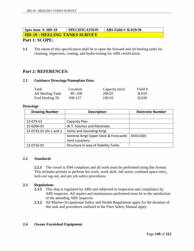
HD-19 : HEELING TANKS SURVEY
Page 149 of 312
Spec item #: HD-19 SPECIFICATION ABS Field # 3L029/30
HD-19 : HEELING TANKS SURVEY Part 1: SCOPE: 1.1 The intent of this specification shall be to open the forward and aft heeling tanks for
cleaning, inspection, coating, and hydro-testing for ABS certification.
Part 2: REFERENCES: 2.1 Guidance Drawings/Nameplate Data
Tank Location Capacity (m3) Field #
Aft Heeling Tank 89 -108 208.02 3L029 Fwd Heeling Tk 108-127 196.93 3L030
Drawings
Drawing Number Description Electronic Number
13-079-01 Capacity Plan
15-0206-01 W.T. hatches and Manholes
22-0733-01 sht 1 and 2 Vents and Sounding Arrgt
General Arrgt Upper Deck & Forecastle Vent Locations
65411001
12-0716-01 Structure in way of Stability Tanks
2.2 Standards
2.2.1 The vessel is ISM compliant and all work must be performed using this format. This includes permits to perform hot work, work aloft, fall arrest, confined space entry, lock-out tag-out, and pre job safety procedures.
2.3 Regulations
2.3.1 This ship is regulated by ABS and subjected to inspection and compliance by ABS inspector. All repairs and maintenance performed must be to the satisfaction of the attending ABS inspector.
2.3.2 All Marine Occupational Safety and Health Regulations apply for the duration of this task and procedures outlined in the Fleet Safety Manual apply.
2.4 Owner Furnished Equipment

HD-19 : HEELING TANKS SURVEY
Page 150 of 312
2.4.8 The contractor shall supply all materials, equipment, and parts required to
perform the specified work unless otherwise stated.
Part 3: TECHNICAL DESCRIPTION: 3.1 General
Manhole Locations
Aft Heeling Tank Main Gen Room, upper level, port and stbd
Fwd Heeling Tank Main Gen Room, upper level, port and stbd
3.1.1. The ship’s crew will pump out the water in the heeling tanks until suction is lost. The Contractor shall remove the remainder through the docking plugs or portable pumps. A list of all plugs removed must be maintained by the Contractor and all plugs will be identified and passed to the Chief Officer for safe keeping.
3.1.2. All vents and transducers and related equipment are to be blanked or otherwise protected prior to and during cleaning, blasting and painting activity.
3.1.3. All internal surfaces of the tanks are to be high pressure water washed (min 3,000
psi fresh water) with a mixture of 50:1 Holdtight 102® Solution from Vapcor Inc.(contractor supplied) or equivalent. This action will de-salinate all surfaces and prevent flash rusting, while removing all loose deposits to allow viewing of tank/coating condition. The Contractor will be responsible for removal and disposal of all cleaning water, sludge and debris generated by cleaning process.
3.1.4. The Contractor is to pay particular attention to the upper air ducts and lower cross
ducts in the Intering System Tanks.
3.1.5. The contractor shall be responsible for the contacting and scheduling of the ABS inspector to conduct the inside of the tank when deemed cleaned.
3.1.6. All areas of bare steel in tanks are to be abrasive blast cleaned to minimum SSPC-SP6 (ISO 8501-1:1988). The Contractor will be responsible for removal and disposal of all debris generated by abrasive blast process.
3.1.7. For bidding purposes: The Contractor is to bid the percentages of total areas as
described and provide a unit cost/ m2 for adjustment of blast and coating requirement.

HD-19 : HEELING TANKS SURVEY
Page 151 of 312
3.1.8. Fwd Heeling Tank. The tank coating was considered good above stringer deck,
fair below, with breakdown at the edges of openings and faceplates. The surface area in the Fwd Heeling Tank is 1790 m2. The Contractor is quote on blast cleaning 25% or 450 m2 in the tank. The Contractor is to pay particular attention to the lower cross duct in the tank.
3.1.9. Aft Heeling Tank. The tank coating was considered good throughout. The
surface area in the Aft Heeling Tank is 1890 m2. The Contractor is quote on blast cleaning 25% or 472 m2 in the tank. The Contractor is to pay particular attention to the lower cross duct in the tank
3.1.10. Hold for inspection of tanks by owner’s representative and NACE inspector prior
to applying coatings.
3.1.11. The entire surface of the tanks is to be treated with Royal coatings Easy Prep or equivalent as per the manufacturer’s data sheet. Then high pressure water washed (min 3,000 psi fresh water). This will etch the surfaces and prepare the intact existing epoxy coatings for re-coating.
3.1.12. Hold for inspection of tanks by owner’s representative and CG retained consultant
prior to coating.
3.1.13. If flash rusted to worse than Grade HB2M (refer to International Hydroblasting Standards) between blasting and coating application, the surface will be re-blasted to the specified standard.
3.1.14. All areas of bare metal are to be given (1) coat of WASSER MC-Miozinc 100 or
equivalent as per paint manufacturer's instructions for mixing, ventilation, application and precautions at 3 to 5 mils D.F.T.
3.1.15. Hold for inspection of tanks by owner’s representative and CG retained
consultant.
3.1.16. An intermediate coat of WASSER MC-Tar 100 Red or equivalent is to be applied to 100% of the void space surface at 5 to 7 mils D.F.T
3.1.17. Hold for inspection of tanks by owner’s representative and CG retained
consultant.
3.1.18. A final coat of WASSER MC-Ballast Coat beige or equivalent is to be applied to 100% of the void space surface at 4 mils D.F.T.
3.1.19. Hold for inspection of tanks by owner’s representative and CG retained
consultant.

HD-19 : HEELING TANKS SURVEY
Page 152 of 312
3.1.20. Strum boxes to have strainers cleaned and replaced in good order. Strum box
wells to be cleaned of all dirt and debris.
3.1.21. The tank level transducers are to be proven operational in the presence of the Chief Engineer or delegate.
3.1.22. Hold for inspection of tanks by owner’s representative prior to closing up.
3.1.23. The contractor is to disassemble the tanks vent heads from each tank, clean and
lay out the components for inspection by ABS Surveyor and the Chief Engineer.
3.1.24. Following inspection the vent heads are to be reassembled in good order using anti-seizing compound on all fastener threads.
3.1.25. Tanks to be closed up in good order, using new ¼” neoprene gaskets on all
manholes. All fasteners are to be coated with an approved anti-seize compound.
3.1.26. Vent heads to be replaced in good order following the hydro-testing. All fasteners are to be coated with an approved anti-seize compound.
4.1 Proof of Performance
4.1 Inspections
4.1.1 Inspections by owner’s representative and CG retained consultant and ABS
surveyor as detailed above. 4.1.2 NACE inspector will be required to inspect the all components for surface
preparation and for each of the applications of the coating system including enviromentals, equipment, mixing and application processes. It is the contractors responsibility to arrange for the NACE inspector to be present at the required times to inspect the preparation and applications. Coating at each stage will also be to the satisfaction of the chief engineer or designate.
4.2 Testing/Trials
4.2.1 Hydrostatic and/or air test as required by ABS. 4.2.2 The Contractor is to quote separately the cost of each of the following:
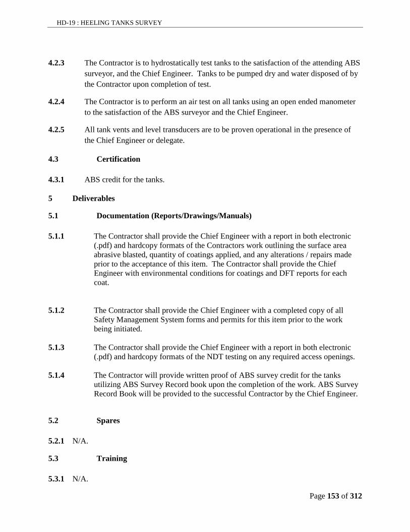
HD-19 : HEELING TANKS SURVEY
Page 153 of 312
4.2.3 The Contractor is to hydrostatically test tanks to the satisfaction of the attending ABS
surveyor, and the Chief Engineer. Tanks to be pumped dry and water disposed of by
the Contractor upon completion of test.
4.2.4 The Contractor is to perform an air test on all tanks using an open ended manometer
to the satisfaction of the ABS surveyor and the Chief Engineer.
4.2.5 All tank vents and level transducers are to be proven operational in the presence of
the Chief Engineer or delegate.
4.3 Certification
4.3.1 ABS credit for the tanks.
5 Deliverables
5.1 Documentation (Reports/Drawings/Manuals)
5.1.1 The Contractor shall provide the Chief Engineer with a report in both electronic
(.pdf) and hardcopy formats of the Contractors work outlining the surface area abrasive blasted, quantity of coatings applied, and any alterations / repairs made prior to the acceptance of this item. The Contractor shall provide the Chief Engineer with environmental conditions for coatings and DFT reports for each coat.
5.1.2 The Contractor shall provide the Chief Engineer with a completed copy of all
Safety Management System forms and permits for this item prior to the work being initiated.
5.1.3 The Contractor shall provide the Chief Engineer with a report in both electronic
(.pdf) and hardcopy formats of the NDT testing on any required access openings. 5.1.4 The Contractor will provide written proof of ABS survey credit for the tanks
utilizing ABS Survey Record book upon the completion of the work. ABS Survey Record Book will be provided to the successful Contractor by the Chief Engineer.
5.2 Spares
5.2.1 N/A.
5.3 Training
5.3.1 N/A.

HD-20: FUEL OIL TANKS SURVEY
Page 154 of 312
Spec item #: HD-20 SPECIFICATION ABS Field # 3L047/48/62
HD-20 : FUEL OIL TANKS SURVEY Part 1: SCOPE: 1.1 The intent of this specification shall be to clean, inspect and obtain ABS survey credit for
the following tanks.
Part 2: REFERENCES: 2.1 Guidance Drawings/Nameplate Data
Tank Name Capacity M3 Location ABS Field Number
# 8 FO Deep Tank Stbd 189.96 150-165 3L047 # 8 FO Deep Tank Port 189.96 150-165 3L048 #5 F/O Tank (S) 115.6 61-83 3L017 #5 F/O Tank (P) 115.6 61-83 3L018 # 2 F/O Tank (P) 200.4 30-61 3L012 Day Tank Stbd 110.99 127-150 3L054 Emergency Gen FO Tank Port 1.53 78-81 3L062
Manhole Locations
Tank Manhole Locations No 8 FO Deep Tank Stbd Bubbler V/V Manifold Compt, Aft Bhead No 8 FO Deep Tank Port Bubbler V/V Manifold Compt, Aft Bhead #5 F/O Tank (S) Heating Compartment Stbd Side #5 F/O Tank (P) Heating Compartment Port Side # 2 F/O Tank (P) (2) Prop Mtr Rm, Upper Level Fore & Aft Day Tank Stbd Electrical workshop Fr 127 Emergency Generator FO Tank Port Emergency Generator Compartment
2.2 Owner Furnished Equipment The contractor shall supply all materials, equipment, and parts required to perform the specified work unless otherwise stated.
Part 3: TECHNICAL DESCRIPTION: 3.1 Tanks will be pumped as low as possible by ship’s staff. Contractor to remove tank
residuals and transfer the tank residuals to another fuel tank(s) as directed by the Chief
Engineer.

HD-20: FUEL OIL TANKS SURVEY
Page 155 of 312
3.2 For bidding purposes quote on 10 m3 of tank residuals, actual amount to be adjusted by
1379 action.
3.3 Prior to the commencement of cleaning, all tanks are to be certified gas free for worker
entry by a marine chemist and certificates posted in conspicuous locations as required by
the CLC. All Contractor workers entering any tanks are to be qualified as per CLC.
3.4 Contractor shall supply any ventilation equipment required for the gas free Certificate and
the certificate’s continued validity for the duration of the work.
3.5 Contractor shall supply any temporary lighting required. Lighting to be removed upon
completion
3.6 The tanks are to be thoroughly cleaned; all scale, dirt and debris is to be removed ashore. Any rusty areas are to be power tool cleaned. All vent, sounding and overflow pipes are to be proven clear.
3.7 Tanks shall be wiped dry with lint free rags after cleaning.
3.8 In conjunction with the ship’s Electrical Officer, tank level transmitter shall be proven
operational.
3.9 All dirt and debris found in tanks shall be removed ashore and disposed of by the
Contractor in an approved manner. Surrounding areas affected by the cleaning to be left
in an ‘as found’ condition.
3.10 The contractor is to disassemble the self closing tank vent heads from each tank, clean
and lay out the components for inspection by ABS Surveyor and the Chief Engineer.
3.11 NOTE: Tanks and vent heads are to be inspected by ABS inspector and Owner’s
representative upon completion of cleaning. Contractor shall arrange scheduling of ABS
inspector.
3.12 The Contractor is to perform an air test on all tanks using an open ended manometer to
the satisfaction of the ABS inspector. The contractor will be responsible to seal/blank all
penetrations to the tested tank and make any necessary isolations. The contractor is to
remove all such seals/blanks and isolations following successful testing.

HD-20: FUEL OIL TANKS SURVEY
Page 156 of 312
3.13 Contractor shall install manhole covers on tanks in good order using new ¼” neoprene
gaskets, after final tank inspection by Chief Engineer. All fasteners shall be coated with
an approved anti-seize compound.
Part 4: PROOF OF PERFORMANCE:
4.1 All work is to be to the satisfaction of the Chief Engineer and attending ABS Surveyor.

HD-21: SEABAY SEACHEST COATING
Page 157 of 312
Spec item #: HD-21 SPECIFICATION ABS Field # N/A
HD-21 : SEABAY SEACHEST COATING
Part 1: SCOPE: 1.1 The intent of this specification is to open the following spaces for cleaning, inspection and
application of coatings. 1.1 This item is to be completed in conjunction with the following
Sea Bays and Chest Anode replacement
Part 2: REFERENCES:
2.2 Equipment Data
Bay/Chest Location Field # Size Main Sea Chest, port Fr. 83 to 89 3L026 2.5 Main Sea Chest, Stbd Fr. 83 to 89 3L025 2.5 Distiller Sea Chest, Stbd Fr. 80 to 81 3L022 0.9 Sea Chest Aft Port Fr. 59 to 61 3L019 1.5 Main Suction Sea Bay Fr. 86 to 89 3L024 19.0 Discharge Sea Bay Fr. 83 to 86 3L023 19.0
2.3 Drawing Number Description 23-0703-02 Sea Chest Aft Arrangement 23-0703-04 Sea Chest / Sea Bays Main Arrangement 23-0703-05 Sea Chest Distiller Arrangement
Part 3: TECHNICAL DESCRIPTION: 3.1 Contractor shall supply all equipment, enclosures, ventilation, staging, chain falls, craneage,
slings, and shackles necessary to perform the work. All lifting equipment shall be appropriate for the expected duties, and be accompanied by current certification indicating, or be permanently marked as to being, of a safe working load for the expected duties.
3.2 The sea bay/sea chests are considered confined spaces under the Safety Management System.
3.3 Access to sea chests is by removal of manhole covers on ship's exterior
3.4 Access to the Main Sea Chest Port, is through manhole located in Steward’s Cabin 133 on Main Deck. Access to Stbd. Sea Chest is through manhole located in P.O.’s Lounge, Main Deck.

HD-21: SEABAY SEACHEST COATING
Page 158 of 312
3.5 Access to Main Suction/Discharge Sea Bays is by removal of manhole covers located in the Auxiliary Engine Room..
3.6 Total of 32 securing plates to be renewed from manhole cover securing studs. Plates are ¼" x 1" x 3" stainless steel. All rough edges to be ground smooth.
3.7 All grid and internal sea bays, Distiller Sea Chest and main port and stbd seachests are to be pressure water cleaned using SSPC-SP12/NACE No 5 cleaning methods. Supplement with SSPC-SP1 Solvent cleaning and SSPC-SP2 and 3 hand and power tool clean areas of corrosion and loose or flaking paint (feather edges of sound existing paint back to a firm edge). Sand glossy surfaces to provide profile. Area at waterline interfaces to be carefully checked for pitting.
3.8 All areas of bare metal are to be given (1) coat of Royal Coatings Easy Prep as per paint manufacturer's instructions for mixing, ventilation, surface profile, application and precautions.
3.9 An intermediate coat of Easy Prime is to be applied over the primed areas of the sea bay/
sea chest surface as per paint manufacturer's instructions for mixing, ventilation, surface profile, application and precautions.
3.10 A final coat of Easy Flex is to be applied to 100% of the sea bay/sea chest surface as per
paint manufacturer's instructions for mixing, ventilation, surface profile, application and precautions.
3.11 The contractor will ensure that pipes passing through the sea chests will be coated as per the sea chest and sea bays.
3.12 Contractor to bid on repair and coating of 40 M² with unit cost for additional M².
3.13 Areas to be used for bidding are as follows: Discharge Sea Bay 340 M², Suction Sea Bay 340M², Port and Stbd Sea Chests 460 M² each, Distiller Sea Bay 23M², Sea Chest Aft Port 23M².
3.14 Contractor responsible for complete and thorough ventilation of sea chest for complete curing of paint.
3.15 Grid holes in shell and on manhole covers are to be cleaned by hydro-blasting or reaming using a close fitting drill. The diameter of each grid hole perforation is 25mm.
3.16 All countersunk screws to be dressed with die nut and all screw holes are to be tapped out. Contractor to bid on supplying and installing 75 stainless steel countersunk screws (19 mm.) to replace all screws from sea bay/sea chest manhole covers. Unit price is also to be quoted.

HD-21: SEABAY SEACHEST COATING
Page 159 of 312
3.17 New stainless steel securing plates (32 off - See Para 2) are to be welded in place after manhole covers and securing studs are in place. All welds are to be ground flush.
3.18 All grids and manhole covers are to be securely refitted. Contractor is to supply and fit new gaskets in way of all manholes. Anti-seizing compound is to be applied to all threads.
3.19 Any dirt and debris from cleaning of sea bays, sea chests to be removed from ship’s bilges and disposed of ashore.
Part 4: PROOF OF PERFORMANCE: 4.1 The completed installation is to be functionally tested during sea trials to the satisfaction of
the Chief Engineer. All leaks to be repaired by contractor. 4.2 Coast Guard will be retaining the services of an independent consultant to verify that the
surface preparation and coating; storage, preparation, and application are as per the specification. Payment for the consultant will be directly by Coast Guard outside of this contract.
Part 5: DELIVERABLES: 5.1 .

HD-22: BUBBLER AND FOAM PUMP PIPING REPAIR
Page 160 of 312
Spec item #: HD-22 SPECIFICATION ABS Field # N/A
HD-22 : BUBBLER PIPING REPAIR Part 1: SCOPE: 1.1 The intent of this specification is to repair a leak in the heeling tank bubbler piping .
Part 2: REFERENCES:
Drawing Number Description DRAWN/MODIFIED BY 13-079-01 Capacity Plan
15-0206-01 W.T. hatches and Manholes
Part 3: TECHNICAL DESCRIPTION: 3.1 Bubbler piping repair
3.2 The contractor is to perform the bubbler pipe repair in conjunction with HD-20 Heeling
Tanks Survey.
3.3 The bubbler pipe is located in the STBD fwd heeling tank at ~ frame 121.
3.4

HD-22: BUBBLER AND FOAM PUMP PIPING REPAIR
Page 161 of 312
3.5 The contractor must supply all materials and staging required to perform repairs.
3.6 The leak ( ½”) is located in a weld. Contractor must gouge out the existing failed weld and re-weld to the satisfaction of the attending surveyer and Chief Engineer.
3.7
3.8 The contractor is to perform NDT on the existing and repaired weld . Any defects found to be repaired by 1379

HD-22: BUBBLER AND FOAM PUMP PIPING REPAIR
Page 162 of 312
Part 4: PROOF OF PERFORMANCE: 4.1 Test All work to be completed to the satisfaction of the Chief Engineer and attending
ABS Surveyor. 4.2
Part 5: DELIVERABLES: 5.1 The contractor will supply welding procedure and NDT reports to the Chief Engineer

HD-23: ANCHORS AND CHAINS SURVEY
Page 163 of 312
Spec item #: HD-23 SPECIFICATION ABS Field # N/A
HD-23 : ANCHORS AND CHAINS SURVEY Part 1: SCOPE: 1.1 The intent of this specification is to perform a TC/MS survey on the anchors and chains
and clean and paint the anchors and chains. This specification will be carried out in conjunction with Chain locker specification.
Part 2: REFERENCES: Anchors 3LL120 Anchor Chain 3LL140
Part 3: TECHNICAL DESCRIPTION: 3.1 Contractor shall supply all equipment, enclosures, ventilation, staging, chain falls,
craneage, slings, and shackles necessary to perform the work. All lifting equipment shall be appropriate for the expected duties, and be accompanied by current certification indicating, or be permanently marked as to being, of a safe working load for the expected duties. Contractor will include cost of performing 2 lead samples and include 10k for lead abatement to be adjusted as required by 1379.
3.2 The Contractor shall be responsible to arrange for ABS survey when completing this specification item.
3.3 The port and starboard anchor chain bitter ends are to be released and the port and starboard anchors and anchor chains (10 shots to port, 9 shots to starboard ) are to be ranged on the dock, and suitably supported for cleaning, painting and inspection by the Chief Officer and ABS
3.4 Chains are to be cleaned of all sand, mud and marine growth by high pressure fresh water cleaning, (approximately 2,000 psi). In preparation for painting, chains are to be abrasive blast cleaned to minimum SSPC-SP6 (ISO 8501-1:1988). If oxidation occurs between blasting and application of Intershield 300, the surface will be re-blasted to the specified visual standard. All grit to be blown clear prior to painting. The Contractor is to turn the chain over to accomplish this.
3.5 Chains are to be inspected by ABS Inspector prior to painting. All links are to be inspected and slack studs or missing lead pellets identified and reported. Contractor to quote on repairs to six (6) slack studs and quote unit cost per each additional stud.
3.6 Contractor is to measure 3 random links in each shot of chain port and stbd. All measurements are to be tabulated and a copy given to the Chief Engineer. Four measurements per link shall be taken.

HD-23: ANCHORS AND CHAINS SURVEY
Page 164 of 312
3.7 The present first two (2) shots of chain, port and starboard, are to be disconnected and rotated to the position of last shots. Free ends to be reconnected to anchors with Babbitt pellets. Centre shackle pins to be sealed.
3.8 Chains to be given 1 (one) coat of Intershield 300 Bronze and (1) one coat of Interguard 345 Black. The Contractor is to turn the chain over and coat the underside .
3.9 Joining shackles are to be painted red with equal numbers of white painted links on either side. The number of white painted links is to correspond with the number of shots of cable paid out beginning from the anchor joining shackle. The outer end links of each white-painted set are to be marked by seizing wire close-hitched around the link stud.
3.10 Both anchors are to be are to be abrasive blast cleaned to minimum SSPC-SP6 (ISO 8501-1:1988). If oxidation has occurred between blasting and application of Intershield 300, the surface should be re-blasted to the specified visual standard and given (1) one coat of Intershield 300 Bronze and (1) one coat of Interguard Black.
3.11 Anchor shackle pins are to be removed for examination. Upon reassembly, new taper pins are to be fitted. Swivels are to be cleaned, inspected for smoothness of operation and lubricated.
3.12 On completion of above work, chains and anchors are to be re-shipped and secured in good order to the satisfaction of the Chief Engineer.
Part 4: PROOF OF PERFORMANCE:
4.1 Inspection
4.2 The Contractor is to be responsible for all inspections and is to consult with ABS, prior to
commencement of work, to determine an inspection schedule; at each inspection point, the Contractor is to advise the Owner’s representative, in advance, to allow his/her attendance.
4.3 All work to be completed to the satisfaction of the Chief Engineer.
4.4 Testing/Trials
4.5 As required by ABS.
4.6 Certification
4.7 Only certified trades persons shall complete the work as detailed in this specification.

HD-23: ANCHORS AND CHAINS SURVEY
Page 165 of 312
Part 5: DELIVERABLES: 5.1 Contractor to supply 2 hard copies and 1 electronic pdf copy of all readings taken on the
anchors and chains to the Chief Engineer

H-01 LIFEBOATS/DAVITS ANNUAL INSPECTION
Page 166 of 312
Spec item #: H-01 SPECIFICATION ABS Field # N/A
H-01 : LIFEBOATS/DAVITS ANNUAL INSPECTION
Part 1: SCOPE: 1.1 The intent of this specification is to have the Contractor supply the services of a Palfinger
FSR to perform the annual inspection of the ship’s Miranda, Lifeboats and Lifeboat Davits.
1.2 The specification also requires some repair work to be performed on the Miranda Davit Hydraulic System.
Part 2: REFERENCES:
2.1 Guidance Drawings/Nameplate Data 2.1.1 Miranda Davit Type MRT 3900 2.1.2 Lifeboat Davit NPD 11300H (2) 2.1.3 Lifeboats LBT 750 C Cargo Version (2)
2.1.4 Palfinger Lifeboat and lifeboat davit #7 in the Engineer’s Office. 2.1.5 FRC Miranda Davit #12 in the Engineer’s Office
2.2 Standards
2.1.1 All repairs and materials used must be in compliance with today’s Ship Building and Repair Standards.
2.3 Regulations 2.3.1 This ship is regulated by the ABS and repairs will be subjected to the
inspection and approval of the attending ABS, marine surveyor.
2.4 Owner Furnished Equipment 2.4.1 The contractor shall supply all the materials and equipment necessary to
execute this spec item, unless stated otherwise. This includes all certified
weights, lifting appliances, load cells, and scaffolding.
Part 3: TECHNICAL DESCRIPTION: 3.1 The contractor shall include an allowance of $10000.00 to hire the Palfinger FSR. The
contractor will include 100hours of assistance to the FSR to be supported by timesheet and adjusted by 1379.
3.2 The contractor shall ensure the Palfinger FSR completes an early summary inspection to identify any obvious deficiencies that require parts that require long lead times to obtain.
3.3 The Palfinger FSR shall conduct the Inspection and Maintenance plan for each of the
Lifeboats according to the schedule identified in part 2, section 5.2.1.in the manual.

H-01 LIFEBOATS/DAVITS ANNUAL INSPECTION
Page 167 of 312
3.4 The Palfinger FSR shall perform the maintenance and inspections of each Life Boat
Davit as identified in the manual in part 8, section 5.
3.5 The FSR shall replace the oil in the winch brake/gear with 5 liters of Castrol Alpha SP 100 or equivalent. The FSR shall replace the hydraulic filter on the hydraulic system with new and the oil will be tested for further use.
3.6 The FSR shall perform all the checks on the wire ropes and sheaves as identified in tab 8 section 5.1.4. The hydraulic system shall be checked as part of 5.1.5 and all inspections performed in section 5.2.
3.7 The FSR shall perform all the maintenance identified on the Miranda Davits in the
owner’s manual Part 3, under Annual maintenance in Accordance with SOLAS chapter III, Regulation 20, Section 11.
3.8 The contractor shall inspect the braking system on all davits and ensure suitable material
remaining for the next operating year.
3.9 The contractor shall inspect all wire ropes and block and supporting tackle for future use.
3.10 The contractor shall complete the gearbox inspection on each davit, installing a new gasket on the inspection cover when complete. Anything remaining open for extended periods must be suitably protected to prevent the ingress of water while not being attended to.
3.11 All access covers removed shall be properly sealed upon completion to ensure weather tight.
3.12 The following list of work on the Miranda Davit Hydraulics shall be performed under the direct supervision of the Palfinger FSR. The Contractor shall remove the corroded rotary limit switch, centrifugal brake, hydraulic winch, and directional control valve block for sandblasting, priming and top coating. The components are to be removed, and transported to the local hydraulic repair shop for servicing and repair. Each component shall be fully dismantled and rebuilt using contractor supplied parts. All the internal components shall be rebuilt in a fully operational condition. All fasteners shall be replaced with new hardware and gaskets and shall be leak free. Once rebuilt, a metal primer shall be applied to prevent corrosion and then a white topcoat of marine epoxy shall be applied prior to re-installing onto the davit.
3.13 All hydraulic connections left on the ship and components shipped away shall be capped/plugged to protect against contamination and ingress of foreign materials.
3.14 The Contractor shall allow $10000.00 for hydraulic parts to refurbish the components and replace the relief valve any all adjustable components that are seized and corroded.

H-01 LIFEBOATS/DAVITS ANNUAL INSPECTION
Page 168 of 312
3.15 The Contractor shall replace 4 hydraulic1” hoses 6 feet in length with a flange and o-ring on one end and JIC on the opposite, from the steel lines to the hydraulic motor.
3.16 The Contractor shall replace 2 lines that are ½” and 4 feet long to the rotary limit from the hydraulic brake.
3.17 The contractor shall protect each end and fittings on the hoses with denso tape.
3.18 Once all the inspections are complete, a function test shall be performed on each davit, using the necessary weights as determined by the FSR.
Part 4: PROOF OF PERFORMANCE: 4.1 The function test with the predetermined weights must ensure smooth, trouble free,
operation. 4.2 All items to be inspected by the Chief Engineer, Chief Officer and the ABS Surveyor. . 4.3 The Contractor is to be responsible for all inspections and is to consult with ABS, prior to
commencement of work, to determine an inspection schedule; at each inspection point, the Contractor is to advise the Owner’s representative, in advance, to allow his/her attendance.
Part 5: DELIVERABLES: 5.1 Three typed work inspections shall be provided to the Owner’s Representative, showing
work completed and deficiencies that require correction.

H-02: Cargo Hatches Repair
Page 169 of 312
Spec item #: H-02 SPECIFICATION ABS Field # N/A
H-02 : Cargo Hatches Repair
Part 1: SCOPE: 1.1 The intent of this specification shall be to remove the cargo hatches from the ship, effect
the necessary repairs identified in a recent Macgregor Service Report, and re-install back onto the vessel in a fully secure and operational condition. The contractor will note that this specification applies to both the port and starboard hatches
1.2 The Contractor shall replace the components identified in the report, supplied by the
owner, under the direct supervision of the Mcgregor FSR.
Part 2: REFERENCES: 2.1 Guidance Drawings/Nameplate Data
2.1.1. Macgregor Hatches installed on the helicopter deck of the Henry Larsen Manual #
39 in the Engineer’s Office. 2.1.2. Flush W.T. Hatch Cover general arrangement 21-69030, included in the manual.
2.2 Standards
2.2.1 The construction and installation of the W.T. hatches conforms to Lloyds Register and CCG requirements and is approved by these agencies.
2.3 Regulations
2.3.1 The Henry Larsen is registered with ABS and will be subjected to the inspection of the ABS Surveyor in relation to any and all work performed on the water tight flush hatches. All work and repairs completed to these hatches must meet current regulations satisfying the attending ABS inspector. Any disputes or clarification must be approved by the surveyor.
2.4 Owner Furnished Equipment
2.4.9 The contractor shall supply all materials, equipment, and parts required to
perform the specified work unless otherwise stated. 2.4.10 The FSR has requested the owner supply 2 flanged wheels Part # 24-69002, 2
plain wheels part # 24-69006, 20 meters of 71 mm x 32mm rubber packing, and 12 springs for the cleats 11.50.09/08.
Part 3: TECHNICAL DESCRIPTION: 3.1 General

H-02: Cargo Hatches Repair
Page 170 of 312
3.1.1. The Contractor shall be responsible for arranging the crane to open and lift off the
flush hatches to the dockyard.
3.1.2. The contractor shall allow $10,000.00 for the MacGregor FSR to supervise and direct the repairs noted.
3.1.3. The contractor shall install the necessary protection against entry by other
workers that could potentially fall through the cargo opening. The contractor shall also ensure the opening is sealed against adverse weather entering the aft cargo area while the hatches are removed.
3.1.4. The contractor shall remove the pins from the hinges and lift the hatch covers off
completely to the dock to perform the necessary maintenance and repairs. 3.1.5. The old rubber shall be removed from the channels and the channels must be
thoroughly cleaned of all rust, dirt, grease, salt, or oil. The manual states this can be done by chipping and then wire brushed to achieve the proper profile.
3.1.6. The contractor will crop off completely and grind smooth the original
compression bars and replace with contractor supplied stainless steel. The new material will be AISI 316-L stainless steel with the top face being ½ round as per the MacGregor service report. The contractor will weld the new stainless steel compression bar to the mild steel as per CWD requirements. For clarity, the contractor will ensure that the complete compression bars around the complete periphery is to be replaced.
3.1.7. Once the channels are prepared to the satisfaction of the FSR, the channels shall be painted on the sides, but not where the adhesive is used to stick the new gasket, to prevent further corrosion.
3.1.8. The entire surface of the hatch shall be swept blast to a commercial profile with
all loose particles and paint scale removed. The contractor shall then coat the hatch with a metal primer and two coats of top coat to the schedule as before.
3.1.9. The contractor shall install the new gasket according to the direction of the FSR. 3.1.10. All rotating wheels shall be removed, cleaned and re-installed in a smooth
operational fashion. 3.1.11. All the hinges and pins shall be removed dressed, lubricated and replaced in a
smooth operational condition. 3.1.12. The track on the vessel shall be cleaned with needle guns and wire brushes to
remove all rust, debris, and loose paint. The contractor shall apply one coat of primer and two coats of top coat around the track area to prevent any further

H-02: Cargo Hatches Repair
Page 171 of 312
corrosion. The contractor will use Royal Coatings Easy Prime and Royal Coatings Easy Flex.
3.1.13. The contractor shall replace the heating element laying around the hatch tracks to
prevent ice from building up and preventing the hatch from operating properly. The contractor shall install retainers around the heating elements to prevent moving and future damage. The contractor will install and secure the heating elements as per the OEM requirements.
3.1.14. The contractor shall strip down, clean, and lubricate the 6 flush cleats on each
hatch for a total of 12 in total. Once repaired, the contractor shall paint the cleats in bright orange or day-glow to permit easy verification the dogs are engaged or unlocked.
3.1.15. The contractor shall allow $4000.00 to purchase hardware or machine new hinge
pins for the hatches and will be adjusted up or down through 1379 and proof of time sheets and invoices.
3.1.16. Once all the repairs and preparation has been completed to the satisfaction of the
FSR, the hatches shall be lifted in place. 3.1.17. The contractor shall arrange the crane and personnel to fit the hatches to the
hinges. 3.1.18. The Contractor shall ensure the hatches are installed as per the manufacturer’s
instructions and is prevented from slipping off the hinges. 3.1.19. The contractor shall operate the hatch up and down three times to prove free
motion, proper function, and adequate sealing. 3.1.20. Once the hatches are closed, the contractor shall dog each hatch and water test for
ABS. 3.1.21. The contractor shall prove the drain lines around the track area to be free and
clear to prevent the accumulation of water around the sealing edges of the hatches.
3.1.22. The contractor is responsible for the scheduling of the ABS inspector to inspect
the work proceedings and the final water test. 3.2 Location
3.2.1. The two hatches are fitted to the boat deck on the flight deck area, 2.793 m x 3.433 m between frames 18-27 on the port and stbd sides.
3.3 Interferences

H-02: Cargo Hatches Repair
Page 172 of 312
3.2.1. Contractor is responsible for the identification of interference items, their
temporary removal, storage and refitting to vessel.
Part 4: PROOF OF PERFORMANCE: 4.1 Inspection
4.1.8. All work shall be completed to the satisfaction of the Chief Engineer, Chief Officer, and attending ABS Surveyor.
4.2 Testing
4.2.1 The contractor shall hose test each hatch when dogged, for 30 minutes at 60 psi to prove no ingress of water to the aft cargo area.
4.3 Certification N/A
Part 5: DELIVERABLES: 5.1 Drawings/Reports
N/A
5.2 Spares N/A
5.3 Manuals N/A

H-03 Helicopter Fueling System Maintenance
Page 173 of 312
Spec item #: H-03 SPECIFICATION ABS Field # N/A
H-03 : Helicopter Fueling System Maintenance Part 1: SCOPE: 1.1 The intent of this item is to carry out annual inspection, maintenance and certification of
the ship’s Helicopter Refueling system. 1.2 Contractor shall supply the services of a qualified service representative to complete the
work in this specification.
Part 2: REFERENCES:
Tank Capacity Location Field
Helo Fuel Tank Cofferdam 132 Fr 4-12 3L007
Helo Fuel Tank 27 Fr 5-11 3L006
2.1 Guidance Drawings/Nameplate Data Flow Diagram – Helicopter Fuelling Package (New-Mar Oil Services) 2.2 Standards Helicopter Fuel Standard – Canada CGSB 3.23-02 2.3 Regulations Transport Canada Marine Safety 2.4 Owner Furnished Equipment The contractor shall supply all materials, equipment, and parts required to perform the
specified work unless otherwise stated.
Part 3: TECHNICAL DESCRIPTION: 3.1 Helicopter fuel tank cofferdam is to be opened to allow required work. The manhole cover is
to be removed and the space certified gas free for entry. The gas free certificate is to be maintained for the duration of necessary work.
3.2 The contractor is to clean the cofferdam of any debris and water.
3.3 Upon completion of work the cofferdam area is to subject to a final inspection by Owner’s
representative and then immediately closed up using new packing on the installed manhole cover.

H-03 Helicopter Fueling System Maintenance
Page 174 of 312
3.4 Contractor shall remove the following safety valves from tank/system and transport them to a
certified testing facility: a. 1 x 1.5” vacuum relief valve (15017) b. 1 x 1.5” ‘UNIACT’ pressure relief valve (15009SP) c. 1 x 8” fire engulfment valve (6R8/411422/C)
Blanks are to be fitted to exposed flanges to prevent ingress of foreign materials into tank. Silica Gel is to be fitted to tank to absorb any moisture from ingress of air into the tank. Silica gel will be supplied by CCG. Removed safety valves shall be thoroughly inspected, cleaned as necessary and certified for proper operation. A condition assessment will be carried out at that time. Upon completion of inspection all valves shall be boxed up, tested, reset and recertified as indicated. Contractor shall return valves to the vessel and refit them in their original locations in good order.
3.5 The Contractor shall supply and install new gaskets on each of the 1.5” vacuum relief valve
and 1.5” pressure relief valve and 8” flame engulfment valve. The gasket material used is to be intended by the manufacturer for use with Jet A helicopter fuel. The Contractor must supply proof that the gasket material is so intended.
3.6 Contractor shall make arrangements to have the 1 ½:” diameter helicopter fueling hose removed from the ship and shipped to a recognized test facility test for annual certification, This certification will require the hose be pressure tested to 150 psi.. A contractor supplied stamped metal tag showing test dates and pressures shall be affixed to the hose. Contractor shall return the hose to the ship and re-install it on the hose reel on the Stbd side flight deck upon completion of testing. A test certificate shall be issued to Chief Engineer. Nozzle and all associated fittings to be inspected.
3.7 Dispensing meter calibration is to be verified. The meter is a positive displacement flow-meter, Bopp & Reuther 0150M5F5, calibrated for use with JET A1.
3.8 The Contractor is to verify the electrical continuity of all the piping associated with the system.
3.9 Monitor elements to be replaced. (Owner supply).
3.10 Filter/water Separator expendable cartridges to be replaced. (Owner supply).
3.11 Silica Gel in tank vent to be renewed (Owner supply).
3.12 A minimum 2.5 litre sample is to be taken from the helicopter fuel pumped from the vessel into the holding facilities for laboratory analysis. This testing and re-certification is to be completed prior to the fuel being returned to the vessel. Laboratory testing of the fuel is to include but not necessarily limited to:
1. Appearance / Colour 2. Water / Contaminants 3. Flash Point 4. Freezing Point

H-03 Helicopter Fueling System Maintenance
Page 175 of 312
5. Distillation 6. Density 7. Copper 8. Corrosion 9. Existent of Gum 10. Water Reaction
3.13 Contractor to dispose of used cartridges, elements and the used Silica Gel ashore as per
Provincial regulations.
3.14 Contractor to supply all materials unless specified otherwise.
3.15 Location
a) The vessel’s aviation tank is located at the lower deck level Fr: 4 to Fr: 11. b) The control for the aviation fuel quick closing valves is located inboard of the
dispensing unit.
3.16 Interferences
Contractor is responsible for the identification of interference items, their temporary removal, storage and refitting to vessel.
Part 4: PROOF OF PERFORMANCE: 4.1 The Contractor is to be responsible for all inspections and is to consult with ABS, prior to
commencement of work, to determine an inspection schedule; at each inspection point, the Contractor is to advise the Owner’s representative, in advance, to allow his/her attendance.
4.2 All work shall be completed to the satisfaction of the Chief Engineer 4.3 Upon completion of work, system is to be run up and proven fully operational to
satisfaction of the Chief Engineer or delegate.
Part 5: DELIVERABLES: 5.1 The Contractor is to provide a Service Report including the as found condition, work
performed, and any parts used. 5.2 Gas free certificates for subject spaces. 5.3 Testing reports and certificates for fuel, fuel hose, valves, gas monitors, and gauges.

H-04 LIFERAFTS
Page 176 of 312
Spec item #: H-04 SPECIFICATION ABS Field # N/A
H-04 : LIFERAFTS
Part 1: SCOPE: 1.1 The intent of this item is for the contractor to have the vessels liferafts serviced. 1.2 The contractor shall remove the liferafts from the vessel, ship to the approved service center, ship the
liferafts back to the vessel, and reinstall back in the original locations. Part 2: REFERENCES:
2.1 There are ten liferafts onboard to be sent for servicing.
Liferafts Location Serial # CAP. Service Due Hydro Expiry Comments
Starboard Rack XDC5EN01A808 25 06-2021 06-2021 MF: 01/2008 Starboard Rack XDC5EV41B909 25 06-2021 06-2021 MF: 02/2009 Starboard Rack XDC0EK06C707-D 25 06-2021 06-2021 MF: 03/2007 Aft of FRC (Port) 5085910203906 10 06-2021 06-2021 MF: 02/2016 Port Crane (SAR Raft) 1FW96G516 10 06-2021 NA MF: 07/2015
Port Rack XDC9EJ12C707 25 06-2021 06-2021 MF: 03/2007 Port Rack XDC5EN02A808 25 06-2021 06-2021 MF: 01/2008 Port Rack XDC0EK12C707-D 25 06-2021 06-2021 MF: 03/2007 Starboard Crane 5085910203903 10 06-2021 06-2021 MF: 02/2016 Barge XDCZ0503D000 6 06-2021 07-2020 MF: 04/2000 Barge
Part 3: TECHNICAL DESCRIPTION: 3.1 The Contractor is to remove and transport the ship's ten liferafts to and from an authorized service
centre, as designated by the vessel, for servicing.
3.2 The contractor shall ensure that the liferafts are placed back in the same location that they were removed from.
3.3 The Contractor is responsible to remove and reinstall the liferafts on the vessel. Item is to be
completed in conjunction with the Chief Officer.
3.4 Contractor is to include 16K for servicing by authorized fsr under proof of invoicing.
Part 4: PROOF OF PERFORMANCE: 4.1 The contractor shall provide original certificates and the work report for each of the life rafts.
4.2 All work to be completed to the satisfaction of the Chief Engineer.
Part 5: DELIVERABLES: 5.1 The Contractor will supply 1 PDF and 1 printed Copy of service report for each liferaft .

H-05 ACCOMMODATION HVAC CLEANING page 177 of 312
Page 177 of 312
Spec item #: H-05 SPECIFICATION ABS Field # N/A
H-05 : ACCOMMODATION HVAC CLEANING
Part 1: SCOPE:
1.1 The intent of this item is to clean all Supply and Re-circulating ducting associated with HVAC systems on the Wheelhouse, Officers Deck, Boat Deck, Upper Deck and Main Deck areas.
Part 2: REFERENCES: Dwg # Location 15-0311-01 Ventilation & A/C Main Deck 15-0311-02 Ventilation & A/C Upper Deck 15-0311-03 Ventilation & A/C Boat Deck 15-0311-04 Ventilation & A/C Officers Deck 15-0311-05 Ventilation and A/C Nav Bridge Deck and Wheelhouse
Part 3: TECHNICAL DESCRIPTION: 3.1 The contractor shall provide the labour and materials to internally clean the ducting
associated with the following Air Handling. a) Air Handling Unit #1, located Officer’s Deck, port side at Frame 105. b) Air Handling Units #2, located Boat Deck, starboard side at Frame 110. c) Air Handling Unit #3, located Upper Deck port side at Frame 20. d) Air Handling Units #4, located Boat Deck, starboard side at Frame 110. e) Air Handling Unit #5, located Main Deck port side at approx Frame 140
3.2 The contractor shall schedule the work in a manner that will ensure minimal disruptions
to the ships personnel. The work schedule shall be agreed upon by both the Chief Engineer and the contractor.
3.3 With the ship’s Electrical Officer the contractor is to ensure the Lockout/Tagout is in
place. The contractor is to supply his/her own locks and tags but complete the vessel’s Lockout/Tagout procedure.
3.4 The following locations are supplied air from Air Handling Unit #2: Officers’ Deck 378, 381, 381 Night Cabin, 383, 389, 389 Night Cabin, 385, and 367. 3.5 Boat Deck Room 339, 341, 343, 352, 350, 350 Night Cabin, and 345. 3.6 The following locations are supplied with air from Air Handling Unit #4: Upper Deck Room 262, 260, 242, 244, 277, & 279. Main Deck Room 130, 131, 132, & 133,Room 151, 162, 161, 160, 159, 158, & 157, 168,
167, 166, 165, 169, & 163

H-05 ACCOMMODATION HVAC CLEANING page 178 of 312
Page 178 of 312
3.7 Contractor shall clean out the ducting by the application of suction at the supply and
discharge ends. Care shall be taken to minimize the ingress of dirt, dust or debris into the spaces.
3.8 Access to the ducting will involve the removal of the deckhead diffusers in each space
and opening the casing at the supply fan. 3.9 Prior to reinstallation, all disturbed deckhead diffusers shall be washed with a degreaser. 3.10 Upon completion of work, all disturbed deckhead diffusers, deckhead panels, grids and
casings, shall be restored to the original as found condition.
Part 4: PROOF OF PERFORMANCE: 4.1 The Contractor shall take digital HD colour photos prior to closing up, labelled with
locations, demonstrating cleanliness at various points throughout the duct work.
4.2 Upon completion of work, the Air Handling Units shall be run up and ductwork proven free and clear.
4.2 All work to be completed to the satisfaction of the Chief Engineer.
Part 5: DELIVERABLES: 5.1 The Contractor is to provide a Service Report including the as found condition, work
performed, and any parts used.

H-06ACCOMMODATION WASHROOM EXHAUST DUCT CLEANING
Page 179 of 312
Spec item #: H-06 SPECIFICATION ABS Field # N/A H-06 : ACCOMMODATION WASHROOM EXHAUST DUCT CLEANING
Part 1: SCOPE: 1.1. The intent of this item is to internally clean the ductwork and fittings associated with the
Main, Upper, Boat and Officers Deck Exhaust Air systems.
Part 2: REFERENCES: Dwg # Location 15-0311-01 Ventilation & A/C Main Deck 15-0311-02 Ventilation & A/C Upper Deck
15-0311-08 Fan Room Boat Deck Arrangement & Details 15-0311-03 Ventilation & A/C Boat Deck 15-0311-04 Ventilation & A/C Officers Deck 15-0401-02 Insulation Plan, Upper, Flight/Boat, Nav Br., Raised Deck & Wheelhouse.
15-0401-03 Insulation Plan Tank Top Lower & Main Decks Part 3: TECHNICAL DESCRIPTION: 3.1 Contractor to provide the required labor and materials to internally clean the ductwork
and fittings associated with the Upper, Boat and Officers Deck Exhaust Air systems. 3.2 With the ship’s Electrical Officer the contractor is to ensure the Lockout/Tagout is in
place. The contractor is to supply his/her own locks and tags but complete the vessel’s Lockout/Tagout procedure.
3.3 The Contractor shall clean the ducting in a manner that will minimize the ingress of dirt
and debris into the spaces. 3.4 The Contractor shall schedule the work in a manner that will ensure minimal disruptions
to the ship’s personnel. The work schedule to be agreed upon by both the Contractor and Chief Engineer.
3.5 The Contractor to access the exhaust ductwork via deckhead mounted diffusers in the
following spaces:
a) Main Deck Washrooms 138, 142, 143, 170, 171, 172, 172, 173, 174, 175, 194, 195. 200 Laundry 183 Gym, 184 Saunas Washroom 152A E/R Crew Change Room 153 Launderette

H-06ACCOMMODATION WASHROOM EXHAUST DUCT CLEANING
Page 180 of 312
b) Upper Deck
Washroom 265, 267, 269, 252, 271, 275, 294, 292, 257, 288, 251, 286, 284 and 282.
c) Boat Deck Washroom 339, 334, 341, 343, 352, 350, 347, 345, and SAR Locker.
d) Officers Deck Washroom 378, 381, 383, 389, 385, 374, 365, and 367
e) Wheelhouse Washroom adjacent to Wheelhouse Stair tower entrance.
3.6 Upon completion of the work, any deckhead accessories disturbed by the Contractor during the cleaning operation, to be restored to their as found condition.
Part 4: PROOF OF PERFORMANCE: 4.1 Upon completion of work, the Washroom Exhaust Fan shall be run up and ductwork
proven free and clear.
4.2 All work to be completed to the satisfaction of the Chief Engineer.
Part 5: DELIVERABLES: 5.1 The Contractor is to provide a Service Report including the as found condition, work
performed, and any parts used.

H-07 GALLEY RANGE HOOD AND EXHAUST FAN TRUNKING
Page 181 of 312
Spec item #: H-07 SPECIFICATION ABS Field # N/A
H-07 : GALLEY RANGE HOOD AND EXHAUST FAN TRUNKING
Part 1: SCOPE: 1.1 The intent of this item is to open up, clean and close up in good order the Galley range
hood and exhaust fan trunking.
Part 2: REFERENCES: Galley range hood (Gaylord model BDL-DS)
Part 3: TECHNICAL DESCRIPTION: 3.1 The Galley range hood shall be opened up for thorough cleaning and degreasing. The
existing exhaust fan trunking run from the Galley Range hood to the Exhaust fan outlet at Upper Deck, port side Frame 30, shall be internally degreased and cleaned.
3.2 The contractor shall co-ordinate the work with the Chief Engineer to minimize
disruptions to ship’s routine. Contractor to include in bid, his and any sub-contractor’s cost for premium time for evenings, weekends and/or holidays worked.
3.3 With the ship’s Electrical Officer the contractor is to ensure the Lockout/Tagout is in
place. The contractor is to supply his/her own locks and tags but complete the vessel’s Lockout/Tagout procedure.
3.4 All chemicals used in cleaning the range hood and galley exhaust fan trunking shall be
non-toxic and safe for use in food preparation and handling areas. Contractor to provide 2 copies of product Material Safety data Sheet information corresponding to the cleaning agents which will be used in the cleaning process.
3.5 Prior to the commencement of work, qualified personnel shall release all range hood
mechanical and electrical components, including suppression system piping, controls and lighting. All fittings liable to interfere with cleaning of the range hood are to be temporarily relocated and protected.
3.6 The range hood filter screens to be removed and steam cleaned. All range hood drains
and grease traps shall be proven clear. Fire dampers to be cleaned and demonstrated in good working order.
3.7 The contractor shall remove all debris and soiled materials from the vessel and dispose
ashore daily

H-07 GALLEY RANGE HOOD AND EXHAUST FAN TRUNKING
Page 182 of 312
3.8 Upon completion of work, the contractor shall return all disturbed range hood components as per original. Range hood wash-down system shall be tested and proven operational.
3.9 The contractor shall access the exhaust trunking by removing the following:
a) In deck cross alleyway and Galley ceiling panels in way of the trunking run. b) Main deck flanged exhaust trunking fire damper. Unit flanged and bolted in situ. c) Inline exhaust fan, located Upper Deck Fan Room. Unit flanged and bolted in situ. d) Two- 12”x12” sheet metal trunking access panels Upper Deck fan room. Screwed in situ. e) Port side Upper Deck exhaust trunking outlet louver. Bolted in situ.
3.10 The Galley Exhaust Fan to be removed to allow for cleaning of trunking on either Side.
Fan and motor units to be completely degreased.
3.11 The exhaust trunking outlet louver shall be removed. Fine mesh screen to be removed and cleaned. Remainder of louver, including cover, to be sandblasted to white metal and painted with two coats of primer and one coat of white paint. Hinge pins to be freed up and greased. Louver door rubber seal to be removed during sandblasting and painting, then reinstalled with proper adhesive. New gasket to be supplied when louver bolted in place.
3.12 All disturbed exhaust trunking access points shall be reinstalled using fire rated
materials.
3.13 Prior to reinstallation of the main deck ceiling panels, the fire damper shall be tested to the satisfaction of the Chief Engineer for correct operation.
Part 4: PROOF OF PERFORMANCE: 4.1 Upon completion of work, the Air Handling Units shall be run up and ductwork proven
free and clear. 4.2 All work to be completed to the satisfaction of the Chief Engineer.
Part 5: DELIVERABLES: 5.1 The Contractor is to provide a Service Report including the as found condition, work
performed, and any parts used.

H-08 LAUNDRY DRYER EXHAUST DUCTWORK CLEANING
Page 183 of 312
Spec item #: H-08 SPECIFICATION ABS Field # N/A
H-08 : LAUNDRY DRYER EXHAUST DUCTWORK CLEANING
Part 1: SCOPE: 1.1 The intent of this item is to clean the clothes dryer(s) exhaust ductwork on the Officers
Deck, Boat Deck, Upper Deck and Main Deck to remove any accumulation of lint and or debris.
Part 2: REFERENCES: Ship’s drawings:
Laundry, Launderette, And Change room – Main Deck Launderette Arrgts. Upper Dk. Boat & Officers Dk.
Part 3: TECHNICAL DESCRIPTION: 3.1 The contractor shall schedule the work in a manner that will ensure minimal disruptions
to the ships personnel. Both the Chief Engineer and the contractor shall agree upon the work schedule.
3.2 The Contractor in consultation with the vessel’s Electrical Officer will lockout the power
supply(s) to the dryers. The Contractor is to supply their own locks and tags and complete the vessel’s Lockout/tagout procedure.
3.3 The contractor shall provide the labor and materials to internally clean the dryer exhaust
ducting associated with the as fitted laundry dryers in the following spaces:
a) Main Deck Laundry Room, Main Deck Room 200, at Fr.167
b) Main Deck Launderette, Main Deck, Room 153, at Fr.116
c) Oilers Change room, Main Deck, Room 152 at Fr. 16
d) Upper Deck Launderette, Upper Deck Room 252, at Fr.122
e) Boat Deck launderette, Boat Deck, Room 334, at Fr.122
f) Officers Deck Launderette, Officers Deck Room 365, at Fr.112

H-08 LAUNDRY DRYER EXHAUST DUCTWORK CLEANING
Page 184 of 312
3.4 The dryer exhaust ducting is to be cleaned from the dryer to the vent head on the vessel’s exterior.
3.5 The Contractor shall clean out the dryer exhaust ducting by the application of suction at
the supply and discharge ends. Care shall be taken to minimize the ingress of dirt, dust or debris into the spaces. Any ingress of dirt, dust or debris is to be cleaned up.
3.6 Any openings made in the ductwork are to be sealed using approved seals such that there
are no leaks at the openings. 3.7 Upon completion of work, all disturbed ducting and associated fittings shall be restored
to their as found condition. 3.8 The Chief Engineer will inspect disturbed ductwork before ceiling panels are reinstalled.
Part 4: PROOF OF PERFORMANCE: 4.1 Upon completion of work, the dryers shall be run up and ductwork proven free and clear. 4.2 All work to be completed to the satisfaction of the Chief Engineer.
Part 5: DELIVERABLES: 5.1 The Contractor is to provide a written report in electronic pdf format to the Chief
Engineer detailing the as found condition, work performed, and digital images showing the before and after condition of the ducting.

H-09: Sewage system
Page 185 of 312
Spec item #: H-09 SPECIFICATION ABS Field # N/A
H-09 : Sewage System
Part 1: SCOPE: 1.1 The intent of this specification shall be to clean, inspect, coat as necessary and return the
sewage system treatment tank to service. 1.2 This work shall be carried out in Conjunction with the following: E - 18
Part 2: REFERENCES: 2.1 Guidance Drawings/Nameplate Data
RED FOX Industries Inc.
Model : PVCL-6R
Location: Auxiliary Machinery Space - Fr. 65 - 75.
Holding capacity : 19,000 litres.
Description: Segregated tank measures 2.1m x 4.2m x 2.4 m which is divided into three
compartments; aeration, clarifier and disinfection chambers.
2.2 Standards
The sewage system treatment tank is considered a confined space under the Safety Management System.
2.3 Regulations
2.4 Owner Furnished Equipment
The contractor shall supply all materials, equipment, and parts required to perform the specified work unless otherwise stated.

H-09: Sewage system
Page 186 of 312
Part 3: TECHNICAL DESCRIPTION:
General
3.1 The intent is to keep the vessel’s sewage system in use during this item.
3.2 The contractor is to provide a suitable sewage holding tank on the dock beside the ship and connect the tank to the vessel’s sewage discharge fitting on the Upper Deck stbd side.
3.3 The tank is to be serviced as required and removed upon completion of this item.
3.4 The daily cost and servicing cost is to be quoted.
3.5 All effluent is to be disposed of by the Contractor.
3.6 Disposal certificates to be provided to PWGSC.
3.7 The contractor shall pump out the sewage treatment plant and dispose of contents ashore. The effluent, sludge and any solid wastes are to be disposed of in accordance with local environmental regulations. 19000litres to be considered for initial pump down of system.
3.8 With the ship’s Electrical Officer the contractor is to ensure the Lockout/Tagout is in place. The contractor is to supply his/her own locks and tags but complete the vessel’s Lockout/Tagout procedure.
3.9 Manhole covers to be removed to gain access to tank internals.
3.10 Ventilation to be provided from the sewage tank to an open deck and over the side of the vessel for the entire period the sewage tank is opened.
3.11 Prior to the commencement of cleaning, all tanks are to be certified gas free for worker entry by a marine chemist and certificates posted in conspicuous locations as required by the CLC. All Contractor workers entering any tanks are to be qualified as per CLC.
3.12 Tank internals to be pressure washed clean. All water remaining in tank after cleaning is to be pumped out and disposed of ashore by Contractor.
3.13 The tank internals including all piping and air manifolds are to be cleaned of all traces of effluent and liquid using a detergent and sanitized using disinfectant. MSDS for the cleaning and sanitizing chemicals to be provided to Chief Engineer before cleaning begins.
3.14 Cleanout plugs in the manifolds are to be removed and manifolds cleaned of any debris. Cleanout plugs to be reinstalled following inspection by the Chief Engineer.
3.15 All liquid remaining in tank after cleaning is to be pumped out and disposed of ashore by Contractor.

H-09: Sewage system
Page 187 of 312
3.16 Tank to be rag wiped dry after cleaning.
3.17 Internals then to be cleaned to prepare surfaces for coating. Power tool cleaning to be to
standard SSPC-SP-3.
3.18 All dirt and debris remaining in tanks after cleaning shall be removed ashore and disposed of by the Contractor
3.19 Contractor to supply any ventilation equipment required for the gas free Certificate and the certificate’s continued validity for the duration of the work. Contractor also to supply ventilation as required during the cleaning and coating of tank internals.
3.20 All associated air piping on the tank top as well as all internal passages, orifices and piping are to be proven clear. Switch column to be disconnected from its piping, inlet and outlet openings and internals column to be thoroughly cleaned and reconnected.
3.21 After completion of thorough cleaning, bare metal surfaces to be primed with Royal Coatings Easy Prime. Tank internals are then to be given one coat of Royal Coatings Easy Novo – bid on 40 m2 with a unit cost per m2 for adjustment purposes. The level switches, probes and orifices are to be protected during painting to ensure operational integrity.
3.22 Upon completion, all level switches, probes and alarms shall be cleaned, inspected and function tested.
3.23 After sufficient time for coating to cure has passed, the contractor is to install the manhole covers using new contractor supplied gaskets and the tanks are to be refilled to the operating level with clean fresh water.
3.24 The ship’s crew will pump down and shut down the ships vacuum system to allow the holding tank to be cleaned. Contractor will remove the tank cover and pressure wash the inside of the tank and remove all residues ashore. As shut down of this tank takes the ship’s sewage system out of operation, cleaning is to be done in a timely manner to ensure the system is out of service for the shortest amount of time.
3.25 The float switches are to be cleaned and proven fully functional.
3.26 Tank is to be inspected and closed up again using a new contractor supplied gasket. System is to be put back in service and to be proven fully functional upon completion.
3.27 All work is to the satisfaction of the Chief Engineer.
3.28 Location
a) The sewage system is located in the Auxiliary Machinery Space.

H-09: Sewage system
Page 188 of 312
b) The ship’s sewage overboard discharge fitting is located on the Upper Deck, stbd side at Frame 79.
3.29 Interferences
Contractor is responsible for the identification of interference items, their temporary removal, storage and refitting to vessel.
Part 4: PROOF OF PERFORMANCE: 4.1 Inspection
All work shall be completed to the satisfaction of the Chief Engineer.
4.3 Testing
N/A 4.3 Certification N/A
Part 5: DELIVERABLES: 5.1 Drawings/Reports
N/A 5.2 Spares
N/A
5.3 Training N/A
5.4 Manuals N/A

H-10: Fixed FM 200 and CO2 Smothering System Inspection
Page 189 of 312
Spec item #: H-10 SPECIFICATION ABS Field # N/A
H-10: Fixed FM 200 and CO2 Smothering System Inspection
SCOPE: 1.1 The intent of this item is to perform required annual servicing of the fixed FM200 fire
suppression system and obtain ABS credit for the system.
1.2 This work shall be carried out in Conjunction with the following:
Part 2: REFERENCES:
2.1 Guidance Drawings/Nameplate Data
2 x FM-200 -675lb Cylinder ADS - Propulsion Motor Room
Serial Number Tare Weight Gross weight Net Weight Last H Test
288092 54 380.4 919.8 539.4 2018
288089 54 380.2 918 537.8 2018
1 x FM200 Fireboy - Barge Serial Number Tare Weight Gross weight Net Weight Last H Test
79304 0 0 15 2018
1 x FM200 - 40LB Cyclinder - ICS Room Serial Number Tare Weight Gross weight Net Weight Last H Test
290992 37.2 65.6 28.4 2018
1 x FM200 - 600LB Cyclinder - Bosuns's stores Serial Number Tare Weight Gross weight Net Weight Last H Test
28810732 377.2 750.6 373.4 2018
1 x FM200 - 600Lb - Cylinder ECS - Engine Control Room Serial Number Tare Weight Gross weight Net Weight Last H Test
28809154 377.4 911 533.6 2018
1 x FM200 - 600Lb - Cylinder ECS - Steering Gear Serial Number Tare Weight Gross weight Net Weight Last H Test
28811348 378.8 878.4 499.6 2018
1 x FM200 - 70Lb - Cylinder ECS - Fan Room 189 AHU #5 Serial Number Tare Weight Gross weight Net Weight Last H Test
288537 50.5 51.2 95.2 44 2018
1 x FM200 - 70Lb - Cylinder ECS - Helicopter workshop Serial Number Tare Weight Gross weight Net Weight Last H Test
288552 61.2 102.2 41 2018

H-10: Fixed FM 200 and CO2 Smothering System Inspection
Page 190 of 312
1 x FM200 - 70Lb - Cylinder ECS - Heli-Fuel Pump Room Serial Number Tare Weight Gross weight Net Weight Last H Test
288564 51.4 101.2 49.8 2018
1 x FM200 - 70Lb - Cylinder ECS – Carpenter’s Shop Serial Number Tare Weight Gross weight Net Weight Last H Test
288542 51 97 46 2018
1 x FM200 - 70Lb - Cylinder ECS - Paint Locker Fwd Serial Number Tare Weight Gross weight Net Weight Last H Test
288571 51.2 96.8 45.6 2018
1 x FM200 - 70Lb - Cylinder ECS - Radio Room Serial Number Tare Weight Gross weight Net Weight Last H Test
288539 51.4 109.2 40.1 2018
1 x FM200 - 70Lb - Cylinder ECS - Salvage Diving Locker Serial Number Tare Weight Gross weight Net Weight Last H Test
288591 54 69.1 109.2 40.1 2018
1 x 1LB CO2 Remote Pull - Cargo Hold Serial Number Tare Weight Gross weight Net Weight Last H Test
515896 3.31 5.51 2 2019
1 x 15Lb CO2 System – E/R Paint Locker Boat Deck Serial Number Tare Weight Gross weight Net Weight Last H Test
2005497 18 33 15 2019
1 x 2.5 Gallon Range Guard System - Galley Serial Number Tare Weight Gross weight Net Weight Last H Test
65092 2.5 2011
8 X 45KG CO2 System Ginge-Kerr - Cargo Hold Serial Number Tare Weight Gross weight Net Weight Last H Test
379404 72.7 117.7 45 2019
379253 73.7 118.7 45 2019
379252 71.8 116.8 45 2019
379271 70.6 115.6 45 2019
379349 72.6 117.5 45 2019
379254 71.5 116.5 45 2019
379213 72.1 117.1 45 2019
379393 72.7 117.7 45 2019
1 x 45 Kg CO2 System Ginge Kerr - Main Engine Center Serial Number Tare Weight Gross weight Net Weight Last H Test
379390 71.9 116.9 45 2019

H-10: Fixed FM 200 and CO2 Smothering System Inspection
Page 191 of 312
1 x 45 Kg CO2 System Ginge Kerr - Main Engine Port
Serial Number Tare Weight Gross weight Net Weight Last H Test
379411 75.8 120.8 45 2019
1 x 45 Kg CO2 System Ginge Kerr - Main Engine STBD Serial Number Tare Weight Gross weight Net Weight Last H Test
379386 72.4 117.4 45 2019
1 x 45 Kg CO2 System Ginge Kerr - Propulsion Motor Port Serial Number Tare Weight Gross weight Net Weight Last H Test
379201 72.4 117.4 45 2019
1 x 45 Kg CO2 System Ginge Kerr - Propulsion Motor STBD Serial Number Tare Weight Gross weight Net Weight Last H Test
379256 70.6 115.6 45 2019
1 x FM200 - 125Lb Cylinder Ecs - Electronics room Serial Number Tare Weight Gross weight Net Weight Last H Test
290515 91.2 162.2 71 2018
1 x FM200 - 1010Lb - Cylinder ADS - Casing Lower Stack Serial Number Tare Weight Gross weight Net Weight Last H Test
288136 60 509.8 1316 806.2 2018
1 x FM200 - 1010Lb - Cylinder ADS - Casing Upper Stack Serial Number Tare Weight Gross weight Net Weight Last H Test
288139 55.5 510 1279.6 769.6 2018
1 x FM200 -225Lb - Cylinder ADS - Generator Flat Bilge Port Serial Number Tare Weight Gross weight Net Weight Last H Test
268820 67 137.8 343.2 205.4 2018
1 x FM200 -225Lb - Cylinder ADS - Generator Flat Bilge STBD Serial Number Tare Weight Gross weight Net Weight Last H Test
268819 67 137.6 343 205.4 2018
1 x FM200 -225Lb - Cylinder ADS - Propulsion Motor room Bilge Port Serial Number Tare Weight Gross weight Net Weight Last H Test
176928 40 135 275.6 140.6 2018
1 x FM200 -225Lb - Cylinder ADS - Propulsion Motor room STBD Serial Number Tare Weight Gross weight Net Weight Last H Test
268821 40 138 279 141 2018
1 x FM200 -395Lb - Cylinder ADS - Main Engine room Bilge Port Serial Number Tare Weight Gross weight Net Weight Last H Test
290226 47.5cm 230.6 527.6 297 2018

H-10: Fixed FM 200 and CO2 Smothering System Inspection
Page 192 of 312
1 x FM200 -395Lb - Cylinder ADS - Main Engine room Bilge STBD
Serial Number Tare Weight Gross weight Net Weight Last H Test
290228 41.5 230.6 526.8 296.2 2018
2 x FM200 -675Lb - Cylinder ADS - Generator Flat and Heating Serial Number Tare Weight Gross weight Net Weight Last H Test
278092 69.5cm 367.6 1009.4 641.8 2018
27808 69.5cm 366.8 1006.6 639.8 2018
2 x FM200 -675Lb - Cylinder ADS - Main Engine Room Lower Serial Number Tare Weight Gross weight Net Weight Last H Test
298833 56 380.4 926.6 546.2 2018
278094 56 367 914.2 547.2 2018
2 x FM200 -675Lb - Cylinder ADS - Main Engine Room Upper Serial Number Tare Weight Gross weight Net Weight Last H Test
283589 71 380.2 1036.8 656.6 2018
283550 71 379.6 1034.6 655 2018
2 x FM200 -675Lb - Cylinder ADS - Propulsion Motor Room Lower Serial Number Tare Weight Gross weight Net Weight Last H Test
283547 54 381.2 921 539.8 2018
283578 54 383.4 923.2 539.8 2018
1 x FM200 - 125Lb Cylinder ECS - Fan Room 222 AHU#3 Serial Number Tare Weight Gross weight Net Weight Last H Test
290529 20 91.2 168 76.8 2018
1 x FM200 - 20Lb Cylinder ECS - Battery Locker Serial Number Tare Weight Gross weight Net Weight Last H Test
286917 28.2 40.2 12 2018
1 x FM200 - 200Lb Cylinder ECS - AC Chiller Room Serial Number Tare Weight Gross weight Net Weight Last H Test
288630 37.5 127.8 264.2 136.4 2018
1 x FM200 - 200Lb Cylinder ECS - Central Stores Serial Number Tare Weight Gross weight Net Weight Last H Test
288644 50 127.4 291.4 164 2018
1 x FM200 - 200Lb Cylinder ECS - Emergency generator Room Serial Number Tare Weight Gross weight Net Weight Last H Test
288633 50 127.2 282.4 155.2 2018
1 x FM200 - 200Lb Cylinder ECS - Fan Room #2/4 Serial Number Tare Weight Gross weight Net Weight Last H Test
288640 45 127.8 280.6 152.8 2018

H-10: Fixed FM 200 and CO2 Smothering System Inspection
Page 193 of 312
1 x FM200 - 200Lb Cylinder ECS - Scientific Room/Chart Room
Serial Number Tare Weight Gross weight Net Weight Last H Test
288628 27.5 127.8 239.4 111.6 2018
1 x FM350 - 200Lb Cylinder ECS - Bubbler Room Serial Number Tare Weight Gross weight Net Weight Last H Test
282084 62 195.8 536.2 340.4 2018
1 x FM200 - 350Lb Cylinder ECS - Heli-Fuel Cofferdam Serial Number Tare Weight Gross weight Net Weight Last H Test
284123 29.5 199.8 429 229.2 2018
1 x FM200 - 350Lb Cylinder ECS -Incinerator Room Serial Number Tare Weight Gross weight Net Weight Last H Test
300042 62 127.8 315 187.2 2018 1 x FM200 - 350Lb Cylinder ECS - Thermal Fluid Expansion AG2 Room
Serial Number Tare Weight Gross weight Net Weight Last H Test
281978 29 196.2 410.8 214.6 2018
1 x FM200 - 40Lb Cylinder ECS - Fan Room #1 Serial Number Tare Weight Gross weight Net Weight Last H Test
290978 37.6 66.6 29 2018
2.2 Standards
2.2.1
2.3 Regulations
All work performed and any modifications made, must be compliant with the latest Canada Shipping Act Regulations and in particular to the Marine Machinery Regulations. All work shall meet Transport Canada approved class regulations
2.4 Owner Furnished Equipment
2.4.11 The contractor shall supply all materials, equipment, and parts required to perform the specified work unless otherwise stated.
Part 3: TECHNICAL DESCRIPTION:

H-10: Fixed FM 200 and CO2 Smothering System Inspection
Page 194 of 312
3.1 FM200 and CO2 Fixed System
3.2 Ensure Contractor Notification of ACM form is signed off.
3.3 Ensure PJSA and Contractor Basic Safety Familiarization is signed off.
3.4 The Chief Engineer is to be notified prior to commencement of any work this system. Pipe to be made on ship’s PA system notifying crew that systems are being worked on and are out of service. Another pipe to be made over PA when systems are placed back in service.
3.5 Contractor to supply certified Kidde FSR to service the vessel’s FM200 and CO2 system.
3.6 All levers, valves, remote pulls, wires, wire junction boxes, pressure operated sirens and
switches to be checked and confirmed in working order. Delay mechanisms to be checked for correct operation.
3.7 Contractor shall inspect all associated fire dampers to check if they have released during
the testing of all systems. Contractor shall reset all fire dampers. Any deficiencies shall be rectified through the PWGSC work arising procedures.
3.8 Piping shall be disconnected from cylinders and blown through with Nitrogen gas. All
multi jet nozzles shall be proven clear.
3.9 FM-200 cylinders shall be measured using an approved method to determine the existing quantities of FM-200 agent in each cylinder. The weights shall be recorded and the cylinders tagged and dated. Individual pressures shall be recorded for each cylinder.
3.10 The entire system shall be properly reassembled, inspected and proven serviceable.
3.11 Remote release stations, fan shut downs as part of system alarm activated, etc., shall be
reset and proven operational.
Part 4: PROOF OF PERFORMANCE: 4.1 Inspection
4.1.1. All work shall be completed to the satisfaction of the Chief Engineer and
attending ABS Surveyor.
4.1.2. The Contractor is responsible for arranging ABS Inspection.
4.2 Testing

H-10: Fixed FM 200 and CO2 Smothering System Inspection
Page 195 of 312
As required by ABS
4.3 Certification
4.3.1 Copy of Kidde Certification is to be given to the Chief Engineer prior to the
commencement of work.
Part 5: DELIVERABLES:
5.1 Drawings/Reports
5.1.1 Two hard copies and 1 electronic copy of all readings and service report shall be
given to the Chief Engineer..
5.2 Spares
N/A
5.3 Training N/A
5.4 Manuals N/A

H-11 : HANGAR FIRE FIGHTING FOAM REPLACEMENT
Page 196 of 312
Spec item #: H-11 SPECIFICATION ABS Field # N/A
H-11 : HANGAR FIRE FIGHTING FOAM REPLACEMENT Part 1: SCOPE: 1.1 The intent of this specification shall be for the Contractor to remove the old fixed foam
fire-fighting system from the hangar and install the new, Owner supplied, system in the hangar.
1.2 The Contractor shall fill the system and have it left in a ready to use condition when complete.
Part 2: REFERENCES: 2.1 Guidance Drawings/Nameplate Data
2.1.1. Helicopter Foam System manual #13 Engineer’s Office 2.1.2. General Arrangement Flight/Boat Deck 13-0075-01
2.2 Standards
2.2.1 All repairs and materials used must be in compliance with today’s Ship Building and Repair Standards. 2.2.2 The vessel is ISM compliant and all work must be performed using this format. This includes permits to perform hot work, work aloft, fall arrest, confined space entry, lock-out tag-out, and pre job safety procedures.
2.3 Regulations
2.3.1 This ship is regulated by the ABS and repairs will be subjected to the inspection and approval of the attending ABS, marine surveyor. 2.3.2 The old foam (AFF) removed from the system must be disposed of in accordance with provincial and federal environmental regulations.
2.4 Owner Furnished Equipment
2.4.1 The contractor shall supply all materials, equipment, and parts required to perform the specified work unless otherwise stated.
Part 3: TECHNICAL DESCRIPTION: 3.1 General
3.1.1. The Contractor shall allow $5000.00 for the procurement of the Representative
from TROY life and fire safety Ltd. to oversee the installation of the new system

H-11 : HANGAR FIRE FIGHTING FOAM REPLACEMENT
Page 197 of 312
in a manner to satisfy the latest regulations and inspections conducted by the ABS Inspector.
3.1.2. The Contractor shall lock out the old system and complete the pre job safety briefing with the workers prior to commencing this task.
3.1.3. The contractor shall drain down and dispose of the 150 gallons (570 liters) of Ansuit AFF foam from the holding tank, to a facility ashore.
3.1.4. Once drained, the Contractor shall disconnect the water supply to the foam system by removing the 8 bolt swing split flange (5” pipe) on the port side of the current system and the 1-1/2” galvanized supply line to the top of the foam tank.
3.1.5. The contractor shall also remove the outlet connection at valve #3 labeled monitor supply on the stbd side with an 8 bolt flange, 5” pipe.
3.1.6. Once all systems are disconnected the tank can be unbolted from the framing by letting go 4 hold down bolts.
3.1.7. The contractor shall then order a crane to lift the tank to the Contractor facility and dispose.
3.1.8. The new unit shall be measured for the foot print support required and beams must be welded to the existing framework in the correct location to enable securing the new system to the existing bedding. Contractor to include $6000 for lead abatement to be adjusted by 1379 as required.
3.1.9. Once the proper framework is in place to support the new foam system, the contractor shall hoist it in place. The new system shall be secured in place as per the old unit with bolts through the feet and welded framework.
3.1.10. Once the new system is landed and secured, the contractor shall reconnect the sea water line to the unit from the broken flange on the port side (5” pipe) and the 1-1/2” line that supplies water to the foam tank to force the foam out. The contactor shall also connect the outlet from the foam system to the monitor valve on the stbd side via a 5” pipe.
3.1.11. Once the new system is in place and all connected, the system shall be filled to working capacity with new, and owner supplied, foam.
3.1.12. All new and heat affected steel shall be primed and top coated to current paint schedule in place in the hangar.
3.1.13. The Contractor is to be aware the hangar has CCTV and a flame detector in operation. All necessary precautions and lock-outs shall be in place prior to creating a false alarm.
3.1.14. Once the system is filled to capacity, the Contractor shall arrange for the FSR to inspect and certify the new arrangement ready for use.
3.2 Location
3.2.1. The helicopter foam system is located at the forward end of the hangar, on the flight deck, between frames 61-65.
3.3 Interferences

H-11 : HANGAR FIRE FIGHTING FOAM REPLACEMENT
Page 198 of 312
3.3.1 Contractor is responsible for the identification of interference items, their temporary removal, storage and refitting to vessel. 3.3.2 The Contractor should be aware the hangar retracts to help with the removal and re-installation but cannot be retracted to expose the system enough to get a crane directly overhead. The foam systems will have to be lifted back for removal and then lifted forward to re-install. 3.3.3 The Contractor shall post the current operating instructions in a location that is easily observed and in the open.
Part 4: PROOF OF PERFORMANCE: 4.1 Inspection
4.1.1. All work shall be completed to the satisfaction of the Chief Engineer, TROY Life and Fire Safety, and ABS surveyor.
4.2 Testing
N/A 4.3 Certification
4.3.1. The system will be certified by the TROY FSR upon completion and left in a “ready to use” state.
4.3.2. Certificates for the system and foam concentration shall be delivered to the Chief Officer for safe keeping.
Part 5: DELIVERABLES: 5.1 Drawings/Reports
5.1.1 5.2 Spares
N/A
5.3 Training 5.3.1. The Contractor shall ensure the Chief Officer has received the instructions and proper procedures for use in the event of an emergency.
5.4 Manuals 5.4.1. All manuals for the new system shall be handed to the Chief Officer for safe keeping and ship’s registry.

H-12 : FIRE DETECTION SYSTEMS
Page 199 of 312
Spec item #: H - 12 SPECIFICATION ABS Field # N/A
H - 12 : FIRE DETECTION SYSTEMS
1.1 Identification
1.1.1 The intent of this specification is to carry out an annual inspection of the Notifier Fire
Detection System and to obtain an inspection certificate to satisfy ABS requirements.
1.1.2 All work shall be performed by authorized qualified technicians.
1.1.3 All work in this specification shall be inspected by the Chief Engineer and ABS
Surveyor.
1.2 References
1.2.1 Equipment Data
1.2.2 Detector & Module Test-Blank.pdf
Drawings
Drawing Number Description Electronic Number NMF-0001-A.pdf Navigation and Bridge deck layout NMF-0001-B.pdf Void space Below Wheelhouse NMF-0001-C.pdf Officers Deck NMF-0001-D.pdf Boat Deck, Flight Deck and Foc’sle NMF-0001-E.pdf Upper Deck NMF-0001-F.pdf Main Deck NMF-0001-G.pdf Lower Deck NMF-0001-H.pdf Tank Top
1.2.3 Regulations
1.2.3.1 All work performed and any modifications made, must be compliant with the latest
Canada Shipping Act Regulations and in particular to the Marine Machinery Regulations. All
work shall meet Transport Canada approved class regulations.
1.2.4 Standards

H-12 : FIRE DETECTION SYSTEMS
Page 200 of 312
1.2.4.1 All work shall be completed in accordance with Canadian Coast Guard’s Ship’s ISM
Fleet Safety and Security Manual. Contractor to supply certified personnel for the performance
of work package and must be able to produce certification for the attending ABS inspector.
1.2.5 Quality Assurance Standards
1.2.5.1 As per the Contractors QA Program.
1.3 Technical
1.3.1 Contractor to test all smoke detectors, heat detectors, fire pulls, mimics (including door
switches) and alarms/lights for correct operation as per Notifier recommended test procedures.
All defects to be noted and repaired by 1379 action.
1.3.2 The contractor shall supply all materials, equipment, and parts required to perform the
specified work unless otherwise stated.
1.3.3 Contractor is responsible for the identification of interference items, their temporary
removal, and storage and refitting to vessel.
1.4 Proof of Performance
1.4.1 Inspection
1.4.1.1 All work shall be inspected by the Chief Engineer.
1.4.1.2 All work shall be completed to the satisfaction of the Chief Engineer.
1.4.2 Testing/Trials
1.4.2.1 All testing as per recommended Notifier test procedures. Where non Notifier equipment
is used, that manufacturer’s instructions to be used.
1.4.2.2 All testing shall be to the satisfaction of ABS Surveyor.
1.4.2.3 100% of all devices are to be function tested.
1.4.3 Certification

H-12 : FIRE DETECTION SYSTEMS
Page 201 of 312
1.4.3.1 All personnel to perform testing to be certified to work on Notifier fire detection systems.
1.5 Deliverables
1.5.1 Documentation (Reports/Drawings/Manuals)
1.5.1.1 The Contractor is to provide 3 hard copies of a written report and 1 electronic pdf format
to the Chief Engineer detailing the as found condition, and any corrective action taken or
recommended.
1.5.2 Spares
N/A.
1.5.3 Training
N/A.

H-13: SENIOR ENGINEER’S CABIN REPAIRS
Page 202 of 312
Spec item #: H-13 SPECIFICATION ABS Field # N/A
H-13 : SENIOR ENGINEER’S CABIN REPAIRS Part 1: SCOPE: 1.1 The intent of this specification is for the contractor to locate and repair the water leaks in
the forward bulkhead into the Senior Engineer’s cabin located on the upper deck on the port side.
1.2 The contractor shall also replace the glass fitted to the port side day cabin with a new,
owner supplied, glass and seal properly to prevent the ingress of water.
Part 2: REFERENCES: 2.1 Guidance Drawings/Nameplate Data
2.1.1. Drawings to reference
i. Windows and sidelights schedule 15-0212-01 ii. Insulation Plan 15-0401-02
iii. G.A. Upper Deck 13-0076-01 2.2 Standards
2.2.1 All repairs and products used on this vessel shall be considered acceptable to the latest standards in ship repair industry.
2.3 Regulations
2.3.1 This ship is regulated by ABS and is subjected to the inspection of the attending marine surveyor. All repairs and products used onboard must comply with the latest regulations contained in the Canada Shipping Act. All products used or substituted shall be accompanied with a certificate of compliance to satisfy ABS.
2.4 Owner Furnished Equipment
2.4.2 All materials needed to execute this specification shall be provided by the
Contractor unless specified. The Contractor shall take the necessary caution and protection for the removed items to gain access to the specified area, since the items will be reused once the repairs are complete.
Part 3: TECHNICAL DESCRIPTION: 3.1 General

H-13: SENIOR ENGINEER’S CABIN REPAIRS
Page 203 of 312
3.1.1. The contractor shall provide the owner’s representative with 24 hour notice of the commencement of this specification, to provide ample time for the Senior Engineer to relocate to an alternate living quarters.
3.1.2. The contractor shall remove the berth, night stand, dresser, closet, light, and telephone to gain access to the panels. The sofa shall be removed and all items stored for reuse. All items remaining in the accommodations shall be protected with covers and secured.
3.1.3. The contractor shall remove all the forward bulkhead panels from the day and
night cabins. 3.1.4. The contractor shall remove all the insulation from the steel superstructure inside
and the deck between the bulkhead panels and steel superstructure. 3.1.5. The contractor is reminded that the insulation attached to the forward steel
bulkhead is to be treated as Asbestos Containing Material and necessary safety precautions taken for abatement, storage, and disposal. The contractor shall bid on the removal and replacement of 300 square feet of insulation.
3.1.6. Once all the insulation has been removed, a hose test of 60 psi will be performed
on the forward bulkhead outside, to determine the source of the water entry. All cracks will be welded and proven water tight before re-insulating. All heat affected and bare steel shall be coated with a metal primer and white paint topcoat by the contractor once the welding is completed.
3.1.7. All corroded sections of the bulkhead shall be coated with a rust converter once
the leaks are repaired and prior to re-insulation. 3.1.8. The contractor shall install new stabs prior to coating application to enable
securing of the new insulation and new tabs. 3.1.9. The contractor shall re-install the bulkhead panels once the insulation is complete. 3.1.10. The contractor shall use A100 thermal insulation , Rockwool Searox SL620 or
equivalent, and produce the certificate for ABS for approval. 3.1.11. The contractor shall install all the furniture and equipment removed to perform
this task in an “as found” condition. 3.1.12. The contractor shall remove the port side glass from the window frame and install
the new owner supplied glass.
3.1.13. The contractor shall install black marine urethane sealant to the glass and frame and be water tight.

H-13: SENIOR ENGINEER’S CABIN REPAIRS
Page 204 of 312
3.1.14. The contractor shall replace the carpet in the day and night cabins with the new owner supplied vinyl plank flooring. For the purpose of bidding, the Contractor shall allow for approximately 300 square feet of planking to be installed with adhesive supplied by the owner, and a unit price provided to replace additional square feet. The old carpet shall be disposed of ashore by the contractor through local disposal regulations.
3.1.15. The contractor shall allow $4000.00 for the replacement of any damaged dexotex
and provide a unit cost per square meter to replace more under 1379. 3.1.16. The contractor shall install all new baseboards once the carpet has been installed.
3.2 Location
3.2.1. The Senior Engineer’s cabin is located on the upper deck on the port side from frames 139- 151.
3.3 Interferences
3.2.1. Contractor is responsible for the identification of interference items, their temporary removal, storage and refitting to vessel.
Part 4: PROOF OF PERFORMANCE: 4.1 Inspection
4.1.9. All work shall be completed to the satisfaction of the Chief Engineer and attending ABS Surveyor.
4.2 Testing
4.2.1 Water test of 60 psi shall be used by the contractor to locate the leaks in the forward bulkhead and to test for no leaks once the repairs have been made.
4.2.2 Water test of 60 psi shall be used by the contractor to the port window once the sealant is cured to test for leaks and satisfy the attending surveyor.
4.3 Certification 4.3.1 Certificates must be supplied for the flooring and insulation used.
Part 5: DELIVERABLES: 5.1 Drawings/Reports
5.1.1 Contractor to supply class certificate for carpeting to be supplied

H-14: MCR Flooring
Page 205 of 312
Spec item #: H-14 SPECIFICATION ABS Field # N/A
H-14 : MCR Flooring
Part 1: SCOPE: 1.1 The intention of this specification is for the contractor to remove all the rubber flooring
from the deck in the MCR, replace the broken dex-o-tex, and supply and install new ¼” diamond grit black matting through-out the space.
Part 2: REFERENCES: 2.1 Guidance Drawings/Nameplate Data
2.1.1 General Arrangement Engine Control Room 35-800-03
2.1.2 The deck in the Engine Control Room was originally coated with “Perstop Navilite
No Floating Floor System”. It has 50 mm Rockwool covered by 20 mm Laminated
Perstop Floating Floor and covered with 30,000 V Rubber Matting.
2.1.3 The Contractor shall be responsible for supplying new Dex-O-Tex Insul-dex as per
manufacturer instructions that meets or exceeds the 20 mm Perstop rating with
certificates for ABS approvals. The contractor shall also provide proof of where
this material is used on other vessel in similar locations to satisfy the regulatory
bodies.
2.2 Standards
2.2.1 The vessel is ISM compliant and all work must be performed using this format. This includes permits to perform hot work, work aloft, fall arrest, confined space entry, lock-out tag-out, and pre job safety procedures.
2.3 Regulations
2.3.1 This ship is regulated by ABS and subjected to inspection and compliance by
ABS inspector. All repairs and maintenance performed must be to the satisfaction of the attending ABS inspector. All products used must be supplied with a certificate detailing its specification and acceptance to be used in accordance to the latest Marine Rugulations.
2.3.2 All Marine Occupational Safety and Health Regulations apply for the duration of this task and procedures outlined in the Fleet Safety Manual apply.
2.4 Owner Furnished Equipment

H-14: MCR Flooring
Page 206 of 312
2.4.3 The contractor shall supply all materials, equipment, and parts required to perform the specified work unless otherwise stated. Coast Guard will supply 30 bags of Insul-Dex .
Part 3: TECHNICAL DESCRIPTION: 3.1 General
3.1.1. The Contractor shall remove all rubber matting from the control room deck and
dispose of ashore according to local regulations.
3.1.2. The contractor shall remove all loose material and debris from the deck area to disposal facility ashore.
3.1.3. The contractor and owner’s representative shall inspect the top coating of Perstop
Navilite and agree upon the square footage to replace. 3.1.4. The contractor shall bid on replacing 55 square meters of rockwool and laminate
with dex-o-tec Insul-dex to minimum 70mm deep matching existing height of flooring. The contractor shall provide a unit cost to do additional per square meter, to be adjusted through 1379 action. Coast Guard will provide 30 bags of Insul-dex.
3.1.5. The contractor shall remove the damaged area to a point that is determined to be
adequate to adhere the new coating to.

H-14: MCR Flooring
Page 207 of 312
3.1.6. 3.1.7. Once the decking support is repaired and fully cured, the contractor shall supply
and install black diamond grit rubber matting over the entire deck in the mcr. The contractor shall allow approximately 100 square meters of matting to complete. The contractor shall lay the matting in the same manner as was removed with long runs reaching fully across the MCR with no butt joints.
3.1.8. The contractor shall cut around the interference items on deck and around the electrical panels in a manner that no deck is showing underneath.
3.1.9. The matting used must be certified for 30,000 VAC and come with a certificate for approval to be used in the mcr area.
3.1.10. Once all the rubber matting is installed, the contractor shall remove all debris from working in this area and clean the new matting with a mild soap and water.

H-14: MCR Flooring
Page 208 of 312
3.2 Location
3.2.1. The MCR is located in the engine room area below the main deck.
3.3 Interferences
3.2.1. Contractor is responsible for the identification of interference items, their temporary removal, storage, and refitting to vessel.
Part 4: PROOF OF PERFORMANCE: 4.1 Inspection
4.1.1. All work shall be completed to the satisfaction of the Chief Engineer and attending ABS surveyor.
4.2 Testing
N/A 4.3 Certification
4.3.1 All materials used must have a certificate of Class approval for use onboard ships and any substitution must be approved of by ABS Inspector prior to use.
Part 5: DELIVERABLES: 5.1 Drawings/Reports
5.1.1 5.2 Spares
N/A
5.3 Training N/A

E-01 PORT and STBD STERNSEAL
Page 209 of 312
Spec item #: E-01 SPECIFICATION ABS Field # N/A
E-01 : PORT and STBD STERNSEAL
Part 1: SCOPE: 1.1 The intent of this specification is to unship the port and stbd shaft stern seals to facilitate
removal of the port and stbd tailshaft, service the stern seals, and obtain TCMS credit for the stern seal.
Part 2: REFERENCES: John Crane Marine Seal 750 Mod 720 Type MB Seal
Wartsila TM-MB-01 Issue D manual.
Drawing Number Description DRAWN/MODIFIED
BY H76738-02 Rev 4 GA of 750 Mod 720 Type MB
Seal
Part 3: TECHNICAL DESCRIPTION: 3.1 Contractor is The contractor is required to provide the services of an authorized John Crane
Marine Seal FSR during the disassembly and reassembly of the seal. Contractor to include $5000 for FSR travel and accommodations. Contractor to include 10 days on site at the fsr posted rates. Contractor to include 2 yard workers for 10 days of assistance. Contact: Barry Brodrick: Phone; (709) 747-4600 email: [email protected].
3.2 Contractor to ensure that no damage occurs to ship’s equipment and fittings as a result of this work.
3.3 Contractor to check free length of seal as per Sect 7.2.3 of the manual.
3.4 Disassemble necessary sea water and service air piping.
3.5 Disassemble seal as per Sect 13.6 of manual.
3.6 Refurbish seat as per Sect 13.7 of manual.
3.7 Ensure a new inflatable seal is installed if required.

E-01 PORT and STBD STERNSEAL
Page 210 of 312
3.8 Reassemble the seal as per Sect 13.8 of the manual.
3.9 Restoration, cleanup, Lubrication.
3.10 All debris to be carried ashore, area to be left in good order.
Part 4: PROOF OF PERFORMANCE: 4.1 Test All work to be completed to the satisfaction of the Chief Engineer and attending
ABS Surveyor.
4.2 As per the Contractors QA program.
4.3 Test the seal installation as per Sect 13.8.12 of the manual and record findings.
Part 5: DELIVERABLES: 5.1 Provide written service report including: as found condition, work performed,
measurements recorded, and parts used, in pdf format.
5.2 Seal Test results from paragraph 9 of manual.
5.3 Seal compression readings as per paragraph 10 of manual.

E-02 TAILSHAFT BEARING WEARDOWN PORT AND STBD
Page 211 of 312
Spec item #: E-02 SPECIFICATION ABS Field # N/A
E-02 : TAILSHAFT BEARING WEARDOWN PORT AND STBD
Part 1: SCOPE: 1.1 The intent of this specification is to take both tailshaft bearing clearances at the sterntube rope
guards.
1.2 This item is to be done in conjunction with Spec item Port Tail Shaft Survey
Part 2: REFERENCES: 2.1
Drawings
Drawing Number Description Electronic Number
Part 3: TECHNICAL DESCRIPTION:
3.1 Contractor shall supply all equipment, enclosures, ventilation, staging, chain falls, craneage, slings, and shackles necessary to perform the work. All lifting equipment shall be appropriate for the expected duties, and be accompanied by current certification indicating, or be permanently marked as to being, of a safe working load for the expected duties.
3.2 The contractor is to take and record within eight hours of docking the ship the wear-down of the port and starboard tailshaft bearings with feeler gauges.
3.3 The port and stbd rope guards are to be removed in half sections and lowered to the dock
bottom.
3.4 Upon completion and in conjunction with items the rope guards are to be reinstalled in good order.

E-02 TAILSHAFT BEARING WEARDOWN PORT AND STBD
Page 212 of 312
Part 4: PROOF OF PERFORMANCE: 4.1 All work to be to the satisfaction of the Chief Engineer. 4.2 The completed installation is to be functionally tested during sea trials to the
satisfaction of the Chief Engineer and attending ABS Surveyor. All work is to be completed to the satisfaction of the Chief Engineer and attending ABS Marine Safety Surveyor.
4.3 Provide details for certification of equipment items – i.e. ABS sign offs, Classification
certifications etc.
PART 5: DELIVERABLES 5.1 A typewritten and pdf copy of the readings obtained is to be passed to the Chief Engineer
within 2 calendar days of being taken.

E - 03 : PORT AND STBD SHAFT SURVEY
Page 213 of 312
Spec item #: E-03 SPECIFICATION ABS Field # N/A
E-03 : Port and Stbd SHAFT SURVEY Part 1: SCOPE: 1.1 The intent of this item is to remove the port & stbd tailshaft for survey by ABS. 1.2 This item shall be completed in conjunction with the following: Specification Hull Coatings & Port Tailshaft Pilgrim Nut Renewal
Part 2: REFERENCES:
2.1 Equipment Data
Component Weights: COUPLING = 3,252 KG; PROPELLER = 14, 870 KG; TAILSHAFT = 41,829 KG, 15.2 METERS LONG; INTERMEDIATE SHAFT = 3,995 KG, 2 METERS LONG.
2.2 Drawings
Drawing Number Description Electronic Number Shaft Removal Cone 2 Pages attached
2.3 Regulations
All work performed and any modifications made, must be compliant with the latest Canada Shipping Act Regulations and in particular to the Marine Machinery Regulations. All work shall meet Transport Canada approved class regulations.
Part 3: TECHNICAL DESCRIPTION: 3.1 The Contractor shall supply all equipment, enclosures, ventilation, staging, chain falls,
craneage, slings, and shackles necessary to perform the work. All lifting equipment shall be appropriate for the expected duties, and be accompanied by current certification indicating, or be permanently marked as to being, of a safe working load for the expected duties.
3.2 The Contractor shall be responsible to arrange for TC/MS survey when completing this
specification item.

E - 03 : PORT AND STBD SHAFT SURVEY
Page 214 of 312
3.3 Due to the easily damaged nature of the tailshaft coating between liners, it is necessary to take special precautions during the removal and installation of the tailshaft to avoid contact between the coating and the ship's structure or lifting devices.
3.4 Whether supported on skids or slings, the weight of the tailshaft has to be carried in way
of the bronze bearing surfaces only. Soft fabric slings or soft wood blocks are to be used.
3.5 A special skid is required to support the forward end of the shaft, and an end support piece with roller is bolted to the forward end of the tailshaft. Hardwood blocks, contractor supplied, are also required during removal operations to protect the shaft bearing staves.
3.6 A tailshaft extension cone has been fabricated to facilitate the removal and installation
process. The contractor shall check this extension piece and be responsible for its safe usage and transportation from the Boat Deck to and from the Motor Room. (see attached sketches).
3.7 If the tailshaft needs to be turned over during this time, the contractor is to inform the
Chief Engineer so that the lubricating water can be turned on. The turning gear is to be operated by ship's staff only.
3.8 Contractor is to note that the tailshaft cannot be removed from the sterntube using the
lifting lugs on the ship. Separate lifting and support equipment is required.
3.9 It will be necessary to remove a section of an 8" support stanchion in way of the tailshaft coupling. While removed, the piece is to be made removable by welding flanges on each end of the removed section and also on the stanchions on the ship’s structure, such that the section of stanchion can be bolted back in place. The removed section of stanchion is to be reinstalled after all work on the tailshaft/coupling using new contractor supplied grade 8 hex head capscrews c/w flat washers, lock washers and hex head nuts.
3.10 Any hull mounted lifting lugs required for removals are to be provided and installed by
contractor. The contractor is responsible for testing and certification of such lugs. Upon completion of work lugs are to be cut off, ground flush, and coated as per Hull Coating Specification.
3.11 Contractor to note that no high voltage cable supports or high voltage cables are to be let
go, moved, etc., until the Chief Engineer has concurred. In addition, Contractor to ensure that no chain falls, slings, etc., bear against cables or piping in the area during lifting, moving or support operations.
3.12 The Wartsila mechanical stern tube seal shall be disassembled prior to removal of the
shaft to prevent damage to the seal components. A Wartsila FSR shall be present during the removal, disassembly, inspection, reassembly of the shaft seal. Seal is to be overhauled as per Specification Seal Survey

E - 03 : PORT AND STBD SHAFT SURVEY
Page 215 of 312
3.13 Weardown readings are to be taken on inside of sterntube after mechanical seal is removed and before tailshaft is uncoupled. Readings to be given to Chief Engineer.
3.14 Complete area forward of the forward sterntube bush is to be thoroughly scraped and
wire brushed clean for application of Belzona metal compound. All holes and pitted areas to be properly prepared and filled with Belzona metal compound as per manufacturer's instructions. Surface preparation is to be to Power Tool Clean Standard SSPC-SP11.
3.15 After metal compound has completely cured, the Contractor is to apply two (2)coats of
Interguard ENA 377, as per manufacturer's instructions - minimum thickness per coat = 6 mils dry.
3.16 Remove rope guard, propeller cone, and propeller. The propeller removal and fitting gear
may be supplied by the Canadian Coast Guard and consists of hydraulic pump and fittings, pilgrim nut, special backing plate and other removal tools. Contractor shall be responsible for moving all tools from the ship to the drydock and returning and securing tools back on the ship after the work is completed. Propeller is removed with pilgrim nut, special backing plate, and ship supplied removal tools. All work is to be to as per manufacturer's instructions. Contractor is to note that lifting eyes in propeller bossing are for vertical lifts only and must not be used for pulls in any other directions. Any turning of the shaft required during this work is to be done by ship's personnel. Contractor to supply lubricating water for shaft if required.
3.17 Remove intermediate shaft/coupling bolts and motor/intermediate shaft bolts, supporting
weight of intermediate shaft with slings. Morgrip bolts to be removed as per manufacturer’s instructions with removal gear that may be supplied by the ship. Morgrip bolts are to be marked and reinstalled in their original holes. Morgrip bolts to be identified and put in a lathe and checked for trueness and bolt diameters measured. Both intermediate shaft flange face bolt holes to be checked for roundness and readings recorded. One typewritten copy of all readings to be given to Chief Engineer. Bolts are to be stowed in a traffic-free area.
3.18 Shaft brake disc to be unbolted and stowed if required. NOTE: Shaft brake chock fast to
be renewed when brake reinstalled and proper alignment of brake maintained.
3.19 Withdraw tailshaft outboard sufficiently to install first lifting clamp on aft end of aft liner. Move intermediate shaft, complete with turning gear ring, to one side and secure. Turning gear unit may be unbolted at this time if required.
3.20 Coupling to be removed with Pilgrim nut and ship supplied tools. Chief Engineer to be
in attendance at this time. It will be necessary to heat the coupling during removal operations. Coupling shall be heated from outside diameter; inside bore of coupling temperature range 144ºC to 196ºC maximum by electric heating blanket (Contractor Supply). Contractor to ensure this heating procedure does not damage or endanger any surrounding equipment or personnel. Flame heat is not to be used.

E - 03 : PORT AND STBD SHAFT SURVEY
Page 216 of 312
i. NOTE: Maximum pressure to pump off nut = 1380 kg/cm² (2000 psi), this pressure is NOT to be exceeded.
3.21 Install skid support. Withdraw tailshaft outboard until coupling taper is over forward end
of skid and install end support piece on shaft. (to trial the new extension support cone (see attached sketches).
3.22 Roller on shaft support piece to be adjusted to allow roller to roll on forward bush staves.
i. NOTE: Hydraulic jack should be used to support forward end of shaft when adjusting height of roller. (roller will not be required if support cone is used).
3.23 Withdraw tailshaft until forward end of coupling taper is at bulkhead 34. Install second
lifting clamp on forward end of aft liner.
3.24 Remove tailshaft aft until shaft support piece is at the end of the forward bush. Install shaped hardwood blocks (Contractor supplied) on bottom radius of sterntube to allow tailshaft to continue to move out on roller. Alternate blocks as required.
3.25 During this stage, the aft liner will clear the aft bearing. Special care must be taken to
maintain the shaft alignment to prevent damage to the shaft coating between the liners.
3.26 Withdraw tailshaft until it is clear of forward bearing. Check alignment to ensure the forward liner will enter the after bearing and continue to withdraw. When the end support piece is at the forward end of the aft liner, check alignment and move carefully onto aft bearing surface. Continue to withdraw until approximately one meter of forward liner is clear of aft bearing and install third lifting clamp on forward liner. The weight and alignment of the tailshaft should now be controlled by the shipyard lifting gear. The tailshaft is now completely withdrawn.
3.27 Tailshaft to be stowed in a suitable Contractor supplied cradle to allow for inspection by
ABS. Cradle supports on shaft to be in way of bronze liners only. If sandblasting or any other potentially damaging work is being done in the vicinity of the withdrawn tailshaft, Contractor to supply and install protective covering over shaft.
3.28 Contractor to supply and schedule a certified technician to perform non-destructive
testing on the following: Propeller key, Shaft and propeller keyways, Interior propeller taper, Forward and aft tailshaft shaft tapers.
3.29 Key and keyways to be measured with micrometers, measurements recorded and clearances shown.
3.30 Weardown readings, measured with inside and outside micrometers, to be taken between
fwd and aft sterntube bearings and bronze liners on tailshaft and recorded. Three copies of the NDT test reports and micrometer readings shall to be given to the Chief Engineer within 2 calendar days of the testing.

E - 03 : PORT AND STBD SHAFT SURVEY
Page 217 of 312
3.31 While the tailshaft is removed the stern tube internals are to be inspected for defects. Particular attention is to be paid to inspecting the stern tube for'd end immediately aft of the seal. All sterntube and sterntube seal lubrication/cooling lines are to be proven clear and free from any obstructions.
3.32 Complete area in the stern tube between the forward and aft bushings (approximately 5m
long x .75m dia.)to be thoroughly scraped and wire brushed clean to meet paint manufacturer's specifications. All debris to be completely removed ashore. All holes and pitted areas deeper than three millimeters (3mm) are to be properly prepared and filled with Belzona metal compound as per manufacturer's instructions. Surface preparation is to be to Power Tool Clean Standard SSPC-SP11.
3.33 After metal compound has completely cured, Contractor to apply two (2) coats of
Intershield ENA 300, as per manufacturer's instructions - minimum thickness per coat = 6 mils dry.
3.34 All areas in sterntube fwd. flange face where metal has wasted to be cleaned as described
above and filled with metal using approved electric arc welding procedures. Contractor to supply a copy of welding procedure used to Chief Engineer. Upon completion sterntube flange face to be ground smooth and level to accept new bulkhead gasket and to ensure no leaks exist between sterntube seal flange and bulkhead when the ship is re-floated.
3.35 Intershield ENA300 is to be applied to stern tube flange face and corresponding bulkhead
area as per manufacturer's recommendations in two coats (minimum thickness per coating is 6 mils dry). Mechanical means of ventilation shall be provided for complete drying of the paint before reinstallation of the tailshaft.
3.36 Contractor to supply and schedule the services of a certified technician to perform a spark
test on the coated sections of tailshaft with ABS inspector and Chief Engineer in attendance. Should it be required to replace the existing tailshaft coating, as determined by spark test, Bidder to quote separately for this work, as specified under the following;
i. Existing coating to be removed in its entirety with tailshaft in support cradle.
ii. Before any sandblasting to bring coated area to bare steel, ensure the following areas are protected: Stbd tailshaft stern tube opening to be completely sealed, bronze liners wrapped on Stbd shaft, and Port stern tube sealed in way of outer seal.
iii. Sandblast steel between liners to quality recommended by tailshaft coating manufacturer, see attached information sheets.
iv. The contractor is then to build a structure over the tailshaft such that the temperature and humidity within can be controlled and such that the temperature of the shaft can be brought up to that required for the application of the new protective coating.
v. New semi-transparent, glass-reinforced, epoxy-laminated shaft wrapping, Philadelphia Resins Phillyclad 1775/620TS, is to be supplied and applied in way of the previously covered areas.

E - 03 : PORT AND STBD SHAFT SURVEY
Page 218 of 312
vi. New shaft wrapping to be applied according to Manufacturer's instructions under the direction of an authorized Service Representative, services who is the responsibility of the contractor. Contractor to include a 10K travel allowance with proof of invoice. FSR services to be based on 4 days for 1 person. Contractor is to provide signed timesheets for hours. FSR hours above this time must be by approved 1379.
vii. Allow sufficient time for coating to cure before installing shaft. It is important to ensure the integrity of the coating between the liner/shaft interface to prevent the ingress of sea water under the bronze liners.
3.37 Inspection on the tailshaft will be carried out by the contractor and witnessed by the
Chief Engineer and TC Marine safety with particular attention being paid to the following areas:
i. Forward and aft keys and keyways on the shaft tapers ii. Forward and aft shaft tapers
iii. The forward and aft ends of the aft liner where it meets the tailshaft. iv. The forward and aft ends of the forward liner where it meets the tailshaft. v. Forward and aft "Pilgrim" nut threads
vi. Fwd and aft liners in way of bearing surfaces. vii. Fwd liner in way of the crane seal & liner extension.
viii. NOTE:Forward and aft bearing staves are to be lubricated with liquid soap, Contractor supplied, sufficient to provide lubrication during shaft installation but not block water cooling passages. All tailshaft bearing surfaces are to be wiped completely clean of any dirt, sand, etc., before tailshaft is installed. No sand or grit blasting to be carried out until tailshaft installation is complete.
3.38 Reverse procedure to be used to install shaft. Care to be exercised to ensure shaft is
correctly aligned with sterntube and epoxy liner and staves are not damaged during installation.
3.39 Taper end of tailshaft and coupling bore to be thoroughly cleaned and degreased using
electrolytic cleaner. Key to be installed and proven true.
3.40 Coupling to be heated from outside diameter by electric heating blanket (Contractor Supply). Inside bore of coupling to be heated to 144ºC to 196ºC maximum. NOTE: Heat blanket shall be left on during push up. Contractor to ensure this heating procedure does not damage or endanger any surrounding equipment or personnel. Ensure tire on Pilgrim nut has been fully compressed.
3.41 Coupling to be located over tailshaft and moved up the taper using the Pilgrim nut to the
datum mark - maximum travel is 4mm, minimum is 3.8mm. Contractor to take care clearance is maintained on either side of keyway.
3.42 With pressure left on Pilgrim nut, allow coupling to cool to ambient temperature. Check
and record keyway clearances. Secure Pilgrim nut as per manufacturer's instructions.

E - 03 : PORT AND STBD SHAFT SURVEY
Page 219 of 312
3.43 Install shaft disc brake ring if required at this point. Intermediate shaft to be installed and
bolted to propulsion motor. If turning gear unit was removed, Contractor to reinstall using new chockfast and taking care to correctly alignment of the gearing.
3.44 Final alignment check and bolting up of intermediate shaft to coupling flange not to be
completed until the ship has been afloat for a minimum of 24 hours.
3.45 Original propeller to be installed as per manufacturer’s instructions.
3.46 Contractor to supply and install 2 new propeller 'O'-rings. 'O'-ring material to be 21mm DIA. nitrile rubber (hardness of 55/60). Shaft diameter in 'O'-ring location is approximately 754mm.
3.47 The propeller removal and fitting gear, which may be supplied by the Canadian Coast
Guard consists of hydraulic pump and fittings, pilgrim nut, special backing plate and other removal tools. Contractor responsible for moving all tools from the ship to the drydock and returning and securing tools back on the ship after the work is completed.
3.48 Contractor to fit propeller to tailshaft. Contractor to quote on three fits plus price per fit
for adjustment purposes. Fit between propeller and tail shaft to be to the satisfaction of attending ABS inspector and Chief Engineer.
3.49 For all fits except the last fit, propeller to be pushed up a maximum of 2mm travel. Start
point load pressure on the hydraulic pump to measure the push up distance is 220 kN. Final push up distance and pressure to be as per ship supplied push up diagram.
3.50 After the propeller fit has been approved by ABS and the Chief Engineer the propeller
and tailshaft mating surfaces are to be thoroughly degreased, tailshaft threads liberally coated with anti-seize compound and propellers pushed up on shafts with pilgrim nuts to required distance, as per Pilgrim Moorside recommendations and witnessed by the Chief Engineer. Final push up distances, pressures and key clearances (top & sides) to be recorded and given to Chief Engineer in three type written copies.
3.51 Pilgrim nut to be locked in place and grease pumped in circumferential grease fittings.
Propeller cone to be installed and filled with tallow. Bolt holes to be cemented after bolts secured with stainless steel locking wire.
3.52 All welded lugs are to be removed and welding ground flush. Areas to be painted in
conjunction with Hull Painting item- Hull Coatings.
3.53 After the ship has been afloat for a minimum of 24 hours, the final alignment readings between the intermediate shaft aft flange and the coupling flange are to be recorded. (See GAP and SAG graph supplied by Chief Engineer.) Coupling bolts to be installed.

E - 03 : PORT AND STBD SHAFT SURVEY
Page 220 of 312
3.54 All removals required for this work to be re-installed in good order and proven in working condition. All tools provided by CCG to be cleaned and returned to storage areas and secured under supervision of a Ship's Officer.
Part 4: PROOF OF PERFORMANCE: 4.1 The Contractor in conjunction with the Chief Engineer and ABS Surveyor shall develop a
list of hold points for inspection prior to the start of work.
4.2 The Contractor shall supply as much notice as possible that hold points are about to be reached.
4.3 It shall be the responsibility of the Contractor to arrange all inspection requirements to
satisfy ABS. 4.4 The completed installation shall be functionally tested at varying speeds and loads during
sea trials to the satisfaction of the Chief Engineer and attending ABS Surveyor. All work is to be completed to the satisfaction of the Chief Engineer and attending TC Marine Safety Surveyor.
4.5 Only certified trades persons shall complete the work as detailed in this specification. 4.6 All lifting appliances and accessories shall be certified to at least 1.5 times the actual
weight of components lifted or as required by local regulations.
Part 5: DELIVERABLES:
Documentation (Reports/Drawings/Manuals)
5.1 The Contractor shall supply readings as specified two hard copies and one electronic
copy are to be delivered to the Chief Engineer.

E-04 : PORT TAILSHAFT PILGRIM NUT RENEWAL
Page 221 of 312
Spec item #: E-04 SPECIFICATION ABS Field # N/A
E-04 : PORT TAILSHAFT PILGRIM NUT RENEWAL
Part 1: SCOPE: 1.1 The port tailshaft coupling Pilgrim Nut Tyre has failed and has proven to be impossible
to remove through traditional means.
1.2 The intention of this specification item is that the contractor arrange for a specialist company to machine off the failed Pilgrim Nut. The prime contractor will provide the services of sub-contractor In-Place Machining Company. The contractor will be aware that the threads on the tailshaft inside the failed Pilgrim Nut are to be preserved.
1.3 In-Place Machining Company attended the vessel at the last dry-dock in order to assess the required machine tools to be able to carry out this scope of work. In-Place Machining Company has already custom fabricated the machine tools and are ready to attend with all required tooling.
1.4 For clarity, the agreed scope of work with In-Place Machining is limited to the removal of the original Pilgrim Nut. The machining of the internal threads in the new Pilgrim Nut will be the responsibility of the prime contractor.
1.5 For clarity, the contractor will get a firm price from In-Place Machining to carry out the known scope of work as part which will be detailed in the pricing data sheet and the contractor will supply a day rate from In-Place Machining should extra work be required.
1.6 For clarity, it is the responsibility of the prime contractor to completely understand the scope of work that will be carried out by the prime contractor and the scope of work to be carried out by the sub-contractor; including carnage, compressed air requirements, electrical requirements, manpower assistance, etc. to In-Place Machining so the specification item can be priced accordingly.
1.7 The contractor will understand that this scope of work is not at all normal or straight forward. The contractor is advised to review this specification closely before pricing.
1.8 The contractor will note that this specification item details the port tailshaft Pilgrim Nut. The condition of the stbd tailshaft Pilgrim Nut is unknown and it is possible the Tyre in that one may also fail. The contractor will include a unit cost to machine off the stbd tailshaft Pilgrim Nut should it become necessary as per the port tailshaft Pilgrim Nut.
1.9 Contractor to include $126k for In-Place Machining travel, living expenses, labour and freight to be adjusted by 1379 on proof of timesheet and invoice Contractor to include the cost of 2 personnel for 14 days for assistance to the Inplace Machining fsr.

E-04 : PORT TAILSHAFT PILGRIM NUT RENEWAL
Page 222 of 312
Contact details of In-Place Machining Company: John Vretenar VP of Operations In-Place Machining Company, LLC 3811 N. Holton St. Milwaukee, WI 53212 P 414.562.2000 x224 F 414.562.2932 M 414.841.7221 Email: [email protected] Web: www.inplace.com
Part 2: REFERENCES: 2.1 Guidance Drawings/Nameplate Data
2.1.1 Manufacturer: Pilgrim
2.1.2 Model: PN8
2.1.5 Drawings
Tailshaft Nut-Coup; 4847-13 Tailshaft, 4847-10 Tailshaft Coupling, 4847-11 Withdrawl Plate-Coup, 4847-35 Pressing Plate-Coup, 4847-36
2.2 Standards
2.2.1 The vessel is ISM compliant and all work must be performed using this format. This includes permits to perform hot work, work aloft, fall arrest, confined space entry, lock-out tag-out, and pre job safety procedures.
2.3 Regulations
2.3.1 This ship is regulated by ABS and subjected to inspection and compliance by
ABS inspector. All repairs and maintenance performed must be to the satisfaction of the attending ABS inspector.

E-04 : PORT TAILSHAFT PILGRIM NUT RENEWAL
Page 223 of 312
2.3.2 All Marine Occupational Safety and Health Regulations apply for the duration of
this task and procedures outlined in the Fleet Safety Manual apply. 2.3.3
2.4 Owner Furnished Equipment
2.4.4 The owner will supply the new Pilgrim PN8 Nut. 2.4.5 The contractor will supply all materials, equipment, and parts required to perform
the specified work unless otherwise stated. 2.4.6
Part 3: TECHNICAL DESCRIPTION: 3.1 General
3.1.1. The contractor will machine off the Pilgrim Nut such that it is reduced in diameter
to allow for the coupling to be removed over the outside diameter of the remaining material of the original Pilgrim Nut.
3.1.2. The contractor will use the spare PN8 Pilgrim nut to hydraulically jack off the tailshaft coupling. The contractor is responsible for all handling, movements, and securing of the Pilgrim Nuts and associated equipment to carry out the specification.
3.1.3. The contractor will mount / secure the owner supplied spare Pilgrim Nut in a
position that will allow the Pilgrim Nut to be used to remove the coupling hydraulically as per normal procedure.
3.1.4. The contractor will install the original strong back with new contractor supplied
longer studs and nuts. For clarity, this line item means that the original studs that are normally used for removing the coupling will not be long enough due to the fact that the new PN8 Pilgrim Nut will be used to jack against the end of the tailshaft and remaining Pilgrim Nut.
3.1.5. The contractor will allow for the use of heat to be applied as per the
manufacturer’s instructions to help release the coupling off the taper. The heating arrangement will be solely supplied by the contractor.
3.1.6. The contractor will use a maximum of 1400 Bar hydraulic pressure to pull the
coupling off the taper. 3.1.7. The contractor will fabricate and install a means that will arrest the movement of
the coupling when it releases from the taper.

E-04 : PORT TAILSHAFT PILGRIM NUT RENEWAL
Page 224 of 312
3.1.8. With the coupling released off the taper, the contractor will release the pressure off the new Pilgrim Nut.
3.1.9. The contractor will continue with the removal of the coupling and tailshaft as per the existing procedure.
3.1.10. The contractor will remove the new spare Pilgrim Nut and temporary mounting
arrangement. 3.1.11. The contractor will remove the remnants of the old failed Pilgrim Nut that has
been machined down. 3.1.12. The contractor will machine the internal threads in the new PN8 Pilgrim Nut to
match with the existing threads on the tailshaft. The thread on the tailshaft is not confidently known and the contractor will measure this when the failed Pilgrim Nut is removed. The contractor will note that the new spare Pilgrim Nuts are supplied with a plain undersize bore; the diameter and threads are required to be machined before final installation.
3.1.13. When the new Pilgrim Nut is completely installed, the contractor will fabricate
and install a new lock arrangement as per the removed original. 3.1.14. The contractor will provide the services of a Pilgrim FSR to oversee the final push
up of the coupling with the new PN8 Pilgrim Nut and the installation of the locking arrangement. The Canadian representative for Pilgrim is Simex Defence INC, 216 Brunswick Blvd, Pointe-Claire, QC. Tel: (514) 697-7655. The contractor will include this attendance as part of the pricing data sheet.
3.4 Location
3.2.1. The port tailshaft is physically located in the propulsion motor room bottom deck.
3.5 Interferences
3.2.1. Contractor is responsible for the identification of interference items, their temporary removal, storage, and refitting to vessel.
3.2.2. The Contractor will be responsible for the installation of work platforms, scaffolding, lifting points, securing points, etc needed to execute the spec.
Part 4: PROOF OF PERFORMANCE: 4.1 Inspection

E-04 : PORT TAILSHAFT PILGRIM NUT RENEWAL
Page 225 of 312
4.1.1. All work shall be completed to the satisfaction of the Chief Engineer and the,
attending ABS Surveyor.
4.2 Testing
4.2.1. 4.3 Certification N/A
Part 5: DELIVERABLES: 5.1 Drawings/Reports 5.1.1 The contractor shall provide reports on the condition of the Pilgrim Nut as found, the
work that was performed to remove the old Pilgrim Nut, the machine work to the new Pilgrim Nut, the installation details, and the as left condition. The contractor will ensure that the details of the new internal thread of the Pilgrim Nut are included in the report.
5.1.2 The contractor will ensure that a service report from the Pilgrim Nut FSR is completed. 5.2 Spares
N/A
5.3 Training N/A
5.4 Manuals

E-05 : DIESEL FUEL PURIFIER PIPING MODIFICATION
Page 226 of 312
Spec item #: E-05 SPECIFICATION ABS Field # N/A
E-05 : DIESEL FUEL PURIFIER PIPING MODIFICATION
Part 1: SCOPE:
1.1 The intent of this specification is that the contractor will modify the existing piping arrangement
as noted.
1.2 The contractor will be responsible for all Marine Chemist Certifications for hotwork on tanks and where required on the pipes.
1.3 The contractor will reference the owner supplied general arrangement sketch as guidance for this specification item. Any deviation from this sketch will be agreed with the vessel Chief Engineer.
1.4 The contractor will note that the purifiers are physically located in the forward engine room at frame 125.
1.5 The contractor will note that there are two diesel fuel purifiers installed and the modifications are required on both. For clarity, it will not be accepted to run one pipe with both purifiers connected by a Tee. There will be two completely independent pipe runs returning to the settling tank.
1.6 This scope of work is to be carried out concurrently with inspection and testing of the settling tank in a separate specification.
Part 2: REFERENCES: 2.1 Guidance Drawings/Nameplate Data
2.1.1. Alfa Laval local Representative Alan Franklin Madsen
2.2 Standards
2.2.1. CWB, Special weld procedures. 2.3 Regulations
2.3.1. Canada Shipping Act 2001 Hull Insp. 2.3.2. Marine Safety Regulatory Authority 2.3.3. ABS Machinery Regulations
2.4 Owner Furnished Equipment
2.4.1. Two check valves. 2.4.2. Two screw lift globe valves.

E-05 : DIESEL FUEL PURIFIER PIPING MODIFICATION
Page 227 of 312
2.4.3. The contractor will supply all materials, equipment, and parts required to perform the
specified work unless otherwise stated.
Part 3: TECHNICAL DESCRIPTION: 3.1 General
3.1.1. Contractor will supply all material required to return the F/O purification systems to complete and satisfactory operation. Contractor Furnished Materials will be new and suitable for their intended purpose.
3.1.2. The Contractor will be responsible for any disassembly and reassembly required to
complete this specification.
3.1.3. Contractor will be responsible for the removal and refitting of any interference items to an as found condition.
3.1.4. Any variation necessary will be determined by the contractor and approved by Chief
Engineer prior to commencing any change to this specification. 3.1.5. All new tank penetrations will be welded on both interior and exterior of tank. 3.1.6. All new and disturbed pipe work, mounting brackets, steel, etc will be prepared to SSPC-
SP3 and have one coat of Royal Coatings Easy Prime and one coat of Royal Coatings Easy Flex. All coatings will be applied as per the paint manufacturer’s instructions.
3.1.7. All items related to coatings will be under the supervision of the owner supplied NACE
inspector. The contractor is responsible to coordinate with the NACE inspector to witness that all parts of the coating process is as per the manfacturers instructions. The contractor will ensure that the QA report gerentated by the owner supplied NACE inspector is included as part of the contractor QA package.
3.1.8. The contractor will note that galvanized piping and fittings will not be accepted in any
location for this specification.
3.1.9. The contractor will take every precaution to ensure that no foreign debris, contaminants, etc, is allowed to enter the vessel pipework. The contractor will remove all slag and welding splatter from inside the pipes fabricated. The final cleanliness of the piping will be shown to the Chief Engineer or delegate prior to final closing up of the pipes and fittings.
3.1.10. All piping flanges and connections from Alfa Laval are DIN. The contractor will supply adapters to connect to ANSI flanges, NPT pipe, and Imperial tubing.
3.1.11. All valves and pipework will be supported with sufficient bracketing. Fitting and fabrication of bracketing is the responsibility of the contractor. Contractor will bid on the fabrication and fitting of 30 pipe brackets. Pipe brackets are to be welded to vessel

E-05 : DIESEL FUEL PURIFIER PIPING MODIFICATION
Page 228 of 312
structures and bolted to pipes. Additional brackets required will be actioned by 1379. Contractor will include cost per additional pipe bracket fabrication and fitting in bid.
3.1.12. All new piping will be schedule 40 seamless black steel, socket welded, unless noted
otherwise. Piping distances will be made as short as possible with number of pipe bends kept to a minimum. Bends in piping will be long radius elbows. No short radius elbows will be used. New piping will be effectively supported to the satisfaction of the Chief Engineer.
3.1.13. All pipe work is to be of flanged welded construction as per Alfa Laval Installation
Drawings. Flanged connections are to be made using new gaskets and hardware suitable for the intended service.
3.1.14. All valves and fittings will be mounted in such a way as to be accessible and serviceable. 3.1.15. All new brackets, pipework, and structural members will be coated with one coat of
Royal Coatings Easy Prime and one coat of Royal Coatings Easy Flex. All coatings damaged by hotwork will be repaired in similar fashion.
3.2 Location
3.2.1. The diesel fuel purifiers are physically located in the main engine room, bottom deck forward.
3.2.2. The tank penetration to the settling tank is physically located the next deck up from the purifiers and inside the “bulb locker” in the electrical workshop.
3.3 Interferences
3.3.1 Contractor is responsible for the identification of interference items, their temporary removal, storage and refitting to vessel to an as found condition.
Part 4: PROOF OF PERFORMANCE:
4.1 Inspection
4.1.2. All work will be completed to the satisfaction of the Chief Engineer, the Technical Authority, and the ABS Surveyor.
4.1.3. All pipework, mounts, installation etc will be verified by the Chief Engineer, Technical
Authority, and the ABS. (Survey Items). The contractor is responsible for coordinating the Chief Engineer, Technical Authority, and ABS Surveyor attendance and satisfactory inspection.
4.1.4. The contractor will note that the inspection of the fuel tanks are contained in a separate
specification item and that procedure will be followed for this scope of work.
4.2 Testing

E-05 : DIESEL FUEL PURIFIER PIPING MODIFICATION
Page 229 of 312
4.2.1 All new and modified pipe work shall be hydrostatically pressure tested to 100 psi and witnessed by the Chief Engineer and ABS Surveyor.
4.2.2 The settling tank will be tested to the satisfaction of the Chief Engineer and the ABS Surveyor for survey credit as per the fuel tank specification.
4.3 Certification
Part 5: DELIVERABLES: 5.1 Drawings/Reports
5.1.1 The Contractor will provide a Quality Assurance report indicating that all pipework has
been pressure tested , the settling tank cleaned, inspected, and pressure tested as well as witnessed by he Chief Engineer and the ABS Surveyor.
5.2 Spares N/A
5.3 Training N/A
5.4 Manuals N/A

E-06 : RELIEF VALVE CERTIFICATION
Page 230 of 312
Spec item #: E-06 SPECIFICATION ABS Field # N/A
E-06: RELIEF VALVE CERTIFICATION Part 1: SCOPE: 1.1 There are 25 air, and heating fluid safety relief valves which require recertification for
TC/MS. The Contractor is to remove these valves and transport them to a recognized facility for testing and recertification
Part 2: REFERENCES:
VALVE LOCATION S/N TYPE SET POINT SIZE
#1 Thermal Heating Unit
Heating Space L85 Kunkle
910 J 122 100 PSI
2”X 3””
#2 Thermal Heating Unit
Heating Space L85 Kunkle
910 J 122 100 PSI
2”X 3””
Emergency Air Receiver
Emergency D/G Rm
TH02745 Consolidated
1990C-1 3200 kpa
1”
Main Air Receiver (Fwd)
Upper Engine Room (S)
NV 3921 Kunkle 264 465 PSI 1”
Main Air Receiver (Aft)
Upper Engine Room (S)
NV 3924 Kunkle 264-1 465 PSI 1”
Ship Service Starting Air
Upper Engine Room (S)
N/V 3920 Kunkle
6010EEM01-KM
140 PSI 1”
Whistle Air Tank Stack N/V 3690 Kunkle
6010FFM01-KM
140 PSI 1 ¼ ”
#1 Main Starting Air Comp 1st Stage
Upper Engine Room (S)
1-041974 Sauer
810SGK 4 bar
½” BSP
#1 Main Starting Air Comp 2nd Stage
Upper Engine Room (S)
1-041977 Sauer
810SGK 12 bar
½” BSP
#1 Main Starting Air Comp 3rd Stage
Upper Engine Room (S)
1-042700 Sauer
810SGK 48 bar
½” BSP
#2 Main Starting Air Comp 1st Stage
Upper Engine Room (S)
41974 Sauer
810SGK 4 bar
½” BSP
#2 Main Starting Air Comp 2nd Stage
Upper Engine Room (S)
41977 Sauer
810SGK 12 bar
½” BSP
#2 Main Starting Air Comp 3rd Stage
Upper Engine Room (S)
42700 Sauer
810SGK 48 bar
½” BSP
#1 Service Air Comp 1st Stage
Upper Engine Room (S)
321711230 Sauer
810SGK 10 bar
½” BSP
VALVE LOCATION S/N TYPE SET POINT
SIZE

E-06 : RELIEF VALVE CERTIFICATION
Page 231 of 312
#1 Service Air Comp 2nd Stage
Upper Engine Room (S)
361713532 Sauer
810SGK 42 bar
½” BSP
#2 Service Air Comp 1st Stage
Upper Engine Room (S)
321711202 Sauer
810SGK 10 Bar
½” BSP
#2 Service Air Comp 2nd Stage
Upper Engine Room (S)
251721983 Sauer
810SGK 42 bar
½” BSP
Service Air Reducing Station
Upper Engine Room (S)
NV1169 6010EDM01-
AM 50 PSI ¾”
Reducing Station to Service Air
Upper Engine Room (S)
6010EEM01-
AM 140 PSI 1”
Emergency Air Comp 1st Stage
Emergency D/G Rm
NV5450 Hatlappa 40.10.50
7 bar ½”
BSP Emergency Air Comp 2nd Stage
Emergency D/G Rm
NV5449 Hatlappa 40.10.60
32 bar ½”
BSP Emergency
Generator Air Start Supply Line
Emergency D/G Rm
NV5811 Kunkle 1100 KPa
1 ½” NPT
Firemain Pressure Relief Valve
Aux. Machinery Space Stbd Side
71326-1 Aquatrol
69F22S1M2U1 120 psi
2” NPT
Stability System Blower #1 Relief
Lower Main Gen Rm Stbd Side
0.55 Bar
Part 3: TECHNICAL DESCRIPTION: 3.1 The Contractor is to be responsible for all inspections and is to consult with ABS, prior to
commencement of work, to determine an inspection schedule; at each inspection point, the Contractor is to advise the Technical Authority, in advance, to allow his/her attendance.
3.2 Lock-out of air inlet valves shall be on a case-by-case basis by ship’s personnel, with TFHU’s
being isolated at the respective circuit breaker/MCC by the ship’s Electrical Officer. 3.3 Air relief valves shall be removed in such a way as to allow ship service air to the vessel to
remain uninterrupted as much as possible; the Contractor is to provide 24 hours notice of any interruption of ship service air supply to allow ship’s personnel to make alternative arrangements, if required.
3.4 Suitable blanks/plugs are to be installed in the piping/receivers while the safety valves are
removed; the Technical Authority (or designate) are to witness the removal of the blanks/plugs upon reinstallation of the relief valves.
3.5 Contractor-supplied thread sealant or new gasket material is to be used on re-installation;
connections are to be proven leak-free, using the medium normally contained in the receiver/piping at operating pressure.
3.6 The Contractor is to allow for any adjustments or repairs required as a result of the above
recertification procedures. Any repairs required over and above cleanup, adjustment and

E-06 : RELIEF VALVE CERTIFICATION
Page 232 of 312
recertification will be adjusted by 1379 action. Any valves failing to operate as required will be replaced by 1379 action.
Part 4: PROOF OF PERFORMANCE: 4.1 Original test certificates are to be supplied to the Technical Authority within three working
days of the completion of all work.

E-07 ANNUAL REFRIGERATION SYSTEMS INSPECTION
Page 233 of 312
Spec item #: E-07 SPECIFICATION ABS Field # N/A
E-07: ANNUAL REFRIGERATION SYSTEMS INSPECTION
Part 1: SCOPE: 1.1 The intent of this item is to ensure the refrigeration systems are operating in an efficient
and environmentally safe manner under the Halocarbon Regulations.
Part 2: REFERENCES:
1. Domestic Refrigeration System: Carrier VM5F60-12 2 units MO79 (2 of) 2. Cargo Refrigeration System: Carrier VM5F40-12 2 units MO79 (2 of) 3. Accommodation A/C Chillers: Carrier 5H40 2 units R-22 (2 of) 4. Electronic Equip. Rm A/C unit: Bronswerk Type NSN-3B 1 unit R-22 (1 of) 5. A/C units for MCR Carrier 90 MA 012 2 units R-22 (2 of)
Part 3: TECHNICAL DESCRIPTION: 3.1 The contractor is to provide the services of a service person properly licensed under
provincial or federal regulations to perform such work to conduct a complete and through examination of the vessel’s Halocarbon containing systems including compressor units, piping and evaporators and all associated components.
3.2 The Domestic refrigeration system, the Cargo refrigeration system, and the water chiller
for the Air conditioning system each have two compressors and condensers. There are 5 cooled spaces on the Domestic system, and a single cooled space on the Cargo system. The contractor will note that there are two evaporators in the cargo freezer (cargo system), two evaporators in the domestic freezer (domestic system), one evaporator in the milk & dairy room (domestic system), one evaporator in the fruit & vegetable room (domestic system), one evaporator in the potatoe room (domestic system), and one evaporator in the galley walk in cooler (domestic system). There are two self-contained A/C units for the MCR and one self contained A/C unit for the Electronics Equipment Room.
3.3 The Contractor is to change all filter/drier elements systems. The Contractor is to perform
oil and filter changes on the 9 compressors (1 through 5). 3.4 All materials are to be contractor supplied by 1379 action upon proof of invoice. 3.5 All systems are to be leak tested when systems are in operation. All the components and
piping to be examined. Any necessary repairs to be by 1379 action, after estimates are reviewed by the Chief Engineer.

E-07 ANNUAL REFRIGERATION SYSTEMS INSPECTION
Page 234 of 312
Part 4: PROOF OF PERFORMANCE: 4.1 The Contractor is to complete the vessel’s halocarbon logbook noting all work performed
on each system. 4.2 All work to be completed to the satisfaction of the Chief Engineer.
Part 5: DELIVERABLES: 5.1 The Contractor is to provide a Service Report including the as found condition, work
performed, and any parts used.
5.2 The Contractor is to provide written documentation of inspection to satisfy Environment Canada regulations to the Chief Engineer.

E-08 MACHINERY SPACE BILGE CLEANING
Page 235 of 312
Spec item #: E-08 SPECIFICATION ABS Field # N/A
E-08 : MACHINERY SPACE BILGE CLEANING
Part 1: SCOPE: 1.1 The intent of this item is to clean the tank top, bilges, piping, machinery seats and frames
below the deck plates in the machinery spaces of all debris and oil and sludge.
Part 2: REFERENCES: 2.1 This item is to be scheduled for the last week of the contract period.
2.2 The contractor is to supply all material and labour to effectively degrease and clean the
area beneath the deck plates in Generator Room, Auxiliary Machinery Room, Propulsion
Motor Room, and Bubbler Manifold Compartment.
2.3 Area of Generator Room 283 m2.
Area of Propulsion Motor Room 228 m2
Area of Bubbler Manifold Compartment 34 m2
Part 3: TECHNICAL DESCRIPTION: 3.1 All water, oil, sludge and debris is to be removed ashore. 3.2 Any chemicals used are to be designed and approved for the intended use by the chemical
manufacturer. Any chemicals are to be compatible with and intended for use with a marine Oily Water Separator system by the chemical manufacturer.
3.3 The contractor is to supply product details and instructions and current MSDS on cleaning
chemical used to Chief Engineer before the chemical is used or brought aboard the vessel.
3.4 The contractor is not to use any cleaning chemical capable of generating toxic or excessively volatile fumes under any circumstances.
3.5 The contractor is to use warning Tape and Barriers to safely mark areas where the deck
plates are up or are unsecured.

E-08 MACHINERY SPACE BILGE CLEANING
Page 236 of 312
3.6 This work will include the marking, removal, and re-installation of a number of steel deckplates as well as the immediate removal ashore and disposal of waste water and solutions from the Bilges and Tank tops.
3.7 A pressurized water cleaning System is to be used to clean the bilges/tanktop of all water,
oil, sludge and debris removed with a pumping/vacuum system.
3.8 Care is to taken to protect machinery using plastic barrier as necessary. 3.9 Areas and equipment above the deck plates are not to be over sprayed.
3.10 All liquids and debris remaining as result from the cleaning shall be continuously removed
from the vessel. Ships Systems and equipment shall not be used to dispose of any liquids or debris.
3.11 All bilge wells shall be shown to be clean upon completion of all work. Bilge float alarms
in the wells shall be proven operational. 3.12 Deck plates to be re-installed with all securing screws in place.
Part 4: PROOF OF PERFORMANCE: 4.1 All work to be completed to the satisfaction of the Chief Engineer.
Part 5: DELIVERABLES: 5.1

E-09 : THERMAL FLUID UNITS MAINTENANCE
Page 237 of 312
Spec item #: E - 09 SPECIFICATION ABS Field # N/A
E-09 : THERMAL FLUID UNITS MAINTENANCE Part 1: 1.1 The intent of this specification is to service the 2 Fulton thermal fluid units. All parts owner
supply
Part 2: REFERENCES: 2.1 Fulton Thermal fluid unit FT-0600 /FT-0400 , NB 1285T151, 1285T152
Part 3: TECHNICAL DESCRIPTION: 3.1 The contractor will be responsible for booking the services of a Fulton FSRs to perform
servicing of the 2 thermal fluid units.
3.2 The contact info for booking the Fulton FSR’s is Karen Chin/Chris Degeer Fulton Boiler Works Canada Inc 75 Mary Street, Unit 10 Phone: Karen Chin 905-727-4013(ext 207) Phone: Chris Degeer 905-727-4013 (ext 202) Fax: 905-727-0104 [email protected] [email protected] Contractor to include a 5K travel allowance with proof of invoice. FSR services to be based on 5 days for 2 person at 10 hours per day. Contractor is to provide signed timesheets for hours. FSR hours above this time must be by approved 1379.
3.3 All Parts are owners supply.

E-09 : THERMAL FLUID UNITS MAINTENANCE
Page 238 of 312
3.4 The following work is to be performed by the FSR’s Review System Installation Heater Inspection
Remove and inspect pilot tube and associated components Remove and inspect burner assembly Repair or replace any burner and pilot components, as necessary Inspect heater internals
Including spider assembly, refractories, tile, dresser plates, inner cover, coils
Reseal inner and outer cover dresser plates, if needed
Re-install pilot and burner assemblies Inspect combustion fan assembly
Clean or replace, if necessary Inspect strainer assembly
Clean basket, if necessary Verify Heater Performance
Set input and combustion at operating temperature Test all safety circuits At operating temperature, review flow circuit of system
Modify bypass valve settings as appropriate Final Check
Review all outstanding safety and operational issues with site contact(s). Provide basic operator training with site contact(s), as needed.
Part 4: PROOF OF PERFORMANCE:
4.1 All work to be completed to the satisfaction of the Chief Engineer.
Part 5: DELIVERABLES: 5.1 Two 2 hard copies and 1 electronic pdf copy of all service reports, modified drawings
and/or test sheets to be given to the chief engineer.

E-10 : Bubbler Compressor Install
Page 239 of 312
Spec item #: E-10 SPECIFICATION ABS Field # N/A
E-10 : Bubbler Compressor Install Part 1: SCOPE: 1.1 The intent of this specification is to remove and replace the CCG supplied bubbler
compressors, motors, 4160 starters and control panels and interconnecting controls. This will NOT include the existing bubbler valve control panel.
Part 2: REFERENCES:
Drawing Number Description 13-0077-01 General Arrangement, Main Deck 22-0716-01 Air Bubbler system Diagram RCS-0010-220 Bubbler blower & motor layout drawing 23-0716-02 Arrangement air bubbler (air inlet and outlet) 32-0800-02 Main Deck Plan Main Deck fwd 34-0821-01 Air Bubbler connection Diagram 1 34-0821-02 Air Bubbler connection Diagram 2 1110-16-0016-01 Seat for Unit 503 Zone 016 Air Bubbler Compressor Seat 1110-16-0016-03 Seats for Unit 505 Zone 016 Air Bubbler Machy. Compt. 821-01 Air
Bubbler Starters 1110-16-0016-03 Seats for Unit 503 Zone 016,Air Bubbler System Control Panel E 39313 Shts 1 to 4 Compressor control panel 22LGA01 & 2 General arrangement for Howden KA22V-GL315 22LLA01 & 2 Howden General Layout and foundation ES6772 Howden Port and Stbd electrical diagram 19-088-101 REV 0 PMC DWG BUBBLER REPLACEMENT TEMPORARY CUTOUT 19-088-102 REV 1 BUBBLER REPLACEMENT COMPRESSOR SEAT INSTALLATION
References for existing equipment to be removed
a. Revelle Compressor 9006CH, serial number 9006CH101 (9006CH102) ( 2x) b. Commander Electric Type 400HA-5R High Voltage contactor( 2x) c. Westinghouse compressor motor, Type HSB, 600HP, 1871RPM, 4160volts,
60Hz( 2x) d. Protech protection panel PK22( 2x) e. Ampower Canada Compressor control Panel( 2x) f. Oil cooler ( 2x) g. Blow of valve (2x)

E-10 : Bubbler Compressor Install
Page 240 of 312
Part 3: TECHNICAL DESCRIPTION: 3.1 The Contractor is to remove and replace the compressors, motors, 4160 starters and control
panels and interconnecting controls. This will NOT include the existing bubbler valve control panel. The contractor will only replicate the existing interconnections between the compressor control panels and the valve control panel.
3.2 The contractor shall remove and dispose of the old obsolete equipment as per applicable provincial regulations.
3.3 The disposal will include the removal of all oil (~1000 liters of Mobil DTE Heavy Medium oil total for both compressors) in the base of the compressors and oil coolers. Contractor will quote a cost per litre for disposal to be used for adjustment purposes.
3.4 The contractor will note that the mechanical installation will be detailed in the included Poseidon Marine Consultants Ltd “19-088-001 Rev 1 outline scope of work”.
3.5 The contractor is to note that the insulation in the compartment contains asbestos. The contractor will remove all asbestos insulation and metal cladding from the space. The contractor will include an allowance of $35,000 for asbestos abatement and removals. The contractor will provide clearance air samples at end of abatement proving space safe for work to proceed. The Contractor shall have proper training in Asbestos Abatement, must complete the necessary permits, and must ensure all debris is contained and disposed of properly through local and provincial legislation. Any areas in question can be tested for confirmation of ACM’s.
3.6 The contractor will replace all removed insulation with minimum A100 thermal insulation , Rockwool Searox SL620 or equivalent. All new metal cladding will be installed as per original over the insulation.
3.7 The contractor will include the cost of 200 new securing pins and pads for insulation and metal cladding installation and must be attached via weld and not adhesives. Contractor will include a cost per pin to be adjusted by 1379 as required.
3.8 The contractor is to note that lead abatement will be required for all steel that is cut or paint coatings removed from steel. Contractor will include a $10k for lead abatement to be adjusted by 1379.
3.9 The contractor will protect all cables to remain while work is being performed. The contractor is to pay particular attention to the 4160 feeds to the original motor starters P-4001 and P-4002. Any cables damaged will be replaced by the Contractor at their expense.
3.10 The contractor will remove cabling as detailed in table 1 at the end of this specification.

E-10 : Bubbler Compressor Install
Page 241 of 312
3.11 The contractor will supply, install and terminate all cabling as detailed in table 2 at the end of this specification.
3.12 The contractor will determine when the Howden FSR is required on site for device hookup and mechanical connections. The costs for the FSR will be covered under an allowance. The contractor will include $80,000 for travel and labour costs for the FSR to be adjusted by 1379. The contractor will submit weekly timesheets for hours expended . Contact info for Howden is : Carlos Callender Project Manager Howden Roots d: 417 380 5689 e: [email protected]
3.13 The contractor will remove the 2 existing blow of valves. The contractor will isolate the hydraulic power pack with the assistance of ships staff and remove all redundant hydraulic lines back to the nearest bulkhead fitting and cap. Contractor to prove to Chief Engineer that all capped lines are leakproof. The electrical power to the solenoids that operate to permit oil to flow to and from the removed valves shall be isolated and terminated as well to prevent the capped lines from being pressurized.
3.14 Contractor is to provide all new bolts and gaskets for securing compressor and transitional piping to old bubbler piping of the equivalent grade and material as removed.
3.15 The contractor is to provide and install 2 new 30/2,110volt phase amp breakers for panel P102 in the MCR
3.16 The contractor is to provide new MCT Brattburg transit blocks for all cabling passing through bulkheads. There are 4 cables passing through 7 bulkheads P102-3, P102-4 and 2 ethernet cables.
3.17 The contractor is to supply new MCT Brattburg blanks for any old cabling that is removed and passing through transits.
3.18 All cabling that passes through watertight bulkheads and decks to have outer protective pvc jacket with integrated braid. All other cabling to have protective braid.
3.19 Contractor to supply and install 2 new motor starters and overloads from existing 5HP to required new 10HP rating for MCC #6, P509-23 and P509-24 (Port and stbd Prelube motors)
3.20 Contractor to supply and install 2 new 3 phase , 15 amp breaker for MCC #6 circuits P509-29 and P509-19

E-10 : Bubbler Compressor Install
Page 242 of 312
3.21 The contractor will note that the new power feed for 4160volt motor will enter at the top of the motor. The contractor is supplying this cable. The ~ cable length is 20meters per motor for a total of 40 Meters.
3.22 The contractor will supply and install a ground strap from the main bubbler control panels, main motor and motor starter to the vessel hull.
3.23 The contractor will supply certified personnel trained in terminating medium voltage (4160V) cabling for all 4160 Volt terminations. The contractor will supply proof of current certification upon request to the Chief Engineer.
3.24 The contractor will supply and install 700litres (1400 total) of oil Petro Canada Hydrex AW46 or Hydrex XV of oil for each air compressor as required by Howden. The contractor will filter the oil through an 2 micron filter prior to filling compressors. A sample of oil will be given to the chief engineer. Any excess oil will be given to the vessel in approved container suitable for intended use.

E-10 : Bubbler Compressor Install
Page 243 of 312
Poseidon Marine Consultants Ltd specification
DOCUMENT INFORMATION
Type 1200 Medium Icebreaker
Prepared For:
CCG Supervisor / Engineering – St. John’s
P.O. Box 5667 St. John’s, NL A1C 5X1
Prepared By:
Poseidon Marine Consultants Ltd. 391 Stavanger Drive St. John's, NL, Canada A1A 0A1

E-10 : Bubbler Compressor Install
Page 244 of 312
Rev Date Description Prepared Checked Approved 0 25 Oct 19 Issued for Review L. Bragg S. Mulrooney - 1 01 Nov 19 Updated per to suit new
drawing revision L. Bragg - -
REVISION SUMMARY
REV Affected
Sections
Remarks By
1 2.0, 6.2, Annex C Drawing Revision 1 LB

E-10 : Bubbler Compressor Install
Page 245 of 312
TABLE OF CONTENTS
1.0 PURPOSE ........................................................................................................................... 246
2.0 REFERENCE DRAWINGS AND DOCUMENTS ......................................................... 246
3.0 DEFINITIONS AND ABBREVIATIONS ....................................................................... 246
4.0 PROJECT OVERVIEW .................................................................................................... 246
5.0 GENERAL REQUIREMENTS ........................................................................................ 247
5.1 CONTRACTOR RESPONSIBILITY 247 5.2 INSPECTIONS AND SURVEY 247 5.3 MATERIALS AND WELDING 247 5.4 EXECUTION OF THE WORK 248
6.0 CONTRACTOR SCOPE OF WORK .............................................................................. 249
6.1 TEMPORARY CUTOUT (FR. 176A TO 183A APPROX.) 249 6.2 COMPRESSOR / MOTOR STARTER REPLACEMENT 251 6.3 OIL COOLER REPLACEMENT 251
ANNEX A
ANNEX B ANNEX C
PHOTOGRAPHS PMC DWG. 19-088-101 REV 0 – CCGS HENRY LARSEN – BUBBLER REPLACEMENT TEMPORARY CUTOUT PMC DWG. 19-088-102 REV 1 – CCGS HENRY LARSEN – BUBBLER REPLACEMENT COMPRESSOR SEAT INSTALLATION

E-10 : Bubbler Compressor Install
Page 246 of 312
1.0 PURPOSE
This document is intended to provide a baseline scope of work to be completed by a qualified Contractor to allow for removal and replacement of the air bubbler compressors, and additional system equipment located in forward air bubbler machinery compartment on the CCGS Henry Larsen. NOTE: The extent of work in this specification is subject to acceptance by ABS.
2.0 REFERENCE DRAWINGS AND DOCUMENTS
12-0005 Rev 4 12-0016 Rev 2
Type 1200 Icebreaker – Fore-End Framing CCGS Henry Larsen – Shell Expansion (Fore)
PMC Dwg. 19-088-101 Rev 0 Bubbler Replacement Temporary Cutout PMC Dwg. 19-088-102 Rev 1 Bubbler Replacement Compressor Seat Installation
3.0 DEFINITIONS AND ABBREVIATIONS
Contractor ABS
TBD American Bureau of Shipping
Refit/Repair Contractor Classification Society and RO on behalf of Transport Canada
CCG Canadian Coast Guard Vessel Owner PMC Poseidon Marine Consultants Ltd. Naval Architect / Technical
Consultant TCMS Transport Canada Marine Safety National Certifying Authority
4.0 PROJECT OVERVIEW
CCGS Henry Larsen is a Type 1200 Medium Icebreaker. Both bubbler compressors are to be replaced in the forward machinery space. In order to facilitate removal of existing compressors, an access must be temporarily cut in way of the port side shell. The new compressors are to be installed through the same access. New seats are to be installed in way of new equipment location. Additionally, compressor starters, and oil coolers are to be replaced.

E-10 : Bubbler Compressor Install
Page 247 of 312
5.0 GENERAL REQUIREMENTS
5.1 Contractor Responsibility
This section describes the general scope of work under the responsibility of the Contractor. While every effort has been made to capture the extent of work, the Contractor shall carry out their own familiarization prior to commencing the work. In the course of planning or execution of the work, the Contractor is welcome to make suggestions for means of accelerating the completion of work, provided that such means are acceptable to CCG and ABS. The contractor shall advise CCG on any anticipated deviations from the supplied scope of work, prior to the commencement of work, as far as practicable. All new materials, equipment and systems not specifically identified in this document shall be approved by CCG and/or ABS prior to procurement. The Contractor shall be responsible for directing the work of subcontractors where necessary to carry out the work. Subcontractors shall be approved by CCG. The Contractor shall arrange ABS inspectors as required with the inspection costs to be covered by CCG.
5.2 Inspections and Survey
All work shall be completed to the satisfaction of CCG and ABS. The Contractor shall establish critical milestones at which the work may be inspected. All parts of the vessel remaining in existing condition, which could be impacted or damaged by ongoing work shall be duly protected. Damaged areas and equipment shall be repaired at contractors expense. The Contractor shall provide appropriate steel certificates and welding procedures to ABS, in accordance with the criteria listed below. The Contractor shall establish critical milestones at which the work may be inspected, which shall include the following stages at minimum:
steel cropped and edges cleaned and prepared for material/equipment fit-up. steel fit-up and prior to welding. following completion of welding and NDT.
5.3 Materials and Welding

E-10 : Bubbler Compressor Install
Page 248 of 312
Unless otherwise specified, all existing steel can be reused if acceptable. Any new plating shall be as per original construction as per drawing no. 12-0016 Rev 2. All hot work to be carried out under vessel work permit system. Welding to be executed in accordance with CSA W59 and CSA W47.1. CWB approved welding procedures shall be developed by the contractor along with supporting documentation and supplied to ABS upon request. All welders to have proper CWB certification for work being completed.
5.4 Execution of the Work
In general, the Contractor shall progress work in a manner that:
regards prevailing and forecasted weather conditions, such that CCG property and equipment is suitably sheltered where applicable.
does not compromise the structural integrity of the vessel.
enables periodic and systematic inspections of ongoing and completed work by CCG and ABS.
Steelwork to be completed using good ship repair practices, generally in accordance with IACS 47.
In preparation for work to be completed, the Contractor shall:
provide all ancillary services necessary to complete the subject work. These may include, but are not limited to strip out, craneage, staging, cleaning, debris removal, water, shore power, etc.
develop a detailed lifting plan, and ensure all lifting equipment is certified, fit for use and
properly rated for associated loads. Ensure all lifts are carried out using the proper equipment and angles of rigging are within acceptable limits.
Remove any items of interference including fittings, machinery, electrical, piping, hydraulics, etc. as required to complete the work. Existing items being temporarily removed from the vessel shall be stored in a dry and secure location that is accepted to CCG and protected from damaged. Items are to be re-used as far as practicable.
Ensure remaining items and work area are properly protected to prevent damage.
Provide all appropriate permits required to complete the work. During the completion of hot work, the Contractor shall:

E-10 : Bubbler Compressor Install
Page 249 of 312
supply fire watch while hot work is ongoing, with appropriate class portable fire extinguisher and charged fire hose ready for use.
subject work to inspection as coordinated with CCG and ABS personnel.
ensure work is completed to the satisfaction of CCG and ABS.
Following the completion of hot work in specific areas of the vessel, the Contractor shall:
subject all welding to 100% visual inspection. Full penetration welds on primary structure members (side shell, deep webs) shall be subject to 100% UT or MPI examination or as otherwise required by ABS. The NDT personnel are to be CGSB, Level II or greater for the technique being used. NDT to be completed using Class evaluation standards. Acceptance standards for visual, magnetic particle and ultrasonic inspection methods shall be in accordance with ABS Guide for Nondestructive Inspection of Hull Welds, Section 10, Class “A” vessels.
Re-install any fittings, fixtures, deck coverings, machinery, electrical, hydraulics, etc. that
were removed to complete the work.
Test and commission all new equipment and affected systems to the satisfaction of CCG and/or ABS.
clean affected spaces and remove debris from vessel.
clean and apply primer to welded seams and other disturbed areas. Apply internal and external coatings as directed by CCG personnel.
6.0 CONTRACTOR SCOPE OF WORK
The following sections outline the scope of work to be completed.
6.1 Temporary Cutout (Fr. 176A to 183A Approx.)
An approximately 3.30m x 2.60m portion of the port side shell, Frames 176A to 183A, is to be temporarily removed to allow for access to the forward air bubbler machinery compartment on the CCGS Henry Larsen. The purpose of the temporary cutout is to allow for removal and replacement of air compressors for the onboard bubbler system.

E-10 : Bubbler Compressor Install
Page 250 of 312
The portion to be temporarily removed shall be done in such a way that the same portion can be returned to original location so that no new steel should be required. The portion to be removed should maintain the stiffening including frames and stringers. Please refer to Annex B – Dwg. 19-088-101 Rev 0 – CCGS Henry Larsen – Bubbler Replacement Temporary Cutout. Note: Port side identified, but contractor can use starboard side upon CCG approval.
starboard side mirror of info given for port side. Locations and offsets indicated are approximate and shall be confirmed onsite by Contractor prior to commencement of the work, in conjunction with CCG or their designate.
6.1.1 Port Side Shell
Vertical Extent Transverse Extent Steel Grade
Approx. Area
a. Approx. 300mm above seam nearest Main Deck, extending upwards approximately 3300mm.
100mm Aft of Fr. 183A to 100mm Fwd of Fr. 176A
8.6 m²
Note:
- All corners shall have a radius of 200mm. - A minimum distance of 300mm between existing seam above the main deck and new
temporary cutout seam shall be maintained. - The upper seam of the temporary cutout is measured at 1000mm above the nearest seam.
If further clearance is required this can be extended to a maximum of approx. 1750mm. Lifting lugs shall be fitted as required at the direction of the contractor.
6.1.2 Side Shell Stiffeners (6) Side Shell stiffeners are to be cut at the location of the temporary cutout at 90° angles to the side shell. Before reattachment of the cutout, all stiffeners in way of new weld seam are to be fitted with 25mm radius rat holes.
6.1.3 Side Shell Stringer The existing intercostal side shell stringer shall have two sections removed in way of new temporary cutout, and replaced per original following fit-up with new 25mm rat holes at weld seam location.

E-10 : Bubbler Compressor Install
Page 251 of 312
6.1.4 Brackets If further head clearance is required and new weld seam interferes with internal brackets between Upper Deck beams and side shell frames, brackets should be temporarily removed and replaced as per original location following fit-up of cutout. NOTE: This is to be confirmed onboard and at the discretion of CCG and the contractor.
6.2 Compressor / Motor Starter Replacement
In way of the existing air compressors, remove any interference items including but not limited to piping, insulation, electrical, HVAC, firefighting, etc. Remove existing compressors and motor starters through temporary cutout in port side shell. Contractor is to provide lifting sequence and any locations for attachment lugs required to move equipment. Existing seats for compressors are to be removed, and affected areas ground smooth. New compressor seats are to be installed as per PMC Dwg. No 19-088-102 Rev 1 – CCGS Henry Larsen – Bubbler Replacement Compressor Seat Installation. Motor starter seats are to be modified to suit new starters, similar to existing. Contractor can use existing seats as far as practicable. If existing arrangement doesn’t support new starter required seat arrangement, existing seat to be removed, and affected area ground smooth. New seat to be constructed similar to existing. New compressors and starters to be installed as per manufacturer specifications. Following installations, new equipment to be tested. Following successful installation and testing of compressors / motor starts, temporary cutout as indicated in Sec. 6.1 is to be replaced. All items are to be replaced and restored as per original construction. Contractor to complete necessary NDT as indicated, and affected areas to be coated and painted as per CCG direction.
6.3 Oil Cooler Replacement
Existing oil coolers on Upper Deck are to be removed and replaced with new owner supplied oil coolers. Existing seats are to be modified to suit new cooler installation. New oil coolers are to be installed as per manufacturer specifications. 3 existing deck penetrations for oil lines are to be replaced with welded couplings compatible with existing JIC hoses, as per existing welding coupling. Air intake for oil coolers to be modified as required to suit new coolers.

E-10 : Bubbler Compressor Install
Page 252 of 312
ANNEX A
Photographs

E-10 : Bubbler Compressor Install
Page 253 of 312
Photograph 1: General View of Compressor End of Starter and Piping Connections
Photograph 2: General View of Compressor Isolators / Skid Plate

E-10 : Bubbler Compressor Install
Page 254 of 312
Photograph 3: View of Oil Coolers be to replaced and Air Intake
Photograph 4: View of Deck Penetrations
One of deck penetrations to be replaced
Existing welded coupling

E-10 : Bubbler Compressor Install
Page 255 of 312
Part 4: PROOF OF PERFORMANCE: 4.1 All work to be completed to the satisfaction of the Chief Engineer and attending
ABS Surveyor. 4.2
Part 5: DELIVERABLES:
5.1 Contractor to provide copy of all air sample clearance report for all abatement
5.2 Contractor to provide disposal certificate for all removed materials
5.3 Contractor to provide welding procedures for hull and seating arrangements
5.4 Contractor to provide copies of all NDT readings

E-10 : Bubbler Compressor Install
Page 256 of 312
Cables to be removed Table 1
Cable size and
type Description From To
PORT
P101-12-2 Power cable Power Supply to Port Control Panel J/Box In Deckhead Midships above
existing Control panels Port Control Panel
P102-5 Power cable Motor Starters and control Cabinets
Anti Condensation heaters MCR Panel P102 Port Motor Starter
P102-5A Port Motor Starter Stbd Motor Starter
P102-5-1 Anti Condensation heater Port Motor Starter Port Control Panel
P102-5-2 Anti Condensation heater Port Motor Starter Port Motor
P102-5A-1 Anti Condensation heater Stbd Motor Starter Stbd Motor
P102-5A-2 Anti Condensation heater Stbd Motor Starter Stbd Control Panel
P-4001-M 3C #1/0 Motor Cable Port Motor Port Starter
MCC #6 P509-23 15 Amp Breaker Port Prelube Pump MCC #6 Pump Motor
MCC #6 P509-27 15 Amp Breaker Port Oil Reservoir Heater MCC #6 Heater
MCC #6 P509-25 3 Amp Breaker Port Lube Oil Cooler cooling Fan MCC #6 Fan Motor
EA-LU8-JB1/54 2c #14awg Port Bubbler Compressor #1 Trip JB1 (Location Unknown) Port Control Panel
EA-LU8-JB1/56 2c #14awg Port Bubbler Compressor #1
Vibration JB1 (Location Unknown) Port Control Panel
EA-LU8-JB2/60 2TW. SC.PR.#16 Port Bubbler Compressor #1 Lube
Oil Pressure JB2 (Located Stbd Aft bulkhead in Bubbler
Compartment) Port Control Panel
EA-LU8-JB2/61 2TW. SC.PR.#16 Port Bubbler Compressor #1 Lube
Oil Temperature JB2 (Located Stbd Aft bulkhead in Bubbler
Compartment) Port Control Panel
EA-LU8-JB2/62 2TW. SC.PR.#16 Port Bubbler Compressor #1 Air
Discharge Temperature JB2 (Located Stbd Aft bulkhead in Bubbler
Compartment) Port Control Panel

E-10 : Bubbler Compressor Install
Page 257 of 312
EA-LU8-JB2/63 2TW. SC.PR.#16 Port Bubbler Compressor #1 Motor
Temperature JB2 (Located Stbd Aft bulkhead in Bubbler
Compartment) Port Control Panel
STBD
P101-12-3 Power cable Power Supply to Stbd Control Panel J/Box In Deckhead Midships above
existing Control panels Stbd Control Panel
P-4002-M 3C #1/0 Motor Cable Stbd Motor Stbd Starter
MCC #6 P509-24 15 Amp Breaker Stbd Prelube Pump MCC #6 Pump Motor
MCC #6 P509-28 15 Amp Breaker Stbd Oil Reservoir Heater MCC #6 Heater
MCC #6 P509-26 3 Amp Breaker Stbd Lube Oil Cooler cooling Fan MCC #6 Fan Motor
EA-LU8-JB1/57 2c #14awg Stbd Bubbler Compressor #2 Trip JB1 (Location Unknown, buried in
asbestos insulation) Port Control Panel
EA-LU8-JB1/59 2c #14awg Stbd Bubbler Compressor #2
Vibration JB1 (Location Unknown, buried in
asbestos insulation)) Port Control Panel
EA-LU8-JB2/64 2TW. SC.PR.#16 Stbd Bubbler Compressor #2 Lube
Oil Pressure JB2 (Located Stbd Aft bulkhead in Bubbler
Compartment) Stbd Control Panel
EA-LU8-JB2/65 2TW. SC.PR.#16 Stbd Bubbler Compressor #2 Lube
Oil Temperature JB2 (Located Stbd Aft bulkhead in Bubbler
Compartment) Stbd Control Panel
EA-LU8-JB2/66 2TW. SC.PR.#16 Stbd Bubbler Compressor #2 Air
Discharge Temperature JB2 (Located Stbd Aft bulkhead in Bubbler
Compartment) Stbd Control Panel
EA-LU8-JB2/67 2TW. SC.PR.#16 Stbd Bubbler Compressor #2 Motor
Temperature JB2 (Located Stbd Aft bulkhead in Bubbler
Compartment) Stbd Control Panel

E-10 : Bubbler Compressor Install
Page 258 of 312
Common to Port and
Stbd
EA-LU8-JB1/55 4c #14awg Port & Stbd Prelube Pump Fail
Alarms JB1 (Location Unknown) MCC #6
New Cabling to be installed Table 2
Port Bubbler Cable Runs Cable size and type Description From To Reference DWG
Power Supplies
120vac/1PH/30 A 3C #10 Awg LCP Power Supply P-102-3 LCP ES6772-L101
CB-5 2C #14 Awg Oil Cooler Mtr Winding Htr LCP Focs'cle ES6772-L103
575vac/3Ph/ 1.6A 3C #14 Awg Blow Off Valve Power Supply MCC #6 P509-19 Blow Off Valve ES6772-LF101
4160vac/3Ph/ ??A 3C # 1/O Awg Motor Power Port Main Motor
Starter Port Compressor Motor
MCC #6 P509-25 3C #14 Awg Oil Cooler Motor MCC #6 P509-25 Port Oil Cooler Motor
MCC #6 P509-23 3C #14 Awg Pre Lube Pump Motor MCC #6 P509-23 Port Pre Lube Motor
MCC #6 P509-27 3C #14 Awg Oil Reservoir Heater MCC #6 P509-27 Port Oil Heater
Control Cables
AO cable 4-20mA twisted pair #16 Blow Off Valve Position
Transmitter LCP Location of Valve ZT ES6772-L108
AO cable 4-20mA twisted pair #16 Blow Off Valve Control Signal LCP Location of Valve ZC ES6772-L117
Control Cable 2C #14 Awg Motor Run Command LCP MMS ES6772-L118

E-10 : Bubbler Compressor Install
Page 259 of 312
DI cable 3C #14 Awg Blow Off Valve Open/Close
Limit LCP Location of Valve ES6772-L119
DI cable 2C #14 Awg Inlet Air Door Open Limit LCP Location of Door, Focsle ES6772-L119
DI cable 3C #14 Awg Discharge Valve Open/Close
Limit LCP Location of Valve ES6772-L119
DI cable 3C #14 Awg Breaker Trip Relay LCP Main Motor Starter ES6772-L120
DI cable 3C #14 Awg Start Command from Bubbler
System Control Panel LCP Valve Control Pnl ES6772-L120
Relay Contact From PLC 2C #14 Awg CR-3 To MCC, Oil Cooler Run
Signal LCP MCC #6 P509-25 ES6772-L122
Relay Contact From PLC 2C #14 Awg CR-4 To MCC, Aux Oil Pump
Run Signal LCP MCC #6 P509-23 ES6772-L122
Relay Contact From PLC 2C #14 Awg CR-14 To Scada, Common
Alarm to Scada LCP JB1 in space ES6772-L122
Relay Contact From PLC 2C #14 Awg CR-15 To MCC, Lube Oil Heater
Run Signal LCP MCC #6 P509-27 ES6772-L124
Relay Contact From PLC
Possibly Multi-Conductor Cable(s)
CR-18 Port Compressor Running
LCP Blower Valve Control
Panel ES6772-L125
Relay Contact From PLC CR-19 Port Compressor Surge LCP Blower Valve Control
Panel ES6772-L125
Relay Contact From PLC CR-20 Port Compressor Failure LCP Blower Valve Control
Panel ES6772-L125
Relay Contact From PLC CR-21 Port Compressor Low Oil
Pressure Ok LCP
Blower Valve Control Panel ES6772-L125
Relay Contact From PLC CR-22 Port Compressor E-Stop LCP Blower Valve Control
Panel ES6772-L125
Relay Contact From PLC CR-23 Port Blow Off Valve
Open LCP
Blower Valve Control Panel
ES6772-L125
Relay Contact From PLC CR-24 Port Blow Valve Closed LCP Blower Valve Control
Panel ES6772-L125
Alarm & Monitoring

E-10 : Bubbler Compressor Install
Page 260 of 312
Alarm data Ethernet Cable Cat 6 To Alarm & Monitoring Sys LCP Main control Room
console ES6772-L106
Stbd Bubbler Cable Runs
Cable size and type Description From To Reference DWG
Power Supplies
120vac/1PH/30 A 3C #10 Awg LCP Power Supply P-102-4 LCP ES6772-L201
CB-4 2C #14 Awg Lube Oil Pump Mtr Winding Htr LCP Motor Location ES6772-L203
CB-5 2C #14 Awg Oil Cooler Mtr Winding Htr LCP Foc'sle ES6772-L203
575vac/3Ph/ 1.6A 3C #14 Awg Blow Off Valve Power Supply MCC #6 P509-29 Blow Off Valve ES6772-LF101
4160vac/3Ph/ ??A 3C # 1/O Awg Motor Power Stbd Main Motor
Starter Stbd Compressor Motor
MCC #6 P509-26 3C #14 Awg Oil Cooler Motor MCC #6 P509-26 Stbd Oil Cooler Motor
MCC #6 P509-24 3C #14 Awg Pre Lube Pump Motor MCC #6 P509-24 Stbd Pre Lube Motor
MCC #6 P509-28 3C #14 Awg Oil Reservoir Heater MCC #6 P509-28 Stbd Oil Heater
Control Cables
AO cable 4-20mA twisted pair #16 Blow Off Valve Position
Transmitter LCP Location of Valve ZT ES6772-L208
AO cable 4-20mA twisted pair #16 Blow Off Valve Control Signal LCP Location of Valve ZC ES6772-L217
Control Cable 2C #14 Awg Motor Run Command LCP MMS ES6772-L218
DI cable 3C #14 Awg Blow Off Valve Open/Close
Limit LCP Location of Valve ES6772-L219
DI cable 2C #14 Awg Inlet Air Door Open Limit LCP Location of Door, foc'sle ES6772-L219

E-10 : Bubbler Compressor Install
Page 261 of 312
DI cable 3C #14 Awg Discharge Valve Open/Close
Limit LCP Location of Valve ES6772-L219
DI cable 3C #14 Awg Breaker Trip Relay LCP Main Motor Starter ES6772-L220
DI cable 3C #14 Awg Start Command from Bubbler
System Control Panel LCP Blower Sys Control Pnl ES6772-L220
Relay Contact From PLC 2C #14 Awg CR-3 To MCC, Oil Cooler Run
Signal LCP MCC #6 P509-26 ES6772-L222
Relay Contact From PLC 2C #14 Awg CR-4 To MCC, Aux Oil Pump
Run Signal LCP MCC #6 P509-24 ES6772-L222
Relay Contact From PLC 2C #14 Awg CR-14 To Scada, Common
Alarm to Scada LCP JB1 in space ES6772-L222
Relay Contact From PLC 2C #14 Awg CR-15 To MCC, Lube Oil Heater
Run Signal LCP MCC #6 P509-28 ES6772-L224
Relay Contact From PLC
Possibly Multi-Conductor Cable(s)
CR-18 Port Compressor Running
LCP Blower Valve Control
Panel ES6772-L225
Relay Contact From PLC CR-19 Port Compressor Surge LCP Blower Valve Control
Panel ES6772-L225
Relay Contact From PLC CR-20 Port Compressor Failure LCP Blower Valve Control
Panel ES6772-L225
Relay Contact From PLC CR-21 Port Compressor Low Oil
Pressure Ok LCP
Blower Valve Control Panel ES6772-L225
Relay Contact From PLC CR-22 Port Compressor E-Stop LCP Blower Valve Control
Panel ES6772-L225
Relay Contact From PLC CR-23 Port Blow Off Valve
Open LCP
Blower Valve Control Panel
ES6772-L225
Relay Contact From PLC CR-24 Port Blow Valve Closed LCP Blower Valve Control
Panel ES6772-L225
Alarm & Monitoring
Alarm data Ethernet Cable Cat 6 To Alarm & Monitoring Sys LCP Main control Room
console ES6772-L206

E-11 : PORT WINDLASS BRAKE BAND REPAIR
Page 262 of 312
Spec item #: E-11 SPECIFICATION ABS Field # N/A
E-11 : PORT WINDLASS BRAKE BAND REPAIR
Part 1: SCOPE: 1.1 The intention of this specification is for the Contractor to repair the brake band on the
port windlass to eliminate the “pinch point” between the hand wheel and vertical brake band linkage.
Part 2: REFERENCES: 2.1 Guidance Drawings/Nameplate Data
2.1.1 #4 Hytac Manual in Engineer’s Office
Drawings
Drawing #’s 1392 and 1389 2.2 Standards
2.2.1 The vessel is ISM compliant and all work must be performed using this format. This includes permits to perform hot work, work aloft, fall arrest, confined space entry, lock-out tag-out, and pre job safety procedures.
2.3 Regulations
2.3.1 This ship is regulated by ABS and subjected to inspection and compliance by
ABS inspector. All repairs and maintenance performed must be to the satisfaction of the attending ABS inspector.
2.3.2 All Marine Occupational Safety and Health Regulations apply for the duration of
this task and procedures outlined in the Fleet Safety Manual apply.
2.4 Owner Furnished Equipment
2.4.1 The contractor shall supply all materials, equipment, and parts required to perform the specified work unless otherwise stated.

E-11 : PORT WINDLASS BRAKE BAND REPAIR
Page 263 of 312
Part 3: TECHNICAL DESCRIPTION: 3.1 General
3.1.1. The Contractor shall ensure the unit is locked out and tagged, prior to
commencing work on this unit. The contractor shall work closely with the Chief Officer to ensure the anchor is properly secured in the pocket or lowered to the dock prior to moving the brake handwheel.
3.1.2. Before proceeding with this specification, the Contractor shall meet with the Chief Officer or Chief Engineer to pull the dimensional drawing DA 1389 from the Hytac manual to determine the exact position required to relocate the top chock to prevent the hand wheel from creating a pinch point and brake fully functional. This new location shall be clearly defined and marked.
3.1.3.
3.1.4. When it is determined to be safe to do so, the Contractor shall release the brake on the port anchor windlass and remove the top brake band.
3.1.5. The wheel and screw has to be taken off and kept in a safe storage. 3.1.6. Once the top band section is lifted, the Contractor shall remove the securing bolts
and brake material from the band. 3.1.7. Once it is separated, the Contractor shall reposition the top chock in the proper
location to maintain breaking power and enough room between the wheel and vertical stanchion to be safe. The distance can be similar to the stbd side for reference.
3.1.8. Once the top chock is repositioned, welded on the inside and out, the Contractor
shall re-install the brake material with new Contractor supplied fasteners. For bidding purposes, the Contractor shall also bid on machining required to the length of the bottom pivot or brake band to the actuating lever or stanchion so that the brake band does not hit the metal post. The stbd brake brand has about a 1”

E-11 : PORT WINDLASS BRAKE BAND REPAIR
Page 264 of 312
clearance between the end and the actuating lever, while the port is about to strike and limit the effectiveness of the brake.
3.1.9. All new and heat affected steel shall be primed with two coats of metal primer to
prevent corrosion. 3.1.10. Once the brake material is re-installed, the top band shall be fitted with the pins
and screw and hand wheel returned. The full operation off the hand wheel and brake shall be tested and witnessed.
3.1.11. The Contractor must show that the brake holds fine and the distance between the
wheel and stanchion is the same as the starboard side with the brake applied.
3.4 Location
3.2.1. The port windlass is fitted to the foc’sle deck on the outside of the ship on the bow on the port side.
3.5 Interferences
3.2.1. Contractor is responsible for the identification of interference items, their temporary removal, storage, and refitting to vessel.
Part 4: PROOF OF PERFORMANCE: 4.1 Inspection
4.1.1. All work shall be completed to the satisfaction of the Chief Engineer/Chief Officer.
4.2 Testing
4.2.1 The Contractor shall prove that the brake operates freely, holds the anchor, and eliminates the pinch point between the wheel and stanchion.
4.3 Certification N/A
Part 5: DELIVERABLES: 5.1 Drawings/Reports N/A

E-12 : BUBBLER CHECK VALVES REPLACEMENT
Page 265 of 312
Spec item #: E-12 SPECIFICATION ABS Field # N/A
E-12 : BUBBLER CHECK VALVES REPLACEMENT
Part 1: SCOPE: 1.1 The intention of this specification is for the Contractor to remove and replace the bubbler
compressed air discharge check valves with owner supplied valves.
1.2 The contractor will note that there are two check valves, one in the port and one in the stbd side. Only one check valve is described but the specification will apply equally to the port and the stbd.
Part 2: REFERENCES: 2.1 Guidance Drawings/Nameplate Data
2.1.1 Manufacturer: Ritepro
2.1.2 Model: V20-15-SMZ-SA-40A
2.1.5 WABS air bubbler System manual #6 in the Engineer’s Office
Drawings
22-0716-01 Air Bubbler System Diagram 2.2 Standards
2.2.1 The vessel is ISM compliant and all work must be performed using this format. This includes permits to perform hot work, work aloft, fall arrest, confined space entry, lock-out tag-out, and pre job safety procedures.
2.3 Regulations
2.3.1 This ship is regulated by ABS and subjected to inspection and compliance by
ABS inspector. All repairs and maintenance performed must be to the satisfaction of the attending ABS inspector.
2.3.2 All Marine Occupational Safety and Health Regulations apply for the duration of this task and procedures outlined in the Fleet Safety Manual apply.
2.3.3 All valves that are worked on below the water line are considered to be submerged and are Lloyds approved and certified.
2.4 Owner Furnished Equipment

E-12 : BUBBLER CHECK VALVES REPLACEMENT
Page 266 of 312
2.4.2 The owner will supply the two Ritepro Check Rite Model 210 Wafer Check Valves.
2.4.3 The contractor shall supply all materials, equipment, and parts required to perform the specified work unless otherwise stated.
2.4.4
Part 3: TECHNICAL DESCRIPTION: 3.1 General
3.1.1. The contractor will note that the physical location of these valves is the lower
bubbler space with limited access, interference items, and lifting points. The contractor is responsible to assess the above and bid accordingly. See further notes regarding interference in section 3.3 below.
3.1.2. The contractor will note that the check valves can fit in both ways but only one direction of flow is correct. The contractor will ensure the Chief Engineer witnesses the actual fitting of the new check valves to agree that the flow direction is correct.
3.1.3. The Contractor will remove the check valves from the fitted location and dispose
of them. The contractor will not dispose of these removed valves until the new ones are installed and completely inspected and accepted by the Chief Engineer.
3.1.4. The contractor is responsible for all handling of the new as well as the old check
valves. 3.1.5. The Contractor will dismantle each of the check valves and fit the removed parts
back onto the new valves such that this becomes a like for like replacement. 3.1.6. The contractor will note that these check valves are under the ships waterline
when the ship is afloat. The gaskets the contractor supplies and installs will be suitable for this application.
3.1.7. The contractor will supply and install all new grade 8 nuts bolts and washers with
Marine Grade anti seize to all threads before installing. 3.1.8. Any work performed outside of this will be through 1379. 3.1.9. All valves are to be tested and shall be water tight when the ship is refloated.
3.2 Location
3.2.1. The check valves are physically located at approximately frame 173 in the lower bubbler space.

E-12 : BUBBLER CHECK VALVES REPLACEMENT
Page 267 of 312
3.2.2. The check valves are listed as AB-001-500 for the port check valve and AB-002-500 for the stbd check valve in drawing 22-0716-01.
3.3 Interferences
3.2.1. Contractor is responsible for the identification of interference items, their temporary removal, storage, and refitting to vessel.
3.2.2. The Contractor will be responsible for the installation of work platforms or scaffolding needed to execute the spec.
Part 4: PROOF OF PERFORMANCE: 4.1 Inspection
4.1.2. All work shall be completed to the satisfaction of the Chief Engineer and attending ABS Surveyor.
4.2 Testing
4.2.1. The check valve operation must be confirmed once re-installed in the correct location.
4.2.2. The valves are to be leak free when the ship is refloated and any leaks will be
repaired at the Contractor’s expense. 4.2.3 The bubbler compressors are being replaced so this specification item will have
the final test when the new port and stbd bubbler compressors are ran up when the ship is back in the water.
4.3 Certification N/A
Part 5: DELIVERABLES: 5.1 Drawings/Reports 5.1.1 The contractor shall provide reports on the condition of the valves as found, the work that
was performed on each valve, and the condition left along with the tests that were performed.
5.2 Spares
N/A
5.3 Training N/A
5.4 Manuals N/A

E-13 : BUBBLER VALVES OVERHAUL
Page 268 of 312
Spec item #: E-13 SPECIFICATION ABS Field # N/A
E-13 : BUBBLER VALVE OVERHAUL Part 1: SCOPE: 1.1 The intention of this specification is for the Contractor to fully remove, refurbish, and
reinstall the 10 hydraulically operated valves in the bubbler system. 1.2 There are two 350 mm, two 600 mm, and one 250 mm butter fly valves on each system
with hydraulic actuators and limit switches to feed back to the control system.
Part 2: REFERENCES: 2.1 Guidance Drawings/Nameplate Data
2.1.1 BV 9 and 10 are 250mm Flanged Cast Steel with Hydraulic actuators
QMHO/A/SN/M25/A
2.1.2 BV 1-4 are 350 mm Flanged Cast Steel with Hydraulic actuators
QMHO/A/SU/M30/A
2.1.3 BV6 and 8 are 600mm Flanged Cast Steel with Hydraulic actuators
QMHI/B/SU/M55/A
2.1.4 B5 and 7 are 600 mm Flanged Cast Steel with Hydraulic actuators
QMHI/B/RU/M55/A
2.1.5 WABS air bubbler System manual #6 in the Engineer’s Office
2.2 Drawings
2.2.1 22-0716-01 Air Bubbler System Diagram 2.2 Standards
2.2.1 The vessel is ISM compliant and all work must be performed using this format. This includes permits to perform hot work, work aloft, fall arrest, confined space entry, lock-out tag-out, and pre job safety procedures.
2.3 Regulations
2.3.1 This ship is regulated by ABS and subjected to inspection and compliance by
ABS inspector. All repairs and maintenance performed must be to the satisfaction of the attending ABS inspector.
2.3.2 All Marine Occupational Safety and Health Regulations apply for the duration of this task and procedures outlined in the Fleet Safety Manual apply.

E-13 : BUBBLER VALVES OVERHAUL
Page 269 of 312
2.3.3 All valves that are worked on below the water line are considered to be submerged and are Lloyds approved and certified.
2.4 Owner Furnished Equipment
2.4.5 The contractor shall supply all materials, equipment, and parts required to
perform the specified work unless otherwise stated.
Part 3: TECHNICAL DESCRIPTION: 3.1 General
3.1.1. The Contractor shall ensure the hydraulic power pack is isolated and locked out
prior to commencing this task. The Contractor shall ensure the hydraulic lines are capped off when removed from each of the valves to permit the operation of the hydraulic power pack for other equipment supplied by this system.
3.1.2. The Contractor shall mark each valve precisely where they were taken from and ensure they are returned to the exact location and orientation after repaired.
3.1.3. The Contractor shall remove the valves from the fitted location and bring them to
their facility for repair and overhaul. 3.1.4. The actuator shall be sent to a reputable hydraulic facility for dismantling,
refurbishing, and reinstalling in good working and free operation. The Contractor shall bench test each hydraulic actuator at the hydraulic shop to be witnessed by the Chief Engineer. The limit switches shall be set up and fully functional to provide feed-back to the operating system to indicate open or closed.
3.1.5. The Contractor shall dismantle each of the valves, clean the discs, seats, and
stems and lubricate the stem to ensure free and smooth operation. 3.1.6. The Contractor shall replace each of the rubber liners in all 10 butterfly valves. 3.1.7. The Contractor shall allow $5000.00 to purchase new fastening hardware and for
machining any damaged valves. Any work performed outside of this will be through 1379.
3.1.8. Once all the valves are reconditioned and operating freely and smoothly, the
Contractor shall install them in the correct location. The hydraulics shall be reconnected and the valve tested in situation to prove fully functional.
3.1.9. The Contractor shall adjust the switches and prove the valve is fully open when it
stops in the open position and fully closed when it stops in the closed position. 3.1.10. All valves are to be tested and shall be water tight when the ship is refloated.

E-13 : BUBBLER VALVES OVERHAUL
Page 270 of 312
3.2 Location
3.2.1. The two 250 mm valves are located inside the bubbler compartment and are on top of the bubblers for the blow off to the deck area.
3.2.2. The four 350 mm valves are located in the forward engine room on the upper landing at the forward end. There is one inside the port work shop and one outside aft of the work shop and similar on the starboard side with one in the electrical workshop and one outside aft.
3.2.3. The four 600 mm valves are located in the 25” pipes down in the lower bubbler compartment.
3.3 Interferences
3.2.1. Contractor is responsible for the identification of interference items, their temporary removal, storage, and refitting to vessel.
3.2.2. The Contractor shall be responsible for the installation of work platforms or scaffolding needed to execute the spec.
Part 4: PROOF OF PERFORMANCE:
4.1 Inspection
4.1.1. All work shall be completed to the satisfaction of the Chief Engineer and attending ABS Surveyor.
4.2 Testing
4.2.1. The valve operation must be confirmed once re-installed in the correct location for proper time and sequence.
4.2.2. The valves are to be leak free when the ship is refloated and any leaks shall be
repaired at the Contractor’s expense. 4.3 Certification N/A
Part 5: DELIVERABLES: 5.1 Drawings/Reports

E-13 : BUBBLER VALVES OVERHAUL
Page 271 of 312
5.1.1 The contractor shall provide reports on the condition of the valves as found, the work that was performed on each valve, and the condition left along with the tests that were performed.
5.1.2 5.2 Spares
N/A
5.3 Training N/A
5.4 Manuals N/A

E-14 : Steering Gear Hydraulics Overhaul
Page 272 of 312
Spec item #: E-14 SPECIFICATION ABS Field # 3HH010, 3E017, 3H046,
3H047, 3H048
E-14: Steering gear Hydraulics Overhaul Part 1: SCOPE: 1.1 The intent of this specification is to open up and inspect steering gear hydraulic system
parts for ABS survey and credit.
Part 2: REFERENCES: Qty Description Manufacturer Part Number Desciption
2 OF MAIN PUMPS BRUENINGHAUS HYDROMATIK
A11VL02600DRS VARIABLE DISPLACEMENT PISTON PUMP
2 OF POWER STEERING MANIFOLD MAIN
JASTRAM PSM 1300 PROPORTIONAL DIRECTIONAL CONTROL VALVE
8 OF RELIEF VALVE WAGNER 2” POPPET VALVE D-1-411
1600 PSI START OF LIFT 2400 PSI FULL LIFT
4 OF HYDRAULIC RAMS WAGNER L200-1047
Part 3: TECHNICAL DESCRIPTION: 3.1 Contractor is responsible for all ancillary services necessary to complete the specification
item. This includes, but is not limited to, strip out, cranage, staging, cleaning, debris removal and disposal, etc.
3.2 With the ship’s Electrical Officer the contractor is to ensure the Lockout/Tagout is in place. The contractor is to supply his/her own locks and tags but complete the vessel’s Lockout/Tagout procedure.
3.3 All of the above pumps to be opened out for inspection as per ABS requirements. The heat exchangers to be tested as per ABS requirements.
3.4 Each pump is to be completely dismantled, cleaned, and laid out for inspection by Chief Engineer and attending ABS Surveyor. All pump components are to be examined for wear and defects. Condition of couplings halves and spiders to be noted. Shims and dowels to be taped in place after pump removal, to ensure correct placement upon reassembly. Position of parts removed to be noted, to ensure proper placement for correct rotation upon reassembly. The Contractor shall also open and renew the seals and cartridges in the control valves mounted on the main hydraulic pumps.

E-14 : Steering Gear Hydraulics Overhaul
Page 273 of 312
3.5 Each heat exchanger to be cleaned externally and pressure tested to the satisfaction of Chief Engineer and ABS surveyor.
3.6 Upon completion of inspection, pumps and associated piping are to be reassembled in good order. New cartridge kits, bearings and shaft seals, to be used in the rebuilding of each pump. Discarded parts are to be removed ashore.
3.7 Pumps to be properly aligned with their respective motors, using dial indicators, to the satisfaction of Chief Engineer.
3.8 Both power steering manifolds to be opened for inspection with any defectives or questionable parts replaced. Manifolds to be rebuild with all new seals.
3.9 All Fast Acting Relief Valves to be removed and opened up for inspection, worn parts that cannot be lapped in to be replaced. Valves to be tested and set for the following pressures first lift 1600 psi with full lift at 2600 psi. Adjusting measurements to be taken and identified as to position on steering system. The contractor shall provide a cost analysis to supply and install DARBs to replace the FARVs all through the authorization of Jastram.
3.10 All hydraulic cylinders (rams) to be removed and opened up for inspection and measurements taken. To be closed back up with all new seals and rings.
3.11 Pumps to be run up until all air is removed from system. System to be operated one hour to check for proper operation, vibration and overheating. Steering gear to be actuated from hard over Port to hard over Stbd and back again, using one main pump at a time. Movement for full travel in each direction to be timed and recorded. This process to be repeated using two main pumps and again using emergency electrical pump and hand pump. Time required is 20 secs hard over to hard over on one pump. Time with 2 pumps hard over to hard over is 10 secs. Time on emergency pump also required.
3.12 The contractor shall allow $15,000.00 to supply parts and for any machining required. This allowance shall also be used to procure the Jastram FSR to make final adjustments to the system and to ensure it is operating to the specifications required by the attending ABS inspector and marine steering regulations.
3.13 All dirt, debris, rags and oil resulting from overhaul, to be removed ashore. Steering flat to be left in a clean, as found condition.
Part 4: PROOF OF PERFORMANCE: 4.1 Test All work to be completed to the satisfaction of the Chief Engineer and attending
ABS Surveyor. 4.2 All systems will have to be run for 2 hours continuous with no leaks and increase in
temperature. Any leaks and repairs or adjustments will be completed by the Contractor.

E-14 : Steering Gear Hydraulics Overhaul
Page 274 of 312
Part 5: DELIVERABLES: 5.1 Provide written service report including: as found condition, work performed,
measurements recorded, and parts used, in pdf format.

E-15: SURVEY MAIN ENGINE LUBE OIL COOLERS
Page 275 of 312
Spec item #: E-15 SPECIFICATION ABS Field # 3H001,3H002,3H003
E-15 : SURVEY MAIN ENGINE LUBE OIL COOLERS Part 1: SCOPE: 1.1 The intention of this specification is for the Contractor to isolate, open, clean, reassemble,
pressure test, and put back into service, the three (3) main engine lube oil coolers on the CCGS Henry Larsen.
Part 2: REFERENCES: 2.1 Guidance Drawings/Nameplate Data
2.1.1 Alfa Laval Instruction Book Engineer’s Office #05
Type A 15 BFM
Liquid volume 170 liter, design pressure 10 Bar
2.2 Standards
2.2.1 The vessel is ISM compliant and all work must be performed using this format. This includes permits to perform hot work, work aloft, fall arrest, confined space entry, lock-out tag-out, and pre job safety procedures.
2.3 Regulations
2.3.1 This ship is regulated by ABS and subjected to inspection and compliance by ABS
inspector. All repairs and maintenance performed must be to the satisfaction of the attending ABS inspector.
2.3.2 All Marine Occupational Safety and Health Regulations apply for the duration of this task and procedures outlined in the Fleet Safety Manual apply.
2.4 Owner Furnished Equipment
2.4.1 The contractor shall supply all materials, equipment, and parts required to perform the specified work unless otherwise stated.

E-15: SURVEY MAIN ENGINE LUBE OIL COOLERS
Page 276 of 312
Part 3: TECHNICAL DESCRIPTION: 3.1 General
3.1.1. The Contractor shall meet with the Chief Engineer to develop a plan to open each
cooler and the order in which to proceed. 3.1.2. The cooler chosen will have to be totally isolated and locked out by the
Contractor and Ship’s crew. 3.1.3. The Contractor shall proceed with the dismantling after carefully measuring the
distance between the pressure plates and clean the plates from oil and cooling water.
3.1.4. The Contractor shall arrange all cleaned parts to be inspected by the attending ABS inspector or delegate.
3.1.5. The Contractor shall arrange the ABS inspector at the appropriate times during the inspection schedule to ensure they are provided the opportunity to inspect all coolers.
3.1.6. Once satisfied by the Inspector, the gaskets shall be inspected for re-assembly. Any damaged gaskets will have to be replaced and will be supplied by the owner.
3.1.7. Once all work has been completed, the cooler can be reassembled according to the instructions in the manual, carefully returning to the original dimensions measured prior to dismantling.
3.1.8. Once the cooler is reassembled, air pressure of 120 psi shall be applied to the water side of the cooler and the entire cooler and gaskets verified for leaks. Any external or internal leaks across the gasket shall be repaired at the Contractors expense. The air pressure shall be left on the cooler for 4 hours with no drop in pressure. The contractor is responsible for supplying the necessary connections and blanks fitted to enable the pressure test on each cooler.
3.1.9. The pressure test shall be witnessed and accepted by the ABS inspector to obtain credits for the Vessel Status Report.
3.1.10. Once the cooler has been certified to put back in service, all the connections to the ship’s system can be made and all the valves opened. The ship’s crew will run the lube oil pump for a couple of hours to check for external lube oil leaks. Any leaks noted will be repaired by the Contractor.
3.1.11. Once all the tests are completed and found to be leak free, the cooler shall be returned to service.
3.4 Location
3.2.1. The three coolers are fitted next to the main engines in the main generator room.
3.5 Interferences
3.2.1. Contractor is responsible for the identification of interference items, their temporary removal, storage, and refitting to vessel. The Contractor shall install new gaskets on any broken flange connections to perform this work and shall be no leaks upon completion.

E-15: SURVEY MAIN ENGINE LUBE OIL COOLERS
Page 277 of 312
Part 4: PROOF OF PERFORMANCE: 4.1 Inspection
4.1.1. All work shall be completed to the satisfaction of the Chief Engineer and the attending ABS inspector.
4.2 Testing
4.2.1 The cooler shall be pressure tested to 120 psi and proven to be leak free. The cooler will be tested on the lube oil side by running the lube oil pumps.
4.3 Certification N/A
Part 5: DELIVERABLES: 5.1 Drawings/Reports
5.1.1 5.2 Spares
N/A
5.3 Training N/A
5.4 Manuals N/A

E-16:
Page 278 of 312
Spec item #: E-16 SPECIFICATION ABS Field #N/A
E-16 : Incinerator Refractory Replacement
Part 1: SCOPE: 1.1 The intention of this specification is for the Contractor to remove the old cracked
refractory from inside the fire box and install all new, owner supplied refractory. 1.2 The contractor shall also complete the annual maintenance on the unit and provide an
inspection report to the owner for future work.
Part 2: REFERENCES: 2.1 Guidance Drawings/Nameplate Data
2.1.1 Teamtec Incinerator OG400CS/16811
The FSR will be used to ensure all the refractory is installed according to the latest
drawings for the combustion chamber.
2.2 Standards
2.2.1 The vessel is ISM compliant and all work must be performed using this format. This includes permits to perform hot work, work aloft, fall arrest, confined space entry, lock-out tag-out, and pre job safety procedures.
2.3 Regulations
2.3.1 This ship is regulated by ABS and subjected to inspection and compliance by
ABS inspector. All repairs and maintenance performed must be to the satisfaction of the attending ABS inspector.
2.3.2 All Marine Occupational Safety and Health Regulations apply for the duration of
this task and procedures outlined in the Fleet Safety Manual apply.
2.4 Owner Furnished Equipment
2.4.2 The contractor shall supply all materials, equipment, and parts required to
perform the specified work unless otherwise stated.

E-16:
Page 279 of 312
Part 3: TECHNICAL DESCRIPTION: 3.1 General
3.1.1. The contractor shall ensure all electrical and fuel supplies are locked out and
tagged out prior to commencing work. The Contractor shall allow $10,000.00 for Teamtec FSR from Hermont Marine to
assist, direct, and ensure all work is performed according to OEM standards.
Martin Seebacher
HERMONT MARINE INC. Tel: 514.856.1212 Cell: 514.463.2166 [email protected] www.hermont.com
3.1.2. The contractor shall remove all the old refractory and transport it to the aft cargo bay area for discharge ashore from the aft cargo hold. Shipyard responsible for all required cranage
3.1.3. Once all old has been removed, the contractor shall install all new refractory as per Teamtec FSR direction.
3.1.4. Once all the refractory is installed, the FSR is to perform the annual maintenance
and safety inspection on the incinerator. This shall include all the items listed in the preventative section of the manual capturing all the safety shut downs and interlocks to be provided to ABS for credits in a pdf style format.
3.1.5. The FSR shall replace the belts on the flue gas fan and adjust to correct tension for proper operation.
3.1.6. Finally, once all work is complete and the safety checks are confirmed, the unit
shall be tested for correct operation, witnessed by the Chief Engineer and attending Marine Surveyor.
3.6 Location
3.2.1. The incinerator is located in the incinerator room, on the port side of the main deck, forward of the galley.
3.7 Interferences
3.2.1. Contractor is responsible for the identification of interference items, their temporary removal, storage, and refitting to vessel.

E-16:
Page 280 of 312
Part 4: PROOF OF PERFORMANCE:
4.1 Inspection
4.1.5. All work shall be completed to the satisfaction of the Chief Engineer. The fan must operate at an acceptable noise and vibration and all safeties verified and identified in the report.
4.2 Testing
4.2.1 The incinerator shall be fired and tested for 1 hour with no garbage for inspection purposes.
4.3 Certification N/A
Part 5: DELIVERABLES: 5.1 Drawings/Reports
5.1.1 The Contractor shall provide a pdf report on the condition of the incinerator as found, all work performed including parts used, and all safety parameters as left.
5.2 Spares
N/A
5.3 Training N/A
5.4 Manuals 5.4

L-01 : MACHINERY SPACE FAN OVERHAULS
Page 281 of 312
Spec item #: L-01 SPECIFICATION ABS Field # N/A
L-01 : MACHINERY SPACE FAN OVERHAULS
Part 1: SCOPE: 1.1 The intent of this item is to remove the following 13 ventilation fans. Motors and housing
to be brought to contractor's shop for complete reconditioning and to replace the
reconditioned units in good order to their original location, upon completion:
Part 2: REFERENCES:
2.1 Equipment Data
Bubbler Compt. Supply Fan (MCC# 6, P509-5) Location: Frame 182, Port Fwd, inbd of stairs at foc’sle, Upper Deck Make/ Supplier: Novenco/ Stork-Werkspoor Type: TEAO Fan Diameter: 515 MM Static Pressure: 25 MM W.C. Volume: 68 m3/ min Motor: Hawker Siddeley, TEAO
0.71 KW, 1800/1200 RPM 575V/ 3/ 60 Hz
Frame: 182T Serial number: 581109-2 Bubbler Compt. Exhaust Fan (MCC# 6, P509-6) Location: Frame 182, Stbd Fwd, inbd of stairs at foc’sle, Upper Deck Make/ Supplier: Novenco/ Stork-Werkspoor Type: TEAO Fan Diameter: 463 MM Static Pressure: 20 MM W.C. Volume: 68 m3/ min Motor: Hawker Siddeley, TEAO 0.46 KW, 1800/1200 RPM 575V/ 3/ 60 Hz Frame: 182T Serial number: 581109-5 Galley Supply Fan (MCC# 7B, P510-13-1) Location: Room # 222 Fan Room Upper Deck Make / Supplier : Novenco / Stork-Werkspoor Type: Tube Axial Fan Diameter: 515mm Static Pressure: 30 mm W.C. Volume: 81 m3/min Motor: Hawker Siddeley

L-01 : MACHINERY SPACE FAN OVERHAULS
Page 282 of 312
2 HP @ 575/3/60Hz/1720RPM Frame: KL145T (T373614) Serial #: 170000099 Bearings Drive end (62052RS) Non Drive end (62032RS) Galley Exhaust Fan (MCC# 7B, P510-13-2) Location: Room # 222 Fan Room Upper Deck Make / Supplier : Novenco / Stork-Werkspoor Type: Tube Axial Fan Diameter: 515mm Static Pressure: 30 mm W.C. Volume: 81 m3/min Motor: Hawker Siddeley (TEAO)
1.5 HP @ 575/3/60Hz/1800 – 1200 RPM Frame: 182T Serial #: 581109-4 Bearings: Drive End (6206 2RS) Non Drive End (6205 2RS)
Incinerator Compartment Supply Fan (MCC# 4, P507-5) Location: Frame 83, Stbd , Officer’s Deck Make / Supplier : Novenco / Stork-Werkspoor Type: Tube Axial Fan Diameter: 463mm Static Pressure: 20 mm W.C. Volume: 57 m3/min Motor: Hawker Siddeley (TEAO)
¾ HP @ 575/3/60Hz/1800 – 1200 RPM Frame: 143T Serial #: 581107-2 Bearings: Drive end (6205 2RS) Non Drive end (6203 2RS) Propulsion Motor Room Supply Fan #1 Port (MCC# 2, P505-15) Location: Frame 31, Port Breezeway Upper Deck Make/ Supplier: Novenco/ Stork-Werkspoor Type: Tube Axial Fan Diameter: 850 MM Static Pressure: 40/17.8 MM W.C. Volume: 550/367 m3/ min Motor: Hawker Siddeley, TEAO 11.2 KW, 1800/1200 RPM 575V/ 3/ 60 Hz Frame: 284T Serial number: 581112-2 Propulsion Motor Room Supply Fan #2 Stbd (MCC# 4, P507-10) Location: Frame 31, Stbd Breezeway Upper Deck Make/ Supplier: Novenco/ Stork-Werkspoor Type: Tube Axial Fan Diameter: 850 MM Static Pressure: 40/17.8 MM W.C.

L-01 : MACHINERY SPACE FAN OVERHAULS
Page 283 of 312
Volume: 550/367 m3/ min Motor: Hawker Siddley, TEAO 11.2 KW, 1800/1200 RPM 575V/ 3/ 60 Hz Frame: 284T Serial number: 581110-2 Steering Gear Compt. Supply Fan (MCC# 7A, P510-10) Location: Room # 101 Steering Compartment, Stbd Side Aft Make / Supplier : Novenco / Stork-Werkspoor Type: Tube Axial Fan Diameter: 515mm Static Pressure: 30 mm W.C. Volume: 120 m3/min Motor: Hawker Siddeley Electric
2 HP /575/3/60Hz/1740RPM Frame: 184T Serial #: 581109-6 Bearings: Drive End (6206 2RS) Non Drive End (6205 2RS)
Steering Gear Compt. Exhaust Fan (MCC# 7A, P510-11) Location: Room # 100 Engineer’s Spares, Port Side Aft Make / Supplier : Novenco / Stork-Werkspoor Type: Tube Axial Fan Diameter: 615mm Static Pressure: 45 mm W.C. Volume: 120 m3/min Motor: Hawker Siddeley Electric
2 HP/575/3/60Hz/1800 - 1200RPM Frame: 184T Serial #: 581109-7 Bearings: Drive End (6206 2RS) Non Drive End (6205 2RS)
Accommodation Toilet Exhaust Fan #1 (MCC# 5, P508-10) Location: Double Fan Room Port side Make / Supplier : Novenco / Stork-Werkspoor Size / Type: 128 / 475 Type CFS SWSI Motor: Hawker Siddeley Electric
2.2Kw/575/3/60/1740RPM Frame: 182T Serial #: 581117-1
Accommodation Toilet Exhaust Fan #2 (MCC# 5, P508-11) Location: Double Fan Room Port side Make/Supplier : Novenco / Stork-Werkspoor Size / Type: 11 / 279 Motor: Hawker Siddeley Electric
3.7Kw/575/3/60/1740RPM Frame: 184T

L-01 : MACHINERY SPACE FAN OVERHAULS
Page 284 of 312
Serial #: 581117-2
Central Stores Supply (MCC# 6, P509-08) Make/ Supplier: Novenco/ Stork-Werkspoor Type: Tube Axial Fan Diameter: 463MM Static Pressure: 38 MM W.C. Volume: 20 m3/ min Motor: Hawker Siddeley, TEA0 1.0 HP, 1800/1200 RPM 575V/ 3/ 60 Hz Frame: 182T Serial number: 581107-2
Part 3: TECHNICAL DESCRIPTION: 3.1 Contractor is responsible for all ancillary services necessary to complete the specification
item. This includes, but is not limited to, strip out, cranage, staging , cleaning, debris
removal and disposal, etc. Unless otherwise stated all materials to be contractor supply
3.2 Prior to commencement of work, the following information is to be recorded. Motor
rotational direction, peak startup motor current , running current at all speeds and motor
balance/vibration.
3.3 Megger readings of each phase of all motors to be conducted at 500VDC. Information to
be delivered to the ship’s Sr. Electrical Officer
3.4 Fans are to be electrically isolated by ship's Electrical Officer and locked out prior to
removals commencing. Contractor to abide by ship's ISM Safety Lockout Procedures.
3.5 Each motor/fan assembly to be removed and transported to Contractor's shop for
servicing. Any removal necessary to facilitate the removal of the fan/motor unit is the
responsibility of the Contractor. Contractor to exercise care during the removal and
installation and not to damage the flexible collars between the motor housings and the
trunking ductwork. Contractor to be responsible for cost and replacement of any
damages.
3.6 Each fan/motor unit to be dismantled for inspection, cleaning and bearing renewal.
Bearings to be SKF sealed bearings. Motor exterior surfaces to be mechanically cleaned.
All exterior surfaces of motor brackets, fans and axial tubes are to be grit blasted and
mechanically cleaned to bare metal. All surfaces to be primed and painted to marine
standards and match the surrounding.

L-01 : MACHINERY SPACE FAN OVERHAULS
Page 285 of 312
3.7 Upon completion of overhauls the Tube Axial Fan units and access doors to be re-
installed in place, using all new fastenings. Contractor to supply all new material
including Tube Axial Housing rubber mount bushing inserts and gaskets.
3.8 Upon completion, checks for vibration, alignment and proper rotation are to be
performed. Motor start current readings, megger readings and motor balance/vibration to
be taken and recorded as before, as well as the numbers to identify the new bearing
installed on each end of each motor. Typewritten copy and electronic copy to be passed
to ship's Senior Electrical Officer and to Chief Engineer with all information listed as
above.
3.9 Any paint work disturbed as a result of cutting, burning or welding is to be wire brushed
clean and coated with primer.
3.10 Upon completion of all work all disturbed items to be installed in good order, as per
original. All dirt and debris resulting from this work is to be disposed of ashore.
Part 4: PROOF OF PERFORMANCE: 4.1 The fans shall be run up and proven operational for a period of 1 hr.
4.2 All work to be to the satisfaction of the Chief Engineer and the Sr. Electrical Officer.
Part 5: DELIVERABLES: 5.1 One hard copy and one electronic copy off all readings and overhaul reports to be passed to
ship's Senior Electrical Officer and to Chief Engineer with all information listed as above.

L-02 : TV distribution replacement
Page 286 of 312
Spec item #: L-02 SPECIFICATION ABS Field # N/A
L-02 : TV Distribution Replacement Part: 1 SCOPE:
1.1 The intent of this specification is to remove the existing TV/FM Radio Distribution
equipment and cabling throughout the vessel and install new owner supplied TV/FM Radio Distribution equipment and cabling as per Drawing # 18147-540-E-001 Rev 0.
1.2 Contractor must supply all materials and parts required to perform the specified work unless
otherwise stated.
Part: 2 REFERENCES:
2.1 Guidance Drawings
Drawing Number Description Electronic Number
MM654-068-BD CCGS Henry Larsen SOCOMAR TV System Block Diagram
65411301 CCGS Henry Larsen TV Distribution System Block Diagram
CCGS Henry Larsen TV Distribution System Block Diagram
17058-540-E-001 TV/FM Radio Distribution GA Drawing (New System)
2.2 Standards 2.2.1 Fleet Safety and Security Manual (DFO/5737) 2.2.2 TP127E – Ships Electrical Standards 2.2.3 IEEE 45:2002 – Recommended Practice for Electrical Installations on Ships 2.2.4 Specification for the Installation of Shipboard Electronic Equipment (70-000-000-
EU-JA-001) 2.2.5 General Information for the Rules and Regulations for the Classification of Ships.
2.3 Regulations
2.3.1 Canada Shipping Act, 2001

L-02 : TV distribution replacement
Page 287 of 312
2.4 Owner Furnished Equipment
2.4.1 Owner furnished equipment consists of the following
Quantity Description Specification
3200 m Coaxial Cable Belden 1694A RG-6/U 66 Diplexer Blonder Tongue LUV-2150 68 2-Way Splitter Blonder Tongue SXRS-2 3 3-Way Splitter Blonder Tongue SXRS-3 14 4-Way Splitter Blonder Tongue SXRS-4 2 8-Way Splitter Blonder Tongue SXRS-8 1 Amplifier Blonder Tongue BIDA 75A-43 2 Fixed Attenuator Blonder Tongue FAM (5dB)
700 Connector Belden FS6U Male RG-6 65 Outlet Boxes and Accessories Assortment 1 Tools (Set) Compression and Preparation Tool 1 Shelf 1 rack Unit Shelf
Part: 3 TECHNICAL DESCRIPTION
3.1 General 3.1.1 The Contractor must supply all equipment, enclosures, ventilation, staging, chain
falls, slings and shackles necessary to perform the work. All lifting equipment must be appropriate for the expected duties, and be accompanied by current certification indicating, or be permanently marked as to being, of an adequate safe working load for the expected duties. Any brackets or other welded attachments required in the performance of this specification must be welded into place by CWB-certified welders certified to welding Std. W47.1, Div. 1 and 2.
3.1.2 Prior to any hot work taking place, the Contractor must ensure that the area of
work and all equipment, wiring, transits, etc. have been sufficiently protected from any sparks or metal filings. The Contractor must also ensure that the area of work, the system, and the adjacent space is certified as gas free and suitable for hot work as per the Fleet Safety and Security Manual.
3.1.3 Contractor must follow existing cable trays throughout the vessel where fitted.
Once installed, all cabling must be secured as per TP127. Contractor must re-use existing cable penetrations and repack with LRS approved products.
3.1.4 For the purpose of adjustment the contractor must include a unit cost for the supply
and install for one (1) ROXTEC S 6 x 1 Primed Frame Steel, or equal LRS approved transit, complete with all RM20 blocks, stainless steel wedge kit, and stainless steel stay plates.

L-02 : TV distribution replacement
Page 288 of 312
3.1.5 For the purpose of adjustment the contractor must include a unit cost for the installation of 10 meters of owner supplied cables.
3.1.6 The contractor must dispose of all cables that have been identified for removal
indicated below at their expense. 3.1.7 The contractor must be responsible to ensure that all areas have been thoroughly
cleaned and free of any debris resulting from the performance of this specification item.
3.1.8 Prior to the commencement of any electrical work, the contractor must ensure that
all electrical supplies feeding the systems have been isolated at the source following an established lockout/tag out procedure, and as per ISM fleet safety manual. Contractor must check with Chief Engineer or Senior Electrical Officer.
3.1.9 Electrical Isolations for AC power listed below.
3.1.9.1 P-106-12 (TV-AC-DIST) – Labelled TV/Radio Antennae Distribution System.
Panel located Nav. Bridge Deck in alleyway at entrance to Nav. Bridge.
3.1.10 The contractor must work in conjunction with a Coast Guard Electronic
Technician to oversee the work to ensure compliance with applicable Coast Guard standards.
3.1.11 Upon final installation, testing must be carried out as per Section 4.2 of this
specification item. 3.1.12 Contractor must disconnect and remove all of the existing equipment and cabling
associated within the systems as detailed in reference drawings and equipment accompanied in the tables below. It would be recommended to start the cable removal from the equipment side to eliminate any discrepancies within the drawings. Reference pictures below.
3.1.13 Equipment Removal List
Equipment Location
SOCOMAR TV Cabinet (Green) complete with all equipment inside
Nav. Bridge Deck Electronics Workshop Room 406
AM/SW Naval Box Nav. Bridge Deck Electronics Workshop Room 406
Right Side of SOCOMAR TV Cabinet Top SOCOMAR AC Power Switch Nav. Bridge Deck

L-02 : TV distribution replacement
Page 289 of 312
Electronics Workshop Room 406 Right Side of SOCOMAR TV Cabinet
UHF Attenuator Switch Nav. Bridge Deck Electronics Workshop Room 406 Above SOCOMAR TV Cabinet
TV/AM Combiner Nav. Bridge Deck Electronics Workshop Room 406
Left Side of the SOCOMAR TV Cabinet All Splitters
4-Way (x1) 2-Way (x3) 3-Way (x1)
Nav. Bridge Deck Electronics Workshop Room 406
Left Side of the SOCOMAR TV Cabinet
TV Antenna Engine Exhaust Funnel Forward
TV Antenna Top of Aft Mast Aft Yard Arm
Antenna Selector Switch Upper Deck Officers Lounge Room 225
TV Outlet Boxes Bridge Deck (x3) Electronics Workshop Room 406
(x2) ICS Room 403 (x1)
Nav. Bridge Deck
TV Outlet Boxes Offices Deck (x8) Commanding Officers Cabins 389
& 390 (x2) Senior Scientist Cabin 383 (x1) Second Officer Cabin 385 (x1) Radio Officer Cabin 367(x1) First Officer Cabin 378 (x1) Chief Officer Cabins 380 & 381
(x2)
Officers Deck
TV Outlet Boxes Flight Deck (x8) First Engineer Cabin 339 (x1) Helicopter Engineer Cabin 341 (x1) Helicopter Pilot Cabin 343 (x1) Officials Cabin 352 (x1) Second Engineer Cabin 345 (x1) Chief Engineer Cabins 347 & 349
(x2) Officials Cabin 350 (x1)
Flight/Boat Deck
TV Outlet Boxes Upper Deck (x20) Senior Engineer Cabins 274 & 276
(x2) Smoking Lounge Room 270 (x1)
Upper Deck

L-02 : TV distribution replacement
Page 290 of 312
Cabin 268 (x1) Senior Electrical Officer Cabin 266
(x1) Junior Electrical Officer Cabin 264
(x1) Ice Observer Cabin 262 (x1) Medical Officer Cabin 260 (x1) Officers Lounge Room 225 (x1) Quarter Master Station Port Room
272 (x1) Quarter Master Station Starboard
Room 290 (x1) Cabin 293 (x1) Electronics Officer Cabin 291 (x1) Logistics Officer Cabin 287 (x1) Boatswain Cabin 285 (x1) 2-Cadets Cabin 283 (x1) 2-Cadets Cabin 281 (x1) 2-Cadets Cabin 279 (x1) 2-Cadets Cabin 277 (x1) Hospital Ward Room 229 (x1)
TV Splitters (x5) Splitter #1 area of Smoking Lounge
Room 270 Splitter #2 area of Ships Office
Room 240 Splitter #3 area of Starboard
Quarter Master Room 290 Splitter #4 area of Logistics Office
Room 244 Splitter in area of Room 270
Upper Deck
Line Amplifier (x2) Line Amplifier #1 area of Senior
Electrical Officers Cabin 266 Line Amplifier #2 area of 2-Cadets
Cabin 283
Upper Deck
TV Outlet Boxes Main Deck (x24) Leading Seaman Cabin 160 (x1) Leading Seaman Cabin 161 (x1) Leading Seaman Cabin 162 (x1) Leading Seaman Cabin 159 (x1) Cabin 158 (x1) Storekeeper Cabin 157 (x1) Steward Cabin 133 (x1)
Main Deck

L-02 : TV distribution replacement
Page 291 of 312
Steward Cabin 132 (x1) Second Cook Cabin 131 (x1) Chief Cook Cabin 130 (x1) Oiler Cabin 191 (x1) Oiler Cabin 192 (x1) Engine Room Technician Cabin
193 (x1) Oiler Cabin 190 (x1) Oiler Cabin 168 (x1) Oiler Cabin 167 (x1) Seaman Cabin 164 (x1) Seaman Cabin 165 (x1) Seaman Cabin 166 (x1) Seaman Cabin 163 (x1) Crews Lounge Room 134 (x2) Crews Mess Room 117 (x1) Electrical Workshop Room 151
(x1) Gymnasium Room 183
TV Splitters (x6) Splitter #5 area of Leading Seaman
Cabin 160 Splitter #6 area of Steward Cabin
133 Splitter #7 area of Oiler Cabin 191 Splitter #8 area of Seaman Cabin
163 Splitter in area of Change/Wash
Room 152 (Line Amplifier #4) Splitter in area of Crews Lounge
Room 134
Main Deck
Line Amplifiers (x3) Line Amplifier #3 in area of Cabin
158 Line Amplifier #4 in area of
Change/Wash Room 152 Line Amplifier in Crews Lounge
Room 134
Main Deck
- 65 - TV/Radio Outlet Boxes - 17 - Various Splitters - 5 - Line Amplifiers - 4 - P-106-12 AC Power Junction Boxes

L-02 : TV distribution replacement
Page 292 of 312
Pictures: TV Distribution Equipment in Electronics Workshop Room 406
3.1.14 Contractor must remove and dispose of 1500 meters of RG59, 150 meters of RG213, and 150 meters of 2C 14 AWG AC Power cables at their own expense as per Cable Removal List below and using reference drawings.
3.1.15 Cable Removal List
Cable Label
Cable Type
Equipment (From)
Equipment (To)
P-106-12 AC Power Cable 2C 14 AWG
120 VAC Panel P 106 Nav. Bridge Alleyway
Breaker #12
P-106-12 Junction Box

L-02 : TV distribution replacement
Page 293 of 312
P-106-12-1 AC Power Cable 2C 14 AWG
P-106-12 Junction Box
P-106-12 Junction Box
Nav. Bridge Deck Electronics Workshop
Room 406 P-106-12-3 AC Power
Cable 2C 14 AWG
P-106-12 Junction Box
P-106-12 Junction Box
Upper Deck Starboard Side Area of Cabin 283
P-106-12-2 AC Power Cable 2C 14 AWG
P-106-12 Junction Box
Nav. Bridge Deck Electronics Workshop
P-106-12 Junction Box
Upper Deck Starboard Side Area of Cabin 283
P-106-12-4 AC Power Cable 2C 14 AWG
P-106-12 Junction Box
Upper Deck Starboard Side Area of Cabin 283
Line Amplifier #1 Upper Deck Starboard Side
Area of Cabin 283
P-106-12-5 AC Power Cable 2C 14 AWG
P-106-12 Junction Box
Upper Deck Starboard Side Area of Cabin 283
Line Amplifier #2 Upper Deck Port Side
Area of Cabin 266
P-106-12-6 AC Power Cable 2C 14 AWG
P-106-12 Junction Box
Upper Deck Starboard Side Area of Cabin 283
P-106-12 Junction Box
Main Deck Starboard Side Area of Change/Wash
Room 152 P-106-12-7 AC Power
Cable 2C 14 AWG
P-106-12 Junction Box
Main Deck Starboard Side Area of Change/Wash
Room 152
Line Amplifier #3 Main Deck Starboard Side
Area of |Change/Wash Room 152
P-106-12-8 AC Power Cable 2C 14 AWG
P-106-12 Junction Box
Main Deck Starboard Side Area of Change/Wash
Room 152
Line Amplifier #4 Main Deck Port Side Area of Cabin 157
AC Power Cable 2C 14 AWG
P-106-12 Junction Box
Nav. Bridge Deck Electronics Workshop
Room 406
Nav. Bridge Deck Electronics Workshop
Room 406 SOCOMAR AC Switch
AC Power Cable 2C 14 AWG
P-106-12 Junction Box
Nav. Bridge Deck Electronics Workshop
Room 406
Nav. Bridge Deck Electronics Workshop
Room 406 AM/SW Naval Amplifier

L-02 : TV distribution replacement
Page 294 of 312
R-RB-16 RG-213 Nav. Bridge Deck Electronics Workshop
Room 406 SOCOMAR Cabinet
(Green)
Upper Deck Aft Shore Cable Junction Box
VHF RG-213 Nav. Bridge Deck Electronics Workshop
Room 406 SOCOMAR Cabinet
(Green)
Engine Exhaust Funnel Forward on platform
UHF RG-213 Nav. Bridge Deck Electronics Workshop
Room 406 SOCOMAR Cabinet
(Green)
Top of Aft Mast Aft on platform
R-RB-22 RG-59 Nav. Bridge Deck Electronics Workshop
Room 406 SOCOMAR Cabinet
(Green)
Nav. Bridge Deck Electronics Workshop
Room 406
R-RB-20 RG-59 Nav. Bridge Deck Electronics Workshop
Room 406 SOCOMAR Cabinet
(Green)
Nav. Bridge Deck Electronics Workshop
Room 406 Multicoupler Panel
R-RB-19 2C 14 AWG
Nav. Bridge Deck Electronics Workshop
Room 406 SOCOMAR Cabinet
(Green)
Upper Deck Aft Officer Lounge
Room 225
ANT. SELECT
2C 14 AWG
Nav. Bridge Deck Electronics Workshop
Room 406 SOCOMAR Cabinet
(Green)
Top of Aft Mast Aft on platform
R-RB-9-1 RG-59 Nav. Bridge Deck Electronics Workshop
Officers Deck 2-Way Splitter
Nav. Bridge Deck Electronics Workshop
Above work bench
R-RB-9 RG-59 Nav. Bridge Deck Electronics Workshop
Room 406 SOCOMAR Cabinet (Green
Nav. Bridge Deck ICS Room 403 Starboard Side
1 R-RB-1
RG-59 Nav. Bridge Deck Electronics Workshop
Officers Deck
Officers Deck Starboard Area of Cabin 367
Radio Officer

L-02 : TV distribution replacement
Page 295 of 312
2-Way Splitter 2
R-RB-2 RG-59 Nav. Bridge Deck
Electronics Workshop Officers Deck 2-Way Splitter
Officers Deck Port Area of Cabin 385
Second Officer
3 R-RB-3
RG-59 Nav. Bridge Deck Electronics Workshop
Flight/Boat Deck 2-Way Splitter
Flight/Boat Deck Starboard Area of Cabin 339
First Engineer
4 R-RB-4
RG-59 Nav. Bridge Deck Electronics Workshop
Flight/Boat Deck 2-Way Splitter
Flight/Boat Deck Port Area of Cabin 345 Second Engineer
5 R-RB-5
RG-59 Nav. Bridge Deck Electronics Workshop
Upper Deck 2-Way Splitter
Upper Deck Starboard Line Amplifier #1 Area of Cabin 266
Senior Electrical Officer 6
R-RB-6 RG-59 Nav. Bridge Deck
Electronics Workshop Upper Deck
2-Way Splitter
Upper Deck Port Line Amplifier #2 Area of Cabin 283
2-Cadets 7
R-RB-7 RG-59 Nav. Bridge Deck
Electronics Workshop Main Deck
2-Way Splitter
Main Deck Port Line Amplifier #3 Area of Room 158
8 R-RB-8
RG-59 Nav. Bridge Deck Electronics Workshop
Main Deck 2-Way Splitter
Main Deck Starboard Line Amplifier #4 Area of Room 152
Change/Wash Room RG-59 Officers Deck
Radio Officer’s Cabin 367 Officers Deck
First Officer’s Cabin 378 RG-59 Officer’s Deck
First Officer’s Cabin 378 Officer’s Deck
Chief Officer’s Night Cabin 380
RG-59 Officer’s Deck Chief Officer’s Night Cabin
380
Officer’s Deck Chief Officers day Cabin 381
RG-59 Officer’s Deck Second Officers Cabin 385
Officer’s Deck Captain Night Cabin 387
RG-59 Officer’s Deck Captain Night Cabin 387
Officer’s Deck Captain Day Cabin 389
RG-59 Officer’s Deck Captain Day Cabin 389
Officer’s Deck Senior Scientists Cabin 383
RG-59 Flight/Boat Deck First Engineer Cabin 339
Flight/Boat Deck Helicopter Engineer Cabin
341

L-02 : TV distribution replacement
Page 296 of 312
RG-59 Flight/Boat Deck Helicopter Engineer Cabin
341
Flight/Boat Deck Helicopter Pilot Cabin 343
RG-59 Flight/Boat Deck Helicopter Pilot Cabin 343
Flight/Boat Deck Officials Cabin 352
RG-59 Flight/Boat Deck Second Engineer Cabin 345
Flight/Boat Deck Chief Engineer Day Cabin
347 RG-59 Flight/Boat Deck
Chief Engineer Day Cabin 347
Flight/Boat Deck Chief Engineer Night Cabin
349 RG-59 Flight/Boat Deck
Chief Engineer Night Cabin 349
Flight/Boat Deck Officials Cabin 350
RG-59 Upper Deck Port Line Amplifier #1 Area of Cabin 266
Senior Electrical Officer
Upper Deck Port Splitter #1
Area of Cabin 270 Smoking Lounge
RG-59 Upper Deck Port Line Amplifier #1 Area of Cabin 266
Senior Electrical Officer
Upper Deck Port Splitter #2
Area of Cabin 240 Ships Office
RG-59 Upper Deck Port Splitter #1
Area of Cabin 270 Smoking Lounge
Upper Deck Port Senior Engineer Day Cabin
274
RG-59 Upper Deck Port Senior Engineer Day Cabin
274
Upper Deck Port Senior Engineer Night Cabin
276 RG-59 Upper Deck Port
Splitter #1 Area of Cabin 270 Smoking Lounge
Upper Deck Port Cabin 270
Smoking Lounge
RG-59 Upper Deck Port Splitter
Area of Cabin 270 Smoking Lounge
Upper Deck Port Room 272
Quarter Master Station Port
RG-59 Upper Deck Port Splitter
Area of Cabin 270 Smoking Lounge
Upper Deck Starboard Room 290
Quarter Master Station Starboard
RG-59 Upper Deck Port Cabin 270
Upper Deck Port Cabin 268
RG-59 Upper Deck Port Cabin 268
Upper Deck Port Senior Electrical Officer
Cabin 266

L-02 : TV distribution replacement
Page 297 of 312
RG-59 Upper Deck Port Splitter #2
Area of Cabin 240 Ships Office
Upper Deck Port Medical Officer Cabin 260
RG-59 Upper Deck Port Medical Officer Cabin 260
Upper Deck Port Officer’s Lounge Room 225
RG-59 Upper Deck Port Splitter #2
Area of Cabin 240 Ships Office
Upper Deck Port Ice Observer Cabin 262
RG-59 Upper Deck Port Ice Observer Cabin 262
Upper Deck Port Junior Electrical Officer
Cabin 264 RG-59 Upper Deck Starboard
Line Amplifier #2 Area of Cabin 283
2-Cadets
Upper Deck Starboard Splitter #3
Area of Quarter Master Room 290
RG-59 Upper Deck Starboard Splitter #3
Area of Quarter Master Room 290
Upper Deck Starboard Room 291
Electronics Officer
RG-59 Upper Deck Starboard Room 291
Electronics Officer
Upper Deck Starboard Cabin 293
RG-59 Upper Deck Starboard Splitter #3
Area of Quarter Master Room 290
Upper Deck Starboard Cabin 287
Logistics Officer
RG-59 Upper Deck Starboard Cabin 287
Logistics Officer
Upper Deck Starboard Cabin 285 Boatswain
RG-59 Upper Deck Starboard Cabin 285 Boatswain
Upper Deck Starboard Cabin 283 2-Cadets
RG-59 Upper Deck Starboard Line Amplifier #2 Area of Cabin 283
2-Cadets
Upper Deck Starboard Splitter #4
Area of Cabin 244 Supply Officers Office
RG-59 Upper Deck Starboard Splitter #4
Area of Cabin 244 Supply Officers Office
Upper Deck Starboard Cabin 279 2-Cadets
RG-59 Upper Deck Starboard Cabin 279 2-Cadets
Upper Deck Starboard Cabin 281 2-Cadets
RG-59 Upper Deck Starboard Upper Deck Starboard

L-02 : TV distribution replacement
Page 298 of 312
Splitter #4 Area of Cabin 244
Supply Officers Office
Cabin 277 2-Cadets
RG-59 Upper Deck Starboard Cabin 277 2-Cadets
Upper Deck Starboard Cabin 229
Hospital Ward RG-59 Main Deck Port
Line Amplifier #3 Area of Cabin 158
Main Deck Port Splitter #5
Area of Cabin 160 Leading Seaman
RG-59 Main Deck Port Splitter #5
Area of Cabin 160 Leading Seaman
Main Deck Port Cabin 160
Leading Seaman
RG-59 Main Deck Port Cabin 160
Leading Seaman
Main Deck Port Cabin 161
Leading Seaman RG-59 Main Deck Port
Cabin 161 Leading Seaman
Main Deck Port Cabin 162
Leading Seaman RG-59 Main Deck Port
Splitter #5 Area of Cabin 160 Leading Seaman
Main Deck Port Cabin 159
Leading Seaman
RG-59 Main Deck Port Cabin 159
Leading Seaman
Main Deck Port Cabin 159
RG-59 Main Deck Port Line Amplifier #3 Area of Cabin 158
Main Deck Port Splitter #6
Area of Cabin 133 Steward
RG-59 Main Deck Port Splitter #6
Area of Cabin 133 Stewart
Main Deck Port Cabin 133 Steward
RG-59 Main Deck Port Cabin 133 Steward
Main Deck Port Cabin 157
Storekeeper RG-59 Main Deck Port
Splitter #6 Area of Cabin 133
Stewart
Main Deck Port Cabin 132 Steward
RG-59 Main Deck Port Cabin 132 Steward
Main Deck Port Cabin 131
Second Cook RG-59 Main Deck Port Main Deck Port

L-02 : TV distribution replacement
Page 299 of 312
Cabin 131 Second Cook
Cabin 130 Chief Cook
RG-59 Main Deck Starboard Line Amplifier #4 Area of Room 152
Change/Wash Room
Main Deck Starboard Splitter #7
Area of Cabin 191 Oiler
RG-59 Main Deck Starboard Splitter #7
Area of Cabin 191 Oiler
Main Deck Starboard Cabin 191
Oiler
RG-59 Main Deck Starboard Cabin 191
Oiler
Main Deck Starboard Cabin 192
Oiler RG-59 Main Deck Starboard
Cabin 192 Oiler
Main Deck Starboard Cabin 193
Engine Room Technician RG-59 Main Deck Starboard
Splitter #7 Area of Cabin 191
Oiler
Main Deck Starboard Cabin 190
Oiler
RG-59 Main Deck Starboard Cabin 190
Oiler
Main Deck Starboard Cabin 168
Oiler RG-59 Main Deck Starboard
Cabin 168 Oiler
Main Deck Starboard Cabin 167
Oiler RG-59 Main Deck Starboard
Line Amplifier #4 Area of Room 152
Change/Wash Room
Main Deck Starboard Splitter #8
Area of Cabin 163 Seaman
RG-59 Main Deck Starboard Splitter #8
Area of Cabin 163 Seaman
Main Deck Starboard Cabin 163 Seaman
RG-59 Main Deck Starboard Cabin 163 Seaman
Main Deck Starboard Cabin 134-A
Crew’s Lounge (FWD) RG-59 Main Deck Starboard
Cabin 134-A Crew’s Lounge
Main Deck Starboard Cabin 134-B
Crew’s Lounge (AFT) RG-59 Main Deck Starboard
Splitter #8 Area of Cabin 164
Seaman
Main Deck Starboard Cabin 164 Seaman
RG-59 Main Deck Starboard Cabin 164
Main Deck Starboard Cabin 165

L-02 : TV distribution replacement
Page 300 of 312
Seaman Seaman RG-59 Main Deck Starboard
Cabin 165 Seaman
Main Deck Starboard Cabin 166 Seaman
3.1.16 The contractor must install all the equipment listed above in the Government Furnished Equipment as per CCGS Henry Larsen TV/Radio Distribution Wiring Diagram Drawing # 18147-540-E-001 Rev 0.
3.1.17 The contractor must install all the equipment located within Room # 406
Electronics Workshop Bridge Deck on an owner supplied shelf within the assigned rack by Technical Representative.
3.1.18 The contractor must supply and install one (1) ROXTEC S 6 x 1 Primed Frame
Steel, or equal LRS approved transit, complete with all RM20 blocks, stainless steel wedge kit, and stainless steel stay plates.
3.1.19 The contractor must install all splitters (2, 3, 4, & 8-Way) on new fabricated 1/8”
aluminum plates approximately 6” x 6” and mounted to the sides of the existing cable trays and must be as close as possible to the identified location as indicated in drawing.
3.1.20 The contractor must install all the diplexers and 2-way splitters located at each
outlet location on a new fabricated 1/8” thick by 6” x 6” aluminum plate and mounted just above the outlet location in the deck head either to the existing cable tray or onto the bulkhead panels.
3.1.21 The contractor must install all new owner supplied cable outlet boxes at each
location indicated by the CCGS Henry Larsen TV/RADIO Distribution Wiring Diagram and they must occupy the existing locations of the old outlet boxes as much as possible. Several places will need to have new cutouts in bulkheads to allow cable access to outlet box.
3.1.22 Once all these items are installed at their final location contractor must supply and
install lamacoid labels and secure them directly to deck head panels to identify each items location. Labeling as follows; - TV/FM – 2-WAY SPLITTER - TV/FM – 3-WAY SPLITTER - TV/FM – 4-WAY SPLITTER - TV/FM – 8-WAY SPLITTER - TV/FM – DIPLEXER

L-02 : TV distribution replacement
Page 301 of 312
3.1.23 Contractor must install 3200 meters of owner supplied new Belden 1694A (RG6U) cable between all devices and all the way to new outlet boxes/faceplates as per CCGS Henry Larsen TV/Radio Distribution Wiring Diagram 18147-540-E-001 Rev 0.
3.1.24 Contractor must supply and install new AC power feed from Panel P-106 Breaker
12 (P-106-12) Bridge Deck to Room # 406 Electronics Workshop Bridge Deck at the location of new amplifier.
3.1.25 All cabling, once installed, the contractor must label each cable with marked with
a stamped stainless steel metal tag. The labels are to be securely affixed to the cable at each end and through any deck, deck heads, and gland penetrations with the designation for each cable as provided in this specification.
3.1.26 The contractor must terminate all cable runs between devices using FS6U
connectors with crimp tool CPLCCT-SLM and tip LMTIP-S, and cable preparation tool PS59/6
3.1.27 The contractor must terminate all runs at the outlet box using FS6U connectors
with the same tools as above. These are to be mounted using wall plates, inserts, and modules at each location. The cable connected to the diplexer port label 950 – 2050 MHz must be connected to the unlabeled port on the faceplate. The cable from the diplexer port labeled 40- 862 MHz will be split to feed the other two inserts which must be labeled TV and FM Radio by contractor.
3.1.28 All new outlets will occupy the space vacated by the old outlets.
3.1.29 All unused ports on the splitters must be terminated using LTF 2150 75 Ohm
terminator.
3.1.30 Contractor must be responsible for sealing all cable glands. 3.1.31 CCG Techs will oversee this installation
3.2 Location
3.2.1 Bridge Deck 3.2.2 Officers Deck 3.2.3 Flight/Boat Deck 3.2.4 Upper Deck 3.2.5 Main Deck
3.3 Interferences
3.3.1 Contractor is responsible for the identification of interference items, their temporary
removal, storage, and refitting to vessel.

L-02 : TV distribution replacement
Page 302 of 312
Part: 4 PROOF OF PERFORMANCE:
4.1 Inspection
4.1.1 All work must be subject to witness by the Chief Engineer of delegate and the
attending ABS surveyor.
4.2 Testing
4.2.1 All cables are to be checked for continuity after installation to ensure operational capability. Should any cable run fail to pass testing, the cable must be replaced at the contractor’s expense.
4.2.2 All cable testing must be verified by a Coast Guard Technician.
4.2.3 New AC/DC circuits must be proven operational.
4.2.4 Electronic equipment which has been removed for the performance of this specification item must be returned to operational condition.
4.2.5 The TV Distribution system must be tested by a CCG Technical Representative to
ensure all drops are balanced to within +/- 3dB from each other. A signal must be injected at the head end diplexer in Room # 406 Electronics Workshop at the port labeled 40 – 860MHz, the frequency must be set at 221.25MHz and the level must be set at 0dB, measure signal dB level at each outlet labeled TV only. The outlets should all be within +/- 3dB of each other and the results must be entered in the table below.
Room #
Compartment (Location)
Test Level Injected Signal at Head
End
Signal Level at Output (Result)
403 ICS Room
221.25 MHz @ 0 dB
404 Special Navigation Chart Room 405 Radio Room 406 Electronics Workshop 367 Communications (Radio) Officer 378 First Officer 380 Chief Officers Bedroom 381 Chief Officers Dayroom 383 Senior Scientist 385 Second Officer 387 Commanding Officers Bedroom 389 Commanding Officers Dayroom

L-02 : TV distribution replacement
Page 303 of 312
339 First Engineer 341 Helicopter Engineer 343 Helicopter Pilot 345 Second Engineer 347 Chief Engineer Dayroom 349 Chief Engineer Bedroom 350 Senior Official 352 Official 225 Officers Lounge 226 Officers Mess 229 Hospital Ward 260 Medical Officer 262 Ice Observer 264 Jr. Electrical Officer 266 Sr. Electrical Officer 268 Spare 270 Spare 272 Quarter Master Station (Port) 274 Senior Engineer Dayroom 276 Senior Engineer Bedroom 277 2-Cadets 279 2-Cadets 281 2-Cadets 283 2-Cadets 285 Bosun 287 Logistics Officer 290 Quarter Master Station (Starboard) 291 Electronics Officer 293 Spare 117 Crew’s Cafeteria (Mess) 130 Chief Cook 131 Second Cook 132 Steward 133 Steward 134 Crew’s Lounge (FWD) 143 Crew’s Lounge (AFT) 157 Storekeeper 158 Spare 159 Leading Seaman 160 Leading Seaman 161 Leading Seaman 162 Leading Seaman 163 Seaman 164 Seaman 165 Seaman

L-02 : TV distribution replacement
Page 304 of 312
166 Seaman 167 Oiler 168 Oiler 183 Gymnasium 190 Oiler 191 Oiler 192 Oiler 193 Engine Room Technician
4.3 Certification N/A Part: 5 DELIVERABLES:
5.1 Drawings/Reports N/A
5.2 Spares
5.2.1 All owner supplied cable/equipment/materials which has not been used must be
returned to the owner prior to the acceptance of the item.

L-03: SEATEL TVRO INSTALL
Page 305 of 312
Spec item #: L-03 SPECIFICATION ABS Field # N/A
L-03: SEATEL TVRO INSTALL
PART 1: SCOPE
1.1. The intention of this specification is for the removal of the existing Fleet Broadband and Iridium Pilot Systems and upgrade to the new owner supplied Thales Vessel Link and Seatel TV Antenna Systems.
PART 2: REFERENCES
2.1. 99-141160-A Sea Tel TV Antenna Systems Dealer Technical Manual 2.2. 84464-IETM Thales Vessel Link Installation Manual 2.3. Preliminary Drawing TVRO Wiring Diagram 2.4. Preliminary Drawing Vessel Link Wiring Diagram 2.5. TP127E – Ships Electrical Standards 2.6. IEEE 45- Recommended Practice for Electrical Installations on Ships 2.7. Specification for the Installation of Shipboard Electronic Equipment (70-000-000-EU-Jan-
001) 2.8. General Information for the Rules and Regulations for the Classification of Ships. 2.9. Engine Stack Mast Photo #1 2.10. Iridium Pilot Antenna Photo #2 2.11. MSAT Ant Pedestal Photo #3
PART 3: TECHNICAL DESCRIPTION
3.1. General 3.1.1. The contractor must supply all equipment, enclosures, ventilation, staging,
scaffolding, chain falls, crane, slings, and shackles necessary to perform the work. All lifting equipment shall be appropriate for the expected duties, and be accompanied by current certification indicating, or be permanently marked as to being, of a safe working load for the expected duties. Any brackets, mounts, or any other welded attachments required in the performance of this specification must be welded into place by certified welders.
3.1.2. Prior to any hot work taking place, the contractor must ensure that the area of work and all equipment has been sufficiently protected from any sparks or metal filings.
3.1.3. Contractor must ensure that all areas have been cleaned and free of any debris resulting from the performance of this specification item.
3.1.4. Contractor shall be responsible for the temporary removal and reinstallation of any deck heads, bulkheads, paneling, insulation, and any items that is deemed to be interfering with the installation of cables or equipment within this specification.
3.2. Removals 3.2.1. Prior to the commencement of any electrical work, the contractor must ensure all
electrical supplies feeding the systems have been isolated at the source following an established lockout/tagout procedure.
3.2.2. Electrical isolations for AC power are as follows. 3.2.2.1. EP-102-17 Fleet Broadband Heater Bridge Deck Electronics Eqpt Room

L-03: SEATEL TVRO INSTALL
Page 306 of 312
3.2.2.2. EP-101-3 Fleet Broadband System Bridge Deck Radio Room 3.2.2.3. EL-102-16 Iridium Pilot System Bridge Deck Radar Closet 3.2.2.4. EL-102-15 MSAT System Bridge Deck Special Nav Chartroom
3.2.3. All electronic equipment and components removed from the vessel resulting from
the performance of this specification must be safely stored and returned to the owner.
3.2.4. Contractor must disconnect and remove all existing equipment and cabling indicated in table 1 (TVRO Cable Removal List) and table 2 (TVRO Equipment Removal List). 3.2.4.1.1. TVRO Cable Removal List
Table 1
Cable Label Cable Type
From To Signal
SAC-1 CAT-5 Nav Bridge Deck
Radar Closet
Wheel House Top Port Fwd
Iridium Pilot Ant
Data
SAC-1 LMR-600 Nav Bridge Deck
Radio Room
Engine Stack Mast
Fleet Broadband Ant
RF
EP-102-17 Bronze Armour AC
Bridge Deck
Electronics Eqpt RM
Engine Stack Mast
Fleet Broadband Ant
AC Pwr
No Label LMR-400 Nav Bridge Deck
Nav Chart Room
Engine Stack Mast MSAT Antenna
RF
No Label Bronze
Armour DC
Nav Bridge Deck
Nav Chart Room
Engine Stack Mast MSAT Antenna
DC Pwr
3.2.4.1.2. TVRO Equipment Removal List
Table 2
Equipment Location
Fleet broadband Antenna Engine Stack Mast
Iridium Pilot Antenna Bridge Top Port Side
MSAT Space Antenna and Pedestal Engine Stack Mast

L-03: SEATEL TVRO INSTALL
Page 307 of 312
3.2.5. It would be recommended to start the cable removal from the equipment side to eliminate any discrepancies within the applicable drawings. Reference pictures can be found in Appendix “Fleet Broadband photo and Iridium Pilot photo ”.
3.2.6. The contractor must dispose of all cables that have been identified in the cable
removal list at their own expense.
3.3. Installations 3.3.1. Contractor must work with a Coast Guard Electronic Technician/Technologist to
oversee the installation of the new systems and ensure compliance with applicable
Coast Guard standards.
3.3.2. Contractor must install the new owner supplied Sea Tel TV Antenna and supplied Thales Vesselink Antenna, as detailed in reference drawings and as per manufacturer’s installation instructions. Contractors will mount Sea Tel TV Antenna on top of Engine Stack Mast in previous location of Fleet Broadband Antenna. The Thales Vessel Link Antenna will be mounted on Bridge Top Port Side Fwd in previous location of Iridium Pilot Antenna. The final installation location of both Antenna’s will be approved by CGTA.
3.3.3. The contractor must install the owner supplied cable as indicated in table 3 below:
Table 3
Cable Label Cable Type
From To Signal
SAC-1 LMR 300 Nav Bridge Deck Radio Room
Bridge Top Port Fwd New Vessel Link Ant
RF
SAT-TV-RED
Belden RG11
Nav Bridge Deck Electronic Eqpt Rm
Engine Stack Mast New Seatel TV Ant
DC Ant Control
SAT-TV-BLU
Belden RG11
Nav Bridge Deck Electronic Eqpt Rm
Engine Stack Mast New Seatel TV Ant
RF
SAT-TV-WHT
Belden RG11
Nav Bridge Deck Electronic Eqpt Rm
Engine Stack Mast New Seatel TV Ant
RF
3.3.4. All cable terminations will be conducted by CCG Technicians with the exception of AC power. Contractor will terminate AC power to heater in newly installed Sea Tel Antenna.
3.3.5. Contractor must provide a unit price for the installation of 5 meters of each type cable in table 3.

L-03: SEATEL TVRO INSTALL
Page 308 of 312
3.3.6. Contractor must install a new AC power feed from Power Panel EP 101-15 in Nav Bridge Deck Electronic Equipment Room to Equipment Rack #2 located in same compartment. Contractor shall supply class approved Cable, Circuit Breaker, and Electrical Outlet. New Cable to include marine protective braid with outer PVC jacket. Final mounting location of Electrical outlet will be determined by CGTA.
3.3.7. Contractor must install a new AC power feed from Power Panel EP 102-17 in Nav Bridge Deck Electronic Equipment Room to Engine Stack Mast Newly installed SeaTel Tv Antenna. Contractor will supply class approved #14 AWG Cable and 15 Amp Circuit Breaker. New Cable to include marine protective braid with outer PVC jacket.
3.3.8. Contractor must supply and install a IP67 rated junction box with cable glands. The junction box will be used to house the AC connection to the Seatel Antenna. It will be located within 6 feet of newly installed SeaTel antenna, final location will be determined by the Technical Authority. The junction box is to be primed and painted.
3.3.9. Contractor must supply and install a new gooseneck pipe complete with new Roxtec R 127 AISI316 Transit and new Roxtec blocks as required for cabling. The new pipe must turn inwards towards the aft part of ship. It will be located at base of Engine Stack Mast . Final location will be determined by the Technical Authority.
3.3.10. Contractor must supply and install a steel blanking plate to cover the hole created in Antenna Junction Box when the MSAT Antenna was removed, the plate must be installed to prevent water from entering the Junction Box. The plate is to be primed and painted.
3.3.11. The contractor must follow existing cable trays throughout the vessel where fitted for all cable installation. Once installed, all cabling must be secured as per TP127.
3.3.12. Contractor must re-use existing cable penetrations and repack with classification society approved products. Any cable penetration that is determined to be not reusable by the contractor must be approved for replacement by either the Technical Authority or Chief Engineer. Contractor must supply and install all required materials.
3.3.13. All cabling installed by contractor must be identified with a marked stamped stainless steel metal tag. Labels are to be securely affixed to the cable at each end, through any deck, deck head, and gland penetration. The designation for each cable is provided in Table 3.
PART 4: GOVERNMENT SUPPLIED MATERIAL
4.1. Sea Tel TV Antenna 4.2. Thales Vessel Link Antenna 4.3. All cabling with the exception of AC power cable.
PART 5: PROOF OF PERFORMANCE
5.1. Inspection 5.1.1. All work must be subject to witness by the Chief Engineer or delegate and the
attending surveyor if applicable.

L-03: SEATEL TVRO INSTALL
Page 309 of 312
5.2. Testing 5.2.1. The commissioning of the new Sea Tel and Vessel Link System be done in
accordance with the manufacturers approved procedures. This will be arranged by CCG personal.
5.2.2. All cables are to be checked for continuity after installation to ensure operational capability. Should any cable run fail to pass testing, the cable must be replaced at the contractor’s expense.
5.2.3. All cable testing shall be witnessed by the Technical Authority.
5.2.4. Contractor shall be responsible to ensure AC connection to Seatel Antenna heater
is proven operational.
5.3. Certification 5.3.1. N/A
PART 6: DELIVERABLES
Drawings/Reports
6.1.1. The Contractor must provide the Chief Engineer a report of the contractor’s work in both electronic and hardcopy formats outlining the details of the inspections and any alterations/repairs prior to the acceptance of this item.

L-04 : Steering gear motor overhauls
Page 310 of 312
Spec item #: L-04 SPECIFICATION TCMSB Field # 3E015, 3E016
L-04 : Steering gear motor overhauls Part 1: SCOPE: 1.1 The intent of this item is to remove the following 2 steering gear . Motors to be brought to
contractor's shop for complete reconditioning and to replace the reconditioned units in
good order to their original location, upon completion:
Part 2: REFERENCES:
2.1 Equipment Data
Location: Port Steering Gear compartment Motor: Baldor 75HP, 1780 RPM 575V/3/60Hz Frame: 365T Serial number: A1501052034 ABS : 3E016 Location: Stbd Steering Gear compartment Motor: Baldor 75HP, 1780 RPM 575V/3/60Hz Frame: 365T Serial number: A1501052035 ABS: 3E015
Part 3: TECHNICAL DESCRIPTION: 3.1 Contractor is responsible for all ancillary services necessary to complete the specification
item. This includes, but is not limited to, strip out, cranage, staging , cleaning, debris
removal and disposal, etc. Unless otherwise stated all materials to be contractor supply
3.2 Prior to commencement of work, the following information is to be recorded. Motor
rotational direction, peak startup motor current , running current at all speeds and motor
balance/vibration.
3.3 Megger readings of each phase of all motors to be conducted at 500VDC. Information to
be delivered to the ship’s Sr. Electrical Officer

L-04 : Steering gear motor overhauls
Page 311 of 312
3.4 Motors are to be electrically isolated by ship's Electrical Officer and locked out prior to
removals commencing. Contractor to abide by ship's ISM Safety Lockout Procedures.
3.5 Each motor to be removed and transported to Contractor's shop for servicing. Any
removal necessary to facilitate the removal of the fan/motor unit is the responsibility of
the Contractor. Contractor to be responsible for cost and replacement of any damages.
3.6 Each motor to be dismantled for inspection, cleaning and bearing renewal. Bearings to
be SKF or equivalent sealed bearings as per original. Motor exterior surfaces to be
mechanically cleaned. All exterior surfaces of motor brackets, fans and axial tubes are to
be grit blasted and mechanically cleaned to bare metal. All surfaces to be primed and
painted to marine standards and match the surrounding.
3.7 Upon completion, checks for vibration, alignment and proper rotation are to be
performed. Motor start current readings, megger readings and motor balance/vibration to
be taken and recorded as before, as well as the numbers to identify the new bearing
installed on each end of each motor. Typewritten copy and electronic copy to be passed
to ship's Senior Electrical Officer and to Chief Engineer with all information listed as
above.
3.8 Any paint work disturbed as a result of cutting, burning or welding is to be wire brushed
clean and coated with primer.
3.9 Upon completion of all work all disturbed items to be installed in good order, as per
original. All dirt and debris resulting from this work is to be disposed of ashore.
Part 4: PROOF OF PERFORMANCE: 4.1 The motors shall be run up and proven operational for a period of 1 hr.
4.2 All work to be to the satisfaction of the Chief Engineer and the Sr. Electrical Officer.
Part 5: DELIVERABLES:

L-04 : Steering gear motor overhauls
Page 312 of 312
5.1 One hard copy and one electronic copy off all readings and overhaul reports to be passed to
ship's