Catalysis Science & Technology - CDMF
16
Catalysis Science & Technology PAPER Cite this: Catal. Sci. Technol., 2019, 9, 2469 Received 1st April 2019, Accepted 10th April 2019 DOI: 10.1039/c9cy00618d rsc.li/catalysis Oxidative dehydrogenation of ethylbenzene to styrene over the CoFe 2 O 4 –MCM-41 catalyst: preferential adsorption on the O 2− Fe 3+ O 2− sites located at octahedral positions† Moisés da Costa Borges Soares, a Felipe Fernandes Barbosa, a Marco Antonio Morales Torres, b Antoninho Valentini, c Anderson dos Reis Albuquerque, d Julio Ricardo Sambrano, e Sibele B. C. Pergher, a Nadine Essayem f and Tiago Pinheiro Braga * a The present study describes the catalytic performance of cobalt ferrite supported on MCM-41 for the oxi- dative dehydrogenation of ethylbenzene. The catalytic activity of cobalt ferrite was compared with that of the traditional hematite based catalyst. A mechanism is described indicating the role of the O 2− –Fe 3+ –O 2− and O 2− –Co 2+ –O 2− acid–base sites present in the tetrahedral and octahedral positions of the cobalt ferrite structure. The solids were characterized by X-ray diffraction (XRD), Raman spectroscopy (RS), Mössbauer spectroscopy (MS), X-ray photoelectron spectroscopy (XPS), vibrating-sample magnetometry (VSM), temperature-programmed reduction (H 2 -TPR), chemical adsorption of NO and pyridine followed by infra- red analysis, temperature programmed desorption of CO 2 (TPD), N 2 physisorption and transmission electronic microscopy (TEM). The catalytic tests were performed in a fixed bed reactor using a saturator containing ethylbenzene. The XRD, RS, MS and VSM results confirmed the formation of cobalt ferrite, which was classified as partially inverted ferrite. The low-angle XRD, N 2 isotherms and TEM images show the formation of the mesoporous MCM-41 support with a high surface area. The catalytic tests confirmed that the cobalt ferrite is more active and stable than the traditional hematite catalyst. The catalytic cycle for ethylbenzene dehydrogenation occurs preferentially in the O 2− –Fe 3+ –O 2− octahedral sites compared to the O 2− –Co 2+ –O 2− sites. A theoretical approach using density functional theory revealed a higher acidity of iron sites compared to cobalt ones on the surface of the partially inverted spinel. The adsorption of ethylben- zene takes place preferentially in the outermost FeO x (x > 4) sites (Lewis acid) and the dehydrogenation re- action occurs predominantly in the oxygens bound to iron (Lewis base) according to the complementary electrostatic potential surface approach. 1. Introduction Catalytic dehydrogenation of ethylbenzene is the most applied industrial process to produce styrene, which is a precursor for the production of polymers, including polystyrene and sty- rene−butadiene rubber. 1 In industry, this reaction is generally conducted over iron oxide-based catalysts with an excess sup- ply of steam at high temperature (endothermic process). 2 Several studies have been carried out using commercial catalysts containing Fe 2 O 3 as the main active site. 3–5 How- ever, there are several issues related to the use of super- heated steam and concerning the Fe 2 O 3 sites. The generation of steam occurs with a great loss of energy in the gas–liquid separator and the equilibrium conversion is low even at high reaction temperatures. 6 Furthermore, although a commercial Fe 2 O 3 -based catalyst presents reasonable activity and Catal. Sci. Technol., 2019, 9, 2469–2484 | 2469 This journal is © The Royal Society of Chemistry 2019 a Laboratório de Peneiras Moleculares (LABPEMOL), Instituto de Química, Universidade Federal do Rio Grande do Norte, 59078-970, Natal, RN, Brazil. E-mail: [email protected] b Departamento de Física, Universidade Federal do Rio Grande do Norte, 59078- 970, Natal, RN, Brazil c Langmuir - Laboratório de Adsorção e Catálise, Departamento de Química Analítica e Físico-Química, Universidade Federal do Ceará, Campus do Pici, CEP, 60455-970, Fortaleza, CE, Brazil d Instituto de Química, Universidade Federal do Rio Grande do Norte, 59078-970, Natal, RN, Brazil e Grupo de Modelagem e Simulação Molecular, INCTMN-UNESP, São Paulo State University, CEP, 17033-360, Bauru, SP, Brazil f Institut de recherches sur la catalyse et l'environnement, 2 Av. A. Einstein, 69626 Villeurbanne Cedex, France † Electronic supplementary information (ESI) available. See DOI: 10.1039/ c9cy00618d Published on 11 April 2019. Downloaded on 7/17/2019 9:54:37 PM. View Article Online View Journal | View Issue
-
Upload
khangminh22 -
Category
Documents
-
view
0 -
download
0
Transcript of Catalysis Science & Technology - CDMF

CatalysisScience &Technology
PAPER
Cite this: Catal. Sci. Technol., 2019,
9, 2469
Received 1st April 2019,Accepted 10th April 2019
DOI: 10.1039/c9cy00618d
rsc.li/catalysis
Oxidative dehydrogenation of ethylbenzene tostyrene over the CoFe2O4–MCM-41 catalyst:preferential adsorption on the O2−Fe3+O2− siteslocated at octahedral positions†
Moisés da Costa Borges Soares,a Felipe Fernandes Barbosa,a
Marco Antonio Morales Torres,b Antoninho Valentini, c
Anderson dos Reis Albuquerque,d Julio Ricardo Sambrano,e Sibele B. C. Pergher,a
Nadine Essayemf and Tiago Pinheiro Braga *a
The present study describes the catalytic performance of cobalt ferrite supported on MCM-41 for the oxi-
dative dehydrogenation of ethylbenzene. The catalytic activity of cobalt ferrite was compared with that of
the traditional hematite based catalyst. A mechanism is described indicating the role of the O2−–Fe3+–O2−
and O2−–Co2+–O2− acid–base sites present in the tetrahedral and octahedral positions of the cobalt ferrite
structure. The solids were characterized by X-ray diffraction (XRD), Raman spectroscopy (RS), Mössbauer
spectroscopy (MS), X-ray photoelectron spectroscopy (XPS), vibrating-sample magnetometry (VSM),
temperature-programmed reduction (H2-TPR), chemical adsorption of NO and pyridine followed by infra-
red analysis, temperature programmed desorption of CO2 (TPD), N2 physisorption and transmission
electronic microscopy (TEM). The catalytic tests were performed in a fixed bed reactor using a saturator
containing ethylbenzene. The XRD, RS, MS and VSM results confirmed the formation of cobalt ferrite,
which was classified as partially inverted ferrite. The low-angle XRD, N2 isotherms and TEM images show
the formation of the mesoporous MCM-41 support with a high surface area. The catalytic tests confirmed
that the cobalt ferrite is more active and stable than the traditional hematite catalyst. The catalytic cycle for
ethylbenzene dehydrogenation occurs preferentially in the O2−–Fe3+–O2− octahedral sites compared to the
O2−–Co2+–O2− sites. A theoretical approach using density functional theory revealed a higher acidity of iron
sites compared to cobalt ones on the surface of the partially inverted spinel. The adsorption of ethylben-
zene takes place preferentially in the outermost FeOx (x > 4) sites (Lewis acid) and the dehydrogenation re-
action occurs predominantly in the oxygens bound to iron (Lewis base) according to the complementary
electrostatic potential surface approach.
1. Introduction
Catalytic dehydrogenation of ethylbenzene is the most appliedindustrial process to produce styrene, which is a precursor forthe production of polymers, including polystyrene and sty-rene−butadiene rubber.1 In industry, this reaction is generallyconducted over iron oxide-based catalysts with an excess sup-ply of steam at high temperature (endothermic process).2
Several studies have been carried out using commercialcatalysts containing Fe2O3 as the main active site.3–5 How-ever, there are several issues related to the use of super-heated steam and concerning the Fe2O3 sites. The generationof steam occurs with a great loss of energy in the gas–liquidseparator and the equilibrium conversion is low even at highreaction temperatures.6 Furthermore, although a commercialFe2O3-based catalyst presents reasonable activity and
Catal. Sci. Technol., 2019, 9, 2469–2484 | 2469This journal is © The Royal Society of Chemistry 2019
a Laboratório de Peneiras Moleculares (LABPEMOL), Instituto de Química,
Universidade Federal do Rio Grande do Norte, 59078-970, Natal, RN, Brazil.
E-mail: [email protected] de Física, Universidade Federal do Rio Grande do Norte, 59078-
970, Natal, RN, Brazilc Langmuir - Laboratório de Adsorção e Catálise, Departamento de Química
Analítica e Físico-Química, Universidade Federal do Ceará, Campus do Pici, CEP,
60455-970, Fortaleza, CE, Brazild Instituto de Química, Universidade Federal do Rio Grande do Norte, 59078-970,
Natal, RN, Brazile Grupo de Modelagem e Simulação Molecular, INCTMN-UNESP, São Paulo State
University, CEP, 17033-360, Bauru, SP, Brazilf Institut de recherches sur la catalyse et l'environnement, 2 Av. A. Einstein, 69626
Villeurbanne Cedex, France
† Electronic supplementary information (ESI) available. See DOI: 10.1039/c9cy00618d
Publ
ishe
d on
11
Apr
il 20
19. D
ownl
oade
d on
7/1
7/20
19 9
:54:
37 P
M.
View Article OnlineView Journal | View Issue
2470 | Catal. Sci. Technol., 2019, 9, 2469–2484 This journal is © The Royal Society of Chemistry 2019
selectivity as well as low cost, the solid has very low stabilityleading to deactivation during the reaction. The deactivationis mainly due to chemical reduction of Fe3+ (major site) andcoke deposition.7
Several investigations are being done in order to developalternative processes to the steam process and to find activesites that are more resistant to a reducing atmosphere.8–12
The substitution of H2O(g) by CO2(g) as a soft oxidant duringthe oxidative dehydrogenation of ethylbenzene is an interest-ing alternative, since it minimizes the thermodynamic limita-tion of the commercial process, reduces energy expenditureand generates a commercial value for CO2, one of the gasescausing the greenhouse effect.8
Oxides with high structural stability such as perovskites andspinels have higher catalytic stability, minimizing the deactiva-tion by phase change and carbon deposition compared to con-ventional hematite under hard reaction conditions.9–12
Madduluri et al. synthesized MgAl2O4 spinel based-catalystsand applied them in the oxidative dehydrogenation of ethyl-benzene. It was confirmed that the presence of Fe in the spinelphase has a synergistic effect with promising catalytic proper-ties compared to the classical Fe2O3 catalyst.
9 Ji et al. presentedthe synthesis of an Fe-doped MgAl2O4 spinel catalyst for ethyl-benzene dehydrogenation in the presence of CO2. The resultsshowed that the catalytic performance of Fe3+ in the spinel issuperior to traditional α-Fe2O3, and the synergistic effect be-tween Fe2+ and Fe3+ increases the catalytic activity.10
Watanabe et al. prepared the La0.8Ba0.2Fe0.4Mn0.6O3−γ perov-skite based-oxide. The results indicated that this type of solid ishighly resistant to the reaction conditions and consequentlyshows extremely high activity and stability for ethylbenzene de-hydrogenation to produce styrene.11 Watanabe et al. showedthat the BaFe0.02Zr0.98O3 perovskite based-solid presented ahigher styrene yield than the classic Fe2O3–K catalyst,confirming the high stability of the perovskite structure.12
Spinel-type ferrites (MFe2O4) are structures with Fe3+ andlattice oxygen, the major sites for oxidative dehydrogenation ofethylbenzene, have high structural stability and present a rela-tively simple structure and easy stoichiometric control com-pared to iron-based perovskites. Fe3+ and M2+ may occupy tetra-hedral and octahedral positions in the crystal lattice, sincethese spinel ferrites are classified as normal or inverse spinelstructures. In the case of normal spinels, all the divalent metalions (M2+) occupy the tetrahedral sites and all the trivalent ironions (Fe3+) occupy the octahedral sites, while in inverse spinelsthe divalent metal ion totally occupies the octahedral (B) siteand the trivalent iron ions are equally distributed between thetetrahedral (A) and octahedral (B) sites.13 Specifically, the co-balt ferrite may be an inverse or partially inverse spineldepending on the cation substitution, which is directly relatedto the synthesis conditions. The Co2+ and Fe3+ distribution be-tween A-sites and B sites has an influence on the physical prop-erties of the CoFe2O4 structure and consequently on the cata-lytic properties.14
Ferrites as catalysts for the oxidative dehydrogenation ofethylbenzene are rarely described in the literature.15,16 There
are few experimental studies, and these do not detail the sur-face chemistry involved in the catalytic cycle. A mechanisticproposal that takes into account the adsorption of ethylben-zene in the ferrite's tetrahedral and/or octahedral sites, indi-cating the preferred ethylbenzene adsorption sites, remainsan open search field.
On the other hand, it is known that according to the syn-thesis conditions17,18 some spinel particles may exhibit se-lected surfaces with enhanced catalytic activity. Some studiesin cubic spinels have presented the {001} surface as the ther-modynamically most stable, and consequently the most rep-resentative for theoretical modelling.19,20
Furthermore, it is important to mention that the physico-chemical properties of the support directly affect the catalyticperformance for the oxidative dehydrogenation of ethylbenzeneusing iron based solids.21 Among the different supports, MCM-41 is the most well-studied member of the family of meso-structured materials M41S, which presents a high surface area,well-ordered cylindrical channels with a hexagonal arrange-ment and controllable uniform pore sizes of 2–10 nm.22 Fewstudies show the dehydrogenation of ethylbenzene using hema-tite dispersed in MCM-41.22–24 However, to the best of ourknowledge, this is the first investigation on CoFe2O4 dispersedin MCM-41 as a catalyst for oxidative dehydrogenation of ethyl-benzene in the presence of carbon dioxide.
Thus, the present study shows the synthesis of theCoFe2O4–MCM-41 catalyst, and its characterization in orderto obtain information about the physical–chemical propertiesof the ferrite (structure, chemical surface, magnetism, acid-ity–basicity, texture, redox, and morphology) and the catalyticperformance for the conversion of ethylbenzene to styrene inthe presence of CO2. Finally, a mechanistic approach takinginto account the Fe3+ and Co2+ ions in the tetrahedral and oc-tahedral sites of the cobalt ferrite, was presented and the re-sults were supported by a DFT (density functional theory)computational study. The first-principles study provided valu-able insights into the effect of each cation on the particle'ssurfaces. Furthermore, the influence of Fe and Co on theelectronic structure of the (001) surface of the CoFe2O4 parti-cles was investigated.
2. Experimental2.1. Synthesis of the silica MCM-41 support
The synthesis of the mesoporous silica MCM-41 support wasbased on a method previously described.25 The synthesis usesthe following molar ratio, 1SiO2 : 0.15CTABr : 0.26TMAOH:20.52H2O. Initially, 100.53 g of distilled water and 15 g ofCTABr were added to a plastic beaker at room temperatureunder constant stirring for 1 h. Meanwhile, another solutioncontaining 25.95 g of 25% TMAOH and 2.88 g of silica aero-sol was prepared in another plastic beaker under magneticstirring for 1 h to homogenize the solution. Subsequently,both solutions were mixed in a plastic beaker. This new solu-tion was slowly added to 13.56 g of aerosil silica and mixedfor 1 h until the formation of a homogenous gel. Afterward,
Catalysis Science & TechnologyPaper
Publ
ishe
d on
11
Apr
il 20
19. D
ownl
oade
d on
7/1
7/20
19 9
:54:
37 P
M.
View Article Online

Catal. Sci. Technol., 2019, 9, 2469–2484 | 2471This journal is © The Royal Society of Chemistry 2019
the gel was transferred to Teflon-lined stainless steel auto-claves and kept at 135 °C for 24 h. Then, the formed materialwas filtered and dried at 100 °C for 12 h. Finally, theobtained precursor was calcined at 550 °C for 6 h using syn-thetic air. The final sample was named as pure MCM-41.
2.2. Synthesis of CoFe2O4 dispersed on the silica MCM-41support by incipient wetness impregnation
The synthesis of 20 wt% CoFe2O4/MCM-41 and 20 wt% Fe2O3/MCM-41 catalysts was carried out by the classical incipientwetness impregnation method. For the CoFe2O4/MCM-41solid, an aqueous solution of iron nitrate {FeIJNO3)3·9H2O –
404 g mol−1} and cobalt nitrate {CoIJNO3)2·6H2O – 290.7 gmol−1} precursors was used. 1.0 g of MCM-41 was mixed withan aqueous solution containing the appropriate quantity ofiron nitrate and/or cobalt nitrate. Afterward, the sampleswere dried at 100 °C for 12 h and, finally, calcined under airat 700 °C for 2 h to obtain the cobalt ferrite for 20 wt%CoFe2O4/MCM-41 and hematite for 20 wt% Fe2O3/MCM-41.The samples 20 wt% CoFe2O4/MCM-41 and 20 wt% Fe2O3/MCM-41 were labeled as CF-MCM-41 and Fe2O3-MCM-41,respectively.
2.3. Characterization of the solids
The chemical composition of the catalyst was determinedusing X-ray fluorescence (XRF) spectroscopy with a ZSX miniII spectrometer (Rigaku).
The X-ray diffractograms were obtained on a Bruker D2Phaser diffractometer equipped with a CuKα radiation source(λ = 1.54 Å) with a Ni filter, with a step of 0.02° and an angle(2θ) range from 10 to 90°, using a Lynxeye detector to deter-mine the crystal structure of the cobalt ferrite or hematite.Phase identification was done using the X-Pert HighScorePanalytical software and the JCPDS-ICDD 2003 database.26
Rietveld refinements were performed using the GSAS software27
and an EXPGUI interface28 after determining the instrumentalbroadening by means of refining a LaB6 NIST standard sample.The modified pseudo-Voigt function (Thompson–Cox–Hastings) was chosen to adjust the profiles of the diffractionpeaks for the identified crystalline phases. The full width athalf maximum (FWHM) of the peaks was used to calculate thecrystallite size based on the Scherrer equation.29
Raman spectroscopy investigations were conducted atroom temperature using a Raman microscope (HORIBA Sci-entific, LabRAM HR Evolution model) with a 532 nm excita-tion source from an Ar + laser in order to identify theCoFe2O4 and α-Fe2O3 phases.
57Fe Mössbauer spectra were recorded in the transmissionmode using a spectrometer (SEECo) with triangular velocitysweep. A helium closed cycle variable temperature cryostat(Janis) was used to record the spectra at 12 K and 300 K. The14.4 keV γ-radiation source is 57Co in a Rh matrix with an ac-tivity of 20 mCi.
XPS analyses were performed on a Kratos Ultra DLD spectro-meter using monochromated Al Kα radiation (10 mA, 15 kV).
All spectra were taken in the hybrid (combined electrostaticand magnetic lens) mode. All spectra were referenced to the C1s line at binding energy 284.6 eV, characteristic of ever-present adventitious carbon (C–C and C–H). This peak positionwas obtained after Shirley background subtraction and decom-position of the C 1s peak envelope using a Gaussian–Lorentzian (70–30%) curve fit. All other photoelectron peakswere background-subtracted and fitted in the same manner.Quantification was performed using the VISION software sup-plied. The relative sensitivity factors (RSFs) applied are inherentto this software and incorporate Wagner photoelectron cross-sections and analyser transmission correction.
Isothermal hysteresis loop (M × H), zero field cooling(Mzfc) and field cooling (Mfc) magnetic measurements as afunction of temperature were performed using a physicalproperty measurement system (PPMS-Dynaccol, Quantum De-sign) equipped with a vibrating sample magnetometer (VSM).
Temperature-programmed reduction (TPR) analyses wereperformed in the range of 100–950 °C in a quartz reactorusing an 8% H2/N2 mixture flow (20 mL min−1) at a heatingrate of 10 °C min−1. A thermal conductivity detector (TCD)was used to follow the H2 consumption and determine the re-sistance of the materials to the reducing atmosphere and theredox properties.
The FTIR spectra of self-supported pellets of CF-MCM-41-based catalysts were recorded with a Bruker Vector 22 spectro-meter in the absorption mode with a resolution of 2 cm−1. Thecatalysts were placed in an IR cell equipped with CaF2 windowsand treated in situ. The different solids were first pretreated at450 °C under vacuum for 1 h. Pyridine was adsorbed under sat-uration vapor pressure for 5 min at room temperature and thepellet was desorbed at 150 °C for 1 h in order to remove thephysisorbed pyridine species. The sample's spectra afterpretreatment and after pyridine adsorption were recorded inorder to evaluate the acidic properties of the solids.
Before adsorption, NO was further purified by passingthrough a liquid nitrogen cold trap and additional fractiondistillation. Initially, the catalysts were heated at 450 °C un-der vacuum for 3 h as the pretreatment. The adsorption timeis set as 5 min for all the FTIR experiments using a pressureof 20 Torr at room temperature. Subsequently, NO wasadsorbed for 18 h using 20 Torr at 200 °C. Subtractions ofthe IR spectra of the catalyst wafer under vacuum beforeadding NO and the NO gas phase spectra to catalyst waferunder a NO atmosphere were performed in order to evaluatethe surface chemistry of the acid sites present in the cata-lysts. After adsorption and before FTIR analysis, the sampleswere subjected to a vacuum at room temperature.
The CO2 temperature-programmed desorption (TPD-CO2)was performed in the range of 40–500 °C under a He flow (10°C min−1, 16 ml min−1). The samples were preheated under Heflow (16 ml min−1) at 700 °C for 1 h. Afterward, the temperaturewas decreased to 45 °C and the He flow was changed to pureCO2 (16 ml min−1 for 0.5 h). The desorbed CO2 was identifiedby an online thermal conductivity detector (TCD) after passingthrough a trap to remove any trace of water.
Catalysis Science & Technology Paper
Publ
ishe
d on
11
Apr
il 20
19. D
ownl
oade
d on
7/1
7/20
19 9
:54:
37 P
M.
View Article Online

2472 | Catal. Sci. Technol., 2019, 9, 2469–2484 This journal is © The Royal Society of Chemistry 2019
N2 physisorption analysis was performed at a temperatureof 77 K (−196 °C) on a gas adsorption analyzer ASAP 2020physisorption/Micromeritics model in order to obtain the tex-tural properties of the catalysts. Prior to analysis, the solidswere degassed under vacuum at 200 °C for 2 h. From theobtained isotherms, the specific surface area (using the BETmethod), pore volume and pore diameter values weredetermined.
The morphology of the MCM-41 silica support and the dis-persion of the cobalt ferrite were investigated by transmissionelectron microscopy (TEM) with an accelerating voltage of120 kV (Jeol, JEM-2100, with EDS, Thermo scientific). The cat-alysts were prepared by placing one drop of the dispersion ona carbon coated copper grid (300 mesh).
2.4. Catalytic test
The ethylbenzene dehydrogenation reaction was performedin a fixed bed quartz microreactor using 60 mg of catalyst at550 °C and atmospheric pressure under nitrogen flow (30 mLmin−1). Initially, for activating the oxide prior to the reaction,the material was pretreated under nitrogen flow (30 mLmin−1) for 60 min at 550 °C in order to remove water andphysisorbed CO2. Afterward, the ethylbenzene gas wasbrought into contact with the catalyst in the catalytic bedusing a saturator containing ethylbenzene at 34 °C, whichwas carried by a N2 and CO2 mixture (30 mL min−1), conse-quently leading to the dehydrogenation reaction. The CO2 :ethylbenzene molar ratio was 30. Identification of the prod-ucts and transformation of the reagent were analyzed by gaschromatography (GC, Clarus 680, Perkin Elmer) using an in-strument equipped with a FID and a non-polar capillary col-umn. n-Heptane was used as an internal standard for chro-matographic analysis. The ethylbenzene conversion (CEt) wascalculated according to eqn (1), the product selectivity (Sprod)was calculated according to eqn (2) and the specific activity(A) was calculated according to eqn (3).
%Amount of obtainedstyrene mol
Amount of allobtainestyreneS
dd products mol 100 (2)
AC
molm hMolar flow rateof ethylbenzene molh
CatalEt
2 11
yyst mass g surface area m g 2 1
(3)
2.5. Computational methods
In order to evaluate the exchange of iron with cobalt on theelectronic structure of CoFe2O4 surfaces, DFT calculationswere performed using periodic boundary conditions to betterreproduce the two-dimensional surfaces. This allows evalua-tion of the ubiquitous long-range properties in the solid,
which is more realistic and consistent with the obtainedmicrometric material.
To perform the theoretical approach, we have to considerthat CoFe2O4 has a cubic structure (space group Fd3m), lat-tice parameter a = 8.35 Å and three non-equivalent atoms(1Co, 1Fe and 1O). The unit cell (atomic positions and lat-tice parameter) was fully optimized and the relaxed struc-ture was used to model the low index (001) surface throughthe slab model, which is periodic in the x and y directionsbut finite in z. Slab (2 × 2) supercell expansion wasemployed to allow a better structural relaxation of the outer-most surface layers. This slab contains 136 atoms, with asurface area of ∼120 Å2 and a thickness of ∼8.4 Å. The(001) surface of several spinels has been used as a represen-tative in many studies,19,20 and it was concluded that theoctahedral termination is more stable than the tetrahedralone. For an inverse spinel, the outer layers areundercoordinated octahedra [FeO5], while the tetrahedral[CoO4] are in the subsurface. Besides this configuration, twoother possibilities were modeled in which one (12.5%) orfour (50%) iron atoms on the octahedral sites weresubstituted by cobalt atoms, reaching a partially invertedspinel surface.
All theoretical DFT calculations were performed using thehybrid HHLYP functional30 on the CRYSTAL 17 package,31,32
also including the Grimme D3 dispersion correction to betterdescribe long-range interactions.33 The atomic centers wererepresented by an all-electron basis set: Co 8/6411/41 (s/sp/d),Fe 8/6411/41 (s/sp/d) and O 8/411/11 (s/sp/d), as availablewithin the Crystal Basis Set Library.34 The unrestricted Kohn–Sham formalism was adopted for all the systems to ensurethe magnetic solution. The accuracy for the Coulomb and ex-change series was controlled by five threshold parameters setto 8, 8, 8, 8, and 16. The shrinking factor (Pack–Monkhorstand Gilat net) was set to 6 for the bulk (or 2 for the slabsupercell), corresponding to 16 (or 4) independent k-pointsin the irreducible part of the Brillouin zone integration. TheSCF criteria convergence was governed by a threshold on theenergy of 10−7 Hartree for geometry optimizations. All struc-tures were optimized with the Broyden–Fletcher–Goldfarb–
Shanno (BFGS) algorithm for Hessian updating, taking(0.0003 a.u.) for convergence criteria on the gradient and(0.00120 a.u.) for nuclear displacements.
The electronic structure was studied by means of atomiccharges, electrostatic and charge density surfaces, band struc-ture and density of states (DOS), analyzed using the proper-ties 17 routine of the CRYSTAL code, considering the samesetup used in the optimization, but improving the number ofk-points to 20 during the diagonalization of the Fock matrix.
Electrostatic interactions have always been considered animportant factor governing ligand–receptor and acid–base in-teractions from the catalytic point of view. The identification
%Amount of ethylbenzene consumed mol
Amount of ethylbenzeneEtC
iintroduced to the reactor mol 100 (1)
Catalysis Science & TechnologyPaper
Publ
ishe
d on
11
Apr
il 20
19. D
ownl
oade
d on
7/1
7/20
19 9
:54:
37 P
M.
View Article Online

Catal. Sci. Technol., 2019, 9, 2469–2484 | 2473This journal is © The Royal Society of Chemistry 2019
of acidity and basicity sites of the spinel surfaces was donethrough electronic structure analysis, while the ability to ad-sorb the ethylbenzene molecule was predicted indirectly bymeans of an electrostatic potential, VIJr), complementary per-spective, which is a descriptor for Lewis acidity.35
3. Results and discussion3.1. Structural properties and chemical environment of iron/cobalt (XRD, Raman, Mössbauer and XPS)
The samples were analyzed by X-ray diffraction to study theircrystalline properties. The results are presented in Fig. 1A.According to the literature, the formation of the α-Fe2O3
phase is expected for the sample Fe2O3–MCM-41, since thesample was calcined at a temperature of 700 °C after the im-pregnation process.36 However, the Fe2O3–MCM-41 catalystpresented the profile of an amorphous phase without any dif-fraction peak. The amorphous material may be related to theformation of extremely small crystallites of α-Fe2O3 and/or alarge number of defects (microstrain), which hinder their
identification by XRD. The impregnation of Fe3+ on theMCM-41 surface leads to a high dispersion of the hematitephase, justifying the profile presented in the diffractogram.The XRD technique has a sensitivity limitation to identifyphases with extremely small particle sizes. Earlier works onFe2O3 dispersed on silica based supports showed the forma-tion of Fe2O3 with crystallite sizes below the XRD detectionlimit (<4–6 nm).21,37
On the other hand, the sample CF-MCM-41 presentedcharacteristic peaks of cobalt ferrite. Fig. 1A shows the experi-mental data and a column chart indicating the expected posi-tions and intensities for the JCPDS 00–002-1045 card. TheRietveld refinement confirmed the formation of CoFe2O4
nanoparticles with a crystallite size of 8.6 nm. The experi-mental and theoretical diffractograms obtained from the re-finement are detailed in the ESI, Fig. S1.†
The elemental analysis results obtained by XRF, Table S1,†show that the value of the Fe/Co mass ratio is close to that ofcobalt ferrite. Furthermore, the mass ratio between Fe/Si and(Fe + Co)/Si is close to the values predicted in the synthesis
Fig. 1 Structural properties and chemical environment of Fe and Co for the different catalysts. (A) XRD results; (B) Raman spectra; (C) Mössbauerspectra at 12 K; (D) wide-scan XPS spectrum.
Catalysis Science & Technology Paper
Publ
ishe
d on
11
Apr
il 20
19. D
ownl
oade
d on
7/1
7/20
19 9
:54:
37 P
M.
View Article Online

2474 | Catal. Sci. Technol., 2019, 9, 2469–2484 This journal is © The Royal Society of Chemistry 2019
methodology, indicating that the ratio between the active site(Fe2O3 or CoFe2O4) and support (SiO2–MCM-41) is similar forthe two samples.
Low-angle XRD analyses were performed in order to studythe change in the pore structure of MCM-41 after the impreg-nation process. The low-angle diffractograms are presentedin the ESI, Fig. S2.† It is important to highlight that the pat-tern of ordered mesoporous MCM-41 shows a small numberof reflections positioned at small angles due to the large lat-tice parameter. Generally, only three diffraction peaks arewell resolved and are related to (100), (110), and (200) reflec-tions.38 These results confirmed the formation of the hexago-nally ordered mesostructure of MCM-41.
Furthermore, some pores may be filled during the impreg-nation process, causing a slight change in thediffractograms.39,40 Despite the slight difference in thediffractograms of the samples before and after impregnation,we can conclude that the MCM-41 structure was little af-fected. This result is important for catalytic application,allowing reagent accessibility to active sites and consequentlythe catalytic cycle.
Raman analyses were performed in order to obtain infor-mation about the formation of Fe2O3 and confirm the forma-tion of CoFe2O4 for the CF-MCM-41 solid. The Raman spectraof both samples are presented in Fig. 1B. The spectra ofFe2O3–MCM-41 showed five typical bands of the α-Fe2O3
phase, located at 212 (A1g), 272 (Eg), 384 (Eg), 477 (A1g), and582 cm−1 (Eg), originating from Raman active symmetricmodes. A slight displacement of these bands compared to thevalues found in the literature was observed,41,42 which may berelated to structural defects such as oxygen vacancies andFe3+ interstitials.43 Thus, besides the small crystallite size, thepresence of defects in the hematite structure may justify theabsence of well-defined peaks in the diffractograms (Fig. 1A).
In Fig. 1B, the Raman spectra of the CF-MCM-41 catalysthas six Raman active modes for cobalt ferrite (CoFe2O4),
3T2g+ Eg +
2A1g. These six active modes are positioned at 210, 305,470, 576, 618 and 690 cm−1, which are in accordance with thespectra reported in the literature.44–46 The well-defined bandat 470 cm−1 (T2g) is related to the oxygen–metal bond formetals in octahedral positions (Fe–O and Co–O). On theother hand, the band at 690 cm−1 is related to the oxygen–metal bonds for metals in the tetrahedral sites of the spinelstructure. The band located at 618 cm−1 may also be corre-lated with the A1g mode (breathing of Fe–O and Co–O), des-ignated as the A1g sub-band, and is due to partial cation re-distribution42 and disorder effects of Co2+ and Fe3+ over thetetrahedral and octahedral sites.
Mössbauer spectroscopy was performed in order to obtaininformation about the chemical environment of Fe and tocomplement the information obtained from the XRD and Ra-man results. In addition, it is possible to extract informationabout the distribution of Fe3+ and Co2+ in the tetrahedral andoctahedral sites, classifying the cobalt ferrite as a fully or par-tially inverted spinel. The analyses were carried out at roomtemperature and at 12 K, specifically for the Fe2O3–MCM-41
sample, in order to confirm the effect of crystallite size onXRD phase identification.
The room temperature spectrum obtained for the Fe2O3–
MCM-41 catalyst (Fig. S3, ESI†) shows a central doublet indi-cating that, within the Mössbauer window time, the Fe2O3
nanoparticles are in the superparamagnetic regime. Thesuperparamagnetic behavior is related to the small size ofthe nanoparticles and the temperature of measurement.47
Thus, the Mössbauer spectrum confirms the results obtainedfrom the XRD analysis, i.e. the absence of diffraction peaksregarding the Fe2O3 phase suggests (Fig. 1A) the formation ofextremely small crystallites.
The low-temperature measurement shows a six-lineMössbauer spectrum (Fig. 1C). The spectrum is related tothermally blocked nanoparticles with slow relaxing magneticmoments, and confirms the superparamagnetic regime at300 K. The hyperfine parameters of the spectra either at 12 orat 300 K show the presence of Fe3+ in the hematite structure.The isomer shift (IS) and hyperfine magnetic field (Hf) at 12K are 0.365 mm s−1 and 48 T, respectively. These values arein close agreement with an earlier work in ultrasmall Fe2O3
nanoparticles.48
The Mössbauer spectrum of CF-MCM-41 at 12 K was fittedwith two six-line spectra and one two-line spectrum. The sextetsindicate the presence of Fe in two different environments inthe thermally blocked nanoparticles, Fig. 1C. The doublet indi-cates the presence of superparamagnetic nanoparticles withvery small sizes. The sextets are assigned to iron in the tetrahe-dral (Fe-Tetr, A site) and octahedral (Fe-Oct, B site) coordina-tion symmetries. The hyperfine parameters presented inTable 1 are in close agreement with earlier results for CoFe2O4
and in accordance with previous characterized structures.49,50
The chemical formula of cobalt ferrites (Co1−xFex)ijCox-Fe2−x]O4 can be obtained from the degree of inversion (x),which is defined as the fraction of Fe3+ occupying the tetrahe-dral sites. In the mentioned formula, cations enclosed inround and square brackets refer to ions in the A and B sites,respectively. The cobalt ferrite is fully inverted when x = 1.The degree of inversion can be calculated from the ratio ofspectral relative absorption areas (RAA) given by the formula:RAA(A site)/RAA(B site) = fA/fBIJx/(2 − x)), where fA/fB is the ratioof recoilless fractions of Fe atoms in A and B sites. At lowtemperatures, it is known that fB/fA = 0.96,50 thus, the chemi-cal formula is given by: (Co0.06Fe0.94)ijCo0.94Fe1.06]O4, where x= 0.94 indicates that the ferrite is partially inverted and asmall fraction of Co2+ also occupies the tetrahedral positions.
XPS analyses were performed in order to consolidate the pre-vious measurements with the chemical environment of Fe andCo on the solid surface, since the heterogeneous catalytic pro-cess occurs essentially on the surface. Wide-scan X-ray photo-electron spectroscopy (XPS) spectra are presented in Fig. 1D.The detailed spectra of Fe2p and Co2p for Fe2O3–MCM-41 andCF-MCM-41 samples are shown in the ESI, Fig. S4.†
The wide-scan XPS spectrum with binding energies rang-ing from 0 to 850 eV for the CF-MCM-41 solid shows fourcharacteristic peaks at 103, 530, 710 and 781 eV related to Si
Catalysis Science & TechnologyPaper
Publ
ishe
d on
11
Apr
il 20
19. D
ownl
oade
d on
7/1
7/20
19 9
:54:
37 P
M.
View Article Online

Catal. Sci. Technol., 2019, 9, 2469–2484 | 2475This journal is © The Royal Society of Chemistry 2019
2p, O1s, Fe 2p and Co 2p, respectively. The wide scan XPSspectrum of the Fe2O3–MCM-41 solid shows photoelectronpeaks at binding energies of about 103, 530, and 710 eV at-tributed to Si 2p, O1s, and Fe 2p, respectively. Si2p is relatedto the silicon oxide from the MCM-41 support. The wide-scanXPS spectra of the Fe2O3–MCM-41 and CF-MCM-41 samplesare in agreement with previously published spectra.51,52
Fig. S4a† and B exhibit two XPS peaks at approximately711 and 725 eV, which are identified as Fe3+–O bonds inCoIJII)FeIJIII)2O4 oxide or α-FeIJIII)2O3, corroborating with previ-ous characterizations.51,52 The Co 2p signal has four peaks at781, 787, 797, and 803 eV, which confirmed the formation ofthe cobalt ferrite structure, Fig. S4c.† The Co 2p1/2 and Co2p3/2 signals proved the Co2+ valence states. The two mainpeaks and the two satellite peaks confirmed the presence ofCo2+ in the CoIJII)FeIJIII)2O4 structure, concerning the partiallyinverse spinel structures, indicating that the Fe and Co ionsoccupy both the tetrahedral and octahedral ferrite sites. Thebinding energy values observed in the spectra corroboratewith previously published papers.51,52
The relative concentration of Co and Fe for the CF-MCM-41 catalyst has been calculated and found to be 48% and52%, respectively, indicating that the Fe and Co present inthe cobalt ferrite were equally distributed on the support sur-face. Prior to curve fitting, the background was subtractedand the peaks were deconvoluted. Furthermore, the superfi-cial atomic concentrations of the different elements observedin the spectra in Fig. 1D are described in Table S1 (ESI†).
The experimental results shown above indicate that theimpregnation method was successfully performed, since theferrite structure for the CF-MCM-41 solid and the hematitephase for the Fe2O3–MCM-41 sample are present on the cata-lyst surface, which will be essential in the catalysisapplication.
The XRD, Raman, Mössbauer and XPS results presentedessential information about the O−2–Fe3+–O2− and O−2–Co2+–O2− catalytic sites, which will be important in catalytic appli-cations, since the Fe3+ and Co2+ (Lewis acid) and O2−, latticeoxygen, (Lewis base) will have different electron densities andreactivities in the tetrahedral and octahedral sites.
3.2. Magnetic properties (VSM and M–T analysis)
Dormann et al.48 studied finely dispersed hematite grains of2.9 nm in an Al2O3 matrix. They found a sextet with an Hf of47 T at 5 K and a two line spectrum at 300 K. Our spectrum,at 12 K, shows a sextet with a similar Hf to Dormann et al.48
and with wide peaks indicating a distribution of Hf that can
be ascribed to surface disorder; this effect is enhanced insmall particles where the ratio of the surface to the core isrelatively high. Therefore, our results are in close agreementwith the work of Dormann et al.48 and confirm the formationof very small hematite crystallites, which are in accordancewith previously described characterizations.
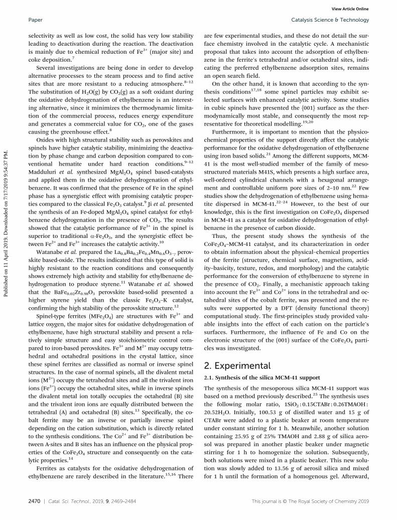
The magnetization curves of Fe2O3–MCM-41 are presentedin Fig. 2b. The isothermal measurement (M × H) recorded at300 K shows a non-saturated and very small magnetizationsignal at 50 kOe. The anhysteretic behavior of this measure-ment confirms the presence of fast relaxing magnetic mo-ments due to superparamagnetic nanoparticles.
In fact, bulk hematite has a Néel transition (TN) at 955 K.Also, it has a Morin transition (TM) at 263 K and below thistemperature the two magnetic sub-lattices are exactly antipar-allel in the [111] axis. However, above TM, the moments havea slight canting, therefore, resulting in a small net magneti-zation. It is known that TM is below 4 K for particles smallerthan 8 nm,53 thus these particles will have a ferromagneticsignal above 4 K. The net magnetization in fine antiferromag-netic nanoparticles has contributions from the canting mo-ments and from the uncompensated moments in the antifer-romagnetic lattice.
The Mzfc curve shows a peak at 20 K due to the blockingtemperature (TB), Fig. 2a. On the other hand, the Mfc curveshows a steeper increase below TB due to moments with en-hanced magneto crystalline anisotropy, probably due to sur-face atoms. Furthermore, the Mzfc does not exhibit theMorin transition, indicating that the hematite nanoparticlesmay be smaller than 8 nm.54 To further study the Fe2O3–
MCM-41 sample, the hematite's particle size (D) was deter-mined by assuming that they are spheres. The particle's vol-ume (V) as a function of the blocking temperature (TB),Boltzmann constant (KB) and the magnetocrystalline aniso-tropy (K) is given by V = 25KBTB/K, where V = πD3/6. Takinginto account the K value determined by Dormann et al.48 of K= 9 × 10⁵ J m−3 for very fine particles, we have obtained D =2.5 nm, which is in close agreement with the work ofDormann et al.48 and is reasonable for nanoparticles withsizes below the XRD detection limit, justifying the profile ofthe diffractogram for the Fe2O3–MCM-41 sample.
The hysteresis for the Fe2O3–MCM-41 sample shows thatunder a maximum magnetic field of 5 T the sample does notsaturate at 4 K, Fig. 2b. The measurement shows a hysteresiswith a coercive field of 1850 Oe and a magnetization at 5 T of2.9 emu g−1. This last value will be higher if we take into ac-count the nominal concentration of hematite of 20 wt%, thusM(5 T) = 14.5 emu g−1. The ferromagnetic signal suggests that
Table 1 Hyperfine parameters of the different samples containing iron before the catalytic test
Sample Spectrum IS (mm s−1) QS (mm s−1) Bhf (T) Area (%) Area – only CoFe2O4
CF-MCM-41 Sextet 1 (Fetetr) 0.29 0.019 51 40 48Sextet 2 (Feoct) 0.39 −0.011 54 45 52Doublet 0.36 0.9 — 15 —
Fe2O3–MCM-41 Sextet 0.36 −0.018 48 100 —
Catalysis Science & Technology Paper
Publ
ishe
d on
11
Apr
il 20
19. D
ownl
oade
d on
7/1
7/20
19 9
:54:
37 P
M.
View Article Online
2476 | Catal. Sci. Technol., 2019, 9, 2469–2484 This journal is © The Royal Society of Chemistry 2019
the Morin transition is below 4 K, therefore, the sample hascanting moments, which contribute to the net magnetization.
For the CF-MCM-41 sample, the M × H measurement at300 K shows an unusual behavior with a coercive field of 508Oe, indicating that the sample is thermally blocked at 300 K,Fig. 2d. The magnetization at 5 T has a value of 6.45 emu g−1.This value is smaller than the one expected for the bulk in-verse spinel cobalt ferrite of 72 emu g−1. However, for thepresent catalyst, the active phase has a small crystallite sizeand is dispersed in the MCM-41 support, which justifies thelower value of saturation magnetization presented in the hys-teresis curve, Fig. 2d. The Mzfc and Mfc curves do not showany peak in the whole range of temperatures, Fig. 2c. Theseresults confirm that the sample is thermally blocked below300 K, Fig. 2d. It is known that cobalt ferrite nanoparticleswith sizes larger than 6 nm are blocked at 300 K,53 which isin agreement with the crystallite size of 14 nm, calculatedusing Scherrer's equation. Catalysts with magnetic propertiesare interesting, since they are easily separated at the end ofthe process by simple magnetic extraction.
3.3. Redox properties of cobalt ferrite (TPR-H2 analysis)
The TPR analysis was performed to study the redox proper-ties of Fe3+ and Co2+ in the tetrahedral and octahedral sitesof the spinel structure. Fig. 3 presents the TPR profile for thetwo samples. The Fe2O3–MCM41 solid showed one well-defined peak at low temperature and two shoulders at higher
temperatures. The broad peak with a maximum near 405 °Cis related to the transformation of hematite to magnetite.The two shoulders at approximately 530 and 580 °C, respec-tively, may be related to the reduction of magnetite (Fe3O4) toFeO followed by reduction of FeO to metallic iron. The reduc-tion of a fraction of magnetite to metallic iron with lowersupport interaction and located on the external surfaces mayhave occurred in the first reduction range, since the amountof H2 consumption in the first peak is much greater thanthose in both shoulders at higher temperatures, indicatingthe incomplete reduction of Fe2+ at higher temperatures.Thus, the two shoulders may be related to the reduction ofthe iron oxide that is more protected by the support andtherefore H2 has limited access, complicating the reductionprocess. These observations are in agreement with other pre-viously published papers.55,56
On the other hand, it is noted from the TPR profile for theCF-MCM-41 sample that Fe3+ ions located in the tetrahedraland octahedral positions of the ferrite structure have differ-ent redox properties compared to the Fe3+ ions present in thehematite structure, considering that the heterogeneity of thespinel structure is much higher. Specifically for this sample,two broad and low-intensity shoulders are observed at lowtemperature and three well-defined peaks at higher tempera-ture. These peaks must be related to the reduction of the di-valent cation (Co2+ → Co+ →Co0) and the trivalent cation(Fe3+ → Fe2+ → Fe0) in the tetrahedral and octahedral posi-tions of the cobalt ferrite structure. Taking into account that
Fig. 2 Magnetic properties of the different samples. (a) and (c) Mzfc and Mfc magnetization curves; (b) and (d) hysteresis cycles from VSManalysis.
Catalysis Science & TechnologyPaper
Publ
ishe
d on
11
Apr
il 20
19. D
ownl
oade
d on
7/1
7/20
19 9
:54:
37 P
M.
View Article Online

Catal. Sci. Technol., 2019, 9, 2469–2484 | 2477This journal is © The Royal Society of Chemistry 2019
in the crystallites the octahedral sites are more exposed com-pared to the tetrahedral sites, one may consider that the re-duction of the octahedral sites occurs preferentially (greaterreactivity) compared to that of the tetrahedral sites.57,58 Theliterature reports that in the TPR curve the Co2+ reductioncannot be easily differentiated from the Fe3+ reduction, sinceboth occur in the same temperature range. In addition, thepresence of Co2+ (more easily reduced cation) shifts to lowertemperatures the traditional reduction range of Fe3+, justify-ing the similar reduction temperature range.59
Many studies report that the reduction of Co2+ and Fe3+ tozero valent metals does not completely occur in the permittedtemperature range for H2-TPR analyses,54,55 indicating thatthe ferrite spinel has high structural stability against a reduc-ing atmosphere. Furthermore, the structural stability of Fe3+
in CoFe2O4 against a reducing atmosphere is much largerthan that of Fe3+ in α-Fe2O3, which is confirmed in our TPRresults where the CF-MCM-41 catalyst showed reductionpeaks at a higher temperature compared to the Fe2O3–MCM-41 sample. For oxidative dehydrogenation of hydrocarbonswhere Fe3+ plays an important role, the cobalt ferrite catalystwill probably have a better performance compared to the he-matite because the ferrite will have greater structural stabilityand will minimize the deactivation due to the reduction ofFe3+ during the catalytic dehydrogenation cycle.60,61
3.4. Acidity and adsorption properties of NO (IR of adsorbedpyridine and NO)
The IR spectra of pyridine adsorbed on Fe2O3–MCM-41 andCF-MCM-41 catalysts are presented in Fig. 4a. The mostintense bands appear at approximately 1449, 1490 and 1608cm−1 and are related to Lewis acidic sites, referring to Fe3+
present in the hematite and Fe3+/Co2+ present in the cobaltferrite. The bands at 1490 and 1608 cm−1 are absent in pureMCM-41, indicating that the Lewis acid sites are mostly fromthe hematite and cobalt ferrite structure. Previous studieshave shown that, for the case of the CF-MCM-41 solid, theband at 1609 cm−1, the contribution of pyridine adsorptionin octahedral sites is greater than that in the tetrahedral posi-
tions, suggesting that the octahedral sites are mostly exposedon the catalyst surface compared to the tetrahedral sites.15,62
Specifically, for the pure MCM-41 support, the spectrum ex-hibits two visible bands at 1446 and 1597 cm−1, which are as-sociated with the adsorption of pyridine on the free silanolgroups present in the MCM-41 structure, since pyridineforms hydrogen bonds with silanol groups.63
Adsorption of NO followed by infrared analysis wasperformed in order to evaluate the adsorption capacity of NOin Fe3+ and Co2+ sites, obtaining information about the sur-face chemistry of Lewis acid sites. The NO species presentsthree electron pairs occupying bonding orbitals and one un-paired electron situated on a π antibonding orbital. In addi-tion, another electron pair is positioned on the 5σ non-bonding orbital. These characteristics make NO a weakelectron donor (a weak Lewis base), presenting the ability tocoordinate with Lewis acid sites such as Co2+ and Fe3+.64
The IR spectra of NO adsorbed on Fe2O3–MCM-41 and CF-MCM-41 solids are shown in Fig. 4b. The results clearly showthat the bands are much more intense in the CF-MCM-41sample compared to those in the Fe2O3–MCM-41 catalyst,suggesting that the active area referring to the Lewis acidsites is much more exposed in the cobalt ferrite compared tothat in the hematite. The NO adsorption on the surfacescontaining Fe3+ or Fe3+/Co2+ sites may be attributed to twotypes of interactions, designated as monodentate andbidentate nitrates. The adsorption of NO on the MCM-41 sup-port practically does not exist, since the spectrum of the puresupport did not show any visible band.
Fig. 3 H2-TPR results for the different solids.
Fig. 4 Chemical adsorption followed by infrared analysis. (a) FTIRspectra of pyridine adsorbed on the solid surface; (b) FTIR spectra ofNO adsorbed on the catalyst surface.
Catalysis Science & Technology Paper
Publ
ishe
d on
11
Apr
il 20
19. D
ownl
oade
d on
7/1
7/20
19 9
:54:
37 P
M.
View Article Online

2478 | Catal. Sci. Technol., 2019, 9, 2469–2484 This journal is © The Royal Society of Chemistry 2019
The CF-MCM-41 catalyst exhibited six bands at approxi-mately 1382, 1463, 1582, 1681, 1806, and 1885 cm−1, respec-tively. The Fe2O3–MCM-41 solid showed three visible bands at1380, 1451 and 1555 cm−1 (similar to CF-MCM-41) and two veryweak bands at 1681 and 1836 cm−1. The bands at 1806 and1885 cm−1 belong to the cobalt ferrite and may be related tovsIJNO) and vassIJNO) modes due to the formation of Co2+(NO)2or Fe3+(NO)3 complexes.65,66 The bands at approximately 1382and 1450–1463 cm−1 may be assigned to monodentate nitratespecies, while the bands at approximately 1555–1582 and 1681cm−1 are attributed to bidentate nitrate species.67
Specifically for the CF-MCM-41 sample, the NO speciescan be adsorbed in the Fe3+ or Co2+ sites and in the tetrahe-dral or octahedral positions of the lattice. Computationalstudies using the DFT approach have shown that the NO mol-ecule is preferentially adsorbed by Fe3+ compared to divalentions and preferably adsorbed in the octahedral positionscompared to the tetrahedral positions in the crystal lattice ofthe ferrite structure.68,69 Thus, the Fe3+ ions located in the oc-tahedral positions will be possibly the preferred sites in thecobalt ferrite for reactions where the Lewis acid sites play animportant role in the catalytic cycle.
3.5. CO2 adsorption capacity and catalyst basicity (TPD-CO2)
CO2 desorption analysis was performed in order to evaluatethe CO2 adsorption capacity considering that CO2 plays therole of a soft oxidant during oxidative ethylbenzene dehydro-genation, minimizing coke deposition. The TPD-CO2 resultsare presented in Fig. 5. All the catalysts show a main peak atlow temperature between 27 and 190 °C. Particularly, theFe2O3–MCM41 solid showed a broad and low intensity bandbetween 150 and 275 °C. The first CO2 desorption peak ob-served in both samples is related to monodentate carbonateformed on weak basic sites. The Fe2O3–MCM-41 catalystshowed greater heterogeneity of the weak basic sites sinceone shoulder was observed at 97 °C, while the CF-MCM-41sample, despite the greater homogeneity, presented a highernumber of weak basic sites due to the greater area of theband at low temperature. The Fe2O3–MCM-41 solid has abroad and low-intensity band with two shoulders at 192 and240 °C; these signals are related to CO2 desorption ofbidentate carbonate formed on moderate basic sites. It isworth mentioning that CO2 adsorbed in the bidentate form(moderate sites), for some reactions, is considered as an oc-cupant of the active sites hindering the catalytic cycle, whilein the monodentate form (weak sites) it is easily desorbed, re-leasing the active site to the new catalytic cycle.70,71 Thus, itis expected that for higher amounts of CO2 adsorbed on thecatalyst surface, especially in weak sites, the activity in oxida-tive dehydrogenation will be greater due to the lower amountof deposited coke (less obstruction of active sites by carbon).
3.6. Textural properties (N2 adsorption–desorption isotherms)
The nitrogen physisorption isotherms are presented in Fig. 6.The corresponding calculated parameters are listed in
Table 2 (surface area, pore volume and pore diameter). Allthe samples exhibited a type IV isotherm according to IUPACclassification with a sharp capillary condensation step atabout 0.25 and 0.6 relative pressures, characteristic of meso-porous silica MCM-41 based materials.72 The range of poresize distribution was very narrow, indicating the uniformityof pores and preservation of mesoporosity. The data referringto the textural properties present in Table 2 indicate that thesurface area decreased after Fe3+ and Co2+ impregnation. Thepore volume also had a slight decrease after insertion of themetals by incipient impregnation. These results suggest thatthe metals inserted by impregnation are mostly on the cata-lyst surface, as presented in the XPS results (Fig. 1D), and asmall fraction of pores is partly blocked by the hematite(Fe2O3–MCM-41 sample) or cobalt ferrite (CF-MCM-41 solid).Despite the slight change in texture properties after impreg-nation, the mesoporous structure of the MCM-41 supportwas practically maintained, corroborating with the low-anglediffractograms (Fig. S2†).
Fig. 5 CO2 desorption curves for the different solids (TPD-CO2).
Fig. 6 N2 adsorption and desorption isotherms for the differentsamples.
Catalysis Science & TechnologyPaper
Publ
ishe
d on
11
Apr
il 20
19. D
ownl
oade
d on
7/1
7/20
19 9
:54:
37 P
M.
View Article Online

Catal. Sci. Technol., 2019, 9, 2469–2484 | 2479This journal is © The Royal Society of Chemistry 2019
3.7. Morphological properties (TEM images)
TEM characterization was employed in order to observe themesoporous structures of the CF-MCM-41 solid. TEM imagesof the CF-MCM-41 catalyst are presented in Fig. 7.
Fig. 7A shows a particle with well-defined long fringes re-lated to pores of the MCM-41 particle with inter pore dis-tances of 3.3 nm in agreement with the small-angle XRDdiffractograms (Fig. S2†) and N2 isotherms (Fig. 6). In thelower right side, there are a large number of aggregates ofsmall particles, probably due to CF, deposited on the MCM-41 surface. Fig. 7B shows the same particle recorded at alower magnification; in the upper side of the MCM-41 parti-cle, a large number of small nanoparticles that seem to clogthe MCM-41 pores are noticed. Approximately, the particle inFig. 7B is 200 nm wide and has a length of 300 nm. Fig. 7Cshows a high magnification image with a few CF nano-particles depicting fringes due to (400) and (311) planes withinterplanar distances of 0.20 nm and 0.25 nm, respectively,according to the JCPDS 00–002-1045 card shown in thediffractograms in Fig. 1A. Fig. 7D shows a histogram with thesize distribution of the CF particles, and the main size isabout 7 nm, which is in agreement with the value obtainedfrom the diffractograms according to the Scherrer equation.
3.8. Catalytic performance (catalytic tests)
The catalytic performance of the different samples in the eth-ylbenzene conversion to styrene is shown in Fig. 8. The re-sults indicate that pure MCM-41 support has practically noactivity in the reaction with a conversion value close to 3%(practically inactive), confirming that the O−2–Fe3+–O2− and/or−2O–Co2+–O2− species in the crystal lattice are the major sitesresponsible for the conversion of ethylbenzene to styrene.The CF-MCM-41 catalyst exhibited better conversion resultscompared to the Fe2O3–MCM-41 solid, confirming that thecobalt ferrite is a more stable structure for the reaction con-ditions compared to the hematite. The CoFe2O4 structureminimizes the deactivation by reduction of the active sitesand by coke deposition compared to the α-Fe2O3 phase.
The diffractogram of the CF-MCM-41 sample after the cata-lytic test, Fig. S5,† confirms the high stability of the cobalt fer-rite structure compared to the hematite, since practically nodifference was observed compared to the diffractogram beforethe reaction (Fig. 1A). The Mössbauer spectroscopy results afterthe reaction (not shown) also confirmed the presence of cobaltferrite. The identification of the hematite phase change to mag-netite for the Fe2O3–MCM-41 sample after the reaction was notpossible, since this sample has a crystallite size below the XRD
Table 2 Textural properties obtained from N2 adsorption–desorption isotherms and specific activity from catalytic performance (A)
Sample SBET (m2 g−1) Vp (cm3 g−1) Dp (nm) A# (mol m−2 h−1)
Pure MCM-41 946 0.75 4.2 0.03Fe2O3–MCM-41 690 0.53 3.9 0.05CF-MCM-41 789 0.45 3.4 0.23
SBET: BET surface area; Vp: total pore volume; Dp: pore diameter obtained by the VBS, method.; # = average values only for a reaction periodhigher than 2 h.
Fig. 7 IJA)–(C): TEM images of the CF-MCM-41 catalyst using different approximations. (D): Histogram with the size distribution.
Catalysis Science & Technology Paper
Publ
ishe
d on
11
Apr
il 20
19. D
ownl
oade
d on
7/1
7/20
19 9
:54:
37 P
M.
View Article Online

2480 | Catal. Sci. Technol., 2019, 9, 2469–2484 This journal is © The Royal Society of Chemistry 2019
detection limit as mentioned previously. On the other hand, itwas previously described from the experimental data after andbefore the reaction that for catalysts containing hematite dis-persed in a silica support a change of hematite to magnetite oc-curs,16,21 justifying the better catalytic performance of the co-balt ferrite compared to the hematite. It is known that thecatalytic performance for the oxidative dehydrogenation of eth-ylbenzene using magnetite (Fe3+/Fe2+) is smaller compared tothat using hematite (Fe3+),73 confirming that the restitution ofFe3+ sites during the catalytic cycle is essential for maintainingthe catalyst activity.
The CF-MCM-41 sample reached ethylbenzene conversionvalues around 30% after 60 min of reaction and remainedconstant during the 300 min reaction, while the Fe2O3–MCM-41 solid was deactivated during the reaction, presenting eth-ylbenzene conversion values close to those of the support inthe last minutes of reaction. Both samples presented almost100% selectivity to styrene, confirming that iron-based mate-rials are highly selective to styrene. Traces of benzene and tol-uene were identified in some reaction time. The results ofspecific activity presented in Table 2 confirm the higher con-version of the sample containing cobalt ferrite compared tohematite and the pure support.
3.9. Mechanistic proposal (catalytic cycle)
The reaction mechanism may change according to the natureof a solid catalyst. The materials need certain characteristicssuch as active sites well distributed on the surface; the acces-sibility of the sites in relation to the reagents is affected byphysicochemical properties (elemental composition, struc-ture, oxidation states, crystallite size, morphology, texture,acidity–basicity and dispersion of active sites).74 All character-izations and catalytic tests presented previously confirmedthat the cobalt ferrite has interesting properties to act as acatalyst in the transformation of ethylbenzene to styrene,since this structure presents Fe3+ (major active site) with ahigh stability structure. However, the role of iron or cobaltand lattice oxygen sites in the tetrahedral or octahedral posi-
tions of the cobalt ferrite in the transformation of ethylben-zene to styrene needs to be clarified.
The mechanism for oxidative dehydrogenation of hydrocar-bons using an iron oxide-based catalyst (Fe3+ sites) has beenpreviously discussed in the literature.75,76 Initially the adsorp-tion of the hydrocarbon group interacting with the Fe3+ activesite and O2− (lattice oxygen) occurs, followed by desorptionsteps, releasing H2 and the hydrocarbon product), and finallythe reoxidation step, regenerating the solid. The sequence of re-actions relating to this mechanism is presented below. Oxida-tive dehydrogenation of ethylbenzene occurs in two steps. Ini-tially, simple dehydrogenation occurs, producing styrene andH2, reaction (4). Subsequently, the generated H2 reacts withCO2 to produce H2O(g) and CO(g) through the reverse water-gas shift section (RWGS), reaction (5).
C6H5 − CH2CH3(g) ⇌ C6H5 − CH = CH2(g) + H2(g) (4)
CO2(g) + H2(g) ⇌ CO(g) + H2O(g) (5)
C + CO2(g) → 2CO(g) (6)
Fe3+ (present in crystalline structure) → Fe2+ (7)
Fe2+ → Fe3+ (present in crystalline structure) (8)
Particularly, some studies have reported the hydrocarbondehydrogenation mechanism using ferrite catalysts. In thiscase, hydrogen abstraction occurs in two steps. In the firststep, a homolytic cleavage occurs to produce the intermediateby forming a π bond with the Fe3+ sites. During the secondstep, a heterolytic cleavage occurs, in which H+ binds to theO2− species (lattice oxygen sites) and forms a CxHy–Fe
3+ com-plex, reactions (7) and (8). The abstraction of α hydrogen issignificantly influenced by the acidic properties of the cata-lyst.77 Although some works proposed a mechanism for oxi-dative dehydrogenation of hydrocarbons using ferrites, theaction of these sites and their role in the oxidative dehydroge-nation of ethylbenzene remains a challenge to be explored.Furthermore, previous studies did not mention the action oftetrahedral and octahedral sites of ferrites. Thus, Scheme 1shows a mechanistic proposal for the oxidative dehydrogena-tion of ethylbenzene to styrene using the CoFe2O4 catalyst.
The reaction begins when the Fe3+ sites (Lewis acids) inthe CoIJII)Fe2IJIII)O4 structure adsorb the aromatic ring of ethyl-benzene (step I), followed by the elimination of two hydrogenfrom ethyl groups over Lewis basic centers (O2−), lattice oxy-gen, with electron transfer to Fe3+ (step II). In this stage ofthe mechanism, the C–H bond is broken. Joseph et al. pro-posed that the basic aromatic molecule adsorbed in theLewis acid sites of iron maintains an interaction with thehighest occupied molecular orbital (HOMO) and the unoccu-pied states of the 3d iron have to be assumed (LUMO).78 Instep (III), iron and oxygen were reduced according to Lewisacid/base interactions. Considering the desorption of the H+
ions from the basic center (O−) and the interaction of theFig. 8 Catalytic performance of the cobalt ferrite in the oxidativedehydrogenation of ethylbenzene.
Catalysis Science & TechnologyPaper
Publ
ishe
d on
11
Apr
il 20
19. D
ownl
oade
d on
7/1
7/20
19 9
:54:
37 P
M.
View Article Online

Catal. Sci. Technol., 2019, 9, 2469–2484 | 2481This journal is © The Royal Society of Chemistry 2019
acid center (Fe2+) with styrene, the reaction will produce H2
and styrene (reaction (4)).The reduction of iron, reaction (7), and formation of OH
groups during the reaction and desorption represents a stage ofcatalyst deactivation. Thus, new reactions are trivial to restorethe Fe3+ active sites and reestablish the catalytic cycle. Thereoxidation of the iron active sites occurs in step (IV), reaction(8), returning to the initial state and consequently continuingthe cyclic mechanism. For this stage, the literature proposessome mechanisms,79 such as homolytic cleavage of the OHgroup, producing H2. In experimental studies, Zhang et al.80
pointed out that the water-gas reverse reaction occurs duringdehydrogenation with CO2 and facilitates ethylbenzene conver-sion. The presence of CO2 helps to sustain the ethylbenzene de-hydrogenation in the CoFe2O4 structure, removing the hydrogenand repairing the oxygen vacancy created on the ferrite surface.
The Fe3+ ions (tetrahedral and octahedral sites) present inthe ferrite are the main acid sites responsible for attractingthe aromatic ring because they have a higher Lewis acidstrength compared to Co2+ in the ferrite structure located inthe tetrahedral and octahedral sites. In addition, the octahe-dral sites are predominant compared to the tetrahedral sites,since they are more abundant in the cobalt ferrite surface.81
Therefore, the lattice oxygen in the vicinity of the Fe3+ in theoctahedral position plays the role of abstracting the hydro-gens from ethylbenzene and dehydrogenates with greaterintensity compared to the lattice oxygen (basic site) near Co2+
in the tetrahedral and octahedral positions.On the other hand, the catalytic dehydrogenation cycle
performed by the −2O–Co2+–O2− sites in the tetrahedral andoctahedral positions cannot be neglected, since some studies
have reported that oxidative dehydrogenation of hydrocar-bons occurs in the presence of Co3O4-based catalysts.82,83 Tyoet al. described the oxidative dehydrogenation in the pres-ence of cobalt oxide from experimental and theoretical stud-ies.83 The activation of hydrocarbon bonds occurs by hetero-lytic or homolytic mechanisms involving pairs of metal–oxygen (M–O*) or oxygen–oxygen (O*–O*) sites, similar topreviously described mechanisms. The heterolytic dissocia-tion occurs through the σ bond, involving the oxidative addi-tion of C–H together with an abstraction of a proton by thebasic site (O*) on the surface. The C–H homolytic activationinvolves the abstraction of hydrogen where a basic oxygenatom on the surface abstracts an H˙ and results in a weaklycoordinated species designated as C3H7 (˙). The C3H7 readilyreturns to a second oxygen in the surface during the courseof the reaction. The reaction occurs on two surface oxygenatoms (O*–O*), providing the dehydrogenation process.
In spite of the evidence presented for the preferential ad-sorption of Fe3+ compared to Co2+ and the preferences for theoctahedral sites compared to the tetrahedral sites in the fer-rite structure, no study using the DFT approach has beenpresented for ethylbenzene adsorption to confirm this as-sumption. Hence, a DFT computational study of ethylbenzeneadsorption on the CoFe2O4 surface was carried out in order tounderstand the site preference for adsorption of ethylbenzeneand confirm the mechanism proposed in Scheme 1.
3.10. Computational study (DFT)
Fig. 9A shows the optimized CoFe2O4 bulk, where the latticeparameter (a = 8.31 Å) was in close agreement with
Scheme 1 Scheme indicating the mechanistic proposal for the oxidative dehydrogenation of ethylbenzene using catalysts based on cobalt ferrite.
Catalysis Science & Technology Paper
Publ
ishe
d on
11
Apr
il 20
19. D
ownl
oade
d on
7/1
7/20
19 9
:54:
37 P
M.
View Article Online

2482 | Catal. Sci. Technol., 2019, 9, 2469–2484 This journal is © The Royal Society of Chemistry 2019
experimental results, Fig. 1A. This bulk was used to build thesurfaces in the (001) plane, Fig. 9B, in which the octahedralsites are occupied by iron or cobalt with a five-fold coordina-tion [MO5]. The nature of site occupation and its coordina-tion are determinant for the adsorptive power of a surface.For adsorption of aromatic compounds, for example, the sur-face should have a Lewis acid character to be able to interactthrough π-bonding of the ring with the undercoordinatedtransition metal at the surface. In fact, as previously de-scribed, the benzene molecule interacts preferentially withthe hematite (001) surfaces through π-bonding in parallel ge-ometries, and only weakly through hydrogen bonds in verti-cal geometries.78 By visual inspection of the electrostatic po-tential surface of ethylbenzene (Fig. 9C) and the catalyst(Fig. 9D–F), it is easy to infer that ethylbenzene interacts withthe surface of CoFe2O4 in a similar way to C6H6/Fe2O3 as de-scribed by Dzade et al.84
The change in the Fe/Co amount in the (001) surfaces af-fected locally the adsorption site acidity, as depicted inFig. 9D–F, by the modulation of VS,min. In general, the effectof the cobalt increase on the surface leads to a decrease inpositive electrostatic potential, which indicates that the ad-sorption capacity of ethylbenzene should become preferentialin iron. Another important factor for ethylbenzene dehydro-
genation into styrene is the role of C–H⋯O2– interaction,which takes place in the VS,max region of surfaces (red areasin Fig. 9D–F, which are the sites most prone to interact asLewis bases). Moreover, the main product of ethylbenzene de-hydrogenation, styrene, has a π-conjugated (–CHCH2) vinylgroup that decrease the basicity of the aromatic ring, favoringthe desorption of the reaction product and consequently thecatalytic cycle. Thus, the DFT results showed good agreementwith the mechanism proposed in Scheme 1.
The electronic effect of the Fe/Co ratio on (001) surfaces isalso observed by density of states (DOSS) analysis (Fig. S6,ESI†), where the pristine cobalt ferrite has the edge of the va-lence band (VB) composed mainly of partially filled Fe 3dstates, while the bottom of the conduction band (CB) wascomposed of Co 3d states. A similar behavior was observedwhen few octahedral sites are inverted (12.5% [CoO5] and87.5% [FeO5]), but it was not observed when the amount ofcobalt was increased on the surface, where an empty Co 3dmidgap state was created, reducing the band gap.
4. Conclusions
Catalysts based on cobalt ferrite dispersed on MCM-41 weresuccessfully synthesized and applied in the conversion of
Fig. 9 (A) Unit cell of cubic CoFe2O4. (B) (001) surface where the octahedral and tetrahedral sites at the outermost layers are occupied by Co orFe. The electrostatic surface potential [VSIJr)] for (C) ethylbenzene (0.01 a.u. isodensity) and (D–F) the top view of spinel (001) termination (0.001 a.u. isodensity).
Catalysis Science & TechnologyPaper
Publ
ishe
d on
11
Apr
il 20
19. D
ownl
oade
d on
7/1
7/20
19 9
:54:
37 P
M.
View Article Online

Catal. Sci. Technol., 2019, 9, 2469–2484 | 2483This journal is © The Royal Society of Chemistry 2019
ethylbenzene to styrene. The active sites in the cobalt ferritestructure are more promising for the transformation of ethyl-benzene to styrene compared to the traditional sites present inthe hematite structure. A partially inverted Co ferrite wasobtained with the chemical structure (Co0.06Fe0.94)ijCo0.94Fe1.06]-O4, where Co2+ and Fe3+ occupy both octahedral and tetrahe-dral positions. Catalytic tests showed excellent selectivity andstability for the CoFe2O4 phase, which are attributed to highstructural stability against the reaction conditions compared tothe hematite (low structural stability). The mechanistic pro-posal has shown that ethylbenzenemainly prefers the Fe3+ sitescompared to Co2+ and the dehydrogenation occurs preferen-tially in the octahedral sites compared to the tetrahedral sites.The computational study using DFT confirmed that the cata-lytic process for ethylbenzene dehydrogenation occurs prefer-entially in iron and lattice oxygen sites located in the octahedralpositions, but the cobalt sites and the tetrahedral positions inthe cobalt ferrite structure cannot be completely neglected.
Conflicts of interest
There are no conflicts to declare.
Acknowledgements
The authors would like to thank the Brazilian CNPq andCAPES funding agencies for financial support. We also thankTatiane Oliveira at LABMIC-UFG for providing the TEM im-ages, Professor José Marcos Sasaki for XRF analysis and Pro-fessor Jhonny Villarroel for assisting in the interpretation ofN2 physisorption analysis. The computational facilities weresupported by resources supplied by Brazilian Funding Agen-cies FAPESP, CNPq and the Center for Scientific Computingof the São Paulo State University (Grid Unesp).
References
1 S. G. Sanz, L. McMillan, J. McGregor, J. A. Zeitler, N. Al-Yassir, S. Al-Khattaf and L. F. Gladden, Catal. Sci. Technol.,2015, 5, 3782.
2 Z. Z. Wu, N. C. Nelson, A. D. Sadow, I. I. Slowing and S. H.Overbury, ACS Catal., 2015, 5, 6426–6435.
3 A. Schüle, O. Shekhah, W. Ranke, R. Schlögl and G. Kolios,J. Catal., 2005, 231, 172–180.
4 T. P. Braga, E. Longhinotti, A. N. Pinheiro and A. Valentini,Appl. Catal., A, 2009, 362, 139–146.
5 M. de S. Ramos, M. de S. Santos, L. P. Gomes, A. Albornozand M. do C. Rangel, Appl. Catal., A, 2008, 341, 12–17.
6 C. Wang, J. Shi, X. Cui, J. Zhang, C. Zhang and L. Wang,J. Catal., 2017, 345, 104–112.
7 T. P. Braga, A. N. Pinheiro, C. V. Teixeira and A. Valentini,Appl. Catal., A, 2009, 366, 193–200.
8 X. Li, J. Feng, H. Fan, Q. Wang and W. Li, Catal. Commun.,2015, 59, 104–107.
9 V. R. Madduluri, P. Nagaiah, C. Prathap, K. Vasikerappa, A.Nagu, B. D. Raju and K. S. R. Rao, Arabian J. Chem.,2018, DOI: 10.1016/j.jscs.2018.10.001.
10 M. Ji, X. Zhanga, J. Wang and S. Park, J. Mol. Catal. A:Chem., 2013, 371, 36–41.
11 R. Watanabe, K. Mukawa, J. Kojima, E. Kikuchi and Y.Sekine, Appl. Catal., A, 2013, 462–463, 168–177.
12 R. Watanabe, Y. Saito and C. Fukuhara, J. Mol. Catal. A:Chem., 2015, 404–405, 57–64.
13 S. A. V. Prasad, M. Deeptya, P. N. Ramesha, G. Prasad, K.Srinivasarao, C. Srinivas, K. Vijaya Babu, E. Ranjith Kumar,N. Krisha Mohan and D. L. Sastry, Ceram. Int., 2018, 44,10517–10524.
14 E. Hutamaningtyasa, U. Suharyanaa, A. T. Wijayantab and B.Purnama, J. Phys.: Conf. Ser., 2016, 776, 012–023.
15 T. Mathew, S. Malwadkar, S. Pai, N. Sharanappa, C. P.Sebastian, C. V. V. Satyanarayana and V. V. Bokade, Catal.Lett., 2003, 91, 217–224.
16 T. P. Braga, B. M. C. Sales, A. N. Pinheiro, W. T. Herrera, E.Baggio-Saitovitch and A. Valentini, Catal. Sci. Technol.,2011, 1, 1383–1392.
17 N. Bao, L. Shen, W. An, P. Padhan, C. H. Turner and A.Gupta, Chem. Mater., 2009, 21, 3458–3468.
18 A. L. Lopes-Moriyama, V. Madigou, C. P. Souza and C.Leroux, Powder Technol., 2014, 256, 482–489.
19 H. Hajiyani and R. Pentcheva, ACS Catal., 2018, 8,11773–11782.
20 X. Shi, S. L. Bernasek and A. Selloni, Surf. Sci., 2018, 677,278–283.
21 T. P. Braga, A. N. Pinheiro, C. V. Teixeira and A. Valentini,Appl. Catal., A, 2009, 366, 193–200.
22 Y. Qiao, C. Miao, Y. Yue, Z. Xie, W. Yang, W. Hua and Z.Gao, Microporous Mesoporous Mater., 2009, 119, 150–157.
23 A. H. Batista, F. F. Sousa, S. B. Honorato, A. P. Ayala, J. M.Filho, F. W. de Sousa, A. N. Pinheiro, J. C. S. Araujo, R. F.Nascimento, A. Valentini and A. C. Oliveira, J. Mol. Catal. A:Chem., 2010, 315, 86–98.
24 S. Wong, H. Lin and C. Mou, Appl. Catal., A, 2000, 198,103–114.
25 E. Rossetto, B. P. Nicola, R. F. de Souza, K. B. Gusmão andS. B. C. Pergher, J. Catal., 2015, 323, 45–54.
26 JCPDS-ICCD Database, The International Center of DiffractionData, version 2.4, 2003.
27 A. C. Larson and R. B. V. Dreele, General Structure AnalysisSystem (GSAS). Los Alamos National Laboratory report LAUR,2004, pp. 86–748.
28 B. H. Toby, J. Appl. Crystallogr., 2001, 34, 210–213.29 L. V. Azaroff, Elements of X-ray Crystallography, McGraw-Hill,
USA, 1968.30 A. D. J. Becke, Chem. Phys., 1993, 98, 1372.31 R. Dovesi, V. R. Saunders, C. Roetti, , R. Orlando, C. M.
Zicovich-Wilson, F. Pascale, B. Civalleri, K. Doll, N. M.Harrison, I. J. Bush, P. D'Arco, M. Llunell, M. Causà, Y. Noël,L. Maschio, A. Erba, M. Rerat and S. Casassa, CRYSTAL17User's Manual, University of Torino, Torino, 2017.
32 A. Erba, J. Baima, I. Bush, R. Orlando and R. Dovesi,J. Chem. Theory Comput., 2017, 13, 5019–5027.
33 S. Grimme, J. Antony, S. Ehrlich and H. Krieg, J. Chem.Phys., 2010, 132, 154104.
Catalysis Science & Technology Paper
Publ
ishe
d on
11
Apr
il 20
19. D
ownl
oade
d on
7/1
7/20
19 9
:54:
37 P
M.
View Article Online

2484 | Catal. Sci. Technol., 2019, 9, 2469–2484 This journal is © The Royal Society of Chemistry 2019
34 CRYSTAL - Basis Sets Library, http://www.crystal.unito.it/basis-sets.php, Accessed: 2018-11-30.
35 J. H. Stenlid and T. Brinck, J. Am. Chem. Soc., 2017, 139,11012–11015.
36 J. Lee and S. Kwak, ACS Omega, 2018, 3, 2634–2640.37 N. I. Cuello, V. R. Elías, C. E. R. Torres, M. E. Crivello, M. I.
Oliva and G. A. Eimer, Microporous Mesoporous Mater.,2015, 203, 106–115.
38 I. Ursachi, A. Stancu and A. Vasile, J. Colloid Interface Sci.,2012, 377, 184–190.
39 N. I. Cuello, V. R. Elías, C. E. R. Torres, M. E. Crivello, M. I.Oliva and G. A. Eimer, Microporous Mesoporous Mater.,2015, 203, 106–115.
40 H. T. Teo, W. R. Siah and L. Yuliati, J. Taiwan Inst. Chem.Eng., 2016, 65, 591–598.
41 D. Yun, C. Krutpijit, B. Jongsomjit and J. E. Herrera, Surf.Sci., 2018, 677, 203–212.
42 Q. Men, Z. Wang, X. Chai, Z. Weng, R. Ding and L. Dong,Appl. Surf. Sci., 2016, 368, 303–308.
43 D. Yana, H. Zhaoa, J. Peia and X. Wang, Mater. Res. Bull.,2018, 101, 100–106.
44 P. Chandramohan, M. P. Srinivasan, S. Velmurugan andS. V. Narasimhan, J. Solid State Chem., 2011, 184, 89–96.
45 O. Vozniuk, C. Bazzo, S. Albonetti, N. Tanchoux, F. Bosselet,J. M. Millet, F. D. Renzo and F. Cavani, ChemCatChem,2017, 9, 2219–2230.
46 V. Georgiadou, V. Tangoulis, I. Arvanitidis, O. Kalogirou andC. Dendrinou-Samara, J. Phys. Chem. C, 2015, 119,8336–8348.
47 B. D. Cullity and C. D. Graham, Introduction to MagneticMaterials, IEEE Press-Wiley, 2009.
48 J. L. Dormann, J. R. Cui and C. Stella, J. Appl. Phys.,1985, 57, 4283.
49 A. D. Arelaro, L. M. Rossi and H. R. Rechenberg, J. Phys.:Conf. Ser., 2010, 217, 012–126.
50 K. Haneda and A. H. Morrish, J. Appl. Phys., 1988, 63,4258.
51 J. Li, M. Xu, Gang Yao and B. Lai, Chem. Eng. J., 2018, 348,1012–1024.
52 M. Nasiria, P. Sangpoura, S. Yousefzadeh and M. Bagheri,J. Environ. Chem. Eng., 2019, 7, 102999.
53 D. Schroeer and R. C. Nininger, Phys. Rev. Lett., 1967, 19,632.
54 A. T. Ngo, P. Bonville and M. P. Pileni, J. Appl. Phys.,2001, 89, 15.
55 B. Pawelec, L. Daza, J. L. G. Fierro and J. A. Anderson, Appl.Catal., A, 1996, 145, 307.
56 T. P. Braga, A. N. Pinheiro, C. V. Teixeira and A. Valentini,Appl. Catal., A, 2009, 366, 193–200.
57 J. P. Jacobs, A. Maltha, J. G. H. Reintjes, J. Drimal, V. Ponecand H. H. Brongersma, J. Catal., 1994, 147, 294.
58 A. Urda, A. Herraïz, Á. Rédey and I. Marcu, Catal. Commun.,2009, 10, 1651–1655.
59 J. Thomas, N. Thomas, F. Girgsdies, M. Beherns, X. Huang,V. D. Sudheesh and V. Sebastian, New J. Chem., 2017, 41,7356.
60 S. Deng, S. Li, H. Li and Y. Zhang, Ind. Eng. Chem. Res.,2009, 48, 7561–7566.
61 I. Rossetti, E. Bencini, L. Trentini and L. Forni, Appl. Catal.,A, 2005, 292, 118–123.
62 T. Mathew, B. B. Tope, N. R. Shiju, S. G. Hegde, B. S. Raoand C. S. Gopinath, Phys. Chem. Chem. Phys., 2002, 4,4260–4267.
63 B. Chakraborty and B. Viswanathan, Catal. Today, 1999, 49,253–260.
64 K. Hadjiivanov, J. Saussey, J. L. Freysz and J. C. Lavalley,Catal. Lett., 1998, 52, 103–108.
65 F. Caron, M. Rivallan, S. Humbert, A. Daudin and S.Bordiga, J. Catal., 2018, 361, 62–72.
66 Q. Wu, G. Mul and R. Krol, Energy Environ. Sci., 2011, 4,2140.
67 T. Boningari, S. M. Pavani, P. R. Ettireddy, S. S. C. Chuangand P. G. Smirniotis, Mol. Catal., 2018, 451, 33–42.
68 Z. Jiang, W. Zhang, W. Shangguan, X. Wu and Y. Teraoka,J. Phys. Chem. C, 2011, 115, 13035–13040.
69 M. Busch, V. Mehar, L. R. Merte, M. Shipilin, E. Lundgren,J. F. Weaver and H. Grönbeck, Chem. Phys. Lett., 2018, 693,84–87.
70 K. Nishida, I. Atake, D. Li, T. Shishido, Y. Oumi and T. Sano,Appl. Catal., A, 2008, 337, 48–57.
71 L. Xing-yi, Z. Yong and Y. Ling, J. Fuel Chem. Technol.,2014, 42, 1087–1092.
72 M. Popova, A. Szegedi, K. Lazar and Z. Karoly, MicroporousMesoporous Mater., 2012, 151, 180–187.
73 O. Shekhah, W. Ranke and R. Schlögl, J. Catal., 2004, 225,56–68.
74 Z. Zhao, G. Ge, W. Li, X. Guo and G. Wang, Chin. J. Catal.,2016, 37, 644–670.
75 A. Kotarba, W. Bieniasz, P. Kuśtrowski, K. Stadnicka and Z.Sojka, Appl. Catal., A, 2011, 407, 100–105.
76 B. B. Tope, R. J. Balasamy, A. Khurshid, L. A. Atanda, H.Yahiro, T. Shishido and S. S. Al-Khattaf, Appl. Catal., A,2011, 407, 118–126.
77 H. Lee, J. C. Jung, H. Kim, Y.-M. Chung, T. J. Kim, S. J. Lee,S. H. Oh, Y. S. Kim and I. K. Song, Catal. Lett., 2008, 124,364.
78 Y. Joseph, M. Wühn, A. Niklewski, W. Ranke, W. Weiss, C.Wöll and R. Schlögl, Phys. Chem. Chem. Phys., 2000, 2,5314–5319.
79 C. Kuhrs, Y. Arita, W. Weiss, W. Ranke and R. Schlögl, Top.Catal., 2001, 14, 1–4.
80 L. Zhang, Z. Wu, N. C. Nelson, A. D. Sadow, I. I. Slowing andS. H. Overbury, ACS Catal., 2015, 5, 6426–6435.
81 M. V. Ushakov, B. Senthilkumar, R. Kalai Selvan, I. Felnerand M. I. Oshtrakh, Mater. Chem. Phys., 2017, 202, 159–168.
82 R. Pochamoni, A. Narani, M. Varkolu, M. D. Gudimella,S. S. P. Potharaju, D. R. Burri and S. R. R. kamaraju, J. Chem.Sci., 2015, 127, 701–709.
83 E. C. Tyo, C. Yin, M. D. Vece, Q. Qian, G. Kwon and S. Vajda,ACS Catal., 2012, 2, 2409–2423.
84 N. Y. Dzade, A. Roldan and N. H. de Leeuw, Minerals,2014, 4, 89–115.
Catalysis Science & TechnologyPaper
Publ
ishe
d on
11
Apr
il 20
19. D
ownl
oade
d on
7/1
7/20
19 9
:54:
37 P
M.
View Article Online