
Catalogue 2021/2022 - Sauter Extranet
528
Catalogue 2021/2022 Product and Systems Information
-
Upload
khangminh22 -
Category
Documents
-
view
0 -
download
0
Transcript of Catalogue 2021/2022 - Sauter Extranet

Catalogue 2021/2022Product and Systems Information
Cat
alog
ue 2
021/
2022
SAUTER – your local partner.
www.sauter-controls.com
Systems
Components
Services
Facility Services
Subj
ect t
o m
odifi
catio
n. ©
202
1 Fr.
Sau
ter A
GP1
0001
9258


Dear Sir or Madam,dear business partner,
SAUTER is continually expanding its range of new digital field devices and systems, and we are SAUTER is continually expanding its range of new digital field devices and systems, and we are pleased to present a number of new products.pleased to present a number of new products.
Intelligent building management becomes predictiveIntelligent building management becomes predictive: With the : With the Smart ActuatorSmart Actuatorwe are putting intelligence into a local field device. It embodies a new generation of devices that can we are putting intelligence into a local field device. It embodies a new generation of devices that can be controlled independently or fully integrated into a building management system. Its installation and be controlled independently or fully integrated into a building management system. Its installation and commissioning, and the maintenance of the plant, are made possible through easy-to-understand user commissioning, and the maintenance of the plant, are made possible through easy-to-understand user interfaces on smartphones via the Internet. This saves time and money.interfaces on smartphones via the Internet. This saves time and money.
In addition, intelligent building management fulfils user requirements for networking and comfort. In addition, intelligent building management fulfils user requirements for networking and comfort. The classic functions of room and building automation are expanded to include functions for the efficient management of The classic functions of room and building automation are expanded to include functions for the efficient management of space and the tracking of assets or people, and offer the user a new experience. The focus is on space and the tracking of assets or people, and offer the user a new experience. The focus is on IoT sensor technolo-IoT sensor technolo-gy and its integration into the SAUTER building automation systemgy and its integration into the SAUTER building automation system. In addition to room temperature, the . In addition to room temperature, the Smart Sensor viaSensSmart Sensor viaSens also measures air humidity and air quality. The integrated brightness and presence detector is assis- also measures air humidity and air quality. The integrated brightness and presence detector is assis-ted by a microphone for reliable detection of people in the room. The iBeacon and Bluetooth Mesh interface enables automatic ted by a microphone for reliable detection of people in the room. The iBeacon and Bluetooth Mesh interface enables automatic localisation of smartphones and, together with SAUTER Mobile Building Services, it can be used to operate room functions. The localisation of smartphones and, together with SAUTER Mobile Building Services, it can be used to operate room functions. The MQTT interface offers a fast connection to room automation devices, and thus to the IoT of the building.MQTT interface offers a fast connection to room automation devices, and thus to the IoT of the building.
In 2021, we will introduce the new In 2021, we will introduce the new Smart EcoClimate Control (LET6)Smart EcoClimate Control (LET6) wireless controller with the associated LRA room wireless controller with the associated LRA room control units for the control of panel heating systems. The system, which is mainly designed for underfloor heating, is operated via control units for the control of panel heating systems. The system, which is mainly designed for underfloor heating, is operated via the cloud with a smartphone or via voice assistants, such as Amazon Alexa. the cloud with a smartphone or via voice assistants, such as Amazon Alexa.
The new The new modulo 6 automation stationmodulo 6 automation station range has been very well received on the market. Since its launch in spring range has been very well received on the market. Since its launch in spring 2019, numerous projects have already been successfully implemented.2019, numerous projects have already been successfully implemented.The omnipresent threat of cyber attacks prompted us to present our own effective and lean solution for securing building automa-The omnipresent threat of cyber attacks prompted us to present our own effective and lean solution for securing building automa-tion at an early stage in the development of the product range. The tion at an early stage in the development of the product range. The modu615-BM Building Data Integrity Managermodu615-BM Building Data Integrity Manageris the local solution for is the local solution for data security in the plantdata security in the plant. Our patented blockchain technology is used to store the data of local . Our patented blockchain technology is used to store the data of local automation stations in blocks. If the data integrity is breached, the affected block is isolated and only reintegrated into the network automation stations in blocks. If the data integrity is breached, the affected block is isolated and only reintegrated into the network once its original state has been restored.once its original state has been restored.
With product innovations such as modulo 6 and the Smart Actuator, SAUTER has developed hardware tailored to the With product innovations such as modulo 6 and the Smart Actuator, SAUTER has developed hardware tailored to the potential of cloud computingpotential of cloud computing. The smart devices integrated into the IoT can provide clear recommendations for action. In . The smart devices integrated into the IoT can provide clear recommendations for action. In the foreseeable future, further offers in the SAUTER Cloud will add yet more customer benefits. “Advanced Energy Management” the foreseeable future, further offers in the SAUTER Cloud will add yet more customer benefits. “Advanced Energy Management” made possible by the cloud will become a reality from spring 2021 with made possible by the cloud will become a reality from spring 2021 with SAUTER Vision Center 7SAUTER Vision Center 7..
Our employees all over the world are on hand to carry out the successful implementation of your ideas!Our employees all over the world are on hand to carry out the successful implementation of your ideas!
Nathanaël RôthNathanaël RôthManaging DirectorManaging DirectorSauter Building Control International GmbHSauter Building Control International GmbH
Right of amendment reserved © 2021 Fr. Sauter AG 1
Dear Sir or Madam,dear business partner,
SAUTER is continually expanding its range of new digital fi eld devices and systems, and we are pleased to present a number of new products.
Intelligent building management becomes predictive: With the Smart Actuatorwe are putting intelligence into a local fi eld device. It embodies a new generation of devices that can be controlled independently or fully integrated into a building management system. Its installation and commissioning, and the maintenance of the plant, are made possible through easy-to-understand user interfaces on smartphones via the Internet. This saves time and money.
In addition, intelligent building management fulfi ls user requirements for networking and comfort. The classic functions of room and building automation are expanded to include functions for the effi cient management of space and the tracking of assets or people, and offer the user a new experience. The focus is on IoT sensor technolo-gy and its integration into the SAUTER building automation system. In addition to room temperature, the Smart Sensor viaSens also measures air humidity and air quality. The integrated brightness and presence detector is assis-ted by a microphone for reliable detection of people in the room. The iBeacon and Bluetooth Mesh interface enables automatic localisation of smartphones and, together with SAUTER Mobile Building Services, it can be used to operate room functions. The MQTT interface offers a fast connection to room automation devices, and thus to the IoT of the building.
In 2021, we will introduce the new Smart EcoClimate Control (LET6) wireless controller with the associated LRA room control units for the control of panel heating systems. The system, which is mainly designed for underfl oor heating, is operated via the cloud with a smartphone or via voice assistants, such as Amazon Alexa.
The new modulo 6 automation station range has been very well received on the market. Since its launch in spring 2019, numerous projects have already been successfully implemented.The omnipresent threat of cyber attacks prompted us to present our own effective and lean solution for securing building automa-tion at an early stage in the development of the product range. The modu615-BM Building Data Integrity Manageris the local solution for data security in the plant. Our patented blockchain technology is used to store the data of local automation stations in blocks. If the data integrity is breached, the affected block is isolated and only reintegrated into the network once its original state has been restored.
With product innovations such as modulo 6 and the Smart Actuator, SAUTER has developed hardware tailored to the potential of cloud computing. The smart devices integrated into the IoT can provide clear recommendations for action. In the foreseeable future, further offers in the SAUTER Cloud will add yet more customer benefi ts. “Advanced Energy Management” made possible by the cloud will become a reality from spring 2021 with SAUTER Vision Center 7.
Our employees all over the world are on hand to carry out the successful implementation of your ideas!
Nathanaël RôthManaging DirectorSauter Building Control International GmbH

http://www.sauter-controls.com
The new SAUTER catalogue
Go online for further information
Every product page in this catalogue provides a QR code at the end of the page. Using the QR code on your smartphone or tablet allows you to access more de-tailed information on the SAUTER website. Find relevant product data sheets, mate-rial declarations, fitting instructions, manuals and operating instructions etc. for all of our products.
Download the PDF version
On the SAUTER website, you will also find the cataloguefor electronic browsing and as a downloadable PDF.
2 Right of amendment reserved © 2021 Fr. Sauter AG

Contents
Field devices
2-point controllers 9
Data capture 47
Single-room, heating and air-conditioning controllers 93
Valves, control valves, dampers, actuators 145
Building management
SAUTER modulo 6 375
SAUTER ecos Room Automation / modulo 5 421
Management level 509
SAUTER CASE Suite 519
Appendix
Alphabetical list of contents 522
Right of amendment reserved © 2021 Fr. Sauter AG 3
Y
X
C
V
¨
N
>
_

Building automation demands ever greater processing power, larger data vol-
umes, and yet, easier operability. Today, the facility is meant to embed seamlessly
in the Internet of Things (IoT), which interconnects equipment systems and people.
Smart equipment integrated in IoT can make action recommendations.
The SAUTER Smart Spaces demonstration area in Freiburg, Germany impressively
shows how smart, holistic, and demand-oriented solutions can be created that transcend
classic building automation offering innumerable benefits to operators and users.
SAUTER has already created hardware and software attuned to the potential of
cloud computing. And our digital journey continues: More and more services will be
accessible via the SAUTER Cloud, creating an all-encompassing digital encounter
for our customers.
Building automation combines the heating, ventilation, climate and electrical supply to form a digitally net-worked system and ensures comfort and well-being. The controlled and targeted use of energy, water and air leads to low operating costs creating sustainable environments.
4 Right of amendment reserved © 2021 Fr. Sauter AG

Around the world and around the corner
With SAUTER specialists in over 70 countries, we optimise the climatic condi-tions and well-being factor of environments all over the world. Our local sales organisations ensure that our expertise is always close at hand. As an inde-pendent company we are able to think and act flexibly, developing tailor-made, innovative solutions for you.
Swiss and German quality hand in hand
As part of SAUTER, staff in Switzerland and Germany undertake joint research, development and production. And our customers all over the world benefit: They can continue to depend on the fact that quality, superlative precision, reliability, know-how protection and the environmental friendliness of the materials used in the manufacture of SAUTER products are given the highest priority.
A partner for life
Our consistent specialisation plus many years of experience guarantee compre-hensive expertise in all aspects of building management. During the planning, realisation, usage and modernisation phases, we are right by your side, every step of the way.
Widely recognised
SAUTER is excellently qualified to issue users and operators with a concise summary of energy flow and consumption. This is the key to reducing costs and increasing efficiency. SAUTER fulfils all basic criterias for Green Buildings and LEED. We also have IQNet, eu.bac and BTL BACnet certification. These seal our provendedication to uncompromising quality, functionality and precision.
Right of amendment reserved © 2021 Fr. Sauter AG 5

[4]
[3]
[2][1]
SAUTER Building Data Integrity ManagerThe modu615-BM provides a local solution for data integrity in the plant. It has an integrated web server for local commissioning, visualisation, operation and notification. A guided configuration process (wizard) creates a blockchain and starts an integrity check. The current process and the state of the blockchain can be accessed at any time in the dashboard. An e-mail noti-fication is sent in case of integrity violation. Proven se-curity technologies provide encryption, authentication and access protection. This means that the system is already well protected against cyber attacks at the au-tomation level.
SAUTER ecos-IoTPowerful function modules in the ecos504/505 inte-grate the regulation of room temperature, lighting, and sunshading to create a comfortable room climate with minimum energy consumption.The SAUTER ecos-IoT is a programmable BACnet server with an integrated BACnet/MQTT gateway. On the one hand, BACnet devices in the operating technology network can publish data to the cloud via the ecos-IoT, or MQTT data from the cloud can be subscribed to. This allows information and data from a public cloud (e.g. meteorological services) to be in-tegrated into the building and room automation. The ecos-IoT, on the other hand, enables efficient data exchange between different building automation devices via BACnet.When combined with an MQTT app on a smartphone, the room automation can be operated intuitively with state-of-the-art technology.
SAUTER Smart ActuatorA Smart Actuator combines the functions of an actuator, of a controller as well as cloud integration for autono-mous control of a wide range of applications. As an IoT device, the Smart Actuator continuously records the status of the installation and transmits this data to the SAUTER Cloud. Here the data is analysed by comparing it to reference values. Plant optimisations are carried out online via the mobile app and maintenance work can be scheduled according to needs.The field devices required for specific applications can be connected directly to the actuator or the I/O box.
SAUTER Smart Sensor viaSensThe Smart Sensor viaSens goes beyond measuring room temperature: it also measures air humidity and air quality. The integrated brightness and presence detector is assisted by a microphone for reliable detection of people in the room.The iBeacon and Bluetooth Mesh interface enables au-The iBeacon and Bluetooth Mesh interface enables au-tomatic localisation of smartphones and, together with tomatic localisation of smartphones and, together with SAUTER Mobile Building Services, it can be used to SAUTER Mobile Building Services, it can be used to operate room functions. operate room functions. The MQTT interface provides a fast connection to the room automation device and thus to the IoT of the building.
SAUTER ECC: Smart EcoClimate ControlThe new wireless controller was developed for demand- oriented underfloor heating systems. An integrated flow temperature control as well as the connection of smart home sensors and actuators represent intelligent extensions.The system is operated via modern room control units, via smartphone or with the aid of a voice assistant, e.g. Amazon Alexa.
New products [1]
[2]
[4]
[5]
[3]
[5]
6 Right of amendment reserved © 2021 Fr. Sauter AG

[6]
[8]
[7][9]
[10]
[11]
SAUTER UVC with BACnetThe SAUTER eValveco system is used for real-time flow regulation and automatic hydronic balancing in the full or partial load ranges. The dynamic flow control system has been supplemented by a BACnet interface.
SAUTER Valveco FlangedSAUTER’s portfolio of dynamic control valves has been expanded. The Valveco valve series is now available as a flanged version in sizes DN65 to DN100.
SAUTER CASE ValveDim AppThe new CASE ValveDim mobile app complements SAUTER’s tools for valve calculation. Finding ideal valve/actuator combinations is impressively convenient and very efficient: Intuitive operation makes it easier to search for individual products and combine them.Selected valve/actuator combinations can be stored in projects. Personal lists with valve/actuator combina-tions can be exported from the app as a project table in PDF format so that they can be shared with contacts. What’s more, CASE ValveDim can also be used offline.
SAUTER MBS: Mobile Building ServicesSAUTER MBS is a SAUTER Cloud solution. When combined with the “Mobile Room Control” (MRC) app available for smartphones and tablets, it can control room conditions in residential buildings, hotels and office buildings. Additional building information and services can be integrated into the MRC app, such as communication between room users and the facility management, hotel reception, or catering etc. The app – easy-to-use from outside the building even – and associated user comfort help fulfil the requirements of planners and builders for a state-of-the-art building.
SAUTER Digital ServicesIn order to meet growing customer requirements, the SAUTER Cloud is supplemented by further services. The “Customer Portal” provides an overview of the installation status as well as related documents, contracts, and invoices etc. “Performance Management” combines current and historical data for plant optmisation. “Remote Management” allows the end customer secure access to assigned applications and for the service staff the possibility of remote maintenance and opti-misation.
SAUTER NRFC: FanCoil Controller with ModbusThe new thermostat can be used for a range of fancoil applications: 2- or 4-pipe plants, two-stage heating systems or water-bearing heat pumps. In addition to this, the NRFC comes with a customisable display, a timer as well as a key lock function.
New products [6]
[11]
[10]
[8]
[9]
[7]
Right of amendment reserved © 2021 Fr. Sauter AG 7

On/off controllers
Proven technology developed further.
Two-point controllers from SAUTER are used to limit, regulate and monitor temperature, pressure and humidity, with no auxiliary energy required. They provide reliability, even in difficult conditions.
8 Right of amendment reserved © 2021 Fr. Sauter AG

2-point controllers
Thermostats
Overview of fan-coil room temperature controllers 10
TSO, TSH: Room thermostat 11
TSHK 621...643: Fan-coil room temperature controller 13
TSHK 670...672: Fan-coil room temperature controller 15
TSHK 681, 682: Fan-coil room temperature controller 17
Overview of universal thermostats 19
TUC: Universal thermostat 20
Thermowells 22
Frost monitors
Overview of frost monitors 24
TFL 201: Frost protection monitor/limiter with capillary-tube sensor 25
TFL 611: Continuous frost monitor 27
Pressure switches
Overview of pressure switches 29
DSA: Pressure switches 30
DSB, DSF: Pressure monitors and pressure switches 32
DSL, DSH: Pressure limiters 34
DFC 17B, 27B: Pressure switch 36
DSD: Differential pressure switch 38
Humidistats
Overview of humidistats 40
HSC 120: Room humidistat 41
HSC 101: Panel-mounted humidistat 42
HBC: Duct-mounted humidistat 43
Right of amendment reserved © 2021 Fr. Sauter AG 9
Y

Fan-coil room temperature controller
SAUTER fan-coil controllers are used for demand-led activation of fan-coil unitsand ensure that they are operated with optimum use of energy. There arecontrollers for fan-coil units with a three-speed fan and for the continuousactivation of EC motors. The controllers are suitable for 2- and 4-pipeinstallations and also for fan-coil units with an electric reheater.
Overview of fan-coil room temperature controllers
Type designation TSO, TSH TSHK 621...643 TSHK 670...672 TSHK 681...682Indicating and operating elements
Mode switch for heating • • • −Mode switch for cooling • • • −Mode switch for fan • • • •Setpoint adjuster • • • •LCD − − − •Mode of operation
Load (A) ≤ 10 ≤ 6 ≤ 10 ≤ 6External sensor − − − •2-pipe installation − • − •4-pipe installation − • • •C/O (changeover) − − − •Further information Page 11 Page 13 Page 15 Page 17
10 Right of amendment reserved © 2021 Fr. Sauter AG

TSO, TSH: Room thermostat
Features
• Variable room temperature as setpoint based on printed temperature scale
• Variants of the standard devices are available, such as thermal feedback, night set-back mode, fan switchesand switches for heating/cooling
• Setpoint adjuster with mechanical min. and max. limitation of the setting range
Technical data
Power supply
Load1) 230 V~ 10(2,5) A,24 V= max. 1 A,24 V~ min. 0.2 A
Parameters
Setting range 5...30 °CNight-time reduction (N/R) Approx. 5 KTime constant in still air 17 minutesTime constant in moving air (0.2 m/s) 13 minutes
Thermal feedback Proportional band Approx. 3 KShortest switching interval Approx. 19 minutes (E = 0.5)
Ambient conditions
Ambient temperature 0...50 °C
Construction
Weight 0.11 kgDimensions 76 × 76 mmHousing Pure white (RAL 9010)Housing material Fire-retardant thermoplasticFitting Wall/recessedCable inlet At rearBaseplate Black thermoplastic with membrane
sensor and contact systemScrew terminals For electrical cables of up to 1.5 mm²
Standards and directives
Type of protection IP20 (EN 60529)Protection class II (IEC 60730)Energy class I = 1%
as per EU 811/2013, 2010/30/EU,2009/125/EC
CE conformity according to EMC Directive 2014/30/EU EN 60730-1, EN 60730-2-9Low-Voltage Directive 2014/35/EU EN 60730-1
Overview of types
/ Supply voltage: 10% more voltage means proportional band approx. 4 K, switching period 15 minutes and actual-value reduction approx. 0.5 K
/ H/C = heating or cooling, depending on connection; H//C = heating or cooling, selectable
Type Operating mode switch Output for Power supply
TSO670F001 - H/C -TSO672F001 Heating/OFF/Cooling H//C -TSH670F002 - H/C 230 V~, ±10%, 50...60 HzTSH676F002 - H/C 230 V~, ±10%, 50...60 Hz
1) For TSO672F001 for cooling 5(1.5) A
2-point controllers | Thermostats
Right of amendment reserved © 2021 Fr. Sauter AG 11
TSO67*F001
TSO67*F001
TSH67*F002
1
0,5
0
Xp
xi
E=0,25
E=0,50
E=0,75
Xs
Xt/2
E
B01806_de
E= control factor
Y

A TSO670F001, TSO672F001: Switching difference 1.3 K without thermal feedback2)
A TSH670F002, TSH676F002: Dynamic switching difference 0.5 K with thermal feedback3)
A TSH676F002: Additional feature N/R (normal/reduced) for external clock
Accessories
Type Description
0362225001 Intermediate plate, pure white, for wall mounting on recessed junction box0303124000 Recessed junction box
A 0303124000: Only in combination with intermediate cover plate 0362225001
2) Devices without thermal feedback are pure 2-point controllers. The static switching difference is given, i.e. for very slowchanges in temperature. For faster changes in temperature, the time constant must be taken into account.
3) Devices with thermal feedback are pulsed by a built-in heating resistor. The control factor falls as the temperatureincreases, i.e. the controller has proportional behaviour. A small temperature variation of ±0.1...0.5 K occurs as aresult of switching, depending on the time constant of the room.
2-point controllers | Thermostats
12 Right of amendment reserved © 2021 Fr. Sauter AG
Y

TSHK 621...643: Fan-coil room temperature controller,electromechanical
Features
• Variable room temperature as setpoint based on printed temperature scale
• Changeover from heating to cooling via switch or type of connection
• ON/OFF toggle switch for mains voltage, plus other slide switches for operating mode and fan, dependingon the type
• More constant room temperature due to thermal feedback
• Suitable for wall mounting or fitting on recessed junction boxes
• Setpoint adjuster with mechanical min. and max. limitation of the setting range
• 2-point pulsed activation
• Individual unitary temperature control in residential and business rooms for activating, for example, electricheating systems, thermal actuators, or fans or cooling units in air-conditioning systems.
Technical data
Power supply
Power supply1) 230 V~, approx. ±10%, 50...60 Hz
Parameters
Setting range 5...30 °CProportional band 3 KHysteresis2) Approx. ±0.1...0.5 KShortest switching interval Approx. 19 minutes (E = 0.5)Time constant in still air 20 minutesDead time in still air 2 minutesTime constant in moving air (0.2 m/s) 15 minutesDead time in moving air (0.2 m/s) 1 minute
Ambient conditions
Ambient temperature 0...55 °C
Outputs
Load 6(3) A, 230 V~Fan load 6(3) A, 230 V~
Construction
Weight 0.18 kgHousing Pure white (RAL 9010)Housing material Fire-retardant thermoplastic (fire classifi-
cation UL94 HB)Baseplate Black thermoplastic with bimetallic sen-
sor and contact snap mechanism withpermanent magnet
Cable inlet At rearScrew terminals For electrical cables of up to 2.5 mm²
Standards and directives
Type of protection IP30 (EN 60529)Protection class II (IEC 60730)Energy class I = 1%
as per EU 811/2013, 2010/30/EU,2009/125/EC
1) 10% more voltage results in: Proportional band approx. 4 K, switching period 15 min, actual-value reduction approx.0.5 K
2) Devices with thermal feedback are pulsed by a built-in heating resistor. The control factor reduces as the temperatureincreases (i.e. the controller has proportional behaviour). A small temperature variation of ±0.1...0.5 K occurs as aresult of pulsing, depending on the time constant of the room
2-point controllers | Thermostats
Right of amendment reserved © 2021 Fr. Sauter AG 13
TSHK6**F00*
Y

Overview of types
Type Operating mode
TSHK621F001 Heating/cooling; 2-pipeTSHK642F001 Heating only/cooling only; 2-pipeTSHK643F001 Heating/cooling; 4-pipe
TSHK621 TSHK642 TSHK643Mains switch ON/OFF • • •Operating mode switch i r — i r
Fan speeds o p ü o p ü o p ü
Accessories
Type Description
0362239001 Pure white intermediate cover plate, suitable for various recessed junction boxes
2-point controllers | Thermostats
14 Right of amendment reserved © 2021 Fr. Sauter AG
Y

TSHK 670...672: Fan-coil room temperature controller,heating/cooling sequence
Features
• Variable room temperature as setpoint based on printed temperature scale
• Gradual transition from heating to cooling through sequence characteristic
• Variants with master switch plus slide switch for the fan
• Suitable for wall mounting or fitting on recessed junction boxes
• Electronics unit and switching relay
• Setpoint adjuster with mechanical min. and max. limitation of the setting range
• Quasi-continuous temperature control
• 2-point pulsed activation
• Individual unitary temperature control in residential and business rooms for activating, for example, electricheating systems, thermal actuators, or fans or cooling units in air-conditioning systems.
Technical data
Power supply
Power supply 230 V~, approx. ±10%, 50...60 Hz
Parameters
Setting range 5...30 °CProportional band 2 × 3 KSequence dead zone 2 K ±0,7Hysteresis1) Approx. ±0.1...0.5 KShortest switching interval Approx. 19 minutes (E = 0.5)Time constant in still air 20 minutesDead time in still air 2 minutesTime constant in moving air (0.2 m/s) 15 minutesDead time in moving air (0.2 m/s) 1 minute
Ambient conditions
Ambient temperature 0...55 °C
Outputs
Load 10(4) A, 230 V~Fan load 6(3) A, 230 V~
Function
Operating mode Heating/cooling sequence; 4-pipe
Construction
Weight 0.18 kgHousing Pure white (RAL 9010)Housing material Fire-retardant thermoplastic (fire classifi-
cation UL94 HB)Baseplate Black thermoplastic with NTC sensorCable inlet At rearScrew terminals For cables of up to 2.5 mm²
Standards and directives
Type of protection IP30 (EN 60529)
1) The device is pulsed electronically. When the temperature increases, the control factor is reduced to 0 on the “Heating”output and increased to E = 1 on the “Cooling” output. A small temperature variation of ±0.1...0.5 K occurs as a resultof pulsing, depending on the time constant of the room
2-point controllers | Thermostats
Right of amendment reserved © 2021 Fr. Sauter AG 15
TSHK67*F001
Y

Protection class II (IEC 60730)Energy class I = 1%
as per EU 811/2013, 2010/30/EU,2009/125/EC
Overview of types
Type Number of switches
TSHK670F001 0TSHK672F001 2
TSHK670 TSHK672Mains switch ON/OFF — •Fan speeds — o p ü
Indicators/display — 1 LED
Accessories
Type Description
0362239001 Pure white intermediate cover plate, suitable for various recessed junction boxes
2-point controllers | Thermostats
16 Right of amendment reserved © 2021 Fr. Sauter AG
Y

TSHK 681, 682: Fan-coil room temperature controller, withdigital display
Features
• LCD of the room temperature or setpoint, with two buttons (±) for adjusting the setpoint
• Output for heating or cooling depending on connection type, or change in direction of operation withexternal switch
• With main switch for mains power supply and slide switch for three fan speeds
• Suitable for wall mounting or fitting on recessed junction boxes
• Electronics unit and switching relay
• Quasi-continuous temperature control
• 2-point pulsed activation
• Individual unitary temperature control in residential and business rooms for activating e.g. electric heatingsystems, thermal actuators, or fans or cooling units in air-conditioning systems.
Technical data
Power supply
Power supply1) 230 V~, approx. ±10 V, 50...60 Hz
Parameters
Setting range 5...30 °C; resolution 0.5 °CProportional band 3 KDisplay of actual value 0...40 °C; resolution 0.1 °CHysteresis2) Approx. ±0.1...0.5 KShortest switching interval Approx. 18 minutes (E = 0.5)Time constant in still air 20 minutesDead time in still air 2 minutesTime constant in moving air (0.2 m/s) 15 minutesDead time in moving air (0.2 m/s) 1 minutes
Ambient conditions
Ambient temperature 0...55 °C
Outputs
Load 3(2) A, 230 V~Fan load 6(3) A, 230 V~
Construction
Weight 0.18 kgHousing Pure white (RAL 9010)Housing material Fire-retardant thermoplastic (fire classifi-
cation UL94 HB)Baseplate Black thermoplastic with NTC sensorCable inlet At rearScrew terminals For cables of up to 2.5 mm²
Standards and directives
Type of protection IP30 (EN 60529)Protection class II (IEC 60730)Energy class I = 1%
as per EU 811/2013, 2010/30/EU,2009/125/EC
1) 10% more voltage results in: Proportional band approx. 4 K, switching period 15 min, actual-value reduction approx.0.5 K
2) The device is pulsed electronically. When the temperature increases, the control factor falls to zero at the “Heating”output and rises to E = 1 at the “Cooling” output. A small temperature variation of ±0.1...0.5 K occurs as a result ofpulsing, depending on the time constant of the room
2-point controllers | Thermostats
Right of amendment reserved © 2021 Fr. Sauter AG 17
TSHK68*F001
Y

Overview of types
Type Operating mode
TSHK681F001 Heating or cooling or heating/cooling; 2-pipeTSHK682F001 Heating/cooling; 4-pipe
TSHK681 TSHK682Mains switch ON/OFF • (•)Operating mode switch — i OFF r o
Fan speeds o p ü o p ü
Indicators/display °C digital °C digital
Accessories
Type Description
0362238001 Cable temperature sensor, 4 m long, made of PVC, for external temperature measurement (max.50 m)
0362239001 Pure white intermediate cover plate, suitable for various recessed junction boxes
2-point controllers | Thermostats
18 Right of amendment reserved © 2021 Fr. Sauter AG
Y

Universal thermostats
Temperature control, temperature monitoring and temperature limitation:SAUTER universal thermostats are used for these three applications. Theyprovide control, monitoring and limitation according to needs without auxiliaryenergy.
Overview of universal thermostats
Type designation TUCApplication
Clamp-on temperature •Duct •Pipe •Operating mode
Temperature controller, monitor (TR, TW) •Safety temperature limiter (STB) •Temperature limiter (TB) •Further information Page 20
Right of amendment reserved © 2021 Fr. Sauter AG 19

TUC: Universal thermostat
Features
• Regulates and monitors the temperature of liquids in baths, containers, pipes and ducts
• Variants as temperature monitors (TW), safety temperature monitors (STW), temperature limiters (TB) orsafety temperature limiters (STB)
• Thermostat with remote sensor
• Clamp-on thermostat
• Capillary tube thermostat with or without thermowell
• Double thermostat, e.g. as TW and STB
• Certified as per EN 14597 (TUC207F003 and TUC407F001, TUC407F002)
• As per PED 2014/68/EU classified as cat. IV (TUC207F003, TUC407F001 and TUC407F002)
• The shift in the change-over point is minimised due to the temperature compensation.
• Thermowell 100 mm supplied (max. 12 bar)
Technical data
Power supply
Max. load Terminal 1-2 230 V~, 10 (2.5) A (on the normally-closed contact)
Terminal 1-4 230 V~, 2 (0.4) AMin. load Terminals 1-2, 1-4 24V =/~, 100 mA
Parameters
Adjustment point For ta 22 °CEffect of temperature at instrumenthead
Approx. –0.1...–0.2 K/K
Time constant with thermowell (LW 7) < 45 s (water)< 60 s (oil)
Time constant without thermowell < 120 s (air)
Ambient conditions
Ambient temperature 0...70 °CStorage and transport temperature –25...80 °CMax. Pipe temperature during fitting 120 °C
Construction
Connection terminals Plug-in connectorsCable cross-section 0.75...2.5 mm2
Sensor cartridge Ø 6.5 mmHousing Two sections, lower section black, up-
per section yellow, including inspectionwindow
Housing material PA, ABS, PMMAWeight 0.2 kg
Standards and directives
Type of protection IP54 (EN 60529)Protection class I (EN 60730)Test mark TÜV ID: 0000046121 (EN 14597)
2-point controllers | Thermostats
20 Right of amendment reserved © 2021 Fr. Sauter AG
TUC*0*F00*
TW, STW
TB, STB
Xsd
Xs
T
1
24
B01571
TUC407F001
TUC407F002
TUC207F003
Y

Overview of types
Type Setting range Type Switching dif-ference
Capillarytube length
Sensor car-tridge length(± 12 mm)
Thermowell Max. sensortemp.
TUC101F003 -10...50 °C TW Approx. 4.2K
1.6 m 80 mm 100 mm,brass
140 °C
TUC102F001 5...30 °C TW Approx. 5.6K
0.7 m 65 mm 100 mm,brass
200 °C
TUC105F001 15...95 °C TW Approx. 5.6K
0.7 m 65 mm 100 mm,brass
200 °C
TUC106F001 40...120 °C TW Approx. 5.6K
0.7 m 65 mm 100 mm,brass
200 °C
TUC107F001 50...130 °C TW Approx. 5.6K
0.7 m 65 mm 100 mm,brass
200 °C
TUC108F001 80...160 °C TW Approx. 5.6K
0.7 m 65 mm 100 mm,stainless steel
200 °C
TUC207F003 70...130 °C STW Approx. 10K
1.6 m 60 mm 100 mm,brass
160 °C
TUC303F001 15...60 °C TB ≤ 20 K 0.7 m 70 mm 100 mm,brass
200 °C
TUC307F001 50...130 °C TB ≤ 20 K 0.7 m 65 mm 100 mm,brass
200 °C
TUC407F001 95...130 °C STB ≤ 20 K 0.7 m 76 mm 100 mm,brass
160 °C
TUC407F002 95...130 °C STB ≤ 20 K 0.7 m 76 mm 150 mm,brass
160 °C
A With TUC407F001, TUC407F002 and TUC207F003, only use the supplied thermowells or stainless-steelthermowells (part nos.: 0393022*** or 0392022***).
A TUC108 with adapter for temperature reduction, only use the supplied thermowell.
Accessories
Type Description
0300360008 Retaining holder for cable temperature sensor or capillary tube with 0392022*** (LW 7) or LW15 (10 pcs)
0300360009 Holder for sensor cartridge0300360010 Retaining strap for fitting onto pipes for a pipe diameter of 15-100 mm0300360011 Mounting plate for double thermostats0300360012 Sensor support spiral for fitting in ventilation duct0300360013 Duct/wall mounting bracket
2-point controllers | Thermostats
Right of amendment reserved © 2021 Fr. Sauter AG 21
Y

Thermowells
Features
• Fitted in pipes and containers for holding sensor cartridges, immersion stems, temperature sensors,temperature controllers or thermostats
• Made of brass (Ms) or stainless steel (V4A)
• Versions with cylindrical pipe thread (G½" male ISO 228/1, flat-sealing)1) or cone-shaped(R½" ISO 7/1 sealing in thread)
• With pressure spring (LW 15)
• With retaining holder
Overview of types
Type LW Length Material Thread Nominal pres-sure
Test pressure Tmax
0391022050 7 50 mm Stainlesssteel
G½" 40 bar 60 bar 325 °C
0391022100 7 100 mm Stainlesssteel
G½" 40 bar 60 bar 325 °C
0391022200 7 200 mm Stainlesssteel
G½" 40 bar 60 bar 325 °C
0391022300 7 300 mm Stainlesssteel
G½" 40 bar 60 bar 325 °C
0391022450 7 450 mm Stainlesssteel
G½" 40 bar 60 bar 325 °C
0391022600 7 600 mm Stainlesssteel
G½" 40 bar 60 bar 325 °C
0391011050 7 50 mm Brass R½" 10 bar 16 bar 160 °C0391011100 7 100 mm Brass R½" 10 bar 16 bar 160 °C0391011150 7 150 mm Brass R½" 10 bar 16 bar 160 °C0391011200 7 200 mm Brass R½" 10 bar 16 bar 160 °C0391011300 7 300 mm Brass R½" 10 bar 16 bar 160 °C0391011450 7 450 mm Brass R½" 10 bar 16 bar 160 °C0393022100 15 100 mm Stainless
steelG½" 40 bar 60 bar 450 °C
0393022200 15 200 mm Stainlesssteel
G½" 40 bar 60 bar 450 °C
0393022450 15 450 mm Stainlesssteel
G½" 40 bar 60 bar 450 °C
0393012100 15 100 mm Brass G½" 16 bar 25 bar 160 °C0393012200 15 200 mm Brass G½" 16 bar 25 bar 160 °C0392022100 7 100 mm Stainless
steelG½" 25 bar 40 bar 450 °C
0392022300 7 300 mm Stainlesssteel
G½" 25 bar 40 bar 450 °C
1) G½" male ISO 228/1, flat-sealing: for welding bushings with flat seal (accessories)
2-point controllers | Thermostats
22 Right of amendment reserved © 2021 Fr. Sauter AG
Y

A 0392022100 and 0392022300 for TUC thermostats only
A With TUC407F001 and TUC207F003, only use the supplied thermowells or stainless-steel thermowells (part nos.:0393022*** or 0392022***).
A 0391... with pressure screw (retaining holder) up to max. 200°C
Accessories
Type Description
0300360008 Retaining holder for cable temperature sensor or capillary tube with 0392022*** (LW 7) or LW15 (10 pcs)
0364263000 Welding sleeve of steel, with female thread G½", flat seal of copper0300360017 Pressure spring for LW 15 (10 pieces)
LW 7, 50 mm• •
L > 50 mm−
LW 7, 100 mm • • −LW 7, 150 mm • • −LW 7, 200 mm • • −
LW 7, 300 mm• •
L > 300 mm−
LW 7, 450 mm • • −LW 7, 600 mm • − −LW 15, 100 mm • − •LW 15, 200 mm • − •LW 15, 450 mm • − •0392022100 − − •0392022300 − − •
A 0392022100 and 0392022300 for TUC thermostats only.
A With TUC407F001 and TUC207F003, only use the supplied thermowells or stainless-steel thermowells (part nos.:0393022*** or 0392022***).
A Only use the thermowells (LW 15) with at least 2 sensors or thermostats with a diameter of at least 6 mm.
A 0391... with pressure screw (retaining holder) up to max. 200°C.
2-point controllers | Thermostats
Right of amendment reserved © 2021 Fr. Sauter AG 23
Y

Frost monitors
SAUTER frost monitors protect ventilation systems against icing. With theirspecial construction and design, they are particularly suitable for compactinstallations and/or installations that are subject to vibrations.
Overview of frost monitors
Type designation TFL 201 TFL 611Function
Monitor • •Limiter • −Output signal
Switched • •Continuous − •Auxiliary energy • −Further information Page 25 Page 27
24 Right of amendment reserved © 2021 Fr. Sauter AG

TFL 201: Frost protection monitor/limiter with capillary-tubesensor
Features
• Temperature monitoring in heating coils and air ducts
• Variants as monitors or limiters
• Copper capillary tube
• Switching point can be set internally
• Small switching difference
• With capillary-tube holders made of plastic
Technical data
Power supply
Max. load Terminal 1-2 230 V~, 10 (2.5) A (on the normally-closed contact)
Terminal 1-4 230 V~, 2 (0.4) A
Parameters
Setting range –10...15 °CFactory setting 5 °CSwitching difference 1.5 KTolerance of switching difference Max. ±1 KMax. sensor temperature 120 °C
Time characteristic Time constant in moving air (0.3 m/s)1) Capillary tube length 1.5 m: 25 sCapillary tube length 3 m: 31 sCapillary tube length 6 m: 51 s
Ambient conditions
Ambient temperature2) –5...70 °CMax. capillary temperature 120 °CStorage and transport temperature –30...80 °C
Construction
Connection terminals Plug-in connectorsCable cross-section Ø 0.75...2.5 mm2
Housing Two sections, lower section black, up-per section yellow, including inspectionwindow
Housing material ABS, PMMAWeight 0.2 kg
Standards and directives
Type of protection IP65 (EN 60529)Protection class I (IEC 60730)EMC Directive 2014/30/EU EN 60730-1, EN 60730-2-9Low-Voltage Directive 2014/35/EU EN 60730-1, EN 60730-2-9
Overview of types
Type Function Switching difference Capillary tube Capillary tube holder
TFL201F002 Monitor 1.5 K (±1 K) 3000 mm 3TFL201F022 Limiter 1.5 K (±1 K) 3000 mm 3TFL201F102 Monitor 1.5 K (±1 K) 1500 mm 3TFL201F602 Monitor 1.5 K (±1 K) 6000 mm 6TFL201F622 Limiter 1.5 K (±1 K) 6000 mm 6
1) The frost monitor always reacts to the coldest point (minimum length 7.5 cm (1.5 m), 15 cm (3 m) und 30 cm (6 m))2) The head of the instrument must be fitted in a warmer location than the sensor, see fitting instructions
2-point controllers | Frost monitors
Right of amendment reserved © 2021 Fr. Sauter AG 25
TFL201F**2
TFL201F*02
Xsd
Xs
T
1
2 4
TFL201F*22
Y

Accessories
Type Description
0300360014 Six holders for fitting the capillary tube
2-point controllers | Frost monitors
26 Right of amendment reserved © 2021 Fr. Sauter AG
Y

TFL 611: Continuous frost monitor with capillary sensor
Features
• Records the lowest temperature that occurs for a length of at least 250 mm at any position along thecapillary tube
• Used on air side in ventilation and air conditioning units where protective measures must be taken againstfreezing
• Active capillary sensor for measuring the lowest temperatures in the range 0...15 °C
• Vapour-filled capillary tube and diaphragm system with inductive system of measurement
• Setting range 1...10 °C
• Start-up function
• LED and 7-segment display
• Self-monitoring of sensor line
Technical data
Power supply
Power supply1) 24 V~, 10/-20%Power consumption < 6.6 VAFrequency 50...60 Hz
Parameters
Measuring range 0...15 °CSetting range 1...10 °CAdjustment point 5 °CAccuracy for adjustment point ± 1 KSwitching difference Approx. 2 KTemperature for capillary tube < 110 °CTime constant in still air Approx. 90 sTime constant in moving air < 40 sResponse length for capillary tube Min. 250 mm
Inputs/outputs
Admissible cable length 300 m with 1.5 mm²Analogue input Valve control for terminal Y 0...10 V
Current < 0.1 mAAnalogue outputs Sensor temperature for terminal B 0...10 V ≙ 0...15 °C
Valve control for terminal Y10 0...10 VCurrent ±1 mA
Potential-free relay outputs (Qterminals)
Min. switching capacity 12 V~/=, 100 mA
Max. switching capacity 250 V~, 6(2) A; 24 V=, 6 A
Ambient conditions
Operation Humidity (non-condensing) < 85% rhTemperature -15...55 °C
Storage and transport Humidity (non-condensing) < 95% rhTemperature -25...65 °C
Construction
Terminals with spring technology Max. 2 × 1.5 mm²Or 1 × 2.5 mm²Min. 0.25 mm²
Cable inlet Cable gland M16 for cable diameter5...10 mm
Protection class2) IHousing PA, silver grey (RAL 7001)
1) SELV/PELV: Safety Extra Low Voltage/Protected Extra Low Voltage2) No earth conductor necessary
2-point controllers | Frost monitors
Right of amendment reserved © 2021 Fr. Sauter AG 27
TFL611F*01
Q12 Q14
Q14Q12
Q11
Q11
6 K
10 V
0 V
2 K
P(1...10 °C)
Y10
T [°C]
Y

Housing cover PC, transparentCap ABS, light grey (RAL 7035)Capillary tube Copper
Standards and directives
Vibration resistance EN 60721-3-3 (class 3M2)Type of protection IP42 (EN 60529)Operation as per IEC 721-3-3 Class 3K5Storage and transport as per IEC721-3-2
Class 2K3
RoHS Directive 2011/65/EU EN 50581EMC Directive 2014/30/EU EN 61000-6-1, EN 61000-6-2,
EN 61000-6-3Low-Voltage Directive 2014/35/EU EN 60730-1, EN60730-2-9
Overview of types
Type Description Weight
TFL611F201 Continuous frost monitor; 0...15 °C; capillarytube length= 2 m
340 g
TFL611F601 Continuous frost monitor; 0...15 °C; capillarytube length= 6 m
410 g
Accessories
Type Description
0292146001 Set for duct fitting consisting of: 5 capillary-tube holders, 1 depth-adjustable flange0300360014 Six holders for fitting the capillary tube0374534001 Depth-adjustable flange
2-point controllers | Frost monitors
28 Right of amendment reserved © 2021 Fr. Sauter AG
Y

Pressure switches
SAUTER pressure switches can be used in any application for controlling andmonitoring the pressure in liquids, gases and vapours. They detect changes inpressure in gaseous and/or liquid media and are used to switch pumps,valves or compressors.
Overview of pressure switches
Type designation DSA DSB DSF DSL DSH DFC 17B DFC 27B DSDPressure monitors • • • − − • • −Pressure limiters
For rising pressure − − − − • •*) •*) −
For falling pressure − − − • − •*) •*) −
Differential pressure switch − − − − − − − •Pressure sensors
Of brass • • − • − • − −Of stainless steel − − • − • − • •Switching difference
Fixed • − − • • − − •Variable − • • − − • • −Certification
VdTÜV 100 − • • • • • • −EN 12952-11, EN 12953-9 − • • • • • • −Germanischer Lloyd (GL) − • • • • • • −Lloyds Register − • • • • − − −Can be used for aggressive media − − • − • − • −Further information Page 30 Page 32 Page 34 Page 36 Page 38
A *) Depending on approval
Right of amendment reserved © 2021 Fr. Sauter AG 29

DSA: Pressure switch
Features
• For regulating and monitoring pressure in liquids, gases and vapours
• Especially suitable for applications in compact installations
• Upper switching point can be adjusted
• Fixed switching difference, no hysteresis setting is necessary
• Sealable
• Pressure sensor made of brass for non-aggressive media
Technical data
Power supply
Maximum load with gold-plated con-tacts1)
400 mA, 24 V, 10 VA
Minimum load with gold-plated con-tacts
4 mA, 5 V
Maximum load with silver-plated con-tacts
10(4) A, 250 V~, 50 W, 250 V=
Minimum load with silver-plated con-tacts
100 mA, 24 V
Parameters
Pressure connection G½" male
Ambient conditions
Admissible sensor temperature 70 °CAmbient temperature –20...70 °C
Construction
Fitting Pipe and wall mountingHousing Transparent coverHousing material Impact-proof thermoplasticDevice plug Standard plug with female cable con-
nector for cable of Ø 6...10 mm
Standards and directives
Type of protection2) IP65 (EN 60529)Protection class I (IEC 60730)
CE conformity according to3) Low-Voltage Directive 2014/35/EU EN 60730-1, EN 60730-2-6EMC Directive 2014/30/EU EN 61000-6-1, EN 61000-6-2
EN 61000-6-3, EN 61000-6-4Machinery Directive 2006/42/EC (according to Appendix II, 1B)
EN ISO 12100
Overview of types
Type Setting range Switching difference Maximum pressure Admissible vacuumloading
Weight
DSA140F002 0.5...2.5 bar 0.25 bar 12 bar -0.7 bar 0.5 kgDSA143F002 0.5...6 bar 0.3 bar 16 bar -0.7 bar 0.5 kgDSA146F002 1...10 bar 0.4 bar 20 bar -1.0 bar 0.4 kg
1) If the contacts are subjected to a load greater than specified, the gold plating will be destroyed. They are then classedmerely as silver contacts and lose the properties of gold-plated contacts
2) Depending on the fitting position, see the fitting instructions. The devices are not suitable for outdoor applications.3) Excluded from the Pressure Equipment Directive 97/23/EC (as per Art. 1.3.6)
2-point controllers | Pressure switches
30 Right of amendment reserved © 2021 Fr. Sauter AG
DSA14*F002
Xsd
Xs
P
3 2
1 B01574
Y

A DSA: Pressure sensor made of brass for non-aggressive media; Xs = upper switching point
Accessories
Type Description
0035465000 Throttle screw for absorbing pressure surges, brass0192222000 Cap nut with solder connector0192700000 1 m capillary tube for absorbing pressure surges, copper0214120000 Throttle screw for absorbing pressure surges, stainless steel0259239000 Reduction nipple G½" on 7/16" 20-UNF-2A for copper tubes of Ø 6 mm, brass0292001000 Setpoint adjuster according to customer's wishes (setting accuracy: ±3% of the setting range, but a
minimum of ±0.2 bar)0292004000 Setpoint adjuster sealed (with accessory 0292001 only)0292018001 Damping screw for absorbing pressure surges in low viscosity media0292150001 Fixing bracket for wall mounting0296936000 Fixing brackets for rail: top-hat rail EN 60715, 35 × 7.5 mm and 35 × 15 mm0311572000 Screw fitting for copper tubes of Ø 6 mm, brass0381141001 Profile sealing ring, copper, for G½"
A 0296936000: With accessory 0292150001 only
2-point controllers | Pressure switches
Right of amendment reserved © 2021 Fr. Sauter AG 31
Y

DSB, DSF: Pressure monitors and pressure switches
Features
• For regulating and monitoring pressure in liquids, gases and vapours
• Adjustable lower switching point
• Adjustable switching difference
• Sealable
• Pressure sensor made of brass for non-aggressive media (DSB)
• Pressure sensor made of stainless steel for aggressive media (DSF)
• SIL 2 certified as per EN 61508
• Approved for marine applications (GL and LR certified)
Technical data
Power supply
Maximum load with gold-plated con-tacts1)
400 mA, 24 V, 10 VA
Minimum load with gold-plated con-tacts
4 mA, 5 V
Maximum load with silver-plated con-tacts
10(4) A, 250 V~, 50 W, 250 V=
Minimum load with silver-plated con-tacts
100 mA, 24 V
Parameters
Pressure connection G½" male
Ambient conditions
Ambient temperature -20...70 °C
Construction
Housing Transparent coverHousing material Impact-proof thermoplasticDevice plug Standard plug with female cable con-
nector for cable Ø 6...10 mm
Standards, directives
Type of protection2) IP65 (EN 60529)Protection class I (IEC 60730)Test mark3) TÜV
DWFS (SDBFS) ID: 0000006024PED 2014/68/EU VdTÜV pressure information sheet 100
cat. IV (as SDBFS)EN 12952-11, EN 12963-9
Ship-approved Germanischer Lloyd (GL) Lloyds Register
CE conformity according to EMC Directive 2014/30/EU EN 61000-6-1, EN 61000-6-2,EN 61000-6-3, EN 61000-6-4
Low-Voltage Directive 2014/35/EU EN 60730-1, EN 60730-2-6Machinery Directive 2006/42/EC (according to Appendix II, 1B)
EN ISO 12100
SIL-conformity as per SIL 2 Standards IEC 61508 parts 1-2 and 4-7
1) If the contacts are subjected to a load greater than specified, the gold plating will be destroyed. They are then classedmerely as silver contacts and lose the properties of gold-plated contacts
2) Depending on the fitting position, see the fitting instructions. The devices are not suitable for outdoor applications.3) DWFS (SDBFS): As a safety pressure limiter when an external electrical locking facility is fitted downstream in the circuit.
Certificates can be downloaded from www.certipedia.com
2-point controllers | Pressure switches
32 Right of amendment reserved © 2021 Fr. Sauter AG
DSB1**F001
Xsd
Xs
3 2
1 B03377
P
Y

Overview of types
Type Setting range Switching differ-ence
Maximum pres-sure
Max. sensortemp.
Admissible vac-uum loading
Weight
DSB138F001 0...1.6 bar 0.25...0.65 bar
12 bar 70 °C -0.7 bar 0.5 kg
DSB140F001 0...2.5 bar 0.25...0.75 bar
12 bar 70 °C -0.7 bar 0.5 kg
DSB143F001 0...6 bar 0.3...1.6 bar 16 bar 70 °C -0.7 bar 0.5 kgDSB146F001 0...10 bar 0.8...3.7 bar 30 bar 70 °C -1 bar 0.4 kgDSB152F001 6...16 bar 1...4 bar 30 bar 70 °C -1 bar 0.4 kgDSB158F001 0...25 bar 1...7.5 bar 60 bar 70 °C -1 bar 0.4 kgDSB170F001 5...40 bar 1.4...7.5 bar 60 bar 70 °C -1 bar 0.4 kgDSF125F001 -1...1.5 bar 0.25...0.75 ba
r12 bar 110 °C -1 bar 0.5 kg
DSF127F001 -1...5 bar 0.3...1.5 bar 16 bar 110 °C -1 bar 0.5 kgDSF135F001 0...0.6 bar 0.12...0.60 ba
r12 bar 110 °C -1 bar 0.5 kg
DSF138F001 0...1.6 bar 0.25...0.7 bar 12 bar 110 °C -1 bar 0.5 kgDSF140F001 0...2.5 bar 0.25...0.75 ba
r12 bar 110 °C -1 bar 0.5 kg
DSF143F001 0...6 bar 0.3...1.5 bar 16 bar 110 °C -1 bar 0.5 kgDSF146F001 0...10 bar 0.8...3.0 bar 18 bar 110 °C -1 bar 0.5 kgDSF152F001 0...16 bar 1.2...3.8 bar 60 bar 110 °C -1 bar 0.3 kgDSF158F001 0...25 bar 1.5...8.0 bar 60 bar 110 °C -1 bar 0.3 kgDSF170F001 15...40 bar 1.7...8.2 bar 60 bar 110 °C -1 bar 0.3 kg
A DSB: Pressure sensor made of brass for non-aggressive media; XS = lower switching point.
A DSF: Pressure sensor made of stainless steel for aggressive media; XS = lower switching point.
A The switching difference must be within the setting range of the switching point. The minimum values of the switchingdifference are only possible in the lower setting range.
Accessories
Type Description
0259239000 Reduction nipple G½" on 7/16" 20-UNF-2A for copper tubes of Ø 6 mm, brass0292001000 Setpoint adjuster according to customer's wishes (setting accuracy: ±3% of the setting range, but a
minimum of ±0.2 bar)0292002000 Switching difference according to customers' wishes (setting accuracy: ±5% of the setting range, but
a minimum of ±0.05 bar, with accessory 0292001 only)0292004000 Setpoint adjuster sealed (with accessory 0292001 only)0292150001 Fixing bracket for wall mounting0296936000 Fixing brackets for rail: top-hat rail EN 60715, 35 × 7.5 mm and 35 × 15 mm0311572000 Screw fitting for copper tubes of Ø 6 mm, brass0381141001 Profile sealing ring, copper, for G½"
A 0296936000: With accessory 0292150001 only
2-point controllers | Pressure switches
Right of amendment reserved © 2021 Fr. Sauter AG 33
Y

DSL, DSH: Specially designed pressure limiter
Features
• Switching point can be adjusted
• Sealable
• Pressure sensor made of brass for non-aggressive media (DSL)
• Pressure sensor made of stainless steel for aggressive media (DSH)
• Locking type: With falling pressure (DSL) or with rising pressure (DSH)
• SIL 2 certified as per EN 61508
• Approved for marine applications (GL and LR certified)
Technical data
Power supply
Maximum load with gold-plated con-tacts1)
400 mA, 24 V, 10 VA
Minimum load with gold-plated con-tacts
4 mA, 5 V
Maximum load with silver-plated con-tacts
10(4) A, 250 V~, 50 W, 250 V=
Minimum load with silver-plated con-tacts
100 mA, 24 V
Parameters
Pressure connection G½" male
Ambient conditions
Ambient temperature -20...70 °C
Construction
Housing Transparent coverHousing material Impact-proof thermoplasticDevice plug Standard plug with female cable con-
nector for cable of Ø 6...10 mm
Standards and directives
Type of protection2) IP65 (EN 60529)Protection class I (IEC 60730)Test mark3) TÜV
DSL: SDBF ID: 0000006022DSH: SDB ID: 0000006023PED: 2014/68/EU, cat. IV
Ship-approved Germanischer Lloyd (GL) Lloyds Register
CE conformity according to EMC Directive 2014/30/EU EN 61000-6-1, EN 61000-6-2, EN 61000-6-3, EN 61000-6-4
Low-Voltage Directive 2014/35/EU EN 60730-1, EN 60730-2-6PED 2014/68/EU VdTÜV pressure information sheet 100,
cat. IVEN 12952-11EN 12953-9
Machinery Directive 2006/42/EC (according to Appendix II, 1B)
EN ISO 12100
SIL-conformity as per SIL 2 Standards IEC 61508 parts 1-2 and 4-7
1) If the contacts are subjected to a load greater than specified, the gold plating will be destroyed. They are then classedmerely as silver contacts and lose the properties of gold-plated contacts
2) Depending on the fitting position, see the fitting instructions. The devices are not suitable for outdoor applications.3) Certificates can be downloaded from www.certipedia.com
2-point controllers | Pressure switches
34 Right of amendment reserved © 2021 Fr. Sauter AG
Xsd
Xs
3 2
1 B0
33
77
P
DSL1**F001
Xsd
Xs
P
3 2
1 B01574
DSH1**F001
Y

Overview of types
/ Min. change for reset: Average values
Type Setting range Min. change forreset
Maximum pres-sure
Admissible sen-sor temperature
Admissible vac-uum loading
Weight
DSL140F001 0...2.5 bar 0.4 bar 12 bar 70 °C -0.7 bar 0.5 kgDSL143F001 0...6 bar 0.5 bar 16 bar 70 °C -0.7 bar 0.5 kgDSL152F001 6...16 bar 1.2 bar 30 bar 70 °C -1.0 bar 0.4 kgDSH127F001 -1...5 bar -0.4 bar 16 bar 110 °C -1.0 bar 0.5 kgDSH143F001 0.5...6 bar -0.45 bar 16 bar 110 °C -0.7 bar 0.5 kgDSH146F001 1...10 bar -0.8 bar 18 bar 110 °C -1.0 bar 0.5 kgDSH152F001 2...16 bar -1.5 bar 60 bar 110 °C -1.0 bar 0.3 kgDSH158F001 5...25 bar -1.8 bar 60 bar 110 °C -1.0 bar 0.3 kgDSH170F001 15...40 bar -2.0 bar 60 bar 110 °C -1.0 bar 0.3 kg
A DSL: Locks when the pressure falls (SDBF); pressure sensor made of brass for non-aggressive media.
A DSH: Locks when the pressure rises (SDB); pressure sensor made of stainless steel.
Accessories
Type Description
0259239000 Reduction nipple G½" on 7/16" 20-UNF-2A for copper tubes of Ø 6 mm, brass0292001000 Setpoint adjuster according to customer's wishes (setting accuracy: ±3% of the setting range, but a
minimum of ±0.2 bar)0292004000 Setpoint adjuster sealed (with accessory 0292001 only)0292150001 Fixing bracket for wall mounting0296936000 Fixing brackets for rail: top-hat rail EN 60715, 35 × 7.5 mm and 35 × 15 mm0311572000 Screw fitting for copper tubes of Ø 6 mm, brass0381141001 Profile sealing ring, copper, for G½"
A 0296936000: With accessory 0292150001 only
2-point controllers | Pressure switches
Right of amendment reserved © 2021 Fr. Sauter AG 35
Y

DFC 17B, 27B: Heavy-duty pressure switch
Features
• For regulating and monitoring pressure in liquids, gases and vapours
• Especially suitable for installations subject to vibrations
• Contact rating 1 mA/6 V to 10 A/400 V
• Gold-plated silver contacts, vibration-proof snap-action switch with single-pole change-over switch
• Upper and lower switching points can be set independently of each other
• Sealable
• Splashproof
• DFC17B**F001: Pressure sensor made of brass for non-aggressive media
• DFC27B**F002: Pressure sensor made of stainless steel for aggressive media
Technical data
Power supply
Maximum load with gold-plated con-tacts1)
200 mA, 50 V
Minimum load with gold-plated con-tacts
1 mA, 6 V
Maximum load with silver-plated con-tacts2)
10(2) A, 400 V~(25 W), 250 V=
Minimum load with silver-plated con-tacts
100 mA, 24 V
Ambient conditions
Temperature of medium ≤ 110 °CAmbient temperature –40...70 °C
Construction
Housing Transparent coverHousing material Light metalCable inlet PG 13.5Screw terminals For electrical cables of up to 2.5 mm²Pressure connection G½" male
Standards and directives
Type of protection IP44 (EN 60529)Protection class I (IEC 60730)Test mark3) TÜV
DWFS (SDBF) ID: 0000006018DWFS (SDB) ID: 0000006019DB (SDBF) ID: 0000006017
Mode of operation Type 2 B (EN 60730)CE conformity according to Low-Voltage Directive 2014/35/EU EN 60730-1, 60730-2-6
EMC Directive 2014/30/EU EN 6100-6-1, EN61000-6-2EN 61000-6-3, EN 61000-6-4
PED 2014/68/EU VdTÜV pressure information sheet 100,sheet 1, cat. IV, DIN 3398 T4EN 12952-11, EN 12953-9
1) If the contacts are subjected to a load greater than 200 mA, 50 V, the gold plating will be destroyed. They are thenclassed merely as silver contacts and lose the properties of gold-plated contacts
2) Take the RC circuitry into account for inductive loads230/400 V networksFrom 70 °C media temperature, the current must be reduced to 6 A
3) Certificates can be downloaded from www.certipedia.com
2-point controllers | Pressure switches
36 Right of amendment reserved © 2021 Fr. Sauter AG
DFC17B76F001
23
1
Xsd
Xs2
PX
s1
B03311
Y

Overview of types
Type Setting range(bar)
Min. switchingdifference (bar)
Maximum pres-sure (bar)
Max. temp., sen-sor (°C)
Admissible vac-uum loading(bar)
Weight (kg)
DFC17B54F001 0...2.5 0.14 16 70 -0.7 1.2DFC17B58F001 0...6.0 0.18 16 70 -1.0 1.2DFC17B59F001 -1...5.0 0.20 16 70 -1.0 1.2DFC17B76F001 0...10 0.50 40 70 -1.0 1.1DFC17B78F001 0...16 0.50 40 70 -1.0 1.1DFC17B79F001 16...32 0.80 42 70 -1.0 1.1DFC17B96F001 0...25 1.70 100 70 -1.0 1DFC17B97F001 25...50 2.00 100 70 -1.0 1DFC17B98F001 0...40 1.80 100 70 -1.0 1DFC27B26F002 -1...2.5 0.30 21 110 -1.0 0.9DFC27B43F002 0.5...6.0 0.30 21 110 -1.0 0.9DFC27B46F002 1...10 0.30 21 110 -1.0 0.9DFC27B52F002 2...16 0.30 21 110 -1.0 0.9
A The switching difference must be within the setting range of the switching point. The minimum values of the switchingdifference are only possible in the lower setting range.
Accessories
Type Description
0259239000 Reduction nipple G½" on 7/16" 20-UNF-2A for copper tubes of Ø 6 mm, brass0311572000 Screw fitting for copper tubes of Ø 6 mm, brass0035465000 Throttle screw for absorbing pressure surges, brass0214120000 Throttle screw for absorbing pressure surges, stainless steel0292018001 Damping screw for absorbing pressure surges in low viscosity media0259189000 Holder for raised wall mounting0259409000 Fixing bracket (provides 3-point fixing with accessory 0259189)0292019001 Setpoint adjustment for each switching point according to customer's wishes (setting accuracy: ±3%
of the setting range)0292019002 Sealing of the adjustment screw for each switching point (only with accessory 0292019001)0381141001 Profile sealing ring, copper, for G½"
2-point controllers | Pressure switches
Right of amendment reserved © 2021 Fr. Sauter AG 37
Y

DSD: Differential pressure switch
Features
• For monitoring the differential pressure in liquids, gases and vapours
• For use in, for example, filter technology and plant and machine engineering
• Differential pressure setting ranges from 0.06 to 6 bar
• Up to 80 °C media temperature
• High repeat precision
• High overload protection
• Can be used in all neutral media, such as heating water, neutral gases, oils etc.
• Long serviceable life
• With fitting bracket
Technical data
Parameters
Min. load 0.1 A, 250 V~, 25 VA0.1 A, 30 V=
Max. load 3(1) A, 250 V~, 250 VA0.4 A, 30 V=, 10 W
Temperature dependence 1.5%/10 KAccuracy 3% of the setting rangeHysteresis 5% of the setting rangeMechanical serviceable life 106 switchingsMax. static operating pressure(positive and negative pressure)
16 bar
Ambient conditions
Ambient temperature -10...70 °CTemperature of medium 0...80 °C
(non-freezing media)Ambient humidity 45...75% rh
Construction
Power cable1) 3 x 0.5 mm2
Diaphragms Chromium-nickel steel 1.4310Connecting thread G ⅛" (female thread)Weight 0.2 kg
Standards and directives
Type of protection IP65 (EN 60529)Protection class II (EN 60730)
CE conformity according to Low-Voltage Directive 2014/35/EU EN 60730-1 / EN 60730-2-6EMC Directive 2014/30/EU EN 55014
Click rate N < 0.2 Art. 4.2PED 97/23/EC Art. 3.3PED 2014/68/EU Art. 13, fluid group 2
Overview of types
Type Setting range (bar)
DSD134F102 0.06...0.6DSD137F002 0.10...1.0DSD140F002 0.25...2.5DSD143F002 0.6...6.0
1) 1 m long, fixed wiring
2-point controllers | Pressure switches
38 Right of amendment reserved © 2021 Fr. Sauter AG
DSD1**F002
32
Y

Accessories
Type Description
0300360005 Cutting ring fitting G⅛" to 6 mm pipe (2 pcs)0300360006 Pneumatic fitting G⅛" to 6 mm hose (2 pcs)0300360016 Throttle screws G⅛", G⅛" (2 pcs)
2-point controllers | Pressure switches
Right of amendment reserved © 2021 Fr. Sauter AG 39
Y

Humidistats
Room-, panel- and duct-mounted humidistats are employed for monitoring andcontrolling devices that are used for humidity regulation (fans, driers andhumidifiers).
Overview of humidistats
Type designation HSC 120 HSC 101 HBCApplication
Room • − −Panel − • −Duct − − •Further information Page 41 Page 42 Page 43
40 Right of amendment reserved © 2021 Fr. Sauter AG

HSC 120: Room humidistat
Features
• Monitoring and regulation of relative air humidity in rooms by controlling fans, drying units and airhumidifiers
• Variable relative humidity as setpoint based on printed scale in % rh
• Measurement taken via a measuring element of stabilised synthetic textile tape.
• Controller with fixed switching difference of Xsd
Technical data
Power supply
Max. load 5(3) A, 250 V~Min. load 100 mA, 24 V=/~
Parameters
Setting range 30...90% rhSetting accuracy1) ±5% rhHumidity calibration at 55% rh, 23 °CSwitching difference Typ. 6% rhLong-term stability Approx. -1.5% rh/aTime constant in moving air (0.2 m/s) Approx. 5 minutesTemperature effect 0.5% rh/K
Ambient conditions
Operation Ambient humidity 30...90% rh non-condensingTemperature 0...50 °C
Storage and transport Ambient humidity 10...95% rh non-condensingTemperature -25...70 °C without condensation
Construction
Dimensions W x H x D 76 × 76 × 34 mmWeight 0.09 kgHousing Pure white (RAL 9010)Housing material Fire-retardant thermoplastic, UL94V-0Screw terminals For electrical wires of up to 1.5 mm²
Standards and directives
Type of protection2) IP 30 (EN 60730-1), operating statusProtection class II (IEC 60730)Environment class 3K3 (IEC 60721-3-3)
CE conformity according to EMC Directive 2014/30/EU EN 60730Low-Voltage Directive 2014/35/EU EN 60730-1, EN 60730-2-13
Overview of types
Type Features
HSC120F001 Setting via external setpoint adjusterHSC120F010 Internal setpoint adjuster
Accessories
Type Description
0362225001 Intermediate plate, pure white, for wall mounting on recessed junction box
1) The setting accuracy of the humidistat is valid for the calibration point ±5% rh at 55% rh and 23 °C following initialcalibration at the factory. See diagram “Setting accuracy”. In general, humidity sensors (humidistats) are subject to in-creased ageing if they are used and/or stored in very contaminated air or aggressive gases. The humidistat may startto drift and its linearity may change under these conditions. If the humidistats are used in very contaminated air, thewarranty does not cover a premature re-calibration or the replacement of the complete humidistat
2) Operating status: device mounted and closed
2-point controllers | Humidistats
Right of amendment reserved © 2021 Fr. Sauter AG 41
HSC120F001
HSC120F010
23
1
XS
d
Xs
H%
B01572
relative humidityat 23 °C
Y

HSC 101: Panel-mounted humidistat (packing unit: 50pieces)
Features
• Monitoring and regulation of relative humidity by controlling fans, drying units and air humidifiers
• Adjustment of change-over point via setpoint adjustment axis
• Suitable for fitted applications with protection class II
• Measurement via a measuring element of stabilised synthetic textile tape
• Secured with bolting hole and fixing hole (blind hole)
• Micro-switch with single-pole change-over contacts and fixed switching difference
• Suitable for panel-mounted units only
Technical data
Power supply
Max. load 5(3) A, 250 V~Min. load 100 mA, 24 V
Parameters
Setting range 25...95% rhSetting accuracy1) ±5% rhHumidity calibration at 55% rh, 23 °CSwitching difference2) 6% rhLong-term stability –1.5% rh/aTime constant in moving air (0.2 m/s) Approx. 3 minutesTemperature effect 0.5% rh/K
Ambient conditions
Operation Humidity (non-condensing) 25...95% rhTemperature 0...70 °C
Storage and transport Humidity (non-condensing) 10...95% rhTemperature -20...70 °C
Construction
Weight 0.03 kgBaseplate ThermoplasticElectrical connection AMP terminals 2.8 mm
Standards and directives3)
Type of protection IP00 (EN 60529)Protection class 0 (IEC 60730)
CE conformity according to EMC Directive 2014/30/EU EN 55014 Art. 4.2Low-Voltage Directive 2014/35/EU EN 60730-1, EN 60730-2-13
Overview of types
Type Features
HSC101F001 Panel-mounted humidistat
1) The setting accuracy of the humidistat is valid for the calibration point ±5% rh at 55% rh and 23 °C following initialcalibration at the factory. See diagram “Setting accuracy”. In general, humidity sensors (humidistats) are subject to in-creased ageing if they are used and/or stored in very contaminated air or aggressive gases. The humidistat may startto drift and its linearity may change under these conditions. If the humidistats are used in very contaminated air, thewarranty does not cover a premature re-calibration or the replacement of the complete humidistat
2) Can be substantially improved by recalibration during usage3) The fitting method must adhere to the relevant safety standards
2-point controllers | Humidistats
42 Right of amendment reserved © 2021 Fr. Sauter AG
HSC101F001
23
1
XS
d
Xs
H%
B01572
relative humidityat 23 °C
Y

HBC: Duct-mounted humidistat
Features
• Monitoring and regulation of relative humidity by controlling fans, drying units and air humidifiers
• Temperature-compensated humidity sensor
• Variable relative humidity as setpoint based on printed scale in % rh
• Includes fixing bracket with seal for duct or wall mounting
• For fitting in a ventilation duct or on a wall
• With single-pole change-over contacts and fixed switching difference Xsd
• Immersion depth 130...156 mm; includes fixing bracket
Technical data
Power supply
Max. load 5(3) A, 250 V~Min. load 100 mA, 24 V
Parameters
Setting range 15...95% rhSetting accuracy ±5% rhHumidity calibration at 55% rh, 23 °CTemperature influence CompensatedLong-term stability –1.5% rh/aTime constant in moving air (0.2 m/s) Approx. 3 minutesSwitching difference Xsd 4% rh (after humidity calibration)Max. air speed 10 m/s
Ambient conditions
Operation Humidity (non-condensing) 30...90% rhTemperature 0...70 °C
Storage and transport Humidity (non-condensing) 10...95% rhTemperature -20...70 °C
Construction
Housing material Glass-fibre-reinforced thermoplasticHousing cover Thermoplastic, sealableSensor tube Glass-fibre-reinforced thermoplastic,
Ø 30 mmCable inlet PG 11Screw terminals For electrical cables of up to 1.5 mm²
Standards and directives
Type of protection IP30 (EN 60529)Protection class II (IEC 60730)EMC Directive 2014/30/EU EN 61000-6-1, EN 61000-6-2,
EN 61000-6-3, EN 61000-6-4Low-Voltage Directive 2014/35/EU EN 60730-1, EN 60730-2-13
Overview of types
Type Switching range Xsh Number of switches Weight
HBC111F001 – 1 0.33 kgHBC112F001 6...25% rh 2 0.35 kg
A HBC 112: For 3-point control or min./max. monitoring and internally adjustable switching range X sd
2-point controllers | Humidistats
Right of amendment reserved © 2021 Fr. Sauter AG 43
HBC11*F001
HBC111F001
23
1
XS
d
Xs
H%
B01572
HBC111F001
HBC112F001
XS
d
H%
XS
d
XS
hX
s
6 5 3 2
1 B0433
3
HBC112F001
Y

Accessories
Type Description
0303538001 Set for increasing protection rating to IP55 (housing lid with transparent cap for setpoint knob, seal,1 cable gland - PG 11, 1 plug - PG 11)
0370560011 Cable screw fitting PG 11, plastic, for cable of Ø 9...11 mm
2-point controllers | Humidistats
44 Right of amendment reserved © 2021 Fr. Sauter AG
Y

Right of amendment reserved © 2021 Fr. Sauter AG 45

Data capture
Accurate data form the basis for efficient control.
The results from the data acquisition form the basis for control and monitoring. SAUTER provides quality sensors for all physical variables, such as temperature, humidity, pressure, flow and air quality, that are specifically geared towards building automation systems and the HVAC industry.
46 Right of amendment reserved © 2021 Fr. Sauter AG

Data capture
Temperature
EGT 130, 330, 332, 335, 430: Room-temperature sensor, surface-moun-ted 49
EGT 386, 388, 486, 686, 688: Room temperature sensors, recessed 51
EGT 301, 401, 601: Outdoor-temperature sensor 52
EGT 353...356, 456, 554, 654: Cable temperature sensors 54
EGT 346...348, 392, 446, 447, 646, 647: Duct temperature sensors 56
Thermowells 58
EGT 311, 411, 611: Clamp-on temperature sensors 60
EGS 100: Radiation temperature sensor 62
Air quality
EGQ 110: Duct transducer, air quality (VOC) 64
EGQ 120: Room transducer, air quality, surface-mounted 66
EGQ 212: Duct transducer, CO2 and temperature 67
EGQ 220, 222: Room transducer, CO2, surface-mounted 69
EGQ 281: Room transducer, CO2, recessed 70
CRP 510: Cleanroom Monitoring Panel 71
Humidity
Overview of humidity sensors 73
EGH 102: Dew point monitor and transducer 74
EGH 103: Dew point monitor 75
EGE 112: Duct transducer, enthalpy 76
EGH 110...112: Duct transducer, relative humidity and temperature 77
EGH 120, 130: Room transducer, relative humidity and temperature 78
EGH 681: Room transducer, relative humidity and temperature, recessed 79
Flow and pressure
Overview of flow and pressure sensors 80
EGP 100: Differential pressure transmitter 81
XAFP 100: Flow probe 83
SVU 100: Air-flow transducer 84
DSU, DSI: Pressure transmitters 85
DSDU, DSDI: Differential pressure transmitter 87
SGU 100: Sash sensor 89
Right of amendment reserved © 2021 Fr. Sauter AG 47
X

Temperature sensors
SAUTER temperature sensors are used for heating and air-conditioning systemsin residential, office and business spaces. They are used to measure room,duct, outside and pipe temperatures.
Overview of temperature sensors
Type designation EGT 130 EGT 330...335, 430 EGT 386, 388, 486,686, 688
EGT 301, 401
Application
Pipe/duct − − − −Cable − − − −Room (passive) − • • −Room (active) • − − −Clamp-on temperature − − − −Outdoor temperature − − − •Further information Page 49 Page 49 Page 51 Page 52
Type designation EGT 353...356, 456,554
EGT 346...348, 392,446, 447
EGT 311, 411 EGS 100
Application
Pipe/duct − • − −Cable • − − −Room (passive) − − − −Room (active) − − − −Clamp-on temperature − − • −Outdoor temperature − − − −Radiation temperature − − − •Further information Page 54 Page 56 Page 60 Page 62
48 Right of amendment reserved © 2021 Fr. Sauter AG

EGT 130, 330, 332, 335, 430: Room-temperature sensor,surface-mounted
Features
• Passive measuring element
• Temperature measurement in dry rooms
• Variants with setpoint adjuster, presence button and status LED
Technical data
Power supply
Power supply See type list
Parameters
Time characteristic Time constant in still air 12 minutes
Ambient conditions
Storage and transport temperature −35…70 °CAmbient temperature −35…70 °C
Construction
Housing Pure white, similar to RAL9010Housing material ASACable inlet From rear or side top/bottomConnection terminals Screw terminal, max. 1.5 mm2
Weight 50 g
Standards and directives
Type of protection IP30 (EN 60529)CE conformity according to EMC Directive 2014/30/EU EN 60730-1 (mode of operation 1,
residential premises)RoHS Directive 2011/65/EU EN 50581
Resistance values
/ The tolerance listed below applies only to the corresponding measuring element. The accuracy of the sensor dependson the cable length and the measuring element used.
Measuring element Standards Nominal value Tolerance at 0°CNi500 DIN 43760 500 Ω at 0 °C ±0.4 KNi1000 DIN 43760 1000 Ω at 0 °C ±0.4 KPt100 DIN EN 60751 100 Ω at 0 °C ±0.3 KPt1000 DIN EN 60751 1000 Ω at 0 °C ±0.3 K
Overview of passive typesType Measuring range Output signal AdjusterEGT330F052 -35...70 °C Passive, Ni500 -EGT330F102 -35...70 °C Passive, Ni1000 -EGT332F102 -35...70 °C Passive, Ni1000 Resistor signal 2.5 kΩEGT335F102 -35...70 °C Passive, Ni1000 Resistor signal 2.5 kΩEGT430F012 -35...70 °C Passive, Pt100 -EGT430F102 -35...70 °C Passive, Pt1000 -
A EGT 335 with presence button and 3 LEDs
Data capture | Temperature
Right of amendment reserved © 2021 Fr. Sauter AG 49
EGT*30F***
EGT332F102
X

ActiveType Measuring range Measuring ac-
curacy at21 °C
Output signal Power supply Power con-sumption
Adjuster
EGT130F031 3 temperatureranges, adjustableon device (see con-nection diagram)
Typ. ±1% ofmeasuringrange1)2)
Active,0...10 V, min.load 5 kΩ
15...24 V=(±10%)/
24 V~ (±10%)
Max. 12 mA /24 V=
-
1) With offset adjustment ±3 K2) The transducers must be operated at a constant operating voltage (±0.2 V). Current/voltage peaks when switching the
supply voltage on/off must be avoided by the customer.
Data capture | Temperature
50 Right of amendment reserved © 2021 Fr. Sauter AG
X

EGT 386, 388, 486, 686, 688: Room temperature sensor,recessed
Features
• Passive room temperature measurement
• For temperature measurement in dry rooms (e.g. in residential properties, offices and business premises)
• Including frame
Technical data
Parameters
Measuring range -35...70 °CTime characteristic Time constant in still air 30 minutes
Ambient conditions
Storage and transport temperature –35...70 °CAmbient temperature -35...70 °C
Construction
Housing Pure whiteHousing material ThermoplasticFrame design Gira E2
Standards and directives
Type of protection IP20 (EN 60529)CE conformity according to RoHS Directive 2011/65/EU EN 50581Resistance values / characteristics
/ The tolerance listed below applies only to the corresponding measuring element. The accuracy of the sensor dependson the cable length and the measuring element used.
Measuring element Standard Nominal value at 0 °C Tolerance at 0 °CNi1000 DIN 43760 1000 Ω ±0.4 KPt1000 DIN EN 60751 1000 Ω ±0.3 KNTC 10k - 10 kΩ at 25 °C ±0.3 K
Overview of types
Type Measuring element Adjuster Weight
EGT386F101 Ni1000 – 53 gEGT388F101 Ni1000 10 kΩ 83 gEGT388F102 Ni1000 100 Ω 83 gEGT486F101 Pt1000 – 83 gEGT686F101 NTC 10k – 53 gEGT688F101 NTC 10k 10 kΩ 83 g
Data capture | Temperature
Right of amendment reserved © 2021 Fr. Sauter AG 51
EGT386F101
EGT486F101
EGT686F101
EGT388F101
EGT388F102
EGT688F101
X

EGT 301, 401, 601: Outdoor-temperature sensor
Features
• Passive or active measuring element
• Extra protection against dust and humidity (IP65)
• Cable inlet on back or via cable gland
• For weather-dependent heating and ventilation systems
Technical data
Parameters
Recommended measurement current < 1 mATime characteristic Time constant in still air EGT*01F102: 12 minutes
EGT301F031: 7 minutes
Ambient conditions
Ambient temperature EGT*01F102: -35…90 °CEGT301F031: -35…70 °C
Storage and transport Storage and transport temperature -35…70 °CHumidity (non-condensing) 85% rh
Construction
Sensor sleeve EGT301F031: stainless steel 1.4571Ø 6 × 25 mm
Housing WhiteHousing material PolyamideConnection terminals Screw terminals
0.35...1.5 mm2, for number of poles, see connection di-agram
Cable inlet EGT*01F102: M16 for cable min. Ø 5 mm, max. Ø 8 mm EGT301F031: M20 for cable min. Ø 5 mm, max. Ø 8 mm
Standards and directives
Type of protection IP65 (EN 60529)CE conformity according to RoHS Directive 2011/65/EU EN 50581
EMC Directive 2014/30/EU EGT301F031:EN 60730-1 (mode of operation 1,residential premises)
Resistance values / characteristics
/ The tolerance listed below applies only to the corresponding measuring element. The accuracy of the sensor dependson the cable length and the measuring element used.
Measuring element Standards Nominal value at 0 °C Tolerance at 0 °CNi1000 DIN 43760 1000 Ω ±0.4 KNi1000 TK5000 1000 Ω ±0.4 KPt1000 DIN EN 60751 1000 Ω ±0.3 K
Overview of types
Type Description
EGT301F102 Outdoor-temperature sensor; Ni1000EGT401F102 Outdoor-temperature sensor; Pt1000EGT601F102 Outdoor-temperature sensor; Ni1000 TK5000EGT301F031 Outdoor-temperature transmitter; 0...10 V
Data capture | Temperature
52 Right of amendment reserved © 2021 Fr. Sauter AG
EGT*01F102
EGT301F031
X

Passive typesType Measuring element Measuring range WeightEGT301F102 Ni1000 -35...90 °C 80 gEGT401F102 Pt1000 -35...90 °C 80 gEGT601F102 Ni1000 TK5000 -35...90 °C 80 g
Active typesType Measuring accu-
racy at 21 °COutput signal Power supply Power con-
sumptionMeasuring range Weight
EGT301F031 Typ. ±1% ofmeasuringrange1)2)
0...10 V, min.load impe-dance 1 kΩ
15...24 V=(±10%)/
24 V~ (±10%)
Max.0.42 W /0.84 VA
5 temperature ranges(-50...160 °C), adjustableon device (see connection di-agram)
120 g
1) With offset adjustment ±3 K2) The transducers must be operated at a constant operating voltage (±0.2 V). Current/voltage peaks when switching the
supply voltage on/off must be avoided by the customer.
Data capture | Temperature
Right of amendment reserved © 2021 Fr. Sauter AG 53
X

EGT 353...356, 456, 554, 654: Cable temperature sensor
Features
• Passive measuring element
• Particularly suitable for direct connection in installations with short distances between the controllers and thesensors
• Sensor with a wide range of applications and high type of protection (IP67) and fast time characteristic
• Used in air, used in liquid media with thermowells, or as a clamp-on temperature sensor with an accessory
• Large temperature measuring range
Technical data
Parameters
Recommended measurement current Typ. < 1 mATime characteristic in water Time constant with thermowell (LW 7)
in still water9 seconds (t63)
Time characteristic in air Time constant in still air 155 seconds (t63)Time constant in moving air (3 m/s) 35 seconds (t63)
Construction
Sensor sleeve Ø 6 × L (mm) - see table, up to 16 barMaterial Sensor sleeve:
Stainless steel 1.4571Cable: see table
Power cable Ø 5 mm with wire ferrulesCable cross-section 2 x 0.25 mm2
Active length 10 mm
Standards and directives
Type of protection IP67 (EN 60529)CE conformity according to RoHS Directive 2011/65/EU EN 50581
Resistance values / characteristics
/ The tolerance listed below applies only to the corresponding measuring element. The accuracy of the sensor dependson the cable length and the measuring element used.
Measuring element Standards Nominal value Tolerance at 0 °CNi1000 DIN 43760 1000 Ω at 0 °C ±0.4 KNi1000 TK5000 1000 Ω at 0 °C ±0.4 KPt100 DIN EN 60751 100 Ω at 0 °C ±0.3 KPt1000 DIN EN 60751 1000 Ω at 0 °C ±0.3 KNTC 10k - 10 kΩ at 25 °C ±0.3 KNTC 22k - 22 kΩ at 25 °C ±0.3 K
Overview of types
Type Measuring ele-ment
Sleeve length LH
Total length Lg
Material Measuringrange
Weight
EGT353F101 NTC 10k 50 mm 1.5 m PVC -35...100 °C 40 gEGT353F103 NTC 10k 50 mm 3 m PVC -35...100 °C 85 gEGT353F110 NTC 10k 50 mm 10 m PVC -35...100 °C 280 gEGT353F120 NTC 10k 50 mm 20 m PVC -35...100 °C 550 gEGT554F103 NTC 22k 50 mm 3 m PVC -35...100 °C 85 gEGT354F102 Ni1000 50 mm 1 m PVC -35...100 °C 30 gEGT354F104 Ni1000 50 mm 3 m PVC -35...100 °C 85 gEGT354F111 Ni1000 50 mm 10 m PVC -35...100 °C 280 gEGT354F121 Ni1000 50 mm 20 m PVC -35...100 °C 550 g
Data capture | Temperature
54 Right of amendment reserved © 2021 Fr. Sauter AG
EGT*5*F***
X

Type Measuring ele-ment
Sleeve length LH
Total length Lg
Material Measuringrange
Weight
EGT654F102 Ni1000TK5000
50 mm 1 m PVC -35…100 °C 30 g
EGT355F902 Ni1000 100 mm 2 m Silicone -50...180 °C 60 gEGT355F903 Ni1000 150 mm 2 m Silicone -50...180 °C 60 gEGT356F102 Ni1000 50 mm 1 m Silicone -50...180 °C 30 gEGT356F104 Ni1000 50 mm 3 m Silicone -50...180 °C 90 gEGT356F111 Ni1000 50 mm 10 m Silicone -50...180 °C 300 gEGT356F304 Ni200 50 mm 3 m Silicone -50...180 °C 90 gEGT456F012 Pt100 50 mm 1 m Silicone -50...180 °C 30 gEGT456F102 Pt1000 50 mm 1 m Silicone -50...180 °C 30 g
Accessories
Type Description
0300360000 Compression fitting G¼"; stainless steel, up to 16 bar0300360003 Mounting flange; plastic (max. 140 °C)0300360004 Heat-conducting paste incl. gun with 2 g content0300360008 Retaining holder for cable temperature sensor or capillary tube with 0392022*** (LW 7) or LW
15 (10 pcs)0300360012 Sensor support spiral for fitting in ventilation duct0313214001 Fixing kit for cable temperature sensor (holder, heat-conducting paste, retaining strap)
A 039*******: Thermowells (LW 7 and LW 15) made of brass or stainless steel (see product data sheet)
Data capture | Temperature
Right of amendment reserved © 2021 Fr. Sauter AG 55
X

EGT 346...348, 392, 446, 447, 646, 647: Duct temperaturesensor
Features
• Passive or active measuring element
• For use in pipes and vessels by means of optional thermowells (LW 7). For use in standard HVACapplications up to 160 °C and aggressive ambient conditions up to 260 °C (EGT392F102)
Technical data
Parameters
Recommended measurement current Typ. < 1 mATime characteristic Time constant in moving air (3 m/s) 35 s (t63)
Time constant in still air 155 s (t63)Time constant in still water 9 s (t63)Time constant in still water, with thermo-well made of brass
17 s (t63)
Time constant in still water, with thermo-well made of stainless steel
20 s (t63)
Ambient conditions
Ambient temperature EGT*4* passive: -35...90 °CEGT*4* active: -35...70 °CEGT392F102: -25...90 °C
Storage and transport Storage and transport temperature -35...70 °CHumidity (non-condensing) 85% rh
Construction
Housing EGT*4*: Black/yellowHousing material EGT*4*: Polyamide
EGT392F102: Form J made of die-castaluminium
Connection terminals EGT*4*: 45° screw terminals0.35...1.5 mm2
For number of poles, see connection di-agram
Cable inlet M16 for cable min. Ø 5 mm, max. Ø 8 mm
Immersion stem Ø 6×L (mm) made of stainless steel 1.4571, up to16 bar, see table
Active length 10 mm
Standards and directives
Type of protection IP65 (EN 60529)CE conformity according to RoHS Directive 2011/65/EU EN 50581
EMC Directive 2014/30/EU EGT34*F031: EN 60730-1 (mode ofoperation 1, residential premises)
Resistance values / characteristics
/ The tolerance listed below applies only to the corresponding measuring element. The accuracy of the sensor dependson the cable length and the measuring element used.
Measuring element Standard Nominal value at 0 °C Tolerance at 0 °CNi1000 DIN 43760 1000 Ω ±0.4 KNi1000 TK5000 1000 Ω ±0.4 KNi200 DIN 43760 200 Ω ±0.4 KPt1000 DIN EN 60751 1000 Ω ±0.3 KPt100 DIN EN 60751 100 Ω ±0.3 K
Data capture | Temperature
56 Right of amendment reserved © 2021 Fr. Sauter AG
EGT*4*
EGT392F102
X
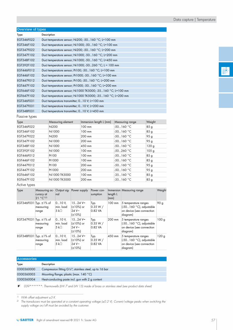
Overview of types
Type Description
EGT346F022 Duct temperature sensor; Ni200; -50...160 °C; L=100 mmEGT346F102 Duct temperature sensor; Ni1000; -50...160 °C; L=100 mmEGT347F022 Duct temperature sensor; Ni200; -50...160 °C; L=200 mmEGT347F102 Duct temperature sensor; Ni1000; -50...160 °C; L=200 mmEGT348F102 Duct temperature sensor; Ni1000; -50...160 °C; L=450 mmEGT392F102 Duct temperature sensor; Ni1000; -50...260 °C; L = 100 mmEGT446F012 Duct temperature sensor; Pt100; -50...160 °C; L=100 mmEGT446F102 Duct temperature sensor; Pt1000; -50...160 °C; L=100 mmEGT447F012 Duct temperature sensor; Pt100; -50...160 °C; L=200 mmEGT447F102 Duct temperature sensor; Pt1000; -50...160 °C; L=200 mmEGT646F102 Duct temperature sensor; Ni1000 TK5000; -35...160 °C; L=100 mmEGT647F102 Duct temperature sensor; Ni1000 TK5000; -35...160 °C; L=200 mmEGT346F031 Duct temperature transmitter; 0...10 V; L=100 mmEGT347F031 Duct temperature transmitter; 0...10 V; L=200 mmEGT348F031 Duct temperature transmitter; 0...10 V; L=450 mm
Passive typesType Measuring element Immersion length L (mm) Measuring range WeightEGT346F022 Ni200 100 mm -50...160 °C 85 gEGT346F102 Ni1000 100 mm -50...160 °C 85 gEGT347F022 Ni200 200 mm -50...160 °C 95 gEGT347F102 Ni1000 200 mm -50...160 °C 95 gEGT348F102 Ni1000 450 mm -50...160 °C 120 gEGT392F102 Ni1000 100 mm -50...260 °C 105 gEGT446F012 Pt100 100 mm -50...160 °C 85 gEGT446F102 Pt1000 100 mm -50...160 °C 85 gEGT447F012 Pt100 200 mm -50...160 °C 95 gEGT447F102 Pt1000 200 mm -50...160 °C 95 gEGT646F102 Ni1000 TK5000 100 mm -35...160 °C 85 gEGT647F102 Ni1000 TK5000 200 mm -35...160 °C 85 g
Active typesType Measuring ac-
curacy at21 °C1)2)
Output sig-nal
Power supply Power con-sumption
Immersionlength L(mm)
Measuring range Weight
EGT346F031 Typ. ±1% ofmeasuringrange
0...10 V,min. load5 kΩ
15...24 V=(±10%) or24 V~(±10%)
Typ.0.35 W /0.82 VA
100 mm 5 temperature ranges(-50...160 °C), adjustableon device (see connectiondiagram)
90 g
EGT347F031 Typ. ±1% ofmeasuringrange
0...10 V,min. load5 kΩ
15...24 V=(±10%) or24 V~(±10%)
Typ.0.35 W /0.82 VA
200 mm 5 temperature ranges(-50...160 °C), adjustableon device (see connectiondiagram)
100 g
EGT348F031 Typ. ±1% ofmeasuringrange
0...10 V,min. load5 kΩ
15...24 V=(±10%) or24 V~(±10%)
Typ.0.35 W /0.82 VA
450 mm 5 temperature ranges(-50...160 °C), adjustableon device (see connectiondiagram)
120 g
Accessories
Type Description
0300360000 Compression fitting G¼"; stainless steel, up to 16 bar0300360003 Mounting flange; plastic (max. 140 °C)0300360004 Heat-conducting paste incl. gun with 2 g content
A 039*******: Thermowells (LW 7 and LW 15) made of brass or stainless steel (see product data sheet)
1) With offset adjustment ±3 K2) The transducers must be operated at a constant operating voltage (±0.2 V). Current/voltage peaks when switching the
supply voltage on/off must be avoided by the customer.
Data capture | Temperature
Right of amendment reserved © 2021 Fr. Sauter AG 57
X

Thermowells
Features
• Fitted in pipes and containers for holding sensor cartridges, immersion stems, temperature sensors,temperature controllers or thermostats
• Made of brass (Ms) or stainless steel (V4A)
• Versions with cylindrical pipe thread (G½" male ISO 228/1, flat-sealing)1) or cone-shaped(R½" ISO 7/1 sealing in thread)
• With pressure spring (LW 15)
• With retaining holder
Overview of types
Type LW Length Material Thread Nominal pres-sure
Test pressure Tmax
0391022050 7 50 mm Stainlesssteel
G½" 40 bar 60 bar 325 °C
0391022100 7 100 mm Stainlesssteel
G½" 40 bar 60 bar 325 °C
0391022200 7 200 mm Stainlesssteel
G½" 40 bar 60 bar 325 °C
0391022300 7 300 mm Stainlesssteel
G½" 40 bar 60 bar 325 °C
0391022450 7 450 mm Stainlesssteel
G½" 40 bar 60 bar 325 °C
0391022600 7 600 mm Stainlesssteel
G½" 40 bar 60 bar 325 °C
0391011050 7 50 mm Brass R½" 10 bar 16 bar 160 °C0391011100 7 100 mm Brass R½" 10 bar 16 bar 160 °C0391011150 7 150 mm Brass R½" 10 bar 16 bar 160 °C0391011200 7 200 mm Brass R½" 10 bar 16 bar 160 °C0391011300 7 300 mm Brass R½" 10 bar 16 bar 160 °C0391011450 7 450 mm Brass R½" 10 bar 16 bar 160 °C0393022100 15 100 mm Stainless
steelG½" 40 bar 60 bar 450 °C
0393022200 15 200 mm Stainlesssteel
G½" 40 bar 60 bar 450 °C
0393022450 15 450 mm Stainlesssteel
G½" 40 bar 60 bar 450 °C
0393012100 15 100 mm Brass G½" 16 bar 25 bar 160 °C0393012200 15 200 mm Brass G½" 16 bar 25 bar 160 °C0392022100 7 100 mm Stainless
steelG½" 25 bar 40 bar 450 °C
0392022300 7 300 mm Stainlesssteel
G½" 25 bar 40 bar 450 °C
1) G½" male ISO 228/1, flat-sealing: for welding bushings with flat seal (accessories)
Data capture | Temperature
58 Right of amendment reserved © 2021 Fr. Sauter AG
X

A 0392022100 and 0392022300 for TUC thermostats only
A With TUC407F001 and TUC207F003, only use the supplied thermowells or stainless-steel thermowells (part nos.:0393022*** or 0392022***).
A 0391... with pressure screw (retaining holder) up to max. 200°C
Accessories
Type Description
0300360008 Retaining holder for cable temperature sensor or capillary tube with 0392022*** (LW 7) or LW15 (10 pcs)
0364263000 Welding sleeve of steel, with female thread G½", flat seal of copper0300360017 Pressure spring for LW 15 (10 pieces)
LW 7, 50 mm• •
L > 50 mm−
LW 7, 100 mm • • −LW 7, 150 mm • • −LW 7, 200 mm • • −
LW 7, 300 mm• •
L > 300 mm−
LW 7, 450 mm • • −LW 7, 600 mm • − −LW 15, 100 mm • − •LW 15, 200 mm • − •LW 15, 450 mm • − •0392022100 − − •0392022300 − − •
A 0392022100 and 0392022300 for TUC thermostats only.
A With TUC407F001 and TUC207F003, only use the supplied thermowells or stainless-steel thermowells (part nos.:0393022*** or 0392022***).
A Only use the thermowells (LW 15) with at least 2 sensors or thermostats with a diameter of at least 6 mm.
A 0391... with pressure screw (retaining holder) up to max. 200°C.
Data capture | Temperature
Right of amendment reserved © 2021 Fr. Sauter AG 59
X

EGT 311, 411, 611: Clamp-on temperature sensor
Features
• Passive or active measuring element
• Extra protection against dust and humidity (IP65)
• Temperature measurement on pipes
• Including retaining strap for pipes of Ø 10...50 mm
• Heat-conducting paste (silicone-free) is included in the scope of delivery
Technical data
Parameters
Recommended measurement current Typ. < 1 mATime characteristic with heat-conducting paste
Time constant 16 s
Ambient conditions
Storage and transport temperature -35...70 °CHumidity (non-condensing) 85% rh
Construction
Housing Yellow/blackHousing material PolyamideConnection terminals Screw terminals 0.35...1.5 mm2,
for number of poles, see connection di-agram
Cable inlet M16 for cable min. Ø 5 mm, max. Ø 8 mm
Standards and directives
Type of protection IP65 (EN 60529)CE conformity according to RoHS Directive 2011/65/EU EN 50581
EMC Directive 2014/30/EU EGT311F031:EN 60730-1 (mode of operation 1,residential premises)
Resistance values / characteristics
/ The tolerance listed below applies only to the corresponding measuring element. The accuracy of the sensor dependson the cable length and the measuring element used.
Measuring element Standards Nominal value Tolerance at 0 °CNi1000 DIN 43760 1000 Ω at 0 °C ±0.4 KNi1000 TK5000 1000 Ω at 0 °C ±0.4 KNi200 DIN 43760 200 Ω at 0 °C ±0.4 KPt1000 DIN EN 60751 1000 Ω at 0 °C ±0.3 K
Overview of types
Type Description
EGT311F022 Clamp-on temperature sensor; Ni200EGT311F102 Clamp-on temperature sensor; Ni1000EGT411F102 Clamp-on temperature sensor; Pt1000EGT611F102 Clamp-on temperature sensor; Ni1000 TK5000EGT311F031 Clamp-on temperature transmitter; 0...10 V
Passive typesType Measuring element Measuring range WeightEGT311F022 Ni200 -35...90 °C 80 gEGT311F102 Ni1000 -35...90 °C 80 g
Data capture | Temperature
60 Right of amendment reserved © 2021 Fr. Sauter AG
EGT*11F***X

Type Measuring element Measuring range WeightEGT411F102 Pt1000 -35...90 °C 80 gEGT611F102 Ni1000 TK5000 -35...90 °C 80 g
Active typesType Measuring accu-
racy at 21 °COutput signal Supply voltage Power con-
sumptionMeasuring range Weight
EGT311F031 Typ. ±1% ofmeasuringrange1)2)
0...10 V, min.load impe-dance 5 kΩ
15...24 V=(±10%)
24 V~ (±10%)
Max.0.42 W /0.84 VA
5 temperature ranges(-50...160 °C), adjustableon device (see connection di-agram)
120 g
Accessories
Type Description
0300360002 Retaining strap 900 mm and heat-conducting paste0300360004 Heat-conducting paste incl. gun with 2 g content
1) With offset adjustment ±3 K2) The transducers must be operated at a constant operating voltage (±0.2 V). Current/voltage peaks when switching the
supply voltage on/off must be avoided by the customer.
Data capture | Temperature
Right of amendment reserved © 2021 Fr. Sauter AG 61
X

EGS 100: Radiation temperature sensor
Features
• Mean value measuring of radiation temperature and room temperature
• Ni or NTC characteristic
• Passive measuring element
• Measuring range: -35…70 °C
• Measuring element: Thin-film sensor
Technical data
Parameters
Measuring range -35...70 °CTime characteristic Time constant in still air 15 min
Construction
Weight 0.1 kgDimensions 84.5 × 84.5 mmHousing Pure white, similar to RAL 9010Housing material Thermoplastic with black hemisphereConnection terminals 2 × 1.5 mm²
Standards and directives
Type of protection IP30 (EN 60529)RoHS Directive 2011/65/EU EN 50581
CE conformity EMC Directive 2014/30/EU EN 60730-1 (mode of operation 1,residential premises)
Overview of types
Type Resistance values Tolerance Measuring elements
EGS100F705 1 kΩ (at 0 °C) ±0.4 K (at 0 °C) 2 × Ni500 as per DIN 43760in series
EGS100F706 10 kΩ (at 25 °C) ±1% (at 25 °C) 2 × NTC 5 kΩ in seriesEGS100F707 22 kΩ (at 25 °C) ±1% (at 25 °C) 2 × NTC 11 kΩ in series
Data capture | Temperature
62 Right of amendment reserved © 2021 Fr. Sauter AG
EGS100F70*
X

Air quality sensors
Air quality is of the utmost importance for the performance and well-being ofpeople in closed rooms. With CO2 and VOC sensors from SAUTER, it is
possible to measure air quality exactly, so that ventilation systems can becontrolled in accordance with demand. As a result, not only is the indoor airquality improved, but energy consumption is also reduced by improving theoperational efficiency of ventilation systems.
Overview of air quality sensors
Type designation EGQ 220, 222 EGQ 120 EGQ 281Application
Room, surface-mounted • • −Room, recessed − − •Duct − − −Variables
CO2 • − •
VOC − • −Temperature • − −Humidity − − −Pressure − − −Further information Page 69 Page 66 Page 70
Type designation EGQ 212 EGQ 110 CRP 510Application
Room, surface-mounted − − −Room, recessed − − •Duct • • −Variables
CO2 • − −
VOC − • −Temperature • − •Humidity − − •Pressure − − •Volume flow − − −Further information Page 67 Page 64 Page 71
Right of amendment reserved © 2021 Fr. Sauter AG 63

EGQ 110: Duct transducer, air quality (VOC)
Features
• Measures the relative mixed gas concentration (organic components in the room air), such as tobaccosmoke, kitchen vapours or human body odours
• Demand-based ventilation control in buildings such as restaurants and offices
• For measuring air quality in air ducts
• Automatic self-calibration through software algorithm
• Calibrated ex works and ready to use immediately
• The sensors have been developed according to the DIN EN 13779, DIN EN 15251, VDI 6038 and6040 directives
• Mounting flange supplied
Technical data
Power supply
Power supply 15...24 V= (±10%) or 24 V~ (±10%)Power consumption Max. 1.5 W (24 V=) | 2.9 VA
(24 V~)Peak inrush current 10 A < 2 ms
Outputs
Output signal 0...10 V Min. load: 10 kΩ
Parameters
Flow speed Min. 3 m/sMax. 10 m/s
Readiness for operation < 2 minutes (operational),15 minutes (max. precision)
Time characteristic In moving air (3 m/s) 5 minutesMeasuring range 0...100%Serviceable life Typically 10 yearsSensor VOC sensor, heated tin dioxide semi-
conductor
Ambient conditions
Ambient temperature 0...50 °CAmbient humidity Max. 85% rh non-condensing
Construction
Connection terminals Clamp connector 1.5 mm2
Cable inlet M20 for cable Ø min. 5 mm, max. 10 mm
Housing Yellow/blackHousing material Polyamide 6Filter unit material Stainless steel, wire meshSensor tube diameter 19.5 mmSensor tube length 180 mmWeight 350 g
Standards and directives
Type of protection Instrument head: IP65 (EN 60529)CE conformity according to EMC Directive 2014/30/EU EN 60730-1 (mode of operation 1,
residential premises)RoHS Directive 2011/65/EU EN 50581
Data capture | Air quality
64 Right of amendment reserved © 2021 Fr. Sauter AG
EGQ110F031
X

Overview of types
Type Features
EGQ110F031 Duct transducer; VOC; 0-10 V
Data capture | Air quality
Right of amendment reserved © 2021 Fr. Sauter AG 65
X

EGQ 120: Room transducer, air quality, surface-mounted
Features
• Measures the relative mixed gas concentration (organic components in the room air), such as tobaccosmoke, kitchen vapours or human body odours
• Demand-based ventilation control in buildings such as restaurants and offices
• Active VOC semi-conductor sensor (volatile organic compound) for measuring the mixed gas concentration
• Calibration of the output signal using a trim potentiometer
• Suitable for fitting directly to walls
Technical data
Power supply
Power supply 24 V=/~ ±10%Power consumption 1.2 W / 2.2 VAWarming-up time Approx. 30 minutes
Parameters
Time constant in moving air (0.5 m/s) Approx. 100 seconds
Ambient conditions
Ambient temperature -20...50°CAmbient humidity Max. 85% rh, no condensation
Inputs/outputs
Output signal 0...10 V, min. load 10 kΩ
Construction
Housing Pure whiteHousing material ABS, ASAConnection terminals Screw terminal, max. 1.5 mm2
Weight 65 g
Standards and directives
Type of protection IP30 (EN 60529)CE conformity according to EMC Directive 2014/30/EU EN 60730-1 (mode of operation 1,
residential premises)
Overview of types
Type Description
EGQ120F031 Room transducer, air quality, surface-mounted
Data capture | Air quality
66 Right of amendment reserved © 2021 Fr. Sauter AG
EGQ120F031
X

EGQ 212: Duct transducer, CO2 and temperature
Features
• Selective measurement of the CO2 concentration and temperature for demand-controlled ventilation ofrooms (e.g. meeting rooms, conference rooms, offices, classrooms, etc.)
• CO2 measurement with NDIR1) Dual-beam technology, therefore stable in the long term and largelyresistant to external influences
• Suitable for 24-hour operation
• Calibrated ex works and ready to use immediately
• The sensors have been developed according to the DIN EN 13779, DIN EN 15251, VDI 6038 and6040 directives
• Mounting flange supplied
Technical data
Power supply
Power supply 15...24 V= (±10%) or 24 V~ (±10%)Power consumption Max. 1.5 W (24 V=) | 2.9 VA
(24 V~)Peak inrush current 10 A, 2 ms
Outputs
Output signal 2 × 0...10 V, load > 10 kΩ
Parameters
Readiness for operation < 2 minutes (operational), 15 minutes(max. precision)
Flow speed Min. 3 m/sMax. 10 m/s
Time characteristic In moving air (3 m/s) 5 minutesCO2 Measuring range 0...2000 ppm
Measuring accuracy ±75 ppm, >750 ppm:±10% (typ. at21 °C)
Pressure dependence Typ.0.135% of the measured value permm Hg
Temperature dependence Typ.2 ppm per °C (0...50 °C)Gradual drift < 5% FS or < 10% per year
Temperature Measuring range 0...50 °CMeasuring accuracy ±1 °C for the measuring range (typ.
21 °C and 24 V=)
Ambient conditions
Ambient temperature 0...50 °CAmbient humidity Max. 85% rh non-condensing
Construction
Connection terminals Plug-in connector, max. 1.5 mm2
Cable inlet M20 for cable Ø min. 5 mm, max. 10 mm
Housing Yellow/blackHousing material PA6Filter unit material Stainless steel, wire meshSensor tube diameter 19.5 mmSensor tube length 180 mmWeight 180 g
Standards and directives
Type of protection Instrument head: IP65 (EN 60529)
1) NDIR: Non-dispersive infrared sensor
Data capture | Air quality
Right of amendment reserved © 2021 Fr. Sauter AG 67
EGQ212F031
X

CE conformity according to EMC Directive 2014/30/EU EN 60730-1 (mode of operation 1,residential premises)
RoHS Directive 2011/65/EU EN 50581
Overview of types
Type Description
EGQ212F031 Duct transducer, CO2 and temperature; 2 x 0-10 V
Data capture | Air quality
68 Right of amendment reserved © 2021 Fr. Sauter AG
X

EGQ 220, 222: Room transducer, CO2, surface-mounted
• Selective measurement of the CO2 concentration for demand-controlled ventilation of rooms (e.g. meetingrooms, conference rooms, offices, classrooms, etc.)
• Available in 2 versions: With and without temperature measurement
• CO2 measurement with NDIR1) Dual-beam technology, therefore stable in the long term and largelyresistant to external influences
• Suitable for 24-hour operation
• Calibrated ex works and ready to use immediately
• Very fast response to changes in the CO2 concentration in rooms
• Temperature-compensated calibration for the standard air pressure of 1013 mbar
• The sensors have been developed according to the DIN EN 13779, DIN EN 15251, VDI 6038 and6040 directives
Technical data
Power supply
Power supply 15...24 V= (±10%) or 24 V~ (±10%)Power consumption Max. 3 W (24 V=) | 6 VA (24 V~)Peak inrush current 10 A, 2 ms
Parameters
Time characteristic In room (0.1 m/s) 2 minutesCO2 Measuring range
Measuring accuracyPressure dependence Typ.0.135% of the measured value per
mm HgTemperature dependence Typ.2 ppm per °C (0...50 °C)Gradual drift2) < 5% FS or < 10% per year
Temperature (EGQ 222) Measuring range 0...50 °CMeasuring accuracy ±1% of measuring range (typ. at
21 °C)
Ambient conditions
Ambient temperature 0...50 °CAmbient humidity Max. 85% rh non-condensing
Construction
Connection terminals Screw terminal, max. 1.5 mm2
Cable inlet From behind, top, bottomHousing Pure whiteHousing material ASAWeight 90 g
Standards and directives
Type of protection IP30 according to EN 60529CE conformity according to EMC Directive 2014/30/EU EN 60730-1 (mode of operation 1,
residential premises)RoHS Directive 2011/65/EU EN 50581
Overview of types
Type Description Readiness for operation Output signal
EGQ220F031 Room transducer, surface-moun-ted, CO2; 0-10 V
< 2 minutes (operational), < 15minutes (response time)
1 x 0...10 V, load ≥ 10 kΩ
EGQ222F031 Room transducer, surface-moun-ted, CO2 + temp; 2 x 0-10 V
< 2 minutes (operational), 15minutes (response time)
2 x 0...10 V, load ≥ 10 kΩ
1) NDIR: Non-dispersive infrared sensor2) Air flow speed 0,15 m/s, air flow direction, laminar from below upwards.
Data capture | Air quality
Right of amendment reserved © 2021 Fr. Sauter AG 69
EGQ220F031
EGQ222F031
X

EGQ 281: Room transducer, CO2, recessed
Features
• CO2 sensor for continuous measurement of the CO2 concentration for the demand-controlled ventilation ofrooms (e.g. meeting rooms, conference rooms, offices, classrooms, etc.)
• CO2 measurement with NDIR dual-beam technology1), therefore stable in the long term and resistant toexternal influences
• Any ageing or contaminating effects are continuously compensated in real time
• Very fast response to changes in the CO2 concentration in rooms
• Temperature-compensated calibration for the standard air pressure of 1013 mbar
• Calibrated ex works and ready to use immediately
• Low energy requirement of the ventilation system during the warming up time of the sensor
• Including frame
Technical data
Power supply
Power supply (SELV) 15...24 V= (±10%) / 24 V~ (±10%)Power consumption < 1.6 W (typ. 0.3 W)
< 3.9 VA (typ. 0.7 VA)
Output signal
Analogue output 0...10 VLoad current Max. 10 mA
Parameters
Measuring range 0...2000 ppmMeasuring accuracy < ±50 ppm 2% of the measured value
(25 °C and 1013 mbar)Time constant < 195 s (t90)Measuring cycle 15 sLong-term stability Typ.20 ppm/year
Ambient conditions
Ambient temperature -20...70 °C
Construction
Housing Pure whiteHousing material Lower section: PA6
Front plate: PCFrame design Gira E2Weight 90 g
Standards and directives
Type of protection IP30 (EN 60529)CE conformity according to EMC Directive 2014/30/EU EN 60730-1 (mode of operation 1,
residential premises)RoHS Directive 2011/65/EU EN 50581
Overview of types
Type Description
EGQ281F031 Room transducer, CO2; 0...10 V, recessed
1) NDIR: Non-dispersive infrared sensor
Data capture | Air quality
70 Right of amendment reserved © 2021 Fr. Sauter AG
EGQ281F031
X

CRP 510: Cleanroom Monitoring Panel
Features
• Clean room panel for data capture of temperature, pressure, humidity in clean rooms and safetylaboratories as per EN ISO 14644-1, class 1-9 and GMP, class A-D
• Integration via serial RS-485 interface with SLC protocol or 0...10 V signals
• Notification via acoustic alarm and background colour of display
• Ports for zero adjustment of pressure sensor
• Convenient operation and actual value indication via touch display
• USB port for convenient data transfer and configuration
• Very precise temperature and humidity sensor
• Dual-membrane pressure sensor with calibrating valve
• Freely configurable inputs and outputs and display tiles
• Surface resistant to chemicals
• Quick display of measured values with alarm thresholds
• User management
Technical data
Power supply
Power supply 24 V~ ± 20%, 50...60 Hz24 V= ± 20%
Power consumption 15 VA / 8 WStart-up current 700 mA
Temperature
Measuring range -40...100 °CAccuracy ± 0.5 °C at 23 °CStability < 0.04 °C/p.a.
Humidity
Measuring range 0...100% rhAccuracy < 2% rh at 10...90% rhStability < 0.3% rh/p.a. at 10...90% rh
Pressure
Measuring range ∆p (gain = 1) -75...75 PaLinearity error 2% FSTime constant 0.1 sReproducibility 0.2% FSZero point stability 0.2% FS at 20 °CAdmissible positive pressure ± 10 kPaAdmissible operating pressure pstat ± 3 kPa
Touch colour display, LCD
Size of display 3.5"Type TN TFTResolution 320 x 240 pixelsTouch Resistive
Ambient conditions
Ambient temperature 0...50 °CAmbient humidity 10...90% rhStorage and transport temperature −10...70 °CEnvironment For use in all clean room classes as per
EN ISO 14611-1 and EU GMP guide-lines
Data capture | Air quality
Right of amendment reserved © 2021 Fr. Sauter AG 71
CRP510F010D
X

Inputs/outputs
Analogue inputs 0...10 VAnalogue outputs 0...10 V, 20 mA
Inputs/outputs in combination with ecos500/504/505
Ni1000/Pt1000 -20...100 °CDigital outputs Relay normally-open contact
230 V~/5 A (total max. 10 A)Analogue outputs 0...10 V, 2 mA
Function
Horn Acoustic, integrated into back
Interfaces and communication
Interface RS-485Protocol SLC (SAUTER Local Communication)
Construction
Weight 3.1 kgDimensions W x H x D 700 × 200 × 49 mmConnections Terminals/plugsPanel fitting 6 × hexagon socket screws, M4Fitting cut-out Min. H: 480 (+2) mm
Min. B: 138 (+2) mmFront panel material V2A
Standards and directives
Type of protection IP67 (front, when built-in)IP20 (back cover)
Protection class II (EN 60730-1)CE conformity according to EMC Directive 2014/30/EU EN 61000-6-1, EN 61000-6-3
Low-Voltage Directive 2014/35/EU EN 60730-1
Overview of types
Type Description
CRP510F010D Clean room panel with integrated pressure, temperature and humidity sensor (rel.)CRP510F001D Clean room panel with integrated pressure sensor
Accessories
Type Description
0297867001 Reference pressure container
Data capture | Air quality
72 Right of amendment reserved © 2021 Fr. Sauter AG
X

Humidity sensors
SAUTER humidity sensors are used for the energy-efficient control andmonitoring of ventilation systems. Sensors are available for measuring therelative humidity and enthalpy of the air. They can be used in residential orbusiness premises and can also be fitted in air ducts.
Overview of humidity sensors
Type designation EGH 120, 130 EGH 681 EGH 110...112 EGE 112 EGH 102Application
Room, surface-mounted • − − − −Room, recessed − • − − −Duct − − • • −Clamp-on sensor − − − − •Measurement
Temperature • • • • −Relative humidity • • • − −Enthalpy − − − • −Dew point − − − − •Further information Page 78 Page 79 Page 77 Page 76 Page 74
Right of amendment reserved © 2021 Fr. Sauter AG 73

EGH 102: Dew point monitor and transducer
Features
• Protects against dew formation on chilled ceilings
• Controls a regulating unit via a holding relay that interrupts the cooling water flow or increases the coolingwater temperature
• Best solution for monitoring chilled-ceiling systems
• Measurement taken by a spring-mounted dew point sensor
• Active measuring element
• Variant with external sensor (EGH102F101)
• Holding relay with changeover contacts
• Includes retaining strap for pipes of Ø 10...100 mm and heat-conducting paste
Technical data
Power supply
Power supply 24 V~/=, ±20%Power consumption Max. 1 VA
Parameters
Measuring range 70...85% rhChangeover contact1) 1 A, 24 V~/=Response time in still air 80 to 99% rh,
99 to 80% rh, max. 3 minutesExposure to dew Max. 30 minSwitching difference Fixed, approx. 5% rhSwitching point 95 ±4% rh
Ambient conditions
Ambient temperature 5...60 °C
Inputs/outputs
Output signal Approx. 70...85% rh, 0...10 V,load > 10 kΩ
Construction
Screw terminals For electrical cables of up to 1.5 mm²Housing Pure white (RAL 9010)Housing material Fire-retardant thermoplasticWeight 0.1 kgCable inlet For Pg 11
Standards and directives
Type of protection IP40 (EN 60529)Mode of operation Type 1 C (EN 60730)
Overview of types
Type Clamp-on sensor
EGH102F001 Integrated in housingEGH102F101 Cable 1 m long, sensor integrated in the cable end
1) When activating relays, gates etc. with cos φ < 0.3, it is recommended to use RC circuitry in parallel to the coil. Thisreduces contact pitting and prevents high-frequency interference
Data capture | Humidity
74 Right of amendment reserved © 2021 Fr. Sauter AG
EGH102F*01
XS
d
6 5
4
95
%rh
X

EGH 103: Dew point monitor
Features
• Protects against dew formation on chilled ceilings, etc.
• Controls a regulating unit via a holding relay that interrupts the cooling water flow or increases the coolingwater temperature.
• Measurement is performed by a dew point sensor
• Potential-free output contact for 24 V and 230 V
• Holding relay with changeover contacts
• LED indicator for power supply and dew formation
• Plug-in connectors for electrical cables up to 1.5 mm2
• Cable inlet M20
• Fitted onto pipes using the provided cable tie for pipes Ø 10...40 mm
Technical data
Power supply
Power supply 230 V~ ±10%Power consumption Max. 3.5 VA
Parameters
Changeover contact1) 5 A, 230 V~Switching point 95 ±4% rhSwitching difference Fixed, approx. 5% rh
Ambient conditions
Ambient temperature −20…60 °C (non-condensing)
Construction
Housing Pure white, PA6Weight 0.19 kg
Standards and directives
Type of protection IP 65 (EN 60529)CE conformity according to EMC Directive 2014/30/EU EN 60730-1 (mode of operation 1,
residential premises)Low-Voltage Directive 2014/35/EU EN 61000-6-1, EN 61000-6-3
Overview of types
Type Description
EGH103F001 Dew point monitor 230 V~
Accessories
Type Description
0300360004 Heat-conducting paste incl. gun with 2 g content
1) When activating relays, gates, etc. with cos φ < 0.3, it is recommended to use RC circuitry in parallel to the coil. Thisreduces contact pitting and prevents high-frequency interference
Data capture | Humidity
Right of amendment reserved © 2021 Fr. Sauter AG 75
EGH103F001
X

EGE 112: Duct transducer, enthalpy
Features
• Measures the enthalpy and temperature in air ducts
• Measurement by means of fast capacitive measuring element
• Active measuring element
• Unaffected by flow speeds and normal contamination
• Mounting flange supplied
Technical data
Power supply
Power supply 15...24 V= (±10%) or 24 V~ (±10%)Power consumption Max. 0.4 W (24 V=) | 0.8 VA
(24 V~)
Outputs
Output signal 2 x 0...10 V (min. load 10 kΩ)
Parameters
Flow speed Min. 3 m/sMax. 10 m/s
Time characteristic Time constant in moving air (3 m/s) 3 minutesEnthalpy Measuring range 0...100 kJ/kg
Measuring accuracy 3.5 kJ/kg (typ. at 21 °C)Temperature Measuring range -20...80 °C
Measuring accuracy ±0.5 °C (typ. at 25 °C)
Ambient conditions
Ambient temperature -20...70 °C
Construction
Connection terminals Screw terminal, max. 1.5 mm2
Cable inlet M20 for cable Ø min. 5.8 mm, max.10 mm
Housing Yellow/blackHousing material PA6Filter unit material Stainless steel, wire meshSensor tube diameter 19.5 mmSensor tube length 140 mmWeight 120 g
Standards and directives
Type of protection Instrument head: IP65 (EN 60529)CE conformity according to EMC Directive 2014/30/EU EN 60730-1 (mode of operation 1,
residential premises)RoHS Directive 2011/65/EU EN 50581
Overview of types
Type Description
EGE112F031 Duct transducer, enthalpy and temperature, 2 x 0-10 V
Data capture | Humidity
76 Right of amendment reserved © 2021 Fr. Sauter AG
EGE112F031
h
X

EGH 110...112: Duct transducer, relative humidity andtemperature
Features
• Measures the relative humidity and temperature in air ducts
• Measurement by means of fast capacitive measuring element
• Active and passive measuring element
• Immersion depth 140 mm
• Mounting flange supplied
Technical data
Power supply
Power supply 15...24 V= (±10%) or 24 V~ (±10%)Peak inrush current 1.5 A, 4 ms
Parameters
Humidity Measuring range, humidity 0...100% rh, no condensationMeasuring accuracy, humidity Typ. ±2% (10...90% rh)Repeat accuracy Typ. ±0.1% rhGradual drift Typ. < 0.5% rh/year
Temperature Measuring range, temperature -20...80 °CMeasuring accuracy, temperature ±0.5 °C (typ. at 25 °C)Repeat accuracy Typ. ±0.1 °CGradual drift Typ. < 0.04 °C/year
Time characteristic In moving air (3 m/s) 2 minutes (t63)Readiness for operation 10 seconds (operational), 5 minutes
(max. precision)Flow speed Min: 0 m/s
Max: 10 m/sHysteresis ±1%
Ambient conditions
Ambient temperature -20...70 C
Construction
Connection terminals Screw terminals, max. 1.5 mm2
Cable inlet M20 for cable with min. Ø 5 mm,max. Ø 10 mm
Housing Yellow/blackHousing material PA6Filter unit material Stainless steel, wire meshSensor tube diameter 19.5 mmSensor tube length 140 mmWeight 120 g
Standards and directives
Type of protection Instrument head: IP65 (EN 60529)CE conformity according to EMC Directive 2014/30/EU EN 60730-1 (mode of operation 1,
residential premises)RoHS Directive 2011/65/EU EN 50581
Overview of types
Type Power consumption Output signal
EGH110F041 Max. 1 W (24 V=) 2 × 4...20 mA (max. load 500 Ω)EGH111F031 Max. 0.4 W (24 V=) | 0.8 VA (24 V~) 2 × 0...10 V (min. load 10 kΩ) + Ni1000EGH112F031 Max. 0.4 W (24 V=) | 0.8 VA (24 V~) 2 × 0...10 V (min. load 10 kΩ)
Data capture | Humidity
Right of amendment reserved © 2021 Fr. Sauter AG 77
EGH11*F0*1
X

EGH 120, 130: Room transducer, relative humidity andtemperature
Features
• Measurement by means of fast capacitive sensor
• Active measuring element
• Suitable for fitting directly to walls
• Converts the measured values into a continuous analogue signal (0...10 V or 4...20 mA)
Technical data
Power supply
Power supply 15...24 V= (±10%) or 24 V~ (±10%)
Parameters
Relative humidity Measuring range 0...100% rh, no condensationMeasuring accuracy ±2% between 10...90% rh (typ. at
21 °C)Temperature Measuring range 0...50 °C
Measuring accuracy ±0.5 °C (typ. at 25 °C)
Ambient conditions
Ambient temperature -20...70 °C
Construction
Housing material ASAHousing Pure whiteConnection terminals Screw terminals, max. 1.5 mm2
Weight 80 g
Standards and directives
Type of protection IP30 (EN 60529)CE conformity according to EMC Directive 2014/30/EU EN 60730-1 (mode of operation 1,
residential premises)RoHS Directive 2011/65/EU EN 50581
Overview of types
Type Output signal Power consumption
EGH120F041 2 x 4...20 mA Max. 1 W (24 V=)EGH130F031 2 x 0...10 V Max. 0.3 W (24 V=) | 0.5 VA (24 V~)
Data capture | Humidity
78 Right of amendment reserved © 2021 Fr. Sauter AG
EGH1*0F0*1
X

EGH 681: Room transducer, relative humidity andtemperature, recessed
Features
• Measures the relative humidity and temperature in rooms
• Regulation of the room climate in combination with room automation systems
• Fast response time and high precision
• Including frame
Technical data
Power supply
Power supply 15...24 V= (±10%) or 24 V~ (±10%)Power consumption Typ.0.3 W / 0.5 VA
Output signal
Output signal 0...10 V, load resistance at least 10 kΩ
Parameters
Measuring range, temperature 0...50° CMeasuring range, humidity 0...100% rh
Ambient conditions
Ambient temperature -20...70 °C
Construction
Housing Pure whiteHousing material Lower section: ABS
Front plate: PCFrame design Gira E2Weight 80 g
Standards and directives
Type of protection IP30 (EN 60529)CE conformity according to RoHS Directive 2011/65/EU EN 50581
EMC Directive 2014/30/EU EN 60730-1 (mode of operation 1,residential premises)
Overview of types
Type Description
EGH681F031 Room transducer, relative humidity and temperature, recessed
Data capture | Humidity
Right of amendment reserved © 2021 Fr. Sauter AG 79
EGH681F031
X

Flow and pressure sensors
SAUTER flow and pressure sensors enable the accurate measurement of airpressures and flow speeds in rooms and ventilation ducts. This includes themeasurement of duct pressures for precise control and monitoring of ventilationsystems. Additionally, SAUTER flow and pressure sensors can also be used tomeasure room pressures in laboratories and clean rooms and for flowmonitoring in fume cupboards.
Overview of flow and pressure sensors
Type designation EGP 100 XAFP 100 SVU 100 DSU, DSI DSDU, DSDI SGU 100Variable ∆p ∆p m/s ∆p ∆p mmApplication
Duct • • − − − −Laboratories & clean rooms • • − − − −Fume cupboards • • • − − •Pressure monitoring in liquids, gases and va-pours
− − − • • −
Travel measurement − − − − − •Further information Page 81 Page 83 Page 84 Page 85 Page 87 Page 89
80 Right of amendment reserved © 2021 Fr. Sauter AG

EGP 100: Differential pressure transducer
Features
• Exact measurement of positive, negative and differential pressures in gases
• Optimised for applications such as filter monitoring, room or duct pressure monitoring, level monitoring influids, actuating frequency converters for fan control and recording volume flow, especially for room airbalancing in laboratories
• Can be ideally combined with XAFP 100 flow probe for precise measurement of volume flow
• Static pressure sensor
• Can be fitted in any position
• Can be used for dusty air or air polluted with chemicals (not ATEX approved)
• Manufacturer’s test certificate ex works
• The measuring range can be adapted optimally to the needs of the application
• Variable zero point and filter time constant to suppress pressure surges in the system
• Display shows the actual value and the signal progression (depending on type)
• Status LED for immediate indication of operating status (depending on type)
• Measuring range can be reduced to one third (depending on type)
• Fitted to either wall or DIN rail (EN 60715)
• Cover that does not require special tools to open
Technical data
Power supply
Power supply 24 V~/=, ±20%Power consumption F**2 24 V~ 3.0 VA
24 V= 1.3 WPower consumption F**1 24 V~ 1.4 VA
24 V= 0.4 W
Parameters
Admissible positive pressure ±10 kPaInfluence of position1) ±1% full span (FS) at 150 Pa, ±75 Pa,
±0,75% FS at 300 Pa, ±150 PaNon-linearity 1% FS pressure-linearZero point stability < 0.3% FSReproducibility 0.2% FSPneumatic connection2) 6.2 mmParts in contact with media PC/ABS blend, MQ, CuSn6, FR4
Ambient conditions
Temperature of medium 0...70 °CAdmissible operating pressure pstat
3) ±3 kPaAmbient temperature 0...60 °CAmbient humidity 5...95% rh, no condensation
Inputs/outputs
Output signal4) F*01: 0...10 V, load > 10 kΩF*02/F*12: 0(2)...10 V,load < 500 Ω
1) The sensor is calibrated at the factory for vertical fitting. The influence of position must be taken into account if the unit isnot fitted in the vertical position.
2) Max. length of measuring wire (di = 6.2 mm): Lmax = 15 m for time constant < 0.5 s, Lmax = 60 m for time constant> 0.5 s
3) The zero point should be recalibrated if the admissible operating pressure is exceeded4) With a load of < 500 Ω, a change-over to 0...20 mA or 4...20 mA occurs automatically. Output protected against
short circuits and excess voltage up to 24 V~
Data capture | Flow and pressure
Right of amendment reserved © 2021 Fr. Sauter AG 81
EGP100F*12
Output signal (sqr)
0 pDDifferential pressureMeasuring range
10 V-
0(2)
Gain p = 1D
Gain p = 3D
X

Filter time constant F*01: 0.05...2 sF*02, F*12: 0.15...5.2 s
Construction
Pressure connection Internal Ø 6 mmHousing PC/ABSCable gland M16Screw terminals For electrical cables of up to 1.5 mm²
Standards and directives
Type of protection IP65 (EN 60529)Protection class III (EN 60730-1)EMC Directive 2014/30/EU EN 61000-6-1, EN 61000-6-2
EN 61000-6-3, EN 61000-6-4
Overview of types
/ Output signal: Analogue output limited to 10.6 V. Measured values with an overrun of 6% of the measuring range cantherefore be transferred
/ Variable characteristic/LED: Manual adjustment of measuring range with gain potentiometer. Signal curve: linear/root-extracted. Output signal: 0...10 V/2...10 V via DIP switches or with CASE Sensors software
Type Measuring range Display Variable characteris-tic/LED
Weight (kg)
EGP100F101 ±75 Pa, ±0,75 mbar − − 0.17EGP100F102 ±75 Pa, ±0,75 mbar − • 0.18EGP100F112 ±75 Pa, ±0,75 mbar • • 0.19EGP100F201 ±150, 1,5 mbar − − 0.17EGP100F202 ±150, 1,5 mbar − • 0.18EGP100F212 ±150, 1,5 mbar • • 0.19EGP100F301 0...150 Pa,
0...1.5 mbar− − 0.17
EGP100F302 0...150 Pa,0...1.5 mbar
− • 0.18
EGP100F312 0...150 Pa,0...1.5 mbar
• • 0.19
EGP100F401 0...300 Pa,0...3.0 mbar
− − 0.17
EGP100F402 0...300 Pa,0...3.0 mbar
− • 0.18
EGP100F412 0...300 Pa,0...3.0 mbar
• • 0.19
EGP100F601 0...1000 Pa,0...10.0 mbar
− − 0.17
EGP100F602 0...1000 Pa,0...10.0 mbar
• • 0.18
EGP100F612 0...300 Pa,0...3.0 mbar
• • 0.19
Accessories
Type Description
0010240300 Connection set, 6 mm, completeXAFP100F001 Flow probe to measure the air volume in ventilation ductsCERTIFICAT001 Manufacturer’s test certificate type MCERTIFICAT999 Test for further device (from 2 pcs.)0300360001 USB-RS-485 converter
Data capture | Flow and pressure
82 Right of amendment reserved © 2021 Fr. Sauter AG
X

XAFP 100: Flow probe for ventilation ducts
Features
• Flow probe for precise and inexpensive recording of differential pressure signals in ventilation and airconditioning systems
• Efficient regulation of applications for demand-controlled ventilation in offices, laboratories, fumecupboards and clean rooms, by combining an air damper and an electronic/pneumatic volume flowcontroller
• In combination with a square root differential pressure sensor, air volume flows can be reliably recordedand monitored
• Optimised flow profile for accurate measurement of differential pressure signals
• Can be used in atmospheres containing aggressive substances
• Length (396 mm) can be shortened on site if necessary
Technical data
Parameters
Measurement tolerance < 3%Range (mm) DN 80…400
Admissible ambient conditions
Operating temperature 0...50 °CAmbient humidity < 85% rh, no condensation
Function
Function Flow probe
Construction
Dimensions 65 × 40 × 396 mm (W × H × L)Bore Ø 30...32 mm
Material Flow probe PA 6Seal PE, physiologically safeConnecting tube PU
Standards and directives
Flow probe Electrical UL 7468Flammability UL 94, IEC 60695-2-12,
IEC 60695-2-13
Overview of types
Type Features
XAFP100F001 Flow probe for ventilation ducts
Data capture | Flow and pressure
Right of amendment reserved © 2021 Fr. Sauter AG 83
XAFP100F001
X

SVU 100: Air-flow transducer
Features
• Precise and long-term stable recording of air inflow speeds in fume cupboards with a time constant of <100ms
• Particularly suitable for fume cupboards with horizontal and vertical front sashes
• Air volume control according to needs for fume cupboards with horizontal and vertical front sashes
• Precise and long-term stable recording of air inflow speeds in fume cupboards
• Reliable detection of reversal of flow direction
• Integrated filter unit that protects against contamination of the sensor
• Dynamic pressure sensor based on thin-film technology
• Fitted to the fume cupboard simply and quickly
Technical data
Power supply
Power supply 24 V~, -15%/+20%, 50...60 HzPower consumption 1 VA
Parameters
Measuring range 0...1 PaMeasuring span1) 0...1.3 m/sDifferential pressure Approx. 0...1 PaTime constant < 0.1 sAir throughput rate 3 cm3/min (at 1 m/s)
Ambient conditions
Ambient temperature 5...55 °CAmbient humidity < 90% rh
Inputs/outputs
Output signal2) 0...10 VLinearity 2% (based on the output signal)
Standards and directives
Type of protection IP40 (EN 60529) with terminal coverCE conformity according to EMC Directive 2014/30/EU EN 61000-6-1, EN 61000-6-3
Overview of types
Type Feature
SVU100F005 Linear to v [m/s]
A Specified flow speed is based on ρ = 1.2 kg/m3
1) Recommended measuring span 0.2...1.3 m/s (output 2...10 V)2) Output signal: Output protected against short circuits and excess voltage up to 24 V~
Data capture | Flow and pressure
84 Right of amendment reserved © 2021 Fr. Sauter AG
SVU100F005
X

DSU, DSI: Pressure transmitter
Features
• For measuring pressure in liquids, gases and vapours
• Sturdy device with ceramic diaphragm
• High precision
• High positive pressure protection
• High vibration resistance
• Low hysteresis
• Standard signal 2...10 V or 4...20 mA
• Pressure sensor made of stainless steel for aggressive media
• With standard plug as per DIN EN 175301-803-A
Technical data
Power supply
Power supply See type listElectrical connection DSI: Two-wire
DSU: Three-wire
Parameters
Temperature dependence Zero point 0.07% FS/KMeasuring range 0.05% FS/K
Admissible load DSU:Ub ≥ 15 V ≥ 5 kΩUb ≥ 20 V ≥ 2 kΩDSI:(Ub-6 V)/0.02 A
Ambient conditions
Ambient temperature 0...60 °CTemperature of medium 0...85 °C
Inputs/outputs
Hysteresis < 0.5% FSLinearity < 1% FS
Construction
Housing material Chromium-nickel steel 1.4305Device plug Plug connection 4-pin, standard plug
DIN EN 175 01-803-A, cable glandM16
Cable cross-section Max. 1.5 mm2
Pressure connection G ½"Weight 0.2 kg
Standards and directives
Type of protection IP65 (EN 60529)Protection class III (EN 61140)
CE conformity according to EMC Directive 2014/30/EU EN 61000-6-1 / EN 61000-6-2EN 61000-6-3 / EN 61000-6-4 EN 60730
PED 2014/68/EU Subject to Art. 3.3 of PED without safe-ty function
Data capture | Flow and pressure
Right of amendment reserved © 2021 Fr. Sauter AG 85
DS*2**F002
X

Overview of types
Type Measuring range(bar)
Output signal Power supply Maximum pressure Power consumption
DSU203F002 0...2.5 bar 0...10 V 24 V=/~ 8 bar 24 V=/~, 0.5 W(VA)
DSU206F002 0...6 bar 0...10 V 24 V=/~ 20 bar 24 V=/~, 0.5 W(VA)
DSU210F002 0...10 bar 0...10 V 24 V=/~ 32 bar 24 V=/~, 0.5 W(VA)
DSU216F002 0...16 bar 0...10 V 24 V=/~ 50 bar 24 V=/~, 0.5 W(VA)
DSU225F002 0...25 bar 0...10 V 24 V=/~ 80 bar 24 V=/~, 0.5 W(VA)
DSI203F002 0...2.5 bar 4...20 mA 24 V= 8 bar 24 V=, 0.7 WDSI206F002 0...6 bar 4...20 mA 24 V= 30 bar 24 V=, 0.7 WDSI210F002 0...10 bar 4...20 mA 24 V= 32 bar 24 V=, 0.7 WDSI216F002 0...16 bar 4...20 mA 24 V= 50 bar 24 V=, 0.7 WDSI225F002 0...25 bar 4...20 mA 24 V= 80 bar 24 V=, 0.7 W
Accessories
Type Description
0300360007 Capillary throttle, stainless steel, length 1 m, G½"-G½"0300360015 Wall holder for DSU/DSI
Data capture | Flow and pressure
86 Right of amendment reserved © 2021 Fr. Sauter AG
X

DSDU, DSDI: Differential pressure transmitter
Features
• For measuring pressure differences in liquids, gases and vapours
• Pressure measuring in non-aggressive fluids or gaseous media
• Sturdy device with ceramic diaphragm
• For use in filter technology, heating systems etc.
• Differential pressure measuring range from 0...6 bar
• Analogue signal 0...10 V or 4...20 mA
• 24 V~/= supply voltage
• With fitting bracket
• Standard plug as per DIN EN 175301-803-A
Technical data
Power supply
Power supply 24 V=/~, ±20%, (50...60 Hz)Electrical connection Three-wirePower consumption < 1.5 W (VA)
Parameters
Output signal 0...10 V Load: > 2 kΩ4...20 mALoad: ≤ 700 Ω (V=), ≤ 400 Ω (V~)
Accuracy1) ≤ 1%
Ambient conditions
Ambient temperature -20...80°CTemperature of medium 0...80°C
(non-freezing media)Ambient humidity 45...75% rhBurst pressure 64 bar (both sides)
Construction
Housing material BrassDiaphragms CeramicConnecting thread G ⅛" (female thread)Device plug Plug connection 4-pin, standard plug
DIN EN 175 01-803-A, cable glandM16
Weight 0.62 kg
Standards and directives
Type of protection IP65 (EN 60529)CE conformity according to EMC Directive 2014/30/EU EN 61326-1, EN 61326-2-3
PED 2014/68/EU Fluid group II, article 4.3
Overview of types
Type Measuring range ∆p Output signal Max. pressure(connection +)
Max. pressure(connection -)
DSDI101F021 0...1 bar 4...20 mA 10 bar 5 barDSDI103F021 0...2.5 bar 4...20 mA 21 bar 15 barDSDI106F021 0...6 bar 4...20 mA 21 bar 15 barDSDU101F021 0...1 bar 0...10 V 10 bar 5 barDSDU103F021 0...2.5 bar 0...10 V 21 bar 15 barDSDU106F021 0...6 bar 0...10 V 21 bar 15 bar
1) Including non-linearity and hysteresis in compensated temperature range 10...70°C
Data capture | Flow and pressure
Right of amendment reserved © 2021 Fr. Sauter AG 87
DSD*10*F021
X

Accessories
Type Description
0300360005 Cutting ring fitting G⅛" to 6 mm pipe (2 pcs)0300360006 Pneumatic fitting G⅛" to 6 mm hose (2 pcs)0300360016 Throttle screws G⅛", G⅛" (2 pcs)
Data capture | Flow and pressure
88 Right of amendment reserved © 2021 Fr. Sauter AG
X

SGU 100: Sash sensor
Features
• Infinitely-variable measurement of the position of the vertical front sash on laboratory fume cupboards
• Accurate detection of sash position, with no wear and tear
• Fast control of the air volume; no oscillation
• Easy fitting, preferably on the counterweight of the front sash
• Teach-in function for adjusting the travel of the front sash
• Easy to program using the SAUTER CASE Sensors software
• Integrated excess-travel alarm
• Power cable 2.5 m long, 7 × 0.32 mm2, fixed to housing
• Fitted with halogen-free cable as standard
• Remote access and remote maintenance: Commissioning and service via bus or external push-button
• 3-colour LED status indicator
• Acoustic status and alarm elements (can be deactivated)
Technical data
Power supply
Power supply 24 V~ ±20%, 50...60 HzPower supply 24 V= ±20%Power consumption 24 V~1) Typically: 2 VA, 0.75 W, inactive buz-
zer,max.: 4 VA, 1.5 W, active buzzer
Power consumption 24 V=2) Typically: 0.6 W, inactive buzzer,max.: 1.1 W, active buzzer
Parameters
Linearity error Max. 1.5% based on working range,e.g.: 2...10 V = 8 V
Hardware response time3) < 100 msFilter time constant 0...5, 22 s, variable using SAUTER
CASE Sensors
Ambient conditions
Operating temperature 0...55 °CStorage and transport temperature –20...70 °CHumidity 85% rh, no condensation
Inputs/outputs
Digital input Iout_source max.: 1 mA,Vout max.: 18 V at Rload = ∞
Alarm output Isink max.: 2 mA, open collector output,100 mV at Isink 2 mA,Vin max.: 24 V=, 20% at Isink = 0 mA
Voltage output4) 0/2...10 V, 1 mA max.,Vout max.: 11.5 V, can be parametr-ised,Default 2...10 V
Typical overall error 2.5% (unlinearity, hysteresis, offset, am-plified; based on working range)
Temperature effect < 0.04 %/K
1) Default is buzzer active2) Inactive/active buzzer: Default is buzzer active3) The set filter time constant must be added4) Protected against short circuits and excess voltage to 24~
Data capture | Flow and pressure
Right of amendment reserved © 2021 Fr. Sauter AG 89
SGU100F01
X

Construction
Weight 0.68 kgLength of cable without bus termina-tion5)
Up to 200 m, Ø 0.5 mm
Standards and directives
Type of protection IP10 (EN 60529, IP20 (EN 60529)Protection class III (EN 60730)Software A (EN 60730)EMC Directive 2014/30/EU EN 61000-6-1, EN 61000-6-2
EN 61000-6-3, EN 61000-6-4
Overview of types
Type Working range Resolution of working stroke
SGU100F010 200…800 mm for bench-mounted fume cup-boards (max. spring travel 1000 mm)
< 1 mm
SGU100F011 400…1600 mm for walk-in fume cupboards(max. spring travel 2000 mm)
< 2 mm
Accessories
Type Description
0300360001 USB-RS-485 converter
5) Cable length of bus termination on both sides 120 Ω: 200...500 m, Ø 0.5 mm
Data capture | Flow and pressure
90 Right of amendment reserved © 2021 Fr. Sauter AG
X

Right of amendment reserved © 2021 Fr. Sauter AG 91

Single-room, heating and air-conditioning controllers
For all building situations: either stand-alone or networked.
SAUTER stand-alone controllers are ideally suited to dedicated applications such as heating, air-conditioning, ventilation, room control. They can be installed quickly. The intuitive operating concept ensures maximum comfort and guarantees, at the same time, the greatest possible energy efficiency in day-to-day operations. SAUTER’s stand-alone controllers meet all the demands with regard to smooth functionality, yet enable the installation to be run economically.
92 Right of amendment reserved © 2021 Fr. Sauter AG

Single-room, heating and air-conditioning con-trollers
Single-room control
Overview of room temperature controllers 94
NRT 300: Electronic air-conditioning controller, equiflex 95
NRT 300: Electronic air-conditioning controller for 6-way ball valve, heat-ing/cooling 97
NRFC 413, 422...424: Modbus fan coil thermostat 99
LRA 650: Room operating unit, temperature and humidity, display 103
LRA 660: Room sensor/room operating unit, temperature and humidity 105
TRA 410, 421: Electronic room thermostat for heating and heating/cool-ing with display 107
TRT 317, 327: Electronic room thermostat for heating and heating/cool-ing 109
LET 62*: Underfloor heating controller, Eco Climate Control 111
FXV 3***: Electrical distributor 114
FXV 33** EasySwitch: Electrical distributor 116
equitherm heating control
Overview of heating controllers 118
EQJW 126: Heating controller, equitherm 119
EQJW 146: Heating and district heating controller, equitherm 121
EQJW 246: Heating and district heating controller, equitherm 124
flexotron controllers for ventilation and air-conditioning
Overview of controllers for ventilation and air-conditioning 127
RDT 405, 410: Electronic controller for heating, cooling and ventilation,flexotron400 128
RDT 808, 815, 828: Communicative controller for universal use, flexo-tron800 130
VAV compact controllers
ASV205BF132*, ASV215BF132*: VAV compact controller 133
ASV2*5BF152*: VAV compact controller for laboratory and pharma-ceutical applications 136
FCCP: Fume cupboard indicator and monitor 139
Right of amendment reserved © 2021 Fr. Sauter AG 93
C

Room temperature controllers
SAUTER single-room controllers combine easy operability with a moderndesign. The devices can be used in various applications on hotel, business orresidential premises. These include individual temperature control for singlerooms, apartments and zones in 2- and 4-pipe systems. The electronic roomcontrollers from SAUTER are efficient, economical and easy to operate.
Overview of room temperature controllers
Type designation NRT300F0*1 NRT300F0*2 NRFC 4Application
Air-conditioning controller • • •Fan-coil controller − − •For 2-pipe installation • − •For 4-pipe installation • • •For 2/3-way zone valve • − −For 6-way ball valve − • −Outputs
Continuous − / • • •Quasi-continuous, 2-point − / • − •3-point − / • − −Relay − − •Control
PI • • •Operation and indicator
Display − − •Presence button • • −Communication
Protocols − − Modbus RTUFurther information Page 95 Page 97 Page 99
94 Right of amendment reserved © 2021 Fr. Sauter AG

NRT 300: Electronic air-conditioning controller,heating/cooling, equiflex
Features
• Air-conditioning controller for 2- and 4-pipe systems (heating, cooling, heating/cooling)
• Measurement of room temperature by either integrated or external temperature sensor
• Saves energy costs by means of presence/absence key and rotary knob on front
• Inputs for C/O signal, changeover between presence and absence, dew-point monitoring and setpoint shift
• Choice of P or PI control with 2-point, pulse-pause, 3-point or outputs (0...10 V)
• LED indicator
• Servicing level with adjustable control parameters
• Frost-protection facility
• Electrical connection in baseplate
• Electronics in attachable housing
Technical data
Power supply
Power supply 24 V~, ±20%, 50...60 HzPower consumption Approx. 2.5 VA
Parameters
Setting range Xs 10...30 °CProportional band 2...20 KIntegral action time 2...20 minutes or OFF (as P-controller)Period or running time of actuator 0.5...20 minutesControl parameters Non-volatile
Dead zone Xt Normal 0,4...5 KExtended 8 K
Sensor time constant for air In room (0.1 m/s) 8 minutesIn duct (0.5 m/s) 3 minutesIn duct (3 m/s) 1 minutes
Ambient conditions
Ambient temperature 0...50 °CAmbient humidity 5...95% rh, no condensation
Inputs/outputs
Command variable w 0...10 V, Ri = 90 kΩInfluence of w 1.6 K/V
Function
Operating mode Sequence (heating/cooling)Change-over functions1) Xt, C/O, TP
Construction
Weight 0.1 kgHousing Pure white (RAL 9010)Housing material Fire-retardant thermoplasticFitting Wall fitting/recessed junction boxCable feed At rearScrew terminals For wire of up to 1 mm²
Standards and directives
Type of protection IP30 (EN 60529)
1) Xt = dead zone ON/OFF; C/O = summer/winter, (changeover); TP = dew point monitoring
Single-room, heating and air-conditioning controllers | Single-room control
Right of amendment reserved © 2021 Fr. Sauter AG 95
NRT300F0*1
NRT300F041
NRT300F061
C

Protection class III (IEC 60730)Energy class I = 1%
as per EU 811/2013, 2010/30/EU,2009/125/EC
CE conformity according to EMC Directive 2014/30/EU EN 60730-1, EN 60730-2-9
Overview of types
Type Output signal Load on outputs
NRT300F041 Switched 0.5 A (0.9 A when external sensor fitted)NRT300F061 Continuous 0...10 V, load > 5 kΩ; with overflow > 11 V
(load-dependent)
A NRT300F061: Suitable as a master controller for max. 10 × NRT 300: (slope S = P-band Xp; shift starting point FF =setpoint Xs; operating mode = sequence)
Accessories
Type Description
AVF*** Motorised valve actuator (see product data sheet)AVM*** Motorised valve actuator (see product data sheet)AXM*** Motorised valve actuator (see product data sheet)AXT2** Thermal actuators for unit valves (see product data sheet)EGH102F001 Dew-point monitor with sensor in housingEGH102F101 Dew-point monitor with sensor on cable0296724000 Sensor holder for wall mounting0368139000 Rubber bung as sensor holder in ventilation duct0303124000 Recessed junction box0313347001 Cover plate, pure white, for 76 × 76 mmEGT353F101 Cable temperature sensor; NTC 10k; -35...100 °C; L = 1.5 mEGT353F103 Cable temperature sensor; NTC 10k; -35...100 °C; L = 3 mEGT353F110 Cable temperature sensor; NTC 10k; -35...100 °C; L = 10mEGT353F120 Cable temperature sensor; NTC 10k; -35...100 °C; L = 20m0386273001 Plug-in power unit, input 230 V~, output 21 V~ (0.34 A), length of cable 1.8 m, IP300313409001 Holder for sensor cartridge in ventilation duct0313501001 Housing with scale 10...30 °C
Single-room, heating and air-conditioning controllers | Single-room control
96 Right of amendment reserved © 2021 Fr. Sauter AG
C

NRT 300: Electronic air-conditioning controller for 6-wayball valve, heating/cooling
Features
• Air-conditioning controller for 4-pipe systems (heating/cooling)
• Measurement of the room temperature either by integrated or external temperature sensor, e.g. inheated/chilled ceilings in hotels and residential and business spaces
• Saves energy costs by means of presence/absence key and rotary knob on front
• Inputs for changeover between presence and absence, dew point monitoring and setpoint shift
• P- /PI control (F063) or PI control (F062)
• LED indicator for presence, heating, cooling and dew point
• Servicing level with adjustable control parameters
• Frost-protection facility
• Electrical connection in baseplate
• Adjustable limiting of the heating volume flow
Technical data
Power supply
Power supply 24 V~, ±20%, 50...60 HzPower consumption Approx. 2.5 VA
Parameters
Setting range Xs 10...30 °CProportional band 2...22 KIntegral action time 2...20 minutes or OFF (as P-controller)Control parameters Non-volatile
Dead zone Xt Normal 0.2...6 KExtended 8 K
Sensor time constant for air In room (0.1 m/s) 8 minutes
Ambient conditions
Ambient temperature 0...50 °CAmbient humidity 5...95% rh, no condensation
Inputs
Setpoint shift w 0...10 V, Ri = 90 kΩDead zone ON/OFFDew point ON/OFF
Function
Operating mode Sequence (heating/cooling)Change-over functions1) Xt, TP
Construction
Weight 0.1 kgHousing Pure white (RAL 9010)Housing material Flame-retardant thermoplasticFitting Wall mounting/recessed junction boxCable feed At rearScrew terminals For electrical cables of up to 1 mm²
Standards and directives
Type of protection IP30 (EN 60529)Protection class III (IEC 60730)
1) Xt = dead zone ON/OFF; TP = dew point monitoring
Single-room, heating and air-conditioning controllers | Single-room control
Right of amendment reserved © 2021 Fr. Sauter AG 97
NRT300F062
NRT300F063
C

Energy class I = 1%as per EU 811/2013, 2010/30/EU,2009/125/EC
CE conformity according to EMC Directive 2014/30/EU EN60730-1 EN60730-2-9
Overview of types
Type Function Output
NRT300F062 Regulation of heating/cooling with 6-way ballvalve
1 x 10 V load > 5 kΩ; with overflow at 11 V(load-dependent)
NRT300F063 Heating/cooling changeover with 6-way ballvalve; control with dynamic regulating valve
1 x 0...10 V load > 5 kΩ; with overflow > 11 V(load-dependent)1 x switching 0.5 A (0.9 A with external sensor)
Accessories
Type Description
AKM115SF132 Rotary actuator with SAUTER Universal Technology (SUT) for ball valve; 24 VAKM115F122 Rotary actuator for ball valve 2-/3-pt; 24 V~AXM*** Motorised valve actuator (see product data sheet)AXS2** Continuous thermal actuators for unit valves (see product data sheet)EGH102F001 Dew-point monitor with sensor in housingEGH102F101 Dew-point monitor with sensor on cable0303124000 Recessed junction box0313214001 Fixing kit for cable temperature sensor (holder, heat-conducting paste, retaining strap)0313347001 Cover plate, pure white, for 76 × 76 mmEGT353F101 Cable temperature sensor; NTC 10k; -35...100 °C; L = 1.5 mEGT353F103 Cable temperature sensor; NTC 10k; -35...100 °C; L = 3 mEGT353F110 Cable temperature sensor; NTC 10k; -35...100 °C; L = 10mEGT353F120 Cable temperature sensor; NTC 10k; -35...100 °C; L = 20m0386273001 Plug-in power unit, input 230 V~, output 21 V~ (0.34 A), length of cable 1.8 m, IP300313501001 Housing with scale 10...30 °C
Single-room, heating and air-conditioning controllers | Single-room control
98 Right of amendment reserved © 2021 Fr. Sauter AG
C

NRFC 413, 422...424: Modbus fan coil thermostat
Features
• Single-room controller for heating and cooling by means of air conditioning units in commercial andresidential buildings
• For 2- or 4-pipe fan coil units, two-stage heating systems or water-bearing heat pumps
• Can be integrated into building management systems via Modbus/RTU
• Large configurable display with backlight
• Integrated on/off timer
• Deactivatable button operation for public installations
• Valve control via 2-point or 0...10 V output
• Supports 3-speed fans or fans with EC motor
• Summer/winter changeover in 2-pipe applications
• Automatic deactivation of internal temperature sensor when using a cable temperature sensor
• Installation via mounting plate without opening the controller
• Universal design and low installation height of 14 mm for inconspicuous fitting
Technical data
Power supply
Power supply 100...240 V~, 50/60 HzPower consumption 5 VA
Ambient conditions
Ambient temperature 0...40 °CAmbient humidity 5...95% rh, no condensationStorage and transport temperature –25...60 °C
Inputs/outputs
Inputs Temperature sensor NTC 10kDigital input closed < 0.3 V=
open > 0.7 V=Analogue input 0…10 V
Outputs Analogue output U 0...10 V (100 kOhm)Relay output 1 × 2.2 A (IR)
1 × 3.6 A (IX)cos φ 0.98 each at 240 V~
Interfaces, communication
RS-485 Communication protocol Modbus/RTUConnection Terminal, 3-pinBaud rate 9600, 4800 (adjustable)Indicator/display LCD display with backlight (adjustable)Buttons 6
Construction
Weight 0.3 kgDimensions W x H x D 88 × 88 × 46.2 mmHousing Upper and lower part whiteHousing material PolycarbonateFitting On round or square recessed box
Standards, directives
Type of protection IP20 (EN 60529)Protection class III as per IEC 60730
CE conformity according to EMC Directive 2014/30/EU EN 61000-6-1, EN 61000-6-3Low-Voltage Directive 2014/35/EU EN 60730-1/EN 60730-2-9
Single-room, heating and air-conditioning controllers | Single-room control
Right of amendment reserved © 2021 Fr. Sauter AG 99
NRFC413MF111 C

Inputs/outputsType AI DI AO DONRFC413MF111 1 × NTC, 1 × 0...10 V 1 1 3 × relay (single-pole normally-open contact)NRFC422MF111 1 × NTC 1 0 5 × relay (single-pole normally-open contact)NRFC423MF111 1 × NTC 1 2 3 × relay (single-pole normally-open contact)NRFC424MF112 1 × NTC 1 2 3 × relay (single-pole normally-open contact)
Overview of types
Type Description Fan
NRFC413MF111 2-pipe, continuous, with positional feedback sig-nal
3 speeds
NRFC422MF111 2-pipe or 4-pipe, 2-point 3 speedsNRFC423MF111 2-pipe or 4-pipe, continuous 3 speedsNRFC424MF112 2-pipe or 4-pipe, 2-point or 2-pipe, continuous EC motor with cut-off function
Single-room, heating and air-conditioning controllers | Single-room control
100 Right of amendment reserved © 2021 Fr. Sauter AG
C

Surface temperature regulation
The systems and solutions from SAUTER set standards for convenient control ofsurface heating and cooling systems. The products stand for technologicallyadvanced, precise and easy to operate installations. The systems providemodern solutions for single- and multi-family residences, hotels and publicbuildings, where the focus is on optimal comfort, easy operation and energyefficiency.
Overview of surface temperature regulation
Type designation LRA 650 LRA 660 TRA 410, 421 TRT 317, 327Application
Controller − − • •Electrical distributor − − − −Operating device • −/• • •Circuits/zones
Channels − − − −Time programme/setback mode • − • •Power supply
24 V / 230 V − − • •Battery mode • • − −Operation and indicator
Display • − • −Sensor buttons • −/• − −Rotary knob − − • •Status LED − • − −Communication and functions
Communication via wireless connection • • − −Communication via wire connection − − • •Network connection/LAN − − − −Heating/cooling • − • •Access via app • • − −Further information Page 103
Available from end of 2021
Page 105Available from end of 2021
Page 107 Page 109
Right of amendment reserved © 2021 Fr. Sauter AG 101

Type designation LET 62* FXV 3*** FXV 33**Application
Controller • − −Electrical distributor • • •Operating device − − −Circuits/zones
Channels 4/8/12 6/10 8Time programme/setback mode • • •Power supply
24 V / 230 V • / • • / • − / •Battery mode − − −Operation and indicator
Display − − −Sensor buttons − − −Rotary knob − − −Status LED • • •Communication and functions
Communication via wireless connection • − −Communication via wire connection − • •Network connection/LAN • − −Heating/cooling • • •Access via app • − −Further information Page 111
Available from end of 2021
Page 114 Page 116
102 Right of amendment reserved © 2021 Fr. Sauter AG

LRA 650: Room operating unit, temperature and humidity,display
Features
• Comfortable single-room control in residential and business premises with bidirectional radio transmission
• Compatible with SAUTER Eco Climate Control (ECC) and LET62* wireless controller (868 MHz)
• Display with graphical interface and plain text display for user-friendly operation and easyparameterisation
• Operation via three touch keypads
• Adjustment of setpoint and the heating/cooling operating mode
• Display of the weather forecast
• Configuration also via smartphone app
• Simple commissioning without wiring
• Integrated temperature and humidity sensor
• Battery-saving e-paper display
• Plastic front panel with scratch-resistant surface
• Optional accessories for 230 V power supply and connection of external sensors
Technical data
Power supply
Power supply Button cell, type CR2032 (3 V)
Parameters
Temperature Temperature sensor Integrated digital sensorSetting range for temperature 15…30 °CMeasuring range, temperature 0...45 °CMeasuring accuracy, temperature ±0.3 °C (typical at 21 °C)Setting accuracy 1 °C stepsFrost-protection temperature 8 °C (factory activated)
Humidity Measuring range, humidity 10…85% rh, no condensationMeasuring accuracy, humidity ±2% at 20...80% rh (typical at 21 °C)Hysteresis ±1% rh (average value, typical at
21 °C)
Ambient conditions
Ambient temperature 0...50 °CStorage temperature −20...70 °CAmbient humidity 10...85% rh, no condensationPlace of use Indoor spaces
Indicators, display, operation
Indicator/display Setpoint/actual value, weather dataand weather forecast
Resolution of display 0.1 °CScreen diagonal 2.13 inchesSize of display Approx. 24 × 49 mmResolution 250 × 122 pixels (130 DPI)Type E-paper (monochrome)Operation 3 touch keypads (sensor surfaces as
soft keys)
Wireless communication
Integration In SAUTER Eco Climate Control withLET62* wireless controller
Protocol SAUTER wireless protocol (proprietary)Radio frequency 868 MHzTransmission interval Autom. every 10 minutes
Single-room, heating and air-conditioning controllers | Single-room control
Right of amendment reserved © 2021 Fr. Sauter AG 103
LRA650RF101C

Range1) ≤ 30 m (through walls)Transmission power 13 mW (self-adjusting)Number of participants2) Max. 12 per controllerExternal sensor3) Optional, see accessories
Construction
Fitting Wall mounting with mounting plate (al-so suitable for 60 mm recessed junc-tion box)
Dimensions W x H x D 79 × 79 × 11 mmHousing White (similar to RAL9016)Housing material Plastic, ABS+GF, flame retardant as
per UL94 V-0Front panel material Plastic, scratch-resistantMaterial of adapter plate PlasticWeight 0.013 kg
Standards, directives
Type of protection IP20 (EN 60529)Protection class III (EN 60730-1)
CE conformity according to EMC Directive 2014/30/EU EN 61000-6-1, EN 61000-6-2,EN 61000-6-3, EN 61000-6-4
RED Directive 2014/53/EU EN 300220-1, EN 300220-3
Overview of types
Type Description
LRA650RF101 Wireless room operating unit with temperature and humidity sensor, e-paper display, sensor keys
A Supplied with the unit: 1 pc. CR2032 battery (already inserted), 2 pcs. Torx screw (3 × 19 mm), 2 pcs. plasticdowels (5 mm), 1 pc. adapter plate for wall mounting
Accessories
Type Description
0450576001 Power supply 230 V for wireless room units0313214001 Fixing kit for cable temperature sensor (holder, heat-conducting paste, retaining strap)EGT353F101 Cable temperature sensor; NTC 10k; -35...100 °C; L = 1.5 mEGT353F103 Cable temperature sensor; NTC 10k; -35...100 °C; L = 3 mEGT501F102 Outdoor-temperature sensor (NTC 10k), in housing, −35…90 °C, type of protection IP65
1) In buildings or single-family homes with solid construction. Up to 300 metres in open field without obstacles and localsources of interference
2) Mixed installation possible, but max. 12 room operating units or room sensors in total3) Cable temperature sensor or outdoor temperature sensor
Single-room, heating and air-conditioning controllers | Single-room control
104 Right of amendment reserved © 2021 Fr. Sauter AG
C

LRA 660: Room sensor/room operating unit, temperatureand humidity
Features
• Comfortable single-room control in residential and business premises with bidirectional radio transmission
• Compatible with SAUTER Eco Climate Control (ECC) and LET62* wireless controller (868 MHz)
• LRA660RF201: LED indicator with intuitive circular touch sensor for setpoint adjustment of the roomtemperature
• Configuration via smartphone app
• Simple commissioning without wiring
• Status LED to indicate the heating/cooling mode, battery capacity and wireless signal strength
• Integrated temperature and humidity sensor
• Plastic front panel with scratch-resistant surface
• Optional accessories for 230 V power supply and connection of external sensors
Technical data
Power supply
Power supply Button cell, type CR2032 (3 V)
Parameters
Temperature Temperature sensor Integrated digital sensorSetting range for temperature 15…30 °CMeasuring range, temperature 0…45 °CMeasuring accuracy, temperature ±0.3 °C (typical at 21 °C)Setting accuracy 1 °C stepsFrost-protection temperature
Humidity Measuring range, humidity 10…85% rh, no condensationMeasuring accuracy, humidity ±2% at 20...80% rh (typical at 21 °C)Hysteresis ±1% rh (average value, typical at
21 °C)
Ambient conditions
Ambient temperature 0...50 °CStorage temperature −20...70 °CAmbient humidity 10...85% rh, no condensationPlace of use Indoor spaces
Display, signalling
Status indicator Three-colour status LED (blue, green,red)
Buzzer Piezo sound converter
Wireless communication
Integration In SAUTER Eco Climate Control withLET62* wireless controller
Protocol SAUTER wireless protocol (proprietary)Radio frequency 868 MHzTransmission interval Autom. every 10 minutesRange1) ≤ 30 m (through walls)Transmission power 13 mW (self-adjusting)Number of participants2) Max. 12 per controllerExternal sensor3) Optional, see accessories
1) In buildings or single-family homes with solid construction. Up to 300 metres in open field without obstacles and localsources of interference
2) Mixed installation possible, but max. 12 room operating units or room sensors in total3) Cable temperature sensor or outdoor temperature sensor
Single-room, heating and air-conditioning controllers | Single-room control
Right of amendment reserved © 2021 Fr. Sauter AG 105
LRA660RF001
LRA660RF201
C

Construction
Fitting Wall mounting with mounting plate (al-so suitable for 60 mm recessed junc-tion box)
Dimensions W x H x D 79 × 79 × 11 mmHousing White (similar to RAL9016)Housing material Plastic, ABS+GF, flame retardant as
per UL94 V-0Front panel material Plastic, scratch-resistantMaterial of adapter plate PlasticWeight 0.013 kg
Standards, directives
Type of protection IP20 (EN 60529)Protection class III (EN 60730-1)
CE conformity according to EMC Directive 2014/30/EU EN 61000-6-1, EN 61000-6-2,EN 61000-6-3, EN 61000-6-4
RED Directive 2014/53/EU EN 300220-1, EN 300220-3
Overview of types
Type Description
LRA660RF001 Wireless room sensor with temperature and humidity sensorLRA660RF201 Wireless room operating unit with temperature and humidity sensor, circular touch sensor
A Supplied with the unit: 1 pc. CR2032 battery (already inserted), 2 pcs. Torx screw (3 × 19 mm), 2 pcs. plasticdowels (5 mm), 1 pc. adapter plate for wall mounting
Accessories
Type Description
0450576001 Power supply 230 V for wireless room units0313214001 Fixing kit for cable temperature sensor (holder, heat-conducting paste, retaining strap)EGT353F101 Cable temperature sensor; NTC 10k; -35...100 °C; L = 1.5 mEGT353F103 Cable temperature sensor; NTC 10k; -35...100 °C; L = 3 mEGT501F102 Outdoor-temperature sensor (NTC 10k), in housing, −35…90 °C, type of protection IP65
Single-room, heating and air-conditioning controllers | Single-room control
106 Right of amendment reserved © 2021 Fr. Sauter AG
C

TRA 410, 421: Electronic room thermostat for heating andheating/cooling with display
Features
• Electronic room thermostat for 24 V or 230 V for heating or heating/cooling with display
• Easy to read LCD with backlight on TRA 421
• Silent-switching Triac output (24 V types)
• Easy to wire up
• NTC sensor
• Time programme and pilot clock output integrated in TRA 421
• Optimised time programme for comfort control and energy saving
• Input for lowering the room temperature (TRA 410)
• Input for heating/cooling changeover (TRA 421)
• Input for external temperature sensor
• Cooling lock function on versions for heating/cooling
• Integrated “NC” and “NO” changeover
• Modern design with ergonomic setpoint adjuster
• Restriction of temperature setting range
• Automatic frost protection facility at 5 °C and valve protection facility
Technical data
Power supply
Power supply See type listPower consumption < 0.3 W in idle stateFuse In housing:
230 V= T1AH24 V= T1A
Parameters
Number of actuators AXT 211/201:230 V, max. 5 pcs. parallel24 V, max. 4 pcs. parallel
Setting range 5...30 °CSwitching difference ±0.2 KSet-back 2 K or adjustableMeasuring element NTC 22k
Ambient conditions
Ambient temperature 0...50 °CAmbient humidity 5...80% rh, no condensation
Construction
Housing Cover: White (RAL 9016)Lower section: Signal white (RAL9003)
Housing material Thermoplastic PC + ABSFitting Wall, recessed junction box
Inputs/outputs
Switching element 230 V, relay24 V, Triac
Switch rating 230 V, 1 A24 V, 1 A
ECO input 230 V, voltage detection 230 V24 V, voltage detection 24 V
Single-room, heating and air-conditioning controllers | Single-room control
Right of amendment reserved © 2021 Fr. Sauter AG 107
TRA4**F21*
C

Heating/cooling Input:230 V, voltage detection 230 V24 V, voltage detection 24 V
Pilot timer Output:230 V, 100 mA24 V, 100 mA
Connection terminals / cable
Connection terminals Screw terminals0.22 mm2 to 1.5 mm2
Power cable Solid:NYM-J/NYM-O (max. 5 × 1.5 mm²)Flexible:H03V2V2H2-F / H05V2V2H2-F
Standards and directives
Type of protection IP20 (EN 60529)Protection class 24 V III (EN 60730)Protection class 230 V II (EN 60730)
CE conformity according to EMC Directive 2014/30/EU EN 61000-6-1, EN 61000-6-3Low-Voltage Directive 2014/35/EU EN 60730-1, EN 60730-2-9
Overview of types
Type Description Power supply Weight
TRA410F210 Heating, lowering, frost protec-tion function
230 V~, ±10%, 50 Hz 130 g
TRA410F212 Heating, lowering, frost protec-tion function
24 V~, ±20%, 50 Hz 130 g
TRA421F210 Heating/cooling, lowering, frostprotection and valve protectionfunction, cooling lock
230 V~, ±10%, 50 Hz 140 g
TRA421F212 Heating/cooling, lowering, frostprotection and valve protectionfunction, cooling lock
24 V~, ±10%, 50 Hz 140 g
Accessories
Type Description
AXT2** Thermal actuators for unit valves (see product data sheet)EGT554F103 Cable temperature sensor NTC 22k, -35...100 °C, IP67, length 3 m
Single-room, heating and air-conditioning controllers | Single-room control
108 Right of amendment reserved © 2021 Fr. Sauter AG
C

TRT 317, 327: Electronic room thermostat for heating andheating/cooling
Features
• Electronic room thermostat for 24 V or 230 V for heating or heating/cooling
• Silent-switching Triac output on 24 V types
• Easy to wire up
• NTC sensor
• With input for lowering the room temperature
• With input for heating/cooling changeover (TRT 327)
• With cooling lock function on versions for heating/cooling
• Modern design with ergonomic setpoint adjuster
• With restriction of temperature setting range
• Electrical connection in baseplate with screw terminals
• With automatic frost protection facility at 8 °C and valve protection function
Technical data
Power supply
Power supply 24 V~ / 230 V~Power consumption < 0.3 W in idle stateFuse In housing:
230 V = T2AH24 V = T1A
Parameters
Number of actuators AXT211/201:230 V, max. 6 pcs. parallel24 V, max. 4 pcs. parallel
Setting range 10...28 °CSwitching difference ±0.5 KSet-back 2 KMeasuring element NTC
Ambient conditions
Ambient temperature 0...50 °CAmbient humidity 5...80% rh, no condensation
Construction
Housing Cover: White (RAL 9016)Lower section: Signal white (RAL9003)
Housing material Thermoplastic PC + ABSFitting Wall, recessed junction box
Inputs/outputs
Switching element 230 V, relay24 V, Triac
Switch rating 230 V, 1.8 AECO input 230 V, voltage detection 230 V
24 V, voltage detection 24 VHeating/cooling 230 V, voltage detection 230 V
24 V, voltage detection 24 V
Connection terminals / cable
Connection terminals Screw terminals0.22mm2 to 1.5mm2
Switching difference ±0.5 KCord grip External
Single-room, heating and air-conditioning controllers | Single-room control
Right of amendment reserved © 2021 Fr. Sauter AG 109
TRT3**F21*
C

Standards and directives
Type of protection IP20 (EN 60529)Protection class 24 V III (EN 60730)Protection class 230 V II (EN 60730)
CE conformity according to EMC Directive 2014/30/EU EN 61000-6-1, EN 61000-6-3Low-Voltage Directive 2014/35/EU EN 60730-1, EN 60730-2-9
Overview of types
Type Description Voltage Weight
TRT317F210 Heating, lowering, frost protec-tion function
230 V~, ± 10 %, 50 Hz 90 g
TRT317F212 Heating, lowering, frost protec-tion function
24 V~, ± 20 %, 50 Hz 90 g
TRT327F210 Heating/cooling, lowering, frostprotection and valve protectionfunction, cooling lock
230 V~, ± 10 %, 50 Hz 135 g
TRT327F212 Heating/cooling, lowering, frostprotection and valve protectionfunction, cooling lock
24 V~, ± 10 %, 50 Hz 135 g
Accessories
Type Description
AXT2** Thermal actuators (see product data sheet)
Single-room, heating and air-conditioning controllers | Single-room control
110 Right of amendment reserved © 2021 Fr. Sauter AG
C

LET 62*: Underfloor heating controller, Eco Climate Control
Features
• Intelligent bidirectional wireless controller for heating/cooling of surface heating
• Commissioning and operation via smartphone app
• Control and monitoring of individual zones, rooms and complete buildings
• User roles in the app allow defined access to activated functions
• Optional connection to the SAUTER cloud for remote access, historical data, weather forecast, andpresence and absence profiles
• Connect and control with Amazon Alexa
• LED indicators for communication and operating modes
• Integrated safety circuit in case of break in wireless connection to room operating unit or room sensor
• Optional connectable heating and cooling release function based on outside temperature
• Functions for weather-dependent supply temperature control
• Heating/cooling changeover via room operating unit or app via digital input
• Input for outdoor temperature or supply temperature sensor
• Inputs for return temperature sensor, supply temperature limiter and dew point monitor
• Integrated pump logic and potential-free output contact
• Output for mixer actuator
• Can be upgraded to a smart home central unit with optional wireless accessories (switchable socket,window contacts, valve actuator)
• Window contacts enable heating and cooling operation to be switched off (optional accessory)
• Up to three controllers can be integrated into one system via wireless
Technical data
Power supply
Power supply1) 24 V= ±15%Distributor fuse Internal, self-resettingPower consumption in stand-by mode 2.6 W
Ambient conditions
Ambient temperature 0...55 °CStorage temperature -20...70 °CAmbient humidity 5...80% rh, non-condensing
Inputs/outputs
Outputs Pump connection 230 V~, max. 2.5 (1) A, potential-freeHeating/cooling 230 V~, max. 2.5 (1) APower supply for mixer 24 V~Mixer connection 0…10 VNumber of actuators 1 or 2 pcs. per channel,
Triac: 24 V~, 1 AInputs Changeover (CO) or temperature
limiter (TB)24 V~ or 230 V~, contacts inputpotential-free
Changeover (CO) Contacts input potential-freeDew point monitor (%H) Contacts input potential-freeOutdoor temperature or supply temper-ature sensor
NTC input (10 kΩ)
Return-temperature sensor NTC input (10 kΩ)
1) 24 V power supply via included transformer 230 V~ / 24 V=, 50/60 Hz, 42 VA power consumption incl. transform-er power supply
Single-room, heating and air-conditioning controllers | Single-room control
Right of amendment reserved © 2021 Fr. Sauter AG 111
LET6212RF001
C

Function
Buffer battery Backup power supply2) Max. 24 hours bridging withinterrupted power supply
Display, operation
Display LED indicator System/controller:9 LED (differentcolours)Channel: 1 LED each (green)
Operation Buttons System/controller:3 push-buttonsChannel: 1 push-button each
Mobile app For standalone or remote access viaSAUTER cloud
Interfaces, communication
Ethernet/LAN Ethernet network 1 × RJ45 connector10/100 BASE-T(X) 10/100 Mbit/sCommunication protocols DHCP, HTTPS (port 443), SNTP
(port 123)Wireless Wireless technology Bidirectional SAUTER wireless standard
(proprietary)Transmission frequency 868 MHzTransmission power 1...25 mW (depending on the recep-
tion quality),Class 1 Radio Equipment
Transmission power3) Approx. 0.4 µWRange4) Open field:≤ 100 m
In buildings:Depending on buildingstructure ≤ 30 m
Transmission interval Autom. every 10 minutesSD memory expansion Type5) microSD, SC or HC
Memory size Max. 32 GB
Construction
Housing material Flame retardant PC/ABS plastic, blackRAL9005
Cover material Flame retardant plastic, PC, grey trans-parent
Fitting Built-in device, on DIN rail 35 mm(EN 50022)
Connection terminals Terminals with spring technologyfor 0.2 to 1.5 mm²
Power cable Solid:NYM-J/O (max. 5 × 1.5 mm²)Flexible:H03/H05V2V2H2-F
Cable clamping device Cable clamping without tools, integra-ted in housing
Standards, directives
Type of protection IP20 (EN 60529)Protection class II (EN 60730)
CE conformity according to EMC Directive 2014/30/EU EN 60730-1 Type 1CLow-Voltage Directive 2014/35/EU EN 60730-1 & -2-9 Type 1CRED Directive 2014/53/EU EN 300220
ETSI EN 300220‑1 (V3.1.1)ETSI EN 300220‑2 (V3.1.1)
2) Battery not replaceable3) Average transmission capacity depending on the distance between the room operating unit and the wireless controller4) In buildings or single-family homes with solid construction. Up to 300 metres in open field without obstacles and local
sources of interference5) Memory card not included in delivery
Single-room, heating and air-conditioning controllers | Single-room control
112 Right of amendment reserved © 2021 Fr. Sauter AG
C

Overview of types
Type Features Power consumption Number of thermalactuators
Dimensions W x H xD(mm)
Weight
LET6204RF001 4 channels 15 W Max. 6 225 × 74 × 52 1.3 kgLET6208RF001 8 channels 27 W Max. 12 290 × 74 × 52 1.5 kgLET6212RF001 12 channels 39 W Max. 18 355 × 74 × 52 1.7 kg
A Power consumption depends on the number of thermal actuators connected
A Weight including transformer
A Supplied with the unit: Transformer 230 V~ / 24 V= (0450573001), 1 pc. DIN rail 35 mm
Accessories
Type Description
LRA650RF101 Wireless room operating unit with temperature and humidity sensor, e-paper display, sensor keys,white
LRA660RF001 Wireless room sensor with temperature and humidity sensor, whiteLRA660RF201 Wireless room operating unit with temperature and humidity sensor, circular touch sensor, whiteEGT353F101 Cable temperature sensor; NTC 10k; -35...100 °C; L = 1.5 mEGT353F103 Cable temperature sensor; NTC 10k; -35...100 °C; L = 3 mEGT501F102 Outdoor-temperature sensor (NTC 10k), in housing, −35…90 °C, type of protection IP650313214001 Fixing kit for cable temperature sensor (holder, heat-conducting paste, retaining strap)0450576001 Power supply 230 V for wireless room units
System extensionsWireless room operating units Max. 12 pcs.Configurable zones Max. 3 per controllerWireless switchable sockets Max. 2 pcs.Wireless window contacts Max. 24 pcs.
Max. 4 per roomWireless valve actuators Max. 4 pcs.Wireless controllers Additional 2 connectable to master
Single-room, heating and air-conditioning controllers | Single-room control
Right of amendment reserved © 2021 Fr. Sauter AG 113
C

FXV 3***: Electric distributor for positioning signals
Features
• For easy wiring of up to 6 or 10 zones in a surface heating system
• For transferring switching signals from the unitary controllers for heating or heating/cooling
• Individual forwarding of time commands or night set-back to the appropriate actuators; max. 2 timerchannels
• With pump and boiler control
• Pump logic with adjustable follow-on time for actuating the circulation pump
• Integrated valve protection function
• Input for temperature limiter or dew point monitor
• LED status indicator
• Pump control direction switching for NC/NO actuators
• For connecting up to 18 actuators
• Cable guidance, standard-compliant cord grip and screwless terminal connections
• Easy, intuitive wiring and installation
Technical data
Power supply
Power supply 230 V~ ±10%, 50...60 HzPower supply 24 V~ ±20%, 50...60 HzDistributor fuse 24 V T2ADistributor fuse 230 V T4AH
Parameters
Circuits/zones 6 or 10Timer channels/set-back 2
Ambient conditions
Ambient temperature 0...50 °CStorage temperature -20…70 °CAmbient humidity < 80% rh
Inputs/outputs
Outputs Number of actuators 6 channels:Max. 15 pcs.10 channels:Max. 18 pcs.
Pump connection Max. 6 (2) ABoiler connection Max. 6 (2) A
Inputs Set-back Potential-free contact inputHeating/cooling Potential-free contact inputTB or dew point Potential-free NC contact
Construction
Housing material Flame-retardant ABS plastic, blackRAL9005
Cover Transparent grey plasticFitting Mounted unit, DIN rail
Connection terminals / cable
Connection terminals Terminals with spring technologyfor 0.2 to 1.5 mm²vertical cable entry
Power cable Solid:NYM-J/NYM-O (max. 5 × 1.5 mm²)Flexible:H03V2V2H2-F / H05V2V2H2-F
Cable clamping device Integrated in housing
Single-room, heating and air-conditioning controllers | Single-room control
114 Right of amendment reserved © 2021 Fr. Sauter AG
FXV3210F002
C

Standards and directives
Type of protection IP20 (EN 60529)Protection class II (EN 60730)
CE conformity EMC Directive 2014/30/EU EN 60730-1 Type 1CLow-Voltage Directive 2014/35/EU EN 60730-1 & -2-9 Type 1C
Overview of types
Type Nominal voltage Features Channels Weight
FXV3006F001 24 V~ / 230 V~ Heating, with decrease 6 482 gFXV3110F001 230 V~ Heating/cooling, with
decrease and pumpcontrol
10 515 g
FXV3110F002 24 V~ Heating/cooling, withdecrease and pumpcontrol
10 515 g
FXV3210F001 230 V~ Heating/cooling, withdecrease, pump logic,boiler control and LEDindicator
10 550 g
FXV3210F002 24 V~ Heating/cooling, withdecrease, pump logic,boiler control and LEDindicator
10 534 g
Accessories
Type Description
0450573001 Transformer 230 / 24 V, 42 VA
Single-room, heating and air-conditioning controllers | Single-room control
Right of amendment reserved © 2021 Fr. Sauter AG 115
C

FXV 33** EasySwitch: Electric distributor for positioningsignals
Features
• For the control of a maximum of twelve thermal actuators for unit valves and the connection of up to eightroom thermostats
• Flexible assignment of the actuators to the room thermostats via rotary switch
• Distribution of the power supply, the positioning signals and a shared time programme for room operatingunits
• Easy to change channel assignment without rewiring
• Pump logic module for activating a circulation pump
• Input for timer for individual forwarding of time commands to the heating zones
• LED status indicators for power supply, pump logic module and active heating channels
• Integrated cable guides and terminal connection without tools
• Fitting on DIN rail or wall mounting
Technical data
Power supply
Power supply 230 V~, ±10%, 50...60 HzDistributor fuse 230 V T4AH (5 × 20 mm)
Parameters
Control loops/heating zones1) Max. 8 inputsTimer channel/set-back Yes
Ambient conditions
Ambient temperature 0...50 °CStorage temperature -20...70 °CAmbient humidity 10...85% rh
Inputs/outputs
Outputs Number of actuators Max. 12 thermal actuators for unitvalves (for heating circuits)
Pump connection Max. 2 (1) AInputs Set-back Contacts input
Construction
Housing material PC-ABS plastic, black (similar to RAL9005) Fire-retardant as per UL94V-0
Cover material PC plastic, grey transparent Fire-retardant as per UL94V-0
Fitting Mounted unit, DIN rail, 35 mm or optionally screw-on mounting
Dimensions W x H x D 350 × 100 × 52 mm
Connection terminals / cable
Connection terminals Spring-loaded plug-in connectorsCable cross-section 0.5...1.5 mm²Power cable Solid: NYM-J/NYM-O
(max. 5 × 1.5 mm²) Flexible: H05V2V2H2-F
Cable clamping device Cable fastening points integrated with-out tools into housing
1) TRA or TRT room thermostats: TRA: max. five AXT2 per heating zone TRT: max. six AXT2 per heating zone
Single-room, heating and air-conditioning controllers | Single-room control
116 Right of amendment reserved © 2021 Fr. Sauter AG
FXV3308F011
C

Standards and directives
Type of protection IP20 (EN 60730)Protection class II (EN 60730)
CE conformity EMC Directive 2014/30/EU EN 60730-1, residential premisesLow-Voltage Directive 2014/35/EU EN 60730-1 & -2-9 type 1C
Overview of types
Type Nominal voltage Features Channels Weight
FXV3308F011 230 V~ Heating/cooling, withset-back, pump logicmodule and LED indica-tor
8 580 g
Single-room, heating and air-conditioning controllers | Single-room control
Right of amendment reserved © 2021 Fr. Sauter AG 117
C

Heating controller
SAUTER heating controllers of the equitherm series are easy to operate, whileensuring that your installation meets the highest standards of energy-optimisedoperation. Using communication accessories, the devices can be networkedtogether in larger plants or integrated into a building automation system. Theapplications for these heating controllers include weather-dependent boilerand/or supply temperature control and domestic hot water preparation, aswell as heating control in local or district heating networks.
Overview of heating controllers
Type designation EQJW 126 EQJW146F001 EQJW146F002 EQJW246F002Application
Solar − • • •Boiler control − • • •Supply temperature control • • • •Heating of drinking water − • • •Local/district heating • • • •Operation
Symbol display • • − −Graphics display − − • •Function
Control loops 1 2 3Switching programmes • • • •Inputs/outputs
Inputs/outputs (0...10 V) − 1 1/1Digital inputs − 2 17Analogue inputs (Ni1000/ Pt1000) 3 8 17Relay (pump/actuator) 3 7 11Communication
Interfaces RJ45Protocols Modbus RTU, device bus (TAP) Modbus RTU,
Device bus (TAP), M-Bus
Logbook − − • •Further information Page 119 Page 121 Page 121 Page 124
118 Right of amendment reserved © 2021 Fr. Sauter AG

EQJW 126: Heating controller with digital user interface,equitherm
Features
• PI supply temperature control by heating curve or 4-point characteristic
• Convenient to use with modern operating concept (turn and press) and large LCD
• Convenient weekly and annual switching programmes with optimisation of switching times
• Automatic summertime/wintertime changeover
• Min./max. limitation of supply temperature and max. limitation of return temperature
• Frost-protection facility and pump and valve anti-jamming function
• Function heating (floor-drying function)
• Room temperature switching using room temperature sensor
• Ni/Pt1000 inputs for the outside, supply, return flow and room temperature
• Relay outputs with varistor suppression for activating control units and pump
• Manual mode
• Electrical connection in baseplate
• Interface for various accessories such as modem, gateway, data logging module etc.
Technical data
Power supply
Power supply 230 V~, ±15%, 50...60 HzPower consumption Approx. 1.5 VA
Parameters
Control parameters Amplification KP 0.1...50Integral action time 1...999 secondsFrost-protection temperature 3 °C
Temperature ranges Normal temperature 0...40 °CReduced temperature 0...40 °CSupply temperature −5...150 °COutdoor temperature −50...50 °CCycle time Running time of the valve ÷ 15Running time of valve 30...300 seconds
Ambient conditions
Ambient temperature 0...40 °CAmbient humidity 5...95% rh, no condensationStorage and transport temperature −10...60 °C
Inputs/outputs
Number of inputs 3 analogue, Ni1000/Pt1000Number of outputs 3 relaysPump relay1) 1 × 2 A, 250 V~, cos φ > 0,5Actuator relay (3-point or 2-point)2) 2 × 2 A, 250 V~, cos φ > 0,5
Function
Digital timer for weekly/annualswitching programme
Backup power supply Min. 24 hours, typically 48 hours
Accuracy < 10 minutes/yearWeekly switching programme Number of switching commands 42/week
Min. switching interval 15 minutesAnnual switching programme Number of switching commands 20
Min. switching interval 1 day
1) Start-up current max. 16 A (1 second)2) Extra low voltage not admissible
Single-room, heating and air-conditioning controllers | equitherm heating control
Right of amendment reserved © 2021 Fr. Sauter AG 119
EQJW126F001
C

Interfaces and communication
Interface RJ45Protocol Modbus, device bus (TAP)
Construction
Weight 0.5 kgDimensions 144 × 98 × 54 mmHousing Light-greyHousing material Fire-retardant thermoplasticFitting Wall, switch panel, DIN railScrew terminals For electrical cables of up to 2.5 mm²
Standards and directives
Type of protection (when fitted in pan-els)
IP40 (EN 60529)
Protection class II (IEC 60730-1)Software class A (IEC 60730-1, Appendix H)
CE conformity according to EMC Directive 2014/30/EU EN 61000-6-1, EN 61000-6-3Low-Voltage Directive 2014/35/EU EN 60730-1
Overview of types
Type Features
EQJW126F001 Heating controller with digital user interface
Accessories
Type Description
AVF*** Motorised valve actuator (see product data sheet)AVM*** Motorised valve actuator (see product data sheet)AXM*** Motorised valve actuator (see product data sheet)EGT*** External temperature sensor Ni1000 (see product data sheet)0440210001 Communication module for connecting EQJW 126/146 controllers to RS-232 (PC)0440210002 Communication module for connecting EQJW 126/146 controllers to modem0440210003 Communication module for connecting EQJW 126/146 controllers to RS-485 bus0440210004 Communication module for connecting EQJW 126/146 controllers to RS-485 bus (master)0440210005 ModBus-TCP gateway0440210011 ModBus-GPRS gateway0440210006 ModBus-MBus gateway0440210007 Converter/repeater for RS-232 or RS-485 interfaces0440210008 RS-485 overvoltage protection0440210010 Parameter storage module for transferring controller parameters0440210012 Cable converter, 2 conductors, RS-485
Single-room, heating and air-conditioning controllers | equitherm heating control
120 Right of amendment reserved © 2021 Fr. Sauter AG
C

EQJW 146: Heating and district heating controller,equitherm
Features
• Weather-dependent supply temperature control by heating curve or 4-point characteristic and drinkingwater heating
• 29 system models, for example for district heating, single-stage boilers, drinking water heating with solarenergy or buffer tank.
• Convenient to use with modern operating concept (turn and press) and large LCD
• Convenient weekly and annual switching programmes with optimisation of switching times
• Automatic summertime/wintertime changeover
• Min./max. limitation of supply temperature and max. limitation of return temperature
• Frost-protection facility and anti-jamming function for valve and pump
• Floor-drying function
• Function for protecting against legionellae
• Room temperature switching using room-temperature sensors
• Ni/PT1000 inputs for the outside, supply, drinking water, return flow and room temperature
• Relay outputs with varistor suppression for activating control units and pumps
• Manual mode
• Logbook (only EQJW146F002)
• Configurable input/output 0...10 V
• External demand processing, binary or analogue (0..10 V)
• Interface for various accessories such as modem, gateway, data logging module etc.
Technical data
Power supply
Power supply 230 V~, ±15%, 50...60 HzPower consumption Approx. 1.5 VA
Parameters
Control characteristic Supply temperature PI controlDrinking water temperature 2-point
Control parameters Amplification KP 0.1...50Integral action time 1...999 secondsSwitching difference for drinking water 1...30 K
Temperature ranges Normal temperature 0...40 °CReduced temperature 0...40 °CSupply temperature 0...140 °CReturn temperature 0...140 °COutdoor temperature −50...50 °CDrinking water temperature 20...90 °CFrost-protection temperature −15...3°CRunning time of valve 30...300 secondsCycle time Running time of the valve ÷ 15
Ambient conditions
Ambient temperature 0...40 °CAmbient humidity 5...95% rh, no condensationStorage and transport temperature −10...60 °C
Inputs/outputs
Number of outputs 7 relaysPump relay1) 3 × 2 A, 250 V~, cos φ > 0,5
1) Start-up current max. 16 A (1 second)
Single-room, heating and air-conditioning controllers | equitherm heating control
Right of amendment reserved © 2021 Fr. Sauter AG 121
EQJW146F001
EQJW146F002
C

Actuator relay2) 4 × 2 A, 250 V~, cos φ > 0,5Continuous input/output3) 1 × 0...10 VNumber of inputs 2 digital, 8 analogueAnalogue inputs 8 Ni1000/Pt1000
Function
Timer Backup power supply Min. 24 hours, typically 48 hoursAccuracy < 10 minutes/year
Weekly switching programme Number of programmes 3Number of switching commands 42 eachMin. switching interval 15 minutes
Annual switching programme Number of programmes 1 (for heating circuits)Number of switching commands 20 eachMin. switching interval 1 day
Interfaces and communication
Communication Interface RJ45Protocol Modbus, device bus (TAP)
Construction
Weight 0.5 kgDimensions 144 × 98 x 54 mmHousing Light-greyHousing material Fire-retardant thermoplasticFitting Wall, switch panel, DIN railScrew terminals For electrical cables of up to 2.5 mm²
Standards and directives
Type of protection IP40 (EN 60529) (when fitted in pan-els)
Protection class II (IEC 60730-1)Software class A (IEC 60730-1, Appendix H)
CE conformity according to EMC Directive 2014/30/EU EN 61000-6‑1, EN 61000‑6‑3Low-Voltage Directive 2014/35/EU EN 60730-1
Overview of types
Type Features
EQJW146F001 Heating and district heating controller with symbol displayEQJW146F002 Heating and district heating controller with graphic display
Accessories
Type Description
AVF*** Motorised valve actuator (see product data sheet)AVM*** Motorised valve actuator (see product data sheet)AXM*** Motorised valve actuator (see product data sheet)EGT*** External temperature sensor Ni1000 (see product data sheet)0440210001 Communication module for connecting EQJW 126/146 controllers to RS-232 (PC)0440210002 Communication module for connecting EQJW 126/146 controllers to modem0440210003 Communication module for connecting EQJW 126/146 controllers to RS-485 bus0440210004 Communication module for connecting EQJW 126/146 controllers to RS-485 bus (master)0440210005 ModBus-TCP gateway0440210011 ModBus-GPRS gateway0440210006 ModBus-MBus gateway0440210007 Converter/repeater for RS-232 or RS-485 interfaces0440210008 RS-485 overvoltage protection
2) Extra low voltage not admissible3) As input for requirement or outside temperature signal. As output for continuous control or requirement request, load
> 5 kΩ
Single-room, heating and air-conditioning controllers | equitherm heating control
122 Right of amendment reserved © 2021 Fr. Sauter AG
C

Type Description
0440210010 Parameter storage module for transferring controller parameters0440210012 Cable converter for 2-conductor RS-485 interface
Single-room, heating and air-conditioning controllers | equitherm heating control
Right of amendment reserved © 2021 Fr. Sauter AG 123
C

EQJW 246: Heating and district heating controller,equitherm
Features
• Max. three control loops in the following combinations:• Control of a primary heat exchanger or boiler, two regulated and one unregulated heating circuit, and
control of the drinking water heating in the secondary circuit• Weather-dependent buffer tank control with solid fuel boiler and solar circuit control, as well as max. two
mixed-heating circuits• Control of two weather-dependent heating circuits and one drinking water heating with three valves in
the primary circuit• Control of three weather-dependent heating circuits
• Different system models, e.g. for district heating, single-stage boilers, buffer tanks, drinking water heatingwith solar energy
• Weather-dependent supply temperature control based on heating characteristic or 4-point characteristic
• To regulate more circuits, multiple controllers can be connected to each other via a device bus
• Convenient operation with state-of-the-art operating concept (turn and press) and large graphical display
• Convenient weekly and annual switching programmes with optimisation of switching times
• Automatic summertime/wintertime change-over
• Min./max. limitation of supply temperature and max. limitation of return temperature
• Frost-protection facility and anti-jamming function for valve and pump
• Floor-drying function
• Function for protecting against legionellae
• Room temperature switching using room-temperature sensors
• Ni/PT1000 inputs for the outside, supply, drinking water, return flow and room temperature
• Relay outputs with varistor suppression for activating control units and pumps
• Manual mode
• Logbook
• 0...10 V input for external requirement or outdoor temperature signal
• 0...10 V output for continuous control for control loop RK1 or signal for external requirement
• Binary inputs for fault signals or external requirement processing
• Interface for various accessories such as modem, gateway, data storage module etc.
Technical data
Power supply
Power supply 230 V~, ±15%, 50...60 HzPower consumption Approx. 1.5 VA
Parameters
Control characteristic Supply temperature PI controlDrinking water temperature 2-point
Control parameters Amplification KP 0.1...50Integral action time 1...999 secondsSwitching difference for drinking water 1...30 K
Temperature ranges Normal temperature 0...40 °CReduced temperature 0...40 °CSupply temperature 0...140 °CReturn temperature 0...140 °COutdoor temperature −50...50 °CDrinking water temperature 20...90 °CFrost-protection temperature −15...3°CRunning time of valve 15...240 secondsCycle time Running time of the valve ÷ 15
Single-room, heating and air-conditioning controllers | equitherm heating control
124 Right of amendment reserved © 2021 Fr. Sauter AG
EQJW246F002
C

Ambient conditions
Ambient temperature 0...40 °CAmbient humidity 5...95% rh, no condensationStorage and transport temperature −10...60 °C
Inputs/outputs
Number of outputs 11 relays, 2 × 0...10 VPump relay1) 5 × 2 A, 250 V~, cos φ > 0,5Actuator relay2) 6 × 2 A, 250 V~, cos φ > 0,5Continuous output 0...10 V (e.g. for continuous control,
outdoor temperature, external require-ment request or for speed control ofpumps, load > 5 kΩ)0/10 V PWM signal for speed controlof pumps
Inputs 17 configurable Ni1000/Pt1000 andbinary1 × 0...10 V (e.g. for requirement oroutdoor temperature)1 × pulse 3...800 lmp/h of heat meterfor output limitation in RK1
Function
Timer Backup power supply Min. 24 hours, typically 48 hoursAccuracy < 10 minutes/year
Weekly switching programme Number of programmes 3Number of switching commands 42 eachMin. switching interval 15 minutes
Annual switching programme Number of programmes 1 (for heating circuits)Number of switching commands 20 eachMin. switching interval 1 day
Interfaces and communication
M-Bus For max. 3 M-Bus units, protocol as perEN 1434-3 (with accessories)
Device bus interface RS-485, for max. 32 bus participants(2-wire bus, inverse, with protectionagainst reversed polarity, with accesso-ries)
Modbus Optional, for 2-wire bus with RS-485communication module (Modbus RTUprotocol, data format 8N1, RJ45)
Construction
Weight 0.5 kgDimensions 144 × 98 x 54 mmHousing Light-greyHousing material Fire-retardant thermoplasticFitting Wall, switch panel, DIN railScrew terminals For electrical cables of up to 2.5 mm²
Standards and directives
Type of protection IP40 (EN 60529) (when fitted in pan-els)
Protection class II (IEC 60730-1)Software class A (IEC 60730-1, Appendix H)
CE conformity according to EMC Directive 2014/30/EU EN 61000-6‑1, EN 61000‑6‑3Low-Voltage Directive 2014/35/EU EN 60730-1
1) Start-up current max. 16 A (1 second)2) Extra low voltage not admissible
Single-room, heating and air-conditioning controllers | equitherm heating control
Right of amendment reserved © 2021 Fr. Sauter AG 125
C

Overview of types
Type Features
EQJW246F002 Heating and district heating controller with graphic display
Accessories
Type Description
AVF*** Motorised valve actuator (see product data sheet)AVM*** Motorised valve actuator (see product data sheet)AXM*** Motorised valve actuator (see product data sheet)EGT*** External temperature sensor Ni1000 (see product data sheet)0440210001 Communication module for connecting EQJW 126/146 controllers to RS-232 (PC)0440210002 Communication module for connecting EQJW 126/146 controllers to modem0440210003 Communication module for connecting EQJW 126/146 controllers to RS-485 bus0440210004 Communication module for connecting EQJW 126/146 controllers to RS-485 bus (master)0440210005 ModBus-TCP gateway0440210006 ModBus-MBus gateway0440210011 ModBus-GPRS gateway0440210007 Converter/repeater for RS-232 or RS-485 interfaces0440210008 RS-485 overvoltage protection0440210010 Parameter storage module for transferring controller parameters0440210012 Cable converter for 2-conductor RS-485 interface
Single-room, heating and air-conditioning controllers | equitherm heating control
126 Right of amendment reserved © 2021 Fr. Sauter AG
C

Controllers for ventilation and air-conditioning
SAUTER controllers for ventilation and air-conditioning cover all the possibleapplications for demand-led control of ventilation and air-conditioning systems.The large number of integrated standard applications meets the requirementsfor the modularity and the energy-efficient operation of your installations. Awide range of additional functions enable the establishment of complex controlsystems and the integration into a building automation system.
Overview of controllers for ventilation and air-conditioning
flexotron400 flexotron800Type designation RDT405F201 RDT410F*01 RDT 808, 815, 828Control loops
Cascade − • •P-controller • • •PI-controller • • •PID-controller − • •Function
Time programme − • •Communication
Number of inputs 3 5 5 / 8/ 16Number of outputs 2 5 3 / 7 / 12Modbus − − •BACnet − − •Serial interface for parametersand configuration
− − •
Application
Supply temperature control • • •Supply-air cascade control − • •Air-conditioning control − − •Further information Page 128 Page 130
Right of amendment reserved © 2021 Fr. Sauter AG 127

RDT 405, 410: Electronic controller for simple applications,flexotron400
Features
• Five different control models for each device, for temperature, pressure, CO2, supply air cascade, heating
• Easy to operate with large, illuminated LCD and rotary knob
• Fast commissioning due to simple operating concept
• Weekly programme (depending on variant)
• External setpoint
Technical data
Power supply
Power supply 24 V~, ±15%, 50...60 Hz(RDT4**F201230 V~, +10%/-15% 50…60 Hz(RDT4**F301)
RDT 405 Power consumption 4 VA, 2 WRDT 410 Power consumption 7.5 VA, 5 W
Start-up current 16 A (2 ms) 24V~ devices23 A (2 ms) 230 V~ devices
Parameters
Control characteristics P/PIP-band Xp 0...99 KIntegral action time 0...990 s
Setting and measuring ranges
RDT 405 Measuring range, temperature -20...60, 20…100, 60…140°CRDT 410 Measuring range, temperature 5…80, -30…50°C
Input for external setpoint 0…40°CHumidity 0...100% rhHumidity 0...100% rhCO2 10...9900 ppm for 100% signal
Ambient conditions
Ambient temperature 0...50 °CAmbient humidity 5...95% rh, no condensationStorage and transport temperature –20...70 °C
Inputs/outputs
Universal inputs Ni1000 (DIN 43760)Digital inputs Potential-free contactsAnalogue inputs Ni1000 (DIN 43760) for temperature,
setpointAnalogue outputs 0...10 V, 2 mA, protected against short
circuitDigital outputs RDT410F201:
Triac2 × 24 V~, 0.3 A1 × 230 V~, 5 ARDT410F301:Triac2 × 24 V~, 0.16 A1 × 230 V~, 5 A
Construction
Dimensions W x H x D 123 × 99 × 64 mmScrew terminals For electrical cables of up to 1.5 mm²Fitting Top-hat rail, wall, panelHousing material PC+ABS
Single-room, heating and air-conditioning controllers | flexotron controllers for ventilation and air-conditioning
128 Right of amendment reserved © 2021 Fr. Sauter AG
RDT4**F*01
Y10188PI
RDT405F201
PI
RDT410F*01
C

Standards and directives
Type of protection1) IP20 (EN 60529)Protection class II (RDT410F301 only)
CE conformity according to EMC Directive 2014/30/EU EN 61000-6-1, EN61000-6-3
Overview of types
Type Analogueinputs
Digital in-puts
Universal in-puts
Analogueoutputs
Digital out-puts
Input for ex-ternal set-point
Week time-switch
Weight
RDT405F201 1 1 1 2 0 1 − 0.2 kgRDT410F201 2 2 1 2 3 1 • 0.3 kgRDT410F301 2 2 1 2 3 1 • 0.45 kg
A Week time-switch: only RDT410F*01 (number of switching commands: 8)
Accessories
Type Description
XYE460F001 flexotron400 demo case0460240001 flexotron400/800 pluggable terminal strips0460240010 Cabinet fitting kit for flexotron400EGT388F102 External setpoint adjuster, room operating unit with potentiometer and temperature sensor
1) When installed
Single-room, heating and air-conditioning controllers | flexotron controllers for ventilation and air-conditioning
Right of amendment reserved © 2021 Fr. Sauter AG 129
C

RDT 808, 815, 828: Communicative controller for universaluse, flexotron800
Features
• Configurable controller for a wide range of applications for ventilation, air-conditioning and heating
• Many functions for sequences and monitoring
• Easy to operate with large, illuminated LCD and buttons
• Menus in 20 languages
• Weekly and annual switching programmes with summertime/wintertime change-over
• Configuration using display or PC tool
• RS-485 interfaces with Modbus/RTU or TCP/IP with BACnet/IP (B-ASC controller) or integrated web server
Technical data
Power supply
Power supply 24 V~, ±15%, 50...60 Hz21...36 V=
Dissipated power Approx. 7.5 VA, 3.4 WApprox. 8 VA, 3.7 W TCP models
Start-up current 28 A (2 ms)
Parameters
Integral action time 0...600 sControl characteristics P, P/PIP-band Xp 0...300 K
Measuring ranges Normal temperature -50...115 °CPressure sensor -500...5000 PaAuxiliary controller for setpoint/actualvalue
-50...115 °C
Reduced temperature -50...115 °CHumidity 0...100% rhCO2 0...5000 ppm
Ambient conditions
Ambient temperature 0...50 °CAmbient humidity 5...95% rh, no condensationStorage and transport temperature −20...70 °C
Inputs/outputs
Digital inputs Potential-free connectionAnalogue inputs Ni1000, 0...10 VInput impedance 10 MΩ (for 0...10 V)Digital outputs MOSFET each 2 A, 24 V~/V=, not
protected against short circuit, max.8 A total
Analogue outputs 0...10 V, 2 mA, protected against shortcircuit
Universal inputs Ni1000 or 0...10 V Potential-free contacts
Function
Timer 24 h system clockBackup with battery
Accuracy < 2.5 s/d at 25 °CBackup power supply Min. 24 h
Weekly switching programme Number of switching commands 4/d individualMin. switching interval 15 minutes
Annual switching programme Number of switching commands 24Min. switching interval 1 d
Single-room, heating and air-conditioning controllers | flexotron controllers for ventilation and air-conditioning
130 Right of amendment reserved © 2021 Fr. Sauter AG
RDT828F222
C

Timer channel Number of switching commands 4/d individualNumber of timer channels 5
Interfaces and communication
Interfaces RS-485TCP/IP (option)
Protocol Modbus/RTU (slave)BACnet/IP (B-ASC)
Construction
Weight 0.4 kgDimensions W x H x D 148 × 123 × 60 mm (with terminals)Screw terminals Pluggable terminals for connecting ca-
blesup to 1.5 mm²
Fitting DIN rail, switch panel (with accesso-ries)
Standards and directives
Type of protection IP20 (EN 60529)CE conformity according to EMC Directive 2014/30/EU EN 60730-1
RoHS Directive 2011/65/EU EN 50581
Overview of types
Type Description
RDT808F012 Universal controller, 8 inputs/outputs, without LCD, RS-485RDT808F212 Universal controller, 8 inputs/outputs, with LCD, RS-485RDT815F012 Universal controller, 15 inputs/outputs, without LCD, RS-485RDT815F212 Universal controller, 15 inputs/outputs, with LCD, RS-485RDT815F022 Universal controller, 15 inputs/outputs, without LCD, TCP interfaceRDT815F222 Universal controller, 15 inputs/outputs, with LCD, TCP interfaceRDT815F032 Universal controller, 15 inputs/outputs, without LCD, TCP interface and RS-485RDT815F232 Universal controller, 15 inputs/outputs, with LCD, TCP interface and RS-485RDT828F012 Universal controller, 28 inputs/outputs, without LCD, RS-485RDT828F212 Universal controller, 28 inputs/outputs, with LCD, RS-485RDT828F022 Universal controller, 28 inputs/outputs, without LCD, TCP interfaceRDT828F222 Universal controller, 28 inputs/outputs, with LCD, TCP interfaceRDT828F032 Universal controller, 28 inputs/outputs, without LCD, TCP interface and RS-485RDT828F232 Universal controller, 28 inputs/outputs, with LCD, TCP interface and RS-485
Accessories
Type Description
XYE460F002 flexotron800 demo case0460240001 flexotron400/800 pluggable terminal strips0460240011 Cabinet fitting kit for flexotron800RDB800F002 Operating unit for flexotron800 V20300360001 USB-RS-485 converterEGT388F102 External setpoint adjuster, room operating unit with potentiometer and temperature sensor
Single-room, heating and air-conditioning controllers | flexotron controllers for ventilation and air-conditioning
Right of amendment reserved © 2021 Fr. Sauter AG 131
C

VAV compact controller for laboratory andpharmaceutical applications
SAUTER VAV controllers enable the air volume to be regulated in accordancewith demand in order to optimise energy consumption in ventilation systems.They are used in laboratories, clean rooms, hospital wards and operatingtheatres. In combination with additional sensors and monitoring facilities, theyensure that fume cupboards are regulated in accordance with the relevantstandards.
Overview of VAV compact controllers
Type designation ASV205BF132*, ASV215BF132* ASV215BF152Technical data
Adm. dimensions of damper shaft (mm) Ø 8...16 Ø 8...16Running time (s) 30...105
60...1053...15
Power supply (V) 24 24Communication/protocol RS-485 SLC / BACnet MS/TP RS-485 SLC / BACnet MS/TPFurther information Page 133 Page 136
132 Right of amendment reserved © 2021 Fr. Sauter AG

ASV205BF132E, ASV215BF132E: VAV compact controller
Features
• Supply and return air control for individual rooms such as offices, conference rooms and hotel rooms, inconjunction with a VAV box or a damper and flow probe
• Pressure control in supply and return air ducts for low-noise, energy-efficient air distribution
• Static measurement of differential pressure with MEMS sensor
• Can be used for measuring in areas with dirty or contaminated return air
• Low energy consumption and long serviceable life thanks to low-wear stepping motor
• Electromechanical torque-based switch-off for safe operation
• Extremely simple installation due to self-centring shaft adapter
• Disengageable gear unit for manual adjustment and positioning of damper
• Integrated second control loop for the following applications:1):• Duct pressure and zone control
• Room climate regulation
• 2 x RS-485 bus interface on RJ12 and connection terminal• Up to 31 subscribers in a segment with SLC (SAUTER Local Communication) protocol
• Communication within network via BACnet MS/TP
• Input and output signals for connecting:• Setpoints and actual values
• Power outputs for reheaters and recoolers
• EY-RU 3** digital room operating units
• Analogue output
• Easy programming of the following applications using the SAUTER CASE VAV software2):• Volume flow control
• Room pressure control
• Duct pressure control
• Adjustable end values of the differential pressure measuring range3)
• 100...300 Pa
• Efficient control algorithm for fast control loops
• Priority control via switching contacts
• Zero point can be calibrated
Technical data
Power supply
Power supply4) 24 V~, +/-20%, 50...60 Hz24 V=, -10%/+20%
Power consumption at nominal voltage50/60 Hz (~/=)
Power consumption during operation5) 4.7 VA/2.5 W
Power consumption when idle6) 1.5 VA/0.7 W
1) Application support depending on hardware and software version in CASE VAV manual D100316836 (German),D100316957 (English), D100316878 (French)
2) Application support depending on hardware and software version in CASE VAV manual D100316836 (German),D100316957 (English), D100316878 (French)
3) Available measuring ranges depending on hardware/type4) 24 V=: Analogue inputs that are not connected are rated 0 V. The nominal torque is achieved within the specified toler-
ances.5) Power specified without operating units FCCP 200, EY-RU 3*6) Holding torque ASV205*: 4 Nm
ASV215*: 8 Nm
Single-room, heating and air-conditioning controllers | VAV compact controllers
Right of amendment reserved © 2021 Fr. Sauter AG 133
ASV205BF132E
++
C

Parameters
Integrated damper actuator Angle of rotation7) 90°Admissible dimensions of damper shaft Ø 8...16 mm, 6.5...12.7 mmAdmissible damper shaft (hardness) Max. 300 HVSurge-voltage resistance 500 V (EN 60730)Operating noise < 35 dB (A)
∆p sensor Measuring range ∆p (gain = 1)8) 0...500 PaLinearity error 2% (at 25 °C)Time constant 0.2 sInfluence of position9) < 1 PaReproducibility 0.2% FSZero point stability 0.2% for 1 yearAdmissible positive pressure ±12.5 kPaAdmissible operating pressure pstat
10) ±7 kPaLow-pressure connections11) Ø i = 3.5...6 mm
Ambient conditions
Operating temperature 0...55 °CStorage and transport temperature –20...55 °CHumidity < 85% rh, no condensation
Inputs/outputs
Analogue inputs 0...10 V (Ri = 100 kΩ)Analogue outputs 0...10 V, load > 10 kΩDigital inputs12) Closed 1 V=, 1 mA,
open > 2 V=Digital output 0.3 A at 24 V ~/=Resistive input 0 to 50 °C
Ni1000 (DIN 43760),NTC10k (10k3A1),Pt1000 (EN 60751)
Resolution 0.3 °C (Ni1000/Pt1000),0.1 °C (NTC)
Measuring difference +/- 0.6 °CPWM 0.3 A at 24 V ~/=
Period duration 1 s....15 minutes0...100%
Interfaces and communication
RS-485 not electrically isolated 115 kBaudCommunication protocols SAUTER Local Communication (SLC),
BACnet MS/TP, ¼ loadAccess method Master/slaveTopology LineNumber of participants13) 31 (32) with SLCBus termination 120 Ω (both ends)
Construction
Weight 0.8 kgFitting Self-centring spindle adapter
Standards and directives
Type of protection IP00, IP30 (EN 60529) (with protec-tion set)
Protection class III (EN 60730)
7) Maximum rotation angle 102° (without end stop)8) Available measuring ranges depending on hardware/type9) Zero adjustment recommended during commissioning10) Short-term overload; zero adjustment of sensor is recommended11) Recommended hardness of tubing < 40 Sha (e.g. silicone)12) Digital inputs for external potential-free contacts (gold-plated recommended)13) One participant is always also the parametering tool, hence the maximum number of 31 connectible devices
Single-room, heating and air-conditioning controllers | VAV compact controllers
134 Right of amendment reserved © 2021 Fr. Sauter AG
C

Conformity Machine directive 2006/42/EC, ap-pendix II 1.B
EMC Directive 2014/30/EU EN 61000-6-1, EN 61000-6-3, EN 61000-6-4,EN 61000-6-2
Overview of types
Type Measuring range ∆p Running time for 90° Torque Holding torque
ASV205BF132E 0...300 Pa 30, 45, 60, 75, 90,105 s
5 Nm 4 Nm
ASV215BF132E 0...300 Pa 60, 75, 90, 105 s 10 Nm 8 Nm
A For a running time of 105 s and an ambient temperature of ≥ 55 °C, the specified torque is reduced by 0.5 Nm.
A Current-free holding torque by means of interlocking in gear unit.
Accessories
Type Description
0372301001 Spindle adaptor for squared end hollow profile (x 15 mm), pack of 10 pcs.XAFP100F001 Flow probe to measure the air volume in ventilation ducts0300360001 USB-RS-485 converter0297867001 Reference pressure container0430360100 IP30 protection set0430360200 Replacement LP connector0372129001 Torsion protection
Single-room, heating and air-conditioning controllers | VAV compact controllers
Right of amendment reserved © 2021 Fr. Sauter AG 135
C

ASV215BF152*: VAV compact controller for laboratory andpharmaceutical applications
Features
• Controlling the return air in fume cupboards and controlling the supply and return air in laboratories,clean rooms, hospital wards and operating theatres using a VAV box or a damper and flow probe
• Static measurement of differential pressure based on the capacitive method of measurement
• Zero point can be calibrated using software
• Adjustable end values of the differential pressure measuring range1)
• 50...150 Pa
• 100...300 Pa
• Can be used for measuring in areas with dirty or contaminated return air
• Brushless DC motor guarantees minimum energy consumption and a long service life
• Electromechanical torque-based switch-off for safe operation
• Extremely simple installation due to self-centring shaft adapter
• Disengageable gear unit for manual adjustment and positioning of damper
• Easy programming of the following applications using SAUTER CASE Components:2)
• Volume flow control
• Room pressure control
• Duct pressure control
• Flow control for fume cupboards
• Efficient control algorithm for fast control loops
• Integrated second control loop for:3)
• Room-pressure control: can be ideally combined with EGP 100 with symmetrical measuring range
• Fume-cupboard control ideally combined with SVU 100, SGU 100 and FCCP 200
• 2 x RS-485 bus interface on RJ12 and connection terminal• Up to 31 subscribers in a segment with SLC (SAUTER Local Communication) protocol
• Communication within network via BACnet MS/TP4)
• Integration of EY-RU 3** digital room operating units
• FCCP 200 display and alarm unit for fume-cupboard control or room monitoring
• Input and output signals for integrating:• Setpoints and actual values
• Analogue output
• Priority control via switching contacts
Technical data
Power supply
Torque 10 NmPower supply5) 24 V~, ±20%, 50...60 Hz
24 V=, -10%/+20%Power consumption at nominal voltage50/60 Hz (~/=) after 3 s running time
Power consumption during operation Approx. 19 VA/10 W (10 Nm) Approx. 20 VA/11 W with FCCP 200
Power consumption when idle6) Approx. 6 VA/2 W
1) Available measuring ranges depending on hardware/type2) Application support depending on hardware and software version in CASE VAV manual3) Application support depending on hardware and software version in CASE VAV manual4) Support of BACnet MS/TP interface5) 24 V=: Analogue inputs that are not connected are rated 0 V. The nominal torque is achieved within the specified toler-
ances.6) Holding torque approx. 5 Nm
Single-room, heating and air-conditioning controllers | VAV compact controllers
136 Right of amendment reserved © 2021 Fr. Sauter AG
ASV215BF152D
++
C

Parameters
Torque 10 NmHolding torque7) 2 Nm
Integrated damper actuator Angle of rotation8) 90°Running time for 90°9) 3...15 sAdmissible dimensions of damper shaft Ø 8...16 mm, 6.5...12.7 mmAdmissible damper shaft (hardness) Max. 300 HVSurge-voltage resistance 500 V (EN 60730)Operating noise < 49 dB (A) at 3 s
∆p sensor Measuring range ∆p (gain = 1)Pressure range, types D/E10)
0...150/300 Pa
Linearity error 2% FSTime constant 0.1 sInfluence of position11) Typically ±1 PaReproducibility 0.2% FSZero point stability 0.2% FS (at 20 °C)Admissible positive pressure ±10 kPaAdmissible operating pressure pstat
12) ±3 kPaLow-pressure connections13) Ø i = 3.5...6 mm
Ambient conditions
Operating temperature 0...55 °CStorage and transport temperature –20...55 °CHumidity < 85% rh, no condensation
Inputs/outputs
Analogue inputs14) 0...10 V (Ri = 100 kΩ)Digital inputs15) Closed 1 V=, 1 mA,
open > 2 V=Analogue outputs16) 0...10 V, load > 10 kΩ
max. cable length 30 mmax. adm. external voltage ±24 V
Digital output 0.3 A at 24 V ~/=
Interfaces and communication
RS-485 not electrically isolated 115 kBaudCommunication protocols17) SAUTER Local Communication (SLC),
BACnet MS/TP, ¼ loadAccess method Master/slaveTopology LineNumber of participants18) 31 (32) with SLCBus termination 120 Ω (both ends)
Construction
Weight 0.8 kgFitting Self-centring spindle adapter
Standards and directives
Type of protection IP00, IP30 (EN 60529) (with protec-tion set)
Protection class III (EN 60730)
7) Current-free holding torque by means of interlocking in gear unit8) Maximum rotation angle 102° (without end stop)9) Running time can be set via software10) Available measuring ranges depending on hardware/type11) Zero adjustment recommended during commissioning12) Short-term overload; zero adjustment of sensor is recommended13) Recommended hardness of tubing < 40 Sha (e.g. silicone)14) Depending on the application, can be parameterised as an analogue input or output using SAUTER CASE Components15) Digital inputs for external potential-free contacts (gold-plated recommended)16) Depending on the application, can be parameterised as an analogue input or output using SAUTER CASE Components17) Available protocols switched using software18) One participant is always also the parametering tool, hence the maximum number of 31 connectible devices
Single-room, heating and air-conditioning controllers | VAV compact controllers
Right of amendment reserved © 2021 Fr. Sauter AG 137
C

Conformity Machine directive 2006/42/EC, ap-pendix II 1.B
EMC Directive 2014/30/EU EN 61000-6-1, EN 61000-6-3,EN 61000-6-4, EN 61000-6-2
Overview of types
Type Measuring range ∆p
ASV215BF152D 0...150 PaASV215BF152E 0...300 Pa
Accessories
Type Description
0372301001 Spindle adaptor for squared end hollow profile (x 15 mm), pack of 10 pcs.XAFP100F001 Flow probe to measure the air volume in ventilation ducts0300360001 USB-RS-485 converter0297867001 Reference pressure container0430360100 IP30 protection set0430360200 Replacement LP connector0372129001 Torsion protection
Single-room, heating and air-conditioning controllers | VAV compact controllers
138 Right of amendment reserved © 2021 Fr. Sauter AG
C

FCCP 200: Fume-cupboard indicator and monitor
Features
• Measured value display and indication of operating statuses for a range of ambient conditions such aspressure, temperature, relative humidity etc. in combination with an EY-RU 504/505 room automationstation or an ASV 2*5 VAV compact controller
• Monitoring fume cupboards as per EN 14175-2 to check that they are functioning correctly and that theventilation is operated to provide maximum safety for the laboratory staff• Indication when the front sash is open > 500 mm
• Switching the fume cupboard lighting on and off
• Up to two function indicators for double-sided fume cupboards
• Indication of day/night change-over
• Audible alarm can be delayed or muted via configuration
• Demand-controlled regulation of fume cupboards as per EN 14175-6 in combination with the ASV 2*5VAV compact controller
• Function indicator with visual and audible notification as per EN 14175-2
• Storage of all defined parameters with protection from power failure
• Interface for easy configuration of the connected VAV ASV 2*5
• Five freely configurable push-buttons1)
• Chemical-resistance glass surface
• Units that can be displayed: m/s, fps, l/s, m3/h, cfm, Pa, °C, °F, %rh, ppm
Technical data
Power supply
Power supply 5V; ±10%Power consumption 0.7 VA
Parameters
Audible alarm Sound pressure level 80 dB (A)Frequency 4 kHzAlarm duration2) 60 sStart-up delay Adjustable from 0 to 3200 s
Optical alarm Brightness EN 842, punctiformField of view > 120°
Temperature sensor Measuring range of temperaturesensor3)
-5 … +50°C
Admissible ambient conditions
Operating temperature 5...45 °CStorage temperature -20…+80 °CHumidity without condensation <5...85% rh
Construction
Dimensions W x H x D 169 × 36 × 12 mm
Standards and directives
Protection class IIIProtection class (when installed) IP41 installed verticallyEMC Directive 2014/30/EU EN 61000-6-1, EN 61000-6-2,
EN 61000-6-3, EN 61000-6-4
1) In combination with the EY-RU 504/505 room automation station and CASE Engine.2) Can be set using software.3) After it is installed, the temperature sensor must be calibrated using CASE Engine software during the commissioning.
Single-room, heating and air-conditioning controllers | VAV compact controllers
Right of amendment reserved © 2021 Fr. Sauter AG 139
FCCP200F010
International Design
Award
C

Overview of types
Type Features
FCCP200F010 Fume cupboard monitor and indicator
Accessories
Type Description
0300360001 USB-RS-485 converter0430600100 USB-C RJ12 cable FCCP 200
Single-room, heating and air-conditioning controllers | VAV compact controllers
140 Right of amendment reserved © 2021 Fr. Sauter AG
C

Right of amendment reserved © 2021 Fr. Sauter AG 141

Valves, control valves, dampers, actuators
A high degree of flexibility provides optimum results.
SAUTER’s valves and SUT actuators cover all possible needs with regard to reliable and long-lasting control elements. The valve and the actuator, being perfectly matched to one another, form the basis for a high degree of control quality.
With the latest addition to the portoflio, the Smart Actuator, predictive mainte-nance has become reality: The Smart Actuator enables the heating, ventilation and air-conditioning regulation to be performed autonomously. SAUTER pro-vides cloud-based applications for controlling various plants. Commissioning then follows through simple configuration in the mobile app. Operating data is visualised graphically via the SAUTER Cloud, allowing operation to be optimised online via smartphone.
142 Right of amendment reserved © 2021 Fr. Sauter AG
Valves, control valves, dampers, actuators
A high degree of fl exibility provides optimum results.
SAUTER’s valves and SUT actuators cover all possible needs with regard to reliable and long-lasting control elements. The valve and the actuator, being perfectly matched to one another, form the basis for a high degree of control quality.
With the latest addition to the portfolio, the Smart Actuator, predictive mainte-nance has become reality: The Smart Actuator enables the heating, ventilation and air-conditioning regulation to be performed autonomously. SAUTER pro-vides cloud-based applications for controlling various plants. Commissioning then follows through simple confi guration in the mobile app. Operating data is visualised graphically via the SAUTER Cloud, allowing operation to be optimised online via smartphone.

0,11,6 6,3 16 22 28
63 80 160250 320 340
252,50,50,40,30,20,150,16 0,25
0,63 1,51 10 100987 706 504 403 30 3002 20 200 400150,1 0,15 5
1041000 105 1067000700 7 75000500 5 54400 433000 3 322000 2 21,51500 1,5 1,5 50,1 1 10 100 1000980,7 7 70 70060,50,4 5 50 5004 40 4000,3 3 30 3000,2 2 20 2000,15 1,5 15 150
101 100 100070,7 70 70050,5 50 500404 400303 300 3000202 200 2000151,5 150 5000
F
A
4 4 4 4 2,8 2,1 1,2 0,9 0,9
6 6 6 6 6 5,2 3,3 2 2
6 6 6 6 6 6 6 4 4
6 6 6 6 6 5,2 3,3 2 2
1,6
15
2,5
15
4
15
6,3
20
10
25
16
32
22
40
25
40
28
50
40
50
2,5 1,5
3 3 2
3 3 2
2,5 1,5
3 3 2 1,5 1
3 3 2 1,5 1
7,1 4,7 3 2 1,5
5,6 3,4 2,2 1,6 1,2
6,1 3,9 1,5 1 0,7
4,7 3 1,5 1 0,7
63
65
100
80
160
100
220
125
250
125
320
150
340
150
4 4 4 4 4 3 2 0,81,2 0,8
6 6 6 6 5 4 3,7 1,82,7 1,8
10 10 10 10 10 10 10 6 4 4
6 6 6 6 6 5 4 3,7 2,7 2,7
1,0
15
0,63
15
4 4 4 4 4 4 4 4 3 11,9 1
6 6 6 6 6 6 5 4 3,5 2,43 2,4
10 10 10 10 10 10 10 10 10 46 4
6 6 6 6 6 6 5 4 3,5 2,43 2,4
4* 4* 4 4 4 4 4 2,8 2,1 1,4 0,9 0,9
6* 6* 6 6 6 6 6 6 5,2 3,3 2 2
10* 10* 10 10 10 10 10 10 9 5,7 3,4 3,4
6* 6* 6 6 6 6 6 6 5,2 3,3 2 2
0,40
15
0,25
15
16* 16* 16* 16* 16 16 16 16 16 15,2 9,4 46,1
16* 16* 16* 16* 16 16 16 16 16 16 16 1116
16* 16* 16* 16* 16 16 16 16 16 16 16 8,513,5
40* 40* 40* 40* 40* 40 40 40 40 37,8 28,7 10,516,4
40* 40* 40* 40* 40* 40 40 40 40 29,6 22,5 8,212,8
0,16
15
? ? ? ? ?? ?? ? ? ? ? ? ? ? ? ? ? ? ??
0,110
0,011
1100
101000
0,770 7
7 0,550
0,055
5500
0,330
0,033
3300
0,220
0,022
2202002000
VUN
PN16
CC752S-GM
PN6
EN-JL 1040
PN16
EN-JL 1040
PN25
EN-JS 102
PN40
1.0619
BUN
AVM 105(S)
AVM 105(S)
AVM 105(S)
AVM 105(S)
AVM 115(S)
AVM 115(S)
AVM 115(S)
AVM 115(S)
AVM 321(S)
AVM 321(S)
AVM 321(S)
AVM 321(S)
AVF 124/125S
AVF 124/125S
AVF 124/125S
AVF 124/125S
AVM 322(S)
AVM 322(S)
AVM 322(S)
AVM 234S
AVM 234S
AVM 234S
AVF 234S
AVF 234S
AVF 234S
VUD
BUD
VUE*
BUE
VQD
BQD
VQE
BQE
VUG*
BUG
VUS*
BUS
2000500500250 1000
40/8080/160
120/240
40/8080/160
120/240
40/8080/160120/240
2500
60120
60120
60120
60120
60120
9648
9648
4832
120240
120240
12080
3560120
30 120
230 V AC
F100
F120
F122
SF
132
F120
F122
SF
132
F110
F112
SF
132
F120
F122
SF
132
F130
F230
SF
132
SF
132
SF
132
SF
132
SF
132
24 V AC
24 V DC
2-Pt
3-Pt
0...10 V
4...20mA
1)
2)Module 230V-24V: 0372332 001
Module 230V-24V
second
www.sauter-controls.com
105
AVM AVF
115 321 322 234 124 125 234
Newton
120 120 120
1)1)1)2)2)
10 1007 705 504 40302015
1 0,7 0,52 1,5
! t [K]
" Q
[kW]
§ Q
[kcal/h]
$
%
(
)
&
/
V
p
kvs
DN
pv
[m /h]3
[m /h]3
[kcal/h]
[kg/dm ]3
[kPa]
kv
[bar]
kvs
AVM 322(S)
AVM 234S
AVF 234S
F
A
[1] [2]
[3]
Valve specification – calculating made easy
SAUTER valve slide ruleUse SAUTER´s practical valve slide rule to specify the valve nominal diameter depen-ding on the flow rate for liquids and saturated steam. You can order the slide rule at your sales partner or sales consultant.
SAUTER VALVEDIM softwareA tried and tested tool for convenient valve and actuator specification, SAUTER pro-vides installers and project engineers with its SAUTER VALVEDIM PC software. The tool comprises three function levels:1. Valve and actuator specification • using recommended values for a rough specification of the required versions and variables; • based on the existing or stipulated installation values for the definitive specification of the required versions and variables.2. Selection of the valve and the suitable actuator based on characteristics.3. Direct transfer of the results to the project documentation.
VALVEDIM is available from your SAUTER subsidiary or as a download at https://www.sauter-controls.com/produkt/case-suite/
[1]
[2]
[3] SAUTER CASE ValveDim mobile app
With the new CASE ValveDim mobile app, finding the right parts and the ideal valve/actuator combinations is impressively convenient and very efficient: Intuitive operation makes it easier to search for individual pro-ducts and combine them.
Selected valve/actuator combinations can be stored in projects. Personal lists with valve/actuator combinations can be exported from the app as a project table in PDF format so that they can be shared with contacts. What’s more, CASE ValveDim can also be used offline.
Right of amendment reserved © 2021 Fr. Sauter AG 143

Variables, constants and formulas
Valve specification – manual calculation
Here you will find all the necessary information for the manual valve specification.
Example plotted: Given are the volume flow (3 m³/h) and a desired Δpv of 45 mbar, which results in a Kv value of 14.1 m³/h. The Kvs values entered are deliverable values. Selected: A valve with kvs = 16 m³/h, which results in a pressure difference Δpv of 35.2 mbar.
kv = V ·1 barΔpv
Calculation formula for kv
Diagram[3] Calculations
1000
100
10
1
0.1
0.0110 100 1000 10 000 100 000
35.2 45
3
Variable Description Value Unit
V Volume flow
Supplied heat per unit of time (heat flow)
Supplied heat per unit of time (heat flow)
Temperature difference
Specific thermal capacity of water
Density of water
Pressure difference across the valve
Calculated flow rate for the valve
Actual flow rate for the valve at nominal stroke, selected according to table or chart
The following are given: Q to = 70 kW ≈ 250 000 kJ/h Δt = 20 K Δpv = 45 mbar = 4.5 kPa (corresponds to 450 mm water column)
To be found: V, kv
Approximate calculation of V
Assumption: Q to = Q from
Q to = Q from = V · cw · Δt · ρw
V =
V = 701.164 · 10–3 · 20 · 1 000
· kW·(kg·K)·m3
kWh·K·kg·h ≈ 3 m3/h
Calculation of Kv
kv = 3 m3/h · 1 bar0.045 bar
≈ 14.1 m3/h
Determination of flow rate
Determination of kv from the diagram kvs = 16 m3/h
Variables, constants and formulas
Supposition:
[2]
[1]
[4]
Q to
cw · Δt · ρw
Q to
Q from
Calculation formula for kv
Diagram Calculations
144 Right of amendment reserved © 2021 Fr. Sauter AG

Valves, control valves, dampers, actuators
Smart actuators
AKM 115SA: Smart actuator for ball valves 148
AVM 115SA: Smart actuator for globe valves 151
ASM 115SA: Smart actuator for ventilation dampers 154
SAIO 100: I/O module for smart actuators 157
Power cables and connecting cables for smart actuators 159
Unit valves and actuators for unit valves
Overview of unit valves 162
VUL: 2-way valves, PN 16 163
BUL: 3-way unit valve, PN 16 166
VUT: 2-way valve, PN 16 171
BUT: 3-way unit valve 173
BXL: 3-way unit valve, PN 16 176
Overview of actuators for unit valves 178
AXT 201, 211: Thermal actuator for unit valves 179
AXS 215S: Continuous actuator for unit valves 183
AXM 217: Motorised actuator for unit valves 185
AXM 217S: Motorised actuator for unit valves with positioner 187
Regulating valves and valve actuators
VUN: 2-way valve with male thread, PN 16 192
BUN: 3-way valve, PN 16 195
V6R: 2-way valve, PN 16 198
B6R: 3-way valve, PN 16 201
VUD: 2-way flanged valve, PN 6 204
BUD: 3-way flanged valve, PN 6 208
VUE: 2-way flanged valve, PN 16/10 212
BUE: 3-way flanged valve, PN 16/10 216
VQD: 2-way flanged valve, PN 6 220
BQD: 3-way flanged valve, PN 6 222
VQE: 2-way flanged valve, PN 16 225
BQE: 3-way flanged valve, PN 16 227
VUG: 2-way flanged valve, PN 25/16 230
BUG: 3-way flanged valve, PN 25/16 234
VUP: Pressure-relieved 2-way flanged valve, PN 25 237
VUS: 2-way flanged valve, PN 40 239
BUS: 3-way flanged valve, PN 40 242
Overview of valve actuators 245
AVM 105, 115: Valve actuator 247
AVM 105S, 115S: Valve actuator (SUT) 249
AVM 215: Valve actuator 251
AVM 215S-R: Valve actuator with SAUTER Universal Technology (SUT) 253
AVM 321, 322: Valve actuator 255
AVM 321S, 322S: SUT valve actuator 258
AVM 322-R: Retrofit actuator 261
AVM 322S-R: Retrofit actuator 263
AVM 234S: SUT valve actuator 266
AVF 124: Valve actuator 269
AVF 125S: SUT valve actuator 271
AVF 234S: SUT valve actuator 273
AVN 224S: SUT valve actuator 276
Multi-function valves
Overview of dynamic regulating valves 279
UVC 106: Dynamic flow control system with 6-way ball valve, eValveco 281
UVC 102, 103: Dynamic flow control system with 2-way or 3‑way valveand energy monitoring, eValveco 283
UVC102MF065…100: Dynamic flow control system with 2‑way valveand energy monitoring, eValveco 285
VDL 010...050: 2-way regulating valve, PN 25, Valveco compact 288
VDL 050…100: 2-way regulating valve, PN 16, Valveco flange 293
Ball valves and ball valve actuators
Overview of ball valves 295
VKR: 2-way regulating ball valve, PN 40 297
VKRA: 2-way regulating ball valve, PN 40 301
BKR: 3-way regulating ball valve, PN 40 305
BKRA: 3-way regulating ball valve, PN 40 308
VKAI: 2-way cut-off ball valve, PN 40 311
VKAI: 2-way cut-off ball valve, PN 40 313
BKLI: 3-way changeover ball valve (L) with female thread, PN 40 315
BKTI: 3-way changeover ball valve with female thread, PN 40 317
BKTA: 3-way change-over ball valve with male thread, PN 40 319
Overview of 6-way ball valves 321
B2KL: 6-way ball valve with male thread, PN 16 322
Right of amendment reserved © 2021 Fr. Sauter AG 145
V

Overview of actuators for ball valves 324
AKM 105, 115: Rotary actuator 326
AKM 105S, 115S: Rotary actuator 328
AKM 115S F152: High-speed rotary actuator 330
AKF 112, 113: Rotary actuator 332
AKF 113S: Rotary actuator 333
Control valves and rotary and damper actuators
Overview of control valves and butterfly valves 334
M3R, M4R: Control valve, PN 10 335
MH32F, MH42F: Control valve, PN 6 337
DEF: Tight-sealing butterfly valve, PN 16 340
Damper and rotary actuators
Overview of damper and rotary actuators 343
ADM 322: Rotary actuator 345
ADM 322S: Rotary actuator with positioner 347
A44 W0...W2: Motorised actuator 350
A44 W0S…W2S: Motorised actuator 352
ASM 105, 115: Damper actuator 354
ASM 105S, 115S F132: Damper actuator, SUT 356
ASM 105S, 115S F152: High-speed damper actuator, SUT 358
ASM 124: Damper actuator 360
ASM 134: Damper actuator 362
ASM 124S, 134S: Damper actuator, SUT 364
ASF 112, 113: Damper actuator 366
ASF 113S: Damper actuator 368
ASF 122, 123: Damper actuator 370
ASF 123S: Damper actuator 372
146 Right of amendment reserved © 2021 Fr. Sauter AG
V

SAUTER smart actuators
Smart actuator 3 in 1: Actuator, controller and cloud integration forautonomous control of a wide range of heating, ventilation and air-conditioning applications. Information on the status of the plant is continuously recorded and transferredto the SAUTER Cloud. The data is analysed by comparing it with referencevalues. Maintenance work can be specifically planned. The system is operated andcommissioned using a smartphone and the mobile app. The I/O box, available as an accessory, is used to record additional sensorsand directly control circulation pumps.
Overview of smart actuators
Type designation AKM115SAF232
AKM115SAF332
AVM115SAF232
AVM115SAF332
ASM115SAF232
ASM115SAF332
SAIO100F010
SAIO100F020
Parameters
Torque (Nm) 8 − 10 −Pushing force (N) − 500 − −Actuator stroke (mm) − 8 − −Angle of rotation 90° − 90° −Running time for 90° (s) 35/60/120 −Characteristic Linear, equal-percentage, quadratic −Inputs/outputs
Universal I/O 2 5Relay − − − − 3Rating − − − − 10 A / 5 AType of universal inputs 0…10 V / 0 (4)…20 mA / Ni1000 / Pt1000 / digital 0/1 / 100…2500 ΩAnalogue output 0…10 VInterfaces and communication
Interfaces RS-485, Bluetooth,
Wi-Fi
RS-485, Bluetooth,
Wi-Fi, Ethernet
RS-485, Bluetooth,
Wi-Fi
RS-485, Bluetooth,
Wi-Fi, Ethernet
RS-485, Bluetooth,
Wi-Fi
RS-485, Bluetooth,
Wi-Fi, Ethernet
RS-485
Protocols BACnet, MQTT, SLC SLCCombination options 2-, 3- and 6-way regulat-
ing ball valves2- and 3-way valves of
the VUN/BUN,VUD/BUD and VUE/BUE
series
Air, shut-off and multi-leafdampers, and butterfly
valves
−
Further information Page 148 Page 151 Page 154 Page 157
Right of amendment reserved © 2021 Fr. Sauter AG 147

AKM 115SA: Smart actuator for ball valves
Features
• Smart actuator as intelligent IoT solution in smart buildings
• IoT device with cloud connection via MQTT using TLS encryption
• Predictive maintenance functions for plant monitoring
• Enables creation of smart actuator networks with distributed intelligence
• Autonomous control of heating and air-conditioning applications
• Comprehensive application library available from the SAUTER Cloud
• BACnet, MQTT, Bluetooth LE and Wi-Fi interfaces for flexible system integration
• Mobile app for easy commissioning and maintenance
• Local memory for archiving historical data and BACnet Trend Logs
• Real Time Clock for calendar functions and time programmes
• Two universal I/Os for connecting external sensors and actuators
• Direct connection of a room operating unit
• Flexibly expandable with up to two smart actuator I/O modules for comprehensive control tasks
• Pre-assembled cables, with colour- and mechanically-coded connectors, allow fast and error-free wiring
• For actuation of 2-, 3- and 6-way ball valves
• Fitting without tools using a bayonet ring made of glass-fibre reinforced plastic
• BLDC motor for advanced and reliable predictive maintenance
• Intelligent angle of rotation adaptation and detection incl. feedback signal
• Electronic, torque-dependent cut-off
• Gear unit can be disengaged for manual adjustment
Technical data
Power supply
Power supply 24 V~, ±20%, 50…60 Hz 24 V=, −10%/+20%
Parameters
Surge-voltage resistance 500 V (EN 60730)Torque 8 NmHolding torque 8 NmAngle of rotation 90°Response time 200 msRunning time for 90°1) 35/60/120 sec.Characteristic Linear, equal-percentage, quadraticNoise during operation (unloaded) < 49 dB (A)
Ambient conditions
Temperature of medium2) Max. 100 °CAmbient temperature -10...55 °CAmbient humidity 5…95% rh, no condensationStorage and transport temperature -20...70 °C
Inputs/outputs
Number of universal I/O 2Type of inputs Analogue input U 0…10 V (Ri = 100 kΩ, ±0.05 V)
Analogue input I 4...20 mA (with ext. resistor 500 Ω)Digital input Closed:1 V=, 1 mA
Open:> 2 V=
1) For a running time of 35 seconds, the torque is halved2) At media temperatures < 5 °C or > 100 °C, appropriate accessory must be used
Valves, control valves, dampers, actuators | Smart actuators
148 Right of amendment reserved © 2021 Fr. Sauter AG
AKM115SAF332
V

Ni1000 -20…100 °C (DIN 43760)Pt1000 -20…100 °C (IEC 751)Resistance 100…2500 Ω (±25 Ω)
Type of output Analogue output U 0…10 V (±0.4 V)
Function
BACnet data point objects Max. 50BACnet client links 16Control 6 loopsActive COV subscription 64
Dynamic objects Time programmes 4 (Schedule)Calendar 3 (Calendar)
Historical data Trend Log 10Historical database (HDB) Max. 13 months for actuator data and
predictive maintenanceAlarms 4 (Notification Class)
Architecture
Processor ARM Cortex-M7 (528 Mhz)RAM (memory) 512 kB SDRAMFlash 2 × 16 MB for data and systemEncryption 128 bit AESApplication data Via CASE Engine or mobile appOperating system ZephyrCycle time 50 msMobile app For commissioning, operation and
maintenanceCloud Via MQTTReal-time clock For time programmes and calendars
Interfaces, communication
Ethernet/LAN3) Ethernet network 1 × RJ45 connector10/100 BASE-T(X) 10/100 Mbit/s
RS-485 A connection4) Communication protocol BACnet MS/TP, ¼ loadConnection 2 × 3-pin connector, coded, dai-
sy chainTermination/Pull-Up/Pull-Down Internal, switchable via software
RS-485 B connection5) Communication protocol SLC masterUse 2 × I/O module, 1 × ecoUnitConnection 5-pin connector, codedTermination/Pull-Up/Pull-Down Internal, switchable via software
Bluetooth Version BLE 4.0Range < 10 mRadiation 6 mW
Wireless Wi-Fi IEEE 802.11 b/g/nDisplay LED indicator 3 status LEDs (green, orange, blue)
Construction
Fitting position Connections at the bottom or side, notat the top
Dimensions W x H x D 168 × 137 × 74 mmWeight 0.9 kgHousing Lower section black, upper section yel-
lowHousing material Flame retardant plastic, PC/ABS
Standards, directives
Type of protection IP54 (EN 60529)Protection class III (IEC 60730)
3) AKM215SAF332 only4) AKM215SAF232 only5) AKM215SAF232 only
Valves, control valves, dampers, actuators | Smart actuators
Right of amendment reserved © 2021 Fr. Sauter AG 149
V

Environment class 3K3 (IEC 60721)CE conformity according to EMC Directive 2014/30/EU EN 61000-6-1, EN 61000-6-3,
EN 61000-6-4Low-Voltage Directive 2014/35/EU EN 60730-1/EN 60730-2-14
Overview of types
Type Features Power consumption
AKM115SAF232 Rotary actuator for ball valve, RS-485 Max. 4 W / 7.3 VA (without peripherals)AKM115SAF332 Rotary actuator for ball valve, Ethernet Max. 4 W / 7.3 VA (without peripherals)
A Power consumption: At runtime 60 seconds and without connected peripheral devices (room operating units, sensors,actuators or I/O modules)
Accessories
Type Description
0510420001 Adaptor required when temperature of the medium > 100 °C0510240011 Adaptor required when temperature of the medium < 5 °CSAIO100F010 I/O module, 6 × UI/AOSAIO100F020 I/O module, 6 × UI/AO, 3 × relay05393601000 Dummy plug spare parts set IP5405303601000 RJ45 connector IP54
A Power cables or connecting cables (053060*****), see order code in PDS 53.950
Valves, control valves, dampers, actuators | Smart actuators
150 Right of amendment reserved © 2021 Fr. Sauter AG
V

AVM 115SA: Smart actuator for globe valves
Features
• Smart actuator as intelligent IoT solution in smart buildings
• IoT device with cloud connection via MQTT using TLS encryption
• Predictive maintenance functions for plant monitoring
• Enables creation of smart actuator networks with distributed intelligence
• Autonomous control of heating and air-conditioning applications
• Comprehensive application library available from the SAUTER cloud
• BACnet, MQTT, Bluetooth LE and Wi-Fi interfaces for flexible system integration
• Mobile app for easy commissioning and maintenance
• Local memory for archiving historical data and BACnet Trend Logs
• Real Time Clock for calendar functions and time programmes
• Two universal I/Os for connecting external sensors and actuators
• Direct connection of a room operating unit
• Flexibly expandable with up to two smart actuator I/O modules for comprehensive control tasks
• Pre-assembled cables, with colour- and mechanically-coded connectors, allow fast and error-free wiring
• Activation of 2-way and 3-way valves of the VUN/BUN, VUD/BUD and VUE/BUE series
• Fitting without tools using a CuZn alloy screw ring
• BLDC motor for advanced and reliable predictive maintenance
• Autonomous adaptation to the valve stroke
• Electronic force-dependent cut-off
• Gear unit can be disengaged for manual adjustment
Technical data
Power supply
Power supply 24 V=, ±10%24 V~, +20%/−15%, 50…60 Hz
Parameters
Surge-voltage resistance 500 V (EN 60730)Actuator stroke 0...10 mmActuating power 500 NResponse time 200 msRunning time for 90°1) 35/60/120 sec.Characteristic Linear, equal-percentage, quadraticNoise during operation (unloaded) < 49 dB (A)
Ambient conditions
Temperature of medium2) Max. 100 °CAmbient temperature -10...55 °CAmbient humidity 5…95% rh, no condensationStorage and transport temperature -20…70 °C
Inputs/outputs
Number of universal I/O 2Type of inputs Analogue input U 0…10 V (Ri = 100 kΩ, ±0.05 V)
Analogue input I 4...20 mA (with ext. resistor 500 Ω)Digital input Closed:1 V=, 1 mA
Open:> 2 V=Ni1000 -20…100 °C (DIN 43760)
1) For a running time of 35 seconds, the torque is halved2) At media temperatures < 5 °C or > 100 °C, appropriate accessory must be used
Valves, control valves, dampers, actuators | Smart actuators
Right of amendment reserved © 2021 Fr. Sauter AG 151
AVM115SAF232
V

Pt1000 -20…100 °C (IEC 751)Resistance 100…2500 Ω (±25 Ω)
Type of output Analogue output U 0…10 V (±0.4 V)
Function
BACnet data point objects Max. 50BACnet client links 16Control 6 loopsActive COV subscription 64
Dynamic objects Time programmes 4 (Schedule)Calendar 3 (Calendar)
Historical data Trend Log 10Historical database (HDB) Max. 13 months for actuator data and
predictive maintenanceAlarms 4 (Notification Class)
Architecture
Processor ARM Cortex-M7 (528 Mhz)RAM (memory) 512 kB SDRAMFlash 2 × 16 MB for data and systemEncryption 128 bit AESApplication data Via CASE Engine or mobile appOperating system ZephyrCycle time 50 msMobile app For commissioning, operation and
maintenanceCloud Via MQTTReal-time clock For time programmes and calendars
Interfaces, communication
Ethernet/LAN3) Ethernet network 1 × RJ45 connector10/100 BASE-T(X) 10/100 Mbit/s
RS-485 A connection4) Communication protocol BACnet MS/TP, ¼ loadConnection 2 × 3-pin connector, coded, dai-
sy chainTermination/Pull-Up/Pull-Down Internal, switchable via software
RS-485 B connection5) Communication protocol SLC masterUse 2 × I/O module, 1 × ecoUnitConnection 5-pin connector, codedTermination/Pull-Up/Pull-Down Internal, switchable via software
Bluetooth Version BLE 4.0Range < 10 mRadiation 6 mW
Wireless Wi-Fi IEEE 802.11 b/g/nDisplay LED indicator 3 status LEDs (green, orange, blue)
Construction
Fitting position Connections at the bottom or side, notat the top
Dimensions W x H x D 168 × 119 × 74 mmWeight 0.9 kgHousing Lower section black, upper section yel-
lowHousing material Flame retardant plastic, PC/ABS
Standards, directives
Type of protection IP54 (EN 60529)Protection class III (IEC 60730)Environment class 3K3 (IEC 60721)
3) AVM215SAF332 only4) AVM215SAF232 only5) AVM215SAF232 only
Valves, control valves, dampers, actuators | Smart actuators
152 Right of amendment reserved © 2021 Fr. Sauter AG
V

CE conformity according to EMC Directive 2014/30/EU EN 61000-6-1, EN 61000-6-3,EN 61000-6-4
Low-Voltage Directive 2014/35/EU EN 60730-1/EN 60730-2-14
Overview of types
Type Features Power consumption
AVM115SAF232 Valve actuator for globe valves, RS-485 Max. 4 W / 7.3 VA (without peripherals)AVM115SAF332 Valve actuator for globe valves, Ethernet Max. 4 W / 7.3 VA (without peripherals)
A Power consumption: At runtime 60 seconds and without connected peripheral devices (room operating units, sensors,actuators or I/O modules)
Accessories
Type Description
SAIO100F010 I/O module, 6 × UI/AOSAIO100F020 I/O module, 6 × UI/AO, 3 × relay05393601000 Dummy plug spare parts set IP5405303601000 RJ45 connector IP54
A Power cables or connecting cables (053060*****), see order code in PDS 53.950
Valves, control valves, dampers, actuators | Smart actuators
Right of amendment reserved © 2021 Fr. Sauter AG 153
V

ASM 115SA: Smart actuator for ventilation dampers
Features
• Smart actuator as intelligent IoT solution in smart buildings
• IoT device with cloud connection via MQTT using TLS encryption
• Predictive maintenance functions for plant monitoring
• Enables creation of smart actuator networks with distributed intelligence
• Autonomous control of heating and air-conditioning applications
• Comprehensive application library available from the SAUTER cloud
• BACnet, MQTT, Bluetooth LE and Wi-Fi interfaces for flexible system integration
• Mobile app for easy commissioning and maintenance
• Local memory for archiving historical data and BACnet Trend Logs
• Real Time Clock for calendar functions and time programmes
• Two universal I/Os for connecting external sensors and actuators
• Direct connection of a room operating unit
• Flexibly expandable with up to two smart actuator I/O modules for comprehensive control tasks
• Pre-assembled cables, with colour- and mechanically-coded connectors, allow fast and error-free wiring
• For operating air dampers, shut-off dampers, butterfly valves and multi-leaf dampers
• BLDC motor for advanced and reliable predictive maintenance
• Intelligent angle of rotation adaptation and detection incl. feedback signal
• Electronic, torque-dependent cut-off
• Gear unit can be disengaged for manual adjustment
Technical data
Power supply
Power supply 24 V=, ±10%24 V~, +20%/−15%, 50…60 Hz
Parameters
Surge-voltage resistance 500 V (EN 60730)Torque 10 NmHolding torque 10 NmAngle of rotation 90°Response time 200 msRunning time for 90°1) 35/60/120 sec.Characteristic Linear, equal-percentage, quadraticNoise during operation (unloaded) < 49 dB (A)Admissible damper shaft Ø 8...16 mm, 6.5...12.5 mmAdmissible damper shaft (hardness) Max. 300 HV
Ambient conditions
Temperature of medium2) Max. 100 °CAmbient temperature -10...55 °CAmbient humidity 5…95% rh, no condensationStorage and transport temperature -20...70 °C
Inputs/outputs
Number of universal I/O 2Type of inputs Analogue input U 0…10 V (Ri = 100 kΩ, ±0.05 V)
Analogue input I 4...20 mA (with ext. resistor 500 Ω)
1) For a running time of 35 seconds, the torque is halved2) At media temperatures < 5 °C or > 100 °C, appropriate accessory must be used
Valves, control valves, dampers, actuators | Smart actuators
154 Right of amendment reserved © 2021 Fr. Sauter AG
ASM115SAF232
V

Digital input Closed:1 V=, 1 mA Open:> 2 V=
Ni1000 -20…100 °C (DIN 43760)Pt1000 -20…100 °C (IEC 751)Resistance 100…2500 Ω (±25 Ω)
Type of output Analogue output U 0…10 V (±0.4 V)
Function
BACnet data point objects Max. 50BACnet client links 16Control 6 loopsActive COV subscription 64
Dynamic objects Time programmes 4 (Schedule)Calendar 3 (Calendar)
Historical data Trend Log 10Historical database (HDB) Max. 13 months for actuator data and
predictive maintenanceAlarms 4 (Notification Class)
Architecture
Processor ARM Cortex-M7 (528 Mhz)RAM (memory) 512 kB SDRAMFlash 2 × 16 MB for data and systemEncryption 128 bit AESApplication data Via CASE Engine or mobile appOperating system ZephyrCycle time 50 msMobile app For commissioning, operation and
maintenanceCloud Via MQTTReal-time clock For time programmes and calendars
Interfaces, communication
Ethernet/LAN3) Ethernet network 1 × RJ45 connector10/100 BASE-T(X) 10/100 Mbit/s
RS-485 A connection4) Communication protocol BACnet MS/TP, ¼ loadConnection 2 × 3-pin connector, coded, dai-
sy chainTermination/Pull-Up/Pull-Down Internal, switchable via software
RS-485 B connection5) Communication protocol SLC masterUse 2 × I/O module, 1 × ecoUnitConnection 5-pin connector, codedTermination/Pull-Up/Pull-Down Internal, switchable via software
Bluetooth Version BLE 4.0Range < 10 mRadiation 6 mW
Wireless Wi-Fi IEEE 802.11 b/g/nDisplay LED indicator 3 status LEDs (green, orange, blue)
Construction
Fitting position Connections at the bottom or side, notat the top
Dimensions W x H x D 168 × 137 × 74 mmWeight 0.9 kgHousing Lower section black, upper section yel-
lowHousing material Flame retardant plastic, PC/ABS
3) ASM215SAF332 only4) ASM215SAF232 only5) ASM215SAF232 only
Valves, control valves, dampers, actuators | Smart actuators
Right of amendment reserved © 2021 Fr. Sauter AG 155
V

Standards, directives
Type of protection IP54 (EN 60529)Protection class III (IEC 60730)Energy classEnvironment class 3K3 (IEC 60721)
CE conformity according to EMC Directive 2014/30/EU EN 61000-6-1, EN 61000-6-3,EN 61000-6-4
Low-Voltage Directive 2014/35/EU EN 60730-1/EN 60730-2-14
Overview of types
Type Features Power consumption
ASM115SAF232 Damper actuator for ventilation dampers, RS-485 Max. 4 W / 7.3 VA (without peripherals)ASM115SAF332 Damper actuator for ventilation dampers, Ether-
netMax. 4 W / 7.3 VA (without peripherals)
A Power consumption: At runtime 60 seconds and without connected peripheral devices (room operating units, sensors,actuators or I/O modules)
Accessories
Type Description
0361977002 Assembly materials for M3R, M4R, MH32R/F, MH42R with ASM 105, 1150372300001 Torsion protection, long (230 mm)SAIO100F010 I/O module, 6 × UI/AOSAIO100F020 I/O module, 6 × UI/AO, 3 × relay05393601000 Dummy plug spare parts set IP5405303601000 RJ45 connector IP54
A Power cables or connecting cables (053060*****), see order code in PDS 53.950
Valves, control valves, dampers, actuators | Smart actuators
156 Right of amendment reserved © 2021 Fr. Sauter AG
V

SAIO 100: I/O module for smart actuators
Features
• Extends the inputs and outputs of the smart actuator for extensive control tasks
• Connection of sensors or actuators via five integrated universal inputs and outputs
• Version with three additional changeover relays available
• Connection to the smart actuator via plug-in I/O module cable (SLC)
• Direct connection of a room operating unit
• Housing according to IP54 enables use without cabinet
• Separate 24 V power supply for sensors and actuators with power requirement up to 1 A
Technical data
Power supply
Power supply 24 V~/= (via smart actuator) 24 V~/= for terminals T4...T7 (via sep-arate power supply)
Power consumption 1.2 VA at 24 V= (without sensors andactuators)
Ambient conditions
Ambient temperature -10...55 °CAmbient humidity 5...95% rh, no condensationStorage and transport temperature -20...70 °C
Inputs/outputs
Number of universal I/O 5 (+1 from smart actuator)Number of relays 3Rating 10 A (resistive)
5 A (inductive)Type Change-over
Type of inputs Analogue input U 0…10 V (Ri = 100 kΩ, ±0.05 V)Analogue input I 4...20 mA (with ext. resistor 500 Ω)Digital input Closed:1 V=, 1 mA
Open:> 2 V=Ni1000 -20…100 °C (DIN 43760)Pt1000 -20…100 °C (IEC 751)Resistance 100…2500 Ω (±25 Ω)
Type of output Analogue output U 0…10 V (±0.4 V)
Interfaces, communication
RS-485 connection Communication protocol SLC slaveUse 1 × I/O module, 1 × ecoUnitConnection 5-pin connector, codedTermination Internal, DIP switch
Display LED indicator 1 status LED (green, red)
Construction
Fitting On DIN rail 35 × 7.5/15 (EN 60715)or on supplied rail
Dimensions W x H x D 200 × 107 × 55 mmWeight 0.5 kgHousing Lower section black, upper section yel-
lowHousing material Flame retardant plastic, PC/ABS
Standards, directives
Type of protection IP54 (EN 60529)Protection class III (IEC 60730)Environment class 3K3 (IEC 60721)
Valves, control valves, dampers, actuators | Smart actuators
Right of amendment reserved © 2021 Fr. Sauter AG 157
SAIO100F010
V

CE conformity according to EMC Directive 2014/30/EU EN 61000-6-1, EN 61000-6-3,EN 61000-6-4
Low-Voltage Directive 2014/35/EU EN 60730-1/EN 60730-2-14
Overview of types
Type Features Power consumption
SAIO100F010 I/O module for smart actuator, 6 pcs. UI/AO Max. 0.8 W / 1.9 VA (without peripherals)SAIO100F020 I/O module for smart actuator, 6 pcs. UI/AO, 3
pcs. relayMax. 1.7 W / 3.6 VA (without peripherals)
Accessories
Type Description
05393601000 Dummy plug spare parts set IP54
Valves, control valves, dampers, actuators | Smart actuators
158 Right of amendment reserved © 2021 Fr. Sauter AG
V

Power cables and connecting cables for smart actuators
Features
• For connection to the power supply, to cable sensors, and for connecting the actuators
• Pre-assembled cables in various lengths from 0.5 to 30 metres
• Flexible, robust PVC sheathed cables with mechanically and colour coded connectors
• Cable type: H05VV-F
• Plug and sheath colour: black (RAL 9005)
Overview of types
Type Cable type Cable length Connector type
05306020000 24 V power supply, open cableend
0.5 m 2-pin
05306020001 24 V power supply, open cableend
1.0 m 2-pin
05306020005 24 V power supply, open cableend
5.0 m 2-pin
05306020010 24 V power supply, open cableend
10.0 m 2-pin
05306020020 24 V power supply, open cableend
20.0 m 2-pin
05306020030 24 V power supply, open cableend
30.0 m 2-pin
05306020201 24 V power supply, Y-connector 1.0 m 2-pin05306031001 I/O signals, open cable end, 3-
core1.0 m 3-pin
05306031005 I/O signals, open cable end, 3-core
5.0 m 3-pin
05306031010 I/O signals, open cable end, 3-core
10.0 m 3-pin
05306031020 I/O signals, open cable end, 3-core
20.0 m 3-pin
05306031030 I/O signals, open cable end, 3-core
30.0 m 3-pin
05306032005 I/O signals, cable sensorNi1000 (-35...100 °C), readyto plug in
5.0 m 3-pin
05306032105 I/O signals, cable sensorPt1000 (-50...180 °C), readyto plug in
5.0 m 3-pin
05306034000 RS-485, daisy chain, open ca-ble end, 3-core
0.5 m 3-pin
05306034001 RS-485, daisy chain, open ca-ble end, 3-core
1.0 m 3-pin
05306034005 RS-485, daisy chain, open ca-ble end, 3-core
5.0 m 3-pin
05306034010 RS-485, daisy chain, open ca-ble end, 3-core
10.0 m 3-pin
05306034020 RS-485, daisy chain, open ca-ble end, 3-core
20.0 m 3-pin
05306034030 RS-485, daisy chain, open ca-ble end, 3-core
30.0 m 3-pin
05306034100 RS-485, daisy chain, connectionof two actuators, ready to plugin
0.5 m 3-pin
05306034101 RS-485, daisy chain, connectionof two actuators, ready to plugin
1.0 m 3-pin
Valves, control valves, dampers, actuators | Smart actuators
Right of amendment reserved © 2021 Fr. Sauter AG 159
V

Type Cable type Cable length Connector type
05306034105 RS-485, daisy chain, connectionof two actuators, ready to plugin
5.0 m 3-pin
05306034110 RS-485, daisy chain, connectionof two actuators, ready to plugin
10.0 m 3-pin
05306034120 RS-485, daisy chain, connectionof two actuators, ready to plugin
20.0 m 3-pin
05306034130 RS-485, daisy chain, connectionof two actuators, ready to plugin
30.0 m 3-pin
05306051000 I/O signals, open cable end, 3-core
0.5 m 5-pin
05306051001 I/O signals, open cable end, 3-core
1.0 m 5-pin
05306051005 I/O signals, open cable end, 3-core
5.0 m 5-pin
05306051010 I/O signals, open cable end, 3-core
10.0 m 5-pin
05306051020 I/O signals, open cable end, 3-core
20.0 m 5-pin
05306051030 I/O signals, open cable end, 3-core
30.0 m 5-pin
05306052105 I/O signals, cable sensorPt1000 (-50...180 °C), readyto plug in
5.0 m 5-pin
05306053000 I/O signals, connection of ac-tuator with I/O moduleSAIO100, ready to plug in
0.5 m 5-pin
05306053001 I/O signals, connection of ac-tuator with I/O moduleSAIO100, ready to plug in
1.0 m 5-pin
05306053005 I/O signals, connection of ac-tuator with I/O moduleSAIO100, ready to plug in
5.0 m 5-pin
05306053010 I/O signals, connection of ac-tuator with I/O moduleSAIO100, ready to plug in
10.0 m 5-pin
05306053020 I/O signals, connection of ac-tuator with I/O moduleSAIO100, ready to plug in
20.0 m 5-pin
05306053030 I/O signals, connection of ac-tuator with I/O moduleSAIO100, ready to plug in
30.0 m 5-pin
05306053500 SLC connection, open cableend, 4-core
0.5 m 5-pin
05306053501 SLC connection, open cableend, 4-core
1.0 m 5-pin
05306053505 SLC connection, open cableend, 4-core
5.0 m 5-pin
05306053510 SLC connection, open cableend, 4-core
10.0 m 5-pin
05306053520 SLC connection, open cableend, 4-core
20.0 m 5-pin
05306053530 SLC connection, open cableend, 4-core
30.0 m 5-pin
A Other models and lengths on request. For order numbers, see order code below
Valves, control valves, dampers, actuators | Smart actuators
160 Right of amendment reserved © 2021 Fr. Sauter AG
V

ExampleOrder no. Designation05306020000 Power cable, 2-pin, 24 V power supply, open cable end, 2-core, 0.5 m
Order code(1) Product type (2) Model (3) Cable length053060… …200… …00
A Not all theoretically possible combinations can be ordered
(1) Product typeOrder no. Type053060… Power cables and connecting cables for smart actuator
(2) ModelOrder no. Plug Function and connection
…200… 2-pin 24 V power supply, open cable end…201… 2-pin 24 V power supply, daisy chain…202… 2-pin 24 V power supply, Y-connector…310… 3-pin
I/O signals, 3-core open cable end…510… 5-pin…320… 3-pin I/O signals, cable sensor Ni1000 (-35...100 °C), ready to plug in…321… 3-pin
I/O signals, cable sensor Pt1000 (-50...180 °C), ready to plug in…521… 5-pin…340… 3-pin RS-485, daisy chain, 3-core open cable end…341… 3-pin RS-485, daisy chain, connection of two actuators, ready to plug in…530… 5-pin I/O signals, connection of actuator with I/O module SAIO100, ready to plug
in…533… 5-pin SLC-Y cable…535… 5-pin SLC connection, 4-core open cable end
(3) Cable lengthOrder no. Length (m) Wire cross section (mm²)
…00 0.5 0.5…01 1.0 0.5…05 5.0 0.5…10 10.0 0.75…20 20.0 0.75…30 30.0 0.75
Valves, control valves, dampers, actuators | Smart actuators
Right of amendment reserved © 2021 Fr. Sauter AG 161
V

Unit valves
In combination with thermal actuators, unit valves are used to control radiators,air reheaters and recoolers as well as fan coil units.
Overview of unit valves
Type designation VUL BUL VUT BUT BXLApplication
Single-room control • • • • •Chilled ceiling, underfloor heating • • • • •Radiator • • • • •Underfloor device • • • • •Version
2-way • − • − −3-way − • − • •Nominal diameter (DN) 10...20 10...20 10...20 10...20 25...40Nominal pressure PN 16 PN 16 PN 16 PN 16 PN 16Combination optionswith actuator
AXT 211,AXS 215S,
AXM 217(S)
AXT 211,AXS 215S,
AXM 217(S)
AXT 211,AXT 201,
AXT 215S,AXM 217(S)
AXT 211,AXT 201,
AXT 215S,AXM 217
AXT 211,AXS 215S,
AXM 217(S)
Further information Page 163 Page 166 Page 171 Page 173 Page 176
162 Right of amendment reserved © 2021 Fr. Sauter AG

VUL: 2-way valve, PN16
Features
• Regulation of heating zones, air secondary-treatment units and fan coil units in combination with AXT 211,AXS 215S or AXM 217(S)
• Flat-sealing standard version or version with clamping-ring screw fitting for pipe Ø 15 mm with DN 10
• Valve with male thread as per DIN EN ISO 228-1, class B
• Stuffing box can be replaced under system pressure
• Control passage A–AB is closed when the spindle is moved in
• Closing procedure against the pressure
• Valve body made of nickel-plated cast brass for DN 10 and gun metal for DN 15 and DN 20
• Plug with EPDM soft seal
• Stainless-steel spindle
• Stuffing box with double O-ring seal
Technical data
Parameters
Nominal pressure PN 16Valve characteristic Equal-percentageValve stroke1) 4 mmLeakage rate 0.002% of Kvs value
Ambient conditions
Operating temperature for valve 2...120 °CAdmissible operating temperature forvalve in combination with AXT 211,AXS 215 and AXM 217 (S)
100 °C at the valve
Maximum operating pressure Up to 120 °C, 16 bar
Standards and directives
Pressure and temperature data EN 764, EN 1333Flow parameters VDI/VDE 2173Pressure Equipment Directive 97/23/EC (fluid group II)
No CE label article 3.3
Overview of types
Type Nominal diameter Kvs value Connection Weight
VUL010F340 DN 10 0.16 m³/h G½" B 0.19 kgVUL010F330 DN 10 0.4 m³/h G½" B 0.18 kgVUL010F320 DN 10 0.63 m³/h G½" B 0.18 kgVUL010F310 DN 10 1 m³/h G½" B 0.18 kgVUL010F300 DN 10 1.6 m³/h G½" B 0.18 kgVUL015F310 DN 15 2.5 m³/h G¾" B 0.28 kgVUL015F300 DN 15 3.5 m³/h G¾" B 0.28 kgVUL020F300 DN 20 4.5 m³/h G1" B 0.33 kgVUL010F630 DN 10 0.4 m³/h Clamping ring vers.
Ø15 mm0.18 kg
VUL010F620 DN 10 0.63 m³/h Clamping ring vers.Ø15 mm
0.18 kg
VUL010F610 DN 10 1 m³/h Clamping ring vers.Ø15 mm
0.18 kg
VUL010F600 DN 10 1.6 m³/h Clamping ring vers.Ø15 mm
0.18 kg
1) The valve stroke is limited by the actuator
Valves, control valves, dampers, actuators | Unit valves and actuators for unit valves
Right of amendment reserved © 2021 Fr. Sauter AG 163
VUL010F310
V

Accessories
Type Description
0378133010 1 threaded sleeve, R⅜", flat-sealing, with cap nut and flat seal, G½ - R⅜0378133015 1 threaded sleeve, R½", flat-sealing, with cap nut and flat seal, G¾ - R½0378133020 1 threaded sleeve, R¾", flat-sealing, with cap nut and flat seal, G1 - R¾0378134010 1 solder nipple, Ø 12, flat-sealing, with cap nut and flat seal, G½0378134015 1 solder nipple, Ø 15, flat-sealing, with cap nut and flat seal, G¾0378134020 1 solder nipple, Ø 22, flat-sealing, with cap nut and flat seal, G10378135010 1 clamping-ring screw fitting for pipe Ø 15 mm, DN 100378145015 1 clamping-ring screw fitting for pipe Ø 15 mm, DN 15, flat-sealing, ¾" B0378145020 1 clamping-ring screw fitting for pipe Ø 22 mm, DN 20, flat-sealing, 1" B0378128001 Stuffing box for VUL valves, can be replaced under pressure
Combination of VUL with electrical actuators
/ Warranty: The technical data and pressure differences indicated here are applicable only in combination with SAUTERvalve actuators. The warranty does not apply if used with valve actuators from other manufacturers.
/ Definition of ∆p s: Maximum admissible pressure drop in the event of a malfunction (pipe break after the valve) at which theactuator reliably closes the valve.
/ Definition of ∆p max: Maximum admissible pressure drop in control mode at which the actuator reliably opens and closes thevalve.
Pressure differences with motorised actuatorsActuator AXM217F200 AXM217F202 AXM217SF402Page 185 185 188Voltage 230 V~ 24 V~/= 24 V~/=
Control signal 3-point 3-point 0/2...10 V, 0...5 V, 5...10 V,0/4...20 mA
Running time 52 s 52 s 52 s
∆p [bar]
Closes againstthe pressure
∆pmax ∆pmax ∆pmax
VUL010F340VUL010F330VUL010F320VUL010F630VUL010F620
4.0 4.0 4.0
VUL010F310VUL010F300VUL010F610VUL010F600
3.8 3.8 3.8
VUL015F310VUL015F300VUL020F300
1.1 1.1 1.1
Cannot be used to close with the pressure
Valves, control valves, dampers, actuators | Unit valves and actuators for unit valves
164 Right of amendment reserved © 2021 Fr. Sauter AG
V

Pressure differences with thermal actuatorsActuator AXT211F210
AXT211HF210AXT211F212AXT211HF212
AXT211F110AXT211F110BAXT211F110MAXT211F190AXT211HF110
AXT211F112 AXT211F112BAXT211F112MAXT211F192AXT211HF112
Page 180 180 180 180 180Voltage 230 V~ 24 V~/= 230 V~ 24 V~/= 24 V~/=Control signal 2-point 2-point 2-point 2-point 2-pointRunning time 33 s/mm 40 s/mm 33 s/mm 33 s/mm 40 s/mm
∆p [bar]
Closes againstthe pressure
∆pmax ∆pmax ∆pmax ∆ps ∆pmax ∆ps ∆pmax ∆ps
VUL010F340VUL010F330VUL010F320VUL010F630VUL010F620
4.0 4.0 4.0 6.0 4.0 6.0 4.0 6.0
VUL010F310VUL010F300VUL010F610VUL010F600
4.0 4.0 4.0 4.0 4.0 4.0 4.0 4.0
VUL015F310VUL015F300VUL020F300
1.1 1.1 1.1 1.1 1.1 1.1 1.1 1.1
Cannot be used to close with the pressure
Actuator AXS215SF222AXS215SF222B
AXS215SF122AXS215SF122B
Page 184 184Voltage 24 V~ 24 V~Control signal 0...10 V 0...10 VRunning time 30 s/mm 30 s/mm
∆p [bar]
Closes againstthe pressure
∆pmax ∆pmax ∆ps
VUL010F340VUL010F330VUL010F320VUL010F630VUL010F620
4.0 4.0 6.0
VUL010F310VUL010F300VUL010F610VUL010F600
4.0 4.0 4.0
VUL015F310VUL015F300VUL020F300
1.1 1.1 1.1
Cannot be used to close with the pressure
Valves, control valves, dampers, actuators | Unit valves and actuators for unit valves
Right of amendment reserved © 2021 Fr. Sauter AG 165
V

BUL: 3-way unit valve, PN 16
Features
• Flat-sealing standard version or version with clamping-ring screw fitting for pipe Ø 15 mm with DN 10
• Valve with male thread as per DIN EN ISO 228-1, class B
• Special model for fan coil units with cast-on by-pass T-piece
• Control passage A–AB is closed when the spindle is moved in
• Can be used as a control valve and, thanks to its tight-sealing third passage, as a distribution valve
• Nickel-plated valve body made of cast brass
• Plug with EPDM soft seal for control passage and mixing passage
• Stainless-steel spindle
• Stuffing box with double O-ring seal
Technical data
Parameters
Nominal pressure PN 16Valve characteristic, control passage Equal-percentageValve characteristic, mixing passage LinearValve stroke 3.7 mmLeakage rate of control passage A-AB 0.0001% of Kvs valueLeakage rate of mixing passage B-AB Approx. 0.1% of Kvs value
Ambient conditions
Operating temperature for valve 2...120 °CAdmissible operating temperature forvalve in combination with AXT 211,AXS 215 and AXM 217 (S)
100 °C at the valve
Operating pressure up to 120 °C 16 bar
Standards and directives
Pressure and temperature data EN 764, EN 1333Flow parameters VDI/VDE 2173Pressure Equipment Directive 2014/68/EU (fluid group II)
No CE label article 4.3
Overview of types
/ The BUL 3-way valve must not be used as a 2-way valve
/ Kvs value: The Kvs value of the mixing passage (B-AB) is reduced by approx. 30%
Type Nominal diameter Kvs value Connection Weight
BUL010F330 DN 10 0.4 m³/h G½" B 0.30 kgBUL010F320 DN 10 0.63 m³/h G½" B 0.30 kgBUL010F310 DN 10 1 m³/h G½" B 0.30 kgBUL010F300 DN 10 1.6 m³/h G½" B 0.30 kgBUL015F310 DN 15 2.5 m³/h G¾" B 0.33 kgBUL015F300 DN 15 4 m³/h G¾" B 0.33 kgBUL020F300 DN 20 5 m³/h G1" B 0.36 kgBUL010F430 DN 10 0.4 m³/h G½" B 0.38 kgBUL010F420 DN 10 0.63 m³/h G½" B 0.38 kgBUL010F410 DN 10 1 m³/h G½" B 0.38 kgBUL010F400 DN 10 1.6 m³/h G½" B 0.38 kgBUL015F410 DN 15 2.5 m³/h G¾" B 0.42 kgBUL015F400 DN 15 4 m³/h G¾" B 0.42 kgBUL020F400 DN 20 5 m³/h G1" B 0.50 kg
Valves, control valves, dampers, actuators | Unit valves and actuators for unit valves
166 Right of amendment reserved © 2021 Fr. Sauter AG
BUL015F310
BUL010F410
Control valve
Distribution valve
V

Type Nominal diameter Kvs value Connection Weight
BUL010F630 DN 10 0.4 m³/h Clamping ring vers. Ø15 mm
0.38 kg
BUL010F620 DN 10 0.63 m³/h Clamping ring vers. Ø15 mm
0.38 kg
BUL010F610 DN 10 1 m³/h Clamping ring vers. Ø15 mm
0.38 kg
BUL010F600 DN 10 1.6 m³/h Clamping ring 0.38 kg
A BUL0**F4**: Version with bypass T-piece
Accessories
Type Description
0378133010 1 threaded sleeve, R⅜", flat-sealing, with cap nut and flat seal, G½ - R⅜0378133015 1 threaded sleeve, R½", flat-sealing, with cap nut and flat seal, G¾ - R½0378133020 1 threaded sleeve, R¾", flat-sealing, with cap nut and flat seal, G1 - R¾0378134010 1 solder nipple, Ø 12, flat-sealing, with cap nut and flat seal, G½0378134015 1 solder nipple, Ø 15, flat-sealing, with cap nut and flat seal, G¾0378134020 1 solder nipple, Ø 22, flat-sealing, with cap nut and flat seal, G10378135010 1 clamping-ring screw fitting for pipe Ø 15 mm, DN 100378145015 1 clamping-ring screw fitting for pipe Ø 15 mm, DN 15, flat-sealing, ¾" B0378145020 1 clamping-ring screw fitting for pipe Ø 22 mm, DN 20, flat-sealing, 1" B0378126001 Stuffing box for BUL valves0378126002 Stuffing box for BUL valves as of manufacturing date 1501
Combination of BUL with electric actuators
/ Warranty: The technical data and pressure differences indicated here are applicable only in combination with SAUTERvalve actuators. The warranty does not apply if used with valve actuators from other manufacturers.
/ Definition of ∆p s: Maximum admissible pressure drop in the event of a malfunction (pipe break after the valve) at which theactuator reliably closes the valve.
/ Definition of ∆p max: Maximum admissible pressure drop in control mode at which the actuator reliably opens and closes thevalve.
Pressure differences with motorised actuatorsActuator AXM217F200 AXM217F202 AXM217SF402Page 185 185 188Voltage 230 V~ 24 V~/= 24 V~/=
Control signal 3-point 3-point 0/2...10 V, 0...5 V, 5...10 V,0/4...20 mA
Running time 48 s 48 s 48 s
∆p [bar]
As control valve ∆pmax ∆pmax ∆pmax
BUL010F330BUL010F320BUL010F310BUL010F300BUL010F430BUL010F420BUL010F410BUL010F400BUL010F630BUL010F620BUL010F610BUL010F600
1.7 1.7 1.7
BUL015F310BUL015F410 1.4 1.4 1.4
Valves, control valves, dampers, actuators | Unit valves and actuators for unit valves
Right of amendment reserved © 2021 Fr. Sauter AG 167
V

Actuator AXM217F200 AXM217F202 AXM217SF402Page 185 185 188BUL015F300BUL015F400 1.2 1.2 1.2
BUL020F300BUL020F400 1.0 1.0 1.0
As distributionvalve
∆pmax ∆pmax ∆pmax
BUL010F330BUL010F320BUL010F310BUL010F300BUL010F430BUL010F420BUL010F410BUL010F400BUL010F630BUL010F620BUL010F610BUL010F600
1.9 1.9 1.9
BUL015F310BUL015F300BUL020F300BUL015F410BUL015F400BUL020F400
1.2 1.2 1.2
Pressure differences with thermal actuatorsActuator AXT211F210
AXT211HF210AXT211F212AXT211HF212
AXT211F110AXT211F110BAXT211F110MAXT211F190AXT211HF110
AXT211F112AXT211F112BAXT211F192AXT211HF112
AXT211F112M
Page 180 180 180 180 180Voltage 230 V~ 24 V~/= 230 V~ 24 V~/= 24 V~/=Control signal 2-point 2-point 2-point 2-point 2-pointRunning time 122 s 148 s 122 s 148 s 148 s
∆p [bar]
As control valve ∆pmax ∆pmax ∆pmax ∆ps ∆pmax ∆ps ∆pmax ∆ps
BUL010F330BUL010F320BUL010F310BUL010F300BUL010F430BUL010F410BUL010F400BUL010F630BUL010F620BUL010F610BUL010F600
1.7 1.7 1.7 1.8 1.7 1.8 1.7 1.8
BUL015F310BUL015F410 1.4 1.4 1.4 1.5 1.4 1.5 1.4 1.5
BUL015F300BUL015F400 1.2 1.2 1.2 1.3 1.2 1.3 1.2 1.3
BUL020F300BUL020F400 1.0 1.0 1.0 1.1 1.0 1.1 1.0 1.1
BUL010F420 1.7 1.7 1.7 1.8 1.7 1.8 1.8 1.8
Valves, control valves, dampers, actuators | Unit valves and actuators for unit valves
168 Right of amendment reserved © 2021 Fr. Sauter AG
V

Actuator AXT211F210AXT211HF210
AXT211F212AXT211HF212
AXT211F110AXT211F110BAXT211F110MAXT211F190AXT211HF110
AXT211F112AXT211F112BAXT211F192AXT211HF112
AXT211F112M
Page 180 180 180 180 180As distributionvalve
∆pmax ∆pmax ∆pmax ∆ps ∆pmax ∆ps ∆pmax ∆ps
BUL010F330BUL010F320BUL010F310BUL010F300BUL010F430BUL010F420BUL010F410BUL010F400BUL010F630BUL010F620BUL010F610BUL010F600
1.9 1.9 1.9 4.0 1.9 4.0 1.9 4.0
BUL015F310BUL015F410 1.6 1.6 1.6 2.1 1.6 2.1 1.6 2.1
BUL015F300BUL015F400 1.4 1.4 1.4 2.1 1.4 2.1 1.4 2.1
BUL020F300BUL020F400 1.2 1.2 1.2 2.0 1.2 2.0 1.2 2.0
Actuator AXS215SF222AXS215SF222B
AXS215SF122AXS215SF122B
Page 184 184Voltage 24 V~ 24 V~Control signal 0...10 V 0...10 VRunning time 111 s 111 s
∆p [bar]
As control valve ∆pmax ∆pmax ∆ps
BUL010F330BUL010F320BUL010F310BUL010F300BUL010F430BUL010F420BUL010F410BUL010F400BUL010F630BUL010F620BUL010F610BUL010F600
1.7 1.7 1.8
BUL015F310BUL015F410 1.4 1.4 1.5
BUL015F300BUL015F400 1.2 1.2 1.3
BUL020F300BUL020F400 1.0 1.0 1.1
Valves, control valves, dampers, actuators | Unit valves and actuators for unit valves
Right of amendment reserved © 2021 Fr. Sauter AG 169
V

Actuator AXS215SF222AXS215SF222B
AXS215SF122AXS215SF122B
Page 184 184As distributionvalve
∆pmax ∆pmax ∆ps
BUL010F330BUL010F320BUL010F310BUL010F300BUL010F430BUL010F420BUL010F410BUL010F400BUL010F630BUL010F620BUL010F610BUL010F600
1.9 1.9 4.0
BUL015F310BUL015F410 1.6 1.6 2.1
BUL015F300BUL015F400 1.4 1.4 2.1
BUL020F300BUL020F400 1.2 1.1 1.2
Valves, control valves, dampers, actuators | Unit valves and actuators for unit valves
170 Right of amendment reserved © 2021 Fr. Sauter AG
V

VUT: 2-way valve, PN 16
Features
• Regulation of fan coil units, air secondary-treatment units, heating zones and in combination with AXT 211,AXT 201, AXS 215S or AXM 217(S).
• Standard version flatsealing
• Adjustable Kvs value
• When the spindle is pressed in, the valve is closed
• Closing procedure against the pressure
• Valve with male thread as per DIN EN ISO 228-1, class B
• Valve body made of cast brass
• Nickel-plated brass spindle
• Plug with EPDM soft seal
• Stuffing box with O-ring seal
Technical data
Parameters
Nominal pressure PN 16Valve characteristic Almost linearLeakage rate ≤ 0.0001% of Kvs value
Admissible ambient conditions
Operating temperature 2...120 °COperating pressure Up to 120 °C, 16 bar
Standards and directives
Pressure and temperature data EN 764, EN 1333Flow parameters EN 60534 (page 3)Pressure Equipment Directive 2014/68/EU (fluid group II)
No CE label article 4.3
Overview of types
Type Nominal diameter(DN)
Kvs range Valve stroke (mm) Connection Weight (kg)
VUT010F200 10 0.2...1.6 m3/h 3 G½ B 0.18
VUT010F210 10 0.2...1.0 m3/h 3 G½ B 0.18
VUT010F220 10 0.2...0.63 m3/h 3 G½ B 0.18
VUT015F200 15 1.0...3.5 m3/h 4 G¾ B 0.28
VUT015F210 15 0.3...2.5 m3/h 3 G¾ B 0.28
VUT020F200 20 4.5 m3/h 4 G1 B 0.33
Combination of VUT with electric actuators
A Warranty: The technical data and pressure differences indicated here are applicable only in combination withSAUTER valve actuators. The warranty does not apply if used with valve actuators from other manufacturers.
A Definition of ∆p s: Maximum admissible pressure drop in the event of a malfunction (pipe break after the valve) at whichthe actuator reliably closes the valve by means of a return spring.
A Definition of ∆p max: Maximum admissible pressure drop in control mode at which the actuator reliably opens and closesthe valve.
Valves, control valves, dampers, actuators | Unit valves and actuators for unit valves
Right of amendment reserved © 2021 Fr. Sauter AG 171
VUT015F200
V

Pressure differences with motorised actuatorsActuator AXM217F200 AXM217F202 AXM217SF402Page 185 185 188Voltage 230 V~ 24 V~/= 24 V~/=
Control signal 3-point 3-point 0/2...10 V, 0...5 V, 5...10 V,0/4...20 mA
Running time 13 s/mm 13 s/mm 8 s/mm
∆p [bar]
Closes againstthe pressure
∆pmax ∆pmax ∆pmax
VUT010F200VUT010F210VUT010F220
2.5 2.5 2.5
VUT015F200VUT015F210 1.8 1.8 1.8
VUT020F200 1.0 1.0 1.0Cannot be used to close with the pressure
Pressure differences with thermal actuatorsActuator AXT201F110 AXT201F112 AXT211F210
AXT211HF210AXT211F212AXT211HF212
AXT211F110AXT211F110BAXT211F110MAXT211F190AXT211HF110
AXT211F112AXT211F112BAXT211F112MAXT211F192AXT211HF112
Page 180 180 180 180 180 180Voltage 230 V~ 24 V~/= 230 V~ 24 V~/= 230 V~ 24 V~/=Control signal 2-point 2-point 2-point 2-point 2-point 2-pointRunning time 33 s/mm 40 s/mm 33 s/mm 40 s/mm 33 s/mm 40 s/mm
∆p [bar]
Closes againstthe pressure
∆pmax ∆ps ∆pmax ∆ps ∆pmax ∆pmax ∆pmax ∆ps ∆pmax ∆ps
VUT010F200VUT010F210VUT010F220
2.3 2.3 2.3 2.3 2.5 2.5 2.5 2.5 2.5 2.5
VUT015F200VUT015F210 1.6 1.6 1.6 1.6 1.8 1.8 1.8 1.8 1.8 1.8
VUT020F200 0.9 0.9 0.9 0.9 1.0 1.0 1.0 1.0 1.0 1.0Cannot be used to close with the pressure
Pressure differences with thermal actuatorsActuator AXS215SF222
AXS215SF222BAXS215SF122AXS215SF122B
Page 184 184Voltage 24 V~ 24 V~Control signal 0...10 V 0...10 VRunning time 30 s/mm 30 s/mm
∆p [bar]
Closes againstthe pressure
∆pmax ∆pmax ∆ps
VUT010F200VUT010F210VUT010F220
2.5 2.5 2.5
VUT015F200VUT015F210 1.8 1.8 1.8
VUT020F200 1.0 1.0 1.0Cannot be used to close with the pressure
Valves, control valves, dampers, actuators | Unit valves and actuators for unit valves
172 Right of amendment reserved © 2021 Fr. Sauter AG
V

BUT: 3-way unit valve, PN 16 (el.)
Features
• Standard version flatsealing
• Special model for fan coil units with cast-on by-pass T-piece
• Control branch closed when spindle is pushed in
• Used as a control valve
• Valve body in cast brass
• Nickel-plated brass spindle
• Plug with soft seal made of EPDM for control branch and mixture branch
• Stuffing box with O-ring seal
• Valve with male thread as per DIN EN ISO 228-1, class B
Technical data
Parameters
Nominal pressure PN 16Valve characteristic, control passage Almost linearValve characteristic, mixing passage Linear (not reduced)Leakage rate of control passage A-AB 0.0001% of Kvs
Leakage rate of mixing passage B-AB Approx. 0.1% of Kvs
Ambient conditions
Maximum operating pressure ≤ 120 °C, 16 barOperating temperature 2...120 °C
Standards, directives
Pressure and temperature data EN 764, EN 1333Flow parameters VDI/VDE 2173Pressure Equipment Directive 2014/68/EU (fluid group II)
No CE label article 4.3
Overview of types
/ The BUT 3-way unit valve must not be used as a through valve or diverting valve; mixing passage is not reduced
Type Nominal diameter(DN)
Valve stroke (mm) Kvs value Connection Weight (kg)
BUT010F200 10 3 1 m³/h G½ B 0.3BUT010F400 10 3 1.6 m³/h G½ B 0.38BUT010F410 10 3 1 m³/h G½ B 0.38BUT010F420 10 3 0.63 m³/h G½ B 0.38BUT015F210 15 3 2.5 m³/h G¾ B 0.33BUT015F400 15 4 3.5 m³/h G¾ B 0.42BUT015F410 15 4 2.5 m³/h G¾ B 0.42BUT020F200 20 4 4.5 m³/h G1 B 0.36BUT020F400 20 4 4.5 m³/h G1 B 0.5
A BUT0**F4**: Version with bypass T-piece
Accessories
Type Description
0378133010 1 threaded sleeve, R⅜", flat-sealing, with cap nut and flat seal, G½ - R⅜0378133015 1 threaded sleeve, R½", flat-sealing, with cap nut and flat seal, G¾ - R½0378133020 1 threaded sleeve, R¾", flat-sealing, with cap nut and flat seal, G1 - R¾0378134010 1 solder nipple, Ø 12, flat-sealing, with cap nut and flat seal, G½
Valves, control valves, dampers, actuators | Unit valves and actuators for unit valves
Right of amendment reserved © 2021 Fr. Sauter AG 173
BUT015F210
BUT015F400
V

Type Description
0378134015 1 solder nipple, Ø 15, flat-sealing, with cap nut and flat seal, G¾0378134020 1 solder nipple, Ø 22, flat-sealing, with cap nut and flat seal, G10378145015 1 clamping-ring screw fitting for pipe Ø 15 mm, DN 15, flat-sealing, ¾" B0378145020 1 clamping-ring screw fitting for pipe Ø 22 mm, DN 20, flat-sealing, 1" B
Combination of BUT with electric actuators
/ Warranty: The technical data and pressure differences indicated here are applicable only in combination with SAUTERvalve actuators. The warranty does not apply if used with valve actuators from other manufacturers.
/ Definition of ∆p s: Maximum admissible pressure drop in the event of a malfunction (pipe break after the valve) at which theactuator reliably closes the valve.
/ Definition of ∆p max: Maximum admissible pressure drop in control mode at which the actuator reliably opens and closes thevalve.
Pressure differences with motorised actuatorsActuator AXM217F200 AXM217F202 AXM217SF402 AXM217SF404Page 185 185 188 188Voltage 230 V~ 24 V~/= 24 V~/= 24 V~/=
Control signal 3-point 3-point0/2...10 V, 0...5 V, 5...10 V,0/4...20 mA
0/2...10 V, 0...5 V, 5...10 V,0/4...20 mA
Running time 13 s/mm 13 s/mm 8 s/mm –
∆p [bar]
As control valve ∆pmax ∆pmax ∆pmax ∆pmax
BUT010F200BUT010F400BUT010F410BUT010F420
2.5 2.5 2.5 2.5
BUT015F210BUT015F400BUT015F410
1.8 1.8 1.8 1.8
BUT020F200BUT020F400 1.0 1.0 1.0 1.0
Cannot be used as distribution valve
Pressure differences with thermal actuatorsActuator AXT201F110
AXT211F110AXT211F110BAXT211F110MAXT211F190AXT211F210AXT211HF110AXT211HF210
AXT201F112AXT211F112AXT211F112BAXT211F112MAXT211F192AXT211F212AXT211HF112AXT211HF212
AXT211F100AXT211F100BAXT211F102AXT211F102BAXT211F200AXT211F202
Page 180 180 180Voltage 230 V~ 24 V~/= –Control signal 2-point 2-point –Running time 33 s/mm 40 s/mm –
∆p [bar]
As control valve ∆pmax ∆ps ∆pmax ∆ps ∆pmax ∆ps
BUT010F200BUT010F400BUT010F410BUT010F420
2.5 2.5 2.5 2.5 2.5 2.5
BUT015F210BUT015F400BUT015F410
1.8 1.8 1.8 1.8 1.8 1.8
Valves, control valves, dampers, actuators | Unit valves and actuators for unit valves
174 Right of amendment reserved © 2021 Fr. Sauter AG
V

Actuator AXT201F110AXT211F110AXT211F110BAXT211F110MAXT211F190AXT211F210AXT211HF110AXT211HF210
AXT201F112AXT211F112AXT211F112BAXT211F112MAXT211F192AXT211F212AXT211HF112AXT211HF212
AXT211F100AXT211F100BAXT211F102AXT211F102BAXT211F200AXT211F202
Page 180 180 180BUT020F200BUT020F400 1.0 1.0 1.0 1.0 1.0 1.0
Cannot be used as distribution valve
Pressure differences with thermal actuatorsActuator AXS215SF122
AXS215SF122BAXS215SF222AXS215SF222B
Page 184Voltage 24 V~Control signal 0...10 VRunning time 30 s/mm
∆p [bar]
As control valve ∆pmax ∆ps
BUT010F200BUT010F400BUT010F410BUT010F420
2.5 2.5
BUT015F210BUT015F400BUT015F410
1.8 1.8
BUT020F200BUT020F400 1.0 1.0
Cannot be used as distribution valve
Valves, control valves, dampers, actuators | Unit valves and actuators for unit valves
Right of amendment reserved © 2021 Fr. Sauter AG 175
V

BXL: 3-way unit valve, PN 16
Features
• Valve with male thread as per DIN EN ISO 228-1, class A
• Control passage A–AB open when the spindle is moved in
• Used as a control valve
• Valve body made of gun metal
• Plug with EPDM soft seal
• Stainless-steel spindle
• Stuffing box with double O-ring seal
• Version with cap nut and flat seal
Technical data
Parameters
Nominal pressure PN 16Valve characteristic, control passage LinearValve characteristic, mixing passage Complementary, reducedValve stroke 2.9 mmLeakage rate, control passage Approx. 0.05% of Kvs valueLeakage rate, mixing passage Approx. 0.2% of Kvs value
Ambient conditions
Operating temperature for valve 2...130 °CAdmissible operating temperature forvalve in combination with AXT 211,AXS 215 and AXM 217 (S)
100 °C at the valve
Operating pressure Max. 16 bar at 130 °C
Overview of types
/ The BXL 3-way valve must not be used as a 2-way valve
Type Nominal diameter Kvs value Weight
BXL025F200 DN 25 6.5 m³/h 1200 gBXL040F200 DN 40 9.5 m³/h 2350 g
Accessories
Type Description
0361824025 3 threaded sleeves, R 1", flat-sealing0361824040 3 threaded sleeves, R 5/4", flat-sealing0361825028 3 solder nipple, Ø 28; flat-sealing, DN 250361825035 3 solder nipple, Ø 35; flat-sealing, DN 400361825042 3 solder nipple, Ø 42; flat-sealing, DN 40
Valves, control valves, dampers, actuators | Unit valves and actuators for unit valves
176 Right of amendment reserved © 2021 Fr. Sauter AG
BXL025F200
V

Combination of BXL with electric actuators
/ Warranty: The technical data and pressure differences indicated here are applicable only in combination with SAUTERvalve actuators. The warranty does not apply if used with valve actuators from other manufacturers.
/ Definition of ∆p s: Maximum admissible pressure drop in the event of a malfunction (pipe break after the valve) at which theactuator reliably closes the valve.
/ Definition of ∆p max: Maximum admissible pressure drop in control mode at which the actuator reliably opens and closes thevalve.
Pressure differences with motorised actuatorsActuator AXM217F200 AXM217F202 AXM217SF402Page 185 185 188Voltage 230 V~ 24 V~/= 24 V~/=
Control signal 3-point 3-point 0/2...10 V, 0...5 V, 5...10 V,0/4...20 mA
Running time 38 s 38 s 38 s
∆p [bar]
As control valve ∆pmax ∆pmax ∆pmax
BXL025F200 0.5 0.5 0.5BXL040F200 2.0 2.0 2.0Cannot be used as distribution valve
Pressure differences with thermal actuatorsActuator AXT211F210
AXT211F110BAXT211F110M
AXT211HF210AXT211F110AXT211F190AXT211HF110
AXT211F212AXT211HF212AXT211F112BAXT211F112MAXT211HF112
AXT211F112AXT211F192
AXS215SF222AXS215SF222BAXS215SF122AXS215SF122B
Page 180 180 180 180 184Voltage 230 V~ 230 V~ 24 V~/= 24 V~/= 24 V~Control signal 2-point 2-point 2-point 2-point 0...10 VRunning time 96 s 96 s 116 s 116 s 87 s
∆p [bar]
As control valve ∆pmax ∆pmax ∆pmax ∆pmax ∆pmax
BXL025F200 2.0 0.5 0.5 2.0 0.5BXL040F200 2.0 2.0 2.0 2.0 2.0Cannot be used as distribution valve
Valves, control valves, dampers, actuators | Unit valves and actuators for unit valves
Right of amendment reserved © 2021 Fr. Sauter AG 177
V

Actuators for unit valves
SAUTER actuators for unit valves provide reliable and accurate control. Pulse-pause control (with pulse widths of a few seconds) or continuous activationguarantees accurate control characteristic.
Overview of actuators for unit valves
Type designation AXT 201, 211 AXS 215S AXM 217 AXM 217STechnical data
Max. nominal stroke (mm) 4.5 4.5/3 6.3 5.5Max. pushing force (N) 125 125 120 120Running time 33/40 s/mm 30 s/mm 13 s/mm 8 s/mmPower supply (V) 24/230 24 24/230 24Mode of operation
Stroke indicator • • − −Thermal • • − −Motor − − • •Control
2-point • − • −3-point − − • −Positioner − • − •Combination optionswith valve
VUL, BUL, VCL, VDL, VUT,BUT, BXL
VUL, BUL, VCL, VDL, VUT,BUT, BXL
VUL, BUL, VUT, BUT, BXL,VCL, VDL
VUL, BUL, VUT, BUT, BXL,VCL, VDL
Further information Page 179 Page 183 Page 185 Page 187
178 Right of amendment reserved © 2021 Fr. Sauter AG

AXT 201, 211: Thermal actuator for unit valves with strokeindicator
Features
• Fitted to the valve using no force thanks to the Low-Force-Locking (LFL) connector
• Fitted onto valve with M30 x 1.5 thread with automatic adjustment of closing dimension
• Pushing force max. 125 N
• With 230 V or 24 V thermal expansion element
• Large visible position indicator
• NC “normally closed” and NO “normally open” models (with and without auxiliary contacts)
• Model with manual adjustment
• Silent and maintenance-free
• Modular electrical plug connection (various functions, cable lengths and types)
• Including bayonet nut made of plastic M30 × 1.5
• Suitable for retrofitting existing installations without an adapter
• Fitting in any position, including upside down
Technical data
Power supply
Power supply 24 V~ ±20%, 50...60 HzPower supply 24 V= ±20%Power supply 230 V~ ±15%, 50...60 HzPower consumption during operation 2.5 W (230 V~), 3 W (24 =/~)Starting power 24 V~/= 5 W/5 VAStarting power 230 V~ 40 W/40 VAStart-up current 24 V~ 220 mAStart-up current 230 V~ 150 mA
Parameters
Stroke Max. 4.5 mm
Ambient conditions
Operating temperature at valve 100 °C max.Storage and transport temperature −25...70 °CAmbient temperature 0...50 °CAmbient humidity < 85% rh, no condensation
Construction
Housing Pure white (RAL 9010) or jet black(RAL 9005), high-gloss surface (FV-0as per EN 60707 and V-0 as perUL94)
Housing material Fire-retardant plasticPower cable Standard length 0.8 m (AXT201), 1 m
(AXT211, H03...), PVC, 2 x 0.50 mm²,white/black
Standards and directives
Type of protection IP54 (EN 60529)Protection class 24 V III (EN 60730-1)Protection class 230 V II (EN 60730-1)
CE conformity according to Low-Voltage Directive 2014/35/EU EN 60730-1, EN 60730-2-14EN 60335-1
RoHS Directive 2011/65/EU EN 50581EMC Directive 2014/30/EU EN 61000-6-1, EN 61000-6-2
EN 61000-6-3, EN 61000-6-4
Valves, control valves, dampers, actuators | Unit valves and actuators for unit valves
Right of amendment reserved © 2021 Fr. Sauter AG 179
AXT201F110
V

Overview of types
Type Features
AXT201F110 White version 230 V, NC, neutral, incl. raised M30 × 1.5 bayonet nut, cable 0.8 mAXT201F112 White version 24 V, NC, incl. raised M30 × 1.5 bayonet nut, cable 1 mAXT211F100 White version 230 V, NC, without cable, pack of oneAXT211F100B Black version 230 V, NC, without cable, pack of oneAXT211F102 White version 24 V, NC, without cable, pack of oneAXT211F102B Black version 24 V, NC, without cable, pack of oneAXT211F110 White version 230 V, NC, cable 1 mAXT211F110B Black version 230 V, NC, cable 1 mAXT211F110M White version 230 V, NC, with manual adjustment, cable 1 mAXT211F112 White version 24 V, NC, cable 1 mAXT211F112B Black version 24 V, NC, cable 1 mAXT211F112M White version 24 V, NC, with manual adjustment, cable 1 mAXT211F190 White version 230 V, NC, packing unit 50 pcs, without cableAXT211F192 White version 24 V, NC, packing unit 50 pcs, without cableAXT211F200 White version 230 V, NO, without cable, pack of oneAXT211F202 White version 24 V, NO, without cable, pack of oneAXT211F210 White version 230 V, NO, cable 1 mAXT211F212 White version 24 V, NO, cable 1 mAXT211HF110 White version 230 V, NC, with auxiliary contacts, cable 1 mAXT211HF210 White version 230 V, NO, with auxiliary contacts, cable 1 mAXT211HF112 White version 24 V, NC, with auxiliary contacts, cable 1 mAXT211HF212 White version 24 V, NO, with auxiliary contacts, cable 1 m
Technical details
/ Closing force in combination with SAUTER valves
Type Voltage Max. stroke (mm) Closing force (N) NC/NO Min. running time (minutes) Weight (kg)White version, neutral, incl. raised M30 × 1.5 bayonet nut, cable 0.8 m, pack of oneAXT201F110 230 V 4.5 90 NC 3.5 0.18AXT201F112 24 V 4.5 90 NC 4.5 0.18
Type Voltage Max. stroke (mm) Closing force (N) NC/NO Min. running time (minutes) Weight (kg)White version, including M30 × 1.5 bayonet nut, cable 1 m, pack of oneAXT211F110 230 V 4.5 115 NC 3.5 0.18AXT211F210 230 V 4.5 110 NO 3.5 0.18AXT211F112 24 V 4.5 115 NC 4.5 0.18AXT211F212 24 V 4.5 110 NO 4.5 0.18
Type Voltage Max. stroke (mm) Closing force (N) NC/NO Min. running time (minutes) Weight (kg)Black version, including M30 × 1.5 bayonet nut, cable 1 m, pack of oneAXT211F110B 230 V 4.5 115 NC 3.5 0.18AXT211F112B 24 V 4.5 115 NC 4.5 0.18
Type Voltage Max. stroke (mm) Closing force (N) NC/NO Min. running time (minutes) Weight (kg)White version, with auxiliary contacts, including M30 × 1.5 bayonet nut, cable 1 m, pack of oneAXT211HF110 230 V 4.5 115 NC 3.5 0.21AXT211HF210 230 V 4.5 110 NO 3.5 0.21AXT211HF112 24 V 4.5 115 NC 4.5 0.21AXT211HF212 24 V 4.5 110 NO 4.5 0.21
Valves, control valves, dampers, actuators | Unit valves and actuators for unit valves
180 Right of amendment reserved © 2021 Fr. Sauter AG
V

Type Voltage Max. stroke (mm) Closing force (N) NC/NO Min. running time (minutes) Weight (kg)White version, with manual adjuster, including M30 × 1.5 bayonet nut, cable 1 m, pack of oneAXT211F110M 230 V 4.5 115 NC 3.5 0.18AXT211F112M 24 V 4.5 115 NC 4.5 0.18
Type Voltage Max. stroke (mm) Closing force (N) NC/NO Min. running time (minutes) Weight (kg)White version, packing unit of 50 pieces, including M30 × 1.5 bayonet nut, without cableAXT211F190 230 V 4.5 115 NC 3.5 0.10AXT211F192 24 V 4.5 115 NC 4.5 0.10
Type Voltage Max. stroke (mm) Closing force (N) NC/NO Min. running time (minutes) Weight (kg)White version, including M30 × 1.5 bayonet nut, without cable, pack of oneAXT211F100 230 V 4.5 115 NC 3.5 0.10AXT211F200 230 V 4.5 110 NO 3.5 0.10AXT211F102 24 V 4.5 115 NC 4.5 0.10AXT211F202 24 V 4.5 110 NO 4.5 0.10
Type Voltage Max. stroke (mm) Closing force (N) NC/NO Min. running time (minutes) Weight (kg)Black version, including M30 × 1.5 bayonet nut, without cable, pack of oneAXT211F100B 230 V 4.5 115 NC 3.5 0.10AXT211F102B 24 V 4.5 115 NC 4.5 0.10
AccessoriesConnectors with different cable lengths for thermal actuatorType Description
0550602801 Plug with cable, white, 0.8 m, PVC H03VV, 2 x 0.50 mm²0550602021 Plug with cable, white, 2 m, PVC H03VV, 2 x 0.50 mm²0550602032 Plug with cable, white, 3 m, PVC H05VV, 2 x 0.75 mm²0550602032B Plug with cable, black, 3 m, PVC H05VV, 2 x 0.75 mm²0550602042 Plug with cable, white, 4 m, PVC H05VV, 2 x 0.75 mm²0550602052 Plug with cable, white, 5 m, PVC H05VV, 2 x 0.75 mm²0550602052B Plug with cable, black, 5 m, PVC H05VV, 2 x 0.75 mm²0550602062 Plug with cable, white, 6 m, PVC H05VV, 2 x 0.75 mm²0550602072 Plug with cable, white, 7 m, PVC H05VV, 2 x 0.75 mm²0550602102 Plug with cable, white, 10 m, PVC H05VV, 2 x 0.75 mm²0550602102B Plug with cable, black, 10 m, PVC H05VV, 2 x 0.75 mm²0550602152 Plug with cable, white, 15 m, PVC H05VV, 2 x 0.75 mm²0550602152B Plug with cable, black, 15 m, PVC H05VV, 2 x 0.75 mm²0550602023 Plug with cable, halogen-free, white, 2 m, Hal F H05Z1Z1, 2 x 0.75 mm²0550602053 Plug with cable, halogen-free, white, 5 m, Hal F H05Z1Z1, 2 x 0.75 mm²0550602103 Plug with cable, halogen-free, white, 10 m, Hal F H05Z1Z1, 2 x 0.75 mm²Connectors with integrated auxiliary contactsType Description
0550484121 Plug, white, with integrated auxiliary contacts for NC actuator, 2 m cable, PVC H03VV, 4 x0.50 mm²
0550484221 Plug, white, with integrated auxiliary contacts for NO actuator, 2 m cable, PVC H03VV, 4 x0.50 mm²
Various accessoriesType Description
0550240001 Removal-protection device for AXT/AXS211 (prevents the unauthorised removal of the plug and ac-tuator)
Valves, control valves, dampers, actuators | Unit valves and actuators for unit valves
Right of amendment reserved © 2021 Fr. Sauter AG 181
V

Adapters & adapter setsType Description
0550390001 Raised M30 × 1.5 bayonet nut (black), with N-insert (normal, black) and S-insert (reduced, white),for all valves with M30 × 1.5 threads and angle valves or valves with measurement sockets; dimen-sion of actuator 5 mm higher. Closing dimension depending on type of use: NC 4.5 mm to18.5 mm and NO 8.5 mm to 22.5 mm
0550390101 Raised M28 × 1.5 bayonet nut (grey), with N-insert (normal, black) and S-insert (reduced, white),for all valves with M28 × 1.5 threads and angle valves or valves with measurement sockets; dimen-sion of actuator 5 mm higher. Closing dimension depending on type of use: NC 4.5 mm to18.5 mm and NO 8.5 mm to 22.5 mm, e.g. Pettinaroli
0550390201 Raised M30 × 1.0 bayonet nut (white), with N-insert (normal, black) and S-insert (reduced, white),for all valves with M30 × 1.0 threads and angle valves or valves of different manufacturers; dimen-sion of actuator 5 mm higher. Closing dimension depending on type of use: NC 4.5 mm to18.5 mm and NO 8.5 mm to 22.5 mm, e.g. Oventrop (up to 1997), Beulco (up to 2004)
0550393002 Adapter for fitting to Danfoss valves, type RAVL, 26 mm0550393003 Adapter for fitting to Danfoss valves, type RAV, 34 mm0550393004 Adapter for fitting to Danfoss valves, type RA 2000, 22 mm0550394001 Adaptor for fitting to Giacomini valves, type R450, R452, R456 and range 600550399001 Adaptor set comprising: raised bayonet nut, black M30 × 1.5 (all manufacturers, M30 × 1.5);
raised bayonet nut, grey M28 × 1.5 (all manufacturers, M28 × 1.5); raised bayonet nut, whiteM30 × 1.0 (e.g. Oventrop, Beulco); 2 × N-inserts (black) and 2 × S-inserts (white); Danfoss adap-tor RA 2000 (Ø 22 mm); Giacomini adaptors
Connectors with continuous actuation (for 24 V version only)Type Description
0550423121 Continuous activation NC adjustable: 0(2)…10 / 10…0(2) V, split-range unit 0…4.5 V or 5.5…10 V, for 4.5 mm or 3 mm stroke, 2 m white cable, PVC 3 x 0.22 mm²
0550423221 Continuous activation NO adjustable: 0(2)…10 / 10…0(2) V, split-range unit 0…4.5 V or 5.5…10 V, for 4.5 mm or 3 mm stroke, 2 m white cable, PVC 3 x 0.22 mm²
0550423151 Continuous activation NC adjustable: 0(2)…10 / 10…0(2) V, split-range unit 0…4.5 V or 5.5…10 V, for 4.5 mm or 3 mm stroke, 5 m white cable, PVC 3 x 0.22 mm²
0550423251 Continuous activation NO adjustable: 0(2)…10 / 10…0(2) V, split-range unit 0…4.5 V or 5.5…10 V, for 4.5 mm or 3 mm stroke, 5 m white cable, PVC 3 x 0.22 mm²
0550423171 Continuous activation NC adjustable: 0(2)…10 / 10…0(2) V, split-range unit 0…4.5 V or 5.5…10 V, for 4.5 mm or 3 mm stroke, 7 m white cable, PVC 3 x 0.22 mm²
0550423271 Continuous activation NO adjustable: 0(2)…10 / 10…0(2) V, split-range unit 0…4.5 V or 5.5…10 V, for 4.5 mm or 3 mm stroke, 7 m white cable, PVC 3 x 0.22 mm²
0550423123 Continuous activation NC adjustable: 0(2)…10 / 10…0(2) V, split-range unit 0…4.5 V or 5.5…10 V, for 4.5 mm or 3 mm stroke, 2 m white halogen-free cable, 3 x 0.22 mm²
0550423153 Continuous activation NC adjustable: 0(2)…10 / 10…0(2) V, split-range unit 0…4.5 V or 5.5…10 V, for 4.5 mm or 3 mm stroke, 5 m white halogen-free cable, 3 x 0.22 mm²
0550423173 Continuous activation NC adjustable: 0(2)…10 / 10…0(2) V, split-range unit 0…4.5 V or 5.5…10 V, for 4.5 mm or 3.2 mm stroke, 7 m white halogen-free cable, H03 3 x 0.22 mm²
Connectors with integrated LED, lights up in blue (for 24 V version only)Type Description
0550120022 White plug with integrated LED, lights up in blue, cable 2 m, PVC H03VV, 2 x 0.50 mm²0550120052 White plug with integrated LED, lights up in blue, cable 5 m, PVC H03VV, 2 x 0.75 mm²
Valves, control valves, dampers, actuators | Unit valves and actuators for unit valves
182 Right of amendment reserved © 2021 Fr. Sauter AG
V

AXS 215S: Continuous actuator for unit valves, with strokeindicator
Features
• Fitted to the valve using no force thanks to the Low-Force-Locking (LFL) connector
• Fitted onto the valve with M30 × 1.5 thread, with automatic adjustment of closing dimension
• With 24 V~ thermal expansion element and accurate continuous input
• Large, visible position indicator
• NC “normally closed” and NO “normally open” versions
• Choice of direction of operation, 0(2)…10 V or 10…(2)0 V and split-range function, 0…4.5 V or 5.5…10 V
• Position monitoring with inductive, non-wearing sensor; does not require periodic recalibration
• Silent and maintenance-free
• Modular electrical plug connection (various cable lengths and types)
• Connected to valve with plastic bayonet connection
• Suitable for retrofitting existing installations without an adapter
• Fitting in any position, including upside down
Technical data
Power supply
Power supply 24 V~, ±20%, 50...60 HzPower consumption during operation 3 WStarting power Max. 5 WStart-up current 220 mAStand-by current Max. 6 mAOperating current Max. 90 mA
Parameters
Stroke 4.5/3 mm (can be selected)Min. running time1) Approx. 30 s/mmControl signal 1 0...10 V, Ri ≥ 100 kΩ
Ambient conditions
Operating temperature at valve 100 °CStorage and transport temperature –25...70 °CAmbient temperature 0...50 °CAmbient humidity < 85% rh, no condensation
Construction
Weight 0.21 kgHousing High-gloss surface (FV-0 as per
EN 60707 and V-0 as per UL94),pure white (RAL 9010) or jet black(RAL 9005)
Housing material Fire-retardant plasticPower cable Standard length 2 m, H03VV, PVC or
halogen-free, 3 x 0.22 mm², white orblack
Standards and directives
Type of protection IP54 (EN 60529)
1) The total time for 100% stroke is approx. 3.5…4.5 minutes (warm-up time) in the cold state or approx. 150 seconds incontrol mode without a dead time, i.e. in stand-by mode, add a dead time of approx. 110 seconds
Valves, control valves, dampers, actuators | Unit valves and actuators for unit valves
Right of amendment reserved © 2021 Fr. Sauter AG 183
AXS215SF122
V

Protection class 24 V III (EN 60730-1, EN 60730-2,EN 60730-14)
CE conformity according to EMC Directive 2014/30/EU EN 61000-6-1/EN 61000-6-2EN 61000-6-3/EN 61000-6-4
Overview of types
/ Closing force in combination with SAUTER valves
Type Closing force NC/NO
AXS215SF122 115 N NCAXS215SF122B 115 N NCAXS215SF222 110 N NOAXS215SF222B 110 N NO
A AXS215SF122, AXS215SF222: White version, including M30 x 1.5 bayonet nut, cable 2 m, pack of one
A AXS215SF122B, AXS215SF222B: Black version, including M30 x 1.5 bayonet nut, cable 2 m, pack of one
AccessoriesConnectors with continuous actuation (for 24 V AC version only)Type Description
0550423121 Continuous activation NC adjustable: 0(2)…10 / 10…0(2) V, split-range unit 0…4.5 V or 5.5…10 V, for 4.5 mm or 3 mm stroke, 2 m white cable, PVC 3 x 0.22 mm²
0550423221 Continuous activation NO adjustable: 0(2)…10 / 10…0(2) V, split-range unit 0…4.5 V or 5.5…10 V, for 4.5 mm or 3 mm stroke, 2 m white cable, PVC 3 x 0.22 mm²
0550423151 Continuous activation NC adjustable: 0(2)…10 / 10…0(2) V, split-range unit 0…4.5 V or 5.5…10 V, for 4.5 mm or 3 mm stroke, 5 m white cable, PVC 3 x 0.22 mm²
0550423251 Continuous activation NO adjustable: 0(2)…10 / 10…0(2) V, split-range unit 0…4.5 V or 5.5…10 V, for 4.5 mm or 3 mm stroke, 5 m white cable, PVC 3 x 0.22 mm²
0550423171 Continuous activation NC adjustable: 0(2)…10 / 10…0(2) V, split-range unit 0…4.5 V or 5.5…10 V, for 4.5 mm or 3 mm stroke, 7 m white cable, PVC 3 x 0.22 mm²
0550423271 Continuous activation NO adjustable: 0(2)…10 / 10…0(2) V, split-range unit 0…4.5 V or 5.5…10 V, for 4.5 mm or 3 mm stroke, 7 m white cable, PVC 3 x 0.22 mm²
0550423123 Continuous activation NC adjustable: 0(2)…10 / 10…0(2) V, split-range unit 0…4.5 V or 5.5…10 V, for 4.5 mm or 3 mm stroke, 2 m white halogen-free cable, 3 x 0.22 mm²
0550423153 Continuous activation NC adjustable: 0(2)…10 / 10…0(2) V, split-range unit 0…4.5 V or 5.5…10 V, for 4.5 mm or 3 mm stroke, 5 m white halogen-free cable, 3 x 0.22 mm²
Various accessoriesType Description
0550240001 Removal-protection device for AXT/AXS211 (prevents the unauthorised removal of the plug and ac-tuator)
Adapters & adapter setsType Description
0550390101 Raised M28 × 1.5 bayonet nut (grey), with N-insert (normal, black) and S-insert (reduced, white),for all valves with M28 × 1.5 threads and angle valves or valves with measurement sockets; dimen-sion of actuator 5 mm higher. Closing dimension depending on type of use: NC 4.5 mm to18.5 mm and NO 8.5 mm to 22.5 mm, e.g. Pettinaroli
0550390201 Raised M30 × 1.0 bayonet nut (white), with N-insert (normal, black) and S-insert (reduced, white),for all valves with M30 × 1.0 threads and angle valves or valves of different manufacturers; dimen-sion of actuator 5 mm higher. Closing dimension depending on type of use: NC 4.5 mm to18.5 mm and NO 8.5 mm to 22.5 mm, e.g. Oventrop (up to 1997), Beulco (up to 2004)
0550393002 Adapter for fitting to Danfoss valves, type RAVL, 26 mm0550393003 Adapter for fitting to Danfoss valves, type RAV, 34 mm0550393004 Adapter for fitting to Danfoss valves, type RA 2000, 22 mm0550394001 Adaptor for fitting to Giacomini valves, type R450, R452, R456 and range 600550399001 Adaptor set comprising: raised bayonet nut, black M30 × 1.5 (all manufacturers, M30 × 1.5);
raised bayonet nut, grey M28 × 1.5 (all manufacturers, M28 × 1.5); raised bayonet nut, whiteM30 × 1.0 (e.g. Oventrop, Beulco); 2 × N-inserts (black) and 2 × S-inserts (white); Danfoss adap-tor RA 2000 (Ø 22 mm); Giacomini adaptors
Valves, control valves, dampers, actuators | Unit valves and actuators for unit valves
184 Right of amendment reserved © 2021 Fr. Sauter AG
V

AXM 217: Motorised actuator for unit valves
Features
• Reliable actuation in efficient control systems
• For 2-point or 3-point controllers in conjunction with single-room control systems
• Stepping motor with electronic activation and cut-out
• Attached to valve with M30 × 1.5 thread
• Maintenance-free gear unit
• Suitable for retrofitting existing installations using the appropriate adapters
• Operating status indicated by integrated LED
• Fitting position vertically upright to horizontal, not suspended
Technical data
Parameters
Nominal stroke 6.3 mmRunning time 13 s/mmActuating power1) 120 NSound pressure level < 30 dB (A)
Ambient conditions
Max. operating temperature at valve 90 °CAmbient temperature 0...50 °CAmbient humidity < 75% rh
Construction
Weight 0.15 kgHousing Two piece, light grey (RAL 7035)Housing material PlasticThread Nickel-plated brass M30 × 1.5Power cable 1.50 m long, 3 × 0,5 mm², light grey,
insertable
Standards and directives
Type of protection IP43 (EN 60529)EMC Directive 2014/30/EU CE as per EN 61000-6-1,
EN 61000-6-2, EN 61000-6-3,EN 61000-6-4
Low-Voltage Directive 2014/35/EU CE as per EN 60730-1 andEN 60730-2-14
Overview of types
Type Power supply Power consumption Protection class
AXM217F200 230 V~, ±10%, 50...60 Hz 6.5 VA, 2 W II (IEC 60730)AXM217F202 24 V~, ±15%, (50...60 Hz) 2.5 VA, 1.5 W III (IEC 60730)
A AXM217F202: Voltage 24V= with relay circuit only
Accessories
Type Description
0550603001 Cable: 24 V, PVC, pluggable, 3 m long0550603002 Cable: 24 V, PVC, pluggable, 7 m long0550603003 Cable: 230 V, PVC, pluggable, 3 m long0550603004 Cable: 230 V, PVC, pluggable, 7 m long0550603005 Cable: 24 V, halogen-free, pluggable, 3 m long
1) Actuating power min. 100 N, max. 150 N
Valves, control valves, dampers, actuators | Unit valves and actuators for unit valves
Right of amendment reserved © 2021 Fr. Sauter AG 185
AXM217F20
V

Type Description
0550603006 Cable: 24 V, halogen-free, pluggable, 7 m long0550603007 Cable: 230 V, halogen-free, pluggable, 3 m long0550603008 Cable: 230 V, halogen-free, pluggable, 7 m long0371235001 Adaptor for fitting to Oventrop valves (M30 × 1)0371356001 Adaptor for fitting to Beulco or Tobler underfloor-heating distributors (M30 × 1)0550393002 Adapter for fitting to Danfoss valves, type RAVL, 26 mm0550393003 Adapter for fitting to Danfoss valves, type RAV, 34 mm0550393004 Adapter for fitting to Danfoss valves, type RA 2000, 22 mm0371361001 Adapter for fitting to Herz valves, type Herz-TS'90 (M28 × 1.5)0371363001 Adapter for fitting to Tour & Andersson valves, type TA/RVT (M28 × 1.5)
Valves, control valves, dampers, actuators | Unit valves and actuators for unit valves
186 Right of amendment reserved © 2021 Fr. Sauter AG
V

AXM 217S: Motorised actuator for unit valves withpositioner
Features
• Stepping motor with electronic activation and cut-out
• Attached to valve with M30 × 1.5 thread
• Version with direction of operation 1 (direct acting) or 2 (reverse acting), adjustable
• Adjustable valve strokes
• Automatic stroke adjustment (AXM217SF404)
• Maintenance-free gear unit
• Suitable for retrofitting existing installations using the appropriate adapters
• Status and diagnostic indicator via integrated bi-colour LED
• Fitting position vertically upright to horizontal, not suspended
Technical data
Power supply
Power supply 24 V~/=, ±15%, 50...60 HzPower consumption 2.5 VA / 1.5 W
Parameters1)
Direction of operation 1 or 2 (adjustable)Nominal stroke 3.2 mm, 4.3 mm, 5.5 mm (adjustable)
Automatic stroke adjustment (F404)Running time 8 s/mmSound pressure level < 30 dB(A)Control signal 0(2)...10 V; 5...10 V; 0...5 V
Ri > 100 kΩ;0(4)...20 mARi = 500 Ω
Ambient conditions
Ambient temperature 0...50 °C, no condensationMax. operating temperature at valve 95 °CStorage and transport temperature –20...65 °CAmbient humidity < 75% rh
Construction
Weight 0.15 kgHousing Two-part, light grey (RAL 7035)Housing material PlasticThread Nickel-plated brass M30 × 1.5Power cable 1.50 m long, 3 × 0.5 mm², light grey,
pluggable3.0 m long, halogen-free (F404)
Standards and directives
Type of protection IP43 (EN 60529)Protection class III (IEC 60730)
CE conformity according to EMC Directive 2014/30/EU 61000-6-1, 61000-6-2, 61000-6-3and EN 61000-6-4
1) The direction of operation and the control voltage can be set using DIP switches; factory setting “2” (RA). Direction ofoperation 1: Control signal increasing = actuator moves out (valve VUT, VUL, VCL, VDL, BUL closes and valve BXL(control passage) opens). Direction of operation 2: Control signal increasing = actuator moves in (valve VUT, VUL, VCL,VDL, BUL opens and valve BXL (control passage) closes).
Valves, control valves, dampers, actuators | Unit valves and actuators for unit valves
Right of amendment reserved © 2021 Fr. Sauter AG 187
AXM217SF402
AXM217SF404
100%
0 V Output signal y 10 V
0 %
Direction
of operation 2
Dire
ction
of o
pera
tion
1
V

Overview of types
Type Features Actuating power
AXM217SF402 Motorised actuator for unit valves with positioner 120 NAXM217SF404 Motorised actuator for unit valves with positioner
and automatic stroke adjustment160 N
A AXM217SF402: Actuating power min. 100 N, max. 150 N
Accessories
Type Description
0550603009 Cable: 24 V, PVC, pluggable, 3 m long0550603010 Cable: 24 V, PVC, pluggable, 7 m long0550603011 Cable: 24 V, halogen-free, pluggable, 3 m long0550603012 Cable: 24 V, halogen-free, pluggable, 7 m long0371235001 Adaptor for fitting to Oventrop valves (M30 × 1)0550393002 Adapter for fitting to Danfoss valves, type RAVL, 26 mm0550393003 Adapter for fitting to Danfoss valves, type RAV, 34 mm0371356001 Adaptor for fitting to Beulco or Tobler underfloor-heating distributors (M30 × 1)0371361001 Adapter for fitting to Herz valves, type Herz-TS'90 (M28 × 1.5)0371363001 Adapter for fitting to Tour & Andersson valves, type TA/RVT (M28 × 1.5)0550393004 Adapter for fitting to Danfoss valves, type RA 2000, 22 mm
Valves, control valves, dampers, actuators | Unit valves and actuators for unit valves
188 Right of amendment reserved © 2021 Fr. Sauter AG
V

Regulating valves
SAUTER regulating valves provide flexible combinations for all requirements.The wide product range at SAUTER comprises threaded valves made of DZRcast brass and flanged valves made of grey cast iron, ductile cast iron or caststeel, ensuring that you will find products that suit your requirements perfectly.These regulating valves can be used for the continuous control of hot and coldwater in closed circuits.
Overview of regulating valves
Type designation VUN BUN V6R B6RApplication
Preheater for ventilation & air-conditioning • • • •Cooler for ventilation & air-conditioning • − • −Steam humidifier for ventilation & air-condi-tioning
− − − −
Reheater for ventilation & air-conditioning • • • •Chilled ceiling, underfloor heating • • − −Static heating • • • •Cooling tower (open systems) • • • •Multi-boiler system • − • −Local heating • • • •District heating − − − −Version
2-way • − • −3-way − • − •Female thread − − • •Male thread • • − −Nominal diameter (DN) 15...50 15...50 15...50 15...50Nominal pressure PN 16 PN 16 PN 16 PN 16Combination optionswith actuator
AVM 105(S),AVM 115(S), AVF 124
AVF 125SAVM 321(S)
AVM 105(S),AVM 115(S), AVF 124
AVF 125SAVM 321(S)
AVM 234S,AVF 234S
AVM 322(S)
AVM 234S,AVF 234S
AVM 322(S)
Further information Page 192 Page 195 Page 198 Page 201
Right of amendment reserved © 2021 Fr. Sauter AG 189

Type designation VUD VQD BUD BQDApplication
Preheater for ventilation & air-conditioning • • • •Cooler for ventilation & air-conditioning • • − −Steam humidifier for ventilation & air-condi-tioning
− − − −
Reheater for ventilation & air-conditioning • • • •Chilled ceiling, underfloor heating • • • •Static heating • • • •Cooling tower (open systems) − − − −Multi-boiler system • • • •Local heating • • • •District heating − − − −Version
2-way • • − −3-way − − • •Flange • • • •Nominal diameter (DN) 15...50 65...100 15...50 65...100Nominal pressure PN 6 PN 6 PN 6 PN 6Combination optionswith actuator
AVM 105(S),AVM 115(S),AVM 321(S)
AVM 234S,AVM 322(S),
AVF 234S
AVM 105(S),AVM 115(S),AVM321(S)
AVM 234S,AVM 322(S),
AVF 234SFurther information Page 204 Page 220 Page 208 Page 222
Type designation VUE VQE BUE BQEApplication
Preheater for ventilation & air-conditioning • • • •Cooler for ventilation & air-conditioning • • − −Steam humidifier for ventilation & air-condi-tioning
− − − −
Reheater for ventilation & air-conditioning • • • •Chilled ceiling, underfloor heating • • • •Static heating • • • •Cooling tower (open systems) − − − −Multi-boiler system • • • •Local heating • • • •District heating − − − −Version
2-way • • − −3-way − − • •Flange • • • •Nominal diameter (DN) 15...50 65...100 15...50 65...100Nominal pressure PN 16/10 PN 16 PN 16/10 PN 16Combination optionswith actuator
AVM 105,AVM 115,
AVM 321(S)
AVM 234S,AVM 322(S),
AVF 234S
AVM 105,AVM 115,
AVM 321(S)
AVM 234S,AVM 322(S),
AVF 234SFurther information Page 212 Page 225 Page 216 Page 227
190 Right of amendment reserved © 2021 Fr. Sauter AG

Type designation VUG BUG VUPApplication
Preheater for ventilation & air-conditioning • • •Cooler for ventilation & air-conditioning • − •Steam humidifier for ventilation & air-condi-tioning
• − −
Reheater for ventilation & air-conditioning • • •Chilled ceiling, underfloor heating − − −Static heating • • •Cooling tower (open systems) − − −Multi-boiler system • • •Local heating • • •District heating • • •Steam • − •Version
2-way • − •3-way − • −Flange • • •Nominal diameter (DN) 15...150 15...150 40...150Nominal pressure PN 25/16 PN 25/16 PN 25Combination optionswith actuator
AVM 234S, AVF 234S,AVN 224S, AVM 322(S)
AVM 234S, AVF 234S,AVN 224S, AVM 322(S)
AVM 234S, AVF 234S,AVN 224S, AVM 322(S)
Further information Page 230 Page 234 Page 237
Type designation VUS BUSApplication
Preheater for ventilation & air-conditioning • •Cooler for ventilation & air-conditioning • −Steam humidifier for ventilation & air-condi-tioning
• •
Reheater for ventilation & air-conditioning • •Chilled ceiling, underfloor heating − −Static heating • •Cooling tower (open systems) − −Multi-boiler system • •Local heating • •District heating • •Steam • −Version
2-way • −3-way − •Flange • •Nominal diameter (DN) 15...150 15...150Nominal pressure PN 40 PN 40Combination optionswith actuator
AVM 234S, AVF 234S, AVM 322(S) AVM 234S, AVF 234S, AVM 322(S)
Further information Page 239 Page 242
Right of amendment reserved © 2021 Fr. Sauter AG 191

VUN: 2-way valve with male thread, PN 16
Features
• Regulating valve free of silicone grease with male thread (DIN EN ISO 228-1) for cold or hot water inclosed and open circuits
• In combination with valve actuators AVM 105(S), 115(S), 321(S) and AVF 124, 125S as a control unit
• Equal-percentage (F300) / linear (F200) characteristic, can be set with SUT valve actuators (SAUTERUniversal Technology)
• The valve is closed when the spindle is moved out
• Closing procedure against the pressure or with the pressure
• Stainless-steel spindle
• Valve body and valve seat in dezincification-resistant (DZR) cast brass
• Plug with glass-fibre-reinforced PTFE sealing ring made of dezincification-resistant (DZR) cast brass
• Stuffing box with wiper ring made of dezincification-resistant (DZR) cast brass and double O-ring sealmade of EPDM
Technical data
Parameters
Nominal pressure 16 barControl ratio > 50:1Valve characteristic F200 = linear
F3*0 = equal percentageNominal stroke 8 mmLeakage rate ≤ 0.02% of Kvs value
Ambient conditions
Operating temperature1) −10...130 °COperating pressure up to 120 °C 16 barOperating pressure up to 130 °C 13 bar
Overview of types
Type Nominal diameter Kvs value Connection Weight
VUN015F350 DN 15 0.4 m³/h G1" B 0.82 kgVUN015F340 DN 15 0.63 m³/h G1" B 0.82 kgVUN015F330 DN 15 1 m³/h G1" B 0.82 kgVUN015F320 DN 15 1.6 m³/h G1" B 0.82 kgVUN015F310 DN 15 2.5 m³/h G1" B 0.82 kgVUN015F300 DN 15 4 m³/h G1" B 0.82 kgVUN020F300 DN 20 6.3 m³/h G1¼" B 1 kgVUN025F300 DN 25 10 m³/h G1½" B 1.3 kgVUN032F300 DN 32 16 m³/h G2" B 1.74 kgVUN040F300 DN 40 22 m³/h G2¼" B 2.52 kgVUN050F300 DN 50 28 m³/h G2¾" B 3.44 kgVUN050F200 DN 50 40 m³/h G2¾" B 3.44 kg
Accessories
Type Description
0361951015 1 screw fitting for male thread with flat seal, DN 150361951020 1 screw fitting for male thread with flat seal, DN 200361951025 1 screw fitting for male thread with flat seal, DN 250361951032 1 screw fitting for male thread with flat seal, DN 32
1) Use stuffing box heater at temperatures below 0 °C; use temperature adapter (accessory) at temperatures above100 °C
Valves, control valves, dampers, actuators | Regulating valves and valve actuators
192 Right of amendment reserved © 2021 Fr. Sauter AG
VUN032F300
V

Type Description
0361951040 1 screw fitting for male thread with flat seal, DN 400361951050 1 screw fitting for male thread with flat seal, DN 500372240001 Manual adjustment for valves with 8 mm stroke0372249001 Adaptor required when temperature of the medium is 100...130 °C (recommended for tempera-
tures <10 °C)0372249002 Adaptor required when temperature of the medium is 130...150 °C0378284100 Stuffing box heater 230V~, 15 W for medium below 0 °C0378284102 Stuffing box heater 24V~, 15 W for medium below 0 °C0378368001 Complete replacement stuffing box for DN 15...50
Combination of VUN with electric actuators
/ Warranty: The technical data and pressure differences indicated here are applicable only in combination with SAUTERvalve actuators. The warranty does not apply if used with valve actuators from other manufacturers.
/ Definition of ∆p s: Maximum admissible pressure drop in the event of a malfunction (pipe break after the valve) at which theactuator reliably closes the valve by means of a return spring.
/ Definition of ∆p max: Maximum admissible pressure drop in control mode at which the actuator reliably opens and closes thevalve.
Pressure differencesActuator AVM105F100 AVM105F120
AVM105F122AVM105SF132 AVM115F120
AVM115F122AVM115SF132
Page 247 247 250 248 250Actuating power 250 N 250 N 250 N 500 N 500 NControl signal 2-/3-point 2-/3-point 2-/3-point, 0...10 V 2-/3-point 2-/3-point, 0...10 VRunning time 30 s 120 s 35/60/120 s 120 s 60/120 s
∆p [bar]
Closes againstthe pressure
∆pmax ∆pmax ∆pmax ∆pmax ∆pmax
VUN015F350VUN015F340VUN015F330VUN015F320VUN015F310VUN015F300
4.0 4.0 4.0 6.0 6.0
VUN020F300 4.0 4.0 4.0 5.0 5.0VUN025F300 4.0 4.0 4.0 4.0 4.0VUN032F300 3.0 3.0 3.0 3.5 3.5VUN040F300 1.9 1.9 1.9 3.0 3.0VUN050F300VUN050F200 1.0 1.0 1.0 2.4 2.4
Cannot be used to close with the pressure
Valves, control valves, dampers, actuators | Regulating valves and valve actuators
Right of amendment reserved © 2021 Fr. Sauter AG 193
V

Actuator AVM321F110AVM321F112
AVM321SF132 AVF124F130AVF124F230
AVF125SF132AVF125SF232
Page 256 259 269 272Actuating power 1000 N 1000 N 500 N 500 N
Control signal 2-/3-point 2-/3-pt., 0...10 V, 4...20 mA 3-point 2-/3-
pt., 0...10 V, 4...20 mARunning time 48/96 s 32/96 s 60/120 s 60/120 s
∆p [bar]
Closes againstthe pressure
∆pmax ∆pmax ∆pmax ∆ps ∆pmax ∆ps
VUN015F350VUN015F340VUN015F330VUN015F320VUN015F310VUN015F300
10.0 10.0 6.0 16.0 6.0 16.0
VUN020F300 10.0 10.0 5.0 12.0 5.0 12.0VUN025F300 10.0 10.0 4.0 8.0 4.0 8.0VUN032F300 10.0 10.0 3.5 6.0 3.5 6.0VUN040F300 6.0 6.0 3.0 3.5 3.0 3.5VUN050F300VUN050F200 4.0 4.0 2.4 2.4 2.4 2.4
Closes with thepressure
∆pmax ∆pmax ∆pmax ∆ps ∆pmax ∆ps
VUN015F350VUN015F340VUN015F330VUN015F320VUN015F310VUN015F300
6.0 6.0 4.0 16.0 4.0 16.0
VUN020F300 6.0 6.0 2.8 16.0 2.8 16.0VUN025F300 5.0 5.0 2.8 8.0 2.8 16.0VUN032F300 4.0 4.0 2.0 16.0 2.0 16.0VUN040F300 2.5 2.5 1.5 16.0 1.5 16.0VUN050F300VUN050F200 2.0 2.0 0.8 16.0 0.8 16.0
A At temperatures above 100°C, accessories are required
Valves, control valves, dampers, actuators | Regulating valves and valve actuators
194 Right of amendment reserved © 2021 Fr. Sauter AG
V
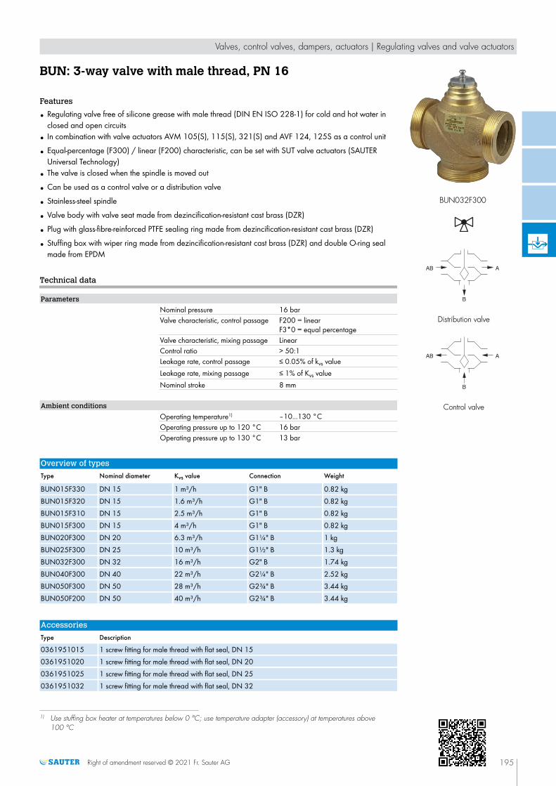
BUN: 3-way valve with male thread, PN 16
Features
• Regulating valve free of silicone grease with male thread (DIN EN ISO 228-1) for cold and hot water inclosed and open circuits
• In combination with valve actuators AVM 105(S), 115(S), 321(S) and AVF 124, 125S as a control unit
• Equal-percentage (F300) / linear (F200) characteristic, can be set with SUT valve actuators (SAUTERUniversal Technology)
• The valve is closed when the spindle is moved out
• Can be used as a control valve or a distribution valve
• Stainless-steel spindle
• Valve body with valve seat made from dezincification-resistant cast brass (DZR)
• Plug with glass-fibre-reinforced PTFE sealing ring made from dezincification-resistant cast brass (DZR)
• Stuffing box with wiper ring made from dezincification-resistant cast brass (DZR) and double O-ring sealmade from EPDM
Technical data
Parameters
Nominal pressure 16 barValve characteristic, control passage F200 = linear
F3*0 = equal percentageValve characteristic, mixing passage LinearControl ratio > 50:1Leakage rate, control passage ≤ 0.05% of kvs valueLeakage rate, mixing passage ≤ 1% of Kvs valueNominal stroke 8 mm
Ambient conditions
Operating temperature1) –10...130 °COperating pressure up to 120 °C 16 barOperating pressure up to 130 °C 13 bar
Overview of types
Type Nominal diameter Kvs value Connection Weight
BUN015F330 DN 15 1 m³/h G1" B 0.82 kgBUN015F320 DN 15 1.6 m³/h G1" B 0.82 kgBUN015F310 DN 15 2.5 m³/h G1" B 0.82 kgBUN015F300 DN 15 4 m³/h G1" B 0.82 kgBUN020F300 DN 20 6.3 m³/h G1¼" B 1 kgBUN025F300 DN 25 10 m³/h G1½" B 1.3 kgBUN032F300 DN 32 16 m³/h G2" B 1.74 kgBUN040F300 DN 40 22 m³/h G2¼" B 2.52 kgBUN050F300 DN 50 28 m³/h G2¾" B 3.44 kgBUN050F200 DN 50 40 m³/h G2¾" B 3.44 kg
Accessories
Type Description
0361951015 1 screw fitting for male thread with flat seal, DN 150361951020 1 screw fitting for male thread with flat seal, DN 200361951025 1 screw fitting for male thread with flat seal, DN 250361951032 1 screw fitting for male thread with flat seal, DN 32
1) Use stuffing box heater at temperatures below 0 °C; use temperature adapter (accessory) at temperatures above100 °C
Valves, control valves, dampers, actuators | Regulating valves and valve actuators
Right of amendment reserved © 2021 Fr. Sauter AG 195
BUN032F300
Distribution valve
Control valve
V

Type Description
0361951040 1 screw fitting for male thread with flat seal, DN 400361951050 1 screw fitting for male thread with flat seal, DN 500372240001 Manual adjustment for valves with 8 mm stroke0372249001 Adaptor required when temperature of the medium is 100...130 °C (recommended for tempera-
tures <10 °C)0372249002 Adaptor required when temperature of the medium is 130...150 °C0378284100 Stuffing box heater 230V~, 15 W for medium below 0 °C0378284102 Stuffing box heater 24V~, 15 W for medium below 0 °C0378368001 Complete replacement stuffing box for DN 15...50
Combination of BUN with electrical actuators
/ Warranty: The technical data and pressure differences indicated here are applicable only in combination with SAUTERvalve actuators. The warranty does not apply if used with valve actuators from other manufacturers.
/ Definition of ∆p s: Maximum admissible pressure drop in the event of a malfunction (pipe break after the valve) at which theactuator reliably closes the valve by means of a return spring.
/ Definition of ∆p max: Maximum admissible pressure drop in control mode at which the actuator reliably opens and closes thevalve.
Pressure differencesActuator AVM105F100 AVM105F120
AVM105F122AVM105SF132 AVM115F120
AVM115F122AVM115SF132
Page 247 247 250 248 250Actuating power 250 N 250 N 250 N 500 N 500 NControl signal 2-/3-point 2-/3-point 2-/3-point, 0...10 V 2-/3-point 2-/3-point, 0...10 VRunning time 30 s 120 s 35/60/120 s 120 s 60/120 s
∆p [bar]
As control valve ∆pmax ∆pmax ∆pmax ∆pmax ∆pmax
BUN015F330BUN015F320BUN015F310BUN015F300
4.0 4.0 4.0 6.0 6.0
BUN020F300 4.0 4.0 4.0 5.0 5.0BUN025F300 3.0 3.0 3.0 4.0 4.0BUN032F300 2.0 2.0 2.0 3.7 3.7BUN040F300 1.2 1.2 1.2 2.7 2.7BUN050F300BUN050F200 0.8 0.8 0.8 1.8 1.8
Cannot be used as distribution valve
Actuator AVM321F110AVM321F112
AVM321SF132 AVF124F130AVF124F230
AVF125SF132AVF125SF232
Page 256 259 269 272Actuating power 1000 N 1000 N 500 N 500 N
Control signal 2-/3-point 2-/3-pt., 0...10 V, 4...20 mA 3-point 2-/3-
pt., 0...10 V, 4...20 mARunning time 48/96 s 32/96 s 60/120 s 60/120 s
∆p [bar]
As control valve ∆pmax ∆pmax ∆pmax ∆ps ∆pmax ∆ps
BUN015F330BUN015F320BUN015F310BUN015F300
10.0 10.0 6.0 16.0 6.0 16.0
BUN020F300 10.0 10.0 5.0 9.5 5.0 9.5BUN025F300 10.0 10.0 4.0 6.5 4.0 6.5
Valves, control valves, dampers, actuators | Regulating valves and valve actuators
196 Right of amendment reserved © 2021 Fr. Sauter AG
V

Actuator AVM321F110AVM321F112
AVM321SF132 AVF124F130AVF124F230
AVF125SF132AVF125SF232
Page 256 259 269 272BUN032F300 10.0 10.0 3.7 4.3 3.7 4.3BUN040F300 6.0 6.0 2.7 2.7 2.7 2.7BUN050F300BUN050F200 4.0 4.0 1.8 1.8 1.8 1.8
As distributionvalve
∆pmax ∆pmax ∆pmax ∆ps ∆pmax ∆ps
BUN015F330BUN015F320BUN015F310BUN015F300
6.0 6.0 4.0 16.0 4.0 16.0
BUN020F300 6.0 6.0 2.8 16.0 2.8 16.0BUN025F300 5.0 5.0 2.8 16.0 2.8 16.0BUN032F300 4.0 4.0 2.0 16.0 2.0 16.0BUN040F300 2.5 2.5 1.5 16.0 1.5 16.0BUN050F300BUN050F200 2.0 2.0 0.8 16.0 0.8 16.0
A At temperatures above 100°C, accessories are required
Valves, control valves, dampers, actuators | Regulating valves and valve actuators
Right of amendment reserved © 2021 Fr. Sauter AG 197
V

V6R: 2-way valve with female thread, PN 16 (el.)
Features
• Regulating valve free of silicone grease with female thread DIN EN ISO 228-1 G for the control ofcold/hot water in closed and open circuits
• In combination with valve actuators AVM 322, AVM 322S, AVM 234S, AVF 234S
• Equal-percentage or linear characteristic, can be set with SUT valve actuators (SAUTER UniversalTechnology) to linear or equal-percentage
• Control passage A–AB closed when the spindle is moved out
• Closing procedure against the pressure or with the pressure
• Valve body and seat made of gunmetal
• Stainless-steel spindle
• Stuffing box made of brass with wiper ring and double O-ring seal made of EPDM
Technical data
Parameters
Control ratio > 50:1Leakage rate ≤ 0.05% of Kvs valueValve stroke 14 mmNominal pressure 16 bar
Ambient conditions
Operating temperature1) –15...130 °COperating pressure up to 120 °C 16 barOperating pressure up to 130 °C 13 bar
Standards and directives
Pressure and temperature data DIN 2401Flow parameters VDI/VDE 2173
Overview of types
Type Nominal diame-ter
Kvs value Valve character-istic
Materials forvalve plug
Type of connec-tion
Weight
V6R15F350 DN 15 0.4 m³/h equal-percent-age
Stainless steel G½" 1.2 kg
V6R15F340 DN 15 0.63 m³/h equal-percent-age
Stainless steel G½" 1.2 kg
V6R15F330 DN 15 1 m³/h equal-percent-age
Stainless steel G½" 1.2 kg
V6R15F320 DN 15 1.6 m³/h equal-percent-age
Stainless steel G½" 1.2 kg
V6R15F310 DN 15 2.5 m³/h equal-percent-age
brass G½" 1.2 kg
V6R15F300 DN 15 4 m³/h equal-percent-age
brass G½" 1.2 kg
V6R15F200 DN 15 4 m³/h linear brass G½" 1.2 kgV6R25F310 DN 25 6.3 m³/h equal-percent-
agebrass G1" 1.6 kg
V6R25F300 DN 25 10 m³/h equal-percent-age
brass G1" 1.6 kg
V6R25F210 DN 25 6.3 m³/h linear brass G1" 1.6 kgV6R25F200 DN 25 10 m³/h linear brass G1" 1.6 kgV6R40F310 DN 40 16 m³/h equal-percent-
agebrass G1½" 3.4 kg
1) At temperatures below 0 °C, use stuffing box heater (accessory)
Valves, control valves, dampers, actuators | Regulating valves and valve actuators
198 Right of amendment reserved © 2021 Fr. Sauter AG
V6R15F300
V

Type Nominal diame-ter
Kvs value Valve character-istic
Materials forvalve plug
Type of connec-tion
Weight
V6R40F300 DN 40 25 m³/h equal-percent-age
brass G1½" 3.4 kg
V6R40F210 DN 40 16 m³/h linear brass G1½" 3.4 kgV6R40F200 DN 40 25 m³/h linear brass G1½" 3.4 kgV6R50F300 DN 50 35 m³/h equal-percent-
agebrass G2" 4.6 kg
V6R50F200 DN 50 35 m³/h linear brass G2" 4.6 kg
Accessories
Type Description
0217268001 Stuffing box heater 15 W, 24 V0217268004 Stuffing box heater 15 W, 230 V0360391015 Screw fitting, DN 15, incl. seal, 2 pcs. required0360391025 Screw fitting, DN 25, incl. seal, 2 pcs. required0360391040 Screw fitting incl. seal, 2 pcs. required, Rp1½ - G1½0360391050 Screw fitting incl. seal, 2 pcs. required, Rp2 - G2
A 0217268*** Stuffing box heater 15 W, light alloy housing, IP54, 3 × 0.75 mm² power cable, earth connector, length 1m, ferrule
Combination of V6R with electrical actuators
/ Warranty: The technical data and pressure differences indicated here are applicable only in combination with SAUTERvalve actuators. The warranty does not apply if used with valve actuators from other manufacturers.
/ Definition of ∆p s: Maximum admissible pressure drop in the event of a malfunction (pipe break after the valve) at which theactuator reliably closes the valve by means of a return spring.
/ Definition of ∆p max: Maximum admissible pressure drop in control mode at which the actuator reliably opens and closes thevalve.
Pressure differencesActuator AVM234SF132 AVF234SF132 AVF234SF232 AVM322F120
AVM322F122AVM322SF132
Page 267 274 274 256 259Actuating power 2500 N 2000 N 2000 N 1000 N 1000 N
Control signal 2-/3-point, 0...10 V, 4...20 mA
2-/3-point, 0...10 V, 4...20 mA
2-/3-point, 0...10 V, 4...20 mA 2-/3-point 2-/3-point, 0...10 V,
4...20 mARunning time 28/56/84 s 28/56/84 s 28/56/84 s 120/240 s 120/80 s
∆p [bar]
Closes againstthe pressure
∆pmax ∆pmax ∆ps ∆pmax ∆ps ∆pmax ∆pmax
V6R15F350V6R15F340V6R15F330V6R15F320V6R15F310V6R15F300V6R15F200V6R25F310V6R25F300V6R25F210V6R25F200
4.0 4.0 16.0 4.0 16.0 4.0 4.0
V6R40F310V6R40F300V6R40F210V6R40F200
3.0 3.0 11.5 3.0 11.5 3.0 3.0
V6R50F300V6R50F200 2.0 2.0 8.6 2.0 8.6 2.0 2.0
Valves, control valves, dampers, actuators | Regulating valves and valve actuators
Right of amendment reserved © 2021 Fr. Sauter AG 199
V

Actuator AVM234SF132 AVF234SF132 AVF234SF232 AVM322F120AVM322F122
AVM322SF132
Page 267 274 274 256 259Closes with thepressure
∆pmax ∆pmax ∆ps ∆pmax ∆ps ∆pmax ∆pmax
V6R15F350V6R15F340V6R15F330V6R15F320V6R15F310V6R15F300V6R15F200
3.0 3.0 16.0 3.0 16.0 4.0 4.0
V6R25F310V6R25F300V6R25F210V6R25F200
2.0 2.0 16.0 2.0 16.0 4.0 4.0
V6R40F310V6R40F300V6R40F210V6R40F200
1.5 1.5 16.0 1.5 16.0 3.0 3.0
V6R50F300V6R50F200 1.0 1.0 16.0 1.0 16.0 2.0 2.0
A Accessories required: Mounting set 0372338001 for AVM 234 and AVF 234
A Accessories required: Mounting set 0510240012 for AVM 322(S)
Valves, control valves, dampers, actuators | Regulating valves and valve actuators
200 Right of amendment reserved © 2021 Fr. Sauter AG
V

B6R: 3-way valve with female thread, PN 16 (el.)
Features
• Regulating valve free of silicone grease with female thread DIN EN ISO 228-1 G for the control ofcold/hot water in closed and open circuits
• In combination with valve actuators AVM 322, AVM 322S, AVM 234S, AVF 234S
• Equal-percentage or linear characteristic, can be set with SUT valve actuators (SAUTER UniversalTechnology) to linear or equal-percentage
• Control passage A–AB closed when the spindle is moved out
• Can be used as a control valve or a distribution valve
• Valve body and seat made of gunmetal
• Stuffing box made of brass with wiper ring and double O-ring seal made of EPDM
• Stainless-steel spindle
Technical data
Parameters
Control ratio > 50:1Leakage rate of control passage A-AB ≤ 0.05% of Kvs valueLeakage rate of mixing passage B-AB ≤ 1% of Kvs valueValve stroke 14 mmValve characteristic, mixing passage Linear
Ambient conditions
Operating temperature1) –15...130 °COperating pressure up to 120 °C 16 barOperating pressure up to 130 °C 13 bar
Standards and directives
Pressure and temperature data DIN 2401Flow parameters VDI/VDE 2173
Overview of types
Type Nominal diame-ter
Kvs value Valve character-istic
Materials forvalve plug
Type of connec-tion
Weight
B6R15F330 DN 15 1 m³/h equal-percent-age
Stainless steel G½" 1.2 kg
B6R15F320 DN 15 1.6 m³/h equal-percent-age
Stainless steel G½" 1.2 kg
B6R15F310 DN 15 2.5 m³/h equal-percent-age
brass G½" 1.2 kg
B6R15F300 DN 15 4 m³/h equal-percent-age
brass G½" 1.2 kg
B6R15F200 DN 15 4 m³/h linear brass G½" 1.2 kgB6R25F310 DN 25 6.3 m³/h equal-percent-
agebrass G1" 1.6 kg
B6R25F300 DN 25 10 m³/h equal-percent-age
brass G1" 1.6 kg
B6R25F210 DN 25 6.3 m³/h linear brass G1" 1.6 kgB6R25F200 DN 25 10 m³/h linear brass G1" 1.6 kgB6R40F310 DN 40 16 m³/h equal-percent-
agebrass G1½" 3.4 kg
B6R40F300 DN 40 25 m³/h equal-percent-age
brass G1½" 3.4 kg
B6R40F210 DN 40 16 m³/h linear brass G1½" 3.4 kg
1) At temperatures below 0 °C, use stuffing box heater (accessory)
Valves, control valves, dampers, actuators | Regulating valves and valve actuators
Right of amendment reserved © 2021 Fr. Sauter AG 201
B6R25F300
Control valve
Distribution valve
V

Type Nominal diame-ter
Kvs value Valve character-istic
Materials forvalve plug
Type of connec-tion
Weight
B6R40F200 DN 40 25 m³/h linear brass G1½" 3.4 kgB6R50F300 DN 50 35 m³/h equal-percent-
agebrass G2" 4.6 kg
B6R50F200 DN 50 35 m³/h linear brass G2" 4.6 kg
Accessories
Type Description
0217268001 Stuffing box heater 15 W, 24 V0217268004 Stuffing box heater 15 W, 230 V0360391015 Screw fitting, DN 15, incl. seal, 3 pcs. required0360391025 Screw fitting, DN 25, incl. seal, 3 pcs. required0360391040 Screw fitting, DN 40, incl. seal, 3 pcs. required0360391050 Screw fitting, DN 50, incl. seal, 3 pcs. required0360429000 Adhesive label for distribution valve0378034001 Stuffing box; with synthetic lubricant; max. 130 °C
A 0217268*** Stuffing box heater 15 W, light alloy housing, IP54, 3 × 0.75 mm² power cable, earth connector, length 1m, ferrule
A 0360429 Sheet with 21 adhesive labels for flow change; see combinations
Combination of B6R with electrical actuators
/ Warranty: The technical data and pressure differences indicated here are applicable only in combination with SAUTERvalve actuators. The warranty does not apply if used with valve actuators from other manufacturers.
/ Definition of ∆p s: Maximum admissible pressure drop in the event of a malfunction (pipe break after the valve) at which theactuator reliably closes the valve by means of a return spring.
/ Definition of ∆p max: Maximum admissible pressure drop in control mode at which the actuator reliably opens and closes thevalve.
Pressure differencesActuator AVM234SF132 AVF234SF132 AVF234SF232 AVM322F120
AVM322F122AVM322SF132
Page 267 274 274 256 259Actuating power 2500 N 2000 N 2000 N 1000 N 1000 N
Control signal 2-/3-point, 0...10 V, 4...20 mA
2-/3-point, 0...10 V, 4...20 mA
2-/3-point, 0...10 V, 4...20 mA 2-/3-point 2-/3-point, 0...10 V,
4...20 mARunning time 28/56/84 s 28/56/84 s 28/56/84 s 120/240 s 120/80 s
∆p [bar]
As control valve ∆pmax ∆pmax ∆ps ∆pmax ∆ps ∆pmax ∆pmax
B6R15F330B6R15F320B6R15F310B6R15F300B6R15F200B6R25F310B6R25F300B6R25F210B6R25F200
4.0 4.0 16.0 4.0 16.0 4.0 4.0
B6R40F310B6R40F300B6R40F210B6R40F200
3.0 3.0 11.5 3.0 11.5 3.0 3.0
B6R50F300B6R50F200 2.0 2.0 8.6 2.0 8.6 2.0 2.0
Valves, control valves, dampers, actuators | Regulating valves and valve actuators
202 Right of amendment reserved © 2021 Fr. Sauter AG
V

Actuator AVM234SF132 AVF234SF132 AVF234SF232 AVM322F120AVM322F122
AVM322SF132
Page 267 274 274 256 259As distributionvalve
∆pmax ∆pmax ∆ps ∆pmax ∆ps ∆pmax ∆pmax
B6R15F330B6R15F320B6R15F310B6R15F300B6R15F200
3.0 3.0 16.0 3.0 16.0 4.0 4.0
B6R25F310B6R25F300B6R25F210B6R25F200
2.0 2.0 16.0 2.0 16.0 4.0 4.0
B6R40F310B6R40F300B6R40F210B6R40F200
1.5 1.5 16.0 1.5 16.0 3.0 3.0
B6R50F300B6R50F200 1.0 1.0 16.0 1.0 16.0 2.0 2.0
A Accessories required: Mounting set 0372338001 for AVM 234 and AVF 234
A Accessories required: Mounting set 0510240012 for AVM 322(S)
Valves, control valves, dampers, actuators | Regulating valves and valve actuators
Right of amendment reserved © 2021 Fr. Sauter AG 203
V

VUD: 2-way flanged valve, PN 6 (el.)
Features
• Continuous control of cold and hot water in closed circuits
• Water quality as per VDI 2035
• In combination with valve actuators AVM 105(S), AVM 115(S), AVM 321(S) and AVF 124 andAVF 125(S) as a control unit
• Not suitable for steam or drinking water or potentially explosive atmospheres
• Valve with flange connection as per EN 1092-2, seal form B
• Regulating valve, free of silicone grease, painted black
• Characteristic can be set with SUT (SAUTER Universal Technology) valve actuator to linear, equal-percentage or quadratic
• The valve is closed when the spindle is moved out
• Closing procedure against the pressure or with the pressure
• Valve body and seat made of grey cast iron
• Stainless-steel spindle
• Plug made of brass with glass-fibre reinforced PTFE sealing ring
• Stuffing box made of brass with wiper ring and double O-ring seal made of EPDM
Technical data
Parameters
Nominal pressure PN 6Connection Flange as per EN 1092-2, form BValve characteristic, control passageF200
Linear
Valve characteristic, control passageF300
Equal-percentage
Control ratio of valve > 50:1Stuffing box 2 EPDM O-ringsLeakage rate ≤ 0.05% of Kvs valueValve stroke 8 mm
Ambient conditions1)
Operating temperature2) −10...150 °COperating pressure Up to 120 °C; 6 bar
At 150 °C; 5.4 barBetween 120 °C and 150 °C, a line-ar interpolation can be performed
Standards and directives
Pressure and temperature data EN 764, EN 1333Flow parameters EN 60534 (page 3)Pressure Equipment Directive 97/23/EC (fluid group II)
No CE label article 3.3
Overview of types
Type Nominal diameter Kvs value Weight
VUD015F320 DN 15 1.6 m³/h 3.2 kgVUD015F310 DN 15 2.5 m³/h 3.2 kgVUD015F300 DN 15 4 m³/h 3.2 kgVUD020F300 DN 20 6.3 m³/h 4.1 kgVUD025F300 DN 25 10 m³/h 4.7 kg
1) Humidity must not exceed 75%2) At temperatures below 0 °C, use stuffing box heater. Use adapter (accessory) at temperatures above 100 °C
Valves, control valves, dampers, actuators | Regulating valves and valve actuators
204 Right of amendment reserved © 2021 Fr. Sauter AG
VUD032F300
V

Type Nominal diameter Kvs value Weight
VUD032F300 DN 32 16 m³/h 7.3 kgVUD040F300 DN 40 22 m³/h 8.6 kgVUD050F300 DN 50 28 m³/h 11.2 kgVUD050F200 DN 50 40 m³/h 11.2 kg
Accessories
Type Description
0372240001 Manual adjustment for valves with 8 mm stroke0372249001 Adapter required when temperature of the medium is 100...130 °C (recommended for tempera-
tures < 10 °C) DN 15...500372249002 Adaptor required when temperature of the medium is 130...150 °C, DN 15...500378284100 Stuffing box heater 230 V~, 15 W for medium below 0 °C0378284102 Stuffing box heater 24 V~, 15 W for medium below 0 °C0378368001 Complete replacement stuffing box for DN 15...50
Combination of VUD with electrical actuators
/ Warranty: The technical data and pressure differences indicated here are applicable only in combination with SAUTERvalve actuators. The warranty does not apply if used with valve actuators from other manufacturers.
/ Definition of ∆p s: Maximum admissible pressure drop in the event of a malfunction (pipe break after the valve) at which theactuator reliably closes the valve by means of a return spring.
/ Definition of ∆p max: Maximum admissible pressure drop in control mode at which the actuator reliably opens and closes thevalve.
Combination of VUD with electric actuator, actuating power 250 N, 500 NActuator AVM105F100 AVM105F120
AVM105F122AVM105SF132 AVM115F120
AVM115F122AVM115SF132
Page 247 247 250 248 250Actuating power 250 N 250 N 250 N 500 N 500 NControl signal 2-/3-point 2-/3-point 2-/3-point, 0...10 V 2-/3-point 2-/3-point, 0...10 VRunning time 30 s 120 s 35/60/120 s 120 s 60/120 s
∆p [bar]
Closes againstthe pressure
∆pmax ∆pmax ∆pmax ∆pmax ∆pmax
VUD015F320VUD015F310VUD015F300VUD020F300
4.0 4.0 4.0 6.0 6.0
VUD025F300 2.8 2.8 2.8 6.0 6.0VUD032F300 2.1 2.1 2.1 5.2 5.2VUD040F300 1.2 1.2 1.2 3.3 3.3VUD050F300VUD050F200 0.9 0.9 0.9 2.0 2.0
Cannot be used to close with the pressure
Valves, control valves, dampers, actuators | Regulating valves and valve actuators
Right of amendment reserved © 2021 Fr. Sauter AG 205
V

Combination of VUD with electric actuator with spring return, actuating power
500 NActuator AVF124F130
AVF124F230AVF125SF132AVF125SF232
Page 269 272Actuating power 500 N 500 NControl signal 3-point 2-/3-pt., 0...10 V, 4...20 mARunning time 60/120 s 60/120 s
∆p [bar]
Closes againstthe pressure
∆pmax ∆ps ∆pmax ∆ps
VUD015F320VUD015F310VUD015F300VUD020F300VUD025F300
6.0 6.0 6.0 6.0
VUD032F300 5.2 5.2 5.2 5.2VUD040F300 3.3 3.3 3.3 3.3VUD050F300VUD050F200 2.0 2.0 2.0 2.0
Closes with thepressure
∆pmax ∆ps ∆pmax ∆ps
VUD015F320VUD015F310VUD015F300VUD020F300
6.0 6.0 6.0 6.0
VUD025F300 5.0 6.0 5.0 6.0VUD032F300 4.0 6.0 4.0 6.0VUD040F300 2.5 6.0 2.5 6.0VUD050F300VUD050F200 1.5 6.0 1.5 6.0
A At temperatures above 100°C, accessories are required
Combination of VUD with electric actuator, actuating power 1000 NActuator AVM321F110
AVM321F112AVM321SF132
Page 256 259Actuating power 1000 N 1000 NControl signal 2-/3-point 2-/3-pt., 0...10 V, 4...20 mARunning time 48/96 s 32/96 s
∆p [bar]
Closes againstthe pressure
∆pmax ∆pmax
VUD015F320VUD015F310VUD015F300VUD020F300VUD025F300VUD032F300VUD040F300
6.0 6.0
VUD050F300VUD050F200 4.0 4.0
Valves, control valves, dampers, actuators | Regulating valves and valve actuators
206 Right of amendment reserved © 2021 Fr. Sauter AG
V

Actuator AVM321F110AVM321F112
AVM321SF132
Page 256 259Closes with thepressure
∆pmax ∆pmax
VUD015F320VUD015F310VUD015F300VUD020F300
6.0 6.0
VUD025F300 5.0 5.0VUD032F300 4.0 4.0VUD040F300 2.5 2.5VUD050F300VUD050F200 1.5 1.5
A At temperatures above 100°C, accessories are required
Valves, control valves, dampers, actuators | Regulating valves and valve actuators
Right of amendment reserved © 2021 Fr. Sauter AG 207
V

BUD: 3-way flanged valve, PN 6 (el.)
Features
• Continuous control of cold and hot water in closed circuits
• Water quality as per VDI 2035
• In combination with valve actuators AVM 105(S), AVM 115(S), AVM 321(S) and AVF 124 andAVF 125(S) as a control unit
• Not suitable for drinking water
• Valve with flange connection as per EN 1092-2, seal form B, for PN 16 and PN 10
• Regulating valve, free of silicone grease, painted black
• Characteristic can be set with SUT valve actuators to linear, equal-percentage or quadratic
• The control passage is closed when the spindle is moved out
• Used as control valve or as distribution valve
• Valve body with seat made of grey cast iron
• Stainless-steel spindle
• Plug made of brass with glass-fibre reinforced PTFE sealing ring
• Stuffing box made of brass with wiper ring and double O-ring seal made of EPDM
Technical data
Parameters
Nominal pressure PN 6Connection Flange as per EN 1092-2, form BValve characteristic, control passageF200
Linear
Valve characteristic, control passageF300
Equal-percentage
Valve characteristic, mixing passage LinearControl ratio of valve > 50:1Stuffing box 2 EPDM O-ringsLeakage rate, control passage < 0.05% of Kvs valueLeakage rate, mixing passage < 1% of Kvs valueValve stroke 8 mm
Ambient conditions1)
Operating temperature2) −10...150 °COperating pressure Up to 120 °C; 6 bar
At 150 °C; 5.4 barBetween 120 °C and 150 °C, a line-ar interpolation can be performed
Standards and directives
Pressure and temperature data EN 764, EN 1333Flow parameters EN 60534 (page 3)PED 2014/68/EU Fluid group II, liquid or steam pressure
no CE label as per article 4.3
Overview of types
Type Nominal diameter Kvs value Weight
BUD015F320 DN 15 1.6 m³/h 3200 gBUD015F310 DN 15 2.5 m³/h 3200 gBUD015F300 DN 15 4 m³/h 3200 gBUD020F300 DN 20 6.3 m³/h 4100 g
1) Humidity must not exceed 75%2) At temperatures below 0 °C, use a stuffing box heater. Use adapter (accessory) at temperatures above 100 °C
Valves, control valves, dampers, actuators | Regulating valves and valve actuators
208 Right of amendment reserved © 2021 Fr. Sauter AG
BUD032F300
Control valve
Distribution valve
V

Type Nominal diameter Kvs value Weight
BUD025F300 DN 25 10 m³/h 4700 gBUD032F300 DN 32 16 m³/h 7100 gBUD040F300 DN 40 22 m³/h 8400 gBUD050F300 DN 50 28 m³/h 10900 gBUD050F200 DN 50 40 m³/h 11200 g
Accessories
Type Description
0372240001 Manual adjustment for valves with 8 mm stroke0372249001 Adapter required when temperature of the medium is 100...130 °C (recommended for tempera-
tures <10 °C)0372249002 Adapter required when temperature of the medium is 130...150 °C0378284100 Stuffing box heater 230 V~, 15 W for medium below 0 °C0378284102 Stuffing box heater 24 V~, 15 W for medium below 0 °C0378368001 Complete replacement stuffing box for DN 15...50
Combination of BUD with electric actuators
/ Warranty: The technical data and pressure differences indicated here are applicable only in combination with SAUTERvalve actuators. The warranty does not apply if used with valve actuators from other manufacturers.
/ Definition of ∆p s: Maximum admissible pressure drop in the event of a malfunction (pipe break after the valve) at which theactuator reliably closes the valve by means of a return spring.
/ Definition of ∆p max: Maximum admissible pressure drop in control mode at which the actuator reliably opens and closes thevalve.
Combination of BUD with electric actuator, actuating power 250 N, 500 NActuator AVM105F100 AVM105F120
AVM105F122AVM105SF132 AVM115F120
AVM115F122AVM115SF132
Page 247 247 250 248 250Actuating power 250 N 250 N 250 N 500 N 500 NControl signal 2-/3-point 2-/3-point 2-/3-point, 0...10 V 2-/3-point 2-/3-point, 0...10 VRunning time 30 s 120 s 35/60/120 s 120 s 60/120 s
∆p [bar]
As control valve ∆pmax ∆pmax ∆pmax ∆pmax ∆pmax
BUD015F320BUD015F310BUD015F300BUD020F300
4.0 4.0 4.0 6.0 6.0
BUD025F300 2.8 2.8 2.8 6.0 6.0BUD032F300 2.1 2.1 2.1 5.2 5.2BUD040F300 1.2 1.2 1.2 3.3 3.3BUD050F300BUD050F200 0.9 0.9 0.9 2.0 2.0
Cannot be used as distribution valve
Valves, control valves, dampers, actuators | Regulating valves and valve actuators
Right of amendment reserved © 2021 Fr. Sauter AG 209
V

Combination of BUD with electric actuator with spring return, actuating power
500 NActuator AVF124F130
AVF124F230AVF125SF132AVF125SF232
Page 269 272Actuating power 500 N 500 NControl signal 3-point 2-/3-pt., 0...10 V, 4...20 mARunning time 60/120 s 60/120 s
∆p [bar]
As control valve ∆pmax ∆ps ∆pmax ∆ps
BUD015F320BUD015F310BUD015F300BUD020F300BUD025F300
6.0 6.0 6.0 6.0
BUD032F300 5.2 5.2 5.2 5.2BUD040F300 3.3 3.3 3.3 3.3BUD050F300BUD050F200 2.0 2.0 2.0 2.0
As distributionvalve
∆pmax ∆ps ∆pmax ∆ps
BUD015F320BUD015F310BUD015F300BUD020F300
6.0 6.0 6.0 6.0
BUD025F300 5.0 6.0 5.0 6.0BUD032F300 4.0 6.0 4.0 6.0BUD040F300 2.5 6.0 2.5 6.0BUD050F300BUD050F200 1.5 6.0 1.5 6.0
A At temperatures above 100 °C, accessories are required
Combination of BUD with electric actuator, actuating power 1000 NActuator AVM321F110
AVM321F112AVM321SF132
Page 256 259Actuating power 1000 N 1000 NControl signal 2-/3-point 2-/3-pt., 0...10 V, 4...20 mARunning time 48/96 s 32/96 s
∆p [bar]
As control valve ∆pmax ∆pmax
BUD015F320BUD015F310BUD015F300BUD020F300BUD025F300BUD032F300BUD040F300
6.0 6.0
BUD050F300BUD050F200 4.0 4.0
As distributionvalve
∆pmax ∆pmax
BUD015F320BUD015F310BUD015F300BUD020F300
6.0 6.0
BUD025F300 5.0 5.0
Valves, control valves, dampers, actuators | Regulating valves and valve actuators
210 Right of amendment reserved © 2021 Fr. Sauter AG
V

Actuator AVM321F110AVM321F112
AVM321SF132
Page 256 259BUD032F300 4.0 4.0BUD040F300 2.5 2.5BUD050F300BUD050F200 1.5 1.5
A At temperatures above 100 °C, accessories are required
Valves, control valves, dampers, actuators | Regulating valves and valve actuators
Right of amendment reserved © 2021 Fr. Sauter AG 211
V

VUE: 2-way flanged valve, PN 16/10 (el.)
Features
• Continuous control of cold/hot water and low-pressure steam up to 115 °C in closed circuits
• Water quality as per VDI 2035
• In combination with valve actuators AVM 105(S), AVM 115(S), AVM 321(S) and AVF 124 andAVF 125(S) as a control unit
• Not suitable for drinking water
• Valve with flange connection as per EN 1092-2, seal form B, for PN 16 and PN 10
• Regulating valve, free of silicone grease, painted black
• Characteristic can be set with SUT (SAUTER Universal Technology) valve actuator to linear, equal-percentage or quadratic
• The valve is closed when the spindle is moved out
• Closing procedure against the pressure or with the pressure
• Valve body and seat made of grey cast iron
• Stainless-steel spindle
• Plug made of brass with glass-fibre reinforced PTFE sealing ring
• Stuffing box made of brass with wiper ring and double O-ring seal made of EPDM
Technical data
Parameters
Nominal pressure PN 16/10Connection Flange as per EN 1092-2, form BValve characteristic, control passageF200
Linear
Valve characteristic, control passageF300
Equal-percentage
Control ratio of valve > 50:1Stuffing box 2 EPDM O-ringsLeakage rate < 0.05% of Kvs valueValve stroke 8 mm
Ambient conditions1)
Operating temperature2) −10...150 °COperating pressure PN 16:
Up to 120 °C, 16 barAt 150 °C, 14.4 barPN 10:Up to 120 °C, 10 barAt 150 °C, 9 barBetween 120 °C and 150 °C, a line-ar interpolation can be performed
Standards and directives
Pressure and temperature data EN 764, EN 1333Flow parameters EN 60534 (page 3)Pressure Equipment Directive 97/23/EC (fluid group II)
No CE label article 3.3
Overview of types
Type Nominal diameter Kvs value Weight
VUE015F350 DN 15 0.4 m³/h 3.2 kgVUE015F340 DN 15 0.63 m³/h 3.2 kg
1) Humidity must not exceed 75%.2) At temperatures below 0 °C, use a stuffing box heater. Use adapter (accessory) at temperatures above 100 °C
Valves, control valves, dampers, actuators | Regulating valves and valve actuators
212 Right of amendment reserved © 2021 Fr. Sauter AG
VUE032F300
V

Type Nominal diameter Kvs value Weight
VUE015F330 DN 15 1 m³/h 3.2 kgVUE015F320 DN 15 1.6 m³/h 3.2 kgVUE015F310 DN 15 2.5 m³/h 3.2 kgVUE015F300 DN 15 4 m³/h 3.2 kgVUE020F300 DN 20 6.3 m³/h 4.1 kgVUE025F300 DN 25 10 m³/h 4.7 kgVUE032F300 DN 32 16 m³/h 7.3 kgVUE040F300 DN 40 22 m³/h 8.6 kgVUE050F300 DN 50 28 m³/h 11.2 kgVUE050F200 DN 50 40 m³/h 11.2 kg
Accessories
Type Description
0372240001 Manual adjustment for valves with 8 mm stroke0372249001 Adapter required when temperature of the medium is 100...130 °C (recommended for tempera-
tures <10 °C)0372249002 Adapter required when temperature of the medium is 130...150 °C0378284100 Stuffing box heater 230 V~, 15 W for medium below 0 °C0378284102 Stuffing box heater 24 V~, 15 W for medium below 0 °C0378368001 Complete replacement stuffing box for DN 15...50
Combination of VUE with electric actuators
/ Warranty: The technical data and pressure differences indicated here are applicable only in combination with SAUTERvalve actuators. The warranty does not apply if used with valve actuators from other manufacturers.
/ Definition of ∆p s: Maximum admissible pressure drop in the event of a malfunction (pipe break after the valve) at which theactuator reliably closes the valve by means of a return spring.
/ Definition of ∆p max: Maximum admissible pressure drop in control mode at which the actuator reliably opens and closes thevalve.
Combination of VUE with electric actuator, actuating power 250 N, 500 NActuator AVM105F100 AVM105F120
AVM105F122AVM105SF132 AVM115F120
AVM115F122AVM115SF132
Page 247 247 250 248 250Actuating power 250 N 250 N 250 N 500 N 500 NControl signal 2-/3-point 2-/3-point 2-/3-point, 0...10 V 2-/3-point 2-/3-point, 0...10 VRunning time 30 s 120 s 35/60/120 s 120 s 60/120 s
∆p [bar]
Closes againstthe pressure
∆pmax ∆pmax ∆pmax ∆pmax ∆pmax
VUE015F350VUE015F340VUE015F330VUE015F320VUE015F310VUE015F300VUE020F300
4.0 4.0 4.0 6.0 6.0
VUE025F300 2.8 2.8 2.8 6.0 6.0VUE032F300 2.1 2.1 2.1 5.2 5.2VUE040F300 1.4 1.4 1.4 3.3 3.3VUE050F300VUE050F200 0.9 0.9 0.9 2.0 2.0
Cannot be used to close with the pressure
Valves, control valves, dampers, actuators | Regulating valves and valve actuators
Right of amendment reserved © 2021 Fr. Sauter AG 213
V

Combination of VUE with electric actuator with spring return, actuating power
500 NActuator AVF124F130
AVF124F230AVF125SF132AVF125SF232
Page 269 272Actuating power 500 N 500 NControl signal 3-point 2-/3-pt., 0...10 V, 4...20 mARunning time 60/120 s 60/120 s
∆p [bar]
Closes againstthe pressure
∆pmax ∆ps ∆pmax ∆ps
VUE015F350VUE015F340VUE015F330VUE015F320VUE015F310VUE015F300
6.0 16.0 6.0 16.0
VUE020F300 6.0 11.0 6.0 11.0VUE025F300 6.0 6.8 6.0 6.8VUE032F300 5.2 5.2 5.2 5.2VUE040F300 3.3 3.3 3.3 3.3VUE050F300VUE050F200 2.0 2.0 2.0 2.0
Closes with thepressure
∆pmax ∆ps ∆pmax ∆ps
VUE015F350VUE015F340VUE015F330VUE015F320VUE015F310VUE015F300VUE020F300
6.0 16.0 6.0 16.0
VUE025F300 5.0 16.0 5.0 16.0VUE032F300 4.0 16.0 4.0 16.0VUE040F300 2.5 16.0 2.5 16.0VUE050F300VUE050F200 1.5 16.0 1.5 16.0
A At temperatures above 100°C, accessories are required
Combination of VUE with electric actuator, actuating power 1000 NActuator AVM321F110
AVM321F112AVM321SF132
Page 256 259Actuating power 1000 N 1000 NControl signal 2-/3-point 2-/3-pt., 0...10 V, 4...20 mARunning time 48/96 s 32/96 s
∆p [bar]
Closes againstthe pressure
∆pmax ∆pmax
VUE015F350VUE015F340VUE015F330VUE015F320VUE015F310VUE015F300VUE020F300VUE025F300VUE032F300
10.0 10.0
Valves, control valves, dampers, actuators | Regulating valves and valve actuators
214 Right of amendment reserved © 2021 Fr. Sauter AG
V

Actuator AVM321F110AVM321F112
AVM321SF132
Page 256 259VUE040F300 6.0 6.0VUE050F300VUE050F200 4.0 4.0
Closes with thepressure
∆pmax ∆pmax
VUE015F350VUE015F340VUE015F330VUE015F320VUE015F310VUE015F300VUE020F300
6.0 6.0
VUE025F300 5.0 6.0VUE032F300 4.0 6.0VUE040F300 2.5 2.5VUE050F300VUE050F200 1.5 1.5
A At temperatures above 100°C, accessories are required
Valves, control valves, dampers, actuators | Regulating valves and valve actuators
Right of amendment reserved © 2021 Fr. Sauter AG 215
V

BUE: 3-way flanged valve, PN 16/10 (el.)
Features
• Continuous control of cold and hot water in closed circuits
• Water quality as per VDI 2035
• In combination with valve actuators AVM 105(S), AVM 115(S), AVM 321(S) and AVF 124 andAVF 125(S) as a control unit
• Not suitable for drinking water
• Valve with flange connection as per EN 1092-2, seal form B, for PN 16 and PN 10
• Regulating valve, free of silicone grease, painted black
• Equal-percentage characteristic with F300, can be set with SUT valve actuators(SAUTER Universal Technology) to linear or quadratic
• Valve passage A–AB is closed when the spindle is moved out
• Can be used as a control valve or a distribution valve
• Valve body and seat made of grey cast iron
• Stainless-steel spindle
• Plug made of brass with glass-fibre reinforced PTFE sealing ring
• Stuffing box made of brass with wiper ring and double O-ring seal made of EPDM
Technical data
Parameters
Connection PN 16/10Connection Flange as per EN 1092-2, form BValve characteristic, control passageF200
Linear
Valve characteristic, control passageF300
Equal-percentage
Valve characteristic, mixing passage LinearControl ratio of valve > 50:1Stuffing box 2 EPDM O-ringsLeakage rate, control passage < 0.05% of Kvs valueLeakage rate, mixing passage < 1% of Kvs valueValve stroke 8 mm
Ambient conditions1)
Operating temperature2) –10...150 °COperating pressure PN 16:
Up to 120 °C, 16 barAt 150 °C, 14.4 barPN 10:Up to 120 °C, 10 barAt 150 °C, 9 barBetween 120 °C and 150 °C, a line-ar interpolation can be performed
Standards and directives
Pressure and temperature data EN 764, EN 1333Flow parameters EN 60534 (page 3)Pressure Equipment Directive 97/23/EC (fluid group II)
No CE label article 3.3
1) Humidity must not exceed 75%2) At temperatures below 0 °C, use a stuffing box heater. Use adapter (accessory) at temperatures above 100 °C
Valves, control valves, dampers, actuators | Regulating valves and valve actuators
216 Right of amendment reserved © 2021 Fr. Sauter AG
BUE032F300
Control valve
Distribution valve
V

Overview of types
Type Nominal diameter Kvs value Weight
BUE015F330 DN 15 1 m³/h 3.2 kgBUE015F320 DN 15 1.6 m³/h 3.2 kgBUE015F310 DN 15 2.5 m³/h 3.2 kgBUE015F300 DN 15 4 m³/h 3.2 kgBUE020F300 DN 20 6.3 m³/h 4.1 kgBUE025F300 DN 25 10 m³/h 4.7 kgBUE032F300 DN 32 16 m³/h 7.1 kgBUE040F300 DN 40 22 m³/h 8.4 kgBUE050F300 DN 50 28 m³/h 11.2 kgBUE050F200 DN 50 40 m³/h 11.2 kg
Accessories
Type Description
0372240001 Manual adjustment for valves with 8 mm stroke0372249001 Adapter required when temperature of the medium is 100...130 °C (recommended for tempera-
tures <10 °C)0372249002 Adapter required when temperature of the medium is 130...150 °C0378284100 Stuffing box heater 230 V~, 15 W for medium below 0 °C0378284102 Stuffing box heater 24 V~, 15 W for medium below 0 °C0378368001 Complete replacement stuffing box for DN 15...50
Combination of BUE with electric actuators
/ Warranty: The technical data and pressure differences indicated here are applicable only in combination with SAUTERvalve actuators. The warranty does not apply if used with valve actuators from other manufacturers.
/ Definition of ∆p s: Maximum admissible pressure drop in the event of a malfunction (pipe break after the valve) at which theactuator reliably closes the valve by means of a return spring.
/ Definition of ∆p max: Maximum admissible pressure drop in control mode at which the actuator reliably opens and closes thevalve.
Combination of BUE with electric actuator, actuating power 250 N, 500 NActuator AVM105F100 AVM105F120
AVM105F122AVM105SF132 AVM115F120
AVM115F122AVM115SF132
Page 247 247 250 248 250Actuating power 250 N 250 N 250 N 500 N 500 NControl signal 2-/3-point 2-/3-point 2-/3-point, 0...10 V 2-/3-point 2-/3-point, 0...10 VRunning time 30 s 120 s 35/60/120 s 120 s 60/120 s
∆p [bar]
As control valve ∆pmax ∆pmax ∆pmax ∆pmax ∆pmax
BUE015F330BUE015F320BUE015F310BUE015F300BUE020F300
4.0 4.0 4.0 6.0 6.0
BUE025F300 2.8 2.8 2.8 6.0 6.0BUE032F300 2.1 2.1 2.1 5.2 5.2BUE040F300 1.4 1.4 1.4 3.3 3.3BUE050F300BUE050F200 0.9 0.9 0.9 2.0 2.0
Cannot be used as distribution valve
Valves, control valves, dampers, actuators | Regulating valves and valve actuators
Right of amendment reserved © 2021 Fr. Sauter AG 217
V

Combination of BUE with electric actuator with spring return, actuating power
500 NActuator AVF124F130
AVF124F230AVF125SF132AVF125SF232
Page 269 272Actuating power 500 N 500 NControl signal 3-point 2-/3-pt., 0...10 V, 4...20 mARunning time 60/120 s 60/120 s
∆p [bar]
As control valve ∆pmax ∆ps ∆pmax ∆ps
BUE015F330BUE015F320BUE015F310BUE015F300
6.0 16.0 6.0 16.0
BUE020F300 6.0 11.0 6.0 11.0BUE025F300 6.0 6.8 6.0 6.8BUE032F300 5.2 5.2 5.2 5.2BUE040F300 3.3 3.3 3.3 3.3BUE050F300BUE050F200 2.0 2.0 2.0 2.0
As distributionvalve
∆pmax ∆ps ∆pmax ∆ps
BUE020F300 6.0 16.0 6.0 16.0BUE025F300 5.0 16.0 5.0 16.0BUE032F300 4.0 16.0 4.0 16.0BUE040F300 2.5 16.0 2.5 16.0BUE050F300BUE050F200 1.5 16.0 1.5 16.0
A Spring return: 18 ± 10 s
A At temperatures above 100°C, accessories are required
Combination of BUE with electric actuator, actuating power 1000 NActuator AVM321F110
AVM321F112AVM321SF132
Page 256 259Actuating power 1000 N 1000 NControl signal 2-/3-point 2-/3-pt., 0...10 V, 4...20 mARunning time 48/96 s 32/96 s
∆p [bar]
As control valve ∆pmax ∆pmax
BUE015F330BUE015F320BUE015F310BUE015F300BUE020F300BUE025F300BUE032F300
10.0 10.0
BUE040F300 6.0 6.0BUE050F300BUE050F200 4.0 4.0
Valves, control valves, dampers, actuators | Regulating valves and valve actuators
218 Right of amendment reserved © 2021 Fr. Sauter AG
V

Actuator AVM321F110AVM321F112
AVM321SF132
Page 256 259As distributionvalve
∆pmax ∆pmax
BUE015F330BUE015F320BUE015F310BUE015F300BUE020F300
6.0 6.0
BUE025F300 6.0 5.0BUE032F300 6.0 4.0BUE040F300 2.5 2.5BUE050F300BUE050F200 1.5 1.5
A At temperatures above 100°C, accessories are required
Valves, control valves, dampers, actuators | Regulating valves and valve actuators
Right of amendment reserved © 2021 Fr. Sauter AG 219
V

VQD: 2-way flanged valve, PN 6
Features
• Continuous control of cold and hot water in closed circuits
• Water quality as per VDI 2035
• In combination with valve actuators AVM 322(S), AVM 234S and AVF 234S as control unit
• Not suitable for steam or drinking water
• Valve with flange connection as per EN 1092-2, seal form B
• Regulating valve, free of silicone grease, painted black
• Characteristic can be set with SUT (SAUTER Universal Technology) valve actuators to linear, equal-percentage or quadratic
• The valve is closed when the spindle is moved out
• Closing procedure against the pressure
• Valve body and seat made of grey cast iron
• Stainless-steel spindle
• Plug made of stainless steel with metal-to-metal seal
• Stuffing box made of stainless steel with wiper ring and double O-ring seal made of EPDM
Technical data
Parameters
Nominal pressure PN 6Connection Flange as per EN 1092-2, form BValve characteristic Equal-percentageControl ratio of valve > 30:1Stuffing box 2 EPDM O-ringsLeakage rate Class III as per DIN EN 60534-4
(0.001 x Kvs)Valve stroke 20 mm (DN 65...80)
40 mm (DN 100)
Ambient conditions1)
Operating temperature2) −10...150 °COperating pressure Up to 120 °C 6 bar
At 150 °C 5.4 barBetween 120 °C and 150 °C, a line-ar interpolation can be performed
Standards and directives
Pressure and temperature data EN 764, EN 1333Flow parameters EN 60534, (page 3)Pressure Equipment Directive 97/23/EC (fluid group II)
No CE label article 3.3
Overview of types
Type Nominal diameter Kvs value Weight
VQD065F300 DN 65 63 m³/h 18.0 kgVQD080F300 DN 80 100 m³/h 25.3 kgVQD100F300 DN 100 160 m³/h 37.1 kg
1) Humidity must not exceed 75%2) At temperatures below 0 °C, use stuffing box heater
Valves, control valves, dampers, actuators | Regulating valves and valve actuators
220 Right of amendment reserved © 2021 Fr. Sauter AG
VQD
V

Accessories
Type Description
0372336180 Adapter (required when temperature of the medium is 130...150 °C)0378284100 Stuffing box heater 230 V~, 15 W for medium below 0 °C0378284102 Stuffing box heater 24 V~, 15 W for medium below 0 °C0378369101 Complete replacement stuffing box
Combination of VQD with electric actuators
/ Warranty: The technical data and pressure differences indicated here are applicable only in combination with SAUTERvalve actuators. The warranty does not apply if used with valve actuators from other manufacturers.
/ Definition of ∆p s: Maximum admissible pressure drop in the event of a malfunction (pipe break after the valve) at which theactuator reliably closes the valve by means of a return spring.
/ Definition of ∆p max: Maximum admissible pressure drop in control mode at which the actuator reliably opens and closes thevalve.
Combination of VQD with electric actuator, actuating power 1000 NActuator AVM322F120
AVM322F122AVM322SF132
Page 256 259Actuating power 1000 N 1000 N
Control signal 2-/3-point 2-/3-point, 0...10 V, 4...20 mA
Running time 120/240 s 120/80 s
∆p [bar]
Closes againstthe pressure
∆pmax ∆pmax
VQD065F300 2.5 2.5VQD080F300 1.5 1.5Cannot be used to close with the pressure
A Maximum media temperature: 100 °C
Combination of VQD with electric actuator, actuating power 2500 N, 2000 NActuator AVF234SF132
AVF234SF232AVM234SF132 PLUS2G
Page 274 267Actuating power 2000 N 2500 N 4500 N
Control signal 2-/3-point, 0...10 V, 4...20 mA
2-/3-point, 0...10 V, 4...20 mA
2-/3-point, 0...10 V, 4...20 mA
Running time forDN 65, DN 80 40/80/120 s 40/80/120 s 0.25 / 0.38 / 0.47 / 1.0 mm/s
Running time forDN 100...150 80/160/240 s 80/160/240 s 0.25 / 0.38 / 0.47 / 1.0 mm/s
∆p [bar]
Closes againstthe pressure
∆pmax ∆ps ∆pmax ∆pmax
VQD065F300 3.0 5.1 1.2 11.0VQD080F300 3.0 3.4 3.0 7.1VQD100F300 2.0 2.2 2.0 4.6Cannot be used to close with the pressure
A Spring return: AVF234SF132 normally closed (NC); AVF234SF232 normally open (NO)
A At temperatures above 130 °C, accessories are required
Valves, control valves, dampers, actuators | Regulating valves and valve actuators
Right of amendment reserved © 2021 Fr. Sauter AG 221
V

BQD: 3-way flanged valve, PN 6
Features
• Continuous control of cold and hot water in closed circuits
• Water quality as per VDI 2035
• In combination with valve actuators AVM 322(S), AVM 234S and AVF 234S as control unit
• Not suitable for drinking water
• Valve with flange connection as per EN 1092-2, seal form B
• Regulating valve, free of silicone grease, painted black
• Equal-percentage control passage characteristic, can be set with SUT (SAUTER Universal Technology)valve actuators to linear or quadratic
• Mixing passage, linear characteristic
• The control passage is closed when the spindle is moved out
• Used as control valve or as distribution valve
• Valve body with seat made of grey cast iron
• Stainless-steel spindle
• Plug made of stainless steel with metal-to-metal seal
• Stuffing box made of stainless steel with wiper ring and double O-ring seal made of EPDM
Technical data
Parameters
Nominal pressure PN 6Connection Flange as per EN 1092-2, form BValve characteristic, control passage Equal-percentageValve characteristic, mixing passage LinearControl ratio of valve > 30:1Stuffing box 2 EPDM O-ringsLeakage rate Class III as per DIN EN 60534-4
(0.001 x Kvs)Valve stroke 20 mm (DN 65...80)
40 mm (DN 100)
Ambient conditions1)
Operating temperature2) −10...150 °COperating pressure Up to 120 °C 6 bar
At 150 °C 5.4 barBetween 120 °C and 150 °C,a linear interpolation can be per-formed
Standards and directives
Pressure and temperature data EN 764, EN 1333Flow parameters EN 60534, (page 3)Pressure Equipment Directive 97/23/EC (fluid group II)
No CE label article 3.3
Overview of types
Type Nominal diameter Kvs value Weight
BQD065F300 DN 65 63 m³/h 14.8 kgBQD080F300 DN 80 100 m³/h 21 kgBQD100F300 DN 100 160 m³/h 31 kg
1) Humidity must not exceed 75%2) At temperatures below 0 °C, use a stuffing box heater
Valves, control valves, dampers, actuators | Regulating valves and valve actuators
222 Right of amendment reserved © 2021 Fr. Sauter AG
BQD
Control valve
Distribution valve
V

Accessories
Type Description
0372336180 Adapter (required when temperature of the medium is 130...150 °C)0378284100 Stuffing box heater 230 V~, 15 W for medium below 0 °C0378284102 Stuffing box heater 24 V~, 15 W for medium below 0 °C0378369101 Complete replacement stuffing box
Combination of BQD with electric actuators
/ Warranty: The technical data and pressure differences indicated here are applicable only in combination with SAUTERvalve actuators. The warranty does not apply if used with valve actuators from other manufacturers.
/ Definition of ∆p s: Maximum admissible pressure drop in the event of a malfunction (pipe break after the valve) at which theactuator reliably closes the valve by means of a return spring.
/ Definition of ∆p max: Maximum admissible pressure drop in control mode at which the actuator reliably opens and closes thevalve.
Combination of BQD with electric actuator, actuating power 1000 NActuator AVM322F120
AVM322F122AVM322SF132
Page 256 259Actuating power 1000 N 1000 N
Control signal 2-/3-point 2-/3-point, 0...10 V, 4...20 mA
Running time 120/240 s 120/80 s
∆p [bar]
As control valve ∆pmax ∆pmax
BQD065F300 2.5 2.5BQD080F300 1.5 1.5
As distributionvalve
∆pmax ∆pmax
BQD065F300 1.0 1.0BQD080F300 0.7 0.7
A At media temperature above 100 °C, accessories are required.
Combination of BQD with electric actuator, actuating power 2500 N, 2000 NActuator AVF234SF132
AVF234SF232AVM234SF132 PLUS2G
Page 274 267Actuating power 2000 N 2500 N 4500 N
Control signal 2-/3-point, 0...10 V, 4...20 mA
2-/3-point, 0...10 V, 4...20 mA
2-/3-point, 0...10 V, 4...20 mA
Running time forDN 65, DN 80 40/80/120 s 40/80/120 s 0.25 / 0.38 / 0.47 / 1.0 mm/s
Running time forDN 100...150 80/160/240 s 80/160/240 s 0.25 / 0.38 / 0.47 / 1.0 mm/s
∆p [bar]
As control valve ∆pmax ∆ps ∆pmax ∆pmax
BQD065F300 3.0 5.1 3.0 11.0BQD080F300 3.0 3.4 3.0 7.1BQD100F300 2.0 2.2 2.0 4.6
As distributionvalve
∆pmax ∆ps ∆pmax ∆pmax
BQD065F300 1.0 6.0 1.0 5.5
Valves, control valves, dampers, actuators | Regulating valves and valve actuators
Right of amendment reserved © 2021 Fr. Sauter AG 223
V

Actuator AVF234SF132AVF234SF232
AVM234SF132 PLUS2G
Page 274 267BQD080F300 0.8 6.0 0.8 3.5BQD100F300 0.5 6.0 0.5 2.3
A At temperatures above 130 °C, accessories are required
Valves, control valves, dampers, actuators | Regulating valves and valve actuators
224 Right of amendment reserved © 2021 Fr. Sauter AG
V

VQE: 2-way flanged valve, PN 16
Features
• Continuous control of cold and hot water and low-pressure steam up to 115 °C in closed circuits
• Water quality as per VDI 2035
• In combination with valve actuators AVM 322(S), AVM 234S and AVF 234S as control unit
• Not suitable for drinking water
• Valve with flange connection as per EN 1092-2, seal form B
• Regulating valve, free of silicone grease, painted black
• Characteristic can be set with SUT (SAUTER Universal Technology) valve actuators to linear, equal-percentage or quadratic
• The valve is closed when the spindle is moved out
• Closing procedure against the pressure
• Valve body and seat made of grey cast iron
• Stainless-steel spindle
• Plug made of stainless steel with metal-to-metal seal
• Stuffing box made of stainless steel with wiper ring and double O-ring seal made of EPDM
Technical data
Parameters
Nominal pressure PN 16Connection Flange as per EN 1092-2, form BValve characteristic Equal-percentageControl ratio of valve > 30:1Stuffing box 2 EPDM O-ringsLeakage rate Class III as per DIN EN 60534-4
(0.001 x Kvs)Valve stroke 20 mm (DN 65...80)
40 mm (DN 100...150)
Ambient conditions1)
Operating temperature2) −10...150 °COperating pressure Up to 120 °C 16 bar
At 150 °C 14.4 barBetween 120 °C and 150 °C, a line-ar interpolation can be performed
Standards and directives
Pressure and temperature data EN 764, EN 1333Flow parameters EN 60534- 3Pressure Equipment Directive 97/23/EC (fluid group II)
With CE label
Overview of types
Type Nominal diameter Kvs value Weight
VQE065F300 DN 65 63 m³/h 23.8 kgVQE080F300 DN 80 100 m³/h 30.2 kgVQE100F300 DN 100 160 m³/h 41.3 kgVQE125F300 DN 125 220 m³/h 62 kgVQE150F300 DN 150 320 m³/h 89 kg
1) Humidity must not exceed 75%2) At temperatures below 0 °C, use a stuffing box heater. Use adapter (accessory) at temperatures above 130 °C
Valves, control valves, dampers, actuators | Regulating valves and valve actuators
Right of amendment reserved © 2021 Fr. Sauter AG 225
VQE
V

Accessories
Type Description
0372336180 Adapter (required when temperature of the medium is 130...150 °C)0378284100 Stuffing box heater 230 V~, 15 W for medium below 0 °C0378284102 Stuffing box heater 24 V~, 15 W for medium below 0 °C0378369101 Complete replacement stuffing box
Combination of VQE with electric actuators
/ Warranty: The technical data and pressure differences indicated here are applicable only in combination with SAUTERvalve actuators. The warranty does not apply if used with valve actuators from other manufacturers.
/ Definition of ∆p s: Maximum admissible pressure drop in the event of a malfunction (pipe break after the valve) at which theactuator reliably closes the valve by means of a return spring.
/ Definition of ∆p max: Maximum admissible pressure drop in control mode at which the actuator reliably opens and closes thevalve.
Combination of VQE with electric actuators, actuating power 1000 NActuator AVM322F120
AVM322F122AVM322SF132
Page 256 259Actuating power 1000 N 1000 N
Control signal 2-/3-point 2-/3-point, 0...10 V, 4...20 mA
Running time 120/240 s 120/80 s
∆p [bar]
Closes againstthe pressure
∆pmax ∆pmax
VQE065F300 2.5 2.5VQE080F300 1.5 1.5Cannot be used to close with the pressure
A At media temperature above 100 °C, accessories are required.
Combination of VQE with electric actuators, actuating power 2500 N, 2000 NActuator AVF234SF132
AVF234SF232AVM234SF132 PLUS2G
Page 274 267Actuating power 2000 N 2500 N 4500 N
Control signal 2-/3-point, 0...10 V, 4...20 mA
2-/3-point, 0...10 V, 4...20 mA
2-/3-point, 0...10 V, 4...20 mA
Running time forDN 65, DN 80 40/80/120 s 40/80/120 s 0.25 / 0.38 / 0.47 / 1.0 mm/s
Running time forDN 100...150 80/160/240 s 80/160/240 s 0.25 / 0.38 / 0.47 / 1.0 mm/s
∆p [bar]
Closes againstthe pressure
∆pmax ∆ps ∆pmax ∆pmax
VQE065F300 3.0 5.1 3.0 11.0VQE080F300 3.0 3.4 3.0 7.1VQE100F300 2.0 2.2 2.0 4.6VQE125F300 1.4 1.4 1.5 2.9VQE150F300 1.0 1.1 1.0 2.0Cannot be used to close with the pressure
A Spring return: AVF234SF132 normally closed (NC); AVF234SF232 normally open (NO)
A At temperatures above 130 °C, accessories are required
Valves, control valves, dampers, actuators | Regulating valves and valve actuators
226 Right of amendment reserved © 2021 Fr. Sauter AG
V

BQE: 3-way flanged valve, PN 16
Features
• Continuous control of cold and hot water in closed circuits
• Water quality as per VDI 2035
• In combination with valve actuators AVM 322(S), AVM 234S and AVF 234S as control unit
• Not suitable for drinking water
• Valve with flange connection as per EN 1092-2, seal form B
• Regulating valve, free of silicone grease, painted black
• Equal-percentage control passage characteristic, can be set with SUT (SAUTER Universal Technology)valve actuators to linear or quadratic
• Mixing passage, linear characteristic
• The control passage is closed when the spindle is moved out
• Used as control valve or as distribution valve
• Valve body with seat made of grey cast iron
• Spindle and plug made of stainless steel; plug with metal-to-metal seal
• Stuffing box made of stainless steel with wiper ring and double O-ring seal made of EPDM
Technical data
Parameters
Nominal pressure PN 16Connection Flange as per EN 1092-2, form BValve characteristic, control passage Equal-percentageValve characteristic, mixing passage LinearControl ratio of valve > 30:1Stuffing box 2 EPDM O-ringsLeakage rate Class III as per DIN EN 60534-4
(0.001 x Kvs)Valve stroke 20 mm (DN 65...80)
40 mm (DN 100...150)
Ambient conditions1)
Operating temperature2) −10...150 °COperating pressure Up to 120 °C 16 bar
At 150 °C 14.4 barBetween 120 °C and 150 °C,a linear interpolation can be per-formed
Standards and directives
Pressure and temperature data EN 764, EN 1333Flow parameters EN 60534, (page 3)Pressure Equipment Directive 97/23/EC (fluid group II)
With CE label
Overview of types
Type Nominal diameter Kvs value Weight
BQE065F300 DN 65 63 m³/h 19000 gBQE080F300 DN 80 100 m³/h 24000 gBQE100F300 DN 100 160 m³/h 34000 gBQE125F300 DN 125 220 m³/h 52000 gBQE150F300 DN 150 320 m³/h 76000 g
1) Humidity must not exceed 75%2) At temperatures below 0 °C, use a stuffing box heater. Use adapter (accessory) at temperatures above 130 °C
Valves, control valves, dampers, actuators | Regulating valves and valve actuators
Right of amendment reserved © 2021 Fr. Sauter AG 227
BQE
Control valve
Distribution valve
V

Accessories
Type Description
0372336180 Adapter (required when temperature of the medium is 130...150 °C)0378284100 Stuffing box heater 230 V~, 15 W for medium below 0 °C0378284102 Stuffing box heater 24 V~, 15 W for medium below 0 °C0378369101 Complete replacement stuffing box
Combination of BQE with electric actuators
/ Warranty: The technical data and pressure differences indicated here are applicable only in combination with SAUTERvalve actuators. The warranty does not apply if used with valve actuators from other manufacturers.
/ Definition of ∆p s: Maximum admissible pressure drop in the event of a malfunction (pipe break after the valve) at which theactuator reliably closes the valve by means of a return spring.
/ Definition of ∆p max: Maximum admissible pressure drop in control mode at which the actuator reliably opens and closes thevalve.
Combination of BQE with electric actuators, actuating power 1000 NActuator AVM322F120
AVM322F122AVM322SF132
Page 256 259Actuating power 1000 N 1000 N
Control signal 2-/3-point 2-/3-point, 0...10 V, 4...20 mA
Running time 120/240 s 120/80 s
∆p [bar]
As control valve ∆pmax ∆pmax
BQE065F300 2.5 2.5BQE080F300 1.5 1.5
As distributionvalve
∆pmax ∆pmax
BQE065F300 1.0 1.0BQE080F300 0.7 0.7
A At media temperature above 100 °C, accessories are required.
Combination of BQE with electric actuators, actuating power 2500 N, 2000 NActuator AVM234SF132 AVF234SF132
AVF234SF232Page 267 274Actuating power 2500 N 2000 N
Control signal 2-/3-point, 0...10 V, 4...20 mA
2-/3-point, 0...10 V, 4...20 mA
Running time forDN 65, DN 80 40/80/120 s 40/80/120 s
Running time forDN 100...150 80/160/240 s 80/160/240 s
∆p [bar]
As control valve ∆pmax ∆pmax ∆ps
BQE065F300 3.0 3.0 5.1BQE080F300 3.0 3.0 3.4BQE100F300 2.0 2.0 2.2BQE125F300 1.5 1.4 1.4
Valves, control valves, dampers, actuators | Regulating valves and valve actuators
228 Right of amendment reserved © 2021 Fr. Sauter AG
V

Actuator AVM234SF132 AVF234SF132AVF234SF232
Page 267 274BQE150F300 1.0 1.0 1.1
As distributionvalve
∆pmax ∆pmax ∆ps
BQE065F300 1.0 1.0 16.0BQE080F300 0.8 0.8 16.0BQE100F300BQE125F300BQE150F300
0.5 0.5 16.0
A At temperatures above 130 °C, accessories are required.
Valves, control valves, dampers, actuators | Regulating valves and valve actuators
Right of amendment reserved © 2021 Fr. Sauter AG 229
V

VUG: 2-way flanged valve, PN 25/16 (el.)
Features
• Continuous control of cold and hot water in closed circuits, and of steam
• In combination with valve actuators AVM 322(S), AVM 234S, AVN 224S and AVF 234S as a control unit
• Water quality as per VDI 2035
• Valve with flange connection as per EN 1092-2, seal form B
• Nominal pressure 25 bar, except VUG065F316, nominal pressure 16 bar
• Not suitable for drinking water
• Complies with standard for control units as per DIN EN 145971)
• Regulating valve, free of silicone grease, painted black
• Equal-percentage characteristic, can be set with SUT (SAUTER Universal Technology) valve actuators tolinear or quadratic
• The valve is closed when the spindle is moved out
• Closing procedure against the pressure or with the pressure
• Valve body made of ductile cast iron; seat and spindle of stainless steel
• Plugs of nominal diameter DN 15...50 made of stainless steel with glass-fibre-reinforced PTFE sealing ring
• Plugs of nominal diameter DN 65...150 made of stainless steel with metal-to-metal seal
• Maintenance-free stuffing box in brass with spring-loaded PTFE washer
Technical data
Parameters
Nominal pressure PN 16/25Connection Flange as per EN 1092-2, form BValve characteristic Equal-percentageControl ratio of valve > 50:1Leakage rate at max. ∆ps ≤ 0.05% of Kvs value
Admissible ambient conditions
Operating temperature2) −20...200 °COperating pressure3) PN 16:
30 °C, 16 barAt 120 °C, 16 barAt 200 °C, 14 barPN 25:30 °C, 25 barAt 120 °C, 25 barAt 200 °C, 21.7 bar
Standards and directives
Pressure and temperature data EN 764, EN 1333Flow parameters EN 60534Test mark TÜV
ID: 13556
1) The VUG065F316 valve does not have TÜV approval. It does not bear the test institute code and is classified undercategory I of the Directive on Pressure Equipment. This valve can be used with the AVN224SF*** actuator, but not asa safety device. Use stuffing box heater at temperatures below 0 °C; use the relevant adapter (accessory) attemperatures above 130 °C or 180 °C. Down to -10 °C, as per AD code of practice W 10, use water with anti-freeze and brine solution. For use as per DIN EN 14597. When valve is combined with AVN 224S, admissiblemedia temperature is > 0 °C.
2) For cold water applications from -20...30 °C, the versions VUG***F3**S with a stuffing box containing silicone(e.g.: VUG015F304S) must be used. The valves VUG***F3**S do not comply with the standard for regulating unitsas per DIN EN 14597. VUG***F3**S are only available up to DN 125.Use stuffing box heater at temperatures below 0 °C; use the relevant adapter (accessory) at temperatures above130 °C or 180 °C. Down to -10 °C, as per AD code of practice W 10, use water with anti-freeze and brine solution
3) For operating pressure, see table: Pressure / temperature assignment
Valves, control valves, dampers, actuators | Regulating valves and valve actuators
230 Right of amendment reserved © 2021 Fr. Sauter AG
VUG032F304
V

Overview of types
Type Nominal diameter Kvs value Valve stroke Connection Weight
VUG015F374 DN 15 0.16 m³/h 20 mm PN 25/16 4000 gVUG015F364 DN 15 0.25 m³/h 20 mm PN 25/16 4000 gVUG015F354 DN 15 0.4 m³/h 20 mm PN 25/16 4000 gVUG015F344 DN 15 0.63 m³/h 20 mm PN 25/16 4000 gVUG015F334 DN 15 1 m³/h 20 mm PN 25/16 4000 gVUG015F324 DN 15 1.6 m³/h 20 mm PN 25/16 4000 gVUG015F314 DN 15 2.5 m³/h 20 mm PN 25/16 4000 gVUG015F304 DN 15 4 m³/h 20 mm PN 25/16 4000 gVUG020F304 DN 20 6.3 m³/h 20 mm PN 25/16 5000 gVUG025F304 DN 25 10 m³/h 20 mm PN 25/16 5600 gVUG032F304 DN 32 16 m³/h 20 mm PN 25/16 9100 gVUG040F304 DN 40 25 m³/h 20 mm PN 25/16 11200 gVUG050F304 DN 50 40 m³/h 20 mm PN 25/16 13800 gVUG065F316 DN 65 63 m³/h 40 mm PN 16 25000 gVUG065F304 DN 65 63 m³/h 40 mm PN 25 25000 gVUG080F304 DN 80 100 m³/h 40 mm PN 25/16 37000 gVUG100F304 DN 100 160 m³/h 40 mm PN 25 50000 gVUG125F304 DN 125 250 m³/h 40 mm PN 25 75000 gVUG150F304 DN 150 340 m³/h 40 mm PN 25 100000 g
Accessories
Type Description
0372336180 Adapter (required when temperature of the medium is 130...150 °C)0372336240 Adaptor (required when temperature of the medium is 180...200 °C)0378284100 Stuffing box heater 230 V~, 15 W for medium below 0 °C0378284102 Stuffing box heater 24 V~, 15 W for medium below 0 °C0378384001 Torsion protection DN 65...1500560260001 Stuffing box for VUG/BUG for cold water application with grease containing silicone
Valves, control valves, dampers, actuators | Regulating valves and valve actuators
Right of amendment reserved © 2021 Fr. Sauter AG 231
V

Combination of VUG with electric actuators
/ Warranty: The technical data and pressure differences indicated here are applicable only in combination with SAUTERvalve actuators. The warranty does not apply if used with valve actuators from other manufacturers.
/ Definition of ∆p s: Maximum admissible pressure drop in the event of a malfunction (pipe break after the valve) at which theactuator reliably closes the valve by means of a return spring.
/ Definition of ∆p max: Maximum admissible pressure drop in control mode at which the actuator reliably opens and closes thevalve.
Pressure differencesActuator AVM322F120
AVM322F122AVM322SF132 AVM234SF132 AVF234SF132 AVF234SF232 AVN224SF132
AVN224SF232Page 256 259 267 274 274 277Actuating power 1000 N 1000 N 2500 N 2000 N 2000 N 1100 N
Control signal 2-/3-point 2-/3-point, 0...10 V, 4...20 mA
2-/3-point, 0...10 V, 4...20 mA
2-/3-point, 0...10 V, 4...20 mA
2-/3-point, 0...10 V, 4...20 mA
2-/3-pt., 0...10 V, 4...20 mA
Running time forDN 15...50 120/240 s 80/120 s 40/80/120 s 40/80/120 s 40/80/120 s 40/80/120 s
Running time forDN 65...150 – – 80/160/240 s 80/160/240 s 80/160/240 s 80/160/240 s
∆p [bar]
Closes againstthe pressure
∆pmax ∆pmax ∆pmax ∆pmax ∆ps ∆pmax ∆ps ∆pmax ∆ps
VUG015F374VUG015F364VUG015F354VUG015F344VUG015F334VUG015F324VUG015F314VUG015F304VUG020F304
16.0 16.0 16.0 16.0 25.0 16.0 25.0 16.0 25.0
VUG025F304 15.2 15.2 16.0 16.0 25.0 16.0 25.0 16.0 17.0VUG032F304 9.4 9.4 16.0 16.0 21.0 16.0 21.0 10.5 10.5VUG040F304 6.1 6.1 16.0 13.5 13.5 13.5 13.5 6.5 6.5VUG050F304 4.0 4.0 11.0 8.5 8.5 8.5 8.5 4.0 4.0VUG065F316 – – 7.1 5.6 5.6 5.6 5.6 – –VUG065F304 – – 7.1 5.6 5.6 5.6 5.6 3.0 3.0VUG080F304 – – 4.7 3.4 3.4 3.4 3.4 2.0 2.0VUG100F304 – – 3.0 2.2 2.2 2.2 2.2 1.1 1.1VUG125F304 – – 2.0 1.6 1.6 1.6 1.6 0.8 0.8VUG150F304 – – 1.5 1.2 1.2 1.2 1.2 0.6 0.6
Closes with thepressure
∆pmax ∆pmax ∆pmax ∆pmax ∆ps ∆pmax ∆ps ∆pmax ∆ps
VUG015F374VUG015F364VUG015F354VUG015F344VUG015F334VUG015F324VUG015F314VUG015F304VUG020F304VUG025F304VUG032F304
6.0 6.0 6.0 6.0 25.0 6.0 25.0 6.0 25.0
VUG040F304 5.5 5.5 6.0 6.0 25.0 6.0 25.0 6.0 25.0VUG050F304 3.5 3.5 6.0 6.0 25.0 6.0 25.0 4.0 25.0VUG065F316 – – 4.5 4.5 25.0 4.5 25.0 – –VUG065F304 – – 4.5 4.5 25.0 4.5 25.0 2.6 25.0VUG080F304 – – 3.5 3.4 25.0 3.4 25.0 1.7 25.0
Valves, control valves, dampers, actuators | Regulating valves and valve actuators
232 Right of amendment reserved © 2021 Fr. Sauter AG
V

Actuator AVM322F120AVM322F122
AVM322SF132 AVM234SF132 AVF234SF132 AVF234SF232 AVN224SF132AVN224SF232
Page 256 259 267 274 274 277VUG100F304 – – 3.0 2.2 25.0 2.2 25.0 1.1 25.0VUG125F304 – – – 1.6 25.0 1.6 25.0 0.8 25.0VUG150F304 – – – 1.0 25.0 1.0 25.0 0.6 25.0
A At temperatures above 130 °C, accessories are required
A Combination with AVN 224S: with safety function as per DIN EN 14597
Valves, control valves, dampers, actuators | Regulating valves and valve actuators
Right of amendment reserved © 2021 Fr. Sauter AG 233
V

BUG: 3-way flanged valve, PN 25/16 (el.)
Features
• Continuous control of cold and hot water in closed circuits
• In combination with valve actuators AVM 322(S), AVM 234S, AVN 224S and AVF 234S as a control unit
• Water quality as per VDI 2035
• Valve with flange connection as per EN 1092-2, seal form B
• Nominal pressure 25 bar, except BUG065F316, nominal pressure 16 bar
• Not suitable for drinking water
• Complies with standard for control units as per DIN EN 14597 1)
• Regulating valve, free of silicone grease, painted black
• Equal-percentage characteristic, can be set with SUT valve actuators to linear or quadratic
• The control passage is closed when the spindle is moved out
• Can be used as a control valve or a distribution valve
• Valve body made of ductile cast iron
• Stainless-steel seat and spindle
• Plugs of nominal diameter DN 15...50 made of stainless steel with glass-fibre-reinforced PTFE sealing ring
• Plugs of nominal diameter DN 65...150 made of stainless steel with metal-to-metal seal
• Maintenance-free stuffing box in brass with spring-loaded PTFE washer
Technical data
Parameters
Nominal pressure PN 16/25Connection Flange as per EN 1092-2, form BControl ratio > 50 : 1Valve characteristic, control passage Equal-percentageValve characteristic, mixing passage Linear
Leakage rate at max. ∆ps Leakage rate, control passage ≤ 0.05% of Kvs valueLeakage rate, mixing passage ≤ 1.0% of Kvs value
Ambient conditions
Operating temperature2) −20...200 °COperating pressure PN 16:
30 °C, 16 barAt 120 °C, 16 barAt 200 °C, 14 barPN 25:30 °C, 25 barUp to 120 °C, 25 barAt 200 °C, 21.7 bar
Standards and directives
Pressure and temperature data EN 764, EN 1333Flow parameters EN 60534Test mark TÜV ID: 0000018388
1) The BUG065F316 valve does not have TÜV approval. It does not bear the test institute code and is classified undercategory I of the Directive on Pressure Equipment. This valve can be used with the AVN224SF*** actuator, but not asa safety device. Use stuffing box heater at temperatures below 0 °C; use the relevant adapter (accessory) attemperatures above 130 °C or 180 °C. Down to -10 °C, as per AD code of practice W 10, use water with anti-freeze and brine solution. For use as per DIN EN 14597. When valve is combined with AVN 224S, admissiblemedia temperature is > 0 °C.
2) For cold water applications below 30 °C, use versions BUG***F3**S with a stuffing box containing silicone(e.g.: BUG015F304S). The valves BUG***F3**S do not comply with the standard for control units as per DIN EN14597. BUG***F3**S are only available up to DN 125.Use stuffing box heater at temperatures below 0 °C; use the relevant adapter (accessory) at temperatures above130 °C or 180 °C. Down to -10 °C, as per AD code of practice W 10, use water with anti-freeze and brine solution.
Valves, control valves, dampers, actuators | Regulating valves and valve actuators
234 Right of amendment reserved © 2021 Fr. Sauter AG
BUG032F304
Control valve
Distribution valve
V

Overview of types
Type Nominal diameter Kvs value Valve stroke Connection Weight
BUG015F334 DN 15 1 m³/h 20 mm PN 25/16 3.1 kgBUG015F324 DN 15 1.6 m³/h 20 mm PN 25/16 3.1 kgBUG015F314 DN 15 2.5 m³/h 20 mm PN 25/16 3.1 kgBUG015F304 DN 15 4 m³/h 20 mm PN 25/16 3.1 kgBUG020F304 DN 20 6.3 m³/h 20 mm PN 25/16 4 kgBUG025F304 DN 25 10 m³/h 20 mm PN 25/16 4.7 kgBUG032F304 DN 32 16 m³/h 20 mm PN 25/16 7.2 kgBUG040F304 DN 40 25 m³/h 20 mm PN 25/16 9.2 kgBUG050F304 DN 50 40 m³/h 20 mm PN 25/16 11.9 kgBUG065F316 DN 65 63 m³/h 40 mm PN 16 26.8 kgBUG065F304 DN 65 63 m³/h 40 mm PN 25 27.1 kgBUG080F304 DN 80 100 m³/h 40 mm PN 25/16 36.3 kgBUG100F304 DN 100 160 m³/h 40 mm PN 25 53 kgBUG125F304 DN 125 250 m³/h 40 mm PN 25 79.1 kgBUG150F304 DN 150 340 m³/h 40 mm PN 25 108.7 kg
Accessories
Type Description
0372336180 Adapter (required when temperature of the medium is 130...150 °C)0372336240 Adaptor (required when temperature of the medium is 180...200 °C)0378284100 Stuffing box heater 230 V~, 15 W for medium below 0 °C0378284102 Stuffing box heater 24 V~, 15 W for medium below 0 °C0378384001 Torsion protection DN 65...1500560260001 Stuffing box for VUG/BUG for cold water application with grease containing silicone
Combination of BUG with electrical actuators
/ Warranty: The technical data and pressure differences indicated here are applicable only in combination with SAUTERvalve actuators. The warranty does not apply if used with valve actuators from other manufacturers.
/ Definition of ∆p s: Maximum admissible pressure drop in the event of a malfunction (pipe break after the valve) at which theactuator reliably closes the valve by means of a return spring.
/ Definition of ∆p max: Maximum admissible pressure drop in control mode at which the actuator reliably opens and closes thevalve.
Pressure differencesActuator AVM322F120
AVM322F122AVM322SF132 AVM234SF132 AVF234SF132 AVF234SF232 AVN224SF132
AVN224SF232Page 256 259 267 274 274 277Actuating power 1000 N 1000 N 2500 N 2000 N 2000 N 1100 N
Control signal 2-/3-point 2-/3-point, 0...10 V, 4...20 mA
2-/3-point, 0...10 V, 4...20 mA
2-/3-point, 0...10 V, 4...20 mA
2-/3-point, 0...10 V, 4...20 mA
2-/3-pt., 0...10 V, 4...20 mA
Running time forDN 15...50 120/240 s 80/120 s 40/80/120 s 40/80/120 s 40/80/120 s 40/80/120 s
Running time forDN 65...150 – – 80/160/240 s 80/160/240 s 80/160/240 s 80/160/240 s
∆p [bar]
As control valve ∆pmax ∆pmax ∆pmax ∆pmax ∆ps ∆pmax ∆ps ∆pmax ∆ps
BUG015F334BUG015F324BUG015F314BUG015F304BUG020F304
16.0 16.0 16.0 16.0 25.0 16.0 25.0 16.0 25.0
BUG025F304 15.2 15.2 16.0 16.0 25.0 16.0 25.0 16.0 17.0BUG032F304 9.4 9.4 16.0 16.0 21.0 16.0 21.0 10.5 10.5
Valves, control valves, dampers, actuators | Regulating valves and valve actuators
Right of amendment reserved © 2021 Fr. Sauter AG 235
V

Actuator AVM322F120AVM322F122
AVM322SF132 AVM234SF132 AVF234SF132 AVF234SF232 AVN224SF132AVN224SF232
Page 256 259 267 274 274 277BUG040F304 6.1 6.1 16.0 13.5 13.5 13.5 13.5 6.5 6.5BUG050F304 4.0 4.0 11.0 8.5 8.5 8.5 8.5 4.0 4.0BUG065F316 – – 7.1 5.6 5.6 5.6 5.6 – –BUG065F304 – – 7.1 5.6 5.6 5.6 5.6 3.0 3.0BUG080F304 – – 4.7 3.4 3.4 3.4 3.4 2.0 2.0BUG100F304 – – 3.0 2.2 2.2 2.2 2.2 1.1 1.1BUG125F304 – – 2.0 1.6 1.6 1.6 1.6 0.8 0.8BUG150F304 – – 1.5 1.2 1.2 1.2 1.2 0.6 0.6
As distributionvalve
∆pmax ∆pmax ∆pmax ∆pmax ∆ps ∆pmax ∆ps ∆pmax ∆ps
BUG015F334BUG015F324BUG015F314BUG015F304BUG020F304BUG025F304BUG032F304
6.0 6.0 6.0 6.0 25.0 6.0 25.0 6.0 25.0
BUG040F304 5.5 5.5 4.0 6.0 25.0 6.0 25.0 6.0 25.0BUG050F304 3.5 3.5 6.0 6.0 25.0 6.0 25.0 4.0 25.0BUG065F316 – – 4.5 4.5 25.0 4.5 25.0 – –BUG065F304 – – 4.5 4.5 25.0 4.5 25.0 2.6 25.0BUG080F304 – – 3.5 3.4 25.0 3.4 25.0 1.7 25.0BUG100F304 – – 3.0 2.2 25.0 2.2 25.0 1.1 25.0BUG125F304 – – 2.0 1.6 25.0 1.6 25.0 0.8 25.0BUG150F304 – – 1.0 1.0 25.0 1.0 25.0 0.6 25.0
A At temperatures above 130 °C, accessories are required
A Combination with AVN 224S: with safety function as per DIN EN 14597
Valves, control valves, dampers, actuators | Regulating valves and valve actuators
236 Right of amendment reserved © 2021 Fr. Sauter AG
V

VUP: Pressure-relieved 2-way flanged valve, PN 25 (el.)
Features
• Continuous control of cold and hot water in closed circuits, and of steam
• In combination with valve actuators AVM 322(S), AVM 234S, AVF 234S and AVN 224S as a control unit
• Water quality as per VDI 2035
• Not suitable for drinking water
• Valve with flange connection as per EN 1092-2, seal form B
• Regulating valve, free of silicone grease, with pressure compensation, galvanised and painted black
• Equal-percentage characteristic, can be set with SUT (SAUTER Universal Technology) valve actuators tolinear or quadratic
• The valve is closed when the spindle is moved in
• Valve body made of ductile cast iron
• Valve seat, plug and spindle made of stainless steel
• Closing procedure only against the pressure
• Maintenance-free stuffing box in brass with spring-loaded PTFE-FKM-PTFE washer
Technical data
Parameters
Nominal pressure PN 25Connection Flange as per EN 1092-2, form BValve characteristic Equal-percentageControl ratio > 100:1Leakage rate at max. ∆ps < 0.05% of Kvs value
Admissible ambient conditions
Operating temperature1) −20...200 °COperating pressure Up to 120 °C, 25 bar
Up to 200 °C, 20 bar
Standards and directives
Test mark TÜV ID: 6973
Overview of types
Type Nominal diameter Kvs value Valve stroke Weight
VUP040F304 DN 40 25 m³/h 14 mm 10000 gVUP050F304 DN 50 40 m³/h 25 mm 14000 gVUP065F304 DN 65 63 m³/h 25 mm 18000 gVUP080F304 DN 80 100 m³/h 25 mm 25500 gVUP100F304 DN 100 160 m³/h 40 mm 36500 gVUP125F304 DN 125 250 m³/h 40 mm 56500 gVUP150F304 DN 150 350 m³/h 40 mm 84500 g
Accessories
Type Description
0372336180 Adaptor (required when temperature of the medium is 130...180 °C)0372336240 Adaptor (required when temperature of the medium is 180...200 °C)0378284100 Stuffing box heater 230V~, 15 W for medium below 0 °C0378284102 Stuffing box heater 24V~, 15 W for medium below 0 °C
1) Use stuffing box heater at temperatures below 0 °C; use the relevant adapter (accessory) at temperatures above130 °C or 180 °C.Valve combined with AVN 224S: For use as per DIN EN 14597, the admissible media temperature is > 0 °C.
Valves, control valves, dampers, actuators | Regulating valves and valve actuators
Right of amendment reserved © 2021 Fr. Sauter AG 237
VUP040F304
ABA
V

Type Description
0378356001 Replacement pack for stuffing box DN 40…800378357001 Replacement pack for stuffing box DN 100…150
Combination of VUP with electrical actuators
/ Warranty: The technical data and pressure differences indicated here are applicable only in combination with SAUTERvalve actuators. The warranty does not apply if used with valve actuators from other manufacturers.
/ Definition of ∆p s: Maximum admissible pressure drop in the event of a malfunction (pipe break after the valve) at which theactuator reliably closes the valve by means of a return spring.
/ Definition of ∆p max: Maximum admissible pressure drop in control mode at which the actuator reliably opens and closes thevalve.
Pressure differencesActuator AVM322F120
AVM322F122AVM322SF132 AVM234SF132 AVF234SF132 AVF234SF232 AVN224SF132
AVN224SF232Page 256 259 267 274 274 277Actuating power 1000 N 1000 N 2500 N 2000 N 2000 N 1100 N
Control signal 2-/3-point 2-/3-point, 0...10 V, 4...20 mA
2-/3-point, 0...10 V, 4...20 mA
2-/3-point, 0...10 V, 4...20 mA
2-/3-point, 0...10 V, 4...20 mA
2-/3-pt., 0...10 V, 4...20 mA
Running time forDN 40 84/168 s 56/84 s 28/56/84 s 28/56/84 s 28/56/84 s 28/56/84 s
Running time forDN 50...80 – – 50/100/150 s 50/100/150 s 50/100/150 s 50/100/150 s
Running time forDN 100...150 – – 80/160/240 s 80/160/240 s 80/160/240 s 80/160/240 s
∆p [bar]
Closes againstthe pressure
∆pmax ∆pmax ∆pmax ∆pmax ∆ps ∆pmax ∆ps ∆pmax ∆ps
VUP040F304 25.0 25.0 25.0 25.0 25.0 25.0 25.0 25.0 25.0VUP050F304 – – 25.0 25.0 25.0 25.0 25.0 20.0 25.0VUP065F304 – – 25.0 25.0 25.0 25.0 25.0 16.0 17.0VUP080F304 – – 25.0 25.0 25.0 25.0 25.0 12.0 15.0VUP100F304 – – 25.0 20.0 22.0 20.0 22.0 9.0 12.0VUP125F304 – – 19.0 14.0 20.0 14.0 20.0 6.0 6.0VUP150F304 – – 15.0 10.0 15.0 10.0 15.0 4.0 4.0Cannot be used to close with the pressure
A Combination with AVN 224S: with safety function as per DIN EN 14597
Valves, control valves, dampers, actuators | Regulating valves and valve actuators
238 Right of amendment reserved © 2021 Fr. Sauter AG
V

VUS: 2-way flanged valve, PN 40 (el.)
Features
• Continuous control of cold, warm and hot water in closed circuits, and of steam
• In combination with valve actuators AVM 322(S), AVM 234S, AVN 224S and AVF 234S as a control unit
• Water quality as per VDI 2035
• Valve with flange connection as per EN 1092-2, seal form B
• Silicone-free regulating valve, matt black
• Not suitable for drinking water
• Equal-percentage characteristic, can be set with SUT valve actuators to linear or quadratic
• The valve is closed when the spindle is moved in. Closing procedure only against the pressure
• Valve body made of cast steel; spindle, seat and plug of stainless steel
• Maintenance-free stuffing box, made of stainless steel, with spring-loaded PTFE washer up to 220 °C, withgraphite seal up to 260 °C
Technical data
Parameters
Nominal pressure PN 40Connection Flange as per EN 1092-2, form BValve characteristic Equal-percentageControl ratio > 50 : 1Leakage rate ≤ 0.05% of Kvs value
Admissible ambient conditions
Operating temperature1) −10...260 °COperating pressure 40 bar at -10...50 °C
36.3 bar at 120 °C29.4 bar at 220 °C27.8 bar at 260 °C
Standards and directives
Pressure and temperature data EN 764, EN 1333Flow parameters EN 60534
Overview of types
Type Nominal diameter Kvs value Valve stroke Weight
VUS015F375 DN 15 0.16 m³/h 20 mm 5.1 kgVUS015F365 DN 15 0.25 m³/h 20 mm 5.1 kgVUS015F355 DN 15 0.4 m³/h 20 mm 5.1 kgVUS015F345 DN 15 0.63 m³/h 20 mm 5.1 kgVUS015F335 DN 15 1 m³/h 20 mm 5.1 kgVUS015F325 DN 15 1.6 m³/h 20 mm 5.1 kgVUS015F315 DN 15 2.5 m³/h 20 mm 5.1 kgVUS015F305 DN 15 4 m³/h 20 mm 5.1 kgVUS020F305 DN 20 6.3 m³/h 20 mm 5.9 kgVUS025F305 DN 25 10 m³/h 20 mm 6.8 kgVUS032F305 DN 32 16 m³/h 20 mm 8.4 kgVUS040F305 DN 40 25 m³/h 20 mm 10.6 kgVUS050F305 DN 50 40 m³/h 20 mm 13.2 kgVUS065F305 DN 65 63 m³/h 30 mm 18.6 kgVUS080F305 DN 80 100 m³/h 30 mm 25.1 kgVUS100F305 DN 100 160 m³/h 30 mm 36.4 kg
1) No stuffing box heater required down to -10 °C. Above 130 °C or 180 °C, use the relevant adapter (accessory).Above 200 °C and up to 260 °C, use stuffing box with graphite seal (accessory)
Valves, control valves, dampers, actuators | Regulating valves and valve actuators
Right of amendment reserved © 2021 Fr. Sauter AG 239
VUS040F305
V

Type Nominal diameter Kvs value Valve stroke Weight
VUS125F305 DN 125 220 m³/h 40 mm 56.4 kgVUS150F305 DN 150 320 m³/h 40 mm 77.9 kg
Accessories
Type Description
0372336180 Adaptor (required when temperature of the medium is 130...180 °C)0372336240 Adaptor (required when temperature of the medium is 180...260 °C)0378373001 Stuffing box with graphite seal for temperatures of 220...260 °C; DN 15…500378373002 Stuffing box with graphite seal for temperatures of 220...260 °C; DN 65…1000378373003 Stuffing box with graphite seal for temperatures of 220...260 °C; DN 125…150
Combination of VUS with electrical actuators
/ Warranty: The technical data and pressure differences indicated here are applicable only in combination with SAUTERvalve actuators. The warranty does not apply if used with valve actuators from other manufacturers.
/ Definition of ∆p s: Maximum admissible pressure drop in the event of a malfunction (pipe break after the valve) at which theactuator reliably closes the valve by means of a return spring.
/ Definition of ∆p max: Maximum admissible pressure drop in control mode at which the actuator reliably opens and closes thevalve.
Pressure differencesActuator AVM322F120
AVM322F122AVM322SF132 AVM234SF132 AVF234SF132 AVF234SF232
Page 256 259 267 274 274Actuating power 1000 N 1000 N 2500 N 2000 N 2000 N
Control signal 2-/3-point 2-/3-point, 0...10 V, 4...20 mA
2-/3-point, 0...10 V, 4...20 mA
2-/3-point, 0...10 V, 4...20 mA
2-/3-point, 0...10 V, 4...20 mA
Running time forDN 15...50 120/240 s 80/120 s 40/80/120 s 40/80/120 s 40/80/120 s
Running time forDN 65...100 – – 60/120/180 s 60/120/180 s 60/120/180 s
Running time forDN 125, DN 150 – – 80/160/240 s 80/160/240 s 80/160/240 s
∆p [bar]
Closes againstthe pressure
∆pmax ∆pmax ∆pmax ∆pmax ∆ps ∆pmax ∆ps
VUS015F375VUS015F365VUS015F355VUS015F345VUS015F335VUS015F325VUS015F315VUS015F305VUS020F305
35.0 35.0 40.0 40.0 25.0 40.0 25.0
VUS025F305 17.4 17.4 37.8 29.6 25.0 29.6 25.0VUS032F305 12.2 12.2 28.7 22.5 21.0 22.5 21.0VUS040F305 6.2 6.2 16.4 12.8 13.5 12.8 13.5VUS050F305 3.7 3.7 10.5 8.2 8.5 8.2 8.5VUS065F305 – – 6.1 4.7 5.6 4.7 5.6VUS080F305 – – 3.9 3.0 3.4 3.0 3.4VUS100F305 – – 1.5 1.5 2.2 1.5 2.2VUS125F305 – – 1.0 1.0 1.6 1.0 1.6
Valves, control valves, dampers, actuators | Regulating valves and valve actuators
240 Right of amendment reserved © 2021 Fr. Sauter AG
V

Actuator AVM322F120AVM322F122
AVM322SF132 AVM234SF132 AVF234SF132 AVF234SF232
Page 256 259 267 274 274VUS150F305 – – 0.7 0.7 1.2 0.7 1.2Cannot be used to close with the pressure
A At temperatures above 130 °C, accessories are required
Valves, control valves, dampers, actuators | Regulating valves and valve actuators
Right of amendment reserved © 2021 Fr. Sauter AG 241
V

BUS: 3-way flanged valve, PN 40 (el.)
Features
• Continuous control of cold/warm/hot water in HVAC installations in closed circuits
• In combination with valve actuators AVM 234S and AVF 234S as control unit
• Water quality as per VDI 2035
• Not suitable for drinking water
• Valve with flange connection as per EN 1092-2, seal form B
• Regulating valve, free of silicone grease, matt black
• Control passage, linear characteristic DN 15...100; adjustable with SUT (SAUTER Universal Technology)valve actuators to equal-percentage
• Control passage, equal-percentage characteristic, DN 125...150; adjustable with SUT actuators to linearor quadratic
• Mixing passage, linear characteristic
• The control passage is closed when the spindle is moved out
• For use only as a control valve
• Valve body made of cast steel
• Stainless-steel seat and plug
• Stainless-steel spindle
• Maintenance-free stuffing box, made of stainless steel, with spring-loaded PTFE washer up to 220 °C, withgraphite seal up to 260 °C
Technical data
Parameters
Nominal pressure PN 40Connection Flange as per EN 1092-2, form BControl ratio > 30 : 1Valve characteristic, mixing passage LinearLeakage rate, control passage ≤ 0.05% of Kvs valueLeakage rate, mixing passage ≤ 1.0% of Kvs value
Ambient conditions
Operating temperature1) −10...260 °COperating pressure 40 bar at -10...50 °C
36.3 bar at 120 °C29.4 bar at 220 °C27.8 bar at 260 °C
Standards and directives
Pressure and temperature data EN 764, EN 1333Flow parameters EN 60534
Overview of types
Type Nominal diameter Kvs value Valve characteristic,control passage
Valve stroke Weight
BUS015F225 DN 15 1.6 m³/h Linear 20 mm 7.2 kgBUS015F215 DN 15 2.5 m³/h Linear 20 mm 7.2 kgBUS015F205 DN 15 4 m³/h Linear 20 mm 7.2 kgBUS020F205 DN 20 6.3 m³/h Linear 20 mm 8.4 kgBUS025F205 DN 25 10 m³/h Linear 20 mm 9.4 kg
1) No stuffing box heater required down to -10 °C. At temperatures below -10 °C and down to -60 °C, use special ver-sion with bellows seal (available on request, only to DN 100). Application: Water with anti-freeze (glycol up to 55%and brine solution), max. operating pressure 30 bar. Above 130 °C or 180 °C, use the relevant adapter (accessory).Above 220 °C and up to 260 °C, use stuffing box with graphite seal (accessory)
Valves, control valves, dampers, actuators | Regulating valves and valve actuators
242 Right of amendment reserved © 2021 Fr. Sauter AG
BUS015F2*5
V

Type Nominal diameter Kvs value Valve characteristic,control passage
Valve stroke Weight
BUS032F205 DN 32 16 m³/h Linear 20 mm 12.4 kgBUS040F205 DN 40 25 m³/h Linear 20 mm 15.5 kgBUS050F205 DN 50 40 m³/h Linear 20 mm 19.2 kgBUS065F205 DN 65 63 m³/h Linear 30 mm 27.6 kgBUS080F205 DN 80 100 m³/h Linear 30 mm 36.5 kgBUS100F205 DN 100 160 m³/h Linear 30 mm 61.2 kgBUS125F305 DN 125 220 m³/h Equal-percentage 40 mm 82.5 kgBUS150F305 DN 150 320 m³/h Equal-percentage 40 mm 113.5 kg
Accessories
Type Description
0372336180 Adaptor (required when temperature of the medium is 130...180 °C)0372336240 Adaptor (required when temperature of the medium is 180...260 °C)0378373001 Stuffing box with graphite seal for temperatures of 220...260 °C; DN 15…500378373002 Stuffing box with graphite seal for temperatures of 220...260 °C; DN 65…1000378373003 Stuffing box with graphite seal for temperatures of 220...260 °C; DN 125…150
Combination of BUS with electrical actuators
/ Warranty: The technical data and pressure differences indicated here are applicable only in combination with SAUTERvalve actuators. The warranty does not apply if used with valve actuators from other manufacturers.
/ Definition of ∆p s: Maximum admissible pressure drop in the event of a malfunction (pipe break after the valve) at which theactuator reliably closes the valve by means of a return spring.
/ Definition of ∆p max: Maximum admissible pressure drop in control mode at which the actuator reliably opens and closes thevalve.
Pressure differencesActuator AVM322F120
AVM322F122AVM322SF132 AVM234SF132 AVF234SF132 AVF234SF232
Page 256 259 267 274 274Actuating power 1000 N 1000 N 2500 N 2000 N 2000 N
Control signal 2-/3-point 2-/3-point, 0...10 V, 4...20 mA
2-/3-point, 0...10 V, 4...20 mA
2-/3-point, 0...10 V, 4...20 mA
2-/3-point, 0...10 V, 4...20 mA
Running time forDN 15...50 120/240 s 80/120 s 40/80/120 s 40/80/120 s 40/80/120 s
Running time forDN 65...100 – – 60/120/180 s 60/120/180 s 60/120/180 s
Running time forDN 125, DN 150 – – 80/160/240 s 80/160/240 s 80/160/240 s
∆p [bar]
As control valve ∆pmax ∆pmax ∆pmax ∆pmax ∆ps ∆pmax ∆ps
BUS015F225BUS015F215BUS015F205
35.0 35.0 40.0 40.0 40.0 40.0 40.0
BUS020F205 35.0 35.0 40.0 34.7 40.0 34.7 40.0BUS025F205 17.4 17.4 37.8 29.6 37.0 29.6 37.0BUS032F205 12.2 12.2 27.0 21.1 27.0 21.1 27.0BUS040F205 6.2 6.2 16.4 12.8 16.0 12.8 16.0BUS050F205 3.7 3.7 10.5 8.2 10.0 8.2 10.0BUS065F205 – – 6.1 4.7 6.1 4.7 6.1BUS080F205 – – 3.9 3.0 3.9 3.0 3.9
Valves, control valves, dampers, actuators | Regulating valves and valve actuators
Right of amendment reserved © 2021 Fr. Sauter AG 243
V

Actuator AVM322F120AVM322F122
AVM322SF132 AVM234SF132 AVF234SF132 AVF234SF232
Page 256 259 267 274 274BUS100F205 – – 2.5 1.9 2.5 1.9 2.5BUS125F305 – – 1.7 1.3 1.7 1.3 1.7BUS150F305 – – 1.2 0.9 1.2 0.9 1.2Cannot be used as distribution valve
A At temperatures above 130 °C, accessories are required
Valves, control valves, dampers, actuators | Regulating valves and valve actuators
244 Right of amendment reserved © 2021 Fr. Sauter AG
V

Valve actuators
SAUTER actuators adapt themselves automatically to the valve. Their accuratecontrol provides a high degree of energy efficiency and a low noise level.Furthermore, they can adjust the regulating valves themselves. To save energy,it is possible to include an electric cut-off. SAUTER valve actuators can be usedfor controllers with a switching or continuous output.
Overview of valve actuators
Type designation AVM 105, 115 AVM 105S, 115S AVM 215 AVM 215STechnical data
Max. nominal stroke (mm) 8 8 8...20 mm 10...20 mmMax. pushing force (N) 250, 500 250, 500 500 500Running time s 30, 120 35, 60, 120 7.5 7.5Power supply (V) 24/230 24 230 V~ 24 V ~/=Control
2-point • • • •3-point • • • •Positioner − • − •Spring return − − − −Combination optionswith valve
VUN/BUN, VUD/BUD,VUE/BUE
VUN/BUN, VUD/BUD,VUE/BUE
VUG/BUG, VUS/BUS toDN 025
VUG/BUG, VUS/BUS toDN 025
Further information Page 247 Page 249 Page 251 Page 253
Right of amendment reserved © 2021 Fr. Sauter AG 245

Type designation AVM 321, 322 AVM 321S, 322STechnical data
Max. nominal stroke (mm) 8, 20 8, 20Max. pushing force (N) 1000 1000Running time 6, 12 s/mm 4, 12 s/mmPower supply (V) 24 / 230 24 / (230)Control
2-point • •3-point • •Positioner − •Spring return − −Combination optionswith valve
VUD/BUD/VQD/BQD, VUE/BUE/VQE/BQE,VUG/BUG VUN/BUN, VUS/BUS, VUP, V6R/B6R
VUD/BUD/VQD/BQD, VUE/BUE/VQE/BQE,VUG/BUG, VUN/BUN, VUS/BUS, VUP, V6R/B6R
Further information Page 255 Page 258
Type designation AVM 234S AVF 234S AVN 224STechnical data
Max. nominal stroke (mm) 40 40 40Max. pushing force (N) 2500 2000 1100Running time 2, 4, 6, s/mm 2, 4, 6 s/mm 2, 4, 6 s/mmPower supply (V) 24 / (230) 24 / (230) 24 / (230)Control
2-point • • •3-point • • •Positioner • • •Spring return − • •Combination optionswith valve
VQD/BQD, VQE/BQE,VUG/BUG, VUS/BUS, VUP,
V6R/B6R
VQD/BQD, VQE/BQE,VUG/BUG, VUS/BUS, VUP,
V6R/B6R
VQE/BQE, VUG/BUG, VUS/BUS,VUP, V6R/B6R
Further information Page 266 Page 273 Page 276
246 Right of amendment reserved © 2021 Fr. Sauter AG

AVM 105, 115: Valve actuator
Features
• Activation of 2-way and 3-way valves of the VUN/BUN, VUD/BUD and VUE/BUE series
• For controllers with a switching (2-/3-point) output
• Synchronous motor with electronic control unit and time-dependent cut-off
• Direction of operation can be selected directly on the cable
• Maintenance-free gearbox with magnetic coupling
• Gear unit can be disengaged in order to position the valve by hand (hexagon key provided)
• Connection with valve spindle performed automatically
• Cap nut for valve fitting made of brass
• Fitting vertically upright to horizontal, not suspended
Technical data
Power supply
Power supply 24 V~ ±20%, 50...60 HzPower supply 230 V~ ±15%, 50...60 Hz
Parameters
Actuator stroke1) 0...8 mmResponse time 200 ms
Ambient conditions
Ambient temperature –10...55 °CTemperature of medium Max. 100 °CAmbient humidity 5...95% rh, no condensation
Function
Control 2-/3-point
Construction
Weight 0.7 kgHousing Lower section black, upper section yel-
lowHousing material Fire-retardant plasticPower cable 1.2 m long, 3 × 0.75 mm²
Standards and directives
Type of protection IP54 (EN 60529), horizontalProtection class 24 V III (EN 60730)Protection class 230 V II (EN 60730)
CE conformity according to EMC Directive 2014/30/EU EN 61000-6-1, EN 61000-6-2EN 61000-6-3, EN 61000-6-4
Low-Voltage Directive 2014/35/EU EN 60730-1EN 60730-2-14Over-voltage category IIIDegree of contamination II
Directive 2006/95/EC EEC (II B)Machinery Directive 2006/42/EC (according to Appendix II, 1B)
EN ISO 12100
Overview of types
Type Actuating power (N) Voltage Running time (s) Power consumption
AVM105F100 250 230 V~ 30 2.4 W, 4.5 VAAVM105F120 250 230 V~ 120 2.0 W, 4.0 VA
1) Stroke 10 mm for AVM115F901
Valves, control valves, dampers, actuators | Regulating valves and valve actuators
Right of amendment reserved © 2021 Fr. Sauter AG 247
AVM1*5F***
V

Type Actuating power (N) Voltage Running time (s) Power consumption
AVM105F122 250 24 V~ 120 1.6 W, 1.7 VAAVM115F120 500 230 V~ 120 2.0 W, 4.0 VAAVM115F122 500 24 V~ 120 1.6 W, 1.7 VAAVM115F901 500 230 V~ 160 2.0 W, 4.0 VA
A AVM115F901: For SAUTER Valveco VCL040 and VCL050, inverse scale, inverse connection
Accessories
Type Description
0372145001 Auxiliary change-over contacts, single0372145002 Auxiliary change-over contacts, double0372249001 Temperature adapter for AVM 321(S), media temperature > 100...130 °C0372273001 Adapter for Siemens valve VVG/VXG 44, 480372286001 Potentiometer, 130 Ω0372286002 Potentiometer, 1000 Ω0372286003 Potentiometer, 5000 Ω0372320001 Hexagon key as visualisation for position indicator0372459102 External switching, 24 V version for parallel operation with A*M 1*4 or actuators with end switch,
incl. junction box
A Auxiliary change-over contacts: Infinitely variable 0...100%, admissible load 5(2) A, 24...230 V
A Potentiometers: Only one potentiometer or one set of auxiliary contacts can be fitted for each actuator
Valves, control valves, dampers, actuators | Regulating valves and valve actuators
248 Right of amendment reserved © 2021 Fr. Sauter AG
V

AVM 105S, 115S: Valve actuator with SAUTER UniversalTechnology (SUT)
Features
• Activation of 2-way and 3-way valves of the VUN/BUN, VUD/BUD and VUE/BUE series
• For controllers with a switching (2- and 3-point) or continuous (0...10 V) output
• Stepping motor with SAUTER Universal Technology (SUT) electronic control unit and electronic, force-dependent cut-off
• Automatic recognition of applied control signal (continuous or switched)
• Coding switches for selecting characteristic and running time
• Type of characteristic (linear/equal-percentage) can be set on the actuator
• Automatic adaptation to valve stroke
• Maintenance-free gear unit
• Gear unit can be disengaged in order to position the valve by hand (hexagon key provided)
• Connection with valve spindle performed automatically after control voltage is applied
• Brass cap nut for fitting the valve
• Fitting vertically upright to horizontal, not suspended
Technical data
Power supply
Power supply 24 V~ ±20%, 50...60 HzPower supply 24 V= -10...20%
Parameters
Actuator stroke1) 0...8 mmResponse time 200 milliseconds
Positioner Control signal 0…10 V, Ri > 100 kΩPositional feedback signal 0...10 V, load > 10 kΩStarting point U0 0 or 10 VControl span ΔU 10 VSwitching range Xsh 200 mV
Ambient conditions
Ambient temperature -10...55 °CAmbient humidity 5…95% rh, no condensationTemperature of medium Max. 100 °C
Construction
Weight 0.7 kgHousing Lower section black, upper section yel-
lowHousing material Fire-retardant plasticPower cable 1.2 m, 5 × 0.75 mm²
Standards, directives
Type of protection IP54 (EN 60529), horizontalProtection class III (IEC 60730)
CE conformity EMC Directive 2014/30/EU EN 61000-6-1, EN 61000-6-3,EN 61000-6-4
1) Stroke 10 mm for AVM115SF901
Valves, control valves, dampers, actuators | Regulating valves and valve actuators
Right of amendment reserved © 2021 Fr. Sauter AG 249
AVM1*5SF***
V

Overview of types
Type Actuating power (N) Voltage Running time Power consumption
AVM105SF132 250 24 V~/= 35/60/120 seconds 4.8 W, 8.5 VAAVM115SF132 500 24 V~/= 60/120 seconds 4.9 W, 8.7 VAAVM115SF901 500 24 V~/= 80/160 seconds 4.9 W, 8.7 VA
A AVM105SF132, AVM115SF132: Equal-percentage characteristic, can be converted to linear
A AVM115SF901: For SAUTER Valveco VCL040 and VCL050, inverse scale, inverse connection
Accessories
Type Description
0313529001 Split-range unit for adjusting sequences, fitted in separate junction box0372145001 Auxiliary change-over contacts, single0372145002 Auxiliary change-over contacts, double0372249001 Temperature adapter for AVM 321(S), media temperature > 100...130 °C0372249002 Temperature adapter for AVM 321(S), media temperature > 130...150 °C0372273001 Adapter for Siemens valve VVG/VXG 44, 480372286001 Potentiometer, 130 Ω0372286002 Potentiometer, 1000 Ω0372286003 Potentiometer, 5000 Ω
A Auxiliary change-over contacts: Infinitely variable 0...100%, admissible load 5(2) A, 24...230 V
A Potentiometers: Only one potentiometer or one set of auxiliary contacts can be fitted for each actuator
Valves, control valves, dampers, actuators | Regulating valves and valve actuators
250 Right of amendment reserved © 2021 Fr. Sauter AG
V

AVM 215: Valve actuator
Features
• Actuation of 2- and 3-way valves
• For controllers with a switching (2-/3-point) output
• Synchronous motor with electronic control unit and cut-off
• Maintenance-free gear unit
• Gear unit can be disengaged in order to position the valve by hand with the provided hexagon key (load-free)
• Connection with valve spindle performed semi-automatically
• Fitting vertically upright to horizontal, not suspended
Technical data
Power supply
Power supply 230 V~ ±15%, 50...60 Hz
Parameters
Actuator stroke 8...20 mmResponse time 200 ms
Ambient conditions
Ambient temperature -10...55 °CTemperature of medium Max. 100 °CAmbient humidity 5...85% rh, no condensation
Function
Control 2-/3-point
Construction
Weight 1 kgHousing Lower section black, upper section yel-
lowHousing material Flame-retardant plasticPower cable 1.2 m long, 3 × 0.75 mm2
Standards and directives
Type of protection IP54 (EN 60529), horizontalProtection class 230 V: II (EN 60730)
CE conformity according to EMC Directive 2014/30/EU EN 61000-6-1, EN 61000-6-2EN 61000-6-3, EN 61000-6-4
Low-Voltage Directive 2014/35/EU EN 60730-1, EN 60730-2-14Over-voltage category IIIDegree of contamination II
Machinery Directive 2006/42/EC (according to Appendix II, 1B)
EN ISO 12100
Overview of types
Type Actuating power Voltage Running time Power consumption
AVM215F120R 400 N 230 V~ 7.5 s/mm 3.2 W7.0 VA
Accessories
Type Description
0510390030 Mounting kit for 8 mm stroke0510390031 Mounting kit for 20 mm stroke0510480003 Dual auxiliary switch for 8 mm stroke0510480004 Dual auxiliary switch for 20 mm stroke
Valves, control valves, dampers, actuators | Regulating valves and valve actuators
Right of amendment reserved © 2021 Fr. Sauter AG 251
AVM215F120R
V

Type Description
0372320001 Hexagon key as visualisation for position indicator0510390032 Adapter set for V6R/B6R0510390033 Adapter set for non-SAUTER valve IMI Hydronics TA-Fusion DN 32...500510390034 Adapter set for non-SAUTER valve IMI Hydronics TA-Fusion DN 65...800510390035 Adapter set for non-SAUTER valve IMI Hydronics CV DN 15...500510390036 Adapter set for non-SAUTER valve IMI Hydronics KTM512 DN 15...500510390037 Adapter set for non-SAUTER valve IMI Hydronics KTM512 DN 65...1000510390038 Adapter set for non-SAUTER valve Frese, stroke 20 mm DN 50…800510390039 Adapter set for non-SAUTER valve Danfoss VFS VEFS VL VF0510390040 Adapter set for non-SAUTER valve Danfoss VRB VRG0510390029 Adapter set for AVM215F***R, stroke 15 mm0510390060 Adapter set for AVM 2*5 for Schneider V241/V341
A Auxiliary change-over contacts: infinitely variable 0...100%, admissible load 3(1.5) A, 24...230 V
A Accessory 0510390029 can also be used for SAUTER Valveco compact DN 40 and DN 50
Valves, control valves, dampers, actuators | Regulating valves and valve actuators
252 Right of amendment reserved © 2021 Fr. Sauter AG
V

AVM 215S-R: Valve actuator with SAUTER UniversalTechnology (SUT)
Features
• Actuation of 2- and 3-way valves
• For controllers with a switching (2- and 3-point) or continuous (0...10 V) output
• Stepping motor with SAUTER Universal Technology (SUT) electronic control unit and electronic, force-dependent cut-off
• Automatic recognition of applied control signal (continuous or switched)
• Coding switches for selecting characteristic and running time
• Type of characteristic (linear/equal-percentage) can be set on the actuator
• Automatic adaptation to valve stroke
• Direction of operation can be selected directly on the cable
• Maintenance-free gear unit
• Gear unit can be disengaged in order to position the valve by hand with the hexagon key provided (load-free)
• Connection with valve spindle performed semi-automatically after control voltage is applied
• Fitting vertically upright to horizontal, not suspended
Technical data
Power supply
Power supply 24 V~ ±20%, 50...60 HzPower supply 24 V= -10%...+20%
Parameters
Actuator stroke 8...20 mmResponse time 200 ms
Positioner Control signal 0...10 V, Ri > 100 kΩPositional feedback signal 0...10 V, load > 10 kΩStarting point U0 0 or 10 VControl span ΔU 10 VSwitching range Xsh 200 mV
Ambient conditions
Ambient temperature -10...55 °CAmbient humidity 5...85% rh, no condensationTemperature of medium Max. 100 °C
Construction
Weight 1 kgHousing Lower section black, upper section yel-
lowHousing material Flame-retardant plasticPower cable 1.2 m, 5 × 0.5 mm2
Standards and directives
Type of protection IP54 (EN 60529) horizontalProtection class III (IEC 60730)
CE conformity according to EMC Directive 2014/30/EU EN 61000-6-1, EN 61000-6-3,EN 61000-6-4
Valves, control valves, dampers, actuators | Regulating valves and valve actuators
Right of amendment reserved © 2021 Fr. Sauter AG 253
AVM215SF132
V

Overview of types
Type Actuating power Voltage Running time Power consumption
AVM215SF132R 500 N 24 V~/= 7.5 s/mm15 s/mm
3.5 W, 6.6 VA2.7 W, 5.3 VA
AVM215SF132-7 500 N 24 V~/= 7.5 s/mm15 s/mm
3.5 W, 6.6 VA2.7 W, 5.3 VA
A AVM215SF132-7 including adapter set for VDL flanged valves DN 50, DN 65 and DN 80
Accessories
Type Description
0510390030 Mounting kit for 8 mm stroke0510390031 Mounting kit for 20 mm stroke0510480003 Dual auxiliary switch for 8 mm stroke0510480004 Dual auxiliary switch for 20 mm stroke0372320001 Hexagon key as visualisation for position indicator0510390032 Adapter set for V6R/B6R0510390033 Adapter set for non-SAUTER valve IMI Hydronics TA-Fusion DN 32...500510390034 Adapter set for non-SAUTER valve IMI Hydronics TA-Fusion DN 65...800510390035 Adapter set for non-SAUTER valve IMI Hydronics CV DN 15...500510390036 Adapter set for non-SAUTER valve IMI Hydronics KTM512 DN 15...500510390037 Adapter set for non-SAUTER valve IMI Hydronics KTM512 DN 65...1000510390038 Adapter set for non-SAUTER valve Frese, stroke 20 mm DN 50…800510390039 Adapter set for non-SAUTER valve Danfoss VFS VEFS VL VF0510390040 Adapter set for non-SAUTER valve Danfoss VRB VRG0510390029 Adapter set for AVM215F***R, stroke 15 mm0510390060 Adapter set for AVM 2*5 for Schneider V241/V341
A Auxiliary change-over contacts: infinitely variable 0...100%, admissible load 3(1.5) A, 24...230 V
A Accessory 0510390029 can also be used for SAUTER Valveco compact DN 40 and DN 50
Valves, control valves, dampers, actuators | Regulating valves and valve actuators
254 Right of amendment reserved © 2021 Fr. Sauter AG
V

AVM 321, 322: Valve actuator
Features
• In ventilation air conditioning units1) for actuation of 2- and 3-way valves of type series AVM 321: VUD,VUE, VUN, BUD, BUE, BUN and AVM 322: V6R, VQD, VQE, VUG, VUP, VUS, B6R, BQD, BQE, BUG,BUS
• For controllers with a switching output (2-point or 3-point control)
• Synchronous motor with electronic control unit and load-dependent cut-off
• Direction of operation and running time can be set using coding switches
• Crank handle for external manual adjustment with motor cut-off
• Low operating noise
• Simple assembly with valve; spindle is automatically connected after nominal voltage is applied
• Numerous adapters enable the unit to be fitted onto non-SAUTER valves
• Electrical parallel operation of five actuators
• Three-piece housing made of flame-retardant yellow/black plastic and seals with type of protection IP54
• Maintenance-free gearbox made of plastic; threaded spindle and gearbox base-plates made of steel
• Patented actuator-valve coupling
• Mounting column made of aluminium
• Fixing bracket made of cast light alloy for valve fitting with 20 mm stroke and made of plastic for valvefitting with 8 mm stroke
• Electrical connections (max. 1.5 mm²) with screw terminals
• Two break-out cable inlets for metric cable gland made of plastic M20 × 1.5
• Fitting vertically upright to horizontal, not suspended
Technical data
Power supply
Power supply 24 V~ ±20%, 50...60 HzPower supply 24 V= -10...20%Power supply 230 V~ ±15%Power consumption2) < 2.4 W, < 4.0 VA
(at nominal voltage, with movement)
Parameters
Nominal force3) 1000 NOperating noise4) < 30 dB (A) at nominal forceResponse time > 200 msTemperature of medium5) 0...100 °C
Ambient conditions
Operating temperature -10...55 °CStorage and transport temperature -40...80 °CHumidity without condensation 5...85% rh
Standards and directives
Type of protection IP54 (EN 60529)Protection class II (EN 60730), III (EN 60730)
1) To be used outside HVAC applications only after consultation with the manufacturer2) For power consumption in combination with accessory 0500570001, see section “Power consumption at nominal volt-
age”3) Actuating power 1000 N under nominal conditions (24 V or 230 V, 25 °C ambient temperature, 50 Hz). With boun-
dary conditions (19.2 V~ / 28.8 V~ / 21.6 V= / 28.8 V=, -10 °C / 55 °C, 60 Hz) and running time, the actuat-ing/tensile force is minimised to 800 N
4) Operating noise with the slowest running time, measuring distance 1 m5) At media temperature > 100 °C appropriate accessory must be used (temperature adapter); at media temperature <
0 °C appropriate accessory must be used (stuffing box heater)
Valves, control valves, dampers, actuators | Regulating valves and valve actuators
Right of amendment reserved © 2021 Fr. Sauter AG 255
AVM32*F1**
V

CE conformity according to EMC Directive 2014/30/EU EN 61000-6-1, EN 61000-6-2EN 61000-6-3, EN 61000-6-4
Low-Voltage Directive 2014/35/EU EN 60730-1, EN 60730-2-14(AVM32*F110 and F120)
Over-voltage categories IIIDegree of contamination IIMax. altitude 2000 mMachinery Directive 2006/42/EC (according to Appendix II, 1B)
EN ISO 12100
Overview of types
Type Nominal voltage Nominal stroke Running time[s/mm]
Power consump-tion
DimensionsW x H x D
Weight
AVM322F120 230 V~ 20 mm 6 (12) < 2.4 W,< 4.0 VA
160 × 241 ×88 mm
1.6 kg
AVM322F122 24 V~/= 20 mm 6 (12) < 2.0 W,< 3.0 VA
160 × 241 ×88 mm
1.6 kg
AVM321F110 230 V~ 8 mm 12 (6) < 2.4 W,< 4.0 VA
160 × 187 ×88 mm
1.5 kg
AVM321F112 24 V~/= 8 mm 12 (6) < 2.0 W,< 3.0 VA
160 × 187 ×88 mm
1.5 kg
A AVM32*F1*2: CSA-certified actuators on request (only for devices with supply voltage 24 V~/=). Accessory is notCSA-certified.
A Power consumption: at nominal voltage and with movement; for more power consumption data, see table “Powerconsumption for supply voltage”.
AccessoriesAVM 321, 322Type Description
0500570001 Energy module for reset function0510600001 Cable module, 1.2 m, 3-wire, PVC0510600002 Cable module, 1.2 m, 3-wire, halogen-free0510600003 Cable module, 1.2 m, 6-wire, PVC0510600004 Cable module, 1.2 m, 6-wire, halogen-free0510600005 Cable module, 5 m, 3-wire, PVC0510600006 Cable module, 5 m, 3-wire, halogen-free0510600007 Cable module, 5 m, 6-wire, PVC0510600008 Cable module, 5 m, 6-wire, halogen-freeAVM 321Type Description
0372249001 Adapter required when temperature of the medium is 100...130 °C (recommended for tempera-tures < 10 °C) DN 15...50
0372249002 Adaptor required when temperature of the medium is 130...150 °C, DN 15...500510480003 Dual auxiliary switch for 8 mm strokeAVM 322Type Description
0372336180 Temperature adaptor for media temperature > 100…150 °C0372336240 Temperature adaptor for media temperature > 130…200 °C0510240012 Mounting set V6... / B6... up to 20 mm stroke0510390006 Adapter set for non-SAUTER valves (Siemens) with stroke up to 20 mm and spindle diameter of
10 mm0510390007 Adapter set for non-SAUTER valves (JCI): VBD-4xx4 DN 15...40, VBD-4xx8 DN
15...40, VBF-2xx4, VBF2xx8, VBB-2xxx, VG82xx VG84xx, VG88xx VG89xx0510390008 Adapter set for non-SAUTER valves (Honeywell): V5025A DN 15...80, V5049A or B
DN 15...65, V5050A DN 15...80, V5095A DN 15...80, V5328A DN 15...80, V5329ADN 15...80
0510390009 Adapter set for non-SAUTER valves (LDM): RV113 R/M, DN15-80
Valves, control valves, dampers, actuators | Regulating valves and valve actuators
256 Right of amendment reserved © 2021 Fr. Sauter AG
V

Type Description
0510390010 Adapter set for ITT-Dräger: PSVF DN 15…32, PSVD DN 15…32, SVF DN 15…32,SVD DN 15...32
0510390012 Adapter set for non-SAUTER valves (Belimo): H6..R DN 15…65, H7..R DN 15...65, H4..RDN 15...50, H5..B DN 15…50, H6..N DN 15…65, H7..N DN 15…65
0510390028 Adapter set for non-SAUTER valves (Frese), stroke 20 mm0510480004 Dual auxiliary switch for 20 mm stroke
A Accessory is not CSA-certified.
Valves, control valves, dampers, actuators | Regulating valves and valve actuators
Right of amendment reserved © 2021 Fr. Sauter AG 257
V

AVM 321S, 322S: Valve actuator
Features
• In ventilation and air conditioning units for actuating 2- and 3-way valves of type series AVM 321S:VUD, VUE, VUN, BUD, BUE, BUN and AVM 322S: V6R, VQD, VQE, VUG, VUP, VUS, B6R, BQD, BQE,BUG, BUS
• For controllers with constant output (0...10 V / 4...20 mA) or switching output (2-point or 3-point control)
• BLDC motor (brushless DC) with SUT (SAUTER Universal Technology) electronic control unit of the thirdgeneration and electronic load-dependent cut-off
• Automatic detection of applied control signal (continuous or switching), operating indicator using bi-colourLED
• Automatic adaptation to the stroke of the valve, between 8 and 20 mm
• Low operating noise
• With the built-in absolute distance measurement system, the position is always maintained in the case ofpower failure
• The direction of operation, characteristic (linear/equal percentage), running time and control signal(voltage/current) can be adjusted via coding switches
• Integrated forced operation can be set via coding switches (with selectable direction of operation)
• Easy re-initialisation using a coding switch
• Crank handle for external manual adjustment with motor cut-off
• Simple assembly with valve; spindle is automatically connected after control voltage is applied
• Numerous adapters enable the unit to be fitted onto non-SAUTER valves
• Electrical parallel operation of five actuators
• Parameterisation option via the BUS interface
• Three-piece housing made of flame-retardant yellow/black plastic and seals with type of protection IP54
• Maintenance-free gearbox made of plastic; threaded spindle and gearbox base-plates made of steel
• Patented actuator-valve coupling
• Mounting column made of aluminium
• Fixing bracket made of cast light alloy for valve fitting with 20 mm stroke and made of plastic for valvefitting with 8 mm stroke
• Electrical connections (max. 1.5 mm²) with screw terminals
• Two break-out cable inlets for metric cable glands made of plastic M20 × 1.5
• Fitting vertically upright to horizontal, not suspended
• Nominal actuating power 1000 N
Technical data
Power supply
Power supply 24 V~ ±20%, 50...60 HzPower supply 24 V= -10...20%Power supply 230 V~ ±15%Power consumption1) < 1.7 W, < 3.5 VA
(at nominal voltage, with movement)
Parameters
Nominal force2) 1000 NOperating noise3) < 30 dB (A) at nominal forceResponse time > 200 ms
1) For power consumption in combination with accessory 0500570001, see section “Power consumption at nominal volt-age”
2) Actuating power 1000 N under nominal conditions (24 V, 25 °C ambient temperature, 50 Hz). With boundary condi-tions (19.2 V~ / 28.8 V~ / 21.6 V= / 28.8 V=, -10 °C / 55 °C, 60 Hz) and running time, the actuating/tensileforce is minimised to 800 N
3) Noise level with the slowest running time, measuring distance 1m
Valves, control valves, dampers, actuators | Regulating valves and valve actuators
258 Right of amendment reserved © 2021 Fr. Sauter AG
AVM32*SF132
V

Temperature of medium4) 0...100 °CNominal voltage 24 V~/=Characteristic Linear/equal percentageControl signal y5) 0...10 V, Ri ≥ 50 kΩ
4...20 mA, Ri ≤ 50 ΩPositional feedback signal y0 0...10 V, load ≥ 5 kΩStarting point U0 0 or 10 VStarting point I0 4 or 20 mAControl span ΔU 10 VControl span ΔI 16 mAHysteresis Xsh 160 mV
0.22 mA
Ambient conditions
Operating temperature -10...55 °CStorage and transport temperature -40...80 °CHumidity without condensation 5...85% rh
Standards and directives
Type of protection IP54 (EN 60529)Protection class III (EN 60730-1), EN 60730-2-14
CE conformity according to EMC Directive 2014/30/EU EN 610000-6-1, EN 610000-6-2,EN 610000-6-3, EN 610000-6-4
Low-Voltage Directive 2014/35/EU EN 60730-1, EN 60730-2-14(AVM32*F110 and F120)
Over-voltage categories IIIDegree of contamination IIMax. altitude 2000 mMachinery Directive 2006/42/EC (according to Appendix II, 1B)
EN ISO 12100
Overview of types
Type Nominal voltage Nominal stroke Running time[s/mm]
DimensionsW x H x D
Weight
AVM321SF132 24 V~/= 8 mm 12 (4) 160 × 187 ×88 mm
1.5 kg
AVM322SF132 24 V~/= 20 mm 6 (4) 160 × 241 ×88 mm
1.6 kg
A CSA-certified actuators on request (only for devices with supply voltage 24 V~/=). Accessory is not CSA-certified.
AccessoriesAVM 321S, 322SType Description
0500570003 Constant 230 V module0500420001 Split-range unit module0500420002 4...20 mA feedback module0500570001 Energy module for reset function0510600001 Cable module, 1.2 m, 3-wire, PVC0510600002 Cable module, 1.2 m, 3-wire, halogen-free0510600003 Cable module, 1.2 m, 6-wire, PVC0510600004 Cable module, 1.2 m, 6-wire, halogen-free0510600005 Cable module, 5 m, 3-wire, PVC0510600006 Cable module, 5 m, 3-wire, halogen-free0510600007 Cable module, 5 m, 6-wire, PVC0510600008 Cable module, 5 m, 6-wire, halogen-free
4) At media temperature > 100 °C appropriate accessory must be used (temperature adapter); at media temperature <0 °C appropriate accessory must be used (stuffing box heater)
5) Positional feedback signal: also for 2- or 3-point, depending on type of connection
Valves, control valves, dampers, actuators | Regulating valves and valve actuators
Right of amendment reserved © 2021 Fr. Sauter AG 259
V

AVM 321SType Description
0372249001 Adapter required when temperature of the medium is 100...130 °C (recommended for tempera-tures < 10 °C) DN 15...50
0372249002 Adaptor required when temperature of the medium is 130...150 °C, DN 15...500510480003 Dual auxiliary switch for 8 mm strokeAVM 322SType Description
0500240001 Temperature adaptor for media temperature > 100…180 °C0500240002 Temperature adaptor for media temperature > 130…240 °C0510240012 Mounting set V6... / B6... up to 20 mm stroke0510390006 Adapter set for non-SAUTER valves (Siemens) with stroke up to 20 mm and spindle diameter of
10 mm0510390007 Adapter set for non-SAUTER valves (JCI): VBD-4xx4 DN 15...40, VBD-4xx8 DN
15...40, VBF-2xx4, VBF2xx8, VBB-2xxx, VG82xx VG84xx, VG88xx VG89xx0510390008 Adapter set for non-SAUTER valves (Honeywell): V5025A DN 15...80, V5049A or B
DN 15...65, V5050A DN 15...80, V5095A DN 15...80, V5328A DN 15...80, V5329ADN 15...80
0510390009 Adapter set for non-SAUTER valves (LDM): RV113 R/M, DN15-800510390010 Adapter set for ITT-Dräger: PSVF DN 15…32, PSVD DN 15…32, SVF DN 15…32,
SVD DN 15...320510390012 Adapter set for non-SAUTER valves (Belimo): H6..R DN 15…65, H7..R DN 15...65, H4..R
DN 15...50, H5..B DN 15…50, H6..N DN 15…65, H7..N DN 15…650510390028 Adapter set for non-SAUTER valves (Frese), stroke 20 mm0510480004 Dual auxiliary switch for 20 mm stroke
A Accessory is not CSA-certified.
A The CASE Components configuration tool can be downloaded from the CASE Suite product page (GZS 100, 150)on the SAUTER homepage.
Valves, control valves, dampers, actuators | Regulating valves and valve actuators
260 Right of amendment reserved © 2021 Fr. Sauter AG
V

AVM 322-R: Retrofit actuator
Features
• In ventilation and air conditioning units1) For actuation of 2- and 3-way valves
• For controllers with a switching output (2-point or 3-point control)
• Synchronous motor with electronic control unit and load-dependent cut-off
• Direction of operation and positioning time can be set using coding switches
• Crank handle for external manual adjustment with motor cut-off
• Low operating noise
• Simple assembly onto valve; spindle is automatically connected after nominal voltage is applied
• Numerous adapters enable the unit to be fitted onto non-SAUTER valves
• Electrical parallel operation of five actuators
• Three-piece housing made of flame-retardant yellow/black plastic and seals with type of protection IP54
• Maintenance-free gearbox made of plastic; threaded spindle and gearbox base-plates made of steel
• Patented actuator-valve coupling
• Electrical connections (max. 1.5 mm²) with screw terminals
• Two break-out cable inlets for metric cable gland made of plastic M20 × 1.5
• Fitting position vertically upright to horizontal, not suspended
Technical data
Power supply
Power supply 24 V~ ±20%, 50...60 HzPower supply 24 V= -10...20%Power supply 230 V~ ±15%Power consumption2) < 2.4 W, < 4.0 VA
(at nominal voltage, with movement)
Parameters
Nominal force3) 1000 NOperating noise4) < 30 dB (A) at nominal forceResponse time > 200 msTemperature of medium5) 0...100 °C max.
Ambient conditions
Operating temperature -10...55 °CStorage and transport temperature -40...80 °CHumidity without condensation 5...85% rh
Construction
Dimensions W x H x D 160 × 114 × 88Weight 0.94
Standards and directives
Type of protection IP54 (EN 60529)Protection class II (EN 60730), III (EN 60730)
1) To be used outside HVAC applications only after consultation with the manufacturer2) For power consumption in combination with accessory 0500570001, see section “Power consumption at nominal volt-
age”3) Actuating power 1000 N under nominal conditions (24 V or 230 V, 25 °C ambient temperature, 50 Hz). With boun-
dary conditions (19.2 V~ / 28.8 V~ / 21.6 V= / 28.8 V=, -10 °C / 55 °C, 60 Hz) and positioning time, theactuating/tensile force is minimised to 800 N
4) Operating noise with the slowest positioning time, measuring distance 1 m5) At media temperature > 100 °C appropriate accessory must be used (temperature adapter); at media temperature <
0 °C appropriate accessory must be used (stuffing box heater)
Valves, control valves, dampers, actuators | Regulating valves and valve actuators
Right of amendment reserved © 2021 Fr. Sauter AG 261
AVM322F12*R
V

CE conformity according to EMC Directive 2014/30/EU EN 61000-6-1, EN 61000-6-2EN 61000-6-3, EN 61000-6-4
Low-Voltage Directive 2014/35/EU EN 60730-1, EN 60730-2-14(AVM322F120R)
Over-voltage categories IIIDegree of contamination IIMax. altitude 2,000 mMachinery Directive 2006/42/EC (according to Appendix II, 1B)
EN ISO 12100
Overview of types
Type Nominal voltage Power consumption Positioning time (s/mm) Nominal stroke
AVM322F120R 230 V~ < 2.4 W,< 4.0 VA
6 (12) 20 mm
AVM322F122R 24 V~/= < 2.4 W,< 4.0 VA
6 (12) 20 mm
A Power consumption: at nominal voltage and with movement; for more power consumption data, see table “Powerconsumption for supply voltage”
Accessories
Type Description
0510480004 Dual auxiliary switch for 20 mm stroke0500570001 Energy module for reset function0510600001 Cable module, 1.2 m, 3-wire, PVC0510600002 Cable module, 1.2 m, 3-wire, halogen-free0510600003 Cable module, 1.2 m, 6-wire, PVC0510600004 Cable module, 1.2 m, 6-wire, halogen-free0510600005 Cable module, 5 m, 3-wire, PVC0510600006 Cable module, 5 m, 3-wire, halogen-free0510600007 Cable module, 5 m, 6-wire, PVC0510600008 Cable module, 5 m, 6-wire, halogen-free0510390020 Mounting kit, SAUTER valves
VUD/BUD DN 65-80 VUE/BUE DN 65-80 VUG/BUG DN 15-50, VUP DN 40
0510390021 Mounting kit, SAUTER V6/B6 and Retrofit valves V6R/B6R DN 15-50, V6F/B6F DN 15-50, V6G/B6G DN 15-50, V6S/B6S DN 15-50
0510390022 Adapter set for non-SAUTER valves (Siemens)VVF21 DN 25-80, VXF21 DN 25-80, VVF31 DN 15-80, VXF31 DN 15-80, VVF40 DN15-80, VXF40 DN 15-80, VVF41 DN 50
0510390023 Adapter set for non-SAUTER valves (JCI)VBD-4xx4 DN 15 ... 40, VBD-4xx8 DN 15 ... 40, VBF-2xx4, VBF2xx8, VBB-2xxx, VG82xxVG84xx, VG88xx VG89xx
0510390024 Adapter set for non-SAUTER valves (Honeywell)V5025A DN 15... 80, V5049A or B DN 15...65, V5049B DN 15...65, V5050A DN 15 ...80, V5095A DN 15...80
0510390025 Adapter set for non-SAUTER valves (LDM)RV113 R/M DN 15-80
0510390026 Adapter set for ITT-DrägerPSVF DN 15...32, PSVD DN 15...32, SVF DN 15...32, SVD DN 15...32
0510390027 Adapter set for non-SAUTER valves (Belimo)H6..R DN 15...65, H7..R DN 15...65, H4..B DN 15...50, H5..B DN 15...50, H6..N DN 15...65,H7..N DN 15...65
0510390028 Adapter set for non-SAUTER valves, Frese Optima Compact flanged valves DN 50...80, stroke 20mm
0510390041 Adapter set for Frese Optima Compact PICV valves DN40-50 and SAUTER VDL040-050
Valves, control valves, dampers, actuators | Regulating valves and valve actuators
262 Right of amendment reserved © 2021 Fr. Sauter AG
V

AVM 322S-R: Retrofit actuator
Features
• In ventilation and air conditioning units1) For actuation of 2- and 3-way valves
• For controllers with constant output (0...10 V / 4...20 mA) or switching output (2-point or 3-point control)
• BLDC motor (brushless DC) with SUT (SAUTER Universal Technology) electronic control unit of the thirdgeneration and electronic load-dependent cut-off
• Automatic detection of applied control signal (continuous or switching), operating indicator using bi-colourLED
• Automatic adaptation to the stroke of the valve, between 8 and 20 mm
• Low operating noise
• With the built-in absolute distance measurement system, the position is always maintained in the case ofpower failure
• The direction of operation, characteristic (linear/equal percentage), positioning time and control signal(voltage/current) can be adjusted via coding switches
• Integrated forced operation can be set via coding switches (with selectable direction of operation)
• Easy re-initialisation using a coding switch
• Crank handle for external manual adjustment with motor cut-off
• Simple assembly onto valve; spindle is automatically connected after control voltage is applied
• Numerous adapters enable the unit to be fitted onto non-SAUTER valves
• Electrical parallel operation of five actuators
• Parameterisation option via the BUS interface
• Three-piece housing made of flame-retardant yellow/black plastic and seals with type of protection IP54
• Maintenance-free gearbox made of plastic; threaded spindle and gearbox base-plates made of steel
• Patented actuator-valve coupling
• Electrical connections (max. 1.5 mm²) with screw terminals
• Two break-out cable inlets for metric cable glands made of plastic M20 × 1.5
• Fitting position vertically upright to horizontal, not suspended
• Nominal actuating power 1000 N
Technical data
Power supply
Power supply 24 V~ ±20%, 50...60 HzPower supply 24 V= -10...20%Power supply 230 V~ ±15%Power consumption2) < 1.7 W, < 3.5 VA
(at nominal voltage, with movement)
Parameters
Positioning time (s/mm) 6 (4)Nominal force3) 1000 NNominal stroke 20 mmOperating noise4) < 30 dB (A) at nominal forceResponse time > 200 msTemperature of medium5) 0...100 °C
1) To be used outside HVAC applications only after consultation with the manufacturer2) For power consumption in combination with accessory 0500570001, see section “Power consumption at nominal volt-
age”3) Actuating power 1000 N under nominal conditions (24 V, 25 °C ambient temperature, 50 Hz); With boundary condi-
tions (19.2 V~ / 28.8 V~ / 21.6 V= / 28.8 V=, -10 °C / 55 °C, 60 Hz) and positioning time, the actuating/ten-sile force is minimised to 800 N
4) Noise level with the slowest positioning time, measuring distance 1m5) At media temperature > 100 °C appropriate accessory must be used (temperature adapter); at media temperature <
0 °C appropriate accessory must be used (stuffing box heater)
Valves, control valves, dampers, actuators | Regulating valves and valve actuators
Right of amendment reserved © 2021 Fr. Sauter AG 263
AVM322SF132R
V

Nominal voltage 24 V~/=Characteristic Linear/equal percentageControl signal y6) 0...10 V, Ri ≥ 50 kΩ
4...20 mA, Ri ≤ 50 ΩPositional feedback signal y0 0...10 V, load ≥ 5 kΩStarting point U0 0 or 10 VStarting point I0 4 or 20 mAControl span ΔU 10 VControl span ΔI 16 mAHysteresis Xsh 160 mV
0.22 mA
Ambient conditions
Operating temperature -10...55 °CStorage and transport temperature -40...80 °CHumidity without condensation 5...85% rh
Construction
Dimensions W x H x D 160 × 114 × 88Weight 0.94
Standards and directives
Type of protection IP54 (EN 60529)Protection class II (EN 60730-1), EN 60730-2-14
CE conformity according to EMC Directive 2014/30/EU EN 61000-6-1, EN 61000-6-2EN 61000-6-3, EN 61000-6-4
Over-voltage categories IIIDegree of contamination IIMax. altitude 2,000 mMachinery Directive 2006/42/EC (according to Appendix II, 1B)
EN ISO 12100
Overview of types
Type Description
AVM322SF132R Retrofit actuator
Accessories
Type Description
0500420001 Split-range unit module0500570001 Energy module for reset function0500420002 4...20 mA feedback module0500570003 Constant 230 V module0510600001 Cable module, 1.2 m, 3-wire, PVC0510600002 Cable module, 1.2 m, 3-wire, halogen-free0510600003 Cable module, 1.2 m, 6-wire, PVC0510600004 Cable module, 1.2 m, 6-wire, halogen-free0510600005 Cable module, 5 m, 3-wire, PVC0510600006 Cable module, 5 m, 3-wire, halogen-free0510600007 Cable module, 5 m, 6-wire, PVC0510600008 Cable module, 5 m, 6-wire, halogen-free0372336180 Adapter (required when temperature of the medium is 130...150 °C)0372336240 Adaptor (required when temperature of the medium is 180...200 °C)0510390020 Mounting kit, SAUTER valves
VUD/BUD DN 65-80 VUE/BUE DN 65-80 VUG/BUG DN 15-50, VUP DN 40
0510390021 Mounting kit, SAUTER V6/B6 and Retrofit valves V6R/B6R DN 15-50, V6F/B6F DN 15-50, V6G/B6G DN 15-50, V6S/B6S DN 15-50
6) Positional feedback signal: also for 2- or 3-point, depending on type of connection
Valves, control valves, dampers, actuators | Regulating valves and valve actuators
264 Right of amendment reserved © 2021 Fr. Sauter AG
V

Type Description
0510390022 Adapter set for non-SAUTER valves (Siemens)VVF21 DN 25-80, VXF21 DN 25-80, VVF31 DN 15-80, VXF31 DN 15-80, VVF40 DN15-80, VXF40 DN 15-80, VVF41 DN 50
0510390023 Adapter set for non-SAUTER valves (JCI)VBD-4xx4 DN 15 ... 40, VBD-4xx8 DN 15 ... 40, VBF-2xx4, VBF2xx8, VBB-2xxx, VG82xxVG84xx, VG88xx VG89xx
0510390024 Adapter set for non-SAUTER valves (Honeywell)V5025A DN 15... 80, V5049A or B DN 15...65, V5049B DN 15...65, V5050A DN 15 ...80, V5095A DN 15...80
0510390025 Adapter set for non-SAUTER valves (LDM)RV113 R/M DN 15-80
0510390026 Adapter set for ITT-DrägerPSVF DN 15...32, PSVD DN 15...32, SVF DN 15...32, SVD DN 15...32
0510390027 Adapter set for non-SAUTER valves (Belimo)H6..R DN 15...65, H7..R DN 15...65, H4..B DN 15...50, H5..B DN 15...50, H6..N DN 15...65,H7..N DN 15...65
0510390028 Adapter set for non-SAUTER valves, Frese Optima Compact flanged valves DN 50...80, stroke 20mm
0510390041 Adapter set for Frese Optima Compact PICV valves DN40-50 and SAUTER VDL040-050
A Accessory is not CSA-certified.
A The CASE Components configuration tool can be downloaded from the CASE Suite product page (GZS 100, 150)on the SAUTER homepage.
Valves, control valves, dampers, actuators | Regulating valves and valve actuators
Right of amendment reserved © 2021 Fr. Sauter AG 265
V

AVM 234S: SUT valve actuator with positioner
Features
• Activation of 2-way and 3-way valves of the VQD/BQD and VQE/BQE series, as well as VUG/BUG,VUS/BUS, VUP, V6R/B6R and VDL
• For controllers with constant output (0...10 V or 4...20 mA) or switching output (2-point or 3-point control)
• Stepping motor with SAUTER Universal Technology (SUT) electronic control unit and electronic, force-dependent cut-off
• Simple assembly with valve; spindle is automatically connected after control voltage is applied (patentedsystem)
• Automatic detection of applied control signal (constant or switched); indicated by two LEDs
• Coding switches for selecting characteristic and running time
• Type of characteristic (linear/quadratic/equal-percentage) can be set on the actuator
• Automatic adaptation to the stroke of the valve (min. valve stroke 8 mm, max. valve stroke 49 mm). Themeasured stroke is saved and is not lost even in the event of a power failure
• Direction of operation can be selected via screw terminals when making the electrical connection
• Crank handle for external manual adjustment with motor cut-off and as trigger for a re-initialisation
• Numerous adapters enable the unit to be fitted onto non-SAUTER valves
• Power supply 230 V with module or direct connection for 24 V~ / 24 V=; continuous activation alsoadmissible with 230 V
• Maintenance-free gear unit made of sintered steel; gearbox base-plate made of steel
• Mounting column made of stainless steel; mounting bracket made of cast light alloy for fitting the valve
• Electrical connections (max. 2.5 mm²) with screw terminals
• Three pre-scored cable inlets for M20 × 1.5 (2×) and M16 × 1.5
• Fitting vertically upright to horizontal, not suspended
Technical data
Power supply
Power supply 24 V~ ±20%, 50...60 HzPower supply 24 V= ±15%Power supply 230 V~ ±15%, 50...60 Hz (with accessories)Power consumption1) 24 V~/24 V=
10 W/20 VA 230 V~ (with accessories)13 W/28 VA
Parameters
Running time 2/4/6 s/mmActuator stroke 0...49 mmResponse time for 3-point 200 ms
Positioner Control signal 1 0...10 V, Ri >100 kΩControl signal 2 4...20 mA, Ri = 50 ΩPositional feedback signal 0...10 V; load > 2.5 kΩStarting point U0 0 or 10 VControl span ΔU 10 VSwitching range Xsh 300 mV
Ambient conditions
Ambient temperature –10...55 °CAmbient humidity < 95% rh, no condensationTemperature of medium2) Max. 130 °C (180 °C or 240 °C
with accessories)
1) Choose transformers for this value, otherwise malfunctions may occur2) For higher temperatures of the medium (180 °C or 240 °C), use an adapter (see accessories)
Valves, control valves, dampers, actuators | Regulating valves and valve actuators
266 Right of amendment reserved © 2021 Fr. Sauter AG
AVM234SF132
V

Construction
Weight 4.1 kgHousing Two-part, yellowHousing material Fire-retardant plastic
Standards and directives
Type of protection IP66 (EN 60529)Protection class III (IEC 60730)EMC Directive 2014/30/EU3) EN 61000-6-2, EN 61000-6-4Low-Voltage Directive 2014/35/EU EN 60730-1, EN 60730-2-14Over-voltage categories IIIDegree of contamination III
Overview of types
/ Actuator for valves: VQD/BQD, VQE/BQE, VUG/BUG, VUP, VUS/BUS
/ Actuator with assembly kit (see accessories) for valves: V6R, B6R
Type Features Actuating power
AVM234SF132 Valve actuator with SUT positioner 2500 NAVM234SF132-5 Valve actuator, positioner 24 V~ for
DN 15...50, V6*/B6*2500 N
AVM234SF132-7 Valve actuator, positioner 24 V~ forDN 100...200, VDL flange, Siemens VPF44,Frese Optima flange with stroke 40/43 mm
1700 N
Accessories
Type Description
0313529001 Split-range unit for adjusting sequences, fitted in separate junction boxModules can be added for 2-point/3-point and continuous activation; additional power 2 VAType Description
0372332001 230 V ±15%, supply voltage0372332002 100 V ±15%, supply voltageAuxiliary change-over contacts (2 each) 12...250 V~Type Description
0372333001 Auxiliary change-over contacts (2 each) 12…250 V~, Infinitely variable, min. 100 mA and 12 Vpermissible load 6(2) A
0372333002 Auxiliary change-over contacts (2 each) 12…250 V~, Gold-plated contacts, from 1 mA, to max.30 V, wider range 3(1) A
PotentiometersType Description
0372334001 Potentiometer, 2000 Ω, 1 W; 24 V0372334006 Potentiometer, 1000 Ω, 1 W; 24 VAdapters for high temperaturesType Description
0372336180 Adapter (required when temperature of the medium is 130...150 °C)0372336240 Adaptor (required when temperature of the medium is 180...200 °C)Mounting set for AVM234SF132 on SAUTER valves (no adapter needed for 0372338 002)Type Description
0372338001 V/B6 to DN 50, V/BXD, V/BXE, to DN 50, stroke 14 mm0372338002 V/B6 DN 65...150, V/BXD, V/BXE from DN 65, stroke 40 mm0372338003 Conversion kit from AV*2*4SF132-5 to standard actuator AV*2*4SF1320372338004 Conversion kit from AV*2*4SF132-6 to standard actuator AV*2*4SF132
3) EN 61000-6-2: (HF immunity limitation. Feedback signal between 80 MHz and 1000 MHz criterion B, otherwise cri-terion A)
Valves, control valves, dampers, actuators | Regulating valves and valve actuators
Right of amendment reserved © 2021 Fr. Sauter AG 267
V

Adapter set for non-SAUTER valvesType Description
0372376010 Siemens with 20 mm stroke or Ø 10 mm spindle0372376014 Siemens with 40 mm stroke or Ø 14 mm spindle0372377001 Johnson Controls DN 15…150, 14, 25, 40 mm stroke, Ø 10, 12, 14 mm spindle0372378001 Honeywell with 20 mm stroke0372378002 Honeywell with 38 mm stroke0372386001 LDM type RY113 R/M0372389001 ITT-Dräger, DN 15…320372389002 ITT-Dräger, DN 40…500378263001 End stop (needed for V/BXD, V/BXE DN 15…50, V/B6 DN 15 with kvs ≤ 1 m3/h)0386263001 Cable screw fitting M16 × 1,50386263002 Cable screw fitting M20 × 1.50372461001 Forced operation for AV×2×4S0372387001 SAUTER Satchwell VZF1727 mounting set0510390052 Adapter set for non-SAUTER valves (Frese), stroke 20 mm0510390053 Adapter set for non-SAUTER valves (Frese), stroke 40/43 mm
A Adapter: Not needed for version AV*2*4SF132-6
A Potentiometer 130 Ω: This potentiometer must only be used as a voltage divider.
Valves, control valves, dampers, actuators | Regulating valves and valve actuators
268 Right of amendment reserved © 2021 Fr. Sauter AG
V

AVF 124: Valve actuator with spring return
Features
• Activation of 2- and 3-way valves of the VUN/BUN, VUD/BUD and VUE/BUE series, DN 15 to DN 50.
• For controllers with a switching output (3-point control)
• Spring return moves the unit to the end position in the event of a power failure or when a limit controller isactivated
• Stepping motor with electronic control unit and electronic, force-dependent cut-off
• Maintenance-free gear unit
• LED display
• Coding switch for changing the running time
• Electrical connections (max. 1.5 mm²) with screw terminals
• Cable inlet M20 × 1.5
• Fitting vertically upright to horizontal, not suspended
Technical data
Power supply
Power supply 230 V~, ±15%, 50...60 HzPower consumption 4 W, 7.6 VA
Parameters
Running time of motor 60/120 sRunning time of spring 18 s ±10Actuating power 500 NActuator stroke 0...8 mmResponse time 200 ms
Ambient conditions
Ambient temperature 5...60 °CTemperature of medium Max. 100 °CAmbient humidity < 95% rh, no condensation
Construction
Weight 2.4 kgHousing Lower section black, cover transparentHousing material Fire-retardant plasticMaterials for gearboxand fitting bracket
Pressure-cast zinc
Standards and directives
Type of protection1) IP54 as per EN 60529Protection class II (IEC 60730)EMC Directive 2014/30/EU EN 61000-6-1, EN 61000-6-2
EN 61000-6-3, EN 61000-6-4Low-Voltage Directive 2014/35/EU EN 60730-1, EN 60730-2-14Over-voltage categories IIIDegree of contamination IIISoftware A (EN 60730)Mode of operation Type 1 AA (200 ms, EN 60730)
Overview of types
Type Reset function
AVF124F130 Actuator spindle retractedAVF124F230 Actuator spindle extended
1) Type of protection IP54 only with cable gland
Valves, control valves, dampers, actuators | Regulating valves and valve actuators
Right of amendment reserved © 2021 Fr. Sauter AG 269
AVF124F130
AVF124F130
AVF124F230
V

A AVF124F130: Valve normally closed (NC) with: VUD, BUD, VUE, BUE, VUN, BUN
A AVF124F230: Valve normally open (NO) with: VUD, BUD, VUE, BUE, VUN, BUN
Accessories
Type Description
0370881001 Auxiliary change-over contacts, single0372249001 Temperature adapter for AVM 321(S), media temperature > 100...130 °C0372249002 Temperature adapter for AVM 321(S), media temperature > 130...150 °C0372460001 Cable screw fitting (plastic M20 × 1,5) incl. locking nut and seal
A Auxiliary change-over contacts: Infinitely variable, admissible load 2(1) A, 12...250 V~, min. load 250 mA, 12 V~
Valves, control valves, dampers, actuators | Regulating valves and valve actuators
270 Right of amendment reserved © 2021 Fr. Sauter AG
V

AVF 125S: SUT valve actuator with spring return
Features
• Activation of 2-way and 3-way valves of the VUN/BUN, VUD/BUD and VUE/BUE series
• For controllers with switching (2- and 3-point) or continuous output (0…10 V, 4…20 mA)
• Spring return moves the unit to the end position in the event of a power failure or when a limit controller isactivated
• Stepping motor with SAUTER Universal Technology (SUT) electronic control unit and electronic, force-dependent cut-off
• Automatic recognition of applied control signal (continuous or switched)
• Coding switches for selecting characteristic and running time
• Type of characteristic (linear/quadratic/equal-percentage) can be set on the actuator
• Direction of operation can be selected via screw terminals when making the electrical connection
• Maintenance-free gear unit
• LED display
• Electrical connections (max. 1.5 mm²) with screw terminals
• Cable inlet M20 × 1.5
• Fitting vertically upright to horizontal, not suspended
Technical data
Power supply
Power supply 24 V~, ±20%, 50...60 HzPower consumption 5 W, 8.4 VAPower consumption on starting1) 30 VA (max. 1 s)
Parameters
Running time of motor 60/120 sRunning time of spring 18 s ±10Actuating power 500 NActuator stroke 0...8 mm
Positioner Control signal 1 0...10 V, Ri = 100 kΩControl signal 2 4...20 mA, Ri = 50 ΩPositional feedback signal 0...10 V; load > 2.5 kΩStarting point U0 0 or 10 VControl span ΔU 10 VSwitching range Xsh 200 mV
Ambient conditions
Ambient temperature –10...55 °CAmbient humidity < 95% rh, no condensationTemperature of medium Max. 100 °C
Construction
Weight 2.4 kgHousing Lower section black, cover transparentHousing material Fire-retardant plasticMaterials for gearboxand fitting bracket
Pressure-cast zinc
Standards and directives
Type of protection2) IP54 as per EN 60529Protection class III (IEC 60730)
1) Only in the event of a restart or after a spring return2) Type of protection IP54 only with M20 cable gland
Valves, control valves, dampers, actuators | Regulating valves and valve actuators
Right of amendment reserved © 2021 Fr. Sauter AG 271
AVF125SF132
AVF125SF132
AVF125SF232
V

EMC Directive 2014/30/EU EN 61000-6-1, EN 61000-6-2EN 61000-6-3, EN 61000-6-4
Software A (EN 60730)Mode of operation Type 1 AA (200 ms, EN 60730)Machinery Directive 2006/42/EC (according to Appendix II, 1B)
EN ISO 12100
Overview of types
/ For valves with equal-percentage characteristic; can be changed to linear
Type Reset function
AVF125SF132 Actuator spindle retractedAVF125SF232 Actuator spindle extended
A AVF125SF132: Actuator spindle normally retracted; valve normally closed (NC) with: VUD, BUD, VUE, BUE, VUN,BUN
A AVF125SF232: Actuator spindle normally extended; valve normally open (NO) with: VUD, BUD, VUE, BUE, VUN,BUN
Accessories
Type Description
0313529001 Split-range unit for adjusting sequences, fitted in separate junction box0370881001 Auxiliary change-over contacts, single0372249001 Temperature adapter for AVM 321(S), media temperature > 100...130 °C0372249002 Temperature adapter for AVM 321(S), media temperature > 130...150 °C0372460001 Cable screw fitting (plastic M20 × 1,5) incl. locking nut and seal
A Auxiliary change-over contacts: Infinitely variable, admissible load 2(1) A, 12...250 V~, min. load 250 mA, 12 V~
Valves, control valves, dampers, actuators | Regulating valves and valve actuators
272 Right of amendment reserved © 2021 Fr. Sauter AG
V

AVF 234S: SUT valve actuator with spring return
Features
• Activation of 2-way and 3-way valves of the VQD/BQD, VQE/BQE, VUG/BUG, VUP, VUS/BUS andV6R/B6R series
• For controllers with switching (2- and 3-point) and continuous output (0…10 V, 4…20 mA)
• Spring return moves to end position in the event of a power failure/interruption or when a limit controller isactivated
• Stepping motor with SAUTER Universal Technology (SUT) electronic control unit and electronic, force-dependent cut-off
• Simple assembly with valve; spindle is automatically connected after control voltage is applied (patentedsystem)
• Automatic detection of applied control signal (constant or switched); indicated by two LEDs
• Coding switches for selecting characteristic and running time
• Type of characteristic (linear/quadratic/equal-percentage) can be set on the actuator
• Automatic adaptation to the stroke of the valve (min. valve stroke 8 mm, max. valve stroke 49 mm). Themeasured stroke is saved and is not lost even in the event of a power failure
• Direction of operation can be selected via screw terminals when making the electrical connection
• Crank handle for external manual adjustment with motor cut-off and as trigger for a re-initialisation
• Numerous adapters enable the unit to be fitted onto non-SAUTER valves
• Power supply 230 V with module or direct connection for 24 V~ or 24 V=; continuous activation alsoadmissible with 230 V
• Maintenance-free gear unit made of sintered steel; gearbox base-plate made of steel
• Spring pack and mounting column made of stainless steel; mounting bracket made of cast light alloy forvalve fitting
• Electrical connections (max. 2.5 mm²) with screw terminals
• Three pre-scored cable inlets for M20 × 1.5 (2×) and M16 × 1.5
• Fitting vertically upright to horizontal, not suspended
Technical data
Power supply
Power supply 24 V~ ±20%, 50...60 HzPower supply 24 V= ±15%Power supply 230 V~ ±15% (with accessories)Power consumption1) 24 V~/24 V=
10 W, 20 VA230 V~ (with accessory)13 W/28 VA
Parameters
Running time of motor 2/4/6 s/mmRunning time of spring2) 15...30 sActuating power 2000 NResponse time for 3-point 200 msNumber of spring returns > 40,000
Positioner Control signal 1 0...10 V, Ri = 100 kΩControl signal 2 4...20 mA, Ri = 50 ΩPositional feedback 0...10 V 0...10 V; load > 2.5 kΩStarting point U0 0 V or 10 VControl span ΔU 10 VSwitching range Xsh 300 mV
1) Choose transformers for this value, otherwise malfunctions may occur2) Return time equates to a stroke of 14...40 mm and does not depend on the set running time
Valves, control valves, dampers, actuators | Regulating valves and valve actuators
Right of amendment reserved © 2021 Fr. Sauter AG 273
AVF234SF132
AVF234SF132
AVF234SF232
V

Ambient conditions
Ambient temperature -10...55 °CAmbient humidity < 95% rh, no condensationTemperature of medium3) Max. 130 °C (180 °C or 240 °C
with accessories)
Construction
Housing Two-part, yellowHousing material Fire-retardant plastic
Standards and directives
Type of protection IP66 (EN60529)Protection class III (IEC 60730)EMC Directive 2014/30/EU4) EN 61000-6-2, EN 61000-6-4Low-Voltage Directive 2014/35/EU EN 60730-1, EN 60730-2-14Over-voltage categories IIIDegree of contamination III
Overview of types
Type Stroke Weight Direction of operation of spring
AVF234SF132 14...40 mm 5600 g Spindle retractedAVF234SF132-5 14 mm 5600 g Spindle retractedAVF234SF232 0...40 mm 5600 g Spindle extended
A AVF234SF132: Valve normally closed (NC) with: VQD/BQD, VQE/BQE, VUG/BUG, BUS; valve normally open(NO) with: VUS, VUP
A AVF234SF132-5: Valve normally closed (NC) with: V6R, B6R
A AVF234SF232: Valve normally open (NO) with: VQD/BQD, VQE/BQE, VUG/BUG, BUS; valve normally closed(NC) with: VUS, VUP
Accessories
Type Description
0313529001 Split-range unit for adjusting sequences, fitted in separate junction boxModules can be added for 2-point/3-point and continuous activation; additional power 2 VAType Description
0372332001 230 V ±15%, supply voltage0372332002 100 V ±15%, supply voltageAuxiliary change-over contacts (2 each) 12...250 V~Type Description
0372333001 Auxiliary change-over contacts (2 each) 12…250 V~, Infinitely variable, min. 100 mA and 12 Vpermissible load 6(2) A
0372333002 Auxiliary change-over contacts (2 each) 12…250 V~, Gold-plated contacts, from 1 mA, to max.30 V, wider range 3(1) A
PotentiometerType Description
0372334001 Potentiometer, 2000 Ω, 1 W; 24 V0372334002 Potentiometer, 130 Ω, 1 W; 24 V0372334006 Potentiometer, 1000 Ω, 1 W; 24 VAdapters for high temperaturesType Description
0372336180 Adapter (required when temperature of the medium is 130...150 °C)0372336240 Adaptor (required when temperature of the medium is 180...200 °C)
3) Adapter is needed for higher temperatures (180 °C or 240 °C) (see accessories)4) EN 61000-6-2: HF immunity, limitation of feedback signal between 80 MHz and 1000 MHz criterion B, otherwise
criterion A
Valves, control valves, dampers, actuators | Regulating valves and valve actuators
274 Right of amendment reserved © 2021 Fr. Sauter AG
V

Assembly kit for AVF234SF*32 on SAUTER valves (no adapter needed for 0372338 002)Type Description
0372338001 V/B6 to DN 50, V/BXD, V/BXE, to DN 50, stroke 14 mm0372338002 V/B6 DN 65...150, V/BXD, V/BXE from DN 65, stroke 40 mm0372338003 Conversion kit from AV*2*4SF132-5 to standard actuator AV*2*4SF1320372338004 Conversion kit from AV*2*4SF132-6 to standard actuator AV*2*4SF132Adapter set for non-SAUTER valvesType Description
0372376010 Siemens with 20 mm stroke or Ø 10 mm spindle0372376014 Siemens with 40 mm stroke or Ø 14 mm spindle0372377001 Johnson Controls DN 15…150, 14, 25, 40 mm stroke, Ø 10, 12, 14 mm spindle0372378001 Honeywell with 20 mm stroke0372378002 Honeywell with 38 mm stroke0372386001 LDM type RY113 R/M0372389001 ITT-Dräger, DN 15…320372389002 ITT-Dräger, DN 40…500378263001 End stop (needed for V/BXD, V/BXE DN 15…50, V/B6 DN 15 with kvs ≤ 1 m3/h)0386263001 Cable screw fitting M16 × 1,50386263002 Cable screw fitting M20 × 1.50372387001 SAUTER Satchwell VZF1727 mounting set0372461001 Forced operation for AV×2×4S0510390052 Adapter set for non-SAUTER valves (Frese), stroke 20 mm0510390053 Adapter set for non-SAUTER valves (Frese), stroke 40/43 mm
A Adapter: Not needed for version AV*2*4SF132-6
A Potentiometer 130 Ω: This potentiometer must only be used as a voltage divider.
Valves, control valves, dampers, actuators | Regulating valves and valve actuators
Right of amendment reserved © 2021 Fr. Sauter AG 275
V

AVN 224S: SUT valve actuator with safety function
Features
• Actuation of 2-way or 3-way valves of type series VUG/BUG and VUP as per DIN EN 14597
• For controllers with constant output (0…10 V or 4…20 mA) and switching output (2-point or 3-pointcontrol)
• Valve actuator with safety function (as per DIN EN 14597) and pushing force of 1100 N, in normallyclosed (NC) or normally open (NO) version
• Stepping motor with SAUTER Universal Technology (SUT) electronic control unit and electronic, force-dependent cut-off
• Simple assembly with valve; spindle is automatically connected after control voltage is applied (patentedsystem)
• Automatic recognition of applied control signal (constant or switched); indicated by two LEDs
• Coding switches for selecting characteristic and running time
• Type of characteristic (linear/quadratic/equal-percentage) can be set on the actuator
• Automatic adaptation to the valve stroke (min. valve stroke 8 mm, max. valve stroke 49 mm); the measuredstroke is stored and is not lost in the event of a power failure
• Direction of operation can be selected via screw terminals when making the electrical connection
• Push-buttons on outside of housing for manual adjustment with motor cut-off and as trigger for re-initialisation
• Numerous adapters enable the unit to be fitted onto non-SAUTER valves
• Maintenance-free gear unit made of sintered steel; gearbox base-plate made of steel
• Spring pack and mounting column made of stainless steel; mounting bracket made of cast light alloy forvalve fitting
• Electrical connections (max. 2.5 mm2) with screw terminals
• Three break-out cable inlets for M20 × 1.5 (2×) and M16 × 1.5
• Fitting vertically upright to horizontal, not suspended
Technical data
Power supply
Power supply 24 V~ ±20%, 50...60 HzPower supply 24 V= ±15%Power supply 230 V~ ±15%, 50...60 Hz (with accessories)Power consumption 24 V~/24 V=
10 W, 18 VA230 V~ (with accessories)11 W / 24 VA
Parameters
Running time of motor 2/4/6 s/mmRunning time of spring1) 15...30 sActuating power 1100 NNumber of spring returns > 40 000Response time for 3-point 200 ms
Positioner Control signal 1 0...10 V, Ri = 100 kΩControl signal 2 4...20 mA, Ri = 50 ΩPositional feedback signal 0...10 V, load > 2.5 kΩStarting point U0 0 V or 10 VControl span ΔU 10 VSwitching range Xsh 300 mV
Ambient conditions
Ambient temperature -10...55 °CAmbient humidity < 95% rh, no condensation
1) Spring return time equates to a stroke of 14...40 mm and does not depend on the set running time
Valves, control valves, dampers, actuators | Regulating valves and valve actuators
276 Right of amendment reserved © 2021 Fr. Sauter AG
AVN224SF132
AVN224SF132
AVN224SF232
V

Temperature of medium Max. 130 °C
Construction
Housing Two-part, yellowHousing material Flame-retardant plastic
Standards and directives
Type of protection IP66 (EN60529)Protection class III (IEC 60730)EMC Directive 2014/30/EU2) EN 61000-6-2, EN 61000-6-4Low-Voltage Directive 2014/35/EU EN 60730-1, EN 60730-2-14Over-voltage categories IIIDegree of contamination IIIPED 2014/68/EU, cat. IV3) Category IV, fluid group II, liquid or
steam pressure modules B+D
Test mark TÜV ID: 0000018388
Overview of types
Type Actuator stroke Weight Direction of operation of spring
AVN224SF132 0...40 mm 5600 g Spindle retractedAVN224SF232 0...40 mm 5600 g Spindle extended
A AVN224SF132: Valve normally closed (NC) with: VUG, BUG (as per DIN EN 14597); valve normally open (NO)with: VUP
A AVN224SF232: Valve normally open (NO) with: VUG, BUG; valve normally closed (NC) with: VUP (as per DIN EN14597)
Accessories
Type Description
0313529001 Split-range unit for adjusting sequences, fitted in separate junction boxModules can be added for 2-point/3-point and continuous activation; additional power 2 VAType Description
0372332001 230 V ±15%, supply voltage0372332002 100 V ±15%, supply voltageAuxiliary change-over contacts (2 each) 12...250 V~Type Description
0372333001 Auxiliary change-over contacts (2 each) 12…250 V~, Infinitely variable, min. 100 mA and 12 Vpermissible load 6(2) A
0372333002 Auxiliary change-over contacts (2 each) 12…250 V~, Gold-plated contacts, from 1 mA, to max.30 V, wider range 3(1) A
PotentiometerType Description
0372334001 Potentiometer, 2000 Ω, 1 W; 24 V0372334002 Potentiometer, 130 Ω, 1 W; 24 V0372334006 Potentiometer, 1000 Ω, 1 W; 24 VAdapters for high temperaturesType Description
0372336180 Adapter (required when temperature of the medium is 130...150 °C)0372336240 Adaptor (required when temperature of the medium is 180...200 °C)Mounting set for AVN224SF*32 onto SAUTER valves (no adapter needed for 0372338 002)Type Description
0372338001 V/B6 to DN 50, V/BXD, V/BXE, to DN 50, stroke 14 mm0372338002 V/B6 DN 65...150, V/BXD, V/BXE from DN 65, stroke 40 mm
2) EN 61000-6-2: HF immunity, limitation of feedback signal between 80 MHz and 1000 MHz criterion B, otherwisecriterion A
3) Only for valves VUP, VUG and BUG. See PDS for the valves.
Valves, control valves, dampers, actuators | Regulating valves and valve actuators
Right of amendment reserved © 2021 Fr. Sauter AG 277
V

Type Description
0372338003 Conversion kit from AV*2*4SF132-5 to standard actuator AV*2*4SF1320372338004 Conversion kit from AV*2*4SF132-6 to standard actuator AV*2*4SF132Adapter set for non-SAUTER valvesType Description
0372376010 Siemens with 20 mm stroke or Ø 10 mm spindle0372376014 Siemens with 40 mm stroke or Ø 14 mm spindle0372377001 Johnson Controls DN 15…150, 14, 25, 40 mm stroke, Ø 10, 12, 14 mm spindle0372378001 Honeywell with 20 mm stroke0372378002 Honeywell with 38 mm stroke0372386001 LDM type RY113 R/M0372389001 ITT-Dräger, DN 15…320372389002 ITT-Dräger, DN 40…500378263001 End stop (needed for V/BXD, V/BXE DN 15…50, V/B6 DN 15 with kvs ≤ 1 m3/h)0386263001 Cable screw fitting M16 × 1,50386263002 Cable screw fitting M20 × 1.50372387001 SAUTER Satchwell VZF1727 mounting set0372461001 Forced operation for AVx2xS0510390052 Adapter set for non-SAUTER valves (Frese), stroke 20 mm0510390053 Adapter set for non-SAUTER valves (Frese), stroke 40/43 mm
A Adapter: Not needed for version AV*2*4SF132-6
A Potentiometer 130 Ω: This potentiometer must only be used as a voltage divider.
Valves, control valves, dampers, actuators | Regulating valves and valve actuators
278 Right of amendment reserved © 2021 Fr. Sauter AG
V

Dynamic regulating valves
The automatic hydronic balancing of water distribution networks usingdynamic SAUTER valves provides correct supply to air-conditioning, coolingand heating devices. These include fan coil units, chilled ceilings, centralunderfloor heating systems, remote heating, air recirculation devices and plantsegments. SAUTER Valveco and eValveco prevent under- or oversupply and theresulting temperature variations caused by pressure changes in the distributionnetwork.
Overview of dynamic regulating valves
Type designation UVC 106 eValveco
UVC 102, 103 eValveco
UVC102MF065…100 eValveco
Application
Preheater for ventilation / air-conditioning andcooler
− • •
Chilled ceiling, underfloor heating • − −Static heating − • •District heating − − −Version
2-way − • •3-way − • −6-way • − −Female thread − • −Male thread • • −Flange − − •Temperature measurement • • •Electronic control • • •Nominal pressure PN 16 PN 16 PN 16Communication
Interfaces − − BluetoothProtocols Modbus RTU,
BACnet MSTPModbus RTU Modbus RTU,
BACnet MSTPCombination optionswith actuator
integrated integrated integrated
Further information Page 281 Page 283 Page 285
Right of amendment reserved © 2021 Fr. Sauter AG 279

Type designation VDL 010…032 Valveco compact
VDL 040, 050 Valveco compact
VDL 050…100 Valveco flange
Application
Preheater for ventilation / air-conditioning andcooler
• • •
Chilled ceiling, underfloor heating • • −Static heating • • •District heating − − •Version
2-way • • •3-way − − −6-way − − −Female thread − • −Male thread • − −Flange − − •Temperature measurement − − −Electronic control − − −Nominal pressure PN 25 PN 25 PN 16Combination optionswith actuator
AXT 211, AXS 215, AXM 217 AVM 215 AVM 215, AVM 234
Further information Page 288 Page 288 Page 293
280 Right of amendment reserved © 2021 Fr. Sauter AG

UVC 106: Dynamic flow control system with 6-way ballvalve, eValveco
Features
• Patented pressure-independent, variable flow control (EP 2307938)
• Integrated flow measurement with feedback
• Easy integration into every building management system
• Variable flow rate setpoint for heating and cooling modes
• For climate ceilings with changeover (4-pipe)
• Integration into the building management system via BACnet MS/TP or Modbus/RTU with RS-485 interface
Technical data
Electronic power supply
Power supply 24 V~, ±20%, 50 HzPower consumption during operation 3 W (4 VA)Power consumption when idle 1.5 W (2 VA)Peak inrush current 5 A [3 ms]Input signal Xs: 0...10 V= (0.17 mA), split-range
0.5...4.5 V= heating5.5...9.5 V= coolingRi ≥ 60 kΩ
Feedback signal1) Xi: 0...10 V= (max. 2 mA)Feedback signal resolution Approx. 100 mV
Parameters
Setpoint adjustment Analogue (Y1) or via Modbus/RTU orBACnet MS/TP
Type of sensor TTM ultrasonic sensor, no moving partsUnit of measurement2) [m3/h], l/s, l/min, gpm (UK), gpm
(US)Measuring accuracy ±3% of actual valueMinimum controllable flow3) 3 l/hReadiness for operation 3...5 minutes after switching on
Valve and actuator Nominal pressure PN16Differential pressure ∆p4) Max. 2 bar (200 kPa)Medium5) Water (glycol-free)Temperature of medium 5...90 °CLeakage rate in % of Kvs 0.001 %Control characteristic Equal-percentage (factory setting) or
linear
Interfaces and communication
Interface STP cable, 1 × 2-core twisted,1/8 load
BMS integration Protocol Modbus/RTU, slave (MF)or BACnet MS/TP (BF)
Connection6) RS-485, 2-core twisted (with sharedlead)
Cable type Shielded 2-core cable, STP or FTPBaud rate7) 9600, 19200, 38400 baudTerminating resistor At both ends 120 Ω
1) In relation to the measured actual flow2) Unit in [ ]: Factory setting3) In relation to the measured actual flow4) No minimum differential pressure required5) In accordance with VDI 2035 sheet 26) Not electrically isolated7) Factory setting: 38400 baud, 8 data bits, even parity, 1 stop bit
Valves, control valves, dampers, actuators | Multi-function valves
Right of amendment reserved © 2021 Fr. Sauter AG 281
UVC106MF0*5
UVC106BF0*5
M
~
V

Construction
Power cable PVC cable, 7 × 0.5 mm2 (length 1 m)Housing material Flow sensor: ABS
Actuator: Flame retardant plastic6-way ball valve: CW617NFlow meter: CW617N
Connection DN 15ISO228/1: 5 × G½" + 1 × G¾"(male thread)DN 25ISO228/1: 6 × G1" (male thread)
Ambient conditions
Ambient temperature 10...45 °CStorage temperature -20...50 °CAmbient humidity Max. 85% rh, non-condensing
Standards and directives
Type of protection8) IP54 (EN 60529), horizontalCE conformity according to EMC Directive 2014/30/EU EN 61000-3-2 (2014)
EN 61000-3-3 (2013)EN 61000-6-1 (2007)EN 61000-6-3 (2007) (A1: 2011 /AC: 2012)
PED 2014/68/EU Fluid group II, no CE label
Overview of types
Type Description Protocol Flow range Kvs value Weight
UVC106MF015 Electronic flowcontrol valve with6-way ball valve,DN 15
Modbus/RTU 0...1400 l/h 1.4 m3 2500 g
UVC106BF015 Electronic flowcontrol valve with6-way ball valve,DN 15
BACnet MS/TP 0...1400 l/h 1.4 m3 2500 g
UVC106MF025 Electronic flowcontrol valve with6-way ball valve,DN 25
Modbus/RTU 0...2500 l/h 2.5 m3 4000 g
UVC106BF025 Electronic flowcontrol valve with6-way ball valve,DN 25
BACnet MS/TP 0...2500 l/h 2.5 m3 4000 g
Accessories
Type Description
0560284015 Screw fitting in brass, flat sealing, female/male thread for DN 150560284025 Screw fitting in brass, flat sealing, female/male thread for DN 250560332015 Strainer in gun metal, –10…150 °C, mesh aperture 0.5 mm, DN 150560332025 Strainer in gun metal, –10…150 °C, mesh aperture 0.8 mm, DN 25
8) See fitting instructions P1000xxxx
Valves, control valves, dampers, actuators | Multi-function valves
282 Right of amendment reserved © 2021 Fr. Sauter AG
V

UVC 102, 103: Dynamic flow control system with 2- or3‑way valve and energy data acquisition, eValveco
Features
• Pressure-independent variable flow control
• Dynamic hydronic balancing at full and partial load
• Energy monitoring
• Integrated flow measurement with feedback and temperature measurement
• Remote commissioning and troubleshooting
• With integrated LCD and operating panel
• Available as 2-way or 3-way ball valve version, DN15…DN50
• For variable-flow HVAC systems
Technical data
Electronic power supply
Power supply Uv: 24 V~ (±20%) 50 HzPower consumption during operation 2.5 W (3 VA)Power consumption when idle 1.0 W (1.5 VA)Peak inrush current 6.4 A [3 ms]Input signal Y1: 0...10 V=
Ri ≥ 60 kΩFeedback signal1) X1: 0...10 V= (max. 2 mA)Feedback signal resolution Approx. 100 mV
Volume flow control
Setpoint adjustment Analogue (Y1) or via Modbus or oper-ating panel
Type of sensor TTM ultrasonic sensor, no moving partsUnit of measurement2) [m3/h], l/s, l/min, gpm (UK),
gpm (US)Measuring accuracy3) ±3% of actual valueMinimum controllable flow 17...70 l/hReadiness for operation 5-10 minutes after switching on
Valve and actuator
Nominal pressure PN16 (16 bar)Differential pressure ∆p Max. 2.4 barMedium4) Water (glycol-free)Temperature of medium 5 °C...90 °CLeakage rate in % of Kvs 0.001 %
Temperature sensor
Measuring element Pt500 as per EN 60751, Class B
Interfaces and communication
Bus connector STP cable, 2x double twistedBMS integration Protocol Modbus/RTU, slave
Connection RS-485 double twisted cable (withshared lead)
Cable type Shielded 2-core cable, STP or FTPBaud rate 9600, 19 200 or 38 400Terminating resistor 120 Ω both sides
1) In relation to the measured actual flow2) Unit in [ ]: Factory setting3) In relation to the measured actual flow4) In accordance with VDI 2035 sheet 2
Valves, control valves, dampers, actuators | Multi-function valves
Right of amendment reserved © 2021 Fr. Sauter AG 283
M
~
UVC102
T
T
M
~
UVC103
T
T
V

Flow meter design
Housing material Polypropylene, steelWater-bearing parts:Pressed brass DN 15 CW617N, DN 20 - 50 CW602N (DZR), bronze,EPDM seal, stainless steel, EN-JM1130 fitting as per EN1562
LCD Backlit liquid crystal display, 2x16characters
Ambient conditions
Ambient temperature 10...45 °CStorage temperature -20...50 °CAmbient humidity Max. 90% rh, no condensation
Standards and directives
Type of protection5) IP54 (EN 60529), horizontalCE conformity according to EMC Directive 2014/30/EU EN 61000-6-3 (2007)
EN 61000-3-2 (2006)EN 61000-3-3 (1995) + am1 (2001)EN 61000-6-1 (2005)
PED 2014/68/EU Fluid group II, no CE label
Overview of types
Type Description Weight
UVC102MF015 2-way ultrasonic energy regulating valve DN 15 3500 gUVC102MF020 2-way ultrasonic energy regulating valve DN 20 5100 gUVC102MF025 2-way ultrasonic energy regulating valve DN 25 5200 gUVC102MF032 2-way ultrasonic energy regulating valve DN 32 5500 gUVC102MF040 2-way ultrasonic energy regulating valve DN 40 6800 gUVC102MF050 2-way ultrasonic energy regulating valve DN 50 7500 gUVC103MF015 3-way ultrasonic energy regulating valve DN 15 3600 gUVC103MF020 3-way ultrasonic energy regulating valve DN 20 5100 gUVC103MF025 3-way ultrasonic energy regulating valve DN 25 5400 gUVC103MF032 3-way ultrasonic energy regulating valve DN 32 5700 gUVC103MF040 3-way ultrasonic energy regulating valve DN 40 7100 gUVC103MF050 3-way ultrasonic energy regulating valve DN 50 8000 g
Additional technical dataParameters, fitting notes, control, general information Applicable EN, DIN, AD, TRD and accident prevention regula-
tions
5) See fitting instructions P100017043
Valves, control valves, dampers, actuators | Multi-function valves
284 Right of amendment reserved © 2021 Fr. Sauter AG
V

UVC102MF065…100: Dynamic flow control system with2‑way valve and energy data acquisition, eValveco
Features
• Pressure-independent variable flow control
• Dynamic hydronic balancing at full and partial load
• Energy monitoring
• Integrated flow measurement with feedback and temperature measurement
• Remote commissioning and troubleshooting
• For variable-flow HVAC systems
• Bluetooth interface for commissioning and maintenance via smartphone app
• Available as 2-way globe valve version DN 65…DN 100
Technical data
Power supply
Power supply 24 V~ ±20%, 50 HzPower supply 24 V= -10%/+20%Power consumption DN 65 6.5 W / 8 VA
DN 80 9.5 W / 11 VADN 100 13.5 W / 19 VA
Input signal Y1: 0…10 V= (0.17 mA)Ri ≥ 60 kΩ
Feedback signal1) X1: 0…10 V= (max. 2 mA)Feedback signal resolution Approx. 100 mV
Volume flow control
Setpoint adjustment2) Analogue (Y1) or via ModbusType of sensor TTM ultrasonic sensor, no moving partsUnit of measurement3) [m3/h], l/s, l/min, gpm (UK)Minimum controllable flow DN 65 175 l/h
DN 80 280 l/hDN 100 420 l/h
Max. controllable flow rate DN 65 48 000 l/hDN 80 70 000 l/hDN 100 118 000 l/h
Readiness for operation 5...10 min. after switching onControl characteristic4) [Equal percentage] or linear
Valve and actuator
Nominal pressure PN 16 (16 bar)Differential pressure ∆p no minimum ∆p required
maximum ∆p depends on DNMedium Water (glycol-free)Medium quality According to VDI 2035Temperature of medium5) 5...120 °CLeakage rate Class III as per DIN EN 60534-4
(0.001 × kvs)
Interfaces, communication
Wireless BluetoothElectric wiring (incl. bus connection) PVC cable, 7 × 0.5 mm2, cable length
LC = 2 m
1) In relation to the measured actual flow2) In relation to the measured actual flow3) Unit in [] corresponds to the factory setting4) Unit in [] corresponds to the factory setting5) For media temperatures > 100 °C use appropriate accessories (DN 65 and DN 80).
Valves, control valves, dampers, actuators | Multi-function valves
Right of amendment reserved © 2021 Fr. Sauter AG 285
UVC102MF065
V

Protocol Modbus RTU/MSTP, slaveConnection6) RS-485 twisted pair cable with shared
leadCable type Shielded 2-core cable, STP or FTPBaud rate 9600, 19 200 or 38 400Terminating resistor At both ends 120 ΩIndicator/display Status LED on the volume flow sensorTemperature sensor measuring element 2 × Pt500 as per EN 60751,
class B
Construction
Fitting position Vertically upright to horizontal, not up-side down
Material of water-bearing parts Brass, bronze, EPDM, stainless steel(1.4401, 1.4122,1.4301), thermo-plastic, ceramic
Material of flow meter housing Steel, polypropyleneMaterial of actuator housing Flame retardant plastic (yellow, black)
Ambient conditions
Operating temperature 10...45 °CStorage and transport temperature -20...50 °CHumidity 5...85% rh (non-condensing)Maintenance / calibration Maintenance-free / factory calibratedMechanical environment M1 (fixed installation with minimal vi-
bration)
Standards, directives
Type of protection IP54 (EN 60529), horizontalProtection class III (EN 60730-1)
CE conformity according to Measuring Instruments Directive2014/32/EU
EN 1434-4:2007
EMC Directive 2014/30/EU Volume flow sensor:EN 61000-3-2 (2014)EN 61000-3-3 (2013)EN 61000-6-1 (2007)EN 61000-6-3 (2007)(A1: 2011 / AC: 2012)AVM234: EN 61000-6-2,EN 61000-6-4AVM322: EN 61000-6-1,EN 610000-6-2EN 610000-6-3, EN 610000-6-4
PED 2014/68/EU Fluid group II, no CE labelLow-Voltage Directive 2014/35/EU AVM 322 and AVM 234
EN 60730-1, EN 60730-2-14Pressure and temperature data EN 764, EN 1333Flow parameters EN 60534Max. altitude 2000 m above sea level
Overview of types
Type Description Weight
UVC102MF065 2-way ultrasonic energy regulating valve DN 65
37.4 kg
UVC102MF080 2-way ultrasonic energy regulating valve DN 80
46.1 kg
UVC102MF100 2-way ultrasonic energy regulating valve DN 100
69.5 kg
6) Not electrically isolated
Valves, control valves, dampers, actuators | Multi-function valves
286 Right of amendment reserved © 2021 Fr. Sauter AG
V

AccessoriesUVC102MF065, UVC102MF080Type Description
0510480004 Dual auxiliary switch for 20 mm stroke0500240001 Temperature adaptor for media temperature > 100…180 °C UVC102MF100Type Description
0372333001 Auxiliary change-over contacts (2 each) 12…250 V~, Infinitely variable, min. 100 mA and 12 Vpermissible load 6(2) A
0372333002 Auxiliary change-over contacts (2 each) 12…250 V~, Gold-plated contacts, from 1 mA, to max.30 V, wider range 3(1) A
0372334001 Potentiometer, 2000 Ω, 1 W; 24 V0372334002 Potentiometer, 130 Ω, 1 W; 24 V0372334006 Potentiometer, 1000 Ω, 1 W; 24 V0386263001 Cable screw fitting M16 × 1,50386263002 Cable screw fitting M20 × 1.5
Valves, control valves, dampers, actuators | Multi-function valves
Right of amendment reserved © 2021 Fr. Sauter AG 287
V

VDL 010...050: 2-way regulating valve for dynamic hydronicbalancing, PN 25, Valveco compact
Features
• Regulating valve with three functions: Control, preset maximum volume flow, automatic flow regulation
• Range 30…11500 l/h
• Easy to preset the max. required volume flow
• Versions with and without pressure measurement nipple
• The valve is closed when the spindle is moved in
• Closing procedure against the pressure
• Slight adaptation of the proven SAUTER actuator technology
• Regulating valve with male (DN 10...DN 32) or female thread (DN 40 and DN 50) according toDIN EN ISO 228-1
• Flat-sealing regulating valve
• Differential pressure across the control unit is kept constant; valve authority 1
• Valve body and plug made of dezincification-resistant (DZR) brass
• Stainless-steel spindle
• Temperature range of medium 0…120 °C
Technical data
Parameters
Nominal pressure 25 barMaximum operating pressure PN 25Valve characteristic LinearLeakage rate 0.01%
Ambient conditions
Operating temperature for valve 0...120 °CAdmissible operating temperature forvalve in combination with AXT 211,AXS 215, AXM 217 (S) and AVM215 (S)
100 °C at the valve
Standards and directives
Pressure and temperature data EN 764, EN 1333Flow parameters EN 60534, page 3
Overview of types
Type Nominal di-ameter (DN)
Volume flowrange (l/h)
Control rangemin ∆p...max∆p (kPa)
Valve stroke(mm)
Connection /toleranceclass
Pressuremeasurementnipple
Weight (kg)
VDL010F200 10 65...370 14...800 5 G½" B − 0.36VDL010F201 10 65...370 14...800 5 G½" B • 0.45VDL010F210 10 30...200 14...800 2.5 G½" B − 0.36VDL010F211 10 30...200 14...800 2.5 G½" B • 0.45VDL015F200 15 100...575 14...800 2.5 G¾" B − 0.38VDL015F200H 15 220...1330 8...800 5 G¾" B − 0.38VDL015F201 15 100...575 14...800 2.5 G¾" B • 0.47VDL015F210 15 65...370 14...800 5 G¾" B − 0.38VDL015F201H 15 220...1330 8...800 5 G¾" B • 0.47VDL015F211 15 65...370 14...800 5 G¾" B • 0.47VDL015F220 15 30...200 14...800 2.5 G¾" B − 0.38VDL015F221 15 30...200 14...800 2.5 G¾" B • 0.47VDL020F200 20 220...1330 15...800 5 G1" B − 0.4
Valves, control valves, dampers, actuators | Multi-function valves
288 Right of amendment reserved © 2021 Fr. Sauter AG
VDL015F210
VDL040F201
V

Type Nominal di-ameter (DN)
Volume flowrange (l/h)
Control rangemin ∆p...max∆p (kPa)
Valve stroke(mm)
Connection /toleranceclass
Pressuremeasurementnipple
Weight (kg)
VDL020F201 20 220...1330 15...800 5 G1" B • 0.5VDL020F210 20 160...990 15...800 4 G1" B − 0.4VDL020F210H 20 300...1800 8...800 5.5 G1" B − 0.4VDL020F211 20 160...990 15...800 4 G1" B • 0.5VDL020F211H 20 300...1800 8...800 5.5 G1" B • 0.5VDL020F220 20 100...575 14...800 2.5 G1" B − 0.4VDL020F221 20 100...575 14...800 2.5 G1" B • 0.5VDL025F200 25 600...3609 8...800 5.5 G1¼" B − 1.02VDL025F201 25 600...3609 8...800 5.5 G1¼" B • 1.12VDL025F210 25 280...1800 8...800 5.5 G1¼" B − 0.51VDL025F211 25 280...1800 8...800 5.5 G1¼" B • 0.62VDL032F200 32 550...4001 8...800 5.5 G1½" B − 1.17VDL032F201 32 550...4001 8...800 5.5 G1½" B • 1.27VDL040F201 40 1370...950
08...800 15 G1½" B • 3.28
VDL050F201 50 1400...11500
8...800 15 G2" B • 3.71
A Valves DN 40 and DN 50 with female thread
A Valves DN 10...DN 32 with male thread
Accessories
Type Description
0378133010 1 threaded sleeve, R⅜", flat-sealing, with cap nut and flat seal, G½ - R⅜0378133015 1 threaded sleeve, R½", flat-sealing, with cap nut and flat seal, G¾ - R½0378133020 1 threaded sleeve, R¾", flat-sealing, with cap nut and flat seal, G1 - R¾0378134010 1 solder nipple, Ø 12, flat-sealing, with cap nut and flat seal, G½0378134015 1 solder nipple, Ø 15, flat-sealing, with cap nut and flat seal, G¾0378134020 1 solder nipple, Ø 22, flat-sealing, with cap nut and flat seal, G10560332015 Strainer in gun metal, –10…150 °C, mesh aperture 0.5 mm, DN 150560332020 Strainer in gun metal, –10…150 °C, mesh aperture 0.8 mm, DN 200510390029 Adapter set for AVM215F***R, stroke 15 mm0361951015 1 screw fitting for male thread with flat seal, G1 - Rp½0361951020 1 screw fitting for male thread with flat seal, G1¼ - Rp¾0361951025 1 screw fitting for male thread with flat seal, G1½ - Rp10360391040 Screw fitting incl. seal, 2 pcs. required, Rp1½ - G1½0360391050 Screw fitting incl. seal, 2 pcs. required, Rp2 - G20560332025 Strainer in gun metal, –10…150 °C, mesh aperture 0.8 mm, DN 250560332032 Strainer in gun metal, –10…150 °C, mesh aperture 0.8 mm, DN 320560332040 Strainer in gun metal, –10…150 °C, mesh aperture 0.8 mm, DN 400560332050 Strainer in gun metal, –10…150 °C, mesh aperture 0.8 mm, DN 50
Valves, control valves, dampers, actuators | Multi-function valves
Right of amendment reserved © 2021 Fr. Sauter AG 289
V

Combination of VDL with electrical actuators
/ Warranty: The technical data and pressure differences indicated here are applicable only in combination with SAUTERvalve actuators. The warranty does not apply if used with valve actuators from other manufacturers.
/ Definition of ∆p s: Maximum admissible pressure drop in the event of a malfunction (pipe break after the valve) at which theactuator reliably closes the valve by means of a return spring.
/ Definition of ∆p max: Maximum admissible pressure drop in control mode at which the actuator reliably opens and closes thevalve.
Pressure differencesActuator AXM217F200 AXM217F202 AXM217SF402
AXM217SF404Page 185 185 188Voltage 230 V~ 24 V~/= 24 V~/=
Control signal 3-point 3-point 0/2...10 V, 0...5 V, 5...10 V,0/4...20 mA
Running time 13 s/mm 13 s/mm 8 s/mm
∆p [bar]
Closes againstthe pressure
∆pmax ∆ps ∆pmax ∆ps ∆pmax ∆ps
VDL010F200VDL010F201VDL010F210VDL010F211VDL015F200VDL015F200HVDL015F201VDL015F210VDL015F201HVDL015F211VDL015F220VDL015F221VDL020F200VDL020F201VDL020F210VDL020F210HVDL020F211VDL020F211HVDL020F220VDL020F221VDL025F210VDL025F211
8.0 6.0 8.0 6.0 8.0 6.0
VDL025F200VDL025F201VDL032F200
8.0 8.0 8.0 8.0 8.0 8.0
Cannot be used to close with the pressure
Valves, control valves, dampers, actuators | Multi-function valves
290 Right of amendment reserved © 2021 Fr. Sauter AG
V

Actuator AXT211F110AXT211F110MAXT211F190AXT211HF110
AXT211F110B AXT211F112AXT211F112BAXT211F112MAXT211F192AXT211HF112
Page 180 180 180Voltage 230 V~ 230 V~ 24 V~/=Control signal 2-point 2-point 2-pointRunning time 33 s/mm 33 s/mm 40 s/mm
∆p [bar]
Closes againstthe pressure
∆pmax ∆ps ∆pmax ∆ps ∆pmax ∆ps
VDL010F200VDL010F201VDL010F210VDL010F211VDL015F200VDL015F201VDL015F210VDL015F211VDL015F220VDL015F221VDL020F200VDL020F201VDL020F210VDL020F211VDL020F220VDL020F221
8.0 6.0 4.0 4.0 8.0 6.0
VDL015F200HVDL015F201HVDL020F210HVDL020F211HVDL025F210VDL025F211
8.0 6.0 – – 8.0 6.0
VDL025F200VDL025F201VDL032F200
8.0 8.0 – – 8.0 8.0
Cannot be used to close with the pressure
Valves, control valves, dampers, actuators | Multi-function valves
Right of amendment reserved © 2021 Fr. Sauter AG 291
V

A In combination with VDL010F20*, VDL015F21* and VDL020F20*: The volume flow range is reduced by 10%.
Actuator AXS215SF122AXS215SF122B
Page 184Voltage 24 V~Control signal 0...10 VRunning time 30 s/mm
∆p [bar]
Closes againstthe pressure
∆pmax ∆ps
VDL010F200VDL010F201VDL010F210VDL010F211VDL015F200VDL015F200HVDL015F201VDL015F210VDL015F201HVDL015F211VDL015F220VDL015F221VDL020F200VDL020F201VDL020F210VDL020F210HVDL020F211VDL020F211HVDL020F220VDL020F221VDL025F210VDL025F211
8.0 6.0
VDL025F200VDL025F201VDL032F200
8.0 8.0
Cannot be used to close with the pressure
A In combination with VDL010F20*, VDL015F21* and VDL020F20*: The volume flow range is reduced by 10%.
Actuator AVM215F120R AVM215SF132RPage 251 254Voltage 230 V~ 24 V~/=Control signal 2-/3-pt. 0...10 VRunning time 7.5 s/mm 7.5 s/mm
∆p [bar]
Closes againstthe pressure
∆pmax ∆ps ∆pmax ∆ps
VDL040F201VDL050F201 8.0 8.0 8.0 8.0
Cannot be used to close with the pressure
Valves, control valves, dampers, actuators | Multi-function valves
292 Right of amendment reserved © 2021 Fr. Sauter AG
V

VDL 050…100: 2-way regulating valve for dynamic hydronicbalancing, PN 16, Valveco flange
Features
• Regulating valve with three functions: Control, preset maximum volume flow, automatic flow regulation
• Control of low and mean temperature domestic hot water, cooled water, water with anti-freeze in closedcircuits1)
• Volume flow range 2.9…90 m3/h
• Easy to preset the max. required volume flow
• All types with pressure measurement nipple
• The valve is closed when the spindle is moved in
• Closing procedure against the pressure
• Simple connection to SAUTER actuators AVM 215 for DN 50...80 and AVM 234 for DN 100
• Regulating valve with flange connection (DN 50...DN 100) according to EN ISO 7005-2
• Flat-sealing regulating valve
• Differential pressure across the control unit is kept constant; valve authority 1
• Valve body DN 50…80 made of grey cast iron (GJL‑250); DN 100 made of ductile cast iron (GJS‑400)
• Stainless-steel spindle
Technical data
Parameters
Nominal pressure 16 barMaximum operating pressure PN 16 (EN 1333)Connection Flange as per ISO 7005-2Valve characteristic Linear (VDI/VDE 2173)Control ratio 1:100Leakage rate 0.01% (class IV, EN 1349)
Ambient conditions
Operating temperature for valve 1…120 °C (DN 50…100) 100 °C on valve in combination withAVM
Standards, directives
Pressure and temperature data EN 764, EN 1333Flow parameters EN 60534, page 3PED 2014/68/EU2) Fluid group II
DN 50: no CE labelDN 65...100: with CE label
Overview of types
Type Nominal diameter(DN)
Volume flow range(m3/h)
Control range min∆p...max ∆p (kPa)
Valve stroke (mm) Weight (kg)
VDL050F501 50 2.9…15.9 9.6…600 20 15VDL050F501H 50 4.2…26.2 22.3…600 20 15VDL065F501 65 4.0…28.0 25.3…600 20 19VDL065F501H 65 5.1…35.8 26.9…600 20 19VDL080F501 80 5.5…36.7 10.2…600 20 28VDL080F501H 80 7.2…47.9 16.2…600 20 28VDL100F501 100 12.1…68 19…600 40 50VDL100F501H 100 14.8…90 29…600 40 50
1) Recommended: Water preparation as per VDI 20352) No special valve test required at operating temperature ≤ 110 °C This also applies to valves with PS x DN < 1000. In
both cases the valves do not have a CE label
Valves, control valves, dampers, actuators | Multi-function valves
Right of amendment reserved © 2021 Fr. Sauter AG 293
VDL065F501
V

Type Average flow accuracyVDL050F501
± 10% of ∆pmin
up to 70 kPa± 5%at 70...600 kPa
VDL050F501HVDL065F501VDL065F501HVDL080F501VDL080F501HVDL100F501 ± 10% of ∆pmin
up to 105 kPa± 5%at 150...600 kPaVDL100F501H
Combination of VDL with electrical actuators
/ Warranty: The technical data and pressure differences indicated here are applicable only in combination with SAUTERvalve actuators. The warranty does not apply if used with valve actuators from other manufacturers.
/ Definition of ∆p s: Maximum admissible pressure drop in the event of a malfunction (pipe break after the valve) at which theactuator reliably closes the valve.
/ Definition of ∆p max: Maximum admissible pressure drop in control mode at which the actuator reliably opens and closes thevalve.
/ Definition of ∆p min: Minimum differential pressure required across the control passage of the valve for the differentialpressure controller to operate reliably.
Pressure differencesActuator AVM215SF132-7 AVM234SF132-7Page 254 267Voltage 24 V~/= 24 V~/=Control signal 0…10 V 0…10 V
Running time 7.5 s/mm15 s/mm 2/4/6 s/mm
∆p [bar]
Closes againstthe pressure
∆pmax ∆ps ∆pmax ∆ps
VDL050F501VDL050F501HVDL065F501VDL065F501HVDL080F501VDL080F501H
6.0 7.0 – –
VDL100F501VDL100F501H – – 6.0 6.0
Cannot be used to close with the pressure
Valves, control valves, dampers, actuators | Multi-function valves
294 Right of amendment reserved © 2021 Fr. Sauter AG
V

Ball valves
The body of the ball valves from SAUTER is made of top-quality DZR brass.This enables the continuous control of cold or hot water in closed circuits, suchas in domestic hot water systems. The dezincification-resistant, chrome-platedbrass ball with its polished surface ensures the best possible control precision.
Overview of regulating ball valves
Type designation VKR VKRA BKR BKRAApplication
Single-room control • • • •Preheater for ventilation & air-conditioning • • • •Preheater, cooler for ventilation & air-condi-tioning
• • • •
Reheater for ventilation & air-conditioning • • • •Chilled ceiling • • • •Static heating • • • •Multi-boiler system • • • •Local heating • • • •Version
2-way • • − −3-way − − • •Female thread • − • −Male thread − • − •Nominal diameter (DN) 15...50 15...50 15...50 15...50Nominal pressure PN 40 PN 40 PN 40 PN 40Combination optionswith actuator
AKM 105(S) AKM 115(S),
AKF 112,AKF 113(S)
AKM 105(S)AKM 115(S)
AKF 112AKF 113(S)
AKM 105(S)AKM 115(S)
AKF 112AKF 113(S)
AKM 105(S)AKM 115(S)
AKF 112AKF 113(S)
Further information Page 297 Page 301 Page 305 Page 308
Right of amendment reserved © 2021 Fr. Sauter AG 295

Overview of cut-off and changeover ball valves
Type designation VKAI VKAA BKLI BKTI BKTAApplication
Single-room control • • • • •Preheater for ventilation & air-conditioning • • • • •Preheater, cooler for ventilation & air-condi-tioning
• • • • •
Reheater for ventilation & air-conditioning • • • • •Version
2-way • • − − −3-way − − • • •Female thread • − • • −Male thread − • − − •Nominal diameter (DN) 15...50 15...50 15...50 15...50 15...50Nominal pressure PN 40 PN 40 PN 40 PN 40 PN 40Combination optionswith actuator
AKM 105(S)AKM 115(S)
AKF 112AKF 113(S)
AKM 105(S)AKM 115(S)
AKF 112AKF 113(S)
AKM 105(S)AKM 115(S)
AKF112AKF 113(S)
AKM 105(S)AKM 115(S)
AKF112AKF 113(S)
AKM 105(S)AKM 115(S)
AKF112AKF 113(S)
Further information Page 311 Page 313 Page 315 Page 317 Page 319
296 Right of amendment reserved © 2021 Fr. Sauter AG

VKR: 2-way regulating ball valve with female thread, PN 40
Features
• 2-way regulating ball valve for continuous control of cold and hot water in closed circuits
• In combination with valve actuators AKM 105(S), 115(S) and AKF 112, 113(S) as a control unit
• Equal-percentage ball valve characteristic; control contour in the ball directly integrated
• Characteristic can be set with SUT rotary actuator (SAUTER Universal Technology) to linear or quadratic
• Spindle with large sliding surface and PTFE glide ring
• Low torque due to collar mounted on O-ring
• Ball valve with female thread as per ISO 7/1 Rp or NPT
• Body made of DZR (dezincification-resistant) cast brass
• Spindle made of DZR brass with PTFE glide ring
• Ball made of DZR brass, chrome-plated and polished surface
• Spindle seal with double O-ring made of EPDM
• Strainer and screw fitting available as accessories
• Water quality as per VDI 2035
• Regulating ball valve with French drinking water approval ACS
Technical data
Parameters
Nominal pressure 40 barValve characteristic Equal-percentageControl ratio of ball valve 500:1Control ratio with actuator > 50:1Leakage rate Waterproof as per EN 60534-4 L/1,
better than class 4Angle of rotation 90°
Ambient conditions
Operating temperature1) −10…130 °C, no condensationOperating pressure 40 bar (−10…50 °C)
35 bar (130 °C)
Standards and directives
Pressure and temperature data EN 764, EN 1333Flow parameters EN 60534 (page 3)
Overview of types
Type Nominal diameter Connection ISO 7/1 Rp Kvs value Weight
VKR015F350-FF DN 15 Rp ½" 1 m³/h 0.29 kgVKR015F340-FF DN 15 Rp ½" 1.6 m³/h 0.29 kgVKR015F330-FF DN 15 Rp ½" 2.5 m³/h 0.29 kgVKR015F320-FF DN 15 Rp ½" 4 m³/h 0.29 kgVKR015F310-FF DN 15 Rp ½" 6.3 m³/h 0.29 kgVKR015F300-FF DN 15 Rp ½" 10 m³/h 0.29 kgVKR020F320-FF DN 20 Rp ¾" 4 m³/h 0.32 kgVKR020F310-FF DN 20 Rp ¾" 6.3 m³/h 0.32 kgVKR020F300-FF DN 20 Rp ¾" 10 m³/h 0.32 kgVKR025F320-FF DN 25 Rp 1" 6.3 m³/h 0.49 kgVKR025F310-FF DN 25 Rp 1" 10 m³/h 0.49 kgVKR025F300-FF DN 25 Rp 1" 16 m³/h 0.49 kg
1) At operating temperatures <5 °C and >100 °C, the appropriate accessories must be used.
Valves, control valves, dampers, actuators | Ball valves and ball valve actuators
Right of amendment reserved © 2021 Fr. Sauter AG 297
VKR040F300
V

Type Nominal diameter Connection ISO 7/1 Rp Kvs value Weight
VKR032F320-FF DN 32 Rp 1¼" 10 m³/h 0.73 kgVKR032F310-FF DN 32 Rp 1¼" 16 m³/h 0.73 kgVKR032F300-FF DN 32 Rp 1¼" 25 m³/h 0.73 kgVKR040F320-FF DN 40 Rp 1½" 16 m³/h 1.1 kgVKR040F310-FF DN 40 Rp 1½" 25 m³/h 1.1 kgVKR040F300-FF DN 40 Rp 1½" 40 m³/h 1.1 kgVKR050F320-FF DN 50 Rp 2" 25 m³/h 1.76 kgVKR050F310-FF DN 50 Rp 2" 40 m³/h 1.76 kgVKR050F300-FF DN 50 Rp 2" 63 m³/h 1.76 kg
Accessories
Type Description
0510240001 Assembly kit for VK**/BK** ball valves as spare part and as accessory for rotary actuators ASF112, 113 from index B
0510240011 Adaptor required when temperature of the medium < 5 °C0510420001 Adaptor required when temperature of the medium > 100 °C0560284015 Screw fitting in brass, flat sealing, female/male thread for DN 150560284020 Screw fitting in brass, flat sealing, female/male thread for DN 200560284025 Screw fitting in brass, flat sealing, female/male thread for DN 250560284032 Screw fitting in brass, flat sealing, female/male thread for DN 320560284040 Screw fitting in brass, flat sealing, female/male thread for DN 400560284050 Screw fitting in brass, flat sealing, female/male thread for DN 500560332015 Strainer in gun metal, –10…150 °C, mesh aperture 0.5 mm, DN 150560332020 Strainer in gun metal, –10…150 °C, mesh aperture 0.8 mm, DN 200560332025 Strainer in gun metal, –10…150 °C, mesh aperture 0.8 mm, DN 250560332032 Strainer in gun metal, –10…150 °C, mesh aperture 0.8 mm, DN 320560332040 Strainer in gun metal, –10…150 °C, mesh aperture 0.8 mm, DN 400560332050 Strainer in gun metal, –10…150 °C, mesh aperture 0.8 mm, DN 50
Valves, control valves, dampers, actuators | Ball valves and ball valve actuators
298 Right of amendment reserved © 2021 Fr. Sauter AG
V

Combination of VKR with electrical actuators
/ Warranty: The technical data and pressure differences indicated here are applicable only in combination with SAUTERvalve actuators. The warranty does not apply if used with valve actuators from other manufacturers.
/ Definition of ∆p s: Maximum admissible pressure drop in the event of a malfunction (pipe break after the ball valve) at whichthe actuator reliably closes the ball valve using the return spring.
/ Definition of ∆p max: Maximum admissible pressure drop in control mode at which the actuator reliably opens and closes theball valve.
Pressure differencesActuator AKM105F100
AKM105F120AKM105F122 AKM105SF132 AKM115F120 AKM115F122 AKM115SF132 AKM115SF152
Page 326 326 329 326 98 98 331Rotational torque 4 Nm 4 Nm 4 Nm 8 Nm 8 Nm 8 Nm 7 Nm
Control signal 2-/3-point 2-/3-point 2-/3-point, 0...10 V 2-/3-point 2-/3-point 2-/3-point, 0...10 V 2-/3-point, 0...10 V,4...20 mA
Running time 30/120 s 30/120 s 35/60/120 s 120 s 120 s 35/60/120 s 6 sOperating voltage 230 V~ 24 V~ 24 V~/V= 230 V~ 24 V~ 24 V~/V= 24 V~/V=
∆p [bar]
Closes againstthe pressure
∆pmax ∆pmax ∆pmax ∆pmax ∆pmax ∆pmax ∆pmax
VKR015F350-FFVKR015F340-FFVKR015F330-FFVKR015F320-FFVKR015F310-FFVKR015F300-FFVKR020F320-FFVKR020F310-FFVKR020F300-FFVKR025F320-FFVKR025F310-FFVKR025F300-FF
1.8 1.8 1.8 3.5 3.5 3.5 3.5
VKR032F320-FFVKR032F310-FFVKR032F300-FFVKR040F320-FFVKR040F310-FFVKR040F300-FFVKR050F320-FFVKR050F310-FFVKR050F300-FF
1.2 1.2 1.2 2.4 2.4 2.4 2.4
Cannot be used to close with the pressure
Valves, control valves, dampers, actuators | Ball valves and ball valve actuators
Right of amendment reserved © 2021 Fr. Sauter AG 299
V

Actuator AKF112F120 AKF112F122 AKF113F122 AKF113SF122Page 332 332 332 333Rotational torque 7 Nm 7 Nm 7 Nm 7 NmControl signal 2-point 2-point 3-point 0...10 VRunning time 90 s 90 s 90 s 90 sOperating voltage 230 V~ 24 V~/V= 24 V~/V= 24 V~/V=
∆p [bar]
Closes againstthe pressure
∆pmax ∆ps ∆pmax ∆ps ∆pmax ∆ps ∆pmax ∆ps
VKR015F350-FFVKR015F340-FFVKR015F330-FFVKR015F320-FFVKR015F310-FFVKR015F300-FFVKR020F320-FFVKR020F310-FFVKR020F300-FFVKR025F320-FFVKR025F310-FFVKR025F300-FF
3.5 5.4 3.5 5.4 3.5 5.4 3.5 5.4
VKR032F320-FFVKR032F310-FFVKR032F300-FFVKR040F320-FFVKR040F310-FFVKR040F300-FFVKR050F320-FFVKR050F310-FFVKR050F300-FF
2.4 3.5 2.4 3.5 2.4 3.5 2.4 3.5
Cannot be used to close with the pressure
Valves, control valves, dampers, actuators | Ball valves and ball valve actuators
300 Right of amendment reserved © 2021 Fr. Sauter AG
V

VKRA: 2-way regulating ball valve with male thread, PN 40
Features
• 2-way regulating ball valve for continuous control of cold and hot water in closed circuits
• In combination with valve actuators AKM 105(S), 115(S) and AKF 112, 113(S) as a control unit
• Equal-percentage ball valve characteristic; control contour in the ball directly integrated
• Characteristic can be set with SUT rotary actuator (SAUTER Universal Technology) to linear or quadratic
• Spindle with large sliding surface and PTFE glide ring
• Low torque due to collar mounted on O-ring
• Ball valve with male thread as per ISO 228-1 G..B
• Body made of DZR (dezincification-resistant) cast brass
• Spindle made of DZR brass with PTFE glide ring
• Ball made of DZR brass, chrome-plated and polished surface
• Spindle seal with double O-ring made of EPDM
• Strainer and screw fitting available as accessories
• Water quality as per VDI 2035
• French drinking water approval ACS
Technical data
Parameters
Nominal pressure 40 barValve characteristic Equal-percentageControl ratio of ball valve 500:1Control ratio with actuator > 50:1Leakage rate Waterproof as per EN 60534-4 L/1,
better than class 5Angle of rotation 90°
Ambient conditions
Operating temperature1) −10...130 °C, no condensationOperating pressure Liquids: 40 bar (-10...50 °C),
35 barGases: 20 bar
Standards and directives
Pressure and temperature data EN 764, EN 1333Flow parameters EN 60534 (page 3)
Overview of types
Type Nominal diameter Connection ISO 228-1 Kvs value Weight
VKRA015F350 DN 15 G 1" B 1 m³/h 360 gVKRA015F340 DN 15 G 1" B 1.6 m³/h 360 gVKRA015F330 DN 15 G 1" B 2.5 m³/h 360 gVKRA015F320 DN 15 G 1" B 4 m³/h 360 gVKRA015F310 DN 15 G 1" B 6.3 m³/h 360 gVKRA020F320 DN 20 G 1¼" B 4 m³/h 440 gVKRA020F310 DN 20 G 1¼" B 6.3 m³/h 440 gVKRA020F300 DN 20 G 1¼" B 10 m³/h 440 gVKRA025F320 DN 25 G 1½" B 6.3 m³/h 570 gVKRA025F310 DN 25 G 1½" B 10 m³/h 570 gVKRA025F300 DN 25 G 1½" B 16 m³/h 570 gVKRA032F320 DN 32 G 2" B 10 m³/h 840 g
1) At operating temperatures <5 °C and >100 °C, the appropriate accessories must be used.
Valves, control valves, dampers, actuators | Ball valves and ball valve actuators
Right of amendment reserved © 2021 Fr. Sauter AG 301
VKRA0**F300
V

Type Nominal diameter Connection ISO 228-1 Kvs value Weight
VKRA032F310 DN 32 G 2" B 16 m³/h 840 gVKRA032F300 DN 32 G 2" B 25 m³/h 840 gVKRA040F320 DN 40 G 2¼" B 16 m³/h 1290 gVKRA040F310 DN 40 G 2¼" B 25 m³/h 1290 gVKRA040F300 DN 40 G 2¼" B 40 m³/h 1290 gVKRA050F320 DN 50 G 2¾" B 25 m³/h 1980 gVKRA050F310 DN 50 G 2¾" B 40 m³/h 1980 gVKRA050F300 DN 50 G 2¾" B 63 m³/h 1980 g
Accessories
Type Description
0510240001 Assembly kit for VK**/BK** ball valves as spare part and as accessory for rotary actuators ASF112, 113 from index B
0510240011 Adaptor required when temperature of the medium < 5 °C0510420001 Adaptor required when temperature of the medium > 100 °C0361951015 1 screw fitting for male thread with flat seal, G1 - Rp½0361951020 1 screw fitting for male thread with flat seal, G1¼ - Rp¾0361951025 1 screw fitting for male thread with flat seal, G1½ - Rp10361951032 1 screw fitting for male thread with flat seal, DN 320361951040 1 screw fitting for male thread with flat seal, DN 400361951050 1 screw fitting for male thread with flat seal, DN 500560332015 Strainer in gun metal, –10…150 °C, mesh aperture 0.5 mm, DN 150560332020 Strainer in gun metal, –10…150 °C, mesh aperture 0.8 mm, DN 200560332025 Strainer in gun metal, –10…150 °C, mesh aperture 0.8 mm, DN 250560332032 Strainer in gun metal, –10…150 °C, mesh aperture 0.8 mm, DN 320560332040 Strainer in gun metal, –10…150 °C, mesh aperture 0.8 mm, DN 400560332050 Strainer in gun metal, –10…150 °C, mesh aperture 0.8 mm, DN 50
Valves, control valves, dampers, actuators | Ball valves and ball valve actuators
302 Right of amendment reserved © 2021 Fr. Sauter AG
V

Combination of VKRA with electric actuators
/ Warranty: The technical data and pressure differences indicated here are applicable only in combination with SAUTERvalve actuators. The warranty does not apply if used with valve actuators from other manufacturers.
/ Definition of ∆p s: Maximum admissible pressure drop in the event of a malfunction (pipe break after the ball valve) at whichthe actuator reliably closes the ball valve using the return spring.
/ Definition of ∆p max: Maximum admissible pressure drop in control mode at which the actuator reliably opens and closes theball valve.
Pressure differencesActuator AKM105F100
AKM105F120AKM105F122 AKM105SF132 AKM115F120 AKM115F122 AKM115SF132 AKM115SF152
Page 326 326 329 326 98 98 331Rotational torque 4 Nm 4 Nm 4 Nm 8 Nm 8 Nm 8 Nm 7 Nm
Control signal 2-/3-point 2-/3-point 2-/3-point, 0...10 V 2-/3-point 2-/3-point 2-/3-point, 0...10 V 2-/3-point, 0...10 V,4...20 mA
Running time 30/120 s 30/120 s 35/60/120 s 120 s 120 s 35/60/120 s 6 sOperating voltage 230 V~ 24 V~ 24 V~/V= 230 V~ 24 V~ 24 V~/V= 24 V~/V=
∆p [bar]
Closes againstthe pressure
∆pmax ∆pmax ∆pmax ∆pmax ∆pmax ∆pmax ∆pmax
VKRA015F350VKRA015F340VKRA015F330VKRA015F320VKRA015F310VKRA020F320VKRA020F310VKRA020F300VKRA025F320VKRA025F310VKRA025F300
1.8 1.8 1.8 3.5 3.5 3.5 3.5
VKRA032F320VKRA032F310VKRA032F300VKRA040F320VKRA040F310VKRA040F300VKRA050F320VKRA050F310VKRA050F300
1.2 1.2 1.2 2.4 2.4 2.4 2.4
Cannot be used to close with the pressure
Valves, control valves, dampers, actuators | Ball valves and ball valve actuators
Right of amendment reserved © 2021 Fr. Sauter AG 303
V

Actuator AKF112F120 AKF112F122 AKF113F122 AKF113SF122Page 332 332 332 333Rotational torque 7 Nm 7 Nm 7 Nm 7 NmControl signal 2-point 2-point 3-point 0...10 VRunning time 90 s 90 s 90 s 90 sOperating voltage 230 V~ 24 V~/V= 24 V~/V= 24 V~/V=
∆p [bar]
Closes againstthe pressure
∆pmax ∆ps ∆pmax ∆ps ∆pmax ∆ps ∆pmax ∆ps
VKRA015F350VKRA015F340VKRA015F330VKRA015F320VKRA015F310VKRA020F320VKRA020F310VKRA020F300VKRA025F320VKRA025F310VKRA025F300
3.5 5.4 3.5 5.4 3.5 5.4 3.5 5.4
VKRA032F320VKRA032F310VKRA032F300VKRA040F320VKRA040F310VKRA040F300VKRA050F320VKRA050F310VKRA050F300
2.4 3.5 2.4 3.5 2.4 3.5 2.4 3.5
Cannot be used to close with the pressure
Valves, control valves, dampers, actuators | Ball valves and ball valve actuators
304 Right of amendment reserved © 2021 Fr. Sauter AG
V

BKR: 3-way regulating ball valve with female thread, PN 40
Features
• 3-way regulating ball valve for continuous control of cold and hot water in closed circuits
• In combination with valve actuators AKM 105(S), 115(S) and AKF 112, 113(S) as a control unit
• Control contour in the ball directly integrated
• Control passage characteristic can be set to linear or quadratic with SUT rotary actuator
• Low torque due to collar mounted on O-ring
• Spindle with large sliding surface and PTFE ring
• Ball valve with female thread as per ISO 7/1 Rp or NPT
• Body made of DZR (dezincification-resistant) cast brass
• Spindle made of DZR brass with PTFE glide ring
• Ball made of DZR brass, chrome-plated and polished surface
• Spindle seal with double O-ring made of EPDM
• Strainer and screw fitting available as accessories
• Water quality as per VDI 2035
• Regulating ball valve with French drinking water approval ACS
Technical data
Parameters
Nominal pressure 40 barKvs value, mixing passage –10…–30% through the control pas-
sageValve characteristic, control passage Equal-percentageValve characteristic, mixing passage LinearControl ratio of ball valve 500:1Control ratio with actuator Approx. 50:1Leakage rate, control passage Waterproof as per EN 60534-4 L/1,
better than class 4Leakage rate, mixing passage < 1%Angle of rotation 90°
Ambient conditions
Operating temperature1) –10…130 °C, no condensationOperating pressure 40 bar (–10…50 °C)
35 bar (130 °C)
Overview of types
Type Nominal diameter Connection ISO 7/1 Rp Kvs value, control pas-sage
Weight
BKR015F340-FF DN 15 Rp ½" 1.6 m³/h 0.31 kgBKR015F330-FF DN 15 Rp ½" 2.5 m³/h 0.31 kgBKR015F320-FF DN 15 Rp ½" 4 m³/h 0.31 kgBKR015F310-FF DN 15 Rp ½" 6.3 m³/h 0.33 kgBKR020F320-FF DN 20 Rp ¾" 4 m³/h 0.4 kgBKR020F310-FF DN 20 Rp ¾" 6.3 m³/h 0.4 kgBKR025F310-FF DN 25 Rp 1" 10 m³/h 0.63 kgBKR032F310-FF DN 32 Rp 1¼" 16 m³/h 0.97 kgBKR040F310-FF DN 40 Rp 1½" 25 m³/h 1.4 kgBKR050F310-FF DN 50 Rp 2" 40 m³/h 2.67 kg
1) At operating temperatures <5 °C and >100 °C, the appropriate accessories must be used.
Valves, control valves, dampers, actuators | Ball valves and ball valve actuators
Right of amendment reserved © 2021 Fr. Sauter AG 305
BKR025F310
V

Accessories
Type Description
0510240001 Assembly kit for VK**/BK** ball valves as spare part and as accessory for rotary actuators ASF112, 113 from index B
0510240011 Adaptor required when temperature of the medium < 5 °C0510420001 Adaptor required when temperature of the medium > 100 °C0560284015 Screw fitting in brass, flat sealing, female/male thread for DN 150560284020 Screw fitting in brass, flat sealing, female/male thread for DN 200560284025 Screw fitting in brass, flat sealing, female/male thread for DN 250560284032 Screw fitting in brass, flat sealing, female/male thread for DN 320560284040 Screw fitting in brass, flat sealing, female/male thread for DN 400560284050 Screw fitting in brass, flat sealing, female/male thread for DN 500560332015 Strainer in gun metal, –10…150 °C, mesh aperture 0.5 mm, DN 150560332020 Strainer in gun metal, –10…150 °C, mesh aperture 0.8 mm, DN 200560332025 Strainer in gun metal, –10…150 °C, mesh aperture 0.8 mm, DN 250560332032 Strainer in gun metal, –10…150 °C, mesh aperture 0.8 mm, DN 320560332040 Strainer in gun metal, –10…150 °C, mesh aperture 0.8 mm, DN 400560332050 Strainer in gun metal, –10…150 °C, mesh aperture 0.8 mm, DN 50
Combination of BKR with electrical actuators
/ Warranty: The technical data and pressure differences indicated here are applicable only in combination with SAUTERvalve actuators. The warranty does not apply if used with valve actuators from other manufacturers.
/ Definition of ∆p max: Maximum admissible pressure drop in control mode at which the actuator reliably opens and closes theball valve.
Pressure differencesActuator AKM105F100
AKM105F120AKM105F122 AKM115F120 AKM115F122 AKM105SF132 AKM115SF132 AKM115SF152
Page 326 326 326 98 329 98 331Rotational torque 4 Nm 4 Nm 8 Nm 8 Nm 4 Nm 8 Nm 7 Nm
Control signal 2-/3-point 2-/3-point 2-/3-point 2-/3-point 2-/3-point, 0...10 V 2-/3-point, 0...10 V 2-/3-point, 0...10 V,4...20 mA
Running time 30/120 s 30/120 s 120 s 120 s 35/60/120 s 35/60/120 s 6 sOperating voltage 230 V~ 24 V~ 230 V~ 24 V~ 24 V~/V= 24 V~/V= 24 V~/V=
∆p [bar]
As control valve ∆pmax ∆pmax ∆pmax ∆pmax ∆pmax ∆pmax ∆pmax
BKR015F340-FFBKR015F330-FFBKR015F320-FFBKR015F310-FFBKR020F320-FFBKR020F310-FFBKR025F310-FF
1.8 1.8 2.0 2.0 1.8 2.0 2.0
BKR032F310-FFBKR040F310-FFBKR050F310-FF
1.2 1.2 2.0 2.0 1.2 2.0 2.0
Cannot be used as distribution valve
Valves, control valves, dampers, actuators | Ball valves and ball valve actuators
306 Right of amendment reserved © 2021 Fr. Sauter AG
V

Actuator AKF112F120 AKF112F122 AKF113F122 AKF113SF122Page 332 332 332 333Rotational torque 7 Nm 7 Nm 7 Nm 7 NmControl signal 2-point 2-point 3-point 0...10 VRunning time 90 s 90 s 90 s 90 sOperating voltage 230 V~ 24 V~/V= 24 V~/V= 24 V~/V=
∆p [bar]
As control valve ∆pmax ∆ps ∆pmax ∆ps ∆pmax ∆ps ∆pmax ∆ps
BKR015F340-FFBKR015F330-FFBKR015F320-FFBKR015F310-FFBKR020F320-FFBKR020F310-FFBKR025F310-FF
2.0 5.4 2.0 5.4 2.0 5.4 2.0 5.4
BKR032F310-FFBKR040F310-FFBKR050F310-FF
2.0 3.5 2.0 3.5 2.0 3.5 2.0 3.5
Cannot be used as distribution valve
Valves, control valves, dampers, actuators | Ball valves and ball valve actuators
Right of amendment reserved © 2021 Fr. Sauter AG 307
V

BKRA: 3-way regulating ball valve with male thread, PN 40
Features
• 3-way regulating ball valve for continuous control of cold and hot water in closed circuits
• As a control unit in combination with valve actuators AKM105(S), 115(S) and AKF112, 113(S)
• Control contour integrated directly in the ball
• Control passage characteristic can be set to linear or quadratic with SUT rotary actuator
• Low torque due to collar mounted on O-ring
• Spindle with large sliding surface and PTFE ring
• Ball valve with male thread as per ISO 228-1 G..B
• Body made of DZR (dezincification-resistant) cast brass
• Spindle made of DZR brass with PTFE glide ring
• Ball made of DZR brass, chrome-plated and polished surface
• Spindle seal with double O-ring made of EPDM
• Strainer and screw fitting available as accessories
• Water quality as per VDI 2035
• French drinking water approval ACS
Technical data
Parameters
Nominal pressure 40 barKvs value, mixing passage -10...-30% through the control passageValve characteristic, control passage Equal-percentageValve characteristic, mixing passage LinearControl ratio of ball valve 500:1Control ratio with actuator Approx. 50:1Leakage rate, control passage Waterproof as per EN 60534-4 L/1,
better than class 4Leakage rate, mixing passage < 1% of the Kvs valueAngle of rotation 90°
Ambient conditions
Operating temperature1) −10...130 °C, no condensationOperating pressure 40 bar (-10...50 °C)
35 bar (130 °C)Gases: 20 bar
Overview of types
Type Nominal diameter Connection ISO 228-1 Kvs value, control pas-sage
Weight
BKRA015F340 DN 15 G 1" B 1.6 m³/h 0.41 kgBKRA015F330 DN 15 G 1" B 2.5 m³/h 0.41 kgBKRA015F320 DN 15 G 1" B 4 m³/h 0.41 kgBKRA015F310 DN 15 G 1" B 6.3 m³/h 0.45 kgBKRA020F320 DN 20 G 1¼" B 4 m³/h 0.52 kgBKRA020F310 DN 20 G 1¼" B 6.3 m³/h 0.4 kgBKRA025F310 DN 25 G 1½" B 10 m³/h 0.75 kgBKRA032F310 DN 32 G 2" B 16 m³/h 1.2 kgBKRA040F310 DN 40 G 2¼" B 25 m³/h 1.84 kgBKRA050F310 DN 50 G 2¾" B 40 m³/h 2.83 kg
1) At operating temperatures <5 °C and >100 °C, the appropriate accessories must be used.
Valves, control valves, dampers, actuators | Ball valves and ball valve actuators
308 Right of amendment reserved © 2021 Fr. Sauter AG
BKRA0**F3*0
V

Accessories
Type Description
0510240001 Assembly kit for VK**/BK** ball valves as spare part and as accessory for rotary actuators ASF112, 113 from index B
0510240011 Adaptor required when temperature of the medium < 5 °C0510420001 Adaptor required when temperature of the medium > 100 °C0361951015 1 screw fitting for male thread with flat seal, G1 - Rp½0361951020 1 screw fitting for male thread with flat seal, G1¼ - Rp¾0361951025 1 screw fitting for male thread with flat seal, G1½ - Rp10361951032 1 screw fitting for male thread with flat seal, DN 320361951040 1 screw fitting for male thread with flat seal, DN 400361951050 1 screw fitting for male thread with flat seal, DN 500560332015 Strainer in gun metal, –10…150 °C, mesh aperture 0.5 mm, DN 150560332020 Strainer in gun metal, –10…150 °C, mesh aperture 0.8 mm, DN 200560332025 Strainer in gun metal, –10…150 °C, mesh aperture 0.8 mm, DN 250560332032 Strainer in gun metal, –10…150 °C, mesh aperture 0.8 mm, DN 320560332040 Strainer in gun metal, –10…150 °C, mesh aperture 0.8 mm, DN 400560332050 Strainer in gun metal, –10…150 °C, mesh aperture 0.8 mm, DN 50
Combination of BKRA with electric actuators
/ Warranty: The technical data and pressure differences indicated here are applicable only in combination with SAUTERvalve actuators. The warranty does not apply if used with valve actuators from other manufacturers.
/ Definition of ∆p max: Maximum admissible pressure drop in control mode at which the actuator reliably opens and closes thevalve.
Pressure differencesActuator AKM105F100
AKM105F120AKM105F122 AKM115F120 AKM115F122 AKM105SF132 AKM115SF132 AKM115SF152
Page 326 326 326 98 329 98 331Rotational torque 4 Nm 4 Nm 8 Nm 8 Nm 4 Nm 8 Nm 7 Nm
Control signal 2-/3-point 2-/3-point 2-/3-point 2-/3-point 2-/3-point, 0...10 V 2-/3-point, 0...10 V 2-/3-point, 0...10 V,4...20 mA
Running time 30/120 s 30/120 s 120 s 120 s 35/60/120 s 35/60/120 s 6 sOperating voltage 230 V~ 24 V~ 230 V~ 24 V~ 24 V~/V= 24 V~/V= 24 V~/V=
∆p [bar]
As control valve ∆pmax ∆pmax ∆pmax ∆pmax ∆pmax ∆pmax ∆pmax
BKRA015F340BKRA015F330BKRA015F320BKRA015F310BKRA020F320BKRA020F310BKRA025F310
1.8 1.8 2.0 2.0 1.8 2.0 2.0
BKRA032F310BKRA040F310BKRA050F310
1.2 1.2 2.0 2.0 1.2 2.0 2.0
Cannot be used as distribution valve
Valves, control valves, dampers, actuators | Ball valves and ball valve actuators
Right of amendment reserved © 2021 Fr. Sauter AG 309
V

Actuator AKF112F120 AKF112F122 AKF113F122 AKF113SF122Page 332 332 332 333Rotational torque 7 Nm 7 Nm 7 Nm 7 NmControl signal 2-point 2-point 3-point 0...10 VRunning time 90 s 90 s 90 s 90 sOperating voltage 230 V~ 24 V~/V= 24 V~/V= 24 V~/V=
∆p [bar]
As control valve ∆pmax ∆ps ∆pmax ∆ps ∆pmax ∆ps ∆pmax ∆ps
BKRA015F340BKRA015F330BKRA015F320BKRA015F310BKRA020F320BKRA020F310BKRA025F310
2.0 5.4 2.0 5.4 2.0 5.4 2.0 5.4
BKRA032F310BKRA040F310 2.0 3.5 2.0 3.5 2.0 3.5 2.0 3.5
BKRA050F310 1.0 3.5 2.0 3.5 2.0 3.5 2.0 3.5Cannot be used as distribution valve
Valves, control valves, dampers, actuators | Ball valves and ball valve actuators
310 Right of amendment reserved © 2021 Fr. Sauter AG
V

VKAI: 2-way cut-off ball valve with female thread, PN 40
Features
• 2-way cut-off ball valve for use in closed circuits in heating, ventilation and air conditioning systems
• As a cut-off device and control unit for 2-point control in combination with valve actuators AKM 105(S),115(S) and AKF 112, 113(S)
• Fast cut-off in six seconds with the AKM115SF152 valve actuator
• Low torque due to collar mounted on O-ring
• Ball valve with female thread as per ISO 7/1 Rp
• Body made of dezincification-resistant cast brass
• Ball made of dezincification-resistant brass, chrome-plated and polished surface
• Strainer and screw fitting available as accessories
• Water quality as per VDI 2035
• Cut-off ball valve with French drinking water approval ACS
Technical data
Parameters
Nominal pressure 40 barLeakage rate 0.0001 x Kvs valueAngle of rotation 90°
Ambient conditions
Operating temperature1) −10…130 °C, no condensationOperating pressure 40 bar (−10…50 °C)
35 bar (130 °C)
Overview of types
Type Nominal diameter (DN) Connection ISO 7/1 Rp Kvs value Weight
VKAI015F300 DN 15 Rp ½" 15 m3/h 275 g
VKAI020F300 DN 20 Rp ¾" 22 m3/h 370 g
VKAI025F300 DN 25 Rp 1" 22 m3/h 456 g
VKAI032F300 DN 32 Rp 1¼" 35 m3/h 700 g
VKAI040F300 DN 40 Rp 1½" 68 m3/h 1120 g
VKAI050F300 DN 50 Rp 2" 96 m3/h 1750 g
Accessories
Type Description
0510240001 Assembly kit for VK**/BK** ball valves as spare part and as accessory for rotary actuators ASF112, 113 from index B
0510240011 Adaptor required when temperature of the medium < 5 °C0510420001 Adaptor required when temperature of the medium > 100 °C0560284015 Screw fitting in brass, flat sealing, female/male thread for DN 150560284020 Screw fitting in brass, flat sealing, female/male thread for DN 200560284025 Screw fitting in brass, flat sealing, female/male thread for DN 250560284032 Screw fitting in brass, flat sealing, female/male thread for DN 320560284040 Screw fitting in brass, flat sealing, female/male thread for DN 400560284050 Screw fitting in brass, flat sealing, female/male thread for DN 500560332015 Strainer in gun metal, –10…150 °C, mesh aperture 0.5 mm, DN 150560332020 Strainer in gun metal, –10…150 °C, mesh aperture 0.8 mm, DN 200560332025 Strainer in gun metal, –10…150 °C, mesh aperture 0.8 mm, DN 25
1) At operating temperatures <5 °C and >100 °C, the appropriate accessories must be used.
Valves, control valves, dampers, actuators | Ball valves and ball valve actuators
Right of amendment reserved © 2021 Fr. Sauter AG 311
VKAI040F300
V

Type Description
0560332032 Strainer in gun metal, –10…150 °C, mesh aperture 0.8 mm, DN 320560332040 Strainer in gun metal, –10…150 °C, mesh aperture 0.8 mm, DN 400560332050 Strainer in gun metal, –10…150 °C, mesh aperture 0.8 mm, DN 50
Combination of VKAI with electric actuators
/ Warranty: The technical data and pressure differences indicated here are applicable only in combination with SAUTERvalve actuators. The warranty does not apply if used with valve actuators from other manufacturers.
/ Definition of ∆pmax: Maximum admissible pressure drop in control mode at which the actuator reliably opens and closes theball valve.
Actuator AKM105F100 AKM105F120 AKM105F122 AKM105SF132 AKM115F120 AKM115F122 AKM115SF132 AKM115SF152Page 326 326 326 329 326 98 98 331Rotational torque 4 Nm 4 Nm 4 Nm 4 Nm 8 Nm 8 Nm 8 Nm 7 Nm
Control signal 2-/3-point 2-/3-point 2-/3-point 2-/3-point,0...10 V 2-/3-point 2-/3-point 2-/3-point,
0...10 V
2-/3-point,0...10 V,4...20 mA
Running time 30 s 120 s 120 s 35/60/120 s 120 s 120 s 35/60/120 s 6 sOperating voltage 230 V~ 230 V~ 24 V~ 24 V~/V= 230 V~ 24 V~ 24 V~/V= 24 V~/V=
∆p [bar]
∆pmax ∆pmax ∆pmax ∆pmax ∆pmax ∆pmax ∆pmax ∆pmax
VKAI015F300VKAI020F300VKAI025F300
1.8 1.8 1.8 1.8 3.5 3.5 3.5 3.5
VKAI032F300VKAI040F300VKAI050F300
1.2 1.2 1.2 1.2 2.4 2.4 2.4 2.4
Actuator AKF112F120 AKF112F122 AKF113F122 AKF113SF122Page 332 332 332 333Rotational torque 7 Nm 7 Nm 7 Nm 7 NmControl signal 2-point 2-point 3-point 0...10 VRunning time 90 s 90 s 90 s 90 sOperating voltage 230 V~ 24 V~/V= 24 V~/V= 24 V~/V=
∆p [bar]
∆pmax ∆ps ∆pmax ∆ps ∆pmax ∆ps ∆pmax ∆ps
VKAI015F300VKAI020F300VKAI025F300
3.5 5.4 3.5 5.4 3.5 5.4 3.5 5.4
VKAI032F300VKAI040F300VKAI050F300
2.4 5.4 2.4 5.4 2.4 5.4 2.4 5.4
Valves, control valves, dampers, actuators | Ball valves and ball valve actuators
312 Right of amendment reserved © 2021 Fr. Sauter AG
V

VKAA: 2-way cut-off ball valve with male thread, PN 40
Features
• 2-way cut-off ball valve for use in closed circuits in heating, ventilation and air conditioning systems
• As a cut-off device and control unit for 2-point control in combination with valve actuators AKM 105(S),115(S) and AKF 112, 113(S)
• Fast changeover in 6 s with valve actuator AKM115SF152
• Low torque due to collar mounted on O-ring
• Ball valve with male thread as per ISO 228-1 G..B
• Body made of dezincification-resistant cast brass
• Ball made of dezincification-resistant brass, chrome-plated and polished surface
• Strainer and screw fitting available as accessories
• Water quality as per VDI 2035
• French drinking water approval ACS
Technical data
Parameters
Nominal pressure 40 barLeakage rate Waterproof as per EN 60534-4 L/1,
better than class 5Angle of rotation 90°
Ambient conditions
Operating temperature −10...130 °C, no condensationOperating pressure Liquids: 40 bar (-10...50 °C)
35 bar (130 °C)Gases: 20 bar
Overview of types
Type Nominal diameter (DN) Connection ISO 228-1 Kvs value Weight
VKAA015F300 DN 15 G 1" B 9 m3 360 g
VKAA020F300 DN 20 G 1¼" B 17 m3 550 g
VKAA025F300 DN 25 G 1½" B 22 m3 570 g
VKAA032F300 DN 32 G 2" B 35 m3 840 g
VKAA040F300 DN 40 G 2¼" B 68 m3 1290 g
VKAA050F300 DN 50 G 2¾" B 96 m3 1980 g
Accessories
Type Description
0510240001 Assembly kit for VK**/BK** ball valves as spare part and as accessory for rotary actuators ASF112, 113 from index B
0510240011 Adaptor required when temperature of the medium < 5 °C0510420001 Adaptor required when temperature of the medium > 100 °C0361951015 1 screw fitting for male thread with flat seal, G1 - Rp½0361951020 1 screw fitting for male thread with flat seal, G1¼ - Rp¾0361951025 1 screw fitting for male thread with flat seal, G1½ - Rp10361951032 1 screw fitting for male thread with flat seal, DN 320361951040 1 screw fitting for male thread with flat seal, DN 400361951050 1 screw fitting for male thread with flat seal, DN 500560332015 Strainer in gun metal, –10…150 °C, mesh aperture 0.5 mm, DN 150560332020 Strainer in gun metal, –10…150 °C, mesh aperture 0.8 mm, DN 200560332025 Strainer in gun metal, –10…150 °C, mesh aperture 0.8 mm, DN 250560332032 Strainer in gun metal, –10…150 °C, mesh aperture 0.8 mm, DN 32
Valves, control valves, dampers, actuators | Ball valves and ball valve actuators
Right of amendment reserved © 2021 Fr. Sauter AG 313
VKAA0**F300
V

Type Description
0560332040 Strainer in gun metal, –10…150 °C, mesh aperture 0.8 mm, DN 400560332050 Strainer in gun metal, –10…150 °C, mesh aperture 0.8 mm, DN 50
Combination of VKAA with electric actuators
/ Warranty: The technical data and pressure differences indicated here are applicable only in combination with SAUTERvalve actuators. The warranty does not apply if used with valve actuators from other manufacturers.
/ Definition of ∆pmax: Maximum admissible pressure drop in control mode at which the actuator reliably opens and closes theball valve.
/ Definition of ∆ps: Maximum admissible pressure drop in the event of a malfunction (pipe break after the valve) at which theactuator reliably closes the valve by means of a return spring.
Actuator AKM105F100 AKM105F120 AKM105F122 AKM105SF132 AKM115F120 AKM115F122 AKM115SF132 AKM115SF152Page 326 326 326 329 326 98 98 331Rotational torque 4 Nm 4 Nm 4 Nm 4 Nm 8 Nm 8 Nm 8 Nm 7 Nm
Control signal 2-/3-point 2-/3-point 2-/3-point 2-/3-point,0...10 V 2-/3-point 2-/3-point 2-/3-point,
0...10 V
2-/3-point,0...10 V,4...20 mA
Running time 30 s 120 s 120 s 35/60/120 s 120 s 120 s 35/60/120 s 6 sOperating voltage 230 V~ 230 V~ 24 V~ 24 V~/V= 230 V~ 24 V~ 24 V~/V= 24 V~/V=
∆p [bar]
∆pmax ∆pmax ∆pmax ∆pmax ∆pmax ∆pmax ∆pmax ∆pmax
VKAA015F300VKAA020F300VKAA025F300
1.8 1.8 1.8 1.8 3.5 3.5 3.5 3.5
VKAA032F300VKAA040F300VKAA050F300
1.2 1.2 1.2 1.2 2.4 2.4 2.4 2.4
Actuator AKF112F120 AKF112F122 AKF113F122 AKF113SF122Page 332 332 332 333Rotational torque 7 Nm 7 Nm 7 Nm 7 NmControl signal 2-point 2-point 3-point 0...10 VRunning time 90 s 90 s 90 s 90 sOperating voltage 230 V~ 24 V~/V= 24 V~/V= 24 V~/V=
∆p [bar]
∆pmax ∆ps ∆pmax ∆ps ∆pmax ∆ps ∆pmax ∆ps
VKAA015F300VKAA020F300VKAA025F300
3.5 5.4 3.5 5.4 3.5 5.4 3.5 5.4
VKAA032F300VKAA040F300VKAA050F300
2.4 5.4 2.4 5.4 2.4 5.4 2.4 5.4
Valves, control valves, dampers, actuators | Ball valves and ball valve actuators
314 Right of amendment reserved © 2021 Fr. Sauter AG
V

BKLI: 3-way changeover ball valve (L) with female thread,PN 40
Features
• 3-way changeover ball valve with L-bore for use in closed circuits in heating, ventilation and airconditioning systems
• For changing over volume flows in combination with valve actuators AKM 105(S), 115(S) and AKF 112,113(S).
• Fast changeover in six seconds with the AKM115SF152 valve actuator
• Low torque due to collar mounted on O-ring
• Spindle with friction ring and double O-ring seal
• Ball valve with female thread as per ISO 7/1 Rp
• Body made of dezincification-resistant cast brass
• Ball made of dezincification-resistant brass, chrome-plated and polished surface
• Strainer and screw fitting available as accessories
• Water quality as per VDI 2035
• Changeover ball valve with French drinking water approval ACS
Technical data
Parameters
Nominal pressure 40 barLeakage rate, through passage 0.0001 x Kvs valueLeakage rate, bypass 0.0001 x Kvs valueAngle of rotation 90°
Ambient conditions
Operating temperature1) −10…130 °C, no condensationOperating pressure 40 bar (−10…50 °C)
35 bar (130 °C)
Overview of types
Type Nominal diameter (DN) Connection ISO 7/1 Rp Kvs value, control pas-sage
Weight
BKLI015F300 DN 15 Rp ½" 5 m³/h 306 gBKLI020F300 DN 20 Rp ¾" 9 m³/h 375 gBKLI025F300 DN 25 Rp 1" 9 m³/h 604 gBKLI032F300 DN 32 Rp 1¼" 13 m³/h 949 gBKLI040F300 DN 40 Rp 1½" 25 m³/h 1364 gBKLI050F300 DN 50 Rp 2" 37 m³/h 2215 g
Accessories
Type Description
0510240001 Assembly kit for VK**/BK** ball valves as spare part and as accessory for rotary actuators ASF112, 113 from index B
0510240011 Adaptor required when temperature of the medium < 5 °C0510420001 Adaptor required when temperature of the medium > 100 °C0560284015 Screw fitting in brass, flat sealing, female/male thread for DN 150560284020 Screw fitting in brass, flat sealing, female/male thread for DN 200560284025 Screw fitting in brass, flat sealing, female/male thread for DN 250560284032 Screw fitting in brass, flat sealing, female/male thread for DN 320560284040 Screw fitting in brass, flat sealing, female/male thread for DN 40
1) At operating temperatures <5 °C and >100 °C, the appropriate accessories must be used.
Valves, control valves, dampers, actuators | Ball valves and ball valve actuators
Right of amendment reserved © 2021 Fr. Sauter AG 315
BKLI025F300
V

Type Description
0560284050 Screw fitting in brass, flat sealing, female/male thread for DN 500560332015 Strainer in gun metal, –10…150 °C, mesh aperture 0.5 mm, DN 150560332020 Strainer in gun metal, –10…150 °C, mesh aperture 0.8 mm, DN 200560332025 Strainer in gun metal, –10…150 °C, mesh aperture 0.8 mm, DN 250560332032 Strainer in gun metal, –10…150 °C, mesh aperture 0.8 mm, DN 320560332040 Strainer in gun metal, –10…150 °C, mesh aperture 0.8 mm, DN 400560332050 Strainer in gun metal, –10…150 °C, mesh aperture 0.8 mm, DN 50
Combination of BKLI with electric actuators
/ Warranty: The technical data and pressure differences indicated here are applicable only in combination with SAUTERvalve actuators. The warranty does not apply if used with valve actuators from other manufacturers.
/ Definition of ∆pmax: Maximum admissible pressure drop in control mode at which the actuator reliably opens and closes theball valve.
Actuator AKM105F100 AKM105F120 AKM105F122 AKM115F120 AKM115F122 AKM105SF132 AKM115SF132 AKM115SF152Page 326 326 326 326 98 329 98 331Rotational torque 4 Nm 4 Nm 4 Nm 8 Nm 8 Nm 4 Nm 8 Nm 7 Nm
Control signal 2-/3-point 2-/3-point 2-/3-point 2-/3-point 2-/3-point 2-/3-point,0...10 V
2-/3-point,0...10 V
2-/3-point,0...10 V,4...20 mA
Running time 30 s 120 s 120 s 120 s 120 s 35/60/120 s 35/60/120 s 6 sOperating voltage 230 V~ 230 V~ 24 V~ 230 V~ 24 V~ 24 V~/V= 24 V~/V= 24 V~/V=
∆p [bar]
∆pmax ∆pmax ∆pmax ∆pmax ∆pmax ∆pmax ∆pmax ∆pmax
BKLI015F300BKLI020F300BKLI025F300
1.8 1.8 1.8 2.0 2.0 1.8 2.0 2.0
BKLI032F300BKLI040F300BKLI050F300
1.2 1.2 1.2 2.0 2.0 1.2 2.0 2.0
Actuator AKF112F120 AKF112F122 AKF113F122 AKF113SF122Page 332 332 332 333Rotational torque 7 Nm 7 Nm 7 Nm 7 NmControl signal 2-point 2-point 3-point 0...10 VRunning time 90 s 90 s 90 s 90 sOperating voltage 230 V~ 24 V~/V= 24 V~/V= 24 V~/V=
∆p [bar]
∆pmax ∆ps ∆pmax ∆ps ∆pmax ∆ps ∆pmax ∆ps
BKLI015F300BKLI020F300BKLI025F300BKLI032F300BKLI040F300BKLI050F300
2.0 5.4 2.0 5.4 2.0 5.4 2.0 5.4
Valves, control valves, dampers, actuators | Ball valves and ball valve actuators
316 Right of amendment reserved © 2021 Fr. Sauter AG
V

BKTI: 3-way changeover ball valve (T) with female thread,PN 40
Features
• 3-way changeover ball valve with T-bore for use in closed circuits in heating, ventilation and airconditioning systems
• For changing over volume flows in combination with valve actuators AKM 105(S), 115(S) and AKF 112,113(S).
• Fast changeover in six seconds with the AKM115SF152 valve actuator
• Low torque due to collar mounted on O-ring
• Spindle with friction ring and double O-ring seal
• Ball valve with female thread as per ISO 7/1 Rp
• Body made of dezincification-resistant cast brass
• Ball made of dezincification-resistant brass, chrome-plated and polished surface
• Strainer and screw fitting available as accessories
• Water quality as per VDI 2035
• Changeover ball valve with French drinking water approval ACS
Technical data
Parameters
Nominal pressure 40 barLeakage rate, through passage 0.0001 x Kvs valueLeakage rate, bypass < 0.01 x Kvs valueAngle of rotation 90°
Ambient conditions
Operating temperature1) −10…130 °C, no condensationOperating pressure 40 bar (−10…50 °C)
35 bar (130 °C)
Overview of types
Type Nominal diameter Connection ISO 7/1 Rp Kvs value, control pas-sage
Weight
BKTI015F300 DN 15 Rp ½" 12 m³/h 306 gBKTI020F300 DN 20 Rp ¾" 16 m³/h 375 gBKTI025F300 DN 25 Rp 1" 16 m³/h 604 gBKTI032F300 DN 32 Rp 1¼" 25 m³/h 949 gBKTI040F300 DN 40 Rp 1½" 49 m³/h 1364 gBKTI050F300 DN 50 Rp 2" 73 m³/h 2215 g
Accessories
Type Description
0510240001 Assembly kit for VK**/BK** ball valves as spare part and as accessory for rotary actuators ASF112, 113 from index B
0510240011 Adaptor required when temperature of the medium < 5 °C0510420001 Adaptor required when temperature of the medium > 100 °C0560284015 Screw fitting in brass, flat sealing, female/male thread for DN 150560284020 Screw fitting in brass, flat sealing, female/male thread for DN 200560284025 Screw fitting in brass, flat sealing, female/male thread for DN 250560284032 Screw fitting in brass, flat sealing, female/male thread for DN 320560284040 Screw fitting in brass, flat sealing, female/male thread for DN 40
1) At operating temperatures <5 °C and >100 °C, the appropriate accessories must be used.
Valves, control valves, dampers, actuators | Ball valves and ball valve actuators
Right of amendment reserved © 2021 Fr. Sauter AG 317
BKTI025F300
V

Type Description
0560284050 Screw fitting in brass, flat sealing, female/male thread for DN 500560332015 Strainer in gun metal, –10…150 °C, mesh aperture 0.5 mm, DN 150560332020 Strainer in gun metal, –10…150 °C, mesh aperture 0.8 mm, DN 200560332025 Strainer in gun metal, –10…150 °C, mesh aperture 0.8 mm, DN 250560332032 Strainer in gun metal, –10…150 °C, mesh aperture 0.8 mm, DN 320560332040 Strainer in gun metal, –10…150 °C, mesh aperture 0.8 mm, DN 400560332050 Strainer in gun metal, –10…150 °C, mesh aperture 0.8 mm, DN 50
Combination of BKTI with electric actuators
/ Warranty: The technical data and pressure differences indicated here are applicable only in combination with SAUTERvalve actuators. The warranty does not apply if used with valve actuators from other manufacturers.
/ Definition of ∆pmax: Maximum admissible pressure drop in control mode at which the actuator reliably opens and closes theball valve.
Actuator AKM105F100 AKM105F120 AKM105F122 AKM115F120 AKM115F122 AKM105SF132 AKM115SF132 AKM115SF152Page 326 326 326 326 98 329 98 331Rotational torque 4 Nm 4 Nm 4 Nm 8 Nm 8 Nm 4 Nm 8 Nm 7 Nm
Control signal 2-/3-point 2-/3-point 2-/3-point 2-/3-point 2-/3-point 2-/3-point,0...10 V
2-/3-point,0...10 V
2-/3-point,0...10 V,4...20 mA
Running time 30 s 120 s 120 s 120 s 120 s 35/60/120 s 35/60/120 s 6 sOperating voltage 230 V~ 230 V~ 24 V~ 230 V~ 24 V~ 24 V~/V= 24 V~/V= 24 V~/V=
∆p [bar]
∆pmax ∆pmax ∆pmax ∆pmax ∆pmax ∆pmax ∆pmax ∆pmax
BKTI015F300BKTI020F300BKTI025F300
1.8 1.8 1.8 2.0 2.0 1.8 2.0 2.0
BKTI032F300BKTI040F300BKTI050F300
1.2 1.2 1.2 2.0 2.0 1.2 2.0 2.0
Actuator AKF112F120 AKF112F122 AKF113F122 AKF113SF122Page 332 332 332 333Rotational torque 7 Nm 7 Nm 7 Nm 7 NmControl signal 2-point 2-point 3-point 0...10 VRunning time 90 s 90 s 90 s 90 sOperating voltage 230 V~ 24 V~/V= 24 V~/V= 24 V~/V=
∆p [bar]
∆pmax ∆ps ∆pmax ∆ps ∆pmax ∆ps ∆pmax ∆ps
BKTI015F300BKTI020F300BKTI025F300BKTI032F300BKTI040F300BKTI050F300
2.0 5.4 2.0 5.4 2.0 5.4 2.0 5.4
Valves, control valves, dampers, actuators | Ball valves and ball valve actuators
318 Right of amendment reserved © 2021 Fr. Sauter AG
V

BKTA: 3-way change-over ball valve (T) with male thread,PN 40
Features
• 3-way change-over ball valve with T-bore for use in closed circuits in heating, ventilation and airconditioning systems
• For changing over volume flows in combination with valve actuators AKM 105(S), 115(S) and AKF112,113(S).
• Fast changeover in 6 s with valve actuator AKM115SF152
• Low torque due to collar mounted on O-ring
• Spindle with friction ring and double O-ring seal
• Ball valve with male thread as per ISO 228-1 G..B
• Body made of dezincification-resistant cast brass
• Ball made of dezincification-resistant brass, chrome-plated and polished surface
• Strainer and screw fitting available as accessories
• Water quality as per VDI2035
• French drinking water approval ACS
Technical data
Parameters
Nominal pressure 40 barLeakage rate, through passage Waterproof as per EN 60534-4 L/1,
better than class 4Leakage rate, bypass < 1% of the Kvs valueAngle of rotation 90°
Ambient conditions
Operating temperature −10...130 °C, no condensationOperating pressure 40 bar (-10...50 °C)
35 bar (130 °C)Gases: 20 bar
Overview of types
Type Nominal diameter Connection ISO 228-1 Kvs value, control pas-sage
Weight
BKTA015F300 DN 15 G 1" B 8 m³/h 450 gBKTA020F300 DN 20 G 1¼" B 13 m³/h 680 gBKTA025F300 DN 25 G 1½" B 13 m³/h 750 gBKTA032F300 DN 32 G 2" B 25 m³/h 1200 gBKTA040F300 DN 40 G 2¼" B 49 m³/h 1840 gBKTA050F300 DN 50 G 2¾" B 73 m³/h 2830 g
Accessories
Type Description
0510240001 Assembly kit for VK**/BK** ball valves as spare part and as accessory for rotary actuators ASF112, 113 from index B
0510240011 Adaptor required when temperature of the medium < 5 °C0510420001 Adaptor required when temperature of the medium > 100 °C0361951015 1 screw fitting for male thread with flat seal, G1 - Rp½0361951020 1 screw fitting for male thread with flat seal, G1¼ - Rp¾0361951025 1 screw fitting for male thread with flat seal, G1½ - Rp10361951032 1 screw fitting for male thread with flat seal, DN 320361951040 1 screw fitting for male thread with flat seal, DN 400361951050 1 screw fitting for male thread with flat seal, DN 50
Valves, control valves, dampers, actuators | Ball valves and ball valve actuators
Right of amendment reserved © 2021 Fr. Sauter AG 319
BKTA0**F300
V

Type Description
0560332015 Strainer in gun metal, –10…150 °C, mesh aperture 0.5 mm, DN 150560332020 Strainer in gun metal, –10…150 °C, mesh aperture 0.8 mm, DN 200560332025 Strainer in gun metal, –10…150 °C, mesh aperture 0.8 mm, DN 250560332032 Strainer in gun metal, –10…150 °C, mesh aperture 0.8 mm, DN 320560332040 Strainer in gun metal, –10…150 °C, mesh aperture 0.8 mm, DN 400560332050 Strainer in gun metal, –10…150 °C, mesh aperture 0.8 mm, DN 50
Combination of BKTA with electric actuators
/ Warranty: The technical data and pressure differences indicated here are applicable only in combination with SAUTERvalve actuators. The warranty does not apply if used with valve actuators from other manufacturers.
/ Definition of ∆pmax: Maximum admissible pressure drop in control mode at which the actuator reliably opens and closes theball valve.
/ Definition of ∆ps: Maximum admissible pressure drop in the event of a malfunction (pipe break after the valve) at which theactuator reliably closes the valve by means of a return spring.
Actuator AKM105F100 AKM105F120 AKM105F122 AKM105SF132 AKM115F120 AKM115F122 AKM115SF132 AKM115SF152Page 326 326 326 329 326 98 98 331Rotational torque 4 Nm 4 Nm 4 Nm 4 Nm 8 Nm 8 Nm 8 Nm 7 Nm
Control signal 2-/3-point 2-/3-point 2-/3-point 2-/3-point,0...10 V 2-/3-point 2-/3-point 2-/3-point,
0...10 V
2-/3-point,0...10 V,4...20 mA
Running time 30 s 120 s 120 s 35/60/120 s 120 s 120 s 35/60/120 s 6 sOperating voltage 230 V~ 230 V~ 24 V~ 24 V~/V= 230 V~ 24 V~ 24 V~/V= 24 V~/V=
∆p [bar]
∆pmax ∆pmax ∆pmax ∆pmax ∆pmax ∆pmax ∆pmax ∆pmax
BKTA015F300BKTA020F300BKTA025F300
1.8 1.8 1.8 1.8 2.0 2.0 2.0 2.0
BKTA032F300BKTA040F300BKTA050F300
1.2 1.2 1.2 1.2 2.0 2.0 2.0 2.0
Actuator AKF112F120 AKF112F122 AKF113F122 AKF113SF122Page 332 332 332 333Rotational torque 7 Nm 7 Nm 7 Nm 7 NmControl signal 2-point 2-point 3-point 0...10 VRunning time 90 s 90 s 90 s 90 sOperating voltage 230 V~ 24 V~/V= 24 V~/V= 24 V~/V=
∆p [bar]
∆pmax ∆ps ∆pmax ∆ps ∆pmax ∆ps ∆pmax ∆ps
BKTA015F300BKTA020F300BKTA025F300BKTA032F300BKTA040F300BKTA050F300
2.0 5.4 2.0 5.4 2.0 5.4 2.0 5.4
Valves, control valves, dampers, actuators | Ball valves and ball valve actuators
320 Right of amendment reserved © 2021 Fr. Sauter AG
V

6-way ball valves
The 6-way ball valve from SAUTER is a compact and precise alternative forregulating heated/chilled ceilings and fan coils in 4-pipe systems. It doublesas a regulating and changeover ball valve. While conventional solutionsoperate with up to four 2-way valves, four actuators and two controllers, nowonly one 6-way ball valve and an actuator are required. Their compactconstruction enables the devices to be installed in false ceilings withoutdifficulty.
Overview of 6-way ball valves
Type designation B2KLApplication
Single-room control •Preheater for ventilation & air-conditioning •Preheater, cooler for ventilation & air-condi-tioning
•
Reheater for ventilation & air-conditioning •Chilled ceiling •Static heating •Multi-boiler system •Local heating •Version
Nominal pressure PN 16Combination optionswith actuator
AKM 115(S) AKM 112,AKF 113(S)
Further information Page 322
Right of amendment reserved © 2021 Fr. Sauter AG 321

B2KL: 6-way ball valve with male thread, PN 16
Features
• 6-way ball valve for changeover or steady control of heating and cooling circuits in a 4-pipe system
• Body made of moulded brass CW602N (dezincification-resistant) or CW617N
• With male thread as per ISO 228
• Kvs selection with exchangeable orifice plates
• In combination with valve actuators AKM 115(S) and AKF 112, 113(S) as a control unit
• Strainer and screw fitting available as accessories
• Water quality as per VDI 2035
Technical data
Parameters
Nominal pressure PN 16Valve characteristic Quasi-linearLeakage rate Class A as per EN 12266-1Total angle of rotation 90° (valve closed at 45°)
Ambient conditions
Operating temperature 5…90 °C
Standards and directives
Pressure and temperature data EN 764, EN 1333Flow parameters EN 60534PED 2014/68/EU Fluid group II, liquid
No CE label as per article 4.3
Overview of types
Type Nominal diameter Connection Kvs value without or-ifice plate
Material Weight
B2KL015F401 DN 15 G¾"B 1.25 m³/h Moulded brassCW602N
980 g
B2KL015F400 DN 15 G¾"B 1.25 m³/h Moulded brassCW617N
980 g
B2KL020F411 DN 20 G¾"B 2.8 m³/h Moulded brassCW602N
1870 g
A Kvs value without orifice plate. Kvs values can be adapted using orifice plates.
Orifice plates for setting the Kvs valueOrifice plate set for B2KL DN15 Part numberKvs value 0589540001
Supplied with the 6-way ball valve0.25 m3/h
0.4 m3/h
0.63 m3/h
1 m3/h
Orifice plate set for B2KL DN20 Part numberKvs value 0589540002
Supplied with the 6-way ball valve0.7 m3/h
1 m3/h
1.6 m3/h
2.1 m3/h
Valves, control valves, dampers, actuators | Ball valves and ball valve actuators
322 Right of amendment reserved © 2021 Fr. Sauter AG
B2KL015F400
MV

Accessories
Type Description
0378133015 1 threaded sleeve, R½", flat-sealing, with cap nut and flat seal, G¾ - R½0378134015 1 solder nipple, Ø 15, flat-sealing, with cap nut and flat seal, G¾0580240002 Insulation shell for 6-way ball valve DN 150580240003 Insulation shell for 6-way ball valve DN 200560284015 Screw fitting of brass, flat-sealing, female thread/male thread for DN 150560284020 Screw fitting in brass, flat sealing, female/male thread for DN 200580090001 Pliers for changing orifice plate on 6-way ball valve DN 15 and DN 200580240001 Fitting bracket for 6-way ball valve DN 15 and DN 200560332015 Strainer in gun metal, –10…150 °C, mesh aperture 0.5 mm, DN 150560332020 Strainer in gun metal, –10…150 °C, mesh aperture 0.8 mm, DN 200560332025 Strainer in gun metal, –10…150 °C, mesh aperture 0.8 mm, DN 25
/ Warranty: The technical data and pressure differences indicated here are applicable only in combination with SAUTERvalve actuators. The warranty does not apply if used with valve actuators from other manufacturers.
/ Definition of ∆p s: Maximum admissible pressure drop in the event of a malfunction (pipe break after the ball valve) at whichthe actuator reliably closes the ball valve using the return spring.
/ Definition of ∆p max: Maximum admissible pressure drop in control mode at which the actuator reliably opens and closes thevalve.
Actuator AKM115F120 AKM115F122 AKM115SF132Page 326 98 98Rotational torque 8 Nm 8 Nm 8 NmControl signal 2-/3-point 2-/3-point 2-/3-point, 0...10 VRunning time 120 s 120 s 35/60/120 sOperating voltage 230 V~ 24 V~ 24 V~/V=
∆p [bar]
∆pmax ∆pmax ∆pmax
B2KL015F401B2KL015F400B2KL020F411
2.0 2.0 2.0
Actuator AKF112F120 AKF112F122 AKF113F122 AKF113SF122Page 332 332 332 333Rotational torque 7 Nm 7 Nm 7 Nm 7 NmControl signal 2-point 2-point 3-point 0...10 VRunning time 90 s 90 s 90 s 90 sOperating voltage 230 V~ 24 V~/V= 24 V~/V= 24 V~/V=
∆p [bar]
∆pmax ∆ps ∆pmax ∆ps ∆pmax ∆ps ∆pmax ∆ps
B2KL015F401B2KL015F400B2KL020F411
2.0 2.0 2.0 2.0 2.0 2.0 2.0 2.0
Valves, control valves, dampers, actuators | Ball valves and ball valve actuators
Right of amendment reserved © 2021 Fr. Sauter AG 323
V

Actuators for ball valves
SAUTER actuators for ball valves adapt themselves automatically to the ballvalves and enable them to be controlled accurately. The actuators areswitched off as a function of the torque. These SAUTER actuators are suitablefor operating 2- and 3-way ball valves. Furthermore, they can be used forcontrollers with switching or continuous outputs.
Overview of actuators for ball valves
Type designation AKM 105, 115 AKM105SF132AKM115SF132
AKM115SF152
Technical data
Adjustable characteristic Equal-percentage Equal-percentage,linear,
quadratic
Equal-percentage,linear,
quadraticRunning time (s) 30, 120 35, 60, 120 6Return time (s) − − −Power supply (V) 24, 230 24 24Control
2-point • • •3-point • • •Positioner − • •High-speed − − •Spring return − − −Combination optionswith ball valve
VKR, VKRA, BKR, BKRA, VKAI,VKAA, BKLI, BKTI, BKTA, B2KL
VKR, VKRA, BKR, BKRA, VKAI,VKAA, BKLI, BKTI, BKTA, B2KL
VKR, VKRA, BKR, BKRA, VKAI,VKAA, BKLI, BKTI, BKTA, B2KL
Further information Page 326 Page 328 Page 330
324 Right of amendment reserved © 2021 Fr. Sauter AG

Type designation AKF 112, 113 AKF 113STechnical data
Adjustable characteristic − −Running time (s) 90 90Return time (s) 15 15Power supply (V) 24, 230 24, 230Control
2-point • •3-point • •Positioner − •High-speed − −Spring return • •Combination optionswith ball valve
VKR, VKRA, BKR, BKRA, VKAI, VKAA, BKLI, BKTI,BKTA, B2KL
VKR, VKRA, BKR, BKRA, VKAI, VKAA, BKLI, BKTI,BKTA, B2KL
Further information Page 332 Page 333
Right of amendment reserved © 2021 Fr. Sauter AG 325

AKM 105, 115: Rotary actuator for ball valve
Features
• For operating 2- and 3-way ball valves VKR, VKRA, BKR, BKRA, VKAI, VKAA, BKLI, BKTI, BKTA and 6-wayball valve B2KL
• For controllers with a switching output (2-/3-point control)
• Assembly with ball valves without the use of tools
• Synchronous motor with electronic activation and cut-out
• Maintenance-free gear unit
• Gear unit can be disengaged in order to position the ball valve manually (using the lever)
• Bracket and bayonet ring made of glass-fibre-reinforced plastic for fitting onto ball valve
• Fitting vertically upright to horizontal, not suspended
Technical data
Power supply
Power supply 230 V~ ±15%, 50...60 HzPower supply 24 V~ ±20%, 50...60 Hz
Parameters
Power cable 1.2 m, 3 × 0.75 mm2
Response time Min. 200 msAngle of rotation 90°
Ambient conditions
Ambient temperature –10...55 °CAmbient humidity 5...95% rh, no condensationTemperature of medium1) Max. 100 °C
Function
Control 2-/3-point
Construction
Weight 0.7 kgHousing Lower section black, upper section yel-
lowHousing material Fire-retardant plastic
Standards and directives
Type of protection2) IP54 (EN 60529), horizontalProtection class 24 V III (EN 60730)Protection class 230 V II (EN 60730)Over-voltage categories IIIDegree of contamination II
CE conformity according to Directive 2006/95/EC EN 60730-1/EN 60730-2-14EMC Directive 2014/30/EU EN 61000-6-1, EN 61000-6-2
EN 61000-6-3, EN 61000-6-4
Overview of types
Type Voltage Running time Rotational torque Power consumption
AKM105F100 230 V~ 30 s 4 Nm 2.4 W, 4.5 VAAKM105F120 230 V~ 120 s 4 Nm 2.0 W, 4.0 VAAKM105F122 24 V~ 120 s 4 Nm 1.6 W, 1.7 VAAKM115F120 230 V~ 120 s 8 Nm 2.0 W, 4.0 VAAKM115F122 24 V~ 120 s 8 Nm 1.6 W, 1.7 VA
1) At media temperatures < 5 °C or > 100 °C, appropriate accessory must be used2) See fitting instructions P100001578
Valves, control valves, dampers, actuators | Ball valves and ball valve actuators
326 Right of amendment reserved © 2021 Fr. Sauter AG
AKM115F12
V

Accessories
Type Description
0372459102 External switching, 24 V version for parallel operation with A*M 1*4 or drives with limit switch,incl. junction box
0510420001 Adaptor required when temperature of the medium > 100 °C0510240011 Adaptor required when temperature of the medium < 5 °C0510480001 Auxiliary change-over contacts, single0510480002 Auxiliary change-over contacts, double
A Auxiliary change-over contacts: Infinitely variable 0...100%, admissible load 5(2) A, 24...230 V
Valves, control valves, dampers, actuators | Ball valves and ball valve actuators
Right of amendment reserved © 2021 Fr. Sauter AG 327
V

AKM 105S, 115S: Rotary actuator with SAUTER UniversalTechnology (SUT) for ball valve
Features
• For operating 2- and 3-way ball valves VKR, VKRA, BKR, BKRA, VKAI, VKAA, BKLI, BKTI, BKTA and 6-wayball valve B2KL
• For controllers with constant output (0…10 V) or switching output (2-/3-point control)
• Assembly with ball valve without the use of tools
• Stepping motor with SAUTER Universal Technology (SUT) electronic control unit
• Electronic force-dependent motor cut-off
• Automatic recognition of applied control signal (continuous or switched)
• Coding switch for selection of characteristic and running time (35 s, 60 s, 120 s)
• Type of characteristic (linear/quadratic/equal-percentage) can be set on the actuator
• Direction of operation can be selected directly on the cable
• Maintenance-free gear unit
• Gear unit can be disengaged in order to position the ball valve manually (using the lever)
• Bracket and bayonet ring made of glass-fibre-reinforced plastic for fitting onto ball valve
Technical data
Power supply
Power supply 24 V~ ±20%, 50...60 HzPower supply 24 V= -10%...20%Power consumption 4.9 W/8.7 VA
Parameters
Running time1) 35/60/120 sAngle of rotation 90°Response time 200 msPower cable 1.2 m, 5 × 0.5 mm2
Positioner Positioning signal y 0...10 V, Ri > 100 kΩPositional feedback signal 0...10 V; load > 10 kΩStarting point U0 0 V or 10 VControl span ΔU 10 VSwitching range Xsh 200 mV
Ambient conditions
Temperature of medium2) Max. 100 °CAmbient temperature –10...55 °CAmbient humidity 5...95% rh, no condensation
Construction
Fitting Vertically upright to horizontal, not upside down
Weight 0.7 kgHousing Lower section black, upper section yel-
lowHousing material Fire-retardant plastic
Standards and directives
Type of protection IP54 as per EN 60529Protection class III as per IEC 60730
1) For a running time of 35 s, the torque is halved2) At media temperatures < 5 °C or > 100 °C, appropriate accessory must be used
Valves, control valves, dampers, actuators | Ball valves and ball valve actuators
328 Right of amendment reserved © 2021 Fr. Sauter AG
AKM115SF132
V

CE conformity according to EMC Directive 2014/30/EU EN 61000-6-1, EN 61000-6-3EN 61000-6-4
Directive 2006/95/EC Machine directive (EN 1050)
Overview of types
Type Rotational torque
AKM105SF132 4 NmAKM115SF132 8 Nm
Accessories
Type Description
0313529001 Split-range unit for adjusting sequences, fitted in separate junction box0510420001 Adaptor required when temperature of the medium > 100 °C0510240011 Adaptor required when temperature of the medium < 5 °C0510480001 Auxiliary change-over contacts, single0510480002 Auxiliary change-over contacts, double
A Auxiliary change-over contacts: Infinitely variable 0...100%, admissible load 5(2) A, 24...230 V
Valves, control valves, dampers, actuators | Ball valves and ball valve actuators
Right of amendment reserved © 2021 Fr. Sauter AG 329
V

AKM 115S F152: High-speed rotary actuator with SAUTERUniversal Technology (SUT) for ball valve
Features
• For operating 2- and 3-way ball valves VKR, VKRA, BKR, BKRA, VKAI, VKAA, BKLI, BKTI, BKTA and6‑way ball valve B2KL
• For controllers with constant output (0…10 V / 4…20 mA) or switching output (2-/3-point control)
• Assembly with ball valve without the use of tools
• Brushless motor with electronic activation and cut-out
• Intelligent adaptation of rotation angle, incl. feedback adjustment
• Electronic force-dependent cut-off
• Direction of rotation selected with DIP switch
• Pulse length correction in 3-point operation, i.e. internal adjustment of start-up time
• Gear unit can be disengaged in order to position the ball valve manually (using the lever)
• Maintenance-free
• Free configuration using the CASE Drive PC tool
• Bracket and bayonet ring made of glass-fibre-reinforced plastic for fitting onto ball valve
Technical data
Power supply
Power supply 24 V~ ±20%, 50…60 HzPower supply 24 V= −10%…20%Power consumption 6.5 W, 9 VA (at nominal voltage)
Parameters
Rotational torque 8 NmNoise during operation (unloaded) < 49 dB(A)Response time 10 msAngle of rotation 90°Running time 6 sCharacteristic linear
Positioner Positioning signal y 0…10 V / 2…10 V, Ri = 100 kΩ,0…20 mA / 4…20 mA, Ri = 50 Ω
Positional feedback signal y0 0…10 V; load > 10 kΩStarting point U0 0 or 10 V / 2 or 10 VStarting point I0 0 or 20 mA / 4 or 20 mAControl span ΔU 10 VSwitching range Xsh 100 mVControl span ΔI 20 mASwitching range Xsh 0.1 mA
Ambient conditions
Operating temperature −20...55 °CTemperature of medium1) Max. 100 °CStorage and transport temperature −30...65 °CAmbient humidity 5…85% rh, no condensation
Construction
Fitting Vertically upright to horizontalDimensions W x H x D 70 × 138 × 127 mmWeight 0.7 kgHousing Lower section black, upper section yel-
lowHousing material Fire-retardant plastic
1) At media temperature > 100 °C, appropriate accessory must be used
Valves, control valves, dampers, actuators | Ball valves and ball valve actuators
330 Right of amendment reserved © 2021 Fr. Sauter AG
AKM115SF152
V

Power cable 1.2 m, 6 × 0.5 mm²
Standards and directives
Type of protection IP54 (EN 60529), horizontalProtection class III (EN 60730)
CE conformity according to EMC Directive 2014/30/EU EN 61000-6-1, EN 61000-6-2EN 61000-6-3, EN 61000-6-4
Overview of types
Type Features
AKM115SF152 High-speed rotary actuator with SAUTER Universal Technology for ball valve
Accessories
Type Description
0313529001 Split-range unit for adjusting sequences, fitted in separate junction box0372459102 External switching, 24 V version for parallel operation with A*M 1*4 or drives with limit switch,
incl. junction box0510420001 Adaptor required when temperature of the medium > 100 °C0510240011 Adaptor required when temperature of the medium < 5 °C
Valves, control valves, dampers, actuators | Ball valves and ball valve actuators
Right of amendment reserved © 2021 Fr. Sauter AG 331
V

AKF 112, 113: Rotary actuator with spring return for controlball valves
Features
• For operating 2- and 3-way ball valves VKR, VKRA, BKR, BKRA, VKAI, VKAA, BKLI, BKTI, BKTA and6‑way ball valve B2KL
• For controllers with a switching output (2-/3-point control)
• Returns to the starting position in the event of a power failure or the activation of a safety device
• Electronic torque-dependent cut-off
• Direction of rotation can be selected during fitting
Technical data
Power supply
Power supply 230 V~ ±10%, 50...60 HzPower supply 24 V~ ±20%, 50...60 HzPower supply 24...48 V= ±20%
Parameters
Torque and holding torque 7 NmAngle of rotation Max. 95°Power cable 0.9 m, 0.75 mm²
(fixed to housing)Running time for 90° motor 90 sRunning time for 90° spring 15 s
Ambient conditions
Ambient temperature –32...55 °CAmbient humidity 5...95% rh
Construction
Weight 1.2 kgHousing Two-pieceHousing material Cast aluminium
Standards and directives
Type of protection IP54 as per EN 60529IP42 depending on fitting position
Protection class 230 V II (EN 60730)Protection class 24 V III (EN 60730)
CE conformity according to EMC Directive 2014/30/EU EN 61000-6-2, EN 61000-6-3Only for AKF120F120 Low-Voltage Directive 2014/35/EU EN 60730-1, EN 60730-2-14
Over-voltage categories IIIDegree of contamination II
Overview of types
Type Power consumption Control function Voltage
AKF112F120 4.5 W, 7.0 VA 2-point 230 V~AKF112F122 3.5 W, 5.0 VA 2-point 24 V~/24...48 V=AKF113F122 3.5 W, 5.0 VA 3-point 24 V~/24...48 V=
Accessories
Type Description
0510240001 Assembly kit for VK**/BK** ball valves as spare part and as accessory for rotary actuators ASF112, 113 from index B
Valves, control valves, dampers, actuators | Ball valves and ball valve actuators
332 Right of amendment reserved © 2021 Fr. Sauter AG
AKF112F122
V

AKF 113S: Rotary actuator with spring return and positioner
Features
• For operating 2- and 3-way ball valves VKR, VKRA, BKR, BKRA, VKAI, VKAA, BKLI, BKTI, BKTA and6‑way ball valve B2KL
• For controllers with a continuous output (0…10 V)
• Returns to the starting position in the event of a power failure or the activation of a safety device
• Electronic torque-dependent cut-off
• Direction of rotation can be selected during fitting
Technical data
Power supply
Power supply 24 V~ ±20%, 50...60 HzPower supply 24...48 V= ±20%Power consumption during operation 3.5 W, 5 VAPower consumption when idle 2.5 W, 2.5 VA
Parameters
Positioner Positioning signal y 0...10 V, Ri = 100 kΩPositional feedback signal 0...10 V (0...100%)Admissible load > 10 kΩStarting point U0 0 VControl span ΔU 10 VSwitching range Xsh 0.2 VTorque and holding torque 7 NmAngle of rotation Max. 95°Power cable 0.9 m, 4 × 0.75 mm²
(fixed to housing)Running time for 90° motor 90 sRunning time for 90° spring 15 s
Ambient conditions
Ambient temperature –32...55 °CAmbient humidity < 95% rh
Construction
Weight 1.3 kgHousing Two-pieceHousing material Cast aluminium
Standards and directives
Type of protection IP54 as per EN 60529Protection class III as per IEC 60730
CE conformity according to EMC Directive 2014/30/EU EN 61000-6-2, EN 61000-6-3
Overview of types
Type Features
AKF113SF122 Rotary actuator with spring return and positioner
Accessories
Type Description
0510240001 Assembly kit for VK**/BK** ball valves as spare part and as accessory for rotary actuators ASF112, 113 from index B
Valves, control valves, dampers, actuators | Ball valves and ball valve actuators
Right of amendment reserved © 2021 Fr. Sauter AG 333
AKF113SF122
V

Control valves and butterfly valves
SAUTER control valves are used to control heating and cooling systems. The3‑way version is suitable for controlling and change-over functions, while the4‑way version is employed for higher temperatures in the return circuit.SAUTER butterfly valves are very versatile and are used for control and shut-offfunctions. Because they close absolutely tightly, they reduce energyconsumption.
Overview of control valves and butterfly valves
Type designation M3R, M4R MH32F, MH42F DEFApplication
Preheater for ventilation & air-conditioning • • −Static heating • • −Cooling tower − − •Multi-boiler system − − •Version
Control valve • • −Butterfly valve − − •Technical data
Nominal diameter (DN) 15...50 20...150 25...200Nominal pressure PN 10 PN 6 PN 16Combination optionswith actuator
AR30 W,ASM 105, 115, 124
ADM 322(S)
AR30 W,ASM 105, 115, 124
ADM 322(S)
AR30 W,A44 W,
ASF 122, 123ASM 124(S)ASM 134(S)ADM 322(S)
Further information Page 335 Page 337 Page 340
334 Right of amendment reserved © 2021 Fr. Sauter AG

M3R, M4R: Control valve with threaded connection, PN 10
Features
• M3R: 3-way valves with nominal diameters DN 15...50
• M4R: 4-way valves with nominal diameters DN 20...50
• Used in combination with the ADM 322 and ASM 105, 115, 124 motorised actuators
• Manual adjustment by means of lever and end stops
• Body, cover, front gate and spindle made of brass
Technical data
Parameters
Nominal pressure 10 barAngle of rotation 90°Valve characteristic LinearLeakage rate < 0.1%
Ambient conditions
Operating temperature 2...110 °COperating pressure Max. 10 bar
Overview of types
Type Nominal diameter Kvs value Weight
M3R015F200 DN 15 (Rp½) 2.5 m³/h 0.8 kgM3R020F200 DN 20 (Rp¾) 6 m³/h 0.7 kgM3R025F200 DN 25 (Rp1) 12 m³/h 1.2 kgM3R032F200 DN 32 (Rp1¼) 18 m³/h 1.2 kgM3R040F200 DN 40 (Rp1½) 26 m³/h 2.2 kgM3R050F200 DN 50 (Rp2) 40 m³/h 2.3 kgM4R020F200 DN 20 (Rp¾) 6 m³/h 0.8 kgM4R025F200 DN 25 (Rp1) 12 m³/h 1.2 kgM4R032F200 DN 32 (Rp1¼) 18 m³/h 1.3 kgM4R040F200 DN 40 (Rp1½) 26 m³/h 2.3 kgM4R050F200 DN 50 (Rp2) 40 m³/h 2.5 kg
Accessories
Type Description
0510240013 ADM322 mounting kit with M3R, M4R, MH32, MH420361977001 Assembly materials for M3R, M4R, MH32F, MH42F with ASM 1240361977002 Assembly materials for M3R, M4R, MH32R/F, MH42R with ASM 105, 115
Valves, control valves, dampers, actuators | Control valves and rotary and damper actuators
Right of amendment reserved © 2021 Fr. Sauter AG 335
M3R015F200
M3R0**F200
M4R0**F200
V

Combination of M3R/M4R with electric actuators
/ Warranty: The technical data and pressure differences indicated here are applicable only in combination with SAUTERvalve actuators. The warranty does not apply if used with valve actuators from other manufacturers.
/ Definition of ∆p s: Maximum admissible pressure drop in the event of a malfunction (pipe break after control valve) at whichthe actuator reliably closes the valve by means of a return spring.
/ Definition of ∆p max: Maximum admissible pressure drop in control mode at which the actuator reliably opens and closes thevalve.
Actuator ASM105F100 ASM105F120 ASM105F122 ASM105SF132 ASM115F120 ASM115F122 ASM115SF132Page 354 354 354 356 354 354 356Rotational torque 5 Nm 5 Nm 5 Nm 5 Nm 10 Nm 10 Nm 10 NmControl signal 2-/3-point 2-/3-point 2-/3-point 2-/3-point, 0...10 V 2-/3-point 2-/3-point 2-/3-point, 0...10 VRunning time 30 s 120 s 120 s 35/60/120 s 120 s 120 s 60/120 sOperating voltage 230 V~ 230 V~ 24 V~ 24 V =/~ 230 V~ 24 V~ 24 V =/~
∆p [bar]
As control valve ∆pmax ∆pmax ∆pmax ∆pmax ∆pmax ∆pmax ∆pmax
M3R015F200 2.0 2.0 2.0 2.0 – – –M3R020F200M4R020F200 1.0 1.0 1.0 1.0 – – –
M3R025F200M3R032F200M3R040F200M3R050F200M4R025F200M4R032F200M4R040F200M4R050F200
1.0 1.0 1.0 1.0 1.0 1.0 1.0
Cannot be used as distribution valve
Actuator ADM322F120ADM322F122ADM322HF120ADM322HF122ADM322PF120ADM322PF122
ADM322SF122ADM322SF152
ASM124F120ASM124F122
ASM124SF132
Page 346 348 360 365Rotational torque 15 Nm 15 Nm 18 Nm 15 NmControl signal 3-point 2-/3-point, 0...10 V 2-/3-point 2-/3-point, 0...10 VRunning time 120 s 30/60/120 s 120 s 60/120 sOperating voltage 24 V~/= / 230 V 24 V~/= 24 V=/~ / 230 V 24 V=/~ / 230 V
∆p [bar]
As control valve ∆pmax ∆pmax ∆pmax ∆pmax
M3R015F200 2.0 2.0 – –M3R020F200M3R025F200M4R020F200M4R025F200
1.0 1.0 – –
M3R032F200M3R040F200M3R050F200M4R032F200M4R040F200M4R050F200
1.0 1.0 1.0 1.0
Cannot be used as distribution valve
A Accessories required: Assembly materials; see accessories. With ASM 124, it is not possible to fit auxiliary contactsor a potentiometer
Valves, control valves, dampers, actuators | Control valves and rotary and damper actuators
336 Right of amendment reserved © 2021 Fr. Sauter AG
V

MH32F, MH42F: Control valve with flange connection, PN 6
Features
• MH32F: 3-way valves with nominal diameters DN 20...150
• MH42F: 4-way valves with nominal diameters DN 32...50
• Can be combined with the ADM 322 and ASM 105, 115, 124 motorised actuators
• Manual adjustment via lever
• Body made of grey cast iron; brass gate
• Spindle made of brass up to DN 25 and stainless steel from DN 32
• Stuffing box with double O-ring guarantees the tightness of the seal at the spindle
Technical data
Parameters
Nominal pressure 6 barAngle of rotation 90°Valve characteristic Linear
Ambient conditions
Operating temperature 2...110 °COperating pressure Max. 6 bar
Overview of types
Type Nominal diameter Kvs value Leakage rate in % of Kvs Weight
MH32F20F200 DN 20 12 m³/h 1 % 2.7 kgMH32F25F200 DN 25 18 m³/h 1 % 3.5 kgMH32F32F200 DN 32 28 m³/h 1 % 4.6 kgMH32F40F200 DN 40 44 m³/h 1 % 5.6 kgMH32F50F200 DN 50 66 m³/h 1 % 7.9 kgMH32F65F200 DN 65 100 m³/h 1 % 9.2 kgMH32F80F200 DN 80 150 m³/h 1 % 14.2 kgMH32F100F200 DN 100 225 m³/h 1 % 19 kgMH32F125F200 DN 125 310 m³/h 1 % 25.8 kgMH32F150F200 DN 150 420 m³/h 1 % 35.5 kgMH42F32F200 DN 32 28 m³/h 1.5 % 5.7 kgMH42F40F200 DN 40 44 m³/h 1.5 % 7.1 kgMH42F50F200 DN 50 66 m³/h 1.5 % 8.3 kg
A MH32F20...25: 3-way valve: Zinc cover, brass spindle
A MH32F32...150: 3-way valve: Cover of grey cast iron, spindle of stainless steel
A MH42F32...50: 4-way valve: Cover of grey cast iron, spindle of stainless steel
Accessories
Type Description
0360392020 Welding flange, DN 20, smooth, PN 6, incl. asbestos-free seal0360392025 Welding flange, DN 25, smooth, PN 6, incl. asbestos-free seal0360392032 Welding flange, DN 32, smooth, PN 6, incl. asbestos-free seal0360392040 Welding flange, DN 40, smooth, PN 6, incl. asbestos-free seal0360392050 Welding flange, DN 50, smooth, PN 6, incl. asbestos-free seal0360392065 Welding flange, DN 65, smooth, PN 6, incl. asbestos-free seal0360392080 Welding flange, DN 80, smooth, PN 6, incl. asbestos-free seal0360392100 Welding flange, DN 100, smooth, PN 6, incl. asbestos-free seal0360392125 Welding flange, DN 125, smooth, PN 6, incl. asbestos-free seal0360392150 Welding flange, DN 150, smooth, PN 6, incl. asbestos-free seal
Valves, control valves, dampers, actuators | Control valves and rotary and damper actuators
Right of amendment reserved © 2021 Fr. Sauter AG 337
MH32F40F200
MH32F**F200
MH42F**F200
3-way control valve
4-way control valve
V

Type Description
0361977001 Assembly materials for M3R, M4R, MH32F, MH42F with ASM 1240361977002 Assembly materials for M3R, M4R, MH32R/F, MH42R with ASM 105, 1150510240013 ADM322 mounting kit with M3R, M4R, MH32, MH42
Combination of MH32F/MH42F with electric actuators
/ Warranty: The technical data and pressure differences indicated here are applicable only in combination with SAUTERvalve actuators. The warranty does not apply if used with valve actuators from other manufacturers.
/ Definition of ∆p s: Max. admissible pressure drop in the event of a malfunction (pipe break after control valve) at which theactuator reliably closes the control valve using the return spring.
/ Definition of ∆p max: Maximum admissible pressure drop in control mode at which the actuator reliably opens and closes thevalve.
Pressure differencesActuator ASM105F100 ASM105F120 ASM105F122 ASM105SF132 ASM115F120 ASM115F122 ASM115SF132Page 354 354 354 356 354 354 356Rotational torque 5 Nm 5 Nm 5 Nm 5 Nm 10 Nm 10 Nm 10 NmControl signal 2-/3-point 2-/3-point 2-/3-point 2-/3-point, 0...10 V 2-/3-point 2-/3-point 2-/3-point, 0...10 VRunning time 30 s 120 s 120 s 35/60/120 s 120 s 120 s 60/120 sOperating voltage 230 V~ 230 V~ 24 V~ 24 V =/~ 230 V~ 24 V~ 24 V =/~
∆p [bar]
As control valve ∆pmax ∆pmax ∆pmax ∆pmax ∆pmax ∆pmax ∆pmax
MH32F20F200MH32F25F200MH32F32F200MH32F40F200
1.0 1.0 1.0 1.0 1.0 1.0 1.0
MH32F50F200MH32F65F200MH32F80F200
– – – – 0.5 0.5 0.5
Cannot be used as distribution valve
Actuator ADM322F120ADM322F122ADM322HF120ADM322HF122ADM322PF120ADM322PF122
ADM322SF122ADM322SF152
ASM124F120ASM124F122
ASM124SF132
Page 346 348 360 365Rotational torque 15 Nm 15 Nm 18 Nm 15 NmControl signal 3-point 2-/3-point, 0...10 V 2-/3-point 2-/3-point, 0...10 VRunning time 120 s 30/60/120 s 120 s 60/120 sOperating voltage 24 V~/= / 230 V 24 V~/= 24 V=/~ / 230 V 24 V=/~ / 230 V
∆p [bar]
As control valve ∆pmax ∆pmax ∆pmax ∆pmax
MH32F20F200MH32F25F200MH32F32F200MH32F40F200MH42F32F200MH42F40F200
1.0 1.0 1.0 1.0
Valves, control valves, dampers, actuators | Control valves and rotary and damper actuators
338 Right of amendment reserved © 2021 Fr. Sauter AG
V

Actuator ADM322F120ADM322F122ADM322HF120ADM322HF122ADM322PF120ADM322PF122
ADM322SF122ADM322SF152
ASM124F120ASM124F122
ASM124SF132
Page 346 348 360 365MH32F50F200MH32F65F200MH32F80F200MH32F100F200MH32F125F200MH32F150F200MH42F50F200
0.5 0.5 0.5 0.5
Cannot be used as distribution valve
A Accessories required: Assembly materials; see accessories. With ASM 124, it is not possible to fit auxiliary contactsor a potentiometer
Valves, control valves, dampers, actuators | Control valves and rotary and damper actuators
Right of amendment reserved © 2021 Fr. Sauter AG 339
V

DEF: Tight-sealing butterfly valve, PN 16
Features
• For cutting off and regulating water and low-pressure steam up to 110 °C
• Butterfly valve with 3-way brass bearing bush as spindle bearing
• Fits PN 6, PN 10 and PN 16 flanges
• Can be combined with motorised actuators of the ADM 322 and A44W type or damper actuators withspring return of the ASM 124, 134 and ASF 122, 123 type
• Damper body made of grey cast iron
• Collar made of ethylene-propylene rubber
• Butterfly disc made of stainless steel
• Spindle made of stainless steel with two O-rings
Technical data
Parameters
Nominal pressure 16 barValve characteristic LinearAngle of rotation 90°Leakage rate1) < 0,0001% of the Kvs value
Ambient conditions
Operating temperature –10...130 °CMaximum operating pressure 16 bar
Overview of types
Type Nominal diameter Kvs value Weight
DEF025F200 DN 25 36 m³/h 1 kgDEF032F200 DN 32 40 m³/h 1.15 kgDEF040F200 DN 40 50 m³/h 2.75 kgDEF050F200 DN 50 85 m³/h 3.05 kgDEF065F200 DN 65 215 m³/h 4.05 kgDEF080F200 DN 80 420 m³/h 4.3 kgDEF100F200 DN 100 800 m³/h 4.85 kgDEF125F200 DN 125 1010 m³/h 7.2 kgDEF150F200 DN 150 2100 m³/h 9.5 kgDEF200F200 DN 200 4000 m³/h 12 kg
Accessories
Type Description
0361632*** Two welding flanges, complete PN 6 as per EN 1092-1DN 25, DN 32, DN 40, DN 50, DN 65, DN 80, DN 100, DN 125, DN 150, DN 200
0361633*** Two welding flanges, complete PN 10 (DN 25...100) as per EN 1092-1 and PN 16(DN 25...200) as per EN 1092-1DN 25, DN 32, DN 40, DN 50, DN 65, DN 80, DN 100, DN 125, DN 150, DN 200
0361634200 2 welding flanges complete PN 10 (DN 200) as per EN 1092-10378110001 Assembly parts; DEF DN 25…65 for A440378111001 Assembly parts; DEF DN 80…125 for A440378112001 Assembly parts; DEF DN 150…200 for A440378113001 Assembly parts; DEF DN 25…100 for ASF122/1230372455001 Assembly part; DEF DN25...65 for ASM 124/1340372455002 Assembly part; DEF DN80...100 for ASM 124; DN125 for ASM 1340372455003 Assembly part; DEF DN150...200 for ASM 134
1) At Δp 1.5 bar
Valves, control valves, dampers, actuators | Control valves and rotary and damper actuators
340 Right of amendment reserved © 2021 Fr. Sauter AG
DEF100F200
V

Type Description
0510240014 ADM322 fitting kit with DEF DN20...650510240015 ADM322 fitting kit with DEF DN80...100
A Ordering information: DN 25 = /025, DN 100 = /100
Combination of DEF with electric actuators
/ Warranty: The technical data and pressure differences indicated here are applicable only in combination with SAUTERvalve actuators. The warranty does not apply if used with valve actuators from other manufacturers.
/ Definition of ∆p s: Max. admissible pressure drop in the event of a malfunction (pipe break after the damper) at which theactuator reliably closes the damper using the return spring.
/ Definition of ∆p max: Max. admissible pressure drop in control mode at which the actuator reliably opens and closes thedamper.
Pressure differencesActuator ADM322F120
ADM322F122ADM322HF120ADM322HF122ADM322PF120ADM322PF122
ADM322SF122ADM322SF152
ASM124F120ASM124F122
ASM124SF132
Page 346 348 360 365Rotational torque 15 Nm 15 Nm 18 Nm 15 NmControl signal 3-point 2-/3-point, 0...10 V 2-/3-point 2-/3-point, 0...10 VRunning time 120 s 30/60/120 s 120 s 60/120 sOperating voltage 24 V~/= / 230 V 24 V~/= 24 V=/~ / 230 V 24 V=/~ / 230 V
∆p [bar]
Closes againstthe pressure
∆pmax ∆pmax ∆pmax ∆pmax
DEF025F200DEF032F200DEF040F200DEF050F200
10.0 10.0 10.0 10.0
DEF065F200 7.0 7.0 7.0 7.0DEF080F200 4.0 4.0 4.0 4.0DEF100F200 2.0 2.0 2.0 2.0Cannot be used to close with the pressure
Actuator ASF122F120ASF122F220
ASF122F122 ASF122F222 ASF123F122 ASF123SF122
Page 370 370 370 370 372Rotational torque 18 Nm 18 Nm 18 Nm 18 Nm 18 NmControl signal 2-point 2-point 2-point 3-point 0...10 VRunning time 90 s 90 s 90 s 90 s 90 sOperating voltage 230 V~ 24 V~ 24V~ 24V~ 24V~
∆p [bar]
Closes againstthe pressure
∆pmax ∆ps ∆pmax ∆ps ∆pmax ∆ps ∆pmax ∆ps ∆pmax ∆ps
DEF025F200DEF032F200DEF040F200DEF050F200
10.0 10.0 10.0 10.0 10.0 10.0 10.0 10.0 10.0 10.0
DEF065F200 7.0 7.0 7.0 7.0 7.0 7.0 7.0 7.0 7.0 7.0DEF080F200 4.0 4.0 4.0 4.0 4.0 4.0 4.0 4.0 4.0 4.0DEF100F200 2.0 2.0 2.0 2.0 2.0 2.0 2.0 2.0 2.0 2.0Cannot be used to close with the pressure
Valves, control valves, dampers, actuators | Control valves and rotary and damper actuators
Right of amendment reserved © 2021 Fr. Sauter AG 341
V

Actuator A44W2F001 A44W2F020 A44W2SF001 ASM134SF132 ASM134F130Page 350 350 353 365 362Rotational torque 30 Nm 30 Nm 30 Nm 30 Nm 30 NmControl signal 3-point 3-point 0...10 V; 4...20 mA 0...10 V 3-pointRunning time 120 s 120 s 120 s 120/240 s 120/240 sOperating voltage 230 V~ 24 V~ 24V~ 24 V~ 230 V~
∆p [bar]
Closes againstthe pressure
∆pmax ∆pmax ∆pmax ∆pmax ∆pmax
DEF025F200DEF032F200DEF040F200DEF050F200
16.0 16.0 16.0 – –
DEF065F200 16.0 16.0 16.0 7.0 7.0DEF080F200DEF100F200 10.0 10.0 10.0 7.0 7.0
DEF125F200 6.0 6.0 6.0 7.0 7.0DEF150F200 5.0 5.0 5.0 6.0 6.0DEF200F200 3.0 3.0 3.0 2.0 2.0Cannot be used to close with the pressure
A Accessories required: Assembly parts; see accessories
Valves, control valves, dampers, actuators | Control valves and rotary and damper actuators
342 Right of amendment reserved © 2021 Fr. Sauter AG
V

Damper and rotary actuators
SAUTER damper and rotary actuators provide a torque- and time-dependentcut-off facility for efficient energy use. They operate air dampers, shut-offdampers and multi-leaf dampers. The overload protection and the end positiondetector in the rotary actuators ensures the efficient use of energy. SAUTERrotary actuators can be used for controllers with a switching or continuousoutput.
Overview of damper and rotary actuators
Type designation ADM322F12* ADM322SF1*2 A44, W0...W2 A44, W0S...W2STechnical data
Torque (Nm) 15 15 25, 30 25, 30Running time for 90°/(s) 120 (240) 30, 60 30, 60, 120 30, 60, 120Power supply (V~) 24, 230 24 24, 230 24Control
3-point • • • −Positioner − • − •Further information Page 345 Page 347 Page 350 Page 352
Type designation ASM 105, 115 ASM 105S, 115S F132 ASM 105S, 115S F152 ASM 124Technical data
Torque (Nm) 5, 10 5, 10 5, 10 18Running time (s) 30, 120 35, 60, 120 3, 6 120Voltage (V) 24, 230 24 24 24, 230Control
2-point • • • •3-point • • • •Positioner − • • −High-speed − − • −Spring return − − − −Further information Page 354 Page 356 Page 358 Page 360
Right of amendment reserved © 2021 Fr. Sauter AG 343

Type designation ASM 134 ASM 124S, 134S ASF 112, 113 ASF 113STechnical data
Torque (Nm) 30 15, 30 7 7Running time (s) 120, 240 60, 120, 240 90 90Voltage (V) 230 24, 230 24 24Control
2-point − • • −3-point • • • −Positioner − • − •High-speed − − − −Spring return − − • •Further information Page 362 Page 364 Page 366 Page 368
Type designation ASF 122, 123 ASF 123STechnical data
Torque (Nm) 18 18Running time (s) 90 90Voltage (V) 24, 230 230Control
2-point • −3-point • −Positioner − •High-speed − −Spring return • •Further information Page 370 Page 372
344 Right of amendment reserved © 2021 Fr. Sauter AG

ADM 322: Rotary actuator
Features
• For operating control units such as control valves, butterfly valves etc.
• For controllers with a switching output (2-point or 3-point control)
• 15 Nm nominal torque and holding torque
• Synchronous motor with electronic control unit and load-dependent cut-off
• Low operating noise
• Direction of operation and running time can be set using coding switches
• Gear unit can be disengaged for manual adjustment
• Electrical parallel operation of up to five actuators possible
• Numerous adapters enable the unit to be fitted onto defined non-SAUTER control valves
• Maintenance-free gearbox made of plastic and steel, and gearbox base-plates made of steel
• Mounting columns made of aluminium
Technical data
Power supply
Power supply 24 V~ ± 20%, 50…60 HzPower supply 24 V= −10%…20%Power supply 230 V~ ± 15%Connections (screw terminals) Max. 1.5 mm2
ADM322(H, P)F120 Power consumption < 2.2 WADM322(H, P)F122 Power consumption < 2.5 W
Parameters
Operating noise1) < 30 dB(A) (loaded)Running time for 90° 120 (240) sResponse time < 200 msAngle of rotation Max. 95°Rotational torque and holding torque 15 Nm
Ambient conditions
Operating temperature −20…55 °CStorage and transport temperature −40…80 °CHumidity without condensation 5…85% rh
Construction
Dimensions W x H x D 194 × 116 × 86 mmWeight 1.5Fitting position Vertically upright to horizontal, not fit-
ted upside downHousing Three-partHousing material Flame retardant yellow/black plasticCable inlet With break-outs, for metric screw fit-
tings M20×1.5
Standards and directives
Type of protection IP54 (EN 60529)Protection class II (EN 60730-1), EN 60730-2-14
III (EN 60730-1), EN 60730-2-14CE conformity according to EMC Directive 2014/30/EU EN 61000-6-1
EN 61000-6-2EN 61000-6-3EN 61000-6-4
Low-Voltage Directive 2014/35/EU EN 60730-1EN 60730-2-14
1) Operating noise with the slowest running time
Valves, control valves, dampers, actuators | Damper and rotary actuators
Right of amendment reserved © 2021 Fr. Sauter AG 345
ADM322F12*
V

Over-voltage categories IIIDegree of contamination IIMax. altitude 2000 metresMachinery Directive 2006/42/EC (according to Appendix II, 1B)
EN ISO 12100
Overview of types
Type Nominal voltage Type
ADM322F120 230 V~ –ADM322F122 24 V~/= –ADM322HF120 230 V~ Auxiliary contactsADM322HF122 24 V ~/= Auxiliary contactsADM322PF120 230 V~ PotentiometerADM322PF122 24 V~/= Potentiometer
Accessories
Type Description
0510600001 Cable module, 1.2 m, 3-wire, PVC0510600002 Cable module, 1.2 m, 3-wire, halogen-free0510600003 Cable module, 1.2 m, 6-wire, PVC0510600004 Cable module, 1.2 m, 6-wire, halogen-free0510600005 Cable module, 5 m, 3-wire, PVC0510600006 Cable module, 5 m, 3-wire, halogen-free0510600007 Cable module, 5 m, 6-wire, PVC0510600008 Cable module, 5 m, 6-wire, halogen-free0510240013 ADM322 mounting kit with M3R, M4R, MH32, MH420510240014 ADM322 fitting kit with DEF DN20...650510240015 ADM322 fitting kit with DEF DN80...1000510390002 Adapter set for control valve, Honeywell, DZ/ZR valves only0510390003 Adapter set for control valve, Danfoss0510390004 Adapter set for control valve, Caleffi0510390005 Adapter set for control valve, Coster
Valves, control valves, dampers, actuators | Damper and rotary actuators
346 Right of amendment reserved © 2021 Fr. Sauter AG
V

ADM 322S: Rotary actuator with positioner
Features
• For operating control units such as control valves, butterfly valves etc.
• For controllers with a continuous output
• 15 Nm nominal torque and holding torque
• ADM322SF122: Synchronous motor with electronic control unit and load-dependent cut-off
• ADM322SF152: Brushless DC motor with SUT (SAUTER Universal Technology) electronic control unit andelectronic, load-dependent cut-off
• Low operating noise
• Automatic recognition of applied control signal
• With the built-in absolute distance measurement system, the position is always maintained in the case ofpower failure
• The direction of operation, running time and control signal (voltage/current) can be adjusted via codingswitches
• High-speed variant ADM322SF152 with 30 s or 60 s for angle of rotation 90°
• Gear unit can be disengaged for manual adjustment
• Easy re-initialisation using a coding switch
• Electrical parallel operation of up to five actuators possible
• Numerous adapters enable the unit to be fitted onto defined non-SAUTER control valves
• ADM322SF152: Integrated forced operation can be set via coding switches (with selectable direction ofoperation)
• Maintenance-free gearbox made of plastic and steel, and gearbox base-plates made of steel
• Mounting columns made of aluminium
Technical data
Power supply
Power supply 24 V~ ± 20%, 50...60 HzPower supply 24 V= -10%...20%Connections (screw terminals) Max. 1.5 mm2
ADM322SF122 Power consumption < 2.5 WADM322SF152 Power consumption < 2.3 W
Parameters
Operating noise1) < 30 dB(A) (loaded)Response time < 200 msAngle of rotation Maximum 95°Rotational torque and holding torque 15 Nm
ADM322SF122 positioner Control signal y 0...10 V, Ri ≥ 50 kΩ, 0...20 mA, Ri ≤ 50 Ω 2...10 V (4...20 mA)
Positional feedback signal y0 0...10 V; load ≥ 5 kΩStarting point U0 0 or 10 VStarting point I0 0 or 20 mAControl span ΔU 10 VSwitching range Xsh 130 mV, 0.26 mAControl span ΔI 20 mAMax. admissible line resistance 3 Ω
ADM332SF152 positioner Control signal y 0...10 V, Ri ≥ 50 kΩ, 4...20 mA, Ri ≤ 50 Ω
Positional feedback signal y0 0...10 V; load ≥ 5 kΩStarting point U0 0 or 10 VStarting point I0 4 or 20 mA
1) Operating noise with the slowest running time
Valves, control valves, dampers, actuators | Damper and rotary actuators
Right of amendment reserved © 2021 Fr. Sauter AG 347
ADM322SF1*2
V

Control span ΔU 10 VSwitching range Xsh 130 mV, 0.26 mAControl span ΔI 20 mAMax. admissible line resistance 3 Ω
Ambient conditions
Operating temperature −20...55 °CStorage and transport temperature −40...80 °CHumidity without condensation 5...85 %rh
Construction
Dimensions W x H x D 194 × 166 × 86 mmWeight 1.5 kgFitting position Vertically upright to horizontal, not fit-
ted upside downHousing Three-partHousing material Flame retardant yellow/black plasticCable inlet With break-outs, for metric screw fit-
tings M20×1.5
Standards and directives
Type of protection IP54 (EN 60529)Protection class III (EN 60730-1), EN 60730-2-14
CE conformity according to EMC Directive 2014/30/EU EN 61000-6-1EN 61000-6-2EN 61000-6-3EN 61000-6-4
Low-Voltage Directive 2014/35/EU EN 60730-1EN 60730-2-14
Over-voltage categories IIIDegree of contamination IIMax. altitude 2000 mMachinery Directive 2006/42/EC (according to Appendix II, 1B)
EN ISO 12100
Overview of types
Type Running time for 90° Nominal voltage
ADM322SF122 120 24 V~/=ADM322SF152 30 (60) 24 V~/=
Accessories
Type Description
0510600001 Cable module, 1.2 m, 3-wire, PVC0510600002 Cable module, 1.2 m, 3-wire, halogen-free0510600003 Cable module, 1.2 m, 6-wire, PVC0510600004 Cable module, 1.2 m, 6-wire, halogen-free0510600005 Cable module, 5 m, 3-wire, PVC0510600006 Cable module, 5 m, 3-wire, halogen-free0510600007 Cable module, 5 m, 6-wire, PVC0510600008 Cable module, 5 m, 6-wire, halogen-free0313529001 Split-range unit for adjusting sequences, fitted in separate junction box0510240013 ADM322 mounting kit with M3R, M4R, MH32, MH420510240014 ADM322 fitting kit with DEF DN20...650510240015 ADM322 fitting kit with DEF DN80...1000510390002 Adapter set for control valve, Honeywell, DZ/ZR valves only0510390003 Adapter set for control valve, Danfoss0510390004 Adapter set for control valve, Caleffi0510390005 Adapter set for control valve, Coster
Valves, control valves, dampers, actuators | Damper and rotary actuators
348 Right of amendment reserved © 2021 Fr. Sauter AG
V

ADM322SF152 onlyType Description
0500420002 4...20 mA feedback module0500570003 Constant 230 V module
Valves, control valves, dampers, actuators | Damper and rotary actuators
Right of amendment reserved © 2021 Fr. Sauter AG 349
V

A44 W0...W2: Motorised actuator
Features
• Operation of control units such as air dampers, gates, butterfly valves etc.
• For controllers with a switching output (3-point)
• Synchronous motor with limit switch
• Maintenance-free gear unit
• Positions the control unit to any intermediate position
• Cable gland M20 × 1.5
• Crank for manual adjustment
Technical data
Power supply
Power supply 230 V~ ±15%, 50...60 HzPower supply 24 V~ ±20%, 50...60 Hz
Parameters
Angle of rotation1) 90°
Ambient conditions
Ambient temperature2) -20...60 °CAmbient humidity 5...95% rhStorage and transport temperature -30...70 °C
Construction
Screw terminals For electric wires up to 1.5 mm²Housing material Light-metal alloy, cover made of fire-re-
tardant plastic
Standards and directives
Type of protection3) IP43 (EN 60529)CE conformity according to EMC Directive for 230 V
EMC Directive 2014/30/EU EN 61000-6-1, EN 61000-6-2EN 61000-6-3, EN 61000-6-4
Overview of types
/ Admissible damper surface area: The recommended admissible damper area applies to equal-sided, smooth-runningair dampers
Type A44W0F020 A44W1F020 A44W2F001 A44W2F020
Rotational torque (Nm) 25 30 30 30Holding torque (Nm) 22 30 30 30Running time for 90°(s)
30 60 120 120
Admissible damper sur-face area (m²)
8 10 10 10
Power consumptionwith 60 Hz
10.4 W 10.4 W 4.8 W 4.8 W
Power consumption at50 Hz
9.2 W 9.2 W 3.8 W 3.8 W
Voltage 24 V~ 24 V~ 230 V~ 24 V~Weight (kg) 2.5 2.5 2.2 2.2
1) Angle of rotation of end shaft is adjustable from min. 30° to max. 320° by means of a switching cam (starting point isfreely selectable). If a potentiometer is fitted: Observe angle of rotation of potentiometer
2) At temperatures under 0 °C, use heating resistor (accessory)3) Type of protection IP43 only in conjunction with M20 × 1.5 cable gland. Type of protection IP55 with steel or alumini-
um cover (accessory) and M20 × 1.5 cable gland
Valves, control valves, dampers, actuators | Damper and rotary actuators
350 Right of amendment reserved © 2021 Fr. Sauter AG
A44W*F0**
V

Accessories
/ Potentiometer with rigid coupling: Obligatory for certain TÜV-approved burner control systems
/ Pluggable auxiliary change-over contacts: Switching cam 180° ON or 180° OFF can be positioned at any point overthe entire angle of rotation (360°)
Type Description
0188614000 Fixing bracket for wall mounting0274605000 Angled ball joint for clamping lever with M10 nut0294967000 Pivot pin for clamping lever0370205001 Heating resistor 5 W, 230 V~0370205002 Heating resistor 5 W, 24 V~0370396000 3 insertable auxiliary change-over contacts, 10(2) A 250 V~0370479000 Steel hood + manual adjuster, hammer enamel finish RAL 10200370486000 Clamping lever, complete (including square hub)0370493000 2 auxiliary contacts Min. load: 100 mA, 24 V~0370628000 Adaptor plate including 4 M6 countersunk screws for replacing A33 W. with A44 W.0370638000 Straight ball joint for clamping lever with nut (M10)0370715001 Cover made of die-cast aluminium with rubber seal, type of protection IP550371290001 Cover, black, made of die-cast aluminium with display window, rubber seal, position indicator and
scale, type of protection IP550372460001 Cable screw fitting (plastic M20 × 1,5) incl. locking nut and seal0370640002 Potentiometer 130 Ω, 1.0 W with friction coupling0370640006 Potentiometer 1000 Ω, 1.0 W with friction coupling0370641006 Dual-operation potentiometer 130/140 Ω, 1.0 W with friction coupling0370644001 Rotation-angle cog set 90° or 180°, with coupling0370644002 Rotation-angle cog set 120° or 150°, with coupling0370645006 Potentiometer 1000 Ω, 1.0 W with rigid coupling0370645007 Potentiometer 5000 Ω, 1.0 W with rigid coupling0370646001 Rotation-angle cog set 90°, without coupling0370646002 Rotation-angle cog set 120°, without coupling0378110001 Assembly parts; DEF DN 25…65 for A440378111001 Assembly parts; DEF DN 80…125 for A440378112001 Assembly parts; DEF DN 150…200 for A44
A 0370396000: (3 auxiliary contacts) Min. load: 100 mA, 24 V~
A 0370479000: (steel hood + manual adjuster) olive yellow, hammer enamel finish RAL 1020
A 0370493000: (2 auxiliary contacts) Min. load: 100 mA, 24 V~
Valves, control valves, dampers, actuators | Damper and rotary actuators
Right of amendment reserved © 2021 Fr. Sauter AG 351
V

A44 W0S…W2S: Motorised actuator with positioner
Features
• Operation of control units such as air dampers, gates, butterfly valves etc.
• For controllers with continuous output (0...10 V/0...20 mA)
• Synchronous motor with limit switch and integrated positioner
• Maintenance-free gear unit
• Moves the control unit to any intermediate position
• Direction of operation can be selected with switch
• Cable gland M20 × 1.5
• Crank for manual adjustment
Technical data
Power supply
Power supply 24 V~, ±20%, 50...60 HzPower consumption when idle 3 VAPower consumption with 60 Hz A44WS02, A44W1S → 13.4 W
A44W2S → 7.8 Wat standstill → 3 VA
Parameters
Positioner Control signal 0...10 V Ri = 30 kΩControl signal 0...20 mA Ri = 50 kΩPositional feedback 0...10 V Permissible load ≥ 2.5 kΩPositional feedback 0...620 mV Permissible load ≥ 100 kΩStarting point U0 0.4...9.1 VControl span ΔU 1...10 VSwitching range Xsh 4% of ∆UAngle of rotation1) 30°...320° (90° nominal)
Ambient conditions
Ambient temperature –5...50 °CAmbient humidity 5...95% rhStorage and transport temperature –30...70 °C
Construction
Housing material Light-metal alloy, cover made of fire-re-tardant plastic
Screw terminals For electrical cables of up to 1.5 mm²
Standards and directives
Type of protection2) IP43 (EN 60529)EMC Directive 2014/30/EU EN 61000-6-1/EN 61000-6-3
EN 61000-6-4
1) Angle of rotation of end shaft is 90° (factory set). Changing the arrangement to 180° is possible by reversing the cogsand readjusting the limit switches. Refer to fitting instruction MV 505228
2) Type of protection IP43 only in conjunction with M20 × 1.5 cable gland. Type of protection IP55 is attained with steelor aluminium cover (accessory) and M20 × 1.5 cable gland.
Valves, control valves, dampers, actuators | Damper and rotary actuators
352 Right of amendment reserved © 2021 Fr. Sauter AG
A44W*SF001
V

Overview of types
/ Admissible damper surface area: The recommended admissible damper area applies to equal-sided, smooth-runningair dampers
Type Rotational tor-que (Nm)
Holding torque(Nm)
Running time for90° (s)
Admissibledamper surfacearea (m²)
Power consump-tion (W)
Weight (kg)
A44W0SF001 25 22 30 8 12.2 2.7A44W1SF001 30 30 60 10 12.2 2.7A44W2SF001 30 30 120 10 6.8 2.4
Accessories
Type Description
0188614000 Fixing bracket for wall mounting0274605000 Angled ball joint for clamping lever with M10 nut0294967000 Pivot pin for clamping lever0370479000 Steel hood + manual adjuster, hammer enamel finish RAL 10200370486000 Clamping lever, complete (including square hub)0370493000 2 auxiliary contacts Min. load: 100 mA, 24 V~0370628000 Adaptor plate including 4 M6 countersunk screws for replacing A33 W. with A44 W.0370638000 Straight ball joint for clamping lever with nut (M10)0371290001 Cover, black, made of die-cast aluminium with display window, rubber seal, position indicator and
scale, type of protection IP550372460001 Cable screw fitting (plastic M20 × 1,5) incl. locking nut and seal0378110001 Assembly parts; DEF DN 25…65 for A440378111001 Assembly parts; DEF DN 80…125 for A440378112001 Assembly parts; DEF DN 150…200 for A44
Valves, control valves, dampers, actuators | Damper and rotary actuators
Right of amendment reserved © 2021 Fr. Sauter AG 353
V

ASM 105, 115: Damper actuator
Features
• For controllers with switching output (2- and 3-point)
• Self-centring spindle adapter
• Gear unit can be disengaged to position the damper and for manual adjustment
• Synchronous motor with electronic activation and cut-out
• Maintenance-free
• Suitable for all fitting positions
Technical data
Parameters
Angle of rotation Max. 95°Admissible damper shaft Ø 8...16 mm, 6,5...12.5 mmAdmissible damper shaft (hardness) Max. 300 HVOperating noise < 30 dB (A)Response time 200 ms
Ambient conditions
Ambient temperature1) –20...65 °CAmbient humidity 5...85% rh, no condensation
Function
Control 2-/3-point
Construction
Weight 0.7 kgHousing Lower section black, upper section yel-
lowHousing material Fire-retardant plasticPower cable 1.2 m long, 3 × 0.75 mm²
Standards and directives
Type of protection IP54 (EN 60529)Protection class 24 V III (EN 60730)Protection class 230 V II (EN 60730)
CE conformity according to EMC Directive 2014/30/EU EN 61000-6-1, EN 61000-6-2EN 61000-6-3, EN 61000-6-4
Directive 2006/95/EC EN 1050Low-Voltage Directive 2014/35/EU2) EN 60730-1, EN 60730-2-14
Over-voltage category IIIDegree of contamination II
Overview of types
Type Rotational torque andholding torque
Running time for 90° Power supply Power consumption
ASM105F100 5 Nm 30 s 230 V~ 2.4 W, 5.4 VAASM105F120 5 Nm 120 s 230 V~ 2.0 W, 5.0 VAASM105F122 5 Nm 120 s 24 V~ 1.6 W, 1.7 VAASM115F120 10 Nm 120 s 230 V~ 2.0 W, 5.0 VAASM115F122 10 Nm 120 s 24 V~ 1.6 W, 1.7 VA
1) Operating time approx. 80% up to 65 °C, 100% up to 55 °C2) Only for ASM1*5F1*0
Valves, control valves, dampers, actuators | Damper and rotary actuators
354 Right of amendment reserved © 2021 Fr. Sauter AG
ASM105F122
V

Accessories
Type Description
0361977002 Assembly materials for M3R, M4R, MH32R/F, MH42R with ASM 105, 1150372145001 Auxiliary change-over contacts, single0372145002 Auxiliary change-over contacts, double0372286001 Potentiometer, 130 Ω0372286002 Potentiometer, 1000 Ω0372286003 Potentiometer, 5000 Ω0372300001 Torsion protection, long (230 mm)0372301001 Spindle adaptor for squared end hollow profile (x 15 mm), pack of 10 pcs.0372320001 Hexagon key as visualisation for position indicator0372459102 External switching, 24 V version for parallel operation with A*M 1*4 or drives with limit switch,
incl. junction box
A Auxiliary change-over contacts: Infinitely variable 0...90°, admissible load 5(2) A, 24...230 V
A Potentiometers: Only one potentiometer or one set of auxiliary contacts can be fitted for each actuator
Valves, control valves, dampers, actuators | Damper and rotary actuators
Right of amendment reserved © 2021 Fr. Sauter AG 355
V

ASM 105S, 115S F132: Damper actuator with SAUTERUniversal Technology (SUT)
Features
• For controllers with switching (2- and 3-point) or continuous output (0…10 V)
• Self-centring spindle adapter
• Gear unit can be disengaged to position the damper and for manual adjustment
• Stepping motor with electronic activation and cut-out
• Maintenance-free
• Intelligent adaptation of rotation angle, incl. feedback adjustment
• Free configuration using the CASE Drive PC tool
• Suitable for all fitting positions
Technical data
Power supply
Power supply 24 V~ ±20%, 51...60 HzPower supply 24 V= ±20%
Parameters
Angle of rotation Max. 95°Admissible damper shaft Ø 8...16 mm, 6,5...12.5 mmAdmissible damper shaft (hardness) Max. 300 HVOperating noise < 30 dB (A)Response time 200 ms
Positioner Control signal y 0...10 V, Ri > 100 kΩPositional feedback signal y0 0...10 V; load > 10 kΩStarting point U0 0 or 10 VControl span ΔU 10 VSwitching range Xsh 200 mV
Ambient conditions
Ambient temperature –20...55 °CAmbient humidity < 95% rh, no condensation
Construction
Weight 0.7 kgHousing Lower section black, upper section yel-
lowHousing material Fire-retardant plasticPower cable 1.2 m long, 5 × 0.5 mm²
Standards and directives
Type of protection IP54 (EN 60529)Protection class III (IEC 60730)
CE conformity EMC Directive 2014/30/EU EN 61000-6-1EN 61000-6-3EN 61000-6-4
Directive 2006/95/EC EN 1050
Overview of types
Type Rotational torque and holding tor-que (Nm)
Running time for 90° Power consumption
ASM105SF132 5 35/60/120 s 5.0 W, 9.0 VAASM115SF132 10 60/120 s 4.8 W, 8.7 VA
Valves, control valves, dampers, actuators | Damper and rotary actuators
356 Right of amendment reserved © 2021 Fr. Sauter AG
ASM105SF132
V

Accessories
Type Description
0313529001 Split-range unit for adjusting sequences, fitted in separate junction box0361977002 Assembly materials for M3R, M4R, MH32R/F, MH42R with ASM 105, 1150372145001 Auxiliary change-over contacts, single0372145002 Auxiliary change-over contacts, double0372286001 Potentiometer, 130 Ω0372286002 Potentiometer, 1000 Ω0372286003 Potentiometer, 5000 Ω0372300001 Torsion protection, long (230 mm)0372301001 Spindle adaptor for squared end hollow profile (x 15 mm), pack of 10 pcs.0372320001 Hexagon key as visualisation for position indicator
A Auxiliary change-over contacts: Infinitely variable 0...90°, admissible load 5(2) A, 24...230 V
A Potentiometers: Only one potentiometer or one set of auxiliary contacts can be fitted for each actuator
Valves, control valves, dampers, actuators | Damper and rotary actuators
Right of amendment reserved © 2021 Fr. Sauter AG 357
V

ASM 105S, 115S F152: High-speed damper actuator withSAUTER Universal Technology (SUT)
Features
• For controllers with switching (2- and 3-point) or continuous output (0…10 V)
• Brushless motor with electronic activation and cut-out
• Intelligent adaptation of rotation angle
• Electronic force-dependent cut-off
• Direction of rotation selected with DIP switches g and h
• Pulse length correction in 3-point operation, i.e. internal adjustment of start-up time
• Self-centring spindle adapter
• Gear unit can be disengaged to position the damper and for manual adjustment
• Free configuration using the CASE Drive PC tool
• Maintenance-free
• Fitting: Vertically upright to horizontal, not suspended
Technical data
Power supply
Power supply 24 V~ ±20%, 50…60 HzPower supply 24 V= +20%, –10%
Parameters
Angle of rotation Max. 95°Admissible damper shaft Ø 8…16 mm, 6,5…12.5 mmAdmissible damper shaft (hardness) Max. 300 HVNoise during operation (unloaded) < 49 dB(A)Response time 10 ms (electrically compensated)
Positioner Positioning signal y 0…10 V / 2…10 V, Ri = 100 kΩ,0…20 mA / 4…20 mA, Ri = 50 Ω
Positional feedback signal y0 0…10 V; load > 10 kΩStarting point U0 0 or 10 V / 2 or 10 VStarting point I0 0 or 20 mA / 4 or 20 mAControl span ΔU 10 VSwitching range Xsh 100 mVControl span ΔI 20 mASwitching range Xsh 0.1 mA
Ambient conditions
Operating temperature –20…55 °CStorage and transport temperature –30…65 °CAmbient humidity 5…85% rh, no condensation
Construction
Dimensions W x H x D 70 × 63 × 133 mmWeight 0.7 kgHousing Lower section black, upper section yel-
lowHousing material Fire-retardant plasticPower cable 1.2 m long, 6 × 0.5 mm²
Standards and directives
Type of protection IP54 (EN 60529)Protection class III (EN 60730)
CE conformity EMC Directive 2014/30/EU EN 61000-6-1, EN 61000-6-2EN 61000-6-3, EN 61000-6-4
Valves, control valves, dampers, actuators | Damper and rotary actuators
358 Right of amendment reserved © 2021 Fr. Sauter AG
ASM115SF152
V

Overview of types
/ Torque and holding torque: Holding torque is typically 1.5 Nm when the actuator is without power
Type Rotational torque and holding tor-que
Running time for 90° Power consumption
ASM105SF152 5 Nm 3 s 6.0 W, 8.5 VAASM115SF152 10 Nm 6 s 6.5 W, 9.0 VA
Accessories
Type Description
0313529001 Split-range unit for adjusting sequences, fitted in separate junction box0372459102 External switching, 24 V version for parallel operation with A*M 1*4 or drives with limit switch,
incl. junction box0361977002 Assembly materials for M3R, M4R, MH32R/F, MH42R with ASM 105, 1150372300001 Torsion protection, long (230 mm)0372301001 Spindle adaptor for squared end hollow profile (x 15 mm), pack of 10 pcs.
Valves, control valves, dampers, actuators | Damper and rotary actuators
Right of amendment reserved © 2021 Fr. Sauter AG 359
V

ASM 124: Damper actuator
Features
• For operating air dampers, shut-off dampers, butterfly valves and multi-leaf dampers
• For controllers with switching (2- and 3-point) output
• Synchronous motor with electronic activation and cut-out
• Maintenance-free gear unit
• Electronic end position detector and motor cut-off
• Self-centring spindle adapter for fitting onto damper spindle
• Gear unit can be disengaged to position the damper and for manual adjustment
• Suitable for all fitting positions
• Threaded holes (M5) for fitting to bracket
• Version with halogen-free cable on demand
Technical data
Power supply
Power supply 230 V~ ±15%, 50...60 HzPower supply 24 V~ ±20%, 50...60 Hz
Parameters
Torque and holding torque 18 NmRunning time for 90° 120 sAngle of rotation Max. 95°Admissible damper shaft Ø 12...20 mm, 10...16 mmAdmissible damper shaft (hardness) max. 300 HVOperating noise < 30 dB (A)Response time 200 ms
Ambient conditions
Ambient temperature –20...55 °CAmbient humidity < 95% rh, no condensation
Construction
Weight 1.2 kgHousing Lower section black, upper section yel-
lowHousing material Fire-retardant plasticPower cable 1.2 m long, 3 × 0.75 mm²
Standards and directives
Type of protection IP40 (EN 60529), IP43 (EN 60529),IP54 (EN 60529), IP55 (EN 60529)
Protection class 230 V II (EN 60730)Protection class 24 V III (EN 60730)EMC Directive 2014/30/EU EN 61000-6-1, EN 61000-6-2
EN 61000-6-3, EN 61000-6-4Low-Voltage Directive 2014/35/EU EN 60730-1, EN 60730-2-14Over-voltage categories IIIDegree of contamination IIMode of operation Type 1 AB (EN 60730)
Type 1 C (EN 60730)Software A (EN 60730)
Overview of types
Type Voltage Power consumption
ASM124F120 230 V~ 2.9 W, 5.6 VAASM124F122 24 V~ 2.3 W, 2.4 VA
Valves, control valves, dampers, actuators | Damper and rotary actuators
360 Right of amendment reserved © 2021 Fr. Sauter AG
ASM124F12
V

A Power consumption when idle:
A ASM124F120: 0.5 W, 5.1 VA
A ASM124F122: 0.03 W, 0.4 VA
Accessories
Type Description
0361977001 Assembly materials for M3R, M4R, MH32F, MH42F with ASM 1240370059000 Clamping lever for shaft, Ø 8...18 mm0370990001 Auxiliary change-over contacts, single0370990002 Auxiliary change-over contacts, double0370992001 Potentiometer, 2000 Ω, 1 W0370992002 Potentiometer, 130 Ω, 1 W0372200001 Fitting bracket0372201001 Spindle extension with coupling0372202001 Lever, fitting strip0372203001 Driver axle for auxiliary contacts0372204001 Spindle for clamping lever 03700590372455001 Assembly part; DEF DN25...65 for ASM 124/1340372455002 Assembly part; DEF DN80...100 for ASM 124; DN125 for ASM 134
A Auxiliary change-over contacts: Infinitely variable 0...90°, admissible load 5(2) A, 24...230 V
Valves, control valves, dampers, actuators | Damper and rotary actuators
Right of amendment reserved © 2021 Fr. Sauter AG 361
V

ASM 134: Damper actuator
Features
• For operating air dampers, shut-off dampers, butterfly valves and multi-leaf dampers
• For controllers with a switching (3-point) output
• Self-centring spindle adapter
• Gear unit can be disengaged to position the damper and for manual adjustment
• Stepping motor with electronic activation and cut-out
• Direction of rotation changed by transposing the connections
• Suitable for all fitting positions
• Maintenance-free
• Version with halogen-free cable on demand
Technical data
Power supply
Power supply 230 V~, ±15%, 50 HzPower consumption 3.7 W, 4.7 VA
Parameters
Torque and holding torque 30 NmRunning time for 90° 120/240 sAngle of rotation Max. 95°Admissible damper shaft Ø 12...20 mm, 10...16 mmAdmissible damper shaft (hardness) Max. 300 HVOperating noise < 30 dB (A)Response time 200 ms
Ambient conditions
Ambient temperature –20...55 °CAmbient humidity < 95% rh, no condensation
Construction
Weight 1.8 kgHousing Lower section black, upper section yel-
lowHousing material Fire-retardant plasticPower cable 1.2 m long, 3 × 0.75 mm²
Standards and directives
Type of protection IP40 (EN 60529)IP54 (EN 60529)IP55 (EN 60529)
Protection class II (IEC 60730)EMC Directive 2014/30/EU EN 61000-6-1, EN 61000-6-2
EN 61000-6-3, EN 61000-6-4Low-Voltage Directive 2014/35/EU EN 60730-1, EN 60730-2-14Over-voltage categories IIIDegree of contamination IIIMode of operation Type 2 B (EN 60730)Software A (EN 60730)
Overview of types
Type Power consumption during operation Power consumption when idle
ASM134F130 3,7 W, 4,7 VA 1,1 W, 2,7 VA
Valves, control valves, dampers, actuators | Damper and rotary actuators
362 Right of amendment reserved © 2021 Fr. Sauter AG
ASM134F130
V

Accessories
Type Description
0361977001 Assembly materials for M3R, M4R, MH32F, MH42F with ASM 1240370990001 Auxiliary change-over contacts, single0370990002 Auxiliary change-over contacts, double0370992001 Potentiometer, 2000 Ω, 1 W0370992002 Potentiometer, 130 Ω, 1 W0372200001 Fitting bracket0372201001 Spindle extension with coupling0372202001 Lever, fitting strip0372203001 Driver axle for auxiliary contacts0372204001 Spindle for clamping lever 03700590372455001 Assembly part; DEF DN25...65 for ASM 124/1340372455002 Assembly part; DEF DN80...100 for ASM 124; DN125 for ASM 1340372455003 Assembly part; DEF DN150...200 for ASM 134
A Auxiliary change-over contacts: Infinitely variable 0...90°, admissible load 5(2) A, 24...230 V
Valves, control valves, dampers, actuators | Damper and rotary actuators
Right of amendment reserved © 2021 Fr. Sauter AG 363
V

ASM 124S, 134S: Damper actuator with SAUTER UniversalTechnology (SUT)
Features
• For operating air dampers, shut-off dampers, butterfly valves and multi-leaf dampers
• For controllers with switching (2- and 3-point) or continuous output (0…10 V)
• Self-centring spindle adapter
• Gear unit can be disengaged to position the damper and for manual adjustment
• Stepping motor with electronic activation and cut-out
• Maintenance-free
• Intelligent adaptation of rotation angle, incl. feedback adjustment
• Direction of rotation changed by transposing the connections
• Suitable for all fitting positions
• Version with halogen-free cable on demand
Technical data
Power supply
Power supply 24 V~ ±20%, 50...60 HzPower supply 24 V=1) ±20%
Parameters
Angle of rotation Max. 95°Admissible damper shaft (hardness) Max. 300 HVOperating noise < 30 dB(A)Response time 200 ms
Positioner Control signal 0...10 V, Ri > 100 kΩPositional feedback signal 0...10 V; load > 10 kΩStarting point U0 0 or 10 VControl span ΔU 10 VSwitching range Xsh 200 mV
Ambient conditions
Ambient temperature –20...55 °CAmbient humidity < 95% rh, no condensation
Construction
Weight 1.6 kgHousing Lower section black, upper section yel-
lowHousing material Fire-retardant plasticPower cable 1.2 m long, 2 × 0.75 mm²
Standards and directives
Type of protection IP40 (EN 60529), IP43 (EN 60529),IP54 (EN 60529)
Protection class III (IEC 60730)EMC Directive 2014/30/EU EN 61000-6-1, EN 61000-6-2
EN 61000-6-3, EN 61000-6-4Mode of operation Type 1 AB (EN 60730)
Type 1 C (EN 60730)Software A (EN 60730)
1) 24 V= only for control signals 0...10 V
Valves, control valves, dampers, actuators | Damper and rotary actuators
364 Right of amendment reserved © 2021 Fr. Sauter AG
ASM1*4SF132
V

Overview of types
Type Rotational torque Holding torque Running time for90°
Power consumption Admissible dampershaft
ASM124SF132 15 Nm 15 Nm 60, 120 s 2.4 W, 4.4 VA Ø 12...20 mm, 10...16 mm
ASM134SF132 30 Nm 30 Nm 120, 240 s 2.4 W, 4.3 VA Ø 12...20 mm, 10...16 mm
A Power consumption when idle:
A ASM124SF132: 0.25 W, 0.46 VA
A ASM134SF132: 0.26 W, 0.48 VA
Accessories
Type Description
0313529001 Split-range unit for adjusting sequences, fitted in separate junction box0361977001 Assembly materials for M3R, M4R, MH32F, MH42F with ASM 1240370059000 Clamping lever for shaft, Ø 8...18 mm0370990001 Auxiliary change-over contacts, single0370990002 Auxiliary change-over contacts, double0370992001 Potentiometer, 2000 Ω, 1 W0370992002 Potentiometer, 130 Ω, 1 W0372200001 Fitting bracket0372201001 Spindle extension with coupling0372202001 Lever, fitting strip0372203001 Driver axle for auxiliary contacts0372204001 Spindle for clamping lever 03700590372455001 Assembly part; DEF DN25...65 for ASM 124/1340372455002 Assembly part; DEF DN80...100 for ASM 124; DN125 for ASM 1340372455003 Assembly part; DEF DN150...200 for ASM 134
A Auxiliary change-over contacts: Infinitely variable 0...90°, admissible load 5(2) A, 24...230 V
Valves, control valves, dampers, actuators | Damper and rotary actuators
Right of amendment reserved © 2021 Fr. Sauter AG 365
V

ASF 112, 113: Damper actuator with spring return
Features
• For operating air dampers, shut-off dampers, butterfly valves and multi-leaf dampers
• For controllers with switching (2- and 3-point) output
• Self-centring spindle adapter
• Manual adjustment using hexagon socket, including locking of gear unit
• Maintenance-free
• Suitable for all fitting positions
Technical data
Power supply
Power supply 230 V~ ±10%, 50...60 HzPower supply 24 V~ ±20%, 50...60 HzPower supply 24...48 V= ±20%
Parameters
Torque and holding torque 7 NmAngle of rotation Max. 95°Admissible damper shaft Ø 6.4...20.5 mm, 6.4...13 mmRunning time for 90° motor 90 sRunning time for 90° spring 15 s
Ambient conditions
Ambient temperature –32...55 °CAmbient humidity 5...95% rh, no condensation
Construction
Housing Cast aluminiumPower cable 0.9 m, 0.75 mm²
Standards and directives
Type of protection IP54 (EN 60529), suspendedIP42 (EN 60529), not suspended
Protection class 24 V III (EN 60730)Protection class 230 V II (EN 60730)EMC Directive 2014/30/EU EN 61000-6-2, EN 61000-6-3Low-Voltage Directive 2014/35/EU EN 60730-1, EN 60730-2-14Degree of contamination IIOver-voltage categories III
Overview of types
Type Control function Voltage Power consumption Weight
ASF112F120 2-point 230 V~ 4.5 W, 7.0 VA 1.2 kgASF112F122 2-point 24 V~/24...48 V= 3.5 W, 5.0 VA 1.2 kgASF112F220 2-point 230 V~ 4.5 W, 7.0 VA 1.3 kgASF112F222 2-point 24 V~/24...48 V= 3.5 W, 5.0 VA 1.3 kgASF113F122 3-point 24 V~/24...48 V= 3.5 W, 5.0 VA 1.2 kg
A ASF112F220, ASF112F222: Double auxiliary contacts 6(2) A; 24...250 V~ with cable 0.9 m; 6 × 0.75 mm²
Valves, control valves, dampers, actuators | Damper and rotary actuators
366 Right of amendment reserved © 2021 Fr. Sauter AG
ASF112F122
V

Accessories
Type Description
0372245001 Lever adaptor for converting rotation into stroke0372245002 Lever adaptor for converting rotation into stroke, with carrier plate for mounting on wall or plinth0510240001 Assembly kit for VK**/BK** ball valves as spare part and as accessory for rotary actuators ASF
112, 113 from index B
Valves, control valves, dampers, actuators | Damper and rotary actuators
Right of amendment reserved © 2021 Fr. Sauter AG 367
V

ASF 113S: Damper actuator with spring return andpositioner
Features
• For operating air dampers, shut-off dampers, butterfly valves and multi-leaf dampers
• For controllers with a continuous output (0...10 V)
• Self-centring spindle adapter
• Manual adjustment using hexagon socket, including locking of gear unit
• Maintenance-free
• Suitable for all fitting positions
Technical data
Power supply
Power supply 24 V~ ±20%, 50...60 HzPower supply 24...48 V= ±20%Power consumption 3.5 W, 5.0 VA
Parameters
Running time for 90° motor 90 sRunning time for 90° spring 15 sTorque 7 NmHolding torque 7 NmAngle of rotation Max. 95°Admissible damper shaft Ø 6.4...20.5 mm, 6.4...13 mmAdmissible damper surface area1) 1.5 m2
Positioner Control signal 0...10 V, Ri = 100 kΩPositional feedback signal 0...10 V (0...100%)Admissible load > 10 kΩSwitching range Xsh 0.2 V
Setting range Starting point U0 0 VControl span ΔU 10 V
Ambient conditions
Ambient temperature –32...55 °CAmbient humidity < 95% rh
Construction
Weight 1.3 kgHousing Cast aluminiumPower cable 0.9 m, 4 × 0.75 mm²
Standards and directives
Type of protection IP54 (EN60529), suspendedIP 42 (EN 60529), not suspended
Protection class III (IEC 60730)Degree of contamination IIOver-voltage categories IIILow-Voltage Directive 2014/35/EU EN 60730-1, EN 60730-2-14EMC Directive 2014/30/EU EN 61000-6-2, EN 61000-6-3
Overview of types
Type Features
ASF113SF122 Damper actuator with spring return and positioner
1) Recommended value for smooth-running air dampers
Valves, control valves, dampers, actuators | Damper and rotary actuators
368 Right of amendment reserved © 2021 Fr. Sauter AG
ASF113SF122
V

Accessories
Type Description
0372245001 Lever adaptor for converting rotation into stroke0372245002 Lever adaptor for converting rotation into stroke, with carrier plate for mounting on wall or plinth0510240001 Assembly kit for VK**/BK** ball valves as spare part and as accessory for rotary actuators ASF
112, 113 from index B
Valves, control valves, dampers, actuators | Damper and rotary actuators
Right of amendment reserved © 2021 Fr. Sauter AG 369
V

ASF 122, 123: Damper actuator with spring return
Features
• For operating air dampers, shut-off dampers, butterfly valves and multi-leaf dampers
• For controllers with switching (2- and 3-point) output
• Self-centring spindle adapter
• Manual adjustment using hexagon socket, including locking of gear unit
• Wear-free brushless motor
• Maintenance-free
• Change direction of rotation by simply turning the actuator
• Suitable for all fitting positions
Technical data
Power supply
Power supply 24 V~ ±20%, 50...60 HzPower supply 230 V~ ±10%, 50...60 HzPower supply 24...48 V= ±20%
Parameters
Running time for 90° motor 90 sRunning time for 90° spring 15 sTorque and holding torque 18 NmAngle of rotation Max. 90°Admissible damper shaft Ø 8...25 mm, 6...18 mm
Ambient conditions
Ambient temperature −32...55 °CAmbient humidity 5...95% rh
Construction
Housing Cast aluminiumPower cable 0.9 m, 0.75 mm²
Standards and directives
Type of protection IP54 (EN60529), suspendedIP42 (EN 60529), not suspended
Protection class 24 V III (EN 60730)Protection class 230 V II (EN 60730)EMC Directive 2014/30/EU EN 61000-6-2, EN 61000-6-3Low-Voltage Directive 2014/35/EU EN 60730-1, EN 60730-2-14Over-voltage categories IIIDegree of contamination II
Overview of types
Type Control function Voltage Power consumption Weight
ASF122F120 2-point 230 V~ 6 W, 8 VA 2 kgASF122F122 2-point 24 V~/24...48 V= 5 W, 7 VA 2 kgASF122F220 2-point 230 V~ 6 W, 8 VA 2.1 kgASF122F222 2-point 24 V~/24...48 V= 5 W, 7 VA 2.1 kgASF123F122 3-point 24 V~/24...48 V= 5 W, 7 VA 2 kg
A ASF122F220, ASF122F222: With double auxiliary contacts 6(2) A; 24...250 V~; with cable 0.9 m; 6 ×0.75 mm²
Valves, control valves, dampers, actuators | Damper and rotary actuators
370 Right of amendment reserved © 2021 Fr. Sauter AG
ASF122F122
V

Accessories
Type Description
0370997001 Lever adaptor for converting rotation into stroke0370998001 Lever adaptor for converting rotation into stroke, with carrier plate for mounting on wall or plinth0378113001 Assembly parts; DEF DN 25…100 for ASF122/123
Valves, control valves, dampers, actuators | Damper and rotary actuators
Right of amendment reserved © 2021 Fr. Sauter AG 371
V

ASF 123S: Damper actuator with spring return andpositioner
Features
• For operating air dampers, shut-off dampers, butterfly valves and multi-leaf dampers
• For controllers with a continuous output (0...10 V)
• Self-centring spindle adapter
• Manual adjustment using hexagon socket, including locking of gear unit
• Wear-free brushless motor
• Maintenance-free
• Change direction of rotation by simply turning the actuator
• Suitable for all fitting positions
Technical data
Power supply
Power supply 24...48 V= ±20%Power consumption 5.4 W, 7.5 VA
Parameters
Running time for 90° motor 90 sRunning time for 90° spring 15 sTorque and holding torque 18 NmAngle of rotation Max. 95°Admissible damper shaft Ø 8...25 mm, 6...18 mm
Positioner Control signal 0...10 V, Ri = 100 kΩPositional feedback signal 0...10 V (0...100%)Admissible load > 10 kΩSwitching range Xsh 0.2 V
Setting range Starting point U0 0 VControl span ΔU 10 V
Ambient conditions
Ambient temperature –32...55 °CAmbient humidity < 95% rh
Construction
Weight 2 kgHousing Cast aluminiumPower cable 0.9 m, 4 × 0.75 mm²
Standards and directives
Type of protection1) IP54 (EN60529), suspendedIP42 (EN 60529), not suspended
Protection class III (IEC 60730)EMC Directive 2014/30/EU EN 61000-6-2, EN 61000-6-3Low-Voltage Directive 2014/35/EU EN 60730-1, EN 60730-2-14Over-voltage categories IIIDegree of contamination II
Overview of types
Type Features
ASF123SF122 Damper actuator with spring return and positioner
1) Depending on fitting position, ensure IP54
Valves, control valves, dampers, actuators | Damper and rotary actuators
372 Right of amendment reserved © 2021 Fr. Sauter AG
ASF123SF122
V

Accessories
Type Description
0370997001 Lever adaptor for converting rotation into stroke0370998001 Lever adaptor for converting rotation into stroke, with carrier plate for mounting on wall or plinth0378113001 Assembly parts; DEF DN 25…100 for ASF122/123
Valves, control valves, dampers, actuators | Damper and rotary actuators
Right of amendment reserved © 2021 Fr. Sauter AG 373
V

SAUTER modulo 6
modulo 6 provides unequalled performance in terms of data points per auto-mation station, memory space and processing speed – all of this while taking up minimum space in the control panel. modulo 6 can be operated intuitively! It connects via Bluetooth to a smartphone or tablet. As an alternative to smartphone operation, modulo 6 also has a local operating unit (LOI) with a high-resolution graphical colour display. The LOI is compatible with all the available I/O mod-ules and offers priority operation independently of the automation station. modulo 6 connects with the cloud and with IoTs just as naturally and securely as with the existing plants for heating, ventilation, and air conditioning. BACnet/SC is adding a further security level to product series.The modulo 6 mobile app with augmented reality function shows real-time va-lues and signal labels. Values can be altered easily on the touchscreen which helps increase service productivity.
The new Building Data Integrity Manager uses block-chain technology. Thus, it represents a local so-lution for data integrity in the plant.
374 Right of amendment reserved © 2021 Fr. Sauter AG

SAUTER modulo 6
HVAC automation
EY6AS80: Modular BACnet automation station and web server,modu680-AS 377
EY6AS60: Modular BACnet automation station, modu660-AS 381
EY6LC01: Module for separated I/O module supply, modu601‑LC 385
EY6LC02: Coupling kit for I/O modules in cabinet, modu602‑LC 387
EY6LC12: IP coupler for I/O modules with web server, modu612‑LC 389
EY6IO30: 16 × DI/CI inputs I/O module, modu630-IO 392
EY6IO31: 8 × UI (DI/CI/AI), 8 × DI/CI I/O module, modu631‑IO 394
EY6IO50: 6 × relay (2A) outputs I/O module, modu650‑IO 396
EY6IO70: 8 × DI/CI/DO (OC) and 8 × DI/CI I/O module,modu670‑IO 398
EY6IO71: 8 × AO and 8 × DI/CI I/O module, modu671‑IO 400
EY6IO72: 4 × AO, 4 × DO(OC), 4 × UI (DI/CI/AI) I/O module,modu672‑IO 402
EY6LO00: Operating and indicating unit for I/O modules, modu600-LO 405
EY6CM20: Modbus-RTU (RS‑485) communication module,modu620‑CM 408
EY6CM30: M-Bus communication module, modu630‑CM 410
EY6CM40: KNX-TP communication module, modu640‑CM 412
EY6CM50: DALI communication module, modu650‑CM 413
EY6CM60: SMI communication module, modu660‑CM 415
EY6BM15: Building Data Integrity Manager, modu615‑B 417
Right of amendment reserved © 2021 Fr. Sauter AG 375
¨

SAUTER modulo 6 automation stations
SAUTER modulo 6 automation stations regulate, control, monitor and optimisethe energy efficiency in HVAC installations. The installation network is basedon BACnet/IP – the communication protocol for networked buildingintelligence.
Overview of automation stations
Type designation EY6AS80 EY6AS60Product name modu680-AS modu660-ASParameters
Power supply 24 V=Connection of ecoLink I/O modules, COM modules, ASV actuators, ecoUnit room operating units, EnOcean wireless inter-
faceI/O and COM extension modules 24 with modulo601-LC (5 of which are COM modules)Interfaces, communication
Interfaces RS-485, WAN, Ethernet, REST API, Bluetooth, USB,microSD
RS-485, Ethernet, REST API, Bluetooth, USB, microSD
Ethernet/LAN 3 × RJ45 (switched) 2 × RJ45 (switched)Ethernet/WAN 1 × RJ45SLC/RS-485 interfaces 1Modbus/RS-485 interfaces 1 −Protocols BACnet/IP, SLC, Modbus RTU, HTTP(S), NTP, SMTP,
SMPPBACnet/IP, SLC, HTTP(S), NTP
BACnet profile B-BCAMEV profile AS-BObjects
Data points (BACnet objects) Max. 1600 I/O Max. 800 I/OControl (loop) 96 48Sequences, scenes (Command) 16Calendars (Calendar) 32Time programmes (Schedule) 64Historical data (Trend Log) 1600 800Alarms (Notification Class) 32Further information Page 377 Page 381
376 Right of amendment reserved © 2021 Fr. Sauter AG

EY6AS80: Modular BACnet automation station and webserver, modu680-AS
Features
• Part of the SAUTER modulo 6 system family
• Modular automation station, expandable with I/O modules and communication modules
• Regulation, control, monitoring and optimisation of operational systems in HVAC
• Locally expandable with up to 24 modules via the SAUTER Extension Bus
• Can be locally equipped with ecoLink I/O modules and ASV actuators via SLC interface
• RS-485 interface for field bus integration (Modbus RTU/ASCII)
• Four RJ45 connections for two separate IP networks (OT/IT; Operational/Information Technology). Threeconnections switched for daisy chain
• BACnet/IP communication (EN ISO 16484-5)
• REST API interface
• BACnet profile B-BC
• AMEV profile AS-B
• Integrated web server for local commissioning, visualisation and operation
• User administration for identification, authentication and access control
• Encryption of communication with TLS 1.2
• Bluetooth interface for mobile commissioning and maintenance
• Programming/parameterisation via PC using CASE Suite (based on IEC 61131-3)
• Control libraries
• Time and calendar function
• Predictive control based on meteorological forecast data
• Data recording on removable media (microSD card)
• User administration and user identification (web server)
• Alive signal output pulsed
Technical data
Power supply
Power supply 24 V= ± 10%Power consumption1) ≤ 2 W without load
≤ 24 W at maximum loadDissipated power ≤ 2 W without load
≤ 4 W at maximum loadPeak inrush current2) ≤ 2 A, ≤ 10 ms
Parameters
Connection 5-pin spring-type terminal, pluggable, 0.5...1.5 mm2 (rigid)0.5...2.5 mm2, min. 8 mm wire strip-ped
Battery (buffer: RTC) CR2032, pluggableEarth connector Spring contact against DIN rail and PE
terminal
Ambient conditions
Operating temperature 0…45 °CStorage and transport temperature −20…70 °CAmbient humidity 10…90% rh, no condensation
1) Maximum load with 12 I/O modules2) Measured value with EY-PS021F021 power supply unit
SAUTER modulo 6 | HVAC automation
Right of amendment reserved © 2021 Fr. Sauter AG 377
EY6AS80F021
¨

Function
BACnet BACnet data point objects Up to 1600 DPBACnet client links 600 (Peer-to-Peer)Control 96 (Loop)Active COV subscription 4800Structured view 128 (Structured View)
Dynamic objects Sequences, scenes 16 (Command)Time programmes 64 (Schedule)Calendar 32 (Calendar)Alarms 32 (Notification Class) intrinsically or
extrinsically with Event EnrolmentHistorical data 1600 (Trend Log) up to 60,000 entriesBBMD in BDT 32FD in FDT 32Time synchronisation Master or client, local or UTC
Services Embedded web server moduWeb Unity HTTP(S)Notification (client) SMTP, SMPPTime synchronisation (client) BACnet or NTPData integrity (client) With modu615-BM
Architecture
Processor ARM Cortex A8, 32 bit, 1 GHzRAM (memory) 512 MB (DDR3)Flash 512 MBOperating system Embedded LinuxApplication data Via CASE EngineProcesses Supports separated processes with dif-
ferent cycle times and independentbooting
Cycle time Adjustable for each process, min.50 ms (50, 100, 500, 1000)
Interfaces and communication
Ethernet network #1 Communication protocols HTTP(S), NTP, SMTP, SMPPEthernet network 1 × RJ45 connector10/100 BASE-T(X) 10/100 Mbit/s
Ethernet network #2 Communication protocols BACnet/IP (DIX), HTTP(S), NTP, SMTP,SMPP
Ethernet network 3 × RJ45 connector10/100 BASE-T(X) switched 10/100 Mbit/s
Connection of I/O / COM modules Use3) 1 × integrated iSEB interface for max.12 modules, expandable withmodu601-LC for max. 24 modules intotal
RS-485 A connection Communication protocol Modbus RTU/ASCIIModbus master according to V1.02
Bus physics 1 unit load (UL), electrically isolatedBus speed 600...115,200 bit/s
Parity bit, stop bit, Rx/Tx bus timingConnection Spring-type terminal, pluggable
0.2...1.5 mm2 stiff/flexibleLine4) 3-/4-wire (D+/D−/COM reference),
twisted, shielded, up to 1000 mUse Integration of Modbus slaves in an
RS-485 segment (line)Participant Up to 31 RS-485 unit loads (UL)120 Ω bus termination and pull-up/pull-down
Switchable via software (CASE Engine)
RS-485 B connection Communication protocol SLC masterUse ecoLink, ASV, ecoUnit, FCCP200
3) Performance-dependent4) Performance-dependent
SAUTER modulo 6 | HVAC automation
378 Right of amendment reserved © 2021 Fr. Sauter AG
¨

Participant Max. 8 ecoLink modules and 4 eco-Unit modules, max. 12 ASV units
Power supply 20…26 V=, max. 1.5 W, protectedagainst short circuit, can be switchedon/off (CASE Sun)
Connection Spring-type terminal, pluggable 0.2...1.5 mm2 stiff/flexible
Line 4-wire, twisted, shieldedLine length Max. 100 m (30 m) with ecoUnit or
ASV, up to 500 m, bus termination nec-essary (120 Ω)
120 Ω bus termination and pull-up/pull-down
Switchable via software (CASE Sun)
Bluetooth Version BLE 4.0Range < 10 mRadiation 6 mW
USB Version 2.0, type ACurrent limitation 400 to max. 500 mA
SD memory expansion Type microSD, suitable for industrial use
Construction
Fitting On metallic DIN rail35 × 7.5/15 as per EN 60715.Rail housing as per DIN 43880
Dimensions W x H x D 92.6 (5 HP) × 100.9 × 58.3 mmWeight 260 g
Standards and directives
Type of protection Connections:IP00Front in DIN cut-out:IP30(EN 60730-1)
Protection class I (EN 60730-1)Environment class 3K3 (IEC 60721)Software class5) A (EN 60730-1, Appendix H)Energy class I to VIII = up to 5%
as per EU 811/2013, 2010/30/EU,2009/125/EC
BACnet profile B-BC (ISO 16484-5)AMEV profile AS-B
CE conformity according to EMC Directive 2014/30/EU EN 61000-6-1, EN 61000-6-2,EN 61000-6-3, EN 61000-6-4,EN 50491-5-1, EN 50491-5-2,EN 50491-5-3
Low-Voltage Directive 2014/35/EU EN 60730-1, EN 60730-2-9,EN 62479
RoHS Directive 2011/65/EU EN 50581RED Directive 2014/53/EU EN 300328 (V2.1.1)
Overview of types
Type Features
EY6AS80F021 Modular BACnet automation station and web server
AccessoriesPlug-in I/O modulesType Description
EY6IO30F001 modu630-IO 16 × DI/CI inputs I/O moduleEY6IO70F001 modu670-IO 8 × DI/CI/DO(OC), 8 × DI/CI I/O moduleEY6IO31F001 modu631-IO 8 × UI(DI/CI/AI), 8 × DI/CI I/O moduleEY6IO71F001 modu671-IO 8 × AO, 8 × DI/CI I/O module
5) The product is not suitable for safety functions
SAUTER modulo 6 | HVAC automation
Right of amendment reserved © 2021 Fr. Sauter AG 379
¨

Type Description
EY6IO50F001 modu650-IO 6 × relay (2A) outputs I/O moduleEY6IO72F001 modu672-IO 4 × AO, 4 × DO(OC), 4 × UI (DI/CI/AI) I/O module (expected to be available in
mid-2021)Connection modulesType Description
EY6LC01F001 Module for separate I/O module supplyEY6LC02F001 Coupling kit for I/O modules in cabinet (P100017761 and P100017762)Function expansionsType Description
Y6WS80F009 Data point extension activation code for moduWeb Unity on modu680-ASY6WS80F031 Network option activation code for modu680-AS (expected to be available in mid-2021)
ManualsDocument number Language TitleD100397589 de Systembeschreibung SAUTER moduloD100408512 de EY-modulo 6 – Best Practice ID100402674 en SAUTER modulo system descriptionD100410201 en EY-modulo 6 – Best Practice ID100402676 fr Description du système SAUTER moduloD100410203 fr EY-modulo 6 – Meilleures pratiques I
SAUTER modulo 6 | HVAC automation
380 Right of amendment reserved © 2021 Fr. Sauter AG
¨

EY6AS60: Modular BACnet automation station, modu660-AS
Features
• Part of the SAUTER modulo 6 system family
• Modular automation station, expandable with I/O modules and communication modules
• Regulation, control, monitoring and optimisation of operational systems in HVAC
• Locally expandable with up to 24 modules via the SAUTER Extension Bus
• Can be locally equipped with ecoLink I/O modules and ASV actuators via SLC interface
• Two connections switched for daisy chain
• BACnet/IP communication (EN ISO 16484-5)
• REST API interface
• BACnet profile B-BC
• AMEV profile AS-B
• Integrated web server for local commissioning, expandable with visualisation and operation
• User administration for identification, authentication and access control
• Encryption of communication with TLS 1.2
• Bluetooth interface for mobile commissioning and maintenance
• Programming/parameterisation via PC using CASE Suite (based on IEC 61131-3)
• Control libraries
• Time and calendar function
• Predictive control based on meteorological forecast data
• Data recording on removable media (microSD card)
• User administration and user identification (web server)
• Alive signal output pulsed
Technical data
Power supply
Power supply 24 V= ± 10%Power consumption1) ≤ 2 W without load
≤ 24 W at maximum loadDissipated power ≤ 2 W without load
≤ 4 W at maximum loadPeak inrush current2) ≤ 2 A, ≤ 10 milliseconds
Parameters
Connection 5-pin spring-type terminal, pluggable, 0.5...1.5 mm2 (rigid)0.5...2.5 mm2, min. 8 mm wire strip-ped
Battery (buffer: RTC) CR2032, pluggableEarth connector Spring contact against DIN rail and PE
terminal
Ambient conditions
Operating temperature 0…45 °CStorage and transport temperature −25…70 °CAmbient humidity 10…90% rh, no condensation
Function
BACnet data point objects Up to 800 DPBACnet client links 200 (Peer-to-Peer)
1) Maximum load with 12 I/O modules2) Measured value with EY-PS021F021 power supply unit
SAUTER modulo 6 | HVAC automation
Right of amendment reserved © 2021 Fr. Sauter AG 381
EY6AS60F011
¨

Control 48 (Loop)Active COV subscription 1500Structured view 128 (Structured View)
Dynamic objects Sequences, scenes 16 (Command)Time programmes 64 (Schedule)Calendar 32 (Calendar)Historical data 800 (Trend Log) up to 60,000 entriesAlarms 32 (Notification Class) intrinsically or
extrinsically with Event EnrolmentServices BBMD in BDT 32
FD in FDT 32Embedded web server moduWeb UnityTime synchronisation BACnet time synchronisation or NTP cli-
ent
Architecture
Processor ARM 8.1 GHzRAM (memory) 512 MB (DDR3)Flash 512 MBApplication data Via CASE EngineOperating system Embedded LinuxProcesses Supports separated processes with dif-
ferent cycle times and independentbooting
Cycle time Adjustable via process, min. 50 milli-seconds (50, 100, 500, 1000)
Interfaces, communication
Ethernet network Ethernet network 2 × RJ45 connector10/100 BASE-T(X) switched 10/100 Mbit/sCommunication protocols BACnet/IP (DIX), HTTP(S), NTP
Connection of I/O / COM modules Use3) 1 × integrated iSEB interface for max.12 modules, expandable withmodu601-LC for max. 24 modules intotal
RS-485 connection Communication protocol SLC masterUse ecoLink, ASV, ecoUnit, FCCP200Participant Max. 8 ecoLink modules and 4 ecoU-
nit modules, max. 8 ASV unitsPower supply 24 V= ± 5%, max. 1.5 W, protected
against short circuit, can be switchedon/off (CASE Sun)
Connection Spring-type terminal, pluggable 0.2...1.5 mm2 stiff/flexible
Line 4-wire, twisted, shieldedLine length Max. 100 m (30 m) with ecoUnit or
ASV, up to 500 m, up to 500 m, bus termination necessa-ry (120 Ω)
120 Ω bus termination and pull-up/pull-down
Switchable via software (CASE Sun)
Bluetooth Version BLE 4.0Range < 10 mRadiation 6 mW
USB Version 2.0, type ACurrent limitation 400 to max. 500 mA
SD memory expansion Type microSD, suitable for industrial use
Construction
Fitting On DIN rail 35 × 7.5/15 as perEN 60715 Rail housing as per DIN 43880
Dimensions W x H x D 92.6 (5 HP) x 100.9 x 58.3 mm
3) Performance-dependent
SAUTER modulo 6 | HVAC automation
382 Right of amendment reserved © 2021 Fr. Sauter AG
¨

Weight 260 g
Standards, directives
Type of protection Connections:IP00Front in DIN cut-out:IP30(EN 60730-1)
Protection class I (EN 60730-1)Environment class 3K3 (IEC 60721)Software class4) A (EN 60730-1, Appendix H)Energy class I to VIII = up to 5%
as per EU 811/2013, 2010/30/EU,2009/125/EC
BACnet profile B-BC (ISO 16484-5)AMEV profile AS-B
CE conformity according to EMC Directive 2014/30/EU EN 61000-6-1, EN 61000-6-2,EN 61000-6-3, EN 61000-6-4,EN 50491-5-1, EN 50491-5-2,EN 50491-5-3
Low-Voltage Directive 2014/35/EU EN 60730-1, EN 60730-2-9,EN 62479
RoHS Directive 2011/65/EU EN 50581RED Directive 2014/53/EU EN 300328 (V2.1.1)
Overview of types
Type Description
EY6AS60F011 Modular BACnet automation station and web server
AccessoriesPlug-in I/O modulesType Description
EY6IO30F001 modu630-IO 16 × DI/CI inputs I/O moduleEY6IO31F001 modu631-IO 8 × UI(DI/CI/AI), 8 × DI/CI I/O moduleEY6IO50F001 modu650-IO 6 × relay (2A) outputs I/O moduleEY6IO70F001 modu670-IO 8 × DI/CI/DO(OC), 8 × DI/CI I/O moduleEY6IO71F001 modu671-IO 8 × AO, 8 × DI/CI I/O moduleEY6IO72F001 modu672-IO 4 × AO, 4 × DO(OC), 4 × UI (DI/CI/AI) I/O module (expected to be available in
mid-2021)Connection modulesType Description
EY6LC01F001 Module for separate I/O module supplyEY6LC02F001 Coupling kit for I/O modules in cabinet (P100017761 and P100017762)Function expansionsType Description
Y6WS60F009 Data point extension activation code for moduWeb Unity on modu660 ASY6WS60F021 Activation code for visualisation on modu660-AS (expected to be available in mid-2021)
ManualsDocument number Language TitleD100397589 de Systembeschreibung SAUTER moduloD100408512 de EY-modulo 6 – Best Practice ID100402674 en SAUTER modulo system descriptionD100410201 en EY-modulo 6 – Best Practice ID100402676 fr Description du système SAUTER moduloD100410203 fr EY-modulo 6 – Meilleures pratiques I
4) The product is not suitable for safety functions
SAUTER modulo 6 | HVAC automation
Right of amendment reserved © 2021 Fr. Sauter AG 383
¨

SAUTER modulo 6 connection modules
The SAUTER modulo 6 connection modules offer more flexibility in the cabinetinstallation (modu602‑LC) and more freedom for a decentralised topology(modu612‑LC). The modu601‑LC ensures the functionality of the I/O modulesif the operation of the automation station is interrupted.
Overview of connection modules
Type designation EY6LC01F001 EY6LC02F001 EY6LC12F011Product name modu601-LC modu602-LC modu612-LCPower supply 24 V= − 24 V=IP network interfaces − − 2 (switch)I/O and COM extension modules − − Max. 24 (of which 6 are COM
modules)Cloud Connector − − MQTTFurther information Page 385 Page 387 Page 389
384 Right of amendment reserved © 2021 Fr. Sauter AG

EY6LC01: Module for separated I/O module supply,modu601‑LC
Features
• Part of the SAUTER modulo 6 system family
• Enables separate supply between automation station and I/O modules
• Power supply of I/O modules and connected LOI units (Local Override and Indication Device)
• Allows extension to up to 24 I/O modules
• Enables simple wiring tests of the I/O modules without the station, together with modu600‑LO on theI/O modules
Technical data
Power supply
Power supply 24 V= ± 10%Dissipated power < 0.5 WPower consumption < 19 W at max. loadPeak inrush current1) ≤ 2 A, ≤ 10 ms
Parameters
Connection 3-pin spring-type terminal, pluggable, 0.5...1.5 mm2 (rigid)0.5...2.5 mm2, min. 8 mm wire strip-ped
Ambient conditions
Operating temperature 0...45 °CStorage and transport temperature −25...70 °CAmbient humidity 10...90% rh, no condensation
Interfaces and communication
Connection, I/O bus 6-pin spring contacts left and 7-pinright
Earth connector Spring contact against DIN rail and PEfeed connection
Construction
Fitting On metallic DIN rail 35 × 7.5/15 asper EN 60715Rail housing as per DIN 43880
Dimensions W x H x D 56 × 97 × 59 mmWeight 98 g
Standards and directives
Protection type (as per EN 60730) Connections and terminals: IP00Front in DIN cut-out: IP30
Protection class I (EN 60730-1)Environment class 3K3 (IEC 60721)
CE conformity according to EMC Directive 2014/30/EU EN 61000-6-1, EN 61000-6-2,EN 61000-6-3, EN 61000-6-4,EN 50491-5-1, EN 50491-5-2,EN 50491-5-3
Overview of types
Type Description
EY6LC01F001 Module for separate I/O module supply
1) Measured value with EY‑PS021F021 power supply unit
SAUTER modulo 6 | HVAC automation
Right of amendment reserved © 2021 Fr. Sauter AG 385
EY6LC01
¨

ManualsDocument number Language TitleD100397589 de Systembeschreibung SAUTER moduloD100408512 de EY-modulo 6 – Best Practice ID100402674 en SAUTER modulo system descriptionD100410201 en EY-modulo 6 – Best Practice ID100402676 fr Description du système SAUTER moduloD100410203 fr EY-modulo 6 – Meilleures pratiques I
SAUTER modulo 6 | HVAC automation
386 Right of amendment reserved © 2021 Fr. Sauter AG
¨

EY6LC02: Coupling kit for I/O modules in cabinet,modu602‑LC
Features
• Part of the SAUTER modulo 6 system family
• Arrangement of I/O modules in up to three rows for space-optimised cabinet installation
• Minimum space requirement of the transmitter and receiver modules (1.5 HP)
• Up to two modu602-LC per station
Technical data
Power supply
Power supply From AS or LC via I/O busDissipated power < 0.3 W incl. 3 m cable
Parameters
Max. number per station 2Max. cable length per station 3 m
Ambient conditions
Operating temperature 0...45 °CStorage and transport temperature −25...70 °CAmbient humidity 10...90% rh, no condensation
Interfaces and communication
Connection RJ45 connectorCable type RJ45 type S/FTP, not crossed, at least
AWG 24Connection, I/O bus P100017761:7-pin spring contacts,
only leftP100017762:7-pin spring contacts,only right
Earth connector Spring contact against DIN rail
Construction
Fitting On metallic DIN rail 35 × 7.5/15 asper EN 60715Rail housing as per DIN 43880
Dimensions W x H x D 27 × 97 × 59 mmWeight1) 95 g
Standards and directives
Protection type (as per EN 60730) Connections and terminals: IP00Front in DIN cut-out: IP30
Protection class I (EN 60730-1)Environment class 3K3 (IEC 60721)
CE conformity according to EMC Directive 2014/30/EU EN 61000-6-1, EN 61000-6-2,EN 61000-6-3, EN 61000-6-4,EN 50491-5-1, EN 50491-5-2,EN 50491-5-3
Overview of types
Type Description
EY6LC02F001 Coupling kit for I/O modules in cabinet (P100017761 and P100017762)
ManualsDocument number Language TitleD100397589 de Systembeschreibung SAUTER moduloD100408512 de EY-modulo 6 – Best Practice I
1) Total weight
SAUTER modulo 6 | HVAC automation
Right of amendment reserved © 2021 Fr. Sauter AG 387
EY6LC02
¨

Document number Language TitleD100402674 en SAUTER modulo system descriptionD100410201 en EY-modulo 6 – Best Practice ID100402676 fr Description du système SAUTER moduloD100410203 fr EY-modulo 6 – Meilleures pratiques I
SAUTER modulo 6 | HVAC automation
388 Right of amendment reserved © 2021 Fr. Sauter AG
¨

EY6LC12: IP coupler for I/O modules with web server,modu612‑LC
Features
• Part of the SAUTER modulo 6 system family
• Remote operation of COM and I/O modules for modulo 6 automation stations via IP network
• Locally expandable with up to 24 modules via iSEB interface
• Two RJ45 connections switched for daisy chain
• MQTT communication
• Integrated web server for local commissioning
• Bluetooth interface for mobile commissioning and maintenance
• User administration and user identification (web server)
Technical data
Power supply
Power supply 24 V= ± 10%
Parameters
Connection 5-pin spring terminal, pluggable, 0.5...2.5 mm2, at least 8 mm
Battery (buffer: RTC/SRAM) CR2032, pluggable
Ambient conditions
Operating temperature 0...45 °CStorage and transport temperature -25...70 °CAmbient humidity 10...90% rh, no condensation
Architecture
Processor ARM 8, 1 GHzEmbedded web server moduWeb UnityOperating system Embedded Linux
Interfaces and communication
Ethernet network Ethernet network 2 × RJ45 socket, switched10/100 BASE-T(X) switched 10/100 Mbit/s
Construction
Dimensions W x H x D 87.5 × 97 × 54 mmFitting On DIN rail 35 × 7.5/15 as per
EN 60715 Rail housing as per DIN 43880
Standards and directives
Type of protection Connections and terminals: IP00(EN 60730)Front in DIN cut-out: IP30 (EN 60730)
Protection class I (EN 60730-1)Environment class 3K3 (IEC 60721)Software class A (EN 60730-1, Appendix H)Energy class I to VIII = up to 5%
as per EU 811/2013, 2010/30/EU,2009/125/EC
CE conformity according to EMC Directive 2014/30/EU EN 61000-6-1, EN 61000-6-2,EN 61000-6-3, EN 61000-6-4
Low-Voltage Directive 2014/35/EU EN 60730-1, EN 60730-2-9,EN 60950-1
RoHS Directive 2011/65/EU EN 50581RED Directive 2014/53/EU EN 300328 (V2.1.1)
SAUTER modulo 6 | HVAC automation
Right of amendment reserved © 2021 Fr. Sauter AG 389
EY6LC12
¨

AccessoriesPlug-in I/O modulesType Description
EY6IO30F001 modu630-IO 16 × DI/CI inputs I/O moduleEY6IO31F001 modu631-IO 8 × UI(DI/CI/AI), 8 × DI/CI I/O moduleEY6IO50F001 modu650-IO 6 × relay (2A) outputs I/O moduleEY6IO70F001 modu670-IO 8 × DI/CI/DO(OC), 8 × DI/CI I/O moduleEY6IO71F001 modu671-IO 8 × AO, 8 × DI/CI I/O moduleEY6IO72F001 modu672-IO 4 × AO, 4 × DO(OC), 4 × UI (DI/CI/AI) I/O module (expected to be available in
mid-2021)Plug-in communication modules (COM)Type Description
EY6CM20F011 modu620-CM Modbus-RTU (RS-485) communication moduleEY6CM20F021 modu620-CM BACnet / MS/TP (RS-485) communication moduleEY6CM30F031 modu630-CM M-Bus communication moduleEY6CM40F041 modu640-CM KNX-TP communication moduleEY6CM50F051 modu650-CM DALI communication moduleEY6CM60F061 modu660-CM SMI communication moduleConnection modulesType Description
EY6LC01F001 Module for separate I/O module supplyEY6LC02F001 Coupling kit for I/O modules in cabinet (P100017761 and P100017762)
SAUTER modulo 6 | HVAC automation
390 Right of amendment reserved © 2021 Fr. Sauter AG
¨

SAUTER modulo 6 I/O modules
SAUTER I/O modules are compatible with the modulo 6 series and are usedto capture digital and analogue signals in HVAC installations. They controldevices such as contactors, relays and valve actuators.
Overview of I/O modules
Type designation EY6IO30F001 EY6IO31F001 EY6IO50F001Product name modu630 modu631 modu650Power supply From AS modulo 6 From AS modulo 6 From AS modulo 6Control panel optional modu600-LO modu600-LO modu600-LOInputs/outputs
Digital inputs 16 8 −Universal inputs − 8 −Digital outputs − − 6Analogue outputs − − −Digital inputs/outputs − − −Further information Page 392 Page 394 Page 396
Type designation EY6IO70F001 EY6IO71F001 EY6IO72F001Product name modu670 modu671 modu672Power supply From AS modulo 6 From AS modulo 6 From AS modulo 6Control panel optional modu600-LO modu600-LO modu600-LOInputs/outputs
Digital inputs 8 8 −Universal inputs − − 4Digital outputs − − 4Analogue outputs − 8 4Digital inputs/outputs 8 − −Further information Page 398 Page 400 Page 402
Right of amendment reserved © 2021 Fr. Sauter AG 391

EY6IO30: 16 × DI/CI inputs I/O module, modu630-IO
Features
• Part of the SAUTER modulo 6 system family
• Plug-in element for extending the modu660‑AS and modu680‑AS automation stations and modu6*2‑LClink coupler
• Receiving digital inputs (alarm, status or pulse counter) in operational systems, e.g. in HVAC engineering
• 16 digital inputs
• Power supply from automation station (modu6**-AS), link coupler (modu6*2‑LC) or supply module(modu601‑LC)
• Can be equipped with a local operating and indicating unit (modu600‑LO)
Technical data
Power supply
Power supply From AS or LC via I/O busDissipated power1) ≤ 0.8 W
Ambient conditions
Operating temperature 0…45 °CStorage and transport temperature −25…70 °CAmbient humidity 10…90% rh, no condensation
Inputs/outputs
Digital inputs (DI/CI) Number of inputs 16Power supply for DI Internal, ~13 V=Pulse counter2) ≤ 50 Hz
Interfaces and communication
Connection, LOI 4-pinConnection, I/O bus 7-pin, spring contactConnection terminals 4 x 8-pin spring-loaded plug-in connec-
torsEarth connector Spring contact against DIN rail
Construction
Fitting On metallic DIN rail35 x 7.5/15 as per EN 60715
Dimensions W x H x D 55.7 (3 HP) x 100 x 59 mmWeight 130 g
Standards and directives
Protection type (as per EN 60730) Connections and terminals:IP00Front in DIN cut-out:IP30
Environment class 3K3 (IEC 60721)Software class3) A (EN 60730-1, Appendix H)
CE conformity according to EMC Directive 2014/30/EU EN 61000-6-1, EN 61000-6-2,EN 61000-6-3, EN 61000-6-4,EN 50491-5-1, EN 50491-5-2,EN 50491-5-3
Overview of types
Type Features
EY6IO30F001 16 x DI/CI inputs I/O module
1) Measured value without accessories2) 50 Hz only with PC module, otherwise 5 Hz3) The product is not suitable for safety functions
SAUTER modulo 6 | HVAC automation
392 Right of amendment reserved © 2021 Fr. Sauter AG
EY6IO30F001
¨

Accessories
Type Description
EY6LO00F001 Local operating and indicating unit for I/O modules
ManualsDocument number Language TitleD100397589 de Systembeschreibung SAUTER moduloD100408512 de EY-modulo 6 – Best Practice ID100402674 en SAUTER modulo system descriptionD100410201 en EY-modulo 6 – Best Practice ID100402676 fr Description du système SAUTER moduloD100410203 fr EY-modulo 6 – Meilleures pratiques I
SAUTER modulo 6 | HVAC automation
Right of amendment reserved © 2021 Fr. Sauter AG 393
¨

EY6IO31: 8 × UI (DI/CI/AI), 8 × DI/CI I/O module,modu631‑IO
Features
• Part of the SAUTER modulo 6 system family
• Plug-in element for extending the modu660‑AS and modu680‑AS automation stations and modu6*2‑LClink coupler
• Receiving digital inputs (alarm, status or pulse counter) and analogue inputs (Ni/Pt1000, R, U) inoperational systems, e.g. in HVAC
• Eight digital inputs and eight universal inputs
• Power supply from automation station (modu6**-AS), link coupler (modu6*2‑LC) or supply module(modu601‑LC)
• Can be equipped with a local operating and indicating unit (modu600‑LO)
Technical data
Power supply
Power supply From AS or LC via I/O busDissipated power1) ≤ 0.8 W
Ambient conditions
Operating temperature 0…45 °CStorage and transport temperature −25…70 °CAmbient humidity 10…90% rh, no condensation
Inputs/outputs
Digital inputs (DI/CI) Number of inputs 8Power supply for DI Internal, ~13 V=Pulse counter ≤ 50 Hz
Universal inputs (UI) Number of inputs 8Analogue 0...10 V, Ni1000, Pt1000, RDigital2) DI/CI: ≤ 50 Hz
Interfaces and communication
Connection, LOI 4-pinConnection, I/O bus 7-pin, spring contactConnection terminals 4 x 8-pin spring-loaded plug-in connec-
torsEarth connector Spring contact against DIN rail
Construction
Fitting On metallic DIN rail35 x 7.5/15 as per EN 60715
Dimensions W x H x D 55.7 (3 HP) x 100 x 59 mmWeight 131 g
Standards and directives
Protection type (as per EN 60730) Connections and terminals:IP00Front in DIN cut-out:IP30
Protection class I (EN 60730-1)Environment class 3K3 (IEC 60721)Software class3) A (EN 60730-1, Appendix H)
CE conformity according to EMC Directive 2014/30/EU EN 61000-6-1, EN 61000-6-2,EN 61000-6-3, EN 61000-6-4,EN 50491-5-1, EN 50491-5-2,EN 50491-5-3
1) Measured value without accessories2) DI: 50 Hz only with PC module, otherwise 5 Hz3) The product is not suitable for safety functions
SAUTER modulo 6 | HVAC automation
394 Right of amendment reserved © 2021 Fr. Sauter AG
EY6IO31F001
¨

Overview of types
Type Features
EY6IO31F001 8 x UI(DI/CI/AI) and 8 x DI/CI I/O module
Accessories
Type Description
EY6LO00F001 Local operating and indicating unit for I/O modules
ManualsDocument number Language TitleD100397589 de Systembeschreibung SAUTER moduloD100408512 de EY-modulo 6 – Best Practice ID100402674 en SAUTER modulo system descriptionD100410201 en EY-modulo 6 – Best Practice ID100402676 fr Description du système SAUTER moduloD100410203 fr EY-modulo 6 – Meilleures pratiques I
SAUTER modulo 6 | HVAC automation
Right of amendment reserved © 2021 Fr. Sauter AG 395
¨

EY6IO50: 6 × relay (2A) outputs I/O module, modu650‑IO
Features
• Part of the SAUTER modulo 6 system family
• Plug-in element for extending the modu660‑AS and modu680‑AS automation stations and modu6*2‑LClink coupler
• Activation of displays in operational systems, such as HVAC engineering
• Activation of actuators such as contactors or valve actuators, in operational systems
• Six digital outputs (relay)
• Power supply from automation station (modu6**‑AS), link coupler (modu6*2‑LC) or supply module(modu601‑LC)
• Can be equipped with a local operating and indicating unit (modu600‑LO)
Technical data
Power supply
Power supply From AS or LC via I/O busDissipated power1) ≤ 1,3 W
Ambient conditions
Operating temperature 0…45 °CStorage and transport temperature −25…70 °CAmbient humidity 10…90% rh, no condensation
Inputs/outputs
Digital outputs (DO) Number of outputs 6Type of outputs Relay (0-I), normally-open contact, gal-
vanically isolatedLoad 24 V=, 24...250 V~
Resistive load: 2 AInductive load: ≤ 1 A, cos φ ≥ 0.8Start-up current: ≤ 5 A
Switching frequency, mechanical 300,000 cycles for 2 A
Interfaces and communication
Connection, LOI 4-pinConnection, I/O bus 7-pin, spring contactConnection terminals 6 x 2-pin spring-loaded plug-in connec-
torsEarth connector Spring contact against DIN rail
Construction
Fitting On metallic DIN rail35 x 7.5/15 as per EN 60715
Dimensions W x H x D 55.7 (3 HP) x 100 x 59 mmWeight 124 g
Standards and directives
Protection type (as per EN 60730) Connections and terminals:IP00Front in DIN cut-out:IP30
Protection class I (EN 60730-1)Environment class 3K3 (IEC 60721)Software class2) A (EN 60730-1, Appendix H)
CE conformity according to EMC Directive 2014/30/EU EN 61000-6-1, EN 61000-6-2,EN 61000-6-3, EN 61000-6-4,EN 50491-5-1, EN 50491-5-2,EN 50491-5-3
Low-Voltage Directive 2014/35/EU EN 60730-1
1) Measured value without accessories2) The product is not suitable for safety functions
SAUTER modulo 6 | HVAC automation
396 Right of amendment reserved © 2021 Fr. Sauter AG
EY6IO50F001
¨

Overview of types
Type Features
EY6IO50F001 6 x relay (2A) outputs I/O module
Accessories
Type Description
EY6LO00F001 Local operating and indicating unit for I/O modules
ManualsDocument number Language TitleD100397589 de Systembeschreibung SAUTER moduloD100408512 de EY-modulo 6 – Best Practice ID100402674 en SAUTER modulo system descriptionD100410201 en EY-modulo 6 – Best Practice ID100402676 fr Description du système SAUTER moduloD100410203 fr EY-modulo 6 – Meilleures pratiques I
SAUTER modulo 6 | HVAC automation
Right of amendment reserved © 2021 Fr. Sauter AG 397
¨

EY6IO70: 8 × DI/CI/DO (OC) and 8 × DI/CI I/O module,modu670‑IO
Features
• Part of the SAUTER modulo 6 system family
• Plug-in element for extending the modu660‑AS and modu680‑AS automation stations and modu6*2‑LClink coupler
• Activation of actuators such as relays and displays of operational systems, e.g. in HVAC engineering
• Activation of displays in operational systems
• Receiving digital inputs (alarm, status or pulse counter) in operational systems
• Eight digital inputs and eight digital inputs/outputs
• Power supply from automation station (modu6**-AS), link coupler (modu6*2‑LC) or supply module(modu601‑LC)
• Can be equipped with a local operating and indicating unit (modu600‑LO)
Technical data
Power supply
Power supply From AS or LC via I/O busDissipated power1) ≤ 0,8 W
Ambient conditions
Operating temperature 0…45 °CStorage and transport temperature −25…70 °CAmbient humidity 10…90% rh, no condensation
Inputs/outputs
Digital inputs (DI/CI) Number of inputs 8Pulse counter2) ≤ 50 Hz
Digital inputs/outputs (DIO) Number of inputs/outputs 8Type of inputs/outputs Open collector, normally-open contacts
(0-I),outputs switched with respect toground (any arrangement)
Power supply for DO External, positive ≤ 28 V=Load 0...100 mA (max. 2 V voltage drop)Power supply for DI Internal, ~13 V=Pulse counter3) ≤ 50 Hz
Interfaces and communication
Connection, LOI 4-pinConnection, I/O bus 7-pin, spring contactConnection terminals 4 x 8-pin spring-loaded plug-in connec-
torsEarth connector Spring contact against DIN rail
Construction
Fitting On metallic DIN rail35 x 7.5/15 as per EN 60715
Dimensions W x H x D 55.7 (3 HP) x 100 x 59 mmWeight 131 g
Standards and directives
Protection type (as per EN 60730) Connections and terminals:IP00Front in DIN cut-out:IP30
Protection class I (EN 60730-1)
1) Measured value without accessories2) 50 Hz only with PC module, otherwise 5 Hz3) 50 Hz only with PC module, otherwise 5 Hz
SAUTER modulo 6 | HVAC automation
398 Right of amendment reserved © 2021 Fr. Sauter AG
EY6IO70F001
¨

Environment class 3K3 (IEC 60721)Software class4) A (EN 60730-1, Appendix H)
CE conformity according to EMC Directive 2014/30/EU5) EN 61000-6-1, EN 61000-6-2,EN 61000-6-3, EN 61000-6-4,EN 50491-5-1, EN 50491-5-2,EN 50491-5-3
Overview of types
Type Features
EY6IO70F001 8 x DI/CI/DO(OC) and 8 x DI/CI I/O module
Accessories
Type Description
EY6LO00F001 Local operating and indicating unit for I/O modules
ManualsDocument number Language TitleD100397589 de Systembeschreibung SAUTER moduloD100408512 de EY-modulo 6 – Best Practice ID100402674 en SAUTER modulo system descriptionD100410201 en EY-modulo 6 – Best Practice ID100402676 fr Description du système SAUTER moduloD100410203 fr EY-modulo 6 – Meilleures pratiques I
4) The product is not suitable for safety functions5) EN 61000-6-2: To comply with the standard, the connecting cables for the digital open collector outputs (DO-OC) may
not be longer than 30 m
SAUTER modulo 6 | HVAC automation
Right of amendment reserved © 2021 Fr. Sauter AG 399
¨

EY6IO71: 8 × AO and 8 × DI/CI I/O module, modu671‑IO
Features
• Part of the SAUTER modulo 6 system family
• Plug-in element for extending the modu660‑AS and modu680‑AS automation stations and modu6*2‑LClink coupler
• Activation with a standard signal (0(2)...10 V) in operational systems, such as HVAC engineering
• Receiving digital inputs (alarm, status or pulse counter) in operational systems
• Eight digital inputs and eight analogue outputs
• Power supply from automation station (modu6**-AS), link coupler (modu6*2‑LC) or supply module(modu601‑LC)
• Can be equipped with a local operating and indicating unit (modu600‑LO)
Technical data
Power supply1)
Power supply From AS or LC via I/O busPower consumption ≤ 1 WDissipated power ≤ 0,8 W
Ambient conditions
Operating temperature 0…45 °CStorage and transport temperature −25…70 °CAmbient humidity 10…90% rh, no condensation
Inputs/outputs
Digital inputs (DI/CI) Number of inputs 8Power supply for DI Internal, ~13 V=Pulse counter2) ≤ 50 Hz
Analogue outputs (AO) Number of outputs 8Analogue 0(2)…10 V=Load ≤ 2 mA
Interfaces and communication
Connection, LOI 4-pinConnection, I/O bus 7-pin, spring contactConnection terminals 4 x 8-pin spring-loaded plug-in connec-
torsEarth connector Spring contact against DIN rail
Construction
Fitting On metallic DIN rail35 x 7.5/15 as per EN 60715
Dimensions W x H x D 55.7 (3 HP) x 100 x 59 mmWeight 130 g
Standards and directives
Protection type (as per EN 60730) Connections and terminals:IP00Front in DIN cut-out:IP30
Protection class I (EN 60730-1)Environment class 3K3 (IEC 60721)Software class3) A (EN 60730-1, Appendix H)
CE conformity according to EMC Directive 2014/30/EU EN 61000-6-1, EN 61000-6-2,EN 61000-6-3, EN 61000-6-4,EN 50491-5-1, EN 50491-5-2,EN 50491-5-3
1) Measured values without accessories2) 50 Hz only with PC module, otherwise 5 Hz3) The product is not suitable for safety functions
SAUTER modulo 6 | HVAC automation
400 Right of amendment reserved © 2021 Fr. Sauter AG
EY6IO71F001
¨

Overview of types
Type Features
EY6IO71F001 8 x AO and 8 x DI/CI I/O module
Accessories
Type Description
EY6LO00F001 Local operating and indicating unit for I/O modules
ManualsDocument number Language TitleD100397589 de Systembeschreibung SAUTER moduloD100408512 de EY-modulo 6 – Best Practice ID100402674 en SAUTER modulo system descriptionD100410201 en EY-modulo 6 – Best Practice ID100402676 fr Description du système SAUTER moduloD100410203 fr EY-modulo 6 – Meilleures pratiques I
SAUTER modulo 6 | HVAC automation
Right of amendment reserved © 2021 Fr. Sauter AG 401
¨

EY6IO72: 4 × AO, 4 × DO(OC), 4 × UI (DI/CI/AI) I/O module,modu672‑IO
Features
• Part of the SAUTER modulo 6 system family
• Plug-in element for extending the modu660‑AS and modu680‑AS automation stations and modu612‑LClink coupler
• Activation with a standard signal (0(2)…10 V, 0(4)…20 mA) in operational systems, such as HVACengineering
• Receiving digital inputs (alarm/status) and analogue inputs (Ni/Pt1000, U/I/R/Pot) in operational systems
• Four universal inputs, four analogue outputs and four digital outputs
• Power supply from automation station (modu6**-AS), link coupler (modu612‑LC) or supply module(modu601‑LC)
• Can be equipped with a local operating and indicating unit (modu600‑LO)
Technical data
Power supply
Power supply From AS or LC via I/O busPower consumptionDissipated power
Ambient conditions
Operating temperature 0…45 °CStorage and transport temperature −25…70 °CAmbient humidity 10…90% rh, no condensation
Inputs/outputs
Universal inputs (UI) Number of inputs 4Analogue 0(2)…10 V, 0(4)…20 mA, R, Ni1000,
Pt1000, PotDigital1) DI/CI (≤ 50 Hz)
Analogue outputs (AO) Number of outputs 4Analogue 0(2)…10 V, 0(4)…20 mALoad ≤ 20 mALoad ≥ 5 Ω Output 0…10 V / 2…10 VLoad ≤ 400 Ω Output 0…20 mA / 4…20 mALoad voltage < 2 V (0(4)…20 mA)
Digital outputs (DO) Number of outputs 4Type of outputs Open collector, normally-open contacts
(0-I),outputs switched with respect toground (any arrangement)
Power supply for DO External, positive ≤ 28 V=Load 0…100 mA (max. 2 V voltage drop)
Interfaces and communication
Connection, LOI 4-pinConnection, I/O bus 7-pin, spring contactConnection terminals 4 × 8-pin spring-loaded plug-in connec-
torsEarth connector Spring contact against DIN rail
Construction
Fitting On DIN rail 35 × 7.5/15 as perEN 60715
Dimensions W x H x D 55.7 (3 HP) × 100 × 59 mmWeight
1) 50 Hz only with PC module, otherwise 5 Hz
SAUTER modulo 6 | HVAC automation
402 Right of amendment reserved © 2021 Fr. Sauter AG
EY6IO72F001
¨

Standards and directives
Type of protection Connections and terminals:IP00Front in DIN cut-out:IP30As per 60730-1
Protection class I (EN 60730-1)Environment class 3K3 (IEC 60721)
CE conformity according to EMC Directive 2014/30/EU EN 61000-6-1, EN 61000-6-2,EN 61000-6-3, EN 61000-6-4,EN 50491-5-1, EN 50491-5-2,EN 50491-5-3
Overview of types
Type Features
EY6IO72F001 4 × AO, 4 × DO(OC), 4 × UI (DI/CI/AI) I/O module (expected to be available in mid-2021)
Accessories
Type Description
EY6LO00F001 Local operating and indicating unit for I/O modules
ManualsDocument number Language TitleD100397589 de Systembeschreibung SAUTER moduloD100408512 de EY-modulo 6 – Best Practice ID100402674 en SAUTER modulo system descriptionD100410201 en EY-modulo 6 – Best Practice ID100402676 fr Description du système SAUTER moduloD100410203 fr EY-modulo 6 – Meilleures pratiques I
SAUTER modulo 6 | HVAC automation
Right of amendment reserved © 2021 Fr. Sauter AG 403
¨

SAUTER modulo 6 operating unit
The SAUTER modulo 6 operating unit allows you to display the current status ofthe inputs and to directly override the outputs of the automation station (AS)and the I/O modules – local priority operation as per EN ISO 16484‑2.
Overview of operating unit
Type designation EY6LO00F001Product name modu600-LOPower supply From I/O moduleDevice Operating device with 4 push-buttonsFunction Visualisation, operationDisplay Display of analogue, digital and multi-state signalsUse Universally for I/O modulesFurther information Page 405
404 Right of amendment reserved © 2021 Fr. Sauter AG

EY6LO00: Operating and indicating unit for I/O modules,modu600-LO
Features
• Part of the SAUTER modulo 6 system family
• Pluggable element for direct operation and visualisation of displays for the modu6** I/O modules
• Automatic detection of the current I/O module configuration
• Display of values and statuses of the inputs and outputs on an LCD colour display
• Detailed display of the individual inputs and outputs including labelling, type, status and graphics
• Simple 4-button operation
• LED indicator of I/O module modu6**-IO
• Manual operation of outputs
• Ready for use without parameterising
Technical data
Power supply
Power supply From I/O module modu6**-IOCurrent consumption ≤ 12.5 mADissipated power ≤ 0,3 W
Ambient conditions
Operating temperature 0…45 °CStorage and transport temperature −25…60 °CAmbient humidity 10…90% rh, no condensation
Indicators, display, operation
Resolution 240 × 240 pixels, colour LCDOperation Four buttons: Back/reject,
Reverse/reduce,Forward/increase, Confirm
Interfaces and communication
Connection 4-pin, spring contactsProtocol Proprietary
Standards and directives
Type of protection Connections: IP00front, plugged in: IP30(EN 60730-1)
Protection class III (EN 60730-1)Environment class 3K3 (IEC 60721)
CE conformity according to EMC Directive 2014/30/EU EN 61000-6-1, EN 61000-6-2,EN 61000-6-3, EN 61000-6-4,EN 50491-5-1, EN 50491-5-2,EN 50491-5-3
Overview of types
Type Features
EY6LO00F001 modu600-LO, operating and indicating unit for I/O modules
ManualsDocument number Language TitleD100386646 de modu600‑LO BedienungsanleitungD100397589 de Systembeschreibung SAUTER moduloD100408512 de EY-modulo 6 – Best Practice ID100408262 en modu600-LO Operating instructionsD100402674 en SAUTER modulo system description
SAUTER modulo 6 | HVAC automation
Right of amendment reserved © 2021 Fr. Sauter AG 405
EY6LO00F001
¨

Document number Language TitleD100410201 en EY-modulo 6 – Best Practice ID100408261 fr modu600-LO Notice d'emploiD100402676 fr Description du système SAUTER moduloD100410203 fr EY-modulo 6 – Meilleures pratiques I
SAUTER modulo 6 | HVAC automation
406 Right of amendment reserved © 2021 Fr. Sauter AG
¨

SAUTER modulo 6 communication modules
SAUTER communication modules enable third-party systems to be integrated onthe automation level. Field-bus protocols, based on EIA-232 or EIA-485, suchas Modbus/RTU and M-Bus, can be integrated directly on the automationstation. The data is mapped in BACnet objects and is visible on theBACnet/IP network.
Overview of communication modules
Type designation EY6CM20F011 EY6CM20F021 EY6CM30F031Product name modu620-CM modu630-CMInterfaces RS-485 RS-232, M-BusProtocol Modbus RTU / ASCII BACnet / MS/TP M-BusFurther information Page 408 Page 410
Type designation EY6CM40F041 EY6CM50F051 EY6CM60F061Product name modu640-CM modu650-CM modu660-CMInterfaces KNX-TP1 DALI SMI / SMI LoVoProtocol KNX DALI SMIFurther information Page 412 Page 413 Page 415
Right of amendment reserved © 2021 Fr. Sauter AG 407

EY6CM20: Modbus-RTU (RS‑485) communication module,modu620‑CM
Features
• Part of the SAUTER modulo 6 system family
• Plug-in element for extending the modu680‑AS and modu660‑AS automation stations or modu612‑LC linkcoupler
• Up to six COM modules per automation station
• Connection to non-SAUTER systems (PLC, chillers, meters etc.)
• RS-485 half duplex, electrically isolated interface for Modbus/RTU, Modbus/ASCII
• Galvanic isolation up to 300 V
• Configurable RS-485 network resistors (software)
• Baud rate 600...115200 bit/s
• Modbus master with up to four Modbus communication profiles
• Integrated tunnelling function for commissioning and monitoring with serial Modbus master tools
Technical data
Power supply
Power supply From AS or LC via I/O busPower consumption ≤ 200 mADissipated power ≤ 0.66 WBus power supply No
Ambient conditions
Operating temperature 0...45 °CStorage and transport temperature -25...70 °CAmbient humidity 10...90% rh, no condensation
Architecture
Number of data points Up to 600 Modbus data points
Interfaces and communication
Communication protocol Modbus/RTU and Modbus/ASCIIMaster as per V1.022-wire (2W)
Bus physics ½ unit load; electrically isolated up to300 V; integrated RS-485 network re-sistors (LT, PU, PD) configurable viasoftware
Bus speed 600...115,200 bit/sParity bit, stop bit, Rx/Tx bus timing
Connection Pluggable spring-type terminals2 × 5-pin0.2...1.5 mm2 rigid/flexible
Line 3-/4-wire (D+/D−/COM reference),shielded, up to 1000 m
Use Modbus master, integration of Modbusslaves in an RS-485 segment (line)
Participant Up to 31 unit loadsFunctions 600 Modbus channels for BACnet
I/O/V objects for up to 247 Modbusdevices; FC01-06, 15, 16, 22; unicastand broadcast; access optimisation
Construction
Fitting On DIN rail 35 × 7.5/15 as perEN 60715 Rail housing as per DIN 43880
Dimensions W x H x D 52.5 × 97 × 54 mm
SAUTER modulo 6 | HVAC automation
408 Right of amendment reserved © 2021 Fr. Sauter AG
EY6CM20F011
¨

Standards and directives
Type of protection Connections and terminals: IP00(EN 60730)Front in DIN cut-out: IP30 (EN 60730)
Protection class III (EN 60730-1)Environment class 3K3 (IEC 60721)Software class A (EN 60730-1, Appendix H)
CE conformity according to EMC Directive 2014/30/EU EN 61000-6-1, EN 61000-6-2,EN 61000-6-3, EN 61000-6-4
Overview of types
Type Features
EY6CM20F011 modu620-CM Modbus-RTU (RS-485) communication moduleEY6CM20F021 modu620-CM BACnet / MS/TP (RS-485) communication module
SAUTER modulo 6 | HVAC automation
Right of amendment reserved © 2021 Fr. Sauter AG 409
¨

EY6CM30: M-Bus communication module, modu630‑CM
Features
• Part of the SAUTER modulo 6 system family
• Plug-in element for extending the modu680‑AS and modu660‑AS automation stations or modu612‑LC linkcoupler
• Up to six COM modules per automation station
• M-Bus master
• Connection to M-Bus meter networks for the integration of heat meters, electricity meters etc.
• 2-wire M-Bus network electrically isolated
• 2-wire RS-232 connection for point-to-point communication
• Up to 80 meters and 256 values
• Modbus master with up to four Modbus communication profiles
• Integrated tunnelling function for commissioning and monitoring on the modulo 6 stations
Technical data
Power supply
Power supply From AS or LC via I/O busPower consumption ≤ 200 mADissipated power ≤ 0.66 WBus power supply 24 V=, 0.56 A, 10 W
Ambient conditions
Operating temperature 0...45 °CStorage and transport temperature -25...70 °CAmbient humidity 10...90% rh, no condensation
Architecture
Protocol processor NXP microcontroller LPC11U67COM port UARTMemory NoNumber of data points 256 M-Bus data points
Interfaces and communication
Communication protocol M-Bus (EN 13757)Power consumption 10 WBus physics Electrically isolated up to 300 VBus speed 300...38400 bit/sConnection Pluggable spring-type terminals
5-pinM-Bus: M+, M−, COMRS-232: RS-232+, RS-232−
Line J-Y(ST)Y 4 × 0.5 mm2
LiYY 2 × 1.5 mm2
Use M-Bus master, integration of meters(slaves)
Participant Up to 80 meters on M-Bus1 level converter on RS‑232
Functions I/O up to 256 data points
Construction
Fitting On DIN rail 35 × 7.5/15 as perEN 60715 Rail housing as per DIN 43880
Dimensions W x H x D 52.5 × 97 × 54 mm
SAUTER modulo 6 | HVAC automation
410 Right of amendment reserved © 2021 Fr. Sauter AG
EY6CM30F031
¨

Standards and directives
Type of protection Connections and terminals: IP00(EN 60730)Front in DIN cut-out: IP30 (EN 60730)
Protection class III (EN 60730-1)Environment class 3K3 (IEC 60721)Software class A (EN 60730-1, Appendix H)
CE conformity according to EMC Directive 2014/30/EU EN 61000-6-1, EN 61000-6-2,EN 61000-6-3, EN 61000-6-4
Overview of types
Type Features
EY6CM30F031 M-Bus communication module
SAUTER modulo 6 | HVAC automation
Right of amendment reserved © 2021 Fr. Sauter AG 411
¨

EY6CM40: KNX-TP communication module, modu640‑CM
Features
• Part of the SAUTER modulo 6 system family
• Plug-in element for extending the modu680‑AS and modu660‑AS automation stations or modu612‑LC linkcoupler
• Up to six COM modules per automation station
• Connection of KNX operating devices, e.g. sensors and actuators
• Integrated KNX tunnelling function (KNX/IP) for the commissioning of KNX with ETS
Technical data
Power supply
Power supply From AS or LC via I/O busPower consumption ≤ 200 mADissipated power ≤ 0.66 WBus power supply 24 V=, 0.56 A, 10 W
Ambient conditions
Operating temperature 0...45 °CStorage and transport temperature -25...70 °CAmbient humidity 10...90% rh, no condensation
Interfaces and communication
Communication protocol KNX/TP1 (ISO/IEC 14543)Power consumption KNX bus max. 6 mABus speed 9600 bit/sConnection KNX bus terminal x4
0.6...0.8 mm rigid linesLine KNX cable, 2-wire, twistedUse KNX actuators and KNX sensorsParticipant Up to 64 KNX devices, depending on
the external KNX power supplyFunctions 256 KNX group addresses for BACnet
I/O objects (256 channels)
Construction
Fitting On DIN rail 35 × 7.5/15 as perEN 60715 Rail housing as per DIN 43880
Dimensions W x H x D 52.5 × 97 × 54 mm
Standards and directives
Type of protection Connections and terminals: IP00(EN 60730)Front in DIN cut-out: IP30 (EN 60730)
Protection class III (EN 60730-1)Environment class 3K3 (IEC 60721)Software class A (EN 60730-1, Appendix H)
CE conformity according to EMC Directive 2014/30/EU EN 61000-6-1, EN 61000-6-2,EN 61000-6-3, EN 61000-6-4
Overview of types
Type Features
EY6CM40F041 KNX-TP communication module
SAUTER modulo 6 | HVAC automation
412 Right of amendment reserved © 2021 Fr. Sauter AG
EY6CM40F041
¨

EY6CM50: DALI communication module, modu650‑CM
Features
• Part of the SAUTER modulo 6 system family
• Plug-in element for extending the modu680‑AS and modu660‑AS automation stations or modu612‑LC linkcoupler
• Up to six COM modules per automation station
• DALI interface with DALI bus power supply for connecting DALI ballasts (EB) and DALI sensors
• Web-based commissioning tool for DALI networks on the modulo 6 stations
• DALI single application master (and multi-master) functionality
• Integrated DALI bus power supply as per IEC 62386‑101 and -103
Technical data
Power supply
Power supply From AS or LC via I/O busPower consumption ≤ 200 mADissipated power ≤ 0.66 WBus power supply 24 V=, 2.7 W
Ambient conditions
Operating temperature 0...45 °CStorage and transport temperature -25...70 °CAmbient humidity 10...90% rh, no condensation
Interfaces and communication
Communication protocol DALI (IEC 62386101/-103)Power consumption DALI bus max. 2 mA (only when oper-
ating with external power supply)Bus speed 9600 bit/sConnection Pluggable spring-type terminals
4-pin2 × DA+, 2 × DA−0.2...2.5 mm2 rigid/flexible
Line 2-wire, NYM, up to 300 mUse DALI ballasts (IEC 62386-102)
DALI sensors (see list)Participant Up to 64 DALI ballasts and 64 DALI
sensors (depending on type and buspower supply)
Functions 256 DALI functions for BACnetI/O objects (256 channels) with ad-dressable 64 DALI short addresses and16 group addresses
Construction
Fitting On DIN rail 35 × 7.5/15 as perEN 60715 Rail housing as per DIN 43880
Dimensions W x H x D 52.5 × 97 × 54 mm
Standards and directives
Type of protection Connections and terminals: IP00(EN 60730)Front in DIN cut-out: IP30 (EN 60730)
Protection class III (EN 60730-1)Environment class 3K3 (IEC 60721)Software class A (EN 60730-1, Appendix H)
CE conformity according to EMC Directive 2014/30/EU EN 61000-6-1, EN 61000-6-2,EN 61000-6-3, EN 61000-6-4
SAUTER modulo 6 | HVAC automation
Right of amendment reserved © 2021 Fr. Sauter AG 413
EY6CM50F051
¨

Overview of types
Type Features
EY6CM50F051 DALI communication module
SAUTER modulo 6 | HVAC automation
414 Right of amendment reserved © 2021 Fr. Sauter AG
¨

EY6CM60: SMI communication module, modu660‑CM
Features
• Part of the SAUTER modulo 6 system family
• Plug-in element for extending the modu680‑AS and modu660‑AS automation stations or modu612‑LC linkcoupler
• Up to six COM modules per automation station
• SMI interface (SMI/SMI LoVo) for activating SMI motors for sunshading (window blinds, roller shutters)
• Integrated tunnelling function for commissioning with SMI-easyMonitor on the modulo 6 stations
Technical data
Power supply
Power supply From AS or LC via I/O busPower consumption ≤ 200 mADissipated power ≤ 0.66 WBus power supply 24 V=, 0.7 W
Ambient conditions
Operating temperature 0...45 °CStorage and transport temperature -25...70 °CAmbient humidity 10...90% rh, no condensation
Interfaces and communication
Communication protocol SMI master (SMI standard V2.3.2)Bus speed 1200 bit/sConnection Pluggable spring-type terminals
4-pin2 × I+, 2 × I−0.2...2.5 mm2 rigid/flexible
Line 2-wire, NYM, up to 350 mUse SMI actuators, SMI (230 V) or SMI Lo-
Vo (see list)Participant Up to 16 SMI motorsFunctions 128 SMI functions for BACnet
I/O objects (128 channels) for up to16 single and group addresses each
Construction
Fitting On DIN rail 35 × 7.5/15 as perEN 60715 Rail housing as per DIN 43880
Dimensions W x H x D 52.5 × 97 × 54 mm
Standards and directives
Type of protection Connections and terminals: IP00(EN 60730)Front in DIN cut-out: IP30 (EN 60730)
Protection class III (EN 60730-1)Environment class 3K3 (IEC 60721)Software class A (EN 60730-1, Appendix H)
CE conformity according to EMC Directive 2014/30/EU EN 61000-6-1, EN 61000-6-2,EN 61000-6-3, EN 61000-6-4
Overview of types
Type Features
EY6CM60F061 SMI communication module
SAUTER modulo 6 | HVAC automation
Right of amendment reserved © 2021 Fr. Sauter AG 415
EY6CM60F061
¨

Building Network Security
The IoT represents one of the most incredible opportunities for buildingautomation thanks to its openness, ubiquity and multiplicity of solutions. On thedownside, it can represent a threat for the very same reasons. Therefore, newdevices shall be secure by design. Under these premises, the development of modulo 6 has followedIEC 62443‑3‑3 recommendations. With modulo 6, the latest generation ofbuilding automation systems, SAUTER offers a security-oriented solution. Thesecurity concept is based on the international standard on cyber security forindustrial automation, IEC 62443, which defines system security requirementsand security levels. With BACnet Secure Connect (BACnet/SC), modulo 6has become even more secure. The new BACnet data link supports encryptedcommunication exclusively and relies on the latest version of the standardencryption solution, TLS 1.3. Furthermore, the underlying technologies used (TCP, WebSocket, TLS, IPv4,IPv6) make BACnet/SC perfectly suitable for corporate IT. Seamlessintegration of existing infrastructure is made easy with BACnet/SC ‒BACnet/IP routers.
The latest addition to the modulo 6 product family is making use of blockchaintechnology (patented). The modu615‑BM, or Building Data integrity Manager,provides a local solution for data integrity supervision in the plant. It has anintegrated web server for local commissioning, visualisation, operation andnotification. A guided configuration process (wizard) creates the blockchainand starts the integrity check. Data from the automation stations is linked in thebuilding network to form a blockchain ring. The current process and the stateof the blockchain can be accessed at any time in the dashboard. An e-mailnotification is sent in case of integrity violation. The affected automation stationis firstly isolated, then automatically restored, and finally reintegrated into thebuilding automation network. Proven security technologies provide encryption,authentication and access protection. This means that the system is alreadywell protected against cyber attacks at the automation level.
416 Right of amendment reserved © 2021 Fr. Sauter AG

EY6BM15: Building Data Integrity Manager, modu615‑BM
Features
• Part of the SAUTER modulo 6 system family
• Blockchain-based solution for monitoring the data integrity of automation stations
• Encrypted communication in the building automation network
• Integrated web server for local commissioning, visualisation, operation and user administration
• Notification and device isolation or self-healing in the event of data integrity breach
• NTP client for time synchronization and certificate protection
• Audit trail
Technical data
Power supply
Power supply 24 V= ± 10%Power consumption ≤ 2 W without loadDissipated power ≤ 2 W without loadPeak inrush current1) ≤ 2 A, ≤ 10 ms
Parameters
Connection 5-pin spring-type terminal, pluggable, 0.5…1.5 mm2 (rigid)0.5…2.5 mm2, at least 8 mm wire strip-ped
Battery (buffer: RTC) CR2032, pluggableEarth connector Spring contact against DIN rail and PE
terminal
Ambient conditions
Operating temperature 0…45 °CStorage and transport temperature −20…70 °CAmbient humidity 10…90% rh, no condensation
Function
Number of slaves Max. 100Hash function SHA-256 (for TLS)
Architecture
Processor ARM 8, 1 GHzRAM (memory) 512 MB (DDR3)Flash 512 MBEmbedded web server moduWeb UnityOperating system Embedded Linux
Interfaces and communication
Communication Via SMTP, NTP, HTTPS, MQTTEthernet network Ethernet network 3 × RJ45 connector
10/100 BASE-T(X) switched 10/100 Mbit/sUse Blockchain network
Construction
Fitting On metallic DIN rail35 × 7.5/15 as per EN 60715.Rail housing as per DIN 43880
Dimensions W x H x D 92.6 (5 HP) × 100.9 × 58.3 mmWeight 260 g
1) Measured value with EY-PS021F021 power supply unit
SAUTER modulo 6 | HVAC automation
Right of amendment reserved © 2021 Fr. Sauter AG 417
EY6BM15F011
¨

Standards and directives
Type of protection Connections and terminals: IP00(EN 60730)Front in DIN cut-out: IP30 (EN 60730)
Protection class I (EN 60730-1)Environment class 3K3 (IEC 60721)Software class A (EN 60730-1, Appendix H)Energy class I to VIII = up to 5%
as per EU 811/2013, 2010/30/EU,2009/125/EC
CE conformity according to EMC Directive 2014/30/EU EN 61000-6-1, EN 61000-6-2,EN 61000-6-3, EN 61000-6-4,EN 50491-5-1, EN 50491-5-2,EN 50491-5-3
Low-Voltage Directive 2014/35/EU EN 60730-1, EN 60730-2-9,EN 62479
RoHS Directive 2011/65/EU EN 50581RED Directive 2014/53/EU EN 300328 (V2.1.1)
Overview of types
Type Features
EY6BM15F011 Building Data Integrity Manager and web server
ManualsDocument number Language TitleD100397589 de Systembeschreibung SAUTER moduloD100408512 de EY-modulo 6 – Best Practice ID100402674 en SAUTER modulo system descriptionD100410201 en EY-modulo 6 – Best Practice ID100402676 fr Description du système SAUTER moduloD100410203 fr EY-modulo 6 – Meilleures pratiques I
SAUTER modulo 6 | HVAC automation
418 Right of amendment reserved © 2021 Fr. Sauter AG
¨

Right of amendment reserved © 2021 Fr. Sauter AG 419

SAUTER modulo 5The SAUTER modulo 5 automation technology fulfils the most complex require-ments in a convenient, efficient building management system. With intelligent functions and modules that are completely forwards- and backwards-compati-ble – even with third-party systems – SAUTER meets all the challenges in open, modular, cross-platform building automation. The pioneering technology is based throughout on the open BACnet/IP communication protocol.
SAUTER ecosIntegrated room automation:
high-performance, modular, communicative and ready for IoT.
SAUTER ecos guarantees both seamless integration in the building management system and in the automation system of the prima-ry plants, while also providing maximum flexibility with minimum use of energy.
420 Right of amendment reserved © 2021 Fr. Sauter AG

SAUTER ecos Room Automation / modulo 5
Room automation
EY-RC 504/505: Room automation station, ecos504/505 423
EY-RC 311: Room controller, ecos311 428
EY-RU 310...316: Room operating unit, ecoUnit310...316 432
EY-RU 365: Touch room operating unit, ecoUnit365 434
EY-RU 355: Room operating unit, ecoUnit355 437
EY-SU 358: Push-button unit for room operating unit, ecoUnit358 440
EY-RU 110: Room sensor, EnOcean, ecoUnit110 442
EY-RU 146: Room operating unit, EnOcean, ecoUnit146 444
EY-SU 106: Push-button unit for EnOcean room operating unit, ecoU-nit106 446
EY-CM 581: Wireless interface, EnOcean, ecosCom581 447
Frame for device inserts 449
FMS 116, 196: Smart Fusion Mesh multi-sensor 452
EY-PS 021: Power supply unit 456
EY-EM 510...512: Remote I/O module, ecoLink510...512 459
EY-EM 514, 515: Remote I/O module, ecoLink514, 515 461
EY-EM 527: Remote I/O module, ecoLink527 463
EY-EM 522, 523: Remote I/O module, ecoLink522, 523 465
HVAC automation
EY-AS 524, 525: Modular automation station, modu524/525 468
Overview of I/O modules 471
EY-IO 530: I/O module, modu530 472
EY-IO 531: I/O module, modu531 474
EY-IO 532: I/O module, modu532 475
EY-IO 533: I/O module, modu533 476
EY-IO 534: I/O module, modu534 478
EY-IO 550: I/O module, modu550 480
EY-IO 551: I/O module, modu551 482
EY-IO 570: I/O module, modu570 484
EY-IO 571: I/O module, modu571 486
EY-IO 572: I/O module, modu572 488
EY-LM 590: novaLink module, modu590 490
Overview of operating units 492
EY-OP 840: Local operating unit, modu840 493
EY-LO 625...670: Operating units, modu625...670 495
EY-WS 500: Web server, moduWeb500 497
Overview of communication modules 499
EY-CM 721: Communication module, modu721 500
EY-CM 731: Communication module, modu731 502
EY-BU 292: novaNet-Ethernet interface, moduNet292 504
EYZ 291: Router, novaNet291 506
Right of amendment reserved © 2021 Fr. Sauter AG 421
N

SAUTER ecos room automation stations
The areas of use for the SAUTER ecos room automation stations range fromprecise room control with heating and cooling to integrated room automationwith demand-controlled ventilation, lighting and sunshading. The scalablesolutions for controlling and regulating the rooms are individually adjusted tothe required functional scope and the usage profile. You thus reduce yourenergy consumption, your costs and the CO2 emissions while providing
maximum comfort and well-being. The ecos devices enable the area usage tobe adjusted flexibly during operation by dividing the area on each floor intoroom segments.
Overview of room automation stations
Type designation EY-RC504F*** EY-RC505F0** EY-RC311F001Product name ecos504 ecos505 ecos311Parameters
Power supply 24 V=/~ 230 V~Room segments 8 1Room operating units 2 × 4 1I/O extension modules 2 × 8 2Inputs/outputs
Universal inputs − 5Digital inputs − −Analogue outputs − 3Digital outputs − 4Relay outputs (2 A / 10 A) − 3/1Interfaces, communication
Interfaces RS-485, Ethernet RS-485Protocols BACnet/IP, MQTT, Modbus RTU, M-Bus, SLC, KNX, DALI, SMI BACnet MS/TP, SLCBACnet profile B-BC B-ASCObjects
Data points (value objects) 600 50Control (Loop) 32 6Calendars (Calendar) 16 3Time programmes (Schedule) 32 4Historical data (Trend Log) 256 −Alarms (Notification Class) 16 −Further information Page 423 Page 423 Page 428
422 Right of amendment reserved © 2021 Fr. Sauter AG

EY-RC 504/505: Room automation station, ecos504/505
Features
• Part of the SAUTER modulo 5 system family
• Modular room automation station (AS) for up to eight rooms or eight flexible room segments
• BACnet/IP communication (EN ISO 164845) as BACnet Building Controller (B-BC)
• The ecoUnit 3 and ecoUnit 1 room operating units enable individual adjustment of the room climate
• Optimises energy consumption thanks to presence function, window contact monitoring, demand-controlledventilation, control of lighting and window blinds, and time-dependent setpoint specification
• Function libraries for climate, lighting and sunshading
• Expansion bus for remote ecoLink modules, ecoUnit room operating units and EnOcean wireless interface
• KNX interface to connect KNX operating units, sensors and actuators
• Integrated KNX tunnelling function (KNX/IP) for the commissioning of KNX with ETS
• DALI interface with DALI bus power supply for the connection of DALI electronic ballasts (EB) and DALIsensors
• Web-based commissioning tool for DALI network
• SMI interface (SMI/SMI LoVo) for activating SMI motors for sunshading (window blinds, roller shutters)
• Integrated tunnelling function for commissioning with SMI-easyMonitor
• RS‑485 half duplex, electrically isolated interface for Modbus/RTU, Modbus/ASCII
• Baud rate 600 to 115,200 bit/s with configurable RS‑485 network resistors
• Modbus master with up to four simultaneous communication profiles
• Integrated tunnelling function for commissioning and monitoring with serial Modbus master tools
• Physical M-Bus interface and RS‑232 interface for external M-Bus level converters
• Supports M-Bus baud rates of 300 to 38,400 bit/s
• M-Bus master function with up to four simultaneous communication profiles
• Integrated tunnelling function for commissioning and monitoring with M-Bus tools
• Time programme and calendar function; data recording
• Integrated moduWeb web server (EY‑RC504F101 only)
• Integrated (EY‑RC504F202 only) or licensable MQTT functionality (MQTT Broker / Client)
• Engineering/programming using SAUTER CASE Suite (based on IEC 61131-3)
• Integration into the building management system via BACnet/IP with Ethernet interface
Technical data
Power supply
Power supply 24 V= ±10%24 V~ +25%/-15%, 48...63 Hz
Max. peak inrush current 23 A (10 milliseconds)Connection Spring-type terminals
0.2...2.5 mm2 rigid/flexibleAmpacity max. 5 A
Ambient conditions
Operating temperature 0…45 °CStorage and transport temperature −25…70 °CAmbient humidity 10...85% rh, no condensation
Function
BACnet BACnet profile B-BC (EN ISO 16484-5)BACnet data point objects 600 (incl. HW)Control 32 (Loop)Active COV subscription 1500BACnet client links 200 (Peer-to-Peer)
SAUTER ecos Room Automation / modulo 5 | Room automation
Right of amendment reserved © 2021 Fr. Sauter AG 423
EY-RC 504
EY-RC 505
N

Dynamic objects Time programmes 32 (Schedule)Calendar 16 (Calendar)Alarms 16 (Notification Class)Historical data 256 (Trend Log)
up to 60,000 entriesChart 32 (Log View), only moduWeb (F101)Command object 16 (Command)
Services Number of BBMDs in BDT 32Number of FDs in FDT 32
Gateway Field bus protocols KNX, DALI, SMI, Modbus, M-Bus, SLC,SLC/EnOcean
IP protocols BACnet/IP as per ISO 16484-5,HTTP for moduWeb (F101 only),MQTT protocol V3.1.1/V5 as perISO/IEC 20922 via TCP or TCP/TLS1.2 (F202 only / licence)
MQTT MQTT Client Number of topics / alias topics formax. number of BACnet objects (600)
MQTT Broker Number of topics, depending onCPU/memory resources (> 1000)
Architecture
Processor 32-bit, 600 MHz (ARM)SDRAM (synchronous dynamic RAM) 128 MBSRAM (static RAM) 64 kBFlash 128 MBOperating system Embedded LinuxCycle time 100 millisecondsApplication data Via CASE EngineEmbedded web server moduWeb (EY-RC504F101 only)
Interfaces and communication
Ethernet network Communication protocol BACnet/IP,HTTP (F101 only), MQTT (F202 only or with licence)
Connection 2 × RJ-45 connectorType 10/100 BASE-TX switched
RS-485 A, RS-485 B Communication protocol 2 × RS-485, SLCUse ecoLink I/O modules;
ecoUnit 1, ecoUnit 3 operating units;ASV 2 VAV actuators
Participant Max. 2 × 8 ecoLink modulesMax. 2 × 4 ecoUnit 1, 3 or FCCP 2Max. 2 × 12 ASV 2
Power supply 5 V ±5% < 200 mA (sum of bothRS-485), protected against short circuit
Connection Pluggable spring-type terminals2 × 4-pin0.2...1.5 mm2 rigid/flexible
Line1) 4-wire, twisted, shieldedLine length2) Max. 100 m (30 m) with ecoUnit,
up to 500 m, bus termination necessa-ry
KNX Communication protocol KNX TP1 (ISO/IEC 14543-3)Power consumption KNX bus max. 6 mABus power supply Via external KNX power supplyConnection KNX bus terminal x4
0.6...0.8 mm rigid linesLine KNX cable, 2-wire, twistedUse KNX actuators and sensors
1) Example cable CAT-5, J-Y(ST)Y, RS-485 bus cable (e.g. Belden 9842)2) With the cable length and the conductor cross-section, the supply voltage (+5 V) for the ecoUnit 3 must not fall below
the minimum required voltage due to the voltage drop.
SAUTER ecos Room Automation / modulo 5 | Room automation
424 Right of amendment reserved © 2021 Fr. Sauter AG
N

Participant Up to 64 KNX devices, depending onthe external KNX power supply
Functions 256 KNX group addresses for BACnetI/O objects (256 channels)
DALI (per COM module) Communication protocol DALI (IEC 62386-101/-103)Power consumption DALI bus max. 2 mA (only when oper-
ating with external power supply)Bus power supply Typ. 16 V, max. 116 mA (can be
switched off for external bus powersupply)
Connection Spring-type terminals0.2...2.5 mm2 rigid/flexible
Line 2-wire, NYM…, up to 300 mUse DALI ballasts (IEC 62386-102)
DALI sensors (see list)Participant Up to 64 DALI ballasts and 64 DALI
sensors (depending on type and buspower supply)
Functions 256 DALI functions for BACnetI/O objects (256 channels) with ad-dressable 64 DALI short addresses and16 group addresses
SMI (per COM module) Communication protocol SMI master (SMI standard V2.3.2)Bus power supply Typ. 17 V, max. 20 mA, for 16 motors
typ. 12.8 mA (0.8 mA/motor), protec-ted against short circuit (30 mA)
Connection Spring-type terminals 0.2...2.5 mm2
rigid/flexibleLine 2-wire, NYM…, up to 350 mUse SMI actuators, SMI (230 V) or SMI Lo-
Vo (see list)Participant Up to 16 SMI motorsFunctions 128 SMI functions for BACnet I/O ob-
jects (128 channels) for up to 16 sin-gle and group addresses each
RS-485 (COM module) Communication protocol Modbus/RTU and Modbus/ASCIIMaster as per V1.022-wire (2W)
Bus physics 1 unit load (unit load = UL); electricallyisolated; integrated RS-485 network re-sistors (LT, PU, PD) configurable viasoftware
Bus speed 600...115,200 bit/sParity bit, stop bit, Rx/Tx bus timing
Connection Pluggable spring-type terminals2 × 5-pin0.2...1.5 mm2 rigid/flexible
Line3) 3-/4-wire (D+/D−/COM reference),twisted, shielded, up to 1000 m
Use Integration of Modbus slaves in anRS-485 segment (line)
Participant Up to 31 RS-485 unit loads (UL)Functions 600 Modbus channels for BACnet
I/O/V objects for up to 247 Modbusdevices; FC01-06, 15, 16, 22; unicastand broadcast; access optimisation
M-Bus/RS-232 (COM module) Communication protocol M-Bus master (EN 13757-3)Bus physics M-Bus (EN 13757-2); electrically isola-
ted, mark voltage 36 V, short-circuitproof, overcurrent monitoring and pro-tection
Bus speed 300...9600 (19,200, 38,400) bit/s
3) Example cable CAT-5, J-Y(ST)Y, RS-485 bus cable (e.g. Belden 9842)
SAUTER ecos Room Automation / modulo 5 | Room automation
Right of amendment reserved © 2021 Fr. Sauter AG 425
N

Connection Pluggable spring-type terminals2 × 5-pin0.2...1.5 mm2 rigid/flexible
Line4) 2-wire (M+/M-) up to 1000 m;RS-232 (D+/D-/GND) up to 15 m
Use Integration of M-Bus metersParticipant Up to 40 M-Bus unit loads (UL of
1.5 mA); up to 256 M-Bus devices(with external M-Bus level converter viaRS-232)
Functions 400 M-Bus channels for BACnetI/O/V objects for up to 256 M-Bus de-vices; REQ_UD2, SND_NKE,SND_UD, primary/secondary ad-dressing, readout (triggered, by offsetor filter)
Construction
Fitting DIN rail 35 × 7.5/15 EN 50022 Rail housing DIN 43880
Dimensions W x H x D EY-RC 504:105 (6 HP) × 90 × 58 mmEY-RC 505:210 (12 HP) × 90 ×58 mm
Standards and directives
Type of protection Connections and terminals: IP00(EN 60730)Front in DIN cut-out: IP30 (EN 60730)IP30 (EN 60529), with accessory ter-minal cover
Energy class5) I to VIII = up to 5%as per EU 811/2013, 2010/30/EU,2009/125/EC
Environment class 3K3 (IEC 60721)Protection class I (EN 61140)
CE conformity according to EMC Directive 2014/30/EU EN 61000-6-1 EN 61000-6-2EN 61000-6-3EN 61000-6-4
eu.bac certificate Energy Performance of BuildingsDirective 2010/31/EU
EN 15500
eu.bac licence No. 2166
Overview of types
Type COM1 COM2 COM3 Weight Current con-sumption (max.)
Power consump-tion
EY-RC504F001 -- -- -- 220 g 0.33 A 4 W / 8 VAEY-RC504F101 -- -- – 220 g 0.33 A 4 W / 8 VAEY-RC504F202 -- -- – 220 g 0.33 A 4 W / 8 VAEY-RC504F011 KNX -- – 240 g 0.33 A 4 W / 8 VAEY-RC504F021 DALI -- -- 245 g 0.43 A 6 W / 10 VAEY-RC504F041 SMI -- – 240 g 0.33 A 4 W / 8 VAEY-RC504F0C1 RS-485 -- -- 243 g 0.33 A 5 W / 9.5 VAEY-RC504F0D1 M-Bus -- -- 253 g 0.48 A 6.9 W / 10 VAEY-RC505F031 KNX DALI -- 385 g 0.61 A 7 W / 10 VAEY-RC505F051 SMI DALI -- 410 g 0.61 A 7 W / 11 VAEY-RC505F061 KNX SMI -- 385 g 0.33 A 4 W / 8 VA
4) M-Bus cable lengths depend on the cable type (J-Y(ST)Y 4 × 0.5 mm2 up to 1000 m, LiYY 2 × 1.5 mm2 up to4000 m), the number of bus segments and the baud rate; see engineering notes
5) When the room automation station is being used as a temperature controller, most temperature controller classes can befulfilled according to EU Directive 2010/30 / EU Regulation 811/2013. For information on the exact temperatureclass reached, please refer to the system integrator’s user program
SAUTER ecos Room Automation / modulo 5 | Room automation
426 Right of amendment reserved © 2021 Fr. Sauter AG
N

Type COM1 COM2 COM3 Weight Current con-sumption (max.)
Power consump-tion
EY-RC505F071 KNX SMI DALI 420 g 0.61 A 7 W / 11 VAEY-RC505F081 -- DALI DALI 410 g 0.61 A 9 W / 14 VAEY-RC505F091 SMI SMI DALI 430 g 0.61 A 8 W / 12 VAEY-RC505F0A1 KNX DALI DALI 420 g 0.61 A 9 W / 14 VAEY-RC505F0B1 SMI SMI -- 400 g 0.33 A 4 W / 8 VAEY-RC505F0E1 RS-485 M-Bus -- 405 g 0.48 A 7.1 W /
10.6 VAEY-RC505F0F1 RS-485 DALI -- 405 g 0.61 A 6 W / 10 VAEY-RC505F0G1 RS-485 SMI DALI 430 g 0.61 A 7 W / 10 VAEY-RC505F0H1 KNX RS-485 DALI 420 g 0.61 A 9 W / 14 VAEY-RC505F0J1 RS-485 DALI DALI 440 g 0.61 A 9 W / 14 VA
A EY-RC 504, 505: Room automation station, 8 rooms/segments, 2 × SLC/RS-485
A COM1...3: Integrated communication interfaces
A F*0*: EY-RC504F001 (ecos504, standard), EY-RC504F101 (ecos504, moduWeb), EY-RC504F202 (ecos504-IoT,BACnet-MQTT gateway)
A DALI: DALI interface with bus power supply (116 mA)
A RS-485: RS-485 interface for Modbus/RTU and Modbus/ASCII
A SMI: SMI interface for SMI or SMI/LoVo
Accessories
Type Description
0940240001 ecos504/505 terminal covers (2 pcs)0450573001 Transformer 230 V~ / 24 V=, 42 VA; for DIN rail 35 mm, dimensions: 78 × 74 × 52 mm
(W×H×D)EY-PS021F011 Power supply module 230 V~ / 24 V=, 1 A; 3 HP DIN rail mountingEY-PS021F021 Power supply module 230 V~ / 24 V=, 2 A; 4 HP DIN rail mountingEY-PS021F041 Power supply module 230 V~ / 24 V=, 4 A; 5 HP DIN rail mountingEY-CM581F081 ecosCom581 EnOcean wireless interfaceEY-RU 1** ecoUnit 1 room operating units with EnOcean wireless technology (via EY-CM581F081)EY-RU 3** ecoUnit 3 room operating units (apart from EY-RU 38*)EY-EM 51* Remote ecoLink I/O modules (24 V)EY-EM 52* Remote ecoLink I/O modules (230 V)YY-FX502F001 ecos-IoT: MQTT Client, licence for ecos504/505YY-FX502F002 ecos-IoT: MQTT Client + Broker, licence for ecos504/505
A 1 HP = one horizontal pitch with 17.5 mm
SAUTER ecos Room Automation / modulo 5 | Room automation
Right of amendment reserved © 2021 Fr. Sauter AG 427
N

EY-RC 311: Room controller, ecos311
Features
• Part of the SAUTER EY-modulo 3 system family (BACnet MS/TP)
• BACnet MS/TP communication (EN ISO 16484-5)
• BACnet room controller (B-ASC) for fan coil unit, chilled beam, chilled ceiling, radiator heater, light, controlof window blinds, variable volume flow control (VAV) etc.
• Individual adjustment of the setpoints via ecoUnit 3 room operating units (EY-RU 3**)
• Optimisation of energy consumption using presence function, monitoring of window contacts, demand-controlled switching of fan speeds and time-dependent setpoint specification
• Freely configurable time programme (BACnet Schedule objects)
• Freely programmable with CASE Suite software (based on IEC 61131-3)
• Expandable with ecoLink I/O modules for lighting and control of window blinds
Technical data
Power supply
Power supply 230 V, 200 V min., 253 V max.,50...60 Hz
Power consumption Max. 14 VADissipated power 5 W / 8 VA
Ambient conditions
Operating temperature 0...45 °CStorage and transport temperature −20...70 °CHumidity 10...85% rh, no condensation
Inputs / outputs
Relay outputs Type 0-I relays, normally-open contacts withshared power supply
Load 230 V~/30 V=2 A resistive load, total max. 5 A230 V~; 10 A resistive load
Switching frequency > 3 × 10⁵ cycles (2 A) > 2 × 10⁵ cycles (10 A)
Semiconductor outputs (MOS-FET) Type 0-I, 24 V~/=, switched to groundLoad 0.5 A
Max. peak current 1 A (< 20 ms)Analogue outputs Type 0…10 V / 2 mAUniversal inputs Analogue 0…10 V
Digital 0-I, max. 2 HzPotentiometer 1…10 kΩ (for potentiometer)Resistance 100…2500 ΩNi1000/Pt1000 -20...100 °C
Interfaces and communication
Interface 1 × RS-485electrically isolated, ½ load
Protocol BACnet MS/TPLine 2-wire, twisted with reference, shieldedLine length 1000 m with bus termination
SAUTER Local Communication interfaces
Interface 1 x RS-485Protocol SLCCable 2x2-wire, twisted, shieldedCable length < 100 m with bus termination (with
ROU)< 500 m with bus termination (withoutROU)
SAUTER ecos Room Automation / modulo 5 | Room automation
428 Right of amendment reserved © 2021 Fr. Sauter AG
EY-RC311F001
N

Room operating units Max. 1; EY-RU 31*, 34*, 1** (via580)
I/O modules Max. 2; EY-EM 51*, 52*
Construction
Dimensions W x H x D 178 × 103 × 53 mmWeight 674 gFitting DIN rail; TH35x7.5/15 EN 50022
Standards and directives
Type of protection IP00 (EN 60529)IP20 (cover with front aperture)
Protection class II (EN 60730-1)Energy class1) I to VIII = up to 5%
as per EU 811/2013, 2010/30/EU,2009/125/EC
Environment class 3K3 (IEC 60721)CE conformity according to EMC Directive 2014/30/EU EN 61000-6-1
EN 61000-6-3Low-Voltage Directive 2014/35/EU EN 60730-1
EN 60730-2-9
Overview of types
Type Description
EY-RC311F001 ecos311 - room controller B-ASC, MS/TP, 16IO, 230 V
Overview of I/O mixUniversal inputs 5Relay outputs 3 (2 A)
1 (10 A)Digital outputs 4Analogue outputs 3
1) When the automation station is being used as a temperature controller, most temperature controller classes can be fulfil-led according to EU Directive 2010/30/EU, Regulation 811/2013. For information on the exact temperature class,please refer to the system integrator’s user program.
SAUTER ecos Room Automation / modulo 5 | Room automation
Right of amendment reserved © 2021 Fr. Sauter AG 429
N

SAUTER ecos room operating units
SAUTER ecoUnit 3 and ecoUnit 1 room operating units combine technologywith design. The buttons can be freely assigned with various functions. Due tothe standard internal dimensions of 55 × 55 mm, these devices fit bothSAUTER frames and common frames of third-party manufacturers of lightswitches.
Overview of room operating units
Type designation EY-RU310F001 EY-RU311F001 EY-RU314F001 EY-RU316F001Product name ecoUnit310 ecoUnit311 ecoUnit314 ecoUnit316Function Temperature sensor Temperature sensor, set-
point correctionTemperature sensor, set-
point correction, occupan-cy, fan
Temperature sensor, set-point correction, occupan-
cy, fan, and control oflighting and window
blindsUse ecos 5, ecos311Interface RS-485Display − − − −Temperature sensor • • • •Button functions − − 2 4Fan speeds − − AUTO-0-1-2-3Setpoint correction − Rotary knobRoom occupancy − − 3 modesFurther information Page 432 Page 432 Page 432 Page 432
430 Right of amendment reserved © 2021 Fr. Sauter AG

Type designation EY-RU365F0** EY-RU355F*** EY-SU358F081Product name ecoUnit365 ecoUnit355 ecoUnit358Function Temperature sensor, 12 setpoints
with 4 functions (temperature,lights, blinds and fans)
Temperature sensor, setpoint cor-rection, occupancy, fan
Push-button unit
Use modulo 6, ecos 5 modulo 6, ecos 5, ecos 311 Connection to ecoUnit355Interface SLC/RS-485 −Display TFT colour display LCD display −Temperature sensor • • −Button functions 12 on 6 × 6 tiles 5 2, 4, 8Fan speeds • AUTO-0-1-2-3 −Setpoint correction Digitally adjustable via push-buttons −Room occupancy • 3 modes −Further information Page 434 Page 437 Page 440
Type designation EY-RU110F201 EY-RU146F201 EY-SU106F100Product name ecoUnit110 ecoUnit146 ecoUnit106Function Temperature sensor Temperature sensor, setpoint cor-
rection, occupancy, fan, and con-trol of lighting and window blinds
Solar panel supply, control of lighting and window
blindsUse With ecosCom581/ecoMod580 for:
ecos 5, ecos311, modulo 6Connection to ecoUnit1**
Interface EnOcean wireless −Display − LCD display −Temperature sensor • • −Button functions − 6 6Fan speeds − AUTO-0-1-2-3 −Setpoint correction − Digitally adjustable via push-but-
tons−
Room occupancy − 3 modes −Further information Page 442 Page 444 Page 446
Right of amendment reserved © 2021 Fr. Sauter AG 431

EY-RU 310...316: Room operating unit, ecoUnit310...316
Features
• Part of the SAUTER EY-modulo 5 system family
• Room operating unit for eco500, 502, 504, 505
• Can be extended with EY-SU 306 push-button unit
• Operating unit to control and guarantee the highest possible room comfort
• Temperature measurement and setpoint adjustment
• Device insert with transparent front, fits into frame with 55 x 55 mm aperture
• Frame can be ordered as an accessory
• Room climate can be adapted individually
• Operating mode can be set for room occupancy and actuation of a 3-speed fan
• Control of window blinds, windows and lighting (ON/OFF/dim)
• Multicolour LED indicators for visualisation of local energy consumption
• Room operating unit with a wide range of functions, designs and colours
Technical data
Power supply
Power supply From automation stationCurrent consumption ≤ 25 mA
≤ 38 mA with 2 × EY-SU306
Ambient conditions
Operating temperature 0...45 °CStorage and transport temperature –25...70 °CAmbient humidity 10...85% rh, no condensation
Parameters
Sensors Measuring range 0...40 °CResolution 0.1 KTime constant Approx. 7 minutes
Functionality Setpoint correction VariableRoom occupancy (presence) 3 modes, LED indicatorFan speeds 5 functions, LED indicatorPosition LED Switchable: green/red/OFF
Interfaces and communication
Connection to automation station Activation ecos 5, modu521Interface RS-485Protocol SLCLine 4-wire, twisted, shieldedLine length1) ≤ 100 m (30 m) with bus terminationConnection terminals Pluggable; for wire of 0.12...0.5 mm²
(Ø 0.4...0.8 mm)
Construction
Fitting Recessed/surface-mounted (see acces-sories)
Dimensions W x H x D 59.5 × 59.5 × 25 mmWeight 0.1 kgHousing Pure white (similar to RAL 9010)Labelling insert Silver (similar to Pantone 877 C)
Standards and directives
Type of protection IP30 (EN 60529)
1) Max. 30 m for industrial applications as per EN 61000-6-2
SAUTER ecos Room Automation / modulo 5 | Room automation
432 Right of amendment reserved © 2021 Fr. Sauter AG
EY-RU316F001
EY-RU310F001
N

Protection class III (EN 60730-1)Environment class 3K3 (IEC 60721)
CE conformity according to EMC Directive 2014/30/EU EN 61000-6-1, EN 61000-6-3
Overview of types
Type Features Buttons
EY-RU310F001 NTC sensor −EY-RU311F001 Operating unit, NTC sensor, dXs setpoint correc-
tion (rotary knob)−
EY-RU314F001 Operating unit, NTC sensor, dXs setpoint correc-tion (rotary knob), fan, occupancy
2
EY-RU316F001 Operating unit, NTC sensor, dXs setpoint correc-tion (rotary knob), fan, occupancy, windowblinds / light
4
AccessoriesOperating unitType Description
EY-SU306F001 Push-button unit, without frameFittingType Description
0940240*** For frames, mounting plates and adapters for third-party frames, see product data sheet 94.0550949360004 Push-in terminal RU/SU (for wire), 2 × 10 pcs. 2-pin (01/02, 03/04)0949241301 Transparent cover for EY-RU and EY-SU, 10 pcs.0949241302 RAL 9010 white cover for EY-CM581, EY-RU and EY-SU (10 pcs.)
SAUTER ecos Room Automation / modulo 5 | Room automation
Right of amendment reserved © 2021 Fr. Sauter AG 433
N

EY-RU 365: Touch room operating unit, ecoUnit365
Features
• Part of the SAUTER EY-modulo 5 system family
• High quality room operating unit with touch operation and tile display
• 3.5" TFT colour display, 320x240 pixels
• Scratch-resistant, capacitive touch interface
• Navigation of up to 6 pages with up to 6 functions (tiles) each
• Intuitive operation for 4 predefined functions (temperature, lights, blinds and fans)
• Up to 12 setpoints can be defined as a reference for BACnet objects
• Display of the energy efficiency function (“ECO 10”)
• Mode and symbol displays, e.g. heating/cooling
• Audio feedback when pressed
• 24 V~/= power supply
• SLC/RS-485 communicative interface for ecos 5
• Can be located up to 500 m from the automation station
• 6 digital inputs for connecting presence detector, door/window contacts, digital contact directly
• Configuration with CASE Suite (CASE Engine “EY-RU365 module configuration”, RU_TOUCH module)
• Optional: Bluetooth 4.0 LE for using a BT app on a smartphone
Technical data
Power supply
Power supply 24 V~/=, ±20% – SELV 0 /50/60 Hzor from EY-PS 021 of the ecos
Power consumption during operation < 2.6 W
Ambient conditions
Operation Operating temperature 0...45 °CAmbient humidity 10...85% rh, no condensation
Transport Ambient humidity < 85% rh, no condensationStorage and transport temperature –25...70 °C
Parameters
Setpoint Up to 12 setpoint entries, configurableSymbol Up to 6 symbols:room mode - com-
fort/reduced/set-back; ECO mode –green-yellow-red; heating/cooling; win-dows; humidity; wind; alarm; block
Number of functions Up to 6 pagesUp to 6 tiles per page
Tile function Temperature, fan, light dimming, lightswitching, control of window blinds(position/angle)
Special functions °C/°F changeover for temperaturefunction; Home button; Navigation display; (Title) labelling for pages, tiles andfunctions
Screensaver display None, Time or Actual TemperatureTemperature sensors Type of sensor NTC 10kΩ
Measuring range 0...40 °CResolution 0.1 KUpdating interval 1 sDrift < 0.1 °C/yearPosition Bottom left
SAUTER ecos Room Automation / modulo 5 | Room automation
434 Right of amendment reserved © 2021 Fr. Sauter AG
EY-RU365F001
N

Inputs Number of inputs 6Type of inputs For potential-free switching contactsPolling voltage 24 V= unregulatedPolling current >3 mA (closed contact)Internal resistance > 4.7 kOhmRefresh interval input 20 msSwitching thresholds <10 V (voltage “rising”)
> 6 V (voltage “falling”)Switching hysteresis >1 V
Audible feedback Type Piezoelectric signalApplication Audio feedback when touch function is
executedDisplay with backlight Screen diagonal 3.5 inches (8.9 cm)
Resolution 320 x 240 pixelsRefresh interval display 60 HzType TFTNumber of colours 262,000Brightness 500 cd/m²Contrast ratio 300Perspective From above:15°
From below:35°From left/right:45°
Touchpad Touchpad type Capacitive with gesture recognitionRefresh rate 10 ms
Light sensor Type of sensor Phototransistor with integrated filterMeasuring range 0...5000 luxResolution Typ.10 luxPosition sensor In the middle above the displayRefresh rate 100 ms
Interfaces and communication
Connection terminals SLC/RS-485, DI, power supply 2 x 6-pin screw terminals, pluggable,for solid or braided wires, max. 1.5mm² (grid dimension 5 mm)
Communication Activation From ecos 5Interface RS-485 with 115kbit/s (no integrated
terminating resistor)Protocol SLC
(SAUTER Local Communication)Line 2-wire twisted, shielded (D+, D-); MM
terminal is reference for RS-485; shiel-ded at controller
Line length ≤ 500 m with bus terminationProtection circuit Protected against excess voltage and
reversed polarityWireless Bluetooth specification 4.0 Low Energy Class 2
Module Panasonic PAN1740Number of app participants 1 simultaneously
256 registeredSupported OS Bluetooth app iOS 8.0 or higher
Android 4.1 (Jelly Bean) or higher
Construction
Device dimensions Fitting Recessed mountingDimensions W x H Glass front:86 x 86 mm²
Plastic housing:85 x 85 mm²Surface depth T Max. 15 mmRecessed depth T (recessed junctionbox)
Min. 34 mm (incl. terminals)
Compatible recessed junction boxes Swiss and European recessed junctionboxes
SAUTER ecos Room Automation / modulo 5 | Room automation
Right of amendment reserved © 2021 Fr. Sauter AG 435
N

Housing Colour F0*1:White (similar to RAL 9010)F0*2:Black (similar to RAL 9005)
Weight Weight F0*1:0.190 kgF0*2:0.200 kg
Glass front Glass type Float glass, chemically hardened soda-lime glass
Glass thickness 2.9 mmSurface hardness 6 H
Standards and directives
Software class A (EN60730)Plastic fire classification UL94V2Type of protection IP30 (EN 60529)Protection class III (EN 60730)Environment class 3K3 (IEC 60721)
CE conformity according to EMC Directive 2014/30/EU EN 50491-5-2, EN 50491-5-3Wireless (Bluetooth)RED Directive as per 2014/53/EU
ETSI EN 300 328 v1.8.1ETSI EN 301 489-1 v1.9.2ETSI EN 301 489-17 v2.1.1
RoHS Directive 2011/65/EU EN 50581EU regulation Reach conformity 1907/2006
WEEE 2012/19/EU
Overview of types
Type Title
EY-RU365F001 ecoUnit365, white, touch, NTC, 6DIEY-RU365F002 ecoUnit365, white, touch, NTC, 6DI, BluetoothEY-RU365F0A1 ecoUnit365, black, touch, NTC, 6DIEY-RU365F0A2 ecoUnit365, black, touch, NTC, 6DI, Bluetooth
Accessories
Type Description
EY-PS021F*** Power supply EY-PS 021
SAUTER ecos Room Automation / modulo 5 | Room automation
436 Right of amendment reserved © 2021 Fr. Sauter AG
N

EY-RU 355: Room operating unit, ecoUnit355
Features
• Part of the SAUTER EY-modulo system family
• Room operating unit for ecos311, 500, 502, 504, 505 and ASV2
• Local, intuitive operation for temperature, fan and occupancy
• Large backlit (BL) display for status information on the room condition
• Ergonomic push-buttons with mechanical, tactile feedback
• Individual adjustment of the room climate via temperature detection and setpoint adjustment
• Operating mode can be set for room occupancy and actuation of a 3-speed fan
• ECO button for resetting to automatic mode
• Multicolour LED indicator for visualisation of energy consumption or as position LED
• Sturdy surface of front cover
• Fits into standard frame with 55 x 55 mm aperture
• Individually labelled buttons as accessories
• Expandable with EY-SU 358 switching unit for operating lights, window blinds etc.
• Frame can be ordered as an accessory
• Room operating unit with various functions, designs and colours
Technical data
Power supply
Power supply 12...24 V=, ± 20% (with BL) 5 V=, ± 20% (without BL) from ecos 5/ecos311/ASV2: 5 V= from ecos311: 15 V= from EY-PS021: 24 V=
Current consumption 5 V= < 10 mA (without active LCDlighting)24 V= < 25 mA (with active LCD light-ing)
Ambient conditions
Operating temperature 0...45 °CStorage and transport temperature –25...70 °CAmbient humidity 10...85% rh, no condensation
Parameters
Sensors Measuring range 0...40 °CResolution 0.1 KTime constant 14 min.Measuring accuracy Typ. 1 K in the 15...35°C range
Functionality Setpoint correction Can be set and reset; LCDRoom occupancy (presence) 3 modes; LCDFan speeds 3 levels, off, automatic; LCDPosition/energy LED 1; green, red, orange, off; switchableSymbols in LCD Time/date, air quality, heating/cool-
ing, ECO, different units, state symbols(window, dew point, locked), SAUTERlogo (can be hidden)
Interfaces and communication
Connection to automation station,controller
Activation ecos 5, ecos311
Interface RS-485Protocol SLCLine 4-wire, twisted, shielded
SAUTER ecos Room Automation / modulo 5 | Room automation
Right of amendment reserved © 2021 Fr. Sauter AG 437
EY-RU355F051
N

Line length1) ≤ 100 m with bus terminationConnection terminals Pluggable for wire of 0.12...0.5 mm²
(Ø 0.4...0.8 mm)
Construction
Fitting Recessed/surface-mounted (see acces-sories)
Dimensions W x H x D 55 × 55 mmWeight 0.05 kgHousing F0xx: traffic white (similar to RAL
9016) FAxx: jet black (similar to RAL 9005)
Button printing F0xx: black (similar to RAL 9005) FAxx: white (similar to RAL 9016)
Standards and directives
Type of protection IP30 (EN 60529)Protection class III (EN 60730-1)Environment class 3K3 (IEC 60721)
CE conformity according to EMC Directive 2014/30/EU EN 61000-6-1, EN 61000-6-2,EN 61000-6-3, EN 61000-6-4
Overview of types
Type Features Buttons _=dummy button, PRA=presence
Colour
EY-RU355Fx02 Operating device, LCD, NTC,0T
No buttons supplied x=0, traffic white x=A, jet black
EY-RU355Fx21 Operating device, LCD, NTC,2T
+ | − | _ | _ | _ x=0, traffic white
EY-RU355Fx31 Operating device, LCD, NTC,3T
+ | − | _ | _ | PRA x=0, traffic white
EY-RU355Fx32 Operating device, LCD, NTC,3T
+ | − | _ | FAN | _ x=0, traffic white
EY-RU355Fx41 Operating device, LCD, NTC,4T
+ | − | _ | FAN | PRA x=0, traffic white
EY-RU355Fx42 Operating device, LCD, NTC,4T
+ | − | ECO | _ | PRA x=A, jet black
EY-RU355Fx51 Operating device, LCD, NTC,5T
+ | − | ECO | FAN | PRA x=0, traffic white x=A, jet black
EY-RU355Fx52 Operating device, LCD, NTC,5T
+ | − | UP | DOWN | PRA x=0, traffic white
EY-RU355Fx53 Operating device, LCD, NTC,5T
+ | − | UP | DOWN | LIGHT x=0, traffic white
EY-RU355Fx54 Operating device, LCD, NTC,5T
+ | − | ECO | FAN | °C/°F x=0, traffic white
Accessories
Type Description Buttons Colour
EY-SU358Fx21 Push-button unit, ecoUnit358, 2T 2 (dual buttons, dual dummybuttons)
x=0, traffic whitex=A, jet black
EY-SU358Fx41 Push-button unit, ecoUnit358, 4T 4 (dual buttons) x=0, traffic whitex=A, jet black
EY-SU358Fx81 Push-button unit, ecoUnit358, 8T 8 (single buttons) x=0, traffic whitex=A, jet black
Fitting accessories, spare partsType Description
0940240*** For frames, mounting plates and adapters for third-party frames, see product data sheet 94.0550940240103 Frame, single, recessed, white (RAL9016), 10 pcs.0940240104 Frame, single, recessed, black (RAL9005), 10 pcs.
1) SLC/RS-485 permits a line length of up to 500 m (decentralised supply)
SAUTER ecos Room Automation / modulo 5 | Room automation
438 Right of amendment reserved © 2021 Fr. Sauter AG
N

Type Description
0940240703 Mounting plate, single, for recessed fitting (10 pcs.)0940240203 Frame, double, recessed, white (RAL9016), 10 pcs.0940240204 Frame, double, recessed, black (RAL9005), 10 pcs.0940240802 Mounting plate, double, for recessed fitting (10 pcs.)0940240302 Frame, single, surface-mounted, white (RAL9016), 10 pcs.0940240303 Frame, single, surface-mounted, black (RAL9005), 10 pcs.0940240402 Frame, double, surface-mounted, white (RAL9016), 10 pcs.0940240403 Frame, double, surface-mounted, black (RAL9005), 10 pcs.094013**** Buttons as accessories/spares, 10 pcs. (see product data sheet PDS 94.056)0949360004 Push-in terminal RU/SU (for wire), 2 × 10 pcs. 2-pin (01/02, 03/04)0940360005 Terminal RU-SU, push-in, @3P (V,C,DQ), 10 pcs. (accessory for EY-SU 358)0940360007 Terminal RU-SU, screw, @3P (V,C,DQ), 10 pcs. (optional accessory for EY-SU 358)0940360006 Terminal and cable RU-SU, @3P (V,C,DQ), 15 cm, 10 pcs. (optional accessory for EY-SU 358)0940360012 Terminal RU, screw, 2x10pcs. @2P (01/02, 03/04) (optional accessory for stranded cable)
SAUTER ecos Room Automation / modulo 5 | Room automation
Right of amendment reserved © 2021 Fr. Sauter AG 439
N

EY-SU 358: Push-button unit for room operating unit,ecoUnit358
Features
• Part of the SAUTER EY-modulo system family
• Push-button unit to supplement the ecoUnit355 (EY-RU 355)
• Various designs and colour versions in black and white
• For controlling window blinds and lighting (on/off, dim)
• 2, 4 or 8 button functions
• Labelling insert for individual labelling
• Fits into frame with 55 x 55 mm aperture
• Frame can be ordered as an accessory
Technical data
Power supply
Power supply From ecoUnit355Current consumption ≤ 2.5 mA (at 24 V= for ROU)
≤ 3 mA (at 15 V= for ROU) ≤ 8.5 mA (at 5 V= for ROU)
Ambient conditions
Operating temperature 0...45 °CStorage and transport temperature –25...70 °CAmbient humidity 10...85% rh, no condensation
Parameters
Functionality Position LED 2; green, red, orange, off; can be connected parallel to EY-RU355 LED
Connection Line 3-wire (V, C, DQ)Length ≤ 30 m (can be installed remotely from
ecoUnit355)Labelling Labelling insert 1 to 3, depending on type;
Colour: silver (similar to Pantone 877C)
Construction
Fitting Recessed/surface-mounted (see list ofaccessories)
Dimensions W x H x D 55 × 55 × 23 mmWeight 0.04 kgButtons F021: two (dual buttons, dummy but-
tons) F041: four (dual buttons) F081: eight (single buttons)
Standards and directives
Type of protection IP30 (EN 60529)Protection class III (EN 60730-1)Environment class 3K3 (IEC 60721)
CE conformity according to EMC Directive 2014/30/EU EN 61000-6-1, EN 61000-6-2,EN 61000-6-3, EN 61000-6-4
SAUTER ecos Room Automation / modulo 5 | Room automation
440 Right of amendment reserved © 2021 Fr. Sauter AG
EY-SU358F081
N

Overview of types
Type Description Colour
EY-SU358Fx21 Push-button unit, ecoUnit358, 2T x=0, traffic whitex=A, jet black
EY-SU358Fx41 Push-button unit, ecoUnit358, 4T x=0, traffic whitex=A, jet black
EY-SU358Fx81 Push-button unit, ecoUnit358, 8T x=0, traffic whitex=A, jet black
Accessories
Type Description
0940360005 Terminal RU-SU, push-in, @3P (V,C,DQ), 10 pcs. (accessory for EY-SU 358)0940360007 Terminal RU-SU, screw, @3P (V,C,DQ), 10 pcs. (optional accessory for EY-SU 358)0940360006 Terminal and cable RU-SU, @3P (V,C,DQ), 15 cm, 10 pcs. (optional accessory for EY-SU 358)0940240*** For frames, mounting plates and adapters for third-party frames, see product data sheet 94.0550940240103 Frame, single, recessed, white (RAL9016), 10 pcs.0940240104 Frame, single, recessed, black (RAL9005), 10 pcs.0940240703 Single mounting plate (10 pcs.)0940240203 Frame, double, recessed, white (RAL9016), 10 pcs.0940240204 Frame, double, recessed, black (RAL9005), 10 pcs.0940240802 Mounting plate, double, for recessed fitting (10 pcs.)0940240302 Frame, single, surface-mounted, white (RAL9016), 10 pcs.0940240303 Frame, single, surface-mounted, black (RAL9005), 10 pcs.0940240402 Frame, double, surface-mounted, white (RAL9016), 10 pcs.0940240403 Frame, double, surface-mounted, black (RAL9005), 10 pcs.0940001501 Blank foil for EY-SU 358, silver, (10 pcs.)094013**** Buttons as accessories/spares, 10 pcs. (see product data sheet PDS 94.056)
SAUTER ecos Room Automation / modulo 5 | Room automation
Right of amendment reserved © 2021 Fr. Sauter AG 441
N

EY-RU 110: Room sensor, EnOcean, ecoUnit110
Features
• Part of the SAUTER modulo system family
• Room sensor with integrated digital temperature sensor
• Compatible with ecosCom581 and EnOcean interfaces from third-party manufacturers
• Battery-free with integrated solar panel
• Expandable with ecoUnit106 as additional solar panel supply
• Device insert with transparent front, fits into frame with 55 x 55 mm aperture
• Frame can be ordered as an accessory
• Frames and foils in many colours and designs possible
Technical data
Power supply
Power supply 3 V, from integrated solar panel (external battery operation optional)
Illuminance Min. 250 lux, min. 5 hours daily in 5 of 7 days
Dark period1) 60 h of full operation,additional 7 days at least in low powermode
Parameters
Technology EnOcean, STM 300Frequency 868 MHz band (868.3 MHz)Range Up to 30 m, depending on building
structure(planning recommendation: 10 m)
Sensor (temperature) Measuring range 0…40 °CResolution2) 0.2 K (hysteresis)Time constant Approx. 7 min.Measuring accuracy, temperature Typ. 0.5 K in the 15…35 °C range
Ambient conditions3)
Operating temperature 0...45 °CStorage and transport temperature −25…70 °CAmbient humidity 5…85% rh, no condensation
Interfaces and communication
Connection4) No wiring necessary, teach-in (pairing)with ecosCom581 or ecoMod580wireless interface via SLC/RS-485
EnOcean Equipment Profile5) EEP: A5-10-01 (unidirectional)
Construction
Weight 0.05 kgDimensions W x H x D 59.5 × 59.5 × 27.8 mmHousing Pure white (similar to RAL 9010)Labelling insert Silver (similar to Pantone 877 C)
1) Bridging time without lighting when the internal energy storage/battery is fully charged2) Measurement value hysteresis for spontaneous transmission (EnOcean telegram)3) The device may be active during transport. The device is equipped with a permanently installed lithium cell (energy
storage/battery)4) See quick reference for ecosCom581/ecoMod5805) EEP V2.6.8 or higher
The ecoUnit110 room sensor currently only supports the temperature value of EEP A5-10-01 and no other EEP as atemperature sensor, such as A5-02-05 (temp. sensor 0...40 °C)
SAUTER ecos Room Automation / modulo 5 | Room automation
442 Right of amendment reserved © 2021 Fr. Sauter AG
EY-RU110F201
N

Fitting Recessed/surface-mounted(see accessories)
Standards and directives
Type of protection IP30 (EN 60529)Protection class III (EN 60730-1)Environment class 3K3 (IEC 60721)
CE conformity according to EMC Directive 2014/30/EU EN 61000-6-1, EN 61000-6-3Low-Voltage Directive 2014/35/EU EN 60730-1RED Directive 2014/53/EU ETSI EN 300220‑2 (V3.1.1)RoHS Directive 2011/65/EU EN 50581
Overview of types
Type Description
EY-RU110F201 Room sensor, EnOcean, temperature sensor, solar panel
A The device is supplied with a silver-coloured labelling insert. Spare inserts: 0940001510 (10 pcs.)
A Order frame and mounting plate separately (see accessories)
Accessories
Type Description
EY-SU106F100 Push-button unit with solar panel, 6 push-buttons, without frame0940240*** For frames, mounting plates and adapters for third-party frames, see product data sheet 94.0550949241301 Transparent cover for EY-RU and EY-SU, 10 pcs.0949360004 Push-in terminal RU/SU (for wire), 2 × 10 pcs. 2-pin (01/02, 03/04)0940360012 Screw terminal RU/SU (optional for braid), 2 × 10 pcs. 2-pin (01/02, 03/04)0949570001 Battery pack, 10 pcs.0940001510 Labelling insert, foil, silver, without button symbols, 10 pcs.
A EY‑SU106F100: Can be used as an extended solar panel for the EY-RU110F201 room sensor, but not as a push-button unit.
A 0949570001: Suitable as energy supply in permanently darkened rooms.
SAUTER ecos Room Automation / modulo 5 | Room automation
Right of amendment reserved © 2021 Fr. Sauter AG 443
N

EY-RU 146: Room operating unit, EnOcean, ecoUnit146
Features
• Part of the SAUTER modulo system family
• Room operating unit with integrated digital temperature sensor
• Bidirectional and compatible with ecosCom581 (EnOcean SMART ACK)
• Compatible with EnOcean interfaces of third-party manufacturers
• Battery-free with LCD, ecoUnit106 push-button unit can be added
• Display with extensive status information on room conditions
• Device insert with transparent front, fits into frame with 55 x 55 mm aperture
• Room climate can be adapted individually
• Selection of three operating modes for room occupancy
• Control of a fan with three speed levels
• Control of window blinds, windows and lights (on/off/dim)
• Frame can be ordered as an accessory
• Frames and foils in many colours and designs possible
Technical data
Power supply
Power supply 3 V, from integrated solar panel (external battery operation optional)
Illuminance Min. 250 lux, min. 5 hours daily in 5 of 7 days
Dark period1) 50 h of full operation,60 h all of most important functions,additional 7 days at least in low powermode
Parameters
Technology EnOcean, STM 300Frequency 868 MHz band (868.3 MHz)Range Up to 30 m, depending on building
structure(planning recommendation: 10 m)
Sensor (temperature) Measuring range 0…40 °CResolution2) 0.1 K (display), 0.2 K (hysteresis)Time constant Approx. 7 min.Measuring accuracy, temperature Typ. 0.5 K in the 15...35 °C range
Ambient conditions3)
Operating temperature 0…45 °CStorage and transport temperature −25…70 °CAmbient humidity 5…85% rh, no condensation
Function
Setpoint correction Adjustable and resettableRoom occupancy (presence) 3 modes, LCDFan speeds 5 functions, LCD
1) Bridging time without lighting when the internal energy storage/battery is fully charged2) 0.2 K (hysteresis): Measurement value hysteresis for spontaneous transmission (EnOcean telegram)3) The device may be active during transport. The device is equipped with a permanently installed lithium cell (energy
storage/battery)
SAUTER ecos Room Automation / modulo 5 | Room automation
444 Right of amendment reserved © 2021 Fr. Sauter AG
EY-RU146F201
N

Interfaces and communication
Connection4) No wiring necessary, teach-in (pairing)with ecosCom581 or ecoMod580wireless interface via SLC/RS-485
EnOcean Equipment Profile5) EEP: D2-00-01 (bidirectional, SMART ACK) EEP: A5-10-01 (unidirectional) EEP: F6-03-01 (buttons 3, 4, [7…12 with ecoUnit106])
Construction
Weight 0.055 kgDimensions W x H x D 59.5 × 59.5 × 27.8 mmHousing Pure white (similar to RAL 9010)Labelling insert Silver (similar to Pantone 877 C)Fitting Recessed/surface-mounted (see acces-
sories)
Standards and directives
Type of protection IP30 (EN 60529)Protection class III (EN 60730-1)Environment class 3K3 (IEC 60721)
CE conformity according to EMC Directive 2014/30/EU EN 61000-6-1, EN 61000-6-3Low-Voltage Directive 2014/35/EU EN 60730-1RED Directive 2014/53/EU ETSI EN 300220‑2 (V3.1.1)RoHS Directive 2011/65/EU EN 50581
Overview of types
Type Description
EY-RU146F201 Room operating unit, EnOcean, LCD, temperature sensor, solar panel, 6 buttons: dXs setpoint cor-rection (+/-), fan, presence, 2 free buttons (window blind/light)
A The device is supplied with a silver-coloured labelling insert. Spare inserts: 0940001533 (10 pcs.)
A Order frame and mounting plate separately (see accessories)
Accessories
Type Description
EY-SU106F100 Push-button unit with solar panel, 6 push-buttons, without frame0940240*** For frames, mounting plates and adapters for third-party frames, see product data sheet 94.0550949241301 Transparent cover for EY-RU and EY-SU, 10 pcs.0949360004 Push-in terminal RU/SU (for wire), 2 × 10 pcs. 2-pin (01/02, 03/04)0940360012 Screw terminal RU/SU (optional for braid), 2 × 10 pcs. 2-pin (01/02, 03/04)0949570001 Battery pack, 10 pcs.0940001511 Labelling insert, foil, silver, (symbols: +, −), 10 pcs.0940001521 Labelling insert, foil, silver, (symbols: +, −, presence), 10 pcs.0940001522 Labelling insert, foil, silver, (symbols: +, −, fan), 10 pcs.0940001523 Labelling insert, foil, silver, (symbols: +, −, presence, fan), 10 pcs.0940001531 Labelling insert, foil, silver, (symbols: +, −, presence, two lights), 10 pcs.0940001532 Labelling insert, foil, silver, (symbols: +, −, fan, two lights), 10 pcs.0940001533 Labelling insert, foil, silver, (symbols: +, −, presence, fan, two lights), 10 pcs.
4) See quick reference for ecosCom581/ecoMod5805) EnOcean Equipment Profile (EEP) V2.6.8 or higher
SAUTER ecos Room Automation / modulo 5 | Room automation
Right of amendment reserved © 2021 Fr. Sauter AG 445
N

EY-SU 106: Push-button unit for EnOcean room operatingunit, ecoUnit106
Features
• Part of the SAUTER modulo system family
• Integrated solar cell for additional solar panel supply of ecoUnit 1 EnOcean devices
• Push-button unit to supplement the ecoUnit14* room operating unit
• Control of window blinds and lighting (on/off, dim)
• Up to six button functions
• Device insert with transparent front, fits into frame with 55 x 55 mm aperture
• Frame can be ordered as an accessory
• Frames and foils in many colours and designs possible
Technical data
Power supply
Power supply1) Not required
Parameters
Connection Line 4-wireLength2) ≤ 1 m
Ambient conditions
Operating temperature 0…45 °CStorage and transport temperature −25…70 °CAmbient humidity 10…85% rh, no condensation
Construction
Fitting Recessed/surface-mounted (see acces-sories)
Dimensions W x H x D 59.5 × 59.5 × 27.8 mmWeight 0.047 kg
Standards and directives
Type of protection IP30 (EN 60529)Protection class III (EN 60730-1)Environment class 3K3 (IEC 60721)
CE conformity according to EMC Directive 2014/30/EU EN 61000-6-1, EN 61000-6-3RoHS Directive 2011/65/EU EN 50581
Overview of types
Type Features
EY-SU106F100 Push-button unit with up to 6 button functions, integrated solar cell
Accessories
Type Description
0940240*** For frames, mounting plates and adapters for third-party frames, see product data sheet 94.0550949241301 Transparent cover for EY-RU and EY-SU, 10 pcs.0949360004 Push-in terminal RU/SU (for wire), 2 × 10 pcs. 2-pin (01/02, 03/04)0940360012 Screw terminal RU/SU (optional for braid), 2 × 10 pcs. 2-pin (01/02, 03/04)0940001541 Labelling insert, foil, silver, (symbols: two lights, two window blinds), 10 pcs.0940001542 Labelling insert, foil, silver, (symbols: two lights), 10 pcs.0940001543 Labelling insert, foil, silver, (symbols: two window blinds), 10 pcs.
1) The power supply is provided by the connected device (ecoUnit14* or ecoUnit110)2) See connection diagram
SAUTER ecos Room Automation / modulo 5 | Room automation
446 Right of amendment reserved © 2021 Fr. Sauter AG
EY-SU106F100
N

EY-CM 581: Wireless interface, EnOcean, ecosCom581
Features
• Part of the SAUTER modulo system family
• Bidirectional wireless communication according to EnOcean (ISO/IEC 14543-3-10)
• Internal, optimised wireless antenna (no BNC antenna necessary)
• Integration of EnOcean devices: SAUTER ecoUnit110 room sensor and ecoUnit146 room operating unitand other EnOcean devices from third-party manufacturers
• Wide-range supply voltage for compatibility with ecos 5 and ecos311 room controllers and modulo 6automation stations
• RS-485 interface for remote, optimum positioning of the wireless interface in the room
• Firmware update via SLC/RS-485
• Device insert with transparent front, fits into frame with 55 x 55 mm aperture
• Frame and white cover front can be ordered as accessories
• Frames and foils in many colours and designs possible
Technical data
Power supply
Power supply 5…24 V DC ±20% ecos 5:+5 V, ecos311:+15 V/+5 V, modulo 6:+24 V
Current consumption 5 V: typ. 36 mA, 68 mA peak15 V: typ. 14 mA, 24 mA peak24 V: typ. 10 mA, 17 mA peak
Ambient conditions
Operating temperature 0...45 °CStorage and transport temperature −25…70 °CAmbient humidity 5…85% rh, no condensation
Interfaces and communication
Wireless technology EnOcean, TCM 300Frequency 868 MHz band (868.3 MHz)Protocol EnOcean EEP (see EEP list)Range Up to 30 m, depending on building
structure(planning recommendation: 10 m)
Connection to automation station Interface RS-485, 115.2 kbit/sProtocol SLC (SAUTER Local Communication)Activation ecos 5, ecos311, modulo 6Line 4-wire twisted (shielding,
RS-485:line end resistance recommen-ded)
Line length ≤ 100 m
Construction
Weight 0.07 kgDimensions W x H x D 59.5 × 59.5 × 27.8 mmHousing Pure white (similar to RAL 9010)Labelling insert Silver (similar to Pantone 877 C)Fitting Recessed/surface-mounted (see acces-
sories)
Standards and directives
Type of protection IP30 (EN 60529)Protection class III (EN 60730-1)Environment class 3K3 (IEC 60721)
SAUTER ecos Room Automation / modulo 5 | Room automation
Right of amendment reserved © 2021 Fr. Sauter AG 447
EY-CM581F081
N

CE conformity according to EMC Directive 2014/30/EU EN 61000-6-1, EN 61000-6-3Low-Voltage Directive 2014/35/EU EN 60730-1RED Directive 2014/53/EU ETSI EN 300220‑2 (V3.1.1)RoHS Directive 2011/65/EU EN 50581
Overview of types
Type Description
EY-CM581F081 COM module EnOcean, SLC/RS-485, 5...24 V DC, 868 MHz
Accessories
Type Description
0940240*** For frames, mounting plates and adapters for third-party frames, see product data sheet 94.0550949241301 Transparent cover for EY-RU and EY-SU, 10 pcs.0949241302 RAL 9010 white cover for EY-CM581, EY-RU and EY-SU (10 pcs.)0949360004 Push-in terminal RU/SU (for wire), 2 × 10 pcs. 2-pin (01/02, 03/04)0940360012 Screw terminal RU/SU (optional for braid), 2 × 10 pcs. 2-pin (01/02, 03/04)
SAUTER ecos Room Automation / modulo 5 | Room automation
448 Right of amendment reserved © 2021 Fr. Sauter AG
N

Frame for device inserts with 55 × 55 mm fitting dimensions
Features
• Accessory components for SAUTER device inserts with 55 × 55 mm aperture
• Suitable for ecoUnit 1 room operating units EY-RU 1** and EY-SU 106
• Suitable for ecoUnit 2 room operating units EY-RU2**
• Suitable for ecoUnit 3 room operating units EY-RU 3** and EY-SU 306
• Suitable for EGT 33* room sensors
• Suitable for viaSens room sensors
• Adhesive plate for smooth surfaces
• Surface and recessed mounting
• Adaptation to the GIRA series: Standard55, E2, Event, Esprit
• Adaptation to the Jung series: LS990, A500, A plus, A Creation, CD500
• Adaptation to the MERTEN series: M-smart, ARTEC, M-Plan, M-ARC
• Adaptation to the Busch-Jaeger series: Future, Future linear
• Adaptation to the Berker series: B.1
• Adaptation to the Feller series: EDIZIOdue
AccessoriesMounting plateType Description
0940240703 Mounting plate, single, for recessed fitting (10 pcs.)0940240704 Mounting plate, single, type 2, for recessed fitting (10 pcs.)0940240802 Mounting plate, double, for recessed fitting (10 pcs.)Frames for recessed mountingType Description
0940240102 Frame, single, pure white, RAL 9010 (10 pcs.)0940240202 Frame, double, pure white, RAL 9010 (10 pcs.)Frames for surface mountingType Description
0940240301 Baseplate, single (for wall mounting), 10 pcs.0940240401 Baseplate, double (for wall mounting), 10 pcs.0940240501 Cable plate, single (for surface-mounted wiring), 10 pcs.0940240601 Cable plate, double (for surface-mounted wiring), 10 pcs.0940240710 Adhesive plate, single, black, 83 × 83 mm, 10 pcs.0940240711 Adhesive plate, double, black, 83 × 143 mm, 10 pcs.Spacer frames for adapting non-SAUTER framesType Description
0940240751 Spacer frame, 0.5 mm (10 pcs.)0940240752 Spacer frame, 1.0 mm (10 pcs.)0940240753 Spacer frame, 1.5 mm (10 pcs.)0940240755 Spacer frame, F1 (10 pcs.)
SAUTER ecos Room Automation / modulo 5 | Room automation
Right of amendment reserved © 2021 Fr. Sauter AG 449
EY-RU 346, EY-SU 306
N

Recessed mounting with SAUTER frame
(1) Recessed junction box(2) Mounting plate(3) Frame(4) Device insert
Surface mounting with SAUTER frame
(1) Optional cable cover plate(2) Baseplate including surface mounting plate(3) Device insert
SAUTER ecos Room Automation / modulo 5 | Room automation
450 Right of amendment reserved © 2021 Fr. Sauter AG
N

SAUTER smart sensors
Smart multi-sensors in a mesh network for precise detection ofpresence/motion, brightness, temperature, humidity, air quality (VOC) andnoise levels in rooms or room zones for optimum indoor air and indoorenvironment quality.
Overview of smart sensors
Type designation FMS116F111 FMS116F121 FMS196F111Sensors
Temperature sensor (digital / FIR) • / − • / • • / −Humidity sensor (digital) • • •VOC sensor (air quality, digital) • • •PIR sensor (presence and motion detector) • • •Light sensor • • •Noise level sensor • • •Display and operation
LED ring 12 LED, 24-bit RGB coloursPush-button, capacitive • • •Interfaces, communication
Interfaces Bluetooth Mesh, Bluetooth Beacon, NFC, UART Ethernet, Bluetooth Mesh, Blue-tooth Beacon, NFC, UART
Ethernet protocols − − MQTT client, MQTT TCP/TLSBluetooth Mesh profile/model Sensor server Sensor server and clientFurther information Page 452
Available from end of 2021
Right of amendment reserved © 2021 Fr. Sauter AG 451

FMS 116, 196: Smart Fusion Mesh multi-sensor, viaSens
Features
• Multi-sensor for detection of temperature, humidity and air quality (VOC) for the indoor air quality (IAQ)
• Multi-sensor for detecting the indoor environment quality (IEQ) such as presence/motion, light intensity andnoise level
• Several measuring sensors can be linked together for more precise information on the state of the room(sensor fusion)
• For ceiling fitting (recessed/surface-mounted)
• Flexible positioning of the sensor possible thanks to mesh network
• Freely controllable, coloured LED ring to indicate the room status for room users (room reserved/free,room air quality good/bad, ready for room cleaning, etc.)
• Bluetooth Beacon technology for locating the room user with a smartphone and optimised use ofSAUTER Mobile Building Services (Mobile Room Control app)
• Simple integration into the SAUTER automation system with viaSens196
• Commissioning of up to 16 sensors for one ecos504/505 room controller with CASE Suite
• Networking of the sensors via Bluetooth Mesh technology
• Bluetooth Mesh Sensors viaSens116 combined in the viaSens196 sensor/gateway
• “IoT ready” thanks to open interface in viaSens196 (MQTT via IP/Ethernet)
• Ideal for room climate automation according to the WELL Building Standard and the IAQ guidelines ofAMEV, ASHRAE, BSRIA, REHVA, VDI
• Option to integrate other Bluetooth Mesh devices
Technical data
Power supply
Power supply 12…34 V=, typ. 24 V=Current consumption Typ.125 mA at 24 V=Power consumption Typ.3 W
Parameters
Temperature sensor (digital) Measuring range 0…40 °C (-40…125 °C)Resolution 0.1 KTime constant > 2 seconds
Temperature sensor (FIR)(FMS116F121)
Measuring range 15...40 °C
Resolution 0.1 KHumidity sensor (digital) Measuring range 0...100%
Resolution 0.08%Time constant Approx. 8 seconds
VOC sensor (digital) Method of measurement Ethanol, hydrogen >br> CalculatedTVOC, CO2eq
Measuring range 0…1000 ppm, typ. for IAQ:0.3…30 ppm (ethanol),0.5…3 ppm (H2)
Resolution 0.2% of the measured valueTime constant min.15 secondsMeasuring accuracy Typ.15% (ethanol), 10% (H2) of the
measured valueMixed gas (TVOC) 0...60 ppm (calculated)CO2 equivalent (CO2eq) 400...60 000 ppm (calculated)
PIR sensor (presence, movement) Detection range ø 9 m and approx. 8 × 8 m area at2.5 m fitting height
Angle of detection 110°Light sensor Measuring range 0…120 000 lux
Resolution 0.0036 lux
SAUTER ecos Room Automation / modulo 5 | Room automation
452 Right of amendment reserved © 2021 Fr. Sauter AG
FMS116F111
N

Noise level sensor Signal-to-noise ratio (SNR)1) 65 dB(A)Sensitivity -26 dB(A) on the measuring range,
±1 dB toleranceFrequency spectrum 50 Hz … 20 kHzNoise level (SPL)2) 0…116 dB
Technology Processor Dual-core ARM Cortex, 32 bit,240 MHz
Ambient conditions
Operating temperature 0...45 °CStorage and transport temperature -25...70 °CAmbient humidity 10...85% rh, no condensation
Display and operation
Indicator/display3) LED ring with 12 LEDs, 24-bit RGB(red, green, blue)
Push-button, capacitive For pairing, identification, reset (frontal)
Interfaces, communication
Bluetooth Mesh Network Bluetooth mesh node (2.4 GHz), up to8 TTL hops
Radio frequency 2.4 GHzRange4) Up to 15 mBluetooth mesh profile V1.0, Sensor Server Model (FMS 116)
Sensor Server and Client Model(FMS 196)
Localisation iBeacon standard, indoor positioningEthernet (FMS 196) Ethernet network 1 × RJ-45 connector
10/100 BASE-T(X) 10/100 Mbit/sCommunication protocol MQTT client V3.1.1/V5, MQTT/TLS
V1.2 (ISO/IEC 20922)NFC (near field communication) For configuration parametersSlide switch Noise level measurement on/off (rear)Serial port UART for firmware update (point to
point)
Construction
Dimensions Surface ø × D:102 × 23 mm Recessed ø × D:56 × 20 mm
Housing Traffic white (similar to RAL 9016),matt
Housing material Thermoplastic (ABS)Fitting Recessed (recessed box min. 45 mm
deep) surface-mounted with accessories
Fitting height 2.5...5 m (ceiling)
Standards, directives
Type of protection IP30 (EN 60529)Protection class III (EN 60730-1)Environment class 3K3 (IEC 60721)Plastic fire classification UL94 V-2
CE conformity according to Low-Voltage Directive 2014/35/EU EN 60730-1EMC Directive 2014/30/EU EN 61000-6-1, EN 61000-6-2,
EN 61000-6-3, EN 61000-6-4RED Directive 2014/53/EU ETSI EN 300 328 (V2.2.2),
2.4 GHz bandRoHS Directive 2011/65/EU EN 50581RoHS delegated directive (EU)2015/863
EN 50581
1) SNR: Signal-to-Noise Ratio2) SPL: Sound Pressure Level3) Example application: Presence: LED ring off / blue, room climate / air quality: LED ring green / red4) Depending on building and room structure; planning recommendation: max. 10 m between two Bluetooth Mesh nodes
SAUTER ecos Room Automation / modulo 5 | Room automation
Right of amendment reserved © 2021 Fr. Sauter AG 453
N

Overview of types
Type Description Weight
FMS116F111 Smart Mesh multi-sensor (T, rh, VOC, PIR, LUX,MIC), BT-Mesh
0.2 kg
FMS116F121 Smart Mesh multi-sensor (T+FIR, rh, VOC, PIR,LUX, MIC), BT-Mesh
0.2 kg
FMS196F111 Smart Mesh multi-sensor with Gateway, BT-Mesh,MQTT/Ethernet
0.3 kg
A FMS196F111 has the same sensor properties as FMS116F111. The additional Ethernet interface is a gateway ofthe Bluetooth mesh network and for integration into the automation with MQTT via TCP/TLS
Abbreviations (sensor types)T Temperature measurement with digital sensor elementT+FIR Temperature measurement with digital sensor element and remote infrared temperature elementrh Measurement of relative humidity with digital sensor elementVOC Volatile Organic Compounds – measurement of volatile organic compounds (measuring element for TVOC
andCO2eq)
PIR Passive infrared sensor for presence and motion detectionLUX Sensor for measuring illuminanceMIC Sensor for measuring the noise level
SAUTER ecos Room Automation / modulo 5 | Room automation
454 Right of amendment reserved © 2021 Fr. Sauter AG
N

SAUTER modulo power supply units
Efficient switched-mode power supply units for supplying power to automationstations, I/O modules and field devices in building automation. Optimal foruse with the SAUTER ecos and modulo 6 system families. • Variable input voltage• Output short-circuit-proof• Flat DIN rail housing for small distribution boxes
Overview of power supply units
Type designation EY-PS021F011 EY-PS021F041 EY-PS021F041Output current with vertical/random fitting po-sition
1.3 / 0.9 A 2.5 / 1.6 A 4.0 / 2.4 A
Current consumption (110/230 V~) 0.7 / 0.4 A 1.4 / 0.6 A 1.6 / 0.9 AEfficiency Typ. 82% Typ. 88% Typ. 88%Dimensions W × H × D 54 × 89 × 59 mm 72 × 89 × 59 mm 90 × 89 × 59 mmWeight 0.17 kg 0.24 kg 0.3 kgFurther information Page 456 Page 456 Page 456
Right of amendment reserved © 2021 Fr. Sauter AG 455

EY-PS 021: Power supply unit
Feautures
• Optimal for use with SAUTER EY-modulo 5 system family
• Variable input voltage
• Output short-circuit-proof
• Flat DIN rail housing fo small distribution boxes
Technical data
Power supply
Power supply 85...264 V~; 44...66 HzStart-up current limitation < 30 A, NTCInternal input fuse 2 A (slow-blow)Recommended pre-fuses,LS switch
6 A, 10 A, 16 A,characteristic B, C
Connection Spring-type terminals0.5...2.5 mm2 stiff/flexible
Ambient conditions
Operating temperature −25...55 °CDerating -3% / K > 45 °CStorage and transport temperature –25...85 °CAmbient humidity 10...85 % rh, no condensation
Output
Output voltage 24 V=, ±2%Setting range 22.8…26.4 V=Resistance to reverse feed 30 V=Overload behaviour Stabilized currentRipple factor (nominal load) Typ.100 mVssLED indicator Green, device ready for operationConnection Spring-type terminals
0.5...2.5 mm2 stiff/flexible
Construction
Fitting DIN rail as per EN 60715, type TH35 x 7.5/15DIN rail housing DIN 43880
Standards and directives
Type of protection Connections and terminals: IP00(EN 60730)Front in DIN cut-out: IP30 (EN 60730)
Protection class II (EN 60730-1)CE conformity according to EMC Directive 2014/30/EU EN 61000-6-1, EN 61000-6-2,
EN 61000-6-3, EN 61000-6-4Low-Voltage Directive 2014/35/EU EN 60950
Overview of types
Type EY-PS021F011 EY-PS021F021 EY-PS021F041
Output current with verti-cal/any fitting position
1.3 / 0.9 A 2.5 / 1.6 A 4.0 / 2.4 A
Current consumption(110/230 V~)
0.7 / 0.4 A 1.4 / 0.6 A 1.6 / 0.9 A
Efficiency Typ. 82% Typ. 88% Typ. 88%Dimensions W x H x D 54 × 89 × 59 mm 72 × 89 × 59 mm 90 × 89 × 59 mmWeight 170 g 240 g 300 g
SAUTER ecos Room Automation / modulo 5 | Room automation
456 Right of amendment reserved © 2021 Fr. Sauter AG
EY-PS021F011
EY-PS021F021
EY-PS021F041
N

SAUTER ecos remote I/O modules
The SAUTER ecoLink modules are remote modules for flexibly expanding theI/O mix of the ecos500/504/505 room automation stations. The modulesare used to capture digital and analogue signals from sensors and HVACplants. They control valve actuators, dampers, fans, dimmable lamps orsunshade actuators. The remote fitting reduces the wiring needed for thesensors and actuators.
Overview of remote I/O modules
Type designation EY-EM510F001 EY-EM511F001 EY-EM512F001Product name ecoLink510 ecoLink511 ecoLink512Power supply 24 V~ 24 V~ 24 V~Inputs/outputs
Universal inputs − − −0-10 V / digital inputs 4 4 4Ni1000/Pt1000 inputs 2 2 −DIM-10 V outputs − − −Normally-open relay contacts 3 − −Changeover relay contacts − − −Triac 3 3 2Analogue outputs 3 3 3Further information Page 459 Page 459 Page 459
Right of amendment reserved © 2021 Fr. Sauter AG 457

Type designation EY-EM514F001 EY-EM515F001Product name ecoLink514 ecoLink515Power supply 24 V~/= 24 V~/=Inputs/outputs
Universal inputs 4 40-10 V/digital inputs − −Ni1000/Pt1000 inputs − −DIM-10 V outputs − −Normally-open relay contacts 4 −Changeover relay contacts − −Triac 24 V= − −MOS-FET 24 V~/= 6 6Analogue outputs 4 4Further information Page 461 Page 461
Type designation EY-EM522F001 EY-EM523F001 EY-EM527F001Product name ecoLink522 ecoLink523 ecoLink527Power supply 230 V~ 230 V~ 230 V~Inputs/outputs
Universal inputs 4 4 40-10 V/digital inputs − − −Ni1000/Pt1000 inputs − − −Digital/meter inputs − − 4DIM-10 V outputs 4 4 −Normally-open relay contacts 4 − 4Changeover relay contacts − − −Triac − − −Analogue outputs 4 4 −Further information Page 465 Page 465 Page 463
458 Right of amendment reserved © 2021 Fr. Sauter AG

EY-EM 510...512: Remote I/O module, ecoLink510...512
Features
• Part of the SAUTER EY-modulo 5 system family
• Regulation, control, monitoring and optimisation of operational systems, e.g. room automation or HVAC engineering
• Remote I/O module for ecos500, 504, 505
• Communicative connection of actuators to automation stations
• Can be located up to 500 m from automation stations
Technical data
Power supply
Power supply 24 V~, ±20%, 50...60 HzCurrent consumption ≤ 0.2 A, without load current from Tri-
ac and relay outputsPower consumption ≤ 6.6 VA Triac outputs not under load,
≤ 48 VA Triac outputs with rated loadDissipated power ≤ 5 W (typically approx. 0.5 W)
Ambient conditions
Operating temperature 0...45 °CStorage and transport temperature –25...70 °CAmbient humidity 10...85% rh, no condensation
Inputs/outputs
Analogue/digital inputs Type 0...10 V/O-INi1000/Pt1000-Eingänge Type -20...100 °CRelay outputs Type 0-I, normally-open contacts
Load1) 230 V~, 5 A(total max. 10 A)
Switching frequency > 3 × 10⁵ cyclesTriac outputs Type 0-I, 24 V~/0.5 AAnalogue outputs Type 0...10 V, 2 mA
Interfaces and communication
Activation From ecos500, 504, 505Interface RS-485Protocol SLCLine 4-wire, twisted, shieldedLine length2) Up to 500 m with bus termination
Construction
Dimensions W x H x D 105 × 95 × 60 mmWeight 0.22 kg
Standards and directives
Type of protection3) IP00 (EN 60529)Protection class II (EN 60730-1) for EY-EM 510,
III (EN 60730-1) for EY-EM 511,EY-EM 512
Environment class 3K3 (IEC 60721)CE conformity according to EMC Directive 2014/30/EU4) EN 61000-6-1, EN 61000-6-2
EN 61000-6-3, EN 61000-6-4Low-Voltage Directive 2014/35/EU EN 60730-1
1) See the section “Digital outputs (relays)”2) See the section “Engineering notes”3) IP20 with terminal cover (accessory 0900240020); IP40 at front when fitted4) EN 61000-6-2: In order to meet the European Standard, the power cables for the inputs and outputs must not exceed
30 metres in length
SAUTER ecos Room Automation / modulo 5 | Room automation
Right of amendment reserved © 2021 Fr. Sauter AG 459
EY-EM510F001
N

Overview of types
Type Description
EY-EM510F001 Remote I/O module, 24 V~, 3 relays, 3 TriacsEY-EM511F001 Remote I/O module, 24 V~, 3 TriacsEY-EM512F001 Remote I/O module, 24 V~, 2 Triacs
Overview of I/O mix EY-EM 510 EY-EM 511 EY-EM 512Relay 3 0 0Triac 3 3 20...10 V Out 3 3 2Ni1000/Pt1000 2 2 00...10 V In, Digital In 4 4 4
Accessories
Type Description
0949360003 Plug-in connector for ecoLink RS-485, 10 pcs.0900240020 Terminal cover0450573001 Transformer 230 V~ / 24 V=, 42 VA; for DIN rail 35 mm, dimensions: 78 × 74 × 52 mm
(W×H×D)
SAUTER ecos Room Automation / modulo 5 | Room automation
460 Right of amendment reserved © 2021 Fr. Sauter AG
N

EY-EM 514, 515: Remote I/O module, ecoLink514, 515
Features
• Part of the SAUTER EY-modulo 5 system family
• Remote I/O module for ecos500, 504, 505
• Communicative, digital connection of actuators and sensors to automation stations
• Activation of actuators for heated/chilled ceilings, recirculated air and fan coil units, and window blinds
• Inputs for presence detectors, temperature sensors, analogue sensors and window contacts
• Can be located up to 500 m from automation stations
Technical data
Power supply
Power supply 24 V~, ±20%, 50...60 Hz24 V=, ±10%
Current consumption Max. 150 mAWithout load current of DO (relay, FET)Plus up to 0.5 A / FET
Dissipated power Max. 2 W (typically 1.2 W)
Ambient conditions
Operating temperature 0...45 °CStorage and transport temperature –25...70 °CAmbient humidity 10...85% rh, no condensation
Inputs/outputs
Relay outputs Type 0-I relay, normally-open contactsLoad 24...250 V
5 A resistive loadTotal max. 10 A
Switching frequency > 3 × 10⁵ cyclesSemiconductor outputs (FET) Type 0-I, 24 V~/=, 0.5 A,
connected to groundmax. peak current 1 A at 20 ms
Analogue outputs Type 0...10 V/2 mAUniversal inputs Analogue 0...10 V/0...1 V
Digital 0-IResistance 100...2500 ΩPotentiometer 1...10 kΩNi1000/Pt1000 -20...100 °C
Interfaces and communication
Connection to automation station Activation From ecos500, 504, 505Interface RS-485Protocol SLCLine 4-wire, twisted, shieldedLine length1) Up to 500 m with bus termination
Construction
Dimensions W x H x D 105 × 95 × 60 mm
Standards and directives
Type of protection2) IP00 (EN 60529)Protection class II (EN 60730-1) for EY-EM 514
III (EN 60730-1) for EY-EM 515Environment class 3K3 (IEC 60721)
1) See the section “Engineering notes”2) IP20 with terminal cover (accessory 0900240020); IP40 at front when fitted
SAUTER ecos Room Automation / modulo 5 | Room automation
Right of amendment reserved © 2021 Fr. Sauter AG 461
EY-EM514F001
EY-EM515F001
N

CE conformity according to EMC Directive 2014/30/EU EN 61000-6-1, EN 61000-6-2EN 61000-6-3, EN 61000-6-4
Low-Voltage Directive 2014/35/EU EN 60730-1 (EY-EM 514 only)
Overview of types
Type Description Weight
EY-EM514F001 Remote I/O module, 24 V~/=, 4 relays, 6 DOFET, 4 AO, 4 UI
270 g
EY-EM515F001 Remote I/O module, 24 V~/=, 6 DO FET, 4AO, 4 UI
220 g
Overview of I/O mix EY-EM 514 EY-EM 515Normally-open relay contacts 4 –Semiconductor FET switch (connected to ground) 6 6Analogue outputs 4 4Universal inputs 4 4
Accessories
Type Description
0949360003 Plug-in connector for ecoLink RS-485, 10 pcs.0900240020 Terminal cover0450573001 Transformer 230 V~ / 24 V=, 42 VA; for DIN rail 35 mm, dimensions: 78 × 74 × 52 mm
(W×H×D)EY-PS021F0** Power supply, 85…264 V~, 24 V=, ±2% (F011: 1.3 A; F021: 2.5 A; F041: 4.0 A)
SAUTER ecos Room Automation / modulo 5 | Room automation
462 Right of amendment reserved © 2021 Fr. Sauter AG
N

EY-EM 527: Remote I/O module, ecoLink527
Features
• Part of the SAUTER EY-modulo 5 system family
• Remote I/O module for ecos500, 504, 505
• Communicative, digital connection of actuators and sensors to automation stations
• Controlling ventilation dampers, motorised windows and blinds
• Inputs for positional feedback, presence detectors, window contacts
• Universal inputs for temperature measurement, 0-10 V signals, potentiometer
• Meter inputs for recording energy pulses up to 10 Hz
• Can be located up to 500 m from automation stations
Technical data
Power supply
Power supply 230 V~, ±10%, 50...60 HzCurrent consumption Max. 15 mA
Without load current of relaysDissipated power Max. 2.5 W (typically 1.5 W)
Ambient conditions
Operating temperature 0...45 °CStorage and transport temperature –25...70 °CAmbient humidity 10...85% rh, no condensation
Inputs/outputs
Relay outputs Type 0-I relay, normally-open contactsLoad 24...250 V~
5 A resistive loadTotal max. 10 A
Switching frequency > 3 × 10⁵ cyclesUniversal inputs Analogue 0...10 V / 0...1 V
Digital 0-IResistance 100...2500 ΩPotentiometer 1...10 kΩNi1000/Pt1000 -20...100 °C
Digital inputs Digital 0-IMeter 10 Hz (pulse duration 50 ms)
Interfaces and communication
Connection to automation station Activation From ecos500, 504, 505Interface RS-485Protocol SLCLine 4-wire, twisted, shieldedLine length1) Up to 500 m with bus termination
Construction
Dimensions W x H x D 105 × 95 × 60 mmWeight 0.35 kg
Standards and directives
Type of protection2) IP00 (EN 60529)Protection class II (EN 60730-1)Environment class 3K3 (IEC 60721)
1) See the section “Engineering notes”2) IP20 with terminal cover (accessory 0900240020); IP40 at front when fitted
SAUTER ecos Room Automation / modulo 5 | Room automation
Right of amendment reserved © 2021 Fr. Sauter AG 463
EY-EM527F001
N

CE conformity according to EMC Directive 2014/30/EU EN 61000-6-1, EN 61000-6-2EN 61000-6-3, EN 61000-6-4
Low-Voltage Directive 2014/35/EU EN 60730-1
Overview of types
Type Description
EY-EM527F001 Remote I/O module, 230 V~, 4 normally-open relay contacts, 4 universal and 4 digital inputs
Overview of I/O mix EY-EM 527Normally-open relay contacts 4Universal inputs 4Digital inputs / meter inputs (10 Hz) 4
Accessories
Type Description
0949360003 Plug-in connector for ecoLink RS-485, 10 pcs.0900240020 Terminal cover
SAUTER ecos Room Automation / modulo 5 | Room automation
464 Right of amendment reserved © 2021 Fr. Sauter AG
N

EY-EM 522, 523: Remote I/O module, ecoLink522, 523
Features
• Part of the SAUTER EY-modulo 5 system family
• Remote I/O module for ecos500, 504, 505
• Switching and dimming of up to 4 lamps
• Can be located up to 500 m from the automation station
Technical data
Power supply
Power supply 230 V~, ±10%, 50...60 HzCurrent consumption Max. 20 mA (typically 14 mA)
Without load current of relaysDissipated power Max. 2.5 W (typically 1.5 W)
Ambient conditions
Operating temperature 0...45 °CStorage and transport temperature –25...70 °CAmbient humidity 10...85% rh, no condensation
Inputs/outputs
Relay outputs Type 0-I relay, normally-open contacts230 V~ with voltage applied
Load 230 V~/5 A resistive load Total max. 10 A
Switching frequency > 3 × 10⁵ cyclesDIM-10V outputs Type 1...10 V passive output
for electronic ballasts as per EN60929Electrically isolated
Analogue outputs Type 0...10 V / 2 mAUniversal inputs Analogue 0...10 V / 0...1 V
Digital O-IResistance 100…2500 ΩPotentiometer 1...10 kΩNi1000/Pt1000 -20...100 °C
Interfaces and communication
Connection to automation station Activation From ecos500, 504, 505Interface RS-485Protocol SLCLine 4-wire, twisted, shieldedLine length1) Up to 500 m with bus termination
Construction
Dimensions W x H x D 105 × 95 × 60 mmWeight 0.32 kg
Standards and directives
Type of protection2) IP00 (EN 60529)Protection class II (EN 60730-1)Environment class 3K3 (IEC 60721)
CE conformity according to EMC Directive 2014/30/EU3) EN 61000-6-1, EN 61000-6-2EN 61000-6-3, EN 61000-6-4
Low-Voltage Directive 2014/35/EU EN 60730-1
1) See the section “Engineering notes”2) IP20 with terminal cover (accessory 0900240020); IP40 at front when fitted3) EN 61000-6-2: In order to meet the European Standard, the power cables for the inputs and outputs must not exceed
30 m in length
SAUTER ecos Room Automation / modulo 5 | Room automation
Right of amendment reserved © 2021 Fr. Sauter AG 465
EY-EM522F001
EY-EM523F001
N

Overview of types
Type Description
EY-EM522F001 Remote I/O module, 230 V~, 4 normally-open relay contacts, 4 DIM outputsEY-EM523F001 Remote I/O module, 230 V~, 4 DIM outputs
Overview of I/O mix EY-EM 522 EY-EM 523Normally-open relay contacts (with voltage applied) 4 -DIM-10V 4 4Analogue outputs 4 4Universal inputs 4 4
Accessories
Type Description
0949360003 Plug-in connector for ecoLink RS-485, 10 pcs.0900240020 Terminal cover
SAUTER ecos Room Automation / modulo 5 | Room automation
466 Right of amendment reserved © 2021 Fr. Sauter AG
N

SAUTER modulo 5 automation stations
SAUTER modulo 5 automation stations regulate, control, monitor and improveenergy efficiency in HVAC installations. The installation network is based onBACnet/IP – the communication protocol for networked building intelligence.
Overview of automation stations
Type designation EY-AS525F001 ES-AS525F005Product name modu525 modu525Power supply 230 V~ 24 V~/=Inputs/outputs
Universal inputs 8 8Digital inputs 8 8Analogue outputs 4 4Digital outputs 6 6Further information Page 468 Page 468
Right of amendment reserved © 2021 Fr. Sauter AG 467

EY-AS 524, 525: Modular automation station, modu524/525
Features
• Part of the SAUTER EY-modulo 5 system family
• Modular automation station (AS)
• Regulation, control, monitoring and optimisation of operational systems, e.g. in HVAC engineering
• 26 inputs/outputs
• Expandable with up to 3 modules (modu524) or 8 modules (modu525)
• BACnet/IP communication (EN ISO 16484-5)
• BACnet profile B-BC
• AMEV profile AS-B (modu525 only)
• Integrated web server
• Programming/parameterisation via PC using CASE Suite (based on IEC 61131-3)
• Control libraries
• Time and calendar function
• Predictive control based on meteorological forecast data
• Data recording
• Can be equipped with local operating and indicating units, located up to 10 m away
• Alive signal output pulsed
Technical data
Power supply
Power supply See list of typesPower consumption See list of typesDissipated power ≤ 5 W (without accessories)Peak inrush current See list of types
Parameters
Battery (buffer: RTC/SRAM) CR2032, insertable
Inputs/outputs
Digital inputs 8 (alarm/status)Digital outputs 6 (relays, 24...250 V~, 2 A)Universal inputs 8 (Ni1000/Pt1000, U/I/R, DI)Analogue outputs 4 (0...10 V)Watchdog output pulsed 1 (5 Hz)
Function
BACnet data point objects 512 (incl. HW)BACnet client links 200 (Peer-to-Peer)Control 32 (Loop)Active COV subscription 1500Structured view 128 (Structured View)BBMD in BDT 32FD in FDT 32
Dynamic objects Time programmes 64 (Schedule)Calendar 16 (Calendar)Historical data 100 (Trend Log) up to 30000 entriesAlarms 16 (Notification Class)Chart 32 (Log View), only via moduWebCommand object 16
Architecture
Processor 32-bit, 400 MHzFlash 16 MB
SAUTER ecos Room Automation / modulo 5 | HVAC automation
468 Right of amendment reserved © 2021 Fr. Sauter AG
EY-AS525F00*
EY-AS524F001
N

Embedded web server moduWebApplication data Via CASE EngineSDRAM (synchronous dynamic RAM) 32 MBSRAM (static RAM) 1 MB
Interfaces and communication
Ethernet network 1 × RJ-45 connector10/100 BASE-T(X) 10/100 Mbit/sCommunication protocols BACnet/IP (DIX)Connection, I/O and COM modules 1 × integrated I/O bus plug for up to
3 or 8 modules (max. load 1100 mA)Operating and indicating units Local operating unit, modu840 (LOP) 1 × integrated interface
Connection, LOI 1 × integrated interface
Ambient conditions
Operating temperature 0...45 °CStorage and transport temperature –25...70 °CAmbient humidity 10...85% rh, no condensation
Construction
Fitting On DIN railDimensions W x H x D 160 × 170 × 115 mmWeight 0.8 kg
Standards and directives
Type of protection1) IP20 (EN 60529)Protection class I (EN 60730-1)Environment class 3K3 (IEC 60721)Software class A (EN 60730-1 Appendix H)Energy class2) I to VIII = up to 5%
as per EU 811/2013, 2010/30/EU,2009/125/EC
BACnet profile B-BC (ISO 16484-5)AMEV profile modu525: certified to AS-B
modu524: functions like AS-B, but without certification
CE conformity according to EMC Directive 2014/30/EU EN 61000-6-1, EN 61000-6-2,EN 61000-6-3, EN 61000-6-4
Low-Voltage Directive 2014/35/EU EN 60730-1, EN 60730-2-9EN 60950-1
Overview of types
Type Power supply Power consumption Peak inrush current Maximum numberof modules
Maximum numberof modules
EY-AS524F001 230 V~, ±10%,50...60 Hz
≤ 13 VA/5 W(without accesso-ries)
At 230 V~: 8 A(5 ms)
3 Max. 3 modules, of whichmax. 2 are I/Omodulesmax. 2 are modu-Com modules
EY-AS525F001 230 V~, ±10%,50...60 Hz
≤ 13 VA/5 W(without accesso-ries)
At 230 V~: 8 A(5 ms)
8 Max. 8 modules, of whichmax. 2 are modu-Com modules
EY-AS525F005 24 V=, ±10%, 24 V~, ±20%,50...60 Hz
≤ 11 VA/4 W(without accesso-ries)
At 24 V=: 35 A(5 ms)At 24 V~: 39 A(5 ms)
8 Max. 8 modules, of whichmax. 2 are modu-Com modules
1) Only on front with terminal cover, blanking piece for LOI and transparent cover2) When the automation station is being used as a temperature controller, most temperature controller classes can be fulfil-
led according to EU Directive 2010/30/EU, Regulation 811/2013. For information on the exact temperature class,please refer to the system integrator’s user program.
SAUTER ecos Room Automation / modulo 5 | HVAC automation
Right of amendment reserved © 2021 Fr. Sauter AG 469
N

AccessoriesPlug-in I/O modulesType Description
EY-IO530F001 Digital and universal inputs (8 DI/8 UI)EY-IO531F001 Digital inputs (16 DI)EY-IO532F001 Universal inputs (16 UI)EY-IO533F001 Universal and digital inputs (8 UI/4 DI/4 S0)EY-IO534F001 Analogue inputs with galvanic isolation (8 AI current/voltage)EY-IO550F001 Digital outputs (6 DO, relay)EY-IO551F001 Digital outputs (16 DO, open collector)EY-IO570F001 Analogue outputs and universal inputs (4 AO/8 UI)EY-IO571F001 Digital inputs/outputs (16 DI/DO, open collector)EY-IO572F001 Analogue outputs, universal and digital inputs (4 AO/8 UI/3 DI)EY-LM590F001 novaLink module (8 channels)Plug-in communication modules (COM)Type Description
EY-CM721F010 Integration of non-SAUTER systems via EIA-232 and EIA-485 for Modbus/RTU masterEY-CM721F020 Integration of non-SAUTER systems via EIA-232 and EIA-485 for M-BusEY-CM731F020 M-Bus and EIA-232 integration of non-SAUTER systems for M-BusLocal operation and indicationType Description
EY-LO625F001 Operation/indication, 6 switches Auto-0-I, 4 LEDs alarm/status, 4 setpoint transmitters (A-0…100%), 8 LEDs alarm/status
EY-LO630F001 16-LED indication, bi-colourEY-LO650F001 6 switches, Auto-0-I, 4 LEDs operation/indicationEY-LO650F002 3 switches, Auto-0-I-II, 4 LEDs operation/indicationEY-LO670F001 4 setpoint transmitters (A-0…100%), 8 LEDs operation/indicationEY-OP840F001 Local operating and display unit, modu8400930240511 Front frame for 4 operating/indicating units0930240540 Connection adaptor for RJ-45 operating/indicating units for front frame0930240541 Connection adaptor for RJ-45 operating panel for front frameReplacement relayType Description
0929360005 PCB relays (2 × pluggable electronic PCB with 3 relays, including connection terminals)ManualsType Description
7010050001 Operating manual for moduWeb, German7010050002 Operating manual for moduWeb, French7010050003 Operating manual for moduWeb, English
SAUTER ecos Room Automation / modulo 5 | HVAC automation
470 Right of amendment reserved © 2021 Fr. Sauter AG
N

SAUTER modulo 5 I/O modules
SAUTER I/O modules are compatible with the modulo 5 series and are usedto capture digital and analogue signals in HVAC installations. They controldevices such as contactors, relays and valve actuators.
Overview of I/O modules
Type designation EY-IO530F001 EY-IO531F001 EY-IO532F001 EY-IO533F001 EY-IO534F001Product name modu530 modu531 modu532 modu533 modu534Power supply From modu525 AS From modu525 AS From modu525 AS From modu525 AS From modu525 ASInputs/outputs
Digital inputs 8 16 − 8 (4 × S0) −Universal inputs 8 − 16 8 −Analogue inputs (with power applied) − − − − 8Optional operating elements modu630 modu630 modu630 modu630 modu630Digital outputs − − − − −Analogue outputs − − − − −Digital inputs/outputs − − − − −Further information Page 472 Page 474 Page 475 Page 476 Page 478
Type designation EY-IO550F001 EY-IO551F001 EY-IO570F001 EY-IO571F001 EY-IO572F001Product name modu550 modu551 modu570 modu571 modu572Power supply From modu525 AS From modu525 AS From modu525 AS From modu525 AS From modu525 ASInputs/outputs
Digital inputs − − − − 3Universal inputs − − 8 − 8Optional operating elements modu630,
modu650modu630,modu650
modu630,modu670
modu630,modu650
modu630,modu670
Digital outputs 6 16 − − −Analogue outputs − − 4 − 4Digital inputs/outputs − − − 16 −Further information Page 480 Page 482 Page 484 Page 486 Page 488
Right of amendment reserved © 2021 Fr. Sauter AG 471

EY-IO 530: I/O module, digital and universal inputs,modu530
Features
• Part of the SAUTER EY-modulo 5 system family
• Plug-in element for extending the modu524/525 automation station (AS)
• Receiving digital (alarm/status) and analogue inputs (Ni/Pt1000, U/I/R) in operational systems, e.g. inHVAC engineering
• 16 inputs
• Power supply of automation station (AS)
• Direct labelling on the front
• Can be equipped with a local indicating unit
Technical data
Power supply
Power supply From AS via I/O busPower consumption1) ≤ 1.6 VA/0.65 WDissipated power ≤ 0.65 WCurrent consumption2) 40 mA
Ambient conditions
Operating temperature 0...45 °CStorage and transport temperature –25...70 °CAmbient humidity 10...85% rh, no condensation
Inputs/outputs
Digital inputs 8 fixed assignment (alarm/status)Pulse counter ≤ 50 HzUniversal inputs 8Analogue Ni1000/Pt1000, U/I/R, PotDigital DI (approx. 3 Hz)
Construction
Fitting On DIN railDimensions W x H x D 42 × 170 × 115 mmWeight 0.29 kg
Interfaces and communication
Connection, LOI 6-pin, integratedConnection, I/O bus 12-pin, integratedConnection terminals 24 (0.5...2.5 mm²)
Standards and directives
Type of protection IP30 (EN 60529)Protection class I (EN 60730-1)Environment class 3K3 (IEC 60721)
CE conformity according to EMC Directive 2014/30/EU EN 61000-6-1, EN 61000-6-2,EN 61000-6-3, EN 61000-6-4
Overview of types
Type Features
EY-IO530F001 I/O module, digital and universal inputs, modu530
1) Primary side of base station2) Supply via base station
SAUTER ecos Room Automation / modulo 5 | HVAC automation
472 Right of amendment reserved © 2021 Fr. Sauter AG
EY-IO530F001
N

AccessoriesLocal operating and indicating units (LOI)Type Description
EY-LO630F001 16-LED indication, bi-colour
SAUTER ecos Room Automation / modulo 5 | HVAC automation
Right of amendment reserved © 2021 Fr. Sauter AG 473
N

EY-IO 531: I/O module, digital inputs, modu531
Features
• Part of the SAUTER EY-modulo 5 system family
• Plug-in element for extending the modu524/525 automation station (AS)
• Receiving digital inputs (alarm/status) in operational systems, e.g. in HVAC engineering
• 16 digital inputs
• Power supply of automation stations
• Direct labelling on the front
• Can be equipped with a local indicating unit
Technical data
Power supply
Power supply From AS via I/O busPower consumption1) ≤ 1 VA/0.4 WDissipated power ≤ 0.4 WCurrent consumption2) 25 mA
Ambient conditions
Operating temperature 0...45 °CStorage and transport temperature –25...70 °CHumidity 10...85% rh, no condensation
Inputs/outputs
Digital inputs 16Pulse counter ≤ 50 Hz
Interfaces and communication
Connection, LOI 6-pin, integratedConnection, I/O bus 12-pin, integratedConnection terminals 24 (0.5...2.5 mm²)
Construction
Fitting On DIN railDimensions W x H x D 42 × 170 × 115 mmWeight 0.29 kg
Standards and directives
Type of protection IP30 (EN 60529)Protection class I (EN 60730-1)Environment class 3K3 (IEC 60721)
CE conformity according to EMC Directive 2014/30/EU EN 61000-6-1, EN 61000-6-2,EN 61000-6-3, EN 61000-6-4
Overview of types
Type Features
EY-IO531F001 I/O module, digital inputs, modu531
AccessoriesLocal operating and indicating units (LOI)Type Description
EY-LO630F001 16-LED indication, bi-colour
1) Primary side of base station2) Supply via base station
SAUTER ecos Room Automation / modulo 5 | HVAC automation
474 Right of amendment reserved © 2021 Fr. Sauter AG
EY-IO531F001
N

EY-IO 532: I/O module, universal inputs, modu532
Features
• Part of the SAUTER EY-modulo 5 system family
• Plug-in element for extending the modu524/525 automation station (AS)
• Receiving digital (alarm/status) and analogue inputs (Ni/Pt1000, U/I/R) in operational systems, e.g. inHVAC engineering
• 16 universal inputs
• Power supply of the automation station
• Direct labelling on the front
• Can be equipped with a local indicating unit
Technical data
Power supply
Power supply From AS via I/O busPower consumption1) ≤ 1.2 VA/0.5 WDissipated power ≤ 0.5 WCurrent consumption2) 35 mA
Ambient conditions
Operating temperature 0...45 °CStorage and transport temperature –25...70 °CAmbient humidity 10...85% rh, no condensation
Inputs/outputs
Universal inputs 16Analogue Ni1000/Pt1000, U/I/R, PotDigital DI (≤ 3 Hz)
Interfaces and communication
Connection, LOI 6-pin, integratedConnection, I/O bus 12-pin, integratedConnection terminals 24 (0.5...2.5 mm²)
Construction
Fitting On DIN railDimensions W x H x D 42 × 170 × 115 mmWeight 0.29 kg
Standards and directives
Type of protection IP30 (EN 60529)Protection class I (EN 60730-1)Environment class 3K3 (IEC 60721)
CE conformity according to EMC Directive 2014/30/EU EN 61000-6-1, EN 61000-6-2,EN 61000-6-3, EN 61000-6-4
Overview of types
Type Features
EY-IO532F001 I/O module, universal inputs, modu532
AccessoriesLocal operating and indicating units (LOI)Type Description
EY-LO630F001 16-LED indication, bi-colour
1) Primary side of base station2) Supply via base station
SAUTER ecos Room Automation / modulo 5 | HVAC automation
Right of amendment reserved © 2021 Fr. Sauter AG 475
EY-IO532F001
N

EY-IO 533: I/O module, universal, digital, S0 inputs,modu533
Features
• Part of the SAUTER EY‑modulo 5 system family
• Plug-in element for extending the modu524/525 automation station (AS)
• Receiving digital (alarm/status), analogue inputs (Ni/Pt1000, U/I/R) and meter signal S0 inoperational systems, e.g. in HVAC engineering
• 16 inputs
• Power supply of the automation station
• Direct labelling on the front
• Can be equipped with a local indicating unit
Technical data
Power supply
Power supply From AS via I/O busPower consumption1) ≤ 2.9 VA/1.5 WDissipated power ≤ 1.5 WCurrent consumption2) 100 mA
Ambient conditions
Operating temperature 0...45 °CStorage and transport temperature –25...70 °CAmbient humidity 10...85% rh, no condensation
Inputs/outputs
Universal inputs 8Analogue Ni1000/Pt1000, U/I(2x)/R, PotDigital DI (≤ 3 Hz)Digital inputs 8 (≤ 50 Hz)Fixed assignment 4Meter inputs S0 4 (as per IEC 62053-31)
Interfaces and communication
Connection, LOI 6-pin, integratedConnection, I/O bus 12-pin, integratedConnection terminals 24 (0.5...2.5 mm²)
Construction
Fitting On DIN railDimensions W x H x D 42 × 170 × 115 mmWeight 0.29 kg
Standards and directives
Type of protection IP30 (EN 60529)Protection class I (EN 60730-1)Environment class 3K3 (IEC 60721)
CE conformity according to EMC Directive 2014/30/EU EN 61000-6-1, EN 61000-6-2,EN 61000-6-3, EN 61000-6-4
Overview of types
Type Features
EY-IO533F001 I/O module, universal, digital, S0 inputs, modu533
1) Primary side of base station2) Supply via base station
SAUTER ecos Room Automation / modulo 5 | HVAC automation
476 Right of amendment reserved © 2021 Fr. Sauter AG
EY-IO533F001
N

AccessoriesLocal operating and indicating units (LOI)Type Description
EY-LO630F001 16-LED indication, bi-colour
SAUTER ecos Room Automation / modulo 5 | HVAC automation
Right of amendment reserved © 2021 Fr. Sauter AG 477
N

EY-IO 534: I/O module, analogue inputs with galvanicisolation, modu534
Features
• Part of the SAUTER EY-modulo 5 system family
• Plug-in element for extending the modu524/525 automation station (AS)
• Receiving analogue inputs in operational systems, such as HVAC engineering
• 8 analogue inputs (U/I) with electrical isolation for non-isolated sensors with external power supply
• Power supply for I/O module of the automation station
• Direct labelling on the front
• Can be equipped with a local indicating unit
Technical data
Parameters
Power supply From AS via I/O busPower consumption1) ≤ 3.5 VA / 1.3 WDissipated power ≤ 1.1 WCurrent consumption2) 80 mA
Ambient conditions
Operating temperature 0…45 °CStorage and transport temperature –25…70 °CHumidity without condensation 10…85% rh
Version
Analogue inputs 8 (with power applied)Voltage 0(2)...10 VCurrent 0(4)...20 mAMax. external voltage Common-mode voltage 80 V=/50 V~
Interfaces and communication
Connection, I/O bus 12-pin, integratedConnection terminals 24, 0.5...2.5 mm²Connection, LOI 6-pin, integrated
Construction
Fitting On DIN railWeight 0.285 kgDimensions W x H x D 42 × 170 × 115 mm
Standards and directives
Type of protection IP30 (EN 60529)Protection class III (EN 60730-1)Environment class 3K3 (IEC 60721)
CE conformity according to EMC Directive 2014/30/EU EN 61000-6-1, EN 61000-6-2,EN 61000-6-4
Overview of types
Type Description
EY-IO534F001 I/O module, analogue inputs
1) Primary side of base station2) Supply via base station
SAUTER ecos Room Automation / modulo 5 | HVAC automation
478 Right of amendment reserved © 2021 Fr. Sauter AG
EY-IO534F001
N
AccessoriesLocal operating and indicating units (LOI)Type Description
EY-LO630F001 16-LED indication, bi-colour
SAUTER ecos Room Automation / modulo 5 | HVAC automation
Right of amendment reserved © 2021 Fr. Sauter AG 479
N

EY-IO 550: I/O module, digital outputs (relays), modu550
Features
• Part of the SAUTER EY-modulo 5 system family
• Plug-in element for extending the modu524/525 automation station (AS)
• Activation of actuators such as contactors, valve actuators or displays of operational systems, e.g. in HVACengineering
• 6 digital outputs
• Power supply of the automation station
• Direct labelling on the front
• Can be equipped with a local operating and indicating unit
Technical data
Power supply
Power supply From AS via I/O busPower consumption1) ≤ 2.9 VA/1.6 WDissipated power ≤ 1.6 WCurrent consumption2) ≤ 100 mA
Ambient conditions
Operating temperature 0...45 °CStorage and transport temperature –25...70 °CAmbient humidity 10...85% rh, no condensation
Inputs/outputs
Digital outputs 6Type of outputs Relay (0-I), NO contact, galvanically
isolatedLoad 24...250 V~/2 ASwitching frequency, mechanical 106 cycles
Interfaces and communication
Connection, LOI 6-pin, integratedConnection, I/O bus 12-pin, integratedConnection terminals 12 (0.5...2.5 mm²)
Construction
Fitting On DIN railDimensions W x H x D 42 × 170 × 115 mmWeight 0.3 kg
Standards and directives
Type of protection IP20 (EN 60529)Protection class I (EN 60730-1)Environment class 3K3 (IEC 60721)Software class EN 60730-1
CE conformity according to Low-Voltage Directive 2014/35/EU EN 60730-1, EN 60730-2-9EMC Directive 2014/30/EU EN 61000-6-1, EN 61000-6-2,
EN 61000-6-3, EN 61000-6-4
Overview of types
Type Features
EY-IO550F001 I/O module, digital outputs (relays), modu550
1) Primary side of base station2) Supply via base station
SAUTER ecos Room Automation / modulo 5 | HVAC automation
480 Right of amendment reserved © 2021 Fr. Sauter AG
EY-IO550F001
N

AccessoriesLocal operating and indicating units (LOI)Type Description
EY-LO630F001 16-LED indication, bi-colourEY-LO650F001 6 switches, Auto-0-I, 4 LEDs operation/indicationEY-LO650F002 3 switches, Auto-0-I-II, 4 LEDs operation/indicationComponentsType Description
0929360005 PCB relays (2 × pluggable electronic PCB with 3 relays, including connection terminals)
SAUTER ecos Room Automation / modulo 5 | HVAC automation
Right of amendment reserved © 2021 Fr. Sauter AG 481
N

EY-IO 551: I/O module, digital outputs (open collector),modu551
Features
• Part of the SAUTER EY-modulo 5 system family
• Plug-in element for extending the modu524/525 automation station (AS)
• Activation of actuators such as relays or displays of operational systems, e.g. in HVAC engineering
• 16 digital outputs
• Power supply of the automation station
• Direct labelling on the front
• Can be equipped with a local operating and indicating unit
Technical data
Power supply
Power supply From AS via I/O busPower consumption1) ≤ 0.7 VA/0.35 WDissipated power ≤ 0.35 WCurrent consumption2) ≤ 30 mA
Ambient conditions
Operating temperature 0...45 °CStorage and transport temperature –25...70 °CAmbient humidity 10...85% rh, no condensation
Inputs/outputs
Digital outputs 16Type of outputs Open collector, NO contacts (0-I)
outputs switched with respect toground
Power supply for DO External, positive ≤ 24 V=Load 0.5 mA up to 100 mA
Interfaces and communication
Connection, modu6** 6-pin, integratedConnection, I/O bus 12-pin, integratedConnection terminals 24 (0.5...2.5 mm²)
Construction
Fitting On DIN railDimensions W x H x D 42 × 170 × 115 mmWeight 0.29 kg
Standards and directives
Type of protection IP30 (EN 60529)Protection class I (EN 60730-1)Environment class 3K3 (IEC 60721)
CE conformity according to EMC Directive 2014/30/EU3) EN 61000-6-1, EN 61000-6-2,EN 61000-6-3, EN 61000-6-4
Overview of types
Type Features
EY-IO551F001 I/O module, digital outputs (open collector), modu551
1) Primary side of base station2) Supply via base station3) EN 61000-6-2: In order to meet the European Standard, the power cables must not exceed 30 metres in length.
SAUTER ecos Room Automation / modulo 5 | HVAC automation
482 Right of amendment reserved © 2021 Fr. Sauter AG
EY-IO551F001
N

AccessoriesLocal operating and indicating units (LOI)Type Description
EY-LO630F001 16-LED indication, bi-colourEY-LO650F001 6 switches, Auto-0-I, 4 LEDs operation/indicationEY-LO650F002 3 switches, Auto-0-I-II, 4 LEDs operation/indication
SAUTER ecos Room Automation / modulo 5 | HVAC automation
Right of amendment reserved © 2021 Fr. Sauter AG 483
N

EY-IO 570: I/O module, analogue outputs and universalinputs, modu570
Features
• Part of the SAUTER EY-modulo 5 system family
• Plug-in element for extending the modu524/525 automation station (AS)
• Actuation with a standard signal (0...10 V), receiving digital (alarm/status) and analogue inputs(Ni/Pt1000, U/I/Pot) in operational systems, e.g. in HVAC engineering
• 12 inputs/outputs
• Power supply of the automation station
• Direct labelling on the front
• Can be equipped with a local operating and indicating unit
Technical data
Power supply
Power supply From AS via I/O busPower consumption1) ≤ 1.5 VA/0.8 WDissipated power ≤ 0.8 WCurrent consumption2) ≤ 50 mA
Ambient conditions
Operating temperature 0...45 °CStorage and transport temperature –25...70 °CAmbient humidity 10...85% rh, no condensation
Inputs/outputs
Analogue outputs 4 (push-pull)Load ≤ 2 mAUniversal inputs 8Analogue Ni1000/Pt1000, U/I/R, PotDigital DI (approx. 3 Hz)
Interfaces and communication
Connection, LOI 6-pin, integratedConnection, I/O bus 12-pin, integratedConnection terminals 24 (0.5...2.5 mm²)
Construction
Fitting On DIN railDimensions W x H x D 42 × 170 × 115 mmWeight 0.29 kg
Standards and directives
Type of protection IP30 (EN 60529)Protection class I (EN 60730-1)Environment class 3K3 (IEC 60721)
CE conformity according to EMC Directive 2014/30/EU EN 61000-6-1, EN 61000-6-2,EN 61000-6-3, EN 61000-6-4
Overview of types
Type Features
EY-IO570F001 I/O module, analogue outputs and universal inputs, modu570
1) Primary side of base station2) Supply via base station
SAUTER ecos Room Automation / modulo 5 | HVAC automation
484 Right of amendment reserved © 2021 Fr. Sauter AG
EY-IO570F001
N

AccessoriesLocal operating and indicating units (LOI)Type Description
EY-LO630F001 16-LED indication, bi-colourEY-LO670F001 4 setpoint transmitters (A-0…100%), 8 LEDs operation/indication
SAUTER ecos Room Automation / modulo 5 | HVAC automation
Right of amendment reserved © 2021 Fr. Sauter AG 485
N

EY-IO 571: I/O module, digital inputs/outputs (opencollector), modu571
Features
• Part of the SAUTER EY-modulo 5 system family
• Plug-in element for extending the modu524/525 automation station (AS)
• Receiving digital inputs (alarm/status) and activation of actuators such as relays or displays of operationalsystems, e.g. in HVAC engineering
• 16 digital inputs/outputs
• Power supply of the automation station
• Direct labelling on the front
• Can be equipped with a local operating and indicating unit
Technical data
Power supply
Power supply From AS via I/O busPower consumption1) ≤ 1 VA/0.4 WDissipated power ≤ 0.4 WCurrent consumption2) ≤ 25 mA
Ambient conditions
Operating temperature 0...45 °CStorage and transport temperature –25...70 °CAmbient humidity 10...85% rh, no condensation
Inputs/outputs
Digital inputs/outputs 16Type of inputs/outputs Open collector, NO contacts (0-I), out-
puts switched with respect to ground(any arrangement)
Power supply for DO External, positive ≤ 24 V=Load 0 mA up to 100 mAPower supply for DI Internal, 13.5 VPulse counter (DI) ≤ 50 Hz
Interfaces and communication
Connection, modu6** 6-pin, integratedConnection, I/O bus 12-pin, integratedConnection terminals 24 (0.5...2.5 mm²)
Construction
Fitting On DIN railDimensions W x H x D 42 × 170 × 115 mmWeight 0.29 kg
Standards and directives
Type of protection IP30 (EN 60529)Protection class I (EN 60730-1)Environment class 3K3 (IEC 60721)
CE conformity according to EMC Directive 2014/30/EU3) EN 61000-6-1, EN 61000-6-2,EN 61000-6-3, EN 61000-6-4
1) Primary side of base station2) Supply via base station3) EN 61000-6-2: In order to meet the European Standard, the power cables must not exceed 30 metres in length.
SAUTER ecos Room Automation / modulo 5 | HVAC automation
486 Right of amendment reserved © 2021 Fr. Sauter AG
EY-IO571F001
N

Overview of types
Type Features
EY-IO571F001 I/O module, digital inputs/outputs (open collector), modu571
AccessoriesLocal operating and indicating units (LOI)Type Description
EY-LO630F001 16-LED indication, bi-colourEY-LO650F001 6 switches, Auto-0-I, 4 LEDs operation/indicationEY-LO650F002 3 switches, Auto-0-I-II, 4 LEDs operation/indication
SAUTER ecos Room Automation / modulo 5 | HVAC automation
Right of amendment reserved © 2021 Fr. Sauter AG 487
N

EY-IO 572: I/O module, analogue outputs, universal anddigital inputs, modu572
Features
• Part of the SAUTER EY-modulo 5 system family
• Plug-in element for extending the modu524/525 automation station (AS)
• Actuation with a standard signal (0...10 V), receiving digital (alarm/status) and analogue inputs(Ni/Pt1000, U/I/Pot) in operational systems, e.g. in HVAC engineering.
• 15 inputs/outputs
• Power supply of the automation station
• Direct labelling on the front
• Can be equipped with a local operating and indicating unit
Technical data
Power supply
Power supply From AS via I/O busPower consumption1) ≤ 1.8 VA/0.8 WDissipated power ≤ 0.8 WCurrent consumption2) ≤ 110 mA
Ambient conditions
Operating temperature 0...45 °CStorage and transport temperature –25...70 °CAmbient humidity 10...85% rh, no condensation
Inputs/outputs
Analogue outputs 4× 0...10 V/0...20 mA (source)Load ≤ 20 mALoad ≥ 5 Ω Output 0...10 V / 2...10 VLoad ≤ 400 Ω Output 0...20 mA / 4...20 mALoad voltage < 2 V (0(4)...20 mA)Universal inputs 8Analogue Ni1000/Pt1000, U/I/R, PotDigital DI (≤ 3 Hz)Digital inputs 3 fixed assignmentPulse counter ≤ 50 Hz
Interfaces and communication
Connection, LOI 6-pin, integratedConnection, I/O bus 12-pin, integratedConnection terminals 24 (0.5...2.5 mm²)
Construction
Fitting On DIN railDimensions W x H x D 42 × 170 × 115 mmWeight 0.29 kg
Standards and directives
Type of protection IP30 (EN 60529)Protection class I (EN 60730-1)Environment class 3K3 (IEC 60721)
CE conformity according to EMC Directive 2014/30/EU EN 61000-6-1, EN 61000-6-2,EN 61000-6-3, EN 61000-6-4
1) Primary side of base station2) Supply via base station
SAUTER ecos Room Automation / modulo 5 | HVAC automation
488 Right of amendment reserved © 2021 Fr. Sauter AG
EY-IO572F001
N

Overview of types
Type Features
EY-IO572F001 I/O module, analogue outputs, universal and digital inputs, modu572
AccessoriesLocal operating and indicating units (LOI)Type Description
EY-LO630F001 16-LED indication, bi-colourEY-LO670F001 4 setpoint transmitters (A-0…100%), 8 LEDs operation/indication
SAUTER ecos Room Automation / modulo 5 | HVAC automation
Right of amendment reserved © 2021 Fr. Sauter AG 489
N

EY-LM 590: novaLink module, modu590
Features
• Part of the SAUTER EY-modulo 5 system family
• Plug-in element for extending the modu524/525 automation station (AS)
• Suitable for connecting EY-FM 1** and EYY 1** remote units
• 24 V ~/= external power supply
• Up to eight field modules per novaLink module with DC power supply; six modules with AC power supply
• I/O bus and novaLink electrically isolated from each other
• Direct labelling on the front
• Can be equipped with a local operating and indicating unit
Technical data
Power supply
Power supply 24 V=, ±10%24 V~, +20%/−15%, 50…60 Hz
Power consumption Max. 20 WDissipated power Max. 1 WCurrent consumption Max. 1.2 AMax. peak inrush current Max. 20 A (2 ms)
Ambient conditions
Operating temperature 0...45 °CStorage and transport temperature −25…70 °CAmbient humidity 10…85% rh, no condensation
Interfaces and communication
Connection, LOI 6-pin, integrated in electronics moduleConnection, I/O bus 12-pin, integrated in baseConnection terminals 24 (0.5…2.5 mm2)
Construction
Fitting On DIN railDimensions W x H x D 42 × 170 × 115 mmWeight 0.315 kg
Standards and directives
Type of protection IP30 (EN 60529)Protection class III (EN 60730-1)Environment class 3K3 (IEC 60721)
CE conformity according to EMC Directive 2014/30/EU EN 61000-6-1, EN 61000-6-2,EN 61000-6-3, EN 61000-6-4
Overview of types
Type Features
EY-LM590F001 novaLink module, 8 novaLink channels, modu590
AccessoriesLocal operating and indicating units (LOI)Type Description
EY-LO630F001 16-LED indication, bi-colourField modulesType Description
EY-FM164F001 moduLink164 digital output 4× 0-I (change-over relay)EY-FM165F001 moduLink165 digital output 2× 0-I-II (change-over relay)
SAUTER ecos Room Automation / modulo 5 | HVAC automation
490 Right of amendment reserved © 2021 Fr. Sauter AG
EY-LM590F001
N

Type Description
EY-FM170F001 moduLink170 analogue output 4× 0...10 V (2× 0...20 mA)EY-FM174F001 moduLink174 digital input 16×
SAUTER ecos Room Automation / modulo 5 | HVAC automation
Right of amendment reserved © 2021 Fr. Sauter AG 491
N

SAUTER modulo 5 operating units
SAUTER operating units allow you to display the current status of the inputs andto directly override the outputs of the automation station (AS) and the I/Omodules.
Overview of operating units
Type designation EY-OP840F001 EY-LO625F001 EY-LO630F001Product name modu840 modu625 modu630Power supply From AS From AS From AS or I/O moduleDevice Operating unit Operating unit with LED Operating unit with LEDFunction Visualisation,
operation6 manual/auto switches, 4 slide
switchesStatus/alarm
Display Structuredinstallations
6 DO (A-0-I), 4 LEDs, 4 AO(A-0...100%),
8 LEDs
16 LEDs
For stations modu525 modu525 modu525For I/O modules − − modu530...533, modu550,
modu551, modu571, modu570,modu572
Interfaces I/O bus I/O bus I/O busFurther information Page 493 Page 495 Page 495
Type designation EY-LO650F001 EY-LO650F002 EY-LO670F001Product name modu650 modu650 modu670Power supply From AS or I/O module From AS or I/O module From AS or I/O moduleDevice Operating unit with LED Operating unit with LED Operating unit with LEDFunction 6 manual/auto
switches3 manual/auto
switches4 slide switches
Display 6 DO (A-0-I), 4 LEDs 3 DO (A-0-I), 4 LEDs 4 AO (A-0...100%),8 LEDs
For stations modu525 modu525 modu525For I/O modules modu550,
modu551,modu571
modu550,modu551,modu571
modu570,modu572
Interfaces I/O bus I/O bus I/O busFurther information Page 495 Page 495 Page 495
492 Right of amendment reserved © 2021 Fr. Sauter AG

EY-OP 840: Local operating unit, modu840
Features
• Part of the SAUTER EY-modulo 5 system family
• Plug-in element for extending the modu524/modu525 automation stations (AS)
• Local operating and display unit for direct local and manual operation of the AS
• Intuitive single-button operation (using the “turn and press” method)
• Graphic display with various font sets and types
• Menu-led navigation with user login for operation rights
• Visualisation of information with structured installation display
• Two LED indicators for installation alarm and function status
• Displays objects, alarms and other information
• Choice of four languages
• Can be fitted remotely (using accessories) in cabinet
Technical data
Power supply
Power supply From ASPower consumption ≤ 50 mADissipated power ≤ 0.1 W
Ambient conditions
Operating temperature 0...45 °CStorage and transport temperature –25...70 °CAmbient humidity 10...85% rh, no condensation
Indicators, display, operation
Resolution 160 × 100 pixels, monochrome (LCD)Operation Turn and pressRotary knob +/–, down/upAcknowledgement OK (short), start (long > 3 s)
Interfaces and communication
Internal connection 5-pin pogo pins for supply and datacommunication
Construction
Weight 0.11 kgDimensions W x H x D 85 × 94 × 25 mm
Standards and directives
Type of protection IP20 (EN 60529)Protection class III (EN 60730-1)Environment class 3K3 (IEC 60721)
CE conformity according to EMC Directive 2014/30/EU EN 61000-6-1, EN 61000-6-2,EN 61000-6-3, EN 61000-6-4,EN 55024
Overview of types
Type Features
EY-OP840F001 Local operating unit, modu840
SAUTER ecos Room Automation / modulo 5 | HVAC automation
Right of amendment reserved © 2021 Fr. Sauter AG 493
EY-OP840F001
N

Accessories
Type Description
7010035001 modu840 user manual, German7010035002 modu840 user manual, French7010035003 modu840 user manual, English0930240511 Front frame for 4 operating/indicating units0930240541 Connection adaptor for RJ-45 operating panel for front frame
SAUTER ecos Room Automation / modulo 5 | HVAC automation
494 Right of amendment reserved © 2021 Fr. Sauter AG
N

EY-LO 625...670: Local operating and indicating units,modu625...670
Features
• Part of the SAUTER EY-modulo 5 system family
• Pluggable elements for direct operation/indication of modu524/525 automation station (AS) and novaLink and I/O modules
• Direct operation via switches/sliders (as per EN ISO 16484-2:2004 “Local override and indicationdevices”)
• Separate indicator for manual operation
• Ready for use without parameterising
Technical data
Power supply
Power supply From AS, novaLink andmodu5** I/O module
Parameters
Factory setting All switches set to “A” (Auto)
Ambient conditions
Operating temperature 0...45 °CStorage and transport temperature –25...70 °CAmbient humidity 10...85% rh, no condensation
Interfaces and communication
Connection for novaLink or I/O mod-ule, AS or lowering frame
Spring contacts, 9-pin
Standards and directives
Type of protection IP30 (EN 60529)Protection class III (EN 60730-1) PELVEnvironment class 3K3 (IEC 60721)
CE conformity according to EMC Directive 2014/30/EU EN 61000-6-1, EN 61000-6-2,EN 61000-6-3, EN 61000-6-4
Overview of types
/ Power consumption: On primary side of base station (230 V~)
/ Current consumption: Supply via base station
Type EY-LO625F001 EY-LO630F001 EY-LO650F001 EY-LO650F002 EY-LO670F001
Use modu521,modu524,modu525 (fromhardware index C)
modu524/525,modu530...590
modu524/525,modu550, 551,571
modu524/525,modu550, 551,571
modu524/525,modu570, 572
Power consump-tion
≤ 2 VA/0.7 W ≤ 1 VA/0.35 W ≤ 1 VA/0.35 W ≤ 1 VA/0.35 W ≤ 1 VA/0.35 W
Dissipated power ≤ 0.7 W ≤ 0.35 W ≤ 0.35 W ≤ 0.35 W ≤ 0.35 WCurrent consump-tion
≤ 40 mA ≤ 20 mA ≤ 20 mA ≤ 20 mA ≤ 20 mA
Operation 6 switches (A-0-I),4 sliders(A-0...100%)
– 6 switches (A-0-I) 3 switches (A-0-I-II) 4 sliding switches(A-0...100%)
Indicator/display 4 LEDs (bi-colour),analogue: 8 LEDs(bi-colour)
16 LEDs (bi-col-our)
4 LEDs (bi-colour) 4 LEDs (bi-colour) 8 LEDs (bi-colour)
DimensionsW x H x D
84 × 92 × 13 mm 42 × 92 × 13 mm 42 × 92 × 13 mm 42 × 92 × 13 mm 42 × 92 × 13 mm
Weight 0.07 kg 0.03 kg 0.03 kg 0.03 kg 0.03 kg
SAUTER ecos Room Automation / modulo 5 | HVAC automation
Right of amendment reserved © 2021 Fr. Sauter AG 495
EY-LO625F001
EY-LO630F001
EY-LO650F001
EY-LO650F002
EY-LO670F001
N

Accessories
Type Description
0930240511 Front frame for 4 operating/indicating units0930240540 Connection adaptor for RJ-45 operating/indicating units for front frame
SAUTER ecos Room Automation / modulo 5 | HVAC automation
496 Right of amendment reserved © 2021 Fr. Sauter AG
N

EY-WS 500: Web server for moduWeb Vision andmoduWeb500 BACnet networks
Features
• Part of the SAUTER EY-modulo 5 system family
• Visualisation and operation of facilities
• Facilities operated via internet using a standard web browser
• Online notification via e-mail and text message
• Recording of historical values and alarms
• Time and calendar functions (BACnet Schedule Client)
• Visualisation either in lists, dynamic images or diagrams
• Engineering/parametrising via PC using CASE Suite
• Communication with web client via standard HTTP protocol
• Secure communication with web client via encrypted HTTPS protocol
• Communication with mail server and SMS gateway via standard SMTP
• Communication with automation devices via BACnet/IP and BACnet web services (EN ISO 16484-5)
• Integrated firewall
Technical data
Power supply
Power supply 24 V~/=, ±20%, 50...60 Hz=(EY-WS500F005, moduWeb500hardware)
Low-voltage connector 10...35 V=Ø 5.5 mm external, Ø 2.5 mm internal
Power consumption ≤ 6.5 VA/5.5 WBattery (buffer: RTC) Lithium button-cell (CR2032), inserta-
bleServiceable life of battery 10 a
Ambient conditions
Operating temperature 0...45 °CStorage and transport temperature -25...65 °CAmbient humidity 5...85% rh, no condensation
Architecture
Watchdog Processor ARM Cortex A8, 600 MHzRAM memory RAM, 256 MBFlash 128 MB (permanent memory)Memory expansion SD-HC card slot ≤ 32 GBBack-up medium USB mass storage device, ≤ 250 mA
USB 2.0, type A connection
Interfaces and communication
Ethernet network 1 × RJ-45 connector10/100 BASE-T(X) 10/100 Mbit/sCommunication protocols BACnet/IP (DIX)Max. load 15 V, 10 mA
Construction
Weight 0.8 kgDimensions W x H x D 133 × 170 × 61 mmFitting Cabinet, DIN rail
SAUTER ecos Room Automation / modulo 5 | HVAC automation
Right of amendment reserved © 2021 Fr. Sauter AG 497
EY-WS500F005
N

Standards and directives
Type of protection1) IP20 (EN 60529)Protection class III (EN 60730-1)Environment class 3K3 (IEC 60721)Low-Voltage Directive 2014/35/EU EN 60730-1, EN 60950-1
CE conformity according to EMC Directive 2014/30/EU EN 61000-6-1, EN 61000-6-2, EN 61000-6-3, EN 61000-6-4
Software class EN 60730-1 Appendix H
Overview of types
Type Description
EY-WS500F005 moduWeb500 hardwareEY-WS505F010 moduWeb Vision software for 800 DP, 75 diagrams, 25 usersEY-WS505F011 Upgrade from EY-WS505F010 to 2500 DP, 250 diagrams, 100 usersEY-WS505F020 moduWeb Vision software for 2500 DP, 250 diagrams, 100 usersEY-WS506F100 moduWeb Vision Touch, optional, incl. various resolutionsEY-TC505F110 Touch Client software for Windows 7
AccessoriesManualsType Description
7010083001 Operating manual for moduWeb Vision, German7010083002 Operating manual for moduWeb Vision, French7010083003 Operating manual for moduWeb Vision, English
1) Only on front with terminal cover
SAUTER ecos Room Automation / modulo 5 | HVAC automation
498 Right of amendment reserved © 2021 Fr. Sauter AG
N

SAUTER modulo 5 communication modules
SAUTER communication modules enable third-party systems to be integrated onthe automation level. Field-bus protocols, based on EIA‑232 or EIA‑485, suchas Modbus RTU and M-Bus, can be integrated directly on the automationstation. The data is mapped in BACnet objects and is visible on theBACnet/IP network. The devices of the moduNet series enable the SAUTER novaNet bus system tobe integrated into parent IT networks. A direct Ethernet interface and BACnetgateway functionality are provided for this purpose.
Overview of communication modules
Type designation EY-CM 721 EY-CM 731Product name modu721 modu731Interfaces EIA-232
EIA-485EIA-232M-Bus
Protocol ModbusM-Bus
M-Bus
Further information Page 500 Page 502
Type designation EY-BU292F001 EYZ291F001Product name moduNet292 novaNet291Property Connection of novaNet to Ethernet/IP RouterFitting Cabinet model Cabinet modelFurther information Page 504 Page 506
Right of amendment reserved © 2021 Fr. Sauter AG 499

EY-CM 721: Communication module with EIA-232 andEIA-485 interfaces, modu721
Features
• Part of the SAUTER EY-modulo 5 system family
• Plug-in element for extending the modu524/525 automation station (AS)
• One or two COM modules per AS
• Connection to non-SAUTER systems (PLC, chillers, meters etc.)
• Connection for point-to-point protocols with EIA-232 interface
• Connection for field bus protocols based on EIA-485
• 2-wire EIA-485 (half-duplex)
• Galvanic isolation up to 300 V
• Jumper for EIA-485 bus voltage, bus termination and connection for galvanic isolation
• M-Bus and further integration of third-party products with the AS for integrated control and optimisedregulation and the option to use BACnet/IP communication with the management level.
• Direct labelling on the front
Technical data
Power supply
Power supply From AS via I/O busPer AS at location 1 or 2 ≤ 2 COM modulesCurrent consumption ≤ 150 mADissipated power ≤ 1.2 W
Ambient conditions
Operating temperature 0...45 °CStorage and transport temperature -25...70 °CAmbient humidity 10...85% rh, no condensation
Architecture
Protocol processor FPGACOM port UARTMemory Flash memory (user and protocol data)Number of data points ≤ 200
Interfaces and communication
COM port, EIA-232 (DTE) D-Sub plug (9-pin, male)COM port, EIA-485 6 screw terminals
(2 × C, 2 × D+, 2 × D-)Baud rate 0.3...57.6 kbit/sData bits 5, 6, 7, 8Stop bits 1, 1.5, 2Parity None, even, oddConnection, I/O bus 12-pin, integrated in base
Construction
Fitting On DIN railDimensions W x H x D 42 × 170 × 115 mmWeight 0.8 kg
Standards and directives
Type of protection IP20 (EN 60529)Protection class III (EN 60730-1)Environment class 3K3 (IEC 60721)
SAUTER ecos Room Automation / modulo 5 | HVAC automation
500 Right of amendment reserved © 2021 Fr. Sauter AG
EY-CM721F010
N

Software class EN 60730-1 Appendix HCE conformity according to EMC Directive 2014/30/EU1) EN 61000-6-1, EN 61000-6-2,
EN 61000-6-3, EN 61000-6-4
Overview of types
Type Protocol
EY-CM721F010 Communication module for Modbus/RTU (master, EIA-232 or EIA-485)EY-CM721F020 Communication module for M-Bus (master, EIA-232 or EIA-485)
Accessories
Type Description
7010037001 Manual for moduCom communication modules, German7010037002 Manual for moduCom communication modules, French7010037003 Manual for moduCom communication modules, English0386301001 Connection cable COM DB9(f)-DB9(f), 3 m (null modem)
1) EN 61000-6-1: EIA-232 cable max. 15 m in length; EIA-485: Shielded cable 2 × 2 twisted pair
SAUTER ecos Room Automation / modulo 5 | HVAC automation
Right of amendment reserved © 2021 Fr. Sauter AG 501
N

EY-CM 731: Communication module with M-Bus and EIA-232interfaces, modu731
Features
• Part of the SAUTER EY-modulo system family
• Plug-in element for extending the modu524/525 automation station (AS)
• One or two COM modules per AS
• EIA-232 interface for point-to-point connection with an M-Bus level converter
• Two-wire M-Bus network (as per EN 1434-3)
• Connection to M-Bus meter networks for up to 200 meters (heat meter, electricity meter, etc.)
• Recording counting values at automation level allows optimum control and regulation of systems and offersthe option of using BACnet/IP communication at the management level.
• Without external power supply: up to 10 M-Bus meters
• With external power supply: up to 50 M-Bus meters
• D-Sub plugs (9-pin, male, DTE) for connecting to external M-Bus level converter
• Direct labelling on the front
Technical data
Power supply
Power supply From AS via I/O busCurrent consumption ≤ 200 mADissipated power ≤ 3.28 W
External power supply For 1...50 meters on the M-Busnetwork
24 V~ (±20%)/24 V= (±20%)
Power consumption 5 W, 6 VA(for 11...50 meters on the M-Bus net-work)
Screw terminals 2 (MM, LS)
Ambient conditions
Operating temperature 0...45 °CStorage and transport temperature -25...70 °CAmbient humidity 10...85% rh, no condensation
Architecture
Protocol processor FPGACOM port UARTMemory Flash memory (user and protocol data)Number of data points ≤ 200
Interfaces and communication
COM port, EIA-232 (DTE) D-Sub plug (9-pin, male)COM port, M-Bus (EN 1434-3) 4 screw terminals
(2 × M+, 2 × M-)Baud rate 0.3...9.6 (38.4) kbit/sConnection, I/O bus 12-pin, integrated in baseProtocol M-Bus (master)
Construction
Fitting On DIN railDimensions W x H x D 42 × 170 × 115 mmWeight 0.8 kg
Standards and directives
Type of protection IP20 (EN 60529)Protection class III (EN 60730-1)Environment class 3K3 (IEC 60721)
SAUTER ecos Room Automation / modulo 5 | HVAC automation
502 Right of amendment reserved © 2021 Fr. Sauter AG
EY-CM731F020
N

Software class EN 60730-1 Appendix HCE conformity according to EMC Directive 2014/30/EU1) EN 61000-6-1, EN 61000-6-3,
EN 61000-6-4
Overview of types
Type Features
EY-CM731F020 Communication module with M-Bus and EIA-232 interface, modu731
Accessories
Type Description
7010037001 Manual for moduCom communication modules, German7010037002 Manual for moduCom communication modules, French7010037003 Manual for moduCom communication modules, English0386301001 Connection cable COM DB9(f)-DB9(f), 3 m (null modem)
1) EN 61000-6-1: EIA-232 cable max. 15 m in length. M-Bus cable: Two-core, twisted pair
SAUTER ecos Room Automation / modulo 5 | HVAC automation
Right of amendment reserved © 2021 Fr. Sauter AG 503
N

EY-BU 292: novaNet-Ethernet interface, moduNet292
Features
• Part of the SAUTER EY-modulo 2 system family
• Bus access device for novaNet system bus with Ethernet interface
• To integrate novaNet stations (EY3600, EY-modulo 2) into IP networks based on Ethernet (LAN/WAN)
• For SAUTER CASE Suite applications
• To download programmes onto the stations
• For SAUTER novaPro visualisations
• For remote monitoring via the internet
• TCP/IP communication
• Communication with two-wire novaNet system bus
• RJ-45 plug for Ethernet 10 Base-T (10 Mbit/s)
• Fixed IP addressing
• RS-232 interface for parameterisation and updating
• Five LEDs for Error, novaNet Send, Power, Activity, Link
Technical data
Power supply
Power supply 230 V~, +10%, –15%115 V~, +10%, –15% (50...60 Hz)
Power consumption 6 VA, < 7 W
Ambient conditions
Operating temperature 0...45 °C (32...113 °F)Storage and transport temperature –25...70 °C (–13...158 °F)Ambient humidity 10...85% rh, no condensation
Interfaces and communication
Ethernet 1 × RJ-45 socket10 Mbit/s (10 Base-T)
RS-232 serial port 1 × DB-9 (male)as per DTE (57k6, 8n1)
Standard settings TCP/IP address 192.168.10.20Subnet mask 255.255.255.0TCP port (App 1) 51806 (nova292-Server)TCP port (App 2) 51807 (nova291-Emulation)
Construction
Fitting EY-BU292F001: DIN railInstallationEY-BU292F002: desktop model
Standards and directives
Type of protection IP00 (EN 60529); IP20 (EN 60529)Protection class I (EN 60730-1)Software class EN 60730-1 Appendix H
CE conformity according to EMC Directive 2014/30/EU EN 61000-6-1, EN61000-6-2,EN 61000-6-4
Low-Voltage Directive 2014/35/EU EN 60950-1
Overview of types
Type Description Dimensions W x H x D novaNet Weight
EY-BU292F001 panel-fitted model 193 × 131 × 41 mm 1 × a/b terminal 650 gEY-BU292F002 desktop model 228 × 131 × 41 mm 1× RJ-11 socket 700 g
SAUTER ecos Room Automation / modulo 5 | HVAC automation
504 Right of amendment reserved © 2021 Fr. Sauter AG
EY-BU292F001
EY-BU292F002
N

AccessoriesSoftwareType Description
GZS100F599 CASE Tools CD, latest version (CASE TPC, CASE HWC, CASE Sun, novaNet292 SW etc.)Connecting cablesType Description
0367862001 novaNet RJ-11 to RJ-11: 1.5 m0367862002 novaNet RJ-11 to RJ-11: 2.9 m0367862003 novaNet RJ-11 to RJ-11: 6.0 m0367842002 Ethernet RJ-45 to RJ-45: 1.5 m0367842003 Ethernet RJ-45 to RJ-45: 2.9 m0367842004 Ethernet RJ-45 to RJ-45: 6.0 m0386507001 Ethernet crossover RJ-45 to RJ-45: 3.0 mGeneral informationType Description
0374509001 Connector, 3-pin, packaged0010240105 Cable housing for 0374509 001, cable cord grip0374677001 Installation kit for 2-DIN rail mounting (for F001)
SAUTER ecos Room Automation / modulo 5 | HVAC automation
Right of amendment reserved © 2021 Fr. Sauter AG 505
N

EYZ 291: Router, novaNet291
Features
• Part of the EY-modulo 2 and EY3600 system family
• Bus access device for novaNet system bus with RS-232 interface
• For configuring EY-modulo 2 and EY3600 stations with SAUTER CASE applications
• For management-level software and all SAUTER novaPro visualisations and novaNet OPC servers
• Direct communication from novaNet stations to PC with a serial connection
• Remote access with router function via RS-232 modem
• Remote monitoring in routel mode via RS-232 modem (i.e. automatic uploading of events)
• Communication using two-wire novaNet system bus
• Communication with RS-232-compatible pairs of devices (dial-up modem, ISDN adapter, electronic surgeprotector, OWG converter, wireless modem etc.)
• 1 MB buffer for separating the time characteristics of novaNet and RS-232 interface
Technical data
Power supply
Power supply 230 V~, 50/60 HzMax. current consumption 10 VA
Ambient conditions
Operating temperature 0...45 °C (32...113 °F)Storage and transport temperature –25...70 °C (–13...158 °F)Humidity 10…90% rh, no condensation
Interfaces and communication
COM port (DTE) DB9 plugnovaNet 1 × a/b terminal, 1 × RJ-11 socketDIP switch 4 (baud rate, router/routel function)
Construction
Weight 0.99 kg (2.2 lb)
Standards and directives
Type of protectionCE conformity according to EMC Directive 2014/30/EU EN 61000-6-1, EN 61000-6-2,
EN 61000-6-3, EN 61000-6-4
Overview of types
Type Description
EYZ291F001 novaNet router
Accessories
Type Description
0367862001 Connecting cable to novaNet291 or moduNet292 automation station 1.5 m (4.9 ft)0367862002 Connecting cable to novaNet291 or moduNet292 automation station 2.9 m (9.5 ft)0367862003 Connecting cable to novaNet291 or moduNet292 automation station 6.0 m (19.7 ft)
SAUTER ecos Room Automation / modulo 5 | HVAC automation
506 Right of amendment reserved © 2021 Fr. Sauter AG
EYZ291F001
N

Right of amendment reserved © 2021 Fr. Sauter AG 507

Management level
Building and energy management from anywhere at all times.
SAUTER Vision Center, the latest generation of web-based building manage-ment software guarantees optimum system monitoring and continuous operation. Energy management and monitoring modules provide additional benefits for the facility management to ensure optimum, energy-efficient operation of the systems, buildings and premises. SAUTER Vision Center 7 integrates both Ad-vanced Energy Management and innovative, user-oriented operation.
SAUTER Mobile Building Services (MBS) is a SAUTER cloud application that is offered for various applications for buildings and premises. In combination with the Mobile Room Control (MRC) app available for smartphones and tablets, it can control room conditions in apartment, hotel and office buildings. The easy-to-use app – even from outside the room or building – and the related user comfort help fulfil the requirements of planners and builders for a state-of-the-art building.
508 Right of amendment reserved © 2021 Fr. Sauter AG

Management level
Software
YZP 480...495: SAUTER Vision Center 510
YCS 200...210: Mobile Building Services (MBS) 512
EMS 100, 200: SAUTER EMS and EMS Mobile 513
Right of amendment reserved © 2021 Fr. Sauter AG 509
>

YZP 480...495: SAUTER Vision Center
Central building management and visualisation of decentralised installations
SAUTER Vision Center (SVC) is a web-based building management solution in the HTML5 standard forrunning and visualising the building operation. SVC is suitable for both larger single buildings and entire realestate parks or distributed premises. Typical areas of use are office complexes, business parks, college andindustrial campuses, airports, railway stations, hospitals or internationally distributed branch networks. Themodular concept allows the software to be extended precisely to meet the customer requirements of everyinstallation. Therefore, SVC gathers all of the data for the entire building and energy management andmakes it available to the user from anywhere at all times.
Thanks to SVC’s simple and intuitive operation, starting, planning and changing predefined buildingautomation procedures is easy with the scenario manager. This allows users with PC skills to set rooms, forexample, to Comfort or ECO mode at precise times and control them via calendar views.
The energy monitoring module integrates energy meters and other data from the buildings to create acomprehensive energy consumption display. Thus, daily, weekly, monthly and annual consumption can beautomatically calculated and represented in diagrams. The maintenance module for SVC is also used foroptimum planning and efficient performance of servicing and facility management tasks. Here support is alsoprovided by plant device data capture, the definition of maintenance intervals and the automatic triggeringof maintenance cycles based on building management information. This enables complete concentration onthe monitoring and evaluation of the installations, as well as their continuous and optimum operation, andtherefore contributes to efficient, sustainable building and energy management.
For the integration of different equipment systems, SVC supports the manufacturer-independent BACnetstandard, as well as connection to OPC servers, for integrating different protocols in the buildingautomation. Thus, SVC is the first building and energy management system (BEMS) certified with a cross-platform profile B-XAWS 1.18. SVC supports device profiles B-AWS, B‑ALWS, B‑ACCWS and thus profileB-XAWS.In addition to the OPC UA client, operation as an OPC UA server is also implemented. An IoT client is alsointegrated that supports the connection of room controllers and automation stations via MQTT. TLS encryption ensures secure communication from decentralised automation stations, e.g. to connectSAUTER ecos or modulo 6 stations via the internet with an SVC located in the cloud.In order to fully support the integration options, it is also possible to directly connectSAUTER moduWeb Vision via web services and SAUTER novaNet installations. This makes it possible toconnect existing systems when converting to the new generation of building management software withouthaving to replace the existing automation level.SVC sends alarms directly via e-mail or SMS to mobile phones according to the responsibilities assigned.With its many user-defined settings and customisable dashboards, SVC guarantees maximum userconvenience.
SVC can be deployed in virtual IT environments and uses Microsoft SQL databases. These modernarchitectures and infrastructures enable topics such as high availability, redundancy via cluster systems andcorresponding load assignments (provisioning) to be implemented and used.1) For optimum integration of theuser structures of a company, it is possible to connect SVC to an existing LDAP server that additionallysupports the latest communication types (LDAP signing & channel binding).
Overview of types
/ SVC licences and options
Type Description
YZP480F000 Provision of all codes in a single ticketYZP480F200 Basic licence for 500 addresses with maintenanceYZP480F098 Latest SVC version on a USB stickYZP481F200 Additional 100 objects with maintenance
1) Scalable via MS SQL Express up to SQL Enterprise depending on the specified properties, virtual IT environments andhigh-availability VMware & SQL Enterprise.
Management level | Software
510 Right of amendment reserved © 2021 Fr. Sauter AG
>

Type Description
YZP481F210 Additional 1000 objects with maintenanceYZP481F220 Additional 10000 objects with maintenanceYZP481F230 Additional 25000 objects with maintenanceYZP485F201 Basic energy monitoring with maintenanceYZP485F210 Maintenance module with software maintenanceYZP485F220 Scenario manager with software maintenanceYZP484F200 Licence key for VM0900360001 Hardlock (dongle) for VMYZP484F310 Migration Manager for SVC from nP32 and nPOYZP487F201 OPC UA client for SVC with maintenanceYZP487F203 OPC UA server with maintenanceYZP487F205 SVC MQTT client with maintenance (price per MQTT broker connection)YZP483F300 novaNet connection (YZP487F201 is a prerequisite)YZP484F400 Vision Center StudioYZP482F101 Termination of the software maintenanceYZP482F210 Resumption of the software maintenance
Management level | Software
Right of amendment reserved © 2021 Fr. Sauter AG 511
>

YCS 200...210: Mobile Building Services (MBS)
Features
• Connects the local building management, including the integral room automation, with the room operationvia smartphone or tablet
• Control of lighting, temperature, window blinds and ventilation (depending on the building equipment)
• Access can be configured with different rights and validity periods
• Through the integration of “Indoor Localisation” or “Geofencing”, automatic allocation to the respectiveavailable options
• The perfect solution for apartment buildings, bed and breakfast accommodations, luxury apartments, hotelsand office buildings
• High level of security and up-to-date functionality thanks to Microsoft Azure technology
• MRC app available free of charge in the Google Play Store and the Apple App Store
Overview of types
Type Description
YCS200F300 MRC app subscription per apartment based on the total number of apartments (1-5 apps per apart-ment) – price per apartment per year / invoice of apartments with at least one badge created;invoice based on report with number of used apartments; issue date after one year of the first basicsubscription
YCS200F310 MRC app subscription for hotel rooms, price per room per year / invoice of rooms defined in theMBS cloud; invoice based on report with number of rooms; issue date after one year of the firstbasic subscription
YCS200F320 MRC app subscription (w/o indoor localisation), price per subscription (device) / invoice of usedbadges defined in the MBS cloud; invoice based on report with number of badges per month; issuedate after one year (first basic subscription)
YCS210F300 MRC app subscription (with indoor localisation), price per subscription (device) / invoice of usedbadges defined in the MBS cloud; invoice based on report with number of badges per month; issuedate after one year (first basic subscription)
YCS200F200 MBS Cloud Basic subscription < 50 app subscriptions, first & following year (investor / operator) –automatically renewed every year
YCS200F210 MBS Cloud Basic subscription < 150 app subscriptions, first & following years (investor / opera-tion) – automatically renewed every year
YCS200F220 MBS Cloud Basic subscription < 300 app subscriptions, first & following years (investor / opera-tion) – automatically renewed every year
YCS200F230 MBS Cloud Basic subscription > 300 app subscriptions, first & following year (investor / operator)– automatically renewed every year
YCS210F200 MBS Cloud Basic subscription Office with indoor localisation < 50 app subscriptions / first & fol-lowing year (investor / operator) including iBeacon / indoor localisation option) – automaticallyrenewed every year
YCS210F210 MBS Cloud Basic subscription Office with indoor localisation < 150 app subscriptions / first & fol-lowing year (investor / operator) including iBeacon / indoor localisation option) – automaticallyrenewed every year
YCS210F220 MBS Cloud Basic subscription Office with indoor localisation < 300 app subscriptions / first & fol-lowing year (investor / operator) including iBeacon / indoor localisation option) – automaticallyrenewed every year
YCS210F230 MBS Cloud Basic subscription Office with indoor localisation > 300 app subscriptions / first & fol-lowing year (investor / operator) including iBeacon / indoor localisation option) – automaticallyrenewed every year
Management level | Software
512 Right of amendment reserved © 2021 Fr. Sauter AG
>

EMS 100, 200: SAUTER EMS and EMS Mobile
SAUTER EMS has proven its effectiveness for more than a decade as a professional solution for visualizingand exploiting all data related to energy consumption and carbon emissions in organizations.SAUTER EMS provides vital information to act more effectively around energy, cost, facility efficiency andtherefore the competitiveness of the organization.SAUTER EMS is the solution when it comes to complying with the requirements of ISO 50001, ISO 50002(EN 16247) standards or to apply the concepts of the IPMVP.
Advantages
Modern and flexibleSAUTER EMS offers all the advantages of a modern solution by being available in a Cloud version. Optingfor the Cloud mode means that users benefit from a high level of security, benefit from the latest innovationsand ensure a quick and worry-free production launch of the necessary IT equipment.For large projects, SAUTER EMS' InHouse mode integrates perfectly into an existing IT infrastructure. Basedon modern technologies such as HTML5 or NoSQL databases for raw values (optional), SAUTER EMSallows you to consult online, at any time, from a client workstation or mobile equipment, information relatingto the organization's energy management.
Accessibility and communicationAutomatically sending reports in different formats, consulting collected or defined alerts, accessing documentmanagement or learning about the actions taken by people involved in the improvement process are all easyoperations to perform thanks to the solution's intuitive interface.The interface has been designed so that a person without specific IT skills can work quickly and efficiently sothat finally the actual time of analysis of the collected data is really available.
Data centralization and accuracyData can come from one or more sites, one or more sources. SAUTER EMS responds to the immensenecessity of flexibility in the measurement concept with its many automatic or manual connectors.SAUTER EMS is not limited to the data from the meters since the operating status, setpoint values,temperature values, valve opening rate, number of users, number of parts produced, amounts invoiced aresome examples that allow the essential correlation of the energy value to its use in practice.
Data qualityThe most experienced know that reality does not always allow to have a reliable physical measurement pointon all equipment. That is why SAUTER EMS provides functions for analysing the received data to informabout data behaviour errors. Missing values, faulty counters, extreme or inconsistent values are detected,reported and can be configured. An automatic or manual correction is then possible and reversible.
Calculation capacityOne of the great strengths of SAUTER EMS is its computing capacity. Thanks to the formulas, setting up asmany virtual points as you need is easy. Beyond the consumption chain, calculating the HDDs according toknown standards, calculating CO2 emission equivalences or comparing the invoiced values with theestimated amounts are all operations that an energy manager can easily perform in SAUTER EMS. We knowthat the calculation rules evolve over time and that is why SAUTER EMS has a time management of formulas.In addition to the formulas, specific modules are available. CM objects are used, for example, to calculateinstant power from counter readings. The forecast module allows to set up calculation algorithms to give afuture visibility based on past data.
Clear and configurable visualizationThe numerous visualization elements, from the value table to maps, graphs and custom elements, highlightnot the data but the analysis that needs to be done. Users with permissions are completely autonomous insetting up the visuals they want to deliver to their users directly from the interface. For the most ambitiousprojects, SAUTER EMS uses the BIRT report engine to generate specific reports on a large scale.
Management level | Software
Right of amendment reserved © 2021 Fr. Sauter AG 513
>

High-performance engineeringWith the pressing nature of the situation, one of the great strengths of SAUTER EMS is its dynamic templates.Once an approach for a building, equipment or organization is confirmed, operators will be able to createone or more templates, dynamizing them so that they can be easily deployed. A time and efficiency savingfor a tremendous efficiency.
Delivery content of the license version
The SAUTER EMS solution is supplied ready to use. It is not necessary to purchase additional licenses to runSAUTER EMS on a server. The deployment of the standard solution therefore only requires about a fewminutes.SAUTER EMS is supplied in the form of a VMWare virtual machine (Hyper-V on request) with the followingtechnical characteristics:
Technical data
Virtual machine HW configuration1)
Processor 1 × Dual-Core CPU 64 bitsRAM memory 4 GBStorage capacity 80 GB HDDNetwork 1 card – bridge mode
Virtual machine SW configuration
Operating system2) Linux openSUSEDatabase3) PostgreSQLWeb server Apache TomcatApplication available SAUTER EMS
BIRT engineGUI access
• Through browser (Firefox, Chrome, Edge) on any computer
• Through browser on mobile devices
• Through Mobile app (Android and iOS)
Data sourcesAutomatic
• Files attached in email
• EDL boxes• Protocols supported as standard: BACnet/IP, MBus, Modbus/TCP, KNXnet/IP (EIB), EDL2EDL
• Optional protocols: Wurm TCP/IP, Danfoss, SNMP, SQL, SAIA SBus/IP, Siemens S5/S7, CSIEC 61107
• SQL database
• Files available on FTP servers
• Specific software connectors (SDC)• SAUTER Software (nPO, Vision Center)
• External database
• Custom-made with the SDC-X
• SNMP protocol
• Weather data
• SOAP Web Service
• Invoices
1) These characteristics are those of the virtual machine as delivered. The benefit of virtualization technology is that theycan be adapted as the needs of the project increase.
2) Modifications may be furnished on request, as an option and subject to technical validity.3) Modifications may be furnished on request, as an option and subject to technical validity.
Management level | Software
514 Right of amendment reserved © 2021 Fr. Sauter AG
>

Manual
• CSV file• Uploaded from the interface or copied to a server directory
• Manual input• From the interface with value consistency check
• From mobile with value consistency check and search by QR code
Product referencesEMS basic packages and user licencesEMS100F011 EMS Sys Basic package 10DP/1CUL/1PCL/1SDC nPO (1 Mandant)EMS100F012 EMS Sys Basic package 10DP/1CUL/1PCL/1SDC EDL (1 Mandant)EMS100F013 EMS Sys Basic package 10DP/1CUL/1PCL/1SDC nP (1 Mandant)EMS100F014 EMS Sys Basic package 10DP/1CUL/1PCL/1SDC nP32 (1 Mandant)EMS100F015 EMS Sys Basic package 10DP/1CUL/1PCL/1SDC nPWeb (1 Mandant)EMS100F016 EMS Sys Basic package 10DP/1CUL/1PCL/1SDC nPE (1 Mandant)EMS100F017 EMS Sys Basic package 10DP/1CUL/1PCL/1SDC SVC (1 Mandant)
EMS110F001 (Sys) 10 EMS Datapoints from 11 to 30 DPEMS110F002 (Sys) 10 EMS Datapoints from 31 to 100 DPEMS110F003 (Sys) 10 EMS Datapoints from 101 to 200 DPEMS110F004 (Sys) 100 EMS Datapoints from 201 to 1.000 DPEMS110F005 (Sys) 200 EMS Datapoints from 1.001 to 2.000 DPEMS110F006 (Sys) 500 EMS Datapoints from 2.001 to 6.000 DPEMS110F007 (Sys) 1000 EMS Datapoints from 6.001 to 10.000 DPEMS110F008 (Sys) 5000 EMS Datapoints from 10.001 to 100.000 DP
EMS120F011 (Sys) 1 additional concurrent UserEMS120F012 (Sys) 5 additional registered Portal UserEMS120F013 (Sys) automatic Export of up to 20 portal elements from a portal
EMS420F001 (Sys) Software maintenance per year from deliveryEMS420F004 (Sys) Software maintenance reinstatement per month since the phase-out
Software Data Connector (SDC) options for data acquisition for various BMS, email, FTP, SQL and SNMP systems licencesEMS140F001 (Sys) SDC to novaPro Open per SDC with up to 5.000 DPEMS140F002 (Sys) SDC to novaPro Web pro SDC with up to 5.000 DPEMS140F003 (Sys) SDC to novaPro32 pro SDC with up to 5.000 DPEMS140F004 (Sys) SDC to novaPro pro SDC with up to 5.000 DPEMS140F005 (Sys) SDC to novaPro Entreprise SDC with up to 5.000 DPEMS140F006 (Sys) SDC to SVC per SDC with up to 5.000 DPEMS140F009 (Sys) SDC to Sauter EDL
EMS140F020 (Sys) SDC for generic SQL connections and 10 data pointsEMS140F031 (Sys) 10 SDC-SQL data points from 11 to 100 DPEMS140F032 (Sys) 100 SDC-SQL data points from 101 to 1.000 DPEMS140F033 (Sys) 1.000 SDC-SQL data points from 1.001 to 50.000 DP
EMS140F021 (Sys) SDC for generic SNMP connections and 10 data pointsEMS140F028 (Sys) 10 SDC-SNMP data points from 11 to 100 DPEMS140F029 (Sys) 100 SDC-SNMP data points from 101 to 1.000 DPEMS140F030 (Sys) 1.000 SDC-SNMP data points from 1.001 to 50.000 DP
EMS140F022 (Sys) SDC for Email (csv*/XML*/MSCONS*/LPEX*) and 10 data pointsEMS140F025 (Sys) 10 SDC-Email data points from 11 to 100 DPEMS140F026 (Sys) 100 SDC-Email data points from 101 to 1.000 DPEMS140F027 (Sys) 1.000 SDC-Email data points from 1.001 to 50.000 DP
EMS140F023 (Sys) SDC for FTP (csv*/XML*/MSCONS*/LPEX*) and 10 data pointsEMS140F034 (Sys) 10 SDC-FTP data points from 11 to 100 DPEMS140F035 (Sys) 100 SDC-FTP data points from 101 to 1.000 DPEMS140F036 (Sys) 1000 SDC-FTP data points from 1.001 to 50.000 DP
EMS140F040 (Sys) SDC for Web Services and 10 data pointsEMS140F041 (Sys) Update per 10 SDC-Web Service data points 11 to 100 DP
Management level | Software
Right of amendment reserved © 2021 Fr. Sauter AG 515
>

Software Data Connector (SDC) options for data acquisition for various BMS, email, FTP, SQL and SNMP systems licencesEMS140F042 (Sys) Update per 100 SDC-Web Service data points 101 to 1.000 DPEMS140F043 (Sys) Update per 1.000 SDC-Web Service data points 1.001 to 50.000 DP
EMS basic hosting packages and user access feeEMS200F001 Basic package Hosting 10DP/1CUL/1SDC nPO (1 Mandant)EMS200F002 Basic package Hosting 10DP/1CUL/1SDC EDL (1 Mandant)EMS200F003 Basic package Hosting 10DP/1CUL/1SDC nP (1 Mandant)EMS200F004 Basic package Hosting 10DP/1CUL/1SDC nP32 (1 Mandant)EMS200F005 Basic package Hosting 10DP/1CUL/1SDC nPWeb (1 Mandant)EMS200F006 Basic package Hosting 10DP/1CUL/1SDC nPE (1 Mandant)EMS200F007 Basic package Hosting 10DP/1CUL/1SDC SVC (1 Mandant)
EMS210F001 (Host) 10 EMS Datapoints from 11 to 30 DPEMS210F002 (Host) 10 EMS Datapoints from 31 to 100 DPEMS210F003 (Host) 10 EMS Datapoints from 101 to 200 DPEMS210F004 (Host) 100 EMS Datapoints from 201 to 1.000 DPEMS210F005 (Host) 200 EMS Datapoints from 1.001 to 2.000 DPEMS210F006 (Host) 500 EMS Datapoints from 2.001 to 6.000 DPEMS210F007 (Host) 1.000 EMS Datapoints from 6.001 DP to 20.000 DPEMS210F008 (Host) 5.000 EMS Datapoints from 20.001 DP to 100.000 DP
EMS220F001 (Host) 1 additional concurrent User access on EMS Hosting (CUL)EMS220F002 (Host) 5 additional registered Portal User on EMS Hosting (PCL)EMS220F013 (Host) automatic Export of up to 20 portal elements from a portal
Software Data Connector (SDC) options for hosting for data acquisition for various BMS, e‑mail, FTP and SQL systemsEMS240F001 (Host) SDC to novaPro Open per SDC with up to 5.000 DPEMS240F002 (Host) SDC to novaPro Web per SDC with up to 5.000 DPEMS240F003 (Host) SDC to novaPro32 per SDC with up to 5.000 DPEMS240F004 (Host) SDC to novaPro per SDC with up to 5.000 DPEMS240F005 (Host) SDC to novaPro Entreprise per SDC with up to 5.000 DPEMS240F006 (Host) SDC to SVC per SDC with up to 5.000 DPEMS240F009 (Host) SDC to EDL
EMS240F020 (Host) SDC for generic SQL connections and 10 data pointsEMS240F031 (Host) 10 SDC-SQL data points from 11 to 100 DPEMS240F032 (Host) 100 SDC-SQL data points from 101 to 1.000 DPEMS240F033 (Host) 1.000 SDC-SQL data points from 1.001 to 50.000 DP
EMS240F022 (Host) SDC for Email (csv*/XML*/MSCONS*/LPEX*) and 10 data pointsEMS240F025 (Host) 10 SDC-Email data points from 11 to 100 DPEMS240F026 (Host) 100 SDC-Email data points from 101 to 1.000 DPEMS240F027 (Host) 1.000 SDC-Email data points from 1.001 to 50.000 DP
EMS240F023 (Host) SDC for FTP (csv*/XML*/MSCONS*/LPEX*) and 10 data pointsEMS240F034 (Host) 10 SDC-FTP data points from 11 to 100 DPEMS240F035 (Host) 100 SDC-FTP data points from 101 to 1.000 DPEMS240F036 (Host) 1000 SDC-FTP data points from 1.001 to 50.000 DP
EMS240F040 (Host) SDC for Web Services and 10 data pointsEMS240F041 (Host) Update per 10 SDC-Web Services data points 11 to 100 DPEMS240F042 (Host) Update per 100 SDC-Web Services data points 101 to 1.000 DPEMS240F043 (Host) Update per 1.000 SDC-Web Services data points 1.001 to 50.000 DP
Management level | Software
516 Right of amendment reserved © 2021 Fr. Sauter AG
>

Right of amendment reserved © 2021 Fr. Sauter AG 517

SAUTER CASE Suite
Project engineering made easy.
SAUTER CASE Suite is used to carry out the technical project processing for both building management systems and conventional control systems. Energy-efficient strategies and methods are already incorporated in the extensive and proven library. Furthermore, SAUTER CASE Suite possesses great flexibility to match the solutions to special circumstances, in order to be able to operate even the most unusual of installations with a great degree of energy efficiency.
518 Right of amendment reserved © 2021 Fr. Sauter AG

SAUTER CASE Suite
Engineering
GZS 100, 150: CASE Suite 520
Right of amendment reserved © 2021 Fr. Sauter AG 519
_

GZS 100, 150: CASE Suite
Features
• Supports the whole process of a project, from the planning stage to the engineering, commissioning andservicing phases
• 'Nerve centre' for the project data and software programs
• Seamless integration of the solution libraries
• Safeguards the workflow between the specialist sub-programs (CASE Builder, CASE Engine, CASE Vision)
• Planning and documentation of the system technology
• Commercial and technical project processing
• Creates the regulation, control and optimisation functions
• Puts the automation stations into service
• Based on the Microsoft Windows operating system
• Multi-lingual program (German, English and French)
• Licence is required for full use of the program
Technical data
System requirements
Hardware Processor Intel I7 (recommended)Clock rate 2.4 GHz or higherRAM memory Min. 4 GB RAM – recommended
8 GB RAMStorage capacity Min. 20 GB free memory spaceConnections USB (operating the VM licence dongle,
SW installation from USB stick)Network
Software Operating system MS Windows 7, 8.1, 10 Professional+ Ultimate each (x64)MS Internet Explorer 9.0 or higherMS IIS (Internet Information Services)installed
Additional software1) MS Office 2010 (32-bit)Graphics program [CorelDRAW GraphicSuite: 32-bit: X4, X5, X6, X7;32/64-bit: X8, 2017, 2018, 2019]
Overview of types
/ All licences delivered without CASE Suite application software
Type Description
GZS150F010 CASE Suite Enterprise licence with maintenance [annual fees]GZS150F011 CASE Suite Enterprise licence, excluding maintenanceGZS150F020 CASE Suite Enterprise time licenceGZS150F021 CASE Suite Partner time licenceGZS150F022 CASE Suite Designer time licenceGZS100F699 CASE Suite, current software version on data carrier
Accessories
Type Description
0900360001 Hardlock VM
1) To be able to use all the functions of CASE Suite Enterprise, we recommend installing the following software.
SAUTER CASE Suite | Engineering
520 Right of amendment reserved © 2021 Fr. Sauter AG
GZS 100, 150
_

Right of amendment reserved © 2021 Fr. Sauter AG 521

Alphabetical list of contents
Type Description Page
Thermowells 22
Thermowells 58
Power cables and connecting cables forsmart actuator 159
Frame for device inserts with 55 x 55 mm fit-ting dimensions 449
A44 W0...W2 Motorised actuator 350
A44 W0S...W2S Motorised actuator 352
ADM 322 Rotary actuator 345
ADM 322S Rotary actuator 347
AKF 112, 113 Rotary actuator 332
AKF 113S Rotary actuator 333
AKM 105, 115 Rotary actuator 326
AKM 115S F132 Rotary actuator 328
AKM 115S F152 High-speed rotary actuator 330
AKM 115SA Smart actuator for ball valve 148
ASF 112, 113 Damper actuator 366
ASF 113S Damper actuator 368
ASF 122, 123 Damper actuator 370
ASF 123S Damper actuator 372
ASM 105, 115 Damper actuator 354
ASM 105S, 115SF132 Damper actuator, SUT 356
ASM 105S, 115SF152 High-speed damper actuator, SUT 358
ASM 115SA Smart actuator for ventilation dampers 154
ASM 124 Damper actuator 360
ASM 124S, 134S Damper actuator, SUT 364
ASM 134 Damper actuator 362
ASV 215BF152* VAV compact controller for laboratory andpharmaceutical applications 136
ASV205BF132E,ASV215BF132E VAV compact controller 133
AVF 124 Valve actuator 269
AVF 125S SUT valve actuator 271
AVF 234S SUT valve actuator 273
AVM 105, 115 Valve actuator 247
AVM 105S, 115S SUT valve actuator 249
AVM 115SA Smart actuator for globe valves 151
AVM 215 Valve actuator 251
AVM 215S-R SUT valve actuator 253
AVM 234S SUT valve actuator 266
AVM 321, 322 Valve actuator 255
AVM 321S, 322S SUT valve actuator 258
AVM 322-R Retrofit actuator 261
AVM 322S-R Retrofit actuator 263
AVN 224S SUT valve actuator 276
AXM 217 Motorised actuator for unit valves 185
AXM 217S Motorised actuator for unit valves with posi-tioner 187
Type Description Page
AXS 215S Continuous actuator for unit valves 183
AXT 201, 211 Thermal actuator for unit valves 179
B2KL 6-way ball valve with male thread, PN 16 322
B6R 3-way valve (el.), PN 16 201
BKLI 3-way changeover ball valve with femalethread, PN 40 315
BKR 3-way regulating ball valve, PN 40 305
BKRA 3-way regulating ball valve with male thread,PN 40 308
BKTA 3-way change-over ball valve, PN 40 319
BKTI 3-way change-over ball valve, PN 40 317
BQD 3-way flanged valve, PN 6 (el.) 222
BQE 3-way flanged valve, PN 16 (el.) 227
BUD 3-way flanged valve, PN 6 (el.) 208
BUE 3-way flanged valve, PN 16/10 (el.) 216
BUG 3-way flanged valve, PN 25/16 (el.) 234
BUL 3-way unit valve, PN 16 166
BUN 3-way valve, PN 16 195
BUS: 3-way flanged valve, PN 40 (el.) 242
BUT 3-way unit valve, PN 16 (el.) 173
BXL 3-way unit valve, PN 16 176
CRP 510 Cleanroom Monitoring Panel 71
DEF Tight-sealing butterfly valve 340
DFC 17B, 27B Pressure switch 36
DSA Pressure switches 30
DSB, DSF Pressure monitors and pressure switches 32
DSD Differential pressure switch 38
DSDU, DSDI Differential pressure transmitter 87
DSL, DSH Pressure limiters 34
DSU, DSI: Pressure transmitters 85
EGE 112 Duct transducer, enthalpy 76
EGH 103 Dew point monitor 75
EGH 120, 130 Room transducer, relative humidity and tem-perature 78
EGH 102 Dew point monitor and transducer 74
EGH 110...112 Duct transducer, relative humidity and temper-ature 77
EGH 681 Room transducer, relative humidity and tem-perature, recessed 79
EGP 100 Differential pressure transmitter 81
EGQ 220, 222 Room transducer, CO2, surface-mounted 69
EGQ 110 Duct transducer, air quality (VOC) 64
EGQ 120 Room transducer, air quality, surface-mounted 66
EGQ 212 Duct transducer, CO2 and temperature 67
EGQ 281 Room transducer, CO2, recessed 70
EGS 100 Radiation temperature sensor 62
EGT 346...348,392, 446, 447,646, 647
Duct temperature sensors 56
EGT 353...356,456, 554, 654 Cable temperature sensors 54
522 Right of amendment reserved © 2021 Fr. Sauter AG

Type Description Page
EGT 386, 486,686, 688 Room temperature sensors, recessed 51
EGT 130, 330,332, 335, 430 Room-temperature sensor, surface-mounted 49
EGT 301, 401, 601 Outdoor-temperature sensor 52
EGT 311, 411, 611 Clamp-on temperature sensors 60
EMS 100, 200 Energy Management Solution 513
EQJW 126 Heating controller with digital user interface,equitherm 119
EQJW 146 Heating and district heating controller, equi-therm 121
EQJW 246 Heating and district heating controller, equi-therm 124
EY6AS60 modular BACnet automation station,modu660-AS 381
EY6AS80 modular BACnet automation station and webserver, modu680-AS 377
EY6BM15 Building Data Integrity Manager, modu615-BM 417
EY6CM20 Modbus-RTU (RS‑485) communication mod-ule, modu620‑CM 408
EY6CM30 M-Bus communication module, modu630‑CM 410
EY6CM40 KNX-TP communication module,modu640‑CM 412
EY6CM50 DALI communication module, modu650‑CM 413
EY6CM60 SMI communication module, modu660‑CM 415
EY6IO30 16 x DI/CI inputs I/O module, modu630-IO 392
EY6IO31 8 x UI (DI/CI/AI) and 8 x DI/CI I/O mod-ule, modu631-IO 394
EY6IO50 6 x relay (2A) outputs I/O module,modu650-IO 396
EY6IO70 8 x DI/CI/DO (OC) and 8 x DI/CI I/O mod-ule 398
EY6IO71 8 x AO and 8 x DI/CI I/O module,modu671-IO 400
EY6IO72 4 × AO, 4 × DO(OC), 4 × UI (DI/CI/AI)I/O module, modu672-IO 402
EY6LC01 Module for separated I/O module supply,modu601-LC 385
EY6LC02 Coupling kit for I/O modules in cabinet,modu602-LC 387
EY6LC12 IP coupler for I/O modules with web server,modu612‑LC 389
EY6LO00 Operating and indicating unit for I/O mod-ules, modu600-LO 405
EY-AS 524, 525 Modular automation station, modu524/525 468
EY-BU 292 novaNet-Ethernet interface, moduNet292 504
EY-CM 581 Wireless interface, EnOcean, ecosCom581 447
EY-CM 721 Communication module, modu721 500
EY-CM 731 Communication module, modu731 502
EY-EM 510...512 Remote I/O module, ecoLink510...512 459
EY-EM 514, 515 Remote I/O module, ecoLink514, 515 461
EY-EM 522, 523 Remote I/O module, ecoLink522, 523 465
EY-EM 527 Remote I/O module, ecoLink527 463
EY-IO 530 I/O module, modu530 472
EY-IO 531 I/O module, modu531 474
Type Description Page
EY-IO 532 I/O module, modu532 475
EY-IO 533 I/O module, modu533 476
EY-IO 534 I/O module, modu534 478
EY-IO 550 I/O module, modu550 480
EY-IO 551 I/O module, modu551 482
EY-IO 570 I/O module, modu570 484
EY-IO 571 I/O module, modu571 486
EY-IO 572 I/O module, modu572 488
EY-LM 590 novaLink module, modu590 490
EY-LO 625...670 Operating and indicating units,modu625...670 495
EY-OP 840 Local operating unit, modu840 493
EY-PS 021 Power supply unit 456
EY-RC 311 Room controller, ecos311 428
EY-RC 504/505 Room automation station, ecos504/505 423
EY-RU 310...316 Room operating unit, ecoUnit310...316 432
EY-RU 365 Touch room operating unit 434
EY-RU 110 Room sensor, ecoUnit110 442
EY-RU 146 Room operating unit, EnOcean, ecoUnit146 444
EY-RU 355 Room operating unit, ecoUnit355 437
EY-SU 106 Push-button unit for EnOcean room operatingunit, ecoUnit106 446
EY-SU 358 Push-button unit for room operating unit,ecoUnit358 440
EY-WS 500 Web server for moduWeb Vision and modu-Web500 BACnet networks 497
EYZ 291 Router, novaNet291 506
FCCP 200 Fume cupboard indicator and monitor 139
FMS 116, 196 Smart Fusion Mesh multi-sensor, viaSens 452
FXV 3*** Electrical distributor 114
FXV 33** Easy-Switch Electric distributor for control signals 116
GZS 100, 150 CASE Suite 520
HBC Duct-mounted humidistat 43
HSC 101 Panel-mounted humidistat 42
HSC 120 Room humidistat 41
LET 62* Underfloor heating controller, Eco ClimateControl 111
LRA 650 Room operating unit, temperature and humidi-ty, display 103
LRA 660 Room sensor/room operating unit, tempera-ture and humidity 105
M3R, M4R Control valve 335
MH32F, MH42F Control valve 337
NRFC 413,422...424 Modbus fan coil thermostat 99
NRT 300 Electronic air-conditioning controller, equiflex 95
NRT 300 Electronic air-conditioning controller for 6-wayball valve 97
RDT 405, 410 Electronic controller for simple applications,flexotron400 128
RDT 808, 815, 828 Communicative controller for universal use,flexotron800 130
SAIO 100 I/O module for smart actuators 157
Right of amendment reserved © 2021 Fr. Sauter AG 523

Type Description Page
SGU 100 Sash sensor 89
SVU 100 Air-flow transducer 84
TFL 201 Frost protection monitor/limiter with capillary-tube sensor 25
TFL 611 Continuous frost monitor 27
TRA 410, 421 Electronic room thermostat for heating andheating/cooling with display 107
TRT 317, 327 Electronic room thermostat for heating andheating/cooling 109
TSHK 621...643 Fan-coil room temperature controller 13
TSHK 670...672 Fan-coil room temperature controller 15
TSHK 681, 682 Fan-coil room temperature controller 17
TSO, TSH Room thermostats 11
TUC Universal thermostat 20
UVC 102, 103 Dynamic flow control system with 2-way or 3-way valve, eValveco 283
UVC 106 Dynamic flow control system with 6-way ballvalve, eValveco 281
UVC102MF065...100
Dynamic flow control system with 2-way valveand energy monitoring, eValveco 285
V6R 2-way valve (el.), PN 16 198
VDL 010...050 2-way regulating valve, PN 25, Valveco com-pact 288
VDL 050...100 2-way regulating valve, PN 16, Valvecoflange 293
VKAA 2-way cut-off ball valve with male thread,PN 40 313
VKAI 2-way cut-off ball valve with female thread,PN 40 311
VKR 2-way regulating ball valve, PN 40 297
VKRA 2-way regulating ball valve with male thread,PN 40 301
VQD 2-way flanged valve, PN 6 (el.) 220
VQE 2-way flanged valve, PN 16 (el.) 225
VUD 2-way flanged valve (el.) 204
VUE 2-way flanged valve, PN 16/10 (el.) 212
VUG 2-way flanged valve, PN 25/16 (el.) 230
VUL 2-way valves, PN 16 163
VUN 2-way valve with male thread, PN 16 192
VUP Pressure-relieved 2-way flanged valve, PN 25(el.) 237
VUS: 2-way flanged valve, PN 40 (el.) 239
VUT 2-way valve, PN 16 171
XAFP 100 Flow probe 83
YCS 200...210 Mobile Building Services (MBS) 512
YZP 480...495 SAUTER Vision Center 510
524 Right of amendment reserved © 2021 Fr. Sauter AG

Right of amendment reserved © 2021 Fr. Sauter AG 525

Catalogue 2021/2022Product and Systems Information
Cat
alog
ue 2
021/
2022
SAUTER – your local partner.
www.sauter-controls.com
Systems
Components
Services
Facility Services
Subj
ect t
o m
odifi
catio
n. ©
202
1 Fr.
Sau
ter A
GP1
0001
9258