CATALOGUE 2020 - TCA Technology Co., Ltd
198
Explosion Proof Electrical Equipment Since 1973 A Quality Product for Safety Community CATALOGUE 2020
-
Upload
khangminh22 -
Category
Documents
-
view
4 -
download
0
Transcript of CATALOGUE 2020 - TCA Technology Co., Ltd

Explosion Proof Electrical Equipment Since 1973A Quality Product for Safety Community
CATALOGUE 2020

The Company
In 1973, Alloy Industry Co., Ltd. In n n n , n n n n n n n n n n n n n n
, n n n n , n n n nn , n n n n n n , n n n n n
n n n n n n n n n n n n n , , n n n n , n
n n n I n n n n , n n , n n n n n 1 3 n I
Product Reliability : n n n n n n n n
n n n n n n n n n n n n n n n
n n n n I 9 1, nn I , n I n n n n n
Customer Satisfaction : In n n n n n , n
n n n n n n n n n n n n n n n n n, n, n n n n n n n n n
n n n n n n n n
Quality Policy : n , n n
“The approach of quality, safety and customer satisfaction has become the company’s culture”
Mission : n n n n n n n n n n n n n In n n n n n n n n n n n n n n n

The Company
The safety at workplace is the most importance for our personnel, thus our company. We are eager to hear how to improve the working environment from both our own personnel, customers and foreign expert to sustain the level of safety and to improve effectively.
High precision up-to-date CNC machines were continuously introduced throughout our over 47 years of experience. The reliability of manufacturing process and re ned company know-how re ect the strength of our company.
We work together as a team towards the same target, to ful ll customer’s requirement and also continual to develop and maintain skills are the key of our success.
Apart from international standards, we also have laboratory, test facilities and company procedures, which must be strictly followed to ensure the products highest quality.


A
B
C
D
E
F
G
H
C


Visit our website at www.alloyindustry.comor contact us at +66 (0) 2434 3688 © June 2020 A1/8
A3 - Factors for fire and explosion incident
The explosive limit of flammable or combustible materials
Petrochemical plant
A.1 Explosion ProtectionCauses of Explosion
An explosion is defined as a sudden reaction involving a rapid chemical oxidation of a flammable material with oxygen causing a simultaneous increment in pressure, energy and temperature. The explosion and fire can be occurred if the following three factors exist, in the right ratio, at the same time. lammable material xygen in the air ource of ignition
lammable materials may be presented in forms of gases, vapors, mists or dusts. If they are mixed with air within a certain concentration range, the explosive atmosphere will then occur. The explosive limit is a boundary between the minimum lean of fuel mixture called lower explosive limit (LEL) and the maximum rich of fuel mixture called upper explosive limit (UEL). Under the LEL or over the UEL, this mixture cannot be ignited. The explosive limit also depends on ambient pressure and level of oxygen enriched in air.
In chemical process areas and workplaces -such as oil refineries, gas separation plants, gas stations, paint workshops, spray booths, alcohol plants, petrochemical factories, mills, grains, wood and paper works- the flammable substances and oxygen in the air are normally present. If they are in sufficient quantities to form an explosive atmosphere, these shall easily be ignited by any sources of ignition. The sample of ignition sources that can cause explosion are: Hot surfaces of machine and equipment lame and hot gas Arcing or sparking of electrical parts echanical and frictional spark Lightning strike ischarge of an accumulated electrostatic charge Electromagnetic wave ptical radiation Chemical reaction
Explosion Protection
Primary explosion protection is measure to prevent the formation of an explosive atmosphere. This can be achieved by: Avoid or restrict the release of any flammable substances Increasing of air circulation, air flushing by artificial ventilation or natural ventilation eactivation by adding nitrogen, carbon dioxide onitoring and limiting of the flammable concentration (i.e. a gas detection system) Practically, we know that it is not easy to eliminate the release of flammable substances in process areas also replacing the atmospheric oxygen is not an option for areas where people work. o the explosive atmosphere cannot be completely avoided by the primary measures.
The secondary explosion protection is then needed to prevent the ignition of explosive substances. This can be achieved by preventing any source of ignition from the explosive substances and other measures taken to reduce the effects of an explosion to a negligible or insignificant level by: Avoid using equipments that generates energy, directly and indirectly, in ha ardous area.
The energy includes arc, spark and high thermal. Using equipment which its surface temperature lower than the ignition temperature of flam-
mable substance in such areas Limit the energy usage for electrical equipment to a safety level (i.e. intrinsic safety method) Limit the result of explosion which may occur within an enclosure (i.e. flameproof enclosure) Limit arc or spark in electrical enclosure by other measures (i.e. powder filling, encapsula-
tion, oil immersion)
An explosion incident in hazardous area
Electrical equipment within the flameproof enclosure
Technical Information:Explosion Protection

Visit our website at www.alloyindustry.comor contact us at +66 (0) 2434 3688 © June 2020A2/8
ALocations where fire or explosion ha ards may exist due to flammable gases, flammable or combustible liquid-produced vapors, combustible dusts, or ignitible fibers and flyings shall be classified so as to facilitate the proper selection and installation of electrical equipment to be used safely in that environment. The area classification should be carried out by those who have knowledge of the properties of flammable and combustible materials, the process and equipment, in consultation, as appropriate, with safety, electrical, mechanical and other engi-neering personnel. The classification shall be referred to standard which is regulated within each country or area of used e.g. the National Electrical Code (NEC) for U A, the Canadian Electrical Code (CEC) for Canada, the European tandard (EN) for Europe and CENELEC members, or the International Electrotechnical Commission (IEC) for countries which prefer using the international standard for reference.
National Electrical Code (NEC)
The National ire Protection Association (N PA) has acted as sponsor to develop the National Electrical Code since 1987 as a result of the united efforts of various insurance, electrical, architectural, and allied interests. This code is made available for a wide variety of both public and private uses in the interest of life and property protection in U A and other countries.
The first mention for ha ardous locations requirement was published in NEC (N PA 70) 1920 edition. NEC articles 00 through 04 have specifically defined the requirements for electrical equipment and wiring for all voltages in areas where fire or explosion ha ards may occur. The principle for classification of locations according to NEC article 00. is determined as Class and ivision , equated suitably depending upon the properties of the flammable gases, flammable or combustible-liquid produced vapors, combustible dusts, or ignitible fibers/ flyings that are or may be present, and the likelihood that the flammable or combustible concentration or quantity is present. urthermore, since 1996 and 200 editions, the area classification also has the one ystem detailed in article 0 and 06. ore Information, see http://www.nfpa.org.
International Standard
The International Electrotechnical Commission (IEC) is an organi ation for standardi ation comprising the national electrotechnical committees worldwide. The IEC’s ob ective is to promote international co-operation on all questions concerning standardi ation in the electrical and electronic fields. IEC Publications have the status of recommendations which are used for orientation purposes for national and regional standards and are accepted by IEC National Committees in that sense. IEC Publica-tions which deal with equipment for explosive atmospheres, classification of ha ardous areas and installation requirements have been prepared and developed by the Technical Committee TC31 and its subcommittees.
The classification of ha ardous areas according to IEC International tandard were previously detailed in IEC 60079-10 and IEC 61241-10. Nowadays the standard publications for areas clas-sification are revised to IEC 60079-10-1 for explosive gas atmospheres and IEC 60079-10-2 for combustible dust atmospheres. The catalogue of IEC Publications and their up-to-date can be searched in website http://webstore.iec.ch.
European StandardThe European Committee for Electrotechnical tandardi ation (CENELEC) was established in 1973 as a result of the merger of two pre-vious European organi ations, CENELC and CENEL. The aim was to harmoni e national electrotechnical standards to help develop a ingle European arket or European Economic Area (EEA) by removing the trade barriers and cutting compliance costs for electrical and electronic goods and services. This single standard is called EN - Europäische Norm (European tandard).
The EN standards related to equipment and protective system for use in the explosive atmospheres were published in 1972 which number-ing in EN 0014 series. Later these standards, developed by the Technical Committee CENELEC TC31, were updated and re-numbered to EN 60079 series which related to the IEC International tandard. The ha ardous areas classification for European tandard, detailed in EN 60079-10-1 and EN 60079-10-2 , are equated to ones classification introduced by the IEC. ore information and relevant EN standards, see http://www.cenelec.eu.
A.2 Hazardous Areas Classification
NFPA 70 (NEC) 2020 ed.
IEC 60079-10-1 (2015)IEC 60079-10-2 (2015)
Technical Information: Hazardous Areas Classification

Visit our website at www.alloyindustry.comor contact us at +66 (0) 2434 3688 © June 2020 A3/8
AThe classification of ha ardous areas according to IEC and EN standards is based upon the frequency and duration of the occurrence of the explosive atmospheres. The basic terms and definition are defined as follows:
Zone 0: An area in which an explosive atmosphere consisting of a mixture with air of flammable substances in the form of gas, vapor or mist is present continuously or for long periods or frequently.
Zone 1: An area in which an explosive atmosphere consisting of a mixture with air of flammable substances in the form of gas, vapor or mist is likely to occur in normal operation.
Zone 2: An area in which an explosive atmosphere consisting of a mixture with air of flammable sub-stances in the form of gas, vapor or mist is not likely to occur in normal operation but, if it does occur, is likely to do so only infrequently and will exist for a short period only.
Zone 20: An area in which an explosive atmosphere, in the form of a cloud of combustible dust in air, is present continuously or for long periods or frequently.
Zone 21: An area in which an explosive atmosphere, in the form of a cloud of combustible dust in air, is likely to occur occasionally in normal operation.
Zone 22: An area in which an explosive atmospheres, in the form of a cloud of combustible dust in air, is not likely to occur in normal operation but, if it does occur, will persist for a short period only.
Explosion Groups/ Equipment Grouping:According to IEC 60079-0, electrical equipment for explosive atmospheres is divided into 3 groups Group I : Electrical equipment which is intended for use in mines susceptible to firedampGroup II : Electrical equipment which is intended for use in explosive gas atmospheres other than mines.Group III : Electrical equipment which is intended for use in explosive dust atmospheres other than mines.
Equipment Protection Level (EPLs)EPLs were introduced to IEC 60079 in year 2006. The EPL code consists of 2 alphabetic abbreviations, one to inform the user the level of protection given to equipment based on one classi cation and another is the type of ha ardous atmosphere that the equipment are applicable in.
Gas ustones EPL ones EPL0 Ga 20 a1 Gb 21 b2 Gc 22 c
Typical Material and Criteria for Grouping:Group I shall be referred to all underground coal mining e.g. methane gas.Group II (for explosive gas atmospheres)Electrical equipment for Group II is subdivided into IIA, II , and IIC according to the nature of the explosion characteristics and ignitibility of flammable gas in which the equipment may be installed. This subdivision is based on the aximum Experimental afe Gap ( E G) or the inimum Ignition Current ( IC) ratio (see IEC 80079-20-1). The E G is the maximum gap width between two parts of the test chamber with an ad ustable gap of 2 mm long flame path which the internal ignition of an explosive mixture is not propagated to the exterior under the test conditions. The IC is a ratio of minimum ignition current to ignite the test gas or vapor with relative to that of laboratory methane.
Criteria for subdivision of explosion group II and the typical materialsExplosion Groups MESG MIC ratio Typical GasIIA above 0.9 mm above 0.8 Propane, Petrol and ma ority of industrial gasIIB between 0. mm to 0.9 mm between 0.4 to 0.8 Ethylene, Coal gas (lighting gas)IIC below 0. mm below 0.4 Hydrogen, Acetylene, Carbon disulphide
Equipment marked II is suitable for application requiring Group IIA equipment. imilarly, equipment marked IIC is suitable for application requiring Group IIA or Group II equipment.
Group III (for explosive dust atmospheres)Electrical equipment for Group III is subdivided into IIIA, III , and IIIC according to the nature of the explosive dust atmosphere for which it is intended. Group IIIA: combustible flyings Group IIIB: non-conductive dust Group IIIC: conductive dust
A.2 Hazardous Areas Classification
Example of zones classification for flammable liquid and vapor
Example of zones for combustible dust
Technical Information: Hazardous Areas Classification

Visit our website at www.alloyindustry.comor contact us at +66 (0) 2434 3688 © June 2020A4/8
AEquipment marked III is suitable for application requiring Group IIIA equipment. imilarly, equipment marked IIIC is suitable for application requiring Group IIIA or Group III equipment.
Equipment Surface Temperature:
The maximum surface temperature of equipment shall be determined or measured when it is sub ected to maximum ambient temperature and, where relevant, the maximum rated external source of heating. Normally the maximum ambient temperature during test is 40 C and higher if such equipment is intended to be used for higher ambient temperature. It is usually to measure the maximum surface temperature of equipment in still ambient air, under the most adverse ratings with an input voltage between 90 and 110 of the rated voltage, and with equipment mounted in its normal service conditions. The fault conditions shall also be concerned during test such as luminaire operating during a lamp end-of-life .
Limit of Maximum Surface Temperature:
Electrical equipment for Group I, Group II, and Group III shall be specified the maximum surface temperature in its marking and relevant documenta-tion. The maximum surface temperature determined shall not exceed the following limitation:
Group I electrical equipment 1 0 C on any surface where coal dust can form a layer, or 4 0 C where coal dust is not likely to form a layer (i.e. inside of a dust-protected enclosure)
Group II electrical equipment the temperature class assigned, or the maximum surface temperature assigned, or the ignition temperature of the specific gas for which it is intended.
Group III electrical equipment the maximum surface temperature assigned, or the layer or cloud ignition temperature of the specific combustible dust for which it is intended
Maximum Surface Temperature (OC) Temperature Class4 0 T1300 T2200 T313 T4100 T58 T6
Temp Group
T1(4 0 C )
T2(300 C 4 0 C)
T3(200 C 300 C)
T4(13 C 200 C)
T5(100 C 13 C)
T6(8 C 100 C)
I ethaneIIA Acetone
EthaneEthyl acetateAmmonia
en ene (pure)Acetic acidCarbon monoxide
ethaneethanol
PropaneToluene
Ethanoli-amyl acetaten-butanen-butyl alcohol
gasolineiesel fuel
Aviation fuelHeating oilsn-hexane
AcetaldehydeEthyl ether
IIB Coal gas(lighting gas)
Ethylene
IIC Hydrogen Acetylene Carbon disul deRemark: Explosion groups are classified according to E G.
A.2 Hazardous Areas Classification
Technical Information: Hazardous Areas Classification

Visit our website at www.alloyindustry.comor contact us at +66 (0) 2434 3688 © June 2020 A /8
ATwo different standards for ha ardous area classification can be compared and summari ed as tables below:
Explosive Atmospheres NEC or CEC IEC or EN Continuously, for long period, frequently Class I iv.1 (gas) one 0 (gas)
Class II iv.1 (dust) one 20 (dust/ ber)Class III iv.1 ( bers/ yings)
ccasionally Class I iv.1 (gas) one 1 (gas)Class II iv.1 (dust) one 21 (dust/ ber)Class III iv.1 ( bers/ yings)
Not occur in normal operation,only for short period
Class I iv.2 (gas) one 2 (gas)Class II iv.2 (dust) one 22 (dust/ ber)Class III iv.2 ( bers/ yings)
Comparison of representative gas groups for NFPA and IECRepresentative Gases Explosion Group/
NFPA 497Explosion Group/
IEC 60079-20Acetylene A IIC
Carbon disulphide IIC
Hydrogen IIC
Ethylene oxide (C) II
C II
Ethylene C II
Acrylonitrile II
Industrial methane IIA
Propane IIA
Ethyl acetate IIA
Group classification shown in parentheses is permitted if equipment is isolated by sealing in all conduits inch or larger.
Temperature classNEC art.500, CEC sec.18
Temperature classIEC, EN,
NEC art.505
Maximum permissible surface temperature of
equipment (OC)
Ignition temperature of OC)
T1 T1 4 0 4 0 Ign. Temp.T2
T2AT2T2CT2
T2
30028026023021
300 Ign. Temp.280 Ign. Temp.260 Ign. Temp.230 Ign. Temp.21 Ign. Temp.
T3T3AT3T3C
T3
20018016160
200 Ign. Temp.180 Ign. Temp.16 Ign. Temp.160 Ign. Temp.
T4T4A
T413120
13 Ign. Temp.120 Ign. Temp.
T T 100 100 Ign. Temp.
T6 T6 8 8 Ign. Temp.
A.3 Areas Classification Comparison (Class and Zone)
Technical Information: Hazardous Areas Classification Comparison

Visit our website at www.alloyindustry.comor contact us at +66 (0) 2434 3688 © June 2020A6/8
AIn process areas or workplaces where the release of explosive substances cannot be eliminated, only the explosion protected equipment with at least one type of protection may be used in the ha ardous classified areas. The types of protection for electrical equipment which are designed and manufactured according to NEC and IEC/ EN standards for any ha ardous classified areas are listed below:
Protection techniques for Class and Division areas (NEC)Type of protection Hazardous area of used Main applicationExplosionproof Apparatus Class I, iv.1 or 2 witchgear, control box, motor, lighting xture
ust Ignitionproof Class II, iv.1 or 2 Terminal box
usttight Class II, iv.2 or Class III, iv.1 or 2 Control box, lighting xture
Purged and Pressuri ed Any ha ardous locations Control cabinet, switchgear
Intrinsic afety Class I, iv.1 or 2 Class II, iv. 1 or 2 orClass III, iv.1 or 2
easurement/ instrument, sensor, control device, data processing
Nonincendive Circuit 1 Class I, iv.2 Class II, iv.2 orClass III, iv.1 or 2
The circuit for equipment which is not capable to ignite the ammable gas or dust under test condition.
Nonincendive Component 1 Class I, iv.2 Class II, iv.2 orClass III, iv.1 or 2
A component having contact, installed in a very small volume, which is not capable to ignite the speci c ammable materials.
Nonincendive Equipment 1 Class I, iv.2 Class II, iv.2 orClass III, iv.1 or 2
Hand-held calculator, battery-operated watches, hearing aids, low-power radio transceivers, solar cell-operated equipment
il Immersion Class I, iv.2 Transformer, capacitor
Hermetically ealed Class I, iv.2 Class II, iv.2 or Class III, iv.1 or 2 Control device, signal unit, relay
Combustible Gas etector As speci ed for appropriate material group, or for speci c gas or vapor to be encountered
Industrial building or cabinet with restricted public access. (Alarm and shutdown criteria shall be speci ed.)
1) Nonincendive (circuit, component or equipment) means any arc or thermal effect produced is not capable to ignite the flammable gas, vapor or dust under test condition.
Protection techniques for Zone areas (IEC)Type of protection Zone area of used Main application Ref. standard
Intrinsic safety i one 0, 1, 2 (ia)one 1, 2 (ib)one 2 (ic)
easurement/ instrument, sensor, control device, data processing IEC 60079-11, EN 60079-11
lameproof d one 1, 2 witchgear, control station, motor, lighting xture IEC 60079-1, EN 60079-1
Increased safety e one 1, 2 Terminal/ unction box, lighting xture IEC 60079-7, EN 60079-7
Encapsulation mone 0, 1, 2 (ma)one 1, 2 (mb)one 2 (mc)
Control device, signal unit, relay IEC 60079-18, EN 60079-18
Liquid immersion o one 1, 2 Transformer, capacitor IEC 60079-6, EN 60079-6
Pressuri ed p one 1, 2 (p, px, py)one 2 (p ) Control cabinet, switchgear IEC 60079-2, EN 60079-2
Powder lling q one 1, 2 Transformer, capacitor, fuse IEC 60079- , EN 60079-
Type of protection n one 2 (nA, nC, n ) Lighting xture, measurement, motor, non-sparking device IEC 60079-1 , EN 60079-1
ust ignition protection by enclosure t
one 20, 21, 22 (ta)one 21, 22 (tb)one 22 (tc)
Control cabinet, switchgear, terminal box, lighting xture IEC 60079-31, EN 60079-31
Pressuri ed enclosure p one 21, 22 witchgear, control cabinet, motor IEC 60079-2, EN 60079-2
Intrinsic safety i one 20,21,22 (ia)one 21,22 (ib)
easurement/ instrument, sensor, actuator, control device IEC 60079-11, EN 60079-11
Encapsulation mone 20,21,22 (ma)one 21,22 (mb)one 22 (mc)
Control and signal device, display unit, sensor IEC 60079-18, EN 60079-18
A.4 Ex-Protection Techniques
Explosionproof or Flameproof Control Box
Technical Information: Ex-Protection Techniques

Visit our website at www.alloyindustry.comor contact us at +66 (0) 2434 3688 © June 2020 A7/8
AThe ATEX DirectivesIn order to remove barriers trading via New Approach laying down Essential Health and afety equirements (EH s), and to ensure free movement for the products to which it applies in the EU territory, many directives are adopted into national law by individual member states. Conformity assessment procedures must be applied to equipment within its scope before being placed on the European market.
The directive which provides the technical requirements to be applied to equipment intended for use in potentially explosive atmospheres is so-called ATE irectives. It is named after the rench “ATmosphere EXplosible”. The relevant directives of ATE are: 94/9/EC (until April 19th, 2016) Equipment and protective system intended
for use in potentially explosive atmospheres 2014/34/EU (from April 20th, 2016) will be replaced 94/9/EC 1999/92/EC inimum requirements for improving the safety and health
protection of workers potentially at risk from explosive atmospheres
The ATE equipment directive and the accompanying health and safety directive, specifying the protection of workers, apply to the European Union. The safety directive requires ha ardous areas to be sub ected to a risk analysis, classified into ones and suitably equipped with conformable equipment and protective system. ore information, see http://ec.europa.eu/enterprise/sectors/mechanical/documents/guidance/atex/index_en.htm
Equipment Group and Category for ATEX Directive:The directive divides equipment into two groups, Group I for underground part of mines and Group II for other places those become endangered by explosive atmospheres. The Group I is categori ed to 1 and 2, also Group II is categori ed into 1, 2 and 3 for the respective present of potentially explosive atmospheres and the level of protection. The category for Group II shall be followed with character G for gas, vapor or mist and/or for dust whether such equipment may be installed.
Categories of equipment and level of protectionZone areas acc. toDirective 1999/92/EC
Presence of potentially explosive atmospheres Level of device protection Equipment category
acc. to Directive 2014/34/EUone 0one 20
Continuously,for long period, frequently
Very high level of protection (2-faults protection)
Category 1GCategory 1
one 1one 21 ccasionally High level of protection
(1-fault protection)Category 2GCategory 2
one 2one 22
Not occur in normal operation, only for short period Normal level of protection Category 3G
Category 3
The IECEx System The IECEx is a multilateral certification scheme based on the use of IEC’s international standards for explosive atmospheres. It caters for different countries whose national standards are either identical to those of the IEC or else very close to IEC standards. The IECEx is global in concept and practice, reduces trade barriers caused by different conformity assessment criteria in various countries, and helps industries open up to new mar-kets. The goal is to help manufacturers reduce costs and time while developing and maintaining uniform product evaluation to protect user with the required level of safety.
The IECEx ystem comprises the following IECEx Certified Equipment cheme IECEx Certified ervice acilities cheme IECEx Conformity ark Licensing ystem IECEx Certification of Personal Competencies (CoPC)
or certified equipment scheme, it is covered to test and assess the sample products for compliance with standards, assessment and auditing of Ex-manufacturer premises, and on-going surveillance audits of manufacturer premises. It is a fast-track process for countries where regulations still require the issuing of national approval or certificates. Certificates by the IECEx system are issued as Electronic Certificates and are live on the IECEx website. ore information, see http://www.iecex.com
A.5 ATEX Directives and IECEx Scheme
Potentially explosive atmosphere within a process area
Technical Information:ATEX Directive and IECEx Scheme

Visit our website at www.alloyindustry.comor contact us at +66 (0) 2434 3688 © June 2020A8/8
A Degree of Protection Provided by Enclosures (IP Code)
Enclosures of electrical equipment which are installed in process areas or work places whether indoors or outdoors shall often come into contact with dust, dirt, water, as well as the other environmental influences. With the ob ectives to protect the persons against the ha ardous parts inside the enclosure, protect the equipment inside the enclosure against the ingress of solid foreign ob ect and the ingress of water, the enclosure body shall be tested according to requirements of IEC 60 29 or EN 60 29 for specific design of the IP code. This code is shown as IPxx by the first numeral is protection against solid foreign matter and the second numeral is protection against water.
Degree of protection according to IEC 60529
irstNumeral
Protection against ingress of solid foreign ob ect
econdNumeral Protection against ingress of water
0 Non-protected 0 Non-protected
1 olid ob ect dia. > 0 mm 1 Vertically dripping
2 olid ob ect dia. > 12. mm 2 Water drop when enclosure tiled up to 1 C
3 olid ob ect dia. > 2. mm 3 Water spraying
4 olid ob ect dia. > 1.0 mm 4 Water splashing
5 ust-protected 5 Water etting
6 ust-tight (No ingress of dust) 6 Powerful water etting
7 Temporary immersion in water
8 Continuous immersion in water
NEMA Type Enclosures for Electrical Equipment (1000 Volts Maximum)
Enclosures for electrical equipment rated not more than 1000 Volts which intended to be installed within Ha ardous or Non-ha ardous locations shall be specified by NE A Type if they are provided according to the American National tandards. The NE A standard publication, NE A 2 0, developed by National Electrical anufacturers Association (NE A) is widely used by the electrical industry to provided guidelines for manufacture and proper application of enclosures within U A and other countries. or more information, see http://www.nema.org.
(Cannot be used to convert IEC Classification esignation to NE A Type ratings)
A A shaded block in the A column indicates that the NE A Enclosure Type exceeds the requirements for the respective IEC 60 29, IP irst Char-acter esignation. The IP irst Character esignation is the protection against access to ha ardous parts and solid foreign ob ects.
A shaded block in the column indicates that the NE A Enclosure Type exceeds the requirements for the respective IEC 60 29, IP econd Character esignation. The IP econd Character esignation is the protection against the ingress of water.
ef: NE A2 0:2003
A.6 IP Code and NEMA Type
Technical Information: IP Code and NEMA Type

1. Cable Gland for Armoured Cable DAC Series B2/ 21
2. Cable Gland for Non-Armoured Cable DNA Series B3/ 21
3. Cable Gland for Non-Armoured Cable DNAF Series B4/ 21
4. Barrier Cable Gland for Armoured Cable DACB Series B5/ 21
5. Barrier Cable Gland for Non-Armoured Cable DNAB Series B6/ 21
6. Barrier Cable Gland for Non-Armoured Cable DNAFB Series B7/ 21
7. Conductor Bushing DCB Series B8/ 21
8. Accessories for Cable Glands B9/ 21 Lock Nut LNB Series Earth Tag DET Series Shroud SPV Series Gasket Ring GK Series
9. Stopping Plug DSP Series B10/ 21
10. Reducer and Adaptor (Enlarger) DRH, DAT Series B11/ 21
11. Union and Elbow Union DUN, DUNL Series B14/ 21
12. Sealing Fitting DYS, DYK, DYD Series B15/ 21
13. Sealing Compound and Fiber SCF-ALLCO® B16/ 21
14. Sealing Compound SCFR B17/ 21
(Resin, Hardener and Fiber)
15. Flexible Coupling DFC Series B18/ 21
16. Drain Fitting DDF Series B19/ 21
17. Clamp and Back clamp CL, CLB Series B20/ 21
18. Bracket Clamp BC Series B20/ 21
19. PG1 Premium Grade B21/ 21
Performance Grease
CABLES AND CONDUIT FITTINGS B
We reserve the right to make alterations to the technical data, weights, dimensions, designs and products available without notice. The illustrations cannot be considered binding.

Visit our website at www.alloyindustry.comor contact us at +66 (0) 2434 3688 © June 2020B2/21
B
The DAC cable glands are suitable for used in zone 1, 2 and zone 21, 22 hazardous areas to enable direct insertion of SWA-steel wire armoured cable into Ex d equipment or enclosure.
Cable Fitting: Cable Gland for Armoured Cable, DAC Series
Application
Body, gland nut : Brass (Nickel-plated brass as option)Thread seal : Nylon (PA6) (For metric threads only)
Technical Data
DAC / - -Series Body Threads Option
S Small NI Nickel-M Medium platedL Large brass
Thread seal
Body(Entry thread)
Neoprene innersealing ring
Clamping cone-A
Inner gland nut
Neoprene outersealing ring
End cap
Outer gland nut
Sealing washer
Clamping cone-B
Bush sleeve
Flameproof/ Increased Safety and Dust protection by enclosureZone 1 & 2 _ 21 & 22
Cat. No.Entries Threads
(Male)Cable Diameter Armour
WireDia.
Dimension in mm. Approx.Weight(kgs.)
ShroudRef.Inner 'd1' Outer 'd2'
l a AcrossCorners
AcrossFlatsMetric NPT Min - Max Min - Max
DAC/S -M0 - M16x1.5 -3.0-8.6 6.0-13.4 0.9 65.0 15.0 26.5 24.0 0.13 SPV-24DAC/S -M1 - M20x1.5 -
DAC/S -N1 - - 1/2” 65.0 19.8 26.5 24.0DAC/M -M1 - M20x1.5 - 6.1-11.9 9.5-16.0 0.9/1.25 65.0 15.0 26.5 24.0 0.14 SPV-24DAC/M -N1 - - 1/2” 65.0 19.8 26.5 24.0DAC/L -M1 - M20x1.5 -
6.5-14.3 12.5-20.9 0.9/1.2573.0 15.0 35.0 31.75 0.20
SPV-31DAC/S -M2 - M25x1.5 - 0.26DAC/L -N1 - - 1/2” 73.0 19.8 35.0 31.75 0.20DAC/S -N2 - - 3/4” 73.0 20.1 35.0 31.75 0.26DAC/M -M2 - M25x1.5 -
11.1-20.2 16.9-26.2 1.25/1.681.0 15.0 42.0 38.1 0.37
SPV-38DAC/S -M3 - M32x1.5 -DAC/M -N2 - - 3/4” 81.0 20.1 42.0 38.1 0.39DAC/S -N3 - - 1” 81.0 25.0 42.0 38.1DAC/M -M3 - M32x1.5 -
17.0-26.5 22.0-31.9 1.6/2.092.0 15.0 49.0 44.4 0.60
SPV-44DAC/S -M4 - M40x1.5 - 0.65DAC/M -N3 - - 1” 92.0 25.0 49.0 44.4 0.60DAC/S -N4 - - 1-1/4” 92.0 25.6 49.0 44.4 0.65DAC/M -M4 - M40x1.5 -
22.0-32.5 26.0-38.5 1.6/2.096.0 15.0 56.0 50.8
0.80 SPV-50DAC/S -M5 - M50x1.5 -DAC/M -N4 - - 1-1/4” 96.0 25.6 56.0 56.0DAC/S -N5 - - 1-1/2” 96.0 26.0 56.0 56.0DAC/M -M5 - M50x1.5 29.5-38.1 35.0-46.8 1.8/2.5 98.0 15.0 63.0 57.1 0.90 SPV-57DAC/M -N5 - 1-1/2” 98.0 26.0 63.0 57.1DAC/L -M5 - M50x1.5 -
35.6-44.0 38.0-50.1 1.8/2.598.0 15.0 70.0 63.5
1.00 SPV-63DAC/S -M6 - M63x1.5 -DAC/L -N5 - - 1-1/2” 98.0 26.0 70.0 63.5DAC/S -N6 - - 2” 98.0 26.9 70.0 63.5DAC/M -M6S - M63x1.5 -
39.0-44.0 47.0-55.0 1.8/2.599.0 15.0 84.0 76.2
1.35 SPV-76DAC/S -M7S - M75x1.5 -DAC/M -N6S - - 2” 99.0 26.9 84.0 76.2DAC/S -N7S - - 2-1/2” 99.0 39.9 84.0 76.2DAC/M -M6L - M63x1.5 -
44.1-54.0 55.1-65.0 1.8/2.599.0 15.0 84.0 76.2
1.35 SPV-76DAC/S -M7L - M75x1.5 -DAC/M -N6L - - 2” 99.0 26.9 84.0 76.2DAC/S -N7L - - 2-1/2” 99.0 39.9 84.0 76.2
Ordering Requirements
Catalogue Number Logic
Brass Nickel-plated brass
Hazardous Area Gas DustZones 1 & 2 21 & 22Equipment Group/Category II 2G II 2DSymbol of Protection Ex db eb IIC Gb Ex tb IIIC Db IP66Certificate TÜV CY 18 ATEX 0206101 UT Rating Temperature class of enclosure to which will be connected.Conformity to Standards EN 60079-0:2012+A11:2013, EN 60079-1:2014,
EN 60079-7:2015, EN 60079-31:2014Ambeint Temperature -20oC to +75oCIndex of Protection IP66
Note: Cables for fixed installations shall have flame propagation characteristics which enable them to withstand the tests according to IEC 60332-1-2 or IEC 60332-3-22.

Visit our website at www.alloyindustry.comor contact us at +66 (0) 2434 3688 © June 2020 B3/21
B
Thread seal
Body(Entry thread)
Neoprene innersealing ring
Gland nut
Sealing washer
Cable Fitting: Cable Gland for Non-Armoured Cable, DNA Series
Flameproof/ Increased Safety and Dust protection by enclosureZone 1 & 2 _ 21 & 22
The DNA cable glands are suitable for used in zone 1, 2 and zone 21, 22 hazardous areas to enable direct insertion of normal non-armoured cable into Ex d equipment or enclosure.
Application
Body, gland nut : Brass (Nickel-plated brass as option)Thread seal : Nylon (PA6) (For metric threads only)
DNA / - -Series Body Threads Option
S Small NI Nickel-M Medium platedL Large brass
Cat. No.Entries Threads
(Male)Cable Dia.Outer ‘d’
Dimension in mm. Approx.Weight(kgs.)
ShroudRef.l a Across
CornersAcrossFlatsMetric NPT Min - Max
DNA/S -M0 - M16x1.5 -3.0-8.6 25.0 15.0 26.5 24.0 0.06
SPV-24DNA/S -M1 - M20x1.5 - 0.07DNA/S -N1 - - 1/2” 25.0 19.8 26.5 24.0 0.07DNA/M -M1 - M20x1.5 - 6.1-11.9 25.0 15.0 26.5 24.0 0.07 SPV-24DNA/M -N1 - - 1/2” 25.0 19.8 26.5 24.0 0.07DNA/L -M1 - M20x1.5 -
6.5-14.326.0 15.0 35.0 31.75 0.09
SPV-31DNA/S -M2 - M25x1.5 - 0.11DNA/L -N1 - - 1/2” 26.0 19.8 35.0 31.75 0.08DNA/S -N2 - - 3/4” 26.0 20.1 35.0 31.75 0.12DNA/M -M2 - M25x1.5 -
11.1-20.233.0 15.0 42.0 38.1 0.14
SPV-38DNA/S -M3 - M32x1.5 - 0.18DNA/M -N2 - - 3/4” 33.0 20.1 42.0 38.1 0.14DNA/S -N3 - - 1” 33.0 25.0 42.0 38.1 0.21DNA/M -M3 - M32x1.5 -
17.0-26.534.0 15.0 49.0 44.4 0.19
SPV-44DNA/S -M4 - M40x1.5 - 0.25DNA/M -N3 - - 1” 34.0 25.0 49.0 44.4 0.19DNA/S -N4 - - 1-1/4” 34.0 25.6 49.0 44.4 0.31DNA/M -M4 - M40x1.5 -
22.0-32.538.0 15.0 56.0 50.8 0.26
SPV-50DNA/S -M5 - M50x1.5 - 0.38DNA/M -N4 - - 1-1/4” 38.0 25.6 56.0 50.8 0.30DNA/S -N5 - - 1-1/2” 38.0 26.0 56.0 50.8 0.41DNA/M -M5 - M50x1.5 29.5-38.1 38.0 15.0 63.0 57.1 0.36 SPV-57DNA/M -N5 - 1-1/2” 38.0 26.0 63.0 57.1 0.37DNA/L -M5 - M50x1.5 -
35.6-44.040.0 15.0 70.0 63.5 0.44
SPV-63DNA/S -M6 - M63x1.5 - 0.65DNA/L -N5 - - 1-1/2” 40.0 26.0 70.0 63.5 0.47DNA/S -N6 - - 2” 40.0 26.9 70.0 63.5 0.67DNA/M -M6S - M63x1.5 -
39.0-44.040.0 15.0 84.0 76.2 0.49
SPV-76DNA/S -M7S - M75x1.5 - 0.76DNA/M -N6S - - 2” 40.0 26.9 84.0 76.2 0.52DNA/S -N7S - - 2-1/2” 40.0 39.9 84.0 76.2 0.95DNA/M -M6L - M63x1.5 -
44.1-54.040.0 15.0 84.0 76.2 0.49
SPV-76DNA/S -M7L - M75x1.5 - 0.76DNA/M -N6L - - 2” 40.0 26.9 84.0 76.2 0.52DNA/S -N7L - - 2-1/2” 40.0 39.9 84.0 76.2 0.95
Ordering Requirements
Catalogue Number Logic
Brass Nickel-plated brass
Note: Cables for fixed installations shall have flame propagation characteristics which enable them to withstand the tests according to IEC 60332-1-2 or IEC 60332-3-22.
Hazardous Area Gas DustZones 1 & 2 21 & 22Equipment Group/Category II 2G II 2DSymbol of Protection Ex db eb IIC Gb Ex tb IIIC Db IP66Certificate TÜV CY 18 ATEX 0206101 UT Rating Temperature class of enclosure to which will be connected.Conformity to Standards EN 60079-0:2012+A11:2013, EN 60079-1:2014,
EN 60079-7:2015, EN 60079-31:2014Ambeint Temperature -20oC to +75oCIndex of Protection IP66
Technical Data

Visit our website at www.alloyindustry.comor contact us at +66 (0) 2434 3688 © June 2020B4/21
B
Thread seal
Body(Entry thread)
Neoprene innersealing ring
Gland nutFemale Threads
ended
Sealing washer
Cable Fitting: Cable Gland for Non-Armoured Cable, DNAF Series (Female threads ended)
Flameproof/ Increased Safety and Dust protection by enclosureZone 1 & 2 _ 21 & 22
The DNAF cable glands are suitable for used in zone 1, 2 and zone 21, 22 hazardous areas to enable direct insertion of normal non-armoured cable into Ex d equipment or enclo-sure. The gland nut is provided with female threads ended.
Application
Body, gland nut : Brass (Nickel-plated brass as option)Thread seal : Nylon (PA6) (For metric threads only)
DNAF / - -Series Body Threads Option
S Small NI Nickel-M Medium platedL Large brass
Cat. No.Entries Threads
(Male)Cable Dia.Outer ‘d’
ThreadsEnded
(Female)
Dimension in mm. Approx.Weight(kgs.)l a Across
CornersAcrossFlatsMetric NPT Min - Max NPT
DNAF/S -M0N1 - M16x1.5 -3.0-8.6 1/2” 38.5 15.0 26.5 24.0 0.08
DNAF/S -M1N1 - M20x1.5 - 0.10DNAF/S -N1 - - 1/2” 41.5 19.8 26.5 24.0 0.11DNAF/M -M1N1 - M20x1.5 - 6.1-11.9 1/2” 38.5 15.0 26.5 24.0 0.10DNAF/M -N1 - - 1/2” 41.5 19.8 26.5 24.0 0.10DNAF/L -M1N1 - M20x1.5 -
6.5-14.3
1/2” 39.5 15.0 35.0 31.75 0.11DNAF/S -M2N2 - M25x1.5 - 3/4” 0.16DNAF/L -N1 - - 1/2” 1/2” 42.5 19.8 35.0 31.75 0.12DNAF/S -N2 - - 3/4” 3/4” 42.5 20.1 35.0 31.75 0.17DNAF/M -M2N2 - M25x1.5 -
11.1-20.2
3/4” 46.5 15.0 42.0 38.1 0.17DNAF/S -M3N3 - M32x1.5 - 1” 0.23DNAF/M -N2 - - 3/4” 3/4” 49.5 20.1 42.0 38.1 0.25DNAF/S -N3 - - 1” 1” 54.5 25.0 42.0 38.1 0.28DNAF/M -M3N3 - M32x1.5 -
17.0-26.5
1” 47.5 15.0 49.0 44.4 0.23DNAF/S -M4N4 - M40x1.5 - 1-1/4” 0.31DNAF/M -N3 - - 1” 1” 55.5 25.0 49.0 44.4 0.25DNAF/S -N4 - - 1-1/4” 1-1/4” 55.5 25.6 49.0 44.4 0.40DNAF/M -M4N4 - M40x1.5 -
22.0-32.5
1-1/4” 51.0 15.0 56.0 50.8 0.30DNAF/S -M5N5 - M50x1.5 - 1-1/2” 63.0 57.1 0.45DNAF/M -N4 - - 1-1/4” 1-1/4” 59.0 25.6 56.0 50.8 0.37DNAF/S -N5 - - 1-1/2” 1-1/2” 59.0 26.0 63.0 57.1 0.49DNAF/M -M5N5 - M50x1.5 29.5-38.1 1-1/2” 51.0 15.0 63.0 57.1 0.42DNAF/M -N5 - 1-1/2” 59.0 26.0 63.0 57.1 0.46DNAF/L -M5N5 - M50x1.5 -
35.6-44.0
1-1/2” 51.0 15.0 70.0 63.5 0.48DNAF/S -M6N6 - M63x1.5 - 2” 52.0 15.0 77.0 70.0 0.72DNAF/L -N5 - - 1-1/2” 1-1/2” 60.0 26.0 70.0 63.5 0.60DNAF/S -N6 - - 2” 2” 60.0 26.9 77.0 70.0 0.80DNAF/M -M6N6S - M63x1.5 -
39.0-44.0
2” 52.0 15.0 84.0 76.2 0.63DNAF/S -M7N7S - M75x1.5 - 2-1/2” 52.0 15.0 99.0 88.9 1.00DNAF/M -N6S - - 2” 2” 60.0 26.9 84.0 76.2 0.84DNAF/S -N7S - - 2-1/2” 2-1/2” 72.0 39.9 99.0 88.9 1.56DNAF/M -M6N6L - M63x1.5 -
44.1-54.0
2” 52.0 15.0 84.0 76.2 0.63DNAF/S -M7N7L - M75x1.5 - 2-1/2” 52.0 15.0 99.0 88.9 1.00DNAF/M -N6L - - 2” 2” 60.0 26.9 84.0 76.2 0.84DNAF/S -N7L - - 2-1/2” 2-1/2” 72.0 39.9 99.0 88.9 1.56
Ordering Requirements
Catalogue Number Logic
Brass Nickel-plated brass
Note: Cables for fixed installations shall have flame propagation characteristics which enable them to withstand the tests according to IEC 60332-1-2 or IEC 60332-3-22.
Hazardous Area Gas DustZones 1 & 2 21 & 22Equipment Group/Category II 2G II 2DSymbol of Protection Ex db eb IIC Gb Ex tb IIIC Db IP66Certificate TÜV CY 18 ATEX 0206101 UT Rating Temperature class of enclosure to which will be connected.Conformity to Standards EN 60079-0:2012+A11:2013, EN 60079-1:2014,
EN 60079-7:2015, EN 60079-31:2014Ambeint Temperature -20oC to +75oCIndex of Protection IP66
Technical Data

Visit our website at www.alloyindustry.comor contact us at +66 (0) 2434 3688 © June 2020 B5/21
B
Cable Fitting: Barrier Cable Glandfor Armoured Cable, DACB Series
Flameproof/ Increased Safety and Dust protection by enclosureZone 1 & 2 _ 21 & 22
The DACB cable glands are suitable for used to direct insertion of SWA-steel wire armoured cable into Ex db equipment or enclosure.
Application
Body, gland nut : BrassThread seal : Nylon (PA6) (For metric threads only)Seal : Epoxy barrier compound
Technical Data
DACB / - -Series Body Threads Option
S Small NI Nickel-M Medium platedL Large brass
Thread seal
Body(Entry thread)
Neoprene innersealing ring
Clamping cone-A
Inner gland nut
Neoprene outersealing ring
End cap
Outer gland nut
Sealing washer
Clamping cone-B
Bush sleeve
Cat. No.Entries Threads
(Male)Cable Diameter Armour
WireDia.
Dimension in mm. Approx.Weight(kgs.)
Inner 'd1' Outer 'd2'l a Across
CornersAcrossFlatsMetric NPT Min - Max Min - Max
DACB/S -M0 - M16x1.5 -3.0-8.6 6.0-13.4 0.9 65.0 15.0 26.5 24.0 0.13DACB/S -M1 - M20x1.5 -
DACB/S -N1 - - 1/2” 65.0 19.8 26.5 24.0DACB/M -M1 - M20x1.5 - 6.1-11.9 9.5-16.0 0.9/1.25 65.0 15.0 26.5 24.0 0.14DACB/M -N1 - - 1/2” 65.0 19.8 26.5 24.0DACB/L -M1 - M20x1.5 -
6.5-14.3 12.5-20.9 0.9/1.2573.0 15.0 35.0 31.75 0.20
DACB/S -M2 - M25x1.5 - 0.26DACB/L -N1 - - 1/2” 73.0 19.8 35.0 31.75 0.20DACB/S -N2 - - 3/4” 73.0 20.1 35.0 31.75 0.26DACB/M -M2 - M25x1.5 -
11.1-20.2 16.9-26.2 1.25/1.681.0 15.0 42.0 38.1 0.37DACB/S -M3 - M32x1.5 -
DACB/M -N2 - - 3/4” 81.0 20.1 42.0 38.1 0.39DACB/S -N3 - - 1” 81.0 25.0 42.0 38.1DACB/M -M3 - M32x1.5 -
17.0-26.5 22.0-31.9 1.6/2.092.0 15.0 49.0 44.4 0.60
DACB/S -M4 - M40x1.5 - 0.65DACB/M -N3 - - 1” 92.0 25.0 49.0 44.4 0.60DACB/S -N4 - - 1-1/4” 92.0 25.6 49.0 44.4 0.65DACB/M -M4 - M40x1.5 -
22.0-32.5 26.0-38.5 1.6/2.096.0 15.0 56.0 50.8
0.80DACB/S -M5 - M50x1.5 -DACB/M -N4 - - 1-1/4” 96.0 25.6 56.0 56.0DACB/S -N5 - - 1-1/2” 96.0 26.0 56.0 56.0DACB/M -M5 - M50x1.5 29.5-38.1 35.0-46.8 1.8/2.5 98.0 15.0 63.0 57.1 0.90DACB/M -N5 - 1-1/2” 98.0 26.0 63.0 57.1DACB/L -M5 - M50x1.5 -
35.6-44.0 38.0-50.1 1.8/2.598.0 15.0 70.0 63.5
1.00DACB/S -M6 - M63x1.5 -DACB/L -N5 - - 1-1/2” 98.0 26.0 70.0 63.5DACB/S -N6 - - 2” 98.0 26.9 70.0 63.5DACB/M -M6S - M63x1.5 -
39.0-44.0 47.0-55.0 1.8/2.599.0 15.0 84.0 76.2
1.35DACB/S -M7S - M75x1.5 -DACB/M -N6S - - 2” 99.0 26.9 84.0 76.2DACB/S -N7S - - 2-1/2” 99.0 39.9 84.0 76.2DACB/M -M6L - M63x1.5 -
44.1-54.0 55.1-65.0 1.8/2.599.0 15.0 84.0 76.2
1.35DACB/S -M7L - M75x1.5 -DACB/M -N6L - - 2” 99.0 26.9 84.0 76.2DACB/S -N7L - - 2-1/2” 99.0 39.9 84.0 76.2
Ordering Requirements
Catalogue Number Logic
Brass Nickel-plated brass
Hazardous Area Gas DustZones 1 & 2 21 & 22Equipment Group/Category II 2G II 2DSymbol of Protection Ex db eb IIC Gb Ex tb IIIC Db IP66T Rating Temperature class of enclosure to which will be connected.Conformity to Standards EN 60079-0:2012+A11:2013, EN 60079-1:2014,
EN 60079-7:2015, EN 60079-31:2014Ambeint Temperature -40oC to +75oCIndex of Protection IP66
Note: Cables for fixed installations shall have flame propagation characteristics which enable them to withstand the tests according to IEC 60332-1-2 or IEC 60332-3-22.
Compound tube
Nickel-plated brass

Visit our website at www.alloyindustry.comor contact us at +66 (0) 2434 3688 © June 2020B6/21
B
Cable Fitting: Barrier Cable Glandfor Non-Armoured Cable, DNAB Series
Flameproof/ Increased Safety and Dust protection by enclosureZone 1 & 2 _ 21 & 22
Thread seal
Body(Entry thread)
Neoprene innersealing ring
Gland nut
Sealing washer
The DNAB cable glands are suitable for used to direct insertion of normal non-armoured cable into Ex db equipment or enclosure.
Application
Body, gland nut : BrassThread seal : Nylon (PA6) (For metric threads only)Seal : Epoxy barrier compound
DNAB / - -Series Body Threads Option
S Small NI Nickel-M Medium platedL Large brass
Cat. No.Entries Threads
(Male)Cable Dia.Outer ‘d’
Dimension in mm. Approx.Weight(kgs.)l a Across
CornersAcrossFlatsMetric NPT Min - Max
DNAB/S -M0 - M16x1.5 -3.0-8.6 25.0 15.0 26.5 24.0 0.06
DNAB/S -M1 - M20x1.5 - 0.07DNAB/S -N1 - - 1/2” 25.0 19.8 26.5 24.0 0.07DNAB/M -M1 - M20x1.5 - 6.1-11.9 25.0 15.0 26.5 24.0 0.07DNAB/M -N1 - - 1/2” 25.0 19.8 26.5 24.0 0.07DNAB/L -M1 - M20x1.5 -
6.5-14.326.0 15.0 35.0 31.75 0.09
DNAB/S -M2 - M25x1.5 - 0.11DNAB/L -N1 - - 1/2” 26.0 19.8 35.0 31.75 0.08DNAB/S -N2 - - 3/4” 26.0 20.1 35.0 31.75 0.12DNAB/M -M2 - M25x1.5 -
11.1-20.233.0 15.0 42.0 38.1 0.14
DNAB/S -M3 - M32x1.5 - 0.18DNAB/M -N2 - - 3/4” 33.0 20.1 42.0 38.1 0.14DNAB/S -N3 - - 1” 33.0 25.0 42.0 38.1 0.21DNAB/M -M3 - M32x1.5 -
17.0-26.534.0 15.0 49.0 44.4 0.19
DNAB/S -M4 - M40x1.5 - 0.25DNAB/M -N3 - - 1” 34.0 25.0 49.0 44.4 0.19DNAB/S -N4 - - 1-1/4” 34.0 25.6 49.0 44.4 0.31DNAB/M -M4 - M40x1.5 -
22.0-32.538.0 15.0 56.0 50.8 0.26
DNAB/S -M5 - M50x1.5 - 0.38DNAB/M -N4 - - 1-1/4” 38.0 25.6 56.0 50.8 0.30DNAB/S -N5 - - 1-1/2” 38.0 26.0 56.0 50.8 0.41DNAB/M -M5 - M50x1.5 29.5-38.1 38.0 15.0 63.0 57.1 0.36DNAB/M -N5 - 1-1/2” 38.0 26.0 63.0 57.1 0.37DNAB/L -M5 - M50x1.5 -
35.6-44.040.0 15.0 70.0 63.5 0.44
DNAB/S -M6 - M63x1.5 - 0.65DNAB/L -N5 - - 1-1/2” 40.0 26.0 70.0 63.5 0.47DNAB/S -N6 - - 2” 40.0 26.9 70.0 63.5 0.67DNAB/M -M6S - M63x1.5 -
39.0-44.040.0 15.0 84.0 76.2 0.49
DNAB/S -M7S - M75x1.5 - 0.76DNAB/M -N6S - - 2” 40.0 26.9 84.0 76.2 0.52DNAB/S -N7S - - 2-1/2” 40.0 39.9 84.0 76.2 0.95DNAB/M -M6L - M63x1.5 -
44.1-54.040.0 15.0 84.0 76.2 0.49
DNAB/S -M7L - M75x1.5 - 0.76DNAB/M -N6L - - 2” 40.0 26.9 84.0 76.2 0.52DNAB/S -N7L - - 2-1/2” 40.0 39.9 84.0 76.2 0.95
Ordering Requirements
Catalogue Number Logic
Brass Nickel-plated brass
Note: Cables for fixed installations shall have flame propagation characteristics which enable them to withstand the tests according to IEC 60332-1-2 or IEC 60332-3-22.
Hazardous Area Gas DustZones 1 & 2 21 & 22Equipment Group/Category II 2G II 2DSymbol of Protection Ex db eb IIC Gb Ex tb IIIC Db IP66T Rating Temperature class of enclosure to which will be connected.Conformity to Standards EN 60079-0:2012+A11:2013, EN 60079-1:2014,
EN 60079-7:2015, EN 60079-31:2014Ambeint Temperature -40oC to +75oCIndex of Protection IP66
Technical Data
Compound tube
(Entry thread)
Compound tube

Visit our website at www.alloyindustry.comor contact us at +66 (0) 2434 3688 © June 2020 B7/21
B
Cable Fitting: Barrier Cable Glandfor Non-Armoured Cable, DNAFB Series
Flameproof/ Increased Safety and Dust protection by enclosureZone 1 & 2 _ 21 & 22
Thread seal
Body(Entry thread)
Neoprene innersealing ring
Gland nutFemale Threads
ended
Sealing washer
The DNAFB cable glands are suitable for used to insertion of normal non-armoured cable into Ex db equipment or enclo-sure. The gland nut is provided with female threads ended.
Application
Body, gland nut : BrassThread seal : Nylon (PA6) (For metric threads only)Seal : Epoxy barrier compound
DNAFB / - -Series Body Threads Option
S Small NI Nickel-M Medium platedL Large brass
Cat. No.Entries Threads
(Male)Cable Dia.Outer ‘d’
ThreadsEnded
(Female)
Dimension in mm. Approx.Weight(kgs.)l a Across
CornersAcrossFlatsMetric NPT Min - Max NPT
DNAFB/S -M0N1 - M16x1.5 -3.0-8.6 1/2” 38.5 15.0 26.5 24.0 0.08
DNAFB/S -M1N1 - M20x1.5 - 0.10DNAFB/S -N1 - - 1/2” 41.5 19.8 26.5 24.0 0.11DNAFB/M -M1N1 - M20x1.5 - 6.1-11.9 1/2” 38.5 15.0 26.5 24.0 0.10DNAFB/M -N1 - - 1/2” 41.5 19.8 26.5 24.0 0.10DNAFB/L -M1N1 - M20x1.5 -
6.5-14.3
1/2” 39.5 15.0 35.0 31.75 0.11DNAFB/S -M2N2 - M25x1.5 - 3/4” 0.16DNAFB/L -N1 - - 1/2” 1/2” 42.5 19.8 35.0 31.75 0.12DNAFB/S -N2 - - 3/4” 3/4” 42.5 20.1 35.0 31.75 0.17DNAFB/M -M2N2 - M25x1.5 -
11.1-20.2
3/4” 46.5 15.0 42.0 38.1 0.17DNAFB/S -M3N3 - M32x1.5 - 1” 0.23DNAFB/M -N2 - - 3/4” 3/4” 49.5 20.1 42.0 38.1 0.25DNAFB/S -N3 - - 1” 1” 54.5 25.0 42.0 38.1 0.28DNAFB/M -M3N3 - M32x1.5 -
17.0-26.5
1” 47.5 15.0 49.0 44.4 0.23DNAFB/S -M4N4 - M40x1.5 - 1-1/4” 0.31DNAFB/M -N3 - - 1” 1” 55.5 25.0 49.0 44.4 0.25DNAFB/S -N4 - - 1-1/4” 1-1/4” 55.5 25.6 49.0 44.4 0.40DNAFB/M -M4N4 - M40x1.5 -
22.0-32.5
1-1/4” 51.0 15.0 56.0 50.8 0.30DNAFB/S -M5N5 - M50x1.5 - 1-1/2” 63.0 57.1 0.45DNAFB/M -N4 - - 1-1/4” 1-1/4” 59.0 25.6 56.0 50.8 0.37DNAFB/S -N5 - - 1-1/2” 1-1/2” 59.0 26.0 63.0 57.1 0.49DNAFB/M -M5N5 - M50x1.5 29.5-38.1 1-1/2” 51.0 15.0 63.0 57.1 0.42DNAFB/M -N5 - 1-1/2” 59.0 26.0 63.0 57.1 0.46DNAFB/L -M5N5 - M50x1.5 -
35.6-44.0
1-1/2” 51.0 15.0 70.0 63.5 0.48DNAFB/S -M6N6 - M63x1.5 - 2” 52.0 15.0 77.0 70.0 0.72DNAFB/L -N5 - - 1-1/2” 1-1/2” 60.0 26.0 70.0 63.5 0.60DNAFB/S -N6 - - 2” 2” 60.0 26.9 77.0 70.0 0.80DNAFB/M -M6N6S - M63x1.5 -
39.0-44.0
2” 52.0 15.0 84.0 76.2 0.63DNAFB/S -M7N7S - M75x1.5 - 2-1/2” 52.0 15.0 99.0 88.9 1.00DNAFB/M -N6S - - 2” 2” 60.0 26.9 84.0 76.2 0.84DNAFB/S -N7S - - 2-1/2” 2-1/2” 72.0 39.9 99.0 88.9 1.56DNAFB/M -M6N6L - M63x1.5 -
44.1-54.0
2” 52.0 15.0 84.0 76.2 0.63DNAFB/S -M7N7L - M75x1.5 - 2-1/2” 52.0 15.0 99.0 88.9 1.00DNAFB/M -N6L - - 2” 2” 60.0 26.9 84.0 76.2 0.84DNAFB/S -N7L - - 2-1/2” 2-1/2” 72.0 39.9 99.0 88.9 1.56
Ordering Requirements
Catalogue Number Logic
Brass Nickel-plated brass
Note: Cables for fixed installations shall have flame propagation characteristics which enable them to withstand the tests according to IEC 60332-1-2 or IEC 60332-3-22.
Hazardous Area Gas DustZones 1 & 2 21 & 22Equipment Group/Category II 2G II 2DSymbol of Protection Ex db eb IIC Gb Ex tb IIIC Db IP66T Rating Temperature class of enclosure to which will be connected.Conformity to Standards EN 60079-0:2012+A11:2013, EN 60079-1:2014,
EN 60079-7:2015, EN 60079-31:2014Ambeint Temperature -40oC to +75oCIndex of Protection IP66
Technical Data
Compound tube
(Entry thread)
Compound tube

Visit our website at www.alloyindustry.comor contact us at +66 (0) 2434 3688 © June 2020B8/21
B
Cable Fitting: Conductor Bushing,DCB Series
Flameproof/ Increased Safety and Dust protection by enclosureZone 1 & 2 _ 21 & 22
Hazardous Area Gas DustZones 1 & 2 21 & 22Equipment Group/Category II 2G II 2DSymbol of Protection Ex db eb IIC Gb Ex tb IIIC Db IP66T Rating Temperature class of enclosure to which will be connected.Conformity to Standards EN 60079-0:2012+A11:2013, EN 60079-1:2014,
EN 60079-7:2015, EN 60079-31:2014Ambeint Temperature -40oC to +105oCIndex of Protection IP66
Technical DataThe conductor bushing are used to provide the wire connection between flameproof enclosures and increased safety enclosures.
Application
Body : Brass (Nickel-plated brass as option)Seal : Polyurethane cast resin
Voltage : up to 750V.Ampere : up to 200A.Conductor : 1.5mm.2 up to 70mm.2
Strand copper wire (H07V2-K)Conductor length : 500/500mm. (Ex db/ Ex eb)
Electrical Rating
Cat. No.
ConductorSize
Rated Operational
Current at 40oC
RatedOperational
Voltage
ConductorQuantity
EntryThreads
Dimension in mm.
Øa b c Ød e f g(mm.2) (A.) (V.) (core) (Metric)DCB 04 1X -M0 -
1.5mm.2 16A. 450/750V.
4 cores M16x1.5 24.5 22.0 20.0 14.0 15.0 5.0 M10x1.5DCB 06 1X -M2 - 6 cores M25x1.5 35.0 31.75 20.0 23.0 15.0 5.0 M18x1.5DCB 12 1X -M3 - 12 cores M32x1.5 42.0 38.1 20.0 30.0 15.0 5.0 M25x1.5DCB 34 1X -M4 - 34 cores M40x1.5 49.0 44.4 20.0 38.0 15.0 5.0 M32x1.5DCB 48 1X -M5 - 48 cores M50x1.5 56.0 50.8 20.0 48.0 15.0 5.0 M42x1.5DCB 03 2X -M0 -
2.5mm.2 23A. 450/750V.
3 cores M16x1.5 24.5 22.0 20.0 14.0 15.0 5.0 M10x1.5DCB 04 2X -M2 - 4 cores M25x1.5 35.0 31.75 20.0 23.0 15.0 5.0 M18x1.5DCB 10 2X -M3 - 10 cores M32x1.5 42.0 38.1 30.0 20.0 15.0 5.0 M25x1.5DCB 22 2X -M4 - 22 cores M40x1.5 49.0 44.4 20.0 38.0 15.0 5.0 M32x1.5DCB 34 2X -M5 - 34 cores M50x1.5 56.0 50.8 20.0 48.0 15.0 5.0 M42x1.5DCB 01 4X -M0 -
4.0mm.2 31A. 450/750V.
1 core M16x1.5 24.5 22.0 20.0 14.0 15.0 5.0 M10x1.5DCB 03 4X -M2 - 3 cores M25x1.5 35.0 31.75 20.0 23.0 15.0 5.0 M18x1.5DCB 06 4X -M3 - 6 cores M32x1.5 42.0 38.1 20.0 30.0 15.0 5.0 M25x1.5DCB 16 4X -M4 - 16 cores M40x1.5 49.0 44.4 20.0 38.0 15.0 5.0 M32x1.5DCB 01 6X -M0 -
6.0mm.2 40A. 450/750V.
1 core M16x1.5 24.5 22.0 20.0 14.0 15.0 5.0 M10x1.5DCB 03 6X -M2 - 3 cores M25x1.5 35.0 31.75 20.0 23.0 15.0 5.0 M18x1.5DCB 06 6X -M3 - 6 cores M32x1.5 42.0 38.1 20.0 30.0 15.0 5.0 M25x1.5DCB 10 6X -M4 - 10 cores M40x1.5 49.0 44.4 20.0 38.0 15.0 5.0 M32x1.5DCB 01 10 -M2 -
10.0mm.2 58A. 450/750V.1 core M25x1.5 35.0 31.75 20.0 23.0 15.0 5.0 M18x1.5
DCB 03 10 -M3 - 3 cores M32x1.5 42.0 38.1 20.0 30.0 15.0 5.0 M25x1.5DCB 06 10 -M4 - 6 cores M40x1.5 49.0 44.4 20.0 38.0 15.0 5.0 M32x1.5DCB 01 16 -M2 -
16.0mm.2 75A. 450/750V.1 core M25x1.5 35.0 31.75 20.0 23.0 15.0 5.0 M18x1.5
DCB 03 16 -M3 - 3 cores M32x1.5 42.0 38.1 20.0 30.0 15.0 5.0 M25x1.5DCB 06 16 -M4 - 6 cores M40x1.5 49.0 44.4 20.0 38.0 15.0 5.0 M32x1.5DCB 01 25 -M2 -
25.0mm.2 98A. 450/750V.1 core M25x1.5 35.0 31.75 20.0 23.0 15.0 5.0 M18x1.5
DCB 03 25 -M4 - 3 cores M40x1.5 49.0 44.4 20.0 38.0 15.0 5.0 M32x1.5DCB 04 25 -M5 - 4 cores M50x1.5 56.0 50.8 20.0 48.0 15.0 5.0 M42x1.5DCB 01 35 -M2 -
35.0mm.2 124A. 450/750V.1 core M25x1.5 35.0 31.75 20.0 23.0 15.0 5.0 M18x1.5
DCB 03 35 -M4 - 3 cores M40x1.5 49.0 44.4 20.0 38.0 15.0 5.0 M32x1.5DCB 04 35 -M5 - 4 cores M50x1.5 56.0 50.8 20.0 48.0 15.0 5.0 M42x1.5DCB 01 50 -M3 - 50.0mm.2 163A. 450/750V. 1 core M32x1.5 42.0 38.1 20.0 30.0 15.0 5.0 M25x1.5DCB 03 50 -M5 - 3 cores M50x1.5 56.0 50.8 20.0 48.0 15.0 5.0 M42x1.5DCB 01 70 -M3 - 70.0mm.2 200A. 450/750V. 1 core M32x1.5 42.0 38.1 20.0 30.0 15.0 5.0 M25x1.5
Ordering Requirements
DCB - -Series Number of Core Conductor Size Threads Option
01 1 core 12 12 cores 1X 1.5mm.2 16 16.0mm.2 M0 M16x1.5 NI Nickel-03 3 cores 22 22 cores 2X 2.5mm.2 25 25.0mm.2 M2 M25x1.5 plated04 4 cores 34 34 cores 4X 4.0mm.2 35 35.0mm.2 M3 M32x1.5 brass06 6 cores 48 48 cores 6X 6.0mm.2 50 50.0mm.2 M4 M40x1.510 10 cores 10 10.0mm.2 70 70.0mm.2 M5 M50x1.5
Catalogue Number Logic
Rated Conduc
Series Number of Core Conductor Size Thread01 1 core 1 1X 1.5mm.2 16 16.0mm.2 M0 M16x03 3 cores 2 25 0mm 2 M2 M25x04 4 cores06 6 cores10 10 cores
tity Threads
c Ød e f g
M10x1 5
x1.5 bx1.5x1.5
ctor Entry Dimension in mm.
12 12 cores 1X 1.5mm22 22 cores 2X 2.5mm.2 25 25.0mm.34 34 cores 4X 4.0mm.2 35 35.0mm.2 M3 M32x48 48 cores 6X 6.0mm.2 50 50.0mm.2 M4 M40x
10 10.0mm.2 70 70.0mm.2 M5 M50x

Visit our website at www.alloyindustry.comor contact us at +66 (0) 2434 3688 © June 2020 B9/21
B
NPT threads are also available upon request.
Cable Fitting: Accessories for Cable Glands, Lock Nut/ Earth Tag/ Shroud/ Entries Thread Seal
Lock nuts are used to secure the cable gland body to the gland plate or the enclosure which are less thick. Material : Brass (Nickel-plated is available upon request)
Lock Nut
Earth tags are installed between the cable gland and equipment to provide an earth/ bond connection. Material : Brass (Nickel-plated is available upon request)
Earth Tag
The shrouds are used to minimise the risk of dirt or foreign substances gathering on the cable gland body. Material : PVC DIP moulded (black)
Shroud
Entries thread seal are used between the cable gland and enclosure interface to maintain the ingress protection rating of equipment. Material : Nylon (PA6)
Entries Thread Seal
Flameproof and Dust protection by enclosureZone 1 & 2 _ 21 & 22
Cat. No.Dimension in mm.
a b øc ød øe fSPV-24 74.0 50.0 24.5 28.1 3.0 1.8SPV-31 77.0 55.0 32.5 36.1 6.5 1.8SPV-38 85.0 60.0 39.5 43.1 11.1 1.8SPV-44 91.0 65.0 46.0 49.6 17.0 1.8SPV-50 96.0 70.0 53.0 56.6 22.0 1.8SPV-57 99.0 75.0 60.0 63.6 29.5 1.8SPV-63 101.0 80.0 66.5 70.1 35.6 1.8SPV-70 57.0 80.0 73.5 77.1 35.6 1.8SPV-76 102.0 85.0 79.5 83.1 39.0 1.8SPV-88 55.0 85.0 94.5 98.1 39.0 1.8
Cat. No.Dimension in mm.
øa øb c d e Thk.DET-0 16.5 6.75 30.0 36.5 22.0 1.5DET-1 21.5 7.0 33.0 39.6 27.0 1.5DET-2 26.5 10.5 36.0 44.5 38.0 1.5DET-3 33.0 12.2 41.0 51.0 44.0 1.5DET-4 41.5 13.5 44.5 60.0 50.0 1.5DET-5 51.0 13.5 58.0 80.0 63.0 1.5DET-6 64.0 13.5 67.0 86.0 76.0 1.5DET-7 76.0 13.5 73.0 94.0 89.0 1.5DET-8 91.0 13.5 84.5 103.0 101.0 2.5DET-9 101.0 13.5 96.0 114.0 114.0 2.5DET-10 113.0 13.5 108.0 126.0 127.0 2.5
Cat. No.Dimension in mm. Approx. Weight
(kgs.)øa øbGK-0 22.0 16.0 0.001GK-1 27.0 21.5 0.001GK-2 32.0 26.6 0.001GK-3 39.0 33.0 0.002GK-4 47.5 41.5 0.002GK-5 58.0 50.0 0.002GK-6 71.0 63.0 0.002GK-7 84.0 75.0 0.003GK-8 101.0 91.0 0.003GK-9 113.0 101.0 0.004GK-10 126.0 114.0 0.004
Cat. No. Gland SizeDimension in mm. Approx.
Weight(kgs.)
AcrossCorners
AcrossFlats
Thk.'t'
LNB-M16 M16x1.5 22.0 24.5 5.0 0.012LNB-M20 M20x1.5 27.0 30.0 5.0 0.014LNB-M25 M25x1.5 31.0 34.0 5.0 0.016LNB-M32 M32x1.5 38.1 42.0 7.0 0.028LNB-M40 M40x1.5 50.8 56.0 7.0 0.036LNB-M50 M50x1.5 63.5 70.0 7.0 0.058LNB-M63 M63x1.5 76.2 84.0 7.0 0.090LNB-M75 M75x1.5 89.0 99.0 10.0 0.101LNB-N1 1/2” NPT 27.0 30.0 5.0 0.156LNB-N2 3/4” NPT 31.0 34.0 5.0 0.015LNB-N3 1” NPT 38.1 42.0 7.0 0.026LNB-N4 1-1/4” NPT 50.8 56.0 7.0 0.053LNB-N5 1-1/2” NPT 63.5 70.0 7.0 0.058LNB-N6 2” NPT 76.2 84.0 7.0 0.106LNB-N7 2-1/2” NPT 89.0 99.0 10.0 0.138
Ordering Requirements
Ordering Requirements
Ordering Requirements
Ordering Requirements
the cable gland body.Material : PVC DIP moulded (black)

Visit our website at www.alloyindustry.comor contact us at +66 (0) 2434 3688 © June 2020B10/21
B
Metric threads
NPT threads
The DSP stopping plugs are used for sealing or closing unused threaded entries of flameproof enclosure.
Application
Body : Aluminium or BrassThread seal : Nylon (PA6) (For metric threads only)
Conduit Fitting: Stopping Plug, DSP Series
Flameproof and Dust protection by enclosureZone 1 & 2 _ 21 & 22
Metric threads
NPT threads
Technical DataHazardous Area Gas DustZones 1 & 2 21 & 22Equipment Group/Category II 2G II 2DSymbol of Protection Ex d IIC Gb Ex tb IIIC Db IP66Certificate LCIE 13 ATEX 3046 U
IECEx LCIE 13.0028UConformity to Standards EN 60079-0:2012, EN 60079-1:2007, EN 60079-31:2009
IEC 60079-0:2011, IEC 60079-1:2007-04,IEC 60079-31:2008
Ambient Temperature -20oC to +75oCIndex of Protection IP66
Cat. No.EntriesThread(Male)
Dimension in mm. Approx. Weight (kgs.)
a b c d Aluminium BrassDSP-M0 - M16x1.5 20.0 5.0 25.0 10.0 0.011 0.035DSP-M1 - M20x1.5 20.0 5.0 30.5 10.0 0.019 0.059DSP-M2 - M25x1.5 20.0 5.0 36.0 10.0 0.030 0.092DSP-M3 - M32x1.5 20.0 5.0 42.5 16.0 0.044 0.132DSP-M4 - M40x1.5 20.0 5.0 51.0 16.0 0.070 0.222DSP-M5 - M50x1.5 20.0 5.0 59.0 16.0 0.107 0.341DSP-M6 - M63x1.5 20.0 5.0 72.0 16.0 0.172 0.550DSP-M7 - M75x1.5 20.0 5.0 84.0 16.0 0.241 0.774DSP-M8 - M80x2.0 25.0 5.0 89.0 24.0 0.330 1.058DSP-M9 - M90x2.0 25.0 5.0 99.0 24.0 0.421 1.350DSP-M10 - M100x2.0 25.0 5.0 109.0 24.0 0.523 1.677
Cat. No.EntriesThread(Male)
Dimension in mm. Approx. Weight (kgs.)
a b c Aluminium BrassDSP-N1 - 1/2” NPT 19.85 21.96 10.0 0.012 0.043DSP-N2 - 3/4” NPT 20.15 27.29 10.0 0.024 0.078DSP-N3 - 1” NPT 25.01 34.16 16.0 0.046 0.144DSP-N4 - 1-1/4” NPT 25.62 42.92 16.0 0.083 0.259DSP-N5 - 1-1/2” NPT 26.04 49.02 16.0 0.112 0.349DSP-N6 - 2” NPT 26.88 61.08 16.0 0.187 0.628DSP-N7 - 2-1/2” NPT 39.91 74.11 24.0 0.421 1.350DSP-N8 - 3” NPT 41.50 89.99 24.0 0.663 1.124DSP-N9 - 3-1/2” NPT 42.77 102.69 24.0 0.901 2.890DSP-N10 - 4” NPT 44.04 115.39 24.0 1.181 3.784
DSP - -
Series Entries threads Material Option (Brass only)M Metric threads A Aluminium NI Nickel-plated brassN NPT threads B Brass
Ordering Requirements and Dimension
Catalogue Number Logic
Metric threads
NPT threads
Brass
Brass Nickel-plated brass
Nickel-plated brass

Visit our website at www.alloyindustry.comor contact us at +66 (0) 2434 3688 © June 2020 B11/21
B
Conduit Fitting: Reducer and Adaptor (Enlarger), DRH and DAT Series
Flameproof and Dust protection by enclosureZone 1 & 2 _ 21 & 22
Reducer and Adaptor are provided a means of attachment between dissimilar thread types or thread sizes.
Application
Body : BrassEntry thread seal : Aramid fiber (For metric threads only)
Brass : Nickel-plated is available upon request
Option
add option (- ) to Cat. No. (Brass only)e.g. DAT-M13-NI (Nickel-plated brass)
Ordering
Selection Chart for Reducer and Adaptor (Enlarger)
Technical Data
Hazardous Area Gas DustZones 1 & 2 21 & 22Equipment Group/Category II 2G II 2DSymbol of Protection Ex d IIC Gb Ex tb IIIC Db IP66Certificate LCIE 13 ATEX 3046 U
IECEx LCIE 13.0028UConformity to Standards EN 60079-0:2012, EN 60079-1:2007, EN 60079-31:2009
IEC 60079-0:2011, IEC 60079-1:2007-04,IEC 60079-31:2008
Ambient Temperature -20oC to +75oCIndex of Protection IP66

Visit our website at www.alloyindustry.comor contact us at +66 (0) 2434 3688 © June 2020B12/21
B
Conduit Fitting: Reducer, DRH Series
Flameproof and Dust protection by enclosureZone 1 & 2 _ 21 & 22
Ordering Requirements and Dimension
NPT threads
Cat. No.Entries Thread Dimension in mm.
D1 (Male) D2 (Female) a b c d e fDRH-N21 3/4” NPT
1/2” NPT18.4 20.15
15.032.15 31.0 30.0
DRH-N311” NPT 24.0 25.01 37.01 38.1 42.0
DRH-N32 3/4” NPTDRH-N41
1-1/4” NPT1/2” NPT
31.0 25.6115.0
39.92 44.4 49.0DRH-N42 3/4” NPTDRH-N43 1” NPT 17.0DRH-N52
1-1/2” NPT3/4” NPT
37.0 26.0415.0
40.04 57.1 63.0DRH-N53 1” NPT 17.0DRH-N54 1-1/4” NPT 17.5DRH-N63
2” NPT1” NPT
49.0 26.8717.0
40.87 70.0 77.0DRH-N64 1-1/4” NPT17.5
DRH-N65 1-1/2” NPTDRH-N74
2-1/2” NPT1-1/4” NPT
60.0 39.9117.5
56.91 76.2 84.0DRH-N75 1-1/2” NPTDRH-N76 2” NPT 18.0DRH-N85
3” NPT1-1/2” NPT
74.0 41.4917.5
61.49 101.0 112.0DRH-N86 2” NPT 18.0DRH-N87 2-1/2” NPT 24.0DRH-N96
3-1/2” NPT2” NPT
86.0 42.7618.0 62.76
114.0 126.0DRH-N97 2-1/2” NPT 24.0 68.76DRH-N98 3” NPT 26.0 70.76DRH-N107
4” NPT2-1/2” NPT
96.070.04 24.0
70.04120.0 134.0DRH-N108 3” NPT
72.0426.0
DRH-N109 3-1/2” NPT 27.5 72.04
Metric threads
Cat. No.Entries Thread Dimension in mm.
D1 (Male) D2 (Female) a b c d e fDRH-M10 M20x1.5 M16x1.5 14.0
15.0 15.0 27.022.0 24.5
DRH-M20M20x1.5
M16x1.517.0 27.0 30.0
DRH-M21 M20x1.5DRH-M30
M32x1.5M16x1.5
24.0 15.0 15.0 27.0 38.1 42.0DRH-M31 M20x1.5DRH-M32 M25x1.5DRH-M41
M40x1.5M20x1.5
32.0 15.0 15.0 29.0 44.4 49.0DRH-M42 M25x1.5DRH-M43 M32x1.5DRH-M52
M50x1.5M25x1.5
42.0 15.0 15.0 29.0 57.1 63.0DRH-M53 M32x1.5DRH-M54 M40x1.5DRH-M63
M63x1.5M32x1.5
55.0 15.0 15.0 29.0 70.0 77.0DRH-M64 M40x1.5DRH-M65 M50x1.5DRH-M74
M75x1.5M40x1.5
67.0 15.0 15.0 32.0 76.2 84.0DRH-M75 M50x1.5DRH-M76 M63x1.5DRH-M85
M90x2.0M50x1.5
78.0 20.0 15.0 40.0 101.0 112.0DRH-M86 M63x1.5DRH-M87 M75x1.5DRH-M96
M100x2.0M63x1.5
88.0 20.015.0 40.0
114.0 126.0DRH-M97 M75x1.5DRH-M98 M90x2.0 20.0 42.0
Metric/NPT threads
Cat. No.Entries Thread Dimension in mm.
D1 (Male) D2 (Female) a b c d e fDRH-MN21 M25x1.5 1/2” NPT 17.0
15.0 15.0 27.027.0 30.0
DRH-MN31M32x1.5 24.0 38.1 42.0
DRH-MN32 3/4” NPTDRH-MN41
M40x1.51/2” NPT
32.0 15.0 15.0 29.0 44.4 49.0DRH-MN42 3/4” NPTDRH-MN43 1” NPTDRH-MN52
M50x1.53/4” NPT
42.0 15.015.0
29.0 57.1 63.0DRH-MN53 1” NPT 17.0DRH-MN54 1-1/4” NPT 17.5DRH-MN63
M63x1.51” NPT
55.0 15.017.0
29.0 70.0 77.0DRH-MN64 1-1/4” NPT17.5
DRH-MN65 1-1/2” NPTDRH-MN74
M75x1.51-1/4” NPT
67.0 15.017.5
32.0 76.2 84.0DRH-MN75 1-1/2” NPTDRH-MN76 2” NPT 18.0DRH-MN85
M90x2.01-1/2” NPT
78.0 20.017.5
40.0101.0 112.0DRH-MN86 2” NPT 18.0
DRH-MN87 2-1/2” NPT 24.0 46.0DRH-MN96
M100x2.02” NPT
88.0 20.018.0 40.0
114.0 126.0DRH-MN97 2-1/2” NPT 24.0 46.0DRH-MN98 3” NPT 26.0 48.0
NPT/Metric threads
Cat. No.Entries Thread Dimension in mm.
D1 (Male) D2 (Female) a b c d e fDRH-NM10 1/2” NPT
M16x1.514.0 19.85
15.031.85 24.0 26.5
DRH-NM203/4” NPT 18.0 20.15 32.15 31.0 34.0
DRH-NM21 M20x1.5DRH-NM30
1” NPTM16x1.5
24.0 25.0 15.0 37.0 38.1 42.0DRH-NM31 M20x1.5DRH-NM32 M25x1.5DRH-NM41
1-1/4” NPTM20x1.5
31.0 25.61 15.0 39.61 44.4 49.0DRH-NM42 M25x1.5DRH-NM43 M32x1.5DRH-NM52
1-1/2” NPTM25x1.5
37.0 26.04 15.0 40.04 57.1 63.0DRH-NM53 M32x1.5DRH-NM54 M40x1.5DRH-NM63
2” NPTM32x1.5
49.0 26.87 15.0 40.87 70.0 77.0DRH-NM64 M40x1.5DRH-NM65 M50x1.5DRH-NM74
2-1/2” NPTM40x1.5
60.0 39.9 15.0 56.9 76.2 84.0DRH-NM75 M50x1.5DRH-NM76 M63x1.5DRH-NM85
3” NPTM50x1.5
74.0 41.49 15.0 61.49 101.0 112.0DRH-NM86 M63x1.5DRH-NM87 M75x1.5DRH-NM96
3-1/2” NPTM63x1.5
86.0 42.7615.0 62.76
114.0 126.0DRH-NM97 M75x1.5DRH-NM98 M90x2.0 20.0 64.76DRH-NM107
4” NPTM75x1.5
96.0 44.0315.0 64.03
120.0 134.0DRH-NM108 M90x2.020.0 66.03
DRH-NM109 M100x2.0

Visit our website at www.alloyindustry.comor contact us at +66 (0) 2434 3688 © June 2020 B13/21
B
Conduit Fitting: Adaptor (Enlarger), DAT Series
Flameproof and Dust protection by enclosureZone 1 & 2 _ 21 & 22
Ordering Requirements and Dimension
NPT threads
Cat. No.Entries Thread Dimension in mm.
D1 (Male) D2 (Female) a b c d e fDAT-N12
1/2” NPT3/4” NPT
14.0 19.8515.0 40.85 38.1 42.0
DAT-N13 1” NPT17.0
42.85 44.4 49.0DAT-N14 1-1/4” NPT 43.35 50.8 56.0DAT-N23
3/4” NPT1” NPT
18.0 20.1517.0 43.15 44.4 49.0
DAT-N24 1-1/4” NPT17.5 43.65
50.8 56.0DAT-N25 1-1/2” NPT 57.1 63.0DAT-N34
1” NPT1-1/4” NPT
24.0 25.017.5 48.5
50.8 56.0DAT-N35 1-1/2” NPT 57.1 63.0DAT-N36 2” NPT 18.0 49.0 76.2 84.0DAT-N45
1-1/4” NPT1-1/2” NPT
31.0 25.6117.5 49.11 57.1 63.0
DAT-N46 2” NPT 18.049.61
76.2 84.0DAT-N47 2-1/2” NPT 24.0 89.0 99.0DAT-N56
1-1/2” NPT2” NPT
37.0 26.0418.0
50.0476.2 84.0
DAT-N57 2-1/2” NPT 24.0 89.0 99.0DAT-N58 3” NPT 26.0 114.0 126.0DAT-N67
2” NPT2-1/2” NPT
49.0 26.8724.0
59.8789.0 99.0
DAT-N68 3” NPT 26.0114.0 126.0
DAT-N69 3-1/2” NPT 27.5 62.37DAT-N78
2-1/2” NPT3” NPT
60.0 39.926.0 72.9
114.0 126.0DAT-N79 3-1/2” NPT 27.5 75.4DAT-N710 4” NPT 28.0 75.9 127.0 140.0DAT-N89
3” NPT3-1/2” NPT
74.041.49
27.5 76.99 114.0 126.0DAT-N810
4” NPT 28.077.49
127.0 140.0DAT-N910 3-1/2” NPT 86.0 78.76
NPT/Metric threads
Cat. No.Entries Thread Dimension in mm.
D1 (Male) D2 (Female) a b c d e fDAT-NM11
1/2” NPTM20 x 1.5
14.0 19.85 15.038.85
27.0 30.0DAT-NM12 M25 x 1.5 38.1 42.0DAT-NM13 M32 x 1.5 40.85 44.4 49.0DAT-NM22
3/4” NPTM25 x 1.5
18.0 20.15 15.039.15 38.1 42.0
DAT-NM23 M32 x 1.541.15
44.4 49.0DAT-NM24 M40 x 1.5 50.8 56.0DAT-NM33
1” NPTM32 x 1.5
24.0 25.0 15.0 46.044.4 49.0
DAT-NM34 M40 x 1.5 50.8 56.0DAT-NM35 M50 x 1.5 63.5 70.0DAT-NM44
1-1/4” NPTM40 x 1.5
31.0 25.61 15.0 46.6150.8 56.0
DAT-NM45 M50 x 1.5 63.5 70.0DAT-NM46 M63 x 1.5 76.2 84.0DAT-NM55
1-1/2” NPTM50 x 1.5
37.0 26.04 15.0 47.0463.5 70.0
DAT-NM56 M63 x 1.5 76.2 84.0DAT-NM57 M75 x 1.5 89.0 99.0DAT-NM66
2” NPTM63 x 1.5
49.0 26.8715.0 47.87
76.2 84.0DAT-NM67 M75 x 1.5 89.0 99.0DAT-NM68 M90 x 2.0 20.0 54.87 101.0 112.0DAT-NM77
2-1/2” NPTM75 x 1.5
60.0 39.915.0 60.9 89.0 99.0
DAT-NM78 M90 x 2.020.0 67.9
101.0 112.0DAT-NM79 M100 x 2.0 120.0 134.0DAT-NM88
3” NPTM90 x 2.0
74.0 41.4920.0
69.49101.0 112.0
DAT-NM89M100 x 2.0 120.0 134.0
DAT-NM99 3-1/2” NPT 86.0 42.76 70.76
Metric threads
Cat. No.Entries Thread Dimension in mm.
D1 (Male) D2 (Female) a b c d e fDAT-M01
M16 x 1.5M20 x 1.5
10.0 15.0 15.034.0
31.0 34.0DAT-M02 M25 x 1.5 38.1 42.0DAT-M03 M32 x 1.5 36.0 44.4 49.0DAT-M12
M20 x 1.5M25 x 1.5
14.0 15.0 15.034.0 38.1 42.0
DAT-M13 M32 x 1.536.0
44.4 49.0DAT-M14 M40 x 1.5 50.8 56.0DAT-M23
M25 x 1.5M32 x 1.5
17.0 15.0 15.0 36.044.4 49.0
DAT-M24 M40 x 1.5 50.8 56.0DAT-M25 M50 x 1.5 63.5 70.0DAT-M34
M32 x 1.5M40 x 1.5
24.0 15.0 15.0 36.050.8 56.0
DAT-M35 M50 x 1.5 63.5 70.0DAT-M36 M63 x 1.5 76.2 84.0DAT-M45
M40 x 1.5M50 x 1.5
32.0 15.0 15.0 36.063.5 70.0
DAT-M46 M63 x 1.5 76.2 84.0DAT-M47 M75 x 1.5 89.0 99.0DAT-M56
M50 x 1.5M63 x 1.5
42.0 15.015.0 36.0
76.2 84.0DAT-M57 M75 x 1.5 89.0 99.0DAT-M58 M90 x 2.0 20.0 43.0 101.0 112.0DAT-M67
M63 x 1.5M75 x 1.5
55.0 15.015.0 36.0 89.0 99.0
DAT-M68 M90 x 2.020.0 43.0
101.0 112.0DAT-M69 M100 x 2.0 120.0 134.0DAT-M78
M75 x 1.5M90 x 2.0
67.0 15.020.0
43.0101.0 112.0
DAT-M79M100 x 2.0 120.0 134.0
DAT-M89 M90 x 1.5 78.0 20.0 48.0
Metric/NPT threads
Cat. No.Entries Thread Dimension in mm.
D1 (Male) D2 (Female) a b c d e fDAT-MN01
M16 x 1.51/2” NPT
10.0 15.015.0 34.0
31.0 34.0DAT-MN02 3/4” NPT 38.1 42.0DAT-MN03 1” NPT 17.0 38.0 44.5 49.0DAT-MN11
M20 x 1.51/2” NPT
14.0 15.015.0 34.0
31.0 34.0DAT-MN12 3/4” NPT 38.1 42.0DAT-MN13 1” NPT 17.0 38.0 44.5 49.0DAT-MN22
M25 x 1.53/4” NPT
17.0 15.015.0 34.0 38.1 42.0
DAT-MN23 1” NPT 17.0 38.0 44.5 49.0DAT-MN24 1-1/4” NPT 17.5 38.5 50.8 56.0DAT-MN33
M32 x 1.51” NPT
24.0 15.017.0 38.0 44.5 49.0
DAT-MN34 1-1/4” NPT17.5 38.5
50.8 56.0DAT-MN35 1-1/2” NPT 57.1 63.0DAT-MN44
M40 x 1.51-1/4” NPT
32.0 15.017.5 38.5
50.8 56.0DAT-MN45 1-1/2” NPT 57.1 63.0DAT-MN46 2” NPT 18.0 39.0 76.2 84.0DAT-MN55
M50 x 1.51-1/2” NPT
42.0 15.017.5 38.5
76.2 84.0DAT-MN56 2” NPT 18.0 39.0DAT-MN57 2-1/2” NPT 24.0 45.0 89.0 99.0DAT-MN66
M63 x 1.52” NPT
55.0 15.018.0 39.0
89.0 99.0DAT-MN67 2-1/2” NPT 24.0 45.0DAT-MN68 3” NPT 26.0 47.0 114.0 126.0DAT-MN77
M75 x 1.52-1/2” NPT
67.0 15.024.0 45.0 89.0 99.0
DAT-MN78 3” NPT 26.0 47.0114.0 126.0
DAT-MN79 3-1/2” NPT 27.5 48.5DAT-MN88
M90 x 2.03” NPT
78.0 20.026.0 52.0
114.0 126.0DAT-MN89 3-1/2” NPT 27.5 53.5DAT-MN810 4” NPT 28.0 54.0 127.0 140.0DAT-MN99
M100 x 2.03-1/2” NPT
88.0 20.027.5 53.5 114.0 126.0
DAT-MN910 4” NPT 28.0 54.0 127.0 140.0

Visit our website at www.alloyindustry.comor contact us at +66 (0) 2434 3688 © June 2020B14/21
B
* The DUNL elbow unions are used for connecting conduit to enclosure in angle position. (1-male and 1-female threaded)
DUN-1 to DUN-3 DUN-4 to DUN-10 DUNL-1 to DUNL-3
Conduit Fitting: Union and Elbow Union, DUN and DUNL Series
Flameproof and Dust protection by enclosureZone 1 & 2 _ 21 & 22
The DUN union and DUNL elbow union are used in a conduit system to connect between two conduits or the conduit to fitting for zone 1, 2 and zone 21, 22 hazardous areas.
Application
Body material : Marine grade copper-free aluminium alloy with polyester powder coated, RAL 7032 (Grey)
Ordering Requirements and Dimension
DUN-1 to DUN-3
DUN-4 to DUN-10
DUNL-1 to DUNL-3
Hazardous Area Gas DustZones 1 & 2 21 & 22Equipment Group/Category II 2G II 2DSymbol of Protection Ex db IIC Gb Ex tb IIIC Db IP65Certificate TÜV CY 16 ATEX 0205742 UConformity to Standards EN 60079-0:2012+A11:2013, EN 60079-1:2014,
EN 60079-31:2014Ambeint Temperature -20oC to +75oCIndex of Protection IP65
Technical Data
Cat. No. Entries Thread(Female)
Dimension in mm. Approx.Weight(kgs.)a Ø b Ø c
UnionDUN-1 Ø1/2” NPT 47.0 31.0 48.0 0.098DUN-2 Ø3/4” NPT 47.0 37.8 51.0 0.101DUN-3 Ø1” NPT 55.0 43.3 58.0 0.131DUN-4 Ø1-1/4” NPT 52.5 64.0 76.0 0.289DUN-5 Ø1-1/2” NPT 60.0 75.0 86.0 0.395DUN-6 Ø2” NPT 66.0 90.0 104.0 0.655DUN-7 Ø2-1/2” NPT 80.0 107.0 120.0 0.819DUN-8 Ø3” NPT 89.0 132.0 142.0 1.442DUN-9 Ø3-1/2” NPT 89.0 136.0 158.0 1.681DUN-10 Ø4” NPT 99.0 160.0 176.0 1.842
90o Elbow Union*DUNL-1 Ø1/2” NPT 74.0 48.0 59.0 0.184DUNL-2 Ø3/4” NPT 74.0 51.0 67.0 0.207DUNL-3 Ø1” NPT 98.0 58.0 75.0 0.354

Visit our website at www.alloyindustry.comor contact us at +66 (0) 2434 3688 © June 2020 B15/21
B
Turning radius with cover or plug removed Turning radius with drain fitting removed
DYS DYK
Conduit Fitting: Sealing Fitting, DYS/ DYK/ DYD Series
Flameproof and Dust protection by enclosureZone 1 & 2 _ 21 & 22
The sealing fittings are used in a conduit system for zone 1, 2 and zone 21, 22 hazardous areas, to prevent the passage of gases, vapors or flames from one portion of the electrical installation to another through the conduit. DYS series for sealing in vertical position. DYK series for sealing in horizontal position. DYD series for sealing in vertical position and provide
continuous water drain path.
Application
Body material : Marine grade copper-free aluminium alloy with polyester powder coated, RAL 7032 (Grey)
Ordering Requirements and DimensionDYS
DYK
DYD
Technical Data
Cat. No. Entries Thread(Female)
Dimension in mm. Approx.Weight(kgs.)a Ø b Turning
RadiusVertical position
DYS 1 Ø1/2” NPT 87.0 32.0 45.0 0.156DYS 2 Ø3/4” NPT 96.0 38.0 54.5 0.237DYS 3 Ø1” NPT 107.0 45.0 63.0 0.365DYS 4 Ø1-1/4” NPT 120.0 58.0 77.5 0.601DYS 5 Ø1-1/2” NPT 138.0 63.0 88.5 0.655DYS 6 Ø2” NPT 157.0 76.0 105.0 1.210DYS 7 Ø2-1/2” NPT 185.0 90.0 124.0 1.707DYS 8 Ø3” NPT 217.0 106.0 146.0 2.436DYS 9 Ø3-1/2” NPT 258.0 132.0 181.5 4.999DYS 10 Ø4” NPT 260.0 133.0 183.0 4.430
Horizontal positionDYK 1 Ø1/2” NPT 87.5 32.0 31.0 0.149DYK 2 Ø3/4” NPT 99.5 40.0 33.5 0.211DYK 3 Ø1” NPT 103.0 45.0 37.5 0.319DYK 4 Ø1-1/4” NPT 130.0 58.0 51.0 0.644DYK 5 Ø1-1/2” NPT 138.0 65.0 54.5 0.705DYK 6 Ø2” NPT 152.0 76.0 60.0 0.963DYK 7 Ø2-1/2” NPT 174.0 88.0 69.0 1.258DYK 8 Ø3” NPT 196.0 104.0 77.0 1.806DYK 9 Ø3-1/2” NPT 241.0 129.0 89.5 3.295DYK 10 Ø4” NPT 242.0 134.0 92.0 3.652
Vertical position with drainDYD 1 Ø1/2” NPT 87.0 32.0 45.5 0.250DYD 2 Ø3/4” NPT 96.0 38.0 52.0 0.335DYD 3 Ø1” NPT 107.0 45.0 61.5 0.347
DYD
Hazardous Area Gas Dust
Zones 1 & 2 21 & 22
Equipment Group/Category II 2G II 2D
Symbol of Protection Ex db IIC Gb Ex tb IIIC Db IP66
T Rating Temperature class of enclosure to which will be connected.
Conformity to Standards EN 60079-0:2012+A11:2013, EN 60079-1:2014,
EN 60079-31:2014
Ambeint Temperature -20oC to +75oC
Index of Protection IP66

Visit our website at www.alloyindustry.comor contact us at +66 (0) 2434 3688 © June 2020B16/21
B
Caution : Do not mix more than it can be poured within 10 minutes after adding water. Use cold water, warm water increases speed of setting. Partical of previous mixing or dirt may spoil the seal.
Depth of sealing compound should be equal to the trade size of conduit, having a minimum of 5/8 inch thickness. Close the plug immediately after pouring.
SCF - ALLCO® Sealing Compound For seal forming between and around each electrical
conductor inside of sealing fitting to restrict the passage of gases, vapors and flames.
SCF - ALLCO® Sealing Fiber Forms a positive dam to hold sealing compound in the
sealing fitting.
SCF - ALLCO® Sealing Compound is water soluble powder that can be easily mixed and poured. Mix 2 parts by volume of SCF -ALLCO® Sealing Compound with 1 part of clean water in a completely clean container. Stir it immediately and thoroughly then pour this compound into the sealing fitting. Compound will harden in 60 minutes then form a secure non-shrinking, acids, water and oil resistant seal.
SCF - ALLCO® Sealing Fiber is a rope type asbestos fiber that easy to form a dam and non-flammable.
Conduit Fitting: Sealing Compound and Fiber
Flameproof and Dust protection by enclosureZone 1 & 2 _ 21 & 22
Application
SCF - ALLCO® Sealing Compound and Sealing Fiber are packed together in standard package 454 g. (1 lb.).
Note : SCF - ALLCO® Sealing Compound and Fiber are approved for use only with ALLOY sealing fittings.
Packing
Feature
Vertical seal Horizontal seal Vertical seal and water drain
Hazardous Area Gas DustZones 1 & 2 21 & 22Conformity to Standards EN 60079-0:2012+A11:2013, EN 60079-1:2014,
EN 60079-14:2013Ambeint Temperature -20oC to +75oC
Technical Data

Visit our website at www.alloyindustry.comor contact us at +66 (0) 2434 3688 © June 2020 B17/21
B
Conduit Fitting: Sealing Compound(Resin, Hardener and Fiber)
Flameproof and Dust protection by enclosureZone 1 & 2 _ 21 & 22
SCFR-R100 Resin and SCFR-H100 Hardener SCFR-R100 Resin and SCFR-H100 Hardener are
certified for use in connection to the sealing fittings type DYS, DYK and/or DYD, therefore the sealing compound and the sealing fittings can be sold only coupled and never separately. The sealing must be done properly to prevent passage of gas, vapours or flames through the pipe system.
SCFR-F100 Fiber The Fiber is inserted into the sealing fittings to avoid
that the resin runs into the pipe below.
Application
The SCFR-R100 Resin and SCFR-H100 Hardener is an exclusive product of Alloy’s. Its chemical composition has been improved after many sealing tests, carried out with the cooperation of ATEX accredited testing laboratory.
Feature
SCFR-R100Resin
Hazardous Area Gas DustZones 1 & 2 21 & 22Conformity to Standards EN 60079-0:2012+A11:2013, EN 60079-1:2014,
EN 60079-14:2013Ambeint Temperature -20oC to +75oC
Technical Data
Gram Required per Fitting
FittingCat. No.
CavityVolume(cm3)
SealingCompound
Weight(gram)
Sealing CompoundMix Ratio (by weight)
100:13Fiber
Weight(gram)SCFR-R100
(Resin)SCFR-H100(Hardener)
DYK 1 25.30 49.2 gram 43.5 gram 5.7 g. 2.0 gramDYK 2 35.90 69.8 gram 61.8 gram 8.0 g. 4.0 gramDYK 3 43.20 84.0 gram 74.3 gram 9.7 g. 6.4 gramDYK 4 115.90 318.2 gram 281.6 gram 41.2 g. 12.2 gramDYK 5 163.70 358.6 gram 317.4 gram 36.6 g. 17.2 gramDYK 6 255.20 496.1 gram 439.0 gram 57.1 g. 32.0 gramDYK 7 394.10 766.1 gram 678.0 gram 88.1 g. 60.8 gramDYK 8 697.70 1356.4 gram 1200.4 gram 156.0 g. 106.4 gramDYK 9 1447.80 2814.5 gram 2490.8 gram 323.7 g. 199.4 gramDYK 10 1627.60 3164.0 gram 2800.1 gram 363.9 g. 200.0 gram
DYD 1 21.45 34.7 gram 30.7 gram 4.0 gram 1.0 gramDYD 2 41.03 66.5 gram 58.9 gram 7.6 gram 2.0 gramDYD 3 67.76 109.8 gram 97.2 gram 12.6 gram 3.2 gram
SCFR-H100Hardener
SCFR-F100Fiber
FittingCat. No.
CavityVolume(cm3)
SealingCompound
Weight(gram)
Sealing CompoundMix Ratio (by weight)
100:13Fiber
Weight(gram)SCFR-R100
(Resin)SCFR-H100(Hardener)
DYS 1 19.50 37.9 gram 33.5 gram 4.4 gram 1.0 gramDYS 2 37.30 72.5 gram 64.2 gram 8.3 gram 2.0 gramDYS 3 61.60 119.8 gram 106.0 gram 13.8 gram 3.2 gramDYS 4 117.20 227.9 gram 201.7 gram 26.2 gram 6.1 gramDYS 5 165.00 320.8 gram 283.9 gram 36.9 gram 8.6 gramDYS 6 305.30 593.5 gram 525.2 gram 68.3 gram 16.0 gramDYS 7 580.70 1128.8 gram 999.0 gram 129.8 gram 30.4 gramDYS 8 1015.00 1973.2 gram 1746.3 gram 226.9 gram 53.2 gramDYS 9 1903.40 3700.2 gram 3274.7 gram 425.5 gram 99.7 gramDYS 10 1910.00 3713.0 gram 3286.0 gram 427.0 gram 100.0 gram

Visit our website at www.alloyindustry.comor contact us at +66 (0) 2434 3688 © June 2020B18/21
B
Conduit Fitting: Flexible Coupling, DFC Series
FlameproofZone 1 & 2 _ 21 & 22
The DFC flexible couplings are used in a conduit system for zone 1, 2 and zone 21, 22 hazardous areas to isolate conduit from vibration or movement of con-
nected equipment. accomplish difficult bends in place of rigid conduit.
Application
Inner flexible tube : Stainless steelOuter wire braid : Stainless steelMale threaded fiitting : Nickel-plated brass
with union (DUN series)
Option
Hazardous Area Gas DustZones 1 & 2 21 & 22Equipment Group/Category II 2G II 2DSymbol of Protection Ex db IIC Gb Ex tb IIIC Db IP65Certificate TÜV CY 16 ATEX 0205741 UConformity to Standards EN 60079-0:2012+A11:2013, EN 60079-1:2014,
EN 60079-31:2014Ambeint Temperature -20oC to +75oCIndex of Protection IP65
Technical Data
Cat. No. EntriesThread (Male)
‘Ød1’
Dimension in mm.
300mm.Flexible length
600mm.Flexible length
900mm.Flexible length
1,200mm.Flexible length Ød2 a b c d e
DFC-130 DFC-160 DFC-190 DFC-1120 Ø1/2” NPT 15.0 41.35 19.85 8.0 35.0 38.0DFC-230 DFC-260 DFC-290 DFC-2120 Ø3/4” NPT 20.0 41.65 20.15 8.0 37.0 40.0DFC-330 DFC-360 DFC-390 DFC-3120 Ø1” NPT 26.0 50.0 25.0 8.0 42.0 46.0DFC-430 DFC-460 DFC-490 DFC-4120 Ø1-1/4” NPT 35.0 50.61 25.61 8.0 56.0 61.0DFC-530 DFC-560 DFC-590 DFC-5120 Ø1-1/2” NPT 40.0 51.04 26.04 8.0 60.0 65.0DFC-630 DFC-660 DFC-690 DFC-6120 Ø2” NPT 52.0 51.87 26.87 8.0 75.0 81.0_ DFC-760 DFC-790 DFC-7120 Ø2-1/2” NPT 62.0 85.90 39.90 11.0 107.0 115.0_ DFC-860 DFC-890 DFC-8120 Ø3” NPT 77.0 87.49 41.49 11.0 125.0 135.0_ DFC-960 DFC-990 DFC-9120 Ø3-1/2” NPT 88.0 93.76 42.76 11.0 165.0 178.0_ DFC-1060 DFC-1090 DFC-10120 Ø4” NPT 102.0 95.03 44.03 11.0 175.0 185.0
Ordering Requirements and Dimension

Visit our website at www.alloyindustry.comor contact us at +66 (0) 2434 3688 © June 2020 B19/21
B
Approx. Weight ; 0.080 kgs.
Conduit Fitting: Drain Fitting, DDF Series
Flameproof and Dust protection by enclosureZone 1 & 2 _ 21 & 22
The DDF drain fitting is installed at bottom of enclosure or conduit fitting to drain water formed by condensation.
Application
Body material : Stainless steelSize : 1/2 inch NPT or M20x1.5
Technical Data
Catalogue Number Logic
DDF -
Series Entries threadsM1 M20x1.5N1 1/2" NPT
Hazardous Area Gas DustZones 1 & 2 21 & 22Equipment Group/Category II 2G II 2DSymbol of Protection Ex db IIC Gb Ex tb IIIC Db IP66Certificate TÜV CY 20 ATEX 0206299 UConformity to Standards EN 60079-0:2012+A11:2013, EN 60079-1:2014,
EN 60079-7:2015, EN 60079-31:2014Ambeint Temperature -20oC to +75oCIndex of Protection IP66

Visit our website at www.alloyindustry.comor contact us at +66 (0) 2434 3688 © June 2020B20/21
B CL clamp
CLB back clamp
Conduit Fitting: Clamp and Back Clamp/ Bracket Clamp, CL and CLB/ BC Series
CL clamps and CLB back clamps are used for fixing the rigid steel conduit (RSC), intermediate metal conduit (IMC) or cable in dry, wet or corrosive locations. CL clamps are used for fixing the conduit or cable
running on surface. CLB back clamps are used with CL clamps to provide
space between conduit and surface.
Application
Body material : Marine grade copper-free aluminium alloy with polyester powder coated, RAL 7032 (Grey)Standard size : 1/2 to 4 inches conduit size
Ordering Requirements and Dimension
Clamp and Back Clamp
Backet Clamp
BC bracket clamps are used for supporting and fixing the rigid steel conduit (RSC), intermediate metal conduit (IMC) or cable in dry, wet or corrosive location.
Application
Body material : Marine grade copper-free aluminium alloy with polyester powder coated, RAL 7032 (Grey)Screw and washer : Stainless steel
Ordering Requirements and Dimension
FlameproofZone 1 & 2 _ 21 & 22
Cat. No.Conduit
Size(inch)
Dimension in mm.
a b c d e f g h i j ø k
BC 1 1/2" 18.0 24.0 72.0 60.0 61.0 30.0 45.0 45.0 14.0 14.0 12.0BC 2 3/4" 23.0 30.0 83.0 60.0 76.0 30.0 50.0 57.0 14.0 14.0 12.0BC 3 1" 30.0 36.0 83.0 60.0 80.0 30.0 50.0 57.0 14.0 14.0 12.0BC 4 1-1/4" 38.0 46.0 111.0 60.0 84.0 30.0 65.0 57.0 14.0 14.0 12.0BC 5 1-1/2" 44.0 52.0 111.0 60.0 87.0 30.0 65.0 57.0 14.0 14.0 12.0BC 6 2" 56.0 63.0 145.0 72.0 124.0 36.0 80.0 87.0 17.0 17.0 14.0BC 7 2-1/2" 69.0 76.0 145.0 72.0 131.0 36.0 80.0 87.0 17.0 17.0 14.0BC 8 3" 84.0 92.0 187.0 90.0 167.0 45.0 100.0 115.0 20.0 20.0 14.0BC 9 3-1/2" 96.0 106.0 187.0 90.0 173.0 45.0 100.0 115.0 20.0 20.0 14.0BC 10 4" 109.0 120.0 187.0 90.0 179.0 45.0 100.0 115.0 20.0 20.0 14.0
Cat. No. ConduitSize
(inch)
Dimension in mm.
Clamps BackClamps a b c d e f g h ø i
CL 1 CLB 1 1/2" 20.0 19.0 30.0 22.0 10.0 8.0 70.0 16.0 6.0CL 2 CLB 2 3/4" 25.0 23.0 33.0 22.0 11.0 8.0 77.0 16.0 6.0CL 3 CLB 3 1" 31.0 28.0 39.0 24.0 12.0 10.0 85.0 16.0 7.0CL 4 CLB 4 1-1/4" 40.0 35.0 47.0 28.0 14.0 10.0 98.0 25.0 8.0CL 5 CLB 5 1-1/2" 44.0 38.0 54.0 28.0 14.0 10.0 105.0 25.0 8.0CL 6 CLB 6 2" 58.0 47.0 68.0 35.0 14.0 12.0 127.0 29.0 8.0CL 7 CLB 7 2-1/2" 73.0 52.0 86.0 35.0 16.0 12.0 145.0 31.0 8.0CL 8 CLB 8 3" 87.0 60.0 102.0 35.0 16.0 13.0 160.0 35.0 8.0CL 9 CLB 9 3-1/2" 97.0 66.0 113.0 35.0 16.0 13.0 182.0 35.0 8.0CL 10 CLB 10 4" 105.0 70.0 120.0 35.0 21.0 13.0 188.0 35.0 8.0

Visit our website at www.alloyindustry.comor contact us at +66 (0) 2434 3688 © June 2020 B21/21
B
PG1 Premium Grade Performance Grease
Protect Flameproof Joint Against Corrosion
For use Ex-equipments’ joints. Resulting in easy-to-open rust-free surface.
Application
Exclusive for Alloy Industry’s Ex-equipments. Withstands extreme pressure and temperrature
(max. at 190°C continuously) Suitable for high vibration locations. Oxidation resistant
Feature


ENCLOSURES C
1. Terminal Box TBE1 Series C2/ 25
2. Junction Box with Terminal JBE1 Series C5/ 25
3. Junction Box with Terminal JBE2 Series C9/ 25 (Stainless Steel)
4. Junction Box with Terminal JBE3 Series C12/ 25 (Stainless Steel)
5. Junction Box (Empty) DER Series C14/ 25
6. Terminal Box DTR Series C16/ 25
7. Empty Enclosure (Threaded cover) DGR2 Series C18/ 25
8. Conduit Outlet Bodies (Rectangular Box) DSB Series C19/ 25
9. Empty Enclosure DJB Series C21/ 25
10. Weatherproof Junction Boxes WJB Series C25/ 25
We reserve the right to make alterations to the technical data, weights, dimensions, designs and products available without notice. The illustrations cannot be considered binding.

Visit our website at www.alloyindustry.comor contact us at +66 (0) 2434 3688 © June 2020C2/25
C
Enclosure: Terminal Box, TBE1 Series
The TBE1 terminal boxes are designed for taps, splices or connecting of conductors for control and instrument. These boxes are suitable for explosive atmospheres zone 1, 2 and zone 21, 22.
Application
Housing material : Marine grade copper-free aluminium alloy with polyester powder coated, RAL 7032 (Grey)Sealing (O-ring) : Silicone -40oC to +175oCLid screws : Stainless steel
Rated voltage : up to 630V.Rated current : up to 41A.(depending on type of terminal used)
Electrical Rating
Ordering Requirements
TBE1 1111 TBE1 1414
Dimension
TBE1 1111 TBE1 1414
please specify Terminal sizes and number of poles.
Option
Increased Safety and Dust protection by enclosureZone 1 & 2 _ 21 & 22
Hazardous Area Gas DustZones 1 & 2 21 & 22Equipment Group/Category II 2G II 2DSymbol of Protection Ex e II T6/T5 Ex tD A21 IP66 T85oC/ T100oCCertificate PTB 04 ATEX 1090Conformity to Standards EN 60079-0:2006, EN 60079-7:2007,
EN 61241-0:2006, EN 61241-1:2004Ambient Temperature -20oC to +55oCIndex of Protection IP66
Entries NPT or Metric threadsMounting Wall mount
Technical Data
Cat. No.Terminal Block, Ex e (Pin type) Maximum
TerminalBlock
(Poles)
Maximum entries thread sizeNPT (Metric) Empty
Weight(kgs.)Brand Model Wire Size Current Voltage Ø1/2”
(M20x1.5)Ø3/4”
(M25x1.5)Ø1”
(M32x1.5)TBE1 1111 ABB Entrelec DR4/6.Ex 0.5-4mm.2 30A. 275V. 6 1 1 - 0.87
Phoenix Contact MUT 4 0.5-4mm.2 32A. 352V.TBE1 1414 ABB Entrelec ZS4 0.5-4mm.2 32A. 630V. 8 2 2 1 1.65
ZS6 0.5-6mm.2 41A.Phoenix Contact UK 3 N 0.5-2.5mm.2 23A. 690V. 9
UK 5 N 0.5-4mm.2 30A. 8UK 6 N 1.5-6mm.2 41A. 7

Visit our website at www.alloyindustry.comor contact us at +66 (0) 2434 3688 © June 2020 C3/25
C
Project: Date:
Customer: Owner:
Contact person:
Tel: Fax: E-mail:Quantity(Set)
Brand: ABB ENTRELEC (Certi cate number LCIE 02 ATEX 0017 U)
Model: DR4/6.Ex 0.5-4.0 mm.2 wire size, 30A. 275V. Q’ty Poles (6-Poles maximum)
Marker No.
Jumper Bar Poles Sets ( for Marker No. )
Poles Sets ( for Marker No. )
Brand: PHOENIX CONTACT (Certi cate number SEV 13 ATEX 0178 U)
Model: MUT 4 0.5-4.0 mm.2 wire size, 32A. 352V. Q’ty Poles (6-Poles maximum)
Marker No.
Jumper Bar Poles Sets ( for Marker No. )
Poles Sets ( for Marker No. )
Entries Threads
1-hole (center)
Bottom view
Material; Acrylic multipolymer (10 x 40mm.)Legend colour; Black letter, white backgroundMaximum no. of letters; 8 letters
Nameplate (NP)Letters
1-hole (center)
Right view
1-hole (center)
Top view
1-hole (center)
Left view
Maximum entriesØ3/4” NPT or M25x1.5
Brand: ABB ENTRELEC (Certi cate number LCIE 02 ATEX 0017 U)
Model: DR4/6.Ex 0.5-4.0 mm.2 wire size, 30A. 275V. Q’ty Poles (6-Poles maximum)
Marker No.
Jumper Bar Poles Sets ( for Marker No. )
Example
6
L, L, N, N, E, E
2 L , N
Note:
2
Terminal Box Specification Sheet, Cat. No. TBE1 1111 (Certificate number PTB 04 ATEX 1090)
Increased Safety and Dust protection by enclosureZone 1 & 2 _ 21 & 22

Visit our website at www.alloyindustry.comor contact us at +66 (0) 2434 3688 © June 2020C4/25
C
Project: Date:
Customer: Owner:
Contact person:
Tel: Fax: E-mail:Quantity(Set)
Brand: ABB ENTRELEC (Certi cate number LCIE 08 ATEX 0007 U)
Model: ZS4 0.5-4.0 mm.2 wire size, 32A. 630V. Q’ty Poles (8-Poles maximum)
Marker No.
Jumper Bar Poles Sets ( for Marker No. )
Model: ZS6 0.5-6.0 mm.2 wire size, 41A. 630V. Q’ty Poles (8-Poles maximum)
Marker No.
Jumper Bar Poles Sets ( for Marker No. )
Brand: PHOENIX CONTACT (Certi cate number KEMA 04 ATEX 2048 U)
Model: UK 3 N 0.5-2.5 mm.2 wire size, 23A. 690V. Q’ty Poles (9-Poles maximum)
Marker No.
Jumper Bar Poles Sets ( for Marker No. )
Model: UK 5 N 0.5-4.0 mm.2 wire size, 30A. 690V. Q’ty Poles (8-Poles maximum)
Marker No.
Jumper Bar Poles Sets ( for Marker No. )
Model: UK 6 N 1.5-6.0 mm.2 wire size, 41A. 690V. Q’ty Poles (7-Poles maximum)
Marker No.
Jumper Bar Poles Sets ( for Marker No. )
Entries Threads
2-holes
1-hole (center)
Bottom view
Material; Acrylic multipolymer (15 x 50mm.)Legend colour; Black letter, white backgroundMaximum no. of letters; 12 letters
Nameplate (NP)Letters
Maximum entries, 2-holes
Ø3/4” NPT or M25x1.5
2-holes
1-hole (center)
Right view
2-holes
1-hole (center)
Top view
2-holes
1-hole (center)
Left view
Note:
Maximum entries, 1-hole
Ø1” NPT or M32x1.5
Terminal Box Specification Sheet, Cat. No. TBE1 1414 (Certificate number PTB 04 ATEX 1090)
Increased Safety and Dust protection by enclosureZone 1 & 2 _ 21 & 22

Visit our website at www.alloyindustry.comor contact us at +66 (0) 2434 3688 © June 2020 C5/25
C
Enclosure: Junction Box with Terminals, JBE1 Series
The JBE1 junction boxes are designed for tap, splice or connecting of conductors for control, instrument or power circuit. These boxes are designed for explosive atmospheres zone 1, 2 and zone 21, 22.
Application
Body, cover : Marine grade copper-free aluminium alloy with polyester powder coated, RAL 7032 (Grey)Sealing (O-ring) : Silicone -40oC to +175oCLid screws : Stainless steel
Ordering Requirements and Dimension
Rated voltage : up to 1000V.Rated current : up to 420A.(depending on type of terminal used)
Electrical Rating
Increased Safety and Dust protection by enclosureZone 1 & 2 _ 21 & 22
Hazardous Area Gas DustZones 1 & 2 21 & 22Equipment Group/Category II 2G II 2D
Symbol of ProtectionEx e II T6/T5 or
Ex tD A21 IP66 T85oC/ T100oCEx e ia/ib IIC T6/T5
Certificate PTB 04 ATEX 1089Conformity to Standards EN 60079-0:2006, EN 60079-7:2007, EN 60079-11:2007,
EN 61241-0:2006, EN 61241-1:2004Ambient Temperature -20oC to +55oCIndex of Protection IP66
Entries NPT or Metric threadsMounting Wall mount
Technical Data
Cat. No.
Maximum entries thread sizeNPT (Metric)
Dimension in mm.EmptyWeight(kgs.)
Internal External MountingØ1/2”
(M20x1.5)Ø3/4”
(M25x1.5)Ø1”
(M32x1.5)Ø1-1/4”
(M40x1.5)Ø1-1/2”
(M50x1.5) a b c d e f g h i j
JBE1 1923 4 4 3 2 2 140 180 95 190 230 99 124 110 216 10 5.05JBE1 2530 13 11 8 5 3 198 248 150 250 300 155 180 110 280 12 8.55JBE1 3540 20 17 12 8 4 298 348 150 350 400 155 180 200 390 12 12.35JBE1 4550 26 21 15 10 6 398 448 170 450 500 179 204 276 490 12 19.55JBE1 4866 46 38 28 18 12 423 603 220 480 660 230 255 500 472 12 44.55JBE1 5882 58 48 36 24 15 523 763 220 580 820 230 255 372 810 12 59.65

Visit our website at www.alloyindustry.comor contact us at +66 (0) 2434 3688 © June 2020C6/25
C
The maximum numbers of terminals in this table are specified by concerning the physical content of each terminal size and the wiring space within the boxes. Please see the operating instruction for maximum numbers of terminals permitted for load current of each terminal size with corresponding to the temperature class T6 or T5.
Terminal Selection Chart
Enclosure: Junction Box with Terminals, JBE1 Series
M8 earth stud bolt with terminal lug for external ground
Increased Safety and Dust protection by enclosureZone 1 & 2 _ 21 & 22
TB Model RatedCurrent
RatedVoltage Wire Size
Maxinum Numbers of Terminals (Physical Content) JBE1 1923 JBE1 2530 JBE1 3540 JBE1 4550 JBE1 4866 JBE1 5882
Brand: EntrelecZS4 32A. 630V. 0.5-4.0mm.2 16 36 72 111 153 279ZS6 41A. 630V. 0.5-6.0mm.2 12 20 54 84 114 200ZS10 57A. 630V. 1.5-10.0mm.2 12 14 42 60 90 160ZS16 76A. 630V. 1.5-16.0mm.2 10 12 21 48 60 53ZS35 125A. 630V. 4.0-35.0mm.2 5 8 16 22 32 42 ZS70 192A. 630V. 16.0-70.0mm.2 _ _ 11 16 24 30 ZS95 232A. 630V. 35.0-95.0mm.2 _ _ 10 12 20 24 D120/42.FF.Ex 269A. 1000V. 16.0-120.0mm.2 _ _ _ 8 12 16 D185/55.FF.Ex 353A. 1000V. 35.0-185.0mm.2 _ _ _ _ 6 12 D300/55.FF.Ex 520A. 1000V. 70.0-240.0mm.2 _ _ _ _ 6 12
Brand: Phoenix ContactUK 3N 23A. 690V. 0.5-2.5mm.2 19 48 86 135 180 325UK 5N 30A. 690V. 0.5-4.0mm.2 16 36 70 99 138 255UK 6N 41A. 690V. 1.5-6.0mm.2 11 20 32 67 100 170UK 10 N 57A. 690V. 1.5-10.0mm.2 8 11 39 59 69 128UK 16 N 74A. 690V. 6.0-16.0mm.2 6 12 18 47 56 75UKH 50 133A. 690V. 16.0-50.0mm.2 _ _ 10 16 24 32 UKH 70 180A. 880V. 10.0-70.0mm.2 _ _ 10 16 24 32 UKH 95 216A. 880V. 25.0-95.0mm.2 _ _ 8 12 18 24
Brand: WeidmüllerWDU2.5N 21A. 440V. 0.5-2.5mm.2 19 48 86 135 180 325WDU4N 27A. 440V. 0.5-4.0mm.2 16 36 70 108 150 279WDU6 36A. 550V. 0.5-6.0mm.2 12 20 32 76 117 200WDU10 50A. 550V. 1.5-10.0mm.2 12 14 26 62 84 160WDU16 66A. 690V. 1.5-16.0mm.2 6 12 21 50 60 75WDU35 109A. 690V. 2.5-35.0mm.2 4 8 16 22 32 42 WDU50N 126A. 690V. 10.0-50.0mm.2 _ _ 14 18 28 36 WDU70N 167A. 690V. 10.0-70.0mm.2 _ _ 12 16 26 32 WDU95N/120N 243A. 880V. 16.0-95.0mm.2 _ _ 8 12 18 24 WDU95N/120N 243A. 880V. 16.0-120.0mm.2 _ _ 8 12 18 24 WDU120/150 309A. 1000V. 35.0-150.0mm.2 _ _ _ _ 16 20 WDU240 415A. 1000V. 70.0-240.0mm.2 _ _ _ _ 8 18
The terminals will be arranged near the top wall and provided with jumper bar for each 2-poles.

Visit our website at www.alloyindustry.comor contact us at +66 (0) 2434 3688 © June 2020 C7/25
C
Enclosure: Junction Box with Terminals, JBE1 Series
Maximum number of terminals permitted for load current
Attention: Adding the terminals may lead to higher surface temperature. Please also observe the table indicating for load current value which is provided in the technical data of the terminal box.
Increased Safety and Dust protection by enclosureZone 1 & 2 _ 21 & 22

Visit our website at www.alloyindustry.comor contact us at +66 (0) 2434 3688 © June 2020C8/25
C
Layout
Junction Box with Terminals Specification Sheet, JBE1 Series (Certificate number PTB 04 ATEX 1089)
Increased Safety and Dust protection by enclosureZone 1 & 2 _ 21 & 22
Junction Box with Terminals
Project: Date:
Customer: Owner:
Contact person:
Tel: Fax: E-mail:Quantity(Set)
Brand: ABB ENTRELEC
JBE1 1923 JBE1 2530 JBE1 3540 JBE1 4550 JBE1 4866 JBE1 5882
Brand: PHOENIX CONTACT Brand: WEIDMÜLLER
Model: Q’ty Poles Marker No. Model: Q’ty Poles Marker No. Model: Q’ty Poles Marker No. Model: Q’ty Poles Marker No.
Jumper Bar, Poles Q’ty Sets
Internal Earth Bar

Visit our website at www.alloyindustry.comor contact us at +66 (0) 2434 3688 © June 2020 C9/25
C
Enclosure: Junction Box with Terminals (Stainless Steel), JBE2 Series
The JBE2 junction boxes are designed for instrument, control and distribution panel. They are suitable for Ex e increased safety equipment or Ex i intrinsic safe terminal blocks for hazardous areas, zone 1, 2 and zone 21, 22.
Application
Housing material : Stainless steel SUS 304L or SUS 316L 1.2, 1.5 or 2.0 mm. thicknessSealing gasket : Neoprene (CR) Lid screws : Stainless steel
Catalogue Number Logic
Rated voltage : up to 750V. (non-intrinsic safe circuit) up to 375V. (intrinsic safe circuit)Rated current : up to 125A.(depending on type of terminal used)
Electrical Rating
Increased Safety and Dust protection by enclosureZone 1 & 2 _ 21 & 22
Hazardous Area Gas DustZones 1 & 2 21 & 22Equipment Group/Category II 2G II 2D
Symbol of Protection Ex e II T6/T5 orEx tD A21 IP66 T80oC/ T95oC
Ex e ib IIC T6/T5Certificate PTB 07 ATEX 1073Conformity to Standards EN 60079-0:2006, EN 60079-7:2007, EN 60079-11:2007,
EN 61241-0:2006, EN 61241-1:2004Ambient Temperature -20oC to +55oCIndex of Protection IP66
Entries Metric threads (recommend for IP66)Mounting Wall mount
Technical Data
Cat. No.Maximum entries thread size
(Metric)Dimension in mm.
Thk.EmptyWeight(kgs.)
Internal External Mounting Fitting Area
M20x1.5 M25x1.5 M32x1.5 M40x1.5 M50x1.5 a b c d e f g h i QA QB
JBE2 -2424 7 7 5 3 2 190 190 240 240 180 185 150 270 10 150 230 1.2 5.15
JBE2 -2533 9 9 8 4 3 200 280 250 330 180 185 160 360 10 150 320 1.2 6.25
JBE2 -2742 20 20 17 8 7 220 370 270 420 235 240 180 450 10 205 410 1.5 6.55
JBE2 -3043 20 20 17 8 7 250 385 300 435 235 240 210 465 10 205 425 1.5 8.58
JBE2 -3243 26 26 22 10 7 270 385 320 435 270 275 230 465 10 240 425 1.5 9.65
JBE2 -3447 30 30 24 12 8 290 420 340 470 270 275 230 640 10 240 460 1.5 11.58
JBE2 -3261 38 38 32 16 10 270 560 320 610 270 275 250 500 10 240 600 2.0 16.55
JBE2 -3465 42 42 36 12 11 290 600 340 650 270 275 250 680 10 240 640 2.0 17.65
JBE2 -3670 46 46 38 14 12 310 650 360 700 270 275 270 730 10 240 690 2.0 20.15
JBE2 -3675 50 50 42 16 13 310 700 360 750 270 275 270 780 10 240 740 2.0 24.15
JBE2 -3880 54 52 44 16 14 330 750 380 800 270 275 290 830 10 240 790 2.0 32.25
JBE2 -4085 56 56 48 18 15 350 800 400 850 270 275 310 880 10 240 840 2.0 35.65
EntriesEntries Plate
Drill HoleM20x1.5 Ø21.5mm.M25x1.5 Ø27.0mm.M32x1.5 Ø33.5mm.M40x1.5 Ø42.5mm.M50x1.5 Ø50.5mm.
JBE2 - Series Housing material Size
4 Stainless steel, SUS 304L (see catalogue6 Stainless steel, SUS 316L number table)
Ordering Requirements
Dimension

Visit our website at www.alloyindustry.comor contact us at +66 (0) 2434 3688 © June 2020C10/25
C
Enclosure: Junction Box with Terminals (Stainless Steel), JBE2 Series
Terminal Selection Chart
Increased Safety and Dust protection by enclosureZone 1 & 2 _ 21 & 22
TB Model RatedCurrent
RatedVoltage Wire Size
Maxinum Numbers of Terminals (Respective to the Temperature Class)
JBE2 -2424 JBE2 -2533 JBE2 -2742 JBE2 -3043 JBE2 -3243 JBE2 -3447Brand: Entrelec
ZS4 32A. 630V. 0.5-4.0mm.2 12 26 40 48 56 64ZS6 41A. 630V. 0.5-6.0mm.2 8 18 28 36 40 48ZS10 57A. 630V. 1.5-10.0mm.2 6 14 24 28 32 36ZS16 76A. 630V. 1.5-16.0mm.2 4 12 18 18 18 24ZS35 125A. 630V. 4.0-35.0mm.2 _ 4 4 12 12 14
Brand: WeidmullerWDU2.5 21A. 550V. 0.5-2.5mm.2 14 30 48 60 68 76WDU4 28A. 550V. 0.5-4.0mm.2 12 26 40 48 56 64WDU6 36A. 550V. 0.5-6.0mm.2 8 18 28 36 40 48WDU10 50A. 550V. 1.5-10.0mm.2 6 14 24 28 32 36WDU16 66A. 690V. 1.5-16.0mm.2 4 12 18 18 18 24WDU35 109A. 690V. 2.5-35.0mm.2 _ 4 4 12 12 14
JBE2 -3261 JBE2 -3465 JBE2 -3670 JBE2 -3675 JBE2 -3880 JBE2 -4085Brand: Entrelec
ZS4 32A. 630V. 0.5-4.0mm.2 84 90 102 112 132 140ZS6 41A. 630V. 0.5-6.0mm.2 60 66 72 84 100 104ZS10 57A. 630V. 1.5-10.0mm.2 42 48 60 68 76 84ZS16 76A. 630V. 1.5-16.0mm.2 20 24 28 42 76 84ZS35 125A. 630V. 4.0-35.0mm.2 16 20 20 20 30 36
Brand: WeidmüllerWDU2.5 21A. 550V. 0.5-2.5mm.2 96 108 126 136 156 168WDU4 28A. 550V. 0.5-4.0mm.2 84 90 102 112 132 140WDU6 36A. 550V. 0.5-6.0mm.2 60 66 72 84 100 104WDU10 50A. 550V. 1.5-10.0mm.2 42 48 60 68 76 84WDU16 66A. 690V. 1.5-16.0mm.2 20 24 28 42 76 84WDU35 109A. 690V. 2.5-35.0mm.2 16 20 20 20 30 36

Visit our website at www.alloyindustry.comor contact us at +66 (0) 2434 3688 © June 2020 C11/25
C
Enclosure: Junction Box with Terminals (Stainless Steel), JBE2 Series
Maximum number of terminals permitted for load current
Increased Safety and Dust protection by enclosureZone 1 & 2 _ 21 & 22

Visit our website at www.alloyindustry.comor contact us at +66 (0) 2434 3688 © June 2020C12/25
C
Enclosure: Junction Box with Terminals (Stainless Steel), JBE3 Series
Increased Safety and Dust protection by enclosureZone 1 & 2 _ 21 & 22
The JBE3 junction boxes are designed for instrument, control and distribution panel. They are suitable for Ex e increased safety equipment or Ex i intrinsic safe terminal blocks for hazardous areas, zone 1, 2 and zone 21, 22.
Application
Housing material : Stainless steel SUS 304 or SUS 316 1.2mm. thicknessSealing gasket : Silicone spong Lid screws : Stainless steel
Catalogue Number Logic
Rated voltage : up to 750V. (non-intrinsic safe circuit) up to 375V. (intrinsic safe circuit)Rated current : up to 240A.(depending on type of terminal used)
Electrical Rating
JBE3 - Series Type Housing material Size
A Type A 4 Stainless steel, SUS 304 (see catalogueB Type B* 6 Stainless steel, SUS 316 number table)
Technical Data
EntriesEntries Plate
Drill HoleM20x1.5 Ø21.5mm.M25x1.5 Ø27.0mm.M32x1.5 Ø33.5mm.M40x1.5 Ø42.5mm.M50x1.5 Ø50.5mm.
Cat. No.Maximum entries thread size (Bottom)
M20x1.5 M25x1.5 M32x1.5 M40x1.5 M50x1.5JBE3 -141410 2 2 ¯ ¯ ¯JBE3 -181812 3 2 2 1 ¯JBE3 -182512 3 2 2 1 ¯JBE3 -202512 3 3 2 2 ¯JBE3 -202016 6 5 2 2 1JBE3 -352016 12 9 4 3 2JBE3 -202515 6 5 2 2 1JBE3 -282015 9 7 3 2 2JBE3 -202516 6 5 2 2 1JBE3 -402016 14 11 4 4 3JBE3 -202520 9 5 3 3 1JBE3 -282520 14 7 5 4 2JBE3 -302516 6 4 2 2 1JBE3 -402516 14 11 4 4 3JBE3 -302515 10 4 3 3 2JBE3 -352511 6 5 4 3 ¯JBE3 -352521 18 14 7 6 3JBE3 -353016 12 9 4 3 3JBE3 -404020 21 11 8 7 3JBE3 -504020 27 14 11 9 4JBE3 -503516 18 14 6 5 4JBE3 -504019 27 14 11 5 4JBE3 -505018 27 14 11 5 4JBE3 -655018 36 19 15 6 5JBE3 -505021 27 21 11 9 4JBE3 -705021 39 30 16 13 5JBE3 -608020 33 26 13 11 5JBE3 -906020 51 41 21 17 7
* Used together with Control Box, DCT1D only* Used to
Entries Plate
Type A
Type B
Hazardous Area Gas DustZones 0 1 & 2 21 & 22Equipment Group/Category II 1G II 2G II 2DSymbol of Protection Ex ia IIC T6/T5 Ga Ex eb IIC T6/T5 Gb Ex tb IIIC T80oC/
T95oC Db IP66Conformity to Standards EN 60079-0:2012+A11:2013, EN 60079-7:2007,
EN 60079-31:2014Ambient Temperature -40oC to +65oC
Index of Protection IP66
Entries NPT or Metric threadsMounting Wall mountRated Voltage Max. 750V.ac 50/60Hz.

Visit our website at www.alloyindustry.comor contact us at +66 (0) 2434 3688 © June 2020 C13/25
C
Enclosure: Junction Box with Terminals (Stainless Steel), JBE3 Series
Increased Safety and Dust protection by enclosureZone 1 & 2 _ 21 & 22
Cat. No.
Dimension in mm.
Internal External Mounting
a b c d e f g hJBE3A -141410 90 90 140 140 107 175 75 11
JBE3A -181812 130 130 180 180 125 215 115 11
JBE3A -182512 130 200 180 250 125 215 185 11
JBE3A -202512 150 200 200 250 125 235 185 11
JBE3A -202016 150 150 200 200 164 235 135 11
JBE3A -352016 300 150 350 200 164 385 135 11
JBE3A -202515 150 200 200 250 155 235 185 11
JBE3A -282015 230 150 280 200 155 315 135 11
JBE3A -202516 150 200 200 250 164 235 185 11
JBE3A -402016 350 150 400 200 164 435 135 11
JBE3A -202520 150 200 200 250 206 235 185 11
JBE3A -282520 230 200 280 250 206 315 185 11
JBE3A -302516 150 200 200 250 166 235 185 11
JBE3A -402516 350 200 400 250 166 435 185 11
JBE3A -302515 250 200 300 250 151 335 185 11
JBE3A -352511 300 200 350 250 113 385 185 11
JBE3A -352521 300 200 350 250 211 385 185 11
JBE3A -353016 300 250 350 300 161 385 235 11
JBE3A -404020 350 350 400 400 202 435 335 11
JBE3A -504020 450 350 500 400 202 535 335 11
JBE3A -503516 450 300 500 350 160 535 285 11
JBE3A -504019 450 350 500 400 194 535 335 11
JBE3A -505018 450 450 500 500 184 535 435 11
JBE3A -655018 600 450 650 500 184 685 435 11
JBE3A -505021 450 450 500 500 212 535 435 11
JBE3A -705021 650 450 700 500 212 735 435 11
JBE3A -608020 550 750 600 800 207 635 735 11
JBE3A -906020 850 550 900 600 207 935 535 11
Cat. No.
Dimension in mm.
Internal External Mounting
a b c d d1 e f g hJBE3B -141410 90 90 140 140 162 107 175 75 11
JBE3B -181812 130 130 180 180 202 125 215 115 11
JBE3B -182512 130 200 180 250 272 125 215 185 11
JBE3B -202512 150 200 200 250 272 125 235 185 11
JBE3B -202016 150 150 200 200 222 164 235 135 11
JBE3B -352016 300 150 350 200 222 164 385 135 11
JBE3B -202515 150 200 200 250 272 155 235 185 11
JBE3B -282015 230 150 280 200 222 155 315 135 11
JBE3B -202516 150 200 200 250 269 164 235 185 11
JBE3B -402016 350 150 400 200 219 164 435 135 11
JBE3B -202520 150 200 200 250 280 206 235 185 11
JBE3B -282520 230 200 280 250 280 206 315 185 11
JBE3B -302516 150 200 200 250 280 166 235 185 11
JBE3B -402516 350 200 400 250 280 166 435 185 11
JBE3B -302515 250 200 300 250 280 151 335 185 11
JBE3B -352511 300 200 350 250 280 113 385 185 11
JBE3B -352521 300 200 350 250 280 211 385 185 11
JBE3B -353016 300 250 350 300 330 161 385 235 11
JBE3B -404020 350 350 400 400 429 202 435 335 11
JBE3B -504020 450 350 500 400 429 202 535 335 11
JBE3B -503516 450 300 500 350 377 160 535 285 11
JBE3B -504019 450 350 500 400 434 194 535 335 11
JBE3B -505018 450 450 500 500 537 184 535 435 11
JBE3B -655018 600 450 650 500 537 184 685 435 11
JBE3B -505021 450 450 500 500 534 212 535 435 11
JBE3B -705021 650 450 700 500 534 212 735 435 11
JBE3B -608020 550 750 600 800 848 207 635 735 11
JBE3B -906020 850 550 900 600 648 207 935 535 11
Dimension
Junction Box with terminals, Type A Junction Box with terminals, Type B

Visit our website at www.alloyindustry.comor contact us at +66 (0) 2434 3688 © June 2020C14/25
CRemark: Certificate with symbol “U” denotes an Ex Component. It indicates that the equipment is incomplete and is not suitable for installation without further evaluation.
Enclosure: Junction Boxes (Empty Enclosure), DER Series
The DER junction boxes (empty enclosures) are designed for taps, splices or connecting of conductor for control and instrument. These boxes are suitable for explosive atmos-pheres Zone 1, 2 and Zone 21, 22.
Application
Body and cover : Marine grade copper-free aluminium alloy with polyester powder coated, RAL 7032 (grey)Sealing (O-ring) : SiliconeScrews : Stainless steel
Rated voltage : up to 630V.ac Rated current : up to 41A.(as per terminal specification)
Electrical Rating
Catalogue Number Logic
Hazardous Area Gas DustZones 1 & 2 21 & 22Equipment Group/Category II 2G II 2DSymbol of Protection Ex d IIC Gb Ex tb IIIC Db IP66Certificate Nemko 12 ATEX 1248 UConformity to Standards EN 60079-0:2009, EN 60079-1:2007, EN 60079-31:2009Ambient Temperature -20oC to +55oCIndex of Protection IP66
Mounting Wall typeEntries NPT or Metric threadMechanical resistance 7Nm. of impact energy
Technical Data
DER - -
Series Enclosure Outline Diagram Entries1 Size 1 C 2-ways Through-feed M0 M16x1.5 N1 Ø1/2” NPT2 Size 2 L 2-ways Angle M1 M20x1.5 N2 Ø3/4” NPT3 Size 3 T 3-ways M2 M25x1.5 N3 Ø1” NPT
X 4-ways M3 M32x1.5 N4 Ø1-1/4” NPTM4 M40x1.5 N5 Ø1-1/2” NPTM5 M50x1.5 N6 Ø2” NPTM6 M63x1.5
Flameproof and Dust protection by enclosureZone 1 & 2 _ 21 & 22
Entries Outline Diagramfor Entries
EnclosureSize Cat. No. Volume
(dm3)
Dissipation Power Lossby use in Temperature Class
Ta 40oC Ta 55oCMetric NPT T6 T5 T6 T5M16x1.5 C type
2-ways Through-FeedSize 1
DER-1C-M0
0.38 35W. 50W. 21W. 38W.M20x1.5 DER-1C-M1M25x1.5 DER-1C-M2
Ø1/2” DER-1C-N1Ø3/4” DER-1C-N2
M32x1.5
Size 2
DER-2C-M3
0.61 40W. 61W. 24W. 43W.M40x1.5 DER-2C-M4
Ø1” DER-2C-N3Ø1-1/4” DER-2C-N4
M50x1.5
Size 3
DER-3C-M5
1.17 54W. 79W. 36W. 57W.M63x1.5 DER-3C-M6
Ø1-1/2” DER-3C-N5Ø2” DER-3C-N6
Ordering Requirements

Visit our website at www.alloyindustry.comor contact us at +66 (0) 2434 3688 © June 2020 C15/25
C
Enclosure: Junction Boxes (Empty Enclosure), DER Series
Dimension
Entries Outline Diagramfor Entries
EnclosureSize Cat. No. Volume
(dm3)
Dissipation Power Lossby use in Temperature Class
Ta 40oC Ta 55oCMetric NPT T6 T5 T6 T5M16x1.5 L type
2-ways AngleSize 1
DER-1L-M0
0.38 35W. 50W. 21W. 38W.M20x1.5 DER-1L-M1M25x1.5 DER-1L-M2
Ø1/2” DER-1L-N1Ø3/4” DER-1L-N2
M32x1.5
Size 2
DER-2L-M3
0.61 40W. 61W. 24W. 43W.M40x1.5 DER-2L-M4
Ø1” DER-2L-N3Ø1-1/4” DER-2L-N4
M50x1.5
Size 3
DER-3L-M5
1.17 54W. 79W. 36W. 57W.M63x1.5 DER-3L-M6
Ø1-1/2” DER-3L-N5Ø2” DER-3L-N6
M16x1.5 T type3-ways
Size 1
DER-1T-M0
0.38 35W. 50W. 21W. 38W.M20x1.5 DER-1T-M1M25x1.5 DER-1T-M2
Ø1/2” DER-1T-N1Ø3/4” DER-1T-N2
M32x1.5
Size 2
DER-2T-M3
0.61 40W. 61W. 24W. 43W.M40x1.5 DER-2T-M4
Ø1” DER-2T-N3Ø1-1/4” DER-2T-N4
M50x1.5
Size 3
DER-3T-M5
1.17 54W. 79W. 36W. 57W.M63x1.5 DER-3T-M6
Ø1-1/2” DER-3T-N5Ø2” DER-3T-N6
M16x1.5 X type4-ways
Size 1
DER-1X-M0
0.38 35W. 50W. 21W. 38W.M20x1.5 DER-1X-M1M25x1.5 DER-1X-M2
Ø1/2” DER-1X-N1Ø3/4” DER-1X-N2
M32x1.5
Size 2
DER-2X-M3
0.61 40W. 61W. 24W. 43W.M40x1.5 DER-2X-M4
Ø1” DER-2X-N3Ø1-1/4” DER-2X-N4
M50x1.5
Size 3
DER-3X-M5
1.17 54W. 79W. 36W. 57W.M63x1.5 DER-3X-M6
Ø1-1/2” DER-3X-N5Ø2” DER-3X-N6
EnclosureSize
Dimension in mm. Approx.Weight(kgs.)a b c d Øe f g h
Size 1 114 114 83 25 88 58 86 86 0.98Size 2 124 124 99 34 98 72 96 96 1.65Size 3 144 144 121 43.5 118 94 123 123 2.35
Flameproof and Dust protection by enclosureZone 1 & 2 _ 21 & 22
Ordering Requirements

Visit our website at www.alloyindustry.comor contact us at +66 (0) 2434 3688 © June 2020C16/25
C
Terminal Selection Chart
TBModel
RatedCurrent
RatedVoltage Wire Size
Maxinum Numbers of Terminals(Respective to the Temperature Class)
Size 1 (DTR-1 ) Size 2 (DTR-2 ) Size 3 (DTR-3 )DR4/6.Ex 30A. 275V. 0.5 - 4.0 mm.2 6-Poles 8-Poles 10-Poles
ZS4 32A. 630V. 0.5 - 4.0 mm.2 3-Poles 5-Poles 8-Poles
ZS6 41A. 630V. 0.5 - 6.0 mm.2¯ ¯ 6-Poles
DTR - - - T
Series Enclosure Outline Diagram Entries Terminals1 Size 1 C 2-ways Through-feed M0 M16x1.5 N1 Ø1/2” NPT 2T 2-Poles2 Size 2 L 2-ways Angle M1 M20x1.5 N2 Ø3/4” NPT 3T 3-Poles3 Size 3 T 3-ways M2 M25x1.5 N3 Ø1” NPT 4T 4-Poles
X 4-ways M3 M32x1.5 N4 Ø1-1/4” NPT 5T 5-PolesM4 M40x1.5 N5 Ø1-1/2” NPT 6T 6-PolesM5 M50x1.5 N6 Ø2” NPT 8T 8-PolesM6 M63x1.5 10T 10-Poles
(see terminal selection chart)
Enclosure: Terminal Boxes, DTR Series
Flameproof and Dust protection by enclosureZone 1 & 2 _ 21 & 22
The DTR terminal boxes are designed for taps, splices or connecting of conductor for control and instrument. These boxes are suitable for explosive atmospheres Zone 1, 2 and Zone 21, 22.
Application
Body and cover : Marine grade copper-free aluminium alloy with polyester powder coated, RAL 7032 (grey)Sealing (O-ring) : Silicone Screws : Stainless steel
Rated voltage : up to 630V.ac Rated current : up to 41A.(as per terminal specification)
Electrical Rating
Hazardous Area Gas DustZones 1 & 2 21 & 22Equipment Group/Category II 2G II 2DSymbol of Protection Ex d IIC T6/T5 Gb Ex tb IIIC T80oC/ T100oC Db IP66Certificate Nemko 12 ATEX 1249Conformity to Standards EN 60079-0:2009, EN 60079-1:2007, EN 60079-31:2009Ambient Temperature -20oC to +55oCIndex of Protection IP66
Mounting Wall typeEntries NPT or Metric threadTerminal Terminal block for 0.5- 6 mm.2 cableMechanical resistance 7Nm. of impact energy
Technical Data
Catalogue Number Logic

Visit our website at www.alloyindustry.comor contact us at +66 (0) 2434 3688 © June 2020 C17/25
C
* Replace with number of terminals (see terminal selection chart)
Enclosure: Terminal Boxes, DTR Series
Ordering Requirements
Maximum Number of Terminal Permitted for Load Current
Entries Outline Diagramfor Entries
EnclosureSize Cat. No. *
Metric NPTM16x1.5 C type
2-ways Through-Feed
Size 1
DTR-1C-M0- TM20x1.5 DTR-1C-M1- TM25x1.5 DTR-1C-M2- T
Ø1/2” DTR-1C-N1- TØ3/4” DTR-1C-N2- T
M32x1.5
Size 2
DTR-2C-M3- TM40x1.5 DTR-2C-M4- T
Ø1” DTR-2C-N3- TØ1-1/4” DTR-2C-N4- T
M50x1.5
Size 3
DTR-3C-M5- TM63x1.5 DTR-3C-M6- T
Ø1-1/2” DTR-3C-N5- TØ2” DTR-3C-N6- T
M16x1.5 T type3-ways
Size 1
DTR-1T-M0- TM20x1.5 DTR-1T-M1- TM25x1.5 DTR-1T-M2- T
Ø1/2” DTR-1T-N1- TØ3/4” DTR-1T-N2- T
M32x1.5
Size 2
DTR-2T-M3- TM40x1.5 DTR-2T-M4- T
Ø1” DTR-2T-N3- TØ1-1/4” DTR-2T-N4- T
M50x1.5
Size 3
DTR-3T-M5- TM63x1.5 DTR-3T-M6- T
Ø1-1/2” DTR-3T-N5- TØ2” DTR-3T-N6- T
Entries Outline Diagramfor Entries
EnclosureSize Cat. No. *
Metric NPTM16x1.5 L type
2-ways Angle
Size 1
DTR-1L-M0- TM20x1.5 DTR-1L-M1- TM25x1.5 DTR-1L-M2- T
Ø1/2” DTR-1L-N1- TØ3/4” DTR-1L-N2- T
M32x1.5
Size 2
DTR-2L-M3- TM40x1.5 DTR-2L-M4- T
Ø1” DTR-2L-N3- TØ1-1/4” DTR-2L-N4- T
M50x1.5
Size 3
DTR-3L-M5- TM63x1.5 DTR-3L-M6- T
Ø1-1/2” DTR-3L-N5- TØ2” DTR-3L-N6- T
M16x1.5 X type4-ways
Size 1
DTR-1X-M0- TM20x1.5 DTR-1X-M1- TM25x1.5 DTR-1X-M2- T
Ø1/2” DTR-1X-N1- TØ3/4” DTR-1X-N2- T
M32x1.5
Size 2
DTR-2X-M3- TM40x1.5 DTR-2X-M4- T
Ø1” DTR-2X-N3- TØ1-1/4” DTR-2X-N4- T
M50x1.5
Size 3
DTR-3X-M5- TM63x1.5 DTR-3X-M6- T
Ø1-1/2” DTR-3X-N5- TØ2” DTR-3X-N6- T
Flameproof and Dust protection by enclosureZone 1 & 2 _ 21 & 22
Dimension
EnclosureSize
Dimension in mm. Approx.Weight(kgs.)a b c d Øe f g h
Size 1 114 114 83 25 88 58 86 86 0.98Size 2 124 124 99 34 98 72 96 96 1.65Size 3 144 144 121 43.5 118 94 123 123 2.35
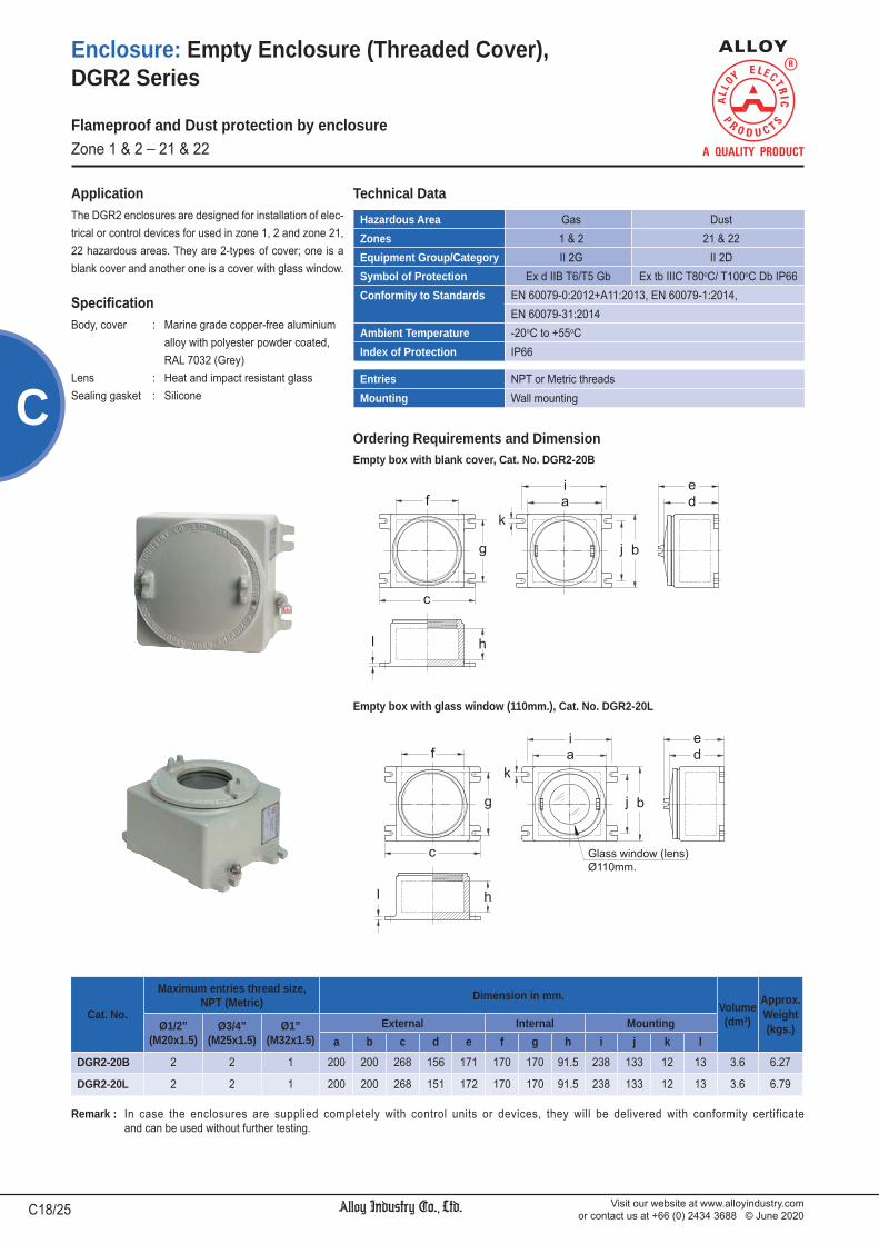
Visit our website at www.alloyindustry.comor contact us at +66 (0) 2434 3688 © June 2020C18/25
C
Enclosure: Empty Enclosure (Threaded Cover), DGR2 Series
Remark : In case the enclosures are supplied completely with control units or devices, they will be delivered with conformity certificate and can be used without further testing.
The DGR2 enclosures are designed for installation of elec-trical or control devices for used in zone 1, 2 and zone 21, 22 hazardous areas. They are 2-types of cover; one is a blank cover and another one is a cover with glass window.
Application
Body, cover : Marine grade copper-free aluminium alloy with polyester powder coated, RAL 7032 (Grey)Lens : Heat and impact resistant glassSealing gasket : Silicone
Ordering Requirements and DimensionEmpty box with blank cover, Cat. No. DGR2-20B
Empty box with glass window (110mm.), Cat. No. DGR2-20L
Flameproof and Dust protection by enclosureZone 1 & 2 _ 21 & 22
Hazardous Area Gas DustZones 1 & 2 21 & 22Equipment Group/Category II 2G II 2DSymbol of Protection Ex d IIB T6/T5 Gb Ex tb IIIC T80oC/ T100oC Db IP66Conformity to Standards EN 60079-0:2012+A11:2013, EN 60079-1:2014,
EN 60079-31:2014Ambient Temperature -20oC to +55oCIndex of Protection IP66
Entries NPT or Metric threadsMounting Wall mounting
Technical Data
Cat. No.
Maximum entries thread size, NPT (Metric) Dimension in mm.
Volume(dm3)
Approx.Weight(kgs.)Ø1/2”
(M20x1.5)Ø3/4”
(M25x1.5)Ø1”
(M32x1.5)External Internal Mounting
a b c d e f g h i j k l
DGR2-20B 2 2 1 200 200 268 156 171 170 170 91.5 238 133 12 13 3.6 6.27
DGR2-20L 2 2 1 200 200 268 151 172 170 170 91.5 238 133 12 13 3.6 6.79

Visit our website at www.alloyindustry.comor contact us at +66 (0) 2434 3688 © June 2020 C19/25
C
DSBB
Enclosure: Conduit Outlet Bodies (Rectangular Box), DSB Series
The DSB rectangular boxes are designed for use in the conduit system in hazardous areas, zone 1,2 and 21,22 to provide opening for taps, splices or pull outlet for
conductors. to provide an access to conduit system for maintenance. to change conduit direction. to use with threaded rigid steel conduit (RSC) or
intermediate metal conduit (IMC).
Application
Body, cover : Marine grade copper-free aluminium alloy with polyester powder coated, RAL 7032 (Grey)Lid screws : Stainless steel
Ordering Requirements and Dimension
DSBC DSBL DSBR DSBT DSBX
DSBB : 2-Ways Angle (Bottom)
DSBC : 2-Ways Through-feed
Hazardous Area Gas DustZones 1 & 2 21 & 22Equipment Group/Category II 2G II 2DSymbol of Protection Ex db IIB Gb Ex tb IIIC Db IP65Certificate TÜV CY 16 ATEX 0205813 UConformity to Standards EN 60079-0:2012+A11:2013, EN 60079-1:2014,
EN 60079-31:2014Ambient Temperature -20oC to +55oCIndex of Protection IP65 (Grease to increase protection) *
Technical Data
Entries Cat. No.Volume(dm3)
Dimension in mm. Approx.Weight(kgs.)a b c d e f g
Ø1/2” NPT DSBB 1 0.11 100.0 44.0 56.0 43.0 20.0 20.0 20.0 0.47Ø3/4” NPT DSBB 2 0.18 110.0 50.0 62.0 49.0 20.0 22.0 25.0 0.59
Ø1” NPT DSBB 3 0.36 130.5 60.0 76.5 61.0 24.0 24.0 27.0 0.95Ø1-1/4” NPT DSBB 4 0.58 144.0 65.0 88.5 73.0 24.5 32.5 33.5 1.25Ø1-1/2” NPT DSBB 5 0.80 161.0 70.0 95.5 78.5 26.5 35.0 43.0 1.64
Ø2” NPT DSBB 6 1.95 200.0 111.0 121.5 104.5 25.0 46.0 45.0 3.20Ø2-1/2” NPT DSBB 7 3.40 231.0 128.0 153.0 133.0 32.0 66.5 55.0 4.55
Ø3” NPT DSBB 8 4.90 262.0 142.0 162.0 142.0 34.0 71.0 60.0 5.71Ø3-1/2” NPT DSBB 9 8.60 311.0 174.0 197.0 173.0 35.5 77.0 78.0 8.55
Ø4” NPT DSBB 10 8.95 311.0 174.0 197.0 173.0 36.0 77.0 78.0 8.85
Ø1/2” NPT DSBC 1 0.11 100.0 44.0 56.0 43.0 20.0 20.0 -- 0.47Ø3/4” NPT DSBC 2 0.18 110.0 50.0 62.0 49.0 20.0 22.0 -- 0.59
Ø1” NPT DSBC 3 0.36 130.5 60.0 76.5 61.0 24.0 24.0 -- 0.95Ø1-1/4” NPT DSBC 4 0.58 144.0 65.0 88.5 73.0 24.5 32.5 -- 1.25Ø1-1/2” NPT DSBC 5 0.80 161.0 70.0 95.5 78.5 26.5 35.0 -- 1.64
Ø2” NPT DSBC 6 1.95 200.0 111.0 121.5 104.5 25.0 46.0 -- 3.20Ø2-1/2” NPT DSBC 7 3.40 231.0 128.0 153.0 133.0 32.0 66.5 -- 4.55
Ø3” NPT DSBC 8 4.90 262.0 142.0 162.0 142.0 34.0 71.0 -- 5.71Ø3-1/2” NPT DSBC 9 8.60 311.0 174.0 197.0 173.0 35.5 77.0 -- 8.55
Ø4” NPT DSBC 10 8.95 311.0 174.0 197.0 173.0 36.0 77.0 -- 8.85
Flameproof and Dust protection by enclosureZone 1 & 2 _ 21 & 22
a b c d e f g
* Recommened “alloy PG1 performance grease” for protect flameproof joint against corrosion and increase the level of the degree of protection.

Visit our website at www.alloyindustry.comor contact us at +66 (0) 2434 3688 © June 2020C20/25
C
Enclosure: Conduit Outlet Bodies (Rectangular Box), DSB Series
Ordering Requirements and Dimension
DSBL : 2-Ways Angle (Left)
DSBR : 2-Ways Angle (Right)
DSBT : 3-Ways
DSBX : 4-Ways
Entries Cat. No.Volume(dm3)
Dimension in mm. Approx.Weight(kgs.)a b c d e f g
Ø1/2” NPT DSBL 1 0.11 100.0 44.0 56.0 43.0 20.0 20.0 20.0 0.47Ø3/4” NPT DSBL 2 0.18 110.0 50.0 62.0 49.0 20.0 22.0 25.0 0.59
Ø1” NPT DSBL 3 0.36 130.5 60.0 76.5 61.0 24.0 24.0 27.0 0.95Ø1-1/4” NPT DSBL 4 0.58 144.0 65.0 88.5 73.0 24.5 32.5 33.5 1.25Ø1-1/2” NPT DSBL 5 0.80 161.0 70.0 95.5 78.5 26.5 35.0 43.0 1.64
Ø2” NPT DSBL 6 1.95 200.0 111.0 121.5 104.5 25.0 46.0 45.0 3.20Ø2-1/2” NPT DSBL 7 3.40 231.0 128.0 153.0 133.0 32.0 66.5 55.0 4.55
Ø3” NPT DSBL 8 4.90 262.0 142.0 162.0 142.0 34.0 71.0 60.0 5.71Ø3-1/2” NPT DSBL 9 8.60 311.0 174.0 197.0 173.0 35.5 77.0 78.0 8.55
Ø4” NPT DSBL 10 8.95 311.0 174.0 197.0 173.0 36.0 77.0 78.0 8.85
Ø1/2” NPT DSBR 1 0.11 100.0 44.0 56.0 43.0 20.0 20.0 20.0 0.47Ø3/4” NPT DSBR 2 0.18 110.0 50.0 62.0 49.0 20.0 22.0 25.0 0.59
Ø1” NPT DSBR 3 0.36 130.5 60.0 76.5 61.0 24.0 24.0 27.0 0.95Ø1-1/4” NPT DSBR 4 0.58 144.0 65.0 88.5 73.0 24.5 32.5 33.5 1.25Ø1-1/2” NPT DSBR 5 0.80 161.0 70.0 95.5 78.5 26.5 35.0 43.0 1.64
Ø2” NPT DSBR 6 1.95 200.0 111.0 121.5 104.5 25.0 46.0 45.0 3.20Ø2-1/2” NPT DSBR 7 3.40 231.0 128.0 153.0 133.0 32.0 66.5 55.0 4.55
Ø3” NPT DSBR 8 4.90 262.0 142.0 162.0 142.0 34.0 71.0 60.0 5.71Ø3-1/2” NPT DSBR 9 8.60 311.0 174.0 197.0 173.0 35.5 77.0 78.0 8.55
Ø4” NPT DSBR 10 8.95 311.0 174.0 197.0 173.0 36.0 77.0 78.0 8.85
Ø1/2” NPT DSBT 1 0.12 100.0 44.0 56.0 43.0 20.0 20.0 ¯ 0.47Ø3/4” NPT DSBT 2 0.20 110.0 50.0 62.0 49.0 20.0 22.0 ¯ 0.59
Ø1” NPT DSBT 3 0.38 130.5 60.0 76.5 61.0 24.0 24.0 ¯ 0.95Ø1-1/4” NPT DSBT 4 0.60 144.0 65.0 88.5 73.0 24.5 32.5 ¯ 1.25Ø1-1/2” NPT DSBT 5 0.83 161.0 70.0 95.5 78.5 26.5 35.0 ¯ 1.64
Ø2” NPT DSBT 6 2.00 200.0 111.0 121.5 104.5 25.0 46.0 ¯ 3.20Ø2-1/2” NPT DSBT 7 3.42 231.0 128.0 153.0 133.0 32.0 66.5 ¯ 4.55
Ø3” NPT DSBT 8 4.92 262.0 142.0 162.0 142.0 34.0 71.0 ¯ 5.71Ø3-1/2” NPT DSBT 9 8.62 311.0 174.0 197.0 173.0 35.5 77.0 ¯ 8.55
Ø4” NPT DSBT 10 8.99 311.0 174.0 197.0 173.0 36.0 77.0 ¯ 8.85
Ø1/2” NPT DSBX 1 0.13 100.0 44.0 56.0 43.0 20.0 20.0 ¯ 0.47Ø3/4” NPT DSBX 2 0.21 110.0 50.0 62.0 49.0 20.0 22.0 ¯ 0.59
Ø1” NPT DSBX 3 0.40 130.5 60.0 76.5 61.0 24.0 24.0 ¯ 0.95Ø1-1/4” NPT DSBX 4 0.62 144.0 65.0 88.5 73.0 24.5 32.5 ¯ 1.25Ø1-1/2” NPT DSBX 5 0.85 161.0 70.0 95.5 78.5 26.5 35.0 ¯ 1.64
Ø2” NPT DSBX 6 2.04 200.0 111.0 121.5 104.5 25.0 46.0 ¯ 3.20Ø2-1/2” NPT DSBX 7 3.44 231.0 128.0 153.0 133.0 32.0 66.5 ¯ 4.55
Ø3” NPT DSBX 8 4.94 262.0 142.0 162.0 142.0 34.0 71.0 ¯ 5.71Ø3-1/2” NPT DSBX 9 8.64 311.0 174.0 197.0 173.0 35.5 77.0 ¯ 8.55
Ø4” NPT DSBX 10 9.00 311.0 174.0 197.0 173.0 36.0 77.0 ¯ 8.85
Flameproof and Dust protection by enclosureZone 1 & 2 _ 21 & 22
a b c d e f g
a b c d e f g
a b c d e f g

Visit our website at www.alloyindustry.comor contact us at +66 (0) 2434 3688 © June 2020 C21/25
C
Enclosure: Empty Enclosures, DJB Series
The DJB empty boxes are designed for in hazardous areas, zone 1, 2 and zone 21, 22. taps, splices or connecting of power circuit.
Application
Body, cover : Marine grade copper-free aluminium alloy with polyester powder coated, RAL 7032 (Grey)Lid screws : Stainless steelSealing gasket : Silicone
Rated voltage : up to 800V.ac (as per equipment specification)
Electrical Rating
Remark: Certificate with symbol “U” denotes an Ex Component. It indicates that the equipment is incomplete and is not suitable for installation without further evaluation.
Dissipation Power Loss by use in Temperature Class
Cat. No.Max. Dissipation Power Loss (Watt)
Ta = +40oC Ta = +55oCT6 T5 T6 T5
DJB 796 100 140 65 100DJB 10126 125 175 80 125DJB 10128 145 200 90 145DJB 9147 135 185 85 135DJB 10158 200 275 125 200DJB 12128 175 240 110 175DJB 12168 245 340 155 245DJB 10208 255 350 160 255DJB 12149 260 360 165 260DJB 14149 270 370 170 270DJB 11199 260 360 165 260DJB 12169 280 380 175 280DJB 121810 350 480 220 350DJB 12219 325 450 205 325DJB 16169 360 495 225 360DJB 12239 390 535 240 390DJB 13269 420 580 165 420DJB 132610 440 605 275 440DJB 162210 460 635 290 460DJB 181812 455 625 285 455DJB 162012 455 625 285 455DJB 15319 530 735 335 530
Hazardous Area Gas DustZones 1 & 2 21 & 22Equipment Group/Category II 2G II 2DSymbol of Protection Ex d IIB T6/T5 Ex tD A21 IP66 T85oC/ T100oCCertificate PTB 07 ATEX 1070 UConformity to Standards EN 60079-0:2006, EN 60079-1:2004,
EN 61241-0:2006, EN 61241-1:2004Ambient Temperature -20oC to +55oCIndex of Protection IP66
Entries NPT or Metric threadsMounting Wall type
Technical Data
Flameproof and Dust protection by enclosureZone 1 & 2 _ 21 & 22

Visit our website at www.alloyindustry.comor contact us at +66 (0) 2434 3688 © June 2020C22/25
C
Enclosure: Empty Enclosures, DJB Series
Ordering Requirements and Dimension
Flameproof and Dust protection by enclosureZone 1 & 2 _ 21 & 22
Cat. No.
Dimension in mm. WallThick-ness
Volume(dm3)
EmptyWeight(kgs.)
Inside Outside Equipment Plate Mounting
a b c d e f g h i j k lDJB 796 111 160 100 183 232 120 145 95 140 148 91 7.5 17 1.9 6.08
DJB 10126 162 212 110 248 298 127 163 144 195 218 135 10 17 4.3 12.05
DJB 10128 168 219 159 254 305 175 211 151 196 218 135 10 17 5.0 13.90
DJB 9147 152 261 126 238 347 146 181 139 246 205 133 10 20 5.4 13.00
DJB 10158 174 295 139 260 381 156 194 156 277 223 179 10 17 7.3 15.85
DJB 12128 217 217 161 303 303 178 216 203 203 269 134 10 20 8.3 16.60
DJB 12168 216 321 119 310 415 143 193 195 300 274 197 12 30 8.7 30.55
DJB 10208 164 423 133 258 517 159 207 148 403 224 308 12 30 8.9 28.00
DJB 12149 217 268 162 311 362 189 236 197 248 270 163 12 30 9.4 25.00
DJB 14149 265 265 166 359 359 190 238 247 247 327 163 12 30 10.5 29.00
DJB 11199 192 384 158 286 478 185 230 174 364 248 280 12 30 11.6 30.55
DJB 12169 216 321 163 310 415 187 237 195 300 270 198 12 30 11.7 31.00
DJB 121810 217 373 171 311 467 195 245 197 351 274 239 12 30 13.7 33.00
DJB 12219 212 435 164 306 529 190 237 198 420 273 326 12 30 14.9 36.85
DJB 16169 312 312 155 410 410 190 239 301 301 376 197 12 35 18.0 42.65
DJB 12239 217 496 157 315 594 190 241 202 480 278 363 12 35 19.6 46.05
DJB 13269 244 569 157 342 667 187 241 224 546 307 441 12 35 25.3 57.45
DJB 132610 244 569 179 342 667 208 262 224 546 307 407 12 35 26.0 58.82
DJB 162210 318 472 173 416 570 202 258 300 450 410 300 15 35 27.3 60.55
DJB 181812 370 370 222 468 468 251 306 338 338 435 237 12 35 28.2 57.25
DJB 162012 315 419 226 413 517 254 309 290 395 376 274 12 35 29.6 56.85
DJB 15319 280 680 149 378 778 184 234 250 650 353 503 15 35 30.7 65.00
DJB - Series Enclosure Position
(see catalogue V Verticalnumber table) H Horizontal
Catalogue Number Logic

Visit our website at www.alloyindustry.comor contact us at +66 (0) 2434 3688 © June 2020 C23/25
C
Enclosure: Empty Enclosures, DJB Series
Maximum Entries Thread Size; VERTICAL
Flameproof and Dust protection by enclosureZone 1 & 2 _ 21 & 22
Cat. No.Maximum entries thread size, NPT (Metric)
Ø1/2”(M20x1.5)
Ø3/4”(M25x1.5)
Ø1”(M32x1.5)
Ø1-1/4”(M40x1.5)
Ø1-1/2”(M50x1.5)
Ø2”(M63x1.5)
Ø2-1/2”(M75x1.5)
Ø3”(M80x2.0)
Ø3-1/2”(M90x2.0)
Ø4”(M100x2.0)
TOP or BOTTOMDJB 796 V 2 2 1 1 1DJB 10126 V 3 3 2 2 2DJB 10128 V 5 4 4 2 2 1 1DJB 9147 V 3 3 2 2 1 1DJB 10158 V 5 5 3 2 2 1 1DJB 12128 7 6 6 3 2 2 2 1DJB 12168 V 4 4 3 2DJB 10208 V 5 3 2 2 2 1DJB 12149 V 7 6 5 3 2 2 1DJB 14149 8 8 7 3 3 2 2 2DJB 11199 V 6 6 4 2 2 1 1DJB 12169 V 7 6 4 2 2 2 1DJB 121810 V 7 6 6 3 2 2 1 1DJB 12219 V 7 6 4 2 2 2 1 1DJB 16169 10 9 7 4 3 3 2DJB 12239 V 7 6 3 2 2 2 1DJB 13269 V 8 7 3 3 2 2 2DJB 132610 V 8 7 6 3 2 2 2 1DJB 162210 V 11 10 9 4 3 3 2 2DJB 181812 15 15 9 8 7 3 3 2 2 2DJB 162012 V 12 12 8 7 5 2 2 2 2 1DJB 15319 V 9 8 5 3 3 2 2
RIGHTDJB 796 V 3 2 2 1 1DJB 10126 V 3 3 2 2 2DJB 10128 V 5 4 4 2 2 1 1DJB 9147 V 4 4 3 2 2 2DJB 10158 V 8 7 5 3 2 2 2DJB 12128 5 5 4 2 2 1 1 1DJB 12168 V 5 5 4 3DJB 10208 V 11 8 6 4 4 3DJB 12149 V 7 6 6 3 2 2 1DJB 14149 6 6 5 2 2 1 1 1DJB 11199 V 11 10 8 5 3 3 2DJB 12169 V 9 8 6 3 3 2 2DJB 121810 V 11 10 9 5 3 3 2 2DJB 12219 V 13 12 9 5 4 3 3 2DJB 16169 8 7 5 3 3 2 2DJB 12239 V 15 13 6 5 5 4 3DJB 13269 V 17 16 8 6 5 4 4DJB 132610 V 17 16 15 6 5 4 4 3DJB 162210 V 14 13 11 5 4 3 3 2DJB 181812 11 11 7 6 5 2 2 2 1 1DJB 162012 V 14 14 9 8 7 3 2 2 2 1DJB 15319 V 22 20 12 8 7 5 5
LEFTDJB 796 V 4 3 2 2 2DJB 10126 V 4 4 3 2 2DJB 10128 V 7 6 5 3 3 2 1DJB 9147 V 5 5 4 3 3 2DJB 10158 V 9 9 6 3 3 2 2DJB 12128 7 6 6 3 2 2 2 1DJB 12168 V 6 5 5 4DJB 10208 V 13 9 7 5 4 3DJB 12149 V 9 8 7 3 3 2 2DJB 14149 8 8 7 3 2 2 2 2DJB 11199 V 12 12 9 5 4 3 3DJB 12169 V 11 10 7 4 3 3 2DJB 121810 V 13 11 10 5 4 3 3 2DJB 12219 V 15 14 10 5 5 4 3 2DJB 16169 10 9 7 4 3 3 2DJB 12239 V 17 15 7 6 5 4 4DJB 13269 V 19 18 8 7 6 5 4DJB 132610 V 19 18 16 7 6 5 4 3DJB 162210 V 16 15 14 6 5 4 3 3DJB 181812 15 15 9 8 7 3 3 2 2 2DJB 162012 V 16 16 10 9 7 3 3 2 2 2DJB 15319 V 23 21 13 8 7 6 5

Visit our website at www.alloyindustry.comor contact us at +66 (0) 2434 3688 © June 2020C24/25
C
Enclosure: Empty Enclosures, DJB Series
Flameproof and Dust protection by enclosureZone 1 & 2 _ 21 & 22
Maximum Entries Thread Size; HORIZONTAL
Cat. No.Maximum entries thread size, NPT (Metric)
Ø1/2”(M20x1.5)
Ø3/4”(M25x1.5)
Ø1”(M32x1.5)
Ø1-1/4”(M40x1.5)
Ø1-1/2”(M50x1.5)
Ø2”(M63x1.5)
Ø2-1/2”(M75x1.5)
Ø3”(M80x2.0)
Ø3-1/2”(M90x2.0)
Ø4”(M100x2.0)
TOP or BOTTOMDJB 796 H 4 3 2 2 2DJB 10126 H 4 4 3 2 2DJB 10128 H 7 6 5 3 3 2 1DJB 9147 H 5 5 4 3 3 2DJB 10158 H 9 9 6 3 3 2 2DJB 12128 7 6 6 3 2 2 2 1DJB 12168 H 6 5 5 4DJB 10208 H 13 9 7 5 4 3DJB 12149 H 9 8 7 3 3 2 2DJB 14149 8 8 7 3 2 2 2 2DJB 11199 H 12 12 9 5 4 3 3DJB 12169 H 11 10 7 4 3 3 2DJB 121810 H 13 11 10 5 4 3 3 2DJB 12219 H 15 14 10 5 5 4 3 2DJB 16169 10 9 7 4 3 3 2DJB 12239 H 17 15 7 6 5 4 4DJB 13269 H 19 18 8 7 6 5 4DJB 132610 H 19 18 16 7 6 5 4 3DJB 162210 H 16 15 14 6 5 4 3 3DJB 181812 15 15 9 8 7 3 3 2 2 2DJB 162012 H 16 16 10 9 7 3 3 2 2 2DJB 15319 H 23 21 13 8 7 6 5
RIGHTDJB 796 H 1 1 1 1 1DJB 10126 H 2 2 1 1 1DJB 10128 H 3 3 1 1 1 1 1DJB 9147 H 2 2 1 1 1 1DJB 10158 H 3 3 2 1 1 1 1DJB 12128 5 5 4 2 2 1 1 1DJB 12168 H 3 3 2 2DJB 10208 H 2 2 1 1 1 1DJB 12149 H 5 5 4 2 2 1 1DJB 14149 6 6 5 2 2 1 1 1DJB 11199 H 4 4 3 2 1 1 1DJB 12169 H 5 4 3 2 2 1 1DJB 121810 H 5 5 4 2 2 1 1 1DJB 12219 H 5 4 3 2 2 1 1 1DJB 16169 8 7 5 3 3 2 2DJB 12239 H 5 4 2 2 1 1 1DJB 13269 H 6 5 3 2 2 1 1DJB 132610 H 6 5 5 2 2 1 1 1DJB 162210 H 8 8 7 3 3 2 2 1DJB 181812 11 11 7 6 5 2 2 2 1 1DJB 162012 H 9 9 6 5 5 2 2 1 1 1DJB 15319 H 8 7 4 3 2 2 2
LEFTDJB 796 H 2 2 1 1 1DJB 10126 H 3 3 2 2 2DJB 10128 H 5 4 4 2 2 1 1DJB 9147 H 3 3 2 2 1 1DJB 10158 H 5 5 3 2 2 1 1DJB 12128 7 6 6 3 2 2 2 1DJB 12168 H 4 4 3 2DJB 10208 H 5 3 2 2 2 1DJB 12149 H 7 6 5 3 2 2 1DJB 14149 8 8 7 3 3 2 2 2DJB 11199 H 6 6 4 2 2 1 1DJB 12169 H 7 6 4 2 2 2 1DJB 121810 H 7 6 6 3 2 2 1 1DJB 12219 H 7 6 4 2 2 2 1 1DJB 16169 10 9 7 4 3 3 2DJB 12239 H 7 6 3 2 2 2 1DJB 13269 H 8 7 3 3 2 2 2DJB 132610 H 8 7 6 3 2 2 2 1DJB 162210 H 11 10 9 4 3 3 2 2DJB 181812 15 15 9 8 7 3 3 2 2 2DJB 162012 H 12 12 8 7 5 2 2 2 2 1DJB 15319 H 9 8 5 3 3 2 2

Visit our website at www.alloyindustry.comor contact us at +66 (0) 2434 3688 © June 2020 C25/25
C
Enclosure: Junction Boxes (Empty), WJB Series
WeatherproofIP66
The WJB junction boxes are designed to provide openings for taps, splices or pull box. to enclose terminals, meters, relays or other electrical
devices. for indoor and outdoor in wet and corrosive locations.
Application
Body, cover : Marine grade copper-free aluminium alloy with polyester powder coated, RAL 7032 (Grey)Lid screws : Stainless steelSealing gasket : Silicone
Rated voltage : up to 800V.ac (as per equipment specification)
Electrical Rating
Ordering Requirements and Dimension
Protection WeatherproofIndex of Protection IP66Ambient Temperature -20 oC to +55 oCMounting Wall mount
Technical Data
Cat. No.
Dimension in mm.Max. Entries Empty
Weight(kgs.)
Inside Outside Equip. Plate Mounting
a b c d e f g h i j k l NPT Metric
WJB 685 96 147 111 147 204 113 135 90 145 128 100 7.5 Ø1-1/4” M40x1.5 2.61
WJB 885 133 133 109 205 205 107 134 115 115 176 90 12 Ø1-1/4” M40x1.5 2.76
WJB 8125 131 235 100 205 310 102 125 115 220 185 160 12 Ø1-1/4” M40x1.5 4.45
WJB 8126 130 235 120 205 310 122 145 115 220 185 160 12 Ø1-1/2” M50x1.5 4.65
WJB 9157 158 309 175 228 381 172 198 150 295 211 230 12 Ø1-1/2” M50x1.5 7.77
WJB 15156 308 308 108 375 375 112 140 280 280 358 240 12 Ø1-1/4” M40x1.5 10.26
WJB 15196 296 397 133 375 475 142 164 280 380 333 300 12 Ø1-1/4” M40x1.5 11.40
WJB - Series Enclosure Position
(see catalogue V Verticalnumber table) H Horizontal
Catalogue Number Logic


1. Panel Mounted Operating Devices and Windows, IIB D2/ 67
2. Panel Mounted Operating Devices and Windows, IIC D7/ 67
3. Control Station (Rectangular Shape) D13/ 67
Push Button EPB Series D14/ 67
Pilot Light EPL Series D16/ 67
Push Button and Pilot Light EPBL Series D18/ 67
Emergency Push Button EEM Series D19/ 67
Selector Switch ESL Series D20/ 67
Key Selector Switch EKS Series D21/ 67
4. Control Unit DCU Series D23/ 67
5. Control Station CTE2 Series D28/ 67
6. Control Station WCT2 Series D29/ 67
7. Emergency Control Station EAS Series D30/ 67 (Break-Glass Type)
8. Control Box DCT Series D31/ 67
Circuit Breaker DCT..-CB Series D33/ 67
Motor Starters DCT..-MS, ECT..-CS Series D34/ 67
Circuit Breaker Panelboards DCT..-PN Series D35/ 67
9. Control Box DCT1 Series D37/ 67
10. Control Box DCT1D Series D43/ 67
11. Control Box/ Junction Box DCT1DE/JBE3B Series D46/ 67
12. Switchrack Assemblies -- D48/ 67
13. Control Box AEC2B Series D49/ 67
We reserve the right to make alterations to the technical data, weights, dimensions, designs and products available without notice. The illustrations cannot be considered binding.
CONTROL STATIONS AND CONTROL PANELS D

Visit our website at www.alloyindustry.comor contact us at +66 (0) 2434 3688 © June 2020D2/67
D
Control Station and Control Panel: Panel Mounted Operating Devices and Windows, IIB
The panel mounted operating devices are designed for used with the flameproof enclosure and dust protection enclosure for controlling or indicating the status of electrical equipment such as motor starter, control equipment operation. They are suitable for Zone 1, 2 and Zone 21, 22 hazardous areas.
Application
Thread coupling, Shaft : Stainless steelThread bushing : AluminiumLock nut : Nickel-plated brass Flush button : PlasticO-ring : Neoprene
Electrical RatingDPL series
Page D3/67
DPB series
Page D3/67
DPBS series
Page D4/67
DMPB series
Page D4/67
LGCR-50-M85
Page D6/67
DCM series
Page D6/67
DSLK series
Page D5/67
DSL series
Page D5/67
Technical DataHazardous Area Gas DustZones 1 & 2 21 & 22Equipment Group/Category II 2G II 2DSymbol of Protection Ex db IIB Ex tb IIIB IP66Ambient Temperature -20oC to +60oCIndex of Protection IP66Certificate Presafe 16 ATEX 8037 U
IECEx PRE 16.0026 UConformity to Standards EN 60079-0:2012+A11:2013, EN 60079-1:2007,
EN 60079-31:2014IEC 60079-0:2011, IEC 60079-1:2007-04, IEC 60079-31:2008
Flameproof and Dust protection by enclosureZone 1 & 2 _ 21 & 22
Pilot lights characteristicsCurrentconsumption
For all colours 24V.dc/ ac 20mA. (27 max)120V.ac 18mA. (21 max)
230-240V.ac 16mA. (20 max)Voltage limit At norminal
voltage24V.dc 19.2-30V.dc24V.ac 26.1-26.4V.ac
120V.ac 100-132V.ac230-240V.ac 195-264V.ac
Service life At norminal voltage andat an ambient temp. of 25oC
70,000Hrs.
Contact Block ratingsRated operational current(EN/IEC 60947-5-1)
AC15 240V. 3A.600V. 1.2A.
DC13 250V. 0.27A.600V. 0.1A.
Rated thermal current 10A.Rated insulation voltage 600V.
Cam operated switchesRated operational current(EN/IEC 60947-3)
16A. 25A. 32A.
Rated thermal current 20A. 30A. 40A.
Rated insulation voltage 400V. 400V. 600V.

Visit our website at www.alloyindustry.comor contact us at +66 (0) 2434 3688 © June 2020 D3/67
DPush Button, DPB series
Pilot Light, DPL series
Control Station and Control Panel: Panel Mounted Operating Devices and Windows, IIB
Catalogue Number Logic
Dimension in mm. (L)
OperatingVoltage
Diagram(Integral LED)
Colourof Lens Cat. No.
Approx.Weight(kgs.)
24V.dc/ ac Green DPL- D02G 0.145Red DPL- D02RYellow DPL- D02YBlue DPL- D02BClear DPL- D02C
120V.ac Green DPL- A12G 0.145Red DPL- A12RYellow DPL- A12YBlue DPL- A12BClear DPL- A12C
220-230V.ac50/60Hz.
Green DPL- A22G 0.145Red DPL- A22RYellow DPL- A22YBlue DPL- A22BClear DPL- A22C
DPL - Series Wall thickness
of enclosureVoltage Colour of lens
D02 24V.dc G Green B BlueA 15-30 mm. A12 120V.ac R Red C ClearB 31-45 mm. A22 220-230V.ac Y Yellow
Wall thickness of enclosure ( )A (15-30mm.) B (31-45mm.)
99.0 119.0
Type of Function Contact Symbol Colourof Button Cat. No.
Approx.Weight(kgs.)
Momentary 1NO Green DPB- 10G 0.215Red DPB- 10RYellow DPB- 10YBlack DPB- 10BWhite DPB- 10W
1NC Green DPB- 01G 0.215Red DPB- 01RYellow DPB- 01YBlack DPB- 01BWhite DPB- 01W
1NO-1NC Green DPB- 11G 0.230Red DPB- 11RYellow DPB- 11YBlack DPB- 11BWhite DPB- 11W
2NO Green DPB- 20G 0.230Red DPB- 20RYellow DPB- 20YBlack DPB- 20BWhite DPB- 20W
2NC Green DPB- 02G 0.230Red DPB- 02RYellow DPB- 02YBlack DPB- 02BWhite DPB- 02W
DPB - Series Wall thickness
of enclosureContact Colour of button
10 1NO 20 2NO G Green B BlackA 15-30 mm. 01 1NC 02 2NC R Red W WhiteB 31-45 mm. 11 1NO-1NC Y Yellow
Dimension in mm. (L)
Wall thickness of enclosure ( )A (15-30mm.) B (31-45mm.)
96.0 116.0
Flameproof and Dust protection by enclosureZone 1 & 2 _ 21 & 22
Ordering Requirements
Catalogue Number Logic
Ordering Requirements

Visit our website at www.alloyindustry.comor contact us at +66 (0) 2434 3688 © June 2020D4/67
DMushroom-Head Push Button,DMPB series
Push Button Shaft, DPBS series
Control Station and Control Panel: Panel Mounted Operating Devices and Windows, IIB
Flameproof and Dust protection by enclosureZone 1 & 2 _ 21 & 22
Type of Function Shaft Length Colourof Button Cat. No.
Approx.Weight(kgs.)
Momentary 50mm. Green DPBS- 50G 0.215Red DPBS- 50RYellow DPBS- 50YBlack DPBS- 50BWhite DPBS- 50W
100mm. Green DPBS- 1XG 0.235Red DPBS- 1XRYellow DPBS- 1XYBlack DPBS- 1XBWhite DPBS- 1XW
DPBS - Series Wall thickness
of enclosureShaft length Colour of button
50 50mm. G Green B BlackA 15-30 mm. 1X 100mm. R Red W WhiteB 31-45 mm. Y Yellow
DMPB - RSeries Wall thickness
of enclosureType of function Contact
1 Push-pull 10 1NO 20 2NOA 15-30 mm. 2 Push-lock, Turn to release 01 1NC 02 2NCB 31-45 mm. 3 Push-lock, Key to release
Type of Function Contact Colourof Button Cat. No.
Approx.Weight(kgs.)
Push-pull 1NO Red DMPB- 110R 0.254Push-lock, Turn to release DMPB- 210R 0.254Push-lock, Key to release DMPB- 310R 0.255
Push-pull 1NC Red DMPB- 101R 0.254Push-lock, Turn to release DMPB- 201R 0.254Push-lock, Key to release DMPB- 301R 0.255
Push-pull 2NO Red DMPB- 120R 0.269Push-lock, Turn to release DMPB- 220R 0.269Push-lock, Key to release DMPB- 320R 0.270
Push-pull 2NC Red DMPB- 102R 0.269Push-lock, Turn to release DMPB- 202R 0.269Push-lock, Key to release DMPB- 302R 0.270
Dimension in mm. (L)
Wall thickness of enclosure ( )A (15-30mm.) B (31-45mm.)
125.0 145.0
Push-pull
Wall thickness of enclosure ( )A (15-30mm.) B (31-45mm.)
122.5 142.5
Push-lock, Turn to release
Wall thickness of enclosure ( )A (15-30mm.) B (31-45mm.)
145.5 165.5
Push-lock, Key to release
Dimension in mm. (L)
Catalogue Number Logic
Ordering Requirements
Wall thickness of enclosure ( )50mm. shaft length 100mm. shaft length
A (15-30mm.) B (31-45mm.) A (15-30mm.) B (31-45mm.)122.0 142.0 172.0 192.0
Catalogue Number Logic
Ordering Requirements

Visit our website at www.alloyindustry.comor contact us at +66 (0) 2434 3688 © June 2020 D5/67
D
Control Station and Control Panel: Panel Mounted Operating Devices and Windows, IIB
Selector Switch, DSL series
Key Selector Switch, DSLK series
Flameproof and Dust protection by enclosureZone 1 & 2 _ 21 & 22
D - Series Wall thickness
of enclosurePosition Contact Function
DSL Selector Switch 2 2-Positions 10 1NO 20 2NO S Spring returnDSLK Key Selector Switch A 15-30 mm. 3 3-Positions 01 1NC 02 2NC R Spring return from Right
B 31-45 mm. 11 1NO-1NC
Type of Function Contact Cat. No.Approx.Weight(kgs.)
2-PositionsStay put(or Maintained)
1NO DSL- 210 0.230
2NO DSL- 220 0.245
1NO-1NC DSL- 211 0.245
Spring return 1NO DSL- 210S 0.230
2NO DSL- 220S 0.245
1NO-1NC DSL- 211S 0.245
3-PositionsStay put(or Maintained)
2NODSL- 320 0.250
Spring returnfrom right to centre 2NO
DSL- 320R 0.250
2-Positions 3-PositionsDimension in mm. (L)
Wall thickness of enclosure ( )2-Positions 3-Positions
A (15-30mm.) B (31-45mm.) A (15-30mm.) B (31-45mm.)
115.5 165.5 132.0 152.0
Type of Function Contact Cat. No.Approx.Weight(kgs.)
2-PositionsStay put(or Maintained)
1NO DSLK- 210 0.235
2NO DSLK- 220 0.250
1NO-1NC DSLK- 211 0.250
3-PositionsStay put(or Maintained)
2NO DSLK- 320 0.255
2-Positions 3-Positions
Dimension in mm. (L)
Wall thickness of enclosure ( )2-Positions 3-Positions
A (15-30mm.) B (31-45mm.) A (15-30mm.) B (31-45mm.)
141.5 161.5 158.0 178.0
Catalogue Number Logic
Ordering Requirements
Ordering Requirements

Visit our website at www.alloyindustry.comor contact us at +66 (0) 2434 3688 © June 2020D6/67
D
Control Station and Control Panel: Panel Mounted Operating Devices and Windows, IIB
Flameproof and Dust protection by enclosureZone 1 & 2 _ 21 & 22
Cam Operated Switch, DCM series
Dimension in mm. (L)
DCM - Series Wall thickness of enclosure Type of function Ampere
A 15-30 mm. 1 Single pole 16 16A.B 31-45 mm. 2 Double poles 25 25A.
32 32A.
Ampere Connection Cat. No.Approx.Weight(kgs.)
2-Steps (Position 45o)Single pole 16A. DCM- 116 0.318
25A. DCM- 12532A. DCM- 132
Double poles 16A. DCM- 216 0.350
25A. DCM- 22532A. DCM- 232Wall thickness of enclosure ( )
A (15-30mm.) B (31-45mm.)128.0 148.0
Inspection Window (Round type)
O 50
M85x1.5
105 30.5 Lens diameter *(mm.) Cat. No. Wall
thickness
Approx.Weight(kgs.)
50 LGCR-50-M85 10-45mm. 0.515
* Suitable for meters with maximum panel size of 48x48mm.
Catalogue Number Logic
Ordering Requirements
Ordering Requirements

Visit our website at www.alloyindustry.comor contact us at +66 (0) 2434 3688 © June 2020 D7/67
D
Control Station and Control Panel: Panel Mounted Operating Devices and Windows, IIC
Flameproof and Dust protection by enclosureZone 1 & 2 _ 21 & 22
The panel mounted operating devices are designed for used with the flameproof enclosure and dust protection enclosure for controlling or indicating the status of electrical equipment such as motor starter, control equipment operation. They are suitable for Zone 1, 2 and Zone 21, 22 hazardous areas.
Application
Thread coupling, Shaft : Stainless steelThread bushing : AluminiumLock nut : Nickel-plated brassFlush button : PlasticO-ring : Neoprene
Electrical Rating
DPL1 series
Page D8/67
DPB1 series
Page D8/67
DPBS1 series
Page D9/67
DMPB1 series
Page D9/67
DCM1 series
Page D11/67
DSLK1 series
Page D10/67
DSL1 series
Page D10/67
ASPB1 series
Page D9/67
Technical DataHazardous Area Gas DustZones 1 & 2 21 & 22Equipment Group/Category II 2G II 2DSymbol of Protection DPL1, DPB1, DPBS1, DMPB1, ASPB1, DSL1 & DSLK1 series
Ex db IIC Gb Ex tb IIIC Db IP66ACM1, ACM2, ALCB1, ALCB2, ALCB3 & DCM1 seriesLGCR, LGCR1 & LGCS series Ex db IIB+H2 Gb Ex tb IIIC Db IP66
Certificate TÜV CY 17 ATEX 0205880 UConformity to Standards EN 60079-0:2012+A11:2013, EN 60079-1:2014, EN 60079-31:2014 Ambient Temperature -20oC to +55oC Index of Protection IP66
Pilot lights characteristicsCurrentconsumption
For all colours 24V.dc/ ac 20mA. (27 max)120V.ac 18mA. (21 max)
230-240V.ac 16mA. (20 max)Voltage limit At norminal
voltage24V.dc 19.2-30V.dc24V.ac 26.1-26.4V.ac
120V.ac 100-132V.ac230-240V.ac 195-264V.ac
Service life At norminal voltage and 70,000Hrs.at an ambient temp. of 25oC
Contact Block ratingsRated operational current(EN/IEC 60947-5-1)
AC15 240V. 3A.600V. 1.2A.
DC13 250V. 0.27A.600V. 0.1A.
Rated thermal current 10A.Rated insulation voltage 600V.
Cam operated switchesRated operational current 16A. 25A. 32A.(EN/IEC 60947-3)Rated thermal current 20A. 30A. 40A.Rated insulation voltage 400V. 400V. 600V.
ACM2 series
Page D11/67
ACM1 series
Page D11/67
ALCB1 series
Page D12/67
LGCS series
Page D12/67
LGCR1 series
Page D12/67
LGCR series
Page D12/67
ALCB3 series
Page D12/67
ALCB2 series
Page D12/67

Visit our website at www.alloyindustry.comor contact us at +66 (0) 2434 3688 © June 2020D8/67
D
Control Station and Control Panel: Panel Mounted Operating Devices and Windows, IIC
Flameproof and Dust protection by enclosureZone 1 & 2 _ 21 & 22
Push Button, DPB1 series
Pilot Light, DPL1 series
Dimension in mm. (L)
OperatingVoltage
Diagram(Integral LED)
Colourof Lens Cat. No.
Approx.Weight(kgs.)
24V.dc/ ac Green DPL1- D02G 0.145Red DPL1- D02RYellow DPL1- D02YBlue DPL1- D02BClear DPL1- D02C
120V.ac Green DPL1- A12G 0.145Red DPL1- A12RYellow DPL1- A12YBlue DPL1- A12BClear DPL1- A12C
220-230V.ac50/60Hz.
Green DPL1- A22G 0.145Red DPL1- A22RYellow DPL1- A22YBlue DPL1- A22BClear DPL1- A22C
DPL1 - Series Wall thickness
of enclosureVoltage Colour of lens
D02 24V.dc G Green B BlueA 15-30 mm. A12 120V.ac R Red C ClearB 31-45 mm. A22 220-230V.ac Y Yellow
Wall thickness of enclosure ( )A (15-30mm.) B (31-45mm.)
99.0 119.0
Type of Function Contact Symbol Colourof Button Cat. No.
Approx.Weight(kgs.)
Momentary 1NO Green DPB1- 10G 0.215Red DPB1- 10RYellow DPB1- 10YBlack DPB1- 10BWhite DPB1- 10W
1NC Green DPB1- 01G 0.215Red DPB1- 01RYellow DPB1- 01YBlack DPB1- 01BWhite DPB1- 01W
1NO-1NC Green DPB1- 11G 0.230Red DPB1- 11RYellow DPB1- 11YBlack DPB1- 11BWhite DPB1- 11W
2NO Green DPB1- 20G 0.230Red DPB1- 20RYellow DPB1- 20YBlack DPB1- 20BWhite DPB1- 20W
2NC Green DPB1- 02G 0.230Red DPB1- 02RYellow DPB1- 02YBlack DPB1- 02BWhite DPB1- 02W
DPB1 - Series Wall thickness
of enclosureContact Colour of button
10 1NO 20 2NO G Green B BlackA 15-30 mm. 01 1NC 02 2NC R Red W WhiteB 31-45 mm. 11 1NO-1NC Y Yellow
Dimension in mm. (L)
Wall thickness of enclosure ( )A (15-30mm.) B (31-45mm.)
96.0 116.0
Catalogue Number Logic
Ordering Requirements
Catalogue Number Logic
Ordering Requirements
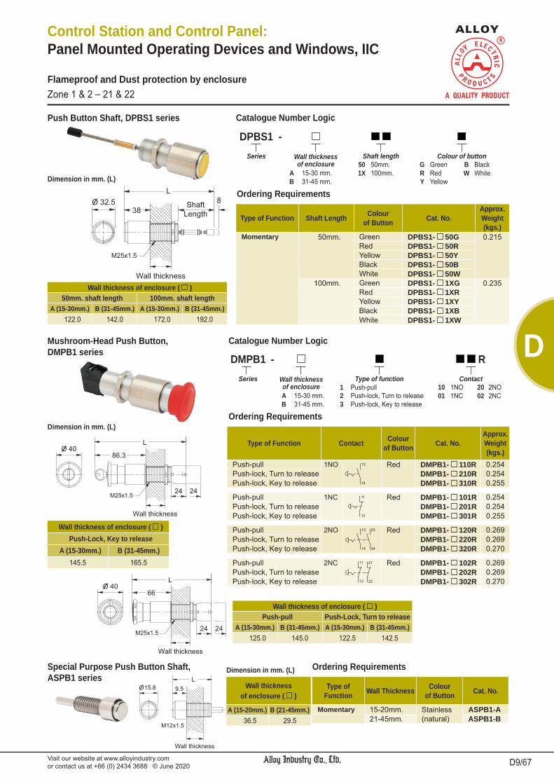
Visit our website at www.alloyindustry.comor contact us at +66 (0) 2434 3688 © June 2020 D9/67
D
Control Station and Control Panel: Panel Mounted Operating Devices and Windows, IIC
Flameproof and Dust protection by enclosureZone 1 & 2 _ 21 & 22
Mushroom-Head Push Button,DMPB1 series
DMPB1 - RSeries Wall thickness
of enclosureType of function Contact
1 Push-pull 10 1NO 20 2NOA 15-30 mm. 2 Push-lock, Turn to release 01 1NC 02 2NCB 31-45 mm. 3 Push-lock, Key to release
Type of Function Contact Colourof Button Cat. No.
Approx.Weight(kgs.)
Push-pull 1NO Red DMPB1- 110R 0.254Push-lock, Turn to release DMPB1- 210R 0.254Push-lock, Key to release DMPB1- 310R 0.255
Push-pull 1NC Red DMPB1- 101R 0.254Push-lock, Turn to release DMPB1- 201R 0.254Push-lock, Key to release DMPB1- 301R 0.255
Push-pull 2NO Red DMPB1- 120R 0.269Push-lock, Turn to release DMPB1- 220R 0.269Push-lock, Key to release DMPB1- 320R 0.270
Push-pull 2NC Red DMPB1- 102R 0.269Push-lock, Turn to release DMPB1- 202R 0.269Push-lock, Key to release DMPB1- 302R 0.270
Wall thickness of enclosure ( )Push-Lock, Key to release
A (15-30mm.) B (31-45mm.)145.5 165.5
Special Purpose Push Button Shaft,ASPB1 series
Type ofFunction Wall Thickness Colour
of Button Cat. No.
Momentary 15-20mm. Stainless ASPB1-A21-45mm. (natural) ASPB1-B
Wall thicknessof enclosure ( )
A (15-20mm.) B (21-45mm.)36.5 29.5
Push Button Shaft, DPBS1 series
Type of Function Shaft Length Colourof Button Cat. No.
Approx.Weight(kgs.)
Momentary 50mm. Green DPBS1- 50G 0.215Red DPBS1- 50RYellow DPBS1- 50YBlack DPBS1- 50BWhite DPBS1- 50W
100mm. Green DPBS1- 1XG 0.235Red DPBS1- 1XRYellow DPBS1- 1XYBlack DPBS1- 1XBWhite DPBS1- 1XW
DPBS1 - Series Wall thickness
of enclosureShaft length Colour of button
50 50mm. G Green B BlackA 15-30 mm. 1X 100mm. R Red W WhiteB 31-45 mm. Y YellowDimension in mm. (L)
Wall thickness of enclosure ( )50mm. shaft length 100mm. shaft length
A (15-30mm.) B (31-45mm.) A (15-30mm.) B (31-45mm.)122.0 142.0 172.0 192.0
Catalogue Number Logic
Ordering Requirements
Catalogue Number Logic
Ordering Requirements
Ordering RequirementsDimension in mm. (L)
Wall thickness of enclosure ( )Push-pull Push-Lock, Turn to release
A (15-30mm.) B (31-45mm.) A (15-30mm.) B (31-45mm.)125.0 145.0 122.5 142.5
Dimension in mm. (L)

Visit our website at www.alloyindustry.comor contact us at +66 (0) 2434 3688 © June 2020D10/67
D
Control Station and Control Panel: Panel Mounted Operating Devices and Windows, IIC
Flameproof and Dust protection by enclosureZone 1 & 2 _ 21 & 22
Selector Switch, DSL1 series
Key Selector Switch, DSLK1 series
D 1 - Series Wall thickness
of enclosurePosition Contact Function
DSL1 Selector Switch 2 2-Positions 10 1NO 20 2NO S Spring returnDSLK1 Key Selector Switch A 15-30 mm. 3 3-Positions 11 1NO-1NC R Spring return from Right
B 31-45 mm.
Type of Function Contact Cat. No.Approx.Weight(kgs.)
2-PositionsStay put(or Maintained)
1NO DSL1- 210 0.230
2NO DSL1- 220 0.245
1NO-1NC DSL1- 211 0.245
Spring return 1NO DSL1- 210S 0.230
2NO DSL1- 220S 0.245
1NO-1NC DSL1- 211S 0.245
3-PositionsStay put(or Maintained)
2NO DSL1- 320 0.250
Spring returnfrom right to centre
2NO DSL1- 320R 0.250
2-Positions 3-PositionsDimension in mm. (L)
Wall thickness of enclosure ( )2-Positions 3-Positions
A (15-30mm.) B (31-45mm.) A (15-30mm.) B (31-45mm.)
115.5 165.5 132.0 152.0
Type of Function Contact Cat. No.Approx.Weight(kgs.)
2-PositionsStay put(or Maintained)
1NO DSLK1- 210 0.235
2NO DSLK1- 220 0.250
1NO-1NC DSLK1- 211 0.250
3-PositionsStay put(or Maintained)
2NO DSLK1- 320 0.255
2-Positions 3-Positions
Dimension in mm. (L)
Wall thickness of enclosure ( )2-Positions 3-Positions
A (15-30mm.) B (31-45mm.) A (15-30mm.) B (31-45mm.)
141.5 161.5 158.0 178.0
Catalogue Number Logic
Ordering Requirements
Ordering Requirements
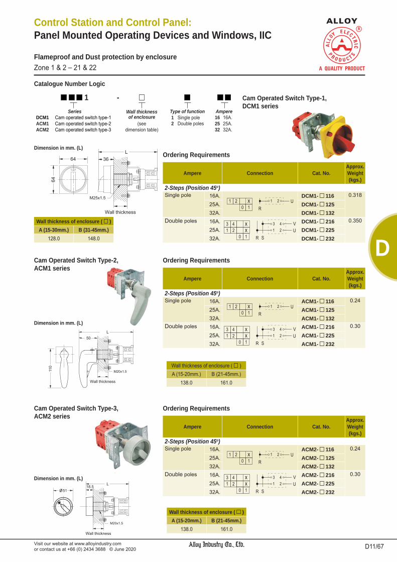
Visit our website at www.alloyindustry.comor contact us at +66 (0) 2434 3688 © June 2020 D11/67
D
Control Station and Control Panel: Panel Mounted Operating Devices and Windows, IIC
Flameproof and Dust protection by enclosureZone 1 & 2 _ 21 & 22
Cam Operated Switch Type-2,ACM1 series
Ampere Connection Cat. No.Approx.Weight(kgs.)
2-Steps (Position 45o)Single pole 16A. ACM1- 116 0.24
25A. ACM1- 12532A. ACM1- 132
Double poles 16A. ACM1- 216 0.30
25A. ACM1- 22532A. ACM1- 232
Wall thickness of enclosure ( )A (15-20mm.) B (21-45mm.)
138.0 161.0
Cam Operated Switch Type-3,ACM2 series
Ampere Connection Cat. No.Approx.Weight(kgs.)
2-Steps (Position 45o)Single pole 16A. ACM2- 116 0.24
25A. ACM2- 12532A. ACM2- 132
Double poles 16A. ACM2- 216 0.30
25A. ACM2- 22532A. ACM2- 232
Wall thickness of enclosure ( )A (15-20mm.) B (21-45mm.)
138.0 161.0
Cam Operated Switch Type-1,DCM1 series
Dimension in mm. (L)
1 - Series Wall thickness
of enclosureType of function Ampere
DCM1 Cam operated switch type-1 1 Single pole 16 16A.ACM1 Cam operated switch type-2 (see 2 Double poles 25 25A.ACM2 Cam operated switch type-3 dimension table) 32 32A.
Ampere Connection Cat. No.Approx.Weight(kgs.)
2-Steps (Position 45o)Single pole 16A. DCM1- 116 0.318
25A. DCM1- 12532A. DCM1- 132
Double poles 16A. DCM1- 216 0.350
25A. DCM1- 22532A. DCM1- 232
Wall thickness of enclosure ( )A (15-30mm.) B (31-45mm.)
128.0 148.0
Catalogue Number Logic
Ordering Requirements
Ordering Requirements
Dimension in mm. (L)
Ordering Requirements
Dimension in mm. (L)

Visit our website at www.alloyindustry.comor contact us at +66 (0) 2434 3688 © June 2020D12/67
D
Control Station and Control Panel: Panel Mounted Operating Devices and Windows, IIC
Flameproof and Dust protection by enclosureZone 1 & 2 _ 21 & 22
Inspection Window (Round type),LGCR/ LGCR1 series
O 50
M85x1.5
105 30.5Lens diameter *
(mm.) Cat. No. Wallthickness
Approx.Weight(kgs.)
50 LGCR1-50-M85 10-45mm. 0.515
Lensdiameter *Øb (mm.)
Cat. No.Dimension in mm. Wall
thickness
Approx.Weight(kgs.)Øa c d Øe
117 LGCR-113 189
46 61
M164
15-45mm.
1.52
179 LGCR-217 251 M226 2.41
208 LGCR-320 280 M255 2.89
Inspection Window (Rectangular type),LGCS series
Cat. No.Dimension in mm. Wall
thicknessW L
LGCS-142 42 42 15-45mm.LGCS-260 60 60
LGCS-383 83 83
LGCS-430 30 145
LGCS-5120 120 120
LGCS-6200 200 200
Mechanism No.3for Molded-Case Circuit Breaker (400 to 800AF), ALCB3 series
Approx. weight; 2.707 kgs.
Wallthickness Cat. No.
15-20mm. ALCB3-A21-45mm. ALCB3-B
* Suitable for meters with maximum panel size of 48x48mm.
* Suitable for meters with maximum panel size of 96x96mm. or 72x72mm. respectively.
Mechanism No.1for Miniature Circuit Breaker (63AF/ 125AF), ALCB1 series
Slide Plate (Left)
Approx. weight; 0.189 kgs.
Wall thickness Cat. No.15-20mm. ALCB1L-A21-45mm. ALCB1L-B
Slide Plate (Right)
Wall thickness Cat. No.15-20mm. ALCB1R-A21-45mm. ALCB1R-B
Mechanism No.2 for Molded-Case Circuit Breaker (30 to 250AF), ALCB2 series
Approx. weight; 0.425 kgs.
Handle Type-1
Wall thickness Cat. No.15-20mm. ALCB21-A21-45mm. ALCB21-B
Handle Type-2
Wall thickness Cat. No.15-20mm. ALCB22-A21-45mm. ALCB22-B
Mechanism for Circuit Breaker
Remark: The molded-case circuit breaker ALCB seriesis limited for installation on enclosures with internal freevolume 2000cm3.
Ordering Requirements
Ordering Requirements
Ordering Requirements

Visit our website at www.alloyindustry.comor contact us at +66 (0) 2434 3688 © June 2020 D13/67
D
Hazardous Area Gas DustZones 1 & 2 22Equipment Group/Category II 2G II 3DSymbol of Protection Ex db IIB T6/T5 Gb Ex tc IIIB T80oC/ T95oC Dc IP54Conformity to Standards EN 60079-0:2012+A11:2013, EN 60079-1:2014,
EN 60079-31:2014Ambient Temperature -20oC to +55oCIndex of Protection IP54
Entries Ø1/2”or Ø3/4” NPTMounting Wall mount
Control Station and Control Panel: Control Station(Rectangular Shape), EPB/ EPL/ EPBL/ ESL/ EKS/ EEM series
The control stations are suitable for use in conjunction with magnetic contactors and relays for remote control of motors, also indicating the electrical function performed. They are suitable for zone 1, 2 and 22 areas.
Application
Body, cover : Marine grade copper-free aluminium alloy with polyester powder coated, RAL 7032 (Grey)Sealing gasket : Silicone Lid screw : Stainless steel
EPB - - N Series Gang Contact per unit
(Momentary)Entries
1 Single gang Dead-end/ Top Dead-end/ Bottom Through-feed2 Two gangs A 1NO B 1NC TN1 Ø1/2” NPT BN1 Ø1/2” NPT CN1 Ø1/2” NPT3 Three gangs C 1NO-1NC D 2NO TN2 Ø3/4” NPT BN2 Ø3/4” NPT CN2 Ø3/4” NPT
E 2NC
Technical Data
Flameproof and Dust protection by enclosureZone 1 & 2 _ 22
EPL - - N Series Gang Voltage Lens colour Entries
1 Single gang 2D 24V.dc G Green Dead-end/ Top Dead-end/ Bottom Through-feed2 Two gangs 12 120V.ac R Red TN1 Ø1/2” NPT BN1 Ø1/2” NPT CN1 Ø1/2” NPT3 Three gangs 22 220-230V.ac Y Yellow TN2 Ø3/4” NPT BN2 Ø3/4” NPT CN2 Ø3/4” NPT
B BlueC Clear
EPBL - - N Series Gang Contact Voltage Lens colour Entries
1 Single gang A 1NO 2D 24V.dc G Green Dead-end/Top
Dead-end/Bottom Through-feed2 Two gangs B 1NC 12 120V.ac R Red
C 1NO-1NC 22 220-230V.ac Y Yellow TN1 Ø1/2” NPT BN1 Ø1/2” NPT CN1 Ø1/2” NPTD 2NO B Blue TN2 Ø3/4” NPT BN2 Ø3/4” NPT CN2 Ø3/4” NPTE 2NC C Clear
EPB series
EEM - - N Series Gang Contact Function Entries
1 Single gang B 1NC P Push-pull Dead-end/Top
Dead-end/Bottom Through-feedC 1NO-1NC L Push-lock Turn to release
E 2NC K Push-lock Key to release TN1 Ø1/2” NPT BN1 Ø1/2” NPT CN1 Ø1/2” NPTTN2 Ø3/4” NPT BN2 Ø3/4” NPT CN2 Ø3/4” NPT
E - - N Series Gang Position Contact Function Entries
ESL Selector Switch 1 Single 2 2-positions A 1NO - Stay put Dead-end/Top
Dead-end/Bottom Through-feedEKS Key Selector gang 3 3-positions B 1NC S Spring
Switch C 1NO-1NC return TN1 Ø1/2” NPT BN1 Ø1/2” NPT CN1 Ø1/2” NPTD 2NO TN2 Ø3/4” NPT BN2 Ø3/4” NPT CN2 Ø3/4” NPTF 4NO
EPL series
EPBL series
EEM series
ESL/ EKS series
Page D14/67
Page D16/67
Page D18/67
Page D19/67
Page D20,21/67
Catalogue Number Logic

Visit our website at www.alloyindustry.comor contact us at +66 (0) 2434 3688 © June 2020D14/67
D
Control Station and Control Panel:Push Button, EPB series
Dimension
Push button, 1NO (momentary)
Cat. No.
Dead-end/ Top Dead-end/ Bottom Through-feed
EntriesØ1/2” NPT EPB1-A-TN1 EPB1-A-BN1 EPB1-A-CN1Ø3/4” NPT EPB1-A-TN2 EPB1-A-BN2 EPB1-A-CN2
Nameplate marking START or ON or SpecifyVolume (dm3) 0.32Approx. weight (kgs.) 1.95
Flameproof and Dust protection by enclosureZone 1 & 2 _ 22
Single gang, 1PB (without wiring)
Push button, 1NC (momentary)
Cat. No.
Dead-end/ Top Dead-end/ Bottom Through-feed
EntriesØ1/2” NPT EPB1-B-TN1 EPB1-B-BN1 EPB1-B-CN1Ø3/4” NPT EPB1-B-TN2 EPB1-B-BN2 EPB1-B-CN2
Nameplate marking STOP or OFF or SpecifyVolume (dm3) 0.32Approx. weight (kgs.) 1.95
Push button, 1NO-1NC (momentary)
Cat. No.
Dead-end/ Top Dead-end/ Bottom Through-feed
EntriesØ1/2” NPT EPB1-C-TN1 EPB1-C-BN1 EPB1-C-CN1Ø3/4” NPT EPB1-C-TN2 EPB1-C-BN2 EPB1-C-CN2
Nameplate marking SpecifyVolume (dm3) 0.32Approx. weight (kgs.) 1.95
Push button, 2NC(momentary)
Cat. No.
Dead-end/ Top Dead-end/ Bottom Through-feed
EntriesØ1/2” NPT EPB1-E-TN1 EPB1-E-BN1 EPB1-E-CN1Ø3/4” NPT EPB1-E-TN2 EPB1-E-BN2 EPB1-E-CN2
Nameplate marking STOP or OFF or SpecifyVolume (dm3) 0.32Approx. weight (kgs.) 1.95
Push button, 2NO (momentary)
Cat. No.
Dead-end/ Top Dead-end/ Bottom Through-feed
EntriesØ1/2” NPT EPB1-D-TN1 EPB1-D-BN1 EPB1-D-CN1Ø3/4” NPT EPB1-D-TN2 EPB1-D-BN2 EPB1-D-CN2
Nameplate marking START or ON or SpecifyVolume (dm3) 0.32Approx. weight (kgs.) 1.95
Push button, 1NO (momentary)
Push button, 1NC (momentary)
Cat. No.
Dead-end/ Top Dead-end/ Bottom Through-feed
EntriesØ1/2” NPT EPB1-AB-TN1 EPB1-AB-BN1 EPB1-AB-CN1Ø3/4” NPT EPB1-AB-TN2 EPB1-AB-BN2 EPB1-AB-CN2
Nameplate marking START, STOP or ON, OFF or SpecifyVolume (dm3) 0.32Approx. weight (kgs.) 1.95
Single gang, 2PB (without wiring)
Push button, 1NO-1NC (momentary)
Push button, 1NO-1NC (momentary)
Cat. No.
Dead-end/ Top Dead-end/ Bottom Through-feed
EntriesØ1/2” NPT EPB1-CC-TN1 EPB1-CC-BN1 EPB1-CC-CN1Ø3/4” NPT EPB1-CC-TN2 EPB1-CC-BN2 EPB1-CC-CN2
Nameplate marking START, STOP or ON, OFF or SpecifyVolume (dm3) 0.32Approx. weight (kgs.) 1.95
Push button, 1NO (momentary)
Push button, 1NO (momentary)
Cat. No.
Dead-end/ Top Dead-end/ Bottom Through-feed
EntriesØ1/2” NPT EPB1-AA-TN1 EPB1-AA-BN1 EPB1-AA-CN1Ø3/4” NPT EPB1-AA-TN2 EPB1-AA-BN2 EPB1-AA-CN2
Nameplate marking UP, DOWN or SpecifyVolume (dm3) 0.32Approx. weight (kgs.) 1.95
Push button, 2NO (momentary)
Push button, 2NO (momentary)
Cat. No.
Dead-end/ Top Dead-end/ Bottom Through-feed
EntriesØ1/2” NPT EPB1-DD-TN1 EPB1-DD-BN1 EPB1-DD-CN1Ø3/4” NPT EPB1-DD-TN2 EPB1-DD-BN2 EPB1-DD-CN2
Nameplate marking UP, DOWN or SpecifyVolume (dm3) 0.32Approx. weight (kgs.) 1.95
1PB 2PB
Ordering Requirements
Ordering Requirements

Visit our website at www.alloyindustry.comor contact us at +66 (0) 2434 3688 © June 2020 D15/67
D
Control Station and Control Panel:Push Button, EPB series
Flameproof and Dust protection by enclosureZone 1 & 2 _ 22
Push button, 1NO (momentary)
Push button, 1NO (momentary)
Push button, 1NC (momentary)
Cat. No.
Dead-end/ Top Dead-end/ Bottom Through-feed
EntriesØ1/2” NPT EPB1-AAB-TN1 EPB1-AAB-BN1 EPB1-AAB-CN1Ø3/4” NPT EPB1-AAB-TN2 EPB1-AAB-BN2 EPB1-AAB-CN2
Nameplate marking UP, DOWN, STOP or SpecifyVolume (dm3) 1.18Approx. weight (kgs.) 1.98
Single gang, 3PB (without wiring)
Push button, 1NO-1NC (momentary)
Push button, 1NO-1NC (momentary)
Push button, 1NO-1NC (momentary)
Cat. No.
Dead-end/ Top Dead-end/ Bottom Through-feed
EntriesØ1/2” NPT EPB1-CCC-TN1 EPB1-CCC-BN1 EPB1-CCC-CN1Ø3/4” NPT EPB1-CCC-TN2 EPB1-CCC-BN2 EPB1-CCC-CN2
Nameplate marking FORWARD, REVERSE, STOP or SpecifyVolume (dm3) 1.18Approx. weight (kgs.) 1.98
Single gang, 3PBPush button, 1NO-1NC (momentary)
Push button, 1NO-1NC (momentary)
Push button, 1NO-1NC (momentary)
Push button, 1NO-1NC (momentary)
Cat. No.
Dead-end/ Top Dead-end/Bottom Through-feed
EntriesØ3/4” NPT EPB2-CCCC-TN2 EPB2-CCCC-BN2 EPB2-CCCC-CN2
Ø1” NPT EPB2-CCCC-TN3 EPB2-CCCC-BN3 EPB2-CCCC-CN3Nameplate marking START, STOP or ON, OFF or SpecifyVolume (dm3) 0.64Approx. weight (kgs.) 3.33
Two gangs, 4PB (without wiring)
Push button, 1NO-1NC (momentary)
Push button, 1NO-1NC (momentary)
Push button, 1NO-1NC (momentary)
Push button, 1NO-1NC (momentary)
Push button, 1NO-1NC (momentary)
Push button, 1NO-1NC (momentary)
Cat. No.
Dead-end/ Top Dead-end/ Bottom Through-feed
EntriesØ3/4” NPT EPB3-CCCCCC-TN2 EPB3-CCCCCC-BN2 EPB3-CCCCCC-CN2
Ø1” NPT EPB3-CCCCCC-TN3 EPB3-CCCCCC-BN3 EPB3-CCCCCC-CN3Nameplate marking START, STOP or ON, OFF or SpecifyVolume (dm3) 0.96Approx. weight (kgs.) 4.93
Three gangs, 6PB (without wiring)
Two gangs, 4PB
Three gangs, 6PB
Ordering Requirements
Ordering Requirements
Dimension

Visit our website at www.alloyindustry.comor contact us at +66 (0) 2434 3688 © June 2020D16/67
D
Control Station and Control Panel:Pilot Light, EPL series
Flameproof and Dust protection by enclosureZone 1 & 2 _ 22
Ordering Requirements
Pilot Light, 220-230V.ac (Green)
Cat. No.
Dead-end/ Top Dead-end/Bottom Through-feed
EntriesØ1/2” NPT EPL1-22G-TN1 EPL1-22G-BN1 EPL1-22G-CN1Ø3/4” NPT EPL1-22G-TN2 EPL1-22G-BN2 EPL1-22G-CN2
Nameplate marking RUN or ON or SpecifyVolume (dm3) 0.32Approx. weight (kgs.) 1.65
Single gang, 1PL (without wiring)
Pilot Light, 220-230V.ac (Red)
Cat. No.
Dead-end/ Top Dead-end/Bottom Through-feed
EntriesØ1/2” NPT EPL1-22R-TN1 EPL1-22R-BN1 EPL1-22R-CN1Ø3/4” NPT EPL1-22R-TN2 EPL1-22R-BN2 EPL1-22R-CN2
Nameplate marking STOP or OFF or SpecifyVolume (dm3) 0.32Approx. weight (kgs.) 1.65
Pilot Light, 220-230V.ac (Clear)
Cat. No.
Dead-end/ Top Dead-end/Bottom Through-feed
EntriesØ1/2” NPT EPL1-22C-TN1 EPL1-22C-BN1 EPL1-22C-CN1Ø3/4” NPT EPL1-22C-TN2 EPL1-22C-BN2 EPL1-22C-CN2
Nameplate marking POWER or SpecifyVolume (dm3) 0.32Approx. weight (kgs.) 1.65
Pilot Light, 220-230V.ac (Green)
Pilot Light, 220-230V.ac (Red)
Cat. No.
Dead-end/ Top Dead-end/ Bottom Through-feed
EntriesØ1/2” NPT EPL1-22GR-TN1 EPL1-22GR-BN1 EPL1-22GR-CN1Ø3/4” NPT EPL1-22GR-TN2 EPL1-22GR-BN2 EPL1-22GR-CN2
Nameplate marking RUN, STOP or ON, OFF or SpecifyVolume (dm3) 0.32Approx. weight (kgs.) 1.69
Single gang, 2PL (without wiring)
Pilot Light, 220-230V.ac (Yellow)
Pilot Light, 220-230V.ac (Green)
Pilot Light, 220-230V.ac (Red)
Cat. No.
Dead-end/ Top Dead-end/ Bottom Through-feed
EntriesØ1/2” NPT EPL1-22YGR-TN1 EPL1-22YGR-BN1 EPL1-22YGR-CN1Ø3/4” NPT EPL1-22YGR-TN2 EPL1-22YGR-BN2 EPL1-22YGR-CN2
Nameplate marking TRIP, RUN, STOP or SpecifyVolume (dm3) 1.18Approx. weight (kgs.) 2.95
Single gang, 3PL (without wiring)
Pilot Light, 220-230V.ac (Yellow)
Cat. No.
Dead-end/ Top Dead-end/Bottom Through-feed
EntriesØ1/2” NPT EPL1-22Y-TN1 EPL1-22Y-BN1 EPL1-22Y-CN1Ø3/4” NPT EPL1-22Y-TN2 EPL1-22Y-BN2 EPL1-22Y-CN2
Nameplate marking FAULT or SpecifyVolume (dm3) 0.32Approx. weight (kgs.) 1.65
Single gang, 3PL
Single gang, 1PL Single gang, 2PLDimension

Visit our website at www.alloyindustry.comor contact us at +66 (0) 2434 3688 © June 2020 D17/67
D
Control Station and Control Panel:Pilot Light, EPL series
Flameproof and Dust protection by enclosureZone 1 & 2 _ 22
Ordering Requirements
Pilot Light, 220-230V.ac (Green)
Pilot Light, 220-230V.ac (Green)
Cat. No.
Dead-end/ Top Dead-end/ Bottom Through-feed
EntriesØ1/2” NPT EPL2-22GG-TN1 EPL2-22GG-BN1 EPL2-22GG-CN1Ø3/4” NPT EPL2-22GG-TN2 EPL2-22GG-BN2 EPL2-22GG-CN2
Nameplate marking RUN, RUN or SpecifyVolume (dm3) 0.64Approx. weight (kgs.) 3.19
Two gangs, 2PL (without wiring)
Pilot Light, 220-230V.ac (Green)
Pilot Light, 220-230V.ac (Red)
Pilot Light, 220-230V.ac (Green)
Pilot Light, 220-230V.ac (Red)
Cat. No.
Dead-end/ Top Dead-end/ Bottom Through-feed
EntriesØ3/4” NPT EPL2-22GRGR-TN2 EPL2-22GRGR-BN2 EPL2-22GRGR-CN2
Ø1” NPT EPL2-22GRGR-TN3 EPL2-22GRGR-BN3 EPL2-22GRGR-CN3Nameplate marking RUN, STOP, RUN, STOP or SpecifyVolume (dm3) 0.64Approx. weight (kgs.) 3.19
Two gangs, 4PL (without wiring)
Pilot Light, 220-230V.ac (Green)
Pilot Light, 220-230V.ac (Red)
Pilot Light, 220-230V.ac (Green)
Pilot Light, 220-230V.ac (Red)
Pilot Light, 220-230V.ac (Green)
Pilot Light, 220-230V.ac (Red)
Cat. No.
Dead-end/ Top Dead-end/ Bottom Through-feed
EntriesØ3/4” NPT EPL3-22GRGRGR-TN2 EPL3-22GRGRGR-BN2 EPL3-22GRGRGR-CN2
Ø1” NPT EPL3-22GRGRGR-TN3 EPL3-22GRGRGR-BN3 EPL3-22GRGRGR-CN3Nameplate marking RUN, STOP, RUN, STOP or SpecifyVolume (dm3) 0.96Approx. weight (kgs.) 3.33
Three gangs, 6PL (without wiring)
Two gangs, 2PL
Two gangs, 4PL
Three gangs, 6PL
Dimension

Visit our website at www.alloyindustry.comor contact us at +66 (0) 2434 3688 © June 2020D18/67
D
Control Station and Control Panel:Push Button & Pilot Light, EPBL series
Flameproof and Dust protection by enclosureZone 1 & 2 _ 22
Pilot Light, 220-230V.ac (Green)
Push button, 1NO (momentary)
Cat. No.
Dead-end/ Top Dead-end/Bottom Through-feed
EntriesØ1/2” NPT EPBL1-A22G-TN1 EPBL1-A22G-BN1 EPBL1-A22G-CN1Ø3/4” NPT EPBL1-A22G-TN2 EPBL1-A22G-BN2 EPBL1-A22G-CN2
Nameplate marking RUN, START or ON, ON or SpecifyVolume (dm3) 0.32Approx. weight (kgs.) 2.35
Single gang, 1PL+1PB (without wiring)
Ordering Requirements
Pilot Light, 220-230V.ac (Green)
Push button, 1NC (momentary)
Cat. No.
Dead-end/ Top Dead-end/Bottom Through-feed
EntriesØ1/2” NPT EPBL1-B22G-TN1 EPBL1-B22G-BN1 EPBL1-B22G-CN1Ø3/4” NPT EPBL1-B22G-TN2 EPBL1-B22G-BN2 EPBL1-B22G-CN2
Nameplate marking STOP, STOP or OFF, OFF or SpecifyVolume (dm3) 0.32Approx. weight (kgs.) 2.35
Pilot Light, 220-230V.ac (Green)
Push button, 1NO-1NC (momentary)
Cat. No.
Dead-end/ Top Dead-end/Bottom Through-feed
EntriesØ1/2” NPT EPBL1-C22G-TN1 EPBL1-C22G-BN1 EPBL1-C22G-CN1Ø3/4” NPT EPBL1-C22G-TN2 EPBL1-C22G-BN2 EPBL1-C22G-CN2
Nameplate marking RUN, START or ON, ON or SpecifyVolume (dm3) 0.32Approx. weight (kgs.) 2.35
Pilot Light, 220-230V.ac (Green)
Push button, 1NO (momentary)
Push button, 1NC (momentary)
Cat. No.
Dead-end/ Top Dead-end/ Bottom Through-feed
EntriesØ1/2” NPT EPBL1-AB22G-TN1 EPBL1-AB22G-BN1 EPBL1-AB22G-CN1Ø3/4” NPT EPBL1-AB22G-TN2 EPBL1-AB22G-BN2 EPBL1-AB22G-CN2
Nameplate marking RUN, START, STOP or ON, ON, OFF or SpecifyVolume (dm3) 1.18Approx. weight (kgs.) 2.35
Single gang, 1PL+2PB (without wiring)
Pilot Light, 220-230V.AC (Green)
Pilot Light, 220-230V.AC (Red)
Push button, 1NO (momentary)
Push button, 1NC (momentary)
Cat. No.
Dead-end/ Top Dead-end/ Bottom Through-feed
EntriesØ1/2” NPT EPBL2-AB22GR-TN1 EPBL2-AB22GR-BN1 EPBL2-AB22GR-CN1Ø3/4” NPT EPBL2-AB22GR-TN2 EPBL2-AB22GR-BN2 EPBL2-AB22GR-CN2
Nameplate marking RUN, STOP, START, STOP or ON, OFF, ON, OFF or SpecifyVolume (dm3) 1.18Approx. weight (kgs.) 2.35
Two gangs, 2PL+2PB (without wiring)
Single gang,1PL+1PB
Single gang,1PL+2PB
Two gangs,2PL+2PB
Dimension

Visit our website at www.alloyindustry.comor contact us at +66 (0) 2434 3688 © June 2020 D19/67
D
Control Station and Control Panel:Emergency Push Button (Red), EEM series
Flameproof and Dust protection by enclosureZone 1 & 2 _ 22
Ordering Requirements
Mushroom-Head Push button, 1NC (push-pull)
Cat. No.
Dead-end/ Top Dead-end/Bottom Through-feed
EntriesØ1/2” NPT EEM1-BP-TN1 EEM1-BP-BN1 EEM1-BP-CN1Ø3/4” NPT EEM1-BP-TN2 EEM1-BP-BN2 EEM1-BP-CN2
Nameplate marking EMERGENCY STOPVolume (dm3) 0.32Approx. weight (kgs.) 1.75
Mushroom-Head Push button, 1NO-1NC (push-pull)
Cat. No.
Dead-end/ Top Dead-end/Bottom Through-feed
EntriesØ1/2” NPT EEM1-CP-TN1 EEM1-CP-BN1 EEM1-CP-CN1Ø3/4” NPT EEM1-CP-TN2 EEM1-CP-BN2 EEM1-CP-CN2
Nameplate marking EMERGENCY STOPVolume (dm3) 0.32Approx. weight (kgs.) 1.75
Mushroom-Head Push button, 2NC (push-pull)
Cat. No.
Dead-end/ Top Dead-end/Bottom Through-feed
EntriesØ1/2” NPT EEM1-EP-TN1 EEM1-EP-BN1 EEM1-EP-CN1Ø3/4” NPT EEM1-EP-TN2 EEM1-EP-BN2 EEM1-EP-CN2
Nameplate marking EMERGENCY STOPVolume (dm3) 0.32Approx. weight (kgs.) 1.75
Mushroom-Head Push button, 1NC (push-lock Turn to release)
Cat. No.
Dead-end/ Top Dead-end/Bottom Through-feed
EntriesØ1/2” NPT EEM1-BL-TN1 EEM1-BL-BN1 EEM1-BL-CN1Ø3/4” NPT EEM1-BL-TN2 EEM1-BL-BN2 EEM1-BL-CN2
Nameplate marking EMERGENCY STOPVolume (dm3) 0.32Approx. weight (kgs.) 1.75
Mushroom-Head Push button, 1NO-1NC (push-lock Turn to release)
Cat. No.
Dead-end/ Top Dead-end/Bottom Through-feed
EntriesØ1/2” NPT EEM1-CL-TN1 EEM1-CL-BN1 EEM1-CL-CN1Ø3/4” NPT EEM1-CL-TN2 EEM1-CL-BN2 EEM1-CL-CN2
Nameplate marking EMERGENCY STOPVolume (dm3) 0.32Approx. weight (kgs.) 1.75
Mushroom-Head Push button, 2NC (push-lock Turn to release)
Cat. No.
Dead-end/ Top Dead-end/Bottom Through-feed
EntriesØ1/2” NPT EEM1-EL-TN1 EEM1-EL-BN1 EEM1-EL-CN1Ø3/4” NPT EEM1-EL-TN2 EEM1-EL-BN2 EEM1-EL-CN2
Nameplate marking EMERGENCY STOPVolume (dm3) 0.32Approx. weight (kgs.) 1.75
Mushroom-Head Push button, 1NC (push-lock Key to release)
Cat. No.
Dead-end/ Top Dead-end/Bottom Through-feed
EntriesØ1/2” NPT EEM1-BK-TN1 EEM1-BK-BN1 EEM1-BK-CN1Ø3/4” NPT EEM1-BK-TN2 EEM1-BK-BN2 EEM1-BK-CN2
Nameplate marking EMERGENCY STOPVolume (dm3) 0.32Approx. weight (kgs.) 1.75
Mushroom-Head Push button, 1NO-1NC (push-lock Key to release)
Cat. No.
Dead-end/ Top Dead-end/Bottom Through-feed
EntriesØ1/2” NPT EEM1-CK-TN1 EEM1-CK-BN1 EEM1-CK-CN1Ø3/4” NPT EEM1-CK-TN2 EEM1-CK-BN2 EEM1-CK-CN2
Nameplate marking EMERGENCY STOPVolume (dm3) 0.32Approx. weight (kgs.) 1.75
Mushroom-Head Push button, 2NC (push-lock Key to release)
Cat. No.
Dead-end/ Top Dead-end/Bottom Through-feed
EntriesØ1/2” NPT EEM1-EK-TN1 EEM1-EK-BN1 EEM1-EK-CN1Ø3/4” NPT EEM1-EK-TN2 EEM1-EK-BN2 EEM1-EK-CN2
Nameplate marking EMERGENCY STOPVolume (dm3) 0.32Approx. weight (kgs.) 1.75
Dimension

Visit our website at www.alloyindustry.comor contact us at +66 (0) 2434 3688 © June 2020D20/67
D
Control Station and Control Panel:Selector Switch, ESL series
Flameproof and Dust protection by enclosureZone 1 & 2 _ 22
Ordering Requirements
Selector Switch, 2-Positions1NO (Stay put)
Cat. No.
Dead-end/ Top Dead-end/Bottom Through-feed
EntriesØ1/2” NPT ESL1-2A-TN1 ESL1-2A-BN1 ESL1-2A-CN1Ø3/4” NPT ESL1-2A-TN2 ESL1-2A-BN2 ESL1-2A-CN2
Nameplate marking OFF-ONVolume (dm3) 0.32Approx. weight (kgs.) 1.75
Selector Switch, 2-Positions2NO (Stay put)
Cat. No.
Dead-end/ Top Dead-end/Bottom Through-feed
EntriesØ1/2” NPT ESL1-2D-TN1 ESL1-2D-BN1 ESL1-2D-CN1Ø3/4” NPT ESL1-2D-TN2 ESL1-2D-BN2 ESL1-2D-CN2
Nameplate marking OFF-ONVolume (dm3) 0.32Approx. weight (kgs.) 1.75
Selector Switch, 2-Positions1NO-1NC (Stay put)
Cat. No.
Dead-end/ Top Dead-end/Bottom Through-feed
EntriesØ1/2” NPT ESL1-2C-TN1 ESL1-2C-BN1 ESL1-2C-CN1Ø3/4” NPT ESL1-2C-TN2 ESL1-2C-BN2 ESL1-2C-CN2
Nameplate marking MAN-AUTOVolume (dm3) 0.32Approx. weight (kgs.) 1.75
Selector Switch, 2-Positions1NO (Spring return from Right)
Cat. No.
Dead-end/ Top Dead-end/Bottom Through-feed
EntriesØ1/2” NPT ESL1-2AS-TN1 ESL1-2AS-BN1 ESL1-2AS-CN1Ø3/4” NPT ESL1-2AS-TN2 ESL1-2AS-BN2 ESL1-2AS-CN2
Nameplate marking OFF-ONVolume (dm3) 0.32Approx. weight (kgs.) 1.75
Selector Switch, 3-Positions2NO (Stay put)
Cat. No.
Dead-end/ Top Dead-end/Bottom Through-feed
EntriesØ1/2” NPT ESL1-3D-TN1 ESL1-3D-BN1 ESL1-3D-CN1Ø3/4” NPT ESL1-3D-TN2 ESL1-3D-BN2 ESL1-3D-CN2
Nameplate marking MAN-OFF-AUTOVolume (dm3) 0.32Approx. weight (kgs.) 1.75
Selector Switch, 3-Positions2NO (Spring return from Right)
Cat. No.
Dead-end/ Top Dead-end/Bottom Through-feed
EntriesØ1/2” NPT ESL1-3DS-TN1 ESL1-3DS-BN1 ESL1-3DS-CN1Ø3/4” NPT ESL1-3DS-TN2 ESL1-3DS-BN2 ESL1-3DS-CN2
Nameplate marking MAN-OFF-AUTOVolume (dm3) 0.32Approx. weight (kgs.) 1.75
Selector Switch, 3-Positions1NO-1NC (Spring return from Right)
Cat. No.
Dead-end/ Top Dead-end/Bottom Through-feed
EntriesØ1/2” NPT ESL1-3CS-TN1 ESL1-3CS-BN1 ESL1-3CS-CN1Ø3/4” NPT ESL1-3CS-TN2 ESL1-3CS-BN2 ESL1-3CS-CN2
Nameplate marking OFF-OPER-ONVolume (dm3) 0.32Approx. weight (kgs.) 1.75
Selector Switch, 2-Positions2NO (Spring return from Right)
Cat. No.
Dead-end/ Top Dead-end/Bottom Through-feed
EntriesØ1/2” NPT ESL1-2DS-TN1 ESL1-2DS-BN1 ESL1-2DS-CN1Ø3/4” NPT ESL1-2DS-TN2 ESL1-2DS-BN2 ESL1-2DS-CN2
Nameplate marking OFF-ONVolume (dm3) 0.32Approx. weight (kgs.) 1.75
Selector Switch, 3-Positions4NO (Stay put) *1
Cat. No.
Dead-end/ Top Dead-end/Bottom Through-feed
EntriesØ1/2” NPT ESL1-3F-TN1 ESL1-3F-BN1 ESL1-3F-CN1Ø3/4” NPT ESL1-3F-TN2 ESL1-3F-BN2 ESL1-3F-CN2
Nameplate marking MAN-OFF-AUTOVolume (dm3) 0.32Approx. weight (kgs.) 1.75
*1 4NO contact uses the height below.
Dimension

Visit our website at www.alloyindustry.comor contact us at +66 (0) 2434 3688 © June 2020 D21/67
D
Control Station and Control Panel:Key Selector Switch, EKS series
Flameproof and Dust protection by enclosureZone 1 & 2 _ 22
Ordering Requirements
Key Selector Switch, 2-Positions1NO (Stay put)
Cat. No.
Dead-end/ Top Dead-end/Bottom Through-feed
EntriesØ1/2” NPT EKS1-2A-TN1 EKS1-2A-BN1 EKS1-2A-CN1Ø3/4” NPT EKS1-2A-TN2 EKS1-2A-BN2 EKS1-2A-CN2
Nameplate marking OFF-ONVolume (dm3) 0.32Approx. weight (kgs.) 1.75
Key Selector Switch, 2-Positions2NO (Stay put)
Cat. No.
Dead-end/ Top Dead-end/Bottom Through-feed
EntriesØ1/2” NPT EKS1-2D-TN1 EKS1-2D-BN1 EKS1-2D-CN1Ø3/4” NPT EKS1-2D-TN2 EKS1-2D-BN2 EKS1-2D-CN2
Nameplate marking OFF-ONVolume (dm3) 0.32Approx. weight (kgs.) 1.75
Key Selector Switch, 2-Positions1NO-1NC (Stay put)
Cat. No.
Dead-end/ Top Dead-end/Bottom Through-feed
EntriesØ1/2” NPT EKS1-2C-TN1 EKS1-2C-BN1 EKS1-2C-CN1Ø3/4” NPT EKS1-2C-TN2 EKS1-2C-BN2 EKS1-2C-CN2
Nameplate marking MAN-AUTOVolume (dm3) 0.32Approx. weight (kgs.) 1.75
Key Selector Switch, 2-Positions1NO (Spring return from Right)
Cat. No.
Dead-end/ Top Dead-end/Bottom Through-feed
EntriesØ1/2” NPT EKS1-2AS-TN1 EKS1-2AS-BN1 EKS1-2AS-CN1Ø3/4” NPT EKS1-2AS-TN2 EKS1-2AS-BN2 EKS1-2AS-CN2
Nameplate marking OFF-ONVolume (dm3) 0.32Approx. weight (kgs.) 1.75
Key Selector Switch, 3-Positions2NO (Stay put)
Cat. No.
Dead-end/ Top Dead-end/Bottom Through-feed
EntriesØ1/2” NPT EKS1-3D-TN1 EKS1-3D-BN1 EKS1-3D-CN1Ø3/4” NPT EKS1-3D-TN2 EKS1-3D-BN2 EKS1-3D-CN2
Nameplate marking MAN-OFF-AUTOVolume (dm3) 0.32Approx. weight (kgs.) 1.75
Key Selector Switch, 3-Positions2NO (Spring return from Right)
Cat. No.
Dead-end/ Top Dead-end/Bottom Through-feed
EntriesØ1/2” NPT EKS1-3DS-TN1 EKS1-3DS-BN1 EKS1-3DS-CN1Ø3/4” NPT EKS1-3DS-TN2 EKS1-3DS-BN2 EKS1-3DS-CN2
Nameplate marking MAN-OFF-AUTOVolume (dm3) 0.32Approx. weight (kgs.) 1.75
Key Selector Switch, 3-Positions1NO-1NC (Spring return from Right)
Cat. No.
Dead-end/ Top Dead-end/Bottom Through-feed
EntriesØ1/2” NPT EKS1-3CS-TN1 EKS1-3CS-BN1 EKS1-3CS-CN1Ø3/4” NPT EKS1-3CS-TN2 EKS1-3CS-BN2 EKS1-3CS-CN2
Nameplate marking OFF-OPER-ONVolume (dm3) 0.32Approx. weight (kgs.) 1.75
Key Selector Switch, 2-Positions2NO (Spring return from Right)
Cat. No.
Dead-end/ Top Dead-end/Bottom Through-feed
EntriesØ1/2” NPT EKS1-2DS-TN1 EKS1-2DS-BN1 EKS1-2DS-CN1Ø3/4” NPT EKS1-2DS-TN2 EKS1-2DS-BN2 EKS1-2DS-CN2
Nameplate marking OFF-ONVolume (dm3) 0.32Approx. weight (kgs.) 1.75
Key Selector Switch, 3-Positions4NO (Stay put) *1
Cat. No.
Dead-end/ Top Dead-end/Bottom Through-feed
EntriesØ1/2” NPT EKS1-3F-TN1 EKS1-3F-BN1 EKS1-3F-CN1Ø3/4” NPT EKS1-3F-TN2 EKS1-3F-BN2 EKS1-3F-CN2
Nameplate marking MAN-OFF-AUTOVolume (dm3) 0.32Approx. weight (kgs.) 1.75
*1 4NO contact uses the height below.
Dimension

Visit our website at www.alloyindustry.comor contact us at +66 (0) 2434 3688 © June 2020D22/67
D
Customized Control Station Specification SheetEPB/ EPL/ EPBL/ ESL/ EKS/ EEM Series
Flameproof and Dust protection by enclosureZone 1 & 2 _ 22
Control Station Style Single Gang,
1-unit Single Gang,
2-units Single Gang,
3-units Two Gangs,
2-units Two Gangs,
4-units Three Gangs,
3-units Three Gangs,
6-units
Unit Panel Mounted Operating Devices Nameplate
Pilot Light (Voltage/ Colour) No nameplate ON OFF
Push Button (Contact/ Colour) RUN OVERLOAD TRIP
Mushroom-head Push Button (Contact/ Colour) RESET START STOP
Selector Switch (Contact/ Position) OFF-ON MAN-OFF-AUTO MAN-AUTO
Key Selector Switch (Contact/ Position) EMER. STOP Others Pilot Light (Voltage/ Colour) No nameplate ON OFF
Push Button (Contact/ Colour) RUN OVERLOAD TRIP
Mushroom-head Push Button (Contact/ Colour) RESET START STOP
Selector Switch (Contact/ Position) OFF-ON MAN-OFF-AUTO MAN-AUTO
Key Selector Switch (Contact/ Position) EMER. STOP Others Pilot Light (Voltage/ Colour) No nameplate ON OFF
Push Button (Contact/ Colour) RUN OVERLOAD TRIP
Mushroom-head Push Button (Contact/ Colour) RESET START STOP
Selector Switch (Contact/ Position) OFF-ON MAN-OFF-AUTO MAN-AUTO
Key Selector Switch (Contact/ Position) EMER. STOP Others Pilot Light (Voltage/ Colour) No nameplate ON OFF
Push Button (Contact/ Colour) RUN OVERLOAD TRIP
Mushroom-head Push Button (Contact/ Colour) RESET START STOP
Selector Switch (Contact/ Position) OFF-ON MAN-OFF-AUTO MAN-AUTO
Key Selector Switch (Contact/ Position) EMER. STOP Others Pilot Light (Voltage/ Colour) No nameplate ON OFF
Push Button (Contact/ Colour) RUN OVERLOAD TRIP
Mushroom-head Push Button (Contact/ Colour) RESET START STOP
Selector Switch (Contact/ Position) OFF-ON MAN-OFF-AUTO MAN-AUTO
Key Selector Switch (Contact/ Position) EMER. STOP Others Pilot Light (Voltage/ Colour) No nameplate ON OFF
Push Button (Contact/ Colour) RUN OVERLOAD TRIP
Mushroom-head Push Button (Contact/ Colour) RESET START STOP
Selector Switch (Contact/ Position) OFF-ON MAN-OFF-AUTO MAN-AUTO
Key Selector Switch (Contact/ Position) EMER. STOP Others
Material: Acrylic multipolymer (12 x 40mm.)Legend colour: Black letter, white background
Pilot Light,DPL series
Project: Date:
Customer: Owner:
Contact person:
Tel: Fax: E-mail:Quantity(Set)
Push Button,DPB series
Mushroom-HeadPush Button,DMPB series
Selector Switch,DSL series Key Selector Switch, DSLK series
EntriesE1
Page D3/45 Page D3/45 Page D4/45 Page D5/45 Page D5/45
Ø1/2" NPT Ø3/4" NPT
E2 Ø1/2" NPT Ø3/4" NPT

Visit our website at www.alloyindustry.comor contact us at +66 (0) 2434 3688 © June 2020 D23/67
D
Control Station and Control Panel: Control Unit, DCU series
The DCU control units are used for local or remote con-trol of machine. They can be built-in with indicating lamps, push buttons, switches, ammeters, or voltmeters. They are suitable for Zone 1, 2 and Zone 21, 22 hazardous areas.
Application
Body and cover : Marine grade copper-free aluminium alloy with polyester powder coated, RAL 7032 (grey)Sealing (O-ring) : Silicone Lid screws : Stainless steelHinge : Stainless steel
Flameproof and Dust protection by enclosureZone 1 & 2 _ 21 & 22
Technical DataHazardous Area Gas DustZones 1 & 2 21 & 22Equipment Group/Category II 2G II 2DSymbol of Protection Ex d IIB T6 Gb Ex tb IIIB T85oC IP66Certificate Presafe 16 ATEX 8036 X
IECEx PRE 16.0025 XConformity to Standards EN 60079-0:2012+A11:2013, EN 60079-1:2007,
EN 60079-31:2014IEC 60079-0:2011, IEC 60079-1:2007-04, IEC 60079-31:2008
Ambient Temperature -20oC to +55oCIndex of Protection IP66
Entries Ø3/4” to Ø1” NPT or M20x1.5 to M32x1.5Mounting Wall typeRated Voltage Max. 400V.ac 50/60Hz.DCU-11-TN1
DCU-22-TN2
DCU-1C116-TN1
DCU-2C125-TN2 DCU-33-TN2 DCU-44-TN2 DCU-68-TN2DCU-5C232-CN2

Visit our website at www.alloyindustry.comor contact us at +66 (0) 2434 3688 © June 2020D24/67
D
8x Panel Mounted Operating Devices (selection)Pilot Light, DPL seriesPush Button, DPB seriesMushroom-Head Push Button, DMPB seriesSeletor Switch, DSL seriesKey Seletor Switch, DSLK series
Cat. No.Entries Dead-end/ Top Dead-end/ Bottom Through-feedØ3/4” NPT DCU-68-TN2 DCU-68-BN2 DCU-68-CN2
Ø1” NPT DCU-68-TN3 DCU-68-BN3 DCU-68-CN3M25x1.5 DCU-68-TM2 DCU-68-BM2 DCU-68-CM2M32x1.5 DCU-68-TM3 DCU-68-BM3 DCU-68-CM3
Empty weight : 8.25 kgs.
2x Panel Mounted Operating Devices (selection)Pilot Light, DPL seriesPush Button, DPB seriesMushroom-Head Push Button, DMPB seriesSeletor Switch, DSL seriesKey Seletor Switch, DSLK series
Cat. No.Entries Dead-end/ Top Dead-end/ Bottom Through-feedØ1/2” NPT DCU-22-TN1 DCU-22-BN1 DCU-22-CN1Ø3/4” NPT DCU-22-TN2 DCU-22-BN2 DCU-22-CN2
M20x1.5 DCU-22-TM1 DCU-22-BM1 DCU-22-CM1M25x1.5 DCU-22-TM2 DCU-22-BM2 DCU-22-CM2
Empty weight : 2.30 kgs.
4x Panel Mounted Operating Devices (selection)Pilot Light, DPL seriesPush Button, DPB seriesMushroom-Head Push Button, DMPB seriesSeletor Switch, DSL seriesKey Seletor Switch, DSLK series
Cat. No.Entries Dead-end/ Top Dead-end/ Bottom Through-feedØ1/2” NPT DCU-44-TN1 DCU-44-BN1 DCU-44-CN1Ø3/4” NPT DCU-44-TN2 DCU-44-BN2 DCU-44-CN2
M20x1.5 DCU-44-TM1 DCU-44-BM1 DCU-44-CM1M25x1.5 DCU-44-TM2 DCU-44-BM2 DCU-44-CM2
Empty weight : 3.50 kgs.
Control Station and Control Panel: Control Unit, DCU series
Catalogue Number Logic
1-unit (size 1)
Flameproof and Dust protection by enclosureZone 1 & 2 _ 21 & 22
1x Panel Mounted Operating Devices (selection)Pilot Light, DPL seriesPush Button, DPB seriesMushroom-Head Push Button, DMPB seriesSeletor Switch, DSL seriesKey Seletor Switch, DSLK series
Cat. No.Entries Dead-end/ Top Dead-end/ Bottom Through-feedØ1/2” NPT DCU-11-TN1 DCU-11-BN1 DCU-11-CN1Ø3/4” NPT DCU-11-TN2 DCU-11-BN2 DCU-11-CN2
M20x1.5 DCU-11-TM1 DCU-11-BM1 DCU-11-CM1M25x1.5 DCU-11-TM2 DCU-11-BM2 DCU-11-CM2
Empty weight : 2.15 kgs.
2-units (size 2)
3-units (size 3)3x Panel Mounted Operating Devices (selection)Pilot Light, DPL seriesPush Button, DPB seriesMushroom-Head Push Button, DMPB seriesSeletor Switch, DSL seriesKey Seletor Switch, DSLK series
Cat. No.Entries Dead-end/ Top Dead-end/ Bottom Through-feedØ1/2” NPT DCU-33-TN1 DCU-33-BN1 DCU-33-CN1Ø3/4” NPT DCU-33-TN2 DCU-33-BN2 DCU-33-CN2
M20x1.5 DCU-33-TM1 DCU-33-BM1 DCU-33-CM1M25x1.5 DCU-33-TM2 DCU-33-BM2 DCU-33-CM2
Empty weight : 3.05 kgs.
4-units (size 4)
(2x)(2x)(2x)(2x)
6x Panel Mounted Operating Devices (selection)Pilot Light, DPL seriesPush Button, DPB seriesMushroom-Head Push Button, DMPB seriesSeletor Switch, DSL seriesKey Seletor Switch, DSLK series
Cat. No.Entries Dead-end/ Top Dead-end/ Bottom Through-feedØ1/2” NPT DCU-56-TN1 DCU-56-BN1 DCU-56-CN1Ø3/4” NPT DCU-56-TN2 DCU-56-BN2 DCU-56-CN2
M20x1.5 DCU-56-TM1 DCU-56-BM1 DCU-56-CM1M25x1.5 DCU-56-TM2 DCU-56-BM2 DCU-56-CM2
Empty weight : 4.20 kgs.
6-units (size 5)
(2x)(2x)(2x)(2x)
8-units (size 6)
(2x)(1x)(2x)(1x)
DCU - - Series Enclosure size Number of unit Entries
1 Size 1 5 Size 5 1 1-unit 5 5-units Position Size2 Size 2 6 Size 6 2 2-units 6 6-units T Dead-end/ Top N1 Ø1/2” NPT M1 M20x1.53 Size 3 3 3-units 7 7-units B Dead-end/ Bottom N2 Ø3/4” NPT M2 M25x1.54 Size 4 4 4-units 8 8-units C Through-feed N3 Ø1” NPT M3 M32x1.5
DPL series DPB series DMPB series DSL series DSLK series
Control Unit with Panel Mounted Operating Devices
If require control unit with terminal blocks and wiring, please contact us.
Ordering Requirements

Visit our website at www.alloyindustry.comor contact us at +66 (0) 2434 3688 © June 2020 D25/67
D
Control Station and Control Panel: Control Unit, DCU series
Flameproof and Dust protection by enclosureZone 1 & 2 _ 21 & 22
Catalogue Number Logic
DCU - C - Series Enclosure size Cam Operated
SwitchNumber of unit Switch Ampere Entries
1 Size 1 1 1-unit 16 16A. Position Size2 Size 2 2 2-units 25 25A. T Dead-end/ Top N1 Ø1/2” NPT M1 M20x1.54 Size 4 32 32A. B Dead-end/ Bottom N2 Ø3/4” NPT M2 M25x1.55 Size 5 C Through-feed
Control Unit with Cam Operated Switch
Cam Operated Switch, 16A. (AC1) 2-stepsDouble poles/ 220V.ac 50Hz., Cat. No. DCM-A216
Cat. No.Entries Dead-end/ Top Dead-end/ Bottom Through-feedØ1/2” NPT DCU-1C116-TN1 DCU-1C116-BN1 DCU-1C116-CN1Ø3/4” NPT DCU-1C116-TN2 DCU-1C116-BN2 DCU-1C116-CN2
M20x1.5 DCU-1C116-TM1 DCU-1C116-BM1 DCU-1C116-CM1M25x1.5 DCU-1C116-TM2 DCU-1C116-BM2 DCU-1C116-CM2
Empty weight : 2.15 kgs.
1-unit (size 1)
Cam Operated Switch, 25A. (AC1) 2-stepsDouble poles/ 220V.ac 50Hz., Cat. No. DCM-A225
Cat. No.Entries Dead-end/ Top Dead-end/ Bottom Through-feedØ1/2” NPT DCU-2C125-TN1 DCU-2C125-BN1 DCU-2C125-CN1Ø3/4” NPT DCU-2C125-TN2 DCU-2C125-BN2 DCU-2C125-CN2
M20x1.5 DCU-2C125-TM1 DCU-2C125-BM1 DCU-2C125-CM1M25x1.5 DCU-2C125-TM2 DCU-2C125-BM2 DCU-2C125-CM2
Empty weight : 2.30 kgs.
1-unit (size 2)
Cam Operated Switch, 32A. (AC1) 2-stepsDouble poles/ 220V.ac 50Hz., Cat. No. DCM-A232
Cam Operated Switch, 32A. (AC1)Double poles/ 220V.ac 50Hz., Cat. No. DCM-A232
Cat. No.Entries Dead-end/ Top Dead-end/ Bottom Through-feedØ1/2” NPT DCU-5C232-TN1 DCU-5C232-BN1 DCU-5C232-CN1Ø3/4” NPT DCU-5C232-TN2 DCU-5C232-BN2 DCU-5C232-CN2
M20x1.5 DCU-5C232-TM1 DCU-5C232-BM1 DCU-5C232-CM1M25x1.5 DCU-5C232-TM2 DCU-5C232-BM2 DCU-5C232-CM2
Empty weight : 4.20 kgs.
2-units (size 5)
(2x)(2x)
(2x)(2x)
Cam Operated Switch, 32A. (AC1) 2-stepsDouble poles/ 220V.ac 50Hz., Cat. No. DCM-A232
Cat. No.Entries Dead-end/ Top Dead-end/ Bottom Through-feedØ1/2” NPT DCU-4C132-TN1 DCU-4C132-BN1 DCU-4C132-CN1Ø3/4” NPT DCU-4C132-TN2 DCU-4C132-BN2 DCU-4C132-CN2
M20x1.5 DCU-4C132-TM1 DCU-4C132-BM1 DCU-4C132-CM1M25x1.5 DCU-4C132-TM2 DCU-4C132-BM2 DCU-4C132-CM2
Empty weight : 3.50 kgs.
1-unit (size 4)
(2x)(2x)
(2x)(2x)
Control Unit with Inspection Window & Panel Mounted Operating Devices
DCU - G A - Series Enclosure
sizeNumberof unit
Inspectionwindow
Ammetersize
Ammeter Range Entries30 0-30 /1A. Position Size
4 Size 4 - none Ø50mm. Size 48x48 50 0-50 /1A. T Dead-end/ Top N1 Ø1/2” NPT M1 M20x1.55 Size 5 2 2-units (LGCR-50-M85) 100 0-100 /1A. B Dead-end/ Bottom N2 Ø3/4” NPT M2 M25x1.56 Size 6 4 4-units 800 0-800 /1A. C Through-feed N3 Ø1” NPT M3 M32x1.5
LGCR-50-M85
If require control unit with terminal blocks and wiring, please contact us.
1-window (size 4)1x Inspection Window, Ø50mm. (LGCR-50-M85)
Ammeter size 48x48, specify ammeter range.
Cat. No.Entries Dead-end/ Top Dead-end/ Bottom Through-feedØ1/2” NPT DCU-4GA -TN1 DCU-4GA -BN1 DCU-4GA -CN1Ø3/4” NPT DCU-4GA -TN2 DCU-4GA -BN2 DCU-4GA -CN2
M20x1.5 DCU-4GA -TM1 DCU-4GA -BM1 DCU-4GA -CM1M25x1.5 DCU-4GA -TM2 DCU-4GA -BM2 DCU-4GA -CM2
Empty weight : 3.50 kgs.
- Ammeter range, see catalogue number logic or specify
Ordering Requirements
Ordering Requirements
Catalogue Number Logic
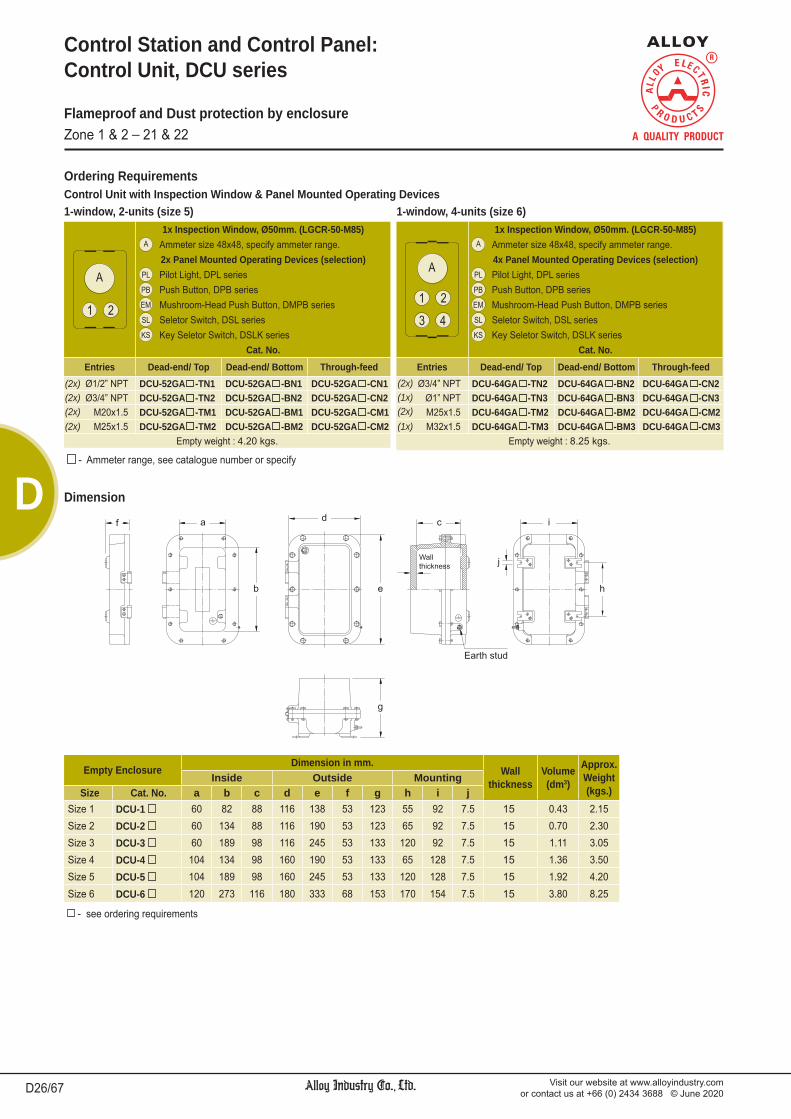
Visit our website at www.alloyindustry.comor contact us at +66 (0) 2434 3688 © June 2020D26/67
D
Control Unit with Inspection Window & Panel Mounted Operating DevicesOrdering Requirements
Control Station and Control Panel: Control Unit, DCU series
Flameproof and Dust protection by enclosureZone 1 & 2 _ 21 & 22
Dimension
- see ordering requirements
Empty EnclosureDimension in mm.
Wallthickness
Volume(dm3)
Approx.Weight(kgs.)
Inside Outside MountingSize Cat. No. a b c d e f g h i j
Size 1 DCU-1 60 82 88 116 138 53 123 55 92 7.5 15 0.43 2.15Size 2 DCU-2 60 134 88 116 190 53 123 65 92 7.5 15 0.70 2.30Size 3 DCU-3 60 189 98 116 245 53 133 120 92 7.5 15 1.11 3.05Size 4 DCU-4 104 134 98 160 190 53 133 65 128 7.5 15 1.36 3.50Size 5 DCU-5 104 189 98 160 245 53 133 120 128 7.5 15 1.92 4.20Size 6 DCU-6 120 273 116 180 333 68 153 170 154 7.5 15 3.80 8.25
1-window, 2-units (size 5)1x Inspection Window, Ø50mm. (LGCR-50-M85)
Ammeter size 48x48, specify ammeter range.2x Panel Mounted Operating Devices (selection)Pilot Light, DPL seriesPush Button, DPB seriesMushroom-Head Push Button, DMPB seriesSeletor Switch, DSL seriesKey Seletor Switch, DSLK series
Cat. No.Entries Dead-end/ Top Dead-end/ Bottom Through-feedØ1/2” NPT DCU-52GA -TN1 DCU-52GA -BN1 DCU-52GA -CN1Ø3/4” NPT DCU-52GA -TN2 DCU-52GA -BN2 DCU-52GA -CN2
M20x1.5 DCU-52GA -TM1 DCU-52GA -BM1 DCU-52GA -CM1M25x1.5 DCU-52GA -TM2 DCU-52GA -BM2 DCU-52GA -CM2
Empty weight : 4.20 kgs.
1-window, 4-units (size 6)1x Inspection Window, Ø50mm. (LGCR-50-M85)
Ammeter size 48x48, specify ammeter range.4x Panel Mounted Operating Devices (selection)Pilot Light, DPL seriesPush Button, DPB seriesMushroom-Head Push Button, DMPB seriesSeletor Switch, DSL seriesKey Seletor Switch, DSLK series
Cat. No.Entries Dead-end/ Top Dead-end/ Bottom Through-feedØ3/4” NPT DCU-64GA -TN2 DCU-64GA -BN2 DCU-64GA -CN2
Ø1” NPT DCU-64GA -TN3 DCU-64GA -BN3 DCU-64GA -CN3M25x1.5 DCU-64GA -TM2 DCU-64GA -BM2 DCU-64GA -CM2M32x1.5 DCU-64GA -TM3 DCU-64GA -BM3 DCU-64GA -CM3
Empty weight : 8.25 kgs.
(2x)(2x)(2x)(2x)
(2x)(1x)(2x)(1x)
- Ammeter range, see catalogue number or specify

Visit our website at www.alloyindustry.comor contact us at +66 (0) 2434 3688 © June 2020 D27/67
D
Customized Control Unit Specification Sheet,DCU series
Flameproof and Dust protection by enclosureZone 1 & 2 _ 21 & 22
Control Station Style Size 1 Size 2 Size 3 Size 4 Size 5 Size 6
Unit Panel Mounted Operating Devices Nameplate
Pilot Light (Voltage/ Colour) No nameplate ON OFF
Push Button (Contact/ Colour) RUN OVERLOAD TRIP
Mushroom-head Push Button (Contact/ Colour) RESET START STOP
Selector Switch (Contact/ Position) OFF-ON MAN-OFF-AUTO MAN-AUTO
Key Selector Switch (Contact/ Position) EMER. STOP Others
Pilot Light (Voltage/ Colour) No nameplate ON OFF
Push Button (Contact/ Colour) RUN OVERLOAD TRIP
Mushroom-head Push Button (Contact/ Colour) RESET START STOP
Selector Switch (Contact/ Position) OFF-ON MAN-OFF-AUTO MAN-AUTO
Key Selector Switch (Contact/ Position) EMER. STOP Others Pilot Light (Voltage/ Colour) No nameplate ON OFF
Push Button (Contact/ Colour) RUN OVERLOAD TRIP
Mushroom-head Push Button (Contact/ Colour) RESET START STOP
Selector Switch (Contact/ Position) OFF-ON MAN-OFF-AUTO MAN-AUTO
Key Selector Switch (Contact/ Position) EMER. STOP Others Pilot Light (Voltage/ Colour) No nameplate ON OFF
Push Button (Contact/ Colour) RUN OVERLOAD TRIP
Mushroom-head Push Button (Contact/ Colour) RESET START STOP
Selector Switch (Contact/ Position) OFF-ON MAN-OFF-AUTO MAN-AUTO
Key Selector Switch (Contact/ Position) EMER. STOP Others Pilot Light (Voltage/ Colour) No nameplate ON OFF
Push Button (Contact/ Colour) RUN OVERLOAD TRIP
Mushroom-head Push Button (Contact/ Colour) RESET START STOP
Selector Switch (Contact/ Position) OFF-ON MAN-OFF-AUTO MAN-AUTO
Key Selector Switch (Contact/ Position) EMER. STOP Others Pilot Light (Voltage/ Colour) No nameplate ON OFF
Push Button (Contact/ Colour) RUN OVERLOAD TRIP
Mushroom-head Push Button (Contact/ Colour) RESET START STOP
Selector Switch (Contact/ Position) OFF-ON MAN-OFF-AUTO MAN-AUTO
Key Selector Switch (Contact/ Position) EMER. STOP Others Pilot Light (Voltage/ Colour) No nameplate ON OFF
Push Button (Contact/ Colour) RUN OVERLOAD TRIP
Mushroom-head Push Button (Contact/ Colour) RESET START STOP
Selector Switch (Contact/ Position) OFF-ON MAN-OFF-AUTO MAN-AUTO
Key Selector Switch (Contact/ Position) EMER. STOP Others Pilot Light (Voltage/ Colour) No nameplate ON OFF
Push Button (Contact/ Colour) RUN OVERLOAD TRIP
Mushroom-head Push Button (Contact/ Colour) RESET START STOP
Selector Switch (Contact/ Position) OFF-ON MAN-OFF-AUTO MAN-AUTO
Key Selector Switch (Contact/ Position) EMER. STOP Others Material: Acrylic multipolymer (12 x 40mm.), Legend colour: Black letter, white background
Project: Date:
Customer: Owner:
Contact person:
Tel: Fax: E-mail:Quantity(Set)
EntriesTop
E1E3E5
BottomE2E4E6
Nameplate (NP)NP Letter

Visit our website at www.alloyindustry.comor contact us at +66 (0) 2434 3688 © June 2020D28/67
D
Control Station and Control Panel: Control Station, CTE2 series
Switch modules ; 16A. 400V. (AC 12) 10A. 400V. (AC 15) 1A. 24V. (DC 13) 690V. rated insulation voltage
Lamp modules ; LED lamp > 105 hr. illuminated AC 12V. to 250V. operating voltage DC 12V. to 60V. operating voltage < 1W. power consumption 300V. rated insulation voltage
Note : For selection of switch and lamp modules, please find the BARTEC ‘s catalogue in series 05-0003, 07-3323, and 07-3353.
* Padlockable by pin for push buttons and/or selector switches
The CTE2 control stations are used for local or remote control of motor and machine in zone 1, 2 and zone 21, 22 hazardous areas.
Application
Body, cover : Marine grade copper-free aluminium alloy with polyester powder coated, RAL 7032 (grey)Sealing gasket : Silicone Bolts, nuts : Stainless steel
Electrical Rating
1-unit 2-units 3-4-units
Flameproof/ Incresed Safety and Dust protection by enclosureZone 1 & 2 _ 21 & 22
Hazardous Area Gas DustZones 1 & 2 21 & 22Equipment Group/Category II 2G II 2DSymbol of Protection Ex de IIC T6 Gb Ex tb IIIC T80oC IP65Ambient Temperature -20oC to +50oCIndex of Protection IP65Conformity to Standards EN 60079-0:2012+A11:2013, EN 60079-1:2007,
EN 60079-7:2007, EN 60079-31:2014
Entries Ø1/2” to Ø1” NPT (M20x1.5 to M32x1.5)Mounting Wall type
Technical Data
Catalogue Number Logic
CTE2 - - - TSeries Number
of UnitNumber
of PadlockableEntries Number of
TerminalPosition Size1 1-unit 00 none T Dead-end/ Top N1 Ø1/2” NPT 2T 2-Poles2 2-units 1P 1-padlockable B Dead-end/ N2 Ø3/4” NPT 4T 4-Poles3 3-units 2P 2-padlockable Bottom N3 Ø1” NPT 6T 6-Poles4 4-units 3P 3-padlockable C Through-feed M1 M20x1.5 8T 8-Poles
M2 M25x1.5M3 M32x1.5
Number of Unit
Number of Padlockable * Cat. No. Approx. Weight (kgs.)
1-unit none CTE2-100- - T 1.201 CTE2-11P- - T
2-units none CTE2-200- - T 1.501 CTE2-21P- - T
3-units none CTE2-300- - T 2.251 CTE2-31P- - T2 CTE2-32P- - T3 CTE2-33P- - T
4-units none CTE2-400- - T 2.25
Dimension
Ordering Requirements

Visit our website at www.alloyindustry.comor contact us at +66 (0) 2434 3688 © June 2020 D29/67
D
Control Station and Control Panel: Control Station, WCT2 series
Optional : Padlockable by pin for push buttons and/or selector switches
Switch rating ; AC 15 (inductive load) 3A./220V. DC 12 (resistive load) 1.1A/220V. Rated insulation voltage 600V. Rated continuous current 10A.LED lamp rating ; Transformer input 110, 220, 230V.ac Direct 6-24V.dcIncan. lamp rating ; Transformer input 380V.ac
The WCT2 control stations are used for local or remote con-trol of motor and machines. They are suitable for industrial plants, general areas and wet locations.
Application
Body, cover : Marine grade copper-free aluminium alloy with polyester powder coated, RAL 7032 (grey)Sealing gasket : Silicone Bolts, nuts : Stainless steel
Electrical Rating
1, 2-units 3, 4-units
5, 6-units
Protection WeatherproofAmbient Temperature -20oC to +50oCIndex of Protection IP65
Connection Terminals Terminal block for 1-2.5mm.2 cableEntries Ø1/2” to Ø1” NPT (M20x1.5 to M32x1.5)Mounting Wall type
Technical Data
WeatherproofIP65
Catalogue Number Logic
WCT2 - - - TSeries Number of Unit Entries Number of
Terminal1 1-unit Position Size2 2-units T Dead-end/ Top N1 Ø1/2” NPT 2T 2-Poles3 3-units B Dead-end/ Bottom N2 Ø3/4” NPT 4T 4-Poles4 4-units C Through-feed N3 Ø1” NPT 6T 6-Poles5 5-units M1 M20x1.5 8T 8-Poles6 6-units M2 M25x1.5
M3 M32x1.5
Number of Unit Cat. No. Approx. Weight (kgs.)1-unit WCT2-1- - T 1.452-units WCT2-2- - T 2.153-units WCT2-3- - T 3.054-units WCT2-4- - T 3.655-units WCT2-5- - T 3.856-units WCT2-6- - T 3.98
Dimension
Ordering Requirements

Visit our website at www.alloyindustry.comor contact us at +66 (0) 2434 3688 © June 2020D30/67
D
Hazardous Area Gas DustZones 1 & 2 22Equipment Group/Category II 2G II 3DSymbol of Protection Ex d IIB T6/T5 Gb Ex tc IIIB T80oC/ T95oC Dc IP54Conformity to Standards EN 60079-0:2012+A11:2013, EN 60079-1:2014,
EN 60079-31:2014Ambient Temperature -20oC to +55oCIndex of Protection IP54
Entries Ø1/2” NPT, Ø3/4” NPT or M20x1.5, M25x1.5Mounting Wall mount
Control Station and Control Panel: Emergency Control Station (Break-Glass type), EAS series
The EAS emergency control stations are used as the “Break-Glass” fire alarm station for conjunction with audible and/ or visible signaling devices. It is suitable for zone 1, 2 and zone 22 hazardous areas.
Application
Body, cover, : Marine grade copper-free aluminium hammer alloy with polyester powder coated, RAL 7032 (Grey)Bolt, chain : Stainless steel
3A. 220V.ac (10A. rated thermal current)
Electrical Rating
Technical Data
Flameproof and Dust protection by enclosureZone 1 & 2 _ 22
Catalogue Number Logic
EAS - -Series Contact
(Momentary)Entries
Dead-end/ Bottom Through-feedA 1NO BN1 Ø1/2” NPT CN1 Ø1/2” NPTB 1NC BN2 Ø3/4” NPT CN2 Ø3/4” NPTC 1NO-1NC BM1 M20x1.5 CM1 M20x1.5
BM2 M25x1.5 CM2 M25x1.5
Mushroom-Head Push button, 1NO (Momentary) (Red)(contact as NC,will change to NO when the glass broken.)
Cat. No.Entries Dead-end/ Bottom Through-feedØ1/2” NPT EAS-A-BN1 EAS-A-CN1Ø3/4” NPT EAS-A-BN2 EAS-A-CN2
M20x1.5 EAS-A-BM1 EAS-A-CM1M25x1.5 EAS-A-BM2 EAS-A-CM2
Volume (dm3) 0.74Approx. weight : 1.75 kgs.
Mushroom-Head Push button, 1NC (Momentary) (Red)(contact as NO,will change to NC when the glass broken.)
Cat. No.Entries Dead-end/ Bottom Through-feedØ1/2” NPT EAS-B-BN1 EAS-B-CN1Ø3/4” NPT EAS-B-BN2 EAS-B-CN2
M20x1.5 EAS-B-BM1 EAS-B-CM1M25x1.5 EAS-B-BM2 EAS-B-CM2
Volume (dm3) 0.74Approx. weight : 1.75 kgs.
Mushroom-Head Push button, 1NO-1NC (Momentary) (Red)(contact as 1NC-1NO,will change to 1NO-1NC when the glass broken.)
Cat. No.Entries Dead-end/ Bottom Through-feedØ1/2” NPT EAS-C-BN1 EAS-C-CN1Ø3/4” NPT EAS-C-BN2 EAS-C-CN2
M20x1.5 EAS-C-BM1 EAS-C-CM1M25x1.5 EAS-C-BM2 EAS-C-CM2
Volume (dm3) 0.74Approx. weight : 1.77 kgs.
Dimension
Ordering Requirements

Visit our website at www.alloyindustry.comor contact us at +66 (0) 2434 3688 © June 2020 D31/67
D
Control Station and Control Panel: Control Box, DCT series
The DCT control boxes are designed for use in hazardous areas, zone 1, 2 and zone 21, 22. installation in petroleum refineries, chemical plants,
storage areas where hazardous substances are handled. instrument box with circular or rectangular window. containing analogue and digital measuring instruments. indicating the electrical function performed.
Application
Body, cover : Marine grade copper-free aluminium alloy with polyester powder coated, RAL 7032 (Grey)Lid screws : Stainless steelSealing gasket : Silicone
The circuit breakers are suitable for short circuit and overcurrent protection of service
entrance, feeder, branch circuit, lighting or motor circuit and serve as a disconnecting mean.
The motor starters are suitable for single speed, non-reversing starting and stopping of
AC squirrel cage induction motors. direct-on-line or star-delta starting method.
The circuit breaker panelboards are suitable for control of branch circuit distribution such as lighting
circuits, receptacles, pumps or motors.
The enclosure with panel mounted operating devices
Circuit breaker box
Motor starter Box
Circuit breaker panelboard
Flameproof and Dust protection by enclosureZone 1 & 2 _ 21 & 22
Hazardous Area Gas DustZones 1 & 2 21 & 22Equipment Group/Category II 2G II 2DSymbol of Protection Ex d IIB T6/T5 Ex tD A21 IP66 T85oC/ T100oCCertificate PTB 07 ATEX 1071 XConformity to Standards EN 60079-0:2006, EN 60079-1:2004,
EN 61241-0:2006, EN 61241-1:2004Ambient Temperature -20oC to +55oCIndex of Protection IP66
Entries NPT or Metric threadsMounting Wall typeRated Voltage Max. 800V.ac 50/60Hz.
Technical Data

Visit our website at www.alloyindustry.comor contact us at +66 (0) 2434 3688 © June 2020D32/67
D
Dimension
Control Station and Control Panel: Control Box, DCT series
Flameproof and Dust protection by enclosureZone 1 & 2 _ 21 & 22
Cat. No.
Dimension in mm. WallThick-ness
Volume(dm3)
EmptyWeight(kgs.)
Inside Outside Equipment Plate Mounting
a b c d e f g h i j k lDCT 796 111 160 100 183 232 120 145 95 140 148 91 7.5 17 1.9 6.08
DCT 10126 162 212 110 248 298 127 163 144 195 218 135 10 17 4.3 12.05
DCT 10128 168 219 159 254 305 175 211 151 196 218 135 10 17 5.0 13.90
DCT 9147 152 261 126 238 347 146 181 139 246 205 133 10 20 5.4 13.00
DCT 10158 174 295 139 260 381 156 194 156 277 223 179 10 17 7.3 15.85
DCT 12128 217 217 161 303 303 178 216 203 203 269 134 10 20 8.3 16.60
DCT 12168 216 321 119 310 415 143 193 195 300 274 197 12 30 8.7 30.55
DCT 10208 164 423 133 258 517 159 207 148 403 224 308 12 30 8.9 28.00
DCT 12149 217 268 162 311 362 189 236 197 248 270 163 12 30 9.4 25.00
DCT 14149 265 265 166 359 359 190 238 247 247 327 163 12 30 10.5 29.00
DCT 11199 192 384 158 286 478 185 230 174 364 248 280 12 30 11.6 30.55
DCT 12169 216 321 163 310 415 187 237 195 300 270 198 12 30 11.7 31.00
DCT 121810 217 373 171 311 467 195 245 197 351 274 239 12 30 13.7 33.00
DCT 12219 212 435 164 306 529 190 237 198 420 273 326 12 30 14.9 36.85
DCT 16169 312 312 155 410 410 190 239 301 301 376 197 12 35 18.0 42.65
DCT 12239 217 496 157 315 594 190 241 202 480 278 363 12 35 19.6 46.05
DCT 13269 244 569 157 342 667 187 241 224 546 307 441 12 35 25.3 57.45
DCT 132610 244 569 179 342 667 208 262 224 546 307 407 12 35 26.0 58.82
DCT 162210 318 472 173 416 570 202 258 300 450 410 300 15 35 27.3 60.55
DCT 181812 370 370 222 468 468 251 306 338 338 435 237 12 35 28.2 57.25
DCT 162012 315 419 226 413 517 254 309 290 395 376 274 12 35 29.6 56.85
DCT 15319 280 680 149 378 778 184 234 250 650 353 503 15 35 30.7 65.00
DCT - Series Enclosure Type
(see catalogue none only terminal block or panel mountednumber table) CB Circuit breaker
MS Motor starterCS Combination motor starterPN Panelboard
Catalogue Number Logic
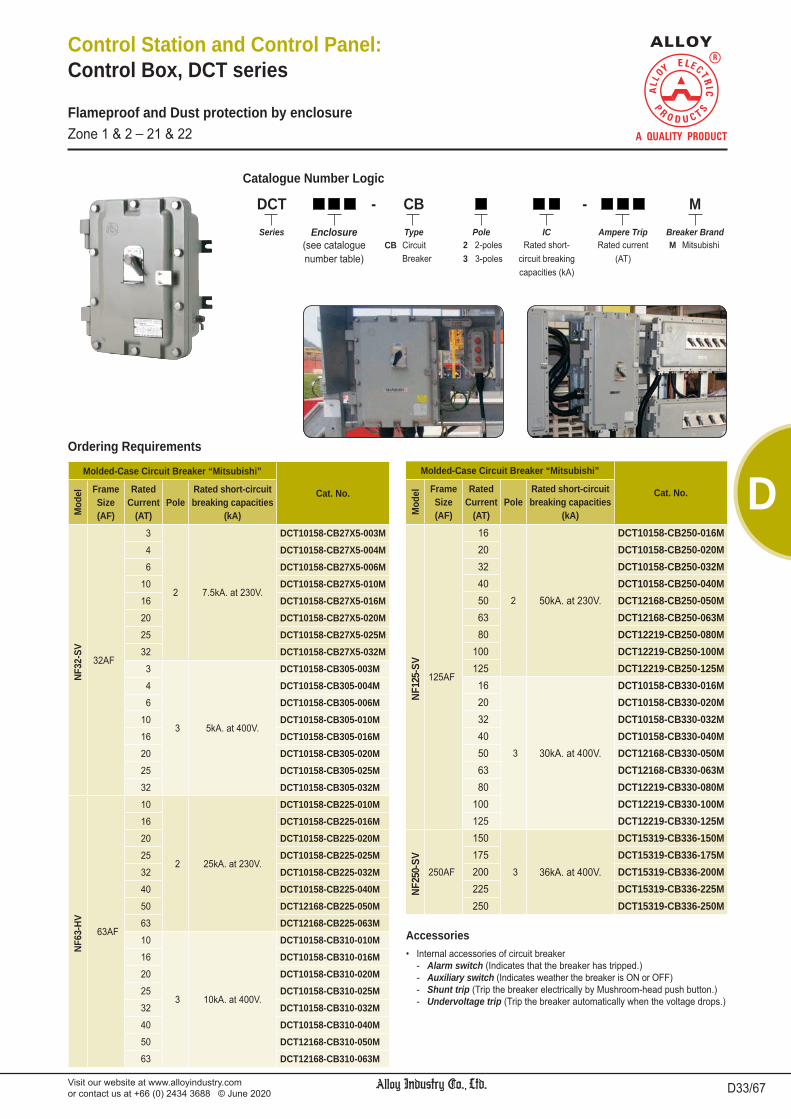
Visit our website at www.alloyindustry.comor contact us at +66 (0) 2434 3688 © June 2020 D33/67
D
Internal accessories of circuit breaker - Alarm switch (Indicates that the breaker has tripped.) - Auxiliary switch (Indicates weather the breaker is ON or OFF) - Shunt trip (Trip the breaker electrically by Mushroom-head push button.) - Undervoltage trip (Trip the breaker automatically when the voltage drops.)
Ordering Requirements
Accessories
Control Station and Control Panel: Control Box, DCT series
Flameproof and Dust protection by enclosureZone 1 & 2 _ 21 & 22
DCT - CB - MSeries Enclosure Type Pole IC Ampere Trip Breaker Brand
(see catalogue CB Circuit 2 2-poles Rated short- Rated current M Mitsubishinumber table) Breaker 3 3-poles circuit breaking (AT)
capacities (kA)
Molded-Case Circuit Breaker “Mitsubishi”
Cat. No.
Mod
el FrameSize(AF)
RatedCurrent
(AT)Pole
Rated short-circuitbreaking capacities
(kA)
NF32
-SV
32AF
3
2 7.5kA. at 230V.
DCT10158-CB27X5-003M4 DCT10158-CB27X5-004M6 DCT10158-CB27X5-006M
10 DCT10158-CB27X5-010M16 DCT10158-CB27X5-016M20 DCT10158-CB27X5-020M25 DCT10158-CB27X5-025M32 DCT10158-CB27X5-032M
3
3 5kA. at 400V.
DCT10158-CB305-003M4 DCT10158-CB305-004M6 DCT10158-CB305-006M
10 DCT10158-CB305-010M16 DCT10158-CB305-016M20 DCT10158-CB305-020M25 DCT10158-CB305-025M32 DCT10158-CB305-032M
NF63
-HV
63AF
10
2 25kA. at 230V.
DCT10158-CB225-010M16 DCT10158-CB225-016M20 DCT10158-CB225-020M25 DCT10158-CB225-025M32 DCT10158-CB225-032M40 DCT10158-CB225-040M50 DCT12168-CB225-050M63 DCT12168-CB225-063M10
3 10kA. at 400V.
DCT10158-CB310-010M16 DCT10158-CB310-016M20 DCT10158-CB310-020M25 DCT10158-CB310-025M32 DCT10158-CB310-032M40 DCT10158-CB310-040M50 DCT12168-CB310-050M63 DCT12168-CB310-063M
Molded-Case Circuit Breaker “Mitsubishi”
Cat. No.
Mod
el FrameSize(AF)
RatedCurrent
(AT)Pole
Rated short-circuitbreaking capacities
(kA)
NF12
5-SV
125AF
16
2 50kA. at 230V.
DCT10158-CB250-016M20 DCT10158-CB250-020M32 DCT10158-CB250-032M40 DCT10158-CB250-040M50 DCT12168-CB250-050M63 DCT12168-CB250-063M80 DCT12219-CB250-080M
100 DCT12219-CB250-100M125 DCT12219-CB250-125M
16
3 30kA. at 400V.
DCT10158-CB330-016M20 DCT10158-CB330-020M32 DCT10158-CB330-032M40 DCT10158-CB330-040M50 DCT12168-CB330-050M63 DCT12168-CB330-063M80 DCT12219-CB330-080M
100 DCT12219-CB330-100M125 DCT12219-CB330-125M
NF25
0-SV
250AF
150
3 36kA. at 400V.
DCT15319-CB336-150M175 DCT15319-CB336-175M200 DCT15319-CB336-200M225 DCT15319-CB336-225M250 DCT15319-CB336-250M
Catalogue Number Logic

Visit our website at www.alloyindustry.comor contact us at +66 (0) 2434 3688 © June 2020D34/67
D
Control Station and Control Panel: Control Box, DCT series
Flameproof and Dust protection by enclosureZone 1 & 2 _ 21 & 22
DCT - - MSeries Enclosure Type Starting Motor Output
(kW)Breaker Brand
(see catalogue MS Motor starter D Direct-On-Line M Mitsubishinumber table) CS Combi. motor starter Y Star-Delta
3Ph. Motor220/380V.ac
AverageFull Load
( I FL )
Cat. No.Motor Starter Combination Motor Starter
kW. HP. Direct-On-Line Star-Delta Direct-On-Line Star-Delta
0.37 0.5 1.2A. DCT10158-MSD-X37M ¯ DCT12219-CSD-X37M ¯0.55 0.75 1.6A. DCT10158-MSD-X55M ¯ DCT12219-CSD-X55M ¯0.75 1 2A. DCT10158-MSD-X75M ¯ DCT12219-CSD-X75M ¯1.1 1.5 2.6A. DCT10158-MSD-1X1M ¯ DCT12219-CSD-1X1M ¯1.5 2 3.5A. DCT10158-MSD-1X5M ¯ DCT12219-CSD-1X5M ¯2.2 3 5A. DCT10158-MSD-2X2M ¯ DCT12219-CSD-2X2M ¯3 4 6.6A. DCT10158-MSD-3M DCT16169-MSY-3M DCT12219-CSD-3M DCT162012-CSY-3M
3.7 5 8.2A. DCT10158-MSD-3X7M DCT16169-MSY-3X7M DCT12219-CSD-3X7M DCT162012-CSY-3X7M
4 5.5 8.5A. DCT10158-MSD-4M DCT16169-MSY-4M DCT12219-CSD-4M DCT162012-CSY-4M
5.5 7.5 11.5A. DCT10158-MSD-5X5M DCT16169-MSY-5X5M DCT12219-CSD-5X5M DCT162012-CSY-5X5M
7.5 10 15.5A. DCT10158-MSD-7X5M DCT16169-MSY-7X5M DCT12219-CSD-7X5M DCT162012-CSY-7X5M
11 15 22A. DCT10158-MSD-11M DCT16169-MSY-11M DCT181812-CSD-11M DCT162012-CSY-11M
15 20 30A. DCT121810-MSD-15M DCT16169-MSY-15M DCT181812-CSD-15M DCT162012-CSY-15M
18.5 25 37A. DCT121810-MSD-18X5M consult factory DCT181812-CSD-18X5M consult factory
22 30 44A. DCT121810-MSD-22M consult factory DCT181812-CSD-22M consult factory
30 40 60A. DCT162012-MSD- 30M consult factory DCT15319-CSD-30M consult factory
Catalogue Number Logic
Ordering Requirements
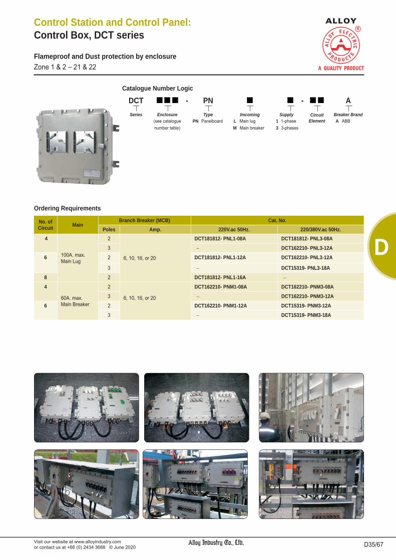
Visit our website at www.alloyindustry.comor contact us at +66 (0) 2434 3688 © June 2020 D35/67
D
Control Station and Control Panel: Control Box, DCT series
Flameproof and Dust protection by enclosureZone 1 & 2 _ 21 & 22
DCT - PN - ASeries Enclosure Type Imcoming Supply Circuit
ElementBreaker Brand
(see catalogue PN Panelboard L Main lug 1 1-phase A ABBnumber table) M Main breaker 3 3-phases
No. ofCircuit Main
Branch Breaker (MCB) Cat. No.Poles Amp. 220V.ac 50Hz. 220/380V.ac 50Hz.
4
100A. max.Main Lug
2
6, 10, 16, or 20
DCT181812- PNL1-08A DCT181812- PNL3-08A
3 ¯ DCT162210- PNL3-12A
6 2 DCT181812- PNL1-12A DCT162210- PNL3-12A
3 ¯ DCT15319- PNL3-18A
8 2 DCT181812- PNL1-16A ¯4
60A. max.Main Breaker
2
6, 10, 16, or 20
DCT162210- PNM1-08A DCT162210- PNM3-08A
3 ¯ DCT162210- PNM3-12A
6 2 DCT162210- PNM1-12A DCT15319- PNM3-12A
3 ¯ DCT15319- PNM3-18A
Ordering Requirements
Catalogue Number Logic

Visit our website at www.alloyindustry.comor contact us at +66 (0) 2434 3688 © June 2020D36/67
D
Control Station and Control Panel: Control Box, Motor Starter Wiring Diagram
Direct-On-line Starting Method
Star-Delta Starting Method
Flameproof and Dust protection by enclosureZone 1 & 2 _ 21 & 22

Visit our website at www.alloyindustry.comor contact us at +66 (0) 2434 3688 © June 2020 D37/67
D
Control Station and Control Panel: Control Box, DCT1 series
Flameproof and Dust protection by enclosureZone 1 & 2 _ 21 & 22
The DCT1 control boxes are designed for use in hazardous areas, zone 1, 2 and zone 21, 22. installation in petroleum refineries, chemical plants,
storage areas where hazardous substances are handled. instrument box with circular or rectangular window. containing analogue and digital measuring instruments. indicating the electrical function performed.
Application
Body, cover : Marine grade copper-free aluminium alloy with polyester powder coated, RAL 7032 (Grey)Lid screws : Stainless steelSealing gasket : Silicone
The circuit breakers are suitable for short circuit and overcurrent protection of service
entrance, feeder, branch circuit, lighting or motor circuit and serve as a disconnecting mean.
The motor starters are suitable for single speed, non-reversing starting and stopping of
AC squirrel cage induction motors. direct-on-line or star-delta starting method.
The circuit breaker panelboards are suitable for control of branch circuit distribution such as lighting
circuits, receptacles, pumps or motors.
Hazardous Area Gas DustZones 1 & 2 21 & 22Equipment Group/Category II 2G II 2DSymbol of Protection Ex db IIB T6/T5 Gb Ex tb IIIC T85oC/ T100oC Db IP66Certificate TÜV CY 18 ATEX 0206140 XConformity to Standards EN 60079-0:2012+A11:2013, EN 60079-1:2014,
EN 60079-31:2014Ambient Temperature -20oC to +55oC
Index of Protection IP66
Entries NPT or Metric threadsMounting Wall mountRated Voltage Max. 415V.ac 50/60Hz.
Technical Data
The enclosurewith panel mounted operating devices
Circuit breaker box
Motor starter Box
Circuit breaker panelboard

Visit our website at www.alloyindustry.comor contact us at +66 (0) 2434 3688 © June 2020D38/67
D
Control Station and Control Panel:Control Box, DCT1 series
Flameproof and Dust protection by enclosureZone 1 & 2 _ 21 & 22
Dimension
Cat. No.
Dimension in mm. WallThick-ness
Volume(dm3)
EmptyWeight(kgs.)
Inside Outside Equip. Plate Mounting
a b c d e f g h i j k l
DCT1 685 100 155 102 170 225 94 134 85 140 160 100 10 15 1.497 4.8
DCT1 886 138 138 130 210 210 114 164 125 125 202 100 10 15 2.352 6.5
DCT1 8126 135 240 127 207 312 114 164 125 230 200 160 12 15 3.958 9.3
DCT1 8187 136 394 167 208 466 154 204 120 380 200 300 12 15 8.653 15.4
DCT1 9157 164 314 160 237 387 148 198 154 295 228 230 12 15 7.954 14.7
DCT1 9207 162 440 171 230 508 158 208 145 420 228 350 12 15 12.116 19.2
DCT1 101610 174 324 217 263 413 202 260 155 300 240 240 12 18 11.767 19.7
DCT1 11218 210 450 177 299 539 162 220 195 435 276 350 12 18 16.284 25.1
DCT1 12127 244 244 162 333 333 147 205 225 225 310 170 12 18 9.339 17.2
DCT1 15156 300 300 122 389 389 107 165 280 280 366 240 12 18 10.697 20.4
DCT1 151510 300 300 222 389 389 207 267 280 280 366 240 12 20 19.398 28.0
DCT1 15198 298 398 172 387 487 157 217 280 380 364 300 12 20 19.928 29.9
DCT1 162810 330 627 225 423 720 202 279 310 610 402 450 12 22 45.689 59.9
DCT1 20208 424 424 182 522 522 160 237 405 405 519 290 15 22 32.012 51.7
DCT1 202410 430 530 220 534 634 194 271 410 510 513 450 15 22 49.278 62.0
DCT1 20329 423 713 208 532 822 184 262 400 690 510 650 15 23 61.662 77.7
DCT1 203611 408 813 235 524 929 216 296 380 775 511 680 15 25 76.200 105.8
DCT1 284411 600 1000 235 743 1143 216 301 565 965 707 800 15 30 138.576 188.9
6 Mounting feet.
DCT1 - Series Enclosure Type
(see catalogue none only terminal block or panel mountednumber table) CB Circuit breaker
MS Motor starterCS Combination motor starterPN Panelboard
Catalogue Number Logic

Visit our website at www.alloyindustry.comor contact us at +66 (0) 2434 3688 © June 2020 D39/67
D
Cat. No.Operating devices
TotalRow Column
DCT1 685 1 1 1DCT1 886 1 2 2DCT1 8126 3 2 6DCT1 8187 5 2 10DCT1 9157 4 2 8DCT1 9207 6 2 12DCT1 101610 4 2 8DCT1 11218 6 3 18DCT1 12127 3 4 12DCT1 15156 4 4 16DCT1 151510 4 4 16DCT1 15198 5 4 20DCT1 162810 9 5 45DCT1 20208 5 6 30DCT1 202410 7 6 42DCT1 20329 10 6 60DCT1 203611 12 6 72DCT1 284411 14 9 126
Control Station and Control Panel: Control Box, DCT1 series
Flameproof and Dust protection by enclosureZone 1 & 2 _ 21 & 22
The enclosure with panel mounted operating devices
The enclosure with inspection windows
Cat. No.X = Maximum center line of Cover to center line of Inspection window
(unit : mm.)LGCR1-50-M85 LGCR-113 LGCR-217 LGCR-320
DCT1 685DCT1 886 0 (center)DCT1 8126 50DCT1 8187 120DCT1 9157 90DCT1 9207 150DCT1 101610 100DCT1 11218 150 100DCT1 12127 50 0 (center)DCT1 15156 80 30 0 (center) 0 (center)DCT1 151510 80 30 0 (center) 0 (center)DCT1 15198 120 80 50 0 (center)DCT1 162810 230 200 170 150DCT1 20208 140 100 50 50DCT1 202410 190 150 120 100DCT1 20329 250 220 200 200DCT1 203611 300 270 250 250DCT1 284411 400 350 300 300
Cat. No.X = Maximum center line of Cover to center line of Inspection window
(unit : mm.)LGCS-142 LGCS-260 LGCS-383 LGCS-430 LGCS-5120 LGCS-6200
DCT1 685DCT1 886 0 (center)DCT1 8126 50 40DCT1 8187 120 120DCT1 9157 80 80 70DCT1 9207 150 150 120DCT1 101610 90 90 70DCT1 11218 150 150 130 100DCT1 12127 50 50 30 50 0 (center) 0 (center)DCT1 15156 80 70 60 70 40 0 (center)DCT1 151510 80 70 60 70 40 0 (center)DCT1 15198 120 120 100 130 80 30DCT1 162810 240 230 210 230 200 140DCT1 20208 140 120 120 140 100 50DCT1 202410 190 180 160 200 150 100DCT1 20329 250 250 250 250 230 170DCT1 203611 300 300 300 300 280 220DCT1 284411 400 400 370 400 350 320
Round type, LGCR series
Rectangular type, LGCS series
60
60
(column)(r
ow)
11
23 4 ....
2
3
4
5....
23

Visit our website at www.alloyindustry.comor contact us at +66 (0) 2434 3688 © June 2020D40/67
D
Control Station and Control Panel: Control Box, DCT1 series
Flameproof and Dust protection by enclosureZone 1 & 2 _ 21 & 22
Ordering Requirements
DCT1 - CB - MSeries Enclosure Type Pole IC Ampere Trip Breaker Brand
(see catalogue CB Circuit 2 2-poles Rated short- Rated current M Mitsubishinumber table) Breaker 3 3-poles circuit breaking (AT)
capacities (kA)
Internal accessories of circuit breaker - Alarm switch (Indicates that the breaker has tripped.) - Shunt trip (Trip the breaker electrically by Mushroom-head push button.)
Accessories
Molded-Case Circuit Breaker “Mitsubishi”
Cat. No.
Mod
el FrameSize(AF)
RatedCurrent
(AT)Pole
Rated short-circuitbreaking capacities
(kA)
NF32
-SV
32AF
3
2 7.5kA. at 230V.
DCT1 8126-CB27X5-003M4 DCT1 8126-CB27X5-004M6 DCT1 8126-CB27X5-006M
10 DCT1 8126-CB27X5-010M16 DCT1 8126-CB27X5-016M20 DCT1 8126-CB27X5-020M25 DCT1 8126-CB27X5-025M32 DCT1 8126-CB27X5-032M
3
3 5kA. at 400V.
DCT1 8126-CB305-003M4 DCT1 8126-CB305-004M6 DCT1 8126-CB305-006M
10 DCT1 8126-CB305-010M16 DCT1 8126-CB305-016M20 DCT1 8126-CB305-020M25 DCT1 8126-CB305-025M32 DCT1 8126-CB305-032M
NF63
-HV
63AF
10
2 25kA. at 230V.
DCT1 8126-CB225-010M16 DCT1 8126-CB225-016M20 DCT1 8126-CB225-020M25 DCT1 8126-CB225-025M32 DCT1 8126-CB225-032M40 DCT1 8126-CB225-040M50 DCT1 9157-CB225-050M63 DCT1 9157-CB225-063M10
3 10kA. at 400V.
DCT1 8126-CB310-010M16 DCT1 8126-CB310-016M20 DCT1 8126-CB310-020M25 DCT1 8126-CB310-025M32 DCT1 8126-CB310-032M40 DCT1 8126-CB310-040M50 DCT1 9157-CB310-050M63 DCT1 9157-CB310-063M
Molded-Case Circuit Breaker “Mitsubishi”
Cat. No.M
odel Frame
Size(AF)
RatedCurrent
(AT)Pole
Rated short-circuitbreaking capacities
(kA)NF
125-
SV
125AF
16
2 50kA. at 230V.
DCT1 9157-CB250-016M20 DCT1 9157-CB250-020M32 DCT1 9157-CB250-032M40 DCT1 9157-CB250-040M50 DCT1 9157-CB250-050M63 DCT1 9157-CB250-063M80 DCT1 9207-CB250-080M
100 DCT1 9207-CB250-100M125 DCT1 9207-CB250-125M
16
3 30kA. at 400V.
DCT1 9157-CB330-016M20 DCT1 9157-CB330-020M32 DCT1 9157-CB330-032M40 DCT1 9157-CB330-040M50 DCT1 9157-CB330-050M63 DCT1 9157-CB330-063M80 DCT1 11218-CB330-080M
100 DCT1 11218-CB330-100M125 DCT1 11218-CB330-125M
NF25
0-SV
250AF
150
3 36kA. at 400V.
DCT1 162810-CB336-150M175 DCT1 162810-CB336-175M200 DCT1 162810-CB336-200M225 DCT1 162810-CB336-225M250 DCT1 162810-CB336-250M
NF40
0-SW
400AF
250
3 45kA. at 400V.
DCT1 20329-CB345-250M300 DCT1 20329-CB345-300M350 DCT1 20329-CB345-350M400 DCT1 20329-CB345-400M
NF63
0-SW
630AF
500
3 50kA. at 400V.
DCT1 203611-CB350-500M600 DCT1 203611-CB350-600M630 DCT1 203611-CB350-630M
- Auxiliary switch (Indicates weather the breaker is ON or OFF) - Undervoltage trip (Trip the breaker automatically when the voltage drops.)
Catalogue Number Logic

Visit our website at www.alloyindustry.comor contact us at +66 (0) 2434 3688 © June 2020 D41/67
D
Control Station and Control Panel: Control Box, DCT1 series
Flameproof and Dust protection by enclosureZone 1 & 2 _ 21 & 22
Ordering Requirements
DCT1 - - MSeries Enclosure Type Starting Motor Output
(kW)Breaker Brand
(see catalogue MS Motor starter D Direct-On-Line M Mitsubishinumber table) CS Combi. motor starter Y Star-Delta
3Ph. Motor220/380V.ac
AverageFull Load
( I FL )
Cat. No.Motor Starter Combination Motor Starter
kW. HP. Direct-On-Line Star-Delta Direct-On-Line Star-Delta
0.37 0.5 1.2A. DCT1 9157-MSD-X37M ¯ DCT1 9207-CSD-X37M ¯0.55 0.75 1.6A. DCT1 9157-MSD-X55M ¯ DCT1 9207-CSD-X55M ¯0.75 1 2A. DCT1 9157-MSD-X75M ¯ DCT1 9207-CSD-X75M ¯1.1 1.5 2.6A. DCT1 9157-MSD-1X1M ¯ DCT1 9207-CSD-1X1M ¯1.5 2 3.5A. DCT1 9157-MSD-1X5M ¯ DCT1 9207-CSD-1X5M ¯
2.2 3 5A. DCT1 9157-MSD-2X2M ¯ DCT1 9207-CSD-2X2M ¯3 4 6.6A. DCT1 9157-MSD-3M DCT1 15198-MSY-3M DCT1 9207-CSD-3M DCT1 15198-CSY-3M
3.7 5 8.2A. DCT1 9157-MSD-3X7M DCT1 15198-MSY-3X7M DCT1 9207-CSD-3X7M DCT1 15198-CSY-3X7M
4 5.5 8.5A. DCT1 9157-MSD-4M DCT1 15198-MSY-4M DCT1 9207-CSD-4M DCT1 15198-CSY-4M
5.5 7.5 11.5A. DCT1 9157-MSD-5X5M DCT1 15198-MSY-5X5M DCT1 11218-CSD-5X5M DCT1 15198-CSY-5X5M
7.5 10 15.5A. DCT1 9157-MSD-7X5M DCT1 15198-MSY-7X5M DCT1 11218-CSD-7X5M DCT1 15198-CSY-7X5M
11 15 22A. DCT1 9207-MSD-11M DCT1 15198-MSY-11M DCT1 15198-CSD-11M DCT1 15198-CSY-11M
15 20 30A. DCT1 9207-MSD-15M DCT1 15198-MSY-15M DCT1 15198-CSD-15M DCT1 15198-CSY-15M
18.5 25 37A. DCT1 11218-MSD-18X5M DCT1 20208-MSY-18X5M DCT1 15198-CSD-18X5M DCT1 20208-CSY-18X5M
22 30 44A. DCT1 11218-MSD-22M DCT1 20208-MSY-22M DCT1 20208-CSD-22M DCT1 20208-CSY-22M
30 40 60A. DCT1 11218-MSD- 30M DCT1 162810-MSY-30M DCT1 20208-CSD-30M DCT1 162810-CSY-30M
37 50 72A. DCT1 15198-MSD-37M DCT1 162810-MSY-37M DCT1 20208-CSD-37M DCT1 162810-CSY-37M
45 60 85A. DCT1 15198-MSD-45M DCT1 20329-MSY-45M DCT1 20208-CSD-45M DCT1 20329-CSY-45M
55 75 105A. DCT1 202410-MSD-55M DCT1 20329-MSY-55M DCT1 202410-CSD-55M DCT1 203611-CSY-55M
75 100 140A. DCT1 202410-MSD-75M DCT1 203611-MSY-75M DCT1 202410-CSD-75M DCT1 203611-CSY-75M
90 125 170A. DCT1 20329-MSD-90M DCT1 284411-MSY-90M DCT1 284411-CSD-90M consult factory
110 150 205A. DCT1 20329-MSD-110M DCT1 284411-MSY-110M DCT1 284411-CSD-110M consult factory
132 180 245A. DCT1 203611-MSD-132M DCT1 284411-MSY-132M DCT1 284411-CSD-132M consult factory
Catalogue Number Logic

Visit our website at www.alloyindustry.comor contact us at +66 (0) 2434 3688 © June 2020D42/67
D
Control Station and Control Panel: Control Box, DCT1 series
Flameproof and Dust protection by enclosureZone 1 & 2 _ 21 & 22
Ordering Requirements
DCT1 - PN - ASeries Enclosure Type Imcoming Supply Circuit
ElementBreaker Brand
(see catalogue PN Panelboard L Main lug 1 1-phase A ABBnumber table) M Main breaker 3 3-phases
No. ofCircuit Main
Branch Breaker (MCB) Cat. No.Poles Amp. 220V.ac 50Hz. 220/380V.ac 50Hz.
6
100A. max.Main Lug
2
6, 10, 16, 20, or 32
DCT1 20208- PNL1-12A DCT1 20208- PNL3-12A
3 ¯ DCT1 20208- PNL3-18A
8 2 DCT1 20208- PNL1-16A DCT1 20208- PNL3-16A
3 ¯ DCT1 202410- PNL3-24A
10
2 DCT1 202410- PNL1-20A DCT1 202410- PNL3-20A
3 ¯ DCT1 202410- PNL3-30A
14
2 DCT1 20329- PNL1-28A DCT1 20329- PNL3-28A
3 ¯ DCT1 203611- PNL3-42A
18 2 DCT1 20329- PNL1-36A DCT1 203611- PNL3-36A
3 ¯ DCT1 203611- PNL3-54A
20 2 DCT1 203611- PNL1-40A DCT1 203611- PNL3-40A
3 ¯ DCT1 203611- PNL3-60A
4
125A. max.Main Breaker
2
6, 10, 16, 20, or 32
DCT1 20208- PNM1-08A DCT1 20208- PNM3-08A
3 ¯ DCT1 20208- PNM3-12A
6 2 DCT1 20208- PNM1-12A DCT1 20208- PNM3-12A1
3 ¯ DCT1 202410- PNM3-18A
8
2 DCT1 202410- PNM1-16A DCT1 202410- PNM3-16A
3 ¯ DCT1 202410- PNM3-24A
12
2 DCT1 20329- PNM1-24A DCT1 20329- PNM3-24A
3 ¯ DCT1 20329- PNM3-36A
14 2 DCT1 20329- PNM1-28A DCT1 20329- PNM3-28A
3 ¯ DCT1 203611- PNM3-42A
16 2 DCT1 203611- PNM1-32A DCT1 203611- PNM3-32A
Catalogue Number Logic
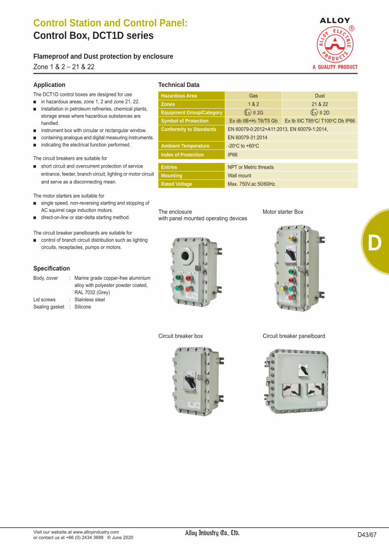
Visit our website at www.alloyindustry.comor contact us at +66 (0) 2434 3688 © June 2020 D43/67
D
Control Station and Control Panel:Control Box, DCT1D series
Flameproof and Dust protection by enclosureZone 1 & 2 _ 21 & 22
The DCT1D control boxes are designed for use in hazardous areas, zone 1, 2 and zone 21, 22. installation in petroleum refineries, chemical plants,
storage areas where hazardous substances are handled. instrument box with circular or rectangular window. containing analogue and digital measuring instruments. indicating the electrical function performed.
Application
Body, cover : Marine grade copper-free aluminium alloy with polyester powder coated, RAL 7032 (Grey)Lid screws : Stainless steelSealing gasket : Silicone
The circuit breakers are suitable for short circuit and overcurrent protection of service
entrance, feeder, branch circuit, lighting or motor circuit and serve as a disconnecting mean.
The motor starters are suitable for single speed, non-reversing starting and stopping of
AC squirrel cage induction motors. direct-on-line or star-delta starting method.
The circuit breaker panelboards are suitable for control of branch circuit distribution such as lighting
circuits, receptacles, pumps or motors.
Hazardous Area Gas DustZones 1 & 2 21 & 22Equipment Group/Category II 2G II 2DSymbol of Protection Ex db IIB+H2 T6/T5 Gb Ex tb IIIC T85oC/ T100oC Db IP66Conformity to Standards EN 60079-0:2012+A11:2013, EN 60079-1:2014,
EN 60079-31:2014Ambient Temperature -20oC to +60oC
Index of Protection IP66
Entries NPT or Metric threadsMounting Wall mountRated Voltage Max. 750V.ac 50/60Hz.
Technical Data
The enclosurewith panel mounted operating devices
Circuit breaker box
Motor starter Box
Circuit breaker panelboard
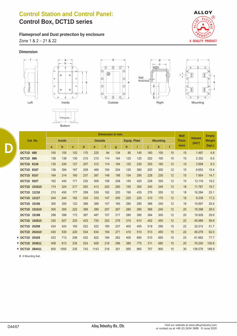
Visit our website at www.alloyindustry.comor contact us at +66 (0) 2434 3688 © June 2020D44/67
D
Control Station and Control Panel:Control Box, DCT1D series
Flameproof and Dust protection by enclosureZone 1 & 2 _ 21 & 22
Dimension
Cat. No.
Dimension in mm. WallThick-ness
Volume(dm3)
EmptyWeight(kgs.)
Inside Outside Equip. Plate Mounting
a b c d e f g h i j k l
DCT1D 685 100 155 102 170 225 94 134 85 140 160 100 10 15 1.497 4.8
DCT1D 886 138 138 130 210 210 114 164 125 125 202 100 10 15 2.352 6.5
DCT1D 8126 135 240 127 207 312 114 164 125 230 200 160 12 15 3.958 9.3
DCT1D 8187 136 394 167 208 466 154 204 120 380 200 300 12 15 8.653 15.4
DCT1D 9157 164 314 160 237 387 148 198 154 295 228 230 12 15 7.954 14.7
DCT1D 9207 162 440 171 230 508 158 208 145 420 228 350 12 15 12.116 19.2
DCT1D 101610 174 324 217 263 413 202 260 155 300 240 240 12 18 11.767 19.7
DCT1D 11218 210 450 177 299 539 162 220 195 435 276 350 12 18 16.284 25.1
DCT1D 12127 244 244 162 333 333 147 205 225 225 310 170 12 18 9.339 17.2
DCT1D 15156 300 300 122 389 389 107 165 280 280 366 240 12 18 10.697 20.4
DCT1D 151510 300 300 222 389 389 207 267 280 280 366 240 12 20 19.398 28.0
DCT1D 15198 298 398 172 387 487 157 217 280 380 364 300 12 20 19.928 29.9
DCT1D 162810 330 627 225 423 720 202 279 310 610 402 450 12 22 45.689 59.9
DCT1D 20208 424 424 182 522 522 160 237 405 405 519 290 15 22 32.012 51.7
DCT1D 202410 430 530 220 534 634 194 271 410 510 513 450 15 22 49.278 62.0
DCT1D 20329 423 713 208 532 822 184 262 400 690 510 650 15 23 61.662 77.7
DCT1D 203611 408 813 235 524 929 216 296 380 775 511 680 15 25 76.200 105.8
DCT1D 284411 600 1000 235 743 1143 216 301 565 965 707 800 15 30 138.576 188.9
6 Mounting feet.

Visit our website at www.alloyindustry.comor contact us at +66 (0) 2434 3688 © June 2020 D45/67
D
Control Station and Control Panel:Control Box, DCT1D series
Flameproof and Dust protection by enclosureZone 1 & 2 _ 21 & 22
Cat. No.Operating devices
TotalRow Column
DCT1D 685 1 1 1DCT1D 886 1 2 2DCT1D 8126 3 2 6DCT1D 8187 5 2 10DCT1D 9157 4 2 8DCT1D 9207 6 2 12DCT1D 101610 4 2 8DCT1D 11218 6 3 18DCT1D 12127 3 4 12DCT1D 15156 4 4 16DCT1D 151510 4 4 16DCT1D 15198 5 4 20DCT1D 162810 9 5 45DCT1D 20208 5 6 30DCT1D 202410 7 6 42DCT1D 20329 10 6 60DCT1D 203611 12 6 72DCT1D 284411 14 9 126
The enclosure with panel mounted operating devices
The enclosure with inspection windows
Cat. No.X = Maximum center line of Cover to center line of Inspection window
(unit : mm.)LGCR1-50-M85 LGCR-113 LGCR-217 LGCR-320
DCT1D 685DCT1D 886 0 (center)DCT1D 8126 50DCT1D 8187 120DCT1D 9157 90DCT1D 9207 150DCT1D 101610 100DCT1D 11218 150 100DCT1D 12127 50 0 (center)DCT1D 15156 80 30 0 (center) 0 (center)DCT1D 151510 80 30 0 (center) 0 (center)DCT1D 15198 120 80 50 0 (center)DCT1D 162810 230 200 170 150DCT1D 20208 140 100 50 50DCT1D 202410 190 150 120 100DCT1D 20329 250 220 200 200DCT1D 203611 300 270 250 250DCT1D 284411 400 350 300 300
Cat. No.X = Maximum center line of Cover to center line of Inspection window
(unit : mm.)LGCS-142 LGCS-260 LGCS-383 LGCS-430 LGCS-5120 LGCS-6200
DCT1D 685DCT1D 886 0 (center)DCT1D 8126 50 40DCT1D 8187 120 120DCT1D 9157 80 80 70DCT1D 9207 150 150 120DCT1D 101610 90 90 70DCT1D 11218 150 150 130 100DCT1D 12127 50 50 30 50 0 (center) 0 (center)DCT1D 15156 80 70 60 70 40 0 (center)DCT1D 151510 80 70 60 70 40 0 (center)DCT1D 15198 120 120 100 130 80 30DCT1D 162810 240 230 210 230 200 140DCT1D 20208 140 120 120 140 100 50DCT1D 202410 190 180 160 200 150 100DCT1D 20329 250 250 250 250 230 170DCT1D 203611 300 300 300 300 280 220DCT1D 284411 400 400 370 400 350 320
Round type, LGCR series
Rectangular type, LGCS series
60
60
(column)(r
ow)
11
23 4 ....
2
3
4
5....
23

Visit our website at www.alloyindustry.comor contact us at +66 (0) 2434 3688 © June 2020D46/67
D
Control Station and Control Panel:Control Box/ Junction Box with terminals, DCT1DE/JBE3B series
Flameproof/ Increased Safety and Dust protection by enclosureZone 1 & 2 _ 21 & 22
DCT1DE control boxes consist of an Ex d enclosure in aluminium alloy, and JBE3B Ex e enclosure in stainless steel are designed for use in hazardous areas, zone 1, 2 and zone 21, 22. installation in petroleum refineries, chemical plants,
storage areas where hazardous substances are handled. instrument box with circular or rectangular window. containing analogue and digital measuring instruments. indicating the electrical function performed.
Application
Ex d enclosure Body, cover : Marine grade copper-free aluminium alloy with polyester powder coated, RAL 7032 (Grey)Ex e enclosure Body, cover : Stainless steel SUS 304 or SUS 316Lid screws : Stainless steelSealing gasket : Silicone
Hazardous Area Gas DustZones 1 & 2 21 & 22Equipment Group/Category II 2G II 2DSymbol of Protection Ex db eb IIB+H2 T6/T5 Gb Ex tb IIIC T85oC/ T100oC Db IP66Conformity to Standards EN 60079-0:2012+A11:2013, EN 60079-1:2014,
EN 60079-7:2007, EN 60079-31:2014Ambient Temperature -40oC to +65oC
Index of Protection IP66
Entries NPT or Metric threadsMounting Wall mountRated Voltage Max. 750V.ac 50/60Hz.
Technical Data

Visit our website at www.alloyindustry.comor contact us at +66 (0) 2434 3688 © June 2020 D47/67
D
Control Station and Control Panel:Control Box/ Junction Box with terminals, DCT1DE/JBE3B series
Flameproof/ Increased Safety and Dust protection by enclosureZone 1 & 2 _ 21 & 22
Dimension
Cat. No.Dimension in mm.
Inside Outside Mounting
Ex db Ex eb a b c a1 b1 c1 A B C D E F G X Y Z X1 Y1 Z1
DCT1DE 685 / JBE3B - 141410 100 155 102 90 90 79 170 225 140 140 370 134 107 160 100 10 175 75 11
DCT1DE 886 / JBE3B - 181812 138 138 130 130 130 97 210 210 180 180 395 164 125 202 100 10 215 115 11
DCT1DE 8126 / JBE3B - 182512 135 240 127 130 200 99 207 312 180 250 567 164 125 200 160 12 215 185 11
DCT1DE 8126 / JBE3B - 202512 240 135 127 150 200 99 312 207 200 250 462 164 125 200 160 12 235 185 11
DCT1DE 8187 / JBE3B - 202016 136 394 167 150 150 136 208 466 200 200 671 204 164 200 300 12 235 135 11
DCT1DE 8187 / JBE3B - 352016 394 136 167 300 150 136 466 208 350 200 413 204 164 200 300 12 385 135 11
DCT1DE 9157 / JBE3B - 202515 164 314 160 150 200 127 237 387 200 250 642 198 155 228 230 12 235 185 11
DCT1DE 9157 / JBE3B - 282015 314 164 160 230 150 127 387 237 280 200 442 198 155 228 230 12 315 135 11
DCT1DE 9207 / JBE3B - 202516 162 440 171 150 200 136 230 508 200 250 763 208 164 228 350 12 235 185 11
DCT1DE 9207 / JBE3B - 402016 440 162 171 350 150 136 508 230 400 200 435 208 164 228 350 12 435 135 11
DCT1DE 101610 / JBE3B - 202520 174 324 217 150 200 178 263 413 200 250 668 260 206 240 240 12 235 185 11
DCT1DE 101610 / JBE3B - 282520 324 174 217 230 200 178 413 263 280 250 518 260 206 240 240 12 315 185 11
DCT1DE 11218 / JBE3B - 302516 210 450 177 150 200 138 299 539 200 250 794 220 166 276 350 12 235 185 11
DCT1DE 11218 / JBE3B - 402516 450 210 177 350 200 138 539 299 400 250 554 220 166 276 350 12 435 185 11
DCT1DE 12127 / JBE3B - 302515 244 244 162 250 200 123 333 333 300 250 588 205 151 310 170 12 335 185 11
DCT1DE 15156 / JBE3B - 352511 300 300 122 300 200 85 389 389 350 250 644 165 113 366 240 12 385 185 11
DCT1DE 151510 / JBE3B - 352521 300 300 222 300 200 183 389 389 350 250 644 267 211 366 240 12 385 185 11
DCT1DE 15198 / JBE3B - 353016 298 398 172 300 250 133 387 487 350 300 792 217 161 364 300 12 385 235 11
DCT1DE 162810 / JBE3B - 404020 330 627 225 350 350 174 423 720 400 400 1125 279 202 402 450 12 435 335 11
DCT1DE 162810 / JBE3B - 504020 627 330 225 450 350 174 720 423 500 400 828 279 202 402 450 12 535 335 11
DCT1DE 20208 / JBE3B - 503516 424 424 182 450 300 132 522 522 500 350 877 237 160 519 290 15 535 285 11
DCT1DE 202410 / JBE3B - 504019 430 530 220 450 350 166 534 634 500 400 1039 271 194 513 450 15 535 335 11
DCT1DE 20329 / JBE3B - 505018 423 713 208 450 450 156 532 822 500 500 1327 262 184 510 650 15 535 435 11
DCT1DE 20329 / JBE3B - 655018 713 423 208 600 450 156 822 532 650 500 1037 262 184 510 650 15 685 435 11
DCT1DE 203611 / JBE3B - 505021 408 813 235 450 450 184 524 929 500 500 1434 296 212 511 680 15 535 435 11
DCT1DE 203611 / JBE3B - 705021 813 408 235 650 450 184 929 524 700 500 1029 296 212 511 680 15 735 435 11
DCT1DE 284411 / JBE3B - 608020 600 1000 235 550 750 179 743 1143 600 800 1948 301 207 707 800 15 635 735 11
DCT1DE 284411 / JBE3B - 906020 1000 600 235 850 550 179 1143 743 900 600 1348 301 207 707 800 15 935 535 11
6 Mounting feet. Housing material ; 4 - SUS 304, 6 - SUS 316

Visit our website at www.alloyindustry.comor contact us at +66 (0) 2434 3688 © June 2020D48/67
D
Control Station and Control Panel: Switchrack Assemblies
The switchrack assemblies are designed for hazardous areas of zone 1, 2 and zone 21, 22 providing a complete circuit breakers, motor starters,
circuit breaker panelboards, terminal boxes, metering or control boxes with factory wired, assembled and mounted on free-standing rack.
Application
Rack structure : Steel with hot-dip galvanized
Hazardous Area Gas DustZones 1 & 2 21 & 22Equipment Group/Category II 2G II 2DSymbol of Protection Ex db IIB Gb Ex tb IIIC Db IP66Conformity to Standards EN 60079-0:2012+A11:2013, EN 60079-1:2014,
EN 60079-31:2014Ambient Temperature -20oC to +55oCIndex of Protection IP66
Entries NPT or Metric threadsMounting Wall mount or Stanchion mountRated Voltage Max. 415V.ac 50/60Hz.
Technical Data
Flameproof and Dust protection by enclosureZone 1 & 2 _ 21 & 22

Visit our website at www.alloyindustry.comor contact us at +66 (0) 2434 3688 © June 2020 D49/67
D
Control Station and Control Panel: Control Box, AEC2B series
Flameproof, Increased Safety and Dust protection by enclosureZone 1 & 2 _ 21 & 22
Application
Housing : Stainless steel (SUS 304)Coating : 5Y7/1 (semi gloss) melamine baking (coating thickness: 10μm) 1-column: Outside coating 2,3,4-column: inside & outside coatingScrews : Stainless steel
Rated insulation voltage : 600V. (with pilot light or ET2A-8PE screw terminal block: 500V.) Meter AC input; 300V. Meter DC input; 150V.Insulation resistance : 100 M minimum (500V.dc megger)Operating humidity : 45 to 85% (no condensation)Altitude : 2000m maximumApplicable wire : Stranded wire; 1.25 to 2.5 mm.2
Solid wire; 1.2 to 1.6 mm.2
Solid/Stranded wire; 16-14 AWG
Electrical Rating
Technical Data
Hazardous Area Gas DustZones 1 & 2 21 & 22Equipment Group/Category II 2G II 2DSymbol of Protection Ex d e IIC T6 Gb Ex tb IIIC T80oC Db IP65Certificate Presafe 17 ATEX 10518
IECEx PRE 17.0024Conformity to standards EN 60079-0:2012+A11:2013, EN 60079-1:2007,
EN 60079-7:2007, EN 60079-31:2014IEC 60079-0:2011, IEC 60079-1:2007-04,IEC 60079-7:2006-07, IEC 60079-31:2013
Ambient Temperature -20oC to +50oC (no freezing)Index of Protection IP65
Mounting Wall typeEntries (Lead-in Fittings) NPT or Metric thread
Catalogue Number Logic
AEC2B - B N C x
Corrosion resistant stainless steel enclosure. Applicable in areas where explosive gases/steam exist including hydrogen and acetylene, and envi-ronments subject to dust
Available with a variety of switches/pilot lights and enclosures.
Control box format11 1 unit /1 column21 2 units /1 column31 3 units /1 column41 4 units /1 column51 5 units /1 column22 2 units /2 columns32 3 units /2 columns42 4 units /2 columns52 5 units /2 columns23 2 units /3 columns33 3 units /3 columns43 4 units /3 columns53 5 units /3 columns63 6 units /3 columns64 6 units /4 columns
Control unit configuration01 PL02 PB04 PB + SS06 SS10 PL + PB13 PL + PB + SS17 PL + SS50 M (for AEC2B-1)
PL + PB + M(for AEC2B-2/3/4/5/6)
51 PL + M52 PB + M53 PL + PB + SS + M54 PB + SS + M56 SS + M57 PL + SS + M
etc.
Wiring
N withoutwiring
Terminal BlockC Standard
screw terminal
Entries *M1 M16x1.5M2 M20x1.5M3 M25x1.5M4 M32x1.5M5 M40x1.5N1 Ø1/2” NPTN2 Ø3/4” NPTN3 Ø1” NPTN4 Ø1-1/4” NPT
* with cable lead-in fittings
PL - Pilot LightPB - Push Button and/or Emergency SwitchSS - Selector Switch and/or Key Selector SwitchM - Meter
Standard formSequential
numberindicated
in standard catalog
(code 1-9)
Meter's capacity and scaleAC input meter (ammeter)
A10 10/1AA15 15/1AA20 20/1A
DC input meterVD10 0-10V.dc input
MD420 4-20mA inputetc.

Visit our website at www.alloyindustry.comor contact us at +66 (0) 2434 3688 © June 2020D50/67
D
Control Station and Control Panel: Control Box, AEC2B series
Flameproof, Increased Safety and Dust protection by enclosureZone 1 & 2 _ 21 & 22
Control Box Format
1, 2 control units 3 control units 4 control units 5 control units
1-co
lum
n2-
colu
mns
3-co
lum
ns
6 control units
3-co
lum
ns4-
colu
mns
Control UnitsControl Unit Pilot Light Push Button Emergency Stop SwitchShape Round Flush Extended Mushroom Mushroom (Ø40)
Operation _ Momentary Push-to-lock, pull orturn-to-reset
Shape
Illumination colour/button colour
Part No. EU2B-YL EU2B-YB1 EU2B-YB2 EU2B-YB3 EU2B-YBV
R (red) G (green) Y (yellow) A (amber)
S (blue) PW (pure white)W (white)
R (red)B (black) G (green) Y (yellow) S (blue)W (white) R (red)
Control Unit Selector Switch Meter
Shape
Knob Operator Key
Part No. EU2B-YS EU2B-YSK EU2B-YM
Nameplate/ Mounting Hole Plug
Control Unit Control Unit Nameplate Marking Plates forControl Unit Nameplate
Emergency Stop SwitchNameplate Sticker
Control UnitMounting Hole Plug
Shape
Part No. EU9Z-NM AEU9Z-NP EU9Z-NVS EU9Z-BP
For details, see page D59 to D64/67
For details, see page D66/67

Visit our website at www.alloyindustry.comor contact us at +66 (0) 2434 3688 © June 2020 D51/67
D
Control Station and Control Panel: Control Box, AEC2B series
Flameproof, Increased Safety and Dust protection by enclosureZone 1 & 2 _ 21 & 22
Cable Lead-in FittingsWall MountReducersReducers installed at the bottom of the control box are as follows:
1 column: 1 reducer2 columns: 2 reducers3 columns: 3 reducers4 columns: 4 reducersMaterial: brass (nickel-plated)
Control UnitStyle Part No. Thread Size Symbol
1-column(1 to 3 control units)
2,3-columns(2,3 control units)
EC9E-H3M16E-UL M16x1.5 M1EC9E-H3M20E-UL M20x1.5 M2EC9E-H3M25E-UL M25x1.5 M3EC9E-H3M32E-UL M32x1.5 M4EC9E-H3NPT1E-UL Ø1/2” NPT N1EC9E-H3NPT2E-UL Ø3/4” NPT N2EC9E-H3NPT3E-UL Ø1” NPT N3
1,2,3-columns(4,5 control units)
3,4-columns(6 control units)
EC9E-H4M25E-UL M25x1.5 M3EC9E-H4M32E-UL M32x1.5 M4EC9E-H4M40E-UL M40x1.5 M5EC9E-H4NPT2E-UL Ø3/4” NPT N2EC9E-H4NPT3E-UL Ø1” NPT N3EC9E-H4NPT4E-UL Ø1-1/4” NPT N4
The following optional reducers can also be installed.
Terminal BlockThe number of terminal blocks, poles, and the installation direction that can be installed on the control box are as follows:
1-column 1, 2 units(1 terminal block/
8 poles)
1-column 3 units(1 terminal block/
8 poles)
1-column 4, 5 units(1 terminal block/
8 poles)
4-column 6 units(8 terminal blocks/
64 poles)
3-column 2, 3 units(3 terminal blocks/
24 poles)
3-column 4, 5, 6 units(6 terminal blocks/
48 poles)
2-column 2, 3 units(2 terminal blocks/
16 poles)
2-column 4,5 units(4 terminal blocks/
32 poles)
A terminal block is not supplied with the standard control boxes (without wiring). When wiring inside the control box is required, specify the wiring circuit.
The terminal block type used on the control boxes with wiring de-pends on the terminal style of the control unit.
C terminal style (exposed screw terminal)Applicable terminal block: ET2A-8PE (material: polyamide)
Certi cation numbers:
IECEx TUR 15.0043UTÜV 15 ATEX 7799U
123
34
22
101
1-column 1,2 units(1 terminal block/
8 poles)
1-column 3 units(1 terminal block/
8 poles)
1-column 4,5 units(2 terminal block/
16 poles)
2-column 2,3 units(2 terminal block/
16 poles)
2-column 4,5 units(4 terminal block/
32 poles)
3-column 2,3 units(3 terminal block/
24 poles)
3-column 4,5,6 units(6 terminal block/
48 poles)
4-column 6 units(8 terminal block/
64 poles)
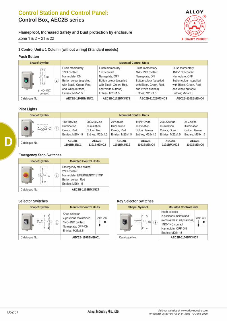
Visit our website at www.alloyindustry.comor contact us at +66 (0) 2434 3688 © June 2020D52/67
D
Control Station and Control Panel: Control Box, AEC2B series
Flameproof, Increased Safety and Dust protection by enclosureZone 1 & 2 _ 21 & 22
Shape/ Symbol Mounted Control Units
31
421
Flush momentary1NO contactNameplate; ONButton colour (suppliedwith Black, Green, Red,and White buttons)Entries; M25x1.5
Flush momentary1NC contactNameplate; OFFButton colour (suppliedwith Black, Green, Red,and White buttons)Entries; M25x1.5
Flush momentary1NO-1NC contactNameplate; ONButton colour (suppliedwith Black, Green, Red,and White buttons)Entries; M25x1.5
Flush momentary1NO-1NC contactNameplate; OFFButton colour (suppliedwith Black, Green, Red,and White buttons)Entries; M25x1.5
(1NO-1NC contact)
Catalogue No. AEC2B-1102BM3NC1 AEC2B-1102BM3NC2 AEC2B-1102BM3NC3 AEC2B-1102BM3NC4
1 Control Unit x 1 Column (without wiring) (Standard models)
Push Button
Shape/ Symbol Mounted Control Units
OFF ON
1 3
2 4
1
Knob selector2-positions maintained1NO-1NC contactNameplate; OFF-ONEntries; M25x1.5
OFF ON
Catalogue No. AEC2B-1106BM3NC1
Shape/ Symbol Mounted Control Units
X1 X2 1
110/110V.acIlluminationColour; RedEntries; M25x1.5
200/220V.acIlluminationColour; RedEntries; M25x1.5
24V.ac/dcIlluminationColour; RedEntries; M25x1.5
110/110V.acIlluminationColour; GreenEntries; M25x1.5
200/220V.acIlluminationColour; GreenEntries; M25x1.5
24V.ac/dcIlluminationColour; GreenEntries; M25x1.5
Catalogue No. AEC2B-1101BM3NC1
AEC2B-1101BM3NC2
AEC2B-1101BM3NC3
AEC2B-1101BM3NC4
AEC2B-1101BM3NC5
AEC2B-1101BM3NC6
Pilot Lights
Shape/ Symbol Mounted Control Units
1
2
1
2
1
Emergency stop switch2NC contactNameplate; EMERGENCY STOPButton colour; RedEntries; M25x1.5
Catalogue No. AEC2B-1102BM3NC7
Emergency Stop Switches
Selector SwitchesShape/ Symbol Mounted Control Units
OFF ON
1 3
2 4
1
Knob selector2-positions maintained(removable at all positions)1NO-1NC contactNameplate; OFF-ONEntries; M25x1.5
OFF ON
Catalogue No. AEC2B-1106BM3NC4
Key Selector Switches

Visit our website at www.alloyindustry.comor contact us at +66 (0) 2434 3688 © June 2020 D53/67
D
Control Station and Control Panel: Control Box, AEC2B series
Flameproof, Increased Safety and Dust protection by enclosureZone 1 & 2 _ 21 & 22
2 Control Units x 1 Column (without wiring) (Standard models)
Shape/ Symbol Mounted Control Units
3
41
2
1
Flush momentary1NO contact, Nameplate; ONButton colour (supplied with Black, Green, Red, and White buttons)
2
Flush momentary1NC contact, Nameplate; OFFButton colour (supplied with Black, Green, Red, and White buttons)
Catalogue No. AEC2B-2102BM3NC1
Two Flush Push ButtonsShape/ Symbol Mounted Control Units
3 1
3 14 2
4 2
1Mushroom momentary1NO-1NC contact, Nameplate; ONButton colour; Black
2Mushroom momentary1NO-1NC contact, Nameplate; OFFButton colour; Red
Catalogue No. AEC2B-2102BM3NC4
Two Mushroom Push Buttons
Shape/ Symbol Mounted Control Units
X1 X2
3 1
4 2
1110/110V.acIllumination Colour; Red
200/220V.acIllumination Colour; Red
24V.ac/dcIllumination Colour; Red
2
Flush momentary1NO-1NC contactNameplate; STOPButton colour (supplied with Black, Green, Red, and White buttons)
Flush momentary1NO-1NC contactNameplate; STOPButton colour (supplied with Black, Green, Red, and White buttons)
Flush momentary1NO-1NC contactNameplate; STOPButton colour (supplied with Black, Green, Red, and White buttons)
Catalogue No. AEC2B-2110BM3NC1 AEC2B-2110BM3NC2 AEC2B-2110BM3NC3
Combination Pilot Light/ Push Button
Shape/ Symbol Mounted Control Units
X1 X2
OFF ON
1 3
2 4
1110/110V.acIllumination Colour; Red
200/220V.acIllumination Colour; Red
2Knob selector, 2-positions maintained1NO-1NC contactNameplate; OFF-ON
OFF ON Knob selector, 2-positions maintained1NO-1NC contactNameplate; OFF-ON
OFF ON
Catalogue No. AEC2B-2117BM3NC1 AEC2B-2117BM3NC2
Combination Pilot Light/ Push Button
3 Control Units x 1 Column (without wiring) (Standard models)
Shape/ Symbol Mounted Control Units
X1 X2
4
32
1
1110/110V.acIllumination Colour; Red
200/220V.acIllumination Colour; Red
24V.ac/dcIllumination Colour; Red
2
Flush momentary1NO contact, Nameplate; ONButton colour (supplied with Black, Green, Red, and White buttons)
Flush momentary1NO contact, Nameplate; ONButton colour (supplied with Black, Green, Red, and White buttons)
Flush momentary1NO contact, Nameplate; ONButton colour (supplied with Black, Green, Red, and White buttons)
3
Flush momentary1NC contact, Nameplate; OFFButton colour (supplied with Black, Green, Red, and White buttons)
Flush momentary1NC contact, Nameplate; OFFButton colour (supplied with Black, Green, Red, and White buttons)
Flush momentary1NC contact, Nameplate; OFFButton colour (supplied with Black, Green, Red, and White buttons)
Catalogue No. AEC2B-3110BM3NC1 AEC2B-3110BM3NC2 AEC2B-3110BM3NC3
Combination 1 Pilot Light/ 2 Push Button

Visit our website at www.alloyindustry.comor contact us at +66 (0) 2434 3688 © June 2020D54/67
D
Control Station and Control Panel: Control Box, AEC2B series
Flameproof, Increased Safety and Dust protection by enclosureZone 1 & 2 _ 21 & 22
Shape/ Symbol Mounted Control Units
3 1
4 2
3 1
4 2
X1 X2
X1 X2
1110/110V.acIllumination Colour; Red
200/220V.acIllumination Colour; Red
24V.ac/dcIllumination Colour; Red
2110/110V.acIllumination Colour; Green
200/220V.acIllumination Colour; Green
24V.ac/dcIllumination Colour; Green
3
Flush momentary1NO-1NC contact, Nameplate; ONButton colour (supplied with Black, Green, Red, and White buttons)
Flush momentary1NO-1NC contact, Nameplate; ONButton colour (supplied with Black, Green, Red, and White buttons)
Flush momentary1NO-1NC contact, Nameplate; ONButton colour (supplied with Black, Green, Red, and White buttons)
4
Flush momentary1NO-1NC contact, Nameplate; OFFButton colour (supplied with Black, Green, Red, and White buttons)
Flush momentary1NO-1NC contact, Nameplate; OFFButton colour (supplied with Black, Green, Red, and White buttons)
Flush momentary1NO-1NC contact, Nameplate; OFFButton colour (supplied with Black, Green, Red, and White buttons)
Catalogue No. AEC2B-4110BM3NC1 AEC2B-4110BM3NC2 AEC2B-4110BM3NC3
3 Control Units x 1 Column (without wiring) (Standard models)
3 Push ButtonsShape/ Symbol Mounted Control Units
3 1
4 2
3 1
4 2
3 1
4 2
1Flush momentary1NO-1NC contact, Nameplate; BlankButton colour (supplied with Black, Green, Red, and White buttons)
2
3
Catalogue No. AEC2B-3102BM3NC1
1 Meter/ 2 Push ButtonsShape/ Symbol Mounted Control Units
3 1
4 2
3
A
1
4 2
1 Specify input, capacity, and scale
2Flush momentary1NO-1NC contact, Nameplate; BlankButton colour (supplied with Black, Green, Red, and White buttons)
3
Catalogue No. AEC2B-3152BM3NC1
Specify the meter’s capacity and scale in place of in the Cat. No.
4 Control Units x 1 Column (without wiring) (Standard models)
2 Pilot Lights/ 2 Push Buttons
Shape/ Symbol Mounted Control Units
3 1
31
4 2
3 1
4 2
X1 X2
HAND AUTO
1110/110V.acIllumination Colour; Red
200/220V.acIllumination Colour; Red
24V.ac/dcIllumination Colour; Red
2
Flush momentary1NO-1NC contact, Nameplate; ONButton colour (supplied with Black, Green, Red, and White buttons)
Flush momentary1NO-1NC contact, Nameplate; ONButton colour (supplied with Black, Green, Red, and White buttons)
Flush momentary1NO-1NC contact, Nameplate; ONButton colour (supplied with Black, Green, Red, and White buttons)
3
Flush momentary1NO-1NC contact, Nameplate; OFFButton colour (supplied with Black, Green, Red, and White buttons)
Flush momentary1NO-1NC contact, Nameplate; OFFButton colour (supplied with Black, Green, Red, and White buttons)
Flush momentary1NO-1NC contact, Nameplate; OFFButton colour (supplied with Black, Green, Red, and White buttons)
4
Knob selector, 2-positionsmaintained1NO-1NC contactNameplate; MAN-AUTO
HAND AUTOKnob selector, 2-positionsmaintained1NO-1NC contactNameplate; MAN-AUTO
HAND AUTOKnob selector, 2-positionsmaintained1NO-1NC contactNameplate; MAN-AUTO
HAND AUTO
Catalogue No. AEC2B-4113BM3NC1 AEC2B-4113BM3NC2 AEC2B-4113BM3NC3
1 Pilot Light/ 2 Push Buttons/ 1 Selector Switch

Visit our website at www.alloyindustry.comor contact us at +66 (0) 2434 3688 © June 2020 D55/67
D
Control Station and Control Panel: Control Box, AEC2B series
Flameproof, Increased Safety and Dust protection by enclosureZone 1 & 2 _ 21 & 22
5 Control Units x 1 Column (without wiring) (Standard models)
Shape/ Symbol Mounted Control Units
3 1
4 2
3 1
4 2
X1 X2
X1 X2
OFF ON2 4
1 3
1110/110V.acIllumination Colour; Red
200/220V.acIllumination Colour; Red
24V.ac/dcIllumination Colour; Red
2110/110V.acIllumination Colour; Green
200/220V.acIllumination Colour; Green
24V.ac/dcIllumination Colour; Green
3
Flush momentary1NO-1NC contact, Nameplate; ONButton colour (supplied with Black, Green, Red, and White buttons)
Flush momentary1NO-1NC contact, Nameplate; ONButton colour (supplied with Black, Green, Red, and White buttons)
Flush momentary1NO-1NC contact, Nameplate; ONButton colour (supplied with Black, Green, Red, and White buttons)
4
Flush momentary1NO-1NC contact, Nameplate; OFFButton colour (supplied with Black, Green, Red, and White buttons)
Flush momentary1NO-1NC contact, Nameplate; OFFButton colour (supplied with Black, Green, Red, and White buttons)
Flush momentary1NO-1NC contact, Nameplate; OFFButton colour (supplied with Black, Green, Red, and White buttons)
5
Knob selector, 2-positionsmaintained1NO-1NC contactNameplate; MAN-AUTO
HAND AUTOKnob selector, 2-positionsmaintained1NO-1NC contactNameplate; MAN-AUTO
HAND AUTOKnob selector, 2-positionsmaintained1NO-1NC contactNameplate; MAN-AUTO
HAND AUTO
Catalogue No. AEC2B-5113BM3NC1 AEC2B-5113BM3NC2 AEC2B-5113BM3NC3
2 Pilot Lights/ 2 Push Buttons/ 1 Selector Switch

Visit our website at www.alloyindustry.comor contact us at +66 (0) 2434 3688 © June 2020D56/67
D
Control Station and Control Panel: Control Box, AEC2B series
Flameproof, Increased Safety and Dust protection by enclosureZone 1 & 2 _ 21 & 22
Shape Dimension (mm.)
95(mounting
hole)
4-ø7 (mounting hole)
Mounting tab
M5 lid mounting screwM4 grounding terminal
ReducerHinge
1 control unit
2 control units
(mou
ntin
gho
le)
3617
0
110
115
1.5
142
100
106
50
Aprox. Weight1 control unit; 1.2 kgs./ 2 control units; 1.4 kgs.
1, 2 Control Units x 1 Column
Shape Dimension (mm.)
192
150
106 1.522
0
115
11036
95(mounting
hole)
4-ø7 (mounting hole)
Mounting tab
M5 lid mounting screwM4 grounding terminal
ReducerHinge
3 control units
(mou
ntin
gho
le)
2×50
P
Aprox. Weight; 1.8 kgs.
3 Control Units x 1 Column
Shape Dimension (mm.)
3635
0
95110
115
322
250
1.51063×50
P4×
50P
4-ø7 (mounting hole)
Mounting tab
M5 lid mounting screwM4 grounding terminal
ReducerHinge
4 control units
5 control units
(mou
ntin
gho
le)
(mountinghole)
Aprox. Weight; 2.4 kgs.
4, 5 Control Units x 1 Column

Visit our website at www.alloyindustry.comor contact us at +66 (0) 2434 3688 © June 2020 D57/67
DShape Dimension (mm.)
Aprox. Weight2 control units; 4.8 kgs./ 3 control units; 5.2 kgs./4 control units; 6.5 kgs./ 5 control units; 7.1 kgs./
Control Station and Control Panel: Control Box, AEC2B series
Flameproof, Increased Safety and Dust protection by enclosureZone 1 & 2 _ 21 & 22
Shape Dimension (mm.)
Aprox. Weight2 control units; 3.8 kgs./ 3 control units; 4.2 kgs./4 control units; 4.6 kgs./ 5 control units; 5.0 kgs./
2, 3, 4, 5 Control Units x 2 Columns
A
230220210
4-ø10
36.5
70
2106
R
Mounting tab
M5 lid mounting screw
M4 grounding terminalReducer
Hinge
(mou
ntin
gho
le)(mounting
hole)
70
3×50
P
50
7070
4×50
P
2×50
P70
2 control units
Control Unit Mounting Holes
3 control units 4 control units 5 control units
DimensionsNo. of Control Units
A R
2 or 3 250 180
4 or 5 350 280
2, 3, 4, 5 Control Units x 3 Columns
DimensionsNo. of Control Units
A R
2 or 3 250 180
4 or 5 350 280
6 Control Units x 3 Columns 6 Control Units x 4 Columns
140
5×50
P
330
70
36.5
70
300310320
400
106 2
(mou
ntin
gho
le)
(mountinghole)
4-ø10
M5 lid mounting screw
M4 grounding terminalReducer
Mounting tab
Hinge
Control UnitMounting Holes
330
70
36.5
7070
370380390
400
106 2
3×70P
5×50
P
(mou
ntin
gho
le)
(mountinghole)
4-ø10
M5 lid mounting screw
M4 grounding terminalReducer
Mounting tab
Hinge
Control UnitMounting Holes
Approx. Weight; 8.1 kg Approx. Weight; 10.7 kg
2
R(m
ount
ing
hole
)
A
320310300
(mountinghole)
36.5
7070
106
4-ø10
M5 lid mounting screw
M4 grounding terminalReducer
Mounting tab
Hinge
4×50
P
2×50
P
3×50
P
50
140 140140 140
Control Unit Mounting Holes
2 control units 3 control units 4 control units 5 control units

Visit our website at www.alloyindustry.comor contact us at +66 (0) 2434 3688 © June 2020D58/67
D
Control Station and Control Panel: Control Box, AEC2B series
Flameproof, Increased Safety and Dust protection by enclosureZone 1 & 2 _ 21 & 22
Applicable StandardsControl Units Applicable
Standards Mark
Pushbuttons
Selector Switch-es
Key Selector Switches
Pilot Lights
Meters
EN60947-5-1 EU Low Voltage Directive
EN60079-0EN60079-1EN60079-7EN60079-31
PTB 08 ATEX 1053UPTB 08 ATEX 1003U
IEC60079-0IEC60079-1IEC60079-7IEC60079-31
IECEx PTB15.0006UIECEx PTB15.0007U
Emergency Stop Switches EN60947-5-5
Rated Insulation Voltage (Ui) 500V
Rated OperatingVoltage (Ue)
6, 12, 24V.ac/dc100/110, 115, 120, 200/220230, 240, 380, 400/440, 480V.ac
Impulse Withstand Voltage (Uimp) 4kVInsulation Resistance 100 M minimum (500V.dc)Frequency 50/60Hz
Power Consumption(approx.)
0.3W (24V.ac/dc)1.5W (100/110V.ac)
Life (reference value) Approx. 40,000 hours
Because the built-in LED lamp is a high-luminance type, the lamp may light dimly due to induction even when the power is off.
Contact Resistance 50m maximum (initial value)Impulse Withstand Voltage (Uimp) 6kV
Insulation Resistance 100M minimum (500V.dc megger)
Short-circuit Protection 250V/10A fuse (Type aM IEC60269-1/IEC60269-2)
Conditional Short-circuit Current 1,000A
Mechanical Life
Pushbutton 1,000,000 operations minimumSelector Switch 500,000 operations minimumKey Selector Switch 500,000 operations minimum
Emergency Stop Switch 50,000 operations minimum
Electrical Life
Pushbutton 250,000 operations minimum (switch-ing frequency 1800 operations/h)
Selector Switch 250,000 operations minimum (switch-ing frequency 900 operations/h)
Key Selector Switch
250,000 operations minimum(switching frequency 900 operations/h)
Emergency Stop Switch
50,000 operations minimum (switch-ing frequency 900 operations/h)
Minimum Force Required for Direct Action
Emergency Stop Switch 60N
Minimum Operator Stroke Required for Direct Opening Action
Emergency Stop Switch 7.0mm
Maximum Operator Stroke
Emergency Stop Switch 9.0mm
Contact bounceContacts will bounce during operation of pushbuttons and selector switch-es (reference value: 20 ms). Be sure to take contact bounce time into con-sideration when designing a control circuit.
Replacing the control units, nameplates, padlock covers, and LED lamps by users affect the explosion-proof performance which is not guaranteed. Contact ALLOY when replacement is necessary.
Contact RatingsRated Insulation Voltage (Ui) 600VRated Thermal Current (Ith) 10A (*)Rated Operating Voltage (Ue) 24V 120V 240V 500V
Rated OperatingCurrent (Ie)
AC50/60Hz
Resistive Load (AC12) 10A (*) 10A (*) 6A 2.8A
Inductive Load (AC15) 10A (*) 6A 3A 1.4A
DC
Resistive Load (DC12) 8A 2.2A 1.1A —
Inductive Load (DC13) 4A 1.1A 0.55A —
Up to 2 contacts (per control unit): 10A 3 contacts (per control unit): 9A Minimum applicable load: 3V.ac/dc, 5 mAApplicable operating locations may vary according to operating conditions and load types. TÜV ratings (emergency stop switches)
AC-15 250V/3A DC-13 125V/1.1A
Accuracy Class 2.5
Insulation Resistance 100 M minimum (500V.dc megger)
AC Ammeter
Rated Insulation Voltage (Ui) 300V
Operation Moving coil
Impulse Withstand Voltage (Uimp) 4kV
Power Consumption 1VA
Measurement 5A, 10A, 30A, 50A, etc.
Input (CT Ratio) 1A, 5A
Extended Memory 3 times, etc
DC Input Meter
Rated Insulation Voltage (Ui) 150V
Operation Moving coil
Impulse Withstand Voltage (Uimp) 2.5kV
Input 0 to 10V.dc, 4 to 20mA.dc, etc
Power Consumption(DC ammeter) 0.01W
Power Consumption(DC voltmeter) 1mA
Use a commercially available CT (current transformer) for AC ammeters with consumption current of 10A minimum. Install the CT in a non-hazard-ous location.AC and DC ammeters other than listed above are also available upon request, such as extended scale or red pointer.
Pointer Zero Adjustment and Red Pointer AdjustmentUsing a at screwdriver, turn the zero adjustment pointer screw and the red pointer screw (see below).Zero adjustment is possible only on AC ammeters. On other meters such as DC voltmeters, DC ammeters, and tachometer, zero adjustment is not possible. Flat screwdriver
Red pointer adjust screw
Zero adjust screw

Visit our website at www.alloyindustry.comor contact us at +66 (0) 2434 3688 © June 2020 D59/67
D
Control Station and Control Panel: Control Box, AEC2B series
Flameproof, Increased Safety and Dust protection by enclosureZone 1 & 2 _ 21 & 22
Pilot Lights
Shape SymbolContactRating
Part No.Illumination Colour
Code *Approx.WeightC terminal style:
exposed screw terminalF terminal style:
Finger-safe screw terminal
PL
100/110V.ac 50/60Hz. EU2B-YL116CD* EU2B-YL116FD* R: redA: amberW: white PW: pure white
G: greenY: yellowS: blue
150g200/220V.ac 50/60Hz. EU2B-YL126CD* EU2B-YL126FD*
24V.ac/dc EU2B-YL122CD* EU2B-YL122FD* 108g
Dimension (mm)
Other voltages are available: 6V.ac/dc, 12V.ac/dc, 115V.ac, 120V.ac, 230V.ac, 240V.ac, 380V.ac, 400/440V.ac, 480V.ac, 100/110/120V.ac/dc, 230/240V ac/dc. For details, see page D62/67.
Because LED illuminated pilot lights have small input currents, they may light due to induction even when the power is off. Specify an illumination color code in place of * in the Part No.
Panel Thickness 1 to 4.5Panel Thickness 1 to 4.5
C Terminal Style F Terminal Style
20.313.3
ø40
67.7
31.4
32.5
61.4
ø40
67.7
20.313.3
X1
X2
Push Buttons, Momentary
Shape Symbol Operator ContactPart No.
Button Colour Code *Approx.WeightC terminal style:
exposed screw terminalF terminal style:
Finger-safe screw terminal
PB
Flush1NO EU2B-YB110C*D EU2B-YB110F*D Blank: supplied with four
buttons (B, G, R, W)Y: yellow S: blue
68g1NC EU2B-YB101C*D EU2B-YB101F*D1NO-1NC EU2B-YB111C*D EU2B-YB111F*D 92g
Extended1NO EU2B-YB210C*D EU2B-YB210F*D B: black
G: greenR: redW: whiteY: yellowS: blue
70g1NC EU2B-YB201C*D EU2B-YB201F*D1NO-1NC EU2B-YB211C*D EU2B-YB211F*D 94g
Mushroom1NO EU2B-YB310C*D EU2B-YB310F*D
76g1NC EU2B-YB301C*D EU2B-YB301F*D1NO-1NC EU2B-YB311C*D EU2B-YB311F*D 101g
Dimension (mm)
13.3
ø40
67.7 13.3
38.4
47.4
32.2
ø40
67.7
ø23.
6
19.3
ø40
24.5
Panel Thickness 1 to 4.5 Panel Thickness 1 to 4.5
Flush (C Terminal Style) Flush (F Terminal Style) Extended Mushroom
4 2NO NC
3 1
Other contact arragements (2NO, 2NC, 1NO-2NC, 2NO-1NC, 3NO, 3NC) are also available. See page D62/67. Specify a button color code in place of * in the Part No.
Emergency Stop Switches, Push-to-lock or Turn-to-reset
Shape Symbol Operator ContactPart No.
Button ColourApprox.WeightC terminal style:
exposed screw terminalF terminal style:
Finger-safe screw terminal
ES Ø40Mushroom
2NC EU2B-YBV302CR EU2B-YBV302FR Red 120g
1NO-2NC EU2B-YBV312CR EU2B-YBV312FR144g
3NC EU2B-YBV303CR EU2B-YBV303FR
Dimension (mm)
4 2NO NC
3 167.7 35
ø40
67.7 35
ø40
38.4
47.4
32.2Panel Thickness 1 to 4.5C Terminal Style F Terminal Style Panel Thickness 1 to 4.5
Other contact arrangements (1NC, 1NO-1NC) are also available. See page D62/67 for details. Emergency stop switches are only available with a red button.

Visit our website at www.alloyindustry.comor contact us at +66 (0) 2434 3688 © June 2020D60/67
D
Control Station and Control Panel: Control Box, AEC2B series
Flameproof, Increased Safety and Dust protection by enclosureZone 1 & 2 _ 21 & 22
Selector Switches
Shape SymbolNo. of
Positions
Contact BlockOperatorPosition
OperationPart No.
Approx.WeightMouting
Positions Contact L R C terminal style:exposed screw terminal
F terminal style:Finger-safe screw terminal
SS
2-positions90o
1 NO Maintained
L R EU2B-YS211C EU2B-YS211F 98g2 _
3 NC
L C R
3-positions45o
1 NO Maintained
L RC EU2B-YS320C EU2B-YS320F 98g2 _
3 NO
Dimension (mm)
4 2NO NC
3 113.3
27.367.7
13.3
27.367.7
38.4
47.4
32.2Panel Thickness 1 to 4.5Panel Thickness 1 to 4.5
C Terminal Style F Terminal Style
ø40
ø40
L RC
Operator Position
1
2
3
ContactBlockPosition
Other contact arrangements (2NO, 2NC, 1NO-2NC, 2NO-1NC, 3NO, 3NC) and overlapping contacts are also available. Spring return from right, spring return from left, spring return two-way also available. See pages D63 to D64/67.
NC contact: direct opening action (IEC 60947 5 1 Annex K)
Key Selector Switches
Shape SymbolNo. of
Positions
Contact BlockOperatorPosition
OperationPart No.
Approx.WeightMouting
Positions Contact L R C terminal style:exposed screw terminal
F terminal style:Finger-safe screw terminal
SS
2-positions90o
1 NO Maintained
L R EU2B-YSK211CA EU2B-YSK211FA 120g2 _
3 NC
L C R
3-positions45o
1 NO Maintained
L RC EU2B-YSK320CA EU2B-YSK320FA 120g2 _
3 NC
Dimension (mm)
Other contact arrangements (2NO, 2NC, 1NO-2NC, 2NO-1NC, 3NO, 3NC) and overlapping contacts are also available. Spring return from right, spring return from left, spring return two-way also available. On the spring-returned, the key can released only from the maintained position. On the maintained, the key can be released from every position. Key retained position can be selected. See pages D63 to D64/67. Each key selector switch is supplied with two identical keys. Three different keys are also available.
NC contact: direct opening action (IEC 60947 5 1 Annex K)
Panel Thickness 1 to 4.5 Panel Thickness 1 to 4.5
C Terminal Style F Terminal Style -GL, -UL
47.4
32.2
67.7 38.313.3
ø40
67.7 38.313.3
ø40
L RC
Operator Position
1
2
3
ContactBlockPosition

Visit our website at www.alloyindustry.comor contact us at +66 (0) 2434 3688 © June 2020 D61/67
D
Control Station and Control Panel: Control Box, AEC2B series
Flameproof, Increased Safety and Dust protection by enclosureZone 1 & 2 _ 21 & 22
Meters
Shape Symbol Input SpecificationsCapacity/
Scale CodePart No.
Approx.Weight
Dimensions (mm)
M
AC inputmeter(ammeter)
Capacity: 5A
Expansionscale x3
5A (3) EU2B-YM53A5
0.3g
Capacity: 10/5A 10/5A (3) EU2B-YM53A10
Capacity: 10/1A 10/1A (3) EU2B-YM13A10
Capacity: 15/5A 15/5A (3) EU2B-YM53A15
Capacity: 15/1A 15/1A (3) EU2B-YM13A15
Capacity: 20/1A 20/1A (3) EU2B-YM13A20
Capacity: 30/5A 30/5A (3) EU2B-YM53A30
Capacity: 30/1A 30/1A (3) EU2B-YM13A30
Capacity: 50/5A 50/5A (3) EU2B-YM53A50
Capacity: 60/5A 60/1A (3) EU2B-YM53A60
Capacity: 75/5A 75/5A (3) EU2B-YM53A75
Capacity: 100/5A 100/5A (3) EU2B-YM53A100
Capacity: 150/5A 150/5A (3) EU2B-YM53A150
DC inputmeter
0-10V dc input Scale 0 to 100% 010VD-PER EU2B-YM010VD -PER
0-10V dc input Scale 0 to 60Hz 010VD-60HZ EU2B-YM010VD -60HZ
0-1mA dc input Scale 0 to 100% 001MD-PER EU2B-YM001MD -PER
0-1mA dc input Scale 0 to 60Hz 001MD-60HZ EU2B-YM001MD -60HZ
0-1mA dc input Scale 0 to 80Hz 001MD-80HZ EU2B-YM001MD -80HZ
4-20mA dc input Scale 0 to 100% 420MD-PER EU2B-YM420MD -PER
4-20mA dc input Scale 0 to 60Hz 420MD-60HZ EU2B-YM420MD -60HZ
Specify a terminal style in place of in the Part No. C: exposed screw terminal) Use a commercially available CT (current transformer) for AC ammeters with consumption current of 10A minimum. Install the CT in a non-hazardous location. AC and DC ammeters other than listed above are also available upon request.
33.562.1
ø64
ø64
33.560.1
Screw Terminal
Finger-safe Screw Terminal
TerminalScrew M3.5
TerminalScrew M3.5

Visit our website at www.alloyindustry.comor contact us at +66 (0) 2434 3688 © June 2020D62/67
D
Control Station and Control Panel: Control Box, AEC2B series
Flameproof, Increased Safety and Dust protection by enclosureZone 1 & 2 _ 21 & 22
Pilot Lights
Input Rated VoltagePart No.
Illumination Color Code *Exposed Screw Terminal Finger-safe Screw Terminal
AC
100/110V ac EU2B-YL116CD* EU2B-YL116FD*
R: redG: greenA: amberY: yellowW: whiteS: bluePW: pure white
115V ac EU2B-YL1116CD* EU2B-YL1116FD*120V ac EU2B-YL1126CD* EU2B-YL1126FD*200/220V ac EU2B-YL126CD* EU2B-YL126FD*230V ac EU2B-YL1236CD* EU2B-YL1236FD*240V ac EU2B-YL1246CD* EU2B-YL1246FD*380V ac EU2B-YL1386CD* EU2B-YL1386FD*400/440V ac EU2B-YL146CD* EU2B-YL146FD*480V ac EU2B-YL1486CD* EU2B-YL1486FD*
AC/DC
6V ac/dc EU2B-YL166CD* EU2B-YL166FD*12V ac/dc EU2B-YL111CD* EU2B-YL111FD*24V ac/dc EU2B-YL122CD* EU2B-YL122FD*100/110/120V ac/dc EU2B-YL1110CD* EU2B-YL1110FD*230/240V ac/dc EU2B-YL1240CD* EU2B-YL1240FD*
Specify a color code in place of * in the Part No.
Pushbuttons
Operator Operation Contact Arrangement
Part No.Button Color Code *
Exposed Screw Terminal Finger-safe Screw Terminal
Flush Momentary
1NO EU2B-YB110C*D EU2B-YB110F*D
Blank: supplied with B (black), G (green), R (red) and W (white) buttons.Y: yellowS: blue
1NC EU2B-YB101C*D EU2B-YB101F*D1NO-1NC EU2B-YB111C*D EU2B-YB111F*D2NO EU2B-YB120C*D EU2B-YB120F*D2NC EU2B-YB102C*D EU2B-YB102F*D2NO-1NC EU2B-YB121C*D EU2B-YB121F*D1NO-2NC EU2B-YB112C*D EU2B-YB112F*D3NO EU2B-YB130C*D EU2B-YB130F*D3NC EU2B-YB103C*D EU2B-YB103F*D
Extended Momentary
1NO EU2B-YB210C*D EU2B-YB210F*D
B: blackG: greenR: redW: whiteY: yellowS: blue
1NC EU2B-YB201C*D EU2B-YB201F*D1NO-1NC EU2B-YB211C*D EU2B-YB211F*D2NO EU2B-YB220C*D EU2B-YB220F*D2NC EU2B-YB202C*D EU2B-YB202F*D2NO-1NC EU2B-YB221C*D EU2B-YB221F*D1NO-2NC EU2B-YB212C*D EU2B-YB212F*D3NO EU2B-YB230C*D EU2B-YB230F*D3NC EU2B-YB203C*D EU2B-YB203F*D
ø40 Mushroom Momentary
1NO EU2B-YB310C*D EU2B-YB310F*D
B: blackG: greenR: redW: whiteY: yellowS: blue
1NC EU2B-YB301C*D EU2B-YB301F*D1NO-1NC EU2B-YB311C*D EU2B-YB311F*D2NO EU2B-YB320C*D EU2B-YB320F*D2NC EU2B-YB302C*D EU2B-YB302F*D2NO-1NC EU2B-YB321C*D EU2B-YB321F*D1NO-2NC EU2B-YB312C*D EU2B-YB312F*D3NO EU2B-YB330C*D EU2B-YB330F*D3NC EU2B-YB303C*D EU2B-YB303F*D
Specify a color code in place of * in the Part No.
Emergency Stop SwitchesOperator Contact Arrangement
Part No.Exposed Screw Terminal Finger-safe Screw Terminal
ø40 Mushroom
1NC EU2B-YBV301CR EU2B-YBV301FR1NO-1NC EU2B-YBV311CR EU2B-YBV311FR2NC EU2B-YBV302CR EU2B-YBV302FR1NO-2NC EU2B-YBV312CR EU2B-YBV312FR3NC EU2B-YBV303CR EU2B-YBV303FR
Emergency stop switches are only available with a red button.

Visit our website at www.alloyindustry.comor contact us at +66 (0) 2434 3688 © June 2020 D63/67
D
Control Station and Control Panel: Control Box, AEC2B series
Flameproof, Increased Safety and Dust protection by enclosureZone 1 & 2 _ 21 & 22
Selector Switches (2-positions)
No.
of P
ositi
ons Contact Block Operator
PositionPart No.
: Terminal
Selector Switch Key Selector Switch
Mount-ing
Position
Con-tact L R
Maintained (90°)
L R
Spring return from right (60°)
L R
Maintained (90°)
L R
Spring return from right (60°)
L R
90°
2-P
ositi
ons/
60° 2
-Pos
ition
s
NOEU2B-YS210 EU2B-YS2110 EU2B-YSK210 EU2B-YSK2110 B
C: Exposed screw
terminal
F: Finger-safe
screw terminal
EU2B-YS201 EU2B-YS2101 EU2B-YSK201 EU2B-YSK2101 BNCNO
EU2B-YS220 EU2B-YS2120 EU2B-YSK220 EU2B-YSK2120 BNONC
EU2B-YS202 EU2B-YS2102 EU2B-YSK202 EU2B-YSK2102 BNCNO
EU2B-YS211 EU2B-YS2111 EU2B-YSK211 EU2B-YSK2111 BNCNO
EU2B-YS230 EU2B-YS2130 EU2B-YSK230 EU2B-YSK2130 BNONONC
EU2B-YS203 EU2B-YS2103 EU2B-YSK203 EU2B-YSK2103 BNCNCNO
EU2B-YS221 EU2B-YS2121 EU2B-YSK221 EU2B-YSK2121 BNONCNO
EU2B-YS212 EU2B-YS2112 EU2B-YSK212 EU2B-YSK2112 BNCNCNO
EU2B-YS2R11 _ EU2B-YSK2R11 _
NC Specify a terminal style in place of in the Part No. C: exposed screw terminal Specify a key removable position code in place of in the Part No. See below for details.
Selector Switches (2-positions/inverse cam)
No.
of P
ositi
ons
Contact Block Operator Position
Part No.
: TerminalSelector Switch Key Selector Switch
Mount-ing
Position
Con-tact
L RMaintained (90°)
L R
Maintained (90°)L R
90o 2
-Pos
ition
s
NOEU2B-YS2J10 EU2B-YSK2J10
C: Exposed screw terminal
F: Finger-safe screw terminal
EU2B-YS2J01 EU2B-YSK2J01NCNO
EU2B-YS2J20 EU2B-YSK2J20NONC
EU2B-YS2J02 EU2B-YSK2J02NCNO
EU2B-YS2J11 EU2B-YSK2J11NCNO
EU2B-YS2J30 EU2B-YSK2J30NONONC
EU2B-YS2J03 EU2B-YSK2J03NCNCNO
EU2B-YS2J21 EU2B-YSK2J21NONCNO
EU2B-YS2J12 EU2B-YSK2J12NCNC
Specify a terminal style in place of in the Part No. C: exposed screw terminal) Specify a key removable position code in place of in the Part No. See the details at right.
: Key Removable PositionA: key remov-able in all positions
B: key remov-able at left
C: key remov-able at right
Selector Switch Key Selector Switch
�
�
�
�
�
�
RL RL
Operator Position Operator Position
ContactBlockPosition
ContactBlockPosition
Positions(2-positions, 2-positions/ inverse cam)
Key Removable Positions(2-positions, 2-positions/ inverse cam)
: Key removable: Key retained

Visit our website at www.alloyindustry.comor contact us at +66 (0) 2434 3688 © June 2020D64/67
D
Control Station and Control Panel: Control Box, AEC2B series
Flameproof, Increased Safety and Dust protection by enclosureZone 1 & 2 _ 21 & 22
L RC
Operator Position
L RC
Operator Position
1
2
3
ContactBlockPosition
1
2
3
ContactBlockPosition
Selector Switch Key Selector Switch
Selector Switches (3-positions)
No.
of P
ositi
ons
Contact Block
Operator Position
Part No.Selector Switch Key Selector Switch
Mount-ing
Posi-tion
Con-tact L C R
Maintained Spring return from right
Spring return from left
Spring return two way
Maintained Spring return from right
Spring return from left
Spring return two way
L RC
LC
R LC
R LC
R L RC
LC
R LC
R LC
R
3-Po
sitio
ns
NO EU2B-YS320
EU2B-YS3120
EU2B-YS3220
EU2B-YS3320
EU2B-YSK320
EU2B-YSK3120
EU2B-YSK3220
EU2B-YSK3320NO
EU2B-YS320N1
EU2B-YS3120N1
EU2B-YS3220N1
EU2B-YS3320N1
EU2B-YSK320N1
EU2B-YSK3120N1
EU2B-YSK3220N1
EU2B-YSK3320N1NO
NONC EU2B-
YS302EU2B-YS3102
EU2B-YS3202
EU2B-YS3302
EU2B-YSK302
EU2B-YSK3102
EU2B-YSK3202
EU2B-YSK3302NC
EU2B-YS302N1
EU2B-YS3102N1
EU2B-YS3202N1
EU2B-YS3302N1
EU2B-YSK302N1
EU2B-YSK3102N1
EU2B-YSK3202N1
EU2B-YSK3302N1NC
NCNO EU2B-
YS311EU2B-YS3111
EU2B-YS3211
EU2B-YS3311
EU2B-YSK311
EU2B-YSK3111
EU2B-YSK3211
EU2B-YSK3311NC
NC EU2B-YS311N1
EU2B-YS3111N1
EU2B-YS3211N1
EU2B-YS3311N1
EU2B-YSK311N1
EU2B-YSK3111N1
EU2B-YSK3211N1
EU2B-YSK3311N1NO
NO EU2B-YS311N2
EU2B-YS3111N2
EU2B-YS3211N2
EU2B-YS3311N2
EU2B-YSK311N2
EU2B-YSK3111N2
EU2B-YSK3211N2
EU2B-YSK3311N2NC
EU2B-YS311N3
EU2B-YS3111N3
EU2B-YS3211N3
EU2B-YS3311N3
EU2B-YSK311N3
EU2B-YSK3111N3
EU2B-YSK3211N3
EU2B-YSK3311N3NC
NO
EU2B-YS311N4
EU2B-YS3111N4
EU2B-YS3211N4
EU2B-YS3311N4
EU2B-YSK311N4
EU2B-YSK3111N4
EU2B-YSK3211N4
EU2B-YSK3311N4NO
NCNO EU2B-
YS330EU2B-YS3130
EU2B-YS3230
EU2B-YS3330
EU2B-YSK330
EU2B-YSK3130
EU2B-YSK3230
EU2B-YSK3330NO
NONC EU2B-
YS303EU2B-YS3103
EU2B-YS3203
EU2B-YS3303
EU2B-YSK303
EU2B-YSK3103
EU2B-YSK3203
EU2B-YSK3303NC
NCNO EU2B-
YS321N1EU2B-YS3121N1
EU2B-YS3221N1
EU2B-YS3321N1
EU2B-YSK321N1
EU2B-YSK3121N1
EU2B-YSK3221N1
EU2B-YSK3321N1NC
NONC EU2B-
YS312N1EU2B-YS3112N1
EU2B-YS3212N1
EU2B-YS3312N1
EU2B-YSK312N1
EU2B-YSK3112N1
EU2B-YSK3212N1
EU2B-YSK3312N1NO
NC Specify a terminal style in place of in the Part No. C: exposed screw terminal) Specify a key removable position code in place of in the Part No. See below for details.
Key Removable Positions (2-Positions)
: Key Removable Position
A: key removable in all positions
B: key removable in right and center
C: key removable at center and right
D: key removable in center
E: key removable at left and right
G: key removable at left
H: key removable at right
Spring return from right Spring return from left Spring return two-way
: Key removable: Key retained
Positions(3-positions)

Visit our website at www.alloyindustry.comor contact us at +66 (0) 2434 3688 © June 2020 D65/67
D
Control Station and Control Panel: Control Box, AEC2B series
Flameproof, Increased Safety and Dust protection by enclosureZone 1 & 2 _ 21 & 22
Plate Lock Padlock CoverShape Part No. Dimensions (mm) Remarks
Material: SUS 304
EU9Z-PC
44 8
32.1
46
24.5
Used for the following purposes.
EU2B-YB2 extended pushbutton: to maintain latched status
EU2B-YB1 ush pushbutton/EU2B-YSK key selector switch: to prevent operation
Emergency Stop Switch Padlock CoverShape Part No. Dimensions (mm) Remarks
Coating: yellowMaterial: SUS 304
EU9Z-PCE
55.450
46
32.28
Base
Used with EU2B-YBV emergency stop switch to maintain the switch in the latched status.
Pushbutton Rubber BootsShape Part No. Button Type For use with
nameplateRubber boot on
pushbutton Remarks
Material: Silicone rubber
EU9Z-DB1 Flush No
Flush pushbutton
Used to protect the button of ush/ex-tended pushbuttons.
Material: Silicone rubber
EU9Z-DB1N Flush Yes
Material: Silicone rubber
EU9Z-DB2 Extended No
Extended pushbutton
Material: Silicone rubber
EU9Z-DB2N Extended Yes

Visit our website at www.alloyindustry.comor contact us at +66 (0) 2434 3688 © June 2020D66/67
D
Control Station and Control Panel: Control Box, AEC2B series
Flameproof, Increased Safety and Dust protection by enclosureZone 1 & 2 _ 21 & 22
Control Unit NameplatesShape Part No. Dimensions (mm) Remarks
EU9Z-NM
4.540
ø40
28.5
(35)
1.5
(6.5
) Marking Plate
Used for pilot light, pushbutton, selector switch, and key selector switch (only EU9Z-NP mark-ing plates can be used on EU9Z-NM control unit nameplates).
Marking Plates for Control Unit NameplatesShape Legend Part No.
Material: Acrylic Multipolymer
Blank AEU9Z-NP0
ON AEU9Z-NP1
OFF AEU9Z-NP2
START AEU9Z-NP3
STOP AEU9Z-NP4
OFF-ON AEU9Z-NP31
HAND-AUTO AEU9Z-NP35
HAND-OFF-AUTO AEU9Z-NP53
When other legends are needed, order blank nameplate and engrave.
Emergency Stop Switch Nameplate StickerShape Legend Part No. Dimensions (mm)
j k
Material: synthetic paperBackground: yellowLegend: black
j Blank EU9Z-NVS0j k
ø58
ø40.5
ø58
ø40.5k EMERGENCY STOP EU9Z-NVS27
Maintenance PartsLens
Shape Color Part No.
Red EU9Z-LRGreen EU9Z-LGAmber EU9Z-LAYellow EU9Z-LYBlue EU9Z-LSWhite EU9Z-LW (*)
* Used for W (white) and PW (pure white) illumination.
Control Unit Mounting Hole PlugShape Part No. Dimensions (mm) Remarks
EU9Z-BP ø 40
13.3
23.2
1.0 to 10.5(panel thickness)
Used to plug unused mounting holes (ø30.5) on the mounting panel.Not mountable on 1 contact block type

Visit our website at www.alloyindustry.comor contact us at +66 (0) 2434 3688 © June 2020 D67/67
D
Customized Control Box Specification Sheet, AEC2B series
Flameproof, Increased Safety and Dust protection by enclosureZone 1 & 2 _ 21 & 22
Quantity(Set)
Unit Panel Mounted Operating Devices Nameplate
Pilot Light (Voltage/ Colour) No nameplate ON OFF
Push Button (Contact/ Colour) RUN OVERLOAD TRIP
Mushroom-head Push Button (Contact/ Colour) RESET START STOP
Selector Switch (Contact/ Position) OFF-ON MAN-OFF-AUTO MAN-AUTO
Key Selector Switch (Contact/ Position) EMER. STOP Specify letters
Pilot Light (Voltage/ Colour) No nameplate ON OFF
Push Button (Contact/ Colour) RUN OVERLOAD TRIP
Mushroom-head Push Button (Contact/ Colour) RESET START STOP
Selector Switch (Contact/ Position) OFF-ON MAN-OFF-AUTO MAN-AUTO
Key Selector Switch (Contact/ Position) EMER. STOP Specify letters
Pilot Light (Voltage/ Colour) No nameplate ON OFF
Push Button (Contact/ Colour) RUN OVERLOAD TRIP
Mushroom-head Push Button (Contact/ Colour) RESET START STOP
Selector Switch (Contact/ Position) OFF-ON MAN-OFF-AUTO MAN-AUTO
Key Selector Switch (Contact/ Position) EMER. STOP Specify letters
Pilot Light (Voltage/ Colour) No nameplate ON OFF
Push Button (Contact/ Colour) RUN OVERLOAD TRIP
Mushroom-head Push Button (Contact/ Colour) RESET START STOP
Selector Switch (Contact/ Position) OFF-ON MAN-OFF-AUTO MAN-AUTO
Key Selector Switch (Contact/ Position) EMER. STOP Specify letters
Pilot Light (Voltage/ Colour) No nameplate ON OFF
Push Button (Contact/ Colour) RUN OVERLOAD TRIP
Mushroom-head Push Button (Contact/ Colour) RESET START STOP
Selector Switch (Contact/ Position) OFF-ON MAN-OFF-AUTO MAN-AUTO
Key Selector Switch (Contact/ Position) EMER. STOP Specify letters
Control Box Format AEC2B-11.. AEC2B-21.. AEC2B-31.. AEC2B-41.. AEC2B-51..
Control Units
Project: Date:
Customer: Owner:
Contact person:
Tel: Fax: E-mail:
EntriesBottom
E1Ø1" NPT or M32x1.5 Max.
E2Ø1 1/4" NPT or M40x1.5 Max.
Nameplate (NP)NP Letter
Nameplate Speci tions Material: Acrylic multipolymer (12 x 40mm.), Legend colour: Black letter, white background


1. Snap Switch ESN Series E2/ 4
2. Receptacle Interlocked with Switch DRCS, DPG Series E3/ 4 and Plug
We reserve the right to make alterations to the technical data, weights, dimensions, designs and products available without notice. The illustrations cannot be considered binding.
SWITCHES AND PLUGS E
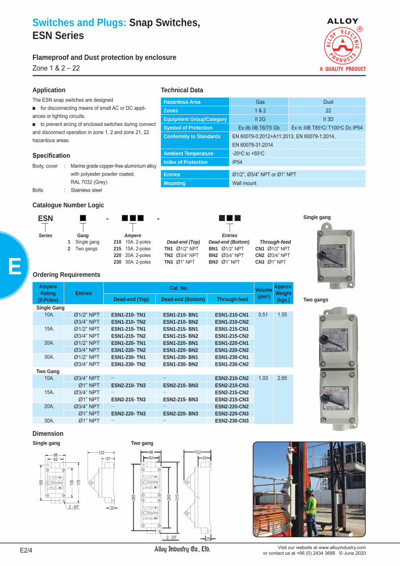
Visit our website at www.alloyindustry.comor contact us at +66 (0) 2434 3688 © June 2020E2/4
E
Switches and Plugs: Snap Switches, ESN Series
The ESN snap switches are designed for disconnecting means of small AC or DC appli-
ances or lighting circuits. to prevent arcing of enclosed switches during connect
and disconnect operation in zone 1, 2 and zone 21, 22 hazardous areas.
Application
Body, cover : Marine grade copper-free aluminium alloy with polyester powder coated, RAL 7032 (Grey)Bolts : Stainless steel
Flameproof and Dust protection by enclosureZone 1 & 2 _ 22
Hazardous Area Gas DustZones 1 & 2 22Equipment Group/Category II 2G II 3DSymbol of Protection Ex db IIB T6/T5 Gb Ex tc IIIB T85oC/ T100oC Dc IP54Conformity to Standards EN 60079-0:2012+A11:2013, EN 60079-1:2014,
EN 60079-31:2014Ambient Temperature -20oC to +55oCIndex of Protection IP54
Entries Ø1/2”, Ø3/4” NPT or Ø1” NPTMounting Wall mount
Technical Data
Ampere Rating
(2-Poles)Entries
Cat. No. Volume(dm3)
Approx.Weight(kgs.)Dead-end (Top) Dead-end (Bottom) Through-feed
Single Gang10A. Ø1/2” NPT ESN1-210- TN1 ESN1-210- BN1 ESN1-210-CN1 0.51 1.55
Ø3/4” NPT ESN1-210- TN2 ESN1-210- BN2 ESN1-210-CN215A. Ø1/2” NPT ESN1-215- TN1 ESN1-215- BN1 ESN1-215-CN1
Ø3/4” NPT ESN1-215- TN2 ESN1-215- BN2 ESN1-215-CN220A. Ø1/2” NPT ESN1-220- TN1 ESN1-220- BN1 ESN1-220-CN1
Ø3/4” NPT ESN1-220- TN2 ESN1-220- BN2 ESN1-220-CN230A. Ø1/2” NPT ESN1-230- TN1 ESN1-230- BN1 ESN1-230-CN1
Ø3/4” NPT ESN1-230- TN2 ESN1-230- BN2 ESN1-230-CN2Two Gang
10A. Ø3/4” NPT _ _ ESN2-210-CN2 1.03 2.65Ø1” NPT ESN2-210- TN3 ESN2-210- BN3 ESN2-210-CN3
15A. Ø3/4” NPT _ _ ESN2-215-CN2Ø1” NPT ESN2-215- TN3 ESN2-215- BN3 ESN2-215-CN3
20A. Ø3/4” NPT _ _ ESN2-220-CN2Ø1” NPT ESN2-220- TN3 ESN2-220- BN3 ESN2-220-CN3
30A. Ø1” NPT _ _ ESN2-230-CN3
Catalogue Number Logic
ESN - -
Series Gang Ampere Entries1 Single gang 210 10A. 2-poles Dead-end (Top) Dead-end (Bottom) Through-feed2 Two gangs 215 15A. 2-poles TN1 Ø1/2” NPT BN1 Ø1/2” NPT CN1 Ø1/2” NPT
220 20A. 2-poles TN2 Ø3/4” NPT BN2 Ø3/4” NPT CN2 Ø3/4” NPT230 30A. 2-poles TN3 Ø1” NPT BN3 Ø1” NPT CN3 Ø1” NPT
Single gang Two gang
Single gang
Two gangs
Dimension
Ordering Requirements

Visit our website at www.alloyindustry.comor contact us at +66 (0) 2434 3688 © June 2020 E3/4
E
Switches and Plugs: Receptacle Interlocked with Switchand Plug, DRCS and DPG Series
The DRCS receptacle interlocked with switches and DPG plugs are used for power supply to portable electrical equip-ments or motors. They are designed for zone 1, 2 and zone 21, 22 hazardous areas.
Application
Body, cover : Marine grade copper-free aluminium alloy with polyester powder coated, RAL 7032 (Grey)Bolts : Stainless steel
To reduce the risk of ignition, do not use receptacles and plugs in locations that contain electri-cally conductive dusts.
Flameproof and Dust protection by enclosureZone 1 & 2 _ 21 & 22
Hazardous Area Gas DustZones 1 & 2 21 & 22Equipment Group/Category II 2G II 2DSymbol of Protection Ex db IIB T6/T5 Gb Ex tb IIIC T85oC/ T100oC Db IP66Certificate TÜV CY 18 ATEX 0205994 XConformity to Standards EN 60079-0:2012+A11:2013, EN 60079-1:2014,
EN 60079-31:2014Ambient Temperature -20oC to +55oCIndex of Protection IP66
Entries Ø1/2” to Ø1-1/2” NPT or M20x1.5 to M50x1.5on Top & Bottom (1-stopping plug)
Mounting Wall mount
Technical Data
DRCS -
Series Number of Pole Max. EntriesCurrent NPT Metric (option)
3 3-poles (L,N,E) 16 16A. N1 Ø1/2” NPT M1 M20x1.54 4-poles (L1,L2,L3,E) 20 20A. N2 Ø3/4” NPT M2 M25x1.55 5-poles (L1,L2,L3,N,E) 32 32A. N3 Ø1” NPT M3 M32x1.5
63 63A. N4 Ø1-1/4” NPT M4 M40x1.5N5 Ø1-1/2” NPT M5 M50x1.5
Catalogue Number LogicReceptacle Interlocked with Switch
DPG -
Series Number of Pole Max. Current Cable Dia.
3 3-poles (L,N,E) 16 16A. 14 9-14mm.4 4-poles (L1,L2,L3,E) 20 20A. 19 15-19mm.5 5-poles (L1,L2,L3,N,E) 32 32A. 22 20-22mm.
63 63A. 24 23-24mm.27 25-27mm.30 28-30mm.33 31-33mm.36 34-36mm.39 37-39mm.40 40mm.
Plug

Visit our website at www.alloyindustry.comor contact us at +66 (0) 2434 3688 © June 2020E4/4
E
Switches and Plugs: Receptacle Interlocked with Switchand Plug, DRCS and DPG Series
Ordering RequirementsReceptacle Interlocked with Switch Plug
Phase/Wire/Pole
Max.
Current
(A)
Voltage
(V)
Entries (Top & Bottom) Volume(dm3)
Approx.Weight(kgs.)
CableDiameter Cat. No.
Approx.Weight(kgs.)NPT Cat. No. Metric Cat. No.
1PH /2W /3P 16A. 220V.ac 50/60Hz.
Ø1/2” NPT DRCS 316-N1 M20x1.5 DRCS 316-M1 2.24 7.25 9-14 mm. DPG 316-14 0.85Ø3/4” NPT DRCS 316-N2 M25x1.5 DRCS 316-M2 15-19 mm. DPG 316-19
20A. 220V.ac50/60Hz.
Ø3/4” NPT DRCS 320-N2 M25x1.5 DRCS 320-M2 2.24 7.25 15-19 mm. DPG 320-19 0.85Ø1” NPT DRCS 320-N3 M32x1.5 DRCS 320-M3 20-22 mm. DPG 320-22
23-24 mm. DPG 320-2432A. 220V.ac
50/60Hz.Ø3/4” NPT DRCS 332-N2 M25x1.5 DRCS 332-M2 2.24 7.25 15-19 mm. DPG 332-19 0.85
Ø1” NPT DRCS 332-N3 M32x1.5 DRCS 332-M3 20-22 mm. DPG 332-2223-24 mm. DPG 332-24
63A. 220V.ac50/60Hz.
Ø1” NPT DRCS 363-N3 M32x1.5 DRCS 363-M3 2.24 12.65 20-22 mm. DPG 363-22 0.8523-24 mm. DPG 363-24
Ø1-1/4” NPT DRCS 363-N4 M40x1.5 DRCS 363-M4 25-27 mm. DPG 363-2728-30 mm. DPG 363-30
3PH /3W /4P 16A. 380V.ac50/60Hz.
Ø3/4” NPT DRCS 416-N2 M25x1.5 DRCS 416-M2 2.24 7.25 15-19 mm. DPG 416-19 0.85Ø1” NPT DRCS 416-N3 M32x1.5 DRCS 416-M3 20-22 mm. DPG 416-22
23-24 mm. DPG 416-2420A. 380V.ac
50/60Hz.Ø3/4” NPT DRCS 420-N2 M25x1.5 DRCS 420-M2 2.24 7.25 15-19 mm. DPG 420-19 0.85
Ø1” NPT DRCS 420-N3 M32x1.5 DRCS 420-M3 20-22 mm. DPG 420-2223-24 mm. DPG 420-24
32A. 380V.ac50/60Hz.
Ø3/4” NPT DRCS 432-N2 M25x1.5 DRCS 432-M2 2.24 7.25 15-19 mm. DPG 432-19 0.85Ø1” NPT DRCS 432-N3 M32x1.5 DRCS 432-M3 20-22 mm. DPG 432-22
23-24 mm. DPG 432-2463A. 380V.ac
50/60Hz.Ø1-1/4” NPT DRCS 463-N4 M40x1.5 DRCS 463-M4 2.24 12.65 25-27 mm. DPG 463-27 0.85
28-30 mm. DPG 463-30Ø1-1/2” NPT DRCS 463-N5 M50x1.5 DRCS 463-M5 31-33 mm. DPG 463-33
34-36 mm. DPG 463-3637-39 mm. DPG 463-39
40 mm. DPG 463-403PH /4W /5P 16A. 220/
380V.ac50/60Hz.
Ø3/4” NPT DRCS 516-N2 M25x1.5 DRCS 516-M2 5.82 8.15 15-19 mm. DPG 516-19 0.85Ø1” NPT DRCS 516-N3 M32x1.5 DRCS 516-M3 20-22 mm. DPG 516-22
23-24 mm. DPG 516-2420A. 220/
380V.ac50/60Hz.
Ø3/4” NPT DRCS 520-N2 M25x1.5 DRCS 520-M2 5.82 8.15 15-19 mm. DPG 520-19 0.85Ø1” NPT DRCS 520-N3 M32x1.5 DRCS 520-M3 20-22 mm. DPG 520-22
23-24 mm. DPG 520-2432A. 220/
380V.ac50/60Hz.
Ø3/4” NPT DRCS 532-N2 M25x1.5 DRCS 532-M2 5.82 8.15 15-19 mm. DPG 532-19 0.85Ø1” NPT DRCS 532-N3 M32x1.5 DRCS 532-M3 20-22 mm. DPG 532-22
23-24 mm. DPG 532-2463A. 220/
380V.ac50/60Hz.
Ø1-1/4” NPT DRCS 563-N4 M40x1.5 DRCS 563-M4 5.82 12.65 25-27 mm. DPG 563-27 0.8528-30 mm. DPG 563-30
Ø1-1/2” NPT DRCS 563-N5 M50x1.5 DRCS 563-M5 31-33 mm. DPG 563-3334-36 mm. DPG 563-3637-39 mm. DPG 563-39
40 mm. DPG 563-40
Flameproof and Dust protection by enclosureZone 1 & 2 _ 21 & 22
Current (A)Dimension in mm.
a b c d e f g h i j Øk16A., 20A., 32A. 171 229 248 114 277 145 100 10 155 195 6863A. 206 311 319 120 312 190 160 12 162 202 68
Receptacle Interlocked with Switch
Plug
Dimension

We reserve the right to make alterations to the technical data, weights, dimensions, designs and products available without notice. The illustrations cannot be considered binding.
1. Fluorescent Lighting Fixture DNGV Series F2/ 43
2. Fluorescent & LED Tube Lighting Fixture DFP-C Series F5/ 43
3. Fluorescent & LED Tube Lighting Fixture DFP-S Series (IIC) F8/ 43
4. Fluorescent & LED Tube Lighting Fixture EARS Series F11/ 43
5. Fluorescent & LED Tube Lighting Fixture ELPG Series F13/ 43
6. Fluorescent & LED Tube Lighting Fixture NFLS Series F15/ 43
7. H.I.D. Lighting Fixture DMV1, DPS1, DMH1 F16/ 43 8. H.I.D. Lighting Fixture DLF1-MV, DLF1-PS, F19/ 43 DLF1-MH Series
9. H.I.D. Lighting Fixture NMV, NPS, F20/ 43 NMH, NMT Series
10. Floodlight DFDM, DFDS, F23/ 43 DFDH Series
11. Floodlight VFDM, VFDS, F24/ 43 VFDH Series
12. LED Floodlight (Rectangular) DFDD Series F25/ 43
13. LED Floodlight (Round) DFDR Series F27/ 43
14. LED Floodlight (Round) DFDR1 Series F28/ 43
15. LED Floodlight DFDF Series F29/ 43
16. LED Lighting Fixture NFDR Series F30/ 43
17. LED Lighting Fixture NFDR1 Series F32/ 43
18. Compact Fluorescent EPF Series F34/ 43 Lighting Fixture
19. Incandescent and VIN, VCF, VLED Series F35/ 43 Compact Fluorescent Lighting Fixture
20. LED Hand Lamp DHL Series, F36/ 43
21. Incandescent and DLF Series F37/ 43 Compact Fluorescent Lighting Fixture
22. Incan., Compact Flu., LED DLF1-IN, DLF1-FC, F38/ 43 Lighting Fixture DLF1-LED Series and Photocell Switch DLF1-PH Series
23. Tank Light EHTK Series F40/ 43
24. Tank Light (LED) DHTK Series F41/ 43
25. Emergency Light DMG Series F42/ 43
26. LED Emergency Exit Sign DFXT Series F43/ 43
LIGHTING FIXTURES F

Visit our website at www.alloyindustry.comor contact us at +66 (0) 2434 3688 © June 2020F2/43
F
Lighting: Fluorescent Lighting Fixture,DNGV Series
Flameproof and Dust protection by enclosureZone 1 & 2 _ 21 & 22
Body mataerial : Marine grade copper-free aluminium alloy with polyester powder coated, RAL 7032 (Grey)
Tube : Borosilicate glassInternal reflector : Stainless steelSealing gasket : Silicone
Hazardous Area Gas DustZones 1 & 2 21 & 22Equipment Group/Category II 2G II 2DSymbol of Protection
Ex d IIB T4, T5 or T6Ex tD A21 IP66 T135oC,
T100oC or T85oCCertificate PTB 08 ATEX 1018
IECEx PTB 08.0014Conformity to Standards EN 60079-0:2006, EN 60079-1:2004,
EN 61241-0:2006, EN 61241-1:2004IEC 60079-0:2004, IEC 60079-1:2003, IEC 61241-0:2004, IEC 61241-1:2004
Ambient Temperature -20oC to +50oC/ +55oCIndex of Protection IP66
Entries 2- M20x1.5, 2- M25x1.5 or 2- Ø3/4” NPT (1-stopping plug)Mounting Ceiling (standard), Pendant or BracketConnection L, N and E ; for 1-4mm.2 cable (Through wiring system with
an extra terminal block for cable connection at both ends.)Rated Voltage 220/ 230/ 240V.ac 5 50Hz. (P.F. 0.98)
Technical Data
Polar Luminous Intensity Distribution
Complete photometrics, please contact us.

Visit our website at www.alloyindustry.comor contact us at +66 (0) 2434 3688 © June 2020 F3/43
F
Lighting: Fluorescent Lighting Fixture,DNGV Series
Catalogue Number Logic
DNGV - - -
Series Lamp Watt Ballast Type Voltage Accessories Entries Mounting(see ordering none Electronic ballast none 220V.ac G Protective guard M1 M20x1.5 C Ceiling (standard)requirement M Electromagnetic ballast 3 220-230V.ac R External reflector M2 M25x1.5 C1 Ceiling (for pipe), Fixedtable below) 4 220-240V.ac E Emergency unit N2 3/4” NPT C2 Ceiling (for pipe), Swing
P1 Pendant (for chain)P2 Pendant (for pipe)B Bracket
Cat. No.LampWatt
Voltage BallastTemp. Class
(for zone 1 & 2)Max. Surface Temp.*
(for zone 21 & 22) Volume(dm3)
Dimension in mm. Approx.Weight(kgs.)Ta 40oC Ta 55oC Ta 40oC Ta 55oC a b c d
T8 Fluorescent LampDNGV-118M - 1x 18W. 220V.ac
50Hz.
Electromagnetic“Philips” T5 T4 T100oC T135oC 17.09 759 657 184 228
9.10DNGV-218M - 2x 18W. 9.35DNGV-136M - 1x 36W.
T6 T5 T85oC T100oC 19.25 1377 1275 184 22815.09
DNGV-236M - 2x 36W. 15.55DNGV-118M - 1x 18W. 220V.ac
50Hz.
Electromagnetic“Vossloh-Schwabe”
T5 T4 T100oC T135oC17.09 759 657 184 228
9.10DNGV-218M - 2x 18W. T4 T4 T135oC T135oC 9.35DNGV-136M - 1x 36W.
T4 T4 T135oC T135oC 19.25 1377 1275 184 22815.09
DNGV-236M - 2x 36W. 15.55DNGV-118M4 - 1x 18W. 220-240V.ac
50Hz.
Electromagnetic“Vossloh-Schwabe”
T4 T4 T135oC T135oC 17.09 759 657 184 2289.10
DNGV-218M4 - 2x 18W. 9.35DNGV-136M4 - 1x 36W.
T5 T4 T100oC T135oC 19.25 1377 1275 184 22815.09
DNGV-236M4 - 2x 36W. 15.55
Cat. No.LampWatt
Voltage BallastTemp. Class
(for zone 1 & 2)Max. Surface Temp.*
(for zone 21 & 22) Volume(dm3)
Dimension in mm. Approx.Weight(kgs.)Ta 40oC Ta 50oC Ta 55oC Ta 40oC Ta 50oC Ta 55oC a b c d
T5 Fluorescent LampDNGV-1144 - 1x 14W. 220-240V.ac
50/60Hz. Electronic“Vossloh-Schwabe”(ELXc)
T6 ¯ T6 T85oC ¯ T85oC17.09 759 657 184 228
12.09DNGV-2144 - 2x 14W. 12.28DNGV-1284 - 1x 28W.
19.25 1377 1275 184 22815.45
DNGV-2284 - 2x 28W. 16.05DNGV-1143 - 1x 14W. 220-230V.ac
50Hz. Electronic“Philips”(EB-E) T6 T6 ¯ T85oC T85oC ¯
17.09 759 657 184 22812.09
DNGV-2143 - 2x 14W. 12.28DNGV-1283 - 1x 28W.
19.25 1377 1275 184 22815.45
DNGV-2283 - 2x 28W. 16.05Lighting source; cool white (6500K) are standard and/or warm white (3000K), please specify.
Flameproof and Dust protection by enclosureZone 1 & 2 _ 21 & 22
Remark * : The maximum surface temperatures are specified for dust free condition. The dust layer which may cover around the lighting fixture will cause to higher surface temperature.
Ordering Requirements and Dimension

Visit our website at www.alloyindustry.comor contact us at +66 (0) 2434 3688 © June 2020F4/43
F
Lighting: Fluorescent Lighting Fixture,DNGV Series
Electromagnetic ballast for fluorescent lamp; 1 x 14W., 1x 28W., 1x 18W. and 1x 36W.
Electronic ballast for fluorescent lamp; 1x 14W., 1x 28W., 1x 18W. and 1x 36W.
Electromagnetic ballast for fluorescent lamp; 2x 14W., 2x 28W., 2x 18W. and 2x 36W.
Electronic ballast for fluorescent lamp; 2x 14W., 2x 28W., 2x 18W. and 2x 36W.
Wiring Diagram
Installation Information
Pole mount Ceiling mount (standard)
Ceiling mount (for pipe)
Bracket mount (or wall mount) Pendant mount (for chain)Pendant mount (for pipe)
Clamp swing
Flameproof and Dust protection by enclosureZone 1 & 2 _ 21 & 22
220-240V.ac50/60Hz.
220-240V.ac50/60Hz.
220V.ac50Hz.
220V.ac50Hz.
2-Inches

Visit our website at www.alloyindustry.comor contact us at +66 (0) 2434 3688 © June 2020 F5/43
F
Lighting: Fluorescent & LED Tube Lighting Fixture,DFP-C Series (Capsule end cap)
Body and cover : Marine grade copper-free aluminium alloy with polyester powder coated, RAL 7032 (grey)Glass tube : Borosilicate glass (4J impact)Re ector : Sheet steel with polyester powder coated, RAL 9016 (white)Protective guard : Stainless steelSealing gasket : Silicone
Technical DataHazardous Area Gas DustZones 1 & 2 21 & 22Equipment Group/Category II 2G II 2DSymbol of Protection Ex d IIB T6 Gb Ex tb IIIC T85oC Db IP66Certificate Sira 12 ATEX 1311 X
IECEx SIR 12.0140XConformity to Standards EN 60079-0:2012, EN 60079-1:2007, EN 60079-31:2009
IEC 60079-0:2011, IEC 60079-1:2007, IEC 60079-31:2008 Ambient Temperature -20oC to +50oCIndex of Protection IP66
Entries 2- M20x1.5, 2- M25x1.5 or 2- Ø3/4” NPT (1-stopping plug)Mounting Ceiling (standard), Pendant or BracketConnection L, N and E ; for 1-4mm.2 cable (Through wiring system with
an extra terminal block for cable connection at both ends.)Rated Voltage 220/ 230/ 240V.ac 5 50Hz. (P.F. 0.98)
Polar Luminous Intensity Distribution
Complete photometrics, please contact us.
Flameproof and Dust protection by enclosureZone 1 & 2 _ 21 & 22

Visit our website at www.alloyindustry.comor contact us at +66 (0) 2434 3688 © June 2020F6/43
F
Lighting: Fluorescent & LED Tube Lighting Fixture,DFP-C Series (Capsule end cap)
Catalogue Number Logic
DFP - - C D -
Series Lamp Watt Type Accessories Body LED Driver Entries Mounting(see ordering L4 Fluorescent G Protective guard C Capsule D with driver M1 M20x1.5 C Ceiling (standard)requirement lamp R External reflector end cap (25W LED tube) M2 M25x1.5 C1 Ceiling (for pipe), Fixedtable below) LED LED tube E Emergency N2 3/4” NPT C2 Ceiling (for pipe), Swing
power unit P1 Pendant (for chain)P2 Pendant (for pipe)B Bracket
Cat. No.LampWatt
Voltage BallastTemp. Class
(for zone 1 & 2)Max. Surface Temp.*
(for zone 21 & 22) Volume(dm3)
Dimension in mm. Approx.Weight(kgs.)Ta 40oC Ta 50oC Ta 40oC Ta 50oC a b
T8 Fluorescent Lamp
DFP-118L4 - 1x 18W. 220-240V.ac50/60Hz.
Electronic T6 T6 T85°C T85°C 3.95 1005 645 6.1
DFP-218L4 - 2x 18W.
DFP-136L4 - 1x 36W. 7.02 1618 1258 9.1
DFP-236L4 - 2x 36W.
T5 Fluorescent Lamp
DFP-114L4 - 1x 14W. 220-240V.ac50/60Hz.
Electronic T6 T6 T85°C T85°C 3.95 1005 645 6.1
DFP-214L4 - 2x 14W.
DFP-128L4 - 1x 28W. 7.02 1618 1258 9.1
DFP-228L4 - 2x 28W.
LED Tube
DFP-109LED -C- 1x 9W. 110-240V.ac50/60Hz.
¯ T6 T6 T85°C T85°C 3.95 1005 645 6.1
DFP-209LED -C- 2x 9W.
DFP-111LED -C- 1x 11W. 7.02 1618 1258 9.1
DFP-211LED -C- 2x 11W.
DFP-118LED -C- 1x 18W.
DFP-218LED -C- 2x 18W.
DFP-120LED -C- 1x 20W.
DFP-220LED -C- 2x 20W.
DFP-121LED -C- 1x 21W.
DFP-221LED -C- 2x 21W.
DFP-122LED -C- 1x 22W.
DFP-222LED -C- 2x 22W.
DFP-125LED -CD- 1x 25W. 110-240V.ac50/60Hz.
LED Driver T6 T6 T85°C T85°C 7.02 1618 1258 9.1
DFP-225LED -CD- 2x 25W.
Remark: * The maximum surface temperatures are specified for dust free condition. The dust layer which may cover around the lighting fixture will cause to higher surface temperature.
Lighting source; cool white (6500K) are standard and/or warm white (3000K), please specify.
Flameproof and Dust protection by enclosureZone 1 & 2 _ 21 & 22
Ordering Requirements and Dimension

Visit our website at www.alloyindustry.comor contact us at +66 (0) 2434 3688 © June 2020 F7/43
F
Lighting: Fluorescent & LED Tube Lighting Fixture,DFP-C Series (Capsule end cap)
Installation Information
Wiring DiagramElectronic ballast for fluorescent lamp; 1x 14W., 1x 28W., 1x 18W. and 1x 36W.
Electronic ballast for fluorescent lamp; 2x 14W., 2x 28W., 2x 18W. and 2x 36W.
LED Tube with driver (25W. only)
LED Tube without driver
Pole mount
Ceiling mount (standard) Ceiling mount (for pipe)
Bracket mount (or wall mount)Pendant mount (for chain)Pendant mount (for pipe)
1x Lamp 2x Lamp
1x 25W.
2x 25W.
Flameproof and Dust protection by enclosureZone 1 & 2 _ 21 & 22
220-240V.ac50/60Hz.
110-240V.ac50/60Hz.
110-240V.ac50/60Hz.
110-240V.ac50/60Hz.
110-240V.ac50/60Hz.
220-240V.ac50/60Hz.

Visit our website at www.alloyindustry.comor contact us at +66 (0) 2434 3688 © June 2020F8/43
F
Hazardous Area Gas DustZones 1 & 2 21 & 22Equipment Group/Category II 2G II 2DSymbol of Protection Ex db IIC T6 Gb Ex tb IIIC T85oC Db IP66Certificate TÜV CY 17 ATEX 0205887 XConformity to Standards EN 60079-0:2012+A11:2013, EN 60079-1:2014,
EN 60079-31:2014Ambient Temperature -20oC to +55oCIndex of Protection IP66
Entries 2- M20x1.5, 2- M25x1.5 or 2- Ø3/4” NPT (1-stopping plug)Mounting Ceiling, Pendant, Bracket, Stanchion or Pole mountConnection L, N and E ; for 1-4mm.2 cableRated Voltage 110-240V.ac 50/60Hz. (P.F. 0.98)
Lighting: Fluorescent & LED Tube Lighting Fixture,DFP-S Series (Short end cap)
Body and cover : Marine grade copper-free aluminium alloy with polyester powder coated, RAL 7032 (grey)Glass tube : Borosilicate glass (4J impact)Re ector : Sheet steel with polyester powder coated, RAL 9016 (white)Protective guard : Stainless steelSealing gasket : Silicone
Technical Data
Polar Luminous Intensity Distribution
Complete photometrics, please contact us.
Flameproof and Dust protection by enclosureZone 1 & 2 _ 21 & 22

Visit our website at www.alloyindustry.comor contact us at +66 (0) 2434 3688 © June 2020 F9/43
F
Catalogue Number Logic
Lighting: Fluorescent & LED Tube Lighting Fixture,DFP-S Series (Short end cap)
Cat. No.LampWatt
Voltage BallastTemp. Class
(for zone 1 & 2)Max. Surface Temp.*
(for zone 21 & 22) Volume(dm3)
Dimension in mm. Approx.Weight(kgs.)Ta 40oC Ta 55oC Ta 40oC Ta 55oC a b
T8 Fluorescent LampDFP-118L4- -S- 1x 18W. 220-240V.ac
50/60Hz. Electronic T6 T6 T85°C T85°C 3.95 750 645 6.80
DFP-218L4- -S- 2x 18W. 6.95DFP-136L4- -S- 1x 36W. 7.02 1365 1258 10.30DFP-236L4- -S- 2x 36W. 10.60
T5 Fluorescent LampDFP-114L4- -S- 1x 14W. 220-240V.ac
50/60Hz. Electronic T6 T6 T85°C T85°C 3.95 750 645 6.80
DFP-214L4- -S- 2x 14W. 6.95DFP-128L4- -S- 1x 28W. 7.02 1365 1258 10.30DFP-228L4- -S- 2x 28W. 10.60
LED TubeDFP-105LED- -S- 1x 5W. 110-240V.ac
50/60Hz. ¯ T6 T6 T85°C T85°C 3.95 750 645 4.80
DFP-205LED- -S- 2x 5W. 5.00DFP-106LED- -S- 1x 6W. 4.80DFP-206LED- -S- 2x 6W. 5.00DFP-108LED- -S- 1x 8W. 4.80DFP-208LED- -S- 2x 8W. 5.00DFP-109LED- -S- 1x 9W. 4.80DFP-209LED- -S- 2x 9W. 5.00DFP-114LED- -S- 1x 14W. 110-240V.ac
50/60Hz. ¯ T6 T6 T85°C T85°C 7.02 1365 1258 9.30
DFP-214LED- -S- 2x 14W. 9.60DFP-115LED- -S- 1x 15W. 9.30DFP-215LED- -S- 2x 15W. 9.60DFP-116LED- -S- 1x 16W. 9.30DFP-216LED- -S- 2x 16W. 9.60DFP-118LED- -S- 1x 18W. 9.30DFP-218LED- -S- 2x 18W. 9.60DFP-120LED- -S- 1x 20W. 9.30DFP-220LED- -S- 2x 20W. 9.60DFP-122LED- -S- 1x 22W. 9.30DFP-222LED- -S- 2x 22W. 9.60DFP-125LED-D -S- 1x 25W. 110-240V.ac
50/60Hz. LED Driver T6 T6 T85°C T85°C 7.02 1365 1258 10.60
DFP-225LED-D -S- 2x 25W. 11.00
DFP - - D - S -
Series Lamp Watt Type LED Driver Accessories Body Entries Mounting(see ordering L4 Fluorescent D with driver G Protective guard S Short M1 M20x1.5 C Ceiling (standard)requirement lamp (25W LED tube) R External reflector end cap M2 M25x1.5 C1 Ceiling (for pipe), Fixedtable below) LED LED tube E Emergency power unit N2 3/4” NPT C2 Ceiling (for pipe), Swing
(ATEX certificate under preparation) P1 Pendant (for chain)P2 Pendant (for pipe)B Bracket
Lighting source; cool white (6500K) are standard and/or warm white (3000K), please specify.
Flameproof and Dust protection by enclosureZone 1 & 2 _ 21 & 22
Remark * : The maximum surface temperatures are specified for dust free condition. The dust layer which may cover around the lighting fixture will cause to higher surface temperature.
Ordering Requirements and Dimension

Visit our website at www.alloyindustry.comor contact us at +66 (0) 2434 3688 © June 2020F10/43
FInstallation Information
Pole mount
Ceiling mount (standard) Ceiling mount (for pipe)
Bracket mount (or wall mount)Pendant mount (for chain)
Pendant mount (for pipe)
Lighting: Fluorescent & LED Tube Lighting Fixture,DFP-S Series (Short end cap)
Electronic ballast for fluorescent lamp; 1x 14W., 1x 28W., 1x 18W. and 1x 36W.
Electronic ballast for fluorescent lamp; 2x 14W., 2x 28W., 2x 18W. and 2x 36W.
LED Tube with driver (25W. only)
LED Tube without driver
1x Lamp 2x Lamp
1x 25W.
2x 25W.
Wiring Diagram
Flameproof and Dust protection by enclosureZone 1 & 2 _ 21 & 22
110-240V.ac50/60Hz.
220-240V.ac50/60Hz.
220-240V.ac50/60Hz.
110-240V.ac50/60Hz.
110-240V.ac50/60Hz.
110-240V.ac50/60Hz.

Visit our website at www.alloyindustry.comor contact us at +66 (0) 2434 3688 © June 2020 F11/43
F
Lighting: Fluorescent & LED Tube Lighting Fixture (Pendant),EARS Series
Body material : Marine grade copper-free aluminium alloy with polyester powder coated, RAL 7032 (grey)Tube : Borosilicate glassReflector (option) : Sheet steel with polyester powder coated, RAL 9016 (white)Guard (option) : Stainless steel
Hazardous Area Gas DustZones 1 & 2 22Equipment Group/Category II 2G II 3DSymbol of Protection Ex d IIB T6 Gb Ex tc IIIB T85oC Dc IP54Conformity to standards EN 60079-0:2012+A11:2013, EN 60079-1:2014,
EN 60079-31:2014Ambient Temperature -20oC to +50oCIndex of Protection IP54
Entries 2- Ø3/4” NPTMounting Pendant mountRated Voltage 110-240V.ac 50/60Hz. (THDi < 10%, P.F. 0.98)
Technical Data
Wiring Diagram
Polar Luminous Intensity Distribution
Complete photometrics, please contact us.
Electronic ballast for fluorescent lamp; 1x 14W., 1x 28W., 1x 18W. and 1x 36W.
Electronic ballast for fluorescent lamp; 2x 14W., 2x 28W., 2x 18W. and 2x 36W.
LED Tube with driver (25W. only)
LED Tube without driver1x Lamp
2x Lamp
1x 25W.
2x 25W.
Flameproof and Dust protection by enclosureZone 1 & 2 _ 22
110-240V.ac50/60Hz.
110-240V.ac50/60Hz.
110-240V.ac50/60Hz.
110-240V.ac50/60Hz.
220-240V.ac50/60Hz.
220-240V.ac50/60Hz.

Visit our website at www.alloyindustry.comor contact us at +66 (0) 2434 3688 © June 2020F12/43
F
Lighting: Fluorescent & LED Tube Lighting Fixture (Pendant),EARS Series
Catalogue Number Logic
EARS - D - -
Series Lamp Watt Type LED Driver Accessories Entries(see ordering none Fluorescent lamp D with driver G Protective guard N2 3/4” NPTrequirement LED LED tube (25W LED tube) R External reflectortable below) E Emergency power unit
Cat. No.LampWatt
Voltage BallastTemp. Class
(for zone 1 & 2)Max. Surface Temp.*
(for zone 22) Volume(dm3)
Dimension in mm. Approx.Weight(kgs.)Ta 40oC Ta 50oC Ta 40oC Ta 50oC a b c
T8 Fluorescent LampEARS-118- 1x 18W. 220-240V.ac
50/60Hz. Electronic T6 T6 T85°C T85°C 3.74 567 722 198 12.15
EARS-218- 2x 18W. 4.45 17.10EARS-136- 1x 36W. 5.02 1180 1330 198 20.00EARS-236- 2x 36W. 7.03 27.35
T5 Fluorescent LampEARS-114- 1x 14W. 220-240V.ac
50/60Hz. Electronic T6 T6 T85°C T85°C 3.74 567 722 198 12.15
EARS-214- 2x 14W. 4.45 17.10EARS-128- 1x 28W. 5.02 1180 1330 198 20.00EARS-228- 2x 28W. 7.03 27.35
LED TubeEARS-105LED- 1x 5W. 110-240V.ac
50/60Hz. ¯ T6 T6 T85°C T85°C 3.74
567 722 198
12.15EARS-205LED- 2x 5W. 4.45 17.10EARS-106LED- 1x 6W. 3.74 12.15EARS-206LED- 2x 6W. 4.45 17.10EARS-108LED- 1x 8W. 3.74 12.10EARS-208LED- 2x 8W. 4.45 17.15EARS-109LED- 1x 9W. 3.74 12.10EARS-209LED- 2x 9W. 4.45 17.15EARS-114LED- 1x 14W. 110-240V.ac
50/60Hz. ¯ T6 T6 T85°C T85°C 5.02
1180 1330 198
12.10EARS-214LED- 2x 14W. 7.03 17.15EARS-115LED- 1x 15W. 5.02 12.10EARS-215LED- 2x 15W. 7.03 17.15EARS-116LED- 1x 16W. 5.02 12.10EARS-216LED- 2x 16W. 7.03 17.15EARS-118LED- 1x 18W. 5.02 12.10EARS-218LED- 2x 18W. 7.03 23.15EARS-120LED- 1x 20W. 5.02 17.15EARS-220LED- 2x 20W. 7.03 25.0EARS-122LED- 1x 22W. 5.02 17.15EARS-222LED- 2x 22W. 7.03 25.0EARS-125LEDD- 1x 25W. 110-240V.ac
50/60Hz. LED Driver T6 T6 T85°C T85°C 5.02 1180 1330 198 17.15
EARS-225LEDD- 2x 25W. 7.03 25.0Lighting source; cool white (6500K) are standard and/or warm white (3000K), please specify.
Flameproof and Dust protection by enclosureZone 1 & 2 _ 22
Remark * : The maximum surface temperatures are specified for dust free condition. The dust layer which may cover around the lighting fixture will cause to higher surface temperature.
Ordering Requirements
Dimension

Visit our website at www.alloyindustry.comor contact us at +66 (0) 2434 3688 © June 2020 F13/43
F
Lighting: Fluorescent & LED Tube Lighting Fixture (Ceiling),ELPG Series
Body material : Marine grade copper-free aluminium alloy with polyester powder coated, RAL 7032 (grey)Tube : Borosilicate glassInternal reflector : Anodized aluminiumGuard (option) : Stainless steel
Technical Data
Polar Luminous Intensity Distribution
Complete photometrics, please contact us.
Flameproof and Dust protection by enclosureZone 1 & 2 _ 22
Wiring DiagramElectronic ballast for fluorescent lamp; 1x 14W., 1x 28W., 1x 18W. and 1x 36W.
Electronic ballast for fluorescent lamp; 2x 14W., 2x 28W., 2x 18W. and 2x 36W.
LED Tube with driver (25W. only)
LED Tube without driver1x Lamp
2x Lamp
1x 25W.
2x 25W. 110-240V.ac50/60Hz.
110-240V.ac50/60Hz.
110-240V.ac50/60Hz.
110-240V.ac50/60Hz.
220-240V.ac50/60Hz.
220-240V.ac50/60Hz.
Hazardous Area Gas DustZones 1 & 2 22Equipment Group/Category II 2G II 3DSymbol of Protection Ex d IIB T6 Gb Ex tc IIIB T85oC Dc IP54Conformity to standards EN 60079-0:2012+A11:2013, EN 60079-1:2014,
EN 60079-31:2014Ambient Temperature -20oC to +50oCIndex of Protection IP54
Entries M20x1.5, M25x1.5 or Ø3/4” NPTMounting Ceiling mountRated Voltage 110-240V.ac 50/60Hz. (THDi < 10%, P.F. 0.98)

Visit our website at www.alloyindustry.comor contact us at +66 (0) 2434 3688 © June 2020F14/43
F
Lighting: Fluorescent & LED Tube Lighting Fixture (Ceiling),ELPG Series
Catalogue Number Logic
ELPG - D - -
Series Lamp Watt Type LED Driver Accessories Entries(see ordering none Fluorescent lamp D with driver G Protective guard N2 3/4” NPTrequirement LED LED tube (25W LED tube) E Emergency power unittable below)
Cat. No.LampWatt
Voltage BallastTemp. Class
(for zone 1 & 2)Max. Surface Temp.*
(for zone 22) Volume(dm3)
Dimension in mm. Approx.Weight(kgs.)Ta 40oC Ta 50oC Ta 40oC Ta 50oC a b
T8 Fluorescent LampELPG-118- 1x 18W. 220-240V.ac
50/60Hz. Electronic T6 T6 T85°C T85°C 1.68 620 715 7.45
ELPG-218- 2x 18W. 3.70 685 725 10.15ELPG-136- 1x 36W. 3.01 1255 1333 9.85ELPG-236- 2x 36W. 6.35 1232 1325 15.38
T5 Fluorescent LampELPG-114- 1x 14W. 220-240V.ac
50/60Hz. Electronic T6 T6 T85°C T85°C 1.68 620 715 7.45
ELPG-214- 2x 14W. 3.70 685 725 10.15ELPG-128- 1x 28W. 3.01 1255 1333 9.85ELPG-228- 2x 28W. 6.35 1232 1325 15.38
LED TubeELPG-105LED- 1x 5W. 110-240V.ac
50/60Hz. ¯ T6 T6 T85°C T85°C 1.68 620 715 7.45
ELPG-205LED- 2x 5W. 3.70 685 725 10.15ELPG-106LED- 1x 6W. 1.68 620 715 7.45ELPG-206LED- 2x 6W. 3.70 685 725 10.15ELPG-108LED- 1x 8W. 1.68 620 715 7.45ELPG-208LED- 2x 8W. 3.70 685 725 10.15ELPG-109LED- 1x 9W. 1.68 620 715 7.45ELPG-209LED- 2x 9W. 3.70 685 725 10.15ELPG-114LED- 1x 14W. 110-240V.ac
50/60Hz. ¯ T6 T6 T85°C T85°C 3.01 1255 1333 7.45
ELPG-214LED- 2x 14W. 6.35 1232 1325 10.15ELPG-115LED- 1x 15W. 3.01 1255 1333 7.45ELPG-215LED- 2x 15W. 6.35 1232 1325 10.15ELPG-116LED- 1x 16W. 3.01 1255 1333 7.45ELPG-216LED- 2x 16W. 6.35 1232 1325 10.15ELPG-118LED- 1x 18W. 3.01 1255 1333 9.85ELPG-218LED- 2x 18W. 6.35 1232 1325 15.38ELPG-120LED- 1x 20W. 3.01 1255 1333 9.35ELPG-220LED- 2x 20W. 6.35 1232 1325 15.38ELPG-122LED- 1x 22W. 3.01 1255 1333 9.38ELPG-222LED- 2x 22W. 6.35 1232 1325 15.38ELPG-125LEDD- 1x 25W. 110-240V.ac
50/60Hz. LED Driver T6 T6 T85°C T85°C 3.01 1255 1333 9.38
ELPG-225LEDD- 2x 25W. 6.35 1232 1325 15.38
1x Lamp 2x Lamp
Lighting source; cool white (6500K) are standard and/or warm white (3000K), please specify.
Flameproof and Dust protection by enclosureZone 1 & 2 _ 22
Remark * : The maximum surface temperatures are specified for dust free condition. The dust layer which may cover around the lighting fixture will cause to higher surface temperature.
Ordering Requirements
Dimension

Visit our website at www.alloyindustry.comor contact us at +66 (0) 2434 3688 © June 2020 F15/43
F
Lighting: Fluorescent & LED Tube Lighting Fixture,NFLS Series
Restricted Breathing and Dust protection by enclosure Zone 2 _ 21 & 22
Hazardous Area Gas DustZones 2 21 & 22Equipment Group/Category II 3G II 2DSymbol of Protection Ex nR IIC T6 Gc Ex tb IIIC T85oC Db IP66 Conformity to standards EN 60079-0:2012+A11:2013, EN 60079-15:2010,
EN 60079-31:2014Ambient Temperature -20oC to +55oCIndex of Protection IP66
Entries Ø21.5mm. (for Ø1/2” NPT or M20x1.5)Mounting Ceiling mount (eye bolts)Rated Voltage 110-240V.ac 50/60Hz.
Technical DataBody material : Stainless steel, SUS 304 gradeGlass lens : Clear tempered glass, heat and impact resistantSealing gasket : Silicone
Catalogue Number Logic
NFLS - - - Series Lamp Watt Type LED Driver Accessories Entries
(see ordering none Fluorescent D with driver E Emergency M2 M25x1.5requirement lamp (25W LED tube) power unit N2 3/4” NPTtable below) LED LED tube
Cat. No.LampWatt
Voltage BallastTemp. Class(for zone 2)
Max. Surface Temp.*(for zone 21 & 22)
Approx.Weight(kgs.)Ta 40oC Ta 55oC Ta 40oC Ta 55oC
T8 Fluorescent LampNFLS-136- 1x 36W. 220-240V.ac
50/60Hz. Electronic T6 T6 T85°C T85°C 11.66
NFLS-236- 2x 36W. 11.86T5 Fluorescent LampNFLS-128- 1x 28W. 220-240V.ac
50/60Hz. Electronic T6 T6 T85°C T85°C 11.66
NFLS-228- 2x 28W. 11.86LED TubeNFLS-114LED- 1x 14W. 110-240V.ac
50/60Hz. ¯ T6 T6 T85°C T85°C 11.66
NFLS-214LED- 2x 14W. 11.86NFLS-115LED- 1x 15W. 11.66NFLS-215LED- 2x 15W. 11.86NFLS-116LED- 1x 16W. 11.66NFLS-216LED- 2x 16W. 11.86NFLS-118LED- 1x 18W. 11.66NFLS-218LED- 2x 18W. 11.86NFLS-120LED- 1x 20W. 11.86NFLS-220LED- 2x 20W. 11.86NFLS-122LED- 1x 22W. 11.66NFLS-222LED- 2x 22W. 12.86NFLS-125LEDD- 1x 25W. 110-240V.ac
50/60Hz. LEDDriver
T6 T6 T85°C T85°C 12.00NFLS-225LEDD- 2x 25W. 12.15
Polar Luminous Intensity Distribution
Complete photometrics, please contact us.
Wiring DiagramElectronic ballast for fluorescent lamp; 1x 28W., 1x 36W.
Electronic ballast for fluorescent lamp; 2x 28W., 2x 36W.
LED Tube with driver (25W. only)
LED Tube without driver1x Lamp
2x Lamp
1x 25W.
2x 25W. 110-240V.ac50/60Hz.
110-240V.ac50/60Hz.
110-240V.ac50/60Hz.
110-240V.ac50/60Hz.
220-240V.ac50/60Hz.
220-240V.ac50/60Hz.
Ordering Requirements and Dimension
Remark * : The maximum surface temperatures are specified for dust free condition. The dust layer which may cover around the lighting fixture will cause to higher surface temperature.

Visit our website at www.alloyindustry.comor contact us at +66 (0) 2434 3688 © June 2020F16/43
F
Lighting: H.I.D. (High Intensity Discharge) Lighting Fixture,DMV1, DPS1, DMH1 Series
Flameproof/ Increased Safety and Dust protection by enclosureZone 1 & 2 _ 21 & 22
Body mataerial : Marine grade copper-free aluminium alloy with polyester powder coated, RAL 7032 (Grey)Glass globe : Borosilicate glassSealing gasket : Silicone Bracket : Hot-dip galvanized steelReflector (option) : Anodized aluminiumBasket guard (option) : Stainless steel
Hazardous Area Gas DustZones 1 & 2 21 & 22Equipment Group/Category II 2G II 2DSymbol of Protection
Ex de IIB T3, T4 or T5Ex tD A21 IP66
T200oC, T135oC or T100oC Certificate PTB 09 ATEX 1042 XConformity to standards EN 60079-0:2006, EN 60079-1:2007, EN 60079-7:2007,
EN 61241-0:2006, EN 61241-1:2004Ambient Temperature -20oC to +40oC/ +55oCIndex of Protection IP66
Entries 2- M25x1.5 or 2- Ø3/4” NPT (1-stopping plug)Mounting Ceiling or Bracket mounting (standard)
(Optional mounting provided with 2x M10 eye bolts,clamps for, Ø2 inch pipe)
Connection L, N and E ; for 1-4mm.2 cable (spring type terminal)(Through wiring system with an extra terminal block for cableconnection at both ends.)
Rated Voltage 220/ 230V.ac ±5% 50Hz.
Technical Data
Polar Luminous Intensity Distribution
Complete photometrics, please contact us.

Visit our website at www.alloyindustry.comor contact us at +66 (0) 2434 3688 © June 2020 F17/43
F
Lighting: H.I.D. (High Intensity Discharge) Lighting Fixture,DMV1, DPS1, DMH1 Series
Catalogue Number Logic
Cat. No.LampWatt
Voltage Lamp/ Ballast/ IgnitorTemp. Class
(for zone 1 & 2)Max. Surface Temp.*
(for zone 21 & 22) WiringDiagram
Ta 40oC Ta 55oC Ta 40oC Ta 55oCMercury Vapor LampDMV1-80 - 80W. 220V.ac
50Hz. HPL-N 80W / Q80.587 / ¯ T5 T4 T100°C T135°C Dia-BHPL-N 80W / OMB80-35 / ¯ T5 T5 T100°C T100°C Dia-B
DMV1-125 - 125W. HPL-N 125W / Q125.549 / ¯ T5 T4 T100°C T135°C Dia-BDMV1-250 - 250W. HPL-N 250W / Q250.513 / ¯ T4 T4 T135°C T135°C Dia-BDMV1-400 - 400W. HPL-N 400W / Q400.561 / ¯ T4 T3 T135°C T200°C Dia-BDMV1-80 3 - 80W. 230V.ac
50Hz. HPL-N 80W / Q80.588 / ¯ T5 T5 T100°C T100°C Dia-B
DMV1-125 3 - 125W. HPL-N 125W / Q125.568 / ¯ T4 T4 T135°C T135°C Dia-BDMV1-250 3 - 250W. HPL-N 250W / Q250.528 / ¯ T4 T4 T135°C T135°C Dia-B
High Pressure Sodium LampDPS1-70 - 70W. 220V.ac
50Hz. SON-70WI / NaHJ70.320 / ¯ T5 T5 T100°C T100°C Dia-B
DPS1-150 - 150W. SON-150W / NaHJ150.355 / Z400M T5 T5 T100°C T100°C Dia-ADPS1-250 - 250W. SON-250W / NaHJ250.160 / Z400M T4 T4 T135°C T135°C Dia-ADPS1-400 - 400W. SON-400W / NaHJ400.162 / Z400M T4 T3 T135°C T200°C Dia-ADPS1-70I 3 - 70W. 230V.ac
50Hz. SON-70WI / NaHJ70.158 / ¯ T5 T4 T100°C T135°C Dia-B
DPS1-70 3 - 70W. SON-70W / NaHJ70.158 / Z400M T5 T4 T100°C T135°C Dia-ADPS1-150 3 - 150W. SON-150W / NaHJ150 100.973 / Z400M T5 T4 T100°C T135°C Dia-ADPS1-400 3 - 400W. SON-400W / NaHJ400.006 / Z400M T4 T3 T135°C T200°C Dia-A
Metal Halide LampDMH1-70 - 70W. 220V.ac
50Hz. MH 70W / NaHJ70.320 / Z400M T5 T4 T100°C T135°C Dia-AMH 70W / OMS 70-T35 / Z400M T5 T5 T100°C T100°C Dia-A
DMH1-100 - 100W. MH 100W / OMS 100 / Z400M T5 T4 T100°C T135°C Dia-ADMH1-150 - 150W. MH 150W / OMS 150 / Z400M T6 T5 T85°C T100°C Dia-ADMH1-250 - 250W. HPI PLUS-250W BU / Q250.513 / Z400M T4 T4 T135°C T135°C Dia-ADMH1-400 - 400W. HPI PLUS-400W BUS / Q400.561 / ¯ T4 T3 T135°C T200°C Dia-BDMH1-70 3 - 70W. 230V.ac
50Hz.MH 70W / NaHJ70.128 / Z400M T5 T4 T100°C T135°C Dia-A
DMH1-250 3 - 250W. HPI PLUS-250W BU / Q250.528 / Z400M T4 T4 T135°C T135°C Dia-A
D 1 - - -Series Lamp Watt Voltage Accessories Mounting Entries
DMV1 Mercury Vapor (see ordering none 220V.ac G Basket guard C Ceiling M2 M25x1.5DPS1 High Pressure Sodium requirement 3 230V.ac R Re ector B Bracket N2 Ø3/4” NPTDMH1 Metal Halide table below)
Cat. No.Dimension in mm. Approx.
Weight(kgs.)Øa b c d Øe
High Pressure Sodium LampDPS1-70I, DPS1-70, DPS1-70 3 274 356 196 208 450 14.0DPS1-150, DPS1-150 3 330 539 319 274 504 25.5DPS1-250 330 539 319 274 504 27.5DPS1-400, DPS1-400 3 330 539 319 274 504 28.5
Metal Halide LampDMH1-70, DMH1-70 3, DMH1-100 274 356 196 208 450 14.0DMH1-150 330 494 274 274 504 25.0DMH1-250, DMH1-250 3 330 539 319 274 504 25.0DMH1-400 330 539 319 274 504 25.5
Cat. No.Dimension in mm. Approx.
Weight(kgs.)Øa b c d Øe
Mercury Vapor LampDMV1-80, DMV1-80 3, DMV1-125, 274 356 196 208 450 14.0DMV1-125 3DMV1-250, DMV1-250 3 330 494 274 274 504 25.0DMV1-400 330 494 274 274 504 25.5
Diagram-A Diagram-B
Flameproof/ Increased Safety and Dust protection by enclosureZone 1 & 2 _ 21 & 22
Remark * : The maximum surface temperatures are specified for dust free condition. The dust layer which may cover around the lighting fixture will cause to higher surface temperature.
220/230V.ac50Hz.
220/230V.ac50Hz.
Ordering Requirements and Dimension

Visit our website at www.alloyindustry.comor contact us at +66 (0) 2434 3688 © June 2020F18/43
F
Lighting: H.I.D. (High Intensity Discharge) Lighting Fixture,DMV1, DPS1, DMH1 Series
Installation Information
Pole mountCeiling mount
Bracket mount (or wall mount)
Suspension 2x M10 eye bolt
Flameproof/ Increased Safety and Dust protection by enclosureZone 1 & 2 _ 21 & 22

Visit our website at www.alloyindustry.comor contact us at +66 (0) 2434 3688 © June 2020 F19/43
F
Lighting: H.I.D. (High Intensity Discharge) Lighting Fixture,DLF1-MV, DLF1-PS, DLF1-MH Series
Flameproof/ Increased Safety and Dust protection by enclosureZone 1 & 2 _ 21 & 22
Body material : Marine grade copper-free aluminium alloy with polyester powder coated, RAL 7032 (grey)Globe : Borosilicate glassGuard, bolts : Stainless steelSeal gasket : Silicone Bracket : Hot-dip galvanized steel
Hazardous Area Gas DustZones 1 & 2 21 & 22Equipment Group/Category II 2G II 2DSymbol of Protection Ex db eb IIC T** Gb Ex tb IIIC T** oC Db IP66Certificate TÜV CY 18 ATEX 0206011 XConformity to standards EN 60079-0:2012+A11:2013, EN 60079-1:2014,
EN 60079-7:2015, EN 60079-31:2014Ambient Temperature -20oC to +55oCIndex of Protection IP66
Entries 2- M25x1.5 or 2- Ø3/4” NPT (1-stopping plug)Mounting Ceiling or Bracket mounting (standard)
(Optional mounting ; 2x M10 eye bolts, clamps for pipe)Connection L, N and E ; for 1-4mm.2 cable (Through wiring system with
an extra terminal block for cable connection at both ends.)Rated Voltage 220/ 230/ 240V.ac ±5% 50/60Hz.
Technical Data
Catalogue Number Logic
DLF1 - - -Series Type Lamp Watt Voltage Accessories Mounting Entries
MV Mercury Vapour (see ordering 22 220V.ac 50Hz. R Re ector C Ceiling M2 M25x1.5PS High Pressure Sodium requirement 23 230V.ac 50Hz. G Basket guard B Bracket N2 Ø3/4” NPTMH Metal halide table below)
Cat. No.LampWatt
VoltageLamp Model
(Lamp/ Ballast/ Ignitor)
Temp. Class(for zone 1 & 2)
Max. Surface Temp.*(for zone 21 & 22) Wiring
Diagram
Approx.Weight(kgs.)Ta 40oC Ta 55oC Ta 40oC Ta 55oC
Mercury Vapor LampDLF1-MV-08022 - 80W. 220V.ac 50Hz. HPL-N 80W / Q80.587 / ¯ T5 T4 T100°C T135°C Dia-B
8.7HPL-N 80W / OMB80-35 / ¯ T5 T5 T100°C T100°C Dia-B
DLF1-MV-12522 - 125W. HPL-N 125W / Q125.549 / ¯ T5 T4 T100°C T135°C Dia-BDLF1-MV-08023 - 80W. 230V.ac 50Hz. HPL-N 80W / Q80.588 / ¯ T5 T5 T100°C T100°C Dia-BDLF1-MV-12523 - 125W. HPL-N 125W / Q125.568 / ¯ T4 T4 T135°C T135°C Dia-B
High Pressure Sodium LampDLF1-PS-070I22 - 70W.
220V.ac 50Hz. SON-70WI / NaHJ70.320 / ¯ T5 T5 T100°C T100°C Dia-B8.7
DLF1-PS-070I23 - 230V.ac 50Hz. SON-70WI / NaHJ70.158 / ¯ T5 T4 T100°C T135°C Dia-BDLF1-PS-07023 - SON-70W / NaHJ70.158 / Z400M T5 T4 T100°C T135°C Dia-A 8.9
Metal Halide LampDLF1-MH-07022 - 70W. 220V.ac 50Hz. MH 70W / NaHJ70.320 / Z400M T5 T4 T100°C T135°C Dia-A
8.9MH 70W / OMS 70-T35 / Z400M T5 T5 T100°C T100°C Dia-A
DLF1-MH-10022 - 100W. MH 100W / OMS 100 / Z400M T5 T4 T100°C T135°C Dia-ADLF1-MH-07023 - 70W. 230V.ac 50Hz. MH 70W / NaHJ70.128 / Z400M T5 T4 T100°C T135°C Dia-A
Ceiling mount Bracket mount
Remark * : The maximum surface temperatures are specified for dust free condition. The dust layer which may cover around the lighting fixture will cause to higher surface temperature.
Diagram-A
Diagram-B
** See temperature class on catalogue number table.
220/230V.ac50Hz.
220/230V.ac50Hz.
Ordering Requirements and Dimension

Visit our website at www.alloyindustry.comor contact us at +66 (0) 2434 3688 © June 2020F20/43
F
Lighting: H.I.D. (High Intensity Discharge) Lighting Fixture,NMV, NPS, NMH, NMT Series
Celling mounting
Pendant mounting
Stanchion mounting
Bracket mounting
Body material : Marine grade copper-free aluminium alloy with polyester powder coated, RAL 7032 (grey)Glass globe : Borosilicate glassGuard : Stainless steelSealing gasket : Silicone
Hazardous Area Gas DustZones 2 21 & 22Equipment Group/Category II 3G II 2DSymbol of Protection Ex nR IIC T** Gc Ex tb IIIC T** oC Db IP66Conformity to standards EN 60079-0:2012+A11:2013, EN 60079-15:2010,
EN 60079-31:2014, EN 60598-1:2015Ambient Temperature -20oC to +55oCIndex of Protection IP66
Mounting Ceiling, Pendant, Stanchion and Bracket mountingConnection L, N and E ; for 1-4mm.2 cable (Through wiring system with
an extra terminal block for cable connection at both ends.)Rated Voltage 220-230V.ac ±5% 50Hz.
Technical Data
** See temperature class on catalogue number table.
Polar Luminous Intensity Distribution
Complete photometrics, please contact us.
Restricted Breathing and Dust protection by enclosure Zone 2 _ 21 & 22
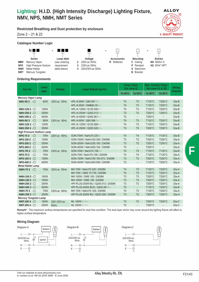
Visit our website at www.alloyindustry.comor contact us at +66 (0) 2434 3688 © June 2020 F21/43
F
Remark* : The maximum surface temperatures are specified for dust free condition. The dust layer which may cover around the lighting fixture will affect to higher surface temperature.
Catalogue Number Logic
Lighting: H.I.D. (High Intensity Discharge) Lighting Fixture,NMV, NPS, NMH, NMT Series
Wiring Diagram
Cat. No.LampWatt
Voltage Lamp/ Ballast/ IgnitorTemp. Class(for zone 2)
Max. Surface Temp.*(for zone 21 & 22) Wiring
DiagramTa 40oC Ta 55oC Ta 40oC Ta 55oC
Mercury Vapor LampNMV-80 2 - 80W. 220V.ac 50Hz. HPL-N 80W / Q80.587 / ¯ T4 T3 T135°C T200°C Dia-B
HPL-N 80W / OMB80-35 / ¯ T4 T3 T135°C T200°C Dia-BNMV-125 2 - 125W. HPL-N 125W / Q125.549 / ¯ T4 T3 T135°C T200°C Dia-BNMV-250 2 - 250W. HPL-N 250W / Q250.513 / ¯ T3 T2 T200°C T250°C Dia-BNMV-400 2 - 400W. HPL-N 400W / Q400.561 / ¯ T2 ¯ T250°C ¯ Dia-BNMV-80 3 - 80W. 230V.ac 50Hz. HPL-N 80W / Q80.588 / ¯ T4 T3 T135°C T200°C Dia-BNMV-125 3 - 125W. HPL-N 125W / Q125.568 / ¯ T4 T3 T135°C T200°C Dia-BNMV-250 3 - 250W. HPL-N 250W / Q250.528 / ¯ T3 T2 T200°C T250°C Dia-B
High Pressure Sodium LampNPS-70 2 - 70W. 220V.ac 50Hz. SON-70WI / NaHJ70.320 /- T4 T4 T135°C T135°C Dia-BNPS-150 2 - 150W. SON-150W / NaHJ150.355 / Z400M T3 T3 T200°C T200°C Dia-ANPS-250 2 - 250W. SON-250W / NaHJ250.160 / Z400M T3 T2 T200°C T250°C Dia-ANPS-400 2 - 400W. SON-400W / NaHJ400.162 / Z400M T2 ¯ T250°C ¯ Dia-ANPS-70I 3 - 70W. 230V.ac 50Hz. SON-70WI / NaHJ70.158 / ¯ T4 T4 T135°C T135°C Dia-BNPS-70 3 - 70W. SON-70W / NaHJ70.158 / Z400M T4 T4 T135°C T135°C Dia-ANPS-150 3 - 150W. SON-150W / NaHJ150 100.973 / Z400M T3 T3 T200°C T200°C Dia-ANPS-400 3 - 400W. SON-400W / NaHJ400.006 / Z400M T2 ¯ T135°C T200°C Dia-A
Metal Halide LampNMH-70 2 - 70W. 220V.ac 50Hz. MH 70W / NaHJ70.320 / Z400M T4 T3 T135°C T200°C Dia-A
MH 70W / OMS 70-T35 / Z400M T4 T3 T135°C T200°C Dia-ANMH-100 2 - 100W. MH 100W / OMS 100 / Z400M T3 T3 T200°C T200°C Dia-ANMH-150 2 - 150W. MH 150W / OMS 150 / Z400M T3 T3 T200°C T200°C Dia-ANMH-250 2 - 250W. HPI PLUS-250W BU / Q250.513 / Z400M T3 T2 T200°C T250°C Dia-ANMH-400 2 - 400W. HPI PLUS-400W BUS / Q400.561 / ¯ T2 - T135°C T200°C Dia-BNMH-70 3 - 70W. 230V.ac 50Hz. MH 70W / NaHJ70.128 / Z400M T4 T3 T135°C T200°C Dia-ANMH-250 3 - 250W. HPI PLUS-250W BU / Q250.528 / Z400M T3 T2 T200°C T250°C Dia-A
Mercury Tungsten LampNMT-160 4 - 160W. 220/ 230V.ac
50Hz. ML 160W / ¯ / ¯ T3 T2 T200°C T250°C Dia-C
NMT-250 4 - 250W. ML 250W / ¯ / ¯ T2 ¯ T250°C ¯ Dia-C
N - - -
Series Lamp Watt Voltage Accessories Mounting EntriesNMV Mercury Vapor (see ordering 2 220V.ac 50Hz. R Re ector C Ceiling M2 M25x1.5NPS High Pressure Sodium requirement 3 230V.ac 50Hz. P Pendant N2 Ø3/4” NPTNMH Metal Halide table below) 4 220/230V.ac 50Hz. S StanchionNMT Mercury Tungsten B Bracket
Diagram-A Diagram-B
Restricted Breathing and Dust protection by enclosure Zone 2 _ 21 & 22
Diagram-C
220/230V.ac50Hz.
220/230V.ac50Hz.
220/230V.ac50Hz.
Ordering Requirements

Visit our website at www.alloyindustry.comor contact us at +66 (0) 2434 3688 © June 2020F22/43
F
Ceiling mounting Pendant mounting
30o Stanchion mounting Bracket mounting
Lighting: H.I.D. (High Intensity Discharge) Lighting Fixture,NMV, NPS, NMH, NMT Series
Dimension
Lamp WattsDimension in mm. Approx.
Weight(kgs.)a b c Ød Øe
Mercury Vapor Lamp80W., 125W. 328 254 228 175 360 4.24250W. 473 395 282 218 450 12.15400W. 510 382 341 286 504 16.55
High Pressure Sodium Lamp70W. 328 254 228 175 360 8.39150W., 250W. 473 395 282 218 450 12.25400W. 510 382 341 286 504 18.35
Metal Halide Lamp70W., 100W. 328 254 228 175 360 4.39150W., 250W. 473 395 282 218 450 12.15400W. 510 382 341 286 504 16.55
Mercury Tungsten Lamp160W. 473 395 282 218 450 12.0250W. 510 382 341 286 504 12.0
Lamp WattsDimension in mm. Approx.
Weight(kgs.)a b c Ød Øe
Mercury Vapor Lamp80W., 125W. 336 262 200 175 360 4.24250W. 466 388 240 218 450 12.15400W. 514 386 315 286 504 16.55
High Pressure Sodium Lamp70W. 336 262 200 175 360 4.39150W., 250W. 466 388 240 218 450 12.25400W. 514 386 315 286 504 18.35
Metal Halide Lamp70W., 100W. 336 262 200 175 360 4.39150W., 250W. 466 388 240 218 450 12.15400W. 514 386 315 286 504 16.55
Mercury Tungsten Lamp160W. 466 388 240 218 450 12.0250W. 514 386 315 286 504 12.0
Lamp WattsDimension in mm. Approx.
Weight(kgs.)a Øb Øc
Mercury Vapor Lamp80W., 125W. 399 175 360 4.39250W. 538 218 450 12.35400W. 597 286 504 16.55
High Pressure Sodium Lamp70W. 399 175 360 4.39150W., 250W. 538 218 450 12.35400W. 597 286 504 18.55
Metal Halide Lamp70W., 100W. 399 175 360 4.39150W., 250W. 538 218 450 12.55400W. 597 286 504 16.55
Mercury Tungsten Lamp160W. 538 218 450 12.0250W. 597 286 504 12.0
Lamp WattsDimension in mm. Approx.
Weight(kgs.)a b Øc Ød
Mercury Vapor Lamp80W., 125W. 347 279 175 360 4.57250W. 479 312 218 450 12.55400W. 532 428 286 504 16.85
High Pressure Sodium Lamp70W. 347 279 175 360 4.39150W., 250W. 479 312 218 450 12.55400W. 532 428 286 504 18.35
Metal Halide Lamp70W., 100W. 347 279 175 360 4.39150W., 250W. 479 312 218 450 12.55400W. 382 341 286 504 16.55
Mercury Tungsten Lamp160W. 479 312 218 450 12.0250W. 532 428 286 504 12.0
Restricted Breathing and Dust protection by enclosure Zone 2 _ 21 & 22

Visit our website at www.alloyindustry.comor contact us at +66 (0) 2434 3688 © June 2020 F23/43
F
Lighting: Floodlight,DFDM/ DFDS/ DFDH Series
Body material : Marine grade copper-free aluminium alloy with polyester powder coated, RAL 7032 (grey)Lens : Heat and impact resistant clear glassBolts : Stainless steelBracket : Hot-dip galvanized steelInternal reflector : Anodized aluminiumSealing gasket : Silicone
Wiring Diagram
Dimension
Hazardous Area Gas DustZones 1 & 2 21 & 22Equipment Group/Category II 2G II 2DSymbol of Protection Ex db eb IIB T** Gb Ex tb IIIC T** oC Db IP66Conformity to standards EN 60079-0:2012+A11:2013, EN 60079-1:2014,
EN 60079-7:2015, EN 60079-31:2014, EN 60598-1:2015Ambient Temperature -20oC to +55oCIndex of Protection IP66
Entries 1-hole standard (M25x1.5 or Ø3/4” NPT), 2-holes are optionalMounting Bracket mountingConnection L, N and E ; for 1-4mm.2 cableRated Voltage 220, 230V.ac ±5% 50Hz.
Technical Data
Cat. No.LampWatt
Voltage Lamp/ Ballast/ IgnitorTemp. Class
(for zone 1 & 2)Max. Surface Temp.*
(for zone 21 & 22) WiringDiagram
Approx.Weight(kgs.)Ta 40oC Ta 55oC Ta 40oC Ta 55oC
Mercury Vapor LampDFDM-2502 - 250W. 220V.ac 50Hz. HPL-N 250W / Q250.513 / ¯ T4 T3 T130°C T160°C
Dia-B24.5
DFDM-4002 - 400W. HPL-N 400W / Q400.561 / ¯ T3 T3 T165°C T180°C 27.2DFDM-2503 - 250W. 230V.ac 50Hz. HPL-N 250W / Q250.528 / ¯ T4 T3 T130°C T165°C Dia-B 24.5
High Pressure Sodium LampDFDS-2502 - 250W. 220V.ac 50Hz. SON-T 250W / NaHJ250.160 / Z400M T4 T3 T130°C T160°C
Dia-A24.5
DFDS-4002 - 400W. SON-T 400W / NaHJ400.162 / Z400M T3 T3 T160°C T180°C 27.2DFDS-4003 - 400W. 230V.ac 50Hz. SON-T 400W / NaHJ400.006 / Z400M T3 T3 T160°C T180°C Dia-A 27.2
Metal Halide LampDFDH-2502 - 250W. 220V.ac 50Hz. HPI-T PLUS 250W / Q250.513 / Z400M T4 T3 T135°C T175°C Dia-A 24.5DFDH-4002 - 400W. HPI-T PLUS-400W / Q400.561 / Z400M T3 T3 T165°C T180°C Dia-A 27.2DFDH-2503 - 250W. 230V.ac 50Hz. HPI-T PLUS-250W / Q250.528 / Z400M T4 T3 T135°C T160°C Dia-A 24.5
** See temperature class on catalogue number table.
Polar Luminous Intensity Distribution
Complete photometrics, please contact us.
Diagram-A Diagram-B
Flameproof/ Increased Safety and Dust protection by enclosureZone 1 & 2 _ 21 & 22
Catalogue Number Logic
DFD - -Series Lamp Watt Voltage Entries
DFDM Mercury Vapor (see ordering 2 220V.ac M2 M25x1.5DFDS High Pressure Sodium requirement 3 230V.ac N2 Ø3/4” NPTDFDH Metal Halide table below)
Remark * : The maximum surface temperatures are specified for dust free condition. The dust layer which may cover around the lighting fixture will cause to higher surface temperature.
220/230V.ac50Hz.
220/230V.ac50Hz.
Ordering Requirements

Visit our website at www.alloyindustry.comor contact us at +66 (0) 2434 3688 © June 2020F24/43
F
Lighting: Floodlight,VFDM/ VFDS/ VFDH Series
Body material : Marine grade copper-free aluminium alloy with polyester powder coated, RAL 7032 (grey)Lens : Heat and impact resistant clear glassBolts : Stainless steelBracket : Hot-dip galvanized steelInternal reflector : Anodized aluminiumSealing gasket : Silicone
Dimension
Hazardous Area Gas DustZones 2 21 & 22Equipment Group/Category II 3G II 2DSymbol of Protection Ex nR IIC T** Gc Ex tb IIIC T** oC Db IP66Conformity to standards EN 60079-0:2012+A11:2013, EN 60079-15:2010,
EN 60079-31:2014, EN 60598-1:2015Ambient Temperature -20oC to +55oCIndex of Protection IP66
Entries 1-hole standard (M25x1.5 or Ø3/4” NPT), 2-holes are optionalMounting Bracket mountingConnection L, N and E ; for 1-4mm.2 cableRated Voltage 220, 230V.ac ±5% 50Hz.
Technical Data
Polar Luminous Intensity Distribution
Complete photometrics, please contact us.
Restricted Breathing and Dust protection by enclosure Zone 2 _ 21 & 22
Wiring Diagram
Cat. No.LampWatt
Voltage Lamp/ Ballast/ IgnitorTemp. Class
(for zone 1 & 2)Max. Surface Temp.*
(for zone 21 & 22) WiringDiagram
Approx.Weight(kgs.)Ta 40oC Ta 55oC Ta 40oC Ta 55oC
Mercury Vapor LampVFDM-2502 - 250W. 220V.ac 50Hz. HPL-N 250W / Q250.513 / ¯ T4 T3 T130°C T160°C
Dia-B24.5
VFDM-4002 - 400W. HPL-N 400W / Q400.561 / ¯ T3 T3 T165°C T180°C 27.2VFDM-2503 - 250W. 230V.ac 50Hz. HPL-N 250W / Q250.528 / ¯ T4 T3 T130°C T165°C Dia-B 24.5
High Pressure Sodium LampVFDS-2502 - 250W. 220V.ac 50Hz. SON-T 250W / NaHJ250.160 / Z400M T4 T3 T130°C T160°C
Dia-A24.5
VFDS-4002 - 400W. SON-T 400W / NaHJ400.162 / Z400M T3 T3 T160°C T180°C 27.2VFDS-4003 - 400W. 230V.ac 50Hz. SON-T 400W / NaHJ400.006 / Z400M T3 T3 T160°C T180°C Dia-A 27.2
Metal Halide LampVFDH-2502 - 250W. 220V.ac 50Hz. HPI-T PLUS-250W / Q250.513 / Z400M T4 T3 T135°C T175°C Dia-A 24.5VFDH-4002 - 400W. HPI-T PLUS-400W / Q400.561 / Z400M T3 T3 T165°C T180°C Dia-A 27.2VFDH-2503 - 250W. 230V.ac 50Hz. HPI-T PLUS-250W / Q250.528 / Z400M T4 T3 T135°C T160°C Dia-A 24.5
Diagram-A Diagram-B
Catalogue Number Logic
VFD - -Series Lamp Watt Voltage Entries
VFDM Mercury Vapor (see ordering 2 220V.ac M2 M25x1.5VFDS High Pressure Sodium requirement 3 230V.ac N2 Ø3/4” NPTVFDH Metal Halide table below)
Remark * : The maximum surface temperatures are specified for dust free condition. The dust layer which may cover around the lighting fixture will cause to higher surface temperature.
** See temperature class on catalogue number table.
220/230V.ac50Hz.
220/230V.ac50Hz.
Ordering Requirements

Visit our website at www.alloyindustry.comor contact us at +66 (0) 2434 3688 © June 2020 F25/43
F
Technical Data
Lighting: LED Floodlight (Rectangular Shape),DFDD Series
Body material : Marine grade copper-free aluminium alloy with polyester powder coated, RAL 7032 (grey)Lens : Heat and high impact resistant clear glass (4J impact)Bolts : Stainless steelBracket : Hot-dip galvanized steelSealing gasket : Silicone
Catalogue Number Logic
Diagram
Cat. No.LED
PowerVoltage
Temp. Class(for zone 1 & 2)
Max. Surface Temp.*(for zone 21 & 22)
Approx.Weight(kgs.)Ta 40oC Ta 50oC Ta 40oC Ta 50oC
DFDD-100- 100W. 110-240V.ac50/60Hz.
T6 T5 T85oC T95oC 16.0DFDD-120- 120W.DFDD-150- 150W.
DFDD - -Series LED Power (Watt) Entries
(see ordering requirement M2 M25x1.5table below) N2 Ø3/4” NPT
Polar Luminous Intensity Distribution
Complete photometrics, please contact us.
Flameproof/ Increased Safety and Dust protection by enclosureZone 1 & 2 _ 21 & 22
Remark * : The maximum surface temperatures are specified for dust free condition. The dust layer which may cover around the lighting fixture will cause to higher surface temperature.
Hazardous Area Gas DustZones 1 & 2 21 & 22Equipment Group/Category II 2G II 2DSymbol of Protection Ex de IIB T6/T5 Gb Ex tb IIIC T85oC/ T95oC Db IP66Certificate LCIE 17 ATEX 3006 X
IECEx LCIE 17.0017XConformity to standards EN 60079-0:2012+A11:2013, EN 60079-1:2007,
EN 60079-7:2007, EN 60079-31:2014IEC 60079-0:2011, IEC 60079-1:2007-04,IEC 60079-7:2006-07, IEC 60079-31:2013
Ambient Temperature -20oC to +50oCIndex of Protection IP66
Entries 1-hole standard (M25x1.5 or Ø3/4” NPT), 2-holes are optionalMounting Bracket mountingConnection L, N and E ; for 1-4mm.2 cable (Through wiring system with
an extra terminal block for cable connection at both ends.)Rated Voltage 110-240V.ac 50/60Hz., THDi < 20%, P.F. 0.95
3- Ø11mm.150150
Entries
300
260
256
535475
110-240V.ac50/60Hz.
LED System
Option (specify)Chip : Lumileds, Bridgelux, NichiaColour temperature : 3000K, 3500K, 4000K, 4500K, 5000K, 6500K or othersColor Rendering Index (Ra) : >80Others beam angle of lens
Luminous efficient : 100 lm/WColour temperature : 5700 K (cool white) Color Rendering Index (Ra) : >70 Chip : CREEBeam angle : 60°, 100°
Ordering Requirements
Dimension

Visit our website at www.alloyindustry.comor contact us at +66 (0) 2434 3688 © June 2020F26/43
F
Technical Data
Lighting: LED Floodlight (Rectangular Shape),DFDD Series
Body material : Marine grade copper-free aluminium alloy with polyester powder coated, RAL 7032 (grey)Lens : Heat and high impact resistant clear glass (4J impact)Bolts : Stainless steelBracket : Hot-dip galvanized steelSealing gasket : Silicone
Catalogue Number Logic
Cat. No.LED
PowerVoltage
Temp. Class(for zone 1 & 2)
Max. Surface Temp.*(for zone 21 & 22)
Approx.Weight(kgs.)Ta 40oC Ta 50oC Ta 40oC Ta 50oC
2x DFDD-100- 200W. 110-240V.ac50/60Hz.
T6 T5 T85oC T95oC 35.02x DFDD-120- 240W.2x DFDD-150- 300W.
DFDD - -Series LED Power (Watt) Entries
(see ordering requirement M2 M25x1.5table below) N2 Ø3/4” NPT
Flameproof/ Increased Safety and Dust protection by enclosureZone 1 & 2 _ 21 & 22
Remark * : The maximum surface temperatures are specified for dust free condition. The dust layer which may cover around the lighting fixture will cause to higher surface temperature.
Polar Luminous Intensity Distribution
LED System
Option (specify)Chip : Lumileds, Bridgelux, NichiaColour temperature : 3000K, 3500K, 4000K, 4500K, 5000K, 6500K or othersColor Rendering Index (Ra) : >80Others beam angle of lens
Luminous efficient : 100 lm/WColour temperature : 5700 K (cool white) Color Rendering Index (Ra) : >70 Chip : CREEBeam angle : 60°, 100°
Ordering Requirements
Hazardous Area Gas DustZones 1 & 2 21 & 22Equipment Group/Category II 2G II 2DSymbol of Protection Ex de IIB T6/T5 Gb Ex tb IIIC T85oC/ T95oC Db IP66Certificate LCIE 17 ATEX 3006 X
IECEx LCIE 17.0017XConformity to standards EN 60079-0:2012+A11:2013, EN 60079-1:2007,
EN 60079-7:2007, EN 60079-31:2014IEC 60079-0:2011, IEC 60079-1:2007-04,IEC 60079-7:2006-07, IEC 60079-31:2013
Ambient Temperature -20oC to +50oCIndex of Protection IP66
Entries 1-hole standard (M25x1.5 or Ø3/4” NPT), 2-holes are optionalMounting Bracket mountingConnection L, N and E ; for 1-4mm.2 cable (Through wiring system with
an extra terminal block for cable connection at both ends.)Rated Voltage 110-240V.ac 50/60Hz., THDi < 20%, P.F. 0.95
Dimension

Visit our website at www.alloyindustry.comor contact us at +66 (0) 2434 3688 © June 2020 F27/43
F
Lighting: LED Floodlight (Round Shape),DFDR Series
Body material : Marine grade copper-free aluminium alloy with polyester powder coated, RAL 7032 (grey)Lens : Heat and high impact resistant clear glass (4J impact)Bolts : Stainless steelBracket : Hot-dip galvanized steelSealing gasket : Silicone
Diagram
Technical Data
Catalogue Number Logic
Cat. No.LED
PowerVoltage
Temp. Class(for zone 1 & 2)
Max. Surface Temp.*(for zone 21 & 22)
Approx.Weight(kgs.)Ta 40oC Ta 50oC Ta 40oC Ta 50oC
DFDR-100- 100W. 110-240V.ac50/60Hz.
T6 T5 T85oC T95oC 14.5DFDR-120- 120W.DFDR-150- 150W.
DFDR - -Series LED Power (Watt) Entries Accessories
(see ordering requirement M2 M25x1.5 G Guardtable below) N2 Ø3/4” NPT
Polar Luminous Intensity Distribution
Complete photometrics, please contact us.
Flameproof/ Increased Safety and Dust protection by enclosureZone 1 & 2 _ 21 & 22
Remark * : The maximum surface temperatures are specified for dust free condition. The dust layer which may cover around the lighting fixture will cause to higher surface temperature.
Hazardous Area Gas DustZones 1 & 2 21 & 22Equipment Group/Category II 2G II 2DSymbol of Protection Ex db e IIB T6/T5 Gb Ex tb IIIC T85oC/ T95oC Db IP66Certificate LCIE 17 ATEX 3031 X
IECEx LCIE 17.0040XConformity to standards EN 60079-0:2012+A11:2013, EN 60079-1:2014,
EN 60079-7:2007, EN 60079-31:2014IEC 60079-0:2011, IEC 60079-1:2014-06,IEC 60079-7:2006-07, IEC 60079-31:2013
Ambient Temperature -20oC to +50oCIndex of Protection IP66
Entries 1-hole standard (M25x1.5 or Ø3/4” NPT), 2-holes are optionalMounting Bracket mountingConnection L, N and E ; for 1-4mm.2 cable (Through wiring system with
an extra terminal block for cable connection at both ends.)Rated Voltage 110-240V.ac 50/60Hz., THDi < 20%, P.F. 0.95
110-240V.ac50/60Hz.
LED System
Option (specify)Chip : Lumileds, Bridgelux, NichiaColour temperature : 3000K, 3500K, 4000K, 4500K, 5000K, 6500K or othersColor Rendering Index (Ra) : >80Others beam angle of lens
Luminous efficient : 100 lm/WColour temperature : 5700 K (cool white) Color Rendering Index (Ra) : >70 Chip : CREEBeam angle : 65°, 100°
Ordering Requirements
Dimension
269
327

Visit our website at www.alloyindustry.comor contact us at +66 (0) 2434 3688 © June 2020F28/43
F
Lighting: LED Floodlight (Round Shape),DFDR1 Series
Flameproof/ Increased Safety and Dust protection by enclosureZone 1 & 2 _ 21 & 22
Body material : Marine grade copper-free aluminium alloy with polyester powder coated, RAL 7032 (grey)Lens : Heat and high impact resistant clear glass (4J impact)Bolts : Stainless steelBracket : Hot-dip galvanized steelSealing gasket : Silicone Guard : Stainless steel
Diagram
Technical Data
Catalogue Number LogicDFDR1 - -
Series LED Power (Watt) Entries Accessories(see ordering requirement M1 M20x1.5 G Guardtable below) M2 M25x1.5
N2 Ø3/4” NPT
Polar Luminous Intensity Distribution
Complete photometrics, please contact us.
Hazardous Area Gas DustZones 1 & 2 21 & 22Equipment Group/Category II 2G II 2DSymbol of Protection Ex de IIC T6/T5 Gb Ex tb IIIC T85oC/ T95oC Db IP66Conformity to standards EN 60079-0:2012+A11:2013, EN 60079-1:2014,
EN 60079-7:2007, EN 60079-31:2014Ambient Temperature -40oC to +60oCIndex of Protection IP66
Entries 1-hole standard (M20x1.5, M25x1.5 or Ø3/4” NPT), 2-holes are optional
Mounting Bracket mountingConnection L, N and E ; for 1-4mm.2 cable (Through wiring system with
an extra terminal block for cable connection at both ends.)Rated Voltage 110-240V.ac 50/60Hz., THDi < 20%, P.F. 0.95
Cat. No.LED
PowerVoltage
Temp. Class(for zone 1 & 2)
Max. Surface Temp.*(for zone 21 & 22)
Approx.Weight(kgs.)Ta 40oC Ta 50oC Ta 40oC Ta 50oC
DFDR1-30 - 30W. 110-240V.ac50/60Hz.
T6 T5 T85oC T95oC 10.0DFDR1-40 - 40W. DFDR1-50 - 50W. DFDR1-60 - 60W. DFDR1-70 - 70W. DFDR1-80 - 80W. DFDR1-90 - 90W.DFDR1-100 - 100W. 110-240V.ac
50/60Hz.T6 T5 T85oC T95oC 14.5
DFDR1-110 - 110W.DFDR1-120 - 120W. DFDR1-130 - 130W. DFDR1-140 - 140W. DFDR1-150 - 150W. DFDR1-160 - 160W. DFDR1-170 - 170W.DFDR1-180 - 180W.DFDR1-190 - 190W.DFDR1-200 - 200W.DFDR1-210 - 210W.DFDR1-220 - 220W.DFDR1-230 - 230W.DFDR1-240 - 240W.
3-Ø1365 65
Entries
Øc
a b
d
LED PowerDimension in mm.
a b Øc d30W. to 90W. 273 306 254 314100W. 265 321 254 331110W. to 240W. 278 329 338 401
110-240V.ac50/60Hz.
LED System
Option (specify)Chip : Lumileds, Bridgelux, NichiaColour temperature : 3000K, 3500K, 4000K, 4500K, 5000K, 6500K or othersColor Rendering Index (Ra) : >80Others beam angle of lens
Luminous efficient : 100 lm/WColour temperature : 5700 K (cool white) Color Rendering Index (Ra) : >70 Chip : CREEBeam angle : 65°, 100°
Ordering Requirements
Dimension
Remark * : The maximum surface temperatures are specified for dust free condition. The dust layer which may cover around the lighting fixture will cause to higher surface temperature.

Visit our website at www.alloyindustry.comor contact us at +66 (0) 2434 3688 © June 2020 F29/43
F
Lighting: LED Floodlight,DFDF Series
Flameproof/ Increased Safety and Dust protection by enclosureZone 1 & 2 _ 21 & 22
Body material : Marine grade copper-free aluminium alloy with polyester powder coated, RAL 7032 (grey)Lens : Heat and impact resistant clear glass (4J impact)Bolts : Stainless steelBracket : Hot-dip galvanized steel
DFDF-30 to DFDF-80
DFDF-100 to DFDF-180
Hazardous Area Gas DustZones 1 & 2 21 & 22Equipment Group/Category II 2G II 2DSymbol of Protection Ex db eb IIB T6 Gb Ex tb IIIC T85oC Db IP66Certificate TÜV CY 17 ATEX 0205814 XConformity to standards EN 60079-0:2012+A11:2013, EN 60079-1:2014,
EN 60079-7:2015, EN 60079-31:2014, EN 60598-1:2015Ambient Temperature 0oC to +55oCIndex of Protection IP66
Entries 2- M25x1.5 or 2- Ø3/4” NPT (1- stopping plug)Mounting Bracket mountingConnection L, N and E ; for 1-4mm.2 cable (Through wiring system with
an extra terminal block for cable connection at both ends.)Rated Voltage 110-240V.ac 50/60Hz., THDi < 20%, P.F. 0.95
Technical Data
Cat. No. LEDPower Voltage
Temp. Class(for zone 1 & 2)
Max. Surface Temp.*(for zone 21 & 22)
Approx.Weight(kgs.)Ta 40oC Ta 55oC Ta 40oC Ta 55oC
DFDF-30 - 30W. 110-240V.ac50/60Hz.
T6 T6 T85oC T85oC 17.0DFDF-40 - 40W. DFDF-50 - 50W. DFDF-60 - 60W. DFDF-70 - 70W. DFDF-80 - 80W. DFDF-100 - 100W. 110-240V.ac
50/60Hz.T6 T6 T85oC T85oC 19.8
DFDF-120 - 120W.DFDF-150 - 150W.DFDF-170 - 170W.DFDF-180 - 180W.
Polar LuminousIntensity Distribution
Remark * : The maximum surface temperatures are specified for dust free condition. The dust layer which may cover around the lighting fixture will cause to higher surface temperature.
Type-1(Top driver)
Dimension
Type-2(Bottom driver)
Type-1(Top driver)
Type-2(Bottom driver)
LED System
Option (specify)Chip : Lumileds, Bridgelux, NichiaColour temperature : 3000K, 3500K, 4000K, 4500K, 5000K, 6500K or othersColor Rendering Index (Ra) : >80Others beam angle of lens
Luminous efficient : 100 lm/WColour temperature : 5700 K (cool white) Color Rendering Index (Ra) : >70 Chip : CREEBeam angle : 60°, 100°
Catalogue Number LogicDFDF - -
Series LED Power (Watt) Entries Mounting(see ordering requirement M2 M25x1.5 C1 Type-1table below) N2 Ø3/4” NPT C2 Type-2
Ordering Requirements

Visit our website at www.alloyindustry.comor contact us at +66 (0) 2434 3688 © June 2020F30/43
F
Lighting: LED Lighting Fixture,NFDR Series
Body material : Marine grade copper-free aluminium alloy with polyester powder coated, RAL 7032 (grey)Lens : Heat and impact resistant clear glassBolts : Stainless steelSealing gasket : Silicone Bracket : Hot-dip gavanized steelGuard : Stainless steel
Hazardous Area Gas DustZones 2 21 & 22Equipment Group/Category II 3G II 2DSymbol of Protection Ex nR IIC T6 Gc Ex tb IIIC T85oC Db IP66Certificate TÜV CY 16 ATEX 0205812 XConformity to standards EN 60079-0:2012+A11:2013, EN 60079-15:2010,
EN 60079-31:2014, EN 60598-1:2015Ambient Temperature -20oC to +55oCIndex of Protection IP66
Entries 1-hole standard (M20x1.5, M25x1.5 or Ø3/4” NPT), 2-holes are optional
Mounting Ceiling, Wall, Pendant or Stanchion mountingConnection L, N and E ; for 1-4mm.2 cable (Through wiring system with
an extra terminal block for cable connection at both ends.)Rated Voltage 110-240V.ac 50/60Hz., THDi < 20%, P.F. 0.95
Technical Data
Cat. No.LED
PowerVoltage
Temp. Class(for zone 2)
Max. Surface Temp.*(for zone 21 & 22)
Ta 40oC Ta 55oC Ta 40oC Ta 55oCNFDR-40 40W. 110-240V.ac
50/60Hz.T6 T6 T85oC T85oC
NFDR-60 60W.NFDR-80 80W.NFDR-100 100W.NFDR-120 120W.NFDR-150 150W.
Restricted Breathing and Dust protection by enclosure Zone 2 _ 21 & 22
Remark * : The maximum surface temperatures are specified for dust free condition. The dust layer which may cover around the lighting fixture will cause to higher surface temperature.
LED System
Option (specify)Chip : Lumileds, Bridgelux, NichiaColour temperature : 2700K, 3000K, 3500K, 4000K, 4500K, 5000K, 6500K or othersColor Rendering Index (Ra) : >80Others beam angle of lens
Luminous efficient : 100 lm/WColour temperature : 5700 K (cool white) Color Rendering Index (Ra) : >70 Chip : CREEBeam angle : 80°, 100°
Catalogue Number LogicNFDR - -
Series LED Power Mounting Entries Accessories(see ordering C Ceiling S30 Stanchion, M1 M20x1.5 G Guardrequirement C1 Steel Bracket 30 degree Angle M2 M25x1.5table below) P Pendant S90 Stanchion, N2 Ø3/4” NPT
W Wall 90 degree Angle
Ceiling Mounting Pendant Mounting
Wall Mounting Stanchion Mounting ; 90 degree angleStanchion Mounting ; 30 degree angle
Steel Bracket Mounting (U-shaped)
Polar Luminous Intensity Distribution
Complete photometrics, please contact us.
Luminaire : NFDR-80
0o30o
60o
90o 90o
60o
30o
120o180o 150o120o 150o
cdC0o-C180o
C90o-C270o
300
200
100
400
500
600
Luminaire : NFDR-150
0o30o
60o
90o 90o
60o
30o
120o180o 150o120o 150o
cdC0o-C180o
C90o-C270o
300
200
100
400
500
600
Ordering Requirements

Visit our website at www.alloyindustry.comor contact us at +66 (0) 2434 3688 © June 2020 F31/43
F
Lighting: LED Lighting Fixture,NFDR Series
DimensionCeiling Mounting Pendant Mounting Wall Mounting
Stanchion Mounting ; 30 degree angle
Stanchion Mounting ; 90 degree angle
Cat. No.Dimension
in mm.Approx. Weight(kgs.)Øa Øb c
NFDR-40P to 80P 235 190 222 7.0NFDR-100P to 150P 340 270 200 8.3
Cat. No. Dimension in mm. Approx. Weight(kgs.)Conduit type Cable type Øa Øb c d
NFDR-40S30 to 80S30 NFDR-40S301 to 80S301 235 190 265 377 7.0NFDR-100S30 to 150S30 NFDR-100S301 to 150S301 340 270 292 446 8.3
Cat. No.Dimension in mm. Approx.
Weight(kgs.)Øa Øb c d e
NFDR-40W to 80W 235 190 217 254 378 7.0NFDR-100W to 150W 340 270 195 232 470 8.3
Restricted Breathing and Dust protection by enclosure Zone 2 _ 21 & 22
Cable type (Pipe clamp)
Steel Bracket Mounting
Detail 'A'
Cat. No.Dimension in mm.
Øa b c d e ØfNFDR-40C1 to 80C1 235 202 234 200 163 2- Ø13NFDR-100C1 to 150C1 340 195 223 189 193 3- Ø13
Cat. No.Dimension in mm. Approx.
Weight(kgs.)Øa b c d
NFDR-40C to 80C 235 221 190 210 7.0NFDR-100C to 150C 340 200 270 300 8.3
Conduit type (standard)
Cable type (Pipe clamp)Conduit type (standard)
Cat. No. Dimension in mm. Approx. Weight(kgs.)Conduit type Cable type Øa Øb c d
NFDR-40S90 to 80S90 NFDR-40S901 to 80S901 235 190 217 367 7.0NFDR-100S90 to 150S90 NFDR-100S901 to 150S901 340 270 195 462 8.3

Visit our website at www.alloyindustry.comor contact us at +66 (0) 2434 3688 © June 2020F32/43
F
Lighting: LED Lighting Fixture,NFDR1 Series
Body material : Marine grade copper-free aluminium alloy with polyester powder coated, RAL 7032 (grey)Lens : Heat and impact resistant clear glassBolts : Stainless steelSealing gasket : Silicone Bracket : Hot-dip gavanized steelGuard : Stainless steel
Hazardous Area Gas DustZones 2 21 & 22Equipment Group/Category II 3G II 2DSymbol of Protection Ex nR IIC T6 Gc Ex tb IIIC T85oC Db IP66Conformity to standards EN 60079-0:2012+A11:2013, EN 60079-15:2010,
EN 60079-31:2014, EN 60598-1:2015Ambient Temperature -40oC to +60oCIndex of Protection IP66
Entries 1-hole standard (M20x1.5, M25x1.5 or Ø3/4” NPT), 2-holes are optional
Mounting Ceiling, Wall, Pendant or Stanchion mountingConnection L, N and E ; for 1-4mm.2 cable (Through wiring system with
an extra terminal block for cable connection at both ends.)Rated Voltage 110-240V.ac 50/60Hz., THDi < 20%, P.F. 0.95
Technical Data
Restricted Breathing and Dust protection by enclosure Zone 2 _ 21 & 22
Remark * : The maximum surface temperatures are specified for dust free condition. The dust layer which may cover around the lighting fixture will cause to higher surface temperature.
LED System
Option (specify)Chip : Lumileds, Bridgelux, NichiaColour temperature : 2700K, 3000K, 3500K, 4000K, 4500K, 5000K, 6500K or othersColor Rendering Index (Ra) : >80Others beam angle of lens
Luminous efficient : 100 lm/WColour temperature : 5700 K (cool white) Color Rendering Index (Ra) : >70 Chip : CREEBeam angle : 80°, 100°
Catalogue Number LogicNFDR1 - -
Series LED Power Mounting Entries Accessories(see ordering C Ceiling S30 Stanchion, M1 M20x1.5 G Guardrequirement C1 Steel Bracket 30 degree Angle M2 M25x1.5table below) P Pendant S90 Stanchion, N2 Ø3/4” NPT
W Wall 90 degree Angle
Ceiling Mounting
Pendant Mounting
Wall Mounting Stanchion Mounting ; 90 degree angleStanchion Mounting ; 30 degree angle
Steel Bracket Mounting (U-shaped)
Cat. No.LED
PowerVoltage
Temp. Class(for zone 2)
Max. Surface Temp.*(for zone 21 & 22)
Ta 40oC Ta 55oC Ta 40oC Ta 55oCNFDR1-30 30W. 110-240V.ac
50/60Hz.T6 T6 T85oC T85oC
NFDR1-40 40W.NFDR1-50 50W.NFDR1-60 60W.NFDR1-70 70W.NFDR1-80 80W.NFDR1-90 90W.NFDR1-100 100W.NFDR1-110 110W.NFDR1-120 120W.NFDR1-130 130W.NFDR1-140 140W.NFDR1-150 150W.NFDR1-160 160W.NFDR1-170 170W.NFDR1-180 180W.NFDR1-190 190W.NFDR1-200 200W.NFDR1-210 210W.NFDR1-220 220W.
Ordering Requirements

Visit our website at www.alloyindustry.comor contact us at +66 (0) 2434 3688 © June 2020 F33/43
F
DimensionCeiling Mounting Pendant Mounting Wall Mounting
Stanchion Mounting ; 30 degree angle
Stanchion Mounting ; 90 degree angle
Cat. No.Dimension
in mm.Øa Øb c
NFDR-30P to 90P 235 190 224NFDR1-100P 235 270 203NFDR1-110P to 220P 340 270 213
Cat. No. Dimension in mm.Conduit type Cable type Øa Øb c d
NFDR1-30S30 to 90S30 NFDR1-30S301 to 90S301 235 190 268 379NFDR1-100S30 NFDR1-100S301 235 270 270 403NFDR1-110S30 to 220S30 NFDR1-110S301 to 220S301 340 270 305 453
Cat. No.Dimension in mm.
Øa Øb c d eNFDR1-30W to 90W 235 190 221 258 378NFDR1-100W 235 270 200 237 435NFDR1-110W to 220W 340 270 210 247 470
Cable type (Pipe clamp)
Steel Bracket Mounting
Detail 'A'
Cat. No.Dimension in mm.
Øa b c d e ØfNFDR1-30C1 to 90C1 235 201 234 200 163 3- Ø13NFDR1-100C1 235 180 213 179 193 3- Ø13NFDR1-110C1 to 220C1 340 190 223 189 193 3- Ø13
Cat. No.Dimension in mm.
Øa Øb c d eNFDR1-30C to 90C 235 190 210 188 210NFDR1-100C 235 270 190 270 300NFDR1-110C to 220C 340 270 200 270 300
Conduit type (standard)
Cable type (Pipe clamp)Conduit type (standard)
Cat. No. Dimension in mm.Conduit type Cable type Øa Øb c d
NFDR1-30S90 to 90S90 NFDR1-30S901 to 90S901 235 190 221 368NFDR1-100S90 NFDR1-100S901 235 270 200 427NFDR1-110S90 to 220S90 NFDR1-110S901 to 220S901 340 270 210 462
Lighting: LED Lighting Fixture,NFDR1 Series
Restricted Breathing and Dust protection by enclosure Zone 2 _ 21 & 22

Visit our website at www.alloyindustry.comor contact us at +66 (0) 2434 3688 © June 2020F34/43
F
Lighting: Compact Fluorescent Lighting Fixture,EPF Series
Body material : Marine grade copper-free aluminium alloywith polyester powder coated, RAL 7032 (grey)Glass globe : Borosilicate glassAxles and guard : Stainless steelSealant : Cast resin
Catalogue Number Logic
Hazardous Area Gas DustZones 1 & 2 22Equipment Group/Category II 2G II 3DSymbol of Protection Ex db IIB T6/T5 Gb Ex tc IIIB T85oC/ T100oC Dc IP54Conformity to standards EN 60079-0:2012+A11:2013, EN 60079-1:2014,
EN 60079-31:2014Ambient Temperature -20oC to +55oCIndex of Protection IP54
Entries M25x1.5 or Ø3/4” NPTMounting Ceiling mountingRated Voltage 220V.ac ±5% 50Hz.
Technical Data
EPF - -
Series Lamp Watt Entries11 11W. M2 M25x1.514 14W. N2 Ø3/4” NPT18 18W.
Cat. No.LampWatt
Voltage Lamp ModelTemp. Class
(for zone 1 & 2)Max. Surface Temp.*
(for zone 21 & 22) Entries Volume(dm3)
Approx.Weight(kgs.)Ta 40oC Ta 55oC Ta 40oC Ta 55oC NPT Metric
EPF-11- 11W. 220V.ac50Hz.
Genie 11W CDL E27 (570lm)T6 T5 T85oC T100oC Ø3/4” M25x1.5 0.63 2.2EPF-14- 14W. Genie 14W CDL E27 (760lm)
EPF-18- 18W. Genie 18W CDL E27 (1040lm)
Flameproof and Dust protection by enclosureZone 1 & 2 _ 22
Remark * : The maximum surface temperatures are specified for dust free condition. The dust layer which may cover around the lighting fixture will cause to higher surface temperature.
Dimension
Ordering Requirements

Visit our website at www.alloyindustry.comor contact us at +66 (0) 2434 3688 © June 2020 F35/43
F
Celling mounting Pendant mounting
Stanchion mounting Bracket mounting
Ceiling mounting Pendant mounting Stanchion mounting Bracket mounting
Body material : Marine grade copper-free aluminium alloy with polyester powder coated, RAL 7032 (grey)Glass globe : Borosilicate glassGuard : Stainless steelSealing gasket : Silicone
Lighting: Incandescent and Compact Fluorescent Lighting Fixture, VIN, VCF, VLED Series
Catalogue Number Logic
Hazardous Area Gas DustZones 2 21 & 22Equipment Group/Category II 3G II 2DSymbol of Protection Ex nR IIC T** Gc Ex tb IIIC T** oC Db IP66Conformity to standards EN 60079-0:2012+A11:2013, EN 60079-15:2010,
EN 60079-31:2014Ambient Temperature -20oC to +55oCIndex of Protection IP66
Mounting Ceiling, Pendant, Stanchion or Bracket mountingConnection L, N and E ; for 1-4mm.2 cableRated Voltage 220/230V.ac ±5% 50Hz.
Technical Data
V -
Series Lamp Watt Accessories MountingVIN Incandescent (see ordering R Re ector C CeilingVCF Compact Fluorescent requirement P PendantVLED LED Bulb table below) S Stanchion
B Bracket
Cat. No.LampWatt
Voltage Lamp ModelTemp. Class(for zone 2)
Max. Surface Temp.*(for zone 21 & 22)
Ta 40 oC Ta 55 oC Ta 40 oC Ta 55 oC
Incandescent LampVIN-60 60W. 220V.ac 50Hz. CLAS 60W E27 A55 (730lm)
T4 T4 T135oC T135oCVIN-100 100W. CLAS 100W E27 A55 (1380lm)
Compact Fluorescent LampVCF-11 11W. 220V.ac 50Hz. Genie 11W CDL E27 (570lm) T6 T5 T80oC T100oCVCF-14 14W. Genie 14W CDL E27 (760m) T6 T5 T80oC T100oCVCF-18 18W. Genie 18W CDL E27 (1040m) T5 T4 T100oC T135oC
LED Bulb (non-dim)VLED-05 5W. 230V.ac 50Hz. Essential LEDBulb 5W E27 6500K A60 (540lm)
T6 T5 T80oC T100oCVLED-07 7W. Essential LEDBulb 7W E27 6500K A60 (720lm)
VLED-09 9W. Essential LEDBulb 9W E27 6500K A60 (950lm)
VLED-12 12W. Essential LEDBulb 12W E27 6500K A60 (1250lm)
Restricted Breathing and Dust protection by enclosure Zone 2 _ 21 & 22
Remark * : The maximum surface temperatures are specified for dust free condition. The dust layer which may cover around the lighting fixture will cause to higher surface temperature.
** See temperature class on catalogue number table.
Ordering Requirements
Dimension
Approx. 3.72kgs. Approx. 3.85 kgs. Approx. 4.26 kgs. Approx. 4.61 kgs.

Visit our website at www.alloyindustry.comor contact us at +66 (0) 2434 3688 © June 2020F36/43
F
Lighting: LED Hand Lamp,DHL Series
Body material : Rubber coated copper-free aluminiumGuard : Stainless steel, SUS304Hook : Stainless steel, SUS304 with polyvinylchloride (PVC)Globe, Tube : Heat and impact resistant glassEntries : M20x1.5 with cable gland for non- armoured cable, Cat. No. DNA/L-M1 (6.5-14.3mm. O.D. cable)
Hazardous Area Gas DustZones 1 & 2 21 & 22Equipment Group/Category II 2G II 2DSymbol of Protection Ex db IIC T6/T5 Gb Ex tb IIIC T80 oC/ T100 oC Db IP66Conformity to standards EN 60079-0:2012+A11:2013, EN 60079-1:2014,
EN 60079-31:2014Ambient Temperature -20oC to +60oCIndex of Protection IP66
Rated Voltage 220-240V.ac 50/60Hz.24V.ac
Technical Data
Cat. No.Vibration Lamp
LampWatt
Voltage
Temp. Class(for zone 1 & 2)
Max. Surface Temp.*(for zone 21 & 22)
Approx.Weight(kgs.)Ta 40oC Ta 60oC Ta 40oC Ta 60oC
DHL-G60-220 60W. 220V.ac 50Hz. T6 T5 T80oC T100oC 2.08
Flameproof and Dust protection by enclosureZone 1 & 2 _ 21 & 22
Remark * : The maximum surface temperatures are specified for dust free condition. The dust layer which maycover around the lighting fixture will cause to higher surface temperature.
ApplicationThe hand lamp are designed for the work of inspection and maintenance in all those potentially explosive places for the presence of gas and dust as petrochemical indus-tries, off-shore facilities, the areas of tank control and the process areas.
Ordering Requirements
Dimension
DHL-G
DHL-T
DHL - - -
Series Shape Lamp Watt Voltage CCT(LED Only)
G Glass globe 60 60W. 220 220V.ac 30 3000KT Glass tube 06 6W. 240 220-240V.ac 65 6500K
08 8W. 24 24V.ac10 10W.
Cat. No.LED Light Lamp
WattVoltage
Temp. Class(for zone 1 & 2)
Max. Surface Temp.*(for zone 21 & 22)
Approx.Weight(kgs.)CCT 3000K CCT 6500K Ta 40oC Ta 60oC Ta 40oC Ta 60oC
DHL-G06-240-30 DHL-G06-240-65 6W. 220-240V.ac50/60Hz.
T6 T5 T80oC T100oC 2.08DHL-G08-240-30 DHL-G08-240-65 8W.DHL-G06-24-30 DHL-G06-24-65 6W. 24V.ac T6 T5 T80oC T100oC 2.08DHL-G08-24-30 DHL-G08-24-65 8W.DHL-T06-240-30 DHL-T06-240-65 6W. 220-240V.ac
50/60Hz.T6 T5 T80oC T100oC 2.08
DHL-T08-240-30 DHL-T08-240-65 8W.DHL-T10-240-30 DHL-T10-240-65 10W.DHL-T06-24-30 DHL-T06-24-65 6W. 24V.ac T6 T5 T80oC T100oC 2.09
DHL-G DHL-T
Catalogue Number Logic
DHL G

Visit our website at www.alloyindustry.comor contact us at +66 (0) 2434 3688 © June 2020 F37/43
F
Lighting: Incandescent and Compact Fluorescent Lighting Fixture, DLF Series
Body mataerial : Marine grade copper-free aluminium alloy with polyester powder coated, RAL 7032 (Grey)Glass globe : Borosilicate glassSealing gasket : Silicone Reflector : Anodized aluminiumBasket guard : Stainless steelBracket : Hot-dip gavanized steel
Catalogue Number Logic
MountingCeiling Mounting Bracket Mounting
Cat. No.LampWatt
Voltage Lamp ModelTemp. Class
(for zone 1 & 2)Max. Surface Temp.*
(for zone 21 & 22) Entries Approx.Weight(kgs.)Ta 40oC Ta 55oC Ta 40oC Ta 55oC NPT Metric
Incandescent LampDLF-IN60 - 60W. 220V. ac
50Hz.“Philips” GLS Clear T6 T5 T80oC T90oC
Ø3/4” M25x1.5 13.0DLF-IN100 - 100W. T5 T4 T95oC T110oCDLF-IN150 - 150W. “Super Lamp” T4 T4 T110oC T125oC
Ø3/4” M25x1.5 13.0DLF-IN200 - 200W. T4 T4 T120oC T135oCCompact Fluorescent LampDLF-FC10 - 10W. 220V. ac
50Hz.“Philips” PL-C (with Ballast)
T6 T6 T65oC T80oC Ø3/4” M25x1.5 13.0DLF-FC13 - 13W.
DLF-FC18 - 18W.
DLF - -
Series Type Lamp Watt Colour Designation Accessories Mounting EntriesIN Incandescent (see ordering W Warm white R Re ector C Ceiling M2 M25x1.5FC Compact Fluorescent requirement C Cool daylight G Basket guard B Bracket N2 Ø3/4” NPT
table below) (Compact u. only)
Hazardous Area Gas DustZones 1 & 2 21 & 22Equipment Group/Category II 2G II 2DSymbol of Protection Ex de llB T4, T5 or T6 Ex tD A21 IP66 T** oCCertificate PTB 08 ATEX 1096 XConformity to standards EN 60079-0:2006, EN 60079-1:2007, EN 60079-7:2007,
EN 61241-0:2006, EN 61241-0:2004Ambient Temperature -20oC to +55oCIndex of Protection IP66
Entries 2- M25x1.5 or 2- Ø3/4” NPT (1-stopping plug)Mounting Ceiling or Bracket mountingConnection L, N and E ; for 1-4mm.2 cable (spring type terminal)
(Through wiring system with an extra terminal block for cableconnection at both ends.)
Rated Voltage 220V.ac ±5% 50Hz.
Technical Data
Flameproof/ Increased Safety and Dust protection by enclosureZone 1 & 2 _ 21 & 22
Remark * : The maximum surface temperatures are specified for dust free condition. The dust layer which may cover around the lighting fixture will cause to higher surface temperature.
** See temperature class on catalogue number table.
Ordering Requirements
Dimension

Visit our website at www.alloyindustry.comor contact us at +66 (0) 2434 3688 © June 2020F38/43
F
Lighting: Incan., Compact Flu. and LED Bulb Lighting Fixtureand Photocell Switch (Photo Electric),DLF1-IN, DLF1-FC, DLF1-LED and DLF1-PH Series
Body material : Marine grade copper-free aluminium alloy with polyester powder coated, RAL 7032 (grey)Globe : Borosilicate glassGuard, bolts : Stainless steelSeal gasket : Silicone Bracket : Hot-dip galvanized steel
Technical Data
Catalogue Number Logic
Flameproof/ Increased Safety and Dust protection by enclosureZone 1 & 2 _ 21 & 22
Remark * : The maximum surface temperatures are specified for dust free condition. The dust layer which may cover around the lighting fixture will cause to higher surface temperature.
** See temperature class on catalogue number table.
DLF1 - - -
Series Type Lamp Watt Voltage Accessories Mounting EntriesIN Incandescent (see ordering 22 220V.ac 50Hz. R Re ector C Ceiling M2 M25x1.5FC Compact Fluorescent requirement 23 230V.ac 50Hz. G Basket guard B Bracket N2 Ø3/4” NPTLED Light-emitting diode table below) LED
1D 12V.dc2D 24V.dc3D 120V.dc11 110V.ac24 220-240V.ac
Cat. No.LampWatt
VoltageLamp Model
(Lamp/ Ballast/ Ignitor)
Temp. Class(for zone 1 & 2)
Max. Surface Temp.*(for zone 21 & 22) Wiring
Diagram
Approx.Weight(kgs.)Ta 40oC Ta 55oC Ta 40oC Ta 55oC
Incandescent LampDLF1-IN-06022 - 60W. 220V.ac
50Hz. “Philips” GLS Clear T6 T5 T80oC T90oC Dia-A 8.5
DLF1-IN-10022 - 100W. T5 T4 T95oC T110oCDLF1-IN-15022 - 150W. “Super Lamp” T4 T4 T110oC T125oCDLF1-IN-20022 - 200W. T4 T4 T120oC T135oC
Compact Fluorescent LampDLF1-FC-1022 - 10W. 220V.ac
50Hz. “Philips” PL-C (with Ballast) T6 T6 T65oC T80oC Dia-B 8.7
DLF1-FC-1322 - 13W.DLF1-FC-1822 - 18W.
LED BulbDLF1-LED-06 - 6W. specify voltage
( )¯ T6 T5 T85oC T100oC Dia-A 8.5
DLF1-LED-07 - 7W.DLF1-LED-09 - 9W.DLF1-LED-10 - 10W.
Diagram-A Diagram-B
Hazardous Area Gas DustZones 1 & 2 21 & 22Equipment Group/Category II 2G II 2DSymbol of Protection Ex db eb IIC T** Gb Ex tb IIIC T**oC Db IP66Certificate TÜV CY 18 ATEX 0206011 XConformity to standards EN 60079-0:2012+A11:2013, EN 60079-1:2014,
EN 60079-7:2015, EN 60079-31:2014Ambient Temperature -20oC to +55oCIndex of Protection IP66
Entries 2- M25x1.5 or 2- Ø3/4” NPT (1-stopping plug)Mounting Ceiling or Bracket mounting (standard)
(Optional mounting ; 2x M10 eye bolts, clamps for pipe)Connection L, N and E ; for 1-4mm.2 cable (Through wiring system with
an extra terminal block for cable connection at both ends.)Rated Voltage 220/ 230/ 240V.ac ±5% 50/60Hz.
220/230V.ac50Hz.
220/230V.ac50Hz.
Ordering Requirements

Visit our website at www.alloyindustry.comor contact us at +66 (0) 2434 3688 © June 2020 F39/43
F
DLF1 - PH - 24 -Series Type Ampere Voltage Mounting Entries
PH Photocell 06 6A. 220-240V.ac C Ceiling M2 M25x1.510 10A. 50/60Hz. B Bracket N2 Ø3/4” NPT15 15A.
Photocell Switch (Photo Electric)
Cat. No. Amp. VoltageTemp. Class
(for zone 1 & 2)Max. Surface Temp.*
(for zone 21 & 22)Approx.Weight(kgs.)Ta 40oC Ta 55oC Ta 40oC Ta 55oC
DLF1-PH-0624 - 6A. 220-240V.ac50/60Hz.
T6 T6 T80oC T80oC 8.5DLF1-PH-1024 - 10A.DLF1-PH-1524 - 15A. Standand lighting; 31.5-125 lux
Wiring Diagram
Catalogue Number Logic
Lighting: Incan., Compact Flu. and LED Bulb Lighting Fixtureand Photocell Switch (Photo Electric),DLF1-IN, DLF1-FC, DLF1-LED and DLF1-PH SeriesFlameproof/ Increased Safety and Dust protection by enclosureZone 1 & 2 _ 21 & 22
Remark * : The maximum surface temperatures are specified for dust free condition. The dust layer which may cover around the lighting fixture will cause to higher surface temperature.
Ceiling mount Bracket mount
Dimension
220-240V.ac50/60Hz.
Ordering Requirements

Visit our website at www.alloyindustry.comor contact us at +66 (0) 2434 3688 © June 2020F40/43
F
Tank Light Tank Light with Switch
Lighting: Tank Light,EHTK Series
Body material : Marine grade copper-free aluminium alloy with polyester powder coated, RAL 7032 (grey)Lens : Heat and impact resistant glass
Hazardous Area Gas DustZones 1 & 2 22Equipment Group/Category II 2G II 3DSymbol of Protection Ex db IIB T6,T2 Gb Ex tc IIIB T80oC, T200oC Dc IP54Conformity to standards EN 60079-0:2012+A11:2013, EN 60079-1:2014,
EN 60079-31:2014Ambient Temperature -20oC to +55oCIndex of Protection IP54
Entries Ø3/4” NPTRated Voltage 220V.ac ±5% 50Hz.
Technical Data
Catalogue Number Logic
EHTK -
Series Lamp Watt Lamp Type Option(see ordering requirement H Halogen S On/Off Switchtable below) LED LED bulb (3A./ 220V.)
Cat. No.LampWatt
Voltage Lamp ModelTemp. Class
(for zone 1 & 2)Max. Surface Temp.*
(for zone 22) Volume(dm3)
Approx.Weight(kgs.)Ta 40oC Ta 55oC Ta 40oC Ta 55oC
Halogen LampEHTK-75H 75W. 220V.ac 50Hz. PAR 30 Halogen T2 T2 T200oC T200oC 3.40 5.15
LED BulbEHTK-11LED 11W. 220V.ac 50Hz. PAR 30 11W T6 T6 T80oC T80oC 3.40 5.15
Flameproof and Dust protection by enclosureZone 1 & 2 _ 22
Remark * : The maximum surface temperatures are specified for dust free condition. The dust layer which may cover around the lighting fixture will cause to higher surface temperature.
Ordering Requirements
Dimension

Visit our website at www.alloyindustry.comor contact us at +66 (0) 2434 3688 © June 2020 F41/43
F
Lighting: LED Tank Light,DHTK Series
Body material : Marine grade copper-free aluminium alloy with polyester powder coated, RAL 7032 (grey)Lens : Heat and impact resistant glassMounting : Hot-dip gavanized steel
Bracket mount Ceiling mount
Hazardous Area Gas DustZones 1 & 2 21 & 22Equipment Group/Category II 2G II 2DSymbol of Protection Ex db eb IIC T6 Gb Ex tb IIIC T80oC Db IP67Conformity to standards EN 60079-0:2012+A11:2013, EN 60079-1:2014,
EN 60079-7:2015, EN 60079-31:2014Ambient Temperature -20oC to +55oCIndex of Protection IP67
Entries 1-hole standard (M25x1.5 or Ø3/4” NPT), 2-holes are optionalMounting Ceiling or Bracket mountingConnection L, N and E ; for 1-4mm.2 cable (Through wiring system with
an extra terminal block for cable connection at both ends.)Rated Voltage 24V.dc or 110-240V.ac 50/60Hz., THDi < 20%, P.F. 0.95
Technical Data
Catalogue Number and Dimension
DHTK - - - -
Series LED Power Voltage Mounting Entries Option(see ordering 22A 110-240V.ac C Ceiling M2 M25x1.5 none Coolwhite (standard)requirement 50/60Hz. B Bracket N2 Ø3/4” NPT R Red lighttable below) 24D 24V.dc G Green light
Y Yellow light
Cat. No.LED
PowerVoltage
Temp. Class(for zone 1 & 2)
Max. Surface Temp.*(for zone 21 & 22)
Ta 40oC Ta 55oC Ta 40oC Ta 55oC
DHTK-1022A- - - 10W. 110-240V.ac50/60Hz.
T6 T6 T80oC T80oCDHTK-1522A- - - 15W. DHTK-1024D- - - 10W. 24V.dc T6 T6 T80oC T80oCDHTK-1524D- - - 15W.
Flameproof/ Increased Safety and Dust protection by enclosureZone 1 & 2 _ 21 & 22
Remark * : The maximum surface temperatures are specified for dust free condition. The dust layer which may cover around the lighting fixture will cause to higher surface temperature.
OptionLED colour: Red, Green or Yellow
LED SystemLuminous efficient : 100 lm/WColour temperature : 5700 K (cool white) Color Rendering Index (Ra) : >70 (standard) >80 (optional)Chip : CREEBeam angle : 60°
Dimension
Ordering Requirements
Ceiling Mounting
Bracket Mounting

Visit our website at www.alloyindustry.comor contact us at +66 (0) 2434 3688 © June 2020F42/43
F
Lighting: Emergency Light,DMG Series
Body material : Marine grade copper-free aluminium alloy with polyester powder coated, RAL 7032 (grey)Lid screws : Stainless steelSealing ring : Silicone
Operation : Non-maintained modeBattery : Ni-MH, 7.2V. 2.25Ah.Recharge time : 24-hours from fully dischargeEmergency duration : 120Min. (2-Hours)
Electrical for Emergency unit
Hazardous Area Gas DustZones 1 & 2 21 & 22Equipment Group/Category II 2G II 2DSymbol of Protection Ex db IIB T6 Gb Ex tb IIIC T85oC Db IP66Certificate TÜV CY 17 ATEX 0205815 XConformity to standards EN 60079-0:2012+A11:2013, EN 60079-1:2014,
EN 60079-31:2014, EN 60529 ed 2.2:2013, EN 60598-1:2015Ambient Temperature 0oC to +55oCIndex of Protection IP66
Entries M25x1.5 or Ø3/4” NPT at right and left sideMounting Wall mountingConnection L, N and E ; for 1-4mm.2 cable (Through wiring system with
an extra terminal block for cable connection at both ends.)Rated Voltage 220V.ac ±5% 50Hz.
Technical Data
Catalogue Number Logic
DMG - 203 LED -
Series Lamp Watt Lamp Type Entries2x 3W. M2 M25x1.5
N2 Ø3/4” NPT
Cat. No.LampWatt
Temp. Class(for zone 1 & 2)
Max. Surface Temp.*(for zone 21 & 22)
Approx.Weight(kgs.)Ta 40oC Ta 55oC Ta 40oC Ta 55oC
DMG-203LED- 2x 3W. T6 T6 T85oC T85oC 10.09
Flameproof and Dust protection by enclosureZone 1 & 2 _ 21 & 22
Remark * : The maximum surface temperatures are specified for dust free condition. The dust layer which may cover around the lighting fixture will cause to higher surface temperature.
LED SystemLuminous efficient : 100 lm/WColour temperature : 5700 K (cool white) Color Rendering Index (Ra) : >70Chip : CREEBeam angle : Lens of 60°- 90°
Option (specify)3-hours emergency duration (please specify)Battery : Ni-MH, 7.2V. 4.5Ah.Color Rendering Index (Ra) : >80 Ordering Requirements
Dimension

Visit our website at www.alloyindustry.comor contact us at +66 (0) 2434 3688 © June 2020 F43/43
F
A
C
B
D
Body material : Marine grade copper-free aluminium alloy with polyester powder coated, RAL 7032 (grey)Lens : Heat and impact resistant clear glassBolts : Stainless steelBracket : Hot-dip galvanized steelExit letter : One side white sign on green plate
Catalogue Number Logic
Exit Signs Symbols ( )
Lighting: LED Emergency Exit Sign,DFXT Series
DFXT - - -Series LED Power (Watt) Exit Sign Symbol Entries Mounting
(see ordering A, B, C or D M2 M25x1.5 C1 Type-1requirement table) E,F,G,H,I (optional) N2 Ø3/4” NPT C2 Type-2
Flameproof/ Increased Safety and Dust protection by enclosureZone 1 & 2 _ 21 & 22
Remark * : The maximum surface temperatures are specified for dust free condition. The dust layer which may cover around the lighting fixture will cause to higher surface temperature.
Operation : Maintained modeBattery : Ni-MH, 7.2V. 2.25Ah.Recharge time : 24-hours from fully dischargeEmergency duration : 120Min. (2-Hours)
Electrical for Emergency unit
LED SystemLuminous efficient : 100 lm/WColour temperature : 5700 K (cool white) Color Rendering Index (Ra) : >70Chip : CREE
Man Exit Right Man Exit Left
Man Exit Up Man Exit Down
E GF
Cat. No. LEDPower Voltage
Temp. Class(for zone 1 & 2)
Max. Surface Temp.*(for zone 21 & 22)
Approx.Weight(kgs.)Ta 40oC Ta 55oC Ta 40oC Ta 55oC
DFXT-18- - 18W. 110-240V.ac50/60Hz.
T6 T6 T85oC T85oC 18.9
Option (specify)3-hours emergency duration (please specify)Battery : Ni-MH, 7.2V. 4.5Ah.Color Rendering Index (Ra) : >80
Hazardous Area Gas DustZones 1 & 2 21 & 22Equipment Group/Category II 2G II 2DSymbol of Protection Ex db eb IIB T6 Gb Ex tb IIIC T85oC Db IP66Certificate TÜV CY 17 ATEX 0205814 XConformity to standards EN 60079-0:2012+A11:2013, EN 60079-1:2014,
EN 60079-7:2015, EN 60079-31:2014, EN 60598-1:2015Ambient Temperature 0oC to +55oCIndex of Protection IP66
Entries 2- M25x1.5 or 2- Ø3/4” NPT (1- stopping plug)Mounting Bracket mountingConnection L, N and E ; for 1-4mm.2 cable (Through wiring system with
an extra terminal block for cable connection at both ends.)Rated Voltage 110-240V.ac 50/60Hz., THDi < 20%, P.F. 0.95
Technical Data
Type-1 (Top driver)
Type-2 (Bottom driver)
Optional sign
Ordering Requirements and Dimension
IH


1. Fixture Hanger EAH Series G2/ 6
2. Fixture Hanger EBH Series G3/ 6
3. Flexible Cushion Fixture Hanger ECH Series G4/ 6
4. Fixture Hanger DCH Series G5/ 6
5. Ceiling Saddles for Conduit Support VH Series G6/ 6
We reserve the right to make alterations to the technical data, weights, dimensions, designs and products available without notice. The illustrations cannot be considered binding.
FIXTURE HANGERS G

Visit our website at www.alloyindustry.comor contact us at +66 (0) 2434 3688 © June 2020G2/6
G
Note : For entries by conduit, the sealing fitting and compound (flame arresting element) shall be used at the point of entries to lighting fixture.
Fixture Hangers: Fixture Hanger,EAH series
Flameproof and Dust protection by enclosureZone 1 & 2 _ 22
The EAH fixture hangers are designed for suspension or pipe pendant mounting of the lighting fixtures. They are suitable for use in zone 1, 2 and zone 22 explosive atmospheres.
Application
Body material : Marine grade copper-free aluminium alloy with polyester powder coated, RAL 7032 (Grey)
Catalogue Number Logic
Hazardous Area Gas DustZones 1 & 2 22Equipment Group/Category II 2G II 3DSymbol of Protection Ex d IIB Gb Ex tc IIIB Dc IP54Conformity to Standards EN 60079-0:2012+A11:2013, EN 60079-1:2014,
EN 60079-31:2014Ambient Temperature -20oC to +75oCIndex of Protection IP54
Technical Data
EAH
Series Type Entries Fixture stemC 2-hubs straight 1 Ø1/2” NPT 1 Ø1/2” NPTT 3-hubs 2 Ø3/4” NPT 2 Ø3/4” NPT
Cat. No. Diagram EntriesThread
FixtureStem Size
Volume(dm3)
Approx.Weight(kgs.)
2- Hubs straightEAHC 11 Ø1/2” NPT Ø1/2” NPT 0.10 0.708EAHC 12 Ø3/4” NPT 0.11EAHC 21 Ø3/4” NPT Ø1/2” NPT 0.11 0.698EAHC 22 Ø3/4” NPT 0.12
3- HubsEAHT 11 Ø1/2” NPT Ø1/2” NPT 0.11 0.786EAHT 12 Ø3/4” NPT 0.12EAHT 21 Ø3/4” NPT Ø1/2” NPT 0.13 0.778EAHT 22 Ø3/4” NPT 0.13
Ordering Requirements
Dimension

Visit our website at www.alloyindustry.comor contact us at +66 (0) 2434 3688 © June 2020 G3/6
G
EBHC
EBHT
Fixture Hangers: Fixture Hanger,EBH series
The EBH fixture hangers are designed for suspension or pipe pendant mounting of the lighting fixtures. They are suitable for use in zone 1, 2 and zone 22 explosive atmospheres.
Application
Body material : Marine grade copper-free aluminium alloy with polyester powder coated, RAL 7032 (Grey)
Catalogue Number Logic
Technical Data
Cat. No. Diagram EntriesThread
FixtureStem Size
Volume(dm3)
Approx.Weight(kgs.)
2- Hubs straightEBHC 11 Ø1/2” NPT Ø1/2” NPT 0.52 1.505EBHC 12 Ø3/4” NPTEBHC 21 Ø3/4” NPT Ø1/2” NPT 0.52 1.465EBHC 22 Ø3/4” NPT
3- HubsEBHT 11 Ø1/2” NPT Ø1/2” NPT 0.52 1.603EBHT 12 Ø3/4” NPTEBHT 21 Ø3/4” NPT Ø1/2” NPT 0.52 1.603EBHT 22 Ø3/4” NPT
EBH
Series Type Entries Fixture stemC 2-hubs straight 1 Ø1/2” NPT 1 Ø1/2” NPTT 3-hubs 2 Ø3/4” NPT 2 Ø3/4” NPT
Ordering Requirements
Dimension
Hazardous Area Gas DustZones 1 & 2 22Equipment Group/Category II 2G II 3DSymbol of Protection Ex d IIB Gb Ex tc IIIB Dc IP54Conformity to Standards EN 60079-0:2012+A11:2013, EN 60079-1:2014,
EN 60079-31:2014Ambient Temperature -20oC to +75oCIndex of Protection IP54
Flameproof and Dust protection by enclosureZone 1 & 2 _ 22
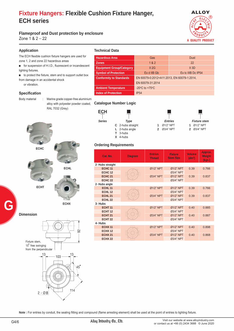
Visit our website at www.alloyindustry.comor contact us at +66 (0) 2434 3688 © June 2020G4/6
G
Note : For entries by conduit, the sealing fitting and compound (flame arresting element) shall be used at the point of entries to lighting fixture.
ECHC
ECHL
ECHT
ECHX
Fixture Hangers: Flexible Cushion Fixture Hanger,ECH series
The ECH flexible cushion fixture hangers are used for zone 1, 2 and zone 22 hazardous areas
for suspension of H.I.D., fluorescent or incandescent lighting fixtures.
to protect the fixture, stem and to support outlet box from damage in an accidental shock or vibration.
Application
Body material : Marine grade copper-free aluminium alloy with polyester powder coated, RAL 7032 (Grey)
Dimension
Catalogue Number Logic
Technical Data
Cat. No. Diagram EntriesThread
FixtureStem Size
Volume(dm3)
Approx.Weight(kgs.)
2- Hubs straightECHC 11 Ø1/2” NPT Ø1/2” NPT 0.39 0.766ECHC 12 Ø3/4” NPTECHC 21 Ø3/4” NPT Ø1/2” NPT 0.39 0.837ECHC 22 Ø3/4” NPT
2- Hubs angleECHL 11 Ø1/2” NPT Ø1/2” NPT 0.39 0.766ECHL 12 Ø3/4” NPTECHL 21 Ø3/4” NPT Ø1/2” NPT 0.39 0.837ECHL 22 Ø3/4” NPT
3- HubsECHT 11 Ø1/2” NPT Ø1/2” NPT 0.40 0.885ECHT 12 Ø3/4” NPTECHT 21 Ø3/4” NPT Ø1/2” NPT 0.40 0.887ECHT 22 Ø3/4” NPT
4- HubsECHX 11 Ø1/2” NPT Ø1/2” NPT 0.40 0.898ECHX 12 Ø3/4” NPTECHX 21 Ø3/4” NPT Ø1/2” NPT 0.40 0.868ECHX 22 Ø3/4” NPT
ECH
Series Type Entries Fixture stemC 2-hubs straight 1 Ø1/2” NPT 1 Ø1/2” NPTL 2-hubs angle 2 Ø3/4” NPT 2 Ø3/4” NPTT 3-hubsX 4-hubs
Ordering Requirements
Hazardous Area Gas DustZones 1 & 2 22Equipment Group/Category II 2G II 3DSymbol of Protection Ex d IIB Gb Ex tc IIIB Dc IP54Conformity to Standards EN 60079-0:2012+A11:2013, EN 60079-1:2014,
EN 60079-31:2014Ambient Temperature -20oC to +75oCIndex of Protection IP54
Flameproof and Dust protection by enclosureZone 1 & 2 _ 22

Visit our website at www.alloyindustry.comor contact us at +66 (0) 2434 3688 © June 2020 G5/6
G
Fixture Hangers: Fixture Hanger,DCH series
The DCH fixture hangers are designed for suspension or pipe pendant mounting of the lighting fixtures. They are suitable for use in zone 1, 2 and zone 22 explosive atmospheres.
Application
Body material : Marine grade copper-free aluminium alloy with polyester powder coated, RAL 7032 (Grey)
Dimension
Catalogue Number Logic
Technical Data
Cat. No. Diagram EntriesThread
FixtureStem Size
Volume(dm3)
Approx.Weight(kgs.)
2- Hubs straightDCHC 11 Ø1/2” NPT Ø1/2” NPT 0.41 0.868DCHC 12 Ø3/4” NPTDCHC 21 Ø3/4” NPT Ø1/2” NPT 0.41 0.875DCHC 22 Ø3/4” NPT
2- Hubs angleDCHL 11 Ø1/2” NPT Ø1/2” NPT 0.42 0.868DCHL 12 Ø3/4” NPTDCHL 21 Ø3/4” NPT Ø1/2” NPT 0.42 0.875DCHL 22 Ø3/4” NPT
3- HubsDCHT 11 Ø1/2” NPT Ø1/2” NPT 0.41 0.868DCHT 12 Ø3/4” NPTDCHT 21 Ø3/4” NPT Ø1/2” NPT 0.41 0.875DCHT 22 Ø3/4” NPT
4- HubsDCHX 11 Ø1/2” NPT Ø1/2” NPT 0.43 0.868DCHX 12 Ø3/4” NPTDCHX 21 Ø3/4” NPT Ø1/2” NPT 0.43 0.875DCHX 22 Ø3/4” NPT
DCH
Series Type Entries Fixture stemC 2-hubs straight 1 Ø1/2” NPT 1 Ø1/2” NPTL 2-hubs angle 2 Ø3/4” NPT 2 Ø3/4” NPTT 3-hubsX 4-hubs
Ordering Requirements
Hazardous Area Gas DustZones 1 & 2 22Equipment Group/Category II 2G II 3DSymbol of Protection Ex d IIB Gb Ex tc IIIB Dc IP54Conformity to Standards EN 60079-0:2012+A11:2013, EN 60079-1:2014,
EN 60079-31:2014Ambient Temperature -20oC to +75oCIndex of Protection IP54
Flameproof and Dust protection by enclosureZone 1 & 2 _ 22

Visit our website at www.alloyindustry.comor contact us at +66 (0) 2434 3688 © June 2020G6/6
G
Fixture Hangers: Ceiling Saddles for Conduit Support,VH series
The VH ceiling saddles are designed for suspending the lighting fixtures from vertical conduit
support. support fluorescent lighting fixtures at dummy size that
no need the wire connecting. Furnished with a loop for conduit passage, maximum to
1 inch conduit size.
Application
Body material : Marine grade copper-free aluminium alloy with polyester powder coated, RAL 7032 (Grey)
Technical Data
Ordering Requirements
Dimension
Corrosion resistant
Protection Corrosion resistantMaximum supporting 40 kgs. of fixture weight
Cat. No. Conduit sizeApprox.Weight(kgs.)
VH 1 Ø1/2” NPT 0.141VH 2 Ø3/4” NPT 0.218

1. Warning Light (Signal Light) DLF1-BN, DLF1-OB, H2/ 10
DLF1-WN Series
2. Obstacle Light EOB Series H3/ 10
3. Low-intensity Obstacle Light VOB Series H4/ 10
4. Traffic Light DCT1-TF Series H5/ 10
5. Alarm Bell DAB Series H6/ 10
6. Buzzer EBZ Series H7/ 10
7. Smoke Detector DSM Series H8/ 10
8. Exhaust Fan EHF Series H9/ 10
9. Grounding Indicator DCT1-GI Series H10/ 10
We reserve the right to make alterations to the technical data, weights, dimensions, designs and products available without notice. The illustrations cannot be considered binding.
SIGNALS AND ALARMS H

Visit our website at www.alloyindustry.comor contact us at +66 (0) 2434 3688 © June 2020H2/10
H
Remark * : The maximum surface temperatures are specified for dust free condition. The dust layer which may cover around the lighting fixture will cause to higher surface temperature.
Signal and Alarm: Warning Light (Signal Light),DLF1-BN, DLF1-OB, DLF1-WN Series
Flameproof/ Increased Safety and Dust protection by enclosureZone 1 & 2 _ 21 & 22
Body material : Marine grade copper-free aluminium alloy with polyester powder coated, RAL 7032 (grey)Globe : Borosilicate glassFilter : Plastic (Warning Light)Guard, bolts : Stainless steelSeal gasket : Silicone Bracket : Hot-dip galvanized steel
Hazardous Area Gas DustZones 1 & 2 21 & 22Equipment Group/Category II 2G II 2DSymbol of Protection Ex db eb IIC T6/ T5 Gb Ex tb IIIC T80oC/ T100oC Db IP66Certificate TÜV CY 18 ATEX 0206011 XConformity to Standards EN 60079-0:2012+A11:2013, EN 60079-1:2014,
EN 60079-7:2015, EN 60079-31:2014Ambient Temperature -20oC to +55oCIndex of Protection IP66
Entries 2- M25x1.5 or 2- Ø3/4” NPT (1-stopping plug)Mounting Ceiling or Bracket mounting (standard)
(Optional mounting ; 2x M10 eye bolts, clamps for pipe)Connection L, N and E ; for 1-4mm.2 cable (Through wiring system with
an extra terminal block for cable connection at both ends.)Rated Voltage 220/ 230/ 240V.ac ±5% 50/60Hz.
Technical Data
Catalogue Number Logic
DLF1 - BN - -Series Type Voltage Lens Colour Accessories Mounting Entries
1D 12V.dc R Red G Basket C Ceiling M2 M25x1.52D 24V.dc Y Yellow guard B Bracket N2 Ø3/4” NPT22 220V.ac G Green
50Hz. B Blue
Cat. No. VoltagePower
ConsumptionFlashRate
Temp. Class(for zone 1 & 2)
Max. Surface Temp.*(for zone 21 & 22)
Ta 40 oC Ta 55 oC Ta 40 oC Ta 55 oCWarning Light (Rotating)DLF1-BN-1D - 12V.dc 2.4W. 120 fpm T6 T5 T80oC T100oCDLF1-BN-2D - 24V.dc 3.4W.DLF1-BN-22 - 220V.ac 50Hz. 3.0W.
Warning Light (LED lamp with lens colour)DLF1-WN-0622 - 220V.ac
50Hz.6W. ¯ T6 T5 T80oC T100oC
DLF1-WN-0722 - 7W.DLF1-WN-0922 - 9W.DLF1-WN-1022 - 10W.
Low Intensity DLF1-OB-24R - 110-240V.ac
50/60Hz.4.65W. ¯ T6 T5 T80oC T100oC
Wiring Diagram
Ceiling mount
Bracket mount
Warning Light (Rotating)
DLF1 - WN - 22 -
Series Type LampWatts Voltage Lens
Colour Accessories Mounting Entries
06 6W. 22 220V.ac R Red G Basket C Ceiling M2 M25x1.507 7W. 50Hz. Y Yellow guard B Bracket N2 Ø3/4” NPT09 9W. G Green10 10W. B Blue
Warning Light (LED lamp with lens colour)
DLF1 - OB - 24 R -Series Type Voltage Lens Colour Accessories Mounting Entries
24 110-240V.ac R Red G Basket C Ceiling M2 M25x1.550/60Hz. guard B Bracket N2 Ø3/4” NPT
Low Intensity ICAO Obstruction Lights (Red LED)
Dimension
Ordering Requirements

Visit our website at www.alloyindustry.comor contact us at +66 (0) 2434 3688 © June 2020 H3/10
H
Ceiling mounting Pendant mounting Bracket mounting
Bracket mounting
Pendant mountingCeiling mounting
Signal and Alarm: Obstacle Light, EOB Series
Flameproof and Dust protection by enclosureZone 1 & 2 _ 21 & 22
The EOB obstacle lights are designed for aviation warning purpose. They are suitable for installation on towers or tall buildings in zone 1, 2 and zone 21, 22 hazardous areas.
Application
Body material : Marine grade copper-free aluminium alloy with polyester powder coated, RAL 7032 (grey)Globe : Borosilicate glassFilter : PlasticGuard, bolts : Stainless steelSeal gasket : Silicone
Hazardous Area Gas DustZones 1 & 2 21 & 22Equipment Group/Category II 2G II 2DSymbol of Protection Ex d IIB T6/ T5 Gb Ex tb IIIC T80oC/ T100oC Db IP66Conformity to Standards EN 60079-0:2012+A11:2013, EN 60079-1:2014,
EN 60079-31:2014Ambient Temperature -20oC to +55oCIndex of Protection IP66
Entries Ø3/4” NPTMounting Ceiling, Pendant or Bracket mountingRated Voltage 220V.ac 50Hz.
Technical Data
Catalogue Number Logic
EOB -
Series Lamp Watt Type Lens colour Mounting(see catalogue IN Incandescent R Red C Ceilingnumber table) CF Compact fluorescent O Orange P Pendant
LED LED bulb G Green B Bracket
Cat. No.LampWatts
Temp. Class(for zone 1 & 2)
Max. Surface Temp.*(for zone 21 & 22) Volume
(dm3)
Approx.Weight(kgs.)Ta 40oC Ta 55oC Ta 40oC Ta 55oC
Incandescent LampEOB-60IN 60W. T6 T5 T80oC T100oC 3.92 7.95EOB-100IN 100W.
Compact Fluorescent LampEOB-11CF 11W. T6 T5 T80oC T100oC 3.92 7.89EOB-15CF 15W.
LED BulbEOB-04LED 4W. T6 T5 T80oC T100oC 3.92 7.75EOB-06LED 6W.EOB-08LED 8W.EOB-10LED 10W.
Remark * : The maximum surface temperatures are specified for dust free condition. The dust layer which may cover around the lighting fixture will cause to higher surface temperature.
Ordering Requirements
Dimension

Visit our website at www.alloyindustry.comor contact us at +66 (0) 2434 3688 © June 2020H4/10
H
Signal and Alarm: Low-intensity Obstacle Light, VOB Series
WeatherproofIP65
The VOB low-intensity obstacle lights are used to provide a visual warning signal of high rise building or structure, or use on mobile object which intend to reduce hazard to aircraft. They are suitable for outdoor use and corrosive environments.
Application
Body material : Marine grade copper-free aluminium alloy with polyester powder coated, RAL 7032 (grey)Lens : Heat and impact resistant colour glassGrip lock and chain : Stainless steel
Technical Data
Protection WeatherproofIndex of Protection IP65Ambient Temperature -20oC to +55oCConformity to Standards ICAO Annex 14 Volume 1
Entries Ø3/4” NPT (Ø1/2” NPT size conduit hub is option)Rated Voltage 220V.ac 50Hz.
Catalogue Number Logic
VOB - -
Series Lamp Watt Lens colour Option(see catalogue R Red H Flashernumber table) O Orange for integral flasher circuit assembly
B Blue into fixture body.C Clear
Cat. No.LampWatts
LightIntensity
Flashing *1(Times/min.)
Approx.Weight(kgs.)
Incandescent LampVOB-1100 - 1x 100W. >10 cd. none 2.25VOB-2100 - 2x 100W. >10 cd. x 2 none 3.56
Halogen LampVOB-1150 - 1x 150W. >40 cd. 70-75 2.25VOB-2150 - 2x 150W. >40 cd. x 2 70-75 3.56
Ordering Requirements
Dimension

Visit our website at www.alloyindustry.comor contact us at +66 (0) 2434 3688 © June 2020 H5/10
H
Signal and Alarm: Traffic Light, DCT1-TF Series
Flameproof and Dust protection by enclosureZone 1 & 2 _ 21 & 22
The DCT1-TF is used for automatic light or traffic signal in hazardous areas (zone 1, 2 and zone 21, 22) due to the presence of flammable gases or vapors, dusts and flying fibers such as oil refineries or petrochemical plant.
Application
Body, cover : Marine grade copper-free aluminium alloy with polyester powder coated, RAL 7032 (Grey)Lid screws : Stainless steelSealing gasket : SiliconeSun shade : Marine grade copper-free aluminium alloy with polyester powder coated, RAL 7032 (Grey)Inspection window : Round type, Ø179mm. lens diameter Model LGCR-217
Hazardous Area Gas DustZones 1 & 2 21 & 22Equipment Group/Category II 2G II 2DSymbol of Protection Ex db IIB T6/T5 Gb Ex tb IIIC T85oC/ T100oC Db IP66Certificate TÜV CY 18 ATEX 0206140 XConformity to Standards EN 60079-0:2012+A11:2013, EN 60079-1:2014,
EN 60079-31:2014Ambient Temperature -20oC to +55oC
Index of Protection IP66
Entries 2- M25x1.5 or 2x Ø3/4” NPT at BottomMounting Wall mountRated Voltage 110-220V.ac 50/60Hz. or 24V.dc
Technical Data
Catalogue Number Logic
DCT1 11218 - TF 20 RG
Series LED power Voltage Colour20 20W. LED 22A 110-240V.ac R Red
50/60Hz. G Green24D 24V.dc
Cat. No. LEDPower Voltage
Temp. Class(for zone 1 & 2)
Max. Surface Temp.*(for zone 21 & 22)
Ta 40oC Ta 55oC Ta 40oC Ta 55oCDCT1 11218-TF2022ARG 20W. 110-240V.ac
T6 T5 T85oC T100oC50/60Hz.DCT1 11218-TF2024DRG 24V.dc
Ordering Requirements
Remark * : The maximum surface temperatures are specified for dust free condition. The dust layer which may cover around the lighting fixture will cause to higher surface temperature.
Dimension
Diagram
Cata
DC
Ser
DCT1
DCT1
Orde
Remarcover a
Dim
Diagram

Visit our website at www.alloyindustry.comor contact us at +66 (0) 2434 3688 © June 2020H6/10
H
Signal and Alarm: Alarm Bell, DAB Series
Flameproof/ Increased Safety and Dust protection by enclosureZone 1 & 2 _ 21 & 22
The DAB alarm bells are used as alarm or signal devices for a various purposes. They are designed for zone 1, 2 and zone 21, 22 hazardous areas.
Application
Housing material : Marine grade copper-free aluminium alloy with polyester powder coated, RAL 3020 (red)Gong : Steel with polyester powder coated, RAL 3020 (red)
Catalogue Number Logic
Cat. No. Voltage CurrentPower
ConsumptionBellDia.
Sound Levelat 10 ft.
Approx.Weight(kgs.)
DAB-6024D- 24V.dc 0.03A. 0.72VA. 6 in. > 85 dB. 3.37DAB-6110A- 110V.ac 0.047A. 5.2VA.DAB-6220A- 220V.ac 0.024A. 5.2VA.
DAB - 6 -Series Bell Diameter Voltage Entries
6 6-inches 024D 24V.dc M1 M20x1.5110A 110V.ac M2 M25x1.5220A 220V.ac N1 Ø1/2” NPT
N2 Ø3/4” NPT
Hazardous Area Gas DustZones 1 & 2 21 & 22Equipment Group/Category II 2G II 2DSymbol of Protection Ex db eb IIC T6/ T5 Gb Ex tb IIIC T85oC/ T105oC Db IP66Certificate TÜV CY 18 ATEX 0205996 XConformity to Standards EN 60079-0:2012+A11:2013, EN 60079-1:2014,
EN 60079-7:2015, EN 60079-31:2014Ambient Temperature -20oC to +55oCIndex of Protection IP66
Entries 3- M20x1.5, M25x1.5 or 3- Ø1/2” NPT, Ø3/4” NPT(2-stopping plug)
Mounting Wall mountingConnection L, N and E ; for 1-4mm.2 cable (Through wiring system with
an extra terminal block for cable connection at both ends.)Rated Voltage 24V.dc, 110V.ac or 220V.ac 50Hz.
Technical Data
Ordering Requirements
Dimension

Visit our website at www.alloyindustry.comor contact us at +66 (0) 2434 3688 © June 2020 H7/10
H
Signal and Alarm: Buzzer, EBZ Series
Flameproof and Dust protection by enclosureZone 1 & 2 _ 21 & 22
The EBZ buzzers are used for call signals, alarms and other signaling application. for flat surface mounted with projectors aimrd in the
desired direction. for zone 1 and 2 hazardous areas.
Application
Housing material : Marine grade copper-free aluminium alloy with polyester powder coated, RAL 7032 (grey)Grill : Marine grade copper-free aluminium alloy with polyester powder coated, RAL 9017 (black)
Hazardous Area Gas DustZones 1 & 2 21 & 22Equipment Group/Category II 2G II 2DSymbol of Protection Ex d IIB T6/ T5 Gb Ex tb IIIC T80oC/ T100oC Db IP65Conformity to Standards EN 60079-0:2012+A11:2013, EN 60079-1:2014,
EN 60079-31:2014Ambient Temperature -20oC to +55oCIndex of Protection IP65
Entries 2- Ø3/4” NPTMounting Wall mountingRated Voltage 6V.dc, 12V.dc, 110V.ac or 220V.ac 50Hz.
Technical Data
Catalogue Number Logic
EBZ - - N2
Series Voltage Entries06D 6V.dc 110A 110V.ac N2 Ø3/4” NPT12D 12V.dc 220A 220V.ac24D 24V.dc
Cat. No. Voltage Current PowerConsumption
Sound Levelat 10 ft.
(dB.)
Temp. Class(for zone 1 & 2)
Max. Surface Temp.*(for zone 21 & 22) Volume
(dm3)
Approx.Weight(kgs.)Ta 40oC Ta 55oC Ta 40oC Ta 55oC
EBZ-06D-N2 6V.dc 0.03A. 0.72VA 100 T6 T5 T80oC T100oC 1.58 4.52EBZ-12D-N2 12V.dc 0.041A. 0.5VAEBZ-24D-N2 24V.dc 0.021A. 0.5VAEBZ-110A-N2 110V.ac 0.022A. 2.5VA 100 T6 T5 T80oC T100oC 1.58 4.52EBZ-220A-N2 220V.ac 0.011A. 2.5VA
Remark * : The maximum surface temperatures are specified for dust free condition. The dust layer which may cover around the lighting fixture will cause to higher surface temperature.
Ordering Requirements
Dimension

Visit our website at www.alloyindustry.comor contact us at +66 (0) 2434 3688 © June 2020H8/10
H
Signal and Alarm: Smoke Detector (Photoelectric sensor), DSM Series
Intrinsic Safety and Dust protection by enclosureZone 1 & 2 _ 22
Hazardous Area Gas DustZones 1 & 2 22Equipment Group/Category II 2G II 3DSymbol of Protection Ex db ia IIC T6 Gb Ex tc IIIB T80oC Dc IP54Conformity to Standards EN 60079-0:2012+A11:2013, EN 60079-1:2014,
EN 60079-11:2012, EN 60079-31:2014Ambient Temperature -20oC to +50oCIndex of Protection IP54 (Applicable to ceiling mount only)
Mounting Ceiling mountOperating Voltage 12/24V.dc
Technical DataSmoke detector is a sensitive yet rugged protection device that is designed for use in hazardous areas for zone 1, 2.
Application
Body : Cast aluminium with polyester powder coatedBolts : Stainless steel
Operating temp. range : 32°F to 120°F (0°C to 50°C)Operating humidity range : 10% to 93% Relative Humidity, NoncondensingAlarm current : 10-130mA.** 85 A StandbyLoop type : 2-wire*Sensitivity : 1 - 3.18%/ft.
* Functionality contingent on panel compatibility.** Must be limited by control panel.
Electrical Rating
Catalogue Number Logic
DSM - -
Series Outline Diagram EntriesC 2-ways Through-feed M1 M20x1.5 N1 Ø1/2” NPTL 2-ways Angle M2 M25x1.5 N2 Ø3/4” NPTT 3-waysX 4-ways
Outline Diagram2-ways Through-feed 2-ways Angle
Detector to Detector Circuit
3-ways 4-ways
Dimension

Visit our website at www.alloyindustry.comor contact us at +66 (0) 2434 3688 © June 2020 H9/10
H
Signal and Alarm: Exhaust Fan, EHF Series
Flameproof and Dust protection by enclosureZone 1 & 2 _ 21 & 22
Motor housing : Cast aluminium with polyester powder coatedFan’s blade : Polished aluminium or ABS (Acrylonitrile Butadiene Styrene)Frame, Guard, Bracket : Stainless steel
Hazardous Area Gas DustZones 1 & 2 21 & 22Equipment Group/Category II 2G II 2DMotor 3 Phases 380V.ac 50Hz.Symbol of Protection Ex d IIC T5/ T4 Gb Ex tb IIIC T100oC/ T135oC Db IP66Certificate (motor) TÜV IT 13 ATEX 039 X (RAEL motor)Motor 1 Phase 220V.ac 50Hz.Symbol of Protection Ex d IIB T5/ T4 Gb Ex tc IIIB T100oC/ T135oC Dc IP55Certificate (motor) TÜV IT 13 ATEX 039 X (RAEL motor)Conformity to Standards EN 60079-0:2012+A11:2013, EN 60079-1:2014,
EN 60079-31:2014Ambient Temperature -20oC to +50oC
Technical Data
Cat. No. BladeDiameter CFM
Dimension in mm. Approx.Weight(kgs.)220V.ac 50Hz. 380V.ac 50Hz. A B Ø C D
EHF 112 EHF 312 12 inches 900 410 410 Ø 315 203 23.0EHF 116 EHF 316 16 inches 2100 510 510 Ø 400 203 25.0EHF 118 EHF 318 18 inches 3000 560 560 Ø 460 203 26.0EHF 124 EHF 324 24 inches 4500 710 710 Ø 615 203 36.0
Dimension
Ordering Requirements
Entries 2- M20x1.5Mounting Wall mountingRated Voltage 220V.ac or 380V.ac. 50Hz.

Visit our website at www.alloyindustry.comor contact us at +66 (0) 2434 3688 © June 2020H10/10
H
Signal and Alarm: Grounding Indicator, DCT1-GI Series
Flameproof and Dust protection by enclosureZone 1 & 2 _ 21 & 22
The DCT1-GI Static Grounding Indicator is the ideal product for safe loading/unloading of ethanol, biofuel, petroleum, chemicals, plastics and other combustible materials. The DCT1-GI is mounted adjacent to loading/unloading ar-eas and connected to transportation tank vehicles, railcars, drums or other portable containers to prevent explosions due to static discharge during product transfer by providing: A ground path for static build-up Automatic pump shutdown when static grounding circuit
is broken Visual indication of safe, static grounding before, during
and after loading and unloading operations
Application
Body, cover : Marine grade copper-free aluminium alloy with polyester powder coated, RAL 7032 (Grey)Lid screws : Stainless steelSealing gasket : Silicone
Hazardous Area Gas DustZones 1 & 2 21 & 22Equipment Group/Category II 2G II 2DSymbol of Protection Ex db IIB T6/T5 Gb Ex tb IIIC T85oC/ T100oC Db IP66Certificate TÜV CY 18 ATEX 0206140 XConformity to Standards EN 60079-0:2012+A11:2013, EN 60079-1:2014,
EN 60079-31:2014Ambient Temperature -20oC to +55oC
Index of Protection IP66
Entries 2- M25x1.5 or 2x Ø3/4” NPT at BottomMounting Wall mountRated Voltage 110-220V.ac 50/60Hz. or 24V.dc
Technical Data
Catalogue Number Logic
DCT1 9157 - GI 22A
Series Grounding Indicator 22A 220V.ac 50/60Hz.
Remark * : The maximum surface temperatures are specified for dust free condition. The dust layer which may cover around the lighting fixture will cause to higher surface temperature.
Dimension
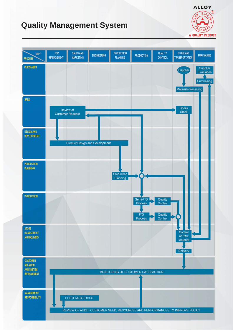
Quality Management SystemQuality Management Systemm

71/53 Borommaratchachonnani Road, Arun AmarinBangkok Noi, Bangkok 10700 THAILANDTel : +66 (0) 2434 8590, +66 (0) 2434 3688 (8 Lines)Fax : +66 (0) 2434 3686E-mail : [email protected]
www.alloyindustry.com
© Copyright 2020 ALLO
Y IND
USTRY CO
., LTD. All Rights Reserved.