
CATALOG Vol. 9 PRODUCTS
216
CATALOG Vol. 9 PRODUCTS ANALOGUE METER TRANSFORMER / SHUNT DIGITAL METER TRANSDUCER TEST MEASURING EQUIPMENT CHARGING DEVICE SINCE 1979
-
Upload
khangminh22 -
Category
Documents
-
view
3 -
download
0
Transcript of CATALOG Vol. 9 PRODUCTS

CATALOG Vol. 9
PRODUCTS
ANALOGUE METER
TRANSFORMER / SHUNT
DIGITAL METER
TRANSDUCER
TEST MEASURING EQUIPMENT
CHARGING DEVICE
SINCE 1979
SAFETY INSTRUCTION
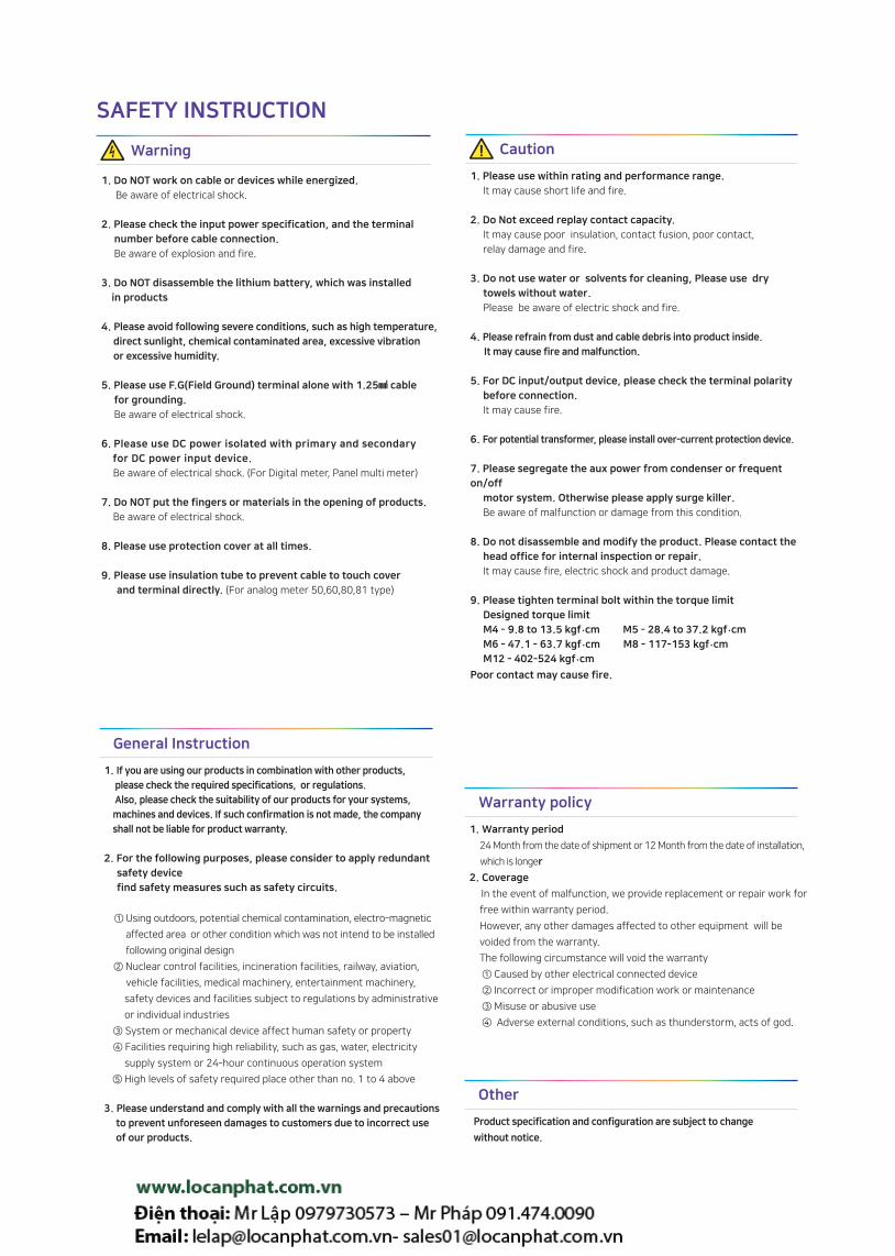
1. Do NOT work on cable or devices while energized.
Be aware of electrical shock.
2. Please check the input power specification, and the terminal
number before cable connection.
Be aware of explosion and fire.
3. Do NOT disassemble the lithium battery, which was installed
in products
4. Please avoid following severe conditions, such as high temperature,
direct sunlight, chemical contaminated area, excessive vibration
or excessive humidity.
5. Please use F.G(Field Ground) terminal alone with 1.25 cable
for grounding.
Be aware of electrical shock.
6. Please use DC power isolated with primary and secondary
for DC power input device.
Be aware of electrical shock. (For Digital meter, Panel multi meter)
7. Do NOT put the fingers or materials in the opening of products.
Be aware of electrical shock.
8. Please use protection cover at all times.
9. Please use insulation tube to prevent cable to touch cover
and terminal directly. (For analog meter 50,60,80,81 type)
Warning
1. Warranty period
24 Month from the date of shipment or 12 Month from the date of installation,
which is longer
2. Coverage
In the event of malfunction, we provide replacement or repair work for
free within warranty period.
However, any other damages affected to other equipment will be
voided from the warranty.
The following circumstance will void the warranty
① Caused by other electrical connected device
② Incorrect or improper modification work or maintenance
③ Misuse or abusive use
④ Adverse external conditions, such as thunderstorm, acts of god.
Warranty policy
1. If you are using our products in combination with other products,
please check the required specifications, or regulations.
Also, please check the suitability of our products for your systems,
machines and devices. If such confirmation is not made, the company
shall not be liable for product warranty.
2. For the following purposes, please consider to apply redundant
safety device
find safety measures such as safety circuits.
① Using outdoors, potential chemical contamination, electro-magnetic
affected area or other condition which was not intend to be installed
following original design
② Nuclear control facilities, incineration facilities, railway, aviation,
vehicle facilities, medical machinery, entertainment machinery,
safety devices and facilities subject to regulations by administrative
or individual industries
③ System or mechanical device affect human safety or property
④ Facilities requiring high reliability, such as gas, water, electricity
supply system or 24-hour continuous operation system
⑤ High levels of safety required place other than no. 1 to 4 above
3. Please understand and comply with all the warnings and precautions
to prevent unforeseen damages to customers due to incorrect use
of our products.
General Instruction
Product specification and configuration are subject to change
without notice.
Other
1. Please use within rating and performance range.
It may cause short life and fire.
2. Do Not exceed replay contact capacity.
It may cause poor insulation, contact fusion, poor contact,
relay damage and fire.
3. Do not use water or solvents for cleaning, Please use dry
towels without water.
Please be aware of electric shock and fire.
4. Please refrain from dust and cable debris into product inside.
It may cause fire and malfunction.
5. For DC input/output device, please check the terminal polarity
before connection.
It may cause fire.
6. For potential transformer, please install over-current protection device.
7. Please segregate the aux power from condenser or frequent
on/off
motor system. Otherwise please apply surge killer.
Be aware of malfunction or damage from this condition.
8. Do not disassemble and modify the product. Please contact the
head office for internal inspection or repair.
It may cause fire, electric shock and product damage.
9. Please tighten terminal bolt within the torque limit
Designed torque limit
M4 - 9.8 to 13.5 kgf .cm M5 - 28.4 to 37.2 kgf .cm
M6 - 47.1 - 63.7 kgf .cm M8 - 117-153 kgf .cm
M12 - 402-524 kgf .cm
Poor contact may cause fire.
Caution

191-211

CEO GREETINGS
CEO Greetings
Thanks for choosing LIGHTSTAR.
Since 1979, we started to manufacture analog meter, and broaden
our business model to current transformer, transducer and digital
meter.
Also, by achieving international certificate such as CE, ABS, JIS and
KS, we are now expanding our market internationally, including
Japan and Vietnam.
Currently, we are focusing on the technology development and
efficient work process for customer.
As always, we will continue to endeavor to satisfy customer needs
and demands.
History
1979 10. 15 - Establishment of LIGHTSTAR
1989 03 - KS(Korean Standard) Approved for Analog meters (KS C 1301, No.6720 by Korean Standard Association)
1997 08 - ISO 9001 approved
1999 09 - KS(Korean Standard) Approved for AC-DC transducer (KS C 1708, No.99-858 by Korean Standard Association) 11 - Company research center approved (No.992046 by Korean Industrial Technology Development Association)
2001 10 - KS(Korean Standard) Approved for Instrument Current Transformer (KS C 1706, No.05-0458 by Korean Standard Association) 07 - JIS(Japan Industrial Standard) Approved for Analog meter (JIS C 1102-2-5 by Japan Industrial Standard Commmitte)
2005 10 - KS(Korean Standard) Approved for Instrument Current Transformer (KS C 1706, No.04-0458 by Korean Standard Association)
2006 01- INNO-BIZ Approved (No.6021-068 by Small and Medium Business Administration)
2008 03 - KS(Korean Standard) Approved for Power metering Current Transformer (KS C 1707, No.08-0124 by Korean Standard Association)
2009 06 - CE(Conformity European) Approved for Analog meter and Others 2010 09 - CE(Conformity European) Approved for Single-phase potential transformer 03 - KEPCO (Korea Electric Power Corporation) registered for Load Shedding device(Demand Controller)
2011 06 - CE(Conformity European) Approved for Digital meter, Transducer and Instrument current transformer
2012 06 - Patent registered (Error testing device and phase checking device for energized 3P instrument current transformer. No.10-1157362)
2013 12 - Patent registered (Power factor calculation method and device for 3 phase balanced circuit, No.10-1311992) 09 - KEPCO (Korea Electric Power Corporation) registered for Power metering Current Transformer
2014 07 - Exporting current transformer to TOYO KEIKI, JAPAN 03 - Korea Fire Institute approved for Earth Leakage Detector 01 - Korea Fire Institute approved for Zero Current Transformer
2016 08 - Relocated Head office and factory. (Jangan Industrial Complex, Busan, South Korea )
Company introduction
Name LIGHT STAR
Establishment date 15th. Oct. 1979
Tel +82-51-723-3000
Fax +82-505-115-3013
Address 126, Jangansandan 8-ro, Jangan-eup, Gijang-gun, Busan, South Korea
Homepage www.vaw.co.kr(Korean)
www.lightstar.co.kr(English)
www.lightstar.co.jp(Japanese)

CE certification
CE stands for "Conformité Européene" and indicates conformity with health, safety,
and environmental protection standards for products sold within the European Economic Area (EEA).
Our CE certified products are complied to the requirements of EU Directives, relating to LVD
(Low Voltage Directives) and EMCD(Electro Magnetic Compatibility Directives).
LIGHTSTAR achieved CE certificate for Analog meter, Current Transformer, Digital meter, Power meter
and Transducers.
KS certification
KS stands for Korean Standard and indicates conformity with Korean government required standards.
LIGHTSTAR achieved KS certificate for Analog meter, Current Transformer and Transducers.

Analog Meters Symbol and terms
45 Type Analog Meter RMS Meter Watt Meter
50 Type Analog Meter
68 Type Analog Meter
60 Type Analog Meter
72 Type Analog Meter
80 Type Analog Meter
08 Type Analog Meter
11 Type Analog Meter
81 Type Analog Meter
08N Type Analog Meter
Ao·Vo Meter
Var Meter Power Factor Meter
08TY Connection Diagram
08TY Connection Diagram
11TY Connection Diagram
For cam switch For sole use
For combined use Analog Meter Relay
ELP(Electro-luminescent Panel)Meter Double Indicatior Meter
3P Selector Meter
Connection Diagram
Analog Meter scale table

AN
ALO
G M
ET
ER
8
Analog Meters Symbol and terms
Types of measurements
Types of operating principles Symbol
Measuring component for DC
Measuring component for AC
1 Measuring component for 3 wire
2 Measuring component for unbalanced 3 wire
2 Measuring component for unbalanced 4 wire
General Type Symbol
External Accessories
Protective earth terminal
Polar terminal
Symbol
Measuring type Symbol
Electrical circuit type
Moving coil type
Moving-iron type
Rectifier-type
Shunt type
Voltage test
Type Symbol
Voltage test 500V
Without test voltage
Voltage test Voltage test over 500V
Ex) 3kV
Accuracy class
Display value tolerances from maximum value,
as per IEC 60051.
Numbers representing accuracy class
ex) 2.5 Class =+2.5 % of Full Scale(F.S)
1.5 Class =+1.5 % of Full Scale(F.S)
1.0 Class =+1.0 % of Full Scale(F.S)
Auxilary items
Items to be connected to anolog meter
for certain purpose
Measuring part
Activated by measuring value and affect driving part.
Moving coil type
Wounded coil to be rotated within fixed magnet
by the influence of induction 。
Moving iron type
Iron vane to be rotated within fixed coil
by the influence of excitation.
Rectifier type
Combination of rectifier and moving coil type
for AC current or AC voltage
Driving part
Driving part affected by measuring part
Maximum indicated value
Maximum indicated value on analog meter
Terms
Operating temperature 23±10
Operating humidity 25~80%
Insulation resistance 10MΩ or higher
Withstand Voltage 3.32kV/1 min
Power consumption 1.0VA
Common specifications
Install type
Type Symbol
Vertical install
Horizontal install
Tilted install
AN
ALO
G M
ET
ER
9www.vaw.co.kr
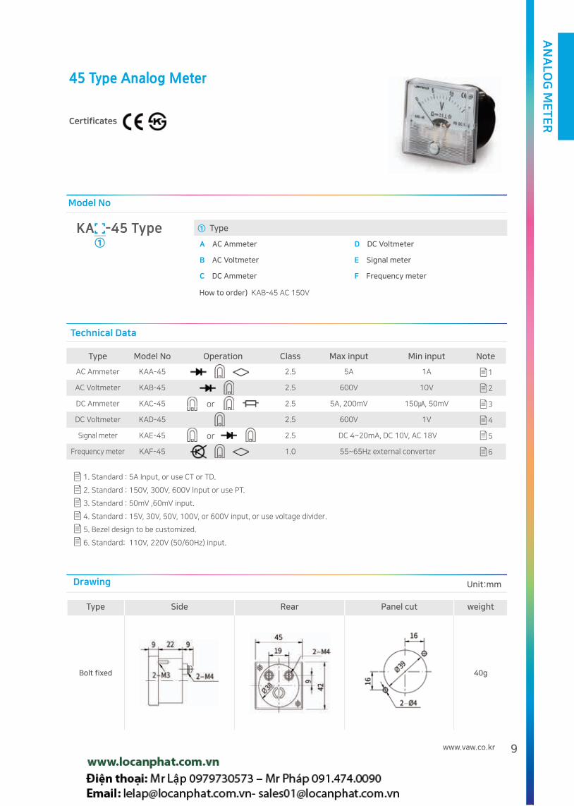
45 Type Analog Meter
Certificates
KA -45 Type①
How to order) KAB-45 AC 150V
① Type
A AC Ammeter D DC Voltmeter
B AC Voltmeter E Signal meter
C DC Ammeter F Frequency meter
Type Model No Operation Class Max input Min input Note
AC Ammeter KAA-45 2.5 5A 1A 1
AC Voltmeter KAB-45 2.5 600V 10V 2
DC Ammeter KAC-45 or 2.5 5A, 200mV 150, 50mV 3
DC Voltmeter KAD-45 2.5 600V 1V 4
Signal meter KAE-45 or 2.5 DC 4~20mA, DC 10V, AC 18V 5
Frequency meter KAF-45 1.0 55~65Hz external converter 6
or
or
1. Standard : 5A Input, or use CT or TD.
2. Standard : 150V, 300V, 600V lnput or use PT.
3. Standard : 50mV ,60mV input.
4. Standard : 15V, 30V, 50V, 100V, or 600V input, or use voltage divider.
5. Bezel design to be customized.
6. Standard: 110V, 220V (50/60Hz) input.
Model No
Technical Data
Type Side Rear Panel cut weight
Bolt fixed 40g
Drawing Unit:mm

AN
ALO
G M
ET
ER
10
50 Type Analog Meter
Certificates
① Type
A AC Ammeter D DC Voltmeter
B AC Voltmeter E Signal meter
C DC Ammeter F Frequency meter
KA -50 Type①
How to order) KAB-50 AC 150V
Model No
Type Model No Operation Class Max input Min input Note
AC Ammeter KAA-50 2.5 5A 0.1A 1
AC Voltmeter KAB-50 2.5 600V 10V 2
DC Ammeter KAC-50 or 2.5 5A, 200mV 150, 50mV 3
DC Voltmeter KAD-50 2.5 600V 1V 4
Signal meter KAE-50 or 2.5 DC 4 ~ 20mA or DC 10V or AC 18V 5
Frequency meter KAF-50 or 1.0 55 ~ 65Hz external converter,
45 ~ 65Hz internal converter 6
or
or
Technical Data
Type Side Rear Panel cut weight
Bolt fixed
KAB/KAC/KAD/KAE/KAF KAA
60gSafety cover
Drawing Unit:mm
1. Standard : 5A Input, or use CT
2. Standard : 150V, 300V, 600V lnput or use PT.
3. Standard : 50mV ,60mV input.
4. Standard : 15V, 30V, 50V, 100V, or 600V input, or use voltage divider.
5. Bezel design to be customized.
6. Standard: 110V, 220V (50/60Hz) input ..

AN
ALO
G M
ET
ER
11www.vaw.co.kr
60 Type Analog Meter
Certificates
① Type
A AC Ammeter D DC Voltmeter
B AC Voltmeter E Signal meter
C DC Ammeter F Frequency meter
KA -60 Type①
How to order) KAB-60 AC 600V
Model No
Type Model No Operation Class Max input Min input Note
AC Ammeter KAA-60 2.5 5A 0.1A 1
AC Voltmeter KAB-60 2.5 600V 10V 2
DC Ammeter KAC-60 or 2.5 5A, 200mV 150, 50mV 3
DC Voltmeter KAD-60 2.5 600V 1V 4
Signal meter KAE-60 or 2.5 DC 4 ~ 20mA or DC 10V or AC 18V 5
Frequency meter KAF-60 or 1.0 55 ~ 65Hz external converter,
45 ~ 65Hz internal converter 6
or
or
Technical Data
Type Side Rear Panel cut weight
Iron cover
fixed type80g
Bolt fixed 80g
Safety cover
Iron cover fixed type
Drawing Unit:mm
1. Standard : 5A Input, or use CT
2. Standard : 150V, 300V, 600V lnput or use PT.
3. Standard : 50mV ,60mV input.
4. Standard : 15V, 30V, 50V, 100V, or 600V input, or use voltage divider.
5. Bezel design to be customized.
6. Standard: 110V, 220V (50/60Hz) input.

AN
ALO
G M
ET
ER
12
68 Type Analog Meter
Certificates
① Type
A AC Ammeter D DC Voltmeter
B AC Voltmeter E Signal meter
C DC Ammeter F Frequency meter
KA -68 Type①
How to order) KAB-68 AC 600V
Model No
Type Side Rear Panel cut Weight
Iron cover
fixed type 130g
Iron cover fixed type
Drawing Unit:mm
Type Model No Operation Class Max input Min input Note
AC Ammeter KAA-68 2.5 5A 0.1A 1
AC Voltmeter KAB-68 2.5 600V 10V 2
DC Ammeter KAC-68 or 2.5 5A, 200mV 150, 50mV 3
DC Voltmeter KAD-68 2.5 600V 1V 4
Signal meter KAE-68 or 2.5 DC 4 ~ 20mA or DC 10V or AC 18V 5
Frequency meter KAF-68 or 1.0 55 ~ 65Hz external converter,
45 ~ 65Hz internal converter 6
or
or
Technical Data
1. Standard : 5A Input, or use CT
2. Standard : 150V, 300V, 600V lnput or use PT.
3. Standard : 50mV ,60mV input.
4. Standard : 15V, 30V, 50V, 100V, or 600V input, or use voltage divider.
5. Bezel design to be customized.
6. Standard: 110V, 220V (50/60Hz) input

AN
ALO
G M
ET
ER
13www.vaw.co.kr
72 Type Analog Meter
Certificates
KA -72 Type①
How to order) KAC-72 DC 100A/50mV
Model No
Type Side Rear Panel cut Weight
Iron cover
fixed type 130g
8 3048
2-M5
66
66
Safety coverIron cover fixed type
67
67
Drawing Unit:mm
Type Model No Operation Class Max input Min input Note
AC Ammeter KAA-72 2.5 5A 0.1A 1
AC Voltmeter KAB-72 2.5 600V 10V 2
DC Ammeter KAC-72 or 2.5 5A, 200mV 150, 50mV 3
DC Voltmeter KAD-72 2.5 600V 1V 4
Signal meter KAE-72 or 2.5 DC 4 ~ 20mA or DC 10V or AC 18V 5
Frequency meter KAF-72 or 1.0 55 ~ 65Hz external converter,
45 ~ 65Hz internal converter 6
or
or
Technical Data
1. Standard : 5A Input, or use CT
2. Standard : 150V, 300V, 600V lnput or use PT.
3. Standard : 50mV ,60mV input.
4. Standard : 15V, 30V, 50V, 100V, or 600V input, or use voltage divider.
5. Bezel design to be customized.
6. Standard: 110V, 220V (50/60Hz) input
① Type
A AC Ammeter D DC Voltmeter
B AC Voltmeter E Signal meter
C DC Ammeter F Frequency meter

AN
ALO
G M
ET
ER
14
80 Type Analog Meter
Certificates
Type Side Rear Panel cut Weight
Iron cover
fixed type 130g
Safety cover
Iron cover fixed type
Drawing Unit:mm
① Type
A AC Ammeter D DC Voltmeter
B AC Voltmeter E Signal meter
C DC Ammeter F Frequency meter
KA -80 Type①
How to order) KAC-80 DC 100A/50mV
Model No
Type Model No Operation Class Max input Min input Note
AC Ammeter KAA-80 2.5 5A 0.1A 1
AC Voltmeter KAB-80 2.5 600V 10V 2
DC Ammeter KAC-80 or 2.5 5A, 200mV 150, 50mV 3
DC Voltmeter KAD-80 2.5 600V 1V 4
Signal meter KAE-80 or 2.5 DC 4 ~ 20mA or DC 10V or AC 18V 5
Frequency meter KAF-80 or 1.0 55 ~ 65Hz external converter,
45 ~ 65Hz internal converter 6
or
or
Technical Data
1. Standard : 5A Input, or use CT
2. Standard : 150V, 300V, 600V lnput or use PT.
3. Standard : 50mV ,60mV input.
4. Standard : 15V, 30V, 50V, 100V, or 600V input, or use voltage divider.
5. Bezel design to be customized.
6. Standard: 110V, 220V (50/60Hz) input

AN
ALO
G M
ET
ER
15www.vaw.co.kr
81 Type Analog Meter
Certificates
Type Side Rear Panel cut Weight
Iron cover
fixed type 140g
Iron cover fixed type
Safety cover
Drawing Unit:mm
① Type
A AC Ammeter D DC Voltmeter
B AC Voltmeter E Signal meter
C DC Ammeter F Frequency meter
KA -81 Type①
How to order) KAC-81 DC 100A/50mV
Model No
Type Model No Operation Class Max input Min input Note
AC Ammeter KAA-81 1.5 5A 0.1A 1
AC Voltmeter KAB-81 1.5 600V 10V 2
DC Ammeter KAC-81 or 1.5 5A, 200mV 150, 50mV 3
DC Voltmeter KAD-81 1.5 600V 1V 4
Signal meter KAE-81 or 1.5 DC 4 ~ 20mA or DC 10V or AC 18V 5
Frequency meter KAF-81 or 1.0 55 ~ 65Hz external converter,
45 ~ 65Hz internal converter 6
or
or
Technical Data
1. Standard : 5A Input, or use CT
2. Standard : 150V, 300V, 600V lnput or use PT.
3. Standard : 50mV ,60mV input.
4. Standard : 15V, 30V, 50V, 100V, or 600V input, or use voltage divider.
5. Bezel design to be customized.
6. Standard: 110V, 220V (50/60Hz) input
AN
ALO
G M
ET
ER
16
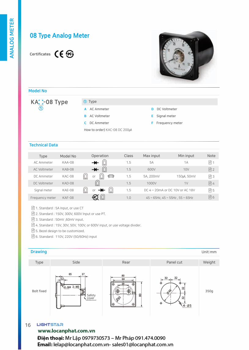
08 Type Analog Meter
Certificates
Type Side Rear Panel cut Weight
Bolt fixed 350gSafetycover
Drawing Unit:mm
① Type
A AC Ammeter D DC Voltmeter
B AC Voltmeter E Signal meter
C DC Ammeter F Frequency meter
KA -08 Type①
How to order) KAC-08 DC 200
Model No
Type Model No Operation Class Max input Min input Note
AC Ammeter KAA-08 1.5 5A 1A 1
AC Voltmeter KAB-08 1.5 600V 10V 2
DC Ammeter KAC-08 or 1.5 5A, 200mV 150, 50mV 3
DC Voltmeter KAD-08 1.5 1000V 1V 4
Signal meter KAE-08 or 1.5 DC 4 ~ 20mA or DC 10V or AC 18V 5
Frequency meter KAF-08 1.0 45 ~ 65Hz, 45 ~ 55Hz , 55 ~ 65Hz 6
or
or
Technical Data
1. Standard : 5A Input, or use CT
2. Standard : 150V, 300V, 600V lnput or use PT.
3. Standard : 50mV ,60mV input.
4. Standard : 15V, 30V, 50V, 100V, or 600V input, or use voltage divider.
5. Bezel design to be customized.
6. Standard: 110V, 220V (50/60Hz) input

AN
ALO
G M
ET
ER
17www.vaw.co.kr
08N Type Analog Meter
Certificates
Type Side Rear Panel cut Weight
Bolt fixed 350g
Safetycover
Drawing
① Type
A AC Ammeter D DC Voltmeter
B AC Voltmeter E Signal meter
C DC Ammeter F Frequency meter
KA -08N Type①
How to order) KAC-08N DC 200
Model No
Type Model No Operation Class Max input Min input Note
AC Ammeter KAA-08N 1.5 5A 1A 1
AC Voltmeter KAB-08N 1.5 600V 10V 2
DC Ammeter KAC-08N or 1.5 5A, 200mV 150, 50mV 3
DC Voltmeter KAD-08N 1.5 1000V 1V 4
Signal meter KAE-08N or 1.5 DC 4 ~ 20mA or DC 10V or AC 18V 5
Frequency meter KAF-08N 1.0 45 ~ 65Hz, 45 ~ 55Hz
55 ~ 65 Hz (With external converter) 6
Technical Data
1. Standard : 5A Input, or use CT
2. Standard : 150V, 300V, 600V lnput or use PT.
3. Standard : 50mV ,60mV input.
4. Standard : 15V, 30V, 50V, 100V, or 600V input, or use voltage divider.
5. Bezel design to be customized.
6. Standard: 110V, 220V (50/60Hz) input
or
or
Unit:mm

AN
ALO
G M
ET
ER
18
11 Type Analog Meter
Certificates
Type Side Rear Panel cut Weight
Bolt fixed 450g
Safety cover
Drawing Unit:mm
① Type
A AC Ammeter D DC Voltmeter
B AC Voltmeter E Signal meter
C DC Ammeter F Frequency meter
KA -11 Type①
How to order)KAD-11 DC 600V
Model No
Type Model No Operation Class Max input Min input Note
AC Ammeter KAA-11 1.5 5A 1A 1
AC Voltmeter KAB-11 1.5 600V 10V 2
DC Ammeter KAC-11 or 1.5 5A, 200mV 150, 50mV 3
DC Voltmeter KAD-11 1.5 1000V 1V 4
Signal meter KAE-11 or 1.5 DC 4 ~ 20mA or DC 10V or AC 18V 5
Frequency meter KAF-11 1.0 45 ~ 65Hz, 45 ~ 55Hz , 55 ~ 65Hz 6
Technical Data
1. Standard : 5A Input, or use CT
2. Standard : 150V, 300V, 600V lnput or use PT.
3. Standard : 50mV ,60mV input.
4. Standard : 15V, 30V, 50V, 100V, or 600V input, or use voltage divider.
5. Bezel design to be customized.
6. Standard: 110V, 220V (50/60Hz) input
or
or

AN
ALO
G M
ET
ER
19www.vaw.co.kr
Technical Data
Type
A0 Meter (AC current Max)
V0 Meter (AC voltage Max)
KAM-11A KAM-11B
Operation
Class 1.5
Input 1A, 5A 110V, 190/3V
Power Consumption
1.0 VA
Holding time 1.0% / 12Hour
Aux power AC 100 ~ 240V(60Hz)
Reset Front : Push button Rear : Reset Terminal
Weight 750g
Refer to page 24 for dimensions and drawing
Ao Meter KAM-11A Vo Meter KAM-11B
Connection Diagram
Rear Rear
INPUT INPUT
Aux power Aux power
(current limit resistor)
RMS MeterCertificates
RMS KAK-11A/KAK-08A RMS KAK-11B/KAK-08B
Technical Data Technical Data
Type KAK-08A KAK-11A
Operation
Class 1.5
InputDirect 5A
Usint CT Primary current/5A
Power consumption
1.0VA
Weight 350g 450g
Type KAK-08B KAK-11B
Operation
Class 1.5
InputDirect 150V, 300V, 600V,
Usint CT Primary Voltage/110V, 220V
Power consumption
1.0VA
Weight 350g 450g
Refer to page 24 for dimensions and Drawing
Ao / Vo Meter
Certificates
RMS KAK-11A/KAK-08A RMS KAK-11B/KAK-08B RMS KAK-11B/KAK-08B RMS KAK-11B/KAK-08B RMS KAK-11B/KAK-08B

AN
ALO
G M
ET
ER
20
Watt Meter
Certificates
① Dimension(WxHxDxΦ)
08 80x80x99x65
11 110x110x107x100
Model No
KAG -①
How to order) KAG-08 3P3W 440/110. 100/5A, 80kW
Calculation method 1Φ=V x A x COS Θ 3Φ=V x A x COS Θ x √3
Type KAG-11 KAG-08
Operation
Class 1.5
Input
1P2W 1P3W 3P3W 3P4W
220V 220V/110V
220V, 380/110V, 440/110V
3300/100V, 6600/110V22000/110V154kV/110V
208/√3V, 380/√3V / 190/√3V
380/√3V11400/√3V / 190/√3V22900/√3V / 190/√3V
No direct connection(Use TD)
1A or 5A
Power Consumption
2VA
Weight 740g 300g(Meter), 450g(TD)
Technical Data
Refer to Connection Diagram 25-27. Customized product can be produced by order.
Drawing
Type Fixed method Side Rear Panel cut
08Ty Bolt fixed type
11Ty Bolt fixed type
Safety cover
Safetycovercover
Unit:mm
AN
ALO
G M
ET
ER
21www.vaw.co.kr
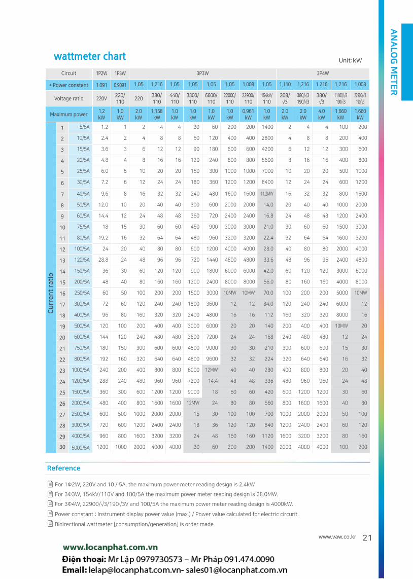
wattmeter chart
Reference
Circuit 1P2W 1P3W 3P3W 3P4W
* Power constant 1.091 0.9091 1.05 1.216 1.05 1.05 1.05 1.05 1.008 1.05 1.110 1.216 1.216 1.216 1.008
Voltage ratio 220V220/110
220380/110
440/110
3300/110
6600/110
22000/110
22900/110
154kV/110
208/√3
380/√3190/√3
380/√3
11400/√3190/√3
22900/√3190/√3
Maximum power1.2kW
1.0kW
2.0kW
1.158kW
1.0kW
1.0kW
1.0kW
1.0kW
0.961kW
1.0kW
2.0kW
2.0kW
4.0kW
1.660kW
1.660kW
1 5/5A 1.2 1 2 4 4 30 60 200 200 1400 2 4 4 100 200
2 10/5A 2.4 2 4 8 8 60 120 400 400 2800 4 8 8 200 400
3 15/5A 3.6 3 6 12 12 90 180 600 600 4200 6 12 12 300 600
4 20/5A 4.8 4 8 16 16 120 240 800 800 5600 8 16 16 400 800
5 25/5A 6.0 5 10 20 20 150 300 1000 1000 7000 10 20 20 500 1000
6 30/5A 7.2 6 12 24 24 180 360 1200 1200 8400 12 24 24 600 1200
7 40/5A 9.6 8 16 32 32 240 480 1600 1600 11.2MW 16 32 32 800 1600
8 50/5A 12.0 10 20 40 40 300 600 2000 2000 14.0 20 40 40 1000 2000
9 60/5A 14.4 12 24 48 48 360 720 2400 2400 16.8 24 48 48 1200 2400
10 75/5A 18 15 30 60 60 450 900 3000 3000 21.0 30 60 60 1500 3000
11 80/5A 19.2 16 32 64 64 480 960 3200 3200 22.4 32 64 64 1600 3200
12 100/5A 24 20 40 80 80 600 1200 4000 4000 28.0 40 80 80 2000 4000
13 120/5A 28.8 24 48 96 96 720 1440 4800 4800 33.6 48 96 96 2400 4800
14 150/5A 36 30 60 120 120 900 1800 6000 6000 42.0 60 120 120 3000 6000
15 200/5A 48 40 80 160 160 1200 2400 8000 8000 56.0 80 160 160 4000 8000
16 250/5A 60 50 100 200 200 1500 3000 10MW 10MW 70.0 100 200 200 5000 10MW
17 300/5A 72 60 120 240 240 1800 3600 12 12 84.0 120 240 240 6000 12
18 400/5A 96 80 160 320 320 2400 4800 16 16 112 160 320 320 8000 16
19 500/5A 120 100 200 400 400 3000 6000 20 20 140 200 400 400 10MW 20
20 600/5A 144 120 240 480 480 3600 7200 24 24 168 240 480 480 12 24
21 750/5A 180 150 300 600 600 4500 9000 30 30 210 300 600 600 15 30
22 800/5A 192 160 320 640 640 4800 9600 32 32 224 320 640 640 16 32
23 1000/5A 240 200 400 800 800 6000 12MW 40 40 280 400 800 800 20 40
24 1200/5A 288 240 480 960 960 7200 14.4 48 48 336 480 960 960 24 48
25 1500/5A 360 300 600 1200 1200 9000 18 60 60 420 600 1200 1200 30 60
26 2000/5A 480 400 800 1600 1600 12MW 24 80 80 560 800 1600 1600 40 80
27 2500/5A 600 500 1000 2000 2000 15 30 100 100 700 1000 2000 2000 50 100
28 3000/5A 720 600 1200 2400 2400 18 36 120 120 840 1200 2400 2400 60 120
29 4000/5A 960 800 1600 3200 3200 24 48 160 160 1120 1600 3200 3200 80 160
30 5000/5A 1200 1000 2000 4000 4000 30 60 200 200 1400 2000 4000 4000 100 200
For 1Φ2W, 220V and 10 / 5A, the maximum power meter reading design is 2.4kW
For 3Φ3W, 154kV/110V and 100/5A the maximum power meter reading design is 28.0MW.
For 3Φ4W, 22900/√3/190√3V and 100/5A the maximum power meter reading design is 4000kW.
Power constant : Instrument display power value (max.) / Power value calculated for electric circurit.
Bidirectional wattmeter [consumption/generation] is order made.
Unit:kW
Cu
rre
nt
rati
o

AN
ALO
G M
ET
ER
22
Var Meter
Certificates
Drawing
Type Fixed method Side Rear Panel dimensions
08Ty Bolt fixed type
11Ty Bolt fixed type
Safety cover
Safetycovercover
① Type(WxHxDxΦ)
08 80x80x99x65
11 110x110x107x100
Model No
KAI -①
How to order)) KAI-08 3P3W 440/110. 100/5A, ±80kvar
Calculation method 1Φ=V x A x Sin Θ 3Φ=V x A x Sin Θ x √3
Type KAI-11 KAI-08
Operation
Class 1.5
Input
1P2W 1P3W 3P3W 3P4W
220V 220V/110V
220V, 380/110V, 440/110V
3300/100V, 6600/110V22000/110V154kV/110V
208/√3V, 380/√3V / 190/√3V
380/√3V11400/√3V / 190/√3V22900/√3V / 190/√3V
No direct connection(Use TD)
1A or 5A
Power Consumption 2VA
weight 740g 300g(Meter), 450g(TD)
Technical Data
Refer to Connection Diagram 25-27. Customized product can be produced by order.
Unit:mm

AN
ALO
G M
ET
ER
23www.vaw.co.kr
Reactive power meter chart
Reference
Circuit 1P2W 1P3W 3P3W 3P4W
* Power constant 1.091 0.9091 1.05 1.216 1.05 1.05 1.05 1.05 1.008 1.05 1.110 1.216 1.216 1.216 1.008
Voltage ratio 220V220/110
220380/110
440/110
3300/110
6600/110
22000/110
22900/110
154kV/110
208/√3
380/√3190/√3
380/√3
11400/√3190/√3
22900/√3190/√3
Maximum power1.2
kvar1.0
kvar2.0
kvar1.158kvar
1.0kvar
1.0kvar
1.0kvar
1.0kvar
0.961kvar
1.0kvar
2.0kvar
2.0kvar
4.0kvar
1.660kvar
1.660kvar
1 5/5A 1.2 1 2 4 4 30 60 200 200 1400 2 4 4 100 200
2 10/5A 2.4 2 4 8 8 60 120 400 400 2800 4 8 8 200 400
3 15/5A 3.6 3 6 12 12 90 180 600 600 4200 6 12 12 300 600
4 20/5A 4.8 4 8 16 16 120 240 800 800 5600 8 16 16 400 800
5 25/5A 6.0 5 10 20 20 150 300 1000 1000 7000 10 20 20 500 1000
6 30/5A 7.2 6 12 24 24 180 360 1200 1200 8400 12 24 24 600 1200
7 40/5A 9.6 8 16 32 32 240 480 1600 1600 11.2Mvar 16 32 32 800 1600
8 50/5A 12.0 10 20 40 40 300 600 2000 2000 14.0 20 40 40 1000 2000
9 60/5A 14.4 12 24 48 48 360 720 2400 2400 16.8 24 48 48 1200 2400
10 75/5A 18 15 30 60 60 450 900 3000 3000 21.0 30 60 60 1500 3000
11 80/5A 19.2 16 32 64 64 480 960 3200 3200 22.4 32 64 64 1600 3200
12 100/5A 24 20 40 80 80 600 1200 4000 4000 28.0 40 80 80 2000 4000
13 120/5A 28.8 24 48 96 96 720 1440 4800 4800 33.6 48 96 96 2400 4800
14 150/5A 36 30 60 120 120 900 1800 6000 6000 42.0 60 120 120 3000 6000
15 200/5A 48 40 80 160 160 1200 2400 8000 8000 56.0 80 160 160 4000 8000
16 250/5A 60 50 100 200 200 1500 3000 10Mvar 10Mvar 70.0 100 200 200 5000 10Mvar
17 300/5A 72 60 120 240 240 1800 3600 12 12 84.0 120 240 240 6000 12
18 400/5A 96 80 160 320 320 2400 4800 16 16 112 160 320 320 8000 16
19 500/5A 120 100 200 400 400 3000 6000 20 20 140 200 400 400 10Mvar 20
20 600/5A 144 120 240 480 480 3600 7200 24 24 168 240 480 480 12 24
21 750/5A 180 150 300 600 600 4500 9000 30 30 210 300 600 600 15 30
22 800/5A 192 160 320 640 640 4800 9600 32 32 224 320 640 640 16 32
23 1000/5A 240 200 400 800 800 6000 12Mvar 40 40 280 400 800 800 20 40
24 1200/5A 288 240 480 960 960 7200 14.4 48 48 336 480 960 960 24 48
25 1500/5A 360 300 600 1200 1200 9000 18 60 60 420 600 1200 1200 30 60
26 2000/5A 480 400 800 1600 1600 12Mvar 24 80 80 560 800 1600 1600 40 80
27 2500/5A 600 500 1000 2000 2000 15 30 100 100 700 1000 2000 2000 50 100
28 3000/5A 720 600 1200 2400 2400 18 36 120 120 840 1200 2400 2400 60 120
29 4000/5A 960 800 1600 3200 3200 24 48 160 160 1120 1600 3200 3200 80 160
30 5000/5A 1200 1000 2000 4000 4000 30 60 200 200 1400 2000 4000 4000 100 200
For 1Φ2W, 220V and 10 / 5A, the maximum power meter reading design is 2.4kW
For 3Φ3W, 154kV/110V and 100/5A the maximum power meter reading design is 28.0Mvar
For 3Φ4W, 22900/√3/190√3V and 100/5A the maximum power meter reading design is 4000kW.
Power constant : Instrument display power value (max.) / Power value calculated for electric circurit.
Bidirectional wattmeter [consumption/generation] is order made.
Unit:kvar
Cu
rre
nt
rati
o
AN
ALO
G M
ET
ER
24
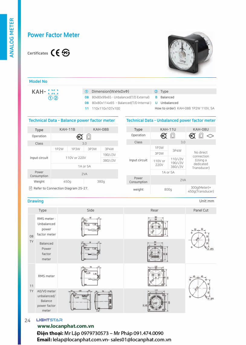
Power Factor Meter
Certificates
Drawing
Type Side Rear Panel Cut
08
TY
RMS meter .
Unbalanced
power
factor meter
Balanced
Power
factor
meter
11
TY
RMS meter
A0/V0 meter
unbalanced/
Balance
power factor
meter
Safety cover
Safety coverSafety cover
Safety cover
SafetySafetycover
① Dimension(WxHxDxΦ) ② Type
08 80x80x99x65 - Unbalanced(T/D External) B Balanced
08 80x80x114x65 - Balanced(T/D Internal ) U Unbalanced
11 110x110x107x100
Model No
KAH-①
How to order) KAH-08B 1P2W 110V, 5A
②
Type KAH-11B KAH-08B
Operation
Class 3.0
Input circuit
1P2W 1P3W 3P3W 3P4W
110V or 220V190/√3V
380/√3V
1A or 5A
Power Consumption
2VA
Weight 450g 380g
Type KAH-11U KAH-08U
Operation
Class 3.0
Input circuit
1P3W3P4W
No direct connection
(Using a dedicated
Transducer)
3P3W
110V or 220V
110/√3V190/√3V380/√3V
1A or 5A
Power Consumption
2VA
weight 800g300g(Meter)+
450g(Transducer)
Technical Data - Balance power factor meter Technical Data - Unbalanced power factor meter
Refer to Connection Diagram 25-27.
Unit:mm

AN
ALO
G M
ET
ER
25www.vaw.co.kr
08TY Connection DiagramFor cam switch
3P3W 2CT(Watt meter, Reactive power meter, Balanced power factor meter)
3P3W 3CT(Watt meter, Reactive power meter, Unbalanced power factor meter)
The A / S (Cam Switch) is based on the koino product. Please check the manufacturer's terminal number.
PT connection is not drawn.
3P4W 3CT(Watt meter, Reactive power meter, Unbalanced power factor meter)

AN
ALO
G M
ET
ER
26
11TY Connection Diagram For sole use
1P3W 11TY(Watt meter, Reactive power meter, Unbalanced power factor meter)
3P3W 11TY(Watt meter, Reactive power meter, Unbalanced power factor meter)
1P3W 11TY(Balanced power factor meter)
3 Phase PTSingle phase PT
3P3W 11TY(Balanced power factor meter)
3 Phase PT Single phase PTSingle phase PT
3P4W 11TY(Watt meter, Reactive power meter, Unbalanced power factor meter)
3P4W 11TY(Balanced power factor meter)
Single phase PT
1P2W 11TY(Watt meter, Reactive power meter, Balanced power factor meter)
AN
ALO
G M
ET
ER
27www.vaw.co.kr
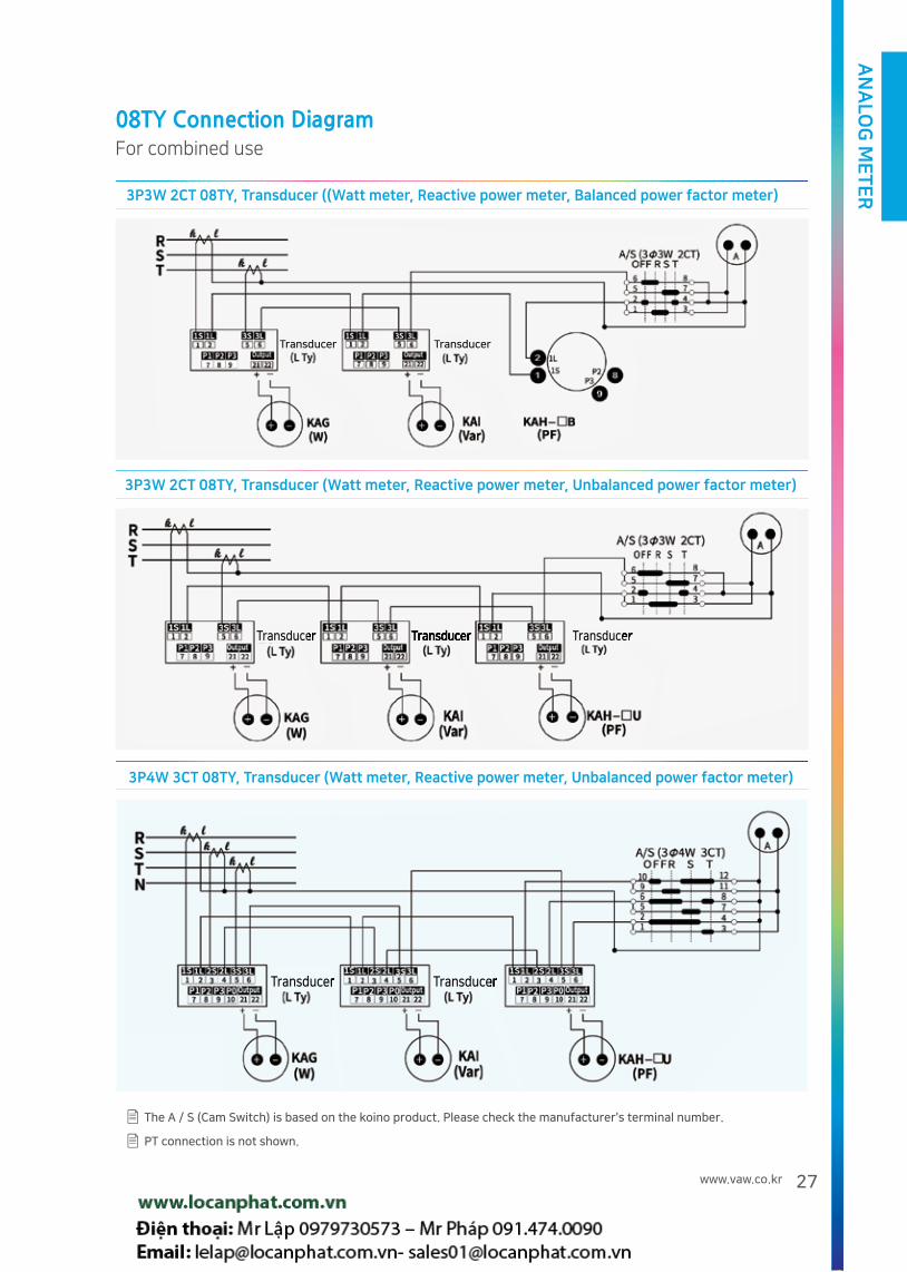
08TY Connection DiagramFor combined use
The A / S (Cam Switch) is based on the koino product. Please check the manufacturer's terminal number.
PT connection is not shown.
3P4W 3CT 08TY, Transducer (Watt meter, Reactive power meter, Unbalanced power factor meter)
TransducerTransducer TransducerTransducer
3P3W 2CT 08TY, Transducer ((Watt meter, Reactive power meter, Balanced power factor meter)
Transducer Transducer
3P3W 2CT 08TY, Transducer (Watt meter, Reactive power meter, Unbalanced power factor meter)
TransducerTransducer TransducerTransducer TransducerTransducer
AN
ALO
G M
ET
ER
28
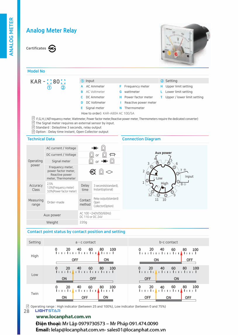
Analog Meter Relay
Certificates
① Input ② Setting
A AC Ammeter F Frequency meter H Upper limit setting
B AC Voltmeter G wattmeter L Lower limit setting
C DC Ammeter H Power factor meter T Upper / lower limit setting
D DC Voltmeter I Reactive power meter
E Signal meter N Thermometer
Model No
KAR - 80①
How to order) KAR-A80H AC 100/5A
②
F,G,H,I,N(Frequency meter, Wattmeter, Power factor meter,Reactive power meter, Thermometers require the dedicated converter)
The Signal meter requires an external sensor by input.
Standard : Delaytime 3 seconds, relay output
Option : Delay time instant, Open Collector output
Contact point status by contact position and setting
Setting a - c contact b-c contact
High
Low
Twin
Operating range : High indicator (between 25 and 100%), Low indicator (between 0 and 75%)
Technical Data Connection Diagram
Operating power
AC current / Voltage
DC current / Voltage or
Signal meter or
Frequency meter, power factor meter,
Reactive power meter, Thermometer
Accuracy Class
2.5%1.0%(Frequency meter)3.0%(Power factor meter)
Delay time
3 seconds(standard),Instant(optional)
Measuring range
Order-madeContact method
Relay output(standard)Open Collector(Option)
Aux power AC 100 ~240V(50/60Hz) DC 110 or DC 24V
Weight 220g
Aux power

AN
ALO
G M
ET
ER
29www.vaw.co.kr
Overview
The Meter Relay is composed of detection part, and indication part, amplification part, and relay part. This device is applied
with contactless type by combining the light emitting diode and the photo transistor in the detection part.
So, it is not affected by external vibration or shock, and can be operated in stable condition.
Operating principle
The detection part consists of GL (light emitting diode) and PT (phototranssistor). PT is ON when the light is being received by
the GL. If the light of the GL is blocked, the PT is turned off. This principle is applied to internal electronic circuits to activate two
internal relays (AC 220/1A or DC 30V/1A)
Restrain relay activation
Normally, relay contact can be activated automatically at the power initiation(For 2 Sec). So, our product is designed to restrain
relay activation from this condition.
DC surge protection circuit
For the case of DC aux power, a protective circuit is applied to prevent the effect of the power surge and it needs to be
cousidered over ±10% of designed voltage.
Protection circuit for mis-wiring
Protection circuit is applied to all models for direct current power supply to prevent damage due to polarity miswiring.
Purpose
Controls, alarm, and detection.
Feature
High quality, high performance
Built-in protection circuit, simplification of the sequence circuit, the front window is thin, and transparent, and resistant
to shock by using PC material
Available in a Aux power of 100 to 240 V
Output contact capacity is AC 220V/1A, DC 30V/1A
Protection circuit is applied in case of incorrect wiring for relay control power
Application of Impulse Noise protection Circuit
Drawing Unit:mm

AN
ALO
G M
ET
ER
30
Analog Meter Relay
Certificates
Motor overload protection circuit - High limit setting
It is designed to prevent machines and electic facilities from
overload.
Input to be conected to secondary of Motor MC.
Electric heater open alarm circuit - Low limit setting
For normal operation with MC on, meter indicate current.
But, buzzer or lamp can be activated with heater open circuit
Input to be connected to secondary of heater MC.
Motor idling protection circuit - Low limit setting
It is designed to prevent motor from continuos idling.
Input to be conected to secondary of Motor MC.

AN
ALO
G M
ET
ER
31www.vaw.co.kr
Battery charge control circuit - High/low limit setting
It is designed to provide stable DC power by controlling
charge and discharge of the battery.
Input to be connected to battery directly.
Level control circuit - High / Low limit setting.
It is designed to control liguid level.
Input to be connected to level sensor.
Electric Discharge machine temperature control circuit - High limit setting.
It is designed to control the temperature of electic electric
discharge machine.
Input to be connected to temperature sensor.

AN
ALO
G M
ET
ER
32
Type KAJ-11A KAJ-11C KAJ-11L
Aux power AC 110V or 220V 60Hz DC 24V DC 24V
Lighting type ELP(Electro Luminescence Panel) ELP(Electro Luminescence Panel) LED LAMP
Class 1.5
Variable resistance 50(2.0W) 10(2.0W) -
Lighting color Blue-green Blue-green Light purple
Technical Data
The color of the lighting may be changed without notice.
① Type② Input (Signal meter)
③ Aux power
A AC Ammeter 1 0 ~ 50mV 6 0 ~ 1mA A AC 110V or 220V ELP
B AC Voltmeter 2 ±50mV 7 0 ~ 10mA C DC 24V ELP
C DC Ammeter 3 0 ~ 10V 8 0 ~ 20mA L DC 24V LAMP
D DC Voltmeter 4 0 ~ 150V 0 Order-made
E Signal meter 5 4 ~ 20mA
Model No.
KAJ -11①
How to order) KAI-11E1A 10kg//DC 4~20mA, AC 220V ELP용
Customized product can be produced by order.
② ③
Connection Diagram
ELP type connection diagram LAMP type connection diagram
Drawing
Type Side Rear Panel cut Weight
Bolt fixed 400g Safetycover
Unit:mm
ELP(Electro-luminescent Panel)Meter
Certificates

AN
ALO
G M
ET
ER
33www.vaw.co.kr
Double Indicator Meter
Certificates
① Type ② Type ③ Pointer ④ Detail
A AC Ammeter F Frequency meter 50 08 D Double Measuring
B AC Voltmeter G Watt meter 60 11 range
C DC Ammeter H Power Factor meter 68 08N
D DC Voltmeter I Var meter 80
E Signal meter N Thermometer 81
Model No.
KA - D①
How to order) KAA-08D AC 100/5A
② ③ ④
Overview
Easy to recongnize normal operation status by rotating the guide indicator on the bezel.
Types of Double Indicator Meter
120˚ Type 240˚ Type
KA-50D KA-72D KA-08D
KA-80D KA-08NDKA-60D
KA-81D KA-11DKA-68D

AN
ALO
G M
ET
ER
34
3P Selector Meter
Certificates
Drawing
Type Side Rear Panel cut Weight
Bolt fixed 130g
Safety cover
① Type ② Circuit
A AC Ammeter(0 ~ 5A) 3 3P3W
B AC Voltmeter(0 ~ 150V) 4 3P4W
C AC Voltmeter(0 ~ 300V)
Model No
KAS - 80①
How to order) KAS-80A3 AC 100/5A
Measure current or voltage by phase selecting switch
②
Panel cut 75Φ
Technical Data
1. Standard : 5A input or use CT
2. Standard 150V, 300 V Direct input or usd PT
Type Model No. Operation Class Rated input Max input Note
AC Ammeter KAS-80A 2.5 5A 15A(3sec) 1
AC Voltmeter KAS-80B/C 2.5 150/300V 300V(3sec) 2
Connection Diagram
KAS-80A Ammeter KAS-80B/C Voltmeter
3P3W 3P4W 3P3W 3P4W
Unit:mm

AN
ALO
G M
ET
ER
35www.vaw.co.kr
Connection Diagram
DC current meter connection diagram
SHUNT
Shunt connectionDirect connection
DC voltmeter connection diagram
MULTI BOX
Voltage divider connectionDirect connection
AC Ammeter Connection Diagram
Cam SW
3-phase CT
3P A/S conection Direct connection CT connection
AC Voltmeter Connection Diagram
3phase instrument PT
Single phase
3P V/S connection Direct connection PT connection

AN
ALO
G M
ET
ER
36
Connection Diagram
Drawing of voltage divider or transducer
L Type(Unit : mm) LL Type(Unit : mm)
Signal meter Connection Diagram
Proximity switch
Potentiometric resistor
Tachometer
Transducer
Potentiometric resistor
Transducer
With Transducer With sensor or transducer
Frequency meter Connection Diagram
External Transducer
Single phase
With external Transducer With internal Transducer
At the time of direct connection When PT connection

AN
ALO
G M
ET
ER
37www.vaw.co.kr
Analog Meter scale table
80/81 Type Analog Meter
45/50 Type Analog Meter
Max scale Scale type Numbersof scale Value
60/68 Type Analog Meter
Max scale Scale type Numbersof scale Value
1
2
3
4
5
6
7
8
9
10
11
45
37.5
Max scale Scale type Numbersof scale Value
Customized product can be produced by order.

AN
ALO
G M
ET
ER
38
Analog Meter scale table
08 Type Analog Meter
1
2
3
4
5
6
7
8
Max scale Scale type Numbersof scale Value Max scale Scale type Numbers
of scale Value
11 Type Analog Meter
1
2
3
4
5
6
7
8
9
Max scale Scale type Numbersof scale Value
10
11
12
13
14
15
16
Max scale Scale type Numbersof scale Value
Customized product can be produced by order.

CE certification
CE stands for "Conformité Européene" and indicates conformity with health, safety,
and environmental protection standards for products sold within the European Economic Area (EEA).
Our CE certified products are complied to the requirements of EU Directives, relating to LVD
(Low Voltage Directives) and EMCD(Electro Magnetic Compatibility Directives).
LIGHTSTAR achieved CE certificate for Analog meter, Current Transformer, Digital meter, Power meter
and Transducers.
KS certification
KS stands for Korean Standard and indicates conformity
with Korean government required standards.
LIGHTSTAR achieved KS certificate for Analog meter, Current Transformer and Transducers.

General Instruction
Ring Type Current Transformer
3Phase Ring Type Current Transformer
Window Type Current Transformer
Window Type Current Transformer
Recommended CT per ACB type
3Phase CT For ACB 3Phase Window Type Current Transformer
Split-Type Current Transformer Current Transformers for Metering Service
Direct connect typeCurrent Transformer
Rogowski Coil CT
Wireless clamp CT Condensor Discharging Coil
Potential Transformer Potential Transformer
3Phase Potential Transformer Voltage Divider for DC
Earthed Voltage Transformer Current Limit Resister
Shunt
Bus bar rated current

TR
AN
SF
OR
ME
R/S
HU
NT
42
Definition
Standard burden for instruments (For reference)
Burden Impedence burdens for assuring capacity under designed condition
Class Accuracy tolerances for rated current or rate voltage under rated burden
AF(Ampere Frame) Capacity of circuit breaker including terminals, contact, trip devices and conductive materials.
Choice of instrument CT (MCT): Normally, in order to protect instrument from overcurrent, CT to be saturated over rated
current ( Overcurrent factor is not indicated)
Choice of OCR CT (PCT) : In case primary current is extreamly bigger than rated current, CT core to be saturated and OCR
can not be operated properly. Please choose correct CT by considering overcurrent factor " (Max current / Rated primary
current of CT) <overcurrent factor"
IEC 60044 Standard for "instrument transformers" according to IEC (International Electrical Commission)
JEC 1201 Standard for "Instrument transformers" according to JEC(Japanese Electrotechnical Commitee)
IEE(ANSI) C57.13.1-2006 Standard for "instrument transformers" according to ANSI(American National Standards Institute)
BS 7627:1993 Standard for "instrument transformers" according to BS(British Standard institution)
DIN EN VDE 0414 Standard for "instrument transformers" according to DIN(Deutsches Institut fur Normung)
NOTE: " ln " indicates the rated primary current of the rated frequency.
Ratio error: [(Calculated current ratio - Measured current ratio)/ Measured current ratio] X 100
Phase angle error: difference between the primary current phase and the secondary current phase rotated by 180 °
Ratio error(%) Phase angle error (Arcmin)
primary current A 0.05 In 0.2 In 1.0 In 0.05 In 0.2 In 1.0 In
class
0.5 ±1.5% ±0.75% ±0.5% ±90' ±45' ±30'
1.0 ±3.0% ±1.5% ±1.0% ±180' ±90' ±60'
3.0 0.5 In ~ 1.0 In ±3.0% 0.5 In ~ 1.0 In ±180'(1' = 1/60o)
Secondary current
Burden ( 2.5 mm 2 cable)
Analog ammeter
Digital ammeter
Current transducer
Digital energy meter
EOCR
5A Approx 0.18VA/m 2.0VA 1.0VA 1.0VA 1.0VA 1.0VA
1A Approx 0.07VA/m 0.4VA 0.20VA 0.20VA 0.20VA -

TR
AN
SF
OR
ME
R/S
HU
NT
43www.vaw.co.kr
General Instruction.
Information for safe use.
Operating condition: ambient temperature - 20 - 50, humidity less than 85%.
Torque limit for bus bar fixing bolt (Excess torque may cause bending and distortion) : M4 - 5~7 kgfㆍcm, M5 - 7~10kgfㆍcm
Torque to Tighten Terminal Bolts
M4 - 9.8~13.5 kgfㆍcm, M5 - 28.4~37.2kgfㆍcm
M6 - 47.1~63.7 kgfㆍcm, M8 - 117~153kgfㆍcm, M12 - 402~524kgfㆍcm
Control cable needs isolation.
Please be aware that bus bar fixing bolt for current transformer can be energized
For busbar fixing bolt insulation covers are recommended for safety
Caution Warning
1. Do not use a three-phase Potential transformer as a
single-phase.
2. Do not use a potential transformer on the secondary side
of the inverter circuit or the thyristar circuit.
1. The removal of short copper wire shall be done only at the
time of meter connection.
2. Do not open the secondary side of the current transformer.
3. The rated fuse must be used for the potential transformer.
Current transformers use for Inverter secondary
Under low frequency excitation current to be increased and error occurs due to harmonics from Inverter. Please choose burden of CTs with 10 times bigger than normal condition.If the current is not in rated frequency(50 or 60 Hz), accuracy tolerance may be over rated range.
Example of Accuracy and burden improvement.
Condition Burden and class KBJ-23 50/5A Picture
5VA 3.0
10VA 1.0
One unit connected
Three units connected
As shown in the figure, serial CT connection can improve class and burden.
As shown in the figure, burden and class can be improved if the number of turns is increased at the same current condition.
Applied CT KBJ-04 100/5A 5VA 1.0 Class KBJ-04 200/5A 15VA 1.0 Class
ACTUAL CONDITION 1 Turn - 100/5A 5VA 1.0 Class 2 Turn - 100/5A 15VA 1.0 Class
Picture

TR
AN
SF
OR
ME
R/S
HU
NT
44
Ring Type Current Transformer
Certificates
How to find Example) KBJ-25 Type is manufactured at 5 VA 1.0 CL within the range from 100 to 200 AT.
and in the range of 40AT in 2.5VA 3.0 class.
How to order Example) KBJ-25 100/5, 5VA, 1.0%
Customized product can be produced by order.
① Size ② Use
See the table below N/A For Meter (MCT)
R For OCR(PCT)
Model No
KBJ -① ②
Selection table
Certi. Size
For meter(MCT) For OCR(PCT)
Current(A) Class(%)
Current(A) Class(IEC)2.5VA 5VA 15VA 40VA 2.5VA 5VA 15VA
1540 50~75 - - 3.0
- - -
5P10
- 100~150 - - 1.0
2340 50~75 - - 3.0
- - -- 100~200 250~300 - 1.0
2550~60 75 - - 3.0
- - -- 100~200 250~300 - 1.0
2630 40 - - 3.0
50~150 200~400 -- 50~80 100~150 200~500 1.0
03 - 100~150 200~350 400~600 1.0 250~400 500~600 -
04 - 100~150 200~350 400~2000 1.0 200~350 400~800 1000~2000
06 - 100~200 250~400 500~3000 1.0 - 500~1000 1200~3000
10 - - 300~500 600~6000 1.0 - 500~1000 1200~6000
Specification
Secondary current Overcurrent strength Maximum voltage Withstand voltage Frequency
5A OR 1A 40times 1.15kV 4.0 kV / 1 min 50/60Hz

TR
AN
SF
OR
ME
R/S
HU
NT
45www.vaw.co.kr
KBJ-03
Safety cover
TYPE A B C D E F G H Weight
KBJ-03 80 Φ30 100 100 45 40 6 78 550g
KBJ-23/KBJ-26
Mountingbracket
Safety cover TYPE A B C D E F G H Weight
KBJ-23 65 Φ23 84 89 42 38 6 72 320g
KBJ-26 90 Φ26 100 120 60 60 6 82 2.5kg
KBJ-04/KBJ-06
Mountingbracket
Safety cover
Mounting bracket 90 ° rotation
TYPE A B C D E F G H Weight
KBJ-04 102 Φ40 95 117 64 40 5 70 800g
KBJ-06 125 Φ60 120 141 75 40 5 92 1100g
KBJ-10
Safety cover
TYPE A B C D E F G H Weight
KBJ-10 182 Φ100 182 203 106 40 6 133 2100g
KBJ-15/KBJ-25
Mountingbracket
Safety cover
Mounting bracket 90 ° rotation
TYPE A B C D E F G H Weight
KBJ-15 66 Φ15 84 83 43 35 6 65 400g
KBJ-25 66 Φ25 84 83 43 35 6 65 320g
Drawing Unit:mm

TR
AN
SF
OR
ME
R/S
HU
NT
46
3Phase Ring Type Current Transformer
Optimized design for Circuit Breaker
Certificates
3Phase Ring Type Current Transformer
②① Size ② Use
See the table below N/A For Meter(MCT)
E For EOCR(PCT)
Model No
KBD -①
How to find Example) KBD-12 Type is manufactured at 5VA 1.0 class within the range from 150 to 200 AT
How to order Example) KBD-22 100/5A, 5VA, 1.0%, KBD-43 250/5A, 5VA, 1.0%
Customized product can be produced by order.
Refer to page 43 for accuracy improvement.
Type Size
For meter(MCT) For EOCR(PCT)
Current(A)Class(%)
Current(A) Class(1.0)
2.5VA 5VA 15VA 1.5VA 2.5VA 5VAOvercurrent
constant
3Φ3W
(2CT)
100AF
1250~100 120 - 3.0
150~200 - - 5P5- 150~200 - 1.0
12S40~75 80 - 3.0 50~60 - - 5P5
- 100~150 200 1.0 75~120 150~200 - 5P10
250AF 2260 75 - 3.0
100~300 - - 5P5- 100~300 - 1.0
400AF 42- 100~150 - 3.0 150~250 - - 5P5
- 200~300 400~500 1.0 300~400 500 - 5P10
600AF 62 - 200~250 300~1200 1.0 - 250~400 500~1000 5P10
3Φ4W
(3CT)
100AF
1350~100 120 - 3.0
150~200 - - 5P5- 150~200 - 1.0
13S40~75 80 - 3.0 50~60 - - 5P5
- 100~200 - 1.0 75~120 150~200 - 5P10
250AF
2160 75 - 3.0
100~200 - - 5P5- 100~200 - 1.0
2375~120 - - 3.0
200~300 - - 5P5- 150~300 - 1.0
400AF 43- 100~150 - 3.0 150~250 - - 5P5
- 200~300 400~500 1.0 300~400 500 - 5P10
600AF 63 - 200~250 300~1200 1.0 - 250~400 500~1000 5P10
Selection table
Specification
Secondary current Overcurrent strength Maximum voltage Withstand voltage Frequency
5A OR 1A 40times 1.15kV 4.0 kV / 1 min 50/60Hz

TR
AN
SF
OR
ME
R/S
HU
NT
47www.vaw.co.kr
Safetycover
KBD-21
Safetycover
KBD-62/63
Safety cover
Size A B C D E F G H
Type
KBD-12/13 119 99 30 14 63 62 55 59
KBD-12S/13S 119 99 30 14 63 75 61 59
KBD-22/23 136 119 35 21.5 89 62 53 78
KBD-42/43 170 149 44 27 117 62 53 93
KBD-12/13,12S/13S, 22/23, 42/43
Outline drawing Unit:mm
Terminal Connection
KBD-12,12S,22,42,62 KBD-13,13S,23,43,63
3P3Wsource
Load
3P4Wsource
Load

TR
AN
SF
OR
ME
R/S
HU
NT
48
Window Type Current Transformer
Optimized design for circuit breaker
Certificates
① Size ② Use
See the table below N/A For meter(MCT)
R For OCR(PCT)
Model No
KBM -① ②
Type Size
For meter(MCT) For OCR(PCT)
Current(A) Class(%)
Current(A) Class(IEC)2.5VA 5VA 15VA 40VA 2.5VA 5VA 15 VA
100AF 31 50~75 100 - - 3.0 - -
5P5250AF 32
75~120 150 - - 3.0 - -
- 200~250 - - 1.0 250~300 400AF 34 - 100~150 200~400 - 1.0 350~400 - 5P10
600AF 36 - 100~150 200~300 400~1000 1.0 300~400 500~700 800~1000 5P10
Selection table
Bolt insulation cover
Design can be changed without notice
Ø10Ø13
Ø3.6
Ø4.6
7
Please avoid to contact busbar directly to prevent damage from heat
Torque limit for bus bar fixing bolt : M4 - 5~7 kgfㆍcm, M5 - 7~10kgfㆍcm (Excess torque may cause bending and distortion)
Please be aware that bus bar fixing bolt for current transformer can be energized
Bolt insulation covers are recommended for safety(See the details below)
Specification
Secondary current Overcurrent strength Maximum voltage Withstand voltage Frequency
5A OR 1A 40times 1.15kV 4.0 kV / 1 min 50/60Hz
Customized product can be produced by order.

TR
AN
SF
OR
ME
R/S
HU
NT
49www.vaw.co.kr
Recommended CT For CB design
Drawing
2-M4
2-M5
2-M5
2-M42-M4 X 15mm(Wrench bolt)
2-M5 X 20mm(Wrench bolt)
2-M4 X 15mm(Wrench bolt)
2-M5 X 20mm(Wrench bolt)
KBM-31[For 100AF]
KBM-34[For 400AF] KBM-36[ For 600AF]
CB frame size 100AF 250AF 400AF 600AF/800AF 1000AF/1200AF1000AF/1200AF
(Double)
A 4 7 8 10 17 34
B 15 20 25 44
C 30 35 44 70
Type KBM-31 KBM-32 KBM-34 KBM-36 KBM-05
A' 7 10 12 20 40
B' 16 21 32 46 61
C' 30 35 44 70
D' 53 118
Unit:mm
Unit:mm
20mm bus bar is recommended for 250AF circuit breaker. 25mm bus bar is recommended for 400AF circuit breaker.
KBM-32[For 250AF]
Circuit breaker
Recommendedproduct

TR
AN
SF
OR
ME
R/S
HU
NT
50
Window Type Current Transformer
Optimized design for air circuit breaker
Certificates
① Size ② Use
See the table below N/A For meter(MCT)
R For OCR(PCT)
Model No
KBM -①
How to find Example) KBM-25 type is manufactured at 5 VA 1.0 class within the range of 100 to 150 AT. KBM-08R type is manufactured at 15 VA 5P 10 within the range of 1000-2000 A
How to order Example) KBM-25 100/5. 5VA, 1.0, KBM-08R 1000/5A, 15VA, 5P10
Customized product can be produced by order.
②
Selection table
Certi. Size
For meter(MCT) For OCR(PCT)
Current(A) Class(%)
Current(A) Class(IEC)5VA 15VA 40VA 5VA 15VA 40VA
25 100~150 200~350 - 1.0 400 - -
5P1003 120~150 200~350 400~600 1.0 400~600 - -
05 200~300 400~700 750~2000 1.0 1000~2000 - -
08 100~200 250~400 500~2000 1.0400~500 1000~2000 - 5P10
600~800 - - 5P20
10 200~300 400~500 600~3200 1.0350~600 1000~2000 3000~4000 5P10
700~800 2500~4000 - 5P20
12 300~400 500~750 800~3000 1.0 1200~3000 - - 5P10
14 - 400~500 600~6000 1.0- 1000~2500 3000~4000 5P10
- 3000~4000 - 5P20
18 - 500~800 1000~8000 1.0- 1200~2500 3000~5000 5P10
- 3000~5000 - 5P20
21 - 500~800 1000~12000 1.0- 1200~2000 3000~5000 5P10
- 2500~5000 6000~8000 5P20
Bolt Insulation Cover
Design can be changed without notice
Ø10Ø13
Ø3.6
Ø4.6
7
Specification
Secondary current Overcurrent strength Maximum voltage Withstand voltage Frequency
5A OR 1A 40times 1.15kV 4.0 kV / 1 min 50/60Hz
Customized product can be produced by order.

TR
AN
SF
OR
ME
R/S
HU
NT
51www.vaw.co.kr
Standard 1000/1200AF
A 34
B 44
C 70
Type KBM-05
A' 40
B' 61
C' 70
D' 118
Circuit breaker Example
40VA is order made
1000 /1200AF Circuit breaker Unit:mm
Drawing
Safety cover
TYPE A B C D E F G Weight
KBM-25 74 2-M5 85 65 26 9 55 500g
KBM-03 74 2-M5 100 80 42 10 55 700g
KBM-05 59 2-M5 107 104 61 40 40 800g
KBM-08 74 2-M5 139 95 80 12 55 1000g
KBM-10 74 2-M5 165 120 105 30 55 1300g
KBM-12 59 2-M5 157 121 105 50 40 840g
KBM-25/03/05/08/10/12
Unit:mm
Torque limit for bus bar fixing bolt : M4 - 5~7 kgfㆍcm, M5 - 7~10kgfㆍcm
(Excess torque may cause bending and distortion)
Safetycover
TYPE A B C D E F G Weight
KBM-14 92 2-M5 186 116 130 34 55 2000g
KBM-18 92 2-M5 238 131 180 43 55 2700g
KBM-21 92 2-M5 280 179 210 85 55 3200g
KBM-14/18/21 Please be aware that bus bar fixing bolt for current transformer can be energized.
Bolt insulation covers are recommended for safety
Recommendedproduct

TR
AN
SF
OR
ME
R/S
HU
NT
52
Current ratio Model selection
Pri.
(A)
Sec.
(A)
CABLE type
1P, MCT 1P, PCT 3P, MCT
Name ID OD Burden Accuracy Name ID OD Burden Accuracy Name ID OD Burden Accuracy
50 5KBJ-15 Φ15 Φ66 5VA 3.0% KBD-12/13 Φ14 30 2.5VA 3.00%
KBJ-25 Φ25 Φ66 2.5VA 3.0%
60 5KBJ-15 Φ15 Φ66 5VA 3.0% KBD-12/13 Φ14 30 2.5VA 3.00%
KBJ-25 Φ25 Φ66 2.5VA 3.0% KBD-21/22 Φ21.5 35 2.5VA 3.00%
75 5
KBJ-15 Φ15 Φ66 5VA 3.0% KBD-12/13 Φ14 30 2.5VA 3.00%
KBJ-25 Φ25 Φ66 5VA 3.0% KBD-21/22 Φ21.5 35 5VA 3.00%
KBD-23 Φ21.5 35 5VA 3.00%
100 5
KBJ-15 Φ15 Φ66 5VA 1.0% KBD-12/13 Φ14 30 2.5VA 3.00%
KBJ-25 Φ25 Φ66 5VA 1.0% KBD-21/22 Φ21.5 35 5VA 1.00%
KBJ-03 Φ30 Φ80 5VA 1.0% KBJ-04R Φ40 Φ102 2.5VA 5P10 KBD-23 Φ21.5 35 2.5VA 3.00%
120 5
KBJ-15 Φ15 Φ66 5VA 1.0% KBD-12/13 Φ14 30 5VA 3.00%
KBJ-25 Φ25 Φ66 5VA 1.0% KBJ-03R Φ30 Φ80 2.5VA 5P10 KBD-21/22 Φ21.5 35 5VA 1.00%
KBJ-03 Φ30 Φ80 5VA 1.0% KBJ-04R Φ40 Φ102 2.5VA 5P10 KBD-23 Φ21.5 35 2.5VA 3.00%
150 5
KBJ-15 Φ15 Φ66 5VA 1.0% KBD-12/13 Φ14 30 5VA 1.00%
KBJ-25 Φ25 Φ66 5VA 1.0% KBJ-03R Φ30 Φ80 2.5VA 5P10 KBD-21/22 Φ21.5 35 5VA 1.00%
KBJ-03 Φ30 Φ80 5VA 1.0% KBJ-04R Φ40 Φ102 2.5VA 5P10 KBD-23 Φ21.5 35 5VA 1.00%
200 5
KBJ-25 Φ25 Φ66 5VA 1.0% KBJ-03R Φ30 Φ80 2.5VA 5P10 KBD-12/13 Φ14 30 5VA 1.00%
KBJ-03 Φ30 Φ80 15VA 1.0% KBJ-04R Φ40 Φ102 5VA 5P10 KBD-21/22 Φ21.5 35 5VA 1.00%
KBJ-04 Φ40 Φ102 15VA 1.0% KBD-23 Φ21.5 35 5VA 1.00%
250 5
KBJ-25 Φ25 Φ66 15VA 1.0% KBJ-03R Φ30 Φ80 5VA 5P10 KBD-23 Φ21.5 35 5VA 1.00%
KBJ-03 Φ30 Φ80 15VA 1.0% KBJ-04R Φ40 Φ102 5VA 5P10 KBD-42/43 Φ27 44 5VA 1.00%
KBJ-04 Φ40 Φ102 15VA 1.0% KBJ-06R Φ60 Φ125 5VA 5P10
300 5
KBJ-25 Φ25 Φ66 15VA 1.0% KBJ-03R Φ30 Φ80 5VA 5P10 KBD-23 Φ21.5 35 5VA 1.00%
KBJ-03 Φ30 Φ80 15VA 1.0% KBJ-04R Φ40 Φ102 5VA 5P10 KBD-42/43 Φ27 44 5VA 1.00%
KBJ-04 Φ40 Φ102 15VA 1.0% KBJ-06R Φ60 Φ125 5VA 5P10
400 5
KBJ-03 Φ30 Φ80 40VA 1.0% KBJ-04R Φ40 Φ102 5VA 5P10 KBD-42/43 Φ27 44 15VA 1.00%
KBJ-04 Φ40 Φ102 40VA 1.0% KBJ-06R Φ60 Φ125 5VA 5P10 KBD-62/63 Φ30 70 15VA 1.00%
KBJ-10R Φ100 Φ182 5VA 5P10
500 5
KBJ-03 Φ30 Φ80 40VA 1.0% KBJ-04R Φ40 Φ80 5VA 5P10 KBD-42/43 Φ27 44 15VA 1.00%
KBJ-04 Φ40 Φ102 40VA 1.0% KBJ-06R Φ60 Φ125 5VA 5P10 KBD-62/63 Φ30 70 15VA 1.00%
KBJ-06 Φ60 Φ125 40VA 1.0% KBJ-10R Φ100 Φ182 5VA 5P10
600 5
KBJ-03 Φ30 Φ80 40VA 1.0% KBJ-04R Φ40 Φ102 15VA 5P10 KBD-62/63 Φ30 70 15VA 1.00%
KBJ-04 Φ40 Φ102 40VA 1.0% KBJ-06R Φ60 Φ125 5VA 5P10
KBJ-06 Φ60 Φ125 40VA 1.0% KBJ-10R Φ100 Φ182 5VA 5P10
750 5
KBJ-04 Φ40 Φ102 40VA 1.0% KBJ-04R Φ40 Φ102 15VA 5P10 KBD-62/63 Φ30 70 15VA 1.00%
KBJ-06 Φ60 Φ125 40VA 1.0% KBJ-06R Φ60 Φ125 15VA 5P10
KBJ-10 Φ100 Φ182 40VA 1.0% KBJ-10R Φ100 Φ182 15VA 5P10
800 5
KBJ-04 Φ40 Φ102 40VA 1.0% KBJ-04R Φ40 Φ102 15VA 5P10 KBD-62/63 Φ30 70 15VA 1.00%
KBJ-06 Φ60 Φ125 40VA 1.0% KBJ-06R Φ60 Φ125 15VA 5P10
KBJ-10 Φ100 Φ182 40VA 1.0% KBJ-10R Φ100 Φ182 15VA 5P10
1000 5
KBJ-04 Φ40 Φ102 40VA 1.0% KBJ-06R Φ60 Φ125 15VA 5P10 KBD-62/63 Φ30 70 15VA 1.00%
KBJ-06 Φ60 Φ125 40VA 1.0% KBJ-10R Φ100 Φ182 15VA 5P10
KBJ-10 Φ100 Φ182 40VA 1.0%
1200 5
KBJ-04 Φ40 Φ102 40VA 1.0% KBJ-06R Φ60 Φ125 15VA 5P10 KBD-62/63 Φ30 70 15VA 1.00%
KBJ-06 Φ60 Φ125 40VA 1.0% KBJ-10R Φ100 Φ182 15VA 5P10
KBJ-10 Φ100 Φ182 40VA 1.0%
1500
(1600)5
KBJ-04 Φ40 Φ102 40VA 1.0% KBJ-06R Φ60 Φ125 15VA 5P10
KBJ-06 Φ60 Φ125 40VA 1.0% KBJ-10R Φ100 Φ182 15VA 5P10
KBJ-10 Φ100 Φ182 40VA 1.0%
2000 5
KBJ-06 Φ60 Φ125 40VA 1.0% KBJ-10R Φ100 Φ182 15VA 5P10
KBJ-10 Φ100 Φ182 40VA 1.0%
2500 5
KBJ-06 Φ60 Φ125 40VA 1.0%
KBJ-10 Φ100 Φ182 40VA 1.0%
3000 5
KBJ-06 Φ60 Φ125 40VA 1.0%
KBJ-10 Φ100 Φ182 40VA 1.0%
4000
over5
KBJ-10 Φ100 Φ182 40VA 1.0%
EASY SELECTION GUIDE FOR CURRENT TRANSFORMER
TR
AN
SF
OR
ME
R/S
HU
NT
53www.vaw.co.kr
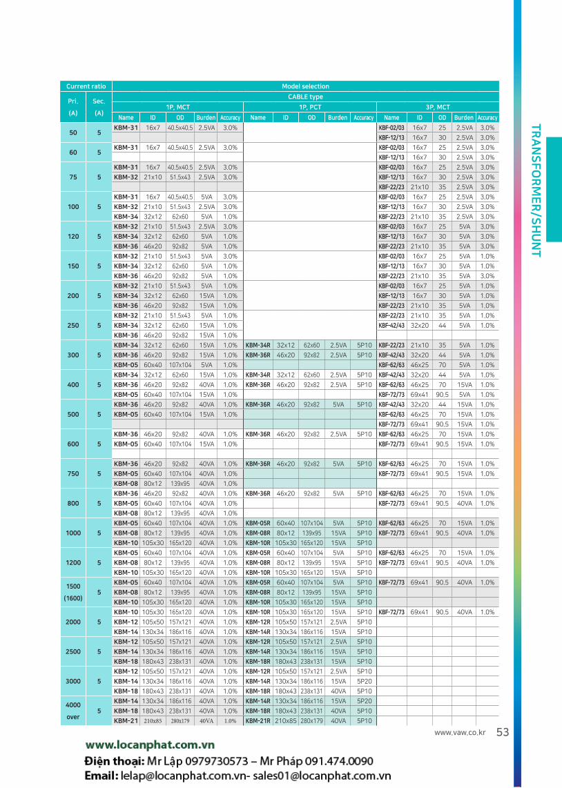
Current ratio Model selection
Pri.
(A)
Sec.
(A)
CABLE type
1P, MCT 1P, PCT 3P, MCT
Name ID OD Burden Accuracy Name ID OD Burden Accuracy Name ID OD Burden Accuracy
50 5KBM-31 16x7 40.5x40.5 2.5VA 3.0% KBF-02/03 16x7 25 2.5VA 3.0%
KBF-12/13 16x7 30 2.5VA 3.0%
60 5KBM-31 16x7 40.5x40.5 2.5VA 3.0% KBF-02/03 16x7 25 2.5VA 3.0%
KBF-12/13 16x7 30 2.5VA 3.0%
75 5
KBM-31 16x7 40.5x40.5 2.5VA 3.0% KBF-02/03 16x7 25 2.5VA 3.0%
KBM-32 21x10 51.5x43 2.5VA 3.0% KBF-12/13 16x7 30 2.5VA 3.0%
KBF-22/23 21x10 35 2.5VA 3.0%
100 5
KBM-31 16x7 40.5x40.5 5VA 3.0% KBF-02/03 16x7 25 2.5VA 3.0%
KBM-32 21x10 51.5x43 2.5VA 3.0% KBF-12/13 16x7 30 2.5VA 3.0%
KBM-34 32x12 62x60 5VA 1.0% KBF-22/23 21x10 35 2.5VA 3.0%
120 5
KBM-32 21x10 51.5x43 2.5VA 3.0% KBF-02/03 16x7 25 5VA 3.0%
KBM-34 32x12 62x60 5VA 1.0% KBF-12/13 16x7 30 5VA 3.0%
KBM-36 46x20 92x82 5VA 1.0% KBF-22/23 21x10 35 5VA 3.0%
150 5
KBM-32 21x10 51.5x43 5VA 3.0% KBF-02/03 16x7 25 5VA 1.0%
KBM-34 32x12 62x60 5VA 1.0% KBF-12/13 16x7 30 5VA 1.0%
KBM-36 46x20 92x82 5VA 1.0% KBF-22/23 21x10 35 5VA 3.0%
200 5
KBM-32 21x10 51.5x43 5VA 1.0% KBF-02/03 16x7 25 5VA 1.0%
KBM-34 32x12 62x60 15VA 1.0% KBF-12/13 16x7 30 5VA 1.0%
KBM-36 46x20 92x82 15VA 1.0% KBF-22/23 21x10 35 5VA 1.0%
250 5
KBM-32 21x10 51.5x43 5VA 1.0% KBF-22/23 21x10 35 5VA 1.0%
KBM-34 32x12 62x60 15VA 1.0% KBF-42/43 32x20 44 5VA 1.0%
KBM-36 46x20 92x82 15VA 1.0%
300 5
KBM-34 32x12 62x60 15VA 1.0% KBM-34R 32x12 62x60 2.5VA 5P10 KBF-22/23 21x10 35 5VA 1.0%
KBM-36 46x20 92x82 15VA 1.0% KBM-36R 46x20 92x82 2.5VA 5P10 KBF-42/43 32x20 44 5VA 1.0%
KBM-05 60x40 107x104 5VA 1.0% KBF-62/63 46x25 70 5VA 1.0%
400 5
KBM-34 32x12 62x60 15VA 1.0% KBM-34R 32x12 62x60 2.5VA 5P10 KBF-42/43 32x20 44 5VA 1.0%
KBM-36 46x20 92x82 40VA 1.0% KBM-36R 46x20 92x82 2.5VA 5P10 KBF-62/63 46x25 70 15VA 1.0%
KBM-05 60x40 107x104 15VA 1.0% KBF-72/73 69x41 90.5 5VA 1.0%
500 5
KBM-36 46x20 92x82 40VA 1.0% KBM-36R 46x20 92x82 5VA 5P10 KBF-42/43 32x20 44 15VA 1.0%
KBM-05 60x40 107x104 15VA 1.0% KBF-62/63 46x25 70 15VA 1.0%
KBF-72/73 69x41 90.5 15VA 1.0%
600 5
KBM-36 46x20 92x82 40VA 1.0% KBM-36R 46x20 92x82 2.5VA 5P10 KBF-62/63 46x25 70 15VA 1.0%
KBM-05 60x40 107x104 15VA 1.0% KBF-72/73 69x41 90.5 15VA 1.0%
750 5
KBM-36 46x20 92x82 40VA 1.0% KBM-36R 46x20 92x82 5VA 5P10 KBF-62/63 46x25 70 15VA 1.0%
KBM-05 60x40 107x104 40VA 1.0% KBF-72/73 69x41 90.5 15VA 1.0%
KBM-08 80x12 139x95 40VA 1.0%
800 5
KBM-36 46x20 92x82 40VA 1.0% KBM-36R 46x20 92x82 5VA 5P10 KBF-62/63 46x25 70 15VA 1.0%
KBM-05 60x40 107x104 40VA 1.0% KBF-72/73 69x41 90.5 40VA 1.0%
KBM-08 80x12 139x95 40VA 1.0%
1000 5
KBM-05 60x40 107x104 40VA 1.0% KBM-05R 60x40 107x104 5VA 5P10 KBF-62/63 46x25 70 15VA 1.0%
KBM-08 80x12 139x95 40VA 1.0% KBM-08R 80x12 139x95 15VA 5P10 KBF-72/73 69x41 90.5 40VA 1.0%
KBM-10 105x30 165x120 40VA 1.0% KBM-10R 105x30 165x120 15VA 5P10
1200 5
KBM-05 60x40 107x104 40VA 1.0% KBM-05R 60x40 107x104 5VA 5P10 KBF-62/63 46x25 70 15VA 1.0%
KBM-08 80x12 139x95 40VA 1.0% KBM-08R 80x12 139x95 15VA 5P10 KBF-72/73 69x41 90.5 40VA 1.0%
KBM-10 105x30 165x120 40VA 1.0% KBM-10R 105x30 165x120 15VA 5P10
1500
(1600)5
KBM-05 60x40 107x104 40VA 1.0% KBM-05R 60x40 107x104 5VA 5P10 KBF-72/73 69x41 90.5 40VA 1.0%
KBM-08 80x12 139x95 40VA 1.0% KBM-08R 80x12 139x95 15VA 5P10
KBM-10 105x30 165x120 40VA 1.0% KBM-10R 105x30 165x120 15VA 5P10
2000 5
KBM-10 105x30 165x120 40VA 1.0% KBM-10R 105x30 165x120 15VA 5P10 KBF-72/73 69x41 90.5 40VA 1.0%
KBM-12 105x50 157x121 40VA 1.0% KBM-12R 105x50 157x121 2.5VA 5P10
KBM-14 130x34 186x116 40VA 1.0% KBM-14R 130x34 186x116 15VA 5P10
2500 5
KBM-12 105x50 157x121 40VA 1.0% KBM-12R 105x50 157x121 2.5VA 5P10
KBM-14 130x34 186x116 40VA 1.0% KBM-14R 130x34 186x116 15VA 5P10
KBM-18 180x43 238x131 40VA 1.0% KBM-18R 180x43 238x131 15VA 5P10
3000 5
KBM-12 105x50 157x121 40VA 1.0% KBM-12R 105x50 157x121 2.5VA 5P10
KBM-14 130x34 186x116 40VA 1.0% KBM-14R 130x34 186x116 15VA 5P20
KBM-18 180x43 238x131 40VA 1.0% KBM-18R 180x43 238x131 40VA 5P10
4000
over5
KBM-14 130x34 186x116 40VA 1.0% KBM-14R 130x34 186x116 15VA 5P20
KBM-18 180x43 238x131 40VA 1.0% KBM-18R 180x43 238x131 40VA 5P10
KBM-21 210x85 280x179 40VA 1.0% KBM-21R 210x85 280x179 40VA 5P10

TR
AN
SF
OR
ME
R/S
HU
NT
54
Rated current
Frame
ACB TerminalBus bar size CT No.
200A
1600AF
AN-D
AS-D
15tX50X1EA
5tX50X1EA
KBM-05
400A
630A5tX50X2EA
10tX60X1EA
800A6tX50X2EA
10tX60X1EA
1000A 8tX50X2EA
1250A
6tX75X2EA ①KBM-12
8tX50X2EAKBM-05
10tX50X2EA
1600A
6tX75X3EA ①KBM-12
10tX60X2EAKBM-05
8tX60X3EA
2000A
2000AF
AS-D
15tX50X1EA
8tX75X3EA KBM-12
10tX100X2EA ②KBM-12
630A
3200AF
AN-E
AS-E
20tX75X1EA
5tX50X2EA
10tX60X1EA
800A6tX50X2EA
10tX60X1EA
1000A 8tX50X2EA
1250A
6tX75X2EA
8tX60X2EA
10tX50X2EA
1600A
6tX75X3EA
10tX60X2EA
8tX60X3EA
2000A8tX75X3EA
10tX100X2EA
2500A10tX75X3EA
8tX75X4EA ①KBM-21
3200A10tX100X3EA ②KBM-12
10tX75X4EA ①KBM-21
4000A
4000AF
AS-E
10tX100X3EA
10tX100X4EA
KBM-18
10tX75X5EA
4000A 5000AF
AS-D
20tX125X2EA
10tX100X4EA
5000A 10tX125X4EA
4000A 6300AF
AS-G
20tX125X2EA
20tX150X2EA
10tX100X4EA
5000A 10tX125X4EA
6300A 10tX150X4EA
Recommended CT per ACB type
LSIS HHI
Rated current
Frame
ACB TerminalBus bar size CT No.
200A
A Frame
UAS/UAN
06-16
15tX50X1EA
5tX50X1EA
KBM-05
400A
630A5tX50X2EA
10tX60X1EA
800A6tX50X2EA
10tX60X1EA
1000A 8tX50X2EA
1250A
6tX75X2EA ①KBM-12
8tX60X2EAKBM-05
10tX50X2EA
1600A
6tX75X3EA ①KBM-12
10tX60X2EAKBM-05
8tX60X3EA
2000A
A Frame
UAN20
15tX75X1EA
8tX75X3EA KBM-12
10tX100X2EA ②KBM-12
630A
B Frame
UAS/UAN
06-25
20tX75X1EA
5tX50X2EA
10tX60X1EA
800A6tX50X2EA
10tX60X1EA
1000A 8tX50X2EA
1250A
6tX75X2EA
8tX60X2EA
10tX50X2EA
1600A
6tX75X3EA
10tX60X2EA
8tX60X3EA
2000A8tX75X3EA
10tX100X2EA
2500A10tX75X3EA
8tX75X4EA
3200A10tX100X3EA
10tX75X4EA
4000A
B Frame
UAN40
15tX100X1EA
10tX100X4EA
KBM-18
10tX125X3EA
4000A
B Frame
UAN40
15tX125X1EA
10tX100X4EA
10tX100X3EA
3200A C Frame
UAN32-50
20tX90X1EA
10tX125X3EA
4000A 10tX100X4EA
5000A 10tX125X4EA
4000A C Frame
UAN32-50
20tX90X1EA
10tX100X4EA
5000A 10tX125X4EA
6300A 10tX150X4EA
B Frame
UAN3220tX90X1EA
KBM-05
KBM-05
KBM-05
KBM-05
KBM-05
KBM-12
KBM-12
KBM-12
KBM-12
KBM-12
②KBM-12
②KBM-12
①KBM-21
①KBM-21
① Busbar bent is recommended for 3P4W
KBM-12
② Busbar bent is recommended

TR
AN
SF
OR
ME
R/S
HU
NT
55www.vaw.co.kr
① For ACB ② Circuit ③ Terminal ④ Use
2 3P2W(2CT) 0 Current transformer N/A For meter
3 3P4W(3CT) 1 Voltage detector + current transformer R OCR Type
2 Temperature sensor + current transformer
3 Temperature sensor + voltage detector + current transformer
Model No.
KBF -7① ② ③ ④
Feature
Suitable design for various ACB type (200-1600A)
Temperature sensor for bus bar temperature(option)/Voltage detector for checking energization (option)
Dimension
Specification
Classification Secondary current Overcurrent strength Maximum voltage Withstand voltage Rated frequency
Contents 5A or 1A 40In 1.15kV 4 kV / 1 min 50/60Hz
Remarks Secondary output 1A can be ordered for 1000A over only
Use For Measure (1.0 CL, MCT) For OCR(PCT)
Burden 5VA 15VA 40VA 2.5VA 5VA
Primary current 200~400A 500~750A 800~2000A 250~600A 750~1000A
Description
Secondary terminal
Secondary terminal
LED indication and voltage terminal
Voltage contact for voltage detector
Temperature Sensor output
Temperature Sensor point
Bus Bar
ACBTERMINAL
Width: 64mm
LS, Hyundai, Ki Sung, Gyeong-dong if using 60mm bus for ACB terminals, place R on the left side of the section, T and N on the right side of the terminal and assemble.
O-Sung Electric Machinery if using a 60mm bus bar on the ACB terminal, place it in the center of the terminal and assemble it.
Vitzro- If using 1 60mm busbar on ACB terminal, place R on the right side of the terminal and T phase is placed on the left side of the terminal and assembled.
Dimensions (Unit: mm)
KBF-7
A' 41
B' 69
B'' 61
C' 19
C'' 25.5
D' 288
E' 105
3Phase CT For ACB
Certificates
Torque limit for current transformer fixing bolt: M4 - 5~7 kgfㆍcm, M5 - 7~10kgfㆍcm

TR
AN
SF
OR
ME
R/S
HU
NT
56
3Phase Window Type Current Transformer
OPTIMIZED DESIGN FOR CIRCUIT BREAKER
Certificates
3Phase Window Type Current Transformer
Circuit Type Size
For meter(MCT) For EOCR(PCT)
Current(A)Class(%)
Current(A) Class(1.0)
2.5VA 5VA 15VA 1.5VA 2.0VA 2.5VAOvercurrent
constant
3P3W
(2CT)
100AF
0250~75 100 - 3.0
150~200 - - 5P5- 120~200 - 1.0
1250~75 100 - 3.0
150~200 - - 5P5- 120~200 - 1.0
12S50~75 80 - 3.0 100~150 - - 5P5
- 100~200 - 1.0 200 - - 5P10
250AF 2275~120 150 - 3.0
150~350 - - 5P5- 200~300 - 1.0
400AF 42 - 200~400 500 1.0 200~400- - 5P5
- - 5P10
600AF 62 - 300 400~1200 1.0 300 350~500 600~1000 5P10
3P4W
(3CT)
100AF
0350~100 120 - 3.0
150~200 - - 5P5- 150~200 - 1.0
1350~100 120 - 3.0
150~200- -
5P5- 150~200 - 1.0 - -
13S50~75 80 - 3.0 100~150
- -5P5
- 100~200 - 1.0 200 5P10
250AF 2375~120 150 - 3.0
150~250 - - 5P5- 200~300 - 1.0
400AF 43 - 200~400 500 1.0 200~400- - 5P5
- - 5P10
600AF800AF
1000AF1200AF
63 - 300 400~1200 1.0 300 350~500 600~1000 5P10
How to order Example) KBF-12 100/5 A, 5 VA, 3.0 class, KBF-43 600/5 A, 15 VA, 1.0 class
Customized product can be produced by order.
These products are designed for standard circuit breakers
① Size ② Use
See the table below N/A For meter(MCT)
E For EOCR(PCT)
Model No.
KBF -① ②
Selection table
Specification
Secondary current Overcurrent strength Maximum voltage Withstand voltage Frequency
5A OR 1A 40times 1.15kV 4.0 kV / 1 min 50/60Hz

TR
AN
SF
OR
ME
R/S
HU
NT
57www.vaw.co.kr
3P3W, 3P4W Recommended CT per CB frame size(For EOCR)
Circuit breaker
50AF 100AF 250AF 400AF600/800
1000/1200AF
Circuit3P3W(2CT)
3P4W(3CT)
3P3W(2CT)
3P4W(3CT)
3P3W(2CT)
3P4W(3CT)
3P3W(2CT)
3P4W(3CT)
3P3W(2CT)
3P4W(3CT)
3P3W(2CT)
3P4W(3CT)
TypeKBF -02E
KBF -03E
KBF -12E
KBF -13E
KBF -12SE
KBF -13SE
KBF -22E
KBF -23E
KBF -42E
KBF -43E
KBF -62E
KBF -63E
1.5VA 1.0
[5P5]
150~
200A
150~
200A
150~
200A
150~
200A
100~
200A
100~
200A
150~
350A
150~
250A
200~
400A
200~
400A-
1.5VA 1.0
[5P10]- - - - - - - - - - 300A 300A
2.0VA 1.0
[5P10]- - - - - - - - - -
350~
500A
350~
500A
2.5VA 1.0
[5P10]- - - - - - - - - -
600~
1000A
600~
1000A
3P3W, 3P4W Recommended CT per CB frame size(For Meter)
Circuit breaker
50AF 100AF 250AF 400AF600/800
1000/1200AF
Circuit3P3W(2CT)
3P4W(3CT)
3P3W(2CT)
3P4W(3CT)
3P3W(2CT)
3P4W(3CT)
3P3W(2CT)
3P4W(3CT)
3P3W(2CT)
3P4W(3CT)
3P3W(2CT)
3P4W(3CT)
TypeKBF -02
KBF -03
KBF -12
KBF -13
KBF -12S
KBF -13S
KBF -22
KBF -23
KBF -42
KBF -43
KBF -62
KBF -63
2.5VA 3.0
50~
75A
50~
100A
50~
75A
50~
100A
50~
75A
50~
75A
75~
120A
75~
120A- - - -
5VA 3.0
100A 120A 100A 120A 80A 80A 150A 150A - - - -
5VA 1.0
120~
200A
150~
200A
120~
200A
150~
200A
100~
200A
100~
200A
200~
300A
200~
300A
200~
400A
200~
400A300A 300A
15VA 1.0
- - - - - - - - 500A 500A400
~1200A
400~
1200A
Torque limit for bus bar fixing bolt : M4 - 5~7 kgfㆍcm, M5 - 7~10kgfㆍcm (Excess torque may cause bending and distortion)
Please be aware that bus bar fixing bolt for current transformer can be energized .
Bolt insulation covers are recommended for safety.

TR
AN
SF
OR
ME
R/S
HU
NT
58
Recommended CT per CB frame size
Example
CB frame size 50AF 100AF 250AF 400AF 600AF 800AF 1000AF 1200AF
A 4 4 7 16 14 20 25 25
B 17 15 *25 30 44 44 44 44
C 50 30 35 44 70 70 70 70
TypeKBF-02KBF-03
KBF-12/12S
KBF-13/13S
KBF-22/23
KBF-42/43
KBF-62/63
A' 7 7 10 20 25
B' 16 16 *21 30 46
C' 50 30 35 44 70
D' 7559/69
(12S,13S)57 57 57
Circuit breaker
Recommend
250 AF breaker terminal is 25mm(B), and B' is 21. Only if bus bar size is 20mm, KBF-23/23 can be fit.
Unit:mm
Drawing
KBF-02/03
7
Unit:mm
KBF-12/13,12S/13S,22/23/42/43,62/63
Safety cover
Dimension A B C D1XD2 E F G H
TYPE
KBF-12/13 122 102 30 7 X 16 60 59 49 52
KBF-12S/13S 122 102 30 7 X 16 60 69 59 52
KBF-22/23 139 119 35 10 x 21 70 57 47 52
KBF-42/43 168 149 44 20 x 30 88 57 47 70
KBF-62/63 237 218 70 25 X 46 140 57 47 85
Torque limit for bus bar fixing bolt : M4 - 5~7 kgfㆍcm, M5 - 7~10kgfㆍcm

TR
AN
SF
OR
ME
R/S
HU
NT
59www.vaw.co.kr
Split-Type Current Transformer
Certificates
① Size ② Mounting bracket
See the table below N/A None
S Mounting bracket included(Option)
Model No.
KBC-① ②
Size
For meter(50/60Hz) For OCR(50/60Hz)
Current(AT) Class(%)
Current(AT) Class(IEC)2.5VA 5VA 15VA 2.5VA 5VA
03
100~
150
100~
150- 3.0
100~
150- 5P5
-200
~300
350~
6001.0
200~
300
350~
6005P10
06 -400
~600
750~
15001.0
400~
600
750~
15005P10
Size
For meter(50/60Hz) For OCR(50/60Hz)
Current(AT) Class(%)
Current(AT) Class(IEC)5VA 15VA 2.5VA 5VA
05
150 - 3.0100
~150
- 5P5
200~
350
400~
6001.0
200~
300
350~
6005P10
12400
~600
750~
15001.0
400~
600
750~
15005P10
Selection table
How to order Example) KBC-03 200/5 A, 5 VA, 1.0%, KBC-06 S 600/5 A, 5 VA, 1.0 %
Drawing
117
61
41 11
4
12
6.5
42
2.5
64 2-M5153
50 12
0
105
13
2.5
44
2.5
66
KBC-03S(Cable)
KBC-05(Busbar) KBC-12(Busbar)
KBC-06S(Cable)
KBC-03S KBC-06S KBC-05 KBC-12(Busbar)(Busbar)(Cable)(Cable)
Specification
Maximum voltage Overcurrent strenght Withstand voltage Frequency Body material Weight
1.15kV 40Times 4.0 kV / 1 min 50/60HzFlame retardant case and polyester flame
retardant resin filling
KBC-03(1100g)KBC-06(1800g)
Customized product can be produced by order. Current transformer bolt torque : Refer to page 43
Unit:mm

TR
AN
SF
OR
ME
R/S
HU
NT
60
Current transformer for Energy meter
Certificates KEPCO (standard item) Bid Approved Item
(KERI test completed)
① Use
N/A Electricity utility meter
R For OCR
Model No.
KBK- 08①
Size
For meter(50/60Hz)
Primary current(AT) Class(%)15VA
08 75~1000 0.5W
For OCR(50/60Hz)
Primary current(AT) Class(%)5VA
150~1000 5P10
Feature
Easy cable installation with single bolt
Decrease electrical loss by using sectional spacious rod.
Minimize cable install space.
Secondary current
Maximum voltage
Rating burden
PolarityBody
materialRated
frequencyClass
Rated overcurrent
strengthWeight
5A230V
(1150V)15VA
(PF 0.8)Subtractive
polarity
Flame retardant
ABSResin
50/60Hz 0.5W 40In 2.5kg
Specification
Double ratio Single ratio
Primary current Contact sectionConductive
sectionPrimary current Contact section
Conductive section
150~75A300~150A400~200A500~250A
180 280150A250A400A
200A300A500A
180 280
1000~600A 940 1120750A
1000A600A800A
940 1120

TR
AN
SF
OR
ME
R/S
HU
NT
61www.vaw.co.kr
100
180
H:120
Drawing
Primary current A B
75~150 Φ20 Φ9
300~600 Φ20 Φ13
750~1000 Φ37 Φ13
Unit:mm
Unit:mmExamples
200AF
400AF 600AF
Single installation Type 1
110
H:120
50
H:120
H:120 H:120
180
240
220
200
190 240
Single installation Type 2
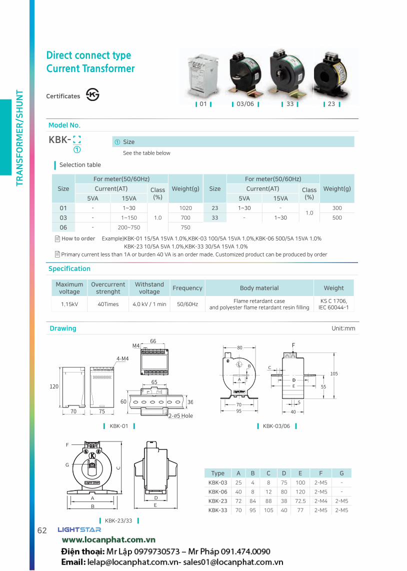
TR
AN
SF
OR
ME
R/S
HU
NT
62
Specification
Maximum voltage
Overcurrent strenght
Withstand voltage
Frequency Body material Weight
1.15kV 40Times 4.0 kV / 1 min 50/60HzFlame retardant case
and polyester flame retardant resin fillingKS C 1706,
IEC 60044-1
KBK-01
KBK-23/33
KBK-03/06
01 03/06 33 23
① Size
Model No.
KBK-①
Size
For meter(50/60Hz)
Weight(g)Current(AT) Class(%)5VA 15VA
01 - 1~30
1.0
1020
03 - 1~150 700
06 - 200~750 750
Size
For meter(50/60Hz)
Weight(g)Current(AT) Class(%)5VA 15VA
23 1~30 -1.0
300
33 - 1~30 500
Selection table
How to order Example)KBK-01 15/5A 15VA 1.0%,KBK-03 100/5A 15VA 1.0%,KBK-06 500/5A 15VA 1.0%
KBK-23 10/5A 5VA 1.0%,KBK-33 30/5A 15VA 1.0%
Primary current less than 1A or burden 40 VA is an order made. Customized product can be produced by order
Type A B C D E F G
KBK-03 25 4 8 75 100 2-M5 -
KBK-06 40 8 12 80 120 2-M5 -
KBK-23 72 84 88 38 72.5 2-M4 2-M5
KBK-33 70 95 105 40 77 2-M5 2-M5
Direct connect typeCurrent Transformer
Certificates
Drawing Unit:mm
See the table below

TR
AN
SF
OR
ME
R/S
HU
NT
63www.vaw.co.kr
Rogowski Coil CT
Model No.
KBA-30①
① Size (diameter Φ 30)
KBA-30 Rogoski coil
Overview
Because the welding current flows a large current (about 100 A - 50 KA) for a short time (0.001 sec - 0.5sec)
and its waveform is complicate. , it is impossible to measure with a normal meter and current transformer.
The Rogowski coil can measure large current without electric saturation.
For power and power factor, the phase shift is necessary (90 ° to 0 °) by the integrator (OP-AMP)
Feature
± 3% accuracy at any position inside coil.
Easy to use in small area, Minimize noise affect with shield cable.
Easy to measure overcurrent peak value or welding peak value (from 4000 A to 10000 A)
Specification
Current range 30A~4000A(Linearity±1%)
Rated output voltage
4000A/2.26V[0.6mV/A]
External connection resistance(at 6kΩ)
Withstand voltage
Conductive part and mounting
-2.5 kV 1 minute
Secondary wire
specification
Secondary shielded wire
[2x0.5]1.5m
Outer case material
Flame retardant case
Internal
: unsaturated polyester resin molding
Temperature range -25~+55
Drawing
Terminal
2 core twist shielded wire
Unit:mm

TR
AN
SF
OR
ME
R/S
HU
NT
64
Wireless clamp CT
① Range of measurement
01 4/40/200A 02 1/10/100/500A
Model No.
KBH -①
Example of order) KBH clamp CT
Overview
To measure the current of special high voltage live state.
This is a device that measures the current value of the primary current of MOF (Metering Out Fit) and transmits it to the main
body wirelessly.
The main body measures secondary current of MOF and compare primary and secondary.
Feature
To transmit the current value to main body wirelessly.
Various measuring range as per the size of current. [KBH-01 (3 steps): 4 A / 40 A / 200 A, KBH-02 (4 steps): 1 A / 10 A / 100 A / 500 A]
Clamp is designed to fit high voltage cable.
Insulated extension rod can be supplied as option.
Outline drawing
KBH-01
KBH-02
Unit:mm

TR
AN
SF
OR
ME
R/S
HU
NT
65www.vaw.co.kr
Condensor Discharging Coil
Model No.
KBN
Specification
Insulation resistance over 10MΩ Rated Voltage 380V
Discharging capacity 100kVA Circuit 3 phase
Operating voltage 1.1Vn(Average)Withstand voltage 2 kV / 1 min , 2Vn/120Hz 60sec
Temperature rise 50deg
Overview
Connected parallel with condenser(Capacitor), which used for Power factor controller.
To protect electrical devices from frequent turn ON/OFF by reducing electric charge collision.
Discharge characteristic graph(AC 380V, 100kVar)
16A
90ms
Connection diagram
F F F F F F
Case 1
Case 2
Drawing Unit:mm

TR
AN
SF
OR
ME
R/S
HU
NT
66
Single Phase Potential Transformer
Certificates
Specification
Type Burden Class Weight Body material
KBQ 50VA 1.0 2.0kg Flame retardant case
KBR50VA
1.0 3.5kg
Flame retardant case
and polyester flame retardant resin filling100VA 5.0kg
KBS 15VA 3.0 1.2kg
Specification
Frequency 60Hz(Standard), 50Hz(order)
Overvoltage factor 1.1 Vn Continuous/1.9Vn 30s
Induced withstand voltage
120HZ, 2 times of rated voltage 1 min
Rated fuse 500V, 2A
Model No.
KB -① ② ③
How to order Example)KBQ-1 220/110V
① Type ② Voltage ③ Rated burden
Q 1 220V/110V 1 15VA(KBS)
R 2 380V/110V 2 50VA(KBQ, KBR)
S 3 440V/110V 3 100VA(KBR)
4 460V/115V 4 Order-made
Order-made
Drawing Unit:mm
77 53
132110
KBQ KBR KBS
KBSKBQ KBR

TR
AN
SF
OR
ME
R/S
HU
NT
67www.vaw.co.kr
Single Phase Potential Transformer (ship)
Certificates
Model No.
KBT-① ②
① Voltage
Primary voltage Secondary voltage
1 220V 110V
2 380V 110V
3 440V 110V
4 460V 115V
0 Order-made
② Rated burden
1 15VA
2 50VA
3 100VA
0 Order-madeExample of order)KBT-11 220/110V 15VA
Customized product can be
produced by order.
Specification Drawing
Class 1.0
Rated burden
Follow the configuration.
Rated voltage
Follow voltage classification
Rated frequency
60 Hz (Standard), 50 Hz (order)
Overvoltage factor
1.1 Vn Continuous
Instantaneous rating
1.9Vn 30s
Withstand voltage
3 kV / 1 min
Induced withstand
voltage120HZ, 2 times of rated voltage 1 min
Rated fuse 500V, 2A
Body material
Flame retardant case
Burden
Size
15VA 50VA 100VA 200VA
H 122 138 145 164
W 90 111 120 137
D 109 109 109 109
a 68±1 68±1 93±1 88
b 74±1 93±1 102±1 120
c 15 10 18 18
d 5 5 5 5
Weight 2.5kg 3.5kg 5kg 7.8kg
Unit:mm
Connection diagram
F F
F F F F
F F F
1P2W 1P3W 3P3W 3P4W
In order to prevent transformer damage, we highly recommend not to connect groundings with PT.
information
2 units connected 2 units connected 3 units connected

TR
AN
SF
OR
ME
R/S
HU
NT
68
3Phase Potential Transformer
Certificates
Specification
Class 1.0Withstand voltage 3 kV / 1 min
Rated burden3P4W, 50VA(17VA X 3)
3P3W, 50VA(25VA X 2)Induced withstand
voltage120HZ, 2 times of rated voltage 1 min
Rated voltage Follow voltage classification Rated fuse 500V, 2A
Rated frequency 60 Hz (basic), 50 Hz (order)Body material
Flame retardant case
and polyester flame retardant resin fillingOvervoltage factor 1.1 Vn Continuous/1.9Vn 30s
Model No.
KBO-① ②
① Circuit ② Voltage
Primary voltage Secondary voltage
1 1P3W 1 220V 110V
2 3P3W
1 220V 110V
2 380V 110V
3 380V 220V
4 440V 110V
5 440V 220V
0 Order-made
3 3P4W1 380/√3V 190/√3V
0 Order-made
How to orderKBO-22 3P3W 380/110VKBO-31 3P4W 380√3/190√3V
Note 3P4W 380√3/190√3V
Customized product can be produced by order.
3P3W1P3W 3P4W
In order to prevent transformer damage, we highly recommend
not to connect groundings with PT.
Information
Drawing Connection diagram
F F F F F FF F F
Unit:mm
1 units connected 1 units connected 1 units connected
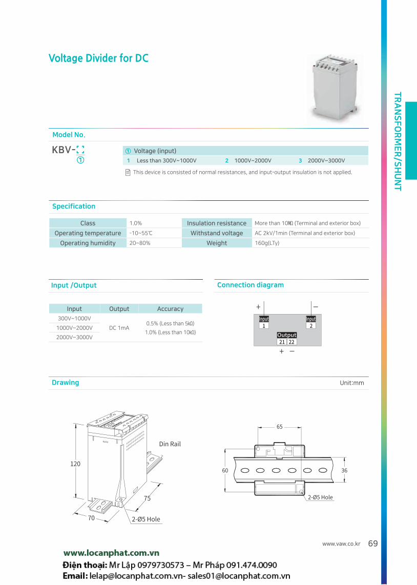
TR
AN
SF
OR
ME
R/S
HU
NT
69www.vaw.co.kr
Specification
Class 1.0% Insulation resistance More than 10 (Terminal and exterior box)
Operating temperature -10~55 Withstand voltage AC 2kV/1min (Terminal and exterior box)
Operating humidity 20~80% Weight 160g(LTy)
Voltage Divider for DC
Model No.
KBV-①
① Voltage (input)
1 Less than 300V~1000V 2 1000V~2000V 3 2000V~3000V
This device is consisted of normal resistances, and input-output insulation is not applied.
Input /Output Connection diagram
Input Output Accuracy
300V~1000V
DC 1mA0.5% (Less than 5)
1.0% (Less than 10)1000V~2000V
2000V~3000V
Drawing Unit:mm

TR
AN
SF
OR
ME
R/S
HU
NT
70
Model No.
KBG-① ② ③
① Primary voltage ② Secondary voltage ③ Tertiary voltage
1 380 /√3V 1 110 /√3V 1 190 /3V
2 440 /√3V 2 190 /√3V 2 110/3V
0 Order-made 0 Order-made 0 Order-made
How to order Example)KBG-111 380/√3V/110/√3V/190/3V
Customized product can be produced by order.
Specification
Primary voltageSecondary
voltageTertiary voltage Burden Class Freq. Over Voltage Factor
220/√3V
~
750/√3V
110/√3V
or
190/√3V
110/3V
or
190/3V
secondary
50VA
Tertiary
100VA
(1min)
KS C 1706 1.0
IEC 60044-2 1.0/3P
JEC 1201 1P/3G
Standard
60Hz
Option
50Hz
1.1Vn Continuous/ 1.9Vn 30s
Body material : Iron case Weight : 5kg
Overview
Drawing Unit:mm
Ground Potential Transformer
Certificates
Connection diagram
F F F
OVGR
Vo
1차측
2차측
3차측
3 units connected
To detect zero phase voltage for the case of un-grounded electrical system.
This item can be used with 3 sets together. Connection will be Y cabling for primary and secondary, and open-delta for Tertiary. Secondary
will be used for measuring and Tertiary used for zero phase voltage detection.
Also tertiary can be used for earth leakage lamp, CLR, SGR and DGR.

TR
AN
SF
OR
ME
R/S
HU
NT
71www.vaw.co.kr
Body material : Iron case
Current Limit Resister
Model No.
KBL-① ②
① GPT Primary voltage ② GPT Tertiary voltage
1 220/√3 5 480/√3 1 110/3
2 380/√3 6 3300/√3 2 190/3
3 440/√3 7 6600/√3
4 460/√3 0 Order-made
Customized product can be produced by order.How to order Example)KBL-31 440/√3V, 110/3
Connection diagram
Refer to page 70
Specification
Drawing Unit:mm
Overview
Used to operate SGR(Selective Ground Relay) or DGR(Directional Ground Relay) and installed at Tertiary of GPT. This item can absorb 3rd
harmonics, and restrain the neutral point error in un-grounded circuit and maintain stability of neutral point.
R xx Ig9
E1 n2=
- E1 : Primary voltage
- n : GPT Primary voltage ÷
Tertiary voltage
- Ig : 0.38
CLR resistance fomula
Ex) Primary 6600/√3, Tertiary 190/3
6600 9
(60.2)2 x 0.38x ≒ 25[Ω]R=
√3
Ex) Primary 440/√3, Tertiary 190/3
440 9
42 x 0.38x ≒ 374[Ω]R=
√3
Primary voltage[V],E1
Tertiary voltage
[V]
n (Pri/Ter)
CLR Value
[Ω]
CLR capacity
[W]
Allowable current
[A]
220/√3
190/3
2.0 748 1) 48 0.22
380/√3 3.5 433 1) 83 0.44
440/√3 4.0 374 1) 97 0.51
460/√3 4.2 358 1)101 0.53
480/√3 4.4 343 1)105 0.55
3300/√3 30.1 50 2)724 3.81
6600/√3 60.2 25 2)1448 7.62
Primary voltage[V],E1
Tertiary voltage
[V]
n (Pri/Ter)
CLR Value
[Ω]
CLR capacity
[W]
Allowable current
[A]
220/√3
110/3
3.5 251 1) 48 0.44
380/√3 6.0 145 1) 83 0.76
440/√3 6.9 125 1) 97 0.88
460/√3 7.2 120 1)101 0.92
480/√3 7.6 115 1)105 0.96
3300/√3 52.0 17 2)724 6.58
6600/√3 103.9 8 2)1448 13.16
Weight : 1300g 1) Continuous 2) Instanenous : 1min
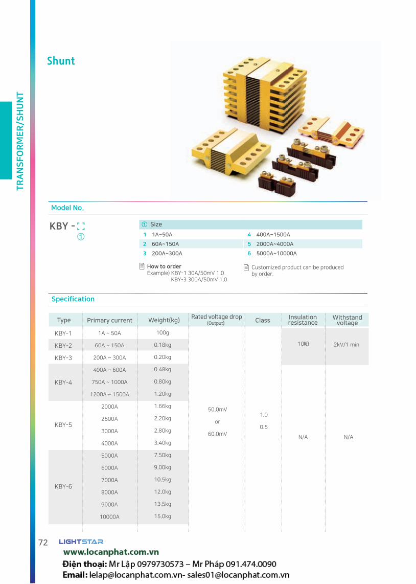
TR
AN
SF
OR
ME
R/S
HU
NT
72
Shunt
Primary current
1A ~ 50A
60A ~ 150A
200A ~ 300A
400A ~ 600A
750A ~ 1000A
1200A ~ 1500A
2000A
2500A
3000A
4000A
5000A
6000A
7000A
8000A
9000A
10000A
KBY-5
KBY-6
Weight(kg)
100g
0.18kg
0.20kg
0.48kg
0.80kg
1.20kg
1.66kg
2.20kg
2.80kg
3.40kg
7.50kg
9.00kg
10.5kg
12.0kg
13.5kg
15.0kg
Rated voltage drop
50.0mV
or
60.0mV
Class
1.0
0.5
Specification
Model No.
① Size
1 1A~50A 4 400A~1500A
2 60A~150A 5 2000A~4000A
3 200A~300A 6 5000A~10000A
How to order Example) KBY-1 30A/50mV 1.0 KBY-3 300A/50mV 1.0
Customized product can be produced by order.
Type Insulationresistance
Withstand voltage
N/A N/A
2kV/1 min
(Output)
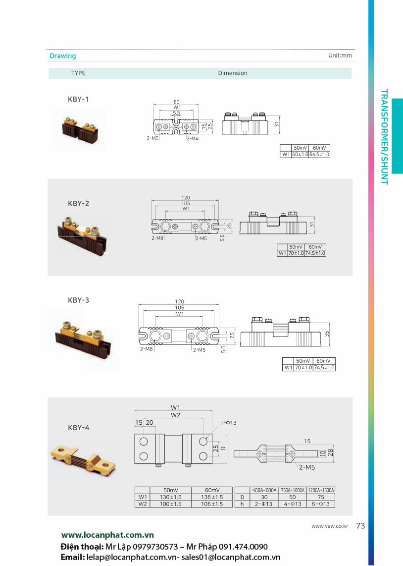
TR
AN
SF
OR
ME
R/S
HU
NT
73www.vaw.co.kr
Drawing
TYPE Dimension
Unit:mm

TR
AN
SF
OR
ME
R/S
HU
NT
74
blade count
Drawing
Current(A)
Sectionalarea()
Voltage drop table for 100 meter length(Unit: V)
TYPE Dimension
Unit:mm

TR
AN
SF
OR
ME
R/S
HU
NT
75www.vaw.co.kr
Usage guide
Design standard
Installation
If Shunt is used for 600 V or more, it is recommended to use insulator.
The terminal part of the shunt is brass, the voltage drop part is a manganese alloy, and the connecting material is a lead alloy.
When connecting the terminal part to the bus bar, tighten it with the specified bolt and do not apply force such as twisting,
compression, expansion and contraction to the connection part.
Shunt to be installed by considering air flow to cool shunt generated heat. and If natural air cooling is impossible,
the air circulation device is necessary.
Bus bar section area to be designed by considering voltage drop and heat.
Shunt protection equipment is required for electric short circuit.
Torque to Tighten Shunt Terminal Bolts : M4 - 9.8~13.5 kgfㆍcm, M5 - 28.4~37.2kgfㆍcm, M6 - 47.1~63.7kgfㆍcm,
M12 - 402~524kgfㆍcm
Shunt to be connected in parallel with the DC measuring instrument, and marked with rated current, rated voltage drop,
grade, serial number and manufacturer name.
The rated current means the measured maximum current. The rated drop is the voltage drop across the output terminal
when the maximum current is passed. And the rated current varies depending on the measuring instrument with 50mV
or 60mV or mainly.
The class of Shunt is classified at 0.5 or 1.0% at an allowable limit value through 80% of the rated current for 15 minutes.
Temperature rise
Rated current and actual usage
Operating time
Shunt generates heat proportional to the square value of the current.
For example, if the product is 1000 A / 50 mV, it generates 50 W when 1000 A is energized and 12.5W
when the current used is 500A.
In order to protect other equipments from heat, it is recommended to apart from devices and use a ventilator.
Shunt was designed to be used at 2/3 of rated current, or will be over the error limit.
If the temperature of Shunt exceeds 150 ˚ C, the resistance value is over the error limit.
In order to improve Shunt’s accuracy and stability, the rated current and voltage drop value are indicated,
and the temperature coefficient is ±0.0001...% between 40 and 60 C
Please select Shunt higher than the rated current under continuous current, and lower shunt can be selected under
incontinuous current.
If you use Shunt to measure the current of a surge or pulse waveform, please contact us.
Appropriate Shunt by instrument class
Instrument class
0.2
0.5
1.0
Instrument class
1.5
2.5
Shunt class
0.1
0.2
0.5
Shunt class
0.5~1.0
1.0

TR
AN
SF
OR
ME
R/S
HU
NT
76
Bus bar rated current
Rated current of bar E-Cu(DIN 43 671)
Continuous current for bus bar
Continuous current for bus bar
Correction ratio chart (as per DIN43671)
E-Cu material, indoor air temperature 35 ° C, bar temperature 65 ° C,
Vertical or horizontal position of bar. (Emissivity 0.4)
Co
rre
ctio
n f
act
or
k2
Am
b.
tem
p.
Bar temp.
Widthx
Thickness(mm)
Sectional area(mm)
Weight1)
Material cotton
2)
Continuous current
Less than AC 60Hz
DC + AC16
Normal Coated Normal Coated
12 X 2 23.5 0.209 108 123 108 123
15 X 2 29.5 0.262 128 148 128 148
15 X 3 44.5 0.396 162 187 162 187
20 X 2 39.5 0.351 162 189 162 189
20 X 3 59.5 0.529 204 237 204 237
20 X 5 99.1 0.882 274 319 274 320
20 X 10 199.0 1.770 427 497 428 499
25 X 3 74.5 0.663 245 287 245 287
25 X 5 124.0 1.110 327 384 327 384
30 X 3 89.5 0.796 285 337 286 337
30 X 5 149.0 1.330E-CuF30
379 447 380 448
30 X 10 299.0 2.660 573 676 579 683
40 X 3 119.0 1.060 366 435 367 436
40 X 5 199.0 1.770 482 573 484 576
40 X 10 399.0 3.550 715 850 728 865
50 X 5 249.0 2.220 583 697 588 703
50 X 10 499.0 4.440 852 1020 875 1050
60 X 5 299.0 2.660 688 826 696 836
60 X 10 599.0 5.330 985 1180 1020 1230
80 X 5 399.0 3.550 885 1070 902 1090
80 X 10 799.0 7.110 1240 1500 1310 1590
1) Density 8.9 kg / dm 32) Reference for continuous current value (AS per DIN 43 671)
1. To operate safely, keep the bus bar temperature at 85 ° C maximum
2. The temperature of the bus bar and bus bar system shall not exceed 40 ° C (Average 35 °C recommended).
3. Emissivity shown in the above table Values correspond to oxidized copper bars
4. Lower emissivity can be expected for IP 54 or higher.
5. If the emissivity is lower, the continuous current may be higher than the value of DIN 43 671 regardless air temperature
and bus bar temperature.
Note 1) Emissivity: Effectiveness in emitting energy as thermal radiation.
Example: For 30 X 10 mm (E - Cu F30) the rated current is IN65 = 573 A
When the air temperature is 20 ° C and the bar temperature is 65 ° C, the
correction factor is k2 = 1.29
IN85 = IN65 x k2
= 573A x 1.29 = 740A
References: RITTAL Catalog

DIGITAL METER
CE certification
CE stands for "Conformité Européene" and indicates conformity with health, safety,
and environmental protection standards for products sold within the European Economic Area (EEA).
Our CE certified products are complied to the requirements of EU Directives, relating to LVD
(Low Voltage Directives) and EMCD(Electro Magnetic Compatibility Directives).
LIGHTSTAR achieved CE certificate for Analog meter, Current Transformer, Digital meter, Power meter
and Transducers.
KS certification
KS stands for Korean Standard and indicates conformity
with Korean government required standards.
LIGHTSTAR achieved KS certificate for Analog meter, Current Transformer and Transducers.

Product structure and dimensions AC Current Meter
DC Current Meter
Frequency Meter
3Phase AC Current Meter
DC Watt·Hour Meter
Power Factor Meter
Connection diagram Digital LeakageCurrent Meter
3P AC Watt Meter AC Watt·Watthour Meter
Switch Digital Relay Meter
Push Button Digital Meter Relay
3Phase AC Voltage Meter Single Phase AC Watt/Hour Meter
Temperature Meter Integrator Meter
DC Voltage Meter Customized Indicating Meter
AC Voltage Meter

Digital Leakage Current Meter
Rectifier Switch Board Digital Meter
Panel Power Meter Panel Power Meter
Panel Power Meter Auto PF Controller
Power Quality Meter
AC 3P V·A Meter AC 3P V·A Meter V·Hz Relay Meter
V·Hz Relay Meter Advanced Panel Power Meter Energy Management Device
Panel Power Meter Panel Power Meter
Auto PF Controller
Harmonic Meter Relay Demand Controller

DIG
ITA
L M
ET
ER
80
Product structure and dimensions
KD ( ) ( )
Model No.
① ③ ④②
① LIGHTSTAR PRODUCT
② Digital Meter
③ Function
P-A AC Current Meter G 3Φ AC Watt Meter O AC 3Φ V A Meter W AC Watt .Watthour Meter
P-B AC Voltage Meter H Power Factor Meter P-R Push Button Digital Meter Relay
X Panel Power Meter
P-C DC Current Meter J Integrator Meter Q Power Quality Meter Y Panel Power Meter
P-D DC VoltageMeter L Single Phase AC Watt Meter
R Switch Digital Relay Meter
S Digital Leakage Current Meter
E Customized Indicating Meter
M DC Watt Meter U V Hz Relay Meter
F Frequency Meter N Temperature Meter
V Rectifier base digital instrument
④ Others
Type Front Side Panel cut
A-1
A-2
B
C
D
E
140
Drawing Unit : mm

DIG
ITAL M
ET
ER
81www.vaw.co.kr
Term
3 1/2 line (1999)
3: Numbers(0~9) can be displayed at 3 digits
from the right
1/2 : Numbers(0 or 1) can be displayed at the
first digit from the left
4 1/2 line (19999)
Numbers(0~9) can be displayed at 4 digits from
the right
Numbers(0 or 1) can be displayed at the first digit
from the left
3 3/4 line (3999)
Numbers(0~9) can be displayed at 3 digits from
the right
Numbers(0 ~ 3) can be displayed at the first digit
from the left
RMS value
In case DC and AC to be connected same circuit
and the power consumption is same
DC value is the RMS value of sinusoidal wave.
VrmsV peak
2
Insulation Resistance test
Test with DC voltage more than 500V between input and output, input and human contacted area , input and
source, caused by switching capacitive burden or Inductive burden
Fast transient/Burst immunity test
Test with bursts and fast transients, caused by switching capacitive burden or Inductive burden.
Measuring interval
Calculating time from the measured value of circuit.
Average value
The value obtained by averaging the AC voltage for one period.
Vav2V peak
π
Accuracy
As the limit of the error specified by the manufacturer,
It is indicated by rdg or FS error rate.
rdg(reading)
-1 100(%)
Error rate
Standard meter reading Value - Test meter reading Value
Maximum value of meter
( )x100(%)
± 2 digit
The lowest digit of measured value have tolerances
up to ±2
Surge impulse test
Test intended for the lightening surge conditions, and to be performed with voltage(1.2,50) and current (8, 20)
on source power by tester.
Voltage waveform Current waveform
Increase : 30%~90%, of Vpk 1.2
Decrease : By 50% of Vpk 50
Increase : 10%~90%, of Vpk 8
Decrease : By 50% of Vpk 20
* Vrms : RMS value
* V peak : Peak value
* Vav : Average value
* V peak : Peak value
Standard meter reading value
Test meter reading value
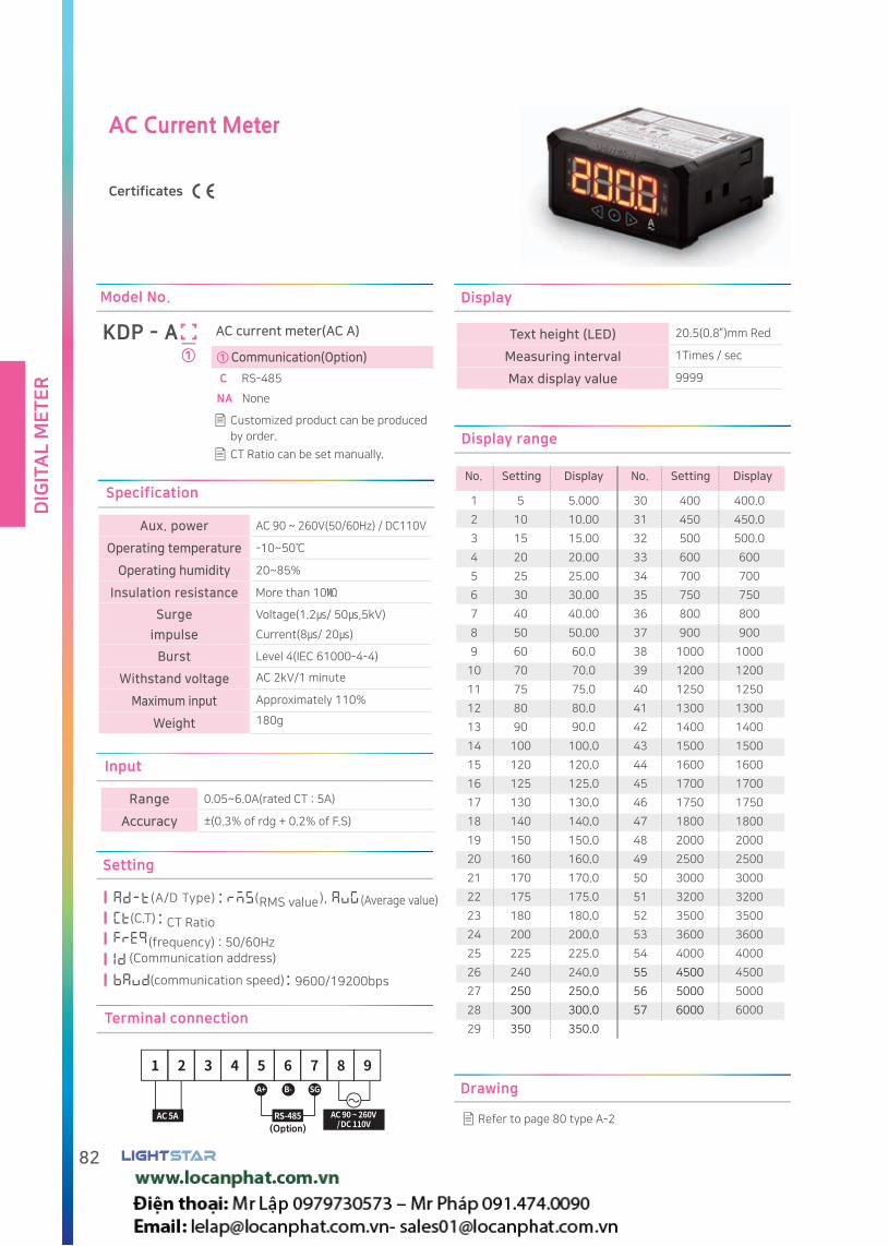
DIG
ITA
L M
ET
ER
82
AC Current Meter
Certificates
Refer to page 80 type A-2
Drawing
KDP - A AC current meter(AC A)
Customized product can be produced
by order.
CT Ratio can be set manually.
Model No.
① Communication(Option)
C RS-485
NA None
①
Terminal connection
(Option)
Setting
::
: 9600/19200bps
(Communication address)
(communication speed)
No. Setting Display
1
2
3
4
5
6
7
8
9
10
11
12
13
14
15
16
17
18
19
20
21
22
23
24
25
26
27
28
29
30
31
32
33
34
35
36
37
38
39
40
41
42
43
44
45
46
47
48
49
50
51
52
53
54
55
56
57
5
10
15
20
25
30
40
50
60
70
75
80
90
100
120
125
130
140
150
160
170
175
180
200
225
240
250
300
350
400
450
500
600
700
750
800
900
1000
1200
1250
1300
1400
1500
1600
1700
1750
1800
2000
2500
3000
3200
3500
3600
4000
4500
5000
6000
5.000
10.00
15.00
20.00
25.00
30.00
40.00
50.00
60.0
70.0
75.0
80.0
90.0
100.0
120.0
125.0
130.0
140.0
150.0
160.0
170.0
175.0
180.0
200.0
225.0
240.0
250.0
300.0
350.0
400.0
450.0
500.0
600
700
750
800
900
1000
1200
1250
1300
1400
1500
1600
1700
1750
1800
2000
2500
3000
3200
3500
3600
4000
4500
5000
6000
No.
Display range
Setting Display
Specification
Aux. power AC 90 ~ 260V(50/60Hz) / DC110V
Operating temperature -10~50
Operating humidity 20~85%
Insulation resistance More than 10
Surge
impulse
Voltage(1.2/ 50,5kV)
Current(8/ 20)
Burst Level 4(IEC 61000-4-4)
Withstand voltage AC 2kV/1 minute
Maximum input Approximately 110%
Weight 180g
Input
Range 0.05~6.0A(rated CT : 5A)
Accuracy ±(0.3% of rdg + 0.2% of F.S)
Display
Text height (LED) 20.5(0.8”)mm Red
Measuring interval 1Times / sec
Max display value 9999
RMS value (Average value)
CT Ratio
(frequency) : 50/60Hz

DIG
ITAL M
ET
ER
83www.vaw.co.kr
AC Voltage Meter
Certificates
Refer to page 80 Type A-2
Drawing
KDP - B AC Voltage Meter(AC V)
①
Model No.
PT ratio can be set manually.
Terminal connection
(Option)
Setting Apply / Displayed UnitNo.
1
2
3
4
5
6
7
8
9
10
11
12
13
14
220
380
440
460
480
3300
6600
7200
11000
11400
22000
22900
66000
154000
220.0
380.0
440.0
460.0
480.0
3300
6.60
7.20
11.00
11.40
22.00
22.90
66.0
154.0
V
kV
Display range
In case of special order, primary and secondary voltages can be set manually other than the table above.
Unit :mm
(P.T) PT primary voltage
(INPUT), Input value(500/190/110V)
Setting
(Communication address)
:
::
Specification
Aux. power AC 90 ~ 260V(50/60Hz) / DC110V
Operating tem-
perature-10~50
Operating humidity 20~85%
Insulation
resistanceMore than 10
Surge
impulse
Voltage(1.2/ 50,5kV)
Current(8/ 20)
Burst Level 4(IEC 61000-4-4)
Withstand voltage AC 2kV/1 minute
Maximum input Approximately 110% of each
Weight 180g
Input
Range 30~500V(rated PT:100 or 190V)
Accuracy ±(0.3 of rdg + 0.2% of F.S)
Display
Text height (LED) 20.5(0.8”)mm Red
Measuring interval 1Times / sec
Max display value 9999
RMS value
Average value
(frequency) : 50/60Hz
(Communication speed) : 9600/19200bps
① Communication(Option)
C RS-485
NA None

DIG
ITA
L M
ET
ER
84
DC Current Meter
Certificates
No. setting settingDisplay Display
1
2
3
4
5
6
7
8
9
10
11
12
13
14
15
16
17
18
19
20
21
22
23
24
25
26
27
28
29
30
31
32
33
34
35
36
37
38
39
40
41
42
43
44
45
46
47
48
49
50
51
52
53
54
55
56
57
5
10
15
20
25
30
40
50
60
70
75
80
90
100
120
125
130
140
150
160
170
175
180
200
225
240
250
300
350
400
450
500
600
700
750
800
900
1000
1200
1250
1300
1400
1500
1600
1700
1750
1800
2000
2500
3000
3200
3500
3600
4000
4500
5000
6000
5.000
10.00
15.00
20.00
25.00
30.00
40.00
50.00
60.0
70.0
75.0
80.0
90.0
100.0
120.0
125.0
130.0
140.0
150.0
160.0
170.0
175.0
180.0
200.0
225.0
240.0
250.0
300.0
350.0
400.0
450.0
500.0
600
700
750
800
900
1000
1200
1250
1300
1400
1500
1600
1700
1750
1800
2000
2500
3000
3200
3500
3600
4000
4500
5000
6000
No.
Display range
Refer to page 80 type A-2
Drawing
KDP - C DC Current Meter (DC A)
①
Model No.
Customized product can be produced
by order.
Shunt ratio can be set manually.
Setting
(SHUNT) CT Ratio
Input value(50/60mV)
(Communication address)
(Communication speed) : 9600/19200bps
:
:
Terminal connection
(Option)
Specification
Aux. power AC 90 ~ 260V(50/60Hz) / DC110V
Operating temperature -10~50
Operating humidity 20~85%
Insulation resistance More than 10
Surge impulseVoltage(1.2/ 50,5kV)
Current(8/ 20)
Burst Level 4(IEC 61000-4-4)
Withstand voltage AC 2kV/1 minute
Maximum inputApproximately 110% of each
measurement input
Weight 180g
Input
Range-60~+60mV
(Rated Shunt : 50 or 60mV)
Accuracy ±(0.3% of rdg + 0.2% of F.S)
Display
Text height (LED) 20.5(0.8”)mm Red
Measuring interval 2Times / sec
Max display value 9999
① Communication(Option)
C RS-485
NA None

DIG
ITAL M
ET
ER
85www.vaw.co.kr
DC Voltage Meter
Certificates
No.
1
2
3
Setting
500
50
5
Display
500.0
50.00
5.000
Display range
Refer to page 80 Type A-2
Drawing
Terminal connection
(Option)
Specification
Aux. power AC 90 ~ 260V(50/60Hz) / DC110V
Operating temperature
-10~50
Operating humidity
20~85%
Insulation resistance
More than 10
Surge impulse
Voltage(1.2/ 50,5kV)
Current(8/ 20)
Burst Level 4(IEC 61000-4-4)
Withstand voltage
AC 2kV/1 minute
Maximum inputApproximately 110% of each
measurement input
Weight 180g
Input
Range
2.0~500V
0.2~50V
0.02~5V
Accuracy ±(0.3% of rdg + 0.2% of F.S)
Display
Text height (LED) 20.5(0.8”)mm Red
Measuring interval 2Times / sec
Max display value 9999
KDP - D DC Voltage Meter(DC V)
Model No.
Customized product can be
produced by order.
The voltage divider primary can be set manually.
①
: Input value(5/50/500V)
Setting
(Communication address)
(Communication speed) : 9600/19200bps
① Communication(Option)
C RS-485
NA None

DIG
ITA
L M
ET
ER
86
Customized Indicating Meter
Certificates
Refer to page 80 Type A-2
Drawing
① Input ② Input ③ Unit
A AC current 1 0~50mV 0 Order made
B AC voltage 2 ±50mV 1 kW Power
C DC current 3 0~10V 2 Temperature
D DC voltage 4 0~150V 3 V Voltage
5 4~20mA 4 A Current
6 0~1mA 5 Hz Frequency
7 0~10mA 6 m Distance
8 0~20mA 7 kg/ Pressure
0 Order made 8 % Ratio or percentage (power factor)
9 m/sec Speed
10 g Weight
11 rpm Rotation speed
KDE -
How to order
KDE-D311 DC voltage/1800rpm/ DC 0~10V
Customized product can be produced by order.
Model No.
① ② ③
Connection diagram
Proximity switch
Aux. power
Potentiometric resistor
Input
Tachometer
Tranducer(4~20mA output or others)
Display
Text height (LED) 20.5(0.8”)mm Red
Measuring interval 2.5Times / sec
Max display value 9999
Specification
Aux. powerAC 90 ~ 260V(50/60Hz) / DC110V
DC 24V±10%(Option)
Operating temperature
-10~50
Operating humidity
20~85%
Insulation resistance
More than 10
Surge impulseVoltage(1.2/ 50,5kV)
Current(8/ 20)
Withstand voltage
AC 2kV/1 minute
Maximum input 150% 10seconds
Weight 250g
Input
Range
DC current
0~1mA, 4~20mA, 0~10mA, 0~20mA
DC voltage
0~50mV, ±50mV, 0~10V, 0~150V
Accuracy ±(0.3% of rdg + 0.2% of F.S)
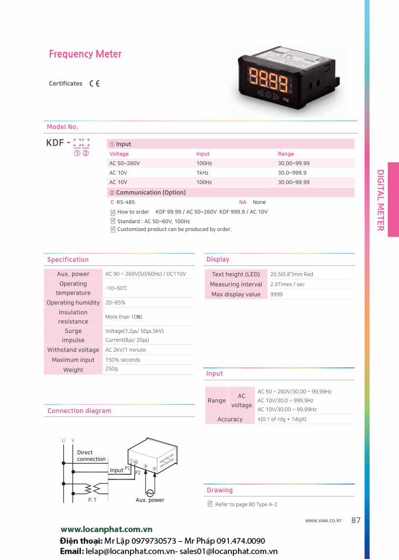
DIG
ITAL M
ET
ER
87www.vaw.co.kr
Frequency Meter
Certificates
Refer to page 80 Type A-2
Drawing
Connection diagram
④
Directconnection
Aux. power
Input
① Input
Voltage Input Range
AC 50~260V 100Hz 30.00~99.99
AC 10V 1kHz 30.0~999.9
AC 10V 100Hz 30.00~99.99
KDF -
How to order KDF 99.99 / AC 50~260V KDF 999.9 / AC 10V
Standard : AC 50~60V, 100Hz
Customized product can be produced by order.
Model No.
① ②
② Communication (Option)
C RS-485 NA None
Display
Text height (LED) 20.5(0.8”)mm Red
Measuring interval 2.5Times / sec
Max display value 9999
Specification
Aux. power AC 90 ~ 260V(50/60Hz) / DC110V
Operating
temperature-10~50
Operating humidity 20~85%
Insulation
resistanceMore than 10
Surge
impulse
Voltage(1.2/ 50,5kV)
Current(8/ 20)
Withstand voltage AC 2kV/1 minute
Maximum input 150% seconds
Weight 250gInput
RangeAC
voltage
AC 50 ~ 260V/30.00 ~ 99.99Hz
AC 10V/30.0 ~ 999.9Hz
AC 10V/30.00 ~ 99.99Hz
Accuracy ±(0.1 of rdg + 1digit)

DIG
ITA
L M
ET
ER
88
Temperature Meter
Refer to page 80 Type A-1
Drawing
① Range ② Sensor Type
1 0~199.9, PT 100Ω K CA (Chromel Alumel)
2 0~400, CA Pt PT 100Ω (Platinum Thermometer)
3 0~1200, CA
4 -50.0~100.0, PT 100Ω
0 Order made
KDN -
How to order KDN-3K 0~1200 CA KDN-1PT 0~199.9 PT 100Ω
Customized product can be produced by order.
Model No.
① ②
Connection diagram
Input
Aux. power
Input
Aux. power
RTD(Resistance Temperature Detector)
CA (Chromel Alumel)
Specification
Aux. power AC 90 ~ 260V(50/60Hz) / DC110V
Operating
temperature-10~50
Operating humidity 20~85%
Insulation
resistanceMore than 10
Surge
impulse
Voltage(1.2/ 50,5kV)
Current(8/ 20)
Withstand voltage AC 2kV/1 minute
Weight 250g
Display
Text height (LED) 14.2(0.56”)mm Red
Measuring interval 2.5Times / sec
Max display value 9999
Input
Range
Thermocouple K, CA 0~1200
RTD (Resistance
Temperature Detector)
0~199.9 / PT 100Ω
Accuracy ±(0.3% of rdg + 0.2% of F.S)

DIG
ITAL M
ET
ER
89www.vaw.co.kr
Integrator Meter
① Type ② Display by input signal
1 Relay Input Number of signals Display and unit
2 Open Collector 1 1 1Wh,1kWh,1MWh
2 10 1Wh,1kWh,1MWh
3 100 1Wh,1kWh,1MWh
KDJ -
How to order KDJ-21 O/C 1/1 Wh KDJ-13 Relay 100/1 Wh
Customized product can be produced by order.
Model No.
① ②
Refer to page 80 Type A-1
Drawing
Connection diagram
InputInput
Output
Aux. power
Aux. power
Specification
Aux. power AC 90 ~ 260V(50/60Hz) / DC110V
Operating
temperature-10~50
Operating
humidity20~85%
Insulation
resistanceMore than 10
Surge
impulse
Voltage(1.2/ 50,5kV)
Current(8/ 20)
Withstand
voltageAC 2kV/1 minute
Weight 250g
Input
Range
Relay 0~1Times / sec
Open Collector 0~10Times / sec
Accuracy ±(0.3% of rdg + 0.2% of F.S)
Display
Text height (LED) 10.2(0.39”)mm Red
Max display value 999999(6digit)

DIG
ITA
L M
ET
ER
90
3Phase AC Current Meter
Certificates
Refer to page 80 Type A-2
Drawing
Connection diagram
S1
1S 1L 2S 2L 3S 3L
S2
10 11 12 13 14 15 16 17 18
INPUT 1S 1L 2S 2L 3S 3L
10 11 12 13 14 15 16 17 18
INPUT1S 1L 2S 2L 3S 3L
10 11 12 13 14 15 16 17 18
INPUT
3P3W 3P4W
5→10→15→20→25→30→40→50→60→70→75→80→90→100→120→125→130→140→150→160→170→175→180→200→225→
240→250→300→400→450→500→600→700→750→800→900→1000→1200→1250→1300→1400→1500→1600→1700→1750→
1800→2000→2500→3000→3200→3500→3600→4000→4500→5000→6000
Primary current selection
For direct connection, see connection diagram 101Page
KDA-3P
How to order KDA-3P R,S,T are switched by the select button
Model No.
① Communication (Option)
C RS-485 N/A None ①
Specification
Aux. power AC 90 ~ 260V(50/60Hz) / DC110V
Operating
temperature-10~50
Operating humidity 20~85%
Insulation
resistanceMore than 10
Surge impulseVoltage(1.2/ 50,5kV)
Current(8/ 20)
Burst Level 4(IEC 61000-4-4)
Withstand voltage AC 2kV/1 minute
Maximum inputApproximately 110% of each
measurement input
Weight 270g
Input
Range 0.05~6A (rated CT : 5A)
Accuracy ±(0.3% of rdg + 0.2% of F.S)
Display
Text height (LED) 20.5(0.8”)mm Red
Measuring interval 1 Times / sec

DIG
ITAL M
ET
ER
91www.vaw.co.kr
3Phase AC Voltage Meter
Certificates
Connection diagram
3P3W 3P4WDirect connection
Refer to page 80 type A-2
Drawing
KDB-3P
How to order KDB-3P RN, SN, TN, RS, ST, RT are switched by the select button
Model No.
① Communication (Option)
C RS-485 N/A None ①
Setting Display Display valueOrder
1
2
3
4
5
6
7
8
9
10
11
12
13
14
220
380
440
460
480
3300
6600
7200
11000
11400
22000
22900
66000
154000
220.0
380.0
440.0
460.0
480.0
3300
6.60
7.20
11.00
11.40
22.00
22.90
66.0
154.0
V
kV
Display range
PT ratio can be changed for order-made customized
product
Input
Range 30~500V(PT ratio)
Accuracy ±(0.3 of rdg + 0.2% of F.S)
Display
Text height (LED) 20.5(0.8”)mm Red
Measuring interval 1Times / sec
Specification
Aux. power AC 90 ~ 260V(50/60Hz) / DC110V
Operating
temperature-10~50
Operating humidity 20~85%
Insulation
resistanceMore than 10
Surge impulseVoltage(1.2/ 50,5kV)
Current(8/ 20)
Burst Level 4(IEC 61000-4-4)
Withstand voltage AC 2kV/1 minute
Maximum inputApproximately 110% of each
measurement input
Weight 250g

DIG
ITA
L M
ET
ER
92
Single Phase AC Watt / Hour Meter
Certificates
5→10→15→20→25→30→40→50→60→70→75→80→90→100→120→125→130→140→150→160→170→175→180→200→225
→240→250→300→400→450→500→600→700→750→800→900→1000→1200→1250→1300→1400→1500→1600→1700→175
0→1800→2000→2500→3000→3200→3500→3600→4000→4500→5000→6000
Primary current selection
Connection diagram
Refer to page 80 type A-2
Drawing
Specification
Aux. power AC 90 ~ 260V(50/60Hz) / DC110V
Operating
temperature-10~50
Operating
humidity20~85%
Insulation
resistanceMore than 10
Surge
impulse
Voltage(1.2/ 50,5kV)
Current(8/ 20)
Burst Level 4(IEC 61000-4-4)
Withstand
voltageAC 2kV/1 minute
Maximum inputA-200% 10 seconds, 120% continuous
V-150% 10 seconds, 120%continuous
Weight 250g
Input
RangeAC voltage 30~300V
AC current 0.05~5.5A(rated CT : 5A)
AccuracyV/A/W ±(0.3% of rdg + 0.2 of F.S)
Wh ±(Watt accuracy + 0.1 count/h)
Display
Text height (LED) 20.5(0.8”)mm Red
V/A/W Selection method
Front button SW
Measuring interval 1Times / sec
Voltage max display 300.0V
Current max display 5.000~6000
Power max display 9999
Energy max display 999999(6digit)
① Input ② Communication (Option)
W W,Wh(6digit) C RS-485
G V,A,W NA None
KDL -
Customized product can be produced by order.
Model No.
① ②
How to order KDL-HC : Watt hour meter with communication KDL : Wattmeter without communication
KDL-W only indicates W and ±Wh.

DIG
ITAL M
ET
ER
93www.vaw.co.kr
DC Watt / Hour Meter
Certificates
5→10→15→20→25→30→40→50→60→70→75→80→90→100→120→125→130→140→150→160→170→175→180→200→225→
240→250→300→400→450→500→600→700→750→800→900→1000→1200→1250→1300→1400→1500→1600→1700→1750→
1800→2000→2500→3000→3200→3500→3600→4000→4500→5000→6000
Primary current selection
Connection diagram
Refer to page 80 type A-2
Drawing
① Input ② Communication (Option)
W W,Wh(6digit) C RS-485
G V,A,W NA None
KDM -
Customized product can be produced by order.
Model No.
① ②
How to order KDL-WC : Watt hour meter with communication
KDM-G : Wattmeter without communication
KDM-W only indicates W and ±Wh.
Specification
Aux. power AC 90 ~ 260V(50/60Hz) / DC110V
Operating
temperature-10~50
Operating
humidity20~85%
Insulation
resistanceMore than 10
Surge
impulse
Voltage(1.2/ 50,5kV)
Current(8/ 20)
Burst Level 4(IEC 61000-4-4)
Withstand
voltageAC 2kV/1 minute
Maximum inputA-200% 10 seconds, 120% continuous
V-150% 10 seconds, 120%continuous
Weight 250g
Input
Range
AC voltage -500~+500V
AC current-60~-60mV
(Rated Shunt : 50 or 60mV)
AccuracyV/A/W ±(0.3% of rdg + 0.2 of F.S)
Wh ±(Watt accuracy + 0.1 count/h)
Display
Text height (LED) 20.5(0.8”)mm Red
V/A/W Selection method
Front button
Measuring interval 1Times / sec
Voltage max display 500.0V
Current max display 5.000~6000
Power max display 9999
Energy max display 999999(6digit)

DIG
ITA
L M
ET
ER
94
Push Button Digital Meter Relay
Certificates
Connection diagram
KDP-AR(AC A)
KDP-CR(AC A)
KDP-BR(AC V)
KDP-DR(AC V)
① Input
A AC currentmeter(AC A) 5A
B AC voltmeter(AC V) 110V/190V/500V
C DC ammeter(DC A) 50mV/60mV/200mV
D DC voltmeter(DC V) 5V/50V/500V
KDP -
How to order KDP-AR(AC current meter)
Limit setting can be done by the front button(SET, , ).
Model No.
①R
Customized product can be produced by order.
Refer to page 80 type A-1
Drawing
Operation
Refer to 95 Page of 'Switch digital relay meter'
Setting
KDP-AR : (A/D Type: RMS/AVG Choice)
(Primary value setting)
KDP-BR(AC voltage) : (A/D Type: RMS/AVG Choice)
(Input specification: 500/190/110V)
(PT) , Primary value setting
KDP-CR(DC current) : (Input specification: 50/60/200mV)
(SHUNT : Shunt Primary value setting)
KDP-DR(DC voltage) : (Input specification: 500/50/5V)
Specification
Aux. power AC 90 ~ 260V(50/60Hz) / DC110V
Operating temperature
-10~50
Operating humidity 20~85%
Insulation resistance More than 10
Surge impulse
Voltage(1.2/ 50,5kV)
Current(8/ 20)
Burst Level 4(IEC 61000-4-4)
Relay rated capacityAC 250V, 2A
DC 30V, 2A Use contact only A
Withstand voltage AC 2kV/1 minute
Maximum input Approximately 110% of each input
Weight 250g
(AC current)
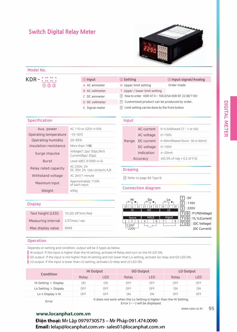
DIG
ITAL M
ET
ER
95www.vaw.co.kr
Switch Digital Relay Meter
① Input ② Setting ③ Input signal/Analog
A AC ammeter H Upper limit setting Order made
B AC voltmeter T Upper / lower limit setting
C DC ammeter
D DC voltmeter
E Signal meter
KDR -
Model No.
① ② ③
How to order KDR-AT 0 ~ 100.0/5A KDR-BT 22.90/110V
Customized product can be produced by order.
Limit setting can be done by the front button
Refer to page 80 Type B
Drawing
Connection diagram
Input
1 : 0V
7 9 : P1, P0(Voltage)
:1S, 1L(Current)
: (DC Voltage)
(DC Current)
2 : 110V
7 9
3 : 220V
7 9
Operation
Depends on setting and condition, output will be 3 types as below.
HI output: If the input is higher than the HI setting, activate HI Relay and turn on the HI LED ON.
GO output: If the input is not higher than HI setting and not lower than Lo setting, activate Go relay and GO LED ON.
LO output: If the input is lower than LO setting, activate LO relay and LO LED ON.
ConditionHI Output GO Output LO Output
Relay LED Relay LED Relay LED
Hi Setting < Display ON ON OFF OFF OFF OFF
Lo Setting > Dispaly OFF OFF OFF OFF ON ON
Lo ≤ Display ≤ Hi OFF OFF ON ON OFF OFF
ErrorIt does not work when the Lo Setting is higher than the HI Setting.
Error (----) will be displayed.
Specification
Aux. power AC 110 or 220V ±10%
Operating temperature -10~50
Operating humidity 20~85%
Insulation resistance More than 10
Surge impulseVoltage(1.2/ 50,5kV)
Current(8/ 20)
Burst Level 4(IEC 61000-4-4)
Relay rated capacity AC 250V, 2ADC 30V, 2A Use contacts A,B
Withstand voltage AC 2kV/1 minute
Maximum input Approximately 110% of each input
Weight 450g
Input
Range
AC current 0~5.5A(Rated CT : 1 or 5A)
AC voltage 0~150V
DC current 0~60mV(Rated Shunt : 50 or 60mV)
DC voltage 0~150V
Indication 4~20mA
Accuracy ±(0.3% of rdg + 0.2 of F.S)
Display
Text height (LED) 10.2(0.39”)mm Red
Measuring interval 2.5Times / sec
Max display value 9999

DIG
ITA
L M
ET
ER
96
Power Factor Meter
2 22
1P3W 3P3W 3P4W
① Circuit ② Voltage / current ③ Communication(Option)
1 1P2W 1 110V/5A C RS-485
2 1P3W 2 220V/5A N/A None
3 3P3W 3 380√3 / 190√3V / 5A
4 3P4W 4 22900/√3 / 190√3V / 5A
5 380√3V/ 5A
KDH -
How to order KDH-43 3Φ4W, 380√3/190√3V/5A
Customized product can be produced by order.
Model No.
① ② ③
Refer to page 80 Type A-2.
Specification
Aux. powerAC 90 ~ 260V(50/60Hz) /
DC110V
Operating
temperature-10~50
Operating humidity 20~85%
Insulation resistance More than 10
Surge impulseVoltage(1.2/ 50,5kV)
Current(8/ 20)
Burst Level 4(IEC 61000-4-4)
Withstand voltage AC 2kV/1 minute
Weight 450g
Input
RangeVoltage 30~300V(Rated PT 110 or 190V)
Current 0.05~6A(Rated CT 5A)
Accuracy ±(1.0ο + 1digit)
Display
Text height (LED) 20.5(0.8”)mm Red
Measuring interval 2.0Times / sec
Max display value 100
Drawing
Connection diagram
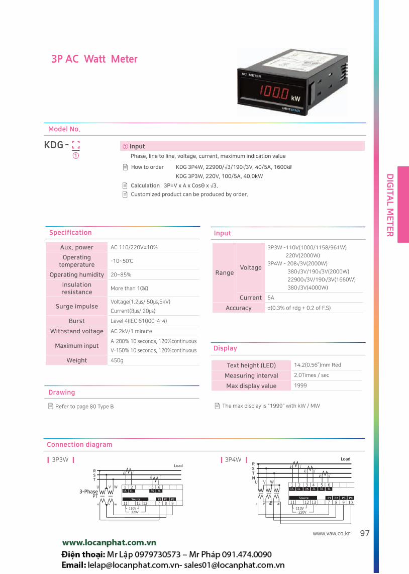
DIG
ITAL M
ET
ER
97www.vaw.co.kr
3P AC Watt Meter
Connection diagram
3-Phase
3P3W 3P4W
① Input
Phase, line to line, voltage, current, maximum indication value
KDG -
How to order KDG 3P4W, 22900/√3/190√3V, 40/5A, 1600
KDG 3P3W, 220V, 100/5A, 40.0kW
Customized product can be produced by order.
Model No.
①
Refer to page 80 Type B
Drawing
Calculation 3P=V x A x CosΘ x √3.
Input
RangeVoltage
3P3W -110V(1000/1158/961W)
220V(2000W)
3P4W - 208√3V(2000W)
380√3V/190√3V(2000W)
22900√3V/190√3V(1660W)
380√3V(4000W)
Current 5A
Accuracy ±(0.3% of rdg + 0.2 of F.S)
The max display is "1999" with kW / MW
Display
Text height (LED) 14.2(0.56”)mm Red
Measuring interval 2.0Times / sec
Max display value 1999
Specification
Aux. power AC 110/220V±10%
Operating temperature
-10~50
Operating humidity 20~85%
Insulation resistance
More than 10
Surge impulseVoltage(1.2/ 50,5kV)
Current(8/ 20)
Burst Level 4(IEC 61000-4-4)
Withstand voltage AC 2kV/1 minute
Maximum inputA-200% 10 seconds, 120%continuous
V-150% 10 seconds, 120%continuous
Weight 450g

DIG
ITA
L M
ET
ER
98
Power Chart for Voltage Ratio and Current Ratio
Circuit 1P2W 1P3W 3P3W 3P4W
* Power constant 1.091 0.9091 1.05 1.216 1.05 1.05 1.05 1.05 1.008 1.05 1.110 1.216 1.216 1.008
Voltage ratio 220V220/110
220380/110
440/110
3300/110
6600/110
22000/110
22900/110
154kV/110
208/√3
380/√3190/√3
380/√3
22900/√3190/√3
Max power1.2kW
1.0kW
2.0kW
1.158kW
1.0kW
1.0kW
1.0kW
1.0kW
0.961kW
1.0kW
2.0kW
2.0kW
4.0kW
1.660kW
1 5/5A 1.20 1000W 2.00 4.00 4.00 30.0 60.0 199.9 199.9 1400 2.00 4.00 4.00 199.9
2 10/5A 2.40 2.00 4.00 8.00 8.00 60.0 120.0 400 400 2.80MW 4.00 8.00 8.00 400
3 15/5A 3.60 3.00 6.00 12.00 12.00 90.0 180.0 600 600 4.20 6.00 12.00 12.00 600
4 20/5A 4.80 4.00 8.00 16.00 16.00 120.0 240 800 800 5.60 8.00 16.00 16.00 800
5 25/5A 6.00 5.00 10.00 19.99 19.99 150.0 300 1000 1000 7.00 10.00 19.99 19.99 1000
6 30/5A 7.20 6.00 12.00 24.0 24.0 180.0 360 1200 1200 8.40 12.00 24.0 24.0 1200
7 40/5A 9.60 8.00 16.00 32.0 32.0 240 480 1600 1600 11.20 16.00 32.0 32.0 1600
8 50/5A 12.00 10.00 19.99 40.0 40.0 300 600 1999 1999 14.00 19.99 40.0 40.0 1999
9 60/5A 14.40 12.00 24.0 48.0 48.0 360 720 2.40MW 2.40MW 16.80 24.0 48.0 48.0 2.40MW
10 75/5A 18.00 15.00 30.0 60.0 60.0 450 900 3.00 3.00 21.0 30.0 60.0 60.0 3.00
11 80/5A 19.20 16.00 32.0 64.0 64.0 480 960 3.20 3.20 22.4 32.0 64.0 64.0 3.20
12 100/5A 24.0 19.99 40.0 80.0 80.0 600 1200 4.00 4.00 28.0 40.0 80.0 80.0 4.00
13 120/5A 28.8 24.0 48.0 96.0 96.0 720 1440 4.80 4.80 33.6 48.0 96.0 96.0 4.80
14 150/5A 36.0 30.0 60.0 120.0 120.0 900 1800 6.00 6.00 42.0 60.0 120.0 120.0 6.00
15 200/5A 48.0 40.0 80.0 160.0 160.0 1200 2.40MW 8.00 8.00 56.0 80.0 16.0 16.0 8.00
16 250/5A 60.0 50.0 100.0 199.9 199.9 1500 3.00 10.00 10.00 70.0 100.0 199.9 199.9 10.00
17 300/5A 72.0 60.0 120.0 240 240 1800 3.60 12.00 12.00 84.0 120.0 240 240 12.00
18 400/5A 96.0 80.0 160.0 320 320 2.40MW 4.80 16.00 16.00 112.0 160.0 320 320 16.00
19 500/5A 120.0 100.0 199.9 400 400 3.00 6.00 19.99 19.99 140.0 199.9 400 400 19.99
20 600/5A 144.0 120.0 240 480 480 3.60 7.20 24.0 24.0 168.0 240 480 480 24.0
21 750/5A 180.0 150.0 300 600 600 4.50 9.00 30.0 30.0 210 300 600 600 30.0
22 800/5A 192.0 160.0 320 640 640 4.80 9.60 32.0 32.0 224 320 640 640 32.0
23 1000/5A 240 200 400 800 800 6.00 12.00 40.0 40.0 280 400 800 800 40.0
24 1200/5A 288 240 480 960 960 7.20 14.40 48.0 48.0 336 480 960 960 48.0
25 1500/5A 360 300 600 1200 1200 9.00 18.00 60.0 60.0 420 600 1200 1200 60.0
26 2000/5A 480 400 800 1600 1600 12.00 24.0 80.0 80.0 560 800 1600 1600 80.0
27 2500/5A 600 500 1000 1999 1999 15.00 30.0 100.0 100.0 700 1000 1999 1999 100.0
28 3000/5A 720 600 1200 2.40MW 2.40MW 18.00 36.0 120.0 120.0 840 1200 2.40MW 2.40MW 120.0
29 4000/5A 960 800 1600 3.20 3.20 24.0 48.0 160.0 160.0 1120 1600 3.20 3.20 160.0
30 5000/5A 1200 1000 1999 4.00 4.00 30.0 60.0 199.9 199.9 1400 1999 4.00 4.00 199.9
Reference
1. For 1Φ2W, 220V, 10 / 5A, the maximum power meter reading design is 2.4kW
2. For 3Ø3W, 154kV/110V, 100/5A, the maximum power meter reading design is 28.0MW
3. For 3Ø4W, 22900/√3/190√3V, 100/5A, the maximum power meter reading design is 4.00MW
Power constant : Instrument display power value (max.) / Calculated power value
Cu
rre
nt
rati
o

DIG
ITAL M
ET
ER
99www.vaw.co.kr
AC Watt . Watthour Meter
Connection diagram
3-PhasePT
3-PhasePT
1P2W
3P3W
1P3W
3P4W
Refer to page 80 Type B
Drawing
NPN Open Collector: 1 Count/Wh Display 1Digit
Output signal
① Input
Phase, line to line, voltage, current, maximum indication value
KDW -
How to order KDW 3ø3W, 220V, 100/5A, 40.0kW/kWh 40.0kW/kWh
Model No.
①
Customized product can be produced by order.Calculation 1P=V x A x CosΘ 3P=V x A x CosΘ x √3.
Specification
Aux. power AC 90 ~ 260V(50/60Hz) / DC110V
Operating temperature
-10~50
Operating humidity 20~85%
Insulation resistance
More than 10
Surge impulseVoltage(1.2/ 50,5kV)Current(8/ 20)
Burst Level 4(IEC 61000-4-4)
Withstand voltage AC 2kV/1 minute
Maximum inputA-200% 10 seconds, continuous 120%V-150% 10 seconds, continuous 120%
Reset methodFront- Push Button (kW/kWh and kwh can be reset)Rear - Terminal, Reset
Weight 450g
Input
RangeVoltage
1P2W - 110V(600W)
220V(1200W)
1P3W - 220V/110V(1000W)
3P3W - 110V(1000/1158/961W)
220V(2000W)
3P4W - 208√3V(2000W)
380√3V/190√3V(2000W)
22900√3V/190√3V(1660W)
380√3V(4000W)
Current 0.05~6A
AccuracyW ±(0.3% of rdg + 0.2 of F.S)
Wh ± (Watt accuracy+0.1 count/h)
Display
Text height (LED) 14.2(0.56”)mm Red
Measuring interval 2.0Times / sec
Power max display 4800
Energy max display 999999

DIG
ITA
L M
ET
ER
100
Energy chart for voltage ratio and current ratio
Circuit 1P2W 1P3W 3P3W 3P4W
* Power constant 1.091 0.9091 1.05 1.216 1.05 1.05 1.05 1.05 1.008 1.05 1.110 1.216 1.216 1.008
Voltage ratio 220V220/110
220380/110
440/110
3300/110
6600/110
22000/110
22900/110
154kV/110
208/√3
380/√3190/√3
380/√3
22900/√3190/√3
Max power1.2kW
1.0kW
2.0kW
1.158kW
1.0kW
1.0kW
1.0kW
1.0kW
0.961kW
1.0kW
2.0kW
2.0kW
4.0kW
1.660kW
1 5/5A 1.20 1.00 2.00 4.00 4.00 30.0 60.0 200 200 1.40MWh 2.00 4.00 4.00 200
2 10/5A 2.40 2.00 4.00 8.00 8.00 60.0 120.0 400 400 2.80 4.00 8.00 8.00 400
3 15/5A 3.60 3.00 6.00 12.00 12.00 90.0 180.0 0.60MWh 0.60MWh 4.20 6.00 12.00 12.00 0.60MWh
4 20/5A 4.80 4.00 8.00 16.00 16.00 120.0 240 0.80 0.80 5.60 8.00 16.00 16.00 0.80
5 25/5A 6.00 5.00 10.00 20.0 20.0 150.0 300 1.00 1.00 7.00 10.00 20.0 20.0 1.00
6 30/5A 7.20 6.00 12.00 24.0 24.0 180.0 360 1.20 1.20 8.40 12.00 24.0 24.0 1.20
7 40/5A 9.60 8.00 16.00 32.0 32.0 240 480 1.60 1.60 11.20 16.00 32.0 32.0 1.60
8 50/5A 12.00 10.00 19.99 40.0 40.0 300 0.60MWh 2.00 2.00 14.00 20.0 40.0 40.0 2.00
9 60/5A 14.40 12.00 24.0 48.0 48.0 360 0.72 2.40 2.40 16.80 24.0 48.0 48.0 2.40
10 75/5A 18.00 15.00 30.0 60.0 60.0 450 0.90 3.00 3.00 21.0 30.0 60.0 60.0 3.00
11 80/5A 19.20 16.00 32.0 64.0 64.0 480 0.96 3.20 3.20 22.4 32.0 64.0 64.0 3.20
12 100/5A 24.0 20.00 40.0 80.0 80.0 0.60MWh 1.20 4.00 4.00 28.0 40.0 80.0 80.0 4.00
13 120/5A 28.8 24.0 48.0 96.0 96.0 0.72 1.44 4.80 4.80 33.6 48.0 96.0 96.0 4.80
14 150/5A 36.0 30.0 60.0 120.0 120.0 0.90 1.80 6.00 6.00 42.0 60.0 120.0 120.0 6.00
15 200/5A 48.0 40.0 80.0 160.0 160.0 1.20 2.40 8.00 8.00 56.0 80.0 160.0 160.0 8.00
16 250/5A 60.0 50.0 100.0 200 200 1.50 3.00 10.00 10.00 70.0 100.0 200 200 10.00
17 300/5A 72.0 60.0 120.0 240 240 1.80 3.60 12.00 12.00 84.0 120.0 240 240 12.00
18 400/5A 96.0 80.0 160.0 320 320 2.40 4.80 16.00 16.00 112.0 160.0 320 320 16.00
19 500/5A 120.0 100.0 200 400 400 3.00 6.00 20.0 20.0 140.0 200 400 400 20.0
20 600/5A 144.0 120.0 240 480 480 3.60 7.20 24.0 24.0 168.0 240 480 480 24.0
21 750/5A 180.0 150.0 300 0.60MWh 0.60MWh 4.50 9.00 30.0 30.0 210 300 0.60MWh 0.60MWh 30.0
22 800/5A 192.0 160.0 320 0.64 0.64 4.80 9.60 32.0 32.0 224 320 0.64 0.64 32.0
23 1000/5A 240 200 400 0.80 0.80 6.00 12.00 40.0 40.0 280 400 0.80 0.80 40.0
24 1200/5A 288 240 480 0.96 0.96 7.20 14.40 48.0 48.0 336 480 0.96 0.96 48.0
25 1500/5A 0.36MWh 0.30MWH 0.60MWh 1.20 1.20 9.00 18.00 60.0 60.0 420 0.60MWh 1.20 1.20 60.0
26 2000/5A 0.48 0.40 0.80 1.60 1.60 12.00 24.0 80.0 80.0 560 0.80 1.60 1.60 80.0
27 2500/5A 0.60 0.50 1.00 2.00 2.00 15.00 30.0 100.0 100.0 700 1.00 2.00 2.00 100.0
28 3000/5A 0.72 0.60 1.20 2.40 2.40 18.00 36.0 120.0 120.0 840 1.20 2.40 2.40 120.0
29 4000/5A 0.96 0.80 1.60 3.20 3.20 24.0 48.0 160.0 160.0 1.12GWh 1.60 3.20 3.20 160.0
30 5000/5A 1.20 1.00 2.00 4.00 4.00 30.0 60.0 200 200 1.40GWh 2.00 4.00 4.00 200
Reference
1.For 1Φ2W, 220V, 10 / 5A, the maximum power meter reading design is 2.40kW
2. For3Ø3W, 154kV/110V, 100/5A, the maximum power meter reading design is 28.0MW
3.For3Ø4W, 22900/√3/190√3V, 100/5A, the maximum power meter reading design is 4.00MW
Power constant: Instrument display power value (maximum) /Calculated power value
Cu
rre
nt
rati
o

DIG
ITAL M
ET
ER
101www.vaw.co.kr
Wiring diagram(For group use)
3P3W 2CT(Wattmeter / Watt-hour meter, Balanced power factor meter)
A/S(3Φ3W 2CT)
KDW(W/Wh) KDI(var) KDH(PF)
Contact symbols Reference
Continuous circuitIntermittent closed
circuit
Terminal 6-8 5-7 2-4 1-3
OFF On Off On Off
R On Off Off On
S Off On Off On
T Off On On Off
3P4W 3CT(Wattmeter / Watt-hour meter, Balanced power factor meter)
A/S(3Φ4W 3CT)
KDW(W/Wh) KDI(var) KDH(PF)
The A / S (Cam Switch) is based on the koino product. Please check the manufacturer's terminal number.
PT connection is not shown

DIG
ITA
L M
ET
ER
102
Connection diagram (single use)
1P2W(Watt meter)
Without CT (less than 5 A) With CT
Single PT
1P3W(Watt meter) 1P3W(Power factor meter)
3-PhasePT
2
3P3W(Watt meter) 3P3W(Power factor meter)
3-PhasePT
2
3P4W(Watt meter) 3P4W(Power factor meter)
2

DIG
ITAL M
ET
ER
103www.vaw.co.kr
Digital Leakage Current Meter
Digital leakage current limit meter.KDS -10
Model No.
Monitoring the leakage current of grounding cable, which is connected to potential transformer secondary. If the output is over
setting value, alarm and relay contact will be activated.
Overview
Connection diagram
Aux. power
Input
Dedicated current transformer(KBJ-26L)
Primary current 0.03~30.0A
Secondary current 0.05~50mA
Class 1.0
Burden 500Ω Less than 500Ω
Feature
Economical price RS-485 communication
Drawing
Refer to page 80 type A-1
Unit :mm
Specification
Aux. power AC 90~260V or DC 110V
Operating temperature -10~50
Operating humidity 20~85%
Insulation resistance More than 10
Surge impulseVoltage(1.2/ 50,5kV)
Current(8/ 20)
Burst Level 4(IEC 61000-4-4)
Withstand voltage AC 2kV/1 minute
Maximum input 300% 10 seconds
SettingCurrent value, delay time,
communication address
communicationRS-485/Modbus RTU Protocol,
9600bps
Relay capacity 250V, 2A
Current transformerKBJ-26L required
(Separate purchase)
Weight 250g
Input
RangeKBJ-26L 0.05~30mA
KBJ-06L 0.1~50mA
Accuracy ±(0.3% of rdg + 0.2 of F.S)
Max display value 30.0A
Primary current
50.0A
Secondary current
50mA
Class 1.0
Dedicated current transformer(KBJ-06L)
Unit :mm
Unit :mm

DIG
ITA
L M
ET
ER
104
Digital Leakage Current Meter
KDS-20 Display [Color LCD 320X240]
Digital leakage current limit meter.KDS -20
Model No.
Monitoring the leakage current of grounding cable, which is
connected to potential transformer secondary. If the output is
over setting value, alarm and relay contact will be activated.
Overview Feature
Certificates
Specification
Waveform display 128 Point x 2 cycles
Harmonic 1-15 Harmonic
Measure lgr lg, lgr, lgc
Aux. power AC 90~260V or DC 110V
Operating temperature -10~50
Operating humidity 20~85%
Insulation resistance More than 10
Surge impulseVoltage(1.2/ 50,5kV)
Current(8/ 20)
Burst Level 4(IEC 61000-4-4)
Withstand voltage AC 2kV/1 minute
Maximum input 300% 10 seconds
SettingCurrent value, delay time,
communication address
communication RS-485
Relay capacity 250V, 2A
Current transformerKBJ-06L required
(Separate purchase)
Weight 800g
Input
Range
Voltage 25~300V
Current 0.1~50mA
(KBJ-26L or KBJ-06L) 1000:1
Accuracy
Voltage ±(0.5% of rdg + 0.2 of F.S)
Leakage
current±(0.5% of rdg + 0.2 of F.S)
Display
Voltage 25~300V
Current0.1~30 (KBJ-06L)
0.030~30,000A (KBJ-26L)
Unit :mm
Refer to page 80 Type E
Drawing
Connection diagram
Refer to page 100
Displayed as waveform and vector
Checking Leakage phase
lg, lgr, lgc Current measurement
RS-485 Communication
Dedicated current transformer Unit : mm
Primary current
50.0A
Secondary current
50mA
Class 1.0

DIG
ITAL M
ET
ER
105www.vaw.co.kr
Harmonic Meter Relay
① Harmonic Meter RelayKDQ - HMR
Model No.
①
Monitoring the harminics and saving the monitored data.
If the output is over setting value, alarm and relay contact
will be activated.
Overview
Refer to page 80 type D
Drawing
Display[Color LCD 320X240]
Voltage/Current
Voltage
Current R
Current S
Current T
Harmonic<IR>
Harmonic<IR> Harmonic<IR>
The harmonic generation rate is displayed, as below.
Input
Range
Line voltage40~500V
(rated PT:110 or 190V)
Current 0.1~5.5A(rated CT:5A)
Frequency 45~65Hz
Accuracy
Voltage ±(0.3% of rdg + 0.2 of F.S)
Current ±(0.3% of rdg + 0.2 of F.S)
Harmonic ±(0.1%)
Phase ±(1.0。)
Specification
Aux. power AC 90/260V(50/60Hz), DC 110V
Operating temperature
-10~50
Operating humidity 20~85%(Over dew point)
Insulation resistance More than 10
Surge impulseVoltage(1.2/ 50,5kV)
Current(8/ 20)
Burst Level 4(IEC 61000-4-4)
Withstand voltage AC 2kV/1 minute
Harmonic display 1~15 Harmonic,THD(0.0~100.0%)
Input lossLess than V - 0.1VA,
Less than A - 0.2VA
Weight 800g
Communication specification
Interface RS-485(2Wire)(A+, B-, Com)
Transmission rate 9600, 19200bps
Transmission distance Maximum 1.2km
Protocol Modbus RTU(Basic)
Connection diagram
Refer to 101Page

DIG
ITA
L M
ET
ER
106
Demand Controller
① Demand ControllerKCD - MX
Model No.
①
Minimizing the electricity tariff by setting working day
and checking date
If the consumption is exceed the setting value, alarm and relay
contact will be activated.
Overview
Drawing
Refer to page 80 type D
Measuring active power and calculate active energy per hour/
day/month.
Monitor and control energy consumption.
Transmitting data by RS-485 and monitoring in remote place.
Based on target energy consumption, daily consumption can be
controlled.
Function
Setting items
Setting Range Unit Remarks
Contract power 1~300 kW
Reading date 1~31 Day
Working days 1~31 Day
Alarm buzzer ON/OFFAlarm
applicable
DO1/DO2AUTO/ON/OFF
/REMOTEAutomatic /
Manual
Delay time 1~200 sec
HMI(Human Machine Interface)
Electricity bill
Demand Controller system
Specification
Aux. power AC 90~260V(50/60Hz)/DC 110V
InputA contact relay,
Capacity AC 220V / 2A 3 pieces
(2 load control, 1 alarm)
Alarm Piezo informing buzzer used
Indicator128x64dot Matrix Graphic LCD,
Indicate LED : Red 3ø 5 pieces
Weight 800g
Communication
Interface RS-485, Multi-drop 2Wire
Protocol Modbus(RTU mode)
Data format1Start bit, 8 Data bits,
1 Stop bits None Parity
Communication speed
9600bps
Input
Range Rated input 3 phase 3 wire AC 440/110V, 5A
3 phase 4 wire AC 380√3V, 5A
Accuracy
Instant power ±(1.0%)
Accumulated Energy
±(2.0%+0.03%/day)
Connection diagram
Refer to page 109

DIG
ITAL M
ET
ER
107www.vaw.co.kr
Rectifier Switch Board Digital Meter
① AC voltage input specification
1 20~250V Direct connection 2 380/110V PT use
KDV-
Model No.
Monitoring AC voltage(input), DC voltage and DC current(out-
put) for Battery charger (or Rectifier), with RS-485 communi-
cation.
Overview
Measure DC voltage, DC current (Rectifier output and battery
output) and the Max value.
Shunt ratio can be set.
RS-485 Serial Communication.
Function
Drawing
Refer to 80Page type D
Connection diagram
Communication signal
①
Input
Item Range Accuracy (%)
AC voltage
KDV-1 20~250V± (0.5% of rdg + 1 digit)
KDV-2 380/110V
DC voltageCommon
20~270V ± (0.3% of rdg + 1 digit)
DC current 0.5~50mV ± (0.3% of rdg + 1 digit)
Communication specification
Interface RS-485, Multi-drop 2Wire
Protocol Modbus(RTU mode)
Transmission distance Max 1.2km
Transmission rate 9600bps
Display items
Item Display Indicate LED
AC VAC voltage VAC
AC voltage Max MAX VAC
DC VDC voltage VDC
DC voltage Max MAX VDC
DC A
Direct current IDC
DC current Max MAX IDC
Battery current IBAT
Battery current Max MAX IBAT
Specification
Aux. power AC 90/260V(50/60Hz), DC 110V
Operating temperature
-10~50
Operating humidity 20~85%(Over dew point)
Insulationresistance
More than 10 (DC 500V)
Between external terminal and case
Surge impulseVoltage(1.2/ 50,5kV)
Current(8/ 20)
Burst Level 4(IEC 61000-4-4)
Withstand voltage AC 2kV/1 minute
Weight 800g

DIG
ITA
L M
ET
ER
108
① Digital meter ② Panel meter
③ Measurement ④ Communication
A 3P V, 3P A, W, PF, var, Hz, Wh, varh C RS-485
B 3P V, 3P A, W, PF, var, Hz N/A None
C 3P V, 3P A, W, PF, var, Hz, wh, varh (No communication)
KDX -
Model No.
①② ③ ④
How to order Example) KDX-AC
KDX-B
Customized product can be produced
by order.
CAUTION If the power is turn off, the accumulated value for 30 minutes can be deleted.
Specification
Item Description
Aux. power
KDX-A/B: AC 90V ~ 260V(50/60)
/DC110V
KDX-C: AC 220V(60 Hz)Only
Display method14.2 LED(0.56Inch, Red)
Update speed : 1000ms
Communication
RS-485 multi-drop 2wire, 9600bps,
0~255,
Maximum 1.2km, Modbus RTU
Withstand voltage
AC 2kV/1 minute
Surge impulse 1.2/50 4, 8/20 2
Burst Level 4(IEC 61000-4-4)
Input loss- V : Less than 0.1VA
- A : Less than 0.2VA
Operating temperature / humidity
-10 ~ 50 / 20~85%
Insulation resistance More than 10 (500VDC )
WeightKDX-A/B: 800g
KDX-C: 1kg
Panel Power Meter
Certificates
Digital meter which can display 3 Ø A, 3 Ø V, W, PF, var, Hz, Wh,
varh and remote power monitoring by RS - 485 communication.
Overview
3-phase voltage, 3 phase current, W, PF, var, Hz, Wh, etc. and
others are displayed with three windows.
CT, PT, primary value can be set.
RS-485 Serial Communication
Up to 500V, direct connection is possible without PT.
Function
Communication
Interface RS-485, Multi-drop 2Wire
Protocol Modbus RTU(Basic)/Melsec(option)
Address setting 0~255
Transmission distance
Maximum 1.2km
Transmission rate 9600bps
Input
Range
Division A/B C
Line voltage
40~500V
50~500V
(Rated PT
:110 or 190V)
Current input
0.1~6A0.5~6A
(Rated CT:5A)
Accuracy
V,A± (0.3% of rdg
+ 0.2% of F.S)
1.5 times of
A / B
Wvar
± (1.0% of rdg
+ 0.2% of F.S)
at PF=1
PF ± (1.0% of rdg + 1.0 )
Whvarh
± (W Accuracy + 0.1
count/h)

DIG
ITAL M
ET
ER
109www.vaw.co.kr
Drawing
Refer to page 80 type D
Detailed Function
Function keys
Select· W-PF-var-Hz-Wh-varh, Communication address selection
VS Button
FS Button
· A1, A2, A3, CT Primary current selection
· CT Primary current selection
C . T Primary current value selection
5→10→15→20→25→30→40→50→60→70→75→80→90
→100→120→125→130→140→150→160→170→175→
180→200→225→240→250→300→400→450→500→600
→700→750→800→900→1000→1200→1250→1300→
1400→1500→1600→1700→1750→1800→2000→2500→
3000→3200→3500→3600→4000→5000→6000
AS Button
Connection diagram
Aux.power
Aux.power
Aux.power
Aux.power
1P2W 1P3W 3P3W 3P4W
A1, A2, A3, CT Primary current selection
CT Primary current selection
· Circuit method selection
· PT primary voltage selection
· CT primary current selection
· Communication address setting
(0 to 255)
· Wh, varh Reset
Setting Mode ( + Key) → Wiring
method( , Key) → Save( key) →
P.T ratio( , Key) → save( Key)
SET
VS
VS
VS
· V1, V2, V3, PT Primary current selection
· Wiring method/P . T Primary current selection
Setting Mode ( + Key)
→ Setting( , Key)→ save
( Key)
SET
AS
AS
Primary voltage value selection(Choose 500 for direct connection)
3P3W
500→380→440→3.30→6.60→7.20
→11.0→11.4→22.0→22.9→66.0→154
3P4W
500→380→11.4→22.9

DIG
ITA
L M
ET
ER
110
Panel Power Meter
Instrument which can display the power distribution boards 3
Ø A, 3 Ø V, W, PF, var, Hz, Wh, varh and remote power moni-
toring by RS - 485 communication.
Overview
3-phase voltage, 3 phase current, W, PF, var, Hz, Wh, etc. and
others are displayed with three windows.
CT, PT, and primary value can be set.
RS-485 Serial Communication.
Function
Connection method setting ( , KEY) & save(SET KEY)
P. T Primary voltage selection ( , KEY) & Save (SET KEY)
C. T 1st current selection ( , KEY) & save(SET KEY)
Communication address setting
→ ones digit setting ( , KEY) & Save(SET KEY)
→ Tens digit setting ( , KEY) & Save(SET KEY)
→ Hundreds digit setting ( , KEY) & Save(SET KEY)
PT/CT ratio need to be checked on installation.
Setting order and method
Connection diagram
Comm Comm Comm Comm
Internal Common
Internal Common
Internal Common
Internal Common
Aux. power Aux. power Aux. power Aux. power
1P2W 1P3W 3P3W 3P4W
Certificates
① Digital Meter
② Panel meter ③ Measurement ④ Communication
A 3PV, 3PA, W, PF, var, Hz, Wh, varh C RS- 485 N/A None
KDY - A
How to order KDY-AC (With communication), KDY-A (Without communication)
Model No.
①② ④③
Customized product can be produced by order.
Specification
Aux. powerAC 110/220V±10%(50/60Hz), DC 110V
Operating temperature -10~50
Operating humidity 20~85%
Insulation resistance More than 10
Surge impulse
Voltage(1.2/ 50,5kV)Current(8/ 20)
Burst Level 4(IEC 61000-4-4)
Withstand voltage AC 2kV/1 minute
Maximum inputLess than A-0.2VA, Less than V-0.1VA
Weight 800g
Communication specification
Interface RS-485, Multi-drop 2Wire
ProtocolModbus RTU(Basic)
Melsec(Option)
Address setting 0~255
Transmission distance maximum 1.2km within
Transmission rate 9600bps
Display
LED 14.2(0.56")mm Red
Display update speed 1000ms
Input
Range
Line voltage 40~500V
Current input 0.1~6A
Frequency45~65Hz1P2W, 1P3W, 3P3W, 3P4W Shared
Accuracy Refer to page 111p

DIG
ITAL M
ET
ER
111www.vaw.co.kr
Accuracy
V, A W, var
± (0.3% of rdg + 0.2% of F.S) ± (1.0% of rdg + 0.2% of F.S)
PF Hz Wh, varh
± (1.0% of rdg +0.1) ± 0.1Hz ± (W Accuracy + 1 count/h)
at 45~65, at COS Ø ± 0.8~1.0, 23
Drawing
The inner diameter of rear-located CT is Ø 9.
110
110 110
15 7540
90
Ø92-Ø6
90
90Ø101
Panel dimension
Unit : mm
Detailed Function
Indicate LED
Select button
Indicate the data shown in displays.
Circuit, current, voltage, communication
Energy reset,
Select indication value
Display window
4 Digit Display item can be varied
by select button window
Using UP / DOWN KEY
Measurement values can be selectively viewed
Communication LED
A1, A2, A3 C .T Primary current selection V1, V2, V3, P . T Primary voltage selection
C.T Primary current value selection.
5→10→15→20→25→30→40→50→60→70→75→
80→90→100→120→125→130→140→150→160→
170→175→180→200→225→240→250→300→4
00→450→500→600→700→750→800→900→
1000→1200→1250→1300→1400→1500→1600→
1700→1750→1800→2000→2500→3000→3200→3
500→3600→4000→5000→6000
Primary voltage value selection range (Select 500 for direct connection) 3P3W : 500→220→380→440→3.30→6.60→7.20→11.0→11.4→22.0→22.9→66.0→1543P4W : 500→380→11.4→22.9
Note If the power is off, the accumulated value for 30 minutes can be deleted.
Display sequence 1 2 3 4 5 6 7
Display A ∑ V R phase V RS V A1 PF Hz A0
Display B ∑ A S Phase V ST V A2 var Wh Varh
Display C W T Phase V TR V A3 W Wh Varh

DIG
ITA
L M
ET
ER
112
Panel Power Meter
Monitoring electrical data(such as voltage, current, active
power, reactive power, surface power, PF, frequency, active
energy, reactive energy)
Communication function with RS-485 or LAN.
Overview
① Digital meter ② Panel Power Meter ③ Model seriesKDY - 200
Model No.
①② ③ Display : 3PV, 3PA, W, PF, var, Hz, Wh, varh, VA Communication : RS-485
Remote power quality monitoring With RS - 485 communication
Easy to use.
Function
Caution Wh, V arh is saved in every 30 min. And if the power is off, the accumulated value for 30 min can be deleted.
Certificates
Specification
Item Contents
Aux. power AC 90V ~ 260V(50/60)/DC110V
Display method Custom LCD
Communication RS-485 cummunication
Insulation resistance More than 10 (500VDCMega standard)between external terminal and case
Withstand voltage AC 2kV/1 minute
Burst Level 4(IEC 61000-4-4)
Electrostatic discharge ± 8kV(Air), ± 4kV(Contact) (IEC 61000-4-2)
Surge impulse 1.2/50, 2kV (IEC 61000-4-5)
Electromagnetic interferenceCE : 0.15~0.5MHz : 79(66)dBuV, 0.5~30MHz : 73(60)dBuV, (KN22)
RE : 30~230MHz : 40dBuV/m, 230~1000MHz : 47dBuV/m, (KN22)
Radio frequency radiation immunity RS:10V/m (IEC 61000-4-3)
Operating temperature/humidity -10 ~ 50 / 20~85%
Weight 600g
Input
Voltage ± (0.2% of rdg + 0.02% of FS)Power factor
± (0.5% of rdg + 0.5。)
Current ± (0.2% of rdg + 0.02% of FS) Frequency ± (0.02Hz)
Active Power
Class 0.5 as per IEC 62053-22
± (0.5% of rdg + 0.01% of FS)Active energy
Class 0.5 as per IEC 62053-22
± (watt accuracy + 0.1 count/h)
Reactive Power
Class 1.0 as per IEC 62053-24
± (1.0% of rdg + 0.01% of FS)Reactive energy
Class 1.0 as per IEC 62053-24
± (var accuracy + 0.1 count/h)
Accuracy
Range
Line voltage 40~500V
Current input 0.1~6A
Frequency 45~65Hz
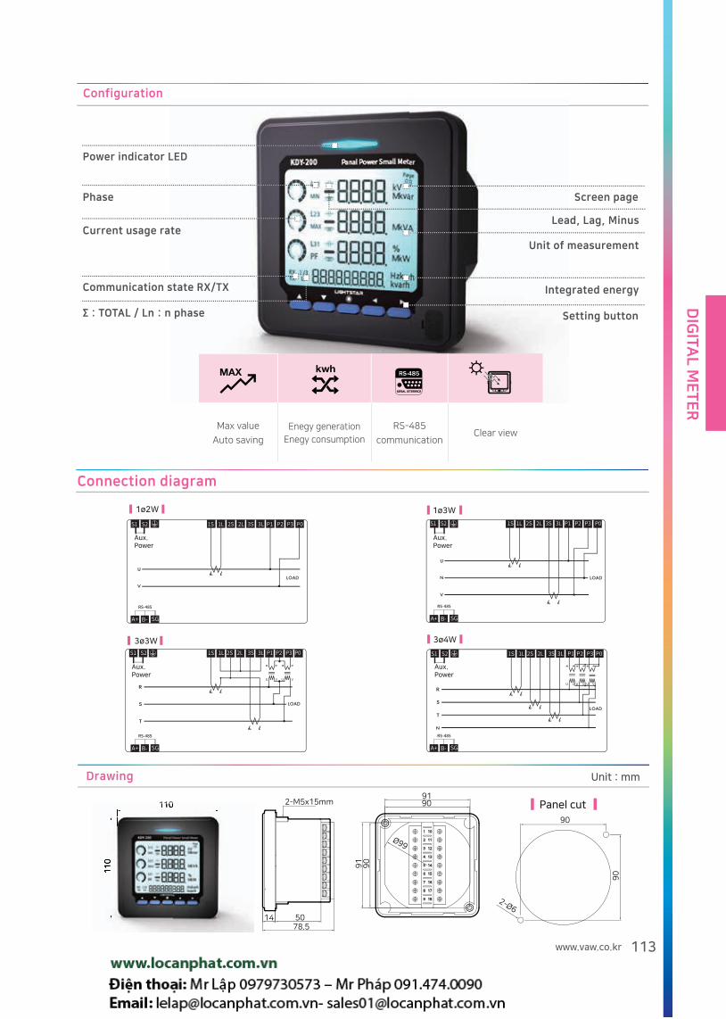
DIG
ITAL M
ET
ER
113www.vaw.co.kr
Connection diagram
Aux.Power
Aux.Power
Aux.Power
Aux.Power
Drawing
110
11
0
110
11
0
14 5078.5
2-M5x15mm
Ø99
91
91
90
90
90
90
2-Ø6
Panel cut
Unit : mm
Configuration
Power indicator LED
Current usage rate
Screen page
Lead, Lag, Minus
Integrated energy
Setting button
Unit of measurement
Communication state RX/TX
Σ : TOTAL / Ln : n phase
Phase
Max value
Auto saving
Enegy generation
Enegy consumption
RS-485
communicationClear view

DIG
ITA
L M
ET
ER
114
Auto PF Controller
Certificates
KCP -
Model No.
① ②① Display type and number of circuits ② Communication
06 LED 6 Circuit C Communication function
12 LED 12 Circuit N/A None
SM LCD 6 Circuit
Specification
KCP-06 KCP-12 KCP-SM
OutputNumber of circuits : 6 point
(1Common)
Number of circuits : 12 point
(2Common)Number of circuits : 6 point (1Common)
Setting
PT Ratio - 500(Direct connection), 380/110, 380√3/190 √3,
440/110, 3300/110, 6600/110, 22900/110,
22900√3/190√3 CT Ratio - 5/5 ~ 6000/5A Target power factor - LAG (+) 80~100 Control method - 1 (sequential)/2(Circulation) Low power range - 0 ~ 999(kW/MW) Input / delay time - 5~1800 second
Basic setting - voltage / current ratio, daytime target,
nighttime target, voltage range, delay time,
clock setting, communication address Control method - sequential, circulation, intelligent OFFSET - Active power OFFSET
Reactive power OFFSET Wiring correction - Automatic, Manual
Display Power factor, voltage, current, active power, reactive powerPower factor, voltage, current, active power, reactive power
Power factor trend, condenser input time
Common
Aux. power - AC 90~260V(50/60Hz), DC 110V Surge impulse - Voltage(1.2/ 50, 5kV), current(8,20)
Operating temperature / humidity - 10~50/20~85% Burst - Level 4(IEC 61000 -4-4)
Insulation resistance - More than 10 Input - Voltage line voltage(S -T), AC 500V
Withstand voltage - AC 2kV / 1min Current Current R phase current input, AC 5A
Contact capacity - Relay AC 250V, 2A / DC 30V, 2A Data - Refer to page 114
Communication Interface RS - 485 Multi-Drop 2Wire Transmission rate 9600bps
Protocol Modbus RTU
Measuring the electrical data and control the external
capacitor(condenser) in order to compensate Power factor
(Balanced type)
Overview Characteristics
Automatic phase finding fuction
Easy setting and easy operation with dip switch
Setting active power / reactive power for potential transformer,
and control the PF in night time.
Setting low load condition and restrain the relay operation.
Over / under voltage, target PF with Day/night setting, Setting
condenser capacity. (KCP-SM)
Monitoring PF trend, and condenser input time (For KCP-SM)
Please be advised that 1st relay to be used for PF compensa-
tion of low load PT.
And the last relay to be used for spare to compensate PF.
Recommendation
Input
RangeVoltage S-T line AC 50~ 500V
Current R phase AC 0.05~ 6.0A
Accuracy
Voltage ± (0.3% of rdg + 0.2% of FS)
Current ± (1.0% of rdg + 0.2% of FS)
Power Factor ± (3.0% of rdg + 1.0)

DIG
ITAL M
ET
ER
115www.vaw.co.kr
Connection diagram
Drawing Refer to page 80 Type D
KCP-06/12 Display
A power factor 100% is displayed on the A window, and power 500 kW is displayed on the B window.
You can switch the measured value by pressing the button.
PF is displayed on the A window and the setting value is displayed on in the B window.
You can change setting value by pressing the button.
Within the range of 80 to 100, it is controlled by the set power factor target value.
KCP-06/12 Normal Display
KCP-06/12 Setting Display
KCP-SM Setting Display
KCP-SM Normal Display
Power factor Power factor
Press ” , ” button to select the modes.
Symbol of lag - and lead “ ”
Setting item selection( / )→Start( )→Change
( / )→Save( )→End setting & previous menu( )
KCP-SM Setting Display
1.Voltage/current ratio
2.Day target
3.Night target
4.Range of Voltage
5.Delay
6. Time setting
7.Communication address
8.Reset
ENT
ENT SET
① Press / button, and ">>" will be located at setting item.
② Press button to change setting with and button.
③ Change remaining items, and press button to finish.
KCP-SM PF setting display
Control time
Upper Power Factor
Lower limit power factor
Load voltage
ENT
ENT

DIG
ITA
L M
ET
ER
116
Auto PF Controller
KCP - S
Model No.
① ②① Number of circuits ② Communication
03 3Circuit N/A None
06 6Circuit
Measuring the electrical data and control the external
capacitor(condenser) in order to compensate Power factor
(Balanced type)
Overview Characteristics
Select control range and setting by day or night
OFFSET can be set on the device to compensate power factor
errors in each region.
Automatic phase finding function (Patented Technology)
Specification
KCP-03S KCP-06S
OutputNumber of circuits : 3 point (1 common) Number of circuits : 6 point (1 common)
Contact capacity: Relay AC 250V, 2A / DC 30V, 2A
Aux. power AC 90 ~ 260V (50~60Hz), DC 110V
Communication
Protocol : Modbus RTU
Interface: RS-485 2Wire Multi drop
Transmission rate : 9600/19200 bps
Data : Start 1bit, Data 8bit, Parity none, Stop 1bit
Others
Operating temperature / humidity : -10~50 / 20~85%
Withstand voltage : AC 2kV / 1min
Insulation resistance - More than 10
Surge impulse - 1.2/ 50, 5kV
Burst immunity test : Level 4(IEC 61000-4-4)
Input
RangeVoltage S-T line voltage AC 50~ 500V
Current R phase AC 0.05~ 6.0A
Accuracy
Voltage ± (0.3% of rdg + 0.2% of FS)
Current ± (1.0% of rdg + 0.2% of FS)
Power Factor ± (3.0% of rdg + 1.0 )
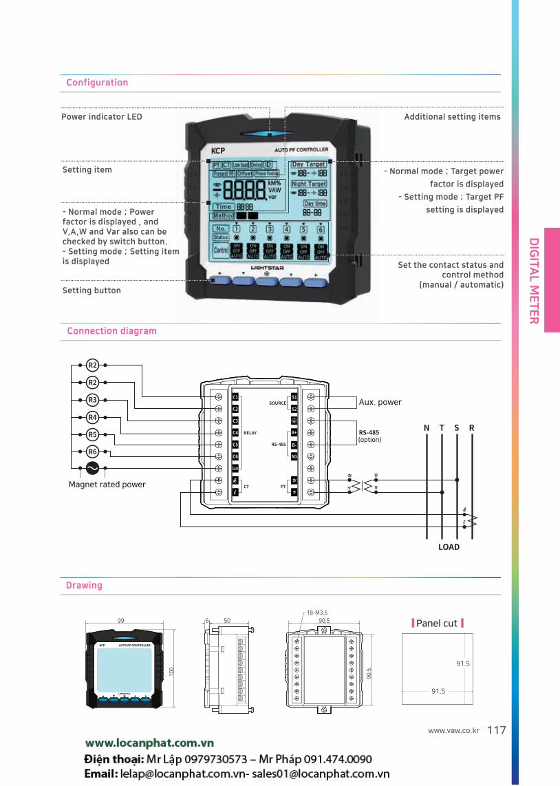
DIG
ITAL M
ET
ER
117www.vaw.co.kr
Connection diagram
C1
C2
C3
C4
C5
C6
Com
k
l
S1
S2
SG
A+
B-
U
V
SOURCE
N
LOAD
T S R
RS-485
PTCT
RELAY RS-485
U
V
U
V
k
l
R6
R5
R4
R3
R2
R2
Magnet rated power
Aux. power
(option)
Drawing
KCP AUTO PF CONTROLLER
Panel cut
Configuration
Set the contact status and control method
(manual / automatic)
- Normal mode ; Target power
factor is displayed
- Setting mode ; Target PF
setting is displayed - Normal mode ; Power factor is displayed , and V,A,W and Var also can be checked by switch button.- Setting mode ; Setting item is displayed
Setting item
Setting button
Power indicator LED Additional setting items

DIG
ITA
L M
ET
ER
118
Power Quality Meter
① Power Quality MeterKDQ -100
Model No.
①
Measuring electrical data (Voltage, Current, power, Power factor,
Frequency, Energy, Demand) and display Harmonics, Waveform,
Phase angle in order to analyze power quality.
Overview
Display[Color LCD 320X240]
Voltage
Current
Power
Total
Energy
Frequency
Measure [1] Waveform [~] Phase [*] [1] Harmonic
Communication
Interface RS-485 (2Wire)(A+,B-,Com)
Protocol Modbus RTU
Transmission distance Max 1.2km
Transmission rate 9600,19200,38400 bps
Drawing
144(W)X144(H)X140(D)
Unit : mm
Specification
Aux. powerAC 110/220V±10%(50/60Hz),
DC 110V
Operating temperature -10~50
Operating humidity 20~85%
Insulation resistance More than 10
Surge impulseVoltage(1.2/ 50,5kV)
Current(8/ 20)
Burst Level 4(IEC 61000-4-4)
Withstand voltage AC 2kV/1 minute
Maximum inputLess than A-0.2VA,
Less than V-0.1VA
Weight 1500g
Input
Range
Line Voltage
40~ 500V
Current 0.1~ 6A
Frequency 45~65Hz
Accuracy
Voltage ± (0.3% of rdg + 0.2% of FS)
Current ± (1.0% of rdg + 0.2% of FS)
Frequency ± (0.02Hz)
ActivePower
± (1.0% of rdg + 0.2% of FS)
at PF=1
Reactive Power
± (1.0% of rdg + 0.2% of FS)
at PF=1
Power Factor ± (1.0% of rdg +0.2% of F.S)
Active energy ± (watt accuracy + 0.1 count/h)
Reactive energy
± (var accuracy + 0.1 count/h)

DIG
ITAL M
ET
ER
119www.vaw.co.kr
Digital power meter KDX-200 selection guide
Comparison table
Type KDX-200 KDX-210 KDX-220 KDX-230 KDX-240
Feature
Size 144x144mm
Display LCD(Back Light : White)
Installation Panel front
Function
Communication RS 485 or Ethernet(Option)
V,A,W,PF,var,h V V V V V
Wh, varh V V V V V
DI - 4 - 4 4
DO - 2 - 2 2
Temperature - - 2 2 -
Max Min((V,A,W,H) V V V V V
Limit setting - V - V V
Leakage current - - - - V

DIG
ITA
L M
ET
ER
120
① Digital meter
② Panel Power Meter
③ Measurement ④ communication
0 Basic 0 No communication
1 Basic + DOx2 + DIx 4 1 RS-485
2 Basic + TEMPx2 2 Ethernet
3 Basic + DOx2 + Dix 4 + TEMPx 2
4 Basic + DOx2 + Dix 4 + Leakage current x1
KDX - 2
How to order Example) KDX-210 KDX-211
Customized product can be produced by order.
Model No.
①② ③ ④
Caution Wh, V arh is saved in every 30 min. And if the power is off, the accumulated value for 30 min can be deleted.
Basic : 3PV, 3PA, W, PF, var, Hz, Wh, varh, VA
Monitoring electrical data(such as voltage, current, active
power, reactive power, surface power, PF, frequency, active
energy, reactive energy), and DI/DO/Temperature/Leakage
current.
Communication function with RS-485 or LAN.
Overview
Remote power quality monitoring With RS - 485 communication
and Ethernet communication.
I / O information can be checked in real time, and output can be
controlled directly / indirectly.
The temperature monitoring of 2 channels.
Leakage current monitoring .
Easy to use.
Function
Panel Power Meter
Certificates
Specification
Item Contents Item Contents
Aux. power AC 90V ~ 260V(50/60)/DC110V Electrostatic discharge± 8kV(Air), ± 4kV(Contact)
(IEC 61000-4-2)
Display method Custom LCD Surge impulse 1.2/50, 2kV (IEC 61000-4-5)
Communication RS-485 CommunicationElectromagnetic
interference
CE : 0.15~0.5MHz : 79(66)dBuV,
0.5~30MHz : 73(60)dBuV, (KN22)
RE : 30~230MHz : 40dBuV/m,
230~1000MHz : 47dBuV/m, (KN22)
Insulation resistanceMore than 10(500VDC)
between external terminal and caseRadio frequency
radiation immunityRS:10V/m (IEC 61000-4-3)
Withstand voltage AC 2kV/1 minuteOperating temperature
/ humidity-10 ~ 50 / 20~85%
Burst Level 4(IEC 61000-4-4) Weight 800g
Input
Voltage ± (0.5% of rdg + 0.1% of FS) Power Factor ± (1.0% of rdg +1.0。)
Current ± (0.2% of rdg + 0.1% of FS) Frequency ± (0.05Hz+0.1% of FS)
Active Power ± (1.0% of rdg + 0.1% of FS) Active energy ± (1.0% of rdg + 0.1 count/h)
Reactive Power ± (1.0% of rdg + 0.1% of FS) Reactive energy ± (2.0% of rdg + 0.1 count/h)
Voltage 40V~500V Current 0.1~6A Frequency 45~65HzInput Range
Accuracy
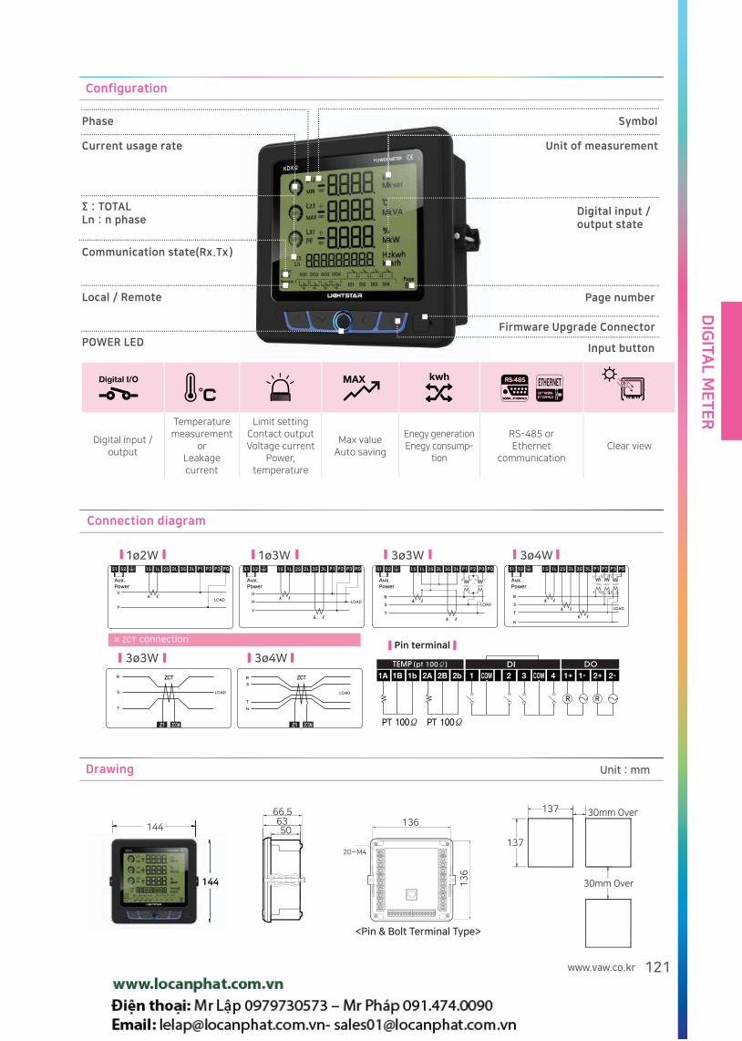
DIG
ITAL M
ET
ER
121www.vaw.co.kr
Configuration
Phase
Current usage rate
Local / Remote
POWER LED
∑ : TOTALLn : n phase
Communication state( Rx. Tx )
Unit of measurement
Digital input / output state
Page number
Firmware Upgrade Connector
Input button
Symbol
Digital input / output
Temperature measurement
orLeakage current
Limit settingContact outputVoltage current
Power, temperature
Max valueAuto saving
Enegy generationEnegy consump-
tion
RS-485 orEthernet
communicationClear view
Connection diagram
Aux.Power
Aux.Power
Aux.Power
Aux.Power
connectionPin terminal
Drawing
144
144
137
13750
6366.5
30mm Over
136
13
6
20-M4
144
30mm Over
<Pin & Bolt Terminal Type>
Unit : mm

DIG
ITA
L M
ET
ER
122
① Digital meter ② Panel Power Meter ③ Model seriesKDX - 300
Model No.
①② ③ Display : 3PV, 3PA, W, PF, var, Hz, Wh, varh, VA Communication: RS-485
Monitoring electrical data(such as voltage, current, active power, reactive power, surface power, PF, frequency, active energy, reactive energy)Communication function with RS-485 or LAN.
Overview
Remote power quality monitoring With RS - 485 communication
Easy to use.
Function
Caution) Wh, Varh is saved in every 30 min.
And if the power is off, the accumulated value for 30 min can
be deleted.
Panel Power Meter
Certificates
Specification
Item Contents Item Contents
Aux. power AC 90V ~ 260V(50/60)/DC110VElectrostatic
discharge± 8kV(Air), ± 4kV(Contact)(IEC 61000-4-2)
Display method Custom LCD Surge impulse 1.2/50, 2kV (IEC 61000-4-5)
Communication RS-485 communicationElectromagnetic
interference
CE : 0.15~0.5MHz : 79(66)dBuV, 0.5~30MHz : 73(60)dBuV, (KN22)RE : 30~230MHz : 40dBuV/m, 230~1000MHz : 47dBuV/m, (KN22)
Insulation resistanceMore than 10 (500VDC mega standard)) between external terminal and case
Radio frequency radiation immunity
RS:10V/m (IEC 61000-4-3)
Withstand voltage AC 2kV/1 minuteOperating
temperature / humidity
-10 ~ 50 / 20~85%
Burst Level 4(IEC 61000-4-4) Weight 600g
Input
Voltage ± (0.2% of rdg + 0.02% of FS) Power Factor ± (0.5% of rdg + 0.5。)
Current ± (0.2% of rdg + 0.02% of FS) Frequency ± (0.02Hz)
Active powerClass 0.5 as per IEC 62053-22
± (0.5% of rdg + 0.01% of FS)Active energy
Class 0.5 as per IEC 62053-22
± (watt accuracy + 0.1 count/h)
Reactive powerClass 1.0 as per IEC 62053-24
± (1.0% of rdg + 0.01% of FS)Reactive energy
Class 1.0 as per IEC 62053-24
± (var accuracy + 0.1 count/h)
Accuracy
Range
Line voltage 40~500V
Current input 0.1~6A
Frequency 45~65Hz

DIG
ITAL M
ET
ER
123www.vaw.co.kr
Configuration
Power indicator LED
Current usage rate
Display page
Lead, Lag, Minus
Integrated energy
Setting button
Unit of measurement
Communication state RX/TX
Σ : TOTAL / Ln : n phase
Phase
Max value
Auto saving
Enegy generation
Enegy consumption
Power monitoring
With RS-485Clear display
Connection diagram
Aux.Power
Aux.Power
Aux.Power
Aux.Power
Drawing
Panel cut
Unit : mm

DIG
ITA
L M
ET
ER
124
AC 3P V ˙ A Meter
① Digital meter
② 3-phase voltage / current
③ Basic specification
KDO - 100
Model No.
①② ③
Configuration
Voltage Display
AS Button
VS Button
Line voltage, Phase voltage
(3Ø3W: total 3EA, 3Ø4W : total 6EA)
Measuring phase indication
Instructions)
VRS : R/S Led ON
VRN : R Led ON
AR : R Led ON
Indicate LED
Current DisplayEach phase current indication
Voltage indication and voltage ratio setting
- 3P3W : RS > ST > TR
- 3P4W : RS > ST > TR > RN > SN > TN
Currents indication R> S> T
and current ratio setting.
Connection diagram
3Ø3W 3Ø4WAux. power Aux. power
Drawing Refer to page 80 type C
Certificates
Monitoring 3 phase voltage and current with 2 sets of LED display.
Overview
Up to 500V, direct connection is possible without PT.
Specification
Item Contents Item Contents
Aux. power AC 90V ~ 260V(50/60) Burst Level 4(IEC 61000-4-4)
Display method 7Segment LED(0.56 in. Red.) Operating temperature -10 ~ 50(Without frost)
Withstand voltage
2000VAC 1 minute (between external terminal and case)
Insulation resistance More than 10 (500VDC)
Surge impulse 1.2/50, 2kV (IEC 61000-4-5) Weight 300g
Setting Voltage ratio : 220/110V, 380/110V, 380√3/190√3V,440/110V Current ratio : 5/5~1000/5A(Total 38 EA)
Electrostatic discharge, Surge impulse , electromagnetic interference, radio frequency immunity are the same as KDX-200.
Input
RangeLine voltage AC 50~ 500V
Accuracy ± (0.3% of rdg + 0.2% of FS)Current AC 0.1~ 6.0A
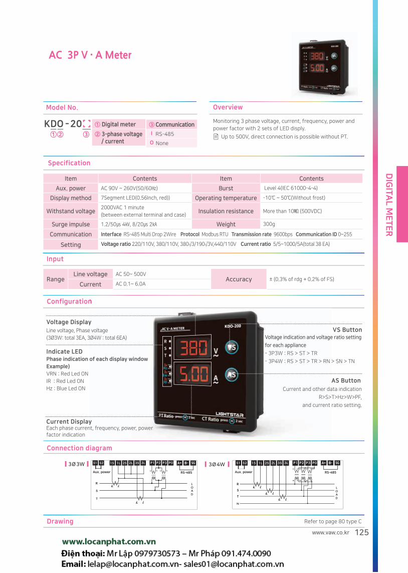
DIG
ITAL M
ET
ER
125www.vaw.co.kr
AC 3P V ˙ A Meter
Specification
Item Contents Item Contents
Aux. power AC 90V ~ 260V(50/60) Burst Level 4(IEC 61000-4-4)
Display method 7Segment LED(0.56Inch, red)) Operating temperature -10 ~ 50(Without frost)
Withstand voltage2000VAC 1 minute
(between external terminal and case)Insulation resistance More than 10 (500VDC)
Surge impulse 1.2/50 4, 8/20 2 Weight 300g
Communication Interface RS-485 Multi Drop 2Wire Protocol Modbus RTU Transmission rate 9600bps Communication ID 0~255
Setting Voltage ratio 220/110V, 380/110V, 380√3/190√3V,440/110V Current ratio 5/5~1000/5A(total 38 EA)
ConfigurationConfiguration
Voltage Display
AS Button
VS ButtonLine voltage, Phase voltage
(3Ø3W: total 3EA, 3Ø4W : total 6EA)
Phase indication of each display windowExample) VRN : Red Led ON
IR : Red Led ON
Hz : Blue Led ON
Indicate LED
Current DisplayEach phase current, frequency, power, power factor indication
Voltage indication and voltage ratio setting
for each appliance
- 3P3W : RS > ST > TR
- 3P4W : RS > ST > TR > RN > SN > TN
Current and other data indication
R>S>T>Hz>W>PF,
and current ratio setting.
Connection diagram
3Ø3W 3Ø4W
RS-485 RS-485Aux. power Aux. power
Drawing Refer to page 80 type C
Up to 500V, direct connection is possible without PT.
Input
RangeLine voltage AC 50~ 500V
Accuracy ± (0.3% of rdg + 0.2% of FS)Current AC 0.1~ 6.0A
Monitoring 3 phase voltage, current, frequency, power and
power factor with 2 sets of LED disply.
Overview
① Digital meter
② 3-phase voltage / current
KDO - 20
Model No.
①② ③③ Communication
I RS-485
O None

DIG
ITA
L M
ET
ER
126
V ˙ Hz Relay Meter
① Digital meter ② V ˙ Hz Relay Meter ③ Basic specificationsKDU - 100
Model No.
①② ③
Specification
Item Contents Item Contents
Aux. power AC 90V ~ 260V(50/60) Burst Level 4(IEC 61000-4-4)
Display method 7Segment LED(0.56Inch, Red) Operating temperature -10 ~ 50(Without frost)
Withstand voltage
2000VAC 1 minute
(between external terminal and case)Insulation resistance More than 10 (500VDC)
Surge impulse 1.2/50 4, 8/20 2 Weight 270g
Setting- Upper / lower limit voltage:500~100V - Upper / lower limit frequency:65~45 - Delay time: 0.16~3.0 sec
- Alarm HOLD : ON/OFF - No input alarm:ON/OFF
Configuration
Voltage display
Button
SET ButtonVoltage indication
- Setting item display
LED ON if exceed setting range.
Indicate LED
Frequency display
Frequency indication
- Set value display
Setting start.
Setting valus change.
Connection diagram Drawing
Refer to page 80 type C
Monitoring voltage and frequency, and relay contact will be actived if exceed setting range
Overview Up to 500V, direct connection is possible without PT
Input
RangeVoltage AC 50~ 500V
AccuracyVoltage ± (0.3% of rdg + 0.2% of FS)
Frequency ± (0.1Hz)Frequency 45~ 65Hz

DIG
ITAL M
ET
ER
127www.vaw.co.kr
V /A ˙ Hz Relay Meter
Specification
Item Contents Item Contents
Aux. power AC 90V ~ 260V(50/60) Burst Level 4(IEC 61000-4-4)
Display method 7Segment LED(0.56Inch, Red) Operating temperature -10 ~ 50(without frost)
Withstand voltage
2000VAC 1 minute
(between external terminal and case)Insulation resistance More than 10 (500VDC)
Surge impulse 1.2/50 4, 8/20 2 Weight 270g
Communication - Interface: RS-485 - Transmission rate : 9600bps - Protocol : Modbus RTU
Setting- Upper / lower limit voltage:500~100V - Upper / lower limit frequency:65~45 - Delay time: 0.16~5.0 sec
- CT ratio : 5/5 ~ 6000/ 5A - Communication address:0~255 - Alarm HOLD : ON/OFF - No input alarm:ON/OFF
Configuration
V,A display
Button
SET Button
Voltage and current indication.
LED ON if exceed setting range
- High : Red LED
- Low : Blue LED
Indicate LED
Frequency Display
Frequency indication
- Set value display
Setting start
- V / A Display: Select voltage or current
indication
The alarm release.
Setting value change
Monitoring voltage, current and frequency, and relay contact will be actived if exceed setting range.
Overview Up to 500V, direct connection is possible without PT
KDU - 20
Model No.
①② ③① Digital meter
② 3 Phase V ˙ Hz Relay Meter
③ Communication I RS-485
O None
Input
RangeVoltage AC 50~ 500V Current 0.1~6A
AccuracyVoltage ± (0.3% of rdg + 0.2% of FS)
Frequency ± (0.1Hz)Frequency 45~ 65Hz
Connection diagram Drawing
Refer to page 80 type C
RS-485
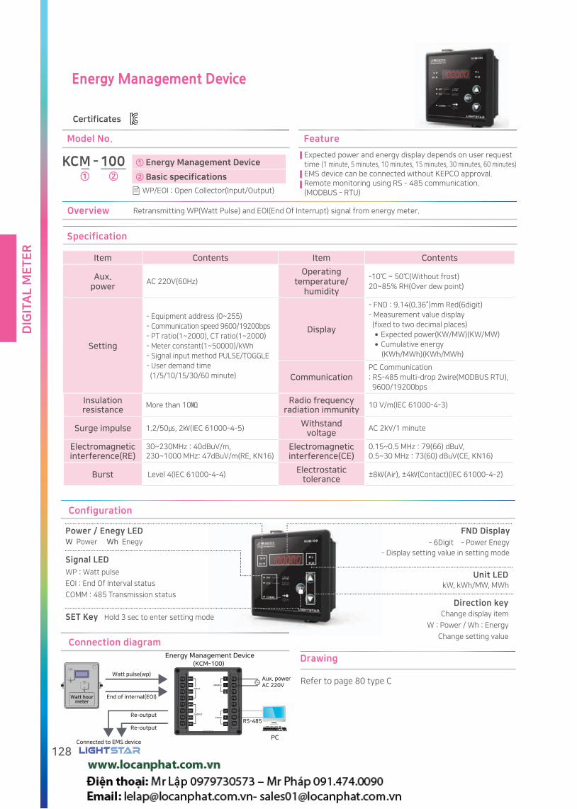
DIG
ITA
L M
ET
ER
128
Energy Management Device
Connection diagram
Drawing
Refer to page 80 type C
Retransmitting WP(Watt Pulse) and EOI(End Of Interrupt) signal from energy meter.Overview
① Energy Management Device
② Basic specifications
KCM - 100
Model No.
① ②WP/EOI : Open Collector(Input/Output)
Expected power and energy display depends on user request time (1 minute, 5 minutes, 10 minutes, 15 minutes, 30 minutes, 60 minutes)EMS device can be connected without KEPCO approval.Remote monitoring using RS - 485 communication.(MODBUS - RTU)
Feature
Insulation resistance
More than 10 Radio frequency
radiation immunity10 V/m(IEC 61000-4-3)
Surge impulse 1.2/50, 2(IEC 61000-4-5)Withstand
voltageAC 2kV/1 minute
Electromagnetic interference(RE)
30~230MHz : 40dBuV/m,230~1000 MHz: 47dBuV/m(RE, KN16)
Electromagnetic interference(CE)
0.15~0.5 MHz : 79(66) dBuV,0.5~30 MHz : 73(60) dBuV(CE, KN16)
Burst Level 4(IEC 61000-4-4)Electrostatic
tolerance±8(Air), ±4(Contact)(IEC 61000-4-2)
Specification
Item Contents Item Contents
Aux. power
AC 220V(60Hz)Operating
temperature/humidity
-10 ~ 50(Without frost)20~85% RH(Over dew point)
Setting
- Equipment address (0~255)- Communication speed 9600/19200bps- PT ratio(1~2000), CT ratio(1~2000) - Meter constant(1~50000)/kWh- Signal input method PULSE/TOGGLE- User demand time (1/5/10/15/30/60 minute)
Display
- FND : 9.14(0.36”)mm Red(6digit)- Measurement value display (fixed to two decimal places) Expected power(KW/MW)(KW/MW) Cumulative energy (KWh/MWh)(KWh/MWh)
CommunicationPC Communication : RS-485 multi-drop 2wire(MODBUS RTU), 9600/19200bps
Watt pulse(wp)
Re-output
Re-output
Connected to EMS device
End of internal(EOI)
RS-485
Aux. powerAC 220V
Energy Management Device (KCM-100)
PC
WP+
INPUT
SOURCEWP-
EOI+
EOI-
WP+
WP-
EOI+
EOI-
P
L
A+
B-
SG
Comm
OUTPUT
~
Watt hourmeter
Certificates
Configuration
Power / Enegy LED FND Display
Unit LED
W Power Wh Enegy
WP : Watt pulse
EOI : End Of Interval status
COMM : 485 Transmission status
Signal LED
SET Key Hold 3 sec to enter setting mode
- 6Digit - Power Enegy
- Display setting value in setting mode
kW, kWh/MW, MWh
Direction keyChange display item
W : Power / Wh : Energy
Change setting value
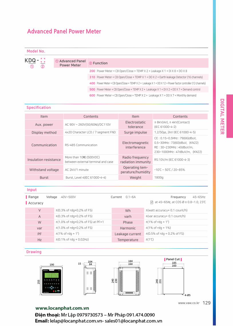
DIG
ITAL M
ET
ER
129www.vaw.co.kr
Advanced Panel Power Meter
① Advanced Panel Power Meter
② Function
200 Power Meter + CB Open/Close + TEMP X 2 + Leakage X 1 + DI X 8 + DO X 8
310 Power Meter + CB Open/Close + TEMP X 1 + DO X 2 + Earth leakage Detector (16 channels)
400 Power Meter + CB Open/Close + TEMP X 2 + Leakage X 1 + DO X 12 + Power factor controller (12 channels)
500 Power Meter + CB Open/Close + TEMP X 2 + Leakage X 1 + DI X 2 + DO X 7 + Demand control
600 Power Meter + CB Open/Close + TEMP X 2 + Leakage X 1 + DO X 7 + Monthly demand
KDQ -
Model No.
① ②
Specification
Item Contents Item Contents
Aux. power AC 90V ~ 260V(50/60)/DC110VElectrostatic
tolerance± 8kV(Air), ± 4kV(Contact)
(IEC 61000-4-2)
Display method 4x20 Character LCD / 7 segment FND Surge impulse 1.2/50, 2kV (IEC 61000-4-5)
Communication RS-485 CommunicationElectromagnetic
interference
CE : 0.15~0.5MHz : 79(66)dBuV,
0.5~30MHz : 73(60)dBuV, (KN22)
RE : 30~230MHz : 40dBuV/m,
230~1000MHz : 47dBuV/m, (KN22)
Insulation resistanceMore than 10 (500VDC)
between external terminal and case
Radio frequency radiation immunity
RS:10V/m (IEC 61000-4-3)
Withstand voltage AC 2kV/1 minuteOperating tem-
perature/humidity-10 ~ 50 / 20~85%
Burst Burst, Level 4(IEC 61000-4-4) Weight 1800g
Input
Voltage 40V~500V Current 0.1~6A Frequency 45~65HzRange
Accuracy
V ±(0.3% of rdg+0.2% of FS) Wh ±(watt accuracy+ 0.1 count/h)
A ±(0.3% of rdg+0.2% of FS) varh ±(var accuracy+ 0.1 count/h)
W ±(1.0% of rdg+0.2% of FS) at PF=1 Phase ±(1% of rdg + 1°)
var ±(1.0% of rdg+0.2% of FS) Harmonic ±(1% of rdg + 1%)
PF ±(1% of rdg + 1°) Leakage current ±(0.5% of rdg + 0.2% of FS)
Hz ±(0.1% of rdg + 0.02Hz) Temperature ±(1)
at 45~65, at COS Ø ± 0.8~1.0, 23
Drawing
Panel Cut

DIG
ITA
L M
ET
ER
130
Connection diagram
1P2W 1P3W
Aux.power
Aux.power
3P3W 3P4W
Aux.power
Aux.power
Leakage current PT-100Ω
Circuit breaker
DICLOSE
CB1CLOSE
CB2CLOSE
DI COM DIOPEN
CB1OPEN
CB2OPEN
DI COM
CB CLOSEDO CB CLOSE
RelayCB OPEN
Relay
CB OPENDI

DIG
ITAL M
ET
ER
131www.vaw.co.kr
Power Quality Advanced Panel Power Meter
KDQ - 200
Model No.
Connection diagram
Configuration(KDQ-200)
A1
Display
A1 LED
display
Power supply, communication, alarm, error
BLUETOOTH( - red), CB CLOSE ( - red),
OPEN ( - green), DI ( - green)
- Bluetooth connection with mobile devices
Measured data can be displayed and saves in mobile devices
by using bluetooth
- Measuring fuctions
Voltage, current, leakage current, active/reactive/surface
power, PF, frequency, energy, temperature, phase can be
displayed.
- Circuit breaker control function.
The status of circuit breaker can be displayed by contact
input, and circuit breaker can be controlled by relay output.
Overview Specification
Power quality
Communication with smart
devices
BLUETOOTH communication,
available distance 5 meter
SettingCircuit, current range, communication
address by smart device
DisplayPower quality related data such as
waveform, harmonics and phase in smart
device
Input DI 8 channels
Refer to page 129 for specifications related to KDQ basic functions.
Waveform
Harmonic
Voltage
Line voltage Demand power Reactive power Reactive energy
Current Unbalance rate Power Energy
Power factor Apparent power Total
Measured value
Android App(KDQ-200 Option)
Phase

DIG
ITA
L M
ET
ER
132
Earth Leakage Detector Advanced Panel Power Meter
KDQ - 310
Model No.
Configuration(KDQ-310)
Earth leakage detecting
A1 LED display Earth leakage alarm(-Red)
A2 FND Display Eakage current
A3 FND Display Circuit number
A4Setting button
Setting mode
A5Confirm button
Save setting
A6Direction button ()
change circuit number and setting
A7 LED displayBuzzer on(-Yellow)Off status(-Green)
A8 Buzzer button
Buzzer on/ off selection
A9 LED display
Alarm statusAutomatic(-Yellow)Manual(-Green)
A10 Alarm button
Alarm setting automatic/manual
A11 Circuit button Select circuit
A12 Reset button Reset the status
A13 Test button
Energizing/Alarm test
A14 LED display
Energizing test status (-Green)
Specification
Earth leakage detecting
Input Current 16Ch (200mA, 100mV, ZCT output)
OutputEarth leakage alarm relay 1Ch,
communication: RS-485
SettingLeakage current sensitivity, buzzer on/off, test,
reset
DisplayMeasurement value of leakage current,
16 circuit status, number of displayed circuit
Refer to page 129 for KDQ series related specifications
A10
A14
A13
A12
A9
A11
A8
A2
A3
A1
A4
A5
A6 A7
Connection diagram
- Earth leakage detector function
This device is detecting earth leakage by zero phase current
transformers, which can be connected up to 16 sets. Alarm and
buzzer to be activated if measured current from ZCT is exceed
setting value.
- Measuring fuctions
Voltage, current, leakage current, active/reactive/surface
power, PF, frequency, energy, temperature, phase can be
displayed.
- Circuit breaker control function.
The status of circuit breaker can be displayed by contact
input, and circuit breaker can be controlled by relay output.
Overview

DIG
ITAL M
ET
ER
133www.vaw.co.kr
Auto Power Factor Control Advanced Panel Power Meter
KDQ - 400
Model No.
- Power factor controller function
Measuring the electrical data and control the external capacitor(condenser)
in order to compensate Power factor
- Measuring fuctions
Voltage, current, leakage current, active/reactive/surface power, PF,
frequency, energy, temperature, phase can be displayed.
- Circuit breaker control function.
The status of circuit breaker can be displayed by contact input, and
circuit breaker can be controlled by relay output.
Overview Specification
Power Factor
Input Same as KDQ-200 (Refer to page 129)
Output Control relay 2Ch, communication: RS-485
Setting12Ch passive control, control method, OFFSET,
wire connection correction
Display Capacitor status, Lead/Lag, Day/Night
Refer to page 129 for KDQ series related specifications
Connection diagram
Power factor control
A1 LED Display Power factor / Error(-Red)
A2 FND Display Power factor / Error, PF trend
A3 LED Display Capacitor status(-Red)
A4Setting
buttonSetting mode
A5 ENT button Save setting and shift digit
A6Direction
button()Change setting value
A7 FND display Var/W, PF trend time
A8 LED display k/M(-Red)
A9 LED display Var/W(-Red)
A10 Dip switch Capacitor On/Off/Auto
A11 LED displayNight control status
(-Yellow)
A12 LED display Day control status (-Red)
Configuration(KDQ-400)
A11
A10
A9
A8
A7
A12
A2
A1
A3
A4
A5
A6

DIG
ITA
L M
ET
ER
134
Demand Advanced Panel Power Meter
KDQ - 500
Model No.
Maximum demand power
A1 LED DisplayPresent power,(-Red)
Expected power(-Red)
A2 FND Display Present power, Expected power
A3 LED Display WP/EOI(-Green), Alarm(-Red)
A4Setting
buttonSetting mode, Shift digit
A5 ENT button Select setting menu, Save setting
A6Direction
button()change setting value
A7 FND DisplayTarget power, Standard power,
Setting value
A8 LED DisplayTarget power(-Red),
Standard power.(-Red)
A9 LED Display Load (-Yellow)
Specification
Demand Controller
Input Watt Pulse(WP), End Of Interval (EOI)
OutputControl relay 4Ch, alarm 3Ch,
communication: RS-485
SettingMeter constant, PCT ratio, 1PULSE / wh, target
power, demand time limit, control time,
load control method
Display
Present power, target power, expected power,
standard power, demand time list
Power before 15 min, Daily/Monthly energy
consumption
Refer to page 129 for KDQ series related specifications
Connection diagram
Configuration(KDQ-500)
A9
A8
A7
A2
A1
A3
A4
A5
A6
WP COM COMEOI
KDQ-500
WP+ WP- EOI-EOI+
OUTPUTKCM-100(Energy Management Device )
- Load shedding control function
In order to minimize electric cost, this device can control and
shedding electric load by the signal from KEPCO approved billing
meter
- Measuring fuctions
Voltage, current, leakage current, active/reactive/surface power,
PF, frequency, energy, temperature, phase can be displayed.
- Circuit breaker control function.
The status of circuit breaker can be displayed by contact input,
and circuit breaker can be controlled by relay output.
Overview

DIG
ITAL M
ET
ER
135www.vaw.co.kr
Monthly Demand Advanced Panel Power Meter
KDQ - 600
Model No.
- Monthly power management function
In order to minimize electric cost, this device can calculate
target energy and control load by working day and time.
- Measuring fuctions
Voltage, current, leakage current, active/reactive/surface
power, PF, frequency, energy, temperature, phase can be
displayed.
- Circuit breaker control function.
The status of circuit breaker can be displayed by contact input,
and circuit breaker can be controlled by relay output.
Overview
Month power control
A1 LED Display Target energy/ Standard energy(-Red)
A2 FND Display Target energy/ Standard energy
A3 LED Display kW/MW(-Red)
A4 LED Display Load(-Yellow)
A5 FND Display Present energy / energy consumption
A6 LED Display kW/MW(-Red)
A7 LED Display present energy / energy consumption(-Red)
A8 LED Display Alarm(-Red)
A9Setting button
Change display, setting mode, Shift digit
A10Enter
buttonSave setting
A11Direction key()
Change setting value
Configuration(KDQ-600)
B1
C2
B5
A8
A7
A6
A5
C1
B2
B4
A2
A1
A3
A9
A4
A10
A11
B3
Connection diagram
Specification
Month power control
Input Same as KDQ-200 (Refer to page 129)
OutputControl relay 8Ch, alarm 3Ch,
communication: RS-485
SettingContract power, Checking date, Holiday setting,
Work start time, Work finish time, Control cycle
DisplayTarget energy, Present energy, Expected energy,
Standard energy, Checking date, working day/hour
Refer to page 129 for KDQ series related specifications

MEMO

CE certification
CE stands for "Conformité Européene" and indicates conformity with health, safety,
and environmental protection standards for products sold within the European Economic Area (EEA).
Our CE certified products are complied to the requirements of EU Directives, relating to LVD
(Low Voltage Directives) and EMCD(Electro Magnetic Compatibility Directives).
LIGHTSTAR achieved CE certificate for Analog meter, Current Transformer, Digital meter, Power meter
and Transducers.
KS certification
KS stands for Korean Standard and indicates conformity
with Korean government required standards.
LIGHTSTAR achieved KS certificate for Analog meter, Current Transformer and Transducers.

Earth Leakage Detector(Relay)
Zero Phase Current Transformer for Cable

Zero Phase Current Transformer for Busbar
Zero Phase Current Transformer for SGR(SELECTIVE GROUND RELAY)

EA
RT
H L
EA
KA
GE
D
ET
EC
TO
R
140
Earth Leakage Detector(Relay)
Certificates Korea Fire Institute approved
Model No.
KG - ① ② ③ ④
① Type ② Number of circuits ③ Communication ④ USE
D Digital Type 08 08 circuit C RS-485 R Relay
10 10 circuit NA None NA None
12 12 circuit If relay option(R) chosen, separated relay (KGR) to be
supplied compatible with KGD.16 16 circuit
Overview
This device can be used for detecting earth leakage for low voltage(<AC600V). Alarm and buzzer to be activated if measured current from ZCT is exceed setting value.
Specification
Item KGD
Number of circuits
8circuit 10circuit 12circuit 16circuit
Terminal connection
Bolt Type
Input ZCT output (KGB, KGC)
Display Leakage : 7-segment LED 3Digit Circuit: 7-segment LED 2Digit Status LED: Green(Normal), Yellow(Test), Red(Alarm)
Aux. power AC110 ~ 220V 50/60 Hz, DC 110VInsulation resistance
More than 5MΩ
Contact capacity
AC 250V / 1A 0.3sec, DC24V / 2AWithstand
voltageAC 2.2kV(60Hz) / 1 minute
Sensitivity setting
0.2A~1.0A(0.1A Unit Setting)Surge impulse 1.2 x 50,6kV
Operating Within 1 second when 75% or more of setting value
Burst Level 4(IEC 61000-4-4)Inoperative
Inoperative when less than 52% of setting current continues 30 sec and more.
Power Operating 10VA, Inoperative less than 6VA Electrostatic discharge
±8kV(Air), ±4kV(Contact)(IEC 61000-4-2)
Buzzer volume More than 70dB
Radio frequencyConduction resistance
0.15~80MHz 10V(IEC 61000-4-6)
Communication (option)
RS-485 2Wire, Modbus RTU communication
Operating temperature
-10~50Radio frequency
Radiation resistance
80~1000MHz 10V/m(IEC 61000-4-3)
Operating Humidity
45~85% RH(Over dew point) Impact Test 50gf, 5times
Vibration
Frequency: 10 to 150 Hz Number of axes: 3Acceleration amplitude: 0.981 m / s 2,Sweep speed: 1 octave / min,Sweep cycles: 1 time per axis
InternalImpedance
2kΩ

EA
RT
H LE
AK
AG
E
DE
TE
CT
OR
141www.vaw.co.kr
Operating principle
Detector
Transformer
Supply
Grounding ZCT
leakage
Connection diagram Terminal configuration
16(3 phase 4 wire) (3 phase 3 wire)
SOURCE
S1, S2 : Aux. power
(AC 110V/220V 50/60Hz
DC 110V)
: Earth(Grounding terminal)
Ta, Tc : Non-voltage contact
A+, B-, SG : RS-485 Communication (option)
COM : ZCT Common
CH1~CH16 : ZCT input for each circuit
Drawing
Panel cut
Unit : mm
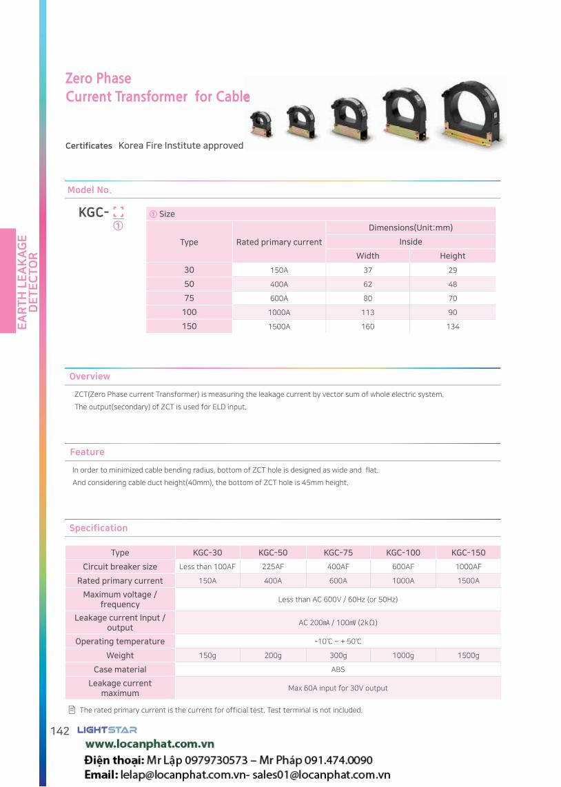
EA
RT
H L
EA
KA
GE
D
ET
EC
TO
R
142
Zero Phase Current Transformer for Cable
Certificates Korea Fire Institute approved
Current Transformer for Cable
Feature
In order to minimized cable bending radius, bottom of ZCT hole is designed as wide and flat.
And considering cable duct height(40mm), the bottom of ZCT hole is 45mm height.
Overview
ZCT(Zero Phase current Transformer) is measuring the leakage current by vector sum of whole electric system.
The output(secondary) of ZCT is used for ELD input.
Model No.
KGC- ①
① Size
Type Rated primary current
Dimensions(Unit:mm)
Inside
Width Height
30 150A 37 29
50 400A 62 48
75 600A 80 70
100 1000A 113 90
150 1500A 160 134
Specification
Type KGC-30 KGC-50 KGC-75 KGC-100 KGC-150
Circuit breaker size Less than 100AF 225AF 400AF 600AF 1000AF
Rated primary current 150A 400A 600A 1000A 1500A
Maximum voltage / frequency
Less than AC 600V / 60Hz (or 50Hz)
Leakage current input / output
AC 200 / 100 (2kΩ)
Operating temperature -10 ~ + 50
Weight 150g 200g 300g 1000g 1500g
Case material ABS
Leakage current maximum
Max 60A input for 30V output
The rated primary current is the current for official test. Test terminal is not included.
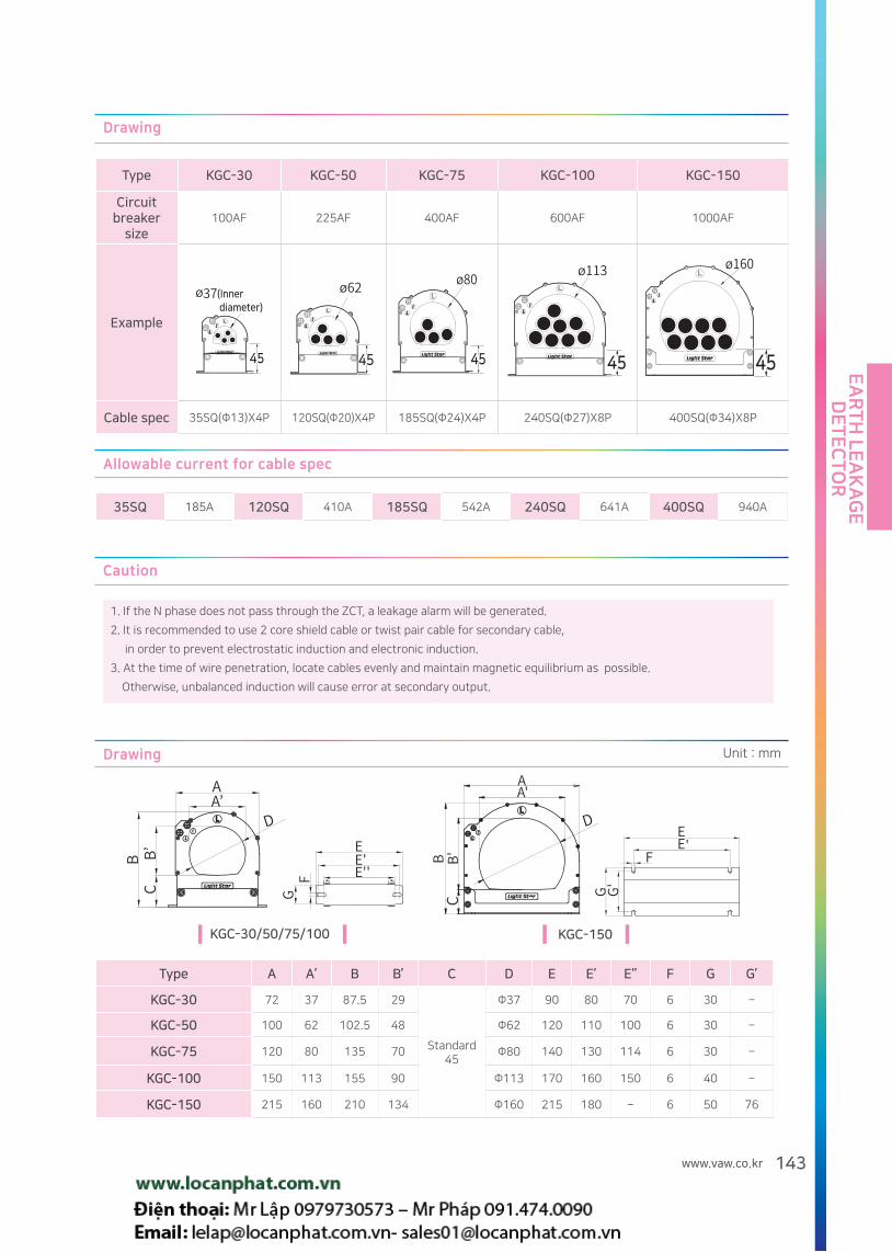
EA
RT
H LE
AK
AG
E
DE
TE
CT
OR
143www.vaw.co.kr
Drawing
Type KGC-30 KGC-50 KGC-75 KGC-100 KGC-150
Circuit breaker
size100AF 225AF 400AF 600AF 1000AF
Example
Cable spec 35SQ(Φ13)X4P 120SQ(Φ20)X4P 185SQ(Φ24)X4P 240SQ(Φ27)X8P 400SQ(Φ34)X8P
(Inner diameter)
45 45 45 45
Allowable current for cable spec
35SQ 185A 120SQ 410A 185SQ 542A 240SQ 641A 400SQ 940A
Caution
1. If the N phase does not pass through the ZCT, a leakage alarm will be generated.
2. It is recommended to use 2 core shield cable or twist pair cable for secondary cable,
in order to prevent electrostatic induction and electronic induction.
3. At the time of wire penetration, locate cables evenly and maintain magnetic equilibrium as possible.
Otherwise, unbalanced induction will cause error at secondary output.
Drawing
Type A A’ B B’ C D E E’ E’’ F G G’
KGC-30 72 37 87.5 29
Standard45
Φ37 90 80 70 6 30 -
KGC-50 100 62 102.5 48 Φ62 120 110 100 6 30 -
KGC-75 120 80 135 70 Φ80 140 130 114 6 30 -
KGC-100 150 113 155 90 Φ113 170 160 150 6 40 -
KGC-150 215 160 210 134 Φ160 215 180 - 6 50 76
KGC-30/50/75/100 KGC-150
Unit : mm

EA
RT
H L
EA
KA
GE
D
ET
EC
TO
R
144
Zero Phase
Current Transformer
for Busbar
Certificates Korea Fire Institute approved
Model No.
KGB- ①
① Size
TypeRated primary
current
Dimensions(Unit:mm)
Inside
Width Height
01 100A 92 10
02 150A 108 10
03 300A 132 11
05 400A 163 30
07 600A 210 30
11 1000A 260 30
Feature
According to the dimension of circuit breaker, the dimension of CT is optimized and minimized.
In order to minimized thermal deformation, ZCT is designed not to be touched on busbar surface directly.
Caution
Due to the structural limit, magnetic equilibrium between the busbar is not easy to achieve. Please consider this limit in design
Specification
The rated primary current is the current for official test. Test terminal is not included.
Type KGB-01 KGB-02 KGB-03 KGB-05 KGB-07 KGB-11
Circuit breaker100AF 125AF 225AF 400AF 400AF 600AF 600AF 800AF 1000AF
3P3W3P4W
3P3W3P4W
3P3W3P4W
3P3W3P4W
3P4W 3P3W 3P4W3P3W3P4W
3P3W3P4W
Rated primary current
100A 150A 300A 400A 600A 1000A
Maximum voltage / frequency
Less than AC 600V/60Hz(or 50Hz)
Leakage current input / output
AC 200mA/100mV(2kΩ)
Operating temperature
-10 ~ +50
Weight 170g 190g 220g 220g 880g 1400g
Case material ABS
Leakage current maximum
Max 60A input for 30V output
KGB-01,02,03
KGB-05,07,11

EA
RT
H LE
AK
AG
E
DE
TE
CT
OR
145www.vaw.co.kr
Drawing
TypeSize
a b c d e f g
KGB-01 92 111 10 54 4-M4X15mm 22 39
KGB-02 108 135 10 54 4-M4X15mm 22 39
KGB-03 132 150 11 54 4-M4X15mm 22 39
KGB-05 163 225 30 90 8-M5X15mm 34 52
KGB-07 210 270 30 90 8-M5X15mm 34 52
KGB-11 260 330 30 100 16-M5X20mm 38 56
Drawing Unit:mm
Dimension
TypeSize
a a’ b b’ c c’ d d’ e
KGB-01 90 92 8 10 54 60 100 111 39
KGB-02 106 108 8 10 54 60 120 135 39
KGB-03 130 132 8 11 54 60 140 153 39
KGB-05 162 163 8 30 90 95 184 225 52
KGB-07 184 210 8 30 90 95 184 270 52
KGB-11 259 260 17 30 100 103 290 330 56
Unit:mm
Design can be changed without notice
Ø10Ø13
Ø3.6
Ø4.6
7
Please prevent direct contact with busbar, which may cause CT deformation and damage.
Torque limit for bus bar fixing bolt(Excess torque may cause bending and distortion) : M4 - 5~7 kgfㆍcm, M5 - 7~10kgfㆍcm
Please be aware that bus bar fixing bolt for current transformer can be energized
Bolt insulation covers are recommended for safety

EA
RT
H L
EA
KA
GE
D
ET
EC
TO
R
146
Zero Phase Current Transformer for SGR(SELECTIVE GROUND RELAY)
Model No.
KG - ② ③①
① Type ② Size
C Cable Type
Cable TypePrimary current
Size(Unit:mm)
B Busbar Type Inside
W H
30 Less than 100AF 150A 37 29
50 Less than 225AF 400A 62 48
75 Less than 400AF 600A 80 70
100 Less than 600AF 1000A 113 90
150 Less than 1000AF 1500A 160 134
Busbar TypePrimary current
Size(Unit:mm)
Inside
W H
05 400AF 3P3W 400A 163 30
07400AF
3P4W, 600AF 3P3W600A 210 30
11600AF 800AF 1000AF
1000A 260 303P4W 3P3W,3P4W 3P3W,3P4W
③ Use
S for SGR
This item is not suitable for DGR
(Directional Ground fault Relay)
and GOCR(Ground Over Current Relay)
Refer to P143 & P145 for dimension
and drawing
Specification
Maximum voltage / frequency Less than AC 600V /60Hz(or 50Hz)
Input / Output AC 200mA/1.5mA
Accuracy H Class(±15% at 200mA~500mA)
Insulation resistance Secondary terminal - Extenal support : DC 500V/100kΩ
Dielectric strength Secondary terminal - Extenal support : AC 1500V/1min
Operating temperature -10 ~ +50
For cableFor cable
S
For bus bar
Design can be changed without notice
Ø10Ø13
Ø3.6
Ø4.6
7
Please prevent direct contact with busbar, which may cause CT deformation and damage.
Torque limit for bus bar fixing bolt(Excess torque may cause bending and distortion) : M4 - 5~7 kgfㆍcm, M5 - 7~10kgfㆍcm
Please be aware that bus bar fixing bolt for current transformer can be energized
Bolt insulation covers are recommended for safety
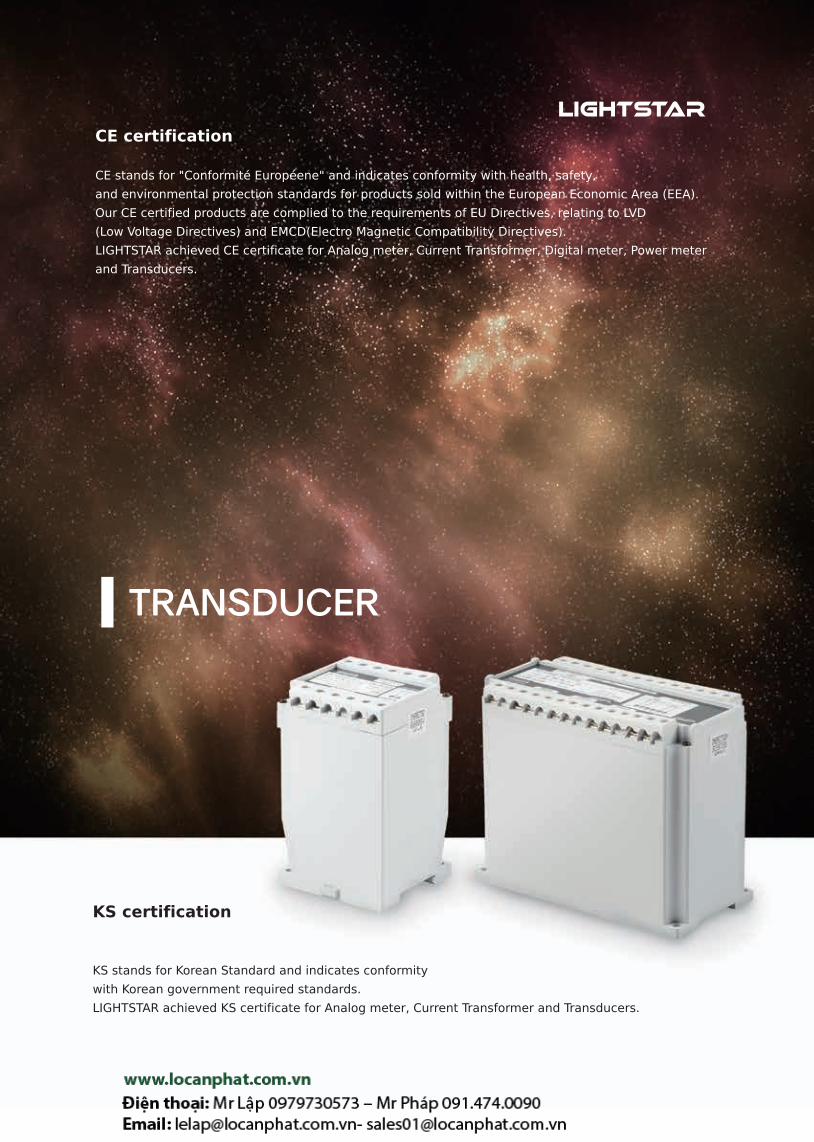
CE certification
CE stands for "Conformité Européene" and indicates conformity with health, safety,
and environmental protection standards for products sold within the European Economic Area (EEA).
Our CE certified products are complied to the requirements of EU Directives, relating to LVD
(Low Voltage Directives) and EMCD(Electro Magnetic Compatibility Directives).
LIGHTSTAR achieved CE certificate for Analog meter, Current Transformer, Digital meter, Power meter
and Transducers.
KS certification
KS stands for Korean Standard and indicates conformity
with Korean government required standards.
LIGHTSTAR achieved KS certificate for Analog meter, Current Transformer and Transducers.

Definition AC Current Transducer
DC Isolated Transducer
Watt Transducer
Power Factor Transducer
VAR & VAR hour Transducer
Potential Transducer
RTD Transducer
AC Voltage Transducer
Frequency Transducer
Watt· Watthour Transducer
VAR Transducer
Pulse·Analog Transducer
DC Watt Transducer

AC Current Socket Transducer AC Voltage Socket Transducer
Frequency Socket Transducer
RTD Socket Transducer
Unit : mm
DC Isolated Socket Transducer
Potential Socket Transducer
Drawing

TR
AN
SD
UC
ER
150
Definition
Class
KS C 1708 Accuracy tolerances for transducer as per base value.
example) 0.1 Class = Tolerance to base value ±0.1% 0.2Class = Tolerance to base value ±0.2%
0.25 Class = Tolerance to base value ±0.25% 0.5 Class = Tolerance to base value ±0.5%
1.0 Class = Tolerance to base value ±1.0% 3.0Class = Tolerance to base value ±3.0%
Base value
Numerical differences from max output to min output.
Withstanding voltage
Test with AC voltage more than 1 min between input and output, input and human contacted area , input and source, source
and output, source and human contacted area
Insulation resistance test
Test with DC voltage more than 500V between input and output, input and human contacted area , input and source, source and
output, source and human contacted area.
Surge impulse test
Test intended for the lightening surge conditions, and to be performed with voltage(1.2.....50..) and current (8...20...) on aux power
by tester.
Voltage waveform Current waveform
Increase : 30%~90%, of Vpk 1.2
Decrease : By 50% of Vpk 50
Increase : 10%~90%, of Vpk 8
Decrease : By 50% of Vpk 20

TR
AN
SD
UC
ER
151www.vaw.co.kr
[MTy] [LLTy] [LTy]
AC Current Transducer
Certificates
Specification
Class Average value(0.2): Rms value(0.5) Withstand voltage AC 2kV /1 min
Aux. power Refer to the table above Surge impulseVoltage(1.2/ 50, 5kV)
Current(8/20)
Operating temperature -10~50 Max allowable currentA-200% 10sec,
120% Continuous
Operating humidity 20 ~ 85%Weight
200g(MTy), 500g(L Ty)
1140g(LL Ty) Insulation resistance More than 10MΩ
Load resistance by output Input
DC Load resistance
4~20
0~1
1~5V
0~10V
0~500Ω
0~10kΩ
More than 200Ω
More than 500Ω
AC Current0 ~ 1A(50/60Hz)
0 ~ 5A(50/60Hz)
Connection diagram
1P2W(LTy)-2Output 1P2W(L,MTy)-1Output 1P3W(LLTy) 3P3W(LLTy) 3P4W(LLTy)
Model No.
KTA- ① ④② ⑤③ ⑥
① AC Current Input ② DC Output ③ Circuit
1 0 ~ 1A 6 4 ~ 20 1 1P2W(LTy)
2 0 ~ 5A 7 0 ~ 1 2 1P3W(LLTy)
8 1 ~ 5V 3 3P3W(LLTy)
9 0 ~ 10V 4 3P4W(LLTy)
0 Order-made 5 1P2W(MTy)
④ Type ⑤ Aux. power ⑥ Number of outputs
A Average value
1 AC 110/220V (Except 2 Output)S 1 Output(M,L ty) for Single phase
3 Output(LL ty) for 3 phase
2 AC 90~260V, DC110V, 220V
(Except RMS) T 2 Output for Single phase
3 DC 24V (Except RMS, 2 Output)
R RMS value 1 AC 110/220V (Except 2 Output)
How to order) KTA-163A1S
1A/4~20/3P3W
/Average/AC 110/220V
How to order) KTA-283A1S
5A/1~5V/3P3W/Average
/AC 110/220V
Customized product can be
produced by order.

TR
AN
SD
UC
ER
152
AC Voltage Transducer
Certificates
Specification
Class Average value(0.2): Rms value(0.5) Withstand voltage AC 2kV /1 min
Aux. power Refer to the table above Surge impulseVoltage(1.2/ 50, 5kV)
Current(8/20)
Operating temperature -10~50 Max allowable VoltageV-150% 10sec,
120% continuous
Operating humidity 20 ~ 85%Weight
200g(MTy), 500g(L Ty)
1140g(LL Ty) Insulation resistance More than 10MΩ
Load resistance by output Input
DC Load resistance
4~200~11~5V
0~10V
0~500Ω0~10kΩ
More than 200Ω More than 500Ω
AC Voltage0 ~ 150V(50/60Hz)
0 ~ 300V(50/60Hz)
Connection diagram
1P2W(L,MTy) 1P3W(LLTy) 3P3W(LLTy) 3P4W(LLTy)1P2W(LTy)-2Output
Model No.
KTB- ① ④② ⑤③ ⑥
① AC Voltage input ② DC Output ③ Circuit
1 0 ~ 150V 6 4 ~ 20 1 1P2W(LTy)
2 0 ~ 300V 7 0 ~ 1 2 1P3W(LLTy)
0 Order-made 8 1 ~ 5V 3 3P3W(LLTy)
Less than Three-phase 9 0 ~ 10V 4 3P4W(LLTy)
Single phase less than 420V 0 Order-made 5 1P2W(MTy)
How to order ) KTB-161A1S
150V/4~20/1P2W
/Average value/AC 110/220V
How to order ) KTB-263R1S
300V/4~20mA/3P3W
/RMS value/AC 110/220V
Customized product can be
produced by order.
[MTy] [LLTy] [LTy]
④ Type ⑤ Aux. power ⑥ Number of outputs
A Average value
1 AC 110/220V (Except 2 Output)S 1 Output(M,L ty) for Single phase
3 Output(LL ty) for 3 phase
2 AC 90~260V, DC110V, 220V
(Except RMS) T 2 Output for Single phase
3 DC 24V (Except RMS, 2 Output)
R RMS value 1 AC 110/220V (Except 2 Output)

TR
AN
SD
UC
ER
153www.vaw.co.kr
DC Isolated Transducer
Certificates
Model No.
KTD- ① ④② ③
① DC Input ② DC Output ③ Aux. power④ Number of outputs
1 0 ~ 50 6 4 ~ 20 1 AC 110/220V (Except 2 Output) S 1 Output
2 ±50 7 0 ~ 1 2 AC 90~260V, DC110V, 220V T 2 Output
3 0 ~ 10V 8 1 ~ 5V 3 DC 24V (Except 2 Output)
4 0 ~ 150V 9 0 ~ 10V
5 4 ~ 20 0 Order-made
6 0 ~ 1
7 0 ~ 10
8 0 ~ 20
0 Order-made
How to order)
KTD-161S
0~50 / 4~20 /
AC 110/220V
How to order)
KTD-472T
0~150V / 0~1 /
AC 90~260V
Customized product
can be produced by order.
Specification
Class 0.2 Withstand voltage AC 2kV /1 min
Aux. power Refer to the table above Surge impulseVoltage(1.2/ 50, 5kV)
Current(8/20)
Operating temperature -10~50 Max allowable currentA-200% 10sec,
120% continuous
Operating humidity 20 ~ 85% Max allowable VoltageV-150% 10sec,
120% continuous
Insulation resistance More than 10MΩ Weight 500g(L Ty)
Load resistance by output Input
DC Load resistance
4~20
0~1
1~5V
0~10V
0~500Ω
0~10kΩ
More than 200Ω
More than 500Ω
DC Voltage DC Current
0~50
±50
0~10V
0~150V
4~20
0~1
0~10
0~20
Connection diagram
1Output 2Output

TR
AN
SD
UC
ER
154
Frequency Transducer
Certificates
Specification
Class 0.1(0~120Hz) 0.5 Withstand voltage AC 2kV /1 min
Aux. power Refer to the table above Surge impulseVoltage(1.2/ 50, 5kV)
Current(8/20)
Operating temperature -10~50 Max allowable VoltageV-150% 10sec,
120% continuous
Operating humidity 20 ~ 85%Weight 500g(L Ty)
Insulation resistance More than 10MΩ
Model No.
KTF- ① ④② ③
① AC input② DC Output
③ Aux. power④ Number of outputs
1 90 ~ 240V(0~120Hz) 6 4 ~ 20 1 AC 110/220V (Except 2 Output) S 1 Output
0 Order-made 7 0 ~ 1 2 AC 90/260V, DC 110V, 220V T 2 Output
8 1 ~ 5V
9 0 ~ 10V
0 Order-made
How to order) KTF-181S
0~120Hz/1~5V/AC
110/220V/1Output
Customized product can be
produced by order.
Load resistance by output Input
DC Load resistance
4~20
0~1
1~5V
0~10V
0~500Ω
0~10kΩ
More than 200Ω
More than 500Ω
0~120Hz : AC 90~240V
Connection diagram
1Output 2Output

TR
AN
SD
UC
ER
155www.vaw.co.kr
Watt Transducer
Certificates
Model No.
KTG - ① ④ ⑤② ③
③ DC Output
6 4 ~ 20
7 0 ~ 1
8 1 ~ 5V
9 0 ~ 10V
0 Order-made
④ Aux. power
2 AC 90~260V, DC 110V
⑤ Number of outputs
S 1 Output
T 2 Output
① Circuit ② AC input Input value
1 1P2W
1 110V/5A 600W
2 220V/5A 1200W
0 Order-made
2 1P3W 1 220/110V/5A 1000W
3 3P3W
1 110V/5A 1000W
2 220V/5A 2000W
0 Order-made
4 3P4W
1 (208/√3)V / 5 A 2000W
2 (380/√3)/(190/√3)V / 5 A 2000W
3 (380/√3)V / 5A 4000W
4 (11400/√3)/(190/√3)V / 5A 1660W
5 (22900/√3)/(190/√3)V / 5A 1660W
0 Order-made
Load resistance by output Input
DC Load resistance
4~200~11~5V
0~10V
0~500Ω0~10kΩ
More than 200Ω More than 500Ω
Circuit type 1P2W, 1P3W, 3P3W, 3P4W
Power 600,1000,1660,2000,4000W
Specification
Class 0.2 Withstand voltage AC 2kV /1 min
Aux. power Refer to the table above Surge impulseVoltage(1.2/ 50, 5kV)
Current(8/20)
Operating temperature -10~50 Max allowable current A-200% 10sec, 120% continuous
Operating humidity 20 ~ 85% Max allowable Voltage V-150% 10sec, 120% continuous
Insulation resistance More than 10MΩ Weight 1140g(LL Ty)
How to order) KTG-4362S
3P4W/380/√3V/5A/4~20/
AC 90~260V/1Output
Connection diagram
1P2W(LLType) 3P3W(LLType) 3P4W(LLType)

TR
AN
SD
UC
ER
156
Watt .Watthour Transducer
Certificates
Specification
ClassVoltage (0.2),
Energy (0.5)Withstand voltage AC 2kV /1 min
Aux. power Refer to the table above Surge impulseVoltage(1.2/ 50, 5kV)
Current(8/20)
Operating temperature -10~50 Max allowable current A-200% 10sec, 120% continuous
Operating humidity 20 ~ 85% Max allowable Voltage V-150% 10sec, 120% continuous
Insulation resistance More than 10MΩ Weight 1140g(LL Ty)
Model No.
KTW - ① ④ ⑤ ⑥② ③
③ DC Output
6 4 ~ 20
7 0 ~ 1
8 1 ~ 5V
9 0 ~ 10V
0 Order-made
④ Count(energy)
A Contact relay
(10,000count/1 hour rated energy)
B Contactless point Open collector
(10,000count/1 hour rated energy)
C Potential signal 5V Pulse
⑤ Aux. power
2 AC 90~260V, DC 110V
⑥ Number of outputs
S 1 Output
How to order Example) KTW-116A2S
1P2W/110, 5A/4~20/Electrical contact
/ DC 110V/1Output
Connection diagram
Refer to page 161-162
Load resistance by output Input
DC Load resistance
4~200~11~5V
0~10V
0~500Ω0~10kΩ
More than 200Ω More than 500Ω
Range -0.5~1~0.5(LEAD~LAG)
Circuit 1P2W, 1P3W, 3P3W, 3P4W
Voltage 110, 220, 190/√3, 208/√3, 380/√3V
Current 5A
① Circuit ② AC input Input value
1 1P2W
1 110V/5A 600W
2 220V/5A 1200W
0 Order-made
2 1P3W 1 220/110V/5A 1000W
3 3P3W
1 110V/5A 1000W
2 220V/5A 2000W
0 Order-made
4 3P4W
1 (208/√3)V / 5 A 2000W
2 (380/√3)/(190/√3)V / 5 A 2000W
3 (380/√3)V / 5A 4000W
4 (11400/√3)/(190/√3)V / 5A 1660W
5 (22900/√3)/(190/√3)V / 5A 1660W
0 Order-made

TR
AN
SD
UC
ER
157www.vaw.co.kr
Electricity meter reference table Pulse / kWh
Circuit 1P2W 1P3W 3P3W 3P4W
* Power constant 1.091 0.9091 1.05 1.216 1.05 1.05 1.05 1.05 1.008 1.05 1.110 1.216 1.216 1.008
Voltage ratio 220V220/110
220380/110
440/110
3300/110
6600/110
22000/110
22900/110
154kV/110
208/√3
380/√3190/√3
380/√3
22900/√3190/√3
Current ratio Pulse Value / kWh
1 5/5A 1200 1000 2000 4000 4000 3000 6000 2000 2000 1400 2000 4000 4000 2000
2 10/5A 2400 2000 4000 8000 8000 6000 1200 4000 4000 2800 4000 8000 8000 4000
3 15/5A 3600 3000 6000 1200 1200 9000 1800 6000 6000 4200 6000 1200 1200 6000
4 20/5A 4800 4000 8000 1600 1600 1200 2400 8000 8000 5600 8000 1600 1600 8000
5 25/5A 6000 5000 1000 2000 2000 1500 3000 1000 1000 7000 1000 2000 2000 1000
6 30/5A 7200 6000 1200 2400 2400 1800 3600 1200 1200 8400 1200 2400 2400 1200
7 40/5A 9600 8000 1600 3200 3200 2400 4800 1600 1600 1120 1600 3200 3200 1600
8 50/5A 1200 1000 2000 4000 4000 3000 6000 2000 2000 1400 2000 4000 4000 2000
9 60/5A 1440 1200 2400 4800 4800 3600 7200 2400 2400 1680 2400 4800 4800 2400
10 75/5A 1800 1500 3000 6000 6000 4500 9000 3000 3000 2100 3000 6000 6000 3000
11 80/5A 1920 1600 3200 6400 6400 4800 9600 3200 3200 2240 3200 6400 6400 3200
12 100/5A 2400 2000 4000 8000 8000 6000 1200 4000 4000 2800 4000 8000 8000 4000
13 120/5A 2880 2400 4800 9600 9600 7200 1440 4800 4800 3360 4800 9600 9600 4800
14 150/5A 3600 3000 6000 1200 1200 9000 1800 6000 6000 4200 6000 1200 1200 6000
15 200/5A 4800 4000 8000 1600 1600 1200 2400 8000 8000 5600 8000 1600 1600 8000
16 250/5A 6000 5000 1000 2000 2000 1500 3000 1000 1000 7000 1000 2000 2000 1000
17 300/5A 7200 6000 1200 2400 2400 1800 3600 1200 1200 8400 1200 2400 2400 1200
18 400/5A 9600 8000 1600 3200 3200 2400 4800 1600 1600 1120 1600 3200 3200 1600
19 500/5A 1200 1000 2000 4000 4000 3000 3000 2000 2000 1400 2000 4000 4000 2000
20 600/5A 1440 1200 2400 4800 4800 3600 7200 2400 2400 1680 2400 4800 4800 2400
21 750/5A 1800 1500 3000 6000 6000 4500 9000 3000 3000 2100 3000 6000 6000 3000
22 800/5A 1920 1600 3200 6400 6400 4800 9600 3200 3200 2240 3200 6400 6400 3200
23 1000/5A 2400 2000 4000 8000 8000 6000 1200 4000 4000 2800 4000 8000 8000 4000
24 1200/5A 2880 2400 4800 9600 9600 7200 1440 4800 4800 3360 4800 9600 9600 4800
25 1500/5A 3600 3000 6000 1200 1200 9000 1800 6000 6000 4200 6000 1200 1200 6000
26 2000/5A 4800 4000 8000 1600 1600 1200 2400 8000 8000 5600 8000 1600 1600 8000
27 2500/5A 6000 5000 1000 2000 2000 1500 3000 1000 1000 7000 1000 2000 2000 1000
28 3000/5A 7200 6000 1200 2400 2400 1800 3600 1200 1200 8400 1200 2400 2400 1200
29 4000/5A 9600 8000 1600 3200 3200 2400 4800 1600 1600 1120 1600 3200 3200 1600
30 5000/5A 1200 1000 2000 4000 4000 3000 6000 2000 2000 1400 2000 4000 4000 2000
For items with 1 kWh to 799 kWh and over 10 000 kWh, please order TD with a applicable digital meter.
Reference
1. 2.40kw is recommended for 1Ø2W, 220V, 10 / 5A
2. 2.40kw is recommended for 3Ø3W, 154kV / 110V and 100 / 5A
3. 2.40kw is recommended for 3Ø4W, 22900 / √3 / 190√3V and 100 / 5A.
Power constant: meter display power (maximum) / Calculated power
1Pulse/1Wh 1Pulse/0.01MWh
1Pulse/0.01kWh 1Pulse/0.1MWh
1Pulse/0.1kWh 1Pulse/1MWh
1Pulse/1kWh
Cu
rre
nt
rati
o
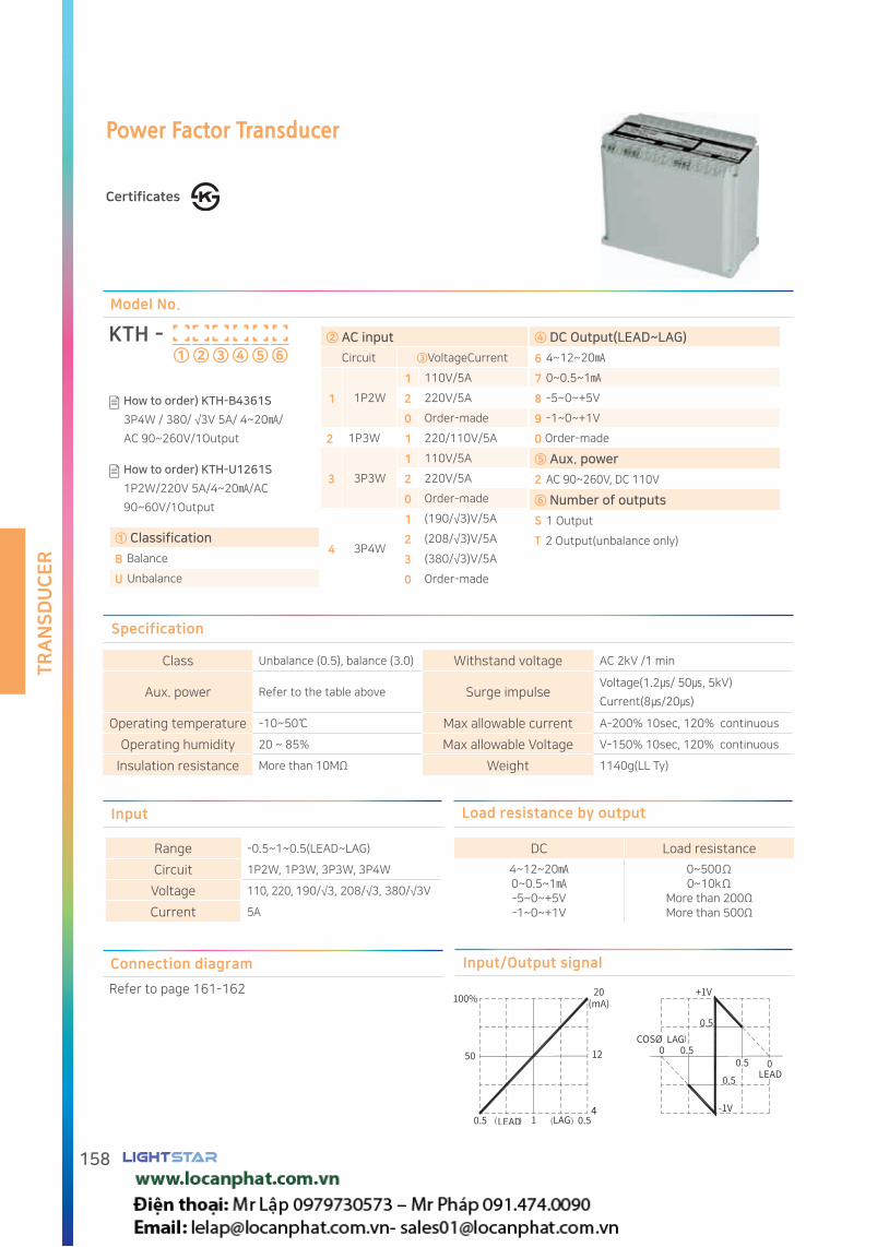
TR
AN
SD
UC
ER
158
Power Factor Transducer
Certificates
Load resistance by output Input
DC Load resistance
4~12~200~0.5~1-5~0~+5V-1~0~+1V
0~500Ω0~10kΩ
More than 200Ω More than 500Ω
Range -0.5~1~0.5(LEAD~LAG)
Circuit 1P2W, 1P3W, 3P3W, 3P4W
Voltage 110, 220, 190/√3, 208/√3, 380/√3V
Current 5A
Specification
Class Unbalance (0.5), balance (3.0) Withstand voltage AC 2kV /1 min
Aux. power Refer to the table above Surge impulseVoltage(1.2/ 50, 5kV)
Current(8/20)
Operating temperature -10~50 Max allowable current A-200% 10sec, 120% continuous
Operating humidity 20 ~ 85% Max allowable Voltage V-150% 10sec, 120% continuous
Insulation resistance More than 10MΩ Weight 1140g(LL Ty)
Model No.
KTH - ① ④ ⑤ ⑥② ③
① Classification
B Balance
U Unbalance
④ DC Output(LEAD~LAG)
6 4~12~20
7 0~0.5~1
8 -5~0~+5V
9 -1~0~+1V
0 Order-made
⑤ Aux. power
2 AC 90~260V, DC 110V
⑥ Number of outputs
S 1 Output
T 2 Output(unbalance only)
② AC input
Circuit ③VoltageCurrent
1 1P2W
1 110V/5A
2 220V/5A
0 Order-made
2 1P3W 1 220/110V/5A
3 3P3W
1 110V/5A
2 220V/5A
0 Order-made
4 3P4W
1 (190/√3)V/5A
2 (208/√3)V/5A
3 (380/√3)V/5A
0 Order-made
How to order) KTH-B4361S
3P4W / 380/ √3V 5A/ 4~20/
AC 90~260V/1Output
How to order) KTH-U1261S
1P2W/220V 5A/4~20/AC
90~60V/1Output
Input/Output signalConnection diagram
Refer to page 161-162

TR
AN
SD
UC
ER
159www.vaw.co.kr
Model No.
VAR Transducer
Certificates
KTI - ① ④ ⑤② ③
③ DC Output
6 4~12~20
7 0~0.5~1
8 -5~0~+5V
9 -1~0~+1V
0 Order-made
④ Aux. power
2 AC 90~260V, DC 110V
⑤ Number of outputs
S 1Output
T 2Output
① Circuit ② AC Input Input value
1 1P2W
1 110V/5A ±600var
2 220V/5A ±1200var
0 Order-made
2 1P3W 1 220/110V/5A ±1000var
3 3P3W
1 110V/5A ±1000var
2 220V/5A ±2000var
0 Order-made
4 3P4W
1 (208/√3)V / 5 A ±2000var
2 (380/√3)/(190/√3)V / 5 A ±2000var
3 (380/√3)V / 5A ±4000var
4 (11400/√3)/(190/√3)V / 5A ±1660var
5 (22900/√3)/(190/√3)V / 5A ±1660var
0 Order-made
Specification
Class 0.2 Withstand voltage AC 2kV /1 min
Aux. powerRefer to the table
above Surge impulse
Voltage(1.2/ 50, 5kV)
Current(8/20)
Operating temperature -10~55 Max allowable current A-200% 10sec,120% continuous
Operating humidity 20 ~ 85% Max allowable Voltage V-150% 10sec, 120% continuous
Insulation resistance More than 10MΩ Weight 1140g(LL Ty)
How to order) KTI-4362S
3P4W/380/√3V/5A/4~20/
AC 90~260V/1Output
Connection diagram
Refer to161-162page
Load resistance by output Input
DC Load resistance
4~12~200~0.5~1-5~0~+5V-1~0~+1V
0~500Ω0~10kΩ
More than 200Ω More than 500Ω
Range -0.5~1~0.5(LEAD~LAG)
Circuit 1P2W, 1P3W, 3P3W, 3P4W
Voltage 110, 220, 190/√3, 208/√3, 380/√3V
Current 5A

TR
AN
SD
UC
ER
160
Model No.
VAR & VAR hour Transducer
Certificates
KTU - ① ④ ⑤ ⑥② ③
④ Count(Energy)
A Relay
(10,000count/1 hour rated energy)
B Contactless Open Collector
(10,000count/1 hour rated energy)
C Potential signal 5V Pulse
③ DC Output
6 4~12~20
7 0~0.5~1
8 -5~0~+5V
9 -1~0~+1V
0 Order-made
⑤ Aux. power
2 AC 90~260V, DC 110V
⑥ Number of outputs
S 1 Output
① Circuit ② AC input Input value
1 1P2W
1 110V/5A ±600var
2 220V/5A ±1200var
0 Order-made
2 1P3W 1 220/110V/5A ±1000var
3 3P3W
1 110V/5A ±1000var
2 220V/5A ±2000var
0 Order-made
4 3P4W
1 (208/√3)V / 5 A ±2000var
2 (380/√3)/(190/√3)V / 5 A ±2000var
3 (380/√3)V / 5A ±4000var
4 (11400/√3)/(190/√3)V / 5A ±1660var
5 (22900/√3)/(190/√3)V / 5A ±1660var
0 Order-made
Load resistance by output
DC Load resistance
4~12~200~0.5~1-5~0~+5V-1~0~+1V
0~500Ω0~10kΩ
More than 200Ω More than 500Ω
Energy Output Specification
Contact
(Replay)10,000count/1 hour rated energy
Contactless
(Open Collector)10,000count/1 hour rated energy
Specification
ClassReactive power(0.2)
Reactive energy(0.5)Withstand voltage AC 2kV /1 min
Aux. power Refer to the table above Surge impulseVoltage(1.2/ 50, 5kV)
Current(8/20)
Operating temperature -10~55 Max allowable current A-200% 10sec, 120% continuous
Operating humidity 20 ~ 85% Max allowable Voltage V-150% 10sec, 120% continuous
Insulation resistance More than 10MΩ Weight 1140g(LL Ty)
How to order) KTU-436A2S
3P4W/380/√3V/5A/4~20/AC 90~260V/1Output
Connection diagram
Refer to 161-162page
Input
Measurement range -0.5~1~0.5(LEAD~LAG)
Circuit 1P2W, 1P3W, 3P3W, 3P4W
Voltage 110, 220, 190/√3, 208/√3, 380/√3V
Current 5A

TR
AN
SD
UC
ER
161www.vaw.co.kr
Connection diagram (Cam Switch)
3P3W 2CT(Watt/Watthour Transducer / VAR Transducer / Power factor Transducer)
Power Powerenergy
KTG W(W/Wh) KTI (var) KTH (PF)
Contact symbols Reference(3P3W 2CT A/S)
Intermittent closed circuitContinuous closed circuit
Terminal No.
6-8 5-7 2-4 1-3
OFF On Off On OFF
R On Off Off On
S Off On Off On
T Off On On Off
3P4W 3CT(Watt/Watthour Transducer / VAR Transducer / Power factor Transducer)
Power Energy
KTG W(W/Wh) KTI (var) KTH (PF)
The A / S (Cam Switch) is based on the koino product. Please check the manufacturer's terminal number.
PT connection is not shown

TR
AN
SD
UC
ER
162
Connection diagram
1P3W(Watt/Watthour Transducer / VAR Transducer) 1P3W(Balanced Power factor Transducer)
L N
Singlephase
3P3W(Watt/Watthour Transducer / VAR Transducer / Unbalanced Power factor Transducer) 3P3W(Balanced Power factor Transducer)
L N
Singlephase
3P4W(Watt/Watthour Transducer / VAR Transducer / Unbalnaced Power factor Transducer)
3P4W(Balance power factor Transducer )
L N
Singlephase
1P2W(Watt/Watthour Transducer / VAR Transducer) 1P2W(Balanced Power factor Transducer)
L N
Single phase
When connecting directly without CT.
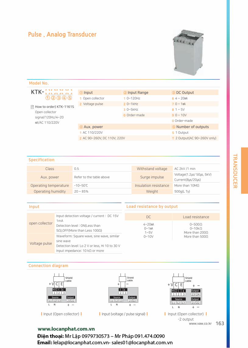
TR
AN
SD
UC
ER
163www.vaw.co.kr
Pulse . Analog Transducer
Model No.
KTK- ① ④② ⑤③
① Input ② Input Range ③ DC Output
1 Open collector 1 0~120Hz 6 4 ~ 20
2 Voltage pulse 2 0~1kHz 7 0 ~ 1
3 0~5kHz 8 1 ~ 5V
0 Order-made 9 0 ~ 10V
0 Order-made
④ Aux. power ⑤ Number of outputs
1 AC 110/220V S 1 Output
2 AC 90~260V, DC 110V, 220V T 2 Output(AC 90~260V only)
How to order) KTK-1161S
Open collector
signal/120Hz/4~20
/AC 110/220V
Specification
Class 0.5 Withstand voltage AC 2kV /1 min
Aux. power Refer to the table above Surge impulseVoltage(1.2/ 50, 5kV)
Current(8/20)
Operating temperature -10~50 Insulation resistance More than 10MΩ
Operating humidity 20 ~ 85% Weight 500g(L Ty)
Load resistance by output Input
DC Load resistance
4~200~11~5V
0~10V
0~500Ω0~10kΩ
More than 200Ω More than 500Ω
open collector
Input detection voltage / current : DC 15V
1mA
Detection level : ON(Less than
5Ω),OFF(More than Less 100Ω)
Voltage pulse
Waveform: Square wave, sine wave, similar
sine wave
Detection level: Lo 2 V or less, Hi 10 to 30 V
Input impedance: 10 kΩ or more
Connection diagram
Input (Open collector) Input (voltage / pulse signal)
Shieldcable
Shieldcable
Shieldcable
Input (Open collector)
-2 output

TR
AN
SD
UC
ER
164
Potential Transducer
Specification
Class 0.5 Withstand voltage AC 2kV /1 min
Aux. power Refer to the table above Surge impulseVoltage(1.2/ 50, 5kV)
Current(8/20)
Operating temperature -10~50 Insulation resistance More than 10MΩ
Operating humidity 20 ~ 85% Weight 500g(L Ty)
Model No.
KTL- ① ④② ③
① Input ② DC Output ③ Aux. power ④ Number of outputs
1 0Ω~10kΩ 6 4 ~ 20 1 AC 110/220V S 1 Output
0 Order-made 7 0 ~ 1 2 DC 24V
8 1 ~ 5V
9 0 ~ 10V
0 Order-made
How to order) KTL-161S
0Ω~10kΩ/4 ~ 20/AC
110/220V/1OutputCustomized product can
be produced by order.
Connection diagram
Output
L N
Variable resistance
Load resistance by output Input
DC Load resistance
4~20
0~1
1~5V
0~10V
0~500Ω
0~10kΩ
More than 200Ω
More than 500Ω
Resistance 0Ω~10kΩ

TR
AN
SD
UC
ER
165www.vaw.co.kr
DC Watt Transducer
Model No.
KTM- ① ②
① DC Voltage Input ② DC Current Input
1 50V A 50mV
2 200V B 60mV
3 500V
4 800V
How to order) KTM-1A(50V,50mV)
Customized product can be
produced by order.
Specification
Class 0.5 Withstand voltage AC 2kV /1 min
Aux. power Refer to the table above Surge impulseVoltage(1.2/ 50, 5kV)
Current(8/20)
Operating temperature -10~50 Max allowable current A-200% 10sec, 120% continuous
Operating humidity 20 ~ 85% Max allowable Voltage V-150% 10sec, 120% continuous
Insulation resistance More than 10MΩ Weight 410g(Ltype)
Input
DC Voltage 50V, 200V, 500V
DC Current
(Shunt)
0~50 (-50~0~50)
0~60 (-60~0~60)
Communication
Communication data Voltage, Current, Power
Interface RS-485 Multi-Drop 2Wire
Transmission speed 9600bps 2Wire
ConnectionPC connection
with RS-485(Ethernet) Converter
Address setting 0~63
Transmission distance Maximum 1.2km
Protocol Modbus(RTU)
Connection diagram
L N

TR
AN
SD
UC
ER
166
Specification
Class 0.5 Withstand voltage AC 2kV /1 min
Aux. power Refer to the table above Surge impulseVoltage(1.2/ 50, 5kV)
Current(8/20)
Operating temperature -10~50 Insulation resistance More than 10MΩ
Operating humidity 20 ~ 85% Weight 500g(L Ty)
Load resistance by output Input
DC Load resistance
4~20
0~1
1~5V
0~10V
0~500Ω
0~10kΩ
More than 200Ω
More than 500Ω
PT(JIS)
Sensor 3Wire
100Ω
50Ω
Order made
RTD Transducer
Certificates
Model No.
KTP- ① ④② ⑤③
① Input ② Temperature range ③ DC Output
1 PT 100Ω 1 0~200 6 4 ~ 20
2 PT 50Ω 0 Order-made 7 0 ~ 1
0 Order-made 8 1 ~ 5V
9 0 ~ 10V
0 Order-made
④ Aux. power ⑤ Number of outputs
1 AC 110/220V S 1 Output
2 DC 24V
How to order) KTP-1161S
PT 100Ω/PT 0~200/
4~20/AC
110/220V/1Output
Customized product can
be produced by order.
Connection diagram
1 Output
L N
RTD sensor
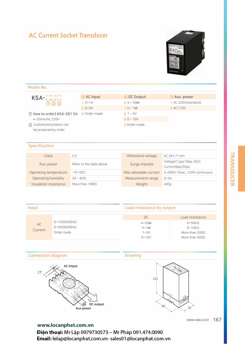
TR
AN
SD
UC
ER
167www.vaw.co.kr
Load resistance by output Input
DC Load resistance
4~20
0~1
1~5V
0~10V
0~500Ω
0~10kΩ
More than 200Ω
More than 500Ω
AC
Current
0~1A(50/60Hz)
0~5A(50/60Hz)
Order made
AC Current Socket Transducer
Model No.
KSA- ① ② ③
① AC input ② DC Output ③ Aux. power
1 0~1A 6 4 ~ 20 1 AC 220V(standard)
2 0~5A 7 0 ~ 1 2 AC 110V
0 Order-made 8 1 ~ 5V
9 0 ~ 10V
0 Order-made
How to order) KSA-261 5A
4~20mA/AC 220V
Customized product can
be produced by order.
Connection diagram
AC intput
Aux powerDC output
Drawing
Specification
Class 0.3 Withstand voltage AC 2kV /1 min
Aux. power Refer to the table above Surge impulseVoltage(1.2/ 50, 5kV)
Current(8/20)
Operating temperature -10~50 Max allowable current A-200% 10sec, 120% continuous
Operating humidity 20 ~ 85% Measurement range 0~5A
Insulation resistance More than 10MΩ Weight 400g

TR
AN
SD
UC
ER
168
Load resistance by output Input
DC Load resistance
4~20
0~1
1~5V
0~10V
0~500Ω
0~10kΩ
More than 200Ω
More than 500Ω
AC
Voltage
0~150V(50/60Hz)
0~300V(50/60Hz)
Order made
* Up to AC 300V
AC Voltage Socket Transducer
Model No.
KSB- ① ② ③
① AC input ② DC Output ③ Aux. power
1 0~150V 6 4 ~ 20 1 AC 220V(standard)
2 0~300V 7 0 ~ 1 2 AC 110V
0 Order-made 8 1 ~ 5V
(Less than AC 300V) 9 0 ~ 10V
0 Order-made
How to order) KSB-161
150V/4~20mA/AC 220V
Customized product can
be produced by order.
Connection diagram
Voltage intput
Aux power
DC output
Drawing
Specification
Class 0.3 Withstand voltage AC 2kV /1 min
Aux. power Refer to the table above Surge impulseVoltage(1.2/ 50, 5kV),
Current(8/20)
Operating temperature -10~50 Max allowable Voltage D-150% 10sec, 120% continuous
Operating humidity 20 ~ 85% Measurement range 0~300V
Insulation resistance More than 10MΩ Weight 400g

TR
AN
SD
UC
ER
169www.vaw.co.kr
Load resistance by output Input
DC Load resistance
4~200~11~5V
0~10V
0~500Ω0~10kΩ
More than 200Ω More than 500Ω
DC Voltage 0~50mV/0~60mV/0~10V/1~5V
DC Current 4~20/0~1/0~10/0~20
DC Isolated Socket Transducer
Model No.
KSD- ① ② ③ ④
① Input② DC Output
③ Aux. power④ Number of outputs
1 0~50mV 6 4 ~ 20 1 AC 220V S 1 Output
2 0~60mV 7 0 ~ 1 2 AC 110V T 2 Output(AC90~260V only)
3 0~10V 8 1 ~ 5V 3 AC 90~260V, DC110V/220V
4 1~5V 9 0 ~ 10V
5 4~20 0 Order-made
6 0~1
7 0~10
8 0~20
0 Order-made
How to order) KSD-361S
10V/4~20mA/AC 220V
/1Output
Customized product can
be produced by order.
Connection diagram
DC input
DC input
1 Output 2 Output
DC output DC outputAux power Aux power
DC
Drawing
Specification
Class 0.25 Withstand voltage AC 2kV /1 min
Aux. power Refer to the table above. Surge impulseVoltage(1.2/ 50, 5kV),
Current(8/20)
Operating temperature -10~50 Max allowable Voltage V-150% 10sec, 120% continuous
Operating humidity 20 ~ 85% Measurement range 0~100%
Insulation resistance More than 10MΩ Weight 400g

TR
AN
SD
UC
ER
170
Frequency Socket Transducer
Connection diagram
Voltage input
Aux power
DC output
Drawing
Load resistance by output Input
DC Load resistance
4~20
0~1
1~5V
0~10V
0~500Ω
0~10kΩ
More than 200Ω
More than 500Ω
AC voltage0~120Hz
AC 90~240V
Specification
Class 0.25(0~120Hz), 0.5(45~65Hz) Withstand voltage AC 2kV /1 min
Aux. power Refer to the table above Surge impulseVoltage(1.2/ 50, 5kV),
Current(8/20)
Operating temperature -10~50 Max allowable Voltage D-150% 10sec, 120% continuous
Operating humidity 20 ~ 85% Measurement range 0~120Hz
Insulation resistance More than 10MΩ Weight 400g
Model No.
KSF- ① ② ③
① AC input ② DC Output ③ Aux. power
1 AC 90~240V(0~120Hz) 6 4 ~ 20 1 AC 220V(Standard)
0 Order-made 7 0 ~ 1 2 AC 110V
8 1 ~ 5V
9 0 ~ 10V
0 Order-made
How to order)KSF-161
AC 90~240V(0~120Hz)/
4~20mA/ AC 220V
Customized product can
be produced by order.
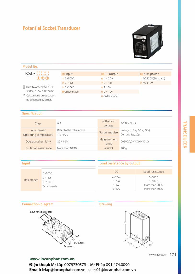
TR
AN
SD
UC
ER
171www.vaw.co.kr
Potential Socket Transducer
Model No.
KSL- ① ② ③
① Input ② DC Output ③ Aux. power
1 0~500Ω 6 4 ~ 20 1 AC 220V(Standard)
2 0~1kΩ 7 0 ~ 1 2 AC 110V
3 0~10kΩ 8 1 ~ 5V
0 Order-made 9 0 ~ 10V
0 Order-made
How to order)KSL-181
500Ω / 1~5V / AC 220V
Customized product can
be produced by order.
Connection diagram
Input variable resistor
Aux power
DC output
Drawing
Load resistance by output Input
DC Load resistance
4~20
0~1
1~5V
0~10V
0~500Ω
0~10kΩ
More than 200Ω
More than 500Ω
Resistance
0~500Ω
0~1kΩ
0~10kΩ
Order-made
Specification
Class 0.5 Withstand
voltageAC 2kV /1 min
Aux. power Refer to the table above Surge impulse
Voltage(1.2/ 50, 5kV)
Current(8/20)Operating temperature -10~50
Operating humidity 20 ~ 85%Measurement
range0~500Ω,0~1kΩ,0~10kΩ
Insulation resistance More than 10MΩ Weight 400g

TR
AN
SD
UC
ER
172
Load resistance by output Input
DC Load resistance
4~20
0~1
1~5V
0~10V
0~500Ω
0~10kΩ
More than 200Ω
More than 500Ω
PT Sensor
3wire
PT 100Ω
PT 50Ω
Order-made
RTD Socket Transducer
Model No.
KSP- ① ② ③ ④
① Input ② Temperature input ③ DC Output ④ Aux. power
1 PT 100Ω 1 0 ~ 200 6 4 ~ 20 1 AC 220V(Standard)
2 PT 50Ω 0 Order-made 7 0 ~ 1 2 AC 110V
0 Order-made 8 1 ~ 5V
9 0 ~ 10V
0 Order-made
How to order ) KSP-1161
PT 100Ω/0 ~ 200/
4~20mA/AC 220V
Customized product can
be produced by order.
Connection diagram
Input variable resistor
Aux power
DC output
Drawing
Specification
Class 0.5 Withstand voltage AC 2kV /1 min
Aux. power Refer to the table above Surge impulse
Voltage(1.2/ 50, 5kV)
Current(8/20)Operating temperature -10~50
Operating humidity 20 ~ 85% Measurement range According to input specification
Insulation resistance More than 10MΩ Weight 400g

KS certification
KS stands for Korean Standard
and indicates conformity
with Korean government required standards.
LIGHTSTAR achieved KS certificate
for Analog meter,
Current Transformer and Transducers.
CE certification
CE stands for "Conformité Européene" and indicates conformity with health, safety,
and environmental protection standards for products sold within the European Economic Area (EEA).
Our CE certified products are complied to the requirements of EU Directives, relating to LVD
(Low Voltage Directives) and EMCD(Electro Magnetic Compatibility Directives).
LIGHTSTAR achieved CE certificate for Analog meter, Current Transformer, Digital meter, Power meter
and Transducers.

KSM-100
5 A
50 A
500 A
Portable Smart Meter(Power Quality)
C·S
Portable power quality meter
Access Probe For Test Potable Power Tester
CT Tester, Transformer Error Meter
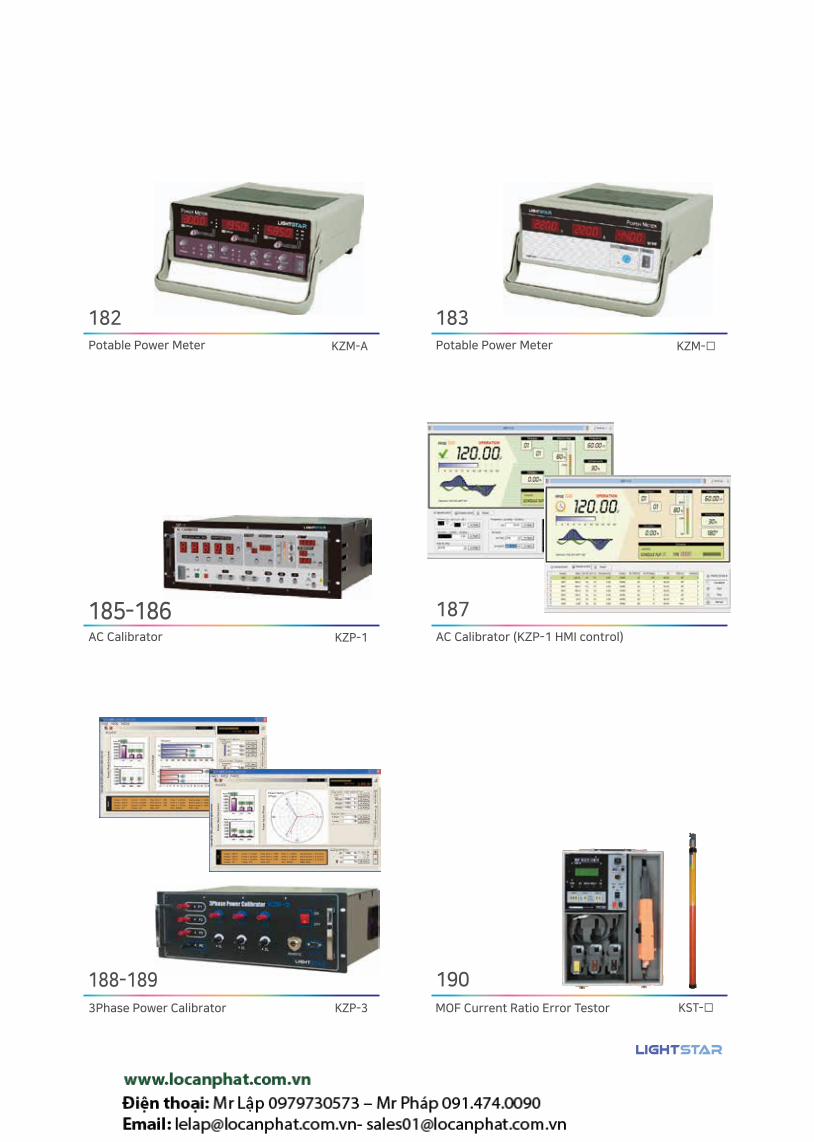
Potable Power Meter
AC Calibrator
3Phase Power Calibrator MOF Current Ratio Error Testor
AC Calibrator (KZP-1 HMI control)
Potable Power Meter
File[F] Set [S] Help [H]
Control
Power
Reactive power(var)
Po
we
r/R
ea
ctiv
e p
ow
er
Cu
rre
nt/
Vo
lta
ge
Voltage(V)
Current(A)
Voltage ( 0.0 - 360.0V )
Current ( 0.000 - 12.000A )
Apply
Apply
Apply
Apply
Apply
Apply
Apply
Apply
Apply
Three-phase Voltage
Three-phase Current
Voltage/Current3 w
ave/FrequencyPower factor/phase
Sta
te
Voltage1 : 350.0V
Voltage2 : 220.0V
Voltage3 : 220.0VS-phase : 120 o
Current 1 : 12.000A
Current 2 : 05.000A
Current 3 : 05.000AT-phase : 240 o
Power factor 1 : 1.000
Power factor 2 : 1.000
Power factor 3 : 1.0003HDG : 000 o
Power 1 : 4,200.0w
Power 2 : 1,100.0w
Power 3 : 1,100.0w3HLV : 00%(B)
Reactive power 1 : 0,000.0var
Reactive power 2 : 0,000.0var
Reactive power 3 : 0,000.0var주파수 : 60Hz
Power
File[F] Set [S] Help [H]
Control
Po
we
r/R
ea
ctiv
e p
ow
er
Po
we
r fa
cto
r/P
ha
se
Power
Reactive power(var)
Power factor/Phase
Voltage/Current3 w
ave/FrequencyPower factor/phase
Apply
Apply
Apply
Apply
Apply
Apply
Apply
Voltage1 : 350.0V
Voltage2 : 220.0V
Voltage3 : 220.0VS-phase : 120 o
Current 1 : 12.000A
Current 2 : 05.000A
Current 3 : 05.000AT-phase : 240 o
Power factor 1 : 0.990
Power factor 2 : 0.990
Power factor 3 : 0.9903HDG : 000 o
Power 1 : 4,158.0w
Power 2 : 1,089.0w
Power 3 : 1,089.0w3HLV : 00%(B)
Reactive power 1 : 0,592.5var
Reactive power 2 : 0,155.2var
Reactive power 3 : 0,155.2var주파수 : 60Hz
Power
Power factor (-1.000-1000)(-90o -90o)
Phase (0o -360o)
Three-phase Power factor
S-phase
T-phase

TE
ST
ME
AS
UR
ING
EQ
UIP
ME
NT
176
Portable power quality meter
① ② Size
00 52Φ Clamp
Model No.
Portable power quality meter
Contents Main body + tablet PC
Input range
Voltage AC 25V~500V
Aux. power Lithium ion battery 3.7 V Current 0.050A~500.0A
Operating temperature
-10~50
Power Factor
±0.000~1.000
Operating Humidity
20~85% (+ : lag, - : lead)
Place of useLess than 2000 meter above sea level
Free from vibration and impact. Bluetooth V2.0 + EDR compatible
Operating distance: Max 5MWiring method 1Ø2W, 3Ø3W, 3Ø4W
Specification
Overview
Portable power quality meter measuring electrical data and showing wave form, phase and harmonics.
All related data to be shown in bluetooth connected tablet PC, which is inclusive as one package.
Feature
Easy to measure 3-phase voltage and current, power and power factor (Current can be measured with one clamp, phase by phase)
High resolution waveform, phase, harmonic analysis data transmitted to android tablet PC.
Applied with lithium ion battery used for 5 hours.
Easy to carry as portable type.
Trend recording, automatic report printing function.
V ±(0.5% of rdg + 0.1% of FS) Harmonic ±(1.0% of rdg + 1.0%)
A
5A : ±(1.0% of rdg + 0.5% of Range) Phase ±(1.0% of rdg + 1 °)
50A : ±(0.5% of rdg + 0.5% of Range)
W
5A : ±(1.0% of rdg + 0.2% of Range) at PF=1
500A : ±(0.5% of rdg + 0.5% of Range) 50A : ±(0.5% of rdg + 0.2% of Range) at PF=1
kWh ±(watt accuracy + 0.1 count/h) 500A : ±(0.5% of rdg + 0.2% of Range) at PF=1
Varh ±(var accuracy + 0.1 count/h)
Var
5A : ±(2.0% of rdg + 0.3% of Range)
PF ±(1.0% of rdg + 1 °) 50A : ±(1.0% of rdg + 0.3% of Range)
Hz ±(0.1% of Range + 0.02Hz) 500A : ±(1.0% of rdg + 0.3% of Range)
Accuracy

TE
ST
ME
AS
UR
ING
EQ
UIP
ME
NT
177www.vaw.co.kr
KSM-100
5 A
50 A
500 A
Portable Smart Meter(Power Quality)
C·S
Charge LED
Charging (Red)
Charging complete - (Orange)
Open/Close
Power switch ON
Power switch OFF
50~500A
5~50A
0.05~5A
Body(KSM-100/110)
Clamp
Power Button
Current Range Switch
Waiting (Red)
Connected (blue)
Bluetooth LED
Power switch ON (Red)
Power LED
Charging port
Micro 5Pin
Voltage clamp
R phase (Yellow)
S phase (Green)
T phase (Red)
N phase (Black)
Display(Android)
SMART ANALYZER
SM Analyzer connected : BL001
❽
❶
❶
❷
❷
❸
❸
❹❺
❼
❽
❹❺❻❼
❻
External connector connector
Earphone
Volume UP / DOWN button
Power / lock button
Touch screen
Speaker
Previous button
Home button
R
S
T
N
LOAD
1st
2nd
3rd
4th
SOURCE
Voltage Energy
Current Power factor
Data Waveform Phase Harmonic
Function
Data Waveform Phase Harmonic
Example

TE
ST
ME
AS
UR
ING
EQ
UIP
ME
NT
178
CT Tester
Model No.
KZA- ① ②
① Types ② Output
2 Current transformer testing device 04 Current 0~400A 32 Current 0~3200A
3 Potential Transformer testing device 08 Current 0~800A 70 Voltage 0~720V
Overview
Testing device for transformer error test and phase test.
Included with standard CT, testing burden, error meter
and testing software to be connected with computer.
Feature
Inspection data transmitted to PC by communication.
Standard CT (5 A, 1 A) and burden box (PF 0.8, 5 A, 1 A) included.
Integrated type, easy installation, minimize inspection time.
Safety device included: Current relay for short circuit and overload protection
Configuration
ERROR METER Primary current display
POWER SWITCH
Secondary current display
Current OUTPUT Switch
SEC RATIO Switch
ADJUST Dial
Primary current terminal
Primary current ON / OFF button
Secondary current terminal
TEST BURDEN SWITCH
Ratio error, phase angle measurement
Burden selection
TEST RATIO SWITCHPrimary current selection
Communication buttonTest data transmission
POWER ON/OFF
150A / 300A Choice
Secondary current 5 A - 1 A selection
Primary current adjustment
Specification
Type KZA-204 KZA-208 KZA-232
Current output 0~450A / 1kVA 0~800A / 1kVA 0~3200A / 3kVA
Test CT ratio
(Standard CT included)
40A-50A-60A75A-100A-120A
150A-200A-250A300A-350A-400A
/ 5A-1A
100A-120A-150A200A-250A-300A350A-400A-500A600A-700A-750A
/ 5A-1A
100A-120A-150A-200A-250A-300A-350A-400A-500A-600A
/ 5A-1A
700A-750A-800A-1000A-1200A-1500A-1600A-2000A
2500A-3000A-3200A/ 5A-1A
Burden(PF 0.8) 2.5VA / 5VA / 15VA 5VA / 15VA / 40VA 5VA / 15VA / 40VA
Size(mm) 500(W)X400(D)X400(H) 600(W)X500(D)X400(H) 1000(W)X1000(D)X2000(H)
Weight 60kg 80kg 150kg
Common
(1) Standard CT class: 5 A 0.1 class, 1A class 0.2 grade(2) Aux power : 220 V AC (3) Communication: ERROR METER (RS-485 communication)(4) Safety device: current relay for short-circuit and overload
Customized product can be produced by order.

TE
ST
ME
AS
UR
ING
EQ
UIP
ME
NT
179www.vaw.co.kr
Transformer Error Meter
Model No.
KZA- 1① ②
① ERROR METER ② Type
00 For current transformer 10 For Potentiol transformer
Overview
Meter for transformer error test and phase test.
Feature
Standard CT / PT ratio error (%) and phase angle (min) error offset function
Transmission of inspection data to PC using communication program
Comfiguration
SET Button
Percentage (%) Display
Selection button
COMM. START / STOP Button
Transmission button
Ratio error display
Phase angle error display
Setting the offset value (ratio-error, phase angle) Select display value
- “ST”: standard CT (or PT)Secondary value
- “TEST”: test CT (or PT)Secondary value
Test status transmission
Test data transmission
Drawing
<For current transformer> <Potential transformer>
Standard Aux. power
Test CT
Standard Aux. power
Test PT
Unit:mm
Specification
Type KZA-100(CT TEST) KZA-110(PT TEST)
Input 5A, 1A 110/√3, 110V, 220V
Range 2%~130%(0.1A~6A, 0.02A~1.12A) 20V ~ 280V
Ratio error display Max. ±19.99% Max. ±19.99%
Ratio error accuracy(Error)More than 20% ±(0.2% of rdg + 2digit)Less than 20% ±(0.5% of rdg + 2digit)
More than 20% ±(0.2% of rdg + 2digit)
Phase angle display MAX. ±199.9min MAX. ±199.9min
Phase angle accuracy(Angle Error)
More than 20% (±1min rdg + 2digit)Less than 20% (±2min rdg + 2digit)
More than 20% (±1min rdg + 2digit)
Ratio error, phase angle correction setting(Offset)
- 5 stages (5/10/20/100/120%).- Setting range: 0.00 to ± 0.99% / 0.0 to ± 9.9 min
- One stage- Setting range: 0.00~±0.99%/ 0.0~±9.9min
Communication RS-485 RS-485

TE
ST
ME
AS
UR
ING
EQ
UIP
ME
NT
180
Access Probe For Test
Model No.
KZB- ①
① Function
10 IP1X Applied test probe Diameter : 50 ±0.05mm Pushing force : 50 N ±10%(5KG)
20 IP2X Applied test probeDiameter : 12.0 ±0.05mm Pushing force : 10 N ±10%(1KG)
30 IP3X Applied test probe Diameter : 2.5 ±0.05mm Pushing force : 3 N ±10%(0.3KG)
40 IP4X Applied test probeDiameter : 1.0 ±0.05mm Pushing force : 1.0 N ±10%(0.1KG)
Purpose
Testing the gap size by this device in order to protect from external dust or human contact
Feature
Push-rod with handle
Test method
Push the probe on checking spot with designed force.
Human body protection acceptable criteria
Shall not be energized(DC 40 V test device) between the probe and the internal hazardous part.
External dust acceptable criteria
A probe of a defined size shall Not pass through the gap.
Additional device for human body protection test
TYPE KZB-PO
INPUT AC 220V
OUTPUT DC 40V
Response BUZZER and LAMP

TE
ST
ME
AS
UR
ING
EQ
UIP
ME
NT
181www.vaw.co.kr
Potable Power Tester
Overview
Testing device for single phase electric equipment.
3 sets of display to show voltage, current, power and PF
Alarm or relay contact to be activated with limit settting switch.
Feature
Built-in FUSE to prevent damage from excessive current
(except for KZT-1)
Adjustable reaction time
RMS measurement
Alarm and relay contact to be activated according to setting value.
V, A, W / PF are displayed.
Easy to recognize with alarm and contact
Measured data can be transmitted to PC and saved
Communication
Interface : RS-232C
Transmission character : ASCII BCD
Transmission speed: fixed : 9600bps
Transmission format : Start 1bit, Data 8bit, Parity None Stop 1bit
Connection diagram
Specification
Input
Type Voltage Current Power Power Factor
KZT - 1
30.0~300.0V
2.00~20.00A 125~5000W
50.0~100.0KZT - 2 0.500~5.000A 25.0~750.0W
KZT - 3 0.200~2.000A 10.0~500.0W
KZT - 4 50.0~999.9mA 2.50~99.99W
Accuracy
10Hz ±1% of range
45~65Hz ±(0.2% of rdg + 0.1% of FS) at 45~65Hz
2kHz ±1% of range
20kHz ±2% of range ±3% of range
Aux. power AC 90~260V(50/60Hz), DC 110V Weight 2.5kg
Model No.
KZT- ①
① Current input range
1 2.00~20.00A 3 0.200~2.00A
2 0.500~5.000A 4 50.0~999.9mA

TE
ST
ME
AS
UR
ING
EQ
UIP
ME
NT
182
Potable Power Meter
Model No.
KZM-AOverview
Testing device for single phase electric equipment.
3 sets of display to show voltage, current, power, PF, active power,
surface power, energy and cumulative current
Measuring range can be chosen to enhance measuring accuracy.
Communication
Interface : RS-232C
Transmission character:ASCII BCD
Transmission speed: 9600bps
Transmission format : Start 1bit, Data 8bit, Parity None Stop 1bit
Connection diagram
Specification
Input
Type Voltage Current Power
Circuit configuration5range
RMS by LOG-anti LOG7range
RMS by LOG-anti LOGTime division, pulse interval,
transformation method
Range0~50, 0~100, 0~150
0~200, 0~3000~0.3, 0~0.5, 0~1
0~2, 0~5, 0~10, 0~201.5~6000W
Max crest factor (maximum value /
effective value)2.0 3.0 -
Accuracy45~65Hz
±(0.2% of rdg+0.1%of range)45~65Hz
±(0.1% of rdg+0.2%of range)At cosΦ=1
±(0.2% of rdg+0.2% of range)
Power Factor(PF) Calculation : W Range of measurement : 0.100~1.000 V x A Accuracy : ±(0.2% of rdg + 2.0% of range)
Apparent power(VA) V x A Range of measurement : 1.50~6000VA Accuracy : ±(0.2% of rdg + 0.5% of range)
Reactive power(Var) Range of measurement : (V X A)2-W2 Range of measurement : 15~6000var Accuracy : ±(0.5% of rdg + 1.0% of range)
Energy(Wh) ±(0.5% of rdg + 1.0% of range)
Cumulated current(Ah) ±(0.2% of rdg + 1.0% of range)
Temperature coefficient 5 to 20 ° C
Less than ±0.03% of range/
Accuracy
10Hz ±1% of range
45~65Hz Refer to above
2kHz ±1% of range
20kHz ±2% of range ±3% of range
Aux. power AC 110V/220V Weight 3.0kg

TE
ST
ME
AS
UR
ING
EQ
UIP
ME
NT
183www.vaw.co.kr
Potable Power Meter
Connection diagram
Model No.
KZM- ①
① Current input range
1 2.00~20.00A 3 0.200~2.00A
2 0.500~5.000A 4 50.0~999.9mA
Overview
Testing device for single phase electric equipment.
3 sets of display to show voltage, current and PF
Communication
Interface : RS-232C
Transmission character:: ASCII BCD
Transmission speed: 9600bps
Transmission format : Start 1bit, Data 8bit, Parity None Stop 1bit
Feature
We provide application programs to be provided.
Simple and robust design / economical price
Specification
Input
Type Voltage Current Power Power Factor
KZM - 1
30.0~300.0V
2.00~20.00A 125~5000W
50.0~100.0KZM - 2 0.500~5.000A 25.0~750.0W
KZM - 3 0.200~2.000A 10.0~500.0W
KZM - 4 50.0~999.9mA 2.50~99.99W
Accuracy
10Hz ±1% of range
45~65Hz ±(0.2% of rdg + 0.1% of FS)at 45~65Hz
2kHz ±1% of range
20kHz ±2% of range ±3% of range
Aux. power AC 90~260V(50/60Hz), DC 110V Weight 2.5kg

TE
ST
ME
AS
UR
ING
EQ
UIP
ME
NT
184
KZM-A Drawing
KZT-1,2,3,4
Voltage displayCurrent display Power / Power Factor displayLow limit setting switchHigh limit setting switchSetting select button (V/A/PF/W)Select button (PF/W)Power switch
Voltage range setting button Current range setting button Hold and Integrator buttonPower switch
Display A
Display B
Display C
KZM-1,2,3,4
Voltage displayCurrent display Power / Power Factor displaySelect button (PF/W)Power switch
Unit:mm

TE
ST
ME
AS
UR
ING
EQ
UIP
ME
NT
185www.vaw.co.kr
AC Calibrator
Model No.
KZP-1
Overview
Accurate ( ±0.1% ) calibrating device which can generate AC voltage(3~720V) or AC current (5mA~60A) with 60VA capacity.
Can be used for electrical meter production line or academic demonstration
This device can be controlled by remote PC(MMI) and scheduled control can be done also
Example 3rd harmonic phase Example 3rd harmonic phase
Fundamentalwave
3rd Harmonic
synthesized waveform
Fundamentalwave 3rd Harmonic
synthesized waveform
Function
Accuracy: AC voltage, current (50/60 Hz) Accuracy ± 0.1%
Wide range: AC voltage 3 V to 720 V (3 Range), AC current 50 mA to 60 A (4 Range)
Frequency: 50, 60 Hz, and 44 - 70 Hz (continuously variable by 0.01Hz).
Output dividing function: Easy to divide output step by step by using output dial (by 20 division)
Deviation reading: Test error percentage can be displayed comparing to max value.
Sweep: 0 to 120% of the set output value can be continuously varied at a constant speed. (12 seconds to set output value)
3rd harmonic output: 3rd harmonic content is controlled from 0 to 30% (1 step) with one dial. And 3rd harmonic phase angle
can be shifted from 0 to ± 180 (30o step).

TE
ST
ME
AS
UR
ING
EQ
UIP
ME
NT
186
Specification
Drawing Recommended terminal wiring
Distortion rate Voltage output: 0.07%, Current output: 0.18% at range 40 to 120%
Output
Setting Range Resolution Max output Accuracy: 50/60Hz
150V 3V~180V 10mV 333mA
0.1% of setting value + 0.015% of Range)
± 0.1% of range, output in under 20% of
range.
(Range ±0.1%)
300V 5V~360V 100mV 166mA
600V 10V~720V 100mV 83mA
1A 5mA~1.2A 100 50V
5A 10mA~6A 1mA 10V
15A 50mA~18A 10mA 4.6V
50A 100mA~60A 10mA 1V
If setting is 1% or less of Range, the output is "0".
Output setting and display
4 Dial setting / voltage (V) - 3 LED / current (A) - 4 LED
Output dividing(Output) = (setting)X n/m
m : 1,2,3,.........................,20, n : 1,2,3,.........................,20
Deviation setting 1 Dial setting
Deviation display 3 LED display, maximum display 10.0% (0.05 to 10.0%)
Response time Approximately 1 sec (0 to 1005) of the setting value (Full scale)
Insulation resistance
100Ω or more with 500 V DC between power supply and case between power supply and output
terminal
Withstand voltage 1 minute with 1500 V AC between power supply and output terminal, with power supply and case
Sweep speed Approximately 120% to set Output
frequency44~70Hz Continuous variable(0.01step)
Output terminal 5M×7EA Aux. power AC 220 ±10%, 50Hz or 60Hz
Operating temperature and
humidity-10~50, 20~85% RH
Power consumption
Less than 500VA
Accessories Power cord 1 set, instruction manual 1 set
Option General control, schedule control with RS-232C communication.
[Front]Body [Case (option)]
50A→10SQ
15A→6SQ
5A→2.5SQ
1A→1.5SQ
Model with AC110v aux power is order-made
Unit:mm

TE
ST
ME
AS
UR
ING
EQ
UIP
ME
NT
187www.vaw.co.kr
AC Calibrator (KZP-1 HMI control)
Overview
KZP-1 HMI can control KZP-1 with every function from PC by RS-232 communication Also this software can visualize the data
with graph.
HMI(Human Machine Interface)
Human-machine interface (HMI) is a component of certain devices that are capable of handling human-machine interactions. The
interface consists of hardware and software that allow user inputs to be translated as signals for machines that, in turn, provide the
required result to the user. Human-machine interface technology has been used in different industries like electronics, entertainment,
military, medical, etc. Human-machine interfaces help in integrating humans into complex technological systems.
Configuration
General control Schedule control
Checking and controlling the voltage / current magnitude
division, deviation, step, frequency and 3rd harmonic
content and phase visually.
User can arrange values by schedule(sequence) of
voltage. current, division, deviation, step. frequency
and 3rd Harmonic. Max 99 scheduled (sequence) input,
Holding time to be varied from 1 to 3600 sec.
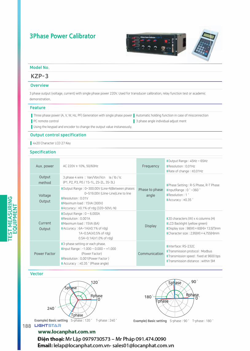
TE
ST
ME
AS
UR
ING
EQ
UIP
ME
NT
188
3Phase Power Calibrator
Overview
3 phase output (voltage, current) with single phase power 220V. Used for transducer calibration, relay function test or academic
demonstration.
Feature
Three phase power (A, V, W, Hz, PF) Generation with single phase power Automatic holding function in case of misconnection
PC remote control 3 phase angle individual adjust ment
Using the keypad and encoder to change the output value instaneously.
Output control specification
4x20 Character LCD 27 Key
Model No.
KZP- 3
Specification
Aux. power AC 220V ± 10%, 50/60Hz Frequency
Output Range : 45Hz ~ 65Hz
Resolution : 0.01Hz
Rate of change : ±0.01Hz
Output
method
3 phase 4 wire : Van/Vbn/Vcn Ia / Ib / Ic
(P1, P2, P3, P0 / 1S-1L, 2S-2L, 3S-3L)
Phase to phase
angle
Phase Setting : R-S Phase, R-T Phase
InputRange : 0˚~360˚
Resolution : 1˚
Accuracy : ±0.35˚Voltage
Output
Output Range : 0~300.00V (Line-N)Between phases
0~519.00V (LIine-Line)Line to line
Resolution : 0.01V
Maximum load : 15VA (300V)
Accuracy : ±0.1% of rdg (320~50VL-N)
Vector
phase
phase
phase
phase
phase
phase
Example) Basic setting S-phase : 120˚ T-phase : 240˚ Example) Basic setting S-phase : 90˚ T-phase : 180˚
Current
Output
Output Range : 0 ~ 6.000A
Resolution : 0.001A
Maximum load : 15VA (6A)
Accuracy : 6A~1A(±0.1% of rdg)
1A~0.5A(±0.5% of rdg)
0.5A~0.1A(±1.0% of rdg)
Display
20 characters (W) x 4 columns (H)
LCD Backlight (yellow green)
Display size : 98(W) × 60(H)× 13.5(T)mm
Character size : 2.95(W) × 4.755(H)mm
Power Factor
3-phase setting or each phase.
Input Range : -1.000 ~ 0.000 ~ +1.000
(Power Factor)
Resolution : 0.001(Power Factor )
Accuracy : ±0.35˚(Phase angle)
Communication
Interface: RS-232C
Transmission protocol : Modbus
Transmission speed : fixed at 9600 bps
Transmission distance : within 5M

TE
ST
ME
AS
UR
ING
EQ
UIP
ME
NT
189www.vaw.co.kr
Drawing
FrontBody 19inch Rack
Case (option)
Unit:mm
HMI Control
HMI can control KZP-1 with every function from PC by RS-232 communication Also this saftware can visualize the data with graph.
Voltage / current setting and display
File[F] Set [S] Help [H]
Control
Power
Reactive power(var)
Po
we
r/R
ea
ctiv
e p
ow
er
Cu
rre
nt/
Vo
lta
ge
Voltage(V)
Current(A)
Voltage ( 0.0 - 360.0V )
Current ( 0.000 - 12.000A )
Apply
Apply
Apply
Apply
Apply
Apply
Apply
Apply
Apply
Three-phase Voltage
Three-phase Current
Voltage/Current3 w
ave/FrequencyPower factor/phase
Sta
te
Voltage1 : 350.0V
Voltage2 : 220.0V
Voltage3 : 220.0VS-phase : 120 o
Current 1 : 12.000A
Current 2 : 05.000A
Current 3 : 05.000AT-phase : 240 o
Power factor 1 : 1.000
Power factor 2 : 1.000
Power factor 3 : 1.0003HDG : 000 o
Power 1 : 4,200.0w
Power 2 : 1,100.0w
Power 3 : 1,100.0w3HLV : 00%(B)
Reactive power 1 : 0,000.0var
Reactive power 2 : 0,000.0var
Reactive power 3 : 0,000.0var주파수 : 60Hz
Power
Checking the magnitude of voltage /
current visually (graph).
If KZP-3 is connected, you can check
the applied value and graph.
Power factor / phase setting and display
File[F] Set [S] Help [H]
Control
Po
we
r/R
ea
ctiv
e p
ow
er
Po
we
r fa
cto
r/P
ha
se
Power
Reactive power(var)
Power factor/Phase
Voltage/Current3 w
ave/FrequencyPower factor/phase
Apply
Apply
Apply
Apply
Apply
Apply
Apply
Voltage1 : 350.0V
Voltage2 : 220.0V
Voltage3 : 220.0VS-phase : 120 o
Current 1 : 12.000A
Current 2 : 05.000A
Current 3 : 05.000AT-phase : 240 o
Power factor 1 : 0.990
Power factor 2 : 0.990
Power factor 3 : 0.9903HDG : 000 o
Power 1 : 4,158.0w
Power 2 : 1,089.0w
Power 3 : 1,089.0w3HLV : 00%(B)
Reactive power 1 : 0,592.5var
Reactive power 2 : 0,155.2var
Reactive power 3 : 0,155.2var주파수 : 60Hz
Power
Power factor (-1.000-1000)(-90o -90o)
Phase (0o -360o)
Three-phase Power factor
S-phase
T-phase
The power factor / phase angle can
be controlled.
The controlled value is shown as a
bar graph, and the power factor and
phase angle of the three phases
are shown as a vector diagram,
and setting condition can be easily
shown.

TE
ST
ME
AS
UR
ING
EQ
UIP
ME
NT
190
MOF Current Ratio Error Tester
Overview
This device is used for measuring ratio error primary and secondary current. Can minimize testing time with phase comparing function.
Model No.
KZE- MOF
Feature
Primary current detector
Main Body
Secondary current detectorWirelessly transmit the current value of primary wire (special high
voltage). According to the magnitude of the current, the range
of 4 A / 40 A / 200 A can be selected to minimize error.
Collecting data from Primary/Secondary detector, calculating and display various data including CT ratio and ratio error Also data can be
save up to 10EA.
A device for transmitting current to the main body with
wire, the measuring range is always set to 4 A, R (yellow), S
(brown), T (black) can be connected at the same time.
DrawingGeneral specification
Primary current detector
Secondary current detection unit
Body
Setting Range Accurcy Temperature
4A AC 0.25 ~ 5A±1.0%
FS±2digit-10 ~ 5040A AC 2.5 ~ 50A
200A AC 25 ~ 200A
Output Wireless communication 5000 digits(Bluetooth)
Aux. power
DC 6V(1.5V AA Alkaline battery 4EA: 5 hours)
Size75(W)×40(D)×300(H) (mm)/ 23Ø
100(W)×50(D)×400(H) (mm)/ 45Ø
Setting Range Accurcy Temperature
4A AC 0.25 ~ 5A±1.0%
FS±2digit-10 ~ 50
Input line
2.5mm
length 40(W) × 20(D) × 100(H)(mm) /18X18(Inside)
InputPrimary current : wireless communication 1 EA
Secondary current : AC 500mV/5A 3EA
Aux. power DC 5V Lithium ion battery - 5 hours
Accuracy ±2.0% FS±2digit
Size and weight
330(W) X 170(D) X 440(H)(mm) / 10kg
Body
Secondary detector
Unit:mm

CE certification
CE stands for "Conformité Européene" and indicates conformity with health, safety,
and environmental protection standards for products sold within the European Economic Area (EEA).
Our CE certified products are complied to the requirements of EU Directives, relating to LVD
(Low Voltage Directives) and EMCD(Electro Magnetic Compatibility Directives).
LIGHTSTAR achieved CE certificate for Analog meter, Current Transformer, Digital meter, Power meter
and Transducers.
KS certification
KS stands for Korean Standard and indicates conformity
with Korean government required standards.
LIGHTSTAR achieved KS certificate for Analog meter, Current Transformer and Transducers.

Battery Charger
Rectifier Transformer DC Dropper
Rectifier
Rectifier Controller

BA
TT
ER
Y C
HA
RG
ER
193www.vaw.co.kr
Battery Charger
Dimensions
Controller-Outerbox attached
Model No.
KH - ① ② ③
① Type
O Controller external type
I Controller integrated type
② Input
2 AC 3P 220V
3 AC 3P 380V
4 AC 3P 440V
③ Output
1 DC 110V, 30A
2 DC 110V, 50A
3 DC 110V, 100A
How to order :
KHO-32 External type AC 3Ø 380V, DC 110V, 50A
Unit:mm
DC 100A output product can be provided by order.
DC 200A output product can be provided by order.
Specification
Input Voltage AC 3 Phase 220V/380V/440V(60Hz) Withstand voltageAC 1.5kV/1 minute (between the external terminal and the case)
Rated Output Voltage DC 110V Insulation resistanceMore than 10 (DC 500V)Between terminal and ground
Rated Output Current 30A/50A/100A/200AOperating temperature /
humidity0 ~ 55/20~85% RH
Measurement
AC input voltage, AC input current, DC voltage, load current (LOAD), charge current (BATT), ambient temperature, voltage, Battery trend(DC voltage, charge current, discharge)Current-10 hours data storage
Communication RS-485

BA
TT
ER
Y C
HA
RG
ER
194
Basic circuit diagram
Option
Fo
r mo
nito
ring
Option
Fo
r mo
nito
ring

BA
TT
ER
Y C
HA
RG
ER
195www.vaw.co.kr
Rectifier
Model No.
KHA- ① ②
① Output Voltage ② Rated capacity
1 DC 110V A 30A
2 DC 125V B 50A
How to order KHA-1A Rectifier DC 110V, 30A Output
Overview
Converts 3-phase AC power into DC for charging
Feature
Equipped with DC voltage and DC current terminals for monitoring
Built-in NVR (No Voltage Relay)
Rack or shelf mounting
Specification
Type KHA-1A KHA-2A KHA-1B KHA-2B
Rated Outpu Voltage DC 110V DC 125V DC 110V DC 125V
Rated Outpu Current DC 30A DC 50A
Rated Input Voltage3-Phase
AC 110V(50/60Hz)3-Phase
AC 120V(50/60Hz)3-Phase
AC 110V(50/60Hz)3-Phase
AC 120V(50/60Hz)
Floating voltage DC 110~127V DC 120~140V DC 110~127V DC 120~140V
Equalizing voltage DC 110~137V DC 120~152V DC 110~137V DC 120~152V
Number of batteries 12V / 9 12V / 10 12V / 9 12V / 10
Withstand voltage AC 1.5kV/1 minute (between external terminal and case)
Insulation resistance More than 10MΩ(DC 500V) Between terminal and ground
Operating temperature / Humidity
-10~50/20~85% RH
Dimensions
4-Φ4
2-Φ42-M4
2-Φ4
<Front> <Fixing Support>
Unit:mm

BA
TT
ER
Y C
HA
RG
ER
196
Rectifier Controller
Model No.
KHB
Overview
Set up and control LIGHT STAR rectifier (KHA) and display the status.
Dimensions
Panel cut
Feature
Trend graph (10 hours) for Charge / discharge current,
and voltage
RS485 communication
Automatic correction of charging voltage depending on
temperature
Rear terminal view
Specification
Display
AC Voltage, AC CurrentPrimary AC voltage (using PT from voltage transformer secondary),
AC current with (CT ratio)
Output DC Voltage DC 80V~160V(±2% FS)
Battery current DC -50~50A(±2% FS)
Temperature -20~100(±3)
Trend DC voltage, charge current, discharge current (10 hours data storage)
Load current DC 0A~50A(±2% FS)
SettingNominal voltage, rated capacity, charge mode (floating, equalizing, stop), equalizing
charge time, Alarm voltage, alarm current, alarm delay time, manual operation, communication address
Input Rectifier (KHA) aux power and communication signal
Communication RS 485, Modbus, 9600bps, DATA BIT:8bit, PARITY:None
Operating temperature / humidity 0~55 / 20~80% RH
Unit:mm
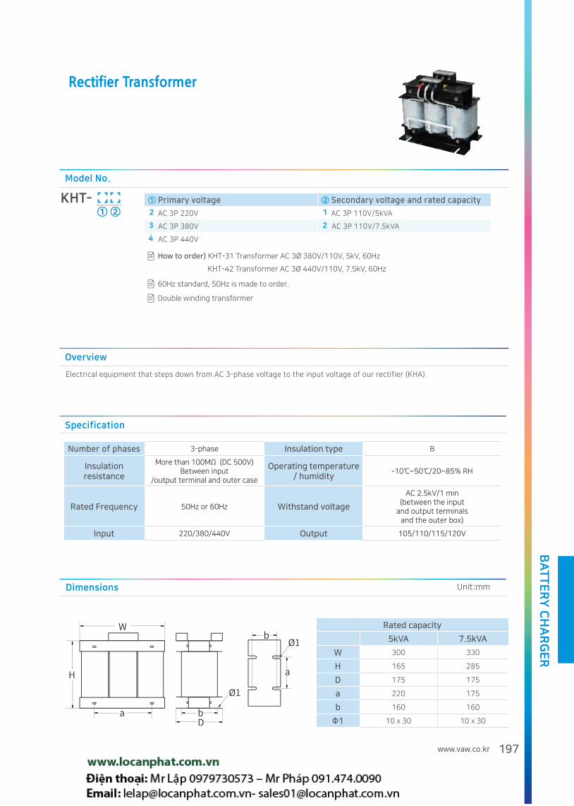
BA
TT
ER
Y C
HA
RG
ER
197www.vaw.co.kr
Rectifier Transformer
Overview
Electrical equipment that steps down from AC 3-phase voltage to the input voltage of our rectifier (KHA)
Model No.
KHT- ① ②
① Primary voltage ② Secondary voltage and rated capacity
2 AC 3P 220V 1 AC 3P 110V/5kVA
3 AC 3P 380V 2 AC 3P 110V/7.5kVA
4 AC 3P 440V
How to order) KHT-31 Transformer AC 3Ø 380V/110V, 5kV, 60Hz
KHT-42 Transformer AC 3Ø 440V/110V, 7.5kV, 60Hz
60Hz standard, 50Hz is made to order.
Specification
Number of phases 3-phase Insulation type B
Insulation resistance
More than 100MΩ (DC 500V)Between input
/output terminal and outer case
Operating temperature / humidity
-10~50/20~85% RH
Rated Frequency 50Hz or 60Hz Withstand voltage
AC 2.5kV/1 min (between the input
and output terminalsand the outer box)
Input 220/380/440V Output 105/110/115/120V
Dimensions
Rated capacity
5kVA 7.5kVA
W 300 330
H 165 285
D 175 175
a 220 175
b 160 160
Φ1 10 x 30 10 x 30
Unit:mm
Double winding transformer

BA
TT
ER
Y C
HA
RG
ER
198
DC Dropper
Model No.
KHD- ①
① Output Current
30 30A
Overview
Under battery discharge, this device is used for lowering voltage from high voltage.
Feature
By using switching circuit method, battery can be used for a longer time comparing to the relay and diode conversion
method.
Specification
Input Voltage DC 115~150V
Output Voltage DC 110V ±2V/30A
Withstand voltage AC 1.5kV/1 minute (between the external terminal and the case)
Insulation resistance More than 10 (DC 500V)(DC 500V)Between terminal and ground
Operating temperature / humidity
-10~50/20~85% RH
Heat dissipation capacity 450W/h
Dimensions
4-Φ4 2-Φ4
2-M4
6-M44-M5
<Front> <Fixing Support>
Unit:mm

CE certification
CE stands for "Conformité Européene" and indicates conformity with health, safety,
and environmental protection standards for products sold within the European Economic Area (EEA).
Our CE certified products are complied to the requirements of EU Directives, relating to LVD
(Low Voltage Directives) and EMCD(Electro Magnetic Compatibility Directives).
LIGHTSTAR achieved CE certificate for Analog meter, Current Transformer, Digital meter, Power meter
and Transducers.
KS certification
KS stands for Korean Standard and indicates conformity
with Korean government required standards.
LIGHTSTAR achieved KS certificate for Analog meter, Current Transformer and Transducers.

211
Condenser Trip Device
Auto Transfer Switch Controller
Current Transformer Open Detector
16 Channel Current Limit Setting Device
Condenser Trip DeviceWith Volt meter
Motor Controller
Demand Controller IV Lighting Controller
TCR (Trip Current Relay)

OT
HE
RS
201www.vaw.co.kr
Condenser Trip Device
Overview
This device used to trip circuit breaker in case of emergency such as power failure or blackout condition. Internal condenser need to be charged with designed capacity. Also, this device can be used as rectifier in case of power online and can be used for small meter source power
Model No.
KHY-① ②
① Input ② Capacitor capacity
1 AC 110V 1 1000/160V
2 2700/160V
How to orderKHY-11 AC 110V/1000 160V
Customized product can be produced by order.
Specification
Type KHY-11, KHY-12
Operating temperature -10 ~ 50
Operating humidity 20 ~ 85%
AC source AC 110V
Frequency 50/60Hz
Charging voltage DC 145V, Max
Function
Discharge characteristics Refer to the graph below
Condenser capacityKHY-11(1000uF/160V),
KHY-12(2700uF/160V)
Rectifying capacity DC 10A/110V
Applicable standard IEC60694/KSC4611
Terminal layoutDischarge graph
Please note that the charge amount can be varied depending on the specifications.
Discharge with 30(Ω) load
Self-dischargeDrawing
Refer to Transducer L Ty drawing

OT
HE
RS
202
Condenser Trip Device With Volt meter
Model No.
KHY-14A
Overview
This device used to trip circuit breaker in case of emergency such as power failure or blackout condition.
Internal condenser need to be charged with designed capacity.
Also, this device can be used as rectifier in case of power online and can be used for small meter source power
Drawing Unit:mm
Terminal layout
Under excessive noise, display may be stopped. In this case, turn off / on the power supply(S1) This device shall be indoor use only. Please avoid direct sunlight.
CAUTION
Specification
Refer to page 201
Function
Condenser capacity ; KHY-14A(6400uF/160V)
Refer to Page 201 for other details
Discharge graph
Discharge with 30(Ω) load
750 1500 2200 3000 10000
Self-discharge

OT
HE
RS
203www.vaw.co.kr
Auto Transfer Switch Controller
Specification
Accuracy±(0.5% rdg + 1digit)
Aux. power
AC 90~260V(50/60Hz)/DC 110V
Operating temperature
-10 ~ 50Operating humidity
20 ~ 85%
Withstandvoltage
AC 2kV 1 minuteInsulation resistance
More than 10MΩ
Surge impulse
Voltage(1.2/ 50, 5kV), Current(8/20)
Burst immunity
Level 4(IEC 61000-4-4)
Input Voltage
3Ø3W 220, 380, 400, 440, 480(V)
Number of contacts
6EAContact capacity
AC 250/5A, DC 30V/5A
Control switch
16ø LED(Green 2EA, Yellow 1EA)
Weight and dimensions
600g / 144×144×90 mm
Overview
This device used to switch normal power to emergency power under power failure or blackout condition.
Model No.
KYC Collaborated with Hyundai Heavy Industries
Function
Measurement, timer, UVR, OVR .
Panel front door installation.
Three LAMPs are included to show power status.
Equipped with 4 relay output to operate lamp and buzzer, following
power condition.
Setting value: Rated voltage, automatic recovery, over voltage,
under voltage, detection time, unbalance ratio, time, switching
delay time.
Feature
Caution
Alarm occurs if power (Normal or Emergency) is NOT supplied.
Do not ground the PT for aux power.
Setting
① Voltage LED ② Error LED ③ Unit LED
④ Upper Display ⑤ Lower Display
⑥ EMERGENCY POWER manual switching button.
⑦ POWER LAMP test button.
⑧ NORMAL POWER manual switching button.
⑨ Setting/ UP / DOWN KEY
Drawing
Refer to 202 Page
Rear terminal diagram
Aux.power
Aux.power
Inputswitch
Inputswitch
⑩ Emergency power supply ⑪ EMERGENCY 3P voltage input.
⑫ Emergency power output(Normal)
⑬ Emergency power output(Error)
⑭ Emergency MC control output. ⑮ Normal power supply.
Normal Three-P voltage input Normal power output(Normal)
Normal power output(Error) NORMAL MC control output.
16
18
17
19

OT
HE
RS
204
16 Channel Current Limit Setting Device
Model No.
KYE-16
Overview
This device is used for motor to check current, idle condition, overcurrent, phase failure, 3P voltage unbalance, And the status can be shown in
color - Stop(off), Normal operation(yellow), Over-load operation(red), Low-load operation(blue)
Specification
Accuracy ± (1% of rdg + 2 digit)
Aux. power AC 90~260V (50/60Hz)
Operating temperature -10 ~ 50
Withstand voltage AC 2kV 1 minute
Surge impulse Current terminal (8/20)
Burst immunity Level 4(IEC 61000-4-4)
Function
InputAC current - 16 channel (50A/20, with dedicated CT)
Frequency -60Hz
Output Digital Output - 16 channel
Open Collect - 6~30V, 100 Less than 100
Display 16 channel 3 color LED, Channel 2digit, Current
value 3digit
Setting
Key 3( , , )SET
Setting items
Current Settings
Upper limit Set upper limit value for control
Lower limit Set lower limit value for control
Minimum value To determine whether the load operate
Delay time
Start Hold for setting time from the load starts even if the values over limit.
On Hold for setting time from moment of values over the limit.
Off Hold for setting time from the recovery moment
ChannelAll Select all channels when setting all
Each Select each channel
Automatic recovery mode Alarm reset auto matically if the value return to normal from abnormal (on/off)
Connection diagram Drawing
Same wiring
Same wiringAux. power
For KYE-16 only 70 X 90X 35(Φ25)
Unit:mm

OT
HE
RS
205www.vaw.co.kr
Motor Controller
Overview
This device is used for to control small crane or hoist for on-shore
project
Model No.
KYBCollaborated with ORIENTAL
특징
Current measurement and over-current relay.
Operating time measurement.
Clear LED display.
The heater is turned off when the motor is in RUN, and it is turned
on when the motor is in STOP.
The motor and heater can not be turned on at the same time.
Upon external trip (alarm) signal input, alarm operation (motor
stop, alarm message display) is possible.
Specification
Current accuracy ± (0.5% of rdg + 3digit)
Aux. powerAC 90~260V (50/60Hz)
/DC 110V
Operating temperature -10~50
Operating humidity 20 ~ 85%
Withstand voltage AC 2kV 1 minute
Insulation resistance More than 10
Surge impulseVoltage(1.2/50,5kV),
Current(8/20)
Burst immunity Level 4(IEC 61000-4-4)
Input AC 0.1~6A, 60Hz(50Hz Option)
Display update speed 0.5sec
Weight and dimensions 600g/144 x 144 x 90mm
Front
① Setting key
- UP & DOWN : Set value
- SET : Save set value
② Display : FND 4×2
③ Unit LED
- General LED (TRIP, SEC, A): Ø 3 mm
- Operation LED(SOURCE, HEATER, MOTOR : Ø6)
④ Manual button : Motor and Heater, ON/OFF
Terminal layout
Aux. power
Function
SettingCurrent ratio, moving time,
breaking current
Inputcontact
MOTOR(RUN, STOP) remote switch
FAULT input
Outputcontact
MAIN MC Contact(M-MC)
HEATER MC Contact(H-MC)
(Contact capacity : AC 220V, 5A)
CurrentDisplay
maximum 5000
Cumulative operation time
indicationUp to 9999 hours
Protective device
Overcurrent relay
Drawing
Refer to page 202

OT
HE
RS
206
Current Transformer Open Detector
Overview
Under CT secondary open condition, current transformer can be damaged and making noise due to insulation breakdown. This device
used to protect current transformer while CT secondary open condition.
Model No.
KYS-01
Feature
Connected to the secondary side of the CT to monitor the voltage of each phase, and if the voltage exceeds the set value, close
secondary of CT.
Two contacts relay for alarm in case CT secondary opens.
Recovery and short circuit button for testing recovery and short.
Specification
Input 0.1~6A
Aux. power AC/DC 90~260V(50/60Hz), DC 110V
Operating humidity 20~85%
Withstand voltage AC 2kV Can withstand 1 minute
Insulation
resistanceMore than 10MΩ
Surge impulseVoltage(2/ 50, 5kV),
Current(8/20)
Burst immunity Level 4(IEC 61000-4-4)
Short circuit relay10A, 250V AC(1 Form A),
Power on time : 0.3sec / Fixed time
Alarm relay5A, 250V AC(1 Form C),
Power on time : 0.3 sec / Fixed time
Operating
temperature-10~50
Elevation Less than 1,000m Nori seaweed
Connection diagram
Function
Open / closed state LED.
Voltage sensitivity digital setting (4 levels).
Delay time setting (1 to 10 sec).
Manual short and recovery for each phase.
Relay setting(Activate/ de-activate) for alarm condition.
Recovery: Normal Recovery / upShort circuit: manual short/down
Current Transformer Open Detector
Selection: Set (press for 3 seconds) /Voltage sensitivity, Delay time, Relay setting, Save
Recovery
SelectionShort circuit
① CT secondary connection : R(P1), S(P2), T(P3), N(P0)
② Alarm relay : ALARM1(A, C, B), ALARM2(A, C, B)
③ Display LED: Open (On), short (Off)
④ Aux. power
⑤ Switch for Recovery, Short circuit and Selection
- Recovery: Normal Recovery / up
- Short circuit: manual short/down
-Selection: Set (press for 3 seconds) /
Voltage sensitivity, Delay time, Relay setting, Save

OT
HE
RS
207www.vaw.co.kr
Demand Controller IV
① Demand ControllerKCD - 4
Model No.
①② 4th product
②
Characteristics
Economical price
Panel and Switchgear attachment Type
Easy to monitor and set using 16 keys and LCD
Drawing
Panel cut
Unit:mm
Specification
Input EOI, WP-(Open Collector)
OutputConnection to KCD-04
(Load Relay 8Channel)
Setting input device 16Key
Aux. power AC/DC 90~260V(50/60Hz), DC 110V
Operating humidity 20~85%
Display
1) LCD 4Line x 20 Character
2) LED indicator
Contact Status Display
Alarm Status Display
Signal input(Pulse, EOI, RS485) 3EA
Withstand voltage AC 2kV/1 minute
Insulation
resistanceMore than 10
Surge impulse 1:1/50, 6kV
Burst immunity Level 4 (IEC 61000-4-4)
communication
1) Communication with PC (MMI)
to control and set up
2) RS-485 Port(LOAD)
Connecting to KCD-04

OT
HE
RS
208
Lighting Controller
Model No.
KCL-①
① Circuit number
08 08 LAMP
16 16 LAMP
32 32 LAMP
RC MC controller (16 circuits)
Specification
Item Description Item Description
Aux. power AC 90~260V(50/60), DC 110VOperating temperature
/ humidity
-10~50(Without frost)
20~85% RH(over dew point)
Communication Communication : RS-485 multi-drop 2wire(MODBUS RTU), 9600bps
Test requirement
Insulation resistance/
Withstand voltageMore than 10 / AC 2kV/1 minute Surge impulse
Voltage (1.2/50, 5 )
Current (8/20) (IEC 60255-5)
Noise resistant Burst, Level 4(IEC 61000-4-4) Static resistance±8(Air), ±4(Contact)
(IEC 61000-4-2)
Setting and display
Setting
-Device address (0 to 255)
-Lighting group (40-49)
-Number of lights (1-32)
-Password (0000 ~ 999)
Display- FND : 14.2(0.56”)mm Red(4digit)
- LED : Lighting number with 32 LEDs
Overview
This device is used for lighting control and monitoring.
KCL-RC is used for controlling magnetic contact.
Feature
Up to 16 Relay X 2ch with one lighting controller.
Remote control by RS-485 communication.
Secure control system for approved manager only.
Group control.
Configuration
LED display window
ALL Key
FND Display window
Direction key
ON/OFF Key
Number key
LED display
Dip Switch
Blue Light Off
Red Light On
Off Not Used
Turn on or off all lights
Lighting number, group number.
Select light number in setting made.
Lights On/Off
Enter the number and setting values
for lighting controls.
Relay status (ON / OFF)
Used for 32 lamps type only
(for 17~32 Lamps)
KCL-08/16/32
KCL-RC
Terminal
Name
Signal DC 12V Signal DC 12V
DA CK + - DA CK + -
Terminal
No19 20 21 22 23 24 25 26
TerminalName
Relay1
...Relay
13Relay
14...
Relay16
TerminalNo
19 20 ... ... 51 52 6 7 ... ... 10 11

OT
HE
RS
209www.vaw.co.kr
Connection diagram
Panel cut
Central control device
Lighting controlpanel
Maximum
Communication
Maximum transmission distance :2mNumber of lower connection : maximum 2 EA
Power supply
DistributionPanel
Unit:mm

OT
HE
RS
210
TCR (Trip Current Relay)
Model No.
Specification
Drawing
Φ23
Terminal type Penetration type
Unit:mm
Terminal type Penetration type
Feature
KYR-① ②
② Output
A a contact
B b contact
① Terminal type
NOCurrent
NOCurrent
NOCurrent
On Off On Off On Off
P5 0.5 0.45 03 3.0 2.7 15 15.0 13.5
01 1.0 0.9 05 5.0 4.5 20 20.0 18.0
02 2.0 1.8 10 10.0 9.0 25 25.0 22.5
① Penetration type
NOCurrent
On Off
30 30.0 27.0
40 40.0 36.0
50 50.0 45.0
How to order KYR-20A1 20-60A
a contact
③
③ Operating time
1 Instantaneous
2 Delayed
Customized product can be produced by order.
Overview
This device includes internal relay to operate as A contact or B contact, which can be activated following the current value. This can be used for checking the operation staus of small electric devices , and can be connected direcly without source power.
With various current range, this device can be used as substitutes for normal fuse.
Easy installation and compact space.
Contact rating AC 220V 0.3A Output operating time 0.1sec(Instantaneous) / 3sec(Delayed)
Withstand voltage2kV, 1 minute between input
and contactFrequency 50~60Hz
Rated voltage Less than AC 300V Allowable current 200%(Continuous)
On-current allowable range ±5% Operating temperature -10 ~ 50
OFF-current allowable range ±5% Weight 200g

OT
HE
RS
211www.vaw.co.kr
Connection diagram
Caution
TCR (Trip Current Relay) is manufactured by operation and return current value. Please inform ON/OFF range before order.
For single phase system N phase of ELB(Earth Leakage Breaker) must be connected with TCR terminal of TCR k&l side
The condition of TCR and ELB must be checked regularly.
Any problem issues related TCR will be followed on company's redemption policy.
KYR
ELB
R N
Z
Pump
K k l
L
KYR
ELB
R N
Z
Load
K k l
L
ELB
KYR
R N
Z
FAN
K k l
L
Please inform
ON/OFF rage
KYR
MC
AUXPOWER
R N
Load
K k l
L
Buzzer
KYR
ELB
R N
Z
K k l
L
Slaidac
Load
KYR
NFB
R N
Load
K k l
L
LAMP
AUXAUXPOWERPOWER
Protect pump idle condition Protect Fan/Pump overload condition
Current limit variation for ELB Alarm for electric heater disconnection Operation status display of electric
equipment
Protect slydax overcurrent
Under pump idle condition, current will
be reduced. TCR(Trip Current Relay) will
activate ELB for low current limit.
Under Fan/Pump motor overload condition
due to obstacle outside, current will be
increased. TCR(Trip Current Relay) will
activate ELB for high current limit.
If the rated current of some devices is lower
than ELB rated current, it is not easy to
protect over-current for individual devices.
TCR(Trip Current Relay) can activate to
operate ELB for this condition.
Under no current flows during heater
operation, TCR(Trip Current Relay) can
activate to alarm the heater disconnection.
In order to check the operation status
of electrical equipment easily, TCR(Trip
Current Relay) can be used to turn on lamp
and show visual indication
Slidax has a large secondary current at low
secondary voltages.
TCR(Trip Current Relay) will activate ELB for
high current limit.


구입한 제품 마음에 안 드시면 돌려주십시오!!
- 특수 주문품 제외
- 구입 후 90일 이내 반품이 가능합니다.
- 정성껏 만들어 생산자의 이름으로 보증합니다.
보증
- 단, 당사 제품의 고장으로 유발되는 피해에 대한 손해는 보증
에서 제외됩니다.
우)46034 부산광역시 기장군 장안읍 장안산단 8로 126
우)08212 서울시 구로구 구로중앙로 198 기계공구상가
B동 13동 221호
문 의 TEL 051) 723-3000(내선 1번) FAX 0505) 115-3013
주 문 TEL 051) 723-3007 FAX 0505) 115-3010
본 사
서울영업소
믿음직한 취급점
www.vaw.co.kr
- 구입 후 또는 지정장소에 납입시점부터 1년까지 당사측의 잘못
으로 제품에 고장이 발생한 경우는 대체품 또는 수리대응을
제품의 구입장소에서 무상으로 실시합니다. - 구입 후 90일 이내 반품이 가능합니다.
- 정성껏 만들어 생산자의 이름으로 보증합니다.- 단, 당사 제품의 고장으로 유발되는 피해에 대한 손해는 보증
에서 제외됩니다.
본 사 믿음직한 취급점
으로 제품에 고장이 발생한 경우는 대체품 또는 수리대응을
제품의 구입장소에서 무상으로 실시합니다.