CAT-CFW09.pdf - Fournais
14
Variable Speed Drive •V/Hz + True Vector •Optimal Braking TM •Self-tuning
-
Upload
khangminh22 -
Category
Documents
-
view
3 -
download
0
Transcript of CAT-CFW09.pdf - Fournais

Variable Speed Drive
•V/Hz + True Vector•Optimal BrakingTM
•Self-tuning
The WEG CFW-09 Series of Variable Speed Drives incorporate the world’s most advanced technology in drives forthree-phase AC induction motors.The Vectrue Technology represents a siginificant advancement, allowing this new generation of WEG inverters tocombine V / F, Sensorless Vector and Closed Loop Vector (with encoder) control techniques all in one product.An innovation was also introduced to simplify applications that require braking torque. A new feature named OptimalBraking eliminates the need for the dynamic braking resistor in some applications allowing a simpler, more compactand economic solution.
Vectrue TechnologyTechnology developped by WEG for variable speed applications with three-phase AC induction motors providingthe following advantages:
V/ F or Vector Control modes via parameter selection;True Flux Vector Control in either open or closed loop vector modes;True Open Loop Vector Control with high torque and fast dynamic response, even at very low speeds;Self-tuning for automatic drive set-up to match the drive to motor and load in vector modes.
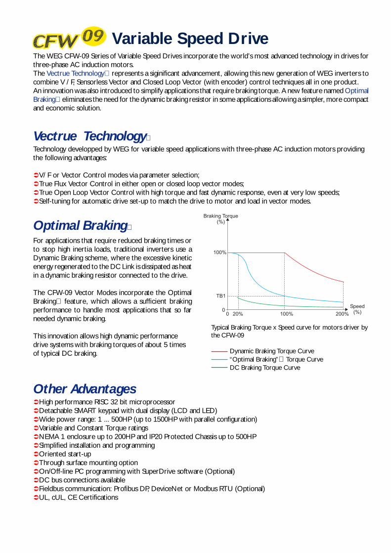
For applications that require reduced braking times orto stop high inertia loads, traditional inverters use aDynamic Braking scheme, where the excessive kineticenergy regenerated to the DC Link is dissipated as heatin a dynamic braking resistor connected to the drive.
The CFW-09 Vector Modes incorporate the OptimalBraking feature, which allows a sufficient brakingperformance to handle most applications that so farneeded dynamic braking.
This innovation allows high dynamic performancedrive systems with braking torques of about 5 timesof typical DC braking.
Variable Speed Drive
Optimal Braking
Other AdvantagesHigh performance RISC 32 bit microprocessorDetachable SMART keypad with dual display (LCD and LED)Wide power range: 1 ... 500HP (up to 1500HP with parallel configuration)Variable and Constant Torque ratingsNEMA 1 enclosure up to 200HP and IP20 Protected Chassis up to 500HPSimplified installation and programmingOriented start-upThrough surface mounting optionOn/Off-line PC programming with SuperDrive software (Optional)DC bus connections availableFieldbus communication: Profibus DP, DeviceNet or Modbus RTU (Optional)UL, cUL, CE Certifications
Typical Braking Torque x Speed curve for motors driver bythe CFW-09
Dynamic Braking Torque Curve“Optimal Braking” Torque CurveDC Braking Torque Curve

Fans / ExhaustsCentrifugal PumpsMetering / Process PumpsCentrifugesMixersCompressorsExtruders
Metering PumpsProcess PumpsFans / ExhaustsAgitators / MixersRotating FiltersRotating KilnsScrap ConveyorsPaper MachinesPaper RewindersCalenders
Fans / ExhaustsRollout TablesWinders / UnwindersCranesPresses / Lathes / Milling CuttersDrillers / GrindersLaminatorsCutting LinesIngot Molding LinesPipe Forming MachinesWire Drawing MachinesPumps
ApplicationsCHEMICAL ANDPETROCHEMICAL PULP AND PAPER
STEEL
PLASTIC AND RUBBER
ExtrudersInjection MachinesMixersCalenders / PullersWinders / UnwindersCut and Welding MachinesGranulators
MINING AND CEMENT
Fans / ExhaustsPumpsScreenersVibratory FeedersCrushersDynamic SeparatorsConveyorsCement Kilns
SUGAR
Sugar CentrifugesProcess PumpsConveyorsBagasse Dosers
TEXTILE
Mixers / AgitatorsWashers / DriersLoomsSpinning MachinesCarding MachinesWarpersWinders
HVAC
Process PumpsFans / ExhaustsAir Conditioning Units
LUMBER
FOOD
Metering / Process PumpsFans / ExhaustsMixersDriers / OvensPalletizersMonorailsConveyors
BEVERAGE
Metering / Process PumpsBottlersMixersRollout TablesConveyors
GLASS
Fans / ExhaustsBottlersRollout TablesConveyors
CERAMIC
Fans / ExhaustsDriers / OvensBall MillsRollout TablesEnamellersConveyors
WASTE WATER
Centrifugal PumpsBooster Systems
ELEVATORS
Load ElevatorsCommercial ElevatorsOverhead CranesHoists
Veneer LathesChippersPlanersSaws

A Complete, Flexible and Compact Product
Optional RS-232Interface Module forPC Communication
7 SegmentLED Display
2 Lines with 16Characters LCDDisplay
Optional FieldbusCommunicationModules for:- Profibus DP- DeviceNet- Modbus RTU
Dynamic Braking Resistor Connection
2 Programmable Analog Outputs
3 ProgrammableRelay Outputs
Optional I/OExpansionBoards for:- RS-485 Serial Interface- Additional Inputs/ Outputs- Encoder Feedback
Standard SMDControl Boardfor all Models
High Performance32 bit RISC Micro-processor
Detachable Keypadwith Multi-languageDouble Display(LCD + LED) andCopy Function
Flange for ThroughSurface Mounting
NEMA 1 / IP20 Enclosure
6 ProgrammableIsolated DigitalInputs
2 ProgrammableAnalog Inputs
Metallic ConduitConnection System
AC Supply Input
Motor Connection OutputDC Bus Connection for:- DC Bus Choke- Common DC BusC- Regenerative Rectifier

Block Diagram
Three-phaseRectifier
Sensors- Ground Fault- Phase Fault
=Falta de fase somente a partir de mecânica 1
DC BUS
CapacitorBank
RFI Filter
IGBTInverter
Feedback-Votlage-Current
PE
Pre-charge
RS-232(optional)
SuperDriveSoftware
Internal electronics power suppliesand control/power interfaces
“CC9”Control Board
with 32 bitRISC CPU
EBA/EBB Expansion (op-tional)-Isolated RS-485-1 digital input 1x14 bit analog input 2x14 bit analog outputs
1x 4...20mA isol. input 2 x4...20mA isol. outputs
- 2 digital outputs- 1encoder input/output- 1 PTC input
RemotaKeypad
DigitalInputs
(D11...DA16)
AnalogInputs
(A11...A12)
PCPLCDCS
FIELDBUS (Optional):- Profibus DP- DeviceNet- Modbus RTU
AnalogOutputs
(AO1...AO2)
RelayOutputs
(RL1...RL3)
ExternalControl
A
B
PC POWERCONTROL
POW
ERSU
PPLY
Designed to integrate large industrial plant automationsystems, high speed communication networks provide on-line supervision and control over the drives with therequired operational flexibility.
The CFW-09 inverters can be connected to “fieldbus”communication networks with the follwing protocols:
•Profibus DP FIELDBUS •DeviceNet
•Modbus RTU
For the connection to Fieldbus networks, the CFW-09allows the installation of an add on communication boardaccording to the desired protocol. No other peripheralsare necessary.
“FieldBus” Communication
PLC
“FIELDBUS” NETWORK
Keypad
High Speed Communication Networks
= DC Bus Choke connection (Optional) (only from Size 2 and up)= DC Bus Connection= DB Resistor Connection (Up to Size 7 only. Option for Sizes 4 to 7)
4
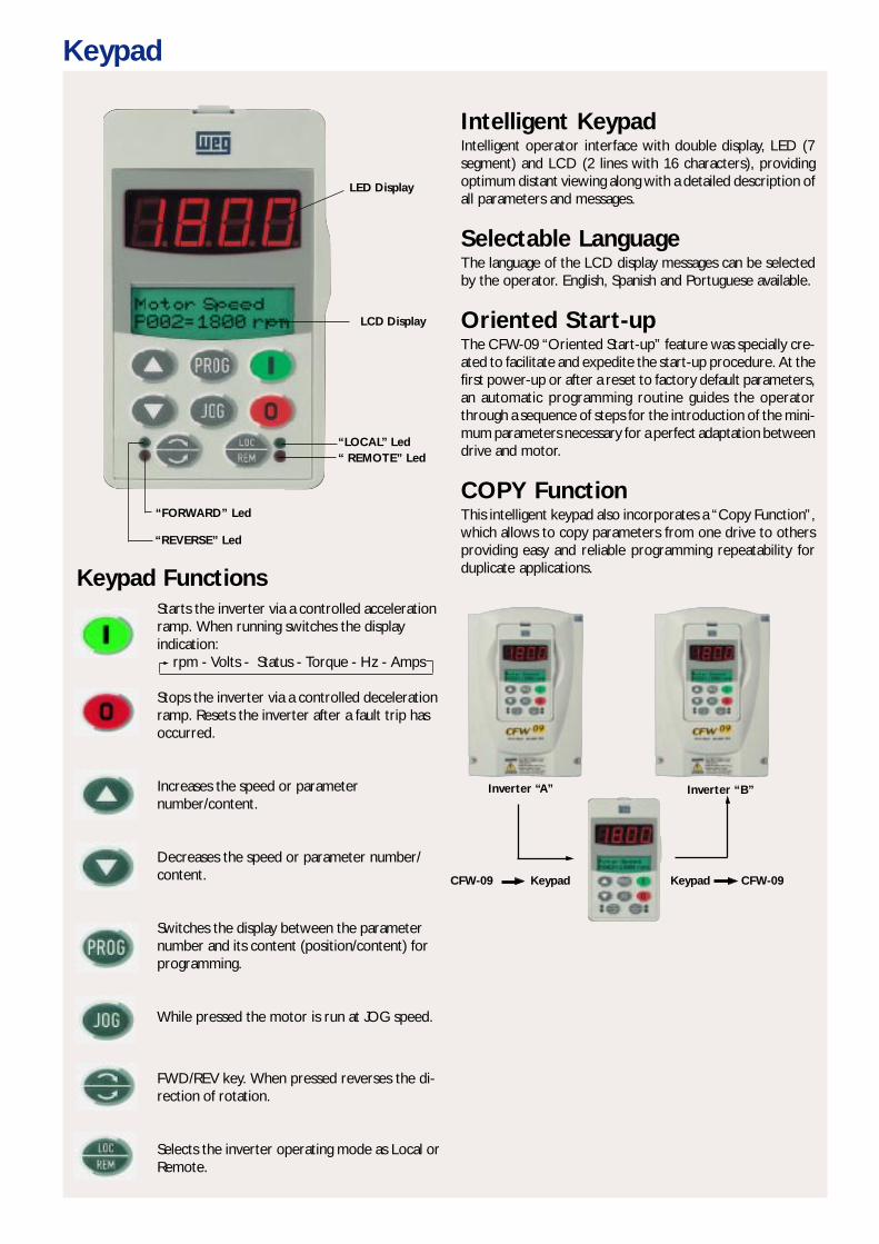
Intelligent KeypadIntelligent operator interface with double display, LED (7segment) and LCD (2 lines with 16 characters), providingoptimum distant viewing along with a detailed description ofall parameters and messages.
Selectable LanguageThe language of the LCD display messages can be selectedby the operator. English, Spanish and Portuguese available.
Oriented Start-upThe CFW-09 “Oriented Start-up” feature was specially cre-ated to facilitate and expedite the start-up procedure. At thefirst power-up or after a reset to factory default parameters,an automatic programming routine guides the operatorthrough a sequence of steps for the introduction of the mini-mum parameters necessary for a perfect adaptation betweendrive and motor.
COPY FunctionThis intelligent keypad also incorporates a “Copy Function”,which allows to copy parameters from one drive to othersproviding easy and reliable programming repeatability forduplicate applications.
LED Display
LCD Display
“LOCAL” Led“ REMOTE” Led
“FORWARD” Led
“REVERSE” Led
Starts the inverter via a controlled accelerationramp. When running switches the displayindication: rpm - Volts - Status - Torque - Hz - Amps
Stops the inverter via a controlled decelerationramp. Resets the inverter after a fault trip hasoccurred.
Increases the speed or parameternumber/content.
Decreases the speed or parameter number/content.
Switches the display between the parameternumber and its content (position/content) forprogramming.
While pressed the motor is run at JOG speed.
FWD/REV key. When pressed reverses the di-rection of rotation.
Selects the inverter operating mode as Local orRemote.
Inverter “A” Inverter “B”
CFW-09 Keypad Keypad CFW-09
Keypad
Keypad Functions
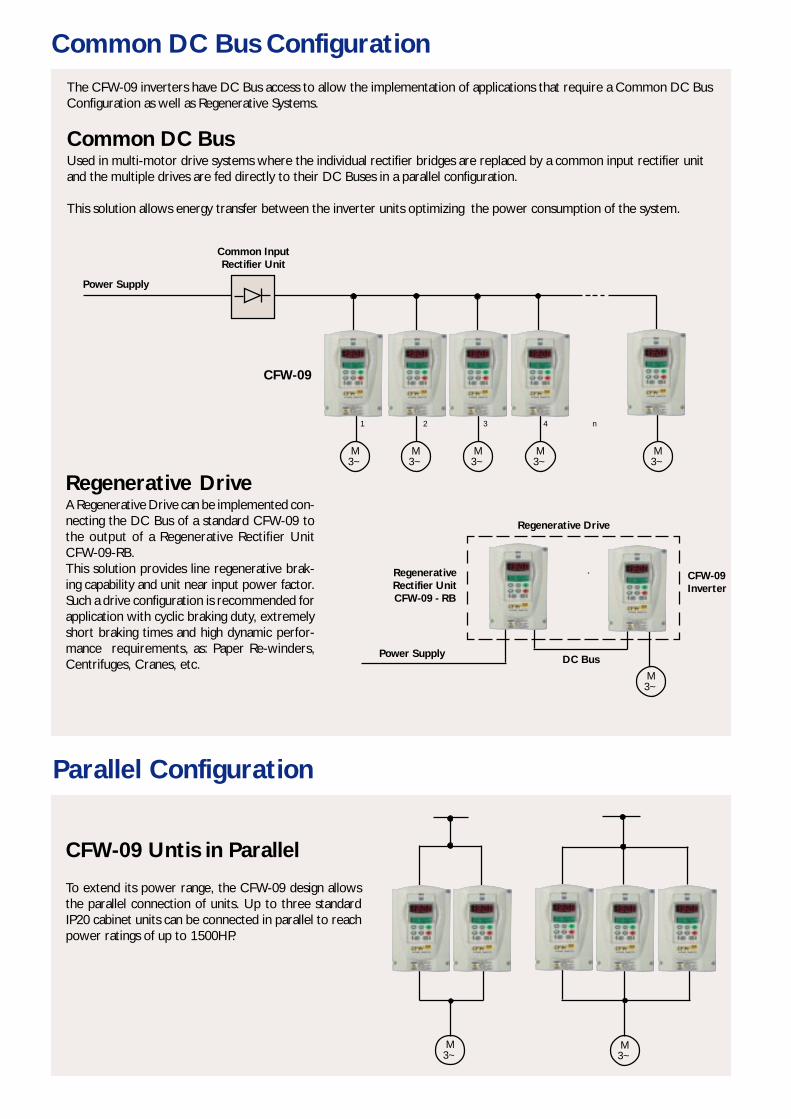
Common DC Bus ConfigurationThe CFW-09 inverters have DC Bus access to allow the implementation of applications that require a Common DC BusConfiguration as well as Regenerative Systems.
Common DC BusUsed in multi-motor drive systems where the individual rectifier bridges are replaced by a common input rectifier unitand the multiple drives are fed directly to their DC Buses in a parallel configuration.
This solution allows energy transfer between the inverter units optimizing the power consumption of the system.
Regenerative DriveA Regenerative Drive can be implemented con-necting the DC Bus of a standard CFW-09 tothe output of a Regenerative Rectifier UnitCFW-09-RB.This solution provides line regenerative brak-ing capability and unit near input power factor.Such a drive configuration is recommended forapplication with cyclic braking duty, extremelyshort braking times and high dynamic perfor-mance requirements, as: Paper Re-winders,Centrifuges, Cranes, etc.
Parallel Configuration
CFW-09 Untis in Parallel
To extend its power range, the CFW-09 design allowsthe parallel connection of units. Up to three standardIP20 cabinet units can be connected in parallel to reachpower ratings of up to 1500HP.
M3~
M3~
Regenerative Drive
RegenerativeRectifier UnitCFW-09 - RB
CFW-09Inverter
DC BusPower Supply
M3~
Power Supply
Common InputRectifier Unit
CFW-09
M3~
M3~
M3~
M3~
M3~
1 2 3 4 n
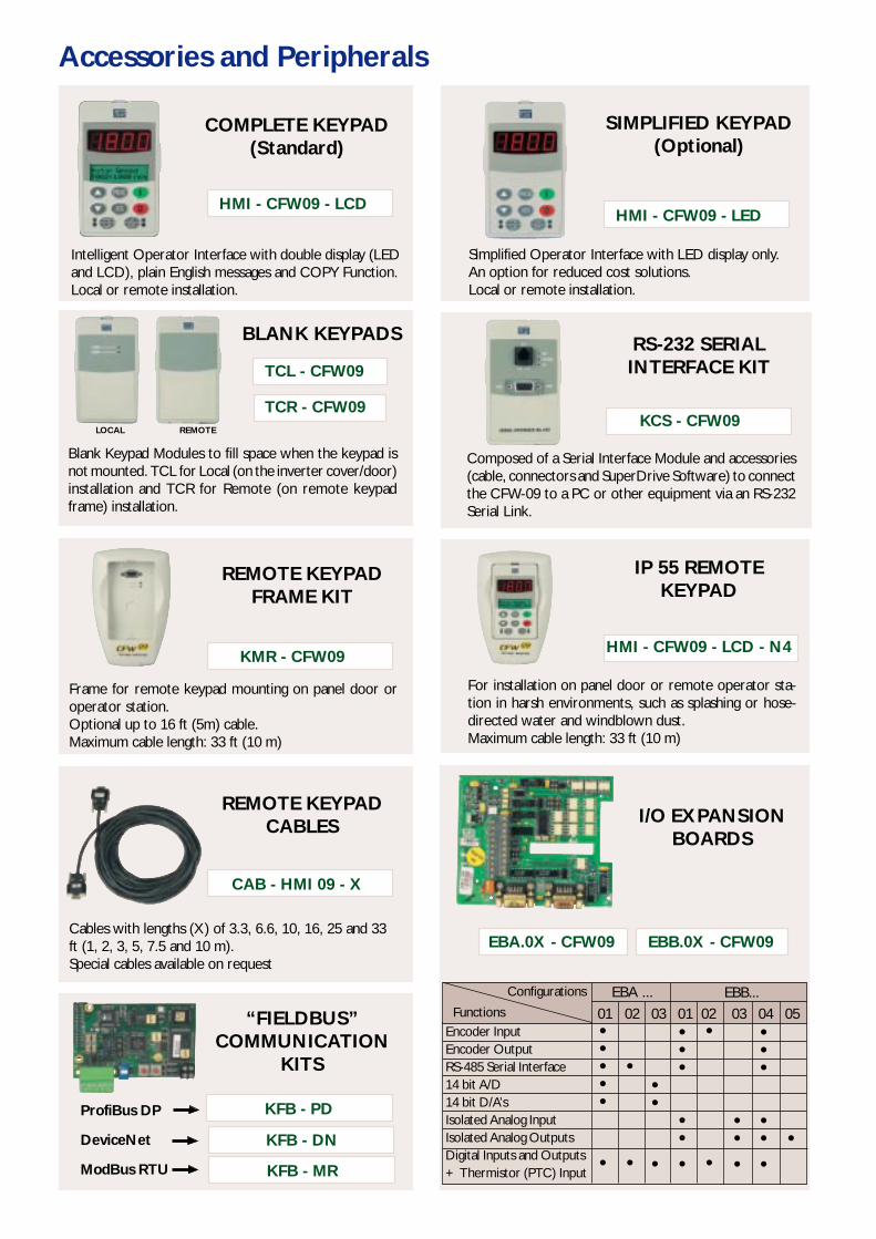
Accessories and Peripherals
Intelligent Operator Interface with double display (LEDand LCD), plain English messages and COPY Function.Local or remote installation.
COMPLETE KEYPAD(Standard)
HMI - CFW09 - LCD
Simplified Operator Interface with LED display only.An option for reduced cost solutions.Local or remote installation.
SIMPLIFIED KEYPAD(Optional)
HMI - CFW09 - LED
Blank Keypad Modules to fill space when the keypad isnot mounted. TCL for Local (on the inverter cover/door)installation and TCR for Remote (on remote keypadframe) installation.
BLANK KEYPADS
TCR - CFW09
TCL - CFW09
Composed of a Serial Interface Module and accessories(cable, connectors and SuperDrive Software) to connectthe CFW-09 to a PC or other equipment via an RS-232Serial Link.
RS-232 SERIALINTERFACE KIT
KCS - CFW09
Frame for remote keypad mounting on panel door oroperator station.Optional up to 16 ft (5m) cable.Maximum cable length: 33 ft (10 m)
REMOTE KEYPADFRAME KIT
KMR - CFW09
For installation on panel door or remote operator sta-tion in harsh environments, such as splashing or hose-directed water and windblown dust.Maximum cable length: 33 ft (10 m)
IP 55 REMOTEKEYPAD
HMI - CFW09 - LCD - N4
Cables with lengths (X) of 3.3, 6.6, 10, 16, 25 and 33ft (1, 2, 3, 5, 7.5 and 10 m).Special cables available on request
CAB - HMI 09 - X
I/O EXPANSIONBOARDS
EBB.0X - CFW09EBA.0X - CFW09
“FIELDBUS”COMMUNICATION
KITS
KFB - PD
KFB - DN
KFB - MR
LOCAL REMOTE
REMOTE KEYPADCABLES
ProfiBus DP
DeviceNet
ModBus RTU
Encoder InputEncoder OutputRS-485 Serial Interface14 bit A/D14 bit D/A’sIsolated Analog InputIsolated Analog OutputsDigital Inputs and Outputs+ Thermistor (PTC) Input
•••••
•
•••
•••
•
•
••
•
•
•
•••
01 02 03 01 02 03 04 05EBA ... EBB...
Functions
Configurations
•••
•••
•

Technical SpecificationsPOWER SUPPLY Voltage Three-phase: 220 – 230 V: 220 / 230 V (+10%, -15%)
380 - 480 V: 380 / 400 / 415 / 440 / 460 / 480 V (+10%, -15%)Frequency 50 / 60 Hz +/- 2 Hz (48 ... 62 Hz)Phase Unbalance Up to 3 %Cos ϕ (Displacement Power Factor) Greater than 0.98
ENCLOSURE Degree of Protection NEMA 1 / IP 20 ( Sizes 1 to 8 )IP 20 (Sizes 9 and 10)
Finishing Color Plastic Cover – Light Gray PANTONE 413 C (sizes 1 and 2)Metallic Cover and Sides – Light Gray RAL 7032 (sizes 3 to 10)Base – Dark Gray RAL 7022 (sizes 3 to 10)
CONTROL Power Supply Switched Mode Power Supply Fed from the DC LinkMicroprocessor 32 bit RISC TechnologyPWM Technique SVM Sine wave PWM (Space Vector Modulation)
Software Implemented Current, Flux and Speed Regulators (Full Digital)Control Modes Scalar (Voltage Source – V / F)
Sensorless Vector (without encoder)Vector with Encoder
Switching Frequency 1.25 / 2.5 / 5.0 / 10 kHzFrequency Range 0 ... 1020 Hz for V / Hz Control
0 ... 408 Hz for Vector Control Overload Capacity 150% for 60 seconds, every 10 minutes
180% for 1 second every 10 minutesEfficiency Greater than 97%
PERFORMANCE Speed Control Regulation (with Slip Compensation): 1% of Motor Rated SpeedResolution: 1 rpm (Keypad Reference)Speed Regulation Range: 1:20Regulation: 0.5% of Motor Rated SpeedResolution: 1 rpm (Keypad Reference)Range: 1:100Regulation with:10 bit Analog Reference: +/- 0.1% of Motor Rated Speed14 bit Analog Reference: +/- 0.01% of Motor Rated Speed Digital Reference (Ex: Keypad or Serial): +/- 0.01% of Motor Rated SpeedRange: Down to 0 rpm
Torque Control Regulation: +/- 10% of Motor Rated TorqueRange: 0 ... 150% of Motor Rated Torque
CONTROL INPUTS Analog 2 Programmable Differential Inputs (10 bit): 0...10 V, 0...20 mA or 4...20 mA1 Programmable Bipolar Input (14 bit): -10 ... +10 V, 0...20 mA or 4...20 mA 1 Programmable Isolated Input (10 bit): 0 ... 10 V, 0...20 mA or 4...20 mA
Digital 6 Programmable Isolated Input: 24 Vdc1 Programmable Isolated Input: 24 Vdc 1 Programmable Isolated Input: 24 Vdc (for Motor PTC Thermistor)
Encoder 1 Differential Input, with 12 Vdc Internal Isolated Power Supply (14 bit resolution) CONTROL OUTPUTS Analog 2 Programmable Outputs (11 bit): 0 ... 10 V
2 Programmable Bipolar Outputs (14 bit): -10 ... +10 V 2 Programmable Isolated Outputs (11 bit): 0 ... 20 mA or 4 ... 20 mA
Relay 2 Programmable Outputs, Form C Contacts (NO/NC): 240 Vac, 1 A1 Programmable Output , Form A Contact (NO): 240 Vac, 1 A
Transistor 2 Programmable Isolated Outputs (Open Collector): 24 Vdc, 50 mA Encoder 1 Isolated Differential Encoder Signals Output: 5 ... 15 Vdc External Power Supply
COMMUNICATION Serial RS-232 with KCS-CFW09 Kit RS-485, Isolated, with EBA or EBB Board
Field Bus Profibus DP, DeviceNet or Modbus RTU, with KFB kits SAFETY Protections DC Link Over Voltage Output Short Circuit
DC Link Under Voltage Output Ground FaultInverter Over Temperature External FaultMotor Over Temperature Self-diagnosis FaultOutput Over Current Programming ErrorMotor Overload (i x t) Serial Communication FaultDynamic Braking Resistor Overload Motor or Encoder Connection FaultCPU / EPROM Error ( Watchdog ) Power Supply Phase Fault ( 30 A and above models)Encoder Fault Keypad Connection Fault
AMBIENT Temperature 0 ... 104 °F (40 °C), up to 122 °F (50 °C) with 2% / °C Output Current De-ratingHumidity 5 ... 90% Non CondensingAltitude 0 ... 3300 ft (1000 m) (up to 13100 ft (4000 m) with 10% / 1000 m Output Current De-rating
CONFORMITIES EMC Directive 89 / 336 /EECEN 61800-3LVD 73/23/EEC Low Voltage DirectiveIEC 146 Semiconductor InvertersUL 508 C Power Conversion EquipmentEN 50178 Electronic Equipment for Use in Power InstallationsEN 61010 Safety Requirements for Electrical Equipment for Measurement, Control and Laboratory Use
CERTIFICATIONS UL (USA) and cUL (CANADA) Underwriters Laboratories Inc. USACE (EUROPE) Competent Body: Phoenix Test-Lab Gmbh - Germany
Optional
V / F Mode
SensorlessVector Mode
EncoderVector Mode
Vector Modes
Electromagnetic Compatibility – Industrial EnvironmentEMC - Emission and Immunity
Technical Specifications
FiledBus Communications kits(Mounted inside inverter)
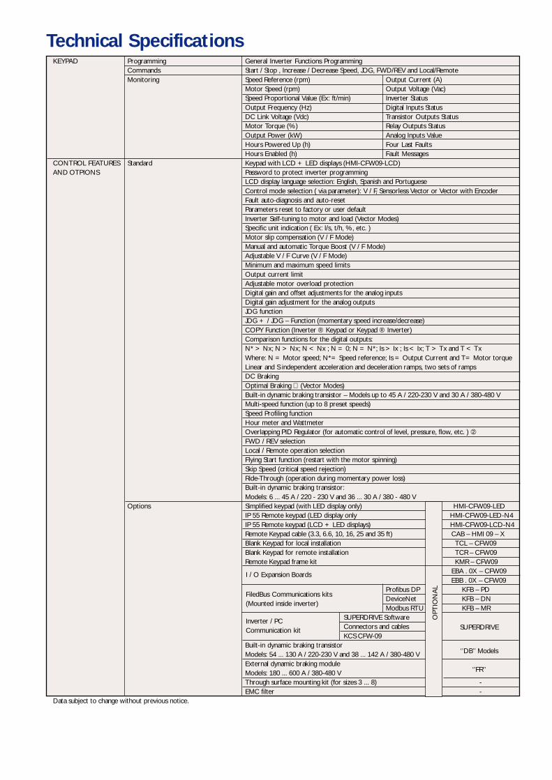
KEYPAD Programming General Inverter Functions ProgrammingCommands Start / Stop , Increase / Decrease Speed, JOG, FWD/REV and Local/RemoteMonitoring Speed Reference (rpm) Output Current (A)
Motor Speed (rpm) Output Voltage (Vac)Speed Proportional Value (Ex: ft/min) Inverter StatusOutput Frequency (Hz) Digital Inputs StatusDC Link Voltage (Vdc) Transistor Outputs StatusMotor Torque (%) Relay Outputs StatusOutput Power (kW) Analog Inputs ValueHours Powered Up (h) Four Last FaultsHours Enabled (h) Fault Messages
CONTROL FEATURES Standard Keypad with LCD + LED displays (HMI-CFW09-LCD)AND OTPIONS Password to protect inverter programming
LCD display language selection: English, Spanish and PortugueseControl mode selection ( via parameter): V / F, Sensorless Vector or Vector with EncoderFault auto-diagnosis and auto-resetParameters reset to factory or user defaultInverter Self-tuning to motor and load (Vector Modes)Specific unit indication ( Ex: l/s, t/h, %, etc. )Motor slip compensation (V / F Mode)Manual and automatic Torque Boost (V / F Mode)Adjustable V / F Curve (V / F Mode)Minimum and maximum speed limitsOutput current limitAdjustable motor overload protectionDigital gain and offset adjustments for the analog inputsDigital gain adjustment for the analog outputsJOG functionJOG + / JOG – Function (momentary speed increase/decrease)COPY Function (Inverter ® Keypad or Keypad ® Inverter)Comparison functions for the digital outputs:N* > Nx; N > Nx; N < Nx ; N = 0; N = N*; Is > Ix ; Is < Ix; T > Tx and T < TxWhere: N = Motor speed; N*= Speed reference; Is = Output Current and T= Motor torqueLinear and S independent acceleration and deceleration ramps, two sets of rampsDC BrakingOptimal Braking (Vector Modes)Built-in dynamic braking transistor – Models up to 45 A / 220-230 V and 30 A / 380-480 VMulti-speed function (up to 8 preset speeds)Speed Profiling functionHour meter and WattmeterOverlapping PID Regulator (for automatic control of level, pressure, flow, etc. ) FWD / REV selectionLocal / Remote operation selectionFlying Start function (restart with the motor spinning)Skip Speed (critical speed rejection)Ride-Through (operation during momentary power loss)Built-in dynamic braking transistor:Models: 6 ... 45 A / 220 - 230 V and 36 ... 30 A / 380 - 480 V
Options Simplified keypad (with LED display only) HMI-CFW09-LEDIP 55 Remote keypad (LED display only HMI-CFW09-LED-N4IP 55 Remote keypad (LCD + LED displays) HMI-CFW09-LCD-N4Remote Keypad cable (3.3, 6.6, 10, 16, 25 and 35 ft) CAB – HMI 09 – XBlank Keypad for local installation TCL – CFW09Blank Keypad for remote installation TCR – CFW09Remote Keypad frame kit KMR – CFW09
EBA . 0X – CFW09 EBB . 0X – CFW09
Profibus DP KFB – PDDeviceNet KFB – DNModbus RTU KFB – MR
SUPERDRIVE SoftwareConnectors and cablesKCS CFW-09 -
Built-in dynamic braking transistorModels: 54 ... 130 A / 220-230 V and 38 ... 142 A / 380-480 VExternal dynamic braking moduleModels: 180 ... 600 A / 380-480 VThrough surface mounting kit (for sizes 3 ... 8) -EMC filter -
Data subject to change without previous notice.
I / O Expansion Boards
OPT
ION
AL
Inverter / PCCommunication kit SUPERDRIVE
‘’DB’’ Models
‘’FR’’

Sizing Table
*CT = Constant Torque; VT = Variable TorqueNote: 1 - Recommended Motor ratings are based on Table 430-150 (Full-Load Current Three-Phase Alternating-Current Motors) of the US National Electrical Code (NEC). 2 - The 6, 7 and 10A/230V models can be single-phase powered without output current de-ratingEnclosure: IP20 Protected Chassis for all sizes.
220
380
440
6,0 7,0 10
1316242845
54 6870 8686 105105 130130 150142 174
1802403,64,05,59,0131624
30 3638 4545 5460 7070 8686 105105 130142 174
1802403614506006868551140128317103,64,05,59,0131624
30 3638 4545 5460 7070 8686 105105 130142 174
180240361450600686855114012831710
Rated Current (A)
CT* VT*
RECOMMENDED MOTOR
HP kW HP kW
380
/ 40
0 /
415
/ 44
0 /
460
/ 48
0V22
0 / 2
30V
0006 T 2223 P S0007 T 2223 P S0010 T 2223 P S0013 T 2223 P S0016 T 2223 P S0024 T 2223 P S0028 T 2223 P S0045 T 2223 P S0054 T 2223 P S0070 T 2223 P S0086 T 2223 P S0105 T 2223 P S0130 T 2223 P S0142 T 2223 P S0180 T 2223 P S0240 T 2223 P S0003 T 3848 P S0004 T 3848 P S0005 T 3848 P S0009 T 3848 P S0013 T 3848 P S0016 T 3848 P S0024 T 3848 P S0030 T 3848 P S0038 T 3848 P S0045 T 3848 P S0060 T 3848 P S0070 T 3848 P S0086 T 3848 P S0105 T 3848 P S0142 T 3848 P S0180 T 3848 P S0240 T 3848 P S0361 T 3848 P S0450 T 3848 P S0600 T 3848 P S0686 T 3848 P S0855 T 3848 P S1140 T 3848 P S1283 T 3848 P S1710 T 3848 P S0003 T 3848 P S0004 T 3848 P S0005 T 3848 P S0009 T 3848 P S0013 T 3848 P S0016 T 3848 P S0024 T 3848 P S0030 T 3848 P S0038 T 3848 P S0045 T 3848 P S0060 T 3848 P S0070 T 3848 P S0086 T 3848 P S0105 T 3848 P S0142 T 3848 P S0180 T 3848 P S0240 T 3848 P S0361 T 3848 P S0450 T 3848 P S0600 T 3848 P S0686 T 3848 P S0855 T 3848 P S1140 T 3848 P S1283 T 3848 P S1710 T 3848 P S
Yes
OptionalBuilt-in
External DBModule
Yes
OptionalBuilt-in
External DBModule
Yes
OptionalBuilt-in
External DBModule
1,5 1,1 1,5 1,12,0 1,5 2,0 1,53,0 2,2 3,0 2,24,0 3,0 4,0 3,06,0 4,4 6,0 4,47,5 5,5 7,5 5,510 7,5 10 7,515 11 15 1120 15 25 18,525 18,5 30 2230 22 40 3040 30 50 3750 37 60 4550 37 75 5575 55 75 55100 75 100 751,5 1,1 1,5 1,12,0 1,5 2,0 1,53,0 2,2 3,0 2,25,0 3,7 5,0 3,77,5 5,5 7,5 5,510 7,5 10 7,515 11 15 1120 15 20 1525 18,5 30 2230 22 30 2240 30 50 3750 37 60 4560 45 75 5575 55 75 55100 75 125 92125 92 125 92150 110 150 110270 200 270 200300 220 300 220400 300 400 300500 370 500 370600 450 600 450800 600 800 600900 660 900 660
1300 950 1300 9501,5 1,1 1,5 1,12,0 1,5 2,0 1,53,0 2,2 3,0 2,26,0 4,4 6,0 4,410 7,5 10 7,5
12,5 9,2 12,5 9,215 11 15 1120 15 25 18,525 18,5 30 2230 22 40 3040 30 50 3750 37 60 4560 45 75 5575 55 100 75100 75 125 92150 110 150 110200 150 200 150300 220 300 220350 260 350 260500 370 500 370600 450 600 450700 500 700 500900 660 900 660
1000 730 1000 7301500 1100 1500 1100
1
2
34
5
6
7
8
1
2
3
4
5
6
7
8
9
10
-
1
2
3
4
5
6
7
8
9
10
-
AC LINEVOLTAGE Part Number
CFW-09...
CFW-09 INVERTER
Built-in DynamicBraking
Voltage(V)
CT VT SIZE
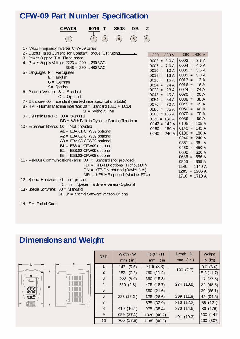
1 - WEG Frequency Inverter CFW-09 Series2 - Output Rated Current for Constant Torque (CT) Sizing3 - Power Supply: T = Three-phase4 - Power Supply Voltage: 2223 = 220 ... 230 VAC
3848 = 380 ... 480 VAC5 - Languages: P = Portuguese
E = EnglishG = GermanS = Spanish
6 - Product Version: S = Standard O = Optional
7 - Enclosure: 00 = standard (see technical specifications table)8 - HMI - Human Machine Interface: 00 = Standard (LED + LCD)
SI = Without HMI9 - Dynamic Braking: 00 = Standard
DB = With Built-in Dynamic Braking Transistor
CFW-09 Part Number SpecificationCFW09 0016 T 3848 DB Z
1 2 3 4 5 6
380 ... 480 V0003 = 3.6 A0004 = 4.0 A0005 = 5.5 A0009 = 9.0 A0013 = 13 A0016 = 16 A0024 = 24 A0030 = 30 A0038 = 38 A0045 = 45 A0060 = 60 A0070 = 70 A0086 = 86 A0105 = 105 A0142 = 142 A0180 = 180 A0240 = 240 A0361 = 361 A0450 = 450 A0600 = 600 A
1
2
3
4
5
6
7
8
9
10
Width - W
mm ( in )
Heigth - H
mm ( in
)
Depth - D
mm ( in )Weight
Ib (kg)SIZE
Dimensions and Weight
143 (5.6)182 (7.2) 223 (8.9)250 (9.8)
335 (13.2 )
410 (16.1)689 (27.1)700 (27.5)
210 (8.3)
290 (11.4)
390 (15.3)
475 (18.7)
550 (21.6)
675 (26.6)
835 (32.9)
975 (38.4)
1020 (40.2)
1185 (46.6)
196 (7.7)
274 (10.8)
299 (11.8)
310 (12.2)
370 (14.6)
491 (19.3)
3.0 (6.6)5.3 (11.7)17 (37.5)22 (48.5)30 (66.1)43 (94.8)55 (121)80 (176)
200 (441)230 (507)
220 ... 230 V0006 = 6.0 A0007 = 7.0 A0010 = 10 A0013 = 13 A0016 = 16 A0024 = 24 A0028 = 28 A0045 = 45 A0054 = 54 A0070 = 70 A0086 = 86 A0105 =105 A0130 = 130 A
0142 = 142 A 0180 = 180 A 0240 = 240 A
0686 = 686 A0855 = 855 A1140 = 1140 A1283 = 1286 A1710 = 1710 A
10 - Expansion Boards: 00 = Not providedA1 = EBA.01-CFW09 optionalA2 = EBA.02-CFW09 optionalA3 = EBA.03-CFW09 optionalB1 = EBB.01-CFW09 optionalB2 = EBB.02-CFW09 optionalB3 = EBB.03-CFW09 optional
11 - FieldBus Communications cards: 00 = Standard (not provided)PD = KFB-PD optional (Profibus DP)DN = KFB-DN optional (Device Net)MR = KFB-MR optional (Modbus RTU)
12 - Special Hardware:00 = not provideH1...Hn = Special Hardware version-Optional
13 - Special Software: 00 = StandardS1...Sn = Special Software version-Otional
14 - Z = End of Code

Special Functions
Automatic Process CycleDI
n1
n2
n3
n4
n5
n6
n7
n8
4
0
0
0
0
1
1
1
1
5
0
0
1
1
0
0
1
1
6
0
1
0
1
0
1
0
1
The purpose of the Ride-Through function is to ensure thatthe inverter maintains the motor running during the line loss,not allowing interruption or fault storing. The energy requiredfor motor running is obtained from the kinetic energy of themotor (inertia) during its deceleration. As soon as the line isreestablished, the motor accelerates again to the speed de-fined by the reference.
Ajustable V/F Curve
The alteration of the standard V/F curve intends to allowdriving motors with rated voltage and/or frequency differentfrom the power supply. The base frequency can be pro-grammed to a new value, bellow or above the power supplyfrequency, the voltage can be set to any value below linevoltage.
This function replaces the traditional linear acceleration anddeceleration ramps by Type “S” Ramps providing smootherstarting, braking and approximation to the set speed curves.The practical result is the elimination of mechanical shocks,undesirable and some times unpractical for certain applica-tions.
Critical Speeds Rejection
This function avoids the possibility of running the motor atcritical speeds that may provoke mechanical resonance onthe motor/load system causing excessive noise or vibration.Up to three speeds and a rejection band can be programmed.
Overlapping PID Regulator
Up to eight different speeds can be programmed by the userand selected via the combination of three Digital Inputs. TheseInputs can be switched by any external device such as LimitSwitches, Photocells, Proximity Sensors, PLC, etc.
“S” Ramp
Multi-speed
This built-in digital PID regulator was designed for applica-tions where a process variable (flow, pressure, level, etc.)has to be controlled by the motor speed. To implement thisregulator the CFW-09 needs a set point and a feedback sig-nal from the process variable sensor so that a closed loop isformed. This function eliminates the need for an externalregulator to control the process reducing the solution cost.
Los RecoverLine Loss
Ride Through
t0 - Line loss;t1 - Line loss detection;t2 - Trip by Undervoltage (E02 without Ride-Through);t3 - Line Recover;t4 - Line Recover detection;t5 - Trip by Undervoltage (E02 com Ride-Through);
t0 t1 t2 t3 t4 t5
Undervoltage (75%)
••••••
E02

WEG EXPORTADORAJARAGUÁ DO SUL - SC - BRAZIL - PHONE: 55 (47) 372-4000 - FAX 55 (47) 372-4020
www.weg.com.br / e-mail: [email protected]
Mod
. 847
.02/
09.2
002
- D
ata
subj
ect t
o ch
ange
with
out p
revi
ous
notic
e.