Carbonylation in microflow close encounters of CO and reactive species
9
Green Chemistry CRITICAL REVIEW Cite this: Green Chem., 2014, 16, 2042 Received 30th August 2013, Accepted 12th December 2013 DOI: 10.1039/c3gc41789a www.rsc.org/greenchem Carbonylation in microflow: close encounters of CO and reactive species Takahide Fukuyama,* Takenori Totoki and Ilhyong Ryu* Microreactors have brought significant improvements to chemical synthesis and production because of their advantageous characteristics over batch reactors, which include highly efficient mixing, efficient heat and mass transfer ability, precise control of the residence time, large surface area-to-volume ratio and high operational safety. Microreactor technology has been found to be beneficial for gas–liquid biphasic reactions, for which the large interfacial area between the two phases is ensured. Carbonylation reactions with carbon monoxide, by which a wide range of carbonyl compounds can be prepared, deal with a variety of reactive species, such as organo transition metals, radicals, cations and anions. These reactions have long been carried out using a glass batch flask or a stainless-steel made autoclave, however, carbonylation reactions using a flow microreactor are now rapidly increasing in popularity. This review focuses on a new greener wave of carbonylation reactions using a flow microreactor. Introduction Over the past two decades, the rapid development of micro- reaction technology has opened the eyes of synthetic organic chemists, who routinely perform batch flask reactions, to the potential of flow reactions. 1,2 Nowadays a wide variety of solu- tion phase organic reactions have been translated into a flow regime. As for gas–liquid biphasic reactions, benefits can be obtained from the large gas–liquid interfacial area brought by gas–liquid segmented flow or annular flow, which is ensured by the narrow microchannel (Scheme 1). In principle flow carbonylation reactions using CO, either at atmospheric pressure or high pressure, as well as other gaseous reactions, can take advantage of the benefits provided by the high surface area to volume ratio available in a microchannel. Carbon monoxide is a potentially abundant feedstock, which is industrially produced from naphtha and coal. 3 While a wide variety of transition metal catalyzed carbonylation Takahide Fukuyama Takahide Fukuyama received his PhD in 1999 from Osaka Univer- sity under the direction of Prof. Shinji Murai. He spent the year 1999–2000 as a postdoctoral fellow of the JSPS at Okayama University of Science (Prof. Junzo Otera). He was appointed Assist- ant Professor at Osaka Prefecture University in 2000. He was pro- moted to Lecturer in 2007 and to Associate Professor in 2010. He had the experience of working with Prof. Max Malacria at the University of Pierre and Marie Curie (2006). His current research includes organometallic chemistry, catalysis, and the development of sustainable chemical processes. Takenori Totoki Takenori Totoki obtained his BSc from Osaka Prefecture University in 2012 under the supervision of Prof. Ilhyong Ryu. He is currently a Master Course student within the same group and studying carbonylation using a flow microreactor. Department of Chemistry, Graduate School of Science, Osaka Prefecture University, Sakai, Osaka 599-8531, Japan. E-mail: [email protected]; Fax: +81 72 254 9695; Tel: +81 72 254 9695 2042 | Green Chem. , 2014, 16, 2042–2050 This journal is © The Royal Society of Chemistry 2014 Published on 13 December 2013. Downloaded by University of California - Santa Cruz on 23/10/2014 15:19:59. View Article Online View Journal | View Issue
-
Upload
independent -
Category
Documents
-
view
0 -
download
0
Transcript of Carbonylation in microflow close encounters of CO and reactive species
Green Chemistry
CRITICAL REVIEW
Cite this: Green Chem., 2014, 16,2042
Received 30th August 2013,Accepted 12th December 2013
DOI: 10.1039/c3gc41789a
www.rsc.org/greenchem
Carbonylation in microflow: close encounters ofCO and reactive species
Takahide Fukuyama,* Takenori Totoki and Ilhyong Ryu*
Microreactors have brought significant improvements to chemical synthesis and production because of
their advantageous characteristics over batch reactors, which include highly efficient mixing, efficient heat
and mass transfer ability, precise control of the residence time, large surface area-to-volume ratio and
high operational safety. Microreactor technology has been found to be beneficial for gas–liquid biphasic
reactions, for which the large interfacial area between the two phases is ensured. Carbonylation reactions
with carbon monoxide, by which a wide range of carbonyl compounds can be prepared, deal with a
variety of reactive species, such as organo transition metals, radicals, cations and anions. These reactions
have long been carried out using a glass batch flask or a stainless-steel made autoclave, however,
carbonylation reactions using a flow microreactor are now rapidly increasing in popularity. This review
focuses on a new greener wave of carbonylation reactions using a flow microreactor.
Introduction
Over the past two decades, the rapid development of micro-reaction technology has opened the eyes of synthetic organicchemists, who routinely perform batch flask reactions, to thepotential of flow reactions.1,2 Nowadays a wide variety of solu-tion phase organic reactions have been translated into a flow
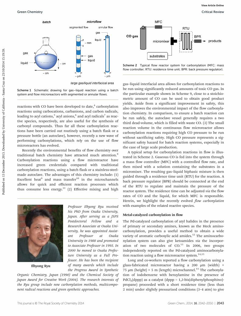
regime. As for gas–liquid biphasic reactions, benefits can beobtained from the large gas–liquid interfacial area brought bygas–liquid segmented flow or annular flow, which is ensuredby the narrow microchannel (Scheme 1). In principle flowcarbonylation reactions using CO, either at atmosphericpressure or high pressure, as well as other gaseous reactions,can take advantage of the benefits provided by the highsurface area to volume ratio available in a microchannel.
Carbon monoxide is a potentially abundant feedstock,which is industrially produced from naphtha and coal.3 Whilea wide variety of transition metal catalyzed carbonylation
Takahide Fukuyama
Takahide Fukuyama received hisPhD in 1999 from Osaka Univer-sity under the direction of Prof.Shinji Murai. He spent the year1999–2000 as a postdoctoralfellow of the JSPS at OkayamaUniversity of Science (Prof. JunzoOtera). He was appointed Assist-ant Professor at Osaka PrefectureUniversity in 2000. He was pro-moted to Lecturer in 2007 and toAssociate Professor in 2010. Hehad the experience of workingwith Prof. Max Malacria at the
University of Pierre and Marie Curie (2006). His current researchincludes organometallic chemistry, catalysis, and the developmentof sustainable chemical processes.
Takenori Totoki
Takenori Totoki obtained his BScfrom Osaka Prefecture Universityin 2012 under the supervision ofProf. Ilhyong Ryu. He is currentlya Master Course student withinthe same group and studyingcarbonylation using a flowmicroreactor.
Department of Chemistry, Graduate School of Science, Osaka Prefecture University,
Sakai, Osaka 599-8531, Japan. E-mail: [email protected];
Fax: +81 72 254 9695; Tel: +81 72 254 9695
2042 | Green Chem., 2014, 16, 2042–2050 This journal is © The Royal Society of Chemistry 2014
Publ
ishe
d on
13
Dec
embe
r 20
13. D
ownl
oade
d by
Uni
vers
ity o
f C
alif
orni
a -
Sant
a C
ruz
on 2
3/10
/201
4 15
:19:
59.
View Article OnlineView Journal | View Issue
reactions with CO have been developed to date,4 carbonylationreactions using carbocations, carbanions, and carbon radicals,leading to acyl cations,5 acyl anions,6 and acyl radicals7 as reac-tive species, respectively, are also useful for the synthesis ofcarbonyl compounds. Thus far all these carbonylation reac-tions have been carried out routinely using a batch flask or apressure bottle (an autoclave), however, recently a new wave ofperforming carbonylations, which rely on the use of flowmicroreactors has evolved.
Recently the environmental benefits of flow chemistry overtraditional batch chemistry have attracted much attention.8
Carbonylation reactions using a flow microreactor haveincreased green credentials compared with traditionalcarbonylation reactions, using a batch flask or a stainless-steel-made autoclave. The advantages of this chemistry include: (1)Excellent heat9 and mass transfer10 in the microchannelsallows for quick and efficient reaction processes whichthus consume less energy.11 (2) Effective mixing and high
gas–liquid interfacial area allows for carbonylation reactions tobe run using significantly reduced amounts of toxic CO gas. Inthe particular example shown in Scheme 9, close to a stoichio-metric amount of CO can be used to obtain good productyields. Aside from a significant improvement in safety, thisalso improves the environmental impact of the flow carbonyla-tion chemistry. In comparison, to ensure a batch reaction canbe run safely, the autoclave vessel generally requires a twothird dead-volume, which is filled with waste CO. (3) The smallreaction volume in the continuous flow microreactor allowscarbonylation reactions requiring high CO pressure to be runwithout sacrificing safety. High CO pressure represents a sig-nificant safety hazard for batch reaction systems, especially inthe case of large scale production.
A typical setup for carbonylation reactions in flow is illus-trated in Scheme 2. Gaseous CO is fed into the system througha mass flow controller (MFC) with a controlled flow rate, andthen mixed with a solution containing the substrates in amicromixer. The resulting gas–liquid biphasic mixture is thenguided through a residence time unit (RTU) for the reaction. Aback pressure regulator (BPR) should be connected at the endof the RTU to regulate and maintain the pressure of thereactor system. The residence time can be adjusted via the flowrates of CO and the liquid, for which MFC is responsible.Herein, we highlight the recently evolved flow carbonylationwith examples of the related reactive species.
Metal-catalyzed carbonylation in flow
The Pd-catalyzed carbonylation of aryl halides in the presenceof primary or secondary amines, known as the Heck amino-carbonylation, provides a useful method to obtain a widevariety of aromatic carboxylic acid amides.12 The aminocarbo-nylation system can also give ketoamides via the incorpor-ation of two molecules of CO.13 In 2006, two groupsindependently reported on the Pd-catalyzed aminocarbonyla-tion reaction using a flow microreactor system.14,15
Long and co-workers reported a flow carbonylation using aglass-fabricated microreactor having a 200 μm (width) ×75 μm (height) × 5 m (length) microchannel.14 The carbonyla-tion of iodobenzene with benzylamine in the presence ofPdCl2(dppp) as a catalyst (dppp = 1,3-bis(diphenylphosphino)-propane) proceeded with a short residence time (less than2 min) under slightly pressurized conditions (3–4 atm) to give
Ilhyong Ryu
Professor Ilhyong Ryu receivedhis PhD from Osaka University,Japan. After serving as a JSPSPostdoctoral Fellow and aResearch Associate at Osaka Uni-versity, he was appointed Assist-ant Professor at OsakaUniversity in 1988 and promotedto Associate Professor in 1995. In2000 he moved to Osaka Prefec-ture University as a Full Pro-fessor. He has been the recipientof many awards which includethe Progress Award in Synthetic
Organic Chemistry, Japan (1990) and the Chemical Society ofJapan Award for Creative Work (2004). The research interests ofthe Ryu group include new carbonylation methods, multicompo-nent radical reactions and green synthetic approaches.
Scheme 1 Schematic drawing for gas–liquid reaction using a batchsystem and flow microreactors with segmented or annular flows.
Scheme 2 Typical flow reactor system for carbonylation (MFC: massflow controller; RTU: residence time unit; BPR: back pressure regulator).
Green Chemistry Critical Review
This journal is © The Royal Society of Chemistry 2014 Green Chem., 2014, 16, 2042–2050 | 2043
Publ
ishe
d on
13
Dec
embe
r 20
13. D
ownl
oade
d by
Uni
vers
ity o
f C
alif
orni
a -
Sant
a C
ruz
on 2
3/10
/201
4 15
:19:
59.
View Article Online

the aminocarbonylation product (46%) along with the doublecarbonylation product (9%). The batch reaction, carried outfor comparison, gave a lower yield of the aminocarbonylationproduct even with a longer reaction time of 10 min (Scheme 3).
During the course of our study on flow cross-coupling reac-tions using ionic liquids as a reaction medium,16 we studiedan aminocarbonylation reaction of iodobenzene with diethyl-amine. An ionic liquid, [bmim]PF6, was used as the reactionmedium and a Pd–carbene complex as the catalyst in a press-urized microflow system using a tubular reactor made of stain-less-steel (1000 μm i.d. × 18 m).15 The double carbonylationproduct was predominantly obtained under 20 atm of CO inthe microflow system, with a double/single ratio at 93/7(Scheme 4). This ratio is superior to the ratio of 85/15 obtainedusing a batch autoclave under the same CO pressure.
Later, Long and co-workers reported a gas–solid–liquid tri-phasic aminocarbonylation using a reusable silica-supportedpalladium diphosphine catalyst packed into standard PTFEtubing.17 The reaction of aryl iodides or aryl bromides bearingan electron-withdrawing substituent with benzylamine in theflow system provided higher yields of amides compared withthat in the batch reaction system (Scheme 5). They also appliedthis flow system to the carbonylation using 11CO to form highpurity radiochemical amides, available for positron-emissiontomography (PET).
Csajági et al. reported the aminocarbonylation of haloge-nated aryl carboxylic acids leading to dicarboxylic acid mono-amides using an automated continuous flow reactor having aPd-packed cartridge (X-Cube™).18 For example, the carbonyla-tion of p-iodobenzoic acid with pyrrolidine took placesmoothly using polymer-supported Pd(PPh3)4 as the catalystpacked in the cartridge (4 mm i.d. and 70 mm length) and
Et3N as the base under 30 atm of CO at 100 °C with 1.5 minresidence time to give the corresponding monoamide in goodyield. Skoda-Földes and coworkers also reported the doublecarbonylation of iodobenzenes using the same flow carbonyla-tion system.19 The reaction of iodobenzene with n-BuNH2
using polymer-supported Pd(PPh3)4 as the catalyst and DBU(1,8-diazabicyclo[5.4.0]undec-7-ene) as the base under 40 atmof CO at 80 °C gave the double carbonylated ketoamide withgood selectivity for the double carbonylation.
Buchwald, Jensen and co-workers reported a flow carbo-nylation catalyzed by a PdCl2/Xantphos system (Xantphos =4,5-bis(diphenylphosphino)-9,9-dimethylxanthene) using asilicon etched microreactor having a 78 μL inner volume.20 Inthis work, the flow of CO was controlled by adjusting a needle
Scheme 3 Heck aminocarbonylation using a glass-fabricatedmicroreactor.
Scheme 4 Heck aminocarbonylation in [bmim]PF6 using a stainless-steel made tubular reactor.
Scheme 5 Heck aminocarbonylation using a Pd-packed microreactorsystem.
Critical Review Green Chemistry
2044 | Green Chem., 2014, 16, 2042–2050 This journal is © The Royal Society of Chemistry 2014
Publ
ishe
d on
13
Dec
embe
r 20
13. D
ownl
oade
d by
Uni
vers
ity o
f C
alif
orni
a -
Sant
a C
ruz
on 2
3/10
/201
4 15
:19:
59.
View Article Online

valve at the gas inlet and a leak valve at the gas outlet. Thereaction of p-iodocyanobenzene and morpholine at 160 °Cunder 2.7 atm of CO gave the aminocarbonylation productselectively, whereas the reaction at 109 °C under 14.8 atm ofCO furnished the ketoamide as the major product (Scheme 6).
Miller and co-workers developed a microfluidic device witha glass-fabricated microchip that allows for rapid catalystscreening for the aminocarbonylation of iodoarenes(Scheme 7).21 The reaction of iodobenzene with CO and ben-zylamine leading to N-benzylbenzamide was performed with aseries of Pd/ligand systems under a variety of temperatures(75–150 °C). It was highlighted in this study that PdCl2/Xant-phos was the most efficient catalyst for the reaction, whichworked at a relatively low temperature (100 °C). Only small
quantities of reagents and catalyst (10.2 mg iodobenzene,∼1 mg catalyst) were required for the catalyst screening.
A practical scale of flow Heck carbonylation was reported byLeadbeater and coworkers.22 The reaction was carried outusing a 14 mL inner volume of residence time unit with1.2 mL min−1 reagent flow rate. CO was introduced through aback pressure regulator. The Heck carbonylation of p-iodo-toluene with ethanol gave 1.41 g of the carbonylated product(Scheme 8).
The research group of Nihon Nohyaku CO., Ltd attainedkilogram scale production by their flow carbonylation system,which employed a large volume residence time unit having850 mL inner volume after a micromixer (200 μm i.d.). Benzoicacid derivatives having two trifluoromethyl substituents at themeta position constitute important structural motifs in biologi-cally active compounds, as well as for pharmaceuticals andagrochemicals. The reaction of 3,5-bis(trifluoromethyl)bromo-benzene with CO (10 atm) and methanol proceeded well togive the carbonylated product in quantitative yield at 120 °Cwith 56 min of residence time, where the reagent flow rate was7.3 mL min−1 (Scheme 9).23 Using this system, 1.86 kg of
Scheme 6 Pd/Xantphos catalyzed aminocarbonylation using a siliconetched microreactor.
Scheme 7 Catalyst screening for Pd-catalyzed aminocarbonylation inflow.
Scheme 8 Practical scale Heck carbonylation.
Scheme 9 Flow system aiming at stoichiometric carbonylation andkilogram scale production.
Green Chemistry Critical Review
This journal is © The Royal Society of Chemistry 2014 Green Chem., 2014, 16, 2042–2050 | 2045
Publ
ishe
d on
13
Dec
embe
r 20
13. D
ownl
oade
d by
Uni
vers
ity o
f C
alif
orni
a -
Sant
a C
ruz
on 2
3/10
/201
4 15
:19:
59.
View Article Online
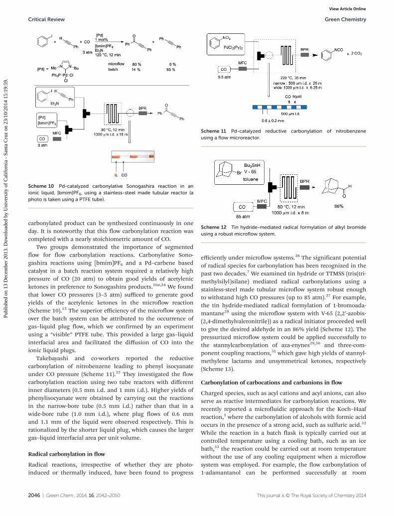
carbonylated product can be synthesized continuously in oneday. It is noteworthy that this flow carbonylation reaction wascompleted with a nearly stoichiometric amount of CO.
Two groups demonstrated the importance of segmentedflow for flow carbonylation reactions. Carbonylative Sono-gashira reactions using [bmim]PF6 and a Pd–carbene basedcatalyst in a batch reaction system required a relatively highpressure of CO (20 atm) to obtain good yields of acetylenicketones in preference to Sonogashira products.16a,24 We foundthat lower CO pressures (3–5 atm) sufficed to generate goodyields of the acetylenic ketones in the microflow reaction(Scheme 10).15 The superior efficiency of the microflow systemover the batch system can be attributed to the occurrence ofgas–liquid plug flow, which we confirmed by an experimentusing a “visible” PTFE tube. This provided a large gas–liquidinterfacial area and facilitated the diffusion of CO into theionic liquid plugs.
Takebayashi and co-workers reported the reductivecarbonylation of nitrobenzene leading to phenyl isocyanateunder CO pressure (Scheme 11).25 They investigated the flowcarbonylation reaction using two tube reactors with differentinner diameters (0.5 mm i.d. and 1 mm i.d.). Higher yields ofphenylisocyanate were obtained by carrying out the reactionsin the narrow-bore tube (0.5 mm i.d.) rather than that in awide-bore tube (1.0 mm i.d.), where plug flows of 0.6 mmand 1.1 mm of the liquid were observed respectively. This isrationalized by the shorter liquid plug, which causes the largergas–liquid interfacial area per unit volume.
Radical carbonylation in flow
Radical reactions, irrespective of whether they are photo-induced or thermally induced, have been found to progress
efficiently under microflow systems.26 The significant potentialof radical species for carbonylation has been recognized in thepast two decades.7 We examined tin hydride or TTMSS (tris(tri-methylsilyl)silane) mediated radical carbonylations using astainless-steel made tubular microflow system robust enoughto withstand high CO pressures (up to 85 atm).27 For example,the tin hydride-mediated radical formylation of 1-bromoada-mantane28 using the microflow system with V-65 (2,2′-azobis-(2,4-dimethylvaleronitrile)) as a radical initiator proceeded wellto give the desired aldehyde in an 86% yield (Scheme 12). Thepressurized microflow system could be applied successfully tothe stannylcarbonylation of aza-enynes29,30 and three-com-ponent coupling reactions,31 which gave high yields of stannyl-methylene lactams and unsymmetrical ketones, respectively(Scheme 13).
Carbonylation of carbocations and carbanions in flow
Charged species, such as acyl cations and acyl anions, can alsoserve as reactive intermediates for carbonylation reactions. Werecently reported a microfluidic approach for the Koch–Haafreaction,5 where the carbonylation of alcohols with formic acidoccurs in the presence of a strong acid, such as sulfuric acid.32
While the reaction in a batch flask is typically carried out atcontrolled temperature using a cooling bath, such as an icebath,33 the reaction could be carried out at room temperaturewithout the use of any cooling equipment when a microflowsystem was employed. For example, the flow carbonylation of1-adamantanol can be performed successfully at room
Scheme 10 Pd-catalyzed carbonylative Sonogashira reaction in anionic liquid, [bmim]PF6, using a stainless-steel made tubular reactor (aphoto is taken using a PTFE tube).
Scheme 11 Pd-catalyzed reductive carbonylation of nitrobenzeneusing a flow microreactor.
Scheme 12 Tin hydride-mediated radical formylation of alkyl bromideusing a robust microflow system.
Critical Review Green Chemistry
2046 | Green Chem., 2014, 16, 2042–2050 This journal is © The Royal Society of Chemistry 2014
Publ
ishe
d on
13
Dec
embe
r 20
13. D
ownl
oade
d by
Uni
vers
ity o
f C
alif
orni
a -
Sant
a C
ruz
on 2
3/10
/201
4 15
:19:
59.
View Article Online
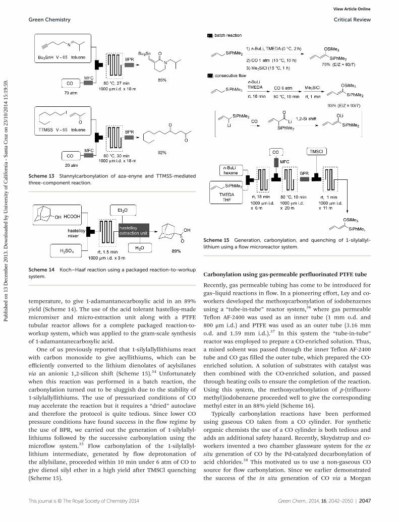
temperature, to give 1-adamantanecarboxylic acid in an 89%yield (Scheme 14). The use of the acid tolerant hastelloy-mademicromixer and micro-extraction unit along with a PTFEtubular reactor allows for a complete packaged reaction-to-workup system, which was applied to the gram-scale synthesisof 1-adamantanecarboxylic acid.
One of us previously reported that 1-silylallyllithiums reactwith carbon monoxide to give acyllithiums, which can beefficiently converted to the lithium dienolates of acylsilanesvia an anionic 1,2-silicon shift (Scheme 15).34 Unfortunatelywhen this reaction was performed in a batch reaction, thecarbonylation turned out to be sluggish due to the stability of1-silylallyllithiums. The use of pressurized conditions of COmay accelerate the reaction but it requires a “dried” autoclaveand therefore the protocol is quite tedious. Since lower COpressure conditions have found success in the flow regime bythe use of BPR, we carried out the generation of 1-silylallyl-lithiums followed by the successive carbonylation using themicroflow system.35 Flow carbonylation of the 1-silylallyl-lithium intermediate, generated by flow deprotonation ofthe allylsilane, proceeded within 10 min under 6 atm of CO togive dienol silyl ether in a high yield after TMSCl quenching(Scheme 15).
Carbonylation using gas-permeable perfluorinated PTFE tube
Recently, gas permeable tubing has come to be introduced forgas–liquid reactions in flow. In a pioneering effort, Ley and co-workers developed the methoxycarbonylation of iodobenzenesusing a “tube-in-tube” reactor system,36 where gas permeableTeflon AF-2400 was used as an inner tube (1 mm o.d. and800 μm i.d.) and PTFE was used as an outer tube (3.16 mmo.d. and 1.59 mm i.d.).37 In this system the “tube-in-tube”reactor was employed to prepare a CO-enriched solution. Thus,a mixed solvent was passed through the inner Teflon AF-2400tube and CO gas filled the outer tube, which prepared the CO-enriched solution. A solution of substrates with catalyst wasthen combined with the CO-enriched solution, and passedthrough heating coils to ensure the completion of the reaction.Using this system, the methoxycarbonylation of p-(trifluoro-methyl)iodobenzene proceeded well to give the correspondingmethyl ester in an 88% yield (Scheme 16).
Typically carbonylation reactions have been performedusing gaseous CO taken from a CO cylinder. For syntheticorganic chemists the use of a CO cylinder is both tedious andadds an additional safety hazard. Recently, Skrydstrup and co-workers invented a two chamber glassware system for the exsitu generation of CO by the Pd-catalyzed decarbonylation ofacid chlorides.38 This motivated us to use a non-gaseous COsource for flow carbonylation. Since we earlier demonstratedthe success of the in situ generation of CO via a Morgan
Scheme 14 Koch–Haaf reaction using a packaged reaction-to-workupsystem.
Scheme 15 Generation, carbonylation, and quenching of 1-silylallyl-lithium using a flow microreactor system.
Scheme 13 Stannylcarbonylation of aza-enyne and TTMSS-mediatedthree-component reaction.
Green Chemistry Critical Review
This journal is © The Royal Society of Chemistry 2014 Green Chem., 2014, 16, 2042–2050 | 2047
Publ
ishe
d on
13
Dec
embe
r 20
13. D
ownl
oade
d by
Uni
vers
ity o
f C
alif
orni
a -
Sant
a C
ruz
on 2
3/10
/201
4 15
:19:
59.
View Article Online
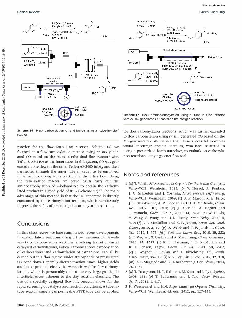
reaction for the flow Koch–Haaf reaction (Scheme 14), wefocused on a flow carbonylation method using ex situ gener-ated CO based on the “tube-in-tube dual flow reactor” withTeflon® AF-2400 as the inner tube. In this system, CO was gen-erated in one flow (in the inner Teflon AF-2400 tube), and thenpermeated through the inner tube in order to be employedin an aminocarbonylation reaction in the other flow. Usingthe tube-in-tube reactor, we could easily carry out theaminocarbonylation of 4-iodoanisole to obtain the carbony-lated product in a good yield of 81% (Scheme 17).39 The mainadvantage of this method is that the CO generated is directlyconsumed by the carbonylation reaction, which significantlyimproves the safety of practicing the carbonylation reaction.
Conclusions
In this short review, we have summarized recent developmentsin carbonylation reactions using a flow microreactor. A widevariety of carbonylation reactions, involving transition-metalcatalyzed carbonylations, radical carbonylations, carbonylationof carbocations, and carbonylation of carbanions, can all becarried out in a flow regime under atmospheric or pressurizedCO conditions. Generally shorter reaction times, higher yieldsand better product selectivities were achieved for flow carbony-lations, which is presumably due to the very large gas–liquidinterfacial areas inherent to the tiny reaction channels. Theuse of a specially designed flow microreactor allows for therapid screening of catalysts and reaction conditions. A tube-in-tube reactor using a gas permeable PTFE tube can be applied
for flow carbonylation reactions, which was further extendedto flow carbonylation using ex situ generated CO based on theMorgan reaction. We believe that these successful exampleswould encourage organic chemists, who have hesitated inusing a pressurized batch autoclave, to embark on carbonyla-tion reactions using a greener flow tool.
Notes and references
1 (a) T. Wirth, Microreactors in Organic Synthesis and Catalysis,Wiley-VCH, Weinheim, 2013; (b) V. Hessel, A. Renken,J. C. Schouten and J. Yoshida, Micro Process Engineering,Wiley-VCH, Weinheim, 2009; (c) B. P. Mason, K. E. Price,J. L. Steinbacher, A. R. Bogdan and D. T. McQuade, Chem.Rev., 2007, 107, 2300; (d) J. Yoshida, A. Nagaki andT. Yamada, Chem.–Eur. J., 2008, 14, 7450; (e) W.-Y. Lin,Y. Wang, S. Wang and H.-R. Tseng, Nano Today, 2009, 4,470; (f ) J. P. McMullen and K. F. Jensen, Annu. Rev. Anal.Chem., 2010, 3, 19; (g) D. Webb and T. F. Jamison, Chem.Sci., 2010, 1, 675; (h) J. Yoshida, Chem. Rec., 2010, 10, 332;(i) J. Wegner, S. Ceylan and A. Kirschning, Chem. Commun.,2011, 47, 4583; ( j) R. L. Hartman, J. P. McMullen andK. F. Jensen, Angew. Chem., Int. Ed., 2011, 50, 7502;(k) J. Wegner, S. Ceylan and A. Kirschning, Adv. Synth.Catal., 2012, 354, 17; (l) S. V. Ley, Chem. Rec., 2012, 12, 378;(m) D. T. McQuade and P. H. Seeberger, J. Org. Chem., 2013,78, 6384.
2 (a) T. Fukuyama, M. T. Rahman, M. Sato and I. Ryu, Synlett,2008, 151; (b) T. Fukuyama and I. Ryu, Green Process.Synth., 2012, 1, 417.
3 K. Weissermel and H.-J. Arpe, Industrial Organic Chemistry,Wiley-VCH, Weinheim, 4th edn, 2012, pp. 127–144.
Scheme 16 Heck carbonylation of aryl iodide using a “tube-in-tube”reactor.
Scheme 17 Heck aminocarbonylation using a “tube-in-tube” reactorwith ex situ generated CO based on the Morgan reaction.
Critical Review Green Chemistry
2048 | Green Chem., 2014, 16, 2042–2050 This journal is © The Royal Society of Chemistry 2014
Publ
ishe
d on
13
Dec
embe
r 20
13. D
ownl
oade
d by
Uni
vers
ity o
f C
alif
orni
a -
Sant
a C
ruz
on 2
3/10
/201
4 15
:19:
59.
View Article Online
4 For reviews, see: (a) M. Beller, Catalytic Carbonylation Reac-tions, Top. Organomet. Chem., Springer, Berlin, Heidelberg,2006, vol. 18; (b) L. Kollár, Modern Carbonylation Methods,Wiley-VCH, Weinheim, 2008; (c) T. Fukuyama and I. Ryu,Carbon Monoxide, e-eros, Encyclopedia of Reagents forOrganic Synthesis, John Wiley & Sons, 2006, DOI: 10.1002/047084289X.rc013.pub2; (d) M. Beller and X.-F. Wu,Transition Metal Catalyzed Carbonylation Reactions: Carbo-nylative Activation of C-X Bonds, Springer, Heidelberg, 2013.
5 For a review, see: H. Bahrmann, Koch Reactions, in NewSyntheses with Carbon Monoxide, ed. J. Falbe, Springer,Berlin, 1980, pp. 372–413.
6 For reviews, see: (a) S. Murai and K. Iwamoto, Acyllithium,in Modern Carbonyl Chemistry, ed. J. Otera, Wiley-VCH,Weinheim, 2000, pp. 131–153; (b) C. Najera and M. Yus,The Chemistry of Acyllithium Derivatives, in The Chemistryof Organolithium Compounds, ed. Z. Rapporort andI. Marek, John Wiley & Sons, Chichester, 2006, vol. 2,pp. 139–293.
7 For reviews, see: (a) I. Ryu and N. Sonoda, Angew. Chem.,Int. Ed. Engl., 1996, 35, 1050; (b) I. Ryu, N. Sonoda andD. P. Curran, Chem. Rev., 1996, 96, 177; (c) I. Ryu, Chem.Soc. Rev., 2001, 30, 16. Also see a review on acyl radicals:(d) C. Chatgilialoglu, D. Crich, M. Komatsu and I. Ryu,Chem. Rev., 1999, 99, 1991.
8 (a) C. Wiles and P. Watts, Green Chem., 2012, 14, 38;(b) S. V. Ley, Chem. Rec., 2012, 12, 378; (c) J. Yoshida,H. Kim and A. Nagaki, ChemSusChem, 2011, 4, 331;(d) S. G. Newman and K. F. Jensen, Green Chem., 2013, 15,1456.
9 F. Trachsel and P. Rudolf van Rohr, in Micro Process Engi-neering, Wiley-VCH, Weinheim, 2009, vol. 1, pp. 255–281.
10 M. N. Kashid, A. Renken and L. Kiwi-Ninsker, Chem. Eng.Sci., 2011, 66, 3876.
11 For selected examples, see: (a) V. Hessel, C. Hofmann,H. Löwe, A. Meudt, S. Scherer, F. Schönfeld and B. Werner,Org. Process Res. Dev., 2004, 8, 511; (b) T. Fukuyama,M. Kobayashi, M. T. Rahman, N. Kamata and I. Ryu, Org.Lett., 2008, 10, 533; (c) I. C. Wienöfer, A. Studer,M. T. Rahman, T. Fukuyama and I. Ryu, Org. Lett., 2009, 11,2457; (d) A. Nagaki, S. Yamada, M. Doi, Y. Tomida,N. Takebayashi and J. Yoshida, Green Chem., 2011, 13,1110; (e) T. Gustafsson, H. Sörensen and F. Pontén, Org.Process Res. Dev., 2012, 16, 925.
12 A. Schoenberg and R. F. Heck, J. Org. Chem., 1974, 39,3327.
13 F. Ozawa, H. Soyama, H. Yanagihara, I. Aoyama, H. Takino,K. Izawa, T. Yamamoto and A. Yamamoto, J. Am. Chem.Soc., 1985, 107, 3235.
14 P. W. Miller, N. J. Long, A. J. de Mello, R. Vilar, J. Passchierand A. Gee, Chem. Commun., 2006, 546.
15 M. T. Rahman, T. Fukuyama, N. Kamata, M. Sato andI. Ryu, Chem. Commun., 2006, 2236.
16 (a) T. Fukuyama, M. Shinmen, S. Nishitani, M. Sato andI. Ryu, Org. Lett., 2002, 4, 1691; (b) S. Liu, T. Fukuyama,M. Sato and I. Ryu, Org. Process Res. Dev., 2004, 8, 477;
(c) T. Fukuyama, M. T. Rahman, Y. Sumino and I. Ryu,Synlett, 2012, 23, 2279.
17 P. W. Miller, N. J. Long, A. J. de Mello, R. Vilar, H. Audrain,D. Bender, J. Passchier and A. Gee, Angew. Chem., Int. Ed.,2007, 46, 2875.
18 C. Csajági, B. Borcsek, K. Niesz, I. Kovács, Z. Székelyhidi,Z. Bajkó, L. Ürge and F. Darvas, Org. Lett., 2008, 10, 1589.
19 J. Balogh, Á. Kuik, L. Ürge, F. Darvas, J. Bakos andR. Skoda-Földes, J. Mol. Catal. A: Chem., 2009, 302, 76.
20 E. R. Murphy, J. R. Martinelli, N. Zaborenko,S. L. Buchwald and K. F. Jensen, Angew. Chem., Int. Ed.,2007, 46, 1734.
21 (a) P. W. Miller, L. E. Jennings, A. J. deMello, A. D. Gee,N. J. Long and R. Vilar, Adv. Synth. Catal., 2009, 351, 3260;(b) X. Gong, P. W. Miller, A. D. Gee, N. J. Long, A. J. deMello and R. Vilar, Chem.–Eur. J., 2012, 18, 2768.
22 C. B. Kelly, C. Lee, M. A. Mercadante and N. E. Leadbeater,Org. Process Res. Dev., 2011, 15, 717.
23 H. Akinaga, N. Masaoka, K. Takagi, T. Fukuyama andI. Ryu, unpublished result.
24 T. Fukuyama, R. Yamaura and I. Ryu, Can. J. Chem., 2005,83, 711.
25 Y. Takebayashi, K. Sue, S. Yoda, T. Furuya and K. Mae,Chem. Eng. J., 2012, 180, 250.
26 T. Fukuyama and I. Ryu, Radical Chemistry by Using FlowMicroreactor Technology, in Encyclopedia of Radicals inChemistry, Biology and Materials, John Wiley & Sons,Chichester, 2012, vol. 2, pp. 1243–1258.
27 T. Fukuyama, M. T. Rahman, N. Kamata and I. Ryu,Beilstein J. Org. Chem., 2009, 5, 34.
28 I. Ryu, K. Kusano, A. Ogawa, N. Kambe and N. Sonoda,J. Am. Chem. Soc., 1990, 112, 1295.
29 (a) I. Ryu, H. Miyazato, H. Kuriyama, K. Matsu, M. Tojino,T. Fukuyama, S. Minakata and M. Komatsu, J. Am.Chem. Soc., 2003, 125, 5632; (b) M. Tojino, N. Otsuka,T. Fukuyama, H. Matsubara, C. H. Schiesser, H. Kuriyama,H. Miyazato, S. Minakata, M. Komatsu and I. Ryu, Org.Biomol. Chem., 2003, 1, 4262; (c) M. Tojino, N. Otsuka,T. Fukuyama, H. Matsubara and I. Ryu, J. Am. Chem. Soc.,2006, 128, 7712; (d) S. H. Kyne, C. Y. Lin, I. Ryu,M. L. Coote and C. H. Schiesser, Chem. Commun., 2010, 46,6521.
30 C. H. Schiesser, U. Wille, H. Matsubara and I. Ryu, Acc.Chem. Res., 2007, 40, 303.
31 (a) I. Ryu, K. Kusano, H. Yamazaki and N. Sonoda, J. Org.Chem., 1991, 56, 5003; (b) I. Ryu, M. Hasegawa,A. Kurihara, A. Ogawa, S. Tsunoi and N. Sonoda, Synlett,1993, 143; (c) Y. Kishimoto and T. Ikariya, J. Org. Chem.,2000, 65, 7656.
32 T. Fukuyama, Y. Mukai and I. Ryu, Beilstein J. Org. Chem.,2011, 7, 1288.
33 (a) H. Koch and W. Haaf, Justus Liebigs Ann. Chem., 1958,618, 251. Recent example on Koch–Haaf reaction, see:(b) F. Hoffmann-Emery, H. Hilpert, M. Scalone andP. Waldmeier, J. Org. Chem., 2006, 71, 2000; (c) C. L. Becker,K. M. Engstrom, F. A. Kerdesky, J. C. Tolle, S. H. Wagaw
Green Chemistry Critical Review
This journal is © The Royal Society of Chemistry 2014 Green Chem., 2014, 16, 2042–2050 | 2049
Publ
ishe
d on
13
Dec
embe
r 20
13. D
ownl
oade
d by
Uni
vers
ity o
f C
alif
orni
a -
Sant
a C
ruz
on 2
3/10
/201
4 15
:19:
59.
View Article Online
and W. Wang, Org. Process Res. Dev., 2008, 12, 1114;(d) V. Barton, S. A. Ward, J. Chadwick, A. Hill andP. M. O’Neill, J. Med. Chem., 2010, 53, 4555.
34 I. Ryu, H. Yamamoto, N. Sonoda and S. Murai, Organo-metallics, 1996, 15, 5459.
35 T. Fukuyama, T. Totoki and I. Ryu, unpublished result.36 J. C. Pastre, D. L. Browne, M. O’Brien and S. V. Ley, Org.
Process Res. Dev., 2013, 17, 1183. and references citedtherein.
37 P. Koos, U. Gross, A. Polyzos, M. O’Brien, I. Baxendale andS. V. Ley, Org. Biomol. Chem., 2011, 9, 6903.
38 (a) P. Hermange, A. T. Lindhardt, R. H. Taaning,K. Bjerglund, D. Lupp and T. Skrydstrup, J. Am. Chem. Soc.,2011, 133, 6061; (b) T. M. Gøgsig, R. H. Taaning,A. T. Lindhardt and T. Skrydstrup, Angew. Chem., Int. Ed.,2012, 51, 798.
39 C. Brancour, T. Fukuyama, Y. Mukai, T. Skrydstrup andI. Ryu, Org. Lett., 2013, 15, 2794.
Critical Review Green Chemistry
2050 | Green Chem., 2014, 16, 2042–2050 This journal is © The Royal Society of Chemistry 2014
Publ
ishe
d on
13
Dec
embe
r 20
13. D
ownl
oade
d by
Uni
vers
ity o
f C
alif
orni
a -
Sant
a C
ruz
on 2
3/10
/201
4 15
:19:
59.
View Article Online