
Cable Tray Systems - Amazon S3
452
Cable Tray Systems Aluminum, Steel, Stainless Steel & Fiberglass Cable Tray Systems Redi-Rail™ & Cent-R-Rail ® Tray Systems Cable Channel & Wire Basket Systems CT-09
-
Upload
khangminh22 -
Category
Documents
-
view
0 -
download
0
Transcript of Cable Tray Systems - Amazon S3
Other Cooper B-Line Product Lines
Strut Systems (Bolted Framing)Electrical EnclosuresElectronic EnclosuresPipe Hanger & Support SystemsSpring Steel FastenersCable Runway & Relay Racks (CommData)Meter Mounting & Distribution EquipmentAnchors
© 2009 Cooper B-Line, Inc. Printed in U.S.A. 10509
SYSTEMS THAT MAKE SENSE
“ BB-- VVOO CCAALLSS MM“ BB-- VVOO CCAALLSS MM
Questions, Comments, Suggestions?
with Cooper B-Line ”Voice Of the Customer...Actively [email protected]
618-654-2184 ext. 456
“ BB-- VVOO CCAALLSS MM
Cable Tray SystemsAluminum, Steel, Stainless Steel & Fiberglass Cable Tray SystemsRedi-Rail™ & Cent-R-Rail® Tray SystemsCable Channel & Wire Basket Systems
Cab
le Tray System
s
CT-09
Cooper B-Line509 West Monroe StreetHighland, IL 62249Phone: 800-851-7415Fax: 618-654-1917
www.cooperbline.com
Cooper Industries, Ltd.600 Travis, Ste. 5800Houston, TX 77002-1001Phone: 713-209-8400www.cooperindustries.com
CT-09

MEMBER
B-Line Systems was formed in 1956 andhas over 30 years experience manufacturingcable tray systems in which it has grown tobecome the industry leader. This growthwas achieved by offering unmatched qualityin both service and products.
Today Cooper B-Line stands alone in itscustomer service resources with cable trayfabrication location at four locationsthroughout the United States. Strategicallylocated facilities alone do not generateunmatched service. The professional staff atCooper B-Line is knowledgeable, energetic,and care about customer needs. The rightattitude coupled with the facilities doesgenerate unsurpassed customer service.
Cooper B-Line’s product offerings alsoset new standards. Cooper B-Linemanufactures cable support product linesthat bridge both the electrical and telecommarkets. Each of those product lines areengineered to provide top performancewhile offering unique installation savings.This catalog is dedicated to the metallic andnon-metallic, two side rail, cable traysystems.
WIREWAYCooper B-Line offers commercial and industrial wireway
and wiring trough to handle almost any of your wire andcable routing needs. Commercial Type 1 and 3R designsare available with or without knockouts. Sizes range from2.5" x 2.5" to 12" x 12" and lengths from 12" to 120".Industrial NEMA 12 designs are available in both lay-in andfeed-through styles. Wireway is available in ANSI 61 graypainted steel and Type 304 stainless steel. Cooper B-Linecan also provide special sizes, finishes, and othermodifications.
CHANNEL CABLE TRAYCooper B-Line’s channel cable tray is a compact,
adaptable, easy to install system that is available in steel,aluminum, and fiberglass. System has fittings availableas well as connectors and a full line of accessories.
CABLE TRAY SYSTEMSCooper B-Line’s traditional two side rail cable tray.
Rugged two side rail construction protects cables and allowsfor a wide range of sizes and strengths. Coupled with alarge selection of materials, finishes, and bottom types,these engineered systems can satisfy your particularrequirements.
REDI-RAIL™ SYSTEMSThis new high tech design offers new freedom to the
installer. The mechanically assembled, pre-punched side raildesign provides unmatched job sight adaptability for a twoside rail system. Loading depths from 2" to 6", aluminumconstruction.
Ask The Experts!Ask The Experts!
“ BB-- VVOO CCAALLSS MM“ BB-- VVOOCCAALLSS MM
Questions, Comments, Suggestions?
with Cooper B-Line ”Voice Of the Customer...Actively [email protected]
618-654-2184 ext. 456
“ BB-- VVOOCCAALLSS MM
Ask The Experts!Ask The Experts!
Cooper B-Line509 West Monroe Street Phone: 800-851-7415Highland, IL 62249 Fax: 618-654-1917
www.cooperbline.com
1-800-851-7415 ext. 366
1-800-851-7415 ext. 366
Cooper B-Line cable trays conformto the requirements of IEC Standard61537, 2001 Ed.
Cable Tray SystemsCable Tray Systems
Cabling Support OptionsIntroduction
449
Important notice: The information herein has been carefully checked for accuracy and is believed to be correct and current.No warranty, either expressed or implied, is made as to either its applicability to or its compatibility withspecific requirements of this information, nor for damages consequential to its use. All design characteristics,specifications, tolerances and similar information are subject to change without notice.
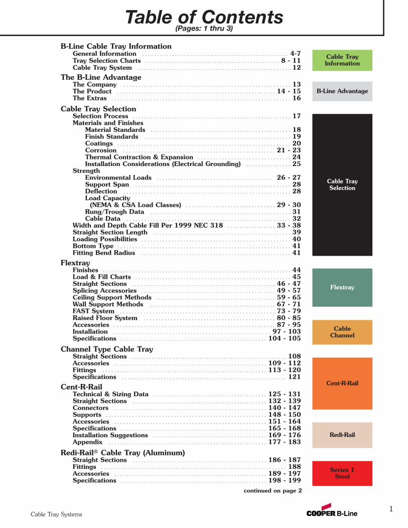
Table of Contents(Pages: 1 thru 3)
Cable Tray Systems
B-Line Cable Tray Information General Information . . . . . . . . . . . . . . . . . . . . . . . . . . . . . . . . . . . . . . . . . . . . . . . . . 4-7Tray Selection Charts . . . . . . . . . . . . . . . . . . . . . . . . . . . . . . . . . . . . . . . . . . . . . 8 - 11Cable Tray System . . . . . . . . . . . . . . . . . . . . . . . . . . . . . . . . . . . . . . . . . . . . . . . . . . . 12
The B-Line Advantage The Company . . . . . . . . . . . . . . . . . . . . . . . . . . . . . . . . . . . . . . . . . . . . . . . . . . . . . . . . 13 The Product . . . . . . . . . . . . . . . . . . . . . . . . . . . . . . . . . . . . . . . . . . . . . . . . . . . . . 14 - 15 The Extras . . . . . . . . . . . . . . . . . . . . . . . . . . . . . . . . . . . . . . . . . . . . . . . . . . . . . . . . . . . . 16
Cable Tray SelectionSelection Process . . . . . . . . . . . . . . . . . . . . . . . . . . . . . . . . . . . . . . . . . . . . . . . . . . . . . 17Materials and Finishes
Material Standards . . . . . . . . . . . . . . . . . . . . . . . . . . . . . . . . . . . . . . . . . . . . . . . 18Finish Standards . . . . . . . . . . . . . . . . . . . . . . . . . . . . . . . . . . . . . . . . . . . . . . . . . 19Coatings . . . . . . . . . . . . . . . . . . . . . . . . . . . . . . . . . . . . . . . . . . . . . . . . . . . . . . . . . . 20Corrosion . . . . . . . . . . . . . . . . . . . . . . . . . . . . . . . . . . . . . . . . . . . . . . . . . . . 21 - 23Thermal Contraction & Expansion . . . . . . . . . . . . . . . . . . . . . . . . . . . . . . . 24Installation Considerations (Electrical Grounding) . . . . . . . . . . . . . . . 25
StrengthEnvironmental Loads . . . . . . . . . . . . . . . . . . . . . . . . . . . . . . . . . . . . . . . 26 - 27Support Span . . . . . . . . . . . . . . . . . . . . . . . . . . . . . . . . . . . . . . . . . . . . . . . . . . . . 28Deflection . . . . . . . . . . . . . . . . . . . . . . . . . . . . . . . . . . . . . . . . . . . . . . . . . . . . . . . . 28Load Capacity
(NEMA & CSA Load Classes) . . . . . . . . . . . . . . . . . . . . . . . . . . . . . . 29 - 30Rung/Trough Data . . . . . . . . . . . . . . . . . . . . . . . . . . . . . . . . . . . . . . . . . . . . . . . 31Cable Data . . . . . . . . . . . . . . . . . . . . . . . . . . . . . . . . . . . . . . . . . . . . . . . . . . . . . . . 32
Width and Depth Cable Fill Per 1999 NEC 318 . . . . . . . . . . . . . . . . 33 - 38Straight Section Length . . . . . . . . . . . . . . . . . . . . . . . . . . . . . . . . . . . . . . . . . . . . . . 39Loading Possibilities . . . . . . . . . . . . . . . . . . . . . . . . . . . . . . . . . . . . . . . . . . . . . . . . . . 40Bottom Type . . . . . . . . . . . . . . . . . . . . . . . . . . . . . . . . . . . . . . . . . . . . . . . . . . . . . . . . . . 41Fitting Bend Radius . . . . . . . . . . . . . . . . . . . . . . . . . . . . . . . . . . . . . . . . . . . . . . . . . . 41
FlextrayFinishes . . . . . . . . . . . . . . . . . . . . . . . . . . . . . . . . . . . . . . . . . . . . . . . . . . . . . . . . . . . . . . . 44 Load & Fill Charts . . . . . . . . . . . . . . . . . . . . . . . . . . . . . . . . . . . . . . . . . . . . . . . . . . . . 45 Straight Sections . . . . . . . . . . . . . . . . . . . . . . . . . . . . . . . . . . . . . . . . . . . . . . . . 46 - 47 Splicing Accessories . . . . . . . . . . . . . . . . . . . . . . . . . . . . . . . . . . . . . . . . . . . . . 49 - 57Ceiling Support Methods . . . . . . . . . . . . . . . . . . . . . . . . . . . . . . . . . . . . . . . . 59 - 65Wall Support Methods . . . . . . . . . . . . . . . . . . . . . . . . . . . . . . . . . . . . . . . . . . 67 - 71FAST System . . . . . . . . . . . . . . . . . . . . . . . . . . . . . . . . . . . . . . . . . . . . . . . . . . . . 73 - 79Raised Floor System . . . . . . . . . . . . . . . . . . . . . . . . . . . . . . . . . . . . . . . . . . . . 80 - 85Accessories . . . . . . . . . . . . . . . . . . . . . . . . . . . . . . . . . . . . . . . . . . . . . . . . . . . . . . 87 - 95Installation . . . . . . . . . . . . . . . . . . . . . . . . . . . . . . . . . . . . . . . . . . . . . . . . . . . . . 97 - 103Specifications . . . . . . . . . . . . . . . . . . . . . . . . . . . . . . . . . . . . . . . . . . . . . . . . . 104 - 105
Channel Type Cable TrayStraight Sections . . . . . . . . . . . . . . . . . . . . . . . . . . . . . . . . . . . . . . . . . . . . . . . . . . . . 108 Accessories . . . . . . . . . . . . . . . . . . . . . . . . . . . . . . . . . . . . . . . . . . . . . . . . . . . 109 - 112Fittings . . . . . . . . . . . . . . . . . . . . . . . . . . . . . . . . . . . . . . . . . . . . . . . . . . . . . . . 113 - 120Specifications . . . . . . . . . . . . . . . . . . . . . . . . . . . . . . . . . . . . . . . . . . . . . . . . . . . . . . . 121
Cent-R-RailTechnical & Sizing Data . . . . . . . . . . . . . . . . . . . . . . . . . . . . . . . . . . . . . . 125 - 131Straight Sections . . . . . . . . . . . . . . . . . . . . . . . . . . . . . . . . . . . . . . . . . . . . . 132 - 139Connectors . . . . . . . . . . . . . . . . . . . . . . . . . . . . . . . . . . . . . . . . . . . . . . . . . . . 140 - 147Supports . . . . . . . . . . . . . . . . . . . . . . . . . . . . . . . . . . . . . . . . . . . . . . . . . . . . . . 148 - 150Accessories . . . . . . . . . . . . . . . . . . . . . . . . . . . . . . . . . . . . . . . . . . . . . . . . . . . 151 - 164Specifications . . . . . . . . . . . . . . . . . . . . . . . . . . . . . . . . . . . . . . . . . . . . . . . . . 165 - 168Installation Suggestions . . . . . . . . . . . . . . . . . . . . . . . . . . . . . . . . . . . . . . 169 - 176Appendix . . . . . . . . . . . . . . . . . . . . . . . . . . . . . . . . . . . . . . . . . . . . . . . . . . . . . 177 - 183
Redi-Rail® Cable Tray (Aluminum)Straight Sections . . . . . . . . . . . . . . . . . . . . . . . . . . . . . . . . . . . . . . . . . . . . . 186 - 187Fittings . . . . . . . . . . . . . . . . . . . . . . . . . . . . . . . . . . . . . . . . . . . . . . . . . . . . . . . . . . . . . . 188Accessories . . . . . . . . . . . . . . . . . . . . . . . . . . . . . . . . . . . . . . . . . . . . . . . . . . . 189 - 197Specifications . . . . . . . . . . . . . . . . . . . . . . . . . . . . . . . . . . . . . . . . . . . . . . . . . 198 - 199
continued on page 2
Cable TrayInformation
B-Line Advantage
Cable TraySelection
Flextray
CableChannel
Cent-R-Rail
1
Redi-Rail
Series 1Steel
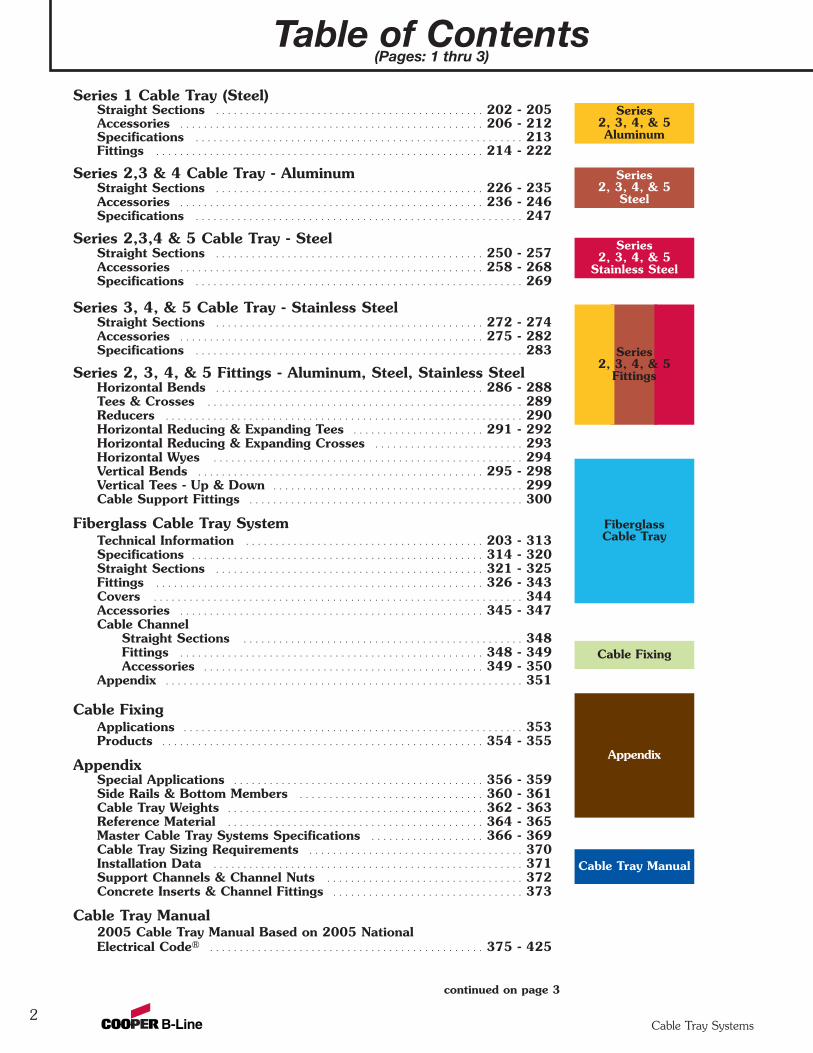
Table of Contents(Pages: 1 thru 3)
2Cable Tray Systems
Series 1 Cable Tray (Steel)Straight Sections . . . . . . . . . . . . . . . . . . . . . . . . . . . . . . . . . . . . . . . . . . . . . 202 - 205Accessories . . . . . . . . . . . . . . . . . . . . . . . . . . . . . . . . . . . . . . . . . . . . . . . . . . . 206 - 212Specifications . . . . . . . . . . . . . . . . . . . . . . . . . . . . . . . . . . . . . . . . . . . . . . . . . . . . . . . 213Fittings . . . . . . . . . . . . . . . . . . . . . . . . . . . . . . . . . . . . . . . . . . . . . . . . . . . . . . . 214 - 222
Series 2,3 & 4 Cable Tray - AluminumStraight Sections . . . . . . . . . . . . . . . . . . . . . . . . . . . . . . . . . . . . . . . . . . . . . 226 - 235Accessories . . . . . . . . . . . . . . . . . . . . . . . . . . . . . . . . . . . . . . . . . . . . . . . . . . . 236 - 246Specifications . . . . . . . . . . . . . . . . . . . . . . . . . . . . . . . . . . . . . . . . . . . . . . . . . . . . . . . 247
Series 2,3,4 & 5 Cable Tray - SteelStraight Sections . . . . . . . . . . . . . . . . . . . . . . . . . . . . . . . . . . . . . . . . . . . . . 250 - 257Accessories . . . . . . . . . . . . . . . . . . . . . . . . . . . . . . . . . . . . . . . . . . . . . . . . . . . 258 - 268Specifications . . . . . . . . . . . . . . . . . . . . . . . . . . . . . . . . . . . . . . . . . . . . . . . . . . . . . . . 269
Series 3, 4, & 5 Cable Tray - Stainless SteelStraight Sections . . . . . . . . . . . . . . . . . . . . . . . . . . . . . . . . . . . . . . . . . . . . . 272 - 274Accessories . . . . . . . . . . . . . . . . . . . . . . . . . . . . . . . . . . . . . . . . . . . . . . . . . . . 275 - 282Specifications . . . . . . . . . . . . . . . . . . . . . . . . . . . . . . . . . . . . . . . . . . . . . . . . . . . . . . . 283
Series 2, 3, 4, & 5 Fittings - Aluminum, Steel, Stainless SteelHorizontal Bends . . . . . . . . . . . . . . . . . . . . . . . . . . . . . . . . . . . . . . . . . . . . . 286 - 288Tees & Crosses . . . . . . . . . . . . . . . . . . . . . . . . . . . . . . . . . . . . . . . . . . . . . . . . . . . . . 289Reducers . . . . . . . . . . . . . . . . . . . . . . . . . . . . . . . . . . . . . . . . . . . . . . . . . . . . . . . . . . . . 290Horizontal Reducing & Expanding Tees . . . . . . . . . . . . . . . . . . . . . . 291 - 292Horizontal Reducing & Expanding Crosses . . . . . . . . . . . . . . . . . . . . . . . . . 293Horizontal Wyes . . . . . . . . . . . . . . . . . . . . . . . . . . . . . . . . . . . . . . . . . . . . . . . . . . . . 294Vertical Bends . . . . . . . . . . . . . . . . . . . . . . . . . . . . . . . . . . . . . . . . . . . . . . . . 295 - 298Vertical Tees - Up & Down . . . . . . . . . . . . . . . . . . . . . . . . . . . . . . . . . . . . . . . . . . 299Cable Support Fittings . . . . . . . . . . . . . . . . . . . . . . . . . . . . . . . . . . . . . . . . . . . . . . 300
Fiberglass Cable Tray SystemTechnical Information . . . . . . . . . . . . . . . . . . . . . . . . . . . . . . . . . . . . . . . . 203 - 313Specifications . . . . . . . . . . . . . . . . . . . . . . . . . . . . . . . . . . . . . . . . . . . . . . . . . 314 - 320Straight Sections . . . . . . . . . . . . . . . . . . . . . . . . . . . . . . . . . . . . . . . . . . . . . 321 - 325Fittings . . . . . . . . . . . . . . . . . . . . . . . . . . . . . . . . . . . . . . . . . . . . . . . . . . . . . . . 326 - 343Covers . . . . . . . . . . . . . . . . . . . . . . . . . . . . . . . . . . . . . . . . . . . . . . . . . . . . . . . . . . . . . . 344Accessories . . . . . . . . . . . . . . . . . . . . . . . . . . . . . . . . . . . . . . . . . . . . . . . . . . . 345 - 347Cable Channel
Straight Sections . . . . . . . . . . . . . . . . . . . . . . . . . . . . . . . . . . . . . . . . . . . . . . . 348Fittings . . . . . . . . . . . . . . . . . . . . . . . . . . . . . . . . . . . . . . . . . . . . . . . . . . . 348 - 349Accessories . . . . . . . . . . . . . . . . . . . . . . . . . . . . . . . . . . . . . . . . . . . . . . . 349 - 350
Appendix . . . . . . . . . . . . . . . . . . . . . . . . . . . . . . . . . . . . . . . . . . . . . . . . . . . . . . . . . . . . 351
Cable FixingApplications . . . . . . . . . . . . . . . . . . . . . . . . . . . . . . . . . . . . . . . . . . . . . . . . . . . . . . . . . 353Products . . . . . . . . . . . . . . . . . . . . . . . . . . . . . . . . . . . . . . . . . . . . . . . . . . . . . . 354 - 355
AppendixSpecial Applications . . . . . . . . . . . . . . . . . . . . . . . . . . . . . . . . . . . . . . . . . . 356 - 359Side Rails & Bottom Members . . . . . . . . . . . . . . . . . . . . . . . . . . . . . . . 360 - 361Cable Tray Weights . . . . . . . . . . . . . . . . . . . . . . . . . . . . . . . . . . . . . . . . . . . 362 - 363Reference Material . . . . . . . . . . . . . . . . . . . . . . . . . . . . . . . . . . . . . . . . . . . 364 - 365Master Cable Tray Systems Specifications . . . . . . . . . . . . . . . . . . . 366 - 369Cable Tray Sizing Requirements . . . . . . . . . . . . . . . . . . . . . . . . . . . . . . . . . . . . 370Installation Data . . . . . . . . . . . . . . . . . . . . . . . . . . . . . . . . . . . . . . . . . . . . . . . . . . . . 371Support Channels & Channel Nuts . . . . . . . . . . . . . . . . . . . . . . . . . . . . . . . . . 372Concrete Inserts & Channel Fittings . . . . . . . . . . . . . . . . . . . . . . . . . . . . . . . . 373
Cable Tray Manual2005 Cable Tray Manual Based on 2005 National Electrical Code® . . . . . . . . . . . . . . . . . . . . . . . . . . . . . . . . . . . . . . . . . . . . . . 375 - 425
continued on page 3
Series2, 3, 4, & 5Aluminum
Series2, 3, 4, & 5
Stainless Steel
FiberglassCable Tray
Cable Fixing
Series2, 3, 4, & 5
Fittings
Series2, 3, 4, & 5
Steel
Appendix
Cable Tray Manual
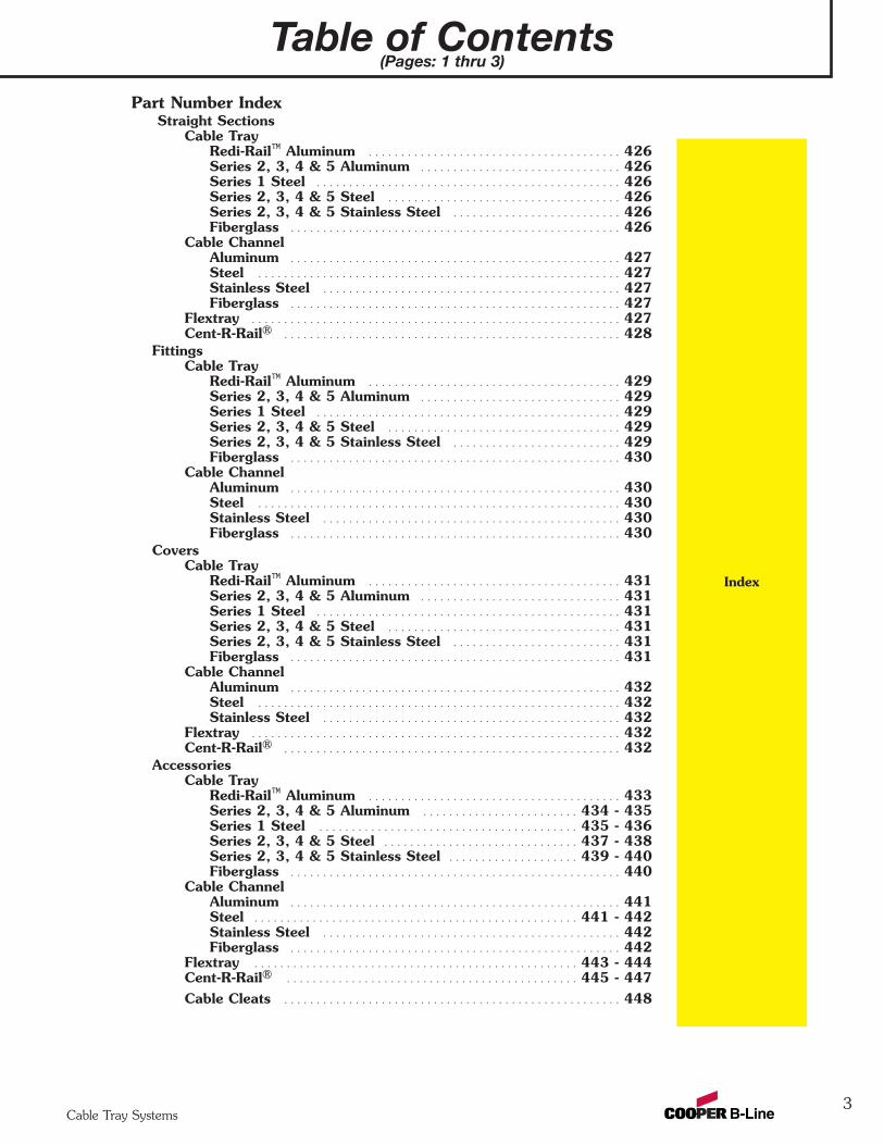
Table of Contents(Pages: 1 thru 3)
Cable Tray Systems
Index
3
Part Number IndexStraight Sections
Cable TrayRedi-Rail™ Aluminum . . . . . . . . . . . . . . . . . . . . . . . . . . . . . . . . . . . . . . . 426Series 2, 3, 4 & 5 Aluminum . . . . . . . . . . . . . . . . . . . . . . . . . . . . . . . 426Series 1 Steel . . . . . . . . . . . . . . . . . . . . . . . . . . . . . . . . . . . . . . . . . . . . . . . 426Series 2, 3, 4 & 5 Steel . . . . . . . . . . . . . . . . . . . . . . . . . . . . . . . . . . . . 426Series 2, 3, 4 & 5 Stainless Steel . . . . . . . . . . . . . . . . . . . . . . . . . . 426Fiberglass . . . . . . . . . . . . . . . . . . . . . . . . . . . . . . . . . . . . . . . . . . . . . . . . . . . 426
Cable ChannelAluminum . . . . . . . . . . . . . . . . . . . . . . . . . . . . . . . . . . . . . . . . . . . . . . . . . . . 427Steel . . . . . . . . . . . . . . . . . . . . . . . . . . . . . . . . . . . . . . . . . . . . . . . . . . . . . . . . 427Stainless Steel . . . . . . . . . . . . . . . . . . . . . . . . . . . . . . . . . . . . . . . . . . . . . . 427Fiberglass . . . . . . . . . . . . . . . . . . . . . . . . . . . . . . . . . . . . . . . . . . . . . . . . . . . 427
Flextray . . . . . . . . . . . . . . . . . . . . . . . . . . . . . . . . . . . . . . . . . . . . . . . . . . . . . . . . . 427Cent-R-Rail® . . . . . . . . . . . . . . . . . . . . . . . . . . . . . . . . . . . . . . . . . . . . . . . . . . . . 428
FittingsCable Tray
Redi-Rail™ Aluminum . . . . . . . . . . . . . . . . . . . . . . . . . . . . . . . . . . . . . . . 429Series 2, 3, 4 & 5 Aluminum . . . . . . . . . . . . . . . . . . . . . . . . . . . . . . . 429Series 1 Steel . . . . . . . . . . . . . . . . . . . . . . . . . . . . . . . . . . . . . . . . . . . . . . . 429Series 2, 3, 4 & 5 Steel . . . . . . . . . . . . . . . . . . . . . . . . . . . . . . . . . . . . 429Series 2, 3, 4 & 5 Stainless Steel . . . . . . . . . . . . . . . . . . . . . . . . . . 429Fiberglass . . . . . . . . . . . . . . . . . . . . . . . . . . . . . . . . . . . . . . . . . . . . . . . . . . . 430
Cable ChannelAluminum . . . . . . . . . . . . . . . . . . . . . . . . . . . . . . . . . . . . . . . . . . . . . . . . . . . 430Steel . . . . . . . . . . . . . . . . . . . . . . . . . . . . . . . . . . . . . . . . . . . . . . . . . . . . . . . . 430Stainless Steel . . . . . . . . . . . . . . . . . . . . . . . . . . . . . . . . . . . . . . . . . . . . . . 430Fiberglass . . . . . . . . . . . . . . . . . . . . . . . . . . . . . . . . . . . . . . . . . . . . . . . . . . . 430
CoversCable Tray
Redi-Rail™ Aluminum . . . . . . . . . . . . . . . . . . . . . . . . . . . . . . . . . . . . . . . 431Series 2, 3, 4 & 5 Aluminum . . . . . . . . . . . . . . . . . . . . . . . . . . . . . . . 431Series 1 Steel . . . . . . . . . . . . . . . . . . . . . . . . . . . . . . . . . . . . . . . . . . . . . . . 431Series 2, 3, 4 & 5 Steel . . . . . . . . . . . . . . . . . . . . . . . . . . . . . . . . . . . . 431Series 2, 3, 4 & 5 Stainless Steel . . . . . . . . . . . . . . . . . . . . . . . . . . 431Fiberglass . . . . . . . . . . . . . . . . . . . . . . . . . . . . . . . . . . . . . . . . . . . . . . . . . . . 431
Cable ChannelAluminum . . . . . . . . . . . . . . . . . . . . . . . . . . . . . . . . . . . . . . . . . . . . . . . . . . . 432Steel . . . . . . . . . . . . . . . . . . . . . . . . . . . . . . . . . . . . . . . . . . . . . . . . . . . . . . . . 432Stainless Steel . . . . . . . . . . . . . . . . . . . . . . . . . . . . . . . . . . . . . . . . . . . . . . 432
Flextray . . . . . . . . . . . . . . . . . . . . . . . . . . . . . . . . . . . . . . . . . . . . . . . . . . . . . . . . . 432Cent-R-Rail® . . . . . . . . . . . . . . . . . . . . . . . . . . . . . . . . . . . . . . . . . . . . . . . . . . . . 432
AccessoriesCable Tray
Redi-Rail™ Aluminum . . . . . . . . . . . . . . . . . . . . . . . . . . . . . . . . . . . . . . . 433Series 2, 3, 4 & 5 Aluminum . . . . . . . . . . . . . . . . . . . . . . . . 434 - 435Series 1 Steel . . . . . . . . . . . . . . . . . . . . . . . . . . . . . . . . . . . . . . . . 435 - 436Series 2, 3, 4 & 5 Steel . . . . . . . . . . . . . . . . . . . . . . . . . . . . . . 437 - 438Series 2, 3, 4 & 5 Stainless Steel . . . . . . . . . . . . . . . . . . . . 439 - 440Fiberglass . . . . . . . . . . . . . . . . . . . . . . . . . . . . . . . . . . . . . . . . . . . . . . . . . . . 440
Cable ChannelAluminum . . . . . . . . . . . . . . . . . . . . . . . . . . . . . . . . . . . . . . . . . . . . . . . . . . . 441Steel . . . . . . . . . . . . . . . . . . . . . . . . . . . . . . . . . . . . . . . . . . . . . . . . . . 441 - 442Stainless Steel . . . . . . . . . . . . . . . . . . . . . . . . . . . . . . . . . . . . . . . . . . . . . . 442Fiberglass . . . . . . . . . . . . . . . . . . . . . . . . . . . . . . . . . . . . . . . . . . . . . . . . . . . 442
Flextray . . . . . . . . . . . . . . . . . . . . . . . . . . . . . . . . . . . . . . . . . . . . . . . . . . 443 - 444Cent-R-Rail® . . . . . . . . . . . . . . . . . . . . . . . . . . . . . . . . . . . . . . . . . . . . . 445 - 447Cable Cleats . . . . . . . . . . . . . . . . . . . . . . . . . . . . . . . . . . . . . . . . . . . . . . . . . . . . 448

Product Search & Construction Specifications
4Cable Tray Systems
Cab
le T
ray
Info
rmat
ion
Searching for Cooper B-LineCable Tray Material?Need a Cable Tray Materials Price Quote?
Get FastrayFastray On-Line.http://www.cooperbline.com/product/CableTray/SearchProducts
• Search for Product Info!• Create Submittal Package! (see page 6)• View Bill of Materials!• Even Receive a Quote Request!
All This ON-LINEAll This ON-LINE
Cooper B-Line Gives Just the Facts on:Construction SpecificationsAll specs are arranged as to their recommended CSI MasterFormat™ Divisions.
All Construction Specification Documents
On-Line or Downloadedin Mircosoft Word formathttp://www.cooperbline.com/engineer/specs.asp
If you need more informationabout this or any other
great B-Line product just...

TrayCAD Information
5Cable Tray Systems
Cable Tray Inform
ation
By Just One Click of the MouseButton add Cooper B-Line CableTray to your next set of Plans
To Download a Free copy of TrayCAD®
Go to: www .cooperbline.comand click on Software & Specifications
Directly: http://www.cooperbline.com/engineer/Software.asp#TrayCADCall: (800) 851-7415TrayCAD® 4.0 is a cable tray layout design program that works with AutoCAD® R14and 2000. TrayCAD® 4.0 is a Windows® based program and installs as an add-on toyour AutoCAD® system. Use the TrayCAD® toolbar to add cable tray to your plansby drawing a single line as the center line of the tray run, then, with the click of abutton, the program will build a 3-D wire-frame model of the cable tray and all ofthe appropriate fittings. The program will also create a Bill of Material and containsa library of details.
By Just One Click of the MouseButton add Cooper B-Line CableRunway, Cent-R-Rail® and RelayRacks to your next set of Plans
To Download a Free copy of Runway Router™Go to: www .cooperbline.com
and click on Software & SpecificationsDirectly: http://www.cooperbline.com/engineer/Software.asp#RunwayCall: (800) 851-7415Runway Router™ is a cable runway (ladder rack) layout design program that workswith AutoCAD® R14 and 2000. Runway Router™ is a Windows® based program thatinstalls as an add-on to your AutoCAD® system. Use the commands from theRunway Router® toolbar to layout cable runway, Cent-R-Rail®, relay racks andelectronic cabinets. Add cable runway or Cent-R-Rail® to your existing plans bydrawing a single line as the centerline path of the run. Then, with the click of abutton, the program will build a 3-D wire-frame model of the cable runway and allof the appropriate connectors and fittings. The program will also create a Bill OfMaterials, and contains a library of details.

Cooper B-Line Cable Tray Systems
6Cable Tray Systems
Cable tray is a mechanical support system that can support cables and raceways. Cable tray is not a raceway.Cable tray systems are required to be electrically continuous but not mechanically continuous.
Advantages of Cooper B-Line Cable TAdvantages of Cooper B-Line Cable Tray Systemsray Systems
• Safety• Dependability• Space Savings• Cost Savings• Design Cost Savings• Material Savings• Installation Cost & Time Savings• Maintenance Savings
For more information refer to Cooper B-Line’s Cable Tray Manual (Pages 375 thru 425)or call Cooper B-Line engineering at 1-800-851-7415 extension 366
Quick List Selection PrQuick List Selection ProcessocessSee pages 36 & 37 for expanded selection process.
1. Support Span Issues are: Strength and Length
• Very important to first consider the support span as it affects the strength of the system and the length ofthe straight sections required.
• Short Span, 6 to 8 foot support spacing - use 12 foot sections.• Intermediate Span, 8 to 12 foot support spacing - use 12 foot sections.• Long Span, 16 to 20 foot support spacing - use 20 foot sections.• Extra Long Span, over 20 foot to 30 foot support spacing - use 24 or 30 foot sections.
2. Working Load Issues are: Size (Width, Loading Depth, and Strength)Cable Load
• Types and numbers of cables to support - Total cable load in lbs. per linear foot (lbs/ft)
• Power - is single layer - issue width (refer to local electrical code)
• Low Voltage - is stacked - issue loading depth and width (refer to affecting code)
• See chart of listed cable load guidelines (refer to pages 36 and 37)
Additional Loads200 lb. concentrated load - Industrial installationsIce, Wind, Snow loads - Outdoor installationsSelect a Cable Tray system that meets the working load for the support span required and a straightsection length that fits the installation. NEMA VE 2 - Straight sections equal to or larger than span.www.cabletrays.com/technical.htm
3. Installation Environment Issues are: Material and Finish• Indoor Dry - Institutional, Office, Commercial, Light Industrial
Aluminum, Pre-Galvanized Steel• Indoor Industrial - Automotive, Pulp and Paper, Power Plants
Aluminum, Pre-Galvanized Steel, Possibly Hot-Dipped Galvanized After Fabrication (HDGAF)• Outdoor Industrial - Petrochemical, Automotive, Power Plants
Aluminum, Hot-Dipped Galvanized After Fabrication (HDGAF)• Outdoor Marine - Off Shore Platforms
Aluminum, Stainless Steel, Fiberglass• Special - Petrochemical, Pulp and Paper, Environmental Air
Contact Cooper B-Line Engineering (1-800-851-7415 ext, 366)
Cab
le T
ray
Info
rmat
ion

Cooper B-Line Cable Tray Systems
7Cable Tray Systems
Important notice: The information herein has been carefully checked for accuracy and is believed to becorrect and current. No warranty, either expressed or implied, is made as to either its applicability to or itscompatibility with specific requirements of this information, nor for damages consequential to its use. Alldesign characteristics, specifications, tolerances and similar information are subject to change withoutnotice.
Cable Tray Inform
ation
Cooper B-Line Cable TCooper B-Line Cable Tray Prray Product Ofoduct Offeringfering
• Two Side Rail SystemsAluminum, Pre-Galvanized Steel, Hot Dip Galvanized After Fabrication Steel, 304 and
316L Stainless Steel, Fiberglass in Polyester Resin, Vinyl Ester, Zero Halogen, and Dis-StatRedi-Rail Systems loaded with special installation and cable friendly features.Systems tested to 173 lbs/ft on a 30 foot spanSpecial bottom options and splicesHighest quality fittingsUnmatched accessories supplied with attachment hardware
• Cable Channel (See Cent-R-Rail Section - pages 106-121)3, 4, and 6 inch widths in Aluminum, Pre-Galvanized Steel, Hot Dip Galvanized After
Fabrication Steel and 304 or 316L Stainless Steel3, 4, 6, and 8 inch widths in Fiberglass in Polyester Resin, Vinyl Ester, Zero Halogen, and Dis-StatUnmatched fitting and accessory offeringSpecial bottom options and splicesHighest quality fittingsUnmatched accessories supplied with attachment hardware
• Cent-R-Rail® Systems (See Cent-R-Rail Section - pages 122-183)Data Track®, Verti-Rack®, Half-Rack®, and Multi-Tier Half-Rack®
Each system targeted to installation needsEach system is the fastest in the industry to installPre-assembled, boxed connectors, splicesCrated straight section shipments
• Wire Flextray Tray (See Flextray Section - pages 42-105)Best finish in the industry, ASTM B633, SC2 (ZN)Strong straight top wire design maximizes strength and minimizes weightUnmatched accessory package
Advantage of Using Cooper B-Line Cable TAdvantage of Using Cooper B-Line Cable Tray?ray?Selection!Selection!
What kind of Cooper B-Line Cable Tray will work for your project?First, answer three questions.
1. Location: Where will the project be located?A. Is the installation inside or outside?
(decision dealing with thermal and weather conditions)
B. Any contact of corrosive materials?(decision on cable tray material or finish)
C. Is the location for the cable tray confined or open?(decision on the size and type of cable tray)
2. Span: What would be the longest and shortest spans between supporting locations for theinstallation of cables? (decision on type or combination of types of cable tray designneeded to be the most efficient and economical)
3. Cables: How many and what type of cables are involved in the support installation?(decision on the strength of the cable tray)
All these variables are important to the cost savings and safetyof your Cooper B-Line Cable Tray installation project.
It is your money, your decision.It is your money, your decision.
Cen
t-R
-Rai
lFl
extr
ay
Cable Tray Selection Charts
8Cable Tray Systems
Cooper B-Line cable trays conform to the requirements of IEC Standard 61537, 2001 Ed.
Cab
le T
ray
Info
rmat
ion
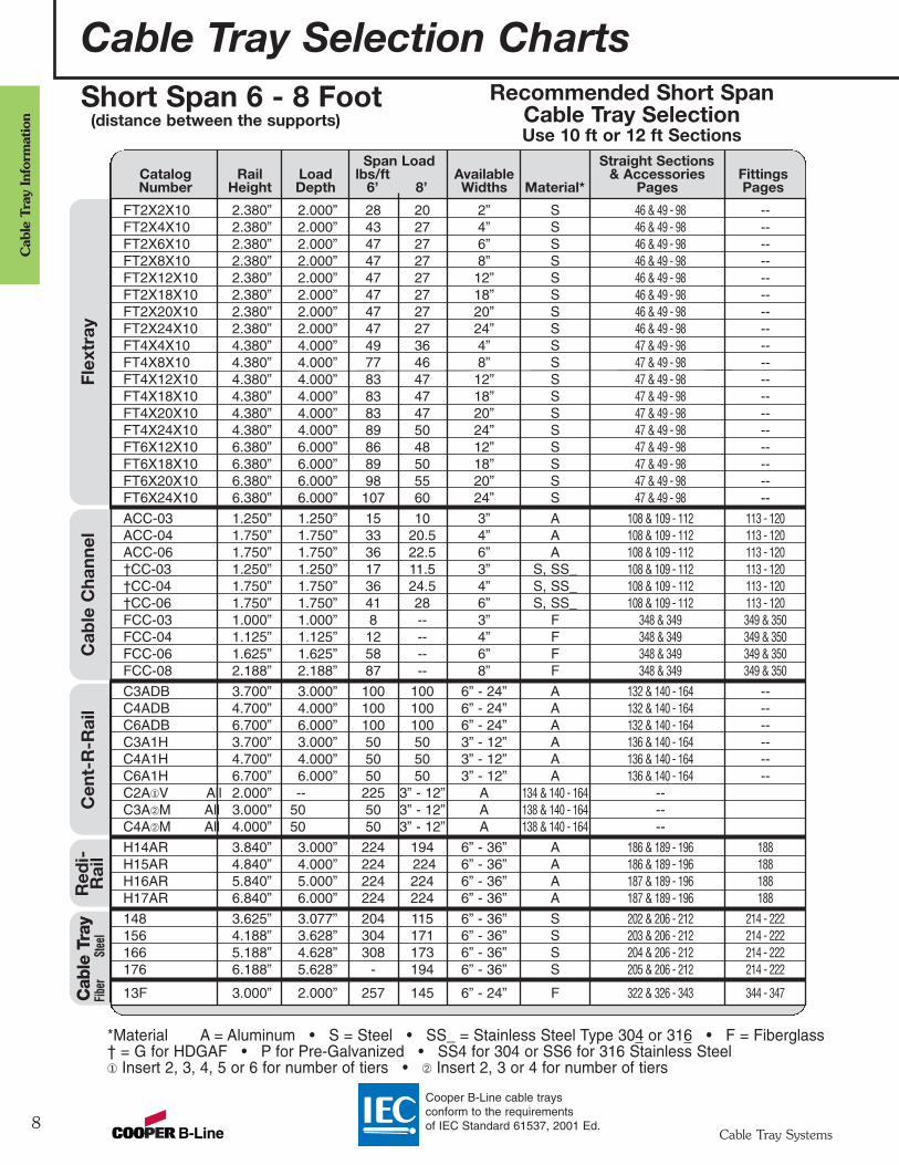
FT2X2X10 2.380” 2.000” 28 20 2” S 46 & 49 - 98 --FT2X4X10 2.380” 2.000” 43 27 4” S 46 & 49 - 98 --FT2X6X10 2.380” 2.000” 47 27 6” S 46 & 49 - 98 --FT2X8X10 2.380” 2.000” 47 27 8” S 46 & 49 - 98 --FT2X12X10 2.380” 2.000” 47 27 12” S 46 & 49 - 98 --FT2X18X10 2.380” 2.000” 47 27 18” S 46 & 49 - 98 --FT2X20X10 2.380” 2.000” 47 27 20” S 46 & 49 - 98 --FT2X24X10 2.380” 2.000” 47 27 24” S 46 & 49 - 98 --FT4X4X10 4.380” 4.000” 49 36 4” S 47 & 49 - 98 --FT4X8X10 4.380” 4.000” 77 46 8” S 47 & 49 - 98 --FT4X12X10 4.380” 4.000” 83 47 12” S 47 & 49 - 98 --FT4X18X10 4.380” 4.000” 83 47 18” S 47 & 49 - 98 --FT4X20X10 4.380” 4.000” 83 47 20” S 47 & 49 - 98 --FT4X24X10 4.380” 4.000” 89 50 24” S 47 & 49 - 98 --FT6X12X10 6.380” 6.000” 86 48 12” S 47 & 49 - 98 --FT6X18X10 6.380” 6.000” 89 50 18” S 47 & 49 - 98 --FT6X20X10 6.380” 6.000” 98 55 20” S 47 & 49 - 98 --FT6X24X10 6.380” 6.000” 107 60 24” S 47 & 49 - 98 --
ACC-03 1.250” 1.250” 15 10 3” A 108 & 109 - 112 113 - 120ACC-04 1.750” 1.750” 33 20.5 4” A 108 & 109 - 112 113 - 120ACC-06 1.750” 1.750” 36 22.5 6” A 108 & 109 - 112 113 - 120†CC-03 1.250” 1.250” 17 11.5 3” S, SS_ 108 & 109 - 112 113 - 120†CC-04 1.750” 1.750” 36 24.5 4” S, SS_ 108 & 109 - 112 113 - 120†CC-06 1.750” 1.750” 41 28 6” S, SS_ 108 & 109 - 112 113 - 120FCC-03 1.000” 1.000” 8 -- 3” F 348 & 349 349 & 350FCC-04 1.125” 1.125” 12 -- 4” F 348 & 349 349 & 350FCC-06 1.625” 1.625” 58 -- 6” F 348 & 349 349 & 350FCC-08 2.188” 2.188” 87 -- 8” F 348 & 349 349 & 350
C3ADB 3.700” 3.000” 100 100 6” - 24” A 132 & 140 - 164 --C4ADB 4.700” 4.000” 100 100 6” - 24” A 132 & 140 - 164 --C6ADB 6.700” 6.000” 100 100 6” - 24” A 132 & 140 - 164 --C3A1H 3.700” 3.000” 50 50 3” - 12” A 136 & 140 - 164 --C4A1H 4.700” 4.000” 50 50 3” - 12” A 136 & 140 - 164 --C6A1H 6.700” 6.000” 50 50 3” - 12” A 136 & 140 - 164 --C2A¬V All 2.000” -- 225 3” - 12” A 134 & 140 - 164 --C3AÁM All 3.000” 50 50 3” - 12” A 138 & 140 - 164 --C4AÁM All 4.000” 50 50 3” - 12” A 138 & 140 - 164 --
H14AR 3.840” 3.000” 224 194 6” - 36” A 186 & 189 - 196 188H15AR 4.840” 4.000” 224 224 6” - 36” A 186 & 189 - 196 188H16AR 5.840” 5.000” 224 224 6” - 36” A 187 & 189 - 196 188H17AR 6.840” 6.000” 224 224 6” - 36” A 187 & 189 - 196 188
148 3.625” 3.077” 204 115 6” - 36” S 202 & 206 - 212 214 - 222156 4.188” 3.628” 304 171 6” - 36” S 203 & 206 - 212 214 - 222166 5.188” 4.628” 308 173 6” - 36” S 204 & 206 - 212 214 - 222176 6.188” 5.628” - 194 6” - 36” S 205 & 206 - 212 214 - 222
13F 3.000” 2.000” 257 145 6” - 24” F 322 & 326 - 343 344 - 347
Recommended Short SpanCable Tray SelectionUse 10 ft or 12 ft Sections
Span Load Straight SectionsCatalog Rail Load lbs/ft Available & Accessories FittingsNumber Height Depth 6’ 8’ Widths Material* Pages Pages
Cab
le C
hann
elR
edi-
Rai
lC
able
Tra
yFib
erSt
eel
Short Span 6 - 8 Foot(distance between the supports)
*Material A = Aluminum • S = Steel • SS_ = Stainless Steel Type 304 or 316 • F = Fiberglass† = G for HDGAF • P for Pre-Galvanized • SS4 for 304 or SS6 for 316 Stainless Steel¬ Insert 2, 3, 4, 5 or 6 for number of tiers • Á Insert 2, 3 or 4 for number of tiers
Red
i-R
ail
Cable Tray Selection Charts
9Cable Tray Systems
Cable Tray Inform
ation
Cooper B-Line cable trays conform to the requirements of IEC Standard 61537, 2001 Ed.
Cab
le T
ray
Fiber
glass
Stain
less S
teel
Stee
lAl
uminu
m
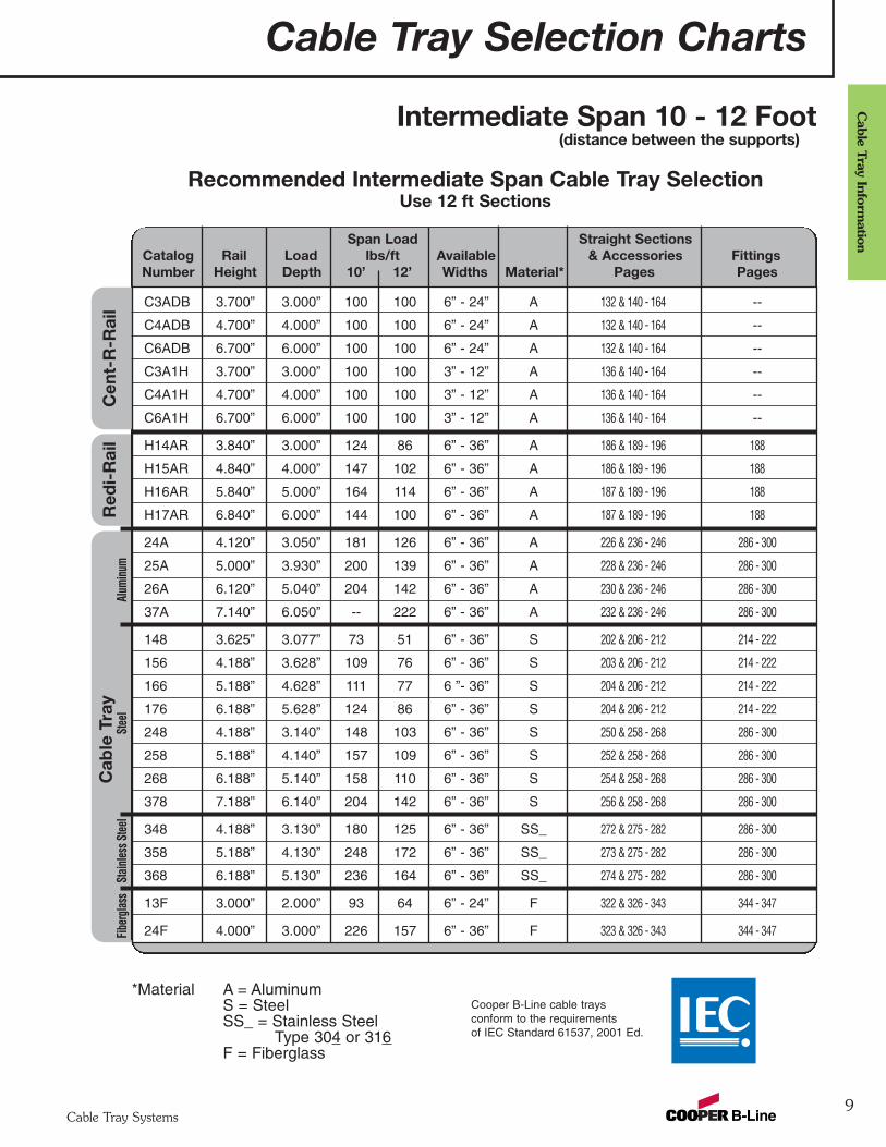
C3ADB 3.700” 3.000” 100 100 6” - 24” A 132 & 140 - 164 --
C4ADB 4.700” 4.000” 100 100 6” - 24” A 132 & 140 - 164 --
C6ADB 6.700” 6.000” 100 100 6” - 24” A 132 & 140 - 164 --
C3A1H 3.700” 3.000” 100 100 3” - 12” A 136 & 140 - 164 --
C4A1H 4.700” 4.000” 100 100 3” - 12” A 136 & 140 - 164 --
C6A1H 6.700” 6.000” 100 100 3” - 12” A 136 & 140 - 164 --
H14AR 3.840” 3.000” 124 86 6” - 36” A 186 & 189 - 196 188
H15AR 4.840” 4.000” 147 102 6” - 36” A 186 & 189 - 196 188
H16AR 5.840” 5.000” 164 114 6” - 36” A 187 & 189 - 196 188
H17AR 6.840” 6.000” 144 100 6” - 36” A 187 & 189 - 196 188
24A 4.120” 3.050” 181 126 6” - 36” A 226 & 236 - 246 286 - 300
25A 5.000” 3.930” 200 139 6” - 36” A 228 & 236 - 246 286 - 300
26A 6.120” 5.040” 204 142 6” - 36” A 230 & 236 - 246 286 - 300
37A 7.140” 6.050” -- 222 6” - 36” A 232 & 236 - 246 286 - 300
148 3.625” 3.077” 73 51 6” - 36” S 202 & 206 - 212 214 - 222
156 4.188” 3.628” 109 76 6” - 36” S 203 & 206 - 212 214 - 222
166 5.188” 4.628” 111 77 6 ”- 36” S 204 & 206 - 212 214 - 222
176 6.188” 5.628” 124 86 6” - 36” S 204 & 206 - 212 214 - 222
248 4.188” 3.140” 148 103 6” - 36” S 250 & 258 - 268 286 - 300
258 5.188” 4.140” 157 109 6” - 36” S 252 & 258 - 268 286 - 300
268 6.188” 5.140” 158 110 6” - 36” S 254 & 258 - 268 286 - 300
378 7.188” 6.140” 204 142 6” - 36” S 256 & 258 - 268 286 - 300
348 4.188” 3.130” 180 125 6” - 36” SS_ 272 & 275 - 282 286 - 300
358 5.188” 4.130” 248 172 6” - 36” SS_ 273 & 275 - 282 286 - 300
368 6.188” 5.130” 236 164 6” - 36” SS_ 274 & 275 - 282 286 - 300
13F 3.000” 2.000” 93 64 6” - 24” F 322 & 326 - 343 344 - 347
24F 4.000” 3.000” 226 157 6” - 36” F 323 & 326 - 343 344 - 347
Recommended Intermediate Span Cable Tray SelectionUse 12 ft Sections
Span Load Straight SectionsCatalog Rail Load lbs/ft Available & Accessories FittingsNumber Height Depth 10’ 12’ Widths Material* Pages Pages
Cen
t-R
-Rai
lIntermediate Span 10 - 12 Foot
(distance between the supports)xx
*Material A = AluminumS = SteelSS_ = Stainless Steel
Type 304 or 316F = Fiberglass
Cable Tray Selection Charts
10Cable Tray Systems
Cab
le T
ray
Info
rmat
ion
Cab
le T
ray
Fibe
rgla
ssSt
ainl
ess
Stee
lSt
eel
Alum
inum
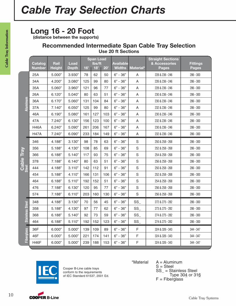
25A 5.000” 3.930” 78 62 50 6” - 36” A 228 & 236 - 246 286 - 300
34A 4.200” 3.080” 125 99 80 6” - 36” A 226 & 236 - 246 286 - 300
35A 5.060” 3.960” 121 96 77 6” - 36” A 228 & 236 - 246 286 - 300
26A 6.120” 5.040” 80 63 51 6” - 36” A 230 & 236 - 246 286 - 300
36A 6.170” 5.060” 131 104 84 6” - 36” A 230 & 236 - 246 286 - 300
37A 7.140” 6.050” 125 99 80 6” - 36” A 232 & 236 - 246 286 - 300
46A 6.190” 5.080” 161 127 103 6” - 36” A 230 & 236 - 246 286 - 300
47A 7.240” 6.130” 156 123 100 6” - 36” A 232 & 236 - 246 286 - 300
H46A 6.240” 5.090” 261 206 167 6” - 36” A 230 & 236 - 246 286 - 300
H47A 7.240” 6.090” 233 184 149 6” - 36” A 232 & 236 - 246 286 - 300
346 4.188” 3.130” 98 78 63 6” - 36” S 250 & 258 - 268 286 - 300
356 5.188” 4.130” 108 85 69 6” - 36” S 252 & 258 - 268 286 - 300
366 6.188” 5.140” 117 93 75 6” - 36” S 254 & 258 - 268 286 - 300
378 7.188” 6.140” 80 63 51 6” - 36” S 256 & 258 - 268 286 - 300
444 4.188” 3.110” 142 112 91 6” - 36” S 250 & 258 - 268 286 - 300
454 5.188” 4.110” 166 131 106 6” - 36” S 252 & 258 - 268 286 - 300
464 6.188” 5.110” 192 152 51 6” - 36” S 254 & 258 - 268 286 - 300
476 7.188” 6.130” 120 95 77 6” - 36” S 256 & 258 - 268 286 - 300
574 7.188” 6.110” 203 160 130 6” - 36” S 256 & 258 - 268 286 - 300
348 4.188” 3.130” 70 56 45 6” - 36” SS_ 272 & 275 - 282 286 - 300
358 5.188” 4.130” 97 77 62 6” - 36” SS_ 273 & 275 - 282 286 - 300
368 6.188” 5.140” 92 73 59 6” - 36” SS_ 274 & 275 - 282 286 - 300
464 6.188” 5.110” 192 152 123 6” - 36” SS_ 274 & 275 - 282 286 - 300
36F 6.000” 5.000” 139 109 89 6” - 36” F 324 & 326 - 343 344 - 347
46F 6.000” 5.000” 221 174 141 6” - 36” F 324 & 326 - 343 344 - 347
H46F 6.000” 5.000” 239 188 153 6” - 36” F 324 & 326 - 343 344 - 347
Recommended Intermediate Span Cable Tray SelectionUse 20 ft Sections
Span Load Straight SectionsCatalog Rail Load lbs/ft Available & Accessories FittingsNumber Height Depth 16’ 18’ 20’ Widths Material* Pages Pages
Long 16 - 20 Foot(distance between the supports)
Cooper B-Line cable trays conform to the requirements of IEC Standard 61537, 2001 Ed.
*Material A = AluminumS = SteelSS_ = Stainless Steel
Type 304 or 316F = Fiberglass
Cab
le T
ray
Ste
elA
lum
inum
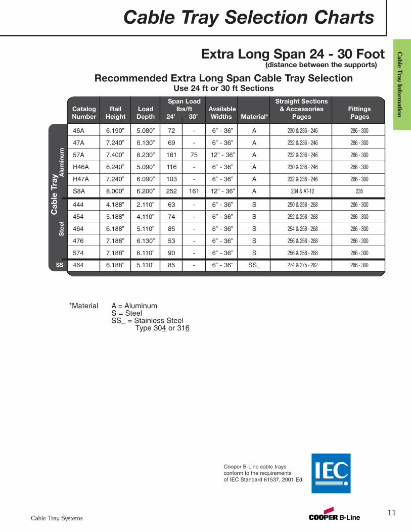
46A 6.190” 5.080” 72 - 6” - 36” A 230 & 236 - 246 286 - 300
47A 7.240” 6.130” 69 - 6” - 36” A 232 & 236 - 246 286 - 300
57A 7.400” 6.230” 161 75 12” - 36” A 232 & 236 - 246 286 - 300
H46A 6.240” 5.090” 116 - 6” - 36” A 230 & 236 - 246 286 - 300
H47A 7.240” 6.090” 103 - 6” - 36” A 232 & 236 - 246 286 - 300
S8A 8.000” 6.200” 252 161 12” - 36” A 234 & AT-12 235
444 4.188” 2.110” 63 - 6” - 36” S 250 & 258 - 268 286 - 300
454 5.188” 4.110” 74 - 6” - 36” S 252 & 258 - 268 286 - 300
464 6.188” 5.110” 85 - 6” - 36” S 254 & 258 - 268 286 - 300
476 7.188” 6.130” 53 - 6” - 36” S 256 & 258 - 268 286 - 300
574 7.188” 6.110” 90 - 6” - 36” S 256 & 258 - 268 286 - 300
464 6.188” 5.110” 85 - 6” - 36” SS_ 274 & 275 - 282 286 - 300
Recommended Extra Long Span Cable Tray SelectionUse 24 ft or 30 ft Sections
Span Load Straight SectionsCatalog Rail Load lbs/ft Available & Accessories FittingsNumber Height Depth 24’ 30’ Widths Material* Pages Pages
Extra Long Span 24 - 30 Foot(distance between the supports)xx
*Material A = AluminumS = SteelSS_ = Stainless Steel
Type 304 or 316
Cable Tray Selection Charts
11Cable Tray Systems
Cable Tray Inform
ation
Cooper B-Line cable trays conform to the requirements of IEC Standard 61537, 2001 Ed.
SS
Cable Tray Systems
12
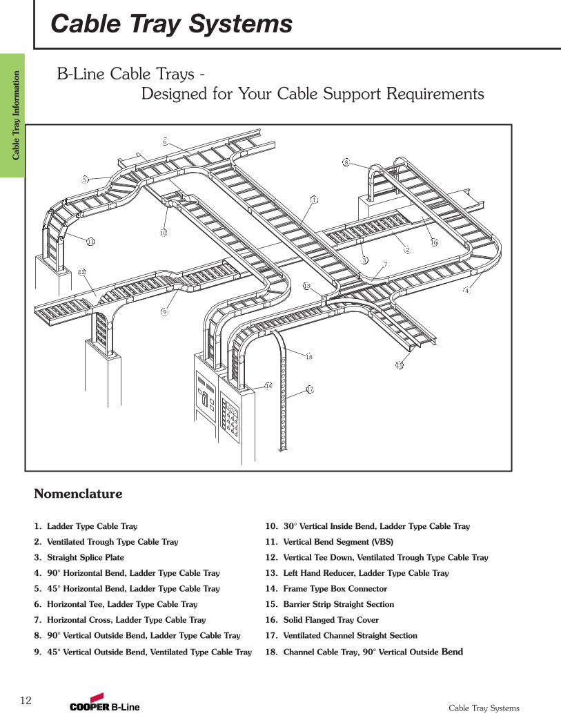
B-Line Cable Trays -Designed for Your Cable Support Requirements
Nomenclature
1. Ladder Type Cable Tray 10. 30° Vertical Inside Bend, Ladder Type Cable Tray
2. Ventilated Trough Type Cable Tray 11. Vertical Bend Segment (VBS)
3. Straight Splice Plate 12. Vertical Tee Down, Ventilated Trough Type Cable Tray
4. 90° Horizontal Bend, Ladder Type Cable Tray 13. Left Hand Reducer, Ladder Type Cable Tray
5. 45° Horizontal Bend, Ladder Type Cable Tray 14. Frame Type Box Connector
6. Horizontal Tee, Ladder Type Cable Tray 15. Barrier Strip Straight Section
7. Horizontal Cross, Ladder Type Cable Tray 16. Solid Flanged Tray Cover
8. 90° Vertical Outside Bend, Ladder Type Cable Tray 17. Ventilated Channel Straight Section
9. 45° Vertical Outside Bend, Ventilated Type Cable Tray 18. Channel Cable Tray, 90° Vertical Outside Bend
6
5
11
12
10
1
8
16
7
2
3
4
15
14 17
18
9
13
Cable Tray Systems
Cab
le T
ray
Info
rmat
ion

The B-Line Advantage - The Company
13
-- is Committed to the Success of its Customers through Manufacturing, Engineering and Service.
-- is Positioned to Serve.
Four United States cable tray fabrication sites:Troy, IL Ellaville, GAAlum Bank, PA Reno, NV
Sixteen factory inventories
-- a Proven Industry Leader.
Over thirty years experience
-- offers Industry Involvement.
NEMA - 5VE Member -- Metallic Cable Tray SectionNEMA - 5FG Member -- Nonmetallic Cable Tray SectionCable Tray Institute (CTI) -- A Founding MemberCooper B-Line cable trays conform to the requirements of
IEC Standard 61537, 2001 Ed.
-- unmatched Cable Support Systems.
Cable Tray -- Two Side Rail (Metallic)Cable Tray -- Two Side Rail (Metallic) Redi-Rail™ DesignCable Tray -- Two Side Rail (Nonmetallic)Cable Tray -- CENT-R-RAIL; DATA-TRACK, VERTI-RACK,
HALF-RACK, and MULTI-TIER HALF-RACK.Cable Tray -- Flextray Cable Support SystemsCable Runways -- B-Line TelecomNEMA Wireways -- Circle AW Products Co., a B-Line Company
B-Line A
dvantage
Cable Tray Systems
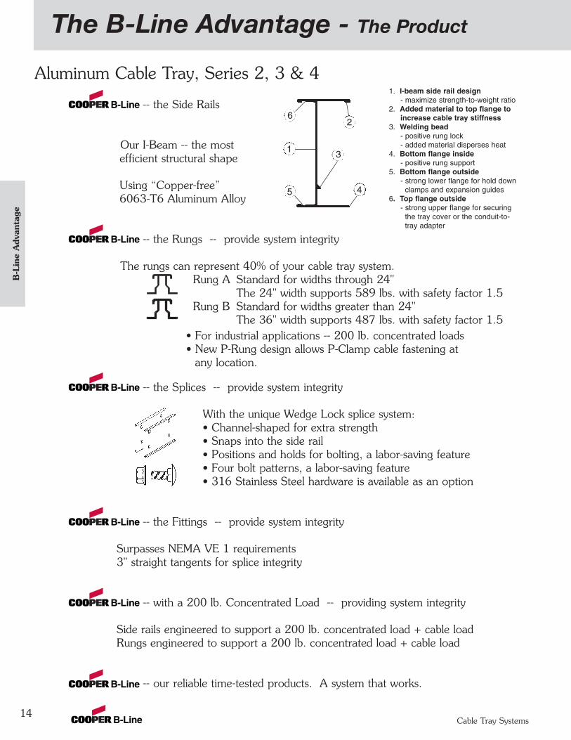
Aluminum Cable Tray, Series 2, 3 & 4
-- the Side Rails
Our I-Beam -- the mostefficient structural shape
Using “Copper-free”6063-T6 Aluminum Alloy
-- the Rungs -- provide system integrity
The rungs can represent 40% of your cable tray system.Rung A Standard for widths through 24"
The 24" width supports 589 lbs. with safety factor 1.5Rung B Standard for widths greater than 24"
The 36" width supports 487 lbs. with safety factor 1.5• For industrial applications -- 200 lb. concentrated loads• New P-Rung design allows P-Clamp cable fastening at
any location.
-- the Splices -- provide system integrity
With the unique Wedge Lock splice system:• Channel-shaped for extra strength• Snaps into the side rail• Positions and holds for bolting, a labor-saving feature• Four bolt patterns, a labor-saving feature• 316 Stainless Steel hardware is available as an option
-- the Fittings -- provide system integrity
Surpasses NEMA VE 1 requirements3" straight tangents for splice integrity
-- with a 200 lb. Concentrated Load -- providing system integrity
Side rails engineered to support a 200 lb. concentrated load + cable loadRungs engineered to support a 200 lb. concentrated load + cable load
-- our reliable time-tested products. A system that works.
The B-Line Advantage - The Product
14
1. I-beam side rail design- maximize strength-to-weight ratio
2. Added material to top flange toincrease cable tray stiffness
3. Welding bead- positive rung lock- added material disperses heat
4. Bottom flange inside- positive rung support
5. Bottom flange outside- strong lower flange for hold down
clamps and expansion guides6. Top flange outside
- strong upper flange for securingthe tray cover or the conduit-to-tray adapter
2
1 3
45
6
B-L
ine
Adv
anta
ge
Cable Tray Systems
The B-Line Advantage - The Product
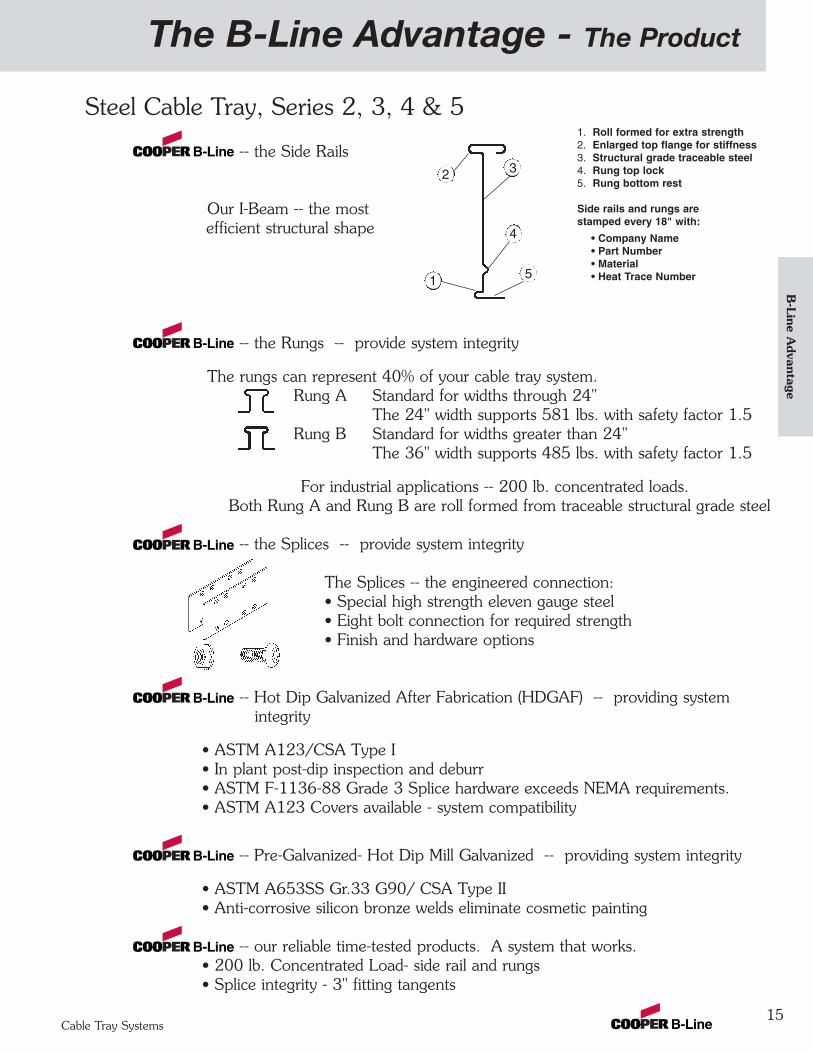
Steel Cable Tray, Series 2, 3, 4 & 5
-- the Side Rails
Our I-Beam -- the mostefficient structural shape
-- the Rungs -- provide system integrity
The rungs can represent 40% of your cable tray system.Rung A Standard for widths through 24"
The 24" width supports 581 lbs. with safety factor 1.5Rung B Standard for widths greater than 24"
The 36" width supports 485 lbs. with safety factor 1.5
For industrial applications -- 200 lb. concentrated loads. Both Rung A and Rung B are roll formed from traceable structural grade steel
-- the Splices -- provide system integrity
The Splices -- the engineered connection:• Special high strength eleven gauge steel• Eight bolt connection for required strength• Finish and hardware options
-- Hot Dip Galvanized After Fabrication (HDGAF) -- providing systemintegrity
• ASTM A123/CSA Type I• In plant post-dip inspection and deburr• ASTM F-1136-88 Grade 3 Splice hardware exceeds NEMA requirements.• ASTM A123 Covers available - system compatibility
-- Pre-Galvanized- Hot Dip Mill Galvanized -- providing system integrity
• ASTM A653SS Gr.33 G90/ CSA Type II• Anti-corrosive silicon bronze welds eliminate cosmetic painting
-- our reliable time-tested products. A system that works.• 200 lb. Concentrated Load- side rail and rungs• Splice integrity - 3" fitting tangents
1. Roll formed for extra strength2. Enlarged top flange for stiffness3. Structural grade traceable steel4. Rung top lock5. Rung bottom rest
Side rails and rungs are stamped every 18" with:
• Company Name• Part Number• Material• Heat Trace Number
2
1
3
4
5
15
B-Line A
dvantage
Cable Tray Systems
The B-Line Advantage - The Extras
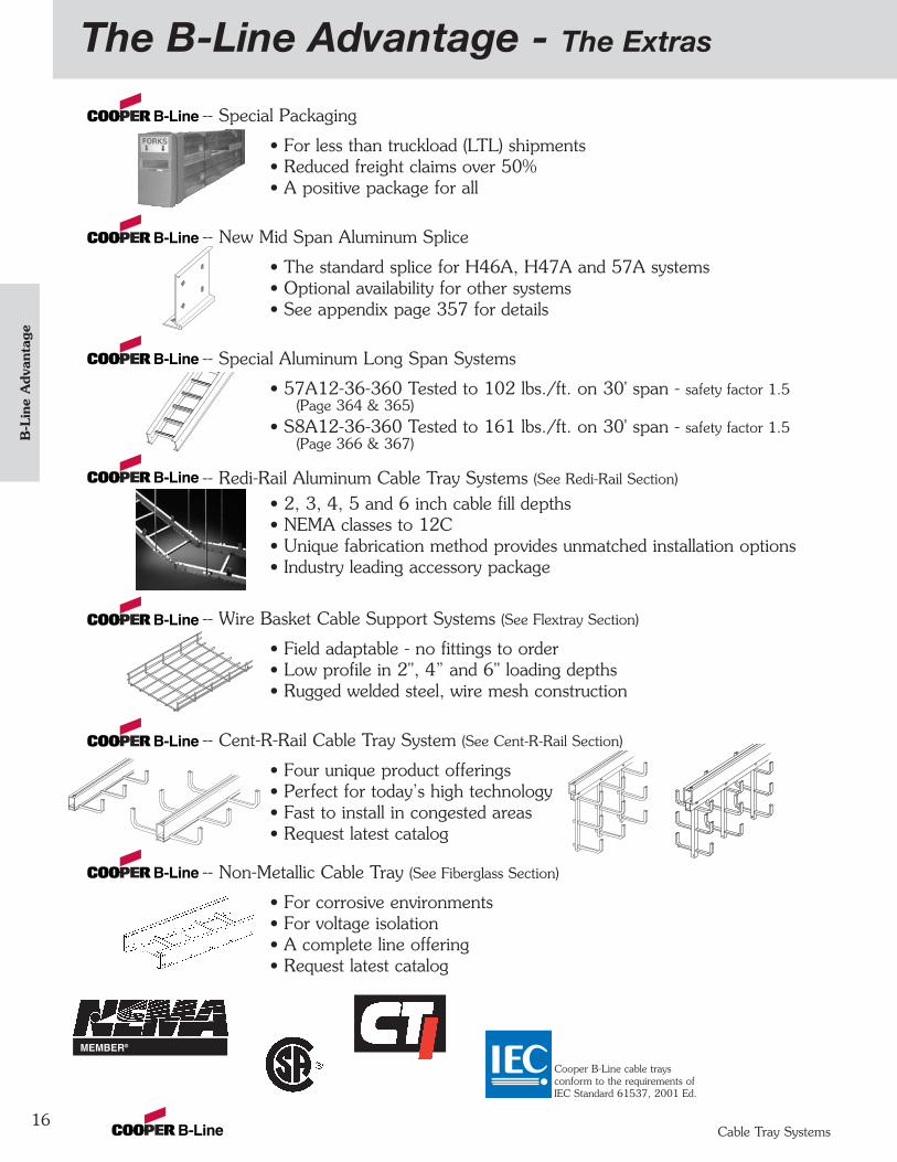
-- Special Packaging
• For less than truckload (LTL) shipments• Reduced freight claims over 50%• A positive package for all
-- New Mid Span Aluminum Splice
• The standard splice for H46A, H47A and 57A systems• Optional availability for other systems• See appendix page 357 for details
-- Special Aluminum Long Span Systems
• 57A12-36-360 Tested to 102 lbs./ft. on 30' span - safety factor 1.5(Page 364 & 365)
• S8A12-36-360 Tested to 161 lbs./ft. on 30' span - safety factor 1.5(Page 366 & 367)
-- Redi-Rail Aluminum Cable Tray Systems (See Redi-Rail Section)
• 2, 3, 4, 5 and 6 inch cable fill depths• NEMA classes to 12C• Unique fabrication method provides unmatched installation options• Industry leading accessory package
-- Wire Basket Cable Support Systems (See Flextray Section)
• Field adaptable - no fittings to order• Low profile in 2", 4” and 6" loading depths• Rugged welded steel, wire mesh construction
-- Cent-R-Rail Cable Tray System (See Cent-R-Rail Section)
• Four unique product offerings• Perfect for today’s high technology• Fast to install in congested areas• Request latest catalog
-- Non-Metallic Cable Tray (See Fiberglass Section)
• For corrosive environments• For voltage isolation• A complete line offering• Request latest catalog
16
Cooper B-Line cable trays conform to the requirements of IEC Standard 61537, 2001 Ed.
MEMBER®
B-L
ine
Adv
anta
ge
Cable Tray Systems
Cable Tray Selection - Selection Process
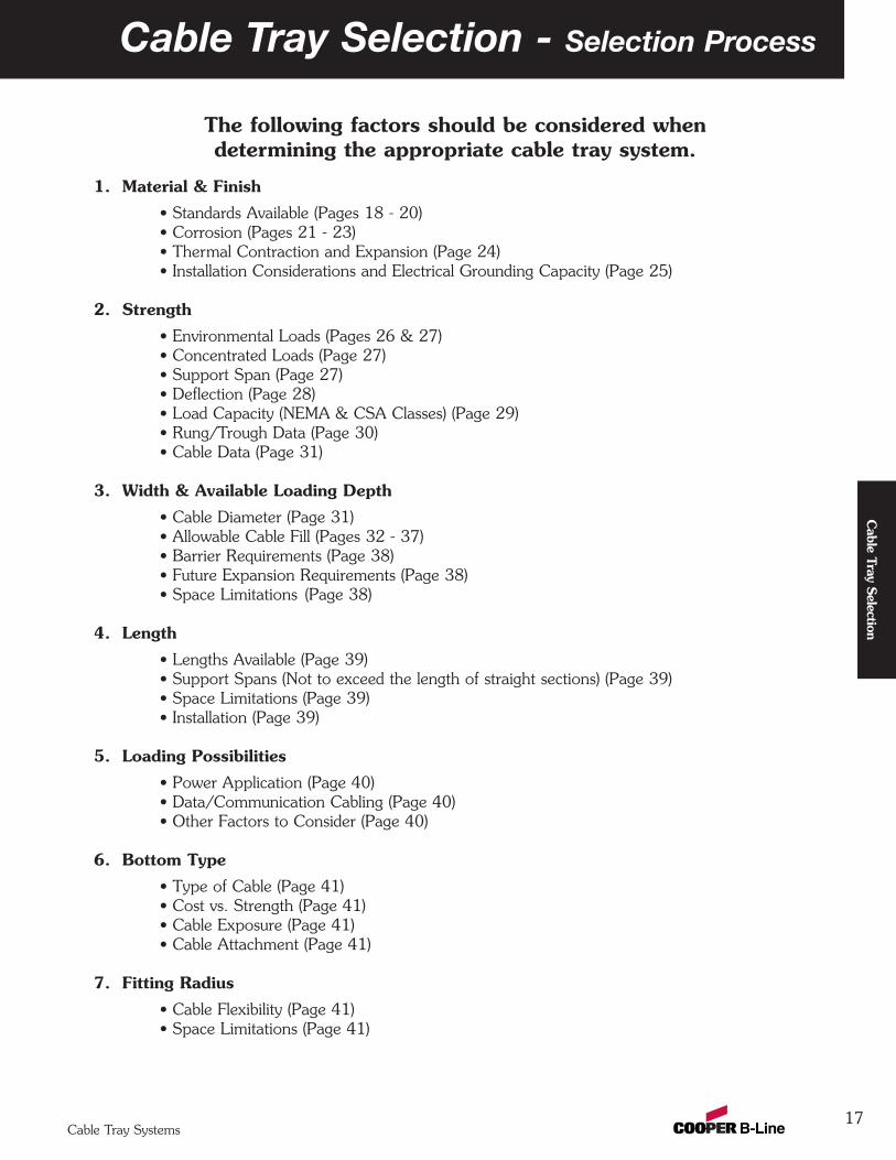
The following factors should be considered when determining the appropriate cable tray system.
1. Material & Finish
• Standards Available (Pages 18 - 20)• Corrosion (Pages 21 - 23)• Thermal Contraction and Expansion (Page 24)• Installation Considerations and Electrical Grounding Capacity (Page 25)
2. Strength
• Environmental Loads (Pages 26 & 27)• Concentrated Loads (Page 27)• Support Span (Page 27)• Deflection (Page 28) • Load Capacity (NEMA & CSA Classes) (Page 29)• Rung/Trough Data (Page 30)• Cable Data (Page 31)
3. Width & Available Loading Depth
• Cable Diameter (Page 31)• Allowable Cable Fill (Pages 32 - 37) • Barrier Requirements (Page 38)• Future Expansion Requirements (Page 38)• Space Limitations (Page 38)
4. Length
• Lengths Available (Page 39)• Support Spans (Not to exceed the length of straight sections) (Page 39)• Space Limitations (Page 39)• Installation (Page 39)
5. Loading Possibilities
• Power Application (Page 40)• Data/Communication Cabling (Page 40)• Other Factors to Consider (Page 40)
6. Bottom Type
• Type of Cable (Page 41)• Cost vs. Strength (Page 41)• Cable Exposure (Page 41)• Cable Attachment (Page 41)
7. Fitting Radius
• Cable Flexibility (Page 41)• Space Limitations (Page 41)
17
Cable Tray Selection
Cable Tray Systems
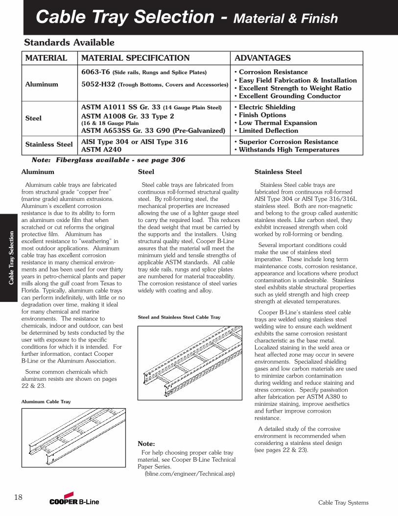
MATERIAL MATERIAL SPECIFICATION ADVANTAGES
6063-T6 (Side rails, Rungs and Splice Plates) • Corrosion Resistance• Easy Field Fabrication & InstallationAluminum 5052-H32 (Trough Bottoms, Covers and Accessories) • Excellent Strength to Weight Ratio• Excellent Grounding Conductor
ASTM A1011 SS Gr. 33 (14 Gauge Plain Steel) • Electric Shielding
Steel ASTM A1008 Gr. 33 Type 2 • Finish Options(16 & 18 Gauge Plain • Low Thermal ExpansionASTM A653SS Gr. 33 G90 (Pre-Galvanized) • Limited Deflection
Stainless Steel AISI Type 304 or AISI Type 316 • Superior Corrosion ResistanceASTM A240 • Withstands High Temperatures
Cable Tray Selection - Material & Finish
18
Steel
Steel cable trays are fabricated fromcontinuous roll-formed structural qualitysteel. By roll-forming steel, themechanical properties are increasedallowing the use of a lighter gauge steelto carry the required load. This reducesthe dead weight that must be carried bythe supports and the installers. Usingstructural quality steel, Cooper B-Lineassures that the material will meet theminimum yield and tensile strengths ofapplicable ASTM standards. All cabletray side rails, rungs and splice platesare numbered for material traceability.The corrosion resistance of steel varieswidely with coating and alloy.
Steel and Stainless Steel Cable Tray
Note:For help choosing proper cable tray
material, see Cooper B-Line TechnicalPaper Series.
(bline.com/engineer/Technical.asp)
Stainless Steel
Stainless Steel cable trays arefabricated from continuous roll-formedAISI Type 304 or AISI Type 316/316Lstainless steel. Both are non-magneticand belong to the group called austeniticstainless steels. Like carbon steel, theyexhibit increased strength when coldworked by roll-forming or bending.
Several important conditions couldmake the use of stainless steelimperative. These include long termmaintenance costs, corrosion resistance,appearance and locations where productcontamination is undesirable. Stainlesssteel exhibits stable structural propertiessuch as yield strength and high creepstrength at elevated temperatures.
Cooper B-Line’s stainless steel cabletrays are welded using stainless steelwelding wire to ensure each weldmentexhibits the same corrosion resistantcharacteristic as the base metal.Localized staining in the weld area orheat affected zone may occur in severeenvironments. Specialized shieldinggases and low carbon materials are usedto minimize carbon contaminationduring welding and reduce staining andstress corrosion. Specify passivationafter fabrication per ASTM A380 tominimize staining, improve aestheticsand further improve corrosionresistance.
A detailed study of the corrosiveenvironment is recommended whenconsidering a stainless steel design(see pages 22 & 23).
Aluminum
Aluminum cable trays are fabricatedfrom structural grade “copper free”(marine grade) aluminum extrusions.Aluminum’s excellent corrosionresistance is due to its ability to forman aluminum oxide film that whenscratched or cut reforms the originalprotective film. Aluminum hasexcellent resistance to "weathering” inmost outdoor applications. Aluminumcable tray has excellent corrosionresistance in many chemical environ-ments and has been used for over thirtyyears in petro-chemical plants and papermills along the gulf coast from Texas toFlorida. Typically, aluminum cable trayscan perform indefinitely, with little or nodegradation over time, making it idealfor many chemical and marineenvironments. The resistance tochemicals, indoor and outdoor, can bestbe determined by tests conducted by theuser with exposure to the specificconditions for which it is intended. Forfurther information, contact CooperB-Line or the Aluminum Association.
Some common chemicals whichaluminum resists are shown on pages22 & 23.
Aluminum Cable Tray
Standards Available
Cab
le T
ray
Sele
ctio
n
Cable Tray Systems
Note: Fiberglass available - see page 306
19
Cable Tray Selection - Material & Finish
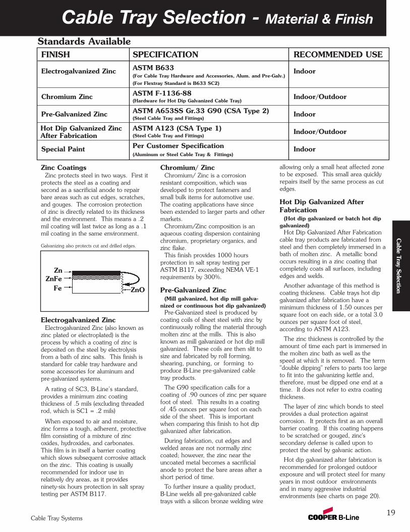
FINISH SPECIFICATION RECOMMENDED USE
Electrogalvanized Zinc ASTM B633 Indoor(For Cable Tray Hardware and Accessories, Alum. and Pre-Galv.)(For Flextray Standard is B633 SC2)
Chromium Zinc ASTM F-1136-88 Indoor/Outdoor(Hardware for Hot Dip Galvanized Cable Tray)
Pre-Galvanized Zinc ASTM A653SS Gr.33 G90 (CSA Type 2) Indoor(Steel Cable Tray and Fittings)
Hot Dip Galvanized Zinc ASTM A123 (CSA Type 1) Indoor/Outdoorafter fabrication (Steel Cable Tray and Fittings)
Special Paint Per Customer Specification Indoor(Aluminum or Steel Cable Tray & Fittings)
Zinc CoatingsZinc protects steel in two ways. First it
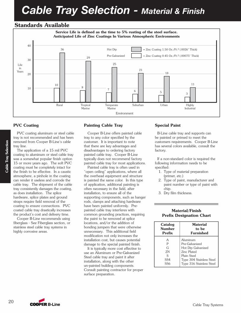
protects the steel as a coating andsecond as a sacrificial anode to repairbare areas such as cut edges, scratches,and gouges. The corrosion protectionof zinc is directly related to its thicknessand the environment. This means a .2mil coating will last twice as long as a .1mil coating in the same environment.
Galvanizing also protects cut and drilled edges.
Electrogalvanized ZincElectrogalvanized Zinc (also known as
zinc plated or electroplated) is theprocess by which a coating of zinc isdeposited on the steel by electrolysisfrom a bath of zinc salts. This finish isstandard for cable tray hardware andsome accessories for aluminum andpre-galvanized systems.
A rating of SC3, B-Line’s standard,provides a minimum zinc coatingthickness of .5 mils (excluding threadedrod, which is SC1 = .2 mils)
When exposed to air and moisture,zinc forms a tough, adherent, protectivefilm consisting of a mixture of zincoxides, hydroxides, and carbonates.This film is in itself a barrier coatingwhich slows subsequent corrosive attackon the zinc. This coating is usuallyrecommended for indoor use inrelatively dry areas, as it providesninety-six hours protection in salt spraytesting per ASTM B117.
allowing only a small heat affected zoneto be exposed. This small area quicklyrepairs itself by the same process as cutedges.
Hot Dip Galvanized AfterFabrication
(Hot dip galvanized or batch hot dipgalvanized)
Hot Dip Galvanized After Fabricationcable tray products are fabricated fromsteel and then completely immersed in abath of molten zinc. A metallic bondoccurs resulting in a zinc coating thatcompletely coats all surfaces, includingedges and welds.
Another advantage of this method iscoating thickness. Cable trays hot dipgalvanized after fabrication have aminimum thickness of 1.50 ounces persquare foot on each side, or a total 3.0ounces per square foot of steel,according to ASTM A123.
The zinc thickness is controlled by theamount of time each part is immersed inthe molten zinc bath as well as thespeed at which it is removed. The term"double dipping" refers to parts too largeto fit into the galvanizing kettle and,therefore, must be dipped one end at atime. It does not refer to extra coatingthickness.
The layer of zinc which bonds to steelprovides a dual protection againstcorrosion. It protects first as an overallbarrier coating. If this coating happensto be scratched or gouged, zinc'ssecondary defense is called upon toprotect the steel by galvanic action.
Hot dip galvanized after fabrication isrecommended for prolonged outdoorexposure and will protect steel for manyyears in most outdoor environmentsand in many aggressive industrialenvironments (see charts on page 20).
Chromium/ ZincChromium/ Zinc is a corrosion
resistant composition, which wasdeveloped to protect fasteners andsmall bulk items for automotive use.The coating applications have sincebeen extended to larger parts and othermarkets.
Chromium/Zinc composition is anaqueous coating dispersion containingchromium, proprietary organics, andzinc flake.
This finish provides 1000 hoursprotection in salt spray testing perASTM B117, exceeding NEMA VE-1requirements by 300%.
Pre-Galvanized Zinc(Mill galvanized, hot dip mill galva-
nized or continuous hot dip galvanized)Pre-Galvanized steel is produced by
coating coils of sheet steel with zinc bycontinuously rolling the material throughmolten zinc at the mills. This is alsoknown as mill galvanized or hot dip millgalvanized. These coils are then slit tosize and fabricated by roll forming,shearing, punching, or forming toproduce B-Line pre-galvanized cabletray products.
The G90 specification calls for acoating of .90 ounces of zinc per squarefoot of steel. This results in a coatingof .45 ounces per square foot on eachside of the sheet. This is importantwhen comparing this finish to hot dipgalvanized after fabrication.
During fabrication, cut edges andwelded areas are not normally zinccoated; however, the zinc near theuncoated metal becomes a sacrificialanode to protect the bare areas after ashort period of time.
To further insure a quality product,B-Line welds all pre-galvanized cabletrays with a silicon bronze welding wire
Zn
FeZnFe
ZnO
Standards Available
Hot Dip Galvanized Zinc After Fabrication
Cable Tray Selection
Cable Tray Systems
Catalog MaterialNumber to bePrefix Furnished
A AluminumP Pre-GalvanizedG Hot Dip GalvanizedZN Zinc PlatedS Plain Steel
SS4 Type 304 Stainless SteelSS6 Type 316 Stainless Steel
Cable Tray Selection - Material & Finish
20
PVC Coating
PVC coating aluminum or steel cabletray is not recommended and has beenremoved from Cooper B-Line’s cabletray line.
The application of a 15 mil PVCcoating to aluminum or steel cable traywas a somewhat popular finish option15 or more years ago. The soft PVCcoating must be completely intact forthe finish to be effective. In a causticatmosphere, a pinhole in the coatingcan render it useless and corrode thecable tray. The shipment of the cabletray consistently damages the coating,as does installation. The splicehardware, splice plates and groundstraps require field removal of thecoating to ensure connections. PVCcoated cable tray drastically increasesthe product’s cost and delivery time.
Cooper B-Line recommends usingfiberglass - See Fiberglass section, orstainless steel cable tray systems inhighly corrosive areas.
Painting Cable Tray
Cooper B-Line offers painted cabletray to any color specified by thecustomer. It is important to notethat there are key advantages anddisadvantages to ordering factorypainted cable tray. Cooper B-Linetypically does not recommend factorypainted cable tray for most applications.
Painted cable tray is often used in“open ceiling” applications, where allthe overhead equipment and structureis painted the same color. In this typeof application, additional painting isoften necessary in the field, afterinstallation, to ensure all of thesupporting components, such as hangerrods, clamps and attaching hardwarehave been painted uniformly. Pre-painted cable tray interferes withcommon grounding practices, requiringthe paint to be removed at splicelocations, and/or the addition ofbonding jumpers that were otherwiseunnecessary. This additional fieldmodification not only increases theinstallation cost, but causes potentialdamage to the special painted finish.
It is typically more cost effective touse an Aluminum or Pre-GalvanizedSteel cable tray and paint it afterinstallation, along with the otherun-painted building components.Consult painting contractor for propersurface preparation.
Special Paint
B-Line cable tray and supports canbe painted or primed to meet thecustomers requirements. Cooper B-Linehas several colors available, consult thefactory.
If a non-standard color is required thefollowing information needs to bespecified:
1. Type of material preparation(primer, etc.)
2. Type of paint, manufacturer andpaint number or type of paint withchip.
3. Dry film thickness.
Service Life is defined as the time to 5% rusting of the steel surface.Anticipated Life of Zinc Coatings In Various Atmospheric Environments
40
30
20
10
= Zinc Coating 1.50 Oz./Ft.2 (.0026" Thick)Hot Dip
= Zinc Coating 0.45 Oz./Ft.2 (.00075" Thick)Pre-Galvanized
Lifein
Years
108
7 6 5 3
11
18
29
21
25
36
Rural Tropical Temperate Suburban Urban HighlyMarine Marine Industrial
Environment
Material/FinishPrefix Designation Chart
Standards Available
Cab
le T
ray
Sele
ctio
n
Cable Tray Systems

Cable Tray Selection - Material & Finish
21
MagnesiumMagnesium AlloysZincBerylliumAluminum - Zinc Alloys (7000 series)Aluminum - Magnesium Alloys (5000 series)Aluminum (1000 series)Aluminum - Magnesium Alloys (3000 series)Aluminum - Magnesium - Silicon Alloys (6000 series)CadmiumAluminum - Copper Alloys (2000 series)Cast Iron, Wrought Iron, Mild SteelAustenitic Nickel Cast IronType 410 Stainless Steel (active)Type 316 Stainless Steel (active)Type 304 Stainless Steel (active)Naval Brass, Yellow Brass, Red BrassTin CopperLead-Tin SoldersAdmiralty Brass, Aluminum BrassManganese BronzeSilicon BronzeTin BronzeType 410 Stainless Steel (passive)Nickel - SilverCopper Nickel AlloysLeadNickel - Aluminum BronzeSilver SolderNickel 200SilverType 316 Stainless Steel (passive)Type 304 Stainless Steel (passive)Incoloy 825Hastelloy BTitaniumHastelloy CPlatinumGraphite
Galvanic Series In Sea Water
Mor
e A
nodi
c
Corrosion
Anodic End
Cathodic End
Cable Tray Selection
All metal surfaces are affected by corrosion. Depending onthe physical properties of the metal and the environment towhich it is exposed, chemical or electromechanical corrosionmay occur.
Atmospheric CorrosionAtmospheric corrosion occurs when metal is exposed toairborne liquids, solids or gases. Some sources of atmos-pheric corrosion are moisture, salt, dirt and sulphuric acid.This form of corrosion is typically worse outdoors, especiallynear marine environments.
Chemical CorrosionChemical corrosion takes place when metal comes in directcontact with a corrosive solution. Some factors which affectthe severity of chemical corrosion include: chemical concen-tration level, duration of contact, frequency of washing, andoperating temperature.
Storage CorrosionWet storage stain (White rust) is caused by the entrapment ofmoisture between surfaces of closely packed and poorlyventilated material for an extended period. Wet storagestain is usually superficial, having no affect on the propertiesof the metal.Light staining normally disappears with weathering.Medium to heavy buildup should be removed, in order toallow the formation of normal protective film.Proper handling and storage will help to assure stain-freematerial. If product arrives wet, it should be unpacked anddried before storage. Dry material should be stored in a wellventilated “low moisture” environment to avoid condensationformation. Outdoor storage is undesirable, and should beavoided whenever possible.
Galvanic CorrosionGalvanic corrosion occurs when two or more dissimilarmetals are in contacts in the presence of an electrolyte (ie.moisture). An electrolytic cell is created and the metals forman anode or a cathode depending on their relative positionon the Galvanic Series Table. The anodic material will bethe one to corrode. Whether a material is anodic dependson the relative position of the other material. For exam-ple: If zinc and steel are in contact, the zinc acts as theanode and will corrode; the steel acts as the cathode, andwill be protected. If steel and copper are in contact, thesteel is now the anode and will corrode.The rate at which galvanic corrosion occurs depends onseveral factors:
1. The amount and concentration of electrolyte present- Anindoor, dry environment will have little or no galvaniccorrosion compared to a wet atmosphere.
2. The relative size of the materials- A small amount of anodic material in contact with a large cathodic materialwill result in greater corrosion. Likewise, a large anodein contact with a small cathode will decrease the rate ofattack.
3. The relative position on the Galvanic Series Table - The further apart in the Galvanic Series Table, the greater thepotential for corrosion of the anodic material.
Cable Tray Systems
Cable Tray Selection - Material & Finish
22
Cable Tray Material
Chemical Aluminum Stainless Type 304 Stainless Type 316
Cold Warm Hot Cold Warm Hot Cold Warm Hot
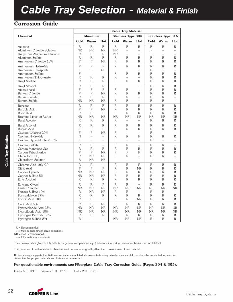
Acteone R R R R R R R R RAluminum Chloride Solution NR NR NR NR -- -- F -- --Anhydrous Aluminum Chloride R R R NR -- -- F -- --Aluminum Sulfate R R R R R R R R RAmmonium Chloride 10% F F NR R R R R R R
Ammonium Hydroxide F F F R R R R R RAmmonium Phosphate F F NR R -- -- R -- --Ammonium Sulfate F -- -- R R R R R RAmmonium Thiocyanate R R R R -- -- R R RAmyl Acetate R R R R R R R R R
Amyl Alcohol R R R R -- -- R R RArsenic Acid F F F R R -- R R RBarium Chloride F F NR R R R R R RBarium Sulfate R R R R R -- R R --Barium Sulfide NR NR NR R R -- R R --
Benzene R R R R R R R R RBenzoic Acid F F NR R R R R R RBoric Acid R R F R R R R R RBromine Liquid or Vapor NR NR NR NR NR NR NR NR NRButyl Acetate R R R R -- -- R R R
Butyl Alcohol R R R R R R R R RButyric Acid F F F R R R R R RCalcium Chloride 20% F F NR R -- -- R -- --Calcium Hydroxide N -- -- R R F R R RCalcium Hypochlorite 2 - 3% F -- -- R -- -- R -- --
Calcium Sulfate R R -- R R -- R R --Carbon Monoxide Gas R R R R R R R R RCarbon Tetrachloride F F NR F F F R R RChloroform Dry R NR NR R R -- R R --Chloroform Solution R NR NR -- -- -- -- -- --
Chromic Acid 10% CP R R -- R R F R R RCitric Acid F F F R R NR R R RCopper Cyanide NR NR NR R R R R R RCopper Sulfate 5% NR NR NR R R R R R REthyl Alcohol R R R R R R R R R
Ethylene Glycol R R F R R -- R R RFerric Chloride NR NR NR NR NR NR NR NR NRFerrous Sulfate 10% R NR NR R R -- R R --Formaldehyde 37% R R R R R R R R RFormic Acid 10% R R -- R R NR R R R
Gallic Acid 5% R R NR R R R R R RHydrochloride Acid 25% NR NR NR NR NR NR NR NR NRHydrofluoric Acid 10% NR NR NR NR NR NR NR NR NRHydrogen Peroxide 30% R R R R R R R R RHydrogen Sulfide Wet R -- -- NR NR NR R R R
R = RecommendedF = May be used under some conditions
NR = Not Recommended-- = Information not available
The corrosion data given in this table is for general comparison only. (Reference Corrosion Resistance Tables, Second Edition)
The presence of contaminates in chemical environments can greatly affect the corrosion rate of any material.
B-Line strongly suggests that field service tests or simulated laboratory tests using actual environmental conditions be conducted in order to determine the proper materials and finishes to be selected.
For questionable environments see Fiberglass Cable Tray Corrosion Guide (Pages 304 & 305).
Cold = 50 - 80°F Warm = 130 - 170°F Hot = 200 - 212°F
Corrosion Guide
Cab
le T
ray
Sele
ctio
n
Cable Tray Systems
Cable Tray Selection - Material & Finish
Cable Tray Material
Chemical Aluminum Stainless Type 304 Stainless Type 316
Cold Warm Hot Cold Warm Hot Cold Warm Hot
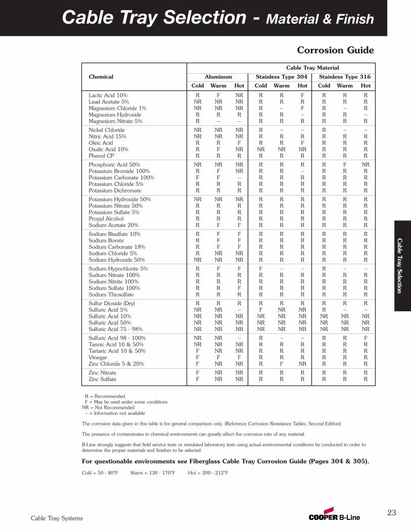
Lactic Acid 10% R F NR R R F R R RLead Acetate 5% NR NR NR R R R R R RMagnesium Chloride 1% NR NR NR R -- F R -- RMagnesium Hydroxide R R R R R -- R R --Magnesium Nitrate 5% R -- -- R R R R R R
Nickel Chloride NR NR NR R -- -- R -- --Nitric Acid 15% NR NR NR R R R R R ROleic Acid R R F R R F R R ROxalic Acid 10% R F NR NR NR NR R R RPhenol CP R R R R R R R R R
Phosphoric Acid 50% NR NR NR R R R R F NRPotassium Bromide 100% R F NR R R -- R R RPotassium Carbonate 100% F F -- R R R R R RPotassium Chloride 5% R R R R R R R R RPotassium Dichromate R R R R R R R R R
Potassium Hydroxide 50% NR NR NR R R R R R RPotassium Nitrate 50% R R R R R R R R RPotassium Sulfate 5% R R R R R R R R RPropyl Alcohol R R R R R R R R RSodium Acetate 20% R F F R R R R R R
Sodium Bisulfate 10% R F F R R R R R RSodium Borate R F F R R R R R RSodium Carbonate 18% R F F R R R R R RSodium Chloride 5% R NR NR R R R R R RSodium Hydroxide 50% NR NR NR R R R R R R
Sodium Hypochlorite 5% R F F F -- -- R -- --Sodium Nitrate 100% R R R R R R R R RSodium Nitrite 100% R R R R R R R R RSodium Sulfate 100% R R F R R R R R RSodium Thiosulfate R R R R R R R R R
Sulfur Dioxide (Dry) R R R R R R R R RSulfuric Acid 5% NR NR -- F NR NR R -- --Sulfuric Acid 10% NR NR NR NR NR NR NR NR NRSulfuric Acid 50% NR NR NR NR NR NR NR NR NRSulfuric Acid 75 - 98% NR NR NR NR NR NR NR NR NR
Sulfuric Acid 98 - 100% NR NR -- R -- -- R R FTannic Acid 10 & 50% NR NR NR R R R R R RTartaric Acid 10 & 50% F NR NR R R R R R RVinegar F F F R R R R R RZinc Chloride 5 & 20% F NR NR R F NR R R R
Zinc Nitrate F NR NR R R R R R RZinc Sulfate F NR NR R R R R R R
R = RecommendedF = May be used under some conditions
NR = Not Recommended-- = Information not available
The corrosion data given in this table is for general comparison only. (Reference Corrosion Resistance Tables, Second Edition)
The presence of contaminates in chemical environments can greatly affect the corrosion rate of any material.
B-Line strongly suggests that field service tests or simulated laboratory tests using actual environmental conditions be conducted in order to determine the proper materials and finishes to be selected.
For questionable environments see Fiberglass Cable Tray Corrosion Guide (Pages 304 & 305).
Cold = 50 - 80°F Warm = 130 - 170°F Hot = 200 - 212°F
23
Corrosion Guide
Cable Tray Selection
Cable Tray Systems

Maximum Spacing Between Expansion Joints For 1" Movement
Temperature Stainless SteelDifferential Steel Aluminum 304 316˚F ˚C Feet m Feet m Feet m Feet m25 13.9 512 156.0 260 79.2 347 105.7 379 115.5
50 27.8 256 78.0 130 39.6 174 53.0 189 57.6
75 41.7 171 52.1 87 26.5 116 35.4 126 38.4
100 55.6 128 39.0 65 19.8 87 26.5 95 29.0
125 69.4 102 31.1 52 15.8 69 21.0 76 23.2
150 83.3 85 25.9 43 13.1 58 17.7 63 19.2
175 97.2 73 22.2 37 11.3 50 15.2 54 16.4
Note: every pair of expansion splice plates requires two bonding jumpers for grounding continuity.
Cable Tray Selection - Material & Finish
1
2
3
4
It is important that thermalcontraction and expansion beconsidered when installing cable traysystems. The length of the straightcable tray runs and the temperaturedifferential govern the number ofexpansion splice plates required (seeTable 2 below).
The cable tray should be anchored atthe support nearest to its midpointbetween the expansion splice plates andsecured by expansion guides at all othersupport locations (see Figure 1).The cable tray should be permittedlongitudinal movement in bothdirections from that fixed point. Whenused, covers should be overlapped atexpansion splices.
Accurate gap settings at the time ofinstallation are necessary for the properoperation of the expansion spliceplates. The following procedure shouldassist the installer in determining thecorrect gap: (see Figure 2)
Plot the highest expected metaltemperature on the maximumtemperature line.
Plot the lowest expected metaltemperature on the minimumtemperature line.
Draw a line between the maximumand minimum points.
Plot the metal temperature at thetime of installation to determinethe gap setting.
Refer to page 309 for thermalcontraction and expansion offiberglass cable trays.
Thermal Contraction and Expansion
C° F° F° C°
Maximum MinimumTemperature Temperature
130
70
50
30
10
-10
-30
90
110
130
110
90
70
50
30
10
-10
-30
50
40
30
20
10
0
-10
-20
-30
-40
50
40
30
20
10
0
-10
-20
-30
-40
1/8
(3.2)1/4
(6.3)3/8
(9.5)1/2
(12.7)5/8
(15.9)3/4
(19.0)7/8
(22.2)
0(0.0)
1(25.4)
GAP SETTING Inches (mm)
Met
al T
empe
ratu
re A
t T
ime
Of
Inst
alla
tion
X -- -- -- -- X -- -- -- -- X
X -- -- -- -- X -- -- -- -- X
X :Denotes hold-down clamp (anchor) at support.
_ : Denotes expansion guide clamp at support.
Expansion Splice Plates(Bonding Jumpers Required
On Each Side of Tray)
Figure 2
Table 2
Figure 1
1
2
3
4
Typical Cable Tray Installation
24Cable Tray Systems
Cab
le T
ray
Sele
ctio
n
WeightThe weight of an aluminum cable tray is approximately half that of a comparable steel tray. Some factors to consider
include: shipping costs, material, handling, project weight restrictions and the strength of support members.
Field ModificationsAluminum cable tray is easier to cut and drill than steel cable tray since it is a “softer” material. Similarly, galvanized
steel cable tray is easier to cut and drill than stainless steel cable tray. Cooper B-Line aluminum cable tray uses a fourbolt splice, resulting in half as much drilling and hardware installation as most steel cable tray, which uses an eight boltsplice. Hot dip galvanized and painted steel cable tray finishes must be repaired when field cutting or drilling. Failure torepair coatings will impair the cable tray’s corrosion resistance.
AvailabilityAluminum, pre-galvanized, stainless steel and fiberglass cable tray can normally be shipped from the factory in a
short period of time. Hot dip galvanized and painted cable tray requires an additional coating process, adding severaldays of preparation before final shipment. Typically, a coated cable tray will be sent to an outside source for coating,requiring additional packing and shipping.
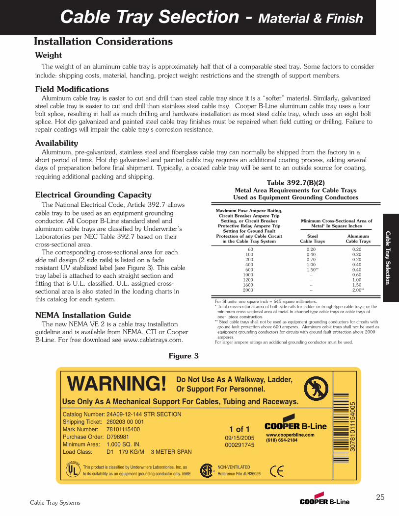
Electrical Grounding CapacityThe National Electrical Code, Article 392.7 allows
cable tray to be used as an equipment groundingconductor. All Cooper B-Line standard steel andaluminum cable trays are classified by Underwriter’sLaboratories per NEC Table 392.7 based on theircross-sectional area.
The corresponding cross-sectional area for eachside rail design (2 side rails) is listed on a faderesistant UV stabilized label (see Figure 3). This cabletray label is attached to each straight section andfitting that is U.L. classified. U.L. assigned cross-sectional area is also stated in the loading charts inthis catalog for each system.
NEMA Installation GuideThe new NEMA VE 2 is a cable tray installation
guideline and is available from NEMA, CTI or CooperB-Line. For free download see www.cabletrays.com.
25
Cable Tray Selection - Material & Finish
Table 392.7(B)(2)Metal Area Requirements for Cable TraysUsed as Equipment Grounding Conductors
Maximum Fuse Ampere Rating,Circuit Breaker Ampere TripSetting, or Circuit Breaker Minimum Cross-Sectional Area of
Protective Relay Ampere Trip Metal* In Square InchesSetting for Ground Fault
Protection of any Cable Circuit Steel Aluminumin the Cable Tray System Cable Trays Cable Trays
60 0.20 0.20100 0.40 0.20200 0.70 0.20400 1.00 0.40600 1.50** 0.40
1000 -- 0.601200 -- 1.001600 -- 1.502000 -- 2.00**
For SI units: one square inch = 645 square millimeters.* Total cross-sectional area of both side rails for ladder or trough-type cable trays; or the
minimum cross-sectional area of metal in channel-type cable trays or cable trays of one- piece construction.
** Steel cable trays shall not be used as equipment grounding conductors for circuits with ground-fault protection above 600 amperes. Aluminum cable trays shall not be used asequipment grounding conductors for circuits with ground-fault protection above 2000amperes.
For larger ampere ratings an additional grounding conductor must be used.
Installation Considerations
Figure 3
CLASSIFIED
®
Use Only As A Mechanical Support For Cables, Tubing and Raceways.
Do Not Use As A Walkway, Ladder,Or Support For Personnel.
www.cooperbline.com(618) 654-2184
Catalog Number: 24A09-12-144 STR SECTIONShipping Ticket: 260203 00 001Mark Number: 78101115400Purchase Order: D798981Minimum Area: 1.000 SQ. IN.Load Class: D1 179 KG/M 3 METER SPAN 30
7810
1115
4005
1 of 109/15/2005000291745
Cable Tray Systems
Cable Tray Selection
WARNING!
This product is classified by Underwriters Laboratories, Inc. asto its suitability as an equipment grounding conductor only. 556E
NON-VENTILATEDReference File #LR36026
Cable Tray Selection - Strength
26Cable Tray Systems
Cab
le T
ray
Sele
ctio
n
Wind LoadsWind loads need to be determined for all outdoor
cable tray installations. Most outdoor cable trays areladder type trays, therefore the most severe loading tobe considered is impact pressure normal to the cabletray side rails (see detail 1).
The impact pressure corresponding to several windvelocities are given below in Table 1.
Table 1Impact Pressures
V(mph) P(lbs/ft2) V(mph) P(lbs/ft2)
15 0.58 85 18.520 1.02 90 20.725 1.60 95 23.130 2.30 100 25.635 3.13 105 28.240 4.09 110 30.945 5.18 115 33.850 6.39 120 36.855 7.73 125 40.060 9.21 130 43.365 10.80 135 46.670 12.50 140 50.175 14.40 145 53.880 16.40 150 57.6
V= Wind VelocityP= Impact Pressure
Note: These values are for an air density of 0.07651 lbs/ft3corresponding to a temperature of 60˚ F and barometricpressure of 14.7 lbs/in2.
Example Calculation:Side load for 6" side rail with 100 mph wind
25.6 x 6 = 12.8 lbs/ft12
When covers are installed on outdoor cable trays,another factor to be considered is the aerodynamiceffect which can produce a lift strong enough to
separate a cover from a tray. Wind moving across acovered tray (see detail 2) creates a positive pressureinside the tray and a negative pressure above thecover. This pressure difference can lift the cover offthe tray.
B-Line recommends the use of heavy duty wrap-around cover clamps when covered trays are installedin an area where strong winds occur.
Special Notice:Covers on wide cable tray and/or cable tray installed atelevations high off the ground may require additionalheavy duty clamps or thicker cover material.
Ice LoadsGlaze ice is the most commonly seen form of ice
build-up. It is the result of rain or drizzle freezing onimpact with an exposed object. Generally, only thetop surface (or the cover) and the windward side of acable tray system is significantly coated with ice. Themaximum design load to be added due to ice shouldbe calculated as follows:
LI = (W x TI ) x DI where;144
LI= Ice Load (lbs/linear foot)W= Cable Tray Width (inches)TI= Maximum Ice Thickness (inches)DI= Ice Density = 57 lbs/ft3the maximum ice thickness will vary depending onlocation. A thickness of 1/2" can be used as aconservative standard.
Example Calculation:Ice Loads for 24" wide tray with 1/2" thick ice;
24 x .5 x 57 = 4.75 lbs/ft144
Detail 1
Detail 2
Environmental Loads
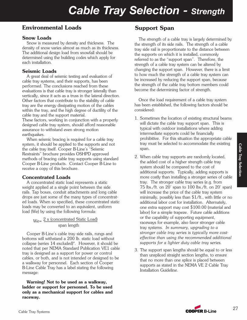
Cable Tray Selection - Strength
27Cable Tray Systems
Cable Tray Selection
Environmental Loads
Snow LoadsSnow is measured by density and thickness. The
density of snow varies almost as much as its thickness.The additional design load from snowfall should bedetermined using the building codes which apply foreach installation.
Seismic LoadsA great deal of seismic testing and evaluation of
cable tray systems, and their supports, has beenperformed. The conclusions reached from theseevaluations is that cable tray is stronger laterally thanvertically, since it acts as a truss in the lateral direction.Other factors that contribute to the stability of cabletray are the energy dissipating motion of the cableswithin the tray, and the high degree of ductility of thecable tray and the support material. These factors, working in conjunction with a properlydesigned cable tray system, should afford reasonableassurance to withstand even strong motionearthquakes.
When seismic bracing is required for a cable traysystem, it should be applied to the supports and notthe cable tray itself. Cooper B-Line’s “SeismicRestraints” brochure provides OSHPD approvedmethods of bracing cable tray supports using standardCooper B-Line products. Contact Cooper B-Line toreceive a copy of this brochure.
Concentrated LoadsA concentrated static load represents a static
weight applied at a single point between the siderails. Tap boxes, conduit attachments and long cabledrops are just some of the many types of concentrat-ed loads. When so specified, these concentrated staticloads may be converted to an equivalent, uniformload (We) by using the following formula:
We= 2 x (concentrated Static Load)span length
Cooper B-Line’s cable tray side rails, rungs andbottoms will withstand a 200 lb. static load withoutcollapse (series 14 excluded)*. However, it should benoted that per NEMA Standard Publication VE1 cabletray is designed as a support for power or controlcables, or both, and is not intended or designed to bea walkway for personnel. Each section of CooperB-Line Cable Tray has a label stating the followingmessage:
Warning! Not to be used as a walkway,ladder or support for personnel. To be usedonly as a mechanical support for cables andraceway.
Support Span
The strength of a cable tray is largely determined bythe strength of its side rails. The strength of a cabletray side rail is proportionate to the distance betweenthe supports on which it is installed, commonlyreferred to as the “support span”. Therefore, thestrength of a cable tray system can be altered bychanging the support span. However, there is a limitto how much the strength of a cable tray system canbe increased by reducing the support span, becausethe strength of the cable tray bottom members couldbecome the determining factor of strength.
Once the load requirement of a cable tray systemhas been established, the following factors should beconsidered:
1. Sometimes the location of existing structural beamswill dictate the cable tray support span. This istypical with outdoor installations where addingintermediate supports could be financiallyprohibitive. For this situation the appropriate cabletray must be selected to accommodate the existingspan.
2. When cable tray supports are randomly located,the added cost of a higher strength cable traysystem should be compared to the cost ofadditional supports. Typically, adding supports ismore costly than installing a stronger series of cabletray. The stronger cable tray series (e.g. from75 lbs./ft. on 20’ span to 100 lbs./ft. on 20’ span)will increase the price of the cable tray systemminimally, possibly less than $1/ft., with little or noadditional labor cost for installation. Alternately,one extra support may cost $100.00 (material andlabor) for a simple trapeze. Future cable additionsor the capability of supporting equipment,raceways for example, also favor stronger cabletray systems. In summary, upgrading to astronger cable tray series is typically more cost-effective than using the recommended additionalsupports for a lighter duty cable tray series.
3. The support span lengths should be equal to or lessthan unspliced straight section lengths, to ensurethat no more than one splice is placed betweensupports as stated in the NEMA VE 2 Cable TrayInstallation Guideline.
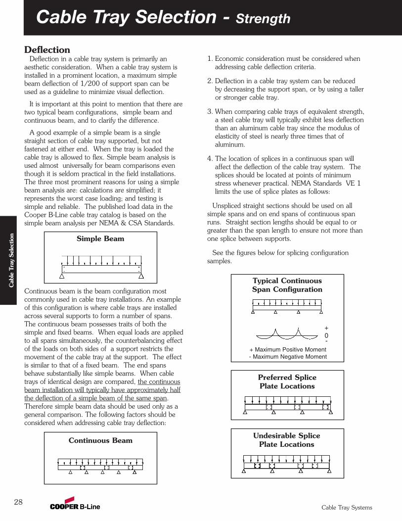
Cable Tray Selection - Strength
28Cable Tray Systems
Cab
le T
ray
Sele
ctio
n
DeflectionDeflection in a cable tray system is primarily an
aesthetic consideration. When a cable tray system isinstalled in a prominent location, a maximum simplebeam deflection of 1/200 of support span can beused as a guideline to minimize visual deflection.
It is important at this point to mention that there aretwo typical beam configurations, simple beam andcontinuous beam, and to clarify the difference.
A good example of a simple beam is a singlestraight section of cable tray supported, but notfastened at either end. When the tray is loaded thecable tray is allowed to flex. Simple beam analysis isused almost universally for beam comparisons eventhough it is seldom practical in the field installations.The three most prominent reasons for using a simplebeam analysis are: calculations are simplified; itrepresents the worst case loading; and testing issimple and reliable. The published load data in theCooper B-Line cable tray catalog is based on thesimple beam analysis per NEMA & CSA Standards.
Continuous beam is the beam configuration mostcommonly used in cable tray installations. An exampleof this configuration is where cable trays are installedacross several supports to form a number of spans.The continuous beam possesses traits of both thesimple and fixed beams. When equal loads are appliedto all spans simultaneously, the counterbalancing effectof the loads on both sides of a support restricts themovement of the cable tray at the support. The effectis similar to that of a fixed beam. The end spansbehave substantially like simple beams. When cabletrays of identical design are compared, the continuousbeam installation will typically have approximately halfthe deflection of a simple beam of the same span.Therefore simple beam data should be used only as ageneral comparison. The following factors should beconsidered when addressing cable tray deflection:
1. Economic consideration must be considered whenaddressing cable deflection criteria.
2. Deflection in a cable tray system can be reducedby decreasing the support span, or by using a talleror stronger cable tray.
3. When comparing cable trays of equivalent strength,a steel cable tray will typically exhibit less deflectionthan an aluminum cable tray since the modulus ofelasticity of steel is nearly three times that ofaluminum.
4. The location of splices in a continuous span willaffect the deflection of the cable tray system. Thesplices should be located at points of minimumstress whenever practical. NEMA Standards VE 1 limits the use of splice plates as follows:
Unspliced straight sections should be used on allsimple spans and on end spans of continuous spanruns. Straight section lengths should be equal to orgreater than the span length to ensure not more thanone splice between supports.
See the figures below for splicing configurationsamples.
Simple Beam
Continuous Beam
Typical ContinuousSpan Configuration
Preferred SplicePlate Locations
Undesirable Splice Plate Locations
+ Maximum Positive Moment- Maximum Negative Moment
+0-
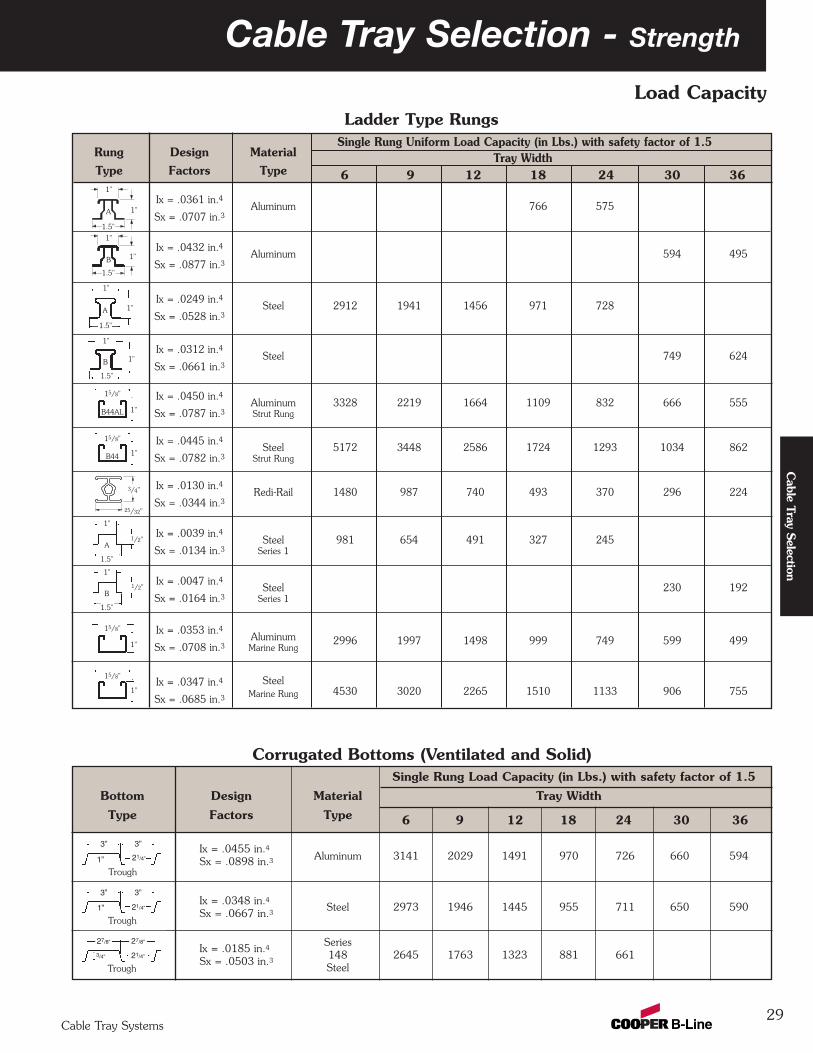
Cable Tray Selection - Strength
29Cable Tray Systems
Cable Tray Selection
Single Rung Uniform Load Capacity (in Lbs.) with safety factor of 1.5Rung Design MaterialType Factors Type
Ix = .0361 in.4Aluminum 766 575
Sx = .0707 in.3
Ix = .0432 in.4Aluminum 594 495
Sx = .0877 in.3
Ix = .0249 in.4Steel 2912 1941 1456 971 728
Sx = .0528 in.3
Ix = .0312 in.4Steel 749 624
Sx = .0661 in.3
Ix = .0450 in.4Aluminum 3328 2219 1664 1109 832 666 555
Sx = .0787 in.3 Strut Rung
Ix = .0445 in.4Steel 5172 3448 2586 1724 1293 1034 862
Sx = .0782 in.3 Strut Rung
Ix = .0130 in.4Redi-Rail 1480 987 740 493 370 296 224
Sx = .0344 in.3
Ix = .0039 in.4Steel 981 654 491 327 245
Sx = .0134 in.3 Series 1
Ix = .0047 in.4Steel 230 192
Sx = .0164 in.3 Series 1
Ix = .0353 in.4Aluminum
Sx = .0708 in.3 Marine Rung2996 1997 1498 999 749 599 499
Ix = .0347 in.4 Steel
Sx = .0685 in.3 Marine Rung 4530 3020 2265 1510 1133 906 755
Corrugated Bottoms (Ventilated and Solid)
Load Capacity
Ix = .0455 in.4Sx = .0898 in.3
Ix = .0348 in.4Sx = .0667 in.3
Ix = .0185 in.4Sx = .0503 in.3
1"
1"A
1"
1"
1"
1"A
1.5"
1.5"
1"B
1"
1/2"
1.5"
A
1"
1/2"
1.5"
B
1"
15/8"
B44AL
1"
15/8"
B44
Ladder Type Rungs
6 9 12 18 24 30 36Tray Width
6 9 12 18 24 30 36
Single Rung Load Capacity (in Lbs.) with safety factor of 1.5Bottom Design Material Tray WidthType Factors Type
Aluminum 3141 2029 1491 970 726 660 594
Steel 2973 1946 1445 955 711 650 590
Series148 2645 1763 1323 881 661Steel
3” 3”
1” 21/4”
Trough
3” 3”
1” 21/4”
Trough
27/8” 27/8”
3/4” 21/4”
Trough
1.5"
1.5"
B
1"
15/8"
1"
15/8"
1"
3/4"
25/32"

Cable Tray Selection - Strength
30Cable Tray Systems
Cab
le T
ray
Sele
ctio
n
Load CapacityCalculate each anticipated load factor, then add them to obtain a total load.
(Example: Working Load = Cable + Concentrated + Wind + Snow + Ice Loads).The Working Load should be used, along with the maximum support spacing, to select a span/loadclass designation from Table 3. Table 4 (page 31) contains the most common load/span classdesignations per the US and Canadian metallic cable tray standard, CSA, C22.2 No. 126.1-98 FirstAddition, NEMA VE 1-1998.
Class Designations for lengths of
lb/ft kg/m ft m ft m ft m ft m ft m8 (2.4) 10 (3.0) 12 (3.7) 16 (4.9) 20 (6.0)
25 37 –– A –– –– ––
45 67 –– –– –– –– D
50 74 8A –– 12A 16A 20A
65 97 –– C –– –– ––
75 112 8B –– 12B 16B E or 20B
100 149 8C –– 12C 16C 20C
120 179 –– D –– –– ––
200 299 –– E –– –– ––
LoadClass
Table 3 - These Loading Classes AreHistorical and Supplied For Reference Only
Note: 8A/B/C, 12A/B/C, 16A/B/C, and 20A/B/C were the traditional NEMA designations. A, C, D, and E were the conventional CSA designations.Actual tested loadings per span will be stated on the product labels.
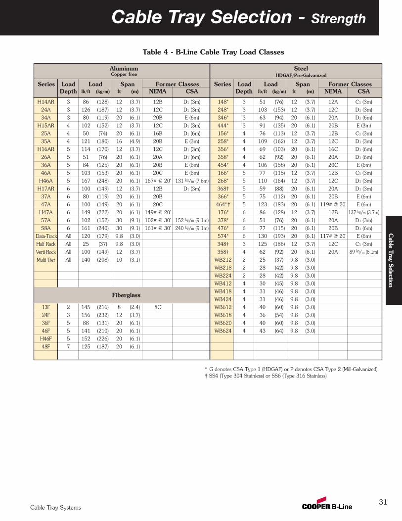
31
Cable Tray Selection - Strength
Cable Tray Systems
Cable Tray Selection
Table 4 - B-Line Cable Tray Load Classes
Aluminum SteelCopper free HDGAF/Pre-Galvanized
Series Load Load Span Former Classes Series Load Load Span Former ClassesDepth lb/ft (kg/m) ft (m) NEMA CSA Depth lb/ft (kg/m) ft (m) NEMA CSA
H14AR 3 86 (128) 12 (3.7) 12B D1 (3m) 148* 3 51 (76) 12 (3.7) 12A C1 (3m)
24A 3 126 (187) 12 (3.7) 12C D1 (3m) 248* 3 103 (153) 12 (3.7) 12C D1 (3m)
34A 3 80 (119) 20 (6.1) 20B E (6m) 346* 3 63 (94) 20 (6.1) 20A D1 (6m)
H15AR 4 102 (152) 12 (3.7) 12C D1 (3m) 444* 3 91 (135) 20 (6.1) 20B E (3m)
25A 4 50 (74) 20 (6.1) 16B D1 (6m) 156* 4 76 (113) 12 (3.7) 12B C1 (3m)
35A 4 121 (180) 16 (4.9) 20B E (3m) 258* 4 109 (162) 12 (3.7) 12C D1 (3m)
H16AR 5 114 (170) 12 (3.7) 12C D1 (3m) 356* 4 69 (103) 20 (6.1) 16C D1 (6m)
26A 5 51 (76) 20 (6.1) 20A D1 (6m) 358* 4 62 (92) 20 (6.1) 20A D1 (6m)
36A 5 84 (125) 20 (6.1) 20B E (6m) 454* 4 106 (158) 20 (6.1) 20C E (6m)
46A 5 103 (153) 20 (6.1) 20C E (6m) 166* 5 77 (115) 12 (3.7) 12B C1 (3m)
H46A 5 167 (248) 20 (6.1) 167# @ 20' 131 kg/m (7.6m) 268* 5 110 (164) 12 (3.7) 12C D1 (3m)
H17AR 6 100 (149) 12 (3.7) 12B D1 (3m) 368† 5 59 (88) 20 (6.1) 20A D1 (3m)
37A 6 80 (119) 20 (6.1) 20B 366* 5 75 (112) 20 (6.1) 20B E (6m)
47A 6 100 (149) 20 (6.1) 20C 464* † 5 123 (183) 20 (6.1) 119# @ 20' E (6m)
H47A 6 149 (222) 20 (6.1) 149# @ 20' 176* 6 86 (128) 12 (3.7) 12B 137 kg/m (3.7m)
57A 6 102 (152) 30 (9.1) 102# @ 30' 152 kg/m (9.1m) 378* 6 51 (76) 20 (6.1) 20A D1 (3m)
S8A 6 161 (240) 30 (9.1) 161# @ 30' 240 kg/m (9.1m) 476* 6 77 (115) 20 (6.1) 20B D1 (6m)
Data-Track All 120 (179) 9.8 (3.0) 574* 6 130 (193) 20 (6.1) 117# @ 20' E (6m)
Half Rack All 25 (37) 9.8 (3.0) 348† 3 125 (186) 12 (3.7) 12C C1 (3m)
Verti-Rack All 100 (149) 12 (3.7) 358† 4 62 (92) 20 (6.1) 20A 89 kg/m (6.1m)
Multi-Tier All 140 (208) 10 (3.1) WB212 2 25 (37) 9.8 (3.0)
WB218 2 28 (42) 9.8 (3.0)
WB224 2 28 (42) 9.8 (3.0)
WB412 4 30 (45) 9.8 (3.0)
WB418 4 31 (46) 9.8 (3.0)Fiberglass
WB424 4 31 (46) 9.8 (3.0)
13F 2 145 (216) 8 (2.4) 8C WB612 4 40 (60) 9.8 (3.0)
24F 3 156 (232) 12 (3.7) WB618 4 36 (54) 9.8 (3.0)
36F 5 88 (131) 20 (6.1) WB620 4 40 (60) 9.8 (3.0)
46F 5 141 (210) 20 (6.1) WB624 4 43 (64) 9.8 (3.0)
H46F 5 152 (226) 20 (6.1)
48F 7 125 (187) 20 (6.1)
* G denotes CSA Type 1 (HDGAF) or P denotes CSA Type 2 (Mill-Galvanized)† SS4 (Type 304 Stainless) or SS6 (Type 316 Stainless)
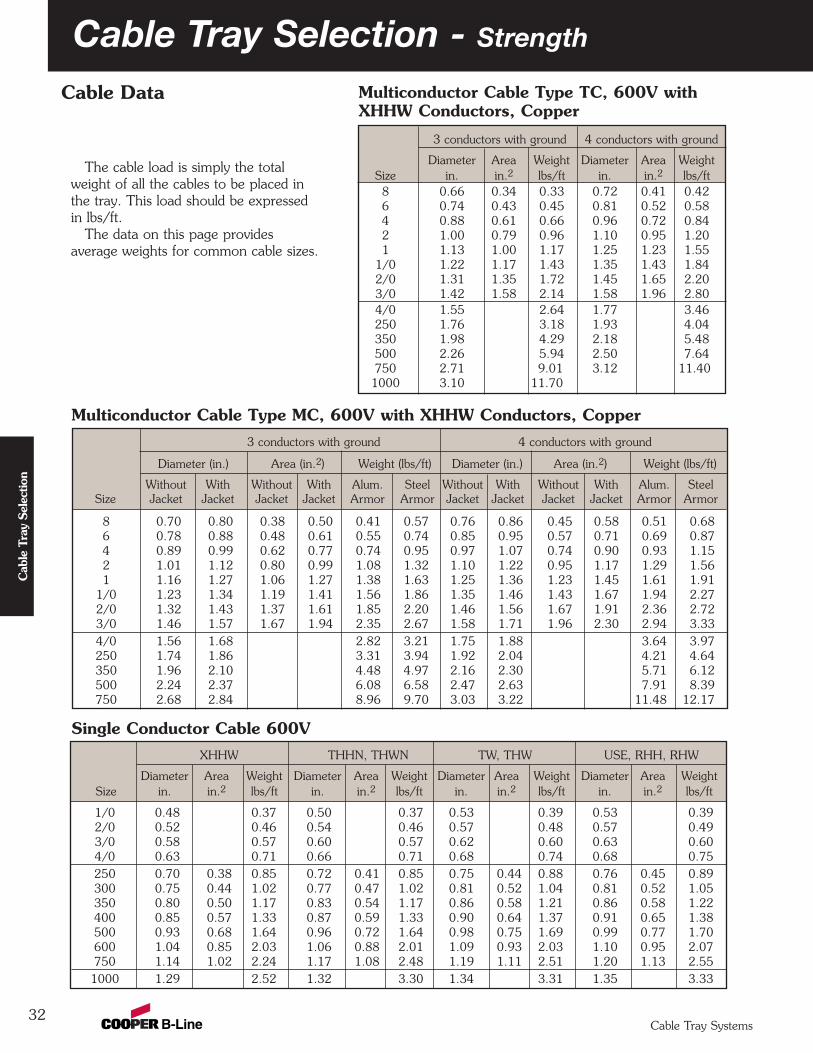
32Cable Tray Systems
Cab
le T
ray
Sele
ctio
n
Cable Tray Selection - Strength
3 conductors with ground 4 conductors with ground
Diameter Area Weight Diameter Area WeightSize in. in.2 lbs/ft in. in.2 lbs/ft8 0.66 0.34 0.33 0.72 0.41 0.426 0.74 0.43 0.45 0.81 0.52 0.584 0.88 0.61 0.66 0.96 0.72 0.842 1.00 0.79 0.96 1.10 0.95 1.201 1.13 1.00 1.17 1.25 1.23 1.55
1/0 1.22 1.17 1.43 1.35 1.43 1.842/0 1.31 1.35 1.72 1.45 1.65 2.203/0 1.42 1.58 2.14 1.58 1.96 2.804/0 1.55 2.64 1.77 3.46250 1.76 3.18 1.93 4.04350 1.98 4.29 2.18 5.48500 2.26 5.94 2.50 7.64750 2.71 9.01 3.12 11.401000 3.10 11.70
XHHW THHN, THWN TW, THW USE, RHH, RHW
Diameter Area Weight Diameter Area Weight Diameter Area Weight Diameter Area WeightSize in. in.2 lbs/ft in. in.2 lbs/ft in. in.2 lbs/ft in. in.2 lbs/ft
1/0 0.48 0.37 0.50 0.37 0.53 0.39 0.53 0.392/0 0.52 0.46 0.54 0.46 0.57 0.48 0.57 0.493/0 0.58 0.57 0.60 0.57 0.62 0.60 0.63 0.604/0 0.63 0.71 0.66 0.71 0.68 0.74 0.68 0.75250 0.70 0.38 0.85 0.72 0.41 0.85 0.75 0.44 0.88 0.76 0.45 0.89300 0.75 0.44 1.02 0.77 0.47 1.02 0.81 0.52 1.04 0.81 0.52 1.05350 0.80 0.50 1.17 0.83 0.54 1.17 0.86 0.58 1.21 0.86 0.58 1.22400 0.85 0.57 1.33 0.87 0.59 1.33 0.90 0.64 1.37 0.91 0.65 1.38500 0.93 0.68 1.64 0.96 0.72 1.64 0.98 0.75 1.69 0.99 0.77 1.70600 1.04 0.85 2.03 1.06 0.88 2.01 1.09 0.93 2.03 1.10 0.95 2.07750 1.14 1.02 2.24 1.17 1.08 2.48 1.19 1.11 2.51 1.20 1.13 2.551000 1.29 2.52 1.32 3.30 1.34 3.31 1.35 3.33
3 conductors with ground 4 conductors with ground
Diameter (in.) Area (in.2) Weight (lbs/ft) Diameter (in.) Area (in.2) Weight (lbs/ft)
Without With Without With Alum. Steel Without With Without With Alum. SteelSize Jacket Jacket Jacket Jacket Armor Armor Jacket Jacket Jacket Jacket Armor Armor
8 0.70 0.80 0.38 0.50 0.41 0.57 0.76 0.86 0.45 0.58 0.51 0.686 0.78 0.88 0.48 0.61 0.55 0.74 0.85 0.95 0.57 0.71 0.69 0.874 0.89 0.99 0.62 0.77 0.74 0.95 0.97 1.07 0.74 0.90 0.93 1.152 1.01 1.12 0.80 0.99 1.08 1.32 1.10 1.22 0.95 1.17 1.29 1.561 1.16 1.27 1.06 1.27 1.38 1.63 1.25 1.36 1.23 1.45 1.61 1.91
1/0 1.23 1.34 1.19 1.41 1.56 1.86 1.35 1.46 1.43 1.67 1.94 2.272/0 1.32 1.43 1.37 1.61 1.85 2.20 1.46 1.56 1.67 1.91 2.36 2.723/0 1.46 1.57 1.67 1.94 2.35 2.67 1.58 1.71 1.96 2.30 2.94 3.334/0 1.56 1.68 2.82 3.21 1.75 1.88 3.64 3.97250 1.74 1.86 3.31 3.94 1.92 2.04 4.21 4.64350 1.96 2.10 4.48 4.97 2.16 2.30 5.71 6.12500 2.24 2.37 6.08 6.58 2.47 2.63 7.91 8.39750 2.68 2.84 8.96 9.70 3.03 3.22 11.48 12.17
Multiconductor Cable Type MC, 600V with XHHW Conductors, Copper
Single Conductor Cable 600V
The cable load is simply the totalweight of all the cables to be placed inthe tray. This load should be expressedin lbs/ft.
The data on this page providesaverage weights for common cable sizes.
Cable Data Multiconductor Cable Type TC, 600V withXHHW Conductors, Copper
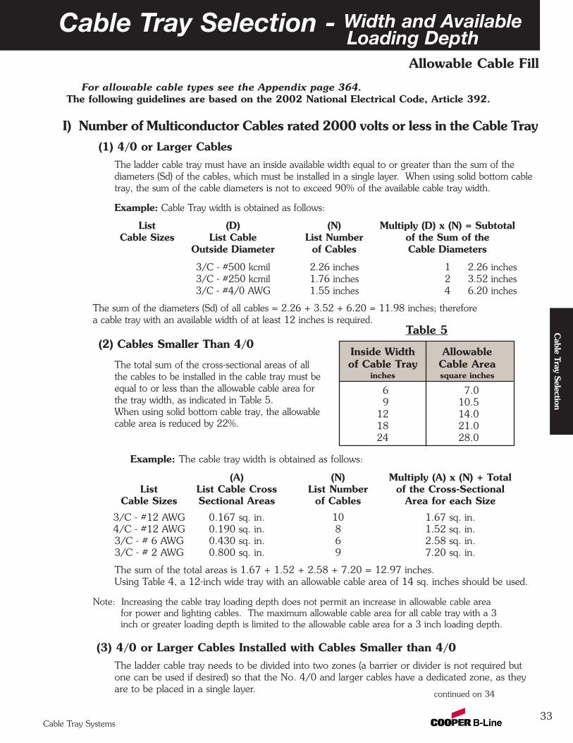
33
Cable Tray Selection - Width and AvailableLoading Depth
Cable Tray Systems
Cable Tray Selection
Allowable Cable Fill
For allowable cable types see the Appendix page 364.The following guidelines are based on the 2002 National Electrical Code, Article 392.
I) Number of Multiconductor Cables rated 2000 volts or less in the Cable Tray (1) 4/0 or Larger Cables
The ladder cable tray must have an inside available width equal to or greater than the sum of thediameters (Sd) of the cables, which must be installed in a single layer. When using solid bottom cabletray, the sum of the cable diameters is not to exceed 90% of the available cable tray width.
Example: Cable Tray width is obtained as follows:
List (D) (N) Multiply (D) x (N) = SubtotalCable Sizes List Cable List Number of the Sum of the
Outside Diameter of Cables Cable Diameters
3/C - #500 kcmil 2.26 inches 1 2.26 inches3/C - #250 kcmil 1.76 inches 2 3.52 inches3/C - #4/0 AWG 1.55 inches 4 6.20 inches
The sum of the diameters (Sd) of all cables = 2.26 + 3.52 + 6.20 = 11.98 inches; therefore a cable tray with an available width of at least 12 inches is required.
(2) Cables Smaller Than 4/0
The total sum of the cross-sectional areas of allthe cables to be installed in the cable tray must beequal to or less than the allowable cable area forthe tray width, as indicated in Table 5.When using solid bottom cable tray, the allowablecable area is reduced by 22%.
Example: The cable tray width is obtained as follows:
(A) (N) Multiply (A) x (N) + TotalList List Cable Cross List Number of the Cross-Sectional
Cable Sizes Sectional Areas of Cables Area for each Size
3/C - #12 AWG 0.167 sq. in. 10 1.67 sq. in.4/C - #12 AWG 0.190 sq. in. 8 1.52 sq. in.3/C - # 6 AWG 0.430 sq. in. 6 2.58 sq. in.3/C - # 2 AWG 0.800 sq. in. 9 7.20 sq. in.
The sum of the total areas is 1.67 + 1.52 + 2.58 + 7.20 = 12.97 inches. Using Table 4, a 12-inch wide tray with an allowable cable area of 14 sq. inches should be used.
Note: Increasing the cable tray loading depth does not permit an increase in allowable cable areafor power and lighting cables. The maximum allowable cable area for all cable tray with a 3inch or greater loading depth is limited to the allowable cable area for a 3 inch loading depth.
(3) 4/0 or Larger Cables Installed with Cables Smaller than 4/0The ladder cable tray needs to be divided into two zones (a barrier or divider is not required butone can be used if desired) so that the No. 4/0 and larger cables have a dedicated zone, as theyare to be placed in a single layer. continued on 34
Inside Width Allowableof Cable Tray Cable Area
inches square inches
6 7.09 10.5
12 14.018 21.024 28.0
Table 5
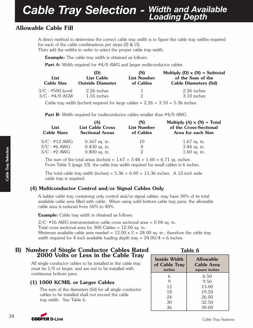
34
Allowable Cable Fill
Cable Tray Selection - Width and AvailableLoading Depth
Cable Tray Systems
Cab
le T
ray
Sele
ctio
n
A direct method to determine the correct cable tray width is to figure the cable tray widths requiredfor each of the cable combinations per steps (2) & (3).Then add the widths in order to select the proper cable tray width.
Example: The cable tray width is obtained as follows:
Part A- Width required for #4/0 AWG and larger multiconductor cables
(D) (N) Multiply (D) x (N) = SubtotalList List Cable List Number of the Sum of the
Cable Size Outside Diameter of Cables Cable Diameters (Sd)
3/C - #500 kcmil 2.26 inches 1 2.26 inches3/C - #4/0 AGW 1.55 inches 2 3.10 inches
Cable tray width (inches) required for large cables = 2.26 + 3.10 = 5.36 inches.
Part B- Width required for multiconductor cables smaller than #4/0 AWG
(A) (N) Multiply (A) x (N) = TotalList List Cable Cross List Number of the Cross-Sectional
Cable Sizes Sectional Areas of Cables Area for each Size
3/C - #12 AWG 0.167 sq. in. 10 1.67 sq. in.3/C - #6 AWG 0.430 sq. in. 8 3.44 sq. in.3/C - #2 AWG 0.800 sq. in. 2 1.60 sq. in.
The sum of the total areas (inches) = 1.67 + 3.44 + 1.60 = 6.71 sq. inches.From Table 5 (page 33), the cable tray width required for small cables is 6 inches.
The total cable tray width (inches) = 5.36 + 6.00 = 11.36 inches. A 12-inch wide cable tray is required.
(4) Multiconductor Control and/or Signal Cables OnlyA ladder cable tray containing only control and/or signal cables, may have 50% of its totalavailable cable area filled with cable. When using solid bottom cable tray pans, the allowablecable area is reduced from 50% to 40%.
Example: Cable tray width is obtained as follows:
2/C- #16 AWG instrumentation cable cross sectional area = 0.04 sq. in.Total cross sectional area for 300 Cables = 12.00 sq. in.Minimum available cable area needed = 12.00 x 2 = 24.00 sq. in.; therefore the cable traywidth required for 4 inch available loading depth tray = 24.00/4 = 6 inches.
II) Number of Single Conductor Cables Rated2000 Volts or Less in the Cable Tray
All single conductor cables to be installed in the cable traymust be 1/0 or larger, and are not to be installed withcontinuous bottom pans.
(1) 1000 KCMIL or Larger CablesThe sum of the diameters (Sd) for all single conductorcables to be installed shall not exceed the cabletray width. See Table 6.
Inside Width Allowableof Cable Tray Cable Area
inches square inches
6 6.509 9.5012 13.0018 19.5024 26.0030 32.5036 39.00
Table 6
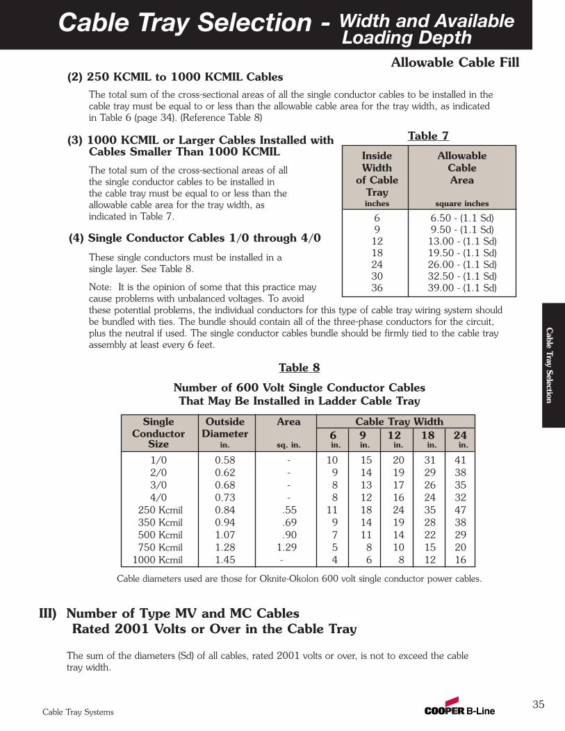
35
Allowable Cable Fill
Cable Tray Selection - Width and AvailableLoading Depth
Cable Tray Systems
Cable Tray Selection
(2) 250 KCMIL to 1000 KCMIL CablesThe total sum of the cross-sectional areas of all the single conductor cables to be installed in thecable tray must be equal to or less than the allowable cable area for the tray width, as indicatedin Table 6 (page 34). (Reference Table 8)
(3) 1000 KCMIL or Larger Cables Installed withCables Smaller Than 1000 KCMIL
The total sum of the cross-sectional areas of allthe single conductor cables to be installed inthe cable tray must be equal to or less than theallowable cable area for the tray width, asindicated in Table 7.
(4) Single Conductor Cables 1/0 through 4/0
These single conductors must be installed in asingle layer. See Table 8.
Note: It is the opinion of some that this practice maycause problems with unbalanced voltages. To avoidthese potential problems, the individual conductors for this type of cable tray wiring system shouldbe bundled with ties. The bundle should contain all of the three-phase conductors for the circuit,plus the neutral if used. The single conductor cables bundle should be firmly tied to the cable trayassembly at least every 6 feet.
Table 8
Number of 600 Volt Single Conductor Cables That May Be Installed in Ladder Cable Tray
Cable diameters used are those for Oknite-Okolon 600 volt single conductor power cables.
III) Number of Type MV and MC CablesRated 2001 Volts or Over in the Cable Tray
The sum of the diameters (Sd) of all cables, rated 2001 volts or over, is not to exceed the cabletray width.
Inside AllowableWidth Cable
of Cable AreaTrayinches square inches
6 6.50 - (1.1 Sd)9 9.50 - (1.1 Sd)12 13.00 - (1.1 Sd)18 19.50 - (1.1 Sd)24 26.00 - (1.1 Sd)30 32.50 - (1.1 Sd)36 39.00 - (1.1 Sd)
Table 7
Single Outside Area Cable Tray WidthConductor Diameter 6 9 12 18 24
Size in. sq. in. in. in. in. in. in.
1/0 0.58 - 10 15 20 31 412/0 0.62 - 9 14 19 29 383/0 0.68 - 8 13 17 26 354/0 0.73 - 8 12 16 24 32
250 Kcmil 0.84 .55 11 18 24 35 47350 Kcmil 0.94 .69 9 14 19 28 38500 Kcmil 1.07 .90 7 11 14 22 29750 Kcmil 1.28 1.29 5 8 10 15 20
1000 Kcmil 1.45 - 4 6 8 12 16

.
36
Sizing Cable Tray Per 2002 NEC 392
Cable Tray Selection - Width and AvailableLoading Depth
392.12W ≥ Sd
(single layer)
392.3(B)(1)Not recognizedby the NEC®
SeeException
392.11(B)(3)
392.10(B)W ≥ Sd
392.10(A)(1)W ≥ Sd
392.10(A)(2)W ≥ A/1.1
Note: The value “A”only applies to cables250 up to 1000 kcmil.The value “Sd” onlyapplies to 1000 kcmiland larger cables.
Note: Use when mixing250 thru 1000 kcmilcables with cables largerthan 1000 kcmil.
392.10(A)(3)
392.10(A)(4)W ≥ Sd
(9” max. RS)
2000Vor lesscables
Multi-conductor
cables
S/C 1/0or larger
Ladderor VentedTroughTray
S/C1000
kcmil orlarger
S/C250
kcmil upto 1000
kcmil
S/C250 kcmil
andlarger
S/C 1/0thru 4/0
VentedChannel
Tray
SolidBottom
Tray
W ≥ A/1.1 +Sd
No
No
No
No
No No No
No
Yes
Yes
Yes
Yes
YesYes Yes
Yes
Yes
Continuedon following
page
Yes
Legend
W = Cable Tray WidthD = Cable Tray Load DepthSd = Sum of Cable DiametersA = Sum of Cable AreasS/C = Single ConductorM/C = Multiconductor CablesRS = Ladder Rung Spacing
StartHere
Cable Tray Systems
Cab
le T
ray
Sele
ctio
n
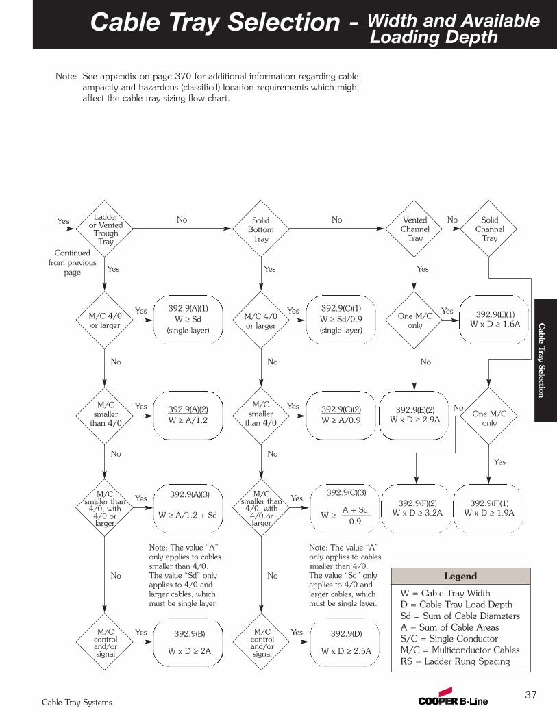
37
Note: See appendix on page 370 for additional information regarding cable ampacity and hazardous (classified) location requirements which might affect the cable tray sizing flow chart.
Cable Tray Selection - Width and AvailableLoading Depth
392.9(E)(1)W x D ≥ 1.6A
392.9(A)(1)W ≥ Sd
(single layer)
392.9(C)(1)W ≥ Sd/0.9(single layer)
Note: The value “A”only applies to cablessmaller than 4/0.The value “Sd” onlyapplies to 4/0 andlarger cables, whichmust be single layer.
Note: The value “A”only applies to cablessmaller than 4/0.The value “Sd” onlyapplies to 4/0 andlarger cables, whichmust be single layer.
392.9(A)(3)
VentedChannel
Tray
SolidChannel
Tray
SolidBottom
Tray
Ladderor VentedTroughTray
One M/C only
M/C 4/0or larger
M/C 4/0or larger
392.9(E)(2)W x D ≥ 2.9A
392.9(F)(1)W x D ≥ 1.9A
392.9(A)(2)W ≥ A/1.2
392.9(C)(2)W ≥ A/0.9
M/C smaller
than 4/0
M/Csmaller
than 4/0
M/Csmaller than4/0, with4/0 orlarger
M/Ccontroland/orsignal
W ≥ A/1.2 + Sd
No NoNo
NoNo
NoNo
No No No
392.9(B)
W x D ≥ 2A
392.9(C)(3)
A + Sd
0.9
M/Csmaller than4/0, with4/0 orlarger
M/Ccontroland/orsignal
W ≥
392.9(D)
W x D ≥ 2.5A
YesYes
YesYes
YesYes
YesYes
Yes
Yes Yes Yes
Yes
Legend
W = Cable Tray WidthD = Cable Tray Load DepthSd = Sum of Cable DiametersA = Sum of Cable AreasS/C = Single ConductorM/C = Multiconductor CablesRS = Ladder Rung Spacing
One M/Conly
No
392.9(F)(2)W x D ≥ 3.2A
Yes
Continuedfrom previous
page
Cable Tray Systems
Cable Tray Selection
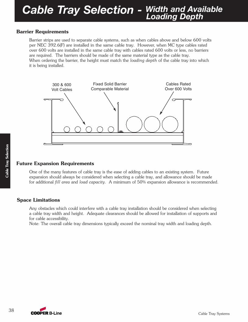
38
Barrier Requirements
Barrier strips are used to separate cable systems, such as when cables above and below 600 voltsper NEC 392.6(F) are installed in the same cable tray. However, when MC type cables ratedover 600 volts are installed in the same cable tray with cables rated 600 volts or less, no barriersare required. The barriers should be made of the same material type as the cable tray.When ordering the barrier, the height must match the loading depth of the cable tray into whichit is being installed.
Future Expansion Requirements
One of the many features of cable tray is the ease of adding cables to an existing system. Futureexpansion should always be considered when selecting a cable tray, and allowance should be madefor additional fill area and load capacity. A minimum of 50% expansion allowance is recommended.
Space Limitations
Any obstacles which could interfere with a cable tray installation should be considered when selectinga cable tray width and height. Adequate clearances should be allowed for installation of supports andfor cable accessibility.Note: The overall cable tray dimensions typically exceed the nominal tray width and loading depth.
300 & 600 Volt Cables
Fixed Solid BarrierComparable Material
Cables RatedOver 600 Volts
Cable Tray Selection - Width and AvailableLoading Depth
Cable Tray Systems
Cab
le T
ray
Sele
ctio
n
Cable Tray Selection - Length
39Cable Tray Systems
Cable Tray Selection
Lengths Available
The current Cable Tray Standard, NEMA VE 1 and C22.2 No. 126.1-98, lists typical lengths as3000 mm (10 ft), 3660 mm (12 ft), 6000 mm (20 ft), and 7320 mm (24 ft). It is impractical tomanufacture either lighter systems in the longer lengths or heavier systems in the shorter lengths.For that reason, Cooper B-Line has introduced a primary and secondary length for each system.These straight section lengths were selected to direct the user to lengths that best suit support spandemands and practical loading requirements. The primary length is the one that is the mostappropriate for the strength of the system and that will provide the fastest service levels. Thesecondary lengths will be made available to service additional requirements. Special lengths areavailable with extended lead times.
For additional information please review the information contained on the Cooper B-Line website atwww.cooperbline.com/product/CableTray/LengthSelection.asp.
Support SpanPer the NEMA VE 2, the support span on which a cable tray is installed should not exceed thelength of the unspliced straight section. Thus installations with support spans greater than 12 feetshould use 240" (20 feet) or 288" (24 feet) cable tray lengths.
Space Limitations
Consideration should be given to the space available for moving the cable tray from delivery to it’sfinal installation location. Obviously, shorter cable tray allows for more maneuverability in tightspaces.
Installation
Shorter cable tray lengths are typically easier to maneuver on the job site during installation. Twopeople may be needed to manipulate longer cable tray sections, while shorter sections might behandled by one person. Although longer cable tray lengths are more difficult to maneuver, theycan reduce installation time due to the fact that there are fewer splice connections. This trade-offshould be evaluated for each set of job site restrictions.
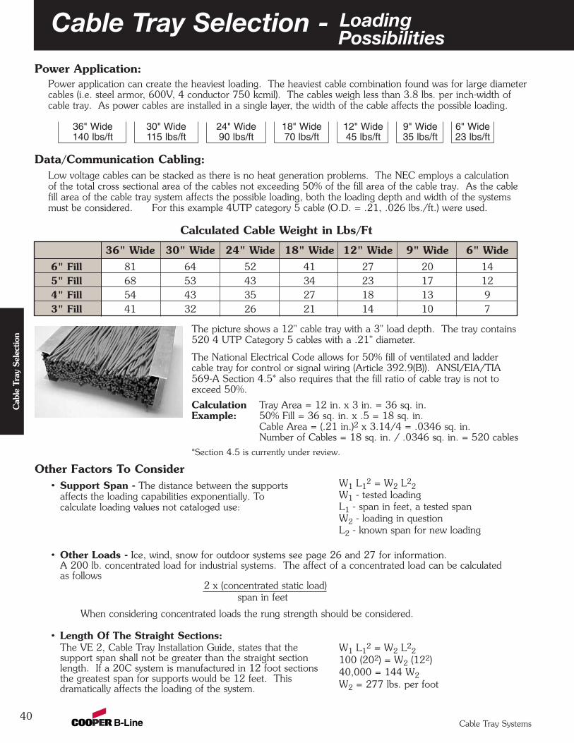
40
36" Wide 30" Wide 24" Wide 18" Wide 12" Wide 9" Wide 6" Wide6" Fill 81 64 52 41 27 20 145" Fill 68 53 43 34 23 17 124" Fill 54 43 35 27 18 13 93" Fill 41 32 26 21 14 10 7
Data/Communication Cabling:Low voltage cables can be stacked as there is no heat generation problems. The NEC employs a calculationof the total cross sectional area of the cables not exceeding 50% of the fill area of the cable tray. As the cable fill area of the cable tray system affects the possible loading, both the loading depth and width of the systemsmust be considered. For this example 4UTP category 5 cable (O.D. = .21, .026 lbs./ft.) were used.
Calculated Cable Weight in Lbs/Ft
Cable Tray Selection - LoadingPossibilities
The picture shows a 12" cable tray with a 3" load depth. The tray contains520 4 UTP Category 5 cables with a .21" diameter.
The National Electrical Code allows for 50% fill of ventilated and laddercable tray for control or signal wiring (Article 392.9(B)). ANSI/EIA/TIA569-A Section 4.5* also requires that the fill ratio of cable tray is not toexceed 50%.
Calculation Tray Area = 12 in. x 3 in. = 36 sq. in.Example: 50% Fill = 36 sq. in. x .5 = 18 sq. in.
Cable Area = (.21 in.)2 x 3.14/4 = .0346 sq. in.Number of Cables = 18 sq. in. / .0346 sq. in. = 520 cables
*Section 4.5 is currently under review.
Cable Tray Systems
Cab
le T
ray
Sele
ctio
n
Other Factors To Consider• Support Span - The distance between the supports
affects the loading capabilities exponentially. Tocalculate loading values not cataloged use:
• Other Loads - Ice, wind, snow for outdoor systems see page 26 and 27 for information. A 200 lb. concentrated load for industrial systems. The affect of a concentrated load can be calculatedas follows
2 x (concentrated static load)span in feet
When considering concentrated loads the rung strength should be considered.
• Length Of The Straight Sections:The VE 2, Cable Tray Installation Guide, states that thesupport span shall not be greater than the straight sectionlength. If a 20C system is manufactured in 12 foot sectionsthe greatest span for supports would be 12 feet. Thisdramatically affects the loading of the system.
W1 L12 = W2 L2
2W1 - tested loadingL1 - span in feet, a tested spanW2 - loading in questionL2 - known span for new loading
W1 L12 = W2 L2
2100 (202) = W2 (122) 40,000 = 144 W2W2 = 277 lbs. per foot
Power Application:Power application can create the heaviest loading. The heaviest cable combination found was for large diametercables (i.e. steel armor, 600V, 4 conductor 750 kcmil). The cables weigh less than 3.8 lbs. per inch-width ofcable tray. As power cables are installed in a single layer, the width of the cable affects the possible loading.
36" Wide140 lbs/ft
30" Wide115 lbs/ft
24" Wide90 lbs/ft
18" Wide70 lbs/ft
12" Wide45 lbs/ft
9" Wide35 lbs/ft
6" Wide23 lbs/ft
41
Cable Tray Selection - Bottom Type
Cable Tray Systems
Cable Tray Selection
Type of CableAccording to NEC Article 392, multiconductor tray cable may be installed in any standard cable traybottom type. According to the 2005 NEC Article 392.11(8)(3), single conductor tray cable may beinstalled in any standard cable tray bottom type. Solid bottom cable trays are not allowed to beinstalled in Class II, Division 2 locations (2002 NEC Section 502.4(B) ). In general, small, highlyflexible cables should be installed in solid bottom, vented bottom or 6" rung spacing ladder type cabletrays. Sensitive cables (e.g. fiberoptic) are typically installed in flat, solid bottom cable trays, insteadof corrugated trough bottoms. Larger, less flexible cables are typically installed in ladder type cabletrays having 9" or 12" rung spacing. Ladder type cable trays having 18" rung spacing should beused for large, stiff cables to reduce cost and facilitate cable drop-outs.
Cost vs StrengthOften more than one bottom type is acceptable. In this case the economic difference shouldbe considered. Ladder cable trays have a lower cost than either non-ventilated or ventilated bottomconfigurations. Typically, the cost of ladder type cable tray decreases as rung spacing increases. However, the effect of rung spacing on load capacity for ladder type cable trays with 18" rungspacing should be evaluated, since NEMA published load capacities are based on 12" rung spacing. Rung spacing can affect individual rung and side rail loading as well as system load capacity. Rungloads applied during cable installation should also be considered. (See page 29 for CooperB-Line rung load capacities)
Cable ExposureTray cables are manufactured to withstand the environment without additional protection, favoringthe use of the ladder type cable tray. Some areas may benefit from the limited exposure of solid orvented bottom cable tray. Solid Bottom metal cable tray with solid metal covers can be utilized inother spaces used for environmental air to support non plenum rated tray cables (2002 NEC®
300.22(C)(1) )
Cable AttachmentThe major advantage of ladder type cable tray is the freedom of entry and exit of the cables. Anotheradvantage of ladder type cable tray is the ability to secure cables in the cable tray. With standardrungs the cables may be attached with either cable ties or cable clamps. The ladder type cable tray isalso available with special purpose, slotted marine or strut rungs to facilitate banding or clampingcables. Cable attachment is particularly important on vertical runs or when the tray is installed on itsside. Ladder rung spacing should be chosen to provide adequate cable attachment points whileallowing the cables to exit the system.
Cable FlexibilityThe proper bend radius for cable tray fittings is usually determined by the bend radius and stiffness ofthe tray cables to be installed. Typically, the tray cable manufacturer will recommend a minimumbend allowance for each cable. The fitting radius should be equal to or larger than the minimumbend radius of the largest cable which may ever be installed in the system. When several cables areto be installed in the same cable tray, a larger bend radius may be desirable to ease cable installation.
Space LimitationsThe overall dimensions for a cable tray fitting will increase as the bend radius increases. Size andcost make the smallest acceptable fitting radius most desirable. When large radius fittings arerequired, the system layout must be designed to allow adequate space.
Cable Tray Selection - Fitting Radius
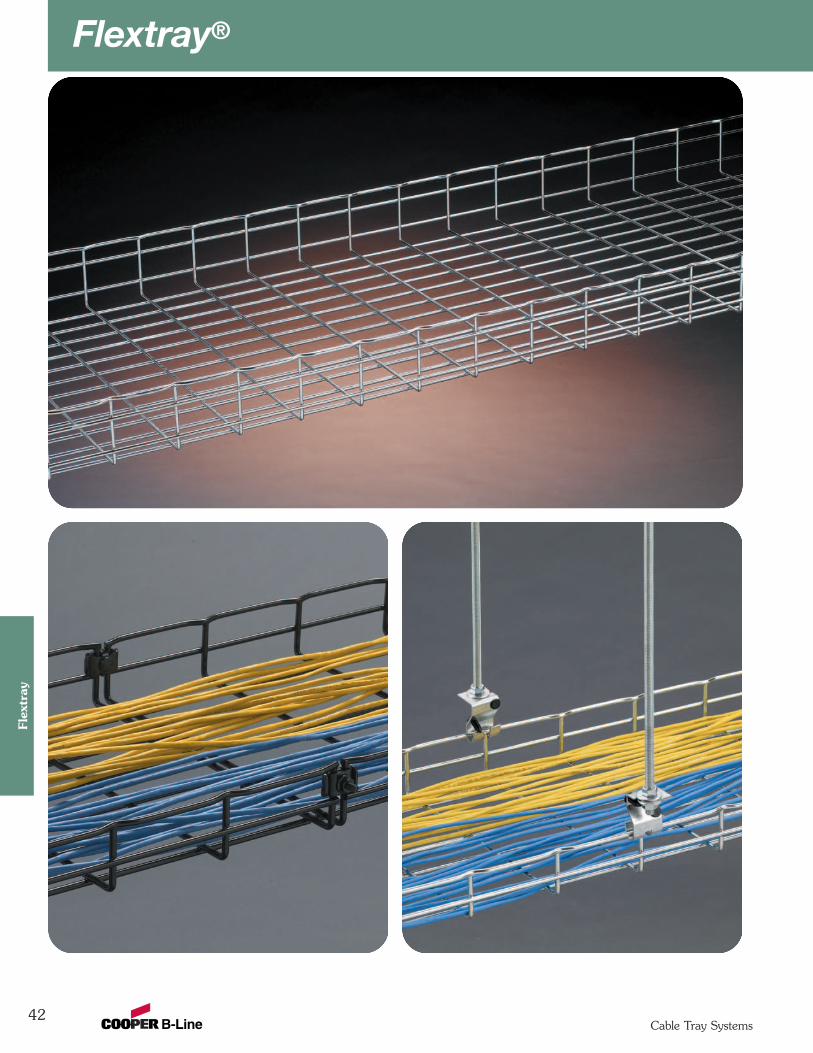
Flextray®
42
Flex
tray
Cable Tray Systems
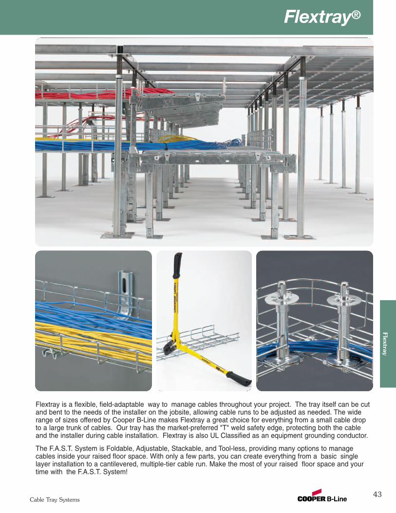
43
Flextray®Flextray
Cable Tray Systems
Flextray is a flexible, field-adaptable way to manage cables throughout your project. The tray itself can be cutand bent to the needs of the installer on the jobsite, allowing cable runs to be adjusted as needed. The widerange of sizes offered by Cooper B-Line makes Flextray a great choice for everything from a small cable dropto a large trunk of cables. Our tray has the market-preferred "T" weld safety edge, protecting both the cableand the installer during cable installation. Flextray is also UL Classified as an equipment grounding conductor.
The F.A.S.T. System is Foldable, Adjustable, Stackable, and Tool-less, providing many options to managecables inside your raised floor space. With only a few parts, you can create everything from a basic singlelayer installation to a cantilevered, multiple-tier cable run. Make the most of your raised floor space and yourtime with the F.A.S.T. System!
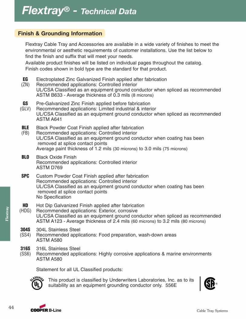
Flextray® - Technical Data
44
Flex
tray
Cable Tray Systems
Finish & Grounding Information
Flextray Cable Tray and Accessories are available in a wide variety of finishes to meet theenvironmental or aesthetic requirements of customer installations. Use the list below tofind the finish and suffix that will meet your needs.Available product finishes will be listed on individual pages throughout the catalog.Finish codes shown in bold type are the standard for that product.
EG Electroplated Zinc Galvanized Finish applied after fabrication(ZN) Recommended applications: Controlled interior
UL/CSA Classified as an equipment ground conductor when spliced as recommendedASTM B633 - Average thickness of 0.3 mils (8 microns)
GS Pre-Galvanized Zinc Finish applied before fabrication(GLV) Recommended applications: Limited industrial & interior
UL/CSA Classified as an equipment ground conductor when spliced as recommendedASTM A641
BLE Black Powder Coat Finish applied after fabrication(FB) Recommended applications: Controlled interior
UL/CSA Classified as an equipment ground conductor when coating has beenremoved at splice contact points
Average paint thickness of 1.2 mils (30 microns) to 3.0 mils (75 microns)
BLO Black Oxide Finish Recommended applications: Controlled interior ASTM D769
SPC Custom Powder Coat Finish applied after fabricationRecommended applications: Controlled interiorUL/CSA Classified as an equipment ground conductor when coating has beenremoved at splice contact points
No Specification
HD Hot Dip Galvanized Finish applied after fabrication(HDG) Recommended applications: Exterior, corrosive
UL/CSA Classified as an equipment ground conductor when spliced as recommendedASTM A123 - Average thickness of 2.4 mils (60 microns) to 3.2 mils (80 microns)
304S 304L Stainless Steel(SS4) Recommended applications: Food preparation, wash-down areas
ASTM A580
316S 316L Stainless Steel(SS6) Recommended applications: Highly corrosive applications & marine environments
ASTM A580
Statement for all UL Classified products:
This product is classified by Underwriters Laboratories, Inc. as to itssuitability as an equipment grounding conductor only. 556E
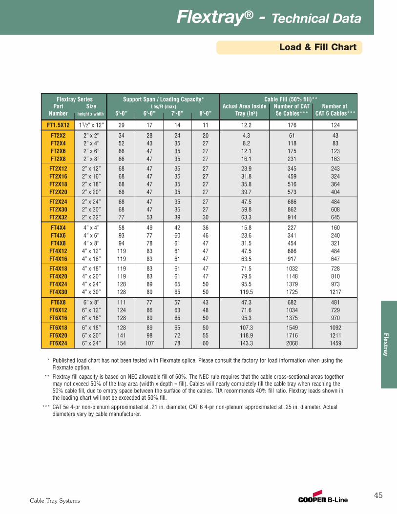
45
Flextray® - Technical DataFlextray
Cable Tray Systems
Flextray Series Support Span / Loading Capacity* Cable Fill (50% fill)** Part Size Lbs/Ft (max) Actual Area Inside Number of CAT Number of
Number height x width 5'-0” 6'-0” 7'-0” 8'-0” Tray (in2) 5e Cables*** CAT 6 Cables***
FT1.5X12 11/2” x 12” 29 17 14 11 12.2 176 124
FT2X2 2” x 2” 34 28 24 20 4.3 61 43FT2X4 2” x 4” 52 43 35 27 8.2 118 83FT2X6 2” x 6” 66 47 35 27 12.1 175 123FT2X8 2” x 8” 66 47 35 27 16.1 231 163
FT2X12 2” x 12” 68 47 35 27 23.9 345 243FT2X16 2” x 16” 68 47 35 27 31.8 459 324FT2X18 2” x 18” 68 47 35 27 35.8 516 364FT2X20 2” x 20” 68 47 35 27 39.7 573 404
FT2X24 2” x 24” 68 47 35 27 47.5 686 484FT2X30 2” x 30” 68 47 35 27 59.8 862 608FT2X32 2” x 32” 77 53 39 30 63.3 914 645
FT4X4 4” x 4” 58 49 42 36 15.8 227 160FT4X6 4” x 6” 93 77 60 46 23.6 341 240FT4X8 4” x 8” 94 78 61 47 31.5 454 321FT4X12 4” x 12” 119 83 61 47 47.5 686 484FT4X16 4” x 16” 119 83 61 47 63.5 917 647
FT4X18 4” x 18” 119 83 61 47 71.5 1032 728FT4X20 4” x 20” 119 83 61 47 79.5 1148 810FT4X24 4” x 24” 128 89 65 50 95.5 1379 973FT4X30 4” x 30” 128 89 65 50 119.5 1725 1217
FT6X8 6” x 8” 111 77 57 43 47.3 682 481FT6X12 6” x 12” 124 86 63 48 71.6 1034 729FT6X16 6” x 16” 128 89 65 50 95.3 1375 970
FT6X18 6” x 18” 128 89 65 50 107.3 1549 1092FT6X20 6” x 20” 141 98 72 55 118.9 1716 1211FT6X24 6” x 24” 154 107 78 60 143.3 2068 1459
Load & Fill Chart
* Published load chart has not been tested with Flexmate splice. Please consult the factory for load information when using the Flexmate option.
** Flextray fill capacity is based on NEC allowable fill of 50%. The NEC rule requires that the cable cross-sectional areas together may not exceed 50% of the tray area (width x depth = fill). Cables will nearly completely fill the cable tray when reaching the 50% cable fill, due to empty space between the surface of the cables. TIA recommends 40% fill ratio. Flextray loads shown in the loading chart will not be exceeded at 50% fill.
*** CAT 5e 4-pr non-plenum approximated at .21 in. diameter, CAT 6 4-pr non-plenum approximated at .25 in. diameter. Actualdiameters vary by cable manufacturer.
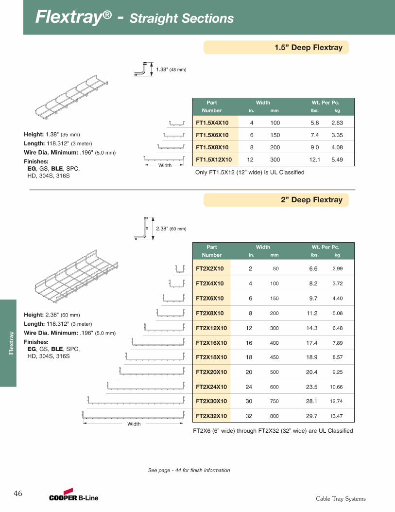
Flextray® - Straight Sections
46
Flex
tray
Cable Tray Systems
See page - 44 for finish information
Part Width Wt. Per Pc.
Number in. mm lbs. kg
FT2X2X10 2 50 6.6 2.99
FT2X4X10 4 100 8.2 3.72
FT2X6X10 6 150 9.7 4.40
FT2X8X10 8 200 11.2 5.08
FT2X12X10 12 300 14.3 6.48
FT2X16X10 16 400 17.4 7.89
FT2X18X10 18 450 18.9 8.57
FT2X20X10 20 500 20.4 9.25
FT2X24X10 24 600 23.5 10.66
FT2X30X10 30 750 28.1 12.74
FT2X32X10 32 800 29.7 13.47
2” Deep Flextray
Height: 2.38" (60 mm)
Length: 118.312" (3 meter)
Wire Dia. Minimum: .196" (5.0 mm)
Finishes:EG, GS, BLE, SPC,HD, 304S, 316S
2.38" (60 mm)
Part Width Wt. Per Pc.
Number in. mm lbs. kg
FT1.5X4X10 4 100 5.8 2.63
FT1.5X6X10 6 150 7.4 3.35
FT1.5X8X10 8 200 9.0 4.08
FT1.5X12X10 12 300 12.1 5.49
1.5” Deep Flextray
Width
Height: 1.38" (35 mm)
Length: 118.312" (3 meter)
Wire Dia. Minimum: .196" (5.0 mm)
Finishes:EG, GS, BLE, SPC,HD, 304S, 316S
1.38" (48 mm)
WidthOnly FT1.5X12 (12” wide) is UL Classified
FT2X6 (6” wide) through FT2X32 (32” wide) are UL Classified
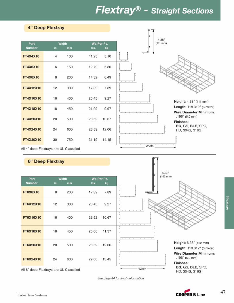
47
Flextray® - Straight SectionsFlextray
Cable Tray Systems
See page 44 for finish information
6” Deep Flextray
6.38"(162 mm)
4” Deep Flextray
Height: 4.38" (111 mm)
Length: 118.312" (3 meter)
Wire Diameter Minimum:.196" (5.0 mm)
Finishes:EG, GS, BLE, SPC,HD, 304S, 316S
Part Width Wt. Per Pc.Number in. mm lbs. kg
FT4X4X10 4 100 11.25 5.10
FT4X6X10 6 150 12.79 5.80
FT4X8X10 8 200 14.32 6.49
FT4X12X10 12 300 17.39 7.89
FT4X16X10 16 400 20.45 9.27
FT4X18X10 18 450 21.99 9.97
FT4X20X10 20 500 23.52 10.67
FT4X24X10 24 600 26.59 12.06
FT4X30X10 30 750 31.19 14.15
4.38"(111 mm)
Width
Height: 6.38" (162 mm)
Length: 118.312" (3 meter)
Wire Diameter Minimum:.196" (5.0 mm)
Finishes:EG, GS, BLE, SPC,HD, 304S, 316S
Part Width Wt. Per Pc.Number in. mm lbs. kg
FT6X8X10 8 200 17.39 7.89
FT6X12X10 12 300 20.45 9.27
FT6X16X10 16 400 23.52 10.67
FT6X18X10 18 450 25.06 11.37
FT6X20X10 20 500 26.59 12.06
FT6X24X10 24 600 29.66 13.45
WidthAll 6” deep Flextrays are UL Classified
All 4” deep Flextrays are UL Classified
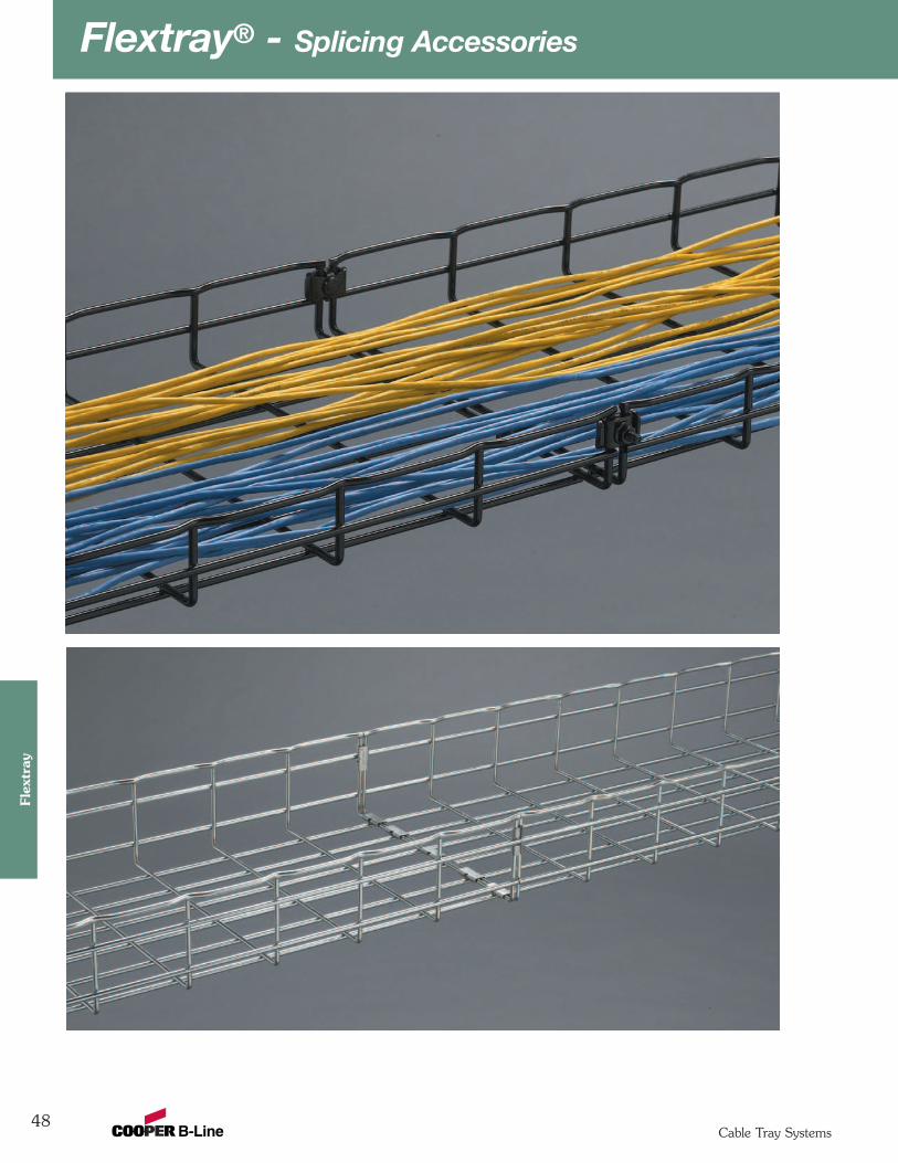
Flextray® - Splicing Accessories
48
Flex
tray
Cable Tray Systems
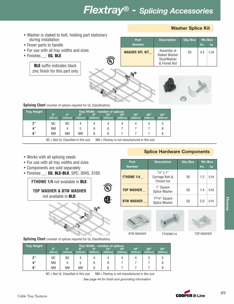
49
Flextray® - Splicing AccessoriesFlextray
Cable Tray Systems
Splice Hardware Components
Washer Splice Kit
See page 44 for finish and grounding information
Part Description Qty./Box Wt./Box
Number lbs. kg
WASHER SPL KIT__ Assembly of 50 4.5 2.04Staked WasherStud/Washer& Finned Nut
• Washer is staked to bolt, holding part stationary during installation
• Fewer parts to handle• For use with all tray widths and sizes• Finishes __: EG, BLE
Part Description Qty./Box Wt./Box
Number lbs. kg
1/4” x 1”FTHDWE 1/4__ Carriage Bolt & 50 1.2 0.54
Finned nut
1” SquareTOP WASHER__ Splice Washer 50 1.4 0.63
13/16” SquareBTM WASHER __ Splice Washer 50 2.0 0.91
• Works with all splicing needs• For use with all tray widths and sizes• Components are sold separately• Finishes __: EG, BLE-BLO, SPC, 304S, 316S
Tray Height Tray Width - number of splices2” 4” 6” 8” 12” 16” 18” 20” 24”
(50mm) (100mm) (150mm) (200mm) (300mm) (400mm) (450mm) (500mm) (600mm)
2” NC NC 4 4 4 4 4 5 54” NM 4 5 6 6 7 7 7 86” NM NM NM 6 6 7 7 7 8
Splicing Chart (number of splices required for UL Classification)
FTHDWE1/4BTM WASHER TOP WASHER
BLE suffix indicates blackzinc finish for this part only
FTHDWE 1/4 not available in BLE.
TOP WASHER & BTM WASHERnot available in BLO.
Tray Height Tray Width - number of splices2” 4” 6” 8” 12” 16” 18” 20” 24”
(50mm) (100mm) (150mm) (200mm) (300mm) (400mm) (450mm) (500mm) (600mm)
2” NC NC 4 4 4 4 4 5 54” NM 4 5 6 6 7 7 7 86” NM NM NM 6 6 7 7 7 8
Splicing Chart (number of splices required for UL Classification)
NC = Not UL Classified in this size NM = Flextray is not manufactured in this size
NC = Not UL Classified in this size NM = Flextray is not manufactured in this size
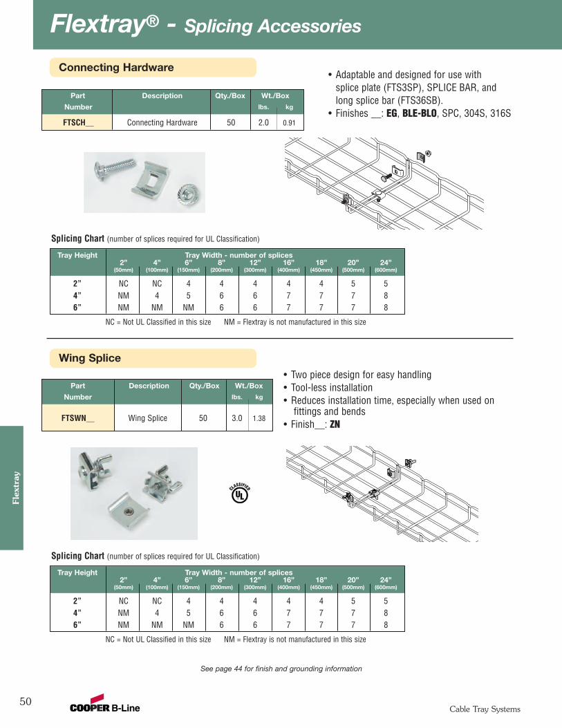
Flextray® - Splicing Accessories
50
Flex
tray
Cable Tray Systems
Wing Splice
Connecting Hardware• Adaptable and designed for use with
splice plate (FTS3SP), SPLICE BAR, andlong splice bar (FTS36SB).
• Finishes __: EG, BLE-BLO, SPC, 304S, 316S
Part Description Qty./Box Wt./Box
Number lbs. kg
FTSWN__ Wing Splice 50 3.0 1.38
• Two piece design for easy handling• Tool-less installation• Reduces installation time, especially when used on
fittings and bends• Finish__: ZN
Part Description Qty./Box Wt./Box
Number lbs. kg
FTSCH__ Connecting Hardware 50 2.0 0.91
Tray Height Tray Width - number of splices2” 4” 6” 8” 12” 16” 18” 20” 24”
(50mm) (100mm) (150mm) (200mm) (300mm) (400mm) (450mm) (500mm) (600mm)
2” NC NC 4 4 4 4 4 5 54” NM 4 5 6 6 7 7 7 86” NM NM NM 6 6 7 7 7 8
Splicing Chart (number of splices required for UL Classification)
NC = Not UL Classified in this size NM = Flextray is not manufactured in this size
See page 44 for finish and grounding information
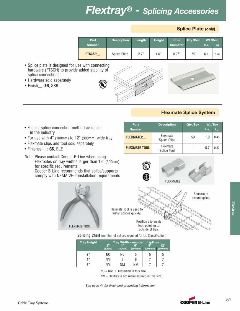
51
Flextray® - Splicing AccessoriesFlextray
Cable Tray Systems
Splice Plate (only)
Flexmate Splice System
Part Description Qty./Box Wt./Box
Number lbs. kg
FLEXMATE2__ Flexmate 50 1.0 0.45Splice Clips
FLEXMATE TOOL Flexmate 1 0.7 0.32Splice Tool
Tray Height Tray Width - number of splices2” 4” 6” 8” 12”
(50mm) (100mm) (150mm) (200mm) (300mm)
2” NC NC 5 5 54” NM 5 6 7 76” NM NM NM 7 7
• Fastest splice connection method availablein the industry
• For use with 4” (100mm) to 12” (300mm) wide tray• Flexmate clips and tool sold separately• Finishes __: GS, BLE
Note: Please contact Cooper B-Line when usingFlexmates on tray widths larger than 12” (300mm)for specific requirements.Cooper B-Line recommends that splice/supportscomply with NEMA VE-2 installation requirements
Splicing Chart (number of splices required for UL Classification)
Flexmate Tool is used toinstall splices quickly.
Position clip insidetool, pointing tooutside of tray.
Squeeze tosecure splice.
FLEXMATE2
FLEXMATE TOOL
NC = Not UL Classified in this sizeNM = Flextray is not manufactured in this size
Part Description Length Height Hole Qty./Box Wt./Box
Number Diameter lbs. kg
FTS3SP__ Splice Plate 2.7” 1.6” 0.27” 50 6.1 2.76
• Splice plate is designed for use with connectinghardware (FTSCH) to provide added stability of splice connections
• Hardware sold separately• Finish__: ZN, SS6
See page 44 for finish and grounding information
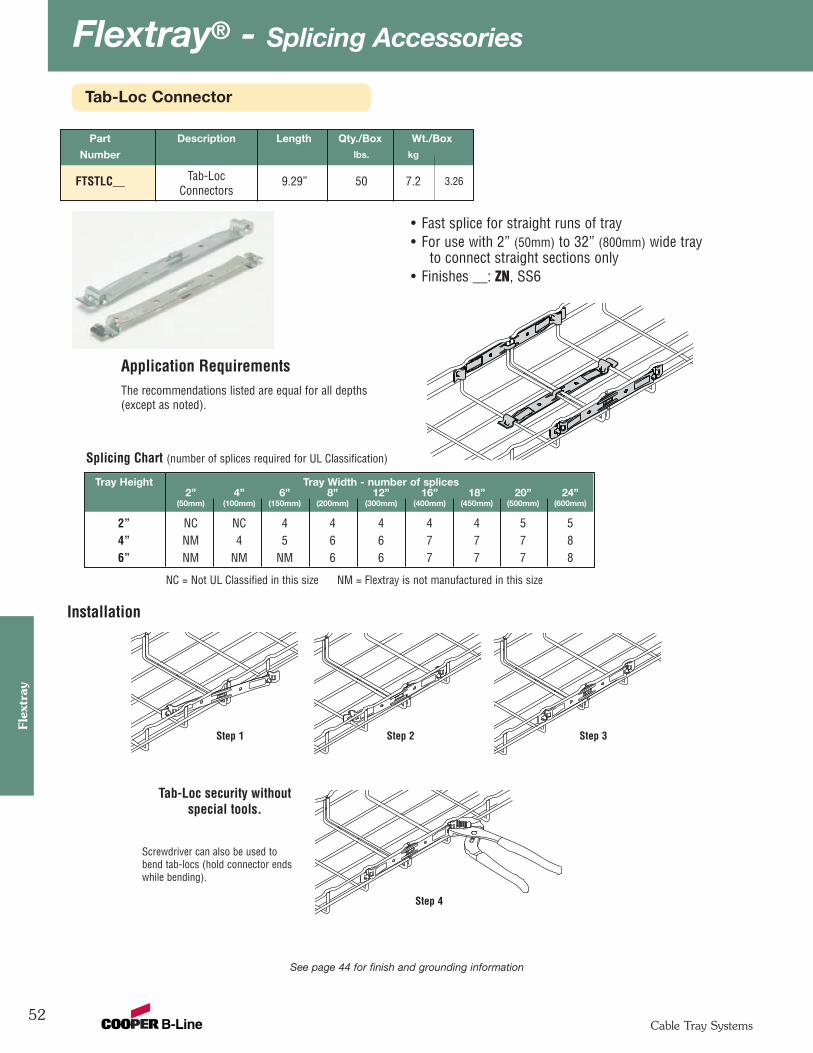
Flextray® - Splicing Accessories
52
Flex
tray
Cable Tray Systems
Tab-Loc Connector
Part Description Length Qty./Box Wt./Box
Number lbs. kg
FTSTLC__ Tab-Loc 9.29” 50 7.2 3.26Connectors
• Fast splice for straight runs of tray• For use with 2” (50mm) to 32” (800mm) wide tray
to connect straight sections only• Finishes __: ZN, SS6
Application Requirements
Tab-Loc security without special tools.
Step 1 Step 3Step 2
Step 4
The recommendations listed are equal for all depths(except as noted).
Installation
Screwdriver can also be used tobend tab-locs (hold connector endswhile bending).
Tray Height Tray Width - number of splices2” 4” 6” 8” 12” 16” 18” 20” 24”
(50mm) (100mm) (150mm) (200mm) (300mm) (400mm) (450mm) (500mm) (600mm)
2” NC NC 4 4 4 4 4 5 54” NM 4 5 6 6 7 7 7 86” NM NM NM 6 6 7 7 7 8
Splicing Chart (number of splices required for UL Classification)
NC = Not UL Classified in this size NM = Flextray is not manufactured in this size
See page 44 for finish and grounding information
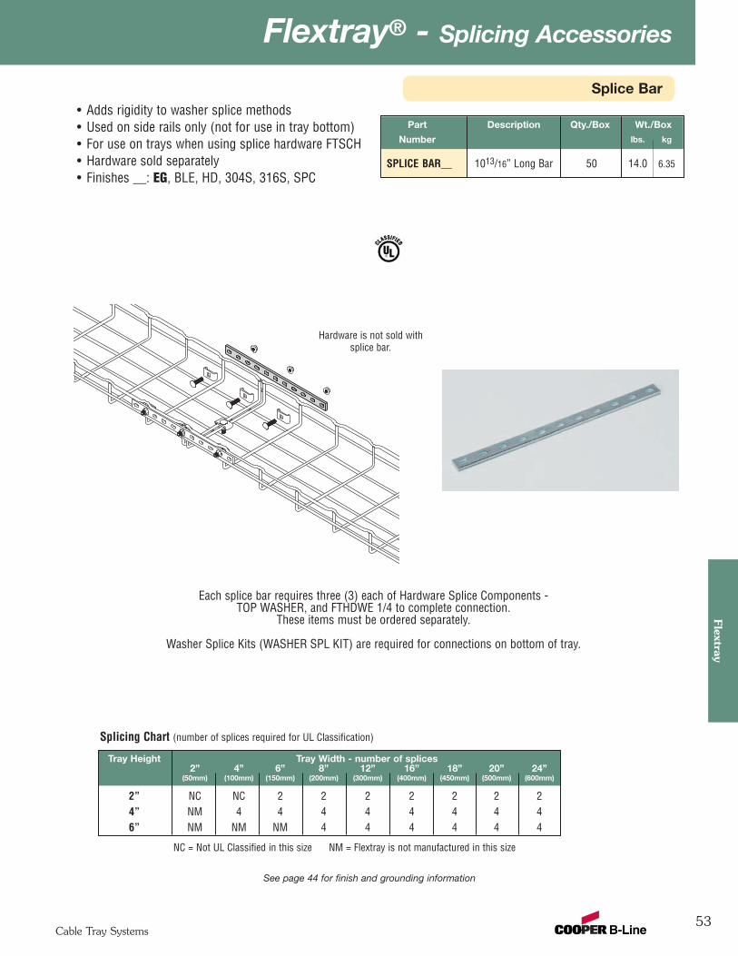
53
Flextray® - Splicing AccessoriesFlextray
Cable Tray Systems
See page 44 for finish and grounding information
Splice Bar
Part Description Qty./Box Wt./Box
Number lbs. kg
SPLICE BAR__ 1013/16” Long Bar 50 14.0 6.35
• Adds rigidity to washer splice methods• Used on side rails only (not for use in tray bottom)• For use on trays when using splice hardware FTSCH• Hardware sold separately• Finishes __: EG, BLE, HD, 304S, 316S, SPC
Each splice bar requires three (3) each of Hardware Splice Components -TOP WASHER, and FTHDWE 1/4 to complete connection.
These items must be ordered separately.
Washer Splice Kits (WASHER SPL KIT) are required for connections on bottom of tray.
Hardware is not sold withsplice bar.
Tray Height Tray Width - number of splices2” 4” 6” 8” 12” 16” 18” 20” 24”
(50mm) (100mm) (150mm) (200mm) (300mm) (400mm) (450mm) (500mm) (600mm)
2” NC NC 2 2 2 2 2 2 24” NM 4 4 4 4 4 4 4 46” NM NM NM 4 4 4 4 4 4
Splicing Chart (number of splices required for UL Classification)
NC = Not UL Classified in this size NM = Flextray is not manufactured in this size
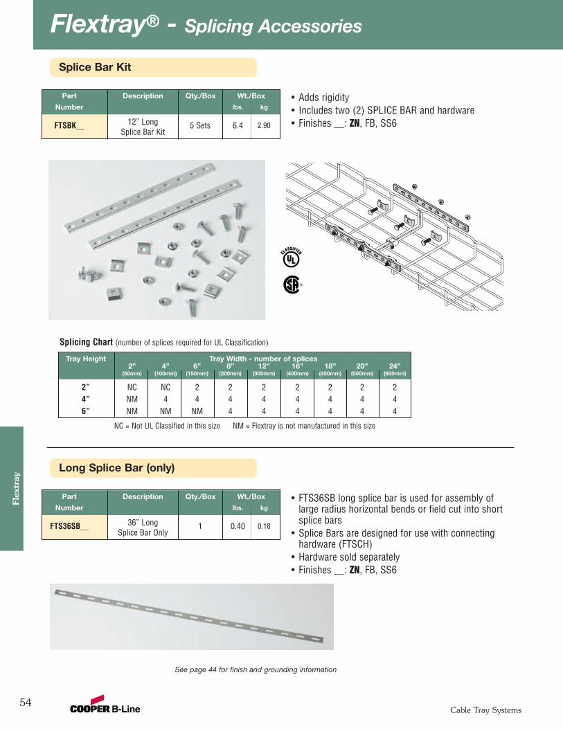
Flextray® - Splicing Accessories
54
Flex
tray
Cable Tray Systems
Long Splice Bar (only)
See page 44 for finish and grounding information
Part Description Qty./Box Wt./Box
Number lbs. kg
FTS36SB__ 36” Long 1 0.40 0.18Splice Bar Only
• FTS36SB long splice bar is used for assembly oflarge radius horizontal bends or field cut into shortsplice bars
• Splice Bars are designed for use with connectinghardware (FTSCH)
• Hardware sold separately• Finishes __: ZN, FB, SS6
Splice Bar Kit
Part Description Qty./Box Wt./Box
Number lbs. kg
FTSBK__ 12” Long 5 Sets 6.4 2.90Splice Bar Kit
• Adds rigidity • Includes two (2) SPLICE BAR and hardware• Finishes __: ZN, FB, SS6
Tray Height Tray Width - number of splices2” 4” 6” 8” 12” 16” 18” 20” 24”
(50mm) (100mm) (150mm) (200mm) (300mm) (400mm) (450mm) (500mm) (600mm)
2” NC NC 2 2 2 2 2 2 24” NM 4 4 4 4 4 4 4 46” NM NM NM 4 4 4 4 4 4
Splicing Chart (number of splices required for UL Classification)
NC = Not UL Classified in this size NM = Flextray is not manufactured in this size
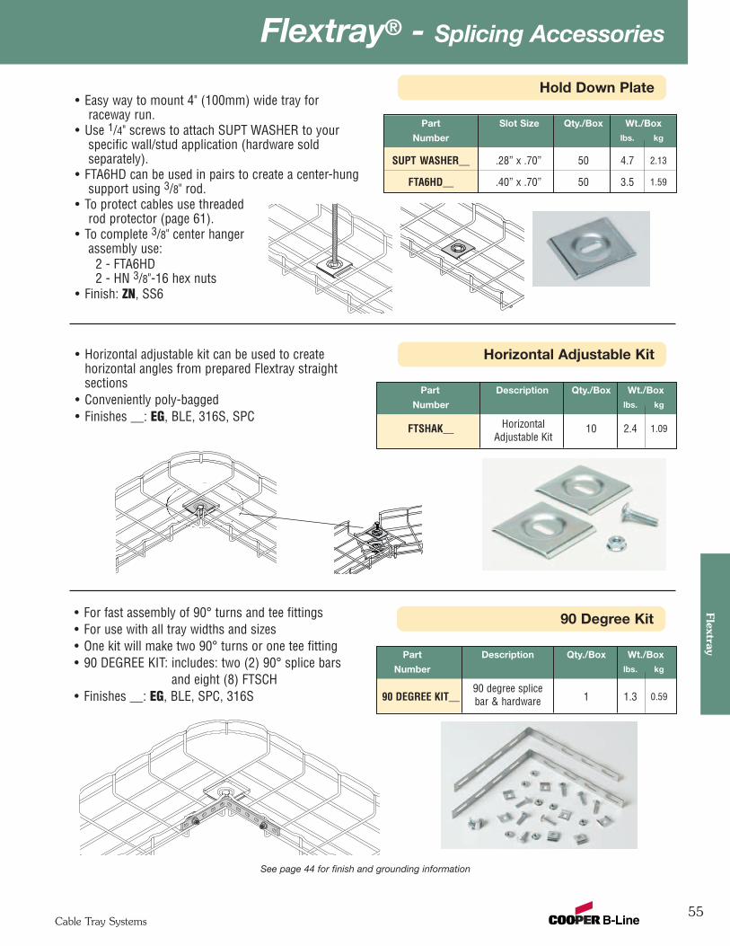
55
Flextray® - Splicing AccessoriesFlextray
Cable Tray Systems
Hold Down Plate
See page 44 for finish and grounding information
Horizontal Adjustable Kit• Horizontal adjustable kit can be used to createhorizontal angles from prepared Flextray straightsections
• Conveniently poly-bagged• Finishes __: EG, BLE, 316S, SPC
Part Description Qty./Box Wt./Box
Number lbs. kg
FTSHAK__ Horizontal 10 2.4 1.09Adjustable Kit
90 Degree Kit• For fast assembly of 90° turns and tee fittings• For use with all tray widths and sizes• One kit will make two 90° turns or one tee fitting• 90 DEGREE KIT: includes: two (2) 90° splice bars
and eight (8) FTSCH• Finishes __: EG, BLE, SPC, 316S
Part Description Qty./Box Wt./Box
Number lbs. kg
90 degree splice90 DEGREE KIT__ bar & hardware 1 1.3 0.59
Part Slot Size Qty./Box Wt./Box
Number lbs. kg
SUPT WASHER__ .28” x .70” 50 4.7 2.13
FTA6HD__ .40” x .70” 50 3.5 1.59
• Easy way to mount 4" (100mm) wide tray forraceway run.
• Use 1/4" screws to attach SUPT WASHER to yourspecific wall/stud application (hardware soldseparately).
• FTA6HD can be used in pairs to create a center-hungsupport using 3/8" rod.
• To protect cables use threadedrod protector (page 61).
• To complete 3/8" center hangerassembly use:
2 - FTA6HD2 - HN 3/8"-16 hex nuts
• Finish: ZN, SS6
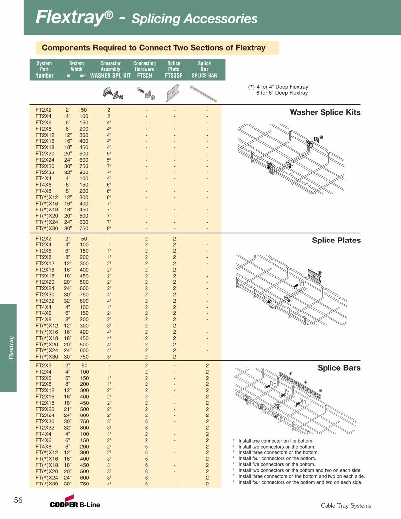
Flextray® - Splicing Accessories
56
Flex
tray
Cable Tray Systems
FT2X2 2” 50 2 - - -FT2X4 4” 100 2 - - -FT2X6 6” 150 42 - - -FT2X8 8” 200 42 - - -FT2X12 12” 300 42 - - -FT2X16 16” 400 42 - - -FT2X18 18” 450 42 - - -FT2X20 20” 500 53 - - -FT2X24 24” 600 53 - - -FT2X30 30” 750 75 - - -FT2X32 32” 800 75 - - -FT4X4 4” 100 42 - - -FT4X6 6” 150 66 - - -FT4X8 8” 200 66 - - -FT(*)X12 12” 300 66 - - -FT(*)X16 16” 400 77 - - -FT(*)X18 18” 450 77 - - -FT(*)X20 20” 500 77 - - -FT(*)X24 24” 600 77 - - -FT(*)X30 30” 750 88 - - -
FT2X2 2” 50 - 2 2 -FT2X4 4” 100 - 2 2 -FT2X6 6” 150 11 2 2 -FT2X8 8” 200 11 2 2 -FT2X12 12” 300 22 2 2 -FT2X16 16” 400 22 2 2 -FT2X18 18” 450 22 2 2 -FT2X20 20” 500 22 2 2 -FT2X24 24” 600 22 2 2 -FT2X30 30” 750 44 2 2 -FT2X32 32” 800 44 2 2 -FT4X4 4” 100 11 2 2 -FT4X6 6” 150 22 2 2 -FT4X8 8” 200 22 2 2 -FT(*)X12 12” 300 33 2 2 -FT(*)X16 16” 400 44 2 2 -FT(*)X18 18” 450 44 2 2 -FT(*)X20 20” 500 44 2 2 -FT(*)X24 24” 600 44 2 2 -FT(*)X30 30” 750 55 2 2 -
FT2X2 2” 50 - 2 - 2FT2X4 4” 100 - 2 - 2FT2X6 6” 150 11 2 - 2FT2X8 8” 200 11 2 - 2FT2X12 12” 300 22 2 - 2FT2X16 16” 400 22 2 - 2FT2X18 18” 450 22 2 - 2FT2X20 21” 500 22 2 - 2FT2X24 24” 600 22 2 - 2FT2X30 30” 750 33 6 - 2FT2X32 32” 800 33 6 - 2FT4X4 4” 100 11 2 - 2FT4X6 6” 150 22 2 - 2FT4X8 8” 200 22 6 - 2FT(*)X12 12” 300 22 6 - 2FT(*)X16 16” 400 33 6 - 2FT(*)X18 18” 450 33 6 - 2FT(*)X20 20” 500 33 6 - 2FT(*)X24 24” 600 33 6 - 2FT(*)X30 30” 750 44 6 - 2
1 Install one connector on the bottom.2 Install two connectors on the bottom.3 Install three connectors on the bottom.4 Install four connectors on the bottom.5 Install five connectors on the bottom.6 Install two connectors on the bottom and two on each side.7 Install three connectors on the bottom and two on each side.8 Install four connectors on the bottom and two on each side.
Washer Splice Kits
Splice Plates
Splice Bars
System System Connector Connecting Splice SplicePart Width Assembly Hardware Plate Bar
Number in. mm WASHER SPL KIT FTSCH FTS3SP SPLICE BAR
(*) 4 for 4” Deep Flextray6 for 6” Deep Flextray
Components Required to Connect Two Sections of Flextray

57
Flextray® - Splicing AccessoriesFlextray
Cable Tray Systems
Part System Weight Box
Number Width Per 100 Quantityin. mm lbs. kg
FTS20SK2” 50 2.91 1.32 104” 100
FTS21SK6” 150 3.63 1.64 108” 200
12” 300
FTS22SK18” 450
4.35 1.97 1020” 50024” 600
Conveniently poly-bagged for use with2" Deep Flextray
Conveniently poly-bagged for use with 4" & 6” Deep Flextray
Part System Weight Box
Number Width Per 100 Quantityin. mm lbs. kg
4” 100
6” 150FTS23SK
8” 2005.07 2.30 10
12” 300
18” 450
FTS24SK 20” 500 5.79 2.62 1024” 600
Splice Plate Kits for 2" Deep Flextray
Splice Plate Kits for 4" & 6” Deep Flextray
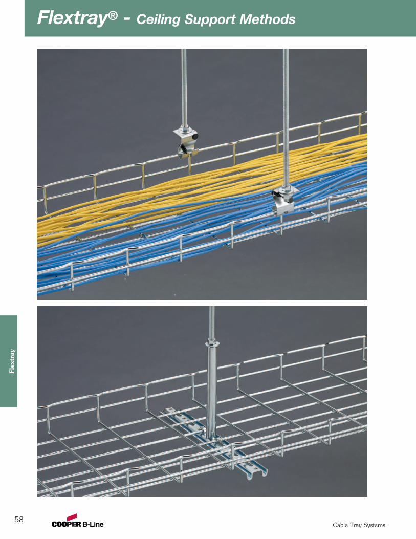
Flextray® - Ceiling Support Methods
58
Flex
tray
Cable Tray Systems
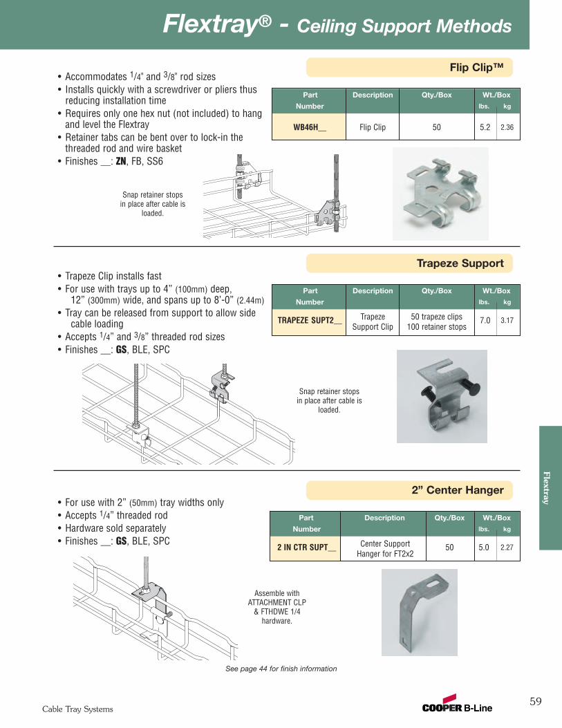
59
Flextray® - Ceiling Support MethodsFlextray
Cable Tray Systems
2” Center Hanger
Flip Clip™
Part Description Qty./Box Wt./Box
Number lbs. kg
WB46H__ Flip Clip 50 5.2 2.36
• Accommodates 1/4" and 3/8" rod sizes• Installs quickly with a screwdriver or pliers thus
reducing installation time• Requires only one hex nut (not included) to hang
and level the Flextray• Retainer tabs can be bent over to lock-in the
threaded rod and wire basket• Finishes __: ZN, FB, SS6
Part Description Qty./Box Wt./Box
Number lbs. kg
2 IN CTR SUPT__ Center Support 50 5.0 2.27Hanger for FT2x2
• For use with 2” (50mm) tray widths only• Accepts 1/4” threaded rod• Hardware sold separately• Finishes __: GS, BLE, SPC
See page 44 for finish information
Snap retainer stopsin place after cable is
loaded.
Trapeze Support
Part Description Qty./Box Wt./Box
Number lbs. kg
TRAPEZE SUPT2__ Trapeze 50 trapeze clips 7.0 3.17Support Clip 100 retainer stops
• Trapeze Clip installs fast• For use with trays up to 4” (100mm) deep,
12” (300mm) wide, and spans up to 8’-0” (2.44m)• Tray can be released from support to allow side
cable loading• Accepts 1/4” and 3/8” threaded rod sizes• Finishes __: GS, BLE, SPC
Snap retainer stopsin place after cable is
loaded.
Assemble withATTACHMENT CLP
& FTHDWE 1/4hardware.
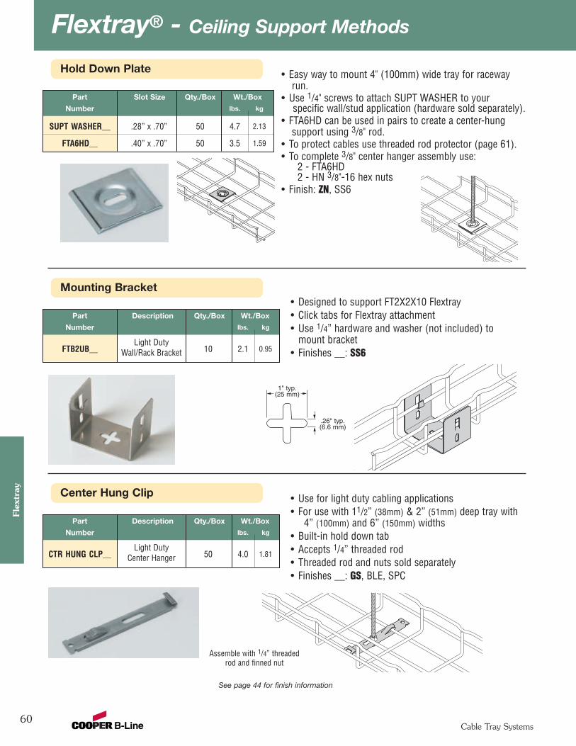
Flextray® - Ceiling Support Methods
60
Flex
tray
Cable Tray Systems
Hold Down Plate
Part Slot Size Qty./Box Wt./Box
Number lbs. kg
SUPT WASHER__ .28” x .70” 50 4.7 2.13
FTA6HD__ .40” x .70” 50 3.5 1.59
• Easy way to mount 4" (100mm) wide tray for racewayrun.
• Use 1/4" screws to attach SUPT WASHER to yourspecific wall/stud application (hardware sold separately).
• FTA6HD can be used in pairs to create a center-hungsupport using 3/8" rod.
• To protect cables use threaded rod protector (page 61).• To complete 3/8" center hanger assembly use:
2 - FTA6HD2 - HN 3/8"-16 hex nuts
• Finish: ZN, SS6
See page 44 for finish information
Center Hung Clip
Part Description Qty./Box Wt./Box
Number lbs. kg
Light DutyCTR HUNG CLP__ Center Hanger 50 4.0 1.81
• Use for light duty cabling applications• For use with 11/2” (38mm) & 2” (51mm) deep tray with
4” (100mm) and 6” (150mm) widths• Built-in hold down tab• Accepts 1/4” threaded rod• Threaded rod and nuts sold separately• Finishes __: GS, BLE, SPC
Assemble with 1/4” threadedrod and finned nut
Mounting Bracket
Part Description Qty./Box Wt./Box
Number lbs. kg
Light DutyFTB2UB__ Wall/Rack Bracket 10 2.1 0.95
• Designed to support FT2X2X10 Flextray• Click tabs for Flextray attachment• Use 1/4” hardware and washer (not included) to
mount bracket• Finishes __: SS6
.26" typ.(6.6 mm)
1" typ.(25 mm)
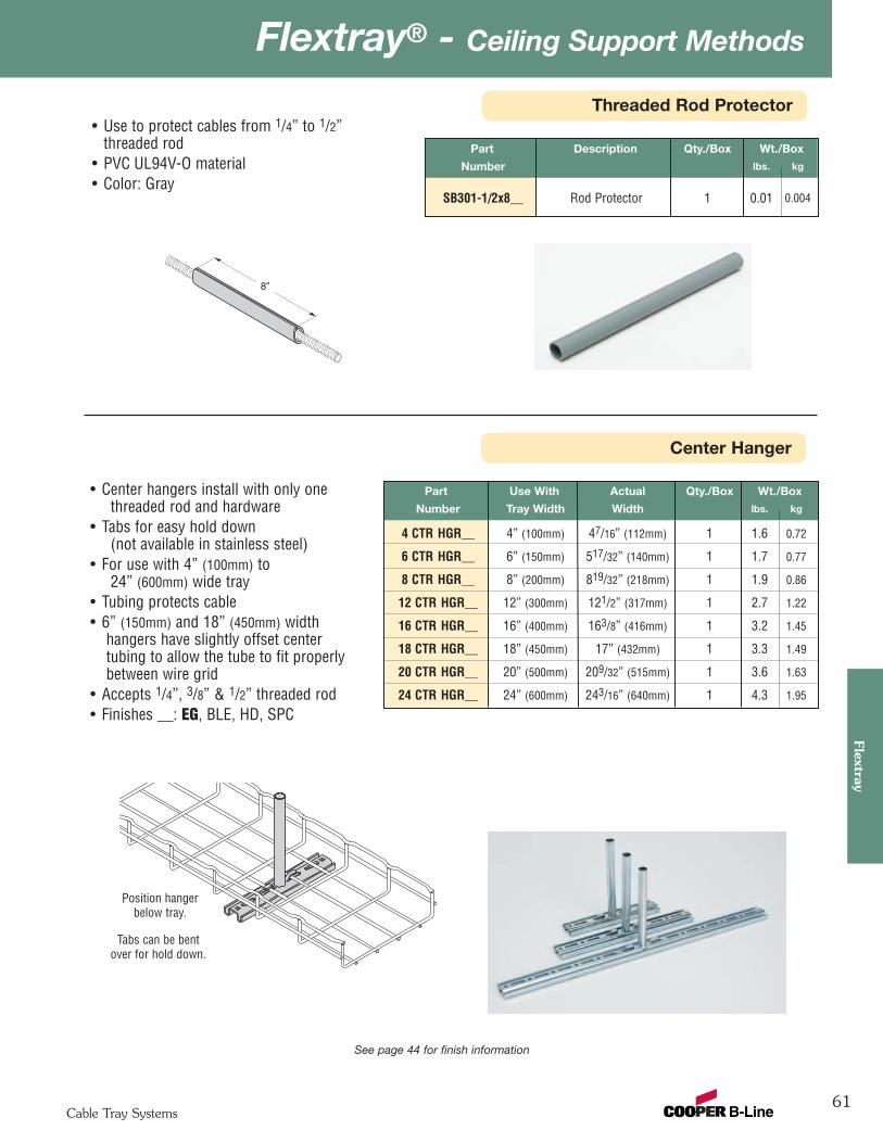
61
Flextray® - Ceiling Support MethodsFlextray
Cable Tray Systems
Threaded Rod Protector
Center Hanger
Part Description Qty./Box Wt./Box
Number lbs. kg
SB301-1/2x8__ Rod Protector 1 0.01 0.004
• Use to protect cables from 1/4” to 1/2”threaded rod
• PVC UL94V-O material• Color: Gray
See page 44 for finish information
Part Use With Actual Qty./Box Wt./Box
Number Tray Width Width lbs. kg
4 CTR HGR__ 4” (100mm) 47/16” (112mm) 1 1.6 0.72
6 CTR HGR__ 6” (150mm) 517/32” (140mm) 1 1.7 0.77
8 CTR HGR__ 8” (200mm) 819/32” (218mm) 1 1.9 0.86
12 CTR HGR__ 12” (300mm) 121/2” (317mm) 1 2.7 1.22
16 CTR HGR__ 16” (400mm) 163/8” (416mm) 1 3.2 1.45
18 CTR HGR__ 18” (450mm) 17” (432mm) 1 3.3 1.49
20 CTR HGR__ 20” (500mm) 209/32” (515mm) 1 3.6 1.63
24 CTR HGR__ 24” (600mm) 243/16” (640mm) 1 4.3 1.95
• Center hangers install with only onethreaded rod and hardware
• Tabs for easy hold down(not available in stainless steel)
• For use with 4” (100mm) to24” (600mm) wide tray
• Tubing protects cable• 6” (150mm) and 18” (450mm) width
hangers have slightly offset centertubing to allow the tube to fit properlybetween wire grid
• Accepts 1/4”, 3/8” & 1/2” threaded rod• Finishes __: EG, BLE, HD, SPC
Position hangerbelow tray.
Tabs can be bentover for hold down.
8”

Flextray® - Ceiling Support Methods
62
Flex
tray
Cable Tray Systems
Heavy Duty Center Hung Support Kit
Trapeze Support Kits
Part Use With Overall Qty./Box Wt./Box
Number Tray Width Width lbs. kg
WB5506__ 6” (150mm) 10” (254mm) 1 1.6 0.73
WB5508__ 8” (200mm) 12” (305mm) 1 1.7 0.77
WB5512 __ 12” (300mm) 16” (406mm) 1 2.0 0.91
WB5518 __ 18” (450mm) 22” (559mm) 1 2.5 1.13
WB5524__ † 28” (711mm) 1 2.9 1.32
• Trapeze Support Kit includes allcomponents required for single trapezesupport in one package.
• Designed for use with 1/4" ATR.• Also available for 3/8" ATR, add -3/8 suffix
to part number.• Order threaded rod separately. • Finish: Channel - GLV
Other components - ZN, SPCAvailable in SS6
Part Channel Qty./Box Wt./Box
Number Length lbs. kg
WB5518CH__ 18” 1 2.2 1.00
See page 44 for finish information
• Designed for 1/2" ATR. Channel length of 18"supports 12", 18" and 20" FlextraySystems.
• Protection sleeve for ATR to prevent damageto cables.
• 1/2" ATR attachment hardware provided.• Flextray mounting attachment hardware provided.• Heavy Duty Center Hung Support
assembly includes:(1) - SB3011/2x8 Threaded Rod Protector(2) - B202 Square Washers(2) - HN 1/2"-13 Hex Nuts(2) - N224WO, 1/4"-20 Channel Nuts (no spring)(2) - SRHMS 1/4"-20 x 1” Machine Screws(2) - SUPT WASHER Hold Down Plates(1) - B54SH Channel, 18" long
• Finishes __: ZN, SS6, SPC
Trapeze Kit for 1/4" ATR includes:
(4) - B450-1/4" U-Washers (4) - HN 1/4"-20 Hex Nuts(1) - SUPT WASHER (1) - TN224 1/4"-20 EZ Twirl Nut(1) - SRHMS 1/4"-20 x 1"
Machine Screw(1) - B54SH Channel
Trapeze Kit for 3/8" ATR add -3/8" suffix, includes:
(4) - B450-3/8" U-Washers (4) - HN 3/8"-16 Hex Nuts(1) - SUPT WASHER (1) - TN224 1/4"-20 EZ Twirl Nut(1) - SRHMS 1/4"-20 x 1"
Machine Screw(1) - B54SH Channel
Overall Width
† For 20” (500 mm) and 24” (600 mm) wide Flextray
Kit supplied withattachment hardware.
Kits supplied withattachment hardware.
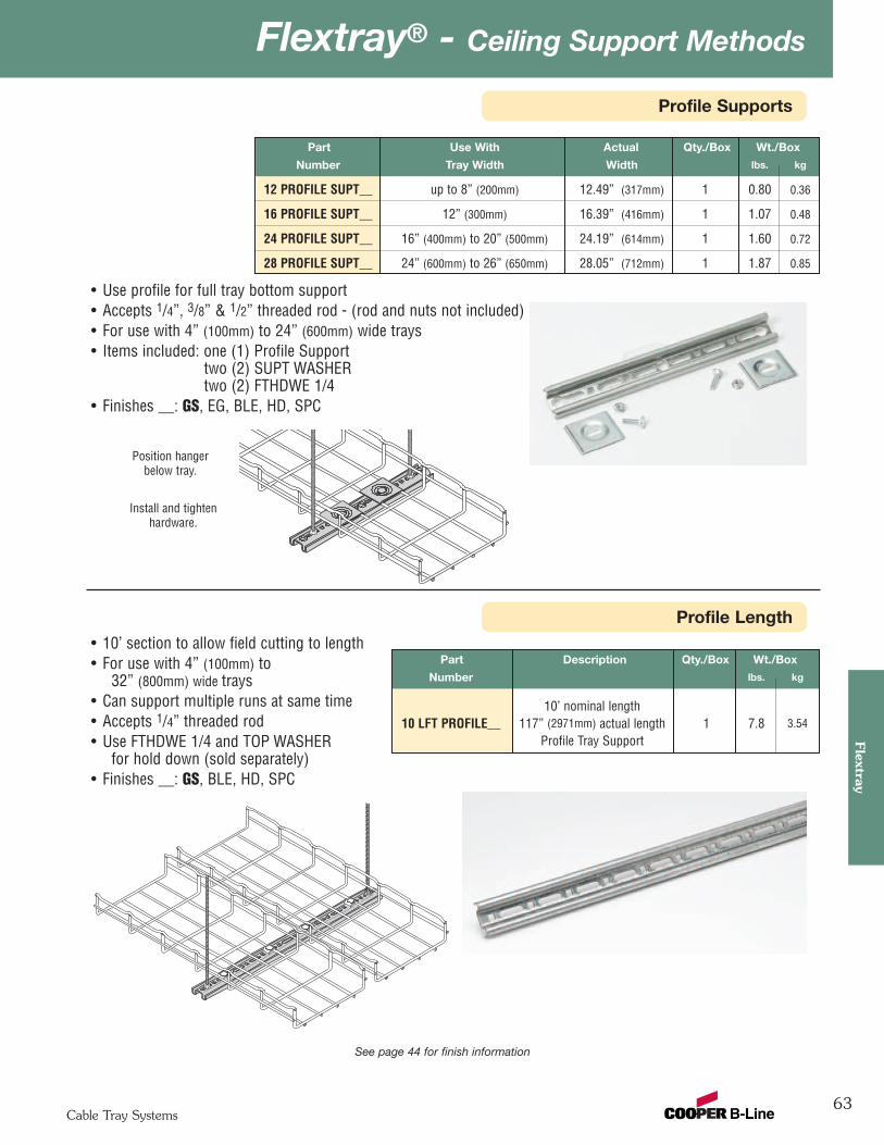
63
Flextray® - Ceiling Support MethodsFlextray
Cable Tray Systems
Profile Supports
See page 44 for finish information
Part Use With Actual Qty./Box Wt./Box
Number Tray Width Width lbs. kg
12 PROFILE SUPT__ up to 8” (200mm) 12.49” (317mm) 1 0.80 0.36
16 PROFILE SUPT__ 12” (300mm) 16.39” (416mm) 1 1.07 0.48
24 PROFILE SUPT__ 16” (400mm) to 20” (500mm) 24.19” (614mm) 1 1.60 0.72
28 PROFILE SUPT__ 24” (600mm) to 26” (650mm) 28.05” (712mm) 1 1.87 0.85
• Use profile for full tray bottom support• Accepts 1/4”, 3/8” & 1/2” threaded rod - (rod and nuts not included) • For use with 4” (100mm) to 24” (600mm) wide trays• Items included: one (1) Profile Support
two (2) SUPT WASHERtwo (2) FTHDWE 1/4
• Finishes __: GS, EG, BLE, HD, SPC
Position hangerbelow tray.
Install and tightenhardware.
Profile Length
Part Description Qty./Box Wt./Box
Number lbs. kg
10’ nominal length10 LFT PROFILE__ 117” (2971mm) actual length 1 7.8 3.54
Profile Tray Support
• 10’ section to allow field cutting to length• For use with 4” (100mm) to
32” (800mm) wide trays• Can support multiple runs at same time• Accepts 1/4” threaded rod• Use FTHDWE 1/4 and TOP WASHER
for hold down (sold separately)• Finishes __: GS, BLE, HD, SPC
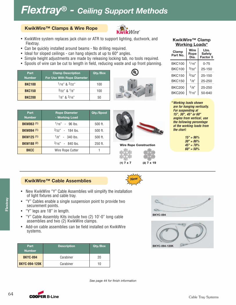
Flextray® - Ceiling Support Methods
64
Flex
tray
Cable Tray Systems
KwikWire™ Clamps & Wire Rope
See page 44 for finish information
Part Clamp Description Qty./Box
Number For Use With Rope Diameter
BKC100 1/16” & 3/32” 100
BKC150 3/32” & 1/8” 100
BKC200 1/8” & 3/16” 50
• KwikWire system replaces jack chain or ATR to support lighting, ductwork, andFlextray.
• Can be quickly installed around beams - No drilling required.• Ideal for sloped ceilings - can hang objects at up to 60° angles.• Simple height adjustments are made by releasing locking tab, no tools required.• Spools of wire can be cut to length in field, reducing waste and up front planning.
(1) 7 x 7
Wire Rope Construction
(2) 7 x 19
Part Rope Diameter Qty./Spool
Number - Working Load
BKW063 (1) 1/16” - 96 lbs. 500 ft.
BKW094 (1) 3/32” - 184 lbs. 500 ft.
BKW125 (1) 1/8” - 340 lbs. 500 ft.
BKW188 (2) 3/16” - 840 lbs. 250 ft.
BKCC Wire Rope Cutter 1
KwikWire™ Cable Assemblies
• New KwikWire “Y” Cable Assemblies will simplify the installationof light fixtures and cable tray.
• “Y” Cables enable a single suspension point to provide twosecurement points.
• “Y” legs are 18” in length.• “Y” Cable Assembly Kits include two (2) 10’-0” long cable
assemblies and two (2) KwikWire clamps.• Add-on cable assemblies can be field installed on KwikWire
systems.
Part Description Qty./Box
Number
BKYC-094 Carabiner 20
BKYC-094-120K Carabiner 10
KwikWire™ ClampWorking Loads*
Clamp Wire Lbs.
Part No. Rope SafetyDia. Factor 5
BKC100 1/16” 0-75
BKC100 3/32” 25-150
BKC150 3/32” 25-150
BKC150 1/8” 25-250
BKC200 1/8” 25-250
BKC200 3/16” 50-640
* Working loads shownare for hanging vertically.For suspending at15°, 30°, 45° or 60°angles from vertical, usethe following percentageof the working loads fromthe chart:
15° = 96%30° = 86%45° = 70%60° = 50%
BKYC-094
BKYC-094-120K
New
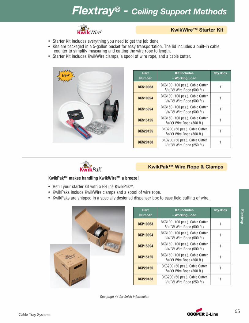
65
Flextray® - Ceiling Support MethodsFlextray
Cable Tray Systems
KwikWire™ Starter Kit
• Starter Kit includes everything you need to get the job done.• Kits are packaged in a 5-gallon bucket for easy transportation. The lid includes a built-in cable
counter to simplify measuring and cutting the wire rope to length.• Starter Kit includes KwikWire clamps, a spool of wire rope, and a cable cutter.
See page 44 for finish information
Part Kit Includes Qty./Box
Number - Working Load
BKS10063 BKC100 (100 pcs.), Cable Cutter 11/16ӯ Wire Rope (500 ft.)
BKS10094 BKC100 (100 pcs.), Cable Cutter 13/32ӯ Wire Rope (500 ft.)
BKS15094 BKC150 (100 pcs.), Cable Cutter 13/32ӯ Wire Rope (500 ft.)
BKS15125 BKC150 (100 pcs.), Cable Cutter 11/8ӯ Wire Rope (500 ft.)
BKS20125 BKC200 (50 pcs.), Cable Cutter 11/8ӯ Wire Rope (500 ft.)
BKS20188 BKC200 (50 pcs.), Cable Cutter 13/16ӯ Wire Rope (250 ft.)
New
KwikPak™ Wire Rope & Clamps
KwikPak™ makes handling KwikWire™ a breeze!
• Refill your starter kit with a B-Line KwikPak™.• KwikPaks include KwikWire clamps and a spool of wire rope.• KwikPaks are shipped in a specially designed dispenser box to ease field cutting of wire.
Part Kit Includes Qty./Box
Number - Working Load
BKP10063 BKC100 (100 pcs.), Cable Cutter 11/16ӯ Wire Rope (500 ft.)
BKP10094 BKC100 (100 pcs.), Cable Cutter 13/32ӯ Wire Rope (500 ft.)
BKP15094 BKC150 (100 pcs.), Cable Cutter 13/32ӯ Wire Rope (500 ft.)
BKP15125 BKC150 (100 pcs.), Cable Cutter 11/8ӯ Wire Rope (500 ft.)
BKP20125 BKC200 (50 pcs.), Cable Cutter 11/8ӯ Wire Rope (500 ft.)
BKP20188 BKC200 (50 pcs.), Cable Cutter 13/16ӯ Wire Rope (250 ft.)
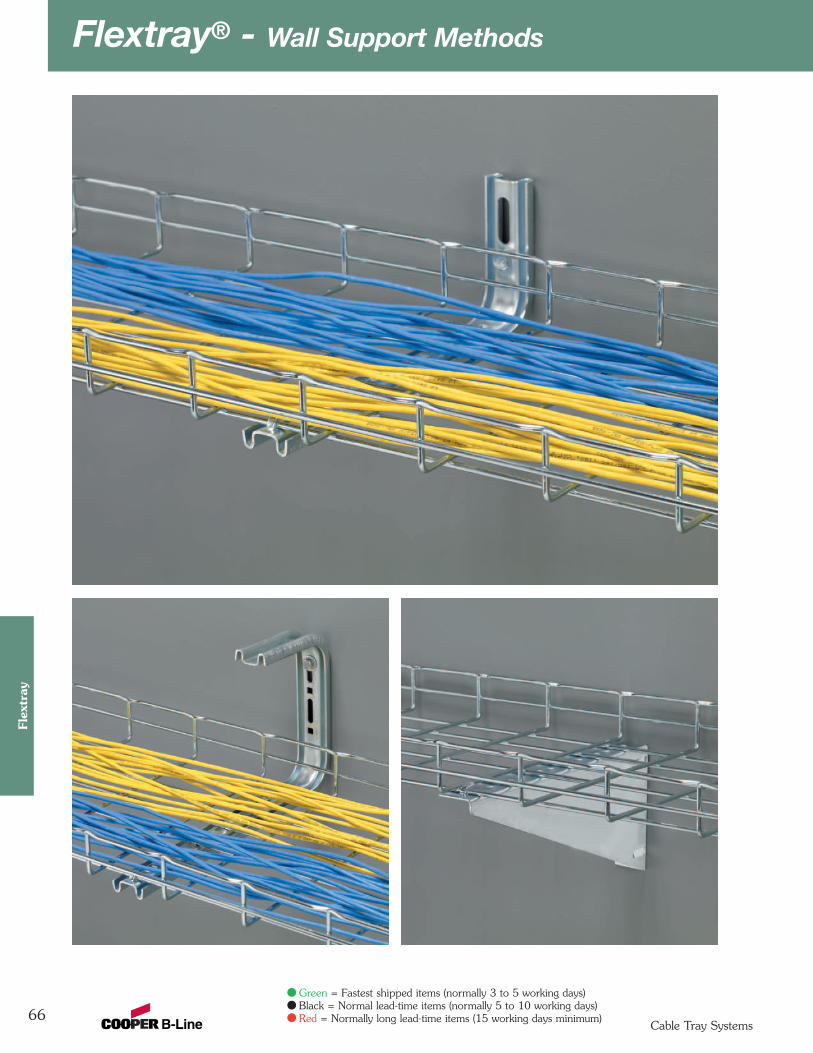
Flextray® - Wall Support Methods
66
Flex
tray
Cable Tray Systems
Green = Fastest shipped items (normally 3 to 5 working days)Black = Normal lead-time items (normally 5 to 10 working days)Red = Normally long lead-time items (15 working days minimum)
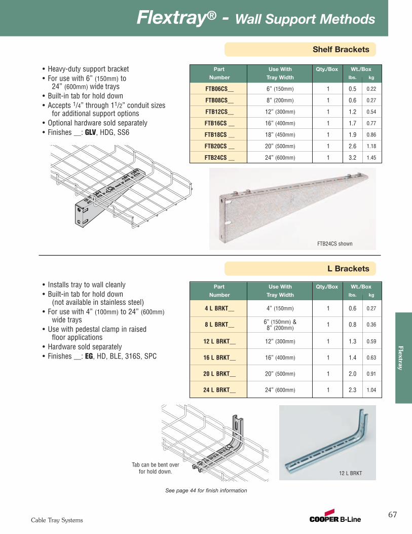
67
Flextray® - Wall Support MethodsFlextray
Cable Tray Systems
Shelf Brackets
L Brackets
Part Use With Qty./Box Wt./Box
Number Tray Width lbs. kg
FTB06CS__ 6” (150mm) 1 0.5 0.22
FTB08CS__ 8” (200mm) 1 0.6 0.27
FTB12CS__ 12” (300mm) 1 1.2 0.54
FTB16CS __ 16” (400mm) 1 1.7 0.77
FTB18CS __ 18” (450mm) 1 1.9 0.86
FTB20CS __ 20” (500mm) 1 2.6 1.18
FTB24CS __ 24” (600mm) 1 3.2 1.45
• Heavy-duty support bracket• For use with 6” (150mm) to
24” (600mm) wide trays• Built-in tab for hold down• Accepts 1/4” through 11/2” conduit sizes
for additional support options• Optional hardware sold separately• Finishes __: GLV, HDG, SS6
See page 44 for finish information
FTB24CS shown
• Installs tray to wall cleanly• Built-in tab for hold down
(not available in stainless steel) • For use with 4” (100mm) to 24” (600mm)
wide trays• Use with pedestal clamp in raised
floor applications• Hardware sold separately• Finishes __: EG, HD, BLE, 316S, SPC
Part Use With Qty./Box Wt./Box
Number Tray Width lbs. kg
4 L BRKT__ 4” (150mm) 1 0.6 0.27
8 L BRKT__ 6” (150mm) & 1 0.8 0.368” (200mm)
12 L BRKT__ 12” (300mm) 1 1.3 0.59
16 L BRKT__ 16” (400mm) 1 1.4 0.63
20 L BRKT__ 20” (500mm) 1 2.0 0.91
24 L BRKT__ 24” (600mm) 1 2.3 1.04
12 L BRKT
Tab can be bent overfor hold down.
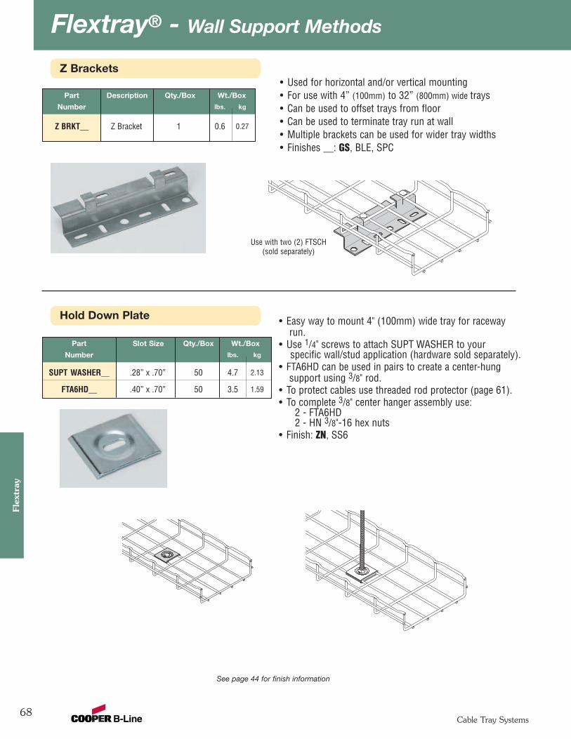
Flextray® - Wall Support Methods
68
Flex
tray
Cable Tray Systems
Z Brackets
See page 44 for finish information
Part Description Qty./Box Wt./Box
Number lbs. kg
Z BRKT__ Z Bracket 1 0.6 0.27
• Used for horizontal and/or vertical mounting• For use with 4” (100mm) to 32” (800mm) wide trays• Can be used to offset trays from floor• Can be used to terminate tray run at wall• Multiple brackets can be used for wider tray widths• Finishes __: GS, BLE, SPC
Use with two (2) FTSCH(sold separately)
Hold Down Plate
Part Slot Size Qty./Box Wt./Box
Number lbs. kg
SUPT WASHER__ .28” x .70” 50 4.7 2.13
FTA6HD__ .40” x .70” 50 3.5 1.59
• Easy way to mount 4" (100mm) wide tray for racewayrun.
• Use 1/4" screws to attach SUPT WASHER to yourspecific wall/stud application (hardware sold separately).
• FTA6HD can be used in pairs to create a center-hungsupport using 3/8" rod.
• To protect cables use threaded rod protector (page 61).• To complete 3/8" center hanger assembly use:
2 - FTA6HD2 - HN 3/8"-16 hex nuts
• Finish: ZN, SS6
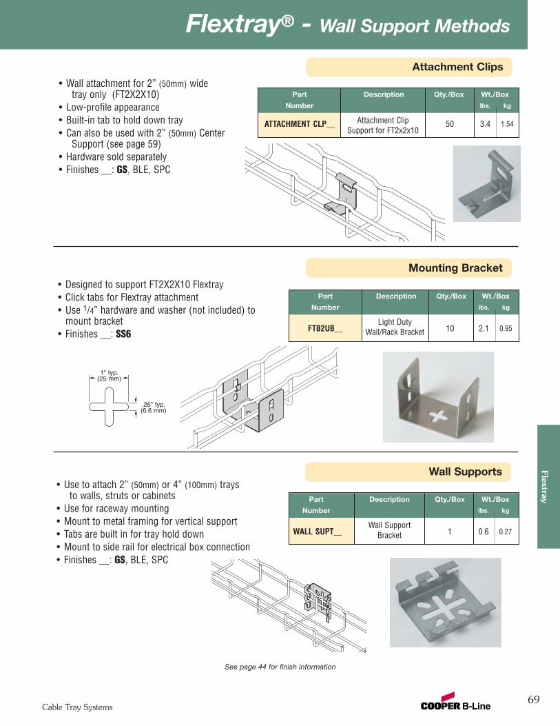
69
Flextray® - Wall Support MethodsFlextray
Cable Tray Systems
Wall Supports
See page 44 for finish information
Attachment Clips
Part Description Qty./Box Wt./Box
Number lbs. kg
ATTACHMENT CLP__ Attachment Clip 50 3.4 1.54Support for FT2x2x10
• Wall attachment for 2” (50mm) widetray only (FT2X2X10)
• Low-profile appearance• Built-in tab to hold down tray• Can also be used with 2” (50mm) Center
Support (see page 59)• Hardware sold separately• Finishes __: GS, BLE, SPC
Part Description Qty./Box Wt./Box
Number lbs. kg
Wall SupportWALL SUPT__ Bracket 1 0.6 0.27
• Use to attach 2” (50mm) or 4” (100mm) traysto walls, struts or cabinets
• Use for raceway mounting• Mount to metal framing for vertical support• Tabs are built in for tray hold down• Mount to side rail for electrical box connection• Finishes __: GS, BLE, SPC
Mounting Bracket
Part Description Qty./Box Wt./Box
Number lbs. kg
Light DutyFTB2UB__ Wall/Rack Bracket 10 2.1 0.95
• Designed to support FT2X2X10 Flextray• Click tabs for Flextray attachment• Use 1/4” hardware and washer (not included) to
mount bracket• Finishes __: SS6
.26" typ.(6.6 mm)
1" typ.(25 mm)

Flextray® - Wall Support Methods
70
Flex
tray
Cable Tray Systems
Wall Termination Kit
Part Length Qty./Box Wt./Box
Number lbs. kg
WBWTK__ 9” 1 1.3 0.59
• Kit includes all hardware necessary to supportFlextray when terminated at a wall
• Mount slotted angle to wall with up to 3/8"hardware (not included)
• Finishes __: ZN, FB, SS6
See page 44 for finish information
Vertically MountedHorizontally Mounted
Wall Termination Kit includes:
1 - SA276-9 Slotted Angle1 - FTA6HD - Hold Down1 - 3/8"-16 x 1" Slotted Head Screw1 - 3/8"-16 Hex Nut
Wall Mount Kit
Part Length Qty./Box Wt./Box
Number lbs. kg
WB48WMK__ 8” 1 0.76 0.35
WB1224WMK__ 12” 1 1.22 0.55
• Kit includes all components necessary to mountFlextray to a wall horizontally or vertically
• Mount strut to wall with up to 1/2" hardware(not included)
• Finish: Channel - GLVHardware - ZNAvailable in SS6
Wall Mount Kit includes:
WB48WMK WB1224WMK1 1 B54SH Strut1 2 SUPT WASHER Hold Downs1 2 1/4"-20 x 1" Slotted Head Screw1 2 N224WO Channel Nut
WB1224WMK shown
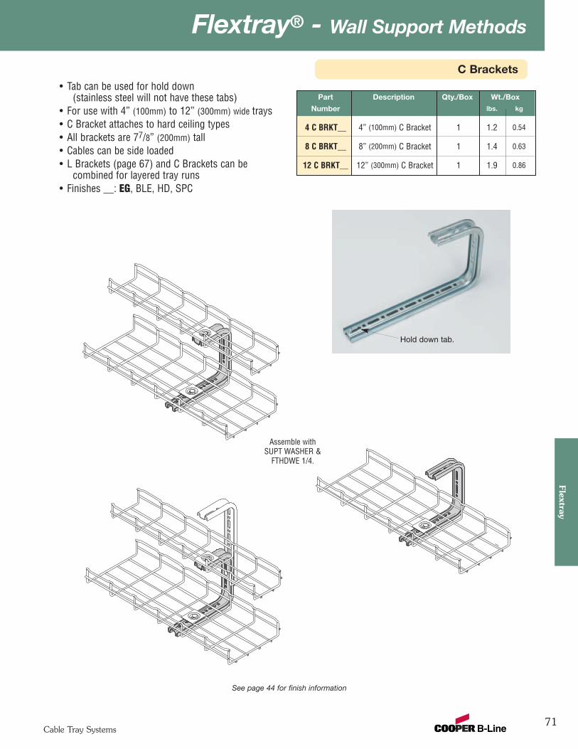
71
Flextray® - Wall Support MethodsFlextray
Cable Tray Systems
C Brackets
Part Description Qty./Box Wt./Box
Number lbs. kg
4 C BRKT__ 4” (100mm) C Bracket 1 1.2 0.54
8 C BRKT__ 8” (200mm) C Bracket 1 1.4 0.63
12 C BRKT__ 12” (300mm) C Bracket 1 1.9 0.86
• Tab can be used for hold down(stainless steel will not have these tabs)
• For use with 4” (100mm) to 12” (300mm) wide trays• C Bracket attaches to hard ceiling types• All brackets are 77/8” (200mm) tall• Cables can be side loaded• L Brackets (page 67) and C Brackets can be
combined for layered tray runs• Finishes __: EG, BLE, HD, SPC
See page 44 for finish information
Hold down tab.
Assemble withSUPT WASHER &
FTHDWE 1/4.
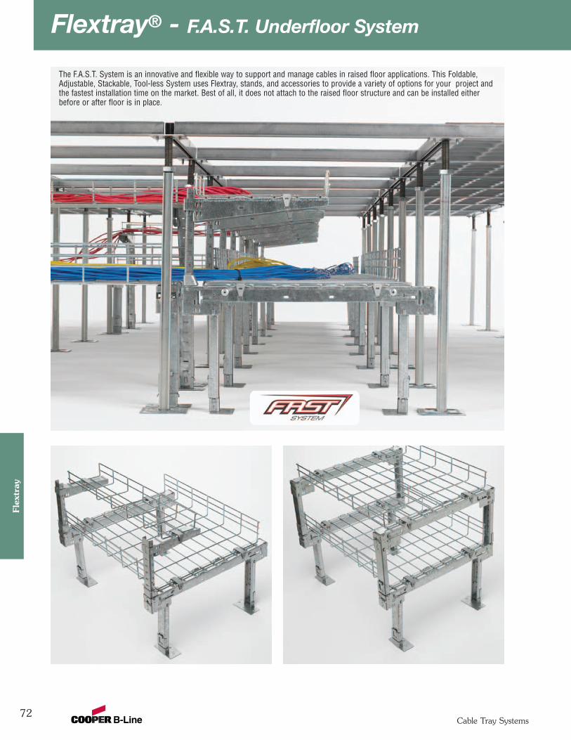
Flextray® - F.A.S.T. Underfloor System
72Cable Tray Systems
Flex
tray
The F.A.S.T. System is an innovative and flexible way to support and manage cables in raised floor applications. This Foldable,Adjustable, Stackable, Tool-less System uses Flextray, stands, and accessories to provide a variety of options for your project andthe fastest installation time on the market. Best of all, it does not attach to the raised floor structure and can be installed eitherbefore or after floor is in place.
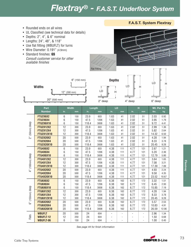
73
Flextray® - F.A.S.T. Underfloor System
Cable Tray Systems
Flextray
See page 44 for finish information
6” (150 mm)
2” deep 4” deep 6” deep
12” (300 mm)
20” (500 mm)
Widths
Depths
LD H
Part Width Length LD H Wt. Per Pc.Number in. mm in. mm in. mm in. mm lbs. kg
FTU2X6X2 6 150 23.9 603 1.63 41 2.02 51 2.03 0.92FTU2X6X4 6 150 47.5 1206 1.63 41 2.02 51 3.95 1.79FTU2X6X10 6 150 118.4 3008 1.63 41 2.02 51 9.72 4.41FTU2X12X2 12 300 23.9 603 1.63 41 2.02 51 2.99 1.36FTU2X12X4 12 300 47.5 1206 1.63 41 2.02 51 5.82 2.64FTU2X12X10 12 300 118.4 3008 1.63 41 2.02 51 14.32 6.50FTU2X20X2 20 500 23.9 603 1.63 41 2.02 51 4.28 1.94FTU2X20X4 20 500 47.5 1206 1.63 41 2.02 51 8.33 3.78FTU2X20X10 20 500 118.4 3008 1.63 41 2.02 51 20.45 9.28
FTU4X6X2 6 150 23.9 603 4.38 111 4.77 121 2.67 1.21FTU4X6X4 6 150 47.5 1206 4.38 111 4.77 121 5.20 2.36FTU4X6X10 6 150 118.4 3008 4.38 111 4.77 121 12.79 5.80FTU4X12X2 12 300 23.9 603 4.38 111 4.77 121 3.64 1.65FTU4X12X4 12 300 47.5 1206 4.38 111 4.77 121 7.08 3.21FTU4X12X10 12 300 118.4 3008 4.38 111 4.77 121 17.39 7.89FTU4X20X2 20 500 23.9 603 4.38 111 4.77 121 4.93 2.24FTU4X20X4 20 500 47.5 1206 4.38 111 4.77 121 9.58 4.35FTU4X20X10 20 500 118.4 3008 4.38 111 4.77 121 23.52 10.67
FTU6X6X2 6 150 23.9 603 6.38 162 6.77 172 3.32 1.51FTU6X6X4 6 150 47.5 1206 6.38 162 6.77 172 6.45 2.93FTU6X6X10 6 150 118.4 3008 6.38 162 6.77 172 15.85 7.19FTU6X12X2 12 300 23.9 603 6.38 162 6.77 172 4.28 1.94FTU6X12X4 12 300 47.5 1206 6.38 162 6.77 172 8.33 3.78FTU6X12X10 12 300 118.4 3008 6.38 162 6.77 172 20.45 9.28FTU6X20X2 20 500 23.9 603 6.38 162 6.77 172 5.57 2.53FTU6X20X4 20 500 47.5 1206 6.38 162 6.77 172 10.83 4.91FTU6X20X10 20 500 118.4 3008 6.38 162 6.77 172 26.59 12.06
WBUFLT 20 500 24 604 - - - - 2.96 1.34WBUFLT-12 12 250 24 604 - - - - 1.50 0.68WBUFLT-06 6 150 24 604 - - - - 1.00 0.45
LD HLD H
2” (5
0mm
)de
ep4”
(100
mm
)de
ep6”
(150
mm
)de
epFl
ats
Flat Fitting
• Rounded ends on all wires • UL Classified (see technical data for details)• Depths: 2”, 4”, & 6” nominal • Lengths: 24”, 48”, & 118”• Use flat fitting (WBUFLT) for turns• Wire Diameter: 0.191” (4.9mm)
• Standard finishes: GSConsult customer service for otheravailable finishes
F.A.S.T. System Flextray
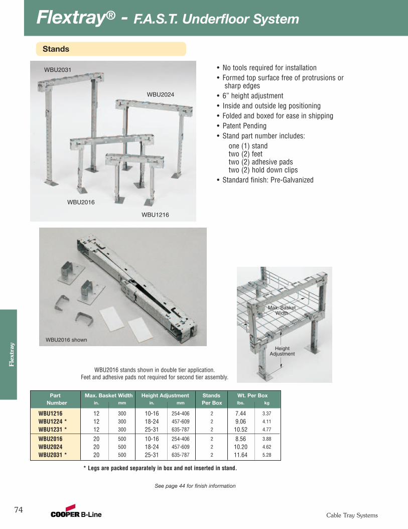
Flextray® - F.A.S.T. Underfloor System
74Cable Tray Systems
Flex
tray
See page 44 for finish information
Part Max. Basket Width Height Adjustment Stands Wt. Per BoxNumber in. mm in. mm Per Box lbs. kg
WBU1216 12 300 10-16 254-406 2 7.44 3.37
WBU1224 * 12 300 18-24 457-609 2 9.06 4.11
WBU1231 * 12 300 25-31 635-787 2 10.52 4.77
WBU2016 20 500 10-16 254-406 2 8.56 3.88
WBU2024 20 500 18-24 457-609 2 10.20 4.62
WBU2031 * 20 500 25-31 635-787 2 11.64 5.28
WBU2016
WBU2016 shown
WBU1216
WBU2024
WBU2031
* Legs are packed separately in box and not inserted in stand.
WBU2016 stands shown in double tier application.Feet and adhesive pads not required for second tier assembly.
HeightAdjustment
Max. BasketWidth
• No tools required for installation • Formed top surface free of protrusions or
sharp edges • 6” height adjustment • Inside and outside leg positioning• Folded and boxed for ease in shipping• Patent Pending• Stand part number includes:
one (1) standtwo (2) feettwo (2) adhesive padstwo (2) hold down clips
• Standard finish: Pre-Galvanized
Stands
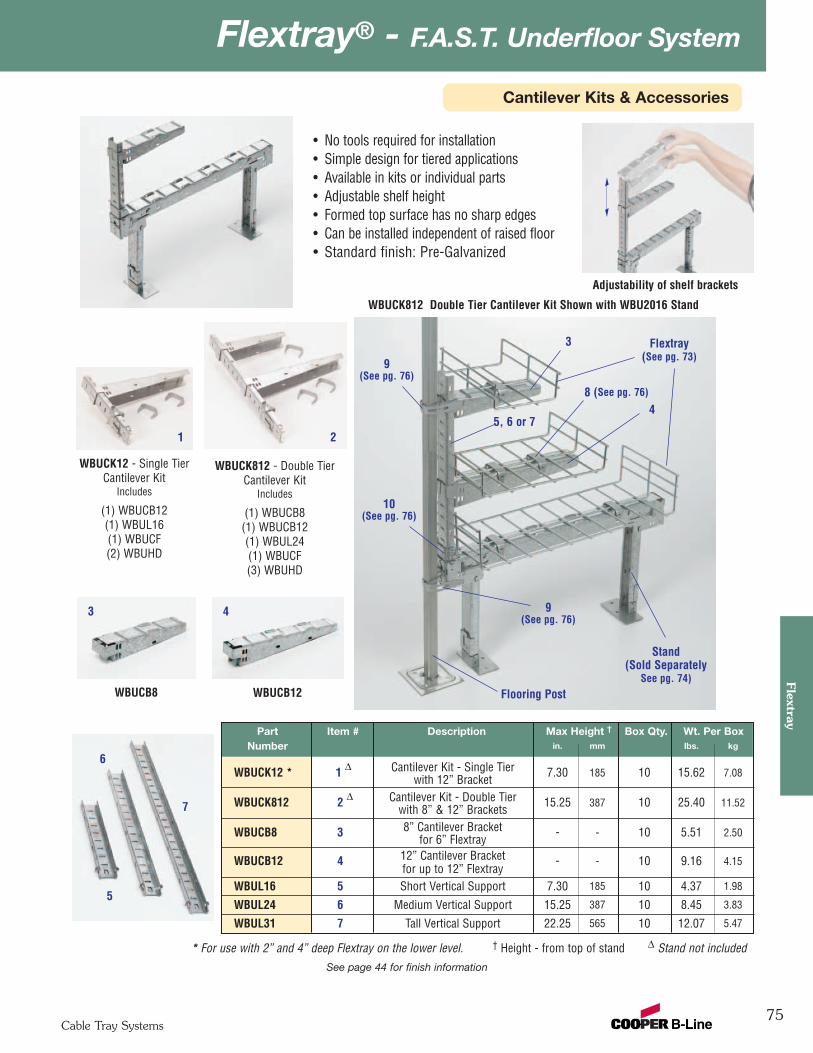
75
Flextray® - F.A.S.T. Underfloor System
Cable Tray Systems
Flextray
See page 44 for finish information
WBUCK12 - Single TierCantilever Kit
Includes
(1) WBUCB12(1) WBUL16(1) WBUCF(2) WBUHD
WBUCB8 WBUCB12
WBUCK812 - Double TierCantilever Kit
Includes
(1) WBUCB8(1) WBUCB12(1) WBUL24(1) WBUCF(3) WBUHD
Part Item # Description Max Height † Box Qty. Wt. Per BoxNumber in. mm lbs. kg
WBUCK12 * 1 ∆ Cantilever Kit - Single Tier 7.30 185 10 15.62 7.08with 12” Bracket
WBUCK812 2 ∆ Cantilever Kit - Double Tier 15.25 387 10 25.40 11.52with 8” & 12” Brackets
WBUCB8 3 8” Cantilever Bracket - - 10 5.51 2.50for 6” Flextray
WBUCB12 4 12” Cantilever Bracket - - 10 9.16 4.15for up to 12” Flextray
WBUL16 5 Short Vertical Support 7.30 185 10 4.37 1.98
WBUL24 6 Medium Vertical Support 15.25 387 10 8.45 3.83
WBUL31 7 Tall Vertical Support 22.25 565 10 12.07 5.47
* For use with 2” and 4” deep Flextray on the lower level. † Height - from top of stand ∆ Stand not included
1
WBUCK812 Double Tier Cantilever Kit Shown with WBU2016 Stand
Flextray (See pg. 73)
Adjustability of shelf brackets
Stand(Sold Separately
See pg. 74)Flooring Post
2
3 4
3
4
5
7
5, 6 or 7
8 (See pg. 76)
10(See pg. 76)
9(See pg. 76)
6
9(See pg. 76)
• No tools required for installation • Simple design for tiered applications • Available in kits or individual parts• Adjustable shelf height• Formed top surface has no sharp edges • Can be installed independent of raised floor • Standard finish: Pre-Galvanized
Cantilever Kits & Accessories
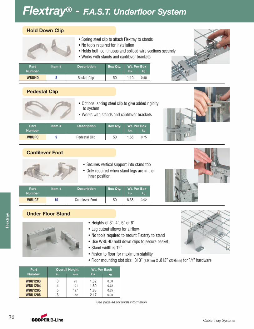
Flextray® - F.A.S.T. Underfloor System
76Cable Tray Systems
Flex
tray
See page 44 for finish information
Part Overall Height Wt. Per EachNumber in. mm lbs. kg
WBU1203 3 76 1.32 0.60WBU1204 4 101 1.60 0.72WBU1205 5 127 1.88 0.85WBU1206 6 152 2.17 0.98
Part Item # Description Box Qty. Wt. Per BoxNumber lbs. kg
WBUHD 8 Basket Clip 50 1.10 0.50
Part Item # Description Box Qty. Wt. Per BoxNumber lbs. kg
WBUPC 9 Pedestal Clip 50 1.65 0.75
Part Item # Description Box Qty. Wt. Per BoxNumber lbs. kg
WBUCF 10 Cantilever Foot 50 8.65 3.92
• Heights of 3”, 4”, 5” or 6”• Leg cutout allows for airflow• No tools required to mount Flextray to stand• Use WBUHD hold down clips to secure basket• Stand width is 12” • Fasten to floor for maximum stability• Floor mounting slot size: .313” (7.9mm) x .813” (20.6mm) for 1/4” hardware
• Secures vertical support into stand top• Only required when stand legs are in the
inner position
• Optional spring steel clip to give added rigidityto system
• Works with stands and cantilever brackets
• Spring steel clip to attach Flextray to stands• No tools required for installation• Holds both continuous and spliced wire sections securely • Works with stands and cantilever brackets
Hold Down Clip
Pedestal Clip
Cantilever Foot
Under Floor Stand
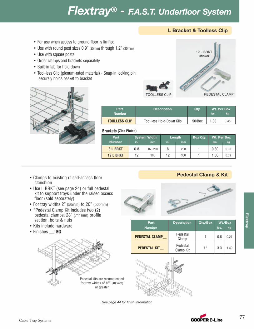
77
Flextray® - F.A.S.T. Underfloor System
Cable Tray Systems
Flextray
See page 44 for finish information
Part System Width Length Box Qty. Wt. Per BoxNumber in. mm in. mm lbs. kg
8 L BRKT 6-8 150-200 8 200 1 0.80 0.36
12 L BRKT 12 300 12 300 1 1.30 0.59
Part Description Qty. Wt. Per BoxNumber lbs. kg
TOOLLESS CLIP Tool-less Hold-Down Clip 50/Box 1.00 0.45
• For use when access to ground floor is limited• Use with round post sizes 0.9” (25mm) through 1.2” (30mm)
• Use with square posts• Order clamps and brackets separately• Built-in tab for hold down• Tool-less Clip (plenum-rated material) - Snap-in locking pin
securely holds basket to bracket
Brackets (Zinc Plated)
12 L BRKTshown
PEDESTAL CLAMPTOOLLESS CLIP
L Bracket & Toolless Clip
Pedestal Clamp & Kit
Part Description Qty./Box Wt./Box
Number lbs. kg
PedestalPEDESTAL CLAMP__ Clamp 1 0.6 0.27
PedestalPEDESTAL KIT__ Clamp Kit 1* 3.3 1.49
• Clamps to existing raised-access floorstanchion
• Use L BRKT (see page 24) or full pedestalkit to support trays under the raised accessfloor (sold separately)
• For tray widths 2” (50mm) to 20” (500mm)• *Pedestal Clamp Kit includes two (2)
pedestal clamps, 28” (711mm) profilesection, bolts & nuts
• Kits include hardware• Finishes __: EG
Pedestal kits are recommendedfor tray widths of 16” (400mm)
or greater
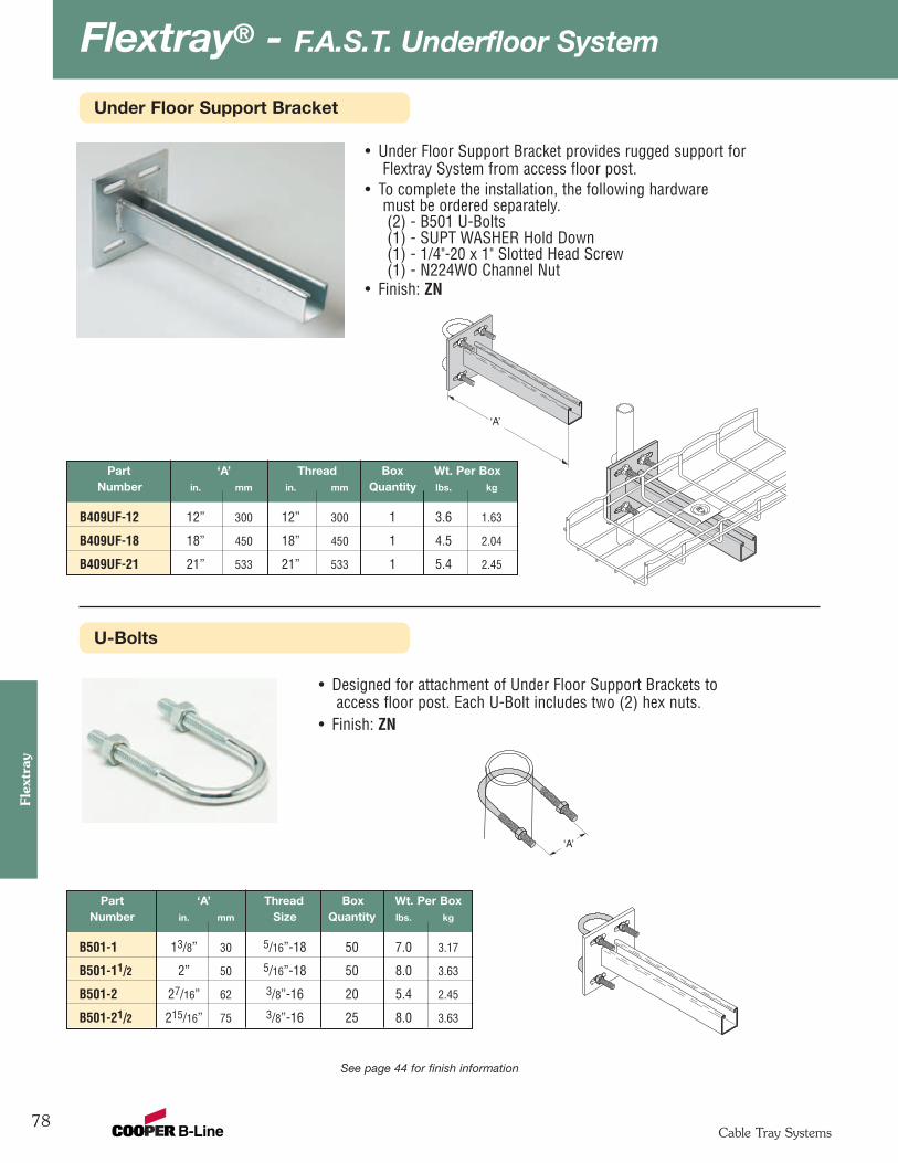
Flextray® - F.A.S.T. Underfloor System
78Cable Tray Systems
Flex
tray
See page 44 for finish information
• Under Floor Support Bracket provides rugged support forFlextray System from access floor post.
• To complete the installation, the following hardwaremust be ordered separately.(2) - B501 U-Bolts(1) - SUPT WASHER Hold Down(1) - 1/4"-20 x 1" Slotted Head Screw(1) - N224WO Channel Nut
• Finish: ZN
• Designed for attachment of Under Floor Support Brackets toaccess floor post. Each U-Bolt includes two (2) hex nuts.
• Finish: ZN
Part ‘A’ Thread Box Wt. Per BoxNumber in. mm Size Quantity lbs. kg
B501-1 13/8” 30 5/16”-18 50 7.0 3.17
B501-11/2 2” 50 5/16”-18 50 8.0 3.63
B501-2 27/16” 62 3/8”-16 20 5.4 2.45
B501-21/2 215/16” 75 3/8”-16 25 8.0 3.63
‘A’
‘A’
Part ‘A’ Thread Box Wt. Per BoxNumber in. mm in. mm Quantity lbs. kg
B409UF-12 12” 300 12” 300 1 3.6 1.63
B409UF-18 18” 450 18” 450 1 4.5 2.04
B409UF-21 21” 533 21” 533 1 5.4 2.45
Under Floor Support Bracket
U-Bolts

79
Flextray® - F.A.S.T. Underfloor System
Cable Tray Systems
Flextray
See page 44 for finish information
Part Description Box Qty. Wt. Per BoxNumber lbs. kg
WBUF Stand Foot 10 2.36 1.07
WBUTAPE Double-Sided Tape 50 2.50 1.13
WBUFA Floor Adhesive 1 Gallon 10.78 4.89
WBUFWBUTAPE
WBUFA
• WBUTAPE - Double-sided adhesive padsfor temporary positioning of floor standsPad Size: 2” (50mm) x 4” (100mm)
• WBUFA - Adhesive to secure stand to floor
Ground Bolt
Adhesive & Feet
Part Description Qty./Box Wt./Box
Number lbs. kg
GROUND BOLT Ground Bolt 1 0.11 0.05
• Attaches up to #1 ground wire to each traysection when separate ground wire is required
• Used for UL grounding compliance. • When using color powder coated finish or
paint, coating must be removed at the pointsof contact.
• Finish: Copper Plated
Floor Stand
• Non-metallic snap lock floor stand isdesigned for use under access floors.
• Floor stand elevates Flextray System15/8" (41.3mm) above the floor.
• To attach floor stand, use Liquid Nails™or anchors.
• Elevation increments of 13/8" (35mm)can be obtained by stacking floorstands.
• Sized for 1/4" hardware(order separately).
• Material: Black Plenum-rated PlasticPart Wt. Per Pc. Box
Number lbs. kg Quantity
FTA2FS 0.44 0.20 10
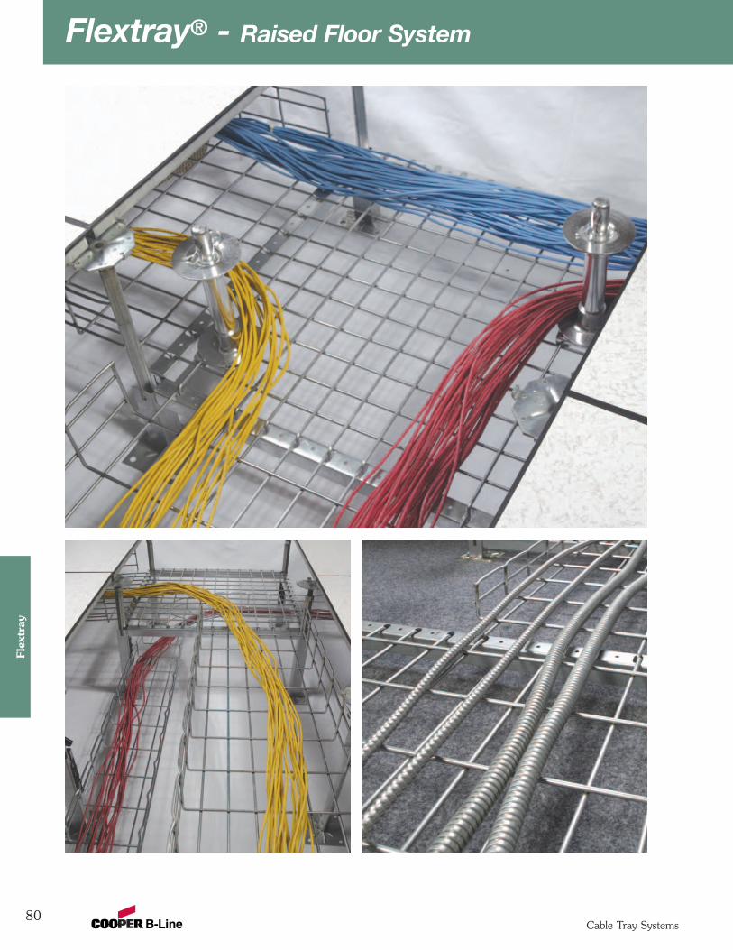
Flextray® - Raised Floor System
80Cable Tray Systems
Flex
tray
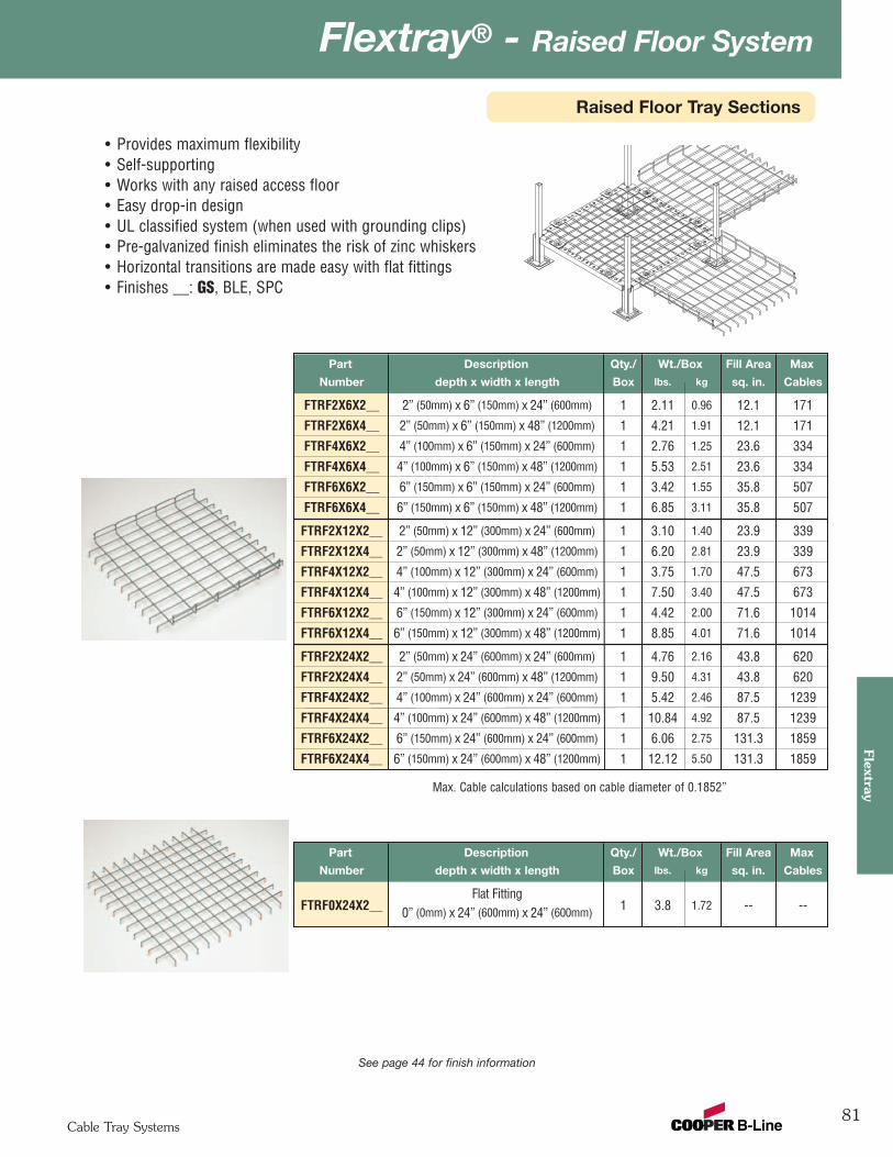
81
Flextray® - Raised Floor System
Cable Tray Systems
Flextray
Raised Floor Tray Sections
Part Description Qty./ Wt./Box Fill Area Max
Number depth x width x length Box lbs. kg sq. in. Cables
FTRF2X6X2__ 2” (50mm) x 6” (150mm) x 24” (600mm) 1 2.11 0.96 12.1 171
FTRF2X6X4__ 2” (50mm) x 6” (150mm) x 48” (1200mm) 1 4.21 1.91 12.1 171
FTRF4X6X2__ 4” (100mm) x 6” (150mm) x 24” (600mm) 1 2.76 1.25 23.6 334
FTRF4X6X4__ 4” (100mm) x 6” (150mm) x 48” (1200mm) 1 5.53 2.51 23.6 334
FTRF6X6X2__ 6” (150mm) x 6” (150mm) x 24” (600mm) 1 3.42 1.55 35.8 507
FTRF6X6X4__ 6” (150mm) x 6” (150mm) x 48” (1200mm) 1 6.85 3.11 35.8 507
FTRF2X12X2__ 2” (50mm) x 12” (300mm) x 24” (600mm) 1 3.10 1.40 23.9 339
FTRF2X12X4__ 2” (50mm) x 12” (300mm) x 48” (1200mm) 1 6.20 2.81 23.9 339
FTRF4X12X2__ 4” (100mm) x 12” (300mm) x 24” (600mm) 1 3.75 1.70 47.5 673
FTRF4X12X4__ 4” (100mm) x 12” (300mm) x 48” (1200mm) 1 7.50 3.40 47.5 673
FTRF6X12X2__ 6” (150mm) x 12” (300mm) x 24” (600mm) 1 4.42 2.00 71.6 1014
FTRF6X12X4__ 6” (150mm) x 12” (300mm) x 48” (1200mm) 1 8.85 4.01 71.6 1014
FTRF2X24X2__ 2” (50mm) x 24” (600mm) x 24” (600mm) 1 4.76 2.16 43.8 620
FTRF2X24X4__ 2” (50mm) x 24” (600mm) x 48” (1200mm) 1 9.50 4.31 43.8 620
FTRF4X24X2__ 4” (100mm) x 24” (600mm) x 24” (600mm) 1 5.42 2.46 87.5 1239
FTRF4X24X4__ 4” (100mm) x 24” (600mm) x 48” (1200mm) 1 10.84 4.92 87.5 1239
FTRF6X24X2__ 6” (150mm) x 24” (600mm) x 24” (600mm) 1 6.06 2.75 131.3 1859
FTRF6X24X4__ 6” (150mm) x 24” (600mm) x 48” (1200mm) 1 12.12 5.50 131.3 1859
• Provides maximum flexibility• Self-supporting• Works with any raised access floor• Easy drop-in design• UL classified system (when used with grounding clips)• Pre-galvanized finish eliminates the risk of zinc whiskers• Horizontal transitions are made easy with flat fittings• Finishes __: GS, BLE, SPC
Part Description Qty./ Wt./Box Fill Area Max
Number depth x width x length Box lbs. kg sq. in. Cables
FTRF0X24X2__Flat Fitting
1 3.8 1.72 -- --0” (0mm) x 24” (600mm) x 24” (600mm)
See page 44 for finish information
Max. Cable calculations based on cable diameter of 0.1852”
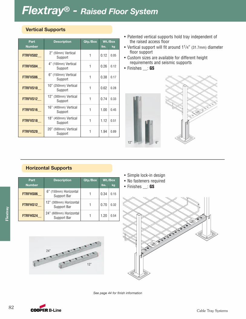
Flextray® - Raised Floor System
82Cable Tray Systems
Flex
tray
Horizontal Supports
Vertical Supports• Patented vertical supports hold tray independent of
the raised access floor• Vertical support will fit around 11/4” (31.7mm) diameter
floor support• Custom sizes are available for different height
requirements and seismic supports• Finishes __: GS
Part Description Qty./Box Wt./Box
Number lbs. kg
6” (150mm) HorizontalFTRFHS06__ Support Bar 1 0.34 0.15
12” (300mm) HorizontalFTRFHS12__ Support Bar 1 0.70 0.32
24” (600mm) HorizontalFTRFHS24__ Support Bar 1 1.20 0.54
• Simple lock-in design• No fasteners required• Finishes __: GS
See page 44 for finish information
Part Description Qty./Box Wt./Box
Number lbs. kg
2” (50mm) VerticalFTRFVS02__ Support 1 0.12 0.05
4” (100mm) VerticalFTRFVS04__ Support 1 0.26 0.12
6” (150mm) VerticalFTRFVS06__ Support 1 0.38 0.17
10” (250mm) VerticalFTRFVS10__ Support 1 0.62 0.28
12” (300mm) VerticalFTRFVS12__ Support 1 0.74 0.33
16” (400mm) VerticalFTRFVS16__ Support 1 1.00 0.45
18” (450mm) VerticalFTRFVS18__ Support 1 1.12 0.51
20” (500mm) VerticalFTRFVS20__ Support 1 1.94 0.89
6”12”
12”
24”
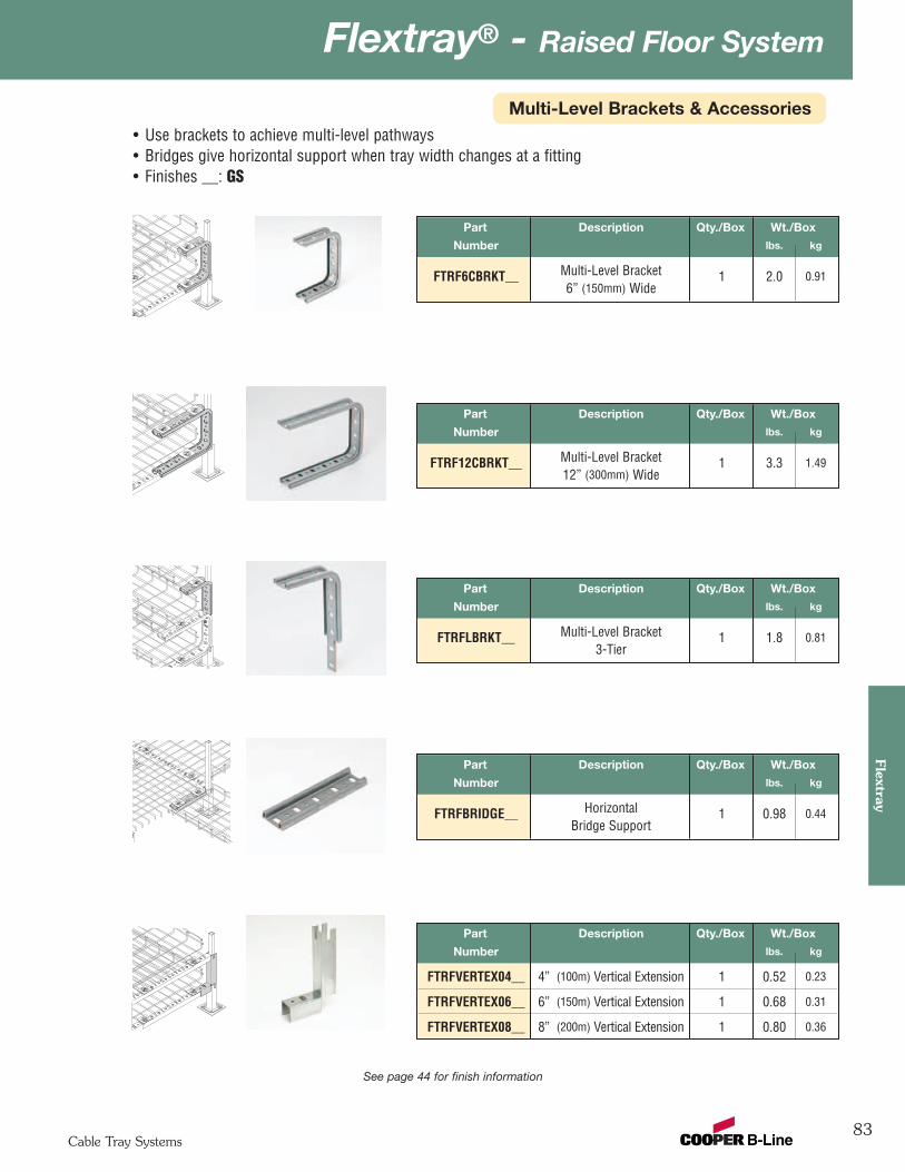
83
Flextray® - Raised Floor System
Cable Tray Systems
Flextray
Multi-Level Brackets & Accessories
Part Description Qty./Box Wt./Box
Number lbs. kg
FTRF6CBRKT__ Multi-Level Bracket 1 2.0 0.916” (150mm) Wide
• Use brackets to achieve multi-level pathways• Bridges give horizontal support when tray width changes at a fitting• Finishes __: GS
See page 44 for finish information
Part Description Qty./Box Wt./Box
Number lbs. kg
FTRF12CBRKT__ Multi-Level Bracket 1 3.3 1.4912” (300mm) Wide
Part Description Qty./Box Wt./Box
Number lbs. kg
FTRFLBRKT__ Multi-Level Bracket 1 1.8 0.813-Tier
Part Description Qty./Box Wt./Box
Number lbs. kg
FTRFBRIDGE__ Horizontal 1 0.98 0.44Bridge Support
Part Description Qty./Box Wt./Box
Number lbs. kg
FTRFVERTEX04__ 4” (100m) Vertical Extension 1 0.52 0.23
FTRFVERTEX06__ 6” (150m) Vertical Extension 1 0.68 0.31
FTRFVERTEX08__ 8” (200m) Vertical Extension 1 0.80 0.36
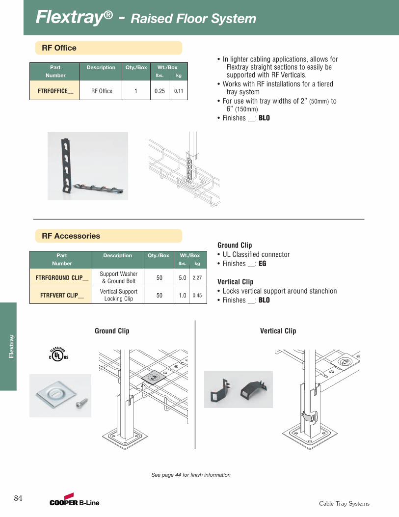
Flextray® - Raised Floor System
84Cable Tray Systems
Flex
tray
RF AccessoriesGround Clip• UL Classified connector• Finishes __: EG
Vertical Clip• Locks vertical support around stanchion• Finishes __: BLO
Ground Clip Vertical Clip
See page 44 for finish information
Part Description Qty./Box Wt./Box
Number lbs. kg
Support WasherFTRFGROUND CLIP__ & Ground Bolt 50 5.0 2.27
Vertical SupportFTRFVERT CLIP__ Locking Clip 50 1.0 0.45
RF Office
Part Description Qty./Box Wt./Box
Number lbs. kg
FTRFOFFICE__ RF Office 1 0.25 0.11
• In lighter cabling applications, allows forFlextray straight sections to easily besupported with RF Verticals.
• Works with RF installations for a tieredtray system
• For use with tray widths of 2” (50mm) to6” (150mm)
• Finishes __: BLO
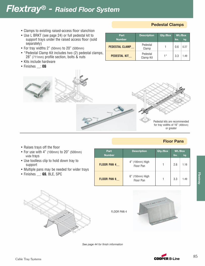
85
Flextray® - Raised Floor System
Cable Tray Systems
Flextray
Pedestal Clamps
See page 44 for finish information
Floor Pans
Part Description Qty./Box Wt./Box
Number lbs. kg
4” (100mm) HighFLOOR PAN 4__ Floor Pan 1 2.6 1.18
6” (150mm) HighFLOOR PAN 6__ Floor Pan 1 3.3 1.49
• Raises trays off the floor• For use with 4” (100mm) to 20” (500mm)
wide trays• Use toolless clip to hold down tray to
support• Multiple pans may be needed for wider trays• Finishes __: GS, BLE, SPC
FLOOR PAN 4
Part Description Qty./Box Wt./Box
Number lbs. kg
PedestalPEDESTAL CLAMP__ Clamp 1 0.6 0.27
PedestalPEDESTAL KIT__ Clamp Kit 1* 3.3 1.49
• Clamps to existing raised-access floor stanchion• Use L BRKT (see page 24) or full pedestal kit to
support trays under the raised access floor (soldseparately)
• For tray widths 2” (50mm) to 20” (500mm)• *Pedestal Clamp Kit includes two (2) pedestal clamps,
28” (711mm) profile section, bolts & nuts• Kits include hardware• Finishes __: EG
Pedestal kits are recommendedfor tray widths of 16” (400mm)
or greater
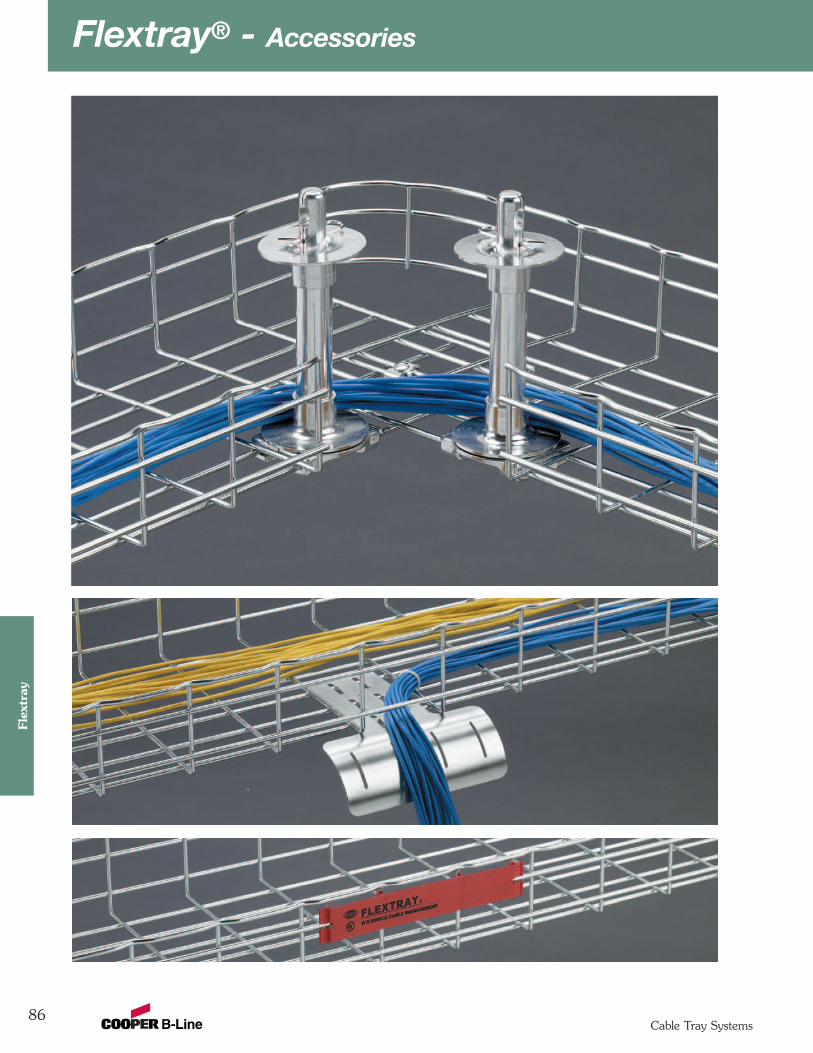
Flextray® - Accessories
86Cable Tray Systems
Flex
tray
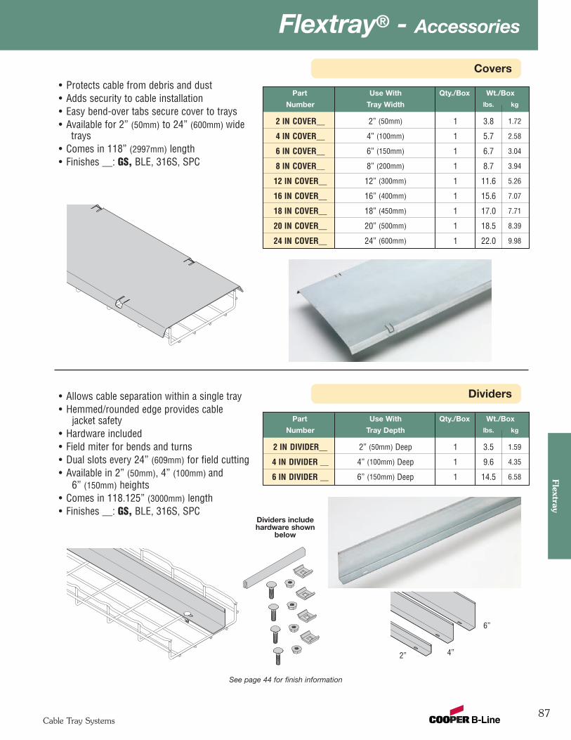
87
Flextray® - Accessories
Cable Tray Systems
Flextray
Covers
Dividers
Part Use With Qty./Box Wt./Box
Number Tray Width lbs. kg
2 IN COVER__ 2” (50mm) 1 3.8 1.72
4 IN COVER__ 4” (100mm) 1 5.7 2.58
6 IN COVER__ 6” (150mm) 1 6.7 3.04
8 IN COVER__ 8” (200mm) 1 8.7 3.94
12 IN COVER__ 12” (300mm) 1 11.6 5.26
16 IN COVER__ 16” (400mm) 1 15.6 7.07
18 IN COVER__ 18” (450mm) 1 17.0 7.71
20 IN COVER__ 20” (500mm) 1 18.5 8.39
24 IN COVER__ 24” (600mm) 1 22.0 9.98
• Protects cable from debris and dust• Adds security to cable installation• Easy bend-over tabs secure cover to trays• Available for 2” (50mm) to 24” (600mm) wide
trays• Comes in 118” (2997mm) length• Finishes __: GS, BLE, 316S, SPC
See page 44 for finish information
• Allows cable separation within a single tray• Hemmed/rounded edge provides cable
jacket safety• Hardware included• Field miter for bends and turns• Dual slots every 24” (609mm) for field cutting• Available in 2” (50mm), 4” (100mm) and
6” (150mm) heights• Comes in 118.125” (3000mm) length• Finishes __: GS, BLE, 316S, SPC
Part Use With Qty./Box Wt./Box
Number Tray Depth lbs. kg
2 IN DIVIDER__ 2” (50mm) Deep 1 3.5 1.59
4 IN DIVIDER __ 4” (100mm) Deep 1 9.6 4.35
6 IN DIVIDER __ 6” (150mm) Deep 1 14.5 6.58
2” 4”
6”
Dividers includehardware shown
below
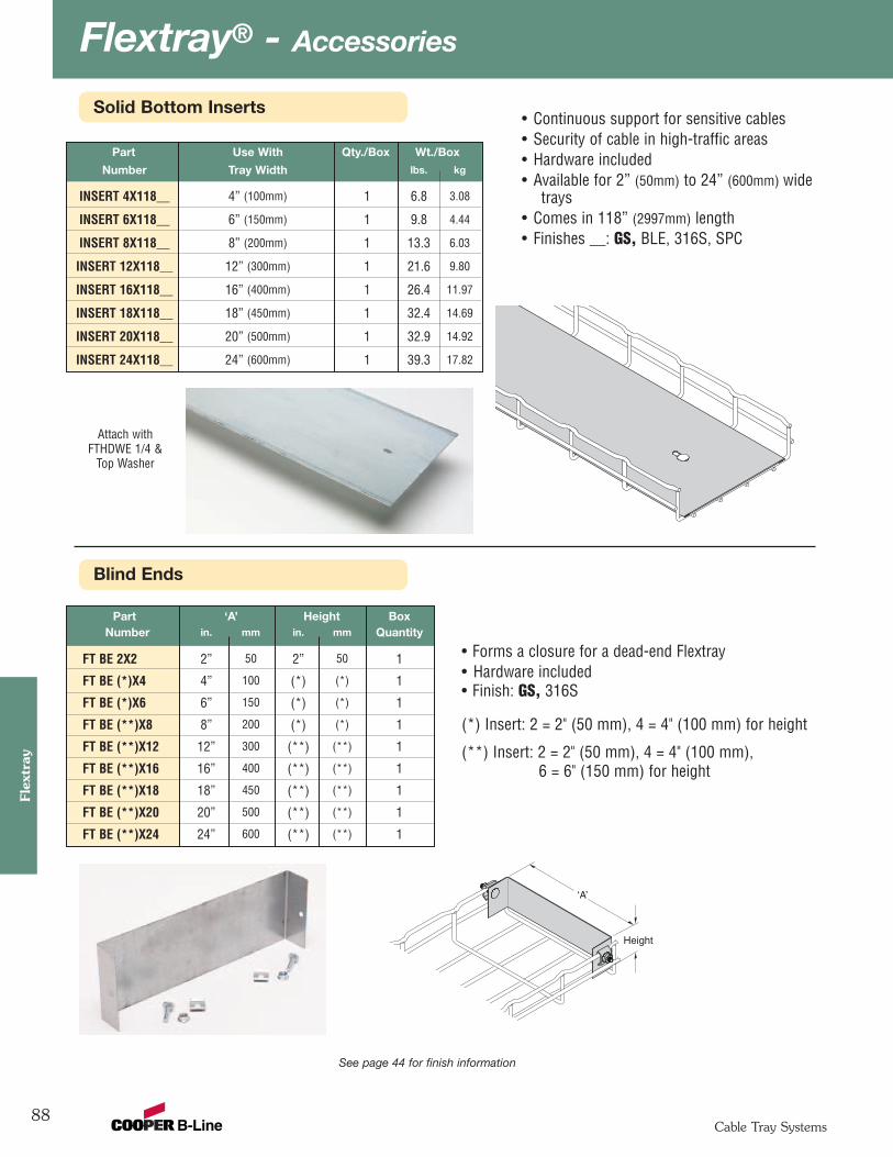
Flextray® - Accessories
88Cable Tray Systems
Flex
tray
Blind Ends
Solid Bottom Inserts• Continuous support for sensitive cables• Security of cable in high-traffic areas• Hardware included• Available for 2” (50mm) to 24” (600mm) wide
trays• Comes in 118” (2997mm) length• Finishes __: GS, BLE, 316S, SPC
See page 44 for finish information
Attach withFTHDWE 1/4 &
Top Washer
Part Use With Qty./Box Wt./Box
Number Tray Width lbs. kg
INSERT 4X118__ 4” (100mm) 1 6.8 3.08
INSERT 6X118__ 6” (150mm) 1 9.8 4.44
INSERT 8X118__ 8” (200mm) 1 13.3 6.03
INSERT 12X118__ 12” (300mm) 1 21.6 9.80
INSERT 16X118__ 16” (400mm) 1 26.4 11.97
INSERT 18X118__ 18” (450mm) 1 32.4 14.69
INSERT 20X118__ 20” (500mm) 1 32.9 14.92
INSERT 24X118__ 24” (600mm) 1 39.3 17.82
‘A’
Height
• Forms a closure for a dead-end Flextray • Hardware included• Finish: GS, 316S
(*) Insert: 2 = 2" (50 mm), 4 = 4" (100 mm) for height
(**) Insert: 2 = 2" (50 mm), 4 = 4" (100 mm),6 = 6" (150 mm) for height
Part ‘A’ Height BoxNumber in. mm in. mm Quantity
FT BE 2X2 2” 50 2” 50 1
FT BE (*)X4 4” 100 (*) (*) 1
FT BE (*)X6 6” 150 (*) (*) 1
FT BE (**)X8 8” 200 (*) (*) 1
FT BE (**)X12 12” 300 (**) (**) 1
FT BE (**)X16 16” 400 (**) (**) 1
FT BE (**)X18 18” 450 (**) (**) 1
FT BE (**)X20 20” 500 (**) (**) 1
FT BE (**)X24 24” 600 (**) (**) 1
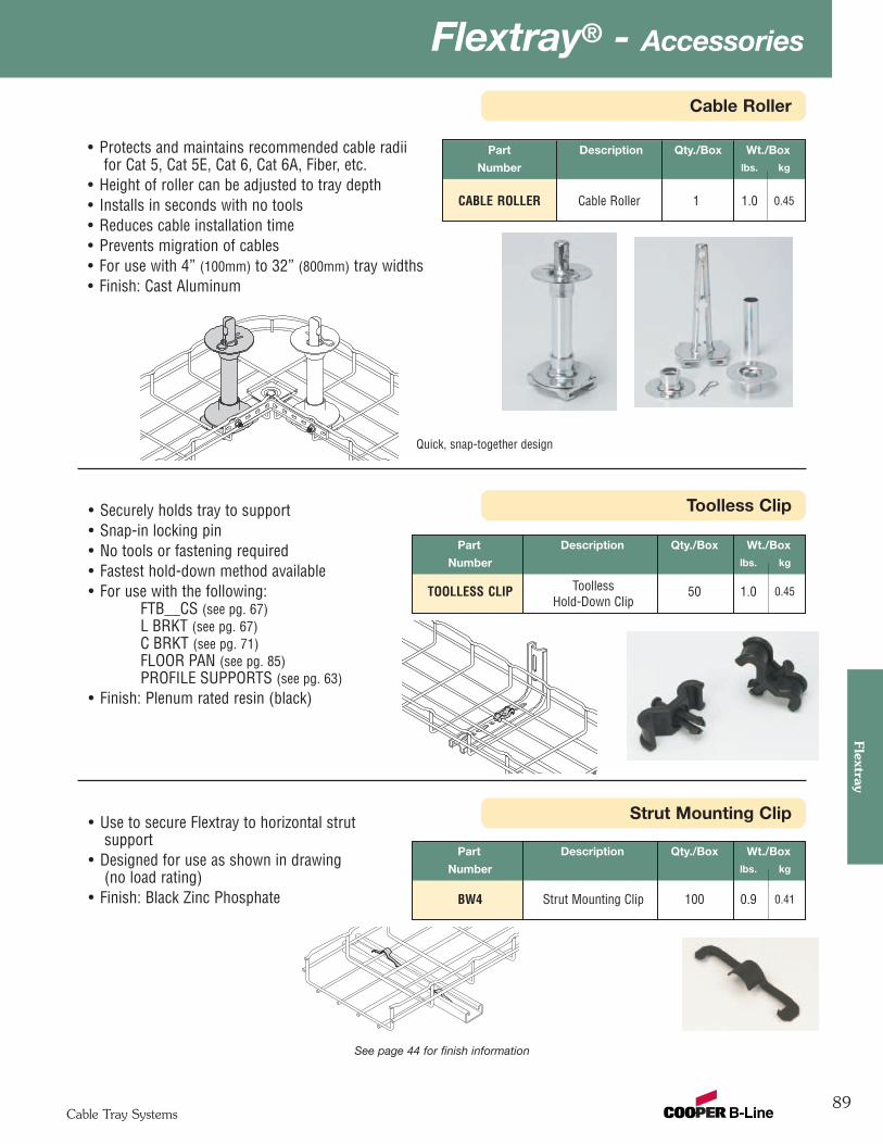
89
Flextray® - Accessories
Cable Tray Systems
Flextray
Cable Roller
Toolless Clip
See page 44 for finish information
Part Description Qty./Box Wt./Box
Number lbs. kg
CABLE ROLLER Cable Roller 1 1.0 0.45
• Protects and maintains recommended cable radiifor Cat 5, Cat 5E, Cat 6, Cat 6A, Fiber, etc.
• Height of roller can be adjusted to tray depth• Installs in seconds with no tools• Reduces cable installation time• Prevents migration of cables• For use with 4” (100mm) to 32” (800mm) tray widths• Finish: Cast Aluminum
Quick, snap-together design
Part Description Qty./Box Wt./Box
Number lbs. kg
TOOLLESS CLIP Toolless 50 1.0 0.45Hold-Down Clip
• Securely holds tray to support• Snap-in locking pin• No tools or fastening required• Fastest hold-down method available• For use with the following:
FTB__CS (see pg. 67)L BRKT (see pg. 67)C BRKT (see pg. 71)FLOOR PAN (see pg. 85)PROFILE SUPPORTS (see pg. 63)
• Finish: Plenum rated resin (black)
Strut Mounting Clip
Part Description Qty./Box Wt./Box
Number lbs. kg
BW4 Strut Mounting Clip 100 0.9 0.41
• Use to secure Flextray to horizontal strutsupport
• Designed for use as shown in drawing(no load rating)
• Finish: Black Zinc Phosphate
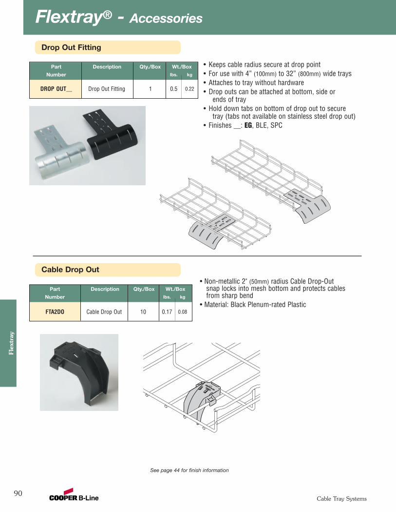
Flextray® - Accessories
90Cable Tray Systems
Flex
tray
Cable Drop Out
Drop Out Fitting
Part Description Qty./Box Wt./Box
Number lbs. kg
FTA2DO Cable Drop Out 10 0.17 0.08
• Non-metallic 2" (50mm) radius Cable Drop-Outsnap locks into mesh bottom and protects cablesfrom sharp bend
• Material: Black Plenum-rated Plastic
See page 44 for finish information
Part Description Qty./Box Wt./Box
Number lbs. kg
DROP OUT__ Drop Out Fitting 1 0.5 0.22
• Keeps cable radius secure at drop point• For use with 4” (100mm) to 32” (800mm) wide trays • Attaches to tray without hardware• Drop outs can be attached at bottom, side or
ends of tray• Hold down tabs on bottom of drop out to secure
tray (tabs not available on stainless steel drop out)• Finishes __: EG, BLE, SPC
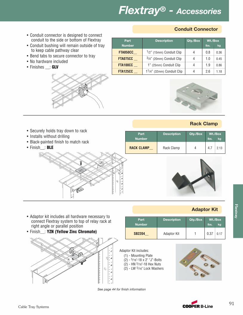
91
Flextray® - Accessories
Cable Tray Systems
Flextray
Rack Clamp
Conduit Connector
See page 44 for finish information
• Conduit connector is designed to connectconduit to the side or bottom of Flextray
• Conduit bushing will remain outside of trayto keep cable pathway clear
• Bend tabs to secure connector to tray• No hardware included• Finishes __: GLV
Part Description Qty./Box Wt./Box
Number lbs. kg
FTA050CC__ 1/2” (15mm) Conduit Clip 4 0.8 0.36
FTA075CC __ 3/4” (20mm) Conduit Clip 4 1.0 0.45
FTA100CC __ 1” (25mm) Conduit Clip 4 1.9 0.86
FTA125CC __ 11/4” (32mm) Conduit Clip 4 2.6 1.18
Part Description Qty./Box Wt./Box
Number lbs. kg
RACK CLAMP__ Rack Clamp 4 4.7 2.13
• Securely holds tray down to rack• Installs without drilling• Black-painted finish to match rack• Finish__: BLE
Adaptor Kit
Part Description Qty./Box Wt./Box
Number lbs. kg
SB2204__ Adaptor Kit 1 0.37 0.17
• Adaptor kit includes all hardware necessary toconnect Flextray system to top of relay rack atright angle or parallel position
• Finish__: YZN (Yellow Zinc Chromate)
Adaptor Kit includes:(1) - Mounting Plate(2) - 5/16"-18 x 2" “J”-Bolts(2) - HN 5/16"-18 Hex Nuts(2) - LW 5/16" Lock Washers
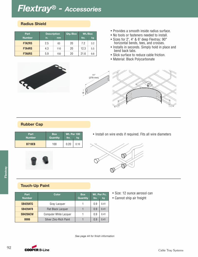
Flextray® - Accessories
92Cable Tray Systems
Flex
tray
Rubber Cap
Radius Shield
See page 44 for finish information
Part Description Qty./Box Wt./Box
Number in. mm lbs. kg
FTA2RS 2.5 63 20 7.2 3.2
FTA4RS 4.3 110 20 12.3 5.5
FTA6RS 5.9 150 20 21.6 9.8
• Provides a smooth inside radius surface.• No tools or fasteners needed to install.• Sizes for 2", 4" & 6" deep Flextray; 90°
horizontal bends, tees, and crosses.• Installs in seconds. Simply hold in place and
bend back tabs.• Slick surface to reduce cable friction. • Material: Black Polycarbonate
‘A’
11"(279 mm)
Part Color Box Wt. Per Pc.Number Quantity lbs. kg
SB420ATG Gray Lacquer 1 0.9 0.41
SB420AFB Flat Black Lacquer 1 0.9 0.41
SB420ACW Computer White Lacquer 1 0.9 0.41
B999 Silver Zinc-Rich Paint 1 0.9 0.41
• Install on wire ends if required. Fits all wire diametersPart Box Wt. Per 100Number Quantity lbs. kg
B719EB 100 0.20 0.10
Touch-Up Paint
• Size: 12 ounce aerosol can• Cannot ship air freight

93
Flextray® - Accessories
Cable Tray Systems
Flextray
Ground Bolt
Label Clip
Part Description Qty./Box Wt./Box
Number lbs. kg
LABEL CLIP 101/2” (267mm) Long 10 0.6 0.27
• Clips easily into trays• Use for identifying your cable pathways• Can be used on all tray sizes• Will not fit on side of 11/2” deep Flextray• Finish: Non-plenum-rated resins
Part Description Qty./Box Wt./Box
Number lbs. kg
GROUND BOLT Ground Bolt 1 0.11 0.05
• Attaches up to #1 ground wire to each traysection when separate ground wire is required
• Used for UL grounding compliance. • When using color powder coated finish or paint,
coating must be removed at the points ofcontact.
• Finish: Copper Plated
Ground Wire Supports
Part Description Qty./Box Wt./Box
Number lbs. kg
GROUND SUPT GL Ground Wire Support 100 0.6 0.27
• Supports ground wire along side of tray• Can be used on all trays• Finish __: Zinc Plated
See page 44 for finish information
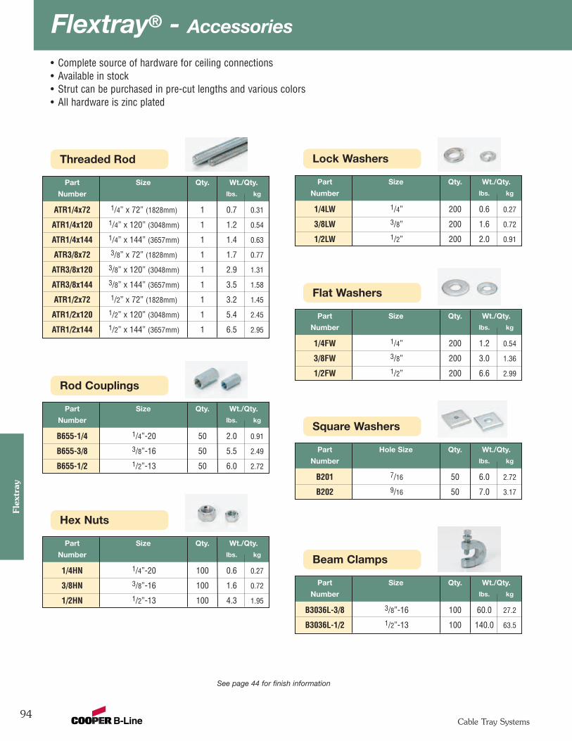
Flextray® - Accessories
94Cable Tray Systems
Flex
tray
• Complete source of hardware for ceiling connections• Available in stock• Strut can be purchased in pre-cut lengths and various colors• All hardware is zinc plated
See page 44 for finish information
Threaded Rod
Part Size Qty. Wt./Qty.
Number lbs. kg
ATR1/4x72 1/4” x 72” (1828mm) 1 0.7 0.31
ATR1/4x120 1/4” x 120” (3048mm) 1 1.2 0.54
ATR1/4x144 1/4” x 144” (3657mm) 1 1.4 0.63
ATR3/8x72 3/8” x 72” (1828mm) 1 1.7 0.77
ATR3/8x120 3/8” x 120” (3048mm) 1 2.9 1.31
ATR3/8x144 3/8” x 144” (3657mm) 1 3.5 1.58
ATR1/2x72 1/2” x 72” (1828mm) 1 3.2 1.45
ATR1/2x120 1/2” x 120” (3048mm) 1 5.4 2.45
ATR1/2x144 1/2” x 144” (3657mm) 1 6.5 2.95
Rod Couplings
Part Size Qty. Wt./Qty.
Number lbs. kg
B655-1/4 1/4”-20 50 2.0 0.91
B655-3/8 3/8”-16 50 5.5 2.49
B655-1/2 1/2”-13 50 6.0 2.72
Hex Nuts
Part Size Qty. Wt./Qty.
Number lbs. kg
1/4HN 1/4”-20 100 0.6 0.27
3/8HN 3/8”-16 100 1.6 0.72
1/2HN 1/2”-13 100 4.3 1.95
Lock Washers
Part Size Qty. Wt./Qty.
Number lbs. kg
1/4LW 1/4” 200 0.6 0.27
3/8LW 3/8” 200 1.6 0.72
1/2LW 1/2” 200 2.0 0.91
Flat Washers
Part Size Qty. Wt./Qty.
Number lbs. kg
1/4FW 1/4” 200 1.2 0.54
3/8FW 3/8” 200 3.0 1.36
1/2FW 1/2” 200 6.6 2.99
Square Washers
Part Hole Size Qty. Wt./Qty.
Number lbs. kg
B201 7/16 50 6.0 2.72
B202 9/16 50 7.0 3.17
Beam Clamps
Part Size Qty. Wt./Qty.
Number lbs. kg
B3036L-3/8 3/8”-16 100 60.0 27.2
B3036L-1/2 1/2”-13 100 140.0 63.5
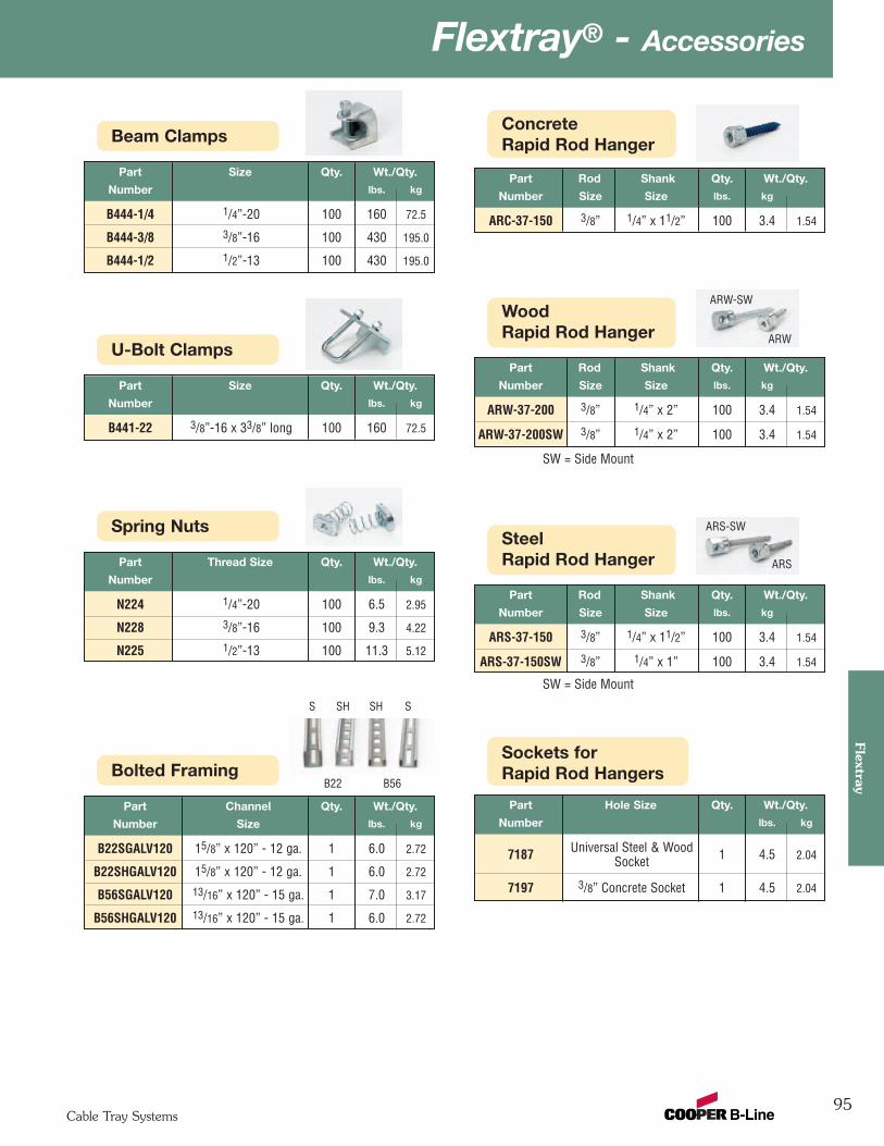
95
Flextray® - AccessoriesFlextray
Cable Tray Systems
Spring Nuts
Part Thread Size Qty. Wt./Qty.
Number lbs. kg
N224 1/4”-20 100 6.5 2.95
N228 3/8”-16 100 9.3 4.22
N225 1/2”-13 100 11.3 5.12
Bolted Framing
Part Channel Qty. Wt./Qty.
Number Size lbs. kg
B22SGALV120 15/8” x 120” - 12 ga. 1 6.0 2.72
B22SHGALV120 15/8” x 120” - 12 ga. 1 6.0 2.72
B56SGALV120 13/16” x 120” - 15 ga. 1 7.0 3.17
B56SHGALV120 13/16” x 120” - 15 ga. 1 6.0 2.72
ConcreteRapid Rod Hanger
Part Rod Shank Qty. Wt./Qty.
Number Size Size lbs. kg
ARC-37-150 3/8” 1/4” x 11/2” 100 3.4 1.54
WoodRapid Rod Hanger
Part Rod Shank Qty. Wt./Qty.
Number Size Size lbs. kg
ARW-37-200 3/8” 1/4” x 2” 100 3.4 1.54
ARW-37-200SW 3/8” 1/4” x 2” 100 3.4 1.54
SteelRapid Rod Hanger
Part Rod Shank Qty. Wt./Qty.
Number Size Size lbs. kg
ARS-37-150 3/8” 1/4” x 11/2” 100 3.4 1.54
ARS-37-150SW 3/8” 1/4” x 1” 100 3.4 1.54
Sockets forRapid Rod Hangers
Part Hole Size Qty. Wt./Qty.
Number lbs. kg
7187 Universal Steel & Wood 1 4.5 2.04Socket
7197 3/8” Concrete Socket 1 4.5 2.04
Beam Clamps
Part Size Qty. Wt./Qty.
Number lbs. kg
B444-1/4 1/4”-20 100 160 72.5
B444-3/8 3/8”-16 100 430 195.0
B444-1/2 1/2”-13 100 430 195.0
U-Bolt Clamps
Part Size Qty. Wt./Qty.
Number lbs. kg
B441-22 3/8”-16 x 33/8” long 100 160 72.5
B22 B56
S SSH SH
ARW-SW
ARW
ARS-SW
ARS
SW = Side Mount
SW = Side Mount
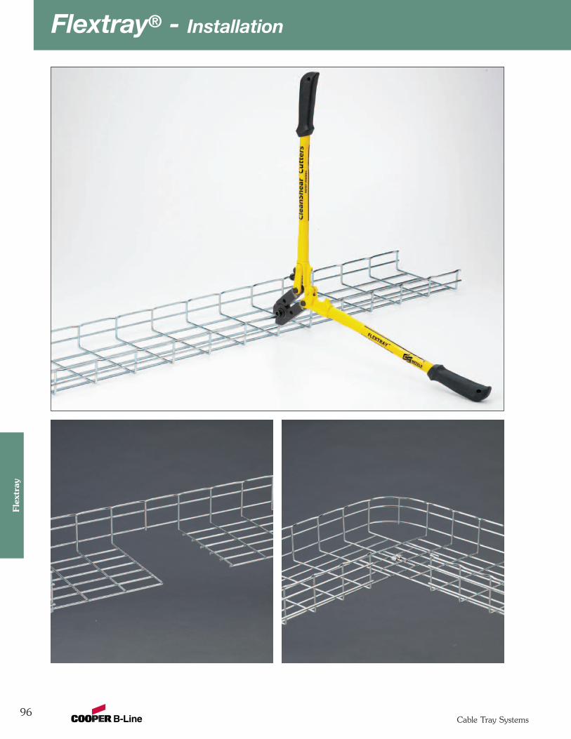
Flextray® - Installation
96Cable Tray Systems
Flex
tray
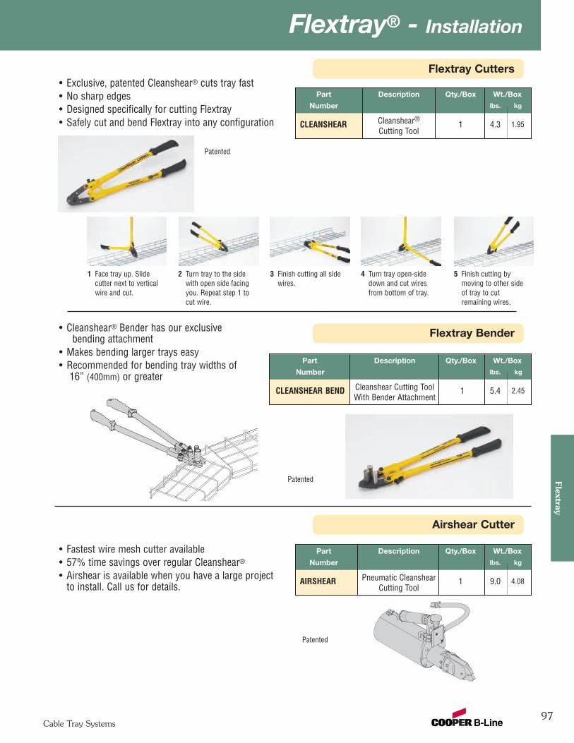
97
Flextray® - InstallationFlextray
Cable Tray Systems
Flextray Bender
Airshear Cutter
Flextray Cutters
Part Description Qty./Box Wt./Box
Number lbs. kg
CLEANSHEAR Cleanshear®1 4.3 1.95
Cutting Tool
• Exclusive, patented Cleanshear® cuts tray fast• No sharp edges• Designed specifically for cutting Flextray• Safely cut and bend Flextray into any configuration
1 Face tray up. Slidecutter next to verticalwire and cut.
2 Turn tray to the sidewith open side facingyou. Repeat step 1 tocut wire.
Patented
Part Description Qty./Box Wt./Box
Number lbs. kg
AIRSHEAR Pneumatic Cleanshear 1 9.0 4.08Cutting Tool
• Fastest wire mesh cutter available• 57% time savings over regular Cleanshear®
• Airshear is available when you have a large projectto install. Call us for details.
Part Description Qty./Box Wt./Box
Number lbs. kg
CLEANSHEAR BEND Cleanshear Cutting Tool 1 5.4 2.45With Bender Attachment
• Cleanshear® Bender has our exclusivebending attachment
• Makes bending larger trays easy• Recommended for bending tray widths of
16” (400mm) or greater
Patented
Patented
3 Finish cutting all sidewires.
4 Turn tray open-sidedown and cut wiresfrom bottom of tray.
5 Finish cutting bymoving to other sideof tray to cutremaining wires,
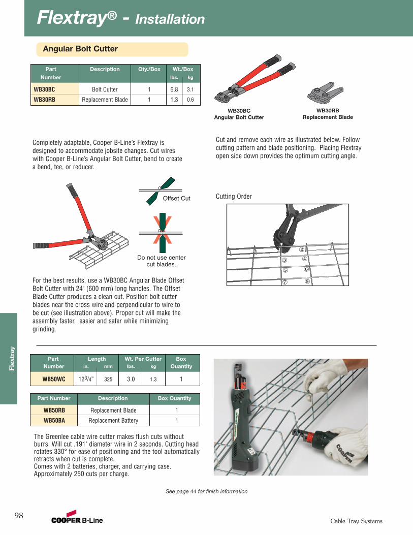
Flextray® - Installation
98Cable Tray Systems
Flex
tray
X
Completely adaptable, Cooper B-Line’s Flextray isdesigned to accommodate jobsite changes. Cut wireswith Cooper B-Line’s Angular Bolt Cutter, bend to createa bend, tee, or reducer.
For the best results, use a WB30BC Angular Blade OffsetBolt Cutter with 24" (600 mm) long handles. The OffsetBlade Cutter produces a clean cut. Position bolt cutterblades near the cross wire and perpendicular to wire tobe cut (see illustration above). Proper cut will make theassembly faster, easier and safer while minimizinggrinding.
Cut and remove each wire as illustrated below. Followcutting pattern and blade positioning. Placing Flextrayopen side down provides the optimum cutting angle.
Cutting Order
The Greenlee cable wire cutter makes flush cuts withoutburrs. Will cut .191" diameter wire in 2 seconds. Cutting headrotates 330° for ease of positioning and the tool automaticallyretracts when cut is complete.Comes with 2 batteries, charger, and carrying case.Approximately 250 cuts per charge.
WB30RB Replacement Blade
WB30BC Angular Bolt Cutter
® ¯
° ±
² ³
Offset Cut
Do not use centercut blades.
Part Length Wt. Per Cutter BoxNumber in. mm lbs. kg Quantity
WB50WC 123/4” 325 3.0 1.3 1
Part Number Description Box Quantity
WB50RB Replacement Blade 1
WB50BA Replacement Battery 1
See page 44 for finish information
Angular Bolt Cutter
Part Description Qty./Box Wt./Box
Number lbs. kg
WB30BC Bolt Cutter 1 6.8 3.1
WB30RB Replacement Blade 1 1.3 0.6
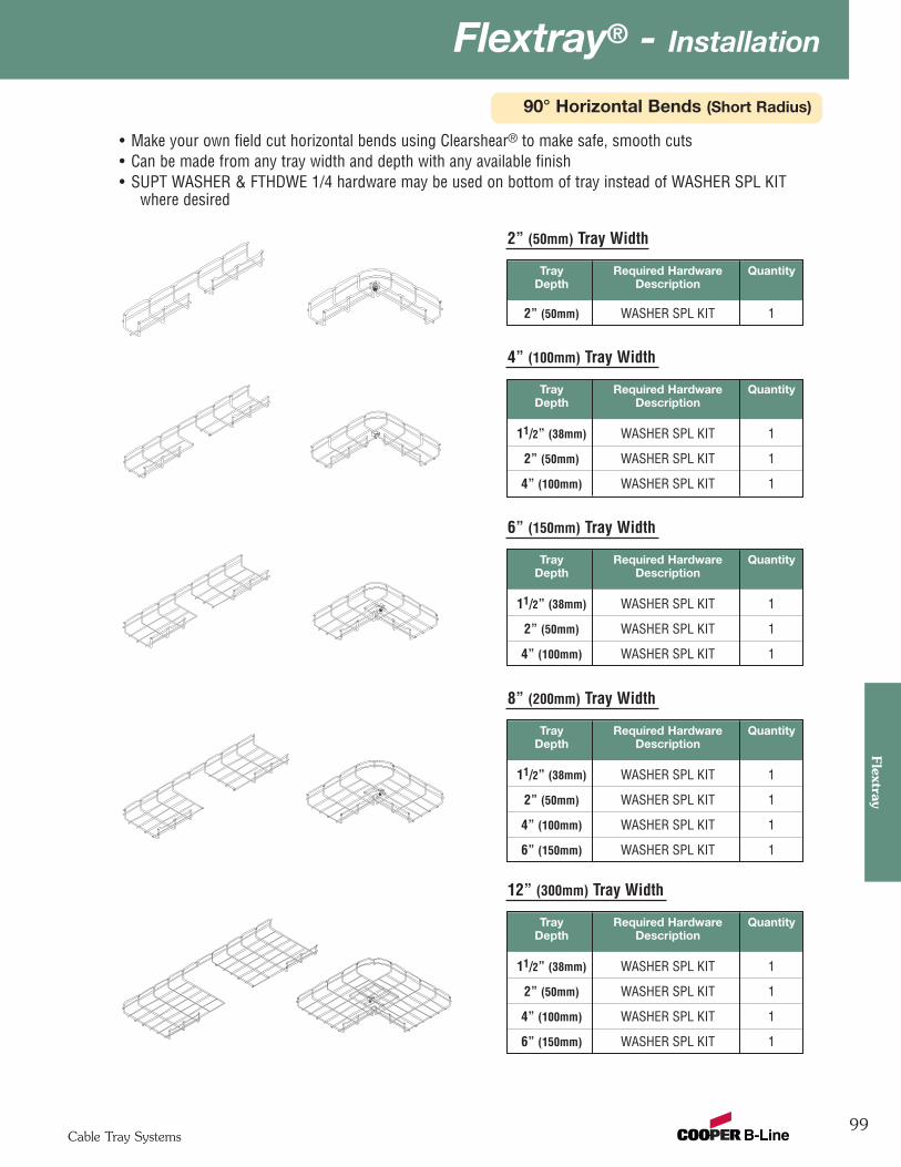
99
Flextray® - InstallationFlextray
Cable Tray Systems
90° Horizontal Bends (Short Radius)
2” (50mm) Tray Width
• Make your own field cut horizontal bends using Clearshear® to make safe, smooth cuts• Can be made from any tray width and depth with any available finish• SUPT WASHER & FTHDWE 1/4 hardware may be used on bottom of tray instead of WASHER SPL KIT
where desired
Tray Required Hardware QuantityDepth Description
2” (50mm) WASHER SPL KIT 1
4” (100mm) Tray Width
Tray Required Hardware QuantityDepth Description
11/2” (38mm) WASHER SPL KIT 1
2” (50mm) WASHER SPL KIT 1
4” (100mm) WASHER SPL KIT 1
6” (150mm) Tray Width
Tray Required Hardware QuantityDepth Description
11/2” (38mm) WASHER SPL KIT 1
2” (50mm) WASHER SPL KIT 1
4” (100mm) WASHER SPL KIT 1
8” (200mm) Tray Width
Tray Required Hardware QuantityDepth Description
11/2” (38mm) WASHER SPL KIT 1
2” (50mm) WASHER SPL KIT 1
4” (100mm) WASHER SPL KIT 1
6” (150mm) WASHER SPL KIT 1
12” (300mm) Tray Width
Tray Required Hardware QuantityDepth Description
11/2” (38mm) WASHER SPL KIT 1
2” (50mm) WASHER SPL KIT 1
4” (100mm) WASHER SPL KIT 1
6” (150mm) WASHER SPL KIT 1

Flextray® - Installation
100Cable Tray Systems
Flex
tray
90° Horizontal Bends (Short Radius)
• Make your own field cut horizontal bends using Clearshear® to make safe, smooth cuts• Can be made from any tray width and depth with any available finish• SUPT WASHER & FTHDWE 1/4 hardware may be used on bottom of tray instead of WASHER SPL KIT
where desired
16” (400mm) Tray Width
Tray Required Hardware QuantityDepth Description
2” (50mm) WASHER SPL KIT 3
4” (100mm) WASHER SPL KIT 3
6” (150mm) WASHER SPL KIT 3
18” (450mm) Tray Width
Tray Required Hardware QuantityDepth Description
2” (50mm) WASHER SPL KIT 3
4” (100mm) WASHER SPL KIT 3
6” (150mm) WASHER SPL KIT 3
20” (500mm) Tray Width
Tray Required Hardware QuantityDepth Description
2” (50mm) WASHER SPL KIT 3
4” (100mm) WASHER SPL KIT 3
6” (150mm) WASHER SPL KIT 3
24” (600mm) Tray Width
Tray Required Hardware QuantityDepth Description
2” (50mm) WASHER SPL KIT 3
4” (100mm) WASHER SPL KIT 3
6” (150mm) WASHER SPL KIT 3
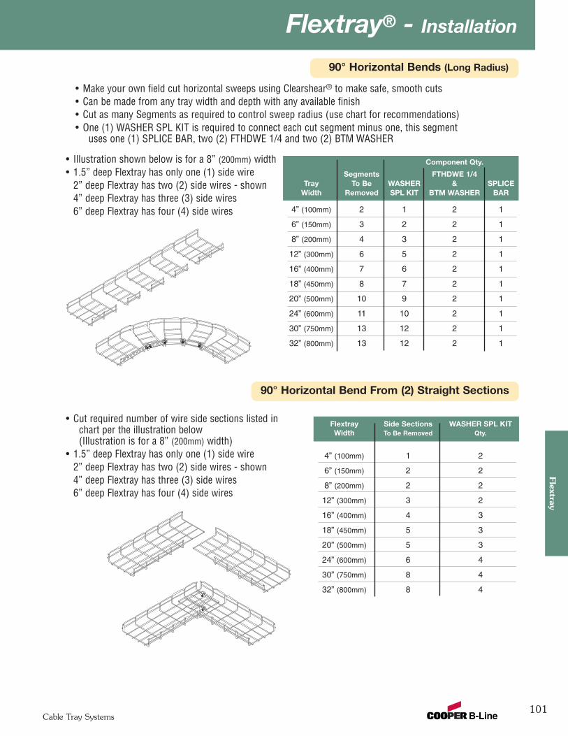
101
Flextray® - InstallationFlextray
Cable Tray Systems
90° Horizontal Bends (Long Radius)
90° Horizontal Bend From (2) Straight Sections
• Make your own field cut horizontal sweeps using Clearshear® to make safe, smooth cuts• Can be made from any tray width and depth with any available finish• Cut as many Segments as required to control sweep radius (use chart for recommendations)• One (1) WASHER SPL KIT is required to connect each cut segment minus one, this segment
uses one (1) SPLICE BAR, two (2) FTHDWE 1/4 and two (2) BTM WASHER
Flextray Side Sections WASHER SPL KITWidth To Be Removed Qty.
4” (100mm) 1 2
6” (150mm) 2 2
8” (200mm) 2 2
12” (300mm) 3 2
16” (400mm) 4 3
18” (450mm) 5 3
20” (500mm) 5 3
24” (600mm) 6 4
30” (750mm) 8 4
32” (800mm) 8 4
• Cut required number of wire side sections listed inchart per the illustration below(Illustration is for a 8” (200mm) width)
• 1.5” deep Flextray has only one (1) side wire2” deep Flextray has two (2) side wires - shown4” deep Flextray has three (3) side wires6” deep Flextray has four (4) side wires
• Illustration shown below is for a 8” (200mm) width• 1.5” deep Flextray has only one (1) side wire
2” deep Flextray has two (2) side wires - shown4” deep Flextray has three (3) side wires6” deep Flextray has four (4) side wires
Component Qty.
Segments FTHDWE 1/4Tray To Be WASHER & SPLICE
Width Removed SPL KIT BTM WASHER BAR
4” (100mm) 2 1 2 1
6” (150mm) 3 2 2 1
8” (200mm) 4 3 2 1
12” (300mm) 6 5 2 1
16” (400mm) 7 6 2 1
18” (450mm) 8 7 2 1
20” (500mm) 10 9 2 1
24” (600mm) 11 10 2 1
30” (750mm) 13 12 2 1
32” (800mm) 13 12 2 1
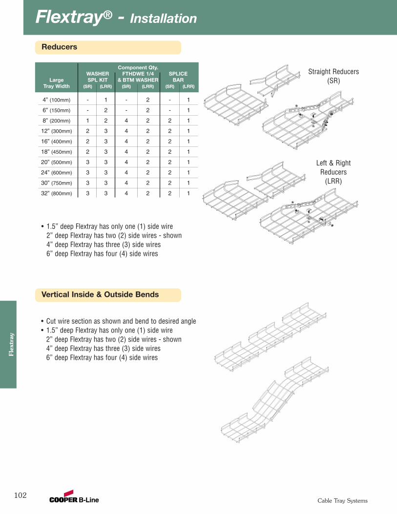
Flextray® - Installation
102Cable Tray Systems
Flex
tray
Reducers
Vertical Inside & Outside Bends
Component Qty.WASHER FTHDWE 1/4 SPLICE
Large SPL KIT & BTM WASHER BARTray Width (SR) (LRR) (SR) (LRR) (SR) (LRR)
4” (100mm) - 1 - 2 - 1
6” (150mm) - 2 - 2 - 1
8” (200mm) 1 2 4 2 2 1
12” (300mm) 2 3 4 2 2 1
16” (400mm) 2 3 4 2 2 1
18” (450mm) 2 3 4 2 2 1
20” (500mm) 3 3 4 2 2 1
24” (600mm) 3 3 4 2 2 1
30” (750mm) 3 3 4 2 2 1
32” (800mm) 3 3 4 2 2 1
• 1.5” deep Flextray has only one (1) side wire2” deep Flextray has two (2) side wires - shown4” deep Flextray has three (3) side wires6” deep Flextray has four (4) side wires
Straight Reducers(SR)
Left & RightReducers
(LRR)
• Cut wire section as shown and bend to desired angle• 1.5” deep Flextray has only one (1) side wire
2” deep Flextray has two (2) side wires - shown4” deep Flextray has three (3) side wires6” deep Flextray has four (4) side wires

103
Flextray® - AccessoriesFlextray
Cable Tray Systems
Horizontal Tees (and crosses)
Flextray WASHER SPL KITWidth Qty.
2” (50mm) 2
4” (100mm) 2
6” (150mm) 3
8” (200mm) 3
12” (300mm) 4
16” (400mm) 4
18” (450mm) 4
20” (500mm) 4
24” (600mm) 4
30” (750mm) 5
32” (800mm) 5
• Cut wire side sections as shown in the illustration below(Illustration is for a 8” (200mm) width)
• 1.5” deep Flextray has only one (1) side wire2” deep Flextray has two (2) side wires - shown4” deep Flextray has three (3) side wires6” deep Flextray has four (4) side wires
• For crosses, duplicate process on opposite side
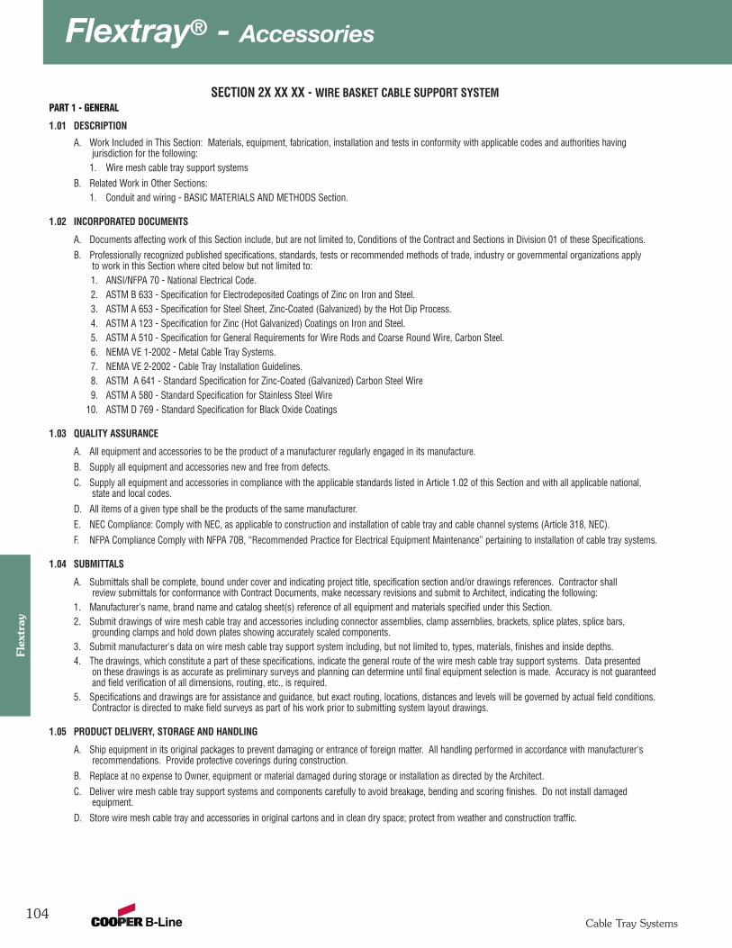
Flextray® - Accessories
104Cable Tray Systems
Flex
tray
SECTION 2X XX XX - WIRE BASKET CABLE SUPPORT SYSTEMPART 1 - GENERAL
1.01 DESCRIPTION
A. Work Included in This Section: Materials, equipment, fabrication, installation and tests in conformity with applicable codes and authorities havingjurisdiction for the following:
1. Wire mesh cable tray support systemsB. Related Work in Other Sections:
1. Conduit and wiring - BASIC MATERIALS AND METHODS Section.
1.02 INCORPORATED DOCUMENTS
A. Documents affecting work of this Section include, but are not limited to, Conditions of the Contract and Sections in Division 01 of these Specifications.B. Professionally recognized published specifications, standards, tests or recommended methods of trade, industry or governmental organizations apply
to work in this Section where cited below but not limited to:1. ANSI/NFPA 70 - National Electrical Code.2. ASTM B 633 - Specification for Electrodeposited Coatings of Zinc on Iron and Steel.3. ASTM A 653 - Specification for Steel Sheet, Zinc-Coated (Galvanized) by the Hot Dip Process.4. ASTM A 123 - Specification for Zinc (Hot Galvanized) Coatings on Iron and Steel.5. ASTM A 510 - Specification for General Requirements for Wire Rods and Coarse Round Wire, Carbon Steel.6. NEMA VE 1-2002 - Metal Cable Tray Systems.7. NEMA VE 2-2002 - Cable Tray Installation Guidelines.8. ASTM A 641 - Standard Specification for Zinc-Coated (Galvanized) Carbon Steel Wire9. ASTM A 580 - Standard Specification for Stainless Steel Wire
10. ASTM D 769 - Standard Specification for Black Oxide Coatings
1.03 QUALITY ASSURANCE
A. All equipment and accessories to be the product of a manufacturer regularly engaged in its manufacture.B. Supply all equipment and accessories new and free from defects.C. Supply all equipment and accessories in compliance with the applicable standards listed in Article 1.02 of this Section and with all applicable national,
state and local codes.D. All items of a given type shall be the products of the same manufacturer.E. NEC Compliance: Comply with NEC, as applicable to construction and installation of cable tray and cable channel systems (Article 318, NEC).F. NFPA Compliance Comply with NFPA 70B, “Recommended Practice for Electrical Equipment Maintenance” pertaining to installation of cable tray systems.
1.04 SUBMITTALS
A. Submittals shall be complete, bound under cover and indicating project title, specification section and/or drawings references. Contractor shallreview submittals for conformance with Contract Documents, make necessary revisions and submit to Architect, indicating the following:
1. Manufacturer's name, brand name and catalog sheet(s) reference of all equipment and materials specified under this Section.2. Submit drawings of wire mesh cable tray and accessories including connector assemblies, clamp assemblies, brackets, splice plates, splice bars,
grounding clamps and hold down plates showing accurately scaled components.3. Submit manufacturer's data on wire mesh cable tray support system including, but not limited to, types, materials, finishes and inside depths. 4. The drawings, which constitute a part of these specifications, indicate the general route of the wire mesh cable tray support systems. Data presented
on these drawings is as accurate as preliminary surveys and planning can determine until final equipment selection is made. Accuracy is not guaranteedand field verification of all dimensions, routing, etc., is required.
5. Specifications and drawings are for assistance and guidance, but exact routing, locations, distances and levels will be governed by actual field conditions. Contractor is directed to make field surveys as part of his work prior to submitting system layout drawings.
1.05 PRODUCT DELIVERY, STORAGE AND HANDLING
A. Ship equipment in its original packages to prevent damaging or entrance of foreign matter. All handling performed in accordance with manufacturer'srecommendations. Provide protective coverings during construction.
B. Replace at no expense to Owner, equipment or material damaged during storage or installation as directed by the Architect.C. Deliver wire mesh cable tray support systems and components carefully to avoid breakage, bending and scoring finishes. Do not install damaged
equipment.D. Store wire mesh cable tray and accessories in original cartons and in clean dry space; protect from weather and construction traffic.
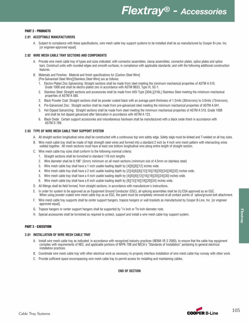
105
Flextray® - AccessoriesFlextray
Cable Tray Systems
PART 2 - PRODUCTS
2.01 ACCEPTABLE MANUFACTURERS
A. Subject to compliance with these specifications, wire mesh cable tray support systems to be installed shall be as manufactured by Cooper B-Line, Inc.[or engineer-approved equal].
2.02 WIRE MESH CABLE TRAY SECTIONS AND COMPONENTS
A. Provide wire mesh cable tray of types and sizes indicated; with connector assemblies, clamp assemblies, connector plates, splice plates and splicebars. Construct units with rounded edges and smooth surfaces; in compliance with applicable standards; and with the following additional constructionfeatures.
B. Materials and Finishes: Material and finish specifications for [Carbon Steel Wire] [Pre-Galvanized Steel Wire][Stainless Steel Wire] are as follows:1. Electro-Plated Zinc Galvanizing: Straight sections shall be made from steel meeting the minimum mechanical properties of ASTM A 510,
Grade 1008 and shall be electro-plated zinc in accordance with ASTM B633, Type III, SC-1.2. Stainless Steel: Straight sections and accessories shall be made from AISI Type [304L][316L] Stainless Steel meeting the minimum mechanical
properties of ASTM A 580.3. Black Powder Coat: Straight sections shall be powder coated black with an average paint thickness of 1.2mils (30microns) to 3.0mils (75microns).4. Pre-Galvanized Zinc: Straight section shall be made from pre-galvanized steel meeting the minimum mechanical properties of ASTM A 641.5. Hot Dipped Galvanizing: Straight sections shall be made from steel meeting the minimum mechanical properties of ASTM A 510, Grade 1008
and shall be hot dipped galvanized after fabrication in accordance with ASTM A 123.6. Black Oxide: Certain support accessories and miscellaneous hardware shall be manufactured with a black oxide finish in accordance with
ASTM D 769.
2.03 TYPE OF WIRE MESH CABLE TRAY SUPPORT SYSTEM
A. All straight section longitudinal wires shall be constructed with a continuous top wire safety edge. Safety edge must be kinked and T-welded on all tray sizes.B. Wire mesh cable tray shall be made of high strength steel wires and formed into a standard 2 inch by 4 inch wire mesh pattern with intersecting wires
welded together. All mesh sections must have at least one bottom longitudinal wire along entire length of straight section. C. Wire mesh cable tray sizes shall conform to the following nominal criteria:
1. Straight sections shall be furnished in standard 118 inch lengths2. Wire diameter shall be 0.196” (5mm) minimum on all mesh sections (minimum size of 4.5mm on stainless steel)3. Wire mesh cable tray shall have a 1 inch usable loading depth by [4][6][8][12] inches wide.4. Wire mesh cable tray shall have a 2 inch usable loading depth by [2][4][6][8][12][16][18][20][24][30][32] inches wide.5. Wire mesh cable tray shall have a 4 inch usable loading depth by [4][6][8][12][16][18][20][24][30] inches wide.6. Wire mesh cable tray shall have a 6 inch usable loading depth by [8][12][16][18][20][24] inches wide.
D. All fittings shall be field formed, from straight sections, in accordance with manufacturer's instructions.E. In order for system to be approved as an Equipment Ground Conductor (EGC), all splicing assemblies shall be UL/CSA approved as an EGC.
When using powder coated wire mesh cable tray as an EGC, the paint must be completely removed at all contact points of splice/ground bolt attachment. F. Wire mesh cable tray supports shall be center support hangers, trapeze hangers or wall brackets as manufactured by Cooper B-Line, Inc. [or engineer
approved equal].G. Trapeze hangers or center support hangers shall be supported by 1/4 inch or 3/8 inch diameter rods.H. Special accessories shall be furnished as required to protect, support and install a wire mesh cable tray support system.
PART 3 - EXECUTION
3.01 INSTALLATION OF WIRE MESH CABLE TRAY
A. Install wire mesh cable tray as indicated; in accordance with recognized industry practices (NEMA VE-2 2000), to ensure that the cable tray equipmentcomplies with requirements of NEC, and applicable portions of NFPA 70B and NECA's “Standards of Installation” pertaining to general electricalinstallation practices.
B. Coordinate wire mesh cable tray with other electrical work as necessary to properly interface installation of wire mesh cable tray runway with other work.C. Provide sufficient space encompassing wire mesh cable tray to permit access for installing and maintaining cables.
END OF SECTION

Channel Cable Tray - Straight Sections
106
Cab
le C
hann
el
Cable Tray Systems
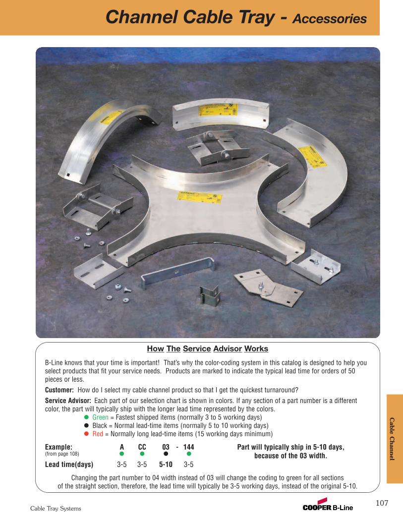
107
Channel Cable Tray - AccessoriesC
able Channel
Cable Tray Systems
How The Service Advisor Works
B-Line knows that your time is important! That’s why the color-coding system in this catalog is designed to help youselect products that fit your service needs. Products are marked to indicate the typical lead time for orders of 50pieces or less.Customer: How do I select my cable channel product so that I get the quickest turnaround?Service Advisor: Each part of our selection chart is shown in colors. If any section of a part number is a differentcolor, the part will typically ship with the longer lead time represented by the colors.
Green = Fastest shipped items (normally 3 to 5 working days)Black = Normal lead-time items (normally 5 to 10 working days)Red = Normally long lead-time items (15 working days minimum)
Example: A CC 03 - 144 Part will typically ship in 5-10 days,(from page 108) because of the 03 width.Lead time(days) 3-5 3-5 5-10 3-5
Changing the part number to 04 width instead of 03 will change the coding to green for all sectionsof the straight section, therefore, the lead time will typically be 3-5 working days, instead of the original 5-10.
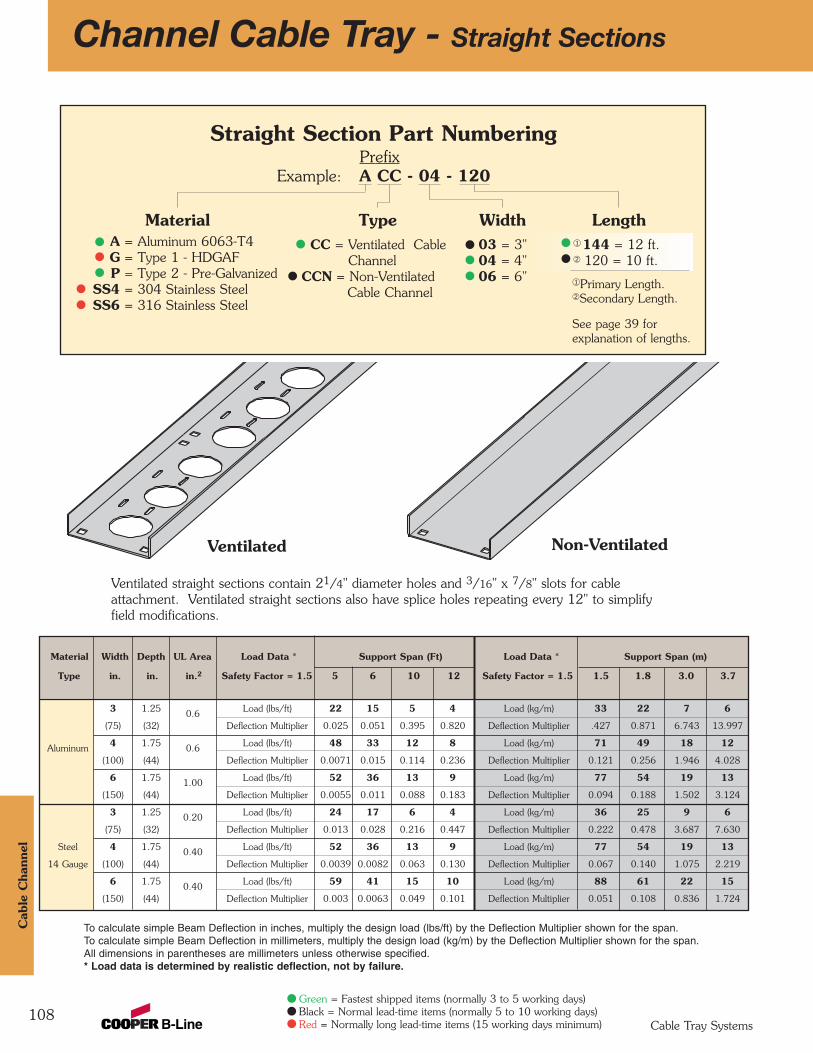
Material Width Depth UL Area Load Data * Support Span (Ft) Load Data * Support Span (m)
Type in. in. in.2 Safety Factor = 1.5 5 6 10 12 Safety Factor = 1.5 1.5 1.8 3.0 3.7
3 1.25 0.6 Load (lbs/ft) 22 15 5 4 Load (kg/m) 33 22 7 6
(75) (32) Deflection Multiplier 0.025 0.051 0.395 0.820 Deflection Multiplier .427 0.871 6.743 13.997
Aluminum 4 1.75 0.6 Load (lbs/ft) 48 33 12 8 Load (kg/m) 71 49 18 12
(100) (44) Deflection Multiplier 0.0071 0.015 0.114 0.236 Deflection Multiplier 0.121 0.256 1.946 4.028
6 1.75 1.00 Load (lbs/ft) 52 36 13 9 Load (kg/m) 77 54 19 13
(150) (44) Deflection Multiplier 0.0055 0.011 0.088 0.183 Deflection Multiplier 0.094 0.188 1.502 3.124
3 1.25 0.20 Load (lbs/ft) 24 17 6 4 Load (kg/m) 36 25 9 6
(75) (32) Deflection Multiplier 0.013 0.028 0.216 0.447 Deflection Multiplier 0.222 0.478 3.687 7.630
Steel 4 1.75 0.40 Load (lbs/ft) 52 36 13 9 Load (kg/m) 77 54 19 13
14 Gauge (100) (44) Deflection Multiplier 0.0039 0.0082 0.063 0.130 Deflection Multiplier 0.067 0.140 1.075 2.219
6 1.75 0.40 Load (lbs/ft) 59 41 15 10 Load (kg/m) 88 61 22 15
(150) (44) Deflection Multiplier 0.003 0.0063 0.049 0.101 Deflection Multiplier 0.051 0.108 0.836 1.724
Straight Section Part NumberingPrefix
Example: A CC - 04 - 120
Channel Cable Tray - Straight Sections
108
MaterialA = Aluminum 6063-T4G = Type 1 - HDGAFP = Type 2 - Pre-Galvanized
SS4 = 304 Stainless SteelSS6 = 316 Stainless Steel
TypeCC = Ventilated Cable
ChannelCCN = Non-Ventilated
Cable Channel
Width03 = 3"04 = 4"06 = 6"
To calculate simple Beam Deflection in inches, multiply the design load (lbs/ft) by the Deflection Multiplier shown for the span.To calculate simple Beam Deflection in millimeters, multiply the design load (kg/m) by the Deflection Multiplier shown for the span.All dimensions in parentheses are millimeters unless otherwise specified.* Load data is determined by realistic deflection, not by failure.
Ventilated straight sections contain 21/4" diameter holes and 3/16" x 7/8" slots for cable attachment. Ventilated straight sections also have splice holes repeating every 12" to simplifyfield modifications.
Ventilated Non-Ventilated
See page 39 for explanation of lengths.
Length¬144 = 12 ft.Á 120 = 10 ft.
¬Primary Length.ÁSecondary Length.
Cab
le C
hann
el
Cable Tray Systems
Green = Fastest shipped items (normally 3 to 5 working days)Black = Normal lead-time items (normally 5 to 10 working days)Red = Normally long lead-time items (15 working days minimum)
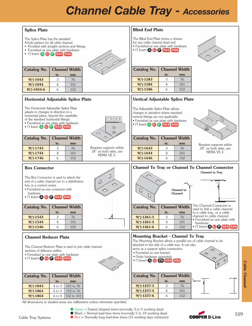
Catalog No. Channel Widthin. mm
9(*)-1843 4 to 3 101 to 76
9(*)-1863 6 to 3 152 to 76
9(*)-1864 6 to 4 152 to 101
Catalog No. Channel Widthin. mm
9(*)-1543 3 76
9(*)-1544 4 101
9(*)-1546 6 152
Catalog No. Channel Widthin. mm
9(*)-1743 3 76
9(*)-1744 4 101
9(*)-1746 6 152
Catalog No. Channel Widthin. mm
9(*)-1043 3 76
9(*)-1044 4 101
9(*)-1044-6 6 152
Catalog No. Channel Widthin. mm
9(*)-1583 3 76
9(*)-1584 4 101
9(*)-1586 6 152
Catalog No. Channel Widthin. mm
9(*)-1643 3 76
9(*)-1644 4 101
9(*)-1646 6 152
Catalog No. Channel Widthin. mm
9(*)-1261-3 3 76
9(*)-1261-4 4 101
9(*)-1261-6 6 152
Catalog No. Channel Widthin. mm
9(*)-1237-3 3 76
9(*)-1237-4 4 101
9(*)-1237-6 6 152
Channel To Tray or Channel To Channel Connector
Channel Reducer Plate
The Channel Reducer Plate is used to join cable channelsections of different widths.• Furnished as one plate with hardware.• (*) Insert
Box Connector
The Box Connector is used to attach theend of a cable channel run to a distribution box or a control center.• Furnished as one connector with
hardware.• (*) Insert
Vertical Adjustable Splice Plate
The Adjustable Splice Plate allowschanges in elevation where standardvertical fittings are not applicable.• Furnished as one plate with hardware.• (*) Insert
109
Channel Cable Tray - Accessories
Horizontal Adjustable Splice Plate
The Horizontal Adjustable Splice Plateadapts to changes in direction in ahorizontal plane, beyond the capabilityof the standard horizontal fittings.• Furnished as one plate with hardware.• (*) Insert
Blind End Plate
The Blind End Plate forms a closurefor any cable channel dead end.• Furnished as one plate with hardware.• (*) Insert
Splice Plate
The Splice Plate has the standard4-hole pattern for all cable channel.• Provided with straight sections and fittings.• Furnished as one plate with hardware.• (*) Insert
Mounting Bracket - Channel To TrayThe Mounting Bracket allows a parallel run of cable channel to beattached to the side of a cable tray. It can alsoserve as a support splice connection.• Furnished as one bracket.• Order hardware separately.• (*) Insert
Channel to Tray
Channel toChannel
All dimensions in shaded areas are millimeters unless otherwise specified.
The Channel Connector is used to link a cable channel to a cable tray, or a cable channel to cable channel.• Furnished as one plate with
hardware.• (*) Insert
Cable C
hannel
Cable Tray Systems
Green = Fastest shipped items (normally 3 to 5 working days)Black = Normal lead-time items (normally 5 to 10 working days)Red = Normally long lead-time items (15 working days minimum)
A G P SS4 SS6
A G P SS4 SS6
A G P SS4 SS6
A G P SS4 SS6
A G P SS4 SS6
A G P SS4 SS6
A G SS4 SS6
A G P SS4 SS6
ZN
Requires supports within24” on both sides, per
NEMA VE 2.
Requires supports within24” on both sides, per
NEMA VE 2.

Catalog Channel Width Uniform Load ANo. in. mm lbs kN in. mm
B409-6 3 76 1920 8.54 6 152
B409-9 4, 6 101, 152 1280 5.69 9 228
Channel Widthin. mm in. mm in. mm
3 76 4 101 6 152
Zinc Plated SteelDouble Channel 9ZN-1232-3 9ZN-1232-4 9ZN-1232-6Single Channel 9ZN-1231-3 & 4 9ZN-1231-3 & 4 9ZN-1231-6
HDGAF Steel (18 Ga.)Double Channel 9G-1232-3 9G-1232-4 9G-1232-6Single Channel 9G-1231-3 & 4 9G-1231-3 & 4 9G-1231-6
Catalog No. Channel Widthin. mm3 764 1016 152
Catalog No. Channel Widthin. mm
9(*)-3305-3 3 76
9(*)-3305-4 4 101
9(*)-3305-6 6 152 Catalog No. 99-1125
Catalog No. Channel Widthin. mm
9(*)-1245 3 76
9(*)-1246 4 101
9(*)-1246 6 152
Catalog No. Channel Widthin. mm
9(*)-1243 3 76
9(*)-1244 4 101
9(*)-1244 6 152
Single Cable ChannelHanger and Wall Mount
Double CableChannel Hanger
Cable Channel Hanger
Channel Cable Tray - Accessories
110
Expansion Guide Clamp
The Expansion Guide Clamp allows cable channel to expand and contract in the horizontal plane, but not in the transverse plane.• Furnished as one clamp.• Order 1/2" hardware separately.• (*) Insert
Hold-Down Clamp
The Hold-Down Clamp secures cablechannel to a support member.• Furnished as one clamp.• Order 1/2" hardware separately.• (*) Insert
Channel To Floor Base Plate
The Channel to Floor Base Plate is used to attach the end of acable channel run to the floor or to an equipment mounting pad.• Anchors and hardware are ordered separately.• (*) Insert
Cable Channel Bushing
The Cable Channel Bushing is a snap-inplastic bushing used to protect cableinsulation from mechanical wear.
Cable Channel Bracket
A
Cable Channel Bracket• Uniform Load: 225 lbs (1.00 kN)
Safety Factor of 2.5• Finishes available:
B185CCL
• Safety Factor of 2.5• Finishes available:
Material
150 lb. Safety Factor 3.0
265 lb. Safety Factor 3.0
Designed for 1/2" Threaded Rod, Double Nut Installation
8"(203mm)
All dimensions in shaded areas are millimeters unless otherwise specified.
Cab
le C
hann
el
Cable Tray Systems
Green = Fastest shipped items (normally 3 to 5 working days)Black = Normal lead-time items (normally 5 to 10 working days)Red = Normally long lead-time items (15 working days minimum)
A G SS4 SS6ZN
A G SS4 SS6ZN
A G SS4 SS6ZN
GZNG GRNZN

Catalog No. Channel Widthin. mm
9(*)-9033 3 76
9(*)-9034 4 101
9(*)-9036 6 152
Catalog No. Channel Widthin. mm
9(*)-9023 3 76
9(*)-9024 4 101
9(*)-9024 6 152
Channel Cable Tray - Accessories
111
Wrap-Around Cover Clamp
Wrap-Around Cover Clamps are used to securely hold a cover on cable channel in locations where strong winds can prevail.• Furnished as one clamp with hardware.• (*) Insert
All dimensions in shaded areas are millimeters unless otherwise specified.
Combination Hold-Down & Cover Clamp
This clamp is used to hold both the cable channeland cover in place at the same time.• Furnished as one clamp.• Order 1/4" hardware separately.• (*) Insert
Straight Section
Fitting covers are available. To order, use the cover prefix followed by the fitting description. Ex: 808A40 - 03 - 90HB12.
Covers Part NumberingPrefix
Example: 80 8 A 40 - 04 - 144
Detail
8 = Flanged
CoverType
80 = Solid
MaterialThickness
40 = .040 Aluminum20 = 20 Gauge Pre-
Galvanized, Gauge SS4 and SS6
18 = 18 Gauge HDGAF
TrayWidth
03 = 3"04 = 4"06 = 6"
90°HB
Cable Channel Covers
Cable C
hannel
Cable Tray Systems
Green = Fastest shipped items (normally 3 to 5 working days)Black = Normal lead-time items (normally 5 to 10 working days)Red = Normally long lead-time items (15 working days minimum)
A G P SS4 SS6A G P SS6
All items normal lead timeexcept for those indicated
Material
A = Aluminum G = Type 1 HDGAFP = Type 2 Pre-GalvanizedSS4 = 304 Stainless SteelSS6 = 316 Stainless Steel
Item Description
For Straight Section Cover:
Pre-Galv & Aluminum Only:144 = 12 ft.120 = 10 ft.
Pre-Galv, HDGAF & Alum72 = 6 ft.60 = 5 ft.
For fitting covers: Insert suffix of fitting to be covered.
Straight Section Part Number Channel WidthMaterial Length in. mm in. mm in. mm
3 76 4 101 6 152
Aluminum (.040) 12' (3.56m) 808A40-03-144 808A40-04-144 808A40-06-144Solid 10' (3.05m) 808A40-03-120 808A40-04-120 808A40-06-120
Type II Pre-Galvanized Steel (20 Ga.) 12' (3.56m) 808P20-03-144 808P20-04-144 808P20-06-144Solid 10' (3.05m) 808P20-03-120 808P20-04-120 808P20-06-120
Type I Hot Dip Galvanized Steel (18 Ga.) 12' (3.56m) 808G18-03-72 808G18-04-72 808G18-06-72Solid 10' (3.05m) 808G18-03-60 808G18-04-60 808G18-06-60

112
Channel Cable Tray Connectors
Fast, economical, space saving Channel Cable Tray ConnectorsPatent No. 5,628,481; 5,782,439. Other patents pending.
Horizontal:
• Provides 0 or 6-inch radius connection for Cable Channel• The Pivot Connector is available for custom angle adjustment
• up to +/– 45˚ angle adjustment• order the desired quantity separately
• Slotted for easy cable fastening• Shipped with the required hardware
Vertical:
• Use the same part for VO and VI applications• Slotted for easy cable fastening• The Pivot Connector is available for custom angle adjustment (order separately)• Shipped with the required hardware
Channel Cable Tray - Accessories
90˚ Bend Tee Cross
PivotConnector
90˚ Bend6-inch radius
90˚ VerticalSquare Connector
0-inch radius PivotConnector
Cab
le C
hann
el
Cable Tray Systems
Green = Fastest shipped items (normally 3 to 5 working days)Black = Normal lead-time items (normally 5 to 10 working days)Red = Normally long lead-time items (15 working days minimum)
Connector Part NumberingPrefix
Example: A CC - 04 - 90HC 060
Width
03 = 3"04 = 4"06 = 6"
Radius
Horizontal Connectors060 = 0" & 6" RadiiVertical Connectors00 = 0" Radius06 = 6" Radius
Connector Type
90HC = 90˚ HorizontalHTC = Horizontal TeeHXC = Horizontal Cross
90VC = 90˚ VerticalPC = Pivot Connector
Tray Type
CC = Ventilated Cable Channel
All items normal lead timeexcept for those indicated
Material
A = Aluminum G = Type 1 HDGAF
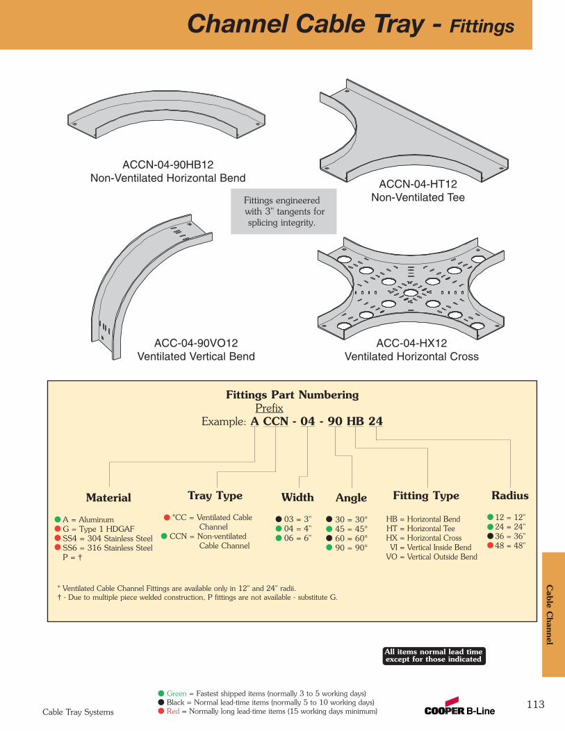
113
Fittings Part NumberingPrefix
Example: A CCN - 04 - 90 HB 24
Fittings engineeredwith 3" tangents for splicing integrity.
Channel Cable Tray - Fittings
Angle
30 = 30°45 = 45°60 = 60°90 = 90°
ACCN-04-90HB12Non-Ventilated Horizontal Bend ACCN-04-HT12
Non-Ventilated Tee
ACC-04-90VO12Ventilated Vertical Bend
ACC-04-HX12Ventilated Horizontal Cross
Cable C
hannel
Cable Tray Systems
Green = Fastest shipped items (normally 3 to 5 working days)Black = Normal lead-time items (normally 5 to 10 working days)Red = Normally long lead-time items (15 working days minimum)
All items normal lead timeexcept for those indicated
Width
03 = 3"04 = 4"06 = 6"
Radius
12 = 12" 24 = 24" 36 = 36" 48 = 48"
Material
A = Aluminum G = Type 1 HDGAFSS4 = 304 Stainless SteelSS6 = 316 Stainless SteelP = †
Tray Type
*CC = Ventilated Cable Channel
CCN = Non-ventilated Cable Channel
* Ventilated Cable Channel Fittings are available only in 12" and 24" radii.† - Due to multiple piece welded construction, P fittings are not available - substitute G.
Fitting Type
HB = Horizontal BendHT = Horizontal TeeHX = Horizontal CrossVI = Vertical Inside Bend
VO = Vertical Outside Bend
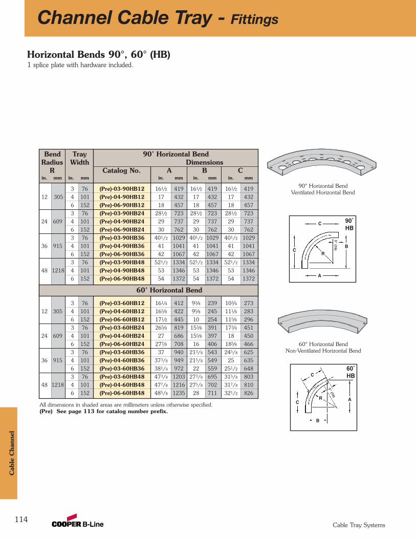
Bend Tray 90˚ Horizontal BendRadius Width Dimensions
R Catalog No. A B Cin. mm in. mm in. mm in. mm in. mm
3 76 (Pre)-03-90HB12 161/2 419 161/2 419 161/2 419
12 305 4 101 (Pre)-04-90HB12 17 432 17 432 17 432
6 152 (Pre)-06-90HB12 18 457 18 457 18 457
3 76 (Pre)-03-90HB24 281/2 723 281/2 723 281/2 723
24 609 4 101 (Pre)-04-90HB24 29 737 29 737 29 737
6 152 (Pre)-06-90HB24 30 762 30 762 30 762
3 76 (Pre)-03-90HB36 401/2 1029 401/2 1029 401/2 1029
36 915 4 101 (Pre)-04-90HB36 41 1041 41 1041 41 1041
6 152 (Pre)-06-90HB36 42 1067 42 1067 42 1067
3 76 (Pre)-03-90HB48 521/2 1334 521/2 1334 521/2 1334
48 1218 4 101 (Pre)-04-90HB48 53 1346 53 1346 53 1346
6 152 (Pre)-06-90HB48 54 1372 54 1372 54 1372
3 76 (Pre)-03-60HB12 161/4 412 93/8 239 103/4 273
12 305 4 101 (Pre)-04-60HB12 165/8 422 95/8 245 111/8 283
6 152 (Pre)-06-60HB12 171/2 445 10 254 115/8 296
3 76 (Pre)-03-60HB24 265/8 819 153/8 391 173/4 451
24 609 4 101 (Pre)-04-60HB24 27 686 155/8 397 18 450
6 152 (Pre)-06-60HB24 277/8 708 16 406 185/8 466
3 76 (Pre)-03-60HB36 37 940 213/8 543 245/8 625
36 915 4 101 (Pre)-04-60HB36 373/8 949 215/8 549 25 635
6 152 (Pre)-03-60HB36 381/4 972 22 559 251/2 648
3 76 (Pre)-03-60HB48 473/8 1203 273/8 695 315/8 803
48 1218 4 101 (Pre)-04-60HB48 477/8 1216 275/8 702 317/8 810
6 152 (Pre)-06-60HB48 485/8 1235 28 711 321/2 826
Channel Cable Tray - Fittings
114
All dimensions in shaded areas are millimeters unless otherwise specified.(Pre) See page 113 for catalog number prefix.
A
C
CR
3" (7
6) B
A
C
CR
3" (76)
B
90˚HB
60˚HB
Horizontal Bends 90°, 60° (HB)1 splice plate with hardware included.
60˚ Horizontal Bend
90° Horizontal BendVentilated Horizontal Bend
60° Horizontal BendNon-Ventilated Horizontal Bend
Cab
le C
hann
el
Cable Tray Systems
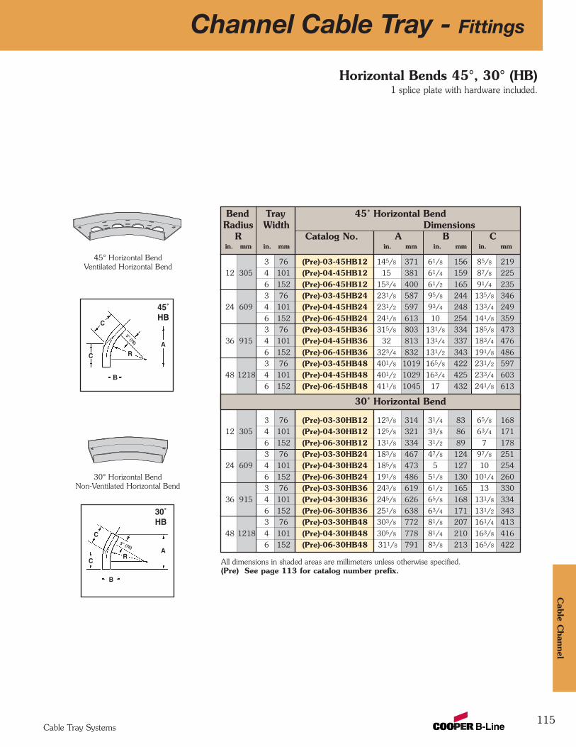
115
A
A
C
C R
B
45˚HB
C
CR
3” (76)
B
30˚HB
Horizontal Bends 45°, 30° (HB)1 splice plate with hardware included.
All dimensions in shaded areas are millimeters unless otherwise specified.(Pre) See page 113 for catalog number prefix.
45° Horizontal Bend Ventilated Horizontal Bend
3” (76)
30° Horizontal BendNon-Ventilated Horizontal Bend
Channel Cable Tray - Fittings
Bend Tray 45˚ Horizontal BendRadius Width Dimensions
R Catalog No. A B Cin. mm in. mm in. mm in. mm in. mm
3 76 (Pre)-03-45HB12 145/8 371 61/8 156 85/8 219
12 305 4 101 (Pre)-04-45HB12 15 381 61/4 159 87/8 225
6 152 (Pre)-06-45HB12 153/4 400 61/2 165 91/4 235
3 76 (Pre)-03-45HB24 231/8 587 95/8 244 135/8 346
24 609 4 101 (Pre)-04-45HB24 231/2 597 93/4 248 133/4 249
6 152 (Pre)-06-45HB24 241/8 613 10 254 141/8 359
3 76 (Pre)-03-45HB36 315/8 803 131/8 334 185/8 473
36 915 4 101 (Pre)-04-45HB36 32 813 131/4 337 183/4 476
6 152 (Pre)-06-45HB36 323/4 832 131/2 343 191/8 486
3 76 (Pre)-03-45HB48 401/8 1019 165/8 422 231/2 597
48 1218 4 101 (Pre)-04-45HB48 401/2 1029 163/4 425 233/4 603
6 152 (Pre)-06-45HB48 411/8 1045 17 432 241/8 613
3 76 (Pre)-03-30HB12 123/8 314 31/4 83 65/8 168
12 305 4 101 (Pre)-04-30HB12 125/8 321 33/8 86 63/4 171
6 152 (Pre)-06-30HB12 131/8 334 31/2 89 7 178
3 76 (Pre)-03-30HB24 183/8 467 47/8 124 97/8 251
24 609 4 101 (Pre)-04-30HB24 185/8 473 5 127 10 254
6 152 (Pre)-06-30HB24 191/8 486 51/8 130 101/4 260
3 76 (Pre)-03-30HB36 243/8 619 61/2 165 13 330
36 915 4 101 (Pre)-04-30HB36 245/8 626 65/8 168 131/8 334
6 152 (Pre)-06-30HB36 251/8 638 63/4 171 131/2 343
3 76 (Pre)-03-30HB48 303/8 772 81/8 207 161/4 413
48 1218 4 101 (Pre)-04-30HB48 305/8 778 81/4 210 163/8 416
6 152 (Pre)-06-30HB48 311/8 791 83/8 213 165/8 422
30˚ Horizontal Bend
Cable C
hannel
Cable Tray Systems
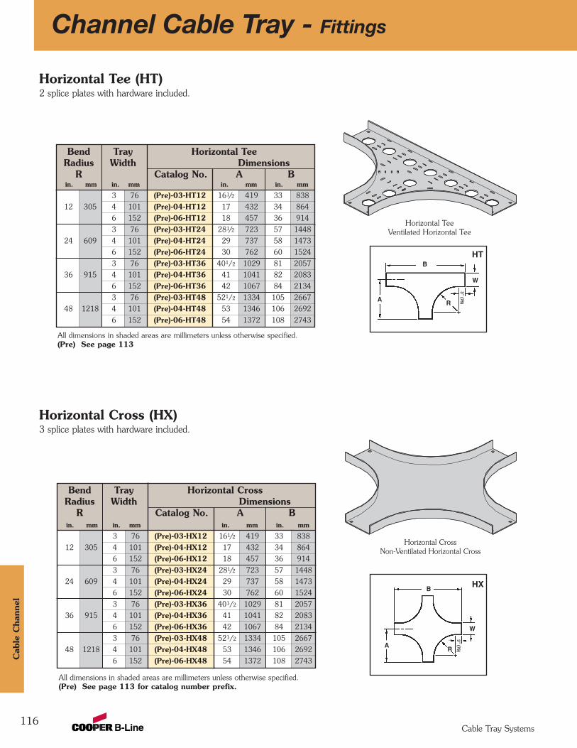
Bend Tray Horizontal CrossRadius Width Dimensions
R Catalog No. A Bin. mm in. mm in. mm in. mm
3 76 (Pre)-03-HX12 161/2 419 33 838
12 305 4 101 (Pre)-04-HX12 17 432 34 864
6 152 (Pre)-06-HX12 18 457 36 914
3 76 (Pre)-03-HX24 281/2 723 57 1448
24 609 4 101 (Pre)-04-HX24 29 737 58 1473
6 152 (Pre)-06-HX24 30 762 60 1524
3 76 (Pre)-03-HX36 401/2 1029 81 2057
36 915 4 101 (Pre)-04-HX36 41 1041 82 2083
6 152 (Pre)-06-HX36 42 1067 84 2134
3 76 (Pre)-03-HX48 521/2 1334 105 2667
48 1218 4 101 (Pre)-04-HX48 53 1346 106 2692
6 152 (Pre)-06-HX48 54 1372 108 2743
Bend Tray Horizontal TeeRadius Width Dimensions
R Catalog No. A Bin. mm in. mm in. mm in. mm
3 76 (Pre)-03-HT12 161/2 419 33 838
12 305 4 101 (Pre)-04-HT12 17 432 34 864
6 152 (Pre)-06-HT12 18 457 36 914
3 76 (Pre)-03-HT24 281/2 723 57 1448
24 609 4 101 (Pre)-04-HT24 29 737 58 1473
6 152 (Pre)-06-HT24 30 762 60 1524
3 76 (Pre)-03-HT36 401/2 1029 81 2057
36 915 4 101 (Pre)-04-HT36 41 1041 82 2083
6 152 (Pre)-06-HT36 42 1067 84 2134
3 76 (Pre)-03-HT48 521/2 1334 105 2667
48 1218 4 101 (Pre)-04-HT48 53 1346 106 2692
6 152 (Pre)-06-HT48 54 1372 108 2743
116
Channel Cable Tray - Fittings
Horizontal Tee (HT)2 splice plates with hardware included.
Horizontal Cross (HX)3 splice plates with hardware included.
A
W
R
3” (76)3” (76)
B
A
W
B
Horizontal CrossNon-Ventilated Horizontal Cross
All dimensions in shaded areas are millimeters unless otherwise specified.(Pre) See page 113
All dimensions in shaded areas are millimeters unless otherwise specified.(Pre) See page 113 for catalog number prefix.
HX
HT
Horizontal TeeVentilated Horizontal Tee
R
Cab
le C
hann
el
Cable Tray Systems

Bend Tray 90˚ Vertical Outside BendRadius Width Dimensions
R Catalog No. A B Cin. mm in. mm in. mm in. mm in. mm
3 76 (Pre)-03-90VO1212 305 4 101 (Pre)-04-90VO12 15 381 15 381 15 381
6 152 (Pre)-06-90VO123 76 (Pre)-03-90VO24
24 609 4 101 (Pre)-04-90VO24 27 686 27 686 27 686
6 152 (Pre)-06-90VO243 76 (Pre)-03-90VO36
36 915 4 101 (Pre)-04-90VO36 39 991 39 991 39 991
6 152 (Pre)-06-90VO363 76 (Pre)-03-90VO48
48 1218 4 101 (Pre)-04-90VO48 51 1295 51 1295 51 1295
6 152 (Pre)-06-90VO48
3 76 (Pre)-03-60VO1212 305 4 101 (Pre)-04-60VO12 147/8 378 81/2 216 97/8 251
6 152 (Pre)-06-60VO123 76 (Pre)-03-60VO24
24 609 4 101 (Pre)-04-60VO24 253/8 645 145/8 372 167/8 428
6 152 (Pre)-06-60VO243 76 (Pre)-03-60VO36
36 915 4 101 (Pre)-04-60VO36 355/8 905 205/8 524 233/4 603
6 152 (Pre)-06-60VO363 76 (Pre)-03-60VO48
48 1218 4 101 (Pre)-04-60VO48 461/8 1172 265/8 676 303/4 781
6 152 (Pre)-06-60VO48
117
Vertical Outside Bends 90°, 60° (VO)1 splice plate with hardware included.
A
C
C
R
3” (76) B
A
C
C
R
3” (76)
B
90˚VO
60˚VO
Channel Cable Tray - Fittings
60˚ Vertical Outside Bend
All dimensions in shaded areas are millimeters unless otherwise specified.(Pre) See page 113 for catalog number prefix.
90° Vertical Outside BendVentilated Vertical Outside Bend
60° Vertical Outside BendNon-Ventilated Vertical Outside Bend
Cable C
hannel
Cable Tray Systems
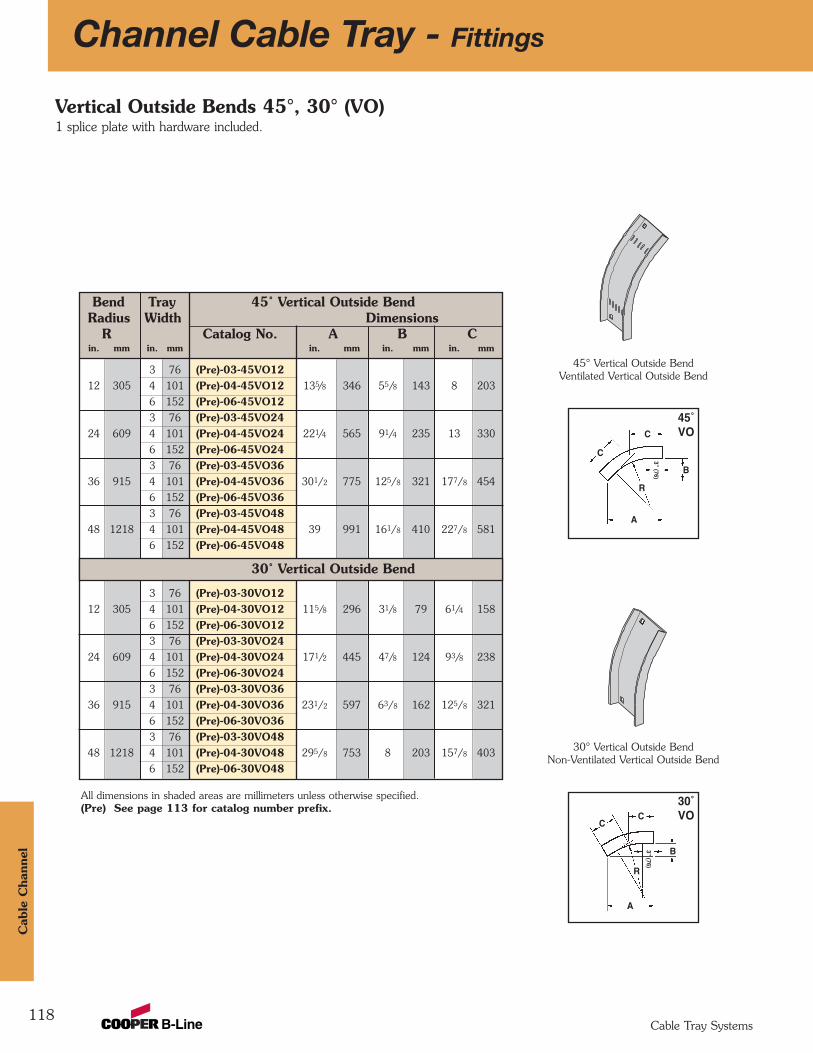
Bend Tray 45˚ Vertical Outside BendRadius Width Dimensions
R Catalog No. A B Cin. mm in. mm in. mm in. mm in. mm
3 76 (Pre)-03-45VO1212 305 4 101 (Pre)-04-45VO12 135/8 346 55/8 143 8 203
6 152 (Pre)-06-45VO123 76 (Pre)-03-45VO24
24 609 4 101 (Pre)-04-45VO24 221/4 565 91/4 235 13 330
6 152 (Pre)-06-45VO243 76 (Pre)-03-45VO36
36 915 4 101 (Pre)-04-45VO36 301/2 775 125/8 321 177/8 454
6 152 (Pre)-06-45VO363 76 (Pre)-03-45VO48
48 1218 4 101 (Pre)-04-45VO48 39 991 161/8 410 227/8 581
6 152 (Pre)-06-45VO48
3 76 (Pre)-03-30VO1212 305 4 101 (Pre)-04-30VO12 115/8 296 31/8 79 61/4 158
6 152 (Pre)-06-30VO123 76 (Pre)-03-30VO24
24 609 4 101 (Pre)-04-30VO24 171/2 445 47/8 124 93/8 238
6 152 (Pre)-06-30VO243 76 (Pre)-03-30VO36
36 915 4 101 (Pre)-04-30VO36 231/2 597 63/8 162 125/8 321
6 152 (Pre)-06-30VO363 76 (Pre)-03-30VO48
48 1218 4 101 (Pre)-04-30VO48 295/8 753 8 203 157/8 403
6 152 (Pre)-06-30VO48
118
Channel Cable Tray - Fittings
Vertical Outside Bends 45°, 30° (VO)1 splice plate with hardware included.
A
C
C
R
3” (76)
B
45˚VO
A
CC
R
3” (76)
B
30˚VO
30˚ Vertical Outside Bend
All dimensions in shaded areas are millimeters unless otherwise specified.(Pre) See page 113 for catalog number prefix.
45° Vertical Outside BendVentilated Vertical Outside Bend
30° Vertical Outside BendNon-Ventilated Vertical Outside Bend
Cab
le C
hann
el
Cable Tray Systems
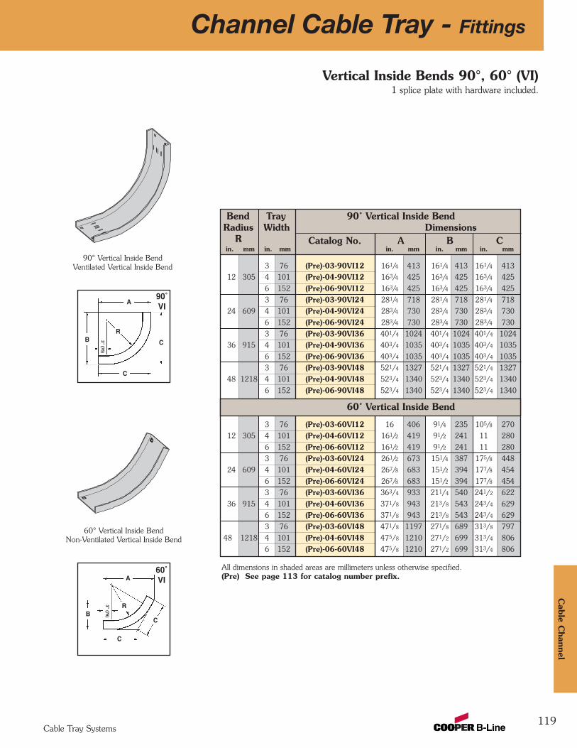
Bend Tray 90˚ Vertical Inside BendRadius Width Dimensions
R Catalog No. A B Cin. mm in. mm in. mm in. mm in. mm
3 76 (Pre)-03-90VI12 161/4 413 161/4 413 161/4 413
12 305 4 101 (Pre)-04-90VI12 163/4 425 163/4 425 163/4 425
6 152 (Pre)-06-90VI12 163/4 425 163/4 425 163/4 425
3 76 (Pre)-03-90VI24 281/4 718 281/4 718 281/4 718
24 609 4 101 (Pre)-04-90VI24 283/4 730 283/4 730 283/4 730
6 152 (Pre)-06-90VI24 283/4 730 283/4 730 283/4 730
3 76 (Pre)-03-90VI36 401/4 1024 401/4 1024 401/4 1024
36 915 4 101 (Pre)-04-90VI36 403/4 1035 403/4 1035 403/4 1035
6 152 (Pre)-06-90VI36 403/4 1035 403/4 1035 403/4 1035
3 76 (Pre)-03-90VI48 521/4 1327 521/4 1327 521/4 1327
48 1218 4 101 (Pre)-04-90VI48 523/4 1340 523/4 1340 523/4 1340
6 152 (Pre)-06-90VI48 523/4 1340 523/4 1340 523/4 1340
3 76 (Pre)-03-60VI12 16 406 91/4 235 105/8 270
12 305 4 101 (Pre)-04-60VI12 161/2 419 91/2 241 11 280
6 152 (Pre)-06-60VI12 161/2 419 91/2 241 11 280
3 76 (Pre)-03-60VI24 261/2 673 151/4 387 175/8 448
24 609 4 101 (Pre)-04-60VI24 267/8 683 151/2 394 177/8 454
6 152 (Pre)-06-60VI24 267/8 683 151/2 394 177/8 454
3 76 (Pre)-03-60VI36 363/4 933 211/4 540 241/2 622
36 915 4 101 (Pre)-04-60VI36 371/8 943 213/8 543 243/4 629
6 152 (Pre)-06-60VI36 371/8 943 213/8 543 243/4 629
3 76 (Pre)-03-60VI48 471/8 1197 271/8 689 313/8 797
48 1218 4 101 (Pre)-04-60VI48 475/8 1210 271/2 699 313/4 806
6 152 (Pre)-06-60VI48 475/8 1210 271/2 699 313/4 806
119
Vertical Inside Bends 90°, 60° (VI)1 splice plate with hardware included.
A
C
C
R
3” (76)
B
A
C
C
R3” (76)B
90˚VI
60˚VI
60˚ Vertical Inside Bend
Channel Cable Tray - Fittings
All dimensions in shaded areas are millimeters unless otherwise specified.(Pre) See page 113 for catalog number prefix.
60° Vertical Inside BendNon-Ventilated Vertical Inside Bend
90° Vertical Inside BendVentilated Vertical Inside Bend
Cable C
hannel
Cable Tray Systems
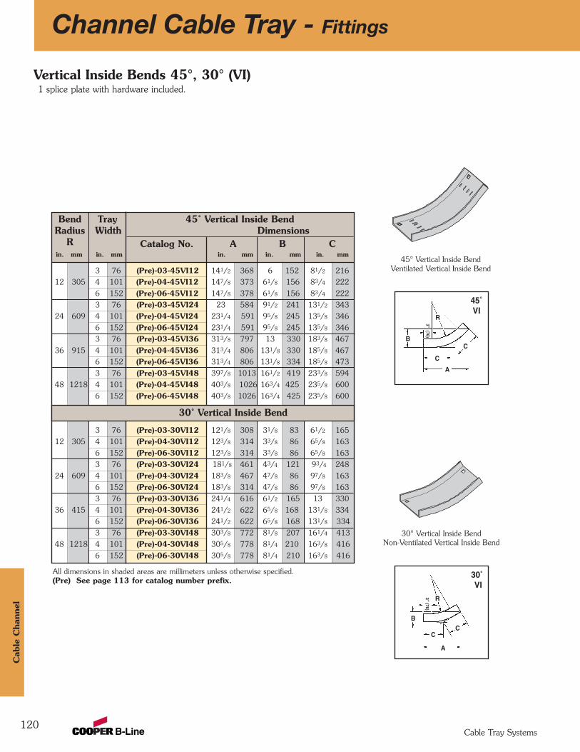
Bend Tray 45˚ Vertical Inside BendRadius Width Dimensions
R Catalog No. A B Cin. mm in. mm in. mm in. mm in. mm
3 76 (Pre)-03-45VI12 141/2 368 6 152 81/2 216
12 305 4 101 (Pre)-04-45VI12 147/8 373 61/8 156 83/4 222
6 152 (Pre)-06-45VI12 147/8 378 61/8 156 83/4 222
3 76 (Pre)-03-45VI24 23 584 91/2 241 131/2 343
24 609 4 101 (Pre)-04-45VI24 231/4 591 95/8 245 135/8 346
6 152 (Pre)-06-45VI24 231/4 591 95/8 245 135/8 346
3 76 (Pre)-03-45VI36 313/8 797 13 330 183/8 467
36 915 4 101 (Pre)-04-45VI36 313/4 806 131/8 330 185/8 467
6 152 (Pre)-06-45VI36 313/4 806 131/8 334 185/8 473
3 76 (Pre)-03-45VI48 397/8 1013 161/2 419 233/8 594
48 1218 4 101 (Pre)-04-45VI48 403/8 1026 163/4 425 235/8 600
6 152 (Pre)-06-45VI48 403/8 1026 163/4 425 235/8 600
3 76 (Pre)-03-30VI12 121/8 308 31/8 83 61/2 165
12 305 4 101 (Pre)-04-30VI12 123/8 314 33/8 86 65/8 163
6 152 (Pre)-06-30VI12 123/8 314 33/8 86 65/8 163
3 76 (Pre)-03-30VI24 181/8 461 43/4 121 93/4 248
24 609 4 101 (Pre)-04-30VI24 183/8 467 47/8 86 97/8 163
6 152 (Pre)-06-30VI24 183/8 314 47/8 86 97/8 163
3 76 (Pre)-03-30VI36 241/4 616 61/2 165 13 330
36 415 4 101 (Pre)-04-30VI36 241/2 622 65/8 168 131/8 334
6 152 (Pre)-06-30VI36 241/2 622 65/8 168 131/8 334
3 76 (Pre)-03-30VI48 303/8 772 81/8 207 161/4 413
48 1218 4 101 (Pre)-04-30VI48 305/8 778 81/4 210 163/8 416
6 152 (Pre)-06-30VI48 305/8 778 81/4 210 163/8 416
120
Channel Cable Tray - Fittings
Vertical Inside Bends 45°, 30° (VI)1 splice plate with hardware included.
A
C
C
R
3” (76)
B
45˚ VI
A
CC
R3” (76)
B
30˚VI
30˚ Vertical Inside Bend
All dimensions in shaded areas are millimeters unless otherwise specified.(Pre) See page 113 for catalog number prefix.
30° Vertical Inside BendNon-Ventilated Vertical Inside Bend
45° Vertical Inside BendVentilated Vertical Inside Bend
Cab
le C
hann
el
Cable Tray Systems
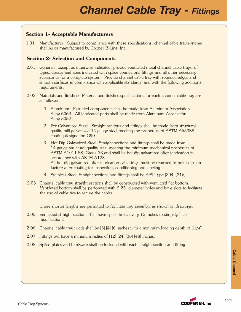
121
Channel Cable Tray - Fittings
Section 1- Acceptable Manufacturers
1.01 Manufacturer: Subject to compliance with these specifications, channel cable tray systemsshall be as manufactured by Cooper B-Line, Inc.
Section 2- Selection and Components
2.01 General: Except as otherwise indicated, provide ventilated metal channel cable trays, oftypes, classes and sizes indicated with splice connectors, fittings and all other necessaryaccessories for a complete system. Provide channel cable tray with rounded edges andsmooth surfaces in compliance with applicable standards, and with the following additionalrequirements.
2.02 Materials and finishes: Material and finishes specifications for each channel cable tray areas follows:
1. Aluminum: Extruded components shall be made from Aluminum AssociationAlloy 6063. All fabricated parts shall be made from Aluminum AssociationAlloy 5052.
2. Pre-Galvanized Steel: Straight sections and fittings shall be made from structuralquality mill galvanized 14 gauge steel meeting the properties of ASTM A653SS,coating designation G90.
3. Hot Dip Galvanized Steel: Straight sections and fittings shall be made from14 gauge structural quality steel meeting the minimum mechanical properties ofASTM A1011 SS, Grade 33 and shall be hot-dip galvanized after fabrication inaccordance with ASTM A123. All hot dip galvanized after fabrication cable trays must be returned to point of manfacture after coating for inspection, conditioning and labeling.
4. Stainless Steel: Straight sections and fittings shall be AISI Type [304] [316].
2.03 Channel cable tray straight sections shall be constructed with ventilated flat bottom.Ventilated bottom shall be perforated with 2.25" diameter holes and have slots to facilitatethe use of cable ties to secure the cables.
2.04 Straight sections shall be supplied in standard [12 foot] [10 foot (3 m)] lengths, exceptwhere shorter lengths are permitted to facilitate tray assembly as shown on drawings.
2.05 Ventilated straight sections shall have splice holes every 12 inches to simplify fieldmodifications.
2.06 Channel cable tray width shall be [3] [4] [6] inches with a minimum loading depth of 11/4".
2.07 Fittings will have a minimum radius of [12] [24] [36] [48] inches.
2.08 Splice plates and hardware shall be included with each straight section and fitting.
Cable C
hannel
Cable Tray Systems
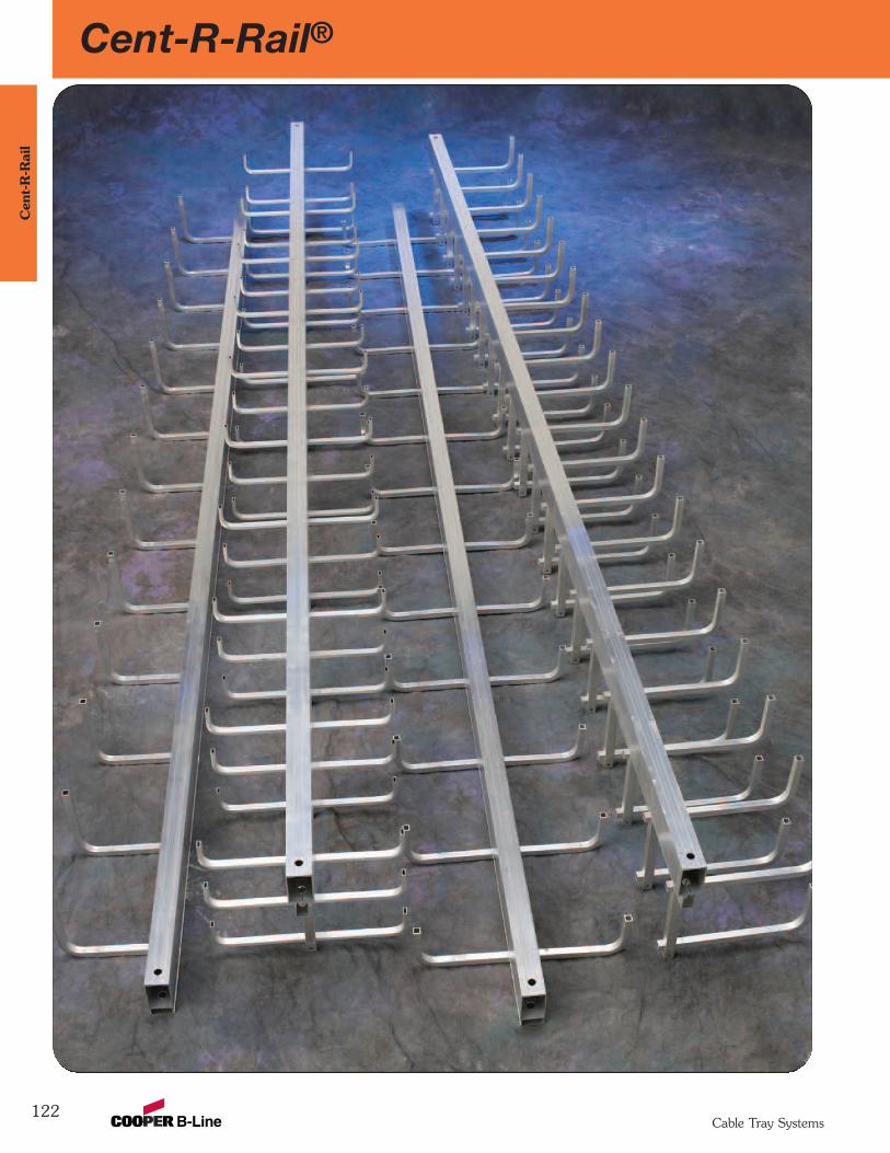
122
Cent-R-Rail®C
ent-
R-R
ail
Cable Tray Systems
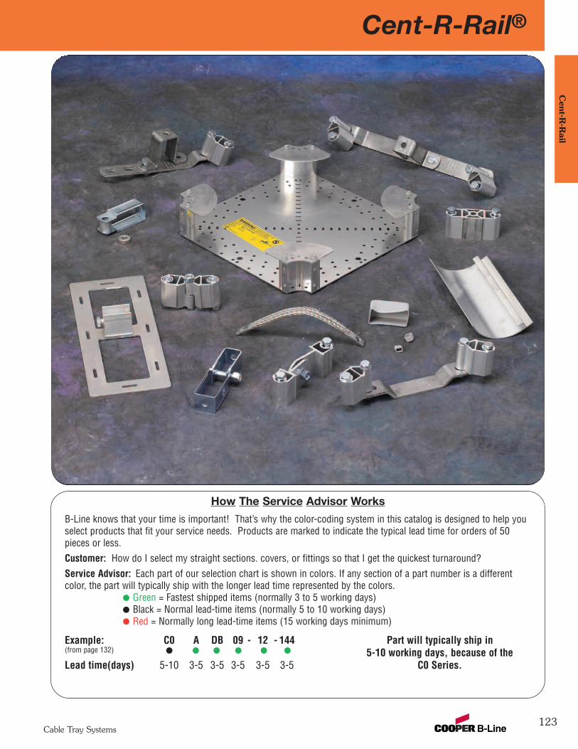
Cent-R-Rail®
123
Cent-R
-Rail
Cable Tray Systems
How The Service Advisor Works
B-Line knows that your time is important! That’s why the color-coding system in this catalog is designed to help youselect products that fit your service needs. Products are marked to indicate the typical lead time for orders of 50pieces or less.Customer: How do I select my straight sections. covers, or fittings so that I get the quickest turnaround?Service Advisor: Each part of our selection chart is shown in colors. If any section of a part number is a differentcolor, the part will typically ship with the longer lead time represented by the colors.
Green = Fastest shipped items (normally 3 to 5 working days)Black = Normal lead-time items (normally 5 to 10 working days)Red = Normally long lead-time items (15 working days minimum)
Example: C0 A DB 09 - 12 - 144 Part will typically ship in(from page 132) 5-10 working days, because of the Lead time(days) 5-10 3-5 3-5 3-5 3-5 3-5 C0 Series.
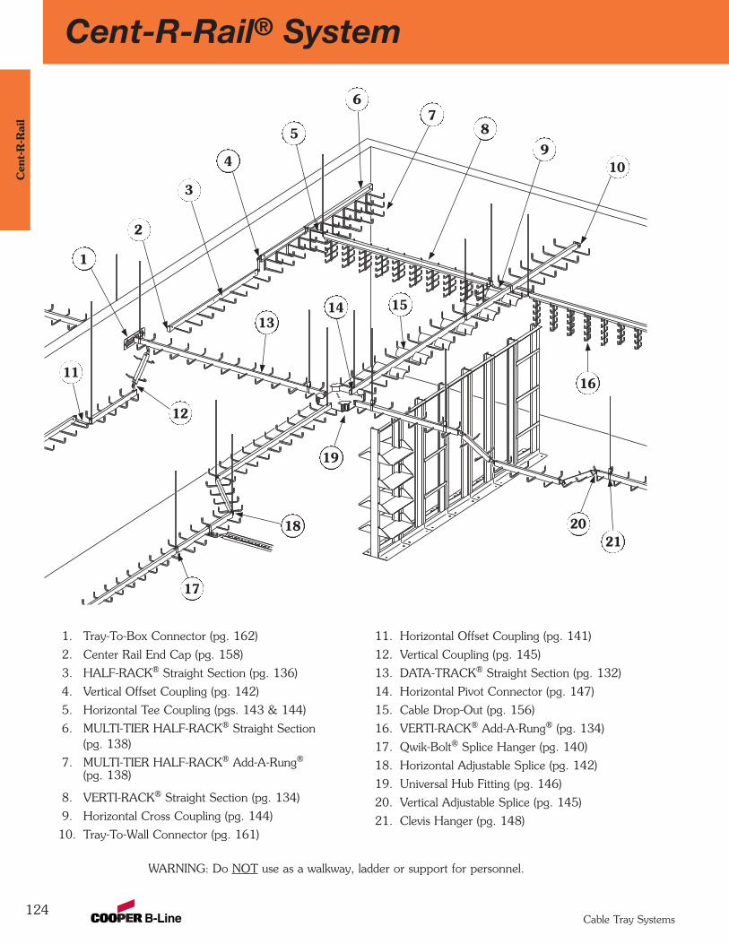
124
Cent-R-Rail® SystemC
ent-
R-R
ail
Cable Tray Systems
WARNING: Do NOT use as a walkway, ladder or support for personnel.
1
2
3
4
5
6
10
11
12
1314 15
16
17
1821
20
78
9
11. Horizontal Offset Coupling (pg. 141)
12. Vertical Coupling (pg. 145)
13. DATA-TRACK® Straight Section (pg. 132)
14. Horizontal Pivot Connector (pg. 147)
15. Cable Drop-Out (pg. 156)
16. VERTI-RACK® Add-A-Rung® (pg. 134)
17. Qwik-Bolt® Splice Hanger (pg. 140)
18. Horizontal Adjustable Splice (pg. 142)
19. Universal Hub Fitting (pg. 146)
20. Vertical Adjustable Splice (pg. 145)
21. Clevis Hanger (pg. 148)
1. Tray-To-Box Connector (pg. 162)
2. Center Rail End Cap (pg. 158)
3. HALF-RACK® Straight Section (pg. 136)
4. Vertical Offset Coupling (pg. 142)
5. Horizontal Tee Coupling (pgs. 143 & 144)
6. MULTI-TIER HALF-RACK® Straight Section(pg. 138)
7. MULTI-TIER HALF-RACK® Add-A-Rung®
(pg. 138)
8. VERTI-RACK® Straight Section (pg. 134)
9. Horizontal Cross Coupling (pg. 144)
10. Tray-To-Wall Connector (pg. 161)
19
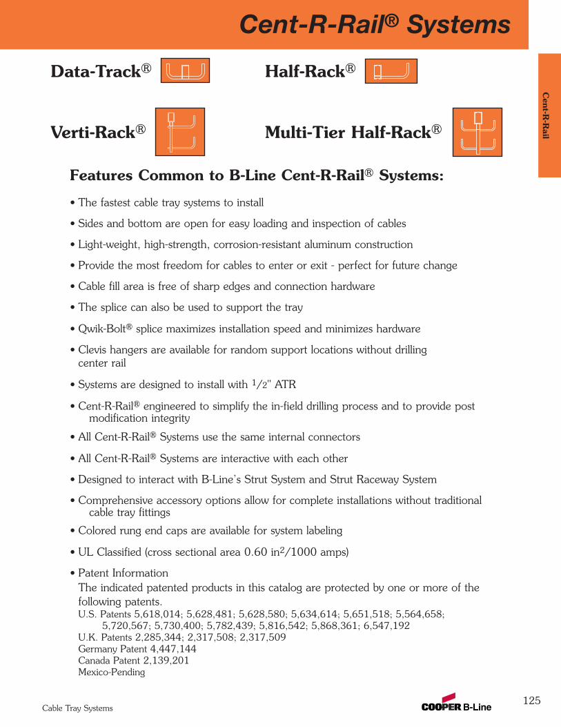
Cent-R-Rail® Systems
125
Cent-R
-Rail
Cable Tray Systems
Features Common to B-Line Cent-R-Rail® Systems:
• The fastest cable tray systems to install
• Sides and bottom are open for easy loading and inspection of cables
• Light-weight, high-strength, corrosion-resistant aluminum construction
• Provide the most freedom for cables to enter or exit - perfect for future change
• Cable fill area is free of sharp edges and connection hardware
• The splice can also be used to support the tray
• Qwik-Bolt® splice maximizes installation speed and minimizes hardware
• Clevis hangers are available for random support locations without drilling center rail
• Systems are designed to install with 1/2" ATR
• Cent-R-Rail® engineered to simplify the in-field drilling process and to provide postmodification integrity
• All Cent-R-Rail® Systems use the same internal connectors
• All Cent-R-Rail® Systems are interactive with each other
• Designed to interact with B-Line’s Strut System and Strut Raceway System
• Comprehensive accessory options allow for complete installations without traditionalcable tray fittings
• Colored rung end caps are available for system labeling
• UL Classified (cross sectional area 0.60 in2/1000 amps)
• Patent InformationThe indicated patented products in this catalog are protected by one or more of the following patents.U.S. Patents 5,618,014; 5,628,481; 5,628,580; 5,634,614; 5,651,518; 5,564,658;
5,720,567; 5,730,400; 5,782,439; 5,816,542; 5,868,361; 6,547,192U.K. Patents 2,285,344; 2,317,508; 2,317,509Germany Patent 4,447,144Canada Patent 2,139,201Mexico-Pending
Data-Track® Half-Rack®
Verti-Rack® Multi-Tier Half-Rack®
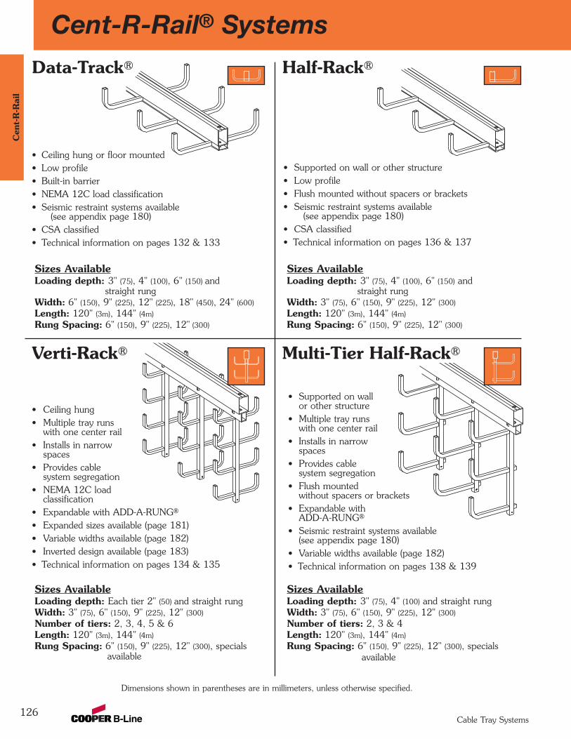
126
Cent-R-Rail® SystemsC
ent-
R-R
ail
Cable Tray Systems
• Ceiling hung• Multiple tray runs
with one center rail• Installs in narrow
spaces• Provides cable
system segregation• NEMA 12C load
classification• Expandable with ADD-A-RUNG®
• Expanded sizes available (page 181)• Variable widths available (page 182)• Inverted design available (page 183)• Technical information on pages 134 & 135
Sizes AvailableLoading depth: 3" (75), 4" (100), 6" (150) and
straight rungWidth: 6" (150), 9" (225), 12" (225), 18" (450), 24" (600)
Length: 120" (3m), 144" (4m)
Rung Spacing: 6" (150), 9" (225), 12" (300)
Sizes AvailableLoading depth: Each tier 2" (50) and straight rungWidth: 3" (75), 6" (150), 9" (225), 12" (300)
Number of tiers: 2, 3, 4, 5 & 6Length: 120" (3m), 144" (4m)
Rung Spacing: 6" (150), 9" (225), 12" (300), specialsavailable
Dimensions shown in parentheses are in millimeters, unless otherwise specified.
• Ceiling hung or floor mounted• Low profile• Built-in barrier• NEMA 12C load classification• Seismic restraint systems available
(see appendix page 180)• CSA classified• Technical information on pages 132 & 133
Sizes AvailableLoading depth: 3" (75), 4" (100), 6" (150) and
straight rungWidth: 3" (75), 6" (150), 9" (225), 12" (300)
Length: 120" (3m), 144" (4m)
Rung Spacing: 6" (150), 9" (225), 12" (300)
• Supported on wall or other structure• Low profile• Flush mounted without spacers or brackets• Seismic restraint systems available
(see appendix page 180)• CSA classified• Technical information on pages 136 & 137
Verti-Rack® Multi-Tier Half-Rack®
Sizes AvailableLoading depth: 3" (75), 4" (100) and straight rungWidth: 3" (75), 6" (150), 9" (225), 12" (300)
Number of tiers: 2, 3 & 4Length: 120" (3m), 144" (4m)
Rung Spacing: 6" (150), 9" (225), 12" (300), specialsavailable
• Supported on wallor other structure
• Multiple tray runswith one center rail
• Installs in narrowspaces
• Provides cablesystem segregation
• Flush mountedwithout spacers or brackets
• Expandable withADD-A-RUNG®
• Seismic restraint systems available (see appendix page 180)
• Variable widths available (page 182)• Technical information on pages 138 & 139
Data-Track® Half-Rack®
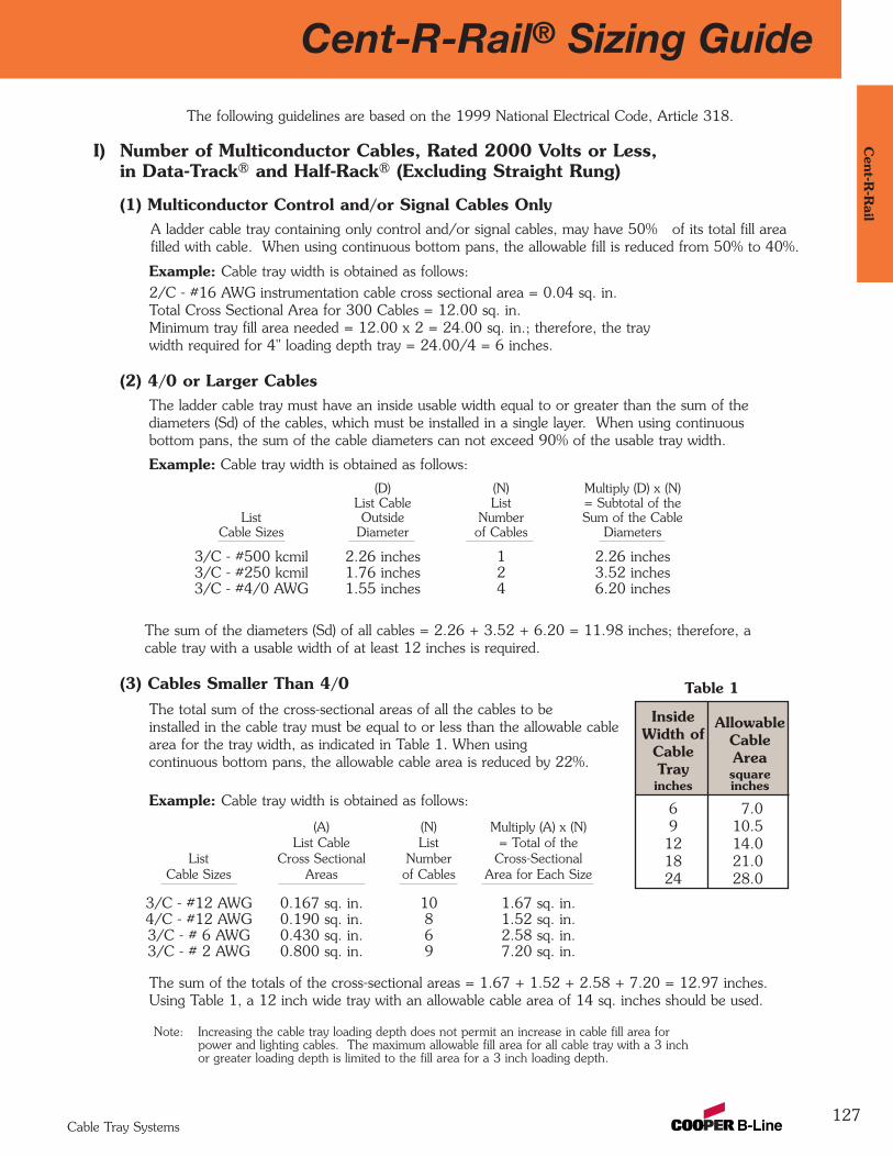
Cent-R-Rail® Sizing Guide
127
Cent-R
-Rail
Cable Tray Systems
The following guidelines are based on the 1999 National Electrical Code, Article 318.
I) Number of Multiconductor Cables, Rated 2000 Volts or Less,in Data-Track® and Half-Rack® (Excluding Straight Rung)
(1) Multiconductor Control and/or Signal Cables OnlyA ladder cable tray containing only control and/or signal cables, may have 50% of its total fill areafilled with cable. When using continuous bottom pans, the allowable fill is reduced from 50% to 40%.
Example: Cable tray width is obtained as follows:2/C - #16 AWG instrumentation cable cross sectional area = 0.04 sq. in.Total Cross Sectional Area for 300 Cables = 12.00 sq. in.Minimum tray fill area needed = 12.00 x 2 = 24.00 sq. in.; therefore, the traywidth required for 4" loading depth tray = 24.00/4 = 6 inches.
(2) 4/0 or Larger CablesThe ladder cable tray must have an inside usable width equal to or greater than the sum of thediameters (Sd) of the cables, which must be installed in a single layer. When using continuousbottom pans, the sum of the cable diameters can not exceed 90% of the usable tray width.
Example: Cable tray width is obtained as follows:
(D) (N) Multiply (D) x (N)List Cable List = Subtotal of the
List Outside Number Sum of the CableCable Sizes Diameter of Cables Diameters
3/C - #500 kcmil 2.26 inches 1 2.26 inches3/C - #250 kcmil 1.76 inches 2 3.52 inches3/C - #4/0 AWG 1.55 inches 4 6.20 inches
The sum of the diameters (Sd) of all cables = 2.26 + 3.52 + 6.20 = 11.98 inches; therefore, acable tray with a usable width of at least 12 inches is required.
(3) Cables Smaller Than 4/0The total sum of the cross-sectional areas of all the cables to beinstalled in the cable tray must be equal to or less than the allowable cablearea for the tray width, as indicated in Table 1. When usingcontinuous bottom pans, the allowable cable area is reduced by 22%.
Example: Cable tray width is obtained as follows:
(A) (N) Multiply (A) x (N)List Cable List = Total of the
List Cross Sectional Number Cross-SectionalCable Sizes Areas of Cables Area for Each Size
3/C - #12 AWG 0.167 sq. in. 10 1.67 sq. in.4/C - #12 AWG 0.190 sq. in. 8 1.52 sq. in.3/C - # 6 AWG 0.430 sq. in. 6 2.58 sq. in.3/C - # 2 AWG 0.800 sq. in. 9 7.20 sq. in.
The sum of the totals of the cross-sectional areas = 1.67 + 1.52 + 2.58 + 7.20 = 12.97 inches. Using Table 1, a 12 inch wide tray with an allowable cable area of 14 sq. inches should be used.
Note: Increasing the cable tray loading depth does not permit an increase in cable fill area forpower and lighting cables. The maximum allowable fill area for all cable tray with a 3 inchor greater loading depth is limited to the fill area for a 3 inch loading depth.
Inside AllowableWidth of Cable
Cable AreaTray squareinches inches
6 7.09 10.512 14.018 21.024 28.0
Table 1
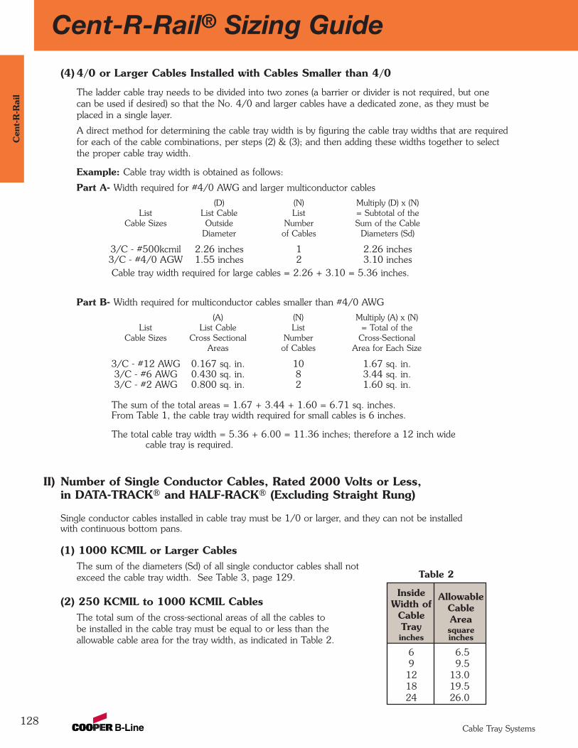
128
Cent-R-Rail® Sizing GuideC
ent-
R-R
ail
Cable Tray Systems
(4) 4/0 or Larger Cables Installed with Cables Smaller than 4/0
The ladder cable tray needs to be divided into two zones (a barrier or divider is not required, but onecan be used if desired) so that the No. 4/0 and larger cables have a dedicated zone, as they must beplaced in a single layer.
A direct method for determining the cable tray width is by figuring the cable tray widths that are requiredfor each of the cable combinations, per steps (2) & (3); and then adding these widths together to selectthe proper cable tray width.
Example: Cable tray width is obtained as follows:
Part A- Width required for #4/0 AWG and larger multiconductor cables
(D) (N) Multiply (D) x (N)List List Cable List = Subtotal of the
Cable Sizes Outside Number Sum of the CableDiameter of Cables Diameters (Sd)
3/C - #500kcmil 2.26 inches 1 2.26 inches3/C - #4/0 AGW 1.55 inches 2 3.10 inchesCable tray width required for large cables = 2.26 + 3.10 = 5.36 inches.
Part B- Width required for multiconductor cables smaller than #4/0 AWG
(A) (N) Multiply (A) x (N)List List Cable List = Total of the
Cable Sizes Cross Sectional Number Cross-SectionalAreas of Cables Area for Each Size
3/C - #12 AWG 0.167 sq. in. 10 1.67 sq. in.3/C - #6 AWG 0.430 sq. in. 8 3.44 sq. in.3/C - #2 AWG 0.800 sq. in. 2 1.60 sq. in.
The sum of the total areas = 1.67 + 3.44 + 1.60 = 6.71 sq. inches.From Table 1, the cable tray width required for small cables is 6 inches.
The total cable tray width = 5.36 + 6.00 = 11.36 inches; therefore a 12 inch wide cable tray is required.
II) Number of Single Conductor Cables, Rated 2000 Volts or Less,in DATA-TRACK® and HALF-RACK® (Excluding Straight Rung)
Single conductor cables installed in cable tray must be 1/0 or larger, and they can not be installedwith continuous bottom pans.
(1) 1000 KCMIL or Larger CablesThe sum of the diameters (Sd) of all single conductor cables shall notexceed the cable tray width. See Table 3, page 129.
(2) 250 KCMIL to 1000 KCMIL CablesThe total sum of the cross-sectional areas of all the cables tobe installed in the cable tray must be equal to or less than theallowable cable area for the tray width, as indicated in Table 2.
Inside AllowableWidth of Cable
Cable AreaTray squareinches inches
6 6.59 9.512 13.018 19.524 26.0
Table 2

Cent-R-Rail® Sizing Guide
129
Cent-R
-Rail
Cable Tray Systems
(3) Cables 1/0 through 4/0
These conductors must be installed in a single layer. See Table 3.
Note: It is the opinion of some that this practice may cause problems with unbalanced voltages.To avoid these potential problems, the cables for this type of cable tray wiring system shouldbe bundled with ties. The bundle should contain the circuit’s three phase conductors plus theneutral, if one is used. The single conductor cables should be firmly tied to the cable traysat intervals not greater than 6 feet.
Cable diameters used are those for Oknite-Okolon 600 volt single conductor power cables.
III) Sizing VertI-Rack® and Multi-Tier Half-Rack®
Due to the unique nature of multiple-tier cable trays, there are no existing guidelines for sizing thesetypes of cable trays. However, the following tables are provided to assist you in comparing the usablewidths and fill areas for the different Cent-R-Rail® trays available.
Single Outside Area Cable Tray WidthConductor Diameter 6 9 12 18 24
Size in. sq. in. in. in. in. in. in.
1/0 0.58 - 10 15 20 31 412/0 0.62 - 9 14 19 29 383/0 0.68 - 8 13 17 26 354/0 0.73 - 8 12 16 24 32
250 Kcmil 0.84 .55 11 18 24 35 47350 Kcmil 0.94 .69 9 14 19 28 38500 Kcmil 1.07 .90 7 11 14 22 29750 Kcmil 1.28 1.29 5 8 10 15 201000 Kcmil 1.45 - 4 6 8 12 16
Table 3Number of 600 Volt Single Conductor
Cables that may be Installed inLadder Cable Tray
This cable tray label is attached to each straight section and fitting that is U.L. classified.U.L. assigned cross-sectional area is also stated in the loading charts in this catalog for each system.
CLASSIFIED
®
Use Only As A Mechanical Support For Cables, Tubing and Raceways.
Do Not Use As A Walkway, Ladder,Or Support For Personnel.
www.cooperbline.com(618) 654-2184
Catalog Number: C3ADB09-12-144 STR SECTIONShipping Ticket: 260203 00 001Mark Number: 78101115400Purchase Order: D798981Minimum Area: 0.60 SQ. IN.Load Class: D1 179 KG/M 3 METER SPAN 30
7810
1115
4005
1 of 109/15/2005000291745
WARNING!
This product is classified by Underwriters Laboratories, Inc. asto its suitability as an equipment grounding conductor only. 556E
VENTILATEDReference File #LR36026

130
Cent-R-Rail® Sizing GuideC
ent-
R-R
ail
Cable Tray Systems
Tray Width Usable Width Overall Outside Width
Bottom Rung Top Rung Bottom Rung Top Rungin. (mm) in. (mm) in. (mm) in. (mm) in. (mm)
6 (150) 6 (150) 6 (150) 8.7 (220) 7.1 (180)9 (225) 9 (225) 9 (225) 11.7 (295) 10.1 (250)12 (300) 12 (300) 12 (300) 14.7 (375) 13.1 (335)18 (450) 16 (400) 18 (450) 19.1 (485) 19.1 (485)24 (600) 22 (550) 24 (600) 25.1 (630) 25.1 (630)
Data-Track®
Usable Tray Width & Overall Outside Width:
Tray Total Usable Width Overall
Width 2 tier 3 tier 4 tier 5 tier 6 tier Outside Widthin. (mm) in. (mm) in. (mm) in. (mm) in. (mm) in. (mm) in. (mm)
3 (75) 6 (150) 9 (225) 12 (300) 15 (381) 18 (450) 4.4 (110)6 (150) 12 (300) 18 (450) 24 (600) 30 (750) 36 (900) 7.4 (190)9 (225) 18 (450) 27 (675) 36 (900) 45 (1125) 54 (1350) 10.4 (265)12 (300) 24 (600) 36 (900) 48 (1200) 60 (1500) 72 (1800) 13.4 (340)
Verti-Rack®
Tray Width Usable Width Overall Outside Widthin. (mm) in. (mm) in. (mm)
3 (75) 3 (75) 5.2 (130)
6 (150) 6 (150) 8.2 (210)
9 (225) 9 (225) 11.2 (285)
12 (300) 12 (300) 14.2 (360)
Half-Rack®
Multi-Tier Half-Rack®
Tray Total Usable Width Overall
Width 2 tier 3 tier 4 tier Outside Widthin. (mm) in. (mm) in. (mm) in. (mm) in. (mm)
3 (75) 6 (150) 9 (225) 12 (300) 4.7 (120)
6 (150) 12 (300) 18 (450) 24 (600) 7.7 (195)
9 (225) 18 (450) 27 (675) 36 (900) 10.7 (270)
12 (300) 24 (600) 36 (900) 48 (1200) 13.7 (350)
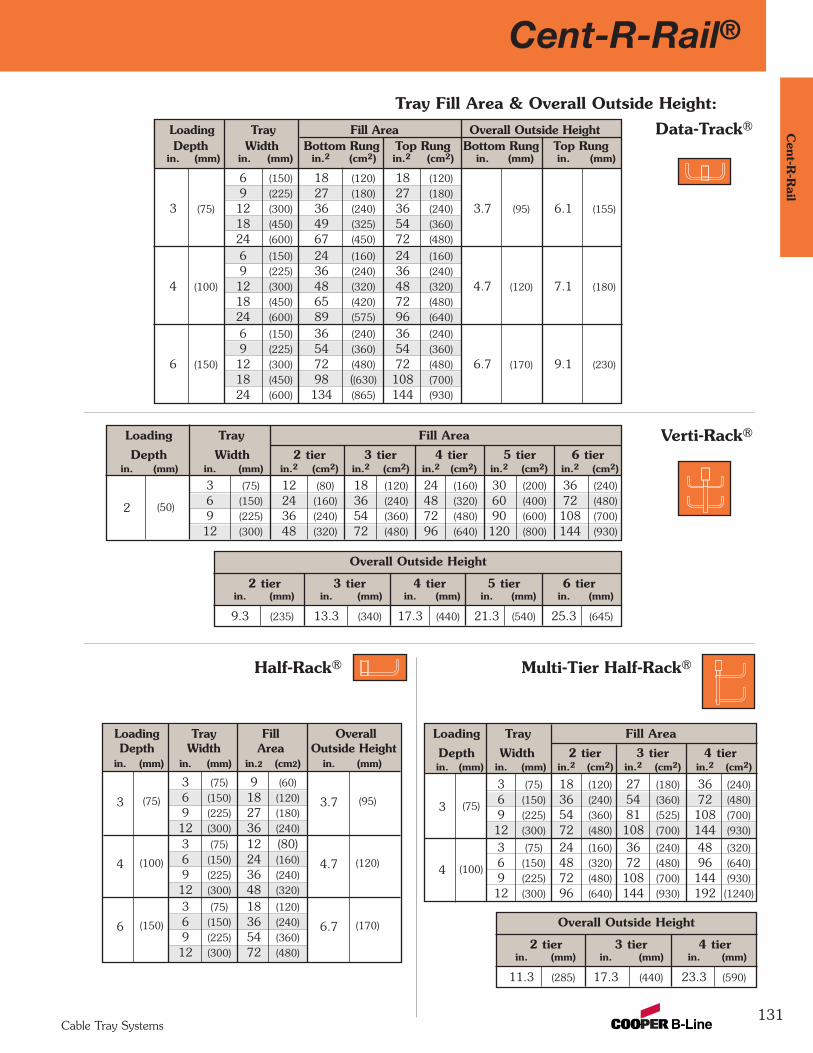
Cent-R-Rail®
131
Cent-R
-Rail
Cable Tray Systems
Tray Fill Area & Overall Outside Height:Loading Tray Fill Area Overall Outside HeightDepth Width Bottom Rung Top Rung Bottom Rung Top Rung
in. (mm) in. (mm) in.2 (cm2) in.2 (cm2) in. (mm) in. (mm)
6 (150) 18 (120) 18 (120)
9 (225) 27 (180) 27 (180)
3 (75) 12 (300) 36 (240) 36 (240) 3.7 (95) 6.1 (155)
18 (450) 49 (325) 54 (360)
24 (600) 67 (450) 72 (480)
6 (150) 24 (160) 24 (160)
9 (225) 36 (240) 36 (240)
4 (100) 12 (300) 48 (320) 48 (320) 4.7 (120) 7.1 (180)
18 (450) 65 (420) 72 (480)
24 (600) 89 (575) 96 (640)
6 (150) 36 (240) 36 (240)
9 (225) 54 (360) 54 (360)
6 (150) 12 (300) 72 (480) 72 (480) 6.7 (170) 9.1 (230)
18 (450) 98 ((630) 108 (700)
24 (600) 134 (865) 144 (930)
Loading Tray Fill Area
Depth Width 2 tier 3 tier 4 tier 5 tier 6 tierin. (mm) in. (mm) in.2 (cm2) in.2 (cm2) in.2 (cm2) in.2 (cm2) in.2 (cm2)
3 (75) 12 (80) 18 (120) 24 (160) 30 (200) 36 (240)
2 (50)6 (150) 24 (160) 36 (240) 48 (320) 60 (400) 72 (480)
9 (225) 36 (240) 54 (360) 72 (480) 90 (600) 108 (700)
12 (300) 48 (320) 72 (480) 96 (640) 120 (800) 144 (930)
Overall Outside Height
2 tier 3 tier 4 tier 5 tier 6 tierin. (mm) in. (mm) in. (mm) in. (mm) in. (mm)
9.3 (235) 13.3 (340) 17.3 (440) 21.3 (540) 25.3 (645)
Data-Track®
Verti-Rack®
Loading Tray Fill OverallDepth Width Area Outside Height
in. (mm) in. (mm) in.2 (cm2) in. (mm)
3 (75)
3 (75) 9 (60)
3.7 (95)6 (150) 18 (120)
9 (225) 27 (180)
12 (300) 36 (240)
4 (100)
3 (75) 12 (80)
4.7 (120)6 (150) 24 (160)
9 (225) 36 (240)
12 (300) 48 (320)
6 (150)
3 (75) 18 (120)
6.7 (170)6 (150) 36 (240)
9 (225) 54 (360)
12 (300) 72 (480)
Half-Rack® Multi-Tier Half-Rack®
Overall Outside Height
2 tier 3 tier 4 tierin. (mm) in. (mm) in. (mm)
11.3 (285) 17.3 (440) 23.3 (590)
Loading Tray Fill Area
Depth Width 2 tier 3 tier 4 tierin. (mm) in. (mm) in.2 (cm2) in.2 (cm2) in.2 (cm2)
3 (75) 18 (120) 27 (180) 36 (240)
3 (75)6 (150) 36 (240) 54 (360) 72 (480)
9 (225) 54 (360) 81 (525) 108 (700)
12 (300) 72 (480) 108 (700) 144 (930)
3 (75) 24 (160) 36 (240) 48 (320)
4 (100)6 (150) 48 (320) 72 (480) 96 (640)
9 (225) 72 (480) 108 (700) 144 (930)
12 (300) 96 (640) 144 (930) 192 (1240)
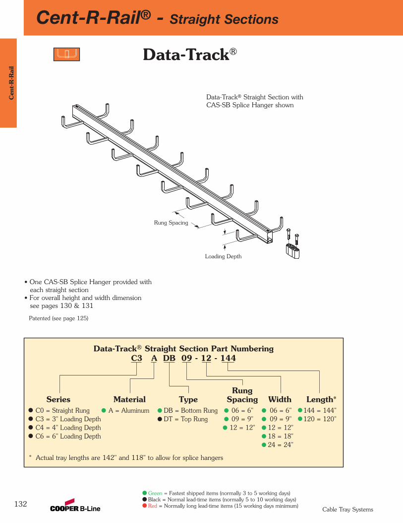
132
Cent-R-Rail® - Straight SectionsC
ent-
R-R
ail
Cable Tray Systems
Green = Fastest shipped items (normally 3 to 5 working days)Black = Normal lead-time items (normally 5 to 10 working days)Red = Normally long lead-time items (15 working days minimum)
Data-Track® Straight Section Part NumberingC3 A DB 09 - 12 - 144
RungSeries Material Type Spacing Width Length*
C0 = Straight Rung A = Aluminum DB = Bottom Rung 06 = 6" 06 = 6" 144 = 144"C3 = 3" Loading Depth DT = Top Rung 09 = 9" 09 = 9" 120 = 120"C4 = 4" Loading Depth 12 = 12" 12 = 12"C6 = 6" Loading Depth 18 = 18"
24 = 24"
* Actual tray lengths are 142" and 118" to allow for splice hangers
Data-Track®
Patented (see page 125)
Rung Spacing
Loading Depth
Data-Track® Straight Section withCAS-SB Splice Hanger shown
• One CAS-SB Splice Hanger provided with each straight section
• For overall height and width dimension see pages 130 & 131
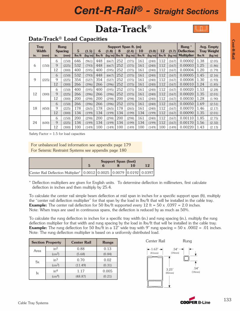
Cent-R-Rail® - Straight Sections
133
Cent-R
-Rail
Cable Tray Systems
* Deflection multipliers are given for English units. To determine deflection in millimeters, first calculatedeflection in inches and then multiply by 25.4.
To calculate the center rail simple beam deflection at mid span in inches for a specific support span (ft), multiplythe “center rail deflection multiplier” for that span by the load in lbs/ft that will be installed in the cable tray. Example: The center rail deflection for 50 lbs/ft supported every 12 ft = 50 x .0397 = 2.0 inches. Note: When trays are used in continuous spans, the deflection is reduced by as much as 50%.
To calculate the rung deflection in inches for a specific tray width (in.) and rung spacing (in.), multiply the rungdeflection multiplier for that width and rung spacing by the load in lbs/ft that will be installed in the cable tray. Example: The rung deflection for 50 lbs/ft in a 12" wide tray with 9" rung spacing = 50 x .0002 = .01 inches. Note: The rung deflection multiplier is based on a uniformly distributed load.
Section Property Center Rail Rungs
Area in2 0.88 0.13(cm2) (5.68) (0.84)
Sx in3 0.70 0.02(cm3) (11.49) (0.31)
Ix in4 1.17 0.005(cm4) (48.87) (0.21)
Tray Rung Support Span ft. (m) Rung * Avg. EmptyWidth Spacing 5 (1.5) 6 (1.8) 8 (2.4) 10 (3.0) 12 (3.7) Deflection Tray Weight
in. (mm) in. (mm) lbs/ft (kg/m) lbs/ft (kg/m) lbs/ft (kg/m) lbs/ft (kg/m) lbs/ft (kg/m) Multiplier lbs/ft (kg/m)
6 (150) 646 (961) 448 (667) 252 (375) 161 (240) 112 (167) 0.00002 1.38 (2.05)
6 (150) 9 (225) 532 (793) 448 (667) 252 (375) 161 (240) 112 (167) 0.00003 1.25 (1.86)
12 (300) 400 (595) 400 (595) 252 (375) 161 (240) 112 (167) 0.00004 1.20 (1.79)
6 (150) 532 (793) 448 (667) 252 (375) 161 (240) 112 (167) 0.00005 1.45 (2.16)
9 (225) 9 (225) 354 (527) 354 (527) 252 (375) 161 (240) 112 (167) 0.00008 1.30 (1.93)
12 (300) 266 (396) 266 (396) 252 (375) 161 (240) 112 (167) 0.00010 1.24 (1.85)
6 (150) 400 (595) 400 (595) 252 (375) 161 (240) 112 (167) 0.00020 1.53 (2.28)
12 (300) 9 (225) 266 (396) 266 (396) 252 (375) 161 (240) 112 (167) 0.00020 1.35 (2.01)
12 (300) 200 (298) 200 (298) 200 (298) 161 (240) 112 (167) 0.00030 1.28 (1.90)
6 (150) 266 (396) 266 (396) 252 (375) 161 (240) 112 (167) 0.00050 1.69 (2.51)
18 (450) 9 (225) 178 (265) 178 (265) 178 (265) 161 (240) 112 (167) 0.00070 1.46 (2.17)
12 (300) 134 (199) 134 (199) 134 (199) 134 (199) 112 (167) 0.00090 1.35 (2.01)
6 (150) 200 (298) 200 (298) 200 (298) 161 (240) 112 (167) 0.00110 1.85 (2.75)
24 (600) 9 (225) 134 (199) 134 (199) 134 (199) 134 (199) 112 (167) 0.00170 1.56 (2.32)
12 (300) 100 (149) 100 (149) 100 (149) 100 (149) 100 (149) 0.00220 1.43 (2.13)
Safety Factor = 1.5 for load capacities
Support Span (feet) 5 6 8 10 12
Center Rail Deflection Multiplier* 0.0012 0.0025 0.0079 0.0192 0.0397
Data-Track®
Center Rail Rung
.54"1.63"
3.25"(82mm)
Data-Track® Load Capacities
For unbalanced load information see appendix page 179For Seismic Restraint Systems see appendix page 180
(41mm) (14mm)
.54"(14mm)
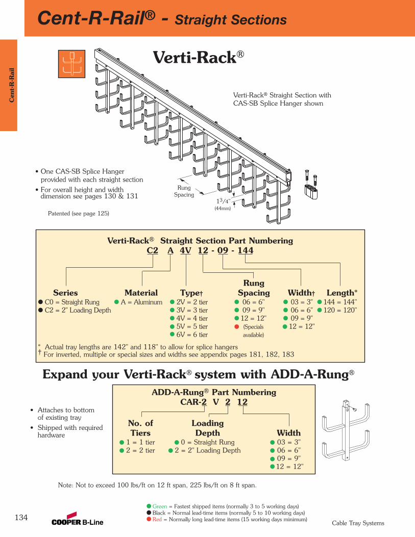
Cent-R-Rail® - Straight Sections
134
Cen
t-R
-Rai
l
Cable Tray Systems
Green = Fastest shipped items (normally 3 to 5 working days)Black = Normal lead-time items (normally 5 to 10 working days)Red = Normally long lead-time items (15 working days minimum)
Verti-Rack®
ADD-A-Rung® Part NumberingCAR-2 V 2 12
No. of LoadingTiers Depth Width
1 = 1 tier 0 = Straight Rung 03 = 3"2 = 2 tier 2 = 2" Loading Depth 06 = 6"
09 = 9"12 = 12"
Verti-Rack® Straight Section Part NumberingC2 A 4V 12 - 09 - 144
Rung Series Material Type† Spacing Width† Length*
C0 = Straight Rung A = Aluminum 2V = 2 tier 06 = 6" 03 = 3" 144 = 144"C2 = 2" Loading Depth 3V = 3 tier 09 = 9" 06 = 6" 120 = 120"
4V = 4 tier 12 = 12" 09 = 9"5V = 5 tier (Specials 12 = 12"6V = 6 tier available)
* Actual tray lengths are 142" and 118" to allow for splice hangers† For inverted, multiple or special sizes and widths see appendix pages 181, 182, 183
Expand your Verti-Rack® system with ADD-A-Rung®
• Attaches to bottomof existing tray
• Shipped with requiredhardware
Note: Not to exceed 100 lbs/ft on 12 ft span, 225 lbs/ft on 8 ft span.
Patented (see page 125)
RungSpacing
13/4"
Verti-Rack® Straight Section withCAS-SB Splice Hanger shown
• One CAS-SB Splice Hanger provided with each straight section
• For overall height and width dimension see pages 130 & 131
(44mm)
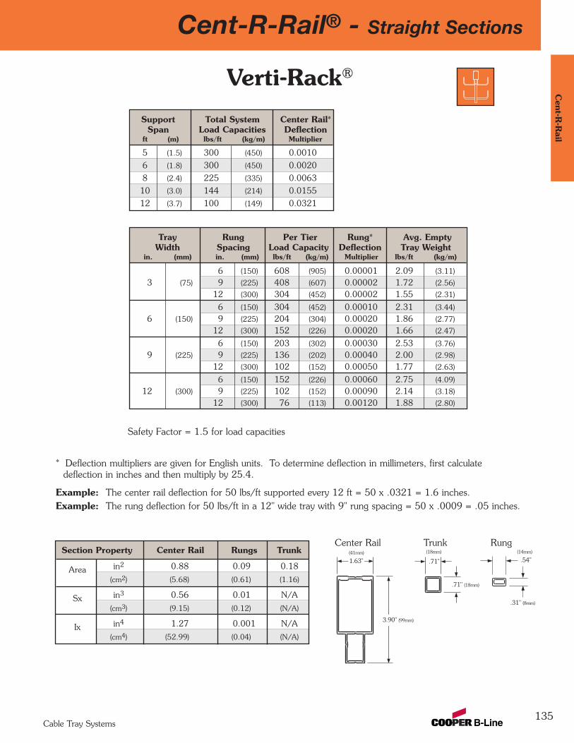
Cent-R-Rail® - Straight Sections
135
Cent-R
-Rail
Cable Tray Systems
Verti-Rack®
* Deflection multipliers are given for English units. To determine deflection in millimeters, first calculatedeflection in inches and then multiply by 25.4.
Example: The center rail deflection for 50 lbs/ft supported every 12 ft = 50 x .0321 = 1.6 inches.Example: The rung deflection for 50 lbs/ft in a 12" wide tray with 9" rung spacing = 50 x .0009 = .05 inches.
Tray Rung Per Tier Rung* Avg. EmptyWidth Spacing Load Capacity Deflection Tray Weight
in. (mm) in. (mm) lbs/ft (kg/m) Multiplier lbs/ft (kg/m)
6 (150) 608 (905) 0.00001 2.09 (3.11)
3 (75) 9 (225) 408 (607) 0.00002 1.72 (2.56)
12 (300) 304 (452) 0.00002 1.55 (2.31)
6 (150) 304 (452) 0.00010 2.31 (3.44)
6 (150) 9 (225) 204 (304) 0.00020 1.86 (2.77)
12 (300) 152 (226) 0.00020 1.66 (2.47)
6 (150) 203 (302) 0.00030 2.53 (3.76)
9 (225) 9 (225) 136 (202) 0.00040 2.00 (2.98)
12 (300) 102 (152) 0.00050 1.77 (2.63)
6 (150) 152 (226) 0.00060 2.75 (4.09)
12 (300) 9 (225) 102 (152) 0.00090 2.14 (3.18)
12 (300) 76 (113) 0.00120 1.88 (2.80)
Safety Factor = 1.5 for load capacities
Section Property Center Rail Rungs Trunk
Area in2 0.88 0.09 0.18
(cm2) (5.68) (0.61) (1.16)
Sx in3 0.56 0.01 N/A
(cm3) (9.15) (0.12) (N/A)
Ix in4 1.27 0.001 N/A
(cm4) (52.99) (0.04) (N/A)
Support Total System Center Rail*Span Load Capacities Deflection
ft (m) lbs/ft (kg/m) Multiplier
5 (1.5) 300 (450) 0.0010
6 (1.8) 300 (450) 0.0020
8 (2.4) 225 (335) 0.0063
10 (3.0) 144 (214) 0.0155
12 (3.7) 100 (149) 0.0321
Center Rail Trunk Rung
.54"
.31" (8mm)
.71"
.71" (18mm)
1.63"
3.90" (99mm)
(41mm) (18mm) (14mm)
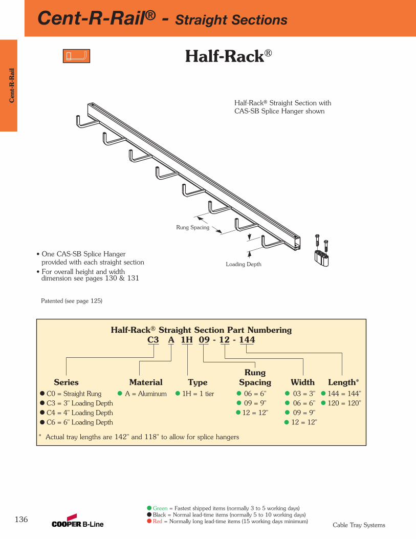
Cent-R-Rail® - Straight Sections
136
Cen
t-R
-Rai
l
Cable Tray Systems
Green = Fastest shipped items (normally 3 to 5 working days)Black = Normal lead-time items (normally 5 to 10 working days)Red = Normally long lead-time items (15 working days minimum)
Half-Rack® Straight Section Part NumberingC3 A 1H 09 - 12 - 144
Rung Series Material Type Spacing Width Length*
C0 = Straight Rung A = Aluminum 1H = 1 tier 06 = 6" 03 = 3" 144 = 144"C3 = 3" Loading Depth 09 = 9" 06 = 6" 120 = 120"C4 = 4" Loading Depth 12 = 12" 09 = 9"C6 = 6" Loading Depth 12 = 12"
* Actual tray lengths are 142" and 118" to allow for splice hangers
Patented (see page 125)
Rung Spacing
Loading Depth
Half-Rack® Straight Section withCAS-SB Splice Hanger shown
• One CAS-SB Splice Hanger provided with each straight section
• For overall height and widthdimension see pages 130 & 131
Half-Rack®

Cent-R-Rail® - Straight Sections
137
Cent-R
-Rail
Cable Tray Systems
Half-Rack® Loading Guidelines
• Support Locations
Sections should be attached to the wall at mid length and at 1/6th of the section length from both ends (20" for 120"; 24" for 144")
• No spacers needed• For Half-Rack® wall attachment options see page 172
• Loading Recommendations• CSA classified A-3M• 50 lbs/ft (74kg/m) maximum based on 3/4" (19mm) rung deflection
1" (25mm)
Mid Length
*24" (609mm)
*24" (609mm)
* = 20" (508mm) for 120" (3m) Length Section
144" (3.7m) (12') Length Section
Center Rail Rung
.54"
.54" (14mm)
1.63"
3.25" (82mm)
(41mm)(14mm)Section Property Center Rail Rungs
Area in2 0.88 0.13
(cm2) (5.68) (0.84)
Sx in3 0.70 0.02
(cm3) (11.49) (0.31)
Ix in4 1.27 0.005
(cm4) (52.99) (0.21)
Half-Rack®

Cent-R-Rail® - Straight Sections
138
Cen
t-R
-Rai
l
Cable Tray Systems
Green = Fastest shipped items (normally 3 to 5 working days)Black = Normal lead-time items (normally 5 to 10 working days)Red = Normally long lead-time items (15 working days minimum)
Expand your Multi-Tier Half-Rack® system with ADD-A-Rung®
Multi-Tier Half-Rack®
Multi-Tier Half-Rack® Straight Section Part NumberingC3 A 2M 09 - 12 - 144
Rung Series Material Type Spacing Width† Length*
C0 = Straight Rung A = Aluminum 2M = 2 tier 06 = 6" 03 = 3" 144 = 144"C3 = 3" Loading Depth 3M = 3 tier 09 = 9" 06 = 6" 120 = 120"C4 = 4" Loading Depth 4M = 4 tier 12 = 12" 09 = 9"
(Specials 12 = 12"available)
* Actual tray lengths are 142" and 118" to allow for splice hangers† For multiple widths see appendix pages 181 & 182
ADD-A-Rung® Part NumberingCAR-2 M 3 12
No. of LoadingTiers Depth Width
1 = 1 tier 0 = Straight Rung 03 = 3"2 = 2 tier 3 = 3" Loading Depth 06 = 6"
4 = 4" Loading Depth 09 = 9"12 = 12"
• Attaches to bottom ofexisting tray
• Shipped with requiredhardware
Patented (see page 125)
Rung Spacing
A = 25/8" (67mm) for 3" (76mm) Loading Depth= 13/4" (44mm) for 4" (102mm) Loading Depth
Loading Depth
Multi-Tier Half-Rack® Straight Sectionwith CAS-SB Splice Hanger shown
• One CAS-SB Splice Hanger provided with each straight section
• For overall height and widthdimension see pages 130 & 131
A
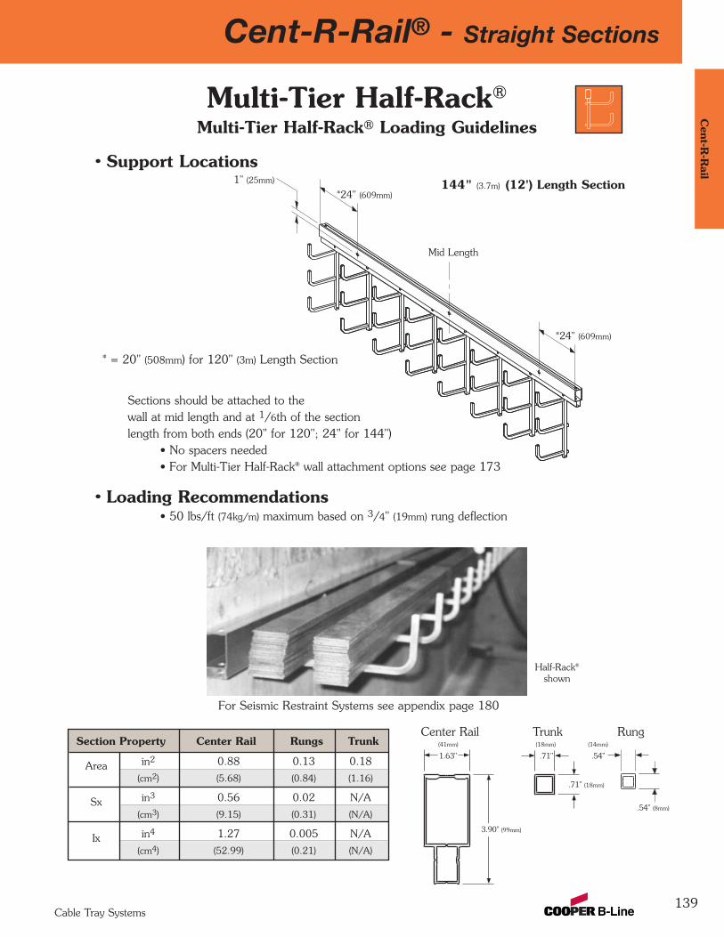
Cent-R-Rail® - Straight Sections
139
Cent-R
-Rail
Cable Tray Systems
Multi-Tier Half-Rack® Loading Guidelines
• Support Locations
Sections should be attached to the wall at mid length and at 1/6th of the section length from both ends (20" for 120"; 24" for 144")
• No spacers needed• For Multi-Tier Half-Rack® wall attachment options see page 173
• Loading Recommendations• 50 lbs/ft (74kg/m) maximum based on 3/4" (19mm) rung deflection
Multi-Tier Half-Rack®
1" (25mm)
Mid Length
*24" (609mm)
*24" (609mm)
* = 20" (508mm) for 120" (3m) Length Section
144" (3.7m) (12') Length Section
Half-Rack®
shown
For Seismic Restraint Systems see appendix page 180
Section Property Center Rail Rungs Trunk
Area in2 0.88 0.13 0.18
(cm2) (5.68) (0.84) (1.16)
Sx in3 0.56 0.02 N/A
(cm3) (9.15) (0.31) (N/A)
Ix in4 1.27 0.005 N/A
(cm4) (52.99) (0.21) (N/A)
Center Rail Trunk Rung
.54"
.54" (8mm)
.71"
.71" (18mm)
1.63"
3.90" (99mm)
(41mm) (18mm) (14mm)
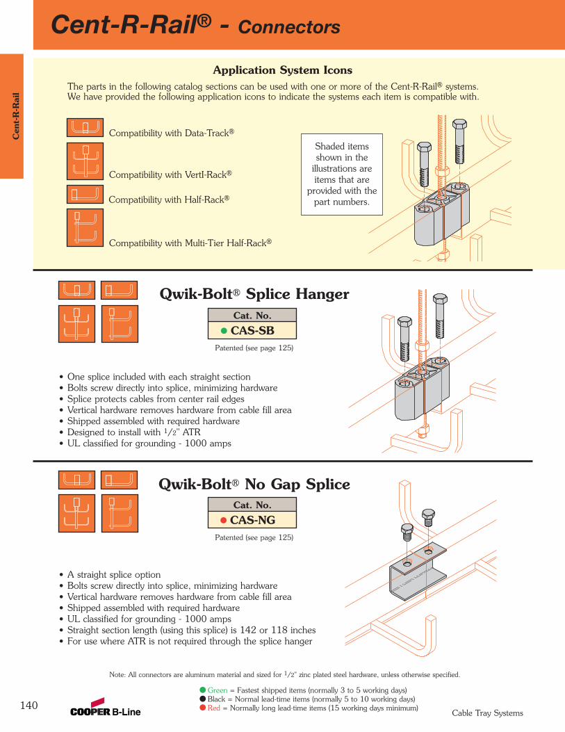
140
Cent-R-Rail® - ConnectorsC
ent-
R-R
ail
Cable Tray Systems
Green = Fastest shipped items (normally 3 to 5 working days)Black = Normal lead-time items (normally 5 to 10 working days)Red = Normally long lead-time items (15 working days minimum)
• One splice included with each straight section• Bolts screw directly into splice, minimizing hardware• Splice protects cables from center rail edges• Vertical hardware removes hardware from cable fill area• Shipped assembled with required hardware• Designed to install with 1/2" ATR• UL classified for grounding - 1000 amps
Note: All connectors are aluminum material and sized for 1/2" zinc plated steel hardware, unless otherwise specified.
Cat. No.
CAS-SB
Qwik-Bolt® Splice Hanger
Patented (see page 125)
• A straight splice option • Bolts screw directly into splice, minimizing hardware• Vertical hardware removes hardware from cable fill area• Shipped assembled with required hardware• UL classified for grounding - 1000 amps• Straight section length (using this splice) is 142 or 118 inches• For use where ATR is not required through the splice hanger
Cat. No.
CAS-NG
Qwik-Bolt® No Gap Splice
Patented (see page 125)
Compatibility with Data-Track®
Compatibility with VertI-Rack®
Compatibility with Half-Rack®
Compatibility with Multi-Tier Half-Rack®
Application System Icons The parts in the following catalog sections can be used with one or more of the Cent-R-Rail® systems. We have provided the following application icons to indicate the systems each item is compatible with.
Shaded itemsshown in the
illustrations areitems that are
provided with thepart numbers.
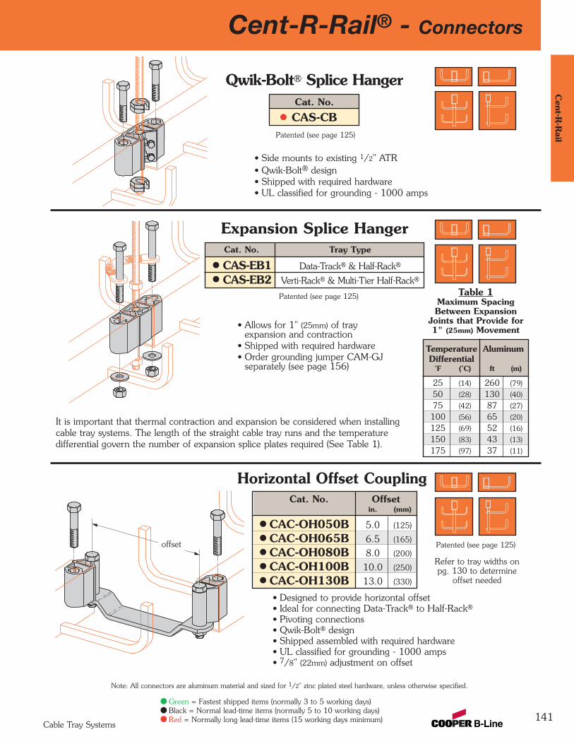
Cent-R-Rail® - Connectors
141
Cent-R
-Rail
Cable Tray Systems
Green = Fastest shipped items (normally 3 to 5 working days)Black = Normal lead-time items (normally 5 to 10 working days)Red = Normally long lead-time items (15 working days minimum)
Note: All connectors are aluminum material and sized for 1/2" zinc plated steel hardware, unless otherwise specified.
• Allows for 1" (25mm) of trayexpansion and contraction
• Shipped with required hardware• Order grounding jumper CAM-GJ
separately (see page 156)
Expansion Splice Hanger
Patented (see page 125)
• Side mounts to existing 1/2" ATR• Qwik-Bolt® design• Shipped with required hardware• UL classified for grounding - 1000 amps
Cat. No.
CAS-CB
Qwik-Bolt® Splice Hanger
Patented (see page 125)
• Designed to provide horizontal offset• Ideal for connecting Data-Track® to Half-Rack®
• Pivoting connections• Qwik-Bolt® design• Shipped assembled with required hardware• UL classified for grounding - 1000 amps• 7/8" (22mm) adjustment on offset
Horizontal Offset Coupling
Patented (see page 125)
Cat. No. Tray Type
CAS-EB1 Data-Track® & Half-Rack®
CAS-EB2 Verti-Rack® & Multi-Tier Half-Rack®
Table 1Maximum SpacingBetween Expansion
Joints that Provide for1" (25mm) Movement
It is important that thermal contraction and expansion be considered when installingcable tray systems. The length of the straight cable tray runs and the temperaturedifferential govern the number of expansion splice plates required (See Table 1).
Temperature AluminumDifferential
˚F (˚C) ft (m)
25 (14) 260 (79)
50 (28) 130 (40)
75 (42) 87 (27)
100 (56) 65 (20)
125 (69) 52 (16)
150 (83) 43 (13)
175 (97) 37 (11)
Refer to tray widths onpg. 130 to determine
offset needed
Cat. No. Offsetin. (mm)
CAC-OH050B 5.0 (125)
CAC-OH065B 6.5 (165)
CAC-OH080B 8.0 (200)
CAC-OH100B 10.0 (250)
CAC-OH130B 13.0 (330)
offset
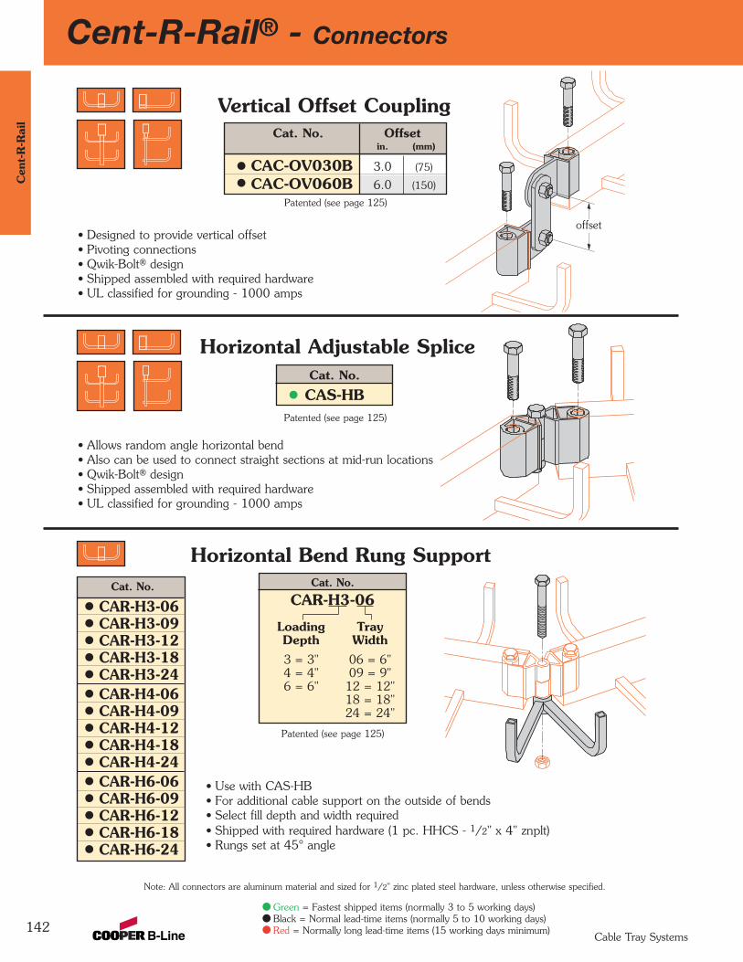
Cent-R-Rail® - Connectors
142
Cen
t-R
-Rai
l
Cable Tray Systems
Green = Fastest shipped items (normally 3 to 5 working days)Black = Normal lead-time items (normally 5 to 10 working days)Red = Normally long lead-time items (15 working days minimum)
Note: All connectors are aluminum material and sized for 1/2" zinc plated steel hardware, unless otherwise specified.
Cat. No.
CAS-HB
Horizontal Adjustable Splice
Patented (see page 125)
• Designed to provide vertical offset• Pivoting connections• Qwik-Bolt® design• Shipped assembled with required hardware• UL classified for grounding - 1000 amps
Vertical Offset Coupling
Patented (see page 125)
• Use with CAS-HB• For additional cable support on the outside of bends• Select fill depth and width required• Shipped with required hardware (1 pc. HHCS - 1/2" x 4" znplt)• Rungs set at 45° angle
Horizontal Bend Rung Support
Patented (see page 125)
offset
Cat. No. Offsetin. (mm)
CAC-OV030B 3.0 (75)
CAC-OV060B 6.0 (150)
• Allows random angle horizontal bend• Also can be used to connect straight sections at mid-run locations• Qwik-Bolt® design• Shipped assembled with required hardware• UL classified for grounding - 1000 amps
Cat. No.
CAR-H3-06CAR-H3-09CAR-H3-12CAR-H3-18CAR-H3-24CAR-H4-06CAR-H4-09CAR-H4-12CAR-H4-18CAR-H4-24CAR-H6-06CAR-H6-09CAR-H6-12CAR-H6-18CAR-H6-24
Cat. No.
CAR-H3-06
Loading TrayDepth Width3 = 3" 06 = 6"4 = 4" 09 = 9"6 = 6" 12 = 12"
18 = 18"24 = 24"
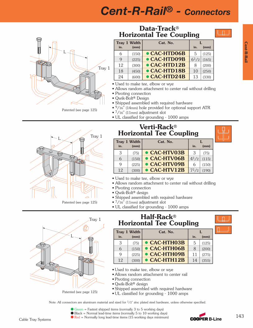
Cent-R-Rail® - Connectors
143
Cent-R
-Rail
Cable Tray Systems
Green = Fastest shipped items (normally 3 to 5 working days)Black = Normal lead-time items (normally 5 to 10 working days)Red = Normally long lead-time items (15 working days minimum)
Note: All connectors are aluminum material and sized for 1/2" zinc plated steel hardware, unless otherwise specified.
• Used to make tee, elbow or wye• Allows random attachment to center rail without drilling• Pivoting connection• Qwik-Bolt® design• Shipped assembled with required hardware• 7/16" (11mm) adjustment slot• UL classified for grounding - 1000 amps
Verti-Rack®
Horizontal Tee Coupling
Patented (see page 125)
• Used to make tee, elbow or wye• Allows random attachment to center rail without drilling• Pivoting connection• Qwik-Bolt® Design• Shipped assembled with required hardware• 9/16" (14mm) hole provided for optional support ATR• 7/16" (11mm) adjustment slot• UL classified for grounding - 1000 amps
Data-Track®
Horizontal Tee Coupling
Patented (see page 125)
• Used to make tee, elbow or wye• Allows random attachment to center rail• Pivoting connection• Qwik-Bolt® design• Shipped assembled with required hardware• UL classified for grounding - 1000 amps
Tray 1
L
Tray 1L
Tray 1 Width Cat. No. Lin. (mm) in. (mm)
6 (150) CAC-HTD06B 5 (125)
9 (225) CAC-HTD09B 61/2 (165)
12 (300) CAC-HTD12B 8 (200)
18 (450) CAC-HTD18B 10 (250)
24 (600) CAC-HTD24B 13 (330)
Tray 1 Width Cat. No. Lin. (mm) in. (mm)
3 (75) CAC-HTV03B 3 (75)
6 (150) CAC-HTV06B 41/2 (115)
9 (225) CAC-HTV09B 6 (150)
12 (300) CAC-HTV12B 71/2 (190)
Half-Rack®
Horizontal Tee CouplingTray 1 Width Cat. No. L
in. (mm) in. (mm)
3 (75) CAC-HTH03B 5 (125)
6 (150) CAC-HTH06B 8 (200)
9 (225) CAC-HTH09B 11 (275)
12 (300) CAC-HTH12B 14 (355)
Tray 1
L
Patented (see page 125)
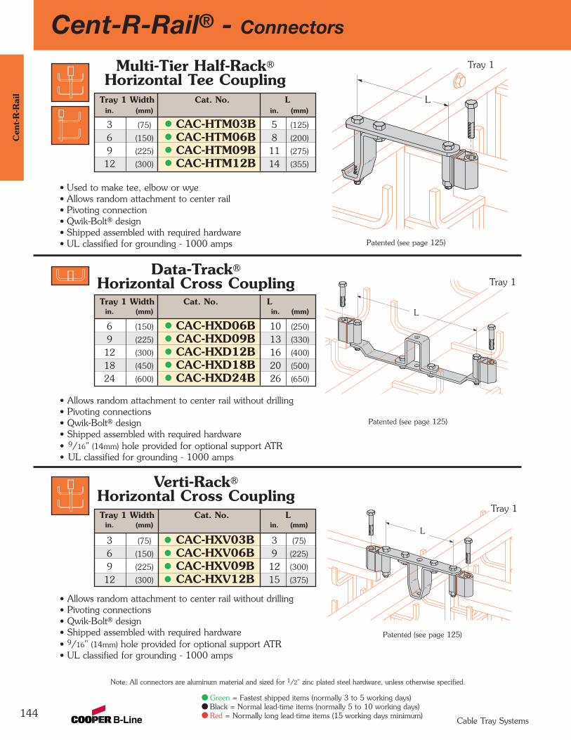
Cent-R-Rail® - Connectors
144
Cen
t-R
-Rai
l
Cable Tray Systems
Green = Fastest shipped items (normally 3 to 5 working days)Black = Normal lead-time items (normally 5 to 10 working days)Red = Normally long lead-time items (15 working days minimum)
Note: All connectors are aluminum material and sized for 1/2" zinc plated steel hardware, unless otherwise specified.
• Allows random attachment to center rail without drilling• Pivoting connections• Qwik-Bolt® design• Shipped assembled with required hardware• 9/16" (14mm) hole provided for optional support ATR• UL classified for grounding - 1000 amps
• Used to make tee, elbow or wye• Allows random attachment to center rail• Pivoting connection• Qwik-Bolt® design• Shipped assembled with required hardware• UL classified for grounding - 1000 amps
• Allows random attachment to center rail without drilling• Pivoting connections• Qwik-Bolt® design• Shipped assembled with required hardware• 9/16" (14mm) hole provided for optional support ATR• UL classified for grounding - 1000 amps
Patented (see page 125)
Patented (see page 125)
Patented (see page 125)
Tray 1
L
Multi-Tier Half-Rack®
Horizontal Tee CouplingTray 1 Width Cat. No. L
in. (mm) in. (mm)
3 (75) CAC-HTM03B 5 (125)
6 (150) CAC-HTM06B 8 (200)
9 (225) CAC-HTM09B 11 (275)
12 (300) CAC-HTM12B 14 (355)
Data-Track®
Horizontal Cross CouplingTray 1 Width Cat. No. L
in. (mm) in. (mm)
6 (150) CAC-HXD06B 10 (250)
9 (225) CAC-HXD09B 13 (330)
12 (300) CAC-HXD12B 16 (400)
18 (450) CAC-HXD18B 20 (500)
24 (600) CAC-HXD24B 26 (650)
L
Tray 1
L
Tray 1
Verti-Rack®
Horizontal Cross CouplingTray 1 Width Cat. No. L
in. (mm) in. (mm)
3 (75) CAC-HXV03B 3 (75)
6 (150) CAC-HXV06B 9 (225)
9 (225) CAC-HXV09B 12 (300)
12 (300) CAC-HXV12B 15 (375)

Cent-R-Rail® - Connectors
145
Cent-R
-Rail
Cable Tray Systems
Green = Fastest shipped items (normally 3 to 5 working days)Black = Normal lead-time items (normally 5 to 10 working days)Red = Normally long lead-time items (15 working days minimum)
Note: All connectors are aluminum material and sized for 1/2" zinc plated steel hardware, unless otherwise specified.
• Ideal for random angle vertical bends• Qwik-Bolt® design• Shipped assembled with required hardware• UL classified for grounding - 1000 amps
Cat. No.
CAS-VB
Vertical Adjustable Splice
Patented (see page 125)
• Use one piece to create vertical tees.• Use two pieces to create vertical crosses.• Pivoting connections• Qwik-Bolt® design• Shipped assembled with required hardware• UL classified for grounding - 1000 amps
Cat. No.
CAC-VB
Vertical Coupling
Patented (see page 125)

146
Cent-R-Rail® - ConnectorsC
ent-
R-R
ail
Cable Tray Systems
Green = Fastest shipped items (normally 3 to 5 working days)Black = Normal lead-time items (normally 5 to 10 working days)Red = Normally long lead-time items (15 working days minimum)
Note: All connectors are aluminum material and sized for 1/2" zinc plated steel hardware, unless otherwise specified.
• Connects up to 4 trays in random directions• Provides an area free of center rails for cable transitions• Ideal for easy system expansion• Slots provided for cable tie down• Order one CAC-UFB pivot connector per tray connection (see page 147)• Positive cable retention for cables routed around corner post• UL classified for grounding - 1000 amps
Patented (see page 125)
Universal Hub Fittings
FillDepth
Width
Cat. No.
U4A-12
FillDepth Width2 = 2" 06 = 6"3 = 3" 09 = 9"4 = 4" 12 = 12"6 = 6" 18 = 18"
24 = 24"
Cat. No.
U2A-06U2A-09U2A-12U2A-18U2A-24U3A-06U3A-09U3A-12U3A-18U3A-24U4A-06U4A-09U4A-12U4A-18U4A-24U6A-06U6A-09U6A-12U6A-18U6A-24
Typical applications for universal hub fittings:
Elbow Tee
Wye
Cross
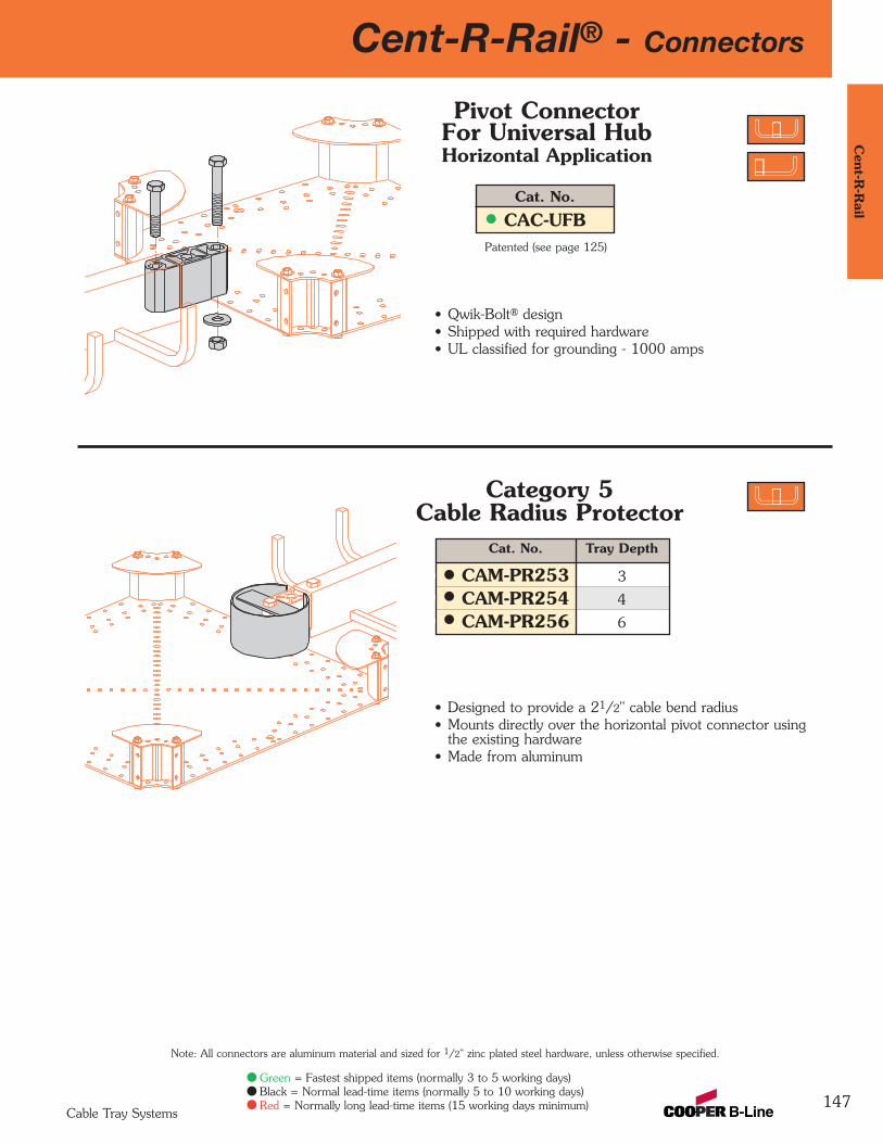
147
Cent-R-Rail® - ConnectorsC
ent-R-R
ail
Cable Tray Systems
Note: All connectors are aluminum material and sized for 1/2" zinc plated steel hardware, unless otherwise specified.
Green = Fastest shipped items (normally 3 to 5 working days)Black = Normal lead-time items (normally 5 to 10 working days)Red = Normally long lead-time items (15 working days minimum)
• Qwik-Bolt® design• Shipped with required hardware• UL classified for grounding - 1000 amps
Cat. No.
CAC-UFB
Pivot ConnectorFor Universal HubHorizontal Application
Patented (see page 125)
Category 5Cable Radius Protector
• Designed to provide a 21/2" cable bend radius• Mounts directly over the horizontal pivot connector using
the existing hardware• Made from aluminum
Cat. No. Tray Depth
CAM-PR253 3
CAM-PR254 4
CAM-PR256 6

148
Cent-R-Rail® - SupportsC
ent-
R-R
ail
Cable Tray Systems
Green = Fastest shipped items (normally 3 to 5 working days)Black = Normal lead-time items (normally 5 to 10 working days)Red = Normally long lead-time items (15 working days minimum)
Note: All connectors are aluminum material and sized for 1/2" zinc plated steel hardware, unless otherwise specified.
Cat. No. Tray Type
CZNH-CD-I Data-Track®
CZNH-CV-I Verti-Rack®
Cat. No. Rod Size
CZNH-CD 1/2”
CZNH-CD-5/8 5/8”
Cat. No. Rod Size
CZNH-CV 1/2”
CZNH-CV-5/8 5/8”
Data-Track®
Standard Clevis Hanger
Verti-Rack®
Standard Clevis Hanger
Isolation Clevis Hanger
• Allows random support without drilling• Zinc plated steel construction• If seismic restraints required, see Seismic Restraints
Cent-R-Rail® Supplement brochure (SRSCR1)
• Allows random support without drilling• Zinc plated steel construction
• Isolates tray from ATR to reduce low voltage interference• Nylon bushing• Allows random support without drilling• Zinc plated steel construction• Used with 1/2" ATR
Data-Track® shown
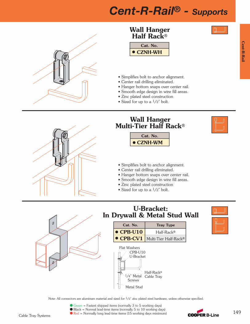
149
Cent-R-Rail® - SupportsC
ent-R-R
ail
Cable Tray Systems
Note: All connectors are aluminum material and sized for 1/2" zinc plated steel hardware, unless otherwise specified.
Green = Fastest shipped items (normally 3 to 5 working days)Black = Normal lead-time items (normally 5 to 10 working days)Red = Normally long lead-time items (15 working days minimum)
Cat. No.
CZNH-WH
Wall HangerHalf Rack®
Cat. No.
CZNH-WM
Wall HangerMulti-Tier Half Rack®
• Simplifies bolt to anchor alignment.• Center rail drilling eliminated.• Hanger bottom snaps over center rail.• Smooth edge design in wire fill areas.• Zinc plated steel construction• Sized for up to a 1/2" bolt.
• Simplifies bolt to anchor alignment.• Center rail drilling eliminated.• Hanger bottom snaps over center rail.• Smooth edge design in wire fill areas.• Zinc plated steel construction• Sized for up to a 1/2" bolt.
Cat. No. Tray Type
CPB-U10 Half-Rack®
CPB-CV1 Multi-Tier Half-Rack®
U-Bracket:In Drywall & Metal Stud Wall
Half-Rack®
Cable Tray
CPB-U10U-Bracket
1/4" MetalScrews
Flat Washers
Metal Stud
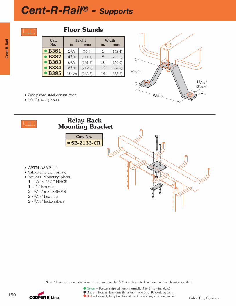
150
Cent-R-Rail® - SupportsC
ent-
R-R
ail
Cable Tray Systems
Green = Fastest shipped items (normally 3 to 5 working days)Black = Normal lead-time items (normally 5 to 10 working days)Red = Normally long lead-time items (15 working days minimum)
Note: All connectors are aluminum material and sized for 1/2" zinc plated steel hardware, unless otherwise specified.
Cat. Height WidthNo. in. (mm) in. (mm)
B381 23/8 (60.3) 6 (152.4)
B382 43/8 (111.1) 8 (203.2)
B383 63/8 (161.9) 10 (254.0)
B384 83/8 (212.7) 12 (304.8)
B385 103/8 (263.5) 14 (355.6)
Floor Stands
Relay RackMounting Bracket
• Zinc plated steel construction• 9/16" (14mm) holes
• ASTM A36 Steel• Yellow zinc dichromate• Includes: Mounting plates
1 - 1/2" x 41/2" HHCS1- 1/2" hex nut2 - 5/16" x 3" SRHMS2 - 5/16" hex nuts2 - 5/16" lockwashers
13/16"(21mm)
Width
Height
Cat. No.
SB-2133-CR
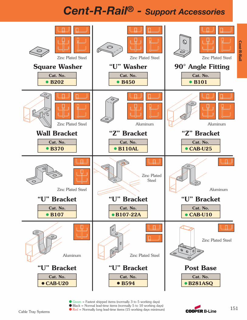
151
Cent-R-Rail® - Support AccessoriesC
ent-R-R
ail
Cable Tray Systems
Green = Fastest shipped items (normally 3 to 5 working days)Black = Normal lead-time items (normally 5 to 10 working days)Red = Normally long lead-time items (15 working days minimum)
Cat. No.
B202
Square WasherCat. No.
B450
“U” WasherCat. No.
B101
90° Angle FittingZinc Plated Steel Zinc Plated Steel Zinc Plated Steel
Cat. No.
B370
Wall BracketCat. No.
B110AL
“Z” BracketCat. No.
CAB-U25
“Z” BracketZinc Plated Steel Aluminum Aluminum
Cat. No.
B107
“U” BracketCat. No.
B107-22A
“U” BracketCat. No.
CAB-U10
“U” Bracket
Zinc Plated Steel
Cat. No.
CAB-U20
“U” BracketCat. No.
B594
“U” BracketCat. No.
B281ASQ
Post Base
Aluminum
Aluminum
Zinc PlatedSteel
Zinc Plated Steel
Zinc Plated Steel
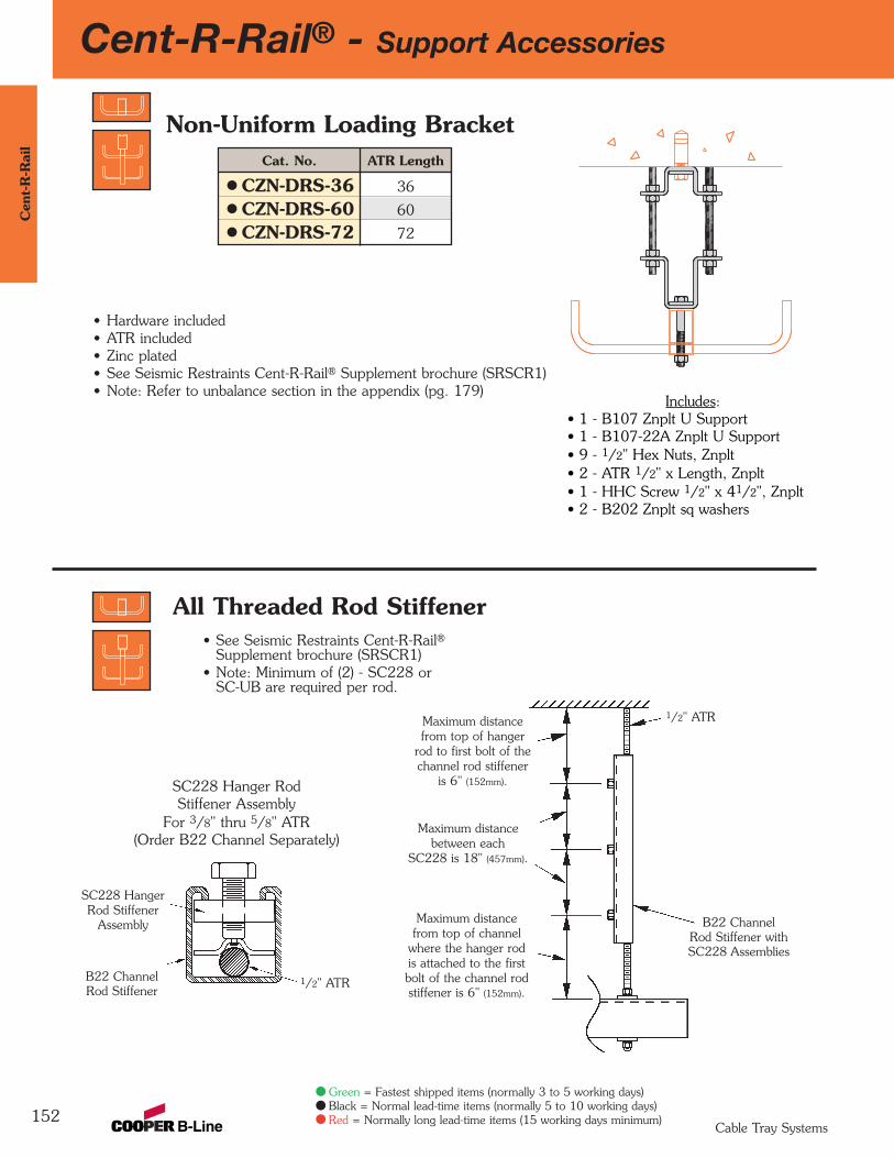
152
Cent-R-Rail® - Support AccessoriesC
ent-
R-R
ail
Cable Tray Systems
Green = Fastest shipped items (normally 3 to 5 working days)Black = Normal lead-time items (normally 5 to 10 working days)Red = Normally long lead-time items (15 working days minimum)
Cat. No. ATR Length
CZN-DRS-36 36
CZN-DRS-60 60
CZN-DRS-72 72
Non-Uniform Loading Bracket
All Threaded Rod Stiffener
• Hardware included• ATR included• Zinc plated• See Seismic Restraints Cent-R-Rail® Supplement brochure (SRSCR1)• Note: Refer to unbalance section in the appendix (pg. 179)
Includes:• 1 - B107 Znplt U Support• 1 - B107-22A Znplt U Support• 9 - 1/2" Hex Nuts, Znplt• 2 - ATR 1/2" x Length, Znplt• 1 - HHC Screw 1/2" x 41/2", Znplt• 2 - B202 Znplt sq washers
Maximum distancefrom top of hanger
rod to first bolt of thechannel rod stiffener
is 6" (152mm).
Maximum distance from top of channel
where the hanger rodis attached to the firstbolt of the channel rod stiffener is 6" (152mm).
1/2" ATR
B22 ChannelRod Stiffener with SC228 Assemblies
Maximum distancebetween each
SC228 is 18" (457mm).
• See Seismic Restraints Cent-R-Rail®Supplement brochure (SRSCR1)
• Note: Minimum of (2) - SC228 orSC-UB are required per rod.
SC228 Hanger RodStiffener Assembly
For 3/8" thru 5/8" ATR(Order B22 Channel Separately)
1/2" ATRB22 ChannelRod Stiffener
SC228 HangerRod Stiffener
Assembly
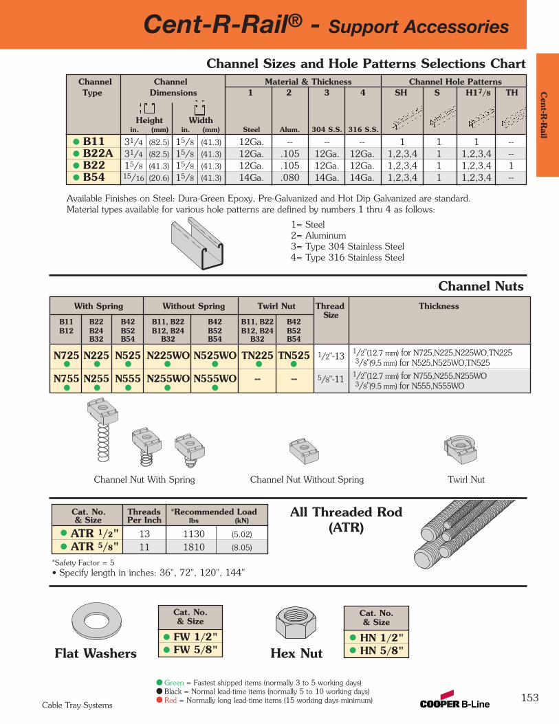
153
Cent-R-Rail® - Support AccessoriesC
ent-R-R
ail
Cable Tray Systems
Green = Fastest shipped items (normally 3 to 5 working days)Black = Normal lead-time items (normally 5 to 10 working days)Red = Normally long lead-time items (15 working days minimum)
Channel Sizes and Hole Patterns Selections Chart
Available Finishes on Steel: Dura-Green Epoxy, Pre-Galvanized and Hot Dip Galvanized are standard.Material types available for various hole patterns are defined by numbers 1 thru 4 as follows:
1= Steel2= Aluminum3= Type 304 Stainless Steel4= Type 316 Stainless Steel
Channel Channel Material & Thickness Channel Hole PatternsType Dimensions 1 2 3 4 SH S H17/8 TH
Height Widthin. (mm) in. (mm) Steel Alum. 304 S.S. 316 S.S.
B11 31/4 (82.5) 15/8 (41.3) 12Ga. -- -- -- 1 1 1 --B22A 31/4 (82.5) 15/8 (41.3) 12Ga. .105 12Ga. 12Ga. 1,2,3,4 1 1,2,3,4 --B22 15/8 (41.3) 15/8 (41.3) 12Ga. .105 12Ga. 12Ga. 1,2,3,4 1 1,2,3,4 1 B54 15/16 (20.6) 15/8 (41.3) 14Ga. .080 14Ga. 14Ga. 1,2,3,4 1 1,2,3,4 --
Channel NutsWith Spring Without Spring Twirl Nut Thread Thickness
B11 B22 B42 B11, B22 B42 B11, B22 B42Size
B12 B24 B52 B12, B24 B52 B12, B24 B52B32 B54 B32 B54 B32 B54
N725 N225 N525 N225WO N525WO TN225 TN525 1/2"-131/2"(12.7 mm) for N725,N225,N225WO,TN2253/8"(9.5 mm) for N525,N525WO,TN525
N755 N255 N555 N255WO N555WO -- -- 5/8"-111/2"(12.7 mm) for N755,N255,N255WO3/8"(9.5 mm) for N555,N555WO
Channel Nut With Spring Channel Nut Without Spring Twirl Nut
Cat. No. Threads *Recommended Load & Size Per Inch lbs (kN)
ATR 1/2" 13 1130 (5.02)
ATR 5/8" 11 1810 (8.05)
*Safety Factor = 5• Specify length in inches: 36", 72", 120", 144"
Cat. No.& Size
FW 1/2"FW 5/8"Flat Washers Hex Nut
Cat. No.& Size
HN 1/2"HN 5/8"
All Threaded Rod(ATR)
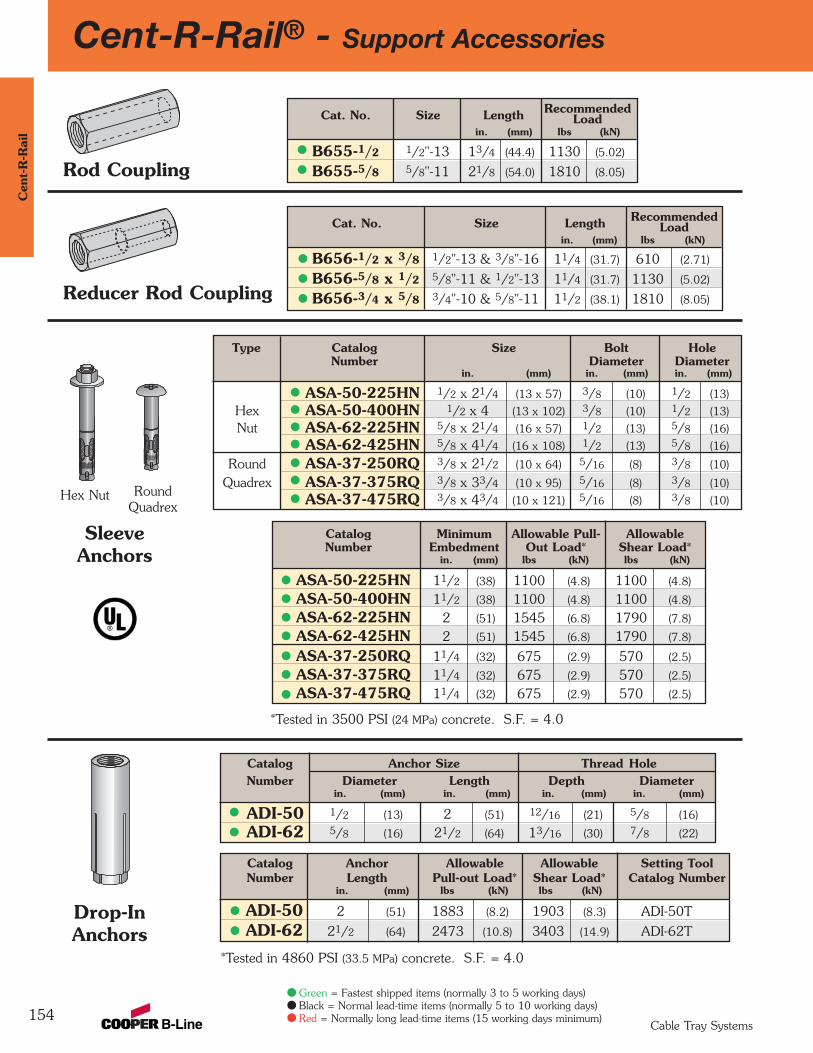
154
Cent-R-Rail® - Support AccessoriesC
ent-
R-R
ail
Cable Tray Systems
Cat. No. Size Length RecommendedLoad
in. (mm) lbs (kN)
B656-1/2 x 3/8 1/2"-13 & 3/8"-16 11/4 (31.7) 610 (2.71)
B656-5/8 x 1/2 5/8"-11 & 1/2"-13 11/4 (31.7) 1130 (5.02)
B656-3/4 x 5/8 3/4"-10 & 5/8"-11 11/2 (38.1) 1810 (8.05)
Rod Coupling
Reducer Rod Coupling
Cat. No. Size Length RecommendedLoad
in. (mm) lbs (kN)
B655-1/2 1/2"-13 13/4 (44.4) 1130 (5.02)
B655-5/8 5/8"-11 21/8 (54.0) 1810 (8.05)
Catalog Minimum Allowable Pull- AllowableNumber Embedment Out Load* Shear Load*
in. (mm) lbs (kN) lbs (kN)
ASA-50-225HN 11/2 (38) 1100 (4.8) 1100 (4.8)
ASA-50-400HN 11/2 (38) 1100 (4.8) 1100 (4.8)
ASA-62-225HN 2 (51) 1545 (6.8) 1790 (7.8)
ASA-62-425HN 2 (51) 1545 (6.8) 1790 (7.8)
ASA-37-250RQ 11/4 (32) 675 (2.9) 570 (2.5)
ASA-37-375RQ 11/4 (32) 675 (2.9) 570 (2.5)
ASA-37-475RQ 11/4 (32) 675 (2.9) 570 (2.5)
Type Catalog Size Bolt HoleNumber Diameter Diameter
in. (mm) in. (mm) in. (mm)
ASA-50-225HN 1/2 x 21/4 (13 x 57) 3/8 (10) 1/2 (13)
Hex ASA-50-400HN 1/2 x 4 (13 x 102) 3/8 (10) 1/2 (13)
Nut ASA-62-225HN 5/8 x 21/4 (16 x 57) 1/2 (13) 5/8 (16)
ASA-62-425HN 5/8 x 41/4 (16 x 108) 1/2 (13) 5/8 (16)
Round ASA-37-250RQ 3/8 x 21/2 (10 x 64) 5/16 (8) 3/8 (10)
Quadrex ASA-37-375RQ 3/8 x 33/4 (10 x 95) 5/16 (8) 3/8 (10)
ASA-37-475RQ 3/8 x 43/4 (10 x 121) 5/16 (8) 3/8 (10)
Catalog Anchor Size Thread Hole Number Diameter Length Depth Diameter
in. (mm) in. (mm) in. (mm) in. (mm)
ADI-50 1/2 (13) 2 (51) 12/16 (21) 5/8 (16)
ADI-62 5/8 (16) 21/2 (64) 13/16 (30) 7/8 (22)
SleeveAnchors
Drop-InAnchors
Catalog Anchor Allowable Allowable Setting ToolNumber Length Pull-out Load* Shear Load* Catalog Number
in. (mm) lbs (kN) lbs (kN)
ADI-50 2 (51) 1883 (8.2) 1903 (8.3) ADI-50T
ADI-62 21/2 (64) 2473 (10.8) 3403 (14.9) ADI-62T
*Tested in 3500 PSI (24 MPa) concrete. S.F. = 4.0
Hex Nut RoundQuadrex
*Tested in 4860 PSI (33.5 MPa) concrete. S.F. = 4.0
Green = Fastest shipped items (normally 3 to 5 working days)Black = Normal lead-time items (normally 5 to 10 working days)Red = Normally long lead-time items (15 working days minimum)

Cent-R-Rail® - Support Accessories
155
Cent-R
-Rail
Cable Tray Systems
Part Design Max. Mat’l Number Load* Flange Thick Thickness
lbs (kN) in. (mm) in. (mm)
B212-3/8 1000 (4.45) 11/8 (28.6) 3/8 (9.5)
Beam Clamps
Anchor Strap
Cat. RodNo. Size B C D
in. (mm) in. (mm)
B307 1/2"-13 1/2"-13 27/16" (61.9) 7/8" (22.2)
B308 1/2"-13 1/2"-13 29/16" (65.1) 7/8" (22.2)
B321-2 1/2"-13 1/2"-13 39/16" (90.5) 111/16" (42.8)
Cat. No. Flange Widthin. (mm)
B312-6 Up to 6" (Up to 152.4)
B312-9 6"-9" (152.4-228.6)
B312-12 9"-12" (228.6-304.8)
DE
B
TF
C
Beam ClampsBeam Clamp
• Design Load Safety Factor = 5• Setscrew included
Used with B307, B308 andB321-2 beam clamps
*when used in pairs
• Design Load Safety Factor = 5• Sold in pieces
Cat. DesignNo. E F T Load
in. (mm) in. (mm) in. (mm) lbs. (kN)
B307 11/8" (28.6) 21/2" (63.5) 7Ga. (4.5) 1100 (4.89)
B308 11/8" (28.6) 21/2" (63.5) 1/4" (6.3) 1500 (7.11)
B321-2 15/8" (41.3) 31/4" (82.5) 1/4" (6.3) 1400 (6.23)
Cat. Design ‘A’ No. Load* Dimension
lbs (kN) in. (mm)
B441-22 1200 (15.34) 33/8 (85.7)
B441-22A 1200 (15.34) 5 (127.0)
B441Z-22 N/A (N/A) 33/8 (85.7)
• Design Load 1200 lbs (5.34kN) when used in pairs• Design Load Safety Factor = 5• Sold in pieces• Order HHCS & channel nuts separately
Cat. No.
B355
Beam Clamp
*when used in pairs
• Design Load Safety Factor = 5• Sold in pieces• Setscrew included
Green = Fastest shipped items (normally 3 to 5 working days)Black = Normal lead-time items (normally 5 to 10 working days)Red = Normally long lead-time items (15 working days minimum)

156
Cent-R-Rail® - AccessoriesC
ent-
R-R
ail
Cable Tray Systems
Cable Drop-Out
• Tin plated copper• 1000 Amps maximum fuse amperage rating• 12" (305mm) overall length• Provides electrical continuity between trays• Required with expansion splice hangers and when trays are discontinuous• For up to 1/2" hardware - not provided
Cat. ANo. in.
CAM-DO-1 1CAM-DO-2 2CAM-DO-3 3CAM-DO-4 4CAM-DO-5 5CAM-DO-7 7CAM-DO-8 8CAM-DO-10 10CAM-DO-11 11
Tray Recommended Drop-out Width A*
Width DATA-TRACK® DATA-TRACK® Half-Rack® Multi-Tierin. Bottom Rung Top Rung Half-Rack®
3 N/A N/A 2 26 2 1 5 59 3 2 8 812 5 4 11 1118 7 7 N/A N/A24 10 10 N/A N/A
* Indicates widest Drop-out that will fit in tray
A
Verti-Rack® Drop-Out
A
Cat. No.
CAM-GJ
Grounding Jumper
Cat. ANo. in.
CAM-VDO-1 1.5CAM-VDO-21/2 3CAM-VDO-4 4.5CAM-VDO-51/2 6
• Provides 3.25" (82mm) bend radius• Attaches to horizontal section of rung• Self-drilling screw included• Part number for one side only
• Provides 3.25" (82mm) bend radius• Attaches to horizontal section of rung• Self-drilling screw included• Part number for one side only
Green = Fastest shipped items (normally 3 to 5 working days)Black = Normal lead-time items (normally 5 to 10 working days)Red = Normally long lead-time items (15 working days minimum)
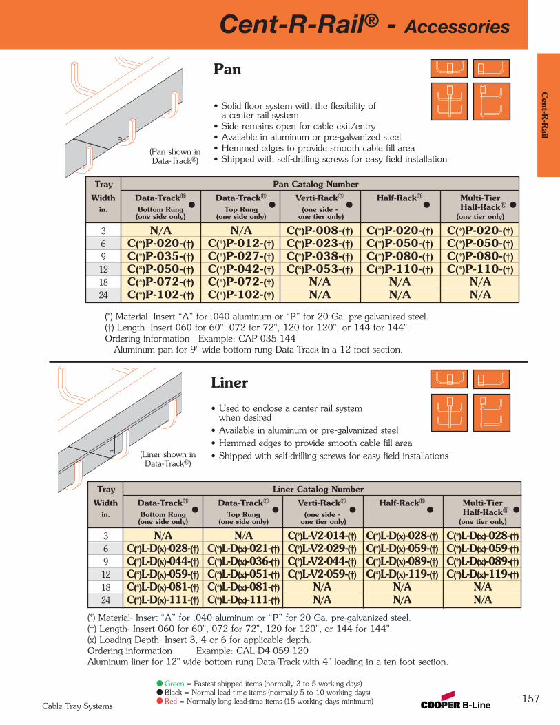
Cent-R-Rail® - Accessories
157
Cent-R
-Rail
Cable Tray Systems
(*) Material- Insert “A” for .040 aluminum or “P” for 20 Ga. pre-galvanized steel.(†) Length- Insert 060 for 60", 072 for 72", 120 for 120", or 144 for 144".Ordering information - Example: CAP-035-144
Aluminum pan for 9" wide bottom rung Data-Track in a 12 foot section.
Pan
• Solid floor system with the flexibility ofa center rail system
• Side remains open for cable exit/entry• Available in aluminum or pre-galvanized steel• Hemmed edges to provide smooth cable fill area• Shipped with self-drilling screws for easy field installation
(Pan shown inData-Track®)
Tray Liner Catalog Number
Width Data-Track® Data-Track® Verti-Rack® Half-Rack® Multi-Tierin. Bottom Rung Top Rung (one side - Half-Rack®
(one side only) (one side only) one tier only) (one tier only)
3 N/A N/A C(*)L-V2-014-(†) C(*)L-D(x)-028-(†) C(*)L-D(x)-028-(†)6 C(*)L-D(x)-028-(†) C(*)L-D(x)-021-(†) C(*)L-V2-029-(†) C(*)L-D(x)-059-(†) C(*)L-D(x)-059-(†)9 C(*)L-D(x)-044-(†) C(*)L-D(x)-036-(†) C(*)L-V2-044-(†) C(*)L-D(x)-089-(†) C(*)L-D(x)-089-(†)12 C(*)L-D(x)-059-(†) C(*)L-D(x)-051-(†) C(*)L-V2-059-(†) C(*)L-D(x)-119-(†) C(*)L-D(x)-119-(†)18 C(*)L-D(x)-081-(†) C(*)L-D(x)-081-(†) N/A N/A N/A24 C(*)L-D(x)-111-(†) C(*)L-D(x)-111-(†) N/A N/A N/A
Liner
• Used to enclose a center rail systemwhen desired
• Available in aluminum or pre-galvanized steel• Hemmed edges to provide smooth cable fill area• Shipped with self-drilling screws for easy field installations
(*) Material- Insert “A” for .040 aluminum or “P” for 20 Ga. pre-galvanized steel.(†) Length- Insert 060 for 60", 072 for 72", 120 for 120", or 144 for 144".(x) Loading Depth- Insert 3, 4 or 6 for applicable depth.Ordering information Example: CAL-D4-059-120Aluminum liner for 12" wide bottom rung Data-Track with 4" loading in a ten foot section.
(Liner shown inData-Track®)
Tray Pan Catalog Number
Width Data-Track® Data-Track® Verti-Rack® Half-Rack® Multi-Tierin. Bottom Rung Top Rung (one side - Half-Rack®
(one side only) (one side only) one tier only) (one tier only)
3 N/A N/A C(*)P-008-(†) C(*)P-020-(†) C(*)P-020-(†)6 C(*)P-020-(†) C(*)P-012-(†) C(*)P-023-(†) C(*)P-050-(†) C(*)P-050-(†)9 C(*)P-035-(†) C(*)P-027-(†) C(*)P-038-(†) C(*)P-080-(†) C(*)P-080-(†)12 C(*)P-050-(†) C(*)P-042-(†) C(*)P-053-(†) C(*)P-110-(†) C(*)P-110-(†)18 C(*)P-072-(†) C(*)P-072-(†) N/A N/A N/A24 C(*)P-102-(†) C(*)P-102-(†) N/A N/A N/A
Green = Fastest shipped items (normally 3 to 5 working days)Black = Normal lead-time items (normally 5 to 10 working days)Red = Normally long lead-time items (15 working days minimum)
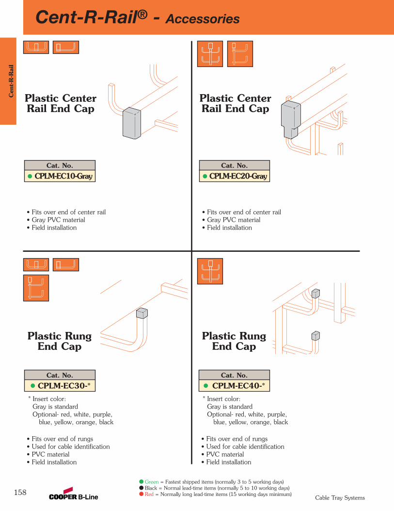
158
Cent-R-Rail® - AccessoriesC
ent-
R-R
ail
Cable Tray Systems
* Insert color:Gray is standardOptional- red, white, purple,
blue, yellow, orange, black
Cat. No.
CPLM-EC10-Gray
Plastic CenterRail End Cap
Cat. No.
CPLM-EC30-*
Plastic RungEnd Cap
Cat. No.
CPLM-EC20-Gray
Plastic CenterRail End Cap
• Fits over end of center rail • Gray PVC material• Field installation
• Fits over end of rungs • Used for cable identification• PVC material• Field installation
• Fits over end of center rail • Gray PVC material• Field installation
* Insert color:Gray is standardOptional- red, white, purple,
blue, yellow, orange, black
Cat. No.
CPLM-EC40-*
Plastic RungEnd Cap
• Fits over end of rungs • Used for cable identification• PVC material• Field installation
Green = Fastest shipped items (normally 3 to 5 working days)Black = Normal lead-time items (normally 5 to 10 working days)Red = Normally long lead-time items (15 working days minimum)
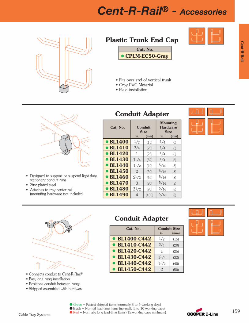
Cent-R-Rail® - Accessories
159
Cent-R
-Rail
Cable Tray Systems
Green = Fastest shipped items (normally 3 to 5 working days)Black = Normal lead-time items (normally 5 to 10 working days)Red = Normally long lead-time items (15 working days minimum)
• Fits over end of vertical trunk• Gray PVC Material• Field installation
Cat. No.
CPLM-EC50-Gray
Plastic Trunk End Cap
MountingCat. No. Conduit Hardware
Size Sizein. (mm) in. (mm)
BL1400 1/2 (15) 1/4 (6)
BL1410 3/4 (20) 1/4 (6)
BL1420 1 (25) 1/4 (6)
BL1430 11/4 (32) 1/4 (6)
BL1440 11/2 (40) 5/16 (8)
BL1450 2 (50) 5/16 (8)
BL1460 21/2 (65) 5/16 (8)
BL1470 3 (80) 5/16 (8)
BL1480 31/2 (90) 5/16 (8)
BL1490 4 (100) 5/16 (8)
• Designed to support or suspend light-duty stationary conduit runs
• Zinc plated steel• Attaches to tray center rail
(mounting hardware not included)
Conduit Adapter
• Connects conduit to Cent-R-Rail®• Easy one rung installation• Positions conduit between rungs• Shipped assembled with hardware
Conduit AdapterCat. No. Conduit Size
in. (mm)
BL1400-C442 1/2 (15)
BL1410-C442 3/4 (20)
BL1420-C442 1 (25)
BL1430-C442 11/4 (32)
BL1440-C442 11/2 (40)
BL1450-C442 2 (50)
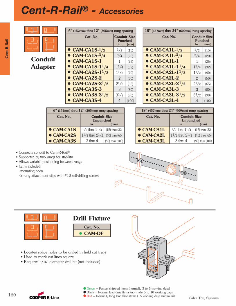
160
Cent-R-Rail® - Accessories
Cable Tray Systems
Green = Fastest shipped items (normally 3 to 5 working days)Black = Normal lead-time items (normally 5 to 10 working days)Red = Normally long lead-time items (15 working days minimum)
6" (152mm) thru 12" (305mm) rung spacing
Cat. No. Conduit SizePunchedin. (mm)
CAM-CA1S-1/2 1/2 (15)
CAM-CA1S-3/4 3/4 (20)
CAM-CA1S-1 1 (25)
CAM-CA1S-11/4 11/4 (32)
CAM-CA2S-11/2 11/2 (40)
CAM-CA2S-2 2 (50)
CAM-CA2S-21/2 21/2 (65)
CAM-CA3S-3 3 (80)
CAM-CA3S-31/2 31/2 (90)
CAM-CA3S-4 4 (100)
• Connects conduit to Cent-R-Rail®• Supported by two rungs for stability• Allows variable positioning between rungs• Items included:
-mounting body-2 rung attachment clips with #10 self-drilling screws
ConduitAdapter
18" (457mm) thru 24" (609mm) rung spacing
Cat. No. Conduit SizePunchedin. (mm)
CAM-CA1L-1/2 1/2 (15)
CAM-CA1L-3/4 3/4 (20)
CAM-CA1L-1 1 (25)
CAM-CA1L-11/4 11/4 (32)
CAM-CA2L-11/2 11/2 (40)
CAM-CA2L-2 2 (50)
CAM-CA2L-21/2 21/2 (65)
CAM-CA3L-3 3 (80)
CAM-CA3L-31/2 31/2 (90)
CAM-CA3L-4 4 (100)
6" (152mm) thru 12" (305mm) rung spacing
Cat. No. Conduit SizeUnpunched
in. (mm)
CAM-CA1S 1/2 thru 11/4 (15) thru (32)
CAM-CA2S 11/2 thru 21/2 (40) thru (65)
CAM-CA3S 3 thru 4 (80) thru (100)
• Locates splice holes to be drilled in field cut trays• Used to mark cut lines square• Requires 9/16" diameter drill bit (not included)
Cat. No.
CAM-DF
Drill Fixture
18" (457mm) thru 24" (609mm) rung spacing
Cat. No. Conduit SizeUnpunched
in. (mm)
CAM-CA1L 1/2 thru 11/4 (15) thru (32)
CAM-CA2L 11/2 thru 21/2 (40) thru (65)
CAM-CA3L 3 thru 4 (80) thru (100)
Cen
t-R
-Rai
l
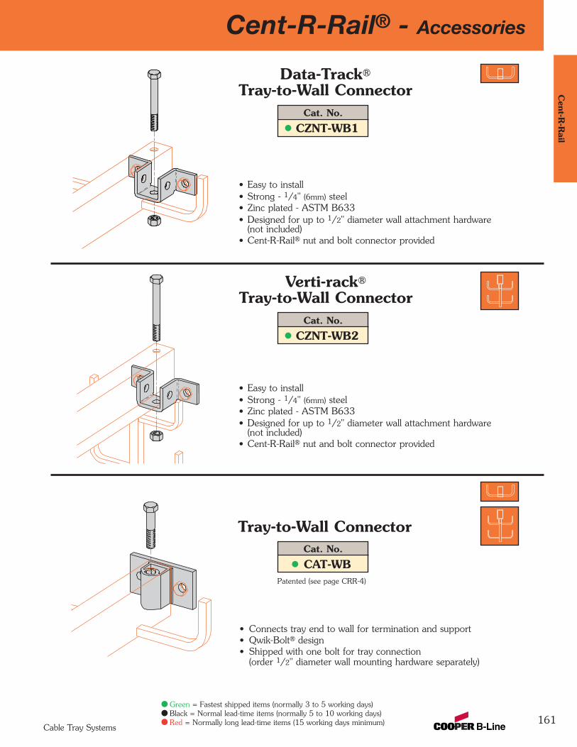
Cent-R-Rail® - Accessories
161
Cent-R
-Rail
Cable Tray Systems
Green = Fastest shipped items (normally 3 to 5 working days)Black = Normal lead-time items (normally 5 to 10 working days)Red = Normally long lead-time items (15 working days minimum)
• Connects tray end to wall for termination and support• Qwik-Bolt® design• Shipped with one bolt for tray connection
(order 1/2" diameter wall mounting hardware separately)
• Easy to install• Strong - 1/4" (6mm) steel• Zinc plated - ASTM B633• Designed for up to 1/2" diameter wall attachment hardware
(not included)• Cent-R-Rail® nut and bolt connector provided
• Easy to install• Strong - 1/4" (6mm) steel• Zinc plated - ASTM B633• Designed for up to 1/2" diameter wall attachment hardware
(not included)• Cent-R-Rail® nut and bolt connector provided
Patented (see page CRR-4)
Cat. No.
CZNT-WB1
Data-Track®
Tray-to-Wall Connector
Cat. No.
CZNT-WB2
Verti-rack®
Tray-to-Wall Connector
Cat. No.
CAT-WB
Tray-to-Wall Connector
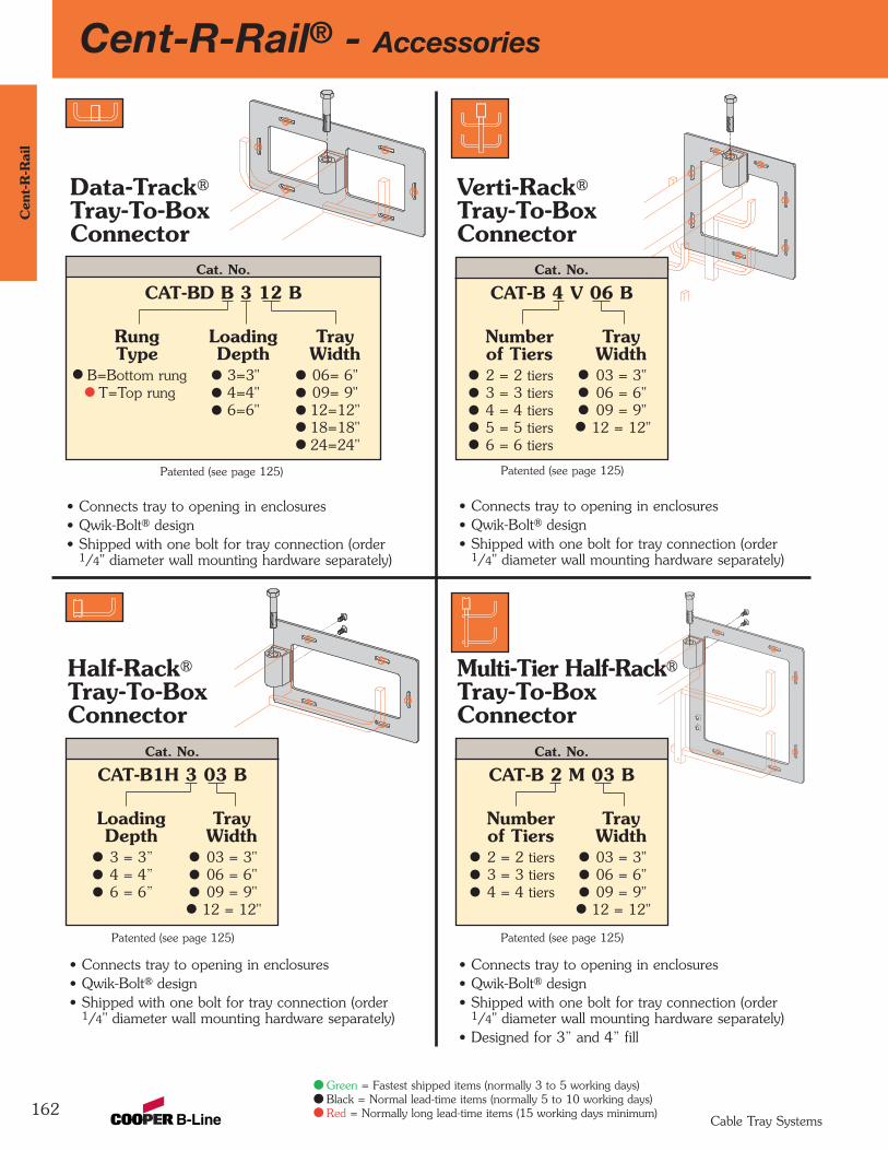
162
Cent-R-Rail® - AccessoriesC
ent-
R-R
ail
Cable Tray Systems
Green = Fastest shipped items (normally 3 to 5 working days)Black = Normal lead-time items (normally 5 to 10 working days)Red = Normally long lead-time items (15 working days minimum)
• Connects tray to opening in enclosures• Qwik-Bolt® design• Shipped with one bolt for tray connection (order
1/4" diameter wall mounting hardware separately)
Data-Track®
Tray-To-BoxConnector
Patented (see page 125)
Cat. No.
CAT-BD B 3 12 B
Rung Loading TrayType Depth Width
B=Bottom rung 3=3" 06= 6"T=Top rung 4=4" 09= 9"
6=6" 12=12"18=18"24=24"
Patented (see page 125)
• Connects tray to opening in enclosures• Qwik-Bolt® design• Shipped with one bolt for tray connection (order
1/4" diameter wall mounting hardware separately)
Cat. No.
CAT-B 4 V 06 B
Number Trayof Tiers Width2 = 2 tiers 03 = 3"3 = 3 tiers 06 = 6"4 = 4 tiers 09 = 9"5 = 5 tiers 12 = 12"6 = 6 tiers
Multi-Tier Half-Rack®
Tray-To-BoxConnector
Patented (see page 125)
• Connects tray to opening in enclosures• Qwik-Bolt® design• Shipped with one bolt for tray connection (order
1/4" diameter wall mounting hardware separately)• Designed for 3” and 4” fill
Cat. No.
CAT-B 2 M 03 B
Number Trayof Tiers Width2 = 2 tiers 03 = 3"3 = 3 tiers 06 = 6"4 = 4 tiers 09 = 9"
12 = 12"
Half-Rack®
Tray-To-BoxConnector
Patented (see page 125)
• Connects tray to opening in enclosures• Qwik-Bolt® design• Shipped with one bolt for tray connection (order
1/4" diameter wall mounting hardware separately)
Cat. No.
CAT-B1H 3 03 B
Loading TrayDepth Width3 = 3” 03 = 3"4 = 4” 06 = 6"6 = 6” 09 = 9"
12 = 12"
Verti-Rack®
Tray-To-BoxConnector
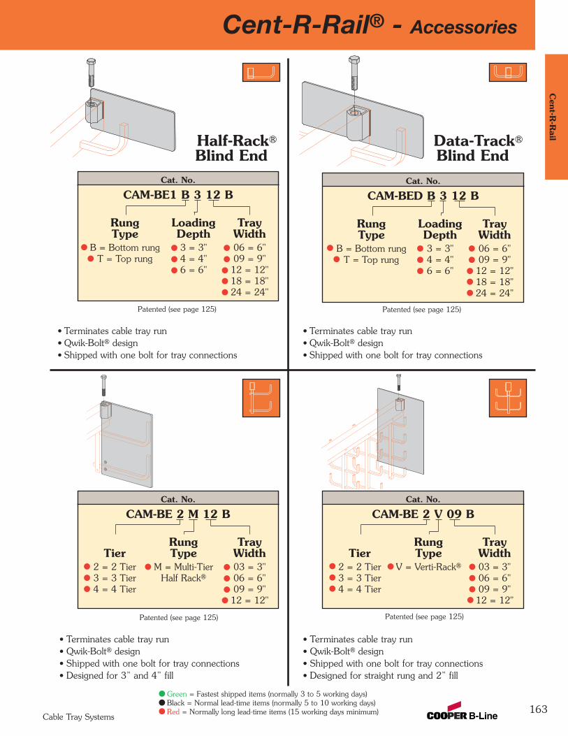
Cent-R-Rail® - Accessories
163
Cent-R
-Rail
Cable Tray Systems
Green = Fastest shipped items (normally 3 to 5 working days)Black = Normal lead-time items (normally 5 to 10 working days)Red = Normally long lead-time items (15 working days minimum)
• Terminates cable tray run• Qwik-Bolt® design• Shipped with one bolt for tray connections
Half-Rack®
Blind End
Patented (see page 125)
Cat. No.
CAM-BE1 B 3 12 B
Rung Loading TrayType Depth Width
B = Bottom rung 3 = 3" 06 = 6"T = Top rung 4 = 4" 09 = 9"
6 = 6" 12 = 12"18 = 18"24 = 24"
Patented (see page 125)
• Terminates cable tray run• Qwik-Bolt® design• Shipped with one bolt for tray connections
Patented (see page 125)
• Terminates cable tray run• Qwik-Bolt® design• Shipped with one bolt for tray connections• Designed for straight rung and 2” fill
Patented (see page 125)
• Terminates cable tray run• Qwik-Bolt® design• Shipped with one bolt for tray connections• Designed for 3” and 4” fill
Data-Track®
Blind EndCat. No.
CAM-BED B 3 12 B
Rung Loading TrayType Depth Width
B = Bottom rung 3 = 3" 06 = 6"T = Top rung 4 = 4" 09 = 9"
6 = 6" 12 = 12"18 = 18"24 = 24"
Cat. No.
CAM-BE 2 M 12 B
Rung TrayTier Type Width
2 = 2 Tier M = Multi-Tier 03 = 3"3 = 3 Tier Half Rack® 06 = 6"4 = 4 Tier 09 = 9"
12 = 12"
Cat. No.
CAM-BE 2 V 09 B
Rung TrayTier Type Width
2 = 2 Tier V = Verti-Rack® 03 = 3"3 = 3 Tier 06 = 6"4 = 4 Tier 09 = 9"
12 = 12"
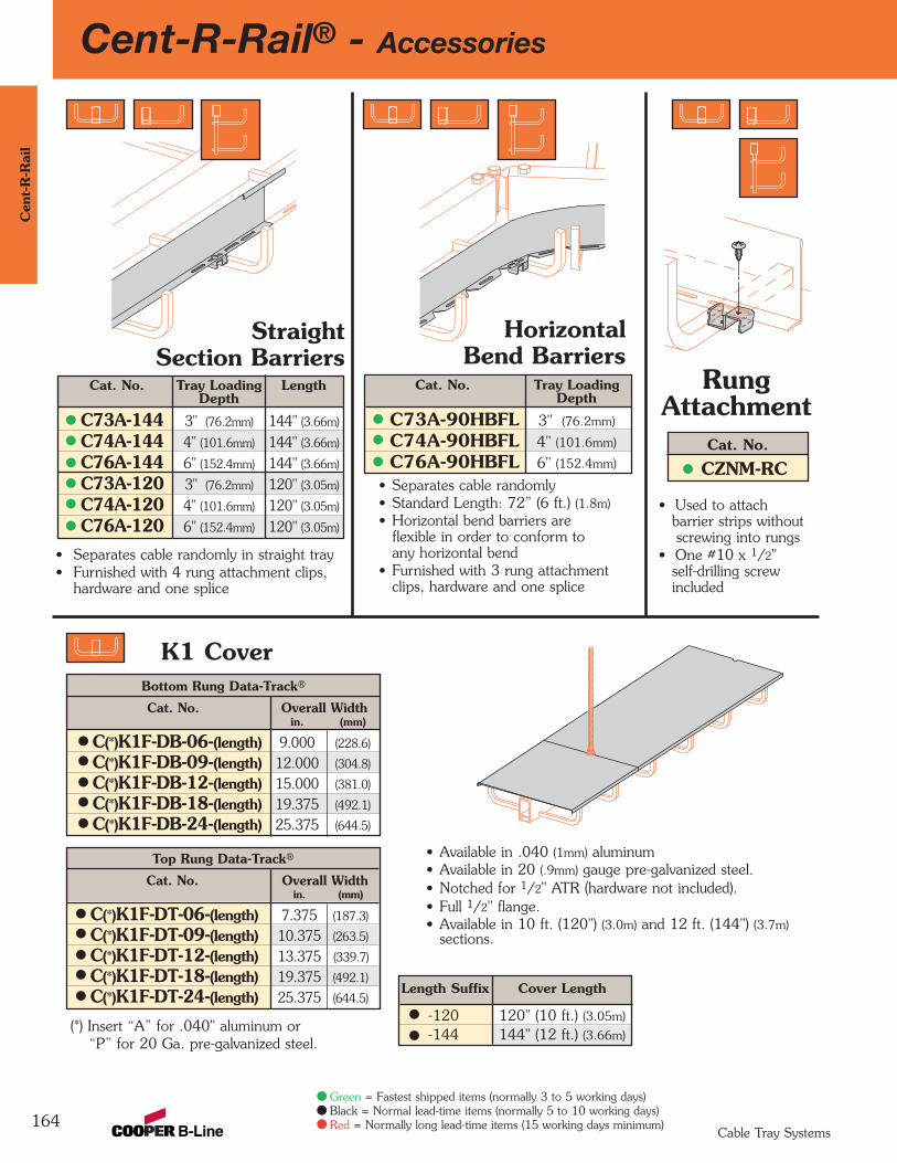
164
Cent-R-Rail® - AccessoriesC
ent-
R-R
ail
Cable Tray Systems
Green = Fastest shipped items (normally 3 to 5 working days)Black = Normal lead-time items (normally 5 to 10 working days)Red = Normally long lead-time items (15 working days minimum)
StraightSection Barriers
• Separates cable randomly in straight tray• Furnished with 4 rung attachment clips,
hardware and one splice
Cat. No. Tray Loading LengthDepth
C73A-144 3" (76.2mm) 144" (3.66m)
C74A-144 4" (101.6mm) 144" (3.66m)
C76A-144 6" (152.4mm) 144" (3.66m)
C73A-120 3" (76.2mm) 120" (3.05m)
C74A-120 4" (101.6mm) 120" (3.05m)
C76A-120 6" (152.4mm) 120" (3.05m)
RungAttachment
• Used to attachbarrier strips without screwing into rungs
• One #10 x 1/2"self-drilling screwincluded
Cat. No.
CZNM-RC
HorizontalBend Barriers
• Separates cable randomly• Standard Length: 72” (6 ft.) (1.8m)• Horizontal bend barriers are
flexible in order to conform toany horizontal bend
• Furnished with 3 rung attachmentclips, hardware and one splice
Cat. No. Tray LoadingDepth
C73A-90HBFL 3" (76.2mm)
C74A-90HBFL 4" (101.6mm)
C76A-90HBFL 6" (152.4mm)
K1 CoverBottom Rung Data-Track®
Cat. No. Overall Widthin. (mm)
C(*)K1F-DB-06-(length) 9.000 (228.6)
C(*)K1F-DB-09-(length) 12.000 (304.8)
C(*)K1F-DB-12-(length) 15.000 (381.0)
C(*)K1F-DB-18-(length) 19.375 (492.1)
C(*)K1F-DB-24-(length) 25.375 (644.5)
Top Rung Data-Track®
Cat. No. Overall Widthin. (mm)
C(*)K1F-DT-06-(length) 7.375 (187.3)
C(*)K1F-DT-09-(length) 10.375 (263.5)
C(*)K1F-DT-12-(length) 13.375 (339.7)
C(*)K1F-DT-18-(length) 19.375 (492.1)
C(*)K1F-DT-24-(length) 25.375 (644.5)
(*) Insert “A” for .040" aluminum or “P” for 20 Ga. pre-galvanized steel.
• Available in .040 (1mm) aluminum• Available in 20 (.9mm) gauge pre-galvanized steel.• Notched for 1/2" ATR (hardware not included).• Full 1/2" flange.• Available in 10 ft. (120") (3.0m) and 12 ft. (144") (3.7m)
sections.
Length Suffix Cover Length
-120 120" (10 ft.) (3.05m)
-144 144" (12 ft.) (3.66m)
Cent-R-Rail® - Sample SpecificationData-Track®
165
Cent-R
-Rail
Cable Tray Systems
Section 1- Acceptable Manufacturers
1.01 Manufacturer: Subject to compliance with these specifications, cable tray system shall be asmanufactured by B-Line® Systems, Inc.
Section 2- Cable Tray Sections and Components
2.01 General: Except as otherwise indicated, provide metal cable trays, of types, classes and sizesindicated with splice hangers and all other necessary accessories. Provide cable trays with roundededges and smooth surfaces in compliance with applicable standards, and with the following additionalconstruction features.
2.02 Materials and Finish: Aluminum: Center rails and rungs shall be extruded from Aluminum AssociationAlloy 6063. All fabricated parts shall be made from Aluminum Association Alloy 5052 and all cast parts from Aluminum Association Alloy 319. All hardware and fasteners shall be zinc plated steel inaccordance with ASTM B633.
2.03 Cable trays shall be constructed of a center rail 1.625" x 3.250" with minimum section properties of Sx = 0.701 in3 and Ix = 1.174 in4. Rungs shall be a single continuous square tube0.54" x 0.54" with radiused corners and minimum section properties of Sx = 0.019 in3 andIx = 0.005 in4. Rungs shall be mechanically connected to the center rail in at least two places,symmetrical about the center rail, with ends finished to protect installers and cables.
2.04 Rungs shall be spaced every [6] [9] [12] inches.
2.05 Straight sections shall be supplied in [10] [12] foot lengths.
2.06 Cable tray width shall be [6] [9] [12] [18] [24] inches.
2.07 Splice hangers must also be capable of acting as the support points for all thread rod.
2.08 Cable tray loading depth shall be [3] [4] [6] inches.
2.09 All splices and connectors must protect cables from the edges of the center rail and act as a barrierto prevent the center rail from transmitting hazardous gases or smoke; hardware must be installedvertically, so as not to interfere with the cables in the cable fill area.
2.10 Where required, expansion splices shall allow for 1" of thermal expansion and contraction.
2.11 When required, and to provide an area free of center rails for cable transitions, contractor shallinstall a universal hub fitting. The universal hub fitting must be a cast aluminum structural member,B-Line CAU Series (flat sheets of steel or aluminum are not acceptable), which can be used withcable ties and allows the center rails to be connected so they may be pivoted at connection points.
Section 3- Loading Capacities and Testing
3.01 Cable tray shall meet the loading requirements of NEMA 12C.
3.02 Upon request, manufacturer shall provide test reports in accordance with the latest revision ofNEMA VE-1 or CSA C22.2 No. 126-M91.
3.03 UL Compliance: Provide products which are UL classified and labeled.
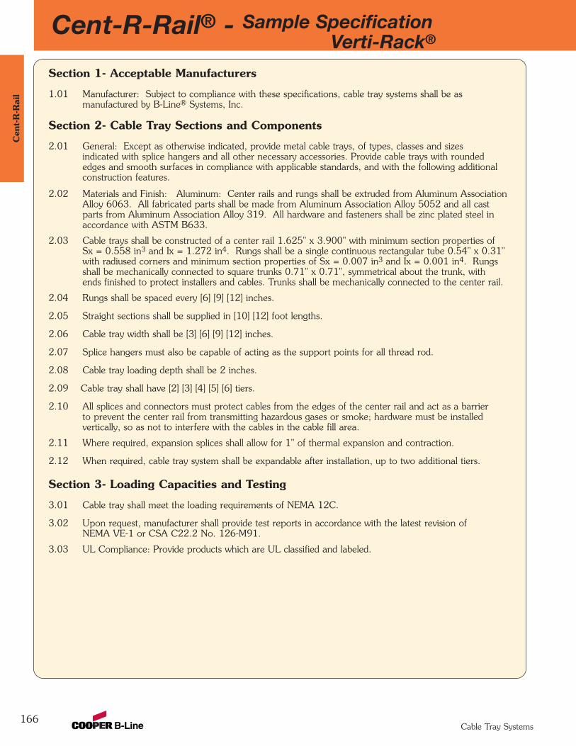
Cent-R-Rail® - Sample SpecificationVerti-Rack®
166
Cen
t-R
-Rai
l
Cable Tray Systems
Section 1- Acceptable Manufacturers
1.01 Manufacturer: Subject to compliance with these specifications, cable tray systems shall be asmanufactured by B-Line® Systems, Inc.
Section 2- Cable Tray Sections and Components
2.01 General: Except as otherwise indicated, provide metal cable trays, of types, classes and sizesindicated with splice hangers and all other necessary accessories. Provide cable trays with roundededges and smooth surfaces in compliance with applicable standards, and with the following additionalconstruction features.
2.02 Materials and Finish: Aluminum: Center rails and rungs shall be extruded from Aluminum AssociationAlloy 6063. All fabricated parts shall be made from Aluminum Association Alloy 5052 and all castparts from Aluminum Association Alloy 319. All hardware and fasteners shall be zinc plated steel inaccordance with ASTM B633.
2.03 Cable trays shall be constructed of a center rail 1.625" x 3.900" with minimum section properties ofSx = 0.558 in3 and Ix = 1.272 in4. Rungs shall be a single continuous rectangular tube 0.54" x 0.31"with radiused corners and minimum section properties of Sx = 0.007 in3 and Ix = 0.001 in4. Rungsshall be mechanically connected to square trunks 0.71" x 0.71", symmetrical about the trunk, withends finished to protect installers and cables. Trunks shall be mechanically connected to the center rail.
2.04 Rungs shall be spaced every [6] [9] [12] inches.
2.05 Straight sections shall be supplied in [10] [12] foot lengths.
2.06 Cable tray width shall be [3] [6] [9] [12] inches.
2.07 Splice hangers must also be capable of acting as the support points for all thread rod.
2.08 Cable tray loading depth shall be 2 inches.
2.09 Cable tray shall have [2] [3] [4] [5] [6] tiers.
2.10 All splices and connectors must protect cables from the edges of the center rail and act as a barrierto prevent the center rail from transmitting hazardous gases or smoke; hardware must be installedvertically, so as not to interfere with the cables in the cable fill area.
2.11 Where required, expansion splices shall allow for 1" of thermal expansion and contraction.
2.12 When required, cable tray system shall be expandable after installation, up to two additional tiers.
Section 3- Loading Capacities and Testing
3.01 Cable tray shall meet the loading requirements of NEMA 12C.
3.02 Upon request, manufacturer shall provide test reports in accordance with the latest revision ofNEMA VE-1 or CSA C22.2 No. 126-M91.
3.03 UL Compliance: Provide products which are UL classified and labeled.
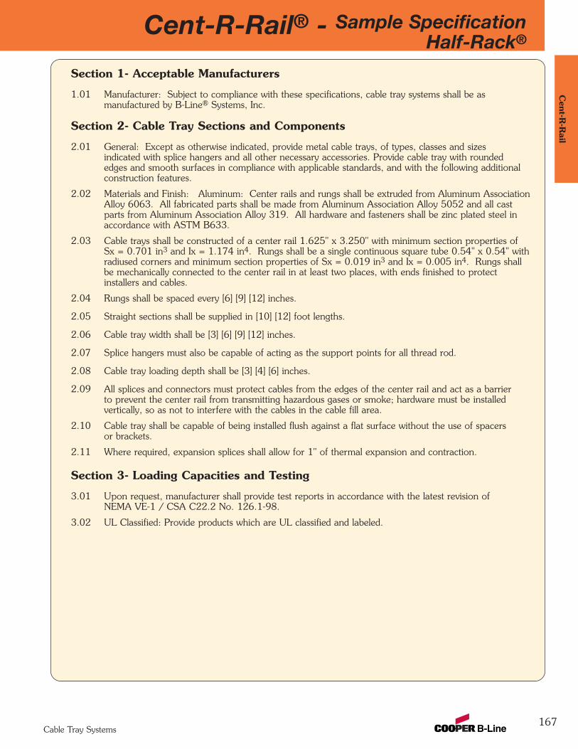
Cent-R-Rail® - Sample SpecificationHalf-Rack®
167
Cent-R
-Rail
Cable Tray Systems
Section 1- Acceptable Manufacturers
1.01 Manufacturer: Subject to compliance with these specifications, cable tray systems shall be asmanufactured by B-Line® Systems, Inc.
Section 2- Cable Tray Sections and Components
2.01 General: Except as otherwise indicated, provide metal cable trays, of types, classes and sizesindicated with splice hangers and all other necessary accessories. Provide cable tray with roundededges and smooth surfaces in compliance with applicable standards, and with the following additionalconstruction features.
2.02 Materials and Finish: Aluminum: Center rails and rungs shall be extruded from Aluminum AssociationAlloy 6063. All fabricated parts shall be made from Aluminum Association Alloy 5052 and all castparts from Aluminum Association Alloy 319. All hardware and fasteners shall be zinc plated steel inaccordance with ASTM B633.
2.03 Cable trays shall be constructed of a center rail 1.625" x 3.250" with minimum section properties ofSx = 0.701 in3 and Ix = 1.174 in4. Rungs shall be a single continuous square tube 0.54" x 0.54" withradiused corners and minimum section properties of Sx = 0.019 in3 and Ix = 0.005 in4. Rungs shallbe mechanically connected to the center rail in at least two places, with ends finished to protectinstallers and cables.
2.04 Rungs shall be spaced every [6] [9] [12] inches.
2.05 Straight sections shall be supplied in [10] [12] foot lengths.
2.06 Cable tray width shall be [3] [6] [9] [12] inches.
2.07 Splice hangers must also be capable of acting as the support points for all thread rod.
2.08 Cable tray loading depth shall be [3] [4] [6] inches.
2.09 All splices and connectors must protect cables from the edges of the center rail and act as a barrierto prevent the center rail from transmitting hazardous gases or smoke; hardware must be installedvertically, so as not to interfere with the cables in the cable fill area.
2.10 Cable tray shall be capable of being installed flush against a flat surface without the use of spacersor brackets.
2.11 Where required, expansion splices shall allow for 1" of thermal expansion and contraction.
Section 3- Loading Capacities and Testing
3.01 Upon request, manufacturer shall provide test reports in accordance with the latest revision ofNEMA VE-1 / CSA C22.2 No. 126.1-98.
3.02 UL Classified: Provide products which are UL classified and labeled.
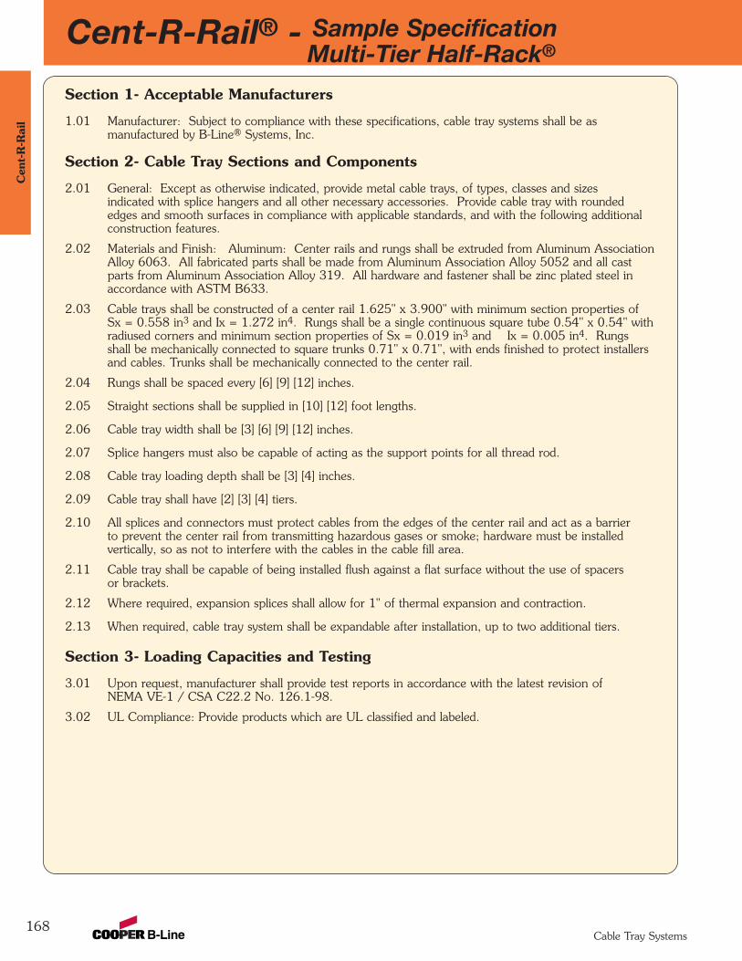
Cent-R-Rail® - Sample SpecificationMulti-Tier Half-Rack®
168
Cen
t-R
-Rai
l
Cable Tray Systems
Section 1- Acceptable Manufacturers
1.01 Manufacturer: Subject to compliance with these specifications, cable tray systems shall be asmanufactured by B-Line® Systems, Inc.
Section 2- Cable Tray Sections and Components
2.01 General: Except as otherwise indicated, provide metal cable trays, of types, classes and sizesindicated with splice hangers and all other necessary accessories. Provide cable tray with roundededges and smooth surfaces in compliance with applicable standards, and with the following additionalconstruction features.
2.02 Materials and Finish: Aluminum: Center rails and rungs shall be extruded from Aluminum AssociationAlloy 6063. All fabricated parts shall be made from Aluminum Association Alloy 5052 and all castparts from Aluminum Association Alloy 319. All hardware and fastener shall be zinc plated steel inaccordance with ASTM B633.
2.03 Cable trays shall be constructed of a center rail 1.625" x 3.900" with minimum section properties ofSx = 0.558 in3 and Ix = 1.272 in4. Rungs shall be a single continuous square tube 0.54" x 0.54" withradiused corners and minimum section properties of Sx = 0.019 in3 and Ix = 0.005 in4. Rungsshall be mechanically connected to square trunks 0.71" x 0.71", with ends finished to protect installersand cables. Trunks shall be mechanically connected to the center rail.
2.04 Rungs shall be spaced every [6] [9] [12] inches.
2.05 Straight sections shall be supplied in [10] [12] foot lengths.
2.06 Cable tray width shall be [3] [6] [9] [12] inches.
2.07 Splice hangers must also be capable of acting as the support points for all thread rod.
2.08 Cable tray loading depth shall be [3] [4] inches.
2.09 Cable tray shall have [2] [3] [4] tiers.
2.10 All splices and connectors must protect cables from the edges of the center rail and act as a barrierto prevent the center rail from transmitting hazardous gases or smoke; hardware must be installedvertically, so as not to interfere with the cables in the cable fill area.
2.11 Cable tray shall be capable of being installed flush against a flat surface without the use of spacersor brackets.
2.12 Where required, expansion splices shall allow for 1" of thermal expansion and contraction.
2.13 When required, cable tray system shall be expandable after installation, up to two additional tiers.
Section 3- Loading Capacities and Testing
3.01 Upon request, manufacturer shall provide test reports in accordance with the latest revision ofNEMA VE-1 / CSA C22.2 No. 126.1-98.
3.02 UL Compliance: Provide products which are UL classified and labeled.
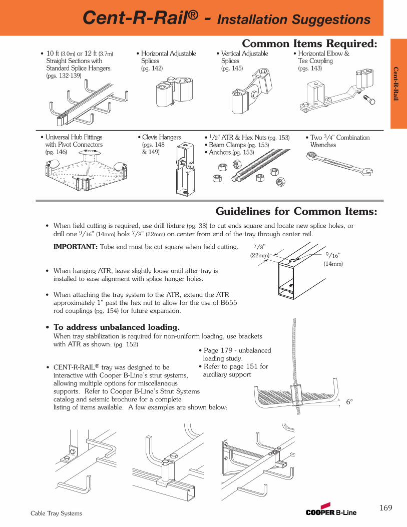
Cent-R-Rail® - Installation Suggestions
169
Cent-R
-Rail
Cable Tray Systems
• 10 ft (3.0m) or 12 ft (3.7m)Straight Sections withStandard Splice Hangers.(pgs. 132-139)
Common Items Required:
Guidelines for Common Items:
• Horizontal AdjustableSplices(pg. 142)
• Vertical AdjustableSplices(pg. 145)
• Horizontal Elbow &Tee Coupling(pgs. 143)
• Universal Hub Fittingswith Pivot Connectors(pg. 146)
• Clevis Hangers(pgs. 148& 149)
• 1/2" ATR & Hex Nuts (pg. 153)• Beam Clamps (pg. 153)• Anchors (pg. 153)
• Two 3/4" CombinationWrenches
• When field cutting is required, use drill fixture (pg. 38) to cut ends square and locate new splice holes, ordrill one 9/16" (14mm) hole 7/8" (22mm) on center from end of the tray through center rail.
IMPORTANT: Tube end must be cut square when field cutting.
• When hanging ATR, leave slightly loose until after tray isinstalled to ease alignment with splice hanger holes.
• When attaching the tray system to the ATR, extend the ATRapproximately 1" past the hex nut to allow for the use of B655rod couplings (pg. 154) for future expansion.
• To address unbalanced loading.When tray stabilization is required for non-uniform loading, use bracketswith ATR as shown: (pg. 152)
• CENT-R-RAIL® tray was designed to beinteractive with Cooper B-Line’s strut systems, allowing multiple options for miscellaneoussupports. Refer to Cooper B-Line’s Strut Systemscatalog and seismic brochure for a completelisting of items available. A few examples are shown below:
7/8"
• Page 179 - unbalanced loading study.
• Refer to page 151 for auxiliary support
6°
(22mm) 9/16"(14mm)
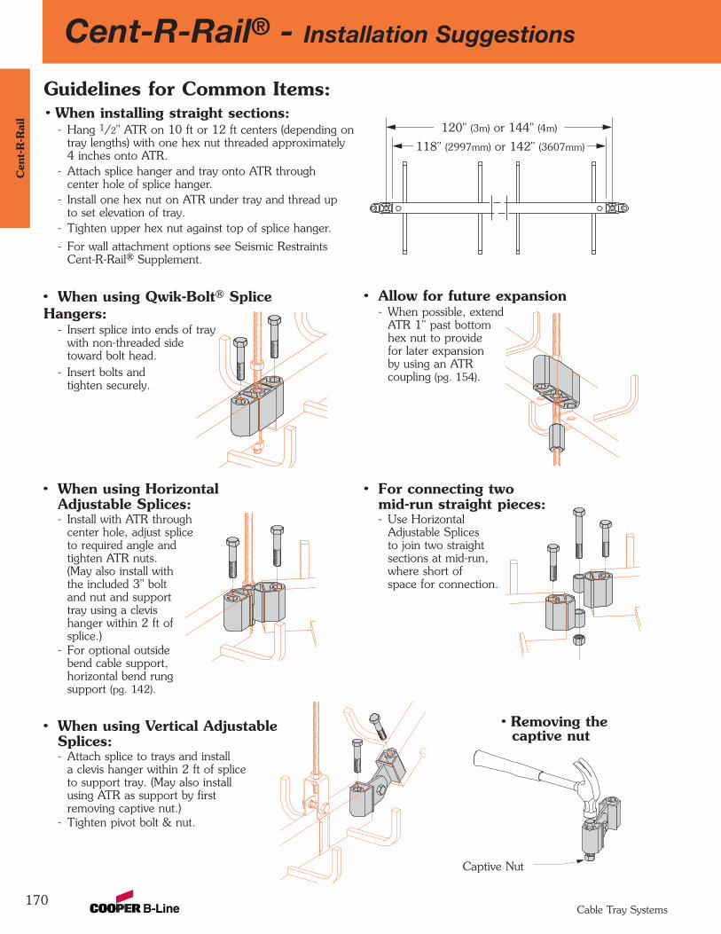
Cent-R-Rail® - Installation Suggestions
170
Cen
t-R
-Rai
l
Cable Tray Systems
Guidelines for Common Items:• When installing straight sections:
- Hang 1/2" ATR on 10 ft or 12 ft centers (depending ontray lengths) with one hex nut threaded approximately4 inches onto ATR.
- Attach splice hanger and tray onto ATR throughcenter hole of splice hanger.
- Install one hex nut on ATR under tray and thread upto set elevation of tray.
- Tighten upper hex nut against top of splice hanger.
- For wall attachment options see Seismic RestraintsCent-R-Rail® Supplement.
• When using Qwik-Bolt® SpliceHangers:
- Insert splice into ends of traywith non-threaded sidetoward bolt head.
- Insert bolts andtighten securely.
120" (3m) or 144" (4m)
118" (2997mm) or 142" (3607mm)
• Allow for future expansion- When possible, extend
ATR 1" past bottomhex nut to providefor later expansionby using an ATRcoupling (pg. 154).
• When using HorizontalAdjustable Splices:- Install with ATR through
center hole, adjust spliceto required angle and tighten ATR nuts.(May also install withthe included 3" boltand nut and supporttray using a clevishanger within 2 ft ofsplice.)
- For optional outsidebend cable support,horizontal bend rungsupport (pg. 142).
• For connecting twomid-run straight pieces:- Use Horizontal
Adjustable Splicesto join two straightsections at mid-run,where short of space for connection.
• Removing thecaptive nut
Captive Nut
• When using Vertical AdjustableSplices:- Attach splice to trays and install
a clevis hanger within 2 ft of spliceto support tray. (May also installusing ATR as support by firstremoving captive nut.)
- Tighten pivot bolt & nut.

Cent-R-Rail® - Installation Suggestions
171
Cent-R
-Rail
Cable Tray Systems
• When wall-mounting tray:- Attach tray and splice to wall by bolting through center rail to wall.
(May also be installed using other methods, such as brackets.)
Guidelines for Common Items:
Sections should be attached to the wallat mid length and at 1/6th of the section length from both ends (20" for 120"; 24" for 144")
1" (25mm)
Mid Length
*24" (609mm)
*24" (609mm)
*= 20" (508mm) for 120" (3m) Length Section
144" (12') (4m) Length Section
Half-Rack® and Multi-Tier Half-Rack®
Support Locations
120" or 144"
• When using Expansion Splice Hangers:- Both splices adjacent to expansion splice hangers must be installed 120"
or 144" (depending on the tray length) on centers from expansion spliceto allow full expansion and contraction.
- Grounding jumper must be installed with expansion splice.
(3m) (4m)120" or 144"(3m) (4m)
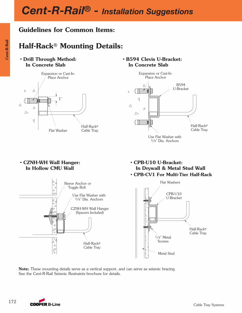
172
Cent-R-Rail® - Installation SuggestionsC
ent-
R-R
ail
Cable Tray Systems
Half-Rack® Mounting Details:
Half-Rack®
Cable Tray
1"
Expansion or Cast-In- Place Anchor
Flat Washer
B594U-Bracket
Half-Rack®
Cable Tray
Expansion or Cast-In- Place Anchor
Use Flat Washer with 3/8" Dia. Anchors
• CPB-U10 U-Bracket:In Drywall & Metal Stud Wall
• CPB-CV1 For Multi-Tier Half-Rack
• CZNH-WH Wall Hanger: In Hollow CMU Wall
CZNH-WH Wall Hanger(Spacers Included)
Half-Rack®
Cable Tray
Sleeve Anchor orToggle Bolt
Use Flat Washer with 3/8" Dia. Anchors
Half-Rack®
Cable Tray
CPB-U10U-Bracket
1/4" MetalScrews
Flat Washers
Metal Stud
Guidelines for Common Items:
• Drill Through Method:In Concrete Slab
• B594 Clevis U-Bracket:In Concrete Slab
Note: These mounting details serve as a vertical support, and can serve as seismic bracing. See the Cent-R-Rail Seismic Restraints brochure for details.
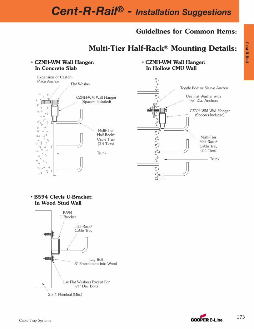
Cent-R-Rail® - Installation Suggestions
173
Cent-R
-Rail
Cable Tray Systems
Half-Rack®
Cable Tray
B594U-Bracket
Lag Bolt3" Embedment into Wood
2 x 4 Nominal (Min.)
Use Flat Washers Except For1/2" Dia. Bolts
Multi-TierHalf-Rack®
Cable Tray(2-4 Tiers)
CZNH-WM Wall Hanger(Spacers Included)
Trunk
Toggle Bolt or Sleeve Anchor
Use Flat Washer with 3/8" Dia. Anchors
• CZNH-WM Wall Hanger: In Hollow CMU Wall
Multi-Tier Half-Rack® Mounting Details:
• B594 Clevis U-Bracket: In Wood Stud Wall
Guidelines for Common Items:
• CZNH-WM Wall Hanger: In Concrete Slab
Multi-TierHalf-Rack®
Cable Tray(2-4 Tiers)
CZNH-WM Wall Hanger(Spacers Included)
Expansion or Cast-In-Place Anchor
Trunk
Flat Washer
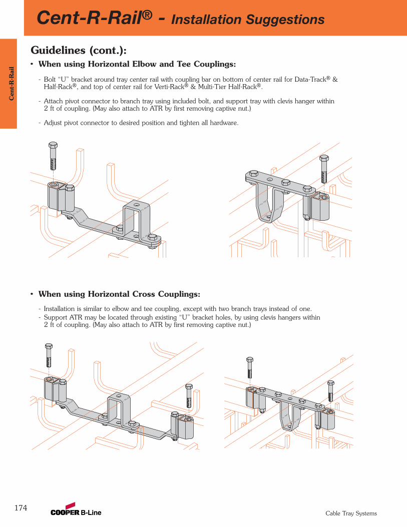
Cent-R-Rail® - Installation Suggestions
174
Cen
t-R
-Rai
l
Cable Tray Systems
Guidelines (cont.):• When using Horizontal Elbow and Tee Couplings:
- Bolt “U” bracket around tray center rail with coupling bar on bottom of center rail for Data-Track® &Half-Rack®, and top of center rail for Verti-Rack® & Multi-Tier Half-Rack®.
- Attach pivot connector to branch tray using included bolt, and support tray with clevis hanger within2 ft of coupling. (May also attach to ATR by first removing captive nut.)
- Adjust pivot connector to desired position and tighten all hardware.
• When using Horizontal Cross Couplings:
- Installation is similar to elbow and tee coupling, except with two branch trays instead of one.- Support ATR may be located through existing “U” bracket holes, by using clevis hangers within
2 ft of coupling. (May also attach to ATR by first removing captive nut.)

Cent-R-Rail® - Installation Suggestions
175
Cent-R
-Rail
Cable Tray Systems
• When using Add-A-Rung® with Verti-Rack® orMulti-Tier Half Rack® in Different Widths:- See loading data for maximum center rail load capacity
to determine the maximum number of tiers in differentwidths allowed.
- 3", 6", 9" and 12" wide tiers.
- Insert Add-A-Rung® into end of vertical trunk.
- Install included screw through pilot hole in trunk.
- See page 134 for part number.
Guidelines (cont.):• When using Add-A-Rung® with Verti-Rack® or
Multi-Tier Half-Rack®:- See loading data for maximum center rail load capacity to
determine the maximum number of tiers allowed.
- Insert Add-A-Rung® into end of vertical trunk.
- Install included screw through pilot hole in trunk.
• When using Universal Hub Fittings:- Position hubs with rounded edges toward cables.
- Attach pivot connectors to cable supportsurface using ATR, or bolt and nut through pivothole. (If bolt and nut are used, tray must besupported using clevis hangers within 2 ft ofpivot connectors.)
- Connect tray ends to pivot connectors.
- Position pivot connectors as desired andtighten hardware.
- Warning: Do not use as a support for personnel!
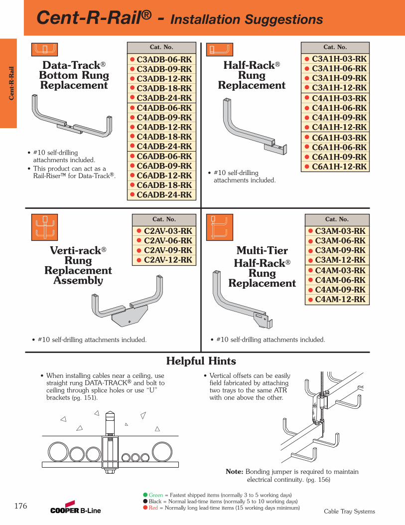
Cent-R-Rail® - Installation Suggestions
176
Cen
t-R
-Rai
l
Cable Tray Systems
Data-Track®
Bottom RungReplacement
• #10 self-drilling attachments included.
• This product can act as a Rail-Riser™ for Data-Track®.
Cat. No.
C3ADB-06-RKC3ADB-09-RKC3ADB-12-RKC3ADB-18-RKC3ADB-24-RKC4ADB-06-RKC4ADB-09-RKC4ADB-12-RKC4ADB-18-RKC4ADB-24-RKC6ADB-06-RKC6ADB-09-RKC6ADB-12-RKC6ADB-18-RKC6ADB-24-RK
• #10 self-drillingattachments included.
Half-Rack®
RungReplacement
Multi-TierHalf-Rack®
RungReplacement
• #10 self-drilling attachments included.
Verti-rack®
RungReplacement
Assembly
• #10 self-drilling attachments included.
• When installing cables near a ceiling, usestraight rung DATA-TRACK® and bolt toceiling through splice holes or use “U”brackets (pg. 151).
Helpful Hints
Note: Bonding jumper is required to maintainelectrical continuity. (pg. 156)
• Vertical offsets can be easilyfield fabricated by attachingtwo trays to the same ATRwith one above the other.
Cat. No.
C3A1H-03-RKC3A1H-06-RKC3A1H-09-RKC3A1H-12-RKC4A1H-03-RKC4A1H-06-RKC4A1H-09-RKC4A1H-12-RKC6A1H-03-RKC6A1H-06-RKC6A1H-09-RKC6A1H-12-RK
Cat. No.
C3AM-03-RKC3AM-06-RKC3AM-09-RKC3AM-12-RKC4AM-03-RKC4AM-06-RKC4AM-09-RKC4AM-12-RK
Cat. No.
C2AV-03-RKC2AV-06-RKC2AV-09-RKC2AV-12-RK
Green = Fastest shipped items (normally 3 to 5 working days)Black = Normal lead-time items (normally 5 to 10 working days)Red = Normally long lead-time items (15 working days minimum)
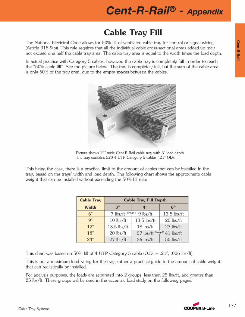
Cent-R-Rail® - Appendix
177
Cent-R
-Rail
Cable Tray Systems
Cable Tray FillThe National Electrical Code allows for 50% fill of ventilated cable tray for control or signal wiring(Article 318-9(b)). This rule requires that all the individual cable cross-sectional areas added up maynot exceed one half the cable tray area. The cable tray area is equal to the width times the load depth.
In actual practice with Category 5 cables, however, the cable tray is completely full in order to reachthe “50% cable fill”. See the picture below. The tray is completely full, but the sum of the cable areais only 50% of the tray area, due to the empty spaces between the cables.
This being the case, there is a practical limit to the amount of cables that can be installed in thetray, based on the trays’ width and load depth. The following chart shows the approximate cableweight that can be installed without exceeding the 50% fill rule:
Cable Tray Cable Tray Fill Depth
Width 3" 4" 6"
6" 7 lbs/ft 9 lbs/ft 13.5 lbs/ft9" 10 lbs/ft 13.5 lbs/ft 20 lbs/ft12" 13.5 lbs/ft 18 lbs/ft 27 lbs/ft18" 20 lbs/ft 27 lbs/ft 41 lbs/ft24" 27 lbs/ft 36 lbs/ft 50 lbs/ft
Group 1
Group 2
This chart was based on 50% fill of 4 UTP Category 5 cable (O.D. = .21", .026 lbs/ft).
This is not a maximum load rating for the tray, rather a practical guide to the amount of cable weightthat can realistically be installed.
For analysis purposes, the loads are separated into 2 groups: less than 25 lbs/ft, and greater than25 lbs/ft. These groups will be used in the eccentric load study on the following pages.
Picture shows 12" wide Cent-R-Rail cable tray with 3" load depth.The tray contains 520 4 UTP Category 5 cables (.21" OD).
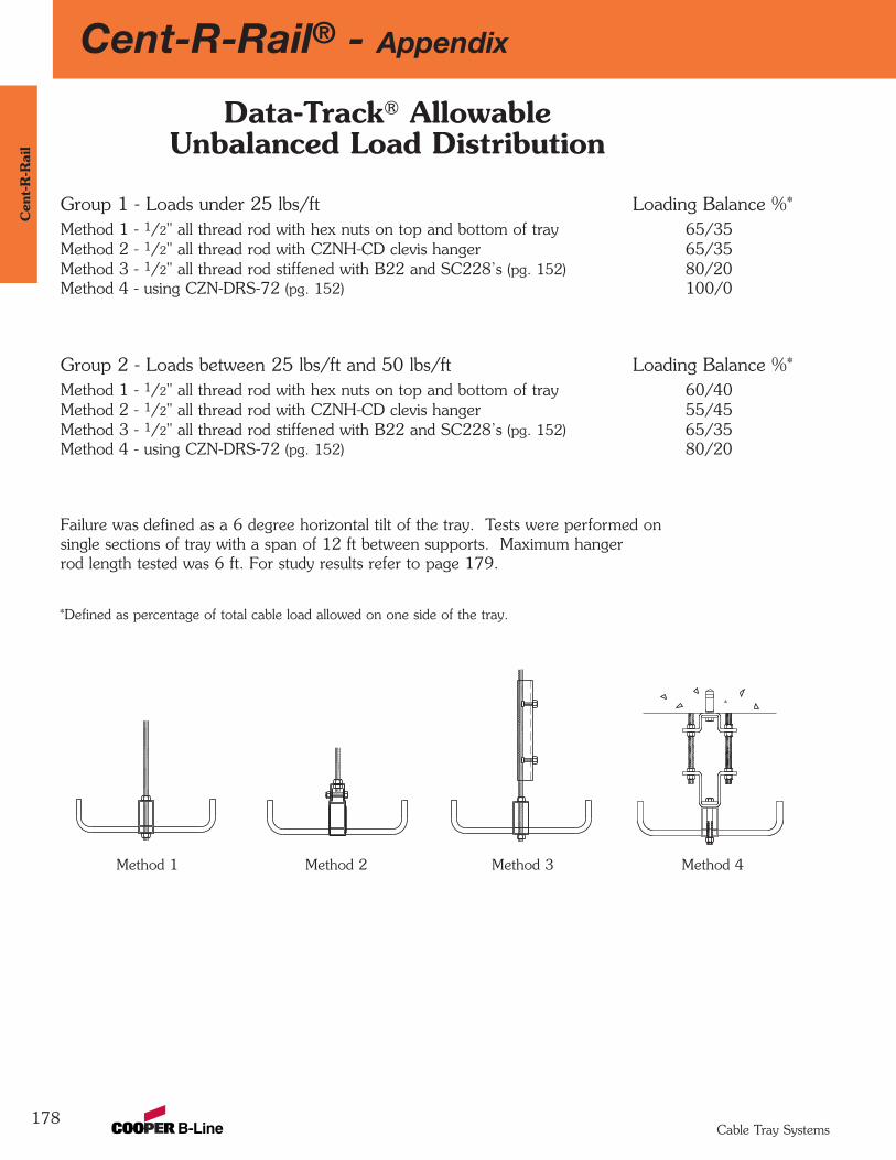
178
Cent-R-Rail® - AppendixC
ent-
R-R
ail
Cable Tray Systems
Group 1 - Loads under 25 lbs/ft Loading Balance %*Method 1 - 1/2" all thread rod with hex nuts on top and bottom of tray 65/35Method 2 - 1/2" all thread rod with CZNH-CD clevis hanger 65/35Method 3 - 1/2" all thread rod stiffened with B22 and SC228’s (pg. 152) 80/20Method 4 - using CZN-DRS-72 (pg. 152) 100/0
Group 2 - Loads between 25 lbs/ft and 50 lbs/ft Loading Balance %*Method 1 - 1/2" all thread rod with hex nuts on top and bottom of tray 60/40Method 2 - 1/2" all thread rod with CZNH-CD clevis hanger 55/45Method 3 - 1/2" all thread rod stiffened with B22 and SC228’s (pg. 152) 65/35Method 4 - using CZN-DRS-72 (pg. 152) 80/20
Failure was defined as a 6 degree horizontal tilt of the tray. Tests were performed on single sections of tray with a span of 12 ft between supports. Maximum hanger rod length tested was 6 ft. For study results refer to page 179.
Method 4Method 3Method 2Method 1
*Defined as percentage of total cable load allowed on one side of the tray.
Data-Track® Allowable Unbalanced Load Distribution
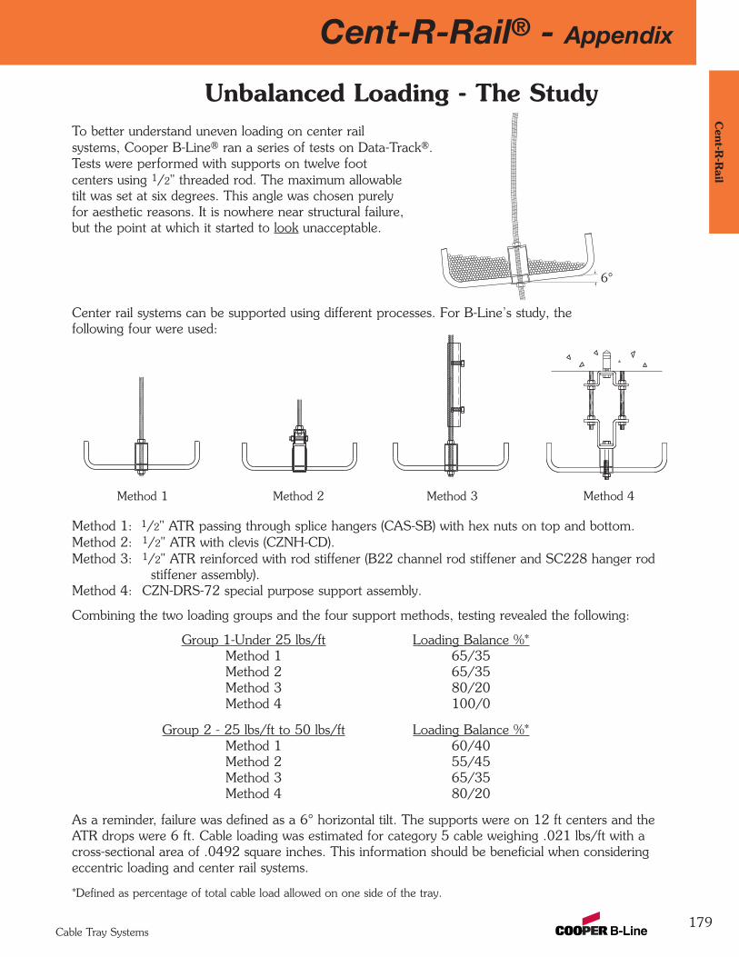
179
Cent-R-Rail® - AppendixC
ent-R-R
ail
Cable Tray Systems
Center rail systems can be supported using different processes. For B-Line’s study, the following four were used:
Method 1: 1/2" ATR passing through splice hangers (CAS-SB) with hex nuts on top and bottom.Method 2: 1/2" ATR with clevis (CZNH-CD).Method 3: 1/2" ATR reinforced with rod stiffener (B22 channel rod stiffener and SC228 hanger rod
stiffener assembly).Method 4: CZN-DRS-72 special purpose support assembly.
Combining the two loading groups and the four support methods, testing revealed the following:
Group 1-Under 25 lbs/ft Loading Balance %*Method 1 65/35Method 2 65/35Method 3 80/20Method 4 100/0
Group 2 - 25 lbs/ft to 50 lbs/ft Loading Balance %*Method 1 60/40Method 2 55/45Method 3 65/35Method 4 80/20
As a reminder, failure was defined as a 6° horizontal tilt. The supports were on 12 ft centers and theATR drops were 6 ft. Cable loading was estimated for category 5 cable weighing .021 lbs/ft with across-sectional area of .0492 square inches. This information should be beneficial when consideringeccentric loading and center rail systems.
*Defined as percentage of total cable load allowed on one side of the tray.
Unbalanced Loading - The StudyTo better understand uneven loading on center railsystems, Cooper B-Line® ran a series of tests on Data-Track®. Tests were performed with supports on twelve footcenters using 1/2" threaded rod. The maximum allowable tilt was set at six degrees. This angle was chosen purelyfor aesthetic reasons. It is nowhere near structural failure,but the point at which it started to look unacceptable.
6°
Method 4Method 3Method 2Method 1
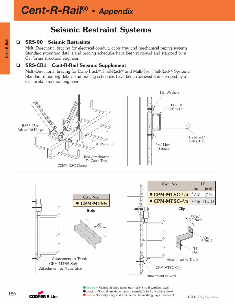
180
Cent-R-Rail® - AppendixC
ent-
R-R
ail
Cable Tray Systems
Seismic Restraint Systemsq SRS-00 Seismic Restraints
Multi-Directional bracing for electrical conduit, cable tray and mechanical piping systems. Standard mounting details and bracing schedules have been reviewed and stamped by a California structural engineer.
q SRS-CR1 Cent-R-Rail Seismic SupplementMulti-Directional bracing for Data-Track®, Half-Rack® and Multi-Tier Half-Rack® Systems. Standard mounting details and bracing schedules have been reviewed and stamped by a California structural engineer.
Strip
B335-21/2
Adjustable Hinge
CZNM-DSC Clamp
Rod AttachmentTo Cable Tray
4" Maximum
Half-Rack®
Cable Tray
CPB-U10U-Bracket
1/4" MetalScrews
Flat Washers
CPM-MTSC Clip
Attachment to Trunk
Attachment to Wall
13/16"(20.7mm)
5/16"(7.9mm)
‘H’Dia.
Attachment to TrunkCPM-MTSS Strip
Attachment to Metal Stud
50"(1270mm)
Clip
Cat. No.
CPM-MTSS
Cat. No. ‘H’in. (mm)
CPM-MTSC-1/4 5/16 (7.9)
CPM-MTSC-3/8 7/16 (11.1)
Green = Fastest shipped items (normally 3 to 5 working days)Black = Normal lead-time items (normally 5 to 10 working days)Red = Normally long lead-time items (15 working days minimum)
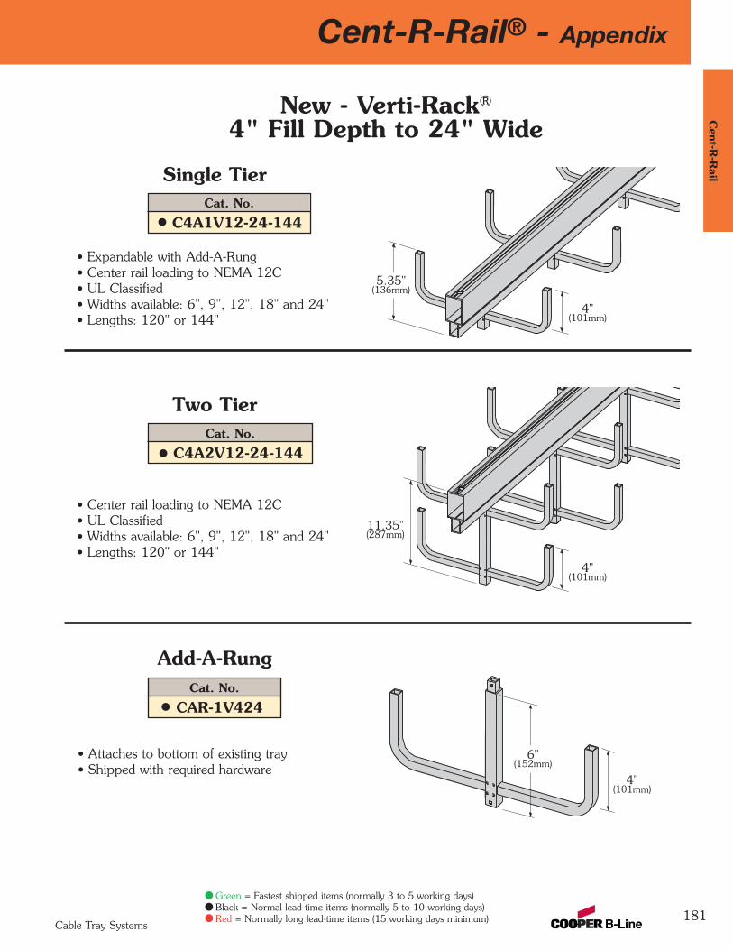
181
Cent-R-Rail® - AppendixC
ent-R-R
ail
Cable Tray Systems
Green = Fastest shipped items (normally 3 to 5 working days)Black = Normal lead-time items (normally 5 to 10 working days)Red = Normally long lead-time items (15 working days minimum)
New - Verti-Rack®
4" Fill Depth to 24" Wide
Single Tier
• Expandable with Add-A-Rung• Center rail loading to NEMA 12C• UL Classified• Widths available: 6", 9", 12", 18" and 24"• Lengths: 120" or 144"
Add-A-Rung
Two Tier
• Center rail loading to NEMA 12C• UL Classified• Widths available: 6", 9", 12", 18" and 24"• Lengths: 120" or 144"
• Attaches to bottom of existing tray• Shipped with required hardware
6"(152mm)
11.35"(287mm)
5.35"(136mm)
4"(101mm)
4"(101mm)
4"(101mm)
Cat. No.
C4A1V12-24-144
Cat. No.
C4A2V12-24-144
Cat. No.
CAR-1V424
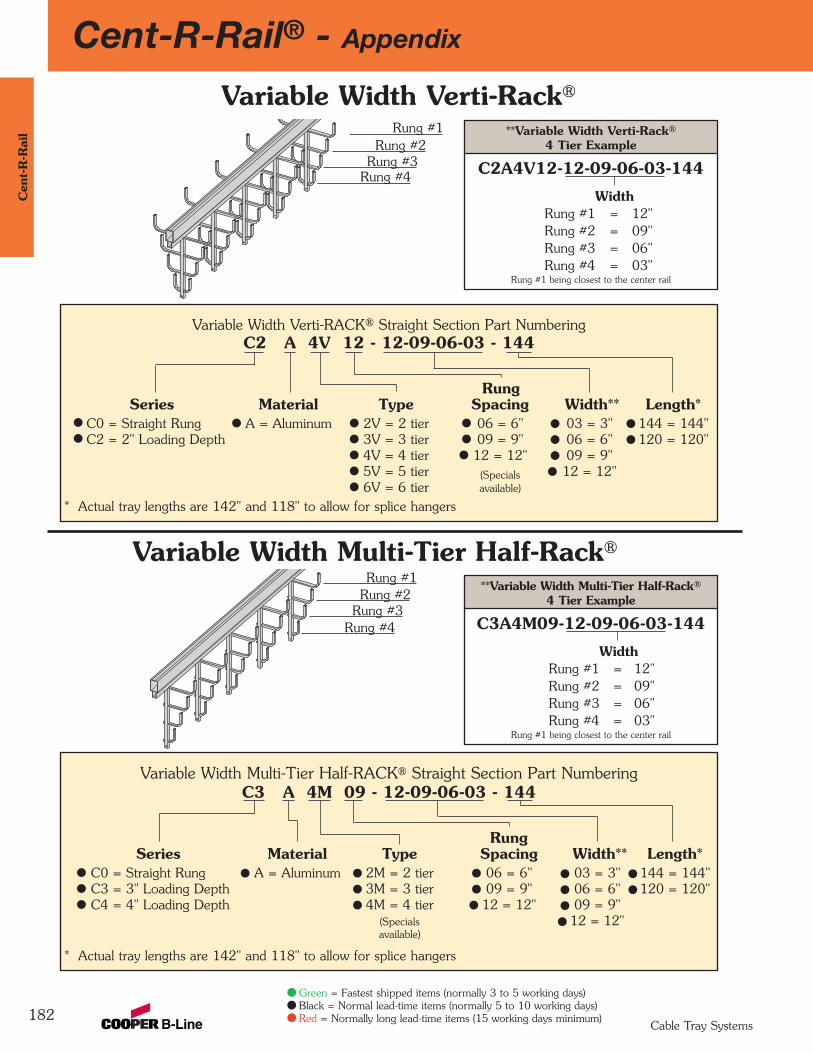
182
Cent-R-Rail® - AppendixC
ent-
R-R
ail
Cable Tray Systems
Green = Fastest shipped items (normally 3 to 5 working days)Black = Normal lead-time items (normally 5 to 10 working days)Red = Normally long lead-time items (15 working days minimum)
Variable Width Verti-RACK® Straight Section Part NumberingC2 A 4V 12 - 12-09-06-03 - 144
Rung Series Material Type Spacing Width** Length*
C0 = Straight Rung A = Aluminum 2V = 2 tier 06 = 6" 03 = 3" 144 = 144"C2 = 2" Loading Depth 3V = 3 tier 09 = 9" 06 = 6" 120 = 120"
4V = 4 tier 12 = 12" 09 = 9"5V = 5 tier (Specials 12 = 12"6V = 6 tier available)
* Actual tray lengths are 142" and 118" to allow for splice hangers
Variable Width Verti-Rack®
Rung #1Rung #2
Rung #3Rung #4
**Variable Width Verti-Rack®
4 Tier Example
C2A4V12-12-09-06-03-144
WidthRung #1 = 12"Rung #2 = 09"Rung #3 = 06"Rung #4 = 03"
Rung #1 being closest to the center rail
Variable Width Multi-Tier Half-Rack®
Variable Width Multi-Tier Half-RACK® Straight Section Part NumberingC3 A 4M 09 - 12-09-06-03 - 144
Rung Series Material Type Spacing Width** Length*
C0 = Straight Rung A = Aluminum 2M = 2 tier 06 = 6" 03 = 3" 144 = 144"C3 = 3" Loading Depth 3M = 3 tier 09 = 9" 06 = 6" 120 = 120"C4 = 4" Loading Depth 4M = 4 tier 12 = 12" 09 = 9"
(Specials 12 = 12"available)
* Actual tray lengths are 142" and 118" to allow for splice hangers
Rung #1Rung #2
Rung #3Rung #4
**Variable Width Multi-Tier Half-Rack®
4 Tier Example
C3A4M09-12-09-06-03-144
WidthRung #1 = 12"Rung #2 = 09"Rung #3 = 06"Rung #4 = 03"
Rung #1 being closest to the center rail

183
Cent-R-Rail® - AppendixC
ent-R-R
ail
Cable Tray Systems
Green = Fastest shipped items (normally 3 to 5 working days)Black = Normal lead-time items (normally 5 to 10 working days)Red = Normally long lead-time items (15 working days minimum)
**Inverted Variable Width Verti-Rack®
3 Tier Example
C2A3VI12-12-09-09-144
WidthRung #1 = 12"Rung #2 = 09"Rung #3 = 09"
Rung #1 being closest to the center rail
Inverted Verti-Rack®
Inverted Verti-Rack® Straight Section Part NumberingC2 A 4VI 12 - 09 - 144
Rung Series Material Type Spacing Width** Length*
C0 = Straight Rung A = Aluminum 2VI = 2 tier 06 = 6" 03 = 3" 144 = 144"C2 = 2" Loading Depth 3VI = 3 tier 09 = 9" 06 = 6" 120 = 120"
4VI = 4 tier 12 = 12" 09 = 9"5VI = 5 tier (Specials 12 = 12"6VI = 6 tier available)
* Actual tray lengths are 142" and 118" to allow for splice hangers
Inverted Variable Width Verti-Rack®
Inverted Variable Width Verti-Rack® Straight Section Part NumberingC2 A 3VI 12 - 12-09-09 - 144
Rung Series Material Type Spacing Width** Length*
C0 = Straight Rung A = Aluminum 2VI = 2 tier 06= 6" 03 = 3" 144 = 144"C2 = 2" Loading Depth 3VI = 3 tier 09= 9" 06 = 6" 120 = 120"
4VI = 4 tier 12=12" 09 = 9"5VI = 5 tier (Specials 12 = 12"6VI = 6 tier available)
* Actual tray lengths are 142" and 118" to allow for splice hangers
Rung #3Rung #2
Rung #1
Used as a floormounted system
Used as a floormounted system
• Requires splice CAS-SBVI
• Requires splice CAS-SBVI

Act as holes for splice plate hardware: allowfor field cutting to any length, no field-drillingnecessary. Holes also allow rungs to berepositioned. Holes allow for easy attachmentof accessory items requiring 1/4" hardware (orsmaller).
Multi-Functional Pre-Punched HolesAn “I”-Beam shaped rung provides agreat strength-to-weight ratio. Patentedfastener hole is designed to providemaximum grip for the fastener threads.
Redi-Rail Rung
Specially designed and finishedrung fastener. Rung pullout tested to over 3000 lbs. Vibrationtested for your confidence.
Redi-Rail Rung Fastener
Patent InformationU.S. Patent D361982; 5,580,014Canada 2,137,879UK Patent 2,285,343Other United States and foreign
patents are pending.
Redi-Rail
184
Red
i-Rai
l
Cable Tray Systems
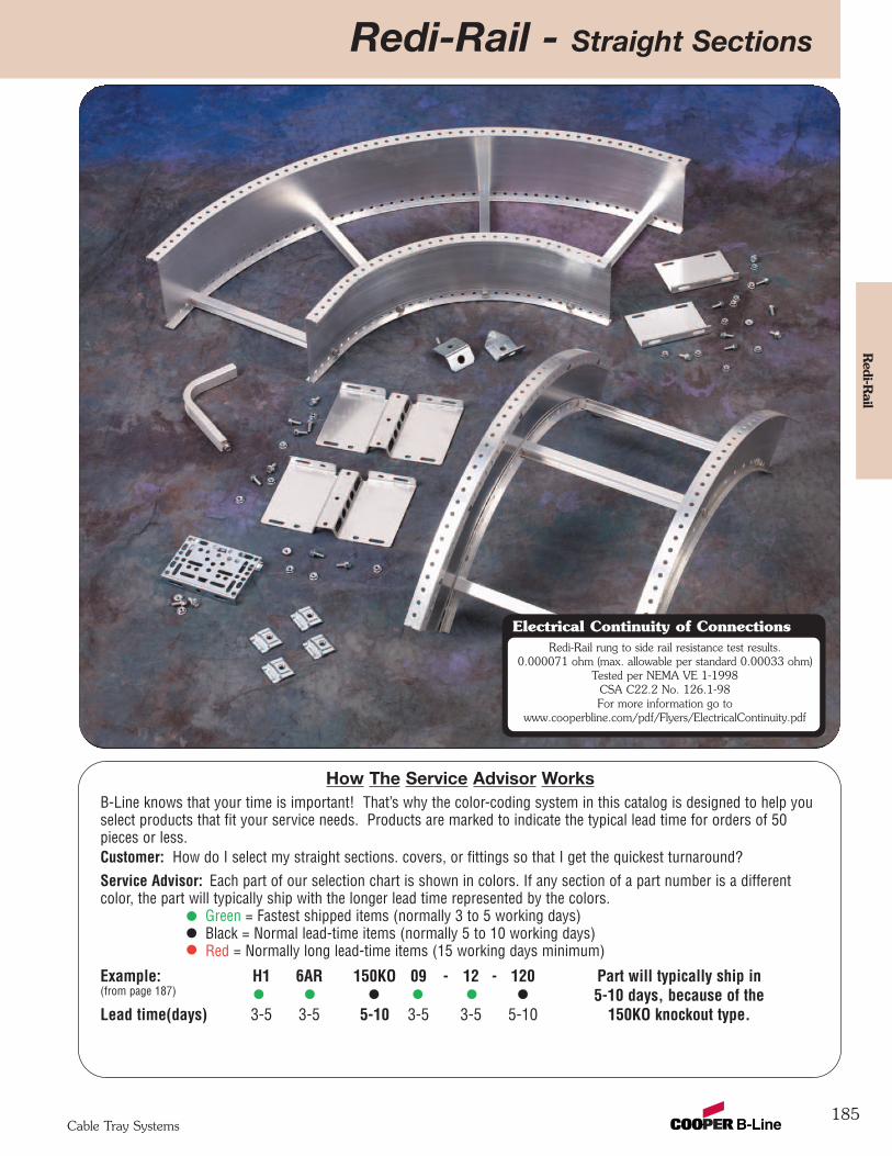
Redi-Rail rung to side rail resistance test results.0.000071 ohm (max. allowable per standard 0.00033 ohm)
Tested per NEMA VE 1-1998CSA C22.2 No. 126.1-98For more information go to
www.cooperbline.com/pdf/Flyers/ElectricalContinuity.pdf
Electrical Continuity of Connections
Redi-Rail - Straight Sections
185
Redi-R
ail
Cable Tray Systems
How The Service Advisor WorksB-Line knows that your time is important! That’s why the color-coding system in this catalog is designed to help youselect products that fit your service needs. Products are marked to indicate the typical lead time for orders of 50pieces or less.Customer: How do I select my straight sections. covers, or fittings so that I get the quickest turnaround?Service Advisor: Each part of our selection chart is shown in colors. If any section of a part number is a differentcolor, the part will typically ship with the longer lead time represented by the colors.
Green = Fastest shipped items (normally 3 to 5 working days)Black = Normal lead-time items (normally 5 to 10 working days)Red = Normally long lead-time items (15 working days minimum)
Example: H1 6AR 150KO 09 - 12 - 120 Part will typically ship in(from page 187) 5-10 days, because of the Lead time(days) 3-5 3-5 5-10 3-5 3-5 5-10 150KO knockout type.
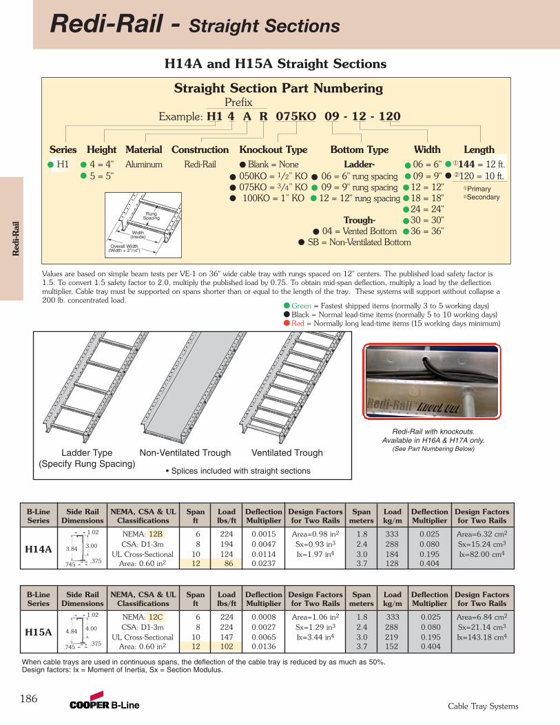
B-Line Side Rail NEMA, CSA & UL Span Load Deflection Design Factors Span Load Deflection Design FactorsSeries Dimensions Classifications ft lbs/ft Multiplier for Two Rails meters kg/m Multiplier for Two Rails
NEMA: 12C 6 224 0.0008 Area=1.06 in2 1.8 333 0.025 Area=6.84 cm2
H15A CSA: D1-3m 8 224 0.0027 Sx=1.29 in3 2.4 288 0.080 Sx=21.14 cm3
UL Cross-Sectional 10 147 0.0065 Ix=3.44 in4 3.0 219 0.195 Ix=143.18 cm4
Area: 0.60 in2 12 102 0.0136 3.7 152 0.404
B-Line Side Rail NEMA, CSA & UL Span Load Deflection Design Factors Span Load Deflection Design FactorsSeries Dimensions Classifications ft lbs/ft Multiplier for Two Rails meters kg/m Multiplier for Two Rails
NEMA: 12B 6 224 0.0015 Area=0.98 in2 1.8 333 0.025 Area=6.32 cm2
H14A CSA: D1-3m 8 194 0.0047 Sx=0.93 in3 2.4 288 0.080 Sx=15.24 cm3
UL Cross-Sectional 10 124 0.0114 Ix=1.97 in4 3.0 184 0.195 Ix=82.00 cm4
Area: 0.60 in2 12 86 0.0237 3.7 128 0.404
Redi-Rail - Straight Sections
186
1.02
.745.375
Red
i-Rai
l
Cable Tray Systems
¬PrimaryÁSecondary
Values are based on simple beam tests per VE-1 on 36" wide cable tray with rungs spaced on 12" centers. The published load safety factor is1.5. To convert 1.5 safety factor to 2.0, multiply the published load by 0.75. To obtain mid-span deflection, multiply a load by the deflectionmultiplier. Cable tray must be supported on spans shorter than or equal to the length of the tray. These systems will support without collapse a200 lb. concentrated load.
Width(Inside)
RungSpacing
Overall Width(Width + 21/16”)
Straight Section Part NumberingPrefix
Example: H1 4 A R 075KO 09 - 12 - 120
Series Height Material Construction Knockout Type Bottom Type Width LengthH1 4 = 4" Aluminum Redi-Rail Blank = None Ladder- 06 = 6" ¬144 = 12 ft.
5 = 5" 050KO = 1/2” KO 06 = 6" rung spacing 09 = 9" Á120 = 10 ft.075KO = 3/4” KO 09 = 9" rung spacing 12 = 12"100KO = 1” KO 12 = 12" rung spacing 18 = 18"
24 = 24"Trough- 30 = 30"
04 = Vented Bottom 36 = 36"SB = Non-Ventilated Bottom
• Splices included with straight sections
Ladder Type(Specify Rung Spacing)
Non-Ventilated Trough Ventilated Trough
When cable trays are used in continuous spans, the deflection of the cable tray is reduced by as much as 50%.Design factors: Ix = Moment of Inertia, Sx = Section Modulus.
3.84 3.00
1.02
.745.375
4.84 4.00
Redi-Rail with knockouts.Available in H16A & H17A only.
(See Part Numbering Below)
H14A and H15A Straight Sections
Green = Fastest shipped items (normally 3 to 5 working days)Black = Normal lead-time items (normally 5 to 10 working days)Red = Normally long lead-time items (15 working days minimum)

Redi-Rail - Straight Sections
187
Redi-R
ail
Cable Tray Systems
B-Line Side Rail NEMA, CSA & UL Span Load Deflection Design Factors Span Load Deflection Design FactorsSeries Dimensions Classifications ft lbs/ft Multiplier for Two Rails meters kg/m Multiplier for Two Rails
NEMA: 12C 6 224 0.0004 Area=1.41 in2 1.8 333 0.025 Area=9.10 cm2
H17A CSA: D1-3m 8 224 0.0011 Sx=2.24 in3 2.4 333 0.080 Sx=36.71 cm3
UL Cross-Sectional 10 144 0.0027 Ix=8.18 in4 3.0 214 0.195 Ix=340.89 cm4
Area: 1.00 in2 12 100 0.0057 3.7 149 0.404
B-Line Side Rail NEMA, CSA & UL Span Load Deflection Design Factors Span Load Deflection Design FactorsSeries Dimensions Classifications ft lbs/ft Multiplier for Two Rails meters kg/m Multiplier for Two Rails
NEMA: 12C 6 224 0.0005 Area=1.26 in2 1.8 333 0.025 Area=8.13 cm2
H16A CSA: D1-3m 8 224 0.0017 Sx=1.75 in3 2.4 333 0.080 Sx=28.68 cm3
UL Cross-Sectional 10 164 0.0041 Ix=5.51 in4 3.0 244 0.195 Ix=229.34 cm4
Area: 1.00 in2 12 114 0.0085 3.7 170 0.404
1.02
.745.375
¬PrimaryÁSecondary
Values are based on simple beam tests per VE-1 on 36" wide cable tray with rungs spaced on 12" centers. The published load safety factor is1.5. To convert 1.5 safety factor to 2.0, multiply the published load by 0.75. To obtain mid-span deflection, multiply a load by the deflectionmultiplier. Cable tray must be supported on spans shorter than or equal to the length of the tray. These systems will support without collapse a200 lb. concentrated load.
Width(Inside)
RungSpacing
Overall Width(Width + 21/16”)
Straight Section Part NumberingPrefix
Example: H1 6 A R 150KO 09 - 12 - 120
Series Height Material Construction Knockout Type Bottom Type Width LengthH1 6 = 6" Aluminum Redi-Rail Blank = None Ladder- 06 = 6" ¬144 = 12 ft.
7 = 7" 050KO = 1/2” KO 06 = 6" rung spacing 09 = 9" Á120 = 10 ft.075KO = 3/4” KO 09 = 9" rung spacing 12 = 12"100KO = 1” KO 12 = 12" rung spacing 18 = 18"
125KO = 11/4” KO 24 = 24"150KO = 11/2” KO Trough- 30 = 30"
04 = Vented Bottom 36 = 36"SB = Non-Ventilated Bottom
• Splices included with straight sections
Ladder Type(Specify Rung Spacing)
Non-Ventilated Trough Ventilated Trough
When cable trays are used in continuous spans, the deflection of the cable tray is reduced by as much as 50%.Design factors: Ix = Moment of Inertia, Sx = Section Modulus.
5.84 5.00
1.02
.745.375
6.84 6.00
Redi-Rail with knockouts.Available in H16A & H17A only.
(See Part Numbering Below)
H16A and H17A Straight Sections
Green = Fastest shipped items (normally 3 to 5 working days)Black = Normal lead-time items (normally 5 to 10 working days)Red = Normally long lead-time items (15 working days minimum)
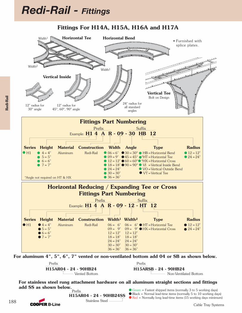
Redi-Rail - Fittings
188
Red
i-Rai
l
Cable Tray Systems
Fittings For H14A, H15A, H16A and H17A
Fittings Part NumberingPrefix Suffix
Example: H1 4 A R - 09 - 30 HB 12
Series Height Material Construction Width Angle Type RadiusH1 4 = 4" Aluminum Redi-Rail 06 = 6" 30 = 30° HB =Horizontal Bend 12 =12"
5 = 5" 09 = 9" 45 = 45° *HT =Horizontal Tee 24 =24"6 = 6" 12 = 12" 60 = 60° *HX =Horizontal Cross7 = 7" 18 = 18" 90 = 90° VI =Vertical Inside Bend
24 = 24" VO =Vertical Outside Bend30 = 30" VT =Vertical Tee36 = 36"
For aluminum 4", 5", 6", 7" vented or non-ventilated bottom add 04 or SB as shown below.Prefix Prefix
H15AR04 - 24 - 90HB24 H15ARSB - 24 - 90HB24Vented Bottom Non-Ventilated Bottom
12" radius for 30° angle
12" radius for 45°, 60°, 90° angle
24" radius for all standard
angles
Horizontal Tee
For stainless steel rung attachment hardware on all aluminum straight sections and fittingsadd SS as shown below.
Prefix H15AR04 - 24 - 90HB24SS
Stainless Steel
*Angle not required on HT & HX
Horizontal Reducing / Expanding Tee or Cross Fittings Part Numbering
Prefix SuffixExample: H1 4 A R - 09 - 12 - HT 12
Series Height Material Construction Width1 Width2 Type RadiusH1 4 = 4" Aluminum Redi-Rail 06 = 6" 06 = 6" HT =Horizontal Tee 12 =12"
5 = 5" 09 = 9" 09 = 9" HX =Horizontal Cross 24 =24"6 = 6" 12 = 12" 12 = 12"7 = 7" 18 = 18" 18 = 18"
24 = 24" 24 = 24"30 = 30" 30 = 30"36 = 36" 36 = 36"
Width2
Width1
Width1
Vertical Inside
Horizontal Bend
Vertical TeeBolt on Design
• Furnished withsplice plates.
Green = Fastest shipped items (normally 3 to 5 working days)Black = Normal lead-time items (normally 5 to 10 working days)Red = Normally long lead-time items (15 working days minimum)
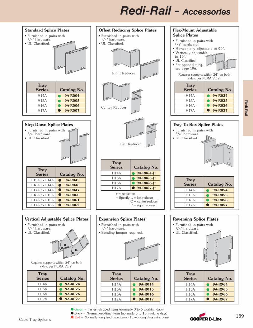
Redi-Rail - Accessories
189
Flex-Mount AdjustableSplice Plates• Furnished in pairs with
1/4" hardware.• Horizontally adjustable to 90°. • Vertically adjustable to 15°.
• UL Classified.• For optional rung,
see page 196.
Offset Reducing Splice Plates• Furnished in pairs with
1/4" hardware.• UL Classified.
Standard Splice Plates• Furnished in pairs with
1/4" hardware.• UL Classified.
Tray To Box Splice Plates• Furnished in pairs with
1/4" hardware.• UL Classified.
Step Down Splice Plates• Furnished in pairs with
1/4" hardware.• UL Classified.
Reversing Splice Plates• Furnished in pairs with
1/4" hardware.• UL Classified.
Expansion Splice Plates• Furnished in pairs with
1/4" hardware.• Bonding jumper required.
Vertical Adjustable Splice Plates• Furnished in pairs with
1/4" hardware.• UL Classified.
Redi-R
ail
Cable Tray Systems
Right Reducer
Left Reducer
Center Reducer
r = reduction† Specify L = left reducer
C = center reducerR = right reducer
TraySeries Catalog No.H14A 9A-R034H15A 9A-R035H16A 9A-R036H17A 9A-R037
TraySeries Catalog No.H14A 9A-R054H15A 9A-R055H16A 9A-R056H17A 9A-R057
TraySeries Catalog No.H14A 9A-R064-†rH15A 9A-R065-†rH16A 9A-R066-†rH17A 9A-R067-†r
TraySeries Catalog No.H14A 9A-R014H15A 9A-R015H16A 9A-R016H17A 9A-R017
TraySeries Catalog No.H14A 9A-R964H15A 9A-R965H16A 9A-R966H17A 9A-R967
TraySeries Catalog No.H14A 9A-R024H15A 9A-R025H16A 9A-R026H17A 9A-R027
TraySeries Catalog No.H14A 9A-R004H15A 9A-R005H16A 9A-R006H17A 9A-R007
TraySeries Catalog No.
H15A to H14A 9A-R045H16A to H14A 9A-R046H17A to H14A 9A-R047H16A to H15A 9A-R060H17A to H15A 9A-R061H17A to H16A 9A-R062
Green = Fastest shipped items (normally 3 to 5 working days)Black = Normal lead-time items (normally 5 to 10 working days)Red = Normally long lead-time items (15 working days minimum)
Requires supports within 24” on bothsides, per NEMA VE 2.
Requires supports within 24” on bothsides, per NEMA VE 2.
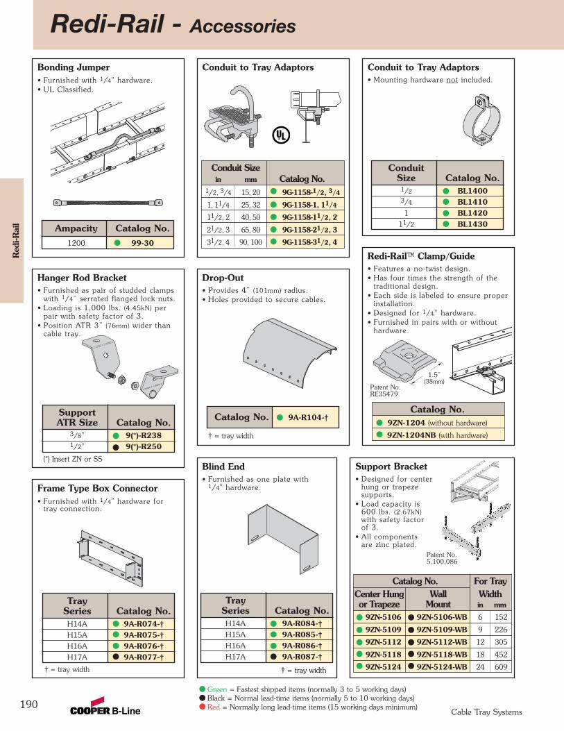
Redi-Rail - Accessories
190
Red
i-Rai
l
Cable Tray Systems
Conduit to Tray Adaptors• Mounting hardware not included.
Conduit to Tray Adaptors
Redi-Rail™ Clamp/Guide• Features a no-twist design.• Has four times the strength of the
traditional design.• Each side is labeled to ensure proper
installation.• Designed for 1/4” hardware. • Furnished in pairs with or without
hardware.
Bonding Jumper• Furnished with 1/4" hardware.• UL Classified.
Hanger Rod Bracket• Furnished as pair of studded clamps
with 1/4” serrated flanged lock nuts.• Loading is 1,000 lbs. (4.45kN) per
pair with safety factor of 3.• Position ATR 3” (76mm) wider than
cable tray.
Blind End• Furnished as one plate with
1/4" hardware.
Drop-Out• Provides 4” (101mm) radius.• Holes provided to secure cables.
Frame Type Box Connector• Furnished with 1/4" hardware for
tray connection.
ConduitSize Catalog No.
1/2 BL14003/4 BL14101 BL1420
11/2 BL1430
Catalog No. 9A-R104-†
TraySeries Catalog No.H14A 9A-R084-†H15A 9A-R085-†H16A 9A-R086-†H17A 9A-R087-†
TraySeries Catalog No.H14A 9A-R074-†H15A 9A-R075-†H16A 9A-R076-†H17A 9A-R077-†
SupportATR Size Catalog No.
3/8” 9(*)-R2381/2” 9(*)-R250
Ampacity Catalog No.1200 99-30
Conduit Sizein mm Catalog No.
1/2, 3/4 15, 20 9G-1158-1/2, 3/4
1, 11/4 25, 32 9G-1158-1, 11/4
11/2, 2 40, 50 9G-1158-11/2, 2
21/2, 3 65, 80 9G-1158-21/2, 3
31/2, 4 90, 100 9G-1158-31/2, 4
Catalog No.9ZN-1204 (without hardware)
9ZN-1204NB (with hardware)† = tray width
† = tray width
(*) Insert ZN or SS
Patent No.RE35479
1.5”(38mm)
† = tray width
Support Bracket• Designed for center
hung or trapezesupports.
• Load capacity is600 lbs. (2.67kN)with safety factorof 3.
• All componentsare zinc plated.
Catalog No. For TrayCenter Hung Wall Widthor Trapeze Mount in mm
9ZN-5106 9ZN-5106-WB 6 152
9ZN-5109 9ZN-5109-WB 9 226
9ZN-5112 9ZN-5112-WB 12 305
9ZN-5118 9ZN-5118-WB 18 452
9ZN-5124 9ZN-5124-WB 24 609
Patent No.5,100,086
Green = Fastest shipped items (normally 3 to 5 working days)Black = Normal lead-time items (normally 5 to 10 working days)Red = Normally long lead-time items (15 working days minimum)
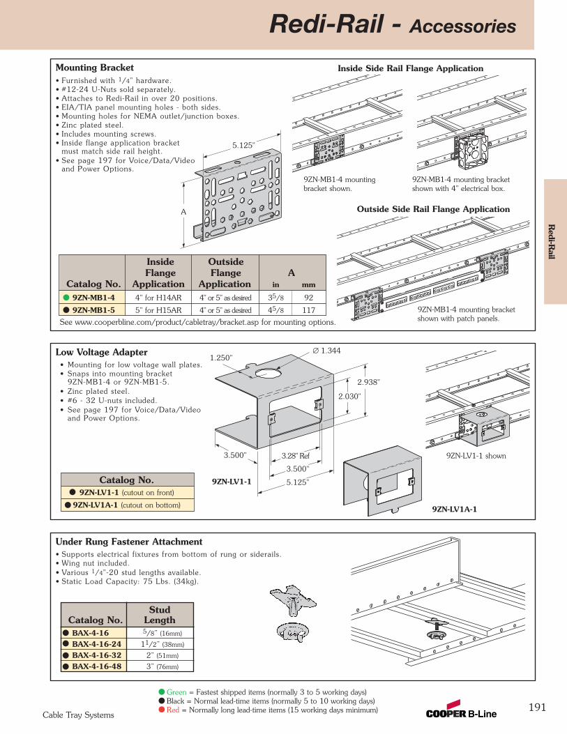
Redi-Rail - Accessories
191
Redi-R
ail
Cable Tray Systems
Inside Side Rail Flange ApplicationMounting Bracket• Furnished with 1/4" hardware.• #12-24 U-Nuts sold separately.• Attaches to Redi-Rail in over 20 positions.• EIA/TIA panel mounting holes - both sides.• Mounting holes for NEMA outlet/junction boxes.• Zinc plated steel.• Includes mounting screws.• Inside flange application bracket
must match side rail height.• See page 197 for Voice/Data/Video
and Power Options.
Low Voltage Adapter• Mounting for low voltage wall plates.• Snaps into mounting bracket
9ZN-MB1-4 or 9ZN-MB1-5.• Zinc plated steel.• #6 - 32 U-nuts included.• See page 197 for Voice/Data/Video
and Power Options.
Under Rung Fastener Attachment• Supports electrical fixtures from bottom of rung or siderails.• Wing nut included.• Various 1/4"-20 stud lengths available.• Static Load Capacity: 75 Lbs. (34kg).
StudCatalog No. LengthBAX-4-16 5/8” (16mm)
BAX-4-16-24 11/2” (38mm)
BAX-4-16-32 2” (51mm)
BAX-4-16-48 3” (76mm)
∅ 1.3441.250"
2.938"
2.030"
3.500" 3.28" Ref
3.500"
5.125"9ZN-LV1-1
9ZN-LV1A-1
9ZN-LV1-1 shown
5.125"
A
9ZN-MB1-4 mounting bracketshown with 4" electrical box.
9ZN-MB1-4 mountingbracket shown.
9ZN-MB1-4 mounting bracketshown with patch panels.
Outside Side Rail Flange Application
Inside OutsideFlange Flange A
Catalog No. Application Application in mm
9ZN-MB1-4 4" for H14AR 4" or 5" as desired 35/8 92
9ZN-MB1-5 5" for H15AR 4" or 5" as desired 45/8 117
See www.cooperbline.com/product/cabletray/bracket.asp for mounting options.
Catalog No.9ZN-LV1-1 (cutout on front)
9ZN-LV1A-1 (cutout on bottom)
Green = Fastest shipped items (normally 3 to 5 working days)Black = Normal lead-time items (normally 5 to 10 working days)Red = Normally long lead-time items (15 working days minimum)
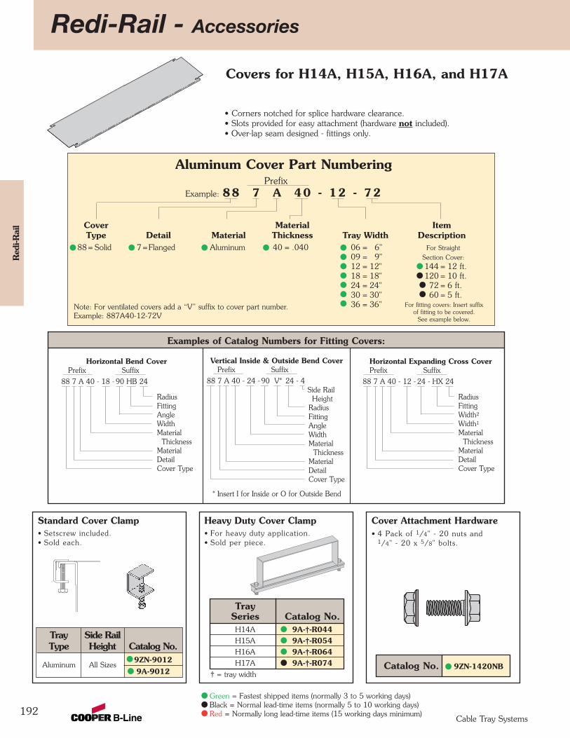
Redi-Rail - Accessories
192
Red
i-Rai
l
Cable Tray Systems
Aluminum Cover Part NumberingPrefix
Example: 88 7 A 40 - 12 - 72
Cover Material ItemType Detail Material Thickness Tray Width Description
88= Solid 7=Flanged Aluminum 40 = .040 06 = 6" For Straight09 = 9" Section Cover:12 = 12" 144 = 12 ft.18 = 18" 120 = 10 ft.24 = 24" 72 = 6 ft.30 = 30" 60 = 5 ft.36 = 36"
• Corners notched for splice hardware clearance.• Slots provided for easy attachment (hardware not included).• Over-lap seam designed - fittings only.
For fitting covers: Insert suffixof fitting to be covered.
See example below.
Note: For ventilated covers add a “V” suffix to cover part number. Example: 887A40-12-72V
Examples of Catalog Numbers for Fitting Covers:
Vertical Inside & Outside Bend CoverPrefix Suffix
88 7 A 40 - 24 - 90 V* 24 - 4Side Rail
Height RadiusFittingAngleWidthMaterial
ThicknessMaterialDetailCover Type
* Insert I for Inside or O for Outside Bend
Horizontal Bend CoverPrefix Suffix
88 7 A 40 - 18 - 90 HB 24
RadiusFittingAngleWidthMaterial
ThicknessMaterialDetailCover Type
Horizontal Expanding Cross CoverPrefix Suffix
88 7 A 40 - 12 - 24 - HX 24
RadiusFittingWidth2
Width1
MaterialThickness
MaterialDetailCover Type
Covers for H14A, H15A, H16A, and H17A
Cover Attachment Hardware• 4 Pack of 1/4" - 20 nuts and
1/4" - 20 x 5/8" bolts.
Heavy Duty Cover Clamp• For heavy duty application.• Sold per piece.
Standard Cover Clamp• Setscrew included.• Sold each.
Catalog No. 9ZN-1420NB
TraySeries Catalog No.H14A 9A-†-R044H15A 9A-†-R054H16A 9A-†-R064H17A 9A-†-R074
† = tray width
Tray Side RailType Height Catalog No.
Aluminum All Sizes9ZN-90129A-9012
Green = Fastest shipped items (normally 3 to 5 working days)Black = Normal lead-time items (normally 5 to 10 working days)Red = Normally long lead-time items (15 working days minimum)
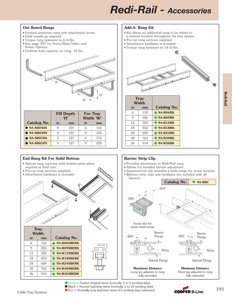
Redi-Rail - Accessories
193
Redi-R
ail
Cable Tray Systems
Fill Depth For Tray'H' Width 'W'
Catalog No. in mm in mm9A-SR0406 4 101 6 152
9A-SR0409 4 101 9 226
9A-SR0506 5 127 6 152
9A-SR0509 5 127 9 226
Out Board Rungs• Formed aluminum rung with attachment screw.• Field installs as required.• Torque rung fasteners to 6 ft/lbs.• See page 197 for Voice/Data/Video and
Power Options.• Uniform load capacity on rung: 10 lbs.
Add-A- Rung Kit• Kit allows an additional rung to be added to
a desired location throughout the tray system.• Pre-cut rung sections supplied. • Attachment hardware is included.• Torque rung fasteners to 18 ft/lbs.
Barrier Strip Clip• Provides attachment to Redi-Rail rung.• Allows for installed barrier adjustment.• Asymmetrical clip provides a wide range for screw location.• Barriers strip clips and hardware are included with all
barriers.
End Rung Kit For Solid Bottom• Special rung captures solid bottom plate when
required at field cuts.• Pre-cut rung sections supplied. • Attachment hardware is included.
TrayWidth
in mm Catalog No.6 152 9A-R06SBERK
9 226 9A-R09SBERK
12 305 9A-R12SBERK
18 452 9A-R18SBERK
24 609 9A-R24SBERK
30 762 9A-R30SBERK
36 914 9A-R36SBERK
TrayWidth
in mm Catalog No.6 152 9A-R06RK
9 226 9A-R09RK
12 305 9A-R12RK
18 452 9A-R18RK
24 609 9A-R24RK
30 762 9A-R30RK
36 914 9A-R36RK
W
H
Green = Fastest shipped items (normally 3 to 5 working days)Black = Normal lead-time items (normally 5 to 10 working days)Red = Normally long lead-time items (15 working days minimum)
Catalog No. 9A-RBC
.390"
.563"
Screw slot forsheet metal screw
RungRung
BarrierFlange.484" .081"
Siderail Flange
Maximum DistanceLong leg adjacent to rung
fully extended
Minimum DistanceShort leg adjacent to rung
fully extended
Siderail Flange
BarrierFlange
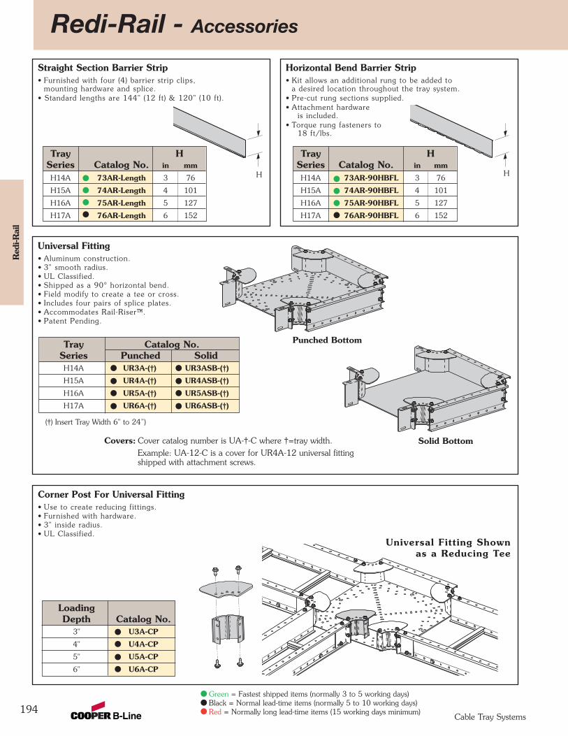
Redi-Rail - Accessories
194
Red
i-Rai
l
Cable Tray Systems
Horizontal Bend Barrier Strip• Kit allows an additional rung to be added to
a desired location throughout the tray system.• Pre-cut rung sections supplied. • Attachment hardware
is included.• Torque rung fasteners to
18 ft/lbs.
Straight Section Barrier Strip• Furnished with four (4) barrier strip clips,
mounting hardware and splice.• Standard lengths are 144" (12 ft) & 120" (10 ft).
Green = Fastest shipped items (normally 3 to 5 working days)Black = Normal lead-time items (normally 5 to 10 working days)Red = Normally long lead-time items (15 working days minimum)
Covers: Cover catalog number is UA-†-C where †=tray width.Example: UA-12-C is a cover for UR4A-12 universal fitting shipped with attachment screws.
Tray Catalog No.Series Punched SolidH14A UR3A-(†) UR3ASB-(†)
H15A UR4A-(†) UR4ASB-(†)
H16A UR5A-(†) UR5ASB-(†)
H17A UR6A-(†) UR6ASB-(†)
Universal Fitting Shownas a Reducing Tee
LoadingDepth Catalog No.
3" U3A-CP
4" U4A-CP
5" U5A-CP
6" U6A-CP
Corner Post For Universal Fitting• Use to create reducing fittings.• Furnished with hardware. • 3" inside radius.• UL Classified.
Universal Fitting• Aluminum construction.• 3" smooth radius.• UL Classified.• Shipped as a 90° horizontal bend.• Field modify to create a tee or cross.• Includes four pairs of splice plates.• Accommodates Rail-Riser™.• Patent Pending.
Punched Bottom
Solid Bottom
H H
Tray HSeries Catalog No. in mm
H14A 73AR-Length 3 76
H15A 74AR-Length 4 101
H16A 75AR-Length 5 127
H17A 76AR-Length 6 152
Tray HSeries Catalog No. in mm
H14A 73AR-90HBFL 3 76
H15A 74AR-90HBFL 4 101
H16A 75AR-90HBFL 5 127
H17A 76AR-90HBFL 6 152
(†) Insert Tray Width 6" to 24”)
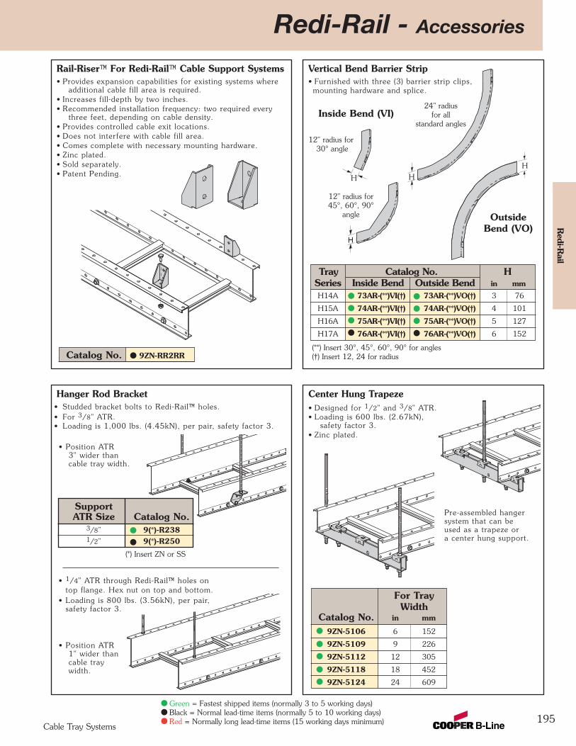
195
Redi-Rail - AccessoriesR
edi-Rail
Cable Tray Systems
Rail-Riser™ For Redi-Rail™ Cable Support Systems• Provides expansion capabilities for existing systems where
additional cable fill area is required.• Increases fill-depth by two inches.• Recommended installation frequency: two required every
three feet, depending on cable density.• Provides controlled cable exit locations.• Does not interfere with cable fill area.• Comes complete with necessary mounting hardware.• Zinc plated.• Sold separately.• Patent Pending.
Vertical Bend Barrier Strip• Furnished with three (3) barrier strip clips, mounting hardware and splice.
Hanger Rod Bracket• Studded bracket bolts to Redi-Rail™ holes.• For 3/8" ATR.• Loading is 1,000 lbs. (4.45kN), per pair, safety factor 3.
Center Hung Trapeze• Designed for 1/2" and 3/8" ATR.• Loading is 600 lbs. (2.67kN),
safety factor 3.• Zinc plated.
Catalog No. 9ZN-RR2RR
Green = Fastest shipped items (normally 3 to 5 working days)Black = Normal lead-time items (normally 5 to 10 working days)Red = Normally long lead-time items (15 working days minimum)
OutsideBend (VO)
H
Inside Bend (VI)
12" radius for30° angle
12" radius for45°, 60°, 90°
angle
24" radiusfor all
standard angles
H
H
H
For TrayWidth
Catalog No. in mm
9ZN-5106 6 152
9ZN-5109 9 226
9ZN-5112 12 305
9ZN-5118 18 452
9ZN-5124 24 609
• Position ATR3" wider thancable tray width.
• Position ATR1" wider thancable traywidth.
Pre-assembled hangersystem that can beused as a trapeze ora center hung support.
• 1/4" ATR through Redi-Rail™ holes on top flange. Hex nut on top and bottom.
• Loading is 800 lbs. (3.56kN), per pair,safety factor 3.
Tray Catalog No. HSeries Inside Bend Outside Bend in mmH14A 73AR-(**)VI(†) 73AR-(**)VO(†) 3 76
H15A 74AR-(**)VI(†) 74AR-(**)VO(†) 4 101
H16A 75AR-(**)VI(†) 75AR-(**)VO(†) 5 127
H17A 76AR-(**)VI(†) 76AR-(**)VO(†) 6 152
(**) Insert 30°, 45°, 60°, 90° for angles(†) Insert 12, 24 for radius
SupportATR Size Catalog No.
3/8” 9(*)-R2381/2” 9(*)-R250
(*) Insert ZN or SS
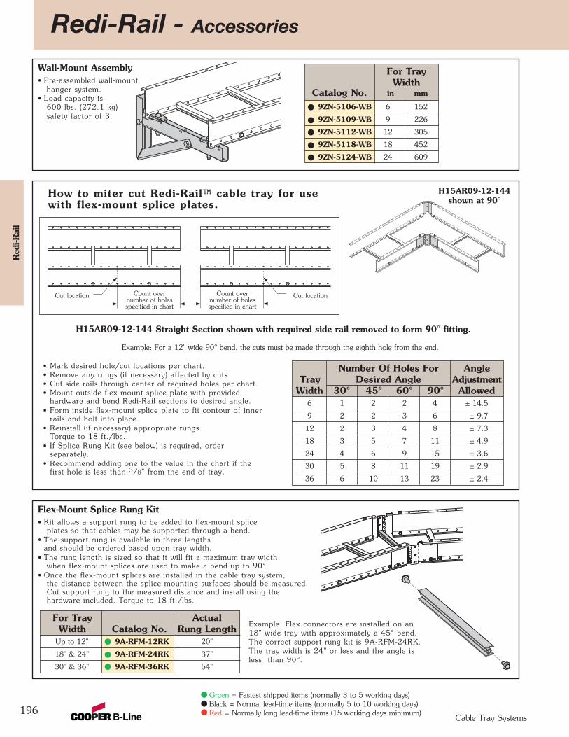
Redi-Rail - Accessories
196
Red
i-Rai
l
Cable Tray Systems
Wall-Mount Assembly• Pre-assembled wall-mount
hanger system.• Load capacity is
600 lbs. (272.1 kg)safety factor of 3.
For TrayWidth
Catalog No. in mm
9ZN-5106-WB 6 152
9ZN-5109-WB 9 226
9ZN-5112-WB 12 305
9ZN-5118-WB 18 452
9ZN-5124-WB 24 609
Green = Fastest shipped items (normally 3 to 5 working days)Black = Normal lead-time items (normally 5 to 10 working days)Red = Normally long lead-time items (15 working days minimum)
How to miter cut Redi-Rail™ cable tray for usewith flex-mount splice plates.
Example: For a 12" wide 90° bend, the cuts must be made through the eighth hole from the end.
Number Of Holes For AngleTray Desired Angle Adjustment
Width 30° 45° 60° 90° Allowed6 1 2 2 4 ± 14.5
9 2 2 3 6 ± 9.7
12 2 3 4 8 ± 7.3
18 3 5 7 11 ± 4.9
24 4 6 9 15 ± 3.6
30 5 8 11 19 ± 2.9
36 6 10 13 23 ± 2.4
• Mark desired hole/cut locations per chart.• Remove any rungs (if necessary) affected by cuts.• Cut side rails through center of required holes per chart.• Mount outside flex-mount splice plate with provided
hardware and bend Redi-Rail sections to desired angle.• Form inside flex-mount splice plate to fit contour of inner
rails and bolt into place.• Reinstall (if necessary) appropriate rungs.
Torque to 18 ft./lbs.• If Splice Rung Kit (see below) is required, order
separately.• Recommend adding one to the value in the chart if the
first hole is less than 3/8" from the end of tray.
H15AR09-12-144 Straight Section shown with required side rail removed to form 90° fitting.
Cut locationCut location Count over number of holesspecified in chart
Count over number of holesspecified in chart
H15AR09-12-144 shown at 90°
Flex-Mount Splice Rung Kit• Kit allows a support rung to be added to flex-mount splice
plates so that cables may be supported through a bend.• The support rung is available in three lengths
and should be ordered based upon tray width.• The rung length is sized so that it will fit a maximum tray width
when flex-mount splices are used to make a bend up to 90°.• Once the flex-mount splices are installed in the cable tray system,
the distance between the splice mounting surfaces should be measured.Cut support rung to the measured distance and install using thehardware included. Torque to 18 ft./lbs.
Example: Flex connectors are installed on an18" wide tray with approximately a 45° bend.The correct support rung kit is 9A-RFM-24RK.The tray width is 24" or less and the angle isless than 90°.
For Tray ActualWidth Catalog No. Rung Length
Up to 12" 9A-RFM-12RK 20"
18" & 24" 9A-RFM-24RK 37"
30" & 36" 9A-RFM-36RK 54"
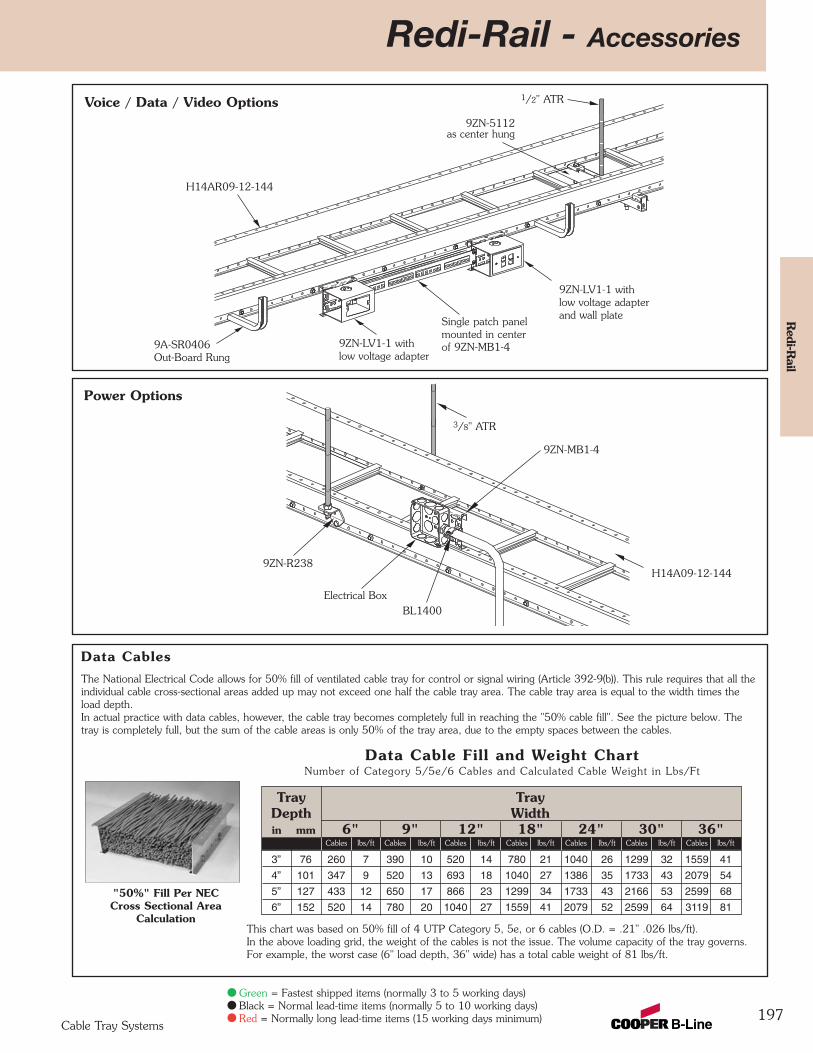
Redi-Rail - Accessories
197
Redi-R
ail
Cable Tray Systems
Green = Fastest shipped items (normally 3 to 5 working days)Black = Normal lead-time items (normally 5 to 10 working days)Red = Normally long lead-time items (15 working days minimum)
H14AR09-12-144
9A-SR0406Out-Board Rung
9ZN-LV1-1 withlow voltage adapter
1/2" ATR
9ZN-5112as center hung
Single patch panelmounted in centerof 9ZN-MB1-4
9ZN-LV1-1 withlow voltage adapterand wall plate
Voice / Data / Video Options
Power Options
3/8" ATR
H14A09-12-144
9ZN-MB1-4
BL1400Electrical Box
9ZN-R238
The National Electrical Code allows for 50% fill of ventilated cable tray for control or signal wiring (Article 392-9(b)). This rule requires that all theindividual cable cross-sectional areas added up may not exceed one half the cable tray area. The cable tray area is equal to the width times theload depth.In actual practice with data cables, however, the cable tray becomes completely full in reaching the "50% cable fill". See the picture below. Thetray is completely full, but the sum of the cable areas is only 50% of the tray area, due to the empty spaces between the cables.
"50%" Fill Per NECCross Sectional Area
CalculationThis chart was based on 50% fill of 4 UTP Category 5, 5e, or 6 cables (O.D. = .21" .026 lbs/ft).In the above loading grid, the weight of the cables is not the issue. The volume capacity of the tray governs.For example, the worst case (6" load depth, 36" wide) has a total cable weight of 81 lbs/ft.
Data Cables
Tray Tray Depth Widthin mm 6" 9" 12" 18" 24" 30" 36"
Cables lbs/ft Cables lbs/ft Cables lbs/ft Cables lbs/ft Cables lbs/ft Cables lbs/ft Cables lbs/ft
3” 76 260 7 390 10 520 14 780 21 1040 26 1299 32 1559 41
4” 101 347 9 520 13 693 18 1040 27 1386 35 1733 43 2079 54
5” 127 433 12 650 17 866 23 1299 34 1733 43 2166 53 2599 68
6” 152 520 14 780 20 1040 27 1559 41 2079 52 2599 64 3119 81
Data Cable Fill and Weight ChartNumber of Category 5/5e/6 Cables and Calculated Cable Weight in Lbs/Ft
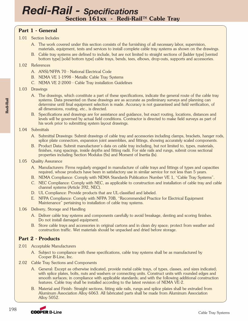
Redi-Rail - Specifications
198
Red
i-Rai
l
Cable Tray Systems
Section 161xx - Redi-Rail™ Cable Tray
Part 1 - General1.01 Section Includes
A. The work covered under this section consists of the furnishing of all necessary labor, supervision,materials, equipment, tests and services to install complete cable tray systems as shown on the drawings.
B. Cable tray systems are defined to include, but are not limited to straight sections of [ladder type] [ventedbottom type] [solid bottom type] cable trays, bends, tees, elbows, drop-outs, supports and accessories.
1.02 References
A. ANSI/NFPA 70 - National Electrical CodeB. NEMA VE 1-1998 - Metallic Cable Tray SystemsC. NEMA VE 2-2000 - Cable Tray installation Guidelines
1.03 Drawings
A. The drawings, which constitute a part of these specifications, indicate the general route of the cable traysystems. Data presented on these drawings are as accurate as preliminary surveys and planning candetermine until final equipment selection is made. Accuracy is not guaranteed and field verification, ofall dimensions, routing, etc., is directed.
B. Specifications and drawings are for assistance and guidance, but exact routing, locations, distances and levels will be governed by actual field conditions. Contractor is directed to make field surveys as part ofhis work prior to submitting system layout drawings.
1.04 Submittals
A. Submittal Drawings: Submit drawings of cable tray and accessories including clamps, brackets, hanger rods,splice plate connectors, expansion joint assemblies, and fittings, showing accurately scaled components.
B. Product Data: Submit manufacturer’s data on cable tray including, but not limited to, types, materials,finishes, rung spacings, inside depths and fitting radii. For side rails and rungs, submit cross sectionalproperties including Section Modulus (Sx) and Moment of Inertia (Ix).
1.05 Quality Assurance
A. Manufacturers: Firms regularly engaged in manufacture of cable trays and fittings of types and capacitiesrequired, whose products have been in satisfactory use in similar service for not less than 5 years.
B. NEMA Compliance: Comply with NEMA Standards Publication Number VE 1, “Cable Tray Systems”.C. NEC Compliance: Comply with NEC, as applicable to construction and installation of cable tray and cable
channel systems (Article 392, NEC). D. UL Compliance: Provide products that are UL-classified and labeled.E. NFPA Compliance: Comply with NFPA 70B, “Recommended Practice for Electrical Equipment
Maintenance” pertaining to installation of cable tray systems.
1.06 Delivery, Storage and Handling
A. Deliver cable tray systems and components carefully to avoid breakage, denting and scoring finishes.Do not install damaged equipment.
B. Store cable trays and accessories in original cartons and in clean dry space; protect from weather andconstruction traffic. Wet materials should be unpacked and dried before storage.
Part 2 - Products2.01 Acceptable Manufacturers
A. Subject to compliance with these specifications, cable tray systems shall be as manufactured byCooper B-Line, Inc.
2.02 Cable Tray Sections and Components
A. General: Except as otherwise indicated, provide metal cable trays, of types, classes, and sizes indicated;with splice plates, bolts, nuts and washers or connecting units. Construct units with rounded edges andsmooth surfaces; in compliance with applicable standards; and with the following additional constructionfeatures. Cable tray shall be installed according to the latest revision of NEMA VE-2.
B. Material and Finish: Straight sections, fitting side rails, rungs and splice plates shall be extruded fromAluminum Association Alloy 6063. All fabricated parts shall be made from Aluminum AssociationAlloy 5052.
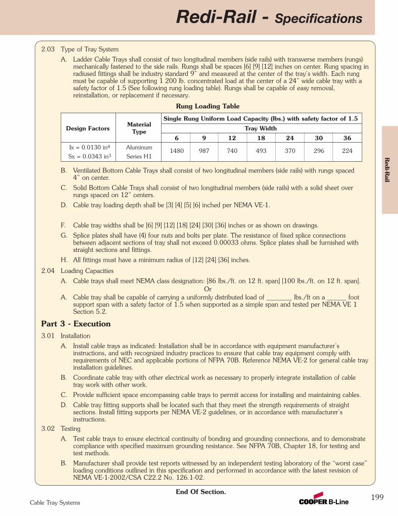
2.03 Type of Tray System
A. Ladder Cable Trays shall consist of two longitudinal members (side rails) with transverse members (rungs)mechanically fastened to the side rails. Rungs shall be spaces [6] [9] [12] inches on center. Rung spacing inradiused fittings shall be industry standard 9” and measured at the center of the tray’s width. Each rungmust be capable of supporting 1 200 lb. concentrated load at the center of a 24” wide cable tray with asafety factor of 1.5 (See following rung loading table). Rungs shall be capable of easy removal,reinstallation, or replacement if necessary.
Rung Loading Table
B. Ventilated Bottom Cable Trays shall consist of two longitudinal members (side rails) with rungs spaced4” on center.
C. Solid Bottom Cable Trays shall consist of two longitudinal members (side rails) with a solid sheet overrungs spaced on 12” centers.
D. Cable tray loading depth shall be [3] [4] [5] [6] inched per NEMA VE-1.
E. Straight sections shall be supplied in standard [10 foot (3.05m)] [12 foot (3.65m)] lengths.
F. Cable tray widths shall be [6] [9] [12] [18] [24] [30] [36] inches or as shown on drawings.
G. Splice plates shall have (4) four nuts and bolts per plate. The resistance of fixed splice connectionsbetween adjacent sections of tray shall not exceed 0.00033 ohms. Splice plates shall be furnished withstraight sections and fittings.
H. All fittings must have a minimum radius of [12] [24] [36] inches.
2.04 Loading Capacities
A. Cable trays shall meet NEMA class designation: [86 lbs./ft. on 12 ft. span] [100 lbs./ft. on 12 ft. span].Or
A. Cable tray shall be capable of carrying a uniformly distributed load of ________ lbs./ft on a ______ footsupport span with a safety factor of 1.5 when supported as a simple span and tested per NEMA VE 1Section 5.2.
Part 3 - Execution3.01 Installation
A. Install cable trays as indicated: Installation shall be in accordance with equipment manufacturer’sinstructions, and with recognized industry practices to ensure that cable tray equipment comply withrequirements of NEC and applicable portions of NFPA 70B. Reference NEMA VE-2 for general cable trayinstallation guidelines.
B. Coordinate cable tray with other electrical work as necessary to properly integrate installation of cabletray work with other work.
C. Provide sufficient space encompassing cable trays to permit access for installing and maintaining cables.
D. Cable tray fitting supports shall be located such that they meet the strength requirements of straightsections. Install fitting supports per NEMA VE-2 guidelines, or in accordance with manufacturer’sinstructions.
3.02 Testing
A. Test cable trays to ensure electrical continuity of bonding and grounding connections, and to demonstratecompliance with specified maximum grounding resistance. See NFPA 70B, Chapter 18, for testing andtest methods.
B. Manufacturer shall provide test reports witnessed by an independent testing laboratory of the “worst case”loading conditions outlined in this specification and performed in accordance with the latest revision ofNEMA VE-1-2002/CSA C22.2 No. 126.1-02.
End Of Section.
Redi-Rail - Specifications
199
Redi-R
ail
Cable Tray Systems
MaterialSingle Rung Uniform Load Capacity (lbs.) with safety factor of 1.5
Design Factors Type Tray Width
6 9 12 18 24 30 36Ix = 0.0130 in4 Aluminum
1480 987 740 493 370 296 224Sx = 0.0343 in3 Series H1
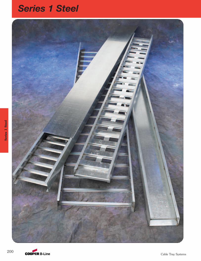
200
Series 1 SteelSer
ies
1 S
teel
Cable Tray Systems
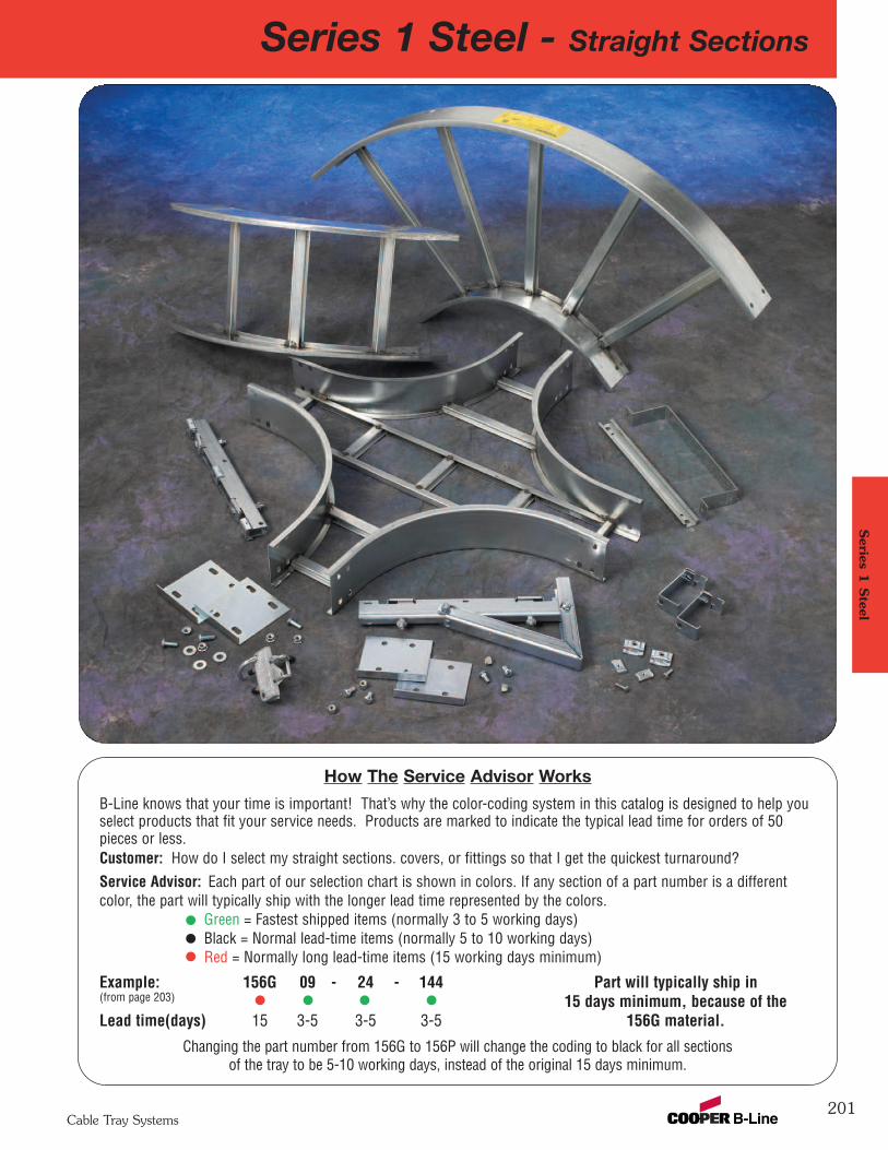
Series 1 Steel - Straight Sections
201
Series 1
Steel
Cable Tray Systems
How The Service Advisor Works
B-Line knows that your time is important! That’s why the color-coding system in this catalog is designed to help youselect products that fit your service needs. Products are marked to indicate the typical lead time for orders of 50pieces or less.Customer: How do I select my straight sections. covers, or fittings so that I get the quickest turnaround?Service Advisor: Each part of our selection chart is shown in colors. If any section of a part number is a differentcolor, the part will typically ship with the longer lead time represented by the colors.
Green = Fastest shipped items (normally 3 to 5 working days)Black = Normal lead-time items (normally 5 to 10 working days)Red = Normally long lead-time items (15 working days minimum)
Example: 156G 09 - 24 - 144 Part will typically ship in(from page 203) 15 days minimum, because of the Lead time(days) 15 3-5 3-5 3-5 156G material.
Changing the part number from 156G to 156P will change the coding to black for all sectionsof the tray to be 5-10 working days, instead of the original 15 days minimum.
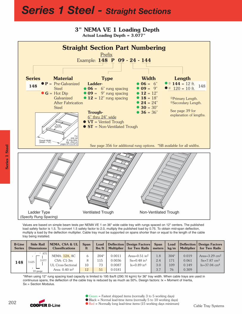
B-Line Side Rail NEMA, CSA & UL Span Load Deflection Design Factors Span Load Deflection Design FactorsSeries Dimensions Classifications ft lbs/ft Multiplier for Two Rails meters kg/m Multiplier for Two Rails
NEMA: 12A, 8C 6 204* 0.0011 Area=0.51 in2 1.8 304* 0.019 Area=3.29 cm2
148 CSA: C1-3m 8 115 0.0036 Sx=0.48 in3 2.4 171 0.061 Sx=7.87 cm3
UL Cross-Sectional 10 73 0.0087 Ix=0.89 in4 3.0 109 0.149 Ix=37.04 cm4
Area: 0.40 in2 12 51 0.0181 3.7 76 0.309
202
Series 1 Steel - Straight Sections
*When using 12" rung spacing load capacity is limited to 195 lbs/ft (290.16 kg/m) for 36" tray width. When cable trays are used in continuous spans, the deflection of the cable tray is reduced by as much as 50%. Design factors: Ix = Moment of Inertia, Sx = Section Modulus.
Values are based on simple beam tests per NEMA VE 1 on 36" wide cable tray with rungs spaced on 12" centers. The publishedload safety factor is 1.5. To convert 1.5 safety factor to 2.0, multiply the published load by 0.75. To obtain mid-span deflection, multiply a load by the deflection multiplier. Cable tray must be supported on spans shorter than or equal to the length of the cabletray being installed.
.875
3.6253.077
18 gauge
3" NEMA VE 1 Loading DepthActual Loading Depth = 3.077"
Overall Width(Width + 1/8”)
Forside rail
& rung data,see chart on
pages AP-5 & AP-6
RungSpacing
Ladder Type(Specify Rung Spacing)
Ventilated Trough Non-Ventilated Trough
Straight Section Part NumberingPrefix
Example: 148 P 09 - 24 - 144
Series Material Type Width Length148 P = Pre-Galvanized Ladder- 06 = 6" ¬ 144 = 12 ft.
148Steel 06 = 6" rung spacing 09 = 9" Á 120 = 10 ft.
G = Hot Dip 09 = 9" rung spacing 12 = 12"Galvanized 12 = 12" rung spacing 18 = 18"After Fabrication 24 = 24"Steel 30 = 30"
Trough- 36 = 36"6" thru 24" wideVT = Vented TroughST = Non-Ventilated Trough
See page 356 for additional rung options. *SB available for all widths.
Ser
ies
1 S
teel
Cable Tray Systems
Green = Fastest shipped items (normally 3 to 5 working days)Black = Normal lead-time items (normally 5 to 10 working days)Red = Normally long lead-time items (15 working days minimum)
¬Primary Length.ÁSecondary Length.
See page 39 for explanation of lengths.
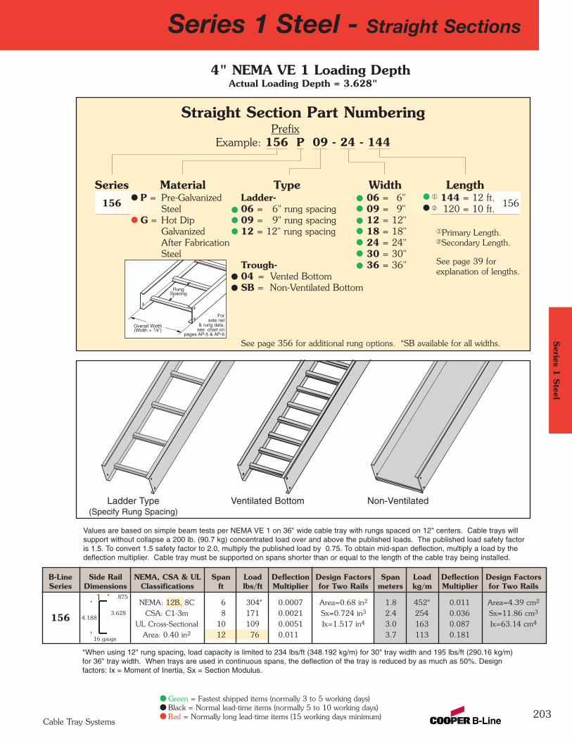
B-Line Side Rail NEMA, CSA & UL Span Load Deflection Design Factors Span Load Deflection Design FactorsSeries Dimensions Classifications ft lbs/ft Multiplier for Two Rails meters kg/m Multiplier for Two Rails
NEMA: 12B, 8C 6 304* 0.0007 Area=0.68 in2 1.8 452* 0.011 Area=4.39 cm2
156 CSA: C1-3m 8 171 0.0021 Sx=0.724 in3 2.4 254 0.036 Sx=11.86 cm3
UL Cross-Sectional 10 109 0.0051 Ix=1.517 in4 3.0 163 0.087 Ix=63.14 cm4
Area: 0.40 in2 12 76 0.011 3.7 113 0.181
Series 1 Steel - Straight Sections
203
.875
3.628
Values are based on simple beam tests per NEMA VE 1 on 36" wide cable tray with rungs spaced on 12" centers. Cable trays willsupport without collapse a 200 lb. (90.7 kg) concentrated load over and above the published loads. The published load safety factoris 1.5. To convert 1.5 safety factor to 2.0, multiply the published load by 0.75. To obtain mid-span deflection, multiply a load by thedeflection multiplier. Cable tray must be supported on spans shorter than or equal to the length of the cable tray being installed.
*When using 12" rung spacing, load capacity is limited to 234 lbs/ft (348.192 kg/m) for 30" tray width and 195 lbs/ft (290.16 kg/m)for 36" tray width. When trays are used in continuous spans, the deflection of the tray is reduced by as much as 50%. Design factors: Ix = Moment of Inertia, Sx = Section Modulus.
4.188
16 gauge
Series 1
Steel
4" NEMA VE 1 Loading DepthActual Loading Depth = 3.628"
Overall Width(Width + 1/8”)
Forside rail
& rung data,see chart on
pages AP-5 & AP-6
RungSpacing
Ladder Type(Specify Rung Spacing)
Ventilated Bottom Non-Ventilated
Straight Section Part NumberingPrefix
Example: 156 P 09 - 24 - 144
Series Material Type Width Length156 P = Pre-Galvanized Ladder- 06 = 6" ¬ 144 = 12 ft.
156Steel 06 = 6" rung spacing 09 = 9" Á 120 = 10 ft.
G = Hot Dip 09 = 9" rung spacing 12 = 12"Galvanized 12 = 12" rung spacing 18 = 18"After Fabrication 24 = 24"Steel 30 = 30"
Trough- 36 = 36"04 = Vented BottomSB = Non-Ventilated Bottom
See page 356 for additional rung options. *SB available for all widths.
Cable Tray Systems
Green = Fastest shipped items (normally 3 to 5 working days)Black = Normal lead-time items (normally 5 to 10 working days)Red = Normally long lead-time items (15 working days minimum)
¬Primary Length.ÁSecondary Length.
See page 39 for explanation of lengths.
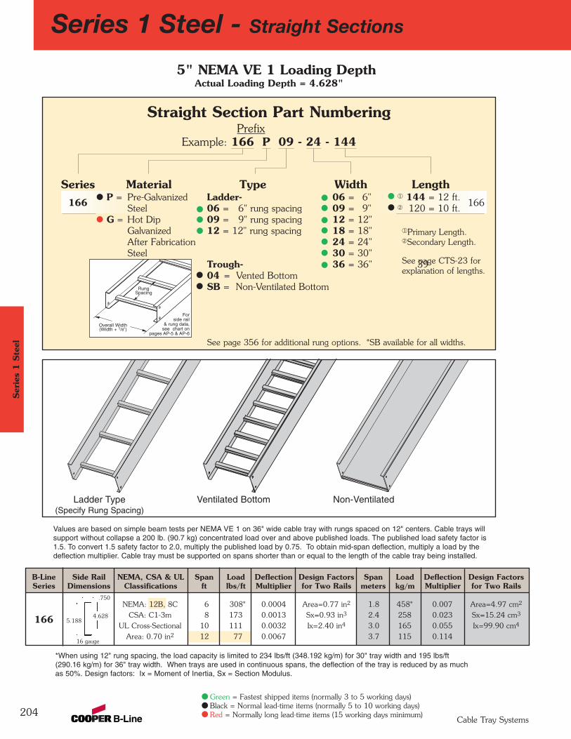
B-Line Side Rail NEMA, CSA & UL Span Load Deflection Design Factors Span Load Deflection Design FactorsSeries Dimensions Classifications ft lbs/ft Multiplier for Two Rails meters kg/m Multiplier for Two Rails
NEMA: 12B, 8C 6 308* 0.0004 Area=0.77 in2 1.8 458* 0.007 Area=4.97 cm2
166 CSA: C1-3m 8 173 0.0013 Sx=0.93 in3 2.4 258 0.023 Sx=15.24 cm3
UL Cross-Sectional 10 111 0.0032 Ix=2.40 in4 3.0 165 0.055 Ix=99.90 cm4
Area: 0.70 in2 12 77 0.0067 3.7 115 0.114
Series 1 Steel - Straight Sections
204
4.6285.188
.750
Values are based on simple beam tests per NEMA VE 1 on 36" wide cable tray with rungs spaced on 12" centers. Cable trays willsupport without collapse a 200 lb. (90.7 kg) concentrated load over and above published loads. The published load safety factor is1.5. To convert 1.5 safety factor to 2.0, multiply the published load by 0.75. To obtain mid-span deflection, multiply a load by thedeflection multiplier. Cable tray must be supported on spans shorter than or equal to the length of the cable tray being installed.
*When using 12" rung spacing, the load capacity is limited to 234 lbs/ft (348.192 kg/m) for 30" tray width and 195 lbs/ft (290.16 kg/m) for 36" tray width. When trays are used in continuous spans, the deflection of the tray is reduced by as much as 50%. Design factors: Ix = Moment of Inertia, Sx = Section Modulus.
16 gauge
5" NEMA VE 1 Loading DepthActual Loading Depth = 4.628"
Overall Width(Width + 1/8”)
Forside rail
& rung data,see chart on
pages AP-5 & AP-6
RungSpacing
Straight Section Part NumberingPrefix
Example: 166 P 09 - 24 - 144
Series Material Type Width Length166 P = Pre-Galvanized Ladder- 06 = 6" ¬ 144 = 12 ft.
166Steel 06 = 6" rung spacing 09 = 9" Á 120 = 10 ft.
G = Hot Dip 09 = 9" rung spacing 12 = 12"Galvanized 12 = 12" rung spacing 18 = 18"After Fabrication 24 = 24"Steel 30 = 30"
Trough- 36 = 36" 3904 = Vented BottomSB = Non-Ventilated Bottom
See page 356 for additional rung options. *SB available for all widths.
Ladder Type(Specify Rung Spacing)
Ventilated Bottom Non-Ventilated
Ser
ies
1 S
teel
Cable Tray Systems
Green = Fastest shipped items (normally 3 to 5 working days)Black = Normal lead-time items (normally 5 to 10 working days)Red = Normally long lead-time items (15 working days minimum)
¬Primary Length.ÁSecondary Length.
See page CTS-23 for explanation of lengths.
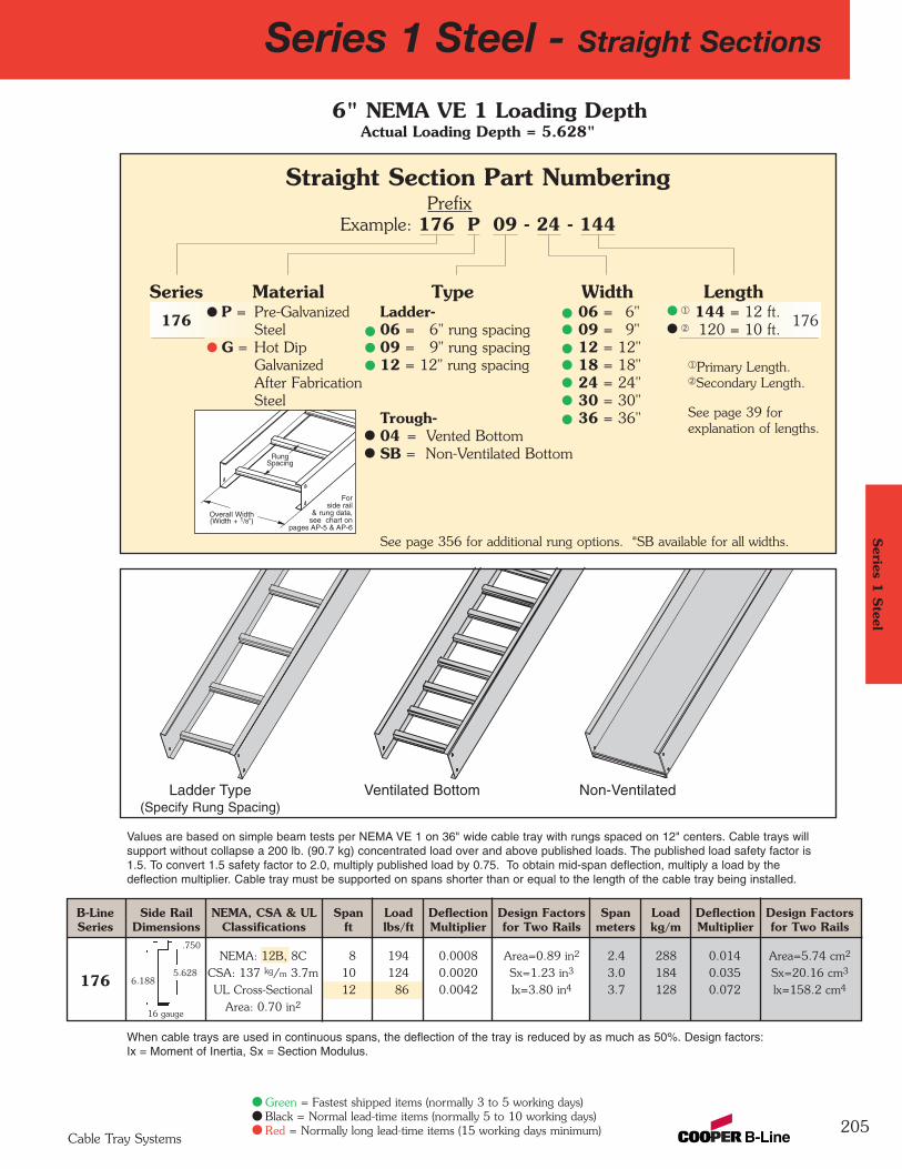
B-Line Side Rail NEMA, CSA & UL Span Load Deflection Design Factors Span Load Deflection Design FactorsSeries Dimensions Classifications ft lbs/ft Multiplier for Two Rails meters kg/m Multiplier for Two Rails
NEMA: 12B, 8C 8 194 0.0008 Area=0.89 in2 2.4 288 0.014 Area=5.74 cm2
CSA: 137 kg/m 3.7m 10 124 0.0020 Sx=1.23 in3 3.0 184 0.035 Sx=20.16 cm3
UL Cross-Sectional 12 86 0.0042 Ix=3.80 in4 3.7 128 0.072 lx=158.2 cm4
Area: 0.70 in2
Series 1 Steel - Straight Sections
205
.750
6.1885.628
When cable trays are used in continuous spans, the deflection of the tray is reduced by as much as 50%. Design factors: Ix = Moment of Inertia, Sx = Section Modulus.
Values are based on simple beam tests per NEMA VE 1 on 36" wide cable tray with rungs spaced on 12" centers. Cable trays willsupport without collapse a 200 lb. (90.7 kg) concentrated load over and above published loads. The published load safety factor is1.5. To convert 1.5 safety factor to 2.0, multiply published load by 0.75. To obtain mid-span deflection, multiply a load by thedeflection multiplier. Cable tray must be supported on spans shorter than or equal to the length of the cable tray being installed.
16 gauge
176
6" NEMA VE 1 Loading DepthActual Loading Depth = 5.628"
Overall Width(Width + 1/8”)
Forside rail
& rung data,see chart on
pages AP-5 & AP-6
RungSpacing
Straight Section Part NumberingPrefix
Example: 176 P 09 - 24 - 144
Series Material Type Width Length176 P = Pre-Galvanized Ladder- 06 = 6" ¬ 144 = 12 ft.
176Steel 06 = 6" rung spacing 09 = 9" Á 120 = 10 ft.
G = Hot Dip 09 = 9" rung spacing 12 = 12"Galvanized 12 = 12" rung spacing 18 = 18"After Fabrication 24 = 24"Steel 30 = 30"
Trough- 36 = 36"04 = Vented BottomSB = Non-Ventilated Bottom
See page 356 for additional rung options. *SB available for all widths.
Ladder Type(Specify Rung Spacing)
Ventilated Bottom Non-Ventilated
Series 1
Steel
Cable Tray Systems
Green = Fastest shipped items (normally 3 to 5 working days)Black = Normal lead-time items (normally 5 to 10 working days)Red = Normally long lead-time items (15 working days minimum)
¬Primary Length.ÁSecondary Length.
See page 39 for explanation of lengths.
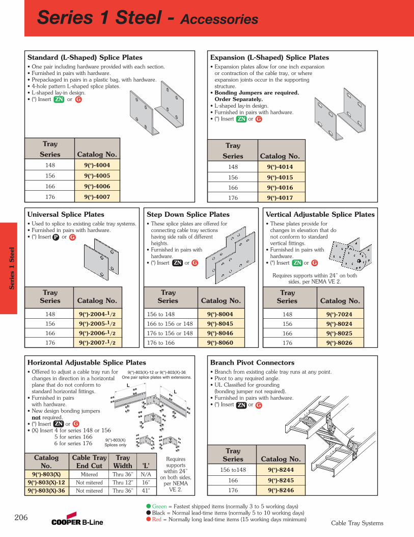
Branch Pivot Connectors• Branch from existing cable tray runs at any point.• Pivot to any required angle.• UL Classified for grounding
(bonding jumper not required).• Furnished in pairs with hardware.• (*) Insert or
Expansion (L-Shaped) Splice Plates• Expansion plates allow for one inch expansion
or contraction of the cable tray, or where expansion joints occur in the supportingstructure.
• Bonding Jumpers are required. Order Separately.
• L-shaped lay-in design.• Furnished in pairs with hardware.• (*) Insert or
Horizontal Adjustable Splice Plates• Offered to adjust a cable tray run for
changes in direction in a horizontalplane that do not conform to standard horizontal fittings.
• Furnished in pairs with hardware.
• New design bonding jumpers not required.
• (*) Insert or• (X) Insert 4 for series 148 or 156
5 for series 1666 for series 176
Catalog Cable Tray Tray No. End Cut Width 'L'
9(*)-803(X) Mitered Thru 36" N/A
9(*)-803(X)-12 Not mitered Thru 12" 16"
9(*)-803(X)-36 Not mitered Thru 36" 41"
TraySeries Catalog No.
156 to 148 9(*)-8004
166 to 156 or 148 9(*)-8045
176 to 156 or 148 9(*)-8046
176 to 166 9(*)-8060
Standard (L-Shaped) Splice Plates• One pair including hardware provided with each section.• Furnished in pairs with hardware.• Prepackaged in pairs in a plastic bag, with hardware.• 4-hole pattern L-shaped splice plates. • L-shaped lay-in design.• (*) Insert or
Tray Series Catalog No.
156 to148 9(*)-8244
166 9(*)-8245
176 9(*)-8246
Tray Series Catalog No.
148 9(*)-2004-1/2
156 9(*)-2005-1/2
166 9(*)-2006-1/2
176 9(*)-2007-1/2
206
Series 1 Steel - Accessories
TraySeries Catalog No.
148 9(*)-7024
156 9(*)-8024
166 9(*)-8025
176 9(*)-8026
9(*)-803(X)-12 or 9(*)-803(X)-36One pair splice plates with extensions.
9(*)-803(X)Splices only
LL
Vertical Adjustable Splice Plates• These plates provide for
changes in elevation that do not conform to standard vertical fittings.
• Furnished in pairs with hardware.
• (*) Insert or
Step Down Splice Plates• These splice plates are offered for
connecting cable tray sections having side rails of different heights.
• Furnished in pairs with hardware.
• (*) Insert or
Universal Splice Plates• Used to splice to existing cable tray systems.• Furnished in pairs with hardware.• (*) Insert or
TraySeries Catalog No.
148 9(*)-4004
156 9(*)-4005
166 9(*)-4006
176 9(*)-4007
Tray Series Catalog No.
148 9(*)-4014
156 9(*)-4015
166 9(*)-4016
176 9(*)-4017
Ser
ies
1 S
teel
Cable Tray Systems
G
G
G
P
ZN
ZN
GZN
GZN
GZN
GZN
Green = Fastest shipped items (normally 3 to 5 working days)Black = Normal lead-time items (normally 5 to 10 working days)Red = Normally long lead-time items (15 working days minimum)
Requires supports within 24” on bothsides, per NEMA VE 2.
Requiressupports
within 24”on both sides,
per NEMAVE 2.
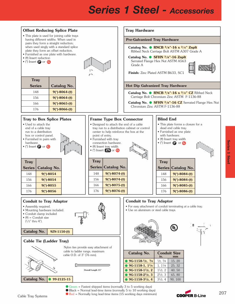
Conduit to Tray Adaptor• Assembly required.• Mounting hardware included.• Conduit clamp included• (‡) = Conduit size
(1/2" thru 4").
Conduit to Tray Adaptor• For easy attachment of conduit terminating at a cable tray.• Use on aluminum or steel cable trays.
Catalog No. Conduit Sizein. mm
9G-1158-1/2, 3/4 1/2, 3/4 15, 20
9G-1158-1, 11/4 1, 11/4 25, 32
9G-1158-11/2, 2 11/2, 2 40, 50
9G-1158-21/2, 3 21/2, 3 65, 80
9G-1158-31/2, 4 31/2, 4 90, 100
Tray Series Catalog No.
148 9(*)-8054
156 9(*)-8054
166 9(*)-8055
176 9(*)-8056
Tray Series Catalog No.
148 9(*)-8074-(‡)
156 9(*)-8074-(‡)
166 9(*)-8075-(‡)
176 9(*)-8076-(‡)
Frame Type Box Connector• Designed to attach the end of a cable
tray run to a distribution cabinet or control center to help reinforce the box at the point of entry.
• Furnished with trayconnection hardware.
• (‡) Insert tray width• (*) Insert or
Tray Hardware
Blind End• This plate forms a closure for a
dead end cable tray.• Furnished as one plate
with hardware.• (‡) Insert tray width• (*) Insert or
Tray Series Catalog No.
148 9(*)-8084-(‡)
156 9(*)-8084-(‡)
166 9(*)-8085-(‡)
176 9(*)-8086-(‡)
Series 1 Steel - Accessories
207
Cable Tie (Ladder Tray)Nylon ties provide easy attachment of cable to ladder rungs; maximum cable O.D. of 3" (76 mm).
Catalog No. 99-2125-15
Pre-Galvanized Tray Hardware
Catalog No. RNCB 3/8"-16 x 3/4" ZnpltRibbed Neck Carriage Bolt ASTM A307 Grade A
Catalog No. SFHN 3/8"-16 ZnpltSerrated Flange Hex Nut ASTM A563Grade A
Finish: Zinc Plated ASTM B633, SC1
Hot Dip Galvanized Tray Hardware
Catalog No. RNCB 3/8"-16 x 3/4" CZ Ribbed Neck Carriage Bolt Chromium Zinc ASTM F-1136-88
Catalog No. SFHN 3/8"-16 CZ Serrated Flange Hex NutChromium Zinc ASTM F-1136-88
Overall Length 15"
Tray to Box Splice Plates• Used to attach the
end of a cable trayrun to a distributionbox or control panel.
• Furnished in pairs withhardware.
• (*) Insert or
Offset Reducing Splice Plate• This plate is used for joining cable trays
having different widths. When used in pairs they form a straight reduction; when used singly with a standard spliceplate they form an offset reduction.
• Furnished as one plate with hardware.• (‡) Insert reduction• (*) Insert or
Tray Series Catalog No.
148 9(*)-8064-(‡)
156 9(*)-8064-(‡)
166 9(*)-8065-(‡)
176 9(*)-8066-(‡)
Catalog No. 9ZN-1150-(‡)
Series 1
Steel
Cable Tray Systems
Green = Fastest shipped items (normally 3 to 5 working days)Black = Normal lead-time items (normally 5 to 10 working days)Red = Normally long lead-time items (15 working days minimum)
GP
GPGP
GZN
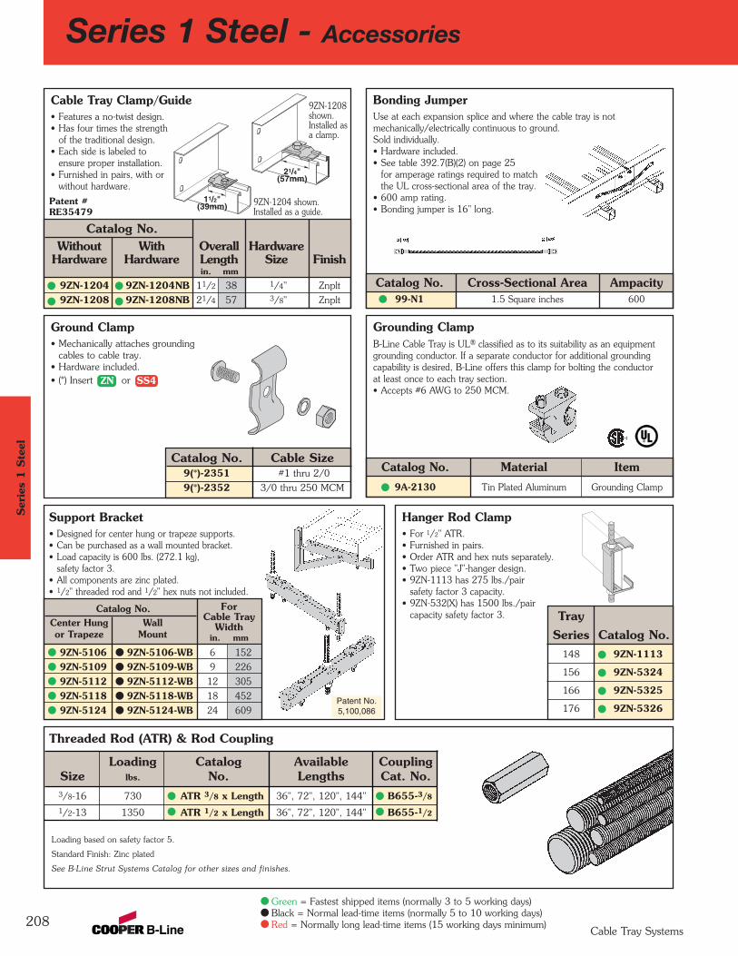
Support Bracket• Designed for center hung or trapeze supports.• Can be purchased as a wall mounted bracket.• Load capacity is 600 lbs. (272.1 kg),
safety factor 3.• All components are zinc plated.• 1/2" threaded rod and 1/2" hex nuts not included.
Cable Tray Clamp/Guide• Features a no-twist design.• Has four times the strength
of the traditional design. • Each side is labeled to
ensure proper installation.• Furnished in pairs, with or
without hardware.
Threaded Rod (ATR) & Rod Coupling
Loading Catalog Available CouplingSize lbs. No. Lengths Cat. No.3/8-16 730 ATR 3/8 x Length 36", 72", 120", 144" B655-3/8
1/2-13 1350 ATR 1/2 x Length 36", 72", 120", 144" B655-1/2
Loading based on safety factor 5.
Standard Finish: Zinc plated
See B-Line Strut Systems Catalog for other sizes and finishes.
Bonding JumperUse at each expansion splice and where the cable tray is not mechanically/electrically continuous to ground. Sold individually. • Hardware included.• See table 392.7(B)(2) on page 25
for amperage ratings required to matchthe UL cross-sectional area of the tray.
• 600 amp rating.• Bonding jumper is 16" long.
Catalog No.Center Hung Wallor Trapeze Mount
9ZN-5106 9ZN-5106-WB 6 152
9ZN-5109 9ZN-5109-WB 9 226
9ZN-5112 9ZN-5112-WB 12 305
9ZN-5118 9ZN-5118-WB 18 452
9ZN-5124 9ZN-5124-WB 24 609
Grounding ClampB-Line Cable Tray is UL® classified as to its suitability as an equipmentgrounding conductor. If a separate conductor for additional grounding capability is desired, B-Line offers this clamp for bolting the conductor at least once to each tray section.• Accepts #6 AWG to 250 MCM.
Catalog No. Material Item9A-2130 Tin Plated Aluminum Grounding Clamp
Series 1 Steel - Accessories
Ground Clamp• Mechanically attaches grounding
cables to cable tray.• Hardware included.• (*) Insert or
Catalog No. Cable Size9(*)-2351 #1 thru 2/0
9(*)-2352 3/0 thru 250 MCM
208
Patent No.5,100,086
9ZN-1204 shown.Installed as a guide.
9ZN-1208shown.Installed asa clamp.
ForCable Tray
Widthin. mm
Hanger Rod Clamp• For 1/2" ATR.• Furnished in pairs.• Order ATR and hex nuts separately.• Two piece "J"-hanger design.• 9ZN-1113 has 275 lbs./pair
safety factor 3 capacity.• 9ZN-532(X) has 1500 lbs./pair
capacity safety factor 3.
Patent #RE35479
Catalog No.Without With Overall Hardware
Hardware Hardware Length Size Finishin. mm
9ZN-1204 9ZN-1204NB 11/2 38 1/4" Znplt
9ZN-1208 9ZN-1208NB 21/4 57 3/8" Znplt
Catalog No. Cross-Sectional Area Ampacity99-N1 1.5 Square inches 600
Tray Series Catalog No.
148 9ZN-1113
156 9ZN-5324
166 9ZN-5325
176 9ZN-5326
11/2"(39mm)
21/4"(57mm)
Ser
ies
1 S
teel
Cable Tray Systems
Green = Fastest shipped items (normally 3 to 5 working days)Black = Normal lead-time items (normally 5 to 10 working days)Red = Normally long lead-time items (15 working days minimum)
ZN SS4
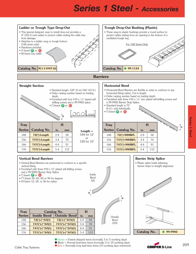
Horizontal Bend• Horizontal Bend Barriers are flexible in order to conform to any
horizontal fitting radius. Cut to length.• Order catalog number based on loading depth.• Furnished with three #10 x 1/2" zinc plated self-drilling screws and
a 99-9982 Barrier Strip Splice.• Standard length is 72"
(6 ft.), sold individually.• (*) Insert or
Vertical Bend Barriers• Vertical Bend Barriers are preformed to conform to a specific
vertical fitting.• Furnished with three #10 x 1/2" plated self-drilling screws
and a 99-9982 Barrier Strip Splice.• (*) Insert or• (**) Insert 30, 45, 60 or 90 for degrees• (†) Insert 12, 24, or 36 for radius
99-9982Catalog No.
Barrier Strip Splice• Plastic splice holds adjoining
barrier strips in straight alignment.
Straight Section• Standard length: 120" (3 m) 144" (12 ft.).• Order catalog number based on loading
depth.• Furnished with four #10 x 1/2" plated self-
drilling screws and a 99-9982 splice.• (*) Insert or
Outside Bend(VO)
Inside Bend(VI)
H
H
Barriers
Length =144 for 12'
or 120 for 10'
H
H
Catalog No. 9(*)-1104T-(‡)
Ladder or Trough Type Drop-Out• This special designed, easy to install drop-out provides a
4" (101.6 mm) radius to protect cables exiting the cable tray from damage.
• Attaches to a ladder rung or trough bottom (148 series only).
• Hardware included.• (*) Insert or• (‡) Insert tray width
Catalog No. 99-1124
Trough Drop-Out Bushing (Plastic)• These snap-in plastic bushings provide a round surface to
protect cables exiting from an opening in the bottom of a ventilated trough tray.
For 148 Series Only
Tray HSeries Catalog No. in. mm
148 72(*)-90HBFL 2.8 58
156 737(*)-90HBFL 3.4 70
166 747(*)-90HBFL 4.4 91
176 757(*)-90HBFL 5.4 112
Tray HSeries Catalog No. in. mm
148 72(*)-Length 2.8 58
156 737(*)-Length 3.4 70
166 747(*)-Length 4.4 91
176 757(*)-Length 5.4 112
Tray Catalog No. HSeries Inside Bend Outside Bend in. mm
148 72(*)-(**)VI(†) 72(*)-(**)VO(†) 2.8 58
156 737(*)-(**)VI(†) 737(*)-(**)VO(†) 3.4 70
166 747(*)-(**)VI(†) 747(*)-(**)VO(†) 4.4 91
176 757(*)-(**)VI(†) 757(*)-(**)VO(†) 5.4 112
Series 1 Steel - Accessories
209
Series 1
Steel
Cable Tray Systems
Green = Fastest shipped items (normally 3 to 5 working days)Black = Normal lead-time items (normally 5 to 10 working days)Red = Normally long lead-time items (15 working days minimum)
GP
GP
GP
GP
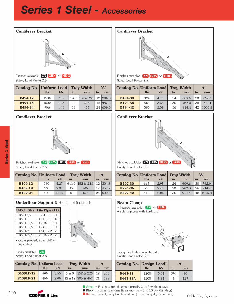
Underfloor Support (U-Bolts not included)
Cantilever Bracket
Catalog No. Uniform Load Tray Width 'A'lbs kN in. mm in. mm
B409-12 960 4.27 6 & 9 152 & 228 12 304.8
B409-18 640 2.84 12 305 18 457.2
B409-24 480 2.13 18 457 24 609.6
Cantilever Bracket
Catalog No. Uniform Load Tray Width 'A'lbs kN in. mm in. mm
B494-30 924 4.11 24 609.6 30 762.0
B494-36 864 3.84 30 762.0 36 914.4
B494-42 580 2.58 36 914.4 42 1066.8
Cantilever Bracket
Catalog No. Uniform Load Tray Width 'A'lbs kN in. mm in. mm
B297-30 665 2.95 24 609.6 30 762.0
B297-36 550 2.44 30 762.0 36 914.4
B297-42 465 2.06 36 914.4 42 1066.8
Beam Clamp• Finishes available: or• Sold in pieces with hardware.
Catalog No. Design Load* 'A'lbs kN in. mm
B441-22 1200 5.34 33/8 86
B441-22A 1200 5.34 5 127
Cantilever Bracket
Catalog No. Uniform Load Tray Width 'A'lbs kN in. mm in. mm
B494-12 1580 7.02 6 & 9 152 & 229 12 304.8
B494-18 1000 4.45 12 305 18 457.2
B494-24 996 4.43 18 457 24 609.6
Series 1 Steel - Accessories
210
A
A
A
A
A
Finishes available: or
Safety Load Factor 2.5
Finishes available: or
Safety Load Factor 2.5
Finishes available: or
Safety Load Factor 2.5
Finishes available: or
Safety Load Factor 2.5
Finish available: Safety Load Factor 2.5
U-Bolt Size Fits Pipe O.D.B501-3/4 .841 - 1.050B501-1 1.051 - 1.315B501-11/4 1.316 - 1.660B501-11/2 1.661 - 1.900B501-2 1.901 - 2.375B501-21/2 2.376 - 2.875
• Order properly sized U-Bolts separately.
Catalog No. Uniform Load Tray Width 'A'lbs kN in. mm in. mm
B409UF-12 800 3.55 6 & 9 152 & 229 12 305
B409UF-21 450 2.00 12 & 18 305 & 457 21 533
Design load when used in pairs.Safety Load Factor 5.0
A
Ser
ies
1 S
teel
Cable Tray Systems
Green = Fastest shipped items (normally 3 to 5 working days)Black = Normal lead-time items (normally 5 to 10 working days)Red = Normally long lead-time items (15 working days minimum)
ZN GRN HDG
ZN
ZN
GRN HDG
ZN HDG
SS4 ZN GRN HDG SS4SS6
ZN GRN HDG
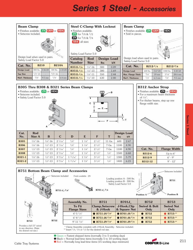
Steel C-Clamp With Locknut• Finishes available:
for 3/8 & 1/2
for 5/8 & 3/4
all sizes
Safety Load Factor 5.0
Catalog Rod Design LoadNumber Size lbs kN
B351L-3/8 3/8"-16 300 0.89
B351L-1/2 1/2"-13 380 1.69
B351L-5/8 5/8"-11 550 2.44
B351L-3/4 3/4"-10 630 2.80
Cat. No. B210 B210A
Design Load 800 lbs. 3.56 kN 300 lbs. 1.33 kN
Tap Size 1/2"-13 - 3/8"-16 -
Mat'l. Thickness 3/8" 9.5 mm 1/4" 6.4 mm
B751 Bottom Beam Clamp and AccessoriesSetscrew included Finish available: ZN
Loading position A - 500 lbs. Loading position B - 300 lbs.
Safety Load Factor 5.0
Assembly No. B751 B701J_ B752 B753To Fit Clamp,Setscrew J-Hook,Clip Swivel & Bolt Swivel Nut
Flange Sizes & J-Hook & Square Nut Only Only4"-5 7/8" B751-J4-3/8* B701-J4-3/8 B752 B753-**
6"-8 7/8" B751-J6-3/8* B701-J6-3/8 B752 B753-**
9"-11 7/8" B751-J9-3/8* B701-J9-3/8 B752 B753-**
B312 Anchor Strap• Finishes available: or• For a maximum beam thickness
of 3/4".• For thicker beams, step up one
flange width size.
Cat. No. Flange WidthB312-6 Up to 6"
B312-9 6" - 9"
B312-12 9" - 12"
B305 Thru B308 & B321 Series Beam Clamps• Finishes available: or• Setscrew included.• Safety Load Factor 5.0
Cat. Rod Design LoadNo. Size A B C D E F T lbs kN
B305 3/8"-16 3/8"-16 2 5/16" 7/8" 1 1/8" 2 1/2" 11 Ga. 600 2.67
B306 3/8"-16 1/2"-13 2 7/16" 7/8" 1 1/8" 2 1/2" 7 Ga. 1100 4.90
B307 1/2"-13 1/2"-13 2 7/16" 7/8" 1 1/8" 2 1/2" 7 Ga. 1100 4.90
B308 1/2"-13 1/2"-13 2 9/16" 7/8" 1 1/8" 2 1/2" 1/4" 1500 6.68
B321-1 3/8"-16 1/2"-13 3 9/16" 1 11/16" 1 5/8" 3 1/4" 1/4" 1300 5.79
B321-2 1/2"-13 1/2"-13 3 9/16" 1 11/16" 1 5/8" 3 1/4" 1/4" 1400 6.23
Series 1 Steel - Accessories
211
* Clamp Assembly complete with J-Hook Assembly. Setscrew included.** Insert 1/4, 3/8 or 1/2 for the desired rod size.
B753
Position A
B701-J_-3/8
B752
B751
Position B
Provides a full 15° swivelin any direction. (Statethe desired rod size.)
B
ED
C
F T
B751-J_-3/8*
Setscrew included
A
Beam Clamp• Finishes available: or• Setscrew included.
Design load when used in pairs.Safety Load Factor 5.0
Cat. No.Design Load 600 lbs. 2.67 kN 1000 lbs. 4.45 kN
Max. Flange Thick 3/4" 19 mm 11/8" 28.6 mm
Mat’l. Thickness 1/4" 6.3 mm 3/8" 9.5 mm
Beam Clamp• Finishes available: or• Sold in pieces.
Design load when used in pairs.Safety Load Factor 5.0
B212-1/4 B212-3/8
Series 1
Steel
Cable Tray Systems
Green = Fastest shipped items (normally 3 to 5 working days)Black = Normal lead-time items (normally 5 to 10 working days)Red = Normally long lead-time items (15 working days minimum)
ZN HDG ZN HDG
ZNZNZN
GRN HDG
SS4
ZN HDGGRN
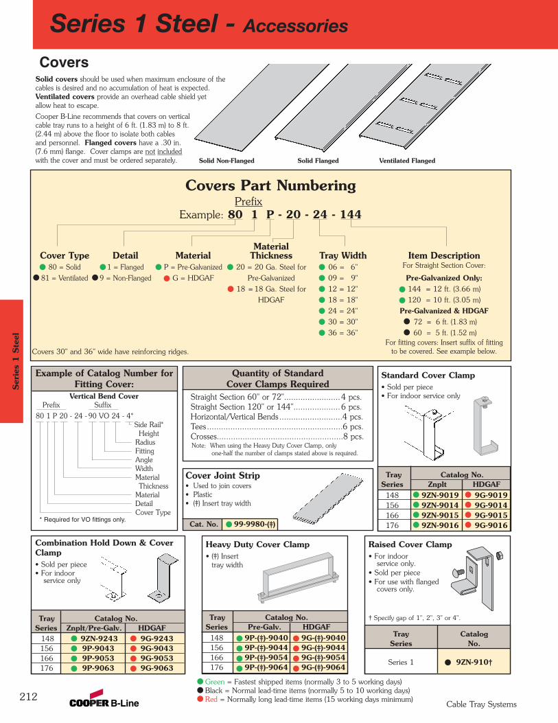
Cat. No. 99-9980-(‡)
Quantity of StandardCover Clamps Required
Straight Section 60" or 72"........................4 pcs.Straight Section 120" or 144"....................6 pcs.Horizontal/Vertical Bends ...........................4 pcs.Tees ..........................................................6 pcs.Crosses......................................................8 pcs.Note: When using the Heavy Duty Cover Clamp, only
one-half the number of clamps stated above is required.
Standard Cover Clamp• Sold per piece• For indoor service only
Tray Catalog No.Series Znplt HDGAF
148 9ZN-9019 9G-9019156 9ZN-9014 9G-9014166 9ZN-9015 9G-9015176 9ZN-9016 9G-9016
Combination Hold Down & Cover Clamp• Sold per piece• For indoor
service only
Tray Catalog No.Series Znplt/Pre-Galv. HDGAF
148 9ZN-9243 9G-9243156 9P-9043 9G-9043166 9P-9053 9G-9053176 9P-9063 9G-9063
Heavy Duty Cover Clamp• (‡) Insert
tray width
Tray Catalog No.Series Pre-Galv. HDGAF
148 9P-(‡)-9040 9G-(‡)-9040156 9P-(‡)-9044 9G-(‡)-9044166 9P-(‡)-9054 9G-(‡)-9054176 9P-(‡)-9064 9G-(‡)-9064
Example of Catalog Number forFitting Cover:
212
Series 1 Steel - Accessories
Solid covers should be used when maximum enclosure of thecables is desired and no accumulation of heat is expected.Ventilated covers provide an overhead cable shield yetallow heat to escape.
Cooper B-Line recommends that covers on verticalcable tray runs to a height of 6 ft. (1.83 m) to 8 ft.(2.44 m) above the floor to isolate both cablesand personnel. Flanged covers have a .30 in. (7.6 mm) flange. Cover clamps are not includedwith the cover and must be ordered separately. Solid Flanged Ventilated Flanged
Vertical Bend CoverPrefix Suffix
80 1 P 20 - 24 - 90 VO 24 - 4*Side Rail*
Height RadiusFittingAngleWidthMaterialThickness
MaterialDetailCover Type
Solid Non-Flanged
Covers Part NumberingPrefix
Example: 80 1 P - 20 - 24 - 144
MaterialCover Type Detail Material Thickness Tray Width Item Description
80 = Solid 1 = Flanged P = Pre-Galvanized 20 = 20 Ga. Steel for 06 = 6" For Straight Section Cover:
81 = Ventilated 9 = Non-Flanged G = HDGAF Pre-Galvanized 09 = 9" Pre-Galvanized Only:18 = 18 Ga. Steel for 12 = 12" 144 = 12 ft. (3.66 m)
HDGAF 18 = 18" 120 = 10 ft. (3.05 m)
24 = 24" Pre-Galvanized & HDGAF30 = 30" 72 = 6 ft. (1.83 m)
36 = 36" 60 = 5 ft. (1.52 m)For fitting covers: Insert suffix of fitting
to be covered. See example below.
Covers
* Required for VO fittings only.
Cover Joint Strip• Used to join covers• Plastic• (‡) Insert tray width
Raised Cover Clamp• For indoor
service only.• Sold per piece• For use with flanged
covers only.
Tray CatalogSeries No.
Series 1 9ZN-910†
† Specify gap of 1", 2", 3" or 4".
Covers 30" and 36" wide have reinforcing ridges.
Ser
ies
1 S
teel
Cable Tray Systems
Green = Fastest shipped items (normally 3 to 5 working days)Black = Normal lead-time items (normally 5 to 10 working days)Red = Normally long lead-time items (15 working days minimum)
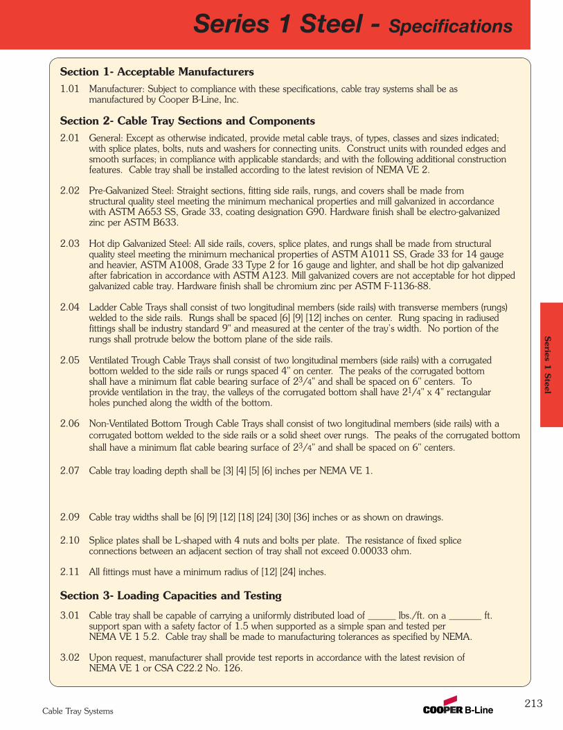
Section 1- Acceptable Manufacturers1.01 Manufacturer: Subject to compliance with these specifications, cable tray systems shall be as
manufactured by Cooper B-Line, Inc.
Section 2- Cable Tray Sections and Components2.01 General: Except as otherwise indicated, provide metal cable trays, of types, classes and sizes indicated;
with splice plates, bolts, nuts and washers for connecting units. Construct units with rounded edges andsmooth surfaces; in compliance with applicable standards; and with the following additional constructionfeatures. Cable tray shall be installed according to the latest revision of NEMA VE 2.
2.02 Pre-Galvanized Steel: Straight sections, fitting side rails, rungs, and covers shall be made fromstructural quality steel meeting the minimum mechanical properties and mill galvanized in accordancewith ASTM A653 SS, Grade 33, coating designation G90. Hardware finish shall be electro-galvanizedzinc per ASTM B633.
2.03 Hot dip Galvanized Steel: All side rails, covers, splice plates, and rungs shall be made from structural quality steel meeting the minimum mechanical properties of ASTM A1011 SS, Grade 33 for 14 gaugeand heavier, ASTM A1008, Grade 33 Type 2 for 16 gauge and lighter, and shall be hot dip galvanizedafter fabrication in accordance with ASTM A123. Mill galvanized covers are not acceptable for hot dippedgalvanized cable tray. Hardware finish shall be chromium zinc per ASTM F-1136-88.
2.04 Ladder Cable Trays shall consist of two longitudinal members (side rails) with transverse members (rungs)welded to the side rails. Rungs shall be spaced [6] [9] [12] inches on center. Rung spacing in radiusedfittings shall be industry standard 9" and measured at the center of the tray’s width. No portion of therungs shall protrude below the bottom plane of the side rails.
2.05 Ventilated Trough Cable Trays shall consist of two longitudinal members (side rails) with a corrugated bottom welded to the side rails or rungs spaced 4" on center. The peaks of the corrugated bottomshall have a minimum flat cable bearing surface of 23/4" and shall be spaced on 6" centers. Toprovide ventilation in the tray, the valleys of the corrugated bottom shall have 21/4" x 4" rectangularholes punched along the width of the bottom.
2.06 Non-Ventilated Bottom Trough Cable Trays shall consist of two longitudinal members (side rails) with acorrugated bottom welded to the side rails or a solid sheet over rungs. The peaks of the corrugated bottomshall have a minimum flat cable bearing surface of 23/4" and shall be spaced on 6" centers.
2.07 Cable tray loading depth shall be [3] [4] [5] [6] inches per NEMA VE 1.
2.08 Straight sections shall be supplied in standard [12 foot] [10 foot (3 m)] lengths.
2.09 Cable tray widths shall be [6] [9] [12] [18] [24] [30] [36] inches or as shown on drawings.
2.10 Splice plates shall be L-shaped with 4 nuts and bolts per plate. The resistance of fixed spliceconnections between an adjacent section of tray shall not exceed 0.00033 ohm.
2.11 All fittings must have a minimum radius of [12] [24] inches.
Section 3- Loading Capacities and Testing
3.01 Cable tray shall be capable of carrying a uniformly distributed load of ______ lbs./ft. on a _______ ft. support span with a safety factor of 1.5 when supported as a simple span and tested perNEMA VE 1 5.2. Cable tray shall be made to manufacturing tolerances as specified by NEMA.
3.02 Upon request, manufacturer shall provide test reports in accordance with the latest revision ofNEMA VE 1 or CSA C22.2 No. 126.
213
Series 1 Steel - SpecificationsSeries 1
Steel
Cable Tray Systems
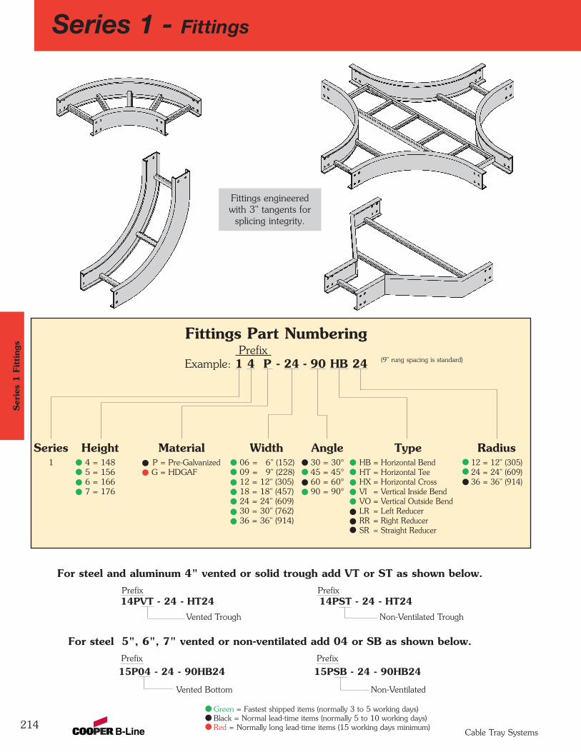
214
For steel 5", 6", 7" vented or non-ventilated add 04 or SB as shown below.Prefix Prefix
15P04 - 24 - 90HB24 15PSB - 24 - 90HB24
Vented Bottom Non-Ventilated
Fittings Part Numbering Prefix
Example: 1 4 P - 24 - 90 HB 24
Height4 = 1485 = 156 6 = 166 7 = 176
Series1
MaterialP = Pre-Galvanized G = HDGAF
Width06 = 6" (152)09 = 9" (228)12 = 12" (305)18 = 18" (457)24 = 24" (609)30 = 30" (762)36 = 36" (914)
Angle30 = 30°45 = 45°60 = 60°90 = 90°
Radius12 = 12" (305)24 = 24" (609)36 = 36" (914)
TypeHB = Horizontal BendHT = Horizontal TeeHX = Horizontal CrossVI = Vertical Inside BendVO = Vertical Outside BendLR = Left ReducerRR = Right ReducerSR = Straight Reducer
For steel and aluminum 4" vented or solid trough add VT or ST as shown below.Prefix Prefix 14PVT - 24 - HT24 14PST - 24 - HT24
Vented Trough Non-Ventilated Trough
(9" rung spacing is standard)
Fittings engineered with 3" tangents for
splicing integrity.
Series 1 - FittingsSer
ies
1 F
itting
s
Cable Tray Systems
Green = Fastest shipped items (normally 3 to 5 working days)Black = Normal lead-time items (normally 5 to 10 working days)Red = Normally long lead-time items (15 working days minimum)
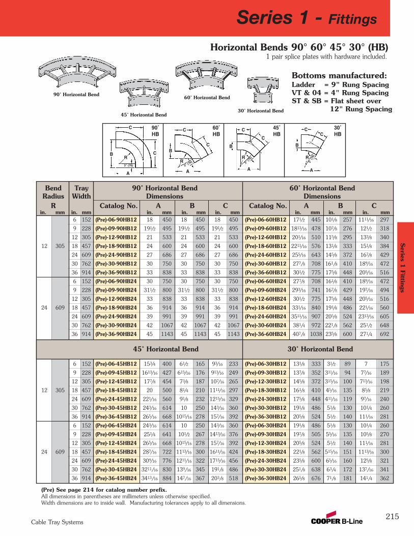
Series 1
Fittings
Bend Tray 90˚ Horizontal Bend 60˚ Horizontal BendRadius Width Dimensions Dimensions
R Catalog No. A B C Catalog No. A B Cin. mm in. mm in. mm in. mm in. mm in. mm in. mm in. mm
6 152 (Pre)-06-90HB12 18 450 18 450 18 450 (Pre)-06-60HB12 171/2 445 101/8 257 1111/16 297
9 228 (Pre)-09-90HB12 191/2 495 191/2 495 191/2 495 (Pre)-09-60HB12 1813/16 478 107/8 276 121/2 318
12 305 (Pre)-12-90HB12 21 533 21 533 21 533 (Pre)-12-60HB12 201/16 510 115/8 295 133/8 340
12 305 18 457 (Pre)-18-90HB12 24 600 24 600 24 600 (Pre)-18-60HB12 2211/16 576 131/8 333 151/8 384
24 609 (Pre)-24-90HB12 27 686 27 686 27 686 (Pre)-24-60HB12 255/16 643 145/8 372 167/8 429
30 762 (Pre)-30-90HB12 30 750 30 750 30 750 (Pre)-30-60HB12 277/8 708 161/8 410 189/16 472
36 914 (Pre)-36-90HB12 33 838 33 838 33 838 (Pre)-36-60HB12 301/2 775 175/8 448 205/16 516
6 152 (Pre)-06-90HB24 30 750 30 750 30 750 (Pre)-06-60HB24 277/8 708 161/8 410 189/16 472
9 228 (Pre)-09-90HB24 311/2 800 311/2 800 311/2 800 (Pre)-09-60HB24 293/16 741 167/8 429 197/16 494
12 305 (Pre)-12-90HB24 33 838 33 838 33 838 (Pre)-12-60HB24 301/2 775 175/8 448 205/16 516
24 609 18 457 (Pre)-18-90HB24 36 914 36 914 36 914 (Pre)-18-60HB24 331/16 840 191/8 486 221/16 560
24 609 (Pre)-24-90HB24 39 991 39 991 39 991 (Pre)-24-60HB24 3511/16 907 205/8 524 2313/16 605
30 762 (Pre)-30-90HB24 42 1067 42 1067 42 1067 (Pre)-30-60HB24 381/4 972 221/8 562 251/2 648
36 914 (Pre)-36-90HB24 45 1143 45 1143 45 1143 (Pre)-36-60HB24 407/8 1038 235/8 600 271/4 692
6 152 (Pre)-06-45HB12 153/4 400 61/2 165 93/16 233 (Pre)-06-30HB12 131/8 333 31/2 89 7 175
9 228 (Pre)-09-45HB12 1613/16 427 615/16 176 913/16 249 (Pre)-09-30HB12 137/8 352 311/16 94 77/16 189
12 305 (Pre)-12-45HB12 177/8 454 73/8 187 107/16 265 (Pre)-12-30HB12 145/8 372 315/16 100 713/16 198
12 305 18 457 (Pre)-18-45HB12 20 500 81/4 210 1111/16 297 (Pre)-18-30HB12 161/8 410 45/16 135 85/8 219
24 609 (Pre)-24-45HB12 221/16 560 91/8 232 1215/16 329 (Pre)-24-30HB12 175/8 448 411/16 119 97/16 240
30 762 (Pre)-30-45HB12 243/16 614 10 250 143/16 360 (Pre)-30-30HB12 191/8 486 51/8 130 101/4 260
36 914 (Pre)-36-45HB12 265/16 668 1015/16 278 157/16 392 (Pre)-36-30HB12 205/8 524 51/2 140 111/16 281
6 152 (Pre)-06-45HB24 243/16 614 10 250 143/16 360 (Pre)-06-30HB24 191/8 486 51/8 130 101/4 260
9 228 (Pre)-09-45HB24 251/4 641 101/2 267 1413/16 376 (Pre)-09-30HB24 197/8 505 55/16 135 105/8 270
12 305 (Pre)-12-45HB24 265/16 668 1015/16 278 157/16 392 (Pre)-12-30HB24 205/8 524 51/2 140 111/16 281
24 609 18 457 (Pre)-18-45HB24 287/16 722 1113/16 300 1611/16 424 (Pre)-18-30HB24 221/8 562 515/16 151 1113/16 300
24 609 (Pre)-24-45HB24 309/16 776 1211/16 322 1715/16 456 (Pre)-24-30HB24 235/8 600 65/16 160 125/8 321
30 762 (Pre)-30-45HB24 3211/16 830 139/16 345 191/8 486 (Pre)-30-30HB24 251/8 638 63/4 172 137/16 341
36 914 (Pre)-36-45HB24 3413/16 884 147/16 367 203/8 518 (Pre)-36-30HB24 265/8 676 71/8 181 141/4 362
(Pre) See page 214 for catalog number prefix. All dimensions in parentheses are millimeters unless otherwise specified.Width dimensions are to inside wall. Manufacturing tolerances apply to all dimensions.
45˚ Horizontal Bend 30˚ Horizontal Bend
215
Horizontal Bends 90° 60° 45° 30° (HB)
90˚ Horizontal Bend
45˚ Horizontal Bend
A A
C
C
C
CR
3" (76)R
3" (76)
B
A
CC
R
3" (7
6)
BC
C
B
1 pair splice plates with hardware included.
60˚ Horizontal Bend
30˚ Horizontal Bend
90˚HB
60˚HB
45˚HB
30˚HB
Bottoms manufactured:Ladder = 9" Rung SpacingVT & 04 = 4" Rung SpacingST & SB = Flat sheet over
12" Rung Spacing
BR
A3"
(76)
Series 1 - Fittings
Cable Tray Systems
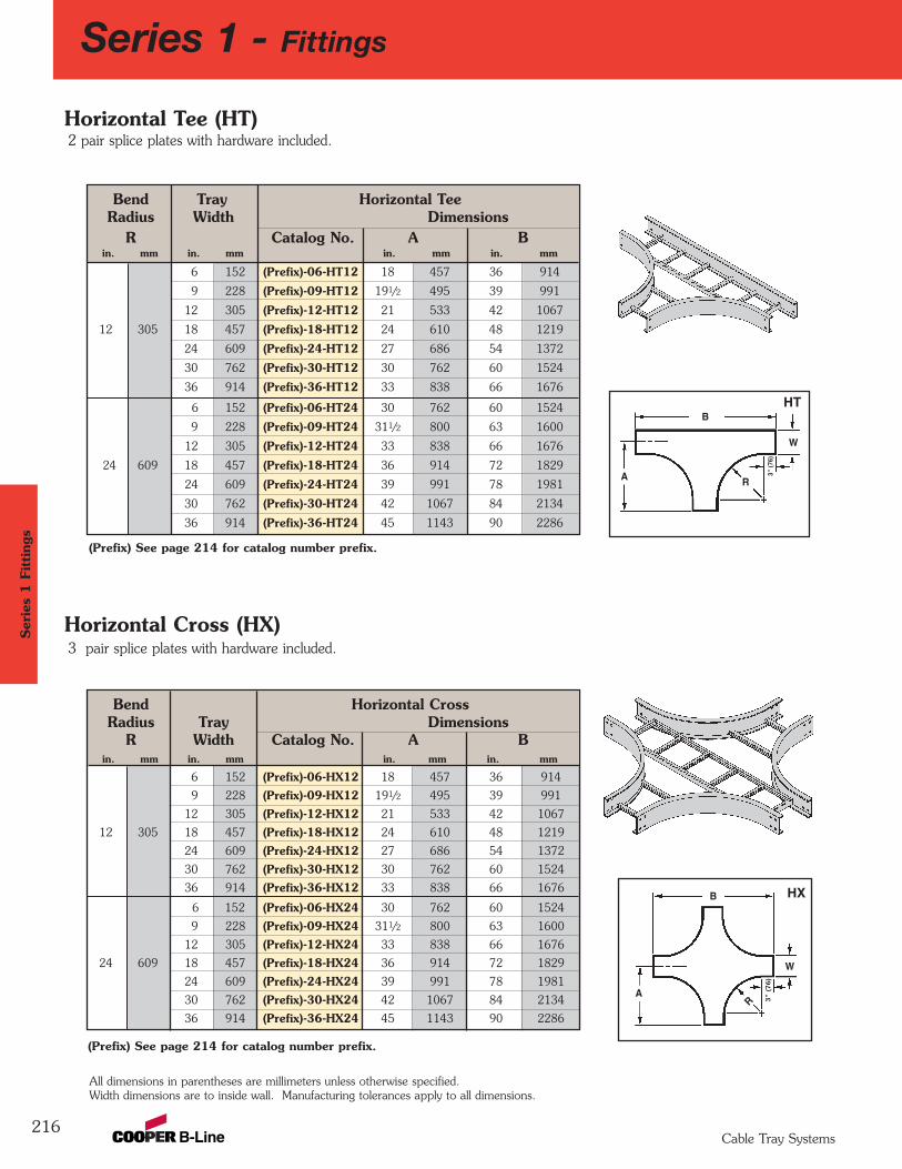
Bend Horizontal CrossRadius Tray Dimensions
R Width Catalog No. A Bin. mm in. mm in. mm in. mm
6 152 (Prefix)-06-HX12 18 457 36 914
9 228 (Prefix)-09-HX12 191/2 495 39 991
12 305 (Prefix)-12-HX12 21 533 42 1067
12 305 18 457 (Prefix)-18-HX12 24 610 48 1219
24 609 (Prefix)-24-HX12 27 686 54 1372
30 762 (Prefix)-30-HX12 30 762 60 1524
36 914 (Prefix)-36-HX12 33 838 66 1676
6 152 (Prefix)-06-HX24 30 762 60 1524
9 228 (Prefix)-09-HX24 311/2 800 63 1600
12 305 (Prefix)-12-HX24 33 838 66 1676
24 609 18 457 (Prefix)-18-HX24 36 914 72 1829
24 609 (Prefix)-24-HX24 39 991 78 1981
30 762 (Prefix)-30-HX24 42 1067 84 2134
36 914 (Prefix)-36-HX24 45 1143 90 2286
Bend Tray Horizontal TeeRadius Width Dimensions
R Catalog No. A Bin. mm in. mm in. mm in. mm
6 152 (Prefix)-06-HT12 18 457 36 914
9 228 (Prefix)-09-HT12 191/2 495 39 991
12 305 (Prefix)-12-HT12 21 533 42 1067
12 305 18 457 (Prefix)-18-HT12 24 610 48 1219
24 609 (Prefix)-24-HT12 27 686 54 1372
30 762 (Prefix)-30-HT12 30 762 60 1524
36 914 (Prefix)-36-HT12 33 838 66 1676
6 152 (Prefix)-06-HT24 30 762 60 1524
9 228 (Prefix)-09-HT24 311/2 800 63 1600
12 305 (Prefix)-12-HT24 33 838 66 1676
24 609 18 457 (Prefix)-18-HT24 36 914 72 1829
24 609 (Prefix)-24-HT24 39 991 78 1981
30 762 (Prefix)-30-HT24 42 1067 84 2134
36 914 (Prefix)-36-HT24 45 1143 90 2286
216
A
W
R
B
A
W
R
B
2 pair splice plates with hardware included.
3 pair splice plates with hardware included.
All dimensions in parentheses are millimeters unless otherwise specified.Width dimensions are to inside wall. Manufacturing tolerances apply to all dimensions.
Horizontal Tee (HT)
Horizontal Cross (HX)
3" (
76)
3"
(76)
(Prefix) See page 214 for catalog number prefix.
(Prefix) See page 214 for catalog number prefix.
HX
HT
Series 1 - FittingsSer
ies
1 F
itting
s
Cable Tray Systems
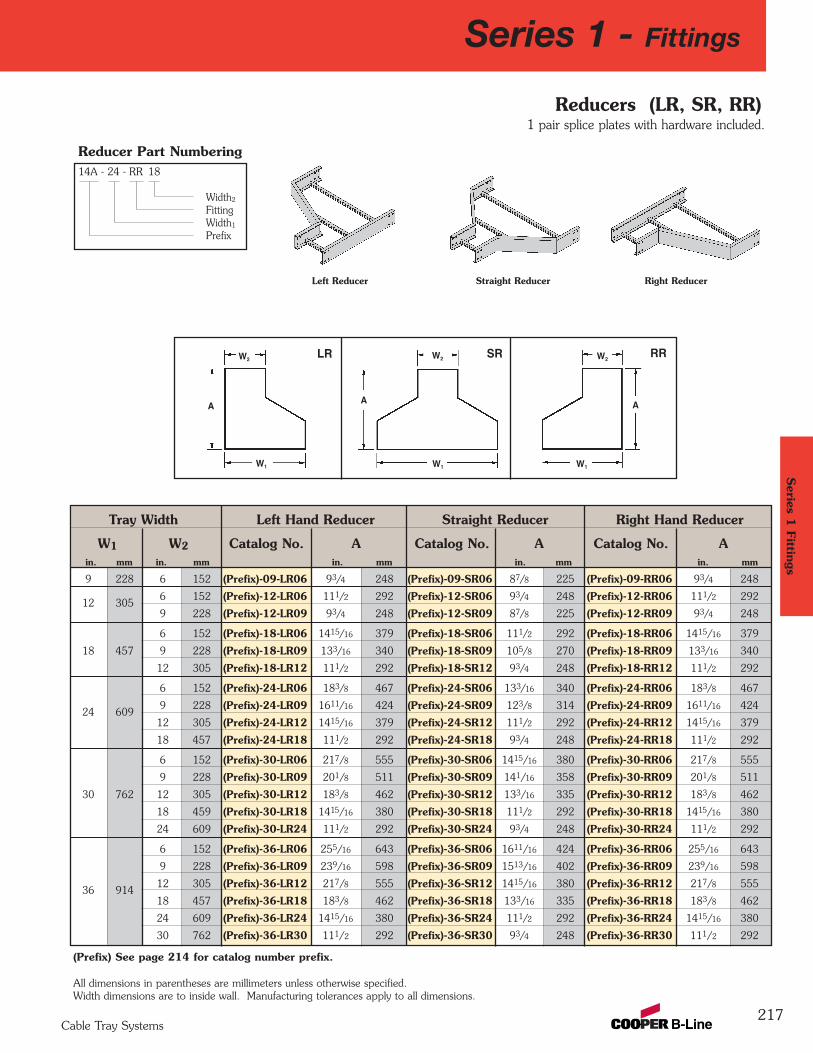
Tray Width Left Hand Reducer Straight Reducer Right Hand Reducer
W1 W2 Catalog No. A Catalog No. A Catalog No. Ain. mm in. mm in. mm in. mm in. mm
9 228 6 152 (Prefix)-09-LR06 93/4 248 (Prefix)-09-SR06 87/8 225 (Prefix)-09-RR06 93/4 248
12 3056 152 (Prefix)-12-LR06 111/2 292 (Prefix)-12-SR06 93/4 248 (Prefix)-12-RR06 111/2 292
9 228 (Prefix)-12-LR09 93/4 248 (Prefix)-12-SR09 87/8 225 (Prefix)-12-RR09 93/4 248
6 152 (Prefix)-18-LR06 1415/16 379 (Prefix)-18-SR06 111/2 292 (Prefix)-18-RR06 1415/16 379
18 457 9 228 (Prefix)-18-LR09 133/16 340 (Prefix)-18-SR09 105/8 270 (Prefix)-18-RR09 133/16 340
12 305 (Prefix)-18-LR12 111/2 292 (Prefix)-18-SR12 93/4 248 (Prefix)-18-RR12 111/2 292
6 152 (Prefix)-24-LR06 183/8 467 (Prefix)-24-SR06 133/16 340 (Prefix)-24-RR06 183/8 467
24 6099 228 (Prefix)-24-LR09 1611/16 424 (Prefix)-24-SR09 123/8 314 (Prefix)-24-RR09 1611/16 424
12 305 (Prefix)-24-LR12 1415/16 379 (Prefix)-24-SR12 111/2 292 (Prefix)-24-RR12 1415/16 379
18 457 (Prefix)-24-LR18 111/2 292 (Prefix)-24-SR18 93/4 248 (Prefix)-24-RR18 111/2 292
6 152 (Prefix)-30-LR06 217/8 555 (Prefix)-30-SR06 1415/16 380 (Prefix)-30-RR06 217/8 555
9 228 (Prefix)-30-LR09 201/8 511 (Prefix)-30-SR09 141/16 358 (Prefix)-30-RR09 201/8 511
30 762 12 305 (Prefix)-30-LR12 183/8 462 (Prefix)-30-SR12 133/16 335 (Prefix)-30-RR12 183/8 462
18 459 (Prefix)-30-LR18 1415/16 380 (Prefix)-30-SR18 111/2 292 (Prefix)-30-RR18 1415/16 380
24 609 (Prefix)-30-LR24 111/2 292 (Prefix)-30-SR24 93/4 248 (Prefix)-30-RR24 111/2 292
6 152 (Prefix)-36-LR06 255/16 643 (Prefix)-36-SR06 1611/16 424 (Prefix)-36-RR06 255/16 643
9 228 (Prefix)-36-LR09 239/16 598 (Prefix)-36-SR09 1513/16 402 (Prefix)-36-RR09 239/16 598
36 91412 305 (Prefix)-36-LR12 217/8 555 (Prefix)-36-SR12 1415/16 380 (Prefix)-36-RR12 217/8 555
18 457 (Prefix)-36-LR18 183/8 462 (Prefix)-36-SR18 133/16 335 (Prefix)-36-RR18 183/8 462
24 609 (Prefix)-36-LR24 1415/16 380 (Prefix)-36-SR24 111/2 292 (Prefix)-36-RR24 1415/16 380
30 762 (Prefix)-36-LR30 111/2 292 (Prefix)-36-SR30 93/4 248 (Prefix)-36-RR30 111/2 292
217
14A - 24 - RR 18
Width2
FittingWidth1
Prefix
Right ReducerStraight ReducerLeft Reducer
Reducers (LR, SR, RR)1 pair splice plates with hardware included.
All dimensions in parentheses are millimeters unless otherwise specified.Width dimensions are to inside wall. Manufacturing tolerances apply to all dimensions.
A
W2
W1
LR
A
W2
W1
SR
A
W2
W1
RR
(Prefix) See page 214 for catalog number prefix.
Reducer Part Numbering
Series 1
Fittings
Series 1 - Fittings
Cable Tray Systems
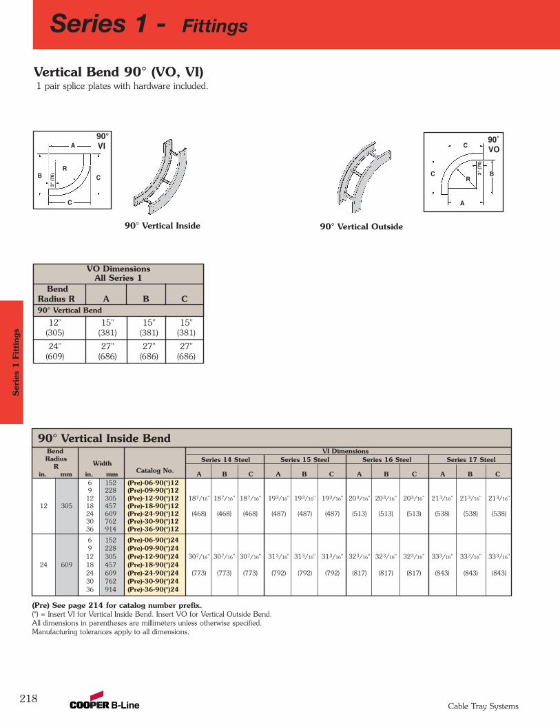
90° Vertical Inside BendBend VI DimensionsRadius
Width Series 14 Steel Series 15 Steel Series 16 Steel Series 17 SteelR
in. mm in. mm Catalog No. A B C A B C A B C A B C6 152 (Pre)-06-90(*)129 228 (Pre)-09-90(*)1212 305 (Pre)-12-90(*)12 187/16" 187/16" 187/16" 193/16" 193/16" 193/16" 203/16" 203/16" 203/16" 213/16" 213/16" 213/16"
12 305 18 457 (Pre)-18-90(*)12 24 609 (Pre)-24-90(*)12 (468) (468) (468) (487) (487) (487) (513) (513) (513) (538) (538) (538)30 762 (Pre)-30-90(*)1236 914 (Pre)-36-90(*)12
6 152 (Pre)-06-90(*)249 228 (Pre)-09-90(*)2412 305 (Pre)-12-90(*)24 307/16" 307/16" 307/16" 313/16" 313/16" 313/16" 323/16" 323/16" 323/16" 333/16" 333/16" 333/16"
24 609 18 457 (Pre)-18-90(*)2424 609 (Pre)-24-90(*)24 (773) (773) (773) (792) (792) (792) (817) (817) (817) (843) (843) (843)30 762 (Pre)-30-90(*)2436 914 (Pre)-36-90(*)24
218
A
C
C
BR
3" (
76)
C
CBR
3" (
76)
A90°VI
90° Vertical Outside
Vertical Bend 90° (VO, VI)1 pair splice plates with hardware included.
(Pre) See page 214 for catalog number prefix. (*) = Insert VI for Vertical Inside Bend. Insert VO for Vertical Outside Bend.All dimensions in parentheses are millimeters unless otherwise specified.Manufacturing tolerances apply to all dimensions.
90° Vertical Inside
90˚VO
Series 1 - FittingsSer
ies
1 F
itting
s
Cable Tray Systems
12" 15" 15" 15"(305) (381) (381) (381)
24" 27" 27" 27"(609) (686) (686) (686)
VO DimensionsAll Series 1
BendRadius R A B C90° Vertical Bend
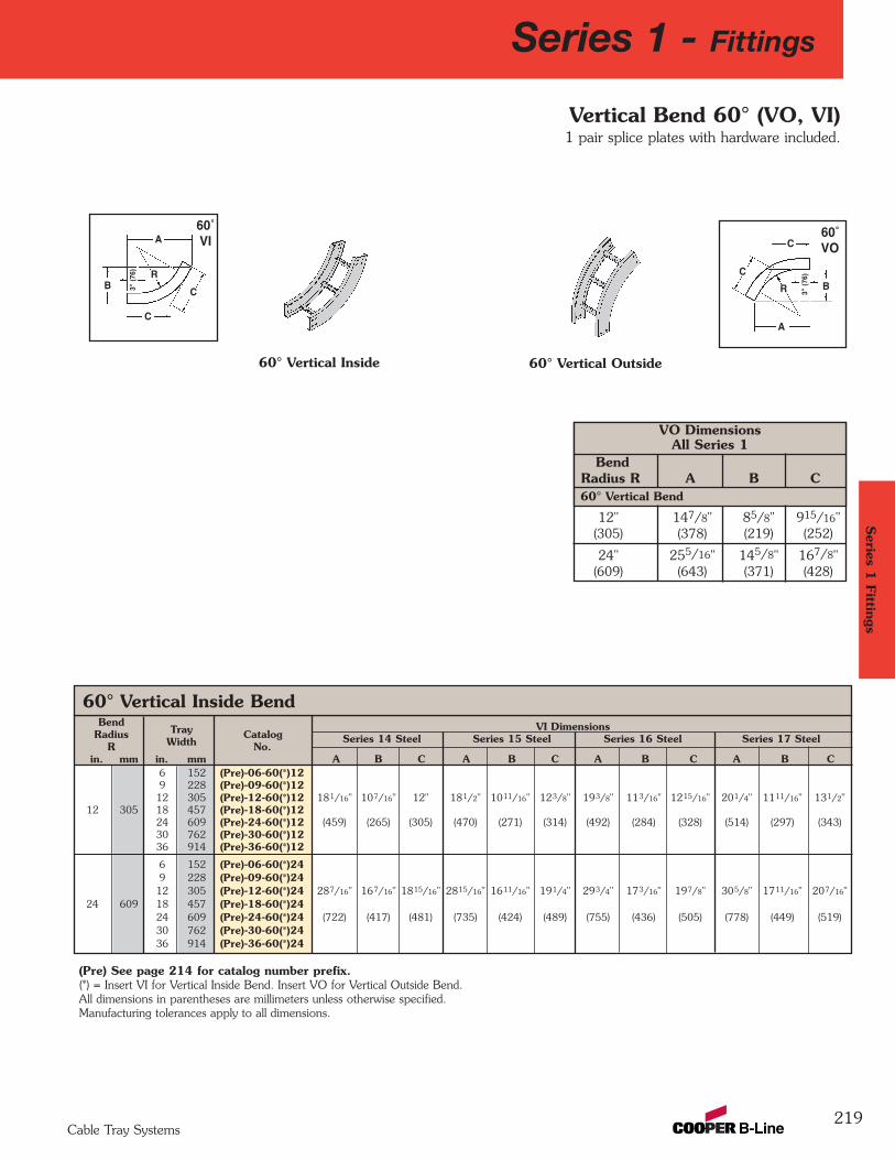
BendTray VI Dimensions
RadiusWidth
Catalog Series 14 Steel Series 15 Steel Series 16 Steel Series 17 Steel R No.
in. mm in. mm A B C A B C A B C A B C6 152 (Pre)-06-60(*)129 228 (Pre)-09-60(*)1212 305 (Pre)-12-60(*)12 181/16" 107/16" 12" 181/2" 1011/16" 123/8" 193/8" 113/16" 1215/16" 201/4" 1111/16" 131/2"
12 305 18 457 (Pre)-18-60(*)1224 609 (Pre)-24-60(*)12 (459) (265) (305) (470) (271) (314) (492) (284) (328) (514) (297) (343)30 762 (Pre)-30-60(*)1236 914 (Pre)-36-60(*)12
6 152 (Pre)-06-60(*)249 228 (Pre)-09-60(*)2412 305 (Pre)-12-60(*)24 287/16" 167/16" 1815/16" 2815/16" 1611/16" 191/4" 293/4" 173/16" 197/8" 305/8" 1711/16" 207/16"
24 609 18 457 (Pre)-18-60(*)2424 609 (Pre)-24-60(*)24 (722) (417) (481) (735) (424) (489) (755) (436) (505) (778) (449) (519)30 762 (Pre)-30-60(*)2436 914 (Pre)-36-60(*)24
60° Vertical Inside Bend
219
60˚VO
60˚VI
A
C
C
R
C
CB
R
3" (
76)
A
(Pre) See page 214 for catalog number prefix. (*) = Insert VI for Vertical Inside Bend. Insert VO for Vertical Outside Bend.All dimensions in parentheses are millimeters unless otherwise specified.Manufacturing tolerances apply to all dimensions.
60° Vertical Inside 60° Vertical Outside
Vertical Bend 60° (VO, VI)1 pair splice plates with hardware included.
3" (
76)
B
Series 1 - Fittings
Cable Tray Systems
Series 1
Fittings
12" 147/8" 85/8" 915/16"(305) (378) (219) (252)
24" 255/16" 145/8" 167/8"(609) (643) (371) (428)
VO DimensionsAll Series 1
BendRadius R A B C60° Vertical Bend
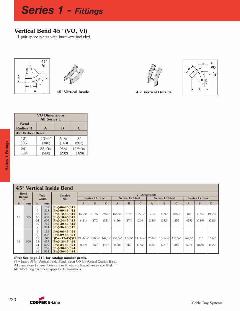
BendTray Catalog VI Dimensions
RadiusWidth No. Series 14 Steel Series 15 Steel Series 16 Steel Series 17 Steel
R in. mm in. mm A B C A B C A B C A B C
6 152 (Pre)-06-45(*)129 228 (Pre)-09-45(*)1212 305 (Pre)-12-45(*)12 163/16" 611/16" 91/2" 169/16" 67/8" 911/16" 171/4" 73/16" 101/8" 18" 77/16" 109/16"
12 305 18 457 (Pre)-18-45(*)12 24 609 (Pre)-24-45(*)12 (411) (170) (241) (420) (174) (246 (438) (182) (257 (457) (189) (268)30 762 (Pre)-30-45(*)1236 914 (Pre)-36-45(*)12
6 152 (Pre)-06-45(*)249 228 (Pre)-09-45(*)2412 305 (Pre)-12-45(*)24 2411/16" 103/16" 147/16" 251/16" 103/8" 1114/16" 253/4" 1011/16" 151/16" 261/2" 11" 151/2"
24 609 18 457 (Pre)-18-45(*)2424 609 (Pre)-24-45(*)24 (627) (259) (367) (662) (263) (373) (654) (271) (382 (673) (279) (394)30 762 (Pre)-30-45(*)2436 914 (Pre)-36-45(*)24
45° Vertical Inside Bend
220
45° Vertical Outside
Vertical Bend 45° (VO, VI)1 pair splice plates with hardware included.
(Pre) See page 214 for catalog number prefix. (*) = Insert VI for Vertical Inside Bend. Insert VO for Vertical Outside Bend.All dimensions in parentheses are millimeters unless otherwise specified.Manufacturing tolerances apply to all dimensions.
45° Vertical InsideA
C
C
B
R
3" (
76)
C
CB
R
3" (
76)
A
45˚VO
45°VI
Series 1 - FittingsSer
ies
1 F
itting
s
Cable Tray Systems
12" 135/8" 55/8" 8"(305) (346) (143) (203)
24" 221/16" 91/8" 1215/16"(609) (560) (232) (328)
VO DimensionsAll Series 1
BendRadius R A B C45° Vertical Bend
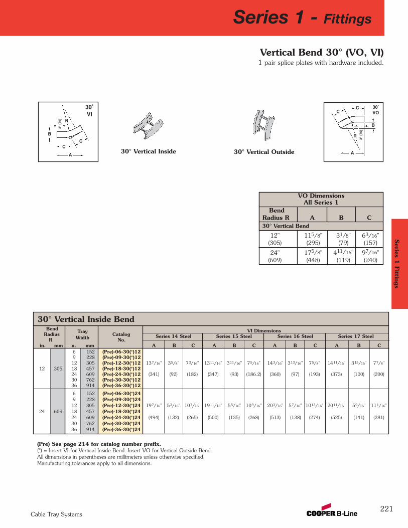
Bend Tray VI DimensionsRadius
WidthCatalog Series 14 Steel Series 15 Steel Series 16 Steel Series 17 Steel
R No.in. mm n. mm A B C A B C A B C A B C
6 152 (Pre)-06-30(*)129 228 (Pre)-09-30(*)1212 305 (Pre)-12-30(*)12 137/16" 35/8" 73/16" 1311/16" 311/16" 75/16" 143/16" 313/16" 75/8" 1411/16" 315/16" 77/8"
12 305 18 457 (Pre)-18-30(*)12 24 609 (Pre)-24-30(*)12 (341) (92) (182) (347) (93) (186.2) (360) (97) (193) (373) (100) (200)30 762 (Pre)-30-30(*)1236 914 (Pre)-36-30(*)12
6 152 (Pre)-06-30(*)249 228 (Pre)-09-30(*)2412 305 (Pre)-12-30(*)24 197/16" 53/16" 107/16" 1911/16" 55/16" 109/16" 203/16" 57/16" 1013/16" 2011/16" 59/16" 111/16"
24 609 18 457 (Pre)-18-30(*)2424 609 (Pre)-24-30(*)24 (494) (132) (265) (500) (135) (268) (513) (138) (274) (525) (141) (281)30 762 (Pre)-30-30(*)2436 914 (Pre)-36-30(*)24
12" 115/8" 31/8" 63/16"(305) (295) (79) (157)
24" 175/8" 411/16" 97/16"(609) (448) (119) (240)
221
30° Vertical Inside Bend
VO DimensionsAll Series 1
BendRadius R A B C30° Vertical Bend
(Pre) See page 214 for catalog number prefix. (*) = Insert VI for Vertical Inside Bend. Insert VO for Vertical Outside Bend.All dimensions in parentheses are millimeters unless otherwise specified.Manufacturing tolerances apply to all dimensions.
30° Vertical Inside 30° Vertical Outside
Vertical Bend 30° (VO, VI)1 pair splice plates with hardware included.
A
CC
B
R
3" (
76)
CC
B
R
3" (
76)
A
30˚VI
30˚VO
Series 1 - Fittings
Cable Tray Systems
Series 1
Fittings
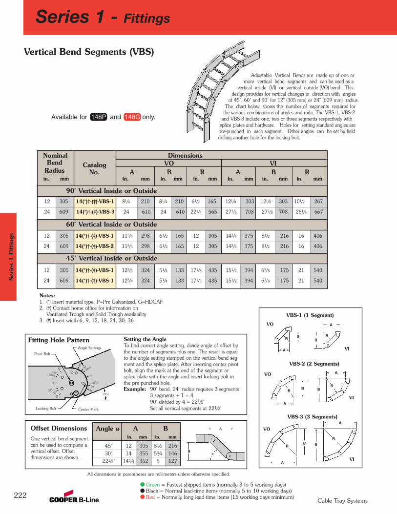
12 305 14(*)†-(‡)-VBS-1 81/4 210 81/4 210 61/2 165 121/8 303 121/8 303 101/2 267
24 609 14(*)†-(‡)-VBS-3 24 610 24 610 221/4 565 277/8 708 277/8 708 261/4 667
12 305 14(*)†-(‡)-VBS-1 113/4 298 61/2 165 12 305 143/4 375 81/2 216 16 406
24 609 14(*)†-(‡)-VBS-2 113/4 298 61/2 165 12 305 143/4 375 81/2 216 16 406
12 305 14(*)†-(‡)-VBS-1 123/4 324 51/4 133 171/8 435 151/2 394 67/8 175 21 540
24 609 14(*)†-(‡)-VBS-1 123/4 324 51/4 133 171/8 435 151/2 394 67/8 175 21 540
Nominal DimensionsBend Catalog VO VI
Radius No. A B R A B Rin. mm in. mm in. mm in. mm in. mm in. mm in. mm
90˚ Vertical Inside or Outside
Angle ø A Bin. mm in. mm
45˚ 12 305 81/2 21630˚ 14 355 53/4 146
221/2˚ 141/4 362 5 127
Series 1 - Fittings
222
Adjustable Vertical Bends are made up of one ormore vertical bend segments and can be used as a
vertical inside (VI) or vertical outside (VO) bend. Thisdesign provides for vertical changes in direction with angles
of 45˚, 60˚ and 90˚ for 12" (305 mm) or 24" (609 mm) radius.The chart below shows the number of segments required for
the various combinations of angles and radii. The VBS-1, VBS-2and VBS-3 include one, two or three segments respectively with
splice plates and hardware. Holes for setting standard angles arepre-punched in each segment. Other angles can be set by fielddrilling another hole for the locking bolt.
Vertical Bend Segments (VBS)
Notes:1. (*) Insert material type: P=Pre Galvanized, G=HDGAF2. (†) Contact home office for information on
Ventilated Trough and Solid Trough availability3. (‡) Insert width 6, 9, 12, 18, 24, 30, 36
Setting the AngleTo find correct angle setting, divide angle of offset bythe number of segments plus one. The result is equalto the angle setting stamped on the vertical bend seg-ment and the splice plate. After inserting center pivotbolt, align the mark at the end of the segment orsplice plate with the angle and insert locking bolt inthe pre-punched hole.Example: 90˚ bend, 24" radius requires 3 segments
3 segments + 1 = 490˚ divided by 4 = 221/2˚Set all vertical segments at 221/2˚
45
45
221/2
0
Locking Bolt
Pivot Bolt
Center Mark
Angle Settings
3045
45
221/2
221/2
221/2
0
30
30
30221/2
Fitting Hole Pattern
Offset DimensionsOne vertical bend segmentcan be used to complete avertical offset. Offsetdimensions are shown.
VO
R
A
R
A
B
R
A
BR
A
B
R
A
BR
B
VO
VO
VI
VI
VI
VBS-1 (1 Segment)
VBS-2 (2 Segments)
A
øB
All dimensions in parentheses are millimeters unless otherwise specified.
Available for 148P and 148G only.
A
60˚ Vertical Inside or Outside
45˚ Vertical Inside or Outside
B
VBS-3 (3 Segments)
Ser
ies
1 F
itting
s
Cable Tray Systems
Green = Fastest shipped items (normally 3 to 5 working days)Black = Normal lead-time items (normally 5 to 10 working days)Red = Normally long lead-time items (15 working days minimum)
Notes
223
Series 1
Fittings
Cable Tray Systems
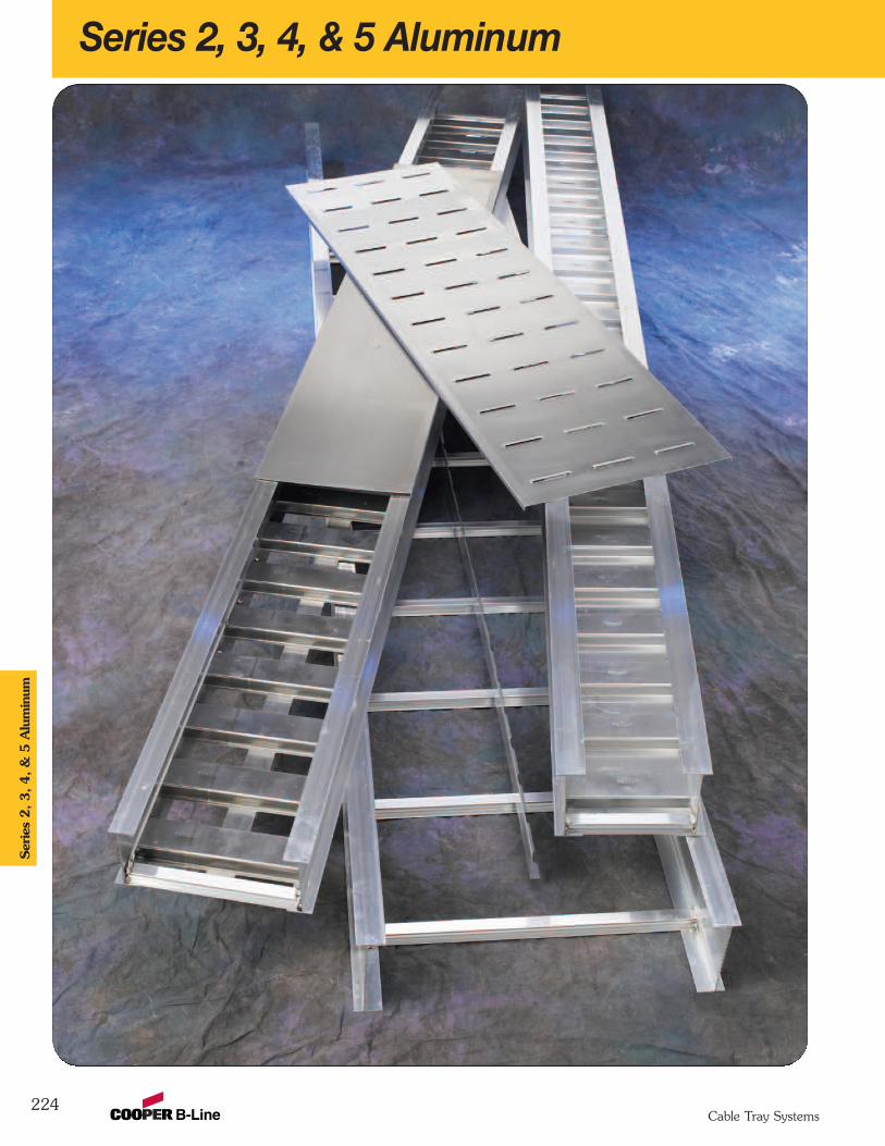
Series 2, 3, 4, & 5 Aluminum
224
Ser
ies
2, 3, 4, &
5 A
lum
inum
Cable Tray Systems
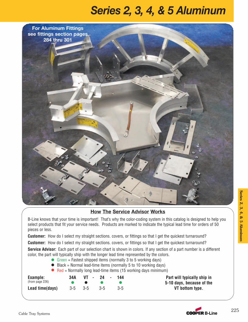
Series 2, 3, 4, & 5 Aluminum
225
Series 2
, 3, 4
, & 5
Alum
inum
Cable Tray Systems
How The Service Advisor Works
B-Line knows that your time is important! That’s why the color-coding system in this catalog is designed to help youselect products that fit your service needs. Products are marked to indicate the typical lead time for orders of 50pieces or less.Customer: How do I select my straight sections. covers, or fittings so that I get the quickest turnaround?Customer: How do I select my straight sections. covers, or fittings so that I get the quickest turnaround?Service Advisor: Each part of our selection chart is shown in colors. If any section of a part number is a differentcolor, the part will typically ship with the longer lead time represented by the colors.
Green = Fastest shipped items (normally 3 to 5 working days)Black = Normal lead-time items (normally 5 to 10 working days)Red = Normally long lead-time items (15 working days minimum)
Example: 34A VT - 24 - 144 Part will typically ship in(from page 226) 5-10 days, because of the Lead time(days) 3-5 3-5 3-5 3-5 VT bottom type.
For Aluminum Fittingssee fittings section pages
284 thru 301
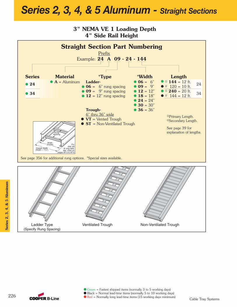
Series 2, 3, 4, & 5 Aluminum - Straight Sections
226
3" NEMA VE 1 Loading Depth4" Side Rail Height
Ladder Type(Specify Rung Spacing)
Ventilated Trough Non-Ventilated Trough
Overall Width(Width + 11/2")
Forside rail
& rung data,see chart on
pages AP-5 & AP-6
RungSpacing
Width(Inside)
Straight Section Part NumberingPrefix
Example: 24 A 09 - 24 - 144
Series Material *Type *Width Length24 A = Aluminum Ladder- 06 = 6" ¬ 144 = 12 ft.
2406 = 6" rung spacing 09 = 9" Á 120 = 10 ft.
34 09 = 9" rung spacing 12 = 12" ¬ 240 = 20 ft.3412 = 12" rung spacing 18 = 18" Á 144 = 12 ft.
24 = 24"30 = 30"
Trough- 36 = 36"6" thru 36" wideVT = Vented TroughST = Non-Ventilated Trough
See page 356 for additional rung options. *Special sizes available.
Ser
ies
2, 3, 4, &
5 A
lum
inum
Cable Tray Systems
Green = Fastest shipped items (normally 3 to 5 working days)Black = Normal lead-time items (normally 5 to 10 working days)Red = Normally long lead-time items (15 working days minimum)
¬Primary Length.ÁSecondary Length.
See page 39 for explanation of lengths.
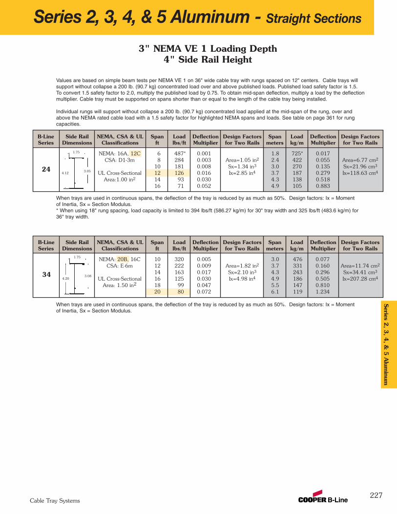
B-Line Side Rail NEMA, CSA & UL Span Load Deflection Design Factors Span Load Deflection Design FactorsSeries Dimensions Classifications ft lbs/ft Multiplier for Two Rails meters kg/m Multiplier for Two Rails
NEMA: 16A, 12C 6 487* 0.001 1.8 725* 0.017CSA: D1-3m 8 284 0.003 Area=1.05 in2 2.4 422 0.055 Area=6.77 cm2
10 181 0.008 Sx=1.34 in3 3.0 270 0.135 Sx=21.96 cm3
UL Cross-Sectional 12 126 0.016 Ix=2.85 in4 3.7 187 0.279 Ix=118.63 cm4
Area:1.00 in2 14 93 0.030 4.3 138 0.51816 71 0.052 4.9 105 0.883
B-Line Side Rail NEMA, CSA & UL Span Load Deflection Design Factors Span Load Deflection Design FactorsSeries Dimensions Classifications ft lbs/ft Multiplier for Two Rails meters kg/m Multiplier for Two Rails
NEMA: 20B, 16C 10 320 0.005 3.0 476 0.077CSA: E-6m 12 222 0.009 Area=1.82 in2 3.7 331 0.160 Area=11.74 cm2
14 163 0.017 Sx=2.10 in3 4.3 243 0.296 Sx=34.41 cm3
UL Cross-Sectional 16 125 0.030 Ix=4.98 in4 4.9 186 0.505 Ix=207.28 cm4
Area: 1.50 in2 18 99 0.047 5.5 147 0.81020 80 0.072 6.1 119 1.234
Series 2, 3, 4, & 5 Aluminum - Straight Sections
227
1.75
4.203.08
Values are based on simple beam tests per NEMA VE 1 on 36" wide cable tray with rungs spaced on 12" centers. Cable trays willsupport without collapse a 200 lb. (90.7 kg) concentrated load over and above published loads. Published load safety factor is 1.5.To convert 1.5 safety factor to 2.0, multiply the published load by 0.75. To obtain mid-span deflection, multiply a load by the deflectionmultiplier. Cable tray must be supported on spans shorter than or equal to the length of the cable tray being installed.
Individual rungs will support without collapse a 200 lb. (90.7 kg) concentrated load applied at the mid-span of the rung, over andabove the NEMA rated cable load with a 1.5 safety factor for highlighted NEMA spans and loads. See table on page 361 for rungcapacities.
When trays are used in continuous spans, the deflection of the tray is reduced by as much as 50%. Design factors: Ix = Momentof Inertia, Sx = Section Modulus.
1.75
4.12 3.05
3" NEMA VE 1 Loading Depth4" Side Rail Height
When trays are used in continuous spans, the deflection of the tray is reduced by as much as 50%. Design factors: Ix = Momentof Inertia, Sx = Section Modulus.* When using 18" rung spacing, load capacity is limited to 394 lbs/ft (586.27 kg/m) for 30" tray width and 325 lbs/ft (483.6 kg/m) for36" tray width.
34
24
Series 2
, 3, 4
, & 5
Alum
inum
Cable Tray Systems
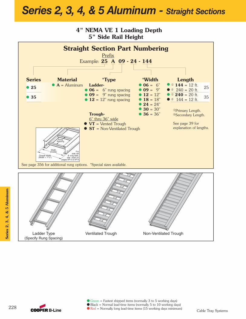
Series 2, 3, 4, & 5 Aluminum - Straight Sections
228
4" NEMA VE 1 Loading Depth5" Side Rail Height
Overall Width(Width + 11/2")
Forside rail
& rung data,see chart on
pages AP-5 & AP-6
RungSpacing
Width(Inside)
Straight Section Part NumberingPrefix
Example: 25 A 09 - 24 - 144
Series Material *Type *Width Length25 A = Aluminum Ladder- 06 = 6" ¬ 144 = 12 ft.
2506 = 6" rung spacing 09 = 9" Á 240 = 20 ft.
35 09 = 9" rung spacing 12 = 12" ¬ 240 = 20 ft.3512 = 12" rung spacing 18 = 18" Á 144 = 12 ft.
24 = 24"30 = 30"
Trough- 36 = 36"6" thru 36" wideVT = Vented TroughST = Non-Ventilated Trough
See page 356 for additional rung options. *Special sizes available.
Ladder Type(Specify Rung Spacing)
Ventilated Trough Non-Ventilated Trough
Ser
ies
2, 3, 4, &
5 A
lum
inum
Cable Tray Systems
Green = Fastest shipped items (normally 3 to 5 working days)Black = Normal lead-time items (normally 5 to 10 working days)Red = Normally long lead-time items (15 working days minimum)
¬Primary Length.ÁSecondary Length.
See page 39 for explanation of lengths.
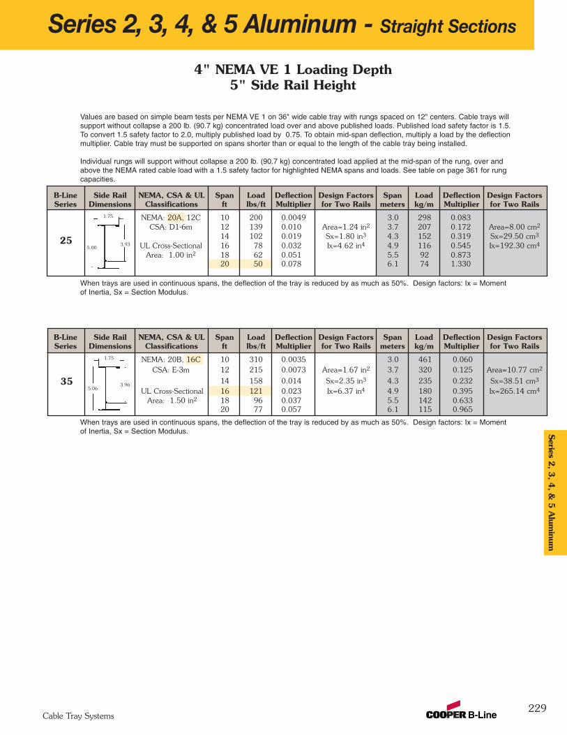
B-Line Side Rail NEMA, CSA & UL Span Load Deflection Design Factors Span Load Deflection Design FactorsSeries Dimensions Classifications ft lbs/ft Multiplier for Two Rails meters kg/m Multiplier for Two Rails
NEMA: 20B, 16C 10 310 0.0035 3.0 461 0.060CSA: E-3m 12 215 0.0073 Area=1.67 in2 3.7 320 0.125 Area=10.77 cm2
14 158 0.014 Sx=2.35 in3 4.3 235 0.232 Sx=38.51 cm3
UL Cross-Sectional 16 121 0.023 Ix=6.37 in4 4.9 180 0.395 Ix=265.14 cm4
Area: 1.50 in2 18 96 0.037 5.5 142 0.63320 77 0.057 6.1 115 0.965
B-Line Side Rail NEMA, CSA & UL Span Load Deflection Design Factors Span Load Deflection Design FactorsSeries Dimensions Classifications ft lbs/ft Multiplier for Two Rails meters kg/m Multiplier for Two Rails
NEMA: 20A, 12C 10 200 0.0049 3.0 298 0.083CSA: D1-6m 12 139 0.010 Area=1.24 in2 3.7 207 0.172 Area=8.00 cm2
14 102 0.019 Sx=1.80 in3 4.3 152 0.319 Sx=29.50 cm3
UL Cross-Sectional 16 78 0.032 Ix=4.62 in4 4.9 116 0.545 Ix=192.30 cm4
Area: 1.00 in2 18 62 0.051 5.5 92 0.87320 50 0.078 6.1 74 1.330
Series 2, 3, 4, & 5 Aluminum - Straight Sections
229
Values are based on simple beam tests per NEMA VE 1 on 36" wide cable tray with rungs spaced on 12" centers. Cable trays willsupport without collapse a 200 lb. (90.7 kg) concentrated load over and above published loads. Published load safety factor is 1.5. To convert 1.5 safety factor to 2.0, multiply published load by 0.75. To obtain mid-span deflection, multiply a load by the deflectionmultiplier. Cable tray must be supported on spans shorter than or equal to the length of the cable tray being installed.
Individual rungs will support without collapse a 200 lb. (90.7 kg) concentrated load applied at the mid-span of the rung, over andabove the NEMA rated cable load with a 1.5 safety factor for highlighted NEMA spans and loads. See table on page 361 for rungcapacities.
1.75
5.003.93
1.75
5.063.96
When trays are used in continuous spans, the deflection of the tray is reduced by as much as 50%. Design factors: Ix = Momentof Inertia, Sx = Section Modulus.
When trays are used in continuous spans, the deflection of the tray is reduced by as much as 50%. Design factors: Ix = Momentof Inertia, Sx = Section Modulus.
4" NEMA VE 1 Loading Depth5" Side Rail Height
25
35
Series 2
, 3, 4
, & 5
Alum
inum
Cable Tray Systems
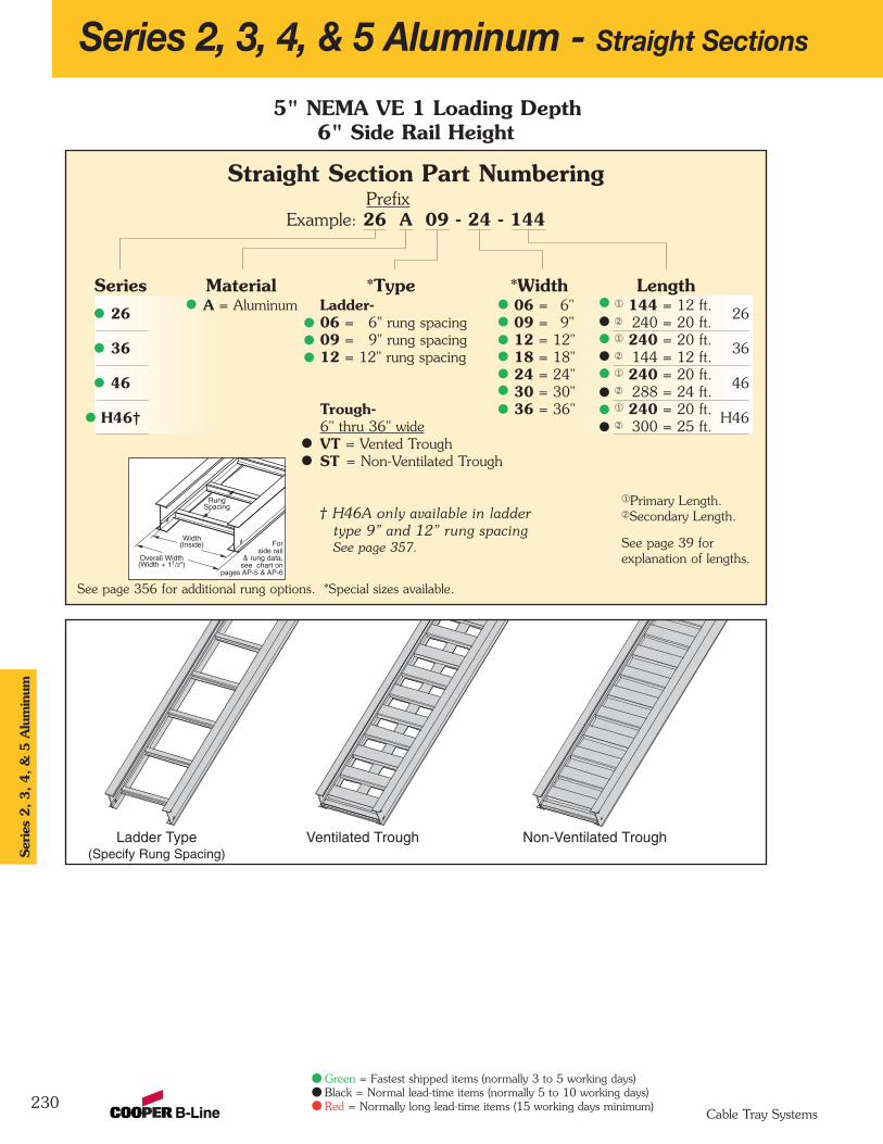
Series 2, 3, 4, & 5 Aluminum - Straight Sections
230
5" NEMA VE 1 Loading Depth6" Side Rail Height
Overall Width(Width + 11/2")
Forside rail
& rung data,see chart on
pages AP-5 & AP-6
RungSpacing
Width(Inside)
Straight Section Part NumberingPrefix
Example: 26 A 09 - 24 - 144
Series Material *Type *Width Length26 A = Aluminum Ladder- 06 = 6" ¬ 144 = 12 ft.
2606 = 6" rung spacing 09 = 9" Á 240 = 20 ft.
36 09 = 9" rung spacing 12 = 12" ¬ 240 = 20 ft.3612 = 12" rung spacing 18 = 18" Á 144 = 12 ft.
46 24 = 24" ¬ 240 = 20 ft.4630 = 30" Á 288 = 24 ft.
H46† Trough- 36 = 36" ¬ 240 = 20 ft.H46
6" thru 36" wide Á 300 = 25 ft.VT = Vented TroughST = Non-Ventilated Trough
† H46A only available in laddertype 9” and 12” rung spacingSee page 357.
See page 356 for additional rung options. *Special sizes available.
Ladder Type(Specify Rung Spacing)
Ventilated Trough Non-Ventilated Trough
Ser
ies
2, 3, 4, &
5 A
lum
inum
Cable Tray Systems
Green = Fastest shipped items (normally 3 to 5 working days)Black = Normal lead-time items (normally 5 to 10 working days)Red = Normally long lead-time items (15 working days minimum)
¬Primary Length.ÁSecondary Length.
See page 39 for explanation of lengths.

B-Line Side Rail NEMA, CSA & UL Span Load Deflection Design Factors Span Load Deflection Design FactorsSeries Dimensions Classifications ft lbs/ft Multiplier for Two Rails meters kg/m Multiplier for Two Rails
NEMA: 20C+ 16 261 0.0085 4.9 388 0.145CSA: 131 kg/m 7.6m 18 206 0.014 Area=2.95 in2 5.5 307 0.233 Area=19.03 cm2
20 167 0.021 Sx=5.33 in3 6.1 248 0.355 Sx=87.34 cm3
UL Cross-Sectional 22 138 0.030 Ix=17.30 in4 6.7 205 0.520 Ix=720.08 cm4
Area: 2.00 in2 24 116 0.043 7.3 173 0.73725 88 0.051 7.6 131 0.867
B-Line Side Rail NEMA, CSA & UL Span Load Deflection Design Factors Span Load Deflection Design FactorsSeries Dimensions Classifications ft lbs/ft Multiplier for Two Rails meters kg/m Multiplier for Two Rails
NEMA: 20C 14 210 0.0071 4.3 313 0.121CSA: E-6m 16 161 0.012 Area=2.06 in2 4.9 239 0.207 Area=13.29 cm2
18 127 0.019 Sx=3.59 in3 5.5 189 0.331 Sx=58.83 cm3
UL Cross-Sectional 20 103 0.030 Ix=12.18 in4 6.1 153 0.505 Ix=506.97 cm4
Area: 1.50 in2 22 85 0.043 6.7 127 0.73924 72 0.061 7.3 106 1.046
B-Line Side Rail NEMA, CSA & UL Span Load Deflection Design Factors Span Load Deflection Design FactorsSeries Dimensions Classifications ft lbs/ft Multiplier for Two Rails meters kg/m Multiplier for Two Rails
NEMA: 20B, 16C 12 233 0.0043 3.7 347 0.073CSA: E-6m 14 171 0.008 Area=1.81 in2 4.3 255 0.136 Area=11.68 cm2
16 131 0.014 Sx=3.36 in3 4.9 195 0.232 Sx=55.06 cm3
UL Cross-Sectional 18 104 0.022 Ix=10.85 in4 5.5 154 0.372 Ix=451.61 cm4
Area: 1.50 in2 20 84 0.033 6.1 125 0.56622 69 0.049 6.7 103 0.829
B-Line Side Rail NEMA, CSA & UL Span Load Deflection Design Factors Span Load Deflection Design FactorsSeries Dimensions Classifications ft lbs/ft Multiplier for Two Rails meters kg/m Multiplier for Two Rails
NEMA: 20A, 16B 10 204 0.0028 3.0 304 0.049CSA: D1-6m 12 142 0.006 Area=1.41 in2 3.7 211 0.101 Area=9.10 cm2
14 104 0.011 Sx=2.53 in3 4.3 155 0.186 Sx=41.46 cm3
UL Cross-Sectional 16 80 0.019 Ix=7.915 in4 4.9 119 0.318 Ix=329.45 cm4
Area: 1.00 in2 18 63 0.030 5.5 94 0.50920 51 0.045 6.1 76 0.776
Series 2, 3, 4, & 5 Aluminum - Straight Sections
231
2.00
2.00
Values are based on simple beam tests per NEMA VE 1 on 36" wide cable tray with rungs spaced on 12" centers. Cable trays willsupport, without collapse, a 200 lb. (90.7 kg) concentrated load over and above published loads. Published load safety factor is 1.5. To convert 1.5 safety factor to 2.0, multiply the published load by 0.75. To obtain mid-span deflection, multiply a load by the deflectionmultiplier. Cable tray must be supported on spans shorter than or equal to the length of the cable tray being installed.
Individual rungs will support without collapse a 200 lb. (90.7 kg) concentrated load applied at the mid-span of the rung, over andabove the NEMA rated cable load with a 1.5 safety factor for highlighted NEMA spans and loads. See table on page 361 for rungcapacities.
When trays are used in continuous spans, the deflection of the tray is reduced by as much as 50%. Design factors: Ix = Momentof Inertia, Sx = Section Modulus.
6.12 5.04
6.17
2.00
6.19 5.08
5" NEMA VE 1 Loading Depth6" Side Rail Height
26
36
46
H46
5.06
2.00
6.245.09
When trays are used in continuous spans, the deflection of the tray is reduced by as much as 50%. Design factors: Ix = Momentof Inertia, Sx = Section Modulus.
When trays are used in continuous spans, the deflection of the tray is reduced by as much as 50%. Design factors: Ix = Momentof Inertia, Sx = Section Modulus.
When trays are used in continuous spans, the deflection of the tray is reduced by as much as 50%. Design factors: Ix = Momentof Inertia, Sx = Section Modulus.
Series 2
, 3, 4
, & 5
Alum
inum
Cable Tray Systems

232
Series 2, 3, 4, & 5 Aluminum - Straight Sections
6" NEMA VE 1 Loading Depth7" Side Rail Height
Overall Width(Width + 11/2")
Forside rail
& rung data,see chart on
pages AP-5 & AP-6
RungSpacing
Width(Inside)
Straight Section Part NumberingPrefix
Example: 37 A 09 - 24 - 240
Series Material *Type *Width Length37 A = Aluminum Ladder- 06 = 6" ¬ 240 = 20 ft.
3706 = 6" rung spacing 09 = 9" Á 144 = 12 ft.
47 09 = 9" rung spacing 12 = 12" ¬ 240 = 20 ft.4712 = 12" rung spacing 18 = 18" Á 288 = 24 ft.
H47† 24 = 24" ¬ 240 = 20 ft.H4730 = 30" Á 300 = 25 ft.
57† 36 = 36" ¬ 360 = 30 ft.57
Á 300 = 25 ft.Trough-6" thru 36" wideVT = Vented TroughST = Non-Ventilated Trough
† H47A & 57A only available in laddertype 9” and 12” rung spacing.See page 357.
See page 356 for additional rung options. *Special sizes available.
Ladder Type(Specify Rung Spacing)
57A available in(9” & 12” rung spacing in
12” to 36” widths)
Ventilated Trough Non-Ventilated Trough
Ser
ies
2, 3, 4, &
5 A
lum
inum
Cable Tray Systems
Green = Fastest shipped items (normally 3 to 5 working days)Black = Normal lead-time items (normally 5 to 10 working days)Red = Normally long lead-time items (15 working days minimum)
¬Primary Length.ÁSecondary Length.
See page 39 for explanation of lengths.
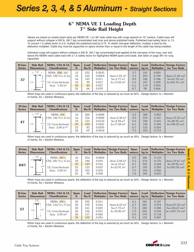
B-Line Side Rail NEMA, CSA & UL Span Load Deflection Design Factors Span Load Deflection Design FactorsSeries Dimensions Classifications ft lbs/ft Multiplier for Two Rails meters kg/m Multiplier for Two Rails
NEMA: 20C 14 204 0.0048 4.3 304 0.083CSA: 142 kg/m 6.1m 16 156 0.0082 Area=2.38 in2 4.9 233 0.141 Area=15.35 cm2
18 123 0.0132 Sx=4.94 in3 5.5 184 0.225 Sx=80.95 cm3
UL Cross-Sectional 20 100 0.0201 Ix=17.88 in4 6.1 149 0.344 Ix=744.22 cm4
Area: 2.00 in^2 22 83 0.0295 6.7 123 0.50324 69 0.0418 7.3 103 0.713
B-Line Side Rail NEMA, CSA & UL Span Load Deflection Design Factors Span Load Deflection Design FactorsSeries Dimensions Classifications ft lbs/ft Multiplier for Two Rails meters kg/m Multiplier for Two Rails
NEMA: 20B, 16C 12 222 0.0035 3.7 331 0.059CSA: 106 kg/m 6.1m 14 163 0.0064 Area=1.81 in2 4.3 243 0.109 Area=11.68 cm2
16 125 0.011 Sx=3.77 in3 4.9 186 0.186 Sx=61.78 cm3
UL Cross-Sectional 18 99 0.017 Ix=13.50 in4 5.5 147 0.299 Ix=561.91 cm4
Area: 1.50 in2 20 80 0.027 6.1 119 0.45522 66 0.039 6.7 98 0.666
Series 2, 3, 4, & 5 Aluminum - Straight Sections
233
Values are based on simple beam tests per NEMA VE 1 on 36" wide cable tray with rungs spaced on 12" centers. Cable trays willsupport without collapse a 200 lb. (90.7 kg) concentrated load over and above published loads. Published load safety factor is 1.5. To convert 1.5 safety factor to 2.0, multiply the published load by 0.75. To obtain mid-span deflection, multiply a load by thedeflection multiplier. Cable tray must be supported on spans shorter than or equal to the length of the cable tray being installed.
Individual rungs will support without collapse a 200 lb. (90.7 kg) concentrated load applied at the mid-span of the rung, over andabove the NEMA rated cable load with a 1.5 safety factor for highlighted NEMA spans and loads. See table on page 361 for rungcapacities.
When trays are used in continuous spans, the deflection of the tray is reduced by as much as 50%. Design factors: Ix = Momentof Inertia, Sx = Section Modulus.
2.00
7.146.05
2.00
7.24 6.13
6" NEMA VE 1 Loading Depth7" Side Rail Height
37
When trays are used in continuous spans, the deflection of the tray is reduced by as much as 50%. Design factors: Ix = Momentof Inertia, Sx = Section Modulus.
47
B-Line Side Rail NEMA, CSA & UL Span Load Deflection Design Factors Span Load Deflection Design FactorsSeries Dimensions Classifications ft lbs/ft Multiplier for Two Rails meters kg/m Multiplier for Two Rails
NEMA: 20C+ 16 233 0.0064 4.9 346 0.110CSA: 241 kg/m 6.1m 18 184 0.010 Area=3.04 in2 5.5 274 0.176 Area=19.61 cm2
20 149 0.016 Sx=6.10 in3 6.1 222 0.268 Sx=99.96 cm3
UL Cross-Sectional 22 123 0.023 Ix=22.91 in4 6.7 183 0.393 Ix=953.59 cm4
Area: 2.00 in2 24 103 0.033 7.3 154 0.55625 95 0.038 7.6 142 0.655
When trays are used in continuous spans, the deflection of the tray is reduced by as much as 50%. Design factors: Ix = Momentof Inertia, Sx = Section Modulus.
When trays are used in continuous spans, the deflection of the tray is reduced by as much as 50%. Design factors: Ix = Momentof Inertia, Sx = Section Modulus.
2.00
7.24 6.09H47
Series 2
, 3, 4
, & 5
Alum
inum
Cable Tray Systems
B-Line Side Rail NEMA, CSA & UL Span Load Deflection Design Factors Span Load Deflection Design FactorsSeries Dimensions Classifications ft lbs/ft Multiplier for Two Rails meters kg/m Multiplier for Two Rails
NEMA: 20C+ 20 232 0.011 6.1 345 0.187CSA: 152 kg/m 9.1m 22 192 0.016 Area=4.22 in2 6.7 285 0.274 Area=27.23 cm2
24 161 0.023 Sx=7.73 in3 7.3 240 0.388 Sx=126.67 cm3
UL Cross-Sectional 26 136 0.031 Ix=32.86 in4 7.9 202 0.534 Ix=1367.74 cm4
Area: 2.00 in2 28 117 0.042 8.5 174 0.71830 102 0.055 9.1 152 0.947
7.40 6.2357
2.00
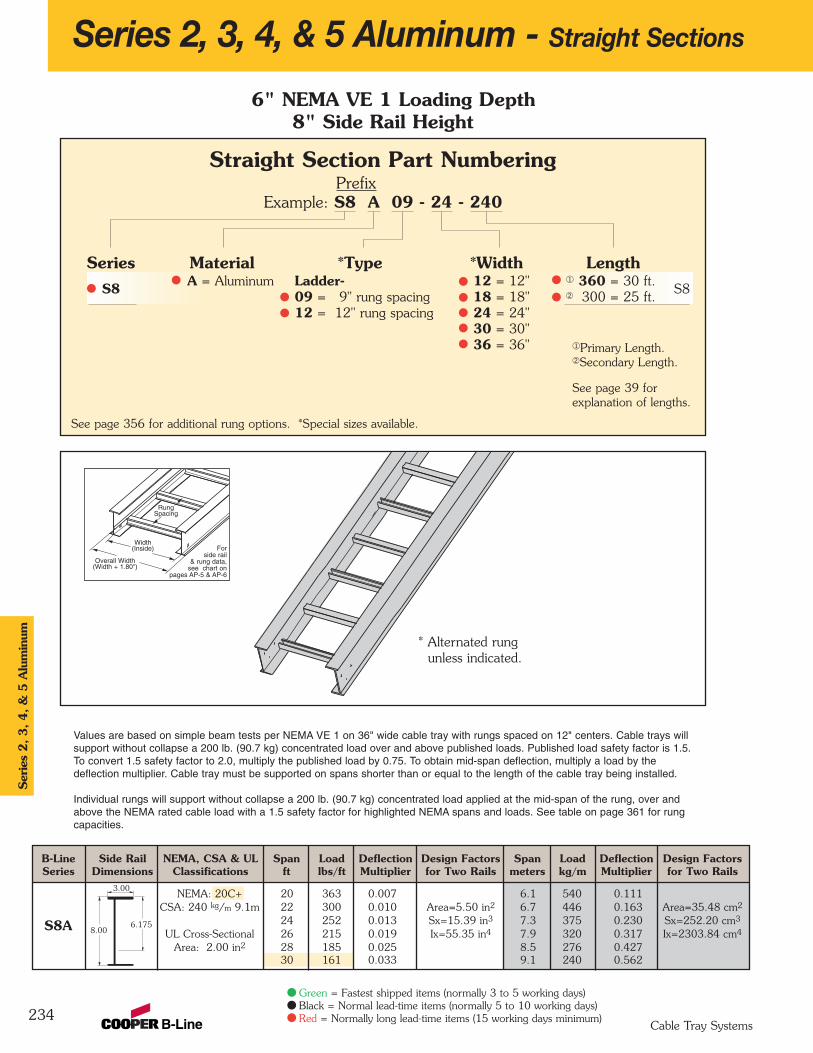
234
Series 2, 3, 4, & 5 Aluminum - Straight Sections
6" NEMA VE 1 Loading Depth8" Side Rail Height
Straight Section Part NumberingPrefix
Example: S8 A 09 - 24 - 240
Series Material *Type *Width LengthS8 A = Aluminum Ladder- 12 = 12" ¬ 360 = 30 ft.
S809 = 9" rung spacing 18 = 18" Á 300 = 25 ft.12 = 12" rung spacing 24 = 24"
30 = 30"36 = 36"
See page 356 for additional rung options. *Special sizes available.
Ser
ies
2, 3, 4, &
5 A
lum
inum
Cable Tray Systems
* Alternated rungunless indicated.
B-Line Side Rail NEMA, CSA & UL Span Load Deflection Design Factors Span Load Deflection Design FactorsSeries Dimensions Classifications ft lbs/ft Multiplier for Two Rails meters kg/m Multiplier for Two Rails
NEMA: 20C+ 20 363 0.007 6.1 540 0.111CSA: 240 kg/m 9.1m 22 300 0.010 Area=5.50 in2 6.7 446 0.163 Area=35.48 cm2
24 252 0.013 Sx=15.39 in3 7.3 375 0.230 Sx=252.20 cm3
UL Cross-Sectional 26 215 0.019 Ix=55.35 in4 7.9 320 0.317 Ix=2303.84 cm4
Area: 2.00 in2 28 185 0.025 8.5 276 0.42730 161 0.033 9.1 240 0.562
3.00
8.006.175S8A
Overall Width(Width + 1.80")
Forside rail
& rung data,see chart on
pages AP-5 & AP-6
RungSpacing
Width(Inside)
Values are based on simple beam tests per NEMA VE 1 on 36" wide cable tray with rungs spaced on 12" centers. Cable trays willsupport without collapse a 200 lb. (90.7 kg) concentrated load over and above published loads. Published load safety factor is 1.5. To convert 1.5 safety factor to 2.0, multiply the published load by 0.75. To obtain mid-span deflection, multiply a load by thedeflection multiplier. Cable tray must be supported on spans shorter than or equal to the length of the cable tray being installed.
Individual rungs will support without collapse a 200 lb. (90.7 kg) concentrated load applied at the mid-span of the rung, over andabove the NEMA rated cable load with a 1.5 safety factor for highlighted NEMA spans and loads. See table on page 361 for rungcapacities.
Green = Fastest shipped items (normally 3 to 5 working days)Black = Normal lead-time items (normally 5 to 10 working days)Red = Normally long lead-time items (15 working days minimum)
¬Primary Length.ÁSecondary Length.
See page 39 for explanation of lengths.
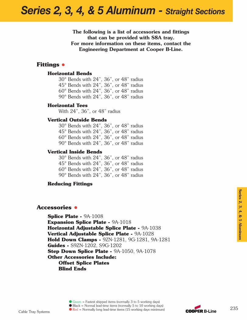
Series 2, 3, 4, & 5 Aluminum - Straight Sections
235
Series 2
, 3, 4
, & 5
Alum
inum
Cable Tray Systems
The following is a list of accessories and fittingsthat can be provided with S8A tray.
For more information on these items, contact theEngineering Department at Cooper B-Line.
FittingsHorizontal Bends
30° Bends with 24”, 36”, or 48” radius45° Bends with 24”, 36”, or 48” radius60° Bends with 24”, 36”, or 48” radius90° Bends with 24”, 36”, or 48” radius
Horizontal TeesWith 24”, 36”, or 48” radius
Vertical Outside Bends30° Bends with 24”, 36”, or 48” radius45° Bends with 24”, 36”, or 48” radius60° Bends with 24”, 36”, or 48” radius90° Bends with 24”, 36”, or 48” radius
Vertical Inside Bends30° Bends with 24”, 36”, or 48” radius45° Bends with 24”, 36”, or 48” radius60° Bends with 24”, 36”, or 48” radius90° Bends with 24”, 36”, or 48” radius
Reducing Fittings
AccessoriesSplice Plate - 9A-1008Expansion Splice Plate - 9A-1018Horizontal Adjustable Splice Plate - 9A-1038Vertical Adjustable Splice Plate - 9A-1028Hold Down Clamps - 9ZN-1281, 9G-1281, 9A-1281Guides - S9ZN-1202, S9G-1202Step Down Splice Plate - 9A-1050, 9A-1078Other Accessories Include:
Offset Splice PlatesBlind Ends
Green = Fastest shipped items (normally 3 to 5 working days)Black = Normal lead-time items (normally 5 to 10 working days)Red = Normally long lead-time items (15 working days minimum)

H46A, H47A and 57A Mid-SpanSplice• Standard for H46A, H47A and 57A
straight sections.• Six bolt design 1/2" Stainless Steel
Type 316 hardware standard.• Available on ladder bottoms
only. 09 and 12" rung spacing.
Branch Pivot Connectors
• Branch from existing cable tray runs at any point.• Pivot to any required angle.• UL Classified for grounding
(bonding jumper not required).• Furnished in pairs with hardware.
Catalog No. Heightin. mm
9A-1004 4 1019A-1005 5 1279A-1006 6 1529A-1007 7 178
Wedge Lock Splice Plates (Excluding H46, H47 & 57 Series)• Standard 4-hole pattern (except 9A-1007).• Furnished in pairs, with hardware.• One pair including hardware
provided with each section.• Boxed in pairs
with hardware.• For field installation
drill 13/32" hole.
Horizontal Adjustable Splice Plates• Offered to adjust a cable tray
run for changes in direction in a horizontal plane that do not conform to standard horizontal fittings.
• Furnished in pairs with hardware.• New design bonding jumpers
not required.• (X) Insert 4, 5, 6 or 7 for
side rail height.
Catalog Cable Tray Tray No. End Cut Width 'L'
9A-103(X) Mitered Thru 36" N/A9A-103(X)-12 Not mitered Thru 12" 16"
9A-103(X)-36 Not mitered Thru 36" 41"
Catalog No. Heightin. mm
9A-1045 5 to 4 127 to 1019A-1046 6 to 4 152 to 1019A-1060 6 to 5 152 to 1279A-1047 7 to 4 178 to 1019A-1061 7 to 5 178 to 1279A-1062 7 to 6 178 to 152
Catalog No. Heightin. mm
9A-1004-1/2 4 1019A-1005-1/2 5 1279A-1006-1/2 6 1529A-1007-1/2 7 178
236
Series 2, 3, 4, & 5 Aluminum - Accessories
Catalog No. Heightin. mm
9A-2044 4 1019A-2045 5 1279A-2046 6 1529A-2047 7 178
Catalog No. Heightin. mm
9A-1014 4 1019A-1015 5 1279A-1016 6 1529A-1017 7 178
9A-103(X)Splice only
9A-103(X)-12 or 9A-103(X)-36One pair splice plates with extensions.
LL
Expansion Splice Plates• Expansion plates allow for one inch
expansion or contraction of the cable tray, or where expansion joints occur in the supporting structure.
• Furnished in pairs with hardware.
• Bonding Jumpers are required oneach siderail.Order Separately.
Universal Splice Plates• Used to splice to existing cable tray
systems.• Furnished in pairs with hardware.
Catalog No. Heightin. mm
9A-1024 4 1019A-1025 5 1279A-1026 6 1529A-1027 7 178
Step Down Splice Plates• These splice plates are
offered for connecting cable tray sections having side rails of different heights.
• Furnished in pairs with hardware.
Vertical Adjustable Splice Plates• These plates provide for changes in
elevation that do not conform to standardvertical fittings.
• Furnished in pairs with hardware.• Bonding Jumper not required.
TraySeries Catalog No.H46A 9A-6006
H47A, 57A 9A-6007
Ser
ies
2, 3, 4, &
5 A
lum
inum
Cable Tray Systems
Green = Fastest shipped items (normally 3 to 5 working days)Black = Normal lead-time items (normally 5 to 10 working days)Red = Normally long lead-time items (15 working days minimum)
Requiressupports within
24” on bothsides, per NEMA
VE 2.
Requiressupports
within 24”on both sides,
per NEMAVE 2.

9A-1240Catalog No.
Cross Connector Bracket• For field connecting crossing section.• Furnished in pairs with 3/8"
hardware.
Offset Reducing Splice Plate• This plate is used for joining cable trays having
different widths. When used in pairs they form a straight reduction; when used singly with a standard splice plate, they form anoffset reduction.
• Furnished as one plate with hardware.
• (‡) Insert reduction
Catalog No. 9ZN-1150-(‡) Catalog No. 9ZN-1155-(‡)
Catalog No. Heightin. mm
9A-1064-(‡) 4 1019A-1065-(‡) 5 1279A-1066-(‡) 6 1529A-1067-(‡) 7 178
Conduit to Cable Tray Adaptor• For easy attachment of conduit terminating at a cable tray. • Use on aluminum or steel cable trays.
Catalog No. Conduit Sizein. mm
9G-1158-1/2, 3/4 1/2, 3/4 15, 209G-1158-1, 11/4 1, 11/4 25, 329G-1158-11/2, 2 11/2, 2 40, 509G-1158-21/2, 3 21/2, 3 65, 809G-1158-31/2, 4 31/2, 4 90, 100
Series 2, 3, 4, & 5 Aluminum - Accessories
237
Tray HardwareFor field installation drill 13/32" hole.
Standard Tray Hardware
Catalog No. SNCB 3/8" x 3/4" Znplt SquareNeck Carriage Bolt ASTM A307 Grade A
Catalog No. SFHN 3/8"-16 ZnpltSerrated Flange Hex Nut ASTM A563Grade A
Finish: Zinc Plated ASTM B633, SC1
Optional Tray Hardware
Catalog No. SNCB 3/8" x 3/4" SS6 SquareNeck Carriage Bolt AISI 316 Stainless Steel
Catalog No. SFHN 3/8"-16 SS6 SerratedFlange Hex Nut AISI 316 Stainless Steel
To order optional 316 Stainless Steel hardware add SS6 suffix to part number
Example: 9A-1004SS6
Aluminum I-Beam
Cable Tie (Ladder Tray)Nylon ties provide easy attachment ofcable to ladder rungs; maximumcable O.D. is 3" (76mm).
Overall Length 15"
Catalog No. 99-2125-15
• Assembly required.• Mounting hardware
included.• Conduit clamps
provided.• (‡) = Conduit size
(1/2" thru 4").
• Assembly required.• Conduit clamp included.• (‡) = Conduit size
(1/2" thru 4").
Conduit to Cable Tray Adaptors
Catalog No. Heightin. mm
9A-1084-(‡) 4 1019A-1085-(‡) 5 1279A-1086-(‡) 6 1529A-1087-(‡) 7 178
Catalog No. Heightin. mm
9A-1074-(‡) 4 1019A-1075-(‡) 5 1279A-1076-(‡) 6 1529A-1077-(‡) 7 178
Catalog No. Heightin. mm
9A-1054 4 1019A-1055 5 1279A-1056 6 1529A-1057 7 178
Frame Type Box Connector• Designed to attach the end of a cable
tray run to a distribution cabinet or control center to help reinforce the box at the point of entry.
• Furnished with tray connection hardware.
• (‡) Insert tray width
Blind End• This plate forms a
closure for a deadend cable tray.
• Furnished as oneplate with hardware.
• (‡) Insert tray width
Tray to Box Splice Plates• Used to attach the
end of a cable trayrun to a distributionbox or control panel.
• Furnished in pairs with hardware.
Series 2
, 3, 4
, & 5
Alum
inum
Cable Tray Systems
Green = Fastest shipped items (normally 3 to 5 working days)Black = Normal lead-time items (normally 5 to 10 working days)Red = Normally long lead-time items (15 working days minimum)
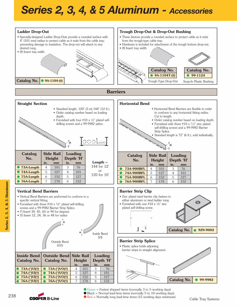
Inside Bend Outside Bend Side Rail LoadingCatalog No. Catalog No. Height Depth 'H'
in. mm in. mm73A-(*)VI(†) 73A-(*)VO(†) 4 101 3 7674A-(*)VI(†) 74A-(*)VO(†) 5 127 4 10175A-(*)VI(†) 75A-(*)VO(†) 6 152 5 12776A-(*)VI(†) 76A-(*)VO(†) 7 178 6 152
Vertical Bend Barriers• Vertical Bend Barriers are preformed to conform to a
specific vertical fitting.• Furnished with three #10 x 1/2" plated self-drilling
screws and a 99-9982 Barrier Strip Splice.• (*) Insert 30, 45, 60 or 90 for degrees• (†) Insert 12, 24, 36 or 48 for radius
Straight Section• Standard length: 120" (3 m) 144" (12 ft.).• Order catalog number based on loading
depth.• Furnished with four #10 x 1/2" plated self-
drilling screws and a 99-9982 splice.
Trough Drop-Out & Drop-Out Bushing• These devices provide a rounded surface to protect cable as it exits
from the trough-type cable tray.• Hardware is included for attachment of the trough bottom drop-out.• (‡) Insert tray width
Catalog No.9A-1104T-(‡)
Catalog No. 99-9982
Barrier Strip Splice• Plastic splice holds adjoining
barrier strips in straight alignment.
9ZN-9002Catalog No.
Barrier Strip Clip• Zinc plated steel barrier clip fastens to
either aluminum or steel ladder rung.• Furnished with one #10 x 1/2" zinc
plated self-drilling screw.
Horizontal Bend• Horizontal Bend Barriers are flexible in order
to conform to any horizontal fitting radius. Cut to length.
• Order catalog number based on loading depth.• Furnished with three #10 x 1/2" zinc plated
self-drilling screws and a 99-9982 Barrier Strip Splice.
• Standard length is 72" (6 ft.), sold individually.
Catalog Side Rail LoadingNo. Height Depth 'H'
in. mm in. mm73A-90HBFL 4 101 3 7674A-90HBFL 5 127 4 10175A-90HBFL 6 152 5 12776A-90HBFL 7 178 6 152
Catalog Side Rail LoadingNo. Height Depth 'H'
in. mm in. mm73A-Length 4 101 3 76
74A-Length 5 127 4 101
75A-Length 6 152 5 127
76A-Length 7 178 6 152
9A-1104-(‡)Catalog No.
Ladder Drop-Out• Specially-designed Ladder Drop-Outs provide a rounded surface with
4" (101 mm) radius to protect cable as it exits from the cable tray, preventing damage to insulation. The drop-out will attach to any desired rung.
• (‡) Insert tray width
238
Snap-In Plastic BushingTrough-Type Drop-Out
Outside Bend(VO)
Inside Bend(VI)
H
Length = 144 for 12'
or 120 for 10'
Series 2, 3, 4, & 5 Aluminum - Accessories
Barriers
H
H
H
Catalog No.99-1124
Ser
ies
2, 3, 4, &
5 A
lum
inum
Cable Tray Systems
Green = Fastest shipped items (normally 3 to 5 working days)Black = Normal lead-time items (normally 5 to 10 working days)Red = Normally long lead-time items (15 working days minimum)
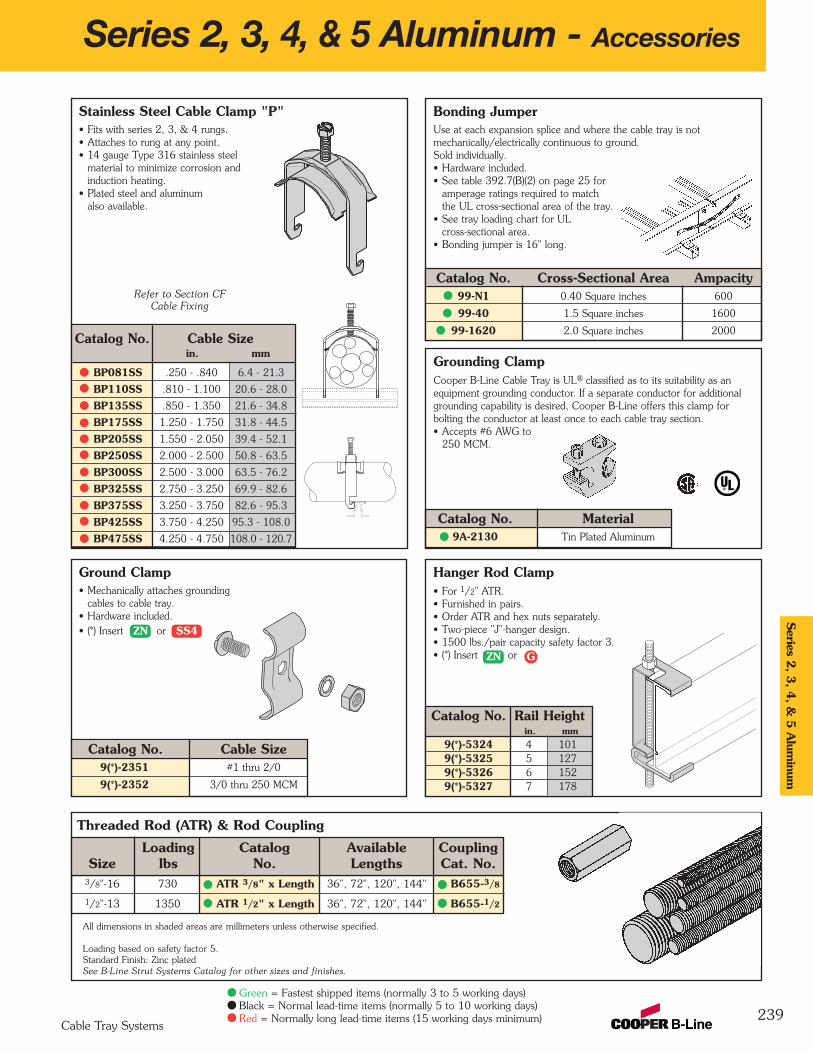
Threaded Rod (ATR) & Rod Coupling
Hanger Rod Clamp• For 1/2" ATR.• Furnished in pairs.• Order ATR and hex nuts separately.• Two-piece "J"-hanger design.• 1500 lbs./pair capacity safety factor 3. • (*) Insert or
Catalog No. Rail Heightin. mm
9(*)-5324 4 1019(*)-5325 5 1279(*)-5326 6 1529(*)-5327 7 178
Stainless Steel Cable Clamp "P"• Fits with series 2, 3, & 4 rungs.• Attaches to rung at any point.• 14 gauge Type 316 stainless steel
material to minimize corrosion and induction heating.
• Plated steel and aluminum also available.
Ground Clamp• Mechanically attaches grounding
cables to cable tray.• Hardware included.• (*) Insert or
Catalog No. Cable Size9(*)-2351 #1 thru 2/0
9(*)-2352 3/0 thru 250 MCM
3/8"-16 730 ATR 3/8" x Length 36", 72", 120", 144" B655-3/8
1/2"-13 1350 ATR 1/2" x Length 36", 72", 120", 144" B655-1/2
Grounding ClampCooper B-Line Cable Tray is UL® classified as to its suitability as anequipment grounding conductor. If a separate conductor for additionalgrounding capability is desired, Cooper B-Line offers this clamp forbolting the conductor at least once to each cable tray section.• Accepts #6 AWG to
250 MCM.
Catalog No. Material9A-2130 Tin Plated Aluminum
Bonding JumperUse at each expansion splice and where the cable tray is not mechanically/electrically continuous to ground. Sold individually.• Hardware included.• See table 392.7(B)(2) on page 25 for
amperage ratings required to match the UL cross-sectional area of the tray.
• See tray loading chart for UL cross-sectional area.
• Bonding jumper is 16" long.
Catalog No. Cross-Sectional Area Ampacity99-N1 0.40 Square inches 600
99-40 1.5 Square inches 1600
99-1620 2.0 Square inches 2000
Series 2, 3, 4, & 5 Aluminum - Accessories
239
Loading Catalog Available CouplingSize lbs No. Lengths Cat. No.
All dimensions in shaded areas are millimeters unless otherwise specified.
Loading based on safety factor 5.Standard Finish: Zinc platedSee B-Line Strut Systems Catalog for other sizes and finishes.
Catalog No. Cable Sizein. mm
BP081SS .250 - .840 6.4 - 21.3
BP110SS .810 - 1.100 20.6 - 28.0
BP135SS .850 - 1.350 21.6 - 34.8
BP175SS 1.250 - 1.750 31.8 - 44.5
BP205SS 1.550 - 2.050 39.4 - 52.1
BP250SS 2.000 - 2.500 50.8 - 63.5
BP300SS 2.500 - 3.000 63.5 - 76.2
BP325SS 2.750 - 3.250 69.9 - 82.6
BP375SS 3.250 - 3.750 82.6 - 95.3
BP425SS 3.750 - 4.250 95.3 - 108.0
BP475SS 4.250 - 4.750 108.0 - 120.7
Series 2
, 3, 4
, & 5
Alum
inum
Cable Tray Systems
Green = Fastest shipped items (normally 3 to 5 working days)Black = Normal lead-time items (normally 5 to 10 working days)Red = Normally long lead-time items (15 working days minimum)
ZN SS4
ZN G
Refer to Section CFCable Fixing

Catalog No. Finish9ZN-1249 Znplt
9G-1249 HDGAF
Cable Tray Guide • Expansion guide for single or double cable tray runs.• Guide allows for longitudinal movement of the
cable tray.• No field drilling of support I-beam or channel
is required.• Guides are required on both sides of cable tray
to prevent lateral movement - can be placed on either the inside or outside flange of cable tray.
• Guides are sold in pieces - two guides are required per tray.
• Maximum flange thickness 11/8" (28.58 mm).
Neoprene Roll• Use for material isolation.• 1/8" x 2" x 20' roll.• Hardness: Shore A60.• Good weatherability.
Nylon Pad• Use for friction reduction.• Hardness: Shore D80.• Low friction coefficient.• UV resistant (black).• Excellent weatherability.• UL - 94HB.
Catalog No. 99-NY36
Catalog No. Finish9ZN-1249HD Znplt
9G-1249HD HDGAF
Cable Tray Clamp• Hold-down clamps for single or double cable tray runs.• No drilling of support I-beam or channel is required.• Sold in pieces
- two clamps are required per tray.• Maximum beam flange thickness 11/8" (28.58 mm).
Cable Tray Clamp/Guide• Features a no-twist design.• Has four times the strength
of the traditional design.• Each side is labeled to
ensure proper installation.• Furnished in pairs, with or
without hardware.
Series 2, 3, 4, & 5 Aluminum - Accessories
240
Catalog No. 99-NP240
1/8"(3mm)
3"(76mm)
6"(152mm)
Note: For heavy duty or vertical applications see 9(*)-1241 or 9(*)-1242 page AT-20
Catalog No.Without With Overall Hardware
Hardware Hardware Length Size Finishin. mm
9ZN-1204 9ZN-1204NB 11/2 38 1/4" Znplt
9ZN-1208 9ZN-1208NB 21/4 57 3/8" Znplt
9A-1205 -- 21/4 57 1/2" Alum.
9G-1205 -- 21/4 57 1/2" HDGAF
9SS6-1205 -- 21/4 57 1/2" 316SS
9ZN-1205 -- 21/4 57 1/2" Znplt
9ZN-1204 shown.Installed as a guide.
9ZN-1208 shown.Installed as a clamp.
Patent #RE35479
11/2"(39mm)
21/4"(57mm)
Isolator Pad• Use as a friction reducer and/or as
a dissimilar metal isolator barrier.• UV resistant HDPE.• Temperature range: -100 to 160° F.• Designed to use with
9(*)-1205 or 9(*)-1208 clamp/guide.
Catalog No. 99-PE34
Isolation pad shown aswhen used with a guide.
Isolation pad shown with topflange doubled under forclamp application.
Ser
ies
2, 3, 4, &
5 A
lum
inum
Cable Tray Systems
Green = Fastest shipped items (normally 3 to 5 working days)Black = Normal lead-time items (normally 5 to 10 working days)Red = Normally long lead-time items (15 working days minimum)
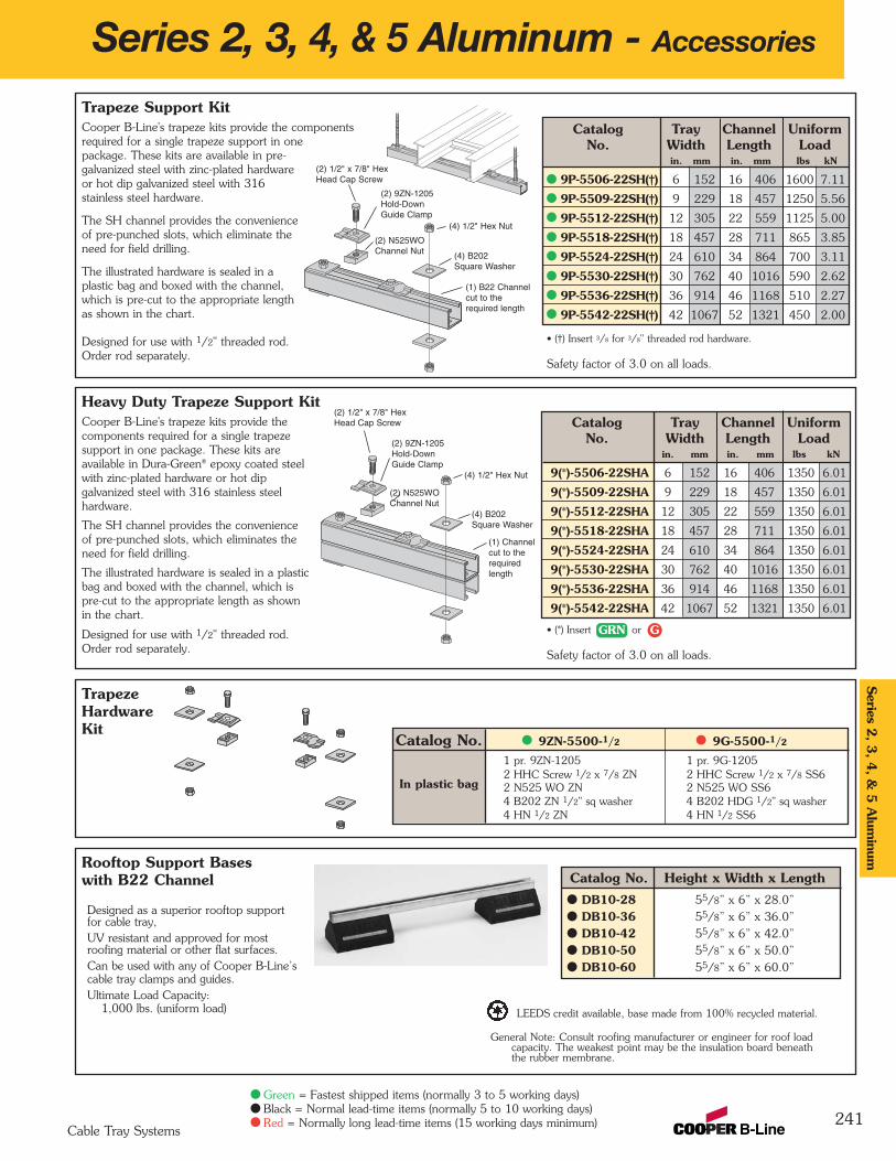
TrapezeHardwareKit
Heavy Duty Trapeze Support KitCooper B-Line's trapeze kits provide thecomponents required for a single trapezesupport in one package. These kits areavailable in Dura-Green® epoxy coated steelwith zinc-plated hardware or hot dipgalvanized steel with 316 stainless steelhardware.
The SH channel provides the convenienceof pre-punched slots, which eliminates the need for field drilling.
The illustrated hardware is sealed in a plastic bag and boxed with the channel, which is pre-cut to the appropriate length as shown in the chart.
Designed for use with 1/2" threaded rod. Order rod separately.
Catalog Tray Channel UniformNo. Width Length Load
in. mm in. mm lbs kN
9(*)-5506-22SHA 6 152 16 406 1350 6.01
9(*)-5509-22SHA 9 229 18 457 1350 6.01
9(*)-5512-22SHA 12 305 22 559 1350 6.01
9(*)-5518-22SHA 18 457 28 711 1350 6.01
9(*)-5524-22SHA 24 610 34 864 1350 6.01
9(*)-5530-22SHA 30 762 40 1016 1350 6.01
9(*)-5536-22SHA 36 914 46 1168 1350 6.01
9(*)-5542-22SHA 42 1067 52 1321 1350 6.01
Trapeze Support KitCooper B-Line's trapeze kits provide the componentsrequired for a single trapeze support in onepackage. These kits are available in pre-galvanized steel with zinc-plated hardwareor hot dip galvanized steel with 316stainless steel hardware.
The SH channel provides the convenienceof pre-punched slots, which eliminate the need for field drilling.
The illustrated hardware is sealed in aplastic bag and boxed with the channel,which is pre-cut to the appropriate lengthas shown in the chart.
Designed for use with 1/2" threaded rod. Order rod separately.
Catalog Tray Channel UniformNo. Width Length Load
in. mm in. mm lbs kN
9P-5506-22SH(†) 6 152 16 406 1600 7.11
9P-5509-22SH(†) 9 229 18 457 1250 5.56
9P-5512-22SH(†) 12 305 22 559 1125 5.00
9P-5518-22SH(†) 18 457 28 711 865 3.85
9P-5524-22SH(†) 24 610 34 864 700 3.11
9P-5530-22SH(†) 30 762 40 1016 590 2.62
9P-5536-22SH(†) 36 914 46 1168 510 2.27
9P-5542-22SH(†) 42 1067 52 1321 450 2.00
Series 2, 3, 4, & 5 Aluminum - Accessories
241
• (†) Insert 3/8 for 3/8" threaded rod hardware.
Safety factor of 3.0 on all loads.
• (*) Insert or
Safety factor of 3.0 on all loads.
(1) B22 Channelcut to therequired length
(2) 9ZN-1205Hold-DownGuide Clamp
(4) B202Square Washer
(2) N525WOChannel Nut
(2) 1/2" x 7/8" HexHead Cap Screw
(4) 1/2" Hex Nut
(1) Channelcut to therequiredlength
(2) 9ZN-1205Hold-DownGuide Clamp
(4) B202Square Washer
(2) N525WOChannel Nut
(2) 1/2" x 7/8" HexHead Cap Screw
(4) 1/2" Hex Nut
Catalog No. 9ZN-5500-1/2 9G-5500-1/2
1 pr. 9ZN-1205 1 pr. 9G-12052 HHC Screw 1/2 x 7/8 ZN 2 HHC Screw 1/2 x 7/8 SS62 N525 WO ZN 2 N525 WO SS64 B202 ZN 1/2" sq washer 4 B202 HDG 1/2" sq washer4 HN 1/2 ZN 4 HN 1/2 SS6
In plastic bag
Series 2
, 3, 4
, & 5
Alum
inum
Cable Tray Systems
Green = Fastest shipped items (normally 3 to 5 working days)Black = Normal lead-time items (normally 5 to 10 working days)Red = Normally long lead-time items (15 working days minimum)
GRN G
Rooftop Support Baseswith B22 Channel Catalog No. Height x Width x Length
DB10-28 55/8” x 6” x 28.0”DB10-36 55/8” x 6” x 36.0”DB10-42 55/8” x 6” x 42.0”DB10-50 55/8” x 6” x 50.0”DB10-60 55/8” x 6” x 60.0”
Designed as a superior rooftop supportfor cable tray,UV resistant and approved for mostroofing material or other flat surfaces.Can be used with any of Cooper B-Line’scable tray clamps and guides.Ultimate Load Capacity:
1,000 lbs. (uniform load) LEEDS credit available, base made from 100% recycled material.
General Note: Consult roofing manufacturer or engineer for roof loadcapacity. The weakest point may be the insulation board beneaththe rubber membrane.
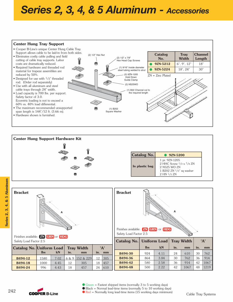
Bracket
Catalog No. Uniform Load Tray Width 'A'lbs kN in. mm in. mm
B494-12 1580 7.02 6 & 9 152 & 229 12 305
B494-18 1000 4.45 12 305 18 457
B494-24 996 4.43 18 457 24 610
Center Hung Tray Support• Cooper B-Line's unique Center Hung Cable Tray
Support allows cable to be laid-in from both sides.• Eliminates costly cable pulling and field
cutting of cable tray supports. Labor costs are dramatically reduced.
• Required hardware and threaded rodmaterial for trapeze assemblies arereduced by 50%.
• Designed for use with 1/2" threaded rod. (Order rod separately)
• Use with all aluminum and steel cable trays through 24" width.
• Load capacity is 700 lbs. per support.Safety factor of 3.0.Eccentric loading is not to exceed a60% vs. 40% load differential.
• The maximum recommended unsupportedspan length is 144"/12 ft. (3.66 m).
• Hardware shown is furnished.
Catalog Tray ChannelNo. Width Length
9ZN-5212 6", 9", 12" 18"
9ZN-5224 18", 24" 30"
Bracket
Catalog No. Uniform Load Tray Width 'A'lbs kN in. mm in. mm
B494-30 924 4.11 24 610 30 762
B494-36 864 3.84 30 762 36 914
B494-42 580 2.58 36 914 42 1067
B494-48 500 2.22 42 1067 48 1219
Series 2, 3, 4, & 5 Aluminum - Accessories
242
(2) 1/2" x 7/8"Hex Head Cap Screws
(2) 1/2" Hex Nut
(1) B202Square Washer
(2) 9ZN-1205Hold Down
Guide Clamp
(2) N525WO
(1) B22 Channel cut tothe required length
(1) 9/16" Inside diametersteel tubing welded to strut
Finishes available: or
Safety Load Factor 2.5
A A
Finishes available: or
Safety Load Factor 2.5
Center Hung Support Hardware Kit
Catalog No. 9ZN-52001 pr. 9ZN-1205 2 HHC Screw 1/2 x 7/8 ZN 2 N525 WO ZN 1 B202 ZN 1/2" sq washer 2 HN 1/2 ZN
In plastic bag
ZN = Zinc Plated
Ser
ies
2, 3, 4, &
5 A
lum
inum
Cable Tray Systems
Green = Fastest shipped items (normally 3 to 5 working days)Black = Normal lead-time items (normally 5 to 10 working days)Red = Normally long lead-time items (15 working days minimum)
ZN GRN HDG
ZN GRN HDG
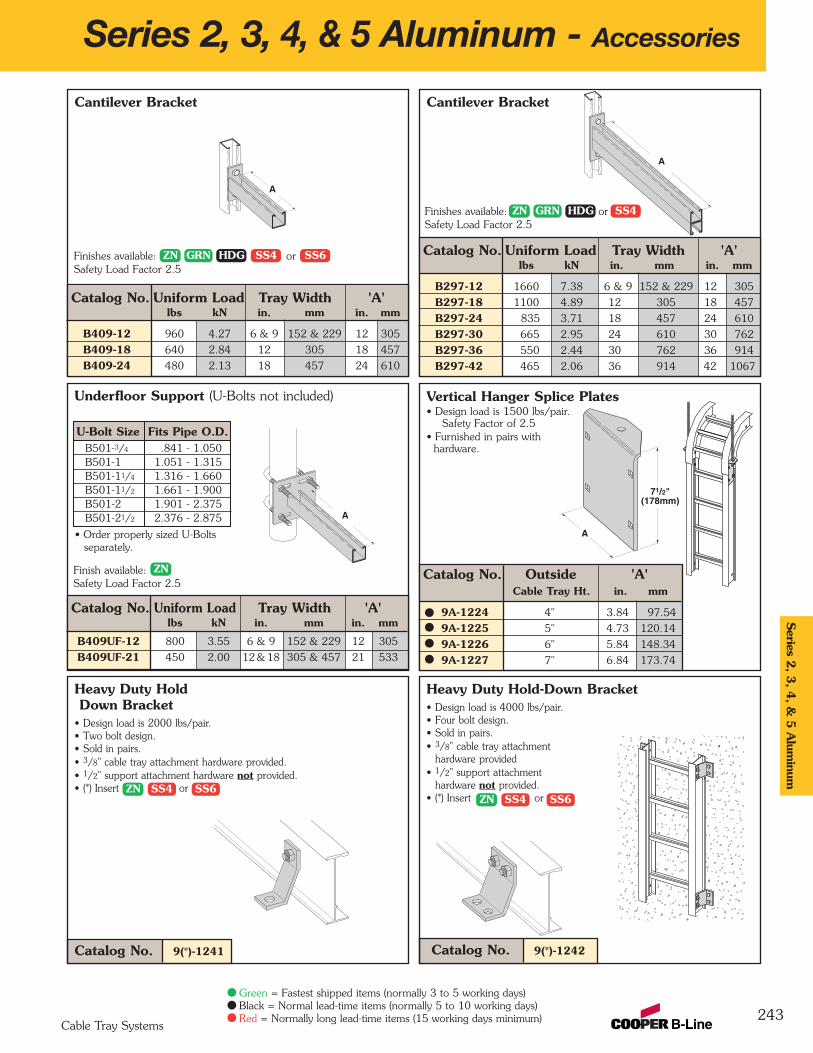
Cantilever Bracket
Catalog No. Uniform Load Tray Width 'A'lbs kN in. mm in. mm
B297-12 1660 7.38 6 & 9 152 & 229 12 305
B297-18 1100 4.89 12 305 18 457
B297-24 835 3.71 18 457 24 610
B297-30 665 2.95 24 610 30 762
B297-36 550 2.44 30 762 36 914
B297-42 465 2.06 36 914 42 1067
Underfloor Support (U-Bolts not included) Vertical Hanger Splice Plates• Design load is 1500 lbs/pair.
Safety Factor of 2.5• Furnished in pairs with
hardware.
Cantilever Bracket
Catalog No. Uniform Load Tray Width 'A'lbs kN in. mm in. mm
B409-12 960 4.27 6 & 9 152 & 229 12 305
B409-18 640 2.84 12 305 18 457
B409-24 480 2.13 18 457 24 610
Series 2, 3, 4, & 5 Aluminum - Accessories
243
Heavy Duty Hold-Down Bracket• Design load is 4000 lbs/pair.• Four bolt design.• Sold in pairs.• 3/8" cable tray attachment
hardware provided• 1/2" support attachment
hardware not provided.• (*) Insert or
Heavy Duty HoldDown Bracket
• Design load is 2000 lbs/pair.• Two bolt design.• Sold in pairs.• 3/8" cable tray attachment hardware provided.• 1/2" support attachment hardware not provided.• (*) Insert or
Catalog No. 9(*)-1241 Catalog No. 9(*)-1242
A
A
A
71/2"(178mm)
A
Finishes available: orSafety Load Factor 2.5
Finishes available: orSafety Load Factor 2.5
Finish available: Safety Load Factor 2.5
Catalog No. Outside 'A'Cable Tray Ht. in. mm
9A-1224 4" 3.84 97.54
9A-1225 5" 4.73 120.14
9A-1226 6" 5.84 148.34
9A-1227 7" 6.84 173.74
U-Bolt Size Fits Pipe O.D.B501-3/4 .841 - 1.050B501-1 1.051 - 1.315B501-11/4 1.316 - 1.660B501-11/2 1.661 - 1.900B501-2 1.901 - 2.375B501-21/2 2.376 - 2.875
• Order properly sized U-Bolts separately.
Catalog No. Uniform Load Tray Width 'A'lbs kN in. mm in. mm
B409UF-12 800 3.55 6 & 9 152 & 229 12 305
B409UF-21 450 2.00 12 & 18 305 & 457 21 533
Series 2
, 3, 4
, & 5
Alum
inum
Cable Tray Systems
Green = Fastest shipped items (normally 3 to 5 working days)Black = Normal lead-time items (normally 5 to 10 working days)Red = Normally long lead-time items (15 working days minimum)
ZN SS4 SS6ZN SS4 SS6
ZN GRN HDG SS4 SS6
ZN GRN HDG SS4
ZN

Beam Clamp
Beam Clamp
B312 Anchor Strap• Finish available:• For a maximum beam
thickness of 3/4".• For thicker beams, step up
one flange width size.
Cat. No. Flange WidthB312-6 Up to 6"
B312-9 6" - 9"
B312-12 9" - 12"
Beam Clamp• Finishes available: or• Sold in pieces.
Design load when used in pairs.Safety Load Factor 5.0
Catalog 'A' Thread Length 'TL' Wt./CNo. in. mm in. mm lbs kg
B700-J4 81/2" 215.9 5" 127.0 44 19.9
B700-J6 111/2" 292.1 6" 152.4 53 24.0
B700-J9 121/4" 368.3 6" 152.4 63 28.6
B700-J12 171/2" 444.5 6" 152.4 78 35.4
B305 Thru B308 & B321 Series Beam Clamps• Finishes available: or• Setscrew included.• Safety Load Factor 5.0
Cat. Rod Design LoadNo. Size A B C D E F T lbs kN
B305 3/8"-16 3/8"-16 2 5/16" 7/8" 1 1/8" 2 1/2" 11 Ga. 600 2.67
B306 3/8"-16 1/2"-13 2 7/16" 7/8" 1 1/8" 2 1/2" 7 Ga. 1100 4.90
B307 1/2"-13 1/2"-13 2 7/16" 7/8" 1 1/8" 2 1/2" 7 Ga. 1100 4.90
B308 1/2"-13 1/2"-13 2 9/16" 7/8" 1 1/8" 2 1/2" 1/4" 1500 6.68
B321-1 3/8"-16 1/2"-13 3 9/16" 1 11/16" 1 5/8" 3 1/4" 1/4" 1300 5.79
B321-2 1/2"-13 1/2"-13 3 9/16" 1 11/16" 1 5/8" 3 1/4" 1/4" 1400 6.23
Beam Clamp• Finishes available: or• Sold in pieces.
Design load when used in pairs.Safety Load Factor 5.0
Cat. No. B212-1/4 B212-3/8
Design Load * 600 lbs. 2.67 kN 1000 lbs. 4.45 kN
Max. Flange Thick 3/4" 19 mm 1 1/8" 28.6 mm
Mat'l. Thickness 1/4" 6.3 mm 3/8" 9.5 mm
Beam Clamp B355• Finishes available: or• Sold in pieces.• Design load is 1200 lbs. when used in pairs.• Safety Load Factor 5.0• Order HHCS and
Channel Nuts separately.
Series 2, 3, 4, & 5 Aluminum - Accessories
244
B
ED
C
F T
• Finish available: • Design Load 500 lbs. (2.22 kN)• Safety Load Factor 5.0• Recommended torque:
'J'-Hook Nut 125 In.-Lbs. (14.1 kN/m)• Maximum flange thickness of 3/4"
• Finish available: • Hex Nut included.
A
A
Material: 7 Gauge (4.6)
1/2"-13 Rod & HexNut Sold Separately
1/2"-13 Threads
1 1/2"(38.1)
“A’
‘TL’
1 7/8"(47.6)
J-Hook & Hex Nut Included
Catalog For Flange Width Wt./CNo. in. mm lbs kg
B750-J4 3"- 6" 76.2 - 152.4 109 49.4
B750-J6 5"- 9" 127.0 - 288.6 124 56.2
B750-J9 8"- 12" 203.2 - 304.8 135 61.2
B750-J12 11"- 15" 279.4 - 381.0 147 66.7
Catalog Design Load* 'A'lbs kN in. mm
B441-22 1200 5.34 33/8 86
B441-22A 1200 5.34 5 127
Ser
ies
2, 3, 4, &
5 A
lum
inum
Cable Tray Systems
Green = Fastest shipped items (normally 3 to 5 working days)Black = Normal lead-time items (normally 5 to 10 working days)Red = Normally long lead-time items (15 working days minimum)
ZN HDG ZN GRN HDG SS4 ZN GRN HDG
ZNZN HDG
ZN
ZN
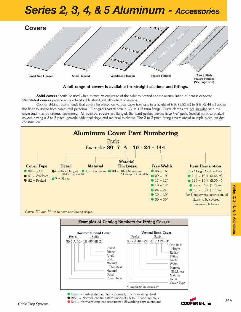
Aluminum Cover Part NumberingPrefix
Example: 80 7 A 40 - 24 - 144
MaterialCover Type Detail Material Thickness Tray Width Item Description
80 = Solid 6 = Non-Flanged A = Aluminum 40 = .040 Aluminum 06 = 6" For Straight Section Cover:
81 = Ventilated(80 & 81 type only) All except 2 to 3 pitch
09 = 9" 144 = 12 ft. (3.66 m)
82 = Peaked7 = Flange
12 = 12" 120 = 10 ft. (3.05 m)
18 = 18" 72 = 6 ft. (1.83 m)
24 = 24" 60 = 5 ft. (1.52 m)
30 = 30" For fitting covers: Insert suffix of
36 = 36" fitting to be covered.
See example below.
Examples of Catalog Numbers for Fitting Covers:
Series 2, 3, 4, & 5 Aluminum - Accessories
245
A full range of covers is available for straight sections and fittings.
Solid covers should be used when maximum enclosure of the cable is desired and no accumulation of heat is expected.Ventilated covers provide an overhead cable shield, yet allow heat to escape.
Cooper B-Line recommends that covers be placed on vertical cable tray runs to a height of 6 ft. (1.83 m) to 8 ft. (2.44 m) abovethe floor to isolate both cables and personnel. Flanged covers have a 1/2 in. (13 mm) flange. Cover clamps are not included with thecover and must be ordered separately. All peaked covers are flanged. Standard peaked covers have 1/2" peak. Special purpose peaked covers, having a 2 to 3 pitch, provide additional slope and material thickness. The 2 to 3 pitch fitting covers are of multiple piece, welded construction.
Solid Flanged Ventilated Flanged Peaked Flanged 2 to 3 PitchPeaked Flanged(See page 358)
Vertical Bend CoverPrefix Suffix
80 7 A 40 - 24 - 90 VO 24 - 4*Side Rail*
Height RadiusFittingAngleWidthMaterialThickness
MaterialDetailCover Type
Solid Non-Flanged
Covers
Horizontal Bend CoverPrefix Suffix
80 7 A 40 - 18 - 90 HB 24
RadiusFittingAngleWidthMaterial
ThicknessMaterialDetailCover Type
* Required for VO fittings only
Covers 30" and 36" wide have reinforcing ridges.
Series 2
, 3, 4
, & 5
Alum
inum
Cable Tray Systems
Green = Fastest shipped items (normally 3 to 5 working days)Black = Normal lead-time items (normally 5 to 10 working days)Red = Normally long lead-time items (15 working days minimum)
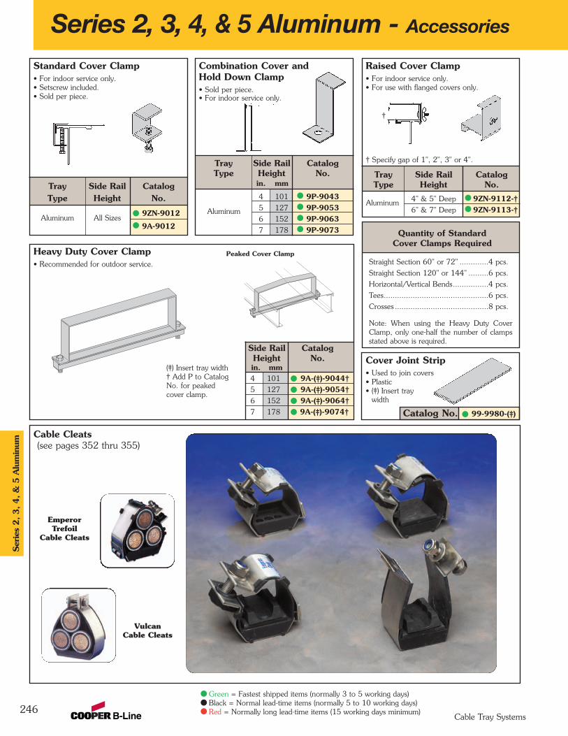
Cover Joint Strip• Used to join covers• Plastic• (‡) Insert tray
width
Raised Cover Clamp• For indoor service only.• For use with flanged covers only.
† Specify gap of 1", 2", 3" or 4".
Tray Side Rail CatalogType Height No.
4" & 5" Deep 9ZN-9112-†6" & 7" Deep 9ZN-9113-†
Combination Cover andHold Down Clamp• Sold per piece.• For indoor service only.
Tray Side Rail CatalogType Height No.
in. mm
4 101 9P-90435 127 9P-90536 152 9P-90637 178 9P-9073
Heavy Duty Cover Clamp• Recommended for outdoor service.
Aluminum
Standard Cover Clamp• For indoor service only.• Setscrew included.• Sold per piece.
Tray Side Rail CatalogType Height No.
Aluminum All Sizes9ZN-9012
9A-9012
Series 2, 3, 4, & 5 Aluminum - Accessories
246
Aluminum
Quantity of Standard Cover Clamps Required
Straight Section 60" or 72" .............4 pcs.
Straight Section 120" or 144" .........6 pcs.
Horizontal/Vertical Bends................4 pcs.
Tees...............................................6 pcs.
Crosses ..........................................8 pcs.
Note: When using the Heavy Duty CoverClamp, only one-half the number of clampsstated above is required.
Peaked Cover Clamp
(‡) Insert tray width† Add P to CatalogNo. for peakedcover clamp.
4 101 9A-(‡)-9044†5 127 9A-(‡)-9054†6 152 9A-(‡)-9064†7 178 9A-(‡)-9074†
Side Rail CatalogHeight No.in. mm
Catalog No. 99-9980-(‡)
†
Cable Cleats(see pages 352 thru 355)
Ser
ies
2, 3, 4, &
5 A
lum
inum
Cable Tray Systems
Green = Fastest shipped items (normally 3 to 5 working days)Black = Normal lead-time items (normally 5 to 10 working days)Red = Normally long lead-time items (15 working days minimum)
EmperorTrefoil
Cable Cleats
VulcanCable Cleats

Section 1- Acceptable Manufacturers
1.01 Manufacturer: Subject to compliance with these specifications, cable tray systems shall be as manufactured by Cooper B-Line, Inc.
Section 2- Cable Tray Sections and Components
2.01 General: Except as otherwise indicated, provide metal cable trays, of types, classes and sizes indicated;with splice plates, bolts, nuts and washers for connecting units. Construct units with rounded edges andsmooth surfaces; in compliance with applicable standards; and with the following additional constructionfeatures. Cable tray shall be installed according to the latest revision of NEMA VE 2.
2.02 Materials and Finish: Straight section and fitting side rails and rungs shall be extruded from Aluminum Association Alloy 6063. All fabricated parts shall be made from Aluminum Association Alloy 5052.
2.03 Ladder Cable Trays shall consist of two longitudinal members (side rails) with transverse members(rungs) welded to the side rails. Rungs shall be spaced [6] [9] [12] inches on center. Rung spacing inradiused fittings shall be industry standard 9" and measured at the center of the tray’s width. Eachrung must be capable of supporting a 200 lb. concentrated load at the center of the cable tray overand above the cable load with a safety factor of 1.5.
2.04 Ventilated Trough Cable Trays shall consist of two longitudinal members (side rails) with a corrugated bottom welded to the side rails or rungs spaced 4" on center. The peaks of the corrugated bottomshall have a minimum flat cable bearing surface of 23/4" and shall be spaced on 6" centers. Toprovide ventilation in the tray, the valleys of the corrugated bottom shall have 21/4" x 4" rectangularholes punched along the width of the bottom.
2.05 Non-Ventilated Bottom Trough Cable Trays shall consist of two longitudinal members (side rails) with acorrugated bottom welded to the side rails or a solid sheet over rungs. The peaks of the corrugatedbottom shall have a minimum flat cable bearing surface of 23/4" and shall be spaced on 6" centers.
2.06 Cable tray loading depth shall be [3] [4] [5] [6] inches per NEMA VE 1.
2.07 Straight sections shall have side rails fabricated as I-beams. Straight sections shall be supplied instandard [12 foot] [24 foot] [10 foot (3 m)] [20 foot (6 m)] lengths.
2.08 Cable tray widths shall be [6] [9] [12] [18] [24] [30] [36] inches or as shown on drawings.
2.09 Splice plates shall be the Wedge-Lock design with 4 nuts and bolts per plate. The resistance of fixed splice connections between an adjacent section of tray shall not exceed 0.00033 ohm.
2.10 All fittings must have a minimum radius of [12] [24] [36] [48] inches.
Section 3- Loading Capacities and Testing
3.01 Cable tray shall be capable of carrying a uniformly distributed load of ______ lbs./ft. on a _______ ft. support span with a safety factor of 1.5 when supported as a simple span and tested per NEMAVE 1 5.2. In addition to the uniformly distributed load the cable tray shall support 200 lbs.concentrated load at mid-point of span. Load and safety factors specified are applicable to both theside rails and rung capacities. Cable tray shall be made to manufacturing tolerances as specified byNEMA.
3.02 Upon request, manufacturer shall provide test reports in accordance with the latest revision of NEMA VE 1 or CSA C22.2 No. 126.
247
Series 2, 3, 4, & 5 Aluminum - Specifications Series 2
, 3, 4
, & 5
Alum
inum
Cable Tray Systems
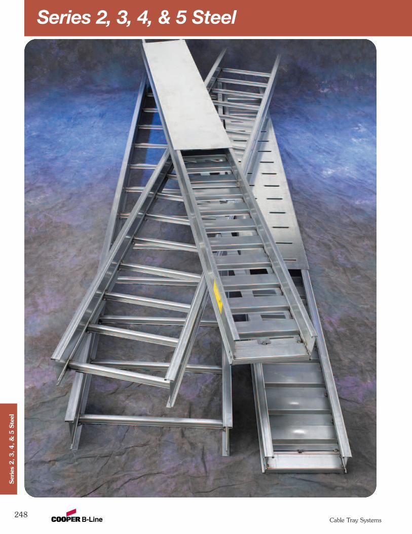
Series 2, 3, 4, & 5 Steel
248Cable Tray Systems
Ser
ies
2, 3, 4, &
5 S
teel
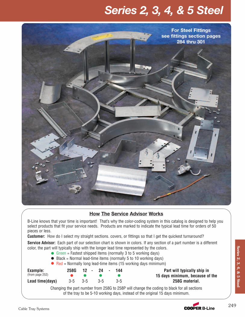
Series 2, 3, 4, & 5 Steel
249Cable Tray Systems
Series 2
, 3, 4
, & 5
Steel
How The Service Advisor Works
B-Line knows that your time is important! That’s why the color-coding system in this catalog is designed to help youselect products that fit your service needs. Products are marked to indicate the typical lead time for orders of 50pieces or less.Customer: How do I select my straight sections. covers, or fittings so that I get the quickest turnaround?Service Advisor: Each part of our selection chart is shown in colors. If any section of a part number is a differentcolor, the part will typically ship with the longer lead time represented by the colors.
Green = Fastest shipped items (normally 3 to 5 working days)Black = Normal lead-time items (normally 5 to 10 working days)Red = Normally long lead-time items (15 working days minimum)
Example: 258G 12 - 24 - 144 Part will typically ship in(from page 252) 15 days minimum, because of the Lead time(days) 3-5 3-5 3-5 3-5 258G material.
Changing the part number from 258G to 258P will change the coding to black for all sectionsof the tray to be 5-10 working days, instead of the original 15 days minimum.
For Steel Fittingssee fittings section pages
284 thru 301

Series 2, 3, 4, & 5 Steel - Straight Sections
250
3" NEMA VE 1 Loading Depth4" Side Rail Height
Ladder Type(Specify Rung Spacing)
Ventilated Trough Non-Ventilated Trough
RungSpacing
Width(Inside)
Overall Width(Width + (*))
For side rail & rungdata, see chart onpages AP-5 &AP-6
(*)=13/16” (Series 2)13/8” (Series 3,4,5)
Straight Section Part NumberingPrefix
Example: 248 P 09 - 24 - 144
Series Material *Type *Width Length248 P = Pre-Galvanized Ladder- 06 = 6" ¬ 144 = 12 ft.
248G = HDGAF 06 = 6" rung spacing 09 = 9" Á 120 = 10 ft.
346 09 = 9" rung spacing 12 = 12" ¬ 240 = 20 ft.34612 = 12" rung spacing 18 = 18" Á 144 = 12 ft.
444 24 = 24" ¬ 240 = 20 ft.44430 = 30" Á 288 = 24 ft.
Trough- 36 = 36"6" thru 36" wideVT = Vented TroughST = Non-Ventilated Trough
See page 356 for additional rung options. *Special sizes available.
Cable Tray Systems
Ser
ies
2, 3, 4, &
5 S
teel
Green = Fastest shipped items (normally 3 to 5 working days)Black = Normal lead-time items (normally 5 to 10 working days)Red = Normally long lead-time items (15 working days minimum)
¬Primary Length.ÁSecondary Length.
See page 39 for explanation of lengths.

B-Line Side Rail NEMA, CSA & UL Span Load Deflection Design Factors Span Load Deflection Design FactorsSeries Dimensions Classifications ft lbs/ft Multiplier for Two Rails meters kg/m Multiplier for Two Rails
NEMA: 20A, 16B 10 252 0.0035 3.0 375 0.060CSA: D1-6m 12 175 0.0072 Area=0.89 in2 3.7 260 0.124 Area=5.74 cm2
14 129 0.013 Sx=0.96 in3 4.3 191 0.229 Sx=15.73 cm3
UL Cross-Sectional 16 98 0.023 Ix=2.22 in4 4.9 146 0.391 Ix=92.40 cm4
Area: 0.70 in2 18 78 0.037 5.5 116 0.62620 63 0.056 6.1 94 0.955
B-Line Side Rail NEMA, CSA & UL Span Load Deflection Design Factors Span Load Deflection Design FactorsSeries Dimensions Classifications ft lbs/ft Multiplier for Two Rails meters kg/m Multiplier for Two Rails
NEMA: 20B, 16C 12 253 0.0055 3.7 376 0.093CSA: E-3m 16 142 0.017 Area=1.19 in2 4.9 212 0.295 Area=7.68 cm2
18 112 0.028 Sx=1.27 in3 5.5 167 0.473 Sx=20.81 cm3
UL Cross-Sectional 20 91 0.042 Ix=2.94 in4 6.1 135 0.721 Ix=122.37 cm4
Area: 1.00 in2 22 75 0.062 6.7 112 1.05524 63 0.088 7.3 94 1.495
B-Line Side Rail NEMA, CSA & UL Span Load Deflection Design Factors Span Load Deflection Design FactorsSeries Dimensions Classifications ft lbs/ft Multiplier for Two Rails meters kg/m Multiplier for Two Rails
NEMA: 16A, 12C 6 412* 0.0007 1.8 613* 0.012CSA: D1-3m 8 232 0.0022 Area=0.62 in2 2.4 345 0.038 Area=4.00 cm2
10 148 0.0054 Sx=0.64 in3 3.0 221 0.093 Sx=10.49 cm3
UL Cross-Sectional 12 103 0.011 Ix=1.43 in4 3.7 153 0.192 Ix=59.52 cm4
Area: 0.40 in2 14 76 0.021 4.3 113 0.35616 58 0.036 4.9 86 0.607
Series 2, 3, 4, & 5 Steel - Straight Sections
251
Values are based on simple beam tests per NEMA VE 1 on 36" wide cable tray with rungs spaced on 12" centers. Cable trays willsupport without collapse a 200 lb. (90.7 kg) concentrated load over and above published loads. Published load safety factor is 1.5. To convert 1.5 safety factor to 2.0, multiply publish load by 0.75. To obtain mid-span deflection, multiply a load by the deflection multiplier. Cable tray must be supported on spans shorter than or equal to the length of the cable tray being installed.
Individual rungs will support without collapse a 200 lb. (90.7 kg) concentrated load applied at the mid-span of the rung, over andabove the NEMA rated cable load with a 1.5 safety factor for highlighted NEMA spans and loads. See table on page 361 for rungcapacities.
*When using 18" rung spacing, load capacity is limited to 394 lbs/ft (586.272 kg/m) for 30" cable tray width and 325 lbs/ft (483.6 kg/m) for 36" cable tray width. When cable trays are used in continuous spans, the deflection of the cable tray is reduced by as much as 50%. Design factors: Ix = Moment of Inertia, Sx = Section Modulus.
1.00
4.188
18 gauge
3.14
1.50
4.1883.13
1.50
4.1883.11
16 gauge
14 gauge
3" NEMA VE 1 Loading Depth4" Side Rail Height
346
444
248
Cable Tray Systems
Series 2
, 3, 4
, & 5
Steel
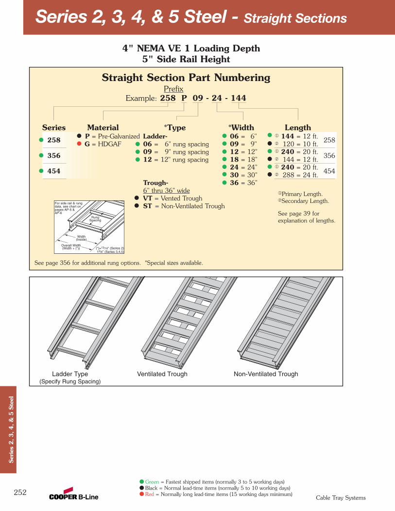
Series 2, 3, 4, & 5 Steel - Straight Sections
252
4" NEMA VE 1 Loading Depth5" Side Rail Height
RungSpacing
Width(Inside)
Overall Width(Width + (*))
For side rail & rungdata, see chart onpages AP-5 &AP-6
(*)=13/16” (Series 2)13/8” (Series 3,4,5)
Straight Section Part NumberingPrefix
Example: 258 P 09 - 24 - 144
Series Material *Type *Width Length258 P = Pre-Galvanized Ladder- 06 = 6" ¬ 144 = 12 ft.
258G = HDGAF 06 = 6" rung spacing 09 = 9" Á 120 = 10 ft.
356 09 = 9" rung spacing 12 = 12" ¬ 240 = 20 ft.35612 = 12" rung spacing 18 = 18" Á 144 = 12 ft.
454 24 = 24" ¬ 240 = 20 ft.45430 = 30" Á 288 = 24 ft.
Trough- 36 = 36"6" thru 36" wideVT = Vented TroughST = Non-Ventilated Trough
See page 356 for additional rung options. *Special sizes available.
Ladder Type(Specify Rung Spacing)
Ventilated Trough Non-Ventilated Trough
Cable Tray Systems
Ser
ies
2, 3, 4, &
5 S
teel
Green = Fastest shipped items (normally 3 to 5 working days)Black = Normal lead-time items (normally 5 to 10 working days)Red = Normally long lead-time items (15 working days minimum)
¬Primary Length.ÁSecondary Length.
See page 39 for explanation of lengths.
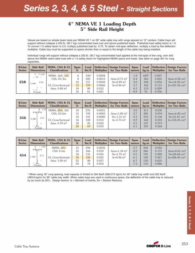
B-Line Side Rail NEMA, CSA & UL Span Load Deflection Design Factors Span Load Deflection Design FactorsSeries Dimensions Classifications ft lbs/ft Multiplier for Two Rails meters kg/m Multiplier for Two Rails
NEMA: 20C 12 294 0.0032 3.7 438 0.055CSA: E-6m 16 166 0.010 Area=1.34 in2 4.9 246 0.175 Area=8.65 cm2
18 131 0.016 Sx=1.75 in3 5.5 195 0.280 Sx=28.68 cm3
UL Cross-Sectional 20 106 0.025 Ix=4.96 in4 6.1 158 0.427 Ix=206.45 cm4
Area: 1.00 in2 22 88 0.037 6.7 130 0.62524 74 0.052 7.3 110 0.886
B-Line Side Rail NEMA, CSA & UL Span Load Deflection Design Factors Span Load Deflection Design FactorsSeries Dimensions Classifications ft lbs/ft Multiplier for Two Rails meters kg/m Multiplier for Two Rails
NEMA: 20A, 16C 10 276 0.0021 3.0 411 0.036CSA: D1-6m 12 192 0.0043 Area=1.00 in2 3.7 285 0.074 Area=6.45 cm2
14 141 0.0080 Sx=1.31 in3 4.3 210 0.136 Sx=21.47 cm3
UL Cross-Sectional 16 108 0.014 Ix=3.73 in4 4.9 160 0.233 Ix=155.25 cm4
Area: 0.70 in2 18 85 0.022 5.5 127 0.37320 69 0.033 6.1 103 0.568
B-Line Side Rail NEMA, CSA & UL Span Load Deflection Design Factors Span Load Deflection Design FactorsSeries Dimensions Classifications ft lbs/ft Multiplier for Two Rails meters kg/m Multiplier for Two Rails
NEMA: 16A, 12C 6 436* 0.0004 1.8 649* 0.007CSA: D1-3m 8 245 0.0013 Area=0.71 in2 2.4 365 0.022 Area=4.58 cm2
10 157 0.0032 Sx=0.89 in3 3.0 234 0.054 Sx=14.58 cm3
UL Cross-Sectional 12 109 0.0066 Ix=2.44 in4 3.7 162 0.113 Ix=101.56 cm4
Area: 0.40 in2 14 80 0.012 4.3 119 0.20916 61 0.021 4.9 91 0.356
Series 2, 3, 4, & 5 Steel - Straight Sections
253
Values are based on simple beam tests per NEMA VE 1 on 36" wide cable tray with rungs spaced on 12" centers. Cable trays willsupport without collapse a 200 lb. (90.7 kg) concentrated load over and above published loads. Published load safety factor is 1.5. To convert 1.5 safety factor to 2.0, multiply published load by 0.75. To obtain mid-span deflection, multiply a load by the deflectionmultiplier. Cable tray must be supported on spans shorter than or equal to the length of the cable tray being installed.
Individual rungs will support without collapse a 200 lb. (90.7 kg) concentrated load applied at the mid-span of the rung, over andabove the NEMA rated cable load with a 1.5 safety factor for highlighted NEMA spans and loads. See table on page 361 for rungcapacities.
* When using 18" rung spacing, load capacity is limited to 394 lbs/ft (586.272 kg/m) for 30" cable tray width and 325 lbs/ft (483.6 kg/m) for 36" cable tray width. When cable trays are used in continuous spans, the deflection of the cable tray is reducedby as much as 50%. Design factors: Ix = Moment of Inertia, Sx = Section Modulus.
1.00
5.1884.14
1.50
5.188 4.13
1.50
5.1884.11
18 gauge
14 gauge
16 gauge
4" NEMA VE 1 Loading Depth5" Side Rail Height
258
356
454
Cable Tray Systems
Series 2
, 3, 4
, & 5
Steel

Series 2, 3, 4, & 5 Steel - Straight Sections
254
5" NEMA VE 1 Loading Depth6" Side Rail Height
RungSpacing
Width(Inside)
Overall Width(Width + (*))
For side rail & rungdata, see chart onpages AP-5 &AP-6
(*)=13/16” (Series 2)13/8” (Series 3,4,5)
Straight Section Part NumberingPrefix
Example: 268 P 09 - 24 - 144
Series Material *Type *Width Length268 P = Pre-Galvanized Ladder- 06 = 6" ¬ 144 = 12 ft.
268G = HDGAF 06 = 6" rung spacing 09 = 9" Á 120 = 10 ft.
366 09 = 9" rung spacing 12 = 12" ¬ 240 = 20 ft.36612 = 12" rung spacing 18 = 18" Á 144 = 12 ft.
464 24 = 24" ¬ 240 = 20 ft.46430 = 30" Á 288 = 24 ft.
Trough- 36 = 36"6" thru 36" wideVT = Vented TroughST = Non-Ventilated Trough
See page 356 for additional rung options. *Special sizes available.
Ladder Type(Specify Rung Spacing)
Ventilated Trough Non-Ventilated Trough
Cable Tray Systems
Ser
ies
2, 3, 4, &
5 S
teel
Green = Fastest shipped items (normally 3 to 5 working days)Black = Normal lead-time items (normally 5 to 10 working days)Red = Normally long lead-time items (15 working days minimum)
¬Primary Length.ÁSecondary Length.
See page 39 for explanation of lengths.
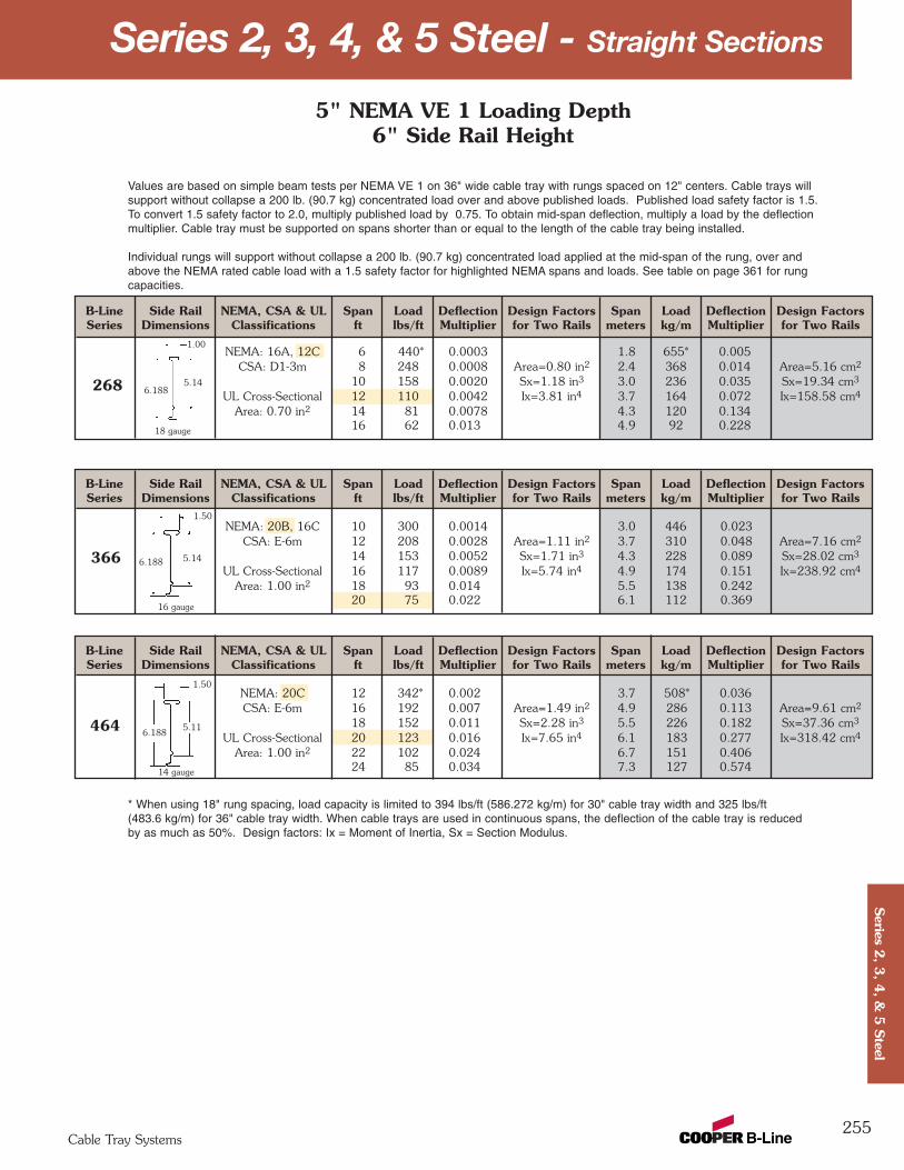
B-Line Side Rail NEMA, CSA & UL Span Load Deflection Design Factors Span Load Deflection Design FactorsSeries Dimensions Classifications ft lbs/ft Multiplier for Two Rails meters kg/m Multiplier for Two Rails
NEMA: 20C 12 342* 0.002 3.7 508* 0.036CSA: E-6m 16 192 0.007 Area=1.49 in2 4.9 286 0.113 Area=9.61 cm2
18 152 0.011 Sx=2.28 in3 5.5 226 0.182 Sx=37.36 cm3
UL Cross-Sectional 20 123 0.016 Ix=7.65 in4 6.1 183 0.277 Ix=318.42 cm4
Area: 1.00 in2 22 102 0.024 6.7 151 0.40624 85 0.034 7.3 127 0.574
B-Line Side Rail NEMA, CSA & UL Span Load Deflection Design Factors Span Load Deflection Design FactorsSeries Dimensions Classifications ft lbs/ft Multiplier for Two Rails meters kg/m Multiplier for Two Rails
NEMA: 20B, 16C 10 300 0.0014 3.0 446 0.023CSA: E-6m 12 208 0.0028 Area=1.11 in2 3.7 310 0.048 Area=7.16 cm2
14 153 0.0052 Sx=1.71 in3 4.3 228 0.089 Sx=28.02 cm3
UL Cross-Sectional 16 117 0.0089 Ix=5.74 in4 4.9 174 0.151 Ix=238.92 cm4
Area: 1.00 in2 18 93 0.014 5.5 138 0.24220 75 0.022 6.1 112 0.369
B-Line Side Rail NEMA, CSA & UL Span Load Deflection Design Factors Span Load Deflection Design FactorsSeries Dimensions Classifications ft lbs/ft Multiplier for Two Rails meters kg/m Multiplier for Two Rails
NEMA: 16A, 12C 6 440* 0.0003 1.8 655* 0.005CSA: D1-3m 8 248 0.0008 Area=0.80 in2 2.4 368 0.014 Area=5.16 cm2
10 158 0.0020 Sx=1.18 in3 3.0 236 0.035 Sx=19.34 cm3
UL Cross-Sectional 12 110 0.0042 Ix=3.81 in4 3.7 164 0.072 Ix=158.58 cm4
Area: 0.70 in2 14 81 0.0078 4.3 120 0.13416 62 0.013 4.9 92 0.228
Series 2, 3, 4, & 5 Steel - Straight Sections
255
Values are based on simple beam tests per NEMA VE 1 on 36" wide cable tray with rungs spaced on 12" centers. Cable trays willsupport without collapse a 200 lb. (90.7 kg) concentrated load over and above published loads. Published load safety factor is 1.5. To convert 1.5 safety factor to 2.0, multiply published load by 0.75. To obtain mid-span deflection, multiply a load by the deflectionmultiplier. Cable tray must be supported on spans shorter than or equal to the length of the cable tray being installed.
Individual rungs will support without collapse a 200 lb. (90.7 kg) concentrated load applied at the mid-span of the rung, over andabove the NEMA rated cable load with a 1.5 safety factor for highlighted NEMA spans and loads. See table on page 361 for rungcapacities.
* When using 18" rung spacing, load capacity is limited to 394 lbs/ft (586.272 kg/m) for 30" cable tray width and 325 lbs/ft (483.6 kg/m) for 36" cable tray width. When cable trays are used in continuous spans, the deflection of the cable tray is reduced by as much as 50%. Design factors: Ix = Moment of Inertia, Sx = Section Modulus.
1.00
6.1885.14
1.50
6.188 5.14
1.50
6.1885.11
18 gauge
16 gauge
14 gauge
5" NEMA VE 1 Loading Depth6" Side Rail Height
268
366
464
Cable Tray Systems
Series 2
, 3, 4
, & 5
Steel

Series 2, 3, 4, & 5 Steel - Straight Sections
256
6" NEMA VE 1 Loading Depth7" Side Rail Height
Overall Width(Width + 13/8")
For side rail & rungdata, see chart onpages AP-5 &AP-6
RungSpacing
Width(Inside)
Straight Section Part NumberingPrefix
Example: 378 P 09 - 24 - 240
Series Material *Type *Width Length378 P = Pre-Galvanized Ladder- 06 = 6" ¬ 144 = 12 ft.
378G = HDGAF 06 = 6" rung spacing 09 = 9" Á 240 = 20 ft.
476 09 = 9" rung spacing 12 = 12" ¬ 240 = 20 ft.47612 = 12" rung spacing 18 = 18" Á 288 = 24 ft.
574 24 = 24" ¬ 240 = 20 ft.57430 = 30" Á 288 = 24 ft.
Trough- 36 = 36"6" thru 36" wideVT = Vented TroughST = Non-Ventilated Trough
See page 356 for additional rung options. *Special sizes available.
Ladder Type(Specify Rung Spacing)
Ventilated Trough Non-Ventilated Trough
Cable Tray Systems
Ser
ies
2, 3, 4, &
5 S
teel
Green = Fastest shipped items (normally 3 to 5 working days)Black = Normal lead-time items (normally 5 to 10 working days)Red = Normally long lead-time items (15 working days minimum)
¬Primary Length.ÁSecondary Length.
See page 39 for explanation of lengths.
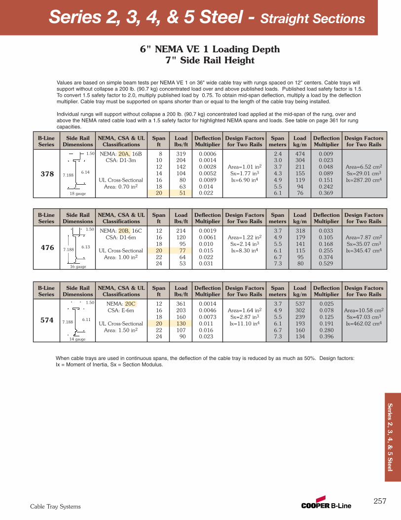
B-Line Side Rail NEMA, CSA & UL Span Load Deflection Design Factors Span Load Deflection Design FactorsSeries Dimensions Classifications ft lbs/ft Multiplier for Two Rails meters kg/m Multiplier for Two Rails
NEMA: 20C 12 361 0.0014 3.7 537 0.025CSA: E-6m 16 203 0.0046 Area=1.64 in2 4.9 302 0.078 Area=10.58 cm2
18 160 0.0073 Sx=2.87 in3 5.5 239 0.125 Sx=47.03 cm3
UL Cross-Sectional 20 130 0.011 Ix=11.10 in4 6.1 193 0.191 Ix=462.02 cm4
Area: 1.50 in2 22 107 0.016 6.7 160 0.28024 90 0.023 7.3 134 0.396
B-Line Side Rail NEMA, CSA & UL Span Load Deflection Design Factors Span Load Deflection Design FactorsSeries Dimensions Classifications ft lbs/ft Multiplier for Two Rails meters kg/m Multiplier for Two Rails
NEMA: 20B, 16C 12 214 0.0019 3.7 318 0.033CSA: D1-6m 16 120 0.0061 Area=1.22 in2 4.9 179 0.105 Area=7.87 cm2
18 95 0.010 Sx=2.14 in3 5.5 141 0.168 Sx=35.07 cm3
UL Cross-Sectional 20 77 0.015 Ix=8.30 in4 6.1 115 0.255 Ix=345.47 cm4
Area: 1.00 in2 22 64 0.022 6.7 95 0.37424 53 0.031 7.3 80 0.529
B-Line Side Rail NEMA, CSA & UL Span Load Deflection Design Factors Span Load Deflection Design FactorsSeries Dimensions Classifications ft lbs/ft Multiplier for Two Rails meters kg/m Multiplier for Two Rails
NEMA: 20A, 16B 8 319 0.0006 2.4 474 0.009CSA: D1-3m 10 204 0.0014 3.0 304 0.023
12 142 0.0028 Area=1.01 in2 3.7 211 0.048 Area=6.52 cm2
14 104 0.0052 Sx=1.77 in3 4.3 155 0.089 Sx=29.01 cm3
UL Cross-Sectional 16 80 0.0089 Ix=6.90 in4 4.9 119 0.151 Ix=287.20 cm4
Area: 0.70 in2 18 63 0.014 5.5 94 0.24220 51 0.022 6.1 76 0.369
Series 2, 3, 4, & 5 Steel - Straight Sections
257
7.188
Values are based on simple beam tests per NEMA VE 1 on 36" wide cable tray with rungs spaced on 12" centers. Cable trays willsupport without collapse a 200 lb. (90.7 kg) concentrated load over and above published loads. Published load safety factor is 1.5. To convert 1.5 safety factor to 2.0, multiply published load by 0.75. To obtain mid-span deflection, multiply a load by the deflectionmultiplier. Cable tray must be supported on spans shorter than or equal to the length of the cable tray being installed.
Individual rungs will support without collapse a 200 lb. (90.7 kg) concentrated load applied at the mid-span of the rung, over andabove the NEMA rated cable load with a 1.5 safety factor for highlighted NEMA spans and loads. See table on page 361 for rungcapacities.
When cable trays are used in continuous spans, the deflection of the cable tray is reduced by as much as 50%. Design factors: Ix = Moment of Inertia, Sx = Section Modulus.
1.50
7.1886.14
1.50
6.13
1.50
7.1886.11
18 gauge
16 gauge
14 gauge
6" NEMA VE 1 Loading Depth7" Side Rail Height
378
476
574
Cable Tray Systems
Series 2
, 3, 4
, & 5
Steel
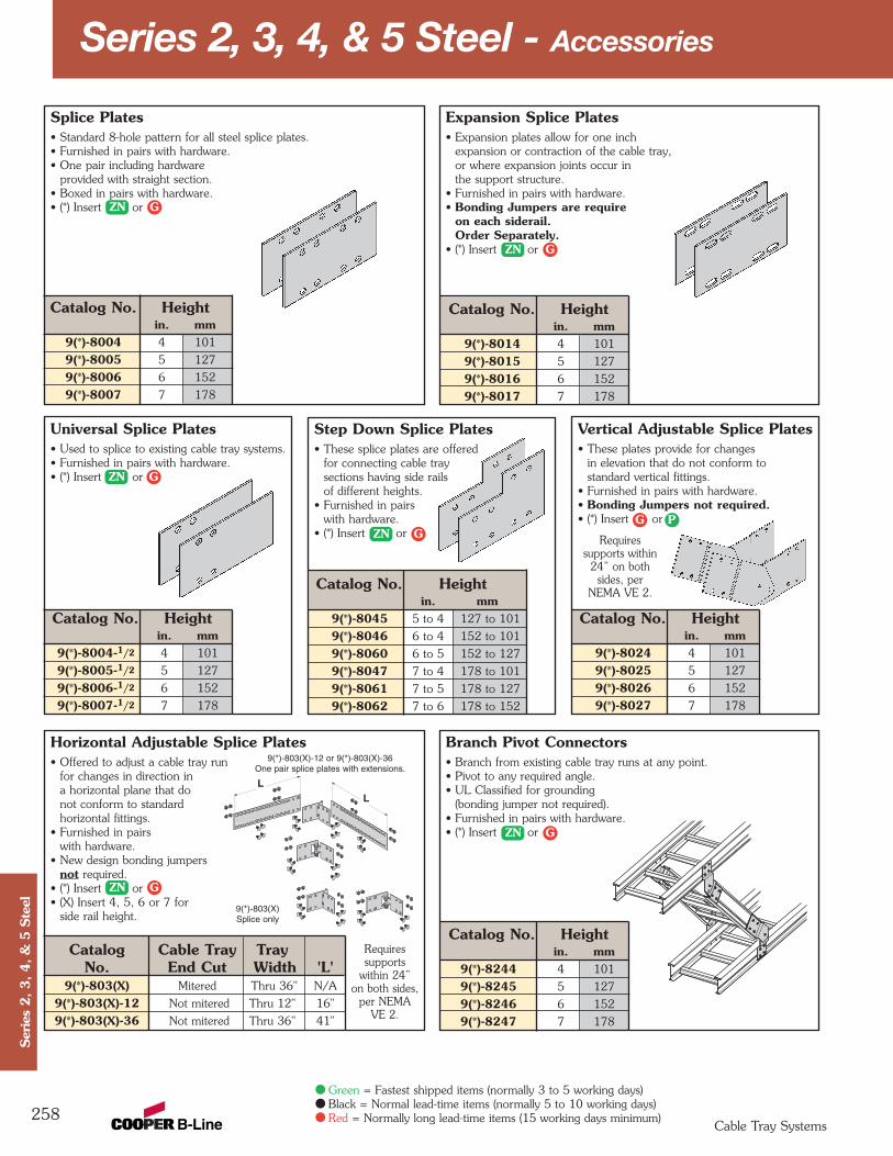
Catalog No. Heightin. mm
9(*)-8014 4 101
9(*)-8015 5 127
9(*)-8016 6 152
9(*)-8017 7 178
Catalog No. Heightin. mm
9(*)-8045 5 to 4 127 to 101
9(*)-8046 6 to 4 152 to 101
9(*)-8060 6 to 5 152 to 127
9(*)-8047 7 to 4 178 to 101
9(*)-8061 7 to 5 178 to 127
9(*)-8062 7 to 6 178 to 152
Splice Plates• Standard 8-hole pattern for all steel splice plates. • Furnished in pairs with hardware.• One pair including hardware
provided with straight section.• Boxed in pairs with hardware.• (*) Insert or
Catalog No. Heightin. mm
9(*)-8004 4 101
9(*)-8005 5 127
9(*)-8006 6 152
9(*)-8007 7 178
Catalog No. Heightin. mm
9(*)-8004-1/2 4 101
9(*)-8005-1/2 5 127
9(*)-8006-1/2 6 152
9(*)-8007-1/2 7 178
Branch Pivot Connectors• Branch from existing cable tray runs at any point.• Pivot to any required angle.• UL Classified for grounding
(bonding jumper not required).• Furnished in pairs with hardware.• (*) Insert or
Catalog No. Heightin. mm
9(*)-8244 4 101
9(*)-8245 5 127
9(*)-8246 6 152
9(*)-8247 7 178
Catalog Cable Tray TrayNo. End Cut Width 'L'
9(*)-803(X) Mitered Thru 36" N/A
9(*)-803(X)-12 Not mitered Thru 12" 16"
9(*)-803(X)-36 Not mitered Thru 36" 41"
Series 2, 3, 4, & 5 Steel - Accessories
258
9(*)-803(X)-12 or 9(*)-803(X)-36One pair splice plates with extensions.
9(*)-803(X)Splice only
LL
Horizontal Adjustable Splice Plates• Offered to adjust a cable tray run
for changes in direction ina horizontal plane that do not conform to standard horizontal fittings.
• Furnished in pairs with hardware.
• New design bonding jumpers not required.
• (*) Insert or• (X) Insert 4, 5, 6 or 7 for
side rail height.
Expansion Splice Plates• Expansion plates allow for one inch
expansion or contraction of the cable tray, or where expansion joints occur in the support structure.
• Furnished in pairs with hardware.• Bonding Jumpers are require
on each siderail.Order Separately.
• (*) Insert or
Universal Splice Plates• Used to splice to existing cable tray systems.• Furnished in pairs with hardware.• (*) Insert or
Catalog No. Heightin. mm
9(*)-8024 4 101
9(*)-8025 5 127
9(*)-8026 6 152
9(*)-8027 7 178
Step Down Splice Plates• These splice plates are offered
for connecting cable tray sections having side rails of different heights.
• Furnished in pairs with hardware.
• (*) Insert or
Vertical Adjustable Splice Plates• These plates provide for changes
in elevation that do not conform to standard vertical fittings.
• Furnished in pairs with hardware.• Bonding Jumpers not required.• (*) Insert or
Cable Tray Systems
Ser
ies
2, 3, 4, &
5 S
teel
Green = Fastest shipped items (normally 3 to 5 working days)Black = Normal lead-time items (normally 5 to 10 working days)Red = Normally long lead-time items (15 working days minimum)
ZN G
ZN G
ZN G
ZN GPG
ZN G
ZN G
Requiressupports
within 24”on both sides,
per NEMAVE 2.
Requiressupports within
24” on bothsides, per
NEMA VE 2.
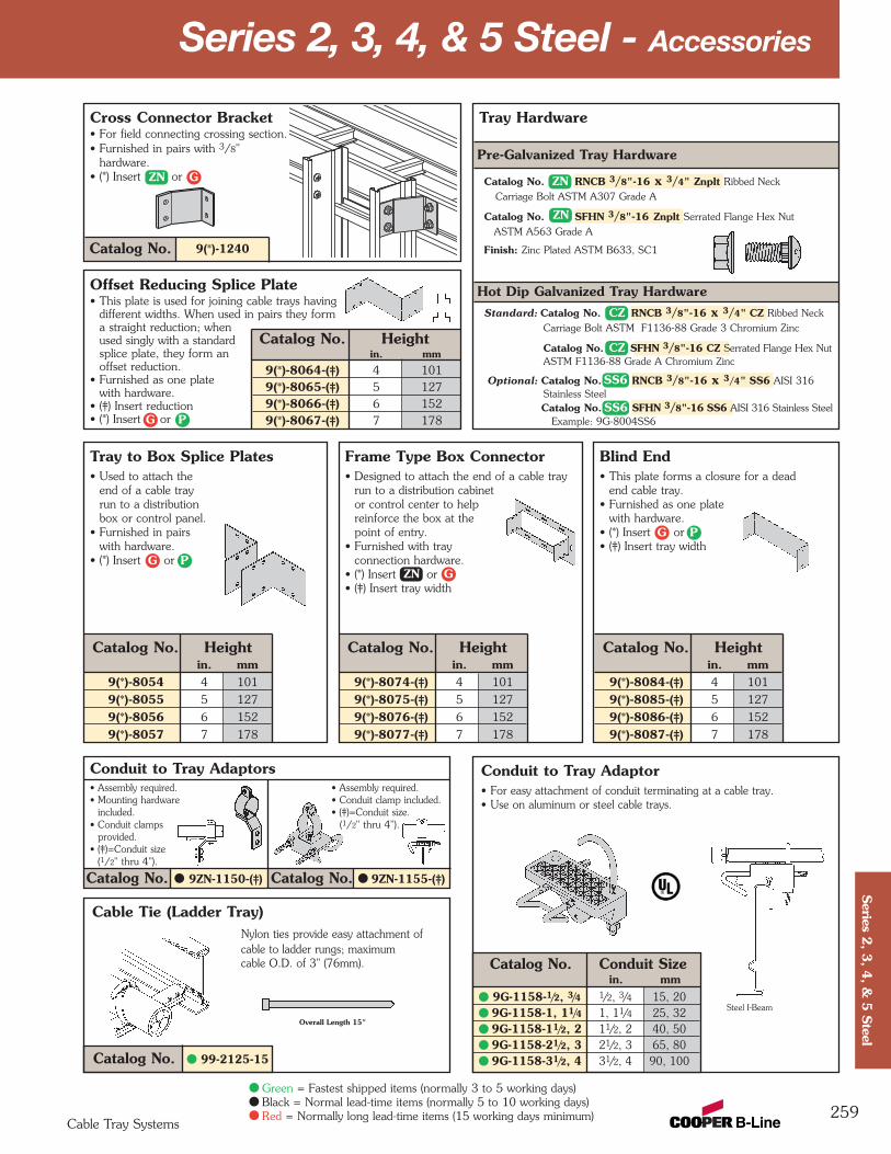
Conduit to Tray Adaptor• For easy attachment of conduit terminating at a cable tray. • Use on aluminum or steel cable trays.
Catalog No. Conduit Sizein. mm
9G-1158-1/2, 3/4 1/2, 3/4 15, 209G-1158-1, 11/4 1, 11/4 25, 329G-1158-11/2, 2 11/2, 2 40, 509G-1158-21/2, 3 21/2, 3 65, 809G-1158-31/2, 4 31/2, 4 90, 100
Series 2, 3, 4, & 5 Steel - Accessories
259
Cable Tie (Ladder Tray)Nylon ties provide easy attachment of cable to ladder rungs; maximum cable O.D. of 3" (76mm).
Tray Hardware
Pre-Galvanized Tray Hardware
Catalog No. RNCB 3/8"-16 x 3/4" Znplt Ribbed Neck Carriage Bolt ASTM A307 Grade A
Catalog No. SFHN 3/8"-16 Znplt Serrated Flange Hex NutASTM A563 Grade A
Finish: Zinc Plated ASTM B633, SC1
Hot Dip Galvanized Tray HardwareStandard: Catalog No. RNCB 3/8"-16 x 3/4" CZ Ribbed Neck
Carriage Bolt ASTM F1136-88 Grade 3 Chromium Zinc
Catalog No. SFHN 3/8"-16 CZ Serrated Flange Hex NutASTM F1136-88 Grade A Chromium Zinc
Optional: Catalog No. RNCB 3/8"-16 x 3/4" SS6 AISI 316Stainless SteelCatalog No. SFHN 3/8"-16 SS6 AISI 316 Stainless Steel
Steel I-Beam
Overall Length 15"
Example: 9G-8004SS6
Catalog No. 99-2125-15
Catalog No. Heightin. mm
9(*)-8084-(‡) 4 101
9(*)-8085-(‡) 5 127
9(*)-8086-(‡) 6 152
9(*)-8087-(‡) 7 178
Catalog No. Heightin. mm
9(*)-8074-(‡) 4 101
9(*)-8075-(‡) 5 127
9(*)-8076-(‡) 6 152
9(*)-8077-(‡) 7 178
Catalog No. Heightin. mm
9(*)-8054 4 101
9(*)-8055 5 127
9(*)-8056 6 152
9(*)-8057 7 178
Tray to Box Splice Plates• Used to attach the
end of a cable tray run to a distribution box or control panel.
• Furnished in pairs with hardware.
• (*) Insert or
Blind End• This plate forms a closure for a dead
end cable tray.• Furnished as one plate
with hardware.• (*) Insert or• (‡) Insert tray width
Frame Type Box Connector• Designed to attach the end of a cable tray
run to a distribution cabinet or control center to help reinforce the box at the point of entry.
• Furnished with tray connection hardware.
• (*) Insert or• (‡) Insert tray width
Conduit to Tray Adaptors• Assembly required. • Assembly required.• Mounting hardware • Conduit clamp included.
included. • (‡)=Conduit size.• Conduit clamps (1/2" thru 4").
provided.• (‡)=Conduit size
(1/2" thru 4").
Catalog No. 9ZN-1150-(‡) Catalog No. 9ZN-1155-(‡)
9(*)-1240Catalog No.
Cross Connector Bracket• For field connecting crossing section.• Furnished in pairs with 3/8"
hardware.• (*) Insert or
Offset Reducing Splice Plate• This plate is used for joining cable trays having
different widths. When used in pairs they form a straight reduction; when used singly with a standard splice plate, they form anoffset reduction.
• Furnished as one plate with hardware.
• (‡) Insert reduction• (*) Insert or
Catalog No. Heightin. mm
9(*)-8064-(‡) 4 1019(*)-8065-(‡) 5 1279(*)-8066-(‡) 6 1529(*)-8067-(‡) 7 178
Cable Tray Systems
Series 2
, 3, 4
, & 5
Steel
Green = Fastest shipped items (normally 3 to 5 working days)Black = Normal lead-time items (normally 5 to 10 working days)Red = Normally long lead-time items (15 working days minimum)
ZN
ZN
CZ
CZ
SS6
SS6
ZN G
G P
G P
G P
ZN G
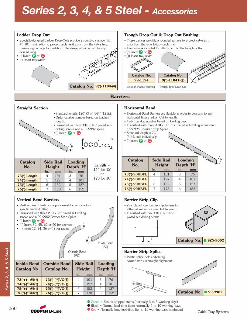
Trough Drop-Out & Drop-Out Bushing• These devices provide a rounded surface to protect cable as it
exits from the trough-type cable tray.• Hardware is included for attachment to the trough bottom.• (*) Insert or• (‡) Insert tray width
Catalog No. 9(*)-1104-(‡)
Ladder Drop-Out• Specially-designed Ladder Drop-Outs provide a rounded surface with
4" (101 mm) radius to protect cable as it exits from the cable tray, preventing damage to insulation. The drop-out will attach to any desired rung.
• (*) Insert or• (‡) Insert tray width
Horizontal Bend• Horizontal Bend Barriers are flexible in order to conform to any
horizontal fitting radius. Cut to length.• Order catalog number based on loading depth.• Furnished with three #10 x 1/2" zinc plated self-drilling screws and
a 99-9982 Barrier Strip Splice.• Standard length is 72"
(6 ft.), sold individually.• (*) Insert or
Catalog Side Rail LoadingNo. Height Depth 'H'
in. mm in. mm73(*)-90HBFL 4 101 3 76
74(*)-90HBFL 5 127 4 101
75(*)-90HBFL 6 152 5 127
76(*)-90HBFL 7 178 6 152
Vertical Bend Barriers• Vertical Bend Barriers are preformed to conform to a
specific vertical fitting.• Furnished with three #10 x 1/2" plated self-drilling
screws and a 99-9982 Barrier Strip Splice.• (*) Insert or• (**) Insert 30, 45, 60 or 90 for degrees• (†) Insert 12, 24, 36 or 48 for radius
Inside Bend Outside Bend Side Rail LoadingCatalog No. Catalog No. Height Depth 'H'
in. mm in. mm
73(*)-(**)VI(†) 73(*)-(**)VO(†) 4 101 3 7674(*)-(**)VI(†) 74(*)-(**)VO(†) 5 127 4 10175(*)-(**)VI(†) 75(*)-(**)VO(†) 6 152 5 12776(*)-(**)VI(†) 76(*)-(**)VO(†) 7 178 6 152 99-9982Catalog No.
Barrier Strip Splice• Plastic splice holds adjoining
barrier strips in straight alignment.
9ZN-9002Catalog No.
Straight Section• Standard length: 120" (3 m) 144" (12 ft.).• Order catalog number based on loading
depth.• Furnished with four #10 x 1/2" plated self-
drilling screws and a 99-9982 splice.• (*) Insert or
Catalog Side Rail LoadingNo. Height Depth 'H'
in. mm in. mm73(*)-Length 4 101 3 7674(*)-Length 5 127 4 10175(*)-Length 6 152 5 12776(*)-Length 7 178 6 152
Series 2, 3, 4, & 5 Steel - Accessories
260
Snap-In Plastic Bushing Trough-Type Drop-Out
Outside Bend(VO)
Inside Bend(VI)
H
H
Catalog No.9(*)-1104T-(‡)
Barriers
Length =144 for 12'
or 120 for 10'
H
H
Catalog No.99-1124
Barrier Strip Clip• Zinc plated steel barrier clip fastens to
either aluminum or steel ladder rung.• Furnished with one #10 x 1/2" zinc
plated self-drilling screw.
Cable Tray Systems
Ser
ies
2, 3, 4, &
5 S
teel
Green = Fastest shipped items (normally 3 to 5 working days)Black = Normal lead-time items (normally 5 to 10 working days)Red = Normally long lead-time items (15 working days minimum)
GPGP
GP
GP
GP
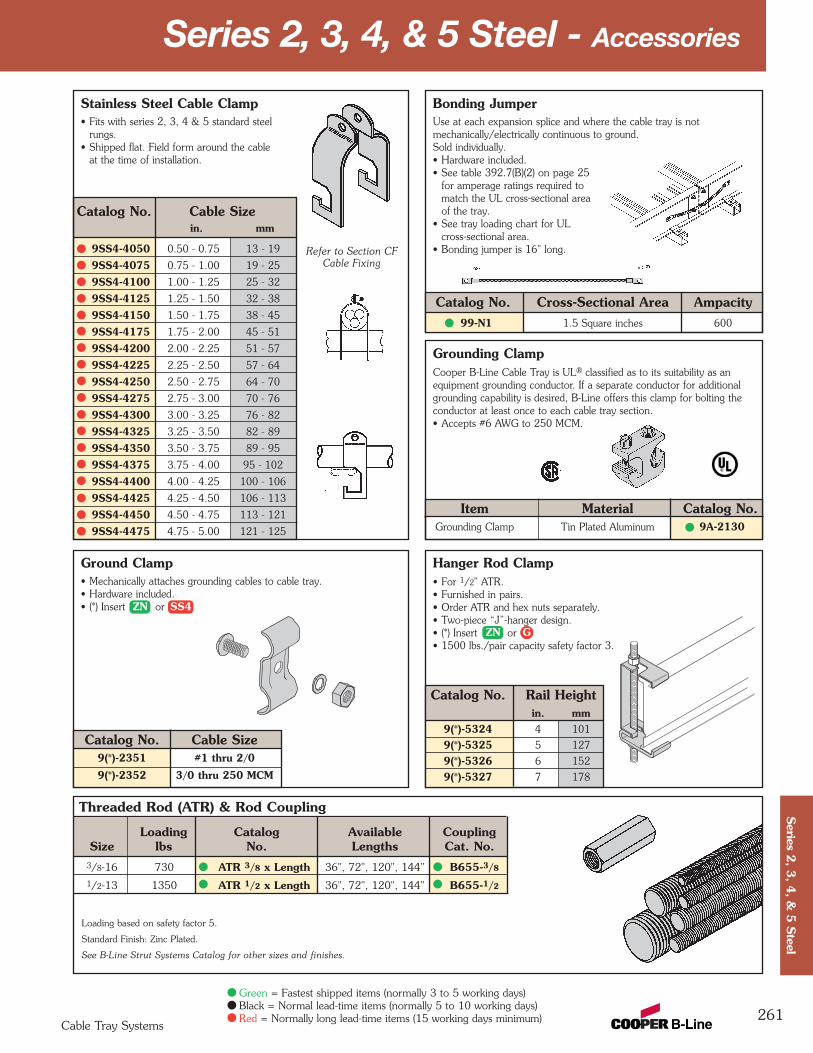
Stainless Steel Cable Clamp• Fits with series 2, 3, 4 & 5 standard steel
rungs.• Shipped flat. Field form around the cable
at the time of installation.
Hanger Rod Clamp• For 1/2" ATR.• Furnished in pairs.• Order ATR and hex nuts separately.• Two-piece “J”-hanger design.• (*) Insert or• 1500 lbs./pair capacity safety factor 3.
Catalog No. Rail Heightin. mm
9(*)-5324 4 101
9(*)-5325 5 127
9(*)-5326 6 152
9(*)-5327 7 178
Ground Clamp• Mechanically attaches grounding cables to cable tray.• Hardware included.• (*) Insert or
Catalog No. Cable Size9(*)-2351 #1 thru 2/0
9(*)-2352 3/0 thru 250 MCM
Bonding JumperUse at each expansion splice and where the cable tray is notmechanically/electrically continuous to ground. Sold individually.• Hardware included.• See table 392.7(B)(2) on page 25
for amperage ratings required tomatch the UL cross-sectional areaof the tray.
• See tray loading chart for ULcross-sectional area.
• Bonding jumper is 16" long.
Catalog No. Cross-Sectional Area Ampacity99-N1 1.5 Square inches 600
Grounding ClampCooper B-Line Cable Tray is UL® classified as to its suitability as anequipment grounding conductor. If a separate conductor for additionalgrounding capability is desired, B-Line offers this clamp for bolting theconductor at least once to each cable tray section.• Accepts #6 AWG to 250 MCM.
Item Material Catalog No.Grounding Clamp Tin Plated Aluminum 9A-2130
Series 2, 3, 4, & 5 Steel - Accessories
261
Threaded Rod (ATR) & Rod Coupling
Loading Catalog Available CouplingSize lbs No. Lengths Cat. No.
3/8-16 730 ATR 3/8 x Length 36", 72", 120", 144" B655-3/8
1/2-13 1350 ATR 1/2 x Length 36", 72", 120", 144" B655-1/2
Loading based on safety factor 5.
Standard Finish: Zinc Plated.
See B-Line Strut Systems Catalog for other sizes and finishes.
Catalog No. Cable Sizein. mm
9SS4-4050 0.50 - 0.75 13 - 19
9SS4-4075 0.75 - 1.00 19 - 25
9SS4-4100 1.00 - 1.25 25 - 32
9SS4-4125 1.25 - 1.50 32 - 38
9SS4-4150 1.50 - 1.75 38 - 45
9SS4-4175 1.75 - 2.00 45 - 51
9SS4-4200 2.00 - 2.25 51 - 57
9SS4-4225 2.25 - 2.50 57 - 64
9SS4-4250 2.50 - 2.75 64 - 70
9SS4-4275 2.75 - 3.00 70 - 76
9SS4-4300 3.00 - 3.25 76 - 82
9SS4-4325 3.25 - 3.50 82 - 89
9SS4-4350 3.50 - 3.75 89 - 95
9SS4-4375 3.75 - 4.00 95 - 102
9SS4-4400 4.00 - 4.25 100 - 106
9SS4-4425 4.25 - 4.50 106 - 113
9SS4-4450 4.50 - 4.75 113 - 121
9SS4-4475 4.75 - 5.00 121 - 125
Cable Tray Systems
Series 2
, 3, 4
, & 5
Steel
Green = Fastest shipped items (normally 3 to 5 working days)Black = Normal lead-time items (normally 5 to 10 working days)Red = Normally long lead-time items (15 working days minimum)
ZN
ZN SS4
G
Refer to Section CFCable Fixing

Cable Tray Clamp/Guide• Features a no-twist design.• Has four times the strength
of the traditional design.• Each side is labeled to
ensure proper installation.• Furnished in pairs, with or
without hardware.
Cable Tray Guide • Expansion guide for single or double cable tray runs.• Guide allows for longitudinal movement of the
cable tray.• No field drilling of support I-beam or channel is required.• Guides are required on both sides of cable tray to
prevent lateral movement - can be placed on either the inside or outside flange of cable tray.
• Guides are sold in pieces - two guides are required per tray.
• Maximum flange thickness 11/8" (28.58 mm).
Catalog No. Finish9ZN-1249 Zinc Plated
9G-1249 HDGAF
Neoprene Roll• Used for material isolation.• 1/8" x 2" x 20' roll.• Hardness: Shore A60.• Good weatherability.
Series 2, 3, 4, & 5 Steel - Accessories
262
Nylon Pad• Use for friction reduction.• Hardness: Shore D80.• Low friction coefficient.• UV resistant (black).• Excellent weatherability.• UL-94HB.
Catalog No. 99-NP240Catalog No. 99-NY36
When installing this device as an expansionguide on the outside flange of Steel Side Rail,use the Catalog No. B202 Square Washerin order to properly elevate the guide.
1/8"(3mm)
6"(152mm)
3"(76mm)
Note: For heavy duty or vertical applicationssee 9(*)-1241 or 9(*)-1242 page 265.
Catalog No.Without With Overall Hardware
Hardware Hardware Length Size Finishin. mm
9ZN-1204 9ZN-1204NB 11/2 38 1/4" Znplt
9ZN-1208 9ZN-1208NB 21/4 57 3/8" Znplt
9A-1205 -- 21/4 57 1/2" Alum.
9G-1205 -- 21/4 57 1/2" HDGAF
9SS6-1205 -- 21/4 57 1/2" 316SS
9ZN-1205 -- 21/4 57 1/2" Znplt
9ZN-1204 shown.Installed as a guide.
Patent #RE35479
11/2"(39mm)
21/4"(57mm)
9ZN-1208 shown.Installed as a clamp.
Cable Tray Systems
Ser
ies
2, 3, 4, &
5 S
teel
Green = Fastest shipped items (normally 3 to 5 working days)Black = Normal lead-time items (normally 5 to 10 working days)Red = Normally long lead-time items (15 working days minimum)
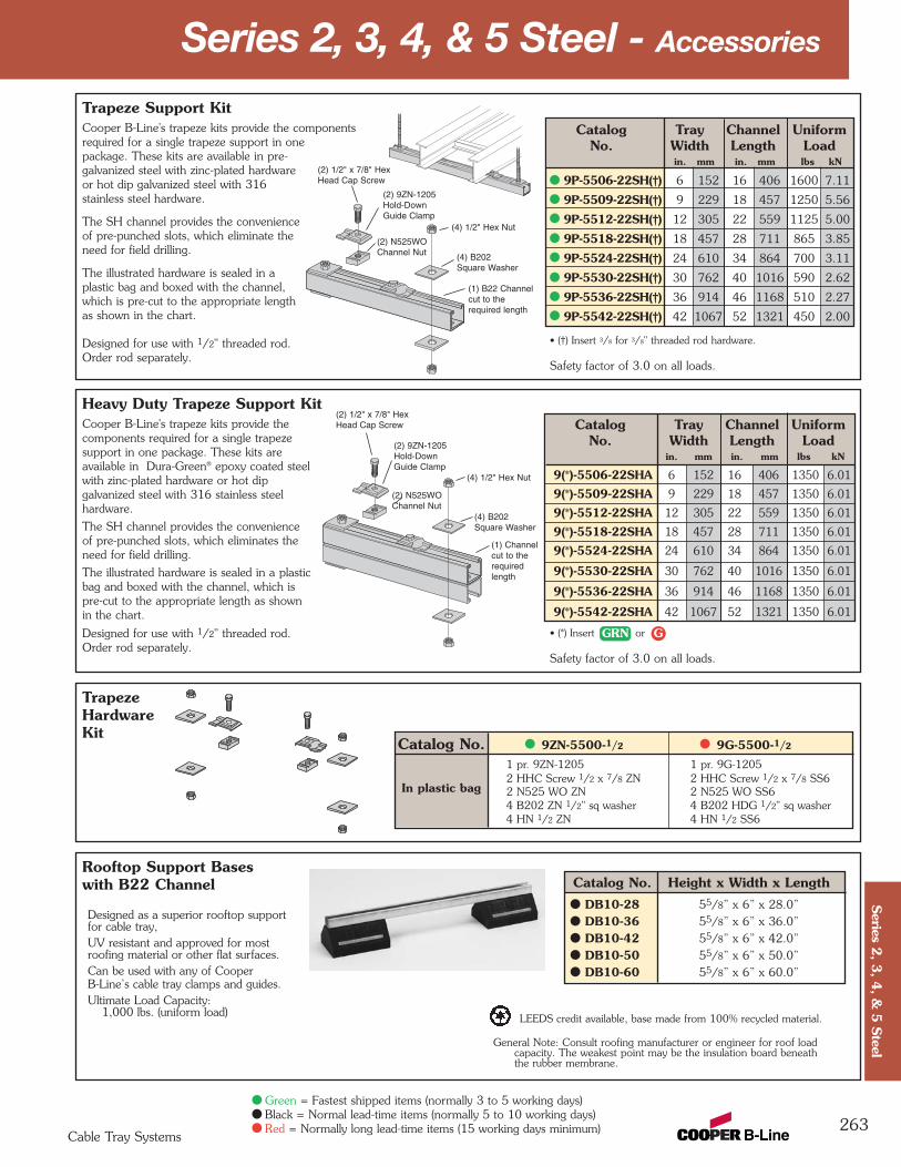
Series 2, 3, 4, & 5 Steel - Accessories
263Cable Tray Systems
Series 2
, 3, 4
, & 5
Steel
Green = Fastest shipped items (normally 3 to 5 working days)Black = Normal lead-time items (normally 5 to 10 working days)Red = Normally long lead-time items (15 working days minimum)
TrapezeHardwareKit
Heavy Duty Trapeze Support KitCooper B-Line's trapeze kits provide thecomponents required for a single trapezesupport in one package. These kits areavailable in Dura-Green® epoxy coated steelwith zinc-plated hardware or hot dipgalvanized steel with 316 stainless steelhardware.
The SH channel provides the convenienceof pre-punched slots, which eliminates the need for field drilling.
The illustrated hardware is sealed in a plastic bag and boxed with the channel, which is pre-cut to the appropriate length as shown in the chart.
Designed for use with 1/2" threaded rod. Order rod separately.
Catalog Tray Channel UniformNo. Width Length Load
in. mm in. mm lbs kN
9(*)-5506-22SHA 6 152 16 406 1350 6.01
9(*)-5509-22SHA 9 229 18 457 1350 6.01
9(*)-5512-22SHA 12 305 22 559 1350 6.01
9(*)-5518-22SHA 18 457 28 711 1350 6.01
9(*)-5524-22SHA 24 610 34 864 1350 6.01
9(*)-5530-22SHA 30 762 40 1016 1350 6.01
9(*)-5536-22SHA 36 914 46 1168 1350 6.01
9(*)-5542-22SHA 42 1067 52 1321 1350 6.01
Trapeze Support KitCooper B-Line's trapeze kits provide the componentsrequired for a single trapeze support in onepackage. These kits are available in pre-galvanized steel with zinc-plated hardwareor hot dip galvanized steel with 316stainless steel hardware.
The SH channel provides the convenienceof pre-punched slots, which eliminate the need for field drilling.
The illustrated hardware is sealed in aplastic bag and boxed with the channel,which is pre-cut to the appropriate lengthas shown in the chart.
Designed for use with 1/2" threaded rod. Order rod separately.
Catalog Tray Channel UniformNo. Width Length Load
in. mm in. mm lbs kN
9P-5506-22SH(†) 6 152 16 406 1600 7.11
9P-5509-22SH(†) 9 229 18 457 1250 5.56
9P-5512-22SH(†) 12 305 22 559 1125 5.00
9P-5518-22SH(†) 18 457 28 711 865 3.85
9P-5524-22SH(†) 24 610 34 864 700 3.11
9P-5530-22SH(†) 30 762 40 1016 590 2.62
9P-5536-22SH(†) 36 914 46 1168 510 2.27
9P-5542-22SH(†) 42 1067 52 1321 450 2.00
• (†) Insert 3/8 for 3/8" threaded rod hardware.
Safety factor of 3.0 on all loads.
• (*) Insert or
Safety factor of 3.0 on all loads.
(1) B22 Channelcut to therequired length
(2) 9ZN-1205Hold-DownGuide Clamp
(4) B202Square Washer
(2) N525WOChannel Nut
(2) 1/2" x 7/8" HexHead Cap Screw
(4) 1/2" Hex Nut
(1) Channelcut to therequiredlength
(2) 9ZN-1205Hold-DownGuide Clamp
(4) B202Square Washer
(2) N525WOChannel Nut
(2) 1/2" x 7/8" HexHead Cap Screw
(4) 1/2" Hex Nut
Catalog No. 9ZN-5500-1/2 9G-5500-1/2
1 pr. 9ZN-1205 1 pr. 9G-12052 HHC Screw 1/2 x 7/8 ZN 2 HHC Screw 1/2 x 7/8 SS62 N525 WO ZN 2 N525 WO SS64 B202 ZN 1/2" sq washer 4 B202 HDG 1/2" sq washer4 HN 1/2 ZN 4 HN 1/2 SS6
In plastic bag
GRN G
Rooftop Support Baseswith B22 Channel Catalog No. Height x Width x Length
DB10-28 55/8” x 6” x 28.0”DB10-36 55/8” x 6” x 36.0”DB10-42 55/8” x 6” x 42.0”DB10-50 55/8” x 6” x 50.0”DB10-60 55/8” x 6” x 60.0”
Designed as a superior rooftop supportfor cable tray,UV resistant and approved for mostroofing material or other flat surfaces.Can be used with any of CooperB-Line’s cable tray clamps and guides.Ultimate Load Capacity:
1,000 lbs. (uniform load) LEEDS credit available, base made from 100% recycled material.
General Note: Consult roofing manufacturer or engineer for roof loadcapacity. The weakest point may be the insulation board beneaththe rubber membrane.
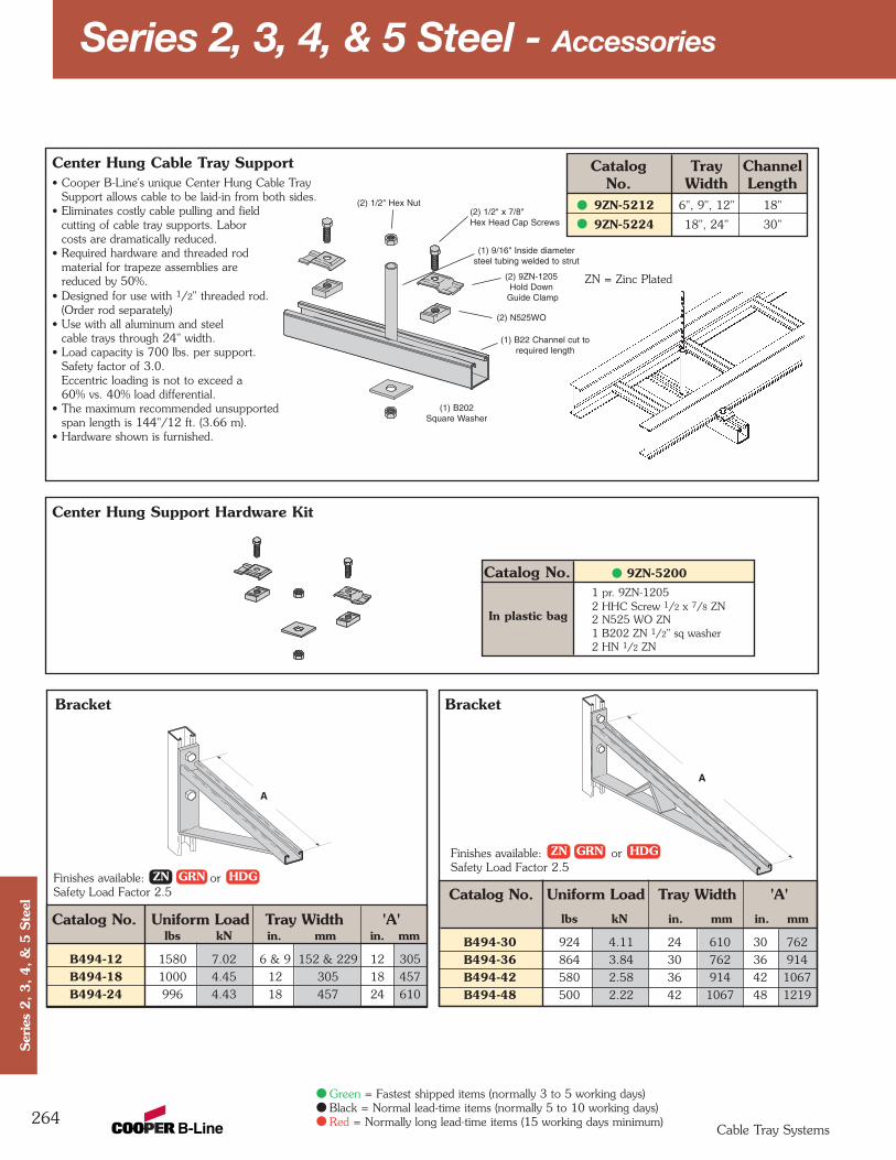
Center Hung Support Hardware Kit
Bracket
Catalog No. Uniform Load Tray Width 'A'lbs kN in. mm in. mm
B494-12 1580 7.02 6 & 9 152 & 229 12 305
B494-18 1000 4.45 12 305 18 457
B494-24 996 4.43 18 457 24 610
Bracket
Catalog No. Uniform Load Tray Width 'A'lbs kN in. mm in. mm
B494-30 924 4.11 24 610 30 762
B494-36 864 3.84 30 762 36 914
B494-42 580 2.58 36 914 42 1067
B494-48 500 2.22 42 1067 48 1219
Center Hung Cable Tray Support• Cooper B-Line's unique Center Hung Cable Tray
Support allows cable to be laid-in from both sides.• Eliminates costly cable pulling and field
cutting of cable tray supports. Labor costs are dramatically reduced.
• Required hardware and threaded rod material for trapeze assemblies are reduced by 50%.
• Designed for use with 1/2" threaded rod.(Order rod separately)
• Use with all aluminum and steel cable trays through 24" width.
• Load capacity is 700 lbs. per support.Safety factor of 3.0.Eccentric loading is not to exceed a 60% vs. 40% load differential.
• The maximum recommended unsupported span length is 144"/12 ft. (3.66 m).
• Hardware shown is furnished.
Catalog Tray ChannelNo. Width Length
9ZN-5212 6", 9", 12" 18"
9ZN-5224 18", 24" 30"
Series 2, 3, 4, & 5 Steel - Accessories
264
(2) 1/2" x 7/8"Hex Head Cap Screws
(2) 1/2" Hex Nut
(1) B202Square Washer
(2) 9ZN-1205Hold Down
Guide Clamp
(2) N525WO
(1) B22 Channel cut torequired length
(1) 9/16" Inside diametersteel tubing welded to strut
Finishes available: orSafety Load Factor 2.5
Finishes available: orSafety Load Factor 2.5
A
A
Catalog No. 9ZN-52001 pr. 9ZN-12052 HHC Screw 1/2 x 7/8 ZN2 N525 WO ZN1 B202 ZN 1/2" sq washer 2 HN 1/2 ZN
In plastic bag
ZN = Zinc Plated
Cable Tray Systems
Ser
ies
2, 3, 4, &
5 S
teel
Green = Fastest shipped items (normally 3 to 5 working days)Black = Normal lead-time items (normally 5 to 10 working days)Red = Normally long lead-time items (15 working days minimum)
ZN GRN HDG
ZN GRN HDG
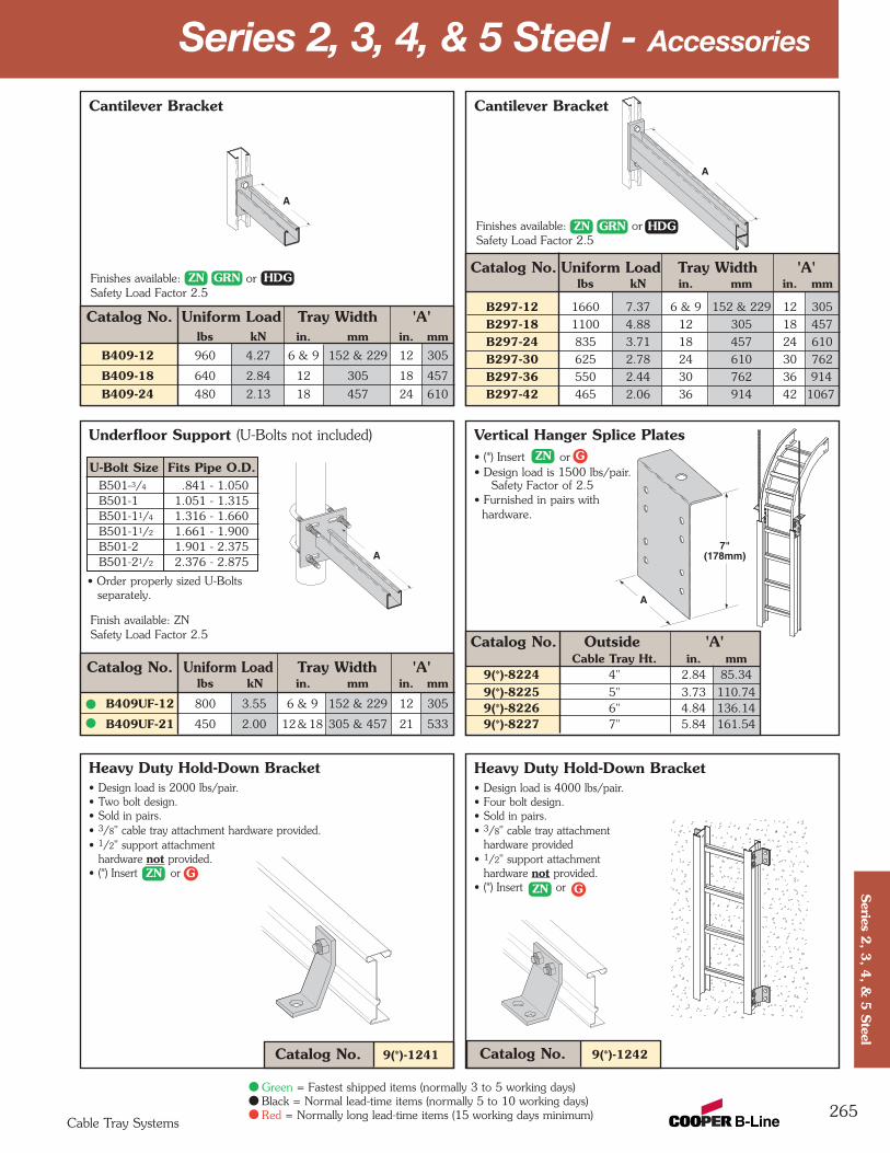
Vertical Hanger Splice Plates• (*) Insert or• Design load is 1500 lbs/pair.
Safety Factor of 2.5• Furnished in pairs with
hardware.
Catalog No. Outside 'A'Cable Tray Ht. in. mm
9(*)-8224 4" 2.84 85.34
9(*)-8225 5" 3.73 110.749(*)-8226 6" 4.84 136.149(*)-8227 7" 5.84 161.54
Underfloor Support (U-Bolts not included)
Cantilever Bracket
Catalog No. Uniform Load Tray Width 'A'lbs kN in. mm in. mm
B297-12 1660 7.37 6 & 9 152 & 229 12 305
B297-18 1100 4.88 12 305 18 457
B297-24 835 3.71 18 457 24 610
B297-30 625 2.78 24 610 30 762
B297-36 550 2.44 30 762 36 914
B297-42 465 2.06 36 914 42 1067
Cantilever Bracket
Catalog No. Uniform Load Tray Width 'A'lbs kN in. mm in. mm
B409-12 960 4.27 6 & 9 152 & 229 12 305
B409-18 640 2.84 12 305 18 457
B409-24 480 2.13 18 457 24 610
265
Heavy Duty Hold-Down Bracket• Design load is 2000 lbs/pair.• Two bolt design.• Sold in pairs.• 3/8" cable tray attachment hardware provided.• 1/2" support attachment
hardware not provided.• (*) Insert or
Catalog No. 9(*)-1241
Series 2, 3, 4, & 5 Steel - Accessories
A
Finishes available: orSafety Load Factor 2.5
A
A7"
(178mm)
A
Finish available: ZNSafety Load Factor 2.5
U-Bolt Size Fits Pipe O.D.B501-3/4 .841 - 1.050B501-1 1.051 - 1.315B501-11/4 1.316 - 1.660B501-11/2 1.661 - 1.900B501-2 1.901 - 2.375B501-21/2 2.376 - 2.875
• Order properly sized U-Bolts separately.
Catalog No. Uniform Load Tray Width 'A'lbs kN in. mm in. mm
B409UF-12 800 3.55 6 & 9 152 & 229 12 305
B409UF-21 450 2.00 12 & 18 305 & 457 21 533
Finishes available: orSafety Load Factor 2.5
Cable Tray Systems
Series 2
, 3, 4
, & 5
Steel
Green = Fastest shipped items (normally 3 to 5 working days)Black = Normal lead-time items (normally 5 to 10 working days)Red = Normally long lead-time items (15 working days minimum)
ZN GRN HDG
ZN GRN HDG
ZN G
ZN G
Heavy Duty Hold-Down Bracket• Design load is 4000 lbs/pair.• Four bolt design.• Sold in pairs.• 3/8" cable tray attachment
hardware provided• 1/2" support attachment
hardware not provided.• (*) Insert or
Catalog No. 9(*)-1242
ZN G
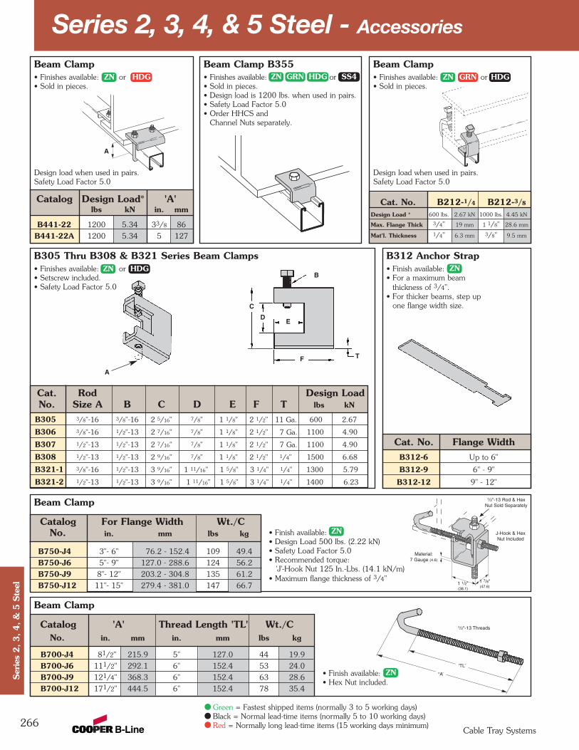
Series 2, 3, 4, & 5 Steel - Accessories
266Cable Tray Systems
Ser
ies
2, 3, 4, &
5 S
teel
Green = Fastest shipped items (normally 3 to 5 working days)Black = Normal lead-time items (normally 5 to 10 working days)Red = Normally long lead-time items (15 working days minimum)
Beam Clamp
Beam Clamp
B312 Anchor Strap• Finish available:• For a maximum beam
thickness of 3/4".• For thicker beams, step up
one flange width size.
Cat. No. Flange WidthB312-6 Up to 6"
B312-9 6" - 9"
B312-12 9" - 12"
Beam Clamp• Finishes available: or• Sold in pieces.
Design load when used in pairs.Safety Load Factor 5.0
Catalog 'A' Thread Length 'TL' Wt./CNo. in. mm in. mm lbs kg
B700-J4 81/2" 215.9 5" 127.0 44 19.9
B700-J6 111/2" 292.1 6" 152.4 53 24.0
B700-J9 121/4" 368.3 6" 152.4 63 28.6
B700-J12 171/2" 444.5 6" 152.4 78 35.4
B305 Thru B308 & B321 Series Beam Clamps• Finishes available: or• Setscrew included.• Safety Load Factor 5.0
Cat. Rod Design LoadNo. Size A B C D E F T lbs kN
B305 3/8"-16 3/8"-16 2 5/16" 7/8" 1 1/8" 2 1/2" 11 Ga. 600 2.67
B306 3/8"-16 1/2"-13 2 7/16" 7/8" 1 1/8" 2 1/2" 7 Ga. 1100 4.90
B307 1/2"-13 1/2"-13 2 7/16" 7/8" 1 1/8" 2 1/2" 7 Ga. 1100 4.90
B308 1/2"-13 1/2"-13 2 9/16" 7/8" 1 1/8" 2 1/2" 1/4" 1500 6.68
B321-1 3/8"-16 1/2"-13 3 9/16" 1 11/16" 1 5/8" 3 1/4" 1/4" 1300 5.79
B321-2 1/2"-13 1/2"-13 3 9/16" 1 11/16" 1 5/8" 3 1/4" 1/4" 1400 6.23
Beam Clamp• Finishes available: or• Sold in pieces.
Design load when used in pairs.Safety Load Factor 5.0
Cat. No. B212-1/4 B212-3/8
Design Load * 600 lbs. 2.67 kN 1000 lbs. 4.45 kN
Max. Flange Thick 3/4" 19 mm 1 1/8" 28.6 mm
Mat'l. Thickness 1/4" 6.3 mm 3/8" 9.5 mm
Beam Clamp B355• Finishes available: or• Sold in pieces.• Design load is 1200 lbs. when used in pairs.• Safety Load Factor 5.0• Order HHCS and
Channel Nuts separately.
B
ED
C
F T
• Finish available: • Design Load 500 lbs. (2.22 kN)• Safety Load Factor 5.0• Recommended torque:
'J'-Hook Nut 125 In.-Lbs. (14.1 kN/m)• Maximum flange thickness of 3/4"
• Finish available: • Hex Nut included.
A
A
Material: 7 Gauge (4.6)
1/2"-13 Rod & HexNut Sold Separately
1/2"-13 Threads
1 1/2"(38.1)
“A’
‘TL’
1 7/8"(47.6)
J-Hook & Hex Nut Included
Catalog For Flange Width Wt./CNo. in. mm lbs kg
B750-J4 3"- 6" 76.2 - 152.4 109 49.4
B750-J6 5"- 9" 127.0 - 288.6 124 56.2
B750-J9 8"- 12" 203.2 - 304.8 135 61.2
B750-J12 11"- 15" 279.4 - 381.0 147 66.7
Catalog Design Load* 'A'lbs kN in. mm
B441-22 1200 5.34 33/8 86
B441-22A 1200 5.34 5 127
ZN HDG ZN GRN HDG SS4 ZN GRN HDG
ZNZN HDG
ZN
ZN
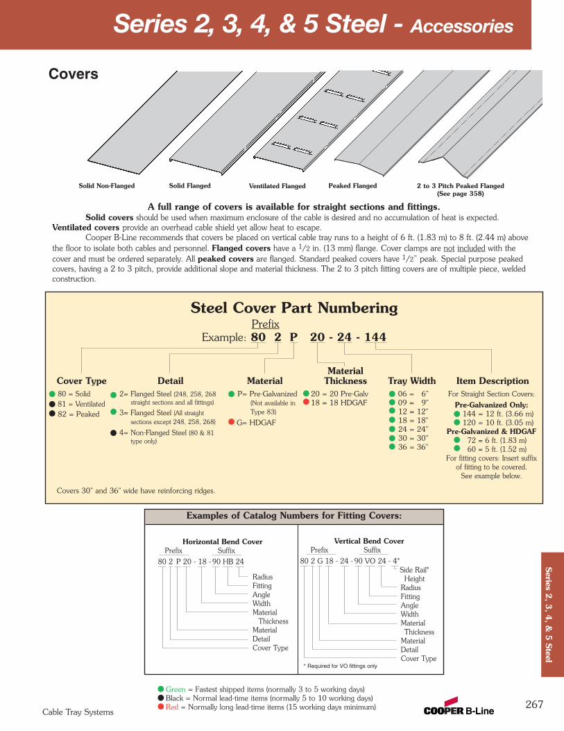
Series 2, 3, 4, & 5 Steel - Accessories
Examples of Catalog Numbers for Fitting Covers:
267
A full range of covers is available for straight sections and fittings.Solid covers should be used when maximum enclosure of the cable is desired and no accumulation of heat is expected.
Ventilated covers provide an overhead cable shield yet allow heat to escape.Cooper B-Line recommends that covers be placed on vertical cable tray runs to a height of 6 ft. (1.83 m) to 8 ft. (2.44 m) above
the floor to isolate both cables and personnel. Flanged covers have a 1/2 in. (13 mm) flange. Cover clamps are not included with thecover and must be ordered separately. All peaked covers are flanged. Standard peaked covers have 1/2” peak. Special purpose peakedcovers, having a 2 to 3 pitch, provide additional slope and material thickness. The 2 to 3 pitch fitting covers are of multiple piece, weldedconstruction.
Solid Flanged Ventilated Flanged Peaked Flanged 2 to 3 Pitch Peaked Flanged(See page 358)
Vertical Bend CoverPrefix Suffix
80 2 G 18 - 24 - 90 VO 24 - 4*Side Rail*
Height RadiusFittingAngleWidthMaterialThickness
MaterialDetailCover Type
Solid Non-Flanged
Steel Cover Part NumberingPrefix
Example: 80 2 P 20 - 24 - 144
MaterialCover Type Detail Material Thickness Tray Width Item Description
Covers
Horizontal Bend CoverPrefix Suffix
80 2 P 20 - 18 - 90 HB 24
RadiusFittingAngleWidthMaterial
ThicknessMaterialDetailCover Type
80 = Solid81 = Ventilated82 = Peaked
2= Flanged Steel (248, 258, 268 straight sections and all fittings)
3= Flanged Steel (All straight sections except 248, 258, 268)
4= Non-Flanged Steel (80 & 81 type only)
06 = 6" 09 = 9" 12 = 12" 18 = 18" 24 = 24" 30 = 30" 36 = 36"
For Straight Section Covers:
Pre-Galvanized Only:144 = 12 ft. (3.66 m)120 = 10 ft. (3.05 m)
Pre-Galvanized & HDGAF72 = 6 ft. (1.83 m)60 = 5 ft. (1.52 m)
For fitting covers: Insert suffix of fitting to be covered.
See example below.
P= Pre-Galvanized(Not available in Type 83)
G= HDGAF
20 = 20 Pre-Galv18 = 18 HDGAF
* Required for VO fittings only
Covers 30" and 36" wide have reinforcing ridges.
Cable Tray Systems
Series 2
, 3, 4
, & 5
Steel
Green = Fastest shipped items (normally 3 to 5 working days)Black = Normal lead-time items (normally 5 to 10 working days)Red = Normally long lead-time items (15 working days minimum)

Combination Cover andHold-Down Clamp• Sold per piece.• (*) Insert or• For indoor
service only.
Tray Side Rail CatalogType Height No.
in. mm
4 101 9(*)-90435 127 9(*)-90536 152 9(*)-90637 178 9(*)-9073
Steel
Heavy Duty Cover Clamp• Recommended for outdoor service.• (*) Insert or
Side Rail CatalogHeight No.
in. mm
Raised Cover Clamp• For indoor service only.• For use with
flanged coversonly.
† Specify gap of 1", 2", 3" or 4".
Tray CatalogType No.
Series 2 Steel 9ZN-9114-†Straight Section
Series 3 & 4 Steel 9ZN-9115-†Straight Section
All Steel Fittings(Also Series 1 Steel 9ZN-910†Straight Sections)
Tray Side Rail CatalogType Height No.
in. mm
4 101 9(*)-90145 127 9(*)-90156 152 9(*)-90167 178 9(*)-9017
Standard Cover Clamp• For indoor service only.• Sold per piece.• (*) Insert or
268
Series 2, 3, 4, & 5 Steel - Accessories
Quantity of Standard Cover Clamps Required
Straight Section 60" or 72" .............4 pcs.Straight Section 120" or 144" .........6 pcs.Horizontal/Vertical Bends................4 pcs.Tees...............................................6 pcs.Crosses ..........................................8 pcs.
Note: When using the Heavy Duty CoverClamp, only one-half the number of clampsstated above is required.
4 101 9(*)-(‡)-9044†5 127 9(*)-(‡)-9054†6 152 9(*)-(‡)-9064†7 178 9(*)-(‡)-9074†
(‡) Insert tray width† Add P to CatalogNo. for 1/2" peakedcover clamp.
Peaked Cover Clamp
Steel
Cover Joint Strip• Used to join covers• Plastic• (‡) Insert tray
width
Catalog No. 99-9980-(‡)
Cable Tray Systems
Ser
ies
2, 3, 4, &
5 S
teel
Green = Fastest shipped items (normally 3 to 5 working days)Black = Normal lead-time items (normally 5 to 10 working days)Red = Normally long lead-time items (15 working days minimum)
ZN G GP
GP
Cable Cleats(see pages 352 thru 355)
EmperorTrefoil
Cable Cleats
VulcanCable Cleats
269
Series 2, 3, 4, & 5 Steel - Specifications
Section 1- Acceptable Manufacturers1.01 Manufacturer: Subject to compliance with these specifications, cable tray systems shall be as
manufactured by Cooper B-Line, Inc.
Section 2- Cable Tray Sections and Components2.01 General: Except as otherwise indicated, provide metal cable trays, of types, classes and sizes indicated;
with splice plates, bolts, nuts and washers for connecting units. Construct units with rounded edges andsmooth surfaces; in compliance with applicable standards; and with the following additional constructionfeatures. Cable tray shall be installed according to the latest revision of NEMA VE 2.
2.02 Pre-Galvanized Steel: Straight sections, fitting side rails, rungs, and covers shall be made from structuralquality steel meeting the minimum mechanical properties and mill galvanized in accordance with ASTMA653 SS, Grade 33, coating designation G90. Hardware finish shall be electrogalvanized zinc perASTM B633.
2.03 Hot Dip Galvanized Steel: All side rails, covers, splice plates, and rungs shall be made from structuralquality steel meeting the minimum mechanical properties of ASTM A1011 SS, Grade 33 for 14 gaugeand heavier, ASTM A1008, Grade 33 Type 2 for 16 gauge and lighter, and shall be hot dip galvanizedafter fabrication in accordance with ASTM A123. Mill galvanized covers are not acceptable for hot dipgalvanized cable tray. Hardware finish shall be chromium zinc per ASTM F-1136-88.
2.04 Ladder Cable Trays shall consist of two longitudinal members (side rails) with transverse members (rungs)welded to the side rails. Rungs shall be spaced [6] [9] [12] inches on center. Rung spacing in radiusedfittings shall be industry standard 9" and measured at the center of the tray’s width. No portion of therungs shall protrude below the bottom plane of the side rails. Each rung must be capable of supportinga 200 lb. concentrated load at the center of the cable tray over and above the cable load with a safetyfactor of 1.5.
2.05 Ventilated Trough Cable Trays shall consist of two longitudinal members (side rails) with a corrugatedbottom welded to the side rails or rungs spaced 4" on center. The peaks of the corrugated bottomshall have a minimum flat cable bearing surface of 23/4" and shall be spaced on 6" centers. Toprovide ventilation in the tray, the valleys of the corrugated bottom shall have 21/4" x 4" rectangularholes punched along the width of the bottom.
2.06 Non-Ventilated Bottom Trough Cable Trays shall consist of two longitudinal members (side rails) with acorrugated bottom welded to the side rails or a solid sheet over rungs. The peaks of the corrugatedbottom shall have a minimum flat cable bearing surface of 23/4" and shall be spaced on 6" centers.
2.07 Cable tray loading depth shall be [3] [4] [5] [6] inches per NEMA VE 1.
2.08 Straight sections shall have side rails fabricated as I-beams. Straight sections shall be supplied instandard [12 foot] [24 foot] [10 foot (3 m)] [20 foot (6 m)] lengths.
2.09 Cable tray widths shall be [6] [9] [12] [18] [24] [30] [36] inches or as shown on drawings.
2.10 Splice plates shall be manufactured of high strength steel, meeting the minimum mechanical propertiesof ASTM A1011 HSLAS, Grade 50, Class 1 and be secured with 8 nuts and bolts per plate. Theresistance of fixed splice connections between an adjacent section of tray shall not exceed 0.00033 ohm.
2.11 All fittings must have a minimum radius of [12] [24] [36] [48] inches.
Section 3- Loading Capacities and Testing3.01 Cable tray shall be capable of carrying a uniformly distributed load of ______ lbs./ft. on a _______ ft.
support span with a safety factor of 1.5 when supported as a simple span and tested per NEMAVE 1 5.2. In addition to the uniformly distributed load the cable tray shall support 200 lbs. concentratedload at mid-point of span. Load and safety factors specified are applicable to both the side rails and rungcapacities. Cable tray shall be made to manufacturing tolerances as specified by NEMA.
3.02 Upon request, manufacturer shall provide test reports in accordance with the latest revision ofNEMA VE 1 or CSA C22.2 No. 126.
Cable Tray Systems
Series 2
, 3, 4
, & 5
Steel
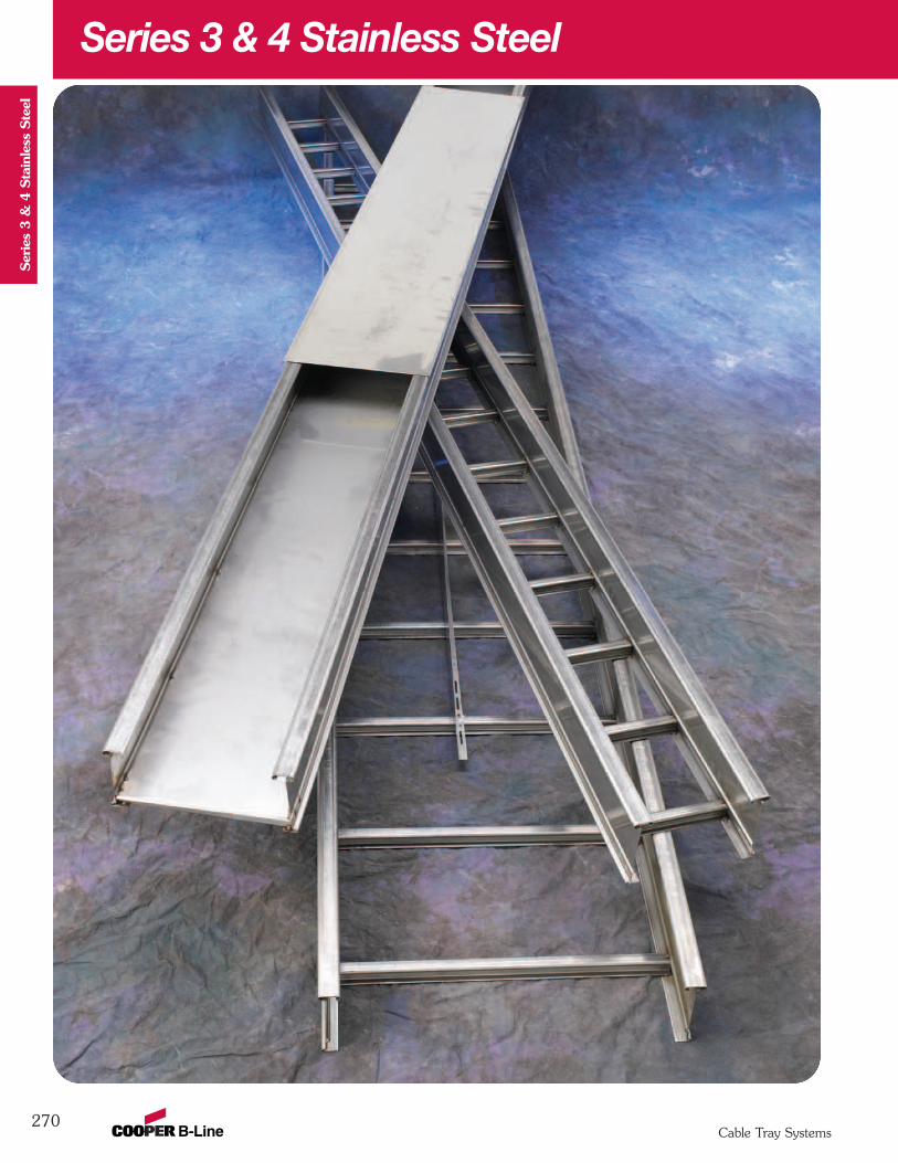
270
Series 3 & 4 Stainless Steel
Cable Tray Systems
Ser
ies
3 &
4 S
tain
less
Ste
el

271
Series 3 & 4 Stainless Steel
Cable Tray Systems
Series 3
& 4
Stainless S
teel
How The Service Advisor Works
B-Line knows that your time is important! That’s why the color-coding system in this catalog is designed to help youselect products that fit your service needs. Products are marked to indicate the typical lead time for orders of 50pieces or less.Customer: How do I select my straight sections. covers, or fittings so that I get the quickest turnaround?Service Advisor: Each part of our selection chart is shown in colors. If any section of a part number is a differentcolor, the part will typically ship with the longer lead time represented by the colors.
Green = Fastest shipped items (normally 3 to 5 working days)Black = Normal lead-time items (normally 5 to 10 working days)Red = Normally long lead-time items (15 working days minimum)
Example: 348SS4 09 - 12 - 144 Part will typically ship in(from page 272) 15 days minimum.
Changing the part number will not change the lead time of the original 15 days minimum.
For Stainless Steel Fittingssee fittings section pages 284 thru 301

B-Line Side Rail NEMA, CSA Span Load Deflection Design Factors Span Load Deflection Design FactorsSeries Dimensions Classifications ft lbs/ft Multiplier for Two Rails meters kg/m Multiplier for Two Rails
NEMA: 16A, 12C 10 180 0.0042 3.0 268 0.072CSA: C1-3m 12 125 0.009 Area=0.74 in2 3.7 186 0.148 Area=4.77 cm2
14 92 0.016 Sx=0.79 in3 4.3 137 0.275 Sx=12.95 cm3
UL Cross-Sectional 16 70 0.027 Ix=1.85 in4 4.9 105 0.469 Ix=77.00 cm4
Area: 0.40 in2 18 56 0.044 5.5 83 0.75220 45 0.067 6.1 67 1.145
272
Values are based on simple beam tests per NEMA VE 1 on 36" wide cable tray rungs spaced on 12" centers. Cable trays will support without collapse a 200 lb. (90.7 kg) concentrated load over and above published loads. Published load safety factor is 1.5.To convert 1.5 safety factor to 2.0, multiply published load by 0.75. To obtain mid-span deflection, multiply a load by the deflectionmultiplier. Cable tray must be supported on spans shorter than or equal to the length of the cable being installed.
When cable trays are used in continuous spans, the deflection of the cable tray is reduced by as much as 50%. Design factors: Ix = Moment of Inertia, Sx = Section Modulus. † Insert 4 for 304 stainless steel or 6 for 316 stainless steel.
1.50
4.193.13
18 gauge
348SS†
3" NEMA VE 1 Loading Depth4" Side Rail Height
¬Primary Length.ÁSecondary Length.
Ladder Type(Specify Rung Spacing)
Vented Bottom Non-Ventilated
Overall Width(Width + 13/8")
Forside rail
& rung data,see chart on
pages AP-5 & AP-6
RungSpacing
Width(Inside)
Series 3 & 4 Stainless Steel - Straight Sections
Straight Section Part NumberingPrefix
Example: 348 SS6 09 - 24 - 240
Series Material *Type *Width Length348 SS4 = 304 Stainless Ladder- 06 = 6" ¬ 144 = 12 ft.
348Steel 06 = 6" rung spacing 09 = 9" Á 120 = 10 ft.
SS6 = 316 Stainless 09 = 9" rung spacing 12 = 12"Steel 12 = 12" rung spacing 18 = 18"
24 = 24"30 = 30"
Trough- 36 = 36"6" and Wider04 = Vented BottomSB = Non-Ventilated
See page 356 for additional rung options. *Special sizes available.
Cable Tray Systems
Ser
ies
3 &
4 S
tain
less
Ste
el
Green = Fastest shipped items (normally 3 to 5 working days)Black = Normal lead-time items (normally 5 to 10 working days)Red = Normally long lead-time items (15 working days minimum)
See page 39 for explanation of lengths.
Passivation availablesee page 18.
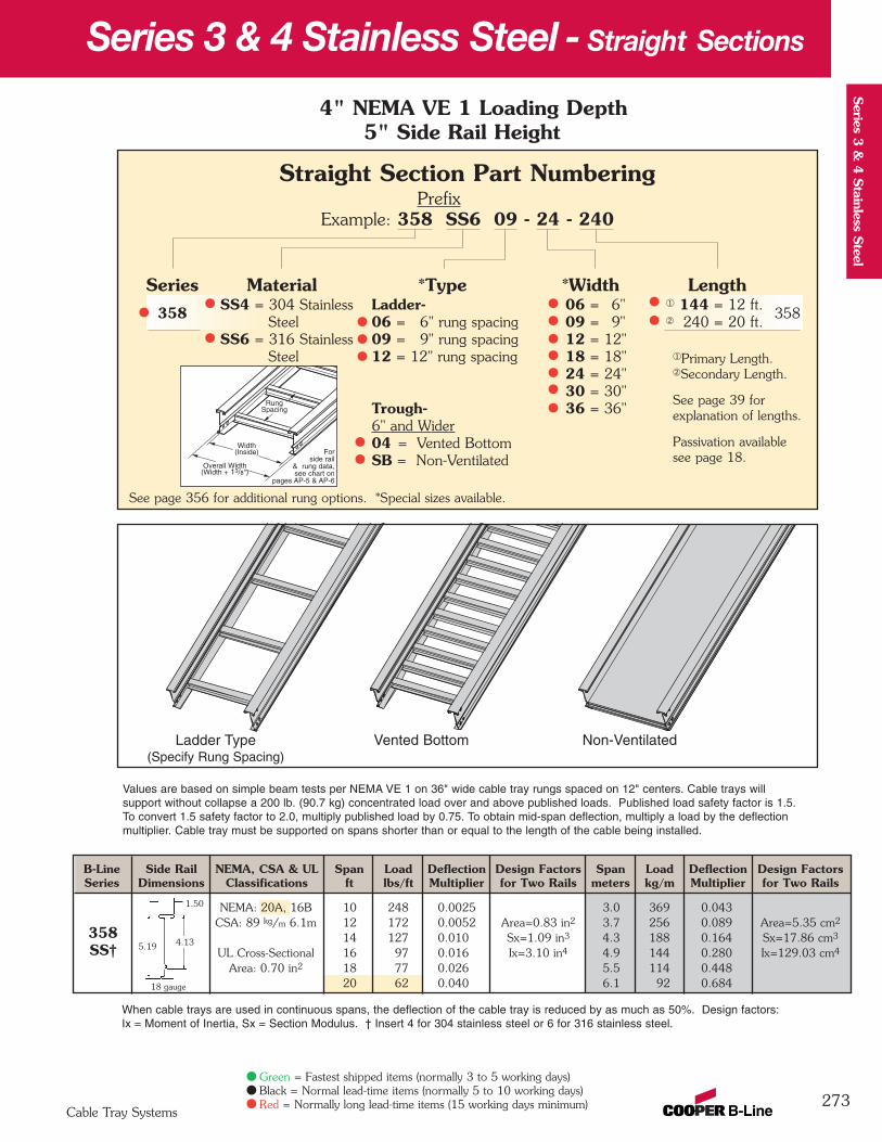
B-Line Side Rail NEMA, CSA & UL Span Load Deflection Design Factors Span Load Deflection Design FactorsSeries Dimensions Classifications ft lbs/ft Multiplier for Two Rails meters kg/m Multiplier for Two Rails
NEMA: 20A, 16B 10 248 0.0025 3.0 369 0.043CSA: 89 kg/m 6.1m 12 172 0.0052 Area=0.83 in2 3.7 256 0.089 Area=5.35 cm2
14 127 0.010 Sx=1.09 in3 4.3 188 0.164 Sx=17.86 cm3
UL Cross-Sectional 16 97 0.016 Ix=3.10 in4 4.9 144 0.280 Ix=129.03 cm4
Area: 0.70 in2 18 77 0.026 5.5 114 0.44820 62 0.040 6.1 92 0.684
273
Values are based on simple beam tests per NEMA VE 1 on 36" wide cable tray rungs spaced on 12" centers. Cable trays will support without collapse a 200 lb. (90.7 kg) concentrated load over and above published loads. Published load safety factor is 1.5.To convert 1.5 safety factor to 2.0, multiply published load by 0.75. To obtain mid-span deflection, multiply a load by the deflectionmultiplier. Cable tray must be supported on spans shorter than or equal to the length of the cable being installed.
When cable trays are used in continuous spans, the deflection of the cable tray is reduced by as much as 50%. Design factors: Ix = Moment of Inertia, Sx = Section Modulus. † Insert 4 for 304 stainless steel or 6 for 316 stainless steel.
1.50
5.19 4.13
18 gauge
358SS†
4" NEMA VE 1 Loading Depth5" Side Rail Height
Overall Width(Width + 13/8")
Forside rail
& rung data,see chart on
pages AP-5 & AP-6
RungSpacing
Width(Inside)
Series 3 & 4 Stainless Steel - Straight Sections
Straight Section Part NumberingPrefix
Example: 358 SS6 09 - 24 - 240
Series Material *Type *Width Length358 SS4 = 304 Stainless Ladder- 06 = 6" ¬ 144 = 12 ft.
358Steel 06 = 6" rung spacing 09 = 9" Á 240 = 20 ft.
SS6 = 316 Stainless 09 = 9" rung spacing 12 = 12"Steel 12 = 12" rung spacing 18 = 18"
24 = 24"30 = 30"
Trough- 36 = 36"6" and Wider04 = Vented BottomSB = Non-Ventilated
See page 356 for additional rung options. *Special sizes available.
Ladder Type(Specify Rung Spacing)
Vented Bottom Non-Ventilated
Cable Tray Systems
Series 3
& 4
Stainless S
teel
Green = Fastest shipped items (normally 3 to 5 working days)Black = Normal lead-time items (normally 5 to 10 working days)Red = Normally long lead-time items (15 working days minimum)
¬Primary Length.ÁSecondary Length.
See page 39 for explanation of lengths.
Passivation availablesee page 18.
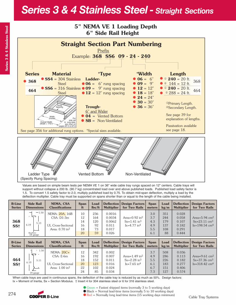
B-Line Side Rail NEMA, CSA Span Load Deflection Design Factors Span Load Deflection Design FactorsSeries Dimensions Classifications ft lbs/ft Multiplier for Two Rails meters kg/m Multiplier for Two Rails
NEMA: 20C+ 12 342 0.002 3.7 508 0.036CSA: E-6m 16 192 0.007 Area=1.49 in2 4.9 286 0.113 Area=9.61 cm2
18 152 0.011 Sx=2.28 in3 5.5 226 0.182 Sx=37.36 cm3
UL Cross-Sectional 20 123 0.016 Ix=7.65 in4 6.1 183 0.277 Ix=318.42 cm4
Area: 1.00 in2 22 102 0.024 6.7 151 0.40624 85 0.034 7.3 127 0.574
B-Line Side Rail NEMA, CSA Span Load Deflection Design Factors Span Load Deflection Design FactorsSeries Dimensions Classifications ft lbs/ft Multiplier for Two Rails meters kg/m Multiplier for Two Rails
NEMA: 20A, 16B 10 236 0.0016 3.0 351 0.028CSA: D1-3m 12 164 0.0034 Area=0.92 in2 3.7 244 0.058 Area=5.94 cm2
14 120 0.0062 Sx=1.41 in3 4.3 179 0.107 Sx=23.11 cm3
UL Cross-Sectional 16 92 0.011 Ix=4.77 in4 4.9 137 0.182 Ix=198.54 cm4
Area: 0.70 in2 18 73 0.017 5.5 108 0.29120 59 0.026 6.1 88 0.444
274
Values are based on simple beam tests per NEMA VE 1 on 36" wide cable tray rungs spaced on 12" centers. Cable trays will support without collapse a 200 lb. (90.7 kg) concentrated load over and above published loads. Published load safety factor is1.5. To convert 1.5 safety factor to 2.0, multiply published load by 0.75. To obtain mid-span deflection, multiply a load by thedeflection multiplier. Cable tray must be supported on spans shorter than or equal to the length of the cable being installed.
When cable trays are used in continuous spans, the deflection of the cable tray is reduced by as much as 50%. Design factors: Ix = Moment of Inertia, Sx = Section Modulus. † Insert 4 for 304 stainless steel or 6 for 316 stainless steel.
1.50
6.195.13
18 gauge
1.50
6.195.11
14 gauge
368SS†
464SS†
5" NEMA VE 1 Loading Depth6" Side Rail Height
Overall Width(Width + 13/8")
Forside rail
& rung data,see chart on
pages AP-5 & AP-6
RungSpacing
Width(Inside)
Series 3 & 4 Stainless Steel - Straight Sections
Straight Section Part NumberingPrefix
Example: 368 SS6 09 - 24 - 240
Series Material *Type *Width Length368 SS4 = 304 Stainless Ladder- 06 = 6" ¬ 240 = 20 ft.
368Steel 06 = 6" rung spacing 09 = 9" Á 144 = 12 ft.
464 SS6 = 316 Stainless 09 = 9" rung spacing 12 = 12" ¬ 240 = 20 ft.464
Steel 12 = 12" rung spacing 18 = 18" Á 288 = 24 ft.24 = 24"30 = 30"
Trough- 36 = 36"6" and Wider04 = Vented BottomSB = Non-Ventilated
See page 356 for additional rung options. *Special sizes available.
Cable Tray Systems
Ser
ies
3 &
4 S
tain
less
Ste
el
Green = Fastest shipped items (normally 3 to 5 working days)Black = Normal lead-time items (normally 5 to 10 working days)Red = Normally long lead-time items (15 working days minimum)
Ladder Type(Specify Rung Spacing)
Vented Bottom Non-Ventilated
¬Primary Length.ÁSecondary Length.
See page 39 for explanation of lengths.
Passivation availablesee page 18.

Catalog No. Heightin. mm
9(*)-8014 4 101
9(*)-8015 5 127
9(*)-8016 6 152
Catalog No. Heightin. mm
9(*)-8004 4 101
9(*)-8005 5 127
9(*)-8006 6 152
Splice Plates• Standard 8-hole pattern for all stainless
steel splice plates. • Furnished in pairs with hardware.• One pair including hardware provided
with straight section.• Boxed in pairs with hardware.• (*) Insert or
Catalog No. Cable Tray TrayNo. End Cut Width 'L'
9(*)-803(X) Mitered Thru 36" N/A
9(*)-803(X)-12 Not Mitered Thru 12" 16"
9(*)-803(X)-36 Not Mitered Thru 36" 41"
Catalog No. Heightin. mm
9(*)-8045 5 to 4 127 to 101
9(*)-8046 6 to 4 152 to 101
9(*)-8060 6 to 5 152 to 127
Catalog No. Heightin. mm
9(*)-8004-1/2 4 101
9(*)-8005-1/2 5 127
9(*)-8006-1/2 6 152
275
Catalog No. Heightin. mm
9(*)-8244 4 101
9(*)-8245 5 127
9(*)-8246 6 152
9(*)-803(X)Splice only
9(*)-803(X)-12 or 9(*)-803(X)-36One pair splice plates with extensions.
Universal Splice Plates• Used to splice to existing cable
tray systems.• Furnished in pairs with
hardware.• (*) Insert or
Catalog No. Heightin. mm
9(*)-8024 4 101
9(*)-8025 5 127
9(*)-8026 6 152
Horizontal Adjustable Splice Plates• Offered to adjust a cable tray run
for changes in direction in a horizontal plane that do not conform to standard horizontal fittings.
• Furnished in pairs with hardware.• New design bonding jumpers
not required.• (*) Insert or• (X) Insert 4, 5 or 6 for
side rail height.
Step Down Splice Plates• These splice plates are offered
for connecting cable tray sections having side rails of different heights.
• Furnished in pairswith hardware.
• (*) Insert or
Expansion Splice Plates• Expansion plates allow for one inch
expansion or contraction of the cable tray, or where expansion joints occur in the support structure.
• Furnished in pairs with hardware.• Bonding Jumpers are required.
Order Separately.• (*) Insert or
Vertical Adjustable Splice Plates• These plates provide for changes in
elevation that do not conform to standard vertical fittings.
• Furnished in pairs with hardware.• (*) Insert or
Branch Pivot Connectors• Branch from existing cable tray runs at any point.• Pivot to any required angle.• UL Classified for grounding
(bonding jumper not required).• Furnished in pairs with hardware.• (*) Insert or
Series 3 & 4 Stainless Steel - Accessories
LL
Cable Tray Systems
Series 3
& 4
Stainless S
teel
Green = Fastest shipped items (normally 3 to 5 working days)Black = Normal lead-time items (normally 5 to 10 working days)Red = Normally long lead-time items (15 working days minimum)
SS4 SS6
SS4 SS6
SS4 SS6
SS4 SS6
SS4 SS6
SS4 SS6
SS4 SS6
Requiressupports
within 24”on both sides,
per NEMAVE 2.
Requiressupports within
24” on bothsides, per
NEMA VE 2.
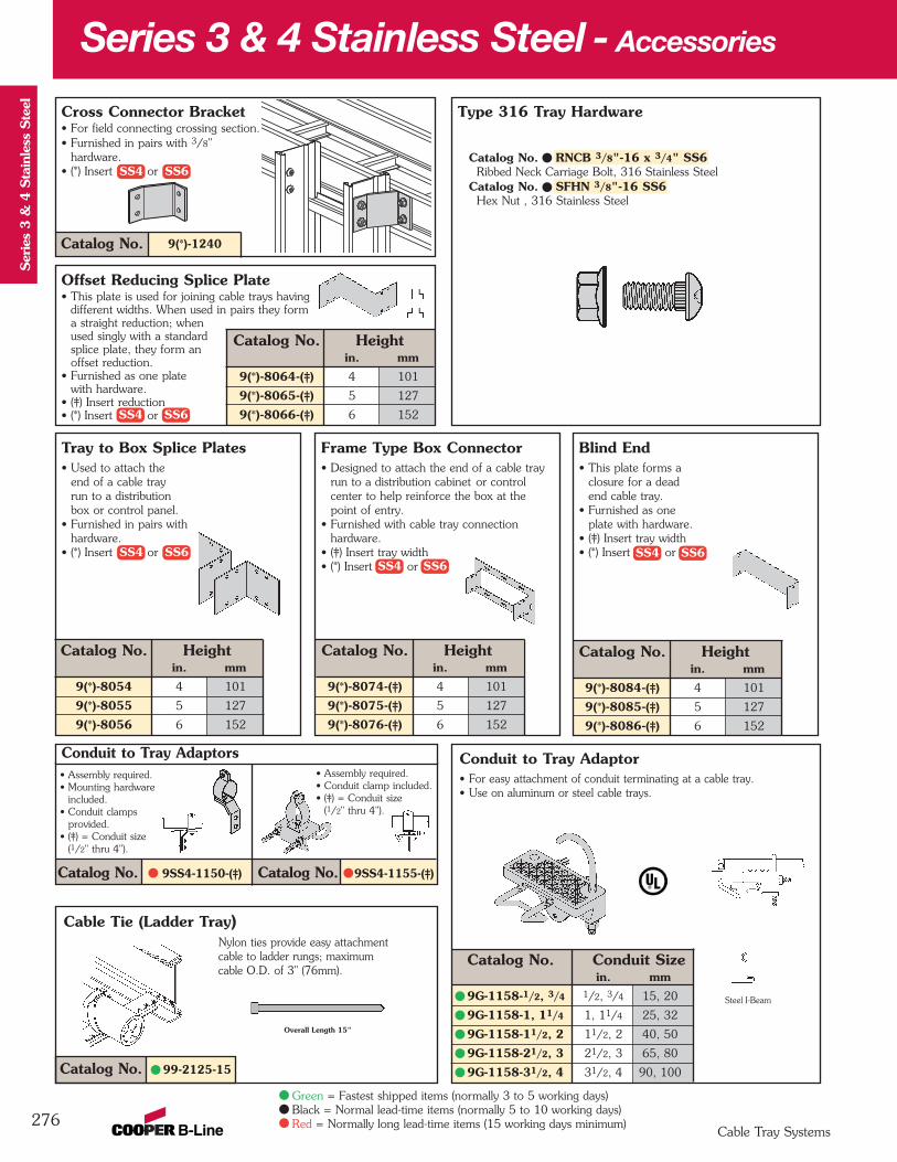
Conduit to Tray Adaptor• For easy attachment of conduit terminating at a cable tray. • Use on aluminum or steel cable trays.
Catalog No. Conduit Sizein. mm
9G-1158-1/2, 3/4 1/2, 3/4 15, 20
9G-1158-1, 11/4 1, 11/4 25, 32
9G-1158-11/2, 2 11/2, 2 40, 50
9G-1158-21/2, 3 21/2, 3 65, 80
9G-1158-31/2, 4 31/2, 4 90, 100
Catalog No. 9SS4-1150-(‡) Catalog No. 9SS4-1155-(‡)
Cable Tie (Ladder Tray)Nylon ties provide easy attachmentcable to ladder rungs; maximum cable O.D. of 3" (76mm).
Catalog No. 99-2125-15
Series 3 & 4 Stainless Steel - Accessories
276
Blind End• This plate forms a
closure for a dead end cable tray.
• Furnished as one plate with hardware.
• (‡) Insert tray width• (*) Insert or
Frame Type Box Connector• Designed to attach the end of a cable tray
run to a distribution cabinet or control center to help reinforce the box at the point of entry.
• Furnished with cable tray connection hardware.
• (‡) Insert tray width• (*) Insert or
Type 316 Tray Hardware
Catalog No. RNCB 3/8"-16 x 3/4" SS6Ribbed Neck Carriage Bolt, 316 Stainless Steel
Catalog No. SFHN 3/8"-16 SS6Hex Nut , 316 Stainless Steel
Steel I-Beam
Overall Length 15"
• Assembly required.• Mounting hardware
included.• Conduit clamps
provided.• (‡) = Conduit size
(1/2" thru 4").
• Assembly required.• Conduit clamp included.• (‡) = Conduit size
(1/2" thru 4").
Conduit to Tray Adaptors
Catalog No. Heightin. mm
9(*)-8054 4 101
9(*)-8055 5 127
9(*)-8056 6 152
Catalog No. Heightin. mm
9(*)-8074-(‡) 4 101
9(*)-8075-(‡) 5 127
9(*)-8076-(‡) 6 152
Catalog No. Heightin. mm
9(*)-8084-(‡) 4 101
9(*)-8085-(‡) 5 127
9(*)-8086-(‡) 6 152
Tray to Box Splice Plates• Used to attach the
end of a cable tray run to a distributionbox or control panel.
• Furnished in pairs withhardware.
• (*) Insert or
9(*)-1240Catalog No.
Cross Connector Bracket• For field connecting crossing section.• Furnished in pairs with 3/8"
hardware.• (*) Insert or
Catalog No. Heightin. mm
9(*)-8064-(‡) 4 101
9(*)-8065-(‡) 5 127
9(*)-8066-(‡) 6 152
Offset Reducing Splice Plate• This plate is used for joining cable trays having
different widths. When used in pairs they form a straight reduction; when used singly with a standard splice plate, they form anoffset reduction.
• Furnished as one plate with hardware.
• (‡) Insert reduction• (*) Insert or
Cable Tray Systems
Ser
ies
3 &
4 S
tain
less
Ste
el
Green = Fastest shipped items (normally 3 to 5 working days)Black = Normal lead-time items (normally 5 to 10 working days)Red = Normally long lead-time items (15 working days minimum)
SS4 SS6
SS4 SS6
SS4 SS6SS4 SS6
SS4 SS6
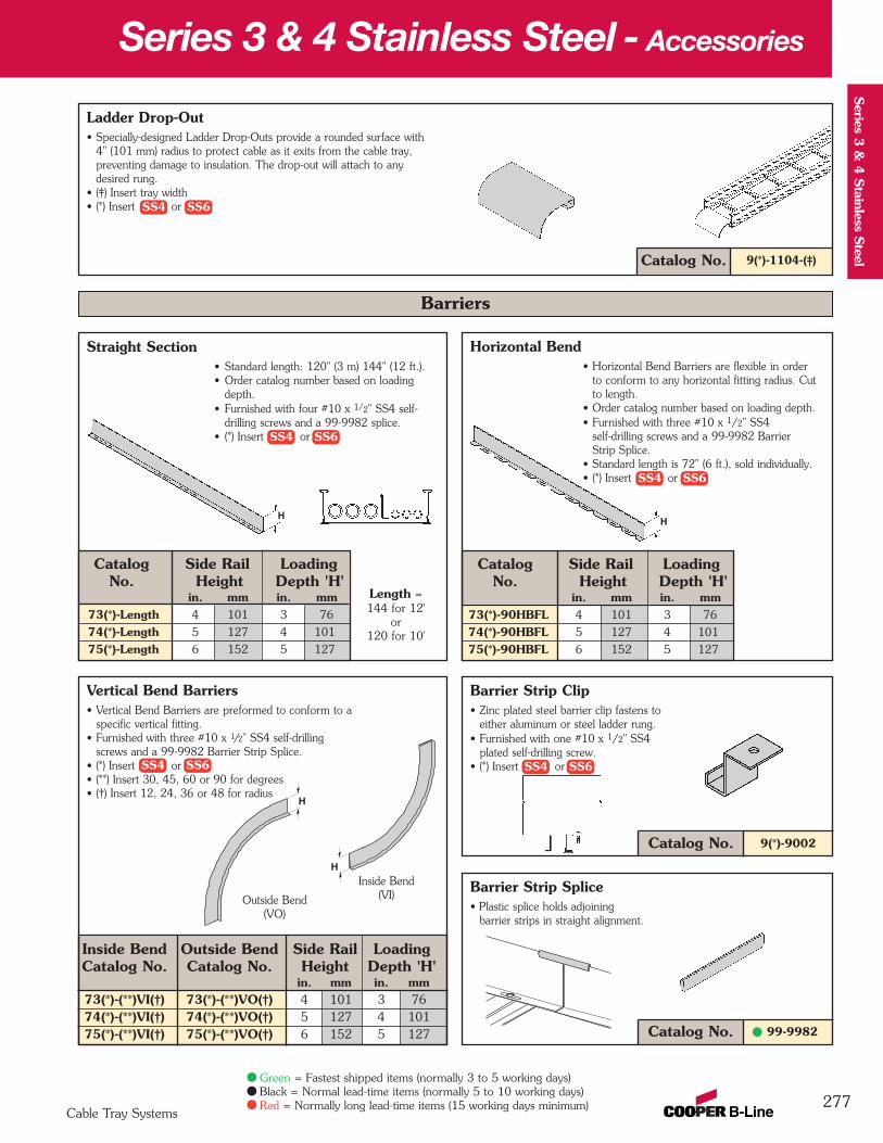
9(*)-1104-(‡)Catalog No.
Ladder Drop-Out• Specially-designed Ladder Drop-Outs provide a rounded surface with
4" (101 mm) radius to protect cable as it exits from the cable tray,preventing damage to insulation. The drop-out will attach to any desired rung.
• (‡) Insert tray width• (*) Insert or
Catalog No.
Inside Bend Outside Bend Side Rail LoadingCatalog No. Catalog No. Height Depth 'H'
in. mm in. mm73(*)-(**)VI(†) 73(*)-(**)VO(†) 4 101 3 7674(*)-(**)VI(†) 74(*)-(**)VO(†) 5 127 4 10175(*)-(**)VI(†) 75(*)-(**)VO(†) 6 152 5 127 Catalog No. 99-9982
Barrier Strip Splice• Plastic splice holds adjoining
barrier strips in straight alignment.
9(*)-9002
Barrier Strip Clip• Zinc plated steel barrier clip fastens to
either aluminum or steel ladder rung.• Furnished with one #10 x 1/2" SS4
plated self-drilling screw.• (*) Insert or
Vertical Bend Barriers• Vertical Bend Barriers are preformed to conform to a
specific vertical fitting.• Furnished with three #10 x 1/2" SS4 self-drilling
screws and a 99-9982 Barrier Strip Splice.• (*) Insert or• (**) Insert 30, 45, 60 or 90 for degrees• (†) Insert 12, 24, 36 or 48 for radius
Horizontal Bend• Horizontal Bend Barriers are flexible in order
to conform to any horizontal fitting radius. Cut to length.
• Order catalog number based on loading depth.• Furnished with three #10 x 1/2" SS4
self-drilling screws and a 99-9982 Barrier Strip Splice.
• Standard length is 72" (6 ft.), sold individually.• (*) Insert or
Catalog Side Rail LoadingNo. Height Depth 'H'
in. mm in. mm73(*)-90HBFL 4 101 3 76
74(*)-90HBFL 5 127 4 101
75(*)-90HBFL 6 152 5 127
Series 3 & 4 Stainless Steel - Accessories
277
Straight Section• Standard length: 120" (3 m) 144" (12 ft.).• Order catalog number based on loading
depth.• Furnished with four #10 x 1/2" SS4 self-
drilling screws and a 99-9982 splice.• (*) Insert or
Outside Bend(VO)
Inside Bend(VI)
HH
Length = 144 for 12'
or 120 for 10'
Barriers
Catalog Side Rail LoadingNo. Height Depth 'H'
in. mm in. mm73(*)-Length 4 101 3 76
74(*)-Length 5 127 4 101
75(*)-Length 6 152 5 127
H
H
Cable Tray Systems
Series 3
& 4
Stainless S
teel
Green = Fastest shipped items (normally 3 to 5 working days)Black = Normal lead-time items (normally 5 to 10 working days)Red = Normally long lead-time items (15 working days minimum)
SS4 SS6
SS4 SS6
SS4 SS6 SS4 SS6
SS4 SS6

Cable Tray Guide• Expansion guide for single or double cable tray runs.• Guide allows for longitudinal movement of the
cable tray.• No field drilling of support I-beam or channel is required.• Guides are required on both sides of cable tray
to prevent lateral movement - can be placed on either the inside or outside flange of cable tray.
• Guides are sold in pieces - two guides are required per tray.
• Maximum flange thickness 11/8" (28.58 mm).
Nylon Pad• Use for friction reduction.• Hardness: Shore D80.• Low friction coefficient.• UV resistant (black).• Excellent weatherability.• UL - 94HB.
Cat. No. 99-NY36
Neoprene Roll• Use for material isolation.• 1/8" x 2" x 20' roll.• Hardness: Shore A60.• Good weatherability.
Catalog No. Finish9G-1249 HDGAF
Stainless Steel Cable Clamp• Fits with series 3 & 4 rungs.• Shipped flat. Field form around the cable
at the time of installation.
Threaded Rod (ATR) & Rod Coupling
Loading Catalog Available CouplingSize lbs No. Lengths Cat. No.3/8-16 730 ATR 3/8 x Length 36", 72", 144" B655-3/8
1/2-13 1350 ATR 1/2 x Length 36", 72", 144" B655-1/2
Loading based on safety factor 5.
Standard Finish: SS4 or SS6
See B-Line Strut Systems Catalog for other sizes and finishes.
Cable Tray Clamp/Guide• Features a no-twist design.• Has four times the strength
of the traditional design.• Each side is labeled to
ensure proper installation.• Available for either 3/8"
or 1/2" hardware.• Furnished in pairs
without hardware.
Vertical Tray Hanger• (*) Insert or• Design load 1500 lbs/pair.
Safety Factor of 2.5• Furnished in pairs with hardware.
Catalog No. Outside 'A'Cable Tray Ht. in. mm
9(*)-8224 4" 3.36 85.34
9(*)-8225 5" 4.36 110.74
9(*)-8226 6" 5.36 136.14
9(*)-8227 7" 6.36 161.54
Catalog No. 9SS6-1205
Series 3 & 4 Stainless Steel - Accessories
278
Catalog No. 99-NP240
Installed as a guide.
7"(178mm)
A
6"(152mm)3"
(76mm)
1/8"(3mm)
Patent #RE35479
Installed as a clamp.
Catalog No. Cable Sizein. mm
9SS4-4050 0.50 - 0.75 13 - 19
9SS4-4075 0.75 - 1.00 19 - 25
9SS4-4100 1.00 - 1.25 25 - 32
9SS4-4125 1.25 - 1.50 32 - 38
9SS4-4150 1.50 - 1.75 38 - 45
9SS4-4175 1.75 - 2.00 45 - 51
9SS4-4200 2.00 - 2.25 51 - 57
9SS4-4225 2.25 - 2.50 57 - 64
9SS4-4250 2.50 - 2.75 64 - 70
9SS4-4275 2.75 - 3.00 70 - 76
9SS4-4300 3.00 - 3.25 76 - 82
9SS4-4325 3.25 - 3.50 82 - 89
9SS4-4350 3.50 - 3.75 89 - 95
9SS4-4375 3.75 - 4.00 95 - 102
9SS4-4400 4.00 - 4.25 100 - 106
9SS4-4425 4.25 - 4.50 106 - 113
9SS4-4450 4.50 - 4.75 113 - 121
9SS4-4475 4.75 - 5.00 121 - 125
Cable Tray Systems
Ser
ies
3 &
4 S
tain
less
Ste
el
Green = Fastest shipped items (normally 3 to 5 working days)Black = Normal lead-time items (normally 5 to 10 working days)Red = Normally long lead-time items (15 working days minimum)
SS4 SS6
Refer to Section CFCable Fixing
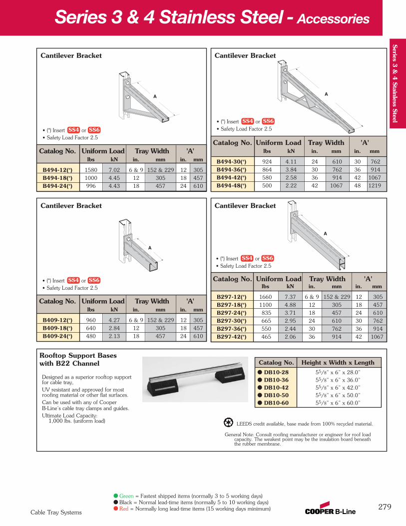
Cantilever Bracket
Catalog No. Uniform Load Tray Width 'A'lbs kN in. mm in. mm
B494-30(*) 924 4.11 24 610 30 762
B494-36(*) 864 3.84 30 762 36 914
B494-42(*) 580 2.58 36 914 42 1067
B494-48(*) 500 2.22 42 1067 48 1219
Cantilever Bracket
Catalog No. Uniform Load Tray Width 'A'lbs kN in. mm in. mm
B297-12(*) 1660 7.37 6 & 9 152 & 229 12 305
B297-18(*) 1100 4.88 12 305 18 457
B297-24(*) 835 3.71 18 457 24 610
B297-30(*) 665 2.95 24 610 30 762
B297-36(*) 550 2.44 30 762 36 914
B297-42(*) 465 2.06 36 914 42 1067
Cantilever Bracket
Catalog No. Uniform Load Tray Width 'A'lbs kN in. mm in. mm
B494-12(*) 1580 7.02 6 & 9 152 & 229 12 305
B494-18(*) 1000 4.45 12 305 18 457
B494-24(*) 996 4.43 18 457 24 610
Series 3 & 4 Stainless Steel - Accessories
279
A A
A
Cable Tray Systems
Series 3
& 4
Stainless S
teel
Cantilever Bracket
Catalog No. Uniform Load Tray Width 'A'lbs kN in. mm in. mm
B409-12(*) 960 4.27 6 & 9 152 & 229 12 305
B409-18(*) 640 2.84 12 305 18 457
B409-24(*) 480 2.13 18 457 24 610
A
Green = Fastest shipped items (normally 3 to 5 working days)Black = Normal lead-time items (normally 5 to 10 working days)Red = Normally long lead-time items (15 working days minimum)
Rooftop Support Baseswith B22 Channel Catalog No. Height x Width x Length
DB10-28 55/8” x 6” x 28.0”DB10-36 55/8” x 6” x 36.0”DB10-42 55/8” x 6” x 42.0”DB10-50 55/8” x 6” x 50.0”DB10-60 55/8” x 6” x 60.0”
Designed as a superior rooftop supportfor cable tray,UV resistant and approved for mostroofing material or other flat surfaces.Can be used with any of CooperB-Line’s cable tray clamps and guides.Ultimate Load Capacity:
1,000 lbs. (uniform load) LEEDS credit available, base made from 100% recycled material.
General Note: Consult roofing manufacturer or engineer for roof loadcapacity. The weakest point may be the insulation board beneaththe rubber membrane.
• (*) Insert or• Safety Load Factor 2.5
SS4 SS6
• (*) Insert or• Safety Load Factor 2.5
SS4 SS6
• (*) Insert or• Safety Load Factor 2.5
SS4 SS6
• (*) Insert or• Safety Load Factor 2.5
SS4 SS6

Series 3 & 4 Stainless Steel - Accessories
280Cable Tray Systems
Ser
ies
3 &
4 S
tain
less
Ste
el
Green = Fastest shipped items (normally 3 to 5 working days)Black = Normal lead-time items (normally 5 to 10 working days)Red = Normally long lead-time items (15 working days minimum)
Beam Clamp B355SS4• Sold in pieces.• Design load is 1200 lbs. when used in pairs.• Safety Load Factor 5.0• Order HHCS and
Channel Nuts separately.
Beam Clamp• Sold in pieces with hardware.• Finishes available: or
Design load when used in pairs.Safety Load Factor 5.0
Catalog No. Design Load* 'A'lbs kN in. mm
B441-22(*) 1200 5.34 33/8 86B441-22A(*) 1200 5.34 5 127
Beam Clamp• Sold in pieces.• 304 stainless steel
Design load when used in pairs.Safety Load Factor 5.0
Cat. No. B212-1/4SS4 B212-3/8SS4Design Load * 600 lbs. 2.67 kN 1000 lbs. 4.45 kN
Max. Flange Thick 3/4" 19 mm 1 1/8" 28.6 mm
Mat'l. Thickness 1/4" 6.3 mm 3/8" 9.5 mm
A
SS4 SS6
Heavy Duty Hold-Down Bracket• Design load is 4000 lbs/pair.• Four bolt design.• Sold in pairs.• 3/8" cable tray attachment
hardware provided• 1/2" support attachment
hardware not provided.• (*) Insert or
Heavy Duty HoldDown Bracket
• Design load is 2000 lbs/pair.• Two bolt design.• Sold in pairs.• 3/8" cable tray attachment
hardware provided.• 1/2" support attachment
hardware not provided.• (*) Insert or
Catalog No. 9(*)-1241 Catalog No. 9(*)-1242
SS4 SS6SS4 SS6
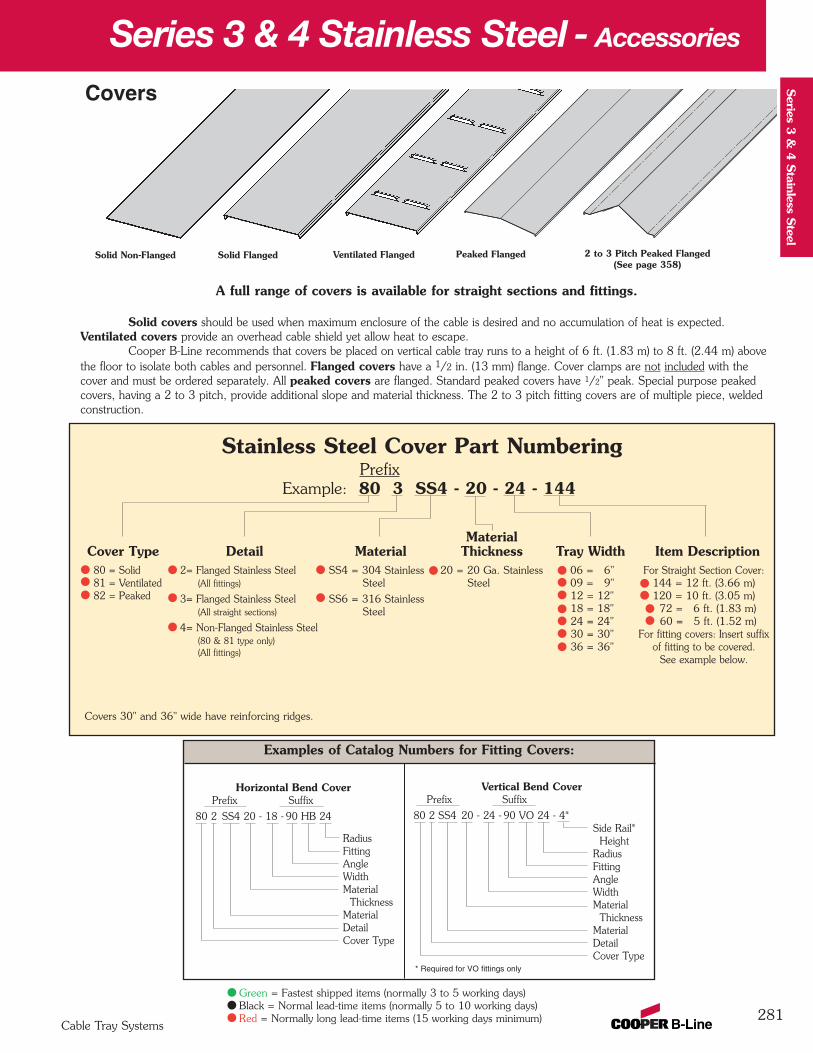
Series 3 & 4 Stainless Steel - Accessories
281Cable Tray Systems
Series 3
& 4
Stainless S
teel
Green = Fastest shipped items (normally 3 to 5 working days)Black = Normal lead-time items (normally 5 to 10 working days)Red = Normally long lead-time items (15 working days minimum)
Examples of Catalog Numbers for Fitting Covers:
A full range of covers is available for straight sections and fittings.
Solid covers should be used when maximum enclosure of the cable is desired and no accumulation of heat is expected.Ventilated covers provide an overhead cable shield yet allow heat to escape.
Cooper B-Line recommends that covers be placed on vertical cable tray runs to a height of 6 ft. (1.83 m) to 8 ft. (2.44 m) abovethe floor to isolate both cables and personnel. Flanged covers have a 1/2 in. (13 mm) flange. Cover clamps are not included with thecover and must be ordered separately. All peaked covers are flanged. Standard peaked covers have 1/2" peak. Special purpose peakedcovers, having a 2 to 3 pitch, provide additional slope and material thickness. The 2 to 3 pitch fitting covers are of multiple piece, weldedconstruction.
Solid Flanged Ventilated Flanged Peaked Flanged 2 to 3 Pitch Peaked Flanged(See page 358)
Vertical Bend CoverPrefix Suffix
80 2 SS4 20 - 24 - 90 VO 24 - 4*Side Rail*
Height RadiusFittingAngleWidthMaterial
ThicknessMaterialDetailCover Type
Solid Non-Flanged
Stainless Steel Cover Part NumberingPrefix
Example: 80 3 SS4 - 20 - 24 - 144
MaterialCover Type Detail Material Thickness Tray Width Item Description
Covers
Horizontal Bend CoverPrefix Suffix
80 2 SS4 20 - 18 - 90 HB 24
RadiusFittingAngleWidthMaterial
ThicknessMaterialDetailCover Type
80 = Solid81 = Ventilated82 = Peaked
2= Flanged Stainless Steel (All fittings)
3= Flanged Stainless Steel(All straight sections)
4= Non-Flanged Stainless Steel (80 & 81 type only)(All fittings)
06 = 6"09 = 9"12 = 12"18 = 18"24 = 24"30 = 30"36 = 36"
For Straight Section Cover:144 = 12 ft. (3.66 m)120 = 10 ft. (3.05 m)
72 = 6 ft. (1.83 m)60 = 5 ft. (1.52 m)
For fitting covers: Insert suffixof fitting to be covered.
See example below.
SS4 = 304 Stainless Steel
SS6 = 316 Stainless Steel
20 = 20 Ga. StainlessSteel
* Required for VO fittings only
Covers 30" and 36" wide have reinforcing ridges.

Series 3 & 4 Stainless Steel - Accessories
282Cable Tray Systems
Ser
ies
3 &
4 S
tain
less
Ste
el
Catalog Side RailNo. Height
in. mm9(*)-(‡)-9044† 4 1019(*)-(‡)-9054† 5 1279(*)-(‡)-9064† 6 152
Cover Joint Strip Catalog No. 99-9980-(‡)
• Used to join Covers• Plastic• (‡) Insert tray width
Raised Cover Clamp• For indoor service only.• (*) Insert or• For use with flanged covers only.
† Specify gap of 1", 2", 3" or 4".
Tray CatalogType No.
Series 3 & 4 Steel 9(*)-9115-†Straight Section
All Steel Fittings 9(*)-910†
Combination Cover andHold Down Clamp• Sold per piece.• (*) Insert or• For indoor
service only.
Standard Cover Clamp• For indoor service only.• Sold per piece.
Tray Side Rail CatalogType Height No.
in. mm
4 101 9SS6-90145 127 9SS6-90156 152 9SS6-9016
Quantity of Standard Cover Clamps Required
Straight Section 60" or 72" .............4 pcs.
Straight Section 120" or 144" .........6 pcs.
Horizontal/Vertical Bends................4 pcs.
Tees...............................................6 pcs.
Crosses ..........................................8 pcs.
Note: When using the Heavy Duty CoverClamp, only one-half the number of clampsstated above is required.
Peaked Cover Clamp
StainlessSteel
Tray Side Rail CatalogType Height No.
in. mm
4 101 9(*)-90435 127 9(*)-90536 152 9(*)-9063
StainlessSteel
Heavy Duty Cover Clamp• Recommended for outdoor service.• (*) Insert or
SS4 SS6SS4 SS6
SS4 SS6
(‡) Insert tray width† Add P to Catalog No. for1/2" peaked cover clamp.
Green = Fastest shipped items (normally 3 to 5 working days)Black = Normal lead-time items (normally 5 to 10 working days)Red = Normally long lead-time items (15 working days minimum)
Cable Cleats(see pages 352 thru 355)
EmperorTrefoil
Cable Cleats
VulcanCable Cleats

283
Series 3 & 4 Stainless Steel - Specifications
Cable Tray Systems
Series 3
& 4
Stainless S
teel
Section 1- Acceptable Manufacturers1.01 Manufacturer: Subject to compliance with these specifications, cable tray systems shall be as manufactured
by Cooper B-Line, Inc.
Section 2- Cable Tray Sections and Components2.01 General: Except as otherwise indicated, provide metal cable trays, of types, classes and sizes indicated;
with splice plates, bolts, nuts and washers for connecting units. Construct units with rounded edges andsmooth surfaces; in compliance with applicable standards; and with the following additional constructionfeatures. Cable tray shall be installed according to the latest revision of NEMA VE 2.
2.02 Stainless Steel: Straight section and fitting side rails and rungs shall be made of AISI Type [304][316] stainless steel. Transverse members (rungs) or corrugated bottoms shall be welded to the siderails with Type 316 stainless steel welding wire. Hardware shall be AISI Type 316 stainless steel.
2.03 Ladder Cable Trays shall consist of two longitudinal members (side rails) with transverse members (rungs) welded to the side rails. Rungs shall be spaced [6] [9] [12] inches on center. Rung spacing in radiusedfittings shall be industry standard 9" and measured at the center of the tray’s width. Each rung must becapable of supporting a 200 lb. concentrated load at the center of the cable tray with a safety factor of 1.5.
2.04 Ventilated Trough Cable Trays shall consist of two longitudinal members (side rails) with a corrugatedbottom welded to the side rails or rungs spaced 4" on center. The peaks of the corrugated bottomshall have a minimum flat cable bearing surface of 23/4" and shall be spaced on 6" centers. Toprovide ventilation in the tray, the valleys of the corrugated bottom shall have 21/4" x 4" rectangularholes punched along the width of the bottom.
2.05 Non-Ventilated Bottom Trough Cable Trays shall consist of two longitudinal members (side rails) with acorrugated bottom welded to the side rails or a solid sheet over rungs. The peaks of the corrugated bottomshall have a minimum flat cable bearing surface of 23/4" and shall be spaced on 6" centers.
2.06 Cable tray loading depth shall be [3] [4] [5] inches per NEMA VE 1.
2.07 Straight sections shall be fabricated as I-beams. Straight sections shall be supplied in standard[12 foot] [24 foot] [10 foot (3 m)] [20 foot (6 m)] lengths.
2.08 Cable tray widths shall be [6] [9] [12] [18] [24] [30] [36] inches or as shown on drawings.
2.09 Splice plates shall be manufactured of high strength steel and be secured with 8 nuts and bolts perplate. The resistance of fixed splice connections between an adjacent section of tray shall not exceed0.00033 ohm.
2.11 All fittings must have a minimum radius of [12] [24] [36] [48] inches.
Section 3- Loading Capacities and Testing3.01 Cable tray shall be capable of carrying a uniformly distributed load of ______ lbs./ft. on a _______ ft.
support span with a safety factor of 1.5 when supported as a simple span and tested per NEMAVE 1 5.2. In addition to the uniformly distributed load the cable tray shall support 200 lbs.concentrated load at mid-point of span. Load and safety factors specified are applicable to both theside rails and rung capacities. Cable tray shall be made to manufacturing tolerances as specifiedby NEMA.
3.02 Upon request, manufacturer shall provide test reports in accordance with the latest revision ofNEMA VE 1 or CSA C22.2 No. 126.
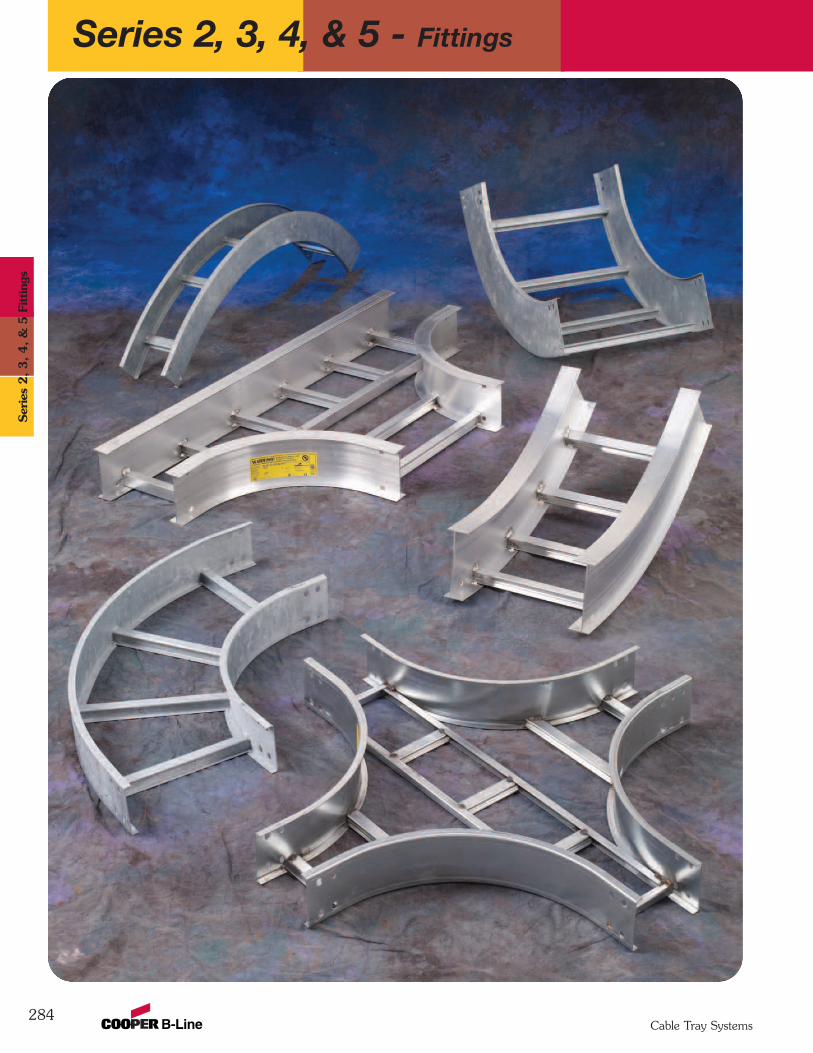
Series 2, 3, 4, & 5 - Fittings
284Cable Tray Systems
Ser
ies
2, 3, 4, &
5 F
ittin
gs
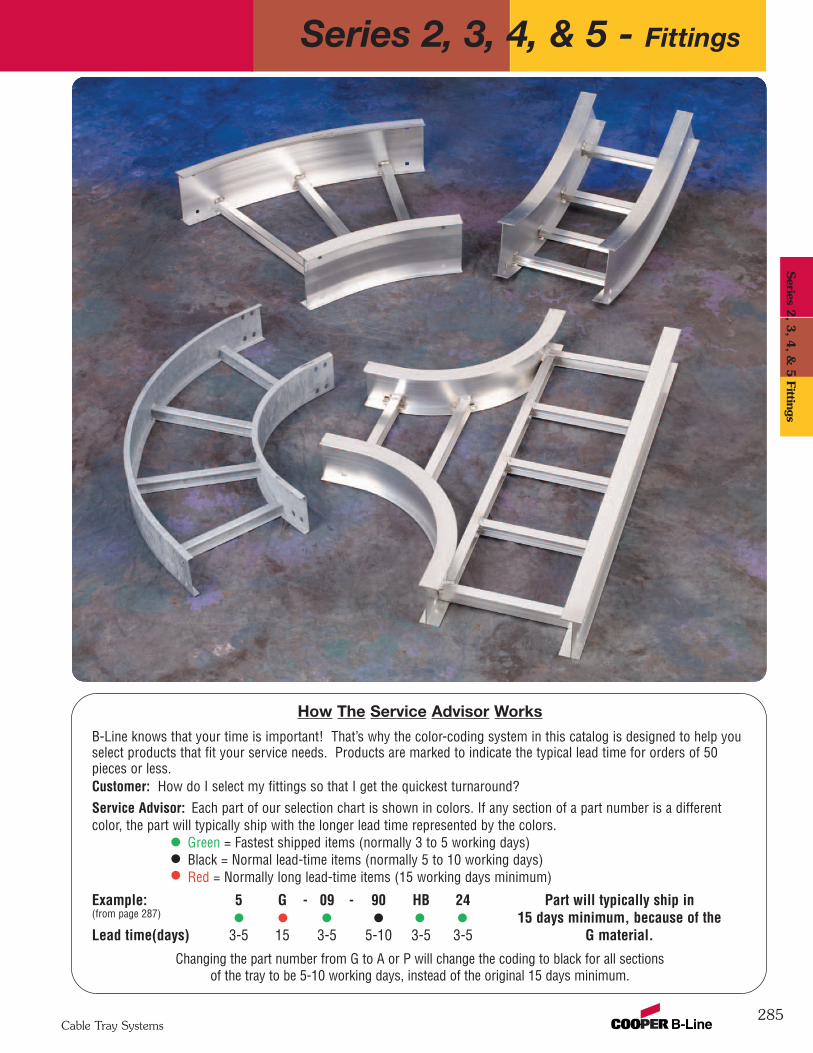
285
Series 2, 3, 4, & 5 - Fittings
Cable Tray Systems
How The Service Advisor Works
B-Line knows that your time is important! That’s why the color-coding system in this catalog is designed to help youselect products that fit your service needs. Products are marked to indicate the typical lead time for orders of 50pieces or less.Customer: How do I select my fittings so that I get the quickest turnaround?Service Advisor: Each part of our selection chart is shown in colors. If any section of a part number is a differentcolor, the part will typically ship with the longer lead time represented by the colors.
Green = Fastest shipped items (normally 3 to 5 working days)Black = Normal lead-time items (normally 5 to 10 working days)Red = Normally long lead-time items (15 working days minimum)
Example: 5 G - 09 - 90 HB 24 Part will typically ship in(from page 287) 15 days minimum, because of the Lead time(days) 3-5 15 3-5 5-10 3-5 3-5 G material.
Changing the part number from G to A or P will change the coding to black for all sectionsof the tray to be 5-10 working days, instead of the original 15 days minimum.
Series 2
, 3, 4
, & 5
Fittings
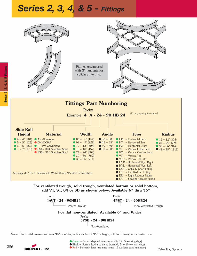
Series 2, 3, 4, & 5 - Fittings
286
For flat non-ventilated: Available 6" and WiderPrefix 5PSB - 24 - 90HB24
Non-Ventilated
Fittings Part NumberingPrefix
Example: 4 A - 24 - 90 HB 24
Side RailHeight4 = 4" (101)5 = 5" (127)6 = 6" (152)7 = 7" (178)
MaterialA= AluminumG=HDGAFP= Pre-GalvanizedSS4= 304 Stainless SteelSS6= 316 Stainless Steel
Width06 = 6" (152)09 = 9" (228)12 = 12" (305)18 = 18" (457)24 = 24" (609)30 = 30" (762)36 = 36" (914)
Angle30 = 30°45 = 45°60 = 60°90 = 90°
Radius12 = 12" (305)24 = 24" (609)36 = 36" (914)48 = 48" (1219)
TypeHB = Horizontal BendHT = Horizontal TeeHX = Horizontal CrossVI = Vertical Inside BendVO = Vertical Outside BendVT = Vertical TeeVTU = Vertical Tee, UpHYR = Horizontal Wye, RightHYL = Horizontal Wye, LeftCSF = Cable Support FittingLR = Left Reducer FittingRR = Right Reducer FittingSR = Straight Reducer Fitting
For ventilated trough, solid trough, ventilated bottom or solid bottom, add VT, ST, 04 or SB as shown below: Available 6" thru 36"
Prefix Prefix
4AVT - 24 - 90HB24 4PST - 24 - 90HB24Vented Trough Non-Ventilated Trough
Fittings engineeredwith 3” tangents for
splicing integrity.
(9" rung spacing is standard)
Note: Horizontal crosses and tees 30" or wider, with a radius of 36" or larger, will be of two-piece construction.
See page 357 for 6” fittings with 9A-6006 and 9A-6007 splice plates.
Cable Tray Systems
Green = Fastest shipped items (normally 3 to 5 working days)Black = Normal lead-time items (normally 5 to 10 working days)Red = Normally long lead-time items (15 working days minimum)
Ser
ies
2, 3, 4, &
5 F
ittin
gs
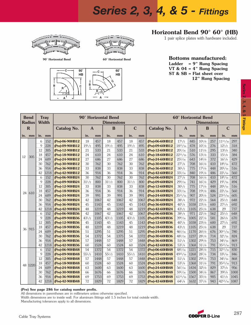
Bend Tray 90˚ Horizontal Bend 60˚ Horizontal BendRadius Width Dimensions Dimensions
R Catalog No. A B C Catalog No. A B C
in. mm in. mm in. mm in. mm in. mm in. mm in. mm in. mm
6 152 (Pre)-06-90HB12 18 457 18 457 18 457 (Pre)-06-60HB12 171/2 445 101/8 257 1111/16 2979 228 (Pre)-09-90HB12 191/2 495 191/2 495 191/2 495 (Pre)-09-60HB12 1813/16 478 107/8 276 121/2 318
12 305 (Pre)-12-90HB12 21 533 21 533 21 533 (Pre)-12-60HB12 201/16 510 115/8 295 133/8 340
12 30518 457 (Pre)-18-90HB12 24 610 24 610 24 610 (Pre)-18-60HB12 2211/16 576 131/8 333 151/8 38424 609 (Pre)-24-90HB12 27 686 27 686 27 686 (Pre)-24-60HB12 255/16 643 145/8 372 167/8 42930 762 (Pre)-30-90HB12 30 762 30 762 30 762 (Pre)-30-60HB12 277/8 708 161/8 410 189/16 47236 914 (Pre)-36-90HB12 33 838 33 838 33 838 (Pre)-36-60HB12 301/2 775 175/8 448 205/16 51642 1218 (Pre)-42-90HB12 36 914 36 914 36 914 (Pre)-42-60HB12 331/16 840 191/8 486 221/16 5606 152 (Pre)-06-90HB24 30 762 30 762 30 762 (Pre)-06-60HB24 277/8 708 161/8 410 189/16 4729 228 (Pre)-09-90HB24 311/2 800 311/2 800 311/2 800 (Pre)-09-60HB24 293/16 741 167/8 429 197/16 494
12 305 (Pre)-12-90HB24 33 838 33 838 33 838 (Pre)-12-60HB24 301/2 775 175/8 448 205/16 516
24 61018 457 (Pre)-18-90HB24 36 914 36 914 36 914 (Pre)-18-60HB24 331/16 708 191/8 486 221/16 56024 609 (Pre)-24-90HB24 39 991 39 991 39 991 (Pre)-24-60HB24 3511/16 907 205/8 524 2313/16 60530 762 (Pre)-30-90HB24 42 1067 42 1067 42 1067 (Pre)-30-60HB24 381/4 972 221/8 564 251/2 64836 914 (Pre)-36-90HB24 45 1143 45 1143 45 1143 (Pre)-36-60HB24 407/8 1038 235/8 600 271/4 69242 1218 (Pre)-42-90HB24 48 1219 48 1219 48 1219 (Pre)-42-60HB24 431/2 1105 251/8 638 29 7376 152 (Pre)-06-90HB36 42 1067 42 1067 42 1067 (Pre)-06-60HB36 381/4 971 221/8 562 251/2 6489 228 (Pre)-09-90HB36 431/2 1105 431/2 1105 431/2 1105 (Pre)-09-60HB36 399/16 1005 227/8 581 263/8 670
12 305 (Pre)-12-90HB36 45 1143 45 1143 45 1143 (Pre)-12-60HB36 407/8 1038 235/8 600 271/4 692
36 91518 457 (Pre)-18-90HB36 48 1219 48 1219 48 1219 (Pre)-18-60HB36 431/2 1105 251/8 638 29 73724 609 (Pre)-24-90HB36 51 1295 51 1295 51 1295 (Pre)-24-60HB36 461/16 1170 265/8 676 3011/16 78030 762 (Pre)-30-90HB36 54 1372 54 1375 54 1372 (Pre)-30-60HB36 481/16 1237 281/8 714 327/16 82436 914 (Pre)-36-90HB36 57 1448 57 1488 57 1448 (Pre)-36-60HB36 511/4 1302 295/8 753 343/16 86942 1218 (Pre)-42-90HB36 60 1524 60 1524 60 1524 (Pre)-42-60HB36 537/8 1368 311/8 791 3515/16 9136 152 (Pre)-06-90HB48 54 1372 54 1372 54 1372 (Pre)-06-60HB48 481/16 1221 281/8 715 3211/16 8309 228 (Pre)-09-90HB48 551/2 1410 551/2 1410 551/2 1410 (Pre)-09-60HB48 4915/16 1268 287/8 734 335/16 846
12 305 (Pre)-12-90HB48 57 1448 57 1448 57 1448 (Pre)-12-60HB48 511/4 1302 295/8 753 343/16 868
48 122018 457 (Pre)-18-90HB48 60 1524 60 1524 60 1524 (Pre)-18-60HB48 537/8 1368 311/8 791 3515/16 91324 609 (Pre)-24-90HB48 63 1600 63 1600 63 1600 (Pre)-24-60HB48 567/16 1434 325/8 829 375/8 95630 762 (Pre)-30-90HB48 66 1676 66 1676 66 1676 (Pre)-30-60HB48 591/16 1500 341/8 867 393/8 100036 914 (Pre)-36-90HB48 69 1753 69 1753 69 1753 (Pre)-36-60HB48 6111/16 1567 355/8 905 411/8 104542 1218 (Pre)-42-90HB48 72 1829 72 1829 72 1829 (Pre)-42-60HB48 641/4 1632 371/8 943 4213/16 1087
287
90˚ Horizontal Bend
C C
CR
3" (76)R
B
60˚ Horizontal Bend
B
90˚HB
60˚HB
Bottoms manufactured:Ladder = 9" Rung SpacingVT & 04 = 4" Rung SpacingST & SB = Flat sheet over
12" Rung Spacing
1 pair splice plates with hardware included.Horizontal Bend 90° 60° (HB)
(Pre) See page 286 for catalog number prefix.All dimensions in parentheses are in millimeters unless otherwise specified.Width dimensions are to inside wall. For aluminum fittings add 1.5 inches for total outside width.Manufacturing tolerances apply to all dimensions.
A
3" (76)
A
C
Series 2, 3, 4, & 5 - Fittings
Cable Tray Systems
Series 2
, 3, 4
, & 5
Fittings
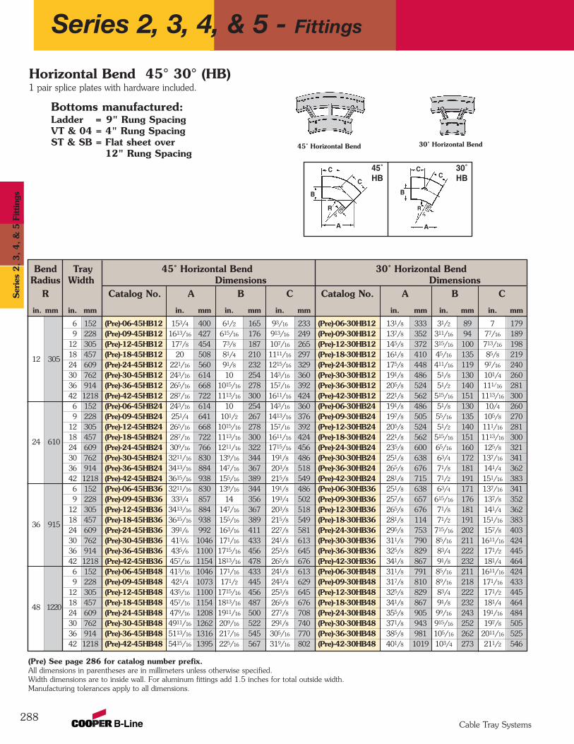
Bend Tray 45˚ Horizontal Bend 30˚ Horizontal BendRadius Width Dimensions Dimensions
R Catalog No. A B C Catalog No. A B C
in. mm in. mm in. mm in. mm in. mm in. mm in. mm in. mm
6 152 (Pre)-06-45HB12 153/4 400 61/2 165 93/16 233 (Pre)-06-30HB12 131/8 333 31/2 89 7 1799 228 (Pre)-09-45HB12 1613/16 427 615/16 176 913/16 249 (Pre)-09-30HB12 137/8 352 311/16 94 77/16 189
12 305 (Pre)-12-45HB12 177/8 454 73/8 187 107/16 265 (Pre)-12-30HB12 145/8 372 315/16 100 713/16 198
12 30518 457 (Pre)-18-45HB12 20 508 81/4 210 1111/16 297 (Pre)-18-30HB12 161/8 410 45/16 135 85/8 21924 609 (Pre)-24-45HB12 221/16 560 91/8 232 1215/16 329 (Pre)-24-30HB12 175/8 448 411/16 119 97/16 24030 762 (Pre)-30-45HB12 243/16 614 10 254 143/16 360 (Pre)-30-30HB12 191/8 486 51/8 130 101/4 26036 914 (Pre)-36-45HB12 265/16 668 1015/16 278 157/16 392 (Pre)-36-30HB12 205/8 524 51/2 140 111/16 28142 1218 (Pre)-42-45HB12 287/16 722 1113/16 300 1611/16 424 (Pre)-42-30HB12 221/8 562 515/16 151 1113/16 3006 152 (Pre)-06-45HB24 243/16 614 10 254 143/16 360 (Pre)-06-30HB24 191/8 486 51/8 130 10/4 2609 228 (Pre)-09-45HB24 251/4 641 101/2 267 1413/16 376 (Pre)-09-30HB24 197/8 505 55/16 135 105/8 270
12 305 (Pre)-12-45HB24 265/16 668 1015/16 278 157/16 392 (Pre)-12-30HB24 205/8 524 51/2 140 111/16 281
24 61018 457 (Pre)-18-45HB24 287/16 722 1113/16 300 1611/16 424 (Pre)-18-30HB24 221/8 562 515/16 151 1113/16 30024 609 (Pre)-24-45HB24 309/16 766 1211/16 322 1715/16 456 (Pre)-24-30HB24 235/8 600 65/16 160 125/8 32130 762 (Pre)-30-45HB24 3211/16 830 139/16 344 191/8 486 (Pre)-30-30HB24 251/8 638 63/4 172 137/16 34136 914 (Pre)-36-45HB24 3413/16 884 147/16 367 203/8 518 (Pre)-36-30HB24 265/8 676 71/8 181 141/4 36242 1218 (Pre)-42-45HB24 3615/16 938 155/16 389 215/8 549 (Pre)-42-30HB24 281/8 715 71/2 191 151/16 3836 152 (Pre)-06-45HB36 3211/16 830 139/16 344 191/8 486 (Pre)-06-30HB36 251/8 638 63/4 171 137/16 3419 228 (Pre)-09-45HB36 333/4 857 14 356 193/4 502 (Pre)-09-30HB36 257/8 657 615/16 176 137/8 352
12 305 (Pre)-12-45HB36 3413/16 884 147/16 367 203/8 518 (Pre)-12-30HB36 265/8 676 71/8 181 141/4 362
36 91518 457 (Pre)-18-45HB36 3615/16 938 155/16 389 215/8 549 (Pre)-18-30HB36 281/8 114 71/2 191 151/16 38324 609 (Pre)-24-45HB36 391/6 992 163/16 411 227/8 581 (Pre)-24-30HB36 295/8 753 715/16 202 157/8 40330 762 (Pre)-30-45HB36 413/6 1046 171/16 433 241/8 613 (Pre)-30-30HB36 311/8 790 85/16 211 1611/16 42436 914 (Pre)-36-45HB36 435/6 1100 1715/16 456 253/8 645 (Pre)-36-30HB36 325/8 829 83/4 222 171/2 44542 1218 (Pre)-42-45HB36 457/16 1154 1813/16 478 265/8 676 (Pre)-42-30HB36 341/8 867 91/8 232 181/4 4646 152 (Pre)-06-45HB48 413/16 1046 171/16 433 241/8 613 (Pre)-06-30HB48 311/8 791 85/16 211 1611/16 4249 228 (Pre)-09-45HB48 421/4 1073 171/2 445 243/4 629 (Pre)-09-30HB48 317/8 810 89/16 218 171/16 433
12 305 (Pre)-12-45HB48 435/16 1100 1715/16 456 253/8 645 (Pre)-12-30HB48 325/8 829 83/4 222 171/2 445
48 122018 457 (Pre)-18-45HB48 457/16 1154 1813/16 487 265/8 676 (Pre)-18-30HB48 341/8 867 91/8 232 181/4 46424 609 (Pre)-24-45HB48 479/16 1208 1911/16 500 277/8 708 (Pre)-24-30HB48 355/8 905 99/16 243 191/16 48430 762 (Pre)-30-45HB48 4911/16 1262 209/16 522 291/8 740 (Pre)-30-30HB48 371/8 943 915/16 252 197/8 50536 914 (Pre)-36-45HB48 5113/16 1316 217/16 545 305/16 770 (Pre)-36-30HB48 385/8 981 105/16 262 2011/16 52542 1218 (Pre)-42-45HB48 5415/16 1395 225/16 567 319/16 802 (Pre)-42-30HB48 401/8 1019 103/4 273 211/2 546
288
45˚ Horizontal Bend
CC
R
3" (7
6)
B
C
C
R
B
30˚ Horizontal Bend
45˚HB
30˚HB
Bottoms manufactured:Ladder = 9" Rung SpacingVT & 04 = 4" Rung SpacingST & SB = Flat sheet over
12" Rung Spacing
Horizontal Bend 45° 30° (HB)
(Pre) See page 286 for catalog number prefix.All dimensions in parentheses are in millimeters unless otherwise specified.Width dimensions are to inside wall. For aluminum fittings add 1.5 inches for total outside width.Manufacturing tolerances apply to all dimensions.
1 pair splice plates with hardware included.
3" (7
6)
A A
Series 2, 3, 4, & 5 - Fittings
Cable Tray Systems
Ser
ies
2, 3, 4, &
5 F
ittin
gs
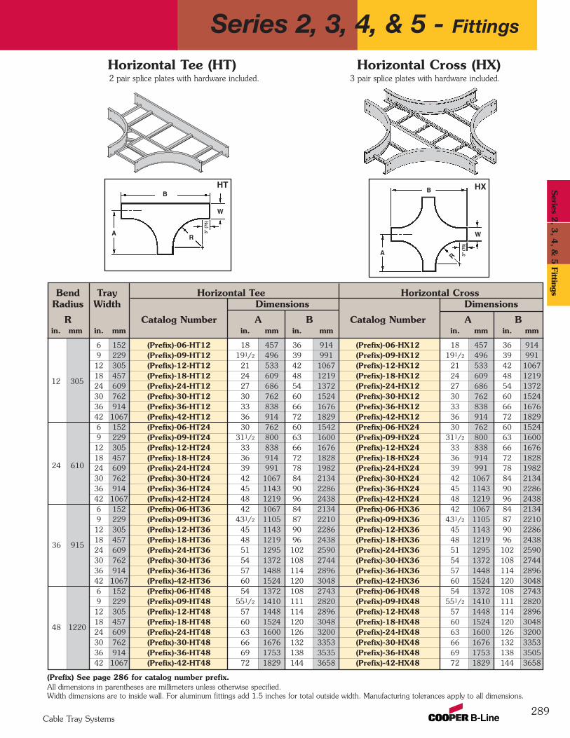
Bend Tray Horizontal Tee Horizontal CrossRadius Width Dimensions Dimensions
R Catalog Number A B Catalog Number A Bin. mm in. mm in. mm in. mm in. mm in. mm
6 152 (Prefix)-06-HT12 18 457 36 914 (Prefix)-06-HX12 18 457 36 9149 229 (Prefix)-09-HT12 191/2 496 39 991 (Prefix)-09-HX12 191/2 496 39 99112 305 (Prefix)-12-HT12 21 533 42 1067 (Prefix)-12-HX12 21 533 42 106718 457 (Prefix)-18-HT12 24 609 48 1219 (Prefix)-18-HX12 24 609 48 121924 609 (Prefix)-24-HT12 27 686 54 1372 (Prefix)-24-HX12 27 686 54 137230 762 (Prefix)-30-HT12 30 762 60 1524 (Prefix)-30-HX12 30 762 60 152436 914 (Prefix)-36-HT12 33 838 66 1676 (Prefix)-36-HX12 33 838 66 167642 1067 (Prefix)-42-HT12 36 914 72 1829 (Prefix)-42-HX12 36 914 72 18296 152 (Prefix)-06-HT24 30 762 60 1542 (Prefix)-06-HX24 30 762 60 15249 229 (Prefix)-09-HT24 311/2 800 63 1600 (Prefix)-09-HX24 311/2 800 63 160012 305 (Prefix)-12-HT24 33 838 66 1676 (Prefix)-12-HX24 33 838 66 167618 457 (Prefix)-18-HT24 36 914 72 1828 (Prefix)-18-HX24 36 914 72 182824 609 (Prefix)-24-HT24 39 991 78 1982 (Prefix)-24-HX24 39 991 78 198230 762 (Prefix)-30-HT24 42 1067 84 2134 (Prefix)-30-HX24 42 1067 84 213436 914 (Prefix)-36-HT24 45 1143 90 2286 (Prefix)-36-HX24 45 1143 90 228642 1067 (Prefix)-42-HT24 48 1219 96 2438 (Prefix)-42-HX24 48 1219 96 24386 152 (Prefix)-06-HT36 42 1067 84 2134 (Prefix)-06-HX36 42 1067 84 21349 229 (Prefix)-09-HT36 431/2 1105 87 2210 (Prefix)-09-HX36 431/2 1105 87 221012 305 (Prefix)-12-HT36 45 1143 90 2286 (Prefix)-12-HX36 45 1143 90 228618 457 (Prefix)-18-HT36 48 1219 96 2438 (Prefix)-18-HX36 48 1219 96 243824 609 (Prefix)-24-HT36 51 1295 102 2590 (Prefix)-24-HX36 51 1295 102 259030 762 (Prefix)-30-HT36 54 1372 108 2744 (Prefix)-30-HX36 54 1372 108 274436 914 (Prefix)-36-HT36 57 1488 114 2896 (Prefix)-36-HX36 57 1448 114 289642 1067 (Prefix)-42-HT36 60 1524 120 3048 (Prefix)-42-HX36 60 1524 120 30486 152 (Prefix)-06-HT48 54 1372 108 2743 (Prefix)-06-HX48 54 1372 108 27439 229 (Prefix)-09-HT48 551/2 1410 111 2820 (Prefix)-09-HX48 551/2 1410 111 282012 305 (Prefix)-12-HT48 57 1448 114 2896 (Prefix)-12-HX48 57 1448 114 289618 457 (Prefix)-18-HT48 60 1524 120 3048 (Prefix)-18-HX48 60 1524 120 304824 609 (Prefix)-24-HT48 63 1600 126 3200 (Prefix)-24-HX48 63 1600 126 320030 762 (Prefix)-30-HT48 66 1676 132 3353 (Prefix)-30-HX48 66 1676 132 335336 914 (Prefix)-36-HT48 69 1753 138 3535 (Prefix)-36-HX48 69 1753 138 350542 1067 (Prefix)-42-HT48 72 1829 144 3658 (Prefix)-42-HX48 72 1829 144 3658
289
A
B
R
AR
B
2 pair splice plates with hardware included. 3 pair splice plates with hardware included.
3" (
76)
3" (
76)
12 305
24 610
36 915
48 1220
(Prefix) See page 286 for catalog number prefix.All dimensions in parentheses are millimeters unless otherwise specified.Width dimensions are to inside wall. For aluminum fittings add 1.5 inches for total outside width. Manufacturing tolerances apply to all dimensions.
Horizontal Tee (HT) Horizontal Cross (HX)
HT HX
W
W
Series 2, 3, 4, & 5 - Fittings
Cable Tray Systems
Series 2
, 3, 4
, & 5
Fittings
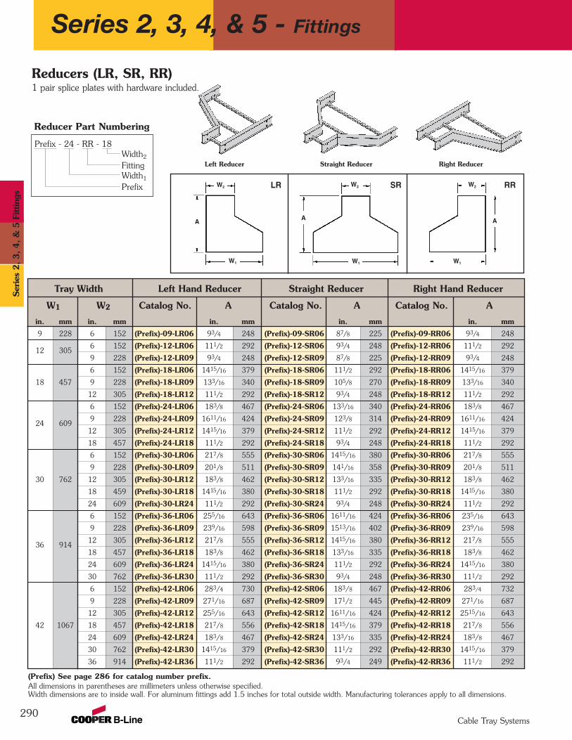
Prefix - 24 - RR - 18Width2
FittingWidth1
Prefix
Tray Width Left Hand Reducer Straight Reducer Right Hand Reducer
W1 W2 Catalog No. A Catalog No. A Catalog No. A
in. mm in. mm in. mm in. mm in. mm
9 228 6 152 (Prefix)-09-LR06 93/4 248 (Prefix)-09-SR06 87/8 225 (Prefix)-09-RR06 93/4 248
12 3056 152 (Prefix)-12-LR06 111/2 292 (Prefix)-12-SR06 93/4 248 (Prefix)-12-RR06 111/2 292
9 228 (Prefix)-12-LR09 93/4 248 (Prefix)-12-SR09 87/8 225 (Prefix)-12-RR09 93/4 248
6 152 (Prefix)-18-LR06 1415/16 379 (Prefix)-18-SR06 111/2 292 (Prefix)-18-RR06 1415/16 379
18 457 9 228 (Prefix)-18-LR09 133/16 340 (Prefix)-18-SR09 105/8 270 (Prefix)-18-RR09 133/16 340
12 305 (Prefix)-18-LR12 111/2 292 (Prefix)-18-SR12 93/4 248 (Prefix)-18-RR12 111/2 292
6 152 (Prefix)-24-LR06 183/8 467 (Prefix)-24-SR06 133/16 340 (Prefix)-24-RR06 183/8 467
24 6099 228 (Prefix)-24-LR09 1611/16 424 (Prefix)-24-SR09 123/8 314 (Prefix)-24-RR09 1611/16 424
12 305 (Prefix)-24-LR12 1415/16 379 (Prefix)-24-SR12 111/2 292 (Prefix)-24-RR12 1415/16 379
18 457 (Prefix)-24-LR18 111/2 292 (Prefix)-24-SR18 93/4 248 (Prefix)-24-RR18 111/2 292
6 152 (Prefix)-30-LR06 217/8 555 (Prefix)-30-SR06 1415/16 380 (Prefix)-30-RR06 217/8 555
9 228 (Prefix)-30-LR09 201/8 511 (Prefix)-30-SR09 141/16 358 (Prefix)-30-RR09 201/8 511
30 762 12 305 (Prefix)-30-LR12 183/8 462 (Prefix)-30-SR12 133/16 335 (Prefix)-30-RR12 183/8 462
18 459 (Prefix)-30-LR18 1415/16 380 (Prefix)-30-SR18 111/2 292 (Prefix)-30-RR18 1415/16 380
24 609 (Prefix)-30-LR24 111/2 292 (Prefix)-30-SR24 93/4 248 (Prefix)-30-RR24 111/2 292
6 152 (Prefix)-36-LR06 255/16 643 (Prefix)-36-SR06 1611/16 424 (Prefix)-36-RR06 235/16 643
9 228 (Prefix)-36-LR09 239/16 598 (Prefix)-36-SR09 1513/16 402 (Prefix)-36-RR09 239/16 598
36 91412 305 (Prefix)-36-LR12 217/8 555 (Prefix)-36-SR12 1415/16 380 (Prefix)-36-RR12 217/8 555
18 457 (Prefix)-36-LR18 183/8 462 (Prefix)-36-SR18 133/16 335 (Prefix)-36-RR18 183/8 462
24 609 (Prefix)-36-LR24 1415/16 380 (Prefix)-36-SR24 111/2 292 (Prefix)-36-RR24 1415/16 380
30 762 (Prefix)-36-LR30 111/2 292 (Prefix)-36-SR30 93/4 248 (Prefix)-36-RR30 111/2 292
6 152 (Prefix)-42-LR06 283/4 730 (Prefix)-42-SR06 183/8 467 (Prefix)-42-RR06 283/4 732
9 228 (Prefix)-42-LR09 271/16 687 (Prefix)-42-SR09 171/2 445 (Prefix)-42-RR09 271/16 687
12 305 (Prefix)-42-LR12 255/16 643 (Prefix)-42-SR12 1611/16 424 (Prefix)-42-RR12 2515/16 643
42 1067 18 457 (Prefix)-42-LR18 217/8 556 (Prefix)-42-SR18 1415/16 379 (Prefix)-42-RR18 217/8 556
24 609 (Prefix)-42-LR24 183/8 467 (Prefix)-42-SR24 133/16 335 (Prefix)-42-RR24 183/8 467
30 762 (Prefix)-42-LR30 1415/16 379 (Prefix)-42-SR30 111/2 292 (Prefix)-42-RR30 1415/16 379
36 914 (Prefix)-42-LR36 111/2 292 (Prefix)-42-SR36 93/4 249 (Prefix)-42-RR36 111/2 292
290
Right ReducerStraight ReducerLeft Reducer
Reducers (LR, SR, RR)1 pair splice plates with hardware included.
A
W2
W1
LR
A
W2
W1
SR
A
W2
W1
RR
(Prefix) See page 286 for catalog number prefix.
Width dimensions are to inside wall. For aluminum fittings add 1.5 inches for total outside width. Manufacturing tolerances apply to all dimensions.All dimensions in parentheses are millimeters unless otherwise specified.
Reducer Part Numbering
Series 2, 3, 4, & 5 - Fittings
Cable Tray Systems
Ser
ies
2, 3, 4, &
5 F
ittin
gs
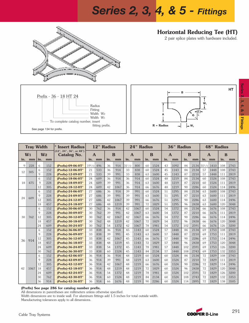
Tray Width * Insert Radius 12" Radius 24" Radius 36" Radius 48" Radius(12", 24", 36", or 48")
W1 W2 Catalog No. A B A B A B A Bin. mm in. mm in. mm in. mm in. mm in. mm in. mm in. mm in. mm in. mm
9 228 6 152 (Prefix)-09-06-HT* 191/2 496 36 914 311/2 800 60 1524 43 1092 84 2134 551/2 1410 108 2743
6 152 (Prefix)-12-06-HT* 21 533 36 914 33 838 60 1524 45 1143 84 2134 57 1448 108 2743
9 228 (Prefix)-12-09-HT* 21 533 39 991 33 838 63 1600 45 1143 87 2210 57 1448 111 2819
6 152 (Prefix)-18-06-HT* 24 609 36 914 36 914 60 1524 48 1219 84 2134 60 1524 108 2743
18 475 9 228 (Prefix)-18-09-HT* 24 609 39 991 36 914 63 1600 48 1219 87 2210 60 1524 111 2819
12 305 (Prefix)-18-12-HT* 24 609 42 1067 36 914 66 1676 48 1219 90 2286 60 1524 114 2496
6 152 (Prefix)-24-06-HT* 27 686 36 914 39 991 60 1524 51 1295 84 2134 63 1600 108 2743
9 228 (Prefix)-24-09-HT* 27 686 39 991 39 991 63 1600 51 1295 87 2210 63 1600 111 2819
12 305 (Prefix)-24-12-HT* 27 686 42 1067 39 991 66 1676 51 1295 90 2286 63 1600 114 2496
18 457 (Prefix)-24-18-HT* 27 686 48 1219 39 991 72 1829 51 1295 96 2438 63 1600 120 3048
6 152 (Prefix)-30-06-HT* 30 762 36 914 42 1067 60 1524 54 1372 84 2134 66 1676 108 2743
9 228 (Prefix)-30-09-HT* 30 762 39 991 42 1067 63 1600 54 1372 87 2210 66 1676 111 2819
30 762 12 305 (Prefix)-30-12-HT* 30 762 42 1067 42 1067 66 1676 54 1372 90 2286 66 1676 114 2496
18 457 (Prefix)-30-18-HT* 30 762 48 1219 42 1067 72 1829 54 1372 96 2438 66 1676 120 3048
24 609 (Prefix)-30-24-HT* 30 762 54 1372 42 1067 78 1981 54 1372 102 2591 66 1676 126 3200
6 152 (Prefix)-36-06-HT* 33 838 36 914 45 1143 60 1524 57 1448 84 2134 69 1753 108 2743
9 228 (Prefix)-36-09-HT* 33 838 39 991 45 1143 63 1600 57 1448 87 2210 69 1753 111 2819
12 305 (Prefix)-36-12-HT* 33 838 42 1067 45 1143 66 1676 57 1448 90 2286 69 1753 114 2496
18 457 (Prefix)-36-18-HT* 33 838 48 1219 45 1143 72 1829 57 1448 96 2438 69 1753 120 3048
24 609 (Prefix)-36-24-HT* 33 838 54 1372 45 1143 78 1981 57 1448 102 2591 69 1753 126 3200
30 762 (Prefix)-36-30-HT* 33 838 60 1524 45 1143 84 2134 57 1448 108 2743 69 1753 132 3353
6 152 (Prefix)-42-06-HT* 36 914 36 914 48 1219 60 1524 60 1524 84 2134 72 1829 108 2743
9 228 (Prefix)-42-09-HT* 36 914 39 991 48 1219 63 1600 60 1524 87 2210 72 1829 111 2819
12 305 (Prefix)-42-12-HT* 36 914 42 1067 48 1219 66 1676 60 1524 90 2286 72 1829 114 2496
42 1067 18 457 (Prefix)-42-18-HT* 36 914 48 1219 48 1219 72 1829 60 1524 96 2438 72 1829 120 3048
24 609 (Prefix)-42-24-HT* 36 914 54 1372 48 1219 78 1981 60 1524 102 2591 72 1829 126 3200
30 762 (Prefix)-42-30-HT* 36 914 60 1524 48 1219 84 2134 60 1524 108 2743 72 1829 132 3353
36 914 (Prefix)-42-36-HT* 36 914 66 1676 48 1219 90 2286 60 1524 114 2895 72 1829 138 3505
Prefix - 36 - 18 HT 24
RadiusFittingWidth W2
Width W1
To complete catalog number, insert fitting prefix. R = Radius
291
Horizontal Reducing Tee (HT)2 pair splice plates with hardware included.
B
A
W2
R
W1
See page 134 for prefix.
HT
(Prefix) See page 286 for catalog number prefix.All dimensions in parentheses are millimeters unless otherwise specified.Width dimensions are to inside wall. For aluminum fittings add 1.5 inches for total outside width.Manufacturing tolerances apply to all dimensions.
3" (
76)
12 305
24 609
36 914
Series 2, 3, 4, & 5 - Fittings
Cable Tray Systems
Series 2
, 3, 4
, & 5
Fittings
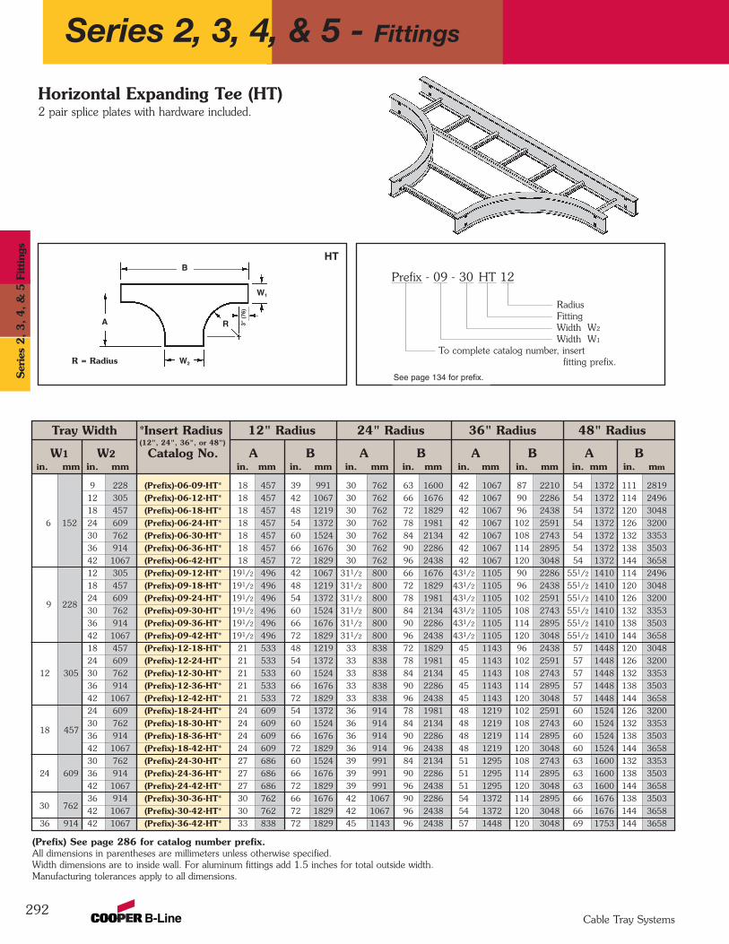
Tray Width *Insert Radius 12" Radius 24" Radius 36" Radius 48" Radius(12", 24", 36", or 48")
W1 W2 Catalog No. A B A B A B A Bin. mm in. mm in. mm in. mm in. mm in. mm in. mm in. mm in. mm in. mm
9 228 (Prefix)-06-09-HT* 18 457 39 991 30 762 63 1600 42 1067 87 2210 54 1372 111 2819
12 305 (Prefix)-06-12-HT* 18 457 42 1067 30 762 66 1676 42 1067 90 2286 54 1372 114 2496
18 457 (Prefix)-06-18-HT* 18 457 48 1219 30 762 72 1829 42 1067 96 2438 54 1372 120 3048
6 152 24 609 (Prefix)-06-24-HT* 18 457 54 1372 30 762 78 1981 42 1067 102 2591 54 1372 126 3200
30 762 (Prefix)-06-30-HT* 18 457 60 1524 30 762 84 2134 42 1067 108 2743 54 1372 132 3353
36 914 (Prefix)-06-36-HT* 18 457 66 1676 30 762 90 2286 42 1067 114 2895 54 1372 138 3503
42 1067 (Prefix)-06-42-HT* 18 457 72 1829 30 762 96 2438 42 1067 120 3048 54 1372 144 3658
12 305 (Prefix)-09-12-HT* 191/2 496 42 1067 311/2 800 66 1676 431/2 1105 90 2286 551/2 1410 114 2496
18 457 (Prefix)-09-18-HT* 191/2 496 48 1219 311/2 800 72 1829 431/2 1105 96 2438 551/2 1410 120 3048
24 609 (Prefix)-09-24-HT* 191/2 496 54 1372 311/2 800 78 1981 431/2 1105 102 2591 551/2 1410 126 3200
30 762 (Prefix)-09-30-HT* 191/2 496 60 1524 311/2 800 84 2134 431/2 1105 108 2743 551/2 1410 132 3353
36 914 (Prefix)-09-36-HT* 191/2 496 66 1676 311/2 800 90 2286 431/2 1105 114 2895 551/2 1410 138 3503
42 1067 (Prefix)-09-42-HT* 191/2 496 72 1829 311/2 800 96 2438 431/2 1105 120 3048 551/2 1410 144 3658
18 457 (Prefix)-12-18-HT* 21 533 48 1219 33 838 72 1829 45 1143 96 2438 57 1448 120 3048
24 609 (Prefix)-12-24-HT* 21 533 54 1372 33 838 78 1981 45 1143 102 2591 57 1448 126 3200
12 305 30 762 (Prefix)-12-30-HT* 21 533 60 1524 33 838 84 2134 45 1143 108 2743 57 1448 132 3353
36 914 (Prefix)-12-36-HT* 21 533 66 1676 33 838 90 2286 45 1143 114 2895 57 1448 138 3503
42 1067 (Prefix)-12-42-HT* 21 533 72 1829 33 838 96 2438 45 1143 120 3048 57 1448 144 3658
24 609 (Prefix)-18-24-HT* 24 609 54 1372 36 914 78 1981 48 1219 102 2591 60 1524 126 3200
30 762 (Prefix)-18-30-HT* 24 609 60 1524 36 914 84 2134 48 1219 108 2743 60 1524 132 3353
36 914 (Prefix)-18-36-HT* 24 609 66 1676 36 914 90 2286 48 1219 114 2895 60 1524 138 3503
42 1067 (Prefix)-18-42-HT* 24 609 72 1829 36 914 96 2438 48 1219 120 3048 60 1524 144 3658
30 762 (Prefix)-24-30-HT* 27 686 60 1524 39 991 84 2134 51 1295 108 2743 63 1600 132 3353
24 609 36 914 (Prefix)-24-36-HT* 27 686 66 1676 39 991 90 2286 51 1295 114 2895 63 1600 138 3503
42 1067 (Prefix)-24-42-HT* 27 686 72 1829 39 991 96 2438 51 1295 120 3048 63 1600 144 3658
36 914 (Prefix)-30-36-HT* 30 762 66 1676 42 1067 90 2286 54 1372 114 2895 66 1676 138 3503
42 1067 (Prefix)-30-42-HT* 30 762 72 1829 42 1067 96 2438 54 1372 120 3048 66 1676 144 3658
36 914 42 1067 (Prefix)-36-42-HT* 33 838 72 1829 45 1143 96 2438 57 1448 120 3048 69 1753 144 3658
292
Prefix - 09 - 30 HT 12
RadiusFittingWidth W2
Width W1
To complete catalog number, insert fitting prefix.
Horizontal Expanding Tee (HT)2 pair splice plates with hardware included.
B
A
W2
R
W1
See page 134 for prefix.
(Prefix) See page 286 for catalog number prefix.All dimensions in parentheses are millimeters unless otherwise specified.Width dimensions are to inside wall. For aluminum fittings add 1.5 inches for total outside width.Manufacturing tolerances apply to all dimensions.
HT3"
(76
)
R = Radius
30 762
18 457
9 228
Series 2, 3, 4, & 5 - Fittings
Cable Tray Systems
Ser
ies
2, 3, 4, &
5 F
ittin
gs
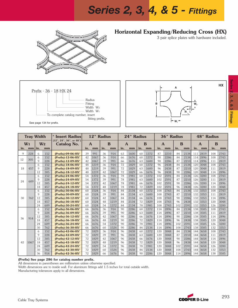
Tray Width * Insert Radius 12" Radius 24" Radius 36" Radius 48" Radius(12", 24", 36", or 48")
W1 W2 Catalog No. A B A B A B A Bin. mm in. mm in. mm in. mm in. mm in. mm in. mm in. mm in. mm in. mm
9 228 6 152 (Prefix)-09-06-HX* 39 991 36 914 63 1600 60 1372 87 2210 84 2134 111 2819 108 27436 152 (Prefix)-12-06-HX* 42 1067 36 914 66 1676 60 1372 90 2286 84 2134 114 2896 108 27439 228 (Prefix)-12-09-HX* 42 1067 39 991 66 1676 63 1600 90 2286 87 2210 114 2896 111 28196 152 (Prefix)-18-06-HX* 48 1219 36 914 72 1829 60 1372 96 2438 84 2134 120 3048 108 2743
18 457 9 228 (Prefix)-18-09-HX* 48 1219 39 991 72 1829 63 1600 96 2438 87 2210 120 3048 111 281912 305 (Prefix)-18-12-HX* 48 1219 42 1067 72 1829 66 1676 96 2438 90 2286 120 3048 114 28966 152 (Prefix)-24-06-HX* 54 1372 36 914 78 1981 60 1372 102 2591 84 2134 126 3200 108 27439 228 (Prefix)-24-09-HX* 54 1372 39 991 78 1981 63 1600 102 2591 87 2210 126 3200 111 281912 305 (Prefix)-24-12-HX* 54 1372 42 1067 78 1981 66 1676 102 2591 90 2286 126 3200 114 289618 457 (Prefix)-24-18-HX* 54 1372 48 1219 78 1981 72 1829 102 2591 96 2438 126 3200 120 30486 152 (Prefix)-30-06-HX* 60 1524 36 914 84 2134 60 1372 108 2743 84 2134 132 3353 108 27439 228 (Prefix)-30-09-HX* 60 1524 39 991 84 2134 63 1600 108 2743 87 2210 132 3353 111 2819
30 762 12 305 (Prefix)-30-12-HX* 60 1524 42 1067 84 2134 66 1676 108 2743 90 2286 132 3353 114 289618 457 (Prefix)-30-18-HX* 60 1524 48 1219 84 2134 72 1829 108 2743 96 2438 132 3353 120 304824 609 (Prefix)-30-24-HX* 60 1524 54 1372 84 2134 78 1981 108 2743 102 2591 132 3353 126 32006 152 (Prefix)-36-06-HX* 66 1676 36 914 90 2286 60 1372 114 2896 84 2134 138 3505 108 27439 228 (Prefix)-36-09-HX* 66 1676 39 991 90 2286 63 1600 114 2896 87 2210 138 3505 111 281912 305 (Prefix)-36-12-HX* 66 1676 42 1067 90 2286 66 1676 114 2896 90 2286 138 3505 114 289618 457 (Prefix)-36-18-HX* 66 1676 48 1219 90 2286 72 1829 114 2896 96 2438 138 3505 120 304824 609 (Prefix)-36-24-HX* 66 1676 54 1372 90 2286 78 1981 114 2896 102 2591 138 3505 126 320030 762 (Prefix)-36-30-HX* 66 1676 60 1524 90 2286 84 2134 114 2896 108 2743 138 3505 132 33536 152 (Prefix)-42-06-HX* 72 1829 36 914 96 2438 60 1372 120 3048 84 2134 144 3658 108 27439 228 (Prefix)-42-09-HX* 72 1829 39 991 96 2438 63 1600 120 3048 87 2210 144 3658 111 281912 305 (Prefix)-42-12-HX* 72 1829 42 1067 96 2438 66 1676 120 3048 90 2286 144 3658 114 2896
42 1067 18 457 (Prefix)-42-18-HX* 72 1829 48 1219 96 2438 72 1829 120 3048 96 2438 144 3658 120 304824 609 (Prefix)-42-24-HX* 72 1829 54 1372 96 2438 78 1981 120 3048 102 2591 144 3658 126 320030 762 (Prefix)-42-30-HX* 72 1829 60 1524 96 2438 84 2134 120 3048 108 2743 144 3658 132 335336 914 (Prefix)-42-36-HX* 72 1829 66 1676 96 2438 90 2286 120 3048 114 2896 144 3658 138 3505
293
Prefix - 36 - 18 HX 24
RadiusFittingWidth W2
Width W1
To complete catalog number, insert fitting prefix.
B
A
W2
3" (
76)
R
W1
HX
(Prefix) See page 286 for catalog number prefix.All dimensions in parentheses are millimeters unless otherwise specified.Width dimensions are to inside wall. For aluminum fittings add 1.5 inches for total outside width.Manufacturing tolerances apply to all dimensions.
See page 134 for prefix.
12 305
24 609
36 914
Horizontal Expanding/Reducing Cross (HX)3 pair splice plates with hardware included.
Series 2, 3, 4, & 5 - Fittings
Cable Tray Systems
Series 2
, 3, 4
, & 5
Fittings
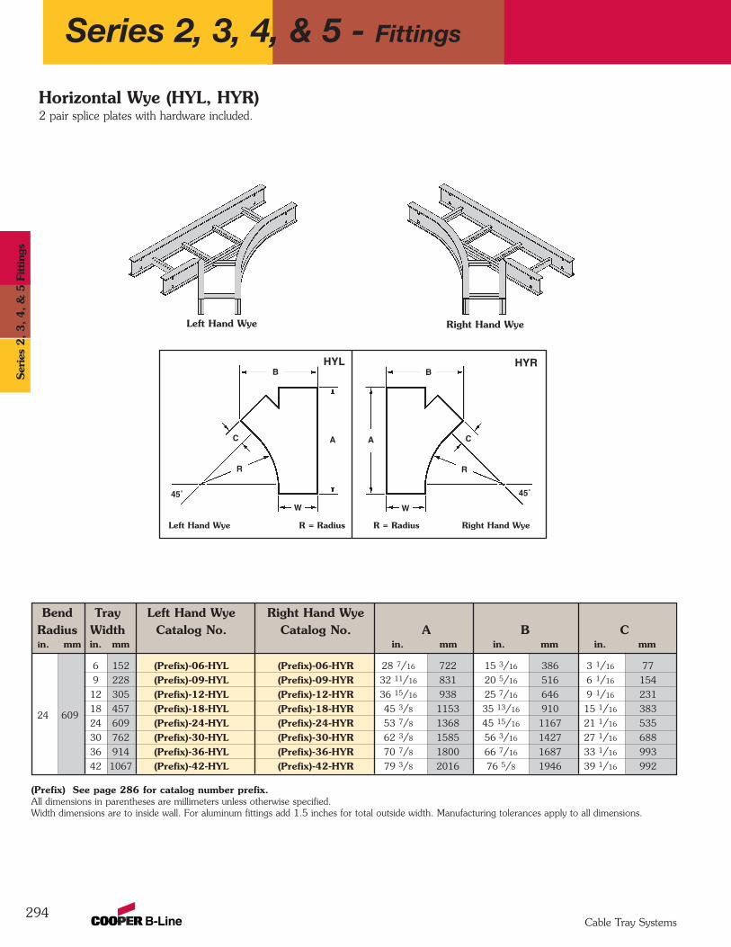
Bend Tray Left Hand Wye Right Hand WyeRadius Width Catalog No. Catalog No. A B Cin. mm in. mm in. mm in. mm in. mm
6 152 (Prefix)-06-HYL (Prefix)-06-HYR 28 7/16 722 15 3/16 386 3 1/16 77
9 228 (Prefix)-09-HYL (Prefix)-09-HYR 32 11/16 831 20 5/16 516 6 1/16 154
12 305 (Prefix)-12-HYL (Prefix)-12-HYR 36 15/16 938 25 7/16 646 9 1/16 231
18 457 (Prefix)-18-HYL (Prefix)-18-HYR 45 3/8 1153 35 13/16 910 15 1/16 383
24 609 (Prefix)-24-HYL (Prefix)-24-HYR 53 7/8 1368 45 15/16 1167 21 1/16 535
30 762 (Prefix)-30-HYL (Prefix)-30-HYR 62 3/8 1585 56 3/16 1427 27 1/16 688
36 914 (Prefix)-36-HYL (Prefix)-36-HYR 70 7/8 1800 66 7/16 1687 33 1/16 993
42 1067 (Prefix)-42-HYL (Prefix)-42-HYR 79 3/8 2016 76 5/8 1946 39 1/16 992
294
Left Hand Wye R = Radius R = Radius Right Hand Wye
Left Hand Wye Right Hand Wye
Horizontal Wye (HYL, HYR)2 pair splice plates with hardware included.
B
AC
45˚
R
W
B
A C
45˚
R
W
HYL HYR
(Prefix) See page 286 for catalog number prefix. All dimensions in parentheses are millimeters unless otherwise specified.Width dimensions are to inside wall. For aluminum fittings add 1.5 inches for total outside width. Manufacturing tolerances apply to all dimensions.
24 609
Series 2, 3, 4, & 5 - Fittings
Cable Tray Systems
Ser
ies
2, 3, 4, &
5 F
ittin
gs
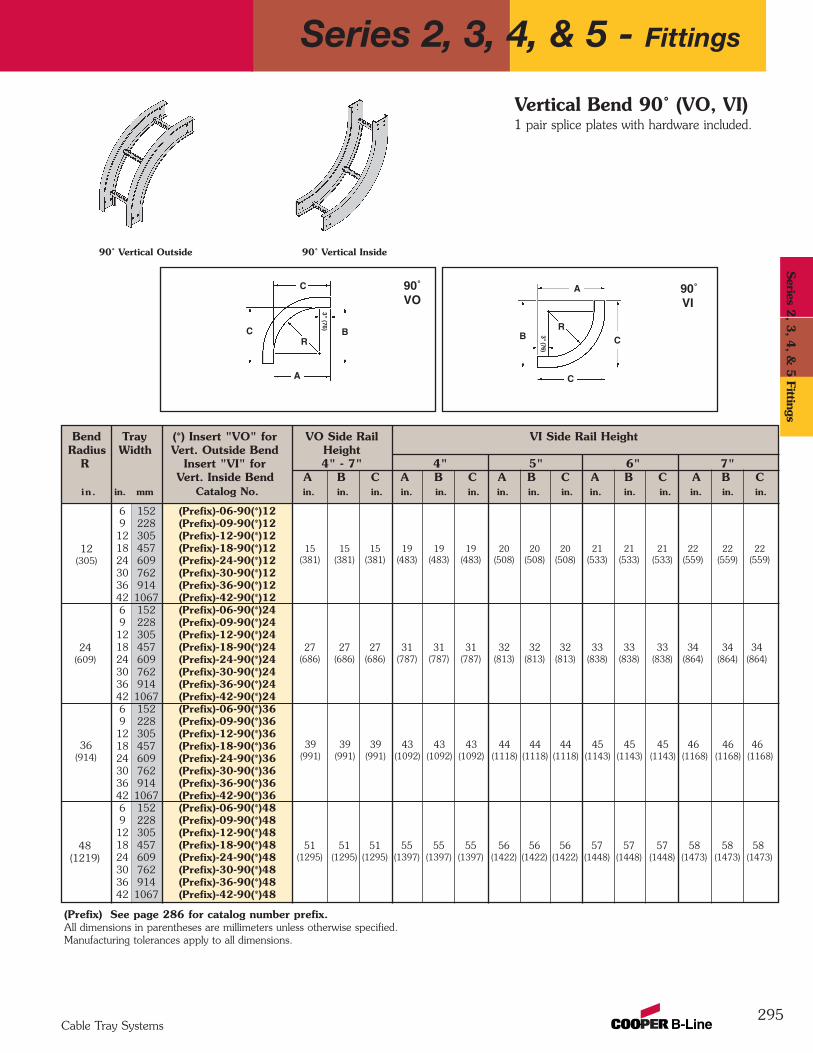
Bend Tray (*) Insert "VO" for VO Side Rail VI Side Rail HeightRadius Width Vert. Outside Bend Height
R Insert "VI" for 4" - 7" 4" 5" 6" 7"Vert. Inside Bend A B C A B C A B C A B C A B C
in . in. mm Catalog No. in. in. in. in. in. in. in. in. in. in. in. in. in. in. in.
6 152 (Prefix)-06-90(*)129 228 (Prefix)-09-90(*)1212 305 (Prefix)-12-90(*)1218 457 (Prefix)-18-90(*)1224 609 (Prefix)-24-90(*)1230 762 (Prefix)-30-90(*)1236 914 (Prefix)-36-90(*)1242 1067 (Prefix)-42-90(*)126 152 (Prefix)-06-90(*)249 228 (Prefix)-09-90(*)2412 305 (Prefix)-12-90(*)2418 457 (Prefix)-18-90(*)2424 609 (Prefix)-24-90(*)2430 762 (Prefix)-30-90(*)2436 914 (Prefix)-36-90(*)2442 1067 (Prefix)-42-90(*)246 152 (Prefix)-06-90(*)369 228 (Prefix)-09-90(*)3612 305 (Prefix)-12-90(*)3618 457 (Prefix)-18-90(*)3624 609 (Prefix)-24-90(*)3630 762 (Prefix)-30-90(*)3636 914 (Prefix)-36-90(*)3642 1067 (Prefix)-42-90(*)366 152 (Prefix)-06-90(*)489 228 (Prefix)-09-90(*)4812 305 (Prefix)-12-90(*)4818 457 (Prefix)-18-90(*)4824 609 (Prefix)-24-90(*)4830 762 (Prefix)-30-90(*)4836 914 (Prefix)-36-90(*)4842 1067 (Prefix)-42-90(*)48
39 39 39 43 43 43 44 44 44 45 45 45 46 46 46(991) (991) (991) (1092) (1092) (1092) (1118) (1118) (1118) (1143) (1143) (1143) (1168) (1168) (1168)
295
90˚ Vertical Inside 90˚ Vertical Outside
15 15 15 19 19 19 20 20 20 21 21 21 22 22 22(381) (381) (381) (483) (483) (483) (508) (508) (508) (533) (533) (533) (559) (559) (559)
51 51 51 55 55 55 56 56 56 57 57 57 58 58 58(1295) (1295) (1295) (1397) (1397) (1397) (1422) (1422) (1422) (1448) (1448) (1448) (1473) (1473) (1473)
27 27 27 31 31 31 32 32 32 33 33 33 34 34 34(686) (686) (686) (787) (787) (787) (813) (813) (813) (838) (838) (838) (864) (864) (864)
12(305)
24(609)
36(914)
48(1219)
Vertical Bend 90˚ (VO, VI) 1 pair splice plates with hardware included.
B
A
C
C
3" (76)
RB
A
C
C
3" (76)
R
90˚VI
90˚VO
(Prefix) See page 286 for catalog number prefix.All dimensions in parentheses are millimeters unless otherwise specified.Manufacturing tolerances apply to all dimensions.
Series 2, 3, 4, & 5 - Fittings
Cable Tray Systems
Series 2
, 3, 4
, & 5
Fittings
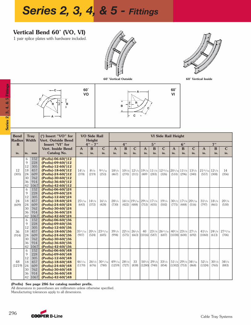
Bend Tray (*) Insert "VO" for VO Side Rail VI Side Rail HeightRadius Width Vert. Outside Bend Height
R Insert "VI" for 4" - 7" 4" 5" 6" 7"Vert. Inside Bend A B C A B C A B C A B C A B C
in. in. mm Catalog No. in. in. in. in. in. in. in. in. in. in. in. in. in. in. in.
6 152 (Prefix)-06-60(*)129 228 (Prefix)-09-60(*)1212 305 (Prefix)-12-60(*)1218 457 (Prefix)-18-60(*)1224 609 (Prefix)-24-60(*)1230 762 (Prefix)-30-60(*)1236 914 (Prefix)-36-60(*)1242 1067 (Prefix)-42-60(*)126 152 (Prefix)-06-60(*)249 228 (Prefix)-09-60(*)2412 305 (Prefix)-12-60(*)2418 457 (Prefix)-18-60(*)2424 609 (Prefix)-24-60(*)2430 762 (Prefix)-30-60(*)2436 914 (Prefix)-36-60(*)2442 1067 (Prefix)-42-60(*)246 152 (Prefix)-06-60(*)369 228 (Prefix)-09-60(*)3612 305 (Prefix)-12-60(*)3618 457 (Prefix)-18-60(*)3624 609 (Prefix)-24-60(*)3630 762 (Prefix)-30-60(*)3636 914 (Prefix)-36-60(*)3642 1067 (Prefix)-42-60(*)366 152 (Prefix)-06-60(*)489 228 (Prefix)-09-60(*)4812 305 (Prefix)-12-60(*)4818 457 (Prefix)-18-60(*)4824 609 (Prefix)-24-60(*)4830 762 (Prefix)-30-60(*)4836 914 (Prefix)-36-60(*)4842 1067 (Prefix)-42-60(*)48
296
60˚ Vertical Inside
3511/16 205/8 2313/16 391/8 225/8 261/8 40 231/8 2611/16 407/8 235/8 271/4 413/4 241/8 2713/16
(907) (524) (605) (994) (575) (663) (1016) (587) (687) (1038) (600) (692) (1060) (613) (706)
147/8 85/8 915/16 183/8 105/8 121/4 191/4 111/8 1213/16 201/16 115/8 133/8 2115/16 121/8 14(378) (219) (253) (467) (270) (311) (489 (283) (326) (510) (296) (340) (557) (308) (356)
461/16 265/8 3011/16 499/16 285/8 33 503/8 291/8 335/8 511/4 295/8 343/16 521/8 301/8 343/4
(1170) (676) (780) (1259) (727) (838) (1280) (740) (854) (1302) (753) (868) (1324) (765) (883)
255/16 145/8 167/8 283/4 165/8 193/16 295/8 171/8 193/4 301/2 175/8 205/16 313/8 181/8 207/8
(643) (372) (428) (730) (422) (488) (753) (435) (502) (775) (448) (516) (797) (461) (530)
12(305)
24(609)
36(914)
48(1219)
Vertical Bend 60˚ (VO, VI)1 pair splice plates with hardware included.
60˚ Vertical Outside
A
C
C
3" (76)RB
A
C
C
3" (
76) R
60˚VI
60˚VO
(Prefix) See page 286 for catalog number prefix.All dimensions in parentheses are millimeters unless otherwise specified.Manufacturing tolerances apply to all dimensions.
B
Series 2, 3, 4, & 5 - Fittings
Cable Tray Systems
Ser
ies
2, 3, 4, &
5 F
ittin
gs
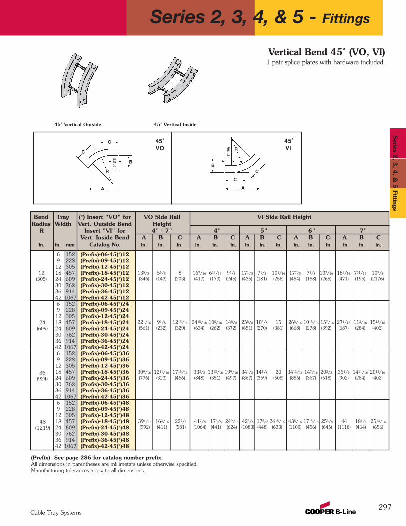
Bend Tray (*) Insert "VO" for VO Side Rail VI Side Rail HeightRadius Width Vert. Outside Bend Height
R Insert "VI" for 4" - 7" 4" 5" 6" 7"Vert. Inside Bend A B C A B C A B C A B C A B C
in. in. mm Catalog No. in. in. in. in. in. in. in. in. in. in. in. in. in. in. in.
6 152 (Prefix)-06-45(*)129 228 (Prefix)-09-45(*)1212 305 (Prefix)-12-45(*)1218 457 (Prefix)-18-45(*)1224 609 (Prefix)-24-45(*)1230 762 (Prefix)-30-45(*)1236 914 (Prefix)-36-45(*)1242 1067 (Prefix)-42-45(*)126 152 (Prefix)-06-45(*)249 228 (Prefix)-09-45(*)2412 305 (Prefix)-12-45(*)2418 457 (Prefix)-18-45(*)2424 609 (Prefix)-24-45(*)2430 762 (Prefix)-30-45(*)2436 914 (Prefix)-36-45(*)2442 1067 (Prefix)-42-45(*)246 152 (Prefix)-06-45(*)369 228 (Prefix)-09-45(*)3612 305 (Prefix)-12-45(*)3618 457 (Prefix)-18-45(*)3624 609 (Prefix)-24-45(*)3630 762 (Prefix)-30-45(*)3636 914 (Prefix)-36-45(*)3642 1067 (Prefix)-42-45(*)366 152 (Prefix)-06-45(*)489 228 (Prefix)-09-45(*)4812 305 (Prefix)-12-45(*)4818 457 (Prefix)-18-45(*)4824 609 (Prefix)-24-45(*)4830 762 (Prefix)-30-45(*)4836 914 (Prefix)-36-45(*)4842 1067 (Prefix)-42-45(*)48
297
45˚ Vertical Inside 45˚ Vertical Outside
309/16 1211/16 1715/16 333/8 1313/16 199/16 341/8 141/8 20 3413/16 147/16 203/8 351/2 1411/16 2013/16
(776) (323) (456) (848) (351) (497) (867) (359) (508) (885) (367) (518) (902) (284) (402)
135/8 55/8 8 167/16 613/16 95/8 171/8 71/8 101/16 177/8 73/8 107/16 189/16 711/16 107/8
(346) (143) (203) (417) (173) (245) (435) (181) (256) (454) (188) (265) (471) (195) (2176)
391/16 163/16 227/8 417/8 173/8 249/16 425/8 175/8 2415/16 435/16 1715/16 253/8 44 181/4 2513/16
(992) (411) (581) (1064) (441) (624) (1083) (448) (633) (1100) (456) (645) (1118) (464) (656)
221/16 91/8 1215/16 2415/16 105/16 145/8 255/8 105/8 15 265/16 1015/16 157/16 271/16 113/16 1513/16
(561) (232) (329) (634) (262) (372) (651) (270) (381) (668) (278) (392) (687) (284) (402)
12(305)
24(609)
36(924)
48(1219)
Vertical Bend 45˚ (VO, VI) 1 pair splice plates with hardware included.
B
A
C
C
3" (
76)
RB
A
C
C
3" (
76) R
45˚VO
45˚VI
(Prefix) See page 286 for catalog number prefix.All dimensions in parentheses are millimeters unless otherwise specified.Manufacturing tolerances apply to all dimensions.
Series 2, 3, 4, & 5 - Fittings
Cable Tray Systems
Series 2
, 3, 4
, & 5
Fittings
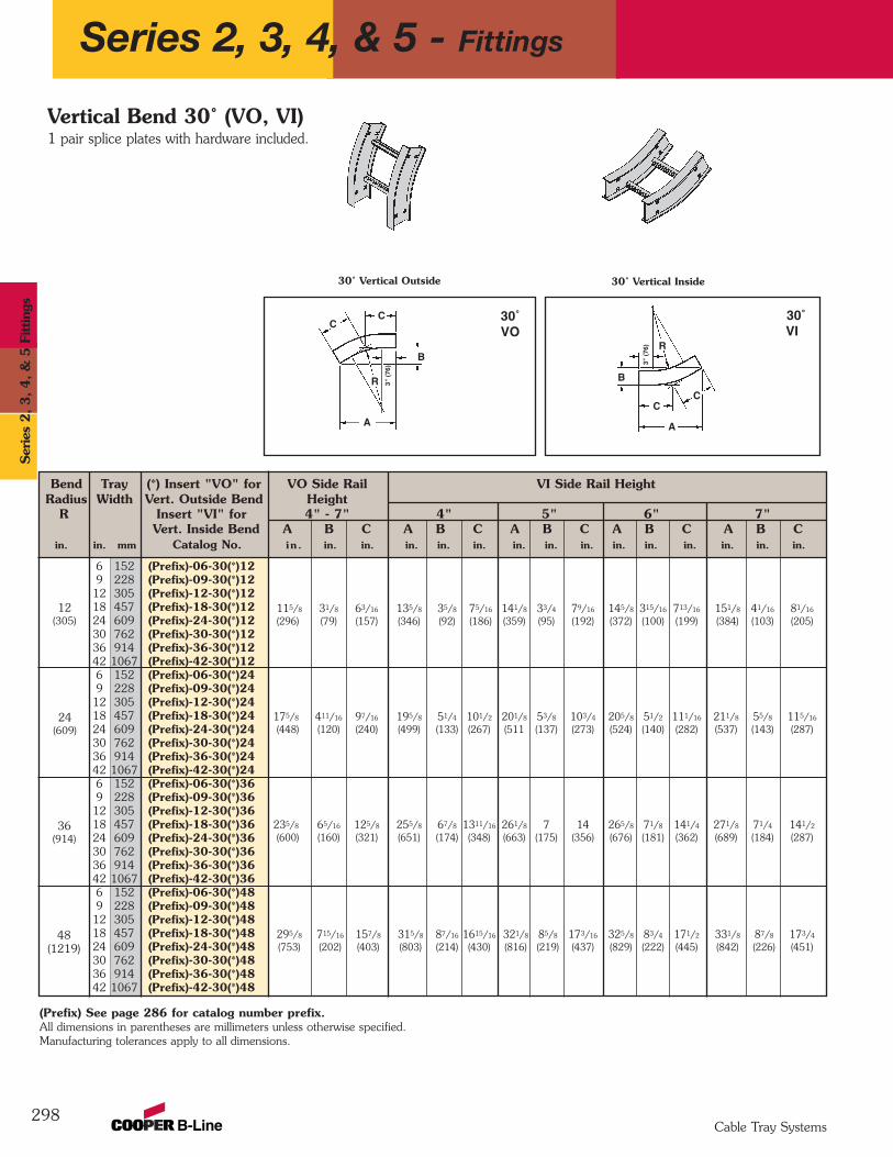
Bend Tray (*) Insert "VO" for VO Side Rail VI Side Rail HeightRadius Width Vert. Outside Bend Height
R Insert "VI" for 4" - 7" 4" 5" 6" 7"Vert. Inside Bend A B C A B C A B C A B C A B C
in. in. mm Catalog No. in . in. in. in. in. in. in. in. in. in. in. in. in. in. in.
6 152 (Prefix)-06-30(*)129 228 (Prefix)-09-30(*)1212 305 (Prefix)-12-30(*)1218 457 (Prefix)-18-30(*)1224 609 (Prefix)-24-30(*)1230 762 (Prefix)-30-30(*)1236 914 (Prefix)-36-30(*)1242 1067 (Prefix)-42-30(*)126 152 (Prefix)-06-30(*)249 228 (Prefix)-09-30(*)2412 305 (Prefix)-12-30(*)2418 457 (Prefix)-18-30(*)2424 609 (Prefix)-24-30(*)2430 762 (Prefix)-30-30(*)2436 914 (Prefix)-36-30(*)2442 1067 (Prefix)-42-30(*)246 152 (Prefix)-06-30(*)369 228 (Prefix)-09-30(*)3612 305 (Prefix)-12-30(*)3618 457 (Prefix)-18-30(*)3624 609 (Prefix)-24-30(*)3630 762 (Prefix)-30-30(*)3636 914 (Prefix)-36-30(*)3642 1067 (Prefix)-42-30(*)366 152 (Prefix)-06-30(*)489 228 (Prefix)-09-30(*)4812 305 (Prefix)-12-30(*)4818 457 (Prefix)-18-30(*)4824 609 (Prefix)-24-30(*)4830 762 (Prefix)-30-30(*)4836 914 (Prefix)-36-30(*)4842 1067 (Prefix)-42-30(*)48
298
30˚ Vertical Outside 30˚ Vertical Inside
235/8 65/16 125/8 255/8 67/8 1311/16 261/8 7 14 265/8 71/8 141/4 271/8 71/4 141/2
(600) (160) (321) (651) (174) (348) (663) (175) (356) (676) (181) (362) (689) (184) (287)
115/8 31/8 63/16 135/8 35/8 75/16 141/8 33/4 79/16 145/8 315/16 713/16 151/8 41/16 81/16
(296) (79) (157) (346) (92) (186) (359) (95) (192) (372) (100) (199) (384) (103) (205)
295/8 715/16 157/8 315/8 87/16 1615/16 321/8 85/8 173/16 325/8 83/4 171/2 331/8 87/8 173/4
(753) (202) (403) (803) (214) (430) (816) (219) (437) (829) (222) (445) (842) (226) (451)
175/8 411/16 97/16 195/8 51/4 101/2 201/8 53/8 103/4 205/8 51/2 111/16 211/8 55/8 115/16
(448) (120) (240) (499) (133) (267) (511 (137) (273) (524) (140) (282) (537) (143) (287)
12(305)
24(609)
36(914)
48(1219)
Vertical Bend 30˚ (VO, VI)1 pair splice plates with hardware included.
B
A
CC
RB
A
CC
3" (
76)
R
30˚VO
30˚VI
(Prefix) See page 286 for catalog number prefix.All dimensions in parentheses are millimeters unless otherwise specified.Manufacturing tolerances apply to all dimensions.
3" (
76)
Series 2, 3, 4, & 5 - Fittings
Cable Tray Systems
Ser
ies
2, 3, 4, &
5 F
ittin
gs
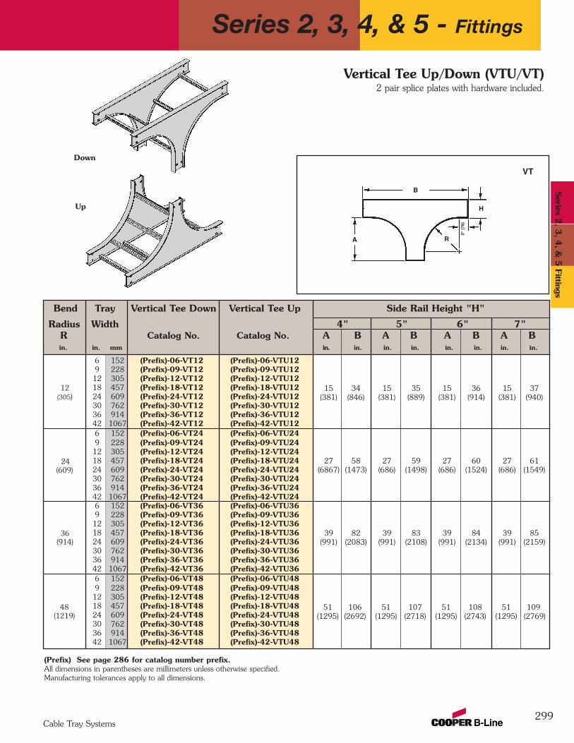
Bend Tray Vertical Tee Down Vertical Tee Up Side Rail Height "H"
Radius Width 4" 5" 6" 7"R Catalog No. Catalog No. A B A B A B A Bin. in. mm in. in. in. in. in. in. in. in.
6 152 (Prefix)-06-VT12 (Prefix)-06-VTU129 228 (Prefix)-09-VT12 (Prefix)-09-VTU1212 305 (Prefix)-12-VT12 (Prefix)-12-VTU1218 457 (Prefix)-18-VT12 (Prefix)-18-VTU1224 609 (Prefix)-24-VT12 (Prefix)-24-VTU1230 762 (Prefix)-30-VT12 (Prefix)-30-VTU1236 914 (Prefix)-36-VT12 (Prefix)-36-VTU1242 1067 (Prefix)-42-VT12 (Prefix)-42-VTU126 152 (Prefix)-06-VT24 (Prefix)-06-VTU249 228 (Prefix)-09-VT24 (Prefix)-09-VTU2412 305 (Prefix)-12-VT24 (Prefix)-12-VTU2418 457 (Prefix)-18-VT24 (Prefix)-18-VTU2424 609 (Prefix)-24-VT24 (Prefix)-24-VTU2430 762 (Prefix)-30-VT24 (Prefix)-30-VTU2436 914 (Prefix)-36-VT24 (Prefix)-36-VTU2442 1067 (Prefix)-42-VT24 (Prefix)-42-VTU246 152 (Prefix)-06-VT36 (Prefix)-06-VTU369 228 (Prefix)-09-VT36 (Prefix)-09-VTU3612 305 (Prefix)-12-VT36 (Prefix)-12-VTU3618 457 (Prefix)-18-VT36 (Prefix)-18-VTU3624 609 (Prefix)-24-VT36 (Prefix)-24-VTU3630 762 (Prefix)-30-VT36 (Prefix)-30-VTU3636 914 (Prefix)-36-VT36 (Prefix)-36-VTU3642 1067 (Prefix)-42-VT36 (Prefix)-42-VTU366 152 (Prefix)-06-VT48 (Prefix)-06-VTU489 228 (Prefix)-09-VT48 (Prefix)-09-VTU4812 305 (Prefix)-12-VT48 (Prefix)-12-VTU4818 457 (Prefix)-18-VT48 (Prefix)-18-VTU4824 609 (Prefix)-24-VT48 (Prefix)-24-VTU4830 762 (Prefix)-30-VT48 (Prefix)-30-VTU4836 914 (Prefix)-36-VT48 (Prefix)-36-VTU4842 1067 (Prefix)-42-VT48 (Prefix)-42-VTU48
299
Up
Down
51 106 51 107 51 108 51 109(1295) (2692) (1295) (2718) (1295) (2743) (1295) (2769)
39 82 39 83 39 84 39 85(991) (2083) (991) (2108) (991) (2134) (991) (2159)
27 58 27 59 27 60 27 61(6867) (1473) (686) (1498) (686) (1524) (686) (1549)
15 34 15 35 15 36 15 37(381) (846) (381) (889) (381) (914) (381) (940)
36(914)
12(305)
48(1219)
B
A
H
R
Vertical Tee Up/Down (VTU/VT)2 pair splice plates with hardware included.
VT
(Prefix) See page 286 for catalog number prefix.All dimensions in parentheses are millimeters unless otherwise specified.Manufacturing tolerances apply to all dimensions.
24(609)
3" (
76)
Series 2, 3, 4, & 5 - Fittings
Cable Tray Systems
Series 2
, 3, 4
, & 5
Fittings
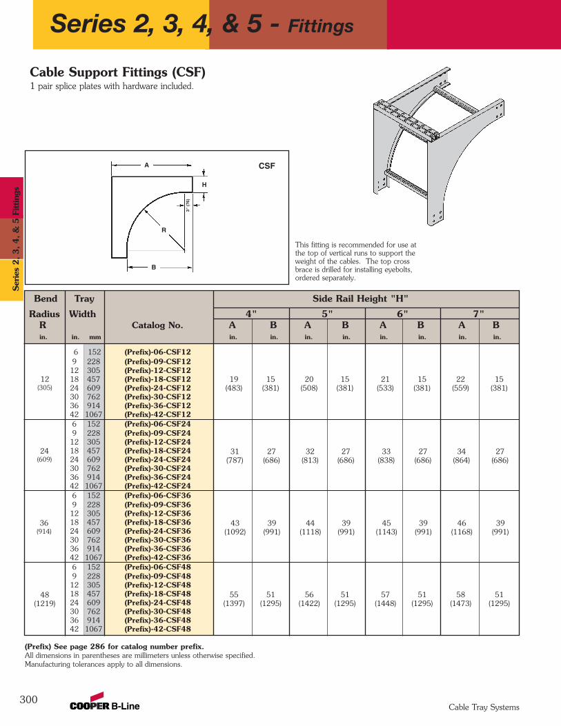
Bend Tray Side Rail Height "H"
Radius Width 4" 5" 6" 7"R Catalog No. A B A B A B A Bin. in. mm in. in. in. in. in. in. in. in.
6 152 (Prefix)-06-CSF129 228 (Prefix)-09-CSF1212 305 (Prefix)-12-CSF1218 457 (Prefix)-18-CSF1224 609 (Prefix)-24-CSF1230 762 (Prefix)-30-CSF1236 914 (Prefix)-36-CSF1242 1067 (Prefix)-42-CSF126 152 (Prefix)-06-CSF249 228 (Prefix)-09-CSF2412 305 (Prefix)-12-CSF2418 457 (Prefix)-18-CSF2424 609 (Prefix)-24-CSF2430 762 (Prefix)-30-CSF2436 914 (Prefix)-36-CSF2442 1067 (Prefix)-42-CSF246 152 (Prefix)-06-CSF369 228 (Prefix)-09-CSF3612 305 (Prefix)-12-CSF3618 457 (Prefix)-18-CSF3624 609 (Prefix)-24-CSF3630 762 (Prefix)-30-CSF3636 914 (Prefix)-36-CSF3642 1067 (Prefix)-42-CSF366 152 (Prefix)-06-CSF489 228 (Prefix)-09-CSF4812 305 (Prefix)-12-CSF4818 457 (Prefix)-18-CSF4824 609 (Prefix)-24-CSF4830 762 (Prefix)-30-CSF4836 914 (Prefix)-36-CSF4842 1067 (Prefix)-42-CSF48
300
This fitting is recommended for use atthe top of vertical runs to support theweight of the cables. The top crossbrace is drilled for installing eyebolts,ordered separately.
55 51 56 51 57 51 58 51(1397) (1295) (1422) (1295) (1448) (1295) (1473) (1295)
43 39 44 39 45 39 46 39(1092) (991) (1118) (991) (1143) (991) (1168) (991)
31 27 32 27 33 27 34 27(787) (686) (813) (686) (838) (686) (864) (686)
19 15 20 15 21 15 22 15(483) (381) (508) (381) (533) (381) (559) (381)
36(914)
24(609)
12(305)
48(1219)
B
A
H3"
(76
)
R
Cable Support Fittings (CSF)1 pair splice plates with hardware included.
CSF
(Prefix) See page 286 for catalog number prefix. All dimensions in parentheses are millimeters unless otherwise specified.Manufacturing tolerances apply to all dimensions.
Series 2, 3, 4, & 5 - Fittings
Cable Tray Systems
Ser
ies
2, 3, 4, &
5 F
ittin
gs
301
Notes
Cable Tray Systems
Series 2
, 3, 4
, & 5
Fittings

302
FiberglassFi
berg
lass
Cable Tray Systems
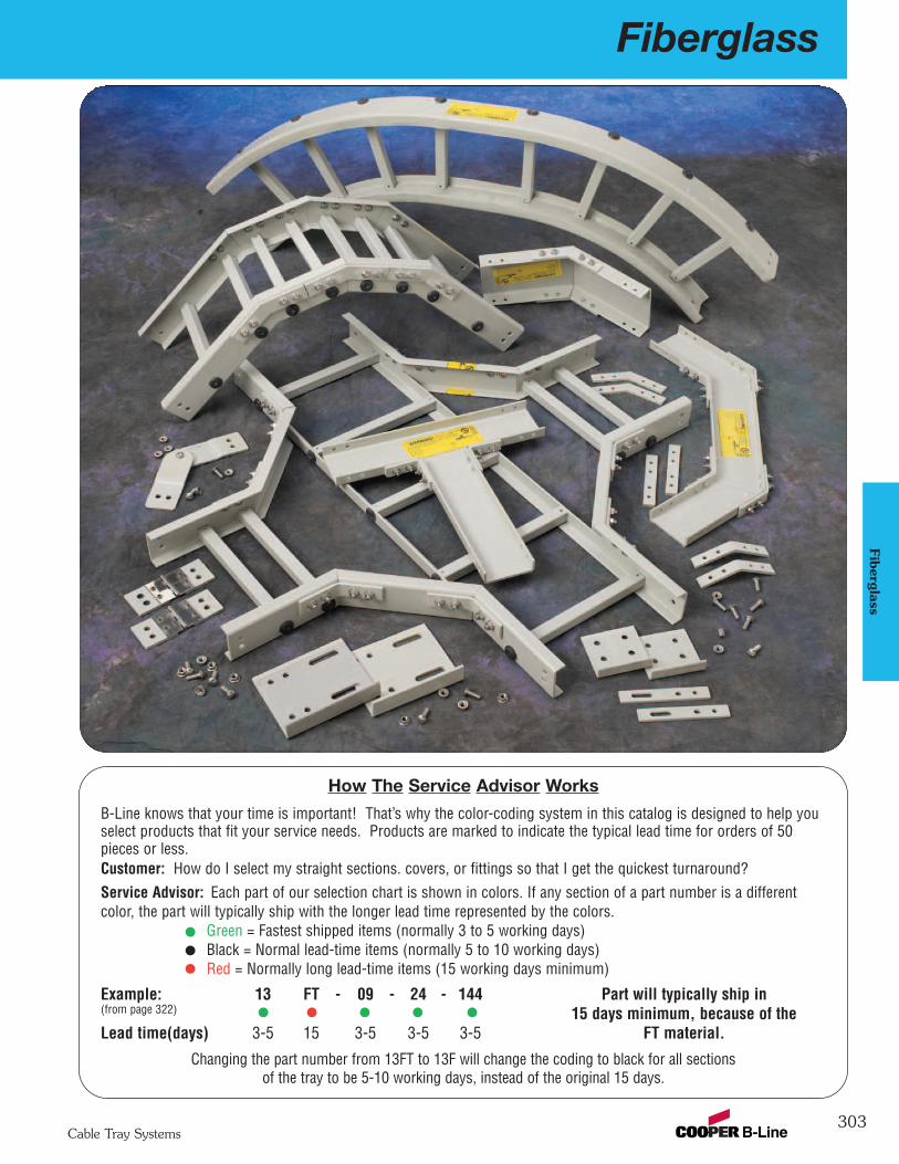
Fiberglass
303
Fiberglass
Cable Tray Systems
How The Service Advisor Works
B-Line knows that your time is important! That’s why the color-coding system in this catalog is designed to help youselect products that fit your service needs. Products are marked to indicate the typical lead time for orders of 50pieces or less.Customer: How do I select my straight sections. covers, or fittings so that I get the quickest turnaround?Service Advisor: Each part of our selection chart is shown in colors. If any section of a part number is a differentcolor, the part will typically ship with the longer lead time represented by the colors.
Green = Fastest shipped items (normally 3 to 5 working days)Black = Normal lead-time items (normally 5 to 10 working days)Red = Normally long lead-time items (15 working days minimum)
Example: 13 FT - 09 - 24 - 144 Part will typically ship in(from page 322) 15 days minimum, because of the Lead time(days) 3-5 15 3-5 3-5 3-5 FT material.
Changing the part number from 13FT to 13F will change the coding to black for all sectionsof the tray to be 5-10 working days, instead of the original 15 days.
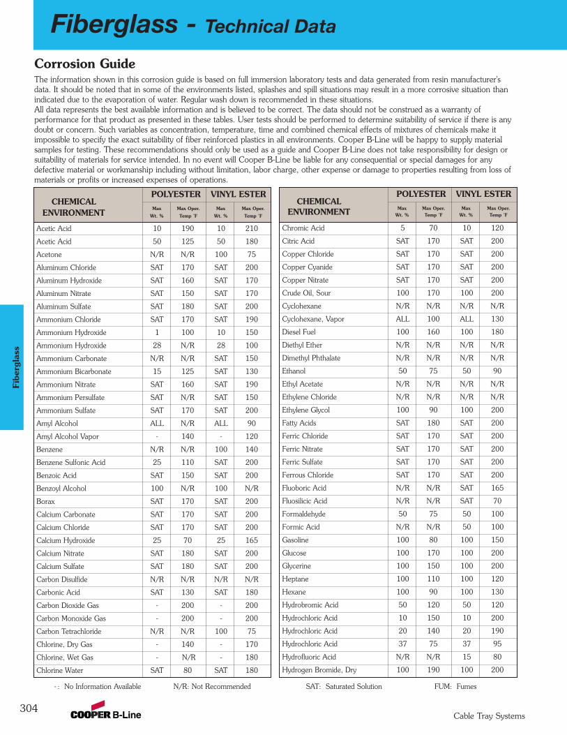
304
Fiberglass - Technical Data
Cable Tray Systems
Fibe
rgla
ss
Acetic Acid 10 190 10 210
Acetic Acid 50 125 50 180
Acetone N/R N/R 100 75
Aluminum Chloride SAT 170 SAT 200
Aluminum Hydroxide SAT 160 SAT 170
Aluminum Nitrate SAT 150 SAT 170
Aluminum Sulfate SAT 180 SAT 200
Ammonium Chloride SAT 170 SAT 190
Ammonium Hydroxide 1 100 10 150
Ammonium Hydroxide 28 N/R 28 100
Ammonium Carbonate N/R N/R SAT 150
Ammonium Bicarbonate 15 125 SAT 130
Ammonium Nitrate SAT 160 SAT 190
Ammonium Persulfate SAT N/R SAT 150
Ammonium Sulfate SAT 170 SAT 200
Amyl Alcohol ALL N/R ALL 90
Amyl Alcohol Vapor - 140 - 120
Benzene N/R N/R 100 140
Benzene Sulfonic Acid 25 110 SAT 200
Benzoic Acid SAT 150 SAT 200
Benzoyl Alcohol 100 N/R 100 N/R
Borax SAT 170 SAT 200
Calcium Carbonate SAT 170 SAT 200
Calcium Chloride SAT 170 SAT 200
Calcium Hydroxide 25 70 25 165
Calcium Nitrate SAT 180 SAT 200
Calcium Sulfate SAT 180 SAT 200
Carbon Disulfide N/R N/R N/R N/R
Carbonic Acid SAT 130 SAT 180
Carbon Dioxide Gas - 200 - 200
Carbon Monoxide Gas - 200 - 200
Carbon Tetrachloride N/R N/R 100 75
Chlorine, Dry Gas - 140 - 170
Chlorine, Wet Gas - N/R - 180
Chlorine Water SAT 80 SAT 180
POLYESTER VINYL ESTERCHEMICAL
Max Max Oper. Max Max Oper.ENVIRONMENT Wt. % Temp ˚F Wt. % Temp ˚F
Corrosion GuideThe information shown in this corrosion guide is based on full immersion laboratory tests and data generated from resin manufacturer'sdata. It should be noted that in some of the environments listed, splashes and spill situations may result in a more corrosive situation thanindicated due to the evaporation of water. Regular wash down is recommended in these situations.All data represents the best available information and is believed to be correct. The data should not be construed as a warranty ofperformance for that product as presented in these tables. User tests should be performed to determine suitability of service if there is anydoubt or concern. Such variables as concentration, temperature, time and combined chemical effects of mixtures of chemicals make itimpossible to specify the exact suitability of fiber reinforced plastics in all environments. Cooper B-Line will be happy to supply materialsamples for testing. These recommendations should only be used as a guide and Cooper B-Line does not take responsibility for design orsuitability of materials for service intended. In no event will Cooper B-Line be liable for any consequential or special damages for anydefective material or workmanship including without limitation, labor charge, other expense or damage to properties resulting from loss ofmaterials or profits or increased expenses of operations.
Chromic Acid 5 70 10 120
Citric Acid SAT 170 SAT 200
Copper Chloride SAT 170 SAT 200
Copper Cyanide SAT 170 SAT 200
Copper Nitrate SAT 170 SAT 200
Crude Oil, Sour 100 170 100 200
Cyclohexane N/R N/R N/R N/R
Cyclohexane, Vapor ALL 100 ALL 130
Diesel Fuel 100 160 100 180
Diethyl Ether N/R N/R N/R N/R
Dimethyl Phthalate N/R N/R N/R N/R
Ethanol 50 75 50 90
Ethyl Acetate N/R N/R N/R N/R
Ethylene Chloride N/R N/R N/R N/R
Ethylene Glycol 100 90 100 200
Fatty Acids SAT 180 SAT 200
Ferric Chloride SAT 170 SAT 200
Ferric Nitrate SAT 170 SAT 200
Ferric Sulfate SAT 170 SAT 200
Ferrous Chloride SAT 170 SAT 200
Fluoboric Acid N/R N/R SAT 165
Fluosilicic Acid N/R N/R SAT 70
Formaldehyde 50 75 50 100
Formic Acid N/R N/R 50 100
Gasoline 100 80 100 150
Glucose 100 170 100 200
Glycerine 100 150 100 200
Heptane 100 110 100 120
Hexane 100 90 100 130
Hydrobromic Acid 50 120 50 120
Hydrochloric Acid 10 150 10 200
Hydrochloric Acid 20 140 20 190
Hydrochloric Acid 37 75 37 95
Hydrofluoric Acid N/R N/R 15 80
Hydrogen Bromide, Dry 100 190 100 200
POLYESTER VINYL ESTERCHEMICAL
Max Max Oper. Max Max Oper.ENVIRONMENT Wt. % Temp ˚F Wt. % Temp ˚F
- : No Information Available N/R: Not Recommended SAT: Saturated Solution FUM: Fumes
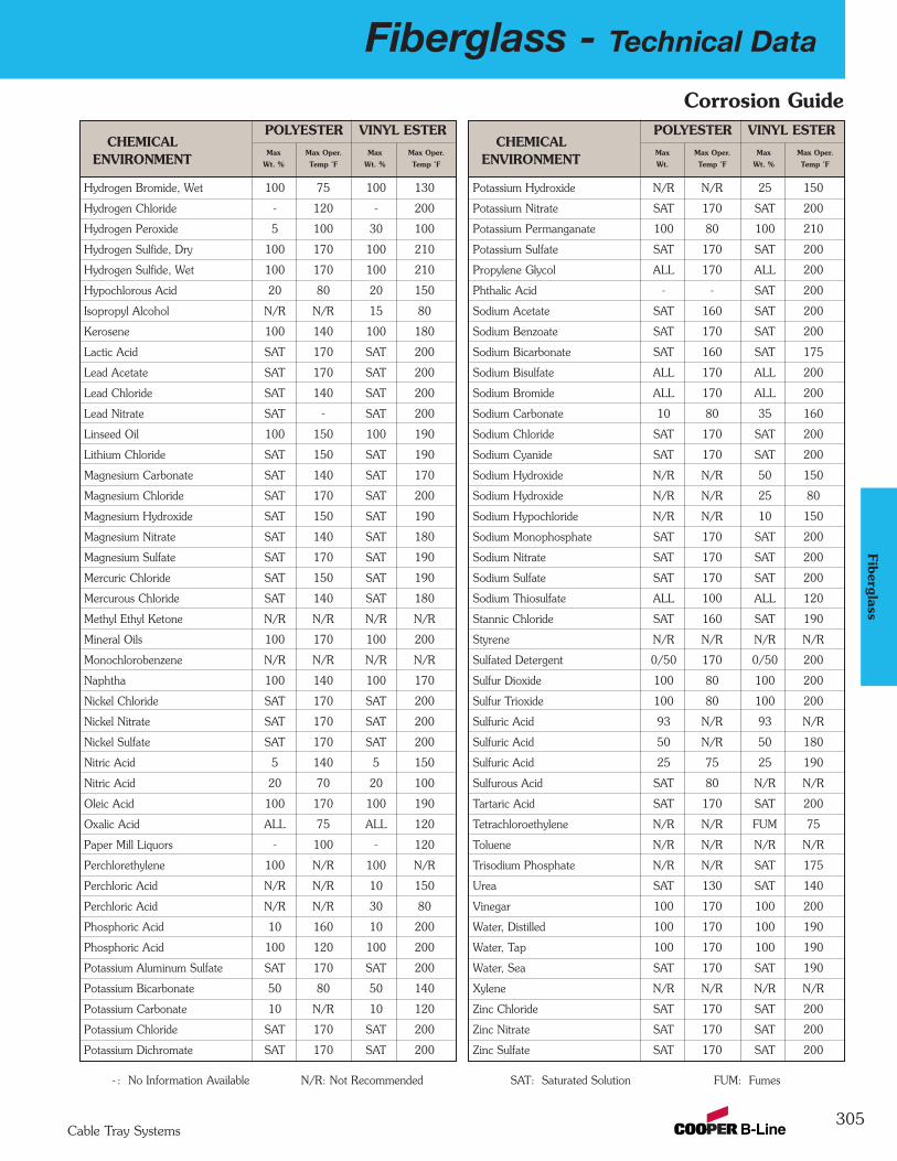
Fiberglass - Technical Data
305Cable Tray Systems
Fiberglass
Corrosion Guide
Hydrogen Bromide, Wet 100 75 100 130
Hydrogen Chloride - 120 - 200
Hydrogen Peroxide 5 100 30 100
Hydrogen Sulfide, Dry 100 170 100 210
Hydrogen Sulfide, Wet 100 170 100 210
Hypochlorous Acid 20 80 20 150
Isopropyl Alcohol N/R N/R 15 80
Kerosene 100 140 100 180
Lactic Acid SAT 170 SAT 200
Lead Acetate SAT 170 SAT 200
Lead Chloride SAT 140 SAT 200
Lead Nitrate SAT - SAT 200
Linseed Oil 100 150 100 190
Lithium Chloride SAT 150 SAT 190
Magnesium Carbonate SAT 140 SAT 170
Magnesium Chloride SAT 170 SAT 200
Magnesium Hydroxide SAT 150 SAT 190
Magnesium Nitrate SAT 140 SAT 180
Magnesium Sulfate SAT 170 SAT 190
Mercuric Chloride SAT 150 SAT 190
Mercurous Chloride SAT 140 SAT 180
Methyl Ethyl Ketone N/R N/R N/R N/R
Mineral Oils 100 170 100 200
Monochlorobenzene N/R N/R N/R N/R
Naphtha 100 140 100 170
Nickel Chloride SAT 170 SAT 200
Nickel Nitrate SAT 170 SAT 200
Nickel Sulfate SAT 170 SAT 200
Nitric Acid 5 140 5 150
Nitric Acid 20 70 20 100
Oleic Acid 100 170 100 190
Oxalic Acid ALL 75 ALL 120
Paper Mill Liquors - 100 - 120
Perchlorethylene 100 N/R 100 N/R
Perchloric Acid N/R N/R 10 150
Perchloric Acid N/R N/R 30 80
Phosphoric Acid 10 160 10 200
Phosphoric Acid 100 120 100 200
Potassium Aluminum Sulfate SAT 170 SAT 200
Potassium Bicarbonate 50 80 50 140
Potassium Carbonate 10 N/R 10 120
Potassium Chloride SAT 170 SAT 200
Potassium Dichromate SAT 170 SAT 200
Potassium Hydroxide N/R N/R 25 150
Potassium Nitrate SAT 170 SAT 200
Potassium Permanganate 100 80 100 210
Potassium Sulfate SAT 170 SAT 200
Propylene Glycol ALL 170 ALL 200
Phthalic Acid - - SAT 200
Sodium Acetate SAT 160 SAT 200
Sodium Benzoate SAT 170 SAT 200
Sodium Bicarbonate SAT 160 SAT 175
Sodium Bisulfate ALL 170 ALL 200
Sodium Bromide ALL 170 ALL 200
Sodium Carbonate 10 80 35 160
Sodium Chloride SAT 170 SAT 200
Sodium Cyanide SAT 170 SAT 200
Sodium Hydroxide N/R N/R 50 150
Sodium Hydroxide N/R N/R 25 80
Sodium Hypochloride N/R N/R 10 150
Sodium Monophosphate SAT 170 SAT 200
Sodium Nitrate SAT 170 SAT 200
Sodium Sulfate SAT 170 SAT 200
Sodium Thiosulfate ALL 100 ALL 120
Stannic Chloride SAT 160 SAT 190
Styrene N/R N/R N/R N/R
Sulfated Detergent 0/50 170 0/50 200
Sulfur Dioxide 100 80 100 200
Sulfur Trioxide 100 80 100 200
Sulfuric Acid 93 N/R 93 N/R
Sulfuric Acid 50 N/R 50 180
Sulfuric Acid 25 75 25 190
Sulfurous Acid SAT 80 N/R N/R
Tartaric Acid SAT 170 SAT 200
Tetrachloroethylene N/R N/R FUM 75
Toluene N/R N/R N/R N/R
Trisodium Phosphate N/R N/R SAT 175
Urea SAT 130 SAT 140
Vinegar 100 170 100 200
Water, Distilled 100 170 100 190
Water, Tap 100 170 100 190
Water, Sea SAT 170 SAT 190
Xylene N/R N/R N/R N/R
Zinc Chloride SAT 170 SAT 200
Zinc Nitrate SAT 170 SAT 200
Zinc Sulfate SAT 170 SAT 200
POLYESTER VINYL ESTERCHEMICAL
Max Max Oper. Max Max Oper.ENVIRONMENT Wt. % Temp ˚F Wt. % Temp ˚F
POLYESTER VINYL ESTERCHEMICAL
Max Max Oper. Max Max Oper.ENVIRONMENT Wt. Temp ˚F Wt. % Temp ˚F
- : No Information Available N/R: Not Recommended SAT: Saturated Solution FUM: Fumes
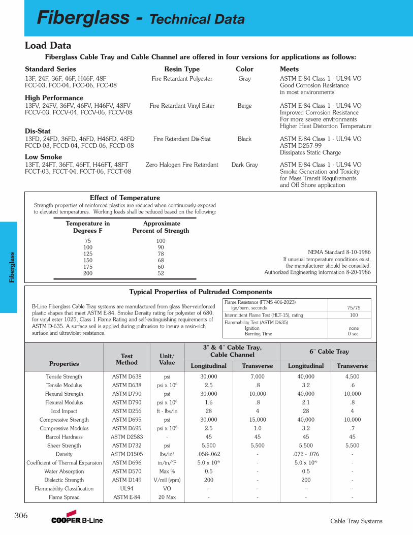
306
Fiberglass - Technical Data
Cable Tray Systems
Fibe
rgla
ss
NEMA Standard 8-10-1986 If unusual temperature conditions exist,the manufacturer should be consulted.
Authorized Engineering information 8-20-1986
Typical Properties of Pultruded Components
B-Line Fiberglass Cable Tray systems are manufactured from glass fiber-reinforced plastic shapes that meet ASTM E-84, Smoke Density rating for polyester of 680, for vinyl ester 1025, Class 1 Flame Rating and self-extinguishing requirements of ASTM D-635. A surface veil is applied during pultrusion to insure a resin-rich surface and ultraviolet resistance.
Test Unit/6" Cable Tray
Properties Method Value Longitudinal Transverse Longitudinal Transverse
Tensile Strength ASTM D638 psi 30,000 7,000 40,000 4,500
Tensile Modulus ASTM D638 psi x 106 2.5 .8 3.2 .6
Flexural Strength ASTM D790 psi 30,000 10,000 40,000 10,000
Flexural Modulus ASTM D790 psi x 106 1.6 .8 2.1 .8
Izod Impact ASTM D256 ft - lbs/in 28 4 28 4
Compressive Strength ASTM D695 psi 30,000 15,000 40,000 10,000
Compressive Modulus ASTM D695 psi x 106 2.5 1.0 3.2 .7
Barcol Hardness ASTM D2583 - 45 45 45 45
Sheer Strength ASTM D732 psi 5,500 5,500 5,500 5,500
Density ASTM D1505 lbs/in3 .058-.062 - .072 - .076 -
Coefficient of Thermal Expansion ASTM D696 in/in/˚F 5.0 x 10⁻⁶ - 5.0 x 10⁻⁶ -
Water Absorption ASTM D570 Max % 0.5 - 0.5 -
Dielectic Strength ASTM D149 V/mil (vpm) 200 - 200 -
Flammability Classification UL94 VO - - - -
Flame Spread ASTM E-84 20 Max - - - -
Load Data
Flame Resistance (FTMS 406-2023)ign/burn, seconds 75/75
Intermittent Flame Test (HLT-15), rating 100
Flammability Test (ASTM D635)Ignition noneBurning Time 0 sec.
3" & 4" Cable Tray, Cable Channel
Effect of TemperatureStrength properties of reinforced plastics are reduced when continuously exposedto elevated temperatures. Working loads shall be reduced based on the following:
Temperature in ApproximateDegrees F Percent of Strength
75 100100 90125 78150 68175 60200 52
Fiberglass Cable Tray and Cable Channel are offered in four versions for applications as follows:
Standard Series Resin Type Color Meets13F, 24F, 36F, 46F, H46F, 48F Fire Retardant Polyester Gray ASTM E-84 Class 1 - UL94 VOFCC-03, FCC-04, FCC-06, FCC-08 Good Corrosion Resistance
in most environmentsHigh Performance13FV, 24FV, 36FV, 46FV, H46FV, 48FV Fire Retardant Vinyl Ester Beige ASTM E-84 Class 1 - UL94 VOFCCV-03, FCCV-04, FCCV-06, FCCV-08 Improved Corrosion Resistance
For more severe environmentsHigher Heat Distortion Temperature
Dis-Stat13FD, 24FD, 36FD, 46FD, H46FD, 48FD Fire Retardant Dis-Stat Black ASTM E-84 Class 1 - UL94 VOFCCD-03, FCCD-04, FCCD-06, FCCD-08 ASTM D257-99
Dissipates Static ChargeLow Smoke13FT, 24FT, 36FT, 46FT, H46FT, 48FT Zero Halogen Fire Retardant Dark Gray ASTM E-84 Class 1 - UL94 VOFCCT-03, FCCT-04, FCCT-06, FCCT-08 Smoke Generation and Toxicity
for Mass Transit Requirementsand Off Shore application

Fiberglass - Technical Data
307Cable Tray Systems
Fiberglass
Warning! WalkwaysIt should be noted that cable tray is designed as a support for power or control cables, or both and is not intended or designed to be awalkway for personnel, the user is urged to display appropriate warnings cautioning against the use of this support as a walkway. The following language is suggested:
WARNING! Not to be used as a walkway, ladder or support for personnel. To be used only as a mechanical support for cables and tubing.
Authorized Engineering Information 8-20-1986
Standard B-Line Label
Structural Characteristics of Cable Tray and SupportsWhen viewed in its installed condition, anycable tray system performs functionally as a beam under a uniformly distributed load.There are four basic beam configurationstypically found in a cable tray installation. All four types of beams support cable traybut each differ in the way that the beam isattached to the support.The first two beam configurations, simpleand continuous, apply to the cable tray itself.The second two beam configurations, cantilever and fixed, apply more to the cabletray supports than to the cable tray itself.
Simple Beam A good example of simple beam is a singlestraight section of cable tray supported butnot fastened at either end. When the tray isloaded the cable tray is allowed to deflect.
Simply beam analysis is used almost universally for beam comparisons eventhough it is seldom practical in field installations. The three most prominent reasons for using a simple beam analysisare: calculations are simplified; it representsthe worst case loading; and testing is simpleand reliable. The published load data in theB-Line cable tray catalog is based on the simple beam analysis per NEMA StandardFG-1.
Continuous Beam Continuous beam is the beam configurationmost commonly used in cable tray installations. An example of this configurationis where cable trays are installed across several supports to form a number of spans.The continuous beam possesses traits of boththe simple and fixed beams.When equal loads are applied to all spanssimultaneously, the counterbalancing effect of the loads on both sides of a supportrestricts the movement of the cable tray atthe support. The effect is similar to that ofa fixed beam. The end spans behave substantially like simple beams. When cabletrays of identical design are compared, continuous beam installations will typicallyhave approximately half the deflection of asimple beam of the same span. Therefore,simple beam data should be used for a general comparison only.
Cantilever Beam A cantilever beam configuration occurs whenone end of the beam is rigidly attached to thesupport and the other end is unsupported.This type of configuration is typically usedwhen wall mounting a bracket to supportcable tray. Since one end is unsupported,
the cantilever beam will hold considerablyless load than a comparable simple beam.
Fixed Beam A fixed beam configuration has both ends ofthe beam rigidly attached to the supports. Agood example of a fixed beam is the rung ofa cable tray. By attaching the ends of therung to the side rails, the ends are not freeto move, bend or twist. This restriction inend movement effectively increases the load carrying capacity of the member.Fixed beam configurations are also typicallyfound in strut rack type support systems.These types of racks are found extensivelyin tunnel applications for support of pipeand cable tray.
CLASSIFIED
®
WARNING!Use Only As A Mechanical Support For Cables, Tubing and Raceways.
Do Not Use As A Walkway, Ladder,Or Support For Personnel.
VENTILATED09/05/2002
816 LIONS DRIVE
TROY, IL 62294
(618) 667-6779
Catalog Number: 24A09-12-144 STR SECTION(and description)
Shipping Ticket: 260203 00 001
Mark Number: 78101115400
Purchase Order: D798981
Minimum Area: 1.000 SQ. IN.
Load Class: D1 179 KG/M 3 METER SPANREFERENCE FILE # LR360266
This product is classified by Underwriters Laboratories, Inc. asto its suitability as an equipment grounding conductor only. 556E
3078
1011
1540
05
1 of 1
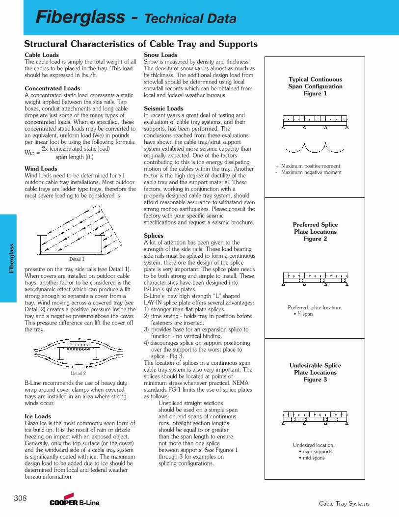
308
Fiberglass - Technical Data
Cable Tray Systems
Fibe
rgla
ss
Cable LoadsThe cable load is simply the total weight of allthe cables to be placed in the tray. This loadshould be expressed in lbs./ft.
Concentrated LoadsA concentrated static load represents a staticweight applied between the side rails. Tapboxes, conduit attachments and long cabledrops are just some of the many types ofconcentrated loads. When so specified, theseconcentrated static loads may be converted toan equivalent, uniform load (We) in poundsper linear foot by using the following formula:
We: = 2x (concentrated static load)
span length (ft.)
Wind LoadsWind loads need to be determined for all outdoor cable tray installations. Most outdoorcable trays are ladder type trays, therefore themost severe loading to be considered is
pressure on the tray side rails (see Detail 1).When covers are installed on outdoor cabletrays, another factor to be considered is theaerodynamic effect which can produce a liftstrong enough to separate a cover from atray. Wind moving across a covered tray (seeDetail 2) creates a positive pressure inside thetray and a negative pressure above the cover.This pressure difference can lift the cover offthe tray.
B-Line recommends the use of heavy dutywrap-around cover clamps when coveredtrays are installed in an area where strongwinds occur.
Ice LoadsGlaze ice is the most commonly seen form ofice build-up. It is the result of rain or drizzlefreezing on impact with an exposed object.Generally, only the top surface (or the cover)and the windward side of a cable tray systemis significantly coated with ice. The maximumdesign load to be added due to ice should bedetermined from local and federal weatherbureau information.
Snow LoadsSnow is measured by density and thickness.The density of snow varies almost as much asits thickness. The additional design load fromsnowfall should be determined using localsnowfall records which can be obtained fromlocal and federal weather bureaus.
Seismic LoadsIn recent years a great deal of testing andevaluation of cable tray systems, and theirsupports, has been performed. The conclusions reached from these evaluationshave shown the cable tray/strut support system exhibited more seismic capacity thanoriginally expected. One of the factors contributing to this is the energy dissipatingmotion of the cables within the tray. Anotherfactor is the high degree of ductility of thecable tray and the support material. Thesefactors, working in conjunction with a properly designed cable tray system, shouldafford reasonable assurance to withstand evenstrong motion earthquakes. Please consult thefactory with your specific seismic specifications and request a seismic brochure.
SplicesA lot of attention has been given to thestrength of the side rails. These load bearingside rails must be spliced to form a continuoussystem, therefore the design of the spliceplate is very important. The splice plate needsto be both strong and simple to install. Thesecharacteristics have been designed intoB-Line’s splice plates.B-Line’s new high strength “L" shapedLAY-IN splice plate offers several advantages:1) stronger than flat plate splices. 2) time saving - holds tray in position before
fasteners are inserted.3) provides base for an expansion splice to
function - no vertical binding.4) discourages splice on support-positioning,
over the support is the worst place tosplice - Fig 3.
The location of splices in a continuous spancable tray system is also very important. Thesplices should be located at points of minimum stress whenever practical. NEMAstandards FG-1 limits the use of splice platesas follows:
Unspliced straight sectionsshould be used on a simple spanand on end spans of continuousruns. Straight section lengthsshould be equal to or greaterthan the span length to ensurenot more than one splicebetween supports. See Figures 1through 3 for examples on splicing configurations.
Typical ContinuousSpan Configuration
Figure 1
+ Maximum positive moment- Maximum negative moment
Undesired location:• over supports • mid spans
Preferred splice location:• 1⁄4 span
Preferred SplicePlate Locations
Figure 2
Undesirable SplicePlate Locations
Figure 3
Structural Characteristics of Cable Tray and Supports
Detail 1
Detail 2

Fiberglass - Technical Data
309Cable Tray Systems
Fiberglass
Cable Tray Thermal Contraction and Expansion
Expansion or Contraction for Various Temperature DifferencesTemperature Differential Cable Tray Length Tray Length for
°F (°C) for 1" Expansion Each Expansion Connector*
25 (-4) 667 Feet (203.3m) 417 Feet (127.1m)50 (10) 333 Feet (101.5m) 208 Feet (63.4m)75 (24) 222 Feet (67.6m) 139 Feet (42.3m)100 (38) 167 Feet (50.9m) 104 Feet (31.7m)125 (51) 133 Feet (40.5m) 83 Feet (25.3m)150 (65) 111 Feet (33.8m) 69 Feet (21.0m)175 (79) 95 Feet (28.9m) 59 Feet (18.0m)
Note for gap set and hold down/guide location, see installation instruction above.*1" (25.4mm) slotted holes in each expansion connector allow 5⁄8" (15.9mm) total expansion or contraction.
Authorized Engineering Information 8-20-1986
1
2
3
4
It is important that thermal contractionand expansion be considered wheninstalling cable tray systems. Thelength of the straight cable tray runsand the temperature differential governthe number of expansion splice platesrequired (see Table 1 below).
The cable tray should be anchored atthe support nearest to its midpointbetween the expansion splice platesand secured by expansion guides at allother support locations (see Figure 1 -Typical Cable Tray Installation). Thecable tray should be permitted longitudinal movement in both directions from that fixed point.
Accurate gap settings at the time ofinstallation is necessary for the properoperation of the expansion spliceplates. The following procedure shouldassist the installer in determining thecorrect gap: (see Figure 2 - GapSetting)
Plot the highest expected traytemperature on the maximumtemperature line.Plot the lowest expected tray temperature on the minimumtemperature line.Draw a line between the maximum and minimum points.Plot the tray temperature at thetime of installation to determinethe gap setting.
C° F° F° C°
Maximum MinimumTemperature Temperature
130
70
50
30
10
-10
-30
90
110
130
110
90
70
50
30
10
-10
-30
50
40
30
20
10
0
-10
-20
-30
-40
50
40
30
20
10
0
-10
-20
-30
-40
1/8
(3.2)1/4
(6.3)3/8
(9.5)1/2
(12.7)
0(0.0)
5/8
(15.9)GAP SETTINGInches (mm)
Tray
Tem
pera
ture
At
Tim
e O
f In
stal
latio
n
X -- -- -- -- X -- -- -- -- X
X -- -- -- -- X -- -- -- -- X
Typical Cable Tray Installation
X : Denotes hold-down clamp (anchor) at support._ : Denotes expansion guide clamp at support.
Expansion Splice Plates
Figure 2
Table 1
Figure 1
1
2
3
4

310
Fiberglass - Technical Data
Cable Tray Systems
Fibe
rgla
ss
Recommended Fiberglass Trapeze Hanging SystemsNotes:1) A snug three to four ft.-lbs. torque is sufficient for all thread rod nuts.2) When supporting cable tray, the spacing between each trapeze should not exceed the distance between splice plates.3) When hanging from beam, B-Line BFPU751 series clamps provide extra thread engagement necessary for load ratings. All thread rod
must be fully engaged in the clamp.4) Design load safety factor is 3:1
BF22A Strut:2" max between materialbeing supported and rod
BF22 Strut:2" max between materialbeing supported and rod
Installation of B-Line fiberglass cable tray should be made in accordance with the standards set by NEMAPublication VE-2, Cable Tray Installation Guide, and National Electrical Code, Article 318.
- Always observe common safety practices when assembling tray and fittings. Installations generally require some field cutting. Dustcreated during fabrication presents no serious health hazard, but skin irritation may be experienced by some workers.
- Operators of saws and drills should wear masks, long sleeve shirts or coveralls.- Fabrication with fiberglass is relatively easy and comparable to working with wood. Ordinary hand tools may be used in most cases.- Avoid excessive pressure when sawing or drilling. Too much force can rapidly dull tools and also produce excessive heat which
softens the bonding resin in the fiberglass resulting in a ragged edge rather than a clean-cut edge.- Field cutting is simple and can be accomplished with a circular power saw with an abrasive cut-off wheel (masonry type) or hack saw
(24 to 32 teeth per inch).- Drill fiberglass as you would drill hard wood. Standard twist drills are more than adequate.- Any surface that has been drilled, cut, sanded or otherwise broken, must be sealed with a compatible resin. (see page 347)- Carbide tipped saw blades and drill bits are recommended when cutting large quantities.- Support the fiberglass material firmly during cutting operations to keep material from shifting which may cause chipping at the
cut edge.- Each tray section length should be equal to or greater than the support span.- When possible, the splice should be located at quarter span.- Fittings should be supported as per NEMA FG-1.
Cable Tray Installation Guide
maximum uniform load1,500 lbs.
maximum uniform load500 lbs.
1⁄2" (13mm) Min.
40" (1016mm)Max.
2" (51mm)Min.
1⁄2" (13mm) Min.
40" (1016mm)Max.
2" (51mm)Min.
1⁄2" fiberglass all-thread rod (BFVATR 1⁄2)
fiberglass ATR nut (BFVATRHN 1⁄2)
fiberglass spacer (BFV202)
BF22A fiberglass strut
fiberglass spacer (BFV202)
fiberglass ATR nut (BFVATRHN 1⁄2)
1⁄2" fiberglass all-thread rod (BFVATR 1⁄2)
fiberglass ATR nut (BFVATRHN 1⁄2)
fiberglass spacer (BFV202)
BF22 fiberglass strut
fiberglass spacer (BFV202)
fiberglass ATR nut (BFVATRHN 1⁄2)
For vinyl ester resin, ‘V’ must be added appropriately to part number. Example: BFV22A.

Fiberglass - Technical Data
311Cable Tray Systems
Fiberglass
Horizontal Cross
Horizontal Elbows
Horizontal Tee
Vertical Elbows
L
1/2L
2 ft. (.6M)
2 ft. (.6M)
2 ft. (.6M) 2 ft. (.6M)
2 f
t. (
.6M
)
2 ft. (.6M)2 ft.
(.6M
)
ø
ø
1/2ø
2/3R2/3R
ø = 30˚, 45˚, 60˚, 90˚
2 ft. (.6M)2 ft. (.6M)
2 ft. (.6M)2 ft. (.6M)
2 ft. (.6M)2 ft. (.6M)
22.5˚45˚
2 ft. (.6M)2 ft. (.6M)
2 f
t. (
.6M
)
2 ft.
(.6M
)
Based on the National Electrical Code - 1993, Section 318The National Electrical Code Article 318 was written primarily for verifying the cable fill in cable trays but little has been done to convert thisinformation into a design procedure.In the development of a complete cable tray support system, B-Line established a simple method of determining the right size tray to supportany given amount of cables. The following tables cover our method for determining cable tray widths based on tray design and system voltage.Table ITable I is subdivided into two categories covering electrical service of 2000 volts or less. The first, Category A, is for any mixture of power orlighting cables with any mixture of control or signal cables. Category B is used when control and/or signal cables only are being used.
Control Circuit - the circuit of a control apparatus or system that carries the electric signalsdirecting the performance of the controller, but does not carry the main power (NEC Article 100).Signaling Circuit - any electric circuit that energizes signaling equipment (NEC Article 100).
Table IITable II has only one category of electrical service and that is 2001 volts and over for types MV and MC cables both single and multiconductor.Type MV is a single or multiconductor solid dielectric insulated cable rated 2001 volts or higher (NEC Article 326).Type MC cable is a factory assembly of one or more conductors, each individually insulated and enclosed in a metallic sheath or interlockingtape, or a smooth or corrugated tube (NEC Article 334).Cables other than Types MV and MC can be installed provided they are "specifically approved for installation in cable trays."Table IIITable III covers 3, 4 and 6 inch ventilated cable channels.
Tray Sizing ProcedureStep 1. Select proper cable tray table below based on cable voltage and tray type.
Cable Voltage Cable Tray Type Use:
2000 Volts or less Ladder, Cable Tray Table I
2001 Volts or more Ladder, Cable Tray Table II
2001 Volts or less Cable Channel, ventilated Table III
Cable Tray Support Locations For Fittings
How To Size Cable Tray
per NEMA VE-2 Installation Guide
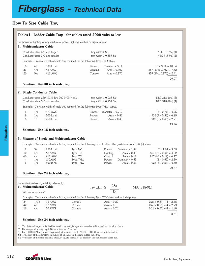
312
Fiberglass - Technical Data
Cable Tray Systems
Fibe
rgla
ss
Tables I - Ladder Cable Tray - for cables rated 2000 volts or less
For power or lighting or any mixture of power, lighting, control or signal cables:
1. Multiconductor Cable
Conductor sizes 4/0 and larger* tray width ≥ Sd NEC 318-9(a) (1)Conductor sizes 3/0 and smaller tray width ≥ 0.857 Sa NEC 318-9(a) (2)
Example: Calculate width of cable tray required for the following Type TC Cables.
6 4/c 500 kcmil Power: Diameter = 3.14 6 x 3.14 = 18.8421 4/c #8 AWG Lighting: Area = 0.407 .857 (21 x 0.407) = 7.3220 5/c #12 AWG Control: Area = 0.170 .857 (20 x 0.170) = 2.91
29.07
Solution: Use 30 inch wide tray
2. Single Conductor Cable
Conductor sizes 250 MCM thru 900 MCM† only tray width ≥ 0.023 Sa* NEC 318-10(a) (2)Conductor sizes 3/0 and smaller tray width ≥ 0.857 Sa NEC 318-10(a) (4)
Example: Calculate width of cable tray required for the following Type THW Wires.
6 1/c 4/0 AWG Power: Diameter = 0.710 (6 x 0.71) = 4.269 1/c 500 kcmil Power: Area = 0.83 .923 (9 x 0.83) = 6.896 1/c 250 kcmil Power: Area = 0.49 .923 (6 x 0.49) = 2.71
13.86
Solution: Use 18 inch wide tray
3. Mixture of Single and Multiconductor Cable
Example: Calculate width of cable tray required for the following mix of cables. Use guidelines from (1) & (2) above.
2 3/c 250 kcmil Type MC Power: Diameter = 1.84 2 x 1.84 = 3.6812 4/c #8 AWG Type TC Lighting: Area = 0.41 .857 (12 x 0.41) = 4.2260 4/c #12 AWG Type TC Control: Area = 0.12 .857 (60 x 0.12) = 6.174 1/c 1/0AWG Type THW Power: Diameter = 0.55 (4 x 0.55) = 2.206 1/c 500kc mil Type THW Power: Area = 0.83 .923 (6 x 0.83) = 4.60
20.87
Solution: Use 24 inch wide tray
For control and/or signal duty cable only:1. Multiconductor Cable
All conductor sizes**
Example: Calculate width of cable tray required for the following Type TC Cables in 4 inch deep tray.
24 16/c 16 AWG Control: Area = 0.29 2(24 x 0.29) ÷ 4 = 3.4842 4/c 12 AWG Control: Area = 0.13 2(42 x 0.13) ÷ 4 = 2.7318 4/c 10 AWG Control: Area = 0.20 2(18 x 0.20) ÷ 4 = 1.80
8.01
Solution: Use 24 inch wide tray
* The 4/0 and larger cable shall be installed in a single layer and no other cables shall be placed on them.** For computation only depth D can not exceed 6 inches.† For 1000 MCM and larger single conductor cable, refer to NEC 318-10(a)1 for sizing information.Sd = the sum of the diameters, in inches, of all cables in the same ladder cable tray.Sa = the sum of the cross-sectional areas, in square inches, of all cables in the same ladder cable tray.
tray width ≥ 2Sa NEC 318-9(b)D
How To Size Cable Tray

Fiberglass - Technical Data
313Cable Tray Systems
Fiberglass
Table II - Ladder - for cables rated 2000 volts or less
For MV or MC cables:
1. Mixture of Single and Multiconductor Cable NEC 318-12All conductor sizes† tray width ≥ Sd
Example: Calculate width of cable tray required for the following cables.
4 1/c 500 kcmil Type MV Diameter = 1.05 4 x 1.05 = 4.2010 3/c 2/0 AWG Type MC Diameter = 1.55 10 x 1.55 = 15.504 3/c 4/0 AWG Type MV Diameter = 1.78 4 x 1.78 = 7.12
26.82
Solution: Use 30 inch wide tray
Table III - Cable Channel, Ventilated - for cables rated 2000 volts or less
For power, lighting, control and/or signal duty cables:1. Multiconductor Cable (all size cables) NEC 318-9(E)
3 inch wide 4 inch wide 6 inch wideOne cable only Sa ≤ 2.3 in2 Sa ≤ 4.5 in2 Sa ≤ 7.0 in2
Two or more cables Sa ≤ 1.3 in2 Sa ≤ 2.5 in2 Sa ≤ 3.8 in2
Example: Calculate width of cable channel required for the following Type TC Cables.
1 3/c 1/0 AWG Area = 1.17 which is less than 1.3. Use 3 inch wide.1 4/c 300 kcmil Area = 3.77 which is less than 4.5. Use 3 inch wide.
6 4/c #10 AWG Area = 6 x 0.20 = 1.20 which is less than 1.3. Use 3 inch wide.2 3/c 1/0 AWG Area = 2 x 1.17 = 2.34 which is less than 2.5. Use 4 inch wide.
2. Single Conductor (1/0 AWG or larger) NEC 318-10(b)
3 inch wide 4 inch wide 6 inch wideAny number of cables Sd ≤ 3.0 Sd ≤ 4.0 Sd ≤ 6.0
Example: Type THW Cables.
3 1/c 500 kcmil Type THW Diameter = 3 x 1.029 = 3.09 which is less than 4.0. Use 4 inch wide.8 1/c 4/0 kcmil Type THW Diameter = 8 x 0.71 = 5.68 which is less than 6.0. Use 6 inch wide.
† Cables shall be installed in a single layer. Where single conductor cables are triplexed, quadruplexed or bound together in circuit groups, the sum of the diameters ofthe single conductors shall not exceed the cable tray width and these groups shall be installed in single layer arrangement.
Sd = the sum of the diameters, in inches, of all cables in the same ladder cable tray.Sa = the sum of the cross-sectional areas, in square inches, of all cables in the same ladder cable tray.
How To Size Cable Tray
Covers (Derating)When cable trays are continuously covered for more than sixfeet with solid unventilated covers, the ampacity of theinstalled cables must be reduced per NEC-1993.2000 volts or less• MULTICONDUCTOR CABLES
- use 95% of tables 310-16 and 310-18• SINGLE CONDUCTOR CABLES
- 600 MCM and larger use 70% of tables 310-17 and310-19 1/0 AWG thru 500 kc mil use 60% of tables310-17 and 310-19
2001 volts and over• MULTICONDUCTOR CABLES
- use 95% of tables 310-75 and 310-76• SINGLE CONDUCTOR CABLES
- use 70% of tables 310-69 and 310-70
Cross-Sectional AreaRarely is the cross-sectional area of amulticonductor cable given in manufacturers literature or theNational Electrical Code. To calculatethe cross-sectional area simply squarethe diameter and multiply by 0.7854.The diameter used in the calculationsis the overall outside diameter (O.D.)of the cable including insulationand/or armor.Cross Sectional Area (Square Inches)
= 0.7854 (O.D.)2
Multipliers Used in TablesThe multipliers used in all tables aremathematical equivalents of Tables318-9 and 318-10 of the NationalElectrical Code-1993.
An example can be found in column 1 of Table 318-9. The proportion ofcable tray width (size inches) to allowable fill (seven square inches) is0.857 for 3/0 and smaller multiconductor cables in ladder typetrays. Therefore the product of 0.857and the cross-sectional area of cablesis the tray width.
314
Fiberglass - Recommended Tray Specifications
Cable Tray Systems
Fibe
rgla
ss
SECTION 161xxNON-METALLIC CABLE TRAY
POLYESTER, VINYL ESTER & DIS-STAT
PART 1 - GENERAL
1.01 SECTION INCLUDESA. The work covered under this section consists of the furnishing of all necessary labor,
supervision, materials, equipment, tests and services to install complete cable tray systems as shown on the drawings.
B. Cable tray systems are defined to include, but are not limited to straight sections of [ladder type] [vented bottom type] [solid bottom type] cable trays, bends, tees, elbows, drop-outs,supports and accessories.
1.02 REFERENCESA. ANSI/NFPA 70 – National Electrical CodeB. NEMA FG 1-2002 – Non-Metallic Cable Tray SystemsC. NEMA VE 2-2002 – Cable Tray Installation Guidelines
1.03 DRAWINGSA. The drawings, which constitute a part of these specifications, indicate the general route of
the cable tray systems. Data presented on these drawings are as accurate as preliminary surveys and planning can determine until final equipment selection is made. Accuracy is notguaranteed and field verification, of all dimensions, routing, etc., is directed.
B. Specifications and drawings are for assistance and guidance, but exact routing, locations,distances and levels will be governed by actual field conditions. Contractor is directed to make field surveys as part of his work prior to submitting system layout drawings.
1.04 SUBMITTALSA. Submittal Drawings: Submit drawings of cable tray and accessories including clamps,
brackets, hanger rods, splice plate connectors, expansion joint assemblies, and fittings, showing accurately scaled components.
B. Product Data: Submit manufacturer's data on cable tray including, but not limited to, types,materials, finishes, rung spacings, inside depths and fitting radii. For side rails and rungs,submit cross sectional properties including Section Modulus (Sx) and Moment of Inertia (Ix).
1.05 QUALITY ASSURANCEA. Manufacturers: Firms regularly engaged in manufacture of cable trays and fittings of types
and capacities required, whose products have been in satisfactory use in similar service fornot less than 5 years.
B. NEMA Compliance: Comply with NEMA Standards Publication Number FG-1,"Non-Metallic Cable Tray Systems".
C. NEC Compliance: Comply with NEC, as applicable to construction and installation of cabletray and cable channel systems (Article 318, NEC).
1.06 DELIVERY, STORAGE AND HANDLINGA. Deliver cable tray systems and components carefully to avoid breakage, denting and scoring
finishes. Do not install damaged equipment.
B. Store cable trays and accessories in original cartons and in clean dry space; protect fromweather and construction traffic. Wet materials should be unpacked and dried before storage.
continued on page 315
Fiberglass - Recommended Tray Specifications
315Cable Tray Systems
Fiberglass
PART 2 - PRODUCTS2.01 ACCEPTABLE MANUFACTURERS
A. Subject to compliance with these specifications, cable tray systems shall be as manufacturedby Cooper B-Line, Inc. [or engineer approved equal].
2.02 CABLE TRAY SECTIONS AND COMPONENTSA. General: Except as otherwise indicated, provide non-metallic cable trays, of types, classes,
and sizes indicated; with splice plates, bolts, nuts and washers for connecting units.Construct units with rounded edges and smooth surfaces; in compliance with applicablestandards; and with the following additional construction features. Cable tray shall be installedaccording to the latest revision of NEMA VE 2.
B. Material and Finish: Straight section structural elements; side rails, rungs and splice platesshall be pultruded from glass fiber reinforced polyester resin, vinyl ester resin or dis-stat.
C. Pultruded shapes shall be constructed with a surface veil to insure a resin-rich surface andultraviolet resistance.
D. Pultruded shapes shall meet ASTM E-84, Class 1 flame rating and self-extinguishingrequirements of ASTM D-635.
2.03 TYPE OF TRAY SYSTEMA. Ladder Cable Trays shall consist of two longitudinal members (side rails) with transverse
members (rungs) mechanically fastened and adhesively bonded to the side rails. Rungs shallbe spaced [6] [9] [12] inches on center. Rung spacing in radiused fittings shall be industrystandard 9" and measured at the center of the tray’s width. Each rung must be capable ofsupporting a 200 lb. concentrated load at the center of the cable tray with a safety factor of1.5 (See following rung loading table).
B. Ventilated Bottom Cable Trays shall consist of two longitudinal members (side rails) withrungs spaced 4" on center.
C. Solid Bottom Cable Trays shall consist of two longitudinal members (side rails) with a solidsheet over rungs spaced on 12" centers.
D. Cable tray loading depth shall be [2] [3] [5] inches per NEMA FG 1.
E. Straight sections shall be supplied in standard [10 foot (3m)] [20 foot (6m)] lengths.
F. Cable tray inside widths shall be [6] [9] [12] [18] [24] [30] [36] inches or as shown ondrawings. Outside width shall not exceed inside by more than a total of 2".
G. Straight and expansion splice plates will be of "L" shaped lay-in design with an eight-boltpattern in 5" fill systems and four-bolt pattern in 3" and 2" fill systems. Splice plates shallbe furnished with straight sections and fittings.
H. All fittings must have a minimum radius of [12] [24] [36].
I. Molded fittings shall be formed with a minimum 3" tangent following the radius.
J. Systems with 3 inch loading depth shall have 90-degree and 45-degree molded fittings in12 inch or 24 inch radius. (Polyester and vinylester only.)
K. Systems with 5 inch loading depth shall have 90-degree and 45-degree molded fittings in24 inch or 36 inch radius. (Polyester and vinylester only.)
L. All other fittings shall be of mitered construction.
M. Dimension tolerances will be per NEMA FG 1.
continued on page 316
316
Fiberglass - Recommended Tray Specifications
Cable Tray Systems
Fibe
rgla
ss
2.04 LOADING CAPACITIESA. Cable trays shall meet NEMA class designation: [8C] [12C] [20B] [20C].
Or
A. Cable tray shall be capable of carrying a uniformly distributed load of _______ lbs./ft ona _______ foot support span with a safety factor of 1.5 when supported as a simple spanand tested per NEMA VE 1 Section 5.2.
PART 3 - EXECUTION
3.01 INSTALLATIONA. Install cable trays as indicated: Installation shall be in accordance with equipment
manufacturer's instructions, and with recognized industry practices to ensure that cable trayequipment comply with requirements of NEC and applicable portions of NFPA 70B.Reference NEMA VE 2 for general cable tray installation guidelines.
B. Coordinate cable tray with other electrical work as necessary to properly integrateinstallation of cable tray work with other work.
C. Provide sufficient space encompassing cable trays to permit access for installing andmaintaining cables.
D. Cable tray fitting supports shall be located such that they meet the strength requirementsof straight sections. Install fitting supports per NEMA VE 2 guidelines, or in accordancewith manufacturer's instructions.
3.02 TESTINGA. Upon request manufacturer shall provide test reports witnessed by an independent testing
laboratory of the "worst case" loading conditions outlined in this specification and performedin accordance with the latest revision of NEMA FG 1.
Fiberglass - Recommended Tray Specifications
317Cable Tray Systems
Fiberglass
SECTION 161xx
LOW SMOKE, ZERO HALOGEN,NON-METALLIC CABLE TRAY
PART 1 - GENERAL1.01 SECTION INCLUDES
A. The work covered under this section consists of the furnishing of all necessary labor,supervision, materials, equipment, tests and services to install complete cable tray systemsas shown on the drawings.
B. Cable tray systems are defined to include, but are not limited to straight sections of laddertype cable trays, bends, tees, elbows, drop-outs, supports and accessories.
1.02 REFERENCESA. ANSI/NFPA 70 – National Electrical Code
B. NEMA FG 1-2002 – Non-Metallic Cable Tray Systems
C. NEMA VE 2-2002 – Cable Tray Installation Guidelines
1.03 DRAWINGSA. The drawings, which constitute a part of these specifications, indicate the general route of
the cable tray systems. Data presented on these drawings are as accurate as preliminarysurveys and planning can determine until final equipment selection is made. Accuracy is notguaranteed and field verification, of all dimensions, routing, etc., is directed.
B. Specifications and drawings are for assistance and guidance, but exact routing, locations,distances and levels will be governed by actual field conditions. Contractor is directed tomake field surveys as part of his work prior to submitting system layout drawings.
1.04 SUBMITTALSA. Submittal Drawings: Submit drawings of cable tray and accessories including clamps,
brackets, hanger rods, splice plate connectors, expansion joint assemblies, and fittings,showing accurately scaled components.
B. Product Data: Submit manufacturer's data on cable tray including, but not limited to, types,materials, finishes, rung spacings, inside depths and fitting radii. For side rails and rungs,submit cross sectional properties including Section Modulus (Sx) and Moment of Inertia (Ix).
1.05 QUALITY ASSURANCEA. Manufacturers: Firms regularly engaged in manufacture of cable trays and fittings of types
and capacities required, whose products have been in satisfactory use in similar service fornot less than 5 years.
B. NEMA Compliance: Comply with NEMA Standards Publication Number FG-1, "Non-MetallicCable Tray Systems".
C. NEC Compliance: Comply with NEC, as applicable to construction and installation of cabletray and cable channel systems (Article 392, NEC).
continued on page 318

318
Fiberglass - Recommended Tray Specifications
Cable Tray Systems
Fibe
rgla
ss
1.06 DELIVERY, STORAGE AND HANDLINGA. Deliver cable tray systems and components carefully to avoid breakage, denting and scoring
finishes. Do not install damaged equipment.
B. Store cable trays and accessories in original cartons and in clean dry space; protect fromweather and construction traffic. Wet materials should be unpacked and dried before storage.
PART 2 - PRODUCTS2.01 ACCEPTABLE MANUFACTURERS
A. Subject to compliance with these specifications, cable tray systems shall be part number24FT09-12-240 as manufactured by Cooper B-Line, Inc. [or engineer approved equal].
2.02 CABLE TRAY SECTIONS AND COMPONENTSA. General: Except as otherwise indicated, provide non-metallic cable trays, of types, classes,
and sizes indicated; with splice plates, bolts, nuts and washers for connecting units. Constructunits with rounded edges and smooth surfaces; in compliance with applicable standards; andwith the following additional construction features. Cable tray shall be installed according tothe latest revision of NEMA VE 2.
B. Material and Finish: Straight section structural elements; side rails, rungs and splice platesshall be pultruded from glass fiber reinforced zero halogen resin.
C. Pultruded shapes shall be constructed with a surface veil to insure a resin-rich surface andultraviolet resistance.
D. Pultruded shapes shall meet the following criteria shown in Table 1:
Table 1
Test Performed Specified Requirement
Flexural Strength 25,000 psi, Min.Flexural Modulus 1,000,000 psi, Min.Tensile Strength 17,000 psi, Min.Tensile Modulus 900,000 psi, Min.Impact Strength 25 ft-lb./in., Min.Dielectric Strength 170 volts/mil, Min.Arc Resistance 180 seconds, Min.Water Absorption 0.2%, Max.Thermal Expansion 0.000007 in./in./°F., Max.Flame Spread Index 60, Max.Flame Resistance UL 94 V-0, Min.Tracking Resistance 600 minutes, Min. at 2500VSpecific Optical 200 Max. within 4 minutesSmoke Density after start of test.
continued on page 319
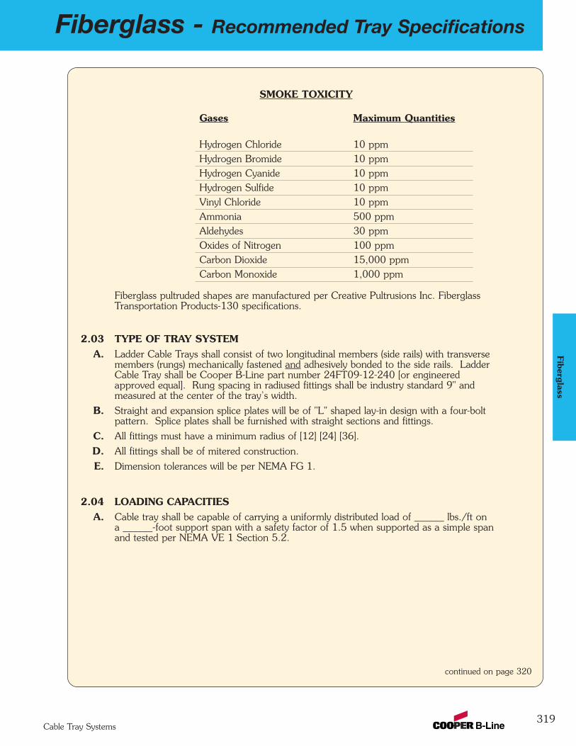
Fiberglass - Recommended Tray Specifications
319Cable Tray Systems
Fiberglass
SMOKE TOXICITY
Gases Maximum Quantities
Hydrogen Chloride 10 ppmHydrogen Bromide 10 ppmHydrogen Cyanide 10 ppmHydrogen Sulfide 10 ppmVinyl Chloride 10 ppmAmmonia 500 ppmAldehydes 30 ppmOxides of Nitrogen 100 ppmCarbon Dioxide 15,000 ppmCarbon Monoxide 1,000 ppm
Fiberglass pultruded shapes are manufactured per Creative Pultrusions Inc. FiberglassTransportation Products-130 specifications.
2.03 TYPE OF TRAY SYSTEMA. Ladder Cable Trays shall consist of two longitudinal members (side rails) with transverse
members (rungs) mechanically fastened and adhesively bonded to the side rails. LadderCable Tray shall be Cooper B-Line part number 24FT09-12-240 [or engineeredapproved equal]. Rung spacing in radiused fittings shall be industry standard 9" andmeasured at the center of the tray’s width.
B. Straight and expansion splice plates will be of "L" shaped lay-in design with a four-boltpattern. Splice plates shall be furnished with straight sections and fittings.
C. All fittings must have a minimum radius of [12] [24] [36].
D. All fittings shall be of mitered construction.
E. Dimension tolerances will be per NEMA FG 1.
2.04 LOADING CAPACITIESA. Cable tray shall be capable of carrying a uniformly distributed load of ______ lbs./ft on
a ______-foot support span with a safety factor of 1.5 when supported as a simple spanand tested per NEMA VE 1 Section 5.2.
continued on page 320
320
Fiberglass - Recommended Tray Specifications
Cable Tray Systems
Fibe
rgla
ss
PART 3 - EXECUTION3.01 INSTALLATION
A. Install cable trays as indicated: Installation shall be in accordance with equipmentmanufacturer's instructions, and with recognized industry practices to ensure that cable trayequipment comply with requirements of NEC and applicable portions of NFPA 70B.Reference NEMA VE 2 for general cable tray installation guidelines.
B. Coordinate cable tray with other electrical work as necessary to properly integrateinstallation of cable tray work with other work.
C. Provide sufficient space encompassing cable trays to permit access for installing andmaintaining cables.
D. Cable tray fitting supports shall be located such that they meet the strength requirementsof straight sections. Install fitting supports per NEMA VE 2 guidelines, or in accordancewith manufacturer's instructions.
3.02 TESTINGA. Upon request manufacturer shall provide test reports witnessed by an independent testing
laboratory of the "worst case" loading conditions outlined in this specification and performedin accordance with the latest revision of NEMA FG 1.
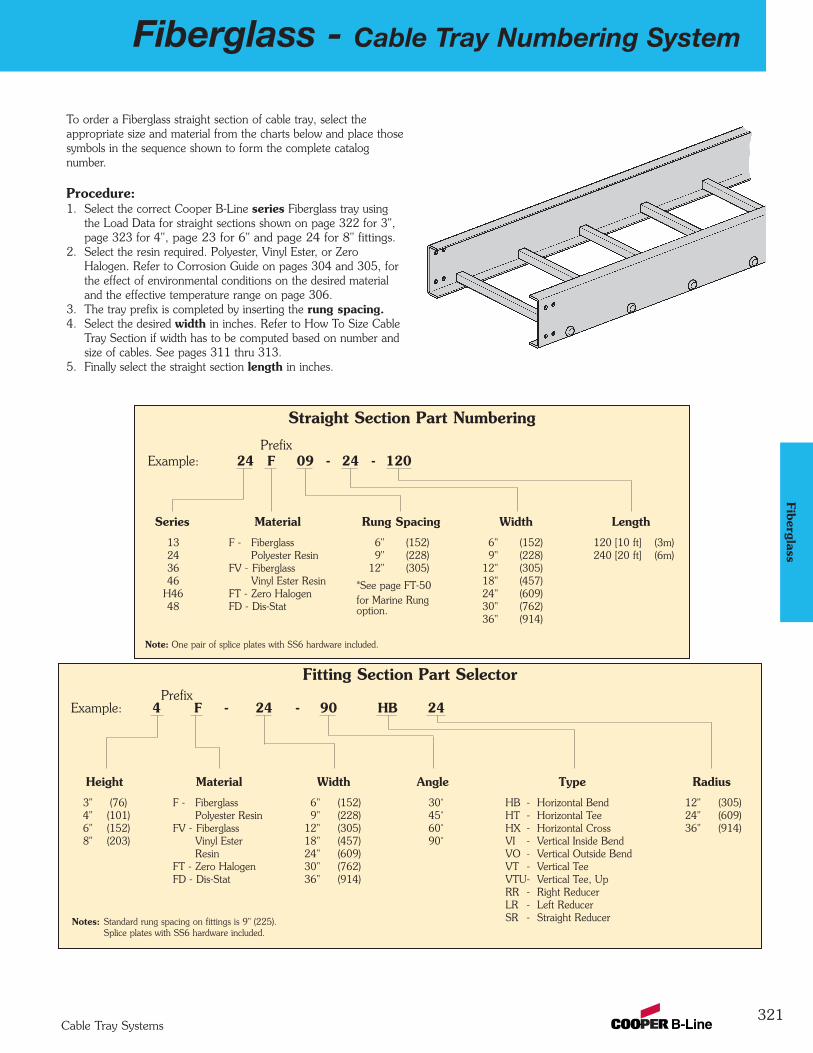
Fiberglass - Cable Tray Numbering System
321Cable Tray Systems
Fiberglass
To order a Fiberglass straight section of cable tray, select the appropriate size and material from the charts below and place thosesymbols in the sequence shown to form the complete catalog number.
Procedure:1. Select the correct Cooper B-Line series Fiberglass tray using
the Load Data for straight sections shown on page 322 for 3",page 323 for 4", page 23 for 6" and page 24 for 8" fittings.
2. Select the resin required. Polyester, Vinyl Ester, or ZeroHalogen. Refer to Corrosion Guide on pages 304 and 305, forthe effect of environmental conditions on the desired materialand the effective temperature range on page 306.
3. The tray prefix is completed by inserting the rung spacing.4. Select the desired width in inches. Refer to How To Size Cable
Tray Section if width has to be computed based on number andsize of cables. See pages 311 thru 313.
5. Finally select the straight section length in inches.Fiberglass 120 [10'] (3m) or 240 [20'] (6m)
Straight Section Part Numbering
PrefixExample: 24 F 09 - 24 - 120
Note: One pair of splice plates with SS6 hardware included.
Series
13243646
H4648
Width
6" (152)9" (228)
12" (305)18" (457)24" (609)30" (762)36" (914)
Rung Spacing
6" (152)9" (228)
12" (305)
*See page FT-50for Marine Rungoption.
Material
F - FiberglassPolyester Resin
FV - Fiberglass Vinyl Ester Resin
FT - Zero HalogenFD - Dis-Stat
Length
120 [10 ft] (3m)240 [20 ft] (6m)
Fitting Section Part SelectorPrefix
Example: 4 F - 24 - 90 HB 24
Height
3" (76) 4" (101) 6" (152)8" (203)
Width
6" (152)9" (228)
12" (305)18" (457)24" (609)30" (762)36" (914)
Radius
12" (305)24" (609)36" (914)
Angle
30˚45˚60˚90˚
Type
HB - Horizontal BendHT - Horizontal TeeHX - Horizontal CrossVI - Vertical Inside BendVO - Vertical Outside BendVT - Vertical TeeVTU- Vertical Tee, UpRR - Right ReducerLR - Left ReducerSR - Straight Reducer
Material
F - FiberglassPolyester Resin
FV - Fiberglass Vinyl EsterResin
FT - Zero HalogenFD - Dis-Stat
Notes: Standard rung spacing on fittings is 9" (225).Splice plates with SS6 hardware included.

322
Fiberglass - 3” Straight Section
Cable Tray Systems
Green = Fastest shipped items (normally 3 to 5 working days)Black = Normal lead-time items (normally 5 to 10 working days)Red = Normally long lead-time items (15 working days minimum)
Fibe
rgla
ss
When trays are used in continuous spans, the deflection of the tray is reduced by as much as 50%.
B-Line Side Rail NEMA & CSA Span Load Deflection Span Load DeflectionSeries Dimensions Classifications ft lbs/ft Multiplier meters kg/m Multiplier
NEMA: 8C 6 257 0.005 1.8 382 0.086
8 145 0.016 2.4 216 0.267
10 93 0.040 3.0 138 0.681
12 64 0.083 3.7 95 1.411
14 47 0.153 4.3 70 2.614
1.00
NEMA2” fill
1.00
13F3.00
Series 13 Fiberglass Straight Section Part NumberingPrefix
Example: 13 F 09 - 24 - 120
Series Material Type Width Length13 F = Polyester Ladder - 06 = 6" ¬ 120 = 10 ft.
13FFV = Vinyl Ester 06 = 6" rung spacing 09 = 9" Á 240 = 20 ft.FT = Zero Halogen 09 = 9" rung spacing 12 = 12"FD = Dis-Stat 12 = 12" rung spacing 18 = 18"
24 = 24"
See page 351 for additional rung options.
¬Primary Length.ÁSecondary Length.
See page 39 for explanation of lengths.
Overall Width(Width + 7/8”) For side rail &
rung data, see chartson pages AP-5 & AP-6
RungSpacing
1" (25)
1" (25)
NEMA2" Fill
3" (76)
One pair of splice plates with SS6 (316 Stainless Steel) hardware included
Values are based on simple beam tests per NEMA VFG-1 on 24" wide cable tray rungs spaced on 12" centers. Published loadsafety factor is 1.5. To convert 1.5 safety factor to 2.0, multiply published load by 0.75. To obtain mid-span deflection, multiply aload by the deflection multiplier. Cable tray must be supported on spans shorter than or equal to the length of the cable beinginstalled.
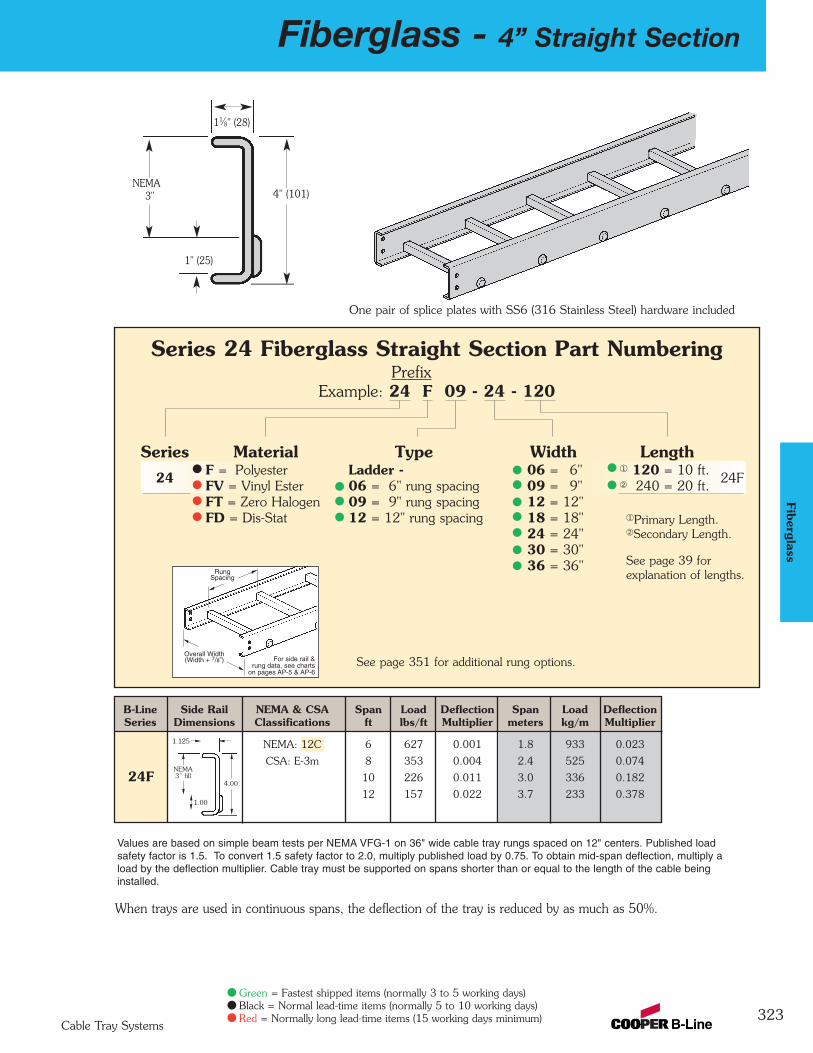
Fiberglass - 4” Straight Section
323Cable Tray Systems
Green = Fastest shipped items (normally 3 to 5 working days)Black = Normal lead-time items (normally 5 to 10 working days)Red = Normally long lead-time items (15 working days minimum)
Fiberglass
11⁄8" (28)
1" (25)
NEMA3" 4" (101)
Series 24 Fiberglass Straight Section Part NumberingPrefix
Example: 24 F 09 - 24 - 120
Series Material Type Width Length24 F = Polyester Ladder - 06 = 6" ¬ 120 = 10 ft.
24FFV = Vinyl Ester 06 = 6" rung spacing 09 = 9" Á 240 = 20 ft.FT = Zero Halogen 09 = 9" rung spacing 12 = 12"FD = Dis-Stat 12 = 12" rung spacing 18 = 18"
24 = 24"30 = 30"36 = 36"
See page 351 for additional rung options.
¬Primary Length.ÁSecondary Length.
See page 39 for explanation of lengths.
One pair of splice plates with SS6 (316 Stainless Steel) hardware included
Overall Width(Width + 7/8”) For side rail &
rung data, see chartson pages AP-5 & AP-6
RungSpacing
When trays are used in continuous spans, the deflection of the tray is reduced by as much as 50%.
Values are based on simple beam tests per NEMA VFG-1 on 36" wide cable tray rungs spaced on 12" centers. Published loadsafety factor is 1.5. To convert 1.5 safety factor to 2.0, multiply published load by 0.75. To obtain mid-span deflection, multiply aload by the deflection multiplier. Cable tray must be supported on spans shorter than or equal to the length of the cable beinginstalled.
B-Line Side Rail NEMA & CSA Span Load Deflection Span Load DeflectionSeries Dimensions Classifications ft lbs/ft Multiplier meters kg/m Multiplier
NEMA: 12C 6 627 0.001 1.8 933 0.023
CSA: E-3m 8 353 0.004 2.4 525 0.074
10 226 0.011 3.0 336 0.182
12 157 0.022 3.7 233 0.378
24F
1.00
4.00
1.125
NEMA3” fill
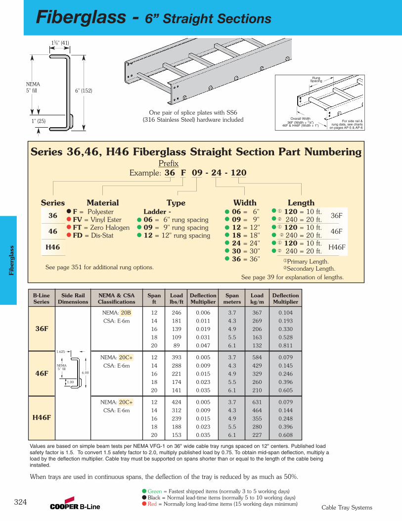
324
Fiberglass - 6” Straight Sections
Cable Tray Systems
Green = Fastest shipped items (normally 3 to 5 working days)Black = Normal lead-time items (normally 5 to 10 working days)Red = Normally long lead-time items (15 working days minimum)
Fibe
rgla
ss
1" (25)
NEMA5" fill
15⁄8" (41)
6" (152)
B-Line Side Rail NEMA & CSA Span Load Deflection Span Load DeflectionSeries Dimensions Classifications ft lbs/ft Multiplier meters kg/m Multiplier
NEMA: 20B 12 246 0.006 3.7 367 0.104
CSA: E-6m 14 181 0.011 4.3 269 0.193
16 139 0.019 4.9 206 0.330
18 109 0.031 5.5 163 0.528
20 89 0.047 6.1 132 0.811
NEMA: 20C+ 12 393 0.005 3.7 584 0.079
CSA: E-6m 14 288 0.009 4.3 429 0.145
16 221 0.015 4.9 329 0.246
18 174 0.023 5.5 260 0.396
20 141 0.035 6.1 210 0.605
NEMA: 20C+ 12 424 0.005 3.7 631 0.079
CSA: E-6m 14 312 0.009 4.3 464 0.144
16 239 0.015 4.9 355 0.248
18 188 0.023 5.5 280 0.396
20 153 0.035 6.1 227 0.608
1.00
36F
6.00
Series 36,46, H46 Fiberglass Straight Section Part NumberingPrefix
Example: 36 F 09 - 24 - 120
Series Material Type Width Length36 F = Polyester Ladder - 06 = 6" ¬ 120 = 10 ft.
36FFV = Vinyl Ester 06 = 6" rung spacing 09 = 9" Á 240 = 20 ft.
46 FT = Zero Halogen 09 = 9" rung spacing 12 = 12" ¬ 120 = 10 ft.46FFD = Dis-Stat 12 = 12" rung spacing 18 = 18" Á 240 = 20 ft.
H46 24 = 24" ¬ 120 = 10 ft.H46F30 = 30" Á 240 = 20 ft.
36 = 36"See page 351 for additional rung options.
See page 39 for explanation of lengths.
One pair of splice plates with SS6(316 Stainless Steel) hardware included Overall Width
36F (Width + 7/8”)46F & H46F (Width + 1”)
For side rail & rung data, see charts
on pages AP-5 & AP-6
RungSpacing
1.625
NEMA5” fill
¬Primary Length.ÁSecondary Length.
46F
H46F
When trays are used in continuous spans, the deflection of the tray is reduced by as much as 50%.
Values are based on simple beam tests per NEMA VFG-1 on 36" wide cable tray rungs spaced on 12" centers. Published loadsafety factor is 1.5. To convert 1.5 safety factor to 2.0, multiply published load by 0.75. To obtain mid-span deflection, multiply aload by the deflection multiplier. Cable tray must be supported on spans shorter than or equal to the length of the cable beinginstalled.
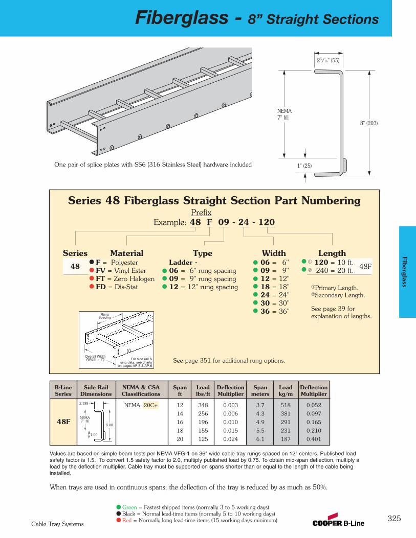
Fiberglass - 8” Straight Sections
325Cable Tray Systems
Green = Fastest shipped items (normally 3 to 5 working days)Black = Normal lead-time items (normally 5 to 10 working days)Red = Normally long lead-time items (15 working days minimum)
Fiberglass
23/16" (55)
1" (25)
NEMA7" fill
8" (203)
When trays are used in continuous spans, the deflection of the tray is reduced by as much as 50%.
Series 48 Fiberglass Straight Section Part NumberingPrefix
Example: 48 F 09 - 24 - 120
Series Material Type Width Length48 F = Polyester Ladder - 06 = 6" ¬ 120 = 10 ft.
48FFV = Vinyl Ester 06 = 6" rung spacing 09 = 9" Á 240 = 20 ft.FT = Zero Halogen 09 = 9" rung spacing 12 = 12"FD = Dis-Stat 12 = 12" rung spacing 18 = 18"
24 = 24"30 = 30"36 = 36"
See page 351 for additional rung options.
¬Primary Length.ÁSecondary Length.
See page 39 for explanation of lengths.
One pair of splice plates with SS6 (316 Stainless Steel) hardware included
Overall Width(Width + 1”) For side rail &
rung data, see chartson pages AP-5 & AP-6
RungSpacing
B-Line Side Rail NEMA & CSA Span Load Deflection Span Load DeflectionSeries Dimensions Classifications ft lbs/ft Multiplier meters kg/m Multiplier
NEMA: 20C+ 12 348 0.003 3.7 518 0.052
14 256 0.006 4.3 381 0.097
16 196 0.010 4.9 291 0.165
18 155 0.015 5.5 231 0.210
20 125 0.024 6.1 187 0.401
48F
Values are based on simple beam tests per NEMA VFG-1 on 36" wide cable tray rungs spaced on 12" centers. Published loadsafety factor is 1.5. To convert 1.5 safety factor to 2.0, multiply published load by 0.75. To obtain mid-span deflection, multiply aload by the deflection multiplier. Cable tray must be supported on spans shorter than or equal to the length of the cable beinginstalled.
1.00
8.00
2.188
NEMA7” fill
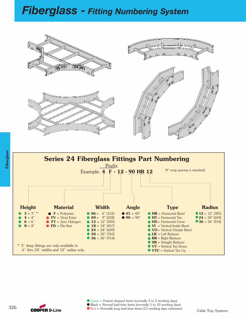
326
Fiberglass - Fitting Numbering System
Cable Tray Systems
Green = Fastest shipped items (normally 3 to 5 working days)Black = Normal lead-time items (normally 5 to 10 working days)Red = Normally long lead-time items (15 working days minimum)
Fibe
rgla
ss
Series 24 Fiberglass Fittings Part Numbering Prefix
Example: 4 F - 12 - 90 HB 12
Height3 = 3” **4 = 4”6 = 6”8 = 8”
MaterialF = Polyester
FV = Vinyl EsterFT = Zero HalogenFD = Dis-Stat
Width06 = 6" (152)09 = 9" (228)12 = 12" (305)18 = 18" (457)24 = 24" (609)30 = 30" (762)36 = 36" (914)
Angle45 = 45°90 = 90°
Radius12 = 12" (305)24 = 24" (609)36 = 36" (914)
TypeHB = Horizontal BendHT = Horizontal TeeHX= Horizontal CrossVI = Vertical Inside BendVO= Vertical Outside BendLR = Left ReducerRR = Right ReducerSR = Straight ReducerVT = Vertical Tee DownVTU = Vertical Tee Up
(9" rung spacing is standard)
** 3” deep fittings are only available in6” thru 24” widths and 12” radius only.
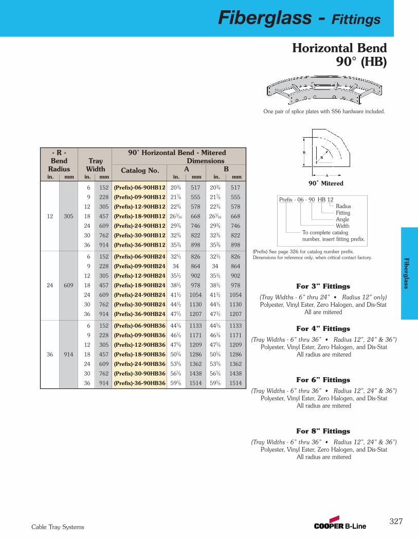
Fiberglass - Fittings
327Cable Tray Systems
Fiberglass
Horizontal Bend90° (HB)
- R - 90˚ Horizontal Bend - MiteredBend Tray Dimensions
Radius Width Catalog No. A Bin. mm in. mm in. mm in. mm
6 152 (Prefix)-06-90HB12 203⁄8 517 203⁄8 517
9 228 (Prefix)-09-90HB12 217⁄8 555 217⁄8 555
12 305 (Prefix)-12-90HB12 223⁄4 578 223⁄4 578
12 305 18 457 (Prefix)-18-90HB12 265⁄16 668 265⁄16 668
24 609 (Prefix)-24-90HB12 293⁄8 746 293⁄8 746
30 762 (Prefix)-30-90HB12 323⁄8 822 323⁄8 822
36 914 (Prefix)-36-90HB12 353⁄8 898 353⁄8 898
6 152 (Prefix)-06-90HB24 321⁄2 826 321⁄2 826
9 228 (Prefix)-09-90HB24 34 864 34 864
12 305 (Prefix)-12-90HB24 351⁄2 902 351⁄2 902
24 609 18 457 (Prefix)-18-90HB24 381⁄2 978 381⁄2 978
24 609 (Prefix)-24-90HB24 411⁄2 1054 411⁄2 1054
30 762 (Prefix)-30-90HB24 441⁄2 1130 441⁄2 1130
36 914 (Prefix)-36-90HB24 471⁄2 1207 471⁄2 1207
6 152 (Prefix)-06-90HB36 445⁄8 1133 445⁄8 1133
9 228 (Prefix)-09-90HB36 461⁄8 1171 461⁄8 1171
12 305 (Prefix)-12-90HB36 475⁄8 1209 475⁄8 1209
36 914 18 457 (Prefix)-18-90HB36 505⁄8 1286 505⁄8 1286
24 609 (Prefix)-24-90HB36 535⁄8 1362 535⁄8 1362
30 762 (Prefix)-30-90HB36 565⁄8 1438 565⁄8 1438
36 914 (Prefix)-36-90HB36 595⁄8 1514 595⁄8 1514
A
BR
90˚ Mitered
One pair of splice plates with SS6 hardware included.
Dimensions for reference only, when critical contact factory.(Prefix) See page 326 for catalog number prefix.
(Tray Widths - 6” thru 24” • Radius 12” only)Polyester, Vinyl Ester, Zero Halogen, and Dis-Stat
All are mitered
For 3” Fittings
(Tray Widths - 6” thru 36” • Radius 12”, 24” & 36”)Polyester, Vinyl Ester, Zero Halogen, and Dis-Stat
All radius are mitered
For 4” Fittings
(Tray Widths - 6” thru 36” • Radius 12”, 24” & 36”)Polyester, Vinyl Ester, Zero Halogen, and Dis-Stat
All radius are mitered
For 6” Fittings
(Tray Widths - 6” thru 36” • Radius 12”, 24” & 36”)Polyester, Vinyl Ester, Zero Halogen, and Dis-Stat
All radius are mitered
For 8” Fittings
Prefix - 06 - 90 HB 12RadiusFitting AngleWidth
To complete catalog number, insert fitting prefix.

328
Fiberglass - Fittings
Cable Tray Systems
Fibe
rgla
ss
Horizontal Bend 45°(HB)
B
C
C
R
A
45˚ Mitered
Dimensions for reference only, when criticalcontact factory.
(Prefix) See page 326 for catalog number prefix.
Prefix - 06 - 45 HB 12RadiusFitting AngleWidth
To complete catalog number, insert fitting prefix.
(Tray Widths - 6” thru 24” • Radius 12” only)Polyester, Vinyl Ester, Zero Halogen, and Dis-Stat
All are mitered
For 3” Fittings
(Tray Widths - 6” thru 36”Radius 12”, 24” & 36”)
Polyester, Vinyl Ester, Zero Halogen, and Dis-StatAll radius are mitered
For 4” Fittings
(Tray Widths - 6” thru 36”Radius 12”, 24” & 36”)
Polyester, Vinyl Ester, Zero Halogen, and Dis-StatAll radius are mitered
For 6” Fittings
(Tray Widths - 6” thru 36”Radius 12”, 24” & 36”)
Polyester, Vinyl Ester, Zero Halogen, and Dis-StatAll radius are mitered
For 8” Fittings
One pair of splice plates with SS6 hardware included.
- R - 45˚ Horizontal Bend - MiteredBend Tray Dimensions
Radius Width Catalog No. A B Cin. mm in mm in. mm in. mm in. mm
6 152 (Prefix)-06-45HB12 2213⁄16 579 97⁄16 240 133⁄8 340
9 228 (Prefix)-09-45HB12 237⁄8 606 97⁄8 251 14 355
12 305 (Prefix)-12-45HB12 247⁄8 632 105⁄16 262 145⁄8 371
12 305 18 457 (Prefix)-18-45HB12 27 686 113⁄16 284 157⁄8 403
24 609 (Prefix)-24-45HB12 291⁄8 740 121⁄16 306 171⁄16 433
30 762 (Prefix)-30-45HB12 311⁄4 794 1215⁄16 328 185⁄16 465
36 914 (Prefix)-36-45HB12 333⁄8 848 1313⁄16 351 199⁄16 497
6 152 (Prefix)-06-45HB24 3111⁄32 796 1231⁄32 329 183⁄8 467
9 228 (Prefix)-09-45HB24 3213⁄32 823 1313⁄32 341 19 483
12 305 (Prefix)-12-45HB24 3313⁄32 849 1327⁄32 352 195⁄8 498
24 609 18 457 (Prefix)-18-45HB24 3517⁄32 902 1423⁄32 374 207⁄8 530
24 609 (Prefix)-24-45HB24 3721⁄32 956 1519⁄32 396 221⁄16 560
30 762 (Prefix)-30-45HB24 3925⁄32 1010 1615⁄32 418 235⁄16 592
36 914 (Prefix)-36-45HB24 4129⁄32 1064 1711⁄32 441 249⁄16 624
6 152 (Prefix)-06-45HB36 397⁄8 1013 161⁄2 419 233⁄8 594
9 228 (Prefix)-09-45HB36 4015⁄16 1040 1615⁄16 430 2315⁄16 608
12 305 (Prefix)-12-45HB36 42 1067 173⁄8 441 249⁄16 624
36 914 18 457 (Prefix)-18-45HB36 441⁄8 1121 181⁄4 463 2513⁄16 655
24 609 (Prefix)-24-45HB36 463⁄16 1173 191⁄8 486 271⁄16 687
30 762 (Prefix)-30-45HB36 485⁄16 1227 20 508 285⁄16 719
36 914 (Prefix)-36-45HB36 507⁄16 1281 207⁄8 530 299⁄16 751

Fiberglass - Fittings
329Cable Tray Systems
Fiberglass
Horizontal Tee(HT)
- R - Horizontal Tee - MiteredBend Tray Dimensions
Radius Width Catalog No. A Bin. mm in. mm in. mm in. mm
6 152 (Prefix)-06-HX12 191⁄4 489 38 965
9 228 (Prefix)-09-HX12 203⁄4 527 41 1041
12 305 (Prefix)-12-HX12 221⁄4 565 44 1117
12 305 18 457 (Prefix)-18-HX12 251⁄4 641 50 1270
24 609 (Prefix)-24-HX12 281⁄4 717 56 1422
30 762 (Prefix)-30-HX12 311⁄4 794 62 1575
36 914 (Prefix)-36-HX12 341⁄4 870 68 1727
6 152 (Prefix)-06-HX24 311⁄4 794 621⁄4 1581
9 228 (Prefix)-09-HX24 323⁄4 832 651⁄4 1657
12 305 (Prefix)-12-HX24 341⁄4 870 681⁄4 1734
24 609 18 457 (Prefix)-18-HX24 371⁄4 946 741⁄4 1886
24 609 (Prefix)-24-HX24 401⁄4 1022 801⁄4 2038
30 762 (Prefix)-30-HX24 431⁄4 1098 861⁄4 2191
36 914 (Prefix)-36-HX24 461⁄4 1175 921⁄4 2343
6 152 (Prefix)-06-HX36 431⁄4 1098 861⁄2 2191
9 228 (Prefix)-09-HX36 443⁄4 1136 891⁄2 2273
12 305 (Prefix)-12-HX36 461⁄4 1175 921⁄2 2343
36 914 18 457 (Prefix)-18-HX36 491⁄4 1251 981⁄2 2502
24 609 (Prefix)-24-HX36 521⁄4 1327 1041⁄2 2654
30 762 (Prefix)-30-HX36 551⁄4 1403 1101⁄2 2807
36 914 (Prefix)-36-HX36 581⁄4 1479 1161⁄2 2959
(Tray Widths - 6” thru 24” • Radius 12” only)Polyester, Vinyl Ester, Zero Halogen, and Dis-Stat
All are mitered
For 3” Fittings
(Tray Widths - 6” thru 36” • Radius 12”, 24” & 36”)Polyester, Vinyl Ester, Zero Halogen, and Dis-Stat
All radius are mitered
For 4” Fittings
(Tray Widths - 6” thru 36” • Radius 12”, 24” & 36”)Polyester, Vinyl Ester, Zero Halogen, and Dis-Stat
All radius are mitered
For 6” Fittings
(Tray Widths - 6” thru 36” • Radius 12”, 24” & 36”)Polyester, Vinyl Ester, Zero Halogen, and Dis-Stat
All radius are mitered
For 8” Fittings
R
W
B
A
Mitered Tee
Two pair of splice plates with SS6 hardware included.
Dimensions for reference only, when critical contact factory.(Prefix) See page 326 for catalog number prefix.
Prefix - 06 - HT 12RadiusFittingWidth
To complete catalog number, insert fitting prefix.
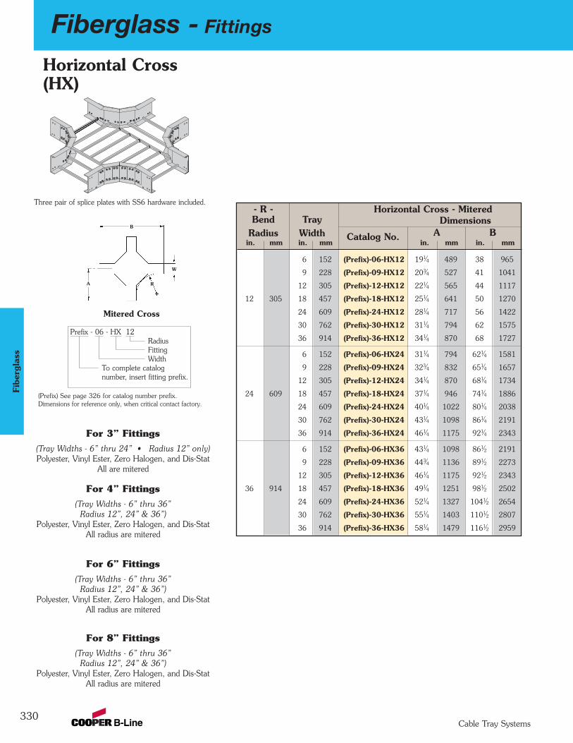
330
Fiberglass - Fittings
Cable Tray Systems
Fibe
rgla
ss
Horizontal Cross(HX)
(Tray Widths - 6” thru 24” • Radius 12” only)Polyester, Vinyl Ester, Zero Halogen, and Dis-Stat
All are mitered
For 3” Fittings
(Tray Widths - 6” thru 36”Radius 12”, 24” & 36”)
Polyester, Vinyl Ester, Zero Halogen, and Dis-StatAll radius are mitered
For 4” Fittings
(Tray Widths - 6” thru 36”Radius 12”, 24” & 36”)
Polyester, Vinyl Ester, Zero Halogen, and Dis-StatAll radius are mitered
For 6” Fittings
(Tray Widths - 6” thru 36”Radius 12”, 24” & 36”)
Polyester, Vinyl Ester, Zero Halogen, and Dis-StatAll radius are mitered
For 8” Fittings
Three pair of splice plates with SS6 hardware included.
R
W
B
A
Mitered Cross
Dimensions for reference only, when critical contact factory.(Prefix) See page 326 for catalog number prefix.
Prefix - 06 - HX 12RadiusFittingWidth
To complete catalog number, insert fitting prefix.
- R - Horizontal Cross - MiteredBend Tray Dimensions
Radius Width Catalog No. A Bin. mm in. mm in. mm in. mm
6 152 (Prefix)-06-HX12 191⁄4 489 38 965
9 228 (Prefix)-09-HX12 203⁄4 527 41 1041
12 305 (Prefix)-12-HX12 221⁄4 565 44 1117
12 305 18 457 (Prefix)-18-HX12 251⁄4 641 50 1270
24 609 (Prefix)-24-HX12 281⁄4 717 56 1422
30 762 (Prefix)-30-HX12 311⁄4 794 62 1575
36 914 (Prefix)-36-HX12 341⁄4 870 68 1727
6 152 (Prefix)-06-HX24 311⁄4 794 621⁄4 1581
9 228 (Prefix)-09-HX24 323⁄4 832 651⁄4 1657
12 305 (Prefix)-12-HX24 341⁄4 870 681⁄4 1734
24 609 18 457 (Prefix)-18-HX24 371⁄4 946 741⁄4 1886
24 609 (Prefix)-24-HX24 401⁄4 1022 801⁄4 2038
30 762 (Prefix)-30-HX24 431⁄4 1098 861⁄4 2191
36 914 (Prefix)-36-HX24 461⁄4 1175 921⁄4 2343
6 152 (Prefix)-06-HX36 431⁄4 1098 861⁄2 2191
9 228 (Prefix)-09-HX36 443⁄4 1136 891⁄2 2273
12 305 (Prefix)-12-HX36 461⁄4 1175 921⁄2 2343
36 914 18 457 (Prefix)-18-HX36 491⁄4 1251 981⁄2 2502
24 609 (Prefix)-24-HX36 521⁄4 1327 1041⁄2 2654
30 762 (Prefix)-30-HX36 551⁄4 1403 1101⁄2 2807
36 914 (Prefix)-36-HX36 581⁄4 1479 1161⁄2 2959
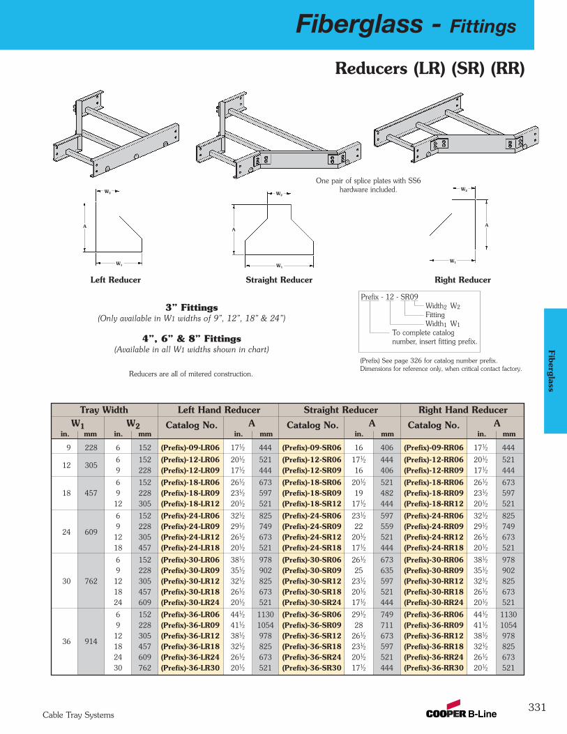
Fiberglass - Fittings
331Cable Tray Systems
Fiberglass
Prefix - 12 - SR09Width2 W2
FittingWidth1 W1
To complete catalog number, insert fitting prefix.
Tray Width Left Hand Reducer Straight Reducer Right Hand ReducerW1 W2 Catalog No. A Catalog No. A Catalog No. A
in. mm in. mm in. mm in. mm in. mm
9 228 6 152 (Prefix)-09-LR06 171⁄2 444 (Prefix)-09-SR06 16 406 (Prefix)-09-RR06 171⁄2 444
12 3056 152 (Prefix)-12-LR06 201⁄2 521 (Prefix)-12-SR06 171⁄2 444 (Prefix)-12-RR06 201⁄2 5219 228 (Prefix)-12-LR09 171⁄2 444 (Prefix)-12-SR09 16 406 (Prefix)-12-RR09 171⁄2 444
6 152 (Prefix)-18-LR06 261⁄2 673 (Prefix)-18-SR06 201⁄2 521 (Prefix)-18-RR06 261⁄2 67318 457 9 228 (Prefix)-18-LR09 231⁄2 597 (Prefix)-18-SR09 19 482 (Prefix)-18-RR09 231⁄2 597
12 305 (Prefix)-18-LR12 201⁄2 521 (Prefix)-18-SR12 171⁄2 444 (Prefix)-18-RR12 201⁄2 521
6 152 (Prefix)-24-LR06 321⁄2 825 (Prefix)-24-SR06 231⁄2 597 (Prefix)-24-RR06 321⁄2 825
24 6099 228 (Prefix)-24-LR09 291⁄2 749 (Prefix)-24-SR09 22 559 (Prefix)-24-RR09 291⁄2 74912 305 (Prefix)-24-LR12 261⁄2 673 (Prefix)-24-SR12 201⁄2 521 (Prefix)-24-RR12 261⁄2 67318 457 (Prefix)-24-LR18 201⁄2 521 (Prefix)-24-SR18 171⁄2 444 (Prefix)-24-RR18 201⁄2 521
6 152 (Prefix)-30-LR06 381⁄2 978 (Prefix)-30-SR06 261⁄2 673 (Prefix)-30-RR06 381⁄2 9789 228 (Prefix)-30-LR09 351⁄2 902 (Prefix)-30-SR09 25 635 (Prefix)-30-RR09 351⁄2 902
30 762 12 305 (Prefix)-30-LR12 321⁄2 825 (Prefix)-30-SR12 231⁄2 597 (Prefix)-30-RR12 321⁄2 82518 457 (Prefix)-30-LR18 261⁄2 673 (Prefix)-30-SR18 201⁄2 521 (Prefix)-30-RR18 261⁄2 67324 609 (Prefix)-30-LR24 201⁄2 521 (Prefix)-30-SR24 171⁄2 444 (Prefix)-30-RR24 201⁄2 521
6 152 (Prefix)-36-LR06 441⁄2 1130 (Prefix)-36-SR06 291⁄2 749 (Prefix)-36-RR06 441⁄2 11309 228 (Prefix)-36-LR09 411⁄2 1054 (Prefix)-36-SR09 28 711 (Prefix)-36-RR09 411⁄2 1054
36 91412 305 (Prefix)-36-LR12 381⁄2 978 (Prefix)-36-SR12 261⁄2 673 (Prefix)-36-RR12 381⁄2 97818 457 (Prefix)-36-LR18 321⁄2 825 (Prefix)-36-SR18 231⁄2 597 (Prefix)-36-RR18 321⁄2 82524 609 (Prefix)-36-LR24 261⁄2 673 (Prefix)-36-SR24 201⁄2 521 (Prefix)-36-RR24 261⁄2 67330 762 (Prefix)-36-LR30 201⁄2 521 (Prefix)-36-SR30 171⁄2 444 (Prefix)-36-RR30 201⁄2 521
W2
W1
A
W2
W1
A
W2
W1
A
Left Reducer Straight Reducer Right Reducer
Reducers are all of mitered construction.
One pair of splice plates with SS6hardware included.
Dimensions for reference only, when critical contact factory.(Prefix) See page 326 for catalog number prefix.
Reducers (LR) (SR) (RR)
3” Fittings(Only available in W1 widths of 9”, 12”, 18” & 24”)
4”, 6” & 8” Fittings(Available in all W1 widths shown in chart)
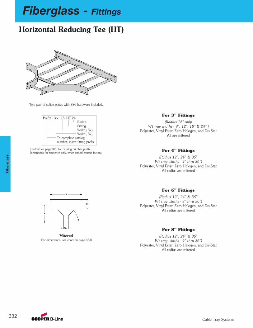
332
Fiberglass - Fittings
Cable Tray Systems
Fibe
rgla
ss
R
W2
B
W1
A
Mitered(For dimensions, see chart on page 333)
Two pair of splice plates with SS6 hardware included.
Dimensions for reference only, when critical contact factory.(Prefix) See page 326 for catalog number prefix.
Horizontal Reducing Tee (HT)
Prefix - 36 - 18 HT 24RadiusFittingWidth2 W2
Width1 W1
To complete catalog number, insert fitting prefix.
(Radius 12” onlyW1 tray widths - 9”, 12”, 18” & 24” )
Polyester, Vinyl Ester, Zero Halogen, and Dis-StatAll are mitered
For 3” Fittings
(Radius 12”, 24” & 36”W1 tray widths - 9” thru 36”)
Polyester, Vinyl Ester, Zero Halogen, and Dis-StatAll radius are mitered
For 4” Fittings
(Radius 12”, 24” & 36”W1 tray widths - 9” thru 36”)
Polyester, Vinyl Ester, Zero Halogen, and Dis-StatAll radius are mitered
For 6” Fittings
(Radius 12”, 24” & 36”W1 tray widths - 9” thru 36”)
Polyester, Vinyl Ester, Zero Halogen, and Dis-StatAll radius are mitered
For 8” Fittings
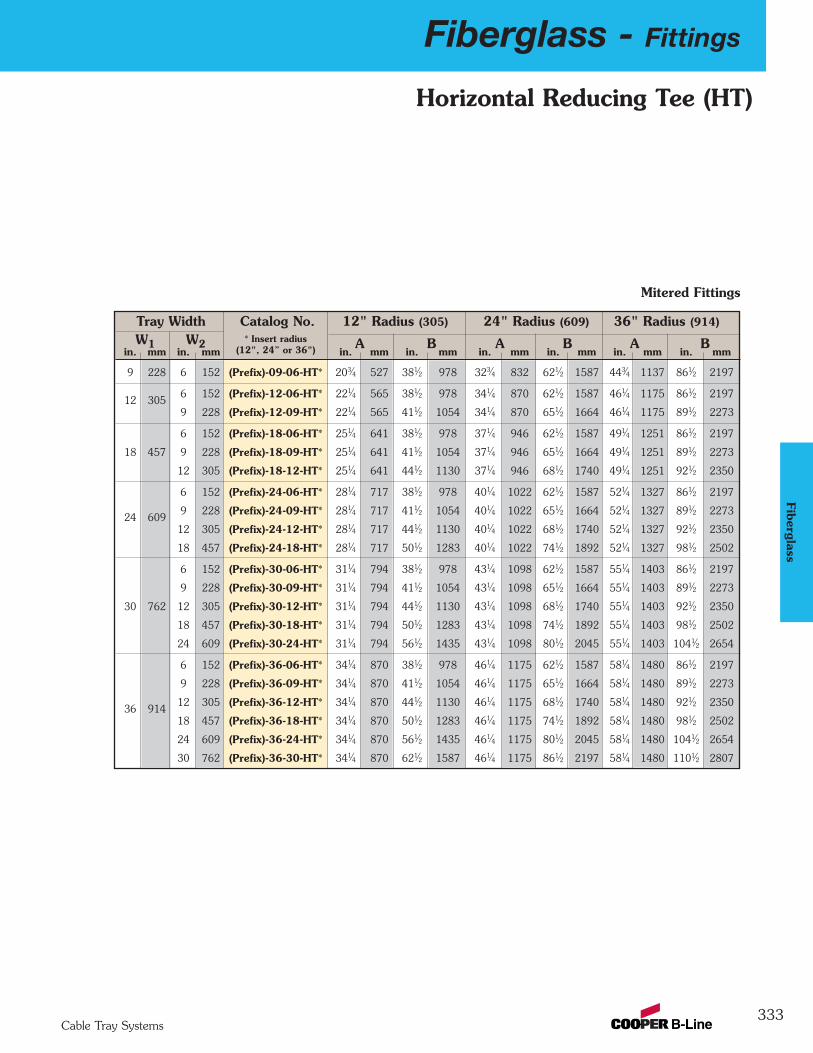
Fiberglass - Fittings
333Cable Tray Systems
Fiberglass
Horizontal Reducing Tee (HT)
Tray Width Catalog No. 12" Radius (305) 24" Radius (609) 36" Radius (914)
W1 W2 A B A B A Bin. mm in. mm in. mm in. mm in. mm in. mm in. mm in. mm
9 228 6 152 (Prefix)-09-06-HT* 203⁄4 527 381⁄2 978 323⁄4 832 621⁄2 1587 443⁄4 1137 861⁄2 2197
12 3056 152 (Prefix)-12-06-HT* 221⁄4 565 381⁄2 978 341⁄4 870 621⁄2 1587 461⁄4 1175 861⁄2 2197
9 228 (Prefix)-12-09-HT* 221⁄4 565 411⁄2 1054 341⁄4 870 651⁄2 1664 461⁄4 1175 891⁄2 2273
6 152 (Prefix)-18-06-HT* 251⁄4 641 381⁄2 978 371⁄4 946 621⁄2 1587 491⁄4 1251 861⁄2 2197
18 457 9 228 (Prefix)-18-09-HT* 251⁄4 641 411⁄2 1054 371⁄4 946 651⁄2 1664 491⁄4 1251 891⁄2 2273
12 305 (Prefix)-18-12-HT* 251⁄4 641 441⁄2 1130 371⁄4 946 681⁄2 1740 491⁄4 1251 921⁄2 2350
6 152 (Prefix)-24-06-HT* 281⁄4 717 381⁄2 978 401⁄4 1022 621⁄2 1587 521⁄4 1327 861⁄2 2197
24 6099 228 (Prefix)-24-09-HT* 281⁄4 717 411⁄2 1054 401⁄4 1022 651⁄2 1664 521⁄4 1327 891⁄2 2273
12 305 (Prefix)-24-12-HT* 281⁄4 717 441⁄2 1130 401⁄4 1022 681⁄2 1740 521⁄4 1327 921⁄2 2350
18 457 (Prefix)-24-18-HT* 281⁄4 717 501⁄2 1283 401⁄4 1022 741⁄2 1892 521⁄4 1327 981⁄2 2502
6 152 (Prefix)-30-06-HT* 311⁄4 794 381⁄2 978 431⁄4 1098 621⁄2 1587 551⁄4 1403 861⁄2 2197
9 228 (Prefix)-30-09-HT* 311⁄4 794 411⁄2 1054 431⁄4 1098 651⁄2 1664 551⁄4 1403 891⁄2 2273
30 762 12 305 (Prefix)-30-12-HT* 311⁄4 794 441⁄2 1130 431⁄4 1098 681⁄2 1740 551⁄4 1403 921⁄2 2350
18 457 (Prefix)-30-18-HT* 311⁄4 794 501⁄2 1283 431⁄4 1098 741⁄2 1892 551⁄4 1403 981⁄2 2502
24 609 (Prefix)-30-24-HT* 311⁄4 794 561⁄2 1435 431⁄4 1098 801⁄2 2045 551⁄4 1403 1041⁄2 2654
6 152 (Prefix)-36-06-HT* 341⁄4 870 381⁄2 978 461⁄4 1175 621⁄2 1587 581⁄4 1480 861⁄2 2197
9 228 (Prefix)-36-09-HT* 341⁄4 870 411⁄2 1054 461⁄4 1175 651⁄2 1664 581⁄4 1480 891⁄2 2273
36 91412 305 (Prefix)-36-12-HT* 341⁄4 870 441⁄2 1130 461⁄4 1175 681⁄2 1740 581⁄4 1480 921⁄2 2350
18 457 (Prefix)-36-18-HT* 341⁄4 870 501⁄2 1283 461⁄4 1175 741⁄2 1892 581⁄4 1480 981⁄2 2502
24 609 (Prefix)-36-24-HT* 341⁄4 870 561⁄2 1435 461⁄4 1175 801⁄2 2045 581⁄4 1480 1041⁄2 2654
30 762 (Prefix)-36-30-HT* 341⁄4 870 621⁄2 1587 461⁄4 1175 861⁄2 2197 581⁄4 1480 1101⁄2 2807
* Insert radius(12", 24” or 36")
Mitered Fittings
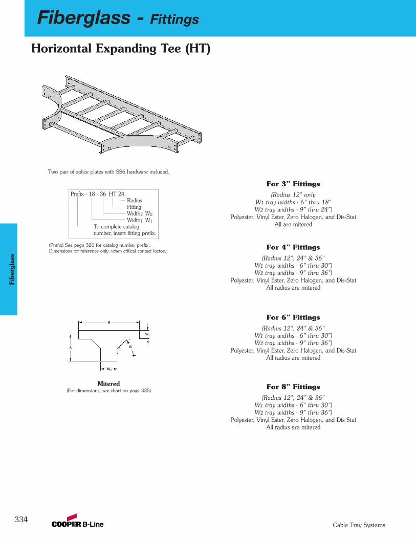
334
Fiberglass - Fittings
Cable Tray Systems
Fibe
rgla
ss
Mitered(For dimensions, see chart on page 335)
Two pair of splice plates with SS6 hardware included.
Dimensions for reference only, when critical contact factory.(Prefix) See page 326 for catalog number prefix.
Horizontal Expanding Tee (HT)
Prefix - 18 - 36 HT 24RadiusFittingWidth2 W2
Width1 W1
To complete catalog number, insert fitting prefix.
(Radius 12” onlyW1 tray widths - 6” thru 18”W2 tray widths - 9” thru 24”)
Polyester, Vinyl Ester, Zero Halogen, and Dis-StatAll are mitered
For 3” Fittings
(Radius 12”, 24” & 36”W1 tray widths - 6” thru 30”)W2 tray widths - 9” thru 36”)
Polyester, Vinyl Ester, Zero Halogen, and Dis-StatAll radius are mitered
For 4” Fittings
(Radius 12”, 24” & 36”W1 tray widths - 6” thru 30”)W2 tray widths - 9” thru 36”)
Polyester, Vinyl Ester, Zero Halogen, and Dis-StatAll radius are mitered
For 6” Fittings
(Radius 12”, 24” & 36”W1 tray widths - 6” thru 30”)W2 tray widths - 9” thru 36”)
Polyester, Vinyl Ester, Zero Halogen, and Dis-StatAll radius are mitered
For 8” Fittings
W1
R
B
W2
A
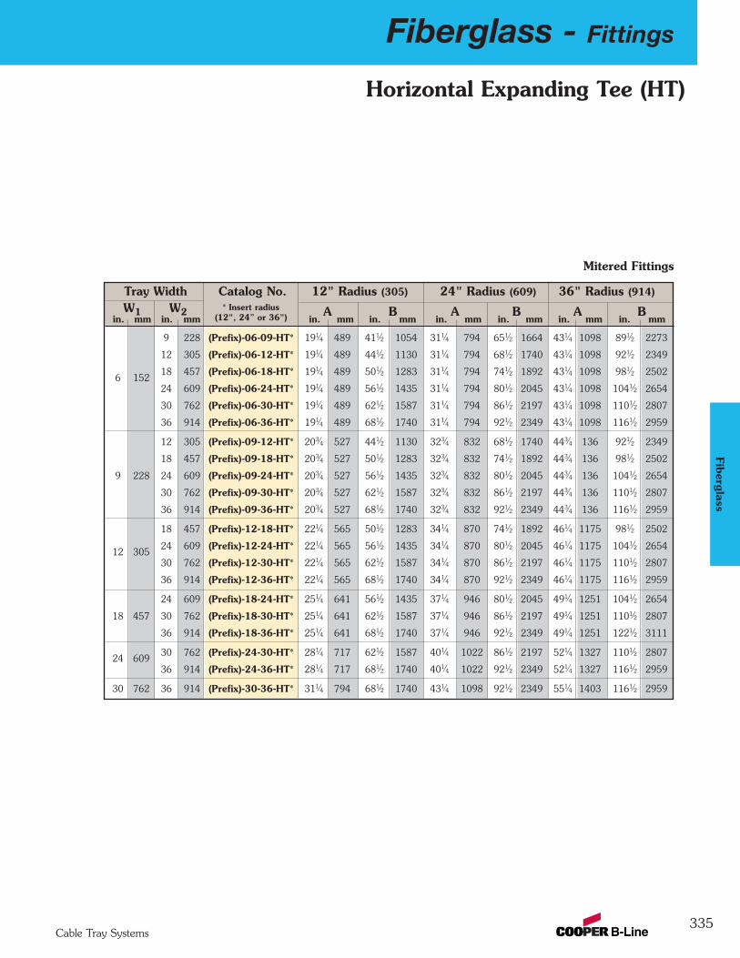
Fiberglass - Fittings
335Cable Tray Systems
Fiberglass
Horizontal Expanding Tee (HT)
Tray Width Catalog No. 12" Radius (305) 24" Radius (609) 36" Radius (914)
W1 W2 A B A B A Bin. mm in. mm in. mm in. mm in. mm in. mm in. mm in. mm
9 228 (Prefix)-06-09-HT* 191⁄4 489 411⁄2 1054 311⁄4 794 651⁄2 1664 431⁄4 1098 891⁄2 2273
12 305 (Prefix)-06-12-HT* 191⁄4 489 441⁄2 1130 311⁄4 794 681⁄2 1740 431⁄4 1098 921⁄2 2349
6 15218 457 (Prefix)-06-18-HT* 191⁄4 489 501⁄2 1283 311⁄4 794 741⁄2 1892 431⁄4 1098 981⁄2 2502
24 609 (Prefix)-06-24-HT* 191⁄4 489 561⁄2 1435 311⁄4 794 801⁄2 2045 431⁄4 1098 1041⁄2 2654
30 762 (Prefix)-06-30-HT* 191⁄4 489 621⁄2 1587 311⁄4 794 861⁄2 2197 431⁄4 1098 1101⁄2 2807
36 914 (Prefix)-06-36-HT* 191⁄4 489 681⁄2 1740 311⁄4 794 921⁄2 2349 431⁄4 1098 1161⁄2 2959
12 305 (Prefix)-09-12-HT* 203⁄4 527 441⁄2 1130 323⁄4 832 681⁄2 1740 443⁄4 136 921⁄2 2349
18 457 (Prefix)-09-18-HT* 203⁄4 527 501⁄2 1283 323⁄4 832 741⁄2 1892 443⁄4 136 981⁄2 2502
9 228 24 609 (Prefix)-09-24-HT* 203⁄4 527 561⁄2 1435 323⁄4 832 801⁄2 2045 443⁄4 136 1041⁄2 2654
30 762 (Prefix)-09-30-HT* 203⁄4 527 621⁄2 1587 323⁄4 832 861⁄2 2197 443⁄4 136 1101⁄2 2807
36 914 (Prefix)-09-36-HT* 203⁄4 527 681⁄2 1740 323⁄4 832 921⁄2 2349 443⁄4 136 1161⁄2 2959
18 457 (Prefix)-12-18-HT* 221⁄4 565 501⁄2 1283 341⁄4 870 741⁄2 1892 461⁄4 1175 981⁄2 2502
12 30524 609 (Prefix)-12-24-HT* 221⁄4 565 561⁄2 1435 341⁄4 870 801⁄2 2045 461⁄4 1175 1041⁄2 2654
30 762 (Prefix)-12-30-HT* 221⁄4 565 621⁄2 1587 341⁄4 870 861⁄2 2197 461⁄4 1175 1101⁄2 2807
36 914 (Prefix)-12-36-HT* 221⁄4 565 681⁄2 1740 341⁄4 870 921⁄2 2349 461⁄4 1175 1161⁄2 2959
24 609 (Prefix)-18-24-HT* 251⁄4 641 561⁄2 1435 371⁄4 946 801⁄2 2045 491⁄4 1251 1041⁄2 2654
18 457 30 762 (Prefix)-18-30-HT* 251⁄4 641 621⁄2 1587 371⁄4 946 861⁄2 2197 491⁄4 1251 1101⁄2 2807
36 914 (Prefix)-18-36-HT* 251⁄4 641 681⁄2 1740 371⁄4 946 921⁄2 2349 491⁄4 1251 1221⁄2 3111
24 60930 762 (Prefix)-24-30-HT* 281⁄4 717 621⁄2 1587 401⁄4 1022 861⁄2 2197 521⁄4 1327 1101⁄2 2807
36 914 (Prefix)-24-36-HT* 281⁄4 717 681⁄2 1740 401⁄4 1022 921⁄2 2349 521⁄4 1327 1161⁄2 2959
30 762 36 914 (Prefix)-30-36-HT* 311⁄4 794 681⁄2 1740 431⁄4 1098 921⁄2 2349 551⁄4 1403 1161⁄2 2959
* Insert radius(12", 24” or 36")
Mitered Fittings
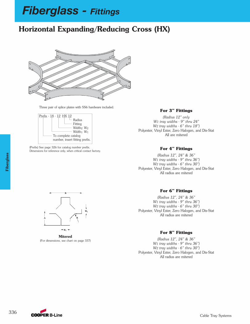
336
Fiberglass - Fittings
Cable Tray Systems
Fibe
rgla
ss
Mitered(For dimensions, see chart on page 337)
Dimensions for reference only, when critical contact factory.(Prefix) See page 326 for catalog number prefix.
Horizontal Expanding/Reducing Cross (HX)
(Radius 12” onlyW1 tray widths - 9” thru 24”W2 tray widths - 6” thru 18”)
Polyester, Vinyl Ester, Zero Halogen, and Dis-StatAll are mitered
For 3” Fittings
(Radius 12”, 24” & 36”W1 tray widths - 9” thru 36”)W2 tray widths - 6” thru 30”)
Polyester, Vinyl Ester, Zero Halogen, and Dis-StatAll radius are mitered
For 4” Fittings
(Radius 12”, 24” & 36”W1 tray widths - 9” thru 36”)W2 tray widths - 6” thru 30”)
Polyester, Vinyl Ester, Zero Halogen, and Dis-StatAll radius are mitered
For 6” Fittings
(Radius 12”, 24” & 36”W1 tray widths - 9” thru 36”)W2 tray widths - 6” thru 30”)
Polyester, Vinyl Ester, Zero Halogen, and Dis-StatAll radius are mitered
For 8” Fittings
B
R
W2
W1
A
Three pair of splice plates with SS6 hardware included.
Prefix - 18 - 12 HX 12RadiusFitting Width2 W2
Width1 W1
To complete catalog number, insert fitting prefix.
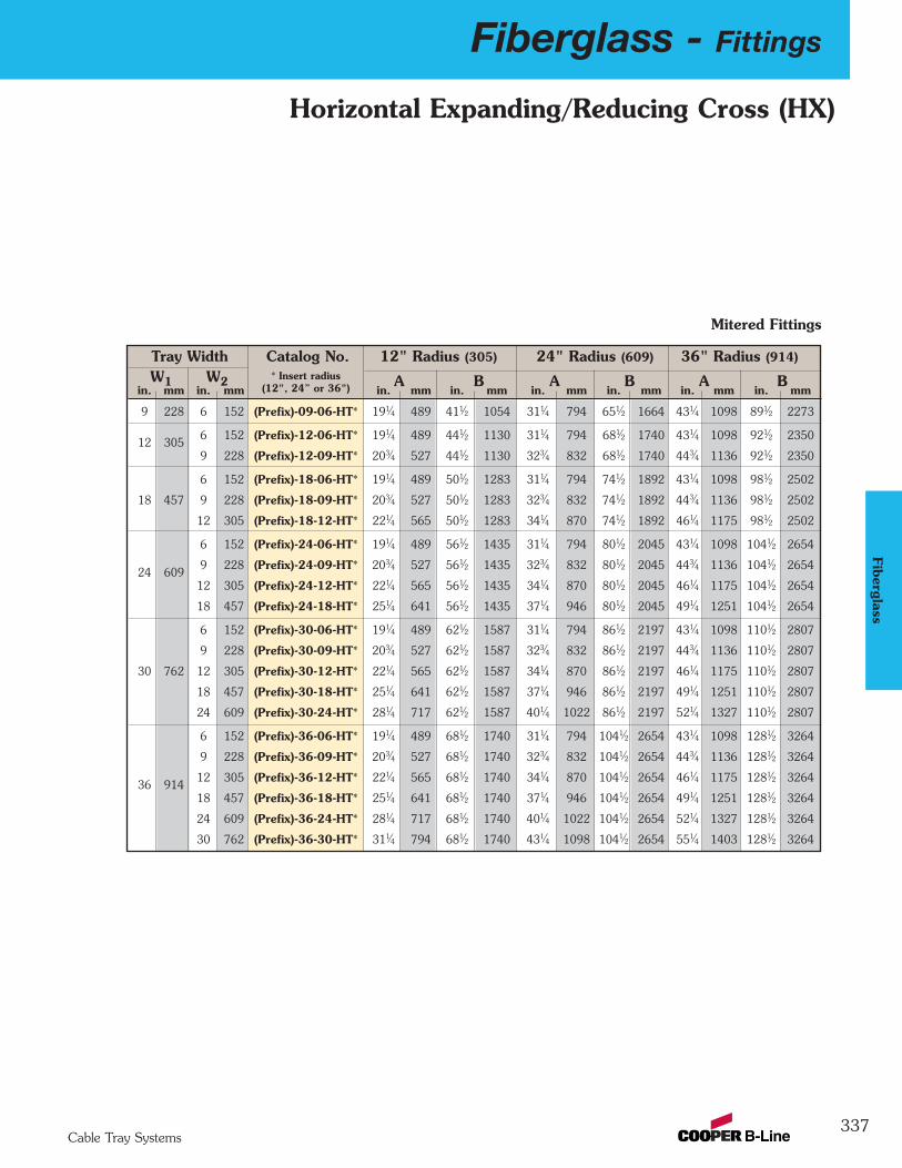
Fiberglass - Fittings
337Cable Tray Systems
Fiberglass
Horizontal Expanding/Reducing Cross (HX)
Tray Width Catalog No. 12" Radius (305) 24" Radius (609) 36" Radius (914)
W1 W2 A B A B A Bin. mm in. mm in. mm in. mm in. mm in. mm in. mm in. mm
9 228 6 152 (Prefix)-09-06-HT* 191⁄4 489 411⁄2 1054 311⁄4 794 651⁄2 1664 431⁄4 1098 891⁄2 2273
12 3056 152 (Prefix)-12-06-HT* 191⁄4 489 441⁄2 1130 311⁄4 794 681⁄2 1740 431⁄4 1098 921⁄2 2350
9 228 (Prefix)-12-09-HT* 203⁄4 527 441⁄2 1130 323⁄4 832 681⁄2 1740 443⁄4 1136 921⁄2 2350
6 152 (Prefix)-18-06-HT* 191⁄4 489 501⁄2 1283 311⁄4 794 741⁄2 1892 431⁄4 1098 981⁄2 2502
18 457 9 228 (Prefix)-18-09-HT* 203⁄4 527 501⁄2 1283 323⁄4 832 741⁄2 1892 443⁄4 1136 981⁄2 2502
12 305 (Prefix)-18-12-HT* 221⁄4 565 501⁄2 1283 341⁄4 870 741⁄2 1892 461⁄4 1175 981⁄2 2502
6 152 (Prefix)-24-06-HT* 191⁄4 489 561⁄2 1435 311⁄4 794 801⁄2 2045 431⁄4 1098 1041⁄2 2654
24 6099 228 (Prefix)-24-09-HT* 203⁄4 527 561⁄2 1435 323⁄4 832 801⁄2 2045 443⁄4 1136 1041⁄2 2654
12 305 (Prefix)-24-12-HT* 221⁄4 565 561⁄2 1435 341⁄4 870 801⁄2 2045 461⁄4 1175 1041⁄2 2654
18 457 (Prefix)-24-18-HT* 251⁄4 641 561⁄2 1435 371⁄4 946 801⁄2 2045 491⁄4 1251 1041⁄2 2654
6 152 (Prefix)-30-06-HT* 191⁄4 489 621⁄2 1587 311⁄4 794 861⁄2 2197 431⁄4 1098 1101⁄2 2807
9 228 (Prefix)-30-09-HT* 203⁄4 527 621⁄2 1587 323⁄4 832 861⁄2 2197 443⁄4 1136 1101⁄2 2807
30 762 12 305 (Prefix)-30-12-HT* 221⁄4 565 621⁄2 1587 341⁄4 870 861⁄2 2197 461⁄4 1175 1101⁄2 2807
18 457 (Prefix)-30-18-HT* 251⁄4 641 621⁄2 1587 371⁄4 946 861⁄2 2197 491⁄4 1251 1101⁄2 2807
24 609 (Prefix)-30-24-HT* 281⁄4 717 621⁄2 1587 401⁄4 1022 861⁄2 2197 521⁄4 1327 1101⁄2 2807
6 152 (Prefix)-36-06-HT* 191⁄4 489 681⁄2 1740 311⁄4 794 1041⁄2 2654 431⁄4 1098 1281⁄2 3264
9 228 (Prefix)-36-09-HT* 203⁄4 527 681⁄2 1740 323⁄4 832 1041⁄2 2654 443⁄4 1136 1281⁄2 3264
36 91412 305 (Prefix)-36-12-HT* 221⁄4 565 681⁄2 1740 341⁄4 870 1041⁄2 2654 461⁄4 1175 1281⁄2 3264
18 457 (Prefix)-36-18-HT* 251⁄4 641 681⁄2 1740 371⁄4 946 1041⁄2 2654 491⁄4 1251 1281⁄2 3264
24 609 (Prefix)-36-24-HT* 281⁄4 717 681⁄2 1740 401⁄4 1022 1041⁄2 2654 521⁄4 1327 1281⁄2 3264
30 762 (Prefix)-36-30-HT* 311⁄4 794 681⁄2 1740 431⁄4 1098 1041⁄2 2654 551⁄4 1403 1281⁄2 3264
* Insert radius(12", 24” or 36")
Mitered Fittings
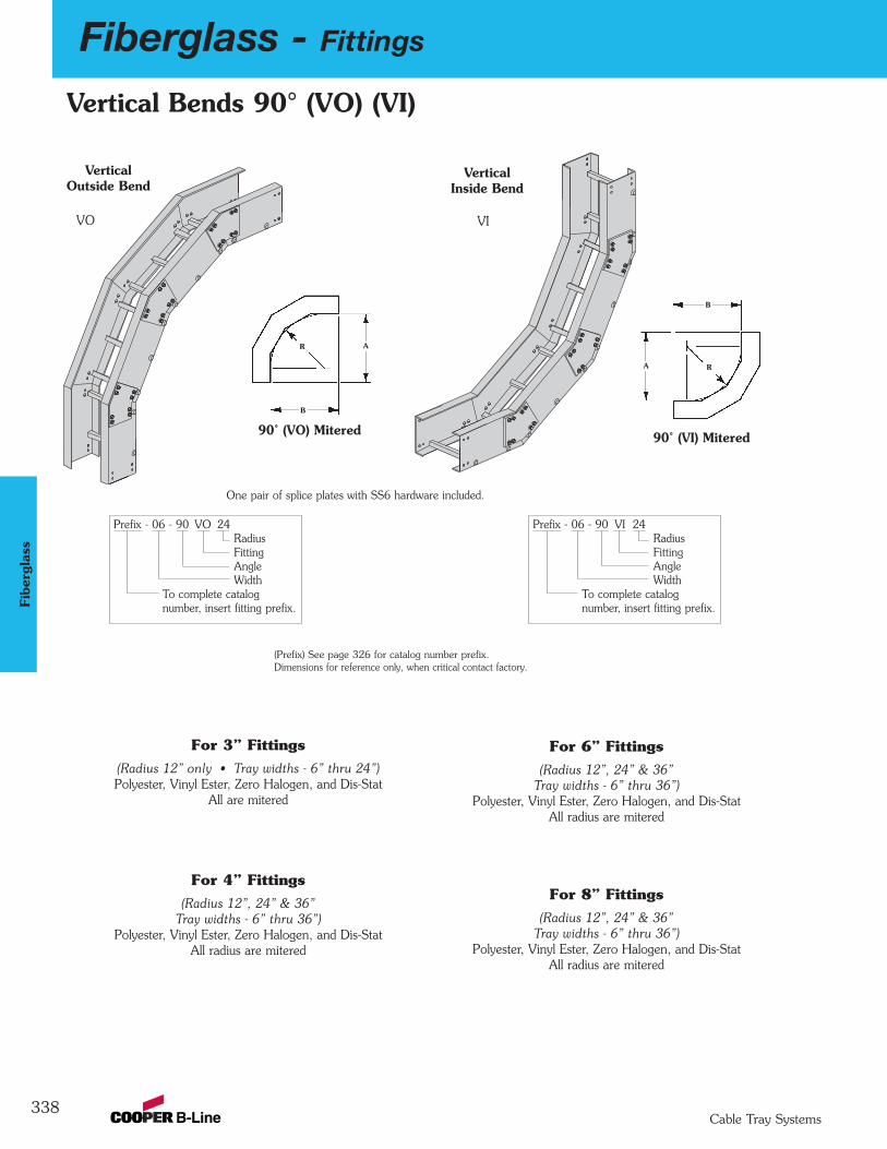
338
Fiberglass - Fittings
Cable Tray Systems
Fibe
rgla
ss
Vertical Bends 90° (VO) (VI)
(Radius 12” only • Tray widths - 6” thru 24”)Polyester, Vinyl Ester, Zero Halogen, and Dis-Stat
All are mitered
For 3” Fittings
(Radius 12”, 24” & 36”Tray widths - 6” thru 36”)
Polyester, Vinyl Ester, Zero Halogen, and Dis-StatAll radius are mitered
For 4” Fittings
(Radius 12”, 24” & 36”Tray widths - 6” thru 36”)
Polyester, Vinyl Ester, Zero Halogen, and Dis-StatAll radius are mitered
For 6” Fittings
(Radius 12”, 24” & 36”Tray widths - 6” thru 36”)
Polyester, Vinyl Ester, Zero Halogen, and Dis-StatAll radius are mitered
For 8” Fittings
Vertical Inside Bend
B
AR
A
B
R
90˚ (VI) Mitered90˚ (VO) Mitered
VerticalOutside Bend
VO VI
Prefix - 06 - 90 VI 24RadiusFittingAngleWidth
To complete catalog number, insert fitting prefix.
Prefix - 06 - 90 VO 24RadiusFittingAngleWidth
To complete catalog number, insert fitting prefix.
One pair of splice plates with SS6 hardware included.
Dimensions for reference only, when critical contact factory.(Prefix) See page 326 for catalog number prefix.
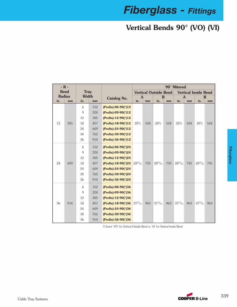
Fiberglass - Fittings
339Cable Tray Systems
Fiberglass
Vertical Bends 90° (VO) (VI)
- R - 90˚ MiteredBend Tray Vertical Outside Bend Vertical Inside Bend
Radius Width Catalog No. A B A Bin. mm in. mm in. mm in. mm in. mm in. mm
6 152 (Prefix)-06-90(*)12
9 228 (Prefix)-09-90(*)12
12 305 (Prefix)-12-90(*)12
12 305 18 457 (Prefix)-18-90(*)12 205⁄8 524 205⁄8 524 205⁄8 524 205⁄8 524
24 609 (Prefix)-24-90(*)12
30 762 (Prefix)-30-90(*)12
36 914 (Prefix)-36-90(*)12
6 152 (Prefix)-06-90(*)24
9 228 (Prefix)-09-90(*)24
12 305 (Prefix)-12-90(*)24
24 609 18 457 (Prefix)-18-90(*)24 2831⁄32 735 2831⁄32 735 2831⁄32 735 2831⁄32 735
24 609 (Prefix)-24-90(*)24
30 762 (Prefix)-30-90(*)24
36 914 (Prefix)-36-90(*)24
6 152 (Prefix)-06-90(*)36
9 228 (Prefix)-09-90(*)36
12 305 (Prefix)-12-90(*)36
36 914 18 457 (Prefix)-18-90(*)36 3715⁄16 963 3715⁄16 963 3715⁄16 963 3715⁄16 963
24 609 (Prefix)-24-90(*)36
30 762 (Prefix)-30-90(*)36
36 914 (Prefix)-36-90(*)36
(*) Insert ‘VO’ for Vertical Outside Bend or ‘VI’ for Vertical Inside Bend.
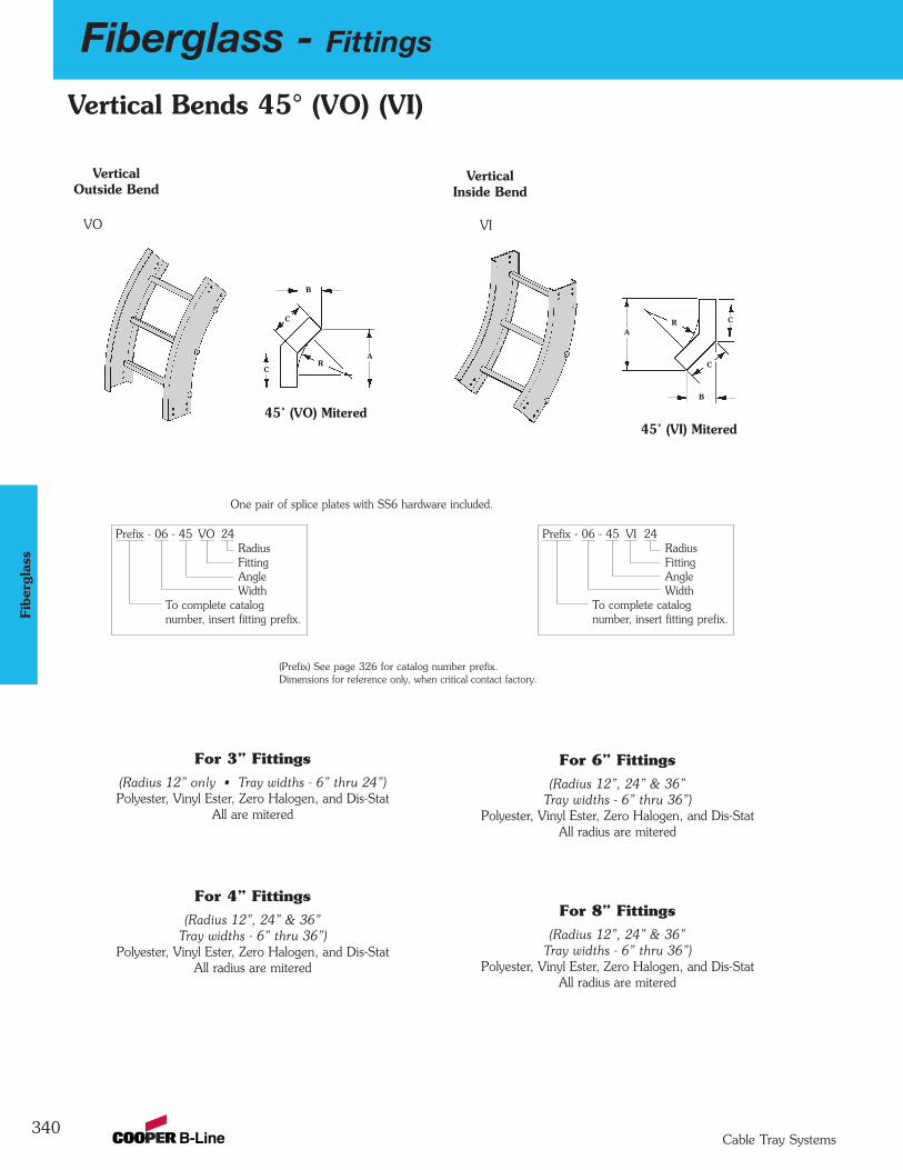
340
Fiberglass - Fittings
Cable Tray Systems
Fibe
rgla
ss
Vertical Bends 45° (VO) (VI)
(Radius 12” only • Tray widths - 6” thru 24”)Polyester, Vinyl Ester, Zero Halogen, and Dis-Stat
All are mitered
For 3” Fittings
(Radius 12”, 24” & 36”Tray widths - 6” thru 36”)
Polyester, Vinyl Ester, Zero Halogen, and Dis-StatAll radius are mitered
For 4” Fittings
(Radius 12”, 24” & 36”Tray widths - 6” thru 36”)
Polyester, Vinyl Ester, Zero Halogen, and Dis-StatAll radius are mitered
For 6” Fittings
(Radius 12”, 24” & 36”Tray widths - 6” thru 36”)
Polyester, Vinyl Ester, Zero Halogen, and Dis-StatAll radius are mitered
For 8” Fittings
Vertical Inside Bend
VerticalOutside Bend
VO VI
Prefix - 06 - 45 VI 24RadiusFittingAngleWidth
To complete catalog number, insert fitting prefix.
Prefix - 06 - 45 VO 24RadiusFittingAngleWidth
To complete catalog number, insert fitting prefix.
One pair of splice plates with SS6 hardware included.
Dimensions for reference only, when critical contact factory.(Prefix) See page 326 for catalog number prefix.
R
B
A
C
C RA
B
C
C
45˚ (VI) Mitered45˚ (VO) Mitered
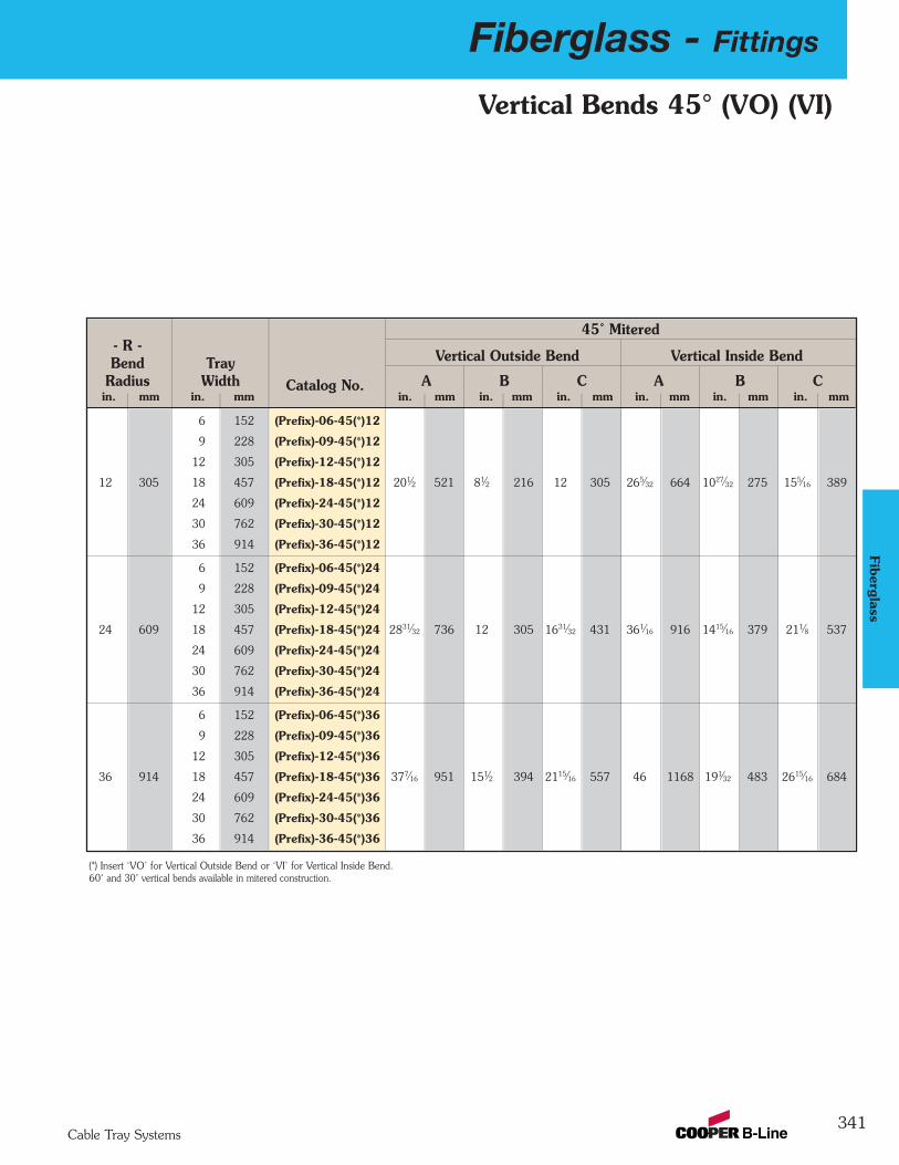
Fiberglass - Fittings
341Cable Tray Systems
Fiberglass
Vertical Bends 45° (VO) (VI)
45˚ Mitered- R -Bend Tray Vertical Outside Bend Vertical Inside Bend
Radius Width Catalog No. A B C A B Cin. mm in. mm in. mm in. mm in. mm in. mm in. mm in. mm
6 152 (Prefix)-06-45(*)12
9 228 (Prefix)-09-45(*)12
12 305 (Prefix)-12-45(*)12
12 305 18 457 (Prefix)-18-45(*)12 201⁄2 521 81⁄2 216 12 305 265⁄32 664 1027⁄32 275 155⁄16 389
24 609 (Prefix)-24-45(*)12
30 762 (Prefix)-30-45(*)12
36 914 (Prefix)-36-45(*)12
6 152 (Prefix)-06-45(*)24
9 228 (Prefix)-09-45(*)24
12 305 (Prefix)-12-45(*)24
24 609 18 457 (Prefix)-18-45(*)24 2831⁄32 736 12 305 1631⁄32 431 361⁄16 916 1415⁄16 379 211⁄8 537
24 609 (Prefix)-24-45(*)24
30 762 (Prefix)-30-45(*)24
36 914 (Prefix)-36-45(*)24
6 152 (Prefix)-06-45(*)36
9 228 (Prefix)-09-45(*)36
12 305 (Prefix)-12-45(*)36
36 914 18 457 (Prefix)-18-45(*)36 377⁄16 951 151⁄2 394 2115⁄16 557 46 1168 191⁄32 483 2615⁄16 684
24 609 (Prefix)-24-45(*)36
30 762 (Prefix)-30-45(*)36
36 914 (Prefix)-36-45(*)36
(*) Insert ‘VO’ for Vertical Outside Bend or ‘VI’ for Vertical Inside Bend.60˚ and 30˚ vertical bends available in mitered construction.
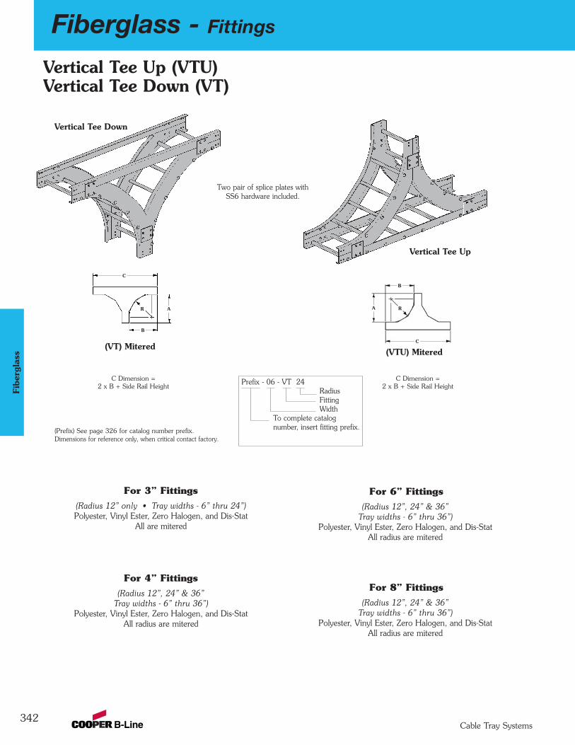
342
Fiberglass - Fittings
Cable Tray Systems
Fibe
rgla
ss
Vertical Tee Up
RR A
C
B
(VTU) Mitered(VT) Mitered
Vertical Tee Down
Prefix - 06 - VT 24RadiusFittingWidth
To complete catalog number, insert fitting prefix.
Two pair of splice plates withSS6 hardware included.
Dimensions for reference only, when critical contact factory.(Prefix) See page 326 for catalog number prefix.
C Dimension =2 x B + Side Rail Height
C Dimension =2 x B + Side Rail Height
Vertical Tee Up (VTU)Vertical Tee Down (VT)
(Radius 12” only • Tray widths - 6” thru 24”)Polyester, Vinyl Ester, Zero Halogen, and Dis-Stat
All are mitered
For 3” Fittings
(Radius 12”, 24” & 36”Tray widths - 6” thru 36”)
Polyester, Vinyl Ester, Zero Halogen, and Dis-StatAll radius are mitered
For 4” Fittings
(Radius 12”, 24” & 36”Tray widths - 6” thru 36”)
Polyester, Vinyl Ester, Zero Halogen, and Dis-StatAll radius are mitered
For 6” Fittings
(Radius 12”, 24” & 36”Tray widths - 6” thru 36”)
Polyester, Vinyl Ester, Zero Halogen, and Dis-StatAll radius are mitered
For 8” Fittings
A
C
B

Fiberglass - Fittings
343Cable Tray Systems
Fiberglass
- R - MiteredBend Tray Vertical Tee Down Vertical Tee Up
Radius Width Catalog No. A B A Bin. mm in. mm in. mm in. mm in. mm in. mm
6 152 (Prefix)-06-(*)12
9 228 (Prefix)-09-(*)12
12 30512 305 (Prefix)-12-(*)12
18 457 (Prefix)-18-(*)12 205⁄8 524 205⁄8 524 205⁄8 524 205⁄8 524
24 609 (Prefix)-24-(*)12
30 762 (Prefix)-30-(*)12
6 152 (Prefix)-06-(*)24
9 228 (Prefix)-09-(*)24
12 305 (Prefix)-12-(*)2424 609 18 457 (Prefix)-18-(*)24 29 736 29 736 29 736 29 736
24 609 (Prefix)-24-(*)24
30 762 (Prefix)-30-(*)24
6 152 (Prefix)-06-(*)36
9 228 (Prefix)-09-(*)36
12 305 (Prefix)-12-(*)3636 914
18 457 (Prefix)-18-(*)36 3715⁄16 963 3715⁄16 963 3715⁄16 963 3715⁄16 963
24 609 (Prefix)-24-(*)36
30 762 (Prefix)-30-(*)36
(*) Insert ‘VT’ for Vertical Tee Down or ‘VTU’ for Vertical Tee Up.
Vertical Tee Up (VTU)Vertical Tee Down (VT)
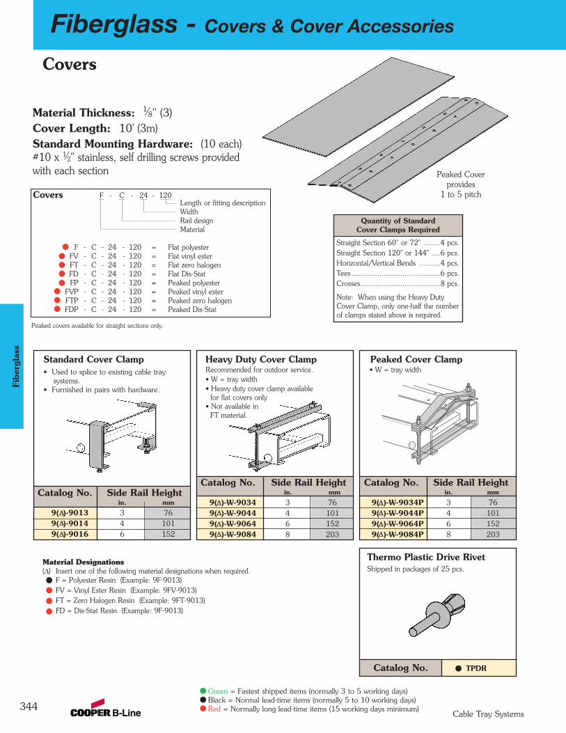
344
Fiberglass - Covers & Cover Accessories
Cable Tray Systems
Green = Fastest shipped items (normally 3 to 5 working days)Black = Normal lead-time items (normally 5 to 10 working days)Red = Normally long lead-time items (15 working days minimum)
Fibe
rgla
ss
Covers
Material Thickness: 1⁄8" (3)Cover Length: 10' (3m)Standard Mounting Hardware: (10 each)#10 x 1⁄2" stainless, self drilling screws providedwith each section
Covers F - C - 24 - 120Length or fitting descriptionWidthRail designMaterial
F - C - 24 - 120 = Flat polyesterFV - C - 24 - 120 = Flat vinyl esterFT - C - 24 - 120 = Flat zero halogenFD - C - 24 - 120 = Flat Dis-StatFP - C - 24 - 120 = Peaked polyester
FVP - C - 24 - 120 = Peaked vinyl esterFTP - C - 24 - 120 = Peaked zero halogenFDP - C - 24 - 120 = Peaked Dis-Stat
Peaked Coverprovides
1 to 5 pitch
Peaked covers available for straight sections only.
Quantity of StandardCover Clamps Required
Straight Section 60" or 72" ........4 pcs.Straight Section 120" or 144" ....6 pcs.Horizontal/Vertical Bends ..........4 pcs.Tees ..........................................6 pcs.Crosses......................................8 pcs.
Note: When using the Heavy DutyCover Clamp, only one-half the numberof clamps stated above is required.
Catalog No. Side Rail Heightin. mm
9(∆∆)-9013 3 769(∆∆)-9014 4 1019(∆∆)-9016 6 152
Catalog No. Side Rail Heightin. mm
9(∆∆)-W-9034 3 769(∆∆)-W-9044 4 1019(∆∆)-W-9064 6 1529(∆∆)-W-9084 8 203
Heavy Duty Cover ClampRecommended for outdoor service.• W = tray width• Heavy duty cover clamp available
for flat covers only• Not available in
FT material.
Catalog No. Side Rail Heightin. mm
9(∆∆)-W-9034P 3 769(∆∆)-W-9044P 4 1019(∆∆)-W-9064P 6 1529(∆∆)-W-9084P 8 203
Peaked Cover Clamp• W = tray width
Thermo Plastic Drive RivetShipped in packages of 25 pcs.
Standard Cover Clamp• Used to splice to existing cable tray
systems.• Furnished in pairs with hardware.
Catalog No. TPDR
Material Designations(∆) Insert one of the following material designations when required.
F = Polyester Resin (Example: 9F-9013)FV = Vinyl Ester Resin (Example: 9FV-9013)FT = Zero Halogen Resin (Example: 9FT-9013)FD = Dis-Stat Resin (Example: 9F-9013)
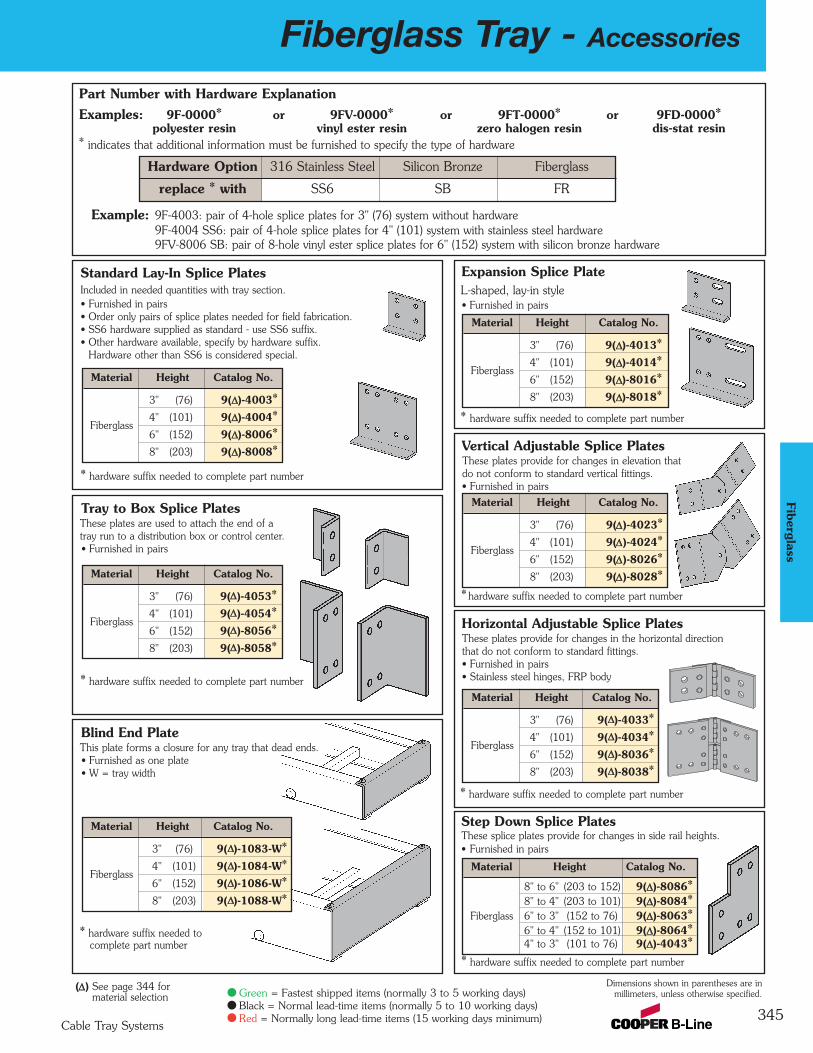
Fiberglass Tray - Accessories
345Cable Tray Systems
Green = Fastest shipped items (normally 3 to 5 working days)Black = Normal lead-time items (normally 5 to 10 working days)Red = Normally long lead-time items (15 working days minimum)
Fiberglass
Part Number with Hardware ExplanationExamples: 9F-0000* or 9FV-0000* or 9FT-0000* or 9FD-0000*
polyester resin vinyl ester resin zero halogen resin dis-stat resin* indicates that additional information must be furnished to specify the type of hardware
Example: 9F-4003: pair of 4-hole splice plates for 3" (76) system without hardware9F-4004 SS6: pair of 4-hole splice plates for 4" (101) system with stainless steel hardware9FV-8006 SB: pair of 8-hole vinyl ester splice plates for 6" (152) system with silicon bronze hardware
Vertical Adjustable Splice PlatesThese plates provide for changes in elevation thatdo not conform to standard vertical fittings. • Furnished in pairs
*hardware suffix needed to complete part number
Blind End PlateThis plate forms a closure for any tray that dead ends.• Furnished as one plate• W = tray width
* hardware suffix needed to complete part number
Tray to Box Splice PlatesThese plates are used to attach the end of a tray run to a distribution box or control center. • Furnished in pairs
* hardware suffix needed to complete part number
Horizontal Adjustable Splice PlatesThese plates provide for changes in the horizontal direction that do not conform to standard fittings. • Furnished in pairs• Stainless steel hinges, FRP body
* hardware suffix needed to complete part number
Standard Lay-In Splice PlatesIncluded in needed quantities with tray section.• Furnished in pairs• Order only pairs of splice plates needed for field fabrication.• SS6 hardware supplied as standard - use SS6 suffix.• Other hardware available, specify by hardware suffix.
Hardware other than SS6 is considered special.
* hardware suffix needed to complete part number
Expansion Splice PlateL-shaped, lay-in style• Furnished in pairs
* hardware suffix needed to complete part number
Step Down Splice PlatesThese splice plates provide for changes in side rail heights. • Furnished in pairs
* hardware suffix needed to complete part number
Hardware Option 316 Stainless Steel Silicon Bronze Fiberglass
replace * with SS6 SB FR
Material Height Catalog No.
8" to 6" (203 to 152) 9(∆∆)-8086*8" to 4" (203 to 101) 9(∆∆)-8084*
Fiberglass 6" to 3" (152 to 76) 9(∆∆)-8063*6" to 4" (152 to 101) 9(∆∆)-8064*4" to 3" (101 to 76) 9(∆∆)-4043*
Material Height Catalog No.
3" (76) 9(∆∆)-4053*
Fiberglass4" (101) 9(∆∆)-4054*6" (152) 9(∆∆)-8056*8" (203) 9(∆∆)-8058*
Material Height Catalog No.
3" (76) 9(∆∆)-4013*
Fiberglass4" (101) 9(∆∆)-4014*6" (152) 9(∆∆)-8016*8" (203) 9(∆∆)-8018*
Material Height Catalog No.
3" (76) 9(∆∆)-4023*
Fiberglass4" (101) 9(∆∆)-4024*6" (152) 9(∆∆)-8026*8" (203) 9(∆∆)-8028*
Material Height Catalog No.
3" (76) 9(∆∆)-4033*
Fiberglass4" (101) 9(∆∆)-4034*6" (152) 9(∆∆)-8036*8" (203) 9(∆∆)-8038*
Material Height Catalog No.
3" (76) 9(∆∆)-4003*
Fiberglass4" (101) 9(∆∆)-4004*6" (152) 9(∆∆)-8006*8" (203) 9(∆∆)-8008*
Dimensions shown in parentheses are inmillimeters, unless otherwise specified.
Material Height Catalog No.
3" (76) 9(∆∆)-1083-W*
Fiberglass4" (101) 9(∆∆)-1084-W*6" (152) 9(∆∆)-1086-W*8" (203) 9(∆∆)-1088-W*
(∆∆) See page 344 formaterial selection

346
Fiberglass Tray - Accessories
Cable Tray Systems
Green = Fastest shipped items (normally 3 to 5 working days)Black = Normal lead-time items (normally 5 to 10 working days)Red = Normally long lead-time items (15 working days minimum)
Fibe
rgla
ss
Horizontal Splice Plates• Furnished in pairs* Hardware suffix needed to complete part number
Catalog No. Catalog No. Catalog No.90˚ 45˚ 30˚
9(∆∆)-4903H* 9(∆∆)-4453H* 9(∆∆)-4303H*9(∆∆)-4904H* 9(∆∆)-4454H* 9(∆∆)-4304H*9(∆∆)-8906H* 9(∆∆)-8456H* 9(∆∆)-8306H*9(∆∆)-8908H* 9(∆∆)-8458H* 9(∆∆)-8308H*
Vertical Splice Plates• Furnished in pairs* Hardware suffix needed to complete part number
Catalog No. Catalog No. Catalog No.90˚ 45˚ 30˚
9(∆∆)-4903V* 9(∆∆)-4453V* 9(∆∆)-4303V*9(∆∆)-4904V* 9(∆∆)-4454V* 9(∆∆)-4304V*9(∆∆)-8906V* 9(∆∆)-8456V* 9(∆∆)-8306V*9(∆∆)-8908V* 9(∆∆)-8458V* 9(∆∆)-8308V*
Horizontal and Vertical Splice Plates* Hardware suffix needed to complete part numberAll splice plate hardware is 3⁄8 ".
Standard lay-in splice plates with SS6 hardware included with tray sections.Splice Plates are available in pairs and are a separate order item. They are not automatically supplied with tray sections.
Hardware Suffix:SS6 - 316SSMO - MonelSB - Silicon BronzeFR - Fiberglass
(∆∆) See page 344 formaterial selection
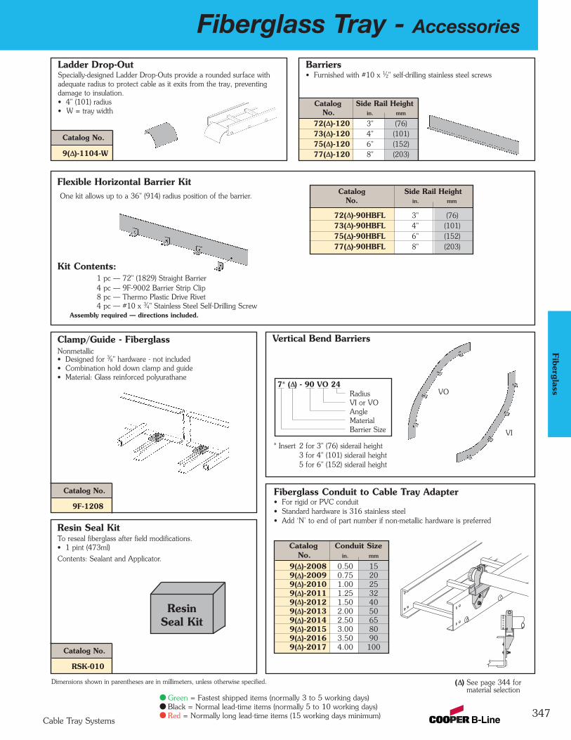
Fiberglass Tray - Accessories
347Cable Tray Systems
Green = Fastest shipped items (normally 3 to 5 working days)Black = Normal lead-time items (normally 5 to 10 working days)Red = Normally long lead-time items (15 working days minimum)
Fiberglass
Resin Seal KitTo reseal fiberglass after field modifications.• 1 pint (473ml)
Contents: Sealant and Applicator.
Vertical Bend Barriers
One kit allows up to a 36" (914) radius position of the barrier.Catalog Side Rail Height
No. in. mm
72(∆∆)-90HBFL 3" (76)73(∆∆)-90HBFL 4" (101)75(∆∆)-90HBFL 6" (152)77(∆∆)-90HBFL 8" (203)
Clamp/Guide - FiberglassNonmetallic• Designed for 3⁄8" hardware - not included• Combination hold down clamp and guide• Material: Glass reinforced polyurathane
Ladder Drop-OutSpecially-designed Ladder Drop-Outs provide a rounded surface with adequate radius to protect cable as it exits from the tray, preventing damage to insulation. • 4" (101) radius• W = tray width
Dimensions shown in parentheses are in millimeters, unless otherwise specified.
Barriers• Furnished with #10 x 1⁄2" self-drilling stainless steel screws
Flexible Horizontal Barrier Kit
VO
VI
Resin Seal Kit
7* (∆∆) - 90 VO 24RadiusVI or VOAngleMaterialBarrier Size
Fiberglass Conduit to Cable Tray Adapter• For rigid or PVC conduit• Standard hardware is 316 stainless steel• Add ‘N’ to end of part number if non-metallic hardware is preferred
Catalog Conduit SizeNo. in. mm
9(∆∆)-2008 0.50 159(∆∆)-2009 0.75 209(∆∆)-2010 1.00 259(∆∆)-2011 1.25 329(∆∆)-2012 1.50 409(∆∆)-2013 2.00 509(∆∆)-2014 2.50 659(∆∆)-2015 3.00 809(∆∆)-2016 3.50 909(∆∆)-2017 4.00 100
Kit Contents:1 pc — 72" (1829) Straight Barrier 4 pc — 9F-9002 Barrier Strip Clip8 pc — Thermo Plastic Drive Rivet4 pc — #10 x 3⁄4" Stainless Steel Self-Drilling Screw
Assembly required — directions included.
Catalog Side Rail HeightNo. in. mm
72(∆∆)-120 3" (76)73(∆∆)-120 4" (101)75(∆∆)-120 6" (152)77(∆∆)-120 8" (203)
Catalog No.
9(∆∆)-1104-W
* Insert 2 for 3" (76) siderail height3 for 4" (101) siderail height5 for 6" (152) siderail height
Catalog No.
9F-1208
Catalog No.
RSK-010
(∆∆) See page 344 formaterial selection
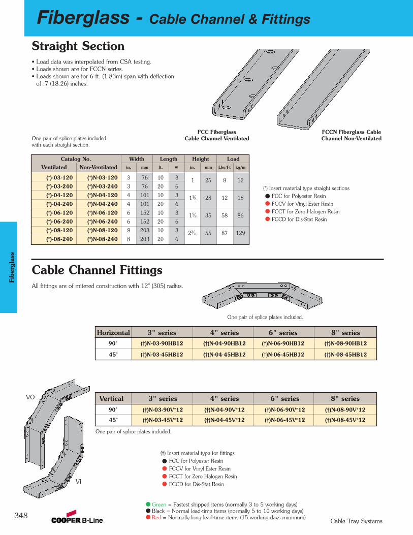
348
Fiberglass - Cable Channel & Fittings
Cable Tray Systems
Green = Fastest shipped items (normally 3 to 5 working days)Black = Normal lead-time items (normally 5 to 10 working days)Red = Normally long lead-time items (15 working days minimum)
Fibe
rgla
ss
Cable Channel Fittings
FCC Fiberglass Cable Channel Ventilated
FCCN Fiberglass Cable Channel Non-Ventilated
Horizontal 3" series 4" series 6" series 8" series90˚ (†)N-03-90HB12 (†)N-04-90HB12 (†)N-06-90HB12 (†)N-08-90HB12
45˚ (†)N-03-45HB12 (†)N-04-45HB12 (†)N-06-45HB12 (†)N-08-45HB12
Catalog No. Width Length Height LoadVentilated Non-Ventilated in. mm ft. m in. mm Lbs/Ft kg/m
(*)-03-120 (*)N-03-120 3 76 10 3 1 25 8 12(*)-03-240 (*)N-03-240 3 76 20 6
(*)-04-120 (*)N-04-120 4 101 10 3 11⁄8 28 12 18(*)-04-240 (*)N-04-240 4 101 20 6
(*)-06-120 (*)N-06-120 6 152 10 3 15⁄8 35 58 86(*)-06-240 (*)N-06-240 6 152 20 6
(*)-08-120 (*)N-08-120 8 203 10 3 23⁄16 55 87 129(*)-08-240 (*)N-08-240 8 203 20 6
All fittings are of mitered construction with 12" (305) radius.
Straight Section
(†) Insert material type for fittingsFCC for Polyester ResinFCCV for Vinyl Ester ResinFCCT for Zero Halogen ResinFCCD for Dis-Stat Resin
VO
VI
Vertical 3" series 4" series 6" series 8" series90˚ (†)N-03-90V*12 (†)N-04-90V*12 (†)N-06-90V*12 (†)N-08-90V*12
45˚ (†)N-03-45V*12 (†)N-04-45V*12 (†)N-06-45V*12 (†)N-08-45V*12
One pair of splice plates includedwith each straight section.
One pair of splice plates included.
One pair of splice plates included.
• Load data was interpolated from CSA testing.• Loads shown are for FCCN series.• Loads shown are for 6 ft. (1.83m) span with deflection
of .7 (18.26) inches.
(*) Insert material type straight sectionsFCC for Polyester ResinFCCV for Vinyl Ester ResinFCCT for Zero Halogen ResinFCCD for Dis-Stat Resin

Fiberglass - Cable Channel Fittings & Accessories
349Cable Tray Systems
Green = Fastest shipped items (normally 3 to 5 working days)Black = Normal lead-time items (normally 5 to 10 working days)Red = Normally long lead-time items (15 working days minimum)
Fiberglass
Cable Channel Splice Plates
Horizontal Tees Horizontal Crosses
Splice plates included with cable channel sections.Standard hardware for splice plates is 1/4”-20 (316SS).
Catalog WidthNo. in. mm
FCC(†)N-03-HT12 3 76
FCC(†)N-04-HT12 4 101
FCC(†)N-06-HT12 6 152
FCC(†)N-08-HT12 8 203
Catalog WidthNo. in. mm
FCC(†)N-03-HX12 3 76
FCC(†)N-04-HX12 4 101
FCC(†)N-06-HX12 6 152
FCC(†)N-08-HX12 8 203
Two pair of spliceplates included.
Three pair of spliceplates included.
Splice Plates (pairs)Included with tray sections.
Expansion Splice Plates (pairs)
Horizontal 90˚ Splice Plates(pairs)
Horizontal 45˚ Splice Plates(pairs)
Horizontal 30˚ Splice Plates(pairs)
Catalog No.
9(∆∆)-1013 SS6
Catalog No.
9(∆∆)-1001 SS6
Catalog No.
9(∆∆)-1901H SS6
Catalog No.
9(∆∆)-1301H SS6
Catalog No.
9(∆∆)-1451H SS6
Vertical 90˚ Splice Plates(pairs)
Cable Channel FittingsAll fittings are of mitered construction with 12" (305) radius.
Catalog No.
9(∆∆)-1901V SS6
(∆∆) See page 344 formaterial selection
(†) See page fitting materialselection bottom of page 348
(†) See page fitting materialselection bottom of page 348
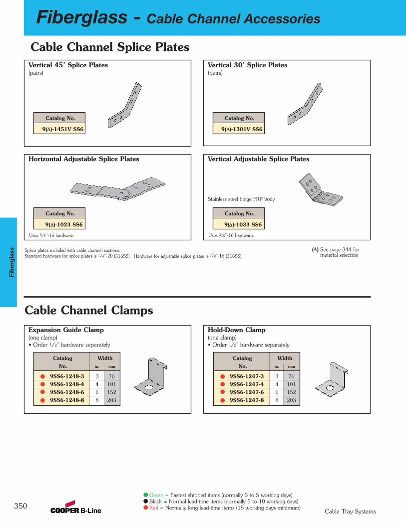
350
Fiberglass - Cable Channel Accessories
Cable Tray Systems
Green = Fastest shipped items (normally 3 to 5 working days)Black = Normal lead-time items (normally 5 to 10 working days)Red = Normally long lead-time items (15 working days minimum)
Fibe
rgla
ss
Expansion Guide Clamp(one clamp)• Order 1/2" hardware separately
Hold-Down Clamp(one clamp)• Order 1/2" hardware separately
Vertical 45˚ Splice Plates(pairs)
Vertical 30˚ Splice Plates(pairs)
Cable Channel Clamps
Horizontal Adjustable Splice Plates
Uses 3/8”-16 hardware.
Vertical Adjustable Splice Plates
Uses 3/8”-16 hardware.
Stainless steel hinge FRP body
Splice plates included with cable channel sections.Standard hardware for splice plates is 1/4”-20 (316SS). Hardware for adjustable splice plates is 3/8”-16 (316SS).
Cable Channel Splice Plates
Catalog No.
9(∆∆)-1301V SS6
Catalog No.
9(∆∆)-1033 SS6
Catalog No.
9(∆∆)-1451V SS6
Catalog No.
9(∆∆)-1023 SS6
Catalog WidthNo. in. mm
9SS6-1247-3 3 76
9SS6-1247-4 4 101
9SS6-1247-6 6 152
9SS6-1247-8 8 203
Catalog WidthNo. in. mm
9SS6-1248-3 3 76
9SS6-1248-4 4 101
9SS6-1248-6 6 152
9SS6-1248-8 8 203
(∆∆) See page 344 formaterial selection
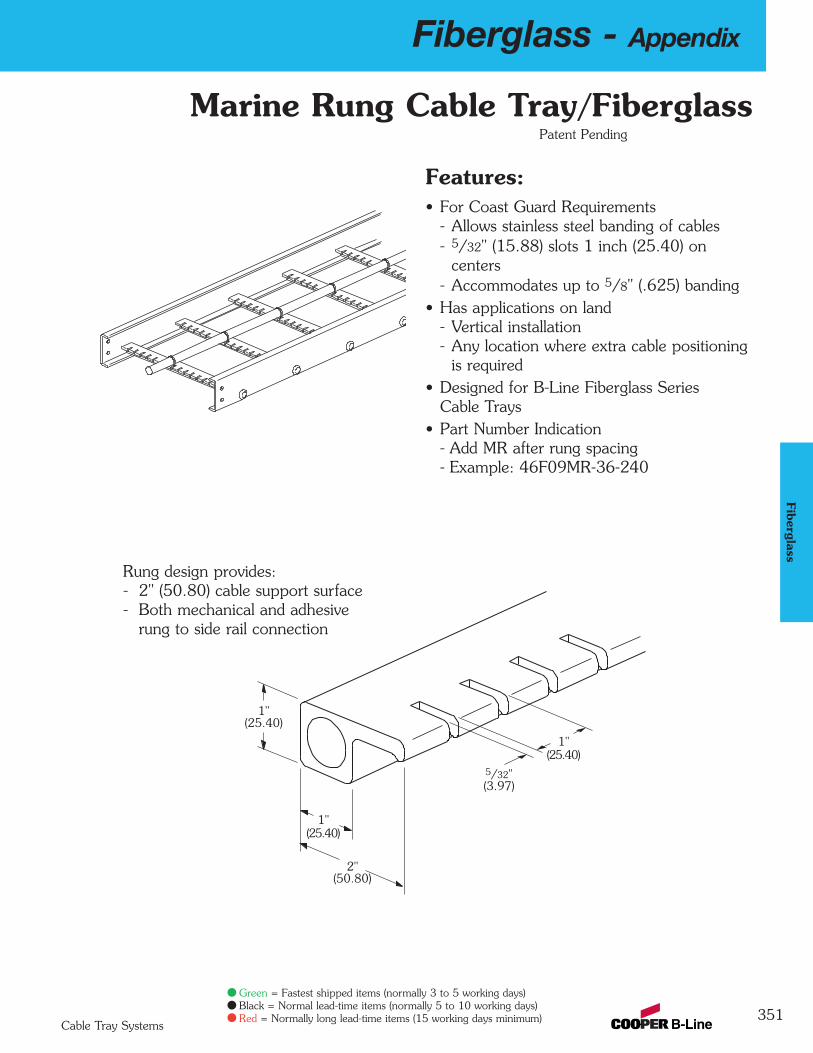
Fiberglass - Appendix
351Cable Tray Systems
Green = Fastest shipped items (normally 3 to 5 working days)Black = Normal lead-time items (normally 5 to 10 working days)Red = Normally long lead-time items (15 working days minimum)
Fiberglass
Rung design provides:- 2" (50.80) cable support surface- Both mechanical and adhesive
rung to side rail connection
Marine Rung Cable Tray/Fiberglass
Features:• For Coast Guard Requirements
- Allows stainless steel banding of cables- 5/32" (15.88) slots 1 inch (25.40) on
centers- Accommodates up to 5/8" (.625) banding
• Has applications on land- Vertical installation- Any location where extra cable positioning
is required• Designed for B-Line Fiberglass Series
Cable Trays• Part Number Indication
- Add MR after rung spacing- Example: 46F09MR-36-240
Patent Pending
1"(25.40)
1"(25.40)
2"(50.80)
5/32"(3.97)
1"(25.40)
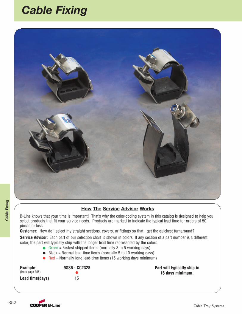
Cable Fixing
352
Cab
le F
ixin
g
Cable Tray Systems
How The Service Advisor Works
B-Line knows that your time is important! That’s why the color-coding system in this catalog is designed to help youselect products that fit your service needs. Products are marked to indicate the typical lead time for orders of 50pieces or less.Customer: How do I select my straight sections. covers, or fittings so that I get the quickest turnaround?Service Advisor: Each part of our selection chart is shown in colors. If any section of a part number is a differentcolor, the part will typically ship with the longer lead time represented by the colors.
Green = Fastest shipped items (normally 3 to 5 working days)Black = Normal lead-time items (normally 5 to 10 working days)Red = Normally long lead-time items (15 working days minimum)
Example: 9SS6 - CC2328 Part will typically ship in(from page 355) 15 days minimum. Lead time(days) 15

Cable Fixing
353
Cable Fixing
Cable Tray Systems
Emperor Trefoil Cable Cleats Vulcan Cable Cleats
Emperor Trefoil Cable Cleats with LSF LinerEmperor cable cleats are recommended forinstallations where the highest levels of short circuitwithstand are required. Emperor cable cleats areindependently certified to BS EN 50368:2003,Category-2 resistance to electromechanical forcesduring short circuits (i.e. cable and cleats are intactand reusable after two successive short circuit tests).To protect and cushion cables, Emperor cleatsincorporate an integral low smoke, low fume, zerohalogen liner in its unique patented design.Recommended fixing methods include one bolt, twobolts, weld stud or framing strut mounting. Optionalbases are available to mount Emperor cable cleats tonon-performed ladder tray rungs.
Vulcan Cable Cleats with LSF LinerVulcan cable cleats are recommended for installationswhere moderate levels of short circuit withstand arerequired. Vulcan cable cleats are designed for trefoil,single and triplex cable installations. Vulcan cablecleats are independently certified to BS EN50368:2003. To protect and cushion cables, eachVulcan cleat incorporates an integral low smoke, lowfume, zero halogen liner in its unique patenteddesign. Recommended fixing methods include onebolt, two bolts, weld stud or framing strut mounting.

Cable Fixing
354
Cab
le F
ixin
g
Cable Tray Systems
BS EN 50368:2003(Cable Cleats for Electric Installations) Classification
Emperor
Cleat Type Composite
Operating Temperature Range -40°C to +60°C
Resistance toElectromechanical Force Category-1: 235kApeak / 109kArms
(See kVA Strategies for Details) Category-2: 178kApeak / 83kArms
Laterial Load Test Refer to kVA Strategies
Axial Load Test 650N
Impact Resistance Very Heavy (>6.7kg @ 300mm)
Needle Flame Test >120 seconds
Technical Specifications
Emperor
50mm Wide x 2mm ThickFrame Marine Grade, Non-magnetic
316L Stainless Steel (BS EN 10088)
Closure Hardware 316L Stainless Steel M12 Bolt,Nyloc Nut & Flat Washer (BS 3692)
Integral LSF Liner Low Smoke, Low FumeZero Halogen Polymer
Tools Required 3/4” or 19mm
Installation Features Captive Closure Bolt1 or 2 Bolt Mounting (3/8” Max. Dia.)
Emperor Trefoil Cable CleatDimensional Drawing
Depthof Cable
Cleat
See Din charton page
355
H
Cables
W
M
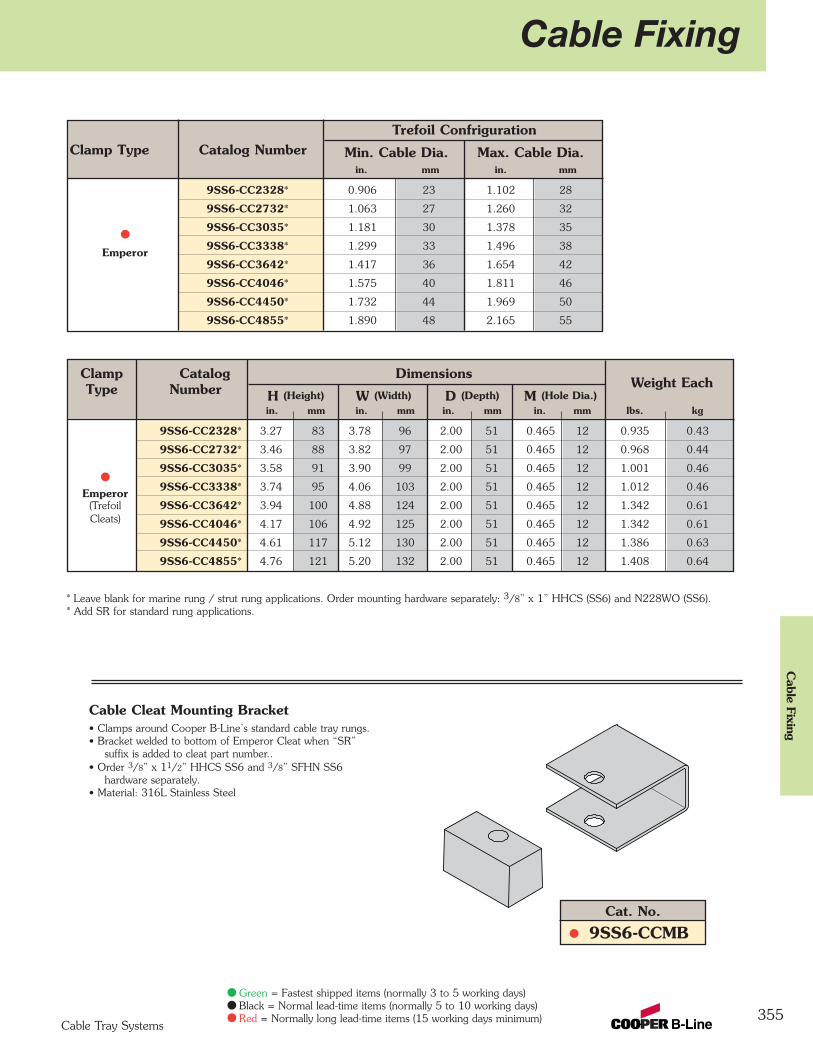
Cable Fixing
355
Cable Fixing
Cable Tray Systems
Green = Fastest shipped items (normally 3 to 5 working days)Black = Normal lead-time items (normally 5 to 10 working days)Red = Normally long lead-time items (15 working days minimum)
Trefoil ConfrigurationClamp Type Catalog Number Min. Cable Dia. Max. Cable Dia.
in. mm in. mm
9SS6-CC2328* 0.906 23 1.102 28
9SS6-CC2732* 1.063 27 1.260 32
9SS6-CC3035* 1.181 30 1.378 35
Emperor 9SS6-CC3338* 1.299 33 1.496 38
9SS6-CC3642* 1.417 36 1.654 42
9SS6-CC4046* 1.575 40 1.811 46
9SS6-CC4450* 1.732 44 1.969 50
9SS6-CC4855* 1.890 48 2.165 55
* Leave blank for marine rung / strut rung applications. Order mounting hardware separately: 3/8” x 1” HHCS (SS6) and N228WO (SS6).* Add SR for standard rung applications.
Clamp Catalog DimensionsType Number H (Height) W (Width) D (Depth) M (Hole Dia.)
Weight Each
in. mm in. mm in. mm in. mm lbs. kg
9SS6-CC2328* 3.27 83 3.78 96 2.00 51 0.465 12 0.935 0.43
9SS6-CC2732* 3.46 88 3.82 97 2.00 51 0.465 12 0.968 0.44
9SS6-CC3035* 3.58 91 3.90 99 2.00 51 0.465 12 1.001 0.46
Emperor 9SS6-CC3338* 3.74 95 4.06 103 2.00 51 0.465 12 1.012 0.46
(Trefoil 9SS6-CC3642* 3.94 100 4.88 124 2.00 51 0.465 12 1.342 0.61Cleats) 9SS6-CC4046* 4.17 106 4.92 125 2.00 51 0.465 12 1.342 0.61
9SS6-CC4450* 4.61 117 5.12 130 2.00 51 0.465 12 1.386 0.63
9SS6-CC4855* 4.76 121 5.20 132 2.00 51 0.465 12 1.408 0.64
Cable Cleat Mounting Bracket• Clamps around Cooper B-Line’s standard cable tray rungs.• Bracket welded to bottom of Emperor Cleat when “SR”
suffix is added to cleat part number..• Order 3/8” x 11/2” HHCS SS6 and 3/8” SFHN SS6
hardware separately.• Material: 316L Stainless Steel
Cat. No.
9SS6-CCMB
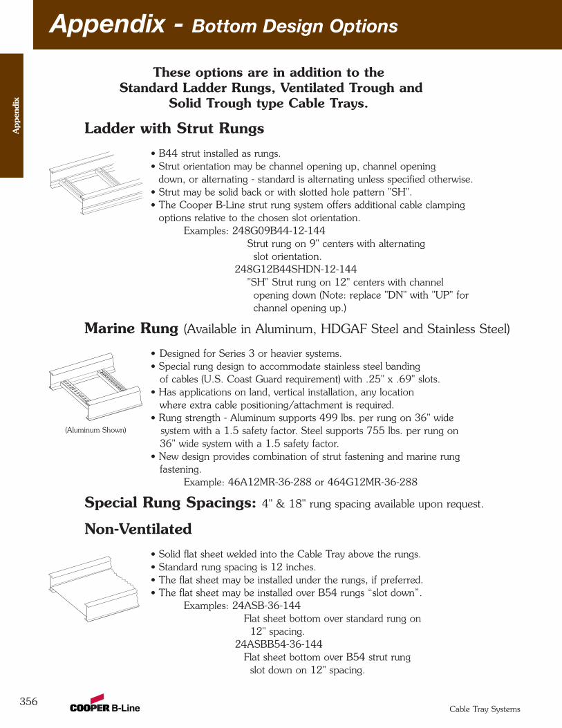
Appendix - Bottom Design Options
356
These options are in addition to theStandard Ladder Rungs, Ventilated Trough and
Solid Trough type Cable Trays.
Ladder with Strut Rungs• B44 strut installed as rungs.• Strut orientation may be channel opening up, channel opening
down, or alternating - standard is alternating unless specified otherwise.• Strut may be solid back or with slotted hole pattern "SH".• The Cooper B-Line strut rung system offers additional cable clamping
options relative to the chosen slot orientation. Examples: 248G09B44-12-144
Strut rung on 9" centers with alternating slot orientation.
248G12B44SHDN-12-144 "SH" Strut rung on 12" centers with channel
opening down (Note: replace "DN" with "UP" for channel opening up.)
Marine Rung (Available in Aluminum, HDGAF Steel and Stainless Steel)
• Designed for Series 3 or heavier systems.• Special rung design to accommodate stainless steel banding
of cables (U.S. Coast Guard requirement) with .25" x .69" slots.• Has applications on land, vertical installation, any location
where extra cable positioning/attachment is required.• Rung strength - Aluminum supports 499 lbs. per rung on 36" wide
system with a 1.5 safety factor. Steel supports 755 lbs. per rung on 36" wide system with a 1.5 safety factor.
• New design provides combination of strut fastening and marine rung fastening.
Example: 46A12MR-36-288 or 464G12MR-36-288
Special Rung Spacings: 4" & 18" rung spacing available upon request.
Non-Ventilated• Solid flat sheet welded into the Cable Tray above the rungs. • Standard rung spacing is 12 inches.• The flat sheet may be installed under the rungs, if preferred.• The flat sheet may be installed over B54 rungs “slot down”.
Examples: 24ASB-36-144Flat sheet bottom over standard rung on
12" spacing.24ASBB54-36-144
Flat sheet bottom over B54 strut rung slot down on 12" spacing.
(Aluminum Shown)
App
endi
x
Cable Tray Systems
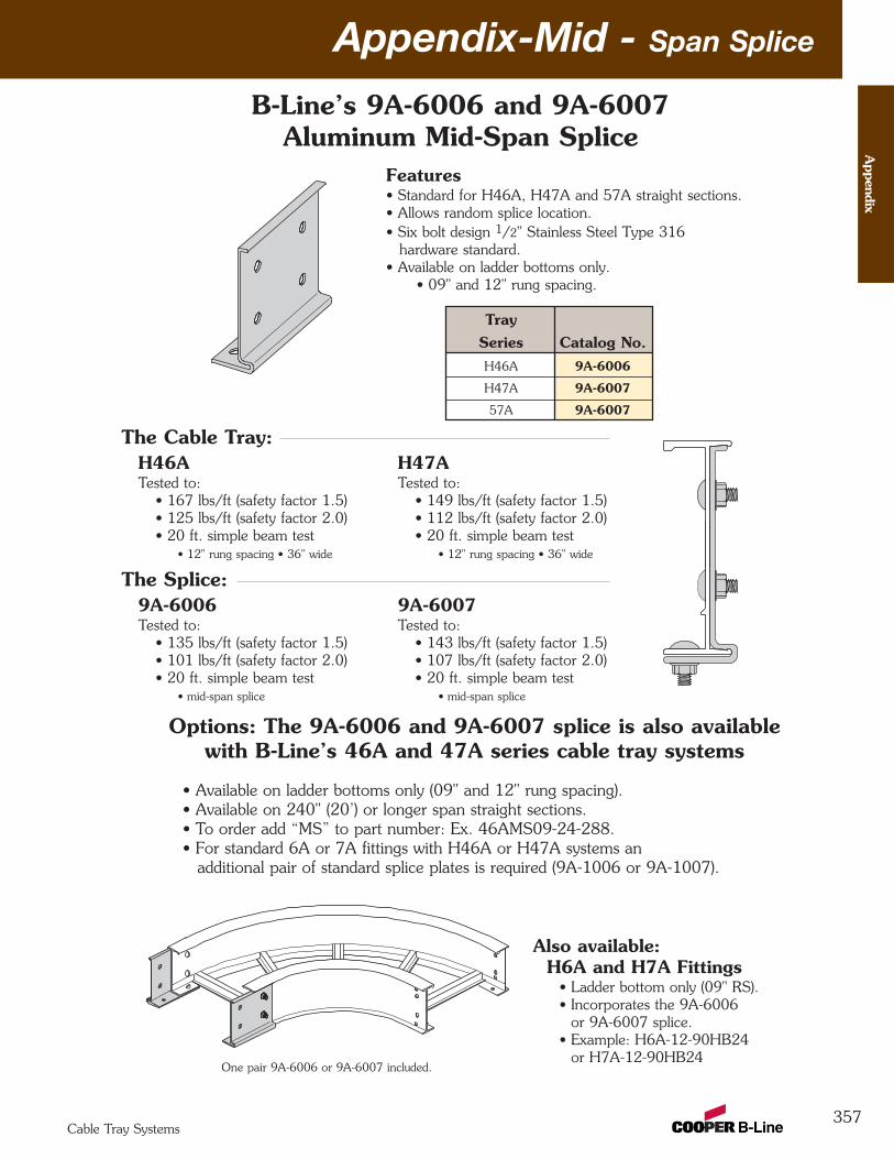
Appendix-Mid - Span Splice
357
B-Line’s 9A-6006 and 9A-6007Aluminum Mid-Span Splice
Features• Standard for H46A, H47A and 57A straight sections.• Allows random splice location.• Six bolt design 1/2" Stainless Steel Type 316
hardware standard.• Available on ladder bottoms only.
• 09" and 12" rung spacing.
Options: The 9A-6006 and 9A-6007 splice is also available with B-Line’s 46A and 47A series cable tray systems
• Available on ladder bottoms only (09" and 12" rung spacing).• Available on 240" (20’) or longer span straight sections.• To order add “MS” to part number: Ex. 46AMS09-24-288.• For standard 6A or 7A fittings with H46A or H47A systems an
additional pair of standard splice plates is required (9A-1006 or 9A-1007).
One pair 9A-6006 or 9A-6007 included.
Appendix
The Cable Tray: H46A H47ATested to: Tested to:
• 167 lbs/ft (safety factor 1.5) • 149 lbs/ft (safety factor 1.5)• 125 lbs/ft (safety factor 2.0) • 112 lbs/ft (safety factor 2.0)• 20 ft. simple beam test • 20 ft. simple beam test
• 12" rung spacing • 36" wide • 12" rung spacing • 36" wide
The Splice: 9A-6006 9A-6007Tested to: Tested to:
• 135 lbs/ft (safety factor 1.5) • 143 lbs/ft (safety factor 1.5)• 101 lbs/ft (safety factor 2.0) • 107 lbs/ft (safety factor 2.0)• 20 ft. simple beam test • 20 ft. simple beam test
• mid-span splice • mid-span splice
TraySeries Catalog No.H46A 9A-6006
H47A 9A-6007
57A 9A-6007
Also available: H6A and H7A Fittings
• Ladder bottom only (09" RS).• Incorporates the 9A-6006
or 9A-6007 splice.• Example: H6A-12-90HB24
or H7A-12-90HB24
Cable Tray Systems
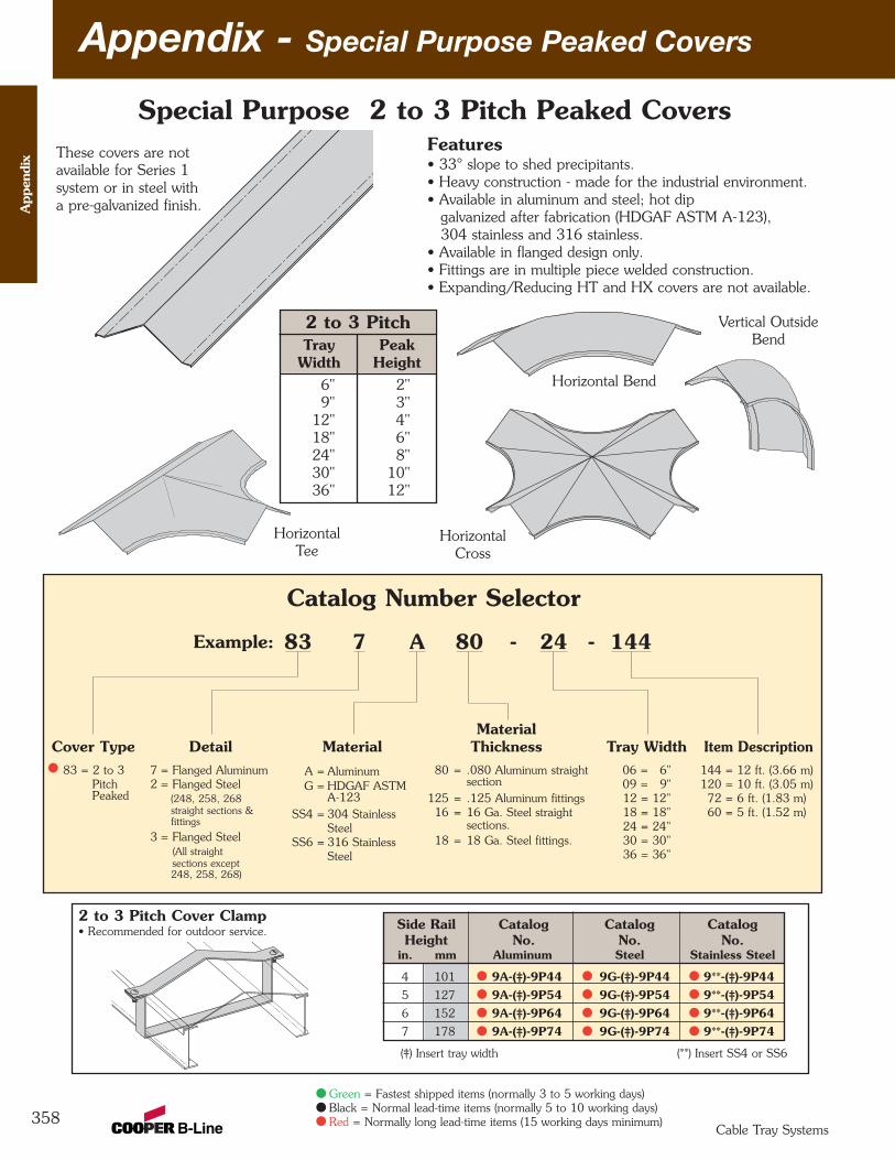
Appendix - Special Purpose Peaked Covers
358
App
endi
x
Cable Tray Systems
Features• 33° slope to shed precipitants.• Heavy construction - made for the industrial environment.• Available in aluminum and steel; hot dip
galvanized after fabrication (HDGAF ASTM A-123), 304 stainless and 316 stainless.
• Available in flanged design only.• Fittings are in multiple piece welded construction.• Expanding/Reducing HT and HX covers are not available.
Horizontal Bend
Vertical OutsideBend
HorizontalCross
HorizontalTee
Cover Type83 = 2 to 3
PitchPeaked
Detail7 = Flanged Aluminum2 = Flanged Steel
(248, 258, 268straight sections &fittings
3 = Flanged Steel (All straightsections except248, 258, 268)
MaterialA = AluminumG = HDGAF ASTM
A-123SS4 = 304 Stainless
SteelSS6 = 316 Stainless
Steel
Material Thickness
80 = .080 Aluminum straightsection
125 = .125 Aluminum fittings16 = 16 Ga. Steel straight
sections. 18 = 18 Ga. Steel fittings.
Tray Width06 = 6" 09 = 9" 12 = 12" 18 = 18" 24 = 24" 30 = 30" 36 = 36"
Item Description144 = 12 ft. (3.66 m)120 = 10 ft. (3.05 m)72 = 6 ft. (1.83 m)60 = 5 ft. (1.52 m)
83 7 A 80 - 24 - 144
Catalog Number Selector
Example:
Special Purpose 2 to 3 Pitch Peaked CoversThese covers are notavailable for Series 1system or in steel witha pre-galvanized finish.
2 to 3 Pitch Cover Clamp• Recommended for outdoor service.
(‡) Insert tray width (**) Insert SS4 or SS6
2 to 3 PitchPeak
HeightTray
Width6" 2"9" 3"
12" 4"18" 6"24" 8"30" 10"36" 12"
Side Rail Catalog Catalog CatalogHeight No. No. No.
in. mm Aluminum Steel Stainless Steel
4 101 9A-(‡)-9P44 9G-(‡)-9P44 9**-(‡)-9P445 127 9A-(‡)-9P54 9G-(‡)-9P54 9**-(‡)-9P546 152 9A-(‡)-9P64 9G-(‡)-9P64 9**-(‡)-9P647 178 9A-(‡)-9P74 9G-(‡)-9P74 9**-(‡)-9P74
Green = Fastest shipped items (normally 3 to 5 working days)Black = Normal lead-time items (normally 5 to 10 working days)Red = Normally long lead-time items (15 working days minimum)
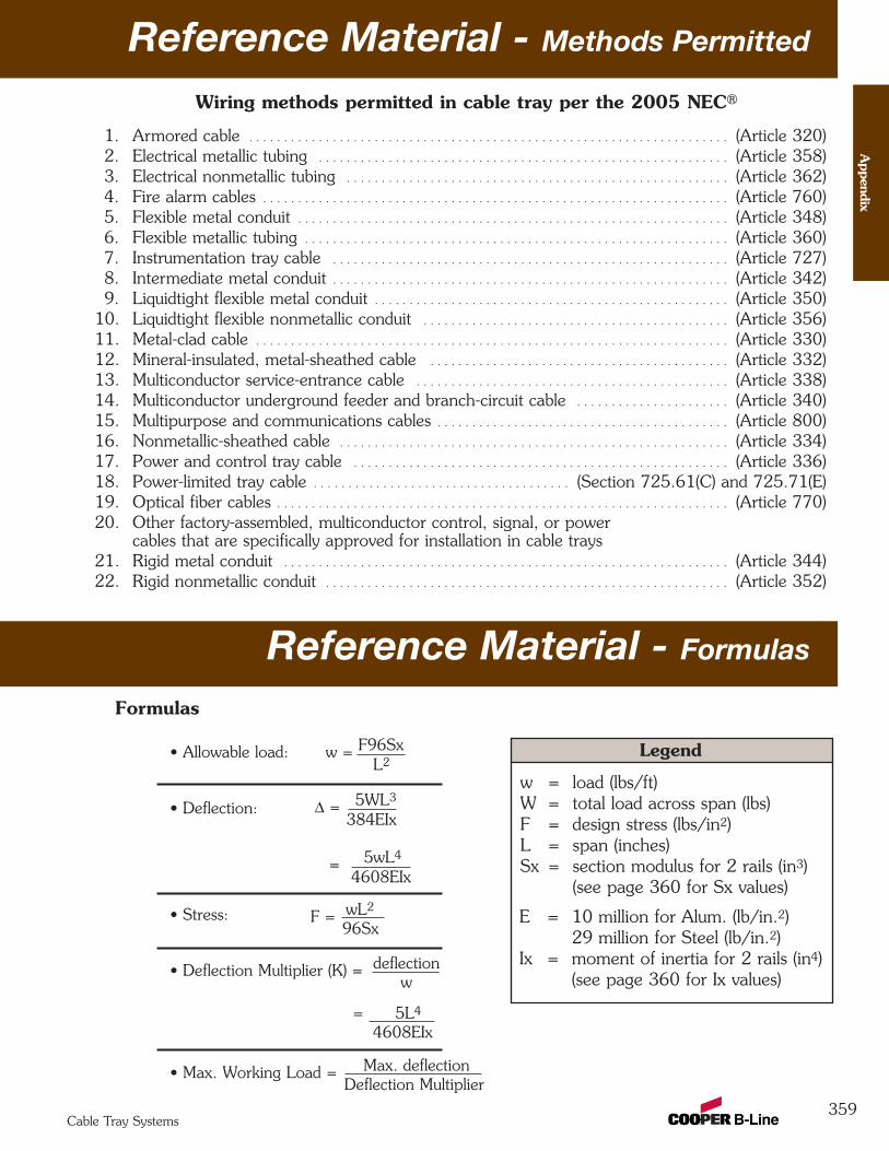
Reference Material - Methods Permitted
359
Appendix
Cable Tray Systems
Reference Material - Formulas
Formulas
• Allowable load: w = F96SxL2
w = load (lbs/ft)W = total load across span (lbs)F = design stress (lbs/in2)L = span (inches)Sx = section modulus for 2 rails (in3)
(see page 360 for Sx values)
• Deflection: ∆ = 5WL3
384EIx
E = 10 million for Alum. (lb/in.2)29 million for Steel (lb/in.2)
Ix = moment of inertia for 2 rails (in4)(see page 360 for Ix values)
∆ = 5wL4
4608EIx
• Stress: F = wL2
96Sx
• Deflection Multiplier (K) = deflectionw
= 5L4
4608EIx
• Max. Working Load = Max. deflectionDeflection Multiplier
Legend
1. Armored cable . . . . . . . . . . . . . . . . . . . . . . . . . . . . . . . . . . . . . . . . . . . . . . . . . . . . . . . . . . . . . . . . . . . . . (Article 320)2. Electrical metallic tubing . . . . . . . . . . . . . . . . . . . . . . . . . . . . . . . . . . . . . . . . . . . . . . . . . . . . . . . . . . . (Article 358)3. Electrical nonmetallic tubing . . . . . . . . . . . . . . . . . . . . . . . . . . . . . . . . . . . . . . . . . . . . . . . . . . . . . . . (Article 362)4. Fire alarm cables . . . . . . . . . . . . . . . . . . . . . . . . . . . . . . . . . . . . . . . . . . . . . . . . . . . . . . . . . . . . . . . . . . . (Article 760)5. Flexible metal conduit . . . . . . . . . . . . . . . . . . . . . . . . . . . . . . . . . . . . . . . . . . . . . . . . . . . . . . . . . . . . . . (Article 348)6. Flexible metallic tubing . . . . . . . . . . . . . . . . . . . . . . . . . . . . . . . . . . . . . . . . . . . . . . . . . . . . . . . . . . . . . (Article 360)7. Instrumentation tray cable . . . . . . . . . . . . . . . . . . . . . . . . . . . . . . . . . . . . . . . . . . . . . . . . . . . . . . . . . (Article 727)8. Intermediate metal conduit . . . . . . . . . . . . . . . . . . . . . . . . . . . . . . . . . . . . . . . . . . . . . . . . . . . . . . . . . (Article 342)9. Liquidtight flexible metal conduit . . . . . . . . . . . . . . . . . . . . . . . . . . . . . . . . . . . . . . . . . . . . . . . . . . . (Article 350)
10. Liquidtight flexible nonmetallic conduit . . . . . . . . . . . . . . . . . . . . . . . . . . . . . . . . . . . . . . . . . . . . (Article 356)11. Metal-clad cable . . . . . . . . . . . . . . . . . . . . . . . . . . . . . . . . . . . . . . . . . . . . . . . . . . . . . . . . . . . . . . . . . . . . (Article 330)12. Mineral-insulated, metal-sheathed cable . . . . . . . . . . . . . . . . . . . . . . . . . . . . . . . . . . . . . . . . . . . (Article 332)13. Multiconductor service-entrance cable . . . . . . . . . . . . . . . . . . . . . . . . . . . . . . . . . . . . . . . . . . . . . (Article 338) 14. Multiconductor underground feeder and branch-circuit cable . . . . . . . . . . . . . . . . . . . . . . (Article 340)15. Multipurpose and communications cables . . . . . . . . . . . . . . . . . . . . . . . . . . . . . . . . . . . . . . . . . . (Article 800)16. Nonmetallic-sheathed cable . . . . . . . . . . . . . . . . . . . . . . . . . . . . . . . . . . . . . . . . . . . . . . . . . . . . . . . . (Article 334)17. Power and control tray cable . . . . . . . . . . . . . . . . . . . . . . . . . . . . . . . . . . . . . . . . . . . . . . . . . . . . . . (Article 336)18. Power-limited tray cable . . . . . . . . . . . . . . . . . . . . . . . . . . . . . . . . . . . . . (Section 725.61(C) and 725.71(E)19. Optical fiber cables . . . . . . . . . . . . . . . . . . . . . . . . . . . . . . . . . . . . . . . . . . . . . . . . . . . . . . . . . . . . . . . . . (Article 770)20. Other factory-assembled, multiconductor control, signal, or power
cables that are specifically approved for installation in cable trays21. Rigid metal conduit . . . . . . . . . . . . . . . . . . . . . . . . . . . . . . . . . . . . . . . . . . . . . . . . . . . . . . . . . . . . . . . . (Article 344)22. Rigid nonmetallic conduit . . . . . . . . . . . . . . . . . . . . . . . . . . . . . . . . . . . . . . . . . . . . . . . . . . . . . . . . . . (Article 352)
Wiring methods permitted in cable tray per the 2005 NEC®
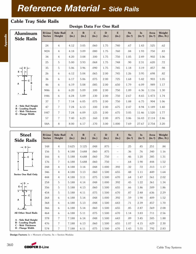
Reference Material - Side Rails
360
Cable Tray Side Rails
B-Line Side Rail A B C D E Sx Ix Area WeightSeries Height (in.) (in.) (in.) (in.) (in.) (in.3) (in.4) (in.2) (lbs./ft.)
24 4 4.12 3.05 .060 1.75 .740 .67 1.43 .525 .62
M24 4 4.18 3.09 .080 1.75 .760 .84 1.93 .750 .83
34 4 4.20 3.08 .100 1.75 .750 1.05 2.49 .902 1.06
25 5 5.00 3.93 .068 1.75 .748 .90 2.31 .620 .72
35 5 5.06 3.96 .090 1.75 .745 1.18 3.19 .857 .98
26 6 6.12 5.04 .065 2.00 .745 1.26 3.95 .698 .82
36 6 6.17 5.06 .075 2.00 .725 1.68 5.42 .903 1.05
46 6 6.19 5.08 .085 2.00 .650 1.79 6.09 .989 1.17
M46 6 6.20 5.09 .100 2.00 .750 1.89 6.36 1.116 1.30
H46 6 6.24 5.09 .130 2.00 .750 2.67 8.65 1.473 1.74
37 7 7.14 6.05 .075 2.00 .750 1.88 6.75 .904 1.06
47 7 7.24 6.13 .100 2.00 .675 2.47 8.94 1.189 1.40
H47 7 7.24 6.09 .125 2.00 .675 3.05 11.46 1.520 1.77
57 7 7.40 6.23 .160 2.00 .875 3.86 16.43 2.114 2.46
S8A 8 8.00 6.17 .170 3.00 1.000 7.69 27.67 2.754 3.20
AluminumSide Rails
A - Side Rail HeightB - Loading DepthC - Web ThicknessD - Flange Width
Design Factors: Ix = Moment of Inertia, Sx = Section Modulus
B-Line Side Rail A B C D E Sx Ix Area WeightSeries Height (in.) (in.) (in.) (in.) (in.) (in.3) (in.4) (in.2) (lbs./ft.)
148 4 3.625 3.125 .048 .875 -- .25 .45 .251 .84
156 5 4.188 3.688 .060 .875 -- .36 .76 .340 1.16
166 6 5.188 4.688 .060 .750 -- .46 1.20 .385 1.31
176 7 6.188 5.688 .060 .750 -- .64 1.90 .444 1.52
248 4 4.188 3.14 .048 1.000 .392 .32 .72 .313 1.17
346 4 4.188 3.13 .060 1.500 .655 .48 1.11 .449 1.64
444 4 4.188 3.11 .075 1.500 .670 .64 1.47 .561 2.02
258 5 5.188 4.14 .048 1.000 .392 .45 1.22 .361 1.34
356 5 5.188 4.13 .060 1.500 .655 .66 1.86 .509 1.86
454 5 5.188 4.11 .075 1.500 .670 .87 2.48 .636 2.29
268 6 6.188 5.14 .048 1.000 .392 .59 1.90 .409 1.52
368 6 6.188 5.13 .048 1.500 .643 .71 2.39 .457 1.70
366 6 6.188 5.14 .060 1.500 .655 .85 2.87 .569 2.08
464 6 6.188 5.11 .075 1.500 .670 1.14 3.83 .711 2.56
378 7 7.188 6.14 .048 1.500 .643 .89 3.45 .505 1.88
476 7 7.188 6.13 .060 1.500 .655 1.07 4.15 .629 2.30
574 7 7.188 6.11 .075 1.500 .670 1.43 5.55 .792 2.83
SteelSide Rails
A - Side Rail HeightB - Loading DepthC - Web ThicknessD - Flange Width
Series One Rail Only
All Other Steel Rails
D
A
C
DE
A
C
B
D
E
CBA
Design Data For One Rail
B
App
endi
x
Cable Tray Systems
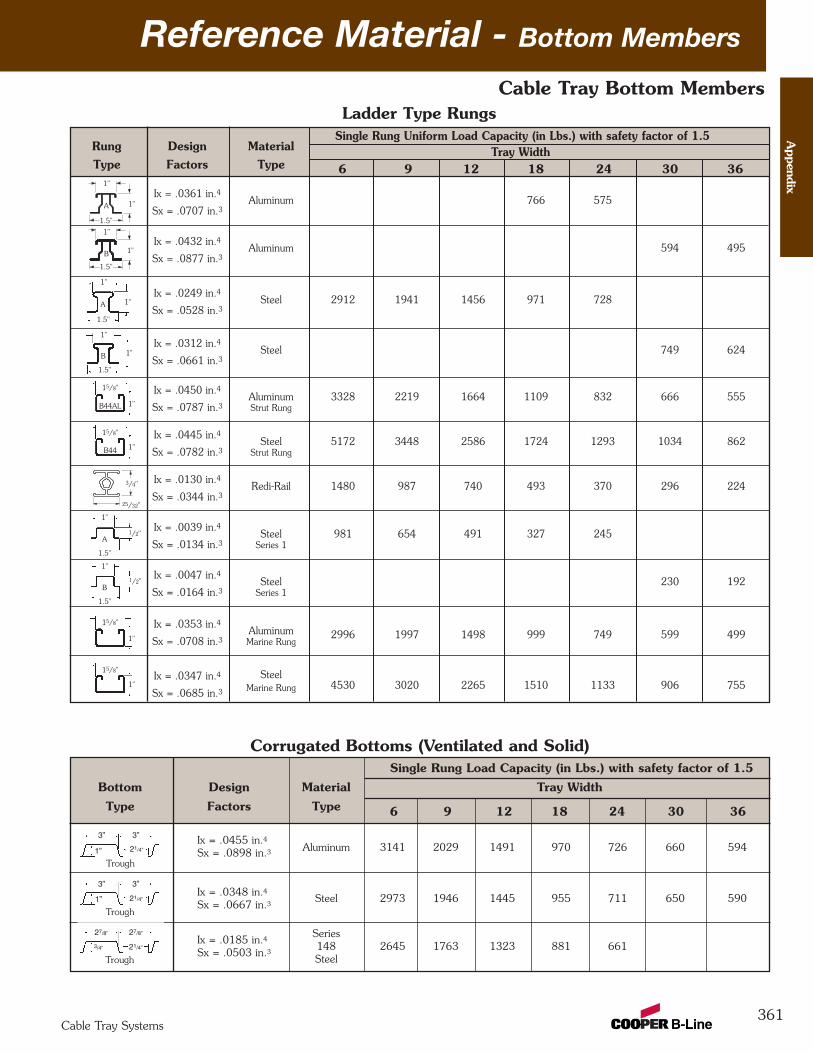
Reference Material - Bottom Members
361
Cable Tray Bottom Members
Corrugated Bottoms (Ventilated and Solid)
Ix = .0455 in.4Sx = .0898 in.3
Ix = .0348 in.4Sx = .0667 in.3
Ix = .0185 in.4Sx = .0503 in.3
Ladder Type Rungs
6 9 12 18 24 30 36
Single Rung Load Capacity (in Lbs.) with safety factor of 1.5Bottom Design Material Tray WidthType Factors Type
Aluminum 3141 2029 1491 970 726 660 594
Steel 2973 1946 1445 955 711 650 590
Series148 2645 1763 1323 881 661Steel
3” 3”
1” 21/4”
Trough
3” 3”
1” 21/4”
Trough
27/8” 27/8”
3/4” 21/4”
Trough
Appendix
Cable Tray Systems
Single Rung Uniform Load Capacity (in Lbs.) with safety factor of 1.5Rung Design MaterialType Factors Type
Ix = .0361 in.4Aluminum 766 575
Sx = .0707 in.3
Ix = .0432 in.4Aluminum 594 495
Sx = .0877 in.3
Ix = .0249 in.4Steel 2912 1941 1456 971 728
Sx = .0528 in.3
Ix = .0312 in.4Steel 749 624
Sx = .0661 in.3
Ix = .0450 in.4Aluminum 3328 2219 1664 1109 832 666 555
Sx = .0787 in.3 Strut Rung
Ix = .0445 in.4Steel 5172 3448 2586 1724 1293 1034 862
Sx = .0782 in.3 Strut Rung
Ix = .0130 in.4Redi-Rail 1480 987 740 493 370 296 224
Sx = .0344 in.3
Ix = .0039 in.4Steel 981 654 491 327 245
Sx = .0134 in.3 Series 1
Ix = .0047 in.4Steel 230 192
Sx = .0164 in.3 Series 1
Ix = .0353 in.4Aluminum
Sx = .0708 in.3 Marine Rung2996 1997 1498 999 749 599 499
Ix = .0347 in.4 Steel
Sx = .0685 in.3 Marine Rung 4530 3020 2265 1510 1133 906 755
1"
1"A
1"
1"
1"
1"A
1.5"
1.5"
1"B
1"
1/2"
1.5"
A
1"
1/2"
1.5"
B
1"
15/8"
B44AL
1"
15/8"
B44
6 9 12 18 24 30 36Tray Width
1.5"
1.5"
B
1"
15/8"
1"
15/8"
1"
3/4"
25/32"
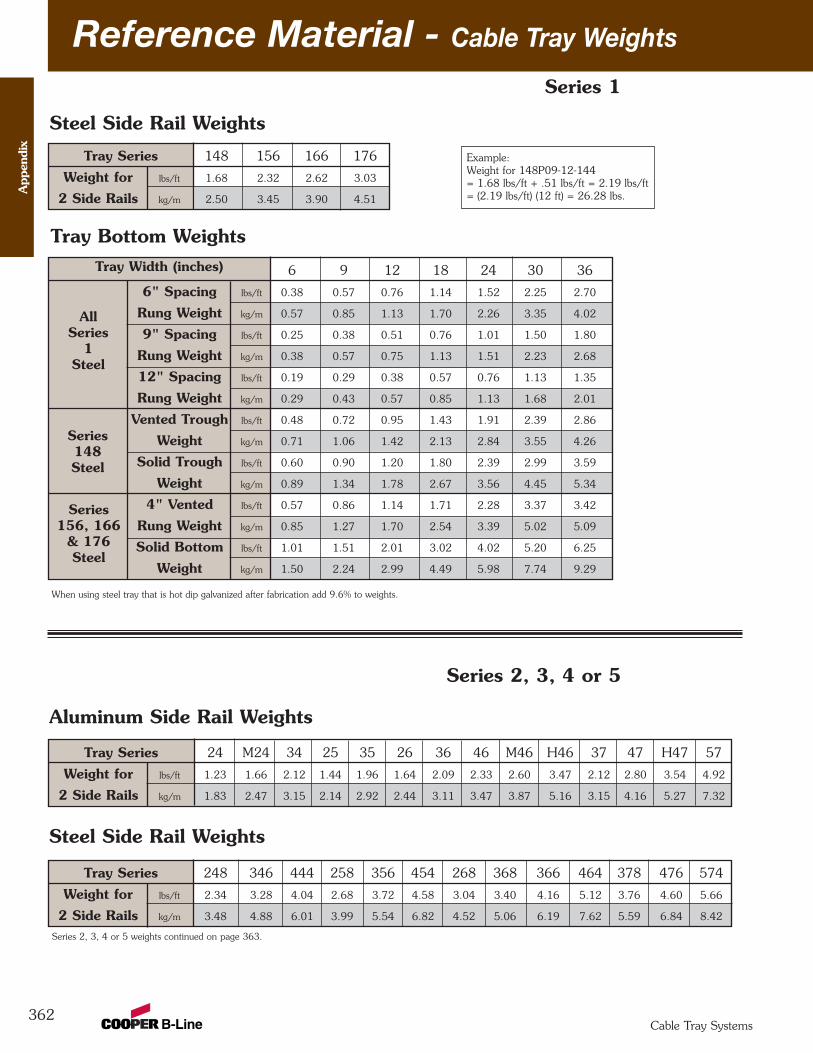
Reference Material - Cable Tray Weights
362
Tray Series 148 156 166 176
Weight for lbs/ft 1.68 2.32 2.62 3.03
2 Side Rails kg/m 2.50 3.45 3.90 4.51
Steel Side Rail Weights
6 9 12 18 24 30 36
6" Spacing lbs/ft 0.38 0.57 0.76 1.14 1.52 2.25 2.70
Rung Weight kg/m 0.57 0.85 1.13 1.70 2.26 3.35 4.02
9" Spacing lbs/ft 0.25 0.38 0.51 0.76 1.01 1.50 1.80
Rung Weight kg/m 0.38 0.57 0.75 1.13 1.51 2.23 2.68
12" Spacing lbs/ft 0.19 0.29 0.38 0.57 0.76 1.13 1.35
Rung Weight kg/m 0.29 0.43 0.57 0.85 1.13 1.68 2.01
Vented Trough lbs/ft 0.48 0.72 0.95 1.43 1.91 2.39 2.86
Weight kg/m 0.71 1.06 1.42 2.13 2.84 3.55 4.26
Solid Trough lbs/ft 0.60 0.90 1.20 1.80 2.39 2.99 3.59
Weight kg/m 0.89 1.34 1.78 2.67 3.56 4.45 5.34
4" Vented lbs/ft 0.57 0.86 1.14 1.71 2.28 3.37 3.42
Rung Weight kg/m 0.85 1.27 1.70 2.54 3.39 5.02 5.09
Solid Bottom lbs/ft 1.01 1.51 2.01 3.02 4.02 5.20 6.25
Weight kg/m 1.50 2.24 2.99 4.49 5.98 7.74 9.29
Tray Bottom Weights
All Series
1 Steel
Tray Width (inches)
Series 148Steel
Series 156, 166
& 176Steel
When using steel tray that is hot dip galvanized after fabrication add 9.6% to weights.
Series 1
Example:Weight for 148P09-12-144= 1.68 lbs/ft + .51 lbs/ft = 2.19 lbs/ft= (2.19 lbs/ft) (12 ft) = 26.28 lbs.A
ppen
dix
Cable Tray Systems
Aluminum Side Rail Weights
Tray Series 24 M24 34 25 35 26 36 46 M46 H46 37 47 H47 57
Weight for lbs/ft 1.23 1.66 2.12 1.44 1.96 1.64 2.09 2.33 2.60 3.47 2.12 2.80 3.54 4.92
2 Side Rails kg/m 1.83 2.47 3.15 2.14 2.92 2.44 3.11 3.47 3.87 5.16 3.15 4.16 5.27 7.32
Steel Side Rail Weights
Tray Series 248 346 444 258 356 454 268 368 366 464 378 476 574
Weight for lbs/ft 2.34 3.28 4.04 2.68 3.72 4.58 3.04 3.40 4.16 5.12 3.76 4.60 5.66
2 Side Rails kg/m 3.48 4.88 6.01 3.99 5.54 6.82 4.52 5.06 6.19 7.62 5.59 6.84 8.42
Series 2, 3, 4 or 5
Series 2, 3, 4 or 5 weights continued on page 363.
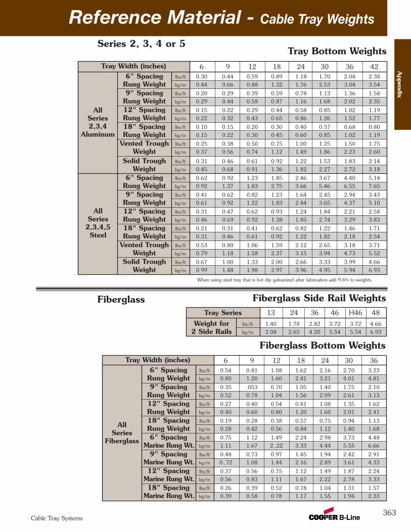
Reference Material - Cable Tray Weights
363
6 9 12 18 24 30 366" Spacing lbs/ft 0.54 0.81 1.08 1.62 2.16 2.70 3.23
Rung Weight kg/m 0.80 1.20 1.60 2.41 3.21 4.01 4.81
9" Spacing lbs/ft 0.35 .053 0.70 1.05 1.40 1.75 2.10
Rung Weight kg/m 0.52 0.78 1.04 1.56 2.09 2.61 3.13
12" Spacing lbs/ft 0.27 0.40 0.54 0.81 1.08 1.35 1.62
Rung Weight kg/m 0.40 0.60 0.80 1.20 1.60 2.01 2.41
18" Spacing lbs/ft 0.19 0.28 0.38 0.57 0.75 0.94 1.13
Rung Weight kg/m 0.28 0.42 0.56 0.84 1.12 1.40 1.68
6" Spacing lbs/ft 0.75 1.12 1.49 2.24 2.98 3.73 4.48
Marine Rung Wt. kg/m 1.11 1.67 2.,22 3.33 4.44 5.55 6.66
9" Spacing lbs/ft 0.48 0.73 0.97 1.45 1.94 2.42 2.91
Marine Rung Wt. kg/m 0.,72 1.08 1.44 2.16 2.89 3.61 4.33
12" Spacing lbs/ft 0.37 0.56 0.75 1.12 1.49 1.87 2.24
Marine Rung Wt. kg/m 0.56 0.83 1.11 1.67 2.22 2.78 3.33
18" Spacing lbs/ft 0.26 0.39 0.52 0.78 1.04 1.31 1.57
Marine Rung Wt. kg/m 0.39 0.58 0.78 1.17 1.55 1.94 2.33
Tray Bottom Weights
All Series
Fiberglass
Tray Width (inches)
Fiberglass Side Rail WeightsTray Series 13 24 36 46 H46 48
Weight for lbs/ft 1.40 1.78 2.82 3.72 3.72 4.66
2 Side Rails kg/m 2.08 2.65 4.20 5.54 5.54 6.93
6 9 12 18 24 30 36 426" Spacing lbs/ft 0.30 0.44 0.59 0.89 1.18 1.70 2.04 2.38
Rung Weight kg/m 0.44 0.66 0.88 1.32 1.76 2.53 3.04 3.54
9" Spacing lbs/ft 0.20 0.29 0.39 0.59 0.78 1.13 1.36 1.58
Rung Weight kg/m 0.29 0.44 0.58 0.87 1.16 1.68 2.02 2.35
12" Spacing lbs/ft 0.15 0.22 0.29 0.44 0.58 0.85 1.02 1.19
Rung Weight kg/m 0.22 0.32 0.43 0.65 0.86 1.26 1.52 1.77
18" Spacing lbs/ft 0.10 0.15 0.20 0.30 0.40 0.57 0.68 0.80
Rung Weight kg/m 0.15 0.22 0.30 0.45 0.60 0.85 1.02 1.19
Vented Trough lbs/ft 0.25 0.38 0.50 0.75 1.00 1.25 1.50 1.75
Weight kg/m 0.37 0.56 0.74 1.12 1.49 1.86 2.23 2.60
Solid Trough lbs/ft 0.31 0.46 0.61 0.92 1.22 1.53 1.83 2.14
Weight kg/m 0.45 0.68 0.91 1.36 1.82 2.27 2.72 3.18
6" Spacing lbs/ft 0.62 0.92 1.23 1.85 2.46 3.67 4.40 5.14
Rung Weight kg/m 0.92 1.37 1.83 2.75 3.66 5.46 6.55 7.65
9" Spacing lbs/ft 0.41 0.62 0.82 1.23 1.64 2.45 2.94 3.43
Rung Weight kg/m 0.61 0.92 1.22 1.83 2.44 3.65 4.37 5.10
12" Spacing lbs/ft 0.31 0.47 0.62 0.93 1.24 1.84 2.21 2.58
Rung Weight kg/m 0.46 0.69 0.92 1.38 1.85 2.74 3.29 3.83
18" Spacing lbs/ft 0.21 0.31 0.41 0.62 0.82 1.22 1.46 1.71
Rung Weight kg/m 0.31 0.46 0.61 0.92 1.22 1.82 2.18 2.54
Vented Trough lbs/ft 0.53 0.80 1.06 1.59 2.12 2.65 3.18 3.71
Weight kg/m 0.79 1.18 1.58 2.37 3.15 3.94 4.73 5.52
Solid Trough lbs/ft 0.67 1.00 1.33 2.00 2.66 3.33 3.99 4.66
Weight kg/m 0.99 1.48 1.98 2.97 3.96 4.95 5.94 6.93
Fiberglass Bottom Weights
All Series 2,3,4
Aluminum
Tray Width (inches)
AllSeries
2,3,4,5Steel
When using steel tray that is hot dip galvanized after fabrication add 9.6% to weights.
Series 2, 3, 4 or 5
Fiberglass
Appendix
Cable Tray Systems
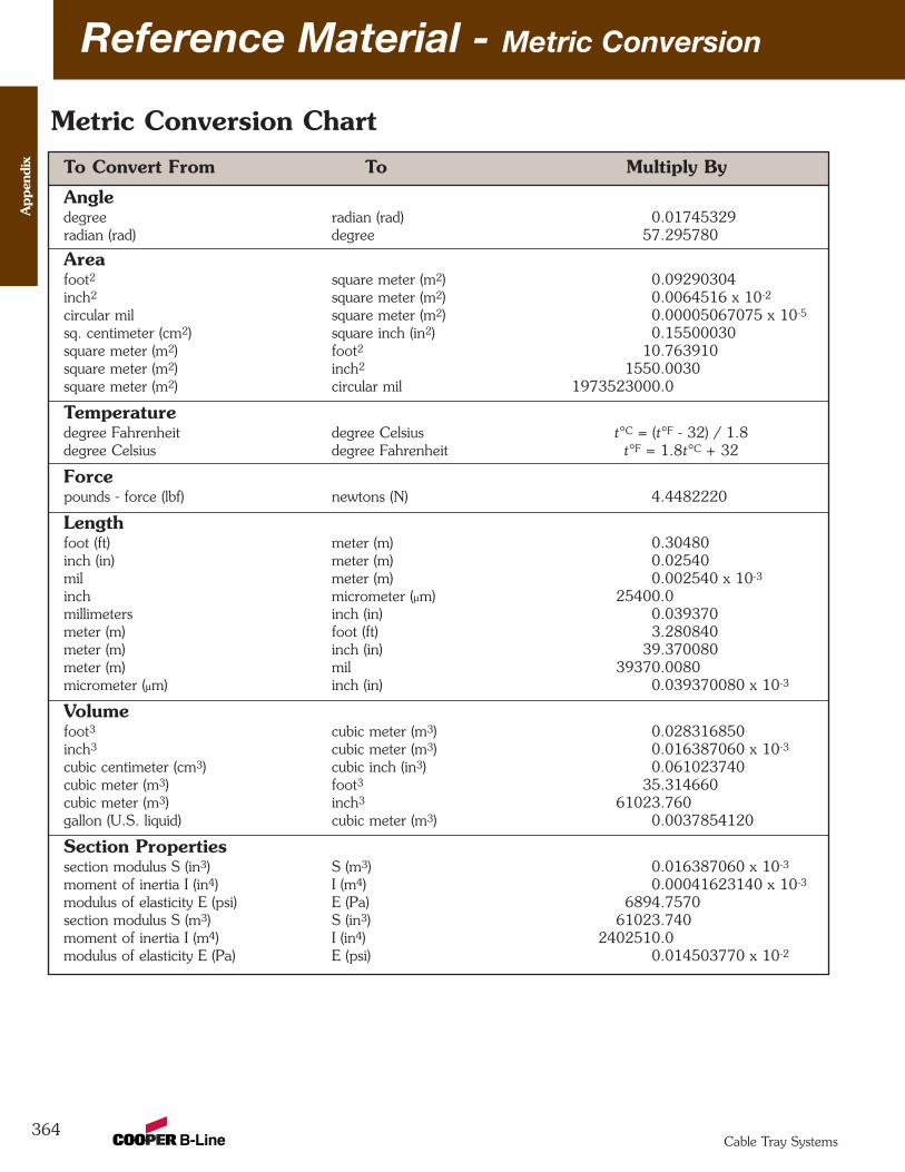
To Convert From To Multiply By
Angledegree radian (rad) 0.01745329radian (rad) degree 57.295780
Areafoot2 square meter (m2) 0.09290304inch2 square meter (m2) 0.0064516 x 10⁻²
circular mil square meter (m2) 0.00005067075 x 10⁻⁵
sq. centimeter (cm2) square inch (in2) 0.15500030square meter (m2) foot2 10.763910square meter (m2) inch2 1550.0030square meter (m2) circular mil 1973523000.0
Temperaturedegree Fahrenheit degree Celsius t°C = (t°F - 32) / 1.8degree Celsius degree Fahrenheit t°F = 1.8t°C + 32
Forcepounds - force (lbf) newtons (N) 4.4482220
Lengthfoot (ft) meter (m) 0.30480inch (in) meter (m) 0.02540mil meter (m) 0.002540 x 10⁻³
inch micrometer (µm) 25400.0millimeters inch (in) 0.039370meter (m) foot (ft) 3.280840meter (m) inch (in) 39.370080meter (m) mil 39370.0080micrometer (µm) inch (in) 0.039370080 x 10⁻³
Volumefoot3 cubic meter (m3) 0.028316850inch3 cubic meter (m3) 0.016387060 x 10⁻³
cubic centimeter (cm3) cubic inch (in3) 0.061023740cubic meter (m3) foot3 35.314660cubic meter (m3) inch3 61023.760gallon (U.S. liquid) cubic meter (m3) 0.0037854120
Section Propertiessection modulus S (in3) S (m3) 0.016387060 x 10⁻³
moment of inertia I (in4) I (m4) 0.00041623140 x 10⁻³
modulus of elasticity E (psi) E (Pa) 6894.7570section modulus S (m3) S (in3) 61023.740moment of inertia I (m4) I (in4) 2402510.0modulus of elasticity E (Pa) E (psi) 0.014503770 x 10⁻²
Reference Material - Metric Conversion
364
Metric Conversion Chart
App
endi
x
Cable Tray Systems
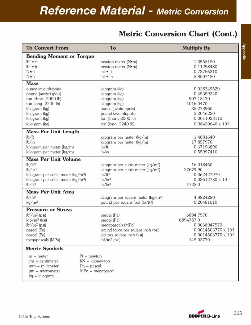
To Convert From To Multiply By
Bending Moment or Torquelbf • ft newton meter (N•m) 1.3558180lbf • in newton meter (N•m) 0.11298480N•m lbf • ft 0.73756210N•m lbf • in 8.8507480
Massounce (avoirdupois) kilogram (kg) 0.028349520pound (avoirdupois) kilogram (kg) 0.45359240ton (short, 2000 lb) kilogram (kg) 907.18470ton (long, 2240 lb) kilogram (kg) 1016.0470kilogram (kg) ounce (avoirdupois) 35.273960kilogram (kg) pound (avoirdupois) 2.2046220kilogram (kg) ton (short, 2000 lb) 0.0011023110kilogram (kg) ton (long, 2240 lb) 0.98420640 x 10⁻³
Mass Per Unit Lengthlb/ft kilogram per meter (kg/m) 1.4881640lb/in kilogram per meter (kg/m) 17.857970kilogram per meter (kg/m) lb/ft 0.67196890kilogram per meter (kg/m) lb/in 0.55997410
Mass Per Unit Volumelb/ft3 kilogram per cubic meter (kg/m3) 16.018460lb/in3 kilogram per cubic meter (kg/m3) 27679.90kilogram per cubic meter (kg/m3) lb/ft3 0.062427970kilogram per cubic meter (kg/m3) lb/in3 0.03612730 x 10⁻³
lb/ft3 lb/in3 1728.0
Mass Per Unit Arealb/ft2 kilogram per square meter (kg/m2) 4.8824280kg/m2 pound per square foot (lb/ft2) 0.20481610
Pressure or Stresslbf/in2 (psi) pascal (Pa) 6894.7570kip/in3 (ksi) pascal (Pa) 6894757.0lbf/in2 (psi) megapascals (MPa) 0.0068947570pascal (Pa) pound-force per square inch (psi) 0.0014503770 x 10⁻¹
pascal (Pa) kip per square inch (ksi) 0.0014503770 x 10⁻⁴
megapascals (MPa) lbf/in2 (psi) 145.03770
Metric Symbolsm = meter N = newtoncm = centimeter kN = kilonewton mm = millimeter Pa = pascalµm = micrometer MPa = megapascalkg = kilogram
Reference Material - Metric Conversion
365
Metric Conversion Chart (Cont.)
Appendix
Cable Tray Systems
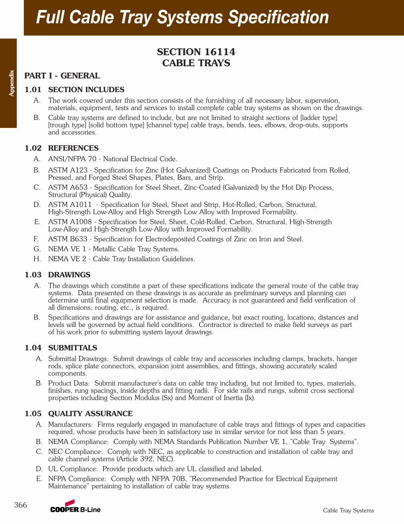
Full Cable Tray Systems Specification
366
SECTION 16114CABLE TRAYS
PART I - GENERAL
1.01 SECTION INCLUDESA. The work covered under this section consists of the furnishing of all necessary labor, supervision,
materials, equipment, tests and services to install complete cable tray systems as shown on the drawings.B. Cable tray systems are defined to include, but are not limited to straight sections of [ladder type]
[trough type] [solid bottom type] [channel type] cable trays, bends, tees, elbows, drop-outs, supportsand accessories.
1.02 REFERENCESA. ANSI/NFPA 70 - National Electrical Code.
B. ASTM A123 - Specification for Zinc (Hot Galvanized) Coatings on Products Fabricated from Rolled,Pressed, and Forged Steel Shapes, Plates, Bars, and Strip.
C. ASTM A653 - Specification for Steel Sheet, Zinc-Coated (Galvanized) by the Hot Dip Process,Structural (Physical) Quality.
D. ASTM A1011 - Specification for Steel, Sheet and Strip, Hot-Rolled, Carbon, Structural, High-Strength Low-Alloy and High Strength Low Alloy with Improved Formability.
E. ASTM A1008 - Specification for Steel, Sheet, Cold-Rolled, Carbon, Structural, High-StrengthLow-Alloy and High-Strength Low-Alloy with Improved Formability.
F. ASTM B633 - Specification for Electrodeposited Coatings of Zinc on Iron and Steel.G. NEMA VE 1 - Metallic Cable Tray Systems.H. NEMA VE 2 - Cable Tray Installation Guidelines.
1.03 DRAWINGSA. The drawings which constitute a part of these specifications indicate the general route of the cable tray
systems. Data presented on these drawings is as accurate as preliminary surveys and planning candetermine until final equipment selection is made. Accuracy is not guaranteed and field verification ofall dimensions, routing, etc., is required.
B. Specifications and drawings are for assistance and guidance, but exact routing, locations, distances andlevels will be governed by actual field conditions. Contractor is directed to make field surveys as partof his work prior to submitting system layout drawings.
1.04 SUBMITTALSA. Submittal Drawings: Submit drawings of cable tray and accessories including clamps, brackets, hanger
rods, splice plate connectors, expansion joint assemblies, and fittings, showing accurately scaledcomponents.
B. Product Data: Submit manufacturer's data on cable tray including, but not limited to, types, materials,finishes, rung spacings, inside depths and fitting radii. For side rails and rungs, submit cross sectionalproperties including Section Modulus (Sx) and Moment of Inertia (Ix).
1.05 QUALITY ASSURANCEA. Manufacturers: Firms regularly engaged in manufacture of cable trays and fittings of types and capacities
required, whose products have been in satisfactory use in similar service for not less than 5 years.B. NEMA Compliance: Comply with NEMA Standards Publication Number VE 1, "Cable Tray Systems".C. NEC Compliance: Comply with NEC, as applicable to construction and installation of cable tray and
cable channel systems (Article 392, NEC).D. UL Compliance: Provide products which are UL classified and labeled.E. NFPA Compliance: Comply with NFPA 70B, "Recommended Practice for Electrical Equipment
Maintenance" pertaining to installation of cable tray systems.
App
endi
x
Cable Tray Systems
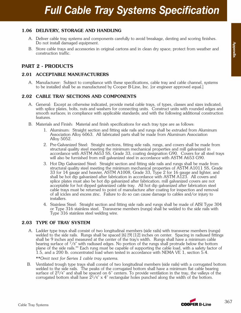
Full Cable Tray Systems Specification
367
1.06 DELIVERY, STORAGE AND HANDLING
A. Deliver cable tray systems and components carefully to avoid breakage, denting and scoring finishes. Do not install damaged equipment.
B. Store cable trays and accessories in original cartons and in clean dry space; protect from weather andconstruction traffic.
PART 2 - PRODUCTS
2.01 ACCEPTABLE MANUFACTURERS
A. Manufacturer: Subject to compliance with these specifications, cable tray and cable channel, systemsto be installed shall be as manufactured by Cooper B-Line, Inc. [or engineer approved equal.]
2.02 CABLE TRAY SECTIONS AND COMPONENTS
A. General: Except as otherwise indicated, provide metal cable trays, of types, classes and sizes indicated;with splice plates, bolts, nuts and washers for connecting units. Construct units with rounded edges andsmooth surfaces; in compliance with applicable standards; and with the following additional constructionfeatures.
B. Materials and Finish: Material and finish specifications for each tray type are as follows: 1. Aluminum: Straight section and fitting side rails and rungs shall be extruded from Aluminum
Association Alloy 6063. All fabricated parts shall be made from Aluminum AssociationAlloy 5052.
2. Pre-Galvanized Steel: Straight sections, fitting side rails, rungs, and covers shall be made fromstructural quality steel meeting the minimum mechanical properties and mill galvanized inaccordance with ASTM A653 SS, Grade 33, coating designation G90. Covers for all steel trayswill also be furnished from mill galvanized steel in accordance with ASTM A653 G90.
3. Hot Dip Galvanized Steel: Straight section and fitting side rails and rungs shall be made fromstructural quality steel meeting the minimum mechanical properties of ASTM A1011 SS, Grade33 for 14 gauge and heavier, ASTM A1008, Grade 33, Type 2 for 16 gauge and lighter, andshall be hot dip galvanized after fabrication in accordance with ASTM A123. All covers andsplice plates must also be hot dip galvanized after fabrication; mill galvanized covers are notacceptable for hot dipped galvanized cable tray. All hot dip galvanized after fabrication steelcable trays must be returned to point of manufacture after coating for inspection and removalof all icicles and excess zinc. Failure to do so can cause damage to cables and/or injury toinstallers.
4. Stainless Steel: Straight section and fitting side rails and rungs shall be made of AISI Type 304or Type 316 stainless steel. Transverse members (rungs) shall be welded to the side rails withType 316 stainless steel welding wire.
2.03 TYPE OF TRAY SYSTEM
A. Ladder type trays shall consist of two longitudinal members (side rails) with transverse members (rungs)welded to the side rails. Rungs shall be spaced [6] [9] [12] inches on center. Spacing in radiused fittingsshall be 9 inches and measured at the center of the tray's width. Rungs shall have a minimum cablebearing surface of 7/8" with radiused edges. No portion of the rungs shall protrude below the bottomplane of the side rails.** Each rung must be capable of supporting the cable load, with a safety factor of1.5, and a 200 lb. concentrated load when tested in accordance with NEMA VE 1, section 5.4.**Omit text for Series 1 cable tray systems.
B. Ventilated trough type trays shall consist of two longitudinal members (side rails) with a corrugated bottomwelded to the side rails. The peaks of the corrugated bottom shall have a minimum flat cable bearingsurface of 23/4" and shall be spaced on 6" centers. To provide ventilation in the tray, the valleys of thecorrugated bottom shall have 21/4" x 4" rectangular holes punched along the width of the bottom.
Appendix
Cable Tray Systems

Full Cable Tray Systems Specification
368
C. Non-Ventilated bottom trough type trays shall consist of two longitudinal members (side rails) with acorrugated bottom welded to the side rails. The peaks of the corrugated bottom shall have a minimumflat cable bearing surface of 23/4" and shall be spaced on 6" centers.
D. Tray Sizes shall have [3] [4] [5] [6] inch minimum usable load depth, or as noted on the drawing.E. Straight tray sections shall have side rails fabricated as I-Beams. All straight sections shall be supplied in
standard [10] [12] [20] [24] foot lengths, except where shorter lengths are permitted to facilitate trayassembly lengths as shown on drawings.
F. Tray widths shall be [6] [9] [12] [18] [24] [30] [36] inches or as shown on drawings.G. All fittings must have a three inch tangent and a minimum radius of [12] [24] [36] [48] inches.H. Splice plates shall be the bolted type made as indicated below for each tray type. The resistance of fixed
splice connections between an adjacent section of tray shall not exceed .00033 ohm. Splice plateconstruction shall be such that a splice may be located anywhere within a continuously supported spanwithout diminishing rated loading capacity of the cable tray.
1. Aluminum Tray - Splice plates shall be made of 6063-T6 aluminum, using four square neckcarriage bolts and serrated flange locknuts. Hardware shall be zinc plated in accordance withASTM B633, SC1. If aluminum cable tray is to be used outdoors, then hardware shall beType 316 stainless steel.
2. Steel (including Pre-Galvanized and Hot Dip Galvanized) - Splice plates shall be manufactured ofhigh strength steel, meeting the minimum mechanical properties of ASTM A1011 HSLAS,Grade 50, Class 1. Each splice plate shall be attached with ribbed neck carriage bolts andserrated flange locknuts. Hardware shall be zinc plated in accordance with ASTM B633 SC1 forpre-galvanized cable trays, or Chromium Zinc in accordance with ASTM F-1136-88 for hot dipgalvanized cable trays.
Splice plates shall be furnished with straight sections and fittings.I. Cable Tray Supports: Shall be placed so that the support spans do not exceed the maximum span
indicated on drawings. Supports shall be constructed from 12 gauge steel formed shape channelmembers 15/8" x 15/8" with necessary hardware such as Trapeze Support Kits (9G-55XX-22SH) asmanufactured by Cooper B-Line, Inc. [or engineer approved equal]. Cable trays installed adjacent to wallsshall be supported on wall mounted brackets such as B409 as manufactured by Cooper B-Line, Inc. [orengineer-approved equal].
J. Trapeze hangers and center hung supports shall be supported by 1/2" (minimum) diameter rods.K. Barrier Strips: Shall be placed as specified on drawings and be fastened into the tray with self drilling
screws.L. Accessories: Special accessories shall be furnished as required to protect, support, and install a cable tray
system. Accessories shall consist of, but are not limited to; section splice plates, expansion plates,blind-end plates, specially-designed ladder drop-outs, barriers, etc.
2.04 LOADING CAPACITIESA. Cable tray shall be capable of carrying a uniformly distributed load of _______ lbs./ft. on a ________ ft.
support span with a safety factor of 1.5 when supported as a simple span and tested per NEMA VE 1,section 5.2. **In addition to the uniformly distributed load the cable tray shall support 200 lbs.concentrated load at mid-point of span.** Load and safety factors specified are applicable to both the siderails and rung capacities. Cable tray shall be made to manufacturing tolerances as specified by NEMA.
**Omit text for Series 1 cable tray systems.
App
endi
x
Cable Tray Systems
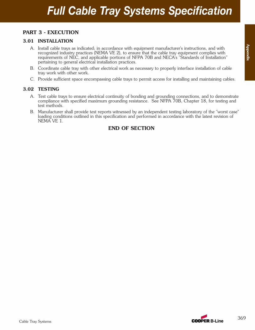
Full Cable Tray Systems Specification
369
PART 3 - EXECUTION
3.01 INSTALLATIONA. Install cable trays as indicated; in accordance with equipment manufacturer's instructions, and with
recognized industry practices (NEMA VE 2), to ensure that the cable tray equipment complies withrequirements of NEC, and applicable portions of NFPA 70B and NECA's "Standards of Installation"pertaining to general electrical installation practices.
B. Coordinate cable tray with other electrical work as necessary to properly interface installation of cabletray work with other work.
C. Provide sufficient space encompassing cable trays to permit access for installing and maintaining cables.
3.02 TESTINGA. Test cable trays to ensure electrical continuity of bonding and grounding connections, and to demonstrate
compliance with specified maximum grounding resistance. See NFPA 70B, Chapter 18, for testing andtest methods.
B. Manufacturer shall provide test reports witnessed by an independent testing laboratory of the "worst case"loading conditions outlined in this specification and performed in accordance with the latest revision ofNEMA VE 1.
END OF SECTION
Appendix
Cable Tray Systems
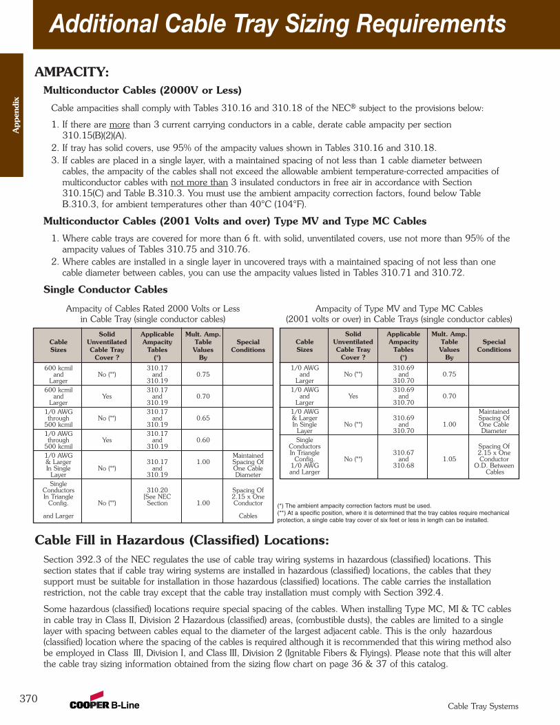
Additional Cable Tray Sizing Requirements
370
App
endi
x
Cable Tray Systems
AMPACITY:Multiconductor Cables (2000V or Less)
Cable ampacities shall comply with Tables 310.16 and 310.18 of the NEC® subject to the provisions below:
1. If there are more than 3 current carrying conductors in a cable, derate cable ampacity per section310.15(B)(2)(A).
2. If tray has solid covers, use 95% of the ampacity values shown in Tables 310.16 and 310.18.3. If cables are placed in a single layer, with a maintained spacing of not less than 1 cable diameter between
cables, the ampacity of the cables shall not exceed the allowable ambient temperature-corrected ampacities of multiconductor cables with not more than 3 insulated conductors in free air in accordance with Section310.15(C) and Table B.310.3. You must use the ambient ampacity correction factors, found below TableB.310.3, for ambient temperatures other than 40°C (104°F).
Multiconductor Cables (2001 Volts and over) Type MV and Type MC Cables
1. Where cable trays are covered for more than 6 ft. with solid, unventilated covers, use not more than 95% of theampacity values of Tables 310.75 and 310.76.
2. Where cables are installed in a single layer in uncovered trays with a maintained spacing of not less than onecable diameter between cables, you can use the ampacity values listed in Tables 310.71 and 310.72.
Single Conductor Cables
Cable Fill in Hazardous (Classified) Locations:Section 392.3 of the NEC regulates the use of cable tray wiring systems in hazardous (classified) locations. Thissection states that if cable tray wiring systems are installed in hazardous (classified) locations, the cables that theysupport must be suitable for installation in those hazardous (classified) locations. The cable carries the installationrestriction, not the cable tray except that the cable tray installation must comply with Section 392.4.
Some hazardous (classified) locations require special spacing of the cables. When installing Type MC, MI & TC cablesin cable tray in Class II, Division 2 Hazardous (classified) areas, (combustible dusts), the cables are limited to a singlelayer with spacing between cables equal to the diameter of the largest adjacent cable. This is the only hazardous(classified) location where the spacing of the cables is required although it is recommended that this wiring method alsobe employed in Class III, Division I, and Class III, Division 2 (Ignitable Fibers & Flyings). Please note that this will alterthe cable tray sizing information obtained from the sizing flow chart on page 36 & 37 of this catalog.
Ampacity of Type MV and Type MC Cables(2001 volts or over) in Cable Trays (single conductor cables)
Ampacity of Cables Rated 2000 Volts or Less in Cable Tray (single conductor cables)
Solid Applicable Mult. Amp.Cable Unventilated Ampacity Table SpecialSizes Cable Tray Tables Values Conditions
Cover ? (*) By
1/0 AWG 310.69and No (**) and 0.75
Larger 310.701/0 AWG 310.69
and Yes and 0.70Larger 310.70
1/0 AWG Maintained& Larger 310.69 Spacing OfIn Single No (**) and 1.00 One Cable
Layer 310.70 DiameterSingle
Conductors Spacing OfIn Triangle 310.67 2.15 x One
Config. No (**) and 1.05 Conductor1/0 AWG 310.68 O.D. Betweenand Larger Cables
(*) The ambient ampacity correction factors must be used.(**) At a specific position, where it is determined that the tray cables require mechanicalprotection, a single cable tray cover of six feet or less in length can be installed.
Solid Applicable Mult. Amp.Cable Unventilated Ampacity Table SpecialSizes Cable Tray Tables Values Conditions
Cover ? (*) By
600 kcmil 310.17and No (**) and 0.75
Larger 310.19600 kcmil 310.17
and Yes and 0.70Larger 310.19
1/0 AWG 310.17through No (**) and 0.65
500 kcmil 310.191/0 AWG 310.17through Yes and 0.60
500 kcmil 310.191/0 AWG Maintained& Larger 310.17 1.00 Spacing OfIn Single No (**) and One Cable
Layer 310.19 DiameterSingle
Conductors 310.20 Spacing OfIn Triangle [See NEC 2.15 x One
Config. No (**) Section 1.00 Conductor1/0 AWG 310.15(B)] O.D. Betweenand Larger Cables
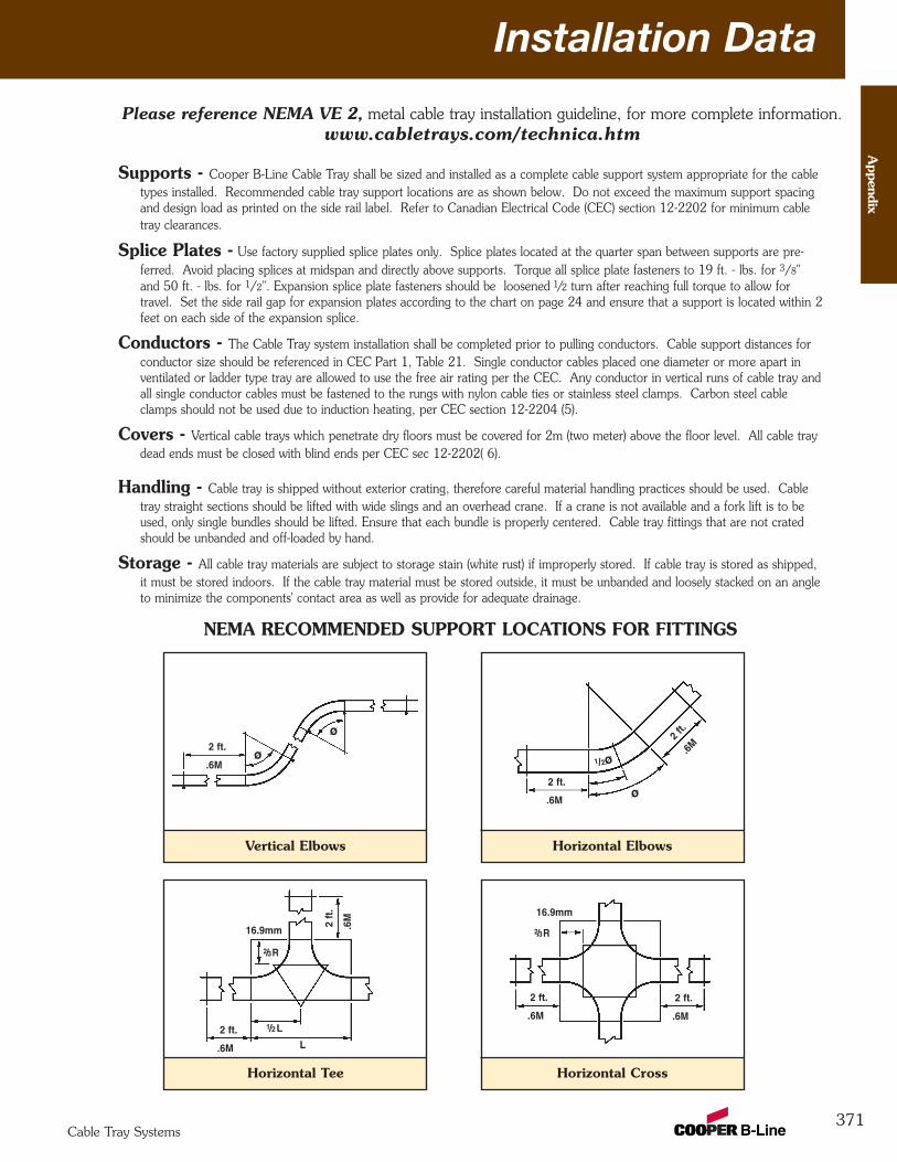
Installation Data
371
Appendix
Cable Tray Systems
Supports - Cooper B-Line Cable Tray shall be sized and installed as a complete cable support system appropriate for the cabletypes installed. Recommended cable tray support locations are as shown below. Do not exceed the maximum support spacingand design load as printed on the side rail label. Refer to Canadian Electrical Code (CEC) section 12-2202 for minimum cabletray clearances.
Splice Plates - Use factory supplied splice plates only. Splice plates located at the quarter span between supports are pre-ferred. Avoid placing splices at midspan and directly above supports. Torque all splice plate fasteners to 19 ft. - lbs. for 3/8"and 50 ft. - lbs. for 1/2". Expansion splice plate fasteners should be loosened 1/2 turn after reaching full torque to allow for travel. Set the side rail gap for expansion plates according to the chart on page 24 and ensure that a support is located within 2feet on each side of the expansion splice.
Conductors - The Cable Tray system installation shall be completed prior to pulling conductors. Cable support distances forconductor size should be referenced in CEC Part 1, Table 21. Single conductor cables placed one diameter or more apart inventilated or ladder type tray are allowed to use the free air rating per the CEC. Any conductor in vertical runs of cable tray andall single conductor cables must be fastened to the rungs with nylon cable ties or stainless steel clamps. Carbon steel cableclamps should not be used due to induction heating, per CEC section 12-2204 (5).
Covers - Vertical cable trays which penetrate dry floors must be covered for 2m (two meter) above the floor level. All cable traydead ends must be closed with blind ends per CEC sec 12-2202( 6).
Handling - Cable tray is shipped without exterior crating, therefore careful material handling practices should be used. Cabletray straight sections should be lifted with wide slings and an overhead crane. If a crane is not available and a fork lift is to beused, only single bundles should be lifted. Ensure that each bundle is properly centered. Cable tray fittings that are not cratedshould be unbanded and off-loaded by hand.
Storage - All cable tray materials are subject to storage stain (white rust) if improperly stored. If cable tray is stored as shipped,it must be stored indoors. If the cable tray material must be stored outside, it must be unbanded and loosely stacked on an angleto minimize the components' contact area as well as provide for adequate drainage.
Vertical Elbows
NEMA RECOMMENDED SUPPORT LOCATIONS FOR FITTINGS
.6M
2 ft.ø
ø
Horizontal Elbows
.6M
2 ft.
.6M2 f
t.
1/2ø
ø
Horizontal Tee
.6M
2 ft.
.6M2 ft
.
Horizontal Cross
L
1/2L
2/3R
2/3R16.9mm
16.9mm
.6M
2 ft.
.6M
2 ft.
Please reference NEMA VE 2, metal cable tray installation guideline, for more complete information.www.cabletrays.com/technica.htm
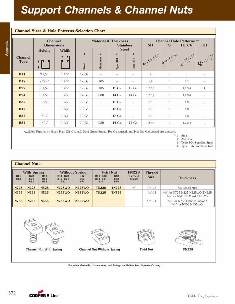
Channel Nuts
Channel Nut With Spring Channel Nut Without Spring Twirl Nut FN228
With Spring Without Spring Twirl Nut FN228B11 B22 B42 B11 B22 B42 B11 B22 B42 E-Z TwirlB12 B24 B52 B12 B24 B52 B12 B24 B52 FN228
B32 B54 B32 B54 B32 B54
N728 N228 N528 N228WO N228WO TN228 TN228 3/8" 3/8"-16 3/8" for all nuts
N725 N225 N525 N225WO N525WO TN225 TN525 1/2"-13 1/2" for N725,N225,N225WO,TN2253/8" for N525,N525WO,TN525
N755 N255 N555 N255WO N555WO -- -- 5/8"-11 1/2" for N755,N255,N255WO3/8" for N555,N555WO
ThreadSize
Channel Sizes & Hole Patterns Selection Chart
Channel Material & Thickness Channel Hole Patterns **Dimensions Stainless SH S H17/8 TH
Steel1 2 3 4
B11 3 1/4" 1 5/8" 12 Ga. -- -- -- 1 1 1 --
B12 2 7/16" 1 5/8" 12 Ga. .105 -- -- 1,2 1 1,2 --
B22 1 5/8" 1 5/8" 12 Ga. .105 12 Ga. 12 Ga. 1,2,3,4 1 1,2,3,4 1
B24 1 5/8" 1 5/8" 14 Ga. .080 14 Ga. 14 Ga. 1,2,3,4 1 1,2,3,4 --
B32 1 3/8" 1 5/8" 12 Ga. -- 12 Ga. -- 1,3 1 1,3 --
B42 1 " 1 5/8" 12 Ga. -- 12 Ga. -- 1,3 1 1,3 --
B52 13/16" 1 5/8" 12 Ga. -- 12 Ga. -- 1,3 1 1,3 --
B54 13/16" 1 5/8" 14 Ga. .080 14 Ga. 14 Ga. 1,2,3,4 1 1,2,3,4 --
Thickness
For other channels, channel nuts, and fittings see B-Line Strut Systems Catalog.
ChannelType
Height Width
Available Finishes on Steel: Plain (Oil Coated), Dura-Green Epoxy, Pre-Galvanized, and Hot Dip Galvanized are standard.
Ste
el
Alu
min
um
Typ
e 304
Typ
e 316
372
Support Channels & Channel Nuts
** 1 - Steel2 - Aluminum3 - Type 304 Stainless Steel4 - Type 316 Stainless Steel
App
endi
x
Cable Tray Systems
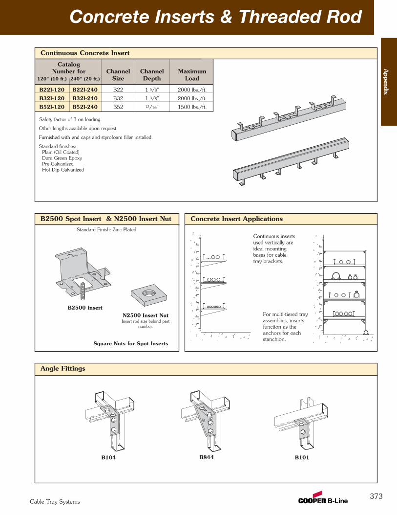
373
Continuous Concrete Insert
CatalogNumber for Channel Channel Maximum
120" (10 ft.) 240" (20 ft.) Size Depth Load
B22I-120 B22I-240 B22 1 5/8" 2000 lbs./ft.
B32I-120 B32I-240 B32 1 3/8" 2000 lbs./ft.
B52I-120 B52I-240 B52 13/16" 1500 lbs./ft.
Safety factor of 3 on loading.
Other lengths available upon request.
Furnished with end caps and styrofoam filler installed.
Standard finishes:Plain (Oil Coated)Dura Green EpoxyPre-GalvanizedHot Dip Galvanized
Concrete Inserts & Threaded Rod
Square Nuts for Spot Inserts
Angle Fittings
B2500 Spot Insert & N2500 Insert Nut
N2500 Insert NutInsert rod size behind part
number.
B2500 Insert
Standard Finish: Zinc Plated
Concrete Insert Applications
Continuous insertsused vertically areideal mountingbases for cabletray brackets.
For multi-tiered trayassemblies, insertsfunction as theanchors for eachstanchion.
B104 B844 B101
Appendix
Cable Tray Systems

374
NotesA
ppen
dix
Cable Tray Systems
CABLE TRAY MANUALBased on the2005 National Electrical Code®
2005
375Cable Tray Systems
Cable T
ray Manual
Table of ContentsPage No.
Introduction ................................................................................................................. 377
Why Cable Tray?Safety ................................................................................................................. 378Dependability ............................................................................................ 378 - 379Space Savings ..................................................................................................... 379Cost Savings ............................................................................................. 379 - 382
An In-depth Look at the 2005 NEC®, Section 392Types of Cable Trays (NEC® 392.1 Scope) ................................................. 383 - 384EMI/RFI Cable Tray ................................................................................... 384 - 385Cable Tray Materials ............................................................................................ 385Types of Cables Allowed in Cable Tray [392.3 (A)] ....................................... 385 - 386
MI - Mineral Insulated Metal Sheathed Cable [Article 332] ............................. 386MC - Metal Clad Cable [Article 330] ............................................................ 386TC - Power and Control Tray Cable [Article 336] ......................................... 386ITC - Instrumentation Tray Cable [Article 727] ............................................. 387PLTC - Power Limited Tray Cable [Sections 725.61 (C) and 725.71 (E)] ........ 387Other Types - Fire Alarm [Article 760],
Multipurpose and Communications Cable [Article 800] ............. 387Single Conductor & Type MV Cables [392.3 (B)] .......................................... 387 - 388Cable Tray Use in Hazardous Locations [392.3 (D)] ...................................... 388 - 390Limitations on Cable Tray Use [392.4] ................................................................... 390Cable Tray Loading [392.5 (A)] ................................................................... 390 - 392Fiberglass Cable Tray [392.3 (E) & 392.5 (F)] ............................................... 392 - 393Discontinuous Cable Tray and Fittings [392.6 (A)] ......................................... 393 - 394Covers [392.6 (D)] ............................................................................................... 395Barriers [392.6 (E) & (F)] ............................................................................ 395 - 396Spacing of Multiple Cable Trays [392.6 (I)] ............................................................. 396Supporting Conduit from Cable Tray [392.6 (J)] ........................................... 396 - 397Use of Cable Tray as an Equipment Grounding Conductor [392.7 Grounding] .... 398 - 400Fastening Cables [392.8 (B)] ................................................................................. 401Cable Installation [392.8] ............................................................................ 401 - 403Sizing Cable Tray
Multiconductor - 2000 volts or less [392.9] ....................................... 403 - 405Single conductor - 2000 volts or less [392.10] ................................... 405 - 406Type MC or MV - 2001 volts or greater [392.12] ........................................ 407
Ampacities of Cables in Cable Tray ............................................................. 406 - 408Cable Tray Wiring System Design and Installation Hints ................................ 408 - 409Fireproofing Tray ....................................................................................... 409 - 410Expansion and Contraction ........................................................................ 410 - 411
Appendix Index & Appendix Sheets ............................................................. 412 - 419
Cable Tray Installation & Specification Checklists .................................... 420 - 423
Footnotes ...................................................................................................................... 424
376Cable Tray Systems
Cab
le T
ray
Man
ual
INTRODUCTION
The Cooper B-Line Cable Tray Manual was produced by Cooper B-Line's technical staff. CooperB-Line has recognized the need for a complete cable tray reference source for electrical engineersand designers. The following pages address the 2005 National Electric Code® requirements forcable tray systems as well as design solutions from practical experience. The information has beenorganized for use as a reference guide for both those unfamiliar and those experienced with cabletray.
Nearly every aspect of cable tray design and installation has been explored for the use of thereader. If a topic has not been covered sufficiently to answer a specific question or if additionalinformation is desired, contact the engineering department at Cooper B-Line. We sincerely hopeyou will find the Cooper B-Line Cable Tray Manual a helpful and informative addition to yourtechnical library.
The information contained herein has been carefully checked for accuracy and is believed to becorrect and current. No warranty, either expressed or implied, is made as to either its applicabilityto, or its compatibility with, specific requirements, of this information, nor for damages consequentto its use. All design characteristics, specifications, tolerances and similar information are subject tochange without notice.
Cooper B-Line, Inc.509 West Monroe Street
Highland, IL 62249-0326Tel: (800) 851-7415Fax: (618) 654-5499
National Electrical Code® and NEC® are registered trademarks of theNational Fire Protection Association, Inc. Quincy, MA 02269.
377Cable Tray Systems
Cable T
ray Manual
Reprinted with permission from NFPA 70-1999, the National Electrical Code®, Copyright© 1998, National FireProtection Association, Quincy, MA 02269. This reprinted material is not the complete and official position of the NationalFire Protection Association, on the referenced subject which is represented only by the standard in its entirety.
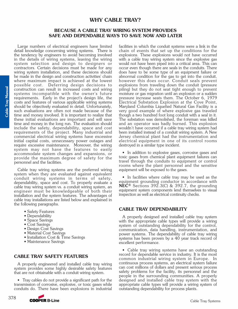
Large numbers of electrical engineers have limiteddetail knowledge concerning wiring systems. There isthe tendency by engineers to avoid becoming involvedin the details of wiring systems, leaving the wiringsystem selection and design to designers orcontractors. Certain decisions must be made for anywiring system installation, and these decisions shouldbe made in the design and construction activities' chainwhere maximum impact is achieved at the lowestpossible cost. Deferring design decisions toconstruction can result in increased costs and wiringsystems incompatible with the owner's futurerequirements. Early in the project's design life, thecosts and features of various applicable wiring systemsshould be objectively evaluated in detail. Unfortunately,such evaluations are often not made because of thetime and money involved. It is important to realize thatthese initial evaluations are important and will savetime and money in the long run. The evaluation shouldinclude the safety, dependability, space and costrequirements of the project. Many industrial andcommercial electrical wiring systems have excessiveinitial capital costs, unnecessary power outages andrequire excessive maintenance. Moreover, the wiringsystem may not have the features to easi lyaccommodate system changes and expansions, orprovide the maximum degree of safety for thepersonnel and the facilities.
Cable tray wiring systems are the preferred wiringsystem when they are evaluated against equivalentconduit wiring systems in terms of safety,dependability, space and cost. To properly evaluate acable tray wiring system vs. a conduit wiring system, anengineer must be knowledgeable of both theirinstallation and the system features. The advantages ofcable tray installations are listed below and explained inthe following paragraphs.
• Safety Features• Dependability• Space Savings• Cost Savings• Design Cost Savings• Material Cost Savings• Installation Cost & Time Savings• Maintenance Savings
CABLE TRAY SAFETY FEATURES
A properly engineered and installed cable tray wiringsystem provides some highly desirable safety featuresthat are not obtainable with a conduit wiring system.
• Tray cables do not provide a significant path for thetransmission of corrosive, explosive, or toxic gases whileconduits do. There have been explosions in industrial
facilities in which the conduit systems were a link in thechain of events that set up the conditions for theexplosions. These explosions would not have occurredwith a cable tray wiring system since the explosive gaswould not have been piped into a critical area. This canoccur even though there are seals in the conduits. Theredoes have to be some type of an equipment failure orabnormal condition for the gas to get into the conduit,however this does occur. Conduit seals preventexplosions from traveling down the conduit (pressurepiling) but they do not seat tight enough to preventmoisture or gas migration until an explosion or a suddenpressure increase seats them. The October 6, 1979Electrical Substation Explosion at the Cove Point,Maryland Columbia Liquefied Natural Gas Facility is avery good example of where explosive gas traveledthough a two hundred foot long conduit with a seal in it.The substation was demolished, the foreman was killedand an operator was badly burned. This explosionwouldn’t have occurred if a cable tray wiring system hadbeen installed instead of a conduit wiring system. A NewJersey chemical plant had the instrumentation andelectrical equipment in one of its control roomsdestroyed in a similar type incident.
• In addition to explosive gases, corrosive gases andtoxic gases from chemical plant equipment failures cantravel through the conduits to equipment or controlrooms where the plant personnel and the sensitiveequipment will be exposed to the gases.
• In facilities where cable tray may be used as theequipment grounding conductor in accordance withNEC® Sections 392.3(C) & 392.7, the groundingequipment system components lend themselves to visualinspection as well as electrical continuity checks.
CABLE TRAY DEPENDABILITY
A properly designed and installed cable tray systemwith the appropriate cable types will provide a wiringsystem of outstanding dependability for the control,communication, data handling, instrumentation, andpower systems. The dependability of cable tray wiringsystems has been proven by a 40 year track record ofexcellent performance.
• Cable tray wiring systems have an outstandingrecord for dependable service in industry. It is the mostcommon industrial wiring system in Europe. Incontinuous process systems, an electrical system failurecan cost millions of dollars and present serious processsafety problems for the facility, its personnel and thepeople in the surrounding communities. A properlydesigned and installed cable tray system with theappropriate cable types will provide a wiring system ofoutstanding dependability for process plants.
WHY CABLE TRAY?
BECAUSE A CABLE TRAY WIRING SYSTEM PROVIDESSAFE AND DEPENDABLE WAYS TO SAVE NOW AND LATER
378Cable Tray Systems
Cab
le T
ray
Man
ual
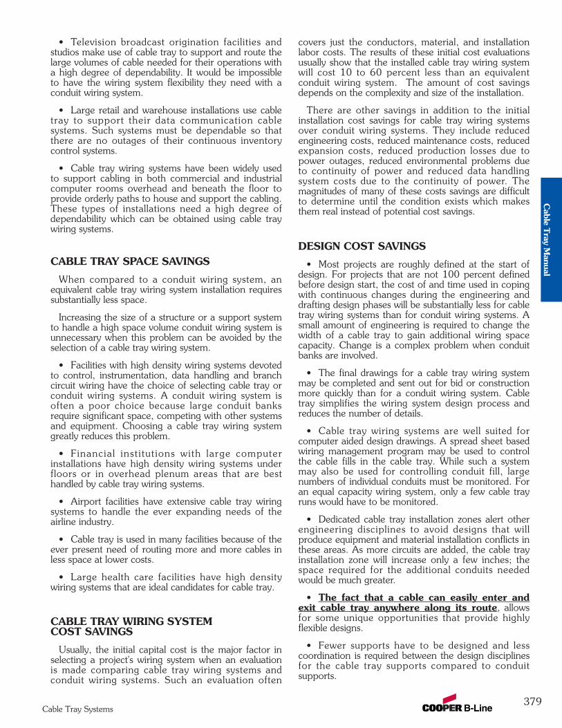
• Television broadcast origination facilities andstudios make use of cable tray to support and route thelarge volumes of cable needed for their operations witha high degree of dependability. It would be impossibleto have the wiring system flexibility they need with aconduit wiring system.
• Large retail and warehouse installations use cabletray to support their data communication cablesystems. Such systems must be dependable so thatthere are no outages of their continuous inventorycontrol systems.
• Cable tray wiring systems have been widely usedto support cabling in both commercial and industrialcomputer rooms overhead and beneath the floor toprovide orderly paths to house and support the cabling.These types of installations need a high degree ofdependability which can be obtained using cable traywiring systems.
CABLE TRAY SPACE SAVINGS
When compared to a conduit wiring system, anequivalent cable tray wiring system installation requiressubstantially less space.
Increasing the size of a structure or a support systemto handle a high space volume conduit wiring system isunnecessary when this problem can be avoided by theselection of a cable tray wiring system.
• Facilities with high density wiring systems devotedto control, instrumentation, data handling and branchcircuit wiring have the choice of selecting cable tray orconduit wiring systems. A conduit wiring system isoften a poor choice because large conduit banksrequire significant space, competing with other systemsand equipment. Choosing a cable tray wiring systemgreatly reduces this problem.
• Financial inst i tut ions with large computerinstallations have high density wiring systems underfloors or in overhead plenum areas that are besthandled by cable tray wiring systems.
• Airport facilities have extensive cable tray wiringsystems to handle the ever expanding needs of theairline industry.
• Cable tray is used in many facilities because of theever present need of routing more and more cables inless space at lower costs.
• Large health care facilities have high densitywiring systems that are ideal candidates for cable tray.
CABLE TRAY WIRING SYSTEM COST SAVINGS
Usually, the initial capital cost is the major factor inselecting a project's wiring system when an evaluationis made comparing cable tray wiring systems andconduit wiring systems. Such an evaluation often
covers just the conductors, material, and installationlabor costs. The results of these initial cost evaluationsusually show that the installed cable tray wiring systemwill cost 10 to 60 percent less than an equivalentconduit wiring system. The amount of cost savingsdepends on the complexity and size of the installation.
There are other savings in addition to the initialinstallation cost savings for cable tray wiring systemsover conduit wiring systems. They include reducedengineering costs, reduced maintenance costs, reducedexpansion costs, reduced production losses due topower outages, reduced environmental problems dueto continuity of power and reduced data handlingsystem costs due to the continuity of power. Themagnitudes of many of these costs savings are difficultto determine until the condition exists which makesthem real instead of potential cost savings.
DESIGN COST SAVINGS
• Most projects are roughly defined at the start ofdesign. For projects that are not 100 percent definedbefore design start, the cost of and time used in copingwith continuous changes during the engineering anddrafting design phases will be substantially less for cabletray wiring systems than for conduit wiring systems. Asmall amount of engineering is required to change thewidth of a cable tray to gain additional wiring spacecapacity. Change is a complex problem when conduitbanks are involved.
• The final drawings for a cable tray wiring systemmay be completed and sent out for bid or constructionmore quickly than for a conduit wiring system. Cabletray simplifies the wiring system design process andreduces the number of details.
• Cable tray wiring systems are well suited forcomputer aided design drawings. A spread sheet basedwiring management program may be used to controlthe cable fills in the cable tray. While such a systemmay also be used for controlling conduit fill, largenumbers of individual conduits must be monitored. Foran equal capacity wiring system, only a few cable trayruns would have to be monitored.
• Dedicated cable tray installation zones alert otherengineering disciplines to avoid designs that willproduce equipment and material installation conflicts inthese areas. As more circuits are added, the cable trayinstallation zone will increase only a few inches; thespace required for the additional conduits neededwould be much greater.
• The fact that a cable can easily enter andexit cable tray anywhere along its route, allowsfor some unique opportunities that provide highlyflexible designs.
• Fewer supports have to be designed and lesscoordination is required between the design disciplinesfor the cable tray supports compared to conduitsupports.
379Cable Tray Systems
Cable T
ray Manual
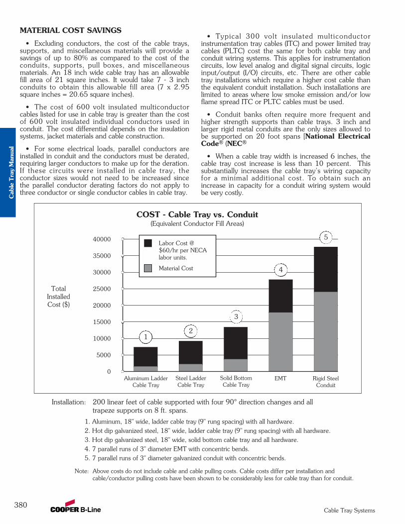
MATERIAL COST SAVINGS
• Excluding conductors, the cost of the cable trays,supports, and miscellaneous materials will provide asavings of up to 80% as compared to the cost of theconduits, supports, pull boxes, and miscellaneousmaterials. An 18 inch wide cable tray has an allowablefill area of 21 square inches. It would take 7 - 3 inchconduits to obtain this allowable fill area (7 x 2.95square inches = 20.65 square inches).
• The cost of 600 volt insulated multiconductorcables listed for use in cable tray is greater than the costof 600 volt insulated individual conductors used inconduit. The cost differential depends on the insulationsystems, jacket materials and cable construction.
• For some electrical loads, parallel conductors areinstalled in conduit and the conductors must be derated,requiring larger conductors to make up for the deration.If these circuits were installed in cable tray, theconductor sizes would not need to be increased sincethe parallel conductor derating factors do not apply tothree conductor or single conductor cables in cable tray.
• Typical 300 volt insulated mult iconductorinstrumentation tray cables (ITC) and power limited traycables (PLTC) cost the same for both cable tray andconduit wiring systems. This applies for instrumentationcircuits, low level analog and digital signal circuits, logicinput/output (I/O) circuits, etc. There are other cabletray installations which require a higher cost cable thanthe equivalent conduit installation. Such installations arelimited to areas where low smoke emission and/or lowflame spread ITC or PLTC cables must be used.
• Conduit banks often require more frequent andhigher strength supports than cable trays. 3 inch andlarger rigid metal conduits are the only sizes allowed tobe supported on 20 foot spans [National ElectricalCode® (NEC®) Table 344.30(B)(2)].
• When a cable tray width is increased 6 inches, thecable tray cost increase is less than 10 percent. Thissubstantially increases the cable tray’s wiring capacityfor a minimal additional cost. To obtain such anincrease in capacity for a conduit wiring system wouldbe very costly.
380Cable Tray Systems
40000
35000
30000
25000
20000
15000
10000
5000
0
TotalInstalledCost ($)
COST - Cable Tray vs. Conduit(Equivalent Conductor Fill Areas)
Material Cost
Labor Cost @$60/hr per NECAlabor units.
Aluminum LadderCable Tray
Steel LadderCable Tray
Solid BottomCable Tray
EMT Rigid SteelConduit
Installation: 200 linear feet of cable supported with four 90° direction changes and all trapeze supports on 8 ft. spans.
1. Aluminum, 18" wide, ladder cable tray (9" rung spacing) with all hardware.2. Hot dip galvanized steel, 18" wide, ladder cable tray (9" rung spacing) with all hardware.3. Hot dip galvanized steel, 18" wide, solid bottom cable tray and all hardware.4. 7 parallel runs of 3" diameter EMT with concentric bends.5. 7 parallel runs of 3" diameter galvanized conduit with concentric bends.
Note: Above costs do not include cable and cable pulling costs. Cable costs differ per installation and cable/conductor pulling costs have been shown to be considerably less for cable tray than for conduit.
4
3
12
5
Cab
le T
ray
Man
ual
INSTALLATION COST AND TIME SAVINGS
• Depending on the complexity and magnitude ofthe wiring system, the total cost savings for the initialinstallation (labor, equipment and material) may be up to75 percent for a cable tray wiring system over a conduitwiring system. When there are banks of conduit to beinstalled that are more than 100 feet long and consist offour or more 2 inch conduits or 12 or more smallerconduits, the labor cost savings obtained using cabletray wiring systems are very significant.
• Many more individual components are involved inthe installation of a conduit system and its conductorscompared to the installation of a cable tray system andits cables. This results in the handling and installing oflarge amounts of conduit items vs. small amounts ofcable tray items for the same wiring capacity.
• The higher the elevation of the wiring system, themore important the number of components required tocomplete the installation. Many additional man-hourswill be required just moving the components needed forthe conduit system up to the work location.
• Conduit wiring systems require pull boxes or spliceboxes when there is the equivalent of more than 360degrees of bends in a run. For large conductors, pull orjunction boxes may be required more often to facilitatethe conductor’s installation. Cable tray wiring systemsdo not require pull boxes or splice boxes.
• Penetrating a masonry wall with cable tray requiresa smaller hole and limited repair work.
• More supports are normally required for rigid steelconduit due to the requirements of NEC® Table344.30(B)(2).
• Concentric conduit bends for direction changes inconduit banks are very labor intensive and difficult tomake. However if they are not used, the installation willbe unattractive. The time required to make a concentricbend is increased by a factor of 3-6 over that of a singleshot bend. This time consuming practice is eliminatedwhen cable tray wiring systems are used.
• Conductor pulling is more complicated and timeconsuming for conduit wiring systems than for cabletray wiring systems. Normally, single conductor wirepulls for conduit wiring systems require multiple reelsetups. For conduit wiring systems, it is necessary to pullfrom termination equipment enclosure to terminationequipment enclosure. Tray cables being installed incable trays do not have to be pulled into the terminationequipment enclosures. Tray cable may be pulled fromnear the first termination enclosure along the cable trayroute to near the second termination enclosure. Then,the tray cable is inserted into the equipment enclosuresfor termination. For projects with significant numbers oflarge conductors terminating in switchgear, this may bea very desirable feature that can save hours of anelectrician's time. Unnecessary power outages can beeliminated since tray cable pulls may be made without
de-energizing the equipment. For conduit installations,the equipment will have to be de-energized for rubbersafety blanketing to be instal led, otherwise theconductor pulls might have to be made on a weekend oron a holiday at premium labor costs to avoid shuttingdown production or data processing operations duringnormal working hours.
• Conductor insulation damage is common inconduits since jamming can occur when pulling theconductors. Jamming is the wedging of conductors in aconduit when three conductors lay side by side in a flatplane. This may occur when pulling around bends orwhen the conductors twist. Ninety-two percent of allconductor failures are the result of the conductor’sinsulation being damaged during the conductor’sinstallation. Many common combinations of conductorsand conduits fall into critical jam ratio values. Criticaljam ratio (J.R.= Conduit ID/Conductor OD) valuesrange from 2.8 to 3.2. The J. R. for 3 single conductorTHHN/THWN insulated 350 kcmil conductors in a21/2 inch conduit would be 3.0 (2.469 inches/ 0.816inches). If conductor insulation damage occurs,additional costs and time are required for replacing theconductors. This cannot occur in a cable tray wiringsystem.
• Smaller electrician crews may be used to install theequivalent wiring capacity in cable tray. This allows formanpower leveling, the peak and average crew wouldbe almost the same number, and the electricianexperience level required is lower for cable trayinstallations.
• Since the work is completed faster there is lesswork space conflict with the other constructiondisciplines. This is especially true if installations areelevated and if significant amounts of piping are beinginstalled on the project.
MAINTENANCE SAVINGS
• One of the most important features of cable tray isthat tray cable can easily be installed in existing trays ifthere is space available. Cable tray wiring systems allowwiring additions or modifications to be made quicklywith minimum disruption to operations. Anyconceivable change that is required in a wiring systemcan be done at lower cost and in less time for a cabletray wiring system than for a conduit wiring system.
• Moisture is a major cause of electrical equipmentand material failures. Breathing due to temperaturecycling results in the conduits accumulating relativelylarge amounts of moisture. The conduits then pipe thismoisture into the electrical equipment enclosures whichover a period of time results in the deterioration of theequipment insulation systems and their eventual failure.Also, moisture may become a factor in the corrosionfailure of some of the critical electrical equipment'smetallic components. Conduit seals are not effective inblocking the movement of moisture. The conduitsystems may be designed to reduce the moisture
381Cable Tray Systems
Cable T
ray Manual
problems but not to completely el iminate it.Few designers go into the design detail necessary toreduce the effects of moisture in the conduit systems.Tray cables do not provide internal moisture paths as doconduits.
• In the event of external f ires in industrialinstallations, the damage to the tray cable and cable trayis most often limited to the area of the flame contactplus a few feet on either side of the flame contact area.For such a fire enveloping a steel conduit bank, the steelconduit is a heat sink and the conductor insulation willbe damaged for a considerable distance inside theconduit. Thermoplastic insulation may be fused to thesteel conduit and the conduit will need to be replacedfor many feet. This occurred in an Ohio chemical plantand the rigid steel conduits had to be replaced for 90feet. Under such conditions, the repair cost for firedamage would normally be greater for a conduit wiringsystem than for cable tray and tray cable. In the Ohiochemical plant fire, there were banks of conduits andruns of cable tray involved. The cable tray wiringsystems were repaired in two days. The conduit wiringsystems were repaired in six days and required a greatdeal more manpower.
• In the event of an external fire, the conduitbecomes a heat sink and an oven which decreases thetime required for the conductor insulation systems tofail. The heat decomposes the cable jackets and theconductor insulation material. If these materials containPVC as do most cables, hydrogen chloride vapors willcome out the ends of the conduits in the control rooms.These fumes are very corrosive to the electronicequipment. They are also hazardous to personnel. Aflame impingement on a cable tray system will not resultin the fumes going into the control room as there is nocontainment path for them. They will be dispersed intothe atmosphere.
IN MOST CASES AN OBJECTIVEEVALUATION OF THE REQUIREMENTS FORMOST HIGH DENSITY WIRING SYSTEMS WILLSHOW THAT A CABLE TRAY WIRING SYSTEMPROVIDES A WIRING SYSTEM SUPERIOR TOA CONDUIT WIRING SYSTEM.
Abandoned Cables
Easily identified, marked, or removed - all possible froman open Cable Tray System
For the 2002 National Electrical Code, severalproposals were submitted to the NFPA to revise the1999 NEC® for Articles 300, 640, 645, 725, 760,770, 800, 820, and 830 to require all abandonedcables to be removed from plenum spaces.
The purpose of the proposals is to remove the cablesas a source of excess combustibles from plenums andother confined spaces such as raised floors and dropceilings. All of the Code Making Panels agreed that thisshould be acceptable practice except Code MakingPanel 3, which oversees Article 300.
Because Article 300 is exempt from this requirementonly low-voltage and communication cables are affected.
Each Article adopted a definition of abandoned cablesand the rule for removal. The general consensus is thatabandoned cable is cable that is not terminated atequipment or connectors and is not identified for futureuse with a tag. Please refer to each individual NEC®
Article for specifics.
Having to tag, remove, or rearrange cables within anenclosed raceway can be a time consuming and difficultjob. Without being able to clearly see the cables andfollow their exact routing throughout a facility,identifying abandoned cables would be very difficult andexpensive.
With the open accessibility of cable tray, thesechanges can be implemented with ease. Abandonedcables can be identified, marked, rearranged, orremoved with little or no difficulty.
382Cable Tray Systems
Cab
le T
ray
Man
ual
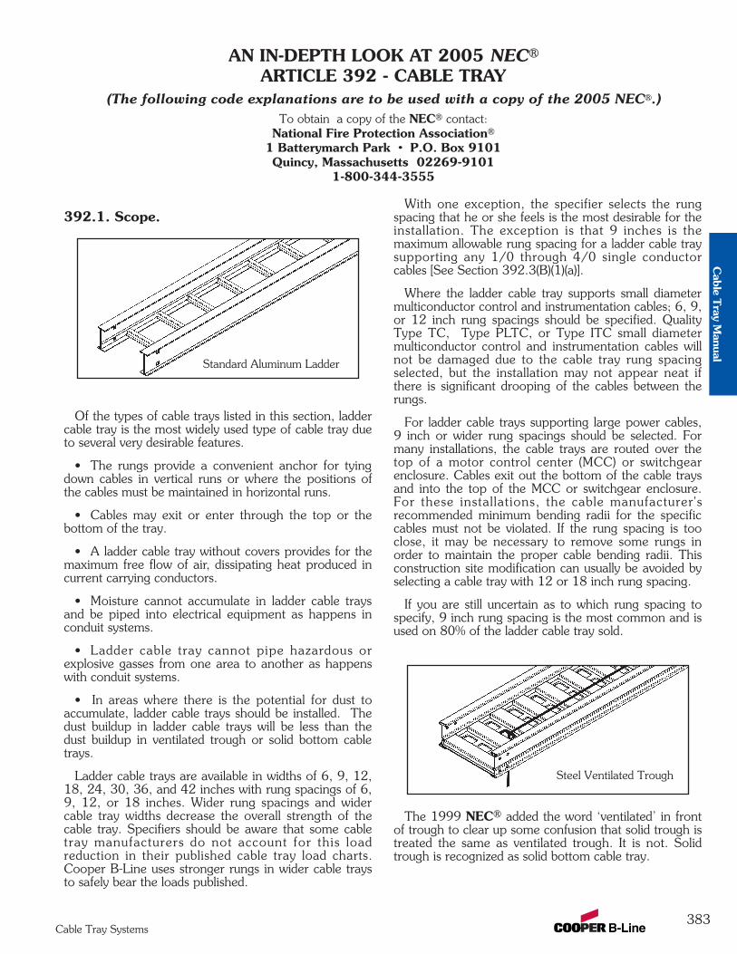
392.1. Scope.
Of the types of cable trays listed in this section, laddercable tray is the most widely used type of cable tray dueto several very desirable features.
• The rungs provide a convenient anchor for tyingdown cables in vertical runs or where the positions ofthe cables must be maintained in horizontal runs.
• Cables may exit or enter through the top or thebottom of the tray.
• A ladder cable tray without covers provides for themaximum free flow of air, dissipating heat produced incurrent carrying conductors.
• Moisture cannot accumulate in ladder cable traysand be piped into electrical equipment as happens inconduit systems.
• Ladder cable tray cannot pipe hazardous orexplosive gasses from one area to another as happenswith conduit systems.
• In areas where there is the potential for dust toaccumulate, ladder cable trays should be installed. Thedust buildup in ladder cable trays will be less than thedust buildup in ventilated trough or solid bottom cabletrays.
Ladder cable trays are available in widths of 6, 9, 12,18, 24, 30, 36, and 42 inches with rung spacings of 6,9, 12, or 18 inches. Wider rung spacings and widercable tray widths decrease the overall strength of thecable tray. Specifiers should be aware that some cabletray manufacturers do not account for this loadreduction in their published cable tray load charts.Cooper B-Line uses stronger rungs in wider cable traysto safely bear the loads published.
With one exception, the specifier selects the rungspacing that he or she feels is the most desirable for theinstallation. The exception is that 9 inches is themaximum allowable rung spacing for a ladder cable traysupporting any 1/0 through 4/0 single conductorcables [See Section 392.3(B)(1)(a)].
Where the ladder cable tray supports small diametermulticonductor control and instrumentation cables; 6, 9,or 12 inch rung spacings should be specified. QualityType TC, Type PLTC, or Type ITC small diametermulticonductor control and instrumentation cables willnot be damaged due to the cable tray rung spacingselected, but the installation may not appear neat ifthere is significant drooping of the cables between therungs.
For ladder cable trays supporting large power cables,9 inch or wider rung spacings should be selected. Formany installations, the cable trays are routed over thetop of a motor control center (MCC) or switchgearenclosure. Cables exit out the bottom of the cable traysand into the top of the MCC or switchgear enclosure.For these installations, the cable manufacturer'srecommended minimum bending radii for the specificcables must not be violated. If the rung spacing is tooclose, it may be necessary to remove some rungs inorder to maintain the proper cable bending radii. Thisconstruction site modification can usually be avoided byselecting a cable tray with 12 or 18 inch rung spacing.
If you are still uncertain as to which rung spacing tospecify, 9 inch rung spacing is the most common and isused on 80% of the ladder cable tray sold.
The 1999 NEC® added the word ‘ventilated’ in frontof trough to clear up some confusion that solid trough istreated the same as ventilated trough. It is not. Solidtrough is recognized as solid bottom cable tray.
383Cable Tray Systems
AN IN-DEPTH LOOK AT 2005 NEC®
ARTICLE 392 - CABLE TRAY(The following code explanations are to be used with a copy of the 2005 NEC®.)
To obtain a copy of the NEC® contact:National Fire Protection Association®
1 Batterymarch Park • P.O. Box 9101Quincy, Massachusetts 02269-9101
1-800-344-3555
Standard Aluminum Ladder
Steel Ventilated Trough
Cable T
ray Manual
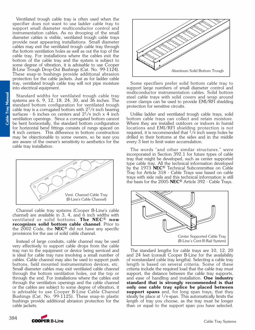
Ventilated trough cable tray is often used when thespecifier does not want to use ladder cable tray tosupport small diameter multiconductor control andinstrumentation cables. As no drooping of the smalldiameter cables is visible, ventilated trough cable traysprovide neat appearing installations. Small diametercables may exit the ventilated trough cable tray throughthe bottom ventilation holes as well as out the top of thecable tray. For installations where the cables exit thebottom of the cable tray and the system is subject tosome degree of vibration, it is advisable to use CooperB-Line Trough Drop-Out Bushings (Cat. No. 99-1124).These snap-in bushings provide additional abrasionprotection for the cable jackets. Just as for ladder cabletray, ventilated trough cable tray will not pipe moistureinto electrical equipment.
Standard widths for ventilated trough cable traysystems are 6, 9, 12, 18, 24, 30, and 36 inches. Thestandard bottom configuration for ventilated troughcable tray is a corrugated bottom with 27/8 inch bearingsurfaces - 6 inches on centers and 21/4 inch x 4 inchventilation openings. Since a corrugated bottom cannotbe bent horizontally, the standard bottom configurationfor horizontal bend fittings consists of rungs spaced on4 inch centers. This difference in bottom constructionmay be objectionable to some owners, so be sure youare aware of the owner's sensitivity to aesthetics for thecable tray installation.
Channel cable tray systems (Cooper B-Line's cablechannel) are available in 3, 4, and 6 inch widths withventi lated or sol id bottoms. The NEC® nowrecognizes solid bottom cable channel. Prior tothe 2002 Code, the NEC® did not have any specificprovisions for the use of solid cable channel.
Instead of large conduits, cable channel may be usedvery effectively to support cable drops from the cabletray run to the equipment or device being serviced andis ideal for cable tray runs involving a small number ofcables. Cable channel may also be used to support pushbuttons, field mounted instrumentation devices, etc.Small diameter cables may exit ventilated cable channelthrough the bottom ventilation holes, out the top orthrough the end. For installations where the cables exitthrough the ventilation openings and the cable channelor the cables are subject to some degree of vibration, itis advisable to use Cooper B-Line Cable ChannelBushings (Cat. No. 99-1125). These snap-in plasticbushings provide additional abrasion protection for thecable jackets.
Some specifiers prefer solid bottom cable tray tosupport large numbers of small diameter control andmulticonductor instrumentation cables. Solid bottomsteel cable trays with solid covers and wrap aroundcover clamps can be used to provide EMI/RFI shieldingprotection for sensitive circuits.
Unlike ladder and ventilated trough cable trays, solidbottom cable trays can collect and retain moisture.Where they are installed outdoors or indoors in humidlocations and EMI/RFI shielding protection is notrequired, it is recommended that 1/4 inch weep holes bedrilled in their bottoms at the sides and in the middleevery 3 feet to limit water accumulation.
The words "and other similar structures." wereincorporated in Section 392.1 for future types of cabletray that might be developed, such as center supportedtype cable tray. All the technical information developedby the 1973 NEC® Technical Subcommittee on CableTray for Article 318 - Cable Trays was based on cabletrays with side rails and this technical information is stillthe basis for the 2005 NEC® Article 392 - Cable Trays.
The standard lengths for cable trays are 10, 12, 20and 24 feet (consult Cooper B-Line for the availabilityof nonstandard cable tray lengths). Selecting a cable traylength is based on several criteria. Some of thesecriteria include the required load that the cable tray mustsupport, the distance between the cable tray supports,and ease of handling and installation. One industrystandard that is strongly recommended is thatonly one cable tray splice be placed betweensupport spans and, for long span trays, that theyideally be place at 1/4-span. This automatically limits thelength of tray you choose, as the tray must be longerthan or equal to the support span you have selected.
384Cable Tray Systems
Vent. Channel Cable Tray(B-Line's Cable Channel)
Aluminum Solid Bottom Trough
Center Supported Cable Tray(B-Line’s Cent-R-Rail System)
Cab
le T
ray
Man
ual
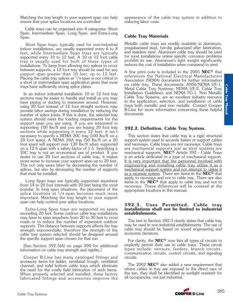
Matching the tray length to your support span can helpensure that your splice locations are controlled.
Cable trays can be organized into 4 categories: ShortSpan, Intermediate Span, Long Span, and Extra-LongSpan.
Short Span trays, typically used for non-industrialindoor installations, are usually supported every 6 to 8feet, while Intermediate Span trays are typicallysupported every 10 to 12 feet. A 10 or 12 foot cabletray is usual ly used for both of these types ofinstallations. To keep from allowing two splices to occurbetween supports, a 12 foot tray should be used for anysupport span greater than 10 feet, up to 12 feet.Placing the cable tray splices at 1/4-span is not critical ina short or intermediate span application given that mosttrays have sufficiently strong splice plates.
In an indoor industrial installation 10 or 12 foot traysections may be easier to handle and install as you mayhave piping or ducting to maneuver around. However,using 20 foot instead of 12 foot straight sections mayprovide labor savings during installation by reducing thenumber of splice joints. If this is done, the selected traysystem should meet the loading requirements for thesupport span you are using. If you are interested insupporting 100 lbs/ft and you are buying 20 foot traysections while supporting it every 12 feet, it isn’tnecessary to specify a NEMA 20C tray (100 lbs/ft on a20 foot span). A NEMA 20A tray (50 lbs/ft on a 20foot span) will support over 130 lbs/ft when supportedon a 12 ft span with a safety factor of 1.5. Specifying a20C tray is not an economical use of product. If youdesire to use 20 foot sections of cable tray, it makesmore sense to increase your support span up to 20 feet.This not only saves labor by decreasing the number ofsplices, but also by decreasing the number of supportsthat must be installed.
Long Span trays are typically supported anywherefrom 14 to 20 foot intervals with 20 feet being the mostpopular. In long span situations, the placement of thesplice locations at 1/4-span becomes much moreimportant. Matching the tray length to your supportspan can help control your splice locations.
Extra-Long Span trays are supported on spansexceeding 20 feet. Some outdoor cable tray installationsmay have to span anywhere from 20 to 30 feet to crossroads or to reduce the number of expensive outdoorsupports. The distance between supports affects the traystrength exponentially; therefore the strength of thecable tray system selected should be designed aroundthe specific support span chosen for that run.
[See Section 392.5(A) on page 390 for additionalinformation on cable tray strength and rigidity.]
Cooper B-Line has many cataloged fittings andaccessory items for ladder, ventilated trough, ventilatedchannel, and solid bottom cable trays which eliminatethe need for the costly field fabrication of such items.When properly selected and installed, these factoryfabricated f i t t ings and accessories improve the
appearance of the cable tray system in addition toreducing labor costs.
Cable Tray Materials
Metallic cable trays are readily available in aluminum,pregalvanized steel, hot-dip galvanized after fabrication,and stainless steel. Aluminum cable tray should be usedfor most installations unless specific corrosion problemsprohibit its use. Aluminum's light weight significantlyreduces the cost of installation when compared to steel.
A fine print note is included in the 2005 NEC® thatreferences the National Electrical ManufacturersAssociation (NEMA) documents for further informationon cable tray. These documents: ANSI/NEMA VE-1,Metal Cable Tray Systems; NEMA VE-2, Cable TrayInstallation Guidelines; and NEMA FG-1, Non MetallicCable Tray Systems, are an excellent industry resourcein the application, selection, and installation of cabletrays both metallic and non metallic. Contact CooperB-Line for more information concerning these helpfuldocuments.
392.2. Definition. Cable Tray System.
This section states that cable tray is a rigid structuralsupport system used to securely fasten or support cablesand raceways. Cable trays are not raceways. Cable traysare mechanical supports just as strut systems aremechanical supports. NEC® Article 392 - Cable Traysis an article dedicated to a type of mechanical support.It is very important that the personnel involved withengineering and installing cable tray utilize it as amechanical support system and not attempt to utilize itas a raceway system. There are items in the NEC® thatapply to raceways and not to cable tray. There are alsoitems in the NEC® that apply to cable tray and not toraceways. These differences will be covered at theappropriate locations in this manual.
392.3. Uses Permitted. Cable trayinstallations shall not be limited to industrialestablishments.
The text in Section 392.3 clearly states that cable traymay be used in non-industrial establishments. The use ofcable tray should be based on sound engineering andeconomic decisions.
For clarity, the NEC® now lists all types of circuits toexplicitly permit their use in cable trays. These circuittypes include: services, feeders, branch circuits,communication circuits, control circuits, and signalingcircuits.
The 2002 NEC® also added a new requirement thatwhere cables in tray are exposed to the direct rays ofthe sun, they shall be identified as sunlight resistant forall occupancies, not just industrial.
385Cable Tray Systems
Cable T
ray Manual
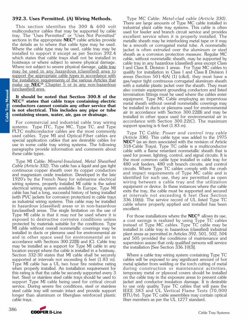
392.3. Uses Permitted. (A) Wiring Methods.
This section identif ies the 300 & 600 voltmulticonductor cables that may be supported by cabletray. The "Uses Permitted" or "Uses Not Permitted"sections in the appropriate NEC® cable articles providethe details as to where that cable type may be used.Where the cable type may be used, cable tray may beinstalled to support it except as per Section 392.4which states that cable trays shall not be installed inhoistways or where subject to severe physical damage.Where not subject to severe physical damage, cable traymay be used in any hazardous (classified) area tosupport the appropriate cable types in accordance withthe installation requirements of the various Articles thatmake up NEC® Chapter 5 or in any non-hazardous(unclassified) area.
It should be noted that Section 300.8 of theNEC® states that cable trays containing electricconductors cannot contain any other service thatis not electrical. This includes any pipe or tubecontaining steam, water, air, gas or drainage.
For commercial and industrial cable tray wiringsystems: Type ITC, Type MC, Type TC, and TypePLTC multiconductor cables are the most commonlyused cables. Type MI and Optical-Fiber cables arespecial application cables that are desirable cables foruse in some cable tray wiring systems. The followingparagraphs provide information and comments aboutthese cable types.
Type MI Cable: Mineral-Insulated, Metal SheathedCable (Article 332). This cable has a liquid and gas tightcontinuous copper sheath over its copper conductorsand magnesium oxide insulation. Developed in the late1920's by the French Navy for submarine electricalwiring systems, properly installed MI cable is the safestelectrical wiring system available. In Europe, Type MIcable has had a long, successful history of being installed(with PVC jackets for corrosion protection) in cable traysas industrial wiring systems. This cable may be installedin hazardous (classified) areas or in non-hazardous(unclassified) areas. The single limitation on the use ofType MI cable is that it may not be used where it isexposed to destructive corrosive conditions unlessprotected by materials suitable for the conditions. TypeMI cable without overall nonmetallic coverings may beinstalled in ducts or plenums used for environmental airand in other space used for environmental air inaccordance with Sections 300.22(B) and (C). Cable traymay be installed as a support for Type MI cable in anylocation except where the cable is installed in a hoistway.Section 332-30 states that MI cable shall be securelysupported at intervals not exceeding 6 feet (1.83 m).Type MI cable has a UL two hour fire resistive ratingwhen properly installed. An installation requirement forthis rating is that the cable be securely supported every 3feet. Steel or stainless steel cable trays should be used tosupport Type MI cable being used for critical circuitservice. During severe fire conditions, steel or stainlesssteel cable tray will remain intact and provide supportlonger than aluminum or fiberglass reinforced plasticcable trays.
Type MC Cable: Metal-clad cable (Article 330).There are large amounts of Type MC cable installed inindustrial plant cable tray systems. This cable is oftenused for feeder and branch circuit service and providesexcellent service when it is properly installed. Themetallic sheath may be interlocking metal tape or it maybe a smooth or corrugated metal tube. A nonmetallicjacket is often extruded over the aluminum or steelsheath as a corrosion protection measure. Regular MCcable, without nonmetallic sheath, may be supported bycable tray in any hazardous (classified) area except ClassI and Class II, Division 1 areas. For Type MC cables toqualify for installation in Class I and Class II Division Iareas (Section 501-4(A) (1) (c&d), they must have agas/vapor tight continuous corrugated aluminum sheathwith a suitable plastic jacket over the sheath. They mustalso contain equipment grounding conductors and listedtermination fittings must be used where the cables enterequipment. Type MC Cable employing an imperviousmetal sheath without overall nonmetallic coverings maybe installed in ducts or plenums used for environmentalair in accordance with Section 300.22(B) and may beinstalled in other space used for environmental air inaccordance with Section 300.22(C). The maximumsupport spacing is 6 feet (1.83 m).
Type TC Cable: Power and control tray cable(Article 336). This cable type was added to the 1975NEC® (as an item associated with the revision of Article318-Cable Trays). Type TC cable is a multiconductorcable with a flame retardant nonmetallic sheath that isused for power, lighting, control, and signal circuits. It isthe most common cable type installed in cable tray for480 volt feeders, 480 volt branch circuits, and controlcircuits. Where Type TC cables comply with the crushand impact requirements of Type MC cable and isidentified for such use, they are permitted as openwiring between a cable tray and the uti l izat ionequipment or device. In these instances where the cableexits the tray, the cable must be supported and securedat intervals not exceeding 6 feet (See Section336.10(6)). The service record of UL listed Type TCcable where properly applied and installed has beenexcellent.
For those installations where the NEC® allows its use,a cost savings is realized by using Type TC cablesinstead of Type MC cables. Type TC cable may beinstalled in cable tray in hazardous (classified) industrialplant areas as permitted in Articles 392, 501, 502, 504and 505 provided the conditions of maintenance andsupervision assure that only qualified persons will servicethe installation [See Section 336.10(3)].
Where a cable tray wiring system containing Type TCcables will be exposed to any significant amount of hotmetal splatter from welding or the torch cutting of metalduring construction or maintenance activit ies,temporary metal or plywood covers should be installedon the cable tray in the exposure areas to prevent cablejacket and conductor insulation damage. It is desirableto use only quality Type TC cables that will pass theIEEE 383 and UL Vertical Flame Tests (70,000BTU/hr). Type TC cable assemblies may contain opticalfiber members as per the UL 1277 standard.
386Cable Tray Systems
Cab
le T
ray
Man
ual
Type ITC Cable: Instrumentation Tray Cable(Article 727). Although this was a new cable article inthe 1996 NEC®, it is not a new type of cable.Thousands of miles of ITC cable have been installed inindustrial situations since the early 1960’s. This is amulticonductor cable that most often has a nonmetallicjacket. The No. 22 through No. 12 insulated conductorsin the cables are 300 volt rated. A metallic shield or ametallized foil shield with a drain wire usually enclosesthe cable’s conductors. These cables are used totransmit the low energy level signals associated with theindustrial instrumentation and data handling systems.These are very critical circuits that impact on facilitysafety and on product quality. Type ITC cable must besupported and secured at intervals not exceeding 6 feet[See Section 727.4].
Type ITC Cable may be installed in cable trays inhazardous (classified) areas as permitted in Articles 392,501, 502, 504 and 505. It states in Article 727 thatType ITC cables that comply with the crush and impactrequirements of Type MC cable and are identified forsuch use, are permitted as open wiring in lengths not toexceed 50 ft. between a cable tray and the utilizationequipment or device. Where a cable tray wiring systemcontaining Type ITC cables will be exposed to anysignificant amount of hot metal splatter from welding orthe torch cutting of metal during construction ormaintenance activities, temporary metal or plywoodcovers should be installed on the cable tray to preventcable jacket or conductor insulation damage. It isdesirable to use only quality Type ITC cables that willpass the IEEE 383 and UL Vertical Flame Tests(70,000BTU/hr).
Type PLTC Cable: Power-Limited Tray Cable(Sections 725-61(C), and 725-71(E)). This is amulticonductor cable with a flame retardant nonmetallicsheath. The No. 22 through No. 12 insulatedconductors in the cables are 300 volt rated. A metallicshield or a metallized foil shield with drain wire usuallyencloses the cable's conductors. This cable type hashigh usage in communication, data processing, fireprotection, signaling, and industrial instrumentationwiring systems.
There are versions of this cable with insulation andjacket systems made of materials with low smokeemission and low flame spread properties which makethem desirable for use in plenums. In IndustrialEstablishments where the conditions of maintenanceand supervision ensure that only qualified personsservice the installation and where the cable is not subjectto physical damage Type PLTC cable may be installedin cable trays hazardous (classified) areas as permitted inSection 501.4(B), 502.4(B) and 504.20. Type PLTCcables that comply with the crush and impactrequirements of Type MC cable and are identified forsuch use, are permitted as open wiring in lengths not toexceed a total of 50 ft. between a cable tray and theutilization equipment or device. In this situation, thecable needs to be supported and secured at intervals notexceeding 6 ft. Where a cable tray wiring systemcontaining Type PLTC cables will be exposed to any
significant amount of hot metal splatter from welding orthe torch cutting of metal during construction ormaintenance activities, temporary metal or plywoodcovers should be installed on the cable tray to preventcable jacket and conductor insulation damage. It isdesirable to use only quality Type PLTC cables that willpass the IEEE 383 and UL Vertical Flame Tests (70,000BTU/hr). Type PLTC cable assemblies may containoptical fiber members as per the UL 1277 standard.
Optical Fiber Cables (Article 770). The addition ofoptical fiber cables in the Section 392.3(A) cable list forthe 1996 NEC was not a technical change. Opticalfiber cables have been allowed to be supported in cabletrays as per Section 770.6. Optical fibers may also bepresent in Type TC cables as per UL Standard 1277.
For the 1999 NEC® code, Article 760 - Fire AlarmCables and Articles 800 - Mult ipurpose andCommunications Cables were added to the list of cablespermitted to be installed in cable tray systems.
For the 1993 NEC®, the general statement in the1990 NEC® which allowed all types of raceways to besupported by cable trays was replaced by individualstatements for each of the ten specific raceway typesthat may now be supported by cable tray. The chancesof any such installations being made are very low, sincestrut is a more convenient and economic choice thancable tray to support raceway systems.
392.3. Uses Permitted. (B) In IndustrialEstablishments.
This section limits the installation of single conductorcables and Type MV multiconductor cables in cabletrays to qualifying industrial establishments as defined inthis section.
Per the 2002 NEC® solid bottom cable trays are nowpermitted to support single conductor cables only inindustrial establ ishments where condit ions ofmaintenance and supervision ensure that only qualifiedpersons will service the installed cable tray system.However, at this time, no fill rules for single conductorcables in solid bottom cable tray have been established.[see Section 392.3(B)]
392.3. Uses Permitted. (B) In IndustrialEstablishments. (1) Single Conductor.
Section 392.3(B)(1) covers 600 volt and Type MVsingle conductor cables.
There are several sections which cover therequirements for the use of single conductor cables incable tray even though they only comprise a smallpercentage of cable tray wiring systems. Suchinstallations are limited to qualifying industrial facilities[See Section 392.3(B)]. Many of the facility engineersprefer to use three conductor power cables. Normally,three conductor power cables provide more desirableelectrical wiring systems than single conductor power
387Cable Tray Systems
Cable T
ray Manual
cables in cable tray (See Section 392.8. Cableinstallation - three conductor vs. single conductorcables).
392.3(B)(1)(a)Single conductor cable shall be No. 1/0 or larger and
shall be of a type listed and marked on the surface foruse in cable trays. Where Nos. 1/0 through 4/0 singleconductor cables are used, the maximum allowable rungspacing for ladder cable tray is 9 inches.
392.3(B)(1)(b)Welding cables shall comply with Article 630, Part IV
which states that the cable tray must provide support atintervals not to exceed 6 inches. A permanent signmust be attached to the cable tray at intervals not toexceed 20 feet. The sign must read “CABLE TRAYFOR WELDING CABLES ONLY”.
392.3(B)(1)(c)This section states that single conductors used as
equipment grounding conductors (EGCs) in cable traysshall be No. 4 or larger insulated, covered or bare.
The use of a single conductor in a cable tray as theEGC is an engineering design option. Section 300.3(B)states that all conductors of the same circuit and theEGC, if used, must be contained within the same cabletray.
The other options are to use multiconductor cablesthat each contain their own EGC or to use the cabletray itself as the EGC in qualifying installations [seeSection 392.3(C)]
If an aluminum cable tray is installed in a moistenvironment where the moisture may contain materialsthat can serve as an electrolyte, a bare copper EGCshould not be used. Under such conditions, electrolyticcorrosion of the aluminum may occur. For suchinstallations, it is desirable to use a low cost 600 voltinsulated conductor and remove the insulation whereconnections to equipment or to equipment groundingconductors are made. (See Section 392.7. Grounding,for additional information on single conductors used asthe EGC for cable tray systems).
392.3. Uses Permitted. (B) In IndustrialEstablishment (2) Medium Voltage.
Single and multiconductor type MV cables must besunlight resistant if exposed to direct sunlight. Singleconductors shall be installed in accordance with392.3(B)(1)
392.3. Uses Permitted. (C) EquipmentGrounding Conductors.
Cable tray may be used as the EGC in any installationwhere qualified persons will service the installed cabletray system. There is no restriction as to where the
cable tray system is installed. The metal in cable traysmay be used as the EGC as per the limitations of table392.7(B)(2). See Section 392.7. Grounding in thismanual for additional information on the use of cabletrays as the EGC.
392.3. Uses Permitted. (D) Hazardous(Classified) Locations.
This section states that if cable tray wiring systems areinstalled in hazardous (classified) areas, the cables thatthey support must be suitable for installation in thosehazardous (classified) areas. The cable carries theinstallation restriction. The installation restriction is noton the cable tray except that the cable tray installationsmust comply with Section 392.4. The following is anexplanation of the parts of the code which affect the useof cable tray in hazardous locations.
501.10. Wiring Methods - Listed TerminationFittings. (A) Class I, Division 1 (Gases or Vapors).501.10(A)(1)(b) Type MI cable may be installed in cabletray in this type of hazardous (classified) area.
501.10(A)(1)(c) allows Type MC-HL cables to beinstalled in Class I, Division I areas if they have agas/vapor tight continuous corrugated aluminum sheathwith a suitable plastic jacket over the sheath. They mustalso contain equipment grounding conductors sized asper Section 250.122 and listed termination fittings mustbe used where the cables enter equipment.
501.10(A)(1)(d) allows Type ITC-HL cable to beinstalled in Class I, Division I areas if they have agas/vapor tight continuous corrugated aluminum sheathwith a suitable plastic jacket over the sheath andprovided with termination fitt ings l isted for theapplication.
501.10. Wiring Methods. (B) Class I, Division 2(Gases or Vapors). Types ITC, PLTC, MI, MC, MV, orTC cables may be installed in cable tray in this type ofhazardous (classified) area. Under the conditionsspecified in Section 501.15(E), Cable seals are requiredin Class 1, Division 2 areas. Cable seals should be usedonly when absolutely necessary.
501.15. Sealing and Drainage. (E) Cable Seals,Class 1, Division 2. (1) Cables will be required to besealed only where they enter certain types of enclosuresused in Class 1, Division 2 areas. Factory sealed pushbuttons are an example of enclosures that do notrequire a cable seal at the entrance of the cable into theenclosure.
501.15. Sealing and Drainage. (E) Cable Seals,Class 1, Division 2. (2) Gas blocked cables areavailable from some cable manufacturers but they havenot been widely used. For gas to pass through thejacketed multiconductor cable's core, a pressuredifferential must be maintained from one end of the
388Cable Tray Systems
Cab
le T
ray
Man
ual

cable to the other end or to the point where there is abreak in the cable's jacket. The existence of such acondition is extremely rare and would require that oneend of the cable be in a pressure vessel or a pressurizedenclosure and the other end be exposed to theatmosphere. The migration of any significant volume ofgas or vapor though the core of a multiconductor cableis very remote. This is one of the safety advantages thatcable tray wiring systems have over conduit wiringsystems. There are documented cases of industrialexplosions caused by the migration of gases and vaporsthrough conduits when they came in contact with anignition source. There are no known cases of cables incable tray wiring systems providing a path for gases orvapors to an ignition source which produced anindustrial explosion.
501.15. Sealing and Drainage. (E) Cable Seals,Class 1, Division 2. (3)
Exception: Cables with an unbroken gas/vapor-tightcontinuous sheath shall be permitted to pass througha Class 1, Division 2 location without seals.
This is an extremely important exception stating thatcable seals are not required when a cable goes from anunclassified area through a classified area then back toan unclassified area.
501.15. Sealing and Drainage. (E) Cable Seals,Class 1, Division 2. (4)
If you do not have a gas/vapor-tight continuoussheath, cable seals are required at the boundary of theDivision 2 and unclassified location.
The sheaths mentioned above may be fabricated ofmetal or a nonmetallic material.
502.10. Wiring Methods. (A) Class II, Division 1(Combustible Dusts).
Type MI cable may be installed in cable tray in this typeof hazardous (classified) area.
The Exception allows Type MC cables to be installed inClass II, Division 1 areas if they have a gas/vapor tightcontinuous corrugated aluminum sheath with a suitableplastic jacket over the sheath. They must also containequipment grounding conductors sized as per Section250.122 and listed termination fittings must be usedwhere the cables enter equipment.
502.10. Wiring Methods. (B) Class II, Division 2(Combustible Dusts).
This section states:
Type ITC and PLTC cables may be installed in ladderor ventilated cable trays following the same practices asused in non-hazardous (unclassified) areas. No spacing isrequired between the ITC or PLTC cables. This is logicalas the ITC and PLTC cable circuits are all low energycircuits which do not produce any significant heat orheat dissipation problems.
Type MC, MI and TC [See Section 336.4(3)] cablesmay be installed in ladder, ventilated trough, orventilated cable channel, but they are not allowed to beinstalled in solid bottom cable trays.
Required Spacing in Cable Trays for Type MC, MI & TCCables in Class II, Division 2 Hazardous (Classified) Areas
Note 1. The cables are limited to a single layer withspacing between cables equal to the diameter of thelargest adjacent cable. This means that the cables mustbe tied down at frequent intervals in horizontal as wellas vertical cable trays to maintain the cable spacing. Areasonable distance between ties in the horizontal cabletray would be approximately 6 feet (See Section 392.8Cable Installation - Tying cables to cable trays).
Note 2. Spacing the cables a minimum of 1 inchfrom the side rai ls to prevent dust bui ldup isrecommended. This is not an NEC requirement but arecommended practice.
Where cable tray wiring systems with current carryingconductors are installed in a dust environment, laddertype cable trays should be used since there is lesssurface area for dust buildup than in ventilated troughcable trays. The spacing of the cables in dust areas willprevent the cables from being totally covered with asolid dust layer. In dusty areas, the top surfaces of allequipment, raceways, supports, or cable jacket surfaceswhere dust layers can accumulate will require cleanuphousekeeping at certain t ime intervals. Goodhousekeeping is required for personnel health,personnel safety and facility safety. Excessive amountsof dust on raceways or cables will act as a thermalbarrier which may not allow the power and lightinginsulated conductors in a raceway or cable to safelydissipate internal heat. This condition may result in theaccelerated aging of the conductor insulation. A cabletray system that is properly installed and maintained willprovide a safe dependable wiring system in dustenvironments.
Exception: Type MC cable listed for use in ClassII,Division I locations shall be permitted to be installedwithout the above spacing limitations. This was a newexception for the 1999 NEC® code.
For this type of wiring there is no danger of the cablesbeing overheated when covered with dust. The currentflow in these circuits is so low that the internallygenerated heat is insufficient to heat the cables andcable spacing is not a necessity. Even under suchconditions, layers of dust should not be allowed toaccumulate to critical depths as they may be ignited or
389Cable Tray Systems
D1 D1 D2 D3D2 D1 D1 D1
Cable T
ray Manual
explode as the result of problems caused by other thanthe electrical system.
502.10(B)(3). Nonincendive Field WiringWiring in nonincendive circuits shall be permitted using
any of the wiring methods suitable for wiring in ordinarylocations.
503.10. Wiring Methods. (A) Class III, Division 1and (B) Class III, Division 2 (Ignitable Fibers orFlyings). Type MI or MC cables may be installed incable tray in these types of hazardous (classified) areas.The installations should be made using practices thatminimize the build-up of materials in the trays. This canbe done by using ladder cable tray with a minimumspacing between the cables equal to the diameter of thelargest adjacent cable. In some cases, a greater spacingbetween cables than that based on the cable diametersmight be desirable depending on the characteristics ofthe material that requires the area to be classified. Hereagain, it must be emphasized that good housekeepingpractices are required for all types of wiring systems toinsure the safety of the personnel and the facility.
504.20. Wiring Methods. This section allowsintrinsically safe wiring systems to be installed in cabletrays in hazardous (classified) areas. Section 504.30specifies the installation requirements for intrinsicallysafe wiring systems that are installed in cable trays.Section 504.70 specifies the sealing requirements forcables that may be part of a cable tray wiring system.Section 504.80(B) states that cable trays containingintrinsical ly safe wiring must be identif ied withpermanently affixed labels.
Cable trays are ideal for supporting both intrinsicallysafe and nonintrinsically safe cable systems as the cablesmay be easily spaced and tied in position or a standardmetallic barrier strip may be installed between theintrinsically and nonintrinsically safe circuits.
505.15. Wiring Methods. This section was added tothe 2002 NEC® to explicitly permit cable trays inhazardous areas classified by the international zonesystem, if the cables comply with the cable requirementsfor zone locations.
392.3. Uses Permitted. (E) NonmetallicCable Tray.
There are limited numbers of applications wherenonmetallic cable trays might be preferred over metalliccable trays for electrical safety reasons and/or for somecorrosive conditions. An example of an electrical safetyapplication would be in an electrolytic cell room. Here,the amperages are very high and significant straycurrent paths are present. Under such conditions, thereis the possibility for a high amperage short circuit if alow resistance metallic path (metallic cable tray ormetallic raceway) is present [See information underSection 392.5(F) Nonmetallic Cable Trays].
392.4. Uses Not Permitted.
This is the only place in the NEC® where all thevarious types of cable tray have limitations on theirplace of use. No cable trays can be used in hoistways orwhere subject to severe physical damage. The designermust identify the zones of installation where a cable traymight be subjected to severe physical damage. Usuallysuch areas are limited and provisions can be made toprotect the cable tray by relocating it to a moredesirable location or as a last resort to provideprotection using the appropriate structural members.
The second sentence of Section 392.4 states thatcable tray shall not be used in ducts, plenums, and otherair-handling spaces except to support the wiringmethods recognized for use in such spaces. This is not arestriction on cable tray as long as it is used as a supportfor the appropriate cable types.
Metallic cable trays may support cable types approvedfor installation in ducts, plenums, and other air-handlingspaces as per Section 300.22(B) and the cable typesapproved for installation in Other Space Used forEnvironmental Air as per Section 300.22(C).
The second sentence of Section 300.22(C)(1) is asfollows:
Other types of cables and conductors shall beinstalled in electrical metallic tubing, flexiblemetallic tubing, intermediate metal conduit, rigidmetal conduit without an overall nonmetalliccovering, flexible metal conduit, or, whereaccessible, surface metal raceway or metalwireway with metal covers or solid bottom metalcable tray with solid metal covers.
Reprinted with permission from NFPA 70-1999,the National Electrical Code®, Copyright© 1998,National Fire Protection Association, Quincy, MA02269. This reprinted material is not the completeand official position of the National Fire ProtectionAssociation, on the referenced subject which isrepresented only by the standard in its entirety.
This part of Section 300.22(C) is confusing. Thestatement as underlined in the above paragraph leadssome to assume, for installations in Other Spaces Usedfor Environmental Air, that the types of insulated singleconductors which are installed in raceway installationsmay also be installed in solid bottom metal cable trayswith metal covers. This is not so. Only the appropriatemulticonductor cable types as per Section 392.3(A) maybe installed in solid bottom cable trays.
Cable tray may be used to support data process wiringsystems in air handling areas below raised floors as perSections 300.22(D) and 800.52(D).
392.5. Construction Specifications. (A)Strength and Rigidity.
The designer must properly select a structurallysatisfactory cable tray for their installation. Thisselection is based on the cable tray's strength, the cable
390Cable Tray Systems
Cab
le T
ray
Man
ual
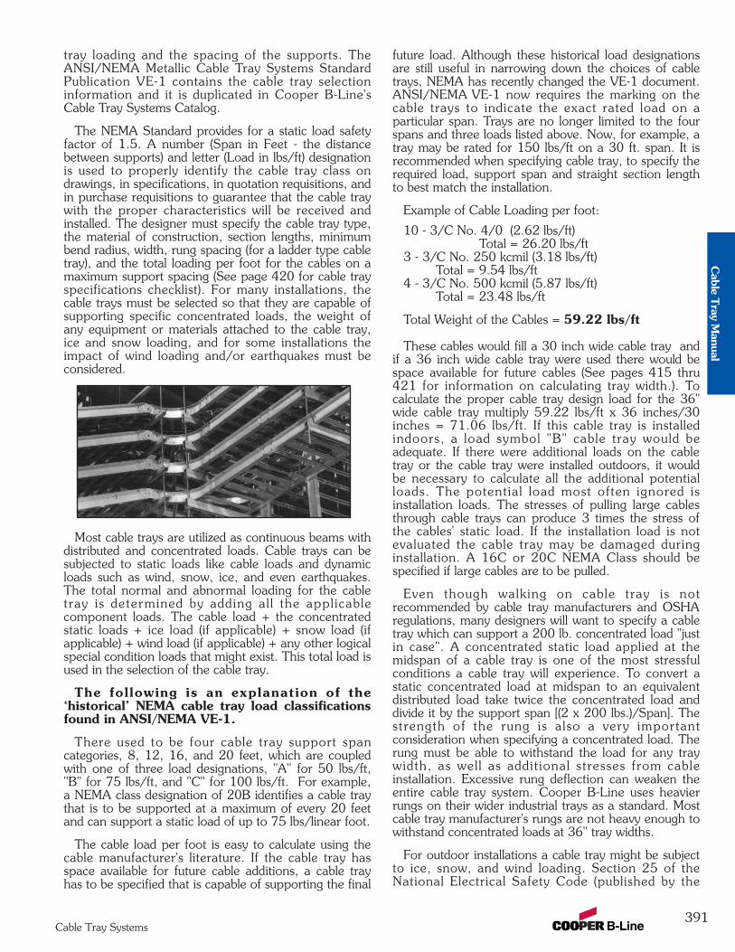
tray loading and the spacing of the supports. TheANSI/NEMA Metallic Cable Tray Systems StandardPublication VE-1 contains the cable tray selectioninformation and it is duplicated in Cooper B-Line'sCable Tray Systems Catalog.
The NEMA Standard provides for a static load safetyfactor of 1.5. A number (Span in Feet - the distancebetween supports) and letter (Load in lbs/ft) designationis used to properly identify the cable tray class ondrawings, in specifications, in quotation requisitions, andin purchase requisitions to guarantee that the cable traywith the proper characteristics will be received andinstalled. The designer must specify the cable tray type,the material of construction, section lengths, minimumbend radius, width, rung spacing (for a ladder type cabletray), and the total loading per foot for the cables on amaximum support spacing (See page 420 for cable trayspecifications checklist). For many installations, thecable trays must be selected so that they are capable ofsupporting specific concentrated loads, the weight ofany equipment or materials attached to the cable tray,ice and snow loading, and for some installations theimpact of wind loading and/or earthquakes must beconsidered.
Most cable trays are utilized as continuous beams withdistributed and concentrated loads. Cable trays can besubjected to static loads like cable loads and dynamicloads such as wind, snow, ice, and even earthquakes.The total normal and abnormal loading for the cabletray is determined by adding al l the applicablecomponent loads. The cable load + the concentratedstatic loads + ice load (if applicable) + snow load (ifapplicable) + wind load (if applicable) + any other logicalspecial condition loads that might exist. This total load isused in the selection of the cable tray.
The following is an explanation of the‘historical’ NEMA cable tray load classificationsfound in ANSI/NEMA VE-1.
There used to be four cable tray support spancategories, 8, 12, 16, and 20 feet, which are coupledwith one of three load designations, "A" for 50 lbs/ft,"B" for 75 lbs/ft, and "C" for 100 lbs/ft. For example,a NEMA class designation of 20B identifies a cable traythat is to be supported at a maximum of every 20 feetand can support a static load of up to 75 lbs/linear foot.
The cable load per foot is easy to calculate using thecable manufacturer's literature. If the cable tray hasspace available for future cable additions, a cable trayhas to be specified that is capable of supporting the final
future load. Although these historical load designationsare still useful in narrowing down the choices of cabletrays, NEMA has recently changed the VE-1 document.ANSI/NEMA VE-1 now requires the marking on thecable trays to indicate the exact rated load on aparticular span. Trays are no longer limited to the fourspans and three loads listed above. Now, for example, atray may be rated for 150 lbs/ft on a 30 ft. span. It isrecommended when specifying cable tray, to specify therequired load, support span and straight section lengthto best match the installation.
Example of Cable Loading per foot:
10 - 3/C No. 4/0 (2.62 lbs/ft) Total = 26.20 lbs/ft
3 - 3/C No. 250 kcmil (3.18 lbs/ft) Total = 9.54 lbs/ft
4 - 3/C No. 500 kcmil (5.87 lbs/ft) Total = 23.48 lbs/ft
Total Weight of the Cables = 59.22 lbs/ft
These cables would fill a 30 inch wide cable tray andif a 36 inch wide cable tray were used there would bespace available for future cables (See pages 415 thru421 for information on calculating tray width.). Tocalculate the proper cable tray design load for the 36"wide cable tray multiply 59.22 lbs/ft x 36 inches/30inches = 71.06 lbs/ft. If this cable tray is installedindoors, a load symbol "B" cable tray would beadequate. If there were additional loads on the cabletray or the cable tray were installed outdoors, it wouldbe necessary to calculate all the additional potentialloads. The potential load most often ignored isinstallation loads. The stresses of pulling large cablesthrough cable trays can produce 3 times the stress ofthe cables' static load. If the installation load is notevaluated the cable tray may be damaged duringinstallation. A 16C or 20C NEMA Class should bespecified if large cables are to be pulled.
Even though walking on cable tray is notrecommended by cable tray manufacturers and OSHAregulations, many designers will want to specify a cabletray which can support a 200 lb. concentrated load "justin case". A concentrated static load applied at themidspan of a cable tray is one of the most stressfulconditions a cable tray will experience. To convert astatic concentrated load at midspan to an equivalentdistributed load take twice the concentrated load anddivide it by the support span [(2 x 200 lbs.)/Span]. Thestrength of the rung is also a very importantconsideration when specifying a concentrated load. Therung must be able to withstand the load for any traywidth, as well as additional stresses from cableinstallation. Excessive rung deflection can weaken theentire cable tray system. Cooper B-Line uses heavierrungs on their wider industrial trays as a standard. Mostcable tray manufacturer's rungs are not heavy enough towithstand concentrated loads at 36" tray widths.
For outdoor installations a cable tray might be subjectto ice, snow, and wind loading. Section 25 of theNational Electrical Safety Code (published by the
391Cable Tray Systems
Cable T
ray Manual
Institute of Electrical and Electronic Engineers) containsa weather loading map of the United States todetermine whether the installation is in a light, medium,or heavy weather load district. NESC Table 250-1indicates potential ice thicknesses in each loadingdistrict as follows: 0.50 inches for a heavy loadingdistrict, 0.25 inches for a medium loading district, andno ice for a light loading district. To calculate the iceload use 57 pounds per cubic foot for the density ofglaze ice. Since tray cables are circular and the cabletray has an irregular surface the resulting ice load on acable tray can be 1.5 to 2.0 times greater than the glazeice load on a flat surface.
Snow load is significant for a cable tray that iscompletely full of cables or a cable tray that has covers.The density of snow varies greatly due to its moisturecontent, however the minimum density that should beused for snow is 5 pounds per cubic foot. The engineerwill have to contact the weather service to determinethe potential snow falls for the installation area orconsult the local building code for a recommendeddesign load.
Usually cable trays are installed within structures suchthat the structure and equipment shelter the cable traysfrom the direct impact of high winds. If wind loading isa potential problem, a structural engineer and/or thepotential cable tray manufacturer should review theinstallation for adequacy. To determine the wind speedfor proper design consult the Basic Wind Speed Map ofthe United States in the NESC (Figure 250-2).
For those installations located in earthquake areas,design engineers can obtain behavioral data for CooperB-Line cable trays under horizontal, vertical andlongitudinal loading conditions. Testing done for nuclearpower plants in the 1970's indicates that cable trays actlike large trusses when loaded laterally and are actuallystronger than when loaded vertically. Cable traysupports may still need to be seismically braced anddesigners should consult the Cooper B-Line SeismicRestraints Catalog for detailed design information.
The midspan deflection multipliers for all B-Line cabletrays are listed in the Cable Tray Systems catalog.Simply pick your support span and multiply your actualload by the deflection multiplier shown for that span.The calculated deflections are for simple beaminstallations at your specified load capacity. If adeflection requirement will be specified, extra careneeds to be taken to ensure that it does not conflict withthe load requirement and provides the aestheticsnecessary. Keep in mind that continuous beamapplications are more common and will decrease thedeflection values shown by up to 50%. Also, aluminumcable trays will deflect 3 times more than steel cabletrays of the same NEMA class.
To complete the design, the standard straight sectionlength and minimum bend radius must be chosen. Whenselecting the recommended length of straight sections,be sure that the standard length is greater than or equalto the maximum support span. Choose a fitting radiuswhich will not only meet or exceed the minimum bend
radius of the cables but will facilitate cable installation.[See pages 354 & 355 for more information on
selecting the appropriate cable tray length]
392.5. Construction Specifications. (B)Smooth Edges.
This is a quality statement for cable tray systems andtheir construction. Cooper B-Line cable tray is designedand manufactured to the highest standards to provideeasy, safe installation of both the cable tray and cables.
392.5. Construction Specifications. (C)Corrosion Protection.
Cable tray shall be protected from corrosion perSection 300.6, which lists some minimum criteria fordifferent corrosive environments. The Cooper B-LineCable Tray Catalog contains a corrosion chart for cabletray materials. Cable trays may be obtained in a widerange of materials including aluminum, pregalvanizedsteel, hot dipped galvanized steel (after fabrication),Type 304 or 316 stainless steel, polyvinyl chloride(PVC) or epoxy coated aluminum or steel and alsononmetallic (fiber reinforced plastic). Check with ametallurgist to determine which metals and coatings arecompatible with a particular corrosive environment. B-Line has corrosion information available and may beable to recommend a suitable material. Remember thatno material is totally impervious to corrosion. Stainlesssteel can deteriorate when attacked by certain chemicalsand nonmetallic cable trays can deteriorate whenattacked by certain solvents.
392.5. Construction Specifications. (D) SideRails.
The technical information in Article 392 wasoriginally developed for cable trays with rigid side railsby the 1973 NEC® Technical Subcommittee on CableTray. “Equivalent Structural Members” was added laterto incorporate new styles of cable tray such as centerrail type tray and ‘mesh’ or wire basket tray.
392.5. Construction Specifications. (E)Fittings.
This section has been misinterpreted to mean thatcable tray fittings must be used for all changes indirection and elevation [See Section 392.6(A) Completesystem for further explanation). When two cable trayruns cross at different elevations, lacing a cable betweenthe rungs of one tray and dropping into the other is acommon practice which changes the direction of thecable while providing adequate cable support. Althoughthe use of cable tray fittings is not mandatory, it is oftendesirable to use them when possible to improve theappearance of the installation.
392Cable Tray Systems
Cab
le T
ray
Man
ual
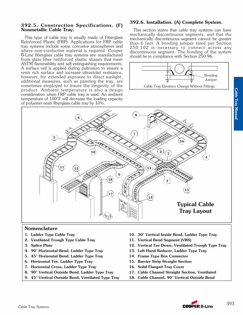
392.5. Construction Specifications. (F)Nonmetallic Cable Tray.
This type of cable tray is usually made of FiberglassReinforced Plastic (FRP). Applications for FRP cabletray systems include some corrosive atmospheres andwhere non-conductive material is required. CooperB-Line fiberglass cable tray systems are manufacturedfrom glass fiber reinforced plastic shapes that meetASTM flammability and self-extinguishing requirements.A surface veil is applied during pultrusion to ensure aresin rich surface and increase ultraviolet resistance,however, for extended exposure to direct sunlight,additional measures, such as painting the tray, aresometimes employed to insure the longevity of theproduct. Ambient temperature is also a designconsideration when FRP cable tray is used. An ambienttemperature of 100°F will decrease the loading capacityof polyester resin fiberglass cable tray by 10%.
392.6. Installation. (A) Complete System.
This section states that cable tray systems can havemechanically discontinuous segments, and that themechanically discontinuous segment cannot be greaterthan 6 feet. A bonding jumper sized per Section250.102 is necessary to connect across anydiscontinuous segment. The bonding of the systemshould be in compliance with Section 250.96.
393Cable Tray Systems
Nomenclature1. Ladder Type Cable Tray 10. 30° Vertical Inside Bend, Ladder Type Tray2. Ventilated Trough Type Cable Tray 11. Vertical Bend Segment (VBS)3. Splice Plate 12. Vertical Tee Down, Ventilated Trough Type Tray4. 90° Horizontal Bend, Ladder Type Tray 13. Left Hand Reducer, Ladder Type Tray5. 45° Horizontal Bend, Ladder Type Tray 14. Frame Type Box Connector6. Horizontal Tee, Ladder Type Tray 15. Barrier Strip Straight Section7. Horizontal Cross, Ladder Type Tray 16. Solid Flanged Tray Cover8. 90° Vertical Outside Bend, Ladder Type Tray 17. Cable Channel Straight Section, Ventilated9. 45° Vertical Outside Bend, Ventilated Type Tray 18. Cable Channel, 90° Vertical Outside Bend
1
2
3
4
6
7
8
10
11 12 13
14
15
16
17
18
Typical CableTray Layout
5
9
Cable Tray Elevation Change Without Fittings
BondingJumper
Cable T
ray Manual
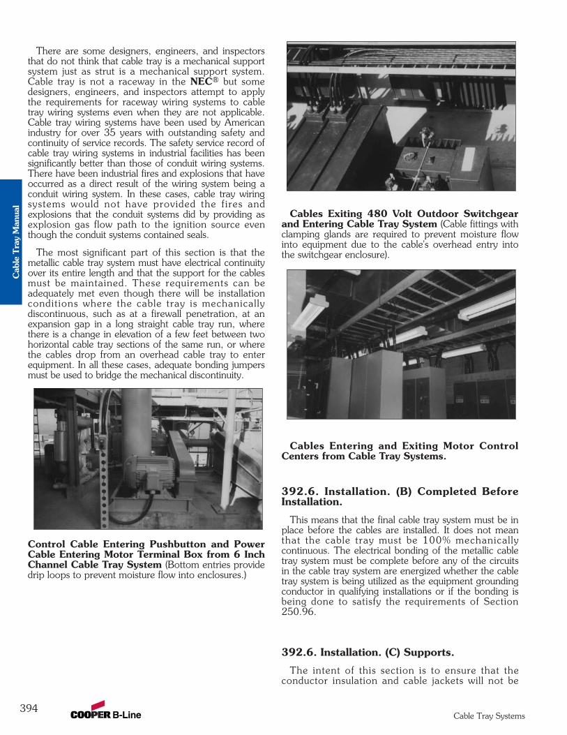
There are some designers, engineers, and inspectorsthat do not think that cable tray is a mechanical supportsystem just as strut is a mechanical support system.Cable tray is not a raceway in the NEC® but somedesigners, engineers, and inspectors attempt to applythe requirements for raceway wiring systems to cabletray wiring systems even when they are not applicable.Cable tray wiring systems have been used by Americanindustry for over 35 years with outstanding safety andcontinuity of service records. The safety service record ofcable tray wiring systems in industrial facilities has beensignificantly better than those of conduit wiring systems.There have been industrial fires and explosions that haveoccurred as a direct result of the wiring system being aconduit wiring system. In these cases, cable tray wiringsystems would not have provided the fires andexplosions that the conduit systems did by providing asexplosion gas flow path to the ignition source eventhough the conduit systems contained seals.
The most significant part of this section is that themetallic cable tray system must have electrical continuityover its entire length and that the support for the cablesmust be maintained. These requirements can beadequately met even though there will be installationconditions where the cable tray is mechanicallydiscontinuous, such as at a firewall penetration, at anexpansion gap in a long straight cable tray run, wherethere is a change in elevation of a few feet between twohorizontal cable tray sections of the same run, or wherethe cables drop from an overhead cable tray to enterequipment. In all these cases, adequate bonding jumpersmust be used to bridge the mechanical discontinuity.
Control Cable Entering Pushbutton and PowerCable Entering Motor Terminal Box from 6 InchChannel Cable Tray System (Bottom entries providedrip loops to prevent moisture flow into enclosures.)
Cables Exiting 480 Volt Outdoor Switchgearand Entering Cable Tray System (Cable fittings withclamping glands are required to prevent moisture flowinto equipment due to the cable's overhead entry intothe switchgear enclosure).
Cables Entering and Exiting Motor ControlCenters from Cable Tray Systems.
392.6. Installation. (B) Completed BeforeInstallation.
This means that the final cable tray system must be inplace before the cables are installed. It does not meanthat the cable tray must be 100% mechanicallycontinuous. The electrical bonding of the metallic cabletray system must be complete before any of the circuitsin the cable tray system are energized whether the cabletray system is being utilized as the equipment groundingconductor in qualifying installations or if the bonding isbeing done to satisfy the requirements of Section250.96.
392.6. Installation. (C) Supports.
The intent of this section is to ensure that theconductor insulation and cable jackets will not be
394Cable Tray Systems
Cab
le T
ray
Man
ual
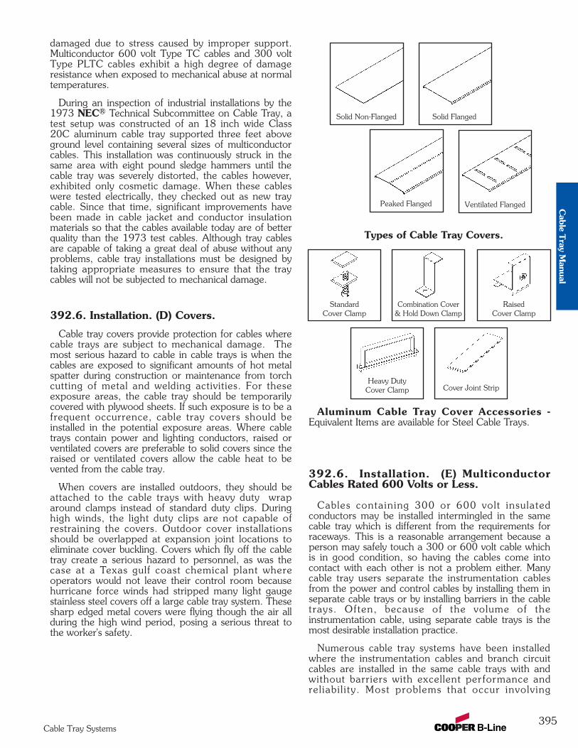
damaged due to stress caused by improper support.Multiconductor 600 volt Type TC cables and 300 voltType PLTC cables exhibit a high degree of damageresistance when exposed to mechanical abuse at normaltemperatures.
During an inspection of industrial installations by the1973 NEC® Technical Subcommittee on Cable Tray, atest setup was constructed of an 18 inch wide Class20C aluminum cable tray supported three feet aboveground level containing several sizes of multiconductorcables. This installation was continuously struck in thesame area with eight pound sledge hammers until thecable tray was severely distorted, the cables however,exhibited only cosmetic damage. When these cableswere tested electrically, they checked out as new traycable. Since that time, significant improvements havebeen made in cable jacket and conductor insulationmaterials so that the cables available today are of betterquality than the 1973 test cables. Although tray cablesare capable of taking a great deal of abuse without anyproblems, cable tray installations must be designed bytaking appropriate measures to ensure that the traycables will not be subjected to mechanical damage.
392.6. Installation. (D) Covers.
Cable tray covers provide protection for cables wherecable trays are subject to mechanical damage. Themost serious hazard to cable in cable trays is when thecables are exposed to significant amounts of hot metalspatter during construction or maintenance from torchcutting of metal and welding activities. For theseexposure areas, the cable tray should be temporarilycovered with plywood sheets. If such exposure is to be afrequent occurrence, cable tray covers should beinstalled in the potential exposure areas. Where cabletrays contain power and lighting conductors, raised orventilated covers are preferable to solid covers since theraised or ventilated covers allow the cable heat to bevented from the cable tray.
When covers are installed outdoors, they should beattached to the cable trays with heavy duty wraparound clamps instead of standard duty clips. Duringhigh winds, the light duty clips are not capable ofrestraining the covers. Outdoor cover installationsshould be overlapped at expansion joint locations toeliminate cover buckling. Covers which fly off the cabletray create a serious hazard to personnel, as was thecase at a Texas gulf coast chemical plant whereoperators would not leave their control room becausehurricane force winds had stripped many light gaugestainless steel covers off a large cable tray system. Thesesharp edged metal covers were flying though the air allduring the high wind period, posing a serious threat tothe worker's safety.
Types of Cable Tray Covers.
Aluminum Cable Tray Cover Accessories -Equivalent Items are available for Steel Cable Trays.
392.6. Installation. (E) MulticonductorCables Rated 600 Volts or Less.
Cables containing 300 or 600 volt insulatedconductors may be installed intermingled in the samecable tray which is different from the requirements forraceways. This is a reasonable arrangement because aperson may safely touch a 300 or 600 volt cable whichis in good condition, so having the cables come intocontact with each other is not a problem either. Manycable tray users separate the instrumentation cablesfrom the power and control cables by installing them inseparate cable trays or by installing barriers in the cabletrays. Often, because of the volume of theinstrumentation cable, using separate cable trays is themost desirable installation practice.
Numerous cable tray systems have been installedwhere the instrumentation cables and branch circuitcables are installed in the same cable trays with andwithout barriers with excellent performance andrel iabi l i ty. Most problems that occur involving
Standard Cover Clamp
Combination Cover& Hold Down Clamp
Heavy DutyCover Clamp Cover Joint Strip
RaisedCover Clamp
Solid Non-Flanged Solid Flanged
Ventilated FlangedPeaked Flanged
395Cable Tray Systems
Cable T
ray Manual
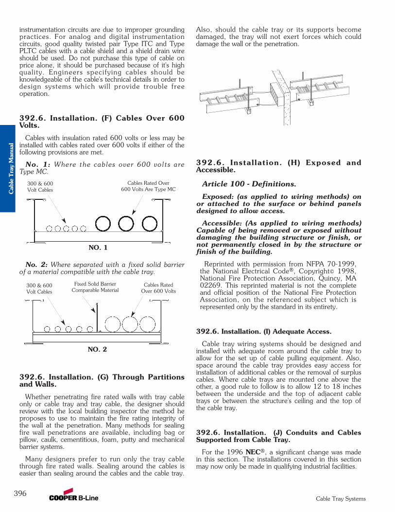
instrumentation circuits are due to improper groundingpractices. For analog and digital instrumentationcircuits, good quality twisted pair Type ITC and TypePLTC cables with a cable shield and a shield drain wireshould be used. Do not purchase this type of cable onprice alone, it should be purchased because of it's highquality. Engineers specifying cables should beknowledgeable of the cable's technical details in order todesign systems which wil l provide trouble freeoperation.
392.6. Installation. (F) Cables Over 600Volts.
Cables with insulation rated 600 volts or less may beinstalled with cables rated over 600 volts if either of thefollowing provisions are met.
No. 1: Where the cables over 600 volts areType MC.
No. 2: Where separated with a fixed solid barrierof a material compatible with the cable tray.
392.6. Installation. (G) Through Partitionsand Walls.
Whether penetrating fire rated walls with tray cableonly or cable tray and tray cable, the designer shouldreview with the local building inspector the method heproposes to use to maintain the fire rating integrity ofthe wall at the penetration. Many methods for sealingfire wall penetrations are available, including bag orpillow, caulk, cementitious, foam, putty and mechanicalbarrier systems.
Many designers prefer to run only the tray cablethrough fire rated walls. Sealing around the cables iseasier than sealing around the cables and the cable tray.
Also, should the cable tray or its supports becomedamaged, the tray will not exert forces which coulddamage the wall or the penetration.
392.6. Installation. (H) Exposed andAccessible.
Article 100 - Definitions.
Exposed: (as applied to wiring methods) onor attached to the surface or behind panelsdesigned to allow access.
Accessible: (As applied to wiring methods)Capable of being removed or exposed withoutdamaging the building structure or finish, ornot permanently closed in by the structure orfinish of the building.
Reprinted with permission from NFPA 70-1999,the National Electrical Code®, Copyright© 1998,National Fire Protection Association, Quincy, MA02269. This reprinted material is not the completeand official position of the National Fire ProtectionAssociation, on the referenced subject which isrepresented only by the standard in its entirety.
392.6. Installation. (I) Adequate Access.
Cable tray wiring systems should be designed andinstalled with adequate room around the cable tray toallow for the set up of cable pulling equipment. Also,space around the cable tray provides easy access forinstallation of additional cables or the removal of surpluscables. Where cable trays are mounted one above theother, a good rule to follow is to allow 12 to 18 inchesbetween the underside and the top of adjacent cabletrays or between the structure's ceiling and the top ofthe cable tray.
392.6. Installation. (J) Conduits and CablesSupported from Cable Tray.
For the 1996 NEC®, a significant change was madein this section. The installations covered in this sectionmay now only be made in qualifying industrial facilities.
300 & 600 Volt Cables
Fixed Solid BarrierComparable Material
Cables RatedOver 600 Volts
NO. 2
300 & 600 Volt Cables
Cables Rated Over 600 Volts Are Type MC
NO. 1
396Cable Tray Systems
Cab
le T
ray
Man
ual
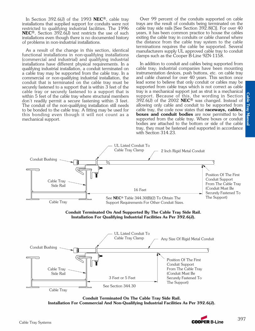
In Section 392.6(J) of the 1993 NEC®, cable trayinstallations that supplied support for conduits were notrestricted to qualifying industrial facilities. The 1996NEC®, Section 392.6(J) text restricts the use of suchinstallations even though there is no documented historyof problems in non-industrial installations.
As a result of the change in this section, identicalfunctional installations in non-qualifying installations(commercial and industrial) and qualifying industrialinstallations have different physical requirements. In aqualifying industrial installation, a conduit terminated ona cable tray may be supported from the cable tray. In acommercial or non-qualifying industrial installation, theconduit that is terminated on the cable tray must besecurely fastened to a support that is within 3 feet of thecable tray or securely fastened to a support that iswithin 5 feet of the cable tray where structural membersdon’t readily permit a secure fastening within 3 feet.The conduit of the non-qualifying installation still needsto be bonded to the cable tray. A fitting may be used forthis bonding even though it wil l not count as amechanical support.
Over 99 percent of the conduits supported on cabletrays are the result of conduits being terminated on thecable tray side rails [See Section 392.8(C)]. For over 40years, it has been common practice to house the cablesexiting the cable tray in conduits or cable channel wherethe distance from the cable tray system to the cableterminations requires the cable be supported. Severalmanufacturers supply UL approved cable tray to conduitclamps such as the Cooper B-Line 9ZN-1158.
In addition to conduit and cables being supported fromcable tray; industrial companies have been mountinginstrumentation devices, push buttons, etc. on cable trayand cable channel for over 40 years. This section oncelead some to believe that only conduit or cables may besupported from cable trays which is not correct as cabletray is a mechanical support just as strut is a mechanicalsupport. Because of this, the wording in Section392.6(J) of the 2002 NEC® was changed. Instead ofallowing only cable and conduit to be supported fromcable tray, the code now states that raceways, cables,boxes and conduit bodies are now permitted to besupported from the cable tray. Where boxes or conduitbodies are attached to the bottom or side of the cabletray, they must be fastened and supported in accordancewith Section 314.23.
UL Listed Conduit ToCable Tray Clamp
See NEC® Table 344.30(B)(2) To Obtain TheSupport Requirements For Other Conduit Sizes.
Conduit Terminated On And Supported By The Cable Tray Side Rail. Installation For Qualifying Industrial Facilities As Per 392.6(J).
16 Feet
2 Inch Rigid Metal Conduit
Position Of The FirstConduit SupportFrom The Cable Tray(Conduit Must BeSecurely Fastened ToThe Support)
Conduit Bushing
Cable TraySide Rail
Cable Tray
UL Listed Conduit ToCable Tray Clamp
See Section 344.30
Conduit Terminated On The Cable Tray Side Rail. Installation For Commercial And Non-Qualifying Industrial Facilities As Per 392.6(J).
3 Feet or 5 Feet
Any Size Of Rigid Metal Conduit
Position Of The FirstConduit SupportFrom The Cable Tray(Conduit Must BeSecurely Fastened ToThe Support)
Conduit Bushing
Cable TraySide Rail
Cable Tray
397Cable Tray Systems
Cable T
ray Manual
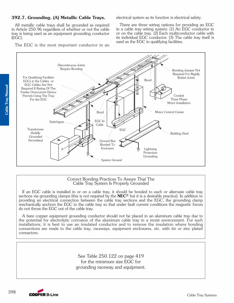
392.7. Grounding. (A) Metallic Cable Trays.
All metallic cable trays shall be grounded as requiredin Article 250.96 regardless of whether or not the cabletray is being used as an equipment grounding conductor(EGC).
The EGC is the most important conductor in an
electrical system as its function is electrical safety.
There are three wiring options for providing an EGCin a cable tray wiring system: (1) An EGC conductor inor on the cable tray. (2) Each multiconductor cable withits individual EGC conductor. (3) The cable tray itself isused as the EGC in qualifying facilities.
Ground BusBonded ToEnclosure
EGC
EGC InCable
Discontinuous JointsRequire Bonding
For Qualifying FacilitiesEGCs in the Cables orEGC Cables Are Not
Required If Rating Of TheFeeder Overcurrent Device
Permits Using The TrayFor the EGC
Bonding Jumper NotRequired For Rigidly
Bolted Joints
ConduitThree Phase
Motor Installation
Building Steel
LightningProtectionGrounding
Bond
Switchgear
Bond
System Ground
Transformer(Solidly
GroundedSecondary)
Motor Control Center
Correct Bonding Practices To Assure That TheCable Tray System Is Properly Grounded
If an EGC cable is installed in or on a cable tray, it should be bonded to each or alternate cable traysections via grounding clamps (this is not required by the NEC® but it is a desirable practice). In addition toproviding an electrical connection between the cable tray sections and the EGC, the grounding clampmechanically anchors the EGC to the cable tray so that under fault current conditions the magnetic forcesdo not throw the EGC out of the cable tray.
A bare copper equipment grounding conductor should not be placed in an aluminum cable tray due tothe potential for electrolytic corrosion of the aluminum cable tray in a moist environment. For suchinstallations, it is best to use an insulated conductor and to remove the insulation where bondingconnections are made to the cable tray, raceways, equipment enclosures, etc. with tin or zinc platedconnectors.
See Table 250.122 on page 419for the minimum size EGC for
grounding raceway and equipment.
398Cable Tray Systems
Cab
le T
ray
Man
ual
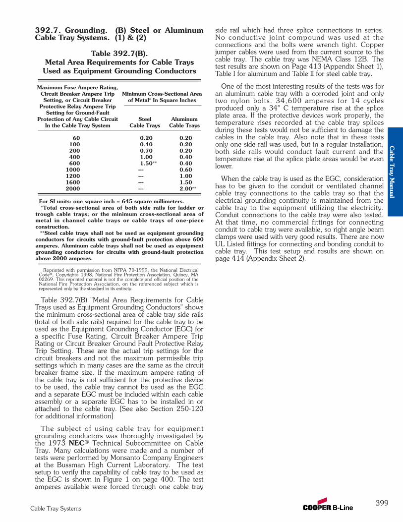
392.7. Grounding. (B) Steel or AluminumCable Tray Systems. (1) & (2)
Reprinted with permission from NFPA 70-1999, the National ElectricalCode®, Copyright© 1998, National Fire Protection Association, Quincy, MA02269. This reprinted material is not the complete and official position of theNational Fire Protection Association, on the referenced subject which isrepresented only by the standard in its entirety.
Table 392.7(B) "Metal Area Requirements for CableTrays used as Equipment Grounding Conductors" showsthe minimum cross-sectional area of cable tray side rails(total of both side rails) required for the cable tray to beused as the Equipment Grounding Conductor (EGC) fora specific Fuse Rating, Circuit Breaker Ampere TripRating or Circuit Breaker Ground Fault Protective RelayTrip Setting. These are the actual trip settings for thecircuit breakers and not the maximum permissible tripsettings which in many cases are the same as the circuitbreaker frame size. If the maximum ampere rating ofthe cable tray is not sufficient for the protective deviceto be used, the cable tray cannot be used as the EGCand a separate EGC must be included within each cableassembly or a separate EGC has to be installed in orattached to the cable tray. [See also Section 250-120for additional information]
The subject of using cable tray for equipmentgrounding conductors was thoroughly investigated bythe 1973 NEC® Technical Subcommittee on CableTray. Many calculations were made and a number oftests were performed by Monsanto Company Engineersat the Bussman High Current Laboratory. The testsetup to verify the capability of cable tray to be used asthe EGC is shown in Figure 1 on page 400. The testamperes available were forced through one cable tray
side rail which had three splice connections in series.No conductive joint compound was used at theconnections and the bolts were wrench tight. Copperjumper cables were used from the current source to thecable tray. The cable tray was NEMA Class 12B. Thetest results are shown on Page 413 (Appendix Sheet 1),Table I for aluminum and Table II for steel cable tray.
One of the most interesting results of the tests was foran aluminum cable tray with a corroded joint and onlytwo nylon bolts. 34,600 amperes for 14 cyclesproduced only a 34° C temperature rise at the spliceplate area. If the protective devices work properly, thetemperature rises recorded at the cable tray splicesduring these tests would not be sufficient to damage thecables in the cable tray. Also note that in these testsonly one side rail was used, but in a regular installation,both side rails would conduct fault current and thetemperature rise at the splice plate areas would be evenlower.
When the cable tray is used as the EGC, considerationhas to be given to the conduit or ventilated channelcable tray connections to the cable tray so that theelectrical grounding continuity is maintained from thecable tray to the equipment utilizing the electricity.Conduit connections to the cable tray were also tested.At that time, no commercial fittings for connectingconduit to cable tray were available, so right angle beamclamps were used with very good results. There are nowUL Listed fittings for connecting and bonding conduit tocable tray. This test setup and results are shown onpage 414 (Appendix Sheet 2).
Table 392.7(B).Metal Area Requirements for Cable TraysUsed as Equipment Grounding Conductors
Maximum Fuse Ampere Rating,Circuit Breaker Ampere Trip Minimum Cross-Sectional AreaSetting, or Circuit Breaker of Metal* In Square Inches
Protective Relay Ampere TripSetting for Ground-Fault
Protection of Any Cable Circuit Steel AluminumIn the Cable Tray System Cable Trays Cable Trays
60 0.20 0.20100 0.40 0.20200 0.70 0.20400 1.00 0.40600 1.50** 0.40
1000 --- 0.601200 --- 1.001600 --- 1.502000 --- 2.00**
For SI units: one square inch = 645 square millimeters.*Total cross-sectional area of both side rails for ladder or
trough cable trays; or the minimum cross-sectional area ofmetal in channel cable trays or cable trays of one-piececonstruction.
**Steel cable trays shall not be used as equipment groundingconductors for circuits with ground-fault protection above 600amperes. Aluminum cable trays shall not be used as equipmentgrounding conductors for circuits with ground-fault protectionabove 2000 amperes.
399Cable Tray Systems
Cable T
ray Manual

392.7. Grounding. (B) Steel or AluminumCable Tray Systems. (3) & (4)
For a cable tray to be used as an EGC themanufacturer must provide a label showing the cross-sectional area available. This also holds true for somemechanically constructed cable tray systems such asRedi-Rail®. Redi-Rail has been tested and UL Classifiedas an EGC. Cooper B-Line's label is shown at the top ofpage 401.
The cable tray system must be electrically continuouswhether or not it is going to serve as the EGC. Atcertain locations (expansion joints, discontinuities, mosthorizontal adjustable splice plates, etc.), bondingjumpers will be required. Section 250.96. BondingOther Enclosures states that cable tray shall beeffectively bonded where necessary to assure electricalcontinuity and to provide the capacity to conduct safelyany fault current likely to be imposed on them (also seeSections 250.92(A)(1) & 250.118(12)).
It is not necessary to install bonding jumpers atstandard splice plate connections. The splice connectionis UL classified as an EGC component of the cable traysystem.
NOTE: The NEC® only recognizes aluminum andsteel cable trays as EGC’s. As with all metallic cabletrays, stainless steel cable trays must be bondedaccording to NEC® guidelines. Fiberglass cable trays donot require bonding jumpers since fiberglass is non-conductive.
Material Thickness: 0.125" Aluminum or 14 Gauge Steel Cross Section Area,2 Rails: Aluminum - 1.00 sq. in.Steel - 0.76 sq. in.
13/16"
3/8"
0.080" Aluminum or14 Gauge Steel
3/8" Bolting Hardware
Cross Section Cable Tray Side Rail
Adjustable VerticalRigid
Cable Tray Connectors
41/2"
91/2"
4"
4"
Figure 1(See Page 413 Appendix Sheet 1)
Temperature Rise Test
C1 T T T C2 C3
Current Source
500 kcmil copper, Type RH Insulation
Insulated Joints
Cable Lug
Fuse (if used)
Cable Lug
T - Temperature Measurement at each Tray Connection C1,C2, & C3 - Cable Tray Connectors or Bonding Jumpers
99-N1600 amps max.
99-401600 amps max.
99-16202000 amps max.
400Cable Tray Systems
Cab
le T
ray
Man
ual
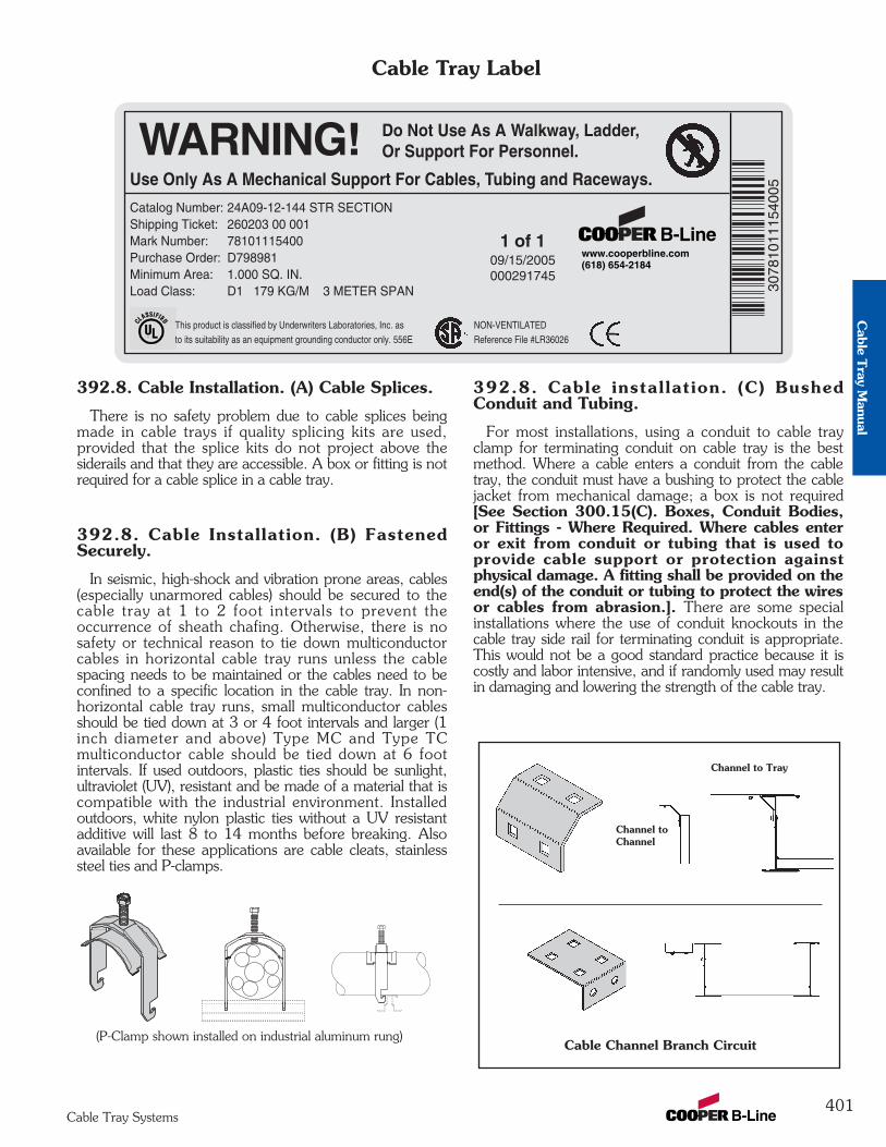
392.8. Cable Installation. (A) Cable Splices.
There is no safety problem due to cable splices beingmade in cable trays if quality splicing kits are used,provided that the splice kits do not project above thesiderails and that they are accessible. A box or fitting is notrequired for a cable splice in a cable tray.
392.8. Cable Installation. (B) FastenedSecurely.
In seismic, high-shock and vibration prone areas, cables(especially unarmored cables) should be secured to thecable tray at 1 to 2 foot intervals to prevent theoccurrence of sheath chafing. Otherwise, there is nosafety or technical reason to tie down multiconductorcables in horizontal cable tray runs unless the cablespacing needs to be maintained or the cables need to beconfined to a specific location in the cable tray. In non-horizontal cable tray runs, small multiconductor cablesshould be tied down at 3 or 4 foot intervals and larger (1inch diameter and above) Type MC and Type TCmulticonductor cable should be tied down at 6 footintervals. If used outdoors, plastic ties should be sunlight,ultraviolet (UV), resistant and be made of a material that iscompatible with the industrial environment. Installedoutdoors, white nylon plastic ties without a UV resistantadditive will last 8 to 14 months before breaking. Alsoavailable for these applications are cable cleats, stainlesssteel ties and P-clamps.
392.8. Cable installation. (C) BushedConduit and Tubing.
For most installations, using a conduit to cable trayclamp for terminating conduit on cable tray is the bestmethod. Where a cable enters a conduit from the cabletray, the conduit must have a bushing to protect the cablejacket from mechanical damage; a box is not required[See Section 300.15(C). Boxes, Conduit Bodies,or Fittings - Where Required. Where cables enteror exit from conduit or tubing that is used toprovide cable support or protection againstphysical damage. A fitting shall be provided on theend(s) of the conduit or tubing to protect the wiresor cables from abrasion.]. There are some specialinstallations where the use of conduit knockouts in thecable tray side rail for terminating conduit is appropriate.This would not be a good standard practice because it iscostly and labor intensive, and if randomly used may resultin damaging and lowering the strength of the cable tray.
401Cable Tray Systems
Cable Tray Label
(P-Clamp shown installed on industrial aluminum rung)Cable Channel Branch Circuit
Channel to Tray
Channel toChannel
Use Only As A Mechanical Support For Cables, Tubing and Raceways.
Do Not Use As A Walkway, Ladder,Or Support For Personnel.
www.cooperbline.com(618) 654-2184
Catalog Number: 24A09-12-144 STR SECTIONShipping Ticket: 260203 00 001Mark Number: 78101115400Purchase Order: D798981Minimum Area: 1.000 SQ. IN.Load Class: D1 179 KG/M 3 METER SPAN 30
7810
1115
4005
1 of 109/15/2005000291745
WARNING!
This product is classified by Underwriters Laboratories, Inc. asto its suitability as an equipment grounding conductor only. 556E
NON-VENTILATEDReference File #LR36026
Cable T
ray Manual
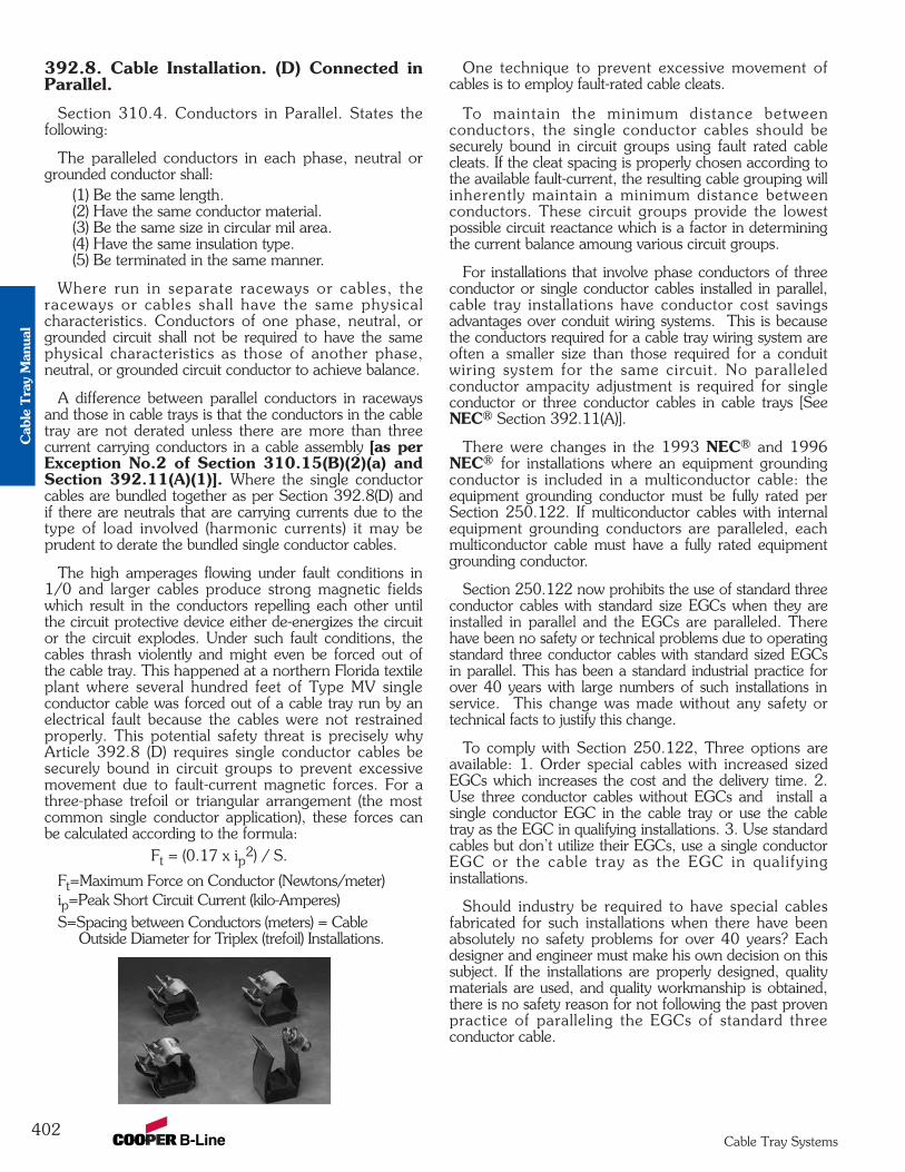
402Cable Tray Systems
392.8. Cable Installation. (D) Connected inParallel.
Section 310.4. Conductors in Parallel. States thefollowing:
The paralleled conductors in each phase, neutral orgrounded conductor shall:
(1) Be the same length. (2) Have the same conductor material. (3) Be the same size in circular mil area.(4) Have the same insulation type. (5) Be terminated in the same manner.
Where run in separate raceways or cables, theraceways or cables shall have the same physicalcharacteristics. Conductors of one phase, neutral, orgrounded circuit shall not be required to have the samephysical characteristics as those of another phase,neutral, or grounded circuit conductor to achieve balance.
A difference between parallel conductors in racewaysand those in cable trays is that the conductors in the cabletray are not derated unless there are more than threecurrent carrying conductors in a cable assembly [as perException No.2 of Section 310.15(B)(2)(a) andSection 392.11(A)(1)]. Where the single conductorcables are bundled together as per Section 392.8(D) andif there are neutrals that are carrying currents due to thetype of load involved (harmonic currents) it may beprudent to derate the bundled single conductor cables.
The high amperages flowing under fault conditions in1/0 and larger cables produce strong magnetic fieldswhich result in the conductors repelling each other untilthe circuit protective device either de-energizes the circuitor the circuit explodes. Under such fault conditions, thecables thrash violently and might even be forced out ofthe cable tray. This happened at a northern Florida textileplant where several hundred feet of Type MV singleconductor cable was forced out of a cable tray run by anelectrical fault because the cables were not restrainedproperly. This potential safety threat is precisely whyArticle 392.8 (D) requires single conductor cables besecurely bound in circuit groups to prevent excessivemovement due to fault-current magnetic forces. For athree-phase trefoil or triangular arrangement (the mostcommon single conductor application), these forces canbe calculated according to the formula:
Ft = (0.17 x ip2) / S.
Ft=Maximum Force on Conductor (Newtons/meter)ip=Peak Short Circuit Current (kilo-Amperes)S=Spacing between Conductors (meters) = Cable
Outside Diameter for Triplex (trefoil) Installations.
One technique to prevent excessive movement ofcables is to employ fault-rated cable cleats.
To maintain the minimum distance betweenconductors, the single conductor cables should besecurely bound in circuit groups using fault rated cablecleats. If the cleat spacing is properly chosen according tothe available fault-current, the resulting cable grouping willinherently maintain a minimum distance betweenconductors. These circuit groups provide the lowestpossible circuit reactance which is a factor in determiningthe current balance amoung various circuit groups.
For installations that involve phase conductors of threeconductor or single conductor cables installed in parallel,cable tray installations have conductor cost savingsadvantages over conduit wiring systems. This is becausethe conductors required for a cable tray wiring system areoften a smaller size than those required for a conduitwiring system for the same circuit. No paralleledconductor ampacity adjustment is required for singleconductor or three conductor cables in cable trays [SeeNEC® Section 392.11(A)].
There were changes in the 1993 NEC® and 1996NEC® for installations where an equipment groundingconductor is included in a multiconductor cable: theequipment grounding conductor must be fully rated perSection 250.122. If multiconductor cables with internalequipment grounding conductors are paralleled, eachmulticonductor cable must have a fully rated equipmentgrounding conductor.
Section 250.122 now prohibits the use of standard threeconductor cables with standard size EGCs when they areinstalled in parallel and the EGCs are paralleled. Therehave been no safety or technical problems due to operatingstandard three conductor cables with standard sized EGCsin parallel. This has been a standard industrial practice forover 40 years with large numbers of such installations inservice. This change was made without any safety ortechnical facts to justify this change.
To comply with Section 250.122, Three options areavailable: 1. Order special cables with increased sizedEGCs which increases the cost and the delivery time. 2.Use three conductor cables without EGCs and install asingle conductor EGC in the cable tray or use the cabletray as the EGC in qualifying installations. 3. Use standardcables but don’t utilize their EGCs, use a single conductorEGC or the cable tray as the EGC in qualifyinginstallations.
Should industry be required to have special cablesfabricated for such installations when there have beenabsolutely no safety problems for over 40 years? Eachdesigner and engineer must make his own decision on thissubject. If the installations are properly designed, qualitymaterials are used, and quality workmanship is obtained,there is no safety reason for not following the past provenpractice of paralleling the EGCs of standard threeconductor cable.
Cab
le T
ray
Man
ual
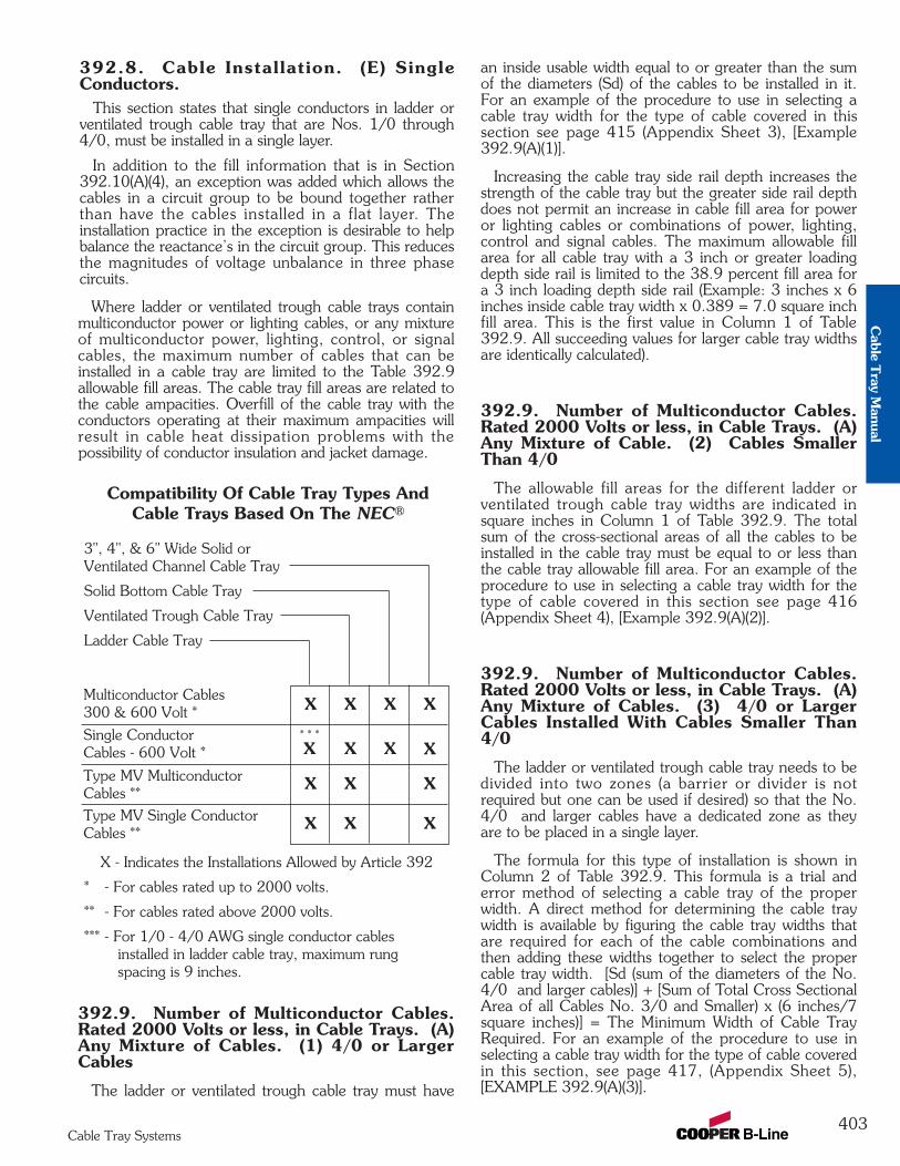
392.8. Cable Installation. (E) SingleConductors.
This section states that single conductors in ladder orventilated trough cable tray that are Nos. 1/0 through4/0, must be installed in a single layer.
In addition to the fill information that is in Section392.10(A)(4), an exception was added which allows thecables in a circuit group to be bound together ratherthan have the cables installed in a flat layer. Theinstallation practice in the exception is desirable to helpbalance the reactance’s in the circuit group. This reducesthe magnitudes of voltage unbalance in three phasecircuits.
Where ladder or ventilated trough cable trays containmulticonductor power or lighting cables, or any mixtureof multiconductor power, lighting, control, or signalcables, the maximum number of cables that can beinstalled in a cable tray are limited to the Table 392.9allowable fill areas. The cable tray fill areas are related tothe cable ampacities. Overfill of the cable tray with theconductors operating at their maximum ampacities willresult in cable heat dissipation problems with thepossibility of conductor insulation and jacket damage.
392.9. Number of Multiconductor Cables.Rated 2000 Volts or less, in Cable Trays. (A)Any Mixture of Cables. (1) 4/0 or LargerCables
The ladder or ventilated trough cable tray must have
an inside usable width equal to or greater than the sumof the diameters (Sd) of the cables to be installed in it.For an example of the procedure to use in selecting acable tray width for the type of cable covered in thissection see page 415 (Appendix Sheet 3), [Example392.9(A)(1)].
Increasing the cable tray side rail depth increases thestrength of the cable tray but the greater side rail depthdoes not permit an increase in cable fill area for poweror lighting cables or combinations of power, lighting,control and signal cables. The maximum allowable fillarea for all cable tray with a 3 inch or greater loadingdepth side rail is limited to the 38.9 percent fill area fora 3 inch loading depth side rail (Example: 3 inches x 6inches inside cable tray width x 0.389 = 7.0 square inchfill area. This is the first value in Column 1 of Table392.9. All succeeding values for larger cable tray widthsare identically calculated).
392.9. Number of Multiconductor Cables.Rated 2000 Volts or less, in Cable Trays. (A)Any Mixture of Cable. (2) Cables SmallerThan 4/0
The allowable fill areas for the different ladder orventilated trough cable tray widths are indicated insquare inches in Column 1 of Table 392.9. The totalsum of the cross-sectional areas of all the cables to beinstalled in the cable tray must be equal to or less thanthe cable tray allowable fill area. For an example of theprocedure to use in selecting a cable tray width for thetype of cable covered in this section see page 416(Appendix Sheet 4), [Example 392.9(A)(2)].
392.9. Number of Multiconductor Cables.Rated 2000 Volts or less, in Cable Trays. (A)Any Mixture of Cables. (3) 4/0 or LargerCables Installed With Cables Smaller Than4/0
The ladder or ventilated trough cable tray needs to bedivided into two zones (a barrier or divider is notrequired but one can be used if desired) so that the No.4/0 and larger cables have a dedicated zone as theyare to be placed in a single layer.
The formula for this type of installation is shown inColumn 2 of Table 392.9. This formula is a trial anderror method of selecting a cable tray of the properwidth. A direct method for determining the cable traywidth is available by figuring the cable tray widths thatare required for each of the cable combinations andthen adding these widths together to select the propercable tray width. [Sd (sum of the diameters of the No.4/0 and larger cables)] + [Sum of Total Cross SectionalArea of all Cables No. 3/0 and Smaller) x (6 inches/7square inches)] = The Minimum Width of Cable TrayRequired. For an example of the procedure to use inselecting a cable tray width for the type of cable coveredin this section, see page 417, (Appendix Sheet 5),[EXAMPLE 392.9(A)(3)].
403Cable Tray Systems
Compatibility Of Cable Tray Types And Cable Trays Based On The NEC®
3", 4", & 6" Wide Solid orVentilated Channel Cable Tray
Solid Bottom Cable Tray
Ventilated Trough Cable Tray
Ladder Cable Tray
X - Indicates the Installations Allowed by Article 392
* - For cables rated up to 2000 volts.
** - For cables rated above 2000 volts.
*** - For 1/0 - 4/0 AWG single conductor cables installed in ladder cable tray, maximum rung spacing is 9 inches.
X X X X
* * *
X X X X
X X X
X X X
Multiconductor Cables 300 & 600 Volt *
Single ConductorCables - 600 Volt *
Type MV MulticonductorCables **
Type MV Single ConductorCables **
Cable T
ray Manual

392.9. Number of Multiconductor Cables.Rated 2000 Volts or less, in Cable Trays. (B)Multiconductor Control and/or Signal CablesOnly.
A ladder or ventilated trough cable tray, having aloading depth of 6 inches or less containing only controland/or signal cables, may have 50 percent of its cross-sectional area filled with cable. If the cable tray has aloading depth in excess of 6 inches, that figure cannotbe used in calculating the allowable fill area as a 6 inchdepth is the maximum value that can be used for thecross-sectional area calculation. For an example of theprocedure to use in selecting a cable tray width for thetype of cable covered in this section, see page 418(Appendix Sheet 6),[Example 392.9 (B)].
392.9. Number of Multiconductor Cables,Rated 2000 Volts, Nominal, or Less, inCable Trays. (C) Solid Bottom Cable TraysContaining Any Mixture.
For solid bottom cable tray, the allowable cable fillarea is reduced to approximately 30 percent asindicated by the values in Columns 3 and 4 of Table392.9. The first value in Column 3 was obtained asfollows: 3 in. loading depth x 6 in. inside width x 0.305= 5.5 square inches. The other values in Column 3were obtained in a like manner. The Sd term in Column4 has a multiplier of 1 vs. the multiplier of 1.2 forColumn 2.
392.9. Number of Multiconductor Cables,Rated 2000 Volts, Nominal, or Less, in CableTrays. (C) Solid Bottom Cable TraysContaining any Mixture. (1) 4/0 or LargerCables
The procedure used in selecting a cable tray width forthe type of cable covered in this section is similar to thatshown on Appendix Sheet 3 page 415, but only 90percent of the cable tray width can be used.
392.9. Number of Multiconductor Cables,Rated 2000 Volts, Nominal, or Less, in CableTrays. (C) Solid Bottom Cable TraysContaining Any Mixture. (2) Cables SmallerThan 4/0
The procedure used in selecting a cable tray width forthe type of cable covered in this section is similar to thatshown on Appendix Sheet 4 page 416. The maximumallowable cable fill area is in Column 3 of Table 392.9.
392.9. Number of Multiconductor Cables,Rated 2000 Volts, Nominal, or Less, in CableTrays. (C) Solid Bottom Cable TraysContaining any Mixture. (3) 4/0 or LargerCables Installed With Cables Smaller Than4/0
No. 4/0 and larger cables must have a dedicated
zone in the tray in order to be installed in one layer.Therefore the cable tray needs to be divided into twozones (a barrier or divider is not required but one can beused if desired).
The formula for this type of installation is shown inColumn 4 of Table 392.9. This formula is a trial anderror method of selecting a cable tray of the properwidth. A direct method for determining the cable traywidth is available by figuring the cable tray widths thatare required for each of the cable combinations andthen adding these widths together to select the propercable tray width. [Sd (sum of the diameters of the No.4/0 and larger cables) x (1.11)] + [(Sum of Total Cross-Sectional Area of all Cables No. 3/0 and Smaller) x (6inches/5.5 square inches) = The Minimum Width ofCable Tray Required. The procedure used in selecting acable tray width for the type of cables covered in thissection is similar to that shown on Appendix Sheet 5page 417.
392.9. Number of Multiconductor Cables,Rated 2000 Volts, Nominal, or Less, in CableTrays. (D) Solid Bottom Cable TrayMulticonductor Control and/or Signal CablesOnly.
This is the same procedure as for ladder andventilated trough cable trays except that the allowablefill has been reduced from 50 percent to 40 percent.The procedure used in selecting a cable tray width forthe type of cable covered in this section is similar to thatshown on Appendix Sheet 6 page 418. [Example392.9(B)]
392.9. Number of Multiconductor Cables,Rated 2000 Volts, Nominal, or Less in CableTrays. (E) Ventilated Channel Cable Trays.
392.9(E)(1)Where only one multiconductor cable is installed in a
ventilated channel cable tray.
392.9(E)(2)The fill areas for combinations of multiconductor
cables of any type installed in ventilated channel cabletray.
404Cable Tray Systems
Ventilated Channel Maximum AllowableCable Tray Size Fill Area
3 Inch Wide 1.3 Square Inches
4 Inch Wide 2.5 Square Inches
6 Inch Wide 3.8 Square Inches
Ventilated Channel Maximum Cross-SectionalCable Tray Size Area of the Cable
3 Inch Wide 2.3 Square Inches
4 Inch Wide 4.5 Square Inches
6 Inch Wide 7.0 Square Inches
Cab
le T
ray
Man
ual
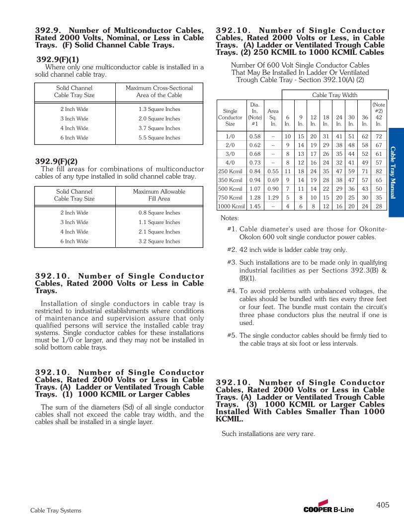
392.9. Number of Multiconductor Cables,Rated 2000 Volts, Nominal, or Less in CableTrays. (F) Solid Channel Cable Trays.
392.9(F)(1)Where only one multiconductor cable is installed in a
solid channel cable tray.
392.9(F)(2)The fill areas for combinations of multiconductor
cables of any type installed in solid channel cable tray.
392.10. Number of Single ConductorCables, Rated 2000 Volts or Less in CableTrays.
Installation of single conductors in cable tray isrestricted to industrial establishments where conditionsof maintenance and supervision assure that onlyqualified persons will service the installed cable traysystems. Single conductor cables for these installationsmust be 1/0 or larger, and they may not be installed insolid bottom cable trays.
392.10. Number of Single ConductorCables, Rated 2000 Volts or Less in CableTrays. (A) Ladder or Ventilated Trough CableTrays. (1) 1000 KCMIL or Larger Cables
The sum of the diameters (Sd) of all single conductorcables shall not exceed the cable tray width, and thecables shall be installed in a single layer.
392.10. Number of Single ConductorCables, Rated 2000 Volts or Less, in CableTrays. (A) Ladder or Ventilated Trough CableTrays. (2) 250 KCMIL to 1000 KCMIL Cables
Number Of 600 Volt Single Conductor CablesThat May Be Installed In Ladder Or Ventilated
Trough Cable Tray - Section 392.10(A) (2)
392.10. Number of Single ConductorCables, Rated 2000 Volts or Less in CableTrays. (A) Ladder or Ventilated Trough CableTrays. (3) 1000 KCMIL or Larger CablesInstalled With Cables Smaller Than 1000KCMIL.
Such installations are very rare.
Dia. (Note Single In. Area #2)
Conductor (Note) Sq. 6 9 12 18 24 30 36 42Size #1 In. In. In. In. In. In. In. In. In.
1/0 0.58 -- 10 15 20 31 41 51 62 72
2/0 0.62 -- 9 14 19 29 38 48 58 67
3/0 0.68 -- 8 13 17 26 35 44 52 61
4/0 0.73 -- 8 12 16 24 32 41 49 57
250 Kcmil 0.84 0.55 11 18 24 35 47 59 71 82
350 Kcmil 0.94 0.69 9 14 19 28 38 47 57 65
500 Kcmil 1.07 0.90 7 11 14 22 29 36 43 50
750 Kcmil 1.28 1.29 5 8 10 15 20 25 30 35
1000 Kcmil 1.45 -- 4 6 8 12 16 20 24 28
Cable Tray Width
Notes:
#1. Cable diameter's used are those for Okonite-Okolon 600 volt single conductor power cables.
#2. 42 inch wide is ladder cable tray only.
#3. Such installations are to be made only in qualifyingindustrial facilities as per Sections 392.3(B) &(B)(1).
#4. To avoid problems with unbalanced voltages, thecables should be bundled with ties every three feetor four feet. The bundle must contain the circuit'sthree phase conductors plus the neutral if one isused.
#5. The single conductor cables should be firmly tied tothe cable trays at six foot or less intervals.
Solid Channel Maximum AllowableCable Tray Size Fill Area
2 Inch Wide 0.8 Square Inches
3 Inch Wide 1.1 Square Inches
4 Inch Wide 2.1 Square Inches
6 Inch Wide 3.2 Square Inches
Solid Channel Maximum Cross-SectionalCable Tray Size Area of the Cable
2 Inch Wide 1.3 Square Inches
3 Inch Wide 2.0 Square Inches
4 Inch Wide 3.7 Square Inches
6 Inch Wide 5.5 Square Inches
405Cable Tray Systems
Cable T
ray Manual
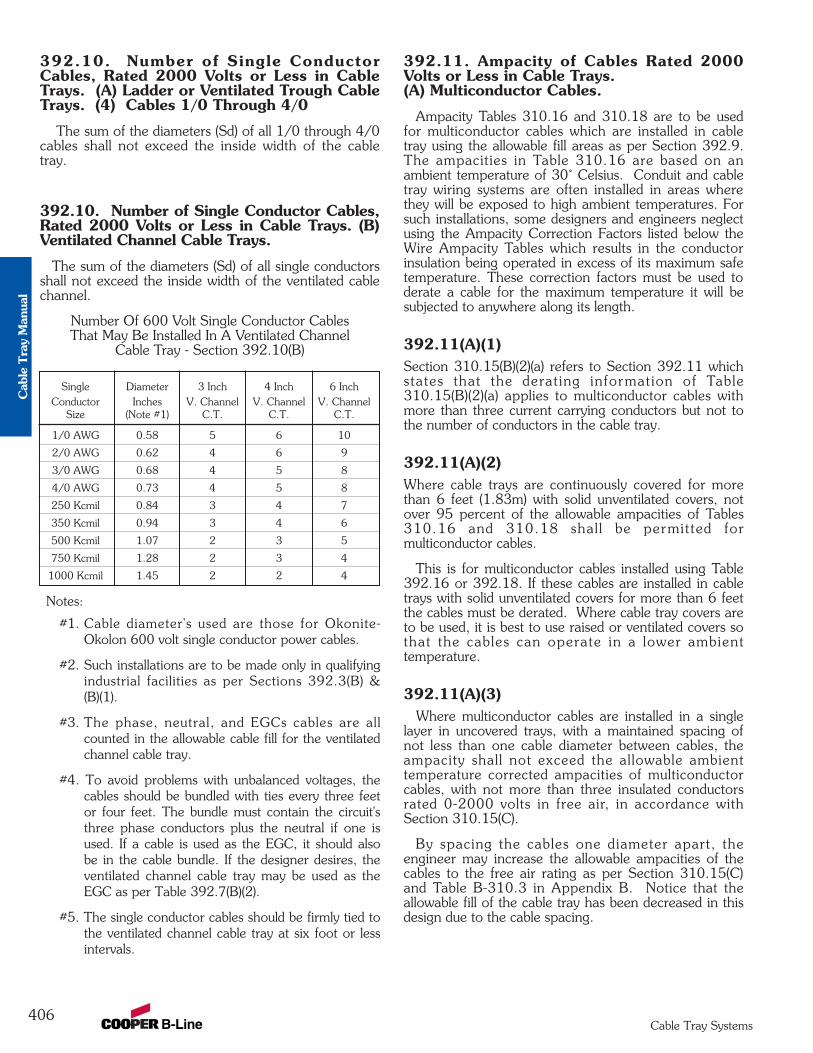
392.10. Number of Single ConductorCables, Rated 2000 Volts or Less in CableTrays. (A) Ladder or Ventilated Trough CableTrays. (4) Cables 1/0 Through 4/0
The sum of the diameters (Sd) of all 1/0 through 4/0cables shall not exceed the inside width of the cabletray.
392.10. Number of Single Conductor Cables,Rated 2000 Volts or Less in Cable Trays. (B)Ventilated Channel Cable Trays.
The sum of the diameters (Sd) of all single conductorsshall not exceed the inside width of the ventilated cablechannel.
Number Of 600 Volt Single Conductor CablesThat May Be Installed In A Ventilated Channel
Cable Tray - Section 392.10(B)
392.11. Ampacity of Cables Rated 2000Volts or Less in Cable Trays.(A) Multiconductor Cables.
Ampacity Tables 310.16 and 310.18 are to be usedfor multiconductor cables which are installed in cabletray using the allowable fill areas as per Section 392.9.The ampacities in Table 310.16 are based on anambient temperature of 30˚ Celsius. Conduit and cabletray wiring systems are often installed in areas wherethey will be exposed to high ambient temperatures. Forsuch installations, some designers and engineers neglectusing the Ampacity Correction Factors listed below theWire Ampacity Tables which results in the conductorinsulation being operated in excess of its maximum safetemperature. These correction factors must be used toderate a cable for the maximum temperature it will besubjected to anywhere along its length.
392.11(A)(1) Section 310.15(B)(2)(a) refers to Section 392.11 whichstates that the derating information of Table310.15(B)(2)(a) applies to multiconductor cables withmore than three current carrying conductors but not tothe number of conductors in the cable tray.
392.11(A)(2) Where cable trays are continuously covered for morethan 6 feet (1.83m) with solid unventilated covers, notover 95 percent of the allowable ampacities of Tables310.16 and 310.18 shal l be permitted formulticonductor cables.
This is for multiconductor cables installed using Table392.16 or 392.18. If these cables are installed in cabletrays with solid unventilated covers for more than 6 feetthe cables must be derated. Where cable tray covers areto be used, it is best to use raised or ventilated covers sothat the cables can operate in a lower ambienttemperature.
392.11(A)(3) Where multiconductor cables are installed in a single
layer in uncovered trays, with a maintained spacing ofnot less than one cable diameter between cables, theampacity shall not exceed the allowable ambienttemperature corrected ampacities of multiconductorcables, with not more than three insulated conductorsrated 0-2000 volts in free air, in accordance withSection 310.15(C).
By spacing the cables one diameter apart, theengineer may increase the allowable ampacities of thecables to the free air rating as per Section 310.15(C)and Table B-310.3 in Appendix B. Notice that theallowable fill of the cable tray has been decreased in thisdesign due to the cable spacing.
406Cable Tray Systems
Notes:
#1. Cable diameter's used are those for Okonite-Okolon 600 volt single conductor power cables.
#2. Such installations are to be made only in qualifyingindustrial facilities as per Sections 392.3(B) &(B)(1).
#3. The phase, neutral, and EGCs cables are allcounted in the allowable cable fill for the ventilatedchannel cable tray.
#4. To avoid problems with unbalanced voltages, thecables should be bundled with ties every three feetor four feet. The bundle must contain the circuit'sthree phase conductors plus the neutral if one isused. If a cable is used as the EGC, it should alsobe in the cable bundle. If the designer desires, theventilated channel cable tray may be used as theEGC as per Table 392.7(B)(2).
#5. The single conductor cables should be firmly tied tothe ventilated channel cable tray at six foot or lessintervals.
Single Diameter 3 Inch 4 Inch 6 InchConductor Inches V. Channel V. Channel V. Channel
Size (Note #1) C.T. C.T. C.T.
1/0 AWG 0.58 5 6 10
2/0 AWG 0.62 4 6 9
3/0 AWG 0.68 4 5 8
4/0 AWG 0.73 4 5 8
250 Kcmil 0.84 3 4 7
350 Kcmil 0.94 3 4 6
500 Kcmil 1.07 2 3 5
750 Kcmil 1.28 2 3 4
1000 Kcmil 1.45 2 2 4
Cab
le T
ray
Man
ual
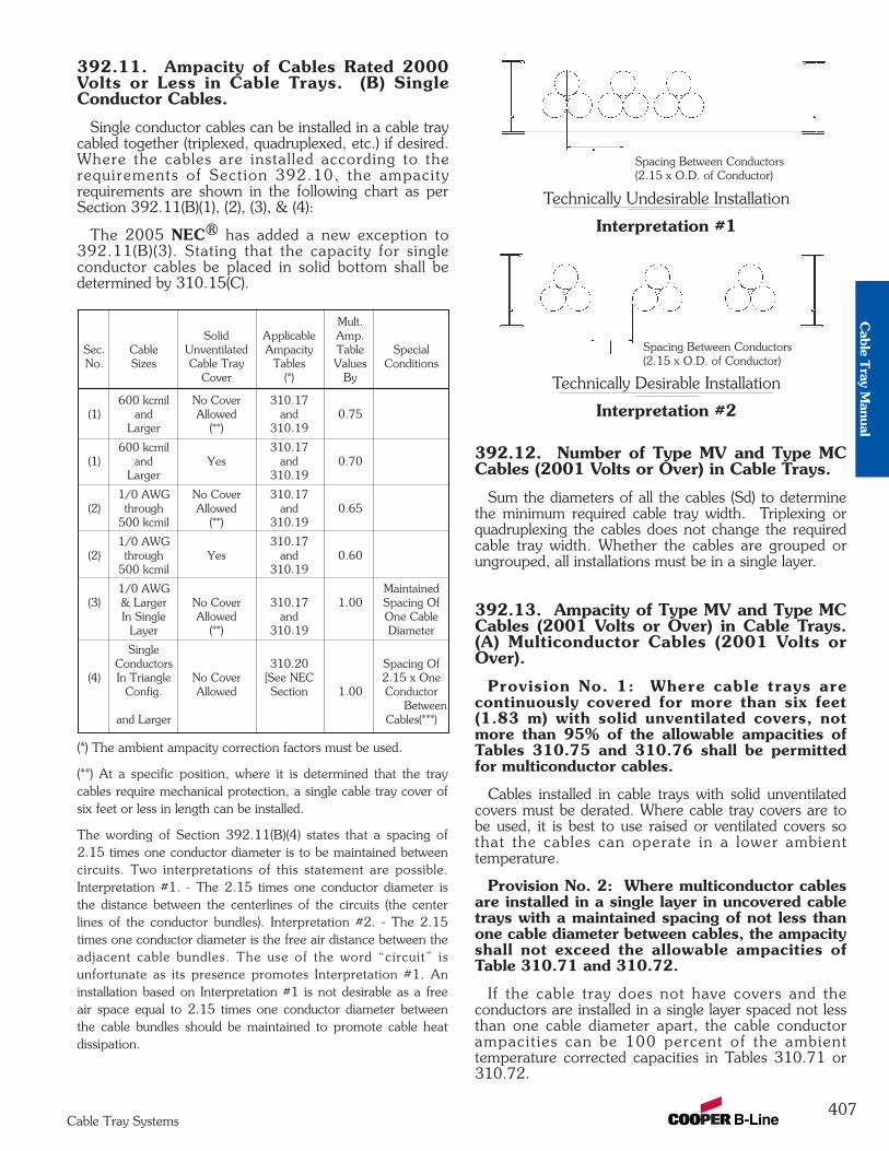
407Cable Tray Systems
392.11. Ampacity of Cables Rated 2000Volts or Less in Cable Trays. (B) SingleConductor Cables.
Single conductor cables can be installed in a cable traycabled together (triplexed, quadruplexed, etc.) if desired.Where the cables are installed according to therequirements of Section 392.10, the ampacityrequirements are shown in the following chart as perSection 392.11(B)(1), (2), (3), & (4):
The 2005 NEC® has added a new exception to392.11(B)(3). Stating that the capacity for singleconductor cables be placed in solid bottom shall bedetermined by 310.15(C).
392.12. Number of Type MV and Type MCCables (2001 Volts or Over) in Cable Trays.
Sum the diameters of all the cables (Sd) to determinethe minimum required cable tray width. Triplexing orquadruplexing the cables does not change the requiredcable tray width. Whether the cables are grouped orungrouped, all installations must be in a single layer.
392.13. Ampacity of Type MV and Type MCCables (2001 Volts or Over) in Cable Trays.(A) Multiconductor Cables (2001 Volts orOver).
Provision No. 1: Where cable trays arecontinuously covered for more than six feet(1.83 m) with solid unventilated covers, notmore than 95% of the allowable ampacities ofTables 310.75 and 310.76 shall be permittedfor multiconductor cables.
Cables installed in cable trays with solid unventilatedcovers must be derated. Where cable tray covers are tobe used, it is best to use raised or ventilated covers sothat the cables can operate in a lower ambienttemperature.
Provision No. 2: Where multiconductor cablesare installed in a single layer in uncovered cabletrays with a maintained spacing of not less thanone cable diameter between cables, the ampacityshall not exceed the allowable ampacities ofTable 310.71 and 310.72.
If the cable tray does not have covers and theconductors are installed in a single layer spaced not lessthan one cable diameter apart, the cable conductorampacit ies can be 100 percent of the ambienttemperature corrected capacities in Tables 310.71 or310.72.
Mult.Solid Applicable Amp.
Sec. Cable Unventilated Ampacity Table SpecialNo. Sizes Cable Tray Tables Values Conditions
Cover (*) By
600 kcmil No Cover 310.17(1) and Allowed and 0.75
Larger (**) 310.19
600 kcmil 310.17(1) and Yes and 0.70
Larger 310.19
1/0 AWG No Cover 310.17(2) through Allowed and 0.65
500 kcmil (**) 310.19
1/0 AWG 310.17(2) through Yes and 0.60
500 kcmil 310.19
1/0 AWG Maintained(3) & Larger No Cover 310.17 1.00 Spacing Of
In Single Allowed and One CableLayer (**) 310.19 Diameter
SingleConductors 310.20 Spacing Of
(4) In Triangle No Cover [See NEC 2.15 x OneConfig. Allowed Section 1.00 Conductor
1/0 AWG (**) 310.15(B)] O.D. Betweenand Larger Cables(***)
(*) The ambient ampacity correction factors must be used.
(**) At a specific position, where it is determined that the traycables require mechanical protection, a single cable tray cover ofsix feet or less in length can be installed.
The wording of Section 392.11(B)(4) states that a spacing of2.15 times one conductor diameter is to be maintained betweencircuits. Two interpretations of this statement are possible.Interpretation #1. - The 2.15 times one conductor diameter isthe distance between the centerlines of the circuits (the centerlines of the conductor bundles). Interpretation #2. - The 2.15times one conductor diameter is the free air distance between theadjacent cable bundles. The use of the word “circuit” isunfortunate as its presence promotes Interpretation #1. Aninstallation based on Interpretation #1 is not desirable as a freeair space equal to 2.15 times one conductor diameter betweenthe cable bundles should be maintained to promote cable heatdissipation.
Spacing Between Conductors(2.15 x O.D. of Conductor)
Technically Desirable Installation
Spacing Between Conductors(2.15 x O.D. of Conductor)
Technically Undesirable Installation
Interpretation #1
Interpretation #2
Cable T
ray Manual
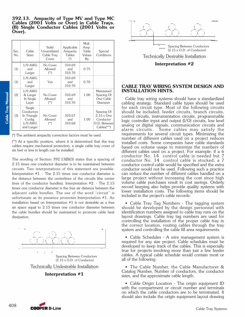
408Cable Tray Systems
392.13. Ampacity of Type MV and Type MCCables (2001 Volts or Over) in Cable Trays.(B) Single Conductor Cables (2001 Volts orOver).
CABLE TRAY WIRING SYSTEM DESIGN ANDINSTALLATION HINTS.
Cable tray wiring systems should have a standardizedcabling strategy. Standard cable types should be usedfor each circuit type. Most of the following circuitsshould be included; feeder circuits, branch circuits,control circuits, instrumentation circuits, programmablelogic controller input and output (I/O) circuits, low levelanalog or digital signals, communication circuits andalarm circuits. Some cables may satisfy therequirements for several circuit types. Minimizing thenumber of different cables used on a project reducesinstalled costs. Some companies have cable standardsbased on volume usage to minimize the numbers ofdifferent cables used on a project. For example: if a 6conductor No. 14 control cable is needed but 7conductor No. 14 control cable is stocked, a 7conductor control cable would be specified and the extraconductor would not be used. Following such a practicecan reduce the number of different cables handled on alarge project without increasing the cost since highvolume cable purchases result in cost savings. Orderlyrecord keeping also helps provide quality systems withlower installation costs. The following items should beincluded in the project's cable records:
• Cable Tray Tag Numbers - The tagging systemshould be developed by the design personnel withidentification numbers assigned to cable tray runs on thelayout drawings. Cable tray tag numbers are used forcontrolling the installation of the proper cable tray inthe correct location, routing cables through the traysystem and controlling the cable fill area requirements.
• Cable Schedules - A wire management system isrequired for any size project. Cable schedules must bedeveloped to keep track of the cables. This is especiallytrue for projects involving more than just a few feedercables. A typical cable schedule would contain most orall of the following:
• The Cable Number, the Cable Manufacturer &Catalog Number, Number of conductors, the conductorsizes, and the approximate cable length.
• Cable Origin Location - The origin equipment IDwith the compartment or circuit number and terminalson which the cable conductors are to be terminated. Itshould also include the origin equipment layout drawing
(*) The ambient ampacity correction factors must be used.
(**) At a specific position, where it is determined that the traycables require mechanical protection, a single cable tray cover ofsix feet or less in length can be installed.
The wording of Section 392.13(B)(3) states that a spacing of2.15 times one conductor diameter is to be maintained betweencircuits. Two interpretations of this statement are possible.Interpretation #1. - The 2.15 times one conductor diameter isthe distance between the centerlines of the circuits (the centerlines of the conductor bundles). Interpretation #2. - The 2.15times one conductor diameter is the free air distance between theadjacent cable bundles. The use of the word “circuit” isunfortunate as its presence promotes Interpretation #1. Aninstallation based on Interpretation #1 is not desirable as a freeair space equal to 2.15 times one conductor diameter betweenthe cable bundles should be maintained to promote cable heatdissipation.
Mult.Solid Applicable Amp.
Sec. Cable Unventilated Ampacity Table SpecialNo. Sizes Cable Tray Tables Values Conditions
Cover (*) By
1/0 AWG No Cover 310.69(1) and Allowed and 0.75
Larger (**) 310.70
1/0 AWG 310.69(1) and Yes and 0.70
Larger 310.70
1/0 AWG Maintained(2) & Larger No Cover 310.69 1.00 Spacing Of
In Single Allowed and One CableLayer (**) 310.70 Diameter
SingleConductors Spacing Of
(3) In Triangle No Cover 310.67 2.15 x OneConfig. Allowed and 1.00 Conductor
1/0 AWG (**) 310.68 O.D. Betweenand Larger Cables(***)
Spacing Between Conductors(2.15 x O.D. of Conductor)
Technically Desirable Installation
Spacing Between Conductors(2.15 x O.D. of Conductor)
Technically Undesirable Installation
Interpretation #1
Interpretation #2
Cab
le T
ray
Man
ual

409Cable Tray Systems
number, and the origin equipment connection diagramnumber.
• Cable Routing - Identifies the cable tray sections orruns that a cable will occupy. Cable tray ID tag numbersare used to track the routing.
• Cable Termination Location - The device orterminal equipment on which the cable conductors areto be terminated. It should also include the terminationequipment layout drawing number, and the terminationequipment connection diagram number.
Some design consultants and corporate engineeringdepartments use spread sheets to monitor the cable trayruns for cable fill. With such a program, the cable trayfill area values for each cable tray run or section can becontinuously upgraded. If a specified cable tray run orsection becomes overfilled, it will be flagged forcorrective action by the designer.
• Cable Installation Provisions - The cable tray systemmust be designed and installed, to allow access for cableinstallation. For many installations, the cables may behand laid into the cable trays and no cable pullingequipment is required. There are other installationswhere sufficient room must be allotted for all the cablepulling activities and equipment.
The cable manufacturers will provide installationinformation for their cables such as maximum pullingtension, allowable sidewall pressures, minimum bendingradii, maximum permissible pull ing length etc..Lubricants are not normally used on cables beinginstalled in cable trays.
The engineer and designers should discuss in detailthe installation of the cables with the appropriateconstruction personnel. This wil l help to avoidinstallation problems and additional installation costs. Itis important that the cable pull is in the direction thatwill result in the lowest tension on the cables. Keep inmind there also needs to be room at the ends of thepulls for the reel setups and for the power pullingequipment. Cable pulleys should be installed at eachdirection change. Triple pulleys should be used for 90degree horizontal bends and all vertical bends. Singlepulleys are adequate for horizontal bends less than 90degrees. Use rollers in-between pulleys and every 10 to20 feet depending on the cable weight. Plastic jacketedcables are easier to pull than are the metallic jacketedcables and there is less chance of cable damage. Thepulling eye should always be attached to the conductormaterial to avoid tensioning the insulation. Forinterlocked armor cables, the conductors and the armorboth have to be attached to the pulling eye.
Normally, the cables installed in cable trays are notsubjected to the damage suffered by insulatedconductors pulled into conduit. Depending on the sizeof the insulated conductors and the conduit, jammingcan take place which places destructive stresses on thecable insulation. In the October, 1991 issue of EC]&Mmagazine, the article on cable pulling stated that 92percent of the insulated conductors that fail do sobecause they were damaged in installation.
CABLE TRAY ACCESSORIES.
B-Line manufactures a full line of prefabricatedaccessories for all types of B-Line cable trays. The useof the appropriate accessories will provide installationcost and time savings. In addition to providing desirableelectrical and mechanical features for the cable traysystem, the use of the appropriate accessories improvesthe physical appearance of the cable tray system. Someof the most common accessories are shown below.
FIREPROOFING CABLE TRAY
Cable trays should not be encapsulated for fireprotection purposes other than for the short lengths atfire rated walls unless the cables are adequately derated.Encapsulation to keep fire heat out will also keepconductor heat in. If conductors cannot dissipate theirheat, their insulation systems will deteriorate. If thecable tray will be encapsulated, the cable manufacturershould be consulted for derating information.
CABLE TRAY MAINTENANCE AND REPAIR
If the cable tray finish and load capacity is properlyspecified and the tray is properly installed, virtually nomaintenance is required.
Ladder Dropout Horizontal Adjustable SpliceRequires supports within 24” on both
sides, per NEMA VE 2.
Frame Box Connector
Cable Support Fitting
Vertical Adjustable SpliceRequires supports within 24” on
both sides, per NEMA VE 2.
Cable T
ray Manual
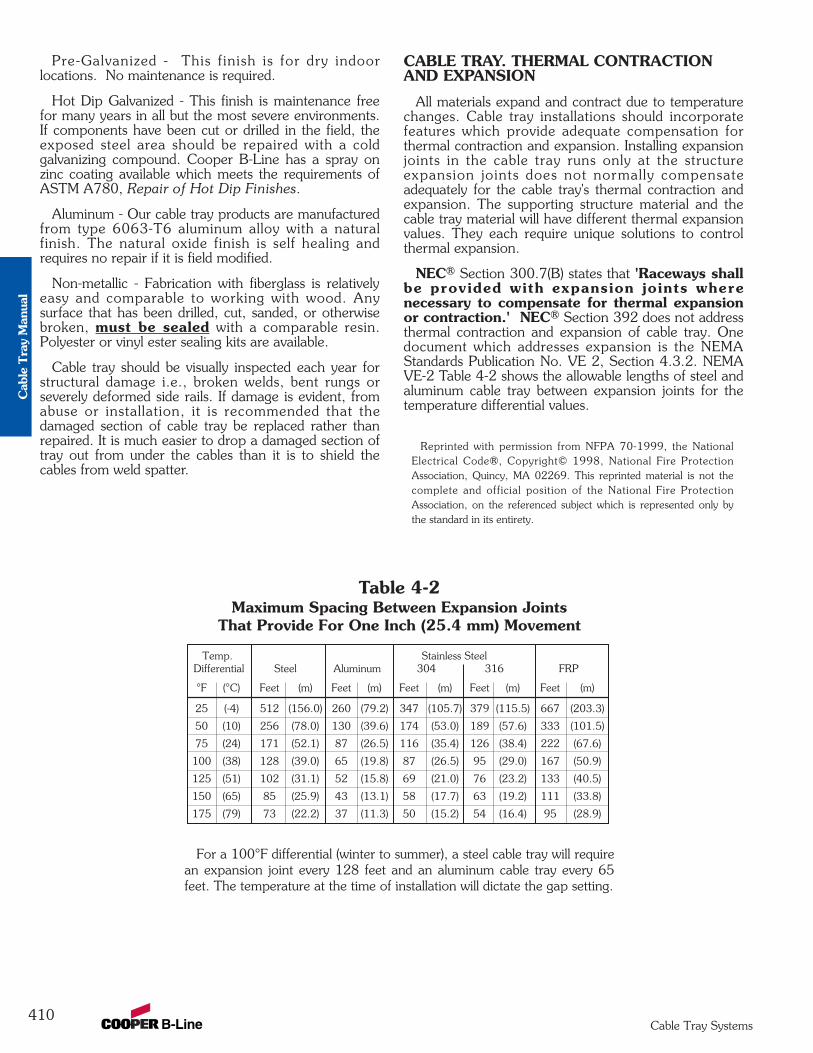
410Cable Tray Systems
Pre-Galvanized - This finish is for dry indoorlocations. No maintenance is required.
Hot Dip Galvanized - This finish is maintenance freefor many years in all but the most severe environments.If components have been cut or drilled in the field, theexposed steel area should be repaired with a coldgalvanizing compound. Cooper B-Line has a spray onzinc coating available which meets the requirements ofASTM A780, Repair of Hot Dip Finishes.
Aluminum - Our cable tray products are manufacturedfrom type 6063-T6 aluminum alloy with a naturalfinish. The natural oxide finish is self healing andrequires no repair if it is field modified.
Non-metallic - Fabrication with fiberglass is relativelyeasy and comparable to working with wood. Anysurface that has been drilled, cut, sanded, or otherwisebroken, must be sealed with a comparable resin.Polyester or vinyl ester sealing kits are available.
Cable tray should be visually inspected each year forstructural damage i.e., broken welds, bent rungs orseverely deformed side rails. If damage is evident, fromabuse or installation, it is recommended that thedamaged section of cable tray be replaced rather thanrepaired. It is much easier to drop a damaged section oftray out from under the cables than it is to shield thecables from weld spatter.
CABLE TRAY. THERMAL CONTRACTIONAND EXPANSION
All materials expand and contract due to temperaturechanges. Cable tray installations should incorporatefeatures which provide adequate compensation forthermal contraction and expansion. Installing expansionjoints in the cable tray runs only at the structureexpansion joints does not normally compensateadequately for the cable tray's thermal contraction andexpansion. The supporting structure material and thecable tray material will have different thermal expansionvalues. They each require unique solutions to controlthermal expansion.
NEC® Section 300.7(B) states that 'Raceways shallbe provided with expansion joints wherenecessary to compensate for thermal expansionor contraction.' NEC® Section 392 does not addressthermal contraction and expansion of cable tray. Onedocument which addresses expansion is the NEMAStandards Publication No. VE 2, Section 4.3.2. NEMAVE-2 Table 4-2 shows the allowable lengths of steel andaluminum cable tray between expansion joints for thetemperature differential values.
Reprinted with permission from NFPA 70-1999, the NationalElectrical Code®, Copyright© 1998, National Fire ProtectionAssociation, Quincy, MA 02269. This reprinted material is not thecomplete and official position of the National Fire ProtectionAssociation, on the referenced subject which is represented only bythe standard in its entirety.
Temp. Stainless SteelDifferential Steel Aluminum 304 316 FRP
°F (°C) Feet (m) Feet (m) Feet (m) Feet (m) Feet (m)
25 (-4) 512 (156.0) 260 (79.2) 347 (105.7) 379 (115.5) 667 (203.3)
50 (10) 256 (78.0) 130 (39.6) 174 (53.0) 189 (57.6) 333 (101.5)
75 (24) 171 (52.1) 87 (26.5) 116 (35.4) 126 (38.4) 222 (67.6)
100 (38) 128 (39.0) 65 (19.8) 87 (26.5) 95 (29.0) 167 (50.9)
125 (51) 102 (31.1) 52 (15.8) 69 (21.0) 76 (23.2) 133 (40.5)
150 (65) 85 (25.9) 43 (13.1) 58 (17.7) 63 (19.2) 111 (33.8)
175 (79) 73 (22.2) 37 (11.3) 50 (15.2) 54 (16.4) 95 (28.9)
Table 4-2Maximum Spacing Between Expansion Joints
That Provide For One Inch (25.4 mm) Movement
For a 100°F differential (winter to summer), a steel cable tray will requirean expansion joint every 128 feet and an aluminum cable tray every 65feet. The temperature at the time of installation will dictate the gap setting.
Cab
le T
ray
Man
ual
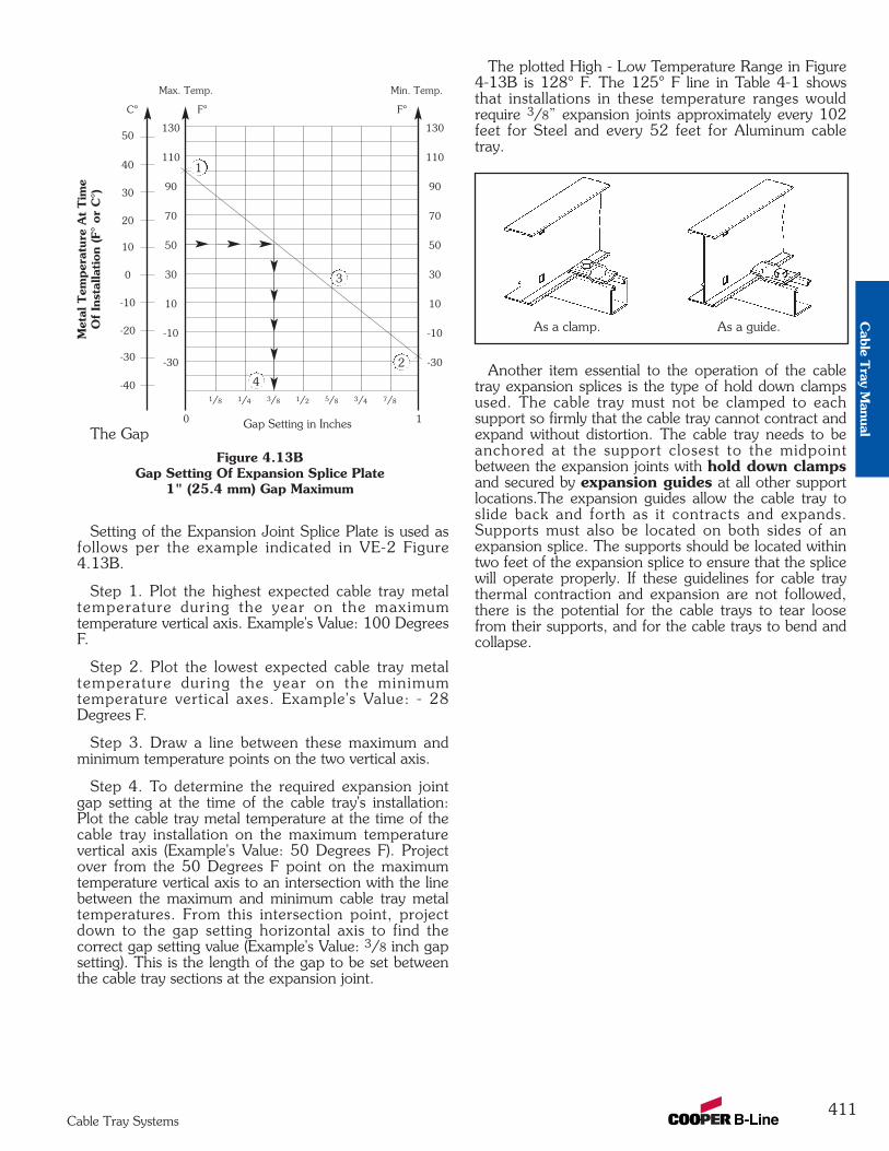
411Cable Tray Systems
The Gap
Setting of the Expansion Joint Splice Plate is used asfollows per the example indicated in VE-2 Figure4.13B.
Step 1. Plot the highest expected cable tray metaltemperature during the year on the maximumtemperature vertical axis. Example's Value: 100 DegreesF.
Step 2. Plot the lowest expected cable tray metaltemperature during the year on the minimumtemperature vertical axes. Example's Value: - 28Degrees F.
Step 3. Draw a line between these maximum andminimum temperature points on the two vertical axis.
Step 4. To determine the required expansion jointgap setting at the time of the cable tray's installation:Plot the cable tray metal temperature at the time of thecable tray installation on the maximum temperaturevertical axis (Example's Value: 50 Degrees F). Projectover from the 50 Degrees F point on the maximumtemperature vertical axis to an intersection with the linebetween the maximum and minimum cable tray metaltemperatures. From this intersection point, projectdown to the gap setting horizontal axis to find thecorrect gap setting value (Example's Value: 3/8 inch gapsetting). This is the length of the gap to be set betweenthe cable tray sections at the expansion joint.
The plotted High - Low Temperature Range in Figure4-13B is 128° F. The 125° F line in Table 4-1 showsthat installations in these temperature ranges wouldrequire 3/8” expansion joints approximately every 102feet for Steel and every 52 feet for Aluminum cabletray.
Another item essential to the operation of the cabletray expansion splices is the type of hold down clampsused. The cable tray must not be clamped to eachsupport so firmly that the cable tray cannot contract andexpand without distortion. The cable tray needs to beanchored at the support closest to the midpointbetween the expansion joints with hold down clampsand secured by expansion guides at all other supportlocations.The expansion guides allow the cable tray toslide back and forth as it contracts and expands.Supports must also be located on both sides of anexpansion splice. The supports should be located withintwo feet of the expansion splice to ensure that the splicewill operate properly. If these guidelines for cable traythermal contraction and expansion are not followed,there is the potential for the cable trays to tear loosefrom their supports, and for the cable trays to bend andcollapse.
Max. Temp. Min. Temp.
Figure 4.13BGap Setting Of Expansion Splice Plate
1" (25.4 mm) Gap Maximum
130
110
90
70
50
30
10
-10
-30
50
C° F° F°
40
30
20
10
0
-10
-20
-30
-40
130
110
90
70
50
30
10
-10
-30
0
1/8 5/81/23/81/4
1
7/83/4
Gap Setting in Inches
Met
al T
empe
ratu
re A
t Tim
eO
f In
stal
lation
(F°
or C
°)
As a clamp. As a guide.
1
2
3
4
Cable T
ray Manual
412Cable Tray Systems
Appendix Pages
Appendix Sheet 1 ...................................................................................................... 413Temperature Rise Tests, Cable Tray Connectors, Class II Aluminum & Steel Ladder Tray
Appendix Sheet 2 ...................................................................................................... 414Temperature Rise Tests, Conduit Clamps For Bonding Rigid Conduit To Cable Tray
Appendix Sheet 3 ...................................................................................................... 415Example - NEC® Section 392.9(A)(1)
Appendix Sheet 4 ...................................................................................................... 416Example - NEC® Section 392.9(A)(2)
Appendix Sheet 5 ...................................................................................................... 417Example - NEC® Section 392.9(A)(3)
Appendix Sheet 6 ...................................................................................................... 418Example - NEC® Section 392.9(B)
Appendix Sheet 7 ...................................................................................................... 419Table 250.122 Minimum Size EGC for Raceway and Equipment
Appendix Sheet 8 ............................................................................................ 420 - 421Cable Tray Sizing Flowchart
Appendix Sheet 9 ............................................................................................ 422 - 423Cable Tray Installation & Specification Checklist
Footnotes ................................................................................................................... 424Additional Cable Tray Resources and Engineering Software
Cab
le T
ray
Man
ual
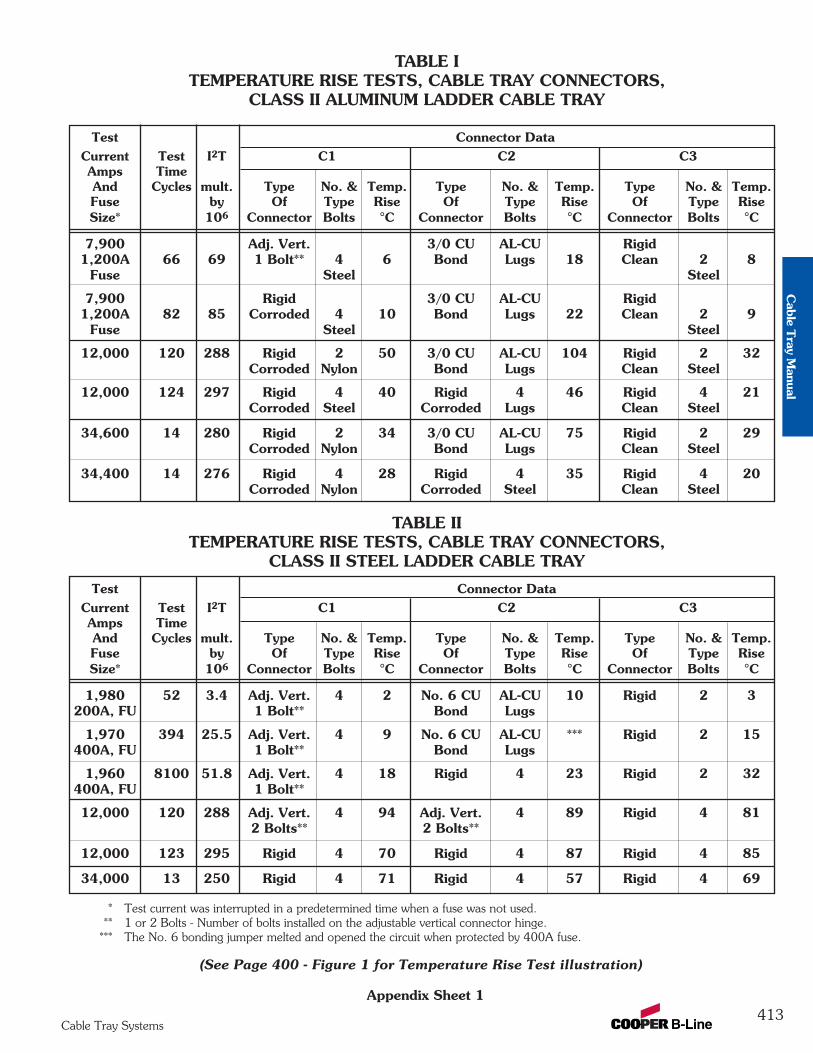
413Cable Tray Systems
Appendix Sheet 1
TABLE ITEMPERATURE RISE TESTS, CABLE TRAY CONNECTORS,
CLASS II ALUMINUM LADDER CABLE TRAY
TABLE IITEMPERATURE RISE TESTS, CABLE TRAY CONNECTORS,
CLASS II STEEL LADDER CABLE TRAY
Test Connector DataCurrent Test I2T C1 C2 C3Amps TimeAnd Cycles mult. Type No. & Temp. Type No. & Temp. Type No. & Temp.Fuse by Of Type Rise Of Type Rise Of Type RiseSize* 106 Connector Bolts °C Connector Bolts °C Connector Bolts °C
1,980 52 3.4 Adj. Vert. 4 2 No. 6 CU AL-CU 10 Rigid 2 3200A, FU 1 Bolt** Bond Lugs
1,970 394 25.5 Adj. Vert. 4 9 No. 6 CU AL-CU *** Rigid 2 15400A, FU 1 Bolt** Bond Lugs
1,960 8100 51.8 Adj. Vert. 4 18 Rigid 4 23 Rigid 2 32400A, FU 1 Bolt**
12,000 120 288 Adj. Vert. 4 94 Adj. Vert. 4 89 Rigid 4 812 Bolts** 2 Bolts**
12,000 123 295 Rigid 4 70 Rigid 4 87 Rigid 4 85
34,000 13 250 Rigid 4 71 Rigid 4 57 Rigid 4 69
Test Connector DataCurrent Test I2T C1 C2 C3Amps TimeAnd Cycles mult. Type No. & Temp. Type No. & Temp. Type No. & Temp.Fuse by Of Type Rise Of Type Rise Of Type RiseSize* 106 Connector Bolts °C Connector Bolts °C Connector Bolts °C
7,900 Adj. Vert. 3/0 CU AL-CU Rigid1,200A 66 69 1 Bolt** 4 6 Bond Lugs 18 Clean 2 8
Fuse Steel Steel
7,900 Rigid 3/0 CU AL-CU Rigid1,200A 82 85 Corroded 4 10 Bond Lugs 22 Clean 2 9
Fuse Steel Steel
12,000 120 288 Rigid 2 50 3/0 CU AL-CU 104 Rigid 2 32Corroded Nylon Bond Lugs Clean Steel
12,000 124 297 Rigid 4 40 Rigid 4 46 Rigid 4 21Corroded Steel Corroded Lugs Clean Steel
34,600 14 280 Rigid 2 34 3/0 CU AL-CU 75 Rigid 2 29Corroded Nylon Bond Lugs Clean Steel
34,400 14 276 Rigid 4 28 Rigid 4 35 Rigid 4 20Corroded Nylon Corroded Steel Clean Steel
* Test current was interrupted in a predetermined time when a fuse was not used.** 1 or 2 Bolts - Number of bolts installed on the adjustable vertical connector hinge.
*** The No. 6 bonding jumper melted and opened the circuit when protected by 400A fuse.
(See Page 400 - Figure 1 for Temperature Rise Test illustration)
Cable T
ray Manual
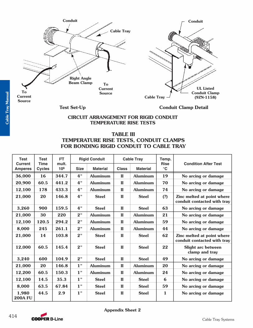
414Cable Tray Systems
TABLE IIITEMPERATURE RISE TESTS, CONDUIT CLAMPSFOR BONDING RIGID CONDUIT TO CABLE TRAY
Test Test I2T Rigid Conduit Cable Tray Temp.Current Time mult. Rise Condition After Test
Amperes Cycles 106 Size Material Class Material °C
36,000 16 344.7 4" Aluminum II Aluminum 19 No arcing or damage
20,900 60.5 441.2 4" Aluminum II Aluminum 70 No arcing or damage
12,100 178 433.3 4" Aluminum II Aluminum 74 No arcing or damage
21,000 20 146.8 4" Steel II Steel (?) Zinc melted at point whereconduit contacted with tray
3,260 900 159.5 4" Steel II Steel 63 No arcing or damage
21,000 30 220 2" Aluminum II Aluminum 21 No arcing or damage
12,100 120.5 294.2 2" Aluminum II Aluminum 59 No arcing or damage
8,000 245 261.1 2" Aluminum II Aluminum 44 No arcing or damage
21,000 14 103.8 2" Steel II Steel 62 Zinc melted at point whereconduit contacted with tray
12,000 60.5 145.4 2" Steel II Steel 22 Slight arc betweenclamp and tray
3,240 600 104.9 2" Steel II Steel 49 No arcing or damage
21,000 20 146.8 1" Aluminum II Aluminum 20 No arcing or damage
12,200 60.5 150.3 1" Aluminum II Aluminum 24 No arcing or damage
12,100 14.5 35.3 1" Steel II Steel 6 No arcing or damage
8,000 63.5 67.84 1" Steel II Steel 59 No arcing or damage
1,980 44.5 2.9 1" Steel II Steel 1 No arcing or damage200A FU
Appendix Sheet 2
Conduit
UL ListedConduit Clamp
(9ZN-1158)Cable Tray
Conduit
Cable Tray
Right AngleBeam Clamp To
CurrentSourceTo
CurrentSource
Conduit Clamp DetailTest Set-Up
CIRCUIT ARRANGEMENT FOR RIGID CONDUITTEMPERATURE RISE TESTSC
able
Tra
y M
anua
l
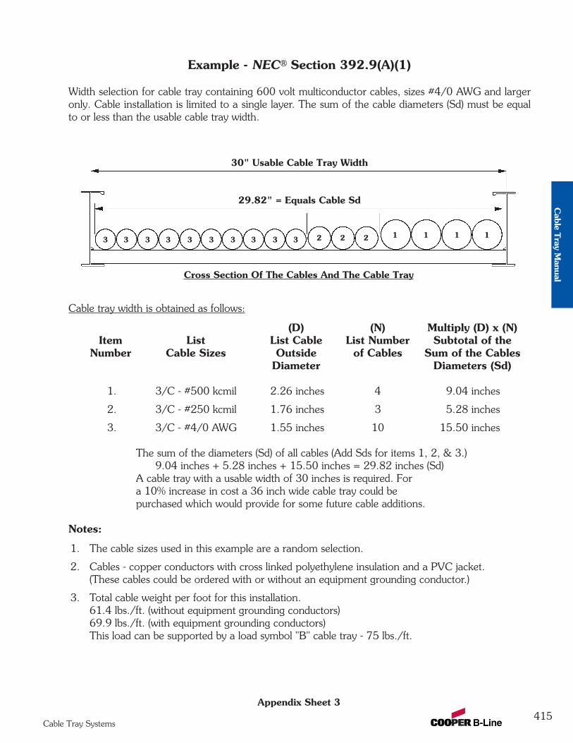
415Cable Tray Systems
Appendix Sheet 3
Example - NEC® Section 392.9(A)(1)
Width selection for cable tray containing 600 volt multiconductor cables, sizes #4/0 AWG and largeronly. Cable installation is limited to a single layer. The sum of the cable diameters (Sd) must be equalto or less than the usable cable tray width.
Cable tray width is obtained as follows:
(D) (N) Multiply (D) x (N)Item List List Cable List Number Subtotal of the
Number Cable Sizes Outside of Cables Sum of the CablesDiameter Diameters (Sd)
1. 3/C - #500 kcmil 2.26 inches 4 9.04 inches
2. 3/C - #250 kcmil 1.76 inches 3 5.28 inches
3. 3/C - #4/0 AWG 1.55 inches 10 15.50 inches
The sum of the diameters (Sd) of all cables (Add Sds for items 1, 2, & 3.)9.04 inches + 5.28 inches + 15.50 inches = 29.82 inches (Sd)
A cable tray with a usable width of 30 inches is required. Fora 10% increase in cost a 36 inch wide cable tray could bepurchased which would provide for some future cable additions.
Notes:
1. The cable sizes used in this example are a random selection.
2. Cables - copper conductors with cross linked polyethylene insulation and a PVC jacket.(These cables could be ordered with or without an equipment grounding conductor.)
3. Total cable weight per foot for this installation.61.4 lbs./ft. (without equipment grounding conductors)69.9 lbs./ft. (with equipment grounding conductors)This load can be supported by a load symbol "B" cable tray - 75 lbs./ft.
30" Usable Cable Tray Width
29.82" = Equals Cable Sd
Cross Section Of The Cables And The Cable Tray
3 3 3 3 3 3 3 3 3 3 2 2 2 1 1 1 1
Cable T
ray Manual
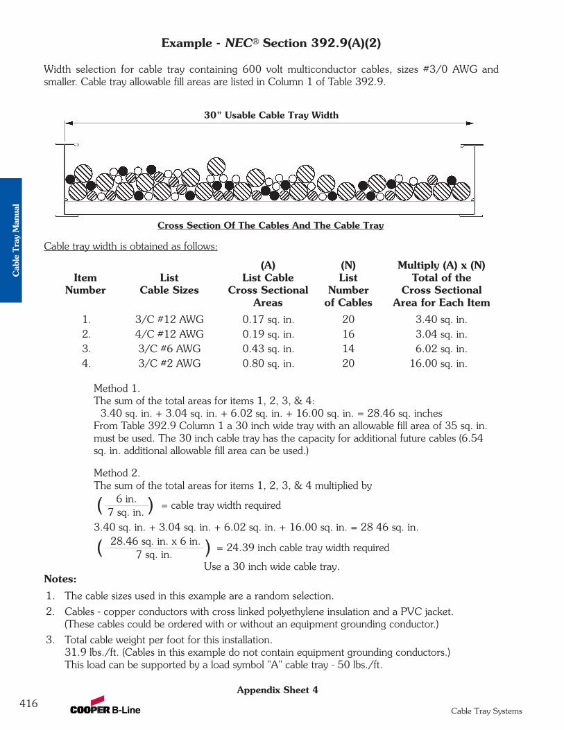
416Cable Tray Systems
Example - NEC® Section 392.9(A)(2)
Width selection for cable tray containing 600 volt multiconductor cables, sizes #3/0 AWG andsmaller. Cable tray allowable fill areas are listed in Column 1 of Table 392.9.
Cable tray width is obtained as follows:
(A) (N) Multiply (A) x (N)Item List List Cable List Total of the
Number Cable Sizes Cross Sectional Number Cross SectionalAreas of Cables Area for Each Item
1. 3/C #12 AWG 0.17 sq. in. 20 3.40 sq. in.2. 4/C #12 AWG 0.19 sq. in. 16 3.04 sq. in.3. 3/C #6 AWG 0.43 sq. in. 14 6.02 sq. in.4. 3/C #2 AWG 0.80 sq. in. 20 16.00 sq. in.
Method 1.The sum of the total areas for items 1, 2, 3, & 4:
3.40 sq. in. + 3.04 sq. in. + 6.02 sq. in. + 16.00 sq. in. = 28.46 sq. inchesFrom Table 392.9 Column 1 a 30 inch wide tray with an allowable fill area of 35 sq. in. must be used. The 30 inch cable tray has the capacity for additional future cables (6.54 sq. in. additional allowable fill area can be used.)
Method 2.The sum of the total areas for items 1, 2, 3, & 4 multiplied by
3.40 sq. in. + 3.04 sq. in. + 6.02 sq. in. + 16.00 sq. in. = 28 46 sq. in.
Use a 30 inch wide cable tray.Notes:
1. The cable sizes used in this example are a random selection.
2. Cables - copper conductors with cross linked polyethylene insulation and a PVC jacket.(These cables could be ordered with or without an equipment grounding conductor.)
3. Total cable weight per foot for this installation.31.9 lbs./ft. (Cables in this example do not contain equipment grounding conductors.)This load can be supported by a load symbol "A" cable tray - 50 lbs./ft.
30" Usable Cable Tray Width
Cross Section Of The Cables And The Cable Tray
( )6 in.7 sq. in.
= cable tray width required
( )28.46 sq. in. x 6 in.7 sq. in.
= 24.39 inch cable tray width required
Appendix Sheet 4
Cab
le T
ray
Man
ual
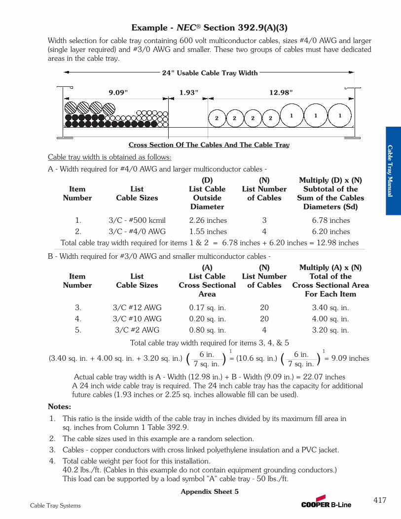
Example - NEC® Section 392.9(A)(3)Width selection for cable tray containing 600 volt multiconductor cables, sizes #4/0 AWG and larger(single layer required) and #3/0 AWG and smaller. These two groups of cables must have dedicatedareas in the cable tray.
Cable tray width is obtained as follows:
A - Width required for #4/0 AWG and larger multiconductor cables -
(D) (N) Multiply (D) x (N)Item List List Cable List Number Subtotal of the
Number Cable Sizes Outside of Cables Sum of the CablesDiameter Diameters (Sd)
1. 3/C - #500 kcmil 2.26 inches 3 6.78 inches
2. 3/C - #4/0 AWG 1.55 inches 4 6.20 inches
Total cable tray width required for items 1 & 2 = 6.78 inches + 6.20 inches = 12.98 inches
B - Width required for #3/0 AWG and smaller multiconductor cables -
(A) (N) Multiply (A) x (N)Item List List Cable List Number Total of the
Number Cable Sizes Cross Sectional of Cables Cross Sectional AreaArea For Each Item
3. 3/C #12 AWG 0.17 sq. in. 20 3.40 sq. in.
4. 3/C #10 AWG 0.20 sq. in. 20 4.00 sq. in.
5. 3/C #2 AWG 0.80 sq. in. 4 3.20 sq. in.
Total cable tray width required for items 3, 4, & 5
Actual cable tray width is A - Width (12.98 in.) + B - Width (9.09 in.) = 22.07 inchesA 24 inch wide cable tray is required. The 24 inch cable tray has the capacity for additionalfuture cables (1.93 inches or 2.25 sq. inches allowable fill can be used).
Notes:
1. This ratio is the inside width of the cable tray in inches divided by its maximum fill area insq. inches from Column 1 Table 392.9.
2. The cable sizes used in this example are a random selection.
3. Cables - copper conductors with cross linked polyethylene insulation and a PVC jacket.
4. Total cable weight per foot for this installation.40.2 lbs./ft. (Cables in this example do not contain equipment grounding conductors.) This load can be supported by a load symbol "A" cable tray - 50 lbs./ft.
24" Usable Cable Tray Width
9.09" 1.93" 12.98"
Cross Section Of The Cables And The Cable Tray
2 2 2 2 1 1 1
Appendix Sheet 5
(3.40 sq. in. + 4.00 sq. in. + 3.20 sq. in.) = (10.6 sq. in.) = 9.09 inches( )6 in.7 sq. in. ( )6 in.
7 sq. in.
1 1
417Cable Tray Systems
Cable T
ray Manual
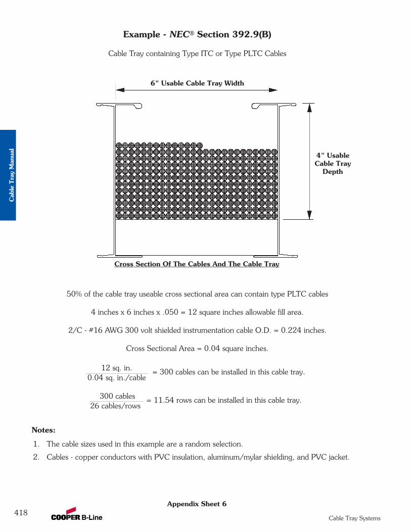
Appendix Sheet 6
Example - NEC® Section 392.9(B)
Cable Tray containing Type ITC or Type PLTC Cables
50% of the cable tray useable cross sectional area can contain type PLTC cables
4 inches x 6 inches x .050 = 12 square inches allowable fill area.
2/C - #16 AWG 300 volt shielded instrumentation cable O.D. = 0.224 inches.
Cross Sectional Area = 0.04 square inches.
Notes:
1. The cable sizes used in this example are a random selection.
2. Cables - copper conductors with PVC insulation, aluminum/mylar shielding, and PVC jacket.
6" Usable Cable Tray Width
4" UsableCable Tray
Depth
Cross Section Of The Cables And The Cable Tray
= 300 cables can be installed in this cable tray.12 sq. in.0.04 sq. in./cable
= 11.54 rows can be installed in this cable tray.300 cables26 cables/rows
418Cable Tray Systems
Cab
le T
ray
Man
ual
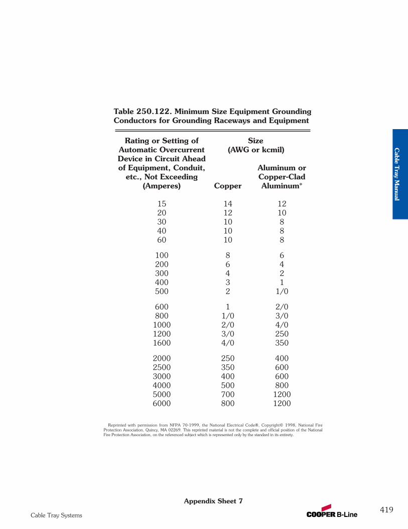
Appendix Sheet 7
Reprinted with permission from NFPA 70-1999, the National Electrical Code®, Copyright© 1998, National FireProtection Association, Quincy, MA 02269. This reprinted material is not the complete and official position of the NationalFire Protection Association, on the referenced subject which is represented only by the standard in its entirety.
Table 250.122. Minimum Size Equipment GroundingConductors for Grounding Raceways and Equipment
Rating or Setting of SizeAutomatic Overcurrent (AWG or kcmil)Device in Circuit Aheadof Equipment, Conduit, Aluminum or
etc., Not Exceeding Copper-Clad(Amperes) Copper Aluminum*
15 14 1220 12 1030 10 840 10 860 10 8
100 8 6200 6 4300 4 2400 3 1500 2 1/0
600 1 2/0800 1/0 3/01000 2/0 4/01200 3/0 2501600 4/0 350
2000 250 4002500 350 6003000 400 6004000 500 8005000 700 12006000 800 1200
419Cable Tray Systems
Cable T
ray Manual
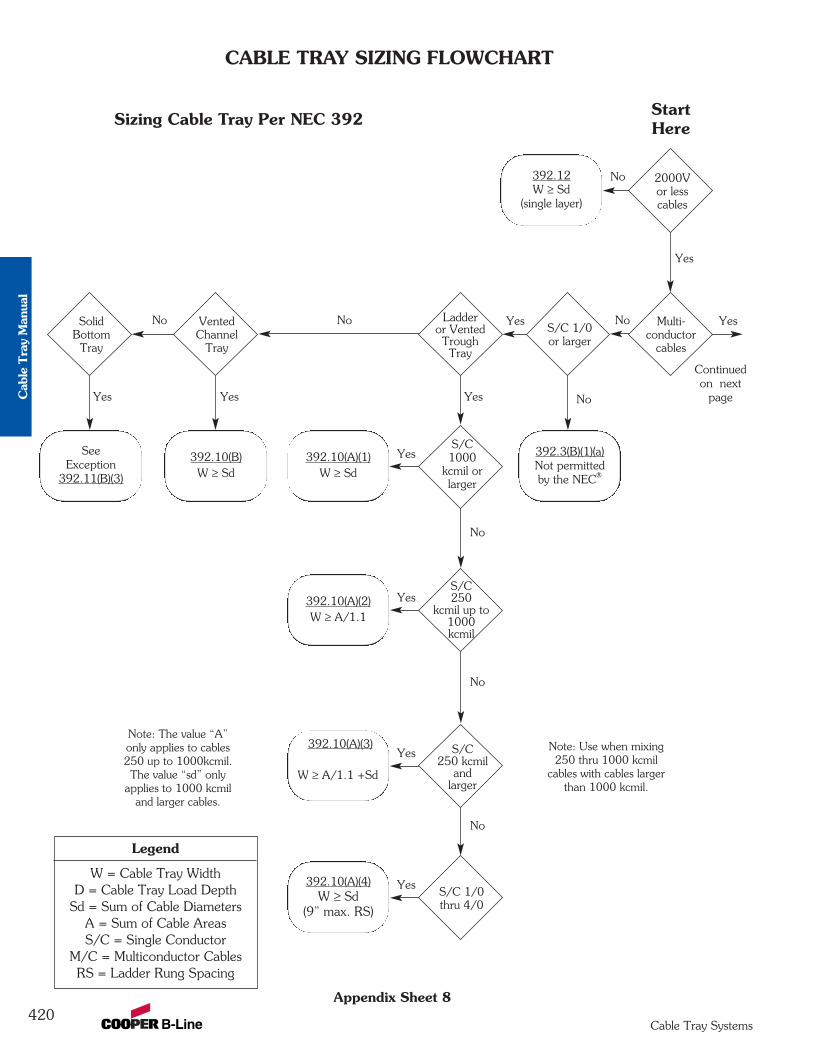
CABLE TRAY SIZING FLOWCHART
Appendix Sheet 8
392.12W ≥ Sd
(single layer)
392.3(B)(1)(a)Not permittedby the NEC®
SeeException
392.11(B)(3)
392.10(B)W ≥ Sd
392.10(A)(1)W ≥ Sd
392.10(A)(2)W ≥ A/1.1
Note: The value “A”only applies to cables250 up to 1000kcmil.The value “sd” only
applies to 1000 kcmiland larger cables.
Note: Use when mixing250 thru 1000 kcmil
cables with cables largerthan 1000 kcmil.
392.10(A)(3)
392.10(A)(4)W ≥ Sd
(9” max. RS)
2000Vor lesscables
Multi-conductor
cables
S/C 1/0or larger
Ladderor VentedTroughTray
S/C1000
kcmil orlarger
S/C250
kcmil up to1000kcmil
S/C250 kcmil
andlarger
S/C 1/0thru 4/0
VentedChannel
Tray
SolidBottom
Tray
W ≥ A/1.1 +Sd
No
No
No
No
No No No
No
Yes
Yes
Yes
Yes
YesYes Yes
Yes
Yes
Continuedon next
page
Yes
Legend
W = Cable Tray WidthD = Cable Tray Load Depth
Sd = Sum of Cable DiametersA = Sum of Cable AreasS/C = Single Conductor
M/C = Multiconductor CablesRS = Ladder Rung Spacing
StartHereSizing Cable Tray Per NEC 392
420Cable Tray Systems
Cab
le T
ray
Man
ual
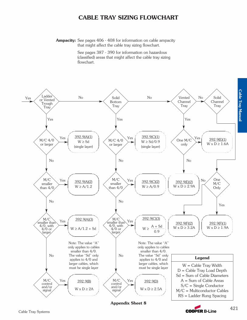
CABLE TRAY SIZING FLOWCHART
Appendix Sheet 8
392.9(E)(1)W x D ≥ 1.6A
392.9(A)(1)W ≥ Sd
(single layer)
392.9(C)(1)W ≥ Sd/0.9(single layer)
Note: The value “A”only applies to cables
smaller than 4/0.The value “Sd” onlyapplies to 4/0 andlarger cables, whichmust be single layer
Note: The value “A”only applies to cables
smaller than 4/0.The value “Sd” onlyapplies to 4/0 andlarger cables, whichmust be single layer
392.9(A)(3)
VentedChannel
Tray
SolidChannel
Tray
SolidBottom
Tray
Ladderor VentedTroughTray
One M/C only
M/C 4/0or larger
M/C 4/0or larger
392.9(E)(2)W x D ≥ 2.9A
392.9(F)(1)W x D ≥ 1.9A
392.9(F)(2)W x D ≥ 3.2A
392.9(A)(2)W ≥ A/1.2
392.9(C)(2)W ≥ A/0.9
M/Csmaller
than 4/0
OneM/COnly
M/Csmaller
than 4/0
M/Csmaller than4/0, with4/0 orlarger
M/Ccontroland/orsignal
W ≥ A/1.2 + Sd
No NoNo
NoNo
NoNo
No No No
392.9(B)
W x D ≥ 2A
392.9(C)(3)
A + Sd
0.9
M/Csmaller than4/0, with4/0 orlarger
M/Ccontroland/orsignal
W ≥
392.9(D)
W x D ≥ 2.5A
YesYes
Yes NoYes
Yes
Yes
Yes
YesYes
Yes
Yes Yes Yes
Yes
Legend
W = Cable Tray WidthD = Cable Tray Load Depth
Sd = Sum of Cable DiametersA = Sum of Cable AreasS/C = Single Conductor
M/C = Multiconductor CablesRS = Ladder Rung Spacing
Ampacity: See pages 406 - 408 for information on cable ampacitythat might affect the cable tray sizing flowchart.
See pages 387 - 390 for information on hazardous(classified) areas that might affect the cable tray sizingflowchart.
421Cable Tray Systems
Cable T
ray Manual
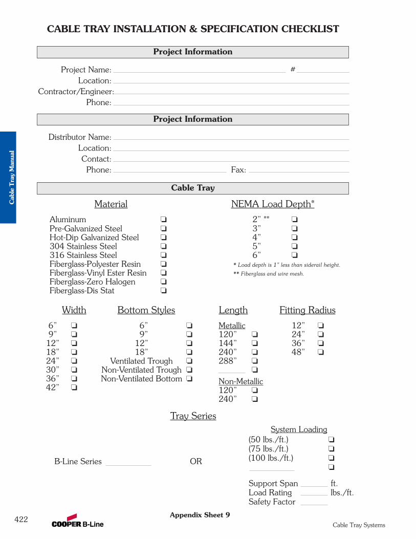
Material NEMA Load Depth*
Aluminum o 2” ** oPre-Galvanized Steel o 3” oHot-Dip Galvanized Steel o 4” o304 Stainless Steel o 5” o316 Stainless Steel o 6” oFiberglass-Polyester Resin o * Load depth is 1” less than siderail height.
Fiberglass-Vinyl Ester Resin o ** Fiberglass and wire mesh.
Fiberglass-Zero Halogen oFiberglass-Dis Stat o
Width Bottom Styles Length Fitting Radius
6” o 6” o Metallic 12” o9” o 9” o 120” o 24” o12” o 12” o 144” o 36” o18” o 18” o 240” o 48” o24” o Ventilated Trough o 288” o30” o Non-Ventilated Trough o o36” o Non-Ventilated Bottom o Non-Metallic42” o 120” o
240” o
Tray SeriesSystem Loading
(50 lbs./ft.) o(75 lbs./ft.) o
B-Line Series OR (100 lbs./ft.) oo
Support Span ft.Load Rating lbs./ft.Safety Factor
CABLE TRAY INSTALLATION & SPECIFICATION CHECKLIST
Appendix Sheet 9
Project Information
Project Name: #Location:
Contractor/Engineer:Phone:
Project Information
Cable Tray
Distributor Name:Location:Contact:Phone: Fax:
422Cable Tray Systems
Cab
le T
ray
Man
ual
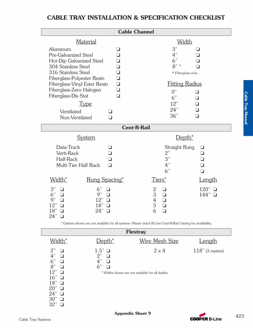
CABLE TRAY INSTALLATION & SPECIFICATION CHECKLIST
Appendix Sheet 9
Material WidthAluminum o 3” oPre-Galvanized Steel o 4” oHot-Dip Galvanized Steel o 6” o304 Stainless Steel o 8” * o316 Stainless Steel o * Fiberglass only.
Fiberglass-Polyester Resin oFiberglass-Vinyl Ester Resin o Fitting RadiusFiberglass-Zero Halogen o 0” oFiberglass-Dis Stat o 6” o
Type 12” o
Ventilated o 24” o
Non-Ventilated o 36” o
Cable Channel
System Depth*
Data-Track o Straight Rung o
Verti-Rack o 2” o
Half-Rack o 3” o
Multi-Tier Half Rack o 4” o
6” o
Width* Rung Spacing* Tiers* Length
3” o 6” o 2 o 120” o6” o 9” o 3 o 144” o9” o 12” o 4 o12” o 18” o 5 o18” o 24” o 6 o24” o
* Options shown are not available for all systems. Please check B-Line Cent-R-Rail Catalog for availability.
Cent-R-Rail
Width* Depth* Wire Mesh Size Length
2” o 1.5” o 2 x 4 118” (3 meters)4” o 2” o6” o 4” o8” o 6” o12” o * Widths shown are not available for all depths.
16” o18” o20” o24” o30” o32” o
Flextray
423Cable Tray Systems
Cable T
ray Manual
1 NEMA Standard VE-2, Section 4, Installation 4.3 Straight Section Installation - 4.3.1. Horizontal Cable Tray Straight Sections states that straight section lengths should be equal to or greater thanthe span length to ensure not more than one splice between supports.
Additional Cable Tray Resources
Cable Tray Institute National Electrical Manufacturers Association1300 N. 17th Street 1300 N. 17th StreetRosslyn, VA 22209 Rosslyn, VA 22209
www.cabletrays.com www.nema.org
B-Line Engineering Software
TrayCAD®
TrayCAD® is a Cable Tray layout design program that works within the AutoCAD®
environment. TrayCAD® is a windows based program and installs as an add-on to your AutoCAD® system. Use the TrayCAD® toolbar to add cable tray to your existing plans by drawing a single centerline representation of the tray run. Then, with the click of a button, the program will build a full-scale 3-D wire-frame model of the cable tray and all the appropriate fittings. The program also automatically creates a Bill of Material and contains a library of modifiable details.
Runway Router®
Runway Router® is a cable ladder runway (ladder rack) layout design program that works within your AutoCAD® environment. Use the commands from the Runway Router® toolbar to layout runway, relay racks and electronic cabinets. Add cable tray or Cent-R-Rail® to your existing plans by drawing a single centerline representation of the cable run. Then, with the click of a button, the program will build a full-scale 3-D wire-frame model of the cable runway and all the appropriate connectors and fittings. The program also automatically creates a Bill of Material and contains a library of modifiable details.
Footnotes:
424Cable Tray Systems
Cab
le T
ray
Man
ual
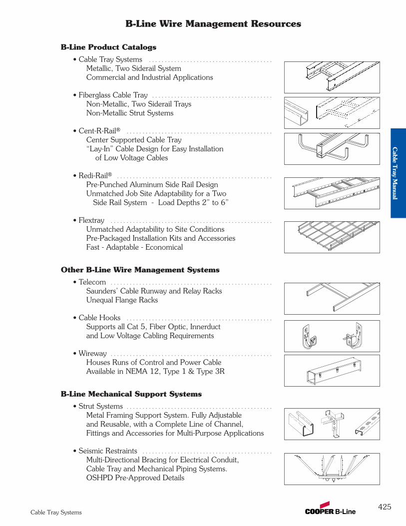
425Cable Tray Systems
B-Line Wire Management Resources
B-Line Product Catalogs
• Cable Tray Systems . . . . . . . . . . . . . . . . . . . . . . . . . . . . . . . . . . . . . . .
Metallic, Two Siderail SystemCommercial and Industrial Applications
• Fiberglass Cable Tray . . . . . . . . . . . . . . . . . . . . . . . . . . . . . . . . . . . . . .
Non-Metallic, Two Siderail TraysNon-Metallic Strut Systems
• Cent-R-Rail® . . . . . . . . . . . . . . . . . . . . . . . . . . . . . . . . . . . . . . . . . . . . . .
Center Supported Cable Tray“Lay-In” Cable Design for Easy Installation
of Low Voltage Cables
• Redi-Rail® . . . . . . . . . . . . . . . . . . . . . . . . . . . . . . . . . . . . . . . . . . . . . . . . .
Pre-Punched Aluminum Side Rail DesignUnmatched Job Site Adaptability for a Two
Side Rail System - Load Depths 2” to 6”
• Flextray . . . . . . . . . . . . . . . . . . . . . . . . . . . . . . . . . . . . . . . . . . . . . . . . . . .
Unmatched Adaptability to Site ConditionsPre-Packaged Installation Kits and AccessoriesFast - Adaptable - Economical
Other B-Line Wire Management Systems
• Telecom . . . . . . . . . . . . . . . . . . . . . . . . . . . . . . . . . . . . . . . . . . . . . . . . . . .
Saunders’ Cable Runway and Relay RacksUnequal Flange Racks
• Cable Hooks . . . . . . . . . . . . . . . . . . . . . . . . . . . . . . . . . . . . . . . . . . . . . .
Supports all Cat 5, Fiber Optic, Innerductand Low Voltage Cabling Requirements
• Wireway . . . . . . . . . . . . . . . . . . . . . . . . . . . . . . . . . . . . . . . . . . . . . . . . . . .Houses Runs of Control and Power CableAvailable in NEMA 12, Type 1 & Type 3R
B-Line Mechanical Support Systems
• Strut Systems . . . . . . . . . . . . . . . . . . . . . . . . . . . . . . . . . . . . . . . . . . . . . .Metal Framing Support System. Fully Adjustableand Reusable, with a Complete Line of Channel,Fittings and Accessories for Multi-Purpose Applications
• Seismic Restraints . . . . . . . . . . . . . . . . . . . . . . . . . . . . . . . . . . . . . . . . .
Multi-Directional Bracing for Electrical Conduit,Cable Tray and Mechanical Piping Systems.OSHPD Pre-Approved Details
Cable T
ray Manual

426
Index - Straight Sections
PrefixExample: 148 * 12 - 24 - 144
Series WidthMaterial LengthRung Spacing
¬ Â Ã Ä
¬ÁÂ
ÃÄ
Á
Cable Tray Straight Sections
Inde
x
Cable Tray Systems
Catalog No. Page
Catalog No. Page Catalog No. Page
Fiberglass Cable Tray13F Â - Ã - Ä . . . . . . . . . . . . . . . 32213FDÂ - Ã - Ä . . . . . . . . . . . . . . 32213FTÂ - Ã - Ä . . . . . . . . . . . . . . 32213FVÂ - Ã - Ä . . . . . . . . . . . . . . 322
24F Â - Ã - Ä . . . . . . . . . . . . . . . 32324FDÂ - Ã - Ä . . . . . . . . . . . . . . 32324FTÂ - Ã - Ä . . . . . . . . . . . . . . 32324FVÂ - Ã - Ä . . . . . . . . . . . . . . 323
36F Â - Ã - Ä . . . . . . . . . . . . . . . 32436FDÂ - Ã - Ä . . . . . . . . . . . . . . 32436FTÂ - Ã - Ä . . . . . . . . . . . . . . 32436FVÂ - Ã - Ä . . . . . . . . . . . . . . 324
46F Â - Ã - Ä . . . . . . . . . . . . . . . 32446FDÂ - Ã - Ä . . . . . . . . . . . . . . 32446FTÂ - Ã - Ä . . . . . . . . . . . . . . 32446FVÂ - Ã - Ä . . . . . . . . . . . . . . 324
48F Â - Ã - Ä . . . . . . . . . . . . . . . 32548FDÂ - Ã - Ä . . . . . . . . . . . . . . 32548FTÂ - Ã - Ä . . . . . . . . . . . . . . 32548FVÂ - Ã - Ä . . . . . . . . . . . . . . 325
H46F Â - Ã - Ä . . . . . . . . . . . . . . 324H46FDÂ - Ã - Ä . . . . . . . . . . . . . 324H46FTÂ - Ã - Ä . . . . . . . . . . . . . 324H46FVÂ - Ã - Ä . . . . . . . . . . . . . 324
F = Polyester ResinFD = Dis-Stat ResinFT = Zero Halogen ResinFV = Vinyl Ester Resin
Series 2, 3, 4, & 5Steel Cable Tray
248 G Â - Ã - Ä . . . . . . . . . . . . . 250248 P Â - Ã - Ä . . . . . . . . . . . . . . 250
258 G Â - Ã - Ä . . . . . . . . . . . . . 252258 P Â - Ã - Ä . . . . . . . . . . . . . . 252
268 G Â - Ã - Ä . . . . . . . . . . . . . 254268 P Â - Ã - Ä . . . . . . . . . . . . . . 254
346 G Â - Ã - Ä . . . . . . . . . . . . . 250346 P Â - Ã - Ä . . . . . . . . . . . . . . 250
356 G Â - Ã - Ä . . . . . . . . . . . . . 252356 P Â - Ã - Ä . . . . . . . . . . . . . . 252
366 G Â - Ã - Ä . . . . . . . . . . . . . 254366 P Â - Ã - Ä . . . . . . . . . . . . . . 254
378 G Â - Ã - Ä . . . . . . . . . . . . . 256378 P Â - Ã - Ä . . . . . . . . . . . . . . 256
444 G Â - Ã - Ä . . . . . . . . . . . . . 250444 P Â - Ã - Ä . . . . . . . . . . . . . . 250
454 G Â - Ã - Ä . . . . . . . . . . . . . 252454 P Â - Ã - Ä . . . . . . . . . . . . . . 252
464 G Â - Ã - Ä . . . . . . . . . . . . . 254464 P Â - Ã - Ä . . . . . . . . . . . . . . 254
476 G Â - Ã - Ä . . . . . . . . . . . . . 256476 P Â - Ã - Ä . . . . . . . . . . . . . . 256
574 G Â - Ã - Ä . . . . . . . . . . . . . 256574 P Â - Ã - Ä . . . . . . . . . . . . . . 256G = Hot Dipped Galvanized SteelP = Pre-Galvanized Steel
Series 2, 3, 4, & 5Aluminum Cable Tray
24A Â - Ã - Ä . . . . . . . . . . . . . . . 22625A Â - Ã - Ä . . . . . . . . . . . . . . . 22826A Â - Ã - Ä . . . . . . . . . . . . . . . 230
34A Â - Ã - Ä . . . . . . . . . . . . . . . 22635A Â - Ã - Ä . . . . . . . . . . . . . . . 22836A Â - Ã - Ä . . . . . . . . . . . . . . . 23037A Â - Ã - Ä . . . . . . . . . . . . . . . 232
46A Â - Ã - Ä . . . . . . . . . . . . . . . 23047A Â - Ã - Ä . . . . . . . . . . . . . . . 232
57A Â - Ã - Ä . . . . . . . . . . . . . . . 232
H46A Â - Ã - Ä . . . . . . . . . . . . . 230H47A Â - Ã - Ä . . . . . . . . . . . . . 232
S8A Â - Ã - Ä . . . . . . . . . . . . . . . 234A = Aluminum
Redi-Rail®Aluminum Cable Tray
H14AR Â - Ã - Ä . . . . . . . . . . . . 186H15AR Â - Ã - Ä . . . . . . . . . . . . 187H16AR Â - Ã - Ä . . . . . . . . . . . . 187H17AR Â - Ã - Ä . . . . . . . . . . . . 187A = Aluminum
Series 1Steel Cable Tray
148 G Â - Ã - Ä . . . . . . . . . . . . . 202148 P Â - Ã - Ä . . . . . . . . . . . . . . 202
156 G Â - Ã - Ä . . . . . . . . . . . . . 203156 P Â - Ã - Ä . . . . . . . . . . . . . . 203
166 G Â - Ã - Ä . . . . . . . . . . . . . 204166 P Â - Ã - Ä . . . . . . . . . . . . . . 204
176 G Â - Ã - Ä . . . . . . . . . . . . . 205176 P Â - Ã - Ä . . . . . . . . . . . . . . 205G = Hot Dipped Galvanized SteelP = Pre-Galvanized Steel
Series 2, 3, 4, & 5Stainless Steel Cable Tray
348SS4 Â - Ã - Ä . . . . . . . . . . . . 272348SS6 Â - Ã - Ä . . . . . . . . . . . . 272
358SS4 Â - Ã - Ä . . . . . . . . . . . . 273358SS6 Â - Ã - Ä . . . . . . . . . . . . 273
368SS4 Â - Ã - Ä . . . . . . . . . . . . 274368SS6 Â - Ã - Ä . . . . . . . . . . . . 274
464SS4 Â - Ã - Ä . . . . . . . . . . . . 274464SS6 Â - Ã - Ä . . . . . . . . . . . . 274SS4 = Stainless Steel 304SS6 = Stainless Steel 316
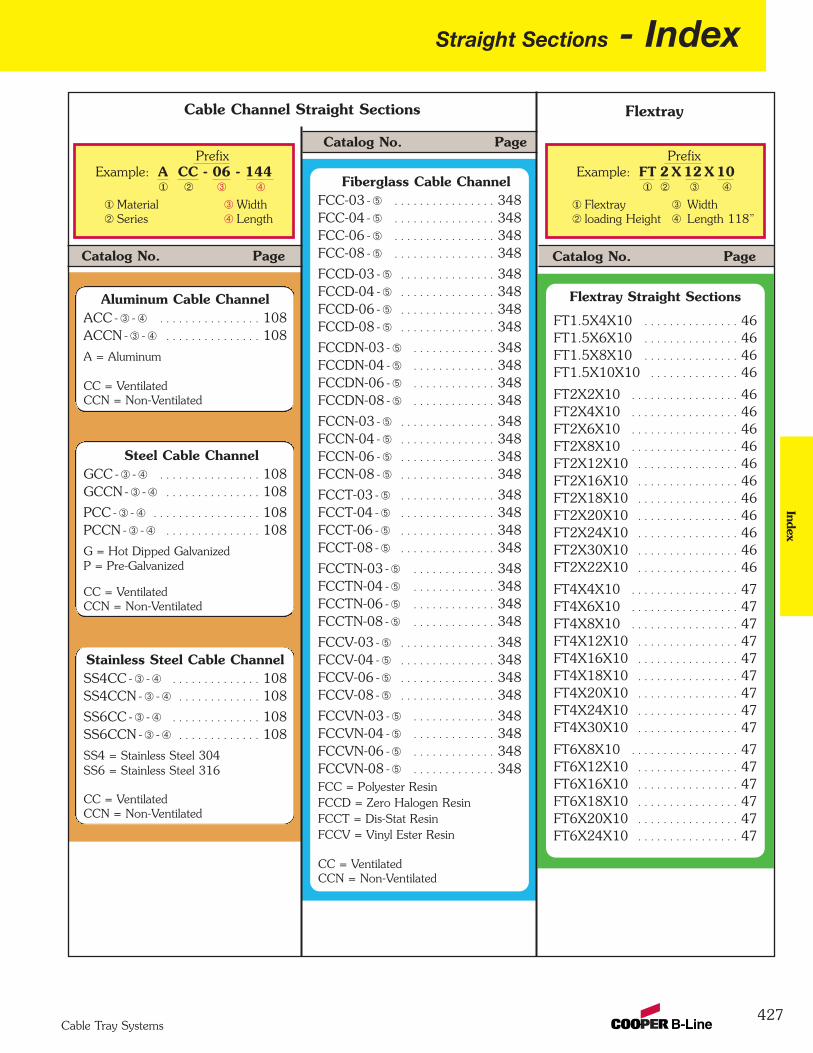
Straight Sections - Index
427
Index
Cable Tray Systems
Flextray
Catalog No. Page
Fiberglass Cable ChannelFCC-03 - Ä . . . . . . . . . . . . . . . . 348FCC-04 - Ä . . . . . . . . . . . . . . . . 348 FCC-06 - Ä . . . . . . . . . . . . . . . . 348 FCC-08 - Ä . . . . . . . . . . . . . . . . 348
FCCD-03 - Ä . . . . . . . . . . . . . . . 348 FCCD-04 - Ä . . . . . . . . . . . . . . . 348 FCCD-06 - Ä . . . . . . . . . . . . . . . 348 FCCD-08 - Ä . . . . . . . . . . . . . . . 348
FCCDN-03 - Ä . . . . . . . . . . . . . 348 FCCDN-04 - Ä . . . . . . . . . . . . . 348 FCCDN-06 - Ä . . . . . . . . . . . . . 348 FCCDN-08 - Ä . . . . . . . . . . . . . 348
FCCN-03 - Ä . . . . . . . . . . . . . . . 348 FCCN-04 - Ä . . . . . . . . . . . . . . . 348 FCCN-06 - Ä . . . . . . . . . . . . . . . 348 FCCN-08 - Ä . . . . . . . . . . . . . . . 348
FCCT-03 - Ä . . . . . . . . . . . . . . . 348 FCCT-04 - Ä . . . . . . . . . . . . . . . 348 FCCT-06 - Ä . . . . . . . . . . . . . . . 348 FCCT-08 - Ä . . . . . . . . . . . . . . . 348
FCCTN-03 - Ä . . . . . . . . . . . . . 348 FCCTN-04 - Ä . . . . . . . . . . . . . 348 FCCTN-06 - Ä . . . . . . . . . . . . . 348 FCCTN-08 - Ä . . . . . . . . . . . . . 348
FCCV-03 - Ä . . . . . . . . . . . . . . . 348 FCCV-04 - Ä . . . . . . . . . . . . . . . 348 FCCV-06 - Ä . . . . . . . . . . . . . . . 348 FCCV-08 - Ä . . . . . . . . . . . . . . . 348
FCCVN-03 - Ä . . . . . . . . . . . . . 348 FCCVN-04 - Ä . . . . . . . . . . . . . 348 FCCVN-06 - Ä . . . . . . . . . . . . . 348 FCCVN-08 - Ä . . . . . . . . . . . . . 348 FCC = Polyester ResinFCCD = Zero Halogen ResinFCCT = Dis-Stat ResinFCCV = Vinyl Ester Resin
CC = VentilatedCCN = Non-Ventilated
Flextray Straight Sections
FT1.5X4X10 . . . . . . . . . . . . . . . 46 FT1.5X6X10 . . . . . . . . . . . . . . . 46 FT1.5X8X10 . . . . . . . . . . . . . . . 46 FT1.5X10X10 . . . . . . . . . . . . . . 46
FT2X2X10 . . . . . . . . . . . . . . . . . 46 FT2X4X10 . . . . . . . . . . . . . . . . . 46 FT2X6X10 . . . . . . . . . . . . . . . . . 46 FT2X8X10 . . . . . . . . . . . . . . . . . 46 FT2X12X10 . . . . . . . . . . . . . . . . 46 FT2X16X10 . . . . . . . . . . . . . . . . 46 FT2X18X10 . . . . . . . . . . . . . . . . 46 FT2X20X10 . . . . . . . . . . . . . . . . 46 FT2X24X10 . . . . . . . . . . . . . . . . 46 FT2X30X10 . . . . . . . . . . . . . . . . 46 FT2X22X10 . . . . . . . . . . . . . . . . 46
FT4X4X10 . . . . . . . . . . . . . . . . . 47 FT4X6X10 . . . . . . . . . . . . . . . . . 47 FT4X8X10 . . . . . . . . . . . . . . . . . 47 FT4X12X10 . . . . . . . . . . . . . . . . 47 FT4X16X10 . . . . . . . . . . . . . . . . 47 FT4X18X10 . . . . . . . . . . . . . . . . 47 FT4X20X10 . . . . . . . . . . . . . . . . 47 FT4X24X10 . . . . . . . . . . . . . . . . 47 FT4X30X10 . . . . . . . . . . . . . . . . 47
FT6X8X10 . . . . . . . . . . . . . . . . . 47 FT6X12X10 . . . . . . . . . . . . . . . . 47 FT6X16X10 . . . . . . . . . . . . . . . . 47 FT6X18X10 . . . . . . . . . . . . . . . . 47 FT6X20X10 . . . . . . . . . . . . . . . . 47 FT6X24X10 . . . . . . . . . . . . . . . . 47
Catalog No. Page
PrefixExample: A CC - 06 - 144
Material WidthSeries Length
¬ Â Ã
¬Á
ÂÃ
Cable Channel Straight Sections
Á
PrefixExample: FT 2 X 12 X 10
Flextray Widthloading Height Length 118”
Á Â Ã
¬Á
ÂÃ
¬
Catalog No. Page
Aluminum Cable ChannelACC - Â - Ã . . . . . . . . . . . . . . . . 108ACCN - Â - Ã . . . . . . . . . . . . . . . 108
A = Aluminum
CC = VentilatedCCN = Non-Ventilated
Steel Cable ChannelGCC - Â - Ã . . . . . . . . . . . . . . . . 108GCCN - Â - Ã . . . . . . . . . . . . . . . 108
PCC - Â - Ã . . . . . . . . . . . . . . . . . 108PCCN - Â - Ã . . . . . . . . . . . . . . . 108
G = Hot Dipped GalvanizedP = Pre-Galvanized
CC = VentilatedCCN = Non-Ventilated
Stainless Steel Cable ChannelSS4CC - Â - Ã . . . . . . . . . . . . . . 108SS4CCN - Â - Ã . . . . . . . . . . . . . 108
SS6CC - Â - Ã . . . . . . . . . . . . . . 108SS6CCN - Â - Ã . . . . . . . . . . . . . 108
SS4 = Stainless Steel 304SS6 = Stainless Steel 316
CC = VentilatedCCN = Non-Ventilated
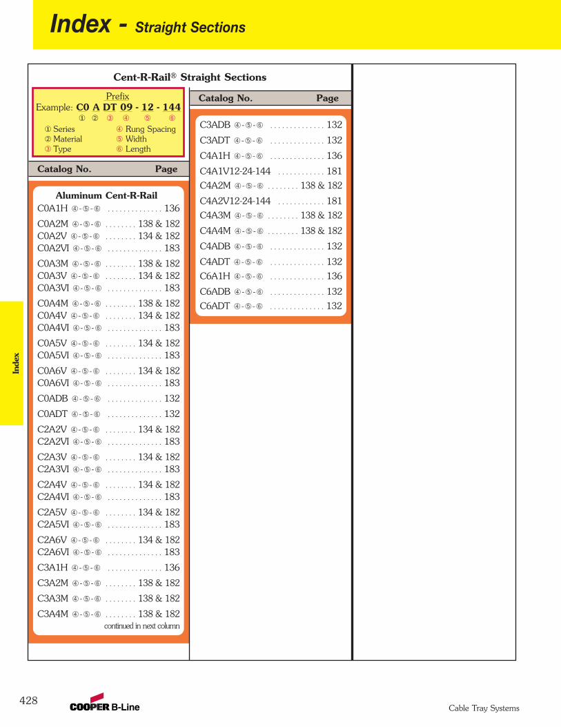
428
Index - Straight Sections
PrefixExample: C0 A DT 09 - 12 - 144
Series Rung SpacingMaterial WidthType Length
¬ ÃÂ Ä Å
¬ÁÂ
ÃÄÅ
Á
Cent-R-Rail® Straight Sections
Inde
x
Cable Tray Systems
Catalog No. Page
Aluminum Cent-R-RailC0A1H Ã -Ä -Å . . . . . . . . . . . . . . 136
C0A2M Ã -Ä -Å . . . . . . . . 138 & 182C0A2V Ã -Ä -Å . . . . . . . . 134 & 182C0A2VI Ã -Ä -Å . . . . . . . . . . . . . . 183
C0A3M Ã -Ä -Å . . . . . . . . 138 & 182C0A3V Ã -Ä -Å . . . . . . . . 134 & 182C0A3VI Ã -Ä -Å . . . . . . . . . . . . . . 183
C0A4M Ã -Ä -Å . . . . . . . . 138 & 182C0A4V Ã -Ä -Å . . . . . . . . 134 & 182C0A4VI Ã -Ä -Å . . . . . . . . . . . . . . 183
C0A5V Ã -Ä -Å . . . . . . . . 134 & 182C0A5VI Ã -Ä -Å . . . . . . . . . . . . . . 183
C0A6V Ã -Ä -Å . . . . . . . . 134 & 182C0A6VI Ã -Ä -Å . . . . . . . . . . . . . . 183
C0ADB Ã -Ä -Å . . . . . . . . . . . . . . 132
C0ADT Ã -Ä -Å . . . . . . . . . . . . . . 132
C2A2V Ã -Ä -Å . . . . . . . . 134 & 182C2A2VI Ã -Ä -Å . . . . . . . . . . . . . . 183
C2A3V Ã -Ä -Å . . . . . . . . 134 & 182C2A3VI Ã -Ä -Å . . . . . . . . . . . . . . 183
C2A4V Ã -Ä -Å . . . . . . . . 134 & 182C2A4VI Ã -Ä -Å . . . . . . . . . . . . . . 183
C2A5V Ã -Ä -Å . . . . . . . . 134 & 182C2A5VI Ã -Ä -Å . . . . . . . . . . . . . . 183
C2A6V Ã -Ä -Å . . . . . . . . 134 & 182C2A6VI Ã -Ä -Å . . . . . . . . . . . . . . 183
C3A1H Ã -Ä -Å . . . . . . . . . . . . . . 136
C3A2M Ã -Ä -Å . . . . . . . . 138 & 182
C3A3M Ã -Ä -Å . . . . . . . . 138 & 182
C3A4M Ã -Ä -Å . . . . . . . . 138 & 182continued in next column
C3ADB Ã -Ä -Å . . . . . . . . . . . . . . 132
C3ADT Ã -Ä -Å . . . . . . . . . . . . . . 132
C4A1H Ã -Ä -Å . . . . . . . . . . . . . . 136
C4A1V12-24-144 . . . . . . . . . . . . 181
C4A2M Ã -Ä -Å . . . . . . . . 138 & 182
C4A2V12-24-144 . . . . . . . . . . . . 181
C4A3M Ã -Ä -Å . . . . . . . . 138 & 182
C4A4M Ã -Ä -Å . . . . . . . . 138 & 182
C4ADB Ã -Ä -Å . . . . . . . . . . . . . . 132
C4ADT Ã -Ä -Å . . . . . . . . . . . . . . 132
C6A1H Ã -Ä -Å . . . . . . . . . . . . . . 136
C6ADB Ã -Ä -Å . . . . . . . . . . . . . . 132
C6ADT Ã -Ä -Å . . . . . . . . . . . . . . 132
Catalog No. Page
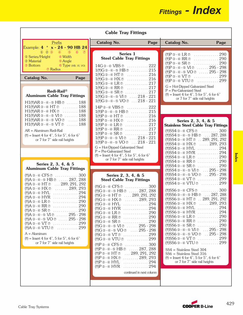
Fittings - Index
429
Index
Cable Tray Systems
Catalog No. Page
Series 1Steel Cable Tray Fittings
14G Â - Ã VBS Æ . . . . . . . . . . . 2221(†)G Â - Ã - Ä HB Æ . . . . . . . . . 215 1(†)G Â - Ã HT Æ . . . . . . . . . . . 216 1(†)G Â - Ã HX Æ . . . . . . . . . . . 216 1(†)G Â - Ã LR Æ . . . . . . . . . . . . 217 1(†)G Â - Ã RR Æ . . . . . . . . . . . 217 1(†)G Â - Ã SR Æ . . . . . . . . . . . . 217 1(†)G Â - Ã - Ä VI Æ . . . . 218 - 2211(†)G Â - Ã - Ä VO Æ . . . 218 - 221
14P Â - Ã VBS Æ . . . . . . . . . . . 2221(†)P Â - Ã - Ä HB Æ . . . . . . . . . 2151(†)P Â - Ã HT Æ . . . . . . . . . . . . 216 1(†)P Â - Ã HX Æ . . . . . . . . . . . 216 1(†)P Â - Ã LR Æ . . . . . . . . . . . . 217 1(†)P Â - Ã RR Æ . . . . . . . . . . . . 217 1(†)P Â - Ã SR Æ . . . . . . . . . . . . 217 1(†)P Â - Ã - Ä VI Æ . . . . 218 - 221 1(†)P Â - Ã - Ä VO Æ . . . 218 - 221 G = Hot-Dipped Galvanized SteelP = Pre-Galvanized Steel(†) = Insert 4 for 4”, 5 for 5”, 6 for 6”
or 7 for 7” side rail heights
Series 2, 3, 4, & 5Steel Cable Tray Fittings
(†)G Â - Ã CFS Æ . . . . . . . . . . . . 300(†)G Â - Ã - Ä HB Æ . . . . . 287, 288(†)G Â - Ã HT Æ . . . . 289, 291, 292(†)G Â - Ã HX Æ . . . . . . . 289, 293(†)G Â - Ã HYL . . . . . . . . . . . . . 294(†)G Â - Ã HYR . . . . . . . . . . . . . 294(†)G Â - Ã LR Æ . . . . . . . . . . . . . 290 (†)G Â - Ã RR Æ . . . . . . . . . . . . . 290 (†)G Â - Ã SR Æ . . . . . . . . . . . . . 290 (†)G Â - Ã - Ä VI Æ . . . . . . 295 - 298 (†)G Â - Ã - Ä VO Æ . . . . 295 - 298 (†)G Â - Ã VT Æ . . . . . . . . . . . . . 299(†)G Â - Ã VTU Æ . . . . . . . . . . . 299(†)P Â - Ã CFS Æ . . . . . . . . . . . . 300(†)P Â - Ã - Ä HB Æ . . . . . 287, 288(†)P Â - Ã HT Æ . . . 289, 291, 292(†)P Â - Ã HX Æ . . . . . . . . 289, 293(†)P Â - Ã HYL . . . . . . . . . . . . . 294(†)P Â - Ã HYR . . . . . . . . . . . . . 294
continued in next column
(†)P Â - Ã LR Æ . . . . . . . . . . . . . 290(†)P Â - Ã RR Æ . . . . . . . . . . . . . 290 (†)P Â - Ã SR Æ . . . . . . . . . . . . . 290 (†)P Â - Ã - Ä VI Æ . . . . . . 295 - 298(†)P Â - Ã - Ä VO Æ . . . . . 295 - 298 (†)P Â - Ã VT Æ . . . . . . . . . . . . . 299(†)P Â - Ã VTU Æ . . . . . . . . . . . 299G = Hot-Dipped Galvanized SteelP = Pre-Galvanized Steel(†) = Insert 4 for 4”, 5 for 5”, 6 for 6”
or 7 for 7” side rail heights
Series 2, 3, 4, & 5Stainless Steel Cable Tray Fittings(†)SS4 Â - Ã CFS Æ . . . . . . . . . 300(†)SS4 Â - Ã - Ä HB Æ . . . 287, 288(†)SS4 Â - Ã HT Æ . . 289, 291, 292 (†)SS4 Â - Ã HX Æ . . . . . 289, 293 (†)SS4 Â - Ã HYL . . . . . . . . . . . 294(†)SS4 Â - Ã HYR . . . . . . . . . . . 294 (†)SS4 Â - Ã LR Æ . . . . . . . . . . . 290 (†)SS4 Â - Ã RR Æ . . . . . . . . . . . 290 (†)SS4 Â - Ã SR Æ . . . . . . . . . . . 290 (†)SS4 Â - Ã - Ä VI Æ . . . 295 - 298 (†)SS4 Â - Ã - Ä VO Æ . . 295 - 298 (†)SS4 Â - Ã VT Æ . . . . . . . . . . . 299 (†)SS4 Â - Ã VTU Æ . . . . . . . . . 299
(†)SS6 Â - Ã CFS Æ . . . . . . . . . 300 (†)SS6 Â - Ã - Ä HB Æ . . . 287, 288(†)SS6 Â - Ã HT Æ . . 289, 291, 292 (†)SS6 Â - Ã HX Æ . . . . . 289, 293(†)SS6 Â - Ã HYL . . . . . . . . . . . 294 (†)SS6 Â - Ã HYR . . . . . . . . . . . 294 (†)SS6 Â - Ã LR Æ . . . . . . . . . . . 290 (†)SS6 Â - Ã RR Æ . . . . . . . . . . . 290 (†)SS6 Â - Ã SR Æ . . . . . . . . . . . 290 (†)SS6 Â - Ã - Ä VI Æ . . . 295 - 298 (†)SS6 Â - Ã - Ä VO Æ . . 295 - 298 (†)SS6 Â - Ã VT Æ . . . . . . . . . . . 299 (†)SS6 Â - Ã VTU Æ . . . . . . . . . 299
SS4 = Stainless Steel 304SS6 = Stainless Steel 316(†) = Insert 4 for 4”, 5 for 5”, 6 for 6”
or 7 for 7” side rail heights
Catalog No. Page
Catalog No. Page
Redi-Rail®Aluminum Cable Tray Fittings
H1(†)AR Â - Ã - Ä HB Æ . . . . . . 188H1(†)AR Â - Ã HT Æ . . . . . . . . 188 H1(†)AR Â - Ã HX Æ . . . . . . . . 188 H1(†)AR Â - Ã - Ä VI Æ . . . . . . . 188 H1(†)AR Â - Ã - Ä VO Æ . . . . . 188 H1(†)AR Â - Ã - Ä VT Æ . . . . . . 188
AR = Aluminum Redi-Rail(†) = Insert 4 for 4”, 5 for 5”, 6 for 6”
or 7 for 7” side rail heights
Series 2, 3, 4, & 5Aluminum Cable Tray Fittings
(†)A Â - Ã CFS Æ . . . . . . . . . . . . 300(†)A Â - Ã - Ä HB Æ . . . . . 287, 288(†)A Â - Ã HT Æ . . . 289, 291, 292(†)A Â - Ã HX Æ . . . . . . . 289, 293(†)A Â - Ã HYL . . . . . . . . . . . . . 294(†)A Â - Ã HYR . . . . . . . . . . . . . 294(†)A Â - Ã LR Æ . . . . . . . . . . . . . 290 (†)A Â - Ã RR Æ . . . . . . . . . . . . . 290 (†)A Â - Ã SR Æ . . . . . . . . . . . . . 290 (†)A Â - Ã - Ä VI Æ . . . . . . 295 - 298(†)A Â - Ã - Ä VO Æ . . . . . 295 - 298(†)A Â - Ã VT Æ . . . . . . . . . . . . . 299 (†)A Â - Ã VTU Æ . . . . . . . . . . . 299A = Aluminum(†) = Insert 4 for 4”, 5 for 5”, 6 for 6”
or 7 for 7” side rail heights
Cable Tray Fittings
PrefixExample: 4 * x - 24 - 90 HB 24
Series/Height WidthMaterial Angle Bottom Type (HB, VI, VO)
¬ Â Ã Ä
¬ÁÂ
ÃÄÅ
Á Å
Æ Radius
Æ

430
Index - FittingsIn
dex
Cable Tray Systems
Catalog No. Page
Steel Cable Channel FittingsGCC - Â - Ã HB Å . . . . . . 114, 115 GCC - Â - Ã HC Å . . . . . . . . . . . 112GCC - Â HT Å . . . . . . . . . . . . . 116GCC - Â HTC Å . . . . . . . . . . . . 112 GCC - Â HX Å . . . . . . . . . . . . . 116
GCC - Â HXC Å . . . . . . . . . . . . 112 GCC - Â PC Å . . . . . . . . . . . . . . 112 GCC - Â - Ã VC Å . . . . . . . . . . . 112 GCC - Â - Ã VI Å . . . . . . . 119, 120 GCC - Â - Ã VO Å . . . . . . 117, 118
GCCN - Â - Ã HB Å . . . . 114, 115 GCCN - Â HT Å . . . . . . . . . . . . 116GCCN - Â HX Å . . . . . . . . . . . . 116GCCN - Â - Ã VI Å . . . . . 119, 120 GCCN - Â - Ã VO Å . . . . 117, 118 G = Hot-Dipped Galvanized SteelNote: Not available in Pre-Galvanized
Catalog No. Page
Stainless Steel Cable Channel FittingsSS4CC - Â - Ã HB Å . . . 114, 115 SS4CC - Â HT Å . . . . . . . . . . . 116SS4CC - Â HX Å . . . . . . . . . . . 116 SS4CC-Â -Ã VIÅ . . . . . . 119, 120 SS4CC-Â-Ã VOÅ . . . . . 117, 118
SS4CCN-Â -Ã HBÅ . . . 114, 115 SS4CCN - Â HT Å . . . . . . . . . . 116 SS4CCN - Â HX Å . . . . . . . . . . 116 SS4CCN-Â-Ã VIÅ . . . . . . 119, 120 SS4CCN-Â-Ã VOÅ . . . . . 117, 118
SS6CC - Â - Ã HB Å . . . 114, 115 SS6CC - Â HT Å . . . . . . . . . . . 116 SS6CC - Â HX Å . . . . . . . . . . . 116 SS6CC-Â -Ã VIÅ . . . . . . 119, 120 SS6CC-Â-Ã VOÅ . . . . . 117, 118
SS6CCN-Â -Ã HBÅ . . . 114, 115 SS6CCN - Â HT Å . . . . . . . . . . 116 SS6CCN - Â HX Å . . . . . . . . . . 116 SS6CCN-Â-Ã VIÅ . . . . . . 119, 120 SS6CCN-Â-Ã VOÅ . . . . . 117, 118 SS4 = Stainless Steel 304SS6 = Stainless Steel 316
Fiberglass Cable Channel FittingsFCC(†)N-(xx)-45HB12 . . . . . . 348
FCC(†)N-(xx)-90HB12 . . . . . . 348
FCC(†)N-(xx)-HT12 . . . . . . . . . 348
FCC(†)N-(xx)-HX12 . . . . . . . . . 348
FCC(†)N-(xx)-45VI12 . . . . . . . 348
FCC(†)N-(xx)-45VO12 . . . . . . 348
FCC(†)N-(xx)-90VI12 . . . . . . . 348
FCC(†)N-(xx)-90VO12 . . . . . . 348
(†) For Polyester Resin leave blankFor Dis-Stat Resin insert DFor Zero Halogen insert TFor Vinyl Ester Resin insert V
(xx) = Insert 03 for 3”, 04 for 4”,06 for 6” or 08 for 8” side rail heights
Catalog No. Page
Cable Tray Fittings Cable Channel Fittings
PrefixExample: 4 * x - 24 - 90 HB 24
Series/Height WidthMaterial Angle Bottom Type (HB, VI, VO)
¬ Â Ã Ä
¬ÁÂ
ÃÄÅ
Á Å
Æ Radius
Æ
PrefixExample: G CC - 04 - 45 VI 12
Material Angle Series Type (HB, VI, VO)
Width Radius
¬ Â Ã Ä
¬ÁÂ
ÃÄÅ
Á Å
Aluminum Cable Channel FittingsACC - Â - Ã HB Å . . . . . . 114, 115ACC - Â - Ã HC Å . . . . . . . . . . . 112ACC - Â HT Å . . . . . . . . . . . . . . 116ACC - Â HTC Å . . . . . . . . . . . . 112 ACC - Â HX Å . . . . . . . . . . . . . 116
ACC - Â HXC Å . . . . . . . . . . . . 112 ACC - Â PC Å . . . . . . . . . . . . . . 112 ACC - Â - Ã VC Å . . . . . . . . . . . 112 ACC - Â - Ã VI Å . . . . . . . 119, 120 ACC - Â - Ã VO Å . . . . . . 117, 118
ACCN - Â - Ã HB Å . . . . 114, 115 ACCN - Â HT Å . . . . . . . . . . . . 116ACCN - Â HX Å . . . . . . . . . . . . 116ACCN - Â - Ã VI Å . . . . . . 119, 120 ACCN - Â - Ã VO Å . . . . 117, 118 A = Aluminum
Fiberglass Cable Tray Fittings(†)F - Ã - Ä HB Æ . . . . . . . 327, 328(†)F - Ã - HT Æ . . . . . 329, 332, 334 (†)F - Ã - HX Æ . . . . . . . . . . 330, 336(†)F - Ã - LR Æ . . . . . . . . . . . . . . . 331(†)F - Ã - RR Æ . . . . . . . . . . . . . . 331(†)F - Ã - SR Æ . . . . . . . . . . . . . . . 331 (†)F - Ã - Ä VI Æ . . . . . . . . 338, 340(†)F - Ã - Ä VO Æ . . . . . . . 338, 340(†)F - Ã - VT Æ . . . . . . . . . . . . . . 342 (†)F - Ã - VTU Æ . . . . . . . . . . . . . 342(†)FD - Ã - Ä HB Æ . . . . . . 327, 328(†)FD - Ã - HT Æ . . . 329, 332, 334 (†)FD - Ã - HX Æ . . . . . . . . 330, 336 (†)FD - Ã - LR Æ . . . . . . . . . . . . . 331 (†)FD - Ã - RR Æ . . . . . . . . . . . . . 331(†)FD - Ã - SR Æ . . . . . . . . . . . . . 331 (†)FD - Ã - Ä VI Æ . . . . . . . 338, 340 (†)FD - Ã - Ä VO Æ . . . . . . 338, 340(†)FD - Ã - VT Æ . . . . . . . . . . . . . 342 (†)FD - Ã - VTU Æ . . . . . . . . . . . 342(†)FT - Ã - Ä HB Æ . . . . . . 327, 328(†)FT - Ã - HT Æ . . . . 329, 332, 334 (†)FT - Ã - HX Æ . . . . . . . . 330, 336 (†)FT - Ã - LR Æ . . . . . . . . . . . . . 331 (†)FT - Ã - RR Æ . . . . . . . . . . . . . 331(†)FT - Ã - SR Æ . . . . . . . . . . . . . 331 (†)FT - Ã - Ä VI Æ . . . . . . . 338, 340 (†)FT - Ã - Ä VO Æ . . . . . . 338, 340(†)FT - Ã - VT Æ . . . . . . . . . . . . . 342 (†)FT - Ã - VTU Æ . . . . . . . . . . . . 342(†)FV - Ã - Ä HB Æ . . . . . . 327, 328(†)FV - Ã - HT Æ . . . 329, 332, 334 (†)FV - Ã - HX Æ . . . . . . . . 330, 336 (†)FV - Ã - LR Æ . . . . . . . . . . . . . 331 (†)FV - Ã - RR Æ . . . . . . . . . . . . . 331(†)FV - Ã - SR Æ . . . . . . . . . . . . . 331 (†)FV - Ã - Ä VI Æ . . . . . . . 338, 340 (†)FV - Ã - Ä VO Æ . . . . . . 338, 340(†)FV - Ã - VT Æ . . . . . . . . . . . . . 342 (†)FV - Ã - VTU Æ . . . . . . . . . . . 342F = Polyester Resin, FD = Dis-Stat ResinFT = Zero Halogen Resin, FV = Vinyl Ester Resin(†) = Insert 3 for 3”, 4 for 4”, 6 for 6”
or 8 for 8” side rail heights
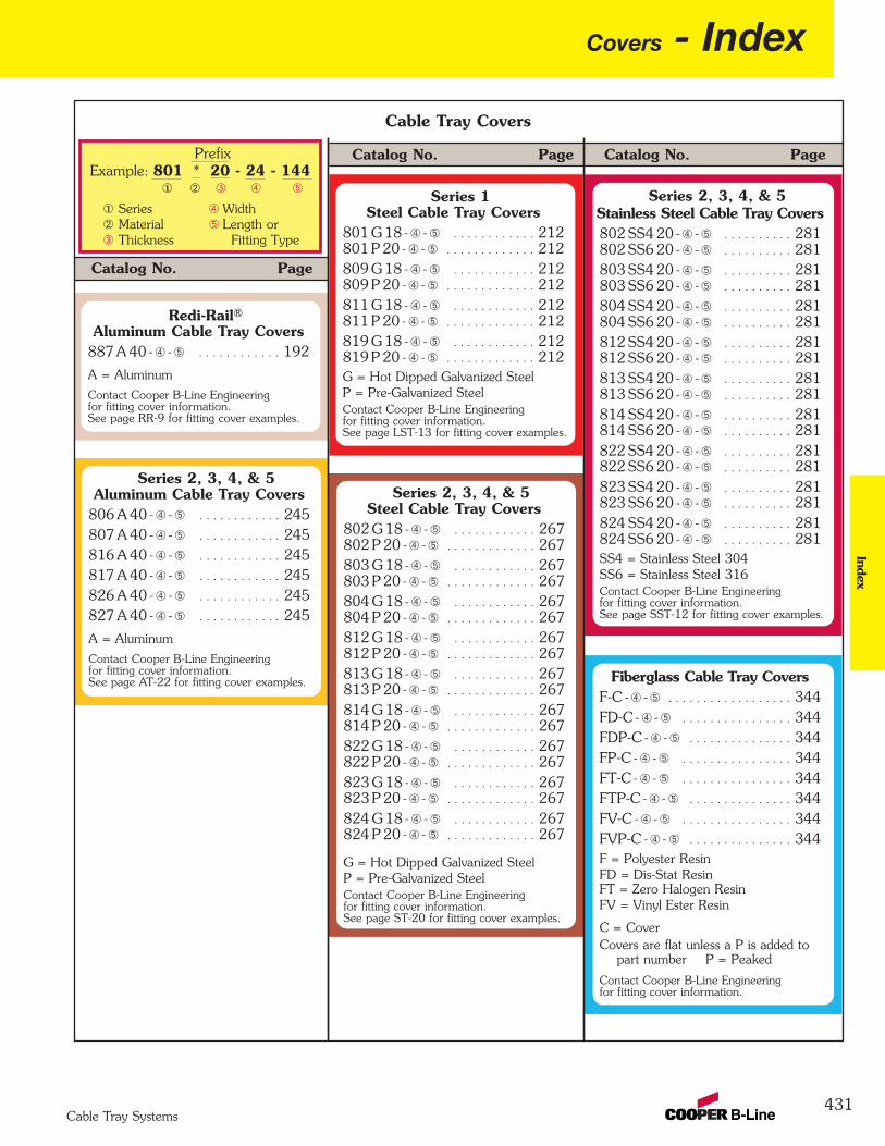
Covers - Index
431
Index
Cable Tray Systems
Cable Tray Covers
Catalog No. Page
Catalog No. Page Catalog No. PagePrefixExample: 801 * 20 - 24 - 144
Series WidthMaterial Length orThickness Fitting Type
¬ Â Ã Ä
¬ÁÂ
ÃÄ
Á
Series 2, 3, 4, & 5Aluminum Cable Tray Covers
806 A 40 - Ã - Ä . . . . . . . . . . . . 245807 A 40 - Ã - Ä . . . . . . . . . . . . 245 816 A 40 - Ã - Ä . . . . . . . . . . . . 245 817 A 40 - Ã - Ä . . . . . . . . . . . . 245 826 A 40 - Ã - Ä . . . . . . . . . . . . 245 827 A 40 - Ã - Ä . . . . . . . . . . . . 245
A = Aluminum
Contact Cooper B-Line Engineeringfor fitting cover information.See page AT-22 for fitting cover examples.
Redi-Rail®Aluminum Cable Tray Covers
887 A 40 - Ã - Ä . . . . . . . . . . . . 192
A = Aluminum
Contact Cooper B-Line Engineeringfor fitting cover information.See page RR-9 for fitting cover examples.
Series 1Steel Cable Tray Covers
801 G 18 - Ã - Ä . . . . . . . . . . . . 212801 P 20 - Ã - Ä . . . . . . . . . . . . . 212 809 G 18 - Ã - Ä . . . . . . . . . . . . 212 809 P 20 - Ã - Ä . . . . . . . . . . . . . 212 811 G 18 - Ã - Ä . . . . . . . . . . . . 212 811 P 20 - Ã - Ä . . . . . . . . . . . . . 212 819 G 18 - Ã - Ä . . . . . . . . . . . . 212 819 P 20 - Ã - Ä . . . . . . . . . . . . . 212 G = Hot Dipped Galvanized SteelP = Pre-Galvanized SteelContact Cooper B-Line Engineeringfor fitting cover information.See page LST-13 for fitting cover examples.
Series 2, 3, 4, & 5Steel Cable Tray Covers
802 G 18 - Ã - Ä . . . . . . . . . . . . 267 802 P 20 - Ã - Ä . . . . . . . . . . . . . 267 803 G 18 - Ã - Ä . . . . . . . . . . . . 267 803 P 20 - Ã - Ä . . . . . . . . . . . . . 267 804 G 18 - Ã - Ä . . . . . . . . . . . . 267 804 P 20 - Ã - Ä . . . . . . . . . . . . . 267 812 G 18 - Ã - Ä . . . . . . . . . . . . 267 812 P 20 - Ã - Ä . . . . . . . . . . . . . 267 813 G 18 - Ã - Ä . . . . . . . . . . . . 267 813 P 20 - Ã - Ä . . . . . . . . . . . . . 267 814 G 18 - Ã - Ä . . . . . . . . . . . . 267 814 P 20 - Ã - Ä . . . . . . . . . . . . . 267 822 G 18 - Ã - Ä . . . . . . . . . . . . 267 822 P 20 - Ã - Ä . . . . . . . . . . . . . 267 823 G 18 - Ã - Ä . . . . . . . . . . . . 267 823 P 20 - Ã - Ä . . . . . . . . . . . . . 267 824 G 18 - Ã - Ä . . . . . . . . . . . . 267 824 P 20 - Ã - Ä . . . . . . . . . . . . . 267
G = Hot Dipped Galvanized SteelP = Pre-Galvanized SteelContact Cooper B-Line Engineeringfor fitting cover information.See page ST-20 for fitting cover examples.
Series 2, 3, 4, & 5Stainless Steel Cable Tray Covers802 SS4 20 - Ã - Ä . . . . . . . . . . 281802 SS6 20 - Ã - Ä . . . . . . . . . . 281 803 SS4 20 - Ã - Ä . . . . . . . . . . 281 803 SS6 20 - Ã - Ä . . . . . . . . . . 281 804 SS4 20 - Ã - Ä . . . . . . . . . . 281 804 SS6 20 - Ã - Ä . . . . . . . . . . 281 812 SS4 20 - Ã - Ä . . . . . . . . . . 281 812 SS6 20 - Ã - Ä . . . . . . . . . . 281 813 SS4 20 - Ã - Ä . . . . . . . . . . 281 813 SS6 20 - Ã - Ä . . . . . . . . . . 281 814 SS4 20 - Ã - Ä . . . . . . . . . . 281 814 SS6 20 - Ã - Ä . . . . . . . . . . 281 822 SS4 20 - Ã - Ä . . . . . . . . . . 281 822 SS6 20 - Ã - Ä . . . . . . . . . . 281 823 SS4 20 - Ã - Ä . . . . . . . . . . 281 823 SS6 20 - Ã - Ä . . . . . . . . . . 281 824 SS4 20 - Ã - Ä . . . . . . . . . . 281 824 SS6 20 - Ã - Ä . . . . . . . . . . 281 SS4 = Stainless Steel 304SS6 = Stainless Steel 316Contact Cooper B-Line Engineeringfor fitting cover information.See page SST-12 for fitting cover examples.
Fiberglass Cable Tray CoversF-C - Ã - Ä . . . . . . . . . . . . . . . . . . 344FD-C - Ã - Ä . . . . . . . . . . . . . . . . 344 FDP-C - Ã - Ä . . . . . . . . . . . . . . . 344 FP-C - Ã - Ä . . . . . . . . . . . . . . . . 344 FT-C - Ã - Ä . . . . . . . . . . . . . . . . 344 FTP-C - Ã - Ä . . . . . . . . . . . . . . . 344 FV-C - Ã - Ä . . . . . . . . . . . . . . . . 344 FVP-C - Ã - Ä . . . . . . . . . . . . . . . 344 F = Polyester ResinFD = Dis-Stat ResinFT = Zero Halogen ResinFV = Vinyl Ester Resin
C = CoverCovers are flat unless a P is added to
part number P = Peaked
Contact Cooper B-Line Engineeringfor fitting cover information.

432
Index - CoversIn
dex
Cable Tray Systems
Catalog No. Page
Catalog No. Page
PrefixExample: 808 * 20 - 04 - 120
Series WidthMaterial Length orThickness Fitting Type
¬ Â Ã Ä
¬ÁÂ
ÃÄ
Á
AluminumCable Channel Covers
808 A 40 - Ã - Ä . . . . . . . . . . . . 111
A = Aluminum
Contact Cooper B-Line Engineeringfor fitting cover information.See page CCT-6 for fitting cover examples.
2 IN COVER . . . . . . . . . . . . . . . . 874 IN COVER . . . . . . . . . . . . . . . . 876 IN COVER . . . . . . . . . . . . . . . . 878 IN COVER . . . . . . . . . . . . . . . . 8712 IN COVER . . . . . . . . . . . . . . 8716 IN COVER . . . . . . . . . . . . . . 8718 IN COVER . . . . . . . . . . . . . . 8720 IN COVER . . . . . . . . . . . . . . 8724 IN COVER . . . . . . . . . . . . . . 87
SteelCable Channel Covers
808 G 18 - Ã - Ä . . . . . . . . . . . . 111808 P 20 - Ã - Ä . . . . . . . . . . . . . 111
G = Hot Dipped Galvanized SteelP = Pre-Galvanized SteelContact Cooper B-Line Engineeringfor fitting cover information.See page CCT-6 for fitting cover examples.
Stainless SteelCable Channel Covers
808 SS4 20 - Ã - Ä . . . . . . . . . . 111808 SS6 20 - Ã - Ä . . . . . . . . . . 111
SS4 = Stainless Steel 304SS6 = Stainless Steel 316Contact Cooper B-Line Engineeringfor fitting cover information.See page CCT-6 for fitting cover examples.
Cable Channel Covers Flextray Covers
Catalog No. Page
Bottom Rung Covers
CAK1F-DB - Ã - Ä . . . . . . . . . . 164
CPK1F-DB - Ã - Ä . . . . . . . . . . . 164
Top Rung Covers
CAK1F-DT - Ã - Ä . . . . . . . . . . 164
CPK1F-DT - Ã - Ä . . . . . . . . . . . 164
A = AluminumP = Pre-Galvanized Steel
Cent-R-Rail® Covers
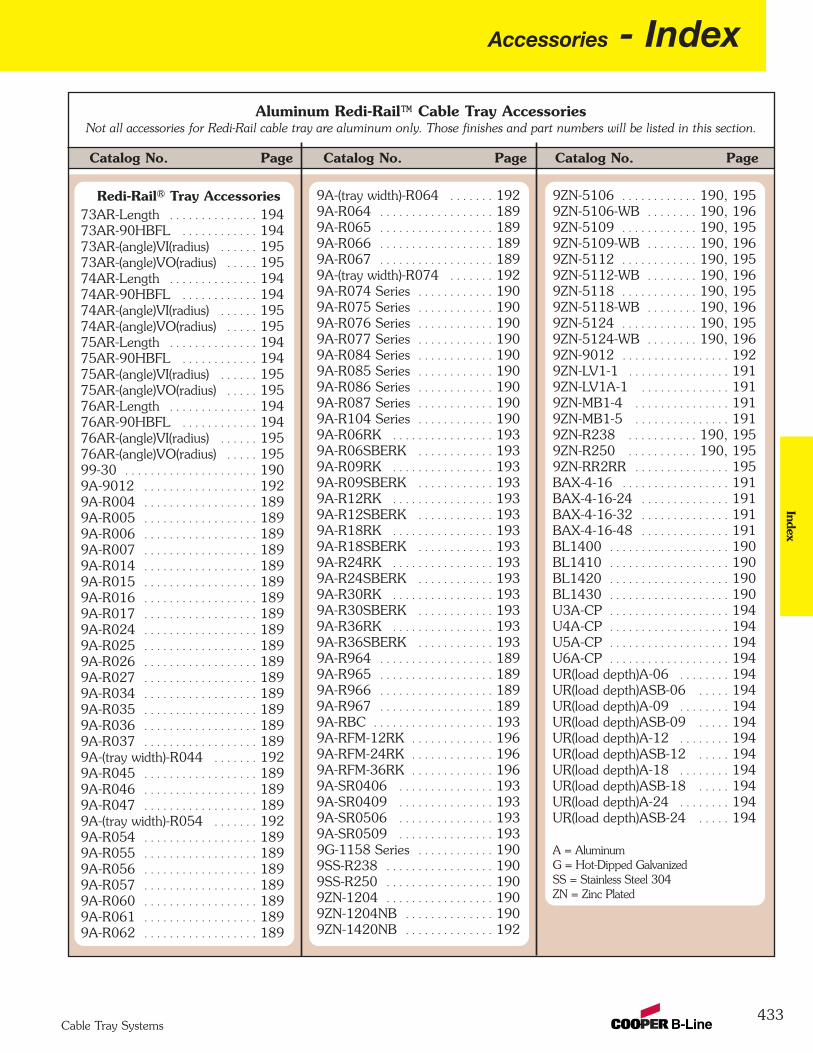
Accessories - Index
433
Index
Cable Tray Systems
Aluminum Redi-Rail™ Cable Tray AccessoriesNot all accessories for Redi-Rail cable tray are aluminum only. Those finishes and part numbers will be listed in this section.
Catalog No. PageCatalog No. Page Catalog No. Page
Redi-Rail® Tray Accessories73AR-Length . . . . . . . . . . . . . . 19473AR-90HBFL . . . . . . . . . . . . 194 73AR-(angle)VI(radius) . . . . . . 19573AR-(angle)VO(radius) . . . . . 195 74AR-Length . . . . . . . . . . . . . . 194 74AR-90HBFL . . . . . . . . . . . . 194 74AR-(angle)VI(radius) . . . . . . 195 74AR-(angle)VO(radius) . . . . . 195 75AR-Length . . . . . . . . . . . . . . 194 75AR-90HBFL . . . . . . . . . . . . 194 75AR-(angle)VI(radius) . . . . . . 195 75AR-(angle)VO(radius) . . . . . 195 76AR-Length . . . . . . . . . . . . . . 194 76AR-90HBFL . . . . . . . . . . . . 194 76AR-(angle)VI(radius) . . . . . . 195 76AR-(angle)VO(radius) . . . . . 195 99-30 . . . . . . . . . . . . . . . . . . . . . 1909A-9012 . . . . . . . . . . . . . . . . . . 1929A-R004 . . . . . . . . . . . . . . . . . . 189 9A-R005 . . . . . . . . . . . . . . . . . . 189 9A-R006 . . . . . . . . . . . . . . . . . . 189 9A-R007 . . . . . . . . . . . . . . . . . . 189 9A-R014 . . . . . . . . . . . . . . . . . . 189 9A-R015 . . . . . . . . . . . . . . . . . . 189 9A-R016 . . . . . . . . . . . . . . . . . . 189 9A-R017 . . . . . . . . . . . . . . . . . . 189 9A-R024 . . . . . . . . . . . . . . . . . . 189 9A-R025 . . . . . . . . . . . . . . . . . . 189 9A-R026 . . . . . . . . . . . . . . . . . . 189 9A-R027 . . . . . . . . . . . . . . . . . . 189 9A-R034 . . . . . . . . . . . . . . . . . . 189 9A-R035 . . . . . . . . . . . . . . . . . . 189 9A-R036 . . . . . . . . . . . . . . . . . . 189 9A-R037 . . . . . . . . . . . . . . . . . . 189 9A-(tray width)-R044 . . . . . . . 1929A-R045 . . . . . . . . . . . . . . . . . . 189 9A-R046 . . . . . . . . . . . . . . . . . . 189 9A-R047 . . . . . . . . . . . . . . . . . . 189 9A-(tray width)-R054 . . . . . . . 1929A-R054 . . . . . . . . . . . . . . . . . . 189 9A-R055 . . . . . . . . . . . . . . . . . . 189 9A-R056 . . . . . . . . . . . . . . . . . . 189 9A-R057 . . . . . . . . . . . . . . . . . . 189 9A-R060 . . . . . . . . . . . . . . . . . . 189 9A-R061 . . . . . . . . . . . . . . . . . . 189 9A-R062 . . . . . . . . . . . . . . . . . . 189
9ZN-5106 . . . . . . . . . . . . 190, 195 9ZN-5106-WB . . . . . . . . 190, 196 9ZN-5109 . . . . . . . . . . . . 190, 195 9ZN-5109-WB . . . . . . . . 190, 196 9ZN-5112 . . . . . . . . . . . . 190, 195 9ZN-5112-WB . . . . . . . . 190, 196 9ZN-5118 . . . . . . . . . . . . 190, 195 9ZN-5118-WB . . . . . . . . 190, 196 9ZN-5124 . . . . . . . . . . . . 190, 195 9ZN-5124-WB . . . . . . . . 190, 196 9ZN-9012 . . . . . . . . . . . . . . . . . 1929ZN-LV1-1 . . . . . . . . . . . . . . . . 1919ZN-LV1A-1 . . . . . . . . . . . . . . 191 9ZN-MB1-4 . . . . . . . . . . . . . . . 191 9ZN-MB1-5 . . . . . . . . . . . . . . . 191 9ZN-R238 . . . . . . . . . . . 190, 195 9ZN-R250 . . . . . . . . . . . 190, 195 9ZN-RR2RR . . . . . . . . . . . . . . . 195BAX-4-16 . . . . . . . . . . . . . . . . . 191 BAX-4-16-24 . . . . . . . . . . . . . . 191 BAX-4-16-32 . . . . . . . . . . . . . . 191 BAX-4-16-48 . . . . . . . . . . . . . . 191 BL1400 . . . . . . . . . . . . . . . . . . . 190 BL1410 . . . . . . . . . . . . . . . . . . . 190 BL1420 . . . . . . . . . . . . . . . . . . . 190 BL1430 . . . . . . . . . . . . . . . . . . . 190 U3A-CP . . . . . . . . . . . . . . . . . . . 194U4A-CP . . . . . . . . . . . . . . . . . . . 194 U5A-CP . . . . . . . . . . . . . . . . . . . 194 U6A-CP . . . . . . . . . . . . . . . . . . . 194 UR(load depth)A-06 . . . . . . . . 194 UR(load depth)ASB-06 . . . . . 194 UR(load depth)A-09 . . . . . . . . 194 UR(load depth)ASB-09 . . . . . 194 UR(load depth)A-12 . . . . . . . . 194 UR(load depth)ASB-12 . . . . . 194 UR(load depth)A-18 . . . . . . . . 194 UR(load depth)ASB-18 . . . . . 194 UR(load depth)A-24 . . . . . . . . 194 UR(load depth)ASB-24 . . . . . 194
A = AluminumG = Hot-Dipped GalvanizedSS = Stainless Steel 304ZN = Zinc Plated
9A-(tray width)-R064 . . . . . . . 1929A-R064 . . . . . . . . . . . . . . . . . . 189 9A-R065 . . . . . . . . . . . . . . . . . . 189 9A-R066 . . . . . . . . . . . . . . . . . . 189 9A-R067 . . . . . . . . . . . . . . . . . . 189 9A-(tray width)-R074 . . . . . . . 1929A-R074 Series . . . . . . . . . . . . 190 9A-R075 Series . . . . . . . . . . . . 190 9A-R076 Series . . . . . . . . . . . . 190 9A-R077 Series . . . . . . . . . . . . 190 9A-R084 Series . . . . . . . . . . . . 190 9A-R085 Series . . . . . . . . . . . . 190 9A-R086 Series . . . . . . . . . . . . 190 9A-R087 Series . . . . . . . . . . . . 190 9A-R104 Series . . . . . . . . . . . . 1909A-R06RK . . . . . . . . . . . . . . . . 1939A-R06SBERK . . . . . . . . . . . . 193 9A-R09RK . . . . . . . . . . . . . . . . 193 9A-R09SBERK . . . . . . . . . . . . 193 9A-R12RK . . . . . . . . . . . . . . . . 193 9A-R12SBERK . . . . . . . . . . . . 193 9A-R18RK . . . . . . . . . . . . . . . . 193 9A-R18SBERK . . . . . . . . . . . . 193 9A-R24RK . . . . . . . . . . . . . . . . 193 9A-R24SBERK . . . . . . . . . . . . 193 9A-R30RK . . . . . . . . . . . . . . . . 193 9A-R30SBERK . . . . . . . . . . . . 193 9A-R36RK . . . . . . . . . . . . . . . . 193 9A-R36SBERK . . . . . . . . . . . . 193 9A-R964 . . . . . . . . . . . . . . . . . . 1899A-R965 . . . . . . . . . . . . . . . . . . 189 9A-R966 . . . . . . . . . . . . . . . . . . 189 9A-R967 . . . . . . . . . . . . . . . . . . 189 9A-RBC . . . . . . . . . . . . . . . . . . . 193 9A-RFM-12RK . . . . . . . . . . . . . 1969A-RFM-24RK . . . . . . . . . . . . . 196 9A-RFM-36RK . . . . . . . . . . . . . 196 9A-SR0406 . . . . . . . . . . . . . . . 193 9A-SR0409 . . . . . . . . . . . . . . . 193 9A-SR0506 . . . . . . . . . . . . . . . 193 9A-SR0509 . . . . . . . . . . . . . . . 193 9G-1158 Series . . . . . . . . . . . . 190 9SS-R238 . . . . . . . . . . . . . . . . . 190 9SS-R250 . . . . . . . . . . . . . . . . . 190 9ZN-1204 . . . . . . . . . . . . . . . . . 190 9ZN-1204NB . . . . . . . . . . . . . . 190 9ZN-1420NB . . . . . . . . . . . . . . 192

434
Index - AccessoriesIn
dex
Cable Tray Systems
Series 2, 3, 4, & 5 Aluminum Cable Tray AccessoriesNot all accessories for aluminum cable tray are aluminum only. Those finishes and part numbers will be listed in this section.
Catalog No. PageCatalog No. Page Catalog No. Page
Aluminum Tray Accessories73A-Length . . . . . . . . . . . . . . . 23873A-90HBFL . . . . . . . . . . . . . . 238 73A-(angle)VI(radius) . . . . . . . . 238 73A-(angle)VO(radius) . . . . . . 238 74A-Length . . . . . . . . . . . . . . . 238 74A-90HBFL . . . . . . . . . . . . . . 238 74A-(angle)VI(radius) . . . . . . . . 238 74A-(angle)VO(radius) . . . . . . 238 75A-Length . . . . . . . . . . . . . . . 238 75A-90HBFL . . . . . . . . . . . . . . 238 75A-(angle)VI(radius) . . . . . . . . 238 75A-(angle)VO(radius) . . . . . . 238 76A-Length . . . . . . . . . . . . . . . 238 76A-90HBFL . . . . . . . . . . . . . . 238 76A-(angle)VI(radius) . . . . . . . . 238 76A-(angle)VO(radius) . . . . . . 238 99-40 . . . . . . . . . . . . . . . . . . . . . 23999-1124 . . . . . . . . . . . . . . . . . . 238 99-1620 . . . . . . . . . . . . . . . . . . 23999-2125-15 . . . . . . . . . . . . . . . 23799-9980-tray width . . . . . . . . . 24699-9982 . . . . . . . . . . . . . . . . . . 238 99-N2 . . . . . . . . . . . . . . . . . . . . 23999-NP240 . . . . . . . . . . . . . . . . . 24099-NY36 . . . . . . . . . . . . . . . . . . 240 99-PE34 . . . . . . . . . . . . . . . . . . 240 9A-tray width-9044 . . . . . . . . 2469A-tray width-9044P . . . . . . . 246 9A-tray width-9054 . . . . . . . . 246 9A-tray width-9054P . . . . . . . 246 9A-tray width-9064 . . . . . . . . 246 9A-tray width-9064P . . . . . . . 246 9A-tray width-9074 . . . . . . . . 246 9A-tray width-9074P . . . . . . . 246 9A-1004 . . . . . . . . . . . . . . . . . . 2369A-1004-1/2 . . . . . . . . . . . . . . 236 9A-1005 . . . . . . . . . . . . . . . . . . 236 9A-1005-1/2 . . . . . . . . . . . . . . 236 9A-1006 . . . . . . . . . . . . . . . . . . 236 9A-1006-1/2 . . . . . . . . . . . . . . 236 9A-1007 . . . . . . . . . . . . . . . . . . 236 9A-1007-1/2 . . . . . . . . . . . . . . 236 9A-1014 . . . . . . . . . . . . . . . . . . 236 9A-1015 . . . . . . . . . . . . . . . . . . 236 9A-1016 . . . . . . . . . . . . . . . . . . 236 9A-1017 . . . . . . . . . . . . . . . . . . 236 9A-1024 . . . . . . . . . . . . . . . . . . 236
9A-2047 . . . . . . . . . . . . . . . . . . 236 9A-2130 . . . . . . . . . . . . . . . . . . 2399A-6006 . . . . . . . . . . . . . . . . . . 236 9A-6007 . . . . . . . . . . . . . . . . . . 236 9A-9012 . . . . . . . . . . . . . . . . . . 2469G-1158 Series . . . . . . . . . . . . 2379G-1205 . . . . . . . . . . . . . . . . . . 240 9G-1249 . . . . . . . . . . . . . . . . . . 240 9G-1249HD . . . . . . . . . . . . . . . 240 9G-5324 . . . . . . . . . . . . . . . . . . 2399G-5325 . . . . . . . . . . . . . . . . . . 239 9G-5326 . . . . . . . . . . . . . . . . . . 239 9G-5327 . . . . . . . . . . . . . . . . . . 239 9G-5500-1/2 . . . . . . . . . . . . . . 2419G-55xx-22SHA Series . . . . . 2419GRN-55xx-22SHA Series . . 2419P-55xx-22SH Series . . . . . . 2419P-9043 . . . . . . . . . . . . . . . . . . 2469P-9053 . . . . . . . . . . . . . . . . . . 246 9P-9063 . . . . . . . . . . . . . . . . . . 246 9P-9073 . . . . . . . . . . . . . . . . . . 246 9SS4-1241 . . . . . . . . . . . . . . . . 2439SS4-1242 . . . . . . . . . . . . . . . . 2439SS4-2351 . . . . . . . . . . . . . . . . 2399SS4-2352 . . . . . . . . . . . . . . . . 2399SS6-1205 . . . . . . . . . . . . . . . . 240 9SS6-1241 . . . . . . . . . . . . . . . . 2439SS6-1242 . . . . . . . . . . . . . . . . 2439ZN-1150 Series . . . . . . . . . . . 237 9ZN-1155 Series . . . . . . . . . . . 237 9ZN-1204 . . . . . . . . . . . . . . . . . 240 9ZN-1204NB . . . . . . . . . . . . . . 240 9ZN-1205 . . . . . . . . . . . . . . . . . 240 9ZN-1208 . . . . . . . . . . . . . . . . . 240 9ZN-1208NB . . . . . . . . . . . . . . 240 9ZN-1241 . . . . . . . . . . . . . . . . . 243 9ZN-1242 . . . . . . . . . . . . . . . . . 243 9ZN-1249 . . . . . . . . . . . . . . . . . 240 9ZN-1249HD . . . . . . . . . . . . . 240 9ZN-2351 . . . . . . . . . . . . . . . . . 2399ZN-2352 . . . . . . . . . . . . . . . . . 239 9ZN-5200 . . . . . . . . . . . . . . . . . 2429ZN-5212 . . . . . . . . . . . . . . . . . 2429ZN-5224 . . . . . . . . . . . . . . . . . 2429ZN-5324 . . . . . . . . . . . . . . . . . 239 9ZN-5325 . . . . . . . . . . . . . . . . . 239 9ZN-5326 . . . . . . . . . . . . . . . . . 239
continued on next page
9A-1025 . . . . . . . . . . . . . . . . . . 236 9A-1026 . . . . . . . . . . . . . . . . . . 236 9A-1027 . . . . . . . . . . . . . . . . . . 236 9A-1034 . . . . . . . . . . . . . . . . . . 236 9A-1034-12 . . . . . . . . . . . . . . . 236 9A-1034-36 . . . . . . . . . . . . . . . 236 9A-1035 . . . . . . . . . . . . . . . . . . 236 9A-1035-12 . . . . . . . . . . . . . . . 236 9A-1035-36 . . . . . . . . . . . . . . . 236 9A-1036 . . . . . . . . . . . . . . . . . . 236 9A-1036-12 . . . . . . . . . . . . . . . 236 9A-1036-36 . . . . . . . . . . . . . . . 236 9A-1037 . . . . . . . . . . . . . . . . . . 236 9A-1037-12 . . . . . . . . . . . . . . . 236 9A-1037-36 . . . . . . . . . . . . . . . 236 9A-1045 . . . . . . . . . . . . . . . . . . 236 9A-1046 . . . . . . . . . . . . . . . . . . 236 9A-1047 . . . . . . . . . . . . . . . . . . 236 9A-1054 . . . . . . . . . . . . . . . . . . 2379A-1055 . . . . . . . . . . . . . . . . . . 237 9A-1056 . . . . . . . . . . . . . . . . . . 237 9A-1057 . . . . . . . . . . . . . . . . . . 237 9A-1060 . . . . . . . . . . . . . . . . . . 236 9A-1061 . . . . . . . . . . . . . . . . . . 236 9A-1062 . . . . . . . . . . . . . . . . . . 236 9A-1064-reduction . . . . . . . . . 237 9A-1065-reduction . . . . . . . . . 237 9A-1066-reduction . . . . . . . . . 237 9A-1067-reduction . . . . . . . . . 237 9A-1074-tray width . . . . . . . . 237 9A-1075-tray width . . . . . . . . 237 9A-1076-tray width . . . . . . . . 237 9A-1077-tray width . . . . . . . . 237 9A-1084-tray width . . . . . . . . 237 9A-1085-tray width . . . . . . . . 237 9A-1086-tray width . . . . . . . . 237 9A-1087-tray width . . . . . . . . 237 9A-1104-tray width . . . . . . . . 2389A-1104T-tray width . . . . . . . 2389A-1205 . . . . . . . . . . . . . . . . . . 240 9A-1224 . . . . . . . . . . . . . . . . . . 2439A-1225 . . . . . . . . . . . . . . . . . . 2439A-1226 . . . . . . . . . . . . . . . . . . 2439A-1227 . . . . . . . . . . . . . . . . . . 2439A-1240 . . . . . . . . . . . . . . . . . . 237 9A-2044 . . . . . . . . . . . . . . . . . . 236 9A-2045 . . . . . . . . . . . . . . . . . . 236 9A-2046 . . . . . . . . . . . . . . . . . . 236
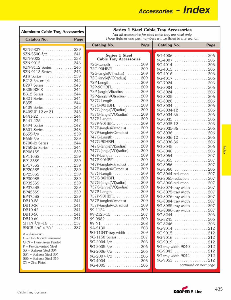
Accessories - Index
435
Index
Cable Tray Systems
Aluminum Cable Tray Accessories Series 1 Steel Cable Tray AccessoriesNot all accessories for steel cable tray are steel only.
Those finishes and part numbers will be listed in this section.
Catalog No. PageCatalog No. Page
Catalog No. Page9ZN-5327 . . . . . . . . . . . . . . . . . 2399ZN-5500-1/2 . . . . . . . . . . . . . 2419ZN-9002 . . . . . . . . . . . . . . . . . 2389ZN-9012 . . . . . . . . . . . . . . . . . 2469ZN-9112 Series . . . . . . . . . . . 2469ZN-9113 Series . . . . . . . . . . . 246ATR Series . . . . . . . . . . . . . . . . 239B212-1/4 or 3/8 . . . . . . . . . . . 244B297 Series . . . . . . . . . . . . . . . 243B305-B308 . . . . . . . . . . . . . . . 244B312 Series . . . . . . . . . . . . . . . 244B321 Series . . . . . . . . . . . . . . . 244B355 . . . . . . . . . . . . . . . . . . . . . 244B409 Series . . . . . . . . . . . . . . . 243B409UF-12 or 21 . . . . . . . . . 243B441-22 . . . . . . . . . . . . . . . . . . 244B441-22A . . . . . . . . . . . . . . . . 244B494 Series . . . . . . . . . . . . . . . 242B501 Series . . . . . . . . . . . . . . . 243B655-3/8 . . . . . . . . . . . . . . . . . . 239B655-1/2 . . . . . . . . . . . . . . . . . . 239B700-Jx Series . . . . . . . . . . . . 244B750-Jx Series . . . . . . . . . . . . 244BP081SS . . . . . . . . . . . . . . . . . 239BP110SS . . . . . . . . . . . . . . . . . 239 BP135SS . . . . . . . . . . . . . . . . . 239 BP175SS . . . . . . . . . . . . . . . . . 239 BP205SS . . . . . . . . . . . . . . . . . 239 BP250SS . . . . . . . . . . . . . . . . . 239 BP300SS . . . . . . . . . . . . . . . . . 239 BP325SS . . . . . . . . . . . . . . . . . 239 BP375SS . . . . . . . . . . . . . . . . . 239 BP425SS . . . . . . . . . . . . . . . . . 239 BP475SS . . . . . . . . . . . . . . . . . 239 DB10-28 . . . . . . . . . . . . . . . . . . 241DB10-36 . . . . . . . . . . . . . . . . . . 241 DB10-42 . . . . . . . . . . . . . . . . . . 241 DB10-50 . . . . . . . . . . . . . . . . . . 241 DB10-60 . . . . . . . . . . . . . . . . . . 241 SFHN 3/8”-16 . . . . . . . . . . . . . 237SNCB 3/8” x 3/4” . . . . . . . . . . 237
A = AluminumG = Hot-Dipped GalvanizedGRN = Dura-Green PaintedP = Pre-Galvanized SteelSS = Stainless Steel 304SS4 = Stainless Steel 304SS6 = Stainless Steel 316ZN = Zinc Plated
9G-4006 . . . . . . . . . . . . . . . . . . 206 9G-4007 . . . . . . . . . . . . . . . . . . 206 9G-4014 . . . . . . . . . . . . . . . . . . 206 9G-4015 . . . . . . . . . . . . . . . . . . 206 9G-4016 . . . . . . . . . . . . . . . . . . 206 9G-4017 . . . . . . . . . . . . . . . . . . 206 9G-7024 . . . . . . . . . . . . . . . . . . 206 9G-8004 . . . . . . . . . . . . . . . . . . 206 9G-8024 . . . . . . . . . . . . . . . . . . 206 9G-8025 . . . . . . . . . . . . . . . . . . 206 9G-8026 . . . . . . . . . . . . . . . . . . 206 9G-8034 . . . . . . . . . . . . . . . . . . 206 9G-8034-12 . . . . . . . . . . . . . . . 206 9G-8034-36 . . . . . . . . . . . . . . . 206 9G-8035 . . . . . . . . . . . . . . . . . . 206 9G-8035-12 . . . . . . . . . . . . . . . 206 9G-8035-36 . . . . . . . . . . . . . . . 206 9G-8036 . . . . . . . . . . . . . . . . . . 206 9G-8036-12 . . . . . . . . . . . . . . . 206 9G-8036-36 . . . . . . . . . . . . . . . 206 9G-8045 . . . . . . . . . . . . . . . . . . 206 9G-8046 . . . . . . . . . . . . . . . . . . 206 9G-8054 . . . . . . . . . . . . . . . . . . 207 9G-8055 . . . . . . . . . . . . . . . . . . 207 9G-8056 . . . . . . . . . . . . . . . . . . 207 9G-8060 . . . . . . . . . . . . . . . . . . 206 9G-8064-reduction . . . . . . . . . 207 9G-8065-reduction . . . . . . . . . 207 9G-8066-reduction . . . . . . . . . 207 9G-8074-tray width . . . . . . . . 207 9G-8075-tray width . . . . . . . . 207 9G-8076-tray width . . . . . . . . 207 9G-8084-tray width . . . . . . . . 207 9G-8085-tray width . . . . . . . . 207 9G-8086-tray width . . . . . . . . 207 9G-8244 . . . . . . . . . . . . . . . . . . 206 9G-8245 . . . . . . . . . . . . . . . . . . 206 9G-8246 . . . . . . . . . . . . . . . . . . 206 9G-9014 . . . . . . . . . . . . . . . . . . 2129G-9015 . . . . . . . . . . . . . . . . . . 212 9G-9016 . . . . . . . . . . . . . . . . . . 212 9G-9019 . . . . . . . . . . . . . . . . . . 212 9G-tray width-9040 . . . . . . . . 212 9G-9043 . . . . . . . . . . . . . . . . . . 212 9G-tray width-9044 . . . . . . . . 212 9G-9053 . . . . . . . . . . . . . . . . . . 212
continued on next page
Series 1 SteelCable Tray Accessories
72G-Length . . . . . . . . . . . . . . . 20972G-90HBFL . . . . . . . . . . . . . . 209 72G-(angle)VI(radius) . . . . . . . 209 72G-(angle)VO(radius) . . . . . . 209 72P-Length . . . . . . . . . . . . . . . . 209 72P-90HBFL . . . . . . . . . . . . . . 209 72P-(angle)VI(radius) . . . . . . . . 209 72P-(angle)VO(radius) . . . . . . . 209 737G-Length . . . . . . . . . . . . . . 209 737G-90HBFL . . . . . . . . . . . . 209 737G-(angle)VI(radius) . . . . . . 209 737G-(angle)VO(radius) . . . . . 209 737P-Length . . . . . . . . . . . . . . 209 737P-90HBFL . . . . . . . . . . . . . 209 737P-(angle)VI(radius) . . . . . . . 209 737P-(angle)VO(radius) . . . . . 209 747G-Length . . . . . . . . . . . . . . 209 747G-90HBFL . . . . . . . . . . . . 209 747G-(angle)VI(radius) . . . . . . 209 747G-(angle)VO(radius) . . . . . 209 747P-Length . . . . . . . . . . . . . . 209 747P-90HBFL . . . . . . . . . . . . . 209 747P-(angle)VI(radius) . . . . . . . 209 747P-(angle)VO(radius) . . . . . 209 757G-Length . . . . . . . . . . . . . . 209 757G-90HBFL . . . . . . . . . . . . 209 757G-(angle)VI(radius) . . . . . . 209 757G-(angle)VO(radius) . . . . . 209 757P-Length . . . . . . . . . . . . . . 209 757P-90HBFL . . . . . . . . . . . . . 209 757P-(angle)VI(radius) . . . . . . . 209 757P-(angle)VO(radius) . . . . . 209 99-1124 . . . . . . . . . . . . . . . . . . 209 99-2125-15 . . . . . . . . . . . . . . . 20799-9982 . . . . . . . . . . . . . . . . . . 209 99-N1 . . . . . . . . . . . . . . . . . . . . 2089A-2130 . . . . . . . . . . . . . . . . . . 2089G-1104T-tray width . . . . . . . 209 9G-1158 Series . . . . . . . . . . . . 2079G-2004-1/2 . . . . . . . . . . . . . . 2069G-2005-1/2 . . . . . . . . . . . . . . 206 9G-2006-1/2 . . . . . . . . . . . . . . 2069G-2007-1/2 . . . . . . . . . . . . . . 2069G-4004 . . . . . . . . . . . . . . . . . . 206 9G-4005 . . . . . . . . . . . . . . . . . . 206
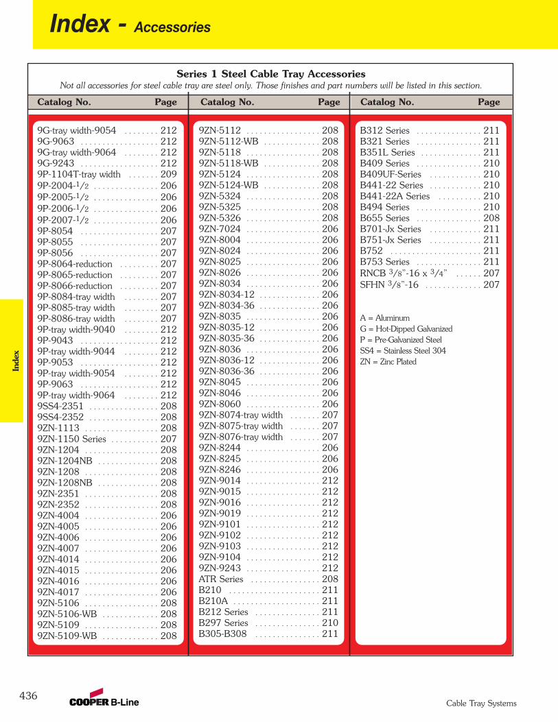
436
Index - AccessoriesIn
dex
Cable Tray Systems
Catalog No. PageCatalog No. Page Catalog No. Page
Series 1 Steel Cable Tray AccessoriesNot all accessories for steel cable tray are steel only. Those finishes and part numbers will be listed in this section.
B312 Series . . . . . . . . . . . . . . . 211 B321 Series . . . . . . . . . . . . . . . 211 B351L Series . . . . . . . . . . . . . . 211 B409 Series . . . . . . . . . . . . . . . 210 B409UF-Series . . . . . . . . . . . . 210 B441-22 Series . . . . . . . . . . . . 210 B441-22A Series . . . . . . . . . . 210 B494 Series . . . . . . . . . . . . . . . 210 B655 Series . . . . . . . . . . . . . . . 208B701-Jx Series . . . . . . . . . . . . 211 B751-Jx Series . . . . . . . . . . . . 211 B752 . . . . . . . . . . . . . . . . . . . . . 211 B753 Series . . . . . . . . . . . . . . . 211 RNCB 3/8”-16 x 3/4” . . . . . . 207SFHN 3/8”-16 . . . . . . . . . . . . . 207
A = AluminumG = Hot-Dipped GalvanizedP = Pre-Galvanized SteelSS4 = Stainless Steel 304ZN = Zinc Plated
9ZN-5112 . . . . . . . . . . . . . . . . . 2089ZN-5112-WB . . . . . . . . . . . . . 208 9ZN-5118 . . . . . . . . . . . . . . . . . 208 9ZN-5118-WB . . . . . . . . . . . . . 208 9ZN-5124 . . . . . . . . . . . . . . . . . 208 9ZN-5124-WB . . . . . . . . . . . . . 208 9ZN-5324 . . . . . . . . . . . . . . . . . 208 9ZN-5325 . . . . . . . . . . . . . . . . . 208 9ZN-5326 . . . . . . . . . . . . . . . . . 208 9ZN-7024 . . . . . . . . . . . . . . . . . 206 9ZN-8004 . . . . . . . . . . . . . . . . . 206 9ZN-8024 . . . . . . . . . . . . . . . . . 206 9ZN-8025 . . . . . . . . . . . . . . . . . 206 9ZN-8026 . . . . . . . . . . . . . . . . . 206 9ZN-8034 . . . . . . . . . . . . . . . . . 206 9ZN-8034-12 . . . . . . . . . . . . . . 206 9ZN-8034-36 . . . . . . . . . . . . . . 206 9ZN-8035 . . . . . . . . . . . . . . . . . 206 9ZN-8035-12 . . . . . . . . . . . . . . 206 9ZN-8035-36 . . . . . . . . . . . . . . 206 9ZN-8036 . . . . . . . . . . . . . . . . . 206 9ZN-8036-12 . . . . . . . . . . . . . . 206 9ZN-8036-36 . . . . . . . . . . . . . . 206 9ZN-8045 . . . . . . . . . . . . . . . . . 206 9ZN-8046 . . . . . . . . . . . . . . . . . 206 9ZN-8060 . . . . . . . . . . . . . . . . . 206 9ZN-8074-tray width . . . . . . . 207 9ZN-8075-tray width . . . . . . . 207 9ZN-8076-tray width . . . . . . . 207 9ZN-8244 . . . . . . . . . . . . . . . . . 206 9ZN-8245 . . . . . . . . . . . . . . . . . 206 9ZN-8246 . . . . . . . . . . . . . . . . . 206 9ZN-9014 . . . . . . . . . . . . . . . . . 212 9ZN-9015 . . . . . . . . . . . . . . . . . 212 9ZN-9016 . . . . . . . . . . . . . . . . . 212 9ZN-9019 . . . . . . . . . . . . . . . . . 212 9ZN-9101 . . . . . . . . . . . . . . . . . 212 9ZN-9102 . . . . . . . . . . . . . . . . . 212 9ZN-9103 . . . . . . . . . . . . . . . . . 212 9ZN-9104 . . . . . . . . . . . . . . . . . 212 9ZN-9243 . . . . . . . . . . . . . . . . . 212 ATR Series . . . . . . . . . . . . . . . . 208B210 . . . . . . . . . . . . . . . . . . . . . 211 B210A . . . . . . . . . . . . . . . . . . . . 211 B212 Series . . . . . . . . . . . . . . . 211 B297 Series . . . . . . . . . . . . . . . 210B305-B308 . . . . . . . . . . . . . . . 211
9G-tray width-9054 . . . . . . . . 2129G-9063 . . . . . . . . . . . . . . . . . . 212 9G-tray width-9064 . . . . . . . . 212 9G-9243 . . . . . . . . . . . . . . . . . . 212 9P-1104T-tray width . . . . . . . 2099P-2004-1/2 . . . . . . . . . . . . . . . 2069P-2005-1/2 . . . . . . . . . . . . . . . 206 9P-2006-1/2 . . . . . . . . . . . . . . . 206 9P-2007-1/2 . . . . . . . . . . . . . . . 206 9P-8054 . . . . . . . . . . . . . . . . . . 2079P-8055 . . . . . . . . . . . . . . . . . . 207 9P-8056 . . . . . . . . . . . . . . . . . . 207 9P-8064-reduction . . . . . . . . . 207 9P-8065-reduction . . . . . . . . . 207 9P-8066-reduction . . . . . . . . . 207 9P-8084-tray width . . . . . . . . 207 9P-8085-tray width . . . . . . . . 207 9P-8086-tray width . . . . . . . . 207 9P-tray width-9040 . . . . . . . . 212 9P-9043 . . . . . . . . . . . . . . . . . . 212 9P-tray width-9044 . . . . . . . . 212 9P-9053 . . . . . . . . . . . . . . . . . . 212 9P-tray width-9054 . . . . . . . . 212 9P-9063 . . . . . . . . . . . . . . . . . . 212 9P-tray width-9064 . . . . . . . . 212 9SS4-2351 . . . . . . . . . . . . . . . . 208 9SS4-2352 . . . . . . . . . . . . . . . . 208 9ZN-1113 . . . . . . . . . . . . . . . . . 208 9ZN-1150 Series . . . . . . . . . . . 2079ZN-1204 . . . . . . . . . . . . . . . . . 208 9ZN-1204NB . . . . . . . . . . . . . . 208 9ZN-1208 . . . . . . . . . . . . . . . . . 208 9ZN-1208NB . . . . . . . . . . . . . . 208 9ZN-2351 . . . . . . . . . . . . . . . . . 208 9ZN-2352 . . . . . . . . . . . . . . . . . 208 9ZN-4004 . . . . . . . . . . . . . . . . . 206 9ZN-4005 . . . . . . . . . . . . . . . . . 206 9ZN-4006 . . . . . . . . . . . . . . . . . 206 9ZN-4007 . . . . . . . . . . . . . . . . . 206 9ZN-4014 . . . . . . . . . . . . . . . . . 206 9ZN-4015 . . . . . . . . . . . . . . . . . 206 9ZN-4016 . . . . . . . . . . . . . . . . . 206 9ZN-4017 . . . . . . . . . . . . . . . . . 206 9ZN-5106 . . . . . . . . . . . . . . . . . 208 9ZN-5106-WB . . . . . . . . . . . . . 208 9ZN-5109 . . . . . . . . . . . . . . . . . 208 9ZN-5109-WB . . . . . . . . . . . . . 208
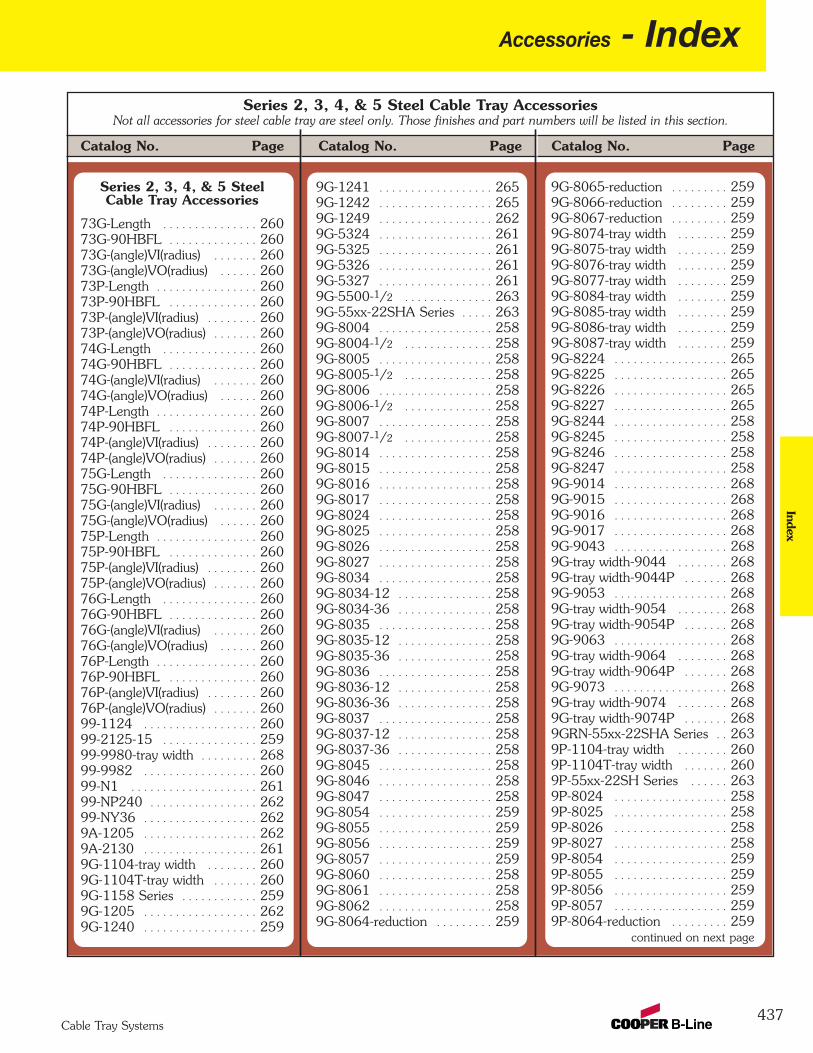
Accessories - Index
437Cable Tray Systems
Index
Catalog No. PageCatalog No. Page Catalog No. Page
Series 2, 3, 4, & 5 Steel Cable Tray AccessoriesNot all accessories for steel cable tray are steel only. Those finishes and part numbers will be listed in this section.
Series 2, 3, 4, & 5 SteelCable Tray Accessories
73G-Length . . . . . . . . . . . . . . . 26073G-90HBFL . . . . . . . . . . . . . . 260 73G-(angle)VI(radius) . . . . . . . 260 73G-(angle)VO(radius) . . . . . . 260 73P-Length . . . . . . . . . . . . . . . . 260 73P-90HBFL . . . . . . . . . . . . . . 260 73P-(angle)VI(radius) . . . . . . . . 260 73P-(angle)VO(radius) . . . . . . . 260 74G-Length . . . . . . . . . . . . . . . 260 74G-90HBFL . . . . . . . . . . . . . . 260 74G-(angle)VI(radius) . . . . . . . 260 74G-(angle)VO(radius) . . . . . . 260 74P-Length . . . . . . . . . . . . . . . . 260 74P-90HBFL . . . . . . . . . . . . . . 260 74P-(angle)VI(radius) . . . . . . . . 260 74P-(angle)VO(radius) . . . . . . . 260 75G-Length . . . . . . . . . . . . . . . 260 75G-90HBFL . . . . . . . . . . . . . . 260 75G-(angle)VI(radius) . . . . . . . 260 75G-(angle)VO(radius) . . . . . . 260 75P-Length . . . . . . . . . . . . . . . . 260 75P-90HBFL . . . . . . . . . . . . . . 260 75P-(angle)VI(radius) . . . . . . . . 260 75P-(angle)VO(radius) . . . . . . . 260 76G-Length . . . . . . . . . . . . . . . 260 76G-90HBFL . . . . . . . . . . . . . . 260 76G-(angle)VI(radius) . . . . . . . 260 76G-(angle)VO(radius) . . . . . . 260 76P-Length . . . . . . . . . . . . . . . . 260 76P-90HBFL . . . . . . . . . . . . . . 260 76P-(angle)VI(radius) . . . . . . . . 260 76P-(angle)VO(radius) . . . . . . . 260 99-1124 . . . . . . . . . . . . . . . . . . 260 99-2125-15 . . . . . . . . . . . . . . . 259 99-9980-tray width . . . . . . . . . 26899-9982 . . . . . . . . . . . . . . . . . . 26099-N1 . . . . . . . . . . . . . . . . . . . . 26199-NP240 . . . . . . . . . . . . . . . . . 26299-NY36 . . . . . . . . . . . . . . . . . . 2629A-1205 . . . . . . . . . . . . . . . . . . 2629A-2130 . . . . . . . . . . . . . . . . . . 2619G-1104-tray width . . . . . . . . 2609G-1104T-tray width . . . . . . . 2609G-1158 Series . . . . . . . . . . . . 2599G-1205 . . . . . . . . . . . . . . . . . . 2629G-1240 . . . . . . . . . . . . . . . . . . 259
9G-1241 . . . . . . . . . . . . . . . . . . 2659G-1242 . . . . . . . . . . . . . . . . . . 2659G-1249 . . . . . . . . . . . . . . . . . . 2629G-5324 . . . . . . . . . . . . . . . . . . 2619G-5325 . . . . . . . . . . . . . . . . . . 261 9G-5326 . . . . . . . . . . . . . . . . . . 261 9G-5327 . . . . . . . . . . . . . . . . . . 261 9G-5500-1/2 . . . . . . . . . . . . . . 2639G-55xx-22SHA Series . . . . . 2639G-8004 . . . . . . . . . . . . . . . . . . 2589G-8004-1/2 . . . . . . . . . . . . . . 258 9G-8005 . . . . . . . . . . . . . . . . . . 258 9G-8005-1/2 . . . . . . . . . . . . . . 258 9G-8006 . . . . . . . . . . . . . . . . . . 258 9G-8006-1/2 . . . . . . . . . . . . . . 258 9G-8007 . . . . . . . . . . . . . . . . . . 258 9G-8007-1/2 . . . . . . . . . . . . . . 258 9G-8014 . . . . . . . . . . . . . . . . . . 258 9G-8015 . . . . . . . . . . . . . . . . . . 258 9G-8016 . . . . . . . . . . . . . . . . . . 258 9G-8017 . . . . . . . . . . . . . . . . . . 258 9G-8024 . . . . . . . . . . . . . . . . . . 258 9G-8025 . . . . . . . . . . . . . . . . . . 258 9G-8026 . . . . . . . . . . . . . . . . . . 258 9G-8027 . . . . . . . . . . . . . . . . . . 258 9G-8034 . . . . . . . . . . . . . . . . . . 258 9G-8034-12 . . . . . . . . . . . . . . . 258 9G-8034-36 . . . . . . . . . . . . . . . 258 9G-8035 . . . . . . . . . . . . . . . . . . 258 9G-8035-12 . . . . . . . . . . . . . . . 258 9G-8035-36 . . . . . . . . . . . . . . . 258 9G-8036 . . . . . . . . . . . . . . . . . . 258 9G-8036-12 . . . . . . . . . . . . . . . 258 9G-8036-36 . . . . . . . . . . . . . . . 258 9G-8037 . . . . . . . . . . . . . . . . . . 258 9G-8037-12 . . . . . . . . . . . . . . . 258 9G-8037-36 . . . . . . . . . . . . . . . 258 9G-8045 . . . . . . . . . . . . . . . . . . 258 9G-8046 . . . . . . . . . . . . . . . . . . 258 9G-8047 . . . . . . . . . . . . . . . . . . 258 9G-8054 . . . . . . . . . . . . . . . . . . 259 9G-8055 . . . . . . . . . . . . . . . . . . 259 9G-8056 . . . . . . . . . . . . . . . . . . 259 9G-8057 . . . . . . . . . . . . . . . . . . 259 9G-8060 . . . . . . . . . . . . . . . . . . 258 9G-8061 . . . . . . . . . . . . . . . . . . 258 9G-8062 . . . . . . . . . . . . . . . . . . 258 9G-8064-reduction . . . . . . . . . 259
9G-8065-reduction . . . . . . . . . 259 9G-8066-reduction . . . . . . . . . 259 9G-8067-reduction . . . . . . . . . 259 9G-8074-tray width . . . . . . . . 259 9G-8075-tray width . . . . . . . . 259 9G-8076-tray width . . . . . . . . 259 9G-8077-tray width . . . . . . . . 259 9G-8084-tray width . . . . . . . . 259 9G-8085-tray width . . . . . . . . 259 9G-8086-tray width . . . . . . . . 259 9G-8087-tray width . . . . . . . . 259 9G-8224 . . . . . . . . . . . . . . . . . . 2659G-8225 . . . . . . . . . . . . . . . . . . 265 9G-8226 . . . . . . . . . . . . . . . . . . 265 9G-8227 . . . . . . . . . . . . . . . . . . 265 9G-8244 . . . . . . . . . . . . . . . . . . 2589G-8245 . . . . . . . . . . . . . . . . . . 258 9G-8246 . . . . . . . . . . . . . . . . . . 258 9G-8247 . . . . . . . . . . . . . . . . . . 258 9G-9014 . . . . . . . . . . . . . . . . . . 2689G-9015 . . . . . . . . . . . . . . . . . . 268 9G-9016 . . . . . . . . . . . . . . . . . . 268 9G-9017 . . . . . . . . . . . . . . . . . . 268 9G-9043 . . . . . . . . . . . . . . . . . . 268 9G-tray width-9044 . . . . . . . . 268 9G-tray width-9044P . . . . . . . 268 9G-9053 . . . . . . . . . . . . . . . . . . 268 9G-tray width-9054 . . . . . . . . 268 9G-tray width-9054P . . . . . . . 268 9G-9063 . . . . . . . . . . . . . . . . . . 268 9G-tray width-9064 . . . . . . . . 268 9G-tray width-9064P . . . . . . . 268 9G-9073 . . . . . . . . . . . . . . . . . . 268 9G-tray width-9074 . . . . . . . . 268 9G-tray width-9074P . . . . . . . 268 9GRN-55xx-22SHA Series . . 2639P-1104-tray width . . . . . . . . 2609P-1104T-tray width . . . . . . . 2609P-55xx-22SH Series . . . . . . 2639P-8024 . . . . . . . . . . . . . . . . . . 2589P-8025 . . . . . . . . . . . . . . . . . . 258 9P-8026 . . . . . . . . . . . . . . . . . . 258 9P-8027 . . . . . . . . . . . . . . . . . . 258 9P-8054 . . . . . . . . . . . . . . . . . . 259 9P-8055 . . . . . . . . . . . . . . . . . . 259 9P-8056 . . . . . . . . . . . . . . . . . . 259 9P-8057 . . . . . . . . . . . . . . . . . . 259 9P-8064-reduction . . . . . . . . . 259
continued on next page

438
Index - AccessoriesIn
dex
Cable Tray Systems
Catalog No. PageCatalog No. Page Catalog No. Page
Series 2, 3, 4, & 5 Steel Cable Tray AccessoriesNot all accessories for steel cable tray are steel only. Those finishes and part numbers will be listed in this section.
9P-8065-reduction . . . . . . . . . 259 9P-8066-reduction . . . . . . . . . 259 9P-8067-reduction . . . . . . . . . 259 9P-8084-tray width . . . . . . . . 259 9P-8085-tray width . . . . . . . . 259 9P-8086-tray width . . . . . . . . 259 9P-8087-tray width . . . . . . . . 259 9P-9043 . . . . . . . . . . . . . . . . . . 2689P-tray width-9044 . . . . . . . . 268 9P-tray width-9044P . . . . . . . 268 9P-9053 . . . . . . . . . . . . . . . . . . 268 9P-tray width-9054 . . . . . . . . 268 9P-tray width-9054P . . . . . . . 268 9P-9063 . . . . . . . . . . . . . . . . . . 268 9P-tray width-9064 . . . . . . . . 268 9P-tray width-9064P . . . . . . . 268 9P-9073 . . . . . . . . . . . . . . . . . . 268 9P-tray width-9074 . . . . . . . . 268 9P-tray width-9074P . . . . . . . 268 9SS4-2351 . . . . . . . . . . . . . . . . 2619SS4-2352 . . . . . . . . . . . . . . . . 261 9SS4-4050 . . . . . . . . . . . . . . . . 261 9SS4-4075 . . . . . . . . . . . . . . . . 261 9SS4-4100 . . . . . . . . . . . . . . . . 261 9SS4-4125 . . . . . . . . . . . . . . . . 261 9SS4-4150 . . . . . . . . . . . . . . . . 261 9SS4-4175 . . . . . . . . . . . . . . . . 261 9SS4-4200 . . . . . . . . . . . . . . . . 261 9SS4-4225 . . . . . . . . . . . . . . . . 261 9SS4-4250 . . . . . . . . . . . . . . . . 261 9SS4-4275 . . . . . . . . . . . . . . . . 261 9SS4-4300 . . . . . . . . . . . . . . . . 261 9SS4-4325 . . . . . . . . . . . . . . . . 261 9SS4-4350 . . . . . . . . . . . . . . . . 261 9SS4-4375 . . . . . . . . . . . . . . . . 261 9SS4-4400 . . . . . . . . . . . . . . . . 261 9SS4-4425 . . . . . . . . . . . . . . . . 261 9SS4-4450 . . . . . . . . . . . . . . . . 261 9SS4-4475 . . . . . . . . . . . . . . . . 261 9SS6-1205 . . . . . . . . . . . . . . . . 262 9ZN-1150 Series . . . . . . . . . . . 2599ZN-1155 Series . . . . . . . . . . . 2599ZN-1204 . . . . . . . . . . . . . . . . . 262 9ZN-1204NB . . . . . . . . . . . . . . 262 9ZN-1205 . . . . . . . . . . . . . . . . . 262 9ZN-1208 . . . . . . . . . . . . . . . . . 262 9ZN-1208NB . . . . . . . . . . . . . . 262 9ZN-1240 . . . . . . . . . . . . . . . . . 259
9ZN-1241 . . . . . . . . . . . . . . . . . 2659ZN-1242 . . . . . . . . . . . . . . . . . 265 9ZN-1249 . . . . . . . . . . . . . . . . . 262 9ZN-2351 . . . . . . . . . . . . . . . . . 261 9ZN-2352 . . . . . . . . . . . . . . . . . 261 9ZN-5200 . . . . . . . . . . . . . . . . . 2649ZN-5212 . . . . . . . . . . . . . . . . . 264 9ZN-5224 . . . . . . . . . . . . . . . . . 264 9ZN-5324 . . . . . . . . . . . . . . . . . 261 9ZN-5325 . . . . . . . . . . . . . . . . . 261 9ZN-5326 . . . . . . . . . . . . . . . . . 261 9ZN-5327 . . . . . . . . . . . . . . . . . 261 9ZN-5500-1/2 . . . . . . . . . . . . . 263 9ZN-8004 . . . . . . . . . . . . . . . . . 2589ZN-8004-1/2 . . . . . . . . . . . . . 258 9ZN-8005 . . . . . . . . . . . . . . . . . 258 9ZN-8005-1/2 . . . . . . . . . . . . . 258 9ZN-8006 . . . . . . . . . . . . . . . . . 258 9ZN-8006-1/2 . . . . . . . . . . . . . 258 9ZN-8007 . . . . . . . . . . . . . . . . . 258 9ZN-8007-1/2 . . . . . . . . . . . . . 258 9ZN-8014 . . . . . . . . . . . . . . . . . 258 9ZN-8015 . . . . . . . . . . . . . . . . . 258 9ZN-8016 . . . . . . . . . . . . . . . . . 258 9ZN-8017 . . . . . . . . . . . . . . . . . 258 9ZN-8034 . . . . . . . . . . . . . . . . . 258 9ZN-8034-12 . . . . . . . . . . . . . . 258 9ZN-8034-36 . . . . . . . . . . . . . . 258 9ZN-8035 . . . . . . . . . . . . . . . . . 258 9ZN-8035-12 . . . . . . . . . . . . . . 258 9ZN-8035-36 . . . . . . . . . . . . . . 258 9ZN-8036 . . . . . . . . . . . . . . . . . 258 9ZN-8036-12 . . . . . . . . . . . . . . 258 9ZN-8036-36 . . . . . . . . . . . . . . 258 9ZN-8037 . . . . . . . . . . . . . . . . . 258 9ZN-8037-12 . . . . . . . . . . . . . . 258 9ZN-8037-36 . . . . . . . . . . . . . . 258 9ZN-8045 . . . . . . . . . . . . . . . . . 258 9ZN-8046 . . . . . . . . . . . . . . . . . 258 9ZN-8047 . . . . . . . . . . . . . . . . . 258 9ZN-8060 . . . . . . . . . . . . . . . . . 258 9ZN-8061 . . . . . . . . . . . . . . . . . 258 9ZN-8062 . . . . . . . . . . . . . . . . . 258 9ZN-8074-tray width . . . . . . . 259 9ZN-8075-tray width . . . . . . . 259 9ZN-8076-tray width . . . . . . . 259 9ZN-8077-tray width . . . . . . . 259 9ZN-8224 . . . . . . . . . . . . . . . . . 265
9ZN-8225 . . . . . . . . . . . . . . . . . 265 9ZN-8226 . . . . . . . . . . . . . . . . . 265 9ZN-8227 . . . . . . . . . . . . . . . . . 265 9ZN-8244 . . . . . . . . . . . . . . . . . 258 9ZN-8245 . . . . . . . . . . . . . . . . . 258 9ZN-8246 . . . . . . . . . . . . . . . . . 258 9ZN-8247 . . . . . . . . . . . . . . . . . 258 9ZN-9002 . . . . . . . . . . . . . . . . . 2609ZN-9014 . . . . . . . . . . . . . . . . . 268 9ZN-9015 . . . . . . . . . . . . . . . . . 268 9ZN-9016 . . . . . . . . . . . . . . . . . 268 9ZN-9017 . . . . . . . . . . . . . . . . . 268 9ZN-9101 . . . . . . . . . . . . . . . . . 268 9ZN-9102 . . . . . . . . . . . . . . . . . 268 9ZN-9103 . . . . . . . . . . . . . . . . . 268 9ZN-9104 . . . . . . . . . . . . . . . . . 268 9ZN-9114 Series . . . . . . . . . . . 268 9ZN-9115 Series . . . . . . . . . . . 268 ATR Series . . . . . . . . . . . . . . . . 261 B212 Series . . . . . . . . . . . . . . . 266B297 Series . . . . . . . . . . . . . . . 265 B305-B308 . . . . . . . . . . . . . . . 266 B312 Series . . . . . . . . . . . . . . . 266 B321 Series . . . . . . . . . . . . . . . 266 B355 Series . . . . . . . . . . . . . . . 266 B409 Series . . . . . . . . . . . . . . . 265 B409UF-Series . . . . . . . . . . . . 265 B441-22 Series . . . . . . . . . . . . 266 B441-22A Series . . . . . . . . . . 266 B494 Series . . . . . . . . . . . . . . . 264 B501 Series . . . . . . . . . . . . . . . 265 B655 Series . . . . . . . . . . . . . . . 261 B700-Jx Series . . . . . . . . . . . . 266 B750-Jx Series . . . . . . . . . . . . 266 DB10-28 . . . . . . . . . . . . . . . . . . 263 DB10-36 . . . . . . . . . . . . . . . . . . 263 DB10-42 . . . . . . . . . . . . . . . . . . 263 DB10-50 . . . . . . . . . . . . . . . . . . 263 DB10-60 . . . . . . . . . . . . . . . . . . 263 RNCB 3/8”-16 x 3/4” . . . . . . 259 SFHN 3/8”-16 . . . . . . . . . . . . . 259
A = AluminumG = Hot-Dipped GalvanizedGRN = Dura-Green PaintedP = Pre-Galvanized SteelSS4 = Stainless Steel 304SS6 = Stainless Steel 316ZN = Zinc Plated
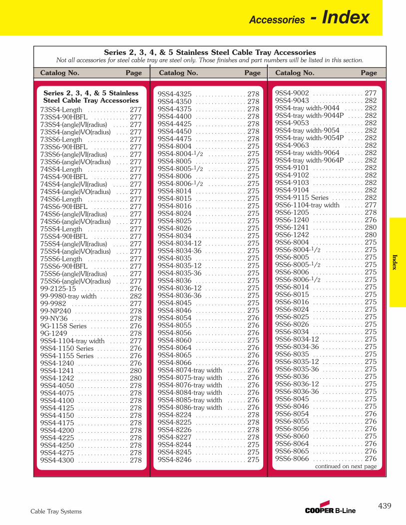
Accessories - Index
439Cable Tray Systems
Index
Catalog No. PageCatalog No. Page Catalog No. Page
Series 2, 3, 4, & 5 Stainless Steel Cable Tray AccessoriesNot all accessories for steel cable tray are steel only. Those finishes and part numbers will be listed in this section.
Series 2, 3, 4, & 5 StainlessSteel Cable Tray Accessories
73SS4-Length . . . . . . . . . . . . . 27773SS4-90HBFL . . . . . . . . . . . 277 73SS4-(angle)VI(radius) . . . . . 277 73SS4-(angle)VO(radius) . . . . 277 73SS6-Length . . . . . . . . . . . . . 277 73SS6-90HBFL . . . . . . . . . . . 277 73SS6-(angle)VI(radius) . . . . . 277 73SS6-(angle)VO(radius) . . . . 277 74SS4-Length . . . . . . . . . . . . . 277 74SS4-90HBFL . . . . . . . . . . . 277 74SS4-(angle)VI(radius) . . . . . 277 74SS4-(angle)VO(radius) . . . . 277 74SS6-Length . . . . . . . . . . . . . 277 74SS6-90HBFL . . . . . . . . . . . 277 74SS6-(angle)VI(radius) . . . . . 277 74SS6-(angle)VO(radius) . . . . 277 75SS4-Length . . . . . . . . . . . . . 277 75SS4-90HBFL . . . . . . . . . . . 277 75SS4-(angle)VI(radius) . . . . . 277 75SS4-(angle)VO(radius) . . . . 277 75SS6-Length . . . . . . . . . . . . . 277 75SS6-90HBFL . . . . . . . . . . . 277 75SS6-(angle)VI(radius) . . . . . 277 75SS6-(angle)VO(radius) . . . . 277 99-2125-15 . . . . . . . . . . . . . . . 27699-9980-tray width . . . . . . . . . 28299-9982 . . . . . . . . . . . . . . . . . . 277 99-NP240 . . . . . . . . . . . . . . . . . 27899-NY36 . . . . . . . . . . . . . . . . . . 278 9G-1158 Series . . . . . . . . . . . . 2769G-1249 . . . . . . . . . . . . . . . . . . 278 9SS4-1104-tray width . . . . . . 277 9SS4-1150 Series . . . . . . . . . . 276 9SS4-1155 Series . . . . . . . . . . 276 9SS4-1240 . . . . . . . . . . . . . . . . 276 9SS4-1241 . . . . . . . . . . . . . . . . 2809SS4-1242 . . . . . . . . . . . . . . . . 280 9SS4-4050 . . . . . . . . . . . . . . . . 278 9SS4-4075 . . . . . . . . . . . . . . . . 278 9SS4-4100 . . . . . . . . . . . . . . . . 278 9SS4-4125 . . . . . . . . . . . . . . . . 278 9SS4-4150 . . . . . . . . . . . . . . . . 278 9SS4-4175 . . . . . . . . . . . . . . . . 278 9SS4-4200 . . . . . . . . . . . . . . . . 278 9SS4-4225 . . . . . . . . . . . . . . . . 278 9SS4-4250 . . . . . . . . . . . . . . . . 278 9SS4-4275 . . . . . . . . . . . . . . . . 278 9SS4-4300 . . . . . . . . . . . . . . . . 278
9SS4-4325 . . . . . . . . . . . . . . . . 278 9SS4-4350 . . . . . . . . . . . . . . . . 278 9SS4-4375 . . . . . . . . . . . . . . . . 278 9SS4-4400 . . . . . . . . . . . . . . . . 278 9SS4-4425 . . . . . . . . . . . . . . . . 278 9SS4-4450 . . . . . . . . . . . . . . . . 278 9SS4-4475 . . . . . . . . . . . . . . . . 278 9SS4-8004 . . . . . . . . . . . . . . . . 275 9SS4-8004-1/2 . . . . . . . . . . . . 275 9SS4-8005 . . . . . . . . . . . . . . . . 275 9SS4-8005-1/2 . . . . . . . . . . . . 275 9SS4-8006 . . . . . . . . . . . . . . . . 275 9SS4-8006-1/2 . . . . . . . . . . . . 275 9SS4-8014 . . . . . . . . . . . . . . . . 275 9SS4-8015 . . . . . . . . . . . . . . . . 275 9SS4-8016 . . . . . . . . . . . . . . . . 275 9SS4-8024 . . . . . . . . . . . . . . . . 275 9SS4-8025 . . . . . . . . . . . . . . . . 275 9SS4-8026 . . . . . . . . . . . . . . . . 275 9SS4-8034 . . . . . . . . . . . . . . . . 275 9SS4-8034-12 . . . . . . . . . . . . . 275 9SS4-8034-36 . . . . . . . . . . . . . 275 9SS4-8035 . . . . . . . . . . . . . . . . 275 9SS4-8035-12 . . . . . . . . . . . . . 275 9SS4-8035-36 . . . . . . . . . . . . . 275 9SS4-8036 . . . . . . . . . . . . . . . . 275 9SS4-8036-12 . . . . . . . . . . . . . 275 9SS4-8036-36 . . . . . . . . . . . . . 275 9SS4-8045 . . . . . . . . . . . . . . . . 275 9SS4-8046 . . . . . . . . . . . . . . . . 275 9SS4-8054 . . . . . . . . . . . . . . . . 276 9SS4-8055 . . . . . . . . . . . . . . . . 276 9SS4-8056 . . . . . . . . . . . . . . . . 276 9SS4-8060 . . . . . . . . . . . . . . . . 275 9SS4-8064 . . . . . . . . . . . . . . . . 276 9SS4-8065 . . . . . . . . . . . . . . . . 276 9SS4-8066 . . . . . . . . . . . . . . . . 276 9SS4-8074-tray width . . . . . . 276 9SS4-8075-tray width . . . . . . 276 9SS4-8076-tray width . . . . . . 276 9SS4-8084-tray width . . . . . . 276 9SS4-8085-tray width . . . . . . 276 9SS4-8086-tray width . . . . . . 276 9SS4-8224 . . . . . . . . . . . . . . . . 278 9SS4-8225 . . . . . . . . . . . . . . . . 278 9SS4-8226 . . . . . . . . . . . . . . . . 278 9SS4-8227 . . . . . . . . . . . . . . . . 278 9SS4-8244 . . . . . . . . . . . . . . . . 275 9SS4-8245 . . . . . . . . . . . . . . . . 275 9SS4-8246 . . . . . . . . . . . . . . . . 275
9SS4-9002 . . . . . . . . . . . . . . . . 277 9SS4-9043 . . . . . . . . . . . . . . . . 2829SS4-tray width-9044 . . . . . . 282 9SS4-tray width-9044P . . . . . 282 9SS4-9053 . . . . . . . . . . . . . . . . 282 9SS4-tray width-9054 . . . . . . 282 9SS4-tray width-9054P . . . . . 282 9SS4-9063 . . . . . . . . . . . . . . . . 282 9SS4-tray width-9064 . . . . . . 282 9SS4-tray width-9064P . . . . . 282 9SS4-9101 . . . . . . . . . . . . . . . . 282 9SS4-9102 . . . . . . . . . . . . . . . . 282 9SS4-9103 . . . . . . . . . . . . . . . . 282 9SS4-9104 . . . . . . . . . . . . . . . . 282 9SS4-9115 Series . . . . . . . . . . 282 9SS6-1104-tray width . . . . . . 277 9SS6-1205 . . . . . . . . . . . . . . . . 278 9SS6-1240 . . . . . . . . . . . . . . . . 276 9SS6-1241 . . . . . . . . . . . . . . . . 280 9SS6-1242 . . . . . . . . . . . . . . . . 280 9SS6-8004 . . . . . . . . . . . . . . . . 275 9SS6-8004-1/2 . . . . . . . . . . . . 275 9SS6-8005 . . . . . . . . . . . . . . . . 275 9SS6-8005-1/2 . . . . . . . . . . . . 275 9SS6-8006 . . . . . . . . . . . . . . . . 275 9SS6-8006-1/2 . . . . . . . . . . . . 275 9SS6-8014 . . . . . . . . . . . . . . . . 275 9SS6-8015 . . . . . . . . . . . . . . . . 275 9SS6-8016 . . . . . . . . . . . . . . . . 275 9SS6-8024 . . . . . . . . . . . . . . . . 275 9SS6-8025 . . . . . . . . . . . . . . . . 275 9SS6-8026 . . . . . . . . . . . . . . . . 275 9SS6-8034 . . . . . . . . . . . . . . . . 275 9SS6-8034-12 . . . . . . . . . . . . . 275 9SS6-8034-36 . . . . . . . . . . . . . 275 9SS6-8035 . . . . . . . . . . . . . . . . 275 9SS6-8035-12 . . . . . . . . . . . . . 275 9SS6-8035-36 . . . . . . . . . . . . . 275 9SS6-8036 . . . . . . . . . . . . . . . . 275 9SS6-8036-12 . . . . . . . . . . . . . 275 9SS6-8036-36 . . . . . . . . . . . . . 275 9SS6-8045 . . . . . . . . . . . . . . . . 275 9SS6-8046 . . . . . . . . . . . . . . . . 275 9SS6-8054 . . . . . . . . . . . . . . . . 276 9SS6-8055 . . . . . . . . . . . . . . . . 276 9SS6-8056 . . . . . . . . . . . . . . . . 276 9SS6-8060 . . . . . . . . . . . . . . . . 275 9SS6-8064 . . . . . . . . . . . . . . . . 276 9SS6-8065 . . . . . . . . . . . . . . . . 276 9SS6-8066 . . . . . . . . . . . . . . . . 276
continued on next page
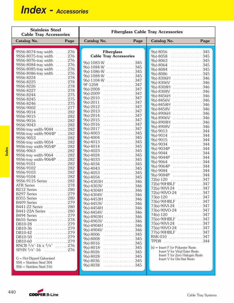
440
Index - AccessoriesIn
dex
Cable Tray Systems
Catalog No. PageCatalog No. Page Catalog No. Page
Stainless SteelCable Tray Accessories
9SS6-8074-tray width . . . . . . 2769SS6-8075-tray width . . . . . . 276 9SS6-8076-tray width . . . . . . 276 9SS6-8084-tray width . . . . . . 276 9SS6-8085-tray width . . . . . . 276 9SS6-8086-tray width . . . . . . 276 9SS6-8224 . . . . . . . . . . . . . . . . 278 9SS6-8225 . . . . . . . . . . . . . . . . 278 9SS6-8226 . . . . . . . . . . . . . . . . 278 9SS6-8227 . . . . . . . . . . . . . . . . 278 9SS6-8244 . . . . . . . . . . . . . . . . 2759SS6-8245 . . . . . . . . . . . . . . . . 275 9SS6-8246 . . . . . . . . . . . . . . . . 275 9SS6-9002 . . . . . . . . . . . . . . . . 2779SS6-9014 . . . . . . . . . . . . . . . . 2829SS6-9015 . . . . . . . . . . . . . . . . 282 9SS6-9016 . . . . . . . . . . . . . . . . 282 9SS6-9043 . . . . . . . . . . . . . . . . 282 9SS6-tray width-9044 . . . . . . 282 9SS6-tray width-9044P . . . . . 282 9SS6-9053 . . . . . . . . . . . . . . . . 282 9SS6-tray width-9054 . . . . . . 282 9SS6-tray width-9054P . . . . . 282 9SS6-9063 . . . . . . . . . . . . . . . . 282 9SS6-tray width-9064 . . . . . . 282 9SS6-tray width-9064P . . . . . 282 9SS6-9101 . . . . . . . . . . . . . . . . 282 9SS6-9102 . . . . . . . . . . . . . . . . 282 9SS6-9103 . . . . . . . . . . . . . . . . 282 9SS6-9104 . . . . . . . . . . . . . . . . 282 9SS6-9115 Series . . . . . . . . . . 282 ATR Series . . . . . . . . . . . . . . . . 278 B212 Series . . . . . . . . . . . . . . . 280B297 Series . . . . . . . . . . . . . . . 279B355 Series . . . . . . . . . . . . . . . 280 B409 Series . . . . . . . . . . . . . . . 279 B441-22 Series . . . . . . . . . . . . 280 B441-22A Series . . . . . . . . . . 280 B494 Series . . . . . . . . . . . . . . . 279 B655 Series . . . . . . . . . . . . . . . 278DB10-28 . . . . . . . . . . . . . . . . . . 279 DB10-36 . . . . . . . . . . . . . . . . . . 279 DB10-42 . . . . . . . . . . . . . . . . . . 279 DB10-50 . . . . . . . . . . . . . . . . . . 279 DB10-60 . . . . . . . . . . . . . . . . . . 279 RNCB 3/8”-16 x 3/4” . . . . . . 276 SFHN 3/8”-16 . . . . . . . . . . . . . 276
G = Hot-Dipped GalvanizedSS4 = Stainless Steel 304SS6 = Stainless Steel 316
Fiberglass Cable Tray Accessories
FiberglassCable Tray Accessories
9(x)-1083-W . . . . . . . . . . . . . . . 3459(x)-1084-W . . . . . . . . . . . . . . . 345 9(x)-1086-W . . . . . . . . . . . . . . . 345 9(x)-1088-W . . . . . . . . . . . . . . . 345 9(x)-1104-W . . . . . . . . . . . . . . . 347 9F-1208 . . . . . . . . . . . . . . . . . . 347 9(x)-2008 . . . . . . . . . . . . . . . . . 347 9(x)-2009 . . . . . . . . . . . . . . . . . 347 9(x)-2010 . . . . . . . . . . . . . . . . . 347 9(x)-2011 . . . . . . . . . . . . . . . . . 347 9(x)-2012 . . . . . . . . . . . . . . . . . 347 9(x)-2013 . . . . . . . . . . . . . . . . . 347 9(x)-2014 . . . . . . . . . . . . . . . . . 347 9(x)-2015 . . . . . . . . . . . . . . . . . 347 9(x)-2016 . . . . . . . . . . . . . . . . . 347 9(x)-2017 . . . . . . . . . . . . . . . . . 347 9(x)-4003 . . . . . . . . . . . . . . . . . 345 9(x)-4004 . . . . . . . . . . . . . . . . . 345 9(x)-4013 . . . . . . . . . . . . . . . . . 345 9(x)-4014 . . . . . . . . . . . . . . . . . 345 9(x)-4023 . . . . . . . . . . . . . . . . . 345 9(x)-4024 . . . . . . . . . . . . . . . . . 345 9(x)-4033 . . . . . . . . . . . . . . . . . 345 9(x)-4034 . . . . . . . . . . . . . . . . . 345 9(x)-4043 . . . . . . . . . . . . . . . . . 345 9(x)-4053 . . . . . . . . . . . . . . . . . 345 9(x)-4054 . . . . . . . . . . . . . . . . . 345 9(x)-4303H . . . . . . . . . . . . . . . . 346 9(x)-4303V . . . . . . . . . . . . . . . . 346 9(x)-4304H . . . . . . . . . . . . . . . . 346 9(x)-4304V . . . . . . . . . . . . . . . . 346 9(x)-4453H . . . . . . . . . . . . . . . . 346 9(x)-4453V . . . . . . . . . . . . . . . . 346 9(x)-4454H . . . . . . . . . . . . . . . . 346 9(x)-4454V . . . . . . . . . . . . . . . . 346 9(x)-4903H . . . . . . . . . . . . . . . . 346 9(x)-4903V . . . . . . . . . . . . . . . . 346 9(x)-4904H . . . . . . . . . . . . . . . . 346 9(x)-4904V . . . . . . . . . . . . . . . . 346 9(x)-8006 . . . . . . . . . . . . . . . . . 345 9(x)-8008 . . . . . . . . . . . . . . . . . 345 9(x)-8016 . . . . . . . . . . . . . . . . . 345 9(x)-8018 . . . . . . . . . . . . . . . . . 345 9(x)-8026 . . . . . . . . . . . . . . . . . 345 9(x)-8028 . . . . . . . . . . . . . . . . . 345 9(x)-8036 . . . . . . . . . . . . . . . . . 345 9(x)-8038 . . . . . . . . . . . . . . . . . 345
9(x)-8056 . . . . . . . . . . . . . . . . . 345 9(x)-8058 . . . . . . . . . . . . . . . . . 345 9(x)-8063 . . . . . . . . . . . . . . . . . 345 9(x)-8064 . . . . . . . . . . . . . . . . . 345 9(x)-8084 . . . . . . . . . . . . . . . . . 345 9(x)-8086 . . . . . . . . . . . . . . . . . 345 9(x)-8306H . . . . . . . . . . . . . . . . 346 9(x)-8306V . . . . . . . . . . . . . . . . 346 9(x)-8308H . . . . . . . . . . . . . . . . 346 9(x)-8308V . . . . . . . . . . . . . . . . 346 9(x)-8456H . . . . . . . . . . . . . . . . 346 9(x)-8456V . . . . . . . . . . . . . . . . 346 9(x)-8458H . . . . . . . . . . . . . . . . 346 9(x)-8458V . . . . . . . . . . . . . . . . 346 9(x)-8906H . . . . . . . . . . . . . . . . 346 9(x)-8906V . . . . . . . . . . . . . . . . 346 9(x)-8908H . . . . . . . . . . . . . . . . 346 9(x)-8908V . . . . . . . . . . . . . . . . 346 9(x)-9013 . . . . . . . . . . . . . . . . . 344 9(x)-9014 . . . . . . . . . . . . . . . . . 344 9(x)-9015 . . . . . . . . . . . . . . . . . 344 9(x)-9034 . . . . . . . . . . . . . . . . . 344 9(x)-9034P . . . . . . . . . . . . . . . . 344 9(x)-9044 . . . . . . . . . . . . . . . . . 344 9(x)-9044P . . . . . . . . . . . . . . . . 344 9(x)-9064 . . . . . . . . . . . . . . . . . 344 9(x)-9064P . . . . . . . . . . . . . . . . 344 9(x)-9084 . . . . . . . . . . . . . . . . . 344 9(x)-9084P . . . . . . . . . . . . . . . . 344 72(x)-120 . . . . . . . . . . . . . . . . . 347 72(x)-90HBLF . . . . . . . . . . . . . 347 72(x)-90VI-24 . . . . . . . . . . . . . 347 72(x)-90VO-24 . . . . . . . . . . . . 347 73(x)-120 . . . . . . . . . . . . . . . . . 347 73(x)-90HBLF . . . . . . . . . . . . . 347 73(x)-90VI-24 . . . . . . . . . . . . . 347 73(x)-90VO-24 . . . . . . . . . . . . 347 74(x)-120 . . . . . . . . . . . . . . . . . 347 75(x)-90HBLF . . . . . . . . . . . . . 347 75(x)-90VI-24 . . . . . . . . . . . . . 347 75(x)-90VO-24 . . . . . . . . . . . . 347 77(x)-90HBLF . . . . . . . . . . . . . 347 RSK-010 . . . . . . . . . . . . . . . . . . 347 TPDR . . . . . . . . . . . . . . . . . . . . . 344
(x) = Insert F for Polyester ResinInsert V for Vinyl Ester ResinInsert T for Zero Halogen ResinInsert V for Dis-Stat Resin
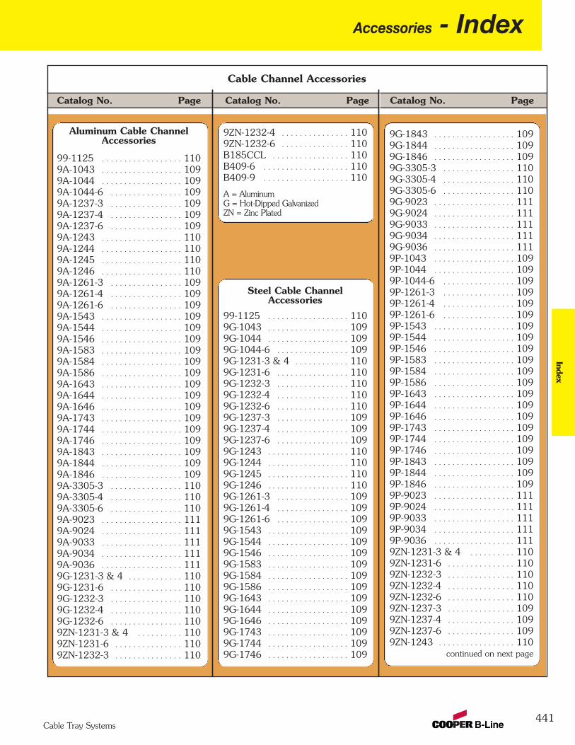
Accessories - Index
441Cable Tray Systems
Catalog No. PageCatalog No. Page Catalog No. Page
Cable Channel Accessories
Index
Aluminum Cable ChannelAccessories
99-1125 . . . . . . . . . . . . . . . . . . 1109A-1043 . . . . . . . . . . . . . . . . . . 109 9A-1044 . . . . . . . . . . . . . . . . . . 109 9A-1044-6 . . . . . . . . . . . . . . . . 109 9A-1237-3 . . . . . . . . . . . . . . . . 109 9A-1237-4 . . . . . . . . . . . . . . . . 109 9A-1237-6 . . . . . . . . . . . . . . . . 109 9A-1243 . . . . . . . . . . . . . . . . . . 110 9A-1244 . . . . . . . . . . . . . . . . . . 110 9A-1245 . . . . . . . . . . . . . . . . . . 110 9A-1246 . . . . . . . . . . . . . . . . . . 110 9A-1261-3 . . . . . . . . . . . . . . . . 109 9A-1261-4 . . . . . . . . . . . . . . . . 109 9A-1261-6 . . . . . . . . . . . . . . . . 109 9A-1543 . . . . . . . . . . . . . . . . . . 109 9A-1544 . . . . . . . . . . . . . . . . . . 109 9A-1546 . . . . . . . . . . . . . . . . . . 109 9A-1583 . . . . . . . . . . . . . . . . . . 109 9A-1584 . . . . . . . . . . . . . . . . . . 109 9A-1586 . . . . . . . . . . . . . . . . . . 109 9A-1643 . . . . . . . . . . . . . . . . . . 109 9A-1644 . . . . . . . . . . . . . . . . . . 109 9A-1646 . . . . . . . . . . . . . . . . . . 109 9A-1743 . . . . . . . . . . . . . . . . . . 109 9A-1744 . . . . . . . . . . . . . . . . . . 109 9A-1746 . . . . . . . . . . . . . . . . . . 109 9A-1843 . . . . . . . . . . . . . . . . . . 109 9A-1844 . . . . . . . . . . . . . . . . . . 109 9A-1846 . . . . . . . . . . . . . . . . . . 109 9A-3305-3 . . . . . . . . . . . . . . . . 110 9A-3305-4 . . . . . . . . . . . . . . . . 110 9A-3305-6 . . . . . . . . . . . . . . . . 110 9A-9023 . . . . . . . . . . . . . . . . . . 1119A-9024 . . . . . . . . . . . . . . . . . . 111 9A-9033 . . . . . . . . . . . . . . . . . . 111 9A-9034 . . . . . . . . . . . . . . . . . . 111 9A-9036 . . . . . . . . . . . . . . . . . . 111 9G-1231-3 & 4 . . . . . . . . . . . . 110 9G-1231-6 . . . . . . . . . . . . . . . . 110 9G-1232-3 . . . . . . . . . . . . . . . . 110 9G-1232-4 . . . . . . . . . . . . . . . . 110 9G-1232-6 . . . . . . . . . . . . . . . . 110 9ZN-1231-3 & 4 . . . . . . . . . . 110 9ZN-1231-6 . . . . . . . . . . . . . . . 110 9ZN-1232-3 . . . . . . . . . . . . . . . 110
Steel Cable ChannelAccessories
99-1125 . . . . . . . . . . . . . . . . . . 110 9G-1043 . . . . . . . . . . . . . . . . . . 109 9G-1044 . . . . . . . . . . . . . . . . . . 109 9G-1044-6 . . . . . . . . . . . . . . . . 109 9G-1231-3 & 4 . . . . . . . . . . . . 110 9G-1231-6 . . . . . . . . . . . . . . . . 110 9G-1232-3 . . . . . . . . . . . . . . . . 110 9G-1232-4 . . . . . . . . . . . . . . . . 110 9G-1232-6 . . . . . . . . . . . . . . . . 110 9G-1237-3 . . . . . . . . . . . . . . . . 109 9G-1237-4 . . . . . . . . . . . . . . . . 109 9G-1237-6 . . . . . . . . . . . . . . . . 109 9G-1243 . . . . . . . . . . . . . . . . . . 110 9G-1244 . . . . . . . . . . . . . . . . . . 110 9G-1245 . . . . . . . . . . . . . . . . . . 110 9G-1246 . . . . . . . . . . . . . . . . . . 110 9G-1261-3 . . . . . . . . . . . . . . . . 109 9G-1261-4 . . . . . . . . . . . . . . . . 109 9G-1261-6 . . . . . . . . . . . . . . . . 109 9G-1543 . . . . . . . . . . . . . . . . . . 109 9G-1544 . . . . . . . . . . . . . . . . . . 109 9G-1546 . . . . . . . . . . . . . . . . . . 109 9G-1583 . . . . . . . . . . . . . . . . . . 109 9G-1584 . . . . . . . . . . . . . . . . . . 109 9G-1586 . . . . . . . . . . . . . . . . . . 109 9G-1643 . . . . . . . . . . . . . . . . . . 109 9G-1644 . . . . . . . . . . . . . . . . . . 109 9G-1646 . . . . . . . . . . . . . . . . . . 109 9G-1743 . . . . . . . . . . . . . . . . . . 109 9G-1744 . . . . . . . . . . . . . . . . . . 109 9G-1746 . . . . . . . . . . . . . . . . . . 109
9G-1843 . . . . . . . . . . . . . . . . . . 109 9G-1844 . . . . . . . . . . . . . . . . . . 109 9G-1846 . . . . . . . . . . . . . . . . . . 109 9G-3305-3 . . . . . . . . . . . . . . . . 110 9G-3305-4 . . . . . . . . . . . . . . . . 110 9G-3305-6 . . . . . . . . . . . . . . . . 110 9G-9023 . . . . . . . . . . . . . . . . . . 111 9G-9024 . . . . . . . . . . . . . . . . . . 111 9G-9033 . . . . . . . . . . . . . . . . . . 111 9G-9034 . . . . . . . . . . . . . . . . . . 111 9G-9036 . . . . . . . . . . . . . . . . . . 111 9P-1043 . . . . . . . . . . . . . . . . . . 109 9P-1044 . . . . . . . . . . . . . . . . . . 109 9P-1044-6 . . . . . . . . . . . . . . . . 109 9P-1261-3 . . . . . . . . . . . . . . . . 109 9P-1261-4 . . . . . . . . . . . . . . . . 109 9P-1261-6 . . . . . . . . . . . . . . . . 109 9P-1543 . . . . . . . . . . . . . . . . . . 109 9P-1544 . . . . . . . . . . . . . . . . . . 109 9P-1546 . . . . . . . . . . . . . . . . . . 109 9P-1583 . . . . . . . . . . . . . . . . . . 109 9P-1584 . . . . . . . . . . . . . . . . . . 109 9P-1586 . . . . . . . . . . . . . . . . . . 109 9P-1643 . . . . . . . . . . . . . . . . . . 109 9P-1644 . . . . . . . . . . . . . . . . . . 109 9P-1646 . . . . . . . . . . . . . . . . . . 109 9P-1743 . . . . . . . . . . . . . . . . . . 109 9P-1744 . . . . . . . . . . . . . . . . . . 109 9P-1746 . . . . . . . . . . . . . . . . . . 109 9P-1843 . . . . . . . . . . . . . . . . . . 109 9P-1844 . . . . . . . . . . . . . . . . . . 109 9P-1846 . . . . . . . . . . . . . . . . . . 109 9P-9023 . . . . . . . . . . . . . . . . . . 111 9P-9024 . . . . . . . . . . . . . . . . . . 111 9P-9033 . . . . . . . . . . . . . . . . . . 111 9P-9034 . . . . . . . . . . . . . . . . . . 111 9P-9036 . . . . . . . . . . . . . . . . . . 111 9ZN-1231-3 & 4 . . . . . . . . . . 110 9ZN-1231-6 . . . . . . . . . . . . . . . 110 9ZN-1232-3 . . . . . . . . . . . . . . . 110 9ZN-1232-4 . . . . . . . . . . . . . . . 110 9ZN-1232-6 . . . . . . . . . . . . . . . 110 9ZN-1237-3 . . . . . . . . . . . . . . . 109 9ZN-1237-4 . . . . . . . . . . . . . . . 109 9ZN-1237-6 . . . . . . . . . . . . . . . 109 9ZN-1243 . . . . . . . . . . . . . . . . . 110
continued on next page
9ZN-1232-4 . . . . . . . . . . . . . . . 110 9ZN-1232-6 . . . . . . . . . . . . . . . 110 B185CCL . . . . . . . . . . . . . . . . . 110 B409-6 . . . . . . . . . . . . . . . . . . . 110 B409-9 . . . . . . . . . . . . . . . . . . . 110
A = AluminumG = Hot-Dipped GalvanizedZN = Zinc Plated
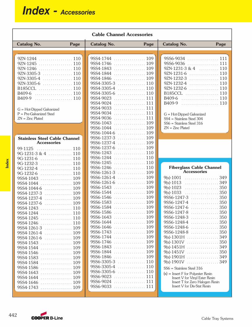
442
Index - AccessoriesIn
dex
Cable Tray Systems
Catalog No. PageCatalog No. Page Catalog No. Page
Cable Channel Accessories
9ZN-1244 . . . . . . . . . . . . . . . . . 1109ZN-1245 . . . . . . . . . . . . . . . . . 110 9ZN-1246 . . . . . . . . . . . . . . . . . 110 9ZN-3305-3 . . . . . . . . . . . . . . . 110 9ZN-3305-4 . . . . . . . . . . . . . . . 110 9ZN-3305-6 . . . . . . . . . . . . . . . 110 B185CCL . . . . . . . . . . . . . . . . . 110 B409-6 . . . . . . . . . . . . . . . . . . . 110 B409-9 . . . . . . . . . . . . . . . . . . . 110
G = Hot-Dipped GalvanizedP = Pre-Galvanized SteelZN = Zinc Plated
Stainless Steel Cable ChannelAccessories
99-1125 . . . . . . . . . . . . . . . . . . 110 9G-1231-3 & 4 . . . . . . . . . . . . 110 9G-1231-6 . . . . . . . . . . . . . . . . 110 9G-1232-3 . . . . . . . . . . . . . . . . 110 9G-1232-4 . . . . . . . . . . . . . . . . 110 9G-1232-6 . . . . . . . . . . . . . . . . 110 9SS4-1043 . . . . . . . . . . . . . . . . 1099SS4-1044 . . . . . . . . . . . . . . . . 109 9SS4-1044-6 . . . . . . . . . . . . . . 109 9SS4-1237-3 . . . . . . . . . . . . . . 109 9SS4-1237-4 . . . . . . . . . . . . . . 109 9SS4-1237-6 . . . . . . . . . . . . . . 109 9SS4-1243 . . . . . . . . . . . . . . . . 110 9SS4-1244 . . . . . . . . . . . . . . . . 110 9SS4-1245 . . . . . . . . . . . . . . . . 110 9SS4-1246 . . . . . . . . . . . . . . . . 110 9SS4-1261-3 . . . . . . . . . . . . . . 109 9SS4-1261-4 . . . . . . . . . . . . . . 109 9SS4-1261-6 . . . . . . . . . . . . . . 109 9SS4-1543 . . . . . . . . . . . . . . . . 109 9SS4-1544 . . . . . . . . . . . . . . . . 109 9SS4-1546 . . . . . . . . . . . . . . . . 109 9SS4-1583 . . . . . . . . . . . . . . . . 109 9SS4-1584 . . . . . . . . . . . . . . . . 109 9SS4-1586 . . . . . . . . . . . . . . . . 109 9SS4-1643 . . . . . . . . . . . . . . . . 109 9SS4-1644 . . . . . . . . . . . . . . . . 109 9SS4-1646 . . . . . . . . . . . . . . . . 109 9SS4-1743 . . . . . . . . . . . . . . . . 109
Fiberglass Cable ChannelAccessories
9(x)-1001 . . . . . . . . . . . . . . . . . 3499(x)-1013 . . . . . . . . . . . . . . . . . 349 9(x)-1023 . . . . . . . . . . . . . . . . . 3509(x)-1033 . . . . . . . . . . . . . . . . . 350 9SS6-1247-3 . . . . . . . . . . . . . . 350 9SS6-1247-4 . . . . . . . . . . . . . . 350 9SS6-1247-6 . . . . . . . . . . . . . . 350 9SS6-1247-8 . . . . . . . . . . . . . . 350 9SS6-1248-3 . . . . . . . . . . . . . . 350 9SS6-1248-4 . . . . . . . . . . . . . . 350 9SS6-1248-6 . . . . . . . . . . . . . . 350 9SS6-1248-8 . . . . . . . . . . . . . . 350 9(x)-1301H . . . . . . . . . . . . . . . . 349 9(x)-1301V . . . . . . . . . . . . . . . . 350 9(x)-1451H . . . . . . . . . . . . . . . . 349 9(x)-1451V . . . . . . . . . . . . . . . . 350 9(x)-1901H . . . . . . . . . . . . . . . . 349 9(x)-1901V . . . . . . . . . . . . . . . . 349
SS6 = Stainless Steel 316(x) = Insert F for Polyester Resin
Insert V for Vinyl Ester ResinInsert T for Zero Halogen ResinInsert V for Dis-Stat Resin
9SS4-1744 . . . . . . . . . . . . . . . . 109 9SS4-1746 . . . . . . . . . . . . . . . . 109 9SS4-1843 . . . . . . . . . . . . . . . . 109 9SS4-1844 . . . . . . . . . . . . . . . . 109 9SS4-1846 . . . . . . . . . . . . . . . . 109 9SS4-3305-3 . . . . . . . . . . . . . . 110 9SS4-3305-4 . . . . . . . . . . . . . . 110 9SS4-3305-6 . . . . . . . . . . . . . . 110 9SS4-9023 . . . . . . . . . . . . . . . . 111 9SS4-9024 . . . . . . . . . . . . . . . . 111 9SS4-9033 . . . . . . . . . . . . . . . . 111 9SS4-9034 . . . . . . . . . . . . . . . . 111 9SS4-9036 . . . . . . . . . . . . . . . . 111 9SS6-1043 . . . . . . . . . . . . . . . . 109 9SS6-1044 . . . . . . . . . . . . . . . . 109 9SS6-1044-6 . . . . . . . . . . . . . . 109 9SS6-1237-3 . . . . . . . . . . . . . . 109 9SS6-1237-4 . . . . . . . . . . . . . . 109 9SS6-1237-6 . . . . . . . . . . . . . . 109 9SS6-1243 . . . . . . . . . . . . . . . . 110 9SS6-1244 . . . . . . . . . . . . . . . . 110 9SS6-1245 . . . . . . . . . . . . . . . . 110 9SS6-1246 . . . . . . . . . . . . . . . . 110 9SS6-1261-3 . . . . . . . . . . . . . . 109 9SS6-1261-4 . . . . . . . . . . . . . . 109 9SS6-1261-6 . . . . . . . . . . . . . . 109 9SS6-1543 . . . . . . . . . . . . . . . . 109 9SS6-1544 . . . . . . . . . . . . . . . . 109 9SS6-1546 . . . . . . . . . . . . . . . . 109 9SS6-1583 . . . . . . . . . . . . . . . . 109 9SS6-1584 . . . . . . . . . . . . . . . . 109 9SS6-1586 . . . . . . . . . . . . . . . . 109 9SS6-1643 . . . . . . . . . . . . . . . . 109 9SS6-1644 . . . . . . . . . . . . . . . . 109 9SS6-1646 . . . . . . . . . . . . . . . . 109 9SS6-1743 . . . . . . . . . . . . . . . . 109 9SS6-1744 . . . . . . . . . . . . . . . . 109 9SS6-1746 . . . . . . . . . . . . . . . . 109 9SS6-1843 . . . . . . . . . . . . . . . . 109 9SS6-1844 . . . . . . . . . . . . . . . . 109 9SS6-1846 . . . . . . . . . . . . . . . . 109 9SS6-3305-3 . . . . . . . . . . . . . . 110 9SS6-3305-4 . . . . . . . . . . . . . . 110 9SS6-3305-6 . . . . . . . . . . . . . . 110 9SS6-9023 . . . . . . . . . . . . . . . . 111 9SS6-9024 . . . . . . . . . . . . . . . . 111 9SS6-9033 . . . . . . . . . . . . . . . . 111
9SS6-9034 . . . . . . . . . . . . . . . . 111 9SS6-9036 . . . . . . . . . . . . . . . . 111 9ZN-1231-3 & 4 . . . . . . . . . . 110 9ZN-1231-6 . . . . . . . . . . . . . . . 110 9ZN-1232-3 . . . . . . . . . . . . . . . 110 9ZN-1232-4 . . . . . . . . . . . . . . . 110 9ZN-1232-6 . . . . . . . . . . . . . . . 110 B185CCL . . . . . . . . . . . . . . . . . 110 B409-6 . . . . . . . . . . . . . . . . . . . 110 B409-9 . . . . . . . . . . . . . . . . . . . 110
G = Hot-Dipped GalvanizedSS4 = Stainless Steel 304SS6 = Stainless Steel 316ZN = Zinc Plated
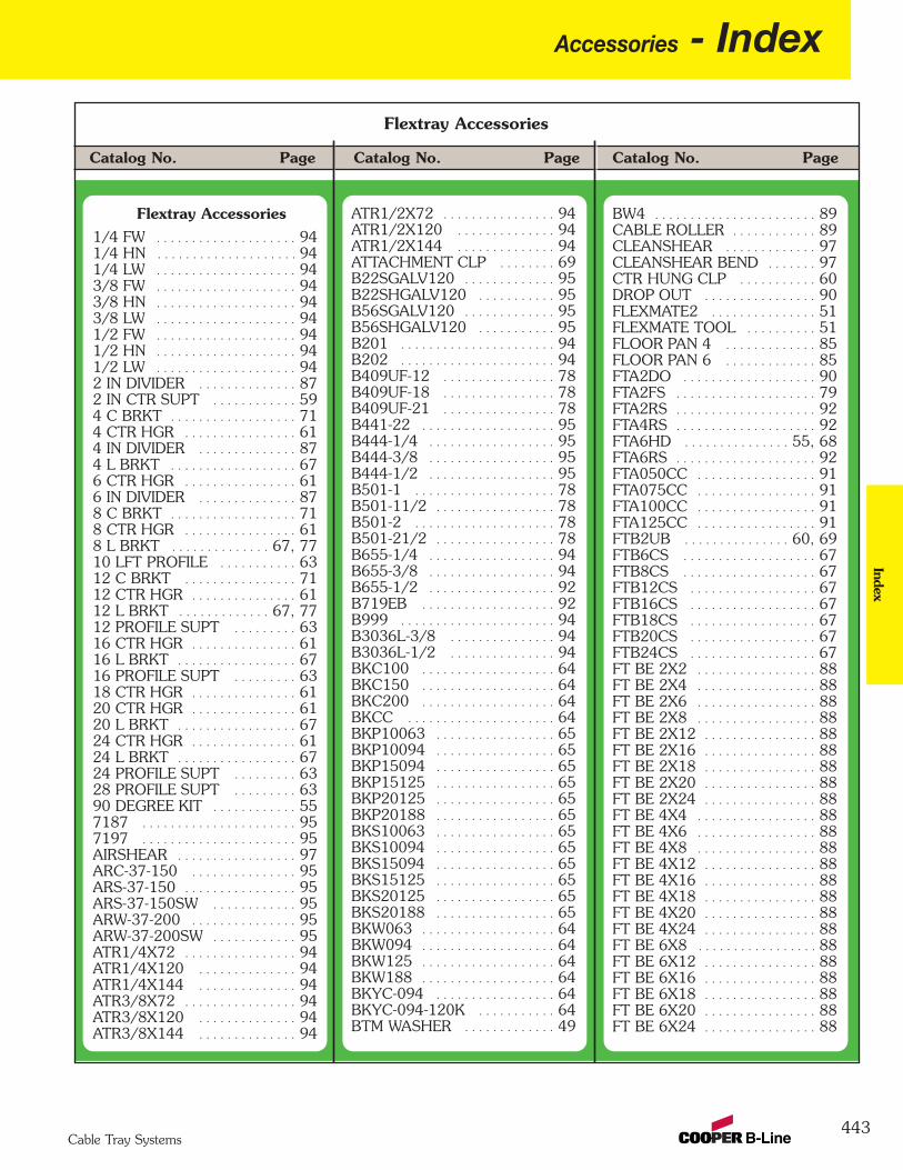
443Cable Tray Systems
Catalog No. PageCatalog No. Page Catalog No. Page
Flextray Accessories
Accessories - IndexIndex
Flextray Accessories1/4 FW . . . . . . . . . . . . . . . . . . . . 941/4 HN . . . . . . . . . . . . . . . . . . . . 94 1/4 LW . . . . . . . . . . . . . . . . . . . . 943/8 FW . . . . . . . . . . . . . . . . . . . . 943/8 HN . . . . . . . . . . . . . . . . . . . . 943/8 LW . . . . . . . . . . . . . . . . . . . . 941/2 FW . . . . . . . . . . . . . . . . . . . . 941/2 HN . . . . . . . . . . . . . . . . . . . . 941/2 LW . . . . . . . . . . . . . . . . . . . . 942 IN DIVIDER . . . . . . . . . . . . . . 872 IN CTR SUPT . . . . . . . . . . . . 594 C BRKT . . . . . . . . . . . . . . . . . . 714 CTR HGR . . . . . . . . . . . . . . . . 614 IN DIVIDER . . . . . . . . . . . . . . 874 L BRKT . . . . . . . . . . . . . . . . . . 676 CTR HGR . . . . . . . . . . . . . . . . 616 IN DIVIDER . . . . . . . . . . . . . . 878 C BRKT . . . . . . . . . . . . . . . . . . 718 CTR HGR . . . . . . . . . . . . . . . . 618 L BRKT . . . . . . . . . . . . . . 67, 7710 LFT PROFILE . . . . . . . . . . . 6312 C BRKT . . . . . . . . . . . . . . . . 7112 CTR HGR . . . . . . . . . . . . . . . 6112 L BRKT . . . . . . . . . . . . . 67, 7712 PROFILE SUPT . . . . . . . . . 6316 CTR HGR . . . . . . . . . . . . . . . 6116 L BRKT . . . . . . . . . . . . . . . . . 6716 PROFILE SUPT . . . . . . . . . 6318 CTR HGR . . . . . . . . . . . . . . . 6120 CTR HGR . . . . . . . . . . . . . . . 6120 L BRKT . . . . . . . . . . . . . . . . . 6724 CTR HGR . . . . . . . . . . . . . . . 6124 L BRKT . . . . . . . . . . . . . . . . . 6724 PROFILE SUPT . . . . . . . . . 6328 PROFILE SUPT . . . . . . . . . 6390 DEGREE KIT . . . . . . . . . . . . 557187 . . . . . . . . . . . . . . . . . . . . . . 957197 . . . . . . . . . . . . . . . . . . . . . . 95AIRSHEAR . . . . . . . . . . . . . . . . . 97ARC-37-150 . . . . . . . . . . . . . . . 95ARS-37-150 . . . . . . . . . . . . . . . . 95ARS-37-150SW . . . . . . . . . . . . 95ARW-37-200 . . . . . . . . . . . . . . . 95ARW-37-200SW . . . . . . . . . . . . 95ATR1/4X72 . . . . . . . . . . . . . . . . 94ATR1/4X120 . . . . . . . . . . . . . . 94ATR1/4X144 . . . . . . . . . . . . . . 94ATR3/8X72 . . . . . . . . . . . . . . . . 94ATR3/8X120 . . . . . . . . . . . . . . 94ATR3/8X144 . . . . . . . . . . . . . . 94
ATR1/2X72 . . . . . . . . . . . . . . . . 94ATR1/2X120 . . . . . . . . . . . . . . 94ATR1/2X144 . . . . . . . . . . . . . . 94ATTACHMENT CLP . . . . . . . . 69B22SGALV120 . . . . . . . . . . . . . 95B22SHGALV120 . . . . . . . . . . . 95B56SGALV120 . . . . . . . . . . . . . 95B56SHGALV120 . . . . . . . . . . . 95B201 . . . . . . . . . . . . . . . . . . . . . . 94B202 . . . . . . . . . . . . . . . . . . . . . . 94B409UF-12 . . . . . . . . . . . . . . . . 78B409UF-18 . . . . . . . . . . . . . . . . 78B409UF-21 . . . . . . . . . . . . . . . . 78B441-22 . . . . . . . . . . . . . . . . . . . 95B444-1/4 . . . . . . . . . . . . . . . . . . 95B444-3/8 . . . . . . . . . . . . . . . . . . 95B444-1/2 . . . . . . . . . . . . . . . . . . 95B501-1 . . . . . . . . . . . . . . . . . . . . 78B501-11/2 . . . . . . . . . . . . . . . . . 78B501-2 . . . . . . . . . . . . . . . . . . . . 78B501-21/2 . . . . . . . . . . . . . . . . . 78B655-1/4 . . . . . . . . . . . . . . . . . . 94B655-3/8 . . . . . . . . . . . . . . . . . . 94B655-1/2 . . . . . . . . . . . . . . . . . . 92B719EB . . . . . . . . . . . . . . . . . . . 92B999 . . . . . . . . . . . . . . . . . . . . . . 94B3036L-3/8 . . . . . . . . . . . . . . . 94B3036L-1/2 . . . . . . . . . . . . . . . 94BKC100 . . . . . . . . . . . . . . . . . . . 64BKC150 . . . . . . . . . . . . . . . . . . . 64BKC200 . . . . . . . . . . . . . . . . . . . 64BKCC . . . . . . . . . . . . . . . . . . . . . 64BKP10063 . . . . . . . . . . . . . . . . . 65BKP10094 . . . . . . . . . . . . . . . . . 65BKP15094 . . . . . . . . . . . . . . . . . 65BKP15125 . . . . . . . . . . . . . . . . . 65BKP20125 . . . . . . . . . . . . . . . . . 65BKP20188 . . . . . . . . . . . . . . . . . 65BKS10063 . . . . . . . . . . . . . . . . . 65BKS10094 . . . . . . . . . . . . . . . . . 65BKS15094 . . . . . . . . . . . . . . . . . 65BKS15125 . . . . . . . . . . . . . . . . . 65BKS20125 . . . . . . . . . . . . . . . . . 65BKS20188 . . . . . . . . . . . . . . . . . 65BKW063 . . . . . . . . . . . . . . . . . . . 64BKW094 . . . . . . . . . . . . . . . . . . . 64BKW125 . . . . . . . . . . . . . . . . . . . 64BKW188 . . . . . . . . . . . . . . . . . . . 64BKYC-094 . . . . . . . . . . . . . . . . . 64BKYC-094-120K . . . . . . . . . . . 64BTM WASHER . . . . . . . . . . . . . 49
BW4 . . . . . . . . . . . . . . . . . . . . . . . 89CABLE ROLLER . . . . . . . . . . . . 89CLEANSHEAR . . . . . . . . . . . . . 97CLEANSHEAR BEND . . . . . . . 97CTR HUNG CLP . . . . . . . . . . . 60DROP OUT . . . . . . . . . . . . . . . . 90FLEXMATE2 . . . . . . . . . . . . . . . 51FLEXMATE TOOL . . . . . . . . . . 51FLOOR PAN 4 . . . . . . . . . . . . . 85FLOOR PAN 6 . . . . . . . . . . . . . 85FTA2DO . . . . . . . . . . . . . . . . . . . 90FTA2FS . . . . . . . . . . . . . . . . . . . . 79FTA2RS . . . . . . . . . . . . . . . . . . . . 92FTA4RS . . . . . . . . . . . . . . . . . . . . 92FTA6HD . . . . . . . . . . . . . . . 55, 68FTA6RS . . . . . . . . . . . . . . . . . . . . 92FTA050CC . . . . . . . . . . . . . . . . . 91FTA075CC . . . . . . . . . . . . . . . . . 91FTA100CC . . . . . . . . . . . . . . . . . 91FTA125CC . . . . . . . . . . . . . . . . . 91FTB2UB . . . . . . . . . . . . . . . 60, 69FTB6CS . . . . . . . . . . . . . . . . . . . 67FTB8CS . . . . . . . . . . . . . . . . . . . 67FTB12CS . . . . . . . . . . . . . . . . . . 67FTB16CS . . . . . . . . . . . . . . . . . . 67FTB18CS . . . . . . . . . . . . . . . . . . 67FTB20CS . . . . . . . . . . . . . . . . . . 67FTB24CS . . . . . . . . . . . . . . . . . . 67FT BE 2X2 . . . . . . . . . . . . . . . . . 88FT BE 2X4 . . . . . . . . . . . . . . . . . 88FT BE 2X6 . . . . . . . . . . . . . . . . . 88FT BE 2X8 . . . . . . . . . . . . . . . . . 88FT BE 2X12 . . . . . . . . . . . . . . . . 88FT BE 2X16 . . . . . . . . . . . . . . . . 88FT BE 2X18 . . . . . . . . . . . . . . . . 88FT BE 2X20 . . . . . . . . . . . . . . . . 88FT BE 2X24 . . . . . . . . . . . . . . . . 88FT BE 4X4 . . . . . . . . . . . . . . . . . 88FT BE 4X6 . . . . . . . . . . . . . . . . . 88FT BE 4X8 . . . . . . . . . . . . . . . . . 88FT BE 4X12 . . . . . . . . . . . . . . . . 88FT BE 4X16 . . . . . . . . . . . . . . . . 88FT BE 4X18 . . . . . . . . . . . . . . . . 88FT BE 4X20 . . . . . . . . . . . . . . . . 88FT BE 4X24 . . . . . . . . . . . . . . . . 88FT BE 6X8 . . . . . . . . . . . . . . . . . 88 FT BE 6X12 . . . . . . . . . . . . . . . . 88FT BE 6X16 . . . . . . . . . . . . . . . . 88FT BE 6X18 . . . . . . . . . . . . . . . . 88FT BE 6X20 . . . . . . . . . . . . . . . . 88FT BE 6X24 . . . . . . . . . . . . . . . . 88
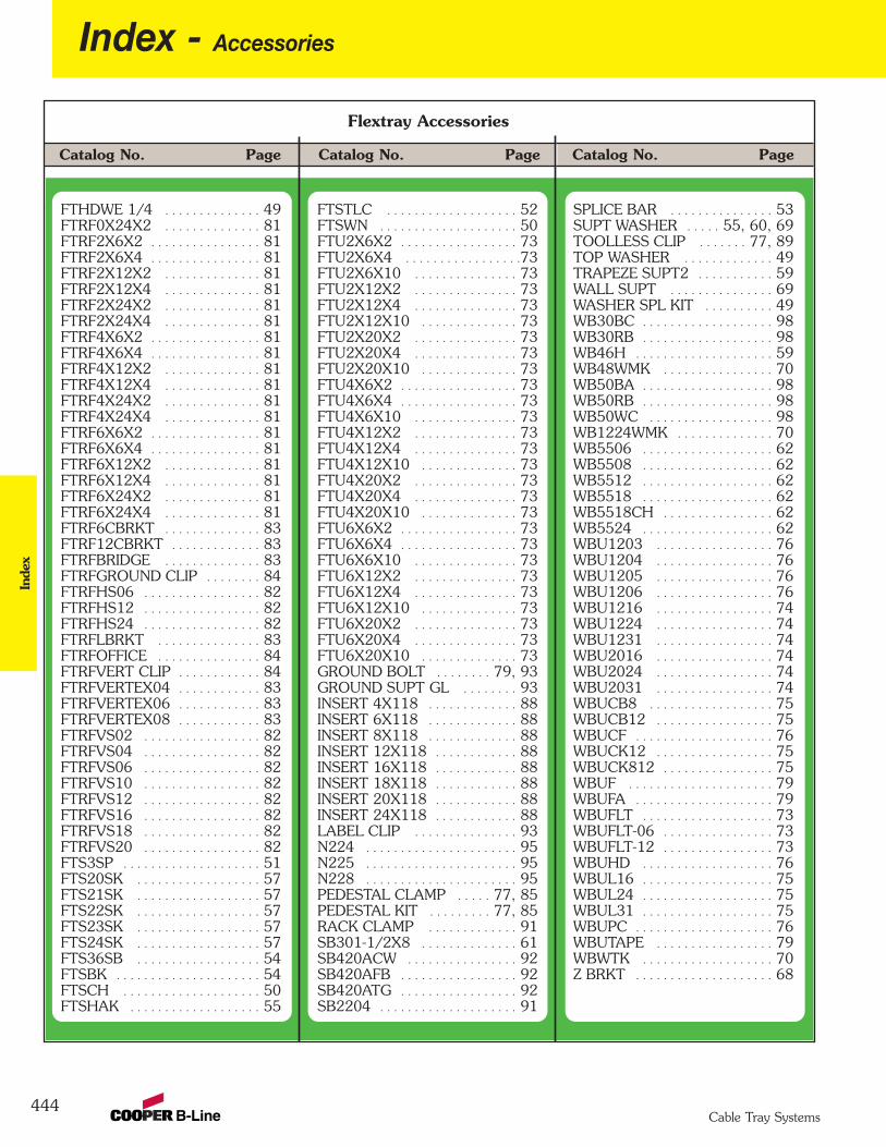
444
Index - AccessoriesIn
dex
Cable Tray Systems
Catalog No. PageCatalog No. Page Catalog No. Page
Flextray Accessories
FTHDWE 1/4 . . . . . . . . . . . . . . 49FTRF0X24X2 . . . . . . . . . . . . . . 81FTRF2X6X2 . . . . . . . . . . . . . . . . 81FTRF2X6X4 . . . . . . . . . . . . . . . . 81FTRF2X12X2 . . . . . . . . . . . . . . 81FTRF2X12X4 . . . . . . . . . . . . . . 81FTRF2X24X2 . . . . . . . . . . . . . . 81FTRF2X24X4 . . . . . . . . . . . . . . 81FTRF4X6X2 . . . . . . . . . . . . . . . . 81FTRF4X6X4 . . . . . . . . . . . . . . . . 81FTRF4X12X2 . . . . . . . . . . . . . . 81FTRF4X12X4 . . . . . . . . . . . . . . 81FTRF4X24X2 . . . . . . . . . . . . . . 81FTRF4X24X4 . . . . . . . . . . . . . . 81FTRF6X6X2 . . . . . . . . . . . . . . . . 81FTRF6X6X4 . . . . . . . . . . . . . . . . 81FTRF6X12X2 . . . . . . . . . . . . . . 81FTRF6X12X4 . . . . . . . . . . . . . . 81FTRF6X24X2 . . . . . . . . . . . . . . 81FTRF6X24X4 . . . . . . . . . . . . . . 81FTRF6CBRKT . . . . . . . . . . . . . . 83FTRF12CBRKT . . . . . . . . . . . . . 83FTRFBRIDGE . . . . . . . . . . . . . . 83FTRFGROUND CLIP . . . . . . . . 84FTRFHS06 . . . . . . . . . . . . . . . . . 82FTRFHS12 . . . . . . . . . . . . . . . . . 82FTRFHS24 . . . . . . . . . . . . . . . . . 82FTRFLBRKT . . . . . . . . . . . . . . . 83FTRFOFFICE . . . . . . . . . . . . . . . 84FTRFVERT CLIP . . . . . . . . . . . . 84FTRFVERTEX04 . . . . . . . . . . . . 83FTRFVERTEX06 . . . . . . . . . . . . 83FTRFVERTEX08 . . . . . . . . . . . . 83FTRFVS02 . . . . . . . . . . . . . . . . . 82FTRFVS04 . . . . . . . . . . . . . . . . . 82FTRFVS06 . . . . . . . . . . . . . . . . . 82FTRFVS10 . . . . . . . . . . . . . . . . . 82FTRFVS12 . . . . . . . . . . . . . . . . . 82FTRFVS16 . . . . . . . . . . . . . . . . . 82FTRFVS18 . . . . . . . . . . . . . . . . . 82FTRFVS20 . . . . . . . . . . . . . . . . . 82FTS3SP . . . . . . . . . . . . . . . . . . . . 51FTS20SK . . . . . . . . . . . . . . . . . . 57FTS21SK . . . . . . . . . . . . . . . . . . 57FTS22SK . . . . . . . . . . . . . . . . . . 57FTS23SK . . . . . . . . . . . . . . . . . . 57FTS24SK . . . . . . . . . . . . . . . . . . 57FTS36SB . . . . . . . . . . . . . . . . . . 54FTSBK . . . . . . . . . . . . . . . . . . . . . 54FTSCH . . . . . . . . . . . . . . . . . . . . 50FTSHAK . . . . . . . . . . . . . . . . . . . 55
FTSTLC . . . . . . . . . . . . . . . . . . . 52FTSWN . . . . . . . . . . . . . . . . . . . . 50FTU2X6X2 . . . . . . . . . . . . . . . . . 73FTU2X6X4 . . . . . . . . . . . . . . . . .73 FTU2X6X10 . . . . . . . . . . . . . . . 73FTU2X12X2 . . . . . . . . . . . . . . . 73FTU2X12X4 . . . . . . . . . . . . . . . 73FTU2X12X10 . . . . . . . . . . . . . . 73FTU2X20X2 . . . . . . . . . . . . . . . 73FTU2X20X4 . . . . . . . . . . . . . . . 73FTU2X20X10 . . . . . . . . . . . . . . 73FTU4X6X2 . . . . . . . . . . . . . . . . . 73FTU4X6X4 . . . . . . . . . . . . . . . . . 73FTU4X6X10 . . . . . . . . . . . . . . . 73FTU4X12X2 . . . . . . . . . . . . . . . 73FTU4X12X4 . . . . . . . . . . . . . . . 73FTU4X12X10 . . . . . . . . . . . . . . 73FTU4X20X2 . . . . . . . . . . . . . . . 73FTU4X20X4 . . . . . . . . . . . . . . . 73FTU4X20X10 . . . . . . . . . . . . . . 73FTU6X6X2 . . . . . . . . . . . . . . . . . 73FTU6X6X4 . . . . . . . . . . . . . . . . . 73FTU6X6X10 . . . . . . . . . . . . . . . 73FTU6X12X2 . . . . . . . . . . . . . . . 73FTU6X12X4 . . . . . . . . . . . . . . . 73FTU6X12X10 . . . . . . . . . . . . . . 73FTU6X20X2 . . . . . . . . . . . . . . . 73FTU6X20X4 . . . . . . . . . . . . . . . 73FTU6X20X10 . . . . . . . . . . . . . . 73GROUND BOLT . . . . . . . . 79, 93GROUND SUPT GL . . . . . . . . 93INSERT 4X118 . . . . . . . . . . . . . 88INSERT 6X118 . . . . . . . . . . . . . 88INSERT 8X118 . . . . . . . . . . . . . 88INSERT 12X118 . . . . . . . . . . . . 88INSERT 16X118 . . . . . . . . . . . . 88INSERT 18X118 . . . . . . . . . . . . 88INSERT 20X118 . . . . . . . . . . . . 88INSERT 24X118 . . . . . . . . . . . . 88LABEL CLIP . . . . . . . . . . . . . . . 93N224 . . . . . . . . . . . . . . . . . . . . . . 95N225 . . . . . . . . . . . . . . . . . . . . . . 95N228 . . . . . . . . . . . . . . . . . . . . . . 95PEDESTAL CLAMP . . . . . 77, 85PEDESTAL KIT . . . . . . . . . 77, 85RACK CLAMP . . . . . . . . . . . . . 91SB301-1/2X8 . . . . . . . . . . . . . . 61SB420ACW . . . . . . . . . . . . . . . . 92SB420AFB . . . . . . . . . . . . . . . . . 92SB420ATG . . . . . . . . . . . . . . . . . 92SB2204 . . . . . . . . . . . . . . . . . . . . 91
SPLICE BAR . . . . . . . . . . . . . . . 53SUPT WASHER . . . . . 55, 60, 69TOOLLESS CLIP . . . . . . . 77, 89TOP WASHER . . . . . . . . . . . . . 49TRAPEZE SUPT2 . . . . . . . . . . . 59WALL SUPT . . . . . . . . . . . . . . . 69WASHER SPL KIT . . . . . . . . . . 49WB30BC . . . . . . . . . . . . . . . . . . . 98WB30RB . . . . . . . . . . . . . . . . . . . 98WB46H . . . . . . . . . . . . . . . . . . . . 59WB48WMK . . . . . . . . . . . . . . . . 70WB50BA . . . . . . . . . . . . . . . . . . . 98WB50RB . . . . . . . . . . . . . . . . . . . 98WB50WC . . . . . . . . . . . . . . . . . . 98WB1224WMK . . . . . . . . . . . . . . 70WB5506 . . . . . . . . . . . . . . . . . . . 62WB5508 . . . . . . . . . . . . . . . . . . . 62WB5512 . . . . . . . . . . . . . . . . . . . 62WB5518 . . . . . . . . . . . . . . . . . . . 62WB5518CH . . . . . . . . . . . . . . . . 62WB5524 . . . . . . . . . . . . . . . . . . . 62WBU1203 . . . . . . . . . . . . . . . . . 76WBU1204 . . . . . . . . . . . . . . . . . 76WBU1205 . . . . . . . . . . . . . . . . . 76WBU1206 . . . . . . . . . . . . . . . . . 76WBU1216 . . . . . . . . . . . . . . . . . 74WBU1224 . . . . . . . . . . . . . . . . . 74WBU1231 . . . . . . . . . . . . . . . . . 74WBU2016 . . . . . . . . . . . . . . . . . 74WBU2024 . . . . . . . . . . . . . . . . . 74WBU2031 . . . . . . . . . . . . . . . . . 74WBUCB8 . . . . . . . . . . . . . . . . . . 75WBUCB12 . . . . . . . . . . . . . . . . . 75WBUCF . . . . . . . . . . . . . . . . . . . . 76WBUCK12 . . . . . . . . . . . . . . . . . 75WBUCK812 . . . . . . . . . . . . . . . . 75WBUF . . . . . . . . . . . . . . . . . . . . . 79WBUFA . . . . . . . . . . . . . . . . . . . . 79WBUFLT . . . . . . . . . . . . . . . . . . . 73WBUFLT-06 . . . . . . . . . . . . . . . . 73WBUFLT-12 . . . . . . . . . . . . . . . . 73WBUHD . . . . . . . . . . . . . . . . . . . 76WBUL16 . . . . . . . . . . . . . . . . . . . 75WBUL24 . . . . . . . . . . . . . . . . . . . 75WBUL31 . . . . . . . . . . . . . . . . . . . 75WBUPC . . . . . . . . . . . . . . . . . . . . 76WBUTAPE . . . . . . . . . . . . . . . . . 79WBWTK . . . . . . . . . . . . . . . . . . . 70Z BRKT . . . . . . . . . . . . . . . . . . . . 68
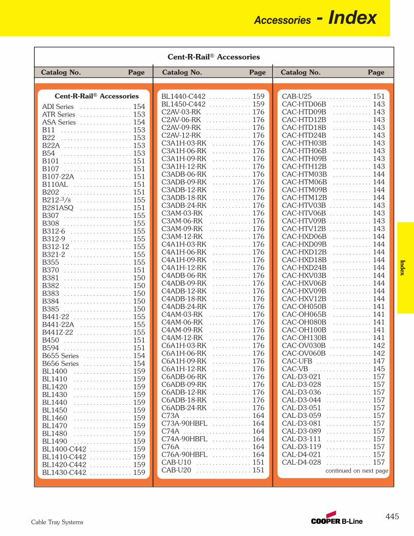
445Cable Tray Systems
Catalog No. PageCatalog No. Page Catalog No. Page
Cent-R-Rail® Accessories
Accessories - IndexIndex
CAB-U25 . . . . . . . . . . . . . . . . . 151CAC-HTD06B . . . . . . . . . . . . 143CAC-HTD09B . . . . . . . . . . . . 143CAC-HTD12B . . . . . . . . . . . . 143CAC-HTD18B . . . . . . . . . . . . 143CAC-HTD24B . . . . . . . . . . . . 143CAC-HTH03B . . . . . . . . . . . . 143CAC-HTH06B . . . . . . . . . . . . 143CAC-HTH09B . . . . . . . . . . . . 143CAC-HTH12B . . . . . . . . . . . . 143CAC-HTM03B . . . . . . . . . . . . 144CAC-HTM06B . . . . . . . . . . . . 144CAC-HTM09B . . . . . . . . . . . . 144CAC-HTM12B . . . . . . . . . . . . 144CAC-HTV03B . . . . . . . . . . . . . 143CAC-HTV06B . . . . . . . . . . . . . 143CAC-HTV09B . . . . . . . . . . . . . 143CAC-HTV12B . . . . . . . . . . . . . 143CAC-HXD06B . . . . . . . . . . . . 144CAC-HXD09B . . . . . . . . . . . . 144CAC-HXD12B . . . . . . . . . . . . 144CAC-HXD18B . . . . . . . . . . . . 144CAC-HXD24B . . . . . . . . . . . . 144CAC-HXV03B . . . . . . . . . . . . 144CAC-HXV06B . . . . . . . . . . . . 144CAC-HXV09B . . . . . . . . . . . . 144CAC-HXV12B . . . . . . . . . . . . 144CAC-OH050B . . . . . . . . . . . . 141CAC-OH065B . . . . . . . . . . . . 141CAC-OH080B . . . . . . . . . . . . 141CAC-OH100B . . . . . . . . . . . . 141CAC-OH130B . . . . . . . . . . . . 141CAC-OV030B . . . . . . . . . . . . . 142CAC-OV060B . . . . . . . . . . . . . 142CAC-UFB . . . . . . . . . . . . . . . . . 147CAC-VB . . . . . . . . . . . . . . . . . . 145CAL-D3-021 . . . . . . . . . . . . . . 157CAL-D3-028 . . . . . . . . . . . . . . 157CAL-D3-036 . . . . . . . . . . . . . . 157CAL-D3-044 . . . . . . . . . . . . . . 157CAL-D3-051 . . . . . . . . . . . . . . 157CAL-D3-059 . . . . . . . . . . . . . . 157CAL-D3-081 . . . . . . . . . . . . . . 157CAL-D3-089 . . . . . . . . . . . . . . 157CAL-D3-111 . . . . . . . . . . . . . . 157CAL-D3-119 . . . . . . . . . . . . . . 157CAL-D4-021 . . . . . . . . . . . . . . 157CAL-D4-028 . . . . . . . . . . . . . . 157
continued on next page
BL1440-C442 . . . . . . . . . . . . . 159BL1450-C442 . . . . . . . . . . . . . 159C2AV-03-RK . . . . . . . . . . . . . . 176C2AV-06-RK . . . . . . . . . . . . . . 176C2AV-09-RK . . . . . . . . . . . . . . 176C2AV-12-RK . . . . . . . . . . . . . . 176C3A1H-03-RK . . . . . . . . . . . . 176C3A1H-06-RK . . . . . . . . . . . . 176C3A1H-09-RK . . . . . . . . . . . . 176C3A1H-12-RK . . . . . . . . . . . . 176C3ADB-06-RK . . . . . . . . . . . . 176C3ADB-09-RK . . . . . . . . . . . . 176C3ADB-12-RK . . . . . . . . . . . . 176C3ADB-18-RK . . . . . . . . . . . . 176C3ADB-24-RK . . . . . . . . . . . . 176C3AM-03-RK . . . . . . . . . . . . . 176C3AM-06-RK . . . . . . . . . . . . . 176C3AM-09-RK . . . . . . . . . . . . . 176C3AM-12-RK . . . . . . . . . . . . . 176C4A1H-03-RK . . . . . . . . . . . . 176C4A1H-06-RK . . . . . . . . . . . . 176C4A1H-09-RK . . . . . . . . . . . . 176C4A1H-12-RK . . . . . . . . . . . . 176C4ADB-06-RK . . . . . . . . . . . . 176C4ADB-09-RK . . . . . . . . . . . . 176C4ADB-12-RK . . . . . . . . . . . . 176C4ADB-18-RK . . . . . . . . . . . . 176C4ADB-24-RK . . . . . . . . . . . . 176C4AM-03-RK . . . . . . . . . . . . . 176C4AM-06-RK . . . . . . . . . . . . . 176C4AM-09-RK . . . . . . . . . . . . . 176C4AM-12-RK . . . . . . . . . . . . . 176C6A1H-03-RK . . . . . . . . . . . . 176C6A1H-06-RK . . . . . . . . . . . . 176C6A1H-09-RK . . . . . . . . . . . . 176C6A1H-12-RK . . . . . . . . . . . . 176C6ADB-06-RK . . . . . . . . . . . . 176C6ADB-09-RK . . . . . . . . . . . . 176C6ADB-12-RK . . . . . . . . . . . . 176C6ADB-18-RK . . . . . . . . . . . . 176C6ADB-24-RK . . . . . . . . . . . . 176C73A . . . . . . . . . . . . . . . . . . . . . 164C73A-90HBFL . . . . . . . . . . . . 164C74A . . . . . . . . . . . . . . . . . . . . . 164C74A-90HBFL . . . . . . . . . . . . 164C76A . . . . . . . . . . . . . . . . . . . . . 164C76A-90HBFL . . . . . . . . . . . . 164CAB-U10 . . . . . . . . . . . . . . . . . 151CAB-U20 . . . . . . . . . . . . . . . . . 151
Cent-R-Rail® AccessoriesADI Series . . . . . . . . . . . . . . . . 154ATR Series . . . . . . . . . . . . . . . . 153ASA Series . . . . . . . . . . . . . . . . 154B11 . . . . . . . . . . . . . . . . . . . . . . 153B22 . . . . . . . . . . . . . . . . . . . . . . 153B22A . . . . . . . . . . . . . . . . . . . . . 153B54 . . . . . . . . . . . . . . . . . . . . . . 153B101 . . . . . . . . . . . . . . . . . . . . . 151B107 . . . . . . . . . . . . . . . . . . . . . 151B107-22A . . . . . . . . . . . . . . . . 151B110AL . . . . . . . . . . . . . . . . . . 151B202 . . . . . . . . . . . . . . . . . . . . . 151B212-3/8 . . . . . . . . . . . . . . . . . 155B281ASQ . . . . . . . . . . . . . . . . 151B307 . . . . . . . . . . . . . . . . . . . . . 155B308 . . . . . . . . . . . . . . . . . . . . . 155B312-6 . . . . . . . . . . . . . . . . . . . 155B312-9 . . . . . . . . . . . . . . . . . . . 155B312-12 . . . . . . . . . . . . . . . . . . 155B321-2 . . . . . . . . . . . . . . . . . . . 155B355 . . . . . . . . . . . . . . . . . . . . . 155B370 . . . . . . . . . . . . . . . . . . . . . 151B381 . . . . . . . . . . . . . . . . . . . . . 150B382 . . . . . . . . . . . . . . . . . . . . . 150B383 . . . . . . . . . . . . . . . . . . . . . 150B384 . . . . . . . . . . . . . . . . . . . . . 150B385 . . . . . . . . . . . . . . . . . . . . . 150B441-22 . . . . . . . . . . . . . . . . . . 155B441-22A . . . . . . . . . . . . . . . . 155B441Z-22 . . . . . . . . . . . . . . . . . 155B450 . . . . . . . . . . . . . . . . . . . . . 151B594 . . . . . . . . . . . . . . . . . . . . . 151B655 Series . . . . . . . . . . . . . . . 154B656 Series . . . . . . . . . . . . . . . 154BL1400 . . . . . . . . . . . . . . . . . . 159BL1410 . . . . . . . . . . . . . . . . . . 159BL1420 . . . . . . . . . . . . . . . . . . 159BL1430 . . . . . . . . . . . . . . . . . . 159BL1440 . . . . . . . . . . . . . . . . . . 159BL1450 . . . . . . . . . . . . . . . . . . 159BL1460 . . . . . . . . . . . . . . . . . . 159BL1470 . . . . . . . . . . . . . . . . . . 159BL1480 . . . . . . . . . . . . . . . . . . 159BL1490 . . . . . . . . . . . . . . . . . . 159BL1400-C442 . . . . . . . . . . . . . 159BL1410-C442 . . . . . . . . . . . . . 159BL1420-C442 . . . . . . . . . . . . . 159BL1430-C442 . . . . . . . . . . . . . 159
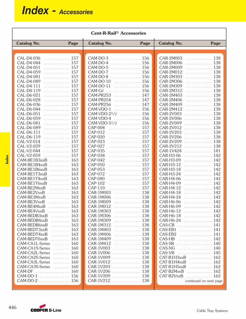
446
Index - AccessoriesIn
dex
Cable Tray Systems
Catalog No. PageCatalog No. Page Catalog No. Page
CAR-2M003 . . . . . . . . . . . . . . 138CAR-2M006 . . . . . . . . . . . . . . 138CAR-2M009 . . . . . . . . . . . . . . 138CAR-2M012 . . . . . . . . . . . . . . 138CAR-2M303 . . . . . . . . . . . . . . 138CAR-2M306 . . . . . . . . . . . . . . 138CAR-2M309 . . . . . . . . . . . . . . 138CAR-2M312 . . . . . . . . . . . . . . 138CAR-2M403 . . . . . . . . . . . . . . 138CAR-2M406 . . . . . . . . . . . . . . 138CAR-2M409 . . . . . . . . . . . . . . 138CAR-2M412 . . . . . . . . . . . . . . 138CAR-2V003 . . . . . . . . . . . . . . . 138CAR-2V006 . . . . . . . . . . . . . . . 138CAR-2V009 . . . . . . . . . . . . . . . 138CAR-2V012 . . . . . . . . . . . . . . . 138CAR-2V203 . . . . . . . . . . . . . . . 138CAR-2V206 . . . . . . . . . . . . . . . 138CAR-2V209 . . . . . . . . . . . . . . . 138CAR-2V212 . . . . . . . . . . . . . . . 138CAR-1V424 . . . . . . . . . . . . . . . 181CAR-H3-06 . . . . . . . . . . . . . . . 142CAR-H3-09 . . . . . . . . . . . . . . . 142CAR-H3-12 . . . . . . . . . . . . . . . 142CAR-H3-18 . . . . . . . . . . . . . . . 142CAR-H3-24 . . . . . . . . . . . . . . . 142CAR-H4-06 . . . . . . . . . . . . . . . 142CAR-H4-09 . . . . . . . . . . . . . . . 142CAR-H4-12 . . . . . . . . . . . . . . . 142CAR-H4-18 . . . . . . . . . . . . . . . 142CAR-H4-24 . . . . . . . . . . . . . . . 142CAR-H6-06 . . . . . . . . . . . . . . . 142CAR-H6-09 . . . . . . . . . . . . . . . 142CAR-H6-12 . . . . . . . . . . . . . . . 142CAR-H6-18 . . . . . . . . . . . . . . . 142CAR-H6-24 . . . . . . . . . . . . . . . 142CAS-CB . . . . . . . . . . . . . . . . . . 141CAS-EB1 . . . . . . . . . . . . . . . . . 141CAS-EB2 . . . . . . . . . . . . . . . . . 141CAS-HB . . . . . . . . . . . . . . . . . . 142CAS-SB . . . . . . . . . . . . . . . . . . . 140CAS-NG . . . . . . . . . . . . . . . . . . 140CAS-VB . . . . . . . . . . . . . . . . . . 145CAT-B1H3xxB . . . . . . . . . . . . 162CAT-B1H4xxB . . . . . . . . . . . . 162CAT-B1H5xxB . . . . . . . . . . . . 162CAT-B2MxxB . . . . . . . . . . . . . 162CAT-B2VxxB . . . . . . . . . . . . . . 162
continued on next page
Cent-R-Rail® Accessories
CAL-D4-036 . . . . . . . . . . . . . . 157CAL-D4-044 . . . . . . . . . . . . . . 157CAL-D4-051 . . . . . . . . . . . . . . 157CAL-D4-059 . . . . . . . . . . . . . . 157CAL-D4-081 . . . . . . . . . . . . . . 157CAL-D4-089 . . . . . . . . . . . . . . 157CAL-D4-111 . . . . . . . . . . . . . . 157CAL-D4-119 . . . . . . . . . . . . . . 157CAL-D6-021 . . . . . . . . . . . . . . 157CAL-D6-028 . . . . . . . . . . . . . . 157CAL-D6-036 . . . . . . . . . . . . . . 157CAL-D6-044 . . . . . . . . . . . . . . 157CAL-D6-051 . . . . . . . . . . . . . . 157CAL-D6-059 . . . . . . . . . . . . . . 157CAL-D6-081 . . . . . . . . . . . . . . 157CAL-D6-089 . . . . . . . . . . . . . . 157CAL-D6-111 . . . . . . . . . . . . . . 157CAL-D6-119 . . . . . . . . . . . . . . 157CAL-V2-014 . . . . . . . . . . . . . . 157CAL-V2-029 . . . . . . . . . . . . . . 157CAL-V2-044 . . . . . . . . . . . . . . 157CAL-V2-059 . . . . . . . . . . . . . . 157CAM-BE1B3xxB . . . . . . . . . . . 163CAM-BE1B4xxB . . . . . . . . . . . 163CAM-BE1B6xxB . . . . . . . . . . . 163CAM-BE1T3xxB . . . . . . . . . . . 163CAM-BE1T4xxB . . . . . . . . . . . 163CAM-BE1T6xxB . . . . . . . . . . . 163CAM-BE2MxxB . . . . . . . . . . . 163CAM-BE2VxxB . . . . . . . . . . . . 163CAM-BE3MxxB . . . . . . . . . . . 163CAM-BE3VxxB . . . . . . . . . . . . 163CAM-BE4MxxB . . . . . . . . . . . 163CAM-BE4VxxB . . . . . . . . . . . . 163CAM-BEDB3xxB . . . . . . . . . . 163CAM-BEDB4xxB . . . . . . . . . . 163CAM-BEDB6xxB . . . . . . . . . . 163CAM-BEDT3xxB . . . . . . . . . . 163CAM-BEDT4xxB . . . . . . . . . . 163CAM-BEDT6xxB . . . . . . . . . . 163CAM-CA1L-Series . . . . . . . . . 160CAM-CA1S-Series . . . . . . . . . 160CAM-CA2L-Series . . . . . . . . . 160CAM-CA2S-Series . . . . . . . . . 160CAM-CA3L-Series . . . . . . . . . 160CAM-CA3S-Series . . . . . . . . . 160CAM-DF . . . . . . . . . . . . . . . . . . 160CAM-DO-1 . . . . . . . . . . . . . . . . 156CAM-DO-2 . . . . . . . . . . . . . . . . 156
CAM-DO-3 . . . . . . . . . . . . . . . . 156CAM-DO-4 . . . . . . . . . . . . . . . . 156CAM-DO-5 . . . . . . . . . . . . . . . . 156CAM-DO-7 . . . . . . . . . . . . . . . . 156CAM-DO-8 . . . . . . . . . . . . . . . . 156CAM-DO-10 . . . . . . . . . . . . . . 156CAM-DO-11 . . . . . . . . . . . . . . 156CAM-GJ . . . . . . . . . . . . . . . . . . 156CAM-PR253 . . . . . . . . . . . . . . 147CAM-PR254 . . . . . . . . . . . . . . 147CAM-PR256 . . . . . . . . . . . . . . 147CAM-VDO-1 . . . . . . . . . . . . . . 156CAM-VDO-21/2 . . . . . . . . . . . 156CAM-VDO-4 . . . . . . . . . . . . . . 156CAM-VDO-51/2 . . . . . . . . . . . 156CAP-008 . . . . . . . . . . . . . . . . . 157CAP-012 . . . . . . . . . . . . . . . . . 157CAP-020 . . . . . . . . . . . . . . . . . 157CAP-023 . . . . . . . . . . . . . . . . . 157CAP-027 . . . . . . . . . . . . . . . . . 157CAP-035 . . . . . . . . . . . . . . . . . 157CAP-038 . . . . . . . . . . . . . . . . . 157CAP-042 . . . . . . . . . . . . . . . . . 157CAP-050 . . . . . . . . . . . . . . . . . 157CAP-053 . . . . . . . . . . . . . . . . . 157CAP-072 . . . . . . . . . . . . . . . . . 157CAP-080 . . . . . . . . . . . . . . . . . 157CAP-102 . . . . . . . . . . . . . . . . . 157CAP-110 . . . . . . . . . . . . . . . . . 157CAR-1M003 . . . . . . . . . . . . . . 138CAR-1M006 . . . . . . . . . . . . . . 138CAR-1M009 . . . . . . . . . . . . . . 138CAR-1M012 . . . . . . . . . . . . . . 138CAR-1M303 . . . . . . . . . . . . . . 138CAR-1M306 . . . . . . . . . . . . . . 138CAR-1M309 . . . . . . . . . . . . . . 138CAR-1M312 . . . . . . . . . . . . . . 138CAR-1M403 . . . . . . . . . . . . . . 138CAR-1M406 . . . . . . . . . . . . . . 138CAR-1M409 . . . . . . . . . . . . . . 138CAR-1M412 . . . . . . . . . . . . . . 138CAR-1V003 . . . . . . . . . . . . . . . 138CAR-1V006 . . . . . . . . . . . . . . . 138CAR-1V009 . . . . . . . . . . . . . . . 138CAR-1V012 . . . . . . . . . . . . . . . 138CAR-1V203 . . . . . . . . . . . . . . . 138CAR-1V206 . . . . . . . . . . . . . . . 138CAR-1V209 . . . . . . . . . . . . . . . 138CAR-1V212 . . . . . . . . . . . . . . . 138

Catalog No. PageCatalog No. Page Catalog No. Page
Cent-R-Rail® Accessories
Catalog No. Page
Cable Cleats &Accessories
Index
447Cable Tray Systems
Accessories - Index
9SS6-CC2328 . . . . . . . . . . . . 3559SS6-CC2732 . . . . . . . . . . . . 3559SS6-CC3035 . . . . . . . . . . . . 3559SS6-CC3338 . . . . . . . . . . . . 3559SS6-CC3642 . . . . . . . . . . . . 3559SS6-CC4046 . . . . . . . . . . . . 3559SS6-CC4450 . . . . . . . . . . . . 3559SS6-CC4855 . . . . . . . . . . . . 3559SS6-CCMB . . . . . . . . . . . . . . 355
U2A-12 . . . . . . . . . . . . . . . . . . . 146U2A-18 . . . . . . . . . . . . . . . . . . . 146U2A-24 . . . . . . . . . . . . . . . . . . . 146U3A-06 . . . . . . . . . . . . . . . . . . . 146U3A-09 . . . . . . . . . . . . . . . . . . . 146U3A-12 . . . . . . . . . . . . . . . . . . . 146U3A-18 . . . . . . . . . . . . . . . . . . . 146U3A-24 . . . . . . . . . . . . . . . . . . . 146U4A-06 . . . . . . . . . . . . . . . . . . . 146U4A-09 . . . . . . . . . . . . . . . . . . . 146U4A-12 . . . . . . . . . . . . . . . . . . . 146U4A-18 . . . . . . . . . . . . . . . . . . . 146U4A-24 . . . . . . . . . . . . . . . . . . . 146U6A-06 . . . . . . . . . . . . . . . . . . . 146U6A-09 . . . . . . . . . . . . . . . . . . . 146U6A-12 . . . . . . . . . . . . . . . . . . . 146U6A-18 . . . . . . . . . . . . . . . . . . . 146U6A-24 . . . . . . . . . . . . . . . . . . . 146
CAT-B3MxxB . . . . . . . . . . . . . 162CAT-B3VxxB . . . . . . . . . . . . . . 162CAT-B4MxxB . . . . . . . . . . . . . 162CAT-B4VxxB . . . . . . . . . . . . . . 162CAT-B5VxxB . . . . . . . . . . . . . . 162CAT-B6VxxB . . . . . . . . . . . . . . 162CAT-BDB3xxB . . . . . . . . . . . . 162CAT-BDB4xxB . . . . . . . . . . . . 162CAT-BDB6xxB . . . . . . . . . . . . 162CAT-BDT3xxB . . . . . . . . . . . . 162CAT-BDT4xxB . . . . . . . . . . . . 162CAT-BDT6xxB . . . . . . . . . . . . 162CAT-WB . . . . . . . . . . . . . . . . . . 161CPB-CV1 . . . . . . . . . . . . . . . . . 149CPB-U10 . . . . . . . . . . . . . . . . . 149CPL-D3-021 . . . . . . . . . . . . . . 157CPL-D3-028 . . . . . . . . . . . . . . 157CPL-D3-036 . . . . . . . . . . . . . . 157CPL-D3-044 . . . . . . . . . . . . . . 157CPL-D3-051 . . . . . . . . . . . . . . 157CPL-D3-059 . . . . . . . . . . . . . . 157CPL-D3-081 . . . . . . . . . . . . . . 157CPL-D3-089 . . . . . . . . . . . . . . 157CPL-D3-111 . . . . . . . . . . . . . . 157CPL-D3-119 . . . . . . . . . . . . . . 157CPL-D4-021 . . . . . . . . . . . . . . 157CPL-D4-028 . . . . . . . . . . . . . . 157CPL-D4-036 . . . . . . . . . . . . . . 157CPL-D4-044 . . . . . . . . . . . . . . 157CPL-D4-051 . . . . . . . . . . . . . . 157CPL-D4-059 . . . . . . . . . . . . . . 157CPL-D4-081 . . . . . . . . . . . . . . 157CPL-D4-089 . . . . . . . . . . . . . . 157CPL-D4-111 . . . . . . . . . . . . . . 157CPL-D4-119 . . . . . . . . . . . . . . 157CPL-D6-021 . . . . . . . . . . . . . . 157CPL-D6-028 . . . . . . . . . . . . . . 157CPL-D6-036 . . . . . . . . . . . . . . 157CPL-D6-044 . . . . . . . . . . . . . . 157CPL-D6-051 . . . . . . . . . . . . . . 157CPL-D6-059 . . . . . . . . . . . . . . 157CPL-D6-081 . . . . . . . . . . . . . . 157CPL-D6-089 . . . . . . . . . . . . . . 157CPL-D6-111 . . . . . . . . . . . . . . 157CPL-D6-119 . . . . . . . . . . . . . . 157CPL-V2-014 . . . . . . . . . . . . . . 157CPL-V2-029 . . . . . . . . . . . . . . 157CPL-V2-044 . . . . . . . . . . . . . . 157CPL-V2-059 . . . . . . . . . . . . . . 157
CPLM-EC10 . . . . . . . . . . . . . . 158CPLM-EC20 . . . . . . . . . . . . . . 158CPLM-EC30 . . . . . . . . . . . . . . 158CPLM-EC40 . . . . . . . . . . . . . . 158CPLM-EC50 . . . . . . . . . . . . . . 159CPM-MTSC-Size . . . . . . . . . . . 180CPM-MTSS . . . . . . . . . . . . . . . 180CPP-008 . . . . . . . . . . . . . . . . . . 157CPP-012 . . . . . . . . . . . . . . . . . . 157CPP-020 . . . . . . . . . . . . . . . . . . 157CPP-023 . . . . . . . . . . . . . . . . . . 157CPP-027 . . . . . . . . . . . . . . . . . . 157CPP-035 . . . . . . . . . . . . . . . . . . 157CPP-038 . . . . . . . . . . . . . . . . . . 157CPP-042 . . . . . . . . . . . . . . . . . . 157CPP-050 . . . . . . . . . . . . . . . . . . 157CPP-053 . . . . . . . . . . . . . . . . . . 157CPP-072 . . . . . . . . . . . . . . . . . . 157CPP-080 . . . . . . . . . . . . . . . . . . 157CPP-102 . . . . . . . . . . . . . . . . . . 157CPP-110 . . . . . . . . . . . . . . . . . . 157CZN-DRS-36 . . . . . . . . . . . . . . 152CZN-DRS-60 . . . . . . . . . . . . . . 152CZN-DRS-72 . . . . . . . . . . . . . . 152CZNH-CD . . . . . . . . . . . . . . . . 148CZNH-CD-I . . . . . . . . . . . . . . . 148CZNH-CD-5/8 . . . . . . . . . . . . . 148CZNH-CV . . . . . . . . . . . . . . . . . 148CZNH-CV-I . . . . . . . . . . . . . . . 148CZNH-CV-5/8 . . . . . . . . . . . . . 148CZNH-WH . . . . . . . . . . . . . . . . 149CZNH-WM . . . . . . . . . . . . . . . . 149CZNM-RC . . . . . . . . . . . . . . . . 164CZNT-WB1 . . . . . . . . . . . . . . . 161CZNT-WB2 . . . . . . . . . . . . . . . 161FW Series . . . . . . . . . . . . . . . . . 153HN Series . . . . . . . . . . . . . . . . . 153N225 Series . . . . . . . . . . . . . . . 153N255 Series . . . . . . . . . . . . . . . 153N525 Series . . . . . . . . . . . . . . . 153N555 Series . . . . . . . . . . . . . . . 153N725 Series . . . . . . . . . . . . . . . 153N755 Series . . . . . . . . . . . . . . . 153SB-2133-CR . . . . . . . . . . . . . . 150SC228 . . . . . . . . . . . . . . . . . . . . 152TN225 . . . . . . . . . . . . . . . . . . . 153TN525 . . . . . . . . . . . . . . . . . . . 153U2A-06 . . . . . . . . . . . . . . . . . . . 146U2A-09 . . . . . . . . . . . . . . . . . . . 146
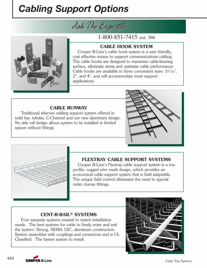
Cabling Support Options
448
FLEXTRAY CABLE SUPPORT SYSTEMSCooper B-Line’s Flextray cable support system is a low
profile, rugged wire mesh design, which provides aneconomical cable support system that is field adaptable.The unique field control eliminates the need to specialorder clumsy fittings.
CABLE HOOK SYSTEMCooper B-Line’s cable hook system is a user friendly,
cost effective means to support communications cabling.The cable hooks are designed to maximize cable-bearingsurface, eliminate stress and optimize cable performance.Cable hooks are available in three convenient sizes: 15/16",2", and 4", and will accommodate most supportapplications.
CABLE RUNWAYTraditional telecom cabling support system offered in
solid bar, tubular, C-Channel and our new aluminum design.No side rail design allows system to be installed in limitedspaces without fittings.
CENT-R-RAIL® SYSTEMSFour separate systems created to match installation
needs. The best systems for cable to freely enter and exitthe system. Strong, NEMA 12C, aluminum construction.System assembles with couplings and connectors and is ULClassified. The fastest system to install.
Ask The Experts!Ask The Experts!1-800-851-7415 ext. 366
Cable Tray Systems

MEMBER
B-Line Systems was formed in 1956 andhas over 30 years experience manufacturingcable tray systems in which it has grown tobecome the industry leader. This growthwas achieved by offering unmatched qualityin both service and products.
Today Cooper B-Line stands alone in itscustomer service resources with cable trayfabrication location at four locationsthroughout the United States. Strategicallylocated facilities alone do not generateunmatched service. The professional staff atCooper B-Line is knowledgeable, energetic,and care about customer needs. The rightattitude coupled with the facilities doesgenerate unsurpassed customer service.
Cooper B-Line’s product offerings alsoset new standards. Cooper B-Linemanufactures cable support product linesthat bridge both the electrical and telecommarkets. Each of those product lines areengineered to provide top performancewhile offering unique installation savings.This catalog is dedicated to the metallic andnon-metallic, two side rail, cable traysystems.
WIREWAYCooper B-Line offers commercial and industrial wireway
and wiring trough to handle almost any of your wire andcable routing needs. Commercial Type 1 and 3R designsare available with or without knockouts. Sizes range from2.5" x 2.5" to 12" x 12" and lengths from 12" to 120".Industrial NEMA 12 designs are available in both lay-in andfeed-through styles. Wireway is available in ANSI 61 graypainted steel and Type 304 stainless steel. Cooper B-Linecan also provide special sizes, finishes, and othermodifications.
CHANNEL CABLE TRAYCooper B-Line’s channel cable tray is a compact,
adaptable, easy to install system that is available in steel,aluminum, and fiberglass. System has fittings availableas well as connectors and a full line of accessories.
CABLE TRAY SYSTEMSCooper B-Line’s traditional two side rail cable tray.
Rugged two side rail construction protects cables and allowsfor a wide range of sizes and strengths. Coupled with alarge selection of materials, finishes, and bottom types,these engineered systems can satisfy your particularrequirements.
REDI-RAIL™ SYSTEMSThis new high tech design offers new freedom to the
installer. The mechanically assembled, pre-punched side raildesign provides unmatched job sight adaptability for a twoside rail system. Loading depths from 2" to 6", aluminumconstruction.
Ask The Experts!Ask The Experts!
“ BB-- VVOO CCAALLSS MM“ BB-- VVOOCCAALLSS MM
Questions, Comments, Suggestions?
with Cooper B-Line ”Voice Of the Customer...Actively [email protected]
618-654-2184 ext. 456
“ BB-- VVOOCCAALLSS MM
Ask The Experts!Ask The Experts!
Cooper B-Line509 West Monroe Street Phone: 800-851-7415Highland, IL 62249 Fax: 618-654-1917
www.cooperbline.com
1-800-851-7415 ext. 366
1-800-851-7415 ext. 366
Cooper B-Line cable trays conformto the requirements of IEC Standard61537, 2001 Ed.
Cable Tray SystemsCable Tray Systems
Cabling Support OptionsIntroduction
449
Important notice: The information herein has been carefully checked for accuracy and is believed to be correct and current.No warranty, either expressed or implied, is made as to either its applicability to or its compatibility withspecific requirements of this information, nor for damages consequential to its use. All design characteristics,specifications, tolerances and similar information are subject to change without notice.
Other Cooper B-Line Product Lines
Strut Systems (Bolted Framing)Electrical EnclosuresElectronic EnclosuresPipe Hanger & Support SystemsSpring Steel FastenersCable Runway & Relay Racks (CommData)Meter Mounting & Distribution EquipmentAnchors
© 2009 Cooper B-Line, Inc. Printed in U.S.A. 10509
SYSTEMS THAT MAKE SENSE
“ BB-- VVOO CCAALLSS MM“ BB-- VVOO CCAALLSS MM
Questions, Comments, Suggestions?
with Cooper B-Line ”Voice Of the Customer...Actively [email protected]
618-654-2184 ext. 456
“ BB-- VVOO CCAALLSS MM
Cable Tray SystemsAluminum, Steel, Stainless Steel & Fiberglass Cable Tray SystemsRedi-Rail™ & Cent-R-Rail® Tray SystemsCable Channel & Wire Basket Systems
Cab
le Tray System
s
CT-09
Cooper B-Line509 West Monroe StreetHighland, IL 62249Phone: 800-851-7415Fax: 618-654-1917
www.cooperbline.com
Cooper Industries, Ltd.600 Travis, Ste. 5800Houston, TX 77002-1001Phone: 713-209-8400www.cooperindustries.com
CT-09