By-product formation in the nitrobenzene hydrogenation ...
28
By-product formation in the nitrobenzene hydrogenation reaction with an 1 industrial nickel catalyst 2 3 a João D. Sousa, b Clemente P. Nunes, a Paulo Araújo, c Nuno M.C. Oliveira, d Filipe G. 4 Freire 5 6 a CUF – Químicos Industriais, S.A., Quinta da Indústria, 3860-680 Estarreja, Portugal 7 8 b Chemical Process Centre, Chemical Engineering Department, Instituto Superior Técnico, 9 Universidade de Lisboa, Av. Rovisco Pais, 1049-001 Lisboa, Portugal 10 11 c Chemical Engineering Department, Faculty of Science and Technology, University of 12 Coimbra, Rua Sílvio Lima, 3030-790 Coimbra, Portugal 13 14 d IBB-Institute for Biotechnology and Bioengineering, CERENA, Instituto Superior Técnico, 15 Universidade de Lisboa, Av. Rovisco Pais, 1049-001 Lisboa, Portugal 16 17 18 Corresponding author: Prof., Filipe Gama Freire; [email protected]; IBB, Instituto Superior 19 Técnico, Universidade de Lisboa, Av. Rovisco Pais, 1049-001 Lisboa, Portugal 20 21 Received [Dates will be filled in by the Editorial office] 22 23 24 Although aniline synthesis via nitrobenzene hydrogenation is well documented, 25 research about simultaneous by-product formation is still scarce. 26 The understanding of undesired side reactions has significant implications for process 27 design, including both the reactor and separation units, and also for tackling important 28 environmental issues. To achieve optimum aniline selectivity, a kinetic mechanism and 29 model, able to predict by-product formation during nitrobenzene hydrogenation at an 30 industrial scale, are fundamental tools. 31 The formation of by-products in the nitrobenzene hydrogenation to aniline was studied 32 in a CSTR during transient operation, using a Ni/SiO2 catalyst. Introducing different 33
-
Upload
khangminh22 -
Category
Documents
-
view
1 -
download
0
Transcript of By-product formation in the nitrobenzene hydrogenation ...

By-product formation in the nitrobenzene hydrogenation reaction with an 1
industrial nickel catalyst 2
3
aJoão D. Sousa, bClemente P. Nunes, aPaulo Araújo, cNuno M.C. Oliveira, dFilipe G. 4
Freire 5
6
aCUF – Químicos Industriais, S.A., Quinta da Indústria, 3860-680 Estarreja, Portugal 7
8
bChemical Process Centre, Chemical Engineering Department, Instituto Superior Técnico, 9
Universidade de Lisboa, Av. Rovisco Pais, 1049-001 Lisboa, Portugal 10
11
cChemical Engineering Department, Faculty of Science and Technology, University of 12
Coimbra, Rua Sílvio Lima, 3030-790 Coimbra, Portugal 13
14
dIBB-Institute for Biotechnology and Bioengineering, CERENA, Instituto Superior Técnico, 15
Universidade de Lisboa, Av. Rovisco Pais, 1049-001 Lisboa, Portugal 16
17
18
Corresponding author: Prof., Filipe Gama Freire; [email protected]; IBB, Instituto Superior 19
Técnico, Universidade de Lisboa, Av. Rovisco Pais, 1049-001 Lisboa, Portugal 20
21
Received [Dates will be filled in by the Editorial office] 22
23
24
Although aniline synthesis via nitrobenzene hydrogenation is well documented, 25
research about simultaneous by-product formation is still scarce. 26
The understanding of undesired side reactions has significant implications for process 27
design, including both the reactor and separation units, and also for tackling important 28
environmental issues. To achieve optimum aniline selectivity, a kinetic mechanism and 29
model, able to predict by-product formation during nitrobenzene hydrogenation at an 30
industrial scale, are fundamental tools. 31
The formation of by-products in the nitrobenzene hydrogenation to aniline was studied 32
in a CSTR during transient operation, using a Ni/SiO2 catalyst. Introducing different 33

2
quantities of the detected by-products in the feed stream, and observing their time evolution 34
during the transient operation, the interactions between the different species were determined. 35
The proposed new mechanism that is now presented, considers all detected species, 36
and the experimental results were simultaneously adjusted to a relative error of approx. 10%. 37
The new mechanism is able to explain the formation of cyclohexanone, and its 38
subsequent hydrogenation to cyclohexanol, and also provides new insights on the inter-39
conversion between cyclohexanone and N-cyclohexylideneaniline. 40
41
Keywords: Aniline, by-products, mechanism, CSTR kinetics, hydrogenation 42
43
44
Introduction 45
46
With more than 300 different end products, aniline (ANL) is currently used as a raw 47
material for p,p-methylene diphenyl diisocyanate (MDI) production (Kirk-Othmer, 2007). 48
MDI, discovered by Bayer in 1930 (Wegener et al., 2001), is one of the main isocyanates that 49
reacts with alcohols (such as polyols and polyetherols) to produce polyurethanes. 50
Applications for MDI based polyurethanes are mainly rigid and semi-rigid foams, elastomers 51
and coating resins for construction, insulation, furniture and the automotive industries 52
(Ullmann’s, 2003). Over 85% of commercial ANL is synthetized by nitrobenzene (MNB) 53
hydrogenation in the presence of a metal catalyst (Fig. 1). The reaction can take place in 54
stirred (CSTR) or tubular reactors. Supported Pd and Pt catalysts are suitable for tubular 55
reactors, while Ni, Rh and Ru catalysts are the most common in CSTR designs (Aramendia et 56
al., 1982; Galvano et al, 1987; Lee et al., 2000; Gottlinger et al., 2004; Gelder, 2005; Meng et 57
al., 2009; Raj et al., 2012; Knauf et al., 2013). For support, silica, alumina or activated carbon 58
are usually chosen. 59
60
61
Fig. 1. Hydrogenation of nitrobenzene to aniline. 62
63

3
The MNB hydrogenation reaction can occur in biphasic or in triphasic reactors (Raj et 64
al., 2012; Gelder, 2005; Relvas et al., 2008a; Lynch & Ryan, 2012). In triphasic 65
configurations, slurry type CSTR reactors are normally used. Solid/liquid separation, catalyst 66
homogeneity and mass/heat transfer limitations become the main challenges in this 67
technology. Small catalyst particles, with circa 50 μm of diameter, associated with milling 68
effects and low sedimentation rates, difficult the catalyst recovery from the reaction effluent. 69
The MNB hydrogenation is carried out in slurry reactors at 353-523 K and 0.1-0.6 70
MPa (Neves, 2007). MNB conversion is normally expected to be 98-99% or higher. Water 71
and ANL form immiscible liquid phases, with 8% (w/w) water in ANL, at 298.15 K 72
(Downing et al., 1997); consequently, MNB is usually mixed in the input stream with an 73
organic solvent to reduce the water mass fraction, thus avoiding liquid phase separation. For 74
economical purposes, the best solvent is often ANL itself. This reaction is also well known 75
for its high exothermicity (ΔrH=-537 kJ mol-1) (Machado 1994; Wegener et al., 2001; Klemm 76
et al., 2001). 77
Nowadays ANL synthesis by MNB hydrogenation is a well documented and patented 78
process (Zhener 2005; Bocquenet 2008; Mahata et al., 2008; Králik et al., 2012; Qin et al., 79
2014). The reaction has been thoroughly studied and several mechanisms and kinetic models 80
have been presented through the years. Langmuir-Hinshelwood based models are usually 81
considered to describe this phenomenon (Turek et al., 1986; Frikha et al., 2006; Relvas et al., 82
2008a). Nevertheless, studies of by-product formation studies in ANL plants are as yet scarce 83
when compared to the main reaction. Few authors have described all of the species involved, 84
and even fewer have presented kinetic models. This is an important subject for economic 85
reasons, since a large fraction of the present operating costs in ANL manufacture is incurred 86
in the subsequent separation of the by-products originated during the hydrogenation step. 87
Hence the significance of more studies, like the present one, which describe the formation of 88
by-products during the MNB hydrogenation to ANL in industrial plants. 89
90
By-products of the MNB hydrogenation 91
92
In 1986, Turek et al. studied the liquid phase MNB hydrogenation in the presence of 93
Ni/Al2O3 in ethanol. The following by-products were detected by gaseous chromatography 94
(GC): cyclohexanol (CHOL), N-ethylaniline, toluidine, cyclohexylamine (CHA) and 95
diaminobenzene. The authors only constructed a kinetic model for CHOL and N-ethylaniline, 96
which were the main by-products. Since ethanol was used as a solvent, these two by-products 97

4
are expected to reach higher concentrations, as a result of the reaction between ethanol and 98
ANL molecules. 99
Graham (1980) and Weidig (1989) patented methods for pure ANL storage during 100
large periods, i.e., to avoid discoloration and oxidation. Their reaction effluent consisted 101
mainly of ANL and water, but Graham noticed that, of all impurities, cyclohexanone 102
(CHONA) was the critical one because of its similar volatility to ANL, thus hindering the 103
purification of this product by distillation. The authors also pointed out that CHONA reacts 104
reversibly with ANL to form N-cyclohexylideneaniline (CHENO) and water (Fig. 2); this 105
reaction is fast even at room temperature. Finally, according to these authors, one can displace 106
the equilibrium to the right by adding phosphoric acid or a derivative thereof. For this 107
purpose, the concentration of phosphoric acid should not exceed 5% (w/w). 108
109
110
Fig. 2. Cyclohexanone / N-cyclohexylideneaniline equilibrium. 111
112
Recently, Shimizu et al. (2011) studied the selective hydrogenation of 113
nitrocyclohexane to cyclohexanone oxime, an important reactant in the nylon-6 synthesis, by 114
alumina-supported gold cluster catalysts. Cyclohexanone oxime can be also hydrogenated into 115
CHONA and CHA. They react between them to form cyclohexyl-cyclohexylidene amine and 116
dicyclohexylamine (DICHA) appeared as by-product. 117
Narayanan et al. (1995; 1997) studied the products formation in the ANL 118
hydrogenation over Co/Al2O3 and Ni/Al2O3. The products identified were: cyclohexylamine 119
(CHA), N-cyclohexylaniline (CHANIL), dicyclohexylamine (DICHA) and, through CHA 120
deamination, cyclohexane and ammonia (Fig. 3). For short residence times, only CHANIL 121
was observed; for medium residence times CHA and DICHA start to appear and, finally, 122
cyclohexane and ammonia were also detected. The authors suggested that ANL is first 123
hydrogenated to CHA and then reacts with another ANL molecule to form CHANIL. This last 124
species can then be hydrogenated to DICHA; this hypothesis was supported by the fact that 125
no CHANIL and DICHA were formed without CHA in the reaction bulk. Comparing 126
Co/Al2O3 and Ni/Al2O3, in the presence of Co/Al2O3, the authors observed only the formation 127

5
of CHA and CHANIL, while in the presence of nickel DICHA was also detected. Residual 128
cyclohexane and ammonia were also detected, but only for temperatures higher than 523 K. 129
130
131
132
Fig. 3. Mechanism of by-product formation during the MNB hydrogenation, by Narayanan et 133
al. (1997). 134
135
In their work on the MNB hydrogenation in trickle-bed reactors, using aluminum 136
supported palladium catalysts, Mitchell et al. (2010) not only observed CHA, CHANIL and 137
DICHA, CHONA and CHENO, but also ciclohexanol (CHOL), benzene and diphenylamine. 138
Mahata et al. (2008), considered the MNB hydrogenation over nickel nanoparticles 139
stabilized by filamentous carbon, and detected the existence of parallel reactions where 140
impurities in MNB act as reactants. The authors identified, for example, the hydrogenation of 141
p-nitrophenol to p-aminophenol. Nitrophenols can be found as residual impurities in 142
commercial MNB (>50 ppm), since they are by-products in the synthesis of MNB through the 143
benzene nitration process. However, this phenomenon can be better observed in lab scale 144
experiments while in industrial MNB plants it is more rarely detected. On the other hand, 145
several authors (Neves 2007; Relvas 2008) mentioned the existence of toluidine in 146
commercial ANL. Toluidine is a nitrotoluene hydrogenation product. Nitrotoluene is an 147
impurity in the MNB feed flow (>200 ppm) formed by the toluene nitration (which is an 148
impurity of benzene). 149
In 1997, Nagata et al. proposed a mechanism for by-product formation in the MNB 150
hydrogenation. The authors identified CHA, CHANIL, CHONA, CHENO and DICHA. Fig. 4 151
presents this mechanism for the MNB hydrogenation in the gas phase, over a Pd/Pt catalyst. 152

6
ANL is first hydrogenated to form an imine, a hypothetical intermediate (not detected by gas 153
chromatography analysis), in a rate-limiting step. This imine is considered to be extremely 154
reactive and originates CHA, CHONA or CHANIL. Like Graham et al., (1980) Nagata et al. 155
(1997) indicate that CHONA reacts with ANL to form CHENO and water. CHENO can be 156
also hydrogenated to CHANIL and further hydrogenated to DICHA. Apparently these last 157
authors did not verify any relation between the presence of CHA and CHANIL, like 158
Narayanan et al. (1997) did. 159
160
Fig. 4. Mechanism for by-product formation during the MNB hydrogenation, by Nagata et al. 161
(1997). 162
163
Cirtiu et al. (2007) indicates that CHONA can be hydrogenated to CHOL and Petrov et al. 164
(1989) mentioned also the presence of benzene, ammonia, diphenyl and methane. 165
With a 2% Ru/Al2O3 catalyst, Debdut and Raghunath (2005) identified aminocyclohexene 166
by GC analysis, as the intermediate of the aniline hydrogenation to cyclohexylamine and 167
proposed a simple mechanism for CHA formation. 168
Relvas (2008; et al., 2008a), in his work on MNB hydrogenation with supported nickel 169
catalysts, analysed the by-product formation in industrial reactors. The author verified the 170
influence of temperature, pressure, MNB concentration and catalyst mass in CSTR 171
experiments, and proposed also a mechanism for by-product formation. Of the already 172

7
mentioned species, CHA, CHANIL, DICHA, CHONA, CHOL and CHENO were observed. 173
The kinetic model was based on the Nagata et al. (1997) mechanism, with the CHONA 174
hydrogenation step (suggested by Cirtiu et al. in 2007) also included (Fig. 5). Although 175
Relvas (2008; et al., 2008) includes the imine formation, this species was not experimentally 176
detected. The type of catalyst and its catalytic activity seemed to have an important role in the 177
extension of the reactions. For example, the author verified that the CHONA concentration 178
increased as the catalyst became deactivated. A problematic aspect was describing the 179
CHENO formation, since this model presented relative deviations higher than 20%, which 180
only occurred with this chemical species. 181
182
183
Fig. 5. Mechanism for by-product formation during MNB hydrogenation, by Relvas (2008; et 184
al., 2008). 185
186
More recently, Králik et al. (2012) suggested a complex reaction mechanism for the 187
hydrogenation of ANL to CHA in the presence of a commercial powder Ru catalyst, directed 188
towards the CHA production. CHA is an important intermediate for the production of CBS 189

8
(N-cyclohexyl-2-benzothiazolesulphenamide), an accelerator for rubber vulcanization and 190
water treatment, among other uses. Yields of CHA of up to 95% were achieved, whereas 191
DICHA was formed as the main side product. The authors claim that the ANL conversion to 192
CHA, which requires the total hydrogenation of the aromatic ring, is a complicated procedure 193
in the liquid phase. It requires a wide number of side reactions as shown in Fig. 6, involving 194
several unstable intermediate species to form CHA and/or DICHA. These occur in several 195
reversible steps, although many of these intermediate species may be assumptions of plausible 196
intermediates that are not readily detected experimentally. However, as the ANL 197
hydrogenation occurs in the absence of oxygen molecules, i.e., in the absence of water and 198
MNB molecules, previously detected species such as CHONA and CHOL are not included in 199
this reaction mechanism. 200
Furthermore, Králik et al. (2012) also addressed the MNB hydrogenation reaction in 201
the liquid phase (Fig. 7). The authors notice that the thermal energy of the output streams in 202
the industrial MNB hydrogenation is also important, due to the high exothermicity of this 203
reaction. In this scenario, although the highest reaction temperature is preferred for maximum 204
heat recovery, the by-product selectivity and lifetime of the catalyst need also to be 205
considered, which constitute potentially conflicting objectives. This compromise has 206
motivated inventors Pasek & Petrisko (2012) to patent a multi-stage reactor, consisting of two 207
continuous reactors in cascade. The first reactor operates at a higher temperature (up to 208
250ºC) with conversion of MNB up to circa 99%, while the second reactor operates at a lower 209
temperature (≤100ºC), to hydrogenate the non-converted MNB. This enables to production of 210
high-pressure steam in the first reactor and ANL with high selectivity in the second reactor, 211
resulting in virtually 100% conversion of MNB. 212
213

9
214
Fig. 6. Reaction routes of aniline hydrogenation, by Králik et al. (2012). 215
216
217
218
Fig. 7. Reaction routes of MNB hydrogenation, by Králik et al. (2012). 219
220

10
221
This overview indicates that the information about by-product formation during ANL 222
production is still little understood. The amount of by-products, the possible mechanism 223
paths, and the possibility of having reversible, parallel and/or side reactions create a very 224
large number of plausible mechanisms that could be considered good initial candidates to 225
quantitatively describe the formation of by-products. However, despite the previous efforts by 226
several authors and to the best of our knowledge, no single mechanism published in the open 227
literature seems to adequately describe the complete formation of by-products resulting from 228
the liquid phase hydrogenation of MNB to ANL, in conditions of industrial interest. 229
The availability of an established mechanism, and a reliable kinetic model for by-230
product formation during the hydrogenation phase, is a key factor for thorough ANL plant 231
optimization, since they can provide a systematic basis for improved reactor designs that 232
allow an increased heat recovery in this phase, while simultaneously leading to significant 233
reductions of the heat loads necessary in the final distillation steps. 234
The main goal of this work is therefore to contribute to a better understanding of the 235
mechanism of by-product formation during the ANL production by liquid phase 236
hydrogenation of MNB. Due to the complexity of the mechanisms previously proposed, an 237
innovative aspect of this study is the use of transient data from various laboratory runs, where 238
some of the by-products are selectively included in the input stream, in various experiments. 239
These combinations of experimental conditions provide independent data that allow a better 240
elucidation of the existing interactions between different by-products during the several 241
reaction steps. 242
243
244
Experimental 245
246
To study the by-product formation, several hydrogenation tests in the presence of a 247
commercial Ni/SiO2 supported catalyst were carried out in a 1 L Parr continuous stirred lab-248
scale reactor (model 4520), for 8 hours each. The diagram of the experimental installation 249
used is presented in Fig. 8. To promote a homogeneous solution with effective gas dispersion, 250
the reactor has an air-impelled stirrer. In each experiment, the reactor was first loaded with 251
catalyst and ANL (≥99.8%) and then pressurized with H2. The H2 flow was monitored with a 252
Brooks flow meter and a pressure regulator is used to control the reactor pressure. The 253
reaction bulk was heated with an electric resistance, while a water-cooling coil removed the 254

11
excess reaction heat. All tests were operated under near isothermal and isobaric conditions, 255
with a stirring speed above 1000 rpm to ensure a chemical regime (Frikha et al., 2006; 256
Machado 1994). A stainless steel filter guaranteed solid-liquid separation of the output flow. 257
The input stream was promoted with a HPLC pump. 258
The set of operating conditions is presented in Table 1. Due to confidentiality reasons, 259
and notwithstanding the main motivation of completely understanding the kinetic mechanism 260
for by-product formation in MNB hydrogenation, some of the operating conditions used are 261
indicated only as reference values, while some of the concentrations are reported in 262
adimensional units (a.u.). 263
264
265
Fig. 8. Schematic representation of the experimental setup. 266
267
268
Table 1. Experimental reactor conditions 269
270
Type CSTR
Temperature (K) T
Pressure (MPa) P
Liquid volume (L) 0.5
Residence time (min) 100
Catalyst concentration (kgcat/kgbulk) Ccat
Catalyst particle diameter (μm) 1-1000
Stirring speed (rpm) >1000
271
Reactor
PI
H2
Sample
Pump
Input stream
Cooling water
Flowmeter
PI
Compressed air
TT
FT
N2
Heat exchanger
Filter

12
272
All experiments were performed at the same temperature, pressure, and residence 273
time, using the same catalyst concentration. On the other hand, in each experiment the input 274
stream had a different composition as shown in Table 2. Five experiments were chosen: in 275
experiment EANL, pure ANL (≥99.8% w/w) was introduced in the reactor; experiments 276
E0.08CHA, E1CHA and EH2O consisted in CHA (0.08% w/w), CHA (1% w/w) and H2O (4% w/w) 277
diluted in the ANL input stream, respectively. These three experiments were then compared 278
with the MNB hydrogenation by feeding the reactor with an ANL/MNB mixture (70/30% 279
w/w). 280
281
282
Table 2. Hydrogenation reaction experiments. 283
284
Experiment Input stream composition
(% w/w)
EANL ANL (≥99.8)
E0.08CHA ANL + CHA (0.08%)
E1CHA ANL + CHA (1%)
EH2O ANL + H2O (4%)
EMNB ANL + MNB (30%)
285
286
Organic compounds were quantified by GC, using an Agilent 6890A chromatograph, 287
equipped with two parallel FID detectors using two columns: a HP-5 column (5% diphenyl e 288
95% dimethylpolysiloxane, 50m × 320µm × 1,05µm) and a wide bore HP-1 column (100% 289
dimethylpolysiloxane, 30m × 320µm × 4µm). The calibration method was done by an external 290
standard. 291
Besides ANL and MNB, the species identified in the output flow were CHA, CHOL, 292
CHONA, CHENO, CHANIL, DICHA and some benzene. Residual o-toluidine was also 293
detected. Species like cyclohexane and phenol were not detected. ANL was the major 294
compound in every sample analysis (≥95% w/w). As ANL behaves in the case as a solvent, its 295
concentration was determined by mass balance closure. For modeling purposes, ANL was 296
assumed to be in excess and its concentration was assumed to remain constant throughout the 297
experiment. 298

13
299
Mathematical modeling 300
301
MNB hydrogenation kinetic rate 302
303
Several authors claim that the MNB hydrogenation reaction can be considered 304
irreversible. Gelder (2005) states that the nitro group is one of the most easily transformed of 305
all functional hydrogenations groups (losing only to acetylene hydrogenation). The estimated 306
value of the equilibrium constant for the MNB hydrogenation reaction is 1.53×1084 at 307
standard temperature and pressure, which indicates that the reaction is essentially irreversible 308
for our practical purposes. The kinetic term for MNB hydrogenation is well described by 309
Langmuir-Hinshelwood based models like the ones shown in expressions Eq. (1), claimed by 310
Relvas et al. (2008a), or Eq. (2), claimed by Turek et al. (1986), respectively: 311
312
(1) 313
314
(2) 315
316
Here r1 is the rate of MNB hydrogenation per mass of catalyst, CMNB and CH2 are the 317
concentrations of MNB and H2, k1 is the rate constant, KMNB and KH2 are adsorption constants 318
for MNB and H2, respectively. Since in this work the total pressure was maintained constant 319
throughout the experiments, the influence of the H2 partial pressure is not quantified. 320
Moreover, as the temperature and residence time also remained constant throughout the tests 321
in this CSTR apparatus, the effect of each adsorption term on the kinetic rate is difficult to be 322
discriminated. However, for MNB concentrations inferior to 50 ppm in the reactor, the 323
reaction can be approximated by a first order model relative to the reactant (Relvas et al., 324
2008a). According to the experimental data, the MNB content was practically residual and 325
therefore, Eq. (1) and Eq. (2) can be simplified to Eq. (3) 326
327
(3) 328
329
)1( 22
2211
HHMNBMNB
HMNBHMNB
CKCKCCKKk
r++
=
)1)(1( 22
2211
HHMNBMNB
HMNBHMNB
CKCKCCKKk
r++
=
MNBCkr '11 )( =-

14
where k’1= k1KMNBKH2CH2 is the apparent kinetic rate constant for the MNB 330
hydrogenation, per mass of catalyst. 331
332
By-product kinetic rates 333
334
All reactions that lead to the formation of by-products were initially assumed as 335
reversible steps, in various possible reaction networks. The setup mass balances can be 336
generically written for species as eq. 4. 337
338
(4) 339
340
where Cj,in and Cj are the concentrations of species j in the input stream and output 341
stream, respectively; τ is residence time, mcat is the catalyst mass, rForm and rCons are the rates 342
of formation/consumption that occur on the surface of the catalyst (and thus are dependent on 343
the catalyst mass), and αl,j are the stoichiometric coefficients of the species j on reaction l. 344
Given the previous assumptions, each reaction rate was considered elementary and so 345
expressed as a product of a kinetic constant and the concentrations of the reactant species j 346
and l as in eq. 5: 347
348
(5) 349
350
Non-linear regression was applied to estimate the kinetic parameters for different 351
hypothetical reaction mechanisms and experimental data. For this purpose, an objective 352
function (eq. 6) based on the weighted sum of squares was minimized, 353
354
(6) 355
356
where ωi,j are the weights for species j in experiment i, which in the present case are 357
given by eq. 7: 358
359
catlConslForml
jljinjj mrrCC
dtdC
úû
ùêë
é-+-= å )()(1 ,,,, a
t
jill CCkr =
( )2
, 0, )()()( å å
=
-=ji
t
ti
Modji
Expjjii tCtCkE v

15
(7) 360
361
E(ki) is the objective function to be minimized; and are the 362
concentrations of the species j, at time t in experiment i, given by the experimental data and 363
corresponding model, is the average concentration of species j registered in experiment 364
i. A nonlinear programming (NLP) formulation was constructed, corresponding to the 365
minimization of this objective function subject to the set of previous mass balances, their 366
kinetic models and parameter constraints, as shown in Eq. (8). In this minimization all 367
parameters and concentrations have non-negative values. 368
Given the nature of the kinetic mechanisms described previously, the existence of 369
intermediate species such as imines (not detected experimentally, though) is very likely. 370
When the mechanisms considered include the presence of this type of species, an additional 371
constraint that limits the maximum concentration of these intermediates to the GC threshold 372
of detection (GC LD) is also added to the formulation. 373
374
(8) 375
376
Approximate standard errors (ASE), sometimes also referred to as an asymptotic 377
standard error, were calculated for each parameter estimate. ASE can be used for computing 378
confidence intervals in place of exact standard errors (Graybill, 1994). 379
Considering the previous kinetic models, proposed by other authors, and the 380
qualitative analysis of the experimental results obtained, an initial mechanistic scheme was 381
considered (Fig. 9). The parameters ki in this model were initially determined, and they were 382
compared with their respective ASE(ki) values. When large ASE(ki) values were detected, 383
various simplifications in the kinetic terms were considered, including suppressing these 384
kinetic steps. 385
386
ϖ i, j =1!CjExp
l
CjExp(t)
lCj
Mod (t)l
!CjExp
l
Min E(ki )s.t. Eqs. (4 − 5)
ki ≥ 0, ∀ik ≡ ki,k−i{ }Cj ≥ 0, ∀iCintermediates ≤GC LD

16
387
388
Fig. 9. Initially proposed mechanism for by-production formation during MNB 389
hydrogenation, in the presence of a supported nickel catalyst. 390
391
392
All of the reaction schemes previously described were used as starting points for this 393
purpose, and modifications were introduced when necessary. Both Narayanan’s and Nagata’s 394
models were not sufficient by themselves to describe all detected species, and thus needed to 395
be combined with additional reaction paths to describe the complete system. Between 396
Relvas’s and Králik’s models, the later could produce better agreement with experimental 397
data, but at the cost of a greatly increased model complexity. 398
The parameter estimation and ASE calculations were performed by COPASI, a 399
Complex Pathway Simulator (Hoops et al., 2006). 400
401
402
Results and discussion 403
404

17
Preliminary experiments, at room temperature, confirmed the equilibrium between 405
CHONA and CHENO, as shown before in Fig. 2. By adding CHONA to a pure ANL sample, 406
the formation of CHENO was immediately detected. Although this experimental data was not 407
modeled, it helped to reach a final reaction mechanism (especially relatively to step 12 in Fig. 408
9). 409
Since the initial scheme has many interdependencies between the by-products giving 410
low precision to some of the parameters, ki, we chose an experimental design that was able to 411
“break” some of these correlations, especially between the intermediate species, by perturbing 412
the eventually reversible steps that involve these species and the reaction steps. 413
Using this procedure, we were able to simplify the initially proposed mechanism to the 414
simplified mechanism presented in Fig. 10. 415
416
417
418
Fig. 10. Final mechanism for by-production formation during the MNB hydrogenation in the 419
presence of a Ni supported catalyst, based on the kinetic modeling results shown in Table 3. 420
421
422
NH2
NH2
ANL
CHA
HN
HN
CHANILDICHA
N
CHENO
O OH
ANL+NH3
CHONA CHOL
NO2
MNB
H2O
2H2O
NH3ANL
NH3ANL
r1
r3
r2
r13
r12
r9
r5

18
Experimental profiles and modeling results achieved with this new proposed 423
mechanism are shown in Figs. 11 to 16, for each case, and duly analysed. 424
As can be observed, the effect of water creates two very different scenarios. In its 425
absence, compounds like CHA, CHANIL, CHENO and DICHA are favored, while no 426
significant amounts of CHONA and CHOL are observed. In fact, in experiments with ANL 427
and ANL+CHA, the amounts of CHONA and CHOL are proportional to the residual humidity 428
in the ANL input stream (<0.01%). In the second scenario, when water exists in the medium, 429
whether introduced in the reactor or appearing as a by-product of the MNB hydrogenation, 430
not only the concentrations of CHONA and CHOL increase considerably, but also the amount 431
of the other compounds is reduced. This phenomenon explains why Narayanan (see Fig. 3) 432
did not observe any CHONA/CHOL. An important fact is that the CHENO formation, 433
although in a way not totally clear yet, plays a major role in the reactor. Most of the reactions 434
steps are influenced by this species and thus its comprehension is crucial to better 435
understanding the formation and behavior of other by-products. 436
Other species like CHA, DICHA and CHOL are molecules with saturated carbon 437
cycles. These come most likely from hydrogenation reactions with ANL, CHANIL and 438
CHONA molecules, respectively, where activated hydrogen at the catalyst surface reacts with 439
the unsaturated bonds in the aromatic rings. The existence of a small quantity of benzene 440
suggests that hydrogenolysis reactions take place in the reactor, by withdrawing the nitro or 441
the amine group from MNB or ANL molecules, respectively. However no cyclohexane was 442
detected. Therefore no hydrogenolysis reactions with molecules with saturated carbon cycles 443
like CHA, CHOL, CHONA and DICHA seemed to take place. 444
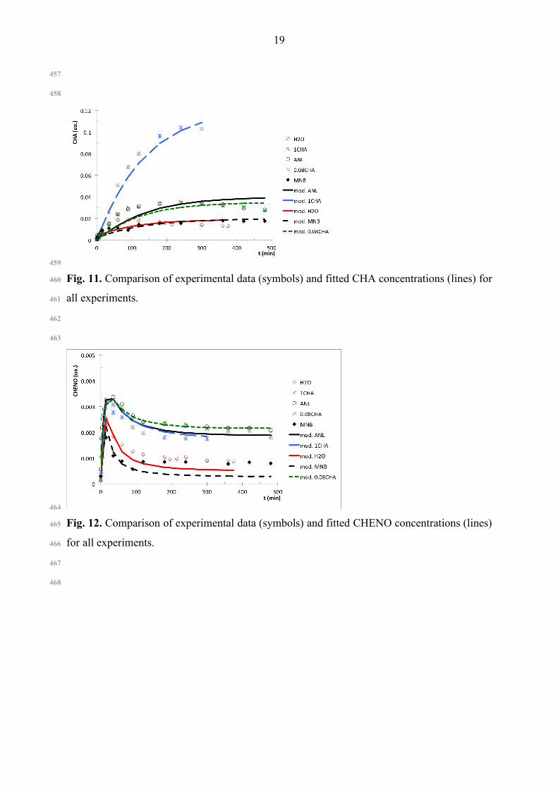
A comparison of the reaction profiles in each experiment shows a distinct behavior for 445
CHENO and for CHONA. The initial rate of CHENO formation is the highest among them 446
(Fig. 12). After a peak, the CHENO concentration drops before reaching stationary state. On 447
the other hand, CHONA (Fig. 13) only appears if water exists in the solution. This 448
observation is in total disagreement with the Nagata’s model (Fig. 4) as CHONA is not 449
present in experiments ANL and ANL+CHA. As such, CHENO must come from another 450
source rather than the reaction between ANL and CHONA (step 12, Fig. 9), which is probably 451
from an imine (step 4, Fig. 9). These statements are supported by the fact that the CHENO 452
concentration diminishes as CHONA increases. Nevertheless, additional modeling results 453
show that these two steps are not sufficient to explain the CHONA and CHENO behaviors, 454
and consequently step 11 cannot be ignored. According to Fig. 14, CHOL was formed only in 455
the presence of CHONA (step 13); this step is expected and intuitive. 456
19
457
458
459
Fig. 11. Comparison of experimental data (symbols) and fitted CHA concentrations (lines) for 460
all experiments. 461
462
463
464
Fig. 12. Comparison of experimental data (symbols) and fitted CHENO concentrations (lines) 465
for all experiments. 466
467
468

20
469
Fig. 13. Comparison of experimental data (symbols) and fitted CHONA concentrations (lines) 470
for all experiments. 471
472
473
Fig. 14. Comparison of experimental data (symbols) and fitted CHOL concentrations (lines) 474
for all experiments. 475
476
477
478

21
Fig. 15. Comparison of experimental data (symbols) and fitted CHANIL concentrations 479
(lines) for all experiments. 480
481
482
483
Fig. 16. Comparison of experimental data (symbols) and fitted DICHA concentrations (lines) 484
for all experiments. 485
486
487
Kinetic constants, ASE and final modeling errors are shown in Table 3 and Table 4, 488
respectively. 489
These suggest that the CHA, CHONA, CHANIL, DICHA and CHOL formation 490
occurs in essentially irreversible reactions. This behavior was to be expected, since it seems 491
unlikely that stable saturated species (like CHA, DICHA or CHOL) are able to dehydrogenate 492
back to their unsaturated forms, and also reinforces the consistency of the kinetic scheme. 493
Nevertheless, this interpretation cannot be extended to all of the steps considered. For 494
instance, in step 2 the results indicate that the reverse constant is orders of magnitude higher 495
than the direct constant. However, as kinetic rates are also proportional to the concentration of 496
the reactants, if we multiply the direct rate constant by the ANL concentration and the reverse 497
constant by the CHENO and NH3 concentrations, we see that step 2 occurs most probably in 498
equilibrium. On the other way, the CHONA formation, known as reversible was achieved as 499
an irreversible reaction. These can be explained as the CSTR experimental conditions are fare 500
from the equilibrium. 501
502
503

22
Table 3. Kinetic rate constants for forward (ki) and reverse (k-i) reactions based on the 504
reaction mechanism considered in Fig. 10. 505
506
Step ki Asymptotic Std.
Error ASE(ki)
r1 4.0×10² - r2 4.1×10⁻⁴ 0.2×10⁻⁴ r-2 1.8×10³ 0.2×10³ r3 2.6×10⁻³ 0.08×10⁻³ r5 1.70×10⁻³ 0.07×10⁻³ r9 4.3 0.15 r12 19.2 0.8 r13 0.44 0.01 507
508
Table 4. Kinetic model errors. 509
510
Experiment Regression error E(ki) (×107)
EANL 4.1 E0.08CHA 2.3 E1CHA 0.87 EH2O 1.0 EMNB 2.4 Objective Value 10.7×10⁻⁷ 511
512
Also according to Table 4, the final values of the objective function obtained for each 513
of these experiments, is of the same order of magnitude. These results indicate that the final 514
model is able to explain equally well each of the experimental tests considered, without a bias 515
towards a particular test. 516
Parity plots for all species and experimental runs are shown below, in Fig. 17. The 517
region inside the dotted lines represents deviations within a relative range of 10%. As can be 518
observed, the model is able in general to interpret reasonably well the experimental data, with 519
some exceptions, such as the CHONA and DICHA species. 520
521
522

23
523
524
525 Fig. 17. Parity plots of experimental concentrations (Exp.) and the corresponding model 526
values (Mod.) for all species and experiments. Dotted lines represent the ±10% error area. 527
528
529
Given the incremental procedure followed in the construction of this reaction scheme, 530
and the many alternative candidates evaluated, we believe that these results are representative 531
of the level of accuracy that can be obtained at this level of model complexity. 532
Based on the NLP results, the final scheme proposed is presented in Fig. 10, 533
constitutes a new and better insight of the overall mechanism for the formation of by-products 534
in the nitrobenzene hydrogenation reaction. 535
536
Conclusions 537
538

24
This work studied the by-product formation during the nitrobenzene hydrogenation 539
with a supported metal catalyst. This is a problem with significant industrial relevance, due to 540
the high costs incurred during the purification phase of aniline manufacture. A literature 541
review indicated that while this subject was considered in several previous works, its present 542
understanding is currently incomplete, and hinders the optimization of the overall industrial 543
process units where this reaction takes place. 544
Using experimental data obtained from a laboratory scale CSTR, various tests were 545
performed, using streams with varying compositions, to elucidate the interdependences of the 546
different by-product species. 547
Based on these results and partial information relative to possible reaction mechanisms 548
resulting from previous studies, a simple new reaction scheme was proposed in Fig. 10, that is 549
a major advance in the overall interpretation of the proposed reaction. 550
A major contribution of this work is that the corresponding kinetic model is able to 551
interpret, for the first time, the concentration profiles obtained in the experimental tests, 552
within a reasonable experimental error. The final reaction scheme illustrates the close 553
dependence of the formation of these secondary species. 554
The results obtained show that the effect of water in the reactor has a decisive impact. 555
In its presence, by-product formation moves towards cyclic carbon molecules with oxygen, 556
like cyclohexanone and cyclohexanol. On the other hand, in its absence molecules like 557
cyclohexylamine, dicyclohexylamine and N-cyclohexylaniline are obtained as the main by-558
products. 559
It was also found that it is most likely for dicyclohexylamine to come mainly from a 560
reaction between cyclohexylamine and aniline molecules and not from the hydrogenation of 561
N-cyclohexylaniline. According to the now proposed new model, for cyclohexanone to exist 562
the bulk reaction mixture must have water, while, on the other hand, N-563
cyclohexylideneaniline is always detected, even without the presence of water. It is also 564
important to underline that in the absence of cyclohexanone, no cyclohexanol is detected. 565
566
567
568
Symbols 569
570
ANL aniline 571
ASE approximate standard error 572

25
CHA cyclohexylamine 573
CHANIL N-cyclohexylaniline 574
CHENO N-cyclohexylideneaniline 575
CHOL cyclohexanol 576
CHONA cyclohexanone 577
CSTR continuous stirred tank reactor 578
DICHA dicyclohexylamine 579
GC LD gas chromatography threshold detection 580
MDI p,p-methylene diphenyl diisocyanate 581
MNB nitrobenzene 582
NLP non-linear programing 583
584
585
Acknowledgements 586
The authors acknowledge financial support from the Fundação para a Ciência e 587
Tecnologia through the Ph.D. Grant SFRH/33920/2009, and technological support from CUF-588
QUI, S.A., for the development of this work. 589
590
591
References 592
593
Aramendia, M. A., Borau, V., Jiménez, C., Marinas, J. M., & Pajares, J. A. (1982). 594
Preparation of Pd/AlPO4, Pd/AlPO4-SiO2, and Pd/AlPO-γ-Al2O3 and study of their catalytic 595
activity for the reduction of nitrobenzene by hydrogen transfer. Journal of Catalysis, 78(1), 596
188-196. DOI: 10.1016/0021-9517(82)90298-6 597
Bocquenet, G., Chesnais, A., Desire, J.-M., Leconte, P., Sever, L. (2008). U.S. Patent No. 598
US7453012 B2. Washington, D.C.: U.S. Patent and Trademark Office. 599
Cirtiu, C. M., Brisach-Wittmeyer, A., & Ménard, H. (2007). Electrocatalysis over Pd 600
catalysts: A very efficient alternative to catalytic hydrogenation of cyclohexanone. Journal 601
of Catalysis, 245(1), 191-197. DOI: 10.1016/j.jcat.2006.10.010 602
Debdut, R., Raghunath, C. (2005). Analysis of a Gas−Liquid−Liquid−Solid Catalytic 603
Reaction: Kinetics and Modeling of a Semibatch Slurry Reactor. Industrial & Engineering 604
Chemistry Research, 44(25), 9586-9593. DOI: 10.1021/ie0502739 605

26
Downing, R. S., Kunkeler, P. J., & Van Bekkum, H. (1997). Catalytic syntheses of aromatic 606
amines. Catalysis Today, 37(2), 121-136. DOI: 10.1016/S0920-5861(97)00005-9 607
Frikha, N., Schaer, E., & Houzelot, J. -L. (2006). Methodology of multiphase reaction 608
kinetics and hydrodynamics identification: Application to catalyzed nitrobenzene 609
hydrogenation. Chemical Engineering Journal, 124(1), 19-28. DOI: 610
10.1016/j.cej.2006.08.012 611
Galvagno, S., Donato, A., Neri, G., Pietropaolo, R., & Poltarzewski, Z. (1987). Nitrobenzene 612
hydrogenation on pt-sn catalysts. Journal of Molecular Catalysis, 42(3), 379-387. DOI: 613
10.1016/0304-5102(87)85014-9 614
Gelder, E. A. (2005). The hydrogenation of nitrobenzene over metal catalysts. Ph.D. thesis. 615
University of Glasgow, Scotland. 616
Göttlinger, M., Gross, M., Krauter, J., Packruhn, U. (2004). EP1441850 A1. European Patent 617
Office. 618
Graham, A. J., & Ibbotson, A. (1980). U.S. Patent No. 4,207,262 A. Washington, D.C.: U.S. 619
Patent and Trademark Office. 620
Graybill, F. A., Hariharan, K. Y. (1994). Regression analysis: Concepts and applications. 621
Duxbury Press. 622
Hoops, S., Sahle, S., Gauges, R., Lee, C., Pahle, J., Simus, N., . . . Kummer, U. (2006). 623
COPASI—a complex pathway simulator. Bioinformatics, 22(24), 3067-3074. DOI: 624
10.1093/bioinformatics/btl485 625
Lee, S.-P. and Y.-W. Chen (2000). Nitrobenzene hydrogenation on Ni–P, Ni–B and Ni–P–B 626
ultrafine materials. Journal of Molecular Catalysis A: Chemical, 152(1-2), 213-223. DOI: 627
10.1016/S1381-1169(99)00298-8 628
Lynch, M.K., Ryan, L.P. (2012). Nitrobenzene/Aniline/MDI, Chemsystems PERP Program , 629
Nexant Inc. 630
Kirk-Othmer (2007). Aniline and its Derivatives, Amines, Aromatic, in Encyclopedia of 631
Chemical Technology, M. Howe-Grant, Editor., John Wiley & Sons: New York. p. 426-482. 632
DOI: 10.1002/0471238961.0114091201130914.a01.pub2 633
Klemm, E., Amon, B., Redlingshöfer, H., Dieterich, E., & Emig, G. (2001). Deactivation 634
kinetics in the hydrogenation of nitrobenzene to aniline on the basis of a coke formation 635
kinetics—investigations in an isothermal catalytic wall reactor. Chemical Engineering 636
Science, 56(4), 1347-1353. DOI: 10.1016/S0009-2509(00)00357-2 637
Knauf, T., Merkel, M., Rausch (2013). WO/2013/030223. World Intellectual Property 638
Organization. Switzerland. 639

27
Králik, M., Turáková, M., Mačák, I., & Wenchich (2012). Catalytic hydrogenation of 640
aromatic compounds in the liquid phase. Journal of Chemistry and Chemical Engineering, 6, 641
1074-1082. 642
Machado, Reinaldo M. (1994). Fundamentals of mass transfer and kinetics for the 643
hydrogenation of nitrobenzene to aniline application note. RC User Forum USA, St. 644
Petersburg, pp. 1-15. 645
Mahata, N., Cunha, A. F., Orfao, J. J. M., & Figueiredo, J. L. (2008). Hydrogenation of 646
nitrobenzene over nickel nanoparticles stabilized by filamentous carbon. Applied Catalysis 647
A: General, 351(2), 204-209. DOI: 10.1016/j.apcata.2008.09.015 648
Meng, X., et al. (2009). Selective hydrogenation of nitrobenzene to aniline in dense phase 649
carbon dioxide over Ni/gama-Al2O3: Significance of molecular interactions. Journal of 650
Catalysis. 264(1), 1-10. DOI: 10.1016/j.jcat.2009.03.008 651
Mitchell, C. J., & Stewart, D. H. (2010). U.S. Patent No. 20,130,006,018 A1. Washington, 652
D.C.: U.S. Patent and Trademark Office. 653
Nagata, T., Kono, Y., Kohayashi, T. (1997) U.S. Patent No. 5616806 A. Washington, D.C.: 654
U.S. Patent and Trademark Office. 655
Narayanan, S., Unnikrishnan, R., & Vishwanathan, V. (1995). Nickel-alumina prepared by 656
constant and varying ph method: Evaluation by hydrogen-oxygen chemisorption and aniline 657
hydrogenation. Applied Catalysis A: General, 129(1), 9-19. DOI: 10.1016/0926-658
860X(95)00087-9 659
Narayanan, S., & Unnikrishnan, R. P. (1997). Comparison of hydrogen adsorption and aniline 660
hydrogenation over co-precipitated Co/Al2O3 and Ni/Al2O3 catalysts. J. Chem. Soc., 661
Faraday Trans., 93(10), 2009-2013. DOI: 10.1039/A608074J 662
Neves, F. J. M. (2007). Modelling and optimization of large-scale processes - application to 663
the liquid-phase aniline production. Ph.D. thesis, University of Coimbra, Portugal. 664
Pasek, J., Petrisko, M. (2012). EU. Patent No. 2,471,768 A1. European Patent Office. 665
Petrov, L., Vladov, C., Eliyas, A., Kirkov, N., Tenchev, K., Bonev, C., . . . Prahov, L. (1989). 666
Thermal oscillations during the catalytic hydrogenation of nitrobenzene. Journal of 667
Molecular Catalysis, 54(2), 237-242. DOI: 10.1016/0304-5102(89)80219-6 668
Petrov, L., Kumbilieva, K., & Kirkov, N. (1990). Kinetic model of nitrobenzene 669
hydrogenation to aniline over industrial copper catalyst considering the effects of mass 670
transfer and deactivation. Applied Catalysis, 59(1), 31-43. DOI: 10.1016/S0166-671
9834(00)82185-5 672

28
Qin, Z.Z., Z.L. Liu, and Y.H. Wang, Promotion Effect of Mo In Amorphous Ni-P Catalysts 673
for the Liquid-Phase Catalytic Hydrogenation of Nitrobenzene to Aniline. Chemical 674
Engineering Communications, 2014. 201(3), 8-351. DOI: 10.1080/00986445.2013.773422 675
Raj, K.J.A., Prakash, M., Mahalakshmy, R., Elangovan, T., Viswanathan, B. Liquid Phase 676
Hydrogenation of Nitrobenzene over Nickel Supported on Titania. Chinese Journal of 677
Catalysis, 2012. 33(7-8), 1299- 1305. DOI: 10.1016/S1872-2067(11)60398-7 678
Relvas, J., Andrade, R., Freire, F. G., Lemos, F., Araújo, P., Pinho, M. J., Ribeiro, F. R. 679
(2008). Secondary Products Formation of the Liquid Phase Hydrogenation of Nitrobenzene 680
over an Industrial Ni/SiO2 Supported Catalyst. In Proceedings of the Catalysis for Society 681
11-15 May 2008 Krakow, Poland. 682
Relvas, J. (2008). Modelação Cinética da Reacção de Hidrogenação do Nitrobenzeno a 683
Anilina num Reactor Trifásico Industrial. Ph.D. thesis, University of Lisbon, Portugal. 684
Relvas, J., Andrade, J. Freire, F., Lemos, F., Araújo, P., Pinho, M.J., Ribeiro, F.R. (2008a). 685
Liquid Phase hydrogenation of nitrobenzene to aniline over an industrial Ni/SiO2 supported 686
catalyst. Catalysis Today, 133, 828-835. DOI: 10.1016/j.cattod.2007.11.050 687
Shimizu, K.-i., Yamamoto, T., Tai, Y., Satsuma, A. (2011) Selective hydrogenation of 688
nitrocyclohexane to cyclohexanone oxime by alumina-supported gold cluster catalysts. 689
Journal of Molecular Catalysis A: Chemical, 345(1-2), 54-59. DOI: 690
10.1016/j.molcata.2011.05.018 691
Turek, F., Geike, R., & Lange, R. (1986). Liquid-phase hydrogenation of nitrobenzene in a 692
slurry reactor. Chemical Engineering and Processing: Process Intensification, 20(4), 213-693
219. DOI: 10.1016/0255-2701(86)80005-8 694
Ullmann's (2003). Aniline. In Ullmann's Encyclopedia of Industrial Chemistry (Vol. 3, pp. 1-695
15). Weinheim, Germany: Wiley-VCH. DOI: 10.1002/14356007.a02_303 696
Wegener, G., Brandt, M., Duda, L., Hofmann, J., Klesczewski, B., Koch, D., . . . Six, C. 697
(2001). Trends in industrial catalysis in the polyurethane industry. Applied Catalysis A: 698
General, 221(1), 303-335. DOI: 10.1016/S0926-860X(01)00910-3 699
Weidig, C. F. (1989). U.S. Patent No. 4,861,914. Washington, D.C.: U.S. Patent and 700
Trademark Office. 701
Zhner, P., Bey, O., Georgi, G., Müller, J., (2005) U.S. Patent No. 6,894,193 B2. Washington, 702
D.C.: U.S. Patent and Trademark Office. 703