

Buyers Guide Deming Power Pumps the Eiciency and ...
430
-
Upload
khangminh22 -
Category
Documents
-
view
4 -
download
0
Transcript of Buyers Guide Deming Power Pumps the Eiciency and ...


BU YERS’ GU IDE
PROTECTIVE CONSTRUCT10N AND EQUIPMENT
For Index to Announcements by C orporations, Firms , Indiv iduals ,named below, see List
'
oi Advertisers , on next Page
N EW YO RK C ITY
AIR CO MPRE SSO RSDem ing Co; (Ralph E . Ca rter C o. , 50 Church S t.)In terna t iona l S prinkler Co .
Rookwood S prinkler Co .
H . G . Vogel C o'
.
ELE CTRICAL APPARATUSH . G . Vogel Co .
F IRE ALARM SYSTEMS , AUXILIARYIn terna t iona l S prinkler Co .
F IRE DE PARTME N T SUPPLIE S.
H . G .
‘Vogel Co .
F IRE P'
AILSH . G . Vogel Co .
F ITTIN GSGenera l F ire E xt inguisher Co .
GAGE S , PRE SSUREH . G . Vogel Co ;
GAGE S, WATERH . G . Vogel Co .
GAS E N GIN E POWERCha l lenge Co . ( S tothoff Bros , 1 6 Murray S t.)
GO VERN O RS F O R PUMPSH G . Vogel Co .
In terna t i ona l S prinkler Co .
H . G . Vogel Co .
HO SE RACKS AN Dt
REEL SIn terna t i ona l S prinkler C O .
H . G . Vogel Co .
HO SE , UN LIN E -D LIN E NIn terna t i ona l S prinkler Co .
H . G . Vogel Co .
HYDRAN TS '
Genera l F ire E xtinguisher Co .
In terna ti ona l S prinkler Co.H . G . Vogel Co .
METER S , WATERH . G . Vogel Co .

2 BUYERS ’
GUIDE
LIST O F ADV ERTISERS .
PAGE
B each- Russ C o. , C hicago , I l l
C hallenge C o. , Batavia, I l l
Deming C o. , T he, S a lem.
Genera l Fire Extinguisher C o. , C hicago , I l l
Graver T ank Works , Wm. , East Chicago , Ind 5
International S prinkler C o. , Philade lphia , Pa 2 3
N ational BoilerWorks , C hicago, I ll
N ew England T ank T ower C o. ,
N iagara Fire Extinguisher C o. , Akron, O hio 2 5
Rockwood S prinkler C ol , Worcester, Mass
S cully S teel and Iron C o. , C hicago , I l l
S implex Valve Meter C o. , Philadelphia, Pa. 1 3
Voge l C o , H. G. , N ew York
Wilson C o. , F . C ortez, C hicago , I l l

BUYERS ’
GUIDE
O I L PUMPS , HAN DDem ing Co . (Ra lph B . Ca rter C o. , 50 Church S t.)H . G . V ogel Co .
PIPE SGenera l F i re E xt inguisher Co .
PIPE HAN GERSH . G . Vogel Co .
PLAY PIPE SH . G . Vogel Co .
PLAY PIPE S , MO N ITO R N O ZZLE SH . G . Vogel Co .
PUMPS , CE N TR I FUGALH . G . Vogel Co .
PUMPS , ELE CTRICDem ing C o. (Ra lph E . Ca rter C o. , 50 Church S t.)H . G . Vogel Co .
PUMPS , RO TARYDem ing Co . (Ra lph E . Carter C o. , 50 Church S t.)H . G Vogel Co .
PUMPS , STEAMH . G . Vogel Co .
PUMPS , POWERDem ing Co . (Ra lph B . Ca rter C o. , 50 Church S t.)H . G . Vogel Co .
SPRIN KLERS , AUTO MAT ICGenera l F ire E xt inguisher Co .
Interna t i ona l S prinkler Co .
Rockwood S prinkler Co .
H . G . Vogel C o.
STAN DPIPE SIn terna t i ona l S prinkler Co .
Rockwood S prinkler Co .
H . G . Vogel Co .
T AN KS , GRAVITYCha l lenge Co . ( S tothoff. Bros . , 1 6 Murray S t.)Rockwood S prinkler Co .
H . G . Vogel Co .
TAN K HEATERSRockwood S prinkler Co .
H . G . Vogel Co .
T AN KS , PRE SSURE '
Rockwood S prinkler Co .
H . G . Vogel Co .
TAN K TELL - TALE SCha l lenge Co . (S tothoff Bros 1 6 Murray S t.)H . G . Vogel Co .
TAN K TOWERS , STEELCha l lenge Co . ( S tothoff Bros . , 1 6 Murray S t.)
VALVE SCha l lenge Co . ( S tothoff Bros . , 1 6 Murray S t.)In terna t i ona l S prink ler Co .
H . G . Vogel Co .

4 BU YERS ’
GUIDE
VALVE S , ALARMGenera l F ire E xtinguisher Co .
Interna ti ona l S prinkler Co .
Rockwood S prinkler Co .
H . G . Vogel Co .
VALVE S , CHE CKDem ing Co . (Ra lph B . Ca rter C o.
,
‘
50 Church S t.)Genera l F ire E xt inguisher Co .
In terna t i ona l S prinkler Co .
H . G . Vogel Co .
VALVE S , DRYGenera l Fi re Ext inguisher Co .
In terna t i ona l S prinkler Co .
Rockwood S prinkler Co .
H . G . Vogel Co .
VALVE S , F LO ATCha l lenge Co . ( S tothoff Bros . , 1 6 Murray S t.)Deming Co . (Ra lph B . Ca rter C o.
, 50 Church S t.)H . G . Vogel Co .
VALVE S , F O O TRockwood S prinkler Co .
H . G . Vogel Co .
VALVE S , IN DICATO R GATEIn terna t iona l S prinkler Co .
Rockwood S prinkler Co .
H . G . Vogel Co .
VALVE S , PO ST IN DICATO R GAT]Genera l F ire E xt inguisher Co .
Interna t i ona l S prinkler Co .
Rockwood S prinkler Co .
H . G . Vogel Co .
L
J
L1)
C HIC AGO
A I R CO MPRE SSO RSBea ch - Russ Co .
Dem ing Co ; (Hen ion Hubbell , 61 IN Jefferson S t.)In terna t i ona l S prinkler Co .
N iaga ra F i re E xt in gu i sh er Co .
Rockwood S prinkler Co .
S cul ly S teel Iron Co .
H . G . Vogel Co .
BAR S , IRO N ST E E LS cu l ly S teel I ron Co .
BEAM STE EL ,
“ I . ”S cu l ly S teel Iron Co .
BLO WERS , PO SITIVE PRE SSUR]Bea ch - Russ Co .
BO ILERSN a t i ona l Boi ler Works .
BO ILER WO RKERS ’ SUPPLIE SS cul ly S teel Iron Co .
BO LTS , ALL KIN DSS cul ly S teel Iron Co .
[1]

BUYERS ’
GUIDE
DEMI N G P O WER PU MP ST he efii ciency and economy of our pumping mach inery has beenthoroughly tested in mil ls,mines, factories, hotels, apar tment houses,suburban residences. etc. , in al l parts O f the civi l ized world , with theresult that Deming Power Pumps have acquired an unequal ledreputation among their users for l ow operating costs, reliabi lity andminimum repairs.
Catalogue “
G ” conta ins many special engineering tabl es a nd a
complete descript ion of our Power Pumps, Power Work ing Headsand Deep Wel l Cyl inders.
THE DEMIN G C OMPAN YSALEM, O HIO
General Western Agents. HEN IO N 81 HUBBELL , C hicagoOT HER AGEN C IES I N PR IN C IPAL C IT IES
G R A V E RO N T A N KS A N D PLAT E WO RK MEA N S Q U ALIT Y
O V ER 3 5 YEARS EXP ER IEN C E
S T EEL TAN KS AN D PLAT E WO RK FO R EVERY PU RPO S E
WR IT E U S FO R PRIC ES AN D ES TIMATES
WM. GRAVER T ANKWO RKS ,E. C hicago, Ind.

6 BUYERS ’
GUIDE
BRE E CHIN GSN a t i ona l Boi ler Works .
CAN S . O ILY ”WASTEF . Cortez YV i l son C O .
CO RRUGATED IRO NS cu l ly S teel Iron C O .
ELE C TR ICAL APPARATUSH . G . Vogel C O .
E N GIN E RO O M SUPPLIE S , SHE E T METALF . Cortez V Vi l S on C O .
F IRE ALARM SYSTEMS , AUXILIARYInterna t i ona l S prinkler C O .
F IRE DEPARTME N T SUPPLIE SH . G . Vogel Co .
F IRE PAILSH . G . Vogel Co .
F ITT IN GSGen era l F i re E x t in gu i sh er C O .
FLO O R PLATE S , WRO UGHT S T E ?S cul ly S teel Iron C O .
FLUE CLEAN ERSS cul ly S teel Iron Co .
GAGE S . PRE SSUREGenera l F i re E xt inguisher Co .
H . G . Vogel C O .
GAGE S , WATERH . G . Vogel C O .
GALVAN IZED SHE E T STEELS cul ly S teel Iron C O .
GAS E N GIN E TAN KSF . Cortez Wi l son C O .
GAS TAN KSIVm . Graver Tank Works , (E a st Chicago , I nd .)
GO VERN O R S F O R PUMPSH . G . Vogel C O .
GRAVE L BASIN SN a ti ona l Boi ler Works .
HEATERS .
’
EXHAUST STEAMF Cortez Wi l son C O .
wt“
In terna t i ona l S prinkler Co .H . G . Vogel Co .
HO SE , ME TALS cu l ly S teel Iron C O .
HO SE RACKS AN D RE ELSIn terna ti ona l S prinkler C O .H . G . Vogel C O .
HO SE , UN LIN ED LIN E NInterna t i ona l S prinkler Co .H . G . Vogel Co .

BUYERS ’
GUIDE
HYDRAN TSGenera l F i re E xtingu isher Co .
Interna t i ona l S prinkler Co .
H . G . Vogel Co .
IRO N AN D STE ELS cul ly S teel Iron Co .
MACHIN ERY ,BO ILER MAKER S AN D IRON WORK
E R S
S cu l ly S teel I ron Co .
MEASURE S , ACCURATE LIQUIDF . Cortez W i l son C 0 .
T C R S , WATERH . G . Vogel Co .
N UTSS cul ly S teel Iron Co .
O I L PUMPS , HAN DDeming Co . (Hen ion Hubbel l , 61 N . Jefferson S t.)H . G . Vogel Co .
O I L PUMPS , POWERBea ch - Russ C O .
O I L PUMPS , SHEE T ME TALF . Cortez Wi lson Co .
PE N STO CKSWm . Graver T ank Works , (E ast Chicago , I nd .)
PIPE SGenera l F i re
PIPE , R IVE TEDWm . Graver Tank Works , (E a st Ch icago , I nd .)
PIPE HAN GERSN iagara F i re E x t ingu i sh er C O .
H . G . Vogel C O .
PLATE S , FLAN GE AN D TAN K S T]S cu l ly S teel I ron C O .
PLATE WO RKWm . Graver Tank Works , (E ast Chicago , I nd .)
PLAY PIPE SH . G . Vogel Co .
PLAY PIPE S , MO N ITO R N OZZLE SH . G . Vogel C O .
PUMPS , CE N T RIFUGALBea ch - Russ C O .
H . G . Vogel GQ V
PUMPS , E LE CTRICBea ch - Russ C O .
Dem ing Co . (Hen ion Hubbel l , 61 N . Jefferson S t.)H . G . Vogel C O .
PUMPS , POWERBea ch - Russ Co .
Dem ing C O . (Hen ion Hubbel l , 61 N . Jefferson S t.)H . G . Vogel Co .
PUMPS , RO TARYBea ch - Russ C O .
Dem ing C O . (Hen i on Hubbel l , 61 N . Jefferson S t.)H . G . Vogel Co .
IVI]I1)
Extinguisher C O .LJ
ELEL)

8 BUYERS ’
GUIDE
PUMPS , SH BE T ME TALF . Cortez Wi lson C 0 .
PUMPS , STEAMH . G . Vogel Co .
PUMPS , VACUUMBea ch - Russ Co .
R IVE TS , BO ILER , STRUCTURAL S T]AN D TAN K
S cul ly S teel Iron Co .
R O O F IN GS cul ly S teel Iron Co .
SHAFTIN GS cul ly S teel Iron Co .
SHEE TS , STE EL , GALVAN IZEDS cul ly S teel Iron Co .
SMOKE STACKSN a t i ona l Boi ler Works .
SPR IN KLE RS , AUTO MATICGenera l Fi re E xt inguisher Co .
In terna t i ona l S prinkler Co .
N iaga ra F i re E xt ingu i sher Co .
Rockwood S prinkler Co .
H . G . Vogel Co .
STAN DPIPE SIn terna t i ona l S prinkler Co .
L1]
Wm . Graver Tank Works , (E a st Chicago ,Rockwood S prinkler Co .
H . G . Vogel C 0 .
STE EL , PLATE S AN D SH?S cul ly S teel Iron Co .
TAN K CARS
L1}
1.
E T S
Wm . Graver Tank Works , (E ast Ch icago ,TAN KS , GAS
Wm . Graver Tank Works , (E ast Ch icago ,TAN KS , GRAVITY
W in. Graver Tank Works , (E a st Ch icago ,Rockwood S prinkler Co .
H . G . Vogel Co .
T AN K H JAT ER SN iaga ra F i re E x t ingu i sher Co .
Rockwood S prinkler Co .
H . G . Vogel Co .
T AN KS , O I L GASO LIN E
F . Cortez Wi lson Co .
T AN KS , PRE SSURE3‘Wm . Graver Tank Works , (E ast Ch icago ,N a t iona l Boi ler V V
.ork S
Rockwood S prinkler Co .
H . G . Vogel Co .
TAN KS , STE ELWm . Graver Tank Works , (E ast Chicago ,
TAN KS , STO RAGEWm . Graver Tank Works , (E a s t Ch icago ,
EL , SH?
I nd .)
I nd .)
I nd .)
I nd .)
I nd .)
I nd .)
I nd .)
EIJ
L4

BUYERS ’
GUIDE “
ES TAB LI S HED 1 8 6 7 I N C O RPO RATED 1 8 9 3
N at iona l Boule r Works
LEFI S
I N C O R PO RAT EDBO I S MO KE S T AC KS
B REEC HI N GSTAN KS
GRAV EL BAS I N S
S PR I N KLER PRES S U RE T AN KSBO ILERHEADS AN D FLU E HO LES FLAN GEDBV MACHI N ERY,
HEADS DISHED AN D FLU E HO LES DRILLED
O FFIC E 6 0 FU LT O N S T REET
C h icago,I l l .
D. R . C O RMO DETELEPHO N E MAI N 4 2 7 2 S EC
'Y 6 . TREAS .
Evenusnue BLOW-OFF“ VALVEEASILYOPERATED.
smmemTHROUGHBLOW.
SELFCLEANING.
SELFeemumeSEATS.N0 REPAIRING.
N0 STUFFINGBOX.
Sendfordescriptivebooklet
andprices
S C U LLY S T EEL IRO N C O .
C HI C AGO , I LL.

1 0 BUYERS ’
GUIDE
T AN K'T E LL - TALE S
H G . Vogel C O .
Scu l ly S teel Iron C 0 .
TO O L STE ELScu l ly S teel Iron Co .
TUBE S , IRO N , SEAMLE SS STE ELScu l ly S teel Iron Co .
VALVE SIn terna t i ona l S prink ler Co .
N iaga ra F i re E x t in gu i sher Co .
H . G . V ogel Co .
VALVE S , ALARMGenera l F i re E xt inguisher Co .
’
In terna t i ona l S prinkler Co .
N iagara F i re E x t in gu i sh er Co .
R ockwood S prinkler Co .
H . G . Vogel Co .
VALVE S , BLO W O FF
Scu l ly S teel Iron Co .
VALVE S , CHE CKDem ing Co . (Hen ion Hubbel l , 61 N . Jefferson St .)Genera l F i re l xtingu isher C 0 .
In terna t i ona l S prinkler Co .
N iaga ra F i re E x t in gu i sher Co .H . G . Vogel Co .
VALVE S , DRYGenera l . Fi re E xt inguisher C 0 .
In terna t i ona l S prinkler C 0 .
N iaga ra F i re E xt in gu i sher Co .
Rockwood S prinkler Co .
H . G . Vogel Co .
VALVE S , FLO ATDem ing Co . (Hen ion Hubbel l , 61 N . Jefferson S t .)H . G . Vogel Co .
VALVE S , F O O TRockwood S prinkler Co .H . G . Vogel Co .
VALVE S , IN DICATO R GATEIn terna t i ona l S prinkler Co .
Rockwood S prinkler Co .H . G . Vogel Co .
VALVE S . PO ST IN DICATO R GAT]Genera l Fi re E xt inguisher C 0 .
In terna t i ona l S prinkler C 0 .
Rockwood S prinkler C O .
H . G . Vogel Co .
WASTE CAN SF . Cortez Wi lson Co .
WATER CO O LERSF . Cortez Wi l son Co .
W’
ATER HEATERSF . Cortez Wi lson Co .
“ Z ” BARSScu l ly S teel Iron Co .
L1}

BUYERS ’
GUIDE
PHILADELPHIA
AI R CO MPRE SSO RSDem ing Co . (W . P . Da l l ett, 49 N . S eventh St .)In terna t i ona l S prinkler Co .
H . G . Vogel Co .
CO N TRO LLERS (F ILT ERS)S implex Va lve Meter C 0 .
LE C T‘
R I C AL APPARATUSH . G . Vogel Co .
F IRE ALARM SYSTEMS , AUXILIARYIn terna t i ona l S prinkler Co .
F IRE DEPARTME N T SUPPLIE SH . G . Vogel Co .
F IRE P AILSH . G . Vogel Co .
F ITTIN GSGenera l F i re E xtinguisher Co .
GAGE S , PRE SSUREH . G . Vogel Co .
GAGE S , WATERH . G . Vogel Co .
GO VERN O RS F O R PUMPSH . G . Vogel Co .
HO SEIn terna t i ona l S prinkler Co .H . G . Vogel Co .
HO SE RACKS AN D REELSIn terna t i ona l S prinkler Co .H . G . Vogel Co .
HO SE , UN LIN ED LIN E NIn terna t iona l S prink ler C O .H . G . Vo ‘gel Co .
HYDRAN TSGenera l F i re E xt inguisher Co .
Interna t iona l S prinkler Co .
H . G . Vogel Co .
MAN O ME TERSS implex Va lve Meter C0 .
ME TERS (RE CO RDIN G)S implex Va lve Meter Co .
METERS , WATERH . G . Vogel C o./
IL PUMPS , HAN DDem ing Co . (W. P . B a l lett , 49 N . S eventh St .)H . G . Vogel Co .
I EZO ME T ER SS implex Va lve Meter C 0 .
PE S
Genera l F i re E xt inguisher Co .
I PE HAN GERSH . G . Vogel Co .
PLAY PIPE SH . G . Vogel Co .
iii
1 1

1 2 BUYERS ’
GUIDE
PLAY PIPE S , MO N ITO R N O ZZLE SH . G . Vogel Co .
PUMPS , CE N TRIFUGALH . G . Vogel Co .
PUMPS , E LE CTRICDem ing Co . (W . P . Da l l ett, 49 N . S eventh S t.)H . G . Vogel Co .
PUMPS , POWERDem ing Co . (W . P . Da l l ett, 49 N . S eventh St .)H . G . Vogel Co .
PUMPS , RO TARYDem ing Co . ( IV . P . Da l l ett, 49 N . S eventh St .)H . G . Vogel Co .
PUMPS , STEAMH . G . Vogel Co .
SPRIN KLERS , AUTO MATICGenera l F i re E xt inguisher Co .
In terna t iona l S prinkler Co .
H . G . Vogel Co .
STAN DPIPE SInterna t i ona l S prink ler Co .
—H . G . Vogel Co .
TAN KS , GRAVITYH . G . Vogel Co .
TAN K HEATER SH . G . Vogel Co .
TAN KS , PRE SSUREH . G . Vogel Co .
TAN K TELL - TALE SH . G . Vogel Co .
VALVE SIn terna t i ona l S prinkler Co .
H . G . Vogel Co .
VALVE S (AI R)AUTO MATICS implex Va lve Meter Co .
VALVE S , ALARMGenera l F ire E xt inguisher Co .
In terna t i ona l S prinkler Co .
H . G . Vogel Co .
VALVE S , ALTITUDES implex Va lve Meter Co .
VALVE S , CHECKDem ing Co . (W. P . Da l l ett, 49 N . S eventh S t .)Genera l F i re E xt inguisher Co .
In terna t i ona l S prinkler Co .H . G . Vogel Co .
VALVE S , CO N TRO LLIN G (STAN DPIPE)S implex Va lve Meter Co .
VALVE S , DRYGenera l F i re E xt inguisher Co .
In terna t i ona l S prinkler Co .H . G . Vogel Co .

BUYER S ’GUIDE
AU T O MAT I C
VAC U U MPRIMI N GO U T FIT S
BEACH-RUSS 00.
Chicago, Il l .
T A N K S A N D V A T S
S T E E L T A N K T O W E R S
ELEVAT ED T AN KS FO R FIRE PRO T ECT IONS PECIAL T OWER S DES IGN ED FO R AN Y
REQUIREMEN T SPumping and S torage Pl an ts insta l led
for fac tory and domestic supp lyA sk for Es tima tes
N EWENGLAN DTAN K&T OWERC O .
“ 2 HIGH STREET,BO STO N ,
MAS S .
HO T ,
S OLD O N APPROVAL , T HEY S T AY'
S O LD
S EPARATE O IL PERFEC TLY
SAV E C O AL SAV E T IME SAV E WATER SAV E MO N EY
T ELL U S WHAT YO U WAN T , LET U S SHO W YO U
F . C O RT EZ W ILS O N C O . , ES T . 1 86 9
S HEET MET AL WO RK S , C HI C AGO
T AN K S WAS T E C AN S AC ET YLEN E GEN ERAT O R S
WAT ER MET ERS for Large Pipes .
C O N T ROLLIN G VALVES forReservo irs and S tand - Pipes .
RAT E C O N T ROLLERS , LOS SO F HEAD and RAT E O F FLGAUGES for Filters , Etc .
AUT O MAT IC AIR VALVES forPi e L ines, and _ O ther Wate
ork S pecialties .
SIMPLEXVALVE METERC0 .
1 1 2 N . BROAD ST PHILADELPHIA, PA.

1 4 BUYERS ’
GUIDE
VALVE S , FLO ATDem ing Co . (NV . P . Da l l ett, 49 N , S eventh S t .)H . G . Vogel Co .
VALVE S , F O O TH . G . Vogel Co .
VALVE S ,IN DICATO R GATE
In terna t iona l S prinkler Co .
H . G . Vogel Co .
VALVE S , PO ST IN DICATO R GATEGenera l F i re E xt inguisher Co .
In terna t iona l S prinkler Co .
H . G . Vogel Co .
VE N TURI TUBE SS implex Va lve Meter Co .
S T . LO UISAI R CO MPRE SSO RS
Dem ing Co . (Chas . S . Lewis Co .)In terna t i ona l S prinkler C O .
N iaga ra F i re E x t i ngu i sher Co .
F IRE ALARM SYSTEMS , AUXILIARYIn terna t i ona l S prinkler Co .
I
F ITTIN GSGenera l F i re E xt inguisher Co .
HO SEInterna ti ona l S prinkler Co .
HO SE RACKS AN D RE ELSIn terna t i ona l S prinkler Co .
HO SE , UN LIN ED LIN E NIn terna t i ona l S prinkler Co .
HYDRAN TSGenera l F i re E xt inguisher Co .
In terna ti ona l S prinkler . C 0 .
O I L PUMPS , HAN DDeming Co . (Cha s . S . Lewis Co .)
PIPE SGenera l F i re E xtinguisher Co .
P IPE HAN GERSN iagara F i re E x t ingu i sh er Co .
PUMPS , ELE CTRICDem ing Co . (Chas . S . L ew is C 0 .)
PUMPS , PO WERDem ing Co . (Cha s . S . Lewis Co .)
PUMPS , RO TARYDem ing Co . (Chas . S . L ewis Co .)
SPRIN KLERS , AUTO MATICGenera l F i re E xt inguisher Co .
In terna t i ona l S prinkler Co .
N iagara F i re E x t ingu i sh er C O .
STAN DPIPE SIn terna t i ona l S prink ler Co .
T AN K HEATERSN iagara F i re E xt ingu i sher Co .

BUYERS ’
GUIDE
VALVE SIn terna t i ona l S prinkler C 0 .
N iaga ra F i re E x t ingu i sh er Co .
VALVE S , ALARMGenera l F i re E xt inguisher Co .
In terna t i ona l S prinkler Co .
N iaga ra F ire E x t ingu i sh er Co .
VALV fl CH ECKDem ing Co . (Cha s S . L ewis C 0 .)Genera l F ire E xt inguisher Co .
In terna t i ona l S prinkler Co .
N iaga ra F i re E xt ingu i sher Co .
EVALV E S , DRY
Genera l F i re E xt inguisher Co .
In terna t i ona l S prinkler Co .
N i aga ra F i re Ex t ingu i sher Co .
VALVE S , FLO ATDem ing Co . (Cha s . S . Lew is C 0 .)
VALVE S , IN DICATO R GATEIn terna t i ona l S prinkler Co .
VALVE S , PO ST IN DICAT O R GATEGenera l F i re E xt inguisher Co .
In terna t iona l S prinkler Co .
BO STO N
AI R CO MPRE SSO RSDem ing Co . (Cha s . J . J
'
ager C o. , 281 Frank l in St .)In terna t iona l S prinkler Co .
Rockwood S prinkler Co .
H . G . Vogel Co .
ELECTRICAL APPARATUSH . G . Vogel Co .
F IRE ALARM SYSTEMS , AUXILIARYInterna t i ona l S prinkler Co .
F IRE DEPAR T M ZN T SUPPLIE SH . G . Vogel Co .
F IRE E SCAPE SN ew E ngland Tank Tower Co .
F IRE PAILSH . G . Vogel Co .
I T T I N GSGenera l F i re E xtinguisher Co .
GE S , MERCURYN ew Eng land Tank Tower Co .
GE S , PRE SSUREH . G . Vogel Co .
E S , WATERH . G . Vogel Co .
ER N O R S F O R PUMPSH . G . Vogel Co .
(C ontinu ed on Page 1 7)

C HA L L E N G E
S T EEL S U BS T RU C T U RES ANDwooo T AN KSare built accord ing to the most approved methods of construction .
Material and workmanship first class and subject to the approva l ofthe Insurance U nderwriters .
We q uote on any size outfit, f. o . b . or erected .
inquiry.
C HA L L E N G E C O M PA N YEstabl ished 1 870 B A T A V IA , I L L I N O I S Incorporated 1
Branches
Minneapolis , Minn . Kansas C ity , Mo . O maha, N eb .

C opyright, 1907, byT HE IN SURAN C E PRES S
N ew York , N . Y.

P R EFAC E
HE O BJEC T of this book , as conceived by the author,is to provide simplified ru les and forms for the con
venience of Engineers , Architects and the Insurance
Fraternity . It is intended to be an a id in solving hydrau lic
problems tha t commonly occur in Fire Insurance Engineering.
Many of the subjects herein contained may have been
more extensive ly treated than wou ld seem necessary and
consistent for a book of this character. T his , however, has
been done for the benefit of those who have not had the
advantage of a theoretica l training and to whom a book of
this character wou ld be of little u se were they not suppliedwith a few e lementa ry principles by which means they may
learn to u se and understand these Formu lae;
Most of the Ru les and Formu lae herein given are taken
from authorities and standard works on the subject, a lthough
perhaps appearing i n new form for the purpose of makingthem more simp le .
Amendments to certain req uirements and specificationsfor standard appliances have been included.
T here are those into whose hands this work wil l fa l l whoare entire ly competent
/
to criticise it, both as to use fu lnessand accuracy . From such critics the author invites criticisms
and suggestions and contribu tions of fresh materia l that may
be usefu l for future editions .
2 42 290LAO


I N DE X
Absolute pressureAir compressorAlarm va lve system .
Atmospheric pressure
AU TO MATI C SPRI N KLERS SYS TEMS :
Arrangement of supplies, etcAuxiliary pumps and steam pump governors , N ationa l S tandard S pecifications (1 904 1907) 1 70- 177, 363- 375
Discharges fromD ischarges from sprinklers (Owen ’s tests)Dry pipe system and fittingsEsty Sprink l erFeed mains and ri sersFeed - pipe distributionFi re engines (Fourth water supply)Fi re pump (Third water supply)Fi t tings and valvesFourth source of water supp lyGravity tank (S econd water supply)Gravi ty tank connecti ons , D iagram of . .
Gravity tanks, N ati onal S tandard S pecificat ions 259 262
Grinnel l sprinklerGrinnell straightway dry pipe .val veIndicator post val vesInternational alarm valveInternat i onal dry pipe valve 89. 387
Internati onal sprinklerLocat ion of sprinklersManufacturers dry pipe valveManufacturers Sprink lerN ational Board rulesN eracher sprinklerN iagara sprinklerPhoenix sprinklerPipe sizes

IN DEX
AU T O MATI C SP RI N KLER S S YS T EMS — Cont inued .
Pipes, Contents of, in cubic feet (U. S . gallons)and weight ofsamePreparation of bu i ldingsPressure tank (Primary water supply)Pressure tank connect 256
Pressure tanks. N ational S tandard S pecificati ons 250 253
Pressure tanks, Capacities ofPressure tank , Diagram ofPrimary source of water supp lyPublic water works systemsPug
r
ggs, electric , N ational S tandard Specificat i ons (1904,
1 228-235 , 380- 381
Pumps, rotary, N ational S tandard'
S pecificationS (1905 , 1 906 .
1907, 1 908) 1 78- 21 5 , 376-379
Pugn
gps, steam , N ati onal S tandard S pecificat ions (1 904,
1 1 03,1 1 1 - 1 65 , 360- 362
Pumps, steam, Index to N ational S tandard S pec ifications . 1 63- 1 65
Pumps, steam, Tests for acceptance ofRisers , Location of A 56- 59
Rockwood dry pipe valve.
Rockwood Sprink lerRotary fire pumps, Tests for acceptance ofSecond source of water supplyS pacing of sprinklersS prinkler head s, Types ofS team pump governors and auxil iary pumps. N at ional S tandard S pecificat ions (1904, 1 907) 1 70- 177, 363- 375
S team pump tables 1 66- 1 69
Tanks and cisterns, cyl indrical. Capacit ies of 292 293
Tanks, rectangular, Capacities of fThird source ofwater supply
Variable pressure alarm valveWater pressures, Tabl e of 289 290
Water suppl ies and connections, Diagram ofWater supply, Diagram of four sources ofWater supply , S ource ofWater, U sefu l information about
Auxil iary pumps and steam pump governors, N ational S tandardSpecificat1ons (1904. 1 907) 1 70 1 77, 363- 375
Centrifugal fire pump , N ational S tandard 217. 223
CO EFFI C I E N TS
D ischarge of nozzles 264- 266

IN DEX
COEFF I CIEN T S — Continued .
O rifices with rounded edgesRing nozzles .
S hort conical converging tubesS hort cylindrical tubesSmooth nozzles .
S tandard circular orificesVel ocity
Cotton , rubber- lined hose , Friction loss inCurve Sheets, discharges of nozzles (O wen).
Discharges from automatic sprinklers (O wen’s tests) 277
D ischarge (U . S . gal l ons)by one piston or p lunger f. 236 239
Discharges of steam fire enginesDischarges of water, C oefificient ofDry pipe sprinkler systems and fittingsDry pipe val ve, Grinnell straightwayDry pipe valve (Internat ional)Dry pipe valve, ManufacturersDry pipe val ve, Rockwood
El ectmc fire pumps, N ational S tandard Specifications (1904,228- 235 , 380, 381
Ellis‘s experiments with friction in pipes
Fire engines, steam 283- 287
Fire streams (Freeman‘
s tables) 270- 275
Friction in pipes (El lis’s experiments)Friction loss in cotton rubber- lined hoseFlow of water, ’Theory ofFreeman’
S tables for discharge of Open hose buttsFreeman
’s tables for discharge of open hydrant butts 248 249
Freeman’s tables for d ischarge of nozzles
Freeman’s pump inspect ion tables 240— 249
Freeman’s standard play pipe 266 , 267
Freeman ’s tests of ringfiozzl es 268, 269
Gravity tank connections, D iagram ofGravity tanks, N ational S tandard S pecificat ions
Hose butts, Open , Dischargeof (Freeman’s tables) 246, 247
Hose, cotton rubber- lined , Friction loss in .
Hydrant bu tts, open , Discharge of (Freeman’s tables) 248, 249
Indicator post valves

IN DEX
LO S SES or P RE S S U RE
Friction
Valves and fittingsVelocity through pipes
LO SS of head or pressure
Measuring instrumentsMercury gagesMeters, Loss of pressu re cau sed by
N ATI O N AL BO ARD STAN DARDS :Automatic sprinklers 50 ,
Centrifugal fire pump .217, 223
Electric fire pumps (1904, 1 905) 228- 235 , 380, 381
Gravity tanksPressure tanks .
Rotary fire pumps ( 1905 , 1906 , 1907, 1908) 1 78- 21 5 , 376- 379
Rotary fire pump , Type A 21 6 , 219, 220
Rotary fire pump . Type B 222
Rotary pump tablesS team fire pumps 1907) 1 1 1 - 1 65 , 360-362
S team pumps, Characteristics ofS team pump governors and auxiliary pumps (1904. 1 907)
1 70- 1 77 363- 375
S team pump tablesTurbine fire pump . electric drive
N ozzles, Curve sheets of discharges (Owen)N ozzles, Discharges ofN ozzles, Discharges of (Freeman
’s tables) 240- 245
N ozzles, ring 268, 269
O wen ’s curve sheets of d ischarges of nozzles (Freeman
‘s tests). 278- 282
Pipes, Friction in (El lis’s experiments)Piston or plunger, Discharge (U . S . gallons)O f one 236- 239
Pitot tubePlay pipe, standard type 266 , 267
Pressure and velocityPressure gagesPressure head of water

I N DEX
TABEES — Continued .
Discharge (U . S . gallons)per minute , Equivalents of 294, 295
Equival ents of water pressures in horse -powersEquivalents of (U . S .)gal lons per minuteFire streams (Freeman)Freeman’
s pump inspection tables 240- 249
Friction in cas t iron pipesFriction in wrought iron pipes 40
Gal lons (U . S .)per minute and their equivalentsHorse- powers of water , Calcu lat ions of. . 296
Loss of head for 1 00 feet of pipe .
Loss of pressure caused by meterPipes, Contents of, in cubic feet (U . S . gallons)and weight ofsame
Pump inspection tables (Freeman)Relative discharge of fu ll pipes.
Rotary fire pumps .
0 0 0 0 0 0 0 0 0 0 0 0 0 0 0 0 0 0 0 0 0 0 0 00
0 0 0 0 0 0 0
S quares, cubes , square roots, cue oots, and reciprocals . 3 1 4- 358
S team pumpsTanks and cisterns, cylindrical (U . S . gal lons)Tanks,rectangular (U . S . gallons)Velocity and discharge under different heads.
Water pressures
Testing gagesTurbine fire pump , N ational S tandard , electric drive 223
VALV E SAl armDry - pipe .82, 89, 94, 382
Post indicatorVariable pressure
Variable pressure a l arm valveVelocity, Consumpt ion of pressureVelocity head of waterVenturi meter.
Water supply for automatic Sprinkler systems
Water , Theory of flow ofWater, U seful information abou t 359

heoryof the Flow of ater.
For reference, see Weiséaelz’
s Mee/zanz’es,Vol .
C/znre/z’s [Wee/1 4m in,E neyelopwa
’
ia B r itannica .
HE following is a concise statement of the principlesinvolved
I n the flow of water,the particl es are urged onward by
gravity,or an equivalent force
,and move with the same
velocity as bodies falling through a height,equal to the
head of water exerting the pressure .Vel ocity .
Is the rapidity with which a particl e moves,i e., its rate
of motion,or rate of change of position.
U niform Ve l ocity.
When the change of position in the second, third, or any
subsequent unit of time is the same as described in thefirst unit
,the velocity is said t o be uniform.
N ote .
V el ocitiestare generally expressed in ft . per sec. in all
hydraulic formulas.T ime .
T he unit of time used in all hydraulic formulas is theS econd .
U n it of Work or Energy .
Is the foot - pound,t , e.
, O ne pound lifted through a vertical distance of one
/
foot.
O ne H. P .= 33
,000 ft. — lbs. per min. or lbs .
lifted a di stance of one/ ft. in one minute.
U n it of Weight.Is the avoirdupois pound
,which is also the unit for
measuring pressures . The intensity of pressure will bemeasured in pounds per square foot or in pounds per square

1 2 « .N o'rEs on HYDRAU LI C S .
0r c
inch as may b e most convenient,and sometimes in atmos
pheres.
Gages for recording the pressures of water are usuallygraduated so as to read in pounds per square inch .
Grav ity .
The symbol (g)is used to denote the acceleration ofgravity ; that is, the increase in velocity per second for abody falling freely in a vacuum at the surface of theearth . At the end of ( t)seconds f rom the beginning ofthe fall
,the velocity of the body is
V z gt or t Z
g
"
(D
The space (h)passed over in this time is the product ofthe mean velocity and the time ( t)in seconds :
1: 4Vt or t (2)E liminating ( t)by substituting Eq. 1 in 2 we have
V 25V z l/Qg/z
g l/
which is the fundamental formulae in hydraulics .feet per see. is an approximate value for (g)which
is the value used in all'
computations in this book. Theabove equation may be stated as follows :THE VELOC ITY I S EQUAL TO THE S QUARE ROOT
OF TWO TIMES THE VALUE OF GRAV ITY MULTIPLIED BY THE HEAD OR PRES SURE WHICH PRODUCES THAT VELOC ITY.
ATMOSPHERIC PRESSURE .
Atmospheric pressure is measured by the readi ngs of theBarometer.The pressure of the air on the surface of .
the liquidcauses it to rise in the tube
,until it attains a height which
exactly balances the pressure of the air,i e., the weight - of
the barometric column,is equal to the weight of a column
of air of the same cross - section as that of the tube.

NOTES O N HYDRAU LI C S . 1 3
The ‘ liquid generally employed i s mercury which weighspounds per cubic inch at common temperatures .
THEREFORE to obtain the value of the atmosphericpressure
,multiply the barometric reading in inches
,by
Exampl e :
The average barometric reading near the sea level is30 inches
,then
30 x 0 .49 : 1 4 .7 pounds per sq. inch or the value of one
atmosphere .
ABSOLUTE PRESSURE .
The pressure of the atmosphere as stated above is aboutlbs . per square inch . Gages are usually indexed so
that the zero reading is at atmospheric pressure . The abso
lute pressure then is the sum of the atmospheric pressure.
and the indicated or gage pressure . Thus if the pressuregage reads 1 0 pounds the absolute pressure would be1 0 lbs . per square inch absolute .
BERNOULLI ’S THEOREM FOR STEADY FLOWWITHOUT FRICTION.
If a pipe is comparatively short without sudden bends,elbows or abrup t changes of cross - section
,the e “ °ect of fric
tion of the liquid particl es against the sides of the pipeand against each other ‘
(as when eddi es are produced, di sturbing the parallelism of flow), is
"
small and can be negl ected.
Deno ting by potential head the vertical head of any
section of pipe abpv'
e a convenient datum level, we maystate B ernoulli ’s Theorem as followsIN THE S TEADY FLOW WITHOUT FRIC TION THE
S U M OF THE VELOC ITY HEAD,PRES SURE HEAD
AND PO TEN TIAL HEAD AT AN Y SEC TION OFPIPE
,I S A C ONS TANT QUANTITY BEING EQUAL
TO THE S U M OF THE C ORRESPONDING HEADS ATANY OTHER SEC TION.
1 4 N OTES O N HYDRAU LI C S .
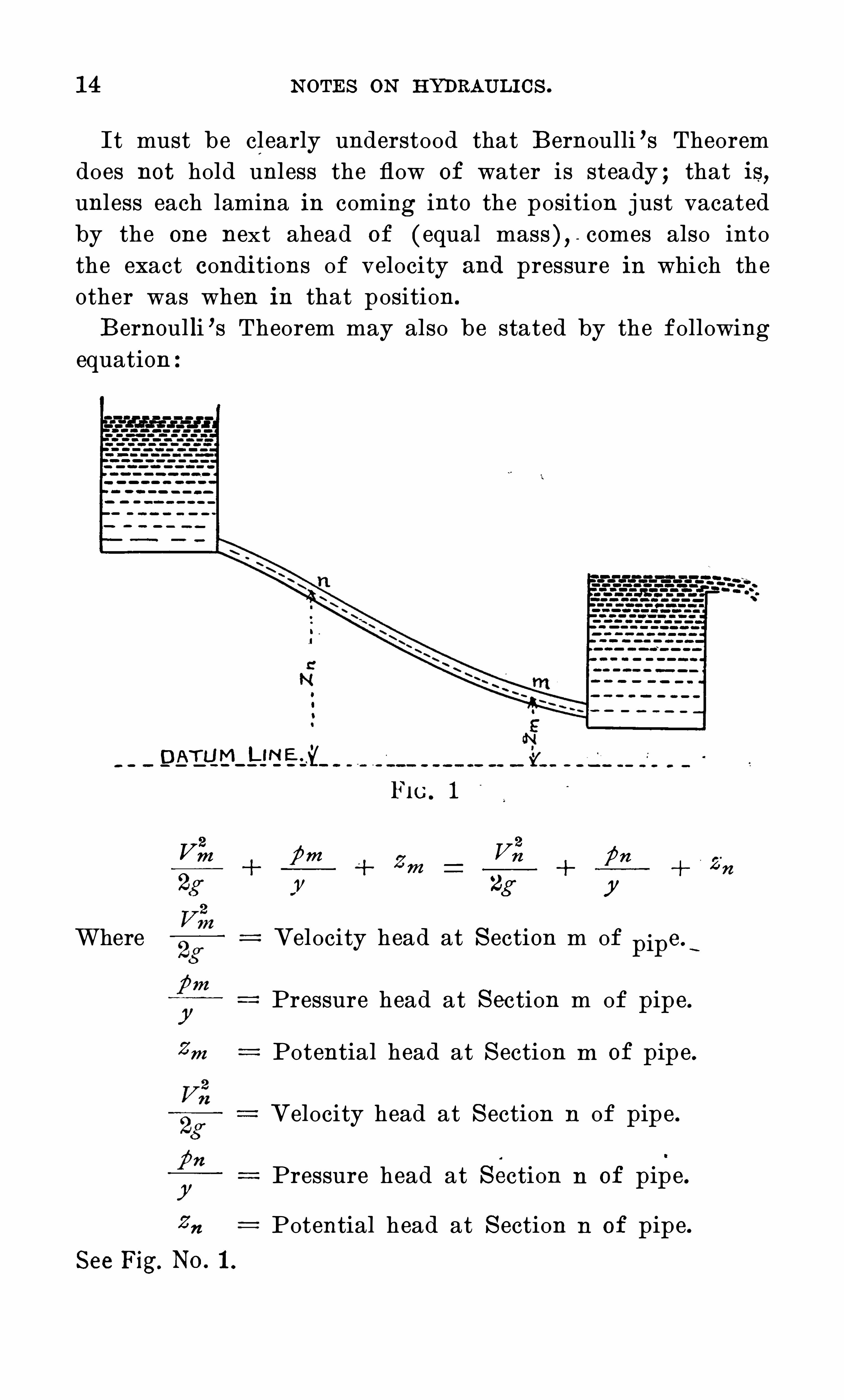
It must be cl early understood that B ernoulli ’s Theoremdoes not hold unl ess the flow of water is steady ; that is,unl ess each lamina in coming into the position j ust vacatedby the one next ahead of ( equal mass), - comes also intothe exact condi tions of velocity and pressure in which theother was when in that position.
B ernoul li ’s Theorem may also be stated by the followingequation :
DEI
FIG. 1
V2
V2
m {5772 Zm72 fin 2
72
2g r 2g y
Where Velocity head at S ection m of pipe s
Pressure head a t S ection m of pipe.
2m Potential head at S ection in of pipe .
Velocity head at S ection 11 of pipe .
yPressure head at section n of pipe .
Potential head at S ection n of pipe.See Fig. N o. 1 .

N OTES O N HYDRAULICS .
BERNOULLI ’S THEOREM FOR STEADY FLOWWITH FRICTION .
If a pipe is of considerable length or has a number of
sudden bonds or elbows .or abrupt changes of Cross - section,the Bernoulli ’s Theorem for steady flow without friction,will not hold
,as frictional losses are produced and in deter
mining the pressure and quantity of water flowing througha pipe
,these losses must be taken into consideration .
Taking into account no resistances or friction excep t theSkin friction ”
or“ fluid friction ”
of the liquid on thesides of the pipe (resistances due to internal friction . or of
eddying occasioned by Sudden enlargements of crosssection of pipe by elbows
,sharp curves
,gate valves
,etc.
,
will be mentioned later).Bernoulli ’s Theorem for steady flow of a liquid in a pipe
of slightly varying sectional area and internal p erimeter W,
may be stated as follows :THE S U M OF THE VELOC ITY HEAD
,PRES SURE
HEAD AND POTENTIAL HEAD AT ANY S EC TIONOF THE PIPE I S EQUAL TO THE C ORRESPONDINGHEADS AT ANY OTHER SEC TION MINUS THE
FRIC TION HEAD OR RES IS TANCE HEAD,DU E TO
SKIN FRIC TION BETWEEN THE SEC TIONS .
PRESSURE HEAD, VELOCITYHEADAND STATIC HEAD.
FIG. 2
When a vessel is filled with water at rest,the pressure
at any point“ depends only on the head of water abovethat
point . But when the water is in mo tion it is a fact of

1 6 N OTES O N HYDRAULIC S .
observation that the pressure b ecomes less than that dueto head . The actual pressure in any event may be meas ~ured by the height of a column of water.Thus
,if the water be at rest in the case shown in the
F ig. 2 and small tubes (open Piezometers)be installed atA
,B,C,the water will rise in each tube to the same height
as that of the water level in the reservoir,and the pres
sures at A,B and C will be those due to heads Aa, Bb and
C c. But if an orifice be open as seen near D,the water
levels in the tubes sink to the points a, , b 1 and cl
— z'
. e.
,
the pressures at A,B,C are reduced to those due to the
heads Aa l , Bb l , and C cl .
Aalis the PRES SURE HEAD P
aalis the VELOC ITY HEAD
Aa - is'
the HYDROS TATIC or S TATIC HEAD h
The theoretical V elocity of flow i s
'
V I/2g/t (1)The theoretical heigh t the j et will rise is then Iz (2)Equation 1 states the velocity due to a given head .
Equation 2 the head which would generate a given velocity.
The term VELO C I TY HEAD is designated by2; mean
ing thereby that its value is the head which can producethe velocity V.
If p is taken in lbs . per square inch,or gage pressure,
and h is taken in feetand W weight of a cubic ft . of water = 62 .5! approx
imately.
Then p hw lbs . per square foot,
or p z
—
l jfi‘ lbs . per square inch .
p h Gage pressure in terms of hydrostatic
head .
p Hydrostatic head in terms of gagepressure .
h H

N OTES O N
'
HYDRAULICS .
It is found that in the actual discharge of water,excep t
in rare cases,the actual velocity of discharge is less than
the theoretical,that the area of the stream discharged is
less than the area of the orifice through which it passes,etc .
,etc .
These losses are corrected by introducing coehcients,and
the'
following are.
definitions of a number of coe“
i cients
commonly used in hydraulic formulae and also the mannerin which they are Obtained from experiment :
COEFFICIENT OF CONTRACTION .
Is the mimber by‘which the area of theOrifice is to be
multiplied in order‘
toObtain the area of the section of thej et at a distance from the plane of the orifice O f about onehalf « its diameter . Thus if C (
be the coe" ’
icient of contraetion
, (A)the area of the orifice, and (a)the area of thecontracted section of the j et
CeA : a
a 7r d ? 2
A 77 0 2
I T MAY ALS O BE DEFINED (AS CAN BE S EEN
BY THE ABOVE EQUATION)AS THE S QUARE O F
THE RATIO O F THE DIAMETER O F THE J ET T o
THAT O F THE ORIFICE .
The mean or average val ue of Cc the coe"
i cient of con
traction,has been given
‘
by different authorities as .6 1
.6 3 .64 .
These values vary for di " °
erent forms Of orifices and for
the same orifice under di“ °
erent heads, but littl e is knownregarding the extent O f these variations or the laws thatgovern them .

N OTES O N HYDRAULICS . 1 9
Probably CCi s slightly smaller for circl es than for
squares,and smaller for squares than for rectangles . Prob
ably CCis larger fer low heads than
,
for high heads .The coe
°
i cient of contraction is directly determined bymeasuring the dimensions of the least cross - section of the
This may be accomplished by the use Of calipers or bymeans of fixed screws of fine pitch ( see fig.
”
3)which areconvenient . These are set to touch the j et and then
e distance between them can be measured at l eisure.
COEFFICIENT OF VELOCITY.
The coefficient of. velocity is the number by which thetheoretical velocity Of flow from the orifice is to be multiplied, in order to give the actual vel ocity at the least crosssection of the j etThus— if C
Z. be yel qcity, ,V the.theoretical
velocity due to head on the center of the orifice,and v the
actual velocity at , the contracted section
7}2 C71
952
V : CO V n/‘l
The velocity Of flow at the contracted section of the j etcannot be directly measured.

20 N OTES O N HYDRAU LIC S .
FIG . 4
O ne method o f finding coe i cient O f velocity (C ?)is toplace the orifice horizontal so that the j et will be directedvertically upward as in fig. 4 . The height to which it risesis the velocity head
in which v is the actual velocity and is equal to C7, Qg/z
S ubstituting this in eq. ( 1)we have
Izo n lz and C
Z,ft
”
from which C?)may be computed. This method fails to
give good results for high velocities, owing to the resistanceof the air and the di " ’
icu l ty in measuring the di stance hwith precision .
A mean or average value for CZ,the coefficient o f velocity
is,98.
The coe i cient of velocity in smooth nozzles is the sameas the coefficient of discharge
,since the j et issues without
contraction.
COEFFICIENT OF DISCHARGE.
The coe ”
icient of discharge is the number by which thetheoretical discharge is to be multiplied in order to obtainthe actual discharge. Thus if c be the coe
"'icient of dis
charge, Q the theoretical, and q the actual discharge per
secondthen 9 z c
'
X Q.

N OTES O N HYDRAULIC S . 2 1
The coem
cient Of discharge may also be defined as theproduct of the coe i cients of contraction and velocity.
I n general c is greater for low heads than for high heads,greater for rectangles than for squares, and greater forsquares than for circles . Its value ranges from to
or higher, and as a mean the following value may bestated :
c C oef . of Discharge
The actual discharge from a standard orifice is,on the
average,about 6 1 % Of the theoretical discharge.
The coe“
i cient O f di scharge can be accurately found byallowing the flow from an orifice to discharge into a tankand the volume measured as explained in articl e on measurement of water. Thus q the actual di scharge is knownand Q the theoretical di scharge having been computed, thecoe
" °
cient of discharge will be equal to q divided by Q or
STANDARD CIRCULAR ORIFICES.
S tandard C ircular O rifices with sharp edges i . e. wherethe water does not touch the orifice after having passed theinner edge . S ee fig . 5 .
C oef . of Discharge .6 1 .
FIG . 5 FIG . 6

22 N OTES O N HYDRAULICS .
O ri fices with Rounded Edges.
When the inner edges of the orifice are rounded. S ee
C oef . of Discharge varies from .6 1 to
S hort C ylindrical T ube .
z’
. e. where length of tube is 2 1A; to 3 times the diameter,and inner corner sharp as standard orifice. S ee fig . 7.
C oef . of discharge .82 .
FIG . 7
S hort C onical C onverging T ubes.
C oef. for this form will vary with the angle (A)at theVertex from .85 to .95 . Where the angl e at the Vertex is1 0 to 1 5 degrees
,the coef. Of discharge is .94 .
Smooth N ozz les.
Like “ underwriters play pipe .C oef . of discharge .976
R ing N ozz l es.
C oef . of di scharge .74

N OTES O N HYDRAULICS . 23
Mr . J . R . Freeman furnishes the following mean or average values of the coe “ cient Of discharge for smooth conenozzles Of di " ”
erent diameters under pressure heads rangingfrom 45 to 1 80 ft
Diam . in Inches . C oef of Disch .
7S
THE MEASUREMENT OF WATER AND INSTRUMENTS
There are many ways by which the determination of acubic
q
vol ume of water that passes a given point in a unitof time can be made. A brief discussion of a few of themethods in common use will be taken up in this chapter.
THE TANK.
The simplest of all methods O f“measuring water is by
the use of the tank . At first sigh t this method seemsextremely simple
,but in reality if accuracy 1 s required
,
measuring water by means of a measuring tank requiresconsiderable skill . Two methods may be employed in measuring tank volumes . First
,by directly computing the
cubical contents,and .S econd
,by weighing the volume Of
water and computifig the con tents from the temperatureO f the contained water and from its weight per cubic foot,corresponding ‘ to the temperature. I n computing thecubical contents ( the tank i f O f wood the wood must bethoroughly water - logged)the water level must be accuratel y determined and the linear measurements -must be cor
rect . I t can be readily seen that if the sides are slightly

24 N OTES O N HYDRAULICS .
warped O r if the form I S Irregular, to Obtain accurateresults would mean a laborious undertaking. It is
,there
fore,advi sabl e in measuring volumes in this way tha t a
tank Of regular form without warps and one which will notabsorb water should be used .
It is Obvious that the easier method is by weighing the
water,taking its temperature and computing the volume
from this data .
K ent gives the following as the weight of water percubic foo t at di ” ercut temperatures from 32 to 1 00 degreesFahr
32 62 . 42 46 60 62 . 37 74 62 . 28 88
33 62 . 42 47 6 1 75 89 62 . 1 4
62 .42 48 62 76 90
35 49 63 77 91
36 62 . 42 50 64 78 92
37 5 1 65 79 93
38 52 66 80 94
39 53 67 81 95
40 54 68 62 . 33 82 96
4 1 5 5 62 . 39 69 62 . 32 83 97
42 62 .42 5 6 62 .39 70 62 . 3 1 84 62 . 1 9 98
43 57 71 85 99
58 72 86 1 00
45 62 . 42 59 62 . 38 73 87
When limiting the length of time during which the streamwhose flow is desired to be measured discharges into thetank
,a convenient way is to use a movable spout by which
the stream of water may be made to di scharge into thetank and again to one side O f it at given signals . By theuse Of a S top -watch the length of time may be determinedduring which the tank receives the di scharge to be meas

26 N OTES O N HYDRAULICS .
APPARATUS FOR TESTING GAGE .
Mercury columns have long been accepted as the standardfor measuring pressures, but are so expensive and di
“ ’
icu l t
to keep in order t hat a more simple and . inexpensive,yet
accurate,machine is required . Apparatus of this nature
consists of a pump or other means of obtaini ng pressureand some methods of attaching the gage to be tested and
the standard with which it is to be compared.
O ne of the forms of gage te‘
sters now in common use isshown in fig . 9.
“
FIG.
“
9
It consists Of a stand fromwhich rises a cylinder havingaccurately fitted into i t a pistonwith an area O f i’ .exactl yone- fifth of a square inch which moves freely up and down.
Attached to the top of the piston rod i s a di sc for supporting the weights . Each weight i s marked with the number of pounds pressure per square inch it will exert on thegage. From ~ the bottom of the cylinder 2 tubes proj ect ;one forms a standard for holding the gage to be tested and
one is furnished with a coupling to connect it,and with a
three -way cock ; the other rises at an incl i nation and formsa reservoir for O i l
,having within it a screw plunger f or
forcing the O i l inward or outward .

N OTES O N HYDRAULICS . 27
DIRECTIONS FOR“
USING‘
GAGE TESTER .
Fasten the gage to the arm by means of a coupler or
similar arrangement ; set the handle of a three -way cockhorizontally or in an op en position ; see that the screwplunger is in as far as i t will go
,then remove the cap and
pour oi l into the cylinder until it is full, then graduallywithdraw the plunger and continue pouring in oi l until itis out nearly to its limit and the bore of the cylinder isnearly full . Now insert the piston which with its discwill exert a pressure on the gage of exactly the weight ofthe disc and piston. The weights
,one at a time
,may now
be placed on the-
di sc which should be gently rotated toinsure p erfect freedom of
'
motion to the piston. Eachweight added will exert a pressure on the gage equal tothe number of pounds marked on it .
If in testing a large gage the piston descends to itsfull l ength
,screw in the plunger and the piston will be
forced upward and more weights may be added as may berequired by the limit o f pressure marked on the gage dial .When the test is completed remove the weights
,one at a
time,and as the piston rises withdraw the plunger to make
room f or the returning oil . When all the weights have beenremoved, turn the cock handle to a vertical position whichwill allow the oi l in the gage to drain out into a can
which should be previously placed under the cock . The oi lmay be l ef t in the machine
,but the piston should be care
fully wiped and replaced in the case .
When it is desired'
to drain the whol e machine of Oil,set
the cock handle so'
that the port l eading to the reservoirfor O i l will be open.- t
It is advisable to use nothing but good ligh t mineral Oilwhich should be kep t entirely free from grit
.
The fol l owing‘
is a form that is used quite f requently incalibrating pressure -gages of this type :

28 N OTES O N HYDRAULIC S .
CALIBRATI NG OF PRESSURE-GAGE WITHGAGE TESTER.
Maker and No . of Gage
Observers,
N 0 .
Load in l bs.on Valve Gage Error Remarks
PITOT TUBE.
I n measuring pressure exerted by moving water in a pipe,
both the velocity head and pressure head have to be takeninto consideration. To separate these two factors
,an in
strument known as the Pito t Tube may be used.

N OTES O N HYDRAULIC S . 29
O ne f orm of this instrument is shown in the followingfigure 1 0 :
P IT O T
U T U BE.
MERC U RY
FIG. 1 0
Tube A is open at the end and connects by rubber tubetoone arm of an ordinary U tube mercury gage, the other,tube B
,is closed upon the end
,but has inits opposite side
two small holes and is connected to the other arm of the
Tube A receives the full e " ect of the current of movingwater and thus tends to indicate upon the gauge the totalhead
,includi ng both the velocity and the pressure heads .
But the influence of the velocity is practically removedfrom B
,which
,therefore
,receives only the pressure due to
the pressure head. As this tube is connected to the o therarm of the gage
,the pressure thus indicated is only that
due to the velocity head ; for both arms being subj ect to thepressure head these pressures are balanced .
The di fference/in height of the mercury in the gagewould be that due to velocity of current ; thus, if the mercury stands at m on one side and at n on the other
,the
velocity is that due to the height of the column of liquid,equal to the di stance that m is above 11 . C all this di stanceh,then the velocity v c x V 2gh ; c is the coe i cient of
velocity for the given tube and must be determined byexperiment made on a tube in which the velocity of flow isknown.
The principal use of this instrument is to determine thevelocity of‘the flowing water.

30 N OTES O N HYDRAULICS .
MERCURY GAGE FOR DETERMINING LOSSOF HEAD OR PRESSURE.
S ome time ago the author occasioned to investigateclosely the actual loss of head in a valve under high pressure and for the - purpose of measuring di rectly this loss
,he
devised a simple apparatus shown in the following sketch,
PET C O C K‘T H T HREE - WAY
VAk VE
U T U BE
MERC U RYGAU QE
PiE ZO MET ERF'TT T TT q .
FIG. 1 1
The di " "
erence in hydraulic pressure existing in any twopoints in a line of water pipe is at once exhibited by thedi
"°
erence in height of two communicating columns of mercury. T he apparatus i s, therefore, merely a pressure di i[ference gage which has the merit of being both sensitiveand accurate and which may also be applied in other similarinvestigations .I n principl e the gage consists of a glass U tube par
tial ly filled with mercury,while the upper ends of these
tubes are connected to the water main by means of suitablecocks and piping . O n the admission of water into the twotubes the mercury will be depressed in one and raised in the
"other until equilibrium is established. Whereupon,the dif
ference in the height of the two mercury columns is to beread O on a suitable scale
—
whose di visions correspond to‘known pressures of water as determined by careful experiments
'
beforehand . I n practice,however
,it i s necessary to
exercise the utmost care to expel all the air in the tubesabove the mercury
,which may be accomplished by judicious
manipulation of the pet- cocks .

N OTES O N HYDRAULIC S . 3 1
I n using this gage as a pressure difference gage theprincipal correction to be made is that due to excess watercolumns on the short l eg of the U tube . This correctionfor any pressure is the di stance in inches between the surfaces of the mercury
,multiplied by .036
,this equal s the
number of pounds to be subtracted from the reading of
the short l eg .
VENTURI METER .
Another method of measuring water is by means-
of theV enturi Meter
,so called from Venturi
,who first pointed
ou t the relation between the pressures and velocities of
flow in converging and diverging tubes .
FIG. 1 2
As shown by the TOngitudinal se’cti’on F ig. 1 2
‘ this meterconsists of a converging, followed by a gently diverging,tube ; between the two i s a short cylindrical piece known asthe throat . A and B are air or pressure chambers which .
are connected with the interior by piezometer hol es . Piezometers are connected as shown by which the flu id pressure
may be measured .

32 N OTES O N HYDRAULICS .
It i s a fundamental principle in hydraul ics that thehydraulic pressure of water in motion against the interI O rof a pipe is equal to the hydrostatic head (pressure of
water not in mo tion)l ess the head due to velocity. If Pbe the pressure in terms of the height of a water - columnat the inl et B and P I
be the pressure in terms of the height
of a water - column at the throat A, P l
— P equals the difference of heads in the piezometers or the “ head on V en
turi,
” as it i s called.
a , and a 2equals the sectional areas at A and B respect
Then the quantity o f flow at A is
Introducing coef . of discharge C the actual deliverythrough A is
a , X 61 2
— a3
a I
An elaborate series of experiments by Herschel gaveC varying from .94 the great maj ority laybetween .96 and .99.
After such a meter has been rated its di scharge can berelied upon as correct within 1 to 2 per cent for any singlereading.
PIEZOMETERS .
A piezometer 1 8 an instrument for measuring the pressure of water which exists in a pipe. The simplest formof this instrument consists of an ordi nary tube insertedinto a pipe at right angles . The water will rise in thetube to a height equal to the pressure exerted at the pointwhere the piezometer or tube is installed .

84 N OTES O N HYDRAU LIC S .
Loss at Entrance.S kin or surface friction.
C hange in cross - section.
Bends or C urvature .Obstructions in C hannel .P
E
P
O n account of lack of experimental and theoretical knowledge regardi ng the laws of flow of water in pipes
,the loss
of pressure can not be definitely computed .
LOSS OF PRESSURE AT ENTRANCE.
The loss of pressure which occurs in the upper end of apipe due to contraction and resistance of ‘ the inner edges,is cal l ed LOS S OF HEAD OR .PRES SURE AT EN
TRANCE and is the same as the loss of head in a shortcylindrical tube under the same velocity of flow. Thisloss is always less than the velocity head
,therefore
,where
l equals the loss of head at entrance we have
The value f or K varies f rom 0 to 93
For a perfect mouth piece K equals 0For an inward proj ectingpipe K equals .93
For a standard end K equals .5 0
Exampl e z— C ompute the loss of head a t entrance in a 1
inch pipe 1 00 feet long di scharging 1 5‘ gallons per minute :
Discharge in cubic ft. per sec . . 033
2
K K . 579[ZE K
2 x
Assuming K to equal .5 then
it 5 x . 579 z.2895 feet, loss of head due to entrance.E

N OTES O N HYDRAULICS . 35
LOSS OF PRESSURE DUE TO FRICTION.
The loss of pressure due to friction of the interior surface of a pipe is governed by the following laws whichhave been deduced from many experiments made on pipesof di ""
erent sizes and l engths under di °“
erent velocities of
1 . THE LO S S IN FRIC TION I S PROPORTIO NALTO THE LENGTH OF THE PIPE .
2 . IT INCREASES AS THE S QUARE OF THE
VELOC ITY .
3 . IT DECREASES AS THE DIAMETER OF THE
PIPE INCREASES .
4 . IT INCREASES WITH THE ROUGHNES S .
5 . . I T I S INDEPENDENT OF THE PRES SURE OFTHE WATER .
L equal the l ength of pipe .a’ equal the 'diameter of pipe .H
Fequal the head or pressure lost due to friction.
f equal a coe“
i cient depending on the roughness Ofthe interior surface of the pipe .
Then these laws may be expressed by the following equation :
LH r.
The factor f for new cl ean pipes ranges from 05 to .0 1 .
For approximate computations the mean or average valuefor f ,
.02 may be used .
Exampl e z— Find the
!
loss of head in 1 00 feet of pipe 2inches in diameter when discharging 1 5 0 gallons of waterper minute .
1 00 225HF ‘02
. 1 7
The velocity 7/ is obtained by dividing the discharge incubic feet per second by the area of the pipe in square
40 feet.

36 N OTES O N HYDRAULICS .
feet ; thus the area of a 2 - inch pipe is .022- the discharge
in cubic feet per second is 1 5 0 6 0 .334 .
Then .334 divided by .022 equals 1 5 the velocity,and 71
2
is 225 .
LOSS OF HEAD OR PRESSURE DUE TO BENDS .
The loss of '
pressure caused by easy curves is very slightand need not be taken into consideration . Where there isa sharp bend
.
such as an elbow the loss is small,b ut where
a number of such bends occur the loss may amount to con
si derabl e. This loss is a percentage of the velocity head
and may be expressed by the equation HB
n2
hereg
HBis the loss due to the bend
,and n the '
coem
cient.
Weisbach gives the following values for n which werederived from experiments made on small pipes . This lossfor larger pipes is undoubtedly less .WhereR Radius of curvatured diameter of pipe
3 1 4 .5 6 7 s 9 1
for these values 11 equals
. 1 3 , . 1 4, . 1 6, . 21 , . 29, .44, .66 ,
.98,1 4 1 ,
LOSS OF PRESSURE DUE TO ENLARGEMENTOF SECTION .
When a section of pipe is enlarged as shown in fig. 1 4,
and the pipe is kep t constantly full of water,a loss of head
or pressure results . From Bernoulli ’s theorem the pressurehead plus the velocity head at any point in a line of pipe isequal to the pressure head p lus the velocity head at any
other section in the line,if no losses occur .

N OTES O N HYDRAULICS . 37
I
em u.
FI C . 1 4
Let V I equal the velocity and h l equa l the pressure headat section A and V
,equal the velocity and h
,equal the
pressure head a t section B,then according to Bourncl l ies
theorem
V 2
but as the second effective head is always smaller than the
first their difference is the l oss of head due to enl argementof pipe.Loss of head due to enlargement
2 V 2
V 2 V 2 V 2
— 1 — f».
1 i — (fze — fn)A)“ 2s
t 26g
This is a general expression giving the l oss due not onlyto enl argement but to al l resistances between any two sec'
tions of a pipe .Another form wh ich is probably more convenient for
practical use is
Loss of head due to enlargement l“ I 2
41”
when a,and (1
2are the areas of the sma l l and l arge secti ons ,

38 N OTES O N HYDRAULIC S .
LOSS OF PRESSURE DUE TO CONTRACTIONOF SECTION.
When a section of pipe is contracted in the direction of
flow as shown in figure 1 5 that is gradual contraction theloss of pressure is
V 2 V 2
Loss due to contraction 1 2
a2 V 2
also2
1) 2" l" k l fi2
( 11 2g
in which V Iand V
2are the velocities
, n, and 11 2 the pressureheads and a and a 1
the areas .
FIG. 1 5 FIG . 1 6
For sudden contraction of section as shown in fig. 1 6 .
1 V 2“
1 2
C'
2g
in which C is the coe " ’
icient of contraction and equal to the
The loss due to contraction
area0 1 the value of C varies from .62 to 1 . For an avera
age .6 5’ may be used.
The loss of pressure through valves and other fittings canonly be determined by experiment . An instrument formeasuring these losses i s described in the chapter on Measurement of Water and instruments used .

N OTES O N HYDRAULICS . 39
LOSS OF HEAD IN FRICTION FOR IOO FEET OF PIPE.
Diameter
l—kl—ti—ll—‘
O
O
O
O
O
co
co
03
01
w
. 05
. 25
. 75
. 25
. 75
Feet1 . 46
0 59
. 20
. 09
. 05
. 04
. 03
. 02
02
. 0 1
. 01
. 01
. 01
. 00
. 00
Velocity in Feet per S econd.
Feet
. 09
. 02 '
Feet
. 45
. 32
. 25
. 20
. 1 6
. 1 3
. 1 0
. 07
. 06
. 05
. 04
. 03
Feet Feet Feet
. 55
. 42
33 . 67
. 26 . 54
. 21 . 45
. 1 6 34
. 1 2 . 26
. 1 0 . 21 . 53
. 08 . 1 7 . 42
. 06 . 1 3
. 05 . 1 0
Feet

N OTES O N HYDRAULIC S .40
8
2
mmwe
cm
3
on
mm
mm
3
3
mp
h
£bfl
mfi
1
”
v.
o
.
o
o
.
o
.
n
o
n
o
o
n
0
0
o
a
wo
n
3
2
NH
wc
wm
om
mm
ww
mwm.
mmm
a
mm
S
ma
g
mwm
ma
m
NI
3
3
8
5
E.
mv
amfi
Se
I
v
$
2
om
fi
bmwm
do.
fl
8m
m
emu
ov
a
mu
5.
90
on
aw
it
on
H
fl
Ev
mmm
mmwfi
cw
mm
3
3an
8am
mm
ow
wwfi
3m
8m
8
2
co
mm
omwm
S
S
24
co
m
cwv
3w
E.
wfl
owom
3
Se
EH
owfi
ma
m
Se
3
3
9
3
8
5
8
3
3
9
2
:
omfi
ov
a
ne
w
8
2
3
3
ma
mm
oo
bm
ofi
mw
S
ao
m
mu
m
ne
w
30
vo
fi
m
ombm
mmmc
E
wH
H
Ne
w
mo
m
ov
a
$
3
8
3
cu
m“ .
cwH
5m.
bo
w
wmm
omwfl
mmwm
8
8
3
S
mu
m
wmm
Sm
ma
m
ma
ma
wm
fi
o
ww
S
wo
fi
mo
H
3m
3m
omofi
oo
mfi
oa
mm
mfl
S
5
Z.
em
.
mmfl
omm
an
»
.
2
5e
o
n
e
g
ne
w.
2
5s
ee
n
De
e
.
25S
ee
n
.
25
S
ee
n
.
9
3
Da
n
.
v:
n
3
in
e
co
DO
E6:
co
au
tm
.
e:
832
56:
no
to
tmd:
Swa
rmdz
comp
o
te“
S HHOHpgHa d
"I V {)‘
8.
fl
warm
d
m.
e
Q
E.
QH
WAN
C
a
m.
5m
warm
.
GH
wfi
35
.
5vi
e
a
m.
5fl
2th
.
5we
33
98
4we
wee
k
commy
ou
G
ER
R
G
EE—
5
ea
mco
:
Ema-
cu
?»
cue—O
EO
wue
ao
fifiwe
Su
e
z
95
30«
a
£33
3
Eco
.
m
t2
3:
z.
m:
omv
0
9N0mm
com
onm
m3
o
fimm:
O
S
mu
aw
mm
mm
mm8 3 d
HI E N IW
"N O
°
S.
fl

N O T ES O N HYDRAU LIC S .42
0
0
0
0
0
0
0
0
0
0
0
0
0
0
0
0
0
0
0
0
0
0
0
0
0
0
0
0
0
0
0
0
0
0
0
0
0
0
0
0
0
0
0
0
0
0
0
0
0
0
0
0
1
.
0
5
,
fi m w
aaaaafiazsau- u - u - u -u - umcz
aaazfiaes%aea
0
0
0
0
0
0
0
0
0
0
0
0
0 0 D 0 0
fi fl-‘Ffl fl fi c lO 0
0
0
0
0
0
0
0
0
0
0
0
0
gawaaeafiafifia
O Oo p o o a o o o
0 0 0 0 I 0 0
H -d —d r-d fu d‘tO l
5.
AA.
oo
o
h.
”
o
n
o
mfi
o
.ooo, ooooo
o
'.
a
o
o
ooo
o
o
o
o
o
o.oa
.gym
“
ooh
0
0
0
0
0
0
0
0
0
0
0
.
O
O
O
O
O
O
O
O
O
O
O
O
O
O
O
0
0
0
0
0
0
0
0
0
0
0
0
0
0
0
0
0
0
0
0
0
0
0
0
0
0
0
0
0
0
0
ma.
0
0
0
0
0
0
0
0
0
0
0
0
0
0
0
0
0
0
.l
‘
w
0
0
0
0
0
0
0
0
0
0
0
0
0
0
0
0
0
0
0
O
0
0
o
n
.
1
0
0
0
0
0
0
0
0
0
0
0
0
0
o
o
o
o
o
o
o
o
o
o
o
o
o
o
o
o
o
o
o
o
o
o
o
o
0
0
.
0
0
0
0
cmd~
fi fi fi O tflQ‘fl
Iflfiaaflfifififiz f zz
pu mmw'www
53$% 8 i $3 3 80
0
QS
Av
a
GO
UQ
E.
na
830
th
“
a.
58
warm4
:
8
.
E
Q
35
now
za
m_h
mau
0
0
0
0
0
0
0
0
0
O
0
0
0
0
0
0
0
0
0
0
0
0
.
0
0
0
0
0
O
0
0
0
0
0
0
0
0
0
0
0
0
0
0
0
0
0
0
0
0
0
0
0
0
0
0
0
0
O
O
O
O
O
O
O
0
0
0
0
0
0
0
0
0
0
0
0
0
0
0
0
i
.
0
0
.
0
0
0
0 0
M fi Q l O im'fiWO 0
fi mm-wwb mco
exquaawzaa
nigfifi'
fi8téfifl 3
he
0
.
O
0
0
0
0
0
O
0
D
0
0
0
0
.
0
0
O
0
0
0
0
0
.
0
0
0
0
0
v- J—Jmm-v'tru .
an
83352
0
0
0
0
0
0
0
0
0
0
tom
wag
“
yum
.
Bq
tom
sumo”
97, mm"I V O
‘
S T]‘5
ga
95:2
wumrw6" (d d
O ’I VQ
0
8'fl

N O T ES O N HYDRAU LI C S . 43
LOSS OF PRESSURE CAUSEDBYVALVES
ANDFITTINGS .
The data given below is condensed from the resul ts of
experimen ts made at difi erent times by the I nspecti on
Department of the Associ ated Factory Mu tual s Fire I nsur
anc e C ompani es. The fri cti on losses in el ls and t ees are
approximate,bu t
,si nce fi tti ngs of the same nominal si ze wi th
the difi erent curvatur es and differen t. smoo thness as made
by difi erent manufacturers wi l l cause materially difi erent
fricti on losses,the figures below wi ll give a fair indica ti on
of Wha t los s may be expected from the several fittings.
N umber of feetof cl ean
,stra ight
pipe of same s ize
N AME O F FITT ING.which wou l dca use the same
l oss as the
fitti ng.
6 7inch Grinnel l Dry-P ip e V alve*41 - inch Grinnell Dry-Pipe V al ve*
6 - inch Grinnell Al arm C h eck4 - inch Grinnel l Alarm Check
6 - inch Pra t t C ady C heck V al ve6 - inch Wal worth Globe C heck V al ve .
4 - inch Pra tt 8: C ady Check V alve«it- inch Walworth Globe C heck Valve
to 8- inch Long‘T urn El l s
mag- inch t o 8- inch S hort - Turn E ll s
3 - inch t o 8- inch Long- Turn Tees3 - inch t o 8- inch S h ort - Tu rn Teeslyg- bend
*Difl'
erential type .

44 N O T ES O N HYDRAU LI C S .
noifiu l qu om
1 1 0 13 tutu-tom‘
ura
umorg)°
u 1 §z flssed
-Kg°
u 1 f;
umora'u 1 8
l i 3a'U I 9
umora‘
u I 3;ssea
- Kg°
u 1 9
i uau oL‘u I 8
h EO T HQ
uotun‘u r 19
AasraH‘
u I f:
umora‘u I f;
mama , W 9
u aqme’
r°
u 1 {7
mon o; 1 1 1 {7
was m 17
1 9pm a orq ; Bu gmol g‘
U IW J ed suoueg)
mma wO O O fi
me o wH mw©
N m
H mmmOO OO
H H N M
O OOO
o N H b
'O H fl
mwfi mO m
m e a n
O H fi b
La me
oo o o
°© N fl
'O mm
ommo
° O H N
M mmmO O O Q
mm b o
° O O O M
v wfi b
O O H H
wwwwN fi ©®
W H O
mm A
H N
W N Q B
e wwwfi r— i
Q r—I H Q
w HH
CO b - v—I v—l
fl fl w©
b b mmO O Q A
me wmfi fi fl N
me o wmmmm
wmv mv b
Q N O °
w h o
0
.
O
.
0
.
0
.
5
6

N O TES O N HYDRAU LICS . 45
The tests.showed :
1 . T hat all meters obstruct the flow of water to a greateror less extent
,many types seriously reducing the pressure
with heavy fire drafts .2 . That ordinary types of disc and piston meters may
almost completely stop the flow of water if their movingparts become blocked
,which is easily possible .
3. That fish traps,while lessening the danger of the mov
ing parts becoming blocked,are liable to become seriously
clogged by pipe scales,leaves
,etc .
4 . Therefore,meters should not be put on fire service sup
plies . The best way to remove a supposed need of meters isto absolutely separate the pipes carrying water for manufacturing and domestic purposes from the fire system andsupply them by a separate metered connection from thepublic mains ; then guarantee that n o water will be usedfrom the fire system except in case of fire or for occasionaltests
,which should be made strictly in accordance with the
rules of the water department .I n the cases where some further check is considered neces
sary,hydrant and sprinkler drain valves may be sealed by
the water department and notice promptlygiven when oneis broken for any cause. I n some such cases the meters ofthe ‘P roportional ’ type may be th e most satisfactory checkand are unobj ectionable .
a . The Gem,C rown and Hersey Meters had fish traps as
part of the meter,so that the losses above include the trap .
The Torrent,Lambert
,U nion and Worthington Meters use
a separate trap ; they were, however, tested without traps .b. Al l the meters t ested
,with the exception of the Worth
ington 3 - inch,which
/had been used for some time
,were new
,
clean meters .0 . The above results were obtained from tests made by the
I nspection Department of the Associated Factory MutualFire I nsurance C ompanies during 1 896 - 7- 8. For full dataof experiments, see “ Journal of N . E . W. W. Association
,
”
vol . xu .,N o. 2 ; also ‘Transactions American S ociety
Mechanical Engineers,
” vol . xx.

46 N O T ES O N HYDRAU LICS .
PRESSURE CONSUMED l N PRODUCING VELOCITY
0FWATER THROUGHPIPES .
When water moves through a pipe at a certain velocity,part of the total pressure is consumed in producing thatvelocity
.The following is the ‘ general formulae for com
puting the pressure consumed in producing velocity
1 07’
. 001 1 487’ 2g X a
’4
WhereP - Velocity pressure lbs . per sq . inch .
’
Z/
2} z Linear velocity . Ft . per second .
a’
: Diameter of pipe in inches .G z Rate of flow. Gals . per minute .
g z Accel eration due to gravityz 322 .
PRO O F.
Let by
=velocity head in feet .
Then lz
Reducing this to pounds per sq . inch,we have
P — /z z
7’
v 0 2g
7/ 7/ 7/P7/
2
2g x 2 x x
V el ocity: ( l ength of pipe in feet holdi ng one gallon)mu l
tipl ied by (number of gallons per sec .)
and
Length of pipe in feet holdi ng one gallon equal s:
Area in square feet
Velocity:
. 1 331 x (gal . per sec.) . 1 831 (gal per min.)x 1 44
Area in square inches 60 x (Area in square inches)

N O TES O N HYDRAULIC S . 47
Area in square inches4
.7854 (diameter in inches)2
1 44 x . 1 33 1 (gal . per min.) 0 3
1V 6 oci ty60 X .7854 (diameter in inches)2 cl
’4
P71 (5
2 0 2(1 44 X G2
7/(1 4 (60 X at
“
P7}
. 001 1 48
EXAMPLE — Find the pressure in pounds per square inchconsumed in producing velocity in a 1 - inch pipe discharging6 0 gallons . of water per minute ?
P7,
. 001 1 48
P z. 001 1 48
1 x 1 X 1 1.001 1 48 x 3000
P z pounds the required answer .
N O TE — The table on page 49 is based on the HydraulicLaw that a quantity of water carried by pipes of the samel ength and smoothness of surface with a given loss of pressure varies as the square roots of the 5 th powers of thediameters . The second column gives this function for thediameters that are printed in the first column . T he remaining columns show how many pipes of the sizes printed atthe top are equival ent to one pipe of the size in the firstcolumn .
EXAMPLE.
— How much water will a. 1 0 - inch pipe carry ascompared with a 6
,with the same loss of pressure ?
Follow down the first column to 1 0,then to the right
under the column head 6 we find which shows that a1 0 - inch p i pe will carry times as much water as a 6 - inch .

48 N O TES O N HYDRAULIC S .
T ABLE Showing theTheoretical Velocityand Discharge in CubicFeetThrough an Orifice of 1 Square Inch IssuingUnder Heads Varying From 1 to 1 00 Feet.
1 51
2 523 534 545 1 075 . 556 567 578 589 59
1 0 1 0 . 7 601 1 6 11 2 621 3 631 4 641 5 651 6 66
1 7 6718 681 9 69
20 7021 71
22 72
23 73
24 74
25 75
26 76
27 77 29 30
17 99
30 241 9 20
4436 42887 2
3 1 3 33
3081 1
3191 832 55
'
4787 8

5 0 N O T ES O N HYDRAULIC S .
AUTOMATIC SPRINKLERS.
The idea conceived by inventors of automatic sprink lerswas to create a device by means of which a fire might bearrested or extinguished in its incipiency through the agencyof heat created by the fire itself . How well they have succeeded
,i s shown by the fire records covering a period
‘
of
more than twenty years . There is no question but that theautomatic Sprinkler system has proven an unqualified success for the purpose for which it was created.
DESCRIPTION AND GENERAL ARRANGEMENT.
Lines of pipes are installed through the buildi ng nearthe ceil ing from 8 to 1 0 feet apart
,and supported by means
of hangers . These lines are connected to larger pipes leading to the source of water supply. To each of these linepipes is connected at intervals from 8 to 1 0 feet , the automatic Sprinkler head . S hould a fire s tart at any point inthe room the heat coming in contact with the fusible solderat a temperature of 1 60 degrees or more would instantlymelt same
,causing a release of the di sc or valve of the
sprinkler head,and the water under pressure would be forced
out through the di scharge orifice,striking the deflector or
distributor and thereby cause the water to spray in alldirections .There are two Sprinkler systems in general use . The Wet
S ystem,which is used in buildings in which there is no dan
ger of freezing,the pipes being at all times filled with
water . The Dry S ystem,which is used where freezing is
possible,the water supply being intercepted at the point
where freezing might occur,by a dry pipe valve ; and be
tween this valve and the Sprinkler heads the pipes are filledwith compressed air at a relatively low pressure of about30 pounds per square inch .

N O TES O N HYDRAULIC S . 5 1
Figures 2 1 to 28,inclusive
,show eight well - known
Sprinkler Heads in general use at th e present time . A furth-er description of these heads is omitted owing to the factthat th e manufacturers have minutely and fully describedthem in their catalogues
,of which a liberal supply is con
stantly bef ore the publi c .
FIG“. 21FIG. 22.
THE GRI N N ELL .
ManufacturedbyThe General Manufactured by The GeneralFire Extinguisher C ompany , Fire Extinguisher C ompany ,
Providence,R. I . Providence , R. I .
T HE N ERACHER .

5 2 N O T ES O N HYDRAULICS .
F I G . 23.
T HE MAN U FAC TU R ER S .
Manufactured by Manu facturersAu tomatic S prink l er C o. ,
S yracu se, N . Y .
F I G . 25 .
T HE I N TE R N ATI O N AL .
Manu factured by T he I nternationa l S prink l er C ompany,Phi l adel ph ia , Pa .
F I G . 24.
T HE,ES TY.
Manufactured by T he EstyS prink l er C ompauLaconia , N . H.
FI G . 26 .
T HE R O C KWO O D .
Manufactu red by T heWorcesterF ire Extinguisher C ompany,
Worcester, Mass .

N O TES O N HYDRAULIC S . 5 3
FIG . 27
T HE N IAGARA.
Manufactured by N iagara FireExtinguisher C ompany ,
Akron,O hio .
FIG. 282
T HE PHO EN IX .
ManufacturedbyThe PhoenixFire Extinguisher C ompany ,
Chicago , I l l .

54 N O TES O N HYDRAULIC S .
NATIONAL BOARD SPRINKLER RULES.
SECTION A— GENERAL INFORMATION .
1 . Preparation of Bui lding.
Many buildi ngs require preparation for Sprinkler equipment . All needless ceiling sheathing, hollow S idi ng, tops ofhigh shelving
,needless partitions or decks Should be re
moved . N ecessary “ stops ” to check draught,necessary new
partitions,clos ets, decks, etc ., Should beput in place so that
the equipment may conform to th e same . The top flooringShould be made thoroughly tight . (S ee S ec. B4 .)2 . Accessory Woodwork.
S prinkler equipments require accessory woodwork,dry
pipe valve closets,ladders
,anti - freezing boxing for tank
pipes,etc . This work should be promptly attended to if not
let with sprinkler contract .
3 . Drapery and S heathing.
Paper or S imilar light inflammable ceiling sheathing isobj ectionable and unnecessary. Where floors leak di rt
,an
acceptable sheathing may be made of lath and plast er,matched boards or j oined metal . All channels back of
sheathing to be thoroughl y closed between timbers or j oists .S heathing to be tightly put together and kept in repair. I n
mill bays,Sheathing to follow contour of timbers without
concealed space .
4 . Vertica l Draughts.
Vertical draughts through buildi ngs are detrimental to theproper action of sprinkl ers and should be “ stopped ” wherepracticable .
5 . C l ear S pace Bel ow C ei l ings.
Full, e ective action of sprinklers requires about 24
inches wholly clear space below roofs or ceilings ; this lossof storage capacity should be realized in advance of
equipment .

N O TES O N HYDRAULIC S . 5 5
6 . Experienced Workmen Recommended.
S prinkler installation is a trade in itself . I nsuranceinspectors cannot be expected to act as working superin
tendents,nor correct errors of beginners . S prinkler work
should be entrusted to none but fully experienced and respon
sible parties .
7. Al l P ortions of Bui ldings to be Protected.
Experience teaches that sprinklers are often necessarywhere seemingly least needed . Their protection is requirednot alone where a fire may begin, but , also wherever anyfire might extend
,including wet or damp locations .
8. Degree of Protecti on.
A maximum protection cannot be expected where sprinklersare at more or l ess permanent di sadvantage
,as in the case
of stocks very susceptibl e to smoke and water damage,buildings having deep piles of ho l l ow goods, excessivedraughts
,explosion or flash fire hazards
,or large amounts
of benzine or S imilar fluid .
9. C urtain B oards .
Where two or more floors of a building communicate byOpenings not provided with approved “ stops
,
” acceptablecurtain boards or cornices
,wide enough to bank up the
heated air at least 6 inches below the fusible device of theSprinklers
,Should be fitted around the openings at each
floor .
1 0. N ecessary C at- ofis.
S prinklers cannot/be expected to keep out fire originatingin unsprinkled territory. S tringent measures Should be usedto properly cut off all unsprinkled portions of buildings orexposures .

5 6 N O TES O N HYDRAULI C S .

58 N O TES O N HYDRAULIC S .

N O TES O N HYDRAULIC S . 59

N O TES O N HYDRAULIC S .
SECTION B— LOCATION OF AUTOMATIC SPRINKLERS.
1 . Position of Sprinkl er.
To be located in an upright position . When constructionor occupancy of a room makes it preferable, permissionmay be given, except on dry - pipe systems
,to locate sprinklers
in a pendant position .
2 . P osition of Deflectors.
S prinkl er deflectors t o be parallel to ceil ings, roofs, orthe incline of stairs
,but when installed in “ th e ‘peak of a
pitched roof,they should be horizontal .
3 . Distance of Defl ectors Bel ow C ei l ing.
Distance of deflectors from ceilings or bottom of j oists tobe not l ess than 3 inches nor more than 1 0 inches (6 to 8inches is preferable).4 . Detai l ed Locations.
S prinklers to be placed throughout premises,including
basement and lofts,under stairs
,inside elevator wells
,in
belt,cable
,pipe
,gear and pulley boxes
,inside small en
closures,such as drying and heating boxes
,tenter and dry
room enclosures,chutes
,conveyor trunks and a l l cupboards
and closets unless they have tops entirely . open and are solocated that sprinklers can properly spray therein . S prinklers not to be omitted in any
'
room merely because it is damp,
wet or of fireproof construction .
S pecial instructions to be O btained relative to placingsprinklers inside Show windows
,boxed machines
,metal air
ducts,ventilators and conceal ed spaces
,and under large
Shelves,benches
,tables
,overhead storage racks
,over dynamos
and‘
swi tchboards,platforms and similar water sheds .
5 . Protecti on of Vertica l S hafts.
I n vertical Shafts having inflammable sides,a sprinkler to
be provided within shaft for each 200 square f eet of theinflammable surface . S uch sprinklers to be installed ateach floor when practicable and always when shaft istrapped . I nflammabl e Shafts even if lined with plaster ormetal require sprinklers as above.

N O TES O N HYDRAULIC S .6 1
SECTION C— SPACING OP AUTOMATIC SPRINKLERS.
1 . Distance from Wa l ls.
T he’
distance from wall or partition not to exceed onehalf the distance between sprinklers in the same direction2 . Partitions.
A line of sprinklers to be run on each side of partition .
C utting holes through a partition to allow sprinklers onone side thereof to distribute water to the other side is note “
ectual . This rule applies to both solid and slattedpartitions .
3 . Mi l l C onstruction.
U nder mill ceiling ( smooth, solid plank and timber construction’
,6 to 1 2 - feet bays)one line of sprinklers Should be
placed in center of each bay and distance between the
sprinklers on each line not to exceed the following :
8 feet in 1 2 - feet bays .9 feet in 1 1 - feet bays .1 0 feet in 1 0 - feet bays .1 1 feet in 9- feet bays .1 2 feet in 6 to 8- feet bays .
Measurements to be taken from center to center oftimbers . S pecial instructions should be asked where ruleallows sprinkler spacing to be over 1 0 feet
,because special
conditions may require the U nderwriters having jurisdictionto modify the rule.
"
4 . J oisted C ei l ings .
U nder j oisted ceiling,open finished
,distance between
sprinklers not to exceed 8 feet at right angles with j oists or1 0 feet parallel with j oists .
EXCEPTI O N .
—An exception may be made to this rule ifthe condi tions warrant
,viz .
,special permission may be
given to install but one line of sprinklers in bays 1 0 to 1 1 1742feet wide from center to center of the timbers whichsupport the j oists . I n all cases where such bays are over
feet wide,two or more lines of sprinklers should be

62 N O TES O N HYDRAULI C S .
installed in each bay as requi red by the rules for spacing .
This does not apply where beams are flush with the j oists,in whi ch case Sprinklers may be spaced as called for in theRule 4 . Where p ermission is given, the Sprinklers shouldbe placed closer together on a line so that in no case willthe area covered by a single sprinkler exceed 80 square feet .Al so see Rule 8.
5 . Smooth S heathed or P lastered C ei l ings .
U nder smooth sheathed or plastered ceilings,in bays 6
to 1 2 feet wide (measurement to .be taken from center tocenter of timber
,girder or other protection or support
forming the bay), one line of sprinklers to be placed incenter of each bay
,and d i stance between the - sprink lers on
each line not to exceed the following : 8 feet in 1 2 - f-
eet
bays ; 9 feet in 1 1 - feet bays ; 1 0 feet in 6 to 1 0.
- feet bays .Bays in excess of 1 2 feet width and less than 23 feet widthto contain at least two lines of sprinklers ; bays 23 feet inwidth or over to have the lines therein not over 1 0 feet apart .I n bays in excess of 1 2 feet width
,not more than 1 00
square feet ceiling area to be allotted any one sprinkler .
6 . Pi tched Roofs .
U nder a pitched roof S loping more steeply than 1 foot in 3,
one line of sprinklers to be located in peak of roof,and
sprinklers on either side to . be spaced according to aboverequi rements . Distance between sprinklers to be measuredon a line parall el with roof . Where the roof meets the floorline there should be a line of sprinklers placed not “ overfeet from where roof timbers meet floor.
Two lines of Sprink l ers not more than feet distanteach way from the peak of roof
,measured on a line with
the roof,may be used in li eu of one line of sprinklers
located in p eak of roof Also s ee Rule 8.
7. S taggered S pacing.
U nder O pen finish,joisted construction floors
,decks and
roofs, the Sprinklers Should be “ staggered ” spaced so thatheads will be opposite a point half -way between Sprinklers

N O TES oN HYDRAULI C S . 6 3
on adj acent lines,the end heads on alternate lines to be
not more than 2 feet from wall of partition . Also seeRule 1 .
This regulation does not except sprinklers within a bay,whether on one
,two or more lines . Adjacent sprinklers
to be so staggered as not to di stribute ‘
water into the samej oist channel ways . S pecial instruction to be obtained ineach case as to whether staggered spacing shall be requi redunder open j ois t construction
,where the channel spaces
between j oists are positively blocked off within the territoryof any two adj acent sprinklers .
8. U nusua l C onstructi on.
S pecial instructions to be obtained from underwritershaving jurisdi ction relative to location of Sprinklers underrs and roofs of panel or other unusual constructionch may interfere with distribution of water and for
which provision is not hereinbefore made .
SECTION D— PIPE SIZES .
1 . Genera l S chedu l e.
I n no case should the number of sprinklers on a givenze pipe exceed the following :
S ize of. Maximum N o. ofS prinklers Allowed .
54 - inch .
0 0 0 0 0 0 0 0 0 0 0 0 0 0 0 0 0 0 0 0 0 0 0

64 N O TES O N HYDRAULI C S .
Where practicable,it is desirable to arrange the piping so
that the number of sprinklers on a branch line will notexceed eight . C are should be taken to ream out al l burr atthe ends of each length of pipe . - This is of particularimportance where the piping is cut by means of wheelcutters .
SECTION E —PEEI)MAINS ANDRISERS.
1 . Locati on of Feed Pipe.
“ C enter central ” or“ side central ” feed to sprinklers is
recommended . The former is preferred,especially where
there are over six sprinklers on a branch l ine . End feedis not approved . (S ee illustrations .)2 . S ize of Risers.
There should be one or more separate risers in each building and in each section of the building divided by fire walls .The size of each riser to be su
""
cient to supply all theSprinklers on any one floor
,as determined by the standard
schedule of pipe S izes . I f the condi tions warrant,special
permissi on will be granted allowing the sprinklers in a firesection of small area ( total number of sprinklers not toexceed forty - eight per floor)to be fed from the riser inanother section .
S tair or other towers without approved stops betweenfloors
,if piped on independent riser
,to be treated as one
room with reference to pipe S izes,i . e.,
feed main to tower tobe of su
" cient size to accommodate the total number ofsprinklers in the tower .
3 . C onnections to S ystems.
All main water supplies to connect with Sprinkler systemat foot of riser.
EXC EPTIO N .
—Where a gravity or pressure tank,or both
,
constitute the only automatic source of water supply,special
permi ssion may be given to connect the tank or tank s withthe sprinkl er system at the top of the riser
,provided lower
level control to several fire sections is not required.

6 6 N O TES O N HYDRAULI C S .
C heck valves on tank connections may be placed insidebuildings
,when located underground and at a safe distance
from the tank riser .
4 . Va lves in S upply P ipes to S prinkl ers.
Each system to be provided with a gate valve so l ocated
as to control all sources of water supply except that fromsteamer connections . All gate valves controlling automaticwater supplies for sprinklers should be located where easilyvisible and readily accessible
5 . I ndicator P osts for Gate Va lues .
Where Sprinklers are supplied from yard main,place
,if
possible,an approved outside post indicator gate valve in
connecting pipe at safe distance from building ( say, 4
6 . Pit for U nderground C heck Va lves.
Each underground check valve to be located in aaccessibl e through a manhole. Pit to be tight enoughkeep out water from the ground or surface and to be provided with a deck
,forming a double air space
,to prevent
freezing.
7. S traps.
All gate valves in supply _pipes to automatic sprinklers,whether or not of indicator or post pattern
,to be kept
secured open with padlocked or riveted leather straps . Draw0 valves to be secured closed . An exception to this rulemay be made only where a reliable system is maintained forpermanently sealing all valves and for immediate notificationof broken seals .
8. F i ttings.
Long bend fittings are recommended.
9. Hangers.
Pipes to be supported in a substantial manner by wroughtor cast- iron hangers well secured .

N O TES O N HYDRAULIC S . 67
1 0. T est P ipe.
O n wet .systems
,there should be a test pip e inch in
diameter connected directly with each riser in upper storyand arranged to discharge outside building.
1 1 . Drip P ipes.
Drip pipes to be provided to drain all parts of the system.
Drip pipes at main risers to be not smaller than two”
( 2)inches
,and when exposed to the weather to be fitted with
hood or down - turned elbow to prevent stoppage with ice .
1 2 . Drainage.
All sprinkler pip e and fittings to be so installed thatey can be thoroughly drained, and, where practicable, all
to be arranged to drain at the main drips . O n wetsystems the horizontal branch pipes to be pitched not
less than 174 inch in 1 0 feet . (S ee also S ec. I I
1 3 . Pressure Gages.
A standard make— 5 - inch dial,spring
,pressure gage to
onnected with the di scharge pipe from each water supincl uding
'
the connecting pipe from public water works,
also as follows :With each sprinkler system above and below the alarmeck or dry pipe valve .
At the air pump supplying the pressure tank.
At the pressure tank .
I n each independent pipe from air supply to dry pipesystems .Gages to be located in a suitable place
,and where water
will not freeze, each to be controlled by a cock valve havinga square head for wrench . A plugged tee or pet cock to belocated between each cock and gage .

68 N O TES O N HYDRAULIC S .
DISCHARGE OF WATER FROM A “ BRANCHLINEOF SIX OPEN PENDANT SPRINKLERS.
As Determi ned by Test Made by T he U nderwriters ’
Bu reau of N ew Engl and , April 1 7, 1 896 .
Pipe S izes and sprinkler orifices as recently suggested bythe N ew York conference
,i . e. :
P ipe S chedu l e .
O ne Sprink l er on - inch pipe,2 on 1 - inch
,4 on - inch
,
8 on l lyé - I I ICh.
O rifice .
The equivalent of an opening inch in diameter cut ina thin plate .With pressures varying from 5 to 40 pounds at the up
stream sprinkler ( these were the pressures used in test)itwas found that the pressure at down - stream or end Sprinkleris ‘ slightly less than one- half the pressure at ups treamsprinkler.I t was found that between these same limi ts of pressure
there I s practically no variation in the proportionate amountof water di scharged by'each of the six sprinklers . The upstream sprinkler di scharges 20 per cent . of the total amount ;the second sprinkl er
,1 8 per cent . third
,1 7 per cent .
fourth, per cent .; fifth,
per cent . ; S ixth,or end
sprinkl er,1 3 per cent . ; i . e.
,the down - stream spri nkler
,all
six Sprinklers being open,discharges 6 5 per cent . as much
water as the up stream Sprinkler.Total volume of water discharged by the six sprinklers is
as follows :
Pounds P ressure at Gallons Di schargedU p
- S tream S prinkler. Per minute .

FIG . 29.
N O TES O N HYDRAULI C S . 69
INDICATOR POST VALVES.
Figure 29 shows a standard form of
indicator post . The obj ect of the indicator post is to provide means foroperating underground valves andfurnishing a positive indicator
,show
ing whether the valves are open orcl osed . They are used principally infactory O
and mil l yards in connectionwith the fire protection service
,but
may, with advantage, be used at anypoint where the valve is underground .
The use of an indicator post doesaway with the annoyance and delay ofsearching for a valve box which may
be covered with snow or dirt . Thedevice consists of a strong
,cast - iron
tubular adjustable post made in twosections
,proj ecting about 32 inches
above the ground and extending belowthe surface where it is fastened to thevalve by studs of th e stuffing box .
The stem of the valve is j oined tothe square operating rods either by acollar
,to which the - inch bronze pin
passes, or by a strong, malleable ironClamp made in two pieces and clampedtogether with bolts .Turning the hand wheel to the left
opens the valve,and exposes the word
O PEN ” at glass indicator turningto the right closes the valve and exposes the word “ SHU T .
”

70 N O TES O N HYDRAULI C S .
NATIONAL BOARD SPRINKLER RULES.
SECTION G —ALARM VALVE SYSTEM .
1 . Gongs and C onnections .
Every automatic Sprinkler system should contain an alarmvalve so constructed that a flow of water through same willoperate an electric gong
,a mechanical gong
,or both
,as
the character of the property and circumstances may require.I n cities where there is an alarm company with a centralstation
,the alarm valve may be connectedwith su ch central
station . I n other places,especially in small
-
towns,the valve
may be directly connected with public fire department houseor some other suitable place .
T he use of both electric and mechanical gongs is stronglyrecommended . The gong of the latter type can be locatedon the outside of building or any other desirable place onthe premises . When located on the outside all gongs tobe protected from the weather .
2 . Al arm Va lue.
To be so located that the passing of water through anyof the automatic sources of supply to any of the sprinklerswill cause its action .
To accomplish this in some equipments it will be necessaryto use two or more alarm valves .
3 . Approva l .
N o alarm valve not approved by the underwriters havingjurisdiction to be inserted in the Sprinkler piping.
S ome alarm valves needlessly obstruct the waterway orfail to open when necessary .
4 . Wiring for E l ectric Al arms.
To be installed in accordance with the rules of the N a
tiona l B oard of Fire U nderwriters . ( S ee S ignalingS ystems .)

N O TES O N HYDRAULIC S . 71
VARIABLE PRESSURE ALARM VALVE .
(General Fire Extingu isher C ompany, Providence , R . I .)
DES C RIPTIO N .
FIGURE 30.
A is the shel l of the alarm valve .
B is the bronze valve disc .
C is the rubber face of disc B .
D is the bronze seat having a circular groove .E is the cover for access to valve B .
FIGURE 3 1 .
F is a 1/z - inch pipe,connecting the groove in valve seat
D,to the drip chamber I .
G is the draw - o valve with pipe for emptying system 0 .
H is the drip pipe from drip chamber I .
I is a drip‘chamber to receive and di scharge the temporary flow of water which occurs when the valve B is liftedby variable pressure in the supply pipe . The lower figureon page 72 is . an enlarged sectional view of the dripchamber I
,Showing a diaphragm J with valve Z attached,
for closing drip pipe I I when'
the drip chamber I is fill edby a continuous flow/Of water
,which occurswhen the valve
B remains open to supply open sprinklers .
K is the pressure gage indicating pressure in sprinklersystem 0 .
L is the pressure gage indicating pressure in supply pipe .
M is the electric circuit closer for sounding alarm.
N is an air vent under the diaphragm of circuit closer.

72 N O TES O N HYDRAULIC S .

74 N O TES O N HYDRAULI C S .
INTERNATIONAL ALARM VALVE.
(Model C , 1 908, Improved .)(International S prinkl er C ompany , Phil adel phia , Pa .)This consists in its complete form of four di
"
erent
parts,via.
.1 . Alarm check valve ; 2 . Retarding or variable
pressure chamber,which prevents a false alarm from water
hammer ; 3 . El ectric circuit closer ( connected with an electric battery and bell)4 . Water motor (operating a 1 6 - inchsteel gong mechanically).
ALARM CHECK VALVE.
DES C RIPTIO N .
This goes in the main riser either horizontally or vertically
,as circumstances may require, and is practically a
straightway swinging check containing a small “ by- pass
to the alarm. The “ by- pass ” is closed by inserting
a bronze diaphragm on the under side of the clapper .
P erforations through the outside edge of this diaphragmadmi t the water pressure above it . When the clappercomes down upon the mai n seat the diaphragm closesover the “ by
- pass ” opening,and the water pressure
above moves the diaphragm su“
i ciently to tightly bottl e upthis “ by
- pass ” to the alarms . The movement of the diaphragm is so S light
,however
,that the passage of su
" cientwater through the check valve to operate one sprinkler onlywill raise the clapper enough to admit water through theby
- pass ” to the alarm system.
VAR IABLE PRES S U RE C HAMBER .
This is placed between the alarm check and the alarmswhen the water Supply is variable in its pressure and productive of false alarms . I t produces a delay of about 1 5seconds before permitting the gongs to ring.

75‘
N O TES O N HYDRAULIC S .
.
mcoo
520
3
AUG
(
9:
ug
wgc
z
du
229
56
6.
“
End.
.
r.
T
vooc.
£
5030“
.
.
oo
fé£95
2
.
0
22dwi t/I d
88d
.
g
fiomcou
uoa
.uoq qn qg m un /she .
m2
383
3d.
.
mc
cq
nN.
a:c.
.
Emdc
xa
d
édd
.
w5.
SO
Fa
co
{
Lo
gs q
'
fi v'vi d
3
0
a:
Loan
Sonar
“
.
EméfidOd.
.
mccan
.
0.
Qwi sd b'
da
d
s.
cease
uto
dn
d
qmmu
mu
¢<J<
<2
O—hUu
02

N O TES O N HYDRAULI C S .
INTERNATIONAL ALARM VALVE .
(International S prink l er C ompany , Phil adel phia , Pa.)
ON
6C
FIG. 33 .

N O TES O N HYDRAULIC S . 77
C IRC U IT C LO S ER .
This consists of a standard el ectric switch in an uppersection
,operated by water pressure on the under side of
a diaphragm. The lower section,which constitutes the water
intake,has a strainer which can be removed through a main
cap. The upper section has an inspection p l ate,through
which access is gained to the electric switch .
WATER MO TO R .
All moving parts are bronze and small in size . I n the topsection (accessible through a plat e)there is a strainer,which may be removed to give access to the water outletnozzl e.
Directions for C are and Maintenance .
Figs . 32 and 33 indicate an “ I nternational ” alarmvalve and all attachments necessary to furnish both el ectrical and mechanical alarms where variable pressure exists .The photograph illustrates the common practice of placinggauges on either S ide of the alarm valve and the us e of the2 - inch outlet furnished in the alarm valve for the extensionof the main "drip when the al arm valve is placed at the lowest level .The variable pressure chamber is designed to prevent any
variation in pressure,commonly termed water - hammer
,giv
ing false alarms and Should always be used where th eSprinkler system is connected to city mains
,automatic
pumps or any suppiywhere the pressure is variable.
Precautions. Al arm Va lue — When attached to air systems the alarm valve should always be located on the waterside of the dry pipe valve. B efore attaching any of theauxiliary alarm apparatus
,the clapper (N o. 3)and the
hinge (N o. 5)should be removed and the system thoroughlycleansed and flushed .

78 N O TES O N HYDRAULIC S .
Variab l e Pressure C hamber.
— Always install close toalarm valve and on same level . N ever attach to new systems until they are thoroughly cleaned by flushing .
C ircuit C l oser.
— P lug outlet at base when connected asillustrated in Fig . 32 . When used without variable pressurechamber and with mechanical alarm place on same l evel aswater motor . Where this arrangement necessitates a runof pipe to a higher level than the alarm valve through an
unheated section,provide a - inch drain outlet for this
pipe close to the alarm valve .
IN S PEC TIO N .
S hould be made only by insurance inspector or personhaving charge of sprinkler system.
Alarm C heck — Remove main plate and raise or removeclapper to clean seat and have access to all openings .
Variab l e Pressure C hamber.
— Remove top plat e to gainaccess to byp ass (pipe C), strainer and opening into airchamber . U nscrew bottom cap to gain access into lower(main supply)chamber, strainer and valve. S trainer and
valve can be pulled down.and out for inspection and
cleansing.
C ircuit C l oser.
— Remove side plate . The switch,thus ex
posed,may be raised with a pencil or knife and contact
e"
ected. I f gong rings the circuit closer is in good condition . S ee that drip opening underneath is entirely open(when this is used as above instructed).Water Motor.
— Remove top plate to gain access to
strainer and j et opening underneath same .
N O TE — Where outlets come under strainer,the strainer
should always be removed and outlet cleaned.

N O TES O N HYDRAULIC S . 79
NATIONAL BOARD SPRINKLER RULES.
SECTION II— DRY PIPE SYSTEM AND FITTINGS.
1 . N ot Recommended.
A dry pipe system should be used only when a wet pipesystem is impracticable
,as in buildings which have no
heating facilities .Dry pipe systems should not be installed where thevarious parts O f a building can be protected from frost bythe exercise of reasonable precautions . The use of anapproved dry pipe System is
,however
,far preferable to
entirely Shutting o” the water supply during cold weather.
Air pressure shou ld be maintained on dry pipe systemsthroughout the year
,unless changed by consent of under
writers having jurisdiction .
2 . Drainage.
S prinklers to be located in an upright position . AllSprinkler pipes and fittings to be S O installed that theycan be thoroughly drained
,and where practicabl e
,all pipes
to be arranged to drain at the main drips . Horizontalbranch pipes to be pitched not l ess than inch in 1 0 feet .C are should be taken to Support the piping in a secure
manner,and to see that the sprinklers do not violate the
rules for position . (S ee S ection B 3 .)3 . S upply to Enter Below Va lue.
All water supplies to Sprinklers should enter the systembelow the dry pipe valve .
4 . S ize of Dry S ystem.
The number of sprinklers dependent on one dry pipe valveshould not exceed 5 00
,preferably not to exceed 300. Where
more than 5 00 sprinklers are necessary in buildings containing two or more floors
,the system should preferably be
divided horizontally and supplied through two or more drypi pe valves .

80. N O TES O N HYDRAULIC S .
5 . I ndependent Air F i l l ing C onnection.
The connection from the air pump should be made at thedry pipe valve
,and on this Supply at this point a shut - ofl
'
valve Should b e placed and immediately back of i t a checkvalve.
6 . Enclosure of Va lue.
Where exposed to cold the dry pipe valve to be locatedin an approved underground pit or enclosed in a closet ofSn i cient S ize to give feet free Space on all sides of andabove and below the valve . Make double walled top, S idesand b ottom with four (4)inch hollow space. S pace maybe filled with tan bark
,mineral wool
,etc .
,as desired. Heat
by steam,l ard oil lantern
,or gas or electric heater. (Elec
tric heater to be install ed in accordance with the N ationalElectrical Code .)A wet pipe sprinkler with a shut - o
valve to be placed in the valve closet .
7. T est P ipe.
P lace a 2 - inch pipe directly under every dry pipe valveand provide the same with shut - o
” valve.
This test pipe provides means of determining whetherwater is on the system up to the dry pip e valve.Where the dry pipe valve i s enclosed as required in Rule6the connection supplyi ng the wet pip e sprinkler may alsobe used as the supply to the test pipe .
8. Air C ompressor.
Pump to be of su" ’
icient capacity to increase air pressurenot less than 1 pound per 2 minutes pumping (preferablyfaster).I t is strongly recommended that a steam or electricallydriven air pump be used instead of a power pump . The airsupply Should be taken from outside or from a room havingdry air
,in order to avoid carrying moisture into the sys
tem. The intake should be protected by a screen .

82 N O TES O N HYDRAULIC S .
GRINNELL” STRAIGHTWAY DRY PIPE VALVE .
(General Fire Extingu isher C o . , Prov idence , R .I
.)

N O TES O N HYDRAULI C S .
S ection through Grinnel l Va lve .
Air Valve S eat“C
”
and Diaphragm “ B .
”
FIG . 35 .

84 N O TES O N HYDRAULIC S .
DES C RIPTIO N .
S ee Figs . 34 and 35 .
A is a round metal disc which closes the waterway.
B is a flexible metal di aphragm which is clamped at itsouter edge between the two parts of the valve body
,and at
its inner edge by a bronze ring screwed into C .
C is the air valve seat carried by the di aphragm B .
D is the piston which draws A from the waterway whenvalve operates . I t fits loosely in a bronze tin - lined cylinder.E is a vent to allow the escap e from the cylinder of any
water that may pass the piston . I t is automatical lyclosedas shown by D’ after valve has operated .
E ’ is the di scharge from e,so designed as to prevent
obstructions from entering the cylinder.
F is’
the water valve .
G is the air valve.
H are guides which limit the upward movement of thedisc A.
I are stops which by coming into contact with the surfaceI ’,limi t the upward movement of C .
J are stops to support C when di sc A is withdrawn .
K is the draw - o valve and pipe for emptying the entiresystem of water.
L is a hand - hole plate which gives access to the interiorof the valve.M is the main gate valve controlling entire system.
N is a pipe which connects the intermediate chamberbelow the di aphragm B to an electric alarm circuit - closer R.
Wh en the valve opens,the full water pressure enters into
the pipe N to R, and the pressure upon a flexible metaldiaphragm closes a circuit and sounds a continuous electricalarm. The pipe N may also be connected to a water motoralarm and made to sound a continuous mechanical alarm.

86 N O TES O N HYDRAULI C S .
D,at the end of its movement
,closes the vent E .
The pressure of water in the pipe N sounds an alarm.
DIREC TIO N S FO R S ETTIN G .
The valves should never be closed without being thoroughlycleaned
,or they may be ruined . N ever apply grease
,tallow
or any oily substance to valve seats F or G.
1 st. S hut the main gate valve M in the supply pipe underthe valve
,and drain the system as described below
,then
open the check P by pressing on th e plunger Q to drainthe body of the dry - pipe valve .
2d . S hut the draw- OM
- valve K .
3 d. O pen the plate L and if A is not out of the waterway,
push it out with one hand,ho ldi ng C up clear of A with the
other . Then wipe clean both fa ces of A,and the seats of
F and G.
0
4th. Hold up C with one hand and push A into position .
Let C down easily.
5 th. Fill the body of the valve above G wi th water throughthe valve W by means of the funnel (valve T being closed).Then close valve W.
6 th. Pump up su"
i cient air - pressure in the sprinkler system to hold the dry - pipe valve closed against the waterpressure in the supply pipe .
N O TE — The di " erence between the areas of diaphragm B
and valve F is such that 1 pound of air pressure on diaphragm B wil l hold about 6 pounds of water pressure on
valve F .
I n practice,pressure should be maintained as follows :
N O TE — Tu using this table the maximum water pressureto which the system is liable to be subj ected should be takeninstead of the normal pressure . Fire pumps give at least1 00 pounds pressure .

N O TES O N HYDRAULIC S . 87
WATER AIR PRES S URE.
PRES S URE. N ot Less Than N ot More Than
5 0 lbs . 1 5 lbs . 25 lbs .75 lbs . 20 lbs . 30 lbs .1 00 lbs . 25 lbs . 35 lbs .1 5 0 lbs . 35 lbs . 5 0 lbs .
7th. O pen main gate valve M wide, and see if the valvesF and G are tight . I f no leak is found, bolt on the plateL so that th e j oint will be water - tight . I f either F or G
leaks it will be on account of di rt on the seat . I n this caseshut the main gate valve M
,and let the air pressure off
through the valve K . C lean the surfaces of the disc A andthe valve seats F and G and reset the valve .The above described method of closing the valve prevents
any sediment being lodged on the valve seats,and it will be
seen that one of th e special obj ects of the peculiar construction of this valve is to thus give opportuni ty to perfectlyclean the valves and seats before subj ecting them to pressure .Water must not be allowed to stand above the draw - O
”
valve W,where it might freeze or exert pressure on the air
valve .
IN S PEC TIO N .
l st. O pen valves T and W to see that the system ofSprinklers and piping is free of water down to this level .I f any water appears
,draw it o ”
,and then tightly close
valves T and W.
2d. O pen the hand -hole plate L occasionally ( say, twicea year)and see that the water valve F and the air valve G aretight ; also that the intermediate chamber is clear and freefrom deposits or other obstructions . This is accomplished bysimply looking in at the hand - hole . Then shut and bolt onplate L .
3d. Test automatic alarm.

88 N O TES O N HYDRAULIC S .
4th. After making the above examination there is nothingmore for an inspector to do ; and it follows that, as far asthe Grinnell valve is concerned
,the system is in perfect
working order .
T O DRAIN T HE SYSTEM.
Whenever a dry - pipe system has been filled with water,
the following directions for emptying the system should beO bserved :
l st. C lose main gate valve M in supply pipe under drypipe valve .
2d. O pen draw - O“ valve K
,closing it when water has
ceased to run .
3d. O pen drip valves and vents throughout the system,
closing them when water has ceased to run .
4th. Pump a few pounds of air pressure on the system.
5 th. O pen drip valves and vents separately (drips to beopened first), to force water , from low points of th e system.
6 th. S et dry - pipe valve and pump up air pressure,as above
described .
C AUTIO N .
— AS water from condensation may settle at thelow points of the system
,i t will be prudent to occasionally
open valve W and other drips throughout the system and ifwater appears draw it 0 closing the valves tightly as soonas air appears .

90 N O TES O N HYDRAULI C S .
I t opens by the combined action of water pressure and theuse of a weight ; th e weight, regardless of water p ressure,causing opening when the air pressure is reduced to 9
pounds per square inch . This weight would,therefore
,lift
a column of water in the air system more than 20 feet inheight
,should it accidentally be present . T he influence of
the water supply on this device is limited (by the l everagesemployed)to 6 pounds per square inch against the air clap~per . When th e adjusting screw is set tight enough to holdany availabl e water pressure
,the valve still opens at not
more than 1 5 pounds of air pressure.
Directions for C are and Maintenance .
T o S et V al ve Dry .
”
1 . Close all supply valves . O pen all drip valves,and
drain the system thoroughly,openi ng a i r cocks or removing
plugs at end of line on each floor .
2 . O pen cover plate (N o. 4)on side of valve . Wipecarefully face of clapper for air seat (N o. air seatring (N o. re- s’et clapper (N o. 1 3)on seat (N o.
wipe both faces of water clapper (N o . water seat ring(N o . 1 4)and outer seat ring (N o. Be sure that nogrit or dirt of any kind remains to prevent clappers fromseating properly. Replace cover plate (N O .
3 . By using primer (see page 387)be sure there is atleast 1 2 inches of water above the air clapper (N O .
4 . C lose all drips and pump air pressure up to 30 pounds .
5 . O pen each drip valve on the system,and allow the air
pressure to blow out any water remaining in the system.
6 . When the system is entirely drained of water, primeas outlined above
,then pum
p30 pounds of air pressure into
system. This pressure is su Icient to safely hold any available water pressure . N ever permit ai r pressure to fallbelow 25 pounds
,for below that pressure there is danger
of the valve tripping . N ever pump air pressure higher than30 pounds
,for while excess pressure is being exhausted
water is delayed from reaching fire .

N O TES O N HYDRAULIC S . 91
7. Loosen the adjusting screw (N O . 23)S O that insideend does not proj ect through bearing . B ring water clapper(N o. 1 2)into position . Raise ball weight (N o. 6)withleft hand
,bringing hook (N o. 8)and tumbler (N O . 9)with
right hand into position . With ball weight still held uphigh and adjusting screw still lo ose
,bring strut (N o. 1 0)
with right hand into position between air clapper (N o. 1 3)and tumbler (N O . S crew up adjusting screw (N o. 23)with moderate strain
,using one hand on a 9 to 1 2 - inch
wrench . S ee that air pressure is fully 30 pounds andair seat properly primed . Examine ball drip for leakage atair seat . I f tight
,then turn water on slowly by opening
supply gate valve . S hould any leak from water sea t Showthrough ball drip
,tighten adjusting screw (N o. 23)until
leak ceases .
8. When both air and water seats are tight,which is
indicated by the absence of water through ba l l drip,close
and lock covers . The system is then ready for service .
N O TE — I t is necessary to open all drip “valves occasionally(during a warm day in winter)to allow any water whichmay have condensed through pumping warm air in coldpipes
,to escape
,otherwise these l ow places at th e drip
might freeze,bursting the pipes and thus crippling the
entire air sys .tem
Inspection .
1 . O pen - inch test valve (so -ft- S eated globe valve)andsee that system i s free from water to level of valve.
2 . Test - cock for water should be placed on end of maindrip port for test of water above air clapper . Air beingfound at this point ’
,valve should be primed with water up
to air test valve by use of primer .
3 . Push in pin on - inch ball drip to ascertain if1é - inch ball is off seat
,no leakage indicates both seats
are tight,valve is in perfect condition
,as partS
'wi l l not gotogether wrong .

92 N O T E S O N HYDRAU L I C S
INTERNATIONAL DRY PIPE VALVE .
Mode l N o . 4.
(International S prinkl er C o . , Phil adel phia , Pa .)DES C R IPTI O N O F VALVE AN D PARTS .
l N TEBNAT l O NAL AIR VALVEMODEL no»
MAN U FAC T UREDBYIN T ERN AT IO NAL S PRINKLER 00
PHILADELPHIA.PEN NA

94 N O TES O N HYDRAULIC S .
MANUFACTURERS ” DRY PIPE VALVE.
(Manu factu rers Au tomatic S prink l er C o . , N . Y . C ity .)DES C R I PTI O N O F VALVE AN D PARTS .
(S ee Figs . 38 and 38A).
N O . 1 . Lever support .N o. 2 . Flat horizontal l ever .N o. 3 . Yoke lever .N o . 4 . Lever hinge .

N O TES O N HYDRAULI C S . 95
N O . 5 . Horizontal weight l ever .N o. 6 . U pright weight lever .N O . 7. Link lever .N O . 8. Fulcrum.
N o. 9. S tem to “
main water valve .N o. 1 0 . S et screw.
1 1 . Lower link .
A and B . U pper and lower chambers of valve body .
C . Swing check valve . T o divide'
upper and lowerchambers .
D. Main water valve.E and F . Arm and support . To swing check valve “ C .
”
G. Face flange . To main water valve “ D.
”
H. O utlet flange . To sprinkler system.
I . Face flange . To swing check valve “ C .
”
J . I nlet flange . To water supply pipe.K . Air cup . C ontrolling leverage system.
L . Valve and steam.
N Drain cock . To lower chamber “ B .
”
O . Main drain valve . To “ riser . ”
P . Drain valve . To anti -water column .
”
Q. Alarm closing device .R . Valve shield .
/
S . Test cock . To “ anti -water column .
”

96 N O TES O N HYDRAULI C S.
MANUFACTURERS DRY PIPE VALVE.
(Manu factu rers Au tomatic S prinkl er C o . ,
N ew York , N . Y.)
FIG. 38A.

98 N O TES O N HYDRAULIC S .
its bearing on end of lever N o. 2,pl acing lower end of yoke
l ever N o. 3 in link N o. 1 1,and bringing upper end in
position under Shoulder of l ever support N o . 1 .
Fifth . P lace main water valve to its seat bymeans of stem N o. 9.
S ixth . P lace link N o. 1 1 on shoulder of horizontal weightlever N O . 5 .
S eventh . ( 1)Tighten set S crew N o. 1 0 with fingers su
cient to hold yoke lever N O . 3 in place . (2)C lose draincock ( 3)O pen controlling gate valve in watersupply pipe about one - third . (4)With a wrench slowlytighten set screw N O . 1 0 until main water valvestops leaki ng . C are should be taken not to pl aCe moretension on set screw N o. 1 0 than is necessary to prevent themain water valve from l eaking at pressure obtained .
Eighth . O pen drain cock and empty the lowerchamber The dry pip e valve is now set completeand ready for operation .
N inth . O pen wide the controlling gate valve in watersupply pipe and strap the same open .
Tenth . C lo se valve
Eleventh . Test alarm circuit to ascertain if in order bypressing in on stem of alarm closing device
T o Test“ Manu facturers Dry Pipe S ystem When
Dry Pipe Val ve is S et.
First . C lose the controlling gate valve in water supply
S econd . O pen drain valve (P)to drain 0 air pressurewhen dry pipe valve wil l trip and operate as in case of afire
,but will not allow water into system.
Third. C lose drain valve (P)Fourth . Reset valve as per instructions ( two to eleven).

N O TES O N HYDRAULIC S . 99
SOURCE DEWATER SUPPLY FDR SPRINKLER SYSTEMS .
For an efficient sprinkler system it is absolutely necessarythat the source of water supply should be both certain andadequate and to insure certainty there should be at leasttwo sources of supply, which should be used exclusively forthe sprinkl er system.
The source of water supplies are usually public or privatereservoir
,public water mains from two streets
,air pressure
tanks,gravity tanks
,fire pumps
,and city steamer or fire
engine of the Public Fire Department .I n arranging a sprinkler system i t should be the aim tomake the first Sprinklers that are opened as e
" ”
ective aspossible
,which depends very largely on the pressure under
which they O pen . A light pressure may result in the failureof the first Sprinklers that open to completely arrest the fire
,
and consequently cause the opening of a large number ofheads with comparatively serious results .I n the typical sprinkler systems of the large cities there
are generally four sources of water supply to the mainri sers of the system
,as shown in Figf 39
,and in the
,
P erspective View S howing the Application of The Automati c S prinklers in a Modern Factory, page 257.
They may be divided into two classes, the AutomaticS upplies, consisting of the pressure tank, gravity tank, auto~matic pump, and occasionally the city water mains, and theManual or Auxiliary S upply
,The Public Fire Department
or the C ity S teamer .N aturally, the automatic supply producing the highest
water pressure woul d be considered the primary source ofsupply, whether City water pressure, pressure tank, gravitytank or automatic pump .
I n order to illustrate the Operation .of typical system wewill assume that the highest pressure before a sprinklerreleases, is produced by the pressure tank .
The main pip e leading from each source of supply contains a check valve. These valves are installed for the

1 00 N O TES O N HYDRAULIC S .
purpose of preventing the water from flowing in any aireetion other than that of the open sprinkler when the supplyfrom one ormore sources has become exhausted .
These valves are indi cated on the diagram by crossesand are lettered A
,B,C,D and E .
Primary S ource of Water S upply .
The primary source of water supply is the PRES S U RETAN K . This can readily be seen by examining the diagram.
With 75 pounds pressure on the pressure tank, which isthe usual pressure per square I nch required tO
‘
be~
maintained,
check valve B would close unless the gravity tank wasplaced high enough to produce a pressure greater than thatof the pressure tank . This would mean that the gravitytank
/
wou l d have to be elevated to a height of about 1 75feet above the pressure tank
,which is impracticable.
As the fire pump is not running continuously,the check
valve D would norma l ly remain closed due to excess pressure from the primary (pressure tank)supply. And as thefourth source of supply or the steamer is not maintained atall times
,the check valve E would be Closed . We then have
check valve A and C O pen,
.with check valve B,D and E
closed, making the pressure tank the primary source of
supply.
S econd S ource of Water S upp ly .
The second source of water supply is the GRAVI TYTAN K .
As I have stated above,ch eck valves D and E are closed .
When the source of water supply is becoming exhausted inthe pressure tank
,the pressure will drop
,and when this
pressure falls below that due to the height of the gravitytank above the pressure tank
,check valve B will open and
check valve A will close,making the gravity tank the
source O f supply.

f
102 N O TES O N HYDRAULI C S .
T hird Sou rce ofWat'
er
‘
S uppl y .
The third source of water supply is the FI RE P UMP,that
is,if the building in which the sprinkler system is located
contains such a pump .
When the primary and second source have given out thefire pump must then be resorted to . O n starting the firepump check valve D will open and check valve C will close;preventing water from flowing back into th e primary or
second source of supply .
Fourth S ource of Water S upp ly
The fourth source of water supply is the f . C I T .Y FI REEN GI N E .
S hould the fire pump break down or become di sabled inany, way, the fourth source of supply resorted to for thesprinkler system will be that furnished by the city fireengine
,or the city water mains .
When the fire engine is connected to the steamer connectioncheck valve E opens and check valves D and C close
,
preventing any water from flowing back into the primary,
second or third sources of supply . I n this case the wateris pumped from the city mains by the steamer into theSprinkler system and may be considered the fourth sourceof water supply.
NATIONAL BOARD SPRINKLER RULES.
SECTION l — WATER SUPPLIES .
1 . Double S upply.
Two independent supplies are absolutely necessary for astandard equipment . At l east one of the supplies to beautomatic and one to be capable of furnishing water underheavy pressure. The choice of water supplies for eachequi pment to be determined by the underwriters havingjurisdi ction .
2 . S ize of C onnecti on.
C onnection from water supply or main pipe system tosprinkler riser to be equal to or larger in size than theriser .

N O TES O N HYDRAULIC S . 1 03
NATIONAL BOARD SPRINKLER RULES.
SECTION J— PUBLIC WATER WORKS SYSTEMS.
(Rules also applicable to private reservoir and stand pipesystems .)
1 . Pressure Required.
S hould give not less than 25 pounds static pressure at allhours of the day at highest line of sprinklers .Where the normal static pressure complies with the above
,
th e supply to be also satisfactory to the underwriters havingjurisdiction
,in its ability to maintain 1 0 pounds pressure at
high-est sprinklers,with the water flowing through the num
ber of sprinklers judged liable to be opened by fire at anyone time .
2 . S ize of Mains.
S treet main should be of ample size,in no case smaller
than 6 inches .
3 . Dead Ends.
I f possible, avoid a dead end in street main by arrangingmain to be fed at both ends .
4 . Meter.
N 0 water supply for sprinklers to pass through a meter orpressure - regulating valve
,except by special consent .
NATloNAL BOARD SPRINKLER RULES.
SECTION K STEAM PUMP.
1 . T ype.
To be in accordance with the N ational S tandard specifica
tions .
2 . C apacity.
T o be determined by underwriters having jurisdiction ineach instance, but never less than 5 00 gallons rated capacityper minute.

1 04 N O TES O N HYDRAULIC S .
3 . Location.
To be so located on th e premises as to be free ‘
from
damage by fire or other cause. Pump room should bereadi ly accessible and provide easy and safe egress forattendant .A cl ean and well floored room with a tight roof Shouldbe provided for a fire pump . N 0 room is acceptable wherethe condi tions prevent or di scourage the engineer fromkeeping the pump in good condition .
4 . S uction and Water S upply.
To take water from an approved source Having=
an available supply specified by the underwriters having jurisdiction
,but never l ess than 6 0 minutes ’ supply while the pump
is delivering its rated capacity.
T he capacity specified is the minimum acceptable . Alarger supply should be provided in large plants and wherethe continued use of hose
,O pen sprinklers
,or both
,may
be necessary
5 . I ntake Wel l .
When a pump takes suction from a river,lake
,or other
large body of water,an effectively screened intake well
(brick or concrete preferred). should be provided . The wellto
'
be deep enough to be free from ice or accumulation of
6 . C istern.
When a pump takes suction from a cistern,reliable means
for keeping the cistern full should be ‘ provided,particularly
where the water can be used for other purposes . Wherewater from public service mains is available
,a filling con
nection not smaller than 2 inches and equipped with a balland cock valveshould be provided . Where possible
,the cis
tern should be constructed so as to supply the water to thepump under head for at least 1 0 minutes . A suinp shouldbe provided in the bottom so that all of the water will beavai labl e. S ee Rul e 4 for capacity.

N O TES O N HYDRAULI C S .
1 0. S team C onnections.
Pump to be supplied through independent connectionfrom boilers
,so installed as to be free from pockets or
traps and so located as not to be subj ect to injury in case offire or o ther accident ; to be fitted with drip pipe and steamtrap at the pump
,so connected that the closed throttl e valve
will not prevent the operation of the steam trap .
~
Whenpossibl e
,the steam connection from the header at boilers
should be taken from the end O pposite to that from whichthe supply for large engine is taken . The steam connectionshould be pitched S O that as much condensation a
_s
_possibl e
will drain back to the boilers .1 1 . S team Va l ues.
Where there is more than one boiler,the arrangement of
pipes and valves to be such that each boiler may be “ cutout ” without interrupting steam supply to pump from theother boilers . Where there are several fire pumps
,each
should be arranged to be “ cut out ” without a "
ecting theothers .Valves to be located in boiler house so that a l l steam
supply to other buildi ngs may be cut 0 from them at timeof fire and reserved for pump .
1 2 . Exhaust Pipe.
Each pump to be provided with an independent exhaustpip e, free from liability to back pressure and equipped withan op en drain pipe at lowest point .1 3 . S team Pressures.
S team pressure of not less than 5 0 pounds to be maintained at the pump at all times .1 4 . B oi l ers.
Provision to be made for su" ’
icient steam power to runpump to full rated capacity ; not less than 40 H. P . foreach 25 0 gallons rated capacity of pump . Boilers to be supplied wi th ample water supply not l iable to be crippled incase of fire . Where forced draught is necessary
,provision
should be made for safe,independent control of the same.

N O TES O N HYDRAULIC S .1 07
1 5 . B oi l er House.
Any boiler house on which pump depends for steam supply should be of brick or stone, detached, or out o.
“
frommain buildings by standard fire doors .1 6 . Priming T ank.
Where pump does not take water under head, it shouldbe primed from a
.water tank, or its equivalent, having acapacity not l ess than one - half the full capacity of thepump for one minute . The tank to be safely located andused exclusively for this purpose .1 7 AutomaticRegu lator.
I f an automatic regulator is placed in steam connectionto pump
,it should be on a by- pass with a Shut - o
” valveon each side of same . These valves to be in addition to thevalve for operating the pump independently of the regulator .The connection from the regulator to the water end of thepump to be O f f inch brass pipe .Regulator to be installed in accordance with the Rules ofthe N ational B oard of Fire U nderwriters .1 8. Recording Gage.
Where a steam pump is the primary supply an approvedautomatic recording gage
,when required
,may be applied to
record theI
’
S team pressure in pump steam chest or waterpressure in pump discharge .U nder the above arrangement the gage .will indi cate when
the steam to the pump has been Shut O The gage shouldbe placed on the wall near the pump
,in proper box or
cabinet,which should contain blank di als
,ink
,etc .
,together
with the fil e of used di als .1 9. Hose C onnections.
When hose connections at pump are not conveni ently'located
,pump may be fitted with a discharge pip e leading to
a convenient location for attachment of the hose valves . Ashut - o
” gate may be required in this pip e. This di schargepipe to be taken out back of the gate and check valve inthe main di scharge pipe .20. T est.
Fire pump to be O perated at least once a week.

1 08 N O TES O N HYDRAULIC S .
THE NATIONAL STANDARD STEAM PUMP .
Key to I l l u stration .
1 . Main steam pipe di rect from boilers independent of allo ther pipes . Valves at boi l ers so arranged that steam canbe shut off from factory supplies and reserved for fire pump .
2 . Main throttl e valve .3 . Automatic regulator placed on a “ by
- pass ” aroundmain throttle . For ordinary conditions it does not need tobe full size of steam inlet
,1 %- inch or 2 inches is su
" cientfor a - gallon pump .
4 . C ontrolling valves for automatic regulator of globepattern to be kept wide O pen .
5 . S ight feed lubricator.6 . S team gage attached di rectly to steam chest .
7. Hand oi l pump . Glass body with one pint capacity.
8. Hand wheels operating cushion valves for regul atingstroke O f pump .
9. Waste pip e from relief valve. This should be carriedoutside pump house
,and if pump draughts from cistern or
other limited supply of water,waste pipe should discharge
into thi s supply.
1 0. O pen cone on waste pipe .1 1 . Relief valve
,spring pattern .
1 2 . S uction air chamber .1 3. S ix or 8- inch pipe extendi ng - from pump di scharge
through wall of pump house . The hose valves each with itsindependent gate to be attached to this
,leaving a hole in
wall,
“covered to prevent freezing . This method does awaywith short bends in hose.1 4. Air chamber.1 5 . N ame plate .1 6 . Duplex spring water - pressure gage .1 7 Hori zontal straightway check - valve .

1 1 0 N O TES O N HYDRAULIC S .

N O TES O N HYDRAU LI C S . 1 1 1
SPEC IFI C AT IO N S
O F T HE
NATIONAL BOARD OF FIRE UNDERWRITERS
FO R T HE MAN U FAC T U RE O F
S T EAM FIRE PU MPS
AS REC O MMEN DED BY T HE
NATIONAL FIRE PROTECTION ASSOCIATION .
EDI T I O N O F 1904.
U N I FO RM REQU IREMEN T S .
T he fo l lowing specifications for the manu factu re of S team Fire
Pumps , developed from those original l y drawn by Mr. John R .
Freeman , are now u sed throughou t the whol e country , having
been agreed upon in joint conference by representatives of the d ifferent organizations interested in this cl ass of work . T hey wil l be
known as T he N ationa l S tandard , and have been up to this time
adopted by the fol l owing associations :
Associated Factory ,Mu tual Fire Insurance C ompanies .
N ational Board . ( f Fire U nderwriters .
N ational Fire Protection Association .
N O T E — Pages 1 1 1 to 1 65 are a reprint of the pamphl et on S teamFire Pumps of the N ational Board of Fire U nderwriters .
1 1 2 N O TES O N HYDRAULI C S .
TIIE NATIONAL STANDARD PUMP.
This pump is merely a pump of the well - known “ duplextype
,built in a very substantial manner
,and with certain
improvements suggested by the experience of inspectors withFire Pumps .The principal points of di “ erence between the N ational
S tandard P ump,
and the ordinary commercial pump are
l st. I ts steam ports and water passages and air'
chamber are made
much l arger than in common trade pumps, so that a l arger vol ume
ofwater can be del ivered in an emergencywi thout water hammer .
2d . I t is rust proofed that it may start instantly after d isu se,
bymak ing i ts piston rods and va l ve rods of T obin Bronze. instead of
steel ; i ts water pistons , stufii ng boxes and'
rock - shaft bearings of
brass,instead of cast- iron . I ts va l ve- l evers are made of steel or
wrought- i ron forgings, or of steel castings .
3d . T he fol l owing necessary attachments are a l l incl uded in the
price of the“N ationa l S tandard Pump,
”vi z — a vacuum chamber ,
two pressure gages , a rel ief va l ve, a set of brass prim ing pipes , 2 to
6 hose va l ves , a stroke gage,a capacity pl ate, an oi l pump,
a sight
feed l ubricator and a cast- iron rel ief- va l ve d ischarge- cone .
By reason of the l arger ports , passageways and pipes , its l arger
number of va l ves,and the added attachments
,and genera l superior
construction a N ationa l S tandard pump costsmore than a common
trade fire pump , but the cost per gal l On wh ich these pumps can del iverin an emergency by reason of their l arge passageways , etc. ,
is no
greater than for the ol d styl e of fire pump and is wel l worth thi s extra
cost.
Final ly it shou l d be remembered that these specifications coveron l y the outl ines of the design ,
and - that a l l pumps bu i l t under them
are not of equa l merit, for certain of the pump factories possess a
broader experience and better shop faci l ities than others,and that the
responsibi l ity for first- cl ass workmansh ip and strength of materia l s
rests on the pump manu facturers , and not on the insurance compan ies .
We adv ise that al l contracts cal l for strict conform ity to the
N ational S tandard S team Fire Pump specifications of the N ational
Board of Fire U nderwriters .

1 1 4 N O TES O N HYDRAULIC S .
N ATI O N AL STAN DARD PU MP S IZES .
C apacity at 2130
0
3366
1
1: Fu l lPump S i zes .
at pump; Requ ired S peed .011
C.
“ 8 asw " I
a:
“
5 5 58 if 53 3 a; gg 3“
5 9.
F “ 3 83C”: E if}3 3 g
a 3 aEC: c k 884 g 04
8 g“ k
5 31 a m5 55 £8:
About 9? g 3“ F
3 Ein) w a.
1 4 x 7 x 1 2!4 1 4831 4 x x 1 2 . to l
Two 500 0 70 1 40
1 6 x 9 x 1 2 Three 750 806 1 1 5 45 1 40
1 8 X 20 K I Z 31 000 1 50 45
1 8% x 1 0% x 1 2 to 1F0“
1 9 3/l l
20 x 1 2 x 1 6 {04
1Six 1 l 5OO 1 655 200 50 6
b . The above sizes of steam and water cylinders andlength of stroke have given general satisf action and willnow be considered as standard .
*This boiler power is required for continuous running atfull speed and pressure . I t is
,however
,often best to put
in a larger pump than the existing boilers could drive atfull capacity
,as a sma l l boi l er wi l l drive a 75 0 -
ga l l on pumpat the 5 00 -
ga l l on speed wi th very nearly as good economyas it can drive a 5 00 -
ga l l on pump at fu l l speed . The pumpthen does not have to be changed when the plant is enlargedand the boiler power increased .
A steam piston relatively larger than necessary is asource of weakness . I t takes more volume of steam
,and
gives more power with which to burst something if thethrottl e is opened wide suddenly during excitement .

N O TES O N HYDRAU LIC S . 1 1 5
I t’
has been common to make all fire pumps with waterplunger of only one - fourth the area of steam piston, withthe idea that pump could thereby be more readily run atnight
,when steam was low . The capacity in gallons is thus
reduced 25 per cent . as compared with a 3 to 1 plunger onthe same steam cylinders .O ften
,especially with large pumps, “ 4 to 1 ”
construc
tion is a mistake,and gives no additional security, although
the pump might start and give a few pu "°s with 30 lbs . ofsteam on banked fires ; because, if any pump of
, whatevercylinder ratio draws 5 0 or 1 00
'
horse - power of steam fromboilers with dead fires
,it can run e
“ °
ectively only a veryshort time (ordinarily, perhaps, 3 to 5
‘ minutes), unlessfires are first aroused to make fresh steam to replace thatwithdrawn .
S team pressures stated above must be maintained at the
pump, to give full speed and 1 00 lbs ; water pressure .
Pressure at boilers must be a littl e more to allow for lossof steam pressure between boiler and pump . Pumps in poororder
,or too tightly packed
,will require more steam.
The,
boiler horse - powers above are reckoned on the A. S .
M. E . basis of 34% lbs'
. of water evaporated from and at2 1 2 degrees Fahrenheit as the unit of boiler horse - power .From 1 2 to 1 5 square feet of water - heating surface in theboiler is commonly assumed necessary for the generationof one horse - power .Smaller boilers than call ed for above
,if favorably set
,
and having excellent chimney draft, can sometimes be forcedto nearly doubl e
'
their nominal capacity for a short run,as
for fire service .c . 250 gal lons per minu te is the standard a l l owance
for a good l l/g- inch (smooth nozz l e)fire stream .
A so- called “ RingN ozzl e ” discharges only three - fourthsas much water as a
/smooth nozzl e of the same bore, and is
not recommended.
From fifteen to twenty automatic sprinklers may be reckoned as discharging about the same quantity as a 1 1743- inchhose stream under the ordi nary practical conditions as top i pes supplying sprinkler and hose systems respectively .
4 . C apacity.
a . P lunger diameter alonewill not tel l how many gallonsper minute a pump can deliver
,and it is not reasonable to

1 1 6 N O TES O N HYDRAULI C S .
continue the ol d time notion of estimating capacity on thebasis of 1 00 feet per minute piston travel .
b. The capacity of a pump depends on the speed at which'
it can be run,and the speed depends largely on the arrange
ment of valves and passageways for water and steam.
c . I t i s al l right to run fire - pumps at the highestspeed that is possibl e w ithou t cau sing v io l ent jar , or
hammering within the cyl inders. C onsiderations of
wear do not affect the brief periods of fire serv ice or
test, hence these speeds are greater than al l owab l e for
constant dail y du ty.
d . C areful experiments on a large number rof'
pumps ofvarious makes at full speed
,Show that in a new pump with
clean valves,and an air - tight suction pipe
,and less than
1 5 feet lift, the actual delivery is O nly from 1 5 to 5 per
cent . —l ess than plunger di splacement . Thi s S lip will increasewith wear
,and for a good average pump in practical use,
probably 1 0 per cent . is a fair allowance to cover slip, valveleakage
,slight short - stroke
,etc .
6 . Largely from tests,but partly from “ average judg
ment,
” and recogni zing that a long stroke pump can run ata higher rate of piston travel in lineal feet per minutethan a short stroke pump, and that a small pump can makemore strokes p er minute than a very large one
,the speeds
given in the precedi ng table have been adopted as standards in fire service for di rect acting (non - flywheel)steampumps
,which have the large steam and water passages
herein specified .
f. Rated capacity is to be based on the speed in thepreceding table
,correcting the plunger di splacement for
one - half the rod area and deducting 1 0 per cent . for slip,
short stroke,etc .
Men sometimes ask why,if they can run a pump smoothly
so as to get a delivery of 1,000 gals . per minute
,we should
not accept i t as “ a thousand gallon pump,
” irrespective ofits suction valve area or its exhaust port area or the sizeof its cylinders .

1 1 8 N O TES O N HYDRAULIC S .
any piece of apparatus obj ections will not be raised atthe present time to its being continued on name plates inplace of the words “ N ational S tandard, ” if manufacturersso desire .b . This plat e must have an area of not less than one
square foot,and must be made of an alloy at least two- thirds
aluminum and the remainder zinc . The letters must beat l east one -half inch in height
,plain and distinct, with
their surfaces raised on a black background and bu“ ed OR
to a dead smooth finish .
The name of pump manufacturer may also be placed onthis plate
,if desired .
0 . A smaller plate of composition must be attached tosteam chest bearing the size of pump, the ShOp number, andthe name O f shop in which the pump was built .
6 . Strength of Parts.
a . The maker must warrant each pump built under thesespecifications to be at time of delivery
,in all its parts
,strong
enough to admit O f closing all valves on water outlet pipeswhil e steam valve is wide open and steam pressure eightypounds
,and agree to so test it before shipment from his
works .b. The pump must be warranted so designed and with
such arrangement of thickness of metal that it shall be safeto instantly turn a ful l head of steam on to a cold pumpwithout cracking or breaking the same by unequal expansion .
7. S hop I nspection.
A systematic shOp inspection must be given to each pumpto ensure completed workmanship
,and to prevent the use
of defective parts,improper materials
,or the careless leaving
of foreign matter in any part of the cylinders or chests .S everal instances have occurred in which chisels
,bolts
,or
core irons have been found in steam chests or steam cylinders . This has resulted in a serious crippling of the pumpand in some cases requi ring repairs to be made before pumpcould be used for fire purposes .

N O TES O N HYDRAULIC S . 1 1 9
T HE STEAM EN D.
8. S team Cyl inders.
a.These must be of hard
,close iron with metal so dis
tributed as to ensure sound castings and freedom fromshrink cracks . The following are the minimum thicknessesacceptable
1 4 Diam. thick . 1 8 Diam. 1 thick .
1 6" 20
”1 5g
"
b. The inside face of the steam cylinder heads and thetwo faces of the piston must be smooth surfaces, fairand true
,so that if the piston should hit the heads it will
strike uniformly all around,thus reducing to a minimum the
chances of cramping the piston rod or injuring the pump .
0 . Al l flanged j oints for steam must be fair and true andmust be steam- tight under 80 pounds pressure if only apacking of oiled paper inch thick covered with graphitewere used . Jenkins
,
“ Rainbow ” or equival ent packing ofnot exceeding inch original thickness is acceptable .O iled paper is not acceptable as a final packing
,as it burns
For size of steam and exhaust pipes,standard flanges and
bolting,see Art. 39.
The specifications originally required machine facing forall these surfaces . The art O f machine molding from metalpatterns with draw plates
,etc .
,has
,however
,attained such
excellence I n certain shops that in regular practice “ foundryfaced ” cylinder heads and piston faces can be made trueand fair
,and steam joints can be made tight under 80 lbs .
pressure with a packing of oiled paper only inchthick .
U nder proper assurance that this precision can be obtainedin regular practice at the shop in question
,foundry finish
may be accepted on cylinder heads and piston faces,steam
chests and steam- chest covers .I n the case of bui l t- up pistons, of separabl e form,
i t mustbe conclusively Shown that the boring and finishing are carried on by such methods as will ensure the faces of pistons

1 20 N O TES O N HYDRAULIC S .
being exactly square to the piston rod and exactly parallel tothe cylinder head .
I n the case of so l id pistons the two faces must be machinefaced
,as proper parallelism cannot well be O btained by
foundry methods .O rdi nary foundry finish secured by the old methods and
wooden patterns i s not acceptable and acceptance of anyfoundry - finish can only be secured after a special investigation of shop practices .
d. Heads at both ends of cylinder must be beveled OH
very slightly over a ring about 1 inch wide,or
'
equi valentmeans provided to give steam a quick push at piston
,should
it stand at contact stroke .
9. B o l ts and S tuds.
a . The stress on bolts or studs in Connection with steamcylinders must not exceed lbs . per square inch undera test pressure O f 80 lbs . steam
,di sregarding such initial
strain as may be due to setting up . (C ompute pressurearea out to center line of bolts .)
. N o stud or bolt smaller than g- inch should be used toassemble parts subj ect to the strain of steam pressure assmaller bolts are likely to be twisted 0
1 0 . Yoke.
a . The steam cylinders and water cylinders must be connected by such a formof yoke as requires no packing
,a
metal to metal j oint at this connection being considerednecessary. The piston rod stu "" ng box heads should concentrically fit the counter - bore of the yoke .I f packing is put into these j oints
,there is a chance of
the steam and water ends getting out of al ignment andleaking at the j oint between cylinders and yoke.
1 1 . S team Ports.
a . The area of each exhaust steam passage,at its smallest
section,must not be less than 4 per cent . of the area of the
piston from whi ch it leads .

1 22 N O TES O N HYDRAULIC S .
1 3 . S team Pistons.
a . May be either built up or solid,as maker thinks best.
I t is believed that “ solid ”
(cored)pistons with ringssprung in
,
” are for fire- pumps much preferable to builtup pistons
,since follower bolts do sometimes get loose.
b. P iston must be not less than four inches thick betweenfaces . I f solid
,walls should be not less than inch thick
,
and special care should be given to Shop inspection todetermine uniformity of thickness .
0 . I f built - up pistons are used, involving fol l ower bolts,such bolts must be of best machinery steely
-wi th screwthread cut for about twice th e diameter - of the bolt andfitting tightly its whol e length .
d. The width of each piston ring must exceed the lengthof the large exhaust port by at least inch .
This is to avoid the possibility of piston ring catching inthe port .S ee also Art . 1 1
, d.
1 4 . S team S l ide Va lves.
a . S lide valves must be machine fitted on all four of theouter edges
,the exhaust port edges
,and the surfaces in '
contact with rod connections .
b. The slide valve itself must have its steam and exhaustedges fitted up “ line and line ” with their respectiYe steamand exhaust ports .
The adding of lap to these edges in lieu of l ost motionis not acceptabl e further than a possibl e of an inch tocover inaccuracies of edges .
0 . The valves must be guided laterally by gui de strips castin steam chest
,and these strips must be machine fitted . The
lateral play at these surfaces should not exceed inch .
The height of these guide strips Should not be less thaninch
,measuring from valve seat .
The construction must be such as to absolutely preclude

N O TES O N HYDRAULIC S . 1 23
the possibility of the valve riding up on top of this guide
d . The valves must be guided vertically by the valve - roditself
,the inside end of which must be kept in alignment
by the usual form of tail - rod guide .The vertical play at these parts Should not exceed of
an inch .
6 . The surface of valves must be machine faced and accuratel y fitted to a plane surface
,and be steam- tight when in
contact with the seat of steam valve .
1 5 . S team S l ide Va lve Adjustment.
a. The lost motion at th e valves and the setti ng of themmust be determined by a solid hub on the rod
,finished in the
pump shop to standard dimensions, so that no adjustmentis possibl e after the pump is once set up .
This hub may be forged on the rod and then lath e - fini shed
to standard dimensions,or it may be made by turning down
a rod of the S ize of the hub . I t is believed that Tobinbronze can be safely forged after a littl e experience
,if care
is taken to maintain the proper heat .I t is recognized that the practice of making adjustable
valve tappets located outside of the steamches t is a goodthing in a large pump in constant service and operated by askilled engineer
,but for the infrequently used ordinary fire
pump, the utmost simplicity is desirable, and it is best not totempt th e ordinary man to readjust the valve gear .The common form of lost motion adjustment consisting
of nut and check nut at each end of the slide valve is notacceptable
,as these nuts are liabl e to become loose and may
be incorrectly reset by incompetent persons . A long,rect
angular nut in the center of the valve is also not acceptable,
as it can be moved /
Out of adjustment . A solid hub madeas a part of the rod is required
,as it absolutely avoids the
possibility of the hub becoming loose,an accident possible
with a separate hub attached to the rod .
The amount of lost motion should generally be such thatadmission takes place at about of the stroke of the piston
,
i . e.,for 1 2 - inch stroke R. H. valve will be about to open
when L . H. piston has moved inches to 8 inches fromthe beginning of stroke . When piston is at end of strokethe ports should be full open .

1 24 N O TES O N HYDRAUL ICS.
1 6 . Rock S hafts, C ranks, Links, Etc.
a. Rock shafts must be either forged iron, forged steel,or cold rolled steel C ast - iron is not acceptable . The foll owing are the mi nimum diameters acceptable :
5 00 gallon pump in.
75 0 gallon pump 1 % in .
1 000 gallon pump1 5 00 gallon pump 2 to 2i in .
b. The rock shaft bearings must be bushed with bronze andthe bushings pinned firmly in place . The length of each of
these non - corrosive bearings must be not less than 4 inches .
0 . Rock shaft cranks,valve rod heads
,valverod links
,and
piston rod spools or crossheadsmay be wrought iron or stee lforgings
,or steel castings . I f of a heavy, strong pattern,
these parts,with the exception of valverod links
,may be of
semi - steel or cast iron .
d . The sectional area of all connections between rockshaft cranks and valve rod must be such as to give a tensileor compressive strength substantially equal to that of thevalve rod.
1 7. Va lve Motion Levers.
a . The valve motion l evers must be steel,wrought iron
,
or steel castings . C ast iron is not acceptable . S teel castings
,if used
,must be deeply stamped with the name of the
makers,with letters one- eighth inch high
,near the upper
end of each l ever,where it can easily be seen
,- thus
S teel C astings.
C ast - iron arms,if bulky enough to be safe against exter
nal blows,are awkward in shape . The sectional area neces
sary for any arm depends upon the means provided forpreventing a S idewis e strain on the lever
,due to rotation of
piston or friction of its connection to piston rod. The spoolor crosshead on the piston rod should be so designed that noS idewise strain can be thus produced in the lever.b. The levers must have a double or bifurcated end at
crosshead.

1 26 N O TES O N HYDRAULIC S .
cushion valves are unski llfully left open too wide and tendsto prevent a pump from pounding itself to pieces in case ofa sudden rel ease of load
,as by a break ‘ in suction or dcliv
ery mains,or by a temporary admission of air to suction
Pumps made with this form of cushion release have givenvery satisfactory results
,and if the ports are properly
located there will be no rebound of piston .
c. C ushion valves must be a l
ways provided with hand -wheelsmarked as per sketch
,for the rea
son that very few men ih chargeof fire pumps are found to clearlyunderstand or to remember their
The lettering must be very open,
clear and distinct,not liable to be
obscured by grease and'
dirt,and FIG . 4
of a permanent character .I t is desirable that Spindle or wheel be so formed that a
monkey wrench can get a grip to open a j ammed valve.
5 shows the stem flattened for this purpose .

N O TES O N HYDRAULIC S . 1 27
d. The valve and stem of cushion valve must be in one
piece without any swivel j oint .
Swivel j oints are apt to come apart and make it impossibleto operate the valve.
20. Piston Rods.
a. Piston rods for their entire l ength must be of solidTobin bronze
,and the distinguishing brand of the manu
facturers of this metal must be visible on at least one endof each rod.
b. The sizes must be not less than in table below.
Size of Pump. 500 Gal . 750 Gal . Gal . l ,500 Gal .
Diameter of rod . 2 Inch . 2% Inch . 2% Inch. 2% ,Inch .
c. The S ize and form of connection of rod to p i stonplunger and cross - head must be such that the ‘
stress in poundsper square inch at bottom of screw thread
,or at such other
point of reduced area as receives the highest tensile strain,shall not exceed lbs . per square inch, when the steampressure acting on the piston is 80 lbs . per square inch .
d . Piston rod nuts,in both steam and water ends,must
be tightly fitted,and preferably of a finer thread than
the U nited S tates S tandard . This is to avoid as much aspossible the unnecessary weakening of the rod at the bottomof the thread
,and to reduce the tendency of the nut to
work loose.I n practice 8 threads per inch has been found to give good
satisfaction .
e. I n addi tion to a tightly fitting nut,some reliable device
must be provided,in both steam and water ends
,for abso
no
l utely preventing these nuts from working 0

1 28 N O TES O N HYDRAULIC S .
Fig . 6 shows one form of such a locking device and illustrates the kind of security desired.
FIG. 6
Thi s device combines the advantage of a taper key and aSplit pin
,and the elongated key - slot gives eu Icient leeway
to always insure that the key can be driven up tight againstthe nut and thus prevent it from even starting to work off .
O ther methods will be approved in writing,if found
satisfactory
21 . Va lve Rods.
a . Valve Rods for their entire length must be of solidTobin Bronze
,with sizes not l ess than in table below.
Size of M p. 500 Gal . 750 Gal . Gal . Gal .
Diameter O f rod . 1 Inch . 1 % Inch. 1 % Inch . 1 % Inch .
b . The net area of valve - rod at its smallest section subj ectto tensile stress
,must not be smaller than at bottom of
U . S . standard screw thread on rod of diameter givenabove.
The construction of this rod as a”
ecting l ost motion atslide valve is specified under Articl e 1 5 .

1 30 N O TES O N HYDRAU LIC S .
b. O iling holes must be provided for all valve motionpins
,and for each end of both rock shafts .
26 . S troke Gage.
a . A l ength - of —stroke - index must be provided for each sideof pump .
~ These must be of simple form for at all timesrendering O bvious the exact l ength of stroke which eachpiston is making
,and thus calling attention to improper
adjustments of cushion valves or stu"
ing boxes .b . The gage piece over which the index slides must have
deep,conspicuous marks at ends of nominal stroke
,and
also light marks at extreme positions ; it need contain noother graduations .
c. This stroke index must be rigidly secured to cross - headin such a way that it cannot get loose or out of adjirstment.
T HE WATER EN D .
27 Water Cyl inders.
a . These must be of hard,clOse iron with metal so dis
tributed as 'to ensure sound castings,and freedom from
shrink cracks .b. The design should be along lines best calculated to
resist internal pressures'
so as to avoid as much as possiblethe need of ribs for
0 . They must be capable of withstanding,without showing
signs of weakness,the pressures and shocks due to running
under the conditions mentioned in C hapter “ Tests 'forAcceptance
,
” Art . 48- 54 .
The suction chamber should be abl e to withstand a waterpressure of 1 00 lbs .Al though suction chambers are not regularly subj ect to
a pressure, it is sometimes desired to connect them to publicwater supplies, and where foot valves are used there is achance of getting pressure on the suction
,so that ample
strength is necessary.
Foundry finish may be permitted on the j oints at watercylinder heads and at hand - pol e plates
,provided surfaces

N O TES O N HYDRAULIC S . 1 3 1
are so true that a rubber packing not over of an inchin thickness is su
" ”
icient to secure perfect tightness .d . C onveniently placed hand - holes of liberal size must be
provided for the ready examination and renewal of valveparts at the yoke end of water cylinders and in the deliverychamber
.
This will necessitate holes not less than 6x8 inches, or itsequivalent
,for the two largest - size pumps
,and holes propor
tionately as large for the 5 00 and 75 0 - gallon pumps . Theeasy access to the valve parts .is of vital importance, andmust receive careful attention .
6 . The thickness of metal for cylinder shell, valve decks,partitions
,ribs
,etc .
,will depend largely upon the form of
construction,but
,in a general way
,to estab l ish safe mini
mIImS for the average water cylinder,of nearly cylindrical
form,whose flat surfaces are sti
"”
iy ribbed, we submit thetabl e below.
Size of Pump. 500 Ga]. 750 Gal . Gal . Gal .
Thickness of cyl in Inches . Inches. Inches . Inches .der Shel l when of
nearly cylindrical
Thickness O f‘
valvedecks when wellribbed 1 V
Thickness transversepartition , depending on ribbing . 1 V to l At o 1 V 1 V to 2 1 1 2 to 2
Thickness of longitudinal partition ,depending on rib- i
bing t o l V t o l At o 2 t o 2
Thickness of V V 1 1
Thickness of suction ichamber 28 V
Thickness O f dclivery chamber 1

1 32 N O TES O N HYDRAULIC S .
Lighter construction than herein specified will not beregarded as satisfactory
,and any construction will be finally
passed upon on examination of drawings .
f. The bolting of all parts of the water end is to be ofsuch strength that the maximum stress at bottom of screwthread will not exceed lbs . per square inch (disregarding for the moment the initial stress due setting up nuts)for a water pressure of 200 lbs . per square inch, computedon an area out to center line of bolts .N o stud or bolt smaller than g- inch should be used to
assemble parts subj ect to the strain of water pressure,as
smaller bolts are likely to be twisted off .
Although these pumps are not expected to be designedfor a regular working water - pressure of 240 or 320 lbs .
,it
is expected that bolts,shells
,rods
,etc .
,will be figured to
stand this comparatively quiet,temporary high pressure
,
exclusive of further allowance for initial strain due settingup of bolts
,with a factor of safety of at least four .
This high test pressure is analogous to the custom of
proving all common cast - iron water pipes to 300 lbs . and allcommon lap -welded steam pipes to 5 00 lbs . per square inch
,
and common water -works gate valves to 400 lbs .,even though
these are to be regularly used at much less pressure .We are assured that castings no heavier than at present
used by the best makers will stand this test,if properly
shaped and l ibera l ly bo l ted .
g. For requirements for stu i ng boxes, see Art . 22 .
28. Water P lungcrs and Bushings.
a . The “ inside plunger and bushing ”'
is preferred for allsituations where the water is free from grit or mud .
b . Water plungers must be of solid brass or bronze,and
the bushing in which they slide must also be of brass orbronze . The composition of the plunger and its bushingshould be of very hard
,though dissimilar alloys
,to ensure
good wearing qualities .For material and size of piston rods and lock for nuts
,
see Art . 20.

1 34 N O TES O N HYDRAULIC S .
S O LID BRO N ZE PLU N GERS AN D BU SHIN GS .
Size of Pump. 500 Gal . 750 Gal . Gal .1 50“
Pl unger.
7 or 7V - in. 9- ih . 1 00r1 0V - ih . 1 2 - ih
Length 1 7- ia . 1 7 1 8- in. 24
Thickness oftransverse petition . . V V V V
Thickness next topartition A V V V
Thickness next toend V3 3
g AN umber of ribs . 4 4 6 6
Thickness of ribs . V;
Bu shing.
7 c l 7 u 8( c 1 0
Thickness at end . V; V AThence taperedevenly to a thicknessnexttobear
ing of not less. than A V 5
3 VThickness at the
center bearingnot less V V
30. Water P istons and Bushings.
a . The “ water piston with fibrous packing ” is p referredfor many situations in the West or S outh, or for watercontaini ng grit or mud
,like that of the O hio River ; and,
for the comparatively few cases where pump pressure governors are used
,the packed piston will give better service
and longer wear .b. The removable bushing or cylinder in whi ch this piston
works must be of solid bronze .e. As stated in Art . 28 d
,this bushing should be so con
structed as to be readi ly interchangeable with the bushingof the inside plunger type .

N O TES O N HYDRAULIC S . 1 35
d: The length o f bushing must be such that the ends of
piston will barely come short of the edges of cylinder atcontact stroke and not uncover.e. The thickness of the cylindrical bushings must be not
less than as given in the following tabl e :
BU SHI'
N GS FO R PAC KED WATER PI STO N S .
Size O I Pump. 500 Gal . 750 Gal . Gal . Gal .
S ol id Bronze .
Thickness at“
ex
treme end - ih .
- in.
Tapered evenlyfrom end to a
thickness next tohearing of not
less than V VThickness at cen
ter hearing, at
f . I n other respects,the specifications for plunger bushings,
already given. in Art . 28, will apply to the above .
g. The water piston used in the - shell described above mustexpose not l eSs than 2 inches in width of fibrous packing
,and
must be of bronze,with disc and follower accurately turned to
a sliding fit,so that the leakage past it will be a minimum,
even when no fibrous packing is in place . There must beat least 2 inches in l ength of metallic bearing on both discand follower.The follower must be accurately centered
'
and fitted to hubof piston
,so that alignment will not be disturbed if taken
h. The water piston must be of simple and strong.
construction
,with follower bolts tightly fitted
,and with fibrous
packi ng so cut as to prevent by- passing .

1 36 N O TES O N HYDRAULIC S .
i . All materials used in construction of piston, exceptpacking
,must be brass
,bronze or other non - corrosive metal .
j . Bushing studs must be of Tobin Bronze, and of suchS ize and number that the maximum stress at the bottom ofthe screw thread shall not exceed lbs . per squareinch
,in the event of plunger becoming fast in the bushing
with 80 lbs . of steam in th e steam cylinders .
k. For each bushing stud there must be provided a composition nut and check nut .
Z. All minor parts exposed to the action of water in watercylinder
,that are not herein specified
,must be of brass
,
bronze or other non - corrosive material .
3 1 . Pump Va lves.
a. Al l the suction and discharge valves in any one pumpmust be of the same size and interchangeable .
b. There must be a clear space around each rubber valve,between it and the nearest valve
,equal to at least one
fourth of the di ameter of the valve,or between it and the
wall of the chamber of at least one- eighth of the di ameterof the valve .
0 . These valves must be of the very best quality of rubber,of medi um temper
,with a face as soft as good wearing
qual ity will permit .They must be double - faced
,so they can be reversed when
one face is worn .
The quality of rubber is almost impossible of determination by brief inspecton or by Chemical analysis . The relative amount of pure gum and of cheaper composition mayvary, or good material may be injured by defective vulcanization . The only safe way to secure excellence and uni
formi ty is for th e pump manufacturer to test samples ofeach new lot under severe duty (as by a week ’s run in asmall Special pump
,with say
,1 5 0 pounds pressure and heavy

1 38 N O TES O N HYDRAULIC S .
b. The net suction valve port area and the total Suctionvalve outlet area under valves lifted inch high must not besmaller than the figures given in the table below
a: (I) <1) pprox .
cu w-l (D O
0 o 53 actua l max .H f, be 23 3
J : CU C:u w 13 P i ston
.:S
.53 g vel oci ty at t:SEm Ci fu l l speed 0 “
<1)"1 <6C! “‘J O C (4- 4
Q) Q)s; 3 per col umn >~o 1 .
(I) G.)04 F 4
0 (3)x “3<8 <3
‘U $1 4 <6
M <1) «1 $2 U
8h m <1)cu g 3
(I) o.5 0
°
c Q) Q)00
‘r aa; 8 w a:
“
8Oa t. u
'O p" (I)5 g MJ: u:
05 Cl ; <1) cu <1)<1) l l) ro a:
'
KO Cd 5 h'"
u +0 it?a) <3"7 J:
c: a)C: in 8 cu 0) u q)8 +4 (“i f biq; im 0 cu cu cu
($k 0 m1—7 0 8 0
glJ-l l I -i Z 1. 01 cu Q
Q Q 6? Q {5 6v v v v
2Aof56% S uct1on
Valve64 Area
By“ valve - outlet area
,
” we mean the vertical cylindricalsurface over the outer edge of th e valve ports
,i . e.
,the dis
tance L multiplied by the circumference at the outer edgeof the valve ports C . Thus for a 4 - inch valve
,with ports
inscribed in a 3Vz - inch circle,whose circumference is
3 .5x3 . 1 4 1 6 — 1 1 inches ; the valve “ outlet area ” for 1A- inchlift would be 5 1A inches .The actual velocity of piston
during the mi ddle portion of
stroke i s from to(average times as great asthe piston travel per minute(as determined in experimentsby Mr. J . R. Freeman on several duplex pumps of di "
erent
manufacture). This is becauseeach
'
piston stands still nearlyhalf the time
,or while its mate
is working,and
,moreover,
moves more S lowly near startand fin ish of stroke . T he words FIG. 8

N O TES O N HYDRAULIC S . 1 39
“ piston speed ” are commonly incorrectly used, and refer to“ piston travel . ” A clear understandi ng that the actualpiston speed is more than twice as great l eads to moregenerous valve design .
Large aggregate valve areas are necessary for pumpsdesigned to run as fast as these
,and experience has Shown
that to prevent valve slam at high speed and to accommodatehigh suction lifts
,it is j ust as important to have a large
valve outlet area ” as to have a large area of valve port .I t is valve S lam or water hammer which commonl y
'
l imits
the highest speed at which a pump can be run . This waterhammer may originate from the pulsations in a long or smallsuction pipe . The vacuum chamber lessens it
, but there iscommonly some point of high water in the vacuum chamberthat will give much smoother action than any other .Valve slam in this styl e of pump is caused chiefly by the
short rebound of the steam piston against the elastic steamcushion at the end of the stroke . This in turn snaps thevalves down with a jump when the speed is high . Dividingthis impact or S lam on numerous valves of l ow lift
,tends
to break up and lessen the shock,therefore with valves of
the siz ~ and style used in fire pumps,other things being
equal, the less they have to rise and drop to l et the waterthrough them
,the less will b e the valve slam. This height
than the port area . Experience and practice has Shown thata l
A- inch limit of lift is reasonabl e and does ensure a smooth
working pump under all ordi nary condi tions .
0 . The followi ng table gives minimums for aggregatevalve port area and aggregate valve outlet area for the different size plungers, figured on a basis of 5 6 % of plungerarea for a 1 2 - inch stroke
,and 64% for a 1 6 - inch stroke .

1 40 N O TES O N HYDRAU LIC S .
Size O I Pump. 500 Gal . 750 Gal . Gal . Gal .
1Diameter ofplunger .
Inches 7V 9 1 0 1 2
Area of plunger in2 square inches
5 6% ofplunger area ,or minimum ag
3 gregate valve portarea al l owed pers ection. S quare
Minimum aggregatevalve port circum
4 ference , al l owedper section. l nches
Minimum aggregatevalve outlet area
5 allowed per section for valves lifted V - inch high .
S quare
d . I f we consider using any one of the three sizes of valvesbelow
,whose port areas may be assumed approximately as
V a l ve PortD i am of Va l ve C i rc of
D i am . V a l ve. Area (N et).Port C i rc. V . C . C 1 rt l e.
S quare I nches .
‘
3 2V"
3V 3
4 3V"
given,then the necessary number of valves per section
will be as in the tabl e following :

1 42 N O TES O N HYDRAULIC S .
The suction valves require more generous port - circumference and port - area than delivery valves
,because when a pump
has to suck its supply through a considerable height orthrough a long pipe there should be the least practicablewaste of the atmospheric - pressure in getting the water intothe plunger chamber
,or in retardi ng it from following the
plunger in full contact . With the water once into theplunger chamber there is plenty of steam pressure availableto force it out through the delivery valves .
35 . Va lve Springs, Guards and C overs .
a . All valve springs must be of the best spring brasswire
,and must be coiled on a cylindrical arbor.
C oni cal valve springs are not approved because thestrain is not uniform throughout spring
,thereby increasing
the liability to breakage and the chance of their getting ou t
of center and becoming “ hooked up .
”
b. The valve spring must be held centrally at its top byresting in a groove in valve guard
,substantially as Shown in
c. A light,rustless metallic plate must be interposed be
tween the bottom of the spring and the rubber valve,and
must be the full area of the valve . This plate must also beformed with a raised bead toguide the spring at the bottom.
The weight of this plat e should be small,for the inertia
of the lifting parts of the valves should be the least possible,
t o permi t qui ck action and to avoid poundi ng.
d . For the average condi tion of a 1 0 or 1 5 - foo t lift,the
stifiness O f suction valve springs should be such that -a forceof about one pound per square inch of net port area will liftvalve i - inch off its seat .The springs on the delivery valves Should ordinarily be
from two to three times as stifi as just specified,but any
other reasonable degree of sti°”
ness which is proved to workwell in practice will not be obj ected to .For suction under
‘
a head,the greater snap with which
water enters the plunger chamber when thus pushed in bysay twice the atmospheric pressure
,renders it di “
1cu l t toavoid water hammer at high speed. Extra sti suction valve

N O TES O N HYDRAULIC S . 1 43
springs will commonly aid in controlling this and should beused wherever pumps are to work under a head .
An approved type of indi cator water gate on the suctionpipe near the pump
,which can be partly closed , will enable
the pump to run quietly at high speed . S uch a gate is anextra not included in price of the pump .
36 . S ticking of Va lves.
a . S team fire pumps should be started to limber them upat l east once a week.
Although vulcani zed Indi a - rubber is much thebest materialyet used for fire- pump valves
,unfortunately the brass is
sometimes corroded by the free sulphur contained in the rubber
,so that if the pump is left standing for several weeks
the rubber valve di scs may become stuck to their brassseats
,and
,if suction has a high lift
,there may not be
vacuum enough to tear all the suction valves open when pumpis started.
37. Va lve S eats.
a . Al l water valve seats must be of bronze composition .
They may be either screwed into the deck on a taper O r
forced in on a smooth taper fit . With either arrangement,the seat must be either flanged out on the under side all thewall round Or be prov i ded with a substantial lug oppositeeach rib
,these lugs being expanded out after the valve is
Iinserted .
I f the valve seats are not expanded-
afterbeing put inplace
,there is a possibility that now and then a valve seat
will work loose and come out,thus crippling the pump .
b . The under side/O f the valve deck must be rounded overto give good bearing for the expanded part of the seat .
0 . T hree - inch valves must have four or five ribs,three
and - a - half —inch valves five or six ribs,and four - inch valves
six ribs .Enough ribs must be provided to give proper support to .
the rubber valve,but too many are obj ectionable
,as small
ports would be li able to obstruction by refuse.d. The edges of the valve - seat ports must be moderately

1 44 N O TES O N HYDRAULIC S .
rounded over to remove such sharp edges and points aswould be liable to cut or damage the rubber valve whenunder pressure .
38. Va lve S tems .
a . All valve stems must be of - inch Tobin bronze andof the fixed type
,and must have the guard fastened on by
one of the methods shown by Figs . 9 and 1 0 .
FIG. 9 FIG . 1 0
O ther methods may be approved, in writing, if found bytest and experience to have especial merit .b. These . stems must be screwed into the seats on - a
straight,tightly fitting thread
,and the lower end then well
headed over into a countersink . The valve guard and nutmust be of composition .
I n Fig . 9 the upper part of the stem i s slabbed off ontwo opposite S ides and fits a correspondi ng hole in the guard.

1 46 N O TES O N HYDRAULIC S .
tightened down to a shoulder,they should be so tightened
for greater safety and to fix the lift at the half - inch limit .
39. Pipe S izes.
a . Water and steam pip e connections must have standardflanges to connect with pipes of the sizes given below.
S ize of Pump.
Diameter.
“ Diameter. S team Exhaust
Ga l s . per M in .
I
8113212
1
1
1
1 ; pD l sc
l
h
n
a
c
l
iffgsé pe Pipe . Pipe.
500 8 6 3 l 4
750 1 0 7 or 8* 3V 4
1 2 8 4 5
1 4 1 0 5'
6
*Eight - inch preferred,this being the more Common size
for valves,fittings and pipes .
These suction pipe sizes,although larger. than common for
trade pumps of the same size,are believed to be
'
amplyj ustified by experience
,and exert a powerful influence to
ward enabling the pump to run smoothly at high Speed withwater cylinders fil l in
‘
g perf ectly at each stroke . N O defectis more common than restricted suction pipes .
b. A singl e suction entrance at the end of the pump is tobe provided unless otherwise specified by the purchaser .S ome S ituations render desirable S ide suction entrances
,
for permitting drafting water from two di "
erent sourcesof supply. These additional openings are to be considered asextras . O rdi narily
,the purchaser can provide for such situa
tions by proper piping at the single end suction entrance .
I f there is to be but one suction opening on casting,this
had best b e at centre,for the reason that
,if suction pipe
ever gets to leaking air,this aid stands a better chance of
being di stributed equally to the two plungers,and has less
tendency to make the pump run unevenly.
a. S tandard flanges and standard bolt layouts as adoptedby the Master S team Fitters
,July 1 8
,1 894
,must be used
on all the above pipe connections,as per table .

N O TES O N HYDRAULIC S . 1 47
S C HEDU LE O F STAN DARD FLAN GES .
S ize O f Pipe x Diameter N umber F l ange
Diameter O f Bol t of S i ze O f T hicknessof Fl ange. C ircl e. Bol ts .
Bol ts .
at Edge.
Inches . I ncnes . Inches. I nches .
6 4 58 x
4: 58 X
4 X 9 4: 34 X
8 V x 3
5 x 1 0 8 V x 3
8 V x 3 1
8 V x 3 1
8 8 V x 3
9 x 1 5 1 3V 1 2 /x
1 0 x 1 6 1 2 V X SV 1
1 2 x 1 9 1 7 1 2 x
1 4 x 21 1 2 1 x
Do not drill bolt holes on center line,but symmetrically
each side of it .O n steam and exhaust openi ngs l oose flanges threaded for
wrought iron pipe must be provided.
Where theS ituation will not permit of a standard flangeon exhaust opening for lack of room
,a special flange thread
ed to fit the proper S ize wrought - iron pipe may be used .
40. Air and Vacuum , Chambers.
a . Air and vacuum chambers in accordance with thesizes given in the following table must be provided with allpumps . If the air chamber is cast iron
,the pump manu
facturers must warrant that it has been subj ected to ahydraulic tes t of 400 lbs . per square inch before it is connected to pump .
I t is to be thoroughly painted inside and out to diminishi ts porosity.

N OTES O N HYDRAULIC S .
S IZE O F VAC U U M AN D AIR C HAMBERS .
V acuum C hamber Air C hamberi s to conta in is to conta in
500 -Gallon Pump . 1 3 Gal l ons. 1 7 Gallons.
6 ‘ ( 6
1 000( K ( C
( C H
The air chamber,combined with connections for discharge
pipe,relief valve
,and hose valves
,should be carefully de
signed t~o make the whole weight as small as possible . K eeping this weight down makes the pump run steadier and bringsless strain on the flanges at high speeds .An air chamber of hammered copper and warranted tested
under a hydraulic pressure not less than 300 lbs . per squareinch is a little better than cast - iron
,as
'
it holds air better,
and,being lighter
,it wrenches and strains th e pump l ess
when running fast and shaking,but because it costs from $25
to $5 0 more than cast - iron,it is not often adopted .
b . The vacuum chamber must be attached to the pumpin the most direct way p racticable, but provision must bemade for attaching it in such manner as not to preventreadi ly taking 0 11 the piston heads .
0 . Every vacuum chamber should be provided on one sidenear the top with a i - inch pipe tap plugged . This to beused for attaching a vacuum gage if desired .
4 1 . Pressure Gage.
a . A pressure gage of the Lane double tube Spring patternwith 5 - inch case
,must be provided with the pump
,and con
nected near to inboard side of air chamber,as shown in Fig .
1 2,by a i - inch cock
,with lever handle .
The dial of.this gage should be scaled to indicate pressuresup to ‘
240 lbs . and be marked “ WATER.
This kind of gage is used on locomotives and is the bestfor withstanding the vibration
,which causes fire- pump

1 5 0 N O TES O N HYDRAULIC S .
For 5 00 - gallon pump,a 3 inch valve .
For 75 0 - gallon pump,
. 35 inch valve .'
For - gallon pump,
4 inch valve.For - gallon pump
,a 5
’ inch valve.The relief valve must di scharge in a vertical downward
direction into a cone or funnel secured to the outlet Of thevalve . (S ee Art .The valve must be S O attached to the delivery elbow and
discharge cone by flange connections as to permit O f its
FIG . 1 2
ready removal for repai rs without di sturbing the wastep i ping.
44 . Discharge Gone.
a . This cone should be S O constructed that the pump Operator can easily see any water wasting through the reliefvalve
,and its passages shoul d be O f such design and size as
to avoid splashing water over into the pump room.
b. The cone must also have a one- inch tapped connectionfor the
'
air vent pipe required by Art . 45,and the arrange
ment must be such that the pump operator can easily tellwhether water is coming from the air pipe or is wastingthrough the relief valve.

N O TES O N HYDRAULIC S . 1 5 1
c. The cone should be piped to some point outside O f thepump house where water can be wasted freely, the wastepipes being as below.
S ize of Pump. D iameter of Waste Pipe from C one .
500 -Gallon .
1 000
The waste pip e can pass down to floor between the yokesat middl e O f pump . I t should be piped in such a way thatsteam and gases from other drains or waste pipes will notwork back through it
,and
,by being troublesome I n the
pump room,suggest the covering O f the cone in any way
,
as it is desirable that the pump operator should a lways beable to see instantly any waste from the relief valve or air
This cast - iron cone,connected to. the safety valve
,and
air vent,is included in price of pump
,but the waste pipe
beyond it is not .45 . Air Va lve.
a . An air vent with a brass gate valve and brass pipe forconnecting up must be provided and connected with deliveryelbow and di scharge cone .b. The size O f this air vent should be One inch for 5 00
gallon and 75 0 - gallon pumps,and one and one - fourth inches
for the 1 000 - gallon and 1 5 00 - gallon sizes .0 . The hand wheel /
I
O f this valvemust be marked as
/per sketch . Thelettering must be very open
,clear
and distinct,not liable to be Ob
structed by grease and di rt,and O f a
permanent character .The Obj ect O f this valve is to reduce
the pressure above force valves andsecure a prompt riddance O f all airthat may come through the water cyl FIG 1 3inders when first starting up .

1 52 N O TES O N HYDRAULIC S .
This valve,O f course
,Should be closed when once pump is
under way, to prevent waste O f water .
46 . Priming.
a . Each pump must be fitted with a set O f brass primingpipes and valves
,according to either one or the other O f
the following methods .b. For and gallon pumps
,the priming pipes
must be 1 1 inch . For the 5 00 and 75 0 gallon pumps,the
pipes must be 1 inch . Pump -makers are to furnish thesepipes and the fittings called for below
,and are to ‘
connect
them up providing a 2 - inch outlet,lo oking upwards, ready
for the supply from the priming tank .
The pipe from the priming tank to this outlet shouldbe at least 2 - inch
,and may be O f iron, and is to be furnished
FIG. 1 4

1 54 N O TES O N HYDRAULIC S .
with the priming valve ensures that the air - vents will beas soon as the pump is primed
,the pump operator is reminded
that the priming valve should be closed .
S hould the pump operator,however
,through a mi staken
idea of the proper method of operati on,think that the prim
ing Should be continued until al l air was exhausted from thesuction pipe and the pump running in normal condi tion
,there
would be some by- passing between chambers,but as there
is a free vent for the air,the main result would be simply
to limit the amount of air exhausted per stroke,from the
main suction,by the amount of water which entered a
chamber in thi s way. The amount of water thus entering,
however,would not be appreciably greater than that which
would enter from the priming tank with the check - valvearrangement .I f
,even in spite of the warni ng given by the Spurting
air - vents,the pump operator should neglect to close the
priming valves when the pump was runni ng normally,the
priming tank would eventually be overflowed ; but this wouldnot be as serious as the drawing in O f air from an exhansted priming tank
,which would resul t with the check
valve method,were the main 2 - inch valve simi larly neglected .
Rubber Check Valves.
f. Four rubber check valves,one for each pulsation cham
ber,and similar to ordi nary pump valves
,must be provided .
The chambers for these « should preferably be made as apart O f the pump cylinder
,thus securing a compact
arrangement .Figure 1 2 shows this arrangement in outline.
g. The valve seat should have three ribs to the centralhub, supporting th e rubber valve. The net port
‘
area throughthe valve should be not less than H square inches .This valve seat Should rest in an inverted position
,and can
be so fitted up as to be readi ly removed . The valve stemscan be of the removable typ e screwing into the seat
,but
must be made long enough to receive a check nut on theopposite side of seat . This will e ”
ectual ly lock the stemin place .h. C are must be taken to arrange the water passages
through and about these priming checks,so as to avoid all

N O TES O N HYDRAULI C S . 1 55
air pockets and so as to reduce to a minimum the possibilityO f the valves becoming choked up by refuse .i . The valve seats, stems and all parts must be of compo
sition and of strong, rugged design, so fitted up that thereis the least Chance for the rubber valves to stick, and witha l l parts securely put together the valves must be readilyaccessible .
j . The valve springs must have only su""
1 cient strength tokeep the valves on their seats
,so that they will freely open
even with the low head of priming water O ften existing.
k. There must be provided,and
attached to the top of each plungerchamber
,a brass check valve and air
cock with umbrella top,as shown by
Fig . 1 7. This cock and valve musthave a clear passageway throughthem— the full equivalent of a - inch
The check - valve is to permit theoutflow of air
,but to prevent the
influx when the plunger is sucking .
C ocks with lever handles are used,as
these Show clearly whether they areopen or shut.
FIG. 1 7
l .’ There must also be provided a 2 - inch brass gate valve
for the general control O f the water to the four check valves .The hand -wheel of this valve must be marked as per Fig . 1 5 .
The lettering must be very clear,open and distinct
,not
liabl e to be obscured by grease,and of a permanent
character .I t is essential for a properly working pump that the main
2 - inch priming valve should be closed as soon as the pumpis primed . O therwise
,water will be drawn from the priming
tank,l essening the lifting power of the pump through the
main suction,and if this is continued the priming tank will
O ften be exhausted and air drawn into the pump,interfering
with its proper action . I t is for this reason that the marking on the priming valve is required.

1 5 6 N O TES O N HYDRAULIC S .
For all average situations,either method of priming
permits of getting the pump under way in a very few minutes
,but
,for cases where the suction pipe is over 300 or
400 feet in length,or sometimes where the l ift is over
1 8 f eet,or where there is a combination of long l ength and
lift wi thin these limits,so much time is consumed in
exhausting the air from the suction pipe that it becomesdesirable to supplement this method.
For such situations,a steam ej ector connected to the
suction pipe near the pump is advised,and may be required
in addition to the regular priming pipes and tank. The sizeof the ej ector should be 811 ’
icient to exhaust the suction pipewi thin about three minutes . S uch ej ectors will be consid
ered as extras not included in the ordi nary pump fittings .For cases where pump can only take its suction under a
head,if absolutely certain that the level of the suction
water will never fall below level of center of pump,these
priming pipes may be omitted, but openings for them intothe pump shell must be provided and capped or plugged .
A foot va lve on a fire-
pump suction is not advised exceptin very rare cases
,as wi th a lift of 1 8 feet or a suction
pipe 5 00 feet or more long . A foot valve is not needed whenthere is
,
a good e“ ’
icient set of priming arrangements asdescribed above and it is commonly found i t gives a falsesense O f security
,and that with a fire- pump left standi ng
several d ays the water will O ften be found to have leakedbaCK, so that it is no better than if no foot valve had been
A foot valve must of necessity generally be l ocated whereit is inaccessible for quick repairs
,and as they grow O l d,
foot valves are often a source of trouble . Where a suctionpipe is exposed even slightly to frost
,a foot valve is specially
O bj ectionable.A priming tank is provided by the purchaser in all cases
where there is ever to be any lift on the suction . I t isgenerally advised that this tank have a capacity of one- halfof what the pump can throw at full speed in a minute. Thismeans 25 0 gallons for a 5 00 - gallon pump and 5 00 gallons fora - gallon pump
,etc . I t is the intention to make the
pump a truly “ independent source ” of supply,therefore
the need of a special priming tank .
O lder Priming Arrangements.
The form of priming arrangement heretofore used,with
metal check valves,one main 2 - inch priming valve
,and

1 58 N O TES O N HYDRAULIC S .
speed . The pump should run smoothly at the rated fullspeed of 70 revolutions per minute ( or 6 0 revolutions if a
- gallon pump)with full length of stroke, and meanwhile maintain a water pressure of 1 00 pounds per square
I f the hose lines are short,or di scharge is too free, partly
close th e water outlet valves,thus throwing an extra back
pressure on the pump equivalent to that which would beproduced through a greater length of hose .
During this trial it is preferable to di scharge the waterthrough l ines O f - inch cotton rubber - lined hose, preferably each 1 5 0 feet long
,each connected directly to the hose
outlets on the pump,and each line having a l l/gri nch smooth
nozzl e at its outer end. Two lines should b e connected fora 5 00 - ga l lon pump
,three for a 75 0
,and so on
,having as
many lines as rating of pump requires .A hose line 1 5 0 feet long
,with an inside surface O f
averagesmoothness,and with a Egg- inch nozzl e attached
,will
require about 80 pounds pressure at th e pump to di scharge25 0 gallons per minute
,and the nozzle pressure will be about
45 pounds . Therefore,with lines attached as above
,a pres
sure at the pump of about 80 pounds should represent a discharge about equal to the rated capacity of the pump
,and
would ordi narily correspond with the rated full speedrevolutions .I f the pump runs smoothly under these conditions
,i t is
well to open the throttl e somewhat further,and bring the
pressure at the pump up to 1 00 pounds . This will give adi scharge of about 280 gallons per stream
,or about 1 2 per .
cent . in exces s of the rated capacity. The revolutions will,
of course,correspondi ngly increase
,and under all“ ordi nary
condi tions a pump should run smoothly at this higher capacity
,though a littl e more vibration and pounding would be
expected than when running S imply at its rated speed .
After cushion valves are adjusted there should be nonoteworthy water hammer or valve - slam. S ometimes valveslam is not the fault of the pump
,but arises from an Oh
structed suction pipe . I t is O bj ectionabl e to doctor waterhammer in a pump by snifting air into the suction
,as this
cuts down the e " cisney and is a poor expedi ent .The quietness of that part of the hose near the pump
,or
its freedom from rubbing back and forth crosswise an inchor more with each pulsation of th e pump
,is a good index

N O TES O N HYDRAULIC S . 1 59
of the pump-maker ’s skill in securing uniform delivery. Bad
pulsation quickly wears holes in the hose,and to reveal this
is the O bj ect of testing with hose connected directly to the
pump.
49. T est of the I nternal Friction.
a . This is shown by the reading of steam gage comparedwith water pressure gage at air chamber .Tests have generally run about a s follows
,for pumps
running at full rated speed :
a u:o (I) o 23 0 Q) "
do H 0 , -1 H c s
b s o q g 3 83 mggfi $3 .
“ 3 6 0 ° 3 8 C 3 . 2 8ac:cc G3 0.) a t! W U I1 .s o. S H
wz 0
Hu m m 4 m
y w u c u a O s
“3 0 0 “o
"’e cu b s: 35 8 8 5 0 ”
on. “cc
“cu
“ Z n;0 U) 0
“5 (at) M A E “
<1)0 14.-4 03
“ Q4 5 0 8-4 0‘J 'U 'c
N S M U) O‘CU 'F‘ CU 0
0 m (1) "“ l
(I) 3 L.“ S UM T6 5 63
2 (s o) “1 0 1-4U w >
°So
(I) Q Cda il -l
an! (V ow-1 ii O m 0
go 11 4 <1
500 4 Times 1 00 25 1 5 40
750 3 1 00 33 1 2 45
1 000 3 1 00 33 1 2 45
1 00 50
b. The steam pressure needed will vary slightly with thefreedom of the exhaust pipe and with the tightness of thepackings
,etc .
,but a steam pressure of 45 pounds at the
steam chest Should su °
1 ce for 1 00 pounds water pressure onpump in proper adjustment .
5 0 . T est of S trength and T ightness.
a . First, shut the main valve between the pump and thefire system l est a sprinkler head beburst
,then shut all water
outlets nearly,but not quite
,tight
,so pump will move very
S lowly. S crew safety valve down hard . S lowly and carefully admit steam pressure sufli cient to give 240 pounds persquare inch water pressure .

1 60 N O TES ON HYDRAU LI C S .
b. With this extreme pressure all joints Should remainsubstantially tight
,and the slow motion O f the pump should
be tolerably smooth and uniform. (The leakage of a fewdrops here and there and a littl e unsteadiness of motionare to be expected .)
0 . I f boiler pressure is above 85 pounds, the safety valveon pump should be attached and screwed down only enoughto hold the required pressure . For with 1 00 pounds or
more of steam the water pressure might be carried too high .
After completing the above test slack o onsafety valve,setting it so that it will begin to open at about 1 00 poundspressure
5 1 . T est of C apacity of S afety Va lve.
a . The relief va lve may next be tested by first adjustingit to pop at 1 00 pO Iinds, then shut the main outlet to pump,and ' then Shut the hose gates one by one
,and thus force
all the discharge through the relief valve,meanwhile opening
steam throttl e,so as to run pump first at two- thirds speed
or about 5 0 revo lutions per minute, and finally at full speed(70 revolutions). The safety valve (relief valve). shouldcarry all this and not let the pressure rise above 1 25 pounds .The pressure in a quick -moving fire pump necessarily fluc
tuates 5 to 1 5 pounds at di ”
erent points in stroke,and an air
chamber of reasonable . size cannot wholly remove this .Therefore
,the safety valve must be set at about 1 5 pounds
hIgher than the intended average working pressure ; otherwise it will get to jumping with almost every ~
stroke.
5 2 . T est of I nterna l Leakage or S l ip.
a . S et safety valves at 1 1 5” lbs .,shut all water outlets
,
admit steam enough to give 1 00 pounds water pressure,then
pump will move very slowly under the influence of the leakage past plungers
,about one revolution of pump per min
ute shows a proper accuracy of fit . Anywhere from to 2revolutions per minute is satisfactory.
T oo tight a fit is bad, as if not exceedi ngly uniform I t
induces scoring or fretting of the metals . Moreover,Should

1 6 2 N O T ES O N HYDRAULI C S .
I t is al l right to run a fire pump up to the utmost speedpossible before water hammer begins
,and very O ften a
pump,while new and if favorably set up
,can deliver 25 to 5 0
per cent . more than rated capacity ; nevertheless, althoughexpert treatment can force gallons from a 1 6x9xl 2
pump,we can rate it as only a 75 0 - gallon pump . T here
must be some margin to a l l ow for wear and for the possib l eabsence of the expert at time of fire.
T he main points of'd ifference between the “
N ationalS tandard and the
“ Trade Pump are :
Brass plungers instead of cast iron plungers .Wrought iron side levers instead of cast - iron .
Bronze piston rods and valve rods instead of iron orsteel .Pump has brass - lined stu i ng boxes instead of cast iron .
Rock shafts are brass bushed .
Area O f water valves is 25 to 5 0 per cent . greater .Steam and exhaust passages 20 to 5 0 per cent . greater .S uction pipe connections two to four
.
inches greaterdiameter .C ushion valves better arranged .
Air chamber is made much larger .S hells and bolting are warranted especially strong .
The following necessary fittings are included in the price,
and regularly furnished as a part of this pump,viz
A capacity plate .A stroke gage .A vacuum chamber .Two best quality pressure gages .A water relief valve of large capacity .
A cast iron relief valve discharge cone .A set of brass priming pipes and special priming valves .From two to six hose valves .A sight feed cylinder lubricator connected above throttl e
.
A one- pint hand oil pump connected below throttle .

N O TES O N HYDRAULIC S . 1 6 3
IN DEX T O PU MP S PEC IFICATIO N S .
Articl e N O .
and section .
Acceptance,tests for 48 to 54
Air valveAutomatic’ Sprinklers
,discharge of
Boiler power required for driving pumpsBolts
,allowable stress and size
Bolting standards requiredBushings for packed water pistonsBushings for plungers .
C apacity of pumps,method of computing
C apacity plateC hambers
,air and vacuum
C learance in steam cylindersC one
,discharge
C over plates for water valves ;C ranks
C ushion valvesC ylinders
,ste'am
C ylinders,water
Delivery,test of maximum
Discharge coneDrain cocksDuplex pumps requiredFire stream
,standard
Flanges,standards required
Friction,internal
,tests for
Guards for valvesGages
,pressure
Gages,stroke
Hose valvesI nspection at Shop .
Leakage,test of internal
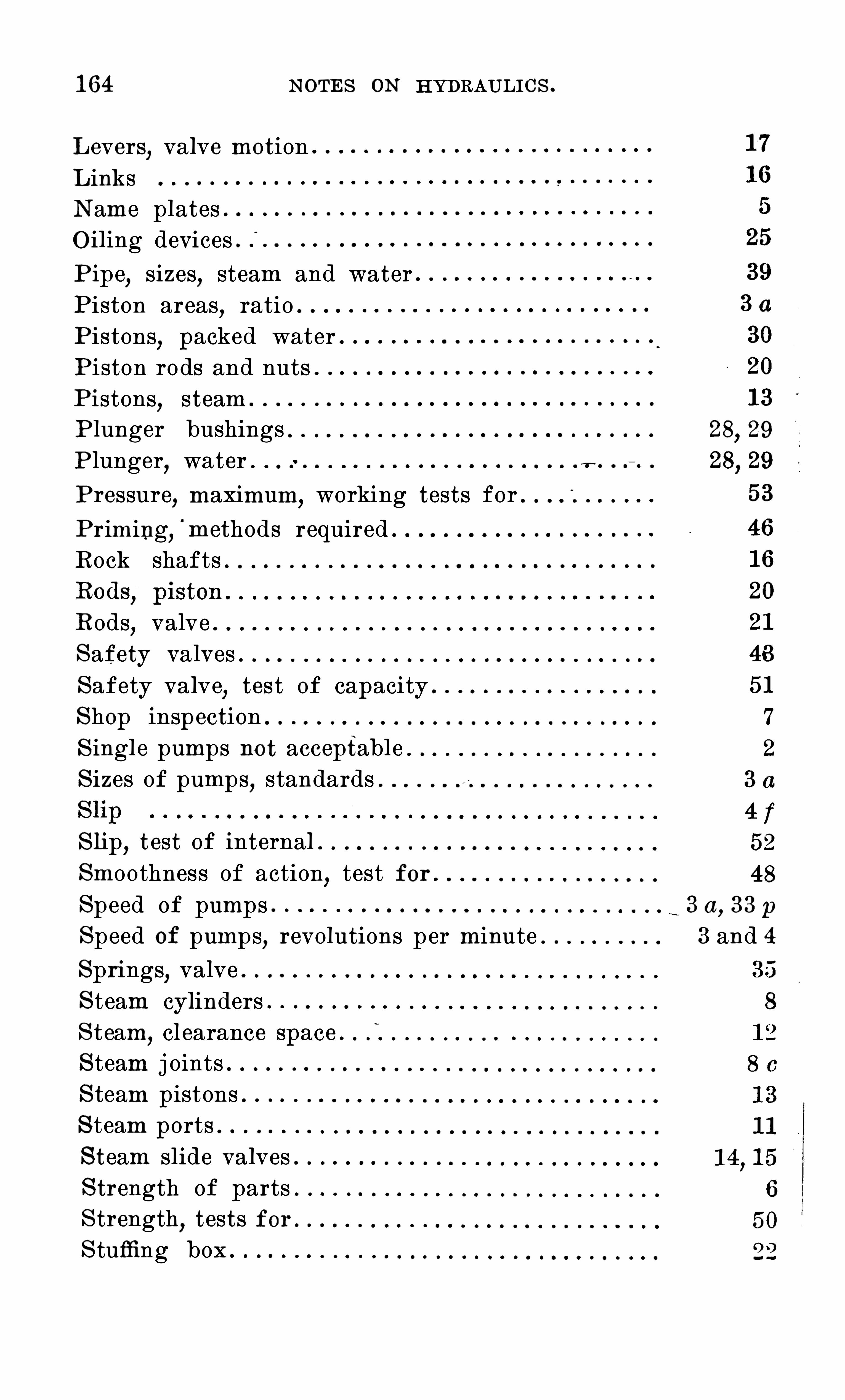
1 64 N O TES O N HYDRAULIC S .
Levers,valve motion
LinksN ame platesO iling devices .
P ipe,sizes
,steam and water
Piston areas,ratio
Pistons,packed water
Piston rods and nutsPistons
,steam
P lunger bushings 28 29
P lunger,water . .
v
Pressure,maximum
,working tests for .
Priming,'
methods requiredRock shafts
Rods,valve
S afety valvesS afety valve
,test of capacity
S hop inspectionS ingle pumps not acceptableS izes of pumps
,standards
S l ip,t est of internal
Smoothness of action,test for
S peed of pumps 3 a,33 p
S peed of pumps,revolutions per minute 3 and 4
S prings,valve
S team cylindersS team
,cl earance space . f
S team j ointsS team pistonsS team portsS team slide valvesS trength of partsS trength
,tests for
S tuffing box

1 6 6 N O TES O N HYDRAULIC S .
S T EAM PU MP T ABLES .
The following data,including capacities
,etc .
,are from
catalogues furnished by the makers °
WHEELER UNDERWRITER FIRE PUMP.
Formerly known as the Barr U nderwriter Pump .
Manufactured by C . H. Wheeler Manufacturing C o.
,
Philadelphia,Pa.
Maker’
s Diam. Diam. Length
Rated Steam Water of Size of Pipes
Capacity Cyl inder Cyl inder Stroke Steam Exhaust Suct. Disch.
5 00 1 4 7z} 1 2 3 4 8 6
75 0 1 6 9 1 2 34 4 1 0 7
1 000 1 8 1 O 1 2 4 5 1 2 8
1 5 00 20 1 2 1 6 5 6 1 4 1 0
FAIRBANKS-MORSE UNDERWRITER FIRE PUMP.
Manufactured byFairbanks-Morse C o.
, Chicago , 1 11.
5 00 1 4 7 1 2 3 4 8 6
75 0 1 6 9 I 2 34 4 1 0 7
1 000 1 8 1 0 1 2 4 5 1 2 8
1 5 00 20 1 2 1 6 5 6 1 4 1 0
FAIRBANKS-MCRSE DUPLEX FIRE PUMP.
204 306 1 0 5 1 2 2 24 6 5
294 44 1 1 2 6 1 2 24 3 6 5
400 6 00 1 4 7 1 2 24 3 8 6
5 22 783 1 6 8 1 2 24 3 8 6
6 6 0 990 1 6 8 1 2 24 3 8 6
81 6 — 1 224 1 8 1 0 1 2 3 34 1 0 8
81 6 — 1 224 1 8 1 0 1 8 3 1 0 8
81 6 — 1 224 2 0 1 0 1 8 3 34 1 0
1 1 74— 1 76 1 20 1 2 1 8 4 5 1 0 8

N O T ES O N HYDRAULI C S .
GARDNER REGULAR FIREPUMP.
Manufactured by the Gardner Governor C o., Quincy ,
l l l .
Maker’
s Diam. Diam. Length
Rated Steam Water of Size of Pipes
Capacity Cyl inder Cyl inder Stroke Steam Exhaust Suet. Disch.
1 0 5 1 0 2 24 5 4
35 0 1 2 6 1 2 24 3 7 6
5 00 1 4 7 1 2 24 3 7 6
75 0 1 6 8 1 2 24 3 7 6
900 1 6 9 1 2 24 3 8 7
1 000 1 8 9 1 2 3 4 8 7
1 200 1 8 1 0 3 4 1 0 8
1 200 1 0 1 2 4 5 1 0 8
1 5 00 20 1 ° 1 2 4 4 1 2 8
GARDNER STANDARD FIRE PUMP .
Maker’
s Diam. Diam. Length HandbookRated Steam Water of Size of Pipes Rated
Capacity Cylinder Cyl inder Stroke Steam Exhaust Suct.’
Disch. Capacity
5 5 0 1 2 7 1 2 24 3 7 6
5 5 0 1 4 7 1 2 24 3 7 6
700 1 4 8 1 2 24 3 7 6
75 0 1 6 8 1 2 24 3 8 6
900 1 6 9 1 2 3 4 8 7
900 1 8 9 1 2 34 4 8 7
1 200 1 8 1 0 1 2 34 4 1 0 8
1 1200 20 1 0 1 2 3 4 4 1 0 8
SMITH-VAILE UNDERWRITER FIRE PUMP.
Manufactured by T he Platt Iron Works C o. ,Dayton , O hio .
320 1 2 6 1 2 24 3 6 5 359
5 00 1 4 7 1 2 3 4 8 6 484
75 0 1 6 9 1 2 34 4 1 0 7 807
1 000 1 8 1 0 1 2 4 5 1 2 8 990
1 000 20 1 2 1 6 5 6 1 4 1 0 1 6 5 0

1 68 N O TES O N HYDRAULIC S .
TIIE SNIDER- IIUGIIES DUPLEX PUMP.
Manufactured byThe Snider-Hughes C o. ,C leveland, O hio .
Maker’
s Diam. Diam. Length HandbookRated Steam Water of SizeofPipes
Capacity Cyl inder Cyl inder Stroke Steam Exhaust Suet. Disch. Capacity
2 00 8 5 1 2 1 4 2 3
200 1 0 5 1 2 2 24 4
292 1 0 6 1 2 2 24 5 4
292 1 2 6 1 2 2 24 5
398 1 0 7 1 2 2 24 6 5
398 1 2 7 1 2 2 24 6 5
398 1 4 7 1 2 24 3 6
5 5 0 1 2 1 2 2 24 8 6
5 5 0 1 4 84 1 2 24 3 8 6
1 6 4 1 2 3 34 8 6
1 4 1 0 1 2 24 3 1 0 8
81 6 1 6 1 0 1 ° 3 3 1 1 0 8
81 6 . 1 8 1 0 1 2 34 4 1 0 8
1 1 74 1 6 1 2 1 2 3 34 1 2 1 0
1 1 74 1 8 1 2 1 2 34 4 1 2 1 0
1 5 5 0 1 8 1 4 1 2 34 1 2 1 0
SNDWUNDERWRITER FIRE PUMP .
Manufactured by the Snow S teamPumpWorks,Buffalo , N Y.
Maker's Diam. Diam. LengthRated Steam Water of S ize of PipesCapacity Cyl inder Cyl inder Stroke Steam Exhaust Snot. Biseh.
36 0 1 2 6 1 2 24 3 6 5
5 20 1 4 74 1 2 3 4 8“
6
800 1 6 9 1 2 34 4 1 0 7
1 000 1 8 1 0 1 2 4 5 1 2 8
1 6 5 0 20 1 2 1 6 5 6 1 4 1 0
BLAKE UNDERWRITER FIRE PUMP.
Manufactured by the Geo . E. Blake Manufacturing C ompany .
5 00 1 4 74 1 2 3 4 8 6
75 0 1 6 9 1 2 3 4 4 1 0 8
1 000 1 8 1 0 1 2 4 5 1 2 8
1 5 00 20 1 2 1 6 O 6 1 4 1 0

1 70 N O TES O N HYDRAULIC S .
RU LES AN D REQU IREMEN T S
For the C onstruction and Instal l ation of
STEAM PUMP GDVERNDRS AND AUXILIARY PUMPS .
N oT Er— Pages 1 70 to 1 77 are a reprint of the Ru l es and
Req u irements of the N ational Board of Fire U nderwriters
Automatically controlled pumps are not advised as aprimary water supply wherever it is possible to get a satisfactory gravity supply .
Whenever it is necessary to put in an~
automaticahy
controlled pump an auxiliary pump should always be usedto maintain the pressure and supply leakage .
The reason for the auxiliary pump is first that it permitsthe large pump to remain at rest
,thus saving excessive wear
,
and,second
,i t i s much more economical O f steam. Excessive
wear is O bj ectionable,as it means a l arge slip
,thus reduc
ing the capacity of the pump,and further
,because the wea r
under those condi tions of running is apt to be in the middleO f the travel of the rods and plungers
,with the danger that
the rods will stick in the stu mg boxes when the pump is putup to full stroke .
C onstru ction of the Governor .
S uccessful governors vary too greatly in type to admit ofuniform mechani cal construction . The following requirements cover general points necessary in gO V C I I l O T S
~ O f alltypes . A searching test under practical working conditions must be the main criterion for acceptance and forthe listing of a governor as an approved device .1 . The governor to be controlled by the water pressure
in the fire system.
2 . To be adjustable to maintain any desired pressure between 75 and 1 25 lbs .
,using steam at any pressure from
5 0 to 1 5 0 lbs .3 . T O be capable of governing th e pump from slow speed
to full speed without more than about 5 lbs . variation aboveor below the intended water pressure .

N O TES O N HYDRAUL I C S . 1 71
4 . T O not show di stress under steam pressure at 200 lbs .5 . T O be capable of enduring 240 lbs . water pressure
without injury.
6 . Must be rustproofed throughout by making all workingparts O f brass
,bronze
,or other suitable non - corrosive
material .7. I t is preferable that valve close by abutment contact
on valve seat .8. Valve and valve seat must be removable without remov
ing governor from piping .
9. Maximum working lift of valve must a "ord practicallysame steam passage area as that of the steam pipe controll edby governor .1 0 . To have screwed connections for attachment to ordi
nary pipe fittings .1 1 . T O have no internal stuffing box or gland .
1 2 . S hould preferably admit of full manual movement oninspection
,as a proof of working freedom of parts .
1 3 . S hould have a tendency to increase rather than decrease the water pressure as the speed of thepump increases .1 4 . S hould respond slowly to any sudden lowering of
water pressure and thus start the pump gradually1 5 . C onceal ed mechanism should be kept at a mi nImum.
1 6 . S hould avoid internal steam j oints capable of l eakingand passing unregulated steam to the pump .
Auxi l iary Pumps .
1 . Auxiliary pump should be O f\
dupl ex type, brass fittedand with packed pistons or exterior packed plungers .2 . The ratio of steam and water piston areas should be
about the same as for the main pump .
For P lan A ( see cuts)it is advised that auxiliary pump be ,
about a For P lans B and C a larger watercylinder is generally necessary to get the lifting powerneeded and about a pump is advised . Thesepumps are large enough to take care O f the leaks and wastesin the ordinary fire system.

N O TES O N HYDRAULI C S .
I n special cases where a larger amount of water must bemore or l ess continuously supplied from a fire system, theauxiliary pump must be larger and may be of any sizedesired.
The “ auxiliary pump is of value to keep the main fire pumpprimed
,as well a s to maintain the pressure and waste in the
fire system.
Instal l ation of Governors and Auxil iary Pumps ;
1 . Auxi liary pump and connections are recommended to
be arranged as shown in P lan A or as in P lan B for lifts upto 1 2 or 1 5 feet . For higher lifts P lan C is suggested . (S ee
Thi s applies to the scheme of connections and number andlocation of valves
,but not to the exact location of the
auxiliary pump .
With plan A the question has been raised that the mainpump may not be primed at all times . This method has,however
,been considerably used and has so far given satis
facti on under all conditions .P lan B insures that main pump will always be primed
,but
can generally no t be successfully maintai ned unless theauxiliary pump has a considerable l ifting ability.
For lifts over 1 2 to 1 5 feet it may be di Icu l t to make anauxili ary pump as per planB work satisfactorily
,and the
possibl e danger from imperfect priming in P lan A , becomesgreater . The arrangement of P lan C i nsures that pump andsucti on pipe are solid full O f water at all times and istherefore considered safer. A metal Seat foot vaIVe i s re
quired,as a soft seat might cause sticki ng after long
subj ection to the auxiliary pump pressure .2 . The main pump and - the auxiliary pump to have sep
arategovernors made entirely independent by a valve on thewater connection of each .
3 The size of governors for the main pump should be as
For 5 00 - gallon pump,1 4
" governor.For 700 - gallon pump
,1 4 governor .
For - gallon pump,2 " governor (possibly 1 4
For - gall on pump,2 ” governor .

1 74 N O T ES O N HYDRAULI C S .

N O TES O N HYDRAULIC S . 1 75
PLAN A— For Lifts U p to 1 2 or 1 5 Feet.
The auxiliary pump is placed under the main pump at one
C C — Automatic governors .RV — Relief valve on auxiliary pump .
H— C onnection to hose valves .T fi
— S team trap .
S ight feed lubricators are shown for both the large andthe small pump .
A forced feed lubricator could be used as shown in P lanC,if desired .
PLAN B — For Lifts U p to 1 2 or 1 5 Feet.
The auxiliary pump is shown on a shelf on the side wallof th e Pump House . I f desired the auxiliary pump can beplaced on brackets on top of the main pump . I f on thewall the auxiliary pump should be set high enough so thatmen can walk under the steam and suction pipe withoutstooping . The check on main pump discharge is shownjust outside of the pump house in a brick wel l .
C C — Pump governors .RV —Relief valve on auxiliary pump .
T — S team trap .
The suction of the auxiliary pump would connect into atee attached to one of the hose
'
outl ets on main pumpdischarge .S ight feed lubricators are Shown on both the large and
the small pumps . A forced feed lubricator could be usedas Shown in P lan C
,if desired.
PLAN C — For LiftsO ver 1 5 Feet, bu t S u itab l e forU se with Lesser Lifts .
The auxiliary pump is shown on the floor of pump houseover against one of the side walls . The suction pipe S for
the auxiliary pump is carried independently of the suctionof the main pump to some reliabl e water supply
,either that
from which the main pump draws or from any other source .A check valve should be provided at the end of this pipe
to act as a root valve .

1 76 N O TES O N HYDRAULIC S .
The discharge of the auxiliary pump is carried into thesuction of the large pump and the large pump suction isprovided with a metal seat for valve . With this arrangement the auxiliary pump keeps all connections on the largepump ful l of water.

N O TES O N HYDRAULIC S .
N ational S tandard Rotary Fire Pump .

N O TES O N HYDRAULI C S . 1 79
SPEC IFIC AT IO N S
O F T HE
NATIONALBOARD OF FIRE UNDERWRITERS
FO R T HE MAN U FAC T U RE O F
RO T ARY FIRE PU MPS
AS REC O MMEN DED BY T HE
NATIONAL nunPROTECTICN assocmlon.
EDI T IO N O F 1905 .
U N IFO RM REQU IREMEN T S .
T hese specifications for Rotary‘
Fire Pumps are now u sed
throughou t the whol e country ,
‘
hav ing been agreed upon in joint
conference by representatives of the different organizations in
terested in this -
cl ass of work . T hey wi l l b e known as T he
N ational S tandard and have been , u p to this time , adopted by
the fo l lowing Associations :
Associated Factory Mu tu al Fire Insu rance C ompanies .
N ational Board/
of Fire U nderwriters .
N ational Fire Protection Association .
N O T E — Pages 1 78 to 21 5 are a reprint of the pamphl et on
Rotary Fire Pumps of the N ational Board of Fire U nderwriters.

1 80 N O TES O N HYDRAULIC S .
RULES AND REQUIREMENTS FOR ROTARY FIRE PUMPS.
These specifications have been drawn up with the ideaof improving the present type of rotary pump as far aspossible without requiring an entirely new line of patterns
,
as it is believed that centrifugal pumps are likely toreplace rotary pumps for fire purposes to a greater or l essextent .Many of the rotary pumps now in use have too small
pip e connections for “ good results,sticking O ften occurs
after disuse (due to rusting), there are weak details inconstruction of some makes
,relief valves and hose connec
tions are frequently absent ; so that some general improvements are essential if rotary pumps are to be consideredsatisfactory fire pumps and comparable with steampumpsbuilt in accordance with the N ational S tandard.
Pumps built accordi ng to these specifications will differfrom the present types principally in the following points :
1 . Larger water passages at the suction and discharge
2 . Less chance of corrosion,the body and cams being
entirely of bronze .
3 . The introduction of a special discharge casting similarto that used with steam pumps and including an air chamber
,
hose connections,reli ef valve
,starting valve
,priming pipe
,
capacity plate,pressure gages
,etc.
T HE PU MP .
1 . Workmanship.
a . The general character and accuracy of foundry andmachine work must be in' line with good machine shoppractice.
This refers to strength of detail,accuracy of foundry work
,
accuracy of alignment, accuracy of fits,etc .
,and does not
apply particularly to exterior finish .
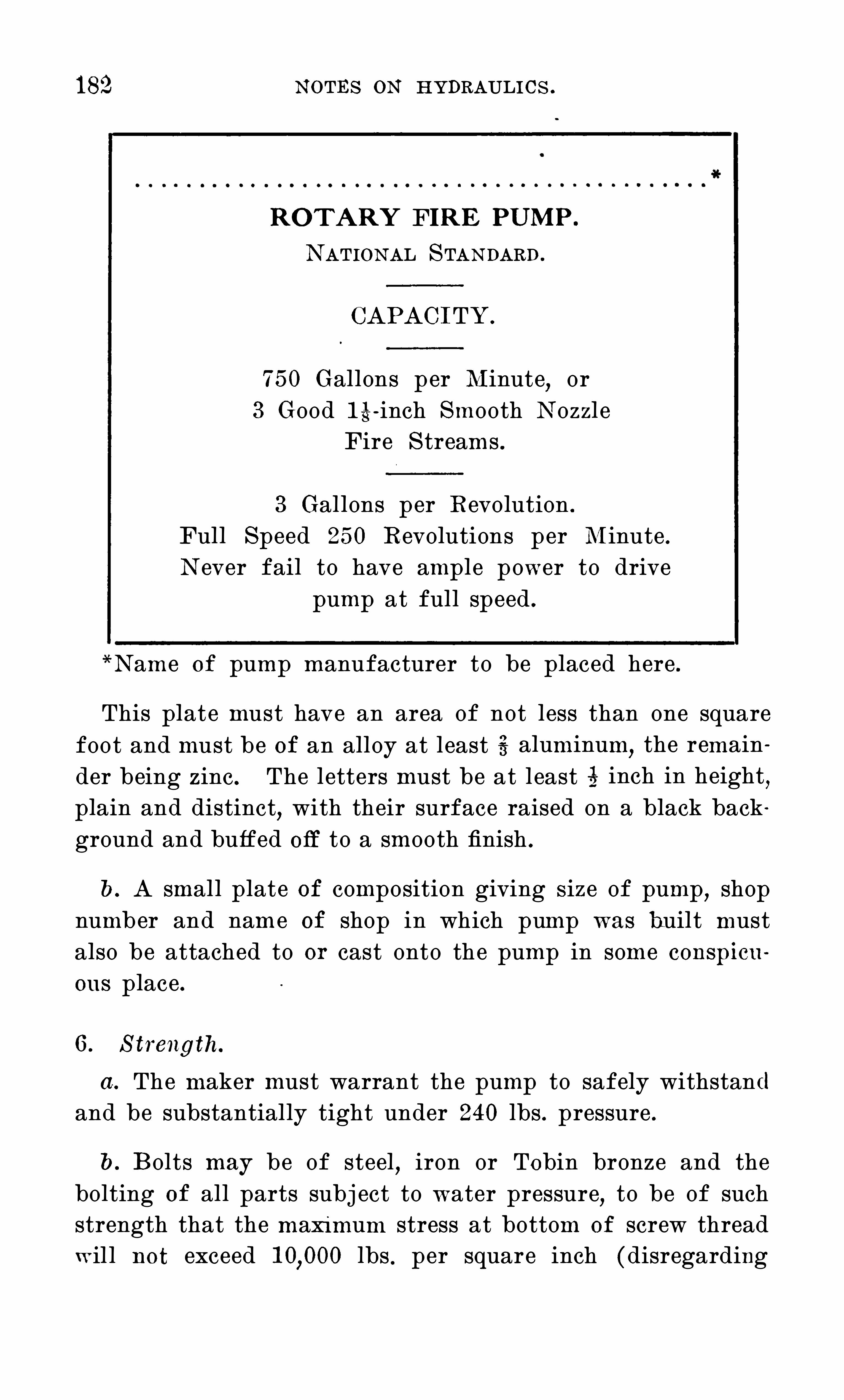
1 82 N O TES O N HYDRAULI C S .
RO TARY FIRE PU MP
N ATI O N AL S TAN DARD.
CAPAC I TY.
75 0 Gallons per Minute or3 Good 1 4- inch Smooth N ozzl e
Fire S treams .
3 Gallons per Revolution .
Full S peed 25 0 Revolutions per Minute .
N ever fail to have ample power to drivepump at full speed .
N ame O f pump manufacturer to be placed here .
This plate must have an area of not less than one squarefoot and must be of an alloy at least 4 aluminum,
the remainder being zinc . The letters must be at least 4 inch in height,plain and distinct
,with their surface raised on a black back
ground and buffed O ff to a smooth finish .
b. A small plate of composition giving S ize of pump,shop
number and name of shop in which pump was built mustalso be attached to or cast onto the pump in some conspicuous place .
6 . S trength.
a. The maker must warrant the pump to safely withstandand be substantially tight under 240 lbs . pressure .
b. B olts may be of steel , iron or Tobin bronze and thebolting O f all parts subj ect to water pressure
,to be of such
strength that the maximum stress at bottom of screw threadwil l not exceed lbs . per square inch (disregarding

N O TES O N HYDRAULIC S . 1 83
r the moment the initial stress due to setting up nuts)forwater pressure of 200 lbs . per square inch , computed on
area out to center line of bolts .
0 . N O steel or iron stud or bol t smaller than 4 inch andno Tobin bronze smaller than 4 inch should be used toassemble parts subj ect to strain of water pressure .
Although these pumps are not expected to be designed fora regular working pressure of 240 pounds
,i t is expected
that bolts,sh ell s
,will be figured to stand this com
parativel y quiet, temporary high pressure, exclusive of further allowance for initial strain due to setting up of bolts
,
with a factor of safety of at least four.
d . Pump must be able to run safe at,
25 V> excess speedth 1 00 lbs . pressure
,or at 4 rated speed with 1 5 0 lbs .
essure for two hours without overheating or requiringgthening of bolts .
7. S hOp I nspecti on.
a . A systematic shop inspection must be given to eachpump to ensure complete workmanship and ‘ to prevent theuse of defective parts
,improper materials
,or the carel ess
leaving O f foreign matter in any part of the pump .
8. Body of Pump.
a . The cylindrical portions and the ends to be of castbronze at l east 4 inches thick for the smallest size whenfinished . Al l sizes to be of su
“
i cient thickness to withstandthe pressure sp ecified in section N o. 6 .
I t is generally believed that careful ribbing is preferableto excessive thickness in metal .I n pumps where cams or pistons have a bearing adjust
able abutments only, i t may be sufficient to have the bodyof pump of iron and the abutments of bronze .
b. These parts to be hard and close grained with metalS O distributed as to ensure sound casting and freedom fromshrink cracks .

N O TES O N HYDRAULI C S .
c. Ends of pump to have arrows cast on the metal,show- x
ing di rection which shaft is designed to turn . Arrows to beat least 4 inches long and raised at least above surface .
9. Bed P l ate.
a . Pump to have a heavy bed plate to which bearings andpump must be firmly secured . Bed plat e to have four and
preferably six bol t holes for securing it to foundation . N 0
bolt to be less than inch in diameter.
1 0. C ams.
a . To be cast in one piece of hard,cl ose=grained bronze ;
to be secured to shaft by standard key runni ng the entirewidth of cam. B lades or buckets t o be designed so as togive ample strength . Bronze packing or adjustable slidesare - not advised
,but will be allowed if found satisfactory
after special examination . The fit of cams to be as closeas practicabl e
,but not so close as to allow for any chance
of sticking .
b. C ams to be so designed that pump will run smoothlywithout poundi ng . This frequently requires properly designed cavities in pump ends to prevent undue pressurefrom water which may be pocketed by cams .
1 1 . S hafts.
a . To be of best forged steel of ample'
strength . S haftsto be bronze covered from ends of cam to outside of stuffingboxes . The bronze cover must fit the shaft closely andmust be forced on making a tight j oint with the cam.
1 2 . Bearings.
a . Main bearings to be lined with best babbitt and to belocated as near ends of pump as possible . Babbitt to behammered in and then bored out to the necessary size.
Length of main bearings to be at least three times thediameter of shaft .

1 86 N O TES O N HYDRAULIC S .
1 4 . Gears .
a . Pump to have a pair of Outside cut gears at each endof shafts with an outside bearing for each gear . Gears tobe O f forged steel or iron
,steel casting or cast iron
,and
designed to transmit the necessary power'
with a libera lfactor O I safety . Gears to be located close to main bearings,and to be protected by cast iron Shields securely fastened in
1 5 . C oupl ings .
a . O ne Shaft to be fitted with a machine . faced jawcoupling O f ample strength .
1 6 . Discharge C asting.
a . Pump to have a discharge casting to which is attachedmain discharge pipe
,hose connections
,relief valve
,starting
valve, priming pipe and air chamber . I t is advised that airchamber be part O f same casting
,but if this is not done the
air chamber to be bolted to the upper side O f the dischargecasting
These outlets to be the following S izes :
S ize O f Pump 75 0 1 000 1 5 00
O n two O pposite S ides for HoseC onnection 5 6 7 A 8
For Main Discharge 6”
8"
8 1 0
For Relief Valve 3”
3 1‘s
"
4”
5”
P riming C onnections 2 ' 2 2”
S tarting Valve 2 ”2? 2 1
k" 3
Air C hamber N eck 5 6 6 8
b . All O f the above outlets except those for starting valveand priming connection to be flanged . S tandard flangesand standard bolt layouts as given in S ection N O . 1 3 to beused . B lank flange to be supplied for hose outlet that isnot u sed .

N O TES O N HYDRAULIC S .
Hose C onnecti ons .
A casting to be furnished with flange connectioned to fit one O f the outlets of the discharge casting as
in S ection N O . 1 6 . This casting to be fitted withor more hose connections according to the capacity of
pump,each hose outlet being fitted with an approved
te va l ve.
S ize of Pump . N O . of C onnections .5 00 gals 2
3
b . Where hose cannot be carried direct to pump the hosennection casting to be placed at any convenient point andnnected to pump by pipe O f same size as hose outletnnection (see S ection
1 8. Air C hamber.
a . T O be properly designed to provide a smooth, even discharge . C apacity to be at least two gallons for every hun
allon capacity of pump . T O be O f as little height asWhere not a part O f discharge casting to have
(1 c onnection arranged to fit
I
the top O f dischargeng (see
"
S chedule O f standard flanges). T O be testednder 400 lbs . and to be painted inside and out.
1 9. S afety Va lve.
a . A spring patterai' safety or relief valve O f any make
agreed upon in writing with the U nderwriters having jurisdiction is to be included in the price . T O be attached toeach pump
,extending horizontally S O that its hand -wheel for
regulating pressure is within easy reach . This hand -wheelmust be marked very conspicuously with the word “ open ”
and an arrow showing. in which direction the valve is O pened .
b. This valve is to be set ordinarily at a working pressure

1 88 N O TES O N HYDRAULI C S .
O f 1 00 lbs . to the square inch, and to be of such capathat when set at 1 00 lbs . it can pass
‘
al l the water discharged by the pump at full speed, at a pump pressure notexceeding 1 25 lbs . per square inch .
S ize O f Pump . S ize of Relief Valve .
5 00 gal
0 . Where relief valve does not di scharge into an open pipein plain sight near pump it should discharfi
'with a cone orfunnel secured to outl et of valve . This cone Should be soconstructed that pump operator can easily see any waterwasting through relief valve
,and its passages should be O f
such'
design and size as to avoid splashing water into thepump room. T O be piped O ff to some point outside O f
pump house where water can be wasted freely.
d . When the supply O f water is limi ted,as from a special
Suction reservoir or cistern,the waste pipe must drain into
such reservoir or cistern entering as far from the pumpsuction as is necessary to prevent the pump from draughtingair which may be carried down into the cistern by the di scharge from the waste pipe .
6 . S ize of wast e pipes to be as follows :
S ize of Pump . S ize O f Waste Pipe .5 00 gal
f. Relief valve to be so attached to delivery elbow anddischarge cone by flange connections as to permit O f itsready removal for repairs without. disturbing the wastepiping.

1 90 N O TES O N HYDRAULIC S .
“
largely upon circumstances and no definite rules governi ngthis can be laid down . The following methods are recom
mended in the order given :
l — Direct from independent source O f power .
2— S pur gearing from independent source O f power . I n
this case the pump should be kept in gear at all times .
3— S pur gearing from -main shaft with a satisfactoryclutch . C lutch Should be O perated from pump room andonly such clutches should be used as are approved by theU nderwriters having jurdisdi ction.
4— Grooved friction gearing from main Shaft . Gears tocomply with rul es given in S ection N O . 24 .
24 .. Grooved Friction Gears .
a . There must be a pair O f’ friction driving gears
,one
being fastened direct to driving shaft and the other connected to pump shaft through jaw coupling . There shouldbe enough play in this coupling to allow gear to slide atrifle and thus mesh properly with driving gear .
b. Friction gears to have bearings at both ends . LengthO f bearings to be at least “ three times the diameter of
shaft .
0 . Friction gears to be properly designed to transmit thenecessary power and give the required speed with a surfacevelocity that is not excessive .
d . Grooves to be recessed at bottom,and to be properly
designed to grip tightly without undue S lip .
e. Gears to be set on rugged framework amply strongto sustain any strain that is liable to be put upon it . C are '
should be taken in setting to ensure that shaft alignment isperfect when gears are in mesh .
I t is recommended that pump and gears be set up with

”
N O TES O N HYDRAUL I C S.1 91
shaft-s I n line and gears in mesh and then bolted to theirfoundations .I n some cases one or more heavy Springs have been
inserted to hold gears in mesh and to prevent undue stressbeing placed on driving gear . I t i s believed that this isa desirable feature and it is recommended for all cases .
f. The following sizes O f gears are recommended :
S ize O f Pump . Minimum Diameter O f Gears .7
” face “
9” face 1 2"face
5 00 gaL 24 2 1 ” 1 8
75 0 gaL 30 24” 2 1
1 000 gah 36 30” 24
1 5 00 gaL 36” 30
g, Friction gears to be protected by a
'
strong sheet meta lcasing or cover securely fastened to the bed plate .
This to prevent grease and O i l from getting into th e :
grooves .
25 . S etting.
a . Bed plate and supports for gearing to be of heavy construction
,well bolted down
,and capable O f withstanding
any strain that is liable to be put upon them. Pump mustbe securely
“fastened to firm foundation S O as to be praetically free from vibration . Good brick
,concrete or ma
sonry. foundations are the best . Heavy I beams or woodenbeams may be employed . N O bolts to be used less than 32
”
in diameter .
26 . C lutch.
a . Except where there is an independent wheel for pumpalone, a reliabl e clutch should be provided S O that mainshafting beyond the pump can be thrown out O f operationwhen pump is running . This to be located near pump
_
O r tobe otherwise arranged S O as to be readily accessibl e in caseO f fire .
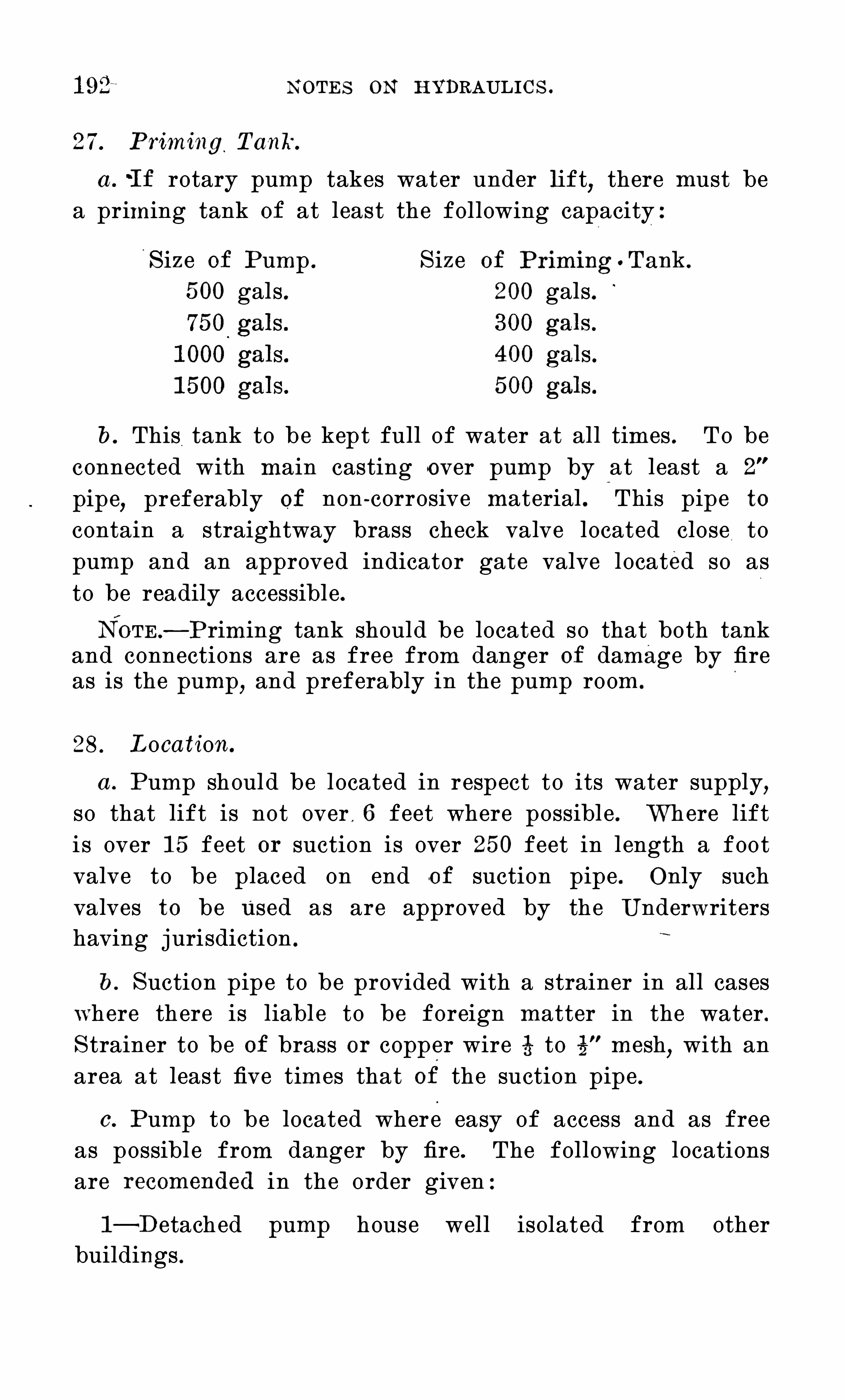
N O TES O N HYDRAULIC S .
27. Priming T anIf.
a .
'I f rotary pump takes water under l ift,there must be
a priming tank O f at least the following capacity :
S ize O f Pump . S ize O f Priming o T ank.
5 00 gals 200 gals
b. This tank to be kept full of water at all times . To beconnected with main casting over pump by at least a 2
pipe,preferably of non - corrosive material . This pipe to
contain a straightway brass check valve located close topump and an approved indicator gate valve located so asto be readily accessible .NO TE — Priming tank should be located so that both tank
and connections are as free from danger O f damage by fireas is the pump
,and preferably in the pump room.
28. Location.
a . Pump should be located in respect to its water supply,so that lift is not over , 6 feet where possible . Where lifti s over 1 5 feet or suction is over 25 0 feet in length a footvalve to be placed on end of suction pipe . O nly suchvalves to be U sed as are approved by the U nderwritershaving jurisdiction .
b . S uction pipe to be provided with a strainer in all caseswhere there is liabl e to be foreign matter in the water .S trainer to be O f brass or copper wire to mesh
,with an
area at least five times that of the suction pipe .
0 . Pump to be located where easy of access and as freeas possibl e from danger by fire . The following locationsare recomended in the order given :
l — Detached pump house well isolated from otherbuildings .

1 94 N O TES O N HYDRAULIC S .
pressure can be maintained at 1 5 0 pounds,or
,under some
conditions and with careful handling,at 1 75 or 200 pounds .
31 . T est for MaximumDel ivery.
Where speed can be increased,add additional streams
and increase the speed until the pump is running at l east25 per cent . above the normal
,and see how fast the pump
can run,maintaining serviceable fire pressure
,before Objec
tionab l e pounding and vibration occur .
32 . T est of C apacity of Rel ief Va lve.
Adjust the relief valve so that it will open at 1 00 pounds ;Shut the main outlet valve and the hose gates
,discharging
all th e water through the relief valve and the starting valve ;then
,with the pump at full speed
,clo se the starting valve
slowly. The relief valve should carry the total dischargeof the pump at its fu l l rated Speed and not let the pressurerise above 1 25 pounds .I n general
,where a pump is properly set up and handled
it Should be able to satisfactorily perform all O f these tests .

N O TES O N HYDRAULIC S . 1 95
APPEN DIX.
N O T E — Append ix to Ru l es of N ational Board of Fire U nder
writers for Rotary Fire Pumps.

1 96 N O TES O N HYDRAULI C S .
’
P'l
WO
TH
L b
TYPE
B

1 98 N O TES O N HYDRAULI C S .
Finally,it should be remembered that these sp
cover O nly the outlines O f the design,and that
bui l t under them will not be of equal merit,for
the pump factories possess a broader exp erienceshop facilities than others ; and that the responsifirst- class workmanship and strength O f materialsthe pump manufacturers and net on the insur
companies .
1 . Workmanship.
a . The general character and accuracy O f foundry anmachine work must throughout equal the best practicethe times as illustrated in geared machinery O f similarpower and rotative speed .
This refers to strength O f details,accuracy of f 0
work,accuracy O f fits
,construction and alignment O f Shaft
bearings,character O f gear cutting
,and does not apply
parti cularly to exterior finish .
2 . Twin Rotary Pumps O nly.
a . O nly twin rotary pumps having two shafts and positivedisplacement cams are acceptabl e .
3 . S izes of Pumps.
a . O nly the four di “ °
erent sizes given in the followingtable will be recognized as approved rotary fire pumps .
STAN DARD S IZES FO R RO TARY FIRE PU MPS .
S C: 20 m’
8 C 3 Us: 2” u; g95 8
~ s"WE S 353
“z
l
2 5 naer: u g 8 a:
oif 8 q"g‘
a) QT
0cu
Q 8 cuc g. am am no. O J)
2 3 a: Z fig“
500 8"
7"
8"
275 2 60750 9 or 1 0
"
8"
9"
275 3 901 000 1 0
"
9"
— 1 0"
250 4 1 201 500 1 2
”
1 0"
— 1 2"
250 6 1 80

N O TES O N HYDRAULIC S .
The multiplicity O f O dd sizes of rotary pumps is confusingand undesirable
,and in the past
'
di fi erent makers haverated their pumps arbitrarily as to their capacity
,giving
to purchasers an incorrect idea as to their actual pos sibilities for fire service.The above dimensions for buckets or cams and the di stance
between centers are,as stated
,only approximate . The use,
t centers and wide cams i s undesirable andunnecessarily lengthens the shafting
and pump . O n the other hand,the use O f a narrow bucket
narrower than the usual centers— makes it di ""
cu l t to provideamp l e Suction and di scharge openi ngs in the pump casing .
The theoretical amount O f power necessary to give a’ pressure of 1 00 pounds per square inch with a delivery O f 1 00
gallons per minute is H. P . This includes -
no al lowancewhatever for ‘
friction O f water,for slip
,and for fri ction in
itself and in the driving gear . Experience withnow in use shows that those losses
,as pumps are
ily found set up,about double the power necessary
,
1 2 H. P . is usually required for each 1 00 gallons perminute delivered at 1 00 pound s pressure
,and 30 H. P . is the
usual allowance for each good Rig- inch stream.
I t is desirable to keep the power required as small aspossible, as there is O ften a limited power available where itis desired to place a rotary pump . I t i s hoped that with animproved pump and better method O f. drivi ng, the . total
power required may be materially less than in the averagepump found to - day.
b . The standard allowance for a good ( smooth nozzle)fire stream is '
25 0 gallons per minuteA S O —called “ ring nozzl e ” discharges only three - fourthsas much water as a smooth nozzl e O f the same bore
,and is
not recommended .
From fifteen to twenty automatic Sprinklers may be reckoned as discharging about the same quantity as a 1 % - inchhose stream under ordinary practical conditions as to pipessupplying sprinkler and hose systems respectively.
4 . C apacity
a . The displacement O f the rotating cams in a rotarypump will not alone tell how many gallons per minute a pumpcan deliver, and it is not reasonable to estimate capacity on

200 N O TES O N HYDRAULIC S .
the basis of the displacement O f the cams per revolutionmultiplied by the number of revolutions per minute . A liberal allowance must be made for slip and for by- passing backinto suction at the point where cams mesh together
b. The capacity O f a rotary pump depends as well uponthe speed at which it can be run
,and the speed depends
largely upon the size and arrangement O f its water passagesand upon
.
the manner in which its power - drive,gearing and
shafting have been fitted up .
c . I t is all right to run rotary fire pumps at the highestspeed that is possible without causing violent vibration orhammering in the pipe system. C onsiderations O f wear donot a ” ect the brief periods O f fire service or test .
d . Pumps must deliver when new 20% more water thancalled for by preceding table .
e. Pumps must be S O built that they can be safely run ata speed 25 % higher than that given in the table at 1 00pounds water pressure .Twenty per cent . margin is to allow for some wear and
still have pumps which will deliver their full rated capacity .
The requirement for ability to withstand 25 per cent . excessspeed is comparable with the possibility ordinarily existingin steam pumps to run them above the rated speed . I t I s
desirable that a rotary pump should have practically thesame di scharging capacity as a steam
'
pump of equivalentrating .
5 . C apacity P l ate.
a . Every rotary fire pump must bear a conspicuous statement of i ts capacity securely attached to the inboard S ide O fair chamber, thus :

202 N O TES O N HYDRAULIC S .
7. S hep I nspection.
A systematic shop inspection must be given to each pump ,to insure complete workmanship and to prevent the use O f
defective parts,improper materials
,or the careless leaving
O f foreign matter in any part O f the pump .
T HE PU MP .
8.
,S tyl e of Pump.
a . The general arrangement O f gears,shaft bearings
,and
pump casing required is shown in Figure 1 . Pumps musthave their two shafts geared together with one set of .
gears,each gear being supported by twO
— “
b earings placedclose up to the gears on either S ide . A third bearing supporting the tail end of each shaft must be provided at theother end of pump casing .
b: The Span between this third bearing and the inboardbearing next to gear must be as short as possible
,to avoid
any deflection of th e shaft .
0 . The power - drive must in every case be connected to thegear end O f the Shaft .
d. These three bearings must form a part of a substan
tial bed plate,rigidly supporting the pump casing in perfect
alignment with the bearings .
e. The pump casing must be surmounted by a special discharge casting with openings arranged as in Figure 1 .
9. Pump Casing.
a . The pump casing and easing heads must be O f solidbronze composition
,made from new stock . T he thickn ess
of this shell and heads must not be less than in the fol
lowing table :
S ize O f Pump . 5 00 75 0 1 000 1 5 00
Thickness of Shell (Z;Thickness O f head 73
" 974. 94

N O TES O N HYDRAULIC S . 203
he shell and heads should be ribbed su" ’
iciently to preventdestruction of pump casing when working again
’
st‘
the
t severe conditions noted in Articl es 29,30
,3 1 and 32,
s 1 9 and 20,under Tests of Acceptance.
The bolting O f the several parts Of casing, heads andon and discharge pieces must be such that the
'
maxi
stress at bottom O f screw thread will not exceedds per square inch (disregardi ng for the moment thestress due to setting up nuts)for a water pressure
200 pounds per square inch figured out to th e center linethe bolts .N o bol t or stud less than 8 should be u sed to assemblerts of easing subj ect to the strain O f water pressure. Allbolts or studs must be of Tobin bronze .
C ase.
a . The rotating cams must be cast in one piece,O f solid
onze composition . Their worki ng surfaces must be accurately machined to fit the casing in which they revolve
,and
properly mesh into each other.
b. Each cam must be secured to its Shaft by a standardkey running th e entire width O f cam.
e cams must be forced onto their respective shaftspressure, so that the subsequent keying will
throw them out of center .
The number O f teeth or buckets in each Cam should noted six or seven
,nor is it desirable to use so few as to
to secure smooth running .
large number of buckets is likely to result in a weakf tooth or . I f the tooth is made strong
,. the capacity
pump is cut down . O n the other hand,there is some
cc that too few buckets are likely toresult in a pumpwill not work Wi thout O bj ectionable noise and vibraI t is important that there be no space in the bucketswater may be trapped and squeezed, as this tendsthe pump pound .
not desiring to restrict manufacturers,we advise
than five and not more than seven buckets on each

204 N O TES O N HYDRAU LIC S .
cam,although strength O f design and smoothness in running‘
will be the main guiding features in determi ning finalacceptance.The use O f packing strips to insure tightness O f cam in
casing is not desired . While in clear water such construetion may be satisfactory, for the rough and only occasionaluse O f the average fire pump the simpler form O f construetion is believed safer .
1 1 . S hafts.
a . The shafts carrying the gears and earns must be O f thebest forged steel
,and to be O f a diameter at gear bearings
not l ess than as given in the following table :
S ize O f Pump . 5 00 75 0 1 000 1 5 00
Distance between inner edgesO f the cam bearings 1 7 1 8
” 20 22
Diameter of shaft at bearing 2% 3 3t 4
These sizes are larger than necessary to simply resis
torsional strain,
“ as they must be su “ "
iciently sti" to p
much deflection for water pressures O f 200 poundsmight occasionally be .needed .
b . The shafts between the bearings and the cams mustbe protected from corrosion by a covering of bronze com
position forced O u into place.
c. T he two shafts must extend beyond the bearings atthe gear end a su
’
icient distance to permit keying on adriving coupling . O ne such coupli ng must be furni shed witheach pump .
1 2 . S tufiing B oxes.
a . S tu"
ng boxes must be of a special and compact design
,S O as to prevent an excessive d istance between main
bearings .T o avoid the use O f very large shafts
,the distance between
bearings must be kept as Small as possible . The specialtype O f stu ng box Shown in Figure 2 suggests one method

206 N O TES O N HYDRAULIC S .
O f saving space at this point . Any other rel iable arrangement accomplishing the same results would be acceptable .
b . I f a stu" ’
ing box O f ordi nary type is used, the glandmust be O f solid composition, and su
’
icient space providedfor inserting the packing .
c. The shaft must not have any bearing at the stuffingbox or casing head .
S uch bearings are di “ ’
icu l t to keeplubricated and are subject to rapid wear due to grit in the Water .
1 3 . Gearing.
a . Each pump gear must be of forged steel,preferably
forged in one piece with the shaft .Manufacturers preferring to make these gears separatefrom the shaft
,fitting and keying them on afterward
,may
do so . There is,however
,no difificu l ty in getting rough
turned forgings O f this character at a reasonable price,and
the wOrk O f fitting and keying to shaft is thereby saved.
S teel castings have been proposed for this work, but theuncertainty O f O btaining sound castings free from blow holesor porosity
'
O f any ki nd renders this material of doubtfulreliabil ity.
b. The teeth O f gears must be accurately cut to insuresmooth running. The use of the involute tooth is advised.
c. The gears must have,
their edges beveled off as shownin Figure 1 . This reduces minimum the possibili ty O f
teeth corners breaking o"
,and does not materially reduce
the worki ng face of gear .I t is advised that not l ess than 20 teeth nor more than 30
teeth be used,employing a circular pitch O f from 1 1744 11 0 1]
to - inch .
d . The face O f gears,made from forged steel
,must not
be less for th e approximate pitch di ameters given than asin table below
,measuring on the pitch surface :
S ize O f Pump . 5 00 75 0 1 000 1 5 00
Approximate pitch s" 9"
1 0 1 2”
Face O f gears 4"
5 ” 6 ”7

N O TES O N HYDRAULIC S . 207
1 4. Bearings.
a . Each O f the three bearings supporting each shaft musthave a bearing length at least three times the diameterO f the shaft which it supports .
b. Each bearing must be lined throughout its entire l ength‘with the 'best babbitt metal
,finished to at least - inch thick .
The babbitt after being cast into place must be thoroughly hammered and then all three boxes bored out at onesetting in the boring machine .
0 . The use O f removable boxes is acceptable only when theyare so fitted up with cylindrical machined fits as to be interchangeable
,thereby maintaining perfect alignment O f the
shafts and pump casing.
d. Liberal - sized O i l grooves must be provided,so as to in
sure lubrication over the entire bearing .
e. Each bearing must be provided with an endless chainO iler O f durabl e construction
,its lower part running in a
chamber cast under the bearings filled with O i l .
f. Each bearing cap must be provided'with a hinged lid
large enough to permit O f inspection of the bearing and theapplication O f O i l .
1 5 . Bed P l ate.
a . A substantial cast iron bed plate rigidly supportingthe bearings and pump casing must be provided .
b. The shaft bearings should preferably form a part O f
this casting,as sho
/wn in Figure 1 .
0 . There must be provided a chamber or basin cast in thisbed plate directly under the gears and the several bearings
,
for the holding of a quantity of O i l in which the gearsand chain oilers wil l run . I t will be desirable to connectall of these oi l basins together
,so as to equally di stribut e the
O i l to all basins as long '
as any remains in the bed plate .

208 N O TES O N HYDRAULIC S .
d . A cast iron hood must - be provided and fitted overthe gears in such a manner as to entirely enclose them andalso prevent the escap e O f O i l from the gears during theoperation O f the pump .
This hood should be secured to .the bed plate by severalsmall bolts .
6 . From four to six bolt holes, 1 to varying withthe size of the pump
,must be provided in bed plate
,so ‘
arranged as to properly secure it to foundation .
1 6 . S uction and Discharge O penings .
a . The openings in pump casing formust not be less than as given below :
S ize O f Pump . 5 00 75 0 1 000 1 5 00
S uction inlet 6”
8"
8"
1 0
Discharge outlet 6 ” 8”
8” 1 0
b. Where pump takes its water under a head,suction
pipe may be O f the same size,but with a suction lift O f 1 0
feet or more and a length O f pipe exceeding 20 feet,or with
more than two elbows,suction pipe 2 inches larger must
be used,and a special reducing casting must be provided to
connect this pipe with the,
pump .
c. A special di scharge casting must be furnished andbolted to th e top O f pump casing . This discharge pieceand air chamber should preferably be cast in one piece .
O penings must be provided in this discharge casting O f
such sizes as are given in table below for the purposesspecified .
O f the two O penings on opposite sides,one must be pro
vided with blank flange and the other left for attaching ahose connection piece . At right angles to these two openings there must be provided the main di scharge O utl et andthe relief valve outlet
,all shown in Figure 1 .
C onveniently arranged openings must be provided forpriming Connection and for a starting or air valve pipe.

21 0 N O TES O N HYDRAULIC S .
1 9. Pressure Gage.
a . A pressure gage of the Lane double - tube Spring pattern with 5 - inch case must be provided with the pump andconnected near to inboard side of air chamber
,as shown in
Figure 1,by a i - inch cock with lever handle.
The dial of this gage shoul d be scaled to indicate pressures up to 240 pounds, and marked
“ WATER.
”
This kind O f gage is used on locomotives and is the bestfor withstanding the vibration which causes fire pump gagesto be O ften unreliable . Moreover, this double spring formis safer against freezing .
20 . Hose Va lves.
a . Hose valves must be provided and included in price Ofpump as follows :
For 5 00 - gallon pump,2 hose valves .
For 75 0 - gallon pump,3 hose valves .
For 1 000 - gallon pump,4 hose valves .
For 1 5 00 - gallon pump,6 hose valves .
These are to be - inch s traightway brass valves,with
out cap,and O f heavy pattern
,good design and workmanship .
The hose screw at end O f these valves is to be fitted toa hose coupling furnished by the customer
,or
,where this
cannot be procured,may be left with the thread uncut .
b . A hose connection casting must be provided and designed to bol t to the pump discharge casting or to a pipeflange where it is desired to locate the hose connections awayfrom the pump . This casting must be fitted with such anumber O f 2%- inch pipe O penings as the size O f th e pumpdemands . S ee Figure 1 .
2 1 . S afety Va lve.
a . A safety or relief valve of approved make is to be regul arly included in the price, and is to be attached to eachpump preferably extending horizontally to one side O f
pump, as Shown in Figure 1,so that its hand -wheel for
regulating pressure is Within easy reach . This hand -wheel

N O TES O N HYDRAULIC S . 21 1
must be marked very conspicuously with word “ O PEN ”
and arrow to show the di rection .
b. This valve is to be set ordinarily at a working pressureof 1 00 pounds to the square inch, and is to be O f suchcapacity that when set at 1 00 pounds it can pass all the
r discharged by th e pump at full speed at a pump presre not exceedi ng 1 25 pounds per square inch .
For 5 00 - gallon pump,a 3 - inch valve .
For 75 0 - gallon pump, a Ss- inch valve .For 1 000 - gallon pump
,a 4 - inch valve .
For 1 5 00 - gallon pump,a 5 - inch valve .
0 . The relief valve must discharge in a vertical downwardrection into a cone or funnel secured to the outlet O f the
valve must be so attached. to the delivery casting andrge cone by flange connections as to permit O f its
dy removal for repairs without disturbing the waste
22 . Discharge C one.
a. This cone should be so constructed that the pump opercan easily see any water wasting through the relief
Ive,and its passages should be O f such design and S ize
to avoid Splashing water over into thepump room.
b. The cone must also have a tapped connection for theand the arrangement must be such that the
erator can easily tell whether water is comingair pipe'or is wasting through the relief valve .
The cone should be piped to some point where waterbe wasted freely; the waste pipes being as below :
S ize O f Pump . Diameter O f WastePip e from C one .
5 00 - gallon 5 inches .75 0 - gallon
,6 inches .
1 000 - gallon, 7 inches .
1 5 00 - gallon, 8 inches .
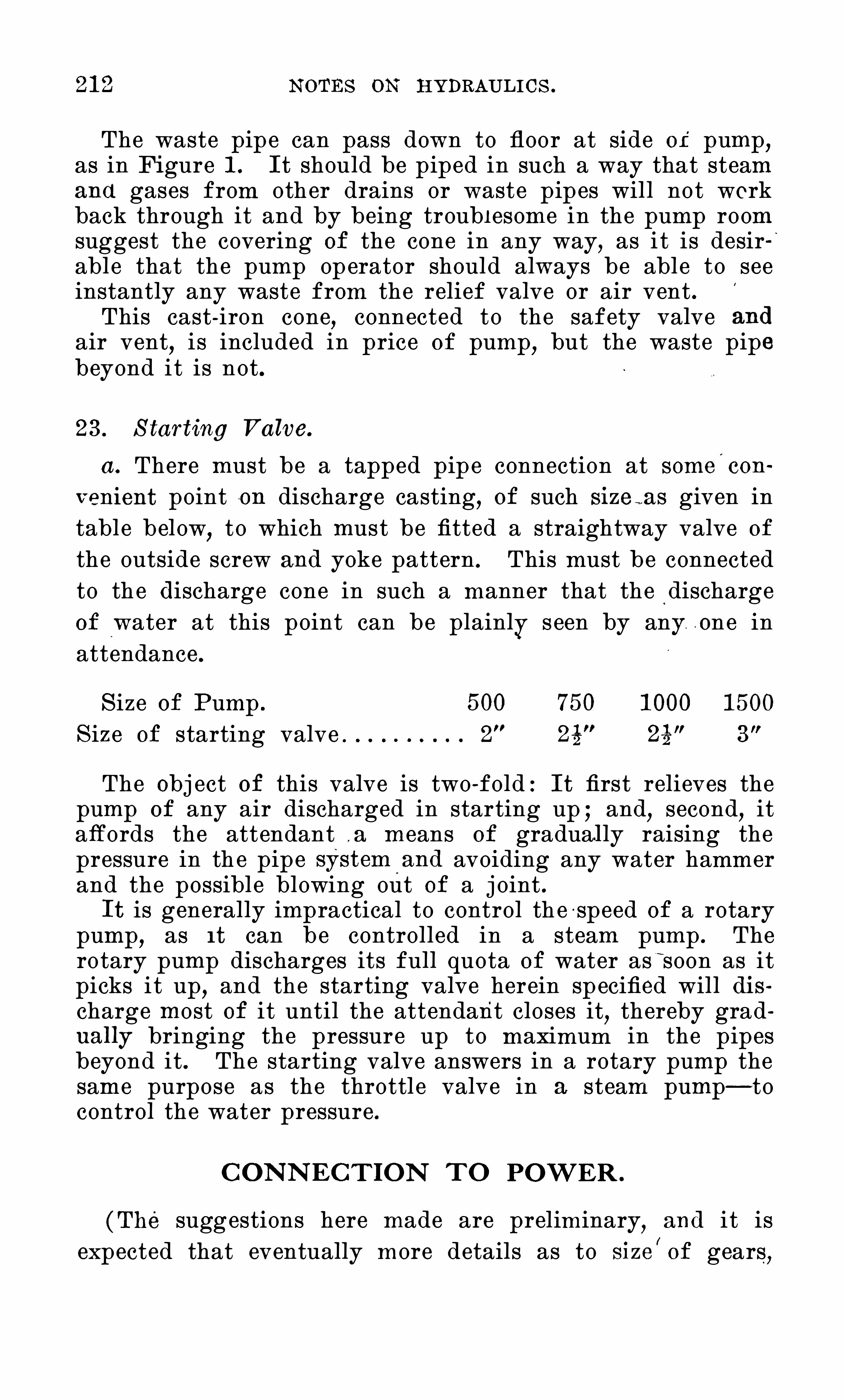
2 1 2 N O TES O N HYDRAULI C S .
The waste pipe can pass down to floor at side of pump,as in Figure 1 . I t should be piped in such a way that steamand gases from other drains or waste pipes will not workback through it and by being troub l esome in the pump roomsuggest the covering O f the cone in any way, as i t is desirable that the pump operator should always be able to seeinstantly any waste from the relief valve or air vent .This cast - iron cone
,connected to the safety valve
air vent,i s included in price O f pump
,but the waste pip
beyond it is not .
23 . S tarting Va lve.
a . There must be a tapped pipe connection at some'
con
venient point on discharge casting, O f such size i as given intable below
,to which must be fitted a straightway valve O f
the outside screw and yoke pattern . This must be connectedto th e discharge cone in such a manner that the dischargeO f water at this point can be plainly s een by any one inattendance .
S ize O f Pump . 5 00 75 0 1 000 1 5 00
S ize O f starting valve 2 25 2s”
3"
The Obj ect O f this valve is two - fold : I t first relieves thepump O f any air discharged in starting up ; and, second, ita ords the attendant . a means O f gradual ly raising thepressure in th e pipe system and avoiding any water hammerand the possible blowing out of a j oint .I t is generally impractical to control th e - speed O f a rotary
pump,as I t can be controlled in a steam pump . The
rotary pump discharges its full quota O f water as soon as itpicks it up
,and the starting valve herein specified will di s
charge most O f it until the attendant closes it,thereby grad
ual ly bringing the pressure up to maximum in the pipesbeyond it . The starting valve answers in a rotary pump thesame purpose as the throttl e valve in a steam pump— tocontrol the water pressure .
C O N N EC TI O N T O PO WER .
( T he suggestions here made are preliminary, and i t isexpected that eventually more details as to size
/O f gears
,

21 4 N O TES O N HYDRAULI C S .
26 . S pur Gears and C lutch.
a . The speed change O ften needed may be secured by apair O f spur gears and the power thus transmitted with moderate loss . With this arrangement some form O f clutch mustbe used to connect the driving gear to the source of power
,
except I n cases where the wheel or other power is usedexclusively for th e pump . A simple
,inexpensive
,but relia
ble clutch of rugged construction is desirabl e for this work,
and the clutch would have to be so designed that it wouldnot become inoperative should it by neglect be allowed to
b. U nder some conditions a .plain,square j awed clutch
which . requires the stopping O f th e power before it isthrown in can be used . S ome provision is then desirable toprevent such a clutch being thrown in while running
,in a
way to do harm.
c. S pur gears,one O f which slides
,have been used in . the
past,but there is always the danger that in the excitement
O f a fire the gears will be thrown in while the power I s running
,thus stripping the teeth
,so that this method
,without
some guard which would absolutely prevent this accident,
is not generally desirable .
27 Design and S trength of C onstruction.
a . Whatever method of construction is adopted,it is
essential that the design be simple,rugged and with a
good margin of strength at all points .
b. Bearings for friction gears must be especially liberal,as the pressure required causes heating . S imple and positive means O f lubrication should always exist .
0 . Gears,clutches and all other parts should be designed
in accordance with the best established practice and withlarge factors O f safety
,as in rotary pump driving there

N O TES O N HYDRAULIC S . 2 1 5
are likely to be severe shocks and the service is generallyhard .
d. Any spur gears used should have cut teeth,as
,for the
power to be carried and the speeds which are run,a cast
tooth is not safe .
TESTS FO R AC C EPTAN C E .
S ee S ecs . 29,30
,3 1
,32 .
For amendments to N ational Board Rules adopted by theN ational Fire Protection Association since the foregoingrules were promulgated
,see page 376 .

N O TES O N HYDRAULIC S .
Type “ A”
N ational S tandard Rotary Fire Pump.

N O TES O N HYDRAULIC S .
S ingle -Power Fire Pump.

N O TES O N HYDRAULIC S .
Type “ A”
N ational S tandard Rotary Fire Pump.

N O TES O N HYDRAULI C S .
Type “ A”
N ational S tandard Rotary Fire Pump.

N O TES O N HYDRAULIC S .
Type “ B”
N ational S tandard Rotary Fire Pump.

N O TES O N HYDRAULI C S .
C entrifugal Fire Pump.
U nderwriterTurbine Fire Pump -Direct El ectricDrive .

224 N O TES O N HYDRAULIC S .
RO T ARY PU MP T ABLES .
(The following data is from catalogues as furnished bythe makers .)
CROCKER TWIN ROTARY PUMP .
Manufactured by E. D. Jones S ons C o. ,Pittsfiel d, Mass.
5 8.
J, g} Makers ’
.53 Width O f z: Diam . Dian]. Ga l s. Est. Ga l s .
E Bucket Face 93 kg 8 of O f per per M inutein Inches .9 t;wcu S uct. Di sch . Rev. Moderate
Q 221 U 5 S peed
1 5 st 3 0 1 0
2 6 6 4 3 1 300
3 7 7 o 4 I t 400
4 8 8 5 5 25 00
5 9 9 6 G 3 800
6 1 1 9 7 6 4 1 000
7 1 0 1 0 8 5 1 25 0
FALES JENKS ROTARY PUMP.
Manufactured byFales Jenks Machine C O Pawtucket, R. I .
4 9 9 6 5 3§r 1 000
5 9 8 6 5 2§ 75 0
6 8} 7'
4 4 1 % 5 00
7 8 6 1 4 3 1 1 400
75 6 3 O 3 3
GOULD ROTARY PUMP.
Manufactured byGould Manufacturing C o. ,S eneca Falls
,N . Y.
2 3g 4 2 .1. 225
54 3 2a 1 400
4 4% 6 5 4 1 a 5 00
5 o 7 6 5 05 0
6 74 9 8 6 4 1 000

226 N O TES O N
HUMPHREY ROTARY PUMP.
HYDRAU LIC S .
Manufactured byHumphrey Machine C ompany , Keene , N . H
L4
,8 Width of
a Bucket Facer: in I nchesZ
1 6
2 6
3 8
8
5 1 0
6 1 2
7 1 6
4 9
a) 9
6 8
8
(CO4
HUNT ROTARY PUMP.
Manufactured byRodney Hunt Machine C ompany , O range , Mass:
9
8
P
l
6
6
a
6 4
8 'n 33: $4: D i am . Di am .
an
al/28a
“ C 1 S C
64 3 or 4 3
84 5 or 6 4'
84 6 4 or 6
1 03 6 or 8 6
1 04 8 or 1 0 6 or 8
31
01
03
1-
54
Ga l s .
per
Rev.
H
t—J
cue
cello
air-t
N)
3
35
25
1 72J
I t
NONESUCHROTARY PUMP.
Makers ’
Est. Ga l s .
per Minu teModerateS peed
300
400
5 00
600
800
85 0
1 00
5 00
400
Manufactured by C larkMachine C ompany , Turners Fal ls , Mass.
1 4
6
8
8
1 0
1 2
1 2OO
G
CI
e
4 3 12 e
i.
1
2
3
5
1 33
225
300
4 1 2
5 5 0
825
1 25 0

N O TES O N HYDRAULIC S . 227
RODNEYHUNT UNDERWRITER ROTARY FIRE PUMP .
Manufactured byRodney Hunt Machine C ompany , O range , Mass .
HQ),Q
E$3
N)
\I
C§
CJl
l -P~
umber
M
l—i
DistanceWid th of Between é
‘d Diam . Ga l s . Ga l l ons
Bucket Face S haft co(3 of per per1 1 1 I nches C enters an; Disch . Rev. M i nute
in Inches 0
1 8 8 1 0 1 0 6 1 5 00
1 24 8 1 0 8 4 1 000
94 8 8 8 3 75 0
64 8 6 6 2 5 00
4 8 6 5 1 4 300
RUMSEY ROTARY PUMP.
Manufactured byRumsey C ompany, S eneca Falls N . Y.
a)g:a)
Width O f 8 $3 Diam . Diam . Ga l s . Est. Ga l s.
Buck et Face $3 32 8 O f O f per per Minutein I nches EE37, O H S uct. Disch . Rev. Moderate
Qm U r: S peed
34 4 2 2 4 1 00
34 44 24 2 4 6 7 25 0
44 54 3 3 1 4 35 0
5 74 4 4 1 4 45 0
7 8 5 5 24 5 00
ROOTS ROTARY PUMP.
ManufacturedbyP. H. F. M. Ro ots C o. , C onnersvil l e . Ind.
1
2
3
4
5
CJI
IQ
H
5’
5 5 4 4 1 40
6 4 6 5 24 31 0
84 84 8 6 44 5 1 0
1 0 1 0 1 0 8 7 770
1 2 1 2 1 0 1 2 1 200
TORRENT ROTARY PUMP.
Formerly Manufactured byH. M. Wiswell .1 0 5 4 3 3 1 300
1 1 64 4 4 1 4 45 0
1 4 84 5 5 3 900

228 N OTES O N HYDRAULI C S .
RU LES AN D REQU IREMEN T SFor the C onstru ction and Instal l ation of
ELECTRIC FIRE PUMPS .
N O T E— T he fol l owing is a reprint of the Ru l es and Req u ire
ments of the N ational Board of Fire U nderwriters .
1 . C urrent S upply.
Whether any particular current supply will be satisfactory must be left more or less to the discretion O f theU nderwriters having jurisdiction
,but any source should
within reasonable limits meet the following requirements :a . The C urrent should be furnished from a fireproof or
semi - fireproof constructed station.
N O TE .
-A S tation having brick walls,concrete floors
,plank
roof,and containi ng modern apparatus and equi pment
,will
be considered as a semi - fireproof ’ station . I t is desirableto have the mains and feeders supplied by two or more stations,
" any one O f which is capable O f f urnishing the necessarycurrent . When two stations are available
,good
,non - fire
proof stations may be accepted in place O f fireproof,but
fireproof stations should be chosen wherever possible .b . The supply O f current must be from mains and feeders
which can furnish the necessary current at all times,day or
night,every day in the year
,and which can Show a service
record O f no interruption . in any one year,exceeding one - half
hour and not over four interruptions exceeding five minutes
0 . The supply must have a reserve capacity such as to bein no way discommoded provided the maximum
‘ quantityneeded
,by a reasonable number O f motors supplied
,was
suddenly called for in addition to the normal load of thecircuit .2 . T ransmissi on of C urrent.
a . TWO circuits should be provided,either from the same
or separate stations,entirely independent from the source
O f supply to the pump room,so arranged as to a
m
ord theleast liability O f interruption .
N O TE — Two connections from di ”
erent sections O f an

230 N O TES O N HYDRAULI C S .
3 . Pump Room and T ransformer Vau l t.
a . Pump Room must be of fireproof construction,tho
oughly cut O ff from balance of plant, and so arrangedaccess can be had to it from the outside . The room sbe used for no other purpose
,must be arranged to all
for ample drainage,and must be thoroughly ventilated
the outer ai r.
b. When it is necessary to provide for transformerspump motor at plant
,they must be located in a firep
vault,cut O ff from pump room and thoroughly ventilated
the outer air through a flue or chimney .
4 . Foundation.
The foundations on which the motor and pump restbe O f substantial fireproof construction
,as O f brick
,s
or concrete, the motor and pump being in
‘ alignmentsecurely fastened to their foundations .
5 . T ransmission of Power.
Motor must be connected to pump directly Or by gearinhaving single reduction . Bearings must be self - l ubricatin
and where gearing is used,must have bronze or other
proved metal pinions .
6 . Motor.
a . May be O f either the continuous or alternating currenttype, and must be designed for voltages within the l imits forl ow potential systems as specified by the “ N ational E lectrical C ode .
b. Must be S O protected that it will not be injured by waterescaping from pump or connections .N O TE.
— I t is desirable,and is strongly recommended
,that
the motor be made waterproof . I n any event, i t shouldbe so protected that escaping water
,as from a leaky stu 1 11 g
box, the blowing out of packing, bursting of hose,etc .
,
will not injure the motor or interfere with its operation .

N O TES O N HYDRAULI C S . 23 1
c. Must have all revolving parts mechanically and electrical ly balanced.
d. Must have self - lubricating bearings .
e. Must be of such capacity that it can run the pump forten ( 1 0)consecutive hours at its normal speed, when pumpis delivering its full capacity at a pressure of 1 00 lbs . persquare inch
,without a rise O f temperature in any part O f
more than 40 ° C . above the surrounding atmosphere .
f . At the end of test prescribed in S ection e those partsof the mo tor designed to
'
be insulated from each other mustwithstand the continued application for one minute O f analternating E . M. F . O f 2
,000 volts.
g. O ther things being equal,preference will be given to
the motor showing the highest e ciency.
h. Must be provided with a name plate stating the nameof the manufacturer
,the capacity in volts and amperes,
and the normal speed in revolutions per minute .
7. Means of Contro l .I t is recommended that th e motor be arranged to startautomatically upon reduction O f the pump 'discharge pressure
,and to stop automatically when the pressure has
reached the maximum desired . Manual control may, however, be permitted at the discretion of the U nderwritershaving jurisdiction, and both systems will be required ifdeemed advisable .
Automatic C ontro l l er.
a . Must substantial lybe waterproof .
b. Must be capable of starting the pump against a pressure not more than 1 0 pounds below that at which the reliefvalve operates
,limiting the starting current to 1 25’ per cent .
O f that required by the motor running at full speed,del iv
ering water through the relief valves with all other pump( or discharge)
'
O utlets closed .

232 N O TES O N HYDRAULIC S .
0 . Must return to the starting position immediatlycutting out the motor, and must be so arranged thatmotor cannot start until the controller has reached suchposition .
d. Must be constructed in a substantial and durable manner throughout
,with special attention to permanency
reliability O f contacts .
6 . Must be provided with a name plate stating the nof the manufacturer
,the voltage and maximum current
which the controller is designed,and the - minimum
sibl e period at which it may operate repeatedly withdamage from overheating.
Manua l C ontro l l er.
f. Must substantially be waterproof .
g. Must be S O proportioned that the motor can be startedunder the mos t severe conditions that are liable to be met
with in practice,limiting the starting current to 1 25 per
cent . of that requi red by the motor running at full speeddelivering water through relief valves with all other pump(or discharge)‘
O utlets closed.
N O TE — Manually O perated,variable - speed controllers of
practicable size cannot meet th e widely varying condi tionsO f pump output which must be provided for in an equipmentfor fire service. I t i s therefore required that where theequipment is not automatic the motor shall be brought tospeed by means of a starting box only
,and shall continue
running at full speed,discharging the surplus water
,if any
,
through the relief valves .h. The starting operation must be accomplished by the
use of one handle or l ever arm.
i . Must be constructed in a substantial and durable manner ’ throughout with special attention as to permanency andreliability of contacts .
j . Must be so designed that if current is interrupted,the

234 N O TES O N HYDRAULIC S .
tank and connections,hose conections
,gages
,valves
,air
chamber,etc .
,must be as called for on S team or Rotary
Pump S pecifications as the case may be .
6 . Must be provided with two relief valves O f the SpringPop Release ” type, attached direct to discharge casting,and to have hand -wheel for pressure regulation.must have same capacity as required in S teamPump S pecifications for pumps of same size. R
to di scharge into a waste pipe having cone topso that discharge can be made visible
,and when the S
water is l imited,as from a special suction reservoir or cis
tern the waste pipe must drain into suchweservoir or
1 0 . C ompression T ank for Automatic Pumps.
a .
'
Where automatic control is installed,the pump dis
charge must have di rect connection with an air tank of
su i cient size to prevent too frequent operation of the automatic starter
,and too wide vari ati on of pressure at any
di scharge which the pump is capabl e of supplying, and therequisite amount O f air in the tank must be maintained bymeans O f an
'
air compressor .N O TE — This tank must be much larger than the air cushionord i narily used to steady the discharge O f reciprocatingpumps
,its function being to take a portion of the di scharge
whi l e the pump is running at full speed and th en supply thesystem after the pump has stopped and while the controlleris recovering and again bringing the pump to speed.
b. The inlet to th e tank must be of the same size as thedischarge pipe from the pump
,and contain a straightway
gate valve of approved outside screw and yoke or otherapproved indi cator pattern . This valve must be kept secured O pen with a padlock or riveted leather strap
,exception
being made only where a reliable system is maintained forpermanently sealing all valves and for immedi ate notificationof broken seals .

N O TES O N HYDRAULIC S . 235
c. The tank must be provided with a suitable water gage,
the two gage valves being ordinarily kept closed,and opened
only to ascertain the water level in the tank .
1 1 . Approva l .
Each type of pump,together with motor and all con
trolling devices,to be submitted to U nderwriters ’ Labora
tori es for test .
For amendments to N ational Board Rules adopted by theN ational Fire Protection Association since the foregoing'rules were promulgated
,see page 380 .

236 N O TES O N HYDRAULIC S .
U. S. GALLONS DISCHARGEI)BY ONE PISTONOR PLUNGER.
Estimated on piston speed O f 1 00 feet per minute,of a
double acting piston,no allowance being made for slip .
DiameterO f Piston
1 4
I t
24
23
24
3
34
33
4
44
44
43
5
54
53
53
6
64
63
63
Gallons 'perMinute
92
1 02
1 1 2
1 23'
1 34
1 46
1 5 9
1 72
1 85
GallonsperHour
749
979
36,

238 N O TES O N HYDRAULIC S .
U. S. GALLONS DISCHARGED BY ONE PISTON
DiameterO fPiston1 64
1 7
1 74
1 8
1 84
1 9
1 94
20
204
2 1
2 1 4
22
224
23
234
24
244
25
254
26
264
27
274
28
284
29
30
OR PLUNGER— (Cont)Gallons perMinute
Gallonsper Hour
Gal s. per24 Hours

N O TES O N HYDRAULIC S .
To compute the equivalent in Imperial gallons,multiply
by .833. The gallons discharged,as noted above
,being for
one double acting plunger,should be multiplied by 2 to
determine quantity di scharged by a duplex pump . Ii‘or
single - acting triplex multiply by 1 4. For double - actingtriplex pump multiply by 3 . For a greater or less pistonspeed than 1 00 feet per minute
,calculations can be readily
made .

240 15 0 1 1 38 O N HYDRAULIC S .
PU MP l N S PEC T l O N
Discharge of N ozz les a ttached
- lnch - lnch - lnch l - lnchHYDRANT
SmoothNozzle. SmoothNozzle. Smo’
othNozzle. SmoothNozzle.PRESSURE
Gal s. perMin. Gal s. perMin. Ga l s . perMin. Gal s. perMin.
i ndicated1: 4; c L
whil e gin gig gt}g? 8 55S tre 1 2
°2 E 9
293 35 figby Gauze 5 5 £2 £3 5 3 g Ema ttachcd to ES 33 in ES. 82 51 Z
"c:
44 4 1. 4 4 1. 4 24. 4” shown. £5 a £33 a 32g ti 5
L a 'C’ L : '3 L u ’6 ’J
5 3 83 8 $5 23 8 85 28 ? 5 9. ii 53? $3
'"
EI 2 ? gper: bq . in . 3
'5
“
D 5'
o"
D 3'
D
5 92 1 0 3 90 70 71 59 59 47
1 0 1 3 1 1 46 1 1 6 1 2 7 99 1 0 1 83 84 66
1 5 1 60 1 79 1 43 1 54 1 2 1 1 2 3 1 0 1 1 0 2 81
20 1 85 2 0 6 1 64 1 79 1 40 1 42 1 1 8 93
25 0 1 20 7 230 1 1 84 2 0 0 1 56 1 58 1 69 1 3 1 1 32 1 37 1 0 4 1 0 5 1 0 730 2 0
'
2 2 6 2 5 1 1 2 0 2 2 1 9 1 71 1 73 1 84 1 43 1 44 1 50 1 1 4 1 1 5 1 1 8
35 38 245 2 72 2 2 1 8 236 1 84 1 88 1 99 1 54 1 56 1 6 2 1 2 3 1 24 1 2740 55 2 62 291 2 233 2 53 1 97 2 0 1 2 1 3 1 65 1 67 1 73 1 32 1 33 1 36
45 2 2 78309 .
2 4 247 2 69 2 09 2 1 3 2 2 6 1 77 1 84 1 1 4 1 1 44
50 2 293 32 5 2 5 2 60 283 2 2 1 2 24 2 38 1 86 1 94 1 1 48 1 52
55 2 30 734 1 2 6 273 296 2 32 235 2 50 1 95 20 4 1 1 55 1 5900 3 320 357 2 7 285 30 9 242 245 2 6 1 204 2 1 3 1 1 6 2 1 67
05 324 333 371 2 296 32 2 2 52 2 55 272 2 1 3 2 2 1 1 68 1 69 1 73
70 336 346 385 3 30 7334 2 6 1 2 65 281 2 2 1 2 30 1 74 1 76 1 80
75 348358 399 3 3 1 8 344 2 70 2 75 291 2 28 238 1 81 1 82 1 86
80 359370 4 1 2 3 329 357 2 79 284 30 1 236 246 1 86 1 88 1 92 ,
Quantities are stated in United S tatesgal l onsof 23 1 cubicinches.

242
PRESSURE
indicated
whi l e
S tream is
flowingby Gaugeattached to
Hydrant,as shown.
Lbs.
per sq . in.
5
1 0
1 5
20
25
30
35
40
45
50
55
60
65
70
75
80
N O TES O N HYDRAULIC S .
PU MP i N S PEC T l O N
Discharge of N ozz les attached
i 3/8 - inch - inch l - lnch l - lnch
SnioothNozz'
le. SmoothNozzle. SmoothNozzle. SmoothNozzle.
Gal s. perMin. Gals . perMin. Gal s. perMin. Gal s. perMin.
83 2 8 882? 882 8 888 i s ” 8 i s ” 8 i s ”
8§ £ s £281 255 88 51 2 5 232 54 2 5 88
8 2! 8T 8 S J S T e BJ S T e S J8 58 148 8 28 88 83 824 43: E 54;
5“35 5 8 8 85 88 E 5 5 4 8 8 88
75 fi l es i 3“
i 8 ?D o
"
D 5 “
z: .E‘
35"
i:
75 79 93 70 72 82 6 2 64 7l 54 551 0 7 1 1 1 1 3 1 98 1 0 2 1 1 6 88 91 1 0 0 76 78
1 3 1 1 36 1 60 1 2 1 1 2 5 1 43 1 0 8 1 1 1 1 23 93 951 5 1 1 57 1 85 1 39 1 44 1 64 1 2 5 1 28 1 42 1 0 7 1 1 0
1 76 2 0 7 1 55 1 6 1 1 84 1 39 1 1 58 1 2 0 1 2 2 1 32
1 92 2 2 6 1 70 1 76 20 2 1 52 1 1 73 1 32 1 34 1 44
2 0 8 245 1 84 1 90 2 1 8 1 65 1 1 88 1 42 1 45 1 56
2 2 2 2 6 2 1 97 2 0 4 2 33 1 76 1 2 0 1 1 52 1 55 1 67
2 2 6 236 2 78 2 09 2 1 6 247 1 87 1 92 2 1 3 1 6 1 1 6 52 39 249 293 2 2 0 2 28 260 1 97 20 2 2 24 1 70 1 74 1 86
2 5 1 2 6 1 30 7 2 3 1 2 39 2 73 2 0 7 2 1 2 235 1 78 1 82 1 9
2 6 1 2 73 320 24 1 2 50 285 2 1 6 2 2 2 245 1 86 1 90 2 0
2 72 284 333 2 5 1 2 60 296 2 2 5 2 3 1 255 1 94 1 98
282 294 346 2 6 1 270 30 7 2 33 240 2 65 2 0 1 2 0 5292 30 4 358 2 70 2 79 3 1 9 2 4 1 248 2 75 2 0 8 2 1 2
30 1 3 1 4 370 2 78 288 329 2 49 2 56 284 2 1 5 2 1 9
SmoothNozzle,or l - inch Ring
N ozzl e.
Gal s. perMin.
1
lnfcrl
r
Rubber-
lined
Cot
“Mil
Hose.
"—Inside
Rou
Unlined
Linen
Hose;
44 45 4763 63 66
76 77'
81
88 89 94
99 1 0 0 1 0 50 8 1 1 0 1 1 51 1 7 1 1 9 1 24
1 2 5 1 2 7x33
1 32 1 34 1 4 1
.
1 39 1 42 1 48
1 46 {48 1 551 53 1 55 1 6 2
1 59 1 6 1 1 69
1 65 1 67 1 76
1 71 1 73 1 82
I 77 I 79
Quantities are stated in United S tatesgal lons of 23 1 cubic inches

T ABLES .
N O TES O N HYDRAULIC S .
to 1 0 0 Feet of 2 % - inch Hose.
243
T AB LE B .
— No 2.FromexperimentsofJ . R. FREEMAN
, 1888.
3/4 'lnCh 3 1 1
SmoothNozzle,Inch inch Inch
orxggc
heRing Ring Nozzle. Ring Nozzle. Ring Nozzle.
ZZ 0
Gal s. perMin Gal s . perMin“
Gal s. perMin. Gal s. perMin
.8 i
“
4.as? 88 88 E
8 £8 538m Lfi =g al t-d asg 8}S i S J 3 |
5 34'
s? 88 28 88<7 175 a t?5; 88 fig 85 28
d
E a? fig 83? 'EE.
75 “ Lbs.D ff 0
" n' H
o per sq . ln.
34 34 35 69 78 68 57 5
48 49 50 97 1 1 0 96 81 1 0
59 60“
6 1 1 2 0 1 35 1 1 7 99 1 5
68 69 71 1 38 1 55 1 35 1 1 4 20.
N O TE .- The above figures forRing N ozzl eDischargeswil l applyto anyord inaryform
of Ring accurate lyenough for practical purposes, bu t applyespecia l lyto ord inaryform ofRing N ozz l ewith square shou l der 1
13 o
r inch deep.
Ring N ozz l es with under-cut or knife-edge shou l der , discharge, as ordinar i lyconstructed , about 3 per cent. l ess than quantitygiven above.

244 N O TES O N HYDRAULIC S .
PU MP l N S PEC T l O
Discharge of N ozz les attached
1 0 0 Feet 2 te- inch Hose .
a s? c l: c g:
88 82 g 88 48 880 l
oa
5 8 g 82 8 538 8 883..5 0 “ no
i:on '5 0 a: «s o
0 2 5 0 0 3 b e ii h a m 0 39 0 - 'd 9 -5 r:a ao t: m
‘U abyGauge E
“
; o - n as”
; o 2 1: 75 15 o
$3 " 5 9 a h “ a n 5'
-t 9 9 a L N
gJ 3 7 5 S J S I 5 g)“8 6
”
8 8 8 8 6'g 2 ; 8 3 e 2 ;
“ shown. 81 8 E3 g94 3 5 8 5 “ 8
.e
8 g 48 3SE a
“ 3 “ e ?! E E's: 7
3 gmt : £1 3 D “
C f-3 fl 'd D "C : a p
a s a ;“ 0 a a ? 3
O " on . O “ ‘ a- l : c .
40 5 46 1
4 1 7 476
429 49°
44 1 50 3
453 5 1 5
N O TE — T his tabl ewas computed from formu l as (2)and (7)of A pendix, Free
man on Hydraul ics of Fire S treams.”in T rans. Am. Soc. C . E .. N ov. 889. C oefficient
of dischargeused .974.
For U n d erwr iter P l a l pe w i th T i p rem oved (this outl et shoul d be
1 % inches)use col umns for 1 i nch Smooth N ozz l e.

246 N O TES O N HYDRAULIC S .
(I tGauge is not connected in this manner. proper a l lowancemust bemade for lossorpressure betweenGauge andHydrant.)
PU MP iN S PEC T l O NT he degree of accuracyattained in estimatin
gof the two preceding tab l es B , N o. 1 an
HYDRANT QuantityofWaterDischarged perminute through ordinary216 - inchFireHose,(United S tatesGal l ons of 2 3 1 cubic luches i OpenHoseButt.
PRESSURE
indicatedwhi l e
S tream isflowing
by Gaugea ttached to
Hydrant.as shown.
per sq . in.
95
1 10
Length25 feet.
U nl ined
Linen
Hose.
Inferior OrdinaryRubberl inedCottonM i l lHose.
”
Inside
Bough.
242
bestual ityubber
l ined
Hose.
I nside
Smooth.
297
363
g4 1 9$5 468
75 S I
3 55
55593 6 30
i és42696g726E756
I
t
Hydran
Length50 feet.
U nl ined
Linen
Hose.
1 76
greater.
a
per
c
nt.
I nferior O rd inaryRubberl inedC ottonM il lHose.
”
I nsideRough.
1 88
2 30h
5 2 66w297
\0
were
of
Style
A,
discharge
would
u:
an
in
4:
A
w
lr
Hydrant
bestqua l ityRubberl ined
Hose.
I nsideSmooth.
242
2973343E; 383
ii 4 20
2 453
§4843 5 1 4
3
g542
were
of
Style
It
Hydrant
NoPlay
Length 100 feet.
h
U nl ined
Linen
Hose.
1 40
1 71
I 99
2 2 2
243
2 6 2
280
297
3 1 3
328
343
358
371
384
397
409
432
443
465
486
I nferior O rd inaryRubberl inedC otton
M i l lHose.
"
I nsideRough.
best
qual ityRubberl inedHose.
InsideSmooth.
x88
2 30
2 66
297
32 6
352
376
399
5 1 5
532
548
S64
579
594
6 2 3
6 5 1

N O TES O N HYDRAULIC S . 247
T ABLE B . No. 3
T ABLES . O pen Hose Butts .
”
(From experiments oJ. B. . Faaauau, 1 888.
ii i scharpe through O pen Butt isnotnearl ysogreatasmaybe obtained bythemethodsB . N o. 2 byreason of greater influence of form of Hydrant and differences in Hose.
with Couplings of 2% - inchBore.
Pipe or Nozzle attached.
Length200 feet. Length400 feet.
I nferior O rdinary Inferior O rdinaryRubberl inedCottonM i l lHose.
”
I nside
bestqual ityRubber.
l inedHose.
I nside
Rough. Smooth.
1 0 2
1 2 51 44
x6 1
1 77
1 90
2 0 4
2 1 7
2 28
2 39
2 50
260
270
2 79
288
297
30 6
3 1 4
32 2
338
354
1 40
1 71
1 99
2 2 2
243
2 62
280
297
3 1 3
328
343
358
37I
384
397
409
42 1
432
443
465
486
Rubberl inedC ottonMi l lHose.
”
I nside
bestual lflubbgl inedHose.
InsideRough. Smooth.
74
90
1 0 4
I I 6
1 27I 371 46
1 55
1 72
I 791 86
1 94
20 1
2 1 5
2 2 1
2 2 72 32
243
2 54
1 0 2
1 2 51 44
1 6 1
I 77I 9O
2 0 4
2 1 7
2 28
2 39
2 50
2 60
2 70
279
288
30 6
3 1 4
32 2
338
354
N O TE.— T he val ues in this tabl eare based
on experimentswith these kinds of Hose attached to a C hapman air-way I ndependent
Gate Hydrant (Coefl. Disch. byExpt.
S o far as influence of kind of Hydrant upondischarge is concerned , the same val ues arecorrect enough forpractical purposes, except
as noted in margin of col umns.
It wi l l be noted that this tabl e gives, foreach l ength, the di scharge through the bestor smoothest hose, and gives, al so, dischargefor same l ength ofHosewith roughestwaterway.
-By use of a l ittl e judgment in inter
pol ating between these twoval ues, error, inordinary use of tabl e need not exceed 1 0 percent.
(S tyl e A.)O rdi nary Matthews (B. D.
Wood 85 C o.
’s)Hydrantwithout independent
gates, inside corner being rounded off.
HOLYOKE HYDRANT TESTS .
Tabl es B , N o. 4 and B , N o. 5 for the dis
charge of open hydrant butts, and the val uesfol lowing, on the friction l osses in hydrants
(pages 58 and were obtained from the
Hol yokeHydrant Tests.
These tests were made in 1 897 and 1 898,
for the Water Department of Hol yoke, byC harl es L. N ewcomb, M. E ., the Inspection
DepartmentoftheAssociatedFactoryMutual
I nsurance C os. cooperating in theWork andin the computation of resu l ts. For fu l l data
on these experiments, see " T ransactions of
the American Society of Mechanical Englneers.
”vol . xx.

248 N O TES O N HYDRAU LIC S .
PU MP iN S PEC T l O Nmade for l oss orpressure betweenGauge and Hydrant. DisC harge through one
.
O pen
Diameter of O ut l et
outlet i s not exactly 1 0 per cent.inches, an add 1 5
tional correction as 5 per cent.
fol l ows must be
u u u 1 1 He aiN0. 1 NO 2'Patte
xglml th
O ld pattern SameHy I ndependentmade from drant as Gates, made
HYDRANT 1 878- 1 899. after 1 897. O ut
PRESSURE
i ndicated mtl ets, 4% ins. i’
air bbl . at ou tl ets
whi le .bbl . at outlets,
f 854 ins.is 44 ndin i ii 1 0 8 See N otep. 44.
flowingh
byGaugeattached to
Hydrant,as shown.
per sqfin.
s.o w
I 1 0 35 g 748 of 72 5
8 792
wa 80 6
0s: 845
ga 883
a 95 1
s 987 a
'f'éi> 1 o g
g gno
1 9 o
8D

250 N O TES O N HYDRAULI C S .
NATIONAL BOARD SPRINKLER RULES.
SECTION M— PRESSURE TANK.
1 . C apaci ty— Total capacity O f tank to be specified. by
U nderwriters having jurisdiction,but not less than
gallons,except by Special permission .
2 Location — Tank not to be located below upper storyO f bui ldi ng .
3 . T ank S ervice — Tanks to be used as a Sifpply to automatic sprinklers and hand hose only. (S ee S ec. T
,1 and
4 . Construction — (a)Materia.l .— T O be O f fire box or
flange steel of even quality,having a tensile strength O f
not l ess than nor more than pounds . Thickness '
O f plates to be determined by the following formula :
P X r X 6
.75 X S
T . r: Thickness O f plate in inches .P Working pressure in pounds per square inch .
7 I nternal radius O f Shell .Tensile strength of plates in pounds per square in .
6 Factor O f safety.
to Value of riveted j oints .
( b)Hed da — T O be 4 inch thicker than shell where thed iameter O f thetank s i s 84 inches or less and at l east 4 inchthicker where the di ameter is in excess O f 84 inches .
Radius O f dish to be equal to the diameter O f the tank .
(0)S eams.
- Longitudi nal seams to be triple riveted andplaced below the water line . Girth seams to be singleriveted except where the diameter O f the tank is in excess

N O TES O N HYDRAULIC S . 25 1
of 84 inches,when double riveting Should be employed.
Riveting to be done in a careful and thoroughly workmanl ike
’
manner. All seams to be thoroughly caulked inside and
(d)Manho l e — To be large enough to allow easy accessto the inside of th e tank and placed below the water line .
( e)O utl ets — Discharge nozzl e to be placed in the bottomof the tank and fitted with 1 73 -inch side outlet threaded forfilling and draini ng connections . I nl et for air connection tobe 1 inch and placed at proper point for upper gage glassnipple
,where suitabl e connections may be made for both
purposes .
5 . T est — Tank to be tested and proved tight at a hydrostatic pressure of at least 25 per cent . in excess of the normalworking pressure required . Water then to be drawn o " tothe two - thirds line and tank tested at the working air pressure required . I n this condition and with all valves closed
,
tank not to show loss of pressure in excess of 5 pound in24 hours .
6 . Fi ttings and C onnect-ion3 .
— (a)Gage Gl ass — To be
placed on the end of horizontal and side of upright tank so
that the two- thirds line will be at the center of the glass .Gage glass valves to be of the best quality angle globepattern .
N O TE — The two valves in the water gage connections tobe kept closed and opened only to ascertain the amount ofwater in th e tank
, as breaking of or l eakage about glass wi llcause the escape of pressure .
(b)Pressure Gage — To be placed directly on the uppergage glass nipple and provided with a separate shut - OHvalve .
( 0)F i l l ing Point — Tank to be kept two- thirds ( 730 full ofwater and have a fixed metallic horizontal line oppositegage gl ass, indicating this water level . A conspicuous

25 2 N O TES O N HYDRAULIC S .
S ign indi cating mi nimum air pressure allowed to be stampedon the fixed metallic plate indicating the water l evel .N O TE.
— For horizontal tanks the two- thirds line to be determined by the following formula : Distance above the bottom equals x radi us of tank in inches .
F i l l ing P ipe— Water for supplying tank to be con
veyed through fixed iron piping not l ess than 1 25 - inch insize . S prinkler piping not to be used for this purpose . P ipefrom air pump to tank to be not smaller than 1 inch ; to beindependent of water supply pipe ; to connect with tank abovethe water level . B oth water and air connections to be fittedwith check and stop valves located near tank? “
H
( e)Drain P ipe— P rovision to be made to drain each tank
independently of other tanks and the sprinkl er system.
7. Pressure — When the tank is located on ’ a levelwith thehighest Sprinklers an air pressure not l ess than 75 poundsshould
.
be maintained in order that a pressure of not lessthan 1 5 pounds . will be furnish ed at the highest line O f
sprinklers when all water has been discharged from the
When the tank is located lower than the highest Sprinklersa pressure in excess of 75 pounds should be maintained .
This excess pressure to be equal to three times the pressure
,due to the height of the sprinklers above the tank .
8. Pump for Fi l l ing.
— I t is desirable to have water~ fed totank by a pump so that proper water level may be restoredat any time without reducing air pressure .
9. Air C ompressor.
— A steam or electrically driven aircompressor having 81.
"
i cient capacity to increase the airpressure at an average rate of at least 1 pound ' in two
minutes should be provided .
N O TE — Where the compressor is also used to maintain drypipe systems
,the air supply should be taken from outside
or from a room having dry air,in order to avoid carrying
moisture into the pipe system. The intake should be protected by a screen .

N O TES O N HYDRAULIC S .
q 1 3 0
M 6 0
0 1 0 2 0 3 0 4 0 5 0 6 0 70 80 90 1 0 0
LIQUID C O N T EN T S I N PER C EN T . O F T O T AL T AN K C APAC I T Y.
C U R V E S HE ET N o. 3.FI G ,
N o , 23 ,

0R
i
ew
N O TES O N HYDRAULI C S .

25 6 N O TES O N HYDRAU LIC S .
N O TAT I O N .
inch connection from tank .
inch connection from tank .
inch S hutoff valve,to be kept closed .
inch water gage .inch S huto valve .inch check valve.
5}inch Shutofi .
52 inch check valve .inch S hutoff valve to be secured O pen .
5 inch di al pressure gage,reading to 1 5 0 lbs .
11; inch S huto ” valve
,to be secured closed.
inch brass plugsecured by chain .
O pening is for attaching test gage .Man hole .
4 inch discharge outlet for connection to Sprinklersystem.
b
mc-w-
i
mmhj
mcj
o
w»
Z
S

258 N O TES O N HYDRAULI C S .
SPECIFICATIONS FOR STANDARD PRESSURE TANKS.
SUITABLE FOR USE IN CONNECTI ONWITHAUTOMATICSPRINKLER EQUIPMENTS .
T HE C HI C AGO U N DERWR I T ERS ’ AS SOC IAT I O N .
Material — O pen Hearth Tank S teel ; Pounds
Tensi l e S trength .
D 60 66 73 73 34 90 96
L— 30'
94'7 4
"
20 6 9"
1 7'3 6
”
1 4'9"
1 2'3"
1 0'1 1
"
r 3 4 9 4 1 0 4 1 1 1 3 1 3
t 656 6 6 6 ~ T
76 6
T 1 6 6 6 6 6 6 6P 76 76 76 76 76
11 _ 3s"
4 1 g."
46 6”
49 4 63 67 6 1
G 4606 4502 45 1 2 45 09 46 19 45 1 6 46 19
g 3003 3000 3003 3006 3003 30 1 1
Where
D— I nside Diameter in inches .L — Length
,End to End O f S heets .
r— Dish of Heads in inches .t— Thickness of S hell in inches .T — T hickness of Heads in inches .P— U sual Working Pressure in pounds .H— Height of 6 Line above B ottom.
G— Total Gallons C apacity.
g— Gallons Water C apacity .
Heads — Radius of dish to be equal to diameter of shell .
S eams.
—Longitudinal seams to be tripl e riveted and
placed below the water line . Girth seams to be single rivetedexcept in th e 90 and 96 inch diameters
,which should be
double riveted . All riveting to be either hand or machine
work ; snap riveting not recommended .
Manho l e — To be placed in the Shell below the water line.

N O TES O N HYDRAULIC S . 25 0
0peni7i -
gs.
-Di scharge nozl e to be 6 - inch, . pl aced in bottom
of tank,with 1 6 - inch inside outlet threaded for filling and
drain connection . I nlet for air connection to be l i - inch andplaced on top of tank .
Gage Gl ass— T o be placed on end of horizontal tank
,and
side of upright tank so that two- thirds line will be at centerof glass .
'
Gage Glass valves to be of angle pattern equal to C raneN O . 5 22 .
NATIONAL BOARD SPRINKLER RULES.SECTION L— GRAVITY TANK.
1 . C apacity.
— T O be specified by th e U nderwriters havingjurisdicti on . I n no case to be of less than gallonscapacity .
N O TE — C apacity of the tank to be computed from thenet depth measured from the top of the discharge pipe tobottom of overflow pipe .
2 . E l evation — El evation of bottom of tank above highestline of sprinklers on system which it supplies to be specifiedby the U nderwriters having jurisdiction . The greater theC‘evation or a gravity tank the less likelihood of inefficientservice . U nderwriters having jurisdiction are urged to havesuch tanks pl aced
/at the greatest practicable elevation .
3 . T ank S ervice — Tank to be used as a supply to automatic sprinkl er system only
,except that
,at the '
di scretion
of the U nderwriters,tank may be made larger than called
for, and so arranged that the excess supply only may be
used for other purposes .
4 . I ndependent Drain — P rovision to be made to draineach tank independently of other tanks and the sprinklersystem. The practice of placing drain valves at lower levelsand accessible from the exterior of buildings is not approved .

260 N O TES O N HYDRAULIC S .
5 . Construction of Wooden T anks.
— (a)Material : T o beof cedar, cypress or white pine, of good quality, thoroughlyair dried . S taves and bottom to be 26 - inch (dressed to notless than 26 - inch)for tanks not exceeding 1 6 feet diameterand 1 6 feet deep
,and for larger tanks 3 - inch stock is to
be used (dressed to not l ess than 26 - inch). Taper of tankto be not l ess than 6 inch per foot and not more than 1
N O TE — The tank should b e filled with water i mmedi atelyon erection
,and contracts should include erection and frost
casing of the discharge pipe .
(b)Hoops .
— T O be of round wrought iron or mild steelof good
“
quality and without welds and thoroughly paintedbefore and after erection of tank . (Wrought iron is preferable
,as it does not rust so easily .)N O hoop less than 6~ inch
in di ameter to be used and Spacing between hoops never toexceed 2 1 inches . T O be of such S ize and so spaced that inno hoop wil l the stress exceed pounds per squareinch
,area computed at the base
'
of the thread . Afterdetermining size of hoops to be used they are to be spacedby th e following formula :
S afe load for given ho op in 1b=.S pacing of hoops ( in inches):
X dia (ft depth (ft)The lugs are to be as strong as the hoop iron and prefer
ably O f malleable iron,but if cast iron
,to be extra heavy .
N O TE — I n th e above formula “ depth ” refers to the distance from the O verflow to the point where the hoop is tobe located .
( 0)S upports for T ania— T o be proportioned so as tosafely carry the load
,using four as a factor of safety. They
are to be installed under requirements O f the municipalor buildi ng authorities where they exi st . P lanks upon whichthe bottom rests to be not over 1 8 inches apart and of suchthickness that lower end of staves wil l be at least 1 inchfrom floor.

26 2 N O TES O N HYDRAULIC S .
( c)O verflow— To be not less than 2 - inch,as near top O f
tank as possible,and arranged to discharge where it can
be readily observed,but not S O as to cause the accumula
tion of ice on the structure .
(d)Heating— Where there is exposure to cold, tank to be
provided with a steam coil inside and at the bottom. C oilto be made of brass or galvanized iron to prevent rustingand provided with a return pi pe to the boiler room,
.o r,tank
to be provided with a direct steam pipe from boilers discharging into water near top and fitted with a check valveand perforated fitting to prevent siphoning .
N O TE — When the coil and return pipe is ’used the checkvalve and perforated fitting are unnecessary . C are shouldbe taken to see that proper drainage is secured in all steamconnections for heating . S ee Rule 5
, ( e), for protection of
piping .
( e)T el l - T a l e.
—A water level indicating device of ap
proved design to be furnished when required by U nderwriters having jurisdiction .
’
7. S teel or I ron T anks — When used,to be constructed in
conformity with the requirements of U nderwriters havingjurisdiction .
AUTHO R ’S N O TE — I t is recommended that the architect
be consulted concerning the safety of walls before attempting to erect a tank upon them. Where it is possibl e, anindependent structure to carry the tank is preferable
,both
as to safety of the tank and building in case of fire .

N O TES O N HYDRAUL I C S .
TYPICAL GRAV ITYTANK
DETAIL oFB O M N G
mo (qRoovED
SHEAT HIN GIN DI CAT O R 2 741 1 6 70 4 5 5 3 5 5
m nu FLO O R O F T ARRED PAPER
O VERF
Di S C HP'PE FRO M
T AN " DR‘IP FO Rmu ng. P I PE
FIG . 44

264 N O TES O N HYDRAULIC S .
DISCHARGE OF NOZZLES.
Theoretically,the number of gallons O f water discharged
through a nozzl e per mi nute equals the velocity of the waterpast the orifice in feet per minute
,multiplied by the area
or the discharge orifice in square feet multiplied by(number of gallons per cubic foot).The theoretical discharge
,as has been stated before
,is
larger than the actual di scharge,and
,in order to O btain
a value which is equal to or approaches very closely theactual di scharges
,the value of the theoretical di scharge
must be multiplied by a coefficient known as the coe°
i cient
of discharge. This coe" ’
icient must be determined by experiment, or if the form O f discharge orifice is similar tothose for whi ch a coe
" ’
icient has been determined ( see chapter on coefficients), a selection can be made which will undoubtedly suit the given case.To compute the discharge of a nozzl e having given the
pressure at the base of the play pipe .The following well - known hydraulic formulae
,which is
accepted as being correct from within 1 or 2 per cent .,is
given below,from which the di scharge of a nozzl e in 'cubic
feet per second or in gallons per minute can be computedwhen the pressure at the base O f the play pip e is known .
d Diameter O f di scharge orifice in inches .0 Diameter of play pipe in inches .c C oefficient of discharge .21 1 : Head in f eet indi cated by the gage which should be
corrected for index error and for di ”erence O f levelbetween gage and discharge orifice .
1z Pressure in pounds per square inch indi cated by the
gage at base O f play pipe (corrected for l evel ifnecessary).
1)z Eflective pressure or static pressu re at the base of theplay pipe in pounds per square inch .

26 6 N O TES O N HYDRAULI C S .
L
__J
EXAMPLE — How many gallons of water per minute willbe di scharged through a 1 6 - inch smooth nozzl e ( similar tothe U nderwriters ’ play pipe)when the pressure at the baseO f the play pipe is 1 00 pounds .
For this type O f nozzle we find the coefii cient of dischargeto be .976 .
S ubstituting in equation 4 we have
G x .976 X x 1 00 v “
X .976 x 1 0
G 373 gallons per minute — Ans .
"
STANDARD UNDERWRITERS’ PLAYPIPE .
Figure 45 shows a standard mi ll play pipe Called theU nderwriters ’ P lay P ipe
,
” which was designed by JohnR. Freeman .
The throat O f this pipe is larger than ordinary,being
1 6 inches in di ameter. The nozzl e is true taper with cornerat end of taper rounded O
M
on an easy curve . S traight partat end of taper is short . Washer at base O f nozzl e isplaced outside to avoid any possible obstru ction in thewaterway
,and is covered by a lip to prevent its being
blown out . The body of the pipe is wound with cord forthe purpose of a "ordi ng a better grip
,and rendering i t
more p l easant to handle in cold weather .The play pip e is made O f roll ed brass pipe of an
inch thick or seaml ess drawn copper .05 inches thick. Thewaterway of the play
-
pip e should be absolutely free fromrough drops of solder or other proj ections and should havea smooth surface throughout . For best results
,waterway
Should be smooth as a gun barrel . I nside of dischargeorifice of tip should be straight for 6 of an inch . End O f
tip should be extra heavy and cut out to prevent bruising .
I nside taper of tip should be straight . All mountings tobe of brass .

N O TES O N HYDRAULIC S .26 7
FIG. 45

268 N O T ES O N HYDRAU LIC S .
RING NOZZLES .
In the results of comparative tests made by Mr. J . R.
Freeman,on Ring and Smooth N ozzl es
,he states
THESE EXPERIMEN TS ALL SHOWED C O N
CLU S I VELY THAT THE RI N G N O ZZLE DO ES N O T
PO S SEss THE SLIGHTES T ADVAN TAGE O VER”
THE
SMO O TH N O ZZLE . The Smooth N ozzl e proVed_
'
sl ightly
superior ; its stream was more solid, and reached a littl efurther ; this difierence was very small, however. O ther
experiments proved that A RI N G N O ZZLE DI S CHARGES
O N LY 2 AS MU CH WATER PER MI N U TE AS” A
SMO O TH N O ZZLE O F THE SAME S I ZE. The sharp
corner O f the ring contracts the stream,and if any one will
measure diameter of stream close to nozzl e with a pair of
common machi ni st ’s calipers, he will find it about 6 inch
smaller than the hole from 'which it issues . THE O N LY
U SE O F THE RI N G N O ZZLE’
I S T O MAKE A SHOWO F PLAYIN G A LARGER STREAM THAN I s THE
FACT. The apparent advantage of the Ring N ozzl e,which
has misled many fir emen,i s easily explained. THE
RES U LT I S THE SAME AS I F A SMALLER N O ZZLE
WERE U SED,while hydrant pressure remai ned the same.
T he number of gallons per mi nute flowing being less,the
pressure lost by friction through hose is l ess ; therefore,pressure at base of play pipe remains greater
,therefore
,
stream goes higher. ”
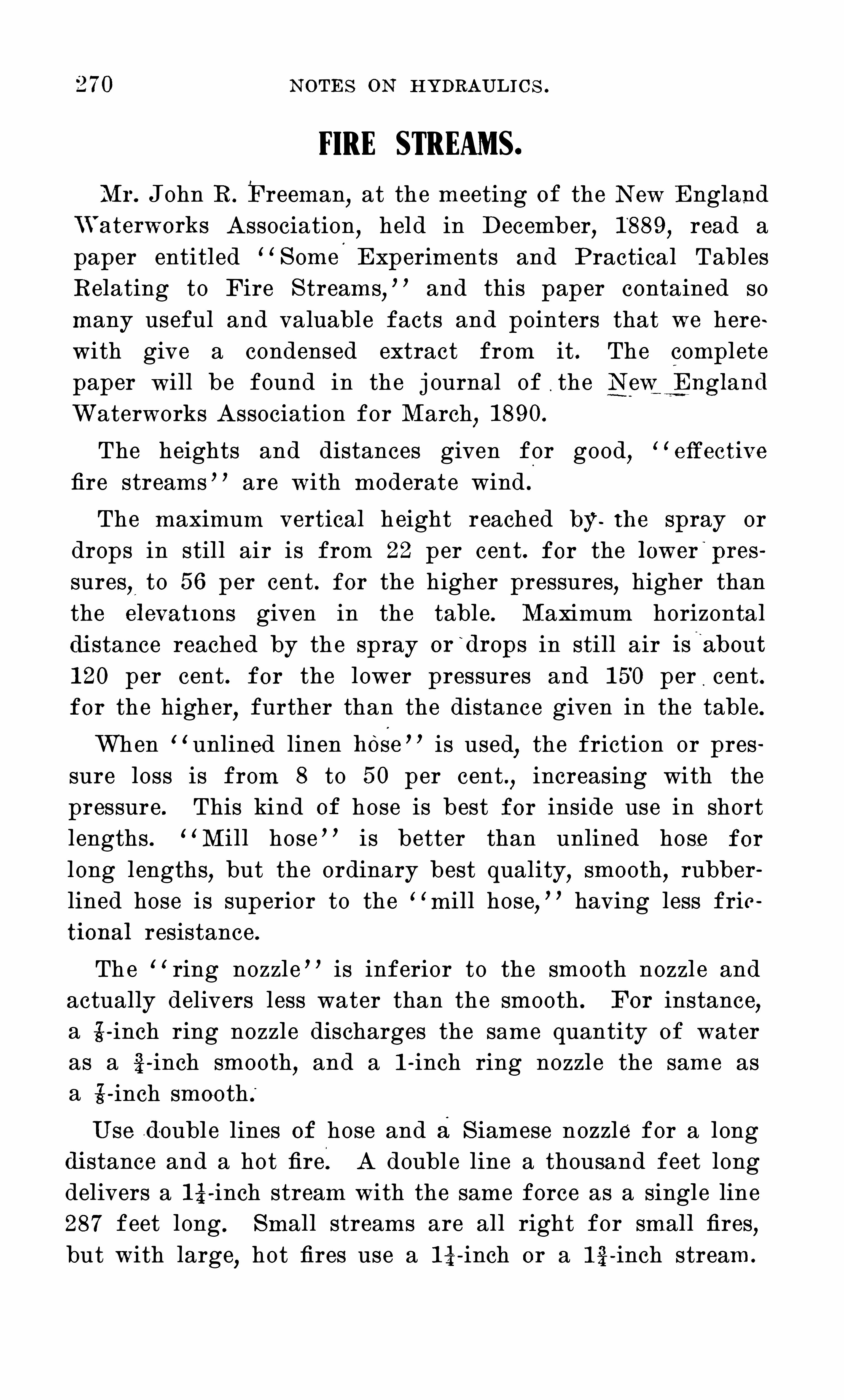
270 N O TES O N HYDRAULI C S .
FIRE STREAMS.
Mr. John R. Freeman,at the meeting of the N ew England
“'
aterworks Association,held in December
,1 889
,read a
paper entitled “ S ome Experiments and Practical TablesRelating to Fire S treams
,
” and this paper contained somany useful and valuable facts and pointers that we herewith give a condensed extract from it . The completepaper will be found in the j ournal of . the N ewg ngl and
Waterworks Association for March,1 890 .
The heights and distances given for good,
“e
" "
ective
fire streams ” are with moderate wind .
The maximum vertical h eight reached by the spray ordrops in still air is from 22 per cent . for the l ower
'
pres
sures,to 5 6 per cent . for the higher pressures, higher than
the el evatI Ons given in the table . Maximum horizontaldi stance reached by the spray or
‘
drops in still air is'
l
about
1 20 per cent . for the lower pressures and 1 5 0 per cent .for the higher
,further than the distance given in the table .
When “ unlined linen hOSe ” is used,the friction or pres
sure loss is from 8 to 5 0 per cent .,increasing with the
pressure . This kind of hose is best for inside use in shortlengths . “ Mill hose ” is better than unlined hose for
l ong lengths,but the ordinary best quality
,smooth
,rubber
lined hose is superior to the “ mill hose,
” having less frictional resistance .The “ ring nozzl e ” is inferior to the smooth nozzl e and
actually delivers less water than the smooth . For instance,
a 6 - inch ring nozzl e discharges the same quantity O f wateras a 6 - inch smooth
,and a 1 - inch ring nozzl e the same as
a 6 - inch smooth .
“
U se double lines of hose and a S iamese nozzle for a longdi stance and a hot fire. A doubl e line a thousand feet longdelivers a 1 6 - inch stream with the same force as a single line287 feet long . Small streams are all right for small fires,but with large
,hot fires use a 1 6 - inch or a 1 6 - inch stream.

N O TES O N HYDRAULIC S . 271
S uch a stream will always make a black mark wherever ithits
,and the stream which hits and cools the burning coals
is the e" °
ective fire stream.
” Small streams are convertedinto steam before touching the coals .Two hundred and fifty gallons per minute is a good
standard fire stream with 80 pounds pressure at the hydrant .O ne hundred pounds pressure should not be exceeded
,except
for very high buildings or l ength of hose exceeding 300
C urves shown in Figs . 27 and 28 (pages 281 and 282)give the discharge of hose nozzl es through 5 0 and 1 00 feetof 2 14 - inch ordinary best quality
.
ofi
rubber- lined hose,and
the head or pressure indicated at the hydrant .C urves shown in Fig . 26 (page 280)show the pressure
lost in pounds per square inch in 1 00 feet O f cotton rubberlined ( smoothest lined)hose from 2 to 4 inches in diameter .C urves shown in Figs . '24 and 25 (pages .278 and 279)
give the discharge of nozzl es and the head or pressure atthe base of the play - pipe . Mr. Freeman states that withsmooth
,true
,carefully calibrated nozzl es very accurate re
su l ts can be obtained .

Press
.
at
Nozzle
40
45
50
5 5
70
75
80
95
1 00
35
40
45
50
5 5
60
70
75
95
1 00
Di
sch
.
per
Mi
n.
Gallons
Vert
.
Di
st
.
97
1 04
1 1 0
1 1 6
1 22
1 27
1 32
1 37
1 42
1 47
1 5]1 56
1 60
1 64
1 33
1 42
1 50
1 59
1 6 6
1 74
1 81
1 88
1 94
201
207
21 3
21 9
224
of
Stream
5 5
67
70
72
74
76
78
79
80
81
82
83
5 6
6 2
6 7
71
74
77
79
81
85
87
89
Hor.
Di
st
.
of
Stream
4 1
47
5 0
5 2
5 4
5 6
58
60
62
64
66
68
N O TES O N HYDRAULIC S .
FIRE STREAMS.
FromTables Published by John R. Freeman,M. E.
Pressure in l bs. requ ired atHydrant or Pump tomaintain pressure at nozz l e through various l engthsof 256 inch smooth
,rubber- l ined hose.
300 400 50050Ft.
34 I N CH SMO O T H N O ZZLE .
1 00Ft.
200Ft.
37 38 40
42 43 46
47 48 5 1
5 2 54 5 7
58 59 63
63 65 68
68 70 74
73 75 80
79 81 85
84 86 91
89 92 97
94 97 1 02
99 1 02 1 08
1 05 1 08 1 1 4
Ft.
42
48
5 4
60
66
72
78
84
90
96
1 02
1 08
1 1 4
1 20
Ft.
44
50
57
6 3
69
76
82
88
94
1 01
1 07
1 1 3
1 20
1 26
Ft.
46
5 3
59
6 6
73'79
86
92
99
1 06
1 1 2
1 1 9
1 25
1 32
7- 8 I N CH SMO O T H N O ZZLE .
46
49
52
5 5
58
6 1
64
6 6
68
70
72
74
75
76
38
43
49
54
60
6 5
71
76
82
87
92
98
1 03
1 09
40
46
5 1
57
63- 1 69
74
80
86
91
97
1 03
1 09
1 1 4
44
5 0
57
6 3
69
75
82
88
94
1 01
1 07
1 1 3
1 1 9
1 26
48
5 5
62
69
75
82
89
96
1 03
1 1 0
1 1 6
1 23
1 30
1 37
5 2
59
67
74
82
89
96
1 04
1 1 1
1 1 9
1 26
1 34
1 41
1 48
5 6
64
72
80
88
96
1 04
1 1 2
1 20
1 28
1 36
1 44
1 52
1 60
600P t.
48
5 5
62
6 9
76
83
97
1 04
1 1 1
1 1 7
1 24
1 3 1
1 38
77
86
94
1 03
1 1 1
1 20
1 28
1 37
1 45
1 54
1 63
1 71
800 1 000Ft.
1 43
1 50
78
87
97
1 07
1 1 6
1 26
1 36
1 45
1 5 5
1 65
1 74
1 84
1 94
Ft.
76
87
97
1 08
1 1 9
1 30
1 4 1
1 5 2
1 62
1 73
1 84
1 95
206
21 6

I
v\l
4; N O TES O N HYDRAULI C S .
FIRE STREAMS— Cont.
From Tables Published by John R. Freeman , M. E.
g E 4 ; 8Pressu re in l bs . requ ired at Hydrant or Pump to
<6 <0 83 3 5 8.98maintain pressure at nozz l e through vari :us l engths
S, r?82
Q3
Qj; of inch smooth ,
rubber- l ined hose.
00 F 1
F4H m
.
r‘
532 89 g S i 50 1 00 200 300 400 500 600 300 1 000O m0 Ft .
. F t. Ft . r t . r t. Ft. F t. Ft. Ft .
1 1 I N CH SMO O T H N O ZZLE .
35 277 60 59 48 57 74 91 1 09 1 26 1 42 1 78 2 1 2’
40 296 67 63 5 5 6 5 84 1 04 1 44 1 6 4 203
45 3 1 4 72 6 7 62 73 95 1 1 7 1 40 1 6 2 1 84 229
5 0 33 1 77 70 68 81 1 06 1 30 1 5 5 1 80 204 254
5 5 347 81 73 75 89 1 1 6 1 43 1 70 1 98 225
6 0 363 85 76 82 97 1 27 1 5 6 1 86 2 1 6
6 5 377 79 89 1 05 1 37 1 69 20 1 234
70 392 91 81 96 1 1 3 1 48 1 82 2 1 7 25 2
75 405 93 83 1 03 1 2 1 1 95 232
80 4 1 9 95 85 1 1 0 1 29 1 69 208‘ 248
85 432 97 1 1 6 1 37 22 1
90 444 99 90 1 23 1 90 234
95 45 6 1 00 92 1 30 1 54 20 1 247
1 00 468 1 01 93 1 37 1 62 2 1 1 26 1
1 % I N C H SMO O T H N O ZZLE .
340 62 6 ? 5 4 67 94 1 20 1 46 1 72 1 93 260
40 36 3 69 6 6 6 2 77 1 07 1 37 1 6 6 1 96 226
45 74 70 70 37 1 20 1 54 1 37 22 1 264
5 0 406 79 73 73 96 1 34 1 71- 203 245
6 6 426 33 76 36 1 06 1 47 1 33 229 270
6 0 446 37 79 93 1 1 6 1 60 206 26 0
46 3 90 3 ? 1 01 1 26 1 74 222
0 430 92 34 1 09 1 35 1 37 239
6 437 95 36 1 1 7 1 45 20 1 2 66
0 6 1 4 97 33 1 24 1 64 2 1 4
85 99 90 1 32 1 64 22790 1 00 92 1 40 1 73 240
96 6 60 1 01 94 1 43 1 33 264
1 00 5 74 1 03 96 1 56 1 93

N O TES oN HYDRAULI C S . 275
The pressures given are indicated pressures,not e
m
ectiveF
1pressures . 14.“
ective pressures would be slightly greater .The horizontal and vertical distances given are for good
,
e"
ective fire streams . The di stances to which insulateddrops would be thrown are very much greater .The pressures stated are based on th e hose being coupled
directly to the pump or the hydrant and while the stream isflowing .

[O
1
00
N O TES O N HYDRAU LIC S .
O O O O O O O O00 P0 CD 10 d‘ 00 02 F 4
’
HO N I aavofis ‘
83 1 N I ssoa N ou oraa

1
00
N O TES O N HYDRAULI C S .
O O O O O O(D P (D K) 00 C?
'
Hzmr aavnfis‘
S EI ’I N I Hanssaa a

1
00
90
N O TES O N HYDRAUL I C S .
b o o o o o o00 P co 3: <3 co oz
'
HDN I anvnbs'sa
’
r N I aunssaaa

1
00
N O TES O N HYDRAU LIC S .
O O O O O O Oon b 0 no Q‘ 00 CQ
001 3 3 6 $ 3 1 N I S S O'I N O ILDIHd
c" Mo e:
i
nute
o
di
ame
r
Fr
eemn
UTE
by
2

282 N O TES O N HYDRAULIC S .
O O O O O O O O O O O
2 CD (I) E Co no d‘ 00 02 H
KLN V 3 GAH LV HDN I HHVHO S‘
saa 3 1 s 3 oss3 3 a

N O TES O N HYDRAULI C S .
TEE STEAM FIRE ENGl NE.
The modern steam fire engine,practically a portable
pumping engine,illustrates the remarkable concentration
of power in small compass,with lightness and strength of
As constructed by the best builders they are composedof sel ected materials
,are exceedingly careful and well
proportioned and are beautifully finished .
The machine itself is composed of a boiler,engine
,pump
and the auxiliary appliances found.
necessary for itsoperation .
T heir pumps have large passages and valves of sma l llift and deliver large volumes of water easily . The pumpsare generally of the reciprocating or rotary type and aregenerally placed in front of the boiler . I f of the recipro
cating type,two pumps are placed alongside each other and
are operated either by a double - slide valve or piston valveengine .
The piston rods of the engines connect directly'
withplunger rods of the pumps and are also connected to acrank shaft by means of either connecting rods or yokes,the cranks being set at right angles
,so
“ that one pump isalways acting
,while the other passes the “ dead ” center
,
which thus gives a practically steady stream.
S ome of the engines are equipped with a boiler feed pumpand others depend/ upon an inj ector or feed directly fromthe main pump . The engines exhaust
,into the stack
,which
gives the necessary draft .The boilers
,which are generally of the upright semi
water tube type,are combined with the engine by means
of a strong iron frame,which carries all the auxi liary appl i
ances.
and forms the body of the truck . The boilers contain littl e water and are crowded with heating surface ; theytherefore make steam with great rapidity
,working pressure
being genera ted in S ix to seven minutes from cold water .

N O TES O N HYDRAULIC S .
The modern steam fire engines are generally classified asto size
,and their capacities as follows :
S ize of Engine . C apacity gallonsper minute.
Double Extra First . 1 300
Extra First .
First
ThirdFourthFifth

N O TES O N HYDRAULIC S .

N O TES O N HYDRAUL I C S .

N O TES O N HYDRAULI C S?
COMPARISON 0F COLUMNS OF WATER IN FEET.
Mercury in Inches and Pressure'
in Lbs . ,per Square Inch .
I Jbs
S q . I n:
woo
-a
mmwxoo
mra
VVater hi ercu ry
Feet Inches Feet
O
zo
OO
-c
mrh
oo
N
H
H
1 4
1 5
1 6
1 7
1 8
1 9
20
21
22
23
24
25
26
27
. 29
vVater hdercu ryr I Jbs.
Press.
I nches S q . I n .
Mercury Water LbsPress
Inches Feet S q . I n

Feet Press . Feet Press . Feet Press . Feet
Head S q . I n . Head S q . I n . Head S q . I n . Head
40 1 04 1 68 232
41 1 05 1 69 233
42 1 06 1 70 234
43 1 07 1 71 235
44 1 08 1 72 236
45 1 09 1 73 237
46 1 1 0 1 74 238
47 1 1 1 1 75 239
48 1 1 2 1 76 240
49 1 1 3 1 77 241
50 1 1 4 1 78 242
51 1 1 5 1 79 243
52 1 1 6 1 80 244
53 1 1 7 1 81 245
54 1 1 8 1 82 246
55 1 1 9 1 83 247
56 1 20 1 84 248
57 1 21 1 85 249
58 1 22 1 86 250
59 1 23 1 87 251
60 1 24 1 88 252
61 1 25 1 89 253
62 1 26 1 90 254
63 1 27 1 91 255
64 1 28 1 92 256
N O TES O N HYDRAULIC S .
PRESSURE 0FWATER— Cont.
Press . Feet Press .
S q . I n . Head S q . I n .
296
297
298
299
300
31 0
330
340 1 47.
360 1 61 .
360
370
380
390
400
500
600
700
800
900
1 000

291N O TES O N HYDRAULIC S .
fi
H
who
mm9mm
no
woo
fi
n
mom
mmmmm
mv
haw
mm
wmmwmv
mmcam
mmmam
mp
mam
amwww
mmwww
mfl
mam
we
bu~
mfi
mw~
w
aam
we
vb
mv
M v—i v—d r— i v- i
.
MZ4Fu
fi
vUZQA
.
aa
ao
fi
5“
00mma
O
2
52:
E
r— l v—‘ l— i v— i
mmbe
2on
3.
mm
3.
m
m.
z

2923 N O TES O N HYDRAULIC S .
CAPACITY 0F CYLINDRICAI. TANKS AND CISTERNS.
(In U . S . Gall ons of 231 cubic inches).InsideI)iarnu
I?t. I I L
4
5
6
7
8
9
1 0
6
1 1
1 2
1 3
1 4
1 5
WaterDepthl lFt.
1 1 91)
1 7737
2291 5
26737
33045
3521)
3764)
4754)50237
558i ;
6791)
71 04)7431 3
777.0
846 1)91 81)
1 0701 3
l 235i 3
VVater VVaier
Depth Depthél I?t. 5 PM;
376 470
476 595
588 734
71 1 889
846 1 058
91 8 1 1 48
993 1 241
1 071 1 338
1 1 52 1 439
1 235 1 544
1 322 1 652
1 41 2 1 764
1 504 1 880
1 600 1 999
1 698 21 22
1 799 2249
1 904 2380
201 1 251 4
21 21 2651
2234 2793
2350 2938
2469 3086
2591 3239
271 6 3395
2844 3555
2974 371 8
31 08 3885
3245 4056
3384 4230
3672 4590
3972 4965
4283 5354
4606 5758
4941 61 76
5288 661 0
5646 7058
VVater
Depfli(i I?t.
564
71 4
881
1 066
1 269
1 377
1 489
1 606
1 727
1 853
1 983
21 1 7
2256
2399
2547
2699
2855
301 6
31 81
335 1
3525
3704
3886
4074
4265
4462
4662
4867
5076
5508
5957
6425
6909
741 2
7932
8469
VVater VVater IVater
Depth Depth Depth7'I?t. E§I?t. S)I?t658 752 846
833 952 1 071
1 028 1 1 75 1 322
1 244 1 422 - 4 1 600
1 481 1 692 1 904
1 607 1 836 2066
1 738 1 986 2234
1 874 21 42 2409
201 5 2303 2591
21 62 2471 2779
231 3 2544 2974
2470 2823 31 76
2632 3008 3384
2799 , 31 99 3599
2971 3396 3820
31 49 3599 41 48
3331 3807 4283
351 9 4022 4524
371 2 4242 4772
391 0 4468 5027
41 1 3 4700 5288
4321 4938 5555
4534 51 82 5830
4753 5432 61 1 1
4976 5687 6398
5205 5949 6692
5439 621 6 6993
5678 6489 7300
5922 6768 461 4
6426 7344 8262
6950 7943 8936
7495 8566 9637
8061 921 2 1 0364
8647 9882 1 1 1 1 7
9253 1 0575 1 1 897
9881 . 1 1 292 1 2704
VVater
Depth1 2 PM;
1 1 28
1 428
1 763
-r 21 33
2633
2764
2979
321 2
3455
3706
3966
4235
451 2
4799
5094
5398
571 1
6032
6363
6702
7060
7407
7773
31 47
8531
8923
9324
9734
1 01 52
1 1 01 6
1 1 91 5
1 2849
1 381 9
1 4823
1 5863
1 6938
VVater
1 41 0
1 785
2203
2666
3443
3724
401 5
431 8
4632
4957
5293
5640
5998
6367
6747
71 38
7540
7954
8378
881 3
9259
971 6
1 01 84
1 0664
1 1 1 54
1 1 65 5
1 21 67
1 2691
1 3770
1 4894
1 6061
1 7273
1 3629
1 9329
21 1 73
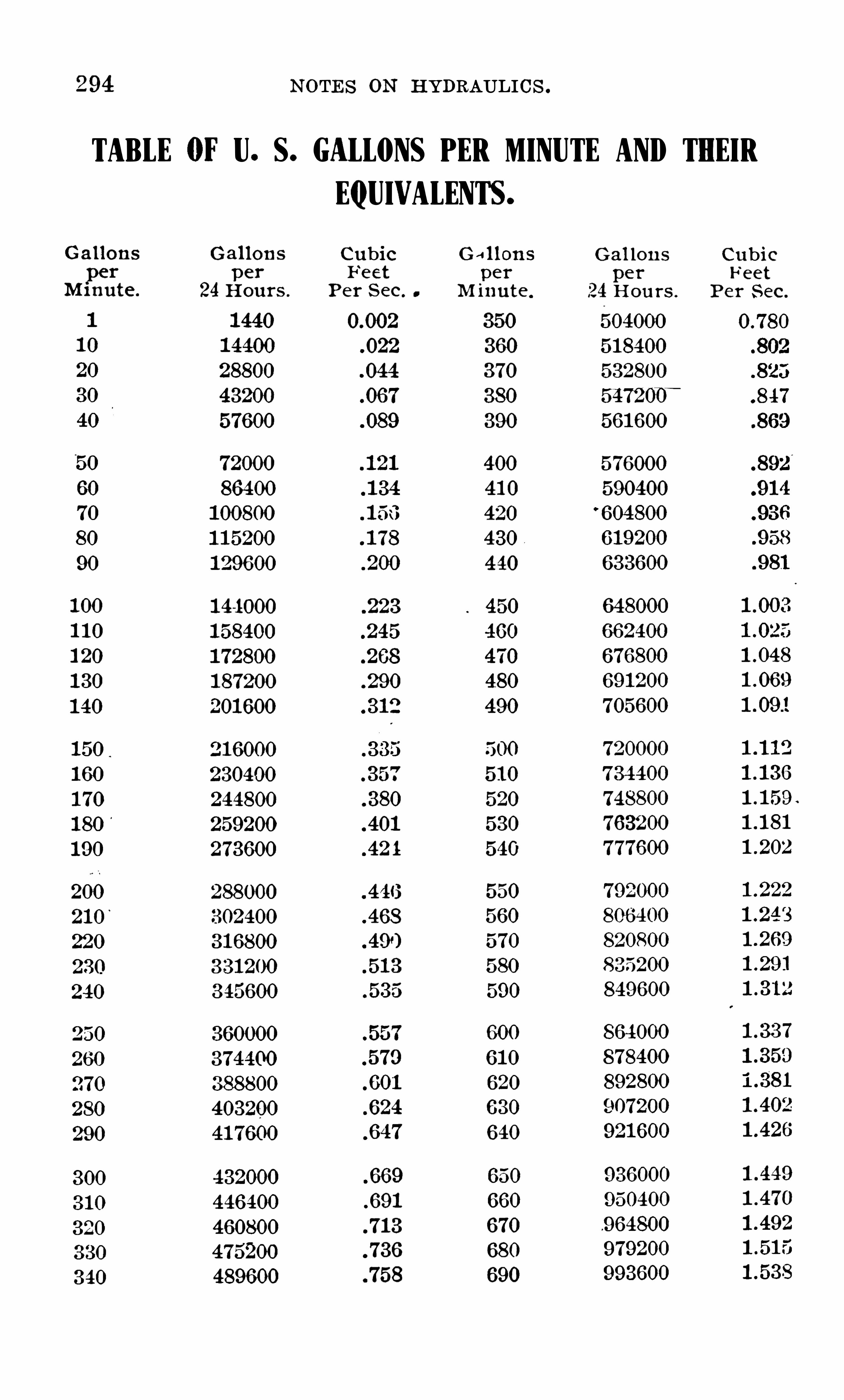
294 N O TES O N HYDRAULIC S .
TABLE (WU. S. GALLONS PER MINUTE AND THEIR
Ga l l ons
perMi nute.
1
1 0
20
30
40
5 0
60
70
80
90
1 00
1 1 0
1 20
1 30
1 40
1 5 0.
1 60
1 70
1 80'
1 90
200
21 0’
220
230
240
250
260
270
280
300
3 1 0
320
330
340
Ga l l ons
per
24Hours .
1 440
1 4400
28800
43200
57600
72000
86400
1 00800
1 1 5200
1 29600
1 44000
1 58400
1 72800
1 87200
201 600
2 1 6000
230400
244800
259200
273600
288000
302400
31 6800
33 1 200
345600
360000
374400
388800
403200
41 7600
432000
446400
460800
475200
489600
EQUIVALENTS .
C ubic Ga l l onse ct per
Per S ec. M inute.
(1 002 35 0
022 360
044 370
067 380
089 390
1 2 1 400
1 34 41 0
1 5 6 420
1 78 430
200 440
223 450
245 460
268 470
290 480
3 1 2 490
5 00
357 5 1 0
380 5 20
401 5 30
42 4 540
446 5 50
468 5 60
5 70
5 1 3 580
5 35 590
5 5 7 600
579 6 1 0
60 1 620
624 6 30
647 6 40
669 6 50
691 6 60
71 3 670
736 680
758 690
Ga l l ons
per
24 Hou rs .
6040006 1 3400
6 32300
5472007 “
5 6 1 600
576000
590400
6 04800
6 1 9200
6 33600
648000
66 2400
676800
691 200
705 600
720000
734400
748800
763200
777600
792000
806400
820800
35200
849600
864000
878400
892800
907200
92 1 600
936000
95 0400
964800
979200
993600
C ubicFeet
Per S ec.
(1 780
847
.91 4
958
1 -3 1 2

N O TES O N HYDRAULI C S . 1295
TABLE (WU . S. GALLONS PER MINUTE AND THEIR
Ga l l ons
per
M inute .
700
71 0
720
730
740 .
750
760
770
780
790
800
81 0
820
830
840
850
860
870
890
900
91 0
920
930
940
95 0
960
970
980
990
1 000
1 05 0
1 1 00
1 1 50
1 200
Ga l l ons
per
24 Hours .
1 008000
1 022400
1 036800
1 05 1 200
1 005 600
1 080000
1 094400
1 1 08800
1 1 23200
1 1 37600
1 1 5 2000
1 1 66400
1 1 80800
1 1 95200
1 209600
1 224000
1 238400
1 252800
1 267200
1 281 600
1 296000
1 3 1 0400
1 324800
1 339200
1 35 3600
1 368000
1 382400
1 396800
1 4 1 1 200
1 425 6 00
1 440000
1 6 1 2000
1 584000
1 6 66000
1 723000
C ubicFeet
Per S ec.
1 -871
23 005
51 027
21 048
23073
21 093
281 1 4
23 1 38
21 1 6 1
51 1 81
24 202
21 228
23 339
51 450
24562
23 672
EQUIVALENTS— Cont.
Ga l l ons
per
Minu te .
1 250
1 300
1 350
1 400
1 45 0
1 500
1 5 5 0
1 600
1 6 5 0
1 700
1 75 0
1 800
1 850
1 900
1 950
2000
2050
2 1 00
2 1 5 0
2200
2250
2300
235 0
2400
2450
2500
25 50
2600
265 0
2700
2750
2800
2850
2900
2950
3000
Gal l ons
per'
24 Hours.
1 800000
1 872000
1 944000
20 1 6 000
2088000
2 1 60000
2232000
2304000
2376000
2448000
2520000
2592000
2664000
2736000
2808000
2880000
2952000
3024000
3096 000
3 1 68000
3240000
33 1 2000
3384000
3456000
3528000
3600000
3672000
3744000
381 6000
3888000
3960000
4032000
4 1 04000
4 1 76000
4248000
4320000
C ubicFeet
Per S ec.
21 785
$1 893
£1 1 1 9
£1 230
51 3 41
£1 4 5 3
£1 5 62
£1 785
£1 899
4L0 1 0
<L1 2J
4L233
4L344
4L45 3
<L790
€L901
51 0 1 3
51 1 25
£1 235
51 347
51 458
51 5 70
51 681
51 792
(1 0 1 5
(1 1 27
(1 245
(i 349
(i 464
(i 573
(1 684

296 NOTES O N HYDRAULI CS .
TABLE FOR CALCULATING TIIE HORSE-POWEROF WATER.
The fol l owing table gives the horse -
power that may be developedunder normal conditions with one cubic fo ot of water perminute under heads from one up to eleven hundred feet :
I i eads I I orse I I eads I i orse
in Feet. Power . in Feet. Power.
1 001 6098 320 6 16 1 36
20 0321 96 330 531 234
30 048294 340 547332
40 064392 350 563430
50 080490 360 579528
60 096588 370 595626
70 1 1 2686 380 61 1 724
80 1 28784 390 627822
90 1 44892 400 643920
1 00 1 60980 41 0 66001 8
1 1 0 1 77078 420 6761 1 6
1 20 1 931 76 430 69221 4
1 30 2092 44 440 70831 2
1 40 225372 450 72441 0
1 50 241 470 460 740508
1 60 257568 470 756606
1 70 273666 480 772794
1 80 289764 490 788802
1 90 305862 500 804900
200 321 960 520 837096
21 0 338058 540 869292
220 3541 56 560 901 488
230 370254 580 933684
240 386352 600 965880
250 402450 650
260 41 8548 700
270 434646 750
280 450744 800
290 466842 900
300 482940
3 10 499038

298
Decimal Fraction
. 01 5625
. 031 250
. 046875
. 062500
. 0781 25
. 093750
. 1 09376
. 1 25000
. 1 40625
. 1 56250
. 1 71 875
. 1 87500
. 2031 25
. 218750
.234375
.250000
N O TES O N HYDRAULIC S .
Dmfinml
. 266626
. 231 260
. 296875
. 31 2600
. 3231 25
.343750
. 359375
. 375000
. 390625
.406250
.421 875
.437500
.4531 25
.468750
.484375
. 500000
Fraction
21/32
Decimal
. 5 1 5625
. 531 250
. 546875
. 662500
. 5781 25
. 593750
. 609375
. 626000
. 640625‘
.656260
. 671 875
. 687500
.7031 25
.71 3750
. 734375
.750000
DECIMAL EQUIVALENTS 0F AN INCH.
By 64ths : from to 1 inch .
Fraction
1
Baima l
765625
.781 250
.796875
.81 2500
.8281 25
.843750
.859375
.875000
.890625
.906250
.921 875
.937500
.9531 25
.968750
.984375

N O TES O N HYDRAULIC S . 299
TABLE GIVING AREAS OF CIRCLES.
From to 2 inches diameter.

300 N O TES on HYDRAULIC S .

302 N O TES O N HYDRAULIC S .

N O TES O N HYDRAULIC S .

304 N O TES O N HYDRAULI C S .

N O TES O N HYDRAULIC S .306
mm.
noa
.L
Q “
ma
nmkfi
g
o
a
so
94
8
$5
q
$5
32
.
wwéfl
m:
mv
émw
g
mméomwfi
m?
m
tg
mm.
w
§m~
wY
mmumfi
mmfiommfi
womvwmma
vb
mwoma
“E
mmo
z
wo.
wom:
d.«
o
m28
.
0
5
co
n
cm
23
mo
rm
.
»
23
on
fi
ne
:
s
o
34
5
owmom
:
a
n
ga
g
an
mo
2mm:
no
owmwfi
«o
80
2
a
mwmw
fi
wm
Ewmfi
«wmmm
fi
E«
if
3
gm:
2an
own
:
8ma
m:
emm2:
3mmwm:

N O TES O N HYDRAU LIC S . 307

308 N O TES O N HYDRAUL I C S .

31 0 N O TES O N HYDRAU LIC S .

3 1 1N O TES O N HYDRAULIC S .
v—t v—t v—‘v—t v—‘r—‘H fi fi r fi v—l
338
000.
000
000.
~00
000.
00
0
0
.
0
0
.
007
0
5
000.
3
38
4
83
8
£
38
86
80
8
58
.
000.
000
$0
6
8
36
80
8
38
SN
floo
d
m
O
G
0
0
0
0
0
.
0
0
.
00
70
0
00
00
0
0
3.
000
83
3
8
£6
83
0
0
.
0
0
.
0
0
.
0
0
.
0
0
.
0
0
0
«
00.
20
000
000
00
0.
80
x0n0
000
007
000
0
8.
00
0
007
30
0
8.
20
00
7
000

N O TES O N HYDRAULIC S .3 1 2
0
0
.
00
0.
0
00
0
00
00
0
000.
0
00
2
00.
020
020.
0
0
0
0
0
.
0
.
835.
80
20
N
ew
s.“
0
2.
25
gm.
3
s5.
in
£5.
Q
2
33
80
mm”
£0
0
3
80
8
how
0
0
.
0
0
0
00
0.
000
000.
00
0
000.
20
000.
000
002.
000
c
o
.
c
o
.
n
o
.
0
0
.
0
0
.
0
0
.
n
o.
0
0
.
c
o
.
0
0
.
t
o
.
0
0
.
0
00
£
52.
89
m8
33
20.
8”
8
33
8
m$
23
$
53
20.
Sm
0
2.
000

3 1 4 N O T ES O N HYDRAULIC S .
T able of S q uares, C ubes, S q u are Roots , C ube Roots ,
and Reciproca l s of al l Integer N umbers from 1 to 2200.
1 '00000001 '41 421 36 1 ‘259921 01 '7320508 1 '4422496
1 '587401 12 2360680 1 7099759
'2000000002 4494897 1 3 1 71 206 '1 666666672 645751 3 1 '91 2931 2 ‘1 428571 432 ‘8284271 2 ‘0000000
3 0000000 2 0800837 '1 1 1 1 1 1 1 1 1
3 1 622777 2 1 5443471 331 3 3 1 66248 2 2239801 '090909091
3'4641 0
0
1 6 2 2894286 '083333333
3 605551 3 2 351 3347 '0760230773741 6574 2 41 01 422 '071 428571
3375 33 729833 2 46621 21 '0666666674096 40 000000 2 5 1 98421 ’062500000491 3 41 231 056 2 571 281 6 '058823529
42 426407 2 620741 4 '055555556
6859 43 588989 2 668401 6 '052631 57944 721 360 2 71 441 77
9261 4'5825757 2 “7589243
‘04761 9048
1 0648 4‘69041 58 2 8020393
'045454545
4795831 5 2 8438670 ‘043478261
1 3824 43 989795 2 8844991 '041 6666672 92401 77
‘040000000
1 7576 5 0 9901 95 2 9624960 ’03846]5381 9683 6 1 961 524
'0370370372 1952 5 '291 5026 3
'0365889 '03571 428624389 5 3 85 1 648 3 ‘07231 68 '034482759
3 1 072325'033333333
29791 5 '5677644 3'1 41 3806'032258065
32768 5 6568542 3 1 748021 '031 250000
1 089 35937 57445626 3 2 075343 '030303030
39304 5'830951 9 3 '23961 1 8 '02941 1 765
42875 5 '91 60798 3 2 71 0663'028571 429
6 0000000 33 01 9272 '027777778
6 0827625 33 32221 8 '02702702754872 6 1 6441 40 3 3 61 9754
’02631 5789
6 2449980 33 91 21 1 4'025 641 026
6 3 245553 34 1 95 1 9
6 403 1 242 . 21 72
6 4807407 3 4760266 0 233809524
6 5574385 3 5 033981
6 6332496 3 “5303483
6 7082039 35 568933

Squaw;
21 1 6
2304
2401
2601
2809
291 6
3025
31 36
3249
3364
3481
3721
39694096
44894624
4761
50415 1 84
5476562557765929
6084
6889
7056
72257396
7569
7744
81 008281
8464
8649
8836
N O T ES O N HYDRAULICS .
97336
1 03823
1 1 0592
1 1 7649
1 25000
1 326511 406081 488771 574641 663751 7561 61 851 93
1 951 1 2
205379
226981
2500472621 44
2746252874963007633 1 4432
32850934300035791 1373248389017405224
421 875438976456533
474552493039
571 7875927046 1 41 25636056658503
681 472
704969729000753571778688804357830584
60
78233006 85565466 0
9282032
70
00000007
0071 0678
70 1 41 4284
7021 1 1 026
702801 099
703484692
7041 61 985
7048331 48
705498344
70 61 57731
70681 1 4577
0
74596677
081 024977
0
8740079
709372539
80 0000008
0
06225780 1 24038
80 1 8535288024621 1 3
80
3066239
80366600380
426 1 498
80
485281 480544003780602325380 66025408071 779798 77496448 831 7609808881 944
80944271 99
0
00000009
0
055385 19 0
1 1 0433690 1 651 5 1 49021 954459027361 8590327379190380831 5
90433981 1
904868330
90
5393920
90591 6630
90
6436508
90 6953597
3 058304793 0608826 1
3 0634241 1
3065930573 0
684031 4
30
70842983 0
73251 1 13 0
75628583 0
77976313 08029525
3 08258624
3 0
848501 13 087087663 089299653 091 486763 093649723 0957891 53 0979057140 00000040 20725640 41 24014 006 1 5480
40
081 65514 0 1 01 566 1
4 1 21 285341 4081 784 1 601 6764 0 1 7933924 0 1 983364
4 021 71 63342 3582364 2 54321 0
402726586
4029084044
030886954
0
3267487
4036207074
037951 914 0396829644 1 40049
40431 047644 47960244 6474514 4 81 40474 0
497941 44
0 5 1 435744
0
5306549
40
5468359
3 1 5
"021 7391 30'021 276600‘020833333‘0204081 63
001 9607843001 9230769001 8867925001 851 85 1 90
01 81 81 81 8001 78571 43001 7543860001 7241 3790
0 1 69491 530
01 6666667001 6393443001 61 290320
01 587301 6001 5625000001 53846 1 5001 51 51 5 1 5001 4925373001 4705882001 4492754001 428571 40
01 4084507001 3888889001 3698630001 35 1 351 4001 3333333001 31 57895001 298701 3001 28205 1 3001 2658228001 25000000
01 23456790012 1 95 1 22001 20481 93001 1 9047620 01 1 764706001 1 627907001 1 494253001 1 363636001 1 235955001 1 1 1 1 1 1 1001 098901 1001 0369565001 0752688001 0638298

3 1 6
1 081 091 1 01 1 11 121 1 3
1 1 7
1 1 9
1 21
1 23
1 26
1 271 28
1 33
1 341 351 361 37
1 39
1 1 236
1 1 6641 1 8811 21 00
1 2769
1 3689
1 41 61
1 4641 0
1 5 1 29
51 58761 61 29
1 76891 79561 82251 8496
20449
NOTES O N HYDRAU LI CS .
85737588473691 2673941 1 92
1 061 208
1 1 91 01 6
1 25971 21 2950291 331 0001 3676311 4049281 4428971 481 5441 5208751 5608961 601 61 3
1 6851 59
1 771 5611 81 5848
2000376
20971 5221 4668921 97000
2406 1 04
2571 353
268561 9
28632882924207
974679439797959
393 99494990 498744
1 00 4987561 009950491 01 48891 6
1 02 4695081 02 9563011 03 4408041 03 9230481 04 403065
1 05 8300521 00 301 4581 0‘67707831 072380531 0 ‘77032961 03 1 6653
?1 0954451 21 1 000000001 1 0045361 01 1 009058651 1 0 1 3552871 1 0 1 8033991 1 022497221 1 026942771 1 031 370851 1 035781 671 1 0401 75431 1 044552311 1 04891 2531 1 5 32562
81 1 061 895001 1 0661 90381 1 70469991 1 074734011 1 78982611 1 08321 5961 1 87434221 1 9 1 63753
1 1 9582607
4 056290264
0
57885704059470094 061 043634 062606504 641 588846 5700954 0672328746 875482 - 0
4 070266940
47 1769404 0
732623547474594476220324 077685624791 41 994 080589554 08202845
4 084880764 86294424 087699904 089097324 0904868149 1 86847493242424 094608744 095967574 09731 898
$986631 0
5 0 1 329795 0 2652575 003968425 005277435 006579705 0
07875315 0091 64345 0 1 0446875 0 1 1 722995 1 2992785 0 1 4256325 0 1 55 1 3675 0 1 6764935 0 1 801 01 55 0 1 9249415mwm95 2 1 71 0345 0229321 5
0 1 052631 60 1 041 66670 1 03092780 1 02040820 1 01 01 01 00 1 0000000
0 09803922
00096 1 53850 0952381 0000943396200093457940009259259000917431 2
0 089285710 088495580 08771 9300 086956520 086206900 085470090 084745760 0840336 10 083333330 082644630 081 967210 081 300810 0806451 6
0 07936508
0 0781 25000 07751 9380 076923080 076335880 075757580 0751 87970 074626870 074074070 073529410 072992700 072463770 071 942450 071 42857

3 1 8
Square
372493763638025
3841 6
38809
39204
39601
40000
40401
40804
41 209
41 61 6
4202542436
42849
43264
43681441 00
4452]44944
45369
45796
4622546656
47089475244796148400
48841
49284
49729
50176
506255 1 0765 1 529
5 1 984
52441
52900
5336 1
53824
54289
54756
55696
56 1 69
56644
571 21
5760058081
N O T ES
'
O N HYDRAULICS .
71 890577301 384
741 4875
7529536
76453737762392
78805998000000
81 20601
8242408
83654278489664
86 1 5 1 25
8741 81 6
8869743
899891 2
91 29329
926 1 000
9393931
95281 28
96635979800344
99383751 0077696
1 021 831 3
1 0360232
1 0503459
1 0648000
1 0793861
1 0941 048
1 1 0895671 1 239424
1 1 3906251 1 5431 761 1 697083
1 1 852352
1 2008989
1 21 67000
1 2326391
1 24871 681 26493371 281 29041 29778751 31 44256
1 331 2053
1 3481 272
1 365 1 91 91 38240001 3997521
1 33 9244401 3 “9283883
1 3“
96424001 40 0000001 40 356688
1 40 71 24731 4 “ 1 067360
1 4 1 7744691 42 1 267041 42 4780681 42 828569
1 43 1 7821 11 43 5270011 43 8749461 44 22205 1
1 4 4568323
1 45 258390
1 45 6021 98
1 45 945 1 95
1 40 2873881 4 “66287831 46 969385
1 4373091 991 47 6482311 479864861 43 3239701 43 6606871 43 996644
1 40 331 845
1 40 6662951 5 0 000000
1 5 0 332964
1 5 0 665 1 92
1 5 0 996689
1 5 1 327460
1 5 2 31 5462 0
1 5 026433751 5 029705851 5 “32970971 5 3 62291 5
1 5 3 948043
1 5 4272486
1 5345962481 5 491 9334
1 5 5 241 747
5778996657889604
5 7988900
5 80878575 3 1 86479
5 “82847675 3 382725
5 3 480355
5“
8577660
5 3 674643
5 08771 3075
088676535 08963685
50
9059406
5 91 5481 75 09249921
50
9344721
5 09489220
5 09533418
5 09627320
5 097209265 0981 4240
50
9907264
6 0 000000
600092450
6 0 1 846 1 76 0 276502
6 003681 076 0 459435
6 0 550489
600641 270
6 0 731 779
6 0 822020
6 0 91 1 994
6 0 1 001 702
6 0 1 091 1 476 0 1 1 80332
6 0 1 2692576 0 1 357924
6 0
1 4463376 0 1 534495
6 0 1 622401
6 0 1 71 0058
60
1 797466
60
1 8846286 1 971 544
6 0205821 8
6 021 44650
6 02230843
“005 1 81 347“005 1 54639“0051 28205“005 1 02041“005076 1 42“005050505“005025 1 26“005000000
4975 1 24“004950495“
004926 1 08“004901 961“
004878049“004854369“00483091 8“004807692“004784689“00476 1 905“
004739336“00471 6981“004694836“004672897“00465 1 1 63“004629630“004608295“0045871 56“00456621 0“004545455“004524887“004504505“004484305“004464286“004444444“004424779“004405286“004385965“00436681 2“004347826“004329004“00431 0345“004291 845“004273504“00425531 9“004237288“00421 9409“004201 681“0041 841 00“0041 66667“0041 49378

N o.
242
243244
245246
247248
249
250
25 1
252
253
254
255
256
257258
259
260261
262
263
264
265
266
267268
269
270271
272273274275276
277278
279
280281282283
284285286287288
289
290
Square
585645904959536
600256051 66 1 0096 1 504
62001
625006300163504
64009
645 1 66502565536
6604966564
6708167600681 2168644691 6969696
702257075671 28971 8247236 172900734417398474529
7507675625
761 76
7672977284
77841
78400
7896 17952480089
80656
81 22581 796
82369
82944
83521
841 00
N O TES O N HYDRAULIC S .
C ube
1 41 724881 43489071 45267841 4706 1 251 48869361 5069223
1 5252992
1 5438249
1 5625000
1 581 32511 60030081 6 1942771 63870641 6581 3751 677721 61 69745931 71 7351 21 73739791 75760001 77795811 79847281 81 91 4471 83997441 86096251 8821 0961 90341 631 92488321 9465 1 091 96830001 990251 1201 236482034641 7205708242079687521 02457621 25393321 48495221 71 763921 95200022 1 8804122425768226651 8722906304
231 491 25233936562363990323887872241 3756924389000
1 5 5 563492
1 5 5 8845731 5 0 204994
1 5“
65247581 5 0 8438711 57 1 623361 574801 571 577973381 5 “81 1 3883
1 5 “84297951 5 3 7450791 5 0 0597371 5 “93737751 5 “96871 941 6 0 0000001 6 “031 21 951 6 0 6237841 6 0 9347691 6 “1 2451 55
1 6 1 8641 411 6 2 1 727471 62 4807681 6 “27882061 6 “3095064
1 6 3 401 3461 6 3 7070551 6 401 21 951 6 “431 67671 64 620776
1 6 “52271 1 61 6 “55294541 6 5 831 2401 6 0 1 324771 6 0 4331 701 60 7333201 670329311 673320051 676 305461 6 79285561 6 3 2260381 6
“
8522995
1 6 “
881 94301 6 0 1 1 53451 6
“
941 07431 6 0 7056271 70 0000001 7
“0293864
6 2 31 67976 2 4025 1 56 2 4879986 2 5732486 2 6582666 2 7430546 2 82761 36 2 91 1 9466 2 996053
6 3 0799356 “31 635966 3 2470356 “33302566 “341 32576 3 4960426 “357861 16 “36609686 “37431 1 16 “38250436 “39067656 3 988279
6 41 506876
“
4231 5836 431 2
276
6 4 3927676 “
4473057
6 4 6330416 “4712 7366 “
47922366 4 871 5416 “
4950653
6 5 0295726 “5 1 083006 5 1 868396 “
5265 1 896
“
53433516 5 421 3266 “54991 1 6
6 5 5767226 5 6541 446 5 731 3856 5 8084436 5 8853236 5 9620236 0 0385456 “6 1 1 4890
6 0 1 91 060
31 9
“0041 32231“0041 1 5226“004098361“004081 633“004065041“
004048583“
004032258“00401 6064“004000000“003984064“003968254“003952569“003937008“003921 569“003906250“003891 051“003875969“003861 004“003846 1 54“003831 418“00381 6794“003802281“003787879“003773585“003759398“00374531 8“003731 343“00371 7472“003703704“003690037“093676471“003663004“003649635“003636364“0036231 88“00361 01 08“0035971 22“003584229“003571 429“00355871 9“003546099“003533569“003521 1 27“003508772
“003484321“003472222“003460208“003448276

85264
87025876 1 6
89401
91 20491 8099241 6
93636“94249
95481
96721
979699859699225
998561 004891 01 1 24
1 024001 030411 036841 04329
1 049761 056251 06276
1 075841 08241
1 089001 0956 1
1 1 0889
1 1 1 556
1 1 2225
1 1 28961 1 35691 1 4244
1 1 4921
N OTES O N HYDRAULIC S .
246421 7124897088251 537572541 21 84
2567237525934336261 98073264635922673089927000000272709012 75436082781 81 2728094464283726252865261 628934443
2921 81 1 2
29503629
29791 0003008023130371 32830664297309591 443 1 25587531 55449631 85501 3
321 574323246 175932768000320761 6133386248
336982673401 2224
343281 25
34645976
349657352875523561 1 289
3593700036264691
36594368369260373725970437595375
3793305638272753386 1 4472
3895821 9
1 7005872211 7
008800751 7
0 1 1724281 7
0 1 464282
1 70 1 7556401 7
020465051 7
023368791 7
026267651 70291 61 651 7
032050811 70349351 6
1 703781 472
1 704068952
1 704355958
1 704642492
1 704928557
1 70521 41 55
1 75 4992881 7057839581 7060681 69
1 706351 921
1 70 663521 7
1 70 691 80601 7
072004511 774823931 7077638881 7
080449381 7
08325545
1 70860571 1
1 708885438
1 7091 647291 70 443584
1 7097220081 8
0
0000000
1 800277564
1 800554701
1 80 831 41 3
1 80 1 1 07703
1 80 1 383571
1 80 1 659021
1 801 934054
1 802208672
1 802482876
1 802756669
1 803030052
1 803303028
1 803575598
1 80
3847763
1 80
41 1 9526
6“62670546 “63428746 0 41 85226
“
64939986 “
6569302
6“66444376 0 71 9403
6“
67942006 0 8688316 0 9432956
“
701 759367091 72967 1 657006 7239508673 1 31 556 73866416 7459967675331 3467 606 1 43676789956
“
7751 6906 7824229
6789661 36 79688446 3 040921
6 3 1 1 28476 3 1 84620
(78256242
6 3 32771 4
6 3 3990376
“
847021 36 “8541 240
6 3 6 1 21 20
6 3 682855
6 3 753443
6“8823888
6 “88941 88
6 “8964345
6 0 034359
6 “91 04232
6 0 1 739646 9243556
6 0 31 3008
6 0 382321
6 “
945 1 496
6 0 520533
6 “9589434
6 “96581 98
6 0 726826
“003424658“00341 2969
'
“003401 36 1“003389831“003378378“003367003“
003355705“003344482“003333333“003322259“
00331 1 258“003300330“
003289474“003278689“003267974“
003257329“
003246753“003236246“003225806“00321 5434“0032051 28“
0031 94888“0031 8471 3“0031 74603“0031 64557“
0031 54574“0031 44654“
0031 34796“0031 25000“0031 1 5265“0031 05590“003095975“003086420“003076923“003067485“0030581 04“003048780“00303951 4“003030303“003021 1 48“00301 2048“003003003“00299401 2
“002976 1 90“002967359“002958580
0 02949853

322
1 5681 6
1 58404
1 608011 61 604
1 640251 648361 65649
1 672811 681 00
1 705691 71 396
1 730561 73889
1 755611 764001 772411 78084
1 79776
1 81 476
1 83 1 84
1 85761
NOTES O N HYDRAULICS .
58863869
5931 9000
5977647160236288
606984576 1 1 62984
6 1 629875620991 36
62570773
6304479263521 1 99
6400000064481 201
64964808654508276 5939264
664301 25
6692341 6
6741 91 436791 731 26841 792968921 000
6942653169934528
704449977095794471 47337571 991 296725 1 1 71 373034632735 60059740880007461 8461751 5 1 448756869677622502476765 62577308776778544837840275278953589795070008006299180621 56881 1 8273781 746504823 1 287582881 856
1 972308291 974841 771 9“
77371 991 9
“
79898991 9“82422761 9“
84943321 93 7460691 9“89974871 90 248588
1 90 4993731 90 74984420 “0000000200 249844200 49937720 “0748599200 99751 220 1 2461 1 820 “1 49441 720 1 7424 1 0
20“2237484
20 2 48456720 2 731 34920 “297783l203 22401 4203 469899203 71 5488203 960781
20“
445048320 “
4694895204 93901 5200 1 82845
200 426386200 669638200 91 2603200 1 55281
20“
6397674200 63978320 “6881 609
20 71 231 5220736441 4207605395207846097203 086520
203 326667203 566536
203 8061 30200 045450
Cube Root
72 99893673 06 1 436
73 1 2382873 1 86 1 1 4
73 24829573 31 0369
73 37233973 4342057“3495966
7“35576247“361 91 78
7“3680630
73 741 97973 80322773 86437373 92541 873 986363
74 1 07950.
70
41 68595
704289589
70
4349938
70441 01 89
70 4470342704530399
704590359
704650223
70470999170
4769664
70
4829242
704888724
7049481 1 3
705007406
7050666077 05 1 2571 57
05 1 84730
70
5243652
70
5302482
705361 221
70
541 98677
05478423
705536888
70 595263 .
70 65354870 71 1 74370 76984970 827865
70885793
“002570694“0025641 03
0025575450 0255 1 020“002544529“002538071“00253 1 646“002525253“0025 1 8892“00251 2563
“002500000
0 02493766“002487562“002481 390“002475248“0024691 36“002463054
“002450980“002444988“002439024“002433090“0024271 84“002421 308“00241 5459“002409639“002403846“002398082‘002392344“002386635“002380952“002375297“002369668“002364066“002358491“002352941“00234741 8“002341 920“002336449“002331 002“00232558100023201 86“00231 481 5“002309469“0023041 47“002298851“002293578

1 91 844
1 927211 93600
1 94481
1 95364
1 96249
1 971 36
1 9891 6
1 99809
200704201 601202500
203401
204304
205209
206 1 1 6
207936208849
21 0681
21 1 600
21 2521
21 436921 5296
21 071 562 18089
21 9961
221841222784223729
225625226576227529228484229441230400
.
231 36 1
232324233289
235225
236 1 96
NOTES O N HYDRAULICS .
840276728460451 9851 8400085766 1 2186350888
87528384
881 21 1 25
8871 65368931 4623
8991 53929051 8849
91 1 25000
91 73385192345408
9295967793576664941 963759481 88169544399396071 91 2967025 79
97336000979721 81986 1 1 1 2899252847998973441 005446251 01 1 946961 01 8475631 025032321 031 6 17091 038230001 044871 1 11 051 54048
1 0582381 71 064964241 071 71 8751 078501 761 08531 333
1 099022391 1 05920001 1 1 284641
1 1 1 9801 681 1 26785871 1 33799041 1 40841 251 1 4791 256
200 284495200 523268200 76177021 0 00000021 “023796021 “0475652
21 071 307521 0 95023121 1 1 871 21
21“ 1 6601 05
21 4 896201
21 2 1 32034
21 3 36760621 “260291 6
21 ‘283796721 3 072758
21 3 541 56521 3 77558321
“4009346
21 “4242853
21“44761 06
21 0 1 7434821 0 40659221 “563858721 “587033121 “61 01 82821 “633307721 “656407821 “
67948342 1
.
“702534421 “725561 0
21 “
771 541 121 794494721 81 7424221 3 40329721
“
86321 1 1
21“8860686
21“
90890232 1 “93171 2221 0 544984
21“977261 0
220 000000220 2271 5522 0 454077
705943633
70 6001 385
7 6059049706 1 1 66267061741 1 670 6231 51 97062888377
0634606770 640321 3
7“646027270651 72477
065741 387
0 663094370 687665
70680085770 6857328
70691 371 77
0
69700237
0
7026246
707082388
70
71 38448
7071 94426
707250325
70
73061 416
774731 097752860677584023
77 694620
7780490477859928
1579 97
73 079254
73 1 33892
73 188456
738297353
7“8351 688
73 405949
73 4601 34
73 568281
73 622242
323
0 02277004“002272727“002267574
000225225200022471 9100022421 5200022371 3600022321 43
“00221 2389
“0021 97802“0021 92982“0021 881 84
“0021 7391 3“0021 691 97“0021 64502“
0021 59827“0021 551 72“
0021 50538“0021 45923
'
“0021 41 328“0021 36752“0021 32196
“0021 1 41 65“0021 09705
00020920500 0020876830
002083333000207900200020746890002070393
“00205761 3

NOTES O N HYDRAULICS .

NOTES O N HYDRAULICS .
001 709402
“00 1703578005700680
“001 69491 5“001 692047“001 6891 89“
001 6863410001 633502
001 680672
“00 1 67224100 1 669449
001 647446'
“001 639344001 63666 1
“001 62601 6
“001 620746“001 61 81 23“001 61 5509001 6 1 2903
“00 1 597444“001 594896
001 592357
“001 587302“001 584786“001 582278“001 579779

636
637
643
644
646
647
648
650
651652
653
654
655
656
657658
401 956403225404496
405769407044
409600
41 088141 2 1 64
41 3449
41 473641 6025
41 731 641 8609
41 9904
422500423801
425 1 04
426409;42771 6429025
430336
431 649
432964
434281
435600
436921
438244)
439569 1
440896
443556
444889
44756 1448900450241451 584
454276455625456976458329459684461 041462400
46376 14651 24
N OTES oN HYDRAU LICS .
2548401 04
256047875257259456258474853259694072
2609171 1 92621 44000263374721264609288
265847707267089984268336 1252695861 36
27084002327209779227335944927462500027589445 1.2771 67808278445077279726264281 01 1 37528230041 6
28359339328489031 2
2861 91 1 792874960002888047812901 1 7528291 43424729275494429407962529540829629674096329807763229941 8309
3007630003021 1 1 71 130346444830482121 7306 1 8202430754687530891 577631 02887333 1 1 6657523 1 3046839
31 4432000
31 5821 241
31 721 4563
Square Root
250
1 79356625 0 1 992063
25 02 1 90404
25 02388589
25 0258661 9
25 02784493
25 0298221 3
25 031 7977825 033771 8925 0357444725 03771 55125 03968502
25 041 65301
25 04361 94725 04558441
25 0475478425 0495097625 051 4701 625 0534290725 0553864725 0573423725 0 592967825 0 61 24969
25 063201 1 2
25 0 651 5 1 0725 0670995325 0 6904652
250
709920325 0729360725 0748786425 0
7681 97525 0
787593925 0806975825 08263431
25 0845696025 08650343
25 08843582
25 0903667725 0922962825 09422435
25 0961 5 1 00
25 09807621
26 “01 9223726 0 384331
260 576284
26 0 768096260 95976723 1 1 51 297
80 9072383 5952380
8“
599747680 042525
80 0875264 80 1 32480
80 1 77388
8“62670638“631 1 83080 35655 180 401 226
8“6445855
80 49043780 53497480 57946580 62391 1
80 66831 0
80 71 266580 75697480 801 23780 84545680 889630
8“
693375980 977843
8 7021 8828706587787 1 0982787 1 537348 71 975968724 1 41 4
872851 878732891 8873726048741 624687 459846
8750340187 54691 387590383
87 63380987 6771 928772053287763830
8780708487850296
8789346687936593
879796793 8022721
“001 577287“001 574803“00 1 572327“001 569859“001 567398“001 564945“001 562500“001 560062“001 557632“00 1 55521 0“00 1 552795“001 550388“001 547988“001 545595“001 5432 1 0“001 540832“001 538462“001 536098“001 533742“001 531 394“001 529052“001 52671 8“00 1 524390“001 522070“001 51 9757“001 5 1 745 1“001 5 1 5 1 52“001 5 1 2859“001 5 1 0574“001 508296“001 506024“001 503759“001 501 502“001 499250“
001 497006“001 494768“001 492537“001 49031 3“001 488095“001 485884“001 483680“001 481 481“001 479290“001 4771 05“001 474926“001 472754“001 470588“001 468429“001 466276

328
690691
698699
703704
705
722
723
724
466489467856469225470596471 969473344474721476 1 00477481478864480249
481 636
48302548441 6485809487204488601
491 401492804
4942094956 1 6497025498436
499849
501 264502681
5041 00
506944
509796
5 1 26565 1 40895 1 5524
5 1 6961
5 1 84005 1 9841
521 284
531 441
N O TES O N HYDRAU LICS .
31 861 1 98732001 3504
321 41 91 25
322828856
324242703325660672
327082769328509000
329939371331 37388833281 2557334255384
3357023753371 53536338608873340068392
341 532099
343000000
3444721 0134594840834742892734891 3664
350402625
35 1 89581 6
353393243
35489491 2
356400829
35791 1 000359425431
3609441 28
362467097363994344
365525875367061 696368601 81 3
3701 46232371 69495937324800037480536 1376367048377933067379503424381 0781 253826571 76384240583385828352387420489
38901 7000 .
39061 7891
26 “1 34268723 1 53393723 1 72504723 1 91 601 726 “21 06848
26 2 29754126 “2488095
26 2 67851 126 2 86878926 “305892926 “3248932
23 343879723 362852726 3 81 81 1 9
23 400757623 41 9689623 438608123 45751 31
23 476404623 495282623 5 1 41 47226 “5329983
26 “551 8361
23 570660523 589471 623 608269423 6270539
26 0 458252
23 6645833
23 683328123 702059823 720778423 7394839267581 76323 776855726795522026 “81 41 75423 83281 5723 851 4432
23 870057723 8886593
23 9072481
23 9258240
23 9443872
26 “962937523 981 475 1
270 1 85 1 22270 3701 1 7
3 80657223 81 086813 81 51 598
3 81 944743 82373073 8280099
8“8322850
3 8365559
3 84082273 8450854
3 84934403 8535985
8“8578489
3 8620952
8“86633753 87057573 87480993 87904003 88326 613 88748823 891 70633 8959204
3 9001 304
3 90433663 90853873 91 273693 91 6931 1
3 921 1 21 4
8“92530783 9294902
3 93366873 93784333 94201 40
3 946 1 8093 9503438
3 9545029
3 95865813 9628095
3 96695703 971 1 0073 97524063 97937663 9835089
3 98763738
“99176203 9958829
90 041 1 34
“001 4641 29“001 461 988“001 459854“001 457726“001 455604“001 453488“001 45 1 379“001 449275“001 4471 78“001 445087“001 443001
0 01 4409220001 4388490001 4367820001 4347200001 4326650001 4306 1 50001 4285710001 4265340001 4245010001 4224750001 4204550001 41 84400001 41 64310001 41 44270001 41 24290001 41 04370001 4084510001 4064700001 4044940001 4025250001 400560“001 3986010001 3966480001 3947000001 3927580001 39082 10001 3888890001 3869630001 3850420001 3831 260001 381 21 50001 37931 00001 37741 00001 3755 1 60001 3736260001 371742“001 3698630001 367989

784
785
786
787788
789
790791792
793794
795
796
797798
799800801
803804
805
806807808
809
81 0
81 1
81 2
81 3
81 4
81 5
81 6
81781 8
81 9
820
821
822
823
824
825826
827828
829
Square
609961
6 1 1 524
6 1 3089
6 1 4656
6 1 6225
6 1 77966 1 9369620944
625681
627264628849
630436
63361 6
636804
6 384016 40000
641 601
644809
64641 6
648025
649636
65 1 249
652864
654481656 1 00
657721659344
660969
662596
664225
665856
6674896691 24
670761672400674041675684677329678976680625682276683929
685584
687241
NOTES O N HYDRAULICS .
47637954147821 1 768
480048687481 890304
483736625
485587656
487443403
489303872
491 1 69069
493039000
49491 3671
496793088
4986772575005661 84
502459875
504358336
506261 5735081 69592
5 1 0082399
5 1 2000000
5 1 3922401
5 1 5849608
5 1 7781 6275 1 971 8464521 6601 2552360661 6
5255579435275 1 41 1 2
529475 1 29
531 441 000 0
53341 1 731
5353873285373677975393531 44
541 343375
543338496
54533851 3
547343432
54935325955 1 368000
5 5338766 15 5541 2248
557441 7675594762245 61 51 5625563559976565609283
567663552
569722789
270 463772270 642629270 821 372
23 01 785 1 5 .
280
035691 52800535203280071 33772800891 438280 1 069386280 1 247222280 1 424946
280 1 602557280 1 780056280 1 95744428
0
21 34720280 231 1 884
28024889382802665881
280284271 2
280
301943428031 9604528033725462803548938280372521 92803901 391280407745428042534082804429253
2804604989280
478061 7280 4956 1 3728051 31 549280
53068522805482048
2805 6571 3728058321 1 928
0
6006993
280
61 81 7602806356421
28065309762806705424
2806879766280705400228072281 3228074021 572807576077280
7749891280
7923601
C ube Root
92 09096292 1 3025092 1 69505
9“220872692 24791 492 2870689“2326 1 89
92 36527792 404333
92 44335592 48234492 521 300
9“
2560224
92 5991 1 4
92 6379739
“
26767989“271 5592
9“
275435292 793081
92 83177792 8704409“290907292 94767192 98623993 02477593 063278
93 101 750
93 1 401 9093 1785999“321 6975
93 255320
9“3293634
93 331 91 6
93 3701 6793 408386
93 44657593 48473193 52285793 56095293 59901 6
93 63704993 67505193 71 3022
93 75096393 788873
93 82675293 86460093 90241 9
93 940206
“001 28041 0“00 1 278772“001 2771 39“001 27551 0“001273885“001 2722650 0 1 270648“001 269036“001 267427“001 265823“001 264223“001 262626“001 26 1 034001 2594460001 2578620001 2562810001 2547050001 2531 33000 1 25 1 5640001 2500000 001 2484390001 2468830 001 245330000 1 2437810001 2422360001 2406950001 2391 570001 2376240001 2360940001 2345680001 2330460001 231 5270001 23001 20001 2285010001 2269940091 225490000 1 2239900001 2224940001 221 0010
00 1 21 95 1 20001 21 80270001 21 6545000 1 21 50670001 21 35920001 21 21 210001 21 06540001 2091 900001 2077290001 206272

N O TES O N HYDRAU LICS .

£232
882883
891892
893894895
896
897898
899
7761 61
777924
784996786769
788544
7903217921 00
793881795664
797449
799236801 025
80281 6
804609
808201
81 1 801
81 3604
81 5409
81 721 681 9025820836
822649
824464
826281
829921
831 744
833569
835396
837225
839056
840889
84272484456 1846400848241
85 1 929853776
859329
N O T ES O N HYDRAULICS .
6791 51 439681 4720006837978416861 28968
6884653876908071 04
6931 541 25695506456
6978641 03
700227072
702595369
704969000
707347971
709732288
71 21 21 95771 451 6984
71 691 7375
71 93231 36
721 734273
7241 50792
726572699
729000000731 432701
73387080873631 4327738763264
741 21 762574367741 6
746 1 42643
7486 1 331 2
75 1 089429
753571 000
756058031
758550528
76 1 048497763551 944
766060875
768575296
771 09521 3
773620632
7761 5 1 559778688000
781 22996 1
783777448786330467
791 4531 25
794022776
796597983
296 479342296 647939296 81 6442
29“6984848297 1 531 59297321 375297489496297657521297825452297993289293 1 6 1 030
293 328678293 496231293 663690293 831 056
293 998328290 1 65506
290 332591
290 499583290 666481
290 833287
300 1 66620
300 3331 48300 499584
300 665928300 832179300 998339
301 1 6440730 1 330383
30 1 496269301 662063
301 993377302 1 5889930 2324329
302 489669302 65491 9302 820079302 9851 48303 1 501 28303 31 501 8
303 47981 8303 644529
1 5 1
30 4302481
304466747
9“57920859 582839
95 864682
95 90093995 9371 6995 97337396 0095489“604569696 081 81796 1 1 791 196 1 5397796 1 9001 79“6226030
96 26201 6
96 2979759“633390796 36981 2
96 405690
96 51 0 1 66
96 584684
96 620403
96 656096
96 691 762
96 72740396 76301 796 79860496 8341 66
96 869701
9“6940694
96 9761 51970 1 1 5839 7046989
9“7082369
97 1 1 772397 1 5305 197 1 883549722363197258883972941 099 329309
973644849739963497434758
87469857

3 4»
Square
954529
956484
958441
96040096236 1
964324
966289
968256 0
9702259721 96
9741 69976 1 44
9781 21
9801 00
982081
984064
986049
9880360990025
9920 1 6
994009
996004
998001
1 000000
1 0020011 004004
1 0060091 00801 61 0 1 0025
1 01 20361 01 4049
1 01 60641 018081
1 0201 001 0221 211 0241 44
1 0261 691 0281 961 0302251 0322561 034289
1 036324
1 03836 1
1 0404001 0424411 0444841 0465291 0485761 050625
N O T ES O N HYDRAULICS .
932574833935441 352
9383 1 3739941 1 92000
944076 1 41946966 1 68949862087952763904955671 62595858525696 1 504803964430272
96736 1 669970299000
973242271976 1 91 4889791 466579821 07784985074875988047936991 026973
99401 1 9929970029991 0000000001 0030030011 00601 20081 0090270271 0 1 20480641 01 5075 1 251 01 81 0821 61 021 1 473431 0241 925 1 2
1 0272437291 030301 0001 0333643311 0364337281 0395091 971 0425907441 0456783751 0487720961 05 1 871 91 31 0549778321 058089859
1 06 1 2080001 06433226 1
1 0674626481 0705991 671 073741 8241 076890625
3 1 2 569992
3 1 2 72991 5
3 1 2 88975731 80495 1 73 1 3 2091 95
3 1 8 368792
3 1 3 528308
3 1 8 687743
3 1 88470973 1 4 006369
3 1 4 1 655 6 1
31 4 324673
3 1 4 483704
31 4 642654
3 1 6 80 1 525
3 1 4 9603 1 5
3 1 6 1 1 9025
31 5 2776553 1 5 436206
3 1 6 5946773 1 5 753068
3 1 . 591 1 380
3 1 6 06961 3
3 1 6 2277663 1 6 385840
31 6 543836
3 1 6 701 752
3 1 6 859590
31 701 73493 1 7 1 750303 1 7332633
3 1 74901 573 1 764760331 7804972
3 1 79622623 1 8 1 1 9474
3 1 8276609
3 1 8 433666
3 1 8 590646
3 1 87475493 1 8904374
3 1 906 1 1 23
3 1 0 21 7794
31 0 3743883 1 0 530906
31 0 6873473 1 0 84371 2
32 6 000000
326 1 5621 2
Cube Root
90 227379
90 26 1 222
90 295042
90 328839
90 3626 1 3
90 39636390 430092
9“946379790 497479
90 531 1 38
90 56477590 598389
90 63 1 981
90 665549
90 699095
90 7326 1 9
90 766 1 20
90 799599
90 833055
90 866488
90 899900
90 933289
90 966656
1 00 000000
1 00 033322
1 00 066622
1 00 099899
1 00 1 331 55
1 0 0 1 66389
1 00 199601
1 00 232791
1 00 265958
1 0 0 2991 04
1 00 332228
1 00 365330
1 00 39841 0
1 00 431 469
1 00 464506
1 00 4975211 00 5305 1 4
1 00 563485
1 00 596435
1 00 629364
1 00 6622711 00 695 1 56
1 00 728020
1 00 760863
1 00 793684
1 00 826484
“001 023541“001 022495“001 021 450“001 020408“00 1 01 9368“001 01 8330“001 01 7294“001 01 6260“001 01 5228“001 0 141 99“001 01 31 71“001 01 21 46“091 01 1 1 22“001 01 01 01“001 009082“001 008065“001 007049“001 006036“00 1 005025“001 00401 6“00 1 003009“001 002004“001 001 001“001 0000000“000999001 0“0009980040“0009970090“00099601 59“0009950249“0009940358“0009930487“0009920635“000991 0803“0009900990“0009891 1 97“0009881 423“0009871 668“000986 1 933“0009852217“0009842520“0009832842“00098231 83“000981 3543“0009803922“000979431 9“0009784736“0009775 1 71“0009765625“0009756098

1 0526761 0547291 0567841 058841
1 060900
1 062961
1 065024
1 0670891 0691 56
1 071 2251 073296
1 0753691 0774441 0795211 081 600
1 0836811 0857641 0878491 089936
1 092025
1 0941 1 61 0962091 0983041 1 0040 11 1 02500
1 1 046011 1 067041 1 088091 1 1 091 61 1 1 30251 1 1 5 1 361 1 1 72491 1 1 93641 1 21 481
1 1 23600'
1 1 25721
1 1 278441 1 299691 1 320961 1 342251 1 36356
1 1 384891 1 406241 1 4276 11 1 44900
1 1 470411 1 491 841 1 51 329
1 1 53476
NOTES O N HYDRAULICS .
1 080045576
1 088206683
1 086373952
1 089547389
1 092727000
1 09591 2791
1 0991 047681 1 023029371 1 05507304
1 1 0871 78751 1 1 1 934656
1 1 1 5 1 57653
1 1 1 8386872
1 1 21 62231 9
1 1 24864000
1 1 281 1 1 921
1 1 31 366088
1 1 346265071 1 37893184
1 1 41 1 66 1 25
1 1 44445336
1 1 477308231 1 5 1 022592
1 1 543206491 1 576250001 1 6093565 1
1 1 64252608
1 1 675758771 1 709054641 1 74241 3751 1 775836 1 61 1 809321 931 1 842871 1 21 1 876483791 1 91 01 6000
1 1 94389981
1 1 977703281 201 1 570471 2045501 44
1 207949625
1 21 1 355496
1 21 47677631 21 81 864321 221 61 1 509
1 225043000
1 22848091 1
1 23 19252481 23537601 71 3224
320 31 2348
320 468407320 624391320 780298320 936 1 31
321 091 887321 247568
32 1 4031 7332 1 558704
321 71 41 59
32 1 869539
32 202484432 2 1 80074
32“
2335229
32 249031 0
32 264531 6
322 800248
322 9551 05323 1 09888
323 264598
323 41 9233
323 573794323 728281
323 882695324 03703532 “41 91 301
324 345495
32 4 4996 1 5
324 653662
324 807635324 961 536
326 1 1 5364
326 2691 1 9
326 422802
326 57641 2326 729949
326 88341 5326 036807326 1 901 29
326 343377326 496554326 649659
326 802693
326 955654
327 1 0854432726 1 363
32741 41 1 1
327 56678732771 9392
1 00 8592621 00 89201 9
1 00 9247551 00 9574691 00 9901 63
1 0 1 022835
1 0 1 0554871 0 1 0881 1 71 0 1 1 207261 0 1 1 5331 4
1 0 1 1 85882
1 0 1 21 8428
1 01 250953
1 0 1 2834571 0 1 31 5941
1 01 348403
1 0 1 380845
1 0 1 41 3266
1 0 1 4456671 01 478047.
1 0 1 51 0406
1 0 1 5427441 0 1 5750621 0 1 607359
1 01 639636
1 0 1 671 8931 0 1 7041 291 0 1 736344
1 0 1 7685391 0 1 80071 4
1 0 1 832868
1 01 865002
1 0 1 8971 1 61 0 1 929209
1 01 961 2831 0 1 993336
1 02 0253691 02 0573821 02 0893751 02 1 21 3471 02 1 533001 02 1 85233
1 02 21 71 46
1 02 249039
1 02 28091 2
1 02 31 27661 02 344599
1 02 37641 31 02 408207
335
“0009746589“0009737098“0009727626
0 00971 81 73
“0009671 1 80“000966 1 836“00096525 1 0“0009643202“000963391 1
“00096 1 5385“00096061 48“0009596929“0009587728“0009578544“0009569378“0009560229“0009551 098“0009541 985“0009532888“000952381 0“000951 4748“0009505703“0009496676“0009487666“0009478673“0009469697“0009460738“000945 1796“0009442871“0009433962“0009425071“000941 6 1 96“0009407338“0009398496“0009389671
“0009372071
“0009354537“0009345794“0009337068
“0009319664“0009810987

NOTES ON HYDRAULICS .

338
1 1 781 1 791 1 801 1 811 1 821 1 831 1 841 1851 1 861 1 871 1 881 1 891 1 901 1 911 1 921 1 931 1 94
1 1 951 1 961 1 971 1 98
1 201
1 2031 2041 20
1 20
1 20
1 20
1 209
1 21 0
1 21 1
1 21 3
1 21 4
1 1 51 1 6
1 171 1 8
1 21 9
1 3759291 3782761 330625
1 3329761 335329
1 3376341 390041
1 392400
1 39476 11 3971 241 399439
1 401 356
1 404225
1 406596
1 403969
1 41 1 344
1 41 37211 41 6 1 00
1 41 3431
1 420364
1 4232491 425636
1 428025
1 43041 6
1 432309
1 435204
1 437601
1 440000
1 442401
1 444304
1 4472091 44961 6
1 452025
1 4544361 456349
1 459264
1 46 1 631
1 4641 001 466521
1 463944
1 471 369
1 473796
1 4762251 4736561 431 039
1 433524
1 43596 1
1 433400
1 490341
N O T ES O N HYDRAULICS .
1 6 1 396471 71 6 1 80960241 6222343751 6263797761 6305322331 634691 7521 638858339
1 643032000
1 6472 1 27411 65 1 4005681 6555954871 6597975041 6640066251 668222856
1 6724462031 6766766721 68091 42691 6851 590001 68941 08711 6936698881 6979360571 7022093841 7064898751 71 07775361 71 50723731 71 9374392
1 723683599’
1 7280000001 7323236011 7366544081 7409924271 7453376641 7496901 251 75404981 61 75841 67431 76279091 2
1 7671 72329
1 771 56 1 000
1 775956931
1 7803601 281 7847705971 7891 883441 7936 1 3375
1 798045696
1 80248531 3
1 806932232
1 81 1 386459
1 81 5848000
1 82031 686 1
342 490875342 636834
342 782730342 923564
343 074336343 22004634 3365694
343 5 1 1 281343 656805345 802268
34 3947670344 0930 1 134 423828934 438350734-4528663
344 673759343 481 879334 496 3 766345 1 08678345 253530345 398321345 54305 1345 687720345 332329
345 976879'
345 1 21 366
345 265794345 41 01 62
345 554469345 69871 64 6842904
345 987031
347 1 31 099347275 10734741 9055347 562944
347706773347850543347994253348 1 37904
348281 495
348425028
348568501
34871 1 91 53488552713489985673491 41 80534 9284984
3484281 04
1 05 46281 0
1 05 4927711 05 52271 51 05 552642'1 05 582552
1 05 61 2445
1 05 6423221 05 6721 811 0 5 7020241 05 7318491 05 76 1 6581 05 791 4491 05 821 225
1 0 5 850983
1 05 8807251 0 5 91 0450
1 05 9401 58
1 0 5 9698501 05 999525
1 05 0291 84
1 05 0588261 05 08845 1
1 05 1 1 8060
1 0 5 1 476521 05 1 772281 05 206788
1 0 5 236331
1 05 2658571 0 5 2953671 05 324860
1 05 354338
1 05 383799
1 05 41 32441 0 5 4426721 05 4720851 05 501 480
1 05 5308601 0 5 560223
1 05 589570
1 05 61 8902
1 05 64821 71 05 67751 61 05 7067991 05 7360661 05 76531 71 05 794552
1 05 8237711 05 8529731 05 8821 60
‘0008525 1 49'000851 7888'000851 0638‘0008503401'0008496 1 77'0008488964'0008481764'0008474576'0008467401‘0008460237'0008453085'0008445946’000843881 9
'
'0008431703“ 0008424600-000841 7508-000341 0429-0008403361-0008396306~0008389262~0008382230'0003375209~0003368201'000836 1 204-000835421 9~0008347245-0003340284-0008333333-0003326395-000831 9468-000831 2552-0008305648-0008298755~0008291 874~0008285004-00082731 46-0003271 299-0008264463~00082576380 008250825'0008244023-0008237232~0008230453-0008223684-000821 6927-000821 01 31-0008203445-00031 96721-00081 90008

1 259
1 260
1 261
1 262
1 263
1 264
1 265
1 266
1 2671 2681 269
1 270
S quare
1 4932841 4957291 4981 761 500625
1 5030761 505529
1 5079841 51 0441
1 5 1 2900
1 51 5361
1 51 7824
1 520289
1 5227561 525225
1 5276961 5301 69
1 532644
1 5351 21
1 5376001 540081
1 542564
1 545049
1 5475361 5500251 5525 1 6
1 555009
1 5575041 5600011 5625001 565001
1 5675041 5700091 57251 61 5750251 5775361 580049
1 582564
1 585081
1 5876001 5901 21
1 592644
1 5951 69
1 597696
1 600225
1 6027561 605289
1 607824
1 61 0361
1 6 1 2900
N O T ES O N HYDRAULICS .
1 3247930481 8292765671 8337674241 8382656251 342771 1 761 8472840331 851 804352
1 856331 989
1 3608670001 3654093911 8699591 68
1 87451 63371 8790809041 8836523751 888232256
1 89281 9053
1 89741 32721 90201 491 9
1 906624000
1 91 1 240521
1 91 5864488
1 9204959071 9251 347841 929781 1 251 9344349361 939096223
1 9437649921 948441 2491 9531 250001 95781 62511 96251 5008
1 967221 2771 971 9350641 9766563751 931 3852 1 6
1 9361 21 593
1 99086551 21 99561 697920003760002005 1 42581
200991 6728
201 4698447201 94877442024284625
2029089096
2033901 1 63
2 03872083220435481 09
3488571 1 435 5 000000
35 5 1 4282835 5 28559835 “042830935 5 57096335 5 71 355835 5 85609635 5 998575
4099733 1 28336135 1 42566835 1 56791 733 1 71 01 08
35 1 99431 835 2 1 36337352 27829935 “2420204352 56205 135 “
270384235 2 84557535 2 987252358 1 2887235827043535841 1 941
358553391358694784358836 1 20
35 897740033 41 1 8624
35 “425979233 4400903
33 4541 958
35 “468295735 “
4823900
33 496478735 5 1 056 1 835 5 246393
35 5 3871 1 3
35 5 52777735 5 66838535 5 80893735 5 94943435 5 08987635 5 230262
35 5 370593
Cube
1 0 691 1 3311 0 69404361 0 69696251 0 69987481 0 70273551 0 70569471 0 70360231 0 71 1 50831 0 71 441 271 0 71 731 551 0 72021 681 0 7231 1 651 0 72601 461 0 72391 1 21 0 731 30621 0 73469971 0 737591 61 0 740481 91 0 74337071 0 74625791 0 7491 4361 0 75202771 0 85491 031 0 757791 31 0 76067081 0 76354881 0 76642521 0 76930011 0 7721 7351 0 77504531 0 77791 561 0 78078431 0 78365 1 61 0 78651731 0 789381 51 0 79224411 0 795 1 0531 0 79796491 0 8008230
1 0 80367971 0 8065348
1 0 30938841 0 81 22404
1 0 81 509091 0 31 794001 0 82078761 0 3236336
1 0 32647821 0 829321 3
339
“0008183306“00081 766 1 5“00081 69935“00081 63265“00081 56607“00081 49959“00081 43322“00081 36696“00081 30081“00081 23477“00081 1 6883“00081 1 0300“00081 03728“00080971 66“000809061 5“0008084074“0008077544“0008071 025“000806451 6“000805801 8“000805 1 530 .
“0008038585“00080321 29
“000801 9246“000801 2821
“0007993605“0007987220“0007980846“0007974482“00079681 27“000796 1 783
000“00079491 26
“0007936508“000793021 4“0007923930“0007917656“000791 1 392“00079051 38“0007898894“000789266030007886435“0007880221“000787401 6

N O T ES ON HYDRAULICS

342
1 3691 3701 3711 3721 3731 3741 3751 376
1 3771 3781 379
1 380
1 381
1 382
1 383
1 384
1 385
1 386
1 3871 388
1 389
1 390
1 391
1 393
1 394
1 395
1 396
1 3971 3981 3991 400
1 401
1 402
1 403
1 404
1 405
1 406
1 4071 408
1 409
1 41 0
1 41 1
1 41 2
1 41 3
1 41 4
1 41 5
,1 41 6
1 41 7
S quare
1 8741 611 8769001 8796411 882384
1 8851 291 8878761 890625
1 8933761 896 1 29
1 898884
1 90 1 641
1 904400
1 9071 6 11 909924
1 91 2689
1 91 5456
1 91 82251 920996
1 923769
1 926544
1 929321
1 9321 00
1 934881
1 9376641 940449
1 9432361 946025
1 94881 6
1 95 1 609
1 954404
1 9572011 9600001 962801
1 965604
1 968409
1 971 21 61 9740251 9768361 979649
1 982464
1 985281
1 9881 001 990921
1 9937441 996569
1 999396
2002225
20050562007889
N O TES O N HYDRAU LIC S .
Cube
25657264092571 353000257698731 1258263084825882821 172593941 6242599609375260528537626 1 0969633
261 66621 52
26223629392628072000263378934126395 1 496826452488872650991 1 042656741 6252662500456266826760326740430722679826869268561 90002691 41 9471269722828827030454572708870984271 470487527205471 3627263977732732256792
27381 241 99
27440000002749834201
27557768082761 677827276758726427735051 252779431 41 627853661 43
2791 30931 227972609292803221 000
28091 89531231 5 1 665282321 1 5 1 99728271 4594428331 4837528391 59296
2845 1 7371 3
371XXXKKK)375 1 35 1 1 037
“02701 72375 4051 84375 5401 46375 675060
375 809924375 944740371 079506371 21 4224371 348893371 4835 1 2371 6 1 8084371 752606
372 021 50537“21 55881
372 290209372 424489372 558720372 692903372 8270373 72 961 1 243780951 62
37“32291 52
378 36309437
“3496988
378630834378764632378898382
65738
37“
4432904
37“456641 6
37°469988O
37“4966665
375 09998737
“5233261
37“5366487
375 499667375 632799
37“
5765885375 898922
375 1 64857375 297754
375 430604
1 1 f 1 064054
1 1 f 1 1 1 8073
1 1 -1 1 99004
1 1 f 1 27981 7
1 13 1 36051 4_
1 1 f1 41 4246
1 1 -1 467926
1 1 f 1 548350
1 1 f 1 5751 33
1 1f 1 655403
1 1f 1 708852
1 13 1 7622501 1f 1 788930
1 1 - 1 31 5598
1 1 - 1 842252
l 1 f 1 s68894
1 1 -1 895523
1 1 f2028479
1 1f2081 573
1 1-2293448
“0007304602“0007299270“0007293946“0007288630“0007283321 ~
“0007278020“0007272727“0007267442“00072621 64“0007256894“0007251 632“0007246377
7241 1 30“0007235890“0007230658“0007225434“000722021 7“000721 5007“0007209805“000720461 1“00071 99424“00071 94245“00071 89073“00071 83908“00071 7875 1“00071 73601“00071 68459“00071 633243“
00071 581 96300071 53076“00071 47963“00071 42857“00071 37759“00071 32668“00071 27584“00071 22507“00071 1 7438“00071 1 2376“00071 07321“00071 02273“0007097232“00070921 99“00070871 72“00070821 53“00070771 41“00070721 36“00070671 38“00070621 47“00070571 63

201 0724201 3561201 6400201 9241202208420249292027776
20334762036329
2042041
2044900204776 12050624
2053489
2056356205922520620962064969
2067844207072120736002076481207936420822492085 1 362088025209091 620938092096704209960121 0250021 0540121 0830421 1 1 209
2 1 1 41 1 621 1 702521 1 9936
21 22849
21 2576421 2868121 31 60021 3452121 3744421 40369
21 432962 1 46225 .
21 491 56
N O T ES O N HYDRAULICS
2851 206632285724305928632880002869341 46128754034482881 47396728875530242893640625
28997367762905841 483291 1 954752
291 807658929242070002930345991
2936493568
29426497372 94881 450429549878752961 1 6985 629673604532973559672297976751 92985984000
29922091 212998442888~
3004685307301 0936384301 71 961 2530234645363029741 62330360273923042321 849
30486250003054936851
306 1257408
306758667730739246643080271 375308662681 63092990993
809936391 231 0574557931 1 2 1 3600031 1 85351 81
31 249431 2831 31 35984731 377853443 14421 9625
31 50662696
375 56340737“66961 64375 828874375 961 536
0941 53
37“7359245377491 722377 6241 52377756535377888873378021 1 63
378 1 5340837828560637841 775937854986437“8681 924
37881 3938
37“907782837“9209704375 341 535375 47331 9375 605058375 73675 1375 868398
385 000000
385 1 31 556
385 263067385 394532
385 525952
385 657326385 788655385 91 9939
381 051 1 78381 1 82371381 31 35 1 9
381 444622381 575681
381 706693381 837662
381 968585382 099463
382 230297382 361 08538“2491 829
382 6225295 531 84
382 883794
1 1 2 3462921 1 2 372696
1 1 2 3990871 1 2 425465
1 1 “245 1 8311 1 2 4781 851 1 “25045271 1 2 530856
1 1 2 5571 731 1 2 583478
1 1 “2609770
1 1“2636050
1 1 “266231 8
1 1 “2688573
1 1 “271 481 6
1 1 2 741 0471 1 2 767266
1 1 2 7934721 1 “281 96661 1 “2845849
1 1 “287201 9
1 1 “28981 771 1 2 924323
1 1 “29504571 1 “29765791 1 80026881 1 “30287861 1 “3054871
1
1 1 “3080945
1 1 8 1 070061 1 8 1 33056
1 1 8 1 59094
1 1 “31 85 1 1 9
1 1 “321 1 1 32
1 1 “32371 341 1 “32631 24
1 1“32891 02
1 1 “331 50671 1 8341 022
1 1 “3366964
1 1 “3392894
1 1 “341 881 3
1 1 “344471 91 1 847061 4
1 1 84964971 1 “3522368
1 1 “35482271 1 8 574075
1 1 859991 1
343
“00070521 86“000704721 620007042254“0007037298
“000701 2623“00070077085 007002801“0006997901
-0006973367-00069735015 006968641“0006963788“0006958942“00069541 030006949270
“0006944444“0006939625“000693481 3“0006930007“0006925208'000692041 5“000691 5629
000691 0850-0006906078“0006901 31 2“0006896552-0006891 799“0006887052-000688231 2“0006877579“0006872852“00068681 32“000686341 8“000685871 1“000685401 0-000684931 5~0006844627
“0006835270“0006830601“0006825939“0006821 282

3421
S quama
21 52089
21 55024
21 57961900
1
4
29
6 6
625
576
21 84484
21 8744121 904002193361
21 9632421 99289
6
2205225r22081 96221 1 1 69221 41 44221 71 21
1 008164
49
22320362235025223801 6
2241 009
00422470012250000225300122560042259009226201 622650252268036
2271 0492274064227708122801 00
1 2122861 4422891 6922921 96
NOTES O N HYDRAULICS .
C ube
31 571 1 456331 6357523231 7004470931 7652300031 3301 01 1 131 39506043
31 6901 031 732025244243209046875321 55731 7632221 1 3333322366735232352252393241 792000324836764132549521 63326 1 54558732631 4790432747591 253281 379256828300330332946462723301 2931 693807949000331 461 37713321 23743333279701 573334661 7843341 3623753348071 93633547904733361 51 7992336325449933750000003331 754501338851 8003
339529052734020720643403862625341 566221 6
3422470343342923851 2
34361 1 52293442951 0003449795331
345664972334635 1 26973470384744
33 301 4360
33 31 44331
33 327535833 340579033 35361 7833 3666522
33 379632133 3927076334 05728733 41 8745433 431 7577334 44765633 457769133 470763133 483762733 496753033 509739033 522720633 535697733 548670533 561 6339
33 574603033 587562733 60051 81
33 61 34691
33 62641 5333 6393582
33 6522962
33 6652299
33 6781 59333 691 0343
33 7040050
33 71 6921 433 729833533 742741 233 755644733 763543933 731 438933 794329433 80721 5333 820097333 3329757
“
38845849133 35371 3433 871 533433 442
33 897300633 91 01 529
1 1 86257351 1 3 65 1 5471 1 3 6773471 1 3 7031 361 1 3 72391 41 1 87546791 1 3 7804331 1 3 806 1 751 1 3 831 906
1 1 88576251 1 3 333332
1 1 3 909023
1 1 3 93471 21 1 8960384
1 1 3 986045
1 1 4 01 1 6951 1 4 0373321 1 4 062959
1 1 4 088574
1 1 4 1 1 41 771 1 4 1 397691 1 4 1 653491 1 4 1 9091 31 1 4 21 64761 1 4 2420221 1 4 2675561 1 4 2930791 1 4 31 85911 1 4 3440921 1 4 3695311 1 4 3950591 1 44205251 1 4 4459801 1 4471 4241 1 4 4968571 1 4 5222731 1 4 5476831 1 4 5730871 1 4 5984741 1 4 6238501 1 4 64921 5
1 1 4 6745681 1 4 69991 11 1 4 7252421 1 4 7505621 1 4 7758711 1 4 801 1 69
1 1 4 3264551 1 4 35 1 731
“000681 6633“000681 1 989
“0006802721“0006798097“0006793478“0006788866“0006784261“0006779661“0006775068“0006770481“000676590030006761 3257 0006756757“0006752194“0006747638“0006743088“0006738544“0006734007“0006729475“0006724950“0006720430“000671 591 7-000671 1 409‘0006706908“000670241 3“0006697924“0006693440“0006688963“0006684492“0006680027“0006675567“0006671 1 1 4“0006666667
“0006657790“0006643360“0006648936“00066445 1 8“00066401 06“0006635700“0006631 300“0006626905“00066225 1 7“00066 1 81 34“00066 1 3757“0006609385

5546
24523565489
24246 1 76 1
9001
1 84
7476
62524837762486929249008424932412496400249956125027242505889250905625 1 2225251 5396251 85692521 744252492125281 002531 2312534464
253764925408362544025254721 62550409255360425568012560000256320125664042569609257281 6257602525792362582449258566425 8888125921 002595321
2598544
2601769
N O TES ON HYDRAULIC S .
38330371 253840389496384775 1 26338551 2243238625030093869893000
387729241 13834701 24838921 1 95 1 738995472243906984375391 44309763921 88703339293525523936827539394431 2000
395 1 8059413959309368
3966822287
39743447043981 876625398941 80563996969003
4004529472401 2099469
401 96790004027268071403486668840424748574050092584
405771 9875406535673640730031 7340806591 924088324799409600000041 0368480141 1 1 37920841 1 908322741 2679686441 345201 2541 4225301 641 4999554341 5774771 241 6550952941 73281 00041 81 0621 3141 3885292841 96653397
395 600809395 7271 7939 5853508
395 97979739 6 1 06046
39 6232255
39 6358424
39 648455239 66 1 064039 673 68839 686 69639 698866539 71 1 459339 724048139 736632939 74921 3839 761 790739774363639 786932539 79949753981 205853982461 55398371 68639 84971 7739862262839 874804039 887341 339 899874739 91 24041
39 9249295
39 937451 139 949968739 9624824
39 974992239 987498049 000000049 012498049 0249922
49 037482449 049968849 06245 1 2
49 074929849 087-1 045
49 099875349 1 1 23423
49 1 248053
49 1 37264549 1 4971 9849 1 621 71 3
1 1 361 01 5751 1 36 1 26299
1 136 1 51 01 2
113 6 17571 5
1 13 62004071 1 3 6225088
1 1362497591 1 362744201 1 362990701 1 0 32371 01 136348339
1 1363975661 1364221 64
1 13 644675 1
1 1364958951 1365204521 1365449981 1 36569534
1 1 365940591 1 3661 85741 1 3 66430791 1366675741 1 -66920581 13671 6532
1 13 67409961 1 -6765449
1 13678989211 3 681 4325
1 136838748
1 1 368631 6 1
1 13 68875631 1 -691 1 955
1 1 369363371 1 369607091 1369850711 1 -70094221 1370337641 1
37058095
1 13708241 71 1371 067281 1371 31 029
1 1 371 553201 1371 796011 1372038721 1372281 331 1 37252384
1 1 72765625
“0006389776“0006385696“0006381 621“0006377551“0006373486“
0006369427“0006365372“0006361 323“0006357279“0006353240“00063490263 0006345 1 78“0006341 1 54“00063371 36“00063331 22“00063291 1 4“00063251 1 1“0006321 1 1 3’
000631 71 1 9“00063431 31“00063091 48
“0006297229“0006293266“0006289308“0006285355“0006281 407“0006277464“0006273526
“0006265664“0006261 741“0006257822“0006253909“0006250000“0006246096“00062421 97“0006238303“000623441 4“0006230530“0006226650“0006222775“000621 8905“000621 5040“000621 1 1 80“0006207325“0006203474“0006 1 99628

Square
2604996
2608225261 1 456
261 4689
26 179242621 1 6 1
2624400
26276412630884
26341 29
26373762640625
264387626471 2926503842653641
2656900
26601 61
2663424
2666689
2669956
2673225267649626797692683044
2686321
2689600
2692881
2696 1 64
269944927027362706025270931 6271 2609271 5904271 92012722500272580127291 042732409273571 6273902527423362745649
2748964
2752281
27556002758921
2762244
N O TES O N HYDRAULICS .
4204463544421 228337542201 1 2896
42279521 1 34235801 032
4243659659
4251 528000425940606142672938484275 1 91 36742830986244291 01 562542989423764306878883431 48251 52
4322781 1 8943307470004338722591434670796843547031 3743627031 04437072287543787474564386781 853439482607244028801 1 9441 094400044 1 901 772144271 01 28844351 9470744432979844451 41 1 1 2544595341 3644676670234475809792448396244944921 25000
450029745 14508479808.
451 6672077452487426445330863754541 30841 6
‘
4549540393455778231 245660341 79457429600045825677814590849528
S quare Root
40 1 7461 8840 1 87062640 1 995025402 1 1 9385402 24370740 2 367990402 492236
402 6 1 6443402 7406 1 1402 864742402 988834
49 31 1 2888
403 236903
403 360881
403 484820
403 60872149373258549 385641 0
49 39801 98
404 1 03947404 227658
404 351 332
04 47496804 598566
404 7221 27404 845649404 9691 35
405 092582
4 05 21 5992405 339364
405 462699
405 585996405 709255405 832477405 955663
49 607881 049 6201 920
49 6324993
49 6448029
49 6571 02740 “
669398849 681 691 2
49 693979949 706264849 71 8546 149 730823749 743097649 7553677407676342
1 1 “
73008551 1 73250761 1 “73492861 1 73734871 1 “
73976771 1 7421 8581 1 “74460291 1 “74701 90
1 1 “74943411 1 “751 8482
1 1 “754261 3
1 1 7 5667341 1 “75908461 1 7 6 1 49471 1 “76390391 1 “76631 211 1 76871 931 1 “771 1 2551 1 77353061 1 “77593491 1 77833811 1 78074041 1 “
7831 41 71 1 78554201 1 “
787941 41 1 “
79033971 1 “79273711 1 7951 3351 1 79752891 1 79992341 1 80231 69
1 1 80470941 1 “8071 01 01 1 809491 6
1 1 8 1 1 881 2
1 1 8 1 42698
1 1 “81 665761 1 “81 90443
1 1 “821 4301
1 1 “82381 49
1 1 8261 9871 1 “828581 6
1 1 8309634
1 1“8333444
1 1 “8357244
1 1 8381 0341 1
“
840481 51 1 84285861 1 8452348
“00061 95787“00061 91 950“00061 881 1 9“00061 84292“00061 80470
“0006 172840“00061 69031“00061 65228“00061 61 429“0006 1 57635“00061 53846“00061 50062“0006 1 46282“00061 42506“00061 38735“00061 34969“00061 31 208“00061 27451
“00061 1 9951“00061 1 6208“0006 1 1 2469“0006 1 08735“0006 1 05006“00061 01 281“0006097561“0006093845
“0006082725“0006079027“0006075334
“000606796 1
“0006060606“0006056935“0006053269
“0006038647
“0006031 363
“0006024096“0006020470

348
27655692768896277222527755568889
561
279224127955842798929
22 628056252808976281 2329281 5684281 9041
400282576128291 24
8928358562839225
96969
2849344
285272128561 002859481
286286428662492869636
2873025287641 62879809288320428866012890000289340128968042900209290361 62907025291 0436291 3849
291 72642920681
29241 00
2927521
N O T ES O N HYDRAULICS .
45991 41 2474607442994461 575462546240762964632407963464074963246491 01 3094657463000466583471 1467421 6448468260821 74691 01 0024
4699421 8754707843776471 6275733472471 775247331 69839
4741 63200047501 04241
475858656847670789874775581 50447840941 25479261 68564801 1 497034809692672481 82457694826809000483538237148439658884852559557486 1 1 6338448697773754878401 536488703587348956803924904335099491 3000000
4921 6751 014930360403
4939055927494776 1 6644956477625496520381 6
4973940243493268691 2
4991 443829
500021 1 000
5008988431
407798970407921 56 14080441 1 5
40 82891 1 340841 1 55740853396440865633540877866940890096644r9023227409 1 454514092676384093897904095 1 1 905409633983
40975602540987803141 40000000
41 0 1 21 933
41 0 24383041 30365691
41 0 48751 541 3060930341 0 731 055
41 0 85277241 0 97445241 1 09609641 1 21 7704413 1 33927641 1 46081 2
41 1 58231 3
41 1 70377741 1 825206
41 1 946599
41 2 06795641 2 1 3927741 7 31 0563
41 2 431 81 241 “255302741 “267420541 “279534941 “291 6456
41 “303752941 “31 58565
41 “327956 641 “3400532
41 “3521 46341 8642358
1 1 8476 1 001 1 84998431 1 8523576
1 1 38571 01 41 1 859471 91 1 3861 841 4
1 1 386421 001 1 386657761 1 86894431 13871 31 001 1387367481 1 87603871 13878401 61 1 8801 138831 2461 1388548471 138878439
1 138902022’
1 1389255951 1389491 59
1 1 8996258
1 1 3904331 9
1 1 90668361 1 9090344
1 1 391 1 3843
1 1 391 6081 2
1 1 391 84283
1 139231 1 961 1 92546391 1 92 31 139301 497
1 1 3934831 91 1 9 371 7161 1 49395 1 041 13941 8482
1 139441 8521 1 3946521 31 139488564
1 1395 1 1 906
1 1395585631 139581 8781 1 396051 84

N O T ES ON HYDRAULICS .

N O T ES ON HYDRAULICS .
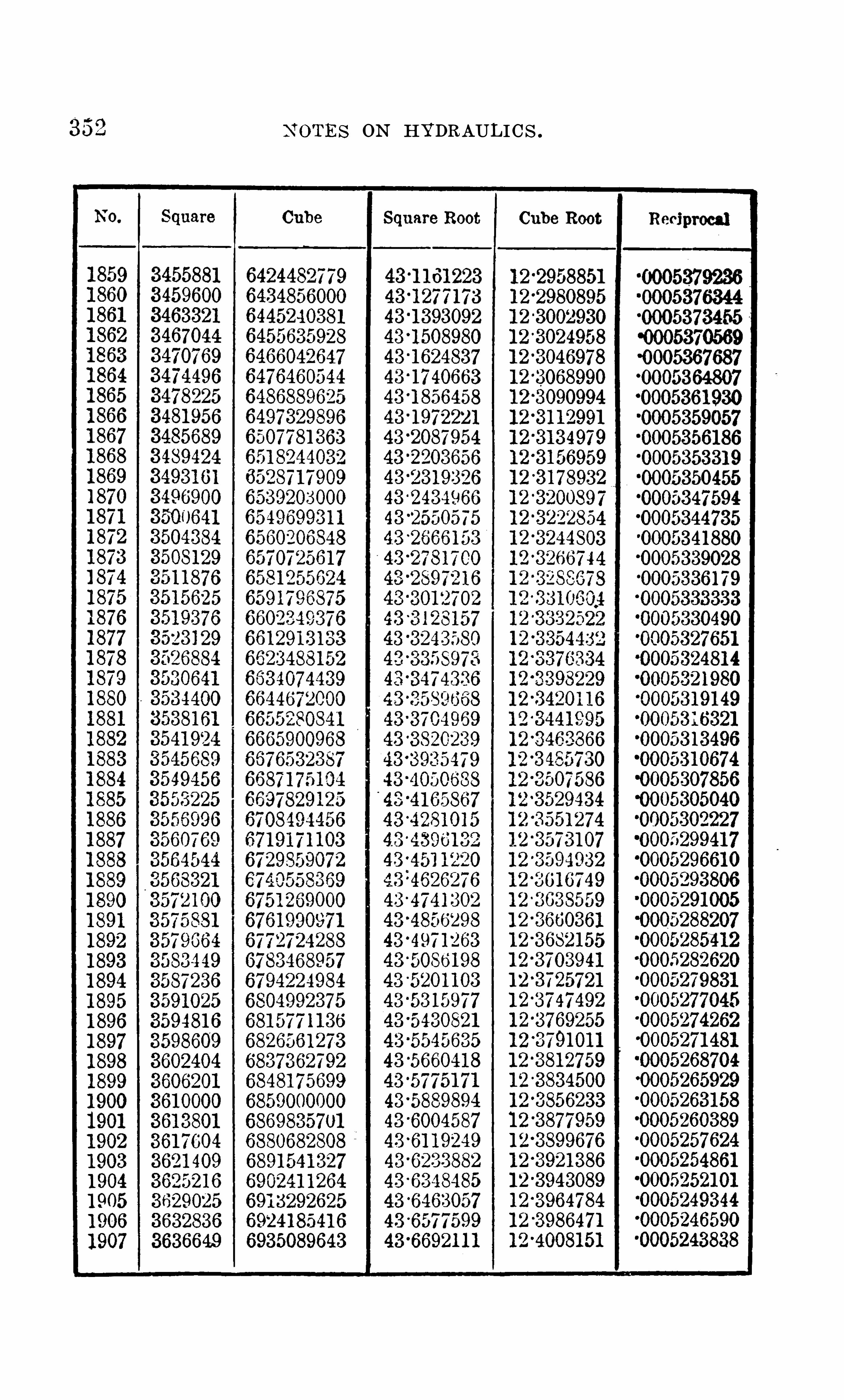
N O T ES ON HYDRAULICS .

354
382984964
38376813841 600
3845521
3849444
3853369
3857296
3861 2253865 1 56
3869089
387302438769613880900
3884841
38887843892729
38966763900625
39045763908529
391 2484
391 6441
3920400
392436 139283243932289
3936256
3940225
39441 9639481 6939521 44
39561 21
39601 00
3964081
3968064
39720493976036
3980025
398401 6
3988009
3992004
399600140000004004001
4008004
401 2009
401 601 6
4020025
N O T ES O N HYDRAULICS .
C ube
749501 4493
750650991 2
75 1 801 7079
7529536000
7541 066681
75526091 28
75641 633477575729344
75873071 25
7598896696
761 0498063
76221 1 1 23276337362097645373000
7657021 6 1 17668682048
768035431 77692038424
7703734375771 54421 76
77271 6 1 83377388933527750636739
7762392000
77741 591 41
77859381 68
77977290877809531 904
7821 34662578331 73256
784501 1 8037856862272
7868724669
7880599000
73924852717904383488
791 6293657792821 5784
79401 498757952095936
7964053973
7976023992
7988005999mmwmw301 2006001
8024024008
80360540278048096064
80601 501 25
Square Root
442 379927442 492938
44 “260591 9
442 71 8872442 83 1 797442 944692
448057558448 1 70396443 3283205
448395985
448508737448621 460
4487341 5544
“3846820448959457
44 4409720-5
44347471 1 9
4435084262
445 1 96586445 308881
445 421 1 49
445 533388
445 645599
445 75778144 “5869936
445 982062
4480941 60448206230
44831 8272
448430286448542271448654228
4487661 58448878059448989933
447 1 01 77844721 35964473253854474371 46447 548880
447 660586
447772264
Cube Root
1 2 5 08261 21 2 5 1 0391 4
1 2 5 1 25208
1 25 1 46495
1 2 5 1 677751 2 5 1 890471 25 21 031 3
1 25 23 1 5712
1 25 2740651 2 5 2953021 2 5 31 6531
1 2 5 3377531 2 5 3589681 25 3801761 25 401 3771 25 42257014454437571 25 4649361 25 486 1 071 2 5 5072721 25 528430
1 25 5495801 2 5 5707231 25 591 360
1 25 61 2989
1 25 6341 1 1
1 25 655226
1 25 676334
1 25 6974351 25 71 85291 2 5 73961 51 2 5 7606951 25 781 7671 2 5 302832
1 2 5 823891
1 2 5 844942
1 25 8659871 25 887024
1 2 5 908054
1 25 929073
1 25 950094
1 25 971 1 03
1 2 5 9921 05
1 2801 31 01
1 28034089
1 280550701 f 60 60 14
1 2 609701 1
“0005 1 09862“00051 07252“0005 1 04645“0005 1 02041“0005099439“0005096840“0005094244“0005091 650“0005089059“0005086470“0005083884“0005081 301“0005078720“0005076 1 42“0005073567“0005070994“0005068424“0005065856“0005063291“0005060729“00050581 69“000505561 2“0005053057“0005050505“0005047956“0005045409“0005042864“0005040323“0005037783“0005035247“000503271 3“0005030 181“0005027652“0005025 1 26“0005022602“0005020080“000501 7561“000501 5045“000501 253 1“000501 0020“00050075 1 1
“0005002501
“0004997501“0004995005“
00049925 1 1“0004990020“0004987531

03640280494032064
403608140401 0040441 2140481 4440521 6940561 964060225
4064256
4068289
40723244076361408040040844414088484
4092529
409657641 0062541 04676410872941 1 278441 1 684141 20900
41 2496141 29024
41 330894 371 56
41 41 2241 4529641 4936941 53444
41 57521
41 6 1 60041 65681
41 6976441 73849
41 7793641 8202541 861 1 6
41 90209
41 9430441 9840142025004206601
421 0704421 4809
421 891 6
N O T ES O N HYDRAULICS .
307221 621 68084294343
809633451 2
81 0848672981 20601 00081 32727331
81 4486572881 5701 61 9781 691 7874481 81 353375
81 93540096820573391 3
821 794933232301 728598242408000
8254655261826691 464882791 861 67
8291 4693248303765625831 6073576
832839368383407259528353070389
8365427000837779579183901 767683402569937841 4975304
842739237584393226568452264653846471 887284771 3531 9843966400085021 5492185 1 4658038
85271 735078539701 1 348552241 1 25856479333685773573238589934592
8602523649
861 5 1 25000
86277386518640364608
86530028778665653464
44f788391 3447995535448 1 071 3044821 86974438330235448441 746448553230448664685448776 1 1 344833751 4448993836
449 1 1 0231449221 549
449332839
449 4441 01“
449555336449666543
449777723449388375
450 000000450 1 1 1 09745 02221 6745 033321 045 0444225
45 0555 21 3
45 06661 7345 07771 0745 038801 345099889145 1 1 09743
45 1 22056745 1 331 36445 1 4421 34
45 1 55237645 1 663592
45 1 77428045 1 83494145 1 99557545 21 06 1 82
45 221 676245 232731 545 24-37341
40
45 265881 2
45 276925745 287967545 29900664581 00430
4582 1 0768
1 28 1 1 79711 28 1 389241 28 1 598701 28 1 8081 01 28201 7431 282226691 282435871 28264499
1 282854041 28306301
1 283271 921 283480761 283689531 28 389823
1 2841 06871 28431 543
1 284523931 284732351 284940711 2851 4900
1 285357221 285565381 28577346
1 285981 481 286189431 286397311 2866051 2
128681 2861 287020531 2872281 4
1 287435671 2876431 41 287850541 288057881 288265 1 4
1 288472341 288679471 28888654
1 28909354
1 289300471 289507331 28971 41 21 28992084
1 2701 27501 270334091 270540611 270747071 270953461 27 1 1 5978
3EL
“0004982561“0004980080“0004977601“
00049751 24“0004972650“00049701 79“000496771 0“0004965243“0004962779“000406031 7“0004957858“0004955401“ 0004952947“0004950495“0004948046“
0004945598“00049431 54
“0004938272“
0004935834
“0004930966“0004928536“00049261 08“0004923683“0004921 260
“000491 6421
“000491 1 591“00049091 80“0004906771“0004904365“0004901 961“0004899559.
“00048971 60
00048“0004889976“
0004887586“00048851 98“000488281 3“0004880429“0004878049“0004875670“0004873294“000487092 1“0004868549

35 6
20
20572058
2061
2062
2063
2064
2065
2066
20672068
2069
2070
2072
2073
20742075
2077
2079
2080
2081
2082
20832084
2085
2087
20922093
20972098
2 1 00
2 1 01
2 1 03
422302542271 36
4231 249
4235364
42394814243600
4247721425 1 844
4255969
4260096
4264225
4268356
4272489
4276624
4280761
4284900
4289041
42931 84
42973294301 4764305625
430977643 1 3929
431 8084
4322241
4326400
4330561
4334724
4338889
4343056
4347225435 1 396
4355569
43597444363921
43681 00
4372281
4376464
4380649
6
4389025
439321 6
43974094401 604
4405801
441 0000
441 4201
441 8404
4422609
N O T ES O N HYDRAULICS .
867831 63758690991 6 1 6
87036791 93871 63791 1 28729091 379
8741 81 6000
8754552981
8767302328
78006404787928381 44
8805624625881 8423496
8831 2347638844058432
8856894509
8869743000
888260391 1
8895477248
890836301 78921 26 1 224
89341 71 8758947094976
8960030533
8972978552
8985939039
899891 2000
901 1 897441
9024895368
9037905787905092870490639641 25
907701 2056
9090072503
91 031 45472
91 1 6230969
91 29329000
91 42439571
91 55562688
91 6869835791 81 846584
91 95007375
92081 807369221 366673
9234565 1 92
92477762999261 000000
9274236301
9287485208
9300746727
45 33321 07845 ‘3431 362
45 3 762052
45 ‘3872229
45‘
3982378
45 4097501
45 464271 7454 752680
45 48626 1 6
45 4 972526
45 5 08241 0
45 5 1 9226745 5 30209745 5 41 1 901
45 5 521 679
45 ‘5631 43045 5 741 1 5545 5 850853
45 5 960525
45 60701 7045 6 1 79789
45 6 289382
45 6398948
45 66 1 8002
45 ’6727490
45 6 83695 1
45 '7055795
457383865
45 7 4931 69
45 7602447
45 8039299
45 8 1 48447458 257569
45 8366665
45'8475735
40 8584 1 79
1 2 71 366031 2 1 5 222
1 2 71 77835
1 2 71 984411 2 72 19040
1 2 7239632
1 2 726021 81 2 72807971 2 7301 3701 2 732 1 935
1 2 73424941 2 736304 61 2 73835921 2 74041 31
1 2 7424664
1 2 7445 1 89
1 2 74657091 2 74862221 2 7506728
1 2 75272271 2 75477211 2 75682071 2 75886871 2 76091 60
1 2 76296271 2 76500871 2 76705401 2 76909871 2 771 1 4271 2 7731 8611 2 77522881 2 7772709
1 2 77931 231 2 781 35311 2 7833932
1 2 7854326
1 2 787471 41 2 78950961 2 791 54711 2 79358401 2 7956202
1 2 79765581 2 7996907
1 2 801 72501 2 80375861 2 805791 6
1 2 80782391 2 80985561 2 81 1 8866
'0004866 180-000486381 3-0004861 449
0 004859086-00048567270 004854369
0 0048520 1 4-0004849661-000484731 0-0004844961
0 00484261 5
10004840271-00048379290 004835590'0004833253-000483091 8-0004828585
0 004826255
0 004823927'0004821 601-000481 9277-000481 6956-000481 4636
0 00481 2320
0 00481 0005~0004807692~0004805382-00048030740 0048007680 004798464~00047961 630 004793864-0004791 567
-0004786979-0004784689-0004782401'00047801 1 5~0004777831-00047755490
‘0004768717‘0004766444‘00047641 73‘0004761 905'0004759638‘0004757374'0004755 1 1 2

3
54
55
56
5758
59
60
6 1
62
21 64
21 65
21 6721 68
21 70
21 7221 73
21 7521 7621 7721 7821 7921 8021 812 1 82
2 1 84
21 8621 8721 88
21 89
21 9121 9221 932 1 94
21 9621 9721 9821 99
463971 64644025
4648336
4656964
466 1 281
4665600
4669921
467424446785 69
4682896
4687225
4691 556
4695889
4700224470456 1
4708900471 3241471 75844721 9294726276473062547349764739329474368447480414752400475676 1476 1 1 244765489476985647742254778596478296947873444791 7214796 1 00480048148048644809249481 3636481 8025482241 648268094831 204483560148400004844401
N O TES O N HYDRAULIC S .
99800355779993948264
1 00078738751 0021 81 241 6
1 00357638931 004972831 21 00637056791 00776960001 0091 699281
1 01 0571 5528
1 0 1 1 97447471 01 337869441 01 47842 1 251 01 6 1 91 0296
1 01 75991 4631 0 1 90085632
1 02041 928091 021 831 30001 023244621 11 02465924481 026075 1 71 71 02749240241 02891 093751 03033077761 031 751 92331 0331 7437521 0345981 3391 03602320001 03744957411 03887725681 04030624871 041 73655041 0431 681 6251 044601 08561 04603532031 04747086721 04890772691 0503459000
1 05 1 78538711 053226 1 8881 05466830571 056 1 1 1 73841 05755648751 05900255361 06044993731 06 1 89863921 06334865991 06480000001 0662526601
46 400431 0
46 '41 1 2055
46 42 1 977546 432747146 4435 1 41
46 454278646 4650406
46 475800246 486557246 49731 1 846 5080638
46 5 1 881 34
46 5295605
46 540305 1
46 55 1 0472
46 56 1 7869
46 5725241
46 5832588
46 593991 0
46 6047208
46 6 1 54481
46 626 1 729
46 6368953
46 6476 1 52
46 6583326
46 6690476
46 679760146 6904701
46'701 1 777
46 71 1 882946 7225855
46 733285846 7439836
46 754678946 765371 846 776062346 786750346 797435846 8081 1 89
46 81 87996
46 829477946 8401 53746 850827146 86 1 4981
46 8721 66646 882832746 8934963
46 “9041 57646 91 481 64
1 29 1 26291
1 29 1 462791 29 1 66262
1 29 1 86238
1 29206208
1 29226 1 72
1 292461 29
1 29266081
1 292860271 2 9305966
1 29325899
1 2 93458271 2 93657471 29 385662
1 29405570
1 29425472
1 2 9445369
1 294652591 29485 14 3
1 29505021
1 29524893
1 29544759
1 295646 18
1 29 584472
1 29 60431 9
1 296241 6 1
1 29643996
1 29 663826
1 29 683649
1 297034661 297232771 29743082
1 297628811 29782674
1 29802461
1 29822242
1 298420171 29861 7861 29881 549
1 29901 306
1 29921 0571 29940802
1 29960540
1 299802731 3 0 000000
1 30 01 9721
1 30 039436
1 30 0591 45
1590078848
'0004642526'0004640371
0 00463821 9'0004636069
'0004631 774
0 004629630'0004627487
'0004623209
:0004621 072-000461 8938-000461 6805~000461 4675-00046 1 2546-00046 1 0420
0 004608295-00046061 72-0004604052~0004601 933-000459981 6-0004597701-0004595588-0004593477-0004591 368~0004589261-00045871 56-0004585053‘000458295 1~0004580852-0004578755-0004576659'0004574565-00045724740 004570384'0004568296'00045662 1 0-00045641 26-0004562044-0004559964-0004557885~0004555809-0004553734-0004551 66 1-0004549591-00045475220 004545455

N O T ES O N HYDRAULICS . 359
USEFUL l NFORMATl 0N ABOUT WATER.
Water i s incompressible,or nearly so
,showing no sensible
change of volume under changes of pressure .
The pressure of a perfect fluid on any surface with whichi t is in contact i s perpendicular to th e surface .
The pressure of a fluid at any point of a surface is thepressure per uni t area .
Any pressure applied at th e surface of a fluid i s transmitted equal ly to a l l parts of the fluid .
The pressure of water at rest under gravi ty increasesuniform l y wi th the distance that i s
,the di m erence of pres
sure at any two points varies as th e vertical distance betweenthe points .The free surface of a l iquid at rest under gravity is a
horizontal plane .O ne cubic foo t of water con tain s abou t 7.48 gallons .
O ne cubic fo o t of pure water at a temperature of 6 0
degrees Fahr .,weighs pounds .
O ne U . S . gallon of pure water at a temperature of 6 0
degrees Fahr .,weigh s pounds .
The amount of water required to fill an ordinary automatic sprinkler system is abou t 1 gallon per Sprinkler .This includes riser and al l distributi on pipes, bu t does no tinclude ground mains from pump or city supply to base of
This figure ( one gallon per head)applies especially tosystems piped from
/
the center with 75 - t o 1 5 0 heads on
each floor .I f system of 1 5 0 sprinkler heads i s fed from end insteadof center
,contents wi l l be abou t 1 14 gal l ons p er head .
For large systems with 6 - inch rider and abou t 25 0 headsper floor
,con tents
,i f riser i s in center
,will be abou t 1 3
gal lons per head,and i f riser i s at one end
,will be 1 3 gallons
per head .

380 N O T ES O N HYDRAULI C S .
SPECIFICATIONS F011 STEAM FIRE PUMPS .
AMEN DMEN T S
Adopted by the N a tional Fire ProtectionAssociation , 1 907.
(Page 1 1 5 , fourth paragraph , second l ine).C hange to read : o f 34 14; l bs. of water per hour, etc.
(Page 1 1 8, first paragraph , second l ine).5 . C apaci ty P l ate.
C hange to read : at least 85 per cent . a l uminum,etc .
N O T E — This per cent . of a l uminum is considered neces
sary to guard agains t tarnish ing .
(Page 1 20. newnote).8. S team Cyl inders .
d . Add : N o te — The s l igh t bevel ing of piston face edgesmay be cons idered as the equ iva l en t of th i s .
(Page 1 21 , fifth paragraph , third l ine).1 2 . S team C l earance S pace.
a . C hange c l ause in second parenth es i s to read : C on tactS troke shou l d overrun nomina l stroke at each end abou t
- ineh.
N O T E — I t i s no t found practicab l e t o run fu l l strokeunder fire conditi ons w i th a much l ess c l earance and rece ivethe des i red benefit from the cushion ports .
(Page 1 22, third paragraph).1 3 . S team P istons.
C hange to read : The thickness of p i ston shou l d be
abou t one - fourth of i ts diameter . I f so l id,wa l l s shou l d
be no t l ess than - inch thick,and specia l care shoul d be
g iven to sh op inspecti on to insure uniformity of thickness .N O T E .
— This w i l l demand,for the four s izes of pumps .
pi stons as fo l l ows :500~GAL . 750-GAL .
Diameter 1 4 in . Diameter 1 6 in .
Th ickness 3% in . Thickness 4 in .

36 2 N O T ES O N HYDRAULI C S .
Al so substi tu te for the second tab l e in same paragraphthe fo l l owing :
S ize of Pump. 500-Gal . 750-Gal .-Gal . - Gal .
S ize of 3 " 395"4” 3
” 354" 4” 3” 4” 3
"3i3/g” 4”
N ecessary numberof val ves to satisfy (4)under c . . 6 5 6 9 8 7 1 1 9 8 19 1 4 1 4
ecessary numberof val ves to sat
isfy (3)under c . . 7 5 4 1 0 8 6 1 3 9 7 21 1 5
I n th e same artic l e change fine print no te to read :
val ve,
”and no t valve .
(Page 1 50, l ast paragraph).44 . Discharge C one.
b . C hange to read : The cone must be provided_
with an
opening to receive the air- ven t required by Artic l e 45,
~ ete.
(Page 1 53, second paragraph).46 . Priming,
C ontro l l abl e Va lve Arrangement.
d . C hange fine print no te to read : This va l ve can preferab l y be provided w i th a flange connect ion in p l ace of the threaded one
,and secured to water cyl inder with three bo l ts .
This w i l l permit of easier fitting up as to p ipe . connections .O bj ection has been raised to th i s doub l e - seated va l ve fromthe poss ib l e di 1 cu l ty of keeping both seat s t igh t . I f desired
,the stem between the two seats may be somewha t
enl arged and provided wi th a sui tab l e spring, .thus givingflexibi l ity between the two sea ts and pr eventing a l l troub l efrom uneven wear .

N O T ES O N HYDRAULI C S . 36 3
STEAM PUMP GOVERNORS ANDAUXILIARY PUMPS.
AMEN DED RU LES AN D REQU IREMEN T S .
Adopted by the N ational Fire Protection
Association , 1 907.
General Ru les.
1 . Au tomatically con trolled p umps are no t accep table as
the so l e primary water supp l y for automatic sprinklers .S uch pumps may occasiona l l y b e used to advantage to
supp l emen t a weak tank or public water supply un til moreextens ive and permanent improvement s can be made .Experience has shown that the au toma tic devices for such
pumps are easi l y deranged and require more care than can
sure l y be counted upon at the average risk . As i t i s absol utely necessary tha t the primary supply to sprinklersshou l d be instantly and surel y avai l ab l e for every moment
,
nigh t and day, a good gravi ty supp l y has been found thebest and on l y thorough l y sati sfactory one .
2 . Where there i s a good gravity supp l y i t i s not advis
ab l e to equip the fire pump with an automatic governor .U nder th ese conditions automatic control i s no t needed,
and i t s firs t cost and constan t use of steam and possibledamage to 'the pump
,if the governor goes wrong, had better
be avoided . The fire pump shou l d,h owever
,be started as
so on as a fire i s discovered and Opgrated by hand at
,
goodpressure and at such speeds as n ecessary to give the
amoun t of water needed . Experience shows this t o be thesimp l est
,surest
,and safes t method .
3 . Whenever i t i s necessary to use an automatical l y contro l l ed pump an auxi l iary pump shou l d always be providedto maintain the pressure and supp l y leakage .The arrangemen t of the auxiliary pumps
, governors, etc .,i s Shown in P l ans A
,B and C
,fol l owing.
T he governor on the smal l pump is set for abou t 1 0

364 N O T ES O N HYDRAU LI C S .
pounds higher water pressure than the governor onmain pump
,so that the large pump does not start til l
pressure has dropped abou t 1 0 pounds . The smal l pump,
therefore,does a l l the work of supp l ying the l eakage
in the system and mainta ining the pressure .
This saves the large and expensive pump from constantwear and further lim i ts the steam consumpt ion to a pumphaving a much sma l l er
‘
steam cy l inder than the ma in pump,
thus considerab l y reducing th e cost of the steam .
Exper i ence has shown tha t where th e main'
pump a l oneis rel ied upon to keep up the pressure the l eakage in the
system and past the'
l arge p l ungers a l l ows i t to run continuously at a few strokes per minute. After a
‘
few yearsthe plungers become so worn that the del ivery of thepump is cu t down 1 0 per cent . and often more . This further wastes steam as we l l as reduces the capacity of thepump f or fire fighting .
V alves and o ther part s o f th e pump are a l so l ikel y toget ou t of o rder under this service. Moreover
,the con
stan t action of the large governor within narrow limi tsis l iab l e to impair i ts certa inty of action when l arge del ivery is suddenly required .
Governor C onstruction .
S uccessfu l governors vary too great l y in type to admi tof uni form mechan i ca l construct i on . The fo l l ow ing specifications cover genera l point s necessary in governors of a l l
types . A search ing test under pract ica l working conditionsmust be the main criterion for accep tance
,and for the l i st ~
ing of a governor as an approved dev i ce .
T he Governor
1 Must be con trol l ed by the water pressure in the fire
2 . Must be adjustab l e to maintain any desired pressurebetween 75 and 1 25 pounds us ing steam at any pressurefrom 5 0 to 200 pounds .

36 6 N O TES O N HYDRAULIC S .
Aux i l iary Pumps.
1 . Auxi liary pumps shou l d be of dup l ex type,brass fi tted
and wi th packed pistons or exterior packed p l ungers .B rass fitting prevents rusting .
,Packed pistons make i t
easy to take care of wear . Exterior packed p lungers makeit easy to dectect leakage and remedy it .
2 . The ratio of steam to water piston areas sh ould besuch that the auxiliary pump can maintain the desiredwater pressure with 5 0 pounds of steam .
At nigh t boiler pressures may drop to 5 0 pounds and ifthi s rati o is too smal l the large pump wi l l Start .A pump has been used in many situations
with good sati sfaction . A woul d probab l yanswer equal l y wel l in most cases and have the advantageof some greater capacity. Where a larger capaci ty i sneeded
,as in a very l arge pipe system,
a wouldbe advised . These pumps are large enough to have goodl ifting abi l i ty and they are of su i cient capacity to takecare o f a l l ordinary l eaks and wastes .I n sp ecial cases where a larger amoun t of water must ‘
be more or less continuously supp l ied from a fire system,
the auxi l iary pump must be larger and may be of any sizedesired .
Th e auxi l iary pump i s of value to keep the main firepump primed
,as wel l as to maintain the pressure and waste
in the fire system .
Instal l ation of Governors and Aux i l iary Pumps .
1 . Pump governors and auxi l iary pumps should be ar
ranged in accordance - with one of the three p l ans,A
,B or
C,following .
This app l ies to the scheme of connections and numberand location of va l ves
,bu t no t to the exact position of the
auxi l iary pump and c onnecting pipes .

N O T ES O N HYDRAULI C S . 367
2 . T he main pump and the auxiliary pump must havesepara te governors made en tire l y independent by a valveon the water connection of each .
3 The size of governors for the main pump should be as
For 5 00 - gal l on pump,1 14
" governor.For 75 0 - ga l l on pump
,1 15
” governor.For - gallon pump
,or 2 ”
governor .For - gallon pump
,2 governor .
The size of the governor i s restricted in this way in orderthat the pump may no t run too rapid l y for safety in theabsence of an attendan t
,in cas e of an excessive demand
for water,or of a loss of its suction supp l y . When
,in case
of fire,the attendan t reaches th e pump
,i t i s expected that
he wi l l con tro l i t through the regu l ar thro tt l e va l ve . How
ever,with the bo i ler pressures now common
,these governors
wi l l run the pumps at good speed and O ften at ful l speed.
4 . The governor for the auxi l iary pump should be {21connected into a 1A)
” steam pipe .
A pip e larger than is undesirab l e,as i t would permi t
excessive racing of th e smal l pump if the pressure in themain system were l ow. A governor i s required to getthe working parts large enough to be re l iab l e .
5 The auxi l iary pump shou l d have an independen t ex
I f the auxi l iary primp exhaust i s connected in to the ex
haust of the main pump there i s danger of water co l lectingin the l arge pump
/pipe and causing troub l e .
6 . The water pressure pipe con tro l l ing the governors mus tbe of brass . I t must connect beyond the main pump discharge check and must have control gates as cal l ed for inArt. 2 .
B rass is requ I red to avoid trouble from corrosion .
7. Lubrican t must be app l ied so as no t t o pass through

368 N O T ES O N HYDRAUL I C S .
governors befo re entering pumps,unl ess manufacturers
specify o therwise .
U n l ess the governors are des igned for i t there is dangerof the oi l gumming up the parts .
8. The governor for l arge pump to be insta l l ed on usualthree valve ” by
- pass arrangemen t of steam p iping .
This is shown in the cuts,a va l ve being prov ided on each
side of the governor,whi l e the governor i t sel f i s on a by
pass around the ma in va l ve . This permit s shutting off thegovernor for repairs and sti l l have steam avai l ab l e on thepump through the ma in thro tt l e .
9. T he aux i l iary pump shou l d have a re l ief va l ve capab l eof discharging fu l l capac i ty of pump withou t l etting pressure ri se more than 25 pounds above that at which governori s set.
This is to prevent the smal l pump pu t ting a dangerouspressure on the sys tem . I n some cases the l arge pumpgovernor i s a l so avai l ab l e for the sma l l pump
,bu t where
this is no t so a specia l governor must be provided for i t .
1 0 . Dup l icate governors,or dupl icates of wear ing parts ,
shou l d be kep t on hand in al l important insta l l at i ons .This is to avoid del ay in repairs .
1 1 . The governor on the auxi l iary pump shou l d usua l l ybe set at abou t 1 0 pounds higher water pressure than the
governor O f the main pump .
This is to give some marg in so that the l arge pumpwi l l no t start with sma l l changes in pressure .
1 " An auxiliary pump wi l l no t operate successfu l ly um
l ess the water end stuffing boxes and j o ints and suct i onfittings compl ete O f
'
th'
e‘ma infire pump are in go od condi
t ion . Further,there shou l d be no ser i ous l eaks in any part
of the fire system .
U nder proper cond i t i ons the sma l l pump wi l l move s l ow l ya l l the time
,making j ust enough strokes to ma inta in the

370 N O T ES O N HYDRAULI C S .
in a we l l in the pump room . The point i s to place thI Scheck so tha t shou l d the jar of the pump break the . di scharge pipe or loosen a j oint
,or Shou l d some o ther accident
happen in or abou t the pump,this check wou l d be S O
secure l y located that i t wou l d not be affected,but wou l d
c l ose and prevent the waste of water from o ther sources,
as pub l ic mains,tanks or o ther fire pumps connected to the
system . The discharge va l ve on the main pump is bol tedd i rect l y t o the pump out l et
,so that .
no matter wha t breakoccurs in the pipe beyond
,i t can be closed and the pump
used through its hose connections .PLAN B .
— For Pumps Wi th S hort S uction -
Pipes and
Li fts N ot Over Ten F eet,and N ot P rovided With a Foo t
V a l ve . Al so S uitab l e For U se Where Water I s TakenU nder a Head .
“ l i tlr this arrangemen t the sma l l pl
ump 1 s l ocated nearthe floor and takes its suct ion from the suct ion of the largepump at a point j ust abOve the l eve l of . th e suction deck .
Th i s sma l l suct ion pipe Shou l d run level,or S l igh t l y ascend
ing towards the sma l l pump . The sma l l pump dischargesinto the pu l sation chambers of ma in pump through theprim ing connections
,and thence through the di scharge
va l ves into fire system .
'
A va l ve is p l aced on bo th thesuct i on and discharge of sma l l pump
,so that a l l i ts con
nections may be shut 0 and the l arge pump operatedindependent l y .
This p l an wi l l keep the l arge pump fu l ly primed and wi l lwork we l l on moderate l i ft s adv i sab l y no t exceed ing 8 to1 0 feet . I t i s no t recommended for higher l ifts or l ongsucti on pipes
,as th e sma l l pump canno t be re l ied upon to
maintain the suction under severe'
conditions . S ee P l an Cfor such - cases .G and C 1 are the governors . T is a steam trap for tak
ing care of condensat ion .
N o rel ief va lve is requ ired,
as sma l l pump operatesagainst rel ief va l ve of ma in pump .
A val ve is provided on each side of the governor on
“
3

N O TES O N HYDRAUL I C S . 371
the large pump,so that i t can be shut o ” for repairs, etc .
,
and steam sti l l used through the main thro ttle . The ideai s to make it impossib l e for any derangemen t of the au tomatic apparatus to preven t the use of the large pump inthe ordinary way, that i s, by hand contro l , through themain thro ttle .S igh t feed lubricators are shown on bo th the large and
the small pumps . A forced feed lubricator could be usedas shown in Plan C
,i f desired .
The check valve on the main pump discharge is Shown ina well outside the pump room
,and this is a very good
arrangement . The conditions governing the arrangemen tof this check valve and the main gate on the large pumpare ful l y exp lained under P lan A. The we l l for '
the checkval ve i s desirable
,as i t not only makes th e check va l ve
easi l y accessible,but also th e connection from th e smal l
pump discharge is put where i t can readi l y be go tten at.
PLAN C .
— For Pumps With Long S uction P ipe or LiftsO ver Ten Feet
,Requ i ri ng a Foo t V alve
,But S ui table For
U se Wi th Lesser Lifts or Where Wa ter I s Taken U ndera Head}The auxiliary pump is Shown on the floor of the pump
house,over against the distan t S ide wal l . The sma l l
pump takes i ts suction independent l y of the main one,from
some rel iable water supply,either tha t from which the main
pump draws or any o th er sure source . I f a near watersupp ly for the sma l l pump can be ob tained at a moderatelift i t i s b etter than to have i t working under a high l ift .The auxil iary pump discharges in t-o the suction p i pe of thelarge pump
,and on 'th e end of the large pump suction a
ch eck or foo t valve is p l aced to retain the water . The foo tor check val ve used Should have meta l seat and valve
,as
,
i f a sof t seat i S _used, the continual h igh water pressure oni t maintained by the smal l pump may in time indent thesoft material
,possib l y making the c l apper stick
,so that
the suct i on action of the l arge pump would no t be su m
cient
to tear i t from i ts seat . As in the o ther p l ans,a val ve is

372 N O T ES O N HYDRAULI C S .
provided on the discharge so that the smal l pump connect i ons may be shu t o and the l arge pump run independ -
q
ent l y . The connections from the sma l l to the l arge pumpare sh own running up the side wa l l to a height sufficien tt o l et a man wal k under them where they pass overhead tothe l arge pump . T he discharge p ipe shou l d be carried jus tbe l ow the floor in a trench covered with a p l ate.
This arrangement i s advised for high l ift s,but i s
,of
course,
avai l ab l e for l ess severe conditions,because i t
abso l utel y insures keep ing the l arge pump and suction pipefu l l of
'
water,thus giving n o chance that when a sudden
demand for water comes and steam i s turned on to the l argepump i t wi l l fai l to take water and work '
aS‘
deS ired .
Where a pump is equipped with an automatic governorthere i s a lmos t sure to be some damage done the p umpif
,when a demand for water arises
,and the governor turns
on steam,the pump does no t at once obtai n a fu l l supp l y
of water,fo r withou t water th e pump wou l d tend to run
away,frequent l y resu l ting in breaking some part or wrench
ing some connections l oose .T he exp l anati on of detai l s is the same as for P l ans A
and B . I n this case no re l ief va l ve is necessary on the
sma l l pump,as the re l ief va l ve - O n the large pump wou l d
take care of the pressure'
on both pumps .A forced feed l ubricator i s S hown on
, the l arge pump,
bu t of course a s igh t feed lubr i cator as in P l ans A and B
cou l d be used if preferred .

3 74 N O T ES O N HYDRAULI C S .

N O T ES O N HYDRAU LI C S . w"1

376 N O T ES O N HYDRAUL I C S .
SPECIFICATIONS FOR ROTARY FIRE PUMPS .
AMEN DMEN T S .
Adopted by the N ational Fire Pro tection Association ,
1 906 , 1 907 and 1 908.
N AME PLAT ES
(T ype A, page 182. T ype 8 , page
S pec ifications (pages 1 78 to 1 94)to be des ignated as
Type A ”
; those in the appendix (pages 1 95 to 2 1 5)toremain T ype B.
’
N ame pl ates to be as fo l l ows :
. PUMP C O MPAN Y
RO T ARY FIRE PU MP
TYPE A.
T HE N A'J‘
I ‘1 N A1 . S 1 AN l)AR I).
. PUMP C O MPAN Y
RO T ARY FIRE PU MP .
'
1 VHS I}.
T HE N AT I O N AL S T AN DARD .
T YPE A . ( 1 907)(Page 181 , new paragraph).
9. B ed P l ate.
( 1 . A substant ia l cast iron bed pl a te mus t be provided,

378 N O TES O N HYDRAULI C S .
(Page 208. th ird paragraph).1 5 . Bed P l ate.
e. C hange to read : F oundation bo l ts of a size no t l ess_than from - inch to 1 - inch
,according t o S ize of pump
,
mus t be provided for anchoring bed p l ate to foundation .
(Page 21 1 , new paragraph).2 1 . S afety Va lve.
d . Pumps operated by e l ectric mo tors must be provi deda
with two rel ief va l ves,each one of which must be at leas t
of a size next sma l l er than that required for this S ize pump .
N O T E .
— This i s a precauti on necessitated by the dangerof cripp l ing the e l ectric ci rcuit by the b l owing of._a mai nfuse in case one of the re l ief va l ves i s inopera tive at thedesired pressure. I t i s be l i eved the chances are much lessfor bo th va l ves be ing stuck or set at too h igh a pressure .
T ype B .
(Page 199, third paragraph . third l ine).3 . S izes of Pump.
C hange, in third paragraph of fine no te,
to read
(Page 20 1)Amend wording of p l ate t o read : “ N ominal C apaci ty, ”
in stead of C apaci ty.
(Page 206 , first paragraph. th ird l ine).1 2 . S tufiing B oxes.
b. Add : S ome means must be provided for preventingth e g l and nuts from j arring l oose .
(Page 206. ninth paragraph , l ast l i ne)1 3 . Gearing.
0 . Add : or the equivalen t diametrica l pitch .
(Page 209, fourth l ine.)1 6 . S uction and Discharge O penings.
0 . Amend second l ine of di ameters in . tab l e to read, forthe respective pump sizes
,5 - inch or 6 - inch
,6 - inch or 8- inch,
8- inch or 1 0 - inch .
N O T E — S tarting valve should be connected to the discharge casting at such a po in t tha t the water from th e

N O T ES O N HYDRAULI C S . 379
priming pipe wi l l no t run out through this starting valvewhen O pen .
N O T E — The obj ec t of th e change in the table i s to permi tth e manufacturer at his op tion to make the openings forthe hose connecti on piece th e same S ize as for the maindischarge
,thus permi tting the discharge pipe to l ead away
from the pump in any one of three di ”
erent directions .This undoubted l y wou l d be a considerab l e advantage undermany condi tions o f pump insta l l ati on .
(Page 21 1 , fifth paragraph).22 . Discharge C one.
b . Amend to read : Th e eone must be provided with an
opening to receive th e a ir - vent pipe required by S teamPump Rules
,Articl e 45 (page
REMARK S .
Further amendments were proposed to the specificationsfor Type B Rotary Fire Pumps
,as out l ined in a committee
report printed in the 1 908 P roceedings of the N at ionalFire P ro tection Associa ti on (page 1 67 of the Proceedings).

380 N O T ES O N HYDRAULIC S .
SPECIFICATIONS FOR ELECTRIC FIRE PUMPS.
AMEN DMEN T S
Adopted by the N ational Fire Protec tionAssociation , 1 905 .
(Page 230, fifth paragraph).6 . Motor.
a . C hange to read : May be of either the direct or a l ternating curren t type and mus t be des igned for vo l tageswith in the l imi ts for l ow po tentia l systems as specified bythe “ N ational E l ectrica l C ode .
(Page 232, seventh paragraph).7. Means of C ontro l , Manua l C ontro l l er.
h. C hange to read : The starting operati on shou l d preferab l y be accomp l i shed by the use' of one hand l e or l eve rarm.
N O T E — When more than one lever or arm must be man ipu l ated
,the l ever or arm must be inter l ocked in order to
insure their hand l ing in proper order .
(Page 234, first paragraph).9. Pump .
e. S ect ion stricken out .
(Page 234, new articl es).1 0 . Rel ief Va lve.
a . Must be prov ided with two rel ief valves of the springPop Re l ease ” type
,a ttached to discharge cast ing
,and
to have hand wheel for pressure regu l at ion . Each va l vemust have same capacity as requ ired in S team or Ro taryPump S pecifications for pumps of same S ize . Re l ief va l vest o d i scharge int o waste p ipes having cone tops w i th S l idess o that the discharge from each va l ve can be made v i sib l e.
b. When the suppl y of water is l im i ted, as from a spec ia lsucti on reservo ir or ci stern
,the waste pipes must drain into
such reservo i r or ci stern,entering as far from th e pump
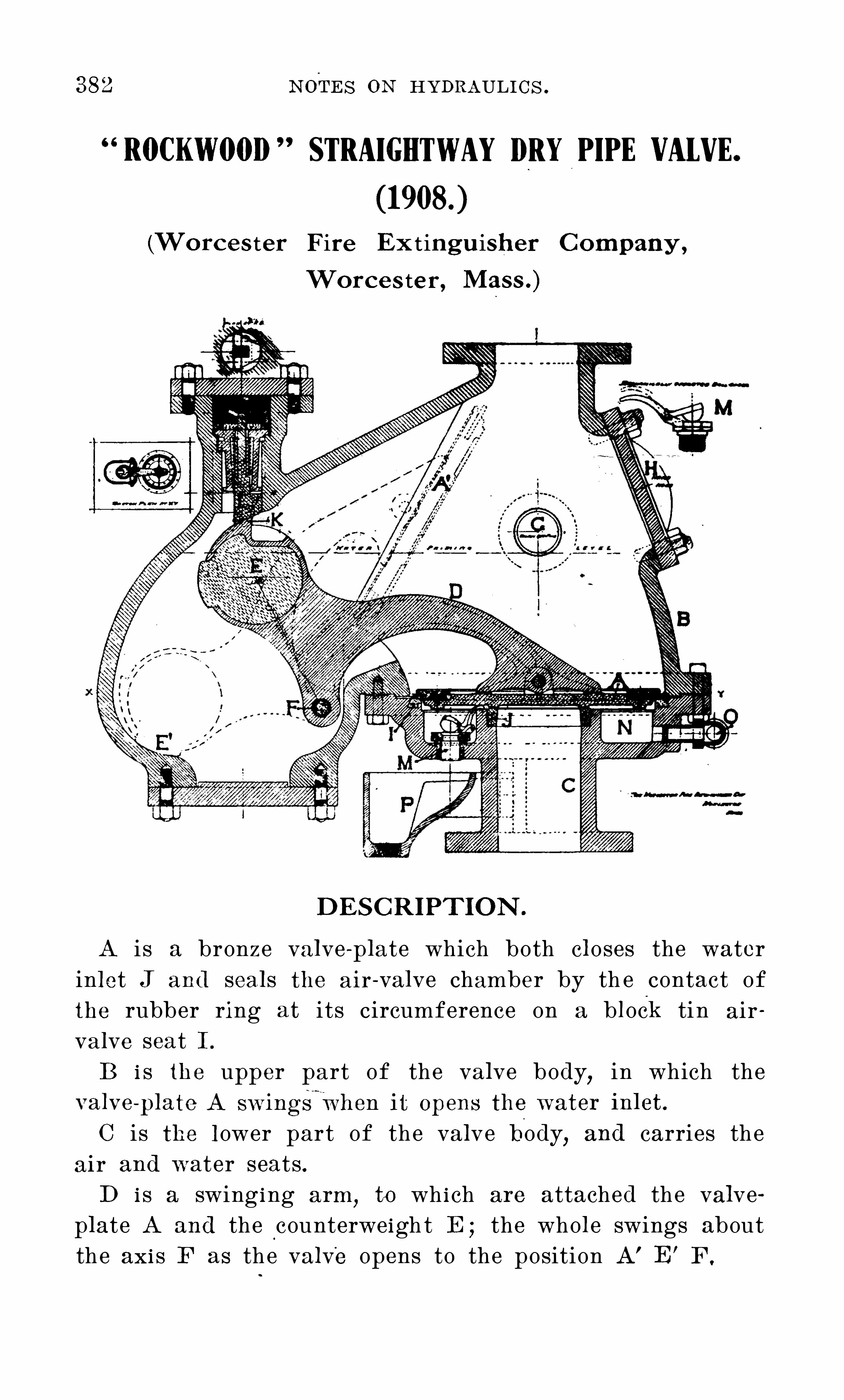
382 N O TES O N HYDRAUL I C S .
RO0KWO0I) STRAIGHTWAY DRYPIPE VALVE.
(Worcester Fire Ex tingu isher C ompany ,
Worces ter, Mass .)
DES C R I PT I O N .
A i s a bronze va l ve - p l ate which bo th c l oses the waterin l et J and sea l s the a ir - va l ve chamber by th e contact ofthe rubber ring at i ts circumference on a b l ock tin air
va l ve seat I .
B i s the upper part of the valve body,in which the
C i s the l ower par t of the va l ve body,and carries the
air and water seats .D i s a swing ing arm
,to wh i ch are attached the val ve
p l ate A and the counterwe igh t E ; the who l e swings abou tthe ax i s F as the va l ve opens to the position A’
E’F .

N O TES O N HYDRAULI C S . 383
E i s an iron bal l fi l l ed with lead . The weigh t of thevalve - p l ate A tends to ho l d i tsel f down on its two seatswhen shut
,and the
,weigh t of the ball tends to hold the
valve - plate open after i t has started t o open .
G i s the draw - o“ ’ valve and pipe for emp tying the entire
system of Sprinkl ers and piping .
H i s the hand - ho l e cover plate,for giving access to al l
interior parts of the valve .
I and .I are the tin air seat ond bronze water seat,respectively.
K i s a proj ection on th e bal l E adap ted to engage a

N O T ES O N HYDRAULIC S .
spring l atch L. I t i s brough t into u Se to prevent the valvep l ate from returning to i ts seat s i f the combination S hou l doccur of ( 1)a feeb l e water supp l y ; a corroded orj ammed spind l e F ; a reversa l of flow after the riserhad been fi l l ed wi th water . U nder normal condi t i ons i tp l ays no part .M i s a ba l l - seated swing check - va l ve
,which is automati
ca l ly he l d 0” its seat by the contact of i ts arm extension
with the under side of the va l ve - p l ate,
and thus a l l owsany water wh ich may leak by J to run freely out of theintermediate chamber N in to the drip cup P .
O i s a drip pipe for draining the priming wa_ter l eft inthe va l ve - body after the system has been emp t i ed throughC .
R i s a jack for rai sing th e lip of the upper body B overthe flange of the under body C when i t i s desired to removeC o r A for repa i rs . To use the j ack
,ho l d the pipe post R
wi th one pipe wrench whi l e screwing upwards the coup l ingat the upper end of R with another wrench .
DIREC T I O N S
For setting the Rockwood S traightway
Dry- Pipe V al ve .
N ever app ly grease ,ta l low , O r any o ily su bstance to val ve
seats I or J.
1 . Drain the system through G,
and the va l ve- bodythrough 0 .
2 . Wi th a piece of waste,c l ean the surfaces o f ( 1)th e
rubber va l ve ; ( 2)the t in air seat I ; ( 3)the bronze waterseat J . Wi th the hand
,scoop ou t any excess of sca l e 0 1
so l id partic l es found in the intermed iate chamber N .
3 . Push the va l ve - p l ate A down towards its seats . I t
wi l l stop when engaged by the l atch L . To l ift the l atchover th e proj ect i on on the ba l l , insert the end of the va l vewrench between the top of the ba l l and the l atch and prythe l atter up
,thus re l eas ing the va l ve - p l ate
,wh ich wi l l then
seat i tse l f .

N O T ES O N HYDRAULIC S .
2 . O bserve the ou t l et from the ball - seated swing checkvalve M to see that there is no leakage from either valveseat . I nsert the middle finger of the hand into this ou tletand tip the bal l of . the check - valve to see that there i sentire freedom of movemen t and no dirt surrounding i t .3 . Test automatic alarm occasionally .
T O DRAIN SYS T EM
1 C lose main gate valve Q, in supp l y pipe under dry- pipe
2 . O pen draw - o valve Cr,closing i t (after operation 3)
when water has stopped running.
3 . O pen drip - valves and vent s throughou t system“
; thenclose af ter water stops running .
4 . Pump a few pounds of air pressure onthe system .
5 . O pen drip - va lves and vents to force water from lowpoint s of th e system .
6 . S et DRY-P I PE VALVE and pump up air pressure,
as described before under DI REC T I O N S .
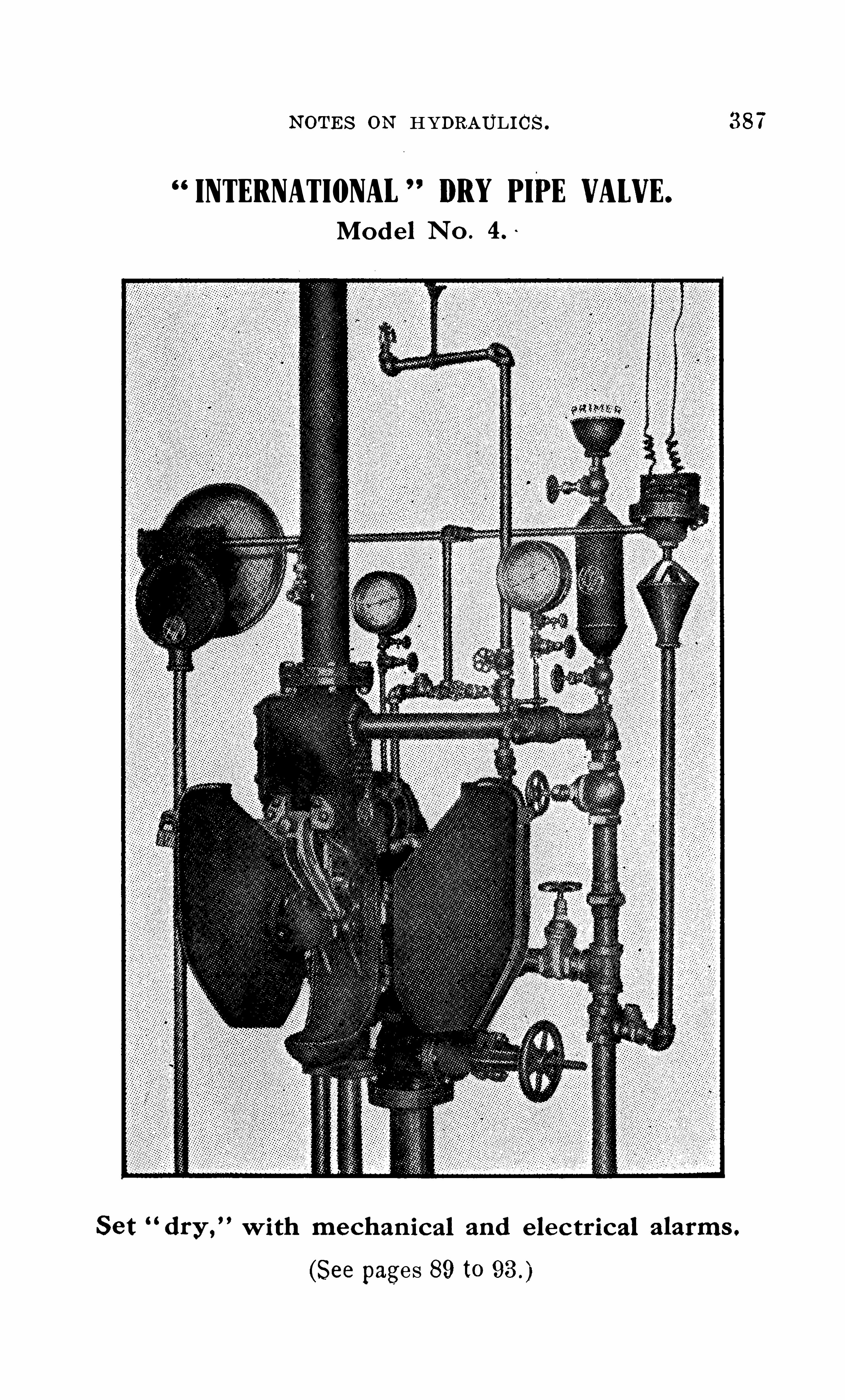
N O T ES O N HYDRAU L I C S . 387
INTERNATIONAL DRY PIPE VALVE.
Mode l N o .
S et“dry,
” with mechan ical and e l ectrical a l arms .
(See pages 89 to

N O T ES O N HYDRAULI C S .
ALARMS 0N DRYPIPE SYSTEMS.
O n dry pipe systems where air i s maintained throughoutthe year
,either the circui t closer or the water mo tor
,or
both,may be connected direct to the intermediate chamber
of th e air - valve . I n dry pip e systems where the air is no tmaintained in the system throughou t the year
,bu t water
is admitted during the summer,an alarm check valve must
be used with the dry pipe valve at the water intake end .

N O T ES O N HYDRAULI C S .
FIG. 1 .

N O T ES O N HYDRAULI C S . 391
FIG . 2 .

N O T ES O N HYDRAULIC S .
FIG. 3 .

394 N O T ES O N HYDRAULI C S .
and : thorough ly c l ean the air pot (1 4)and seat of air clapper (1 5)and repl ace the c over lN ext raise the ou .er end of (1 2A)sothe inner end rests under the depend ing portion of afterwhich pump up the air on the system to 35 pounds or morepressure.
N ext hang up weight (1 1)by booking (33A)on (1 2A)as shown .
in the d iagram .
T he water c l apper (3)and seat (2)should now be thorough lyc l eaned and the c l apper (3)seated on N ext screw the nut (6)up as h igh as possib l e on (5)and set the end O f l ower strut (4)in the socket on top of Draw the p l unger (7)— into the va lvebody as far as possible and set the l evers (9)and (1 0)in position “
shown in d iagram ; pl ace the l ower end , or bal l portion , of thestress nut (6)in the socket on top of (7)and screw dOWn the nut
O pen the gate val ve bel ow the dry va lve and see that waterseat is tight .
C lose the hinged cover (20)and do ors (1 7)and (1 7A)and valveis set for acti on .
A bal l drip (24)is provided to take care of anypossible leakagepast the water seat (2I n order to prime the air pot and a ir check , while system is
under pressure, open the upper va lve on fil l the primingchambers (23)through (D), c l ose upper va lve and open lowervalve, ~when the water w i l l descend and cover seats . Prime untilwater shows at test va lves (F).
O PERAT IO N .
I n case air is al l owed to escape from the system , because of asprink l er head opening or a valve being opened , and the pressurebecomes reduced to , say, from 1 3 to 1 5 ’
pounds per square inch ,the weight (1 1)will begin to drop, thereby rel easing the l ever (9)and a l l owing the plunger (7 to move to a seat in bushing (8)andc l ose the O pening in same. This O peration wil l rel ease the
stress toggl e and perm it the water c l apper (3)to O pen and waterto fil l the system .
T he com ing in contact with the plunger of theal arm device causes an alarm to be sounded until such timeas contact is broken .
T he va lve canno t be reset unt i l the air seat is raised above theinner portion of (1 2 A). This guards against any chance of
water co lumn in air riser pipe, as this cannot be done untila l l pressure is out of the system .

BU YERS ’
GU IDE 1 7
(C ontinu ed from Page 1 5)
HOS EInterna t iona l S pr ink l er Co .
H . G . Vogel C O .
HOS E RACKS AN D R EELSIn terna t iona l S prink l er C O .
H . G . Vogel Co .
HOS E , U N L I N J3D L I N EN
Interna t iona l S prink l er Co .H . G . Vogel C O .
HYDRAN T SGenera l F ire E xt ingu i sher C O .
In terna t iona l S prink l er C O .
H . G . Vogel C O .
ME T ER S , WAT DRH . G . Vogel C O .
OIL PUMPS , HAN DDem ing C O . (Cha s . J Jager C o. , 281 Frank l in S t.)H . G . Vogel C O .
PIPE SGenera l F ire E x t ingui sher C O .
PIPE HAN GER SH . G . Vogel Co .
PLAY PIPE SH . G . Vogel C O .
PLAY PIPE S , MON IT OR N OZZLE SH . G . Vogel C O .
PUMPS , CE N T R IFUGALH . G . Vogel C O .
PU MPS , ELECT R ICDem ing C O . (Cha s . J . Jager C o. , 281 F rank l in S t.)H . G . Vogel C O .
PUMPS , POWER
Dem ing C O . (Cha s . J . Jager C o. , 281 F rank l in S t.)H . G . Vogel C O .
PUMPS , ROT ARYDeming C O . (Chas . J . Jager C o. , 281 F rank l in S t.)H . G . Vogel C o.
PU MP S . S T EAMH. G. V ogel C o.
S PR IN KLER S , AUT O MAT I CGenera l F ire Ext inguisher GO .
I nterna tiona l S prink l er C O .
Rockwood S prink l er C o.
H. G. Vogel C o.
S T AN DP IPE SInterna t iona l S pr ink l er C O .
Rockwood S pr ink l er C O .
H . G . Vogel C O .
T AN KS , GRAVIT YN ew E ng l and T ank T ower C O .
R ockwood S prink l er C O .
H . G . Vogel C O .
T AN K HEAT ER SR ockwood prink l er C o.
H . G . Voge C O .
J

BU YERS ’ GU IDE
T AN KS , PR E S S URER ockwood S pr ink l er Co .
H . G . Vogel Co .
T AN K T ELL - T ALE SN ew E ng l and T ank T ower Co .
H . G . Vogel Co .
VALVE SInterna t iona l S prink l er Co .
H . G . Vogel Co .
VALVE S , ALARMGenera l F ire E xtingu isher Co .
Interna t iona l S prink l er C 0 .
R ockwood S prink l er Co .
H . G . Vogel Co .
VALVE S , CHE CKDem ing Co . (Cha s . J . J ager C o. , 281 F rank l in S t.)Genera l F ire E xtingu i sher Co .
In terna t iona l S prink l er Co .
H . G . Vogel Co .
VALVE S , DRYGenera l F ire E xt ingu i sher Co .
“
Interna t iona l S prink l er Co .
R ockwood S prink l er CoH ; G . Vogel Co .
VALVE S , FLOATDem ing Co . (Cha s . J. J ager C o . , 281 F rank l in S t.)H . G . Vogel Co .
VALVE S , FOOTR ockwood S prink l er Co .
H . G . Vogel Co .
VALVE S , IN DICAT OR GAT EInterna t iona l S prink l er Co .
R ockwood S prink l er Co .
H . G . Vogel Co .
VALVE S , POS T IN DICAT OR GAT EGenera l F ire E xtingu i sher Co .
In terna t iona l S pr ink l er Co .
R ockwood S prink l er Co .H . G . Vogel Co .
BALT IMO REAI R COMPRE S S OR S
Deming Co . (Crook -Homer C o.)OIL PUMPS , HAN D
Dem ing Co . (Crook -Homer Co .)PUMPS , ELECT R IC
Deming Co . (Crook - Hom er Co .)PUMPS , POWER
Dem ing Co . (Crook - Horner Co .)PUMPS , ROT ARY
Dem ing C 0 . (Crook - Horner C 0 .)VALVE S , CHE CK
Dem ing Co . (Crook - Hom er Co .)VALVE S , FLOAT
Dem ing C 0 . (Crook - Hom er Co .)

BUYERS ’ GU IDE
C LEVELAN D
AI R COMPRE S S OR SIn terna t iona l S pr ink l er Co .
F IRE ALARM SYS T EMS ,AUX ILIARY
In terna t iona l S pr ink l er Co .
F IT T IN GSGenera l F ire E xt ingu isher Co .
HOS EInterna t iona l S pr ink l er Co .
HOS E RACKS AN D RE ELSInterna t iona l S pr ink l er C 0 .
HOS E , UN LIN ED LIN E NIn terna t iona l S pr ink l er C 0 .
HYDRAN T SGenera l F ire E xt ingu i sher Co .
In terna t iona l S pr ink l er C 0 .
PIPE SGenera l F ire E xt ingu i sher Co .
S PR IN KLE R S , AUT OMAT ICGenera l F ire E xt ingu i sher Co .
In terna t iona l S pr ink l er Co .
S T AN DPIPE SIn terna t iona l S pr ink l er Co .
VALVE SIn terna t iona l S pr ink l er Co .
VALVE S ALARMGenera l F ire E xt ingu i sher Co .
In terna t iona l S pr ink l er Co .
VALVE S , CHE CKGenera l F ire E xtingui sher Co .
In terna t iona l S prink l er C 0 .
VALVE S , DRYGenera l F ire E xt ingu i sher Co .
Interna t iona l S prink l er Co .
VALVE S , IN DICAT OR GAT EI n terna t iona l S pr ink l er Co .
VALVE S , POS T I N DICAT OR GAT EGenera l F ire Extingu isher C o.
I nternat iona l S pr ink l er C o.
BU FFALO
AI R COMPRE S S OR SDem ing Co . (R oot , N ea l Co 1 78 Ma in S t.)H . G . Vogel Co .
E LE CT R ICAL APPARAT USH . G . Vogel Co .
F IRE DEPAR T ME N T S UPPLIE SH . G . Vogel Co .

BU YERS ’
GU IDE
E N EHI L IRE XT INGU ISHER
OMPANY‘
Equips Factories and Warehouses with the
GR I N N ELL AU T O MAT I C S PR I N KLER
BothWet Pipe and DryPipe Systems
J obbers , Manufactu re rs , Dea l ers in P ipe ,
Fittings , Va lves , Hyd rants , a nd a l l
kind s of S team , Gas and Water .
S u pp l ies and S pec ia l t ies .
Executive O ffices, Providence, R. I
The O ldl
est and Largest Manuiacturers oi Automatic Sprinkers in thewor d.
Estimates on both wet and dry pipe systems tarnished at the various
ottices, namely:
NEWYORK, German-AmericanB l dg. BOSTON, Post OfficeSq. B ldg.
PHILADELPHIA. Mutual Life B l dg. BUFFALO. DunBui ldingCLEVELAND, SocietyforSavings B ldg. ST. LOUIS, LincolnTrust B ldg.
CINCINNATI, UnionTrust B ldg. ATLANTA, 276MariettaSt.CHARLOTTE. N. Col legeSt. MONTREAL, 620 St. Paul St. West.NEWORLEANS, Canal N. Claiborne Sts. PITTSBURO, MacChesneyB ldg.
WesternFactory, Warren, Ohio.
C HIC AGO O FFIC E
T empl e B l dg . , 1 84 La S a l l e S treet
J . G. T HOMAS , N orthwestern Dept. Agt.
A. J . N EBACHER, C hicago Dept. Agt.

BU YERS ’
GU IDE
F IRE PAILSH . G . Vogel Co .
F IT T IN GSGenera l F ire E xt ingu isher Co .
GAGE S , PR E S S UREH . G . Vogel Co .
GAGE S , WAT ERH . G . Vogel Co .
GOVER N OR S F O R PUMPSH . G . Vogel Co .
HOS EH . G . Vogel Co .
HO S E RACKS AN D R _EELSH . G . Vogel Co .
HO S E , U N L I N ED LIN E NH . G . Vogel Co .
HYDRAN T SGenera l F ire E xt ingu i sher C o .
H . G . Vogel Co .
ME T ER S , WAT ERH . G . Vogel Co .
OIL PUMPS , HAN DDem ing Co . (R oo t , N ea l C o.
, 1 78 Ma in S t.)H . G . Vogel Co .
PIPE SGenera l F ire E xt ingu isher (‘o
PIPE HAN GER SH . G . Vogel Co .
PLAY PIPE SH . G . Vogel Co .
PLAY PIPE S , MON IT O R N OZZLE SH . G . Vogel Co .
PUMPS , CE N T R IFUGALH . G . Vogel Co .
PUMPS , E LE CT R ICDem ing Co . (R oo t , N ea l Co 1 78 Ma in S t.)H . G . Vogel Co .
PUMPS , POWERDem ing Co . (R oo t , N ea l Co 1 78 Ma in S t.)H . G . Vogel Co .
PUMPS , ROT ARYDem ing Co . (R oot , N ea l C c .
,1 78 Ma in S t.)
H . G . Vogel Co .
PUMPS , S T EAMH . G . Vogel C O .
S PR IN KLER S , AUT OMAT ICGenera l F ire E xt inguisher Co .
H . G . Vogel C 0 .
S T AN DPIPE SH . G . Vogel Co .

24 BU YERS ’
GU IDE
T AN KS , GRAVIT YH . G . Vogel Co .
T AN K HEAT E R SH . G . Vogel Co .
T AN KS , PRE S S UREH . G . Vogel Co .
T AN K T ELL - T ALE SH . G . Vogel Co .
VALVE SH . G . Vogel Co .
VALVE S , ALARMGenera l F ire E xt ingu i sher Co .
H . G . Vogel Co .
VALVE S , CHE CKDem ing Co . (R oo t , N ea l C c . , 1 78 Ma in S t.)Genera l F ire E xt ingui sher Co .
H . G . Vogel Co .
VALVE S , DRYG enera l F ire E xt ingu i sher Co .
H . G . Vogel Co .
VALV E S , FLOATDem ing Co . (R oo t , N ea l C c . , 1 78 Ma in S t.)H . G . Vogel Co .
VALVE S , F OOTH . G . Vogel Co .
V ALVE S , IN DICAT OR GAT EH . G . Vogel Co .
VALVE S , POS T IN DICAT OR GAT]Genera l F ire E xtingu isher Co .
H . G . Vogel Co .
L‘J
PI T T S BU RG
AI R COMPRE S S OR SDemi
j
r
ig (
5
0 . (Ha rri s Pump S uppl y C o. , 320 S econdve .
In terna t iona l S pr ink l er Co .
F IRE ALARM SYS T EMS . AUX ILIARYIn terna t iona l S pr ink l er Co .
HOS EIn terna t iona l S prink l er Co .
HOS E RACKS AN D RE E LSIn terna t iona l S pr ink l er Co .
HO S E , U N LIN ED LIN E NInterna t iona l S pr ink l er Co .
HYDRAN T SIn terna t iona l S pr ink l er Co .
OIL PUMPS , HAN DDem i
fig
Co. (Ha rris Pump S uppl y C o. , 320 S econd
ve.

BU YERS ’ GU IDE
IAGIRI RE TINGIIISHERAKRO N , O HI O
We manufactu re and insta l l comp l ete and
standa rd Automatic S prinkl e r Eq u i p
ments in eve ry part of the
U nited S tates .
Fu l ly approved by a l l the l ead ing I ns urance
O rganiz at ions .
I nformation and Proposa l s furnished by our
severa l Depa rtment Agencies .
EXEC U T IV E O FFI C ES
HAM I LT O N B U I LDI NG , AKRO N , O HI O ,
T he S tandard Automatic Fi re S prinkler C o. ,Ltd .
,
Montreal , C anada, Agents for C anada .

BU YERS ’ GU IDE
PUMPS , ELECT R ICDem ing Co . (Harri s Pump S uppl y Co . 320 S econd
Ave.)PUMPS , POWER
Dem ing Co . (Ha rri s Pump S uppl y C o. , 320 S econdAve.)
PUMPS , ROT ARYDem ing Co . (Harri s Pump S uppl y C o. , 320 S econd
Ave.)S PR IN KLER S , AUT OMAT IC
Interna t iona l S prink l er C 0 .
S T AN DPIPE SIn terna t iona l S pr ink l er Co .
VALVE SIn terna t iona l S pr ink l er C 0 .
VALVE S , ALARMIn terna t iona l S pr ink l er Co .
VALVE S , O H EC KDem ing Co . (Harri s Pump S uppl y C o. 320 S econd
Ave.)Interna t iona l S pr ink l er Co .
VALVE S , DRYIn terna t iona l S pr ink l er Co .
VALVE S , FLOATDem ing Co (Ha rri s Pump S uppl y C o. , 320 S econd
VALVE S ,IN DICAT OR GAT E
In terna t iona l S prink l er Co .
VALVE S , PO S T IN DICAT OR GAT EIn terna t iona l S prink l er C 0 .
SAN FRAN C I S C O
AI R COMPRE S S OR SDem ing Co . (Henshaw , B u l k l ey Co .)In terna t iona l S prink l er C 0 .
F IRE ALARM SYS T EMS , AUX ILIARYIn terna t iona l S pr ink l er Co .
In ternat iona l S prink l er Co .
HOS E RACKS AN D REELSInterna t iona l S prink l er Co .
HO S E , UN LIN ED LIN ENInterna t iona l S pr ink l er Co .
HYDRAN T SIn terna t iona l S pr ink l er C 0 .
OIL PUMPS , HAN DDem i ng Co . (Henshaw, B u l k l ey C 0 .)
PUMPS , ELE CT R ICDem ing C 0 . (Henshaw, B u l k l ey Co .)

28 BU YERS ’
GU IDE
PUMPS,POWER
Dem ing Co . (Henshaw , B u l k l ey C 0 .)PUMPS , ROT ARY
Dem ing Co . (Henshaw, B u l k l ey Co .)S PR IN KLER S , AUT OMAT IC
Interna t iona l S pr ink l er C 0 .
S T AN DPIPE SIn terna t iona l S pr ink l er C 0 .
VALVE SInterna t iona l S pr ink l er Co .
VALVE S , ALARMIn terna t iona l S prink l er Co .
VALVE S , CHE CKDem ing Co . (Henshaw , B u l k l ey Co .)In terna t iona l S prink l er Co .
VALVE S , DRYInterna t iona l S prink l er Co .
VALVE S , FLOATDem ing Co . (Henshaw, B u l k l ey Co .)
VALVE S , IN DICAT OR GAT EIn terna t iona l S prink l er Co .
VALVE S , POS T IN DICAT OR GAT EIn terna t iona l S pr ink l er Co .
DET RO I T
AI R COMPRE S S OR SDem ing Co . (Kerr Ma ch inery S uppl y Co .)
OIL PUMPS , HAN DDem ing Co . (Kerr Ma ch inery S uppl y Co .)
PUMPS , E LE CT R ICDem ing Co . (Kerr Ma ch inery S uppl y Co .)
PUMPS , POWERDem ing Co . (Kerr Ma ch inery S uppl y Co .)
PUMPS , ROT ARYDem ing Co . (Kerr Mach inery S uppl y Co .)
VALVE S . CHECKDeming C o. (Kerr Mach inery S uppl y C o.)
VALVE S , FLO ATDeming C o. (Kerr Mach inery S uppl y C o.)
C IN C IN N AT I
AI R COMPRE S S OR SDem ing Co . (Fai rbanks , Morse C o.)In terna t iona l S pr ink l er Co .
N iaga ra F i re E x t ingu i sh er C o .
H . G . Vogel Co .
ELE CT R ICAL APPARAT USH . G . Vogel C 0 .
F IRE ALARM SYS T EMS , AUX ILIARYIn terna t iona l S prink l er Co .

BU YERS ’
GU IDE
F IRE DEPAR T ME N T S UPPLIE SH . G . Vogel Co .
F IRE PAILSH . G . Vogel Co .
GAGE S , PRE S S UREH . G . Vogel Co .
GAGE S , WAT ERH . G . Vogel Co .
GOVER N OR S F O R PUMPSH . G . Vogel Co .
HOS EIn terna t iona l S pr ink l er Co .
H . G . Vogel Co .
HOS E RACKS AN D RE ELSInterna t iona l S prink er C O .
H . G . Vogel Co .
HO S E , UN LIN ED LIN E NInterna t iona l S pr ink l er Co .
H . G . Vogel Co .
HYDRAN T SIn terna t iona l S pr ink l er Co .
H . G . Vogel Co .
ME T ER S , WAT E RH . G . Vogel Co .
OIL PUMPS , HAN DDem ing Co . (F a irbanks , Morse C o.)H . G . Vogel Co .
PIPE HAN G J R SN i aga ra Fi re E x t i ngu i sh er C o .
H . G . Vogel Co .
PLAY PIPE SH . G . Vogel Co .
PLAY PIPE S , MON IT OR N O ZZL]H . G . Vogel Co .
PUMPS , CE N T R IF U GALH . G . Vogel Co .
PUMPS , ELE CT R ICDem ing Morse Co .)H . G . Vog/el C o.
PUMPS , POWERDem ing Co . (Fa irbanks , Morse Co .)H . G .
'
V ogel Co .PUMPS , ROT ARY
Dem ing Co . (F a irbanks , Morse Co .)H . G . Vogel Co .
PUMPS , S T EAMH . G . Vogel Co .
S PR IN KLER S , AUT OMAT ICIn terna t iona l S prink l er Co .
N i aga ra F i re E x t ingu i sh er C o .
H . G . Vogel Co .
S T AN DP I PE SIn terna t iona l S pr ink l er CoH . G . Vogel C o.
B)(I)
29

BU YERS ’
GU IDE
T AN KS , GRAVIT YH . G . Vogel Co .
T AN K HEAT ER SN iaga ra F i re E xt ingu i sh er C o .
H . G . Vogel Co .
T AN KS , PRE S S UREH . G . Vogel Co .
T AN K T ELL - T ALE SH . G . Vogel Co .
VALVE SIn terna t iona l S pr ink l er Co .
N iaga ra F i re Ex t ingu i sh er C o .
H . G . Vogel Co .
VALVE S , ALARMIn terna t iona l S prink l er Co .
N ia g a ra F ire E xt ingu i sh er C o .
H . G . Vogel Co .
VALVE S , CHE CKDem ing Co . (Fa irbanks , Morse C 0 )In terna t iona l S pr ink l er Co .
N iaga ra F i re E xt i ngu i sh er C o .
H . G . Vogel Co .
VALVE S , DRYIn terna t iona l S prink l er Co .
N iaga ra F i re E x t ingu i sh er C o .
. Vogel Co .
VALV]IEI
ES , FL OATDem ing Co . (F a irbanks , Morse C U.)H . G . Vogel Co .
VALVE S , FOOTH . G . Vogel Co .
VALVE S , IN DICAT OR GAT EIn terna t iona l S prink l er C O .
H . G .
- Vogel Co .
VALVE S , PO S T IN DICAT OR GAT EIn terna tiona l S pr ink l er Co .
H . G . Vogel Co .
N EW O RLEAN SAI R C O MPR S S S O R S
Dem ing Co . (Wi lmot Ma ch inery Co.)In terna t iona l S pr ink l er Co .
F IRE ALARM S YS T EMS , AUX ILIARYIn terna t iona l S pr ink l er Co .
F IT T IN GSGenera l F ire E xt ingu isher Co .
HOS EIn terna t iona l S pr ink l er Co .
HOS E RACKS AN D REELSIn terna t iona l S pr ink l er Co .
HO S E , UN LIN ED LIN E NIn terna t iona l S pr ink l er Co .
HYDRAN T SGenera l F ire E xt ingu isher Co .I n terna t iona l S prink l er C o.

32 BU YERS ’ GU IDE
MI N N EAPO LI S
AI R C O MPR AS S O R SIn terna t iona l S pri nk l er Co .
F IRE ALARM SYS T EMS , AUX ILIARYInterna t iona l S prink l er Co .
GAS E N GIN E POWER
Cha l l enge Co .
HOS EInterna t iona l S pr ink l er Co .
HOS E RACKS AN D REELSIn terna t iona l S pr ink l er Co .
HOS E , UN LIN ED LIN E NInterna t iona l S prink l er Co .
HYDRAN T SIn terna t iona l S pr ink l er Co .
S PR IN KLER S , AUT OMAT ICIn terna t iona l S pr ink l er Co .
S T AN DPIPE SIn terna t iona l S prink l er Co .
T AN KS ,GRAVIT YCha l l enge Co .
T AN K T ELL - T ALE SCha l l enge Co .
T AN K T OWER S, S T EEL
Cha l l enge Co .
VALVE SCha l l enge Co .
Interna t iona l S prink l er Co .
VALVE S , ALARMIn terna t iona l S prink l er Co .
VALVE S , CHE CKIn terna t iona l S prink l er Co .
VALVE S , DRYIn terna t iona l S pr ink l er C 0 .
VALVE S , FLOATCha l l enge Co .
VALVE S , IN DICAT OR GAT EIn terna t iona l S prink l er Co .
VALVE S , PO S T IN DICAT OR GAT EInterna t iona l S prink l er Co .
l
LO U I S V ILLE
AI R COMPRE S S OR SDem ing Co . (La ib Co .)
OIL PUMPS , HAN DDem ing Co . (
'La ib Co .)PUMPS , E LECT R IC
Dem ing Co . (La ib Co .)

BU YERS .
’
GU IDE
PUMPS , POW ER
Dem ing Co . (La ib Co .)PUMPS , ROT ARY
Dem ing Co . (La ib Co .)VALVE S , CHE CK
Dem ing C o. (La ib Co .)VALVE S , FLOAT
Dem ing Co . (La ib Co .)
KAN SAS C I T Y
AI R COMPRE S S OR SDem ing Co . (E ngl i sh Iron Works Co .)In terna t iona l S prink l er Co .
F IRE ALARM SYS T EMS , AUX ILIARYI n terna t iona l S pr ink l er Co .
GAS E N GIN E POWER
Cha l l enge Co .
HOS EIn terna t iona l S pr ink l er Co .
HOS E RACKS AN D RE ELSIn terna t iona l S pr ink l er Co .
HOS E , U N L I N 3D LIN E NIn terna t iona l S pr ink l er Co .
HYDRAN T SIn terna t iona l S pr ink l er C 0 .
OIL P U MP S ,HAN DDem ing Co . (E ngl ish Iron Works Co .)
PUMPS , E LE CT R ICDem ing Co . ( Engl i sh Iron Works Co .)
PUMPS , P OW JR
Dem ing Co . (E ngl ish Iron Works Co .)PUMPS , ROT ARY
Dem ing Co . (E ngl ish Iron Works Co .)S PR IN KLER S , AUT OMAT IC
I nternatiofia l S pr ink l er Co .
S T AN DPIPE SIn terna t iona l S pr ink l er Co .
T AN KS , GRAVIT YCha l l enge Co .
T AN K T ELL - T ALE SCha l l enge Co .
T AN K T OWE R S , S T E ?Cha l lenge Co .
VALVE SCha l l enge Co .
In terna t iona l S prink l er Co .
VALVE S , ALARMInterna t iona l S pr ink l er C 0 .
VALVE S , CHE CKDeming Co . (E ng l ish Iron Works Co .)I n terna t iona l S pr ink l er Co .
111
t"
33

BU YERS ’
GU IDE
VALVE S , DRYInterna t iona l S pr ink l er Co .
VALVE S , FLOATCha l l enge Co .
Dem ing Co . (E ng l ish Iron Works Co .)VALVE S , IN DICAT OR GAT E
In terna t iona l S prink l er Co .
VALVE S , POS T IN DICAT OR GAT EInterna t iona l S pr ink l er Co .
DEN V ER
AI R COMPRE S S OR SDem ing Co . (Hendrie B ol thoff Mfg . S upp l y Co .)In terna t iona l S pr ink l er Co .
F IRE ALARM SYS T EMS , AUX ILIARYIn terna t iona l S prink l er Co .
HOS EInterna t iona l S pr ink l er Co .
HOS E RACKS AN D RE E LSIn terna t iona l S pr ink l er Co .
HOS E , UN LIN ED LIN E NIn terna t iona l S prink l er Co .
HYDRAN T S,
Interna t iona l S pr ink l er Co .
OIL PUMPS ,HAN D
Dem ing Co . (Hendrie B ol thoff Mfg . S uppl y Co .)PUMPS , ELE CT R IC
Dem ing Co . (Hendrie B ol thoff Mfg . S upp l y Co .)PUMPS , POWER
Dem ing Co , (Hendrie B ol thoff Mfg. S upp l y Co .)PUMPS , R OT ARY
Dem ing Co . (Hendrie B ol thoff Mfg . S upp l y Co .)S PR IN KLER S , AUT OMAT I C
Interna t iona l S prink l er Co .
S T AN DP I PE SInterna tiona l S pr ink l er Co .
VALVE SIn terna t iona l S pr ink l er Co .
VALVE S , ALARMIn terna t iona l S pr ink l er Co .
VALVE S , CHE CKDem ing Co . (Hendrie B ol thoff Mfg . S uppl y Co .)In terna t iona l S pr ink l er Co .
VALVE S , DRYInterna t iona l S pr ink l er Co .
VALVE S , FLOATDem ing Co . (Hendrie B ol thofii Mfg . S upp l y C o.)
VALVE S , IN DICAT OR GAT EInterna tiona l S pr ink l er Co .
VALVE S , PO S T IN DICAT OR GAT EInterna t iona l S prink l er Co .