BURGER KING FLOOR PLAN & MISC. DETAILS - City of ...
23
DINING ROOM FREEZER KITCHEN COOLER OFFICE CREW STOCK CUSTOMER PICK-UP MEN WOMEN SERVING SCALE: 1/4" = 1'-0" FLOOR PLAN SCALE: 3 NOT TO SCALE TYPICAL INTERIOR PARTITION SCALE: 1 1 1/2" = 1'-0" PLAN DETAIL SCALE: 2 1 1/2" = 1'-0" PLAN DETAIL D a t e : D r a w n By : C h e c k e d By: J o b N u m b e r : D r a w i n g N o . JAMES W. MANGUSO ARCHITECT SSUE . ' No. Description Date - R E V I S I O N S J A M E S W. M A N G U S O A R C H I T E C T 4 0 8 0 R i d g e L e a R o a d B u f f a l o, N. Y. 1 4 2 2 8 ( 7 1 6 ) 8 3 7 - 0 8 3 3 J:\2019 jobs\19057 BK CLEMSON SC\Drawings\10 A-1 Floor Plan.dwg(A-1) 1\15\20-10:08am(cpolanski) BURGER KING 500 OLD GREENVILLE HWY CLEMSON, S. CAROLINA 29631 CARROLS, LLC SYRACUSE, NEW YORK 1/9/20 1 REVISED PER REVIEW COMMENTS 1/9/20 12/10/2019 CJP JWM 19057 A-1 FLOOR PLAN & MISC. DETAILS
-
Upload
khangminh22 -
Category
Documents
-
view
1 -
download
0
Transcript of BURGER KING FLOOR PLAN & MISC. DETAILS - City of ...

DINING ROOM
FREEZER
KITCHEN
COOLER
OFFICE
CREW
STOCK
CU
STO
MER
PIC
K-U
PMENWOMEN
SER
VIN
GSCALE: 1/4" = 1'-0"FLOOR PLAN
SCALE:3 NOT TO SCALETYPICAL INTERIOR PARTITION
SCALE:1 1 1/2" = 1'-0"PLAN DETAIL SCALE:2 1 1/2" = 1'-0"
PLAN DETAILD a t e :D r a w n By :
C h e c k e d By:J o b N u m b e r :
D r a w i n g N o .
JAMES W. MANGUSOARCHITECT
SSUE. D
No. Description Date
- R E V I S I O N S
J A M E S W. M A N G U S O A R C H I T E C T 4 0 8 0 R i d g e L e a R o a d B u f f a l o, N. Y. 1 4 2 2 8 ( 7 1 6 ) 8 3 7 - 0 8 3 3
J:\2
019
jobs
\190
57 B
K C
LEM
SO
N S
C\D
raw
ings
\10
A-1
Flo
or P
lan.
dwg(
A-1
) 1\1
5\20
-10:
08am
(cpo
lans
ki)
BURGER KING500 OLD GREENVILLE HWY
CLEMSON, S. CAROLINA 29631
CARROLS, LLCSYRACUSE, NEW YORK
1/9/20
1 REVISED PER REVIEW COMMENTS 1/9/20
12/10/2019CJP
JWM19057
A-1
FLOOR PLAN& MISC. DETAILS
AutoCAD SHX Text
1
AutoCAD SHX Text
3
AutoCAD SHX Text
4
AutoCAD SHX Text
A-2.1
AutoCAD SHX Text
2
AutoCAD SHX Text
A-2.1
AutoCAD SHX Text
3
AutoCAD SHX Text
A-2.1
AutoCAD SHX Text
10
AutoCAD SHX Text
2
AutoCAD SHX Text
A-3
AutoCAD SHX Text
2
AutoCAD SHX Text
A-3
AutoCAD SHX Text
1
AutoCAD SHX Text
A-3
AutoCAD SHX Text
8
AutoCAD SHX Text
58 SEATS
AutoCAD SHX Text
(REFERENCE ID-1)
AutoCAD SHX Text
(REFERENCE EQ-1)
AutoCAD SHX Text
+++++++++++
AutoCAD SHX Text
++++++++++++++++++++++
AutoCAD SHX Text
++++++++++++++++++++++++++++++++++++
AutoCAD SHX Text
5
AutoCAD SHX Text
A-7
AutoCAD SHX Text
1
AutoCAD SHX Text
3
AutoCAD SHX Text
A-7
AutoCAD SHX Text
FACE OF
AutoCAD SHX Text
FOUNDATION
AutoCAD SHX Text
++++++++
AutoCAD SHX Text
A-2.1
AutoCAD SHX Text
1
AutoCAD SHX Text
FOR TOILET ROOM DETAILS
AutoCAD SHX Text
REFERENCE SHEET A-3.1
AutoCAD SHX Text
+++++++++++++++++
AutoCAD SHX Text
2
AutoCAD SHX Text
A-6
AutoCAD SHX Text
1
AutoCAD SHX Text
A-6
AutoCAD SHX Text
4
AutoCAD SHX Text
A-6
AutoCAD SHX Text
1
AutoCAD SHX Text
A-8
AutoCAD SHX Text
2
AutoCAD SHX Text
A-7
AutoCAD SHX Text
6
AutoCAD SHX Text
7
AutoCAD SHX Text
A
AutoCAD SHX Text
A
AutoCAD SHX Text
B
AutoCAD SHX Text
++++++++++++++++
AutoCAD SHX Text
C
AutoCAD SHX Text
1
AutoCAD SHX Text
A-7
AutoCAD SHX Text
2
AutoCAD SHX Text
2
AutoCAD SHX Text
A-8
AutoCAD SHX Text
2
AutoCAD SHX Text
A-8
AutoCAD SHX Text
A
AutoCAD SHX Text
OPP.
AutoCAD SHX Text
10
AutoCAD SHX Text
B
AutoCAD SHX Text
1
AutoCAD SHX Text
A-8
AutoCAD SHX Text
1
AutoCAD SHX Text
A-3
AutoCAD SHX Text
FACE OF
AutoCAD SHX Text
FOUNDATION
AutoCAD SHX Text
1
AutoCAD SHX Text
FACE OF
AutoCAD SHX Text
FOUNDATION
AutoCAD SHX Text
FACE OF
AutoCAD SHX Text
FOUNDATION
AutoCAD SHX Text
A1
AutoCAD SHX Text
A1
AutoCAD SHX Text
1
AutoCAD SHX Text
A-6
AutoCAD SHX Text
SIM
AutoCAD SHX Text
3
AutoCAD SHX Text
A-6
AutoCAD SHX Text
RAMP
AutoCAD SHX Text
UP
AutoCAD SHX Text
SIM.
AutoCAD SHX Text
EXTERIOR GRADE
AutoCAD SHX Text
1/2" PLYWOOD SHEATHING
AutoCAD SHX Text
SUBSTRATE PANELS - REF. KEYED NOTES
AutoCAD SHX Text
2X6 WOOD STUD
AutoCAD SHX Text
SUBSTRATE PANELS - REF. KEYED NOTES
AutoCAD SHX Text
LINE OF WALL BELOW
AutoCAD SHX Text
ALUMINUM STOREFRONT
AutoCAD SHX Text
SILL
AutoCAD SHX Text
2x6 WOOD STUD (REF. FRAMING PLAN)
AutoCAD SHX Text
PLYWOOD SHEATHING
AutoCAD SHX Text
1/2" EXTERIOR GRADE
AutoCAD SHX Text
AT 16" O.C. MAX.
AutoCAD SHX Text
2x4 WOOD STUDS
AutoCAD SHX Text
SUBSTRATE PANELS
AutoCAD SHX Text
3 1/2"
AutoCAD SHX Text
3 1/2"
AutoCAD SHX Text
4 3/4"
AutoCAD SHX Text
4 3/4"
AutoCAD SHX Text
FACE OF FOUNDATION WALL
AutoCAD SHX Text
(REF. FRAMING PLAN)
AutoCAD SHX Text
BATT INSULATION (R-19)
AutoCAD SHX Text
EXTERIOR FINISH
AutoCAD SHX Text
(FINISH VARIES - REF. ID SHEETS)
AutoCAD SHX Text
(FINISH VARIES - REF. ID SHEETS)
AutoCAD SHX Text
REFERENCE KEYED NOTES
AutoCAD SHX Text
FACE OF 1/2"
AutoCAD SHX Text
PLYWOOD SHEATHING
AutoCAD SHX Text
ELEVATION OF DRIVE-THROUGH LANE 2" (MAXIMUM) BELOW FINISH FLOOR
AutoCAD SHX Text
FACE OF FOUNDATION WALL BELOW.
AutoCAD SHX Text
%%UGENERAL NOTES:
AutoCAD SHX Text
ALL ANGLED WALLS ARE AT 90%%d UNLESS NOTED OTHERWISE.
AutoCAD SHX Text
EXTERIOR DIMENSIONS ARE TO FACE OF MASONRY. INTERIOR DIMENSIONS ARE TO STUD.
AutoCAD SHX Text
OVERALL DIMENSIONS TO EXTERIOR WALLS ARE THE SAME AS TO THE OUTSIDE
AutoCAD SHX Text
FIRE EXTINGUISHER, SHALL COMPLY WITH APPLICABLE BUILDING CODES
AutoCAD SHX Text
E.
AutoCAD SHX Text
AND LOCAL RESTRICTIONS.
AutoCAD SHX Text
D.
AutoCAD SHX Text
B.
AutoCAD SHX Text
C.
AutoCAD SHX Text
A.
AutoCAD SHX Text
ELEVATION. DRIVE-THROUGH LANE AT SAME ELEVATION AS FINISH FLOOR
AutoCAD SHX Text
IS PREFERRED. REFERENCE DETAIL #5, SHEET A-1.1
AutoCAD SHX Text
%%UKEYED NOTES:
AutoCAD SHX Text
1. SELF-SERVE DRINKS AND CONDIMENT STAND. REFER TO SHEET EQ-1. SELF-SERVE DRINKS AND CONDIMENT STAND. REFER TO SHEET EQ-1. 2. STEEL BOLLARD - REFER TO SHEET S-1. STEEL BOLLARD - REFER TO SHEET S-1. 3. ELECTRIC SERVICE. REFER TO ELECTRICAL DRAWINGS. ELECTRIC SERVICE. REFER TO ELECTRICAL DRAWINGS. 4. SERVICE COUNTER PARTITION BY G.C. REFER TO DETAILS ON SHEET E-4 SERVICE COUNTER PARTITION BY G.C. REFER TO DETAILS ON SHEET E-4 FOR ADDITIONAL INFORMATION. COORDINATE COUNTER TOP/FINISHES INSTALLATION RESPONSIBILITIES WITH THE DECOR SUPPLIER. MAXIMUM COUNTER HEIGHT = 32" A.F.F. 5. CORNER GUARDS - REFER TO DETAIL #4, SHEET A-1.1. CORNER GUARDS - REFER TO DETAIL #4, SHEET A-1.1. 6. MENU BOARD BULKHEAD ABOVE. REFER TO DETAIL 1, SHEET A-4 MENU BOARD BULKHEAD ABOVE. REFER TO DETAIL 1, SHEET A-4 7. INTERIOR WALK-IN BOX WITH FLOOR ON CONCRETE SLAB. VERIFY SIZE INTERIOR WALK-IN BOX WITH FLOOR ON CONCRETE SLAB. VERIFY SIZE WITH MANUFACTURER. INSTALL ALTRO STRONGHOLD 30 SAFTY FLOORING. 8. PROVIDE ADDITIONAL BLOCKING IN WALLS BEHIND URINAL SCREEN AND PROVIDE ADDITIONAL BLOCKING IN WALLS BEHIND URINAL SCREEN AND BEHIND PLUMBING FIXTURES FOR SUPPORT OF WATER LINES (TYPICAL). 9. ALL WALLS AT EXPOSED TRUSSES TO BE FRAMED AND FINISHED TO THE ALL WALLS AT EXPOSED TRUSSES TO BE FRAMED AND FINISHED TO THE ROOF DECK. 10. LINE OF AWNING/CANOPY ABOVE. LINE OF AWNING/CANOPY ABOVE. 11. SUBSTRATE PANELS: SUBSTRATE PANELS: KITCHEN - CREW - RESTROOMS 5/8" USG "DUROCK" PANELS AT FINISH FLOOR TO 24" A.F.F. 5/8" WATER RESISTANT GYPSUM BOARD FROM 24" A.F.F. TO 6" ABOVE FINISHED CEILING. PROVIDE ALTERNATE BID OF 5/8" USG "FIBEROCK" PANELS IN LIEU OF DUROCK. DINING ROOM AND CORRIDOR: 5/8" PLYWOOD FROM FINISH FLOOR TO 36" A.F.F. 5/8" TYPE USG "SHEETROCK" GYPSUM WALL BOARD FROM 36" TO 6" ABOVE CEILING. FINISH: FRP TO 36" A.F.F. AND PAINT ON GYPSUM WALL BOARD. 12. ELECTRICAL PANELS: ELECTRICAL PANELS: RECESS ELECTRICAL CONTACTOR PANEL AND PANELS "A", "B" AND "M" IN FURRED OUT WALL ADJACENT TO EXTERIOR FRAMING. G.C. TO VERIFY PANEL SIZES PRIOR TO FURR-OUT TO INSURE ADEQUATE SPACE. 13. STAINLESS STEEL PANEL BEHIND FRY DUMP, HOODS, CONTINUOUS BETWEEN STAINLESS STEEL PANEL BEHIND FRY DUMP, HOODS, CONTINUOUS BETWEEN HOODS AND SUPPLIED BY G.C. AND INSTALL BE G.C. +/- 24'-0" 14. CAN WASH - DUROCK SUBSTRATE ON ALL THREE SIDES, FLOOR TO CAN WASH - DUROCK SUBSTRATE ON ALL THREE SIDES, FLOOR TO CEILING. 15. OFFICE WINDOW - REFERENCE SHEET A-10. OFFICE WINDOW - REFERENCE SHEET A-10. 16. EXTERIOR FEATURE ELEMENTS - OMIT MASONRY. EXTERIOR FEATURE ELEMENTS - OMIT MASONRY. 17. TILE FLOOR (REFERENCE SPECIFICATIONS ON ID SHEETS. TILE FLOOR (REFERENCE SPECIFICATIONS ON ID SHEETS. 18. DRIVE-THROUGH WINDOW. DRIVE-THROUGH WINDOW. 19. +++++++ INDICATES 5/8" PLYWOOD BACKING ON WALLS FOR EQUIPMENT +++++++ INDICATES 5/8" PLYWOOD BACKING ON WALLS FOR EQUIPMENT AS INDICATED ON PLAN OR SHELF SUPPORT FROM 48" A.F.F. TO 96" A.F.F., BEHIND 3-COMPARTMENT SINK AND PREP SINK AND ON BULKHEAD AT MENU BOARD WALL FROM 7'-0" A.F.F. TO BOTTOM OF ROOF TRUSSES. 20. USG 5/8" DUROCK (BOTH SIDES) ON 5 1/2", 18 GAUGE CEE STUD USG 5/8" DUROCK (BOTH SIDES) ON 5 1/2", 18 GAUGE CEE STUD FRAMING AT 16" O.C. BEHIND HOOD. WALL TO EXTEND AS SHOWN (18" BEYOND EACH END OF HOOD). 21. COUNTER TOP - REFERENCE DETAIL #6, A-1.1COUNTER TOP - REFERENCE DETAIL #6, A-1.1
AutoCAD SHX Text
%%UWARNING:%%U It is a violation of State Law for any persons, unless acting under the direction of a Licensed Architect or Professional Engineer, to alter in any way, plans, specifications, or reports to which the seal of a Licensed Architect or Professional Engineer has been applied.
AutoCAD SHX Text
These documents and their contents are the property of JWM and are issued only for the specific project noted on these drawings. Any reproductions, revisions, or modifications of these documents without expressed written consent of JWM is prohibited by law.
AutoCAD SHX Text
PRELIMINARY
AutoCAD SHX Text
NOT FOR CONSTRUCTION
AutoCAD SHX Text
1
AutoCAD SHX Text
1


DINING ROOM
KITCHEN
GAYLORD
1 BUILDING SECTION
2 BUILDING SECTION
3 SITE CROSS SECTIOND a t e :D r a w n By :
C h e c k e d By:J o b N u m b e r :
D r a w i n g N o .
JAMES W. MANGUSOARCHITECT
SSUE. D
No. Description Date
- R E V I S I O N S
J A M E S W. M A N G U S O A R C H I T E C T 4 0 8 0 R i d g e L e a R o a d B u f f a l o, N. Y. 1 4 2 2 8 ( 7 1 6 ) 8 3 7 - 0 8 3 3
J:\2
019
jobs
\190
57 B
K C
LEM
SO
N S
C\D
raw
ings
\14
A-3
Bui
ldin
g se
ctio
ns.d
wg(
A-3
P) 1
\15\
20-1
:54p
m(c
pola
nski
)
BURGER KING500 OLD GREENVILLE HWY
CLEMSON, S. CAROLINA 29631
CARROLS, LLCSYRACUSE, NEW YORK
1/9/20
1 REVISED PER REVIEW COMMENTS 1/9/20
12/10/2019CJP
JWM19057
A-3P
BUILDINGCROSS SECTIONS
AutoCAD SHX Text
1
AutoCAD SHX Text
A-4.1
AutoCAD SHX Text
7
AutoCAD SHX Text
A-4.1
AutoCAD SHX Text
REFER TO INTERIOR PACKAGE FOR FINISHES
AutoCAD SHX Text
SELF-SERVE DRINKS
AutoCAD SHX Text
ROOF DECK AND INSULATION
AutoCAD SHX Text
CONCRETE FLOOR SLAB
AutoCAD SHX Text
HOOD DRAWINGS
AutoCAD SHX Text
REFER TO
AutoCAD SHX Text
DRIVE-THROUGH
AutoCAD SHX Text
WINDOW
AutoCAD SHX Text
PARAPET WALL (BEYOND)
AutoCAD SHX Text
LIGHT BAND (BEYOND)
AutoCAD SHX Text
TOP OF COPING
AutoCAD SHX Text
OVEN
AutoCAD SHX Text
DUKE BROILER
AutoCAD SHX Text
EXTERIOR/INTERIOR FINISHES NOT SHOWN
AutoCAD SHX Text
SCALE:
AutoCAD SHX Text
1/4" = 1'-0"
AutoCAD SHX Text
SCALE:
AutoCAD SHX Text
1/4" = 1'-0"
AutoCAD SHX Text
MENU BOARD
AutoCAD SHX Text
CONCRETE FLOOR SLAB
AutoCAD SHX Text
TOP OF COPING
AutoCAD SHX Text
+22'-0" A.F.F.
AutoCAD SHX Text
CANOPY AT DRIVE-
AutoCAD SHX Text
THROUGH (BEYOND)
AutoCAD SHX Text
SELF-SERVE
AutoCAD SHX Text
DRINKS
AutoCAD SHX Text
FOUNDATION WALL
AutoCAD SHX Text
FOOTING
AutoCAD SHX Text
DRIVE-THROUGH
AutoCAD SHX Text
LANE
AutoCAD SHX Text
TOP OF COPING
AutoCAD SHX Text
+24'-0" A.F.F.
AutoCAD SHX Text
FINISH FLOOR
AutoCAD SHX Text
+0'-0" A.F.F.
AutoCAD SHX Text
T.O. WINDOW
AutoCAD SHX Text
+9'-0" A.F.F.
AutoCAD SHX Text
TOP OF LIGHT BAND
AutoCAD SHX Text
+22'-0" A.F.F.
AutoCAD SHX Text
TOP OF COPING
AutoCAD SHX Text
+24'-0" A.F.F.
AutoCAD SHX Text
SILL HEIGHT
AutoCAD SHX Text
+3'-0" A.F.F.
AutoCAD SHX Text
LIGHT BAND
AutoCAD SHX Text
STOREFRONT
AutoCAD SHX Text
PARAPET WALL (BEYOND)
AutoCAD SHX Text
TOP OF COPING
AutoCAD SHX Text
+22''-0" A.F.F.
AutoCAD SHX Text
CANOPY
AutoCAD SHX Text
FOUNDATION WALL
AutoCAD SHX Text
FOOTING
AutoCAD SHX Text
TOP OF COPING
AutoCAD SHX Text
+24'-0" A.F.F.
AutoCAD SHX Text
FINISH FLOOR
AutoCAD SHX Text
+0'-0" A.F.F.
AutoCAD SHX Text
T.O. WINDOW
AutoCAD SHX Text
+9'-0" A.F.F.
AutoCAD SHX Text
TRUSS BEARING
AutoCAD SHX Text
+13'-4"
AutoCAD SHX Text
TOP OF COPING
AutoCAD SHX Text
+24'-0" A.F.F.
AutoCAD SHX Text
STOREFRONT
AutoCAD SHX Text
ELECTRICAL PANELS
AutoCAD SHX Text
REFER TO MECHANICAL DRAWINGS FOR
AutoCAD SHX Text
INFORMATION ON MECHANICAL EQUIPMENT
AutoCAD SHX Text
TO STRUCTURE ABOVE, TYP.
AutoCAD SHX Text
BRACE INTERIOR PARTIONS
AutoCAD SHX Text
TOP OF COPING
AutoCAD SHX Text
+22'-0" A.F.F.
AutoCAD SHX Text
OPEN TO
AutoCAD SHX Text
CORRIDOR
AutoCAD SHX Text
CORNER ARCHON
AutoCAD SHX Text
DRIVE-THRU ARCHON
AutoCAD SHX Text
MAIN ELEVATION ARCHON
AutoCAD SHX Text
TRUSS BEARING
AutoCAD SHX Text
VARIES
AutoCAD SHX Text
+10'-6" A.F.F.
AutoCAD SHX Text
CANOPY BEYOND
AutoCAD SHX Text
LIGHT BAND
AutoCAD SHX Text
FOUNDATION WALL
AutoCAD SHX Text
FOOTING
AutoCAD SHX Text
REFER TO MECHANICAL DRAWINGS FOR
AutoCAD SHX Text
INFORMATION ON MECHANICAL EQUIPMENT
AutoCAD SHX Text
LOW POINT
AutoCAD SHX Text
SLOPE 1/4"/ FT
AutoCAD SHX Text
ON 5/8" PLYWD
AutoCAD SHX Text
GYP. BD. CLG
AutoCAD SHX Text
GYP. BD. CLG
AutoCAD SHX Text
TRUSS BEARING
AutoCAD SHX Text
15'-0-1/2"+/-
AutoCAD SHX Text
HIGH POINT
AutoCAD SHX Text
T.O. WINDOW
AutoCAD SHX Text
+13'-0" A.F.F.
AutoCAD SHX Text
TOP OF COPING
AutoCAD SHX Text
TOP OF COPING
AutoCAD SHX Text
SLOPE 1/4"/ FT
AutoCAD SHX Text
WOOD TRUSSES
AutoCAD SHX Text
STOREFRONT
AutoCAD SHX Text
TOP OF TRUSS
AutoCAD SHX Text
17'-6-1/2"+/-
AutoCAD SHX Text
HIGH POINT
AutoCAD SHX Text
OLD GREENVILLE HWY
AutoCAD SHX Text
BURGER KING
AutoCAD SHX Text
RTU
AutoCAD SHX Text
RTU
AutoCAD SHX Text
RTU
AutoCAD SHX Text
RTU
AutoCAD SHX Text
DRIVE-THRU
AutoCAD SHX Text
LANE
AutoCAD SHX Text
DRIVE-THRU
AutoCAD SHX Text
LANE
AutoCAD SHX Text
PARKING
AutoCAD SHX Text
PARKING
AutoCAD SHX Text
DRIVE-THRU
AutoCAD SHX Text
LANE
AutoCAD SHX Text
LINE OF SIGHT FROM SIDEWALK
AutoCAD SHX Text
LINE OF SIGHT FROM PARKING LOT
AutoCAD SHX Text
SCALE:
AutoCAD SHX Text
NOT TO SCALE
AutoCAD SHX Text
%%UWARNING:%%U It is a violation of State Law for any persons, unless acting under the direction of a Licensed Architect or Professional Engineer, to alter in any way, plans, specifications, or reports to which the seal of a Licensed Architect or Professional Engineer has been applied.
AutoCAD SHX Text
These documents and their contents are the property of JWM and are issued only for the specific project noted on these drawings. Any reproductions, revisions, or modifications of these documents without expressed written consent of JWM is prohibited by law.
AutoCAD SHX Text
PRELIMINARY
AutoCAD SHX Text
NOT FOR CONSTRUCTION


™SECURITYLIGHTINGLIGHTING RWSC
Web: www.securitylighting.com 2100 Golf Road, Suite 460, Rolling Meadows, IL 60008-4704Phone: 1-800-LIGHT IT, 1-800-544-4848, Fax: 847-279-0642Copyright ©2016 Security Lighting, a division of Hubbell Lighting, Inc.All Rights Reserved. • Specifications subject to change without notice. • Printed in U.S.A. • SLS0027 04/18
LED RADIUS WALL SCONCE
Ordering Information Ordering Example: RWSC - XXL - XK - XX - U - XX - XX
RWSCSeries
RWSC Radius Wall Sconce
The RWSC LED radius wall sconce series offers a combination of light distributions that wash the building facade while the radial soft form housing accentuates building architectural design elements in all commercial and residential applications.
The RWSC LED provides excellent illumination with a high efficiency LED light source of 72 or 36 mid power LEDS that deliver up to 2,400 lumens and up to 109 lumens per watt.
The RWSC LED fixture has become a building standard and is stocked as a quick ship item in many colors and distributions.
Dimensions
Features
A B C
7.25" 18.0" 9.0"
Voltage
U Universal 120/277V
# of LED's
36L1 36 Mid-Power LED's
72L2 72 Mid-Power LED's
• Durable cast aluminum housing• Integrated design eliminates high angle brightness• Completely sealed, flat tempered glass lenses, UL listed for use in wet locations• DLC, Downlight only, full cut-off Operating Temperature• -30°C to 40°C Electrical:• Dimming is an option (consult factory) Mounting RWSC features Intelligent Mounting Bracket which helps save time and money by allowing only one person to easily install. The small mounting bracket is very user friendly and features an integrated level bubble on the bracket ensuring fixture installation will always be perfect.
4.2
A
B C
Options
PC Photocontrol6,7
CCT
3K 3000K
5K 5000K
Distribution
DO Down only
UD Up/Down
Finish
DB Dark Bronze
WH White
BK Black
PS Platinum Silver
RA RAL Color4
CC Custom Color5
Certifications/Listings
1 36L Only available in DO distribution2 72L Only available in UD distribution3 One remote inverter required to operate every 8 down only or 5
up/down fixtures requiring EM operation4 Must provide RAL color at time of ordering5 Must provide color sample at time of ordering6 PC must be factory installed7 PC available on down only
Accessories
LG125T Remote Emergency Inverter (grid mount only)3
LG125S Remote Emergency Inverter (surface mount only)3
Quick Ship:
RWSC36LU5KDOBK
RWSC36LU5KDOWH
RWSC36LU5KDODB
RWSC36LU5KDOPS
RWSC72L5KUDUWH
RWSC72LU5KUDBK
RWSC72LU5KUDDB
RWSC72LU5KUDPS
nvendetti
Rectangle
nvendetti
Rectangle

™SECURITYLIGHTINGLIGHTING RWSC
Web: www.securitylighting.com 2100 Golf Road, Suite 460, Rolling Meadows, IL 60008-4704Phone: 1-800-LIGHT IT, 1-800-544-4848, Fax: 847-279-0642Copyright ©2016 Security Lighting, a division of Hubbell Lighting, Inc.All Rights Reserved. • Specifications subject to change without notice. • Printed in U.S.A. • SLS0027 04/18
LED RADIUS WALL SCONCE
5K(5000K nominal, 80 CRI)
3K(3000K nominal, 80 CRI)
# of LEDS Drive Current(Milliamps) System Watts Distribution Type Lumens LPW1 B U G Lumens LPW1 B U G
36 350 14.4 down 1565 108.7 0 0 0 1561 109.1 0 0 0
72 350 25 up/down 2400 96 n/a n/a n/a 2391 97.6 n/a n/a n/a
1Lumen values are from photometric tests performed in accordance with IESNA LM-79-08. Data is considered to be representative of the configurations shown. Actual performance may differ as a result of end-user environment and application.
Performance Data
Photometric DataLUMINAIRE DATARWSC-36L-5K-DO-U-PSWall Mounting Outdoor Fixture
DRIVER LED30W-085-C0350
Lamp LED
Lumens 1565
Watts 14.4
Efficacy 109
Mounting Wall
Spacing Criterion (0-180) 1.20
LUMINAIRE DATARWSC-72L-5K-UD-U-PSWall Mounting Outdoor Fixture
DRIVER LED50W-142-C0350
Lamp LED
Lumens 2400
Watts 25
Efficacy 96
Mounting Wall
Spacing Criterion (0-180) 1.20
ISOMETRIC FOOT CANDLES
ISOMETRIC FOOT CANDLES
POLAR GRAPH
POLAR GRAPH
ZONE LUMENS % FIXT.
Front Low (0-30) 218.6 14.0
Front Medium (30-60) 424.2 27.1
Front High (60-80) 135.5 8.7
Front Very High (80-90) 4.2 0.3
Back Low (0-30) 218.6 14.0
Back Medium (30-60) 424.2 27.1
Back High (60-80) 135.5 8.7
Back Very High (80-90) 4.2 0.3
Uplight Low (90-100) 0.0 0.0
Uplight High (100-180) 0.0 0.0
ZONE LUMENS % FIXT.
Front Low (0-30) 201.4 8.4
Front Medium (30-60) 387.5 16.1
Front High (60-80) 119.6 5.0
Front Very High (80-90) 3.5 0.1
Back Low (0-30) 201.4 8.4
Back Medium (30-60) 387.5 16.1
Back High (60-80) 119.6 5.0
Back Very High (80-90) 3.5 0.1
Uplight Low (90-100) 5.6 0.2
Uplight High (100-180) 970.7 40.4
0 1 2 2.25 3 3.75 44
32.75
21.75
1
0
1
2
3
Distance In Units Of Mounting HeightValues Based On 10 Foot Mounting Height
.1
.2
.5
1
2
5
1/2 Maximum Candela Trace Shown As Dashed Curve(+) = Maximum Candela Point
IES ROAD REPORTPHOTOMETRIC FILENAME : RWSC-72L-5K-UD-U-PS.IES
ISOFOOTCANDLE LINES OF HORIZONTAL ILLUMINANCE
0 1 2 2.25 3 3.75 44
32.75
21.75
1
0
1
2
3
Distance In Units Of Mounting HeightValues Based On 10 Foot Mounting Height
.1
.2
.5
1
2
5
1/2 Maximum Candela Trace Shown As Dashed Curve(+) = Maximum Candela Point
141
281
422
562
1
Maximum Candela = 562 Located At Horizontal Angle = 0, Vertical Angle = 0# 1 - Vertical Plane Through Horizontal Angles (0 - 180) (Through Max. Cd.)# 2 - Horizontal Cone Through Vertical Angle (0) (Through Max. Cd.)
IES ROAD REPORTPHOTOMETRIC FILENAME : RWSC-72L-5K-UD-U-PS.IES
POLAR GRAPH
130
260
389
519
1
2
Maximum Candela = 519 Located At Horizontal Angle = 0, Vertical Angle = 0# 1 - Vertical Plane Through Horizontal Angles (0 - 180) (Through Max. Cd.)# 2 - Horizontal Cone Through Vertical Angle (0) (Through Max. Cd.)
Photometric Toolbox Professional Edition - Copyright 2002-2011 by Lighting Analysts, Inc.Calculations based on published IES Methods and recommendations, values rounded for display purposes.Results derived from content of manufacturers photometric file.
Page 5
nvendetti
Rectangle
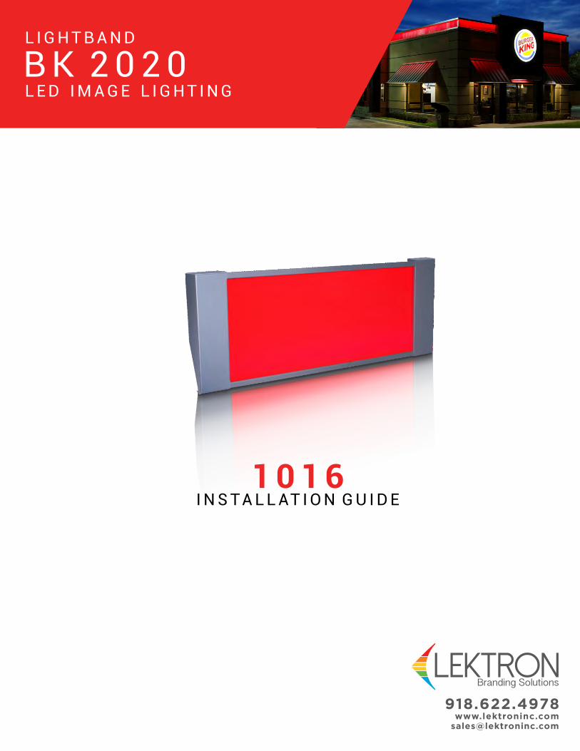
B K 2 0 2 0L E D I M A G E L I G H T I N G
L I G H T B A N D
1 0 1 6I N S TA L L AT I O N G U I D E

GETTING STARTED CONTENTS
Getting Started, Component Identification & Required Tools
1. Component Identification & Required Tools.........................
2. Proper Measuring & Placement of the Lightband.................
3. Installation of Cut Sections & Sizing the LED Band..............
4. Setting the Power Supply........................................................
5. Testing Each Section................................................................
6. Lens Installation........................................................................
7. End Cap Installation.................................................................
2
3
4
5
6
7
8
SECTION PAGE
Following these few simple steps will ensure a successfulinstallation each time. Remember: No more than 32 boards perpower supply.
1. Read ALL instructions, before starting installation.
2. Inspect the boxes for damage and check the parts against
the supplied parts list.
3. Refer to attached provided print and confirm job
measurements.
4. Layout your job on paper, making note of power supply
placement.
Power supplies can be placed at the end of runs or side by side
to power allowable linear footage in each direction.
NOTE: Report damaged parts or shortages immediately toprevent job slowdown/stoppage to 1-800-634-4059 ext. 0
NOTE: If job measurements do not correspond to provideddrawing, call Lektron Immediately at 1-800-634-4059.
Page 1
INSTALLATION SEQUENCE
12” LED boards pull close to the same voltage as shorterbreak-apart boards. Maximum of 3-3” Boards per circuit. No morethan 32 boards on a circuit. Do not connect more than one powersupply per circuit.
LED SPECIFICATIONS
Below we have identified a sequence of operations that will
guide you in the proper installation of the parapet band
system. However, always be aware of your surroundings
and site conditions that cannot be taken into consideration
when writing this guideline. It is always your responsibility
to ensure a safe and clean workplace environment.
1. Review the onsite construction plans; if they are different
from what was supplied with the parapet band system or if
you are missing any components in the system call Lektron
Branding Solutions at 1-800-634-4059 immediately.It is recommended that you start your installation with a
corner, and then work to the towers or the back of the
building. This will allow the smaller section of cut housing
to be on the end opposing corners. By doing this it will
eliminate two small sections of housing being close to one
another.
2. Install mounting brackets; reference “Installing the
Mounting Brackets” for proper installation procedures. 3. Install string line or laser level; it is recommended that
you install a string line 18” up from the top of the parapet
wall to properly align the top of the housing and corners.4. Set corners into place; reference “Installing the Inside
and Outside Corners” for proper installation procedures. 5. Set housing into place; reference “Installing the
Housings” for proper installation procedures. 6. Install remaining adjustment brackets; reference
“Installing Adjustment Brackets” for proper installation
procedures. 7. Install LED’s; reference “Installing LED’s” for proper
installation procedures.8. Install the transformers; it is critical to test the LED’s
for proper operation prior to installing the lens.9. Install the lens; reference “Installing the Lens” for
proper installation procedures.10. Install the end and corner caps; reference “Installing
the End Caps” and “Installing the Inside and Outside
Corners for proper installation procedures.11. Inspect to insure parapet band system look and
operates correctly.
7 - Y E A R W A R R A N T YInput
Output
Max. Load Footage
Watts per Foot
Dimming Capable
Bending Parameters
Limited Warranty Terms
Materials
Dimensions
Certification
120V
25 VAC
32 Lineal ft. 20L
1.50 (if 20L)
Yes
None
BK Pro Rated Warranty
Aluminum Housing
Polycarbonate Lens
Custom
cULus E174914
DETAILS...................................................................
...............................................................
...........................................
..................................................
.............................................
.........................................
..................................
............................................................
........................................................
......................................................

Page 2
S E C . 1 C O M P O N E N T I D E N T I F I C AT I O N& R E Q U I R E D T O O L S
MOUNTING SURFACES VARY
PLEASE USE PROPER SCREW WHEN MOUNTING
THE HOUSING TO THE STRUCTURE.
HEX HEAD TEK SCREW WITH NEOPRENE WASHER
IS PROVIDED AND NOT TO BE USED WITH
MATERIAL OTHER THAN METAL
• 25’ Measuring Tape• 100’ Measuring Tape• Framing Square• Square - (1’)• Portable Rechargable Drill 5/16” Hexbit and unibit Masonry bits (if brick wall)• Extension Cord• Sawzall or Compound Saw
• Carpenter Pencil• Caulk Gun• Box Knife• Wire Strippers• Wire Snips• Laser Tool or Chalk Line• Substitute Fasteners for the Application if Applicable
REQUIRED TOOLS:
2.50
.75
Red Lens
13.3815.00
16 Ga.Galvinized
Steel
16 Ga.Galvinized
Steel
.88
Die-stampedAluminumHousingPrefinished
AluminumHousingPrefinished BK Silver
185-5021MALE
PIGTAILCONNECTOR
185-5022FEMALEPIGTAIL
CONNECTOR
SEAL TIGHTCONDUIT
STRAIN RELIEF& LIQUID-TIGHT
CONNECTOR
185-0007PLTC
CABLE
185-5023BLUE
WIRE NUT
185-0017J-BOX
185-200625V LOW VOLTAGE
TRANSFORMER
#12 x 2”HEX HEAD
SCREW
#10 x 3/4”HEX HEAD
SCREW
191-5003HOUSING
COUPLING
185-7022FLAT RED POLYCARBONATE LENS
CONTINUOUS LENGTH
191-7011ALUMINUMHOUSING
8’ LENGTH
185-5045MOUNTINGBRACKET
185-5515ADJUSTMENT
BRACKET
12” 20 LAMP RED MAIN BOARD
191-11363” 5L RED BOARD
#6 x 1/2”PAN
HEADSCREW
#8 x 1/2”PAN
HEADSCREW
191-2040TRACK
CLIP
LEFTENDCAP
RIGHTENDCAP
O.S.CORNER
HOUSING
191-1025O.S. CORNER
CAP
I.S.CORNER
HOUSING
191-1026I.S. CORNER
CAP

Page 3
S E C . 2 P R O P E R M E A S U R I N G &P L A C E M E N T O F T H E L I G H T B A N D
INSTALLING THE MOUNTING BRACKET
INSTALLING THE CORNERS
INSTALLING THE CORNERS CONT.
INSTALLING ADJUSTMENT BRACKETS
2-#12 X 2”
TYPICALMOUNTING
HIGH WINDMOUNTING
48”
32”
32”
32”
48”
1. Determine if your location is typical or high wind zone. 2. Mark mounting bracket locations. Housings will share a bracket. Set bracket 1/4” from the end of the run.3. Install using a dab of caulk beneath each #12 x 2 screw penetration as shown.
NOTE: Adjustment brackets should be mounted at equal
intervals, to the mounting brackets. The purpose of the
adjustment bracket is to keep the light band vertically
straight, as well as provide stability to the light band.
TIP: APPLY ALL BOTTOM BRACKETS FIRST, ALL TOP
BRACKETS NEXT AND THEN SECURE IN THE MIDDLE.
1. Measure and mark locations for the Adjustment Brackets,
install 1/2 of the Adjustment Bracket. Use two #12 x 2” tek
screws, applied through a dot of caulk.
IMPORTANT: SCORE PROTECTIVEPLASTIC ALONG THE HOUSINGBRACKET WITH A RAZOR KNIFE,AND REMOVE FROM HOUSING.
3. Install the first 8’ aluminum fixture housing by aligning to the edge of the mounting bracket and approximately 1/4” from the end of the run. Insure that housing is plumb and level, shim if required. Fasten each with 5 #10 x 3/4” Hex Head tek screws, spaced approximately 2 in. apart, through the mounting bracket.4. Using four #10 x 3/4” tek screws, screw through housing and the fixture coupling while holding the seam together, put one screw into each fixture, joining the pieces together securely.5. Apply second bracket to the backside of the housing fixture using a dot of caulk for each screw to waterproof. Secure with two #10 x 3/4” tek screws. 6. Slide brackets until the housing is plumb. Clamp the adjustment bracket together and run two #10 x 3/4” tek screws through the assembly to hold securely.7. Repeat the process.
1. Set corner housing onto 4 mounting brackets2. Attach corner to brackets with #10 x 3/4” tek screws.
COUPLING 2 8ft SECTIONS
IMPORTANT: DO NOT SKIP ANY STEPS IN THIS SECTION. FIXTURES MAY BE LIFTED AND BLOWN OFF PRIOR TO ALL ATTACHMENTS BEING SECURELY MADE.
NOTE: BRACKETS ENLARGED TO SHOW DETAIL
Page 4Page 4
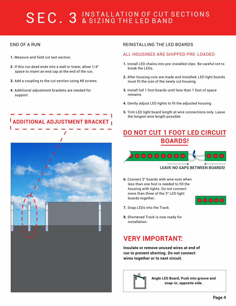
END OF A RUN
S E C . 3 I N S TA L L AT I O N O F C U T S E C T I O N S& S I Z I N G T H E L E D B A N D
1. Measure and field cut last section.
2. If this run dead ends into a wall or tower, allow 1/4”
space to insert an end cap at the end of the run.
3. Add a coupling to the cut section using #8 screws.
4. Additional adjustment brackets are needed for
support.
REINSTALLING THE LED BOARDS
ALL HOUSINGS ARE SHIPPED PRE-LOADED
6. Connect 3” boards with wire nuts when
less than one foot is needed to fill the
housing with lights. Do not connect
more than three of the 3” LED light
boards together.
7. Snap LEDs into the Track.
8. Shortened Track is now ready for
installation.
VERY IMPORTANT:Insulate or remove unused wires at end of
run to prevent shorting. Do not connect
wires together or to next circuit.
LEAVE NO GAPS BETWEEN BOARDS!
DO NOT CUT 1 FOOT LED CIRCUIT
BOARDS!
1. Install LED chains into pre-installed clips. Be careful not to
break the LEDs.
2. After housing cuts are made and installed, LED light boards
must fit the size of the newly cut housing.
3. Install full 1 foot boards until less than 1 foot of space
remains.
4. Gently adjust LED lights to fit the adjusted housing
5. Trim LED light board length at wire connections only. Leave
the longest wire length possible
Angle LED Board, Push into groove and
snap-in, opposite side.
ADDITIONAL ADJUSTMENT BRACKET

Page 5
S E C . 4 S E T T I N G T H EP O W E R S U P P LY
32 Boards or Less16 Boards or Less 16 Boards or Less
8 Boards or Less8 Boards or Less
120 VAC
120 VAC 120 VAC
120 VAC32 Boards or Less 32 Boards or Less
8 Boards or Less 8 Boards or Less
NOTE: MAXIMUM 32 BOARDS PER POWER SUPPLY. SHOWN 3 CONFIGURATIONS.
1. Attach J-Boxes with supplied screws to available support member.
2. Attach transformers inside of J-Boxes.
3. Drill 7/8” hole through the housing.
4. Install Liquid-Tight Connector for low voltage wire. Connect conduit.
5. Install low voltage wire into the conduit and connect to LED.
Side by Side mounting location shown below can reduce primary and secondary wiring labor time.
NOTE: One transformer per 32 boards maximum or less. No less than 8 boards per transformer
NOTE: Any primary voltage supply greater than 120, “STOP” call Lektron at 918-622-4978
VERY IMPORTANT: KEEP LOW VOLTAGE CIRCUITS ELECTRICALLY SEPARATE, DO NOT CONNECT TRANSFORMERSOR LEDs FROM DIFFERENT 32 BOARD CIRCUITS TOGETHER OR CONNECT MORE THAN 32 BOARDS TO A TRANSFORMER!
WIRE CONNECTIONS
NOTE: LEDs are not polarity sensitive, color coding is forconsistency on the low voltage side.
!
Black & White wires = Primaryconnection only by Electrician
A conduit fittinginstalled so that conduitcan be used.
Power Cable frompower supplyto LEDs Only
Blue and Yellow lowvoltage wires frompower supplies.Connect to lowvoltage cable(Non-Polarized)
.55 AMP PRIMARY LOADPOWER SUPPLY
DO NOT CONNECT120 VOLTS TO LEDs.LEDs are 25Vac only
SECURE ELECTRICAL BOX SCREWS PROVIDEDOR OTHER SUITABLE ANCHORS. MOUNT ASCLOSE AS POSSIBLE TO LEDs TO MINIMIZELOW VOLTAGE POWER CABLE LENGTH. INSTALLPOWER SUPPLY INSIDE ELECTRICAL BOX ANDATTACH WITH 3/4” SCREW.
25 VAC LowVoltage
25 VACPrimary
25 VAC LowVoltage
UL
Cla
ss 2
Rec
og
niz
ed 2
4V
ac
10
0va
Use
On
ly U
L A
pp
rove
dP
rovi
ded
Tra
nsf
orm
er
Siliconetop ofJ-Box
Liquid-TightConnector
TO J-BOX

Page 6
S E C . 5 T E S T I N GE A C H S E C T I O N
IMPORTANT: DO NOT SKIP THIS STEP! ALWAYS CHECK ALL LEDLIGHTS BEFORE CONTINUING.
REMEMBER: BLACK AND WHITE WIRES ARE FOR 120V POWER INBLUE AND RED ARE FOR LOW-VOLTAGE POWER OUT.
DO NOT APPLY 120V TO THE BLUE OR RED WIRES OR DIRECTLYTO THE LED LIGHT BOARDS
1. Using the installed power supplies, supply power to the
LED light chains by connecting a temporary 120V
connection to the black and white wires on the power
supply to power the LED lights.
2. Check to see if all LEDs are lit and working correcting.
3. If a board or section does not light up, is damaged, etc.,
disconnect power and check connections or replace a
board by splicing in another.
TESTING EACH SECTION

Page 7
S E C . 6 L E N SI N S TA L L AT I O N
LENS SIZING, CUTTING, AND INSTALLATION
The lens has a high expansion and contraction rate and therefore must be trimmed from the overall dimension in accordance with the lens trim guide.
There is also a UV protection applied to one side of the lens, make sure that the UV protected side is facing out when installed.
1. First measure each section of housing from end to end, corner to corner, etc. this will determine your overall length of lens for each section.
2. Check outside temperature, reference the “Lens Trim Guide” to the right to determine the amount of lens that needs to be subtracted from the overall length.
NOTE: The length of lens that will be deducted from your overall length is critical in order to accommodate the expansion and contraction of the lens in varying temperatures.
3. After determining the Trim Length, subtract that from your overall length for that section.
Example: 45’ section will require a trim length of 1 3/4”, leaving you with an overall cut length of 44’ 10 1/4”.
4. Using the example above, cut your lens to 44’ 10 1/4” long using a sawzall or jig saw.
Use caution when cutting your lens as the vibration caused by cutting can scratch the lens if not properly secured.
5. Once ready to install the lens, remove the protective film from both sides and slide the lens into the bottom portion of the housing. See Figure 1.
NOTE: This may take 2 or more people depending on the length of the lens.
FIGURE 2FIGURE 1
Temp(F) 10’ 20’ 30’ 40’ 50’
0
5
10
15
20
25
30
35
40
45
50
55
60
65
70
75
80
85
90
95
100
105
110
115
120
125
130
135
140
11/16
11/16
5/8
5/8
5/8
5/8
5/8
1/2
1/2
1/2
1/2
3/8
3/8
3/8
3/8
5/16
5/16
5/16
5/16
5/16
3/16
3/16
3/16
3/16
1/8
1/8
1/8
1/8
0.00
1 5/16
1 1/4
1 3/16
1 1/8
1 1/16
1 1/16
1
1
1
7/8
13/16
3/4
3/4
11/16
5/8
9/16
9/16
1/2
1/2
7/16
3/8
5/16
1/4
1/4
3/16
3/16
1/8
1/8
0.00
1 15/16
1 7/8
1 3/4
1 11/16
1 5/8
1 9/16
1 1/2
1 7/16
1 3/8
1 5/16
1 1/4
1 3/16
1 3/16
1
1
7/8
13/16
3/4
11/16
5/8
9/16
1/2
3/8
5/16
1/4
3/16
3/16
1/8
0.00
2 9/16
2 1/2
2 3/8
2 1/4
2 3/16
2 1/8
2
1 7/8
1 13/16
1 3/4
1 5/8
1 9/16
1 7/16
1 3/8
1 1/4
1 3/16
1 1/8
1
7/8
13/16
3/4
5/8
9/16
1/2
3/8
1/4
3/16
1/8
0.00
3 3/16
3 1/8
3
2 7/8
2 3/4
2 5/8
2 1/2
2 3/8
2 1/4
2 3/16
2 1/16
1 15/16
1 13/16
1 11/16
1 9/16
1 1/2
1 3/8
1 1/4
1 1/8
1
7/8
13/16
11/16
9/16
7/16
3/8
1/4
3/16
0.00
LENS TRIM GUIDE
Polycarbonate Lens Trim Length (Inches)
for a Given Temperature and Length

Page 8
S E C . 7 E N D C A PI N S TA L L AT I O N
SILVER END CAP INSTALLATION RED CORNER CAP INSTALLATION
1. Fasten the silver end cap to the top of the
housing using (2) #8 x 1/2” silver self-tapping
screws.
2. Fasten the bottom of the end cap to the back
of the housing using (2) #8 x 1/2” silver
self-tapping screws.
3. Slide the upper portion of the red corner cap
into the housing and secure between the lens
and the lens flashing.
1. Place top edge of end cap inside housing lip.
2. Attach bottom trim to hold in place.
NOTE: Do not install the
corner or end caps until
the LEDs and Lens have
been installed and tested.
ISO. VIEW - OUTSIDE CORNER & OUTSIDE CORNER CAP
ISO. VIEW -INSIDE CORNER &INSIDE CORNER CAP
NOTE: Trim is on the outside of the lens
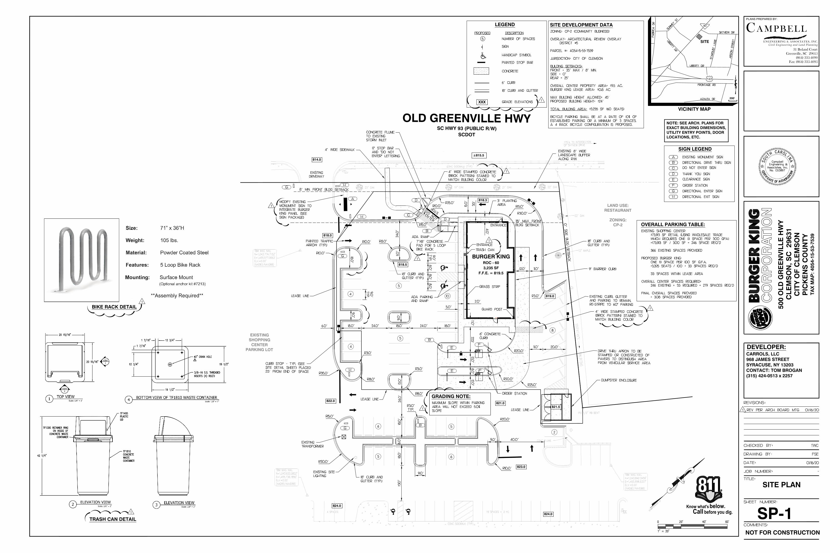
BURGER KINGROC - 603,235 SF
F.F.E. = 819.5
OLD GREENVILLE HWYSC HWY 93 (PUBLIC R/W)
SCDOT
LAND USE:RESTAURANT
ZONING:CP-2
EXISTINGSHOPPINGCENTER
PARKING LOT
814.0
818.0
822.0
823.0
824.0
824.0
819.0
818.5
818.3
821.0821.5
±815.5
PLANS PREPARED BY:
CENGINEERING & ASSOCIATES, INC.
A M PB EL L
31 Boland Court
Greenville, SC 29615
(864) 335-4090
Fax: (864) 335-4095
Civil Engineer ing and Land Planning
500
OLD
GR
EE
NV
ILLE
HW
YC
LEM
SO
N, S
C 2
9631
CIT
Y O
F C
LEM
SO
NP
ICK
EN
S C
OU
NTY
TAX
MA
P: 4
054-
15-5
3-75
39
DEVELOPER:CARROLS, LLC968 JAMES STREETSYRACUSE, NY 13203CONTACT: TOM BROGAN(315) 424-0513 x 2257
SITE DEVELOPMENT DATALEGEND
NOTE: SEE ARCH. PLANS FOREXACT BUILDING DIMENSIONS,UTILITY ENTRY POINTS, DOORLOCATIONS, ETC.
SC GRID(NAD83)
Know what's below.before you dig.Call
R
SP-1
SITE PLAN
SIGN LEGEND
VICINITY MAP
OVERALL PARKING TABLE:
NOT FOR CONSTRUCTION
SITE
200'
GRADING NOTE:
TRASH CAN DETAIL
BIKE RACK DETAIL
XXX
AutoCAD SHX Text
CONC SIDEWALK (TYP)
AutoCAD SHX Text
CONC SIDEWALK (TYP)
AutoCAD SHX Text
19 SPACES + 2 HC
AutoCAD SHX Text
4 SPACES
AutoCAD SHX Text
175'± TO INTERSECTIONOF SKYVIEW DRIVE
AutoCAD SHX Text
CONC FLUME
AutoCAD SHX Text
STOP
AutoCAD SHX Text
DO NOT ENTER
AutoCAD SHX Text
9" BARRIER CURB
AutoCAD SHX Text
PAINTED TRAFFIC ARROW (TYP.)
AutoCAD SHX Text
12" STOP BAR AND "DO NOT ENTER" LETTERING
AutoCAD SHX Text
4' WIDE SIDEWALK
AutoCAD SHX Text
ADA PARKING AND RAMP
AutoCAD SHX Text
DUMPSTER ENCLOSURE
AutoCAD SHX Text
GUARD POST
AutoCAD SHX Text
ORDER STATION
AutoCAD SHX Text
18" CURB AND GUTTER (TYP.)
AutoCAD SHX Text
DRIVE THRU APRON TO BE STAMPED OR CONSTRUCTED OF PAVERS TO DISTINGUISH AREA FROM VEHICULAR SERVICE AREA
AutoCAD SHX Text
10
AutoCAD SHX Text
35' MAX. FRONT BLDG SETBACK
AutoCAD SHX Text
0' SIDE BLDG SETBACK
AutoCAD SHX Text
8' MIN. FRONT BLDG SETBACK
AutoCAD SHX Text
7'X8' CONCRETE PAD FOR 5 LOOP BIKE RACK
AutoCAD SHX Text
TRASH CAN
AutoCAD SHX Text
5
AutoCAD SHX Text
18" CURB AND GUTTER (TYP.)
AutoCAD SHX Text
CURB STOP - TYP. (SEE SITE DETAIL SHEET) PLACED 2.5' FROM END OF SPACE
AutoCAD SHX Text
EXISTING 8' WIDE LANDSCAPE BUFFER ALONG R/W
AutoCAD SHX Text
6
AutoCAD SHX Text
GRASS STRIP
AutoCAD SHX Text
6" CONCRETE CURB
AutoCAD SHX Text
ADA RAMP
AutoCAD SHX Text
4
AutoCAD SHX Text
6
AutoCAD SHX Text
5
AutoCAD SHX Text
EXISTING TRANSFORMER
AutoCAD SHX Text
3' PLANTING AREA
AutoCAD SHX Text
5
AutoCAD SHX Text
CONCRETE FLUME TO EXISTING STORM INLET
AutoCAD SHX Text
MODIFY EXISTING MONUMENT SIGN TO INTEGRATE BURGER KING PANEL (SEE SIGN PACKAGE)
AutoCAD SHX Text
EXISTING CURB, GUTTER AND PARKING TO REMAIN, RE-STRIPE TO 60° PARKING
AutoCAD SHX Text
8
AutoCAD SHX Text
2
AutoCAD SHX Text
ENTRANCE
AutoCAD SHX Text
ENTRANCE
AutoCAD SHX Text
A
AutoCAD SHX Text
D
AutoCAD SHX Text
B
AutoCAD SHX Text
C
AutoCAD SHX Text
D
AutoCAD SHX Text
E
AutoCAD SHX Text
E
AutoCAD SHX Text
F
AutoCAD SHX Text
F
AutoCAD SHX Text
G
AutoCAD SHX Text
G
AutoCAD SHX Text
G
AutoCAD SHX Text
H
AutoCAD SHX Text
H
AutoCAD SHX Text
H
AutoCAD SHX Text
13.0'
AutoCAD SHX Text
11.0'
AutoCAD SHX Text
24.0'
AutoCAD SHX Text
9.0'
AutoCAD SHX Text
LEASE LINE
AutoCAD SHX Text
5
AutoCAD SHX Text
LEASE LINE
AutoCAD SHX Text
LEASE LINE
AutoCAD SHX Text
B
AutoCAD SHX Text
B
AutoCAD SHX Text
18" CURB AND GUTTER (TYP.)
AutoCAD SHX Text
EXISTING DRIVEWAY
AutoCAD SHX Text
4
AutoCAD SHX Text
EXISTING SITE LIGHTING
AutoCAD SHX Text
4' WIDE STAMPED CONCRETE (BRICK PATTERN) STAINED TO MATCH BUILDING COLOR
AutoCAD SHX Text
4' WIDE STAMPED CONCRETE (BRICK PATTERN) STAINED TO MATCH BUILDING COLOR
AutoCAD SHX Text
TWC
AutoCAD SHX Text
FSE
AutoCAD SHX Text
01/16/20
AutoCAD SHX Text
-
AutoCAD SHX Text
REVISIONS:
AutoCAD SHX Text
DRAWING BY:
AutoCAD SHX Text
JOB NUMBER:
AutoCAD SHX Text
DATE:
AutoCAD SHX Text
TITLE:
AutoCAD SHX Text
COMMENTS:
AutoCAD SHX Text
SHEET NUMBER:
AutoCAD SHX Text
CHECKED BY:
AutoCAD SHX Text
S
AutoCAD SHX Text
O
AutoCAD SHX Text
U
AutoCAD SHX Text
T
AutoCAD SHX Text
H
AutoCAD SHX Text
C
AutoCAD SHX Text
A
AutoCAD SHX Text
R
AutoCAD SHX Text
O
AutoCAD SHX Text
L
AutoCAD SHX Text
I
AutoCAD SHX Text
N
AutoCAD SHX Text
A
AutoCAD SHX Text
A
AutoCAD SHX Text
T
AutoCAD SHX Text
U
AutoCAD SHX Text
F
AutoCAD SHX Text
E
AutoCAD SHX Text
A
AutoCAD SHX Text
C
AutoCAD SHX Text
T
AutoCAD SHX Text
O
AutoCAD SHX Text
I
AutoCAD SHX Text
F
AutoCAD SHX Text
I
AutoCAD SHX Text
R
AutoCAD SHX Text
T
AutoCAD SHX Text
C
AutoCAD SHX Text
E
AutoCAD SHX Text
H
AutoCAD SHX Text
Associates, Inc.
AutoCAD SHX Text
Engineering &
AutoCAD SHX Text
O
AutoCAD SHX Text
R
AutoCAD SHX Text
I
AutoCAD SHX Text
Z
AutoCAD SHX Text
A
AutoCAD SHX Text
T
AutoCAD SHX Text
I
AutoCAD SHX Text
O
AutoCAD SHX Text
N
AutoCAD SHX Text
Campbell
AutoCAD SHX Text
No. C03897
AutoCAD SHX Text
CONCRETE
AutoCAD SHX Text
%%UPROPOSED
AutoCAD SHX Text
5
AutoCAD SHX Text
%%UDESCRIPTION
AutoCAD SHX Text
HANDICAP SYMBOL
AutoCAD SHX Text
PAINTED STOP BAR
AutoCAD SHX Text
NUMBER OF SPACES
AutoCAD SHX Text
SIGN
AutoCAD SHX Text
6' CURB
AutoCAD SHX Text
18" CURB AND GUTTER
AutoCAD SHX Text
ZONING: CP-2 (C0MMUNITY BUSINESS) OVERLAY: ARCHITECTURAL REVIEW OVERLAY DISTRICT #5 PARCEL #: 4054-15-53-7539 JURISDICTION: CITY OF CLEMSON BUILDING SETBACKS: FRONT = 35' MAX / 8' MIN. SIDE = 0' REAR = 25' OVERALL CENTER PROPERTY AREA: ±9.5 AC.BURGER KING LEASE AREA: ±0.8 AC.MAX BUILDING HEIGHT ALLOWED: 45' PROPOSED BUILDING HEIGHT: ±24'TOTAL BUILDING AREA: 3,235 SF (60 SEATS) ±3,235 SF (60 SEATS)BICYCLE PARKING SHALL BE AT A RATE OF 10% OF ESTABLISHED PARKING OR A MINIMUM OF 3 SPACES. A 4 RACK BICYCLE CONFIGURATION IS PROPOSED.
AutoCAD SHX Text
0
AutoCAD SHX Text
20'
AutoCAD SHX Text
40'
AutoCAD SHX Text
60'
AutoCAD SHX Text
1" = 20'
AutoCAD SHX Text
A
AutoCAD SHX Text
EXISTING MONUMENT SIGN
AutoCAD SHX Text
B
AutoCAD SHX Text
DIRECTIONAL DRIVE THRU SIGN
AutoCAD SHX Text
C
AutoCAD SHX Text
D
AutoCAD SHX Text
THANK YOU SIGN
AutoCAD SHX Text
DO NOT ENTER SIGN
AutoCAD SHX Text
E
AutoCAD SHX Text
F
AutoCAD SHX Text
ORDER STATION
AutoCAD SHX Text
CLEARANCE SIGN
AutoCAD SHX Text
G
AutoCAD SHX Text
DIRECTIONAL ENTER SIGN
AutoCAD SHX Text
H
AutoCAD SHX Text
DIRECTIONAL EXIT SIGN
AutoCAD SHX Text
EXISTING SHOPPING CENTER: ±73,913 SF RETAIL (USING WHOLESALE TRADE WHICH REQUIRES ONE (1) SPACE PER 300 GFA) =±73,913 SF / 300 SF = 246 SPACE REQ'D366 EXISTING SPACES PROVIDED PROPOSED BURGER KING: ONE (1) SPACE PER 100 SF G.F.A. =3,325 SEATS / 100 = 33 SPACES REQ'D 33 SPACES WITHIN LEASE AREA OVERALL CENTER SPACES REQUIRED: 246 EXISTING + 33 REQUIRED = 279 SPACES REQ'D FINAL OVERALL SPACES PROVIDED = 308 SPACES PROVIDED
AutoCAD SHX Text
123
AutoCAD SHX Text
93
AutoCAD SHX Text
LIBERTY DR
AutoCAD SHX Text
STARDUST LANE
AutoCAD SHX Text
ARGON STREET
AutoCAD SHX Text
SKYVIEW DR
AutoCAD SHX Text
SUMMEY ST
AutoCAD SHX Text
FABRICA DR
AutoCAD SHX Text
LIBERTY DR
AutoCAD SHX Text
FRONTAGE RD
AutoCAD SHX Text
AZALEA DR
AutoCAD SHX Text
MAXIMUM SLOPE WITHIN PARKING AREA WILL NOT EXCEED 5.0% SLOPE
AutoCAD SHX Text
GRADE ELEVATIONS
AutoCAD SHX Text
01/16/20
AutoCAD SHX Text
1
AutoCAD SHX Text
REV PER ARCH BOARD MTG
AutoCAD SHX Text
1
AutoCAD SHX Text
1
AutoCAD SHX Text
1
AutoCAD SHX Text
1
AutoCAD SHX Text
1
AutoCAD SHX Text
1
AutoCAD SHX Text
1
AutoCAD SHX Text
1
AutoCAD SHX Text
1

GENERAL NOTES & SPECIFICATIONS
LAWN INSTALLATION: Lawn areas shall be fine graded to a smooth, positively draining
slope, removing all stones over 3/4" . Agricultural limestone shall be incorporated
into the soil at a rate of 50 pounds per 1000 square feet. Apply specified seed at
recommended rate. Straw mulch or hydromulch shall be used as deemed necessary by the
Landscape Contractor and Landscape Architect. The Landscape Contractor shall be
responsible to establish a full stand of grass and will repair any bare spots 1'- 0" square
due to uneven seed distribution, drought or erosion.
the Landscape Architect.
QUANTITIES Plant quantities are shown for the contractor's convenience only.
PLANTS SHALL BE INSTALLED AS SHOWN. Contractor is responsible for confirming
service and is responsible for any damage done to utilities.
UTILITY LOCATION: The Landscape Contractor is responsible for contacting the utility locator
SOD INSTALLATION: Sodded lawn areas shall be fine graded to a smooth, positively draining
slope, removing all stones over 3/4" . Sod shall be healthy, thick sod placed so that joints
are butt tight. Staple as necessary. Sod shall be trimmed to match bed lines shown on plan.
Startup fertilizer shall be incorporated into the soil at the manufacturer's recommended rate.
Any area of sod that fails to root, settles or dies will be replace by the Landscape Contractor.
for Nursery Stock" (published by the American Association of Nurserymen).
Please contact the Landscape Architect if there is difficulty in locating a
particular plant. If necessary, a substitute plant will be recommended by
or insects. General plant quality shall be as specified in the "USA Standard
growth as is characteristic of that species, and shall be free of disease
PLANT QUALITY All plants shall be nursery grown, have a full habit of
BIDS In order to keep all bids standard, all bids are to have unit prices listed.
The Owner has the option to delete any portion of the contract prior to signing the contract
or beginning work. This will be a unit price contract.
all quantities prior to bidding and installation.
might arise during installation.
the work.
natural compaction, pinestraw should have a depth of 2".
the responsibility of the landscape contractor.
is to follow the above listed guidelines.
not providing evidence of such insurance will be ineligible to recieve the contract for the job
certificate of insurance for workman's compensation and a contractor's general liability. Contractors
INSURANCE With the submittal of bid documents, the landscape contractor shall also submit a
CLEAN UP Final clean up of any disturbances occurring as a result of landscape operations shall be
BACKFILL Landscape contractor to verify any additional backfill/topsoil needed prior to beginning
work. A unit price for topsoil shall be included in all bid documents to allow for circumstances that
All trees located in lawn areas shall receive a 3' diameter ring of mulch. Mulch in these areas
will not be accepted and shall be replaced at the contractor's own expense.
LICENSES The contractor will be responsible for obtaining all licenses necessary to complete
freezing rains, or winds over 60 miles per hour, fire, vandalism or theft.
contractors control which result from natural causes such as floods, lightning, storms,
abuse or damage by others, or unusual phenomena or incidents beyond the landscape
The contractor will not be responsible for defects resulting from neglect by the Owner,
the date of acceptance by the Owner. Plant replacement to occur only once.
GUARANTEE All plant material and workmanship to be guaranteed for one year from
for any additional grading (if needed) shall be determined prior to bidding.
GRADING All final grading shall be the responsibility of the landscape contractor. The responsibility
All plant material will be inspected. Plants not conforming precisely to the plant list
of the plant material by the Landscape Architect prior to installation.
INSPECTION It shall be the contractor's responsibility to provide for inspection
and may stake other trees (for his own protection) at his option. Landscape Contractor will be
TRANSPLANTS All plant material to be transplanted shall be transplanted according to guidelines
hardwood bark mulch (free of wood chips or large chunks of bark). Fresh hardwood bark mulch
MULCHING As specified on planting list. Hardwood mulch: All beds to receive a 3" layer of aged
set by AAN standards. Transplanted material will not be guaranteed by the landscape contractor.
for all wind damage to trees, (provided winds are less than 60 mph) during the guarantee period,
of the Landscape Contractor or Landscape Architect. The Landscape Contractor is responsible
high winds or steep slopes. Under certain circumstances, others may be staked at the discretion
STAKING OF TREES Trees should only be staked if necessary, such as when planted in areas of
contractor. Pinestraw: All beds to receive a 4" layer (prior to compaction) of pinestraw. After
All damages incurred by the use of fresh hardwood mulch shall be the responsibility of the landscape
is not recommended to be used, as water run-off may cause staining on adjacent concrete surfaces.
is 1/2 original soil and 1/2 plant mix.
screened, pine bark mulch, or equal.
16-4-8 ( 50% of nitrogen slow release) per 1000 square feet.
inch of caliper. Ground cover beds shall be fertilized at the rate of 20 pounds of
Trees shall receive 1/4 cup of 16-4-8 fertilizer (50% of nitrogen slow release) per
fertilizer (50% of nitrogen slow release) evenly broadcast at the base of the plants.
FERTILIZING Upon completion of plantings, all shrubs shall receive 1/6 cup of 16-4-8
Finish filling hole with loose amended backfill and gently tamp again. Water shrub bed to settle soil.
shrubs with amended backfill (see ORGANIC AMENDMENTS). Tamp lightly and water to settle soil
with loose soil and gently tamp again. SHRUB BEDS - Backfill bottom half of bed surrounding
necessary for good soil tilth, (See ORGANIC AMENDMENTS). Tamp lightly. Finish filling the hole
bottom half of space around the rootball with loosened original soil (use amended soil only when
will be even with or slightly above the adjacent soil line. SINGLE PLANTING HOLE - backfill
in several places prior to planting. Plant shrubs and trees so that the top of the root ball
SETTING OF PLANTS The root ball of container grown plants shall be scarified
Dig holes two to three times as wide as the rootball and only as dep as the height of the
PREPARATION OF GROUND COVER AND SEASONAL COLOR BEDS : The existing soil in
ground cover and seasonal color beds shall be thoroughly cultivated 6 inches deep,
screened shredded topsoil, 20% sand, and 20% well rotted sawdust or peat shall then
to a fine texture ( no clods over 1/2") with a mechanical tiller. A plant mix of 60%
PLANTINGS NOT DONE IN THIS MANNER SHALL BE REMOVED AND PROPERLY REPLANTED.
be thoroughly incorporated into the existing soil with the tiller so that the soil mix (6" deep)
All groundcover and seasonal color beds shall receive a 2" layer of fine textured,
PLANTING HOLES Trees and shrubs: Remove rock and construction debris from planting area.
root ball. Soil at the bottom ot the hole is left undisturbed. See planting detail
additional information.
when deemed necessary to improve soil tilth of single planting holes. Organic matter should comprise
ORGANIC AMENDMENTS Organic amendments should be added to backfill for all shrub beds and
approximately 10 to 20 percent of this total soil volume.
responsible for removal of all staking material one year after installation.
BOTANICAL NAMEBOTANICAL NAMEBOTANICAL NAMEBOTANICAL NAMECOMMON NAME COMMON NAME
ULMUS PARVIFOLIA 'UPMTF'2" CALIPER
BE
BOSQUE ELM
PLANT LIST
5
MINIMUM SIZE AT TIME OF PLANTING
1. PLANT MATERIAL / SOD / MULCH SHALL BE VERIFIED BY THE LANDSCAPE CONTRACTOR PRIOR TO
BIDDING. ANY DISCREPANCIES SHALL BE REPORTED TO THE LANDSCAPE ARCHITECT
IMMEDIATELY. LANDSCAPE ARCHITECT ASSUMES NO LIABILITY FOR QUANTITY DISCREPANCIES.
2. CONTRACTOR TO VERIFY THAT ALL PLANT MATERIALS ARE AVAILABLE, AS SPECIFIED, WHEN
PROPOSAL IS SUBMITTED.
3. NO PLANT MATERIAL SUBSTITUTIONS WILL BE ACCEPTED WITHOUT WRITTEN APPROVAL BY THE
LANDSCAPE ARCHITECT PRIOR TO INSTALLATION.
4. LANDSCAPE ARCHITECT OR OWNER SHALL HAVE THE RIGHT, AT ANY STAGE OF THE
CONSTRUCTION OPERATION, TO REJECT ANY AND ALL WORK WHICH, IN HIS OPINION, DO NOT
MEET THE REQUIREMENTS OF THESE PLANS OR SPECIFICATIONS.
KEY QUANTITY
NOTES:
CLEYERA JAPONICA
CLJ
CLEYERA
3 GALLON
5
ILEX CRENATA 'GREEN LUSTRE'
GLH
GREEN LUSTRE HOLLY
3 GALLON
87
JUNIPERUS CHINENSIS 'SEA GREEN'
SGJ
SEA GREEN JUNIPER
3 GALLON
19
ACER RUBRUM BUERGERANUM
TM
TRIDENT MAPLE
2" CALIPER
2
ARCHITECTURAL REVIEW OVERLAY DISTRICT #5 STANDARDS
d. Landscaping
2. Existing trees over 8" DBH retained
1 - 12" Maple
1 - 19" Oak
1 - 21" Oak
2 - 22" Oaks
1 - 23" Oak
EXISTING 23" OAK
TO REMAIN
EXISTING 19" OAK
TO REMAIN
EXISTING 21" OAK
TO REMAIN
EXISTING 22" OAK
TO REMAIN
5. Upperstory trees planted along property line abutting Old Greenville Highway
at a ratio of one tree for every 30 linear feet in a minimum 8' wide planting strip.
161.23 lf / 30 = 5 trees required
Provided: 2 new trees / 3 existing trees
WO-1
1. SITE STANDARDS
CITY OF CLEMSON ZONING ORDINANCE
SECTION 19-905. BUFFERYARD, SCREENING AND LANDSCAPING SPECIFICATIONS
G. Vehicular use area
1. At least 10% of the total interior square footage of all vehicular use area shall be
dedicated to landscaping
21,700 square feet x 10% = 2,170
H. Landscape requirements of vehicular use area
1. Sufficient upper story trees within and around vehicular use area to ensure any
portion is within 40 ft of a planted, or retained tree trunk
4. Shrubs within a landscape buffer abutting a street right-of-way or within a perimeter
of the vehicle use area shall be arranged to form a continuous row
GLH-16
(SHRUBS SPACED 4' O.C.)
CGD-9
VL-148
DYH-7
BE-1
BE-1
WO-1
DBH-5
QUERCUS PHELLOS
WO
WILLOW OAK
2" CALIPER
6
PICEA ABIES 'NIDIFORMIS'
BNS
BIRD'S NEST SPRUCE
3 GALLON
23
ILEX CRENATA 'SOFT TOUCH'
STH
SOFT TOUCH HOLLY
3 GALLON
28
PLANTINGS NOT DONE IN THIS MANNER SHALL BE REMOVED AND PROPERLY REPLANTED.
SOD
SOD
SOD
LIRIOPE MUSCARII 'VARIEGATA'
VL
VARIEGATED LIROPE
4' POT
373
MULCHHARDWOOD
SODBERMUDA
LEASE LINE
LEASE LINE
LEASE LINE
SOD
2,385 square feet provided
BURGER KIN
G
OLD G
REENVILLE
HW
Y
SC HW
Y 93
(PUBLI
C R/W
)
SCDOT
VL-90
STH-3
GLH-48
(SHRUBS SPACED 4' 0.C.)
EXISTING 22" OAK
TO REMAIN
EXISTING 12" MAPLE
TO REMAIN
DYH-7
CLJ-5
STH-3
STH-5
BNS-5
GLH-23
(SHRUBS SPACED AT 4' O.C.)
SOD
BNS-18
DETAIL: TREE PROTECTION BARRIER
TREE CANOPY (DRIPLINE)
UNDISTURBED AREA
METAL "T" FENCE POST
ORANGE SAFETY FENCE
4' Ht.
10 GAUGE METAL WIRE ATTACHED
TO POST RUN CONTINUOUS
INSTALL FENCE AT DRIP-LINE
OF TREE
INSTALL POST AT 10' O.C.
INSTALL 10 GAUGE METAL WIRE ALONG
TOP OF POST. ATTACH SAFETY FENCE
TO METAL WIRE.
DETAIL: ELEVATION-TREE PROTECTION BARRIER
WO-1
SOD
WO-1
VL-20
STH-11
CGD-13
LOR-11
DISTYLIUM 'PIIDIST-V' pp27,631
CGD
CINNAMON GIRL DISTYLIUM
3 GALLON
19
LOROPETALUM CHINENSE 'RUBY'
LOR
RUBY LOROPETALUM
3 GALLON
11
BE-1
BE-1
EXISTING
MAPLE
STH-5
REMOVE TWINE, ROPE, WIRE AND BURLAP FROM
TOP HALF OF ROOTBALL. REMOVE ALL TREE STRAPS.
DIAMETER OF THE HOLE SHALL BE
TRIPLE THE DIAMETER OF ROOT BALL
SIDES SHOULD GRADUALLY SLOPE
SIT ROOTBALL ON 6" MOUND OF UNDISTURBED SOIL
TO PREVENT SETTLING
4" HIGH EARTH SAUCER BEYOND EDGE OF ROOTBALL
EACH TREE MUST BE PLANTED SUCH THAT THE ROOT FLARE
IS VISIBLE AT THE TOP OF THE ROOTBALL. TREES WHERE
THE ROOT FLARE IS NOT VISIBLE SHALL BE REJECTED.
DO NOT COVER THE TOP OF THE ROOTBALL WITH SOIL.
AMENDED BACKFILL MIXTURE OF
1/3 ORGANIC MATTER AND
2/3 SOIL FROM SITE
3" MIN MULCH RING. DO NOT PLACE MULCH IN CONTACT WITH
TREE TRUNK. KEEP MULCH 4" AWAY FROM TRUNK BASE
6"
CROSS SECTION
AREA TWICE THE WIDTH OF ROOT BALL
TREE MUST MEET OR EXCEED ANSI Z60.1
(AMERICAN STANDARD FOR NURSERY STOCK
SET TOP OF ROOT BALL 3"
ABOVE ADJACENT FINISH GRADE
DO NOT HEAVILY PRUNE THE TREE
AT PLANTING. PRUNE ONLY
CROSSOVER LIMBS, CO-DOMINANT
LEADERS, AND BROKEN OR DEAD
BRANCHES. SOME INTERIOR TWIGS
AND LATERAL RANCHES MAY BE
PRUNED; HOWEVER, DO NOT
REMOVE THE TERMINAL BUDS OF
BRANCHES THAT EXTEND TO THE
EDGE OF THE CROWN.
MULCH RING 2FT BEYOND TREE PIT
TREE STRAPPING TO BE A FLEXIBLE
MATERIAL SUCH AS RUBBER OR NYLON.
TIGHTEN ONLY ENOUGH TO KEEP FROM SLIPPING.
ALLOW FOR TRUNK MOVEMENT.
30" LONG WOOD STAKE
OPTIONAL METAL DRIVE ANCHORS,
INSTALLED PER MANUFACTURES DIRECTIONS
SECTION: TREE PLANTING DETAIL
MULCH AND WATER ENTIRE BED
DIAMETER OF HOLE SHALL
BE TWICE THE DIAMETER
OF THE ROOT BALL.
TOP OF BALL 1"-2" ABOVE GRADE
REMOVE PAPER, PLASTIC, OR METAL
CONTAINER THAT MAY BE AROUND ROOTS
BALLS GREATER THAN 2' IN DIAMETER
SHALL SIT ON MOUND OF UNDISTURBED
SOIL TO PREVENT SETTLING. BALLS
SMALLER THAN 2' MAY SIT ON
COMPACTED SOIL MIXTURE.
SECTION: SHRUB PLANTING DETAIL
N.T.S.
AMENDED BACKFILL MIXTURE OF
1/3 ORGANIC MATTER AND
2/3 SOIL FROM SITE
AREA DOUBLE THE WIDTH OF ROOT BALL
SHAPE OF SHRUB IN THIS DRAWING
NOT TYPICAL FOR ALL VARIETIES
N.T.S.
N.T.S.
BURGER KIN
G
1" = 20' - 0"
0 2020 10
EXISTING
TRANSFORMER
WO-1
SOD
BE-1
EXISTING
LIGHT POLE
SOD
TM-2
SGJ-24
(SHRUBS SPACED
4' O.C.)
WO-1
NOTE: CUTTING ANY OF THE TREE'S ROOT SYSTEM
ORIGINAL GRADE (UNDISTURBED)
TREE CANOPY
DRIP-LINEDRIP-LINE
TREE CANOPY
DURING CONSTRUCTION IS HIGHLY DISCOURAGED.
WHEN THIS IS UNAVOIDABLE, HOWEVER, FLUSH
CUTS SHOULD BE MADE.
IRRIGATION Adequate irrigation to support the required plant material shall be required.
SOD
SOD
SOD
VL-41
ILEX VOMITORIA 'STOKE'S DWARF'DWARF YAUPON HOLLY
3 GALLON
14DYH
VL-80
VL-35
ILEX CORNUTA 'BURFORDII NANA'
DBH
DWARF BURFORD HOLLY
3 GALLON
5
100 West Washington StreetSuite 400
Greenville, SC 29601(864) 370-3635
McLeodLandscape Architects, LLC
S:\B
UR
GE
R K
IN
G\C
LE
MS
ON
\F
ILE
S IN
\01-17-20 from
G
eorgia\for plotting.dw
g | Layout: L1.0
Jan 17, 2020 at 8:02 by fegli
SEALS
REVISIONS
DRAWN
DESIGN
CHECKED
DATE
SCALE
JOB NO.
SHEET
THIS DOCUMENT IS PROPERTY OF
McLEOD LANDSCAPE ARCHITECTS, LLC.
THE UNAUTHORIZED USE, REPRODUCTION,
OR COPYING OF THIS DOCUMENT IS
STRICTLY PROHIBITED AND IS TO BE
RETURNED UPON REQUEST.
Bu
rg
er K
in
g R
estau
ran
t
Lan
dscap
e S
ub
mittal
SC
H
ig
hw
ay 93
Clem
so
n, S
ou
th
C
aro
lin
a
GMA
GMA
Dec 2019
1"=20'-0"
20002
L1.0
1.
01/16/20
REV PER ARCH BOARD MTG
AutoCAD SHX Text
CONC SIDEWALK (TYP)
AutoCAD SHX Text
ACCESS
AutoCAD SHX Text
STOP
AutoCAD SHX Text
DO NOT ENTER
AutoCAD SHX Text
MAGNETIC
AutoCAD SHX Text
1
AutoCAD SHX Text
1
AutoCAD SHX Text
1
AutoCAD SHX Text
1
AutoCAD SHX Text
1
AutoCAD SHX Text
1
AutoCAD SHX Text
1
AutoCAD SHX Text
1
AutoCAD SHX Text
1
AutoCAD SHX Text
1
AutoCAD SHX Text
1
Catalog # : Project :
Date :Prepared By :
LSI Industries Inc. 10000 Alliance Rd. Cincinnati, OH 45242 • www.lsi-industries.com • (513) 372-3200 • ©LSI Industries Inc. All Rights Reserved. 11/19/19
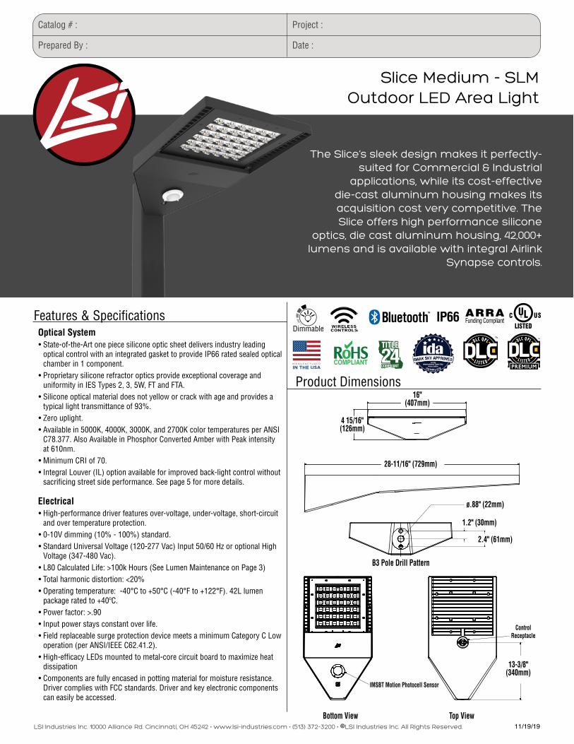
ARRAFunding CompliantFeatures & Specifications
Optical System• State-of-the-Art one piece silicone optic sheet delivers industry leading
optical control with an integrated gasket to provide IP66 rated sealed optical chamber in 1 component.
• Proprietary silicone refractor optics provide exceptional coverage and uniformity in IES Types 2, 3, 5W, FT and FTA.
• Silicone optical material does not yellow or crack with age and provides a typical light transmittance of 93%.
• Zero uplight.• Available in 5000K, 4000K, 3000K, and 2700K color temperatures per ANSI
C78.377. Also Available in Phosphor Converted Amber with Peak intensity at 610nm.
• Minimum CRI of 70. • Integral Louver (IL) option available for improved back-light control without
sacrificing street side performance. See page 5 for more details.
Electrical • High-performance driver features over-voltage, under-voltage, short-circuit
and over temperature protection.• 0-10V dimming (10% - 100%) standard.• Standard Universal Voltage (120-277 Vac) Input 50/60 Hz or optional High
Voltage (347-480 Vac).• L80 Calculated Life: >100k Hours (See Lumen Maintenance on Page 3)• Total harmonic distortion: <20%• Operating temperature: -40°C to +50°C (-40°F to +122°F). 42L lumen
package rated to +40ºC.• Power factor: >.90• Input power stays constant over life.• Field replaceable surge protection device meets a minimum Category C Low
operation (per ANSI/IEEE C62.41.2).• High-efficacy LEDs mounted to metal-core circuit board to maximize heat
dissipation• Components are fully encased in potting material for moisture resistance.
Driver complies with FCC standards. Driver and key electronic components can easily be accessed.
Slice Medium - SLMOutdoor LED Area Light
The Slice’s sleek design makes it perfectly-suited for Commercial & Industrial
applications, while its cost-effective die-cast aluminum housing makes its acquisition cost very competitive. The Slice offers high performance silicone
optics, die cast aluminum housing, 42,000+ lumens and is available with integral Airlink
Synapse controls.
Product Dimensions
IP66
4 15/16"(126mm)
16"(407mm)
13-3/8"(340mm)
28-11/16" (729mm)
2.4" (61mm)
ø.88" (22mm)
1.2" (30mm)
IMSBT Motion Photocell Sensor
Bottom View
B3 Pole Drill Pattern
Top View
ControlReceptacle
LSI Industries Inc. 10000 Alliance Rd. Cincinnati, OH 45242 • www.lsi-industries.com • (513) 372-3200 • ©LSI Industries Inc. All Rights Reserved. 11/19/19
[email protected] (800) 436-7800 (support, option 8)
More informationFor more information on AirLink, visit our website at www.lsi-airlink.com
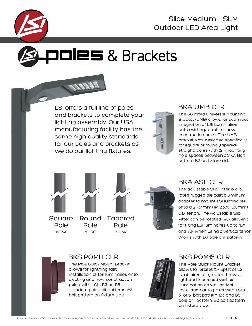
Slice Medium - SLMOutdoor LED Area Light
BKA UMB CLR
BKA ASF CLR
BKS PQMH CLR
BKS PQM15 CLR
Square Pole14'-39'
Round Pole10'-30'
Tapered Pole20'-39'
& Brackets
LSI offers a full line of poles and brackets to complete your lighting assembly. Our USA manufacturing facility has the same high quality standards for our poles and brackets as we do our lighting fixtures.
The adjustable Slip Fitter is a 3G
rated rugged die cast aluminum
adapter to mount LSI luminaires
onto a 2" (51mm) IP, 2.375" (60mm)
O.D. tenon. The Adjustable Slip
Fitter can be rotated 180º allowing
for tilting LSI luminaires up to 45º and 90º when using a vertical tenon.
Works with B3 pole drill pattern.
The 3G rated Universal Mounting Bracket (UMB) allows for seamless integration of LSI Luminaires onto existing/retrofit or new construction poles. The UMB bracket was designed specifically for square or round (tapered/ straight) poles with (2) mounting hole spaces between 3.5"-5". Bolt pattern B3 on fixture side.
The Pole Quick Mount Bracket allows for preset 15º uptilt of LSI luminaires for greater throw of light and increased vertical illumination as well as fast installation onto poles with LSI's 3" or 5" bolt pattern. B3 and B5 pole drill pattern. B3 bolt pattern on fixture side.
The Pole Quick Mount Bracket allows for lightning fast installation of LSI luminaires onto existing and new construction poles with LSI's B3 or B5 standard pole bolt patterns. B3 bolt pattern on fixture side.

AutoCAD SHX Text
Total Project Watts
AutoCAD SHX Text
Total Watts = 1699.2
AutoCAD SHX Text
Total Project Watts
AutoCAD SHX Text
Total Watts = 1699.2
AutoCAD SHX Text
Luminaire Schedule
AutoCAD SHX Text
Symbol
AutoCAD SHX Text
Qty
AutoCAD SHX Text
Label
AutoCAD SHX Text
Arrangement
AutoCAD SHX Text
Description
AutoCAD SHX Text
LLD
AutoCAD SHX Text
UDF
AutoCAD SHX Text
LLF
AutoCAD SHX Text
Arr. Lum. Lumens
AutoCAD SHX Text
Arr. Watts
AutoCAD SHX Text
4
AutoCAD SHX Text
A
AutoCAD SHX Text
D180° 2RTD
AutoCAD SHX Text
SLM-LED-24L-SIL-(1)FT-L;(1)FT-R-50-70CRI-IL-D180-24'POLE+2'BASE
AutoCAD SHX Text
1.000
AutoCAD SHX Text
1.000
AutoCAD SHX Text
1.000
AutoCAD SHX Text
31770
AutoCAD SHX Text
377.6
AutoCAD SHX Text
1
AutoCAD SHX Text
B
AutoCAD SHX Text
SINGLE
AutoCAD SHX Text
SLM-LED-24L-SIL-3-50-70CRI-SINGLE-24'POLE+2'BASE
AutoCAD SHX Text
1.000
AutoCAD SHX Text
1.000
AutoCAD SHX Text
1.000
AutoCAD SHX Text
25976
AutoCAD SHX Text
188.8
AutoCAD SHX Text
Calculation Summary
AutoCAD SHX Text
Label
AutoCAD SHX Text
CalcType
AutoCAD SHX Text
Units
AutoCAD SHX Text
Avg
AutoCAD SHX Text
Max
AutoCAD SHX Text
Min
AutoCAD SHX Text
Avg/Min
AutoCAD SHX Text
Max/Min
AutoCAD SHX Text
ALL CALC POINTS
AutoCAD SHX Text
Illuminance
AutoCAD SHX Text
Fc
AutoCAD SHX Text
1.70
AutoCAD SHX Text
8.2
AutoCAD SHX Text
0.0
AutoCAD SHX Text
N.A.
AutoCAD SHX Text
N.A.
AutoCAD SHX Text
INSIDE CURB
AutoCAD SHX Text
Illuminance
AutoCAD SHX Text
Fc
AutoCAD SHX Text
4.55
AutoCAD SHX Text
8.2
AutoCAD SHX Text
0.3
AutoCAD SHX Text
15.17
AutoCAD SHX Text
27.33
AutoCAD SHX Text
OF 1
AutoCAD SHX Text
SHEET 1
AutoCAD SHX Text
SCALE: 1"=20'
AutoCAD SHX Text
LIGHTING PROPOSAL
AutoCAD SHX Text
0
AutoCAD SHX Text
20
AutoCAD SHX Text
(513) 793-3200 * FAX (513) 793-6023
AutoCAD SHX Text
10000 ALLIANCE RD. CINCINNATI, OHIO 45242 USA
AutoCAD SHX Text
Based on the information provided, all dimensions and luminaire locations
AutoCAD SHX Text
shown represent recommended positions. The engineer and/or architect must
AutoCAD SHX Text
determine the applicability of the layout to existing or future field conditions.
AutoCAD SHX Text
This lighting plan represents illumination levels calculated from laboratory data
AutoCAD SHX Text
taken under controlled conditions in accordance with The Illuminating Engineering
AutoCAD SHX Text
Society (IES) approved methods. Actual performance of any manufacturer's luminaires
AutoCAD SHX Text
may vary due to changes in electrical voltage, tolerance in lamps/LED's and other
AutoCAD SHX Text
variable field conditions. Calculations do not include obstructions such as buildings,
AutoCAD SHX Text
curbs, landscaping, or any other architectural elements unless noted. Fixture nomenclature
AutoCAD SHX Text
noted does not include mounting hardware or poles. This drawing is for photometric
AutoCAD SHX Text
evaluation purposes only and should not be used as a construction document or as a final
AutoCAD SHX Text
document for ordering product.
AutoCAD SHX Text
DATE:1-06-20
AutoCAD SHX Text
BURGER KING
AutoCAD SHX Text
OLD GREENVILLE HWY
AutoCAD SHX Text
CLEMSON,SC
AutoCAD SHX Text
LO-150068-1
AutoCAD SHX Text
REV:1/15/2020
AutoCAD SHX Text
BY:SMB
AutoCAD SHX Text
C
AutoCAD SHX Text
ES + 2 H
AutoCAD SHX Text
C
AutoCAD SHX Text
19 SPA
AutoCAD SHX Text
ES
AutoCAD SHX Text
C
AutoCAD SHX Text
4 SPA
AutoCAD SHX Text
SIDEWALK (TYP)
AutoCAD SHX Text
C
AutoCAD SHX Text
ON
AutoCAD SHX Text
C
AutoCAD SHX Text
SIDEWALK (TYP)
AutoCAD SHX Text
C
AutoCAD SHX Text
ON
AutoCAD SHX Text
C
AutoCAD SHX Text
ESS
AutoCAD SHX Text
CC
AutoCAD SHX Text
A
AutoCAD SHX Text
F.F.E. = 819.5
AutoCAD SHX Text
3,235 SF
AutoCAD SHX Text
ROC - 60
AutoCAD SHX Text
BURGER KING
AutoCAD SHX Text
STOP
AutoCAD SHX Text
ENTER
AutoCAD SHX Text
DO NOT
AutoCAD SHX Text
SCDOT
AutoCAD SHX Text
SC HWY 93 (PUBLIC R/W)
AutoCAD SHX Text
OLD GREENVILLE HWY
AutoCAD SHX Text
B
AutoCAD SHX Text
A
AutoCAD SHX Text
A
AutoCAD SHX Text
A
AutoCAD SHX Text
A
AutoCAD SHX Text
0.0
AutoCAD SHX Text
0.0
AutoCAD SHX Text
0.0
AutoCAD SHX Text
0.0
AutoCAD SHX Text
0.0
AutoCAD SHX Text
0.0
AutoCAD SHX Text
0.0
AutoCAD SHX Text
0.3
AutoCAD SHX Text
0.8
AutoCAD SHX Text
1.0
AutoCAD SHX Text
1.1
AutoCAD SHX Text
1.1
AutoCAD SHX Text
0.9
AutoCAD SHX Text
0.5
AutoCAD SHX Text
0.2
AutoCAD SHX Text
0.1
AutoCAD SHX Text
0.1
AutoCAD SHX Text
0.1
AutoCAD SHX Text
0.0
AutoCAD SHX Text
0.0
AutoCAD SHX Text
0.0
AutoCAD SHX Text
0.0
AutoCAD SHX Text
0.0
AutoCAD SHX Text
0.0
AutoCAD SHX Text
0.0
AutoCAD SHX Text
0.0
AutoCAD SHX Text
0.0
AutoCAD SHX Text
0.0
AutoCAD SHX Text
0.0
AutoCAD SHX Text
0.0
AutoCAD SHX Text
0.0
AutoCAD SHX Text
0.0
AutoCAD SHX Text
0.0
AutoCAD SHX Text
0.0
AutoCAD SHX Text
0.0
AutoCAD SHX Text
0.0
AutoCAD SHX Text
0.0
AutoCAD SHX Text
0.0
AutoCAD SHX Text
0.0
AutoCAD SHX Text
0.0
AutoCAD SHX Text
0.1
AutoCAD SHX Text
0.9
AutoCAD SHX Text
1.8
AutoCAD SHX Text
2.2
AutoCAD SHX Text
2.3
AutoCAD SHX Text
2.1
AutoCAD SHX Text
1.6
AutoCAD SHX Text
0.7
AutoCAD SHX Text
0.4
AutoCAD SHX Text
0.4
AutoCAD SHX Text
0.7
AutoCAD SHX Text
0.7
AutoCAD SHX Text
0.4
AutoCAD SHX Text
0.1
AutoCAD SHX Text
0.1
AutoCAD SHX Text
0.1
AutoCAD SHX Text
0.1
AutoCAD SHX Text
0.0
AutoCAD SHX Text
0.0
AutoCAD SHX Text
0.0
AutoCAD SHX Text
0.0
AutoCAD SHX Text
0.0
AutoCAD SHX Text
0.0
AutoCAD SHX Text
0.0
AutoCAD SHX Text
0.0
AutoCAD SHX Text
0.0
AutoCAD SHX Text
0.0
AutoCAD SHX Text
0.0
AutoCAD SHX Text
0.0
AutoCAD SHX Text
0.0
AutoCAD SHX Text
0.0
AutoCAD SHX Text
0.0
AutoCAD SHX Text
0.0
AutoCAD SHX Text
0.0
AutoCAD SHX Text
0.2
AutoCAD SHX Text
1.9
AutoCAD SHX Text
3.5
AutoCAD SHX Text
4.1
AutoCAD SHX Text
4.1
AutoCAD SHX Text
3.7
AutoCAD SHX Text
3.1
AutoCAD SHX Text
2.8
AutoCAD SHX Text
2.9
AutoCAD SHX Text
3.7
AutoCAD SHX Text
3.7
AutoCAD SHX Text
3.6
AutoCAD SHX Text
3.7
AutoCAD SHX Text
2.7
AutoCAD SHX Text
2.0
AutoCAD SHX Text
1.2
AutoCAD SHX Text
0.6
AutoCAD SHX Text
0.2
AutoCAD SHX Text
0.1
AutoCAD SHX Text
0.1
AutoCAD SHX Text
0.0
AutoCAD SHX Text
0.0
AutoCAD SHX Text
0.0
AutoCAD SHX Text
0.0
AutoCAD SHX Text
0.0
AutoCAD SHX Text
0.0
AutoCAD SHX Text
0.0
AutoCAD SHX Text
0.0
AutoCAD SHX Text
0.0
AutoCAD SHX Text
0.0
AutoCAD SHX Text
0.0
AutoCAD SHX Text
0.0
AutoCAD SHX Text
0.0
AutoCAD SHX Text
0.0
AutoCAD SHX Text
0.1
AutoCAD SHX Text
2.8
AutoCAD SHX Text
5.0
AutoCAD SHX Text
6.0
AutoCAD SHX Text
5.6
AutoCAD SHX Text
5.0
AutoCAD SHX Text
4.9
AutoCAD SHX Text
5.1
AutoCAD SHX Text
5.8
AutoCAD SHX Text
7.4
AutoCAD SHX Text
7.7
AutoCAD SHX Text
7.7
AutoCAD SHX Text
7.4
AutoCAD SHX Text
5.6
AutoCAD SHX Text
4.4
AutoCAD SHX Text
2.8
AutoCAD SHX Text
1.4
AutoCAD SHX Text
0.6
AutoCAD SHX Text
0.3
AutoCAD SHX Text
0.1
AutoCAD SHX Text
0.1
AutoCAD SHX Text
0.0
AutoCAD SHX Text
0.0
AutoCAD SHX Text
0.0
AutoCAD SHX Text
0.0
AutoCAD SHX Text
0.0
AutoCAD SHX Text
0.0
AutoCAD SHX Text
0.0
AutoCAD SHX Text
0.0
AutoCAD SHX Text
0.0
AutoCAD SHX Text
0.0
AutoCAD SHX Text
0.0
AutoCAD SHX Text
0.0
AutoCAD SHX Text
0.1
AutoCAD SHX Text
0.3
AutoCAD SHX Text
3.7
AutoCAD SHX Text
6.6
AutoCAD SHX Text
7.6
AutoCAD SHX Text
6.5
AutoCAD SHX Text
5.6
AutoCAD SHX Text
5.6
AutoCAD SHX Text
5.9
AutoCAD SHX Text
7.1
AutoCAD SHX Text
7.7
AutoCAD SHX Text
7.4
AutoCAD SHX Text
7.4
AutoCAD SHX Text
7.7
AutoCAD SHX Text
7.1
AutoCAD SHX Text
5.4
AutoCAD SHX Text
3.6
AutoCAD SHX Text
1.9
AutoCAD SHX Text
0.9
AutoCAD SHX Text
0.4
AutoCAD SHX Text
0.2
AutoCAD SHX Text
0.1
AutoCAD SHX Text
0.1
AutoCAD SHX Text
0.0
AutoCAD SHX Text
0.0
AutoCAD SHX Text
0.0
AutoCAD SHX Text
0.0
AutoCAD SHX Text
0.0
AutoCAD SHX Text
0.0
AutoCAD SHX Text
0.0
AutoCAD SHX Text
0.0
AutoCAD SHX Text
0.0
AutoCAD SHX Text
0.0
AutoCAD SHX Text
0.0
AutoCAD SHX Text
0.1
AutoCAD SHX Text
0.8
AutoCAD SHX Text
4.8
AutoCAD SHX Text
8.0
AutoCAD SHX Text
7.9
AutoCAD SHX Text
7.3
AutoCAD SHX Text
5.8
AutoCAD SHX Text
5.6
AutoCAD SHX Text
5.7
AutoCAD SHX Text
6.1
AutoCAD SHX Text
6.8
AutoCAD SHX Text
7.3
AutoCAD SHX Text
7.4
AutoCAD SHX Text
7.0
AutoCAD SHX Text
6.3
AutoCAD SHX Text
5.6
AutoCAD SHX Text
4.1
AutoCAD SHX Text
2.4
AutoCAD SHX Text
1.2
AutoCAD SHX Text
0.5
AutoCAD SHX Text
0.3
AutoCAD SHX Text
0.2
AutoCAD SHX Text
0.1
AutoCAD SHX Text
0.0
AutoCAD SHX Text
0.0
AutoCAD SHX Text
0.0
AutoCAD SHX Text
0.0
AutoCAD SHX Text
0.0
AutoCAD SHX Text
0.0
AutoCAD SHX Text
0.0
AutoCAD SHX Text
0.0
AutoCAD SHX Text
0.0
AutoCAD SHX Text
0.0
AutoCAD SHX Text
0.1
AutoCAD SHX Text
0.1
AutoCAD SHX Text
0.9
AutoCAD SHX Text
4.1
AutoCAD SHX Text
7.6
AutoCAD SHX Text
7.6
AutoCAD SHX Text
7.7
AutoCAD SHX Text
5.7
AutoCAD SHX Text
5.1
AutoCAD SHX Text
4.6
AutoCAD SHX Text
4.4
AutoCAD SHX Text
4.4
AutoCAD SHX Text
4.6
AutoCAD SHX Text
4.7
AutoCAD SHX Text
4.9
AutoCAD SHX Text
5.1
AutoCAD SHX Text
5.0
AutoCAD SHX Text
4.2
AutoCAD SHX Text
2.7
AutoCAD SHX Text
1.5
AutoCAD SHX Text
0.7
AutoCAD SHX Text
0.4
AutoCAD SHX Text
0.2
AutoCAD SHX Text
0.1
AutoCAD SHX Text
0.0
AutoCAD SHX Text
0.0
AutoCAD SHX Text
0.0
AutoCAD SHX Text
0.0
AutoCAD SHX Text
0.0
AutoCAD SHX Text
0.0
AutoCAD SHX Text
0.0
AutoCAD SHX Text
0.0
AutoCAD SHX Text
0.0
AutoCAD SHX Text
0.1
AutoCAD SHX Text
0.1
AutoCAD SHX Text
0.1
AutoCAD SHX Text
0.9
AutoCAD SHX Text
4.9
AutoCAD SHX Text
8.1
AutoCAD SHX Text
7.9
AutoCAD SHX Text
7.4
AutoCAD SHX Text
5.4
AutoCAD SHX Text
4.2
AutoCAD SHX Text
3.3
AutoCAD SHX Text
2.9
AutoCAD SHX Text
2.7
AutoCAD SHX Text
2.8
AutoCAD SHX Text
3.2
AutoCAD SHX Text
3.5
AutoCAD SHX Text
4.0
AutoCAD SHX Text
4.2
AutoCAD SHX Text
3.9
AutoCAD SHX Text
2.9
AutoCAD SHX Text
1.6
AutoCAD SHX Text
0.8
AutoCAD SHX Text
0.4
AutoCAD SHX Text
0.2
AutoCAD SHX Text
0.1
AutoCAD SHX Text
0.0
AutoCAD SHX Text
0.0
AutoCAD SHX Text
0.0
AutoCAD SHX Text
0.0
AutoCAD SHX Text
0.0
AutoCAD SHX Text
0.0
AutoCAD SHX Text
0.0
AutoCAD SHX Text
0.0
AutoCAD SHX Text
0.1
AutoCAD SHX Text
0.1
AutoCAD SHX Text
0.1
AutoCAD SHX Text
0.2
AutoCAD SHX Text
0.5
AutoCAD SHX Text
4.2
AutoCAD SHX Text
7.2
AutoCAD SHX Text
7.7
AutoCAD SHX Text
6.5
AutoCAD SHX Text
4.7
AutoCAD SHX Text
3.2
AutoCAD SHX Text
1.9
AutoCAD SHX Text
1.3
AutoCAD SHX Text
1.2
AutoCAD SHX Text
1.2
AutoCAD SHX Text
1.7
AutoCAD SHX Text
2.3
AutoCAD SHX Text
2.8
AutoCAD SHX Text
3.4
AutoCAD SHX Text
3.7
AutoCAD SHX Text
2.8
AutoCAD SHX Text
1.6
AutoCAD SHX Text
0.7
AutoCAD SHX Text
0.3
AutoCAD SHX Text
0.2
AutoCAD SHX Text
0.1
AutoCAD SHX Text
0.0
AutoCAD SHX Text
0.0
AutoCAD SHX Text
0.0
AutoCAD SHX Text
0.0
AutoCAD SHX Text
0.0
AutoCAD SHX Text
0.0
AutoCAD SHX Text
0.0
AutoCAD SHX Text
0.0
AutoCAD SHX Text
0.1
AutoCAD SHX Text
0.1
AutoCAD SHX Text
0.2
AutoCAD SHX Text
0.3
AutoCAD SHX Text
0.4
AutoCAD SHX Text
3.2
AutoCAD SHX Text
5.6
AutoCAD SHX Text
6.5
AutoCAD SHX Text
5.6
AutoCAD SHX Text
4.2
AutoCAD SHX Text
2.6
AutoCAD SHX Text
1.3
AutoCAD SHX Text
0.7
AutoCAD SHX Text
0.6
AutoCAD SHX Text
0.7
AutoCAD SHX Text
1.0
AutoCAD SHX Text
1.7
AutoCAD SHX Text
2.1
AutoCAD SHX Text
2.9
AutoCAD SHX Text
3.8
AutoCAD SHX Text
3.0
AutoCAD SHX Text
1.5
AutoCAD SHX Text
0.6
AutoCAD SHX Text
0.2
AutoCAD SHX Text
0.1
AutoCAD SHX Text
0.1
AutoCAD SHX Text
0.0
AutoCAD SHX Text
0.0
AutoCAD SHX Text
0.0
AutoCAD SHX Text
0.0
AutoCAD SHX Text
0.0
AutoCAD SHX Text
0.0
AutoCAD SHX Text
0.0
AutoCAD SHX Text
0.1
AutoCAD SHX Text
0.1
AutoCAD SHX Text
0.2
AutoCAD SHX Text
0.3
AutoCAD SHX Text
0.5
AutoCAD SHX Text
0.8
AutoCAD SHX Text
2.6
AutoCAD SHX Text
4.2
AutoCAD SHX Text
4.6
AutoCAD SHX Text
4.4
AutoCAD SHX Text
3.6
AutoCAD SHX Text
2.3
AutoCAD SHX Text
1.1
AutoCAD SHX Text
0.6
AutoCAD SHX Text
0.6
AutoCAD SHX Text
0.8
AutoCAD SHX Text
1.4
AutoCAD SHX Text
2.4
AutoCAD SHX Text
2.7
AutoCAD SHX Text
3.5
AutoCAD SHX Text
4.7
AutoCAD SHX Text
3.5
AutoCAD SHX Text
1.4
AutoCAD SHX Text
0.4
AutoCAD SHX Text
0.2
AutoCAD SHX Text
0.1
AutoCAD SHX Text
0.1
AutoCAD SHX Text
0.0
AutoCAD SHX Text
0.0
AutoCAD SHX Text
0.0
AutoCAD SHX Text
0.0
AutoCAD SHX Text
0.0
AutoCAD SHX Text
0.0
AutoCAD SHX Text
0.0
AutoCAD SHX Text
0.1
AutoCAD SHX Text
0.1
AutoCAD SHX Text
0.3
AutoCAD SHX Text
0.6
AutoCAD SHX Text
1.0
AutoCAD SHX Text
1.3
AutoCAD SHX Text
1.9
AutoCAD SHX Text
2.2
AutoCAD SHX Text
2.7
AutoCAD SHX Text
2.8
AutoCAD SHX Text
2.5
AutoCAD SHX Text
1.8
AutoCAD SHX Text
0.9
AutoCAD SHX Text
0.6
AutoCAD SHX Text
0.7
AutoCAD SHX Text
1.3
AutoCAD SHX Text
2.4
AutoCAD SHX Text
3.8
AutoCAD SHX Text
4.1
AutoCAD SHX Text
4.5
AutoCAD SHX Text
5.3
AutoCAD SHX Text
4.1
AutoCAD SHX Text
1.4
AutoCAD SHX Text
0.3
AutoCAD SHX Text
0.1
AutoCAD SHX Text
0.1
AutoCAD SHX Text
0.0
AutoCAD SHX Text
0.0
AutoCAD SHX Text
0.0
AutoCAD SHX Text
0.0
AutoCAD SHX Text
0.0
AutoCAD SHX Text
0.0
AutoCAD SHX Text
0.0
AutoCAD SHX Text
0.0
AutoCAD SHX Text
0.1
AutoCAD SHX Text
0.2
AutoCAD SHX Text
0.5
AutoCAD SHX Text
1.0
AutoCAD SHX Text
1.7
AutoCAD SHX Text
2.1
AutoCAD SHX Text
2.0
AutoCAD SHX Text
1.0
AutoCAD SHX Text
1.3
AutoCAD SHX Text
1.4
AutoCAD SHX Text
1.4
AutoCAD SHX Text
1.2
AutoCAD SHX Text
0.7
AutoCAD SHX Text
0.5
AutoCAD SHX Text
0.7
AutoCAD SHX Text
1.9
AutoCAD SHX Text
3.3
AutoCAD SHX Text
4.0
AutoCAD SHX Text
3.9
AutoCAD SHX Text
5.2
AutoCAD SHX Text
5.6
AutoCAD SHX Text
4.3
AutoCAD SHX Text
1.4
AutoCAD SHX Text
0.3
AutoCAD SHX Text
0.1
AutoCAD SHX Text
0.1
AutoCAD SHX Text
0.0
AutoCAD SHX Text
0.0
AutoCAD SHX Text
0.0
AutoCAD SHX Text
0.0
AutoCAD SHX Text
0.0
AutoCAD SHX Text
0.0
AutoCAD SHX Text
0.0
AutoCAD SHX Text
0.0
AutoCAD SHX Text
0.1
AutoCAD SHX Text
0.4
AutoCAD SHX Text
1.0
AutoCAD SHX Text
1.8
AutoCAD SHX Text
2.9
AutoCAD SHX Text
3.3
AutoCAD SHX Text
2.9
AutoCAD SHX Text
0.4
AutoCAD SHX Text
0.5
AutoCAD SHX Text
0.6
AutoCAD SHX Text
0.7
AutoCAD SHX Text
0.7
AutoCAD SHX Text
0.5
AutoCAD SHX Text
0.5
AutoCAD SHX Text
0.7
AutoCAD SHX Text
1.9
AutoCAD SHX Text
3.2
AutoCAD SHX Text
4.0
AutoCAD SHX Text
4.0
AutoCAD SHX Text
5.1
AutoCAD SHX Text
5.6
AutoCAD SHX Text
4.3
AutoCAD SHX Text
1.5
AutoCAD SHX Text
0.3
AutoCAD SHX Text
0.1
AutoCAD SHX Text
0.1
AutoCAD SHX Text
0.0
AutoCAD SHX Text
0.0
AutoCAD SHX Text
0.0
AutoCAD SHX Text
0.0
AutoCAD SHX Text
0.0
AutoCAD SHX Text
0.0
AutoCAD SHX Text
0.0
AutoCAD SHX Text
0.0
AutoCAD SHX Text
0.0
AutoCAD SHX Text
0.5
AutoCAD SHX Text
1.6
AutoCAD SHX Text
3.0
AutoCAD SHX Text
4.3
AutoCAD SHX Text
4.7
AutoCAD SHX Text
3.9
AutoCAD SHX Text
1.2
AutoCAD SHX Text
2.3
AutoCAD SHX Text
3.7
AutoCAD SHX Text
4.0
AutoCAD SHX Text
4.4
AutoCAD SHX Text
5.3
AutoCAD SHX Text
4.1
AutoCAD SHX Text
1.5
AutoCAD SHX Text
0.3
AutoCAD SHX Text
0.1
AutoCAD SHX Text
0.1
AutoCAD SHX Text
0.0
AutoCAD SHX Text
0.0
AutoCAD SHX Text
0.0
AutoCAD SHX Text
0.0
AutoCAD SHX Text
0.0
AutoCAD SHX Text
0.0
AutoCAD SHX Text
0.0
AutoCAD SHX Text
0.0
AutoCAD SHX Text
0.0
AutoCAD SHX Text
0.2
AutoCAD SHX Text
2.0
AutoCAD SHX Text
4.0
AutoCAD SHX Text
5.6
AutoCAD SHX Text
6.2
AutoCAD SHX Text
5.1
AutoCAD SHX Text
0.9
AutoCAD SHX Text
1.4
AutoCAD SHX Text
2.4
AutoCAD SHX Text
2.8
AutoCAD SHX Text
3.6
AutoCAD SHX Text
4.7
AutoCAD SHX Text
3.5
AutoCAD SHX Text
1.5
AutoCAD SHX Text
0.4
AutoCAD SHX Text
0.2
AutoCAD SHX Text
0.1
AutoCAD SHX Text
0.0
AutoCAD SHX Text
0.0
AutoCAD SHX Text
0.0
AutoCAD SHX Text
0.0
AutoCAD SHX Text
0.0
AutoCAD SHX Text
0.0
AutoCAD SHX Text
0.0
AutoCAD SHX Text
0.0
AutoCAD SHX Text
0.0
AutoCAD SHX Text
0.1
AutoCAD SHX Text
1.3
AutoCAD SHX Text
4.0
AutoCAD SHX Text
6.4
AutoCAD SHX Text
7.5
AutoCAD SHX Text
7.0
AutoCAD SHX Text
1.3
AutoCAD SHX Text
1.7
AutoCAD SHX Text
2.4
AutoCAD SHX Text
2.8
AutoCAD SHX Text
3.4
AutoCAD SHX Text
4.1
AutoCAD SHX Text
3.1
AutoCAD SHX Text
1.5
AutoCAD SHX Text
0.6
AutoCAD SHX Text
0.2
AutoCAD SHX Text
0.1
AutoCAD SHX Text
0.1
AutoCAD SHX Text
0.0
AutoCAD SHX Text
0.0
AutoCAD SHX Text
0.0
AutoCAD SHX Text
0.0
AutoCAD SHX Text
0.0
AutoCAD SHX Text
0.0
AutoCAD SHX Text
0.0
AutoCAD SHX Text
0.0
AutoCAD SHX Text
0.0
AutoCAD SHX Text
0.1
AutoCAD SHX Text
2.7
AutoCAD SHX Text
6.6
AutoCAD SHX Text
7.9
AutoCAD SHX Text
7.7
AutoCAD SHX Text
7.4
AutoCAD SHX Text
5.3
AutoCAD SHX Text
2.5
AutoCAD SHX Text
3.0
AutoCAD SHX Text
2.8
AutoCAD SHX Text
2.9
AutoCAD SHX Text
3.4
AutoCAD SHX Text
4.0
AutoCAD SHX Text
4.2
AutoCAD SHX Text
4.3
AutoCAD SHX Text
3.9
AutoCAD SHX Text
2.7
AutoCAD SHX Text
1.4
AutoCAD SHX Text
0.6
AutoCAD SHX Text
0.3
AutoCAD SHX Text
0.1
AutoCAD SHX Text
0.1
AutoCAD SHX Text
0.0
AutoCAD SHX Text
0.0
AutoCAD SHX Text
0.0
AutoCAD SHX Text
0.0
AutoCAD SHX Text
0.0
AutoCAD SHX Text
0.0
AutoCAD SHX Text
0.0
AutoCAD SHX Text
0.0
AutoCAD SHX Text
0.0
AutoCAD SHX Text
0.1
AutoCAD SHX Text
0.9
AutoCAD SHX Text
4.6
AutoCAD SHX Text
7.5
AutoCAD SHX Text
7.6
AutoCAD SHX Text
8.0
AutoCAD SHX Text
6.7
AutoCAD SHX Text
6.0
AutoCAD SHX Text
5.9
AutoCAD SHX Text
5.4
AutoCAD SHX Text
4.9
AutoCAD SHX Text
4.6
AutoCAD SHX Text
4.6
AutoCAD SHX Text
4.7
AutoCAD SHX Text
5.0
AutoCAD SHX Text
5.1
AutoCAD SHX Text
5.0
AutoCAD SHX Text
4.4
AutoCAD SHX Text
3.4
AutoCAD SHX Text
2.2
AutoCAD SHX Text
1.1
AutoCAD SHX Text
0.5
AutoCAD SHX Text
0.3
AutoCAD SHX Text
0.1
AutoCAD SHX Text
0.1
AutoCAD SHX Text
0.0
AutoCAD SHX Text
0.0
AutoCAD SHX Text
0.0
AutoCAD SHX Text
0.0
AutoCAD SHX Text
0.0
AutoCAD SHX Text
0.0
AutoCAD SHX Text
0.0
AutoCAD SHX Text
0.0
AutoCAD SHX Text
0.0
AutoCAD SHX Text
0.0
AutoCAD SHX Text
0.4
AutoCAD SHX Text
1.5
AutoCAD SHX Text
5.5
AutoCAD SHX Text
8.0
AutoCAD SHX Text
8.0
AutoCAD SHX Text
7.3
AutoCAD SHX Text
6.7
AutoCAD SHX Text
7.0
AutoCAD SHX Text
7.1
AutoCAD SHX Text
7.0
AutoCAD SHX Text
7.3
AutoCAD SHX Text
7.6
AutoCAD SHX Text
7.5
AutoCAD SHX Text
7.0
AutoCAD SHX Text
6.3
AutoCAD SHX Text
5.6
AutoCAD SHX Text
4.2
AutoCAD SHX Text
2.7
AutoCAD SHX Text
1.6
AutoCAD SHX Text
0.9
AutoCAD SHX Text
0.4
AutoCAD SHX Text
0.3
AutoCAD SHX Text
0.1
AutoCAD SHX Text
0.1
AutoCAD SHX Text
0.0
AutoCAD SHX Text
0.0
AutoCAD SHX Text
0.0
AutoCAD SHX Text
0.0
AutoCAD SHX Text
0.0
AutoCAD SHX Text
0.0
AutoCAD SHX Text
0.0
AutoCAD SHX Text
0.0
AutoCAD SHX Text
0.0
AutoCAD SHX Text
0.0
AutoCAD SHX Text
0.1
AutoCAD SHX Text
0.5
AutoCAD SHX Text
2.0
AutoCAD SHX Text
5.2
AutoCAD SHX Text
6.3
AutoCAD SHX Text
6.5
AutoCAD SHX Text
6.4
AutoCAD SHX Text
6.8
AutoCAD SHX Text
7.4
AutoCAD SHX Text
8.2
AutoCAD SHX Text
8.2
AutoCAD SHX Text
7.5
AutoCAD SHX Text
7.6
AutoCAD SHX Text
7.8
AutoCAD SHX Text
6.9
AutoCAD SHX Text
5.3
AutoCAD SHX Text
3.5
AutoCAD SHX Text
2.0
AutoCAD SHX Text
1.1
AutoCAD SHX Text
0.6
AutoCAD SHX Text
0.3
AutoCAD SHX Text
0.1
AutoCAD SHX Text
0.1
AutoCAD SHX Text
0.0
AutoCAD SHX Text
0.0
AutoCAD SHX Text
0.0
AutoCAD SHX Text
0.0
AutoCAD SHX Text
0.0
AutoCAD SHX Text
0.0
AutoCAD SHX Text
0.0
AutoCAD SHX Text
0.0
AutoCAD SHX Text
0.0
AutoCAD SHX Text
0.0
AutoCAD SHX Text
0.0
AutoCAD SHX Text
0.0
AutoCAD SHX Text
0.1
AutoCAD SHX Text
0.2
AutoCAD SHX Text
2.2
AutoCAD SHX Text
4.0
AutoCAD SHX Text
4.5
AutoCAD SHX Text
4.5
AutoCAD SHX Text
5.1
AutoCAD SHX Text
5.8
AutoCAD SHX Text
6.5
AutoCAD SHX Text
7.9
AutoCAD SHX Text
7.8
AutoCAD SHX Text
7.9
AutoCAD SHX Text
7.0
AutoCAD SHX Text
5.4
AutoCAD SHX Text
4.1
AutoCAD SHX Text
2.6
AutoCAD SHX Text
1.3
AutoCAD SHX Text
0.7
AutoCAD SHX Text
0.1
AutoCAD SHX Text
0.1
AutoCAD SHX Text
0.0
AutoCAD SHX Text
0.0
AutoCAD SHX Text
0.0
AutoCAD SHX Text
0.0
AutoCAD SHX Text
0.0
AutoCAD SHX Text
0.0
AutoCAD SHX Text
0.0
AutoCAD SHX Text
0.0
AutoCAD SHX Text
0.0
AutoCAD SHX Text
0.0
AutoCAD SHX Text
0.0
AutoCAD SHX Text
0.0
AutoCAD SHX Text
0.0
AutoCAD SHX Text
0.0
AutoCAD SHX Text
0.4
AutoCAD SHX Text
1.7
AutoCAD SHX Text
2.3
AutoCAD SHX Text
2.2
AutoCAD SHX Text
2.3
AutoCAD SHX Text
2.7
AutoCAD SHX Text
3.1
AutoCAD SHX Text
3.8
AutoCAD SHX Text
3.5
AutoCAD SHX Text
3.6
AutoCAD SHX Text
3.4
AutoCAD SHX Text
2.4
AutoCAD SHX Text
1.8
AutoCAD SHX Text
1.0
AutoCAD SHX Text
0.5
AutoCAD SHX Text
0.2
AutoCAD SHX Text
0.0
AutoCAD SHX Text
0.0
AutoCAD SHX Text
0.0
AutoCAD SHX Text
0.0
AutoCAD SHX Text
0.0
AutoCAD SHX Text
0.0
AutoCAD SHX Text
0.0
AutoCAD SHX Text
0.0
AutoCAD SHX Text
0.0
AutoCAD SHX Text
0.0
AutoCAD SHX Text
0.0
AutoCAD SHX Text
0.0
AutoCAD SHX Text
0.0
AutoCAD SHX Text
0.0
AutoCAD SHX Text
0.0
AutoCAD SHX Text
0.0
AutoCAD SHX Text
0.0
AutoCAD SHX Text
0.2
AutoCAD SHX Text
0.7
AutoCAD SHX Text
0.7
AutoCAD SHX Text
0.5
AutoCAD SHX Text
0.4
AutoCAD SHX Text
0.3
AutoCAD SHX Text
0.5
AutoCAD SHX Text
0.7
AutoCAD SHX Text
0.6
AutoCAD SHX Text
0.3
AutoCAD SHX Text
0.1
AutoCAD SHX Text
0.1
AutoCAD SHX Text
0.1
AutoCAD SHX Text
0.1
AutoCAD SHX Text
0.1
AutoCAD SHX Text
0.0
AutoCAD SHX Text
0.0
AutoCAD SHX Text
0.0
AutoCAD SHX Text
0.0
AutoCAD SHX Text
0.0
AutoCAD SHX Text
0.0
AutoCAD SHX Text
0.0
AutoCAD SHX Text
0.0
AutoCAD SHX Text
0.0
AutoCAD SHX Text
0.0
AutoCAD SHX Text
0.0
AutoCAD SHX Text
0.0
AutoCAD SHX Text
0.0
AutoCAD SHX Text
0.0
AutoCAD SHX Text
0.0
AutoCAD SHX Text
0.0
AutoCAD SHX Text
0.0
AutoCAD SHX Text
0.0
AutoCAD SHX Text
0.0
AutoCAD SHX Text
0.0
AutoCAD SHX Text
0.1
AutoCAD SHX Text
0.2
AutoCAD SHX Text
0.2
AutoCAD SHX Text
0.1
AutoCAD SHX Text
0.1
AutoCAD SHX Text
0.1
AutoCAD SHX Text
0.1
AutoCAD SHX Text
0.1
AutoCAD SHX Text
0.0
AutoCAD SHX Text
0.0
AutoCAD SHX Text
0.0
AutoCAD SHX Text
0.0
AutoCAD SHX Text
0.0
AutoCAD SHX Text
0.0
AutoCAD SHX Text
0.0
AutoCAD SHX Text
0.0
AutoCAD SHX Text
0.0
AutoCAD SHX Text
0.0
AutoCAD SHX Text
0.0
AutoCAD SHX Text
0.0
AutoCAD SHX Text
0.0
AutoCAD SHX Text
0.0
AutoCAD SHX Text
0.0
AutoCAD SHX Text
0.0
AutoCAD SHX Text
0.0
AutoCAD SHX Text
0.0
AutoCAD SHX Text
0.0
AutoCAD SHX Text
0.0
AutoCAD SHX Text
0.0
AutoCAD SHX Text
0.0
AutoCAD SHX Text
0.0
AutoCAD SHX Text
0.0
AutoCAD SHX Text
0.0
AutoCAD SHX Text
0.0
AutoCAD SHX Text
0.0
AutoCAD SHX Text
0.0
AutoCAD SHX Text
0.1
AutoCAD SHX Text
0.1
AutoCAD SHX Text
0.1
AutoCAD SHX Text
0.1
AutoCAD SHX Text
0.0
AutoCAD SHX Text
0.0
AutoCAD SHX Text
0.0
AutoCAD SHX Text
0.0
AutoCAD SHX Text
0.0
AutoCAD SHX Text
0.0
AutoCAD SHX Text
0.0
AutoCAD SHX Text
0.0
AutoCAD SHX Text
0.0
AutoCAD SHX Text
0.0
AutoCAD SHX Text
0.0
AutoCAD SHX Text
0.0
AutoCAD SHX Text
0.0
AutoCAD SHX Text
0.0
AutoCAD SHX Text
0.0
AutoCAD SHX Text
0.0
AutoCAD SHX Text
0.0
AutoCAD SHX Text
0.0
AutoCAD SHX Text
0.0
AutoCAD SHX Text
pole
AutoCAD SHX Text
Use Type
AutoCAD SHX Text
FT-R
AutoCAD SHX Text
Use Type
AutoCAD SHX Text
FT-L
AutoCAD SHX Text
(Optics Rotated Right)
AutoCAD SHX Text
Fixture Type A
AutoCAD SHX Text
For D180 Forward Throw installations specify left rotated optics (FT-L) and/or right rotated optics (FT-R)
AutoCAD SHX Text
side mounting. Orientation is based on standing at the pole and looking out at the area to be illuminated.
AutoCAD SHX Text
(Optics Rotated Left)
AutoCAD SHX Text
Top View
AutoCAD SHX Text
Optics Rotated Left
AutoCAD SHX Text
Optics Rotated Right
AutoCAD SHX Text
FT-R
AutoCAD SHX Text
FT-L
AutoCAD SHX Text
EXAMPLE

METMET
C US
3M TRANSLUCENT VINYL #3630-33 RED
3M TRANSLUCENT VINYL #3630-125 YELLOW
3M TRANSLUCENT VINYL #3630-8703 BLUE
3M WHITE DIFFUSER #3635-30
BK SILVER SATIN FINISH
COLOR SPECIFICATIONS
Burger King OP018857Clemson, SC
01/15/20

METMET
C US
3M TRANSLUCENT VINYL #3630-33 RED
3M TRANSLUCENT VINYL #3630-125 YELLOW
3M TRANSLUCENT VINYL #3630-8703 BLUE
3M WHITE DIFFUSER #3635-30
BK SILVER SATIN FINISH
COLOR SPECIFICATIONS
500 Old Greenville Hwy., Clemson, SC 29631
Op018857 Clemson SC_100House Justin BurgessSPN
Burger King Op018857Client
Sales Design PM
File
Project Information
1
2
3
4
Date / Description01/15/20 Issue Date
Title Date
Name
Approved Revise &R esubmitApproved as Noted
Client Review StatusAllen Industries, Inc. requires that an " Approved" drawing be obtained from the client prior to any production release or production release revision.
Copyright © 2018 Allen Industries, Inc. This is an original, unpublished drawing, created by Allen Industries, Inc. This drawing is submitted to you in confidence for your use solely in connection with the project being planned for you by Allen Industries, Inc. and is not to be shown to anyone outside your organization, nor used, reproduced, copied or exhibited in any fashion whatsoever. The designs shown on the drawing (except for any registered trademarks that may belong to a client of Allen Industries, Inc.) remain the property of Allen Industries, Inc.
Declaration
www.allenindustries.com1-800-967-2553
Page 2
Design Option AGraphic Layout+-15'-6" - REMODELED EXISTING MONUMENT SIGN
+-7'-4" - REMODELED FASCIA PANELS
+-5’-0” FASCIA PANEL
FRONT ELEVATION - MONUMENT SIGNSCALE 1/2” = 1’-0”
+-2'-7" - REMODELED
FASCIA PANELS4’-0” BK LOGO
+-5’
-5 3
/4”
- E
XT
EN
SIO
N T
O M
ATC
H E
XIS
TIN
GD
IME
NS
ION
S T
O
MAT
CH
EX
IST
ING
4’-0
” B
K L
OG
O
LANGSTON PLAZA
Non-Illuminated Sign Panel:1 1/8” Depth x 10” x 4’-10” Fabricated aluminumsingle face sign panels with 1/4” thick aluminum plate applied letters installed to each side of the existing Monument Sign.
Added Masonry Split Face Block and aluminum Box Trim with aluminum skirt to tie into the existing Sign Baseconstruction matching building material size, shape and color.
Remodeled Existing Sign with New aluminum fascia panelsand Brake Formed aluminum Box Trim at top and bottomeach section extended from the existing sign.New 4’ Dia. LED Illuminated BK Logo installed each side of sign.
End of Existing End of Existing Monument SignMonument SignEnd of Existing Monument Sign
METMET
C US
burgessju
Typewritten text
Concrete Slab (Covered with landscape)