From Iudicum Dei to Combat d'Honneur: Morphology of Trial by Combat in the Middle Ages
Upload
khangminh22Category
view
3download
0
AD --------------------------
USAARL REPORT NO. 73-13
BJMP PROTECTION EVALUATION OF THE STANDARD P /N 791 COMBAT VEHICLE CREWMAN'S HELMET
May 19 7 3
U. S. ARMY AEROMEDICAL RESEARCH LABORATORY
Fort Rucker, Alabama 36360
Unclassified Security Classification
DOCUMENT CONTROL DATA · R & D
ADA762154 Technical Report
rs,cu-rlty cl•••lllcatlon ol till•. body of •b•ttact and lndexlnl lll'lnot•tiOrl'l mu•t,. entered wh•n the over•ll ,.DOl, Ia el•••lfl•dJ 1. ORI(;INATING ACTIVITY (CorpOtllte author) U. "IEPO"T SECURITY CLA.SSIP"ICATION
US Army Aeromedical Research Laboratory Unclassified Fort Rucker, Alabama 21>. G"OUP
3. REPORT TITLE
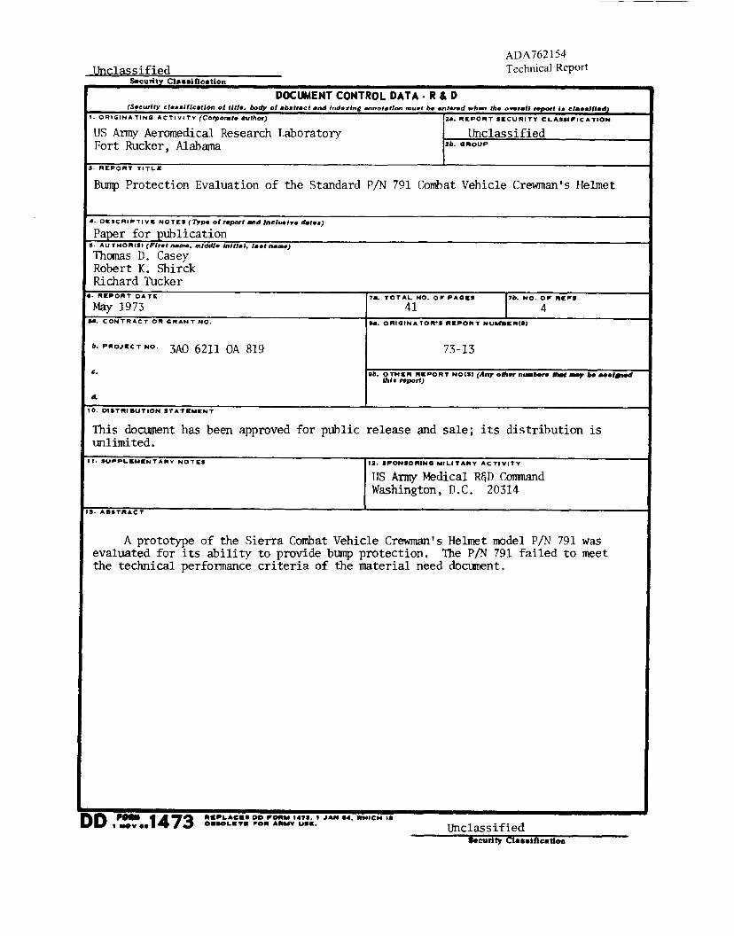
Bump Protection Evaluation of the Standard P/N 791 Combat Vehicle Crewman's Helmet
... OESCRIPTIVII: NOT£S (Type ol repott and lnCIIHIYe datea)
Paper for publication e. AU THOA:tS, (Firat name. middle lnJtJ•I, l••t n•IIN')
Thomas D. Casey Robert K. Shirck Richard Tucker
I· "IEPORT DATE ?a. TOTAL NO. OF PAGI:S rb. NO. 4P" "EFS
May 1973 41 ... CONTRACT OR GAAN T NO. h. ORIGINATO"'S "EPO"T NU ..... E"ISI
b. P"OJEC T NO. 3AO 6211 OA 819 73-13
"· .b. OTHIE" "EPORT NO(SI (Any ofller n-bera -f _,.be -•161ed lhlo report)
d.
10. DISTfltiBUTION STA.TILW-.NT
This document has been approved for public release and sale; its distribution is rmlimi ted.
11· SUjiiJJII'LCMII:NTA .. Y NOTES 12. SPONSO"ING MILITA"V ACTIVITY
US Army Medical R&D Command Washington, D.C. 20314
II. ABST"ACT
A prototype of the Sierra Combat Vehicle Crewman's Helmet model P/N 791 was evaluated for its ability to provide bump protection. The P/N 791 failed to meet the technical performance criteria of the material need document.
DD .'.=-.. 1473 Unclassified .. curlty cl ... uicatloa
Unclassified S4tcurity Clualllcatlon ... L ~NK "' LINt< 8 LINK C KEYWORD.
ROL.E I WT ROLE WT ROLE WT
bump I conditioning
I helmet systems
I impact i
mean time duration I peak "g" protection I
I
prototype I
I I
I I I I i '
I ! ! I
I I I
I I l
' l
Unclassified
FT RUCKER 063044
NOOI~
Qualified requesters may obtain copies from the Defense Documentation-Center (DDC), Cameron Station, Alexandria, Virginia. Orders will be expedited if placed through the librarian or other person designated to request documents from DDC (Formerly ASTIA) .
Change of Address
Organization receiving reports from the us Army Aeromedical Research Laboratory on automatic mailing lists should confirm correct address when corresponding about laboratory reports.
Disposition
Destroy this report when it is no longer needed. return it to the originator.
Distribution Statement
Do not
This document has been approved for public release and sale; its distribution is unlimited.
Disclaimer
The findings in this report are not to be construed as an official Department of the Army position unless so designated by other authorized documents.
AD ________________________ _
USAARL REPORT NO. 73-13
BUMP PROTECTION EVALUATION OF THE STANDARD P/N 791 COMBAT VEHICLE CREWMAN'S HELMET
By
Thomas D. Casey Robert K. Shirck Richard Tucker
May 1973
U. S. ARMY AEROMEDICAL RESEARCH LABORATORY
Fort Rucker, Alabama
U. S. Army Medical Research and Development Command
Distribution Statement
This document has been approved for public release and sale; its distribution is unlimited.
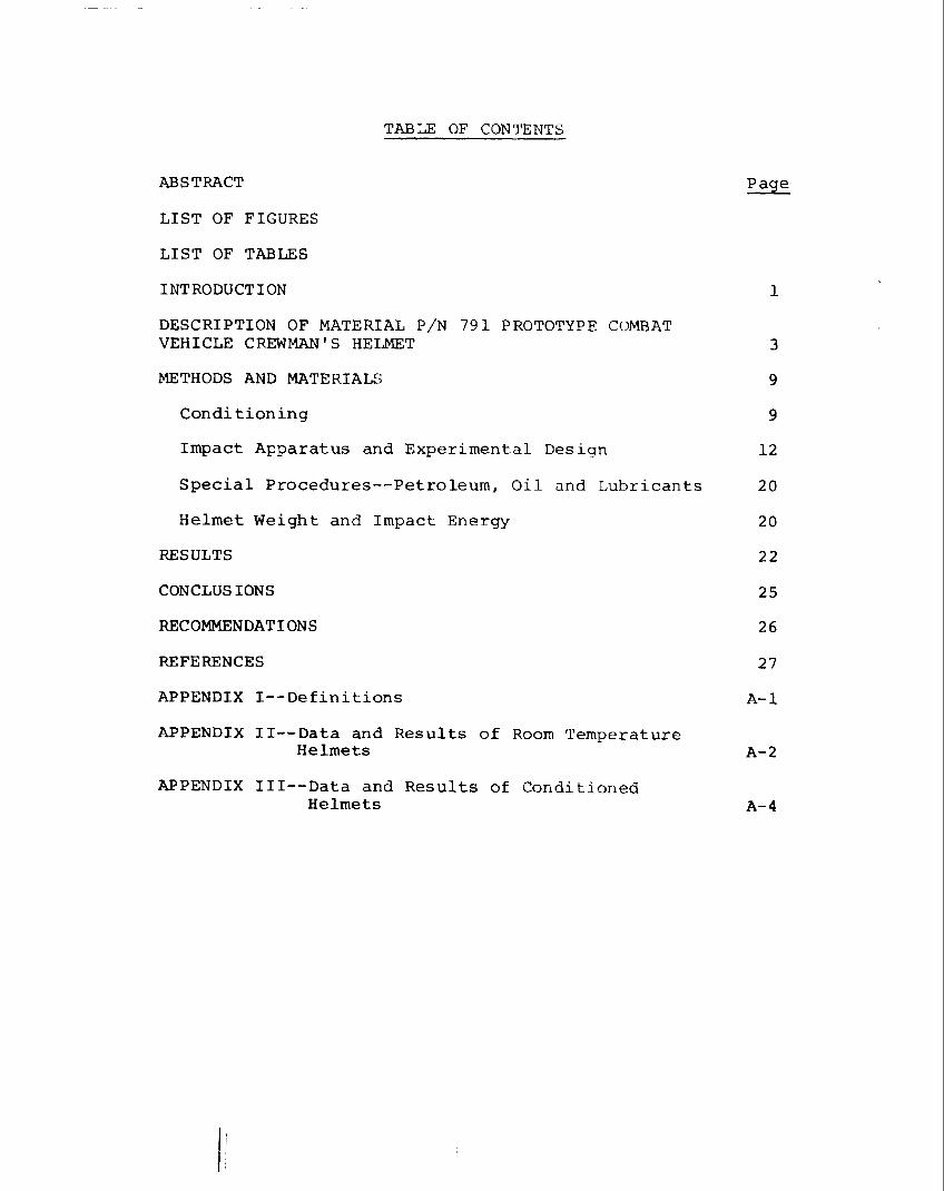
TABLE OF CONTENTS
ABSTRACT
LIST OF FIGURES
LIST OF TABLES
INTRODUCTION 1
DESCRIPTION OF MATERIAL P/N 791 PROTOTYPE COMBAT VEHICLE CREWMAN'S HELMET 3
METHODS AND MATERIALS 9
Conditioning 9
Impact Apparatus and Experimental Design 12
Special Procedures--Petroleum, Oil and Lubricants 20
Helmet Weight and Impact Energy 20
RESULTS 22
CONCLUSIONS 25
RECOMMENDATIONS 26
REFERENCES 27
APPENDIX !--Definitions A-1
APPENDIX II--Data and Results of Room Temperature Helmets A-2
APPENDIX III--Data and Results of Conditioned Helmets A-4
ABSTRACT
A prototype of the Sierra Combat Vehicle Crewman's Helmet model P/N 791 was evaluated for its ability to provide bump protection. The P/N 791 failed to meet the technical performance criteria of the material need document.
~J~~-l Colonel, ~ Commander
FIGURE
l
2
3
4
5
6
7
8
9
10
ll
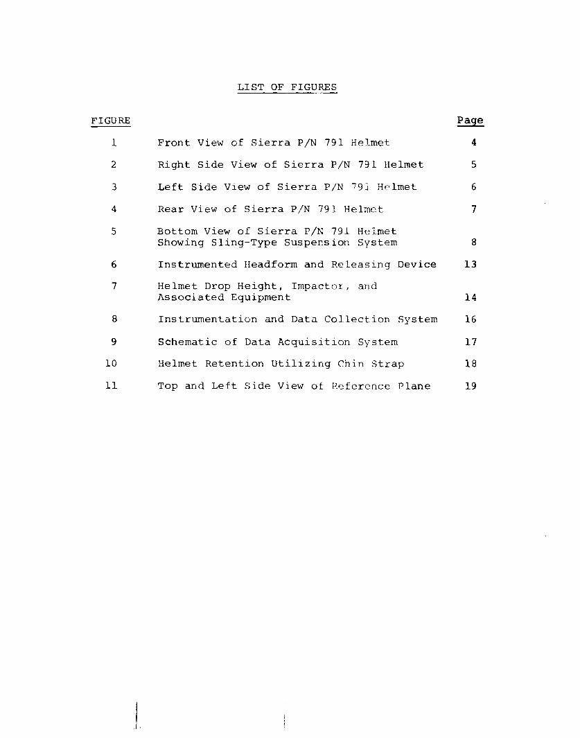
LIST OF FIGURES
Front View of Sierra P/N 791 Helmet
Right Side View of Sierra P/N 791 Helmet
Left Side View of Sierra P/N 791 Helmet
Rear View of Sierra P/N 791 Helmet
Bottom View of Sierra P/N 791 Helmet Showing Sling-Type Suspension System
Instrumented Headform and Releasing Device
Helmet Drop Height, Impactor, and Associated Equipment
Instrumentation and Data Collection System
Schematic of Data Acquisition System
Helmet Retention Utilizing Chin Strap
Top and Left Side View of Reference Plane
5
6
7
8
13
14
16
17
18
19
TABLE
I
II
I II
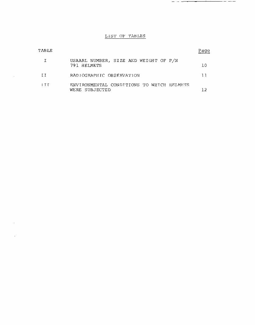
LIST OF TABLES
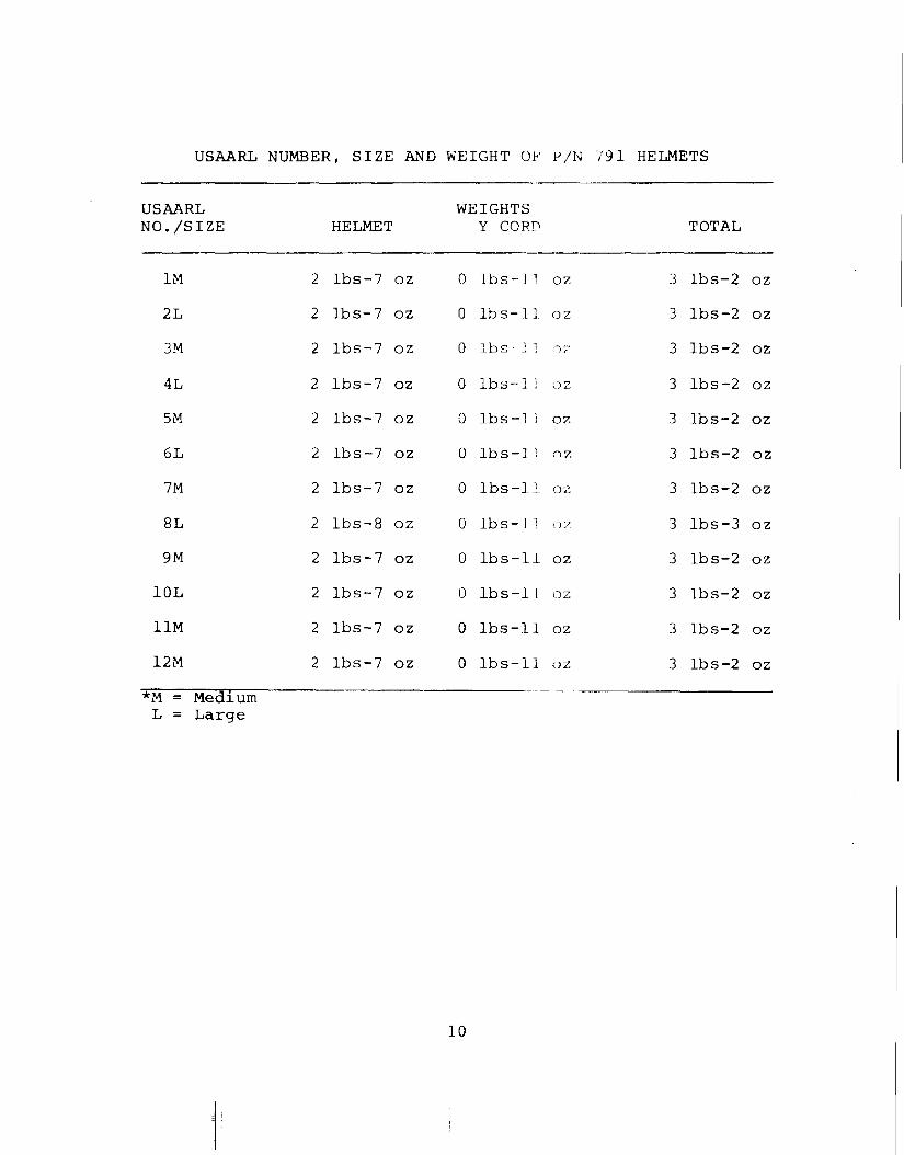
USAARL NUMBER, SIZE AND WEIGHT OF P/N 791 HELMETS
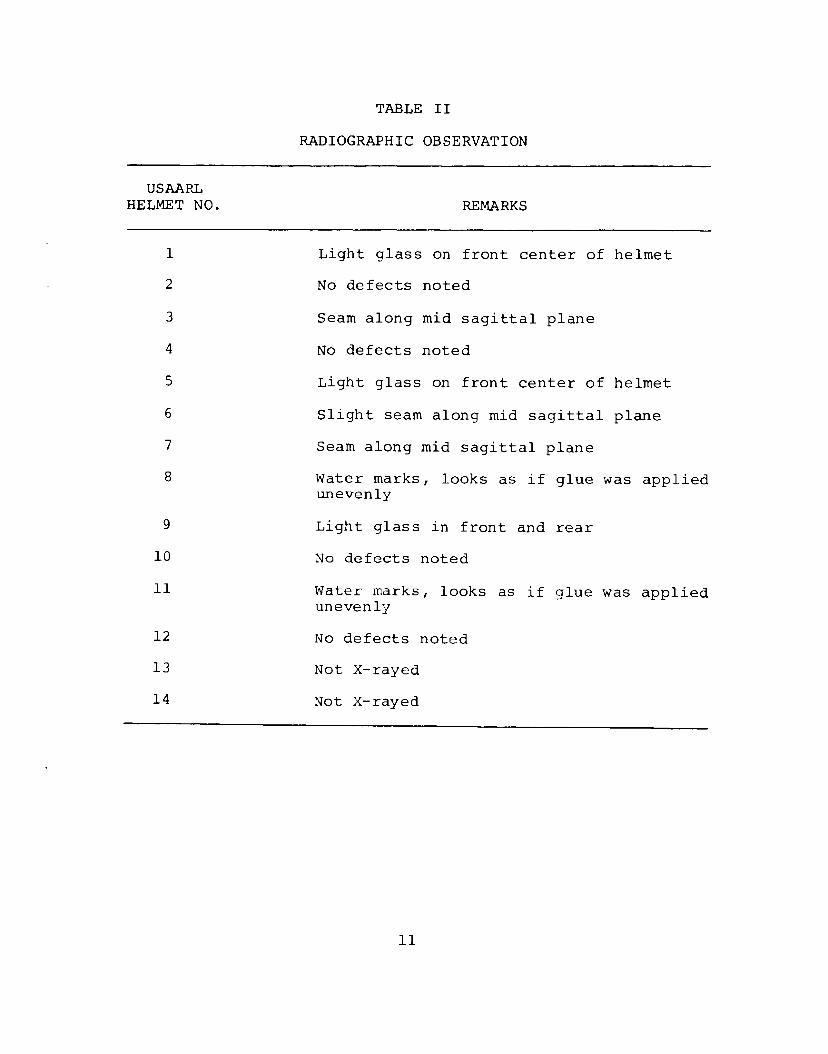
RADIOGRAPHIC OBSERVATION
ENVIRONMENTAL CONDITIONS TO WHICH HELMETS WERE SUBJECTED
10
11
12
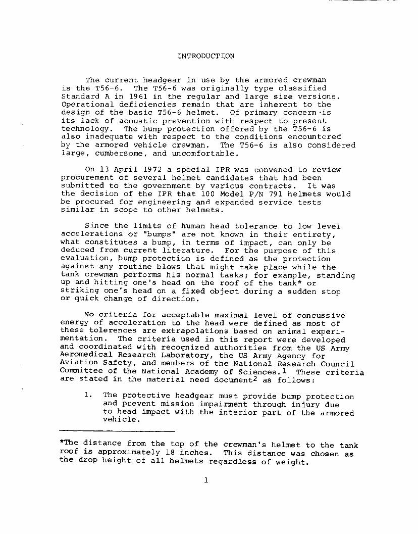
INTRODUCTION
The current headgear in use by the armored crewman is the T56-6. The T56-6 was originally type classified Standard A in 1961 in the regular and large size versions. Operational deficiencies remain that are inherent to the design of the basic T56-6 helmet. Of primary concern-is its lack of acoustic prevention with respect to present technology. The bump protection offered by the T56-6 is also inadequate with respect to the conditions encountered by the armored vehicle crewman. The TS6-6 is also considered large, cumbersome, and uncomfortable.
On 13 April 1972 a special IPR was convened to review procurement of several helmet candidates that had been submitted to the government by various contracts. It was the decision of the IPR that 100 Model P/N 791 helmets would be procured for engineering and expanded service tests similar in scope to other helmets.
Since the limits of human head tolerance to low level accelerations or "bumps" are not known in their entirety, what constitutes a bump, in terms of impact, can only be deduced from current literature. For the purpose of this evaluation, bump protecti0n is defined as the protection against any routine blows that might take place while the tank crewman performs his normal tasks;· for example, standing up and hitting one's head on the roof of the tank* or striking one's head on a fixed object during a sudden stop or quick change of direction.
No criteria for acceptable maximal level of concussive energy of acceleration to the head were defined as most of these tolerences are extrapolations based on animal experimentation. The criteria used in this report were developed and coordinated with recognized authorities from the US Army Aeromedical Research Laboratory, the US Army Agency for Aviation Safety, and members of the National Research Council Committee of the National Academy of Sciences.! These criteria are stated in the material need document2 as follows:
1. The protective headgear must provide bump protection and prevent mission impairment through injury due to head impact with the interior part of the armored vehicle.
*The distance from the top of the crewman's helmet to the tank roof is approximately 18 inches. This distance was chosen as the drop height of all helmets regardless of weight.
1
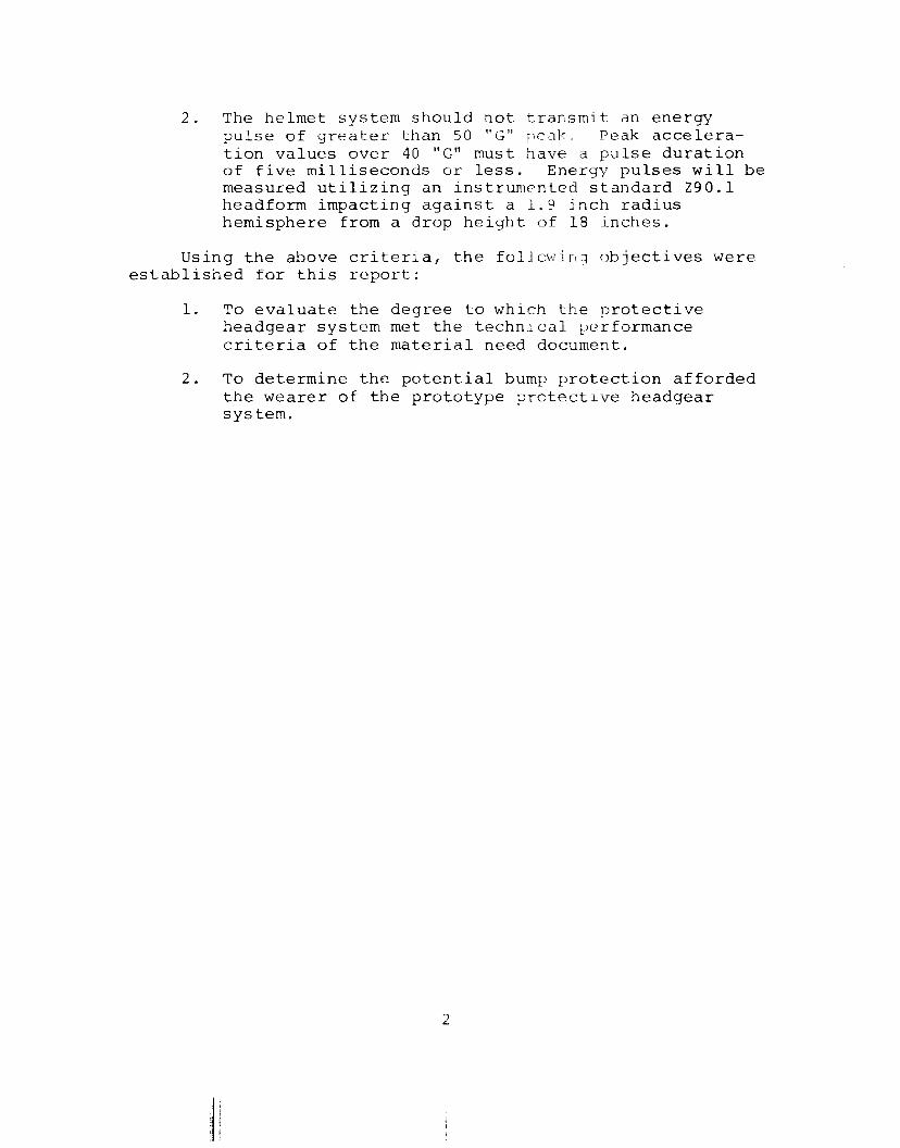
2. The helmet system should not transmjt an energy pulse of greater than 50 "G" peak~ Peak acceleration values over 40 "G" must have a pulse duration of five milliseconds or less. Energy pulses will be measured utilizing an instrumented standard Z90.1 headform impacting against a 1.9 inch radius hemisphere from a drop height of 18 inches.
Using the above criteria, the foUowin::r objectives were established for this report:
1. To evaluate the degree to which the protective headgear system met the technical ~erformance criteria of the material need document.
2. To determine the potential bump protection afforded the wearer of the prototype protective headgear system.
2
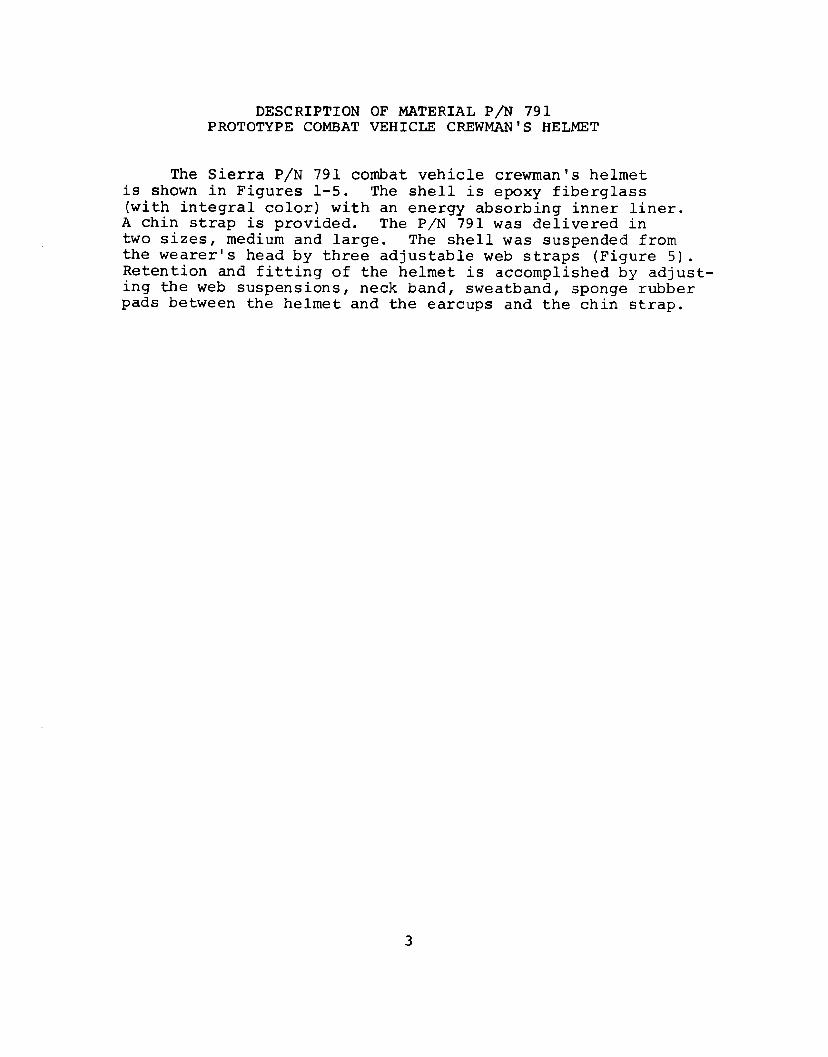
DESCRIPTION OF MATERIAL P/N 791 PROTOTYPE COMBAT VEHICLE CREWMAN'S HELMET
The Sierra P/N 791 combat vehicle crewman's helmet is shown in Figures 1-5. The shell is epoxy fiberglass (with integral color) with an energy absorbing inner liner.
A chin strap is provided. The P/N 791 was delivered in two sizes, medium and large. The shell was suspended from the wearer's head by three adjustable web straps (Figure 5). Retention and fitting of the helmet is accomplished by adjusting the web suspensions, neck band, sweatband, sponge rubber pads between the helmet and the earcups and the chin strap.
3
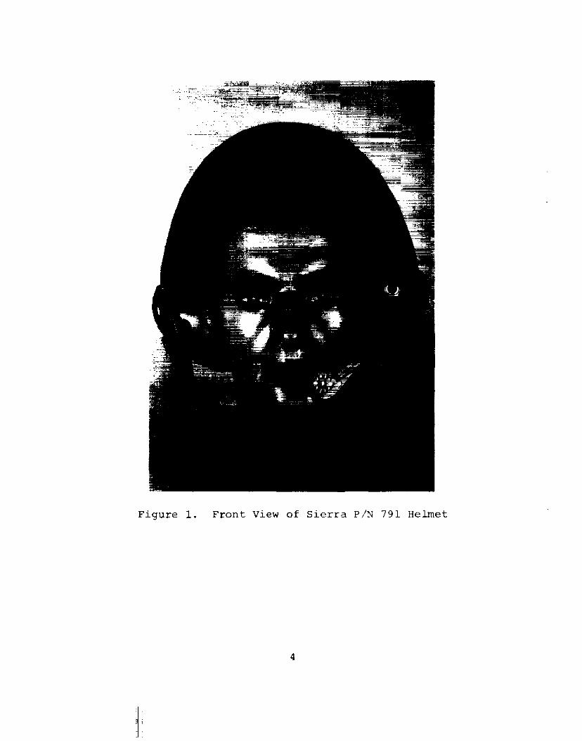
Figure 1. Front View of Sierra P/N 791 Helmet
4
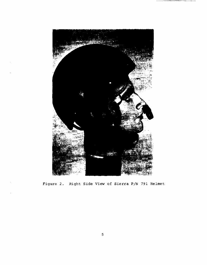
Figure 2. Right Side View of Sierra P/N 791 Helmet
5
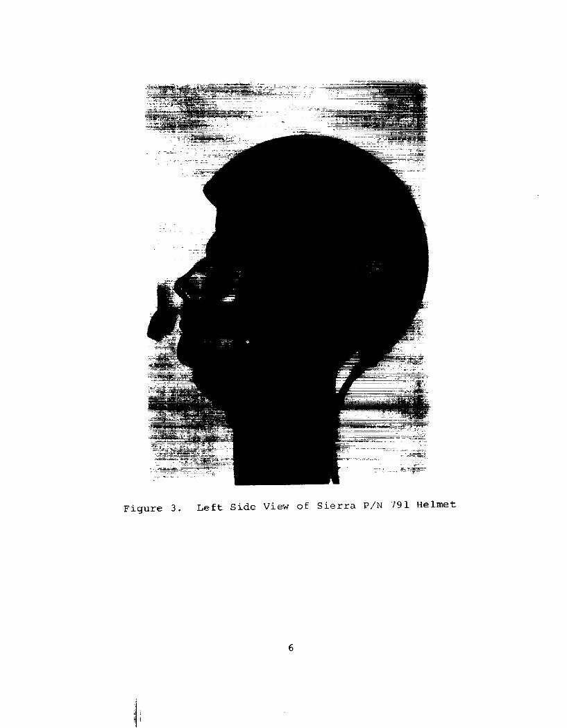
Figure 3. Left Side View of Sierra P/N 791 Helmet
6
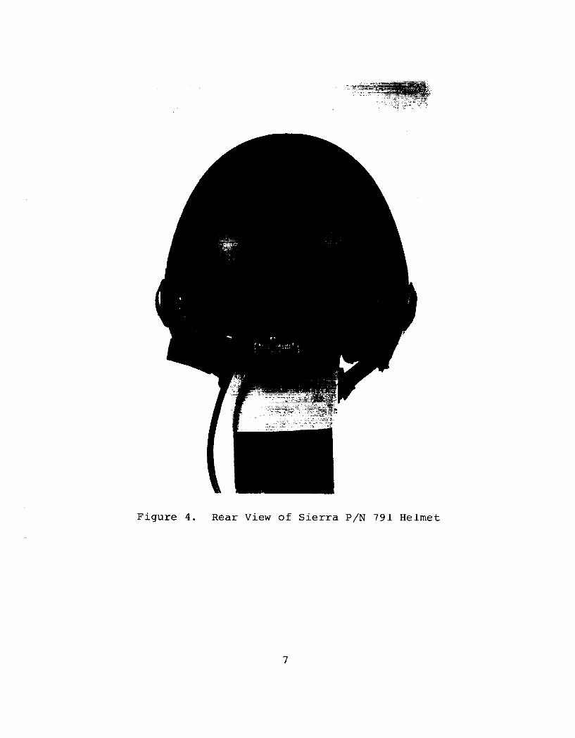
Figure 4. Rear View of Sierra P/N 791 Helmet
7
Figure 5. Bottom View of Sierra P/N 791 Helmet Showing Sling-Type Suspension System
8
METHODS AND MATERIALS
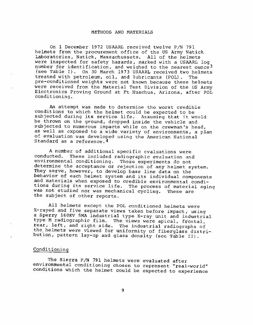
On 1 December 1972 USAARL received twelve P/N 791 helmets from the procurement office of the US Army Natick Laboratories, Natick, Massachussets. All of the helmets were inspected for safety hazards, marked with a USAARL log number for identification, and weighed to the nearest ounce3 (see Table I). On 30 March 1973 USAARL received two helmets treated with petroleum, oil, and lubricants (POL). The pre-conditioned weights were not known because these helmets were received from the Material Test Division of the us Army Electronics Proving Ground at Ft Huachua, Arizona, after POL conditioning.
An attempt was made to determine the worst credible conditions to which the helmet could be expected to be subjected during its service life. Assuming that it would be thrown on the ground, dropped inside the vehicle and subjected to numerous impacts while on the crewman's head, as well as exposed to a wide variety of environments, a plan of evaluation was developed using the American National Standard as a reference.4
A number of additional specific evaluations were conducted. These included radiographic evaluation and environmental conditioning. These experiments do not determine the acceptance or rejection of any helmet system. They serve, however, to develop base line data on the behavior of each helmet system and its individual components and materials when exposed to credible environmental conditions during its service life. The process of material aging was not studied nor was mechanical cycling. These are the subject of other reports.
All helmets except the POL conditioned helmets were X-rayed and five separate views taken before impact, using a Sperry 160KV SMA industrial type X-ray unit and industrial type M radiographic film. The views were apical, frontal, rear, left, and right side. The industrial radiographs of the_ helmets were viewed for uniformity of fiberglass distribution, pattern lay-up and glass density (see Table II).
Conditioning
The Sierra P/N 791 helmets were evaluated after environmental conditioning chosen to represent "real-world" conditions which the helmet could be expected to experience
9
USAARL NUMBER, SIZE AND WEIGHT OF P/N 791 HELMETS
USAARL WEIGHTS NO./SIZE HELMET y CORD TOTAL
1M 2 1bs-7 oz 0 1bs-11 oz 3 1bs-2 oz
2L 2 1bs-7 oz 0 lbs-11 oz 3 1bs-2 oz
3M 2 lbs-7 oz 0 lbs-ll ~--.. '""!' 3 lbs-2 oz , _ _, L_
4L 2 lbs-7 oz 0 lbs-ll oz 3 1bs-2 oz
SM 2 lbs-7 oz 0 lbs-1 1 oz 3 1bs-2 oz
6L 2 1bs-7 oz 0 lbs-11 ;.) z 3 1bs-2 oz
7M 2 1bs-7 oz 0 lbs-12_ oz 3 lbs-2 oz
BL 2 1bs-8 oz 0 1bs-11 C1Z 3 1bs-3 oz
9M 2 lbs-7 oz 0 lbs-11 oz 3 1bs-2 oz
lOL 2 1bs-7 oz 0 lbs-11 oz 3 lbs-2 oz
11M 2 1bs-7 oz 0 1bs-1l oz 3 lbs-2 oz
12M 2 1bs-7 oz 0 lbs-ll 02 3 1bs-2 oz
*M - Med1um L Large
10
USAARL HELMET NO.
l
2
3
4
5
6
7
8
9
10
11
12
13
14
TABLE II
RADIOGRAPHIC OBSERVATION
REMARKS
Light glass on front center of helmet
No defects noted
Seam along mid sagittal plane
No defects noted
Light glass on front center of helmet
Slight seam along mid sagittal plane
Seam along mid sagittal plane
Water marks, looks as if glue was applied unevenly
Light glass in front and rear
No defects noted
Water marks, looks as if glue was applied unevenly
No defects noted
Not X-rayed
Not X-rayed
11
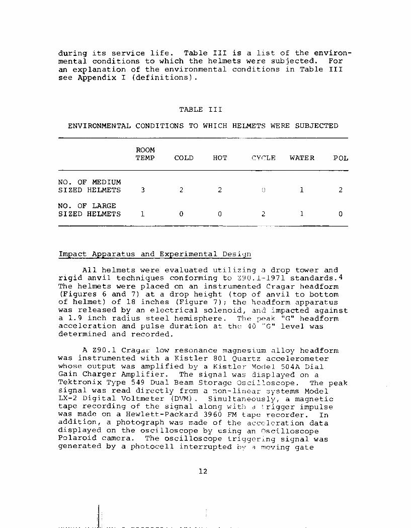
during its service life. Table III is a list of the environmental conditions to which the helmets were subjected. For an explanation of the environmental conditions in Table III see Appendix I (definitions).
TABLE III
ENVIRONMENTAL CONDITIONS TO WHICH HELMETS WERE SUBJECTED
··---~--
ROOM TEMP COLD HOT CYCLE WATER POL
NO. OF MEDIUM SIZED HELMETS 3 2 2 0 1 2
NO. OF LARGE SIZED HELMETS 1 0 0 2 1 0
Impact Apparatus and Experimental Design
All helmets were evaluated utilizing a drop tower and rigid anvil techniques conforming to Z90.l-1971 standards.4 The helmets were placed on an instrumented Cragar headform (Figures 6 and 7) at a drop height (top of anvil to bottom of helmet) of 18 inches (Figure 7); the headform apparatus was released by an electrical solenoid, and impacted against a 1. 9 inch radius steel hemisphere. The peak "G" headform acceleration and pulse duration at the 40 "G" level was determined and recorded.
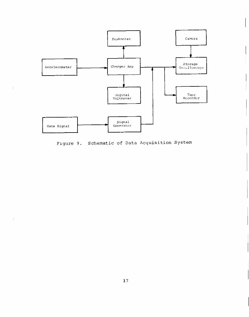
A Z90.1 Cragar low resonance magnesium alloy headform was instrumented with a Kistler 801 Quartz accelerometer whose output was amplified by a Kis tle ~- Mode 1 50 4A Dial Gain Charger Amplifier. The signal was displayed on a Tektronix Type 549 Dual Beam Storage Oscilloscope. The peak signal was read directly from a non-linear systems Model LX-2 Digital Voltmeter (DVM). Simultaneously, a magnetic tape recording of the signal along with a !:rigger impulse was made on a Hewlett-Packard 3960 FM tape recorder. In addition, a photograph was made of the acceleration data displayed on the oscilloscope by using an Oscilloscope Polaroid camera. The oscilloscope triggering signal was generated by a photocell interrupted by R moving gate
12
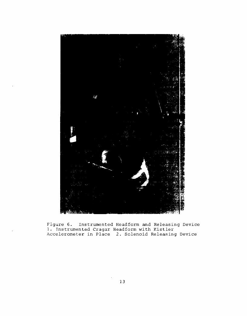
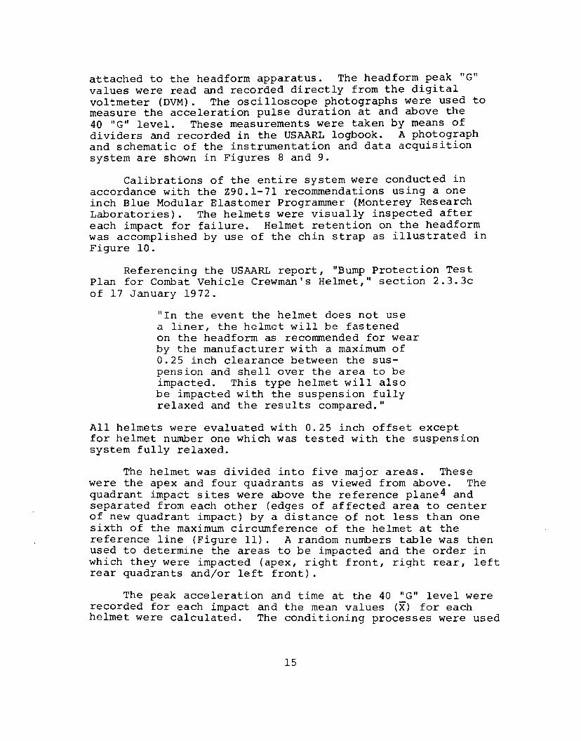
Figure 6. Instrumented Headform and Releasing Device 1. Instrumented Cragar Headform with Kistler Accelerometer in Place 2. Solenoid Releasing Device
13
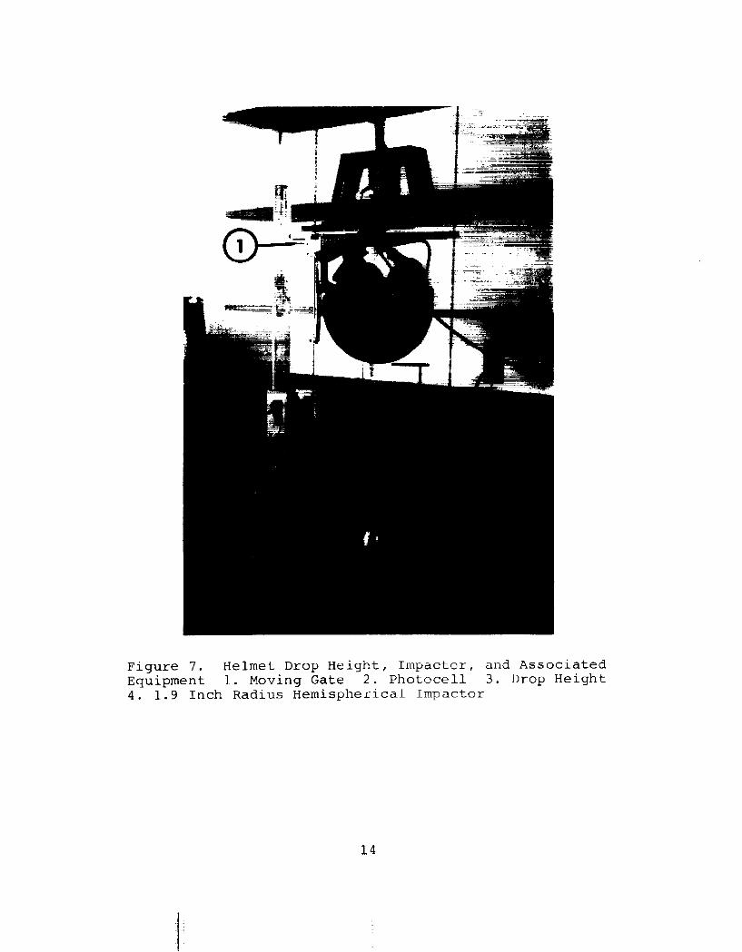
Figure 7. Helmet Drop Height, Impactor, and Associated Equipment 1. Moving Gate 2. Photocell 3. Drop Height 4. 1.9 Inch Radius Hemispherical Impactor
14
attached to the headform apparatus. The headform peak "G" values were read and recorded directly from the digital voltmeter (DVM). The oscilloscope photographs were used to measure the acceleration pulse duration at and above the 40 "G" level. These measurements were taken by means of dividers and recorded in the USAARL logbook. A photograph and schematic of the instrumentation and data acquisition system are shown in Figures 8 and 9.
Calibrations of the entire system were conducted in accordance with the Z90.1-71 recommendations using a one inch Blue Modular Elastomer Programmer (Monterey Research Laboratories). The helmets were visually inspected after each impact for failure. Helmet retention on the headform was accomplished by use of the chin strap as illustrated in Figure 10.
Referencing the USAARL report, "Bump Protection Test Plan for Combat Vehicle Crewman's Helmet," section 2. 3. 3c of 17 January 1972.
"In the event the helmet does not use a liner, the helmet will be fastened on the headform as recommended for wear by the manufacturer with a maximum of 0.25 inch clearance between the suspension and shell over the area to be impacted. This type helmet will also be impacted with the suspension fully relaxed and the results compared."
All helmets were evaluated with 0.25 inch offset except for helmet number one which was tested with the suspension system fully relaxed.
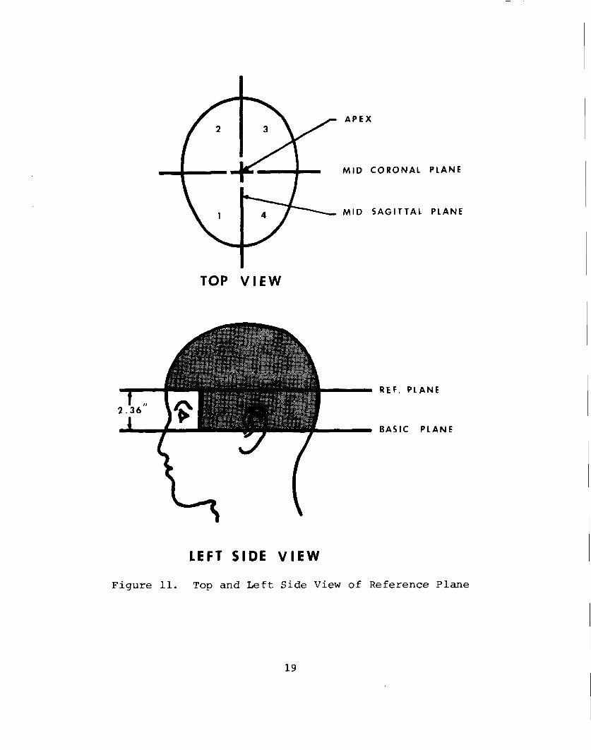
The helmet was divided into five major areas. These were the apex and four quadrants as viewed from above. The quadrant impact sites were above the reference plane4 and separated from each other (edges of affected area to center of new quadrant impact) by a distance of not less than one sixth of the maximum circumference of the helmet at the reference line (Figure 11) . A random numbers table was then used to determine the areas to be impacted and the order in which they were impacted (apex, right front, right rear, left rear quadrants and/or left front).
The peak acceleration and time at the 40 "G" level were recorded for each impact and the mean values (X) for each helmet were calculated. The conditioning processes were used
15

Figure 8. Instrumentation and Data Collection System 1. Hewlett Packard 3960 Recorder 2. Peak Voltage Meter 3. Charger Amplifier 4. Kistler 801 Accelerometer and Case 5. Direct Voltage Meter (DVM) 6. Digital Timer 7. Polaroid Camera 8. Oscilloscope
16
Peak meter Camera
Accelerometer Charger Amp Storage
Oscilloscope
Digital Tape Voltmeter Recorder
Signal Gate Signal Generator
Figure 9. Schematic of Data Acquisition System
17
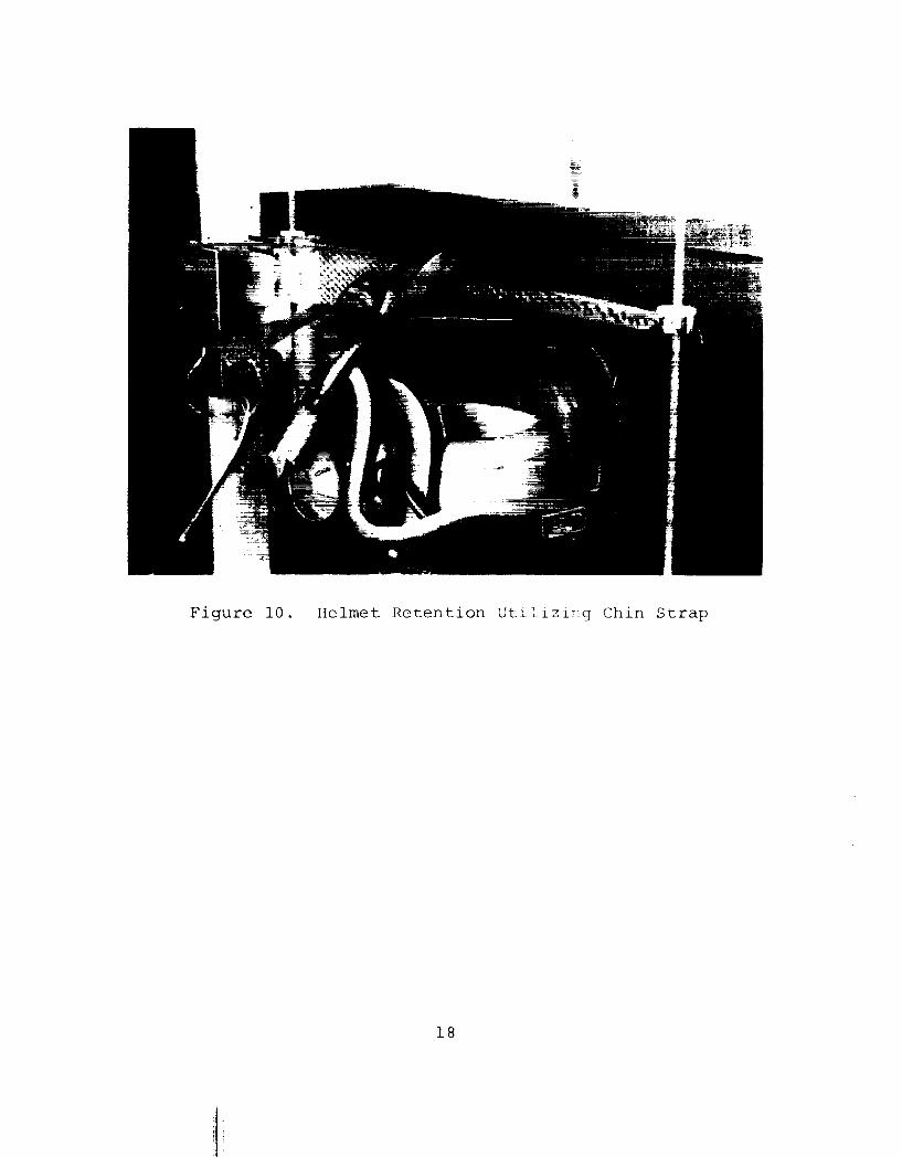
Figure 10. Helmet Retention Utilizing Chin Strap
18
APEX
MID CORONAl PLANE
MID SAGITTAl PLANE
TOP VIEW
REF. PLANE
2
BASIC PLANE
LEFT SIDE VIEW
Figure 11. Top and Left Side View of Reference Plane
19
to evaluate energy absorbing materials and to derive major trends, deficiencies, and identify problem areas that might be experienced during the normal service of the helmet system. The conditioning data is not used in this report as a decision factor in recommending acceptance ur rc-:>jection of the helmet system.
The Two Special Procedures--Petrolc:urr:, Oil and Lubricants
The US Army Electronic Proving Gr '.J'-lnc', Ft lluach uca, Arizona applied unknown amounts of t'F fo"J lowing POL products to the two helmets marked as POL for ~ ~criod of 20 hours. The method of appiic.:l:-_Lon is unknudr' , ,_-~==,;;J,EL.
a. lubricating oil, internal cornbust ion engine (heavy duty)
b. lubricating oil, general purpose: preservative c. grease, automotive and art-illery 'l:c'a\.'Y) d. hydraulir fluid, petroleum base e. fuel oil, diesel f. thinner, paint, mineral sp1r• t-s
g. insoctic~de, aero'3n1
Helmet Weight and Impact Energy
The theoretical input energy was calculated from the following formula:
Input Energy = Weight x ni~~ance
where,
(a) Input energy lS measurPd in foot-pounds
(b) Height is defined as th= ~cr"tl:" i ned weight in pounds of the helmet hea~form 11.1 pounds), shell, and liner minus tnc ~eight of the attaching electrical corcL
(c) Distance is defined as the drop height rneasurPd in feet (1.5 feet)
Example:
Input Energy Weight x Distance (11.1 lbs + 2.4 lbs) x 1.5 ft
Input Energy= 20.3 ft lbs
20
RESULTS
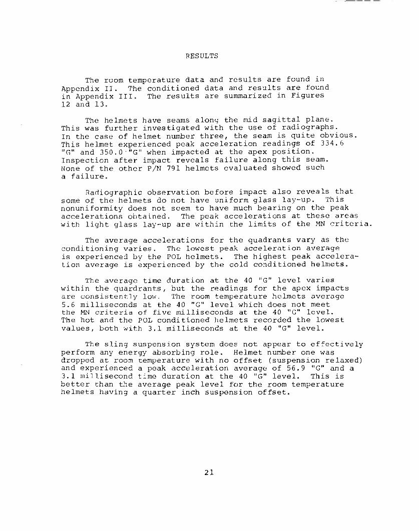
The room temperature data and results are found in Appendix II. The conditioned data and results are found in Appendix III. The results are summarized in Figures 12 and 13.
The helmets have seams along the mid sagittal plane. This was further investigated with the use of radiographs. In the case of helmet number three, the seam is quite obvious. This helmet experienced peak acceleration readings of 334.6 "G" and 350.0·"G" when impacted at the apex position. Inspection after impact reveals failure along this seam. None of the other P/N 791 helmets evaluated showed such a failure.
Radiographic observation before impact also reveals that some of the helmets do not have uniform glass lay-up. This nonuniformity does not seem to have much bearing on the peak accelerations obtained. The peak accelerations at these areas with light glass lay-up are within the limits of the MN criteria.
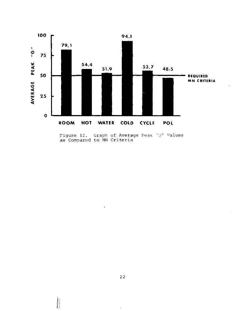
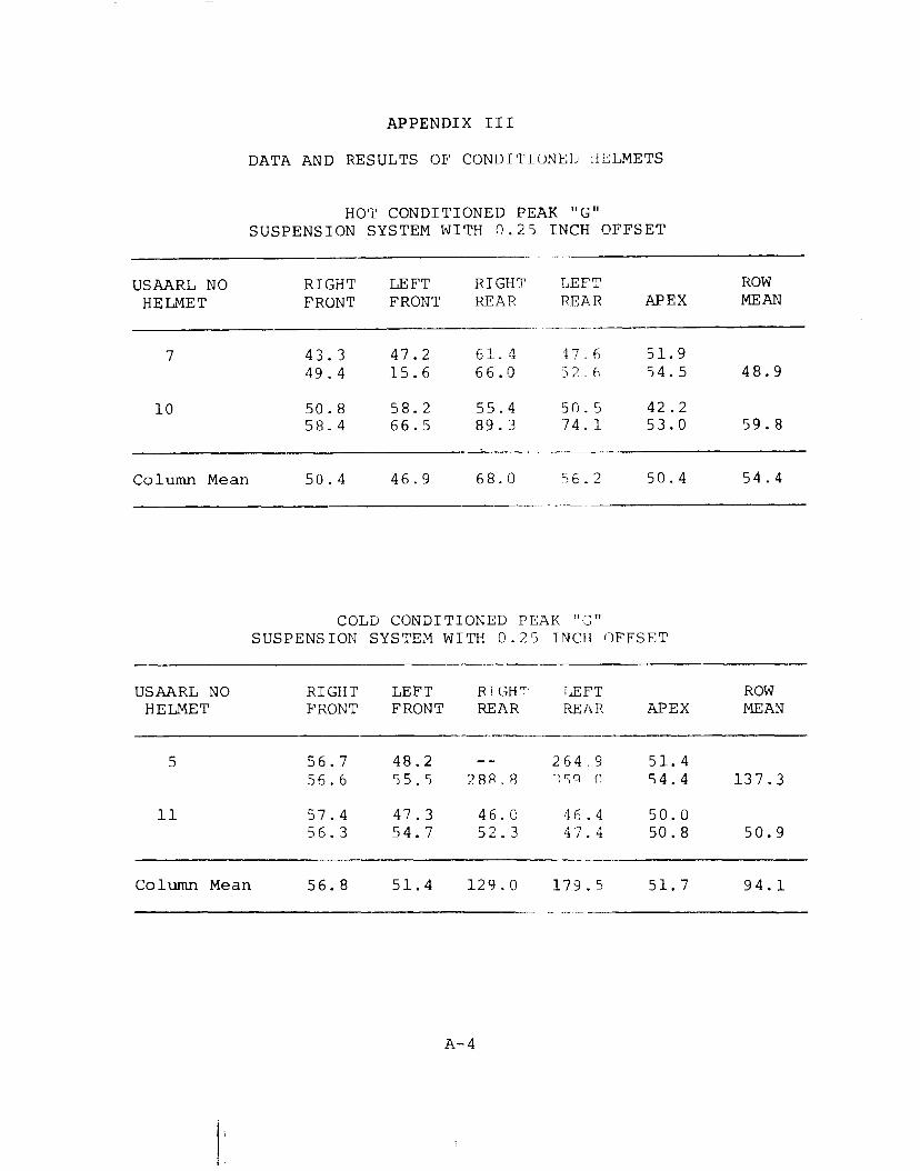
The average accelerations for the quadrants vary as the conditioning varies. The lowest peak acceleration average is experienced by the POL helmets. The highest peak acceleration average is experienced by the cold conditioned helmets.
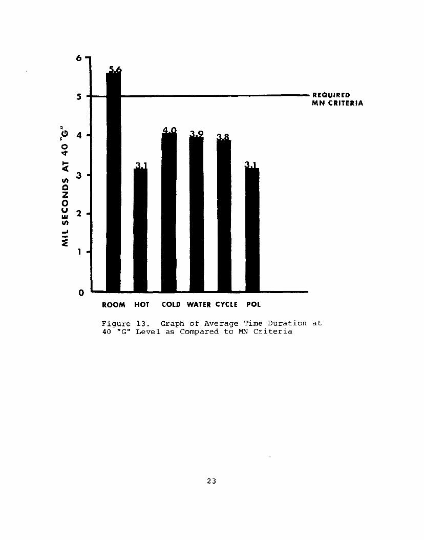
The average time duration at the 40 "G" level varies within the quardrants, but the readings for the apex impacts are consistently low. The room temperature helmets average 5.6 milliseconds at the 40 "G" level which does not meet the MN criteria of five milliseconds at the 40 "G" level. The hot and the POL conditioned helmets recorded the lowest values, both with 3.1 milliseconds at the 40 "G" level.
The sling suspension system does not appear to effectively perform any energy absorbing role. Helmet number one was dropped at room temperature with no offset (suspension relaxed) and experienced a peak acceleration average of 56.9 "G" and a 3.1 millisecond time duration at the 40 "G" level. This is better than the average peak level for the room temperature helmets having a quarter inch suspension offset.
21
100
~ ::: 75
50
25
0
------ REQUIRED
ROOM HOT WATER COLD CYCLE POL
Figure 12. Graph of Average Peak "G" Values as Compared to MN Criteria
22
M N CRITERIA
::: C> ~
0 q-
:( U)
0 z 0 u ..... U) ... ~
6
s
4
3
2
1
0
REQUIRED MN CRITERIA
ROOM HOT COLD WATER CYCLE POL
Figure 13. Graph of Average Time Duration at 40 "G" Level as Compared to MN Criteria
23
CONCLUSIONS
The P/N 791 did not meet the MN criteria for peak "G" or for time duration at the 40 "G" level.
24
RECOMMENDATIONS
Clarification of helmet sizing instructions should be revised so as to have the suspension system adjusted to optimize energy absorption.
25
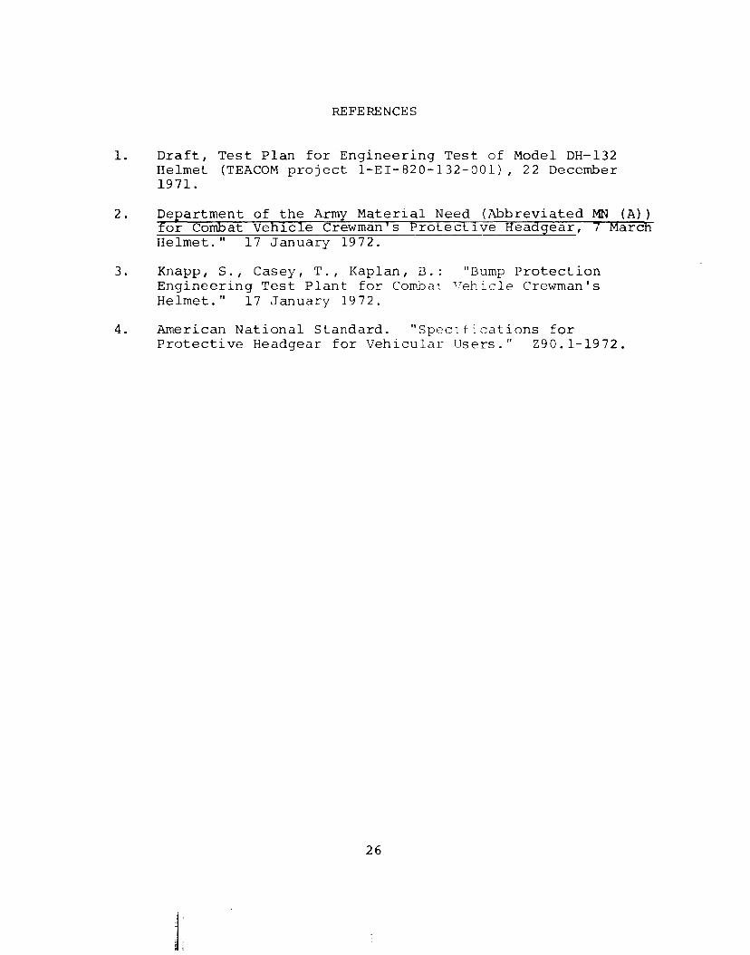
REFERENCES
1. Draft, Test Plan for Engineering Test of Model DH-132 Helmet (TEACOM project 1-EI-820-132-001), 22 December 1971.
2. Department of the Army Material Need (Abbreviated MN (A}} for Combat Vehicle Crewman's Protective Headgear, 7 Marcfi Helmet." 17 January 1972.
3. Knapp, S., Casey, T., Kaplan, B. : "Bump Protection Engineering Test Plant for Combat '/eh icle Crewman's Helmet." 17 January 1972.
4. American National Standard. "Spec1fications for Protective Headgear for Vehicular Users." 290.1-1972.
26
.1 i ~ i
Helmet System
Room Temperature Conditioning
Hot Conditioning
Cold Conditioning
Cycle Conditioning
Water Conditioning
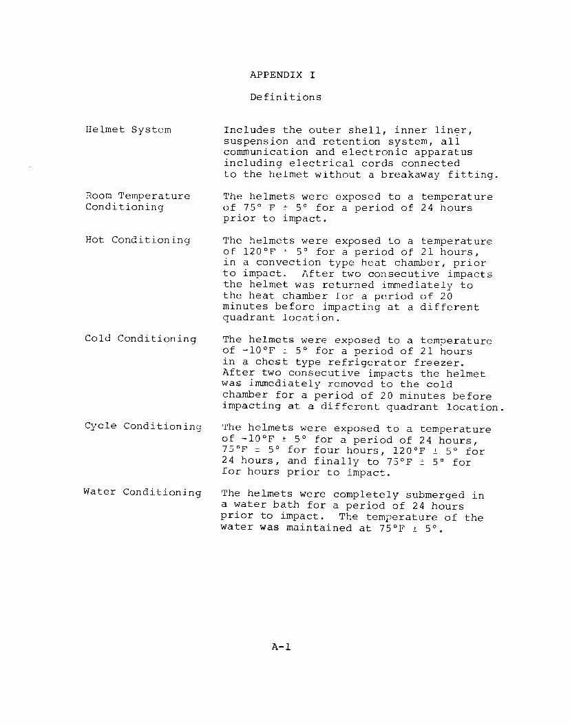
APPENDIX I
Definitions
Includes the outer shell, inner lin~r, suspension and retention system, all communication and electronic apparatus including electrical cords connected to the helmet without a breakaway fitting.
The helmets were exposed to a temperature of 7S° F ± so for a period of 24 hours prior to impact.
The helmets were exposed to a temperature of 120°F ± so for a period of 21 hours, in a convection type heat chamber, prior to impact. After two consecutive impacts the helmet was returned immediately to the heat chamber for a period of 20 minutes before impacting at a different quadrant location.
The helmets were exposed to a temperature of -l0°F ± so for a period of 21 hours in a chest type refrigerator freezer. After two consecutive impacts the helmet was immediately removed to the cold chamber for a period of 20 minutes before impacting at a different quadrant location.
The helmets were exposed to a temperature of -10°F ± so for a period of 24 hours, 75°F ± so for four hours, l20°F ± so for 24 hours, and finally to 75°F ± so for for hours prior to impact.
The helmets were completely submerged in a water bath for a period of 24 hours prior to impact. The temperature of the water was maintained at 75°F ± 5°.
A-1
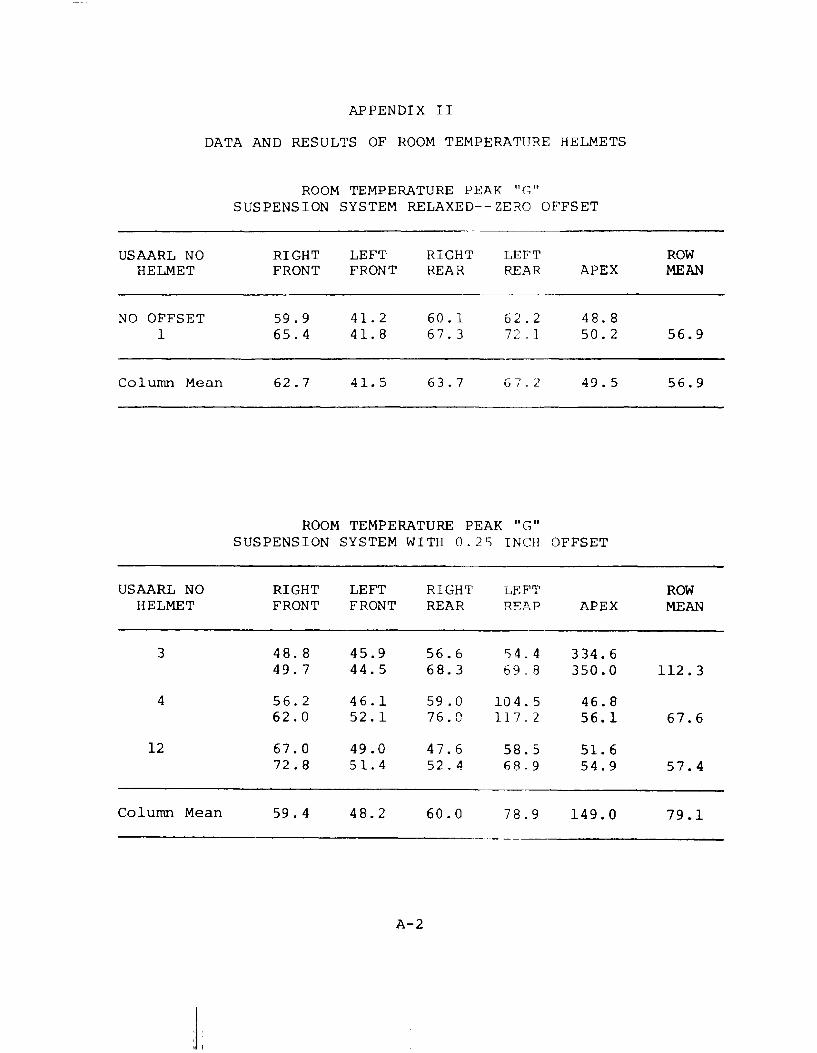
APPENDIX II
DATA AND RESULTS OF ROOM TEMPERATURE HELMETS
USAARL NO HELMET
NO OFFSET 1
Column Mean
USAARL NO HELMET
3
4
12
Column Mean
ROOM TEMPERATURE PEAK nc;" SUSPENSION SYSTEM RELAXED--ZERO OFFSET
RIGHT LEFT RIGHT LEFT FRONT FRONT REAR REAR APEX
59.9 41.2 60. l 62.2 48.8 65.4 41.8 67.3 72 . 1 50.2
62.7 41.5 63.7 G7.2 49.5
ROOM TEMPERATURE PEAK "G" SUSPENSION SYSTEM WITH 0 ?~ INCH OFFSET
RIGHT LEFT RIGHT LEFT FRONT FRONT REAR RE."'.R APEX
4 8. 8 45.9 56.6 54.4 334.6 49.7 44.5 68.3 69.8 350.0
56.2 46.1 59.0 10 4. 5 46.8 62.0 52.1 76.0 l, "! .,
~!. {. 56.1
67.0 49.0 47.6 58.5 51.6 72.8 51.4 52. 4 68.9 54.9
59.4 48.2 60.0 78.9 149.0
A-2
ROW MEAN
56.9
56.9
ROW MEAN
112.3
67.6
57.4
79.1
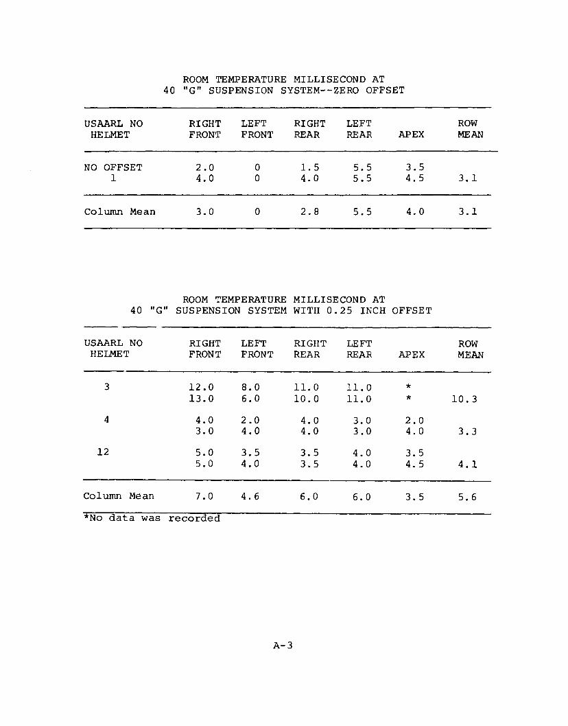
ROOM TEMPERATURE MILLISECOND AT 40 "G" SUSPENSION SYSTEM--ZERO OFFSET
USAARL NO RIGHT LEFT RIGHT LEFT ROW HELMET FRONT FRONT REAR REAR APEX MEAN
NO OFFSET 2.0 0 1.5 5.5 3.5 1 4.0 0 4.0 5.5 4.5 3.1
Column Mean 3.0 0 2.8 5.5 4.0 3.1
ROOM TEMPERATURE MILLISECOND AT 40 "G" SUSPENSION SYSTEM WITH 0.25 INCH OFFSET
USAARL NO RIGHT LEFT RIGHT LEFT ROW HELMET FRONT FRONT REAR REAR APEX MEAN
3 12.0 8.0 11.0 11.0 * 13.0 6.0 10.0 11.0 * 10.3
4 4.0 2.0 4.0 3.0 2.0 3.0 4.0 4.0 3.0 4.0 3.3
12 5.0 3.5 3.5 4.0 3.5 5.0 4.0 3.5 4.0 4.5 4.1
Column Mean 7.0 4.6 6.0 6.0 3.5 5.6
*No data was recorded
A-3
USAARL NO HELMET
7
10
Column Mean
USAARL NO HELMET
5
11
APPENDIX III
DATA AND RESULTS OF CONDITIONED HELMETS
HOT CONDITIONED PEAK "G" SUSPENSION SYSTEM WITH 0.25 INCH OFFSET
RIGHT LEFT RIGHT LEFT FRONT FRONT RE}\R REAR APEX
-·- "-~------·
4 3. 3 47.2 61. 4 47.6 51.9 49.4 15.6 66.0 52.fl 54.5
50.8 58.2 55.4 50.5 42.2 58. 4 66.5 89.3 74.1 53.0
50.4 46.9 68.0 56~ 2 50.4
-•----·c--•
COLD CONDITIONED PEAK 11 • .--. n ··J
SUSPENSION SYSTEM WITH 0.25 INCH OFFSET
RIGHT LEFT RIGHT LEFT FRONT FRONT REAR REl\R APEX
56.7 48.2 264_9 51.4 56.6 55.5 288.8 ~-~ 5 g _ n 54.4
57.4 47.3 46.C 46.4 50.0 56. 3 54.7 52.3 4 7. 4 50. 8
Column Mean 56.8 51.4 129.0 179.5 51. 7
--- ---·-·--
A-4
ROW MEAN
48.9
59.8
54.4
ROW MEAN
137.3
50.9
94.1
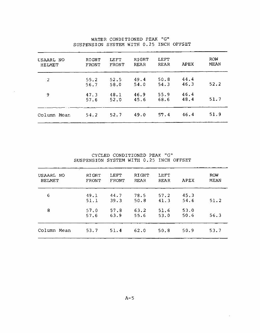
WATER CONDITIONED PEAK "G" SUSPENSION SYSTEM WITH 0.25 INCH OFFSET
USAARL NO RIGHT LEFT RIGHT LEFT ROW HELMET FRONT FRONT REAR REAR APEX MEAN
2 55.2 52.5 49.4 50.8 44.4 56.7 58.0 54.0 54.3 46.3 52.2
9 47.3 48.1 46.9 55.9 46.4 57.6 52.0 45.6 68.6 48.4 51.7
ColUITU1 Mean 54.2 52.7 49.0 5"'7 . 4 46.4 51.9
CYCLED CONDITIONED PEAK "G" SUSPENSION SYSTEM WITH 0.25 INCH OFFSET
USAARL NO RIGHT LEFT RIGHT LEFT ROW HELMET FRONT FRONT REAR REAR APEX MEAN
6 49.1 44.7 78.5 57.2 45.3 51.1 39.3 50.8 41. 3 54.6 51.2
8 57.0 57.8 63.2 51.6 53.0 57.6 63.9 55.6 53.0 50.6 56.3
Column Mean 53.7 51.4 62.0 50.8 50.9 53.7
A-5
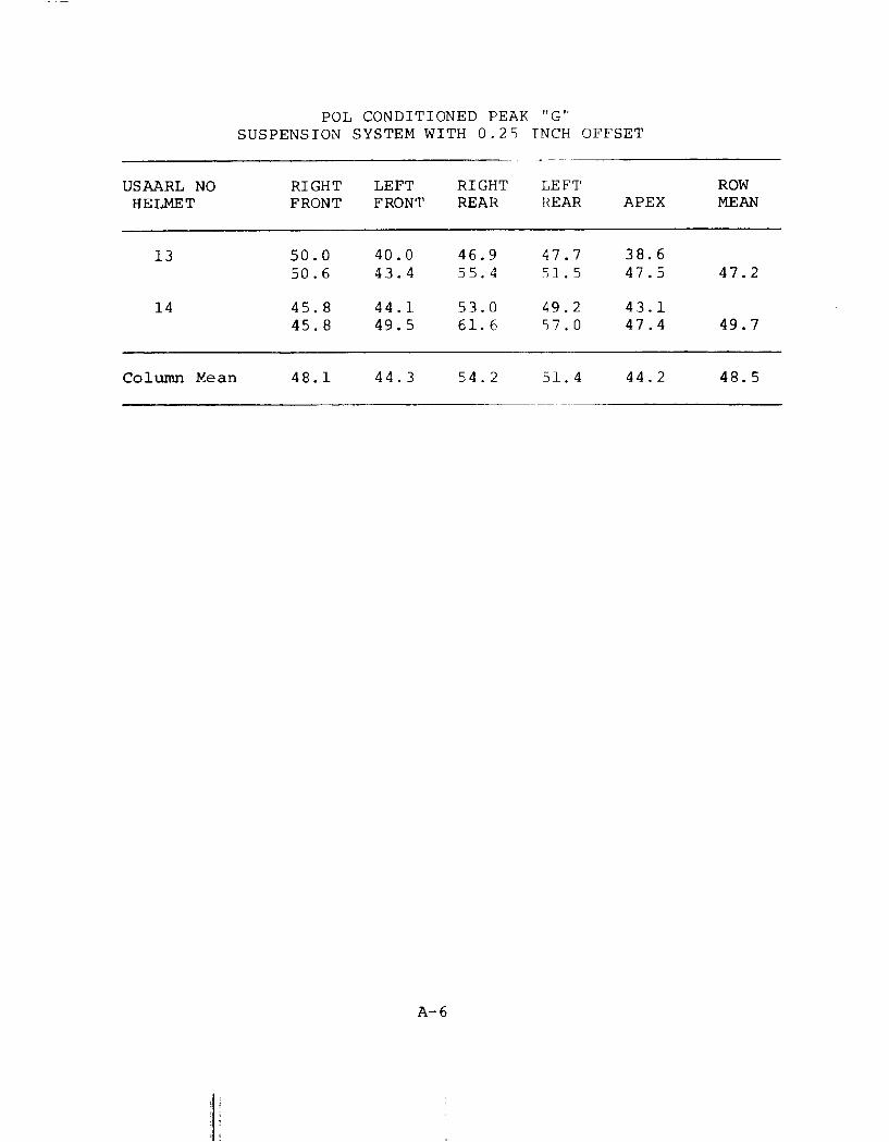
POL CONDITIONED PEAK "G'' SUSPENSION SYSTEM WITH 0.2S TNCH OFFSET
·----~~--
USAARL NO RIGHT LEFT RIGHT LEFT ROW HELMET FRONT FRONT REAR REAR APEX MEAN
13 50.0 40.0 46.9 47.7 38.6 50.6 43.4 55.4 51. 5 47.5 47.2
14 45.8 44.1 53.0 49.2 43.1 45.8 49.5 61.6 57.0 47.4 49.7
Column Mean 48.1 44.3 54.2 51.4 44.2 48.5
A-6
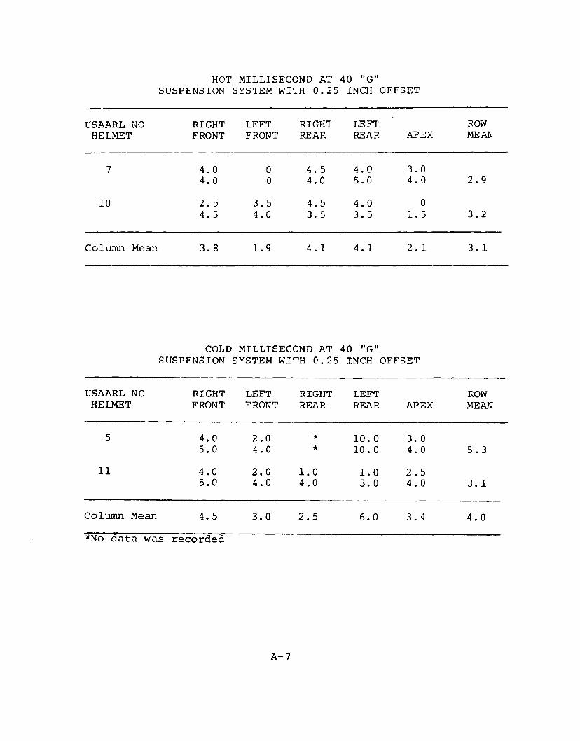
HOT MILLISECOND AT 40 "G" SUSPENSION SYSTE~ WITH 0.25 INCH OFFSET
USAARL NO RIGHT LEFT RIGHT LEFT ROW HELMET FRONT FRONT REAR REAR APEX MEAN
7 4.0 0 4.5 4.0 3.0 4.0 0 4.0 5.0 4.0 2.9
10 2.5 3.5 4.5 4.0 0 4.5 4.0 3.5 3. 5 1.5 3.2
Column Mean 3.8 1.9 4.1 4.1 2.1 3.1
COLD MILLISECOND AT 40 "G" SUSPENSION SYSTEM WITH 0.25 INCH OFFSET
USAARL NO RIGHT LEFT RIGHT LEFT ROW HELMET FRONT FRONT REAR REAR APEX MEAN
5 4.0 2.0 * 10.0 3.0 5.0 4.0 * 10. 0 4. 0 5.3
11 4.0 2.0 l.O l.O 2.5 5.0 4.0 4.0 3.0 4.0 3.1
Column Mean 4.5 3.0 2.5 6.0 3.4 4.0
*No data was recorded
A-7
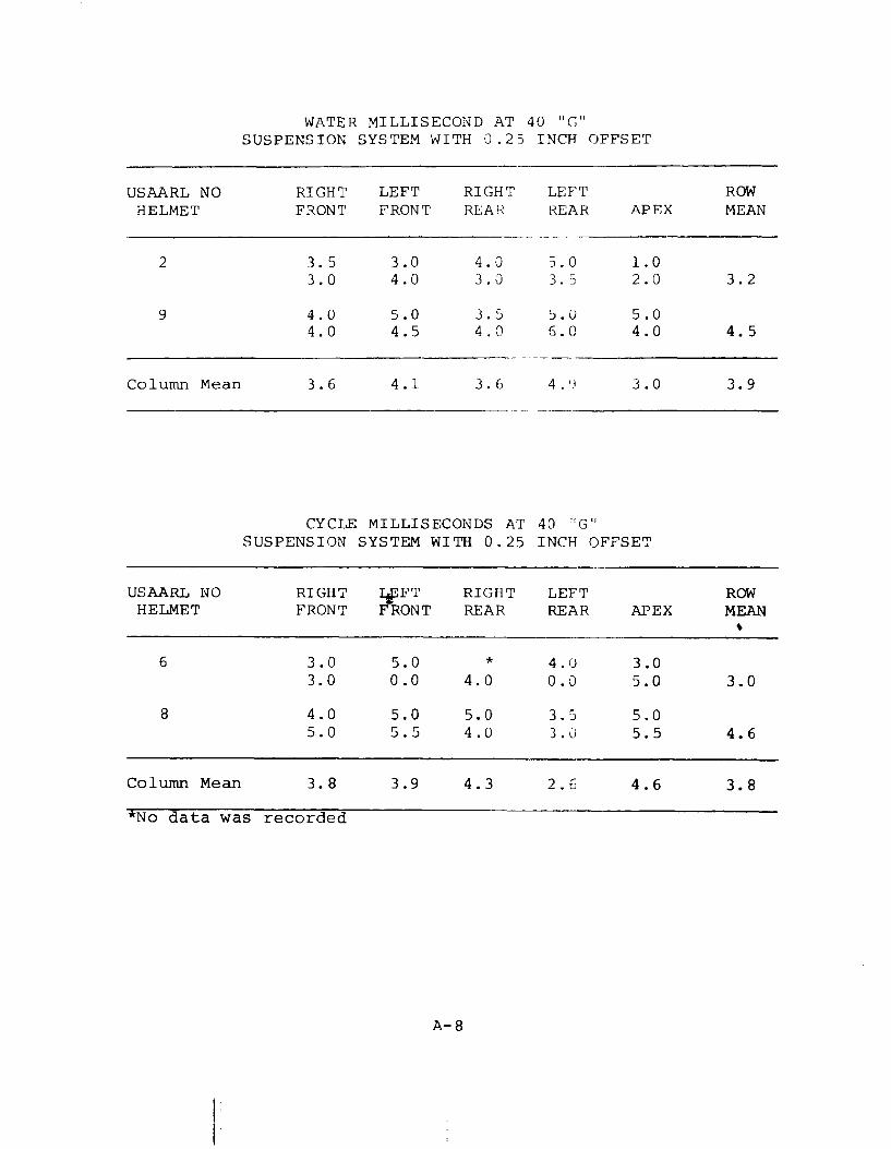
WATER MILLISECOND AT 40 llr_ll '-'
SUSPENSION SYSTEM WITH 0.25 INCH OFFSET
USAARL NO RIGHT LEFT RIGHT LEFT ROW HELMET FRONT FRONT REAR REAR APEX MEAN
> --------
2 3. 5 3.0 4.0 5.0 1.0 3. 0 4.0 3.0 3.5 2.0 3.2
9 4.0 5.0 3.5 5.0 5.0 4.0 4.5 4. 0 6.0 4.0 4. 5
Column Mean 3. 6 4.1 3.6 4 q 3.0 3.9
CYCLE MILLISECONDS AT 40 '!!I""'"'' 10
SUSPENSION SYSTEM WITH 0.25 INCH OFFSET
USAARL NO RIGHT ~FT RIGHT LEFT ROW HELMET FRONT FRONT REAR REAR APEX MEAN
~
6 3.0 5.0 * 4.0 3.0 3.0 0.0 4.0 0.0 5.0 3.0
8 4.0 5.0 5.0 3.5 5.0 5.0 5.5 4.0 3.0 5.5 4.6
Column Mean 3.8 3.9 4.3 2. 6 4.6 3.8
*No data was recorded
A-8
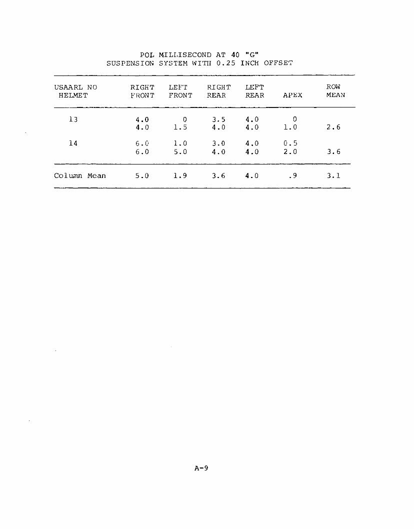
POL MILLISECOND AT 40 II G" SUSPENSION SYSTEM WITH 0. 2 5 INCH OFFSET
USAARL NO RIGHT LEFT RIGHT LEFT ROW HELMET FRONT FRONT REAR REAR APEX MEAN
13 4.0 0 3.5 4.0 0 4.0 1.5 4.0 4.0 1.0 2.6
14 6.0 1.0 3.0 4.0 0. 5 6.0 5.0 4.0 4.0 2.0 3. 6
Column Mean 5.0 1.9 3.6 4.0 . 9 3.1
A-9
Copyright © 2022 FDOKUMEN