BULLETIN NO: 01.08.22-4 CATEGORY: Sigma SUBJECT:
37
Product Information Bulletin Author: Chris Allen Issue Date: 13 October 2005 Telephone: +44 (0) 1753 611211 Email: [email protected] Page 1 of 37 BULLETIN NO: 01.08.22-4 CATEGORY: Sigma SUBJECT: IC-LON Configuration Guide, now covering V5 Plug-in with Auto Binding Index 1. INTRODUCTION ............................................................................................................................................................. 3 2. SYSTEM DESCRIPTION ............................................................................................................................................... 3 3. ENGINEERING PROCEDURE OVERVIEW............................................................................................................... 4 3.1 New Project............................................................................................................................................................... 4 3.2 Modifying An Existing IC-LON And LonMaker Drawing ............................................................................ 4 4. IC-LON CONFIGURATION........................................................................................................................................... 5 4.1 Module Installation................................................................................................................................................. 5 4.2 Equipment And Software Required.................................................................................................................. 5 5. BUILDING THE LNS DATABASE ............................................................................................................................... 6 5.1 Configuring A New LON Network...................................................................................................................... 6 5.2 Setting Drawing Page Size.................................................................................................................................. 8 5.3 Adding Subsystems ............................................................................................................................................... 9 5.4 Adding A Channel To A Subsystem ............................................................................................................... 10 5.5 Adding A Device To LonMaker ......................................................................................................................... 10 5.6 Adding A Function Block .................................................................................................................................... 13 5.7 Binding Between Nodes ..................................................................................................................................... 15 5.8 Connections ............................................................................................................................................................ 15 5.9 Creating A New Connection Type ................................................................................................................... 16 5.10 Creating The Connections (Bindings) Manually...................................................................................... 17 5.11 Network Configuration Inputs ....................................................................................................................... 18 5.12 Backing Up The LonMaker Database .......................................................................................................... 18 5.13 Restoring A LonMaker Database .................................................................................................................. 18 5.14 Device Template................................................................................................................................................. 18 6.0 IC-LON PLUG-IN ....................................................................................................................................................... 19 6.1 Plug-In Installation .............................................................................................................................................. 19 6.2 Running The Plug-In ........................................................................................................................................... 19 6.3 Configure The Default Settings ....................................................................................................................... 20 6.4 Adding Snvt’s To The Database ...................................................................................................................... 21 6.5 Creating A Template............................................................................................................................................ 22 6.6 Structured Snvts................................................................................................................................................... 23 6.7 Building IC-LON Files .......................................................................................................................................... 24 6.8 Object Report ......................................................................................................................................................... 24 6.9 Changing An Existing IC-LON Scheme......................................................................................................... 25 6.9.1 Device Template - Removing ....................................................................................................................... 25 6.10 Files Created By The IC-LON Plug-In ......................................................................................................... 26 6.11 Downloading Files To IC-LON........................................................................................................................ 26 7.0 IC-LON AND LONMAKER ........................................................................................................................................ 27 7.1 Adding IC-LON In LonMaker............................................................................................................................. 27 7.2 Time Synchronisation ......................................................................................................................................... 27 7.3 Automatic Binding Using The IC-LON Plug-In ........................................................................................... 28
-
Upload
khangminh22 -
Category
Documents
-
view
1 -
download
0
Transcript of BULLETIN NO: 01.08.22-4 CATEGORY: Sigma SUBJECT:
ProductInformation
Bulletin
Author: Chris AllenIssue Date: 13 October 2005Telephone: +44 (0) 1753 611211Email: [email protected]
Page 1 of 37
BULLETIN NO: 01.08.22-4
CATEGORY: Sigma
SUBJECT: IC-LON Configuration Guide, now coveringV5 Plug-in with Auto Binding
Index1. INTRODUCTION ............................................................................................................................................................. 32. SYSTEM DESCRIPTION ............................................................................................................................................... 33. ENGINEERING PROCEDURE OVERVIEW............................................................................................................... 4
3.1 New Project............................................................................................................................................................... 43.2 Modifying An Existing IC-LON And LonMaker Drawing ............................................................................ 4
4. IC-LON CONFIGURATION........................................................................................................................................... 54.1 Module Installation................................................................................................................................................. 54.2 Equipment And Software Required.................................................................................................................. 5
5. BUILDING THE LNS DATABASE ............................................................................................................................... 65.1 Configuring A New LON Network...................................................................................................................... 65.2 Setting Drawing Page Size.................................................................................................................................. 85.3 Adding Subsystems ............................................................................................................................................... 95.4 Adding A Channel To A Subsystem ............................................................................................................... 105.5 Adding A Device To LonMaker ......................................................................................................................... 105.6 Adding A Function Block .................................................................................................................................... 135.7 Binding Between Nodes ..................................................................................................................................... 155.8 Connections ............................................................................................................................................................ 155.9 Creating A New Connection Type................................................................................................................... 165.10 Creating The Connections (Bindings) Manually...................................................................................... 175.11 Network Configuration Inputs ....................................................................................................................... 185.12 Backing Up The LonMaker Database .......................................................................................................... 185.13 Restoring A LonMaker Database .................................................................................................................. 185.14 Device Template................................................................................................................................................. 18
6.0 IC-LON PLUG-IN ....................................................................................................................................................... 196.1 Plug-In Installation .............................................................................................................................................. 196.2 Running The Plug-In ........................................................................................................................................... 196.3 Configure The Default Settings ....................................................................................................................... 206.4 Adding Snvt’s To The Database ...................................................................................................................... 216.5 Creating A Template............................................................................................................................................ 226.6 Structured Snvts................................................................................................................................................... 236.7 Building IC-LON Files .......................................................................................................................................... 246.8 Object Report ......................................................................................................................................................... 246.9 Changing An Existing IC-LON Scheme......................................................................................................... 256.9.1 Device Template - Removing ....................................................................................................................... 256.10 Files Created By The IC-LON Plug-In ......................................................................................................... 266.11 Downloading Files To IC-LON........................................................................................................................ 26
7.0 IC-LON AND LONMAKER ........................................................................................................................................ 277.1 Adding IC-LON In LonMaker............................................................................................................................. 277.2 Time Synchronisation ......................................................................................................................................... 277.3 Automatic Binding Using The IC-LON Plug-In ........................................................................................... 28
PIB – 01.08.22-4IC LON CONFIGURATION GUIDE
Author: Chris AllenIssue Date: 13 October 2005Telephone: +44 (0) 1753 611211Email: [email protected]
Page 2 of 37
7.3.1 Binding Report.................................................................................................................................................. 287.4 Drawing Synchronisation................................................................................................................................... 297.4 Manual Binding IC-LON ...................................................................................................................................... 317.5 Uploading Nvconfig.Bin ...................................................................................................................................... 31
8.0 ∑(Sigma) OBJECT CREATION .............................................................................................................................. 328.1 Creating Files With SigmaX .............................................................................................................................. 328.2 Setting Up Default Object Values................................................................................................................... 33
9.0 FINAL COMMISSIONING ........................................................................................................................................ 359.1 Download Point Files ........................................................................................................................................... 359.2 Uploading Nvconfig.Bin ...................................................................................................................................... 35
10.0 GENERAL INFORMATION..................................................................................................................................... 3510.1 Invensys LON Mark Controllers .................................................................................................................... 3510.2 Configuring LonMaker To Use Metric Units .............................................................................................. 3510.3 LonMaker Templates......................................................................................................................................... 3610.4 Domain ID............................................................................................................................................................. 3610.5 Configuring Multiple IC-LON’s ....................................................................................................................... 37
11.0 DOCUMENTATION CONTROL ............................................................................................................................. 37
PIB – 01.08.22-4IC LON CONFIGURATION GUIDE
Author: Chris AllenIssue Date: 13 October 2005Telephone: +44 (0) 1753 611211Email: [email protected]
Page 3 of 37
1. INTRODUCTION
This document describes the steps necessary to understand and configure the IC-LON - ∑(Sigma)Integration Controller.It assumes the reader is fully conversant with Satchwell ∑(Sigma) and has undergone basicLonWorks/IC-LON training.
This document covers the use of LonMaker for Windows to create the LNS database as it is thepreferred network management tool, however there is no reason another network managementtool could not be utilised providing it’s 100% compliant to the LNS specification.
Version 2 of this PIB has been updated to cover version 5 of the Sigma IC-LON Plug-in withsupport for auto binding.
2. SYSTEM DESCRIPTION
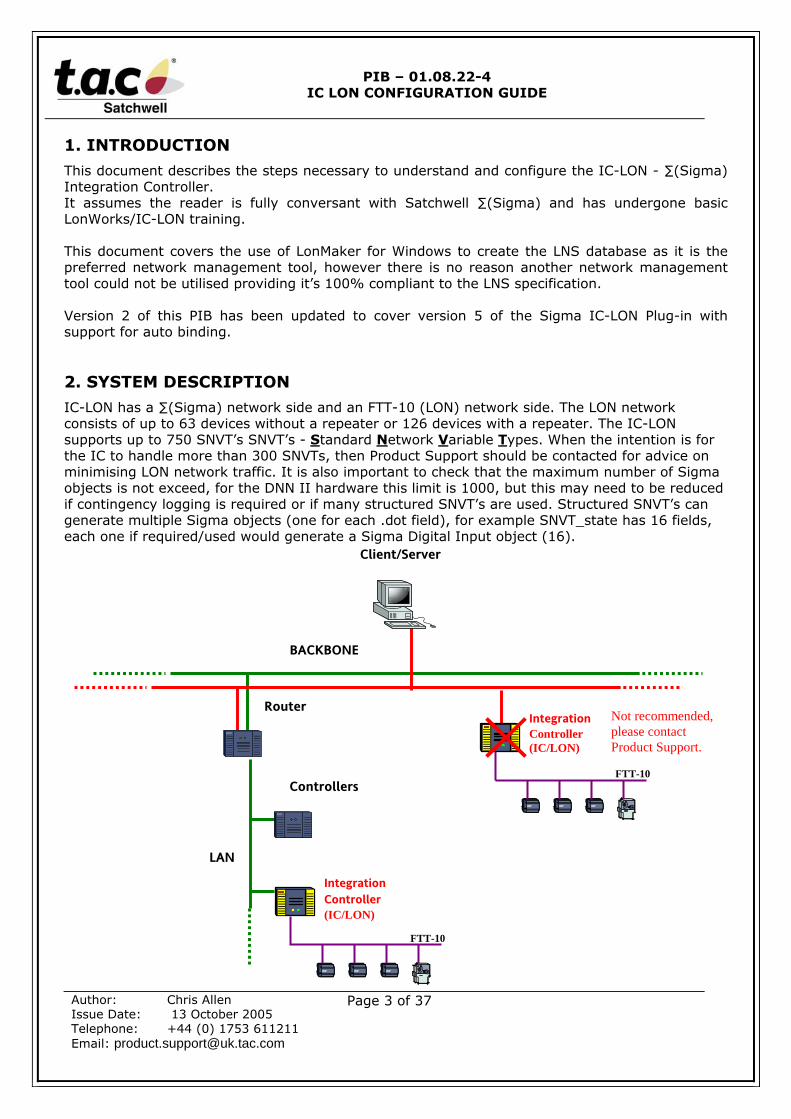
IC-LON has a ∑(Sigma) network side and an FTT-10 (LON) network side. The LON networkconsists of up to 63 devices without a repeater or 126 devices with a repeater. The IC-LONsupports up to 750 SNVT’s SNVT’s - Standard Network Variable Types. When the intention is forthe IC to handle more than 300 SNVTs, then Product Support should be contacted for advice onminimising LON network traffic. It is also important to check that the maximum number of Sigmaobjects is not exceed, for the DNN II hardware this limit is 1000, but this may need to be reducedif contingency logging is required or if many structured SNVT’s are used. Structured SNVT’s cangenerate multiple Sigma objects (one for each .dot field), for example SNVT_state has 16 fields,each one if required/used would generate a Sigma Digital Input object (16).
Client/Server
Router
Controllers
BACKBONE
LAN
IntegrationController(IC/LON)
FTT-10
IntegrationController(IC/LON)
FTT-10
Not recommended,please contactProduct Support.

PIB – 01.08.22-4IC LON CONFIGURATION GUIDE
Author: Chris AllenIssue Date: 13 October 2005Telephone: +44 (0) 1753 611211Email: [email protected]
Page 4 of 37
3. ENGINEERING PROCEDURE OVERVIEW
3.1 New Project
The engineering of a new IC-LON is carried out in five main steps.
1) The first step is to design the architecture of the Lon network and commission each ofthe LON devices using the manufacturers programming tools. This is particularlyimportant if using programmable LonWorks controllers as the External Interface File(XIF) and Program ID could change during the commissioning period.
2) The second step is to create a new LonMaker project and add each device to theLonMaker drawing. See section 5.
3) The third stage is to run the Invensys ∑(Sigma) Plug-in from within LonMaker and createthe gateway and binary files for IC-LON, copy them to the Satchwell ∑(Sigma) serverand subsequently download them.
4) The fourth stage is to install IC-LON into LonMaker and make the Bindings between thedevices and IC-LON. See section 7. This step can be performed without having the IC-LON up and running.
5) The fifth and final stage is to run SigmaX and use the import file produced by the plug-into create the ∑(Sigma) index and object files. See section 8.
3.2 Modifying An Existing IC-LON And LonMaker Drawing
With the IC-LON plug-in version 5 or later it is possible to add or delete SNVT’s/Objects toan existing IC-LON. All that is required is the original *.dnn file (this file is created when theplug-in is run and a selection subsequently saved). Please note that it is also possible tomodify IC-LONs that were created with earlier versions of the plug-in.
The process is exactly the same as for a new IC-LON except that the existing *.dnn file isopened and any changes are made to this configuration, the existing IC-LON device must bedeleted from the LonMaker drawing. Please see section 6.10 for details.

PIB – 01.08.22-4IC LON CONFIGURATION GUIDE
Author: Chris AllenIssue Date: 13 October 2005Telephone: +44 (0) 1753 611211Email: [email protected]
Page 5 of 37
4. IC-LON CONFIGURATION
∑(Sigma) devices require communication cards to be fitted to give them the facility to be part of a∑(Sigma) network and communicate with a ∑(Sigma) Server. The communication card can beeither Arcnet or Ethernet, with the ∑(Sigma) LAN being used as the secondary LAN. As such IC-LON can only be installed in a standard configuration on a sub-lan and not on a backbone.
4.1 Module Installation
IC-LON requires only one of these cards to communicate with the ∑(Sigma) network. Thecard fits in to MODULE 1 (PORT 1) within IC-LON and must be configured with an IPaddress. MODULE 2 is always empty. The LON card is factory fitted in to MODULE 3 whichmeans that the LON FTT10A network connects to PORT 6 (Plug - CONN 10).
The NODE Number and IP addressing etc is set using the SDCU tool.
4.2 EQUIPMENT AND SOFTWARE REQUIRED
To engineer and commission the IC-LON the following is required: -
PC with Windows 2000 Pro or WinXP Pro
LON Interface Card and cable:-SCS part number: WPA – LON – 1 (ISA card for a desktop incl Lon cable) orSCS part number: WPA – LON – 2 (PC card for a Laptop incl Lon cable) orSCS part number: ECH-74401 (PCI card for desktop, PCLTA-20/FT-10)
Spare PCC10 Lon cable, available from Echelon or distributor, part number 78302.Please note this cable does not include the small plug used to connect to our MNLcontrollers. This is available from Maplin part number FK05 (1.3mm mini DC power plug).
LonMaker for Windows:Windows XP SP1 - Echelon LonMaker for Windows 3.1 SP3 update 1 or later – Visio 2002.Windows 2000 SP4 - Echelon LonMaker for Windows 3.0 SP8 update 1 or later – Visio2000.The LNS version must be 3.08.xx or later, this can be viewed from the About LonMakeron the LonMaker menu.
If using MNL100/150/200/VAV controllers the Xif and support files for LonMaker areavailable from the support section of the infonet.
IC-LON Plug-in available from the infonet either as a full install (9.4mb) or as an upgradefrom version 4.
PIB – 01.08.22-4IC LON CONFIGURATION GUIDE
Author: Chris AllenIssue Date: 13 October 2005Telephone: +44 (0) 1753 611211Email: [email protected]
Page 6 of 37
5. BUILDING THE LNS DATABASE
NOTE: - It is important to design the layout of the LonMaker drawings and the ∑(Sigma)mnemonic object structure before creating the LonMaker Database as SigmaX uses the subsystemnames to build the ∑(Sigma) object segments. See section 8.1 for a description of how SigmaXuses these names.
IC-LON can only talk to the sub-net to which it is attached, it must not be bound to devices acrossrouters.
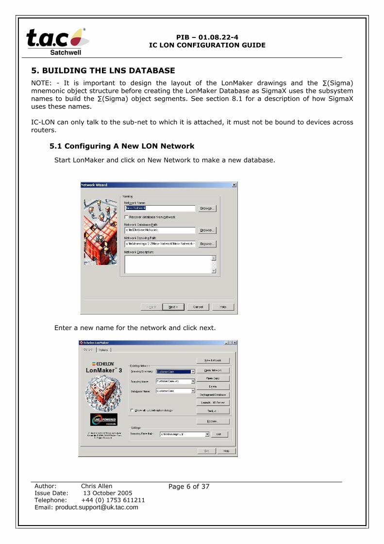
5.1 Configuring A New LON Network
Start LonMaker and click on New Network to make a new database.
Enter a new name for the network and click next.
PIB – 01.08.22-4IC LON CONFIGURATION GUIDE
Author: Chris AllenIssue Date: 13 October 2005Telephone: +44 (0) 1753 611211Email: [email protected]
Page 7 of 37
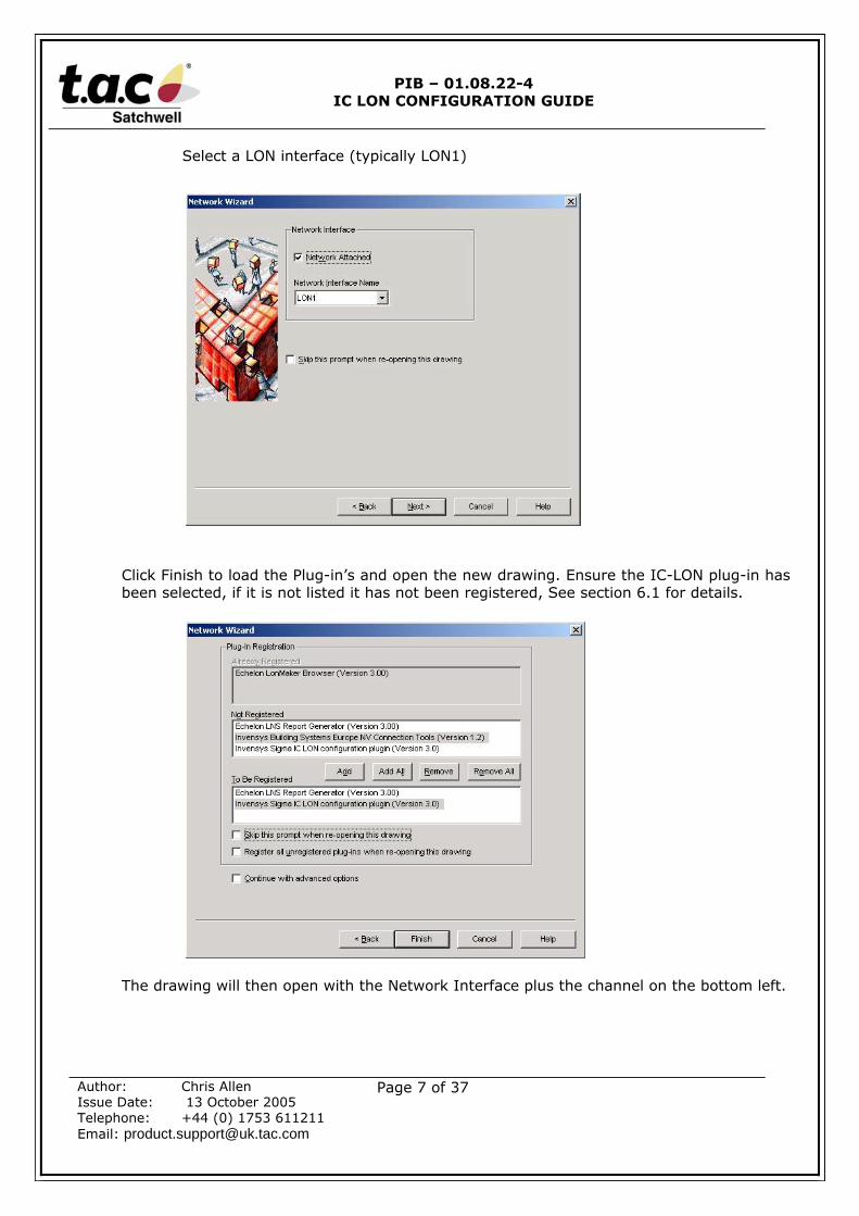
Select a LON interface (typically LON1)
Click Finish to load the Plug-in’s and open the new drawing. Ensure the IC-LON plug-in hasbeen selected, if it is not listed it has not been registered, See section 6.1 for details.
The drawing will then open with the Network Interface plus the channel on the bottom left.
PIB – 01.08.22-4IC LON CONFIGURATION GUIDE
Author: Chris AllenIssue Date: 13 October 2005Telephone: +44 (0) 1753 611211Email: [email protected]
Page 8 of 37
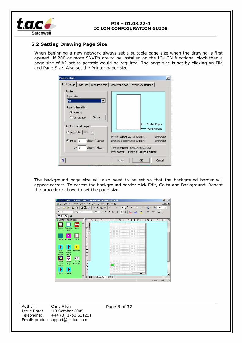
5.2 Setting Drawing Page Size
When beginning a new network always set a suitable page size when the drawing is firstopened. If 200 or more SNVT’s are to be installed on the IC-LON functional block then apage size of A2 set to portrait would be required. The page size is set by clicking on Fileand Page Size. Also set the Printer paper size.
The background page size will also need to be set so that the background border willappear correct. To access the background border click Edit, Go to and Background. Repeatthe procedure above to set the page size.
PIB – 01.08.22-4IC LON CONFIGURATION GUIDE
Author: Chris AllenIssue Date: 13 October 2005Telephone: +44 (0) 1753 611211Email: [email protected]
Page 9 of 37
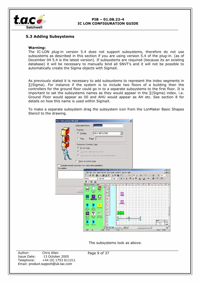
5.3 Adding Subsystems
Warning:The IC-LON plug-in version 5.4 does not support subsystems, therefore do not usesubsystems as described in this section if you are using version 5.4 of the plug-in. (as ofDecember 04 5.4 is the latest version). If subsystems are required (because its an existingdatabase) it will be necessary to manually bind all SNVT’s and it will not be possible toautomatically create the Sigma objects with SigmaX.
As previously stated it is necessary to add subsystems to represent the index segments in∑(Sigma). For instance if the system is to include two floors of a building then thecontrollers for the ground floor could go in to a separate subsystems to the first floor. It isimportant to set the subsystems names as they would appear in the ∑(Sigma) index. i.e.Ground Floor would appear as 00 and AHU would appear as AH etc. See section 8 fordetails on how this name is used within SigmaX.
To make a separate subsystem drag the subsystem icon from the LonMaker Basic ShapesStencil to the drawing.
The subsystems look as above.
PIB – 01.08.22-4IC LON CONFIGURATION GUIDE
Author: Chris AllenIssue Date: 13 October 2005Telephone: +44 (0) 1753 611211Email: [email protected]
Page 10 of 37
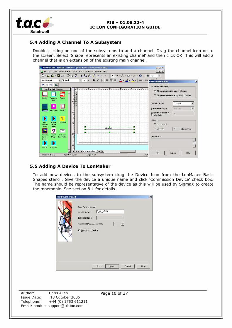
5.4 Adding A Channel To A Subsystem
Double clicking on one of the subsystems to add a channel. Drag the channel icon on tothe screen. Select ‘Shape represents an existing channel’ and then click OK. This will add achannel that is an extension of the existing main channel.
5.5 Adding A Device To LonMaker
To add new devices to the subsystem drag the Device Icon from the LonMaker BasicShapes stencil. Give the device a unique name and click ‘Commission Device’ check box.The name should be representative of the device as this will be used by SigmaX to createthe mnemonic. See section 8.1 for details.
PIB – 01.08.22-4IC LON CONFIGURATION GUIDE
Author: Chris AllenIssue Date: 13 October 2005Telephone: +44 (0) 1753 611211Email: [email protected]
Page 11 of 37
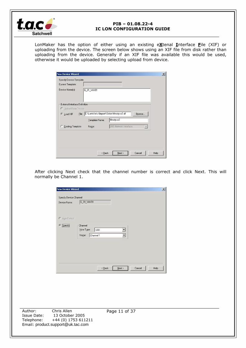
LonMaker has the option of either using an existing eXtenal Interface File (XIF) oruploading from the device. The screen below shows using an XIF file from disk rather thanuploading from the device. Generally if an XIF file was available this would be used,otherwise it would be uploaded by selecting upload from device.
After clicking Next check that the channel number is correct and click Next. This willnormally be Channel 1.
PIB – 01.08.22-4IC LON CONFIGURATION GUIDE
Author: Chris AllenIssue Date: 13 October 2005Telephone: +44 (0) 1753 611211Email: [email protected]
Page 12 of 37
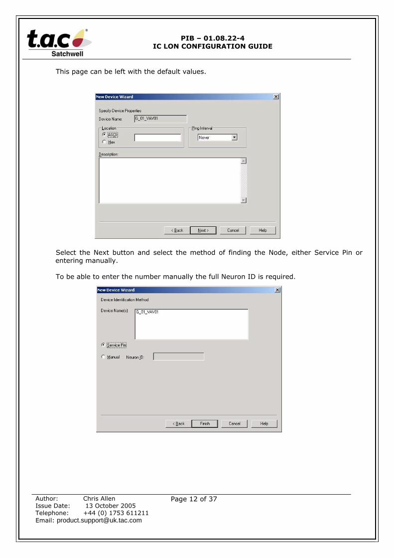
This page can be left with the default values.
Select the Next button and select the method of finding the Node, either Service Pin orentering manually.
To be able to enter the number manually the full Neuron ID is required.
PIB – 01.08.22-4IC LON CONFIGURATION GUIDE
Author: Chris AllenIssue Date: 13 October 2005Telephone: +44 (0) 1753 611211Email: [email protected]
Page 13 of 37
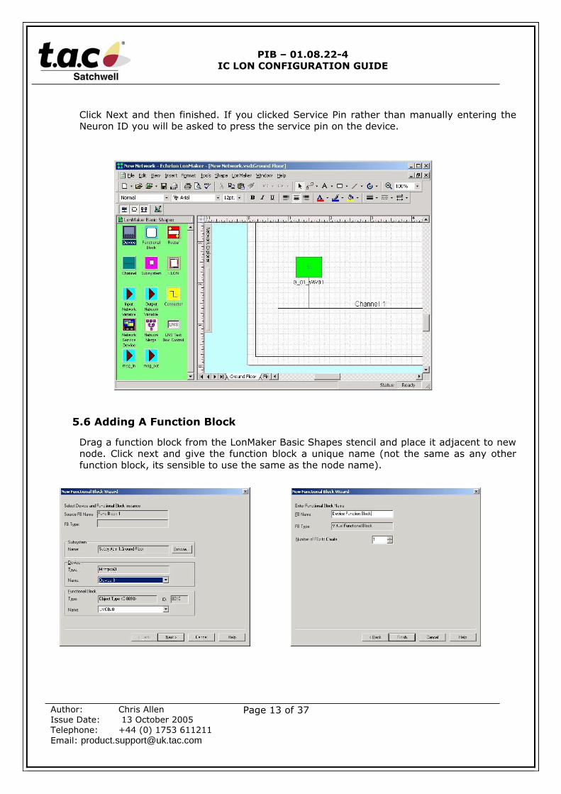
Click Next and then finished. If you clicked Service Pin rather than manually entering theNeuron ID you will be asked to press the service pin on the device.
5.6 Adding A Function Block
Drag a function block from the LonMaker Basic Shapes stencil and place it adjacent to newnode. Click next and give the function block a unique name (not the same as any otherfunction block, its sensible to use the same as the node name).
PIB – 01.08.22-4IC LON CONFIGURATION GUIDE
Author: Chris AllenIssue Date: 13 October 2005Telephone: +44 (0) 1753 611211Email: [email protected]
Page 14 of 37
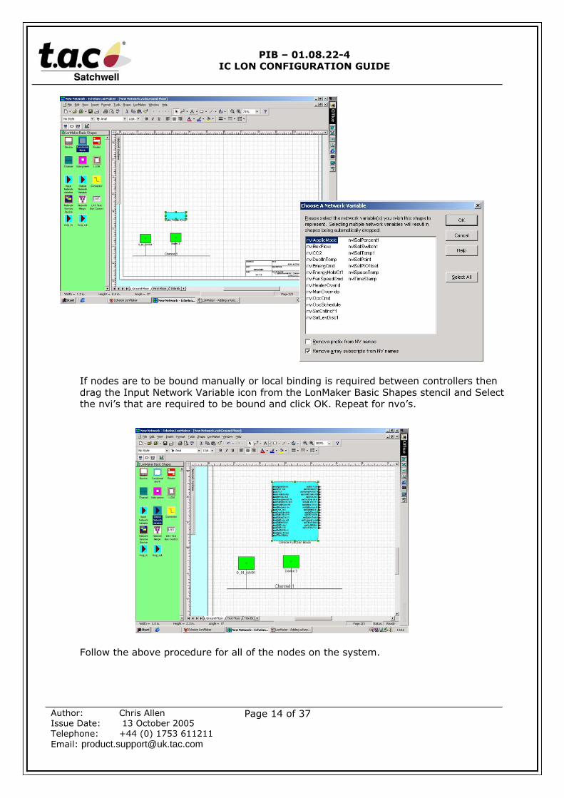
If nodes are to be bound manually or local binding is required between controllers thendrag the Input Network Variable icon from the LonMaker Basic Shapes stencil and Selectthe nvi’s that are required to be bound and click OK. Repeat for nvo’s.
Follow the above procedure for all of the nodes on the system.
PIB – 01.08.22-4IC LON CONFIGURATION GUIDE
Author: Chris AllenIssue Date: 13 October 2005Telephone: +44 (0) 1753 611211Email: [email protected]
Page 15 of 37
5.7 Binding Between Nodes
It may be necessary to bind between controllers (nodes) if for instance a temperaturesensor is to be shared with another node or you are adding the IC-LON to an existingdatabase and binding to existing nodes / SNVT’s.
Warning:When using the IC-LON plug-in to bind to SNVT’s that already exist the connection type forthese existing bindings should use the ‘Sigma’ connection type. Failure to observer thisrequirement will result in the IC-LON plug-in failing to bind to these SNVT’s (no warningwill be given), thus making it necessary to bind these connections manually once theconnections have been created using the plug-in.
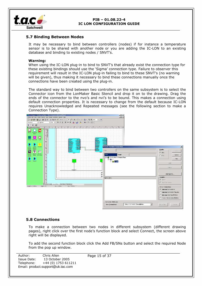
The standard way to bind between two controllers on the same subsystem is to select theConnector icon from the LonMaker Basic Stencil and drop it on to the drawing. Drag theends of the connector to the nvo’s and nvi’s to be bound. This makes a connection usingdefault connection properties. It is necessary to change from the default because IC-LONrequires Unacknowledged and Repeated messages (see the following section to make aConnection Type).
5.8 Connections
To make a connection between two nodes in different subsystem (different drawingpages), right click over the first node’s function block and select Connect, the screen aboveright will be displayed.
To add the second function block click the Add FB/SNs button and select the required Nodefrom the pop up window.
PIB – 01.08.22-4IC LON CONFIGURATION GUIDE
Author: Chris AllenIssue Date: 13 October 2005Telephone: +44 (0) 1753 611211Email: [email protected]
Page 16 of 37
5.9 Creating A New Connection Type
If the IC-LON Plug-in V5 or later is going to be used then there is no need to create a newconnection type as the Plug-in will automatically create the connection and name it‘Sigma’.
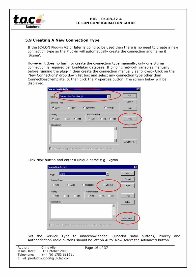
However it does no harm to create the connection type manually, only one Sigmaconnection is required per LonMaker database. If binding network variables manuallybefore running the plug-in then create the connection manually as follows:- Click on the‘New Connections’ drop down list box and select any connection type other thanConnectDescTemplate_0, then click the Properties button. The screen below will bedisplayed.
Click New button and enter a unique name e.g. Sigma.
Set the Service Type to unacknowledged, (Unackd radio button), Priority andAuthentication radio buttons should be left on Auto. Now select the Advanced button.
PIB – 01.08.22-4IC LON CONFIGURATION GUIDE
Author: Chris AllenIssue Date: 13 October 2005Telephone: +44 (0) 1753 611211Email: [email protected]
Page 17 of 37
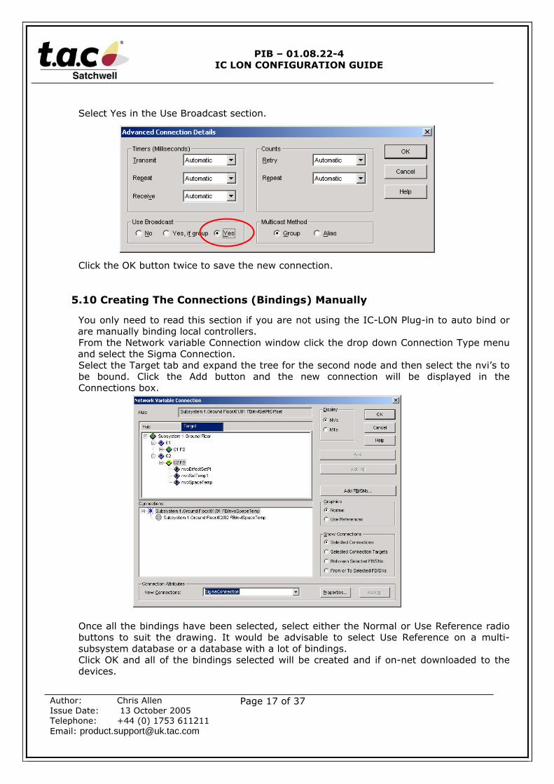
Select Yes in the Use Broadcast section.
Click the OK button twice to save the new connection.
5.10 Creating The Connections (Bindings) Manually
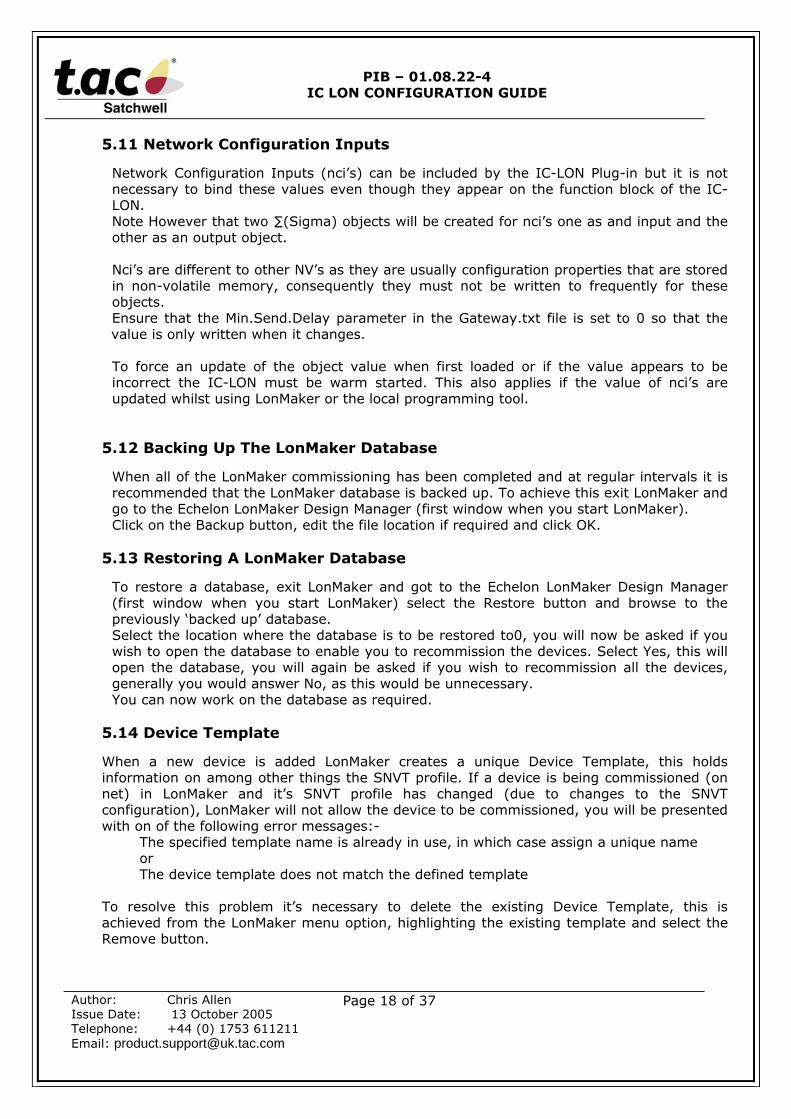
You only need to read this section if you are not using the IC-LON Plug-in to auto bind orare manually binding local controllers.From the Network variable Connection window click the drop down Connection Type menuand select the Sigma Connection.Select the Target tab and expand the tree for the second node and then select the nvi’s tobe bound. Click the Add button and the new connection will be displayed in theConnections box.
Once all the bindings have been selected, select either the Normal or Use Reference radiobuttons to suit the drawing. It would be advisable to select Use Reference on a multi-subsystem database or a database with a lot of bindings.Click OK and all of the bindings selected will be created and if on-net downloaded to thedevices.
PIB – 01.08.22-4IC LON CONFIGURATION GUIDE
Author: Chris AllenIssue Date: 13 October 2005Telephone: +44 (0) 1753 611211Email: [email protected]
Page 18 of 37
5.11 Network Configuration Inputs
Network Configuration Inputs (nci’s) can be included by the IC-LON Plug-in but it is notnecessary to bind these values even though they appear on the function block of the IC-LON.Note However that two ∑(Sigma) objects will be created for nci’s one as and input and theother as an output object.
Nci’s are different to other NV’s as they are usually configuration properties that are storedin non-volatile memory, consequently they must not be written to frequently for theseobjects.Ensure that the Min.Send.Delay parameter in the Gateway.txt file is set to 0 so that thevalue is only written when it changes.
To force an update of the object value when first loaded or if the value appears to beincorrect the IC-LON must be warm started. This also applies if the value of nci’s areupdated whilst using LonMaker or the local programming tool.
5.12 Backing Up The LonMaker Database
When all of the LonMaker commissioning has been completed and at regular intervals it isrecommended that the LonMaker database is backed up. To achieve this exit LonMaker andgo to the Echelon LonMaker Design Manager (first window when you start LonMaker).Click on the Backup button, edit the file location if required and click OK.
5.13 Restoring A LonMaker Database
To restore a database, exit LonMaker and got to the Echelon LonMaker Design Manager(first window when you start LonMaker) select the Restore button and browse to thepreviously ‘backed up’ database.Select the location where the database is to be restored to0, you will now be asked if youwish to open the database to enable you to recommission the devices. Select Yes, this willopen the database, you will again be asked if you wish to recommission all the devices,generally you would answer No, as this would be unnecessary.You can now work on the database as required.
5.14 Device Template
When a new device is added LonMaker creates a unique Device Template, this holdsinformation on among other things the SNVT profile. If a device is being commissioned (onnet) in LonMaker and it’s SNVT profile has changed (due to changes to the SNVTconfiguration), LonMaker will not allow the device to be commissioned, you will be presentedwith on of the following error messages:-
The specified template name is already in use, in which case assign a unique nameorThe device template does not match the defined template
To resolve this problem it’s necessary to delete the existing Device Template, this isachieved from the LonMaker menu option, highlighting the existing template and select theRemove button.
PIB – 01.08.22-4IC LON CONFIGURATION GUIDE
Author: Chris AllenIssue Date: 13 October 2005Telephone: +44 (0) 1753 611211Email: [email protected]
Page 19 of 37
6.0 IC-LON PLUG-IN
6.1 Plug-In Installation
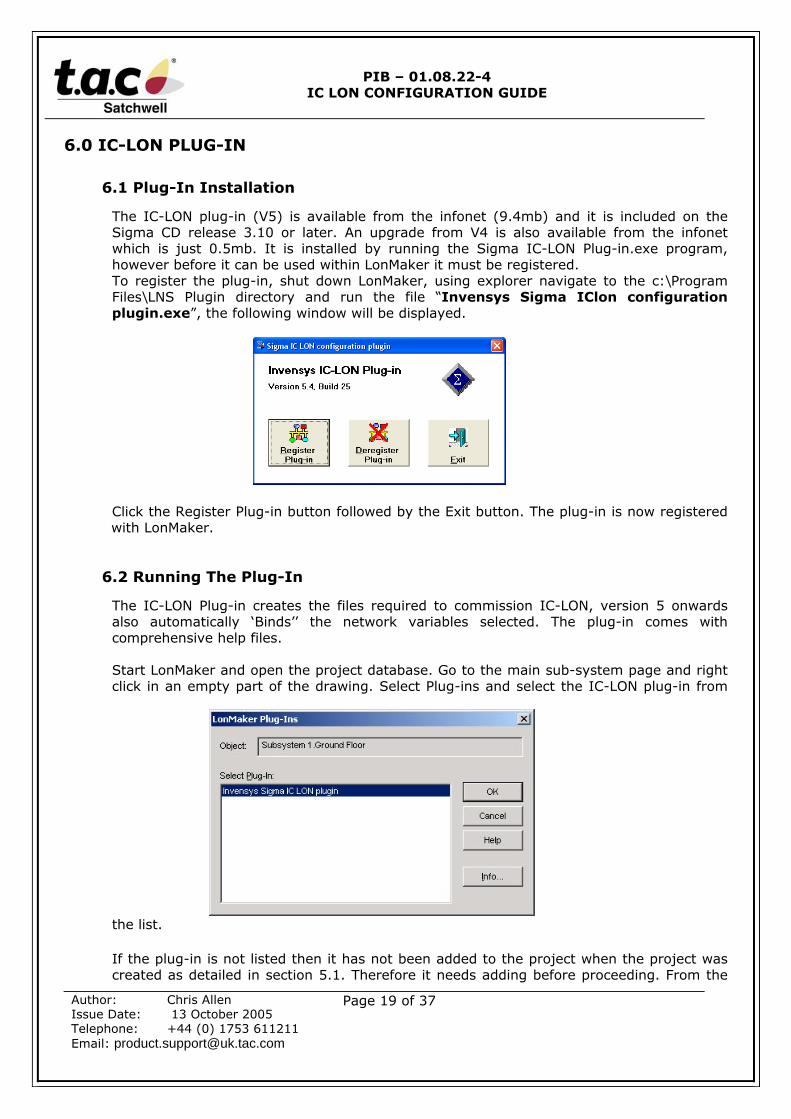
The IC-LON plug-in (V5) is available from the infonet (9.4mb) and it is included on theSigma CD release 3.10 or later. An upgrade from V4 is also available from the infonetwhich is just 0.5mb. It is installed by running the Sigma IC-LON Plug-in.exe program,however before it can be used within LonMaker it must be registered.To register the plug-in, shut down LonMaker, using explorer navigate to the c:\ProgramFiles\LNS Plugin directory and run the file “Invensys Sigma IClon configurationplugin.exe”, the following window will be displayed.
Click the Register Plug-in button followed by the Exit button. The plug-in is now registeredwith LonMaker.
6.2 Running The Plug-In
The IC-LON Plug-in creates the files required to commission IC-LON, version 5 onwardsalso automatically ‘Binds’’ the network variables selected. The plug-in comes withcomprehensive help files.
Start LonMaker and open the project database. Go to the main sub-system page and rightclick in an empty part of the drawing. Select Plug-ins and select the IC-LON plug-in from
the list.
If the plug-in is not listed then it has not been added to the project when the project wascreated as detailed in section 5.1. Therefore it needs adding before proceeding. From the
PIB – 01.08.22-4IC LON CONFIGURATION GUIDE
Author: Chris AllenIssue Date: 13 October 2005Telephone: +44 (0) 1753 611211Email: [email protected]
Page 20 of 37
LonMaker menu option select Network Properties… Select the Plug-in Registration tab.Select the plug-in to be registered and press the apply button.
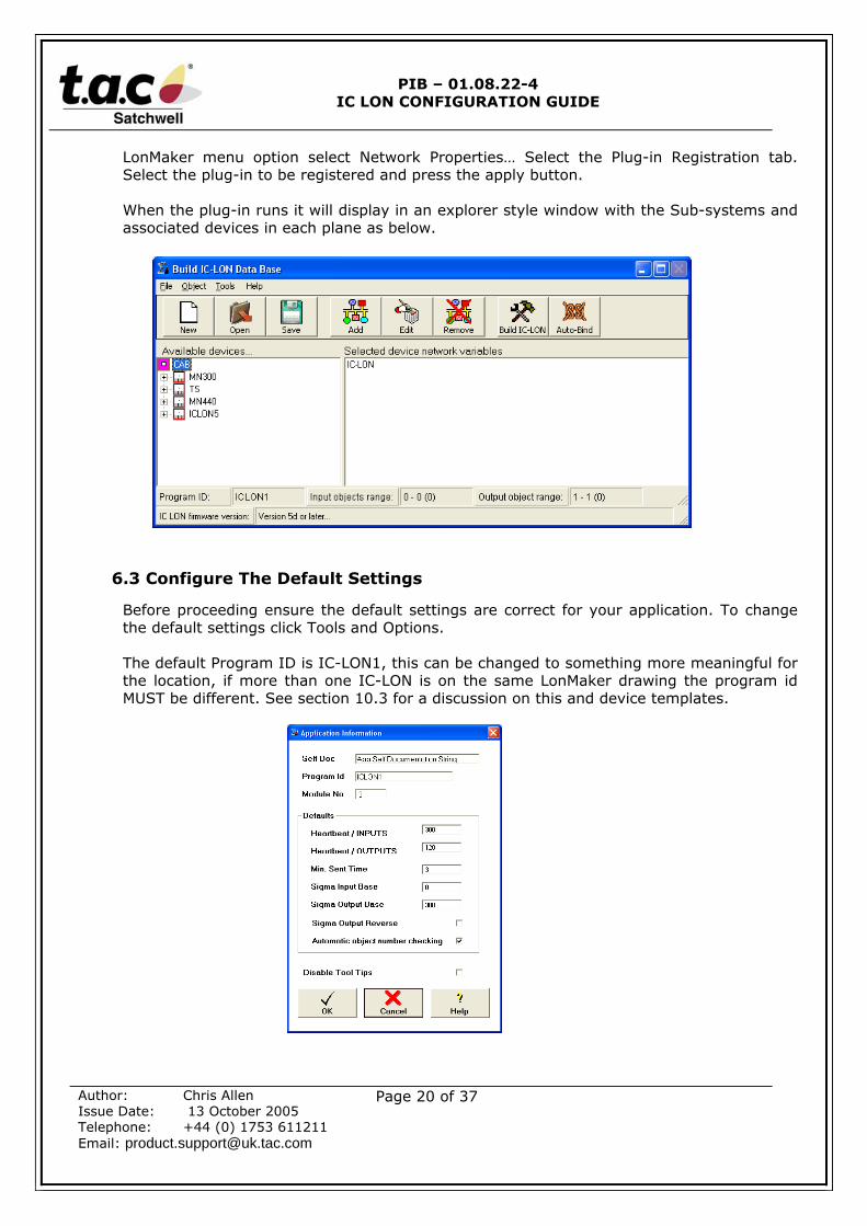
When the plug-in runs it will display in an explorer style window with the Sub-systems andassociated devices in each plane as below.
6.3 Configure The Default Settings
Before proceeding ensure the default settings are correct for your application. To changethe default settings click Tools and Options.
The default Program ID is IC-LON1, this can be changed to something more meaningful forthe location, if more than one IC-LON is on the same LonMaker drawing the program idMUST be different. See section 10.3 for a discussion on this and device templates.
PIB – 01.08.22-4IC LON CONFIGURATION GUIDE
Author: Chris AllenIssue Date: 13 October 2005Telephone: +44 (0) 1753 611211Email: [email protected]
Page 21 of 37
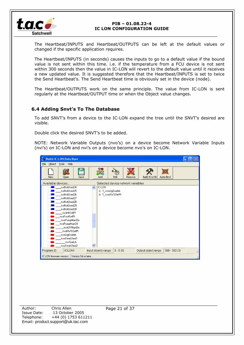
The Heartbeat/INPUTS and Heartbeat/OUTPUTS can be left at the default values orchanged if the specific application requires.
The Heartbeat/INPUTS (in seconds) causes the inputs to go to a default value if the boundvalue is not sent within this time. i.e. if the temperature from a FCU device is not sentwithin 300 seconds then the value in IC-LON will revert to the default value until it receivesa new updated value. It is suggested therefore that the Heartbeat/INPUTS is set to twicethe Send Heartbeat’s. The Send Heartbeat time is obviously set in the device (node).
The Heartbeat/OUTPUTS work on the same principle. The value from IC-LON is sentregularly at the Heartbeat/OUTPUT time or when the Object value changes.
6.4 Adding Snvt’s To The Database
To add SNVT’s from a device to the IC-LON expand the tree until the SNVT’s desired arevisible.
Double click the desired SNVT’s to be added.
NOTE: Network Variable Outputs (nvo’s) on a device become Network Variable Inputs(nvi’s) on IC-LON and nvi’s on a device become nvo’s on IC-LON.
PIB – 01.08.22-4IC LON CONFIGURATION GUIDE
Author: Chris AllenIssue Date: 13 October 2005Telephone: +44 (0) 1753 611211Email: [email protected]
Page 22 of 37
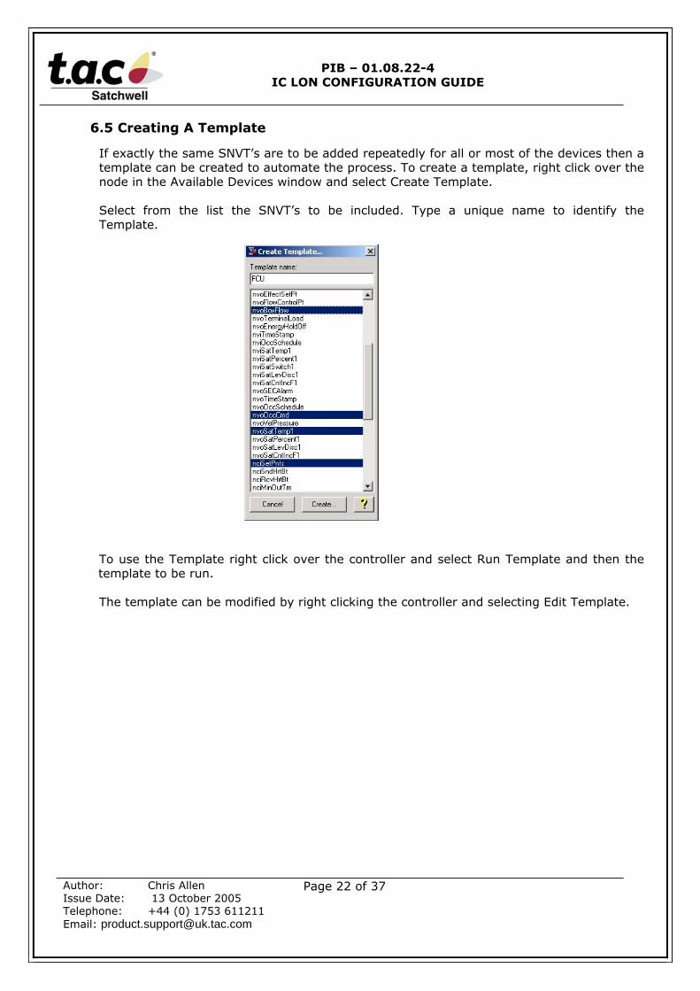
6.5 Creating A Template
If exactly the same SNVT’s are to be added repeatedly for all or most of the devices then atemplate can be created to automate the process. To create a template, right click over thenode in the Available Devices window and select Create Template.
Select from the list the SNVT’s to be included. Type a unique name to identify theTemplate.
To use the Template right click over the controller and select Run Template and then thetemplate to be run.
The template can be modified by right clicking the controller and selecting Edit Template.

PIB – 01.08.22-4IC LON CONFIGURATION GUIDE
Author: Chris AllenIssue Date: 13 October 2005Telephone: +44 (0) 1753 611211Email: [email protected]
Page 23 of 37
6.6 Structured Snvts
Some SNVT’s are structured and therefore create two or more ∑(Sigma) objects. Anexample of this is nvoSatSwitch1 which has two parts (dot fields), .Value and .State. Ifonly one of the parts is required then right click over the SNVT in the Selected devicewindow and select edit. The following window will be displayed. Then deselect the field ofthe SNVT that is not required by clearing the tick in the Active box.
Repeat this process until the list of SNVT’s that are to appear in the IC-LON have beenselected and added to the Selected device network variables window.
PIB – 01.08.22-4IC LON CONFIGURATION GUIDE
Author: Chris AllenIssue Date: 13 October 2005Telephone: +44 (0) 1753 611211Email: [email protected]
Page 24 of 37
6.7 Building IC-LON Files
At this stage all the required SNVT’s/Object should be selected. First save thisconfiguration to disk, select Save from the file menu, it is recommended that the files aresaved in the Controller sub-directory.If changes are required at a later stage, this saved file can be loaded and subsequentlymodified.
To create the IC-LON files select Tools and Build or select the Build IC-LON button, again itis recommended that the files are saved to the Controller directory.A report will appear detailing the total number of objects created and of which type.
The next step is to bind the selected controller SNVT’s to the IC-LON, this can be eithercarried out ‘on net’ (on-line) or ‘off net’ (off-line), if carried out ‘on net’ it will be necessaryto download the IC-LON files first, as detailed in section 6.10 below. If working ‘off net’ thexif file created when the Build button was selected can be used.Please see section 7 for details on the options for binding the network variables.
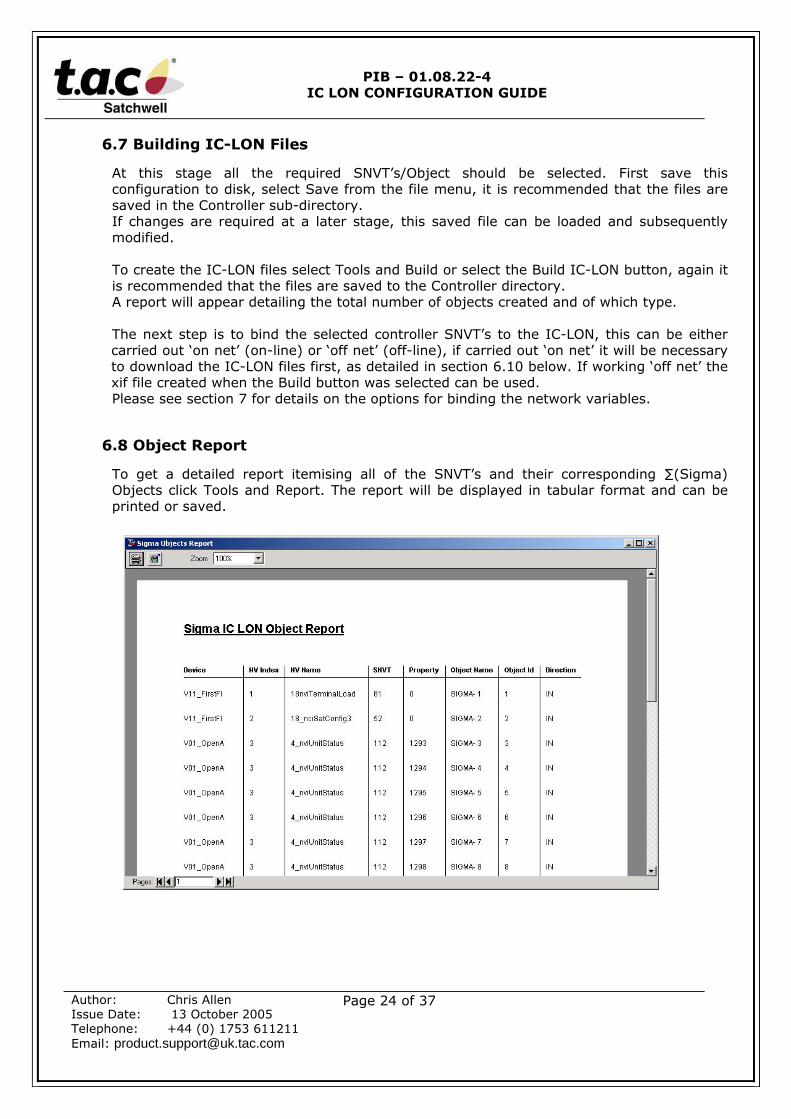
6.8 Object Report
To get a detailed report itemising all of the SNVT’s and their corresponding ∑(Sigma)Objects click Tools and Report. The report will be displayed in tabular format and can beprinted or saved.
PIB – 01.08.22-4IC LON CONFIGURATION GUIDE
Author: Chris AllenIssue Date: 13 October 2005Telephone: +44 (0) 1753 611211Email: [email protected]
Page 25 of 37
6.9 Changing An Existing IC-LON Scheme
With the IC-LON plug-in version 5 or later it is possible to add or delete SNVT’s/Objects toan existing IC-LON. All that is required is the original *.dnn file (this file is created when theplug-in is run and a selection subsequently saved). Please note that it is also possible tomodify IC-LONs that were created with earlier versions of the plug-in.
The process is exactly the same as for a new IC-LON except that the existing *.dnn file isopened and any changes are made to this configuration.
It is also necessary to delete the existing IC-LON device from the drawing and then removethe Device template, see below. When the IC-LON device is deleted this will also remove theassociated IC-LON function block and delete all the bindings. This is not an issue providingversion 5 or later of the plug-in is being used as this has the auto bind feature.
6.9.1 Device Template - Removing
If a device is being commissioned (on net) in LonMaker and it’s SNVT profile has changed(i.e. because SNVT’s have been added, deleted or amended), LonMaker will not allow thedevice to be added, you will be presented with on of the following error messages:-
The specified template name is already in use, in which case change the nameorThe device template does not match the defined template
This is caused by LonMaker checking the device template on disk with the actual device XIFfile. The device template will be associated to the previous XIF file, which will have changed.
To resolve this problem it’s necessary to remove the existing Device Template.
To remove an existing device template select Device Templates… from the LonMaker menuoption, highlighting the existing template (i.e. IC-LON1) and select the Remove button. It ispossible to configure LonMaker to remove a device template when it is no longer referenced.
PIB – 01.08.22-4IC LON CONFIGURATION GUIDE
Author: Chris AllenIssue Date: 13 October 2005Telephone: +44 (0) 1753 611211Email: [email protected]
Page 26 of 37
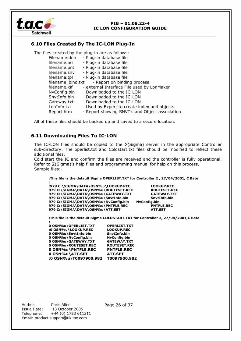
6.10 Files Created By The IC-LON Plug-In
The files created by the plug-in are as follows:Filename.dnn - Plug-in database filefilename.nci - Plug-in database filefilename.pnt - Plug-in database filefilename.snv - Plug-in database filefilename.tpl - Plug-in database filefilename_bind.txt - Report on binding processfilename.xif - eXternal Interface File used by LonMakerNvConfig.bin - Downloaded to the IC-LONSnvtInfo.bin - Downloaded to the IC-LONGateway.txt - Downloaded to the IC-LONLonInfo.txt - Used by Expert to create index and objectsReport.htm - Report showing SNVT’s and Object association
All of these files should be backed up and saved to a secure location.
6.11 Downloading Files To IC-LON
The IC-LON files should be copied to the ∑(Sigma) server in the appropriate Controllersub-directory. The operlist.txt and Coldstart.txt files should be modified to reflect theseadditional files.Cold start the IC and confirm the files are received and the controller is fully operational.Refer to ∑(Sigma)’s help files and programming manual for help on this process.Sample files:-
;This file is the default Sigma OPERLIST.TXT for Controller 2 , 27/04/2001, C Bate;;979 C:\SIGMA\DATA\OSN%u\LOOKUP.REC LOOKUP.REC979 C:\SIGMA\DATA\OSN%u\ROUTESET.REC ROUTESET.REC979 C:\SIGMA\DATA\OSN%u\GATEWAY.TXT GATEWAY.TXT979 C:\SIGMA\DATA\OSN%u\SnvtInfo.bin SnvtInfo.bin979 C:\SIGMA\DATA\OSN%u\NvConfig.bin NvConfig.bin979 C:\SIGMA\DATA\OSN%u\PNTFLE.REC PNTFLE.REC979 C:\SIGMA\DATA\OSN%u\ATT.SET ATT.SET
;This file is the default Sigma COLDSTART.TXT for Controller 2, 27/04/2001,C Bate;0 OSN%u\OPERLIST.TXT OPERLIST.TXT;0 OSN%u\LOOKUP.REC LOOKUP.REC0 OSN%u\SnvtInfo.bin SnvtInfo.bin0 OSN%u\NvConfig.bin NvConfig.bin0 OSN%u\GATEWAY.TXT GATEWAY.TXT0 OSN%u\ROUTESET.REC ROUTESET.REC0 OSN%u\PNTFLE.REC PNTFLE.REC0 OSN%u\ATT.SET ATT.SET;0 OSN%u\T0097900.982 T0097900.982
PIB – 01.08.22-4IC LON CONFIGURATION GUIDE
Author: Chris AllenIssue Date: 13 October 2005Telephone: +44 (0) 1753 611211Email: [email protected]
Page 27 of 37
7.0 IC-LON AND LONMAKER
7.1 Adding IC-LON In LonMaker
IC-LON can be added to the LonMaker drawing either or Off-line (Off Net) or Online (OnNet), the latter will required the IC-LON to be fully operational, that is it has been coldstarted and has received all its files as detailed in section 6.10 above. Please note thatwithout all its files the IC-LON will not run correctly.To add the IC-LON to the drawing, go to the main Subsystem drawing and drag a devicefrom the LonMaker Basic Shapes Stencil. Name the devices with the name assigned in theIC-LON Plug-in, the name does not need to be unique unless more than one IC-LON will beadded to a single LonMaker drawing..
If working On Net it will be possible to select Commission Device, you will then need toenter the Neuron ID or push the service pin on the IC-LON card on the last page of thiswizard, if successful the device shape will turn green.
NOTE: If you have an IC-LON with a large object count the IC-LON may time out duringthe commissioning process, if the occurs it is necessary to increase the Transmit timersettings, from the LonMaker menu option select Network Properties… and the Timing tab,increase the Transmit Timer to 2048 milliseconds.
If working On Net select the option to upload from device, if working Off Net select LoadXIF and click the browser button and select the folder where the IC-LON Plug-in files havebeen saved. Select the XIF file and click OK.
Click next and continue until the node is installed. Drag a function block on to the drawingnext to the IC-LON node giving it a unique name i.e. IC-LON1. Drag both the NetworkVariable Input and the Output icons from the LonMaker Basic Stencil. It is not necessary toadd any inputs and outputs if the IC-LON Plug-in has been used.
The IC-LON snvt’s are now ready to be bound to the individual devices either manually orautomatically using the IC-LON plug-in.
Note: If multiple IC-LON’s are being created that are similar then its possible to create aMaster Shape stencil, please see section 10.3 for details of this process.
7.2 Time Synchronisation
If the Lon devices require time synchronisation with IC-LON it will be necessary to create abinding between the nvo TimeStamp snvt on IC-LON and the nviTimeStamp snvt on everydevice.
Please note that there is no need to include the time stamp snvt when selecting snvt’susing the Plug-in as this snvt is always available within IC-LON.
PIB – 01.08.22-4IC LON CONFIGURATION GUIDE
Author: Chris AllenIssue Date: 13 October 2005Telephone: +44 (0) 1753 611211Email: [email protected]
Page 28 of 37
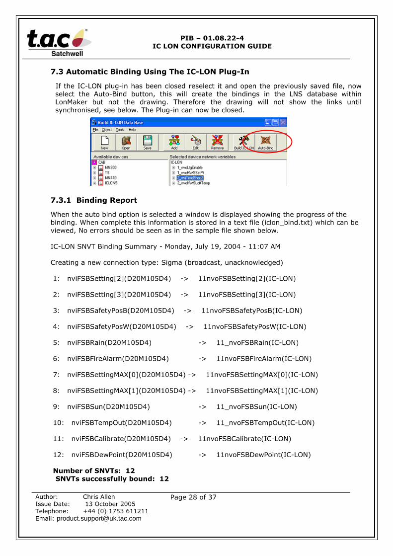
7.3 Automatic Binding Using The IC-LON Plug-In
If the IC-LON plug-in has been closed reselect it and open the previously saved file, nowselect the Auto-Bind button, this will create the bindings in the LNS database withinLonMaker but not the drawing. Therefore the drawing will not show the links untilsynchronised, see below. The Plug-in can now be closed.
7.3.1 Binding Report
When the auto bind option is selected a window is displayed showing the progress of thebinding. When complete this information is stored in a text file (iclon_bind.txt) which can beviewed, No errors should be seen as in the sample file shown below.
IC-LON SNVT Binding Summary - Monday, July 19, 2004 - 11:07 AM
Creating a new connection type: Sigma (broadcast, unacknowledged)
1: nviFSBSetting[2](D20M105D4) -> 11nvoFSBSetting[2](IC-LON)
2: nviFSBSetting[3](D20M105D4) -> 11nvoFSBSetting[3](IC-LON)
3: nviFSBSafetyPosB(D20M105D4) -> 11nvoFSBSafetyPosB(IC-LON)
4: nviFSBSafetyPosW(D20M105D4) -> 11nvoFSBSafetyPosW(IC-LON)
5: nviFSBRain(D20M105D4) -> 11_nvoFSBRain(IC-LON)
6: nviFSBFireAlarm(D20M105D4) -> 11nvoFSBFireAlarm(IC-LON)
7: nviFSBSettingMAX[0](D20M105D4) -> 11nvoFSBSettingMAX[0](IC-LON)
8: nviFSBSettingMAX[1](D20M105D4) -> 11nvoFSBSettingMAX[1](IC-LON)
9: nviFSBSun(D20M105D4) -> 11_nvoFSBSun(IC-LON)
10: nviFSBTempOut(D20M105D4) -> 11_nvoFSBTempOut(IC-LON)
11: nviFSBCalibrate(D20M105D4) -> 11nvoFSBCalibrate(IC-LON)
12: nviFSBDewPoint(D20M105D4) -> 11nvoFSBDewPoint(IC-LON)
Number of SNVTs: 12SNVTs successfully bound: 12

PIB – 01.08.22-4IC LON CONFIGURATION GUIDE
Author: Chris AllenIssue Date: 13 October 2005Telephone: +44 (0) 1753 611211Email: [email protected]
Page 29 of 37
7.4 Drawing Synchronisation
Once the Auto Bind option has been selected it is necessary to synchronise the drawing tothe database, currently the drawing will not show the binding links.From LonMaker select Resynchronize… from the LonMaker menu option, you will be askedif you have backed up your database, if you have recently select Yes, the following windowwill be displayed.
Ensure the ‘Sync drawing to database (fix-up drawing)’ and ‘Sync monitor sets betweendrawing and database’ is checked, select next to proceed to the next window, the valueson this screen can be left at their default values, select the Next button again, the followingscreen will be displayed.
PIB – 01.08.22-4IC LON CONFIGURATION GUIDE
Author: Chris AllenIssue Date: 13 October 2005Telephone: +44 (0) 1753 611211Email: [email protected]
Page 30 of 37
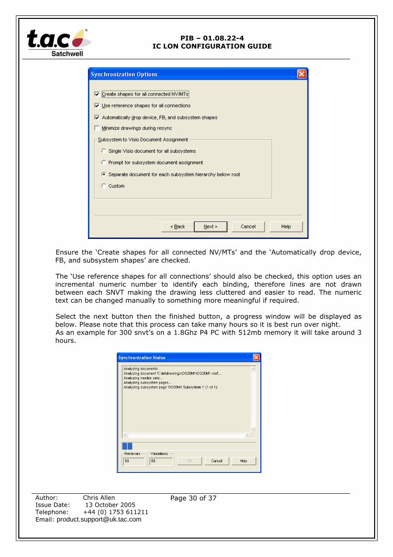
Ensure the ‘Create shapes for all connected NV/MTs’ and the ‘Automatically drop device,FB, and subsystem shapes’ are checked.
The ‘Use reference shapes for all connections’ should also be checked, this option uses anincremental numeric number to identify each binding, therefore lines are not drawnbetween each SNVT making the drawing less cluttered and easier to read. The numerictext can be changed manually to something more meaningful if required.
Select the next button then the finished button, a progress window will be displayed asbelow. Please note that this process can take many hours so it is best run over night.As an example for 300 snvt’s on a 1.8Ghz P4 PC with 512mb memory it will take around 3hours.
PIB – 01.08.22-4IC LON CONFIGURATION GUIDE
Author: Chris AllenIssue Date: 13 October 2005Telephone: +44 (0) 1753 611211Email: [email protected]
Page 31 of 37
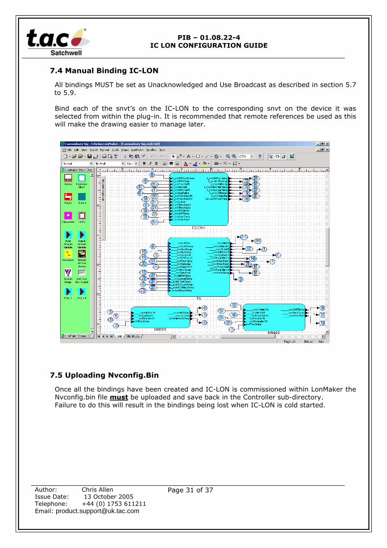
7.4 Manual Binding IC-LON
All bindings MUST be set as Unacknowledged and Use Broadcast as described in section 5.7to 5.9.
Bind each of the snvt’s on the IC-LON to the corresponding snvt on the device it wasselected from within the plug-in. It is recommended that remote references be used as thiswill make the drawing easier to manage later.
7.5 Uploading Nvconfig.Bin
Once all the bindings have been created and IC-LON is commissioned within LonMaker theNvconfig.bin file must be uploaded and save back in the Controller sub-directory.Failure to do this will result in the bindings being lost when IC-LON is cold started.
PIB – 01.08.22-4IC LON CONFIGURATION GUIDE
Author: Chris AllenIssue Date: 13 October 2005Telephone: +44 (0) 1753 611211Email: [email protected]
Page 32 of 37
8.0 ∑(Sigma) OBJECT CREATION
Creation of ∑(Sigma) Objects should be carried out using SigmaX.
8.1 Creating Files With SigmaX
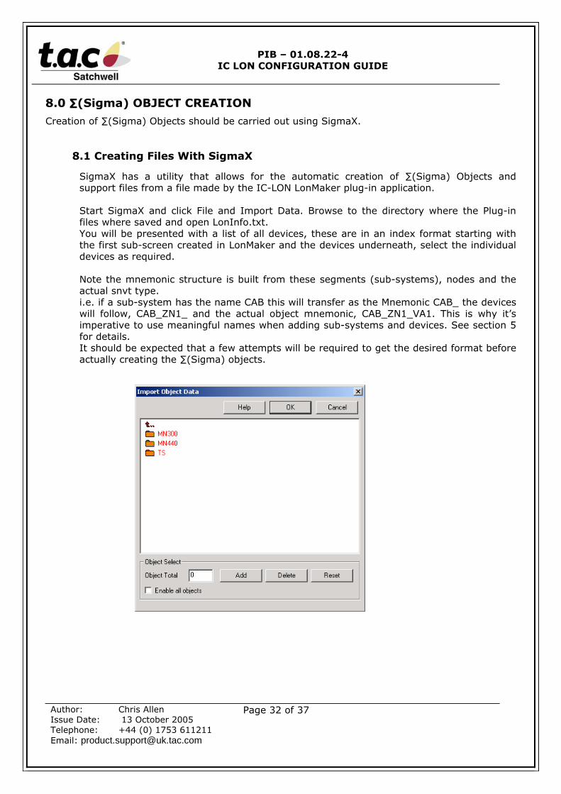
SigmaX has a utility that allows for the automatic creation of ∑(Sigma) Objects andsupport files from a file made by the IC-LON LonMaker plug-in application.
Start SigmaX and click File and Import Data. Browse to the directory where the Plug-infiles where saved and open LonInfo.txt.You will be presented with a list of all devices, these are in an index format starting withthe first sub-screen created in LonMaker and the devices underneath, select the individualdevices as required.
Note the mnemonic structure is built from these segments (sub-systems), nodes and theactual snvt type.i.e. if a sub-system has the name CAB this will transfer as the Mnemonic CAB_ the deviceswill follow, CAB_ZN1_ and the actual object mnemonic, CAB_ZN1_VA1. This is why it’simperative to use meaningful names when adding sub-systems and devices. See section 5for details.It should be expected that a few attempts will be required to get the desired format beforeactually creating the ∑(Sigma) objects.
PIB – 01.08.22-4IC LON CONFIGURATION GUIDE
Author: Chris AllenIssue Date: 13 October 2005Telephone: +44 (0) 1753 611211Email: [email protected]
Page 33 of 37
8.2 Setting Up Default Object Values
The first time LonInfo.txt is opened, controllers added and the Ok button selected SigmaXimports all the snvt names from the selected devices that do not already exist and savesthem in a file called loninfo.ini (in the \SigmaX\ini directory) along with basic default texts,mnemonics etc. This process also adds the objects to the Expert workplace using the textsetc from this ini file.
It is essential to set these default object parameters to something suitable for the job. Itis recommended that an initial import be done of one device so that all the snvt’s are foundand added to the ini file. Cancel the SigmaX workspace, as these objects contain defaultparameters and are not required.
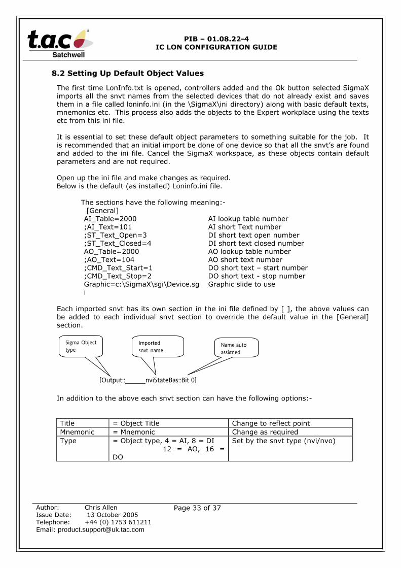
Open up the ini file and make changes as required.Below is the default (as installed) Loninfo.ini file.
The sections have the following meaning:- [General]AI_Table=2000 AI lookup table number;AI_Text=101 AI short Text number;ST_Text_Open=3 DI short text open number;ST_Text_Closed=4 DI short text closed numberAO_Table=2000 AO lookup table number;AO_Text=104 AO short text number;CMD_Text_Start=1 DO short text – start number;CMD_Text_Stop=2 DO short text - stop numberGraphic=c:\SigmaX\sgi\Device.sgi
Graphic slide to use
Each imported snvt has its own section in the ini file defined by [ ], the above values canbe added to each individual snvt section to override the default value in the [General]section.
[Output::_____nviStateBas::Bit 0]
In addition to the above each snvt section can have the following options:-
Title = Object Title Change to reflect pointMnemonic = Mnemonic Change as requiredType = Object type, 4 = AI, 8 = DI
12 = AO, 16 =DO
Set by the snvt type (nvi/nvo)
Sigma Objecttype
Importedsnvt name
Name autoassigned

PIB – 01.08.22-4IC LON CONFIGURATION GUIDE
Author: Chris AllenIssue Date: 13 October 2005Telephone: +44 (0) 1753 611211Email: [email protected]
Page 34 of 37
Sample LonInfo.ini after adding snvt’s and making controller specific:-
[General]AI_Table=2000;AI_Text=101;ST_Text_Open=3;ST_Text_Closed=4AO_Table=2000;AO_Text=104;CMD_Text_Start=1;CMD_Text_Stop=2Graphic=c:\SigmaX\sgi\Device.sgi
[Input::____nvoLtgEnable::Value]Title=Lux LevelAI_Text=345Mnemonic=LTVType=4
[Input::____nvoLtgEnable::Switch]Title=Lighting Enable StatusST_Text_Closed=54ST_Text_Open=55Mnemonic=LTEType=8
[Output::__nviHWSMainTemp::Temperature]Title= HWS Set pointAO_Table=101Type=12
[Output::_____nviStateBas::Bit 0]Title=Alarm StateCMD_Text_Start=6CMD_Text_Stop=262Type=16
Once all the snvt’s / objects have been configured for a single controller rerun the import routine,where a graphic slide is being used select just one device at a time and create the Object andgraphics. If no graphics are being used it is possible to select up to 250 objects to be created at atime.
Obviously if more control is required over the ∑(Sigma) object values then the point defaultsshould be edited.
PIB – 01.08.22-4IC LON CONFIGURATION GUIDE
Author: Chris AllenIssue Date: 13 October 2005Telephone: +44 (0) 1753 611211Email: [email protected]
Page 35 of 37
9.0 FINAL COMMISSIONING
9.1 Download Point Files
When all of the objects have been created the object files can be downloaded to IC-LONand the system tested.
It will be necessary to test at least one object per LON controller to make sure that thebindings for one controller are not crossed with another.
9.2 Uploading Nvconfig.Bin
Once all the bindings have been created and IC-LON is commissioned within LonMaker theNvconfig.bin file must be uploaded and save back in the Controller sub-directory.Failure to do this will result in the bindings being lost when IC-LON is cold started.
10.0 GENERAL INFORMATION
10.1 Invensys LON Mark Controllers
If Invensys LonMark controllers are to be used then it is advisable to load the XIF and FMTfiles into LonMaker and register them.
An explanation on how to achieve this and the associated files is located in a ZIP file calledSIEBEXIF.ZIP, which can be obtained from the intranet or Product Support, Slough.
10.2 Configuring LonMaker To Use Metric Units
LonMaker for Windows III and the NV Browser program when running on Windows 2000default to using US units (‘F / CFM). For LMW to use metric units Windows 2000 must beenabled for metric and set as the default.To configure this go to Control Panel and Select Regional options icon. On the General tabclick the Set default button and select English (United Kingdom), click OK and restart thePC.LonMaker will now default to metric displays. Note it is the action of pressing the SetDefault button that enable the metric units.
PIB – 01.08.22-4IC LON CONFIGURATION GUIDE
Author: Chris AllenIssue Date: 13 October 2005Telephone: +44 (0) 1753 611211Email: [email protected]
Page 36 of 37
10.3 LonMaker Templates
When any device is brought into LonMaker a device template is created, this template usesthe program ID that is present in the device and the XIF file to determine the availablesnvt’s. This is why when adding devices of the same type you simply select the existingDevice Template for this device. However this can cause confusion, particularly whenworking with Lonworks controllers like IC-LON that do not have a fixed snvt profile. Forexample, if it becomes necessary to add or remove snvt’s from IC-LON then its XIF file andprofile will change, in doing this it will be necessary to delete the IC-LON device andfunction block from the LonMaker drawing which will also delete all the bindings. When anew IC-LON device is dropped on the drawing and a new template created, LonMaker willcomplain as it already has a program ID for this device but it now finds that the snvt’shave changed.
There are two options, one is to give IC-LON a new program ID, the other preferredmethod is to delete the existing template (which is now not required).
To delete the template, from the LonMaker menu select Device Templates…. Highlight thetemplate to be deleted and press the Remove button. Note this can only be carried outwhen the device has been removed form the template and is no longer required by thedrawing.
This process can also be performed automatically by LonMaker, however by default this isdisabled. To enable it, from the LonMaker menu select Network Properties… and theLonMaker Options tab. In the Options Category select Device, place a tick in the Removeun-referenced Device Template check box and press the Ok button.
10.4 Domain ID
Whenever a new LonMaker database is created a random Domain ID is assigned, this ID isstored in each controller, consequently if multiple PC’s are being used to commission theinstallation it is imperative they are all set to the same Domain ID. This also applies ifcontroller specific tools are being used to configure the controller, such as VisiSat, thesemust also have the same Domain ID.
To change the Domain ID in LonMaker select Network Properties… from the LonMakermenu option, select the Domain tab and uncheck the Use randomly generated domain idand enter the required Domain id in Hex.
PIB – 01.08.22-4IC LON CONFIGURATION GUIDE
Author: Chris AllenIssue Date: 13 October 2005Telephone: +44 (0) 1753 611211Email: [email protected]
Page 37 of 37
10.5 Configuring Multiple IC-LON’s
If multiple IC-LON’s are to be created with identical schemes / controllers then it ispossible to create the first LonMaker drawing, complete with IC-LON and bindings andconvert this into a Master Shape Stencil.The method to do this is as follows, however this should not be attempted until the schemehas been fully tested. As this could replicate unnecessary errors.The controllers and IC-LON for the first IC-LON should all be added to one page whichwould mean the page size will need to be increased to allow all the controller to be placed.The bindings should be created between all devices, the ∑(Sigma) objects created and fullytested. At this stage make a backup of the LonMaker database.Once satisfied that the first IC-LON is operating as required, from within LonMaker selectall the devices and bindings except the LNS Network Interface and the Channel.From the file menu select Stencils and New Stencil, then Drag all the selected items ontothe stencil, this process will take some time so be patient.Close the existing project and save the new stencil.
Start a new network and open the stencil created above. There is currently a bug in LMWin that the Connection is not saved, i.e. the specially created SigmaConnection will not besave to the Master Shape stencil. To overcome this, with the blank drawing showing selectConnect from the right mouse menu, click cancel in the Select objects to be bound box.Then create a new connection with the same name as described in section 5.9.
Now drag the image from the stencil, again this will take sometime, you will be promptedwith each device in turn, select a new name for the device reflecting its function/location.If you are on-line you can commission the device by placing a tick in the box, you mustselect this option if the xif file is not available and be on-line. This process will be repeatedfor each device on the original drawing.When successfully added you will have a copy of the original IC-LON, now simply run theSigmaX and create the ∑(Sigma) objects.
11.0 DOCUMENTATION CONTROL
PIBversion
Author Date Changes
01.08.22-1 Colin Bate 22/08/2004 First release01.08.22-2 Colin Bate 05/08/2004 Updated to cover IC-LON plug-in Version 501.08.22-3 Colin Bate 01/12/2004 Added a warning to section 5.7 page 15 detailing issues when
using the plug-in with existing bindings.Added a warning to section 5.3 page 9 re using sub-systemsin LonMaker.
01.08.22-4 Chris Allen 13/10/2005 Revised to represent the change of ownership fromInvensys to T. A. C. Content does not differ from theprevious issue
If you have any questions regarding our PIB then contact Product Support on: -“+44 (0) 1753 611211 or email [email protected]”