Deflection Control of High Rise Symmetrical Building Using ...
Upload
khangminh22Category
view
1download
0
Building Management and Control Systems Standard
Design, Engineering, Planning & Sustainability
University Infrastructure
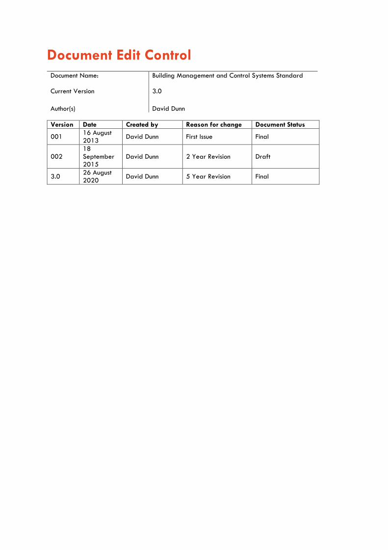
Document Edit Control
Document Name: Building Management and Control Systems Standard Current Version
3.0
Author(s) David Dunn
Version Date Created by Reason for change Document Status
001 16 August 2013
David Dunn First Issue Final
002 18 September 2015
David Dunn 2 Year Revision Draft
3.0 26 August 2020
David Dunn 5 Year Revision Final
BMCS Standard 1
Contents 1 Purpose................................................................................................................................................................. 4
2 Scope .................................................................................................................................................................... 4
3 Glossary of Terms .............................................................................................................................................. 5
4 Roles and Responsibilities ................................................................................................................................. 6
5 Construction Requirements ................................................................................................................................ 6
5.1 New Buildings ............................................................................................................................................. 6
5.2 Refurbishments ............................................................................................................................................ 7
5.3 Reuse of existing equipment .................................................................................................................... 7
6 Technical Requirements ..................................................................................................................................... 7
6.1 Introduction.................................................................................................................................................. 7
6.2 Design and Documentation ...................................................................................................................... 7
6.2.1 General ................................................................................................................................................. 7
6.2.2 Calculations ........................................................................................................................................... 7
6.2.3 Equipment Selection and Sizing ........................................................................................................ 8
6.2.4 Drawings and Documentation ........................................................................................................... 8
6.2.5 Workshop Submittals .......................................................................................................................... 8
6.3 BACnet Protocol ......................................................................................................................................... 9
6.3.1 Standard Compliance ......................................................................................................................... 9
6.3.2 BTL Listing .............................................................................................................................................. 9
6.3.3 BACnet Documentation ....................................................................................................................... 9
6.4 System Configuration ................................................................................................................................ 9
6.5 Control Systems .......................................................................................................................................... 9
6.6 Servers ....................................................................................................................................................... 10
6.6.1 Tag Naming Convention ................................................................................................................... 10
6.6.2 BACnet Priority Array ....................................................................................................................... 10
6.6.3 Trend Logs ........................................................................................................................................... 11
6.7 Device Instances and Addresses ........................................................................................................... 11
6.7.1 BACnet Device Numbering Convention ......................................................................................... 11
6.8 Quality Assurance .................................................................................................................................... 11
6.8.1 Products ............................................................................................................................................... 11
6.8.2 System Performance ......................................................................................................................... 12
6.8.3 Critical Environments ......................................................................................................................... 13
6.8.4 Submittals ............................................................................................................................................ 13
6.8.5 OWNERSHIP OF PROPRIETARY MATERIAL .................................................................................. 14
6.8.6 Lighting Controls Integration with BMCS ....................................................................................... 14
6.9 Network and Communication Requirements ....................................................................................... 14
6.9.1 General ............................................................................................................................................... 14
BMCS Standard 2
6.9.2 BACnet ................................................................................................................................................. 14
6.10 Function requirements of systems .......................................................................................................... 15
6.10.1 Maintenance Supervision .................................................................................................................. 15
6.10.2 Sequencing .......................................................................................................................................... 15
6.10.3 PID Control .......................................................................................................................................... 15
6.11 Power Supplies......................................................................................................................................... 15
6.11.1 General ............................................................................................................................................... 15
6.11.2 Surge Diverters .................................................................................................................................. 15
6.11.3 Ethernet filters ..................................................................................................................................... 15
6.11.4 Dedicated Circuits ............................................................................................................................. 15
6.12 Graphic displays ..................................................................................................................................... 15
6.12.1 General ............................................................................................................................................... 15
6.12.2 Front page .......................................................................................................................................... 16
6.12.3 Building main page ........................................................................................................................... 16
6.12.4 Floor plans ........................................................................................................................................... 16
6.12.5 System/equipment pages ................................................................................................................ 16
6.12.6 Summary Page ................................................................................................................................... 16
6.12.7 Operational description ................................................................................................................... 17
6.12.8 Controller list ....................................................................................................................................... 17
6.13 Software requirements ........................................................................................................................... 17
6.13.1 System Help ........................................................................................................................................ 17
6.13.2 System security ................................................................................................................................... 17
6.13.3 Operator Display .............................................................................................................................. 18
6.13.4 Programming ...................................................................................................................................... 18
6.13.5 Global settings/override ................................................................................................................. 18
6.13.6 Schedules ............................................................................................................................................. 18
6.13.7 Trending ............................................................................................................................................... 19
6.13.8 Operator log ...................................................................................................................................... 19
6.13.9 Point\Value Changes ........................................................................................................................ 19
6.13.10 User Auto- Logout ..................................................................................................................... 19
6.13.11 Data Storage ............................................................................................................................. 19
6.14 Alarms ........................................................................................................................................................ 19
6.14.1 Security connections ........................................................................................................................... 19
6.14.2 Alarm Priorities ................................................................................................................................... 19
6.14.3 E-mail alarms ...................................................................................................................................... 20
6.14.4 Alarm functionality ............................................................................................................................ 21
6.15 Efficiency ................................................................................................................................................... 21
6.15.1 HVAC ................................................................................................................................................... 21
6.15.2 Space control methods ...................................................................................................................... 21
BMCS Standard 3
6.15.3 Room Booking System ....................................................................................................................... 22
6.16 BMCS Points .............................................................................................................................................. 22
6.16.1 Control Valves .................................................................................................................................... 22
6.16.2 Damper Actuators .............................................................................................................................. 22
6.16.3 Transducers ......................................................................................................................................... 23
6.16.4 Sensors ................................................................................................................................................. 23
6.17 BMCS Cabinets ........................................................................................................................................ 25
6.17.1 General ............................................................................................................................................... 25
6.17.2 Locations .............................................................................................................................................. 25
6.17.3 Quality ................................................................................................................................................. 25
6.17.4 Wiring .................................................................................................................................................. 25
6.18 Product Support ....................................................................................................................................... 26
6.19 Software Life Cycle ................................................................................................................................ 26
7 Commissioning ................................................................................................................................................... 26
7.1 Building Tuning ......................................................................................................................................... 26
8 Safety in design ............................................................................................................................................... 27
9 Documentation and Records ........................................................................................................................... 27
9.1 Design Documentation ............................................................................................................................. 28
9.2 Completion Documents ............................................................................................................................ 28
10 Assets and Warranties .................................................................................................................................... 29
11 Defects and Liability Period .......................................................................................................................... 29
11.1 Maintenance and Testing ....................................................................................................................... 30
12 Operations & Maintenance Manuals ........................................................................................................... 30
13 Authorisation of variations.............................................................................................................................. 31
14 Quality control .................................................................................................................................................. 31
14.1 Design Standard Compliance ............................................................................................................... 31
14.2 Design Standard Certification .............................................................................................................. 31
14.3 Construction Compliance ........................................................................................................................ 32
14.4 Acceptance ............................................................................................................................................... 32
15 Document Amendment History ....................................................................................................................... 32
16 Attachments ....................................................................................................................................................... 33
Attachment 1 Network and Hardware Configuration ................................................................................... 33
Attachment 2 Services Points List ....................................................................................................................... 33
Attachment 3 Operational Description Template .......................................................................................... 33
BMCS Standard 4
1 Purpose The UI BMCS Standard sets out the University of Sydney's minimum requirements for the design, construction and maintenance of BMCS systems. It ensures new and refurbished systems are energy efficient, fit-for-purpose, made from durable good-quality materials, contain no or minimal environmentally harmful substances, and are cost efficient to operate and maintain. Applicable requirements documented in Workplace Health and Safety legislation, Disability Discrimination legislation, State Environmental Planning legislation, Commonwealth and State legislation, National Construction Codes (NCC), the Building Code of Australia (BCA) and Australian and New Zealand Standards (AS/NZS) are the minimum and mandatory compliance requirements. Where any ambiguity exists between this standard and the aforementioned mandatory requirements then: a. The highest performance requirements must apply b. Applicable requirements must follow this order of precedence:
1. Workplace Health and Safety legislation. 2. Safety in Design Legislation. 3. Disability Discrimination legislation. 4. State Environmental Planning and Assessment legislation. 5. All other Commonwealth and State legislation. 6. NCC, BCA and PCA. 7. AS/NZS. 8. This standard and other University of Sydney standards.
2 Scope This standard describes minimum requirements for design, purchase, construction, and operation and maintenance of The BMCS, equipment and infrastructure for buildings and spaces owned, operated, maintained and/or managed by the University of Sydney. It applies to: a. New Building Construction. b. Refurbishment spaces within existing buildings c. Facilities maintenance services. The standards apply to all planners, project managers, consultants, contractors, sub-contractors, tenants, managing agents and University staff involved in the design, construction and maintenance of existing, new and proposed University buildings and facilities. The Standard provides: a. A reference document to enable consistency with the design and engineering objectives. b. Details of the minimum performance requirements for planning, architectural design and
maintenance. c. Support of the University vision for the built environment and best practice. The Standard addresses key objectives: a. Quality design which responds, enhances and complements the environment. b. Appreciation of the heritage context and cultural history of the campuses. c. Value for money in all aspects of the project. d. The design of low maintenance buildings and environments. e. Longevity of construction approach to design. f. Standardization of key flashing and ancillary details.
BMCS Standard 5
g. Flexible design, to future proof building usage for expansion or adaption to new uses h. Safety in design. All BMCS products and services provided or specified by designers, consultants, staff and contractors must conform to this standard. Where specific applications are not explicitly covered, or ambiguity exists, the intent of the design standard must be satisfied. In such cases a return design brief must be provided for review and approval by the issuer of this standard or their appointed delegate who must have relevant technical competence in the subject matter. Additional more stringent requirements may apply on a project-specific basis dependent upon risk management and insurance requirements.
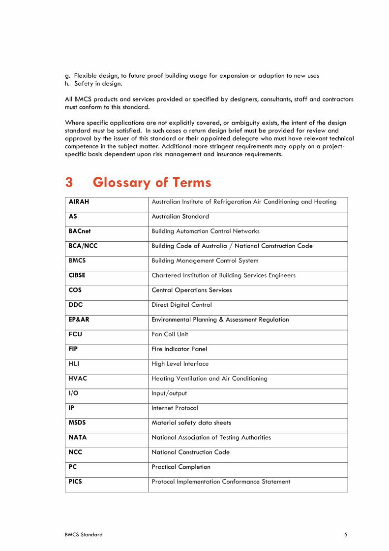
3 Glossary of Terms AIRAH Australian Institute of Refrigeration Air Conditioning and Heating
AS Australian Standard
BACnet Building Automation Control Networks
BCA/NCC Building Code of Australia / National Construction Code
BMCS Building Management Control System
CIBSE Chartered Institution of Building Services Engineers
COS Central Operations Services
DDC Direct Digital Control
EP&AR Environmental Planning & Assessment Regulation
FCU Fan Coil Unit
FIP Fire Indicator Panel
HLI High Level Interface
HVAC Heating Ventilation and Air Conditioning
I/O Input/output
IP Internet Protocol
MSDS Material safety data sheets
NATA National Association of Testing Authorities
NCC National Construction Code
PC Practical Completion
PICS Protocol Implementation Conformance Statement
BMCS Standard 6
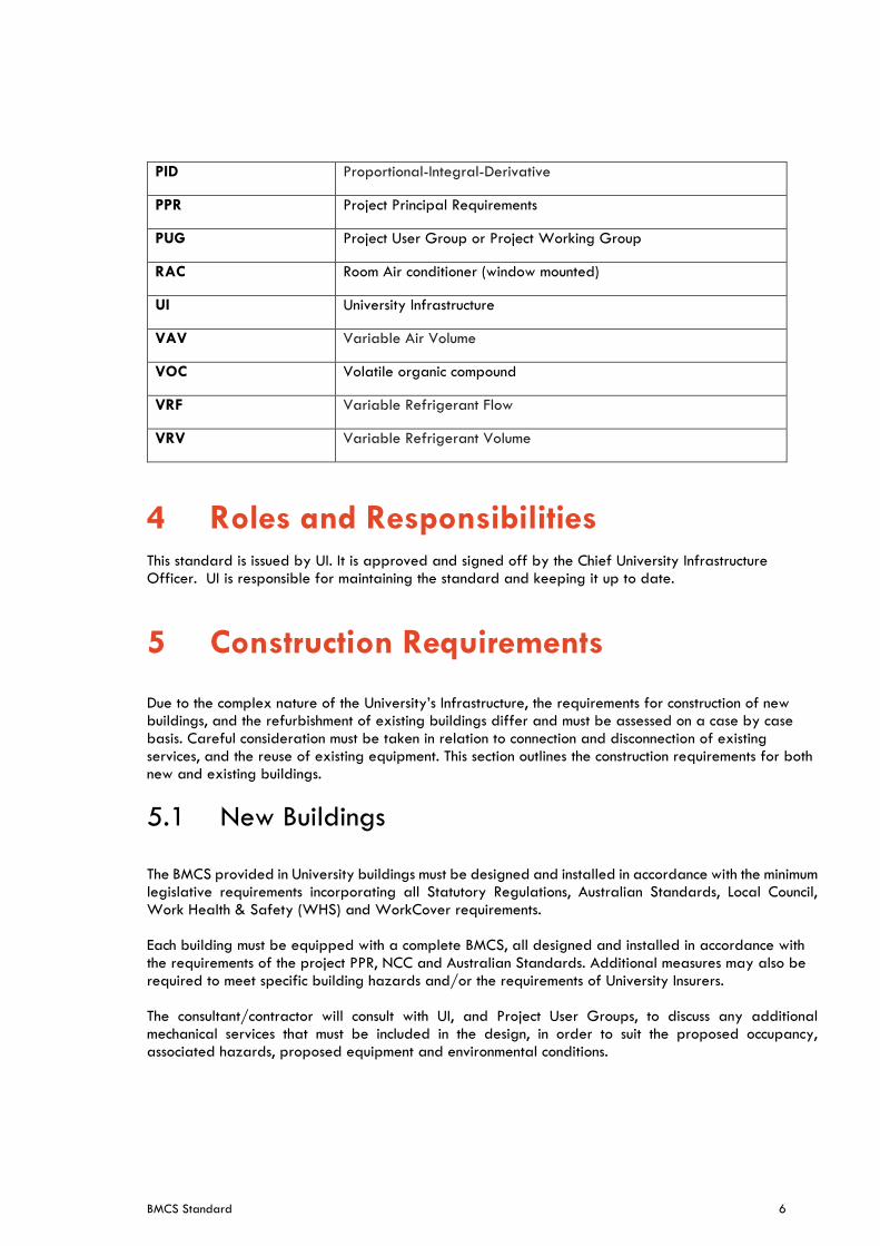
PID Proportional-Integral-Derivative
PPR Project Principal Requirements
PUG Project User Group or Project Working Group
RAC Room Air conditioner (window mounted)
UI University Infrastructure
VAV Variable Air Volume
VOC Volatile organic compound
VRF Variable Refrigerant Flow
VRV Variable Refrigerant Volume
4 Roles and Responsibilities This standard is issued by UI. It is approved and signed off by the Chief University Infrastructure Officer. UI is responsible for maintaining the standard and keeping it up to date.
5 Construction Requirements Due to the complex nature of the University’s Infrastructure, the requirements for construction of new buildings, and the refurbishment of existing buildings differ and must be assessed on a case by case basis. Careful consideration must be taken in relation to connection and disconnection of existing services, and the reuse of existing equipment. This section outlines the construction requirements for both new and existing buildings.
5.1 New Buildings
The BMCS provided in University buildings must be designed and installed in accordance with the minimum legislative requirements incorporating all Statutory Regulations, Australian Standards, Local Council, Work Health & Safety (WHS) and WorkCover requirements. Each building must be equipped with a complete BMCS, all designed and installed in accordance with the requirements of the project PPR, NCC and Australian Standards. Additional measures may also be required to meet specific building hazards and/or the requirements of University Insurers. The consultant/contractor will consult with UI, and Project User Groups, to discuss any additional mechanical services that must be included in the design, in order to suit the proposed occupancy, associated hazards, proposed equipment and environmental conditions.
BMCS Standard 7
5.2 Refurbishments
All existing BMCS systems in a building must be extended/replaced as necessary into the given project. The design for projects within existing buildings must be assessed on a case by case basis and developed in conjunction with this standard. Existing systems must be kept the same system type in a building, mixed systems in a building will not be accepted. All project associated redundant equipment, fixings and wiring, including inaccessible ceiling spaces, must be removed as part of the project works. Make good exposed surfaces before commencing the installation of new services. This includes the removal of redundant underground services unless otherwise approved by the project superintendent.
5.3 Reuse of existing equipment
Where existing equipment is utilised as part of a project it is the responsibility of the contractor to confirm its performance\condition and provide a written report to the University. The contractor must ensure that there is sufficient capacity in the existing equipment.
6 Technical Requirements
6.1 Introduction
The BMCS system of a University building must include surrounding structures and annex buildings. In some cases, components of the BMCS system will be installed or must be installed in other buildings. In these cases, the word building in this document is to be interpreted as inclusive of these structures, annexes and components.
6.2 Design and Documentation
6.2.1 General
This section outlines the extent of the services to be provided by the contractor during the process of Design and Construction. The contractor shall be fully responsible for the complete design of the BMCS installations, including the selection, sizes, quantity of equipment, shall provide calculations, drawings and other documentation as necessary to demonstrate conformance with the design parameters, industry practice, UI requirements, codes, regulations and standards. This includes all calculations required to confirm that existing infrastructure is sufficient to supply the proposed systems and equipment installed under the project. The contractor shall allow to fully co-ordinate the documentation with the Architect, Structural Engineer and all other services consultants / contractors.
6.2.2 Calculations
As part of the contractor’s design, it is expected as a minimum that the following design calculations are produced for review by UI for approval prior to finalising design: a. Cable sizing
BMCS Standard 8
b. Controller capacities (processor capacity and memory) c. Actuator and Valves sizing d. Ensure system has sufficient point Licencing for project (contractor to provide licencing as required
for each project)
6.2.3 Equipment Selection and Sizing
In selecting equipment, the University expects consultants and contractors to select products of proven and reliable quality, with reputable support and after sales service. Products which are of closed systems and proprietary in nature, thus locking the University into exclusive dependence of one manufacturer must be avoided and only used if there are no other options. The provision of 20% spare capacity for future use must be provided when designing and sizing all new BMCS installations. Where existing infrastructure is being used, provision must be made to ensure sufficient capacity remains for future works in the building.
6.2.4 Drawings and Documentation
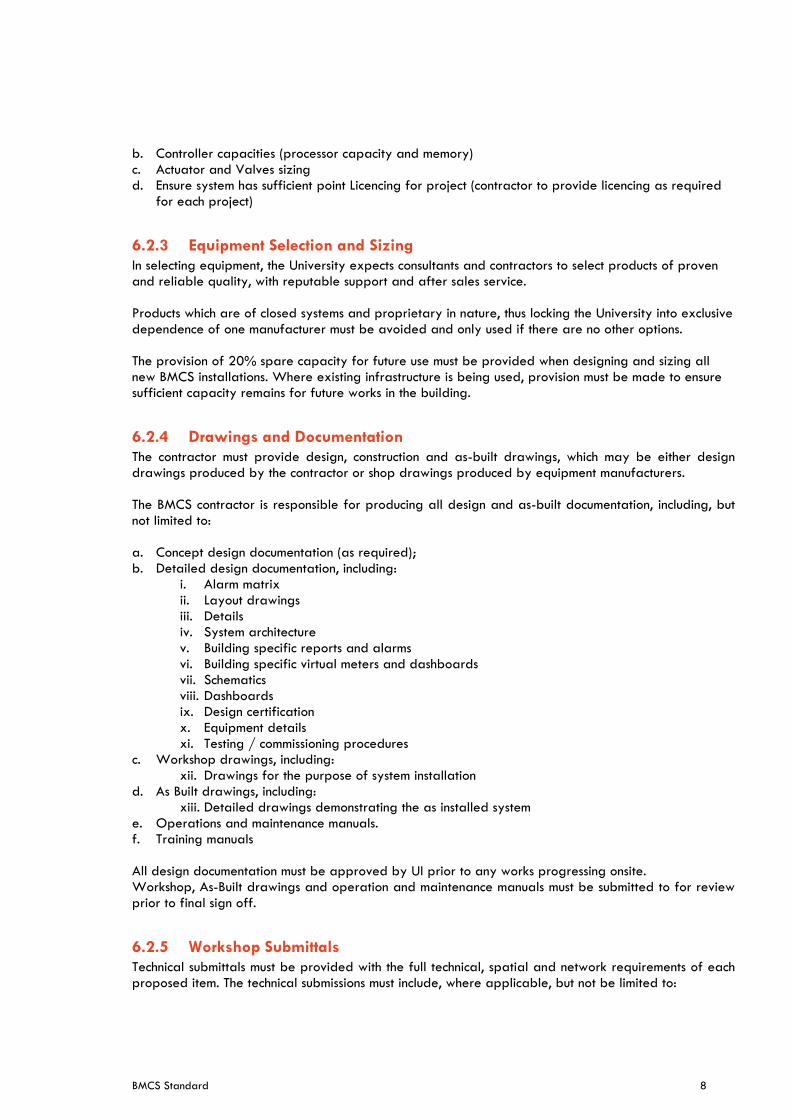
The contractor must provide design, construction and as-built drawings, which may be either design drawings produced by the contractor or shop drawings produced by equipment manufacturers. The BMCS contractor is responsible for producing all design and as-built documentation, including, but not limited to: a. Concept design documentation (as required); b. Detailed design documentation, including:
i. Alarm matrix ii. Layout drawings iii. Details iv. System architecture v. Building specific reports and alarms vi. Building specific virtual meters and dashboards vii. Schematics viii. Dashboards ix. Design certification x. Equipment details xi. Testing / commissioning procedures
c. Workshop drawings, including: xii. Drawings for the purpose of system installation
d. As Built drawings, including: xiii. Detailed drawings demonstrating the as installed system
e. Operations and maintenance manuals. f. Training manuals All design documentation must be approved by UI prior to any works progressing onsite. Workshop, As-Built drawings and operation and maintenance manuals must be submitted to for review prior to final sign off.
6.2.5 Workshop Submittals
Technical submittals must be provided with the full technical, spatial and network requirements of each proposed item. The technical submissions must include, where applicable, but not be limited to:
BMCS Standard 9
a. Certified workshop drawings of each system and control panel complete b. Electrical requirements including, operational voltage, recommended protection devices, wiring
diagrams, connection and terminals details. Also detail of how cables are terminated to the equipment and earthing requirements must be provided.
c. Manufacturer’s recommendations for installation including power quality and thermal requirements. d. Confirmation of product lifespan assuming maintained to manufacturers recommendations. e. Where equipment model numbers / references are stated these are indicative only and the
Contractor MUST ensure the selected equipment fully complies with the entire services standard f. Workshop Submittals
6.3 BACnet Protocol
6.3.1 Standard Compliance
Systems must comply with the BACnet standards ISO 16484. Systems not complying with these guidelines and standards are not accepted by the University.
6.3.2 BTL Listing
All product hardware and software types proposed must have obtained BACnet Testing Laboratories (BTL) listing and must display the BTL logo as shown in Figure 1.
Figure 1 : BTL Logo
6.3.2.1 BACnet Controllers
Building Controllers (BCs) must conform to the following device profile requirements as specified in ISO16484-6.
a. BACnet Building Controller (B-BC) b. Advanced Application Controllers (AACs). c. Application Specific Controllers (ASCs). d. Smart Actuators (SAs).
6.3.3 BACnet Documentation
All products offered must provide a reference of BTL listing.
6.4 System Configuration
The BMCS must represent all inputs and outputs including configuration properties as appropriate BACnet Objects. The BMCS must support the Status attribute of the BACnet Object.
6.5 Control Systems
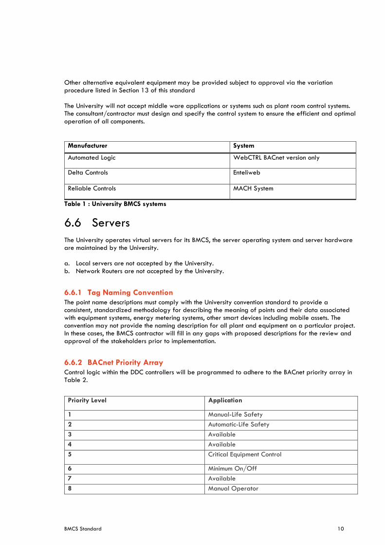
The following systems are deemed to comply with this standard: Below in Table 1
BMCS Standard 10
Other alternative equivalent equipment may be provided subject to approval via the variation procedure listed in Section 13 of this standard The University will not accept middle ware applications or systems such as plant room control systems. The consultant/contractor must design and specify the control system to ensure the efficient and optimal operation of all components.
Manufacturer System
Automated Logic WebCTRL BACnet version only
Delta Controls
Enteliweb
Reliable Controls MACH System
Table 1 : University BMCS systems
6.6 Servers
The University operates virtual servers for its BMCS, the server operating system and server hardware are maintained by the University. a. Local servers are not accepted by the University. b. Network Routers are not accepted by the University.
6.6.1 Tag Naming Convention
The point name descriptions must comply with the University convention standard to provide a consistent, standardized methodology for describing the meaning of points and their data associated with equipment systems, energy metering systems, other smart devices including mobile assets. The convention may not provide the naming description for all plant and equipment on a particular project. In these cases, the BMCS contractor will fill in any gaps with proposed descriptions for the review and approval of the stakeholders prior to implementation.
6.6.2 BACnet Priority Array
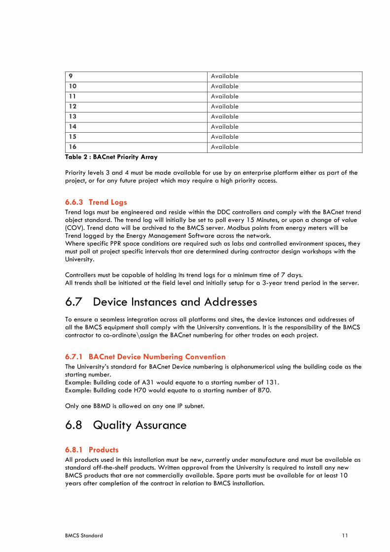
Control logic within the DDC controllers will be programmed to adhere to the BACnet priority array in Table 2.
Priority Level Application
1 Manual-Life Safety
2 Automatic-Life Safety
3 Available
4 Available
5 Critical Equipment Control
6 Minimum On/Off
7 Available
8 Manual Operator
BMCS Standard 11
9 Available
10 Available
11 Available
12 Available
13 Available
14 Available
15 Available
16 Available
Table 2 : BACnet Priority Array Priority levels 3 and 4 must be made available for use by an enterprise platform either as part of the project, or for any future project which may require a high priority access.
6.6.3 Trend Logs
Trend logs must be engineered and reside within the DDC controllers and comply with the BACnet trend object standard. The trend log will initially be set to poll every 15 Minutes, or upon a change of value (COV). Trend data will be archived to the BMCS server. Modbus points from energy meters will be Trend logged by the Energy Management Software across the network. Where specific PPR space conditions are required such as labs and controlled environment spaces, they must poll at project specific intervals that are determined during contractor design workshops with the University. Controllers must be capable of holding its trend logs for a minimum time of 7 days. All trends shall be initiated at the field level and initially setup for a 3-year trend period in the server.
6.7 Device Instances and Addresses
To ensure a seamless integration across all platforms and sites, the device instances and addresses of all the BMCS equipment shall comply with the University conventions. It is the responsibility of the BMCS contractor to co-ordinate\assign the BACnet numbering for other trades on each project.
6.7.1 BACnet Device Numbering Convention
The University’s standard for BACnet Device numbering is alphanumerical using the building code as the starting number. Example: Building code of A31 would equate to a starting number of 131. Example: Building code H70 would equate to a starting number of 870. Only one BBMD is allowed on any one IP subnet.
6.8 Quality Assurance
6.8.1 Products
All products used in this installation must be new, currently under manufacture and must be available as standard off-the-shelf products. Written approval from the University is required to install any new BMCS products that are not commercially available. Spare parts must be available for at least 10 years after completion of the contract in relation to BMCS installation.
BMCS Standard 12
6.8.2 System Performance
The system must have the following functionality: a. Graphic display-the system must display a graphic with 20 dynamic points/objects with all current
data within 2.5 seconds. b. Graphic refresh – the system shall update a graphic with 20 dynamic points/objects with all current
data within 2.5 seconds c. Object command - the maximum time between the command of a binary object by the operator
and the reaction by the device must be less than 2 seconds. Analogue objects must start to adjust within 2 seconds
d. Object scan – all changes of state and change of analogue values must be transmitted over the high-speed network such that any data used or displayed at a controller or workstation will have been current within the previous 2 seconds
e. Alarm response time – the maximum time from when an object goes into alarm to when it is communicated at the workstation must not exceed 5 seconds
f. Program execution frequency - custom and standard applications must be capable of running as often as once every 1(one) second. The contractor must be responsible for selecting execution times consistent with the mechanical process under control
g. PID loops – programmable controllers must be able to execute DDC PID control loops at a frequency of at least once per second. The controller must scan and update the process value and output generated by this calculation at this same frequency.
h. Multiple alarm annunciation - all workstations on the network must receive alarms within 5 seconds of each other
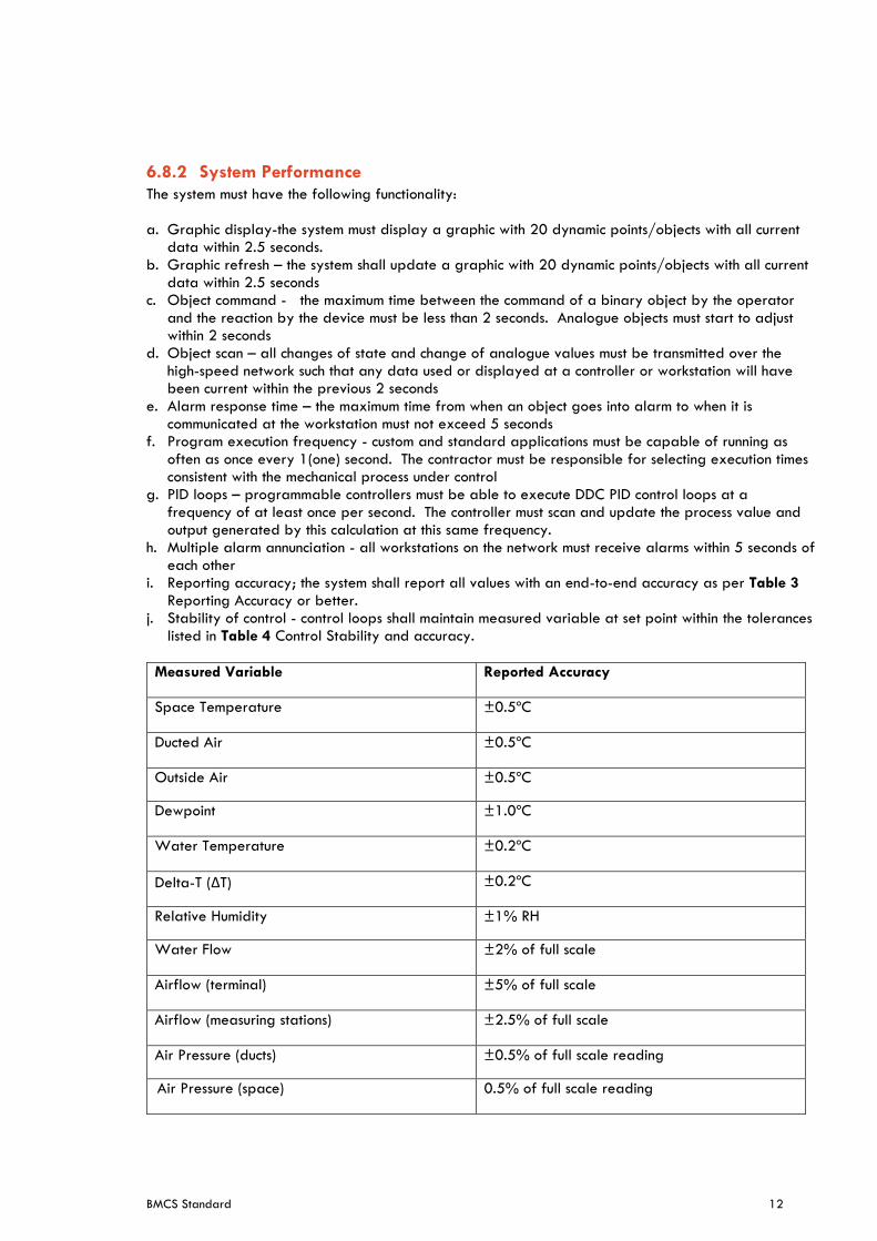
i. Reporting accuracy; the system shall report all values with an end-to-end accuracy as per Table 3 Reporting Accuracy or better.
j. Stability of control - control loops shall maintain measured variable at set point within the tolerances listed in Table 4 Control Stability and accuracy.
Measured Variable Reported Accuracy
Space Temperature ±0.5ºC
Ducted Air ±0.5ºC
Outside Air ±0.5ºC
Dewpoint ±1.0ºC
Water Temperature ±0.2ºC
Delta-T (ΔT) ±0.2ºC
Relative Humidity ±1% RH
Water Flow ±2% of full scale
Airflow (terminal) ±5% of full scale
Airflow (measuring stations) ±2.5% of full scale
Air Pressure (ducts) ±0.5% of full scale reading
Air Pressure (space) 0.5% of full scale reading
BMCS Standard 13
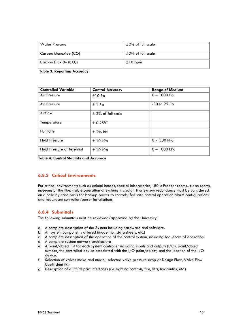
Water Pressure ±2% of full scale
Carbon Monoxide (CO) ±3% of full scale
Carbon Dioxide (CO2) ±10 ppm
Table 3: Reporting Accuracy
Controlled Variable Control Accuracy Range of Medium
Air Pressure 10 Pa 0 – 1000 Pa
Air Pressure 1 Pa -30 to 25 Pa
Airflow 2% of full scale
Temperature 0.25ºC
Humidity 2% RH
Fluid Pressure 10 kPa 0 -1500 kPa
Fluid Pressure differential 10 kPa 0 – 1000 kPa
Table 4: Control Stability and Accuracy
6.8.3 Critical Environments
For critical environments such as animal houses, special laboratories, -80°c Freezer rooms., clean rooms, museums or the like, stable operation of systems is crucial. Thus system redundancy must be considered on a case by case basis for backup power to controls, fail safe control operation alarm configurations and redundant controller/sensor installations.
6.8.4 Submittals
The following submittals must be reviewed/approved by the University:
a. A complete description of the System including hardware and software. b. All system components offered (model no., data sheets, etc.) c. A complete description of the operation of the control system, including sequences of operation. d. A complete system network architecture e. A point/object list for each system controller including inputs and outputs (I/O), point/object
number, the controlled device associated with the I/O point/object, and the location of the I/O device.
f. Selection of valves make and model, selected valve pressure drop at Design Flow, Valve Flow Coefficient (kv)
g. Description of all third part interfaces (i.e. lighting controls, fire, lifts, hydraulics, etc.)
BMCS Standard 14
6.8.5 OWNERSHIP OF PROPRIETARY MATERIAL
All project-developed software and documentation must become the property of the University upon project handover. All Documentation, graphics and programming is to be saved on the University BMCS server. These include, but are not limited to: a. Project graphic images b. Drawings c. Databases d. Application programming code e. All documentation
6.8.6 Lighting Controls Integration with BMCS
Lighting control systems must be integrated into the BMCS via HLI with the following functionalities: a. Provide link to the building lighting control system b. Provide Interface to pick-up status of the space PIR, each space with HVAC that has an integrated
PIR is to display the status of the PIR on the associated rooms HVAC units graphic. c. Lighting system must be able to create an output on BACnet for PIR status.
6.9 Network and Communication Requirements
6.9.1 General
The University network must not be used to transfer data from a controller to another controller such Chiller controller to a condenser water pump or cooling tower fan, where devices are passing data they must be on the same network chain or be directly wired. This is to ensure that systems are controlled via the one control loop.
6.9.2 BACnet
The following are network specific requirements of the system: a. The BMCS system is to be interconnected to all other BMCS systems via the BACnet protocol over IP
and across the university computer network. b. No BMCS subnet or controller is to operate that is not BACnet compliant, and all devices must be
BACnet addressable. c. BACnet must pass data in a bi-directional manner across all routers, gateways on the University
network. d. Un-managed switches are not to be used. e. Data port to be provided from communication room & BMCS cabinet by builder or ICT. f. Network port to be installed in board or next to cabinet. g. Data outlet shall be installed to allow one free port for network access to allow system servicing. h. Contractor is required to provide equipment MAC addresses and port details to Project manager
to obtain IP addresses. i. Contractor is to provide BBMD (ONLY one BBMD per IP subnet) where required to integrate system
on the network.
BMCS Standard 15
6.10 Function requirements of systems
6.10.1 Maintenance Supervision
The system must be designed and installed to be able to totalise run-times for all binary input objects, monitor equipment status and generate maintenance messages based upon use designated run-time, starts, and/or calendar date limits.
6.10.2 Sequencing
Sequence the connected output devices and prevent all controlled equipment from simultaneously restarting after a power outage. The order in which equipment (or groups of equipment) is started, along with the time delay between starts, may be user-selectable.
6.10.3 PID Control
The BACnet loop object complete with self-tuning PID algorithm to calculate a time-varying analogue value that is used to position an output or stage a series of outputs. The set point and PID properties must be user-selectable from the operator interface.
6.11 Power Supplies
6.11.1 General
All transformers and power supplies for field devices to be located within designated control enclosures. Provide all power to cabinets, panels necessary for the complete and satisfactory operation of the entire BMCS. UPS battery must be provided for controllers connected to animal houses, labs and critical control environments/processes. This requirement cascades through to the associated for the space such as FCUs, AHUs, VAVs, chilled/heating/condenser water system or supply/extraction air system.
6.11.2 Surge Diverters
Provide surge diverters connected to protect the sensing devices and all BMCS equipment/controls from damage or spurious operation caused by voltage surges in the power source
6.11.3 Ethernet filters
Provide EMI filters for Ethernet connections.
6.11.4 Dedicated Circuits
All power for controls equipment will be from dedicated circuits. Where a controller is dedicated to controlling a single piece of equipment power may be obtained directly from that equipment.
6.12 Graphic displays
6.12.1 General
The Contractor as part of the workshop phase is to provide sample graphics for review and comment by the University.
BMCS Standard 16
6.12.2 Front page
The front page shall consist of the following: a. List of building names and building codes controlled on the left side of the screen b. System time and date c. Map of selected campus with controlled buildings highlighted and linked d. Link to each campus map e. Temperature and Humidity of campus (to be specific to each campus) f. Link to alarms page g. Link to help page h. Link to user unique preferences/settings i. Link to main plant summary page j. Link to master list of all controller device schedule to be update with each controller installation and
change (attachment 1)
6.12.3 Building main page
The building main page must consist of the following: a. Link to building levels b. Link to grouped equipment types such as all FCU`s or chillers c. Global settings/overrides d. Fire trip monitoring e. Building schedules f. Building network status g. Summary pages providing a brief overview of all equipment statuses h. Link to thermo-graphic thermal maps which depict the temperature in the space i. Buildings operational description PDF document j. Mechanical Floor plans and Schematics in PDF
6.12.4 Floor plans
The contractor must provide floor plans that are the building CAD, all floor plans used must be the most current layout at the time of PC of the project. a. Floors must be broken down into logical sizes for optimised viewing b. Room number must be provided along with VAV, FCU, active chilled beam or package unit that
services the space c. In larger spaces that are serviced by a single or multiple AHUs then the AHU names must be
provided to the floor plans. d. Rooms must be thermographic showing a colour relating to the temperature with a legend
identifying the colour and what it represents e. BMCS panel locations must be identified on the floor plans f. Where zones are ventilation\extraction only, thermographics must not to be used, fan link must be
provided for the space it services
6.12.5 System/equipment pages
System and equipment pages must contain all of the associated inputs and outputs. For equipment serviced by boilers and chillers they must be provided with the associated water temperatures on the page.
6.12.6 Summary Page
The following summary pages must be setup as a minimum a. Building Fan Coil Units b. Building Air Handling Units
BMCS Standard 17
c. Building Humidifier d. Building Reheat Coils e. VAVs f. Active\Passive Chilled Beam Summary Page g. Building Fume Cabinet h. Water Cooled Package Units i. Louvres j. Ventilation Fans k. Cooling\heating call l. Afterhours call m. ChW valves and HW valves positions
6.12.7 Operational description
Included for each project system change musts be a PDF operational description located on the building main page. See Attachment 3 for template. The description must include the following below: a. Each System schematic diagram (per asset type required) b. Network Schematic indicating controller location, address and communications status c. Control programming description d. Control loop parameters e. Alarm list f. Set points g. Project name h. Contractor performing works i. Document Version j. Document title k. Any specific notes l. Date of Drawing
6.12.8 Controller list
A Master controller list must be kept and updated when any change in network address or new/replacement controller is added to the system. Attachment 1 must be used as the template for the controller list. The master list link must be provided on the campus map front page and contain all controllers and third party devices connected to the OEM’s system, this includes items such as VRV or chiller HLI`s.
6.13 Software requirements
6.13.1 System Help
An on-line help system must be available to assist the operator in managing and editing system from a beginner to an advanced level of user.
6.13.2 System security
The following are the minimum system security requirements a. Operators are to log on to the system with a user name and password to gain entry into the
operator workstation software. b. System security must be role based and selectable for each individual operator and include a
provision for granting privileges c. New Logins and access levels must be authorised only by University’s Engineering team
BMCS Standard 18
d. User privileges must be location dependent to provide the user different access levels based on where they are in the system
6.13.3 Operator Display
The operator workstation software is to display and provide operator access to all BACnet and proprietary objects associated with the project as specified in the drawings and/or points list. Right-clicking an object is to bring up a context sensitive pop-up menu of commands and functions that can be initiated directly for the highlighted object without opening the object.
6.13.4 Programming
a. All programming must be available for live viewing and display of operating sequences. b. Pre-programmed Logic blocks that do not allow access to programming/settings will not be
accepted. c. Programming must be laid out in a clear and flowing structure. d. Programming and Graphical software tools shall be provided under the same system software
package using the same database. Separate or independent programming or graphic tools will not be accepted.
e. Software lockout of equipment in fault will not be accepted, equipment must be auto-resetting unless PPR calls for lockout or piece of equipment goes out on fault multiple time during a set time period.
6.13.5 Global settings/override
Provide global override for all common points such as a. Chilled/hot/condenser water valves b. Outside air dampers c. FCU/AHU Set point d. Start/stop signal for all systems e. HVAC mode (for VRV/VRF systems) f. Demand management g. Water treatment flush cycle h. Cooling tower cleaning i. VAV damper position j. Bush fire mode to close all outside air dampers and open return air dampers
6.13.6 Schedules
The following items must be provided in the schedule page a. Weekly calendar capable of having segments programmed b. Special day time setting c. Annual special day calendar for programming special dates of running d. Holiday calendar for periods system not in use e. Seminar and lecture rooms shall have individual schedules f. Floor by floor schedule g. Equipment group schedules h. Ability to schedule multiple events within one day
Each project must be assessed on an individual basis to ensure fit-for-purpose schedules are developed for each area.
BMCS Standard 19
6.13.7 Trending
Operators must be able to create/change trend log setups. All inputs, outputs and values shall be capable of trending by the operator. Trend graphs must auto-update with live data as well as use backdated/historical/archived data. Trends must be easily converted and saved to the following file formats: a. CSV b. XLS c. PDF d. JPEG All trends must be initiated at the field level and initially setup for a 3 year trend period in the server.
6.13.8 Operator log
The system must have an operator log that tracks all operator changes and activities. The log shall include what is changed in the system, operator whom performed the change, date change performed and value before and after change. The system must have the ability to request the user to enter a reason for change pop out. This function must be available to set at the equipment level.
6.13.9 Point\Value Changes
Users/Contractors are required to provide a reason for changing of values this is to include name of the operator and why the point/value has been modified.
6.13.10 User Auto- Logout
System must include an Auto Logout feature that shall automatically logout user when there has been no keyboard or mouse activity for a 15 minute period. Auto logout may be enabled and disabled by administrator.
6.13.11 Data Storage
Historical data must be kept on the server for no less than a 3 year period.
6.14 Alarms
6.14.1 Security connections
The University operates a 24/7 operated security desk. All life threatening, safety and commercial critical alarms must be hard wired to the nearest Cardax communications room with a relay provided with a set of normally open and normally closed contacts for security to connect to. General alarms shall be dealt with via e-mail, alarm logs and visual indications within the BMCS.
6.14.2 Alarm Priorities
Alarm priorities must be identified for each individual project and consultation must occur between the users and UI Engineering. A project specific workshop must be held with the contractor and UI Engineering to develop alarm priorities to be programmed.
BMCS Standard 20
The following is the priorities used to classify alarms and the actions a. Priority 1 - Critical (E-mail to selected recipients and low-level signal sent to security) b. Priority 2 - High (E-mail to selected recipients) c. Priority 3 - Medium (E-mail to selected recipients) d. Priority 4 – Low (E-mail to selected recipients) e. Priority 5 - System Only (Not emailed to reside in the system only) Faults for the following pieces of equipment must be included: a. Filter alarm b. Chiller fault c. Boiler fault d. Pump fault e. AHU fault f. FCU fault g. Fan fault h. Network/communication fault i. Power loss j. Lift fault k. Fire trip l. Hydraulic equipment fault m. Actuator failure zone temperature n. Status mismatch of equipment
The Following are the BACnet event class numbering for each vendor on site:
a. Third party Devices 0-20 b. Reliable Controls 25-60 c. Automated Logic 100-150 d. Delta Controls 200-250
Each vendor must program their alarms within the nominated number ranges as specified above.
6.14.3 E-mail alarms
Alarms that are designated to be e-mailed must be setup to have the following information.
Within the subject line of the email:
Example: G02 – High- BLR 1- Flow Failure
a. Building code b. Alarm Priority c. Plant/equipment d. Fault description
Within the body of the e-mail it must contain:
a. Building code: G02 - b. Plant/equipment: BLR-1 Boiler 1Supply Air Fan c. Description: Boiler Status d. Fault description: Flow Failure e. Link to the plant/equipment f. Object monitored g. Recent alarm history h. BMCS system name
BMCS Standard 21
6.14.4 Alarm functionality
a. Alarms must be viewable from workstation with a pop-up visual message for instances of alarm. b. Alarm messages shall be individually customisable for sending of alarm messages to selected
operators and key personal. c. Alarm log shall be kept of all active alarms, with ability to refine log to building, floor and
equipment level. d. Trending of cleared and active alarms shall be provided. e. System shall include alarm wizard for easy user setup of alarms. f. Wizard must have its own pull-down screen for selection of alarm parameters. There must be a
function for acknowledging and clearing alarms. g. Alarms must be setup so that they do not cascade and cause nuisances alarms. i.e. if an AHU fails
then the VAV`s that it services and the spaces will not generate alarms as the AHU is the highest item in the alarm hierarchy.
h. On power failure or fire trip alarms must not be generated for a period of time once the power\fire trip has been restored unless specifically identified in the BMCS alarm workshop.
i. Timed thresholds must be applied to ensure nuisance alarms are not generated from items.
6.15 Efficiency
6.15.1 HVAC
The BMCS is to be programmed to optimise energy efficiency in HVAC systems by including but not limited to the following: a. Start to operation schedule b. Optimum start/stops c. Plant ambient lockout d. Supply air reset e. Chilled water rest f. Static Pressure Reset in air systems g. Differential pressure reset in water systems h. Economy cycle – full outside air cycle i. Zero energy band/load reset j. Load shedding k. Demand Management l. Energy calculation m. Night Purge n. Optimum plant operation o. Practicable occupancy sensing and control arrangements
6.15.2 Space control methods
The following space control options are acceptable methods to controlling space HVAC usage. The consultant designing the rooms is to use these to provide the optimum control strategy for HVAC stop/start function. a. Passive Infra-Red (PIR) b. Wall mounted push button c. BMCS wall pad control d. BMCS time scheduling e. Room Booking system integration
BMCS Standard 22
Combinations that have been proven acceptable to the university are: a. For individual offices push button initiation with PIR controlling the switching off of the plant or a
pre-programmed push button timer b. For grouped individual offices turned on/off during weekdays via scheduled time clock and also
switch off during this schedule when no motion is detected, if motion is detected during the scheduled time system is turned back on. Weekends and afterhours system is started by a push button and turns off via a motion sensor.
c. Large open plan office spaces turned on/off during weekdays via scheduled time clock and also switch off during this schedule when no motion is detected, if motion is detected during the scheduled time system is turned back on. Weekends and afterhours system is started by a push button and turns off via a motion sensor.
d. Large central lecture theatres turned on/off during weekdays via scheduled time clock and also switch off during this schedule when no motion is detected, if motion is detected during the scheduled time system is turned back on. Weekends and afterhours system is started by a push button and turns off via a motion sensor.
e. Seminar rooms turned on/off during weekdays via scheduled time clock and also switch off during this schedule when no motion is detected, if motion is detected during the scheduled time system is turned back on. Weekends and afterhours system is started by a push button and turns off via a motion sensor.
f. General non occupied spaces operating from pre-programmed time schedule
6.15.3 Room Booking System
Room booking systems allowance must be made in the control functionality of every system systems to accept signal from the University room booking system to start-stop the space HVAC. The functionality must be programmed into each system.
6.16 BMCS Points
Attachment 2 outlines the minimum points required for equipment installed at the University for services to the BMCS, this list does not cover project particular requirements this must be formed as part of the design phase. Additional points must be derived from the functional description and system design process from consultant to contractor.
6.16.1 Control Valves
The following is required in relation to automatic control valves:
a. Size control valve actuators provide a tight close off against system head pressures and pressure differentials with an authority of between 30% and 50%
b. Design and materials of valves and motors to be such that leakage of water from the stem packing does not cause corrosion of any working part
c. Minimum fully open resistance to the flow of 1.5 times that of the combined pressure drop of the branch pipe and the item served.
d. Valve actuators will have 0-10 volt DC control voltage except where two position control is specified
e. All Actuators shall provide feedback signal to allow alarm generation and position validation f. The University Shall not accept Butterfly or ball valves for control through coils Damper Actuators
6.16.2 Damper Actuators
The following is required in relation to damper actuators: a. Motors to be selected conservatively motors for the duty required b. Select or adjust operating speeds so that the motor will remain in step with the controllers without
hunting, regardless of motor variations
BMCS Standard 23
c. A motor operating in sequence with other motors to have adjustable operating ranges and starting points to permit adjustment of the control sequence as required by the operating characteristics of the system
d. Actuators to be direct coupled for either modulating or two position control e. Actuators to be powered by an overload-proof synchronous motor. Provide 0-10 VDC control
voltage for all proportional applications and either line or low voltage actuators for all two position applications
f. Accept analogue or pulsed digital signal directly from the BAS control unit g. Life span to be in excess of 50,000 open-close operations
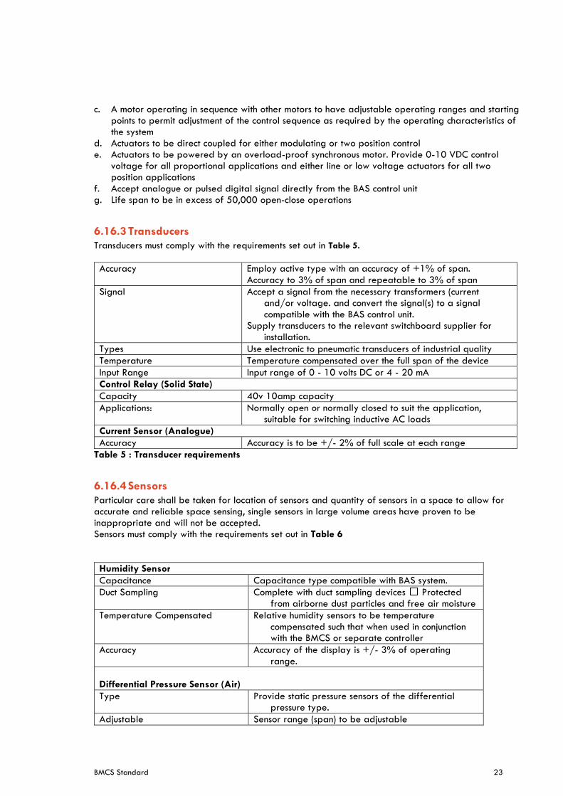
6.16.3 Transducers
Transducers must comply with the requirements set out in Table 5.
Accuracy Employ active type with an accuracy of +1% of span. Accuracy to 3% of span and repeatable to 3% of span
Signal Accept a signal from the necessary transformers (current and/or voltage. and convert the signal(s) to a signal compatible with the BAS control unit.
Supply transducers to the relevant switchboard supplier for installation.
Types Use electronic to pneumatic transducers of industrial quality
Temperature Temperature compensated over the full span of the device
Input Range Input range of 0 - 10 volts DC or 4 - 20 mA
Control Relay (Solid State)
Capacity 40v 10amp capacity
Applications: Normally open or normally closed to suit the application, suitable for switching inductive AC loads
Current Sensor (Analogue)
Accuracy Accuracy is to be +/- 2% of full scale at each range
Table 5 : Transducer requirements
6.16.4 Sensors
Particular care shall be taken for location of sensors and quantity of sensors in a space to allow for accurate and reliable space sensing, single sensors in large volume areas have proven to be inappropriate and will not be accepted. Sensors must comply with the requirements set out in Table 6
Humidity Sensor
Capacitance Capacitance type compatible with BAS system.
Duct Sampling Complete with duct sampling devices Protected from airborne dust particles and free air moisture
Temperature Compensated Relative humidity sensors to be temperature compensated such that when used in conjunction with the BMCS or separate controller
Accuracy Accuracy of the display is +/- 3% of operating range.
Differential Pressure Sensor (Air)
Type Provide static pressure sensors of the differential pressure type.
Adjustable Sensor range (span) to be adjustable
BMCS Standard 24
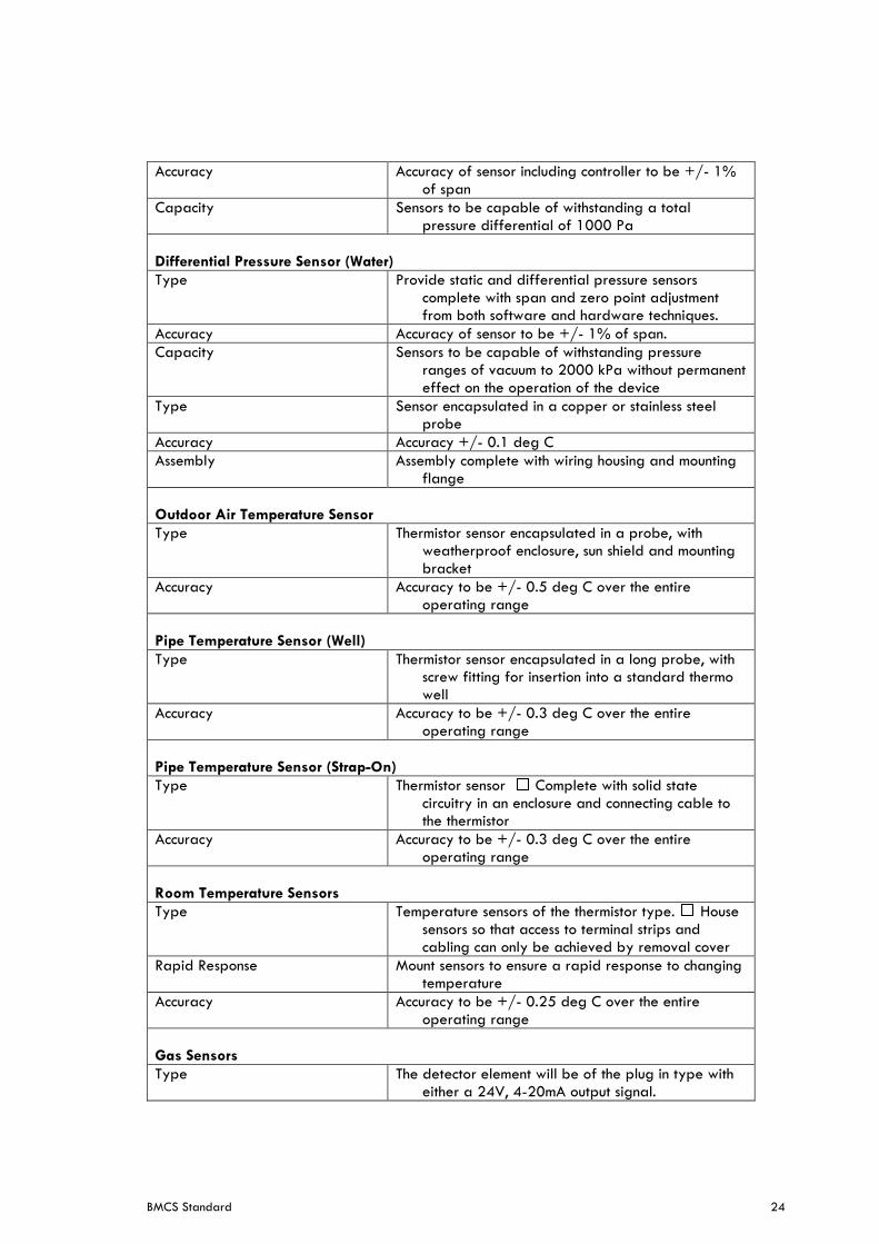
Accuracy Accuracy of sensor including controller to be +/- 1% of span
Capacity Sensors to be capable of withstanding a total pressure differential of 1000 Pa
Differential Pressure Sensor (Water)
Type Provide static and differential pressure sensors complete with span and zero point adjustment from both software and hardware techniques.
Accuracy Accuracy of sensor to be +/- 1% of span.
Capacity Sensors to be capable of withstanding pressure ranges of vacuum to 2000 kPa without permanent effect on the operation of the device
Type Sensor encapsulated in a copper or stainless steel probe
Accuracy Accuracy +/- 0.1 deg C
Assembly Assembly complete with wiring housing and mounting flange
Outdoor Air Temperature Sensor
Type Thermistor sensor encapsulated in a probe, with weatherproof enclosure, sun shield and mounting bracket
Accuracy Accuracy to be +/- 0.5 deg C over the entire operating range
Pipe Temperature Sensor (Well)
Type Thermistor sensor encapsulated in a long probe, with screw fitting for insertion into a standard thermo well
Accuracy Accuracy to be +/- 0.3 deg C over the entire operating range
Pipe Temperature Sensor (Strap-On)
Type Thermistor sensor Complete with solid state circuitry in an enclosure and connecting cable to the thermistor
Accuracy Accuracy to be +/- 0.3 deg C over the entire operating range
Room Temperature Sensors
Type Temperature sensors of the thermistor type. House sensors so that access to terminal strips and cabling can only be achieved by removal cover
Rapid Response Mount sensors to ensure a rapid response to changing temperature
Accuracy Accuracy to be +/- 0.25 deg C over the entire operating range
Gas Sensors
Type The detector element will be of the plug in type with either a 24V, 4-20mA output signal.
BMCS Standard 25
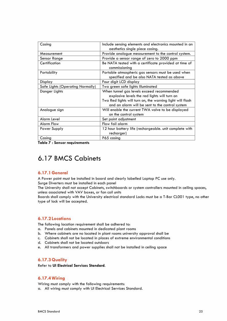
Casing Include sensing elements and electronics mounted in an aesthetics single piece casing.
Measurement Provide analogue measurement to the control system.
Sensor Range Provide a sensor range of zero to 2000 ppm
Certification Be NATA tested with a certificate provided at time of commissioning
Portability Portable atmospheric gas sensors must be used when specified and be also NATA tested as above
Display Four digit LCD display
Safe Lights (Operating Normally) Two green safe lights Illuminated
Danger Lights When tunnel gas levels exceed recommended explosive levels the red lights will turn on
Two Red lights will turn on, the warning light will flash and an alarm will be sent to the control system
Analogue sign Will enable the current TWA valve to be displayed on the control system
Alarm Level Set point adjustment
Alarm Flow Flow fail alarm
Power Supply 12 hour battery life (rechargeable. unit complete with recharger)
Casing P65 casing
Table 7 : Sensor requirements
6.17 BMCS Cabinets
6.17.1 General
A Power point must be installed in board and clearly labelled Laptop PC use only. Surge Diverters must be installed in each panel The University shall not accept Cabinets, switchboards or system controllers mounted in ceiling spaces, unless associated with VAV boxes, or fan coil units Boards shall comply with the University electrical standard Locks must be a T-Bar CL001 type, no other type of lock will be accepted.
6.17.2 Locations
The following location requirement shall be adhered to: a. Panels and cabinets mounted in dedicated plant rooms b. Where cabinets are no located in plant rooms university approval shall be c. Cabinets shall not be located in places of extreme environmental conditions d. Cabinets shall not be located outdoors e. All transformers and power supplies shall not be installed in ceiling space
6.17.3 Quality
Refer to UI Electrical Services Standard.
6.17.4 Wiring
Wiring must comply with the following requirements: a. All wiring must comply with UI Electrical Services Standard.

BMCS Standard 26
b. All communication cabling to comply with ICT Communication Cabling Standard.
6.18 Product Support
All products including software, hardware and programming shall be supported locally and internationally by factory trained service departments. All spare parts shall be available ex-stock factory for a period of 10 years from purchase date. As part of a project all necessary points/software licences must be provided.
6.19 Software Life Cycle
Due to the relatively short life cycle of software-based technology, any software updates, patches or revisions shall be backwards compatible with the field devices and controller hardware for a minimum period of 10 years. Where this is not achievable, the system provider shall submit their product life cycle model for approval. The current status of the offered product life cycle shall be submitted at the time of tender and shall have a minimum of 24 months from DLP expiry, before any revision change is required. Any revisions within the 24 month period shall be provided to keep the system up to date.
7 Commissioning Comprehensive pre-commissioning, commissioning and quality monitoring must be specified by the consultant/designer or contractor. Detailed testing and commissioning requirements shall be specified for each project by the consultant/designer. The CIBSE and AIRAH DA27 commissioning codes are appropriate reference documents to be used. Offsite testing shall be performed for the DDC control logic prior to site implementation to the satisfaction of the engineer and university representative. A project specific commissioning plan must be developed and provided to the University for review and approval. UI have developed a BMCS Commissioning Checklist (UI-ENG-F023) which should be used as a minimum guide when preparing the project specific commissioning plan.
7.1 Building Tuning
The BMCS Contractor shall allow for 12 months of building tuning commencing from practical completion. The BMCS Services Contractor shall provide a building operators log on the BMCS for the principal or principals representative to detail and report any functionality issues. During the tuning period, the principal shall maintain this log or a log in a form nominated by the principal’s to provide building performance observations identifying any system performance issues, which are required to be addressed as part of the building tuning process. A quarterly tunning report and meeting with The University must be undertaken. The BMCS Contractor shall provide a detailed tuning report on the BMCS as an audit trail of the tuning activities. At a minimum, the BMCS Contractor shall allow for the following: a. Review and discuss the building operators report log b. Analysis of Trend logs and alarms

BMCS Standard 27
c. Review EMS energy performance reports d. Review of any exception reports and analytics e. Functional performance review with the Principal to identify any required modifications f. Control logic modifications as required g. Control Loop tuning h. Review email alarms generated and address alarms with a high volume generated i. Update tuning report log on BMS j. Update all manuals and documents such as drawings, functional descriptions, points lists and the like
to reflect the changes made and resubmit these sections to the Principal to be included in the user manuals.
8 Safety in design The contractor must consider risk during the design. A design safety report must be submitted to the relevant UI Project Manager for every design project. Contractors must confirm, so far as it is reasonably practicable, that the structure is without risks to health and safety. Design risks must be considered for the asset lifecycle covering construction, operational and maintenance, refurbishments and decommissioning. The design safety report must include the following: a. Description of design element. b. Description of potential risks and hazards associated with the design element. c. A low/medium/high risk assessment considering likelihood and consequence. d. Proposed measures to eliminate risks where practicable. e. Control measures to mitigate and manage design risks. f. Nominating responsibilities for managing the design risks. This may be provided as a design risk register where appropriate and must include results of any calculations, testing and analysis etc.
9 Documentation and Records The following documents shall be provided at practical completion: a. Maintenance manual b. Commissioning records c. Points list d. Programming logic e. Controller network diagram f. LAN network Diagram g. Valve and controller selection data h. Product Manufacturer specific information i. Electrical & wiring diagrams j. Controller & Hardware diagrams k. System functionality and operation description l. System set point values m. Network and Hardware configuration (Attachment 1)
BMCS Standard 28
A project handover plan must be developed by the consultant/designer to allow systems to be handed over to the University, including updating all BMCS documentation (Operations and Maintenance manuals, configuration records, commissioning and equipment records) to ensure that it remains current.
9.1 Design Documentation
Prior to commencing construction of new or refurbishment projects, the consultant/contractor must fully investigate and document the requirements for the BMCS system required to be installed, altered or modified as part of the project works. This must include: a. Review of the current metering installed for the building to determine the proposed BMCS Upgrade
Strategy. b. Provision of a BCA/ NCC Compliance Report. c. Return Brief defining the systems proposed and any deviations from this standard. d. Future allowances are to be included in all calculations\sizing. e. Calculations & selections on the proposed equipment. f. Budget calculations. g. Points list h. Programming logic i. Controller network diagram j. LAN network Diagram k. Valve and controller selection data l. Product Manufacturer specific information m. Electrical & wiring diagrams n. Controller & Hardware diagrams o. System functionality and operation description p. System set point values q. Network and Hardware configuration (Attachment 1) r. New Device ID schedule s. New Device configuration t. Product manufacturer specific information u. System schematics v. Network Addressing schedule w. Provision of Design Certification of BMCS. x. Requests for all variations to this Standard submitted using the Request for Dispensation Form
(USYD-ENG-F001). y. Complete the Design & Construct checklist using the Design & BMCS Checklist Form (UI-ENG-
F009). This documentation must be provided by the consultant/contractor in both electronic and hard copy formats and approved by the University.
9.2 Completion Documents
At the completion of all projects, the following documentation must be provided by the contractor for each BMCS installed or altered as part of the project works: a. O&M manual(s). b. As-built drawings including all listed items in the design documentation (Cad and DPF format). c. All Design documentation in As built format d. Asset schedules and labelling (as per the Asset Identification and Labelling Standard). e. Commissioning test results.
BMCS Standard 29
f. Product manufacturer specific information. g. Details of all usernames and passwords required to access all equipment and software. h. Warranty schedules for all major items of equipment i. Maintenance requirements for all items of equipment. j. Building User Guide. k. Supply authority completion forms and inspection record. l. Installers Statutory certificates. m. Fully surveyed and documented underground services drawings depicting all as built services both
PDF and CAD format. n. Certification of compliance to Australian Standards, The University Standards and the National
Construction Code. o. Confirmation all associated graphics, functional description and project documents are saves on the
University server
This documentation must be provided by the contractor in both electronic and hard copy formats and approved by the University prior to Practical Completion being granted.
10 Assets and Warranties Assets are to be tagged in accordance with the Universities Asset & Labelling standard for the purpose of maintenance and operation of University Assets. For refurbishment projects the project manage is to provide the existing asset list to the contractor to ensure modified and redundant equipment are captured in the contractors submitted asset list.
Each asset required to be collected can be found in the Form (COS-ASSET-F001), each asset required to be coded will be identified by a unique equipment code. The equipment code will be one the three following types: a. Virtual asset (This is a concatenation Building Code - Floor - Room number) b. Item count asset (This is a concatenation Building Code - Floor - Room number) c. Unique bar code asset (Unique bar code in the million series number affixed to the asset) Asset lists are to be submitted prior to practical completion of the project for review and approval by COS. Equipment Warranties are to be provided for a minimum of 12 months from the date of practical completion. Warranties are to be provided as certificates as part of the O&M from the supplier of the equipment. It is the responsibility of the installation contractor to ensure all maintenance\servicing required to the equipment is provided to ensure warranties are valid at the end of the project DLP period.
11 Defects and Liability Period Consultants/designers must include in the project specification detailed requirements for the defects and liability period following completion of the BMCS installation. The contractor must include and allow for recommissioning of all major plant and equipment in the last month of the 12-month defects and liability period and confirm they achieve the original design requirements. In addition, all commissioning must be witnessed by UI Engineering staff with
BMCS Standard 30
commissioning reports/results formally submitted to UI Engineering. Where specific items are required to be re-witnessed after PC, the 12-month DLP period will commence from this re-witnessing date.
11.1 Maintenance and Testing
For BMCS services installed as part of a refurbishment project of an existing building, regular statutory maintenance, manufacturer recommended maintenance and testing must be carried out by the projects BMCS Services contractor during the Defects Liability Period (DLP). The installation contractor must provide a comprehensive handover and the required completion documentation at Practical Completion. It is the responsibility of the BMCS contractor to provide the mechanical contractor\builder with feedback on the system operation and faults for rectification. The BMCS contractor must tune the email generated alarms during the DLP period to ensure that only minimal number are being generated. All defects arising from regular statutory/manufacturer maintenance and testing performed during the DLP are the responsibility of the installation contractor. For new buildings, the installation contractor must provide statutory maintenance and testing of all mechanical services and associated statutory testing for the building, throughout the DLP. Prior to the completion of the DLP, the installation contractor will perform all annual maintenance procedures in the presence of the University Engineering team and provide documentation confirming the provision of all maintenance has been performed during the DLP. In these instances. Any details which will affect the future maintenance and performance of the new or upgraded equipment must be supplied by the installation contractor at Practical Completion. Prior to completion of the DLP, a final inspection and full meter validation must be undertaken by the: installation contractor, appropriate UI and COS staff, and University maintenance contractor, in order to reconcile the performance of the equipment during DLP to produce a final list of project defects. All project defects identified must be rectified by the installation contractor prior to finalisation of the DLP.
12 Operations & Maintenance Manuals Consultants/designers must include in the project specification detailed requirements for operation and maintenance manuals, including system description, operation procedures, testing and commissioning records, maintenance instructions, product support information and recovery protocols for any computer related systems. Contractors must provide these to the satisfaction of the consultant/designer. Providing a collection of manufacturers’ brochures and catalogues is not acceptable to the University. Discuss with UI to understand what format to submit the O&M Manuals. Typical submissions come via soft copy (editable) and used via a system like Aconex. Contractors must submit the university designed Asset Management Master Asset Data Capture Spreadsheet (COS-ASSET-F001) designed for recording operational and maintenance activities including materials used, test results, comments for future maintenance actions and notes covering asset condition. Completed log book pages recording the operational and maintenance activities undertaken for Practical Completion and during the Defects Liability Period must also be provided.
BMCS Standard 31
Facilities Maintenance must establish, document and implement procedures for operation and maintenance of software, plant and equipment to ensure BMCS are fit-for-purpose, provide secure, efficient, safe and reliable electrical power, and comply with requirements of this standard.
13 Authorisation of variations Project managers, consultants, contractors, commissioning agents and facilities maintenance personnel must ensure compliance with these requirements is achieved. Variations to this standard must only be considered where: a. the University Standard’s requirement cannot physically or technically be achieved. b. the alternative solution delivers demonstrated and proven superior performance for the same
capital and life cycle cost or better. Consultants and contractors must identify and justify requirements of the standard that do not apply to the project or which need to be varied and these which must be approved by the issuer of this standard. Formal requests for all variations to this Standard must be submitted using the UI Request Dispensation from Standard Form (UI-ENG-F001). The issuer of this standard or their delegated authority must review and consider requirements of stakeholders from clients, projects and facilities management before deciding whether to approve variations. Their formal sign-off is required for acceptance of any non-compliances and departures from this standard’s requirements.
14 Quality control
14.1 Design Standard Compliance
Compliance with requirements of this standard must be checked throughout the design, construction and commissioning phases of projects by UI’ services consultant. Any issues or deviations from this standard must be reviewed and approved in writing by the issuer of this standard. Competent UI consultants and representatives must check compliance with this standard during design reviews and formal site inspections. Any non-conformances with requirements of this standard must be documented and provided to the UI Project Manager for issue to contractors and their consultants. Project Managers must maintain a formal register of non-conformances and manage close out of outstanding non-conformances. Contractors and their consultants issued with non-conformances must take appropriate corrective actions. The UI Project Manager must ensure: a. Proposed corrective actions are implemented. b. Close out of non-conformances in relation to this standard is formally approved and signed off by
the author of the standard or their delegate.
14.2 Design Standard Certification
Contractors and Consultants must certify compliance to the design standard by submitting a company Design Certification Form to the UI Project Manager at each of the following project phases: a. Design and Documentation. b. Tender. c. Construction.
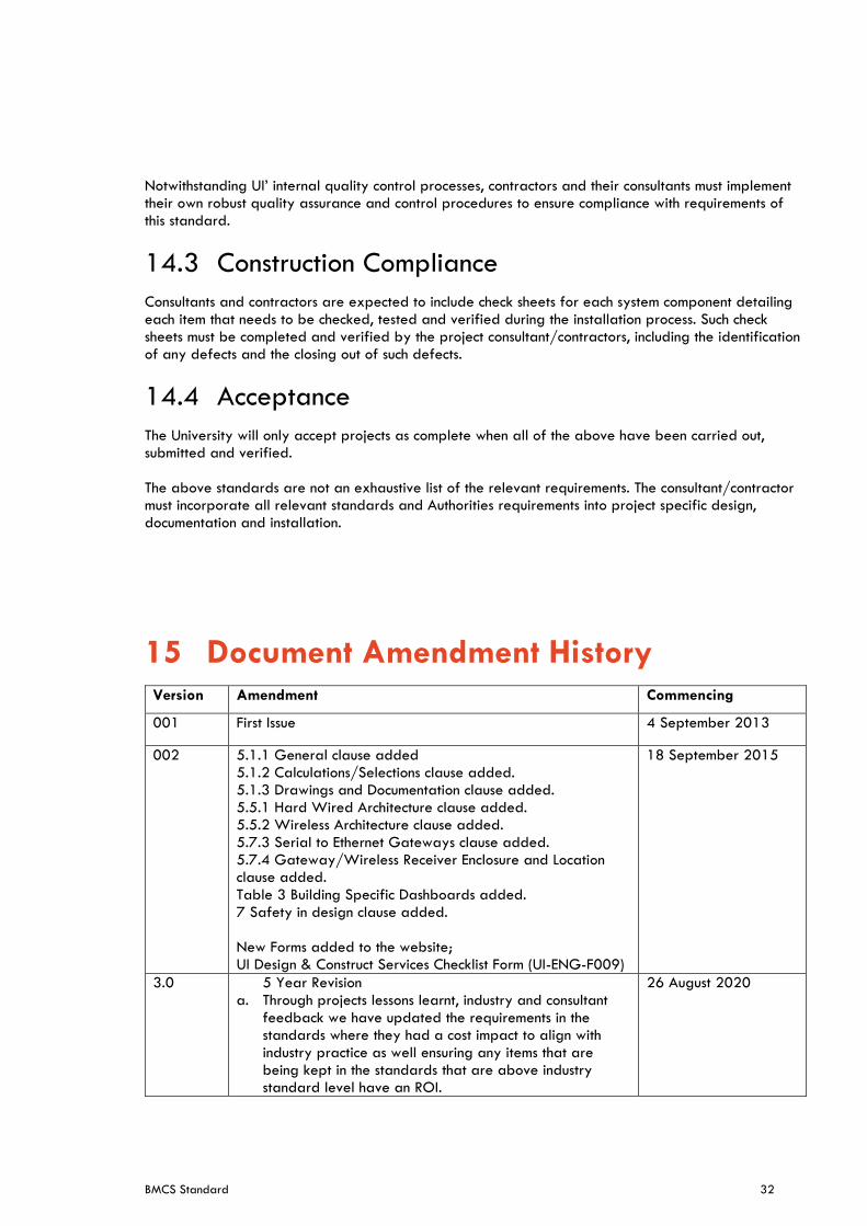
BMCS Standard 32
Notwithstanding UI’ internal quality control processes, contractors and their consultants must implement their own robust quality assurance and control procedures to ensure compliance with requirements of this standard.
14.3 Construction Compliance
Consultants and contractors are expected to include check sheets for each system component detailing each item that needs to be checked, tested and verified during the installation process. Such check sheets must be completed and verified by the project consultant/contractors, including the identification of any defects and the closing out of such defects.
14.4 Acceptance
The University will only accept projects as complete when all of the above have been carried out, submitted and verified. The above standards are not an exhaustive list of the relevant requirements. The consultant/contractor must incorporate all relevant standards and Authorities requirements into project specific design, documentation and installation.
15 Document Amendment History Version Amendment Commencing
001 First Issue 4 September 2013
002 5.1.1 General clause added 5.1.2 Calculations/Selections clause added. 5.1.3 Drawings and Documentation clause added. 5.5.1 Hard Wired Architecture clause added. 5.5.2 Wireless Architecture clause added. 5.7.3 Serial to Ethernet Gateways clause added. 5.7.4 Gateway/Wireless Receiver Enclosure and Location clause added. Table 3 Building Specific Dashboards added. 7 Safety in design clause added. New Forms added to the website; UI Design & Construct Services Checklist Form (UI-ENG-F009)
18 September 2015
3.0 5 Year Revision a. Through projects lessons learnt, industry and consultant
feedback we have updated the requirements in the standards where they had a cost impact to align with industry practice as well ensuring any items that are being kept in the standards that are above industry standard level have an ROI.
26 August 2020
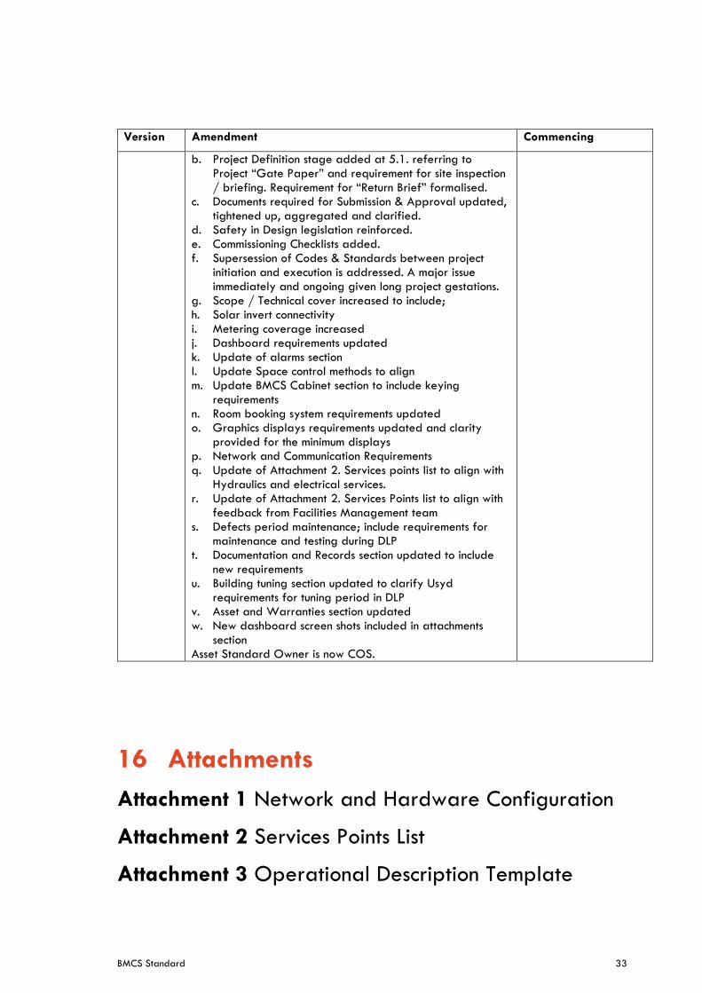
BMCS Standard 33
Version Amendment Commencing
b. Project Definition stage added at 5.1. referring to Project “Gate Paper” and requirement for site inspection / briefing. Requirement for “Return Brief” formalised.
c. Documents required for Submission & Approval updated, tightened up, aggregated and clarified.
d. Safety in Design legislation reinforced. e. Commissioning Checklists added. f. Supersession of Codes & Standards between project
initiation and execution is addressed. A major issue immediately and ongoing given long project gestations.
g. Scope / Technical cover increased to include; h. Solar invert connectivity i. Metering coverage increased j. Dashboard requirements updated k. Update of alarms section l. Update Space control methods to align m. Update BMCS Cabinet section to include keying
requirements n. Room booking system requirements updated o. Graphics displays requirements updated and clarity
provided for the minimum displays p. Network and Communication Requirements q. Update of Attachment 2. Services points list to align with
Hydraulics and electrical services. r. Update of Attachment 2. Services Points list to align with
feedback from Facilities Management team s. Defects period maintenance; include requirements for
maintenance and testing during DLP t. Documentation and Records section updated to include
new requirements u. Building tuning section updated to clarify Usyd
requirements for tuning period in DLP v. Asset and Warranties section updated w. New dashboard screen shots included in attachments
section Asset Standard Owner is now COS.
16 Attachments
Attachment 1 Network and Hardware Configuration
Attachment 2 Services Points List
Attachment 3 Operational Description Template
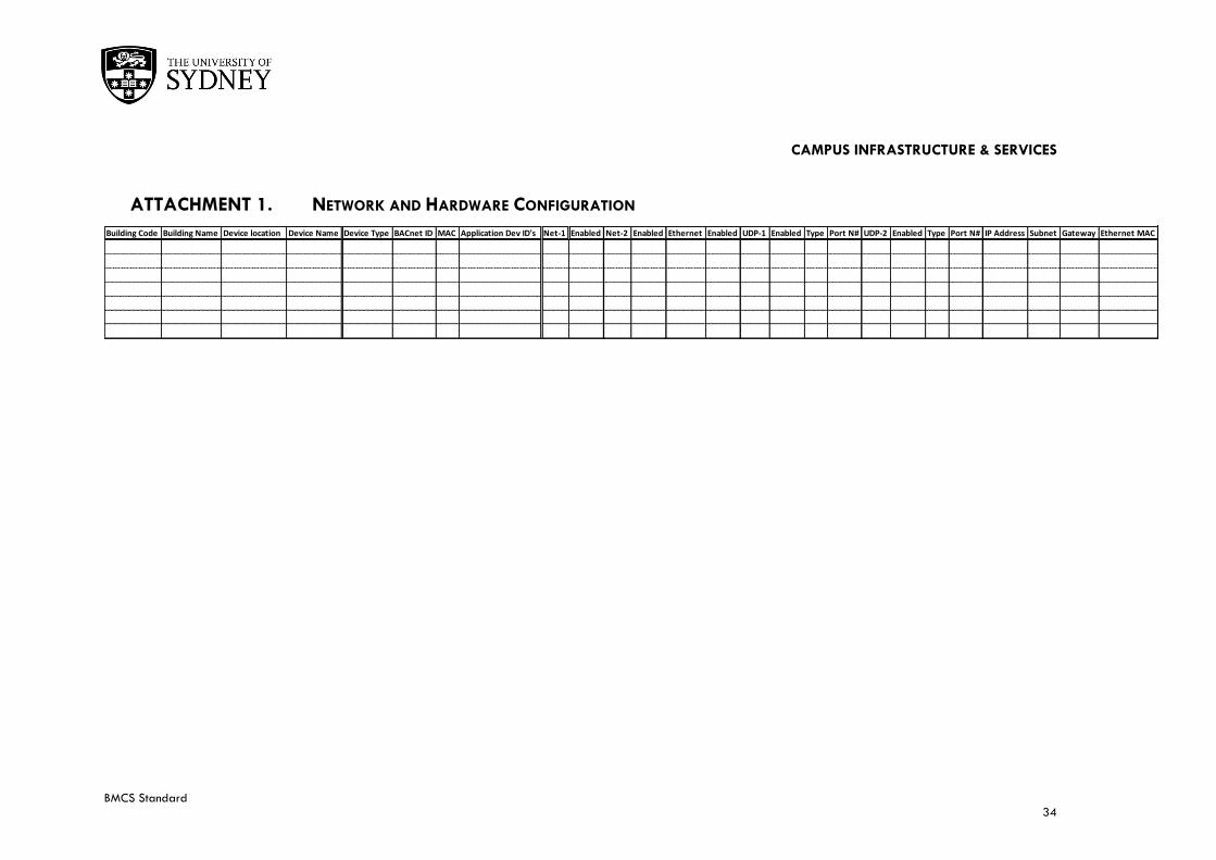
CAMPUS INFRASTRUCTURE & SERVICES
BMCS Standard 34
ATTACHMENT 1. NETWORK AND HARDWARE CONFIGURATION
Building Code Building Name Device location Device Name Device Type BACnet ID MAC Application Dev ID's Net-1 Enabled Net-2 Enabled Ethernet Enabled UDP-1 Enabled Type Port N# UDP-2 Enabled Type Port N# IP Address Subnet Gateway Ethernet MAC
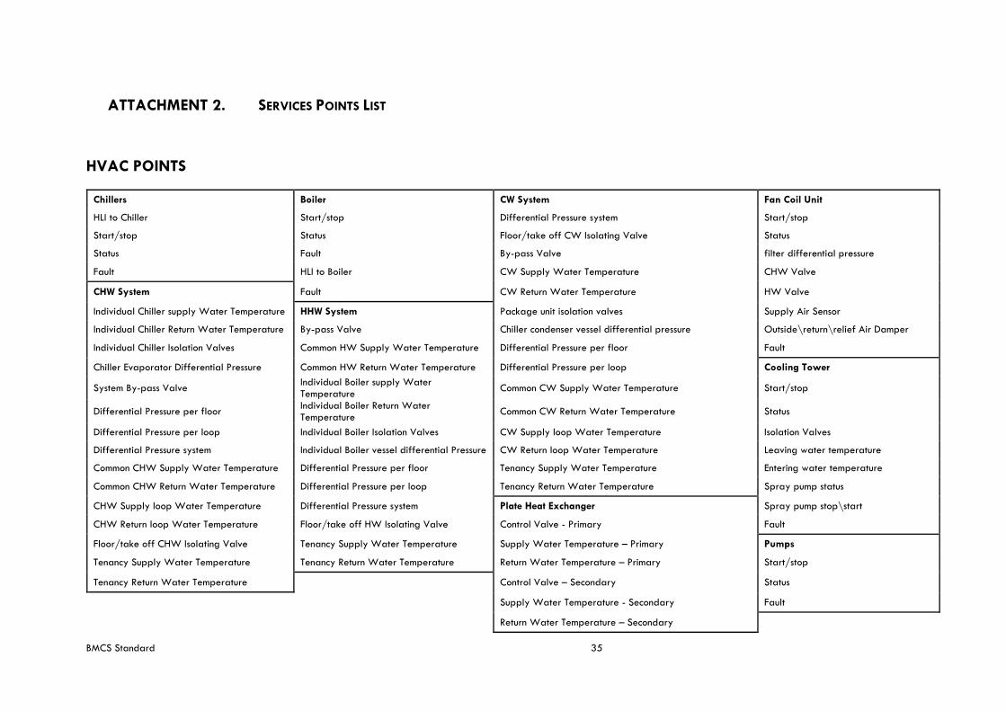
BMCS Standard 35
ATTACHMENT 2. SERVICES POINTS LIST
HVAC POINTS
Chillers Boiler CW System Fan Coil Unit
HLI to Chiller Start/stop Differential Pressure system Start/stop
Start/stop Status Floor/take off CW Isolating Valve Status
Status Fault By-pass Valve filter differential pressure
Fault HLI to Boiler CW Supply Water Temperature CHW Valve
CHW System Fault CW Return Water Temperature HW Valve
Individual Chiller supply Water Temperature HHW System Package unit isolation valves Supply Air Sensor
Individual Chiller Return Water Temperature By-pass Valve Chiller condenser vessel differential pressure Outside\return\relief Air Damper
Individual Chiller Isolation Valves Common HW Supply Water Temperature Differential Pressure per floor Fault
Chiller Evaporator Differential Pressure Common HW Return Water Temperature Differential Pressure per loop Cooling Tower
System By-pass Valve Individual Boiler supply Water Temperature
Common CW Supply Water Temperature Start/stop
Differential Pressure per floor Individual Boiler Return Water Temperature
Common CW Return Water Temperature Status
Differential Pressure per loop Individual Boiler Isolation Valves CW Supply loop Water Temperature Isolation Valves
Differential Pressure system Individual Boiler vessel differential Pressure CW Return loop Water Temperature Leaving water temperature
Common CHW Supply Water Temperature Differential Pressure per floor Tenancy Supply Water Temperature Entering water temperature
Common CHW Return Water Temperature Differential Pressure per loop Tenancy Return Water Temperature Spray pump status
CHW Supply loop Water Temperature Differential Pressure system Plate Heat Exchanger Spray pump stop\start
CHW Return loop Water Temperature Floor/take off HW Isolating Valve Control Valve - Primary Fault
Floor/take off CHW Isolating Valve Tenancy Supply Water Temperature Supply Water Temperature – Primary Pumps
Tenancy Supply Water Temperature Tenancy Return Water Temperature Return Water Temperature – Primary Start/stop
Tenancy Return Water Temperature
Control Valve – Secondary Status
Supply Water Temperature - Secondary Fault
Return Water Temperature – Secondary
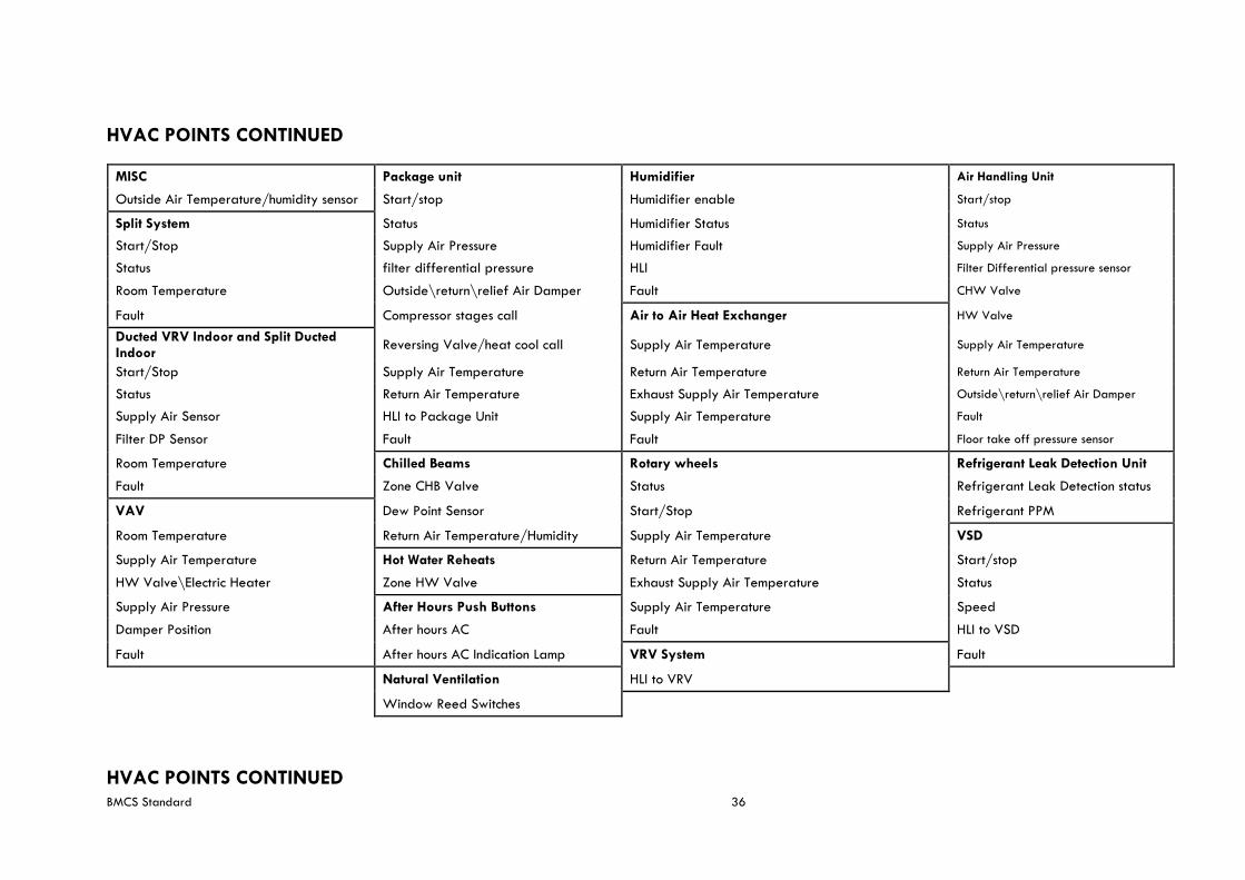
BMCS Standard 36
HVAC POINTS CONTINUED
MISC Package unit Humidifier Air Handling Unit
Outside Air Temperature/humidity sensor Start/stop Humidifier enable Start/stop
Split System Status Humidifier Status Status
Start/Stop Supply Air Pressure Humidifier Fault Supply Air Pressure
Status filter differential pressure HLI Filter Differential pressure sensor
Room Temperature Outside\return\relief Air Damper Fault CHW Valve
Fault Compressor stages call Air to Air Heat Exchanger HW Valve
Ducted VRV Indoor and Split Ducted Indoor
Reversing Valve/heat cool call Supply Air Temperature Supply Air Temperature
Start/Stop Supply Air Temperature Return Air Temperature Return Air Temperature
Status Return Air Temperature Exhaust Supply Air Temperature Outside\return\relief Air Damper
Supply Air Sensor HLI to Package Unit Supply Air Temperature Fault
Filter DP Sensor Fault Fault Floor take off pressure sensor
Room Temperature Chilled Beams Rotary wheels Refrigerant Leak Detection Unit
Fault Zone CHB Valve Status Refrigerant Leak Detection status
VAV Dew Point Sensor Start/Stop Refrigerant PPM
Room Temperature Return Air Temperature/Humidity Supply Air Temperature VSD
Supply Air Temperature Hot Water Reheats Return Air Temperature Start/stop
HW Valve\Electric Heater Zone HW Valve Exhaust Supply Air Temperature Status
Supply Air Pressure After Hours Push Buttons Supply Air Temperature Speed
Damper Position After hours AC Fault HLI to VSD
Fault After hours AC Indication Lamp VRV System Fault
Natural Ventilation HLI to VRV
Window Reed Switches
HVAC POINTS CONTINUED
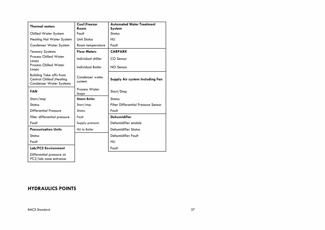
BMCS Standard 37
Thermal meters Cool\Freezer Room
Automated Water Treatment System
Chilled Water System Fault Status
Heating Hot Water System Unit Status HLI
Condenser Water System Room temperature Fault
Tenancy Systems Flow Meters CARPARK
Process Chilled Water Loops
Individual chiller CO Sensor
Process Chilled Water Loops
Individual Boiler NO Sensor
Building Take offs from Central Chilled\Heating Condenser Water Systems
Condenser water system
Supply Air system Including Fan
FAN Process Water loops
Start/Stop
Start/stop Steam Boiler Status
Status Start/stop Filter Differential Pressure Sensor
Differential Pressure Status Fault
filter differential pressure Fault Dehumidifier
Fault Supply pressure Dehumidifier enable
Pressurisation Units HLI to Boiler Dehumidifier Status
Status
Dehumidifier Fault
Fault
HLI
Lab/PC2 Environment
Fault
Differential pressure at PC2/lab zone entrance
HYDRAULICS POINTS
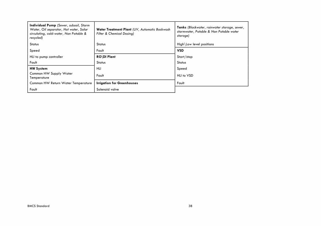
BMCS Standard 38
Individual Pump (Sewer, subsoil, Storm Water, Oil separator, Hot water, Solar circulating, cold-water, Non Potable & recycled)
Water Treatment Plant (UV, Automatic Backwash Filter & Chemical Dosing)
Tanks (Blackwater, rainwater storage, sewer, stormwater, Potable & Non Potable water storage)
Status Status High\Low level positions
Speed Fault VSD
HLI to pump controller RO\DI Plant Start/stop
Fault Status Status
HW System HLI Speed
Common HW Supply Water Temperature
Fault HLI to VSD
Common HW Return Water Temperature Irrigation for Greenhouses Fault
Fault Solenoid valve
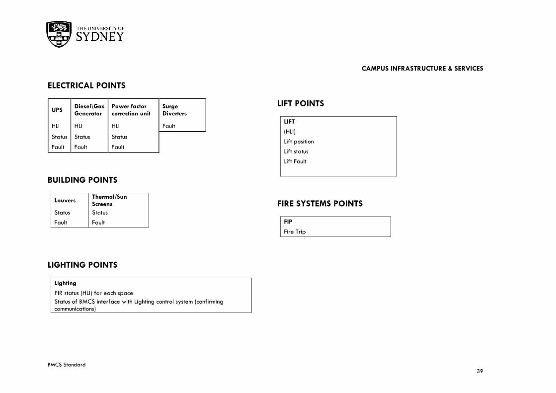
CAMPUS INFRASTRUCTURE & SERVICES
BMCS Standard 39
ELECTRICAL POINTS
UPS Diesel\Gas Generator
Power factor correction unit
Surge Diverters
HLI HLI HLI Fault
Status Status Status
Fault Fault Fault
BUILDING POINTS
Louvers Thermal/Sun Screens
Status Status
Fault Fault
LIGHTING POINTS
Lighting
PIR status (HLI) for each space
Status of BMCS interface with Lighting control system (confirming communications)
LIFT POINTS
LIFT
(HLI)
Lift position
Lift status
Lift Fault
FIRE SYSTEMS POINTS
FIP
Fire Trip
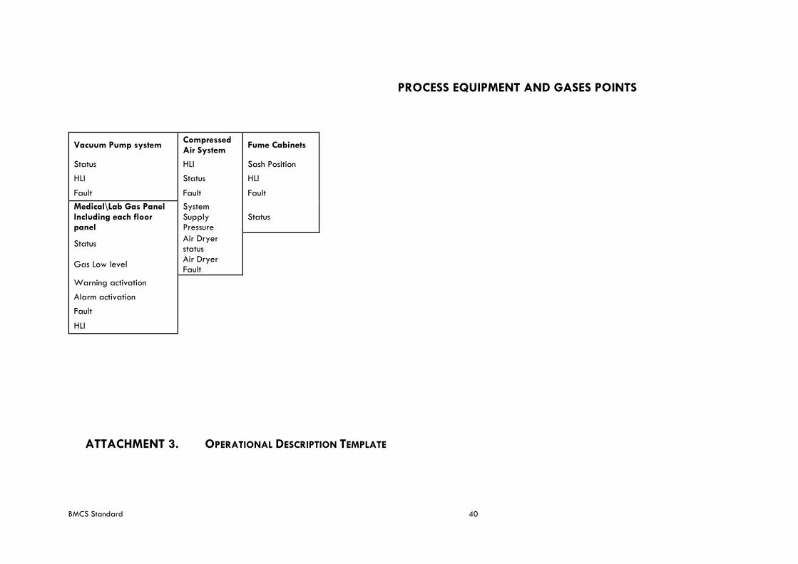
BMCS Standard 40
PROCESS EQUIPMENT AND GASES POINTS
Vacuum Pump system Compressed Air System
Fume Cabinets
Status HLI Sash Position
HLI Status HLI
Fault Fault Fault
Medical\Lab Gas Panel Including each floor panel
System Supply Pressure
Status
Status Air Dryer status
Gas Low level Air Dryer Fault
Warning activation
Alarm activation
Fault
HLI
ATTACHMENT 3. OPERATIONAL DESCRIPTION TEMPLATE
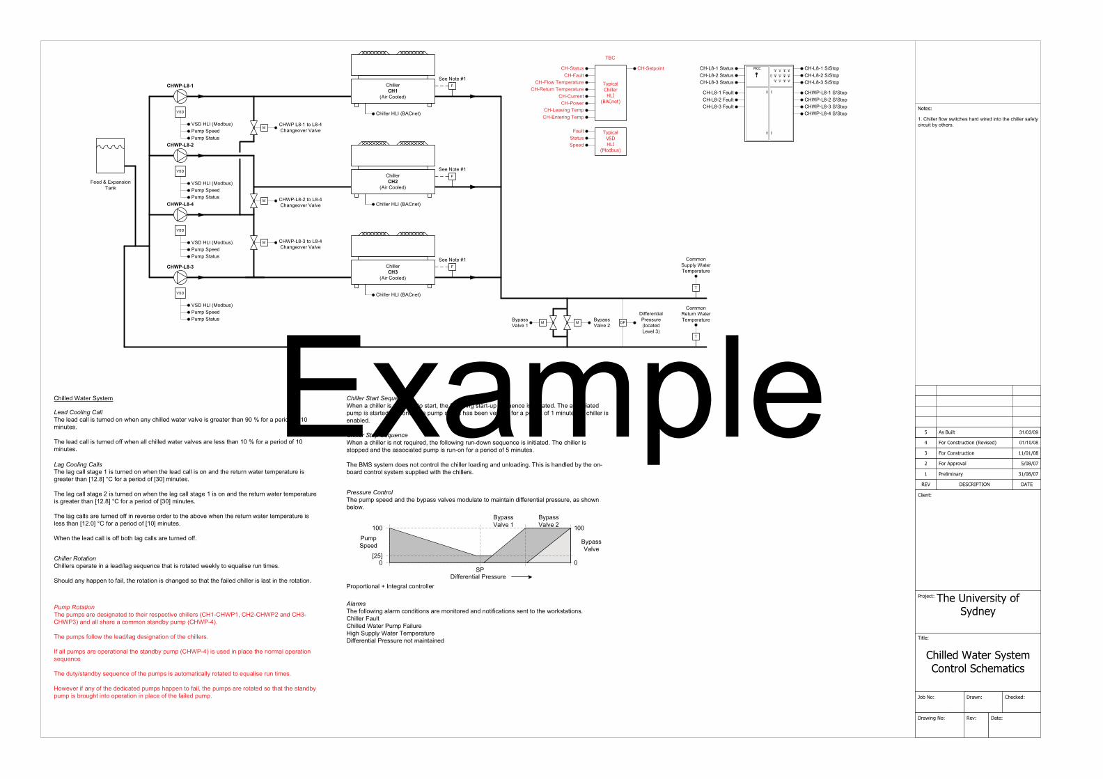
����������
���������
����������������� ����������������
������
����� ���
� � !"#�"$! % �&�
�����
'! �
������ ���(���
!�)�
����
*�+��
���,��)�������-������
.��/����-0��#��1���
#��1����
�������
������
��23�23�4
.�� �����/�����5!�)����6 ������7
#����������� ��238239
�����
' ����������
������������ ������������ ������������ ������������
���������
��
���������������
��������
��
���������
��
���������
��
�
�
�� !!"#��
�$ #����!"��
�� !!"#��
�$ #����!"��
�� !!"#���
�$ #����!"��
�%& '����'!("��
�%& '����'!("��
��
� ))"#"*� '!��#"���#"�!�+'�"���"("!���
�,��� !!"#�)!�-��- �+�"���'#��- #"�� *�����"�+� !!"#��')"�&�+ #+� ���&����"#�,
.
��//�*�� !&��'�"#�."/ "#'��#"
.
��//�*�0"��#*��'�"#�."/ "#'��#"
����������
�� !!"#������%$�*"��
�� !!"#������%$�*"��
�� !!"#������%$�*"��
��:���� �������0"
5;& ���6
����'���
����!�-�."/ "#'��#"���0"��#*�."/ "#'��#"
���"� � *�
�����##"*������-"#
�������������.�"�!"'��+'!!� ����#*"� �*�-�"*�'*&�+� !!"��-'�"#�('!("� ��1#"'�"#���'*�2��3�)�#�'� "# ����)����/ *��"�,
.�"�!"'� +'!!� ����#*"���)) -�"*�'!!�+� !!"��-'�"#�('!("��'#"�!"�����'*����3�)�#�'� "# ����)���/ *��"�,
�� !!"���'�"#�&��"/
�����������.�"� �/ ��'#"��"� 1*'�"�������" #�#"� "+� ("�+� !!"#������������4�����������'*�������������'*� '!!���'#"�'�+�//�* ��'*��&� �/ ��������,
.�"� �/ ��)�!!�-���"�!"'�!'1��"� 1*'� �*��)���"�+� !!"#�,
�)�'!!� �/ ��'#"�� "#'� �*'!���"���'*��&� �/ ���������� ����"�� *� !'+"���"�*�#/'!�� "#'� �*��"5�"*+"
.�"����&��'*��& �"5�"*+"��)���"� �/ �� ��'���/'� +'!!&�#��'�"� ���"5�'! �"�#�*�� /"�,
��-"("#� )�'*&��)���"��"� +'�"�� �/ ���' "*����)' !4���"� �/ ��'#"�#��'�"�������'����"���'*��&� �/ � ���#��1��� *���� "#'� �*� *� !'+"��)���"�)' !"�� �/ ,
�����.�"�)�!!�- *1�'!'#/�+�*� � �*��'#"�/�* ��#"��'*��*�� ) +'� �*���"*�������"�-�#6��'� �*�,�� !!"#��'�!��� !!"���'�"#���/ ��' !�#"� 1��� !&��'�"#�."/ "#'��#"� ))"#"*� '!��#"���#" *���/' *�' *"��
����'�!�""�7��"�8�
""�7��"�8�
""�7��"�8�
�#� �#� �*'!�9��*�"1#'!�+�*�#�!!"#� ))"#"*� '! �#"���#"
��������������.�"� �/ �� ""��'*����"��& '���('!("��/���!'�"����/' *�' *�� ))"#"*� '!� #"���#"4 '�����-*��"!�-,
�
��/ ""�
���
:�;<
%& '���'!("
���
�
.��&::��)��< 4238239
��:����%���0"
5'��+/�6
�'�!�
����"'( *1�."/ ���=*�"# *1�."/
��/ � ""�
%& '���'!("��
%& '���'!("��
����� ��������������'*1"�("#��'!("
.�� �����/������ ��23�238
�
��/ ��'���
�����������������/ � ""���/ ��'���
�����������������/ � ""���/ ��'���
�����������������/ � ""���/ ��'���
���������'������������'���
���������'�!�
���������'���
���������'�!�
���������'�!�
�'��� ""�
�""��>�=? '*� �*.'*6
�
�
�������������������'*1"�("#��'!("
�������������������'*1"�("#��'!("
&�;/��� �����24
���������������������"*�' +� !!"#� ��#"5� #"�������'#�4���"�)�!!�- *1���'#��� ��"5�"*+"� �� * � '�"�,�.�"�'���+ '�"�� �/ � ����'#�"� '*���*+"���"� �/ ���'�����'���""*�("# ) "��)�#�'� "# ����)�� / *��"���"�+� !!"#� ��"*'�!"�,
��������������������"*�'�+� !!"#� ��*���#"5� #"�4���"�)�!!�- *1�#�*���-*��"5�"*+"� �� * � '�"�,�.�"�+� !!"#� ����� "��'*����"�'���+ '�"�� �/ � ��#�*��*�)�#�'� "# ����)�;�/ *��"�,�
.�"�%���&��"/���"��*���+�*�#�!���"�+� !!"#�!�'� *1�'*���*!�'� *1,�.� �� ���'*�!"���&���"��*���'#��+�*�#�!��&��"/��� ! "��- �����"�+� !!"#�,
.%�
�������������.�"�!'1�+'!!���'1"��� ����#*"���*�-�"*���"�!"'��+'!!� ���*�'*����"�#"��#*�-'�"#��"/ "#'��#"� ��1#"'�"#���'*�:��,�< @��)�#�'� "# ����) :��<�/ *��"�,
.�"�!'1�+'!!���'1"��� ����#*"���*�-�"*���"�!'1�+'!!���'1"��� ���*�'*����"�#"��#*�-'�"#��"/ "#'��#"� ��1#"'�"#���'*�:��,�< @��)�#�'� "# ����) :��<�/ *��"�,
.�"�!'1�+'!!��'#"���#*"���))� *�#"("#�"��#�"#������"�'��("�-�"*���"�#"��#*�-'�"#��"/ "#'��#"� ��!"�� ��'*�:��,�< @��)�#�'� "# ����) :��<�/ *��"�,
��"*���"�!"'��+'!!� ���))������!'1�+'!!��'#"���#*"���)),
�������������� !!"#��� "#'�"� *�'�!"'�!'1 �"5�"*+"���'�� ��#��'�"��-""6!& ���"5�'! �"�#�*�� /"�,
���!��'*&��' "*����)' !4���"�#��'� �*� ��+�'*1"�������'����"�)' !"��+� !!"#� ��!'��� *���"�#��'� �*,�
Example
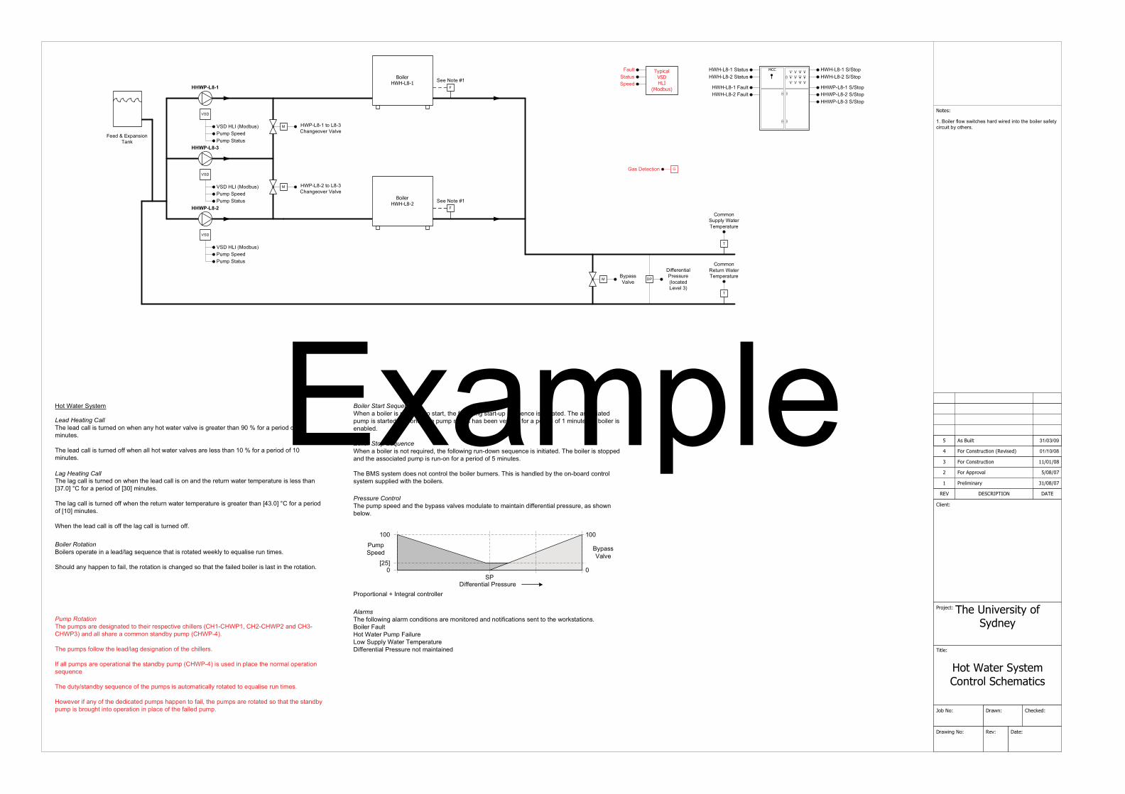
���������
�������������� ����������������
������
��������
� � !"#�"$! % �&�
�����
'! �
������ ���(���
!�)�
����
*�+��
���,��)�������-������
.��/����-0��#��1���
#��1����
�������
������
��23�23�4
.�� �����/�����5!�)����6 ������7
#����������� ��238239
�����
���������
��
���������
��
��������
��
�
�%& '����'!("
��
� ))"#"*� '!��#"���#"�!�+'�"���"("!���
�,�%� !"#�)!�-��- �+�"���'#��- #"�� *�����"��� !"#��')"�&�+ #+� ���&����"#�,
.
��//�*�� !&��'�"#�."/ "#'��#"
.
��//�*�0"��#*��'�"#�."/ "#'��#"
""�7��"�8�
""�7��"�8�
;���������08��
;���������08�<
A'���"�"+� �*�
�����������������/ � ""��""��>�=? '*� �*
.'*6
' ����������'����
������������
����������'����
����������'�!�����������'�!�
����������� �����������
������������ ������������
A
.��&::��)��< 4238239
.�� �����/������ ��23�238
��:����%���0"
5'��+/�6
�'�!�
��/ ��'���
�����������������/ � ""���/ ��'���
�����������������/ � ""���/ ��'���
�'��� ""�
&�;/��� �����24
� ������������������'*1"�("#��'!("
� ������������������'*1"�("#��'!("
��������������.�"�!"'��+'!!� ����#*"� �*�-�"*�'*&���� -'�"#�('!("� ��1#"'�"#���'*�2��3�)�#�'� "# ����)����/ *��"�,
.�"�!"'� +'!!� ����#*"���)) -�"*�'!!���� -'�"#�('!("��'#"�!"�����'*����3�)�#�'� "# ����)���/ *��"�,
��� �'�"#�&��"/
�����������.�"� �/ ��'#"��"� 1*'�"�������" #�#"� "+� ("�+� !!"#������������4�����������'*�������������'*� '!!���'#"�'�+�//�* ��'*��&� �/ ��������,
.�"� �/ ��)�!!�-���"�!"'�!'1��"� 1*'� �*��)���"�+� !!"#�,
�)�'!!� �/ ��'#"�� "#'� �*'!���"���'*��&� �/ ���������� ����"�� *� !'+"���"�*�#/'!�� "#'� �*��"5�"*+"
.�"����&��'*��& �"5�"*+"��)���"� �/ �� ��'���/'� +'!!&�#��'�"� ���"5�'! �"�#�*�� /"�,
��-"("#� )�'*&��)���"��"� +'�"�� �/ ���' "*����)' !4���"� �/ ��'#"�#��'�"�������'����"���'*��&� �/ � ���#��1��� *���� "#'� �*� *� !'+"��)���"�)' !"�� �/ ,
�����.�"�)�!!�- *1�'!'#/�+�*� � �*��'#"�/�* ��#"��'*��*�� ) +'� �*���"*�������"�-�#6��'� �*�,%� !"# �'�!���� �'�"#���/ ��' !�#"��-�� !&��'�"#�."/ "#'��#"� ))"#"*� '!��#"���#" *���/' *�' *"��
�#� �#� �*'!�9��*�"1#'!�+�*�#�!!"#� ))"#"*� '! �#"���#"
��������������.�"� �/ �� ""��'*����"��& '���('!("��/���!'�"����/' *�' *�� ))"#"*� '!� #"���#"4 '�����-*��"!�-,
�
��/ ""�
���
:�;<
%& '���'!("
���
��
���� ����������������"*�' �� !"# ��#"5� #"�������'#�4���"�)�!!�- *1���'#��� ��"5�"*+"� �� * � '�"�,�.�"�'���+ '�"�� �/ � ����'#�"� '*���*+"���"� �/ ���'�����'���""*�("# ) "��)�#�'� "# ����)�� / *��"���"��� !"# ��"*'�!"�,
���� ���������������"*�'��� !"# ��*���#"5� #"�4���"�)�!!�- *1�#�*���-*��"5�"*+"� �� * � '�"�,�.�"��� !"# ����� "��'*����"�'���+ '�"�� �/ � ��#�*��*�)�#�'� "# ����)�;�/ *��"�,�
.�"�%���&��"/���"��*���+�*�#�!���"��� !"#���#*"#�, .� �� ���'*�!"���&���"��*���'#��+�*�#�!��&��"/��� ! "��- �����"��� !"#�,
�������������.�"�!'1�+'!!� ����#*"���*�-�"*���"�!"'��+'!!� ���*�'*����"�#"��#*�-'�"#��"/ "#'��#"� ��!"�� ��'*�:�B,�< @��)�#�'� "# ����) :��<�/ *��"�,
.�"�!'1�+'!!� ����#*"���))�-�"*���"�#"��#*�-'�"#��"/ "#'��#"� ��1#"'�"# ��'*�:��,�< @��)�#�'� "# ����) :��<�/ *��"�,
��"*���"�!"'��+'!!� ���))���"�!'1�+'!!� ����#*"���)),
������������%� !"#��� "#'�"� *�'�!"'�!'1 �"5�"*+"���'�� ��#��'�"��-""6!& ���"5�'! �"�#�*�� /"�,
���!��'*&��' "*����)' !4���"�#��'� �*� ��+�'*1"�������'����"�)' !"���� !"#� ��!'��� *���"�#��'� �*,�
Example
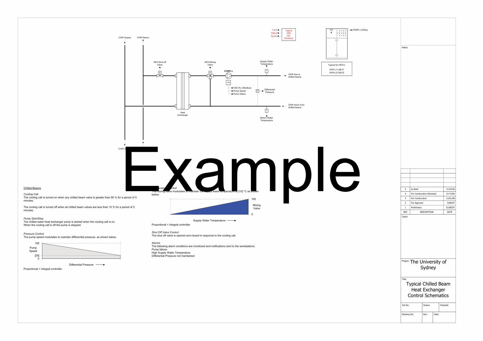
���������
��:���� ������;������� =�������
����������������
������
������ >
� � !"#�"$! % �&�
�����
'! �
������ ���(���
!�)�
����
*�+��
���,��)�������-������
.��/����-0��#��1���
#��1����
�������
������
��23�23�4
.�� �����/�����5!�)����6 ������7
#����������� ��238239
�����
�
�=C������))��'!("
�"'��=?+�'*1"#
�����
�=C�� ? *1��'!("
� ))"#"*� '!��#"���#"
��
����0"��#*����� !&
����0"��#*����� !&
����)!�-����+� !!"���"'/�
����#"��#*�)#�/�+� !!"���"'/�
' �����?���
.& +'!�)�#��=CD�E
�C�������%����C�������%���
�� !!"��%"'/�
��������������.�"�+� !!"��-'�"#��"'��"?+�'*1"#� �/ � ����'#�"��-�"*���"�+��! *1�+'!!� ���*,���"*���"�+��! *1�+'!!� ���))���"� �/ � ����� "�,
��������������.�"� �/ �� ""��/���!'�"�����/' *�' *�� ))"#"*� '!� #"���#"4 '�����-*��"!�-,
�#� �#� �*'!�9��*�"1#'!�+�*�#�!!"#� ))"#"*� '!��#"���#"
����������� ��������.�"�������))�('!("� ��� "*"��'*��+!��"�� *�#"� �*�"������"�+��! *1 +'!!,
��������.�"�+��! *1�+'!!� ����#*"���* -�"*�'*&�+� !!"���"'/�('!("� ��1#"'�"#���'*�2��3�)�#�'� "# ����)�;/ *��"�,
.�"�+��! *1�+'!!� ����#*"���)) -�"*�'!!�+� !!"���"'/�('!("��'#"�!"�����'*��� 3�)�#�'� "# ����)�;�/ *��"�,
.
� !&��'�"#�."/ "#'��#"
.
0"��#*��'�"#�."/ "#'��#"
.��&::��)��< 4238239
�
.�� �����/������ ��23�238
��
�����������������/ � ""�
��/ � ""�
���
�:�;<
��:����%���0"
5'��+/�6
�'�!�
��/ ��'���
�'��� ""�
&�;/��� �����24
�����.�"�)�!!�- *1�'!'#/�+�*� � �*��'#"�/�* ��#"��'*��*�� ) +'� �*���"*�������"�-�#6��'� �*�,��/ �)' !�#",� 1��� !&��'�"#�."/ "#'��#"� ))"#"*� '!��#"���#" *���/' *�' *"��
!�����������������.�"�/ ? *1�('!("�/���!'�"�����/' *�' *���"��� !&�-'�"#��"/ "#'��#"�'��:�;<�@� '�����-*��"!�-,
�#� �#� �*'!�9��*�"1#'!�+�*�#�!!"#� !&��'�"#�."/ "#'��#"
� ? *1��'!("
���
�
Example
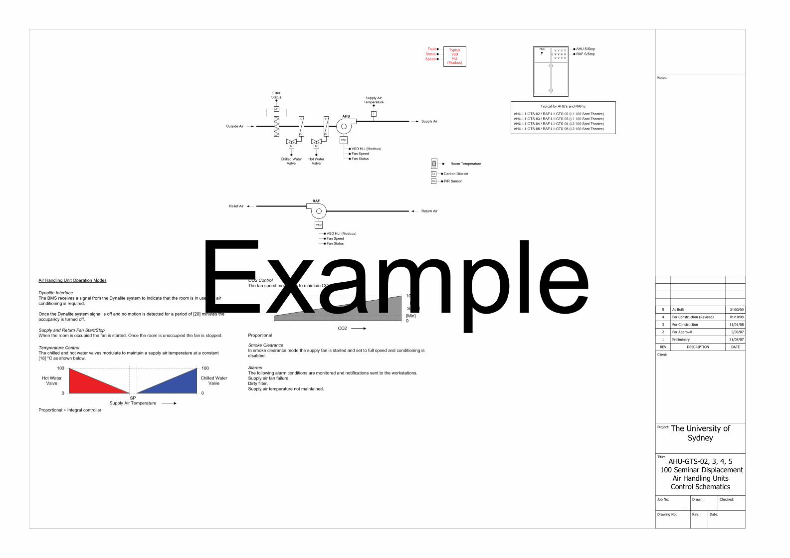
0$����
���������
&�,�?���3<@�@7@4�33������� ���:��������
&����������,���� ����������������
������
�����&�,��
� � !"#�"$! % �&�
�����
'! �
������ ���(���
!�)�
����
*�+��
���,��)�������-������
.��/����-0��#��1���
#��1����
�������
������
��23�23�4
.�� �����/�����5!�)����6 ������7
#����������� ��238239
�����
' $�F���
��
��
���
���
�
�
�
�
�
�
�� !!"���'�"#��'!("
��
� !�"#�'���
G��� �"�$ #
0"! ")�$ #0"��#*�$ #
� !&�$ #
�� �'#��*�� �? �"�
.
� !&�$ #�."/ "#'��#"
��0 ��0�"*��#
�����'�"#��'!(" 0��/�."/ "#'��#"
.��&::��)��< 4238239
.�� �����/������ ��23�238
��:����%���0"
5'��+/�6
�'�!�
����������������'*� ""��'*��'���
����������������'*� ""��'*��'���
.& +'!�)�#�$�FD��'*��0$�D�E
$�F����A.�����0$�����A.������������"'��.�"'�#"�$�F����A.�����0$�����A.������������"'��.�"'�#"�$�F����A.�����0$�����A.������������"'��.�"'�#"�$�F����A.��;��0$�����A.��;���������"'��.�"'�#"�
�'��� ""�
&�;/��� �����24
�����.�"�)�!!�- *1�'!'#/�+�*� � �*��'#"�/�* ��#"��'*��*�� ) +'� �*���"*�������"�-�#6��'� �*�,� !&�' #�)'*�)' !�#",� #�&�) !�"#,�� !&�' #��"/ "#'��#"�*���/' *�' *"�,
$ #��'*�! *1�F* ��G "#'� �*����"�
"#�����$��������.�"�%��#"+" ("��'�� 1*'!�)#�/���"��&*'! �"��&��"/���� *� +'�"���'����"�#��/� �� *���"�'*��' #�+�*� � �* *1� ��#"5� #"�,�
G*+"���"��&*'! �"��&��"/�� 1*'!� ���))�'*��*��/�� �*� ���"�"+�"��)�#�'� "# ����)�:��<�/ *��"����"��++� '*+&� ����#*"���)),
����#������������%���������������"*���"�#��/� ���++� "����"�)'*� ����'#�"�,�G*+"���"�#��/� ���*�++� "����"�)'*� ����� "�,�
��&�������.�"�)'*�� ""��/���!'�"�����/' *�' *��G��'�����-*��"!�-,
�#� �#� �*'!�G�
!�����������������.�"�+� !!"��'*������-'�"#�('!("��/���!'�"����/' *�' *�'��� !&�' #��"/ "#'��#"�'��'�+�*��'*��:��<�@��'�����-*��"!�-,�
� !&�$ #�."/ "#'��#"�
�����'�"#��'!("
���
�
�� !!"���'�"#��'!("
���
�
�#� �#� �*'!�9��*�"1#'!�+�*�#�!!"#
�'* ""�
���
�:� *<
���'�����������*��/�6"�+!"'#'*+"�/��"���"��� !&�)'*� ����'#�"��'*���"�����)�!!�� ""��'*��+�*� � �* *1� ��� �'�!"�,
Example
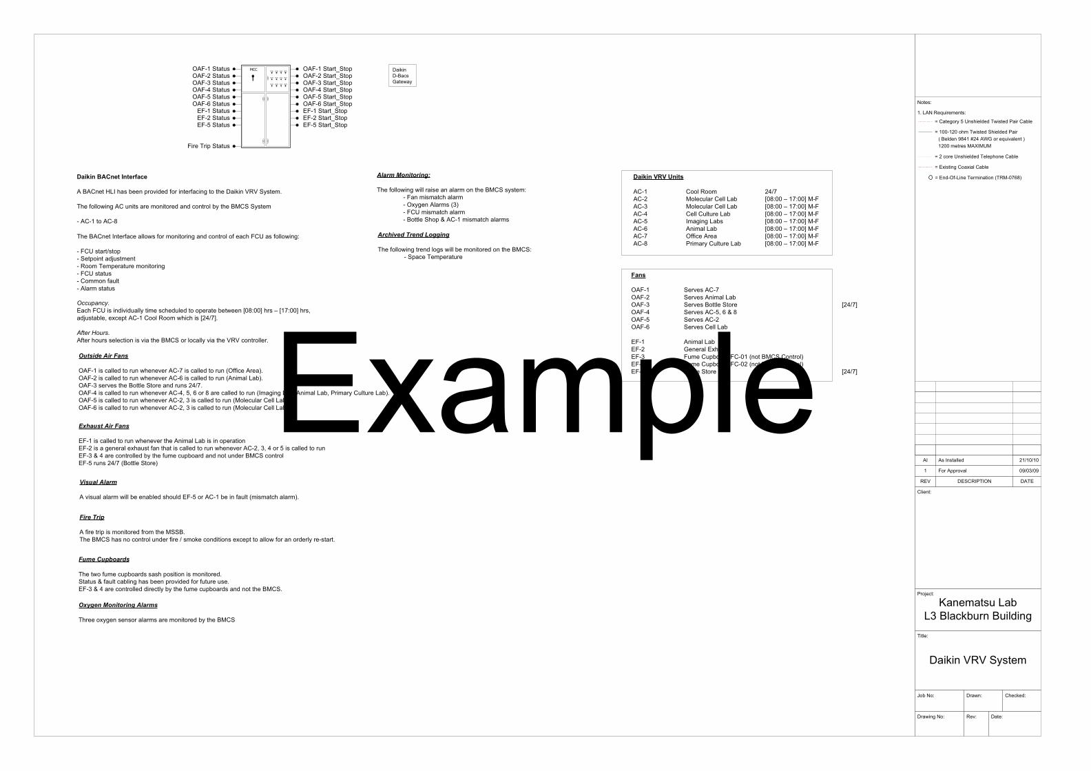
����������� �����������������������������
������������� ����!
���""#�$"�� ���������%�����������
��$�&�� ��������������'����������������
��(��#)*#������� �������+��,#"-./0����
��(1���������1�����������
2(%��3��3)��(4 2��(
2���!
�52 �52
2���! ���&6��!
2�������! ��7!
��""8.
9���!
2��6���4�4�%����
�����!
:��� ���������;�<��&6����<�������
�=�&�!
>�7������������������������
������!
����!
$�?�"?�"�%#� �3
���3�������� $�?�"?�"�3
@��''7��� "A?";?"A
+�<������A/8��B$8��5C������7������0�$""� �����,�D3, ,�
)�@#��%����� ���
)�@#$�%�����
������������ ��������
��<������>�3����������'7�����*�����*�&����������2��6���4�4�%���� �
����*������������������� ����������&�����������<,�%�%����
# ��#������#/
)�@#;�%�����)�@#8�%�����
)�@#��%���E%�')�@#$�%���E%�')�@#;�%���E%�'
2��6���2#<�&��C������
����<������3���*�&��������*� �����������&����*���&��@� ����*������!
# @� �����?��'# %��'������=��� ���# � ��� '������ ������# @� ��������# � ��*����# ��� �������
���������(�&��@� ��������7���������� ���&����������'�������������F"/!""G����H F�-!""G���I���=�������I��1&�'����#������ ����&�����F$8?-G�
�� ��������*�����������&�������7�������<,�%���&�����7�������4�4�&������
����������������
��#� ���� $8?-��#$ ,��&������������ F"/!""�H �-!""G�,#@��#; ,��&������������ F"/!""�H �-!""G�,#@��#8 ��������������� F"/!""�H �-!""G�,#@��#� 3 ���������� F"/!""�H �-!""G�,#@��#. ��� ������ F"/!""�H �-!""G�,#@��#- )**�&����� F"/!""�H �-!""G�,#@��#/ �� ������������� F"/!""�H �-!""G�,#@
����
)�@#� %�7�����#-)�@#$ %�7������ ������)�@#; %�7���<�����%�� F$8?-G)�@#8 %�7�����#�I�.�J�/)�@#� %�7�����#$)�@#. %�7�����������
(@#� ��� ������(@#$ C������(1�����(@#; @� ����'����@�#"��+���<,�%�����0(@#8 @� ����'����@�#"$�+���<,�%�����0(@#� <�����%�� F$8?-G
���������� ��
)�@#�����&����������������7����#-����&�����������+)**�&�����0�)�@#$����&����������������7����#.����&�����������+��� ������0�)�@#;���7�������<�����%�����������$8?-�)�@#8����&����������������7����#8I��I�.��/����&�����������+3 ���������I���� ������I��� �������������0�)�@#�����&����������������7����#$I�;����&�����������+,��&������������0�)�@#.����&����������������7����#$I�;����&�����������+,��&������������0�
)�@#��%�����)�@#.�%�����(@#��%�����(@#$�%�����(@#��%�����
@�����'�%�����
)�@#8�%���E%�')�@#��%���E%�')�@#.�%���E%�'(@#��%���E%�'(@#$�%���E%�'(@#��%���E%�'
��� ������ ��
(@#�����&����������������7��������� �������������'�����(@#$��������������1������*�����������&����������������7����#$I�;I�8�������&����������(@#;�J�8����&��������������*� ��&�'����������������<,�%�&���(@#������$8?-�+<�����%��0
���� �� ��
��7��������� �����������������������(@#�����#��������*�����+ �� ��&����� 0�
��������
��*�����'���� ������* �����,%%<�����<,�%�������&���������*���?�� 6��&���������1&�'���������*����������#�����
��������� ���
�������*� ��&�'����������'��������� ������%������J�*�����&����������������'7�����*�*���������(@#;�J�8����&����������&�����������*� ��&�'����������������<,�%�
����������������� ���
�����1������������� ����� �������������<,�%
� �������������
����*����������������������� �������<,�%������ !# @��� �� ��&����� # )1�������� ��+;0# @� � �� ��&����� # <�����%�'�J���#�� �� ��&����� �
������������ ������
����*������������������������ ������������<,�%!# %'�&���� '�����
Example
Copyright © 2022 FDOKUMEN