Build an Autonomous Arduino Robot with Bump Sensors
12
Build an Autonomous Arduino Robot with Bump Sensors Areas of Science Robotics (http://www.sciencebuddies.org/science-fair-projects/project-ideas/robotics) Difficulty Time Required Short (2-5 days) Prerequisites You will need to know how to use a breadboard to do this project. See the Science Buddies reference How to Use a Breadboard (http://www.sciencebuddies.org/science-fair-projects/references/how-to-use-a-breadboard) if you have not used a breadboard before. Material Availability A kit is available with the robot chassis and circuit parts. Arduino must be purchased separately. See materials list (#materials) for details. Cost High ($100 - $150) Safety No issues Abstract Mechanical switches are common in many machines and robots. They can be used to detect when a button is pushed, when a door is open, or a low-speed collision when two objects bump into each other. Switches can act as "bump sensors" on a simple robot to help it detect when it hits an obstacle. The robot can use this information to navigate around obstacles and avoid getting stuck. Can you build and program a robot that can drive around your house while using bump sensors to avoid obstacles? Credits Ben Finio, PhD, Science Buddies Cite This Page General citation information is provided here. Be sure to check the formatting, including capitalization, for the method you are using and update your citation, as needed. MLA Style Finio, Ben. "Build an Autonomous Arduino Robot with Bump Sensors." Science Buddies, 10 Aug. 2020, https://www.sciencebuddies.org/science-fair- projects/project_ideas/Robotics_p034.shtml. Accessed 10 Aug. 2020. APA Style Finio, B. (2020, August 10). Build an Autonomous Arduino Robot with Bump Sensors. Retrieved from https://www.sciencebuddies.org/science-fair- projects/project_ideas/Robotics_p034.shtml Last edit date: 2020-08-10 Introduction Advanced autonomous robots like the Perseverance rover (Figure 1) use a variety of cameras to detect obstacles and navigate around them. Since the robot is millions of miles from Earth, scientists will be unable to fix it if it crashes or gets stuck. In this case, it is very important to detect obstacles before the robot bumps into them. https://www.sciencebuddies.org/science-fair-projects/project_ideas/Robotics_p034.shtml 2020-08-07
-
Upload
khangminh22 -
Category
Documents
-
view
1 -
download
0
Transcript of Build an Autonomous Arduino Robot with Bump Sensors

Build an Autonomous Arduino Robot with Bump Sensors
Areas of Science Robotics (http://www.sciencebuddies.org/science-fair-projects/project-ideas/robotics)
Difficulty
Time Required Short (2-5 days)
PrerequisitesYou will need to know how to use a breadboard to do this project. See the Science Buddies reference How to Use a Breadboard
(http://www.sciencebuddies.org/science-fair-projects/references/how-to-use-a-breadboard) if you have not used a breadboard before.
Material Availability A kit is available with the robot chassis and circuit parts. Arduino must be purchased separately. See materials list (#materials) for details.
Cost High ($100 - $150)
Safety No issues
Abstract
Mechanical switches are common in many machines and robots. They can be used to detect when a button is pushed, when a door is open, or a low-speed
collision when two objects bump into each other. Switches can act as "bump sensors" on a simple robot to help it detect when it hits an obstacle. The robot can
use this information to navigate around obstacles and avoid getting stuck. Can you build and program a robot that can drive around your house while using bump
sensors to avoid obstacles?
Credits
Ben Finio, PhD, Science Buddies
Cite This Page
General citation information is provided here. Be sure to check the formatting, including capitalization, for the method you are using and update your citation, as needed.
MLA Style
Finio, Ben. "Build an Autonomous Arduino Robot with Bump Sensors." Science Buddies, 10 Aug. 2020, https://www.sciencebuddies.org/science-fair-
projects/project_ideas/Robotics_p034.shtml. Accessed 10 Aug. 2020.
APA Style
Finio, B. (2020, August 10). Build an Autonomous Arduino Robot with Bump Sensors. Retrieved from https://www.sciencebuddies.org/science-fair-
projects/project_ideas/Robotics_p034.shtml
Last edit date: 2020-08-10
Introduction
Advanced autonomous robots like the Perseverance rover (Figure 1) use a variety of cameras to detect obstacles and navigate around them. Since the robot is
millions of miles from Earth, scientists will be unable to fix it if it crashes or gets stuck. In this case, it is very important to detect obstacles before the robot bumps
into them.
https://www.sciencebuddies.org/science-fair-projects/project_ideas/Robotics_p034.shtml 2020-08-07
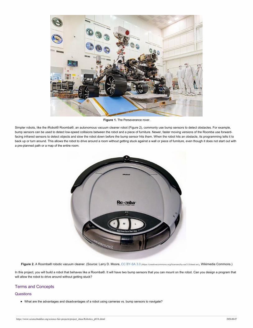
Figure 1. The Perseverance rover.
Simpler robots, like the iRobot® Roomba®, an autonomous vacuum cleaner robot (Figure 2), commonly use bump sensors to detect obstacles. For example,
bump sensors can be used to detect low-speed collisions between the robot and a piece of furniture. Newer, faster moving versions of the Roomba use forward-
facing infrared sensors to detect objects and slow the robot down before the bump sensor hits them. When the robot hits an obstacle, its programming tells it to
back up or turn around. This allows the robot to drive around a room without getting stuck against a wall or piece of furniture, even though it does not start out with
a pre-planned path or a map of the entire room.
Figure 2. A Roomba® robotic vacuum cleaner. (Source: Larry D. Moore, CC BY-SA 3.0 (https://creativecommons.org/licenses/by-sa/3.0/deed.en), Wikimedia Commons.)
In this project, you will build a robot that behaves like a Roomba®. It will have two bump sensors that you can mount on the robot. Can you design a program that
will allow the robot to drive around without getting stuck?
Terms and Concepts
Questions
What are the advantages and disadvantages of a robot using cameras vs. bump sensors to navigate?
https://www.sciencebuddies.org/science-fair-projects/project_ideas/Robotics_p034.shtml 2020-08-07

Bibliography
General electronics references:
Science Buddies (n.d.). How to Use a Breadboard (http://www.sciencebuddies.org/science-fair-projects/references/how-to-use-a-breadboard). Retrieved July 6, 2020.
Science Buddies (n.d.). How to Use a Multimeter (http://www.sciencebuddies.org/science-fair-projects/references/how-to-use-a-multimeter). Retrieved July 6, 2020.
Science Buddies (n.d.). Wire Stripping Tutorial (http://www.sciencebuddies.org/science-fair-projects/references/wire-stripping-tutorial). Retrieved July 6, 2020.
References for using an Arduino:
Science Buddies (n.d.). Getting Started with Arduino (http://www.sciencebuddies.org/science-fair-projects/references/getting-started-with-arduino#introduction). Retrieved July 6, 2020.
Arduino (n.d.). Language Reference (https://www.arduino.cc/reference/en/#functions). Retrieved July 6, 2020.
Reference about the cameras on the Mars 2020 Perseverance rover:
NASA (n.d.). The Cameras on the Mars 2020 Perseverance Rover (https://mars.nasa.gov/mars2020/spacecraft/rover/cameras/). Retrieved July 10, 2020.
References about the Roomba's sensors:
iRobot (n.d.). Why is my Roomba*reg; Bumping into Obstacles Harder than before? (https://homesupport.irobot.com/app/answers/detail/a_id/10211/~/why-is-my-roomba%C2%AE-is-
bumping-into-obstacles-harder-than-before%3F). Retrieved July 10, 2020.
Layton, J. (n.d.). How Robotic Vacuums Work (https://electronics.howstuffworks.com/gadgets/home/robotic-vacuum2.htm). HowStuffWorks. Retrieved July 10, 2020.
Datasheet for the L293D H-bridge motor driver:
Texas Instruments (January 2016). L293x Quadruple Half-H Drivers (https://www.ti.com/lit/ds/symlink/l293.pdf). Retrieved July 8, 2020.
Materials and Equipment (http://www.sciencebuddies.org/store-send?url=https%3a%2f%2fwww.homesciencetools.com%2fproduct%2fbluebot-4-in-1-educational-robotics-kit%3faff%3dSB1)
Bluebot 4-in-1 robotics kit (http://www.sciencebuddies.org/store-send?url=https%3a%2f%2fwww.homesciencetools.com%2fproduct%2fbluebot-4-in-1-educational-robotics-kit%3faff%3dSB1). The kit
includes a robot chassis, wheels, motors, breadboard, batteries, and circuit parts to build four different robots (https://www.sciencebuddies.org/science-kits-instructions?
sku=SB-BLUEBOT).
An Arduino Uno (https://www.amazon.com/s?k=arduino+uno&tag=sciencebuddie-20). A variety of Arduino starter kits are available that contain accessories and parts you can
use for other projects.
A 9V battery snap connector with barrel jack connector (https://www.amazon.com/s?k=9V+snap+connector+arduino&tag=sciencebuddie-20)
9V battery
A USB-B printer cable (https://www.amazon.com/AmazonBasics-USB-2-0-Cable-Male/dp/B00NH11KIK/?tag=sciencebuddie-20) to connect your Arduino to a computer and program it
Computer with free Arduino software (https://www.arduino.cc/en/Main/Software) installed (you can also use Arduino's web-based editor)
Some additional tools are recommended for working with circuits:
A digital multimeter (http://www.sciencebuddies.org/store-send?url=https%3a%2f%2fwww.homesciencetools.com%2fproduct%2fmultimeter-digital%2f%3faff%3dSB1) is strongly
recommended for help with troubleshooting
Alligator clip leads (http://www.sciencebuddies.org/store-send?url=https%3a%2f%2fwww.homesciencetools.com%2fproduct%2falligator-clip-leads-2-pack%2f%3faff%3dSB1) make it easier to
connect your multimeter probes to your circuit
Needle nose pliers or tweezers make it easier to handle small parts
Wire strippers allow you to cut wires to custom lengths, keeping your circuit neater
Double-sided foam tape
Lab notebook
Disclaimer: Science Buddies participates in affiliate programs with Home Science Tools (https://www.homesciencetools.com/?aff=SB1), Amazon.com (https://www.amazon.com/?
ie=UTF8&tag=sciencebuddie-20), Carolina Biological (http://www.carolina.com?s_cid=ptnr_scibuddies), and Jameco Electronics (http://www.avantlink.com/click.php?
tt=cl&mi=10609&pw=182414&ctc=Robotics_p034&url=http%3a%2f%2fwww.jameco.com). Proceeds from the affiliate programs help support Science Buddies, a 501(c)(3) public charity, and
keep our resources free for everyone. Our top priority is student learning. If you have any comments (positive or negative) related to purchases you've made for
science projects from recommendations on our site, please let us know. Write to us at [email protected] (mailto:[email protected]?
subject=Supplier_Comments).
Recommended Project Supplies
https://www.sciencebuddies.org/science-fair-projects/project_ideas/Robotics_p034.shtml 2020-08-07

Get the right supplies — selected and tested to work withthis project.
Project Kit: $99.95
Experimental Procedure
Note: This engineering project is best described by the engineering design process, as opposed to the scientific method. You might want to ask your
teacher whether it's acceptable to follow the engineering design process for your project before you begin. You can learn more about the engineering design
process in the Science Buddies Engineering Design Process Guide (http://www.sciencebuddies.org/engineering-design-process/engineering-design-process-steps.shtml).
1. Assemble your Bluebot chassis as shown in this video. However, instead of mounting the 4xAA battery pack on top of the robot, mount it on the lower plate.
Then mount your Arduino next to the breadboard on the top plate.
https://www.youtube.com/watch?v=SBeGl_IgWwY (https://www.youtube.com/watch?v=SBeGl_IgWwY)
2. To control your robot's motors, you will use the L293D H-bridge motor driver chip, included in your BlueBot kit. This chip allows you to control the speed and
direction of two motors. Figure 3 shows the pinout from the chip's datasheet and Table 1 describes the functions of the pins. When one of the input pins
("A") for a motor is high and the other one is low, the motor will spin. Reversing which pin is high/low reverses the motor's direction (Table 2). If both input
pins are high or both input pins are low, the motor will stop. Do not worry if that does not make sense yet. You will wire the circuit and see example code in
the next few steps.
Figure 3. L293D H-bridge chip pinout.
https://www.sciencebuddies.org/science-fair-projects/project_ideas/Robotics_p034.shtml 2020-08-07

Name Pin number(s) Description
VCC1 16 Digital logic voltage supply (5V from Arduino)
VCC2 8 Motor power voltage supply (6V from 4xAA battery pack)
GROUND 4, 5, 12, 13 Electrical ground
1,2EN 1 Speed control for motor 1 using pulse width modulation (PWM) signal from Arduino
3,4EN 9 Speed control for motor 2 using pulse width modulation (PWM) signal from Arduino
1A, 2A 2, 7 Inputs to control motor 1 using Arduino digital pins
3A, 4A 10, 15 Inputs to control motor 2 using Arduino digital pins
1Y, 2Y 3, 6 Outputs to drive motor 1
3Y, 4Y 11, 14 Outputs to drive motor 2
Table 1. Description of L293D H-bridge pins.
1A 2A Motor 1 behavior
Low Low Stop
Low High Spin
High Low Spin the other way
High High Stop
Table 2. How setting the input pins high and low controls motor behavior.
3. Before you worry about connecting the bump sensors, you should make sure your robot's motors work and that it can drive around. Connect your motors,
batteries, and the L293D, as shown in Figure 4 (note: there is more than one correct way to wire the circuit, this is just an example). The colors shown in
the picture are for readability purposes only; your wire colors do not need to match. If you are not sure how to wire a circuit on a breadboard, see the How to
Use a Breadboard (http://www.sciencebuddies.org/science-fair-projects/references/how-to-use-a-breadboard) resource. Here are a few things to look out for when building the circuit:
a. Make sure the L293D is oriented with the notch facing "up" on the breadboard.
b. Important: All the components in your circuit should have a "common ground." This means the Arduino's ground pin, the L293D's ground pins, and
the 4xAA battery pack's negative wire should all be connected to the ground bus on the breadboard, and the ground buses on opposite sides of the
breadboard should be connected.
c. However, make sure you do not short-circuit the 5V Arduino supply to the 6V battery supply. In the diagram, notice how the left and right
power buses on the breadboard are not connected with a jumper wire. The left-side bus provides 6V from the battery pack, and the right-side bus
provides 5V from the Arduino. The H-bridge makes use of both power supplies: one for internal logic (5V from the Arduino) and one to power the
motors (6V from the batteries). The external 4xAA battery pack is required because the Arduino cannot provide enough current to drive the motors
directly.
https://www.sciencebuddies.org/science-fair-projects/project_ideas/Robotics_p034.shtml 2020-08-07

Figure 4. Wiring diagram for connecting the Arduino to the L293D, your robot's motors, and batteries. A bigger version of the image (http://www.sciencebuddies.org/science-
projects/project-ideas/arduino-bluebot-L293D-breadboard-large-version.png) is available.
4. Make sure the power switch for the 4xAA battery pack is off and that the barrel jack for the 9V battery is unplugged (always do this before connecting the
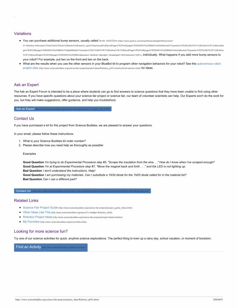
USB cable to program your Arduino). Enter the code shown in Figure 5 and upload it to your Arduino. If you are unsure how to do this, refer to the Getting
Started with Arduino (http://www.sciencebuddies.org/science-fair-projects/references/getting-started-with-arduino#introduction) guide.
https://www.sciencebuddies.org/science-fair-projects/project_ideas/Robotics_p034.shtml 2020-08-07
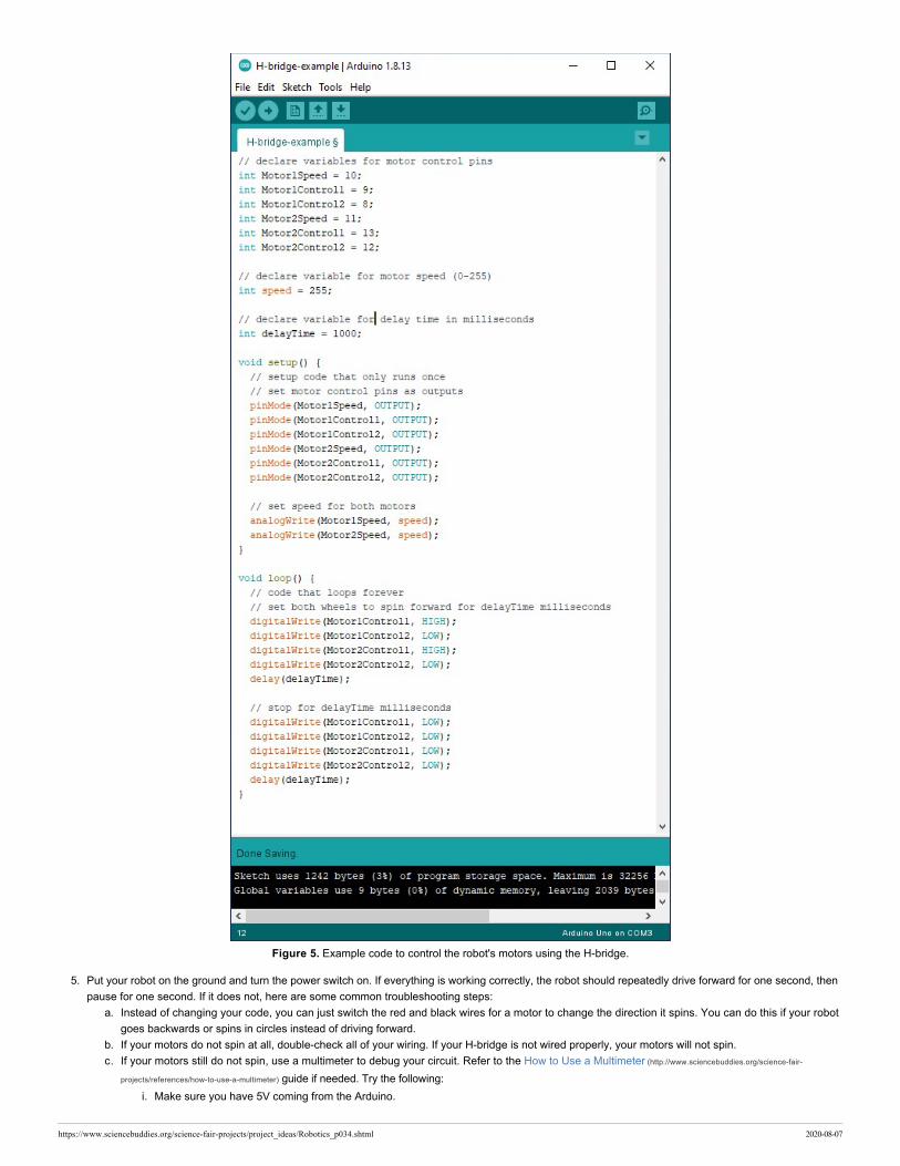
Figure 5. Example code to control the robot's motors using the H-bridge.
5. Put your robot on the ground and turn the power switch on. If everything is working correctly, the robot should repeatedly drive forward for one second, then
pause for one second. If it does not, here are some common troubleshooting steps:
a. Instead of changing your code, you can just switch the red and black wires for a motor to change the direction it spins. You can do this if your robot
goes backwards or spins in circles instead of driving forward.
b. If your motors do not spin at all, double-check all of your wiring. If your H-bridge is not wired properly, your motors will not spin.
c. If your motors still do not spin, use a multimeter to debug your circuit. Refer to the How to Use a Multimeter (http://www.sciencebuddies.org/science-fair-
projects/references/how-to-use-a-multimeter) guide if needed. Try the following:
i. Make sure you have 5V coming from the Arduino.
https://www.sciencebuddies.org/science-fair-projects/project_ideas/Robotics_p034.shtml 2020-08-07

ii. Make sure you have 6V coming from the 4xAA battery pack.
iii. Measure the voltages on the Arduino output pins to make sure they are what you expect (for example, based on the code, pin 9 should toggle
between 5V and 0V).
d. To confirm that your motors work, disconnect them from the H-bridge and connect them directly to 6V and ground on the breadboard.
e. To confirm that your H-bridge works, disconnect it from the Arduino's digital pins. Use jumper wires to manually connect the H-bridge's input pins to
5V or 0V on the breadboard. (Make sure you reconnect the motors to the H-bridge first.)
6. Practice steering your robot. Can you modify the program in Figure 5 to make your robot drive in a square? This is called "open loop" navigation, or "dead
reckoning." The robot is hard-coded to follow a pre-determined path, without responding to any sensor input. This type of navigation is generally not a good
idea, because small errors will accumulate over time, and eventually the robot will drift off course. However, it is a good way to practice programming and
make sure your circuit works.
7. Now it is time to connect a bump sensor. The bump sensor is a switch with three pins. Look closely at the sensor and you will see the labels "N.C.,"
"N.O.," and "C." These stand for Normally Closed, Normally Open, and Common, respectively. This means that when the switch is not pressed, the
connection between the N.C. and C pins is closed, and the connection between the N.O. and C. pins is open. When the switch is pressed, the connections
are reversed. This means that you can use the switch to toggle an Arduino digital pin between 0V and 5V.
8. Connect a bump sensor to your Arduino, as shown in Figure 6. Note that the H-bridge, motors, and batteries are omitted from this diagram to avoid clutter,
but you can leave them connected in your circuit.
a. Important: Note that the sensor's white wire is connected to 5V and the red wire is connected to the Arduino's digital pin. This goes against the
usual convention that red wires are used for the positive power bus connection. It is important to wire the sensor correctly in order to avoid shorting
the Arduino's 5V supply to ground.
Figure 6. Bump sensor connected to an Arduino digital pin. The common pin is connected to an Arduino digital pin. The Normally Open and Normally Closed pins
are connected to 5V and ground, respectively. This way, the digital input pin will read 0V when the switch is not pressed, and 5V when the switch is pressed.
9. Start a new Arduino sketch and enter the code shown in Figure 7.
https://www.sciencebuddies.org/science-fair-projects/project_ideas/Robotics_p034.shtml 2020-08-07

Figure 7. Example code to detect when the bump sensor is pressed using the Arduino's digital input.
10. Upload the code to your Arduino, and leave the Arduino plugged into the USB cable. Select Tools→Serial Monitor from the top menu in your Arduino
window. Make sure you select 9600 baud from the drop-down menu in the lower right. This will give you a window that prints a message indicating whether
or not the switch is pressed (Figure 8).
a. If the message displayed in your serial monitor does not change when you press the switch, double-check your wiring. Use a multimeter to confirm
that the voltage on the Arduino's input pin changes between 0V and 5V when you press the switch. If it does not, your switch is wired incorrectly.
Figure 8. The Arduino serial monitor displaying messages to indicate whether or not the switch is pressed.
11. You now have all the pieces that you need to build an autonomous robot that navigates with bump sensors! Can you program your robot to navigate based
on readings from one or more bump sensors? For example, try programming these different behaviors (see the next step for hints). Which behavior do you
think would be best for a robot that needs to drive around a room without getting stuck?
a. Put one bump sensor on the front of the robot and one sensor on the back. Make the robot change direction whenever it bumps into something.
b. Put both bump sensors on the front of the robot, one on the left and one on the right (Figure 9). Make the robot turn left or right when it hits an
https://www.sciencebuddies.org/science-fair-projects/project_ideas/Robotics_p034.shtml 2020-08-07

obstacle.
c. Make the robot back up first, then turn when it hits an obstacle.
Figure 9. Robot with two bump sensors mounted on the front.
12. Depending on your level of programming experience, you may need to read more in the Arduino Language Reference (https://www.arduino.cc/reference/en/#functions).
You can also ask for help in the Science Buddies Ask an Expert forums (http://www.sciencebuddies.org/science-fair-projects/ask-an-expert-intro). Here are some hints and
suggestions:
a. It is bad practice to repeatedly copy and paste the same lines or sections of code. If you find yourself doing so, it is better to put that code in a
function. It may be useful to make functions for basic robot movements like "driveForward" or "turnRight." Can you simplify the code you wrote to
make your robot drive in a square using functions?
b. "IF/ELSE" statements allow your program to perform different actions depending on whether or not certain conditions are true (for example, if a
variable is above or below a certain value). What happens when you make your robot's motion depend on the sensor input, instead of hard-coding a
certain behavior?
c. You can change the motors' speed using the analogWrite() command (see Figure 7). In the example program, the motors are set to "full speed," or
255. It might be easier to control your robot if it is not going full speed at all times.
https://www.sciencebuddies.org/science-fair-projects/project_ideas/Robotics_p034.shtml 2020-08-07
.
Variations
You can purchase additional bump sensors, usually called lever switches (https://www.jameco.com/shop/StoreCatalogDrillDownView?
rf=1&history=ihsfvwsq%7CfreeText%7Elever%2Bswitch%5Esearch_type%7Ejamecoall%5EprodPage%7E25%5Epage%7ESEARCH%252BNAV%4054d5snsd%7Cposition%7E26%5Erf%7E1%5Erefine%7E1%5EprodPa
ge%7E25%5Epage%7ESEARCH%252BNAV%40g94860dj%7Cposition%7E51%5Erf%7E1%5Erefine%7E1%5EprodPage%7E25%5Epage%7ESEARCH%252BNAV%40z3efbnea%7Cposition%7E76%5Erf%7E1%5Erefine
%7E1%5EprodPage%7E25%5Epage%7ESEARCH%252BNAV&position=1&refine=1&langId=-1&catalogId=10001&storeId=10001), individually. What happens if you add more bump sensors to
your robot? For example, put two on the front and two on the back.
What are the results when you use the other sensors in your BlueBot kit to program other navigation behaviors for your robot? See this autonomous robot
project idea (http://www.sciencebuddies.org/science-fair-projects/project-ideas/Robotics_p031/robotics/build-arduino-robot) for ideas.
Ask an Expert
The Ask an Expert Forum is intended to be a place where students can go to find answers to science questions that they have been unable to find using other
resources. If you have specific questions about your science fair project or science fair, our team of volunteer scientists can help. Our Experts won't do the work for
you, but they will make suggestions, offer guidance, and help you troubleshoot.
Ask an Expert (http://www.sciencebuddies.org/science-fair-projects/ask_an_expert_intro.shtml)
Contact Us
If you have purchased a kit for this project from Science Buddies, we are pleased to answer your questions.
In your email, please follow these instructions:
1. What is your Science Buddies kit order number?
2. Please describe how you need help as thoroughly as possible:
Examples
Good Question I'm trying to do Experimental Procedure step #5, "Scrape the insulation from the wire. . ." How do I know when I've scraped enough?
Good Question I'm at Experimental Procedure step #7, "Move the magnet back and forth . . ." and the LED is not lighting up.
Bad Question I don't understand the instructions. Help!
Good Question I am purchasing my materials. Can I substitute a 1N34 diode for the 1N25 diode called for in the material list?
Bad Question Can I use a different part?
Contact Us (mailto:[email protected]?subject=ScienceBuddies:Build+an+Autonomous+Arduino+Robot+with+Bump+Sensors)
Related Links
Science Fair Project Guide (http://www.sciencebuddies.org/science-fair-projects/project_guide_index.shtml)
Other Ideas Like This (http://www.sciencebuddies.org/search?v=solt&pi=Robotics_p034)
Robotics Project Ideas (http://www.sciencebuddies.org/science-fair-projects/project-ideas/robotics)
My Favorites (http://www.sciencebuddies.org/account/favorites)
Looking for more science fun?
Try one of our science activities for quick, anytime science explorations. The perfect thing to liven up a rainy day, school vacation, or moment of boredom.
Find an Activity (http://www.sciencebuddies.org/stem-activities)
https://www.sciencebuddies.org/science-fair-projects/project_ideas/Robotics_p034.shtml 2020-08-07
You can find this page online at: https://www.sciencebuddies.org/science-fair-projects/project_ideas/Robotics_p034.shtml
You may print and distribute up to 200 copies of this document annually, at no charge, for personal and classroom educational use. When printing this document,you may NOT modify it in any way. For any other use, please contact Science Buddies.
Copyright © 2002-2020 Science Buddies. All rights reserved. Reproduction of material from this website without written permission is strictly prohibited. Use of this site constitutes acceptance of our Terms and Conditions of Fair Use (http://www.sciencebuddies.org/about/terms-and-conditions-of-fair-use).
Privacy Policy (http://www.sciencebuddies.org/about/privacy-policy)
https://www.sciencebuddies.org/science-fair-projects/project_ideas/Robotics_p034.shtml 2020-08-07