bridgeconstructionmanual.pdf - Minnesota Department of ...
366
-
Upload
khangminh22 -
Category
Documents
-
view
0 -
download
0
Transcript of bridgeconstructionmanual.pdf - Minnesota Department of ...
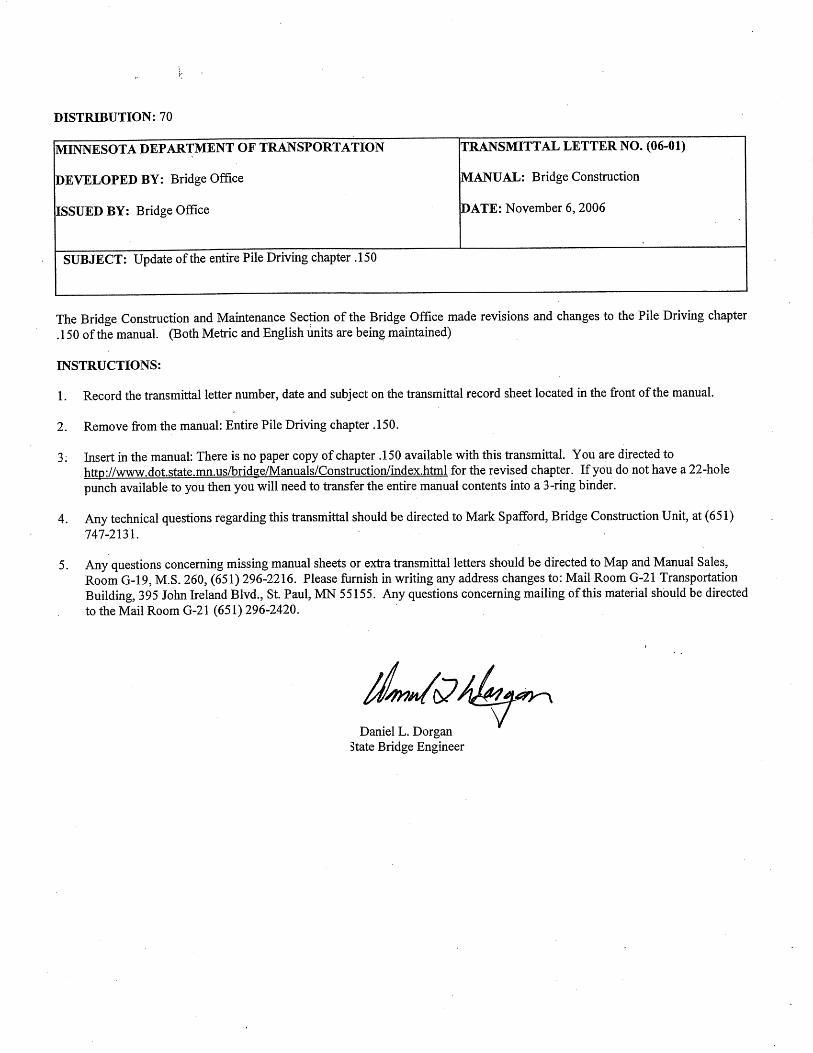

DISTRIBUTION: 70
The Bridge Construction and Maintenance Section of the Bridge Office has made revisions and changes to the entire manual. (Both Metric and English units are being maintained)
MINNESOTA DEPARTMENT OF TRANSPORTATION
DEVELOPED BY: Bridge Office
ISSUED BY: Bridge Office
INSTRUCTIONS:
TRANSMITTAL LETTER NO. (05-01)
MANUAL: Bridge Construction
DATE: November 1,2005
1. Record the transmittal letter number, date and subject on the transmittal record sheet located in the front of the manual.
SUBJECT: Update of the entire Bridge Construction Manual
2. Remove from the manual: Entire contents.
3. Insert in the manual: Revised manual into the respective chapters
4. Any technical questions regarding this transmittal should be directed to Mark Spafford, Bridge Construction Unit, at (65 1) 747-2131.
5. Any questions concerning missing manual sheets or extra transmittal letters should be directed to Map and Manual Sales, Room G-19, M.S. 260, (65 1) 296-2216. Please firnish in writing any address changes to: Mail Room G-2 1 Transportation Building, 395 John Ireland Blvd., St. Paul, MN 55155. Any questions concerning mailing of this material should be directed to the Mail Room G-21 (65 1) 296-2420.
Daniel L. Dorgan v State Bridge Engineer

The Bridge Construction Manual is intended primarily for the use of bridge construction inspectors andtheir assistants. By becoming thoroughly familiar with the contents of this manual, and by following therecommendations and suggestions therein, bridge inspectors will find that their work is made easier,their decisions can be made more quickly and with greater confidence. Greater uniformity in theinterpretation of the Plans and Specifications will be provided and the final results are more likely toreflect the efforts that have been made to obtain a high quality finished product. Contractors, generally speaking, will have more respect for an inspector who knows and understands thework, and the contents herein will enhance the knowledge and understanding of all but the veryadvanced bridge inspectors. Sections and partial-sections will be added from time to time in an effort tomake the manual as complete and up-to-date as possible.
_________________________________Daniel L. Dorgan, State Bridge EngineerMinnesota Department of Transportation

November 1, 2005 BRIDGE CONSTRUCTION MANUAL 5-393.index (1)
Section Index No.
Subsection Index No. Subject
5-393.000
5-393.050
5-393.100
5-393.150
5-393.001 5-393.002 5-393.003 5-393.004 5-393.005 5-393.006 5-393.007 5-393.008 5-393.009 5-393.010 5-393.011 5-393.012 5-393.013 5-393.014 5-393.015 5-393.016 5-393.017 5-393.018
5-393.051 5-393.052 5-393.053
5-393.101 5-393.102 5-393.103 5-393.104 5-393.105 5-393.106 5-393.107 5-393.108 5-393.109 5-393.110
5-393.151 5-393.152 5-393.153 5-393.154 5-393.155 5-393.156 5-393.157 5-393.158 5-393.159
GENERAL Introduction Technical Certification and Duties for Inspectors Field Office and Laboratory Plan Review Preconstruction Conference Control of Work Control of Utility Work Removal of Existing Structures Shop Drawings Safety Construction Diary Protection of the Environment Photographs Materials Field Plan Changes As-Built Bridge Plans Surplus and Salvage Materials Vertical and Horizontal Clearance for Traffic SURVEYING AND STAKING Construction Surveying Staking Bridges Benchmarks FOUNDATIONS General Cofferdams Concrete Seals Excavation Disposal of Materials Drilled Shafts Footings Foundation Soils Examination and Soil Bearing Tests Backfill - General Backfill - Culverts PILE DRIVING General Use of Survey Sheet Pile Nomenclature Storage and Handling of Piles Splicing Piles Jetting and Preboring Driving Equipment Inspection of Pile Driving - Timber Piles Inspection of Pile Driving - Steel Piles

5-393.Index (2) BRIDGE CONSTRUCTION MANUAL November 1, 2005
5-393.200
5-393.250
5-393.300
5-393.160 5-393.161 5-393.162 5-393.163 5-393.164 5-393.165 5-393.166 5-393.167 5-393.168
5-393.201 5-393.202 5-393.203 5-393.204 5-393.205 5-393.206 5-393.207 5-393.208 5-393.209 5-393.210 5-393.211 5-393.212 5-393.213 5-393.214
5-393.251 5-393.252 5-393.253 5-393.254 5-393.255 5-393.256 5-393.257 5-393.258 5-393.259 5-393.260 5-393.261
5-393.301 5-393.302 5-393.303 5-393.304
Pile Driving Formulas Inspection of Pile Driving - Equipment Inspection of Pile Driving - Process Pile Bearing Tables Pile Information Tables Test Pile and Pile Driving Reports Pile Driving Analyzer Pile Load Tests Payment for Piling FALSEWORK AND FORMS Introduction Form and Falsework Materials Deflections and Alignment Formulas and Standard Loads Falsework Details and Analysis Pier Cap Falsework Example Roadway Slab Falsework Example Slab Span Falsework Needle Beam Example Column Examples Joist and Stringer Tables Form Details Pier Cap Form Example Abutment Wall Form Example METAL REINFORCEMENT General Cutting and Bending Epoxy Coated Bars Storage and Protection Placing, Supporting and Tying Reinforcement Bars Splicing Reinforcement Bars Welding Welded Wire Fabric Prestressing Steel Pay Quantities References and Materials Information CONCRETE General Concrete Mix Material Requirements Concrete Quantities

November 1, 2005 BRIDGE CONSTRUCTION MANUAL 5-393.index (3)
5-393.350
5-393.400
5-393.351 5-393.352 5-393.353 5-393.354 5-393.355 5-393.356 5-393.357 5-393.358 5-393.359 5-393.360 5-393.361 5-393.362 5-393.363 5-393.364 5-393.365 5-393.366 5-393.367 5-393.368 5-393.369 5-393.370 5-393.371 5-393.372
5-393.401 5-393.402 5-393.403 5-393.404 5-393.405 5-393.406 5-393.407 5-393.408 5-393.409 5-393.410 5-393.411 5-393.412 5-393.413 5-393.414 5-393.415 5-393.416
CONCRETE BRIDGE CONSTRUCTION Preparations for Concrete Placement Concrete Placement Equipment Concrete Placement Concrete Placement in Cofferdams Removal of Forms Surface Finishes Architectural and Special Surface Finishes Placing Bridge Roadway Slabs Finishing Bridge Roadway Slabs Concrete Curing Cold Weather Protection Vibration Protection Bridge Deck Low Slump and Latex Wearing Courses Diaphragms Anchor Bolts Construction Joints in Concrete Joints Designed for Movement Joints at Abutments Joint Filler Material Expansion Devices Sidewalk and Curb Plates Bearing Assemblies STEEL BRIDGE CONSTRUCTION General Fabrication Shop Detail Drawings Structural Metals Shop Inspection Field Inspection of Materials Field Layout Falsework General Erection Erection Pinning and Bolting of Field Connections Erection of Bearing Assemblies Erection of Beam, Girders, Diaphragms, etc. Erection of Expansion Devices Erecting Metal Railing Bolting of Permanent Field Connections Welding Straightening Bent Material

5-393.Index (4) BRIDGE CONSTRUCTION MANUAL November 1, 2005
5-393.450
5-393.500
5-393.550
5-393.600
5-393.650
5-393.700
5-393.451 5-393.452 5-393.453 5-393.454 5-393.455 5-393.456
5-393.501 5-393.502 5-393.503 5-393.504 5-393.505 5-393.506 5-393.507 5-393.508 5-393.509 5-393.510
5-393.551 5-393.552 5-393.553 5-393.554 5-393.555 5-393.556 5-393.557 5-393.558 5-393.559 5-393.560 5-393.561 5-393.562
5-393.601
5-393.651
SURFACE PREPARATION AND PAINTING STRUCTURAL STEEL General Materials Surface Preparation Application of Industrial Coatings Final Cleanup and Miscellaneous Steel Structures Painting Council Excerpts TIMBER CONSTRUCTION General Materials Pile Bents Framing Wearing Course Glue Laminated Timber Connectors Hardware Field Treatment Placing Rip Rap for Timber Structures CONSTRUCTION ON RAILROAD RIGHT OF WAY General Diaries and Reports Surveying Clearances Pile Driving Excavation Flagging Protection Material Records Force Account and Labor Equipment and Rental Work Not Covered by Agreement Certification and Final Force Account Bills CONDUIT SYSTEMS Conduit Systems QUALITY CONTROL Quality Control GLOSSARY

November 1, 2005 BRIDGE CONSTRUCTION MANUAL 5-393.000
GENERAL 5-393.000
5-393.001 INTRODUCTION This manual has been prepared for the purpose of guiding Project Engineers and their inspectors while engaged in the construction of bridges and related items. It is not intended as a substitute for the General Specifications, nor does it cover all phases of the Specifications; it does, however, cover some sections of the Specifications in considerable detail, primarily for the purpose of promoting more uniformity of interpretation and inspection. What is a Contract? A contract is a written mutual agreement between two or more parties and, as such, governs the relationship between the contracting parties. Each party to the contract has certain rights and corresponding obligations to fulfill and neither party has the right to deviate from the scope of the terms or requirements of the contract without the written consent of the other party. A contract executed between the State and the Contractor for construction of a bridge or a highway provides that the performance of the work, including furnishing of labor and materials and fulfillment of other obligations, shall be in accordance with requirements of the Plans, Specifications and other terms and requirements set forth in the contract. It is of utmost importance that the Specifications, the Plans, and the Special Provisions be studied carefully, first for general aspects of the job, and then repeatedly for each phase of the operations as the job progresses. Mn/DOT 1504 defines the order of priority in the event of a discrepancy between the Plans, Specifications and Special Provisions. Nothing in this manual should be interpreted contrary to the Specifications, Plans, and Special Provisions, since the manual is not part of the contract agreement, and is not binding upon the Contractor except thru the Plans and Specifications. The following excerpts from an article by Frank A. Howard, former District Engineer for the Virginia Highway Department contains good advice for all Transportation Department employees who deal with contractors. Mr. Howard’s advice has been updated in the following information: “The field engineer and the Contractor have a definite personal relationship to work out. The young engineer on a project wants to be right, liked, sociable and friendly. Above all, the engineer wants the job to run smoothly and efficiently. One of the most difficult problems the field engineer has to face is personal relations with the Contractor when he or she is the engineer-in-charge of a project. It is very hard to strike just the right note in personal relations.
Some people are born with this knack of leadership. They never have to argue. They never shout. They say “let’s do this” and it is done. They command the respect of their associates and run a job well. Conversely, some engineers do not have this knack, and never learn it. They find it very hard to get contractors to carry out their suggestions and recommendations. Just what should be the attitude of the engineer toward the Contractor? How can a balanced, harmonious relationship be attained, and maintained? There are no hard-and-fast rules, individuals vary, as do jobs. The Contractor is in business to make money. The engineer’s task is to see that the job gets done and done right. These different viewpoints are not necessarily incompatible. It is necessary for both the engineer and the Contractor to realize that all job forces are on the same team. The Transportation Department wants the best job it is entitled to, at the earliest possible time. The engineer and the inspectors are there to get this job done. But the engineer also is an arbiter and must resist any attempt by the Contractor to avoid contract responsibilities. The engineer must be equally diligent in resisting pressure on the Contractor by the Transportation Department to do more than the contract calls for or do extra work without fair compensation. We find that most contractors want to build and maintain a reputation for good work. In the interest of better engineer-Contractor relations, the following points are offered for your consideration: 1. Be firm. Once you have made up your mind, stick to it
until somebody proves you are wrong.
Let’s assume that you have thoroughly thought out a situation and have made a decision. You tell the other person that you think they should do a certain thing. They start raising the roof. Don’t let them scare you. Nine times out of 10 they are yelling for effect-or just to see how serious you really are.
If you let this noise bother you or change your mind, you are in for a lot of the same treatment every time. Make sure you are right and if you think you are, stick to it. But if you discover you are wrong, admit it and correct your error. You will not lose standing by being fair.
2. Don’t let anybody rush you. Many times you may be
asked for a quick decision. Don’t be hurried. It’s best to take the situation back to the office with you and
5-393.002 BRIDGE CONSTRUCTION MANUAL November 1, 2005
think it over in all its ramifications. You can be sure that the other person has thought it over.
Ask yourself if this change or decision you have to make affects only what you are doing now, or will affect something else later. Remember that you are setting a precedent. Nothing looks quite as bad as changing your mind once you realize the full implications of a snap decision. You can’t tell a Contractor one thing one day and another thing the next...
3. Think ahead. It is taken for granted that the Contractor is thoroughly familiar with what is happening on the project today. But how about what is going to happen tomorrow?
Try to anticipate tomorrow’s trouble today. Look ahead. If you spot any trouble, talk it over with the Contractor. Your foresight may save both the Transportation Department and the Contractor some money.
Be diplomatic. A soft answer gets better results than loud talk. Ask or request rather than order or instruct. Engineers and inspectors on the job act somewhat like brokers who try to bring both parties - the Transportation Department and the Contractor - together in harmony; the end result being a job well done.”
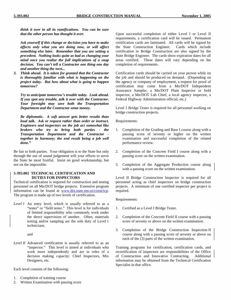
Be fair to both parties. Your obligation is to the State but only through the use of sound judgement will your efforts to serve the State be most fruitful. Insist on good workmanship, but not on the impossible. 5-393.002 TECHNICAL CERTIFICATION AND DUTIES FOR INSPECTORS Technical certification is required for construction and testing personnel on all Mn/DOT bridge projects. Extensive program information can be found at www.dot.state.mn.us/const/tcp. The program is made up of two levels of certification. Level 1 An entry level, which is usually referred to as a
“tester” or “field tester.” This level is for individuals of limited responsibility who commonly work under the direct supervision of another. Often, materials testing and/or sampling are the sole duty of Level 1 technicians.
and
Level II Advanced certification is usually referred to as an
“inspector.” This level is aimed at individuals who work more independently and are in roles of a decision making capacity: Chief Inspectors, Mix Designers, etc.
Each level consists of the following: 1. Completion of training course 2. Written Examination with passing score
Upon successful completion of either Level I or Level II requirements, a certification card will be issued. Permanent certification cards are laminated. All cards will be signed by the State Construction Engineer. Cards which include certification in Bridge Construction are also signed by the State Bridge Engineer. The cards show expiration dates for all areas certified. These dates will vary depending on the completion of requirements. Certification cards should be carried on your person while on the job and should be produced on demand. (Depending on the agency or company of employment, a request for proof of certification may come from a Mn/DOT Independent Assurance Sampler, a Mn/DOT Plant Inspector or field inspector, a Mn/DOT Lab Chief, a local agency inspector, a Federal Highway Administration official, etc.) Level 1 Bridge Tester is required for all personnel working on bridge construction projects. Requirements: 1. Completion of the Grading and Base I course along with a
passing score of seventy or higher on the written examination and successful completion of the related performance review.
2. Completion of the Concrete Field I course along with a
passing score on the written examination. 3. Completion of the Aggregate Production course along
with a passing score on the written examination. Level II Bridge Construction Inspector is required for all personnel acting as chief inspectors on bridge construction projects. A minimum of one certified inspector per project is required. Requirements: 1. Certified as a Level I Bridge Tester. 2. Completion of the Concrete Field II course with a passing
score of seventy or above on the written examination. 3. Completion of the Bridge Construction Inspection II
course along with a passing score of seventy or above on each of the (3) parts of the written examination.
Training programs for certification, certification cards, and recertification of inspectors are responsibilities of the Office of Construction and Innovative Contracting. Additional information may be obtained from the Technical Certification Specialist in that office.

November 1, 2005 BRIDGE CONSTRUCTION MANUAL 5-393.003
The inspector should never become involved in disputes with workers. Orders or instructions about performance of the work should with the Superintendent or a duly appointed representative in the absence of the Superintendent. The inspector is responsible for seeing that the work is executed in full accordance with the Plans and Specifications. The inspector is responsible for having a thorough understanding of the Specifications and for exercising good judgment. Often the inspector’s work is the deciding factor between a good job and an average or poor one. It is assumed that good and sufficient reasons exist for the design, the Specifications, and all items included in the contract documents. It is the responsibility of the Engineer and the inspector to obtain the results specified in the contract documents. It is the inspector’s job to review all phases of the work periodically including various operations being performed by the Contractor to ensure that his or her instructions are being followed and to keep the Project Engineer well informed of progress, problems, and instructions to the Contractor. Unless field inspection is aggressively carried out and well documented, the completed project may well be of unknown quality, a potential high maintenance structure, and reflect badly on the reputation and the prestige of the Department of Transportation. A competent inspector is thoroughly conscious of the importance and scope of his or her work and is fully informed in regard to the design and Specifications. Armed with this knowledge and with sound judgment gained through experience, he or she will not only detect faulty construction but will also be in a position to prevent it by requiring proper construction procedures and materials. 5-393.003 FIELD OFFICE AND LABORATORY Basic requirements for field offices and laboratories are defined under 2031. A number of conveniences which are not required under this specification are included in Special Provisions. It is the responsibility of the District to include additional items in their time and traffic for each job so that offices of desired size and with adequate facilities will be provided for in the contract. When bridges are let separate from grading, this item will be carried in the bridge portion of the contract. 5-393.004 PLAN REVIEW The importance of comprehensive study and review of the Plans, Specifications and Special Provisions can not be over-emphasized. Never assume that the requirements for this job are the same as for the last project. It is good practice to highlight special requirements in colored pen particularly when they are new to the inspector or different than those normally used. Make certain that each point covered and each detail shown is fully understood. Those points and details
which are not clear to you should be discussed with your coworkers or with the Engineer, until there is no longer any question regarding interpretation. One of the best methods of becoming thoroughly familiar with the Plans is to check the quantities shown on the various material schedules. Since this is required for estimate purposes as well, it serves a dual purpose. In this way, errors in the Plans are sometimes discovered before it is too late to make changes conveniently. You will find that, in order to check the quantities for a structure, you will have to become quite familiar with the Plans. 5-393.005 PRECONSTRUCTION CONFERENCE In most cases a preconstruction conference will be held to discuss the contractors proposed work schedule and traffic control and to obtain information on material supplies, subcontractors, etc. In addition to this conference, it is of considerable importance that the Engineer and/or inspector view the site with the Contractor prior to starting work to make certain that the Contractor is fully aware of any special requirements which might later cause delays and hardship. For additional preconstruction conference information see the Contract Administration Manual Section 5-591.310. 5-393.006 CONTROL OF WORK Control of work is covered in the Contract Administration Manual Section 5-591.300 and will not be repeated here. 5-393.007 CONTROL OF UTILITY WORK The purpose of this section is to set forth the provisions that should be made and the practices that should be followed to obtain adequate inspection of utility installation and relocation work in connection with trunk highway construction. “Utility” means all privately, cooperatively or publicly owned communication lines and facilities or systems for the transmission and distribution of electrical energy, oil, gas, water, sewer, steam and other pipe lines, railways, ditches, flumes or other structures which under the laws of this state or the ordinance of any town, village or city may be constructed, placed or maintained along or on trunk highway right-of-way. Dependent upon the meaning intended in the context, “Utility” also may mean the utility company inclusive of any wholly owned subdivision. Inspection is required to assure that Plans are properly provided and fully understood by all parties, that operations are coordinated, executed and completed economically, that activities and costs are systematically recorded so that bills can be checked against the performance and the record and the state’s interests protected and equitable payments made, all in accord with state laws and regulations and in accord with federal laws and regulations, where federal funds are involved.

5-393.007 BRIDGE CONSTRUCTION MANUAL November 1, 2005
A written agreement between the state and the utility is required in every case in which reimbursement for utility relocation is involved. This is so that representatives of each involved party will understand the scope of the undertaking and their respective and separate responsibilities connected with the utility relocation. Utilities presently located on public right of way are required to relocate the utility facility to accommodate highway construction at no expense to the State upon written notice and order from the Commissioner of Transportation or an authorized agent. Original notice and order are issued by the Utilities Agreement Engineer as the authorized agent of the Commissioner of Transportation. The Utility Agreements and Utility Permits Unit negotiates agreements with each utility entitled to reimbursement for all or part of the relocation of a utility facility prior to the letting of a highway construction project. Upon completion of the agreements and encumbrance of funds, notices and orders are issued by the Utility Agreements Engineer as the authorized agent of the Commissioner of Transportation directing and authorizing the utility to proceed with the required relocations. The Project Engineer will be assigned the utility relocation agreement by a letter from the District Engineer. The Utilities Agreement Engineer will forward the Job Code TC08, the approved utility relocation agreement and the related utility permits to the Project Engineer for use during the progress of utility relocation work. Installations and relocations must conform to the utility relocation agreements and utility permits; however, minor changes can be made by the Project Engineer with prior approval of the Utility Agreements Engineer. Permits are required in all cases where the utility has facilities on trunk highway right of way except in those instances wherein the utility subordinates its property right to the State. Any major changes in a utility relocation agreement requires a supplement to the agreement which is negotiated and drafted by the Utility Agreements Unit. If the utility refuses to remove its facilities from the right of way after being ordered to do so by the Project Engineer, contact the Utility Agreements Engineer or District Engineer. Utility companies may be held responsible for damages sought by the Contractor which are a result of failure to cooperate. The Project Engineer is responsible to see that inspection is provided for all utility relocations and installations on the project. The degree of inspection of utility construction will vary considerably with the nature and location of the work as they affect the completed highway construction. The Project Engineer must use judgment in deciding the extent and regularity of the inspection activities. Certain phases of the work may require a very close check to make sure that the highway facility will not be adversely affected and, also, that the required completion certificates, attesting to receipt of
goods and satisfactory performance of work in conformance with the terms of the agreement, are properly executed. The degree of inspection may vary from spot checking to continuous and close observation of the relocation work. The inspector should verify the information given in the Plans regarding the condition of the existing utility prior to any relocation work. Information to be verified may include the size, type and material of mains or conduits and other similar information. Photographs should also be taken if there is any possibility of future disagreement on the condition of the utility. The inspector should be as familiar with utility adjustments on the highway construction project as he or she is with the highway construction plans, and should be aware of the many facts considered in determining the proposed rearrangement of utility facilities. It is the inspector’s duty to see that the utility carries its relocation construction to completion in accordance with the agreement and in the manner proposed in the Plans. If the work or materials are not in conformity with the agreement, it is the inspector’s responsibility to call it to the attention of the Project Engineer and the utility or its contractor. The final solution should be to get all defective work remedied or repaired, or, if necessary, removed and replaced in an acceptable manner by the utility. It is the inspector’s responsibility to take reasonable steps to assure that the utility’s operations and the Contractor’s operations are coordinated. Utility relocations should be made in advance of the Contractor’s operations when such relocations are not dependent upon highway construction, and all relocations should be performed promptly. Utilities are usually installed after bridge construction is completed. Inspection is not normally handled by the bridge inspector and detailed procedures therefore are not included in this manual. Regardless of the type of arrangement under which the utility adjusts its facilities, the Utility’s inspector is to keep a separate diary for the activities of each utility. Entries should be made with the realization that these records afford support for reimbursement to the utility company, without which, great difficulty in prompt and equitable payment may be experienced. It is the Project Engineer’s responsibility to see that the utility complies with the notice and order. When conditions warrant, the Project Engineer may grant the utility an extension of time, but this should only be done with the Contractor’s knowledge and consent to avoid possible claims for delays.

November 1, 2005 BRIDGE CONSTRUCTION MANUAL 5-393.008
5-393.008 REMOVAL OF EXISTING STRUCTURES Caution should be taken when the Plans require removal of existing structures or portions of existing structures.Reinforced concrete structures may require additional shoring if portions of the superstructure are to be removed. Structural steel members that are to be salvaged for the contracting agency should be match marked and properly stored. See 5-393.017 "Surplus and Salvage Materials" for additional information on salvaged materials. The Contract may restrict the type of equipment that can be used when portions of the existing structure are to be reused. Any restrictions will be included in the Special Provisions. Structural steel and concrete beams that are to remain must be protected from jackhammer notches and gouges as well as from concrete saw cuts. This type of damage results in stress concentrations that could result in fatigue cracking or failure of a member. Should damage occur, contact your Supervisor. No repairs should be undertaken without the recommendations of the Bridge Office. Extreme caution should be exercised when blasting to prevent damage to underground utilities or other public and private property. Thoroughly discuss the removal plans with the Contractor and your Supervisor. In addition to the requirements of 1711, the use of explosives in conjunction with the removal of bridges shall be subject to approval of the Engineer. 5-393.009 SHOP DRAWINGS Shop detail drawings are produced for various bridge items and should be used in the inspection, erection and assembly of those items. Structural steel, bearings, ornamental railings and expansion joints are among the common bridge components requiring shop drawings. Any particular bridge may require shop drawings for other items. Specification 2471.3B contains specific references to the use and understanding of shop drawings. Shop drawings become a part of the contract and may be used in lieu of the general plans when specific details are needed. 5-393.010 SAFETY OSHA Safety Standards are lengthy and complex. In addition, they are subject to change by publication in the Federal Register and the enforcement of specific portions may be delayed or postponed. For these reasons, field personnel should cooperate with the enforcing agencies to the fullest extent practicable and be guided by the following policy: Department of Transportation personnel are expected to be safety conscious and alert to reasonable safety precautions in their daily duties. This has always been true in the past and should continue to be our goal in the future.
The Contractor’s responsibility to comply with the applicable safety requirements, as well as all other Federal, State and local laws, shall be discussed at the preconstruction conference and documented in the minutes of the meeting. Where there are conditions which are obvious hazards or pose an imminent danger to employee safety, the Contractor should be notified immediately. If the condition is not improved by the Contractor, the inspector is to report the problem to the Project Engineer. It is not intended that inspectors “enforce” safety regulations other than to notify Contractor and Project Engineer of potentially dangerous conditions. If a Contractor has been notified of an unsafe condition or operation, the notice should be recorded in the project diary. The Project Engineer, as supervisor of the inspection staff, has the responsibility of seeing that proper safety clothing, devices and procedures are used by personnel in performance of their duties. These items may include safety vests, hard hats, safety harnesses/lanyards, life vests, respirators, eye and hearing protection, weekly safety meetings, etc (see Specification 1706 and special provisions). 5-393.011 CONSTRUCTION DIARY Chief inspectors must keep a daily diary of the construction operations, particularly of those for which the inspector is responsible. Make notes in your diary while the information is still fresh in your mind. Illustrate important notations or add detailed information at a later date. 1. It is recommended that the last few minutes of each day
be used for writing up the diary. Make this a habit! Comments should include notes on progress of work, size of force, adequacy of equipment, instructions received and given, and on temperatures and weather conditions. See Contract Administration Manual 5-591.390 for additional instructions.
2. Weekly Construction Diary
Form 2120 - “Weekly Construction Diary and Statement of Working Days” (See Figure A 5-393.011) is used to report progress of bridge construction work. Major bridge items may be listed separately or an entire bridge may be listed as one item on this form. Information on the use of this form is contained in Section 5-591.340 of the Contract Administration Manual. Form 2120 can be found in the CMS (Construction Management System).
5-393.012 PROTECTION OF THE ENVIRONMENT Specifications 1713 and 1717 provide that the Contractor must take certain precautions for protection of the environment. Forests, fish, wildlife, air and water are specifically mentioned in these Specifications. Plans may contain temporary erosion control measures, limitations on cofferdam construction, restrictions on dewatering or other provisions designed to protect lakes and streams. Earth slopes should be finished,

5-393.013 BRIDGE CONSTRUCTION MANUAL November 1, 2005
topsoil placed and seeding or sodding completed at the earliest possible time to provide permanent protection against erosion. Permits from the Corps of Engineers, Department of Natural Resources, U.S. Coast Guard or Minnesota Pollution Control Agency may have been acquired by Mn/DOT for the project. The Plans and Special Provisions will provide for construction in accordance with the terms of those permits; however,certain Contractor operations (construction of work roads, pumping directly into lakes or streams, etc.) may not be allowable under the terms of the permit. Project personnel should be familiar with the terms of all permits obtained by Mn/DOT for the project. Even if not restricted by permit, Contractor operations may be limited by environmental regulations. 5-393.013 PHOTOGRAPHS Photographs have played a very important role in verifying the engineer’s statements concerning disputed claims. Progress pictures taken at appropriate intervals or of unusual situations may discourage a Contractor from submitting a claim unless there is ample justification. 5-393.014 MATERIALS Materials Manual 5-691, Structural Metals Manual 5-394 and Concrete Manual 5-694 cover the sampling, testing and inspecting of materials in considerable detail, and no attempt will be made here to repeat the instructions contained therein. The point to bear in mind is that all materials used on our work must be inspected and approved by some authority, whether it be on the job, prior to shipment, or from samples taken at some stage of the operations. Even though materials may have been inspected prior to delivery to the project, they should be “field checked” for possible damage and to ensure conformance with plan dimensions prior to incorporation into the work. Final inspection and acceptance of material will be made only at the site of the work, after all required tests have been met. Study the manuals thoroughly and refer to them whenever there is a question in your mind concerning a particular item. Keep a record of all materials received and placed, showing date, source, quantity, by whom sampled, and for whom inspected. At the completion of the project, the original record should be retained in the project file and a copy furnished to the Bridge Construction Unit. 5-393.015 FIELD PLAN CHANGES Should it become necessary to make a plan change in the field, such as lowering a footing to obtain bearing on rock, the Bridge Construction Unit should be contacted. This unit provides an advisory service on plan changes through three Regional Bridge Construction Engineers who have direct access to Bridge Designers for information on the effect of plan changes. Plan changes which require design changes in structural components or geometrics must be approved in
writing by the Bridge Design Unit prior to implementation. A pencil notation on a copy of the plan is a good way to provide plan change information to the Bridge Office. Unless revised plan sheets are issued by the Bridge Design Unit, corrections should be transferred to reproducible copies of the plans by the Project Engineer to provide a permanent “as-built” record (see 5-393.016). 5-393.016 “AS-BUILT” BRIDGE PLANS With the increased number of bridge repair and reconstruction projects and the number of contractor options and alternatives allowed in bridge plans and special provisions, there is a need for information in Bridge Office files for this info. This need has been expressed by both the Bridge Office and District Bridge Maintenance personnel. In order to meet the need for additional information and provide a permanent record of bridge construction, Project Engineers, when “finaling” the bridge portion of a project, shall request reproducible copies of bridge Plans from the Bridge Design Unit Leader listed on the plan. Upon receipt of the reproducible copy, the Project Engineer shall revise each plan sheet as necessary to provide the following information: 1. All plan changes (including those approved in writing by
the Bridge Office) including revised standard details shown on appropriate plan sheets. Dimensional changes (including elevation changes) should be shown by lining out original dimension and inserting “as-built” dimension.
2. The options or alternates selected by the Contractor where
allowed in the Plans or Special Provisions. Check either Concrete Wearing Course or the other (manufacturer’s name should be noted). A standard "as-built" plan sheet (addition to original plan) will be provided for this information.
3. The type and/or size and manufacturer’s (not fabricator’s
or supplier’s) name for the following items: (1) expansion joints and glands (2) elastomeric bearing pads (3) non-standard hardware items. This information shall be shown on the appropriate plan detail sheet or standard plan sheet.
4. For the finish coats on painted bridges, type of paint,
color and manufacturer’s name. The standard plan sheet will provide space for this information.
5. Actual rock excavation limits for footings shall be shown
on “as-built” plans. Information shall be sufficient to show the extent of footing supported on rock if only part of the footing is on rock.
6. Utilities installed that are not shown on plan sheets.

November 1, 2005 BRIDGE CONSTRUCTION MANUAL Figure A 5-393.011

5-393.017 BRIDGE CONSTRUCTION MANUAL November 1, 2005
When the Project Engineer has completed the addition of preceding information to the plans in ink, the “as-built” plan sheets shall be returned to the Regional Bridge Engineer. The Regional Bridge Engineer will arrange for microfilming of “as-built” plans to provide a permanent record in accordance with Mn/DOT policies. 5-393.017 SURPLUS AND SALVAGE MATERIALS Materials from the project site which the engineer considers of salvage value, and surplus materials which remain after completion of the work, should be properly accounted for when the contract work is completed. The engineer will determine which materials are of salvageable value and their disposition. The Contractor is compensated for the expense of materials delivered for the project but determined as surplus. Cutoffs and unused pieces of piling for which the Contractor receives payment are salvaged only when the Area Maintenance Engineers express a need for them. Therefore, the engineer should check with the Maintenance Engineer at the start of the project and during the project if the project lasts over a few months, to determine what types and lengths of piling are to be salvaged. The engineer will then notify the Contractor, in writing, of his or her decision. A determination to salvage an existing bridge or parts of it will generally be made by consulting with the Regional Bridge Construction Engineer during the planning stage. Salvage of steel items is usually based on scrap steel prices. 1. Salvaged Materials
Form 17119, Inventory of Salvage Bridge Materials, (see www.dot.state.mn.us/const/tools/index.html under "forms") must be prepared upon the completion of each structure from which materials are salvaged. For cost accounting purposes a separate itemization must be made and the total footage shown on Form 17119 for each size and type of steel H or shell pile pieces which are 3 meters (10 ft) or more in length. The original and one copy of Form 17119 are to be submitted with the final.
5-393.018 VERTICAL AND HORIZONTAL CLEARANCE FOR TRAFFIC Where traffic lanes are open any "temporary" restriction in clearance during construction must be measured and immediately reported to the District Permits Office. Falsework construction, width restrictions due to excavation, construction of a temporary bridge and bridge widening frequently result in temporary or permanent reductions in clearance. The estimated beginning and end dates for "temporary" restrictions should be included with clearance information. The form is available on the Bridge Office website at www.dot.state.mn.us/bridge, click on the
"downloads" button and select "Vertical and Horizontal Bridge Clearance Report". Failure to report this information may result in routing of over dimension vehicles through the project with potentially serious safety consequences. Minimum vertical and horizontal clearances for the completed bridge which may restrict motor vehicle traffic must be recorded on the "as-built" plan. In addition, these measurements should be reported to the District Permit Office and the Bridge Office (Attn: Bridge Management Engineer) prior to opening of the affected roadway for use by the traveling public as per the Contract Administration Manual 5-591.410, under the heading of "Reporting Final Bridge Clearances".

November 1, 2005 BRIDGE CONSTRUCTION MANUAL Figure A 5-393.017
Mn/DOT TP-17119 (3-79)
Sheet No.____ of____Location of yard:_______________________________________________
Condition of material or equipment is to be noted for each item listed. Use the following code: N - New G - Good F - Fair P - Poor Maint. Area No.:_____
Wt.Lb./Ft.
DateDateDateDate
INVENTORY OF SALVAGED BRIDGE MATERIALS
Bridge Foreman
Bridge Crew No.
Distribution: Bridge Construction & Maintenance Engineer (C.O.) Area Maintenance Engineer Bridge Maintenance Supervisor ___________________________________ ___________________________________
RemarksNo. of Pieces Description Length Cond.

5-393.018 BRIDGE CONSTRUCTION MANUAL November 1, 2005
5.393.018 APPENDIX METRIC INFORMATION
Metric Measurement
Lengths = millimeter (mm), meter
(m), kilometer (km)
Areas = square meter (m2)
Volume = liter (L) or cubic meter
(m3)
Mass (Weight) = kilogram (kg)
Force = Newton (N=kg • m/s2)
Pressure, Stress = Pascal (Pa = N/m2)
Energy, Work = Joule (J = N • m)
Torque = Joule (J = N • m)
Speed, Velocity = meter/second (m/s),
kilometers/hour (km/hr)
Acceleration = meter/second squared
(m/s2)
Density = kilograms/meter cubed
(kg/m3)
Temperature = ºCelsius (ºC)
Power = Watt (J/s)

November 1, 2005 BRIDGE CONSTRUCTION MANUAL 5-393.018
Conversions From U.S. Customary To Metric (SI) Multiply By
LENGTH/THICKNESS mil mm 0.0254
inch mm 25.4
ft mm 304.8
ft m 0.3048
yd m 0.9144
mile km 1.609344
AREA
inch2 mm2 645.16
ft2 m2 0.092903
yd2 m2 0.836127
VOLUME
inch3 mm3 16390
foot3 m3 0.02832
yard3 m3 0.7646
gallon L 3.7854
gal/yd2 L/m2 4.5273
gal/yd3 L/m3 4.9511
MASS (Weight)
ounce g 28.35
pound kg 0.453592
ton metric ton 0.907185
FORCE
pound N 4.44822
kip kN 4.44822
FORCE/UNIT LENGTH
lb/ft N/m 14.5939
lb/inch N/mm 0.1751
PRESSURE/STRESS
lbs/ft2 Pa 47.8803
kips/ft2 kPa 47.8803

5-393.018 BRIDGE CONSTRUCTION MANUAL November 1, 2005
Conversions From U.S. Customary To Metric (SI) Multiply By
lbs/inch2 kPa 6.89476
lbs/inch2 Mpa 0.006895
kips/inch2 Mpa 6.89476
ENERGY
foot pound J = N • m 1.35582
MASS/LENGTH
ounces/yd2 kg/m2 0.0339057
lbs/ft2 kg/m2 4.88243
lbs/yd2 kg/m2 0.5425
lbs/ft3 kg/m3 16.0185
lbs/yd3 kg/m3 0.5933
TEMPERATURE
(°F-32)(5/9) = °C
Quick Conversions
Water freezes 0° C 32° F
Room temperature 20° C 68° F
Beach weather 30° C 86° F
Normal body 37° C 98° F
Water boils 100° C 212° F

November 1, 2005 BRIDGE CONSTRUCTION MANUAL 5-393.018 Typical dimensions found in the Bridge Construction Manual and the U.S. Customary equivalents are shown below:
LENGTH LENGTH
Millimeters Inches Meters Feet
3 0.12 (1/8) 0.305 1.0
5 0.20 (3/16) 0.610 2.0
6 0.24 (1/4) 1.0 3.28
7 0.28 1.524 5.0
9 0.375 (3/8) 2.0 6.56
10 0.39 3.0 9.84
13 0.51 (1/2) 3.05 10.0
19 0.75 (3/4) 5.0 16.4
20 0.79 (13/16) 10.0 32.8
25 0.98 15.240 50.0
51 2.01 30.48 100.0
75 2.95 100 328.1
100 3.94 1000 3281
152 5.98
305 12.0
FORCE TEMPERATURE
kiloNewton Pounds Celsius Fahrenheit
4.45 1000 -40 -40
5.0 1124 -20 -4
8.9 2000 -10 14
10.0 2250 0 32
25.0 5620 10 50
50.0 11,240 20 68
100.0 22,480 30 86
200 44,960 40 104
222 50,000 75 167
445 100,000 100 212
500 112,405 300 572
890 200,000 500 932
1000 224,800 1000 1832

November 1, 2005 BRIDGE CONSTRUCTION MANUAL 5-393.050
SURVEYING AND STAKING 5-393.050
5-393.051 CONSTRUCTION SURVEYING According to Specification 1508, Mn/DOT is responsible for furnishing the Contractor sufficient staking for the control points and working points as shown on the Bridge Layout sheet. Control points include benchmarks in the vicinity of substructure units. Grade points for substructure and superstructure forms and beam stool heights are also provided for the Contractor. Refer to the Surveying and Mapping Manual, Section 6-3, for detailed procedures and a sequence of activities for Construction Surveying. 5-393.052 STAKING BRIDGES Staking a structure is a phase of the Engineer's operations which should receive very careful attention. Serious and costly delays have resulted because of stakes placed out of line and because the work was not properly checked. The Contractor should not be permitted to start work on a unit until the location of that unit has been accurately determined and verified. Whenever possible, the entire structure should be completely staked, checked and referenced before construction operations are started. Here, again, it is important to consult with the Contractor so as to avoid placement of reference points where equipment and materials are to be stored. Do not rely on merely two points to re-establish a line. Set enough points on each line during the original staking so that a minimum of three points can be sighted on any setup, with additional check points in the event some points are disturbed. Points should be placed on both ends of each unit so that it will not be necessary to project lines in order to re-establish a location whenever this is possible. Check angles as well as distances for each unit. Be certain that the lines and dimensions shown on the plans are correctly interpreted. A roadway centerline, for instance, is not necessarily the centerline of the bridge. The plans may use one line for superstructure details and the other for substructure units. Beware of such a condition; read the plans carefully! Check the grading plans to make sure that information is the same as in the bridge plan. All bridge plans include a sheet entitled Bridge Layout. The purpose of this sheet is to provide a line diagram of the bridge showing only information essential for staking. Generally, one control point is shown which is established by intersection of center lines or survey lines. This would then be the point where the bridge staking would begin and the working points established. Dimensions between working points are usually
shown in a tabulation at the lower left-hand part of the sheet. The tabulation also shows a number of diagonal distances between working points for checking dimensions. These measurements should be diligently made to assure that the working points have been accurately set. Measurements will be made with either EDM (Electronic Distance Measuring) equipment or standardized steel tapes, pulled to correct tension. Mn/DOT 2402.3 requires that, unless otherwise shown on the plans, bearing assemblies such as rockers and roller nests should be set plumb or at a designated tilt at a temperature of 7°C (45°F). The plans, also usually specify that the opening between expansion joint extrusions be a prescribed width at 7°C (45°F). To obtain the results required by the plans, i.e., specified conditions at 7°C (45°F), it is also necessary that the substructure units be staked to 7°C (45°F). Temperature corrections should, therefore, be made to a base of 7°C (45°F). If the temperature of a steel tape is higher than 7°C (45°F), it will span greater distances between its markings than at 7°C (45°F); therefore, the computed correction must be subtracted from the measured length during the staking operation. If the temperature of the tape is lower than 7°C (45°F), the correction must be added. The amount of correction to be applied can be determined by using the following formulas: Tc = 0.0000117Dm (7-Tt) (For temperature in °C)
Tf = 0.0000065 Df (45-Tt) (For temperature in °F)
Tc = temperature correction in millimeters
Tf = temperature correction in feet
Dm = distance to be measured in millimeters
Df = distance to be measured in feet
Tt = temperature of the tape
0.0000117 is the coefficient of thermal expansion for
steel when using temperature in °C. 0.0000065 is the coefficient of thermal expansion for
steel when using temperature in °F. Tables 1 and 2 5-393.052 have been prepared so they may be used to check field computations and so that corrections will not be made in reverse.

5-393.052 BRIDGE CONSTRUCTION MANUAL November 1, 2005
Example for temperature in °C: It is specified that the opening at Point B be 300 mm at a temperature of 7°C. Temperature on the day of survey is 20°C. To provide the opening of exactly 300 mm at Point B, a tape correction of 46 mm would be required for the 300000 mm true distance between A and B. A taped distance of 299954 mm would be staked.
Example for temperature in °F: It is specified that the opening at Point B be 1.00 foot at a temperature of 45°F. Temperature on the day of survey is 68°F To provide the opening of exactly 1.00 foot at Point B, a tape correction of 0.15 feet would be required for the 1000.00 foot true distance between A and B. A taped distance of 999.85 feet would be staked.
TABLE 1 5-393.052 CORRECTED DISTANCE TO BE MEASURED FOR STAKING
Temperature of Tape in Degrees Celsius Distance to
be staked in
millimeters -30°C -20°C -10°C 0°C 7°C 10°C 20°C 30°C 40°C
50000 50022 50016 50010 50004 50000 49998 49992 49987 49981
100000 100043 100032 100020 100008 100000 99996 99985 99973 99961
150000 150065 150047 150030 150012 150000 149995 149977 149960 149942
200000 200087 200063 200040 200016 200000 199993 199970 199946 199923
250000 250108 250079 250050 250020 250000 249991 249962 249933 294903
500000 500216 500158 500099 500041 500000 499982 499924 499865 499807
TABLE 2 5-393.052 CORRECTED DISTANCE TO BE MEASURED FOR STAKING
Temperature of Tape in Degrees Fahrenheit Distance
to be staked in
feet -20°F 0°F +10°F +30°F +45°F +60°F +80°F +100°F
100.00 100.04 100.03 100.02 100.01 100.00 99.99 99.98 99.96
200.00 200.08 200.06 200.05 200.02 200.00 199.98 199.95 199.93
300.00 300.13 300.09 300.07 300.03 300.00 299.97 299.93 299.89
400.00 400.17 400.12 400.09 400.04 400.00 399.96 399.91 399.86
500.00 500.21 500.15 500.11 500.05 500.00 499.95 499.89 499.82
1000.00 1000.42 1000.29 1000.23 1000.10 1000.00 999.90 999.77 999.64

November 1, 2005 BRIDGE CONSTRUCTION MANUAL 5-393.053 5-393.053 BENCHMARKS Benchmarks shown on the survey sheet of the plans should be checked prior to being used for setting job benches. Report any errors to the District Land Management Engineer. After job benches have been set and checked, they should be used throughout the construction of the entire bridge unless they are destroyed. The Contractor relies upon the accuracy of benchmarks to provide grades for substructure and superstructure forms as they are needed, and it is very important that any such grades be correct. Correct grades cannot be established if the job benchmarks are in error. The resulting discrepancies are quite embarrassing, as well as costly, and can be the source of claims for both time extensions and financial reimbursement. A little extra care taken in establishing good benchmarks is the cheapest possible insurance against subsequent difficulties. Benchmark discs are furnished by the Department and should be placed on new structures at the location designated in the plans. A permanent record should be kept of all levels and cross sections taken. Also, records should be maintained on what process and control was used to set and check the working points or offsets. These notes may be needed if constructed work is found to be at an incorrect elevation. Calculated elevations of tops of girders are available from the Bridge Designer (Bridge Office). The Designer's name is shown on the first sheet of the bridge plan (contact the "reviewer" for consultant plans). It is important to specify the interval at which elevations are desired (i.e., every 1.5 meters (5 feet)) and specific locations needed. Information will be furnished on a computer output sheet.

November 1, 2005 BRIDGE CONSTRUCTION MANUAL 5-393.100
FOUNDATIONS 5-393.100
5-393.101 GENERAL Before starting excavation, and after staking the substructure units, a visual inspection should be made in order to compare the work with the layout shown on the plans. Actual measurement checks should be made to features such as railroad tracks, or to other construction, which may have an influence on the location of the structure. Structures over navigable waters should receive special attention in this respect. Cross sections and levels should be taken for the purpose of determining excavation quantities, when they are required. Place cut stakes at convenient locations for the contractor, so as to properly guide the excavation operations. The excavation limits defined in the specifications are for the purpose of measurement for payment, and are not intended to confine the contractor’s operations to these limits or warrant a stable slope. Any excavation outside of the defined limits must not interfere with or endanger other work or property. If solid rock is encountered, the excavation must conform to specified limits as closely as practical, since any over excavation must be backfilled with concrete. In the case of rock excavation it is often necessary to remove overburden before elevations for computing rock quantities can be obtained. The contractor should be informed that rock excavation should not start until the engineer has had an opportunity to obtain these elevations. A comprehensive record should be kept of the types of soil encountered, water table elevation, and soil stability. The Bridge Office will appreciate receiving such information for its files at the completion of each structure, or after completion of substructure work. (Notations on copies of the plan sheets containing soil boring logs is a good way to send in this information). It may also be required when a decision is to be rendered on whether or not additional soil borings will be required. 5-393.102 COFFERDAMS Cofferdams provide a watertight enclosure for the excavation and construction of structure foundations below the prevailing water surface. To ensure a safe and satisfactory cofferdam, it must be built in accordance with the plans and/or drawings submitted by the Contractor and approved by the Engineer before construction is started. Bracing and other supports cannot extend into the substructure concrete without written approval of the Engineer. See Figure A 5-393.102 for an example of a cofferdam. Loose, permeable or water-saturated soils, water, and the need for protecting adjacent work or structures all dictate the needs for cofferdams. Since our prime concern at all times should be for the safety of the employees and the public, every
possible precaution should be taken to avoid accidents. For that reason, it is advisable to check the cofferdam plans. Assistance in checking plans may be obtained from the Bridge Office. Observe the action of the members during the time it is in service, and report any indications of distress to the Contractor and the Engineer. The adequacy of cofferdams is, in general, the responsibility of the contractor, since they ordinarily are not a permanent part of the structure. The purpose of the cofferdams is to provide a supported opening within which the contractor can perform work, which is required by the contract. Cofferdams must be removed to specified limits after they have served their purpose (See Mn/DOT Specification 2451.3A3a). The Special Provisions may contain limitations on cofferdam construction or removal and should be checked prior to any work. Cofferdams must be large enough to provide room for footing forms and to allow for drainage between the forms and the sheeting. For proper drainage, sump holes are necessary outside the forms at the end of the cofferdam. In laying out the size of the cofferdam, allowance should be made for possible vertical deviation of the sheeting while driving and for the sump at the end. Cofferdams and excavations adjacent to railroads should receive added attention, because any movement or overloading of members here could immediately reflect to the tracks. A slight change in either the vertical or horizontal alignment of a railroad track could result in a serious accident, particularly on a high speed track. Cofferdam plans are usually required by the Railroad when substructure units are to be constructed adjacent to their tracks, and their approval of these plans is necessary. Also, if legal clearance requirements are encroached upon, it will be necessary to get approval of the Mn/DOT Railroad Administration Section, Office of Freight & Commercial Vehicle Operations. Read the Special Provisions to determine whether or not plans are required. In order to satisfy the requirements of the various agencies when excavation is performed adjacent to railroad tracks, it is necessary to submit ten sets of cofferdam plans to the Mn/DOT Railroad Administration Section. Approval by the Railroad Company, and by the Mn/DOT Railroad Administration Section when required, will be obtained, and approved prints returned to the Project Engineer for the contractor and Project Engineer. It sometimes requires two weeks or more to obtain the necessary approvals; therefore the contractor should be encouraged to prepare the plans well in advance of the time they will be needed.

5-393.103 BRIDGE CONSTRUCTION MANUAL November 1, 2005
In order to serve the purpose for which they are intended, cofferdams in water should be reasonably tight to keep pumping requirements to a minimum. They should be sufficiently large to provide for driving batter piles in the outer rows, the construction of forms, and to provide a waterway outside of the footing area. The length of the sheeting should allow for lowering the plan footing elevation at least 1 meter (3 feet), as provided for in the Mn/DOT Specification 2451.3A3a. The sheeting should also be long enough to obtain sufficient toe so that water is not forced below the sheets and up through the soils below the excavation. Insufficient depth of sheeting creates conditions that could cause complete failure of the dam when it is pumped out. To avoid failure due to water pressure often requires that the sheets be driven to a depth below the footing equal to one half the distance, or more, from the bottom of the footing to the water level (referred to as head). Do not permit employees under your supervision to work within cofferdams which are considered questionable or unsafe. In such cases notify the engineer, so that appropriate action can be taken to correct the situation. Struts and braces should be located so as to minimize interference with pile driving, formwork, reinforcement bars, and placement of concrete. They should be tightly secured and adequately supported. Timber should be sound, and should be free of deep cuts, large holes, or other damaging characteristics. For more information on cofferdams refer to "Concrete Placement in Cofferdams" in Section 5-393.354 of this manual.
5-393.103 CONCRETE SEALS Plans for substructure units which must be constructed in water within a cofferdam may require that a concrete seal be placed directly over the bottom of the excavation before pumping the water out of the cofferdam. The purpose of the seal is two fold; it serves to act as a barrier against inflow of water and saturated soils caused by hydrostatic pressure of the water outside of the dam and as a bottom frame for the cofferdam. An example of a seal placement is shown in Figure A 5-393.103. Theoretically, the thickness of a foundation seal must be such as to balance the uplift forces and the forces counteracting uplift. Practically, the thickness is indeterminate because of the variable value of all the factors except the mass (weight) of the concrete and the sheet piling. The character of the underlying soil or rock and the number and penetration of the foundation piles affect the seal design as does the water level during construction or the type of penetration of the sheet piling. When the depth of the water (head) and the character of the soil is such that the designer anticipates that a concrete seal is necessary, or that it will be less costly to provide the seal than to drive sheet piling to adequate depth, a seal will be shown in the plans. When this is done, a pay item is generally included to cover the special concrete required for this purpose. The concrete specified is usually a type with a high cement content, because it is likely that some loss of cement will be encountered during placement, and also because early strength is desirable for the progress of subsequent operations. When the plans do not require a concrete cofferdam seal, but the contractor requests permission to place a seal in lieu of providing and driving cofferdam sheets of a length that will prevent dewatering problems, the seal will be placed at the contractor’s expense. No payment will be made for the additional excavation nor for equipment or material made necessary by such a change, since it is merely a change in the contractor’s method of operation. It is, of course, expected that the contractor’s supervisors will have had previous experience in cofferdam and seal construction. It is also expected that adequate cofferdam material, as well as pumping and driving equipment, will be supplied. A properly constructed cofferdam with a properly constructed seal will require a minimum of continuous pumping. Before the contractor is permitted to start concrete placement for a cofferdam seal, a thorough inspection should be made to make certain that the excavation has been properly completed to specified grade. Some failures have occurred in the past due to mounds of dirt left in the excavation which have resulted in water spouts through the seal. These mounds of dirt were left under the struts and wales where it is difficult to perform the excavation and inspection. Repairing this type of failure is very difficult, costly and time-consuming.

November 1, 2005 BRIDGE CONSTRUCTION MANUAL 5-393.104
For more information regarding placement of concrete seals refer to "Tremis" on page 5-393.352(3) and "Concrete Placement in Cofferdams", section 5-393.354 of this manual. 5-393.104 EXCAVATION In determining excavation quantities, it is imperative that cross sections or levels be taken at the top of the ground before excavation is started. Excavation, regardless of whether it is with or without cofferdam protection, should be conducted carefully to avoid endangering adjacent work or structures. OSHA requires the contractor to designate a competent person to be responsible for excavation safety. State personnel should have sufficient training to recognize hazardous situations, particularly as applies to worker safety. When excavating for a footing where piling will not be used, extra care will be required to avoid excavating below the bottom of the footing. The final stages of excavation must generally be accomplished by hand work in order to prevent such over-excavation. If excavation is carried too deeply in a natural foundation, the contractor is required by the specifications to remove all disturbed material, and to backfill the entire extra depth with concrete at the contractor's expense. (The exception to this is when a sand-gravel subfoundation is required.) The concrete mix to be used for this purpose should be obtained from the Concrete Engineer, unless the contractor elects to use the same mix as provided for the remainder of the footing. When excavation is performed within a cofferdam where a substantial number of tubular or timber foundation
piles are to be driven, it is usually good practice to over-excavate, perhaps as much as a foot or more in some cases. When a large number of such piles are driven within an enclosure, particularly in spongy soils, the tendency is for the ground to heave due to the displacement by the piles. It is generally easier and less expensive for the contractor to backfill to grade if the excavation is low, than it is to excavate in water after piling have been driven. This is, of course, the contractor’s choice, but it is prudent to discuss the matter with the contractor in advance of performing the work. Over-excavation for pile foundations should be backfilled with granular material, or with concrete, at the contractor's expense. After excavation has been completed for an underwater foundation, and before pile driving is started, check the elevation of the bottom of the excavation thoroughly. Make certain that mounds of dirt have not been left under the struts, walers, or bracing. A similar check should be made after pile driving operations have been completed. Should the bottom of an underwater foundation excavation be too high after the piles have been driven, excess material can sometimes be removed by scouring the area with a water jet and pumping while the material is still in suspension. 5-393.105 DISPOSAL OF MATERIALS Unless otherwise noted in the contract, all excavation for substructure units should be used for backfilling to the grade and cross section existing before the excavation was started. When such materials are unsuitable for backfill they should be replaced with suitable material, furnished and paid for as Extra Work, unless other provisions are indicated. All surplus or unsuitable material should be disposed of as provided for in Plans, Special Provisions and Specifications 1701, 1702 and 2104. When the contract requires stock piling of suitable materials removed from abutment areas for use as sand-gravel fill behind the abutment, care should be exercised so as not to contaminate such material during removal operations, or subsequently. Excavations for substructure units located in streams or other waters should also be backfilled to the grade and cross section existing before the work was started, unless a channel change is involved, or unless some other grade is indicated in the plans. Excess materials should be removed and disposed of outside of the stream bed. It is advisable, particularly in navigable waters, to obtain cross sections over the entire area which may be affected by the work. This should be done prior to starting such operations. Cross sections should be repeated on the same pattern after the work has been completed and before the contractor removes his or her equipment from the site. Then it will not be necessary to require the contractor to return the equipment at a later date. The Corps of Engineers has jurisdiction over
5-393.106 BRIDGE CONSTRUCTION MANUAL November 1, 2005
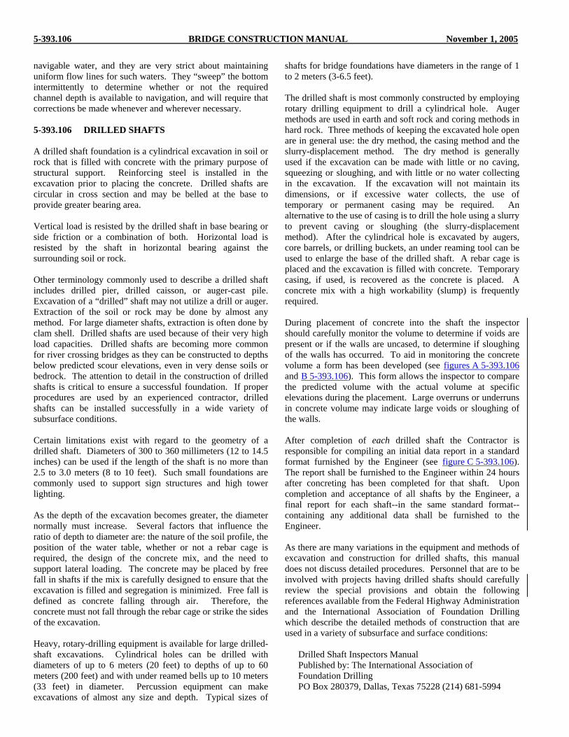
navigable water, and they are very strict about maintaining uniform flow lines for such waters. They “sweep” the bottom intermittently to determine whether or not the required channel depth is available to navigation, and will require that corrections be made whenever and wherever necessary. 5-393.106 DRILLED SHAFTS A drilled shaft foundation is a cylindrical excavation in soil or rock that is filled with concrete with the primary purpose of structural support. Reinforcing steel is installed in the excavation prior to placing the concrete. Drilled shafts are circular in cross section and may be belled at the base to provide greater bearing area. Vertical load is resisted by the drilled shaft in base bearing or side friction or a combination of both. Horizontal load is resisted by the shaft in horizontal bearing against the surrounding soil or rock. Other terminology commonly used to describe a drilled shaft includes drilled pier, drilled caisson, or auger-cast pile. Excavation of a “drilled” shaft may not utilize a drill or auger. Extraction of the soil or rock may be done by almost any method. For large diameter shafts, extraction is often done by clam shell. Drilled shafts are used because of their very high load capacities. Drilled shafts are becoming more common for river crossing bridges as they can be constructed to depths below predicted scour elevations, even in very dense soils or bedrock. The attention to detail in the construction of drilled shafts is critical to ensure a successful foundation. If proper procedures are used by an experienced contractor, drilled shafts can be installed successfully in a wide variety of subsurface conditions. Certain limitations exist with regard to the geometry of a drilled shaft. Diameters of 300 to 360 millimeters (12 to 14.5 inches) can be used if the length of the shaft is no more than 2.5 to 3.0 meters (8 to 10 feet). Such small foundations are commonly used to support sign structures and high tower lighting. As the depth of the excavation becomes greater, the diameter normally must increase. Several factors that influence the ratio of depth to diameter are: the nature of the soil profile, the position of the water table, whether or not a rebar cage is required, the design of the concrete mix, and the need to support lateral loading. The concrete may be placed by free fall in shafts if the mix is carefully designed to ensure that the excavation is filled and segregation is minimized. Free fall is defined as concrete falling through air. Therefore, the concrete must not fall through the rebar cage or strike the sides of the excavation. Heavy, rotary-drilling equipment is available for large drilled-shaft excavations. Cylindrical holes can be drilled with diameters of up to 6 meters (20 feet) to depths of up to 60 meters (200 feet) and with under reamed bells up to 10 meters (33 feet) in diameter. Percussion equipment can make excavations of almost any size and depth. Typical sizes of
shafts for bridge foundations have diameters in the range of 1 to 2 meters (3-6.5 feet). The drilled shaft is most commonly constructed by employing rotary drilling equipment to drill a cylindrical hole. Auger methods are used in earth and soft rock and coring methods in hard rock. Three methods of keeping the excavated hole open are in general use: the dry method, the casing method and the slurry-displacement method. The dry method is generally used if the excavation can be made with little or no caving, squeezing or sloughing, and with little or no water collecting in the excavation. If the excavation will not maintain its dimensions, or if excessive water collects, the use of temporary or permanent casing may be required. An alternative to the use of casing is to drill the hole using a slurry to prevent caving or sloughing (the slurry-displacement method). After the cylindrical hole is excavated by augers, core barrels, or drilling buckets, an under reaming tool can be used to enlarge the base of the drilled shaft. A rebar cage is placed and the excavation is filled with concrete. Temporary casing, if used, is recovered as the concrete is placed. A concrete mix with a high workability (slump) is frequently required. During placement of concrete into the shaft the inspector should carefully monitor the volume to determine if voids are present or if the walls are uncased, to determine if sloughing of the walls has occurred. To aid in monitoring the concrete volume a form has been developed (see figures A 5-393.106 and B 5-393.106). This form allows the inspector to compare the predicted volume with the actual volume at specific elevations during the placement. Large overruns or underruns in concrete volume may indicate large voids or sloughing of the walls. After completion of each drilled shaft the Contractor is responsible for compiling an initial data report in a standard format furnished by the Engineer (see figure C 5-393.106). The report shall be furnished to the Engineer within 24 hours after concreting has been completed for that shaft. Upon completion and acceptance of all shafts by the Engineer, a final report for each shaft--in the same standard format--containing any additional data shall be furnished to the Engineer. As there are many variations in the equipment and methods of excavation and construction for drilled shafts, this manual does not discuss detailed procedures. Personnel that are to be involved with projects having drilled shafts should carefully review the special provisions and obtain the following references available from the Federal Highway Administration and the International Association of Foundation Drilling which describe the detailed methods of construction that are used in a variety of subsurface and surface conditions:
Drilled Shaft Inspectors Manual Published by: The International Association of Foundation Drilling PO Box 280379, Dallas, Texas 75228 (214) 681-5994

November 1, 2005 BRIDGE CONSTRUCTION MANUAL Figure A 5-393.106

Figure B 5-393.106 BRIDGE CONSTRUCTION MANUAL November 1, 2005

November 1, 2005 BRIDGE CONSTRUCTION MANUAL Figure C 5-393.106
MINNESOTA DEPARTMENT OF TRANSPORTATION DRILLED SHAFT REPORT
Bridge No. S.P. No. Pier No. Shaft No. Prime Contractor Drilled Shaft Contractor Mn/DOT Inspector GENERAL INFORMATION OBSTRUCTIONS Date Shaft Construction Started Description of Obstructions Encountered in Earth Shaft Date Shaft Construction Completed River Pool Elev. Water Temp. Construction Method: Wet Dry Removal Methods and Tools Used SHAFT INFORMATION Permanent Casing Dia.: Plan mm As-built mm ROCK SHAFT CLEANOUT PROCEDURE Date Permanent Casing Set Method Bottom Elev. of Permanent Casing Top Elev. of Finished Shaft: Plan Estimated Thickness of Sediment at Bottom of Shaft at Time As-built of Concreting Elev. of Initial Contact of Rock Bottom Elev. of Drilled Shaft CONCRETE PLACEMENT OBSERVATIONS Rock Shaft Dia. Plan mm, As-built mm Concrete Mix No. Placement Date DRILLING INFORMATION Ambient Temperature Drill Rig Make and Mdl. Placement Method Total Placement Time Drilling Tools Used: Water Elev. in Shaft at Time of Conc. Placement VARIATION OF SHAFT FROM PLUMB AND PLAN Excavation Tools Used: LOCATIONS Plumb Lateral Earth Drilling Start Date , Finish Date Rock Drilling Start Date , Finish Date REMARKS/COMMENTS/NOTES Excavation Finished Date Location and Extent of Rock Cavities or Shaft Caving:
5-393.107 BRIDGE CONSTRUCTION MANUAL November 1, 2005
Drilled Shafts, Publication No. FHWA HI-88-042 Published by: U.S. Dept of Transportation Federal Highway Administration Office of Implementation, McLean, VA 22101
5-393.107 FOOTINGS The design of substructure units is, in part, based on information contained on the survey sheet. The borings will indicate soil types encountered and the approximate vertical limits of each type; the blow counts will give an indication of soil densities. When foundation conditions are found to be quite different than shown on the survey sheet, the Engineer should be notified. Depending on the situation, it may necessitate lowering or raising the footings, eliminating or introducing piling, changing pile types, or lengths increasing the size of the footings, or any of several other alternatives. If the Bridge Office is to be notified of the change in conditions, be sure to submit complete and detailed information of the findings, including additional borings below the footing elevations. When a substructure footing is to be placed on a natural foundation, without the use of piling, it is very important that the material encountered at the bottom of the footing be uniform, and that it be capable of supporting the design load. It is also important that uniformity exists for some distance below the bottom of the footing; and again, it would be prudent to obtain additional soils information when there is any reason for doubt. When the footing is to be placed on a recently constructed fill of considerable height, special provisions may require a waiting period, overload or particular sequence of construction. Settlement plates may be required and construction of a substructure may be dependent on analysis of settlement readings. Information regarding installation and monitoring of settlement plates and additional information is available from the Mn/DOT Foundations Unit. In some cases, the plans specify that soil load bearing tests be made on foundations to determine whether or not piling will be required. When necessary, the special provisions will outline the procedure and sequence of loading in detail. When materials encountered at the established footing elevation are such that they are likely to flow into and contaminate the concrete when it is deposited, correction should be made by one of the methods outlined in Specification 2451.3. The contractor should be cautioned that any contamination of foundation areas due to careless operations by his or her forces, must be corrected at his or her expense. If troublesome springs or boils occur in the footing area of an excavation, run-off water should be diverted before placing concrete. This can usually be accomplished by means of an inverted trough placed below grade. If several
smaller springs occur, the flow can be controlled or diverted by means of a canvas placed over the area. Holes made in the canvas to permit piling to project through it should be sealed by wire wraps just above the ground line. Edges of the canvas inside the footing area should be buried, and drainage should be provided under the forms into the outer waterway. Well point systems may be necessary for excavations below the water table. The contractor is required to provide a dry excavation for structure construction at own expense. 5-393.108 FOUNDATION SOILS EXAMINATION AND SOIL BEARING TESTS When the plans indicate that footings are to be founded on undisturbed natural soils, without the use of piling, a thorough visual examination should be made of the foundation soils as soon as excavation operations have been completed for a unit. Even when it seems apparent that the material at the bottom of the excavation is the same as shown in boring logs, a sufficient number of hand borings should be taken to establish the uniformity of the material to adequate depths. The assistance of the District Soils Engineer should be obtained whenever there is any question regarding the quality of the material encountered during this examination. If the above investigation discloses questionable materials a determination should be made as to whether or not a soil bearing test would serve any useful purpose, taking into account the costs for such tests. There is, of course, nothing to be gained from making a soil bearing test if it is evident from visual examination and hand soundings that the foundation material is definitely unsuitable. Also, the presence of rocks and boulders, or of a water table above the bottom of the footing, would generally preclude obtaining reliable information from soil bearing tests. Bear in mind that soil bearing tests do not, by themselves, constitute a basis for evaluation of the capacity of a foundation material to sustain high loads over an extended period of time, but are only an additional tool to be considered along with all other available information. When it has been determined that a soil bearing test is desirable, the test should be made in accordance with instructions from the Mn/DOT Foundations Unit and any special provisions applying thereto. A record should be kept of all dial readings taken, and the information plotted on a graph on as shown on Figure A 5-393.108. A separate sheet, or sheets, showing the results of the visual examination and the borings should be included with the above reports, and two complete sets of the complete report forwarded to the Bridge Construction and Maintenance Engineer, along with the Project Engineer’s recommendations. Final determination regarding the foundation design will then be made by the Bridge Office and appropriate notification made. When expediency is essential, the results of the test, along with other pertinent information and recommendations, may be telephoned to the Bridge Construction Unit, but the required reports should follow immediately as a means of documentation.

November 1, 2005 BRIDGE CONSTRUCTION MANUAL Figure A 5-393.108

5-393.109 BRIDGE CONSTRUCTION MANUAL November 1, 2005
An intelligent determination regarding the adequacy of the supporting soils to support design loads can only be made when complete and accurate information is available from the field. The type of design and the cost of changing to a pile foundation may further influence the final decision. In some cases the dimensions of the footings may be increased to reduce the square-foot loading rather than change to a pile foundation design. The general specifications permit the Engineer to delay all construction, except for foundation excavation, until test conclusions have been determined for all tests which may have an influence on the type of construction to be used. Discretion should be exercised in the application of this specification, however, so as to not unduly delay the work. Substructure units constructed on spread footings, except when founded on rock or other unyielding materials, should be checked for settlement or movement subsequent to construction. In the case of abutments which are to be constructed on high embankments, movement checks should be started as soon as the footings have been completed. The results of these follow-up checks should be forwarded to the Bridge Construction Engineer, so that the Bridge Office may be kept fully informed of the success or failure of this type of foundation design, and so that this information can be used as a guide for future design. 5-393.109 BACKFILL - GENERAL Too much emphasis cannot be made on the importance of properly constructed backfills. This work calls for careful inspection and requires a constant presence during the entire operation. Particular attention must be paid to tamping the areas next to the structure and areas which cannot be reached with the motorized equipment. When the backfill material is too wet, it should be dried before placing it in back of closed abutments or walls. Pneumatic tampers or portable vibratory compactors should be used to compact backfill immediately adjacent to structures, when it is impossible or impractical to use heavy compaction equipment. Vibratory compactors are particularly effective in granular materials. Hand tamping is unsatisfactory where high densities are required and should generally be discouraged. On bridge abutments, the entire excavation behind the abutment must be backfilled using approved granular material. It may not be necessary to excavate to the lines shown as the limit for granular backfill if the embankment is granular as originally constructed. Backfill should be brought up evenly to the elevation shown on the plans. Granular material must be placed in not more than 200 mm (8 inches) layers (lifts) and should have sufficient moisture to facilitate compaction. The amount of fine material is limited by specification to assure that material will drain freely into subdrains.
Backfilling as discussed in this article includes not only the backfill up to the original ground line but also the embankment material that is placed on one or both sides of the structure and immediately adjacent to it above the original ground line. It includes that part of the approach fill which lies next to the structure. The Specifications provide that backfill behind an abutment or wall shall not be placed above the backfill in front of the wall for a specified number of days after the concrete is poured. In addition, it is required that abutments that are designed as beams rather than as cantilevers (such as in slab and rigid frame bridges) may not be backfilled until the superstructure is completed and the falsework removed. 5-393.110 BACKFILL - CULVERTS When backfilling culverts, the material used must have sufficient moisture to permit required compaction. Loose layers must not exceed 200 mm (8 inches). Rollers may be used, but hand operated mechanical tampers must be used to secure proper compaction in the area immediately adjacent to the culvert which the roller cannot reach. Backfill should be placed and compacted on both sides of the culvert to approximately the same elevation. Backfilling on one side to a considerable depth before placing material on the opposite side should not be permitted.
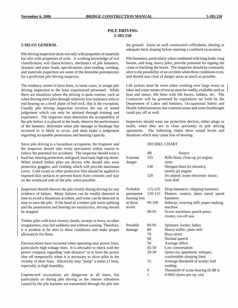
November 6, 2006 BRIDGE CONSTRUCTION MANUAL 5-393.150
PILE DRIVING 5-393.150
5-393.151 GENERAL Pile driving inspection deals not only with properties of materials but also with properties of soils. A working knowledge of soil classification, soil characteristics, mechanics of pile hammers, dynamic and static loads, specifications, plan reading, welding, and materials inspection are some of the desirable prerequisites for a proficient pile driving inspector. The tendency seems to have been, in some cases, to assign pile driving inspection to the least experienced personnel. While there are situations where the driving is quite routine, such as when driving steel piles through relatively low resistance soils to end bearing on a level plane of bed rock, this is the exception. Usually pile driving inspection involves the use of sound judgement which can only be attained through training and experience. The inspector must determine the acceptability of the pile before it is placed in the leads, observe the performance of the hammer, determine when pile damage or breakage has occurred or is likely to occur, and must make a judgement regarding acceptable penetration and bearing capacity. Since pile driving is a hazardous occupation, the Engineer and the inspector should take every precaution within reason to reduce the potential for accidents. The inspector should wear a hard hat, hearing protection, and good, hard toed, high top shoes. When treated timber piles are driven, s/he should also wear protective goggles, and clothing which will provide maximum cover. Cold cream or other protective film should be applied to exposed skin surfaces to prevent burns from creosote; and stay on the windward side of the pile, when possible. Inspectors should observe the pile closely during driving for any evidence of failure. Many failures can be readily detected in time to avoid a disastrous accident, and some can be detected in time to save the pile. If the head of a timber pile starts splitting and the penetration and bearing are satisfactory, driving should be stopped. Timber piles with knot clusters, bends, sweeps or bows, or other irregularities, may fail suddenly and without warning. Therefore, it is prudent to be alert to these conditions and make proper allowances for them. Electrocutions have occurred when operating near power lines, particularly high voltage lines. It is advisable to check with the power company regarding Asafe distance@ or to have the power shut off temporarily when it is necessary to drive piles in the vicinity of their lines. Electricity may Ajump@ a meter (3 feet), especially in high humidity. Unprotected excavations are dangerous at all times, but particularly so during pile driving as the intense vibrations caused by the pile hammer are transmitted through the pile into
the ground. Insist on well constructed cofferdams, shoring or adequate back-sloping before entering a confined excavation. Pile hammers, particularly when combined with long leads, long booms, and long, heavy piles, provide potential for tipping the crane or buckling the boom. The inspector should be constantly alert to the possibility of an accident when these conditions exist, and should stay clear of danger areas as much as possible. Life jackets must be worn when working over large rivers or lakes and some means of rescue must be readily available such as boat and motor, life lines with life buoys, ladders, etc. The Contractor will be governed by regulations set forth by the Department of Labor and Industry, Occupational Safety and Health Administration, but common sense and some forethought could pay off as well. Inspectors should wear ear protection devices, either plugs or muffs, when they are in close proximity to pile driving operations. The following charts show sound levels and durations which may cause loss of hearing: DECIBEL CHART
dB Source Extreme 155 Rifle blast; close-up jet engine; danger siren 140 Shotgun blast (to shooter); nearby jet engine
120 Jet airport; some electronic music; rock drill Probable 115-125 Drop hammers; chipping hammers permanent 110-115 Planers; routers; sheet metal speed hearing loss hammers at these 99-100 Subway; weaving mill; paper-making levels machine
90-95 Screw machines; punch press; riveter; cut-off saw Possible 80-95 Spinners; looms; lathes damage 80 Heavy traffic; plate mill
70 Busy street 60 Normal speech 50 Average office 45-50 Low conversation 20-30 Quiet city apartment; whisper;
comfortable sleeping limit 15 Average threshold of acuity; leaf
rustling 0 Threshold of acute hearing (0 dB is 1 0.0002 dynes per sq. cm)

5-393.152 BRIDGE CONSTRUCTION MANUAL November 6, 2006
Sustained exposure to dB above the upper levels may cause vibration of cranial bones, blurred vision, even weakening of body muscular structure. Frequencies of 500-2,000 Hz are most critical to noise-inducing hearing loss. When the daily noise exposure is composed of two or more periods of noise exposure of different levels, their combined effect should be considered rather than the individual effect of each. Exposure to impulsive or impact noise should not exceed 140 dB peak sound level. Protection against the effects of noise is required by federal regulations when the sound level exceeds those shown below: Duration per day, hours Sound Level dB
Slow Response 8 90 6 92
4 95 3 97 2 100 1-2 102 1 105 2 110 3 or less 115
Authorities generally agree that loss of hearing is caused by prolonged exposure to noise rather than old age. Loss is probably caused by progressive destruction of nerve ends when the sound level exceed 80 decibels (dB). Definite danger of permanent impairment exists at levels above 95 dB and continued exposure to this loudness level in the 300 to 1200 Hz range makes personal hearing protection necessary. Ear protectors may be secured from engineering stores in the District office. 5-393.152 USE OF SURVEY SHEET The survey sheet or sheets attached to the bridge plan includes soils information in the form of borings and soundings. Except in the case of driving through soft overburden to rock, both soundings and boring logs are essential. This information, although intended primarily for the designer, can be very beneficial to the inspector and to the Contractor and it behooves the pile driving inspector to study it carefully. Careful study of the soils information will indicate depths at which: 1. hard driving will likely be encountered 2. rocks and boulders may cause problems 3. weak soil layers which should be penetrated, 4. layers of dense material which may be of adequate depth to
support pile loads without the necessity of driving through them.
The soil borings are now almost always taken with a standard apparatus (standard penetration test - SPT), consisting of a 63.5 kg (140 lb) mass which is dropped 760 mm (30 in.). Some older bridge plans show soundings, using a 22.7 kg (50 lb) mass with a 600 mm (24 in.) drop. Sounding rods, with couplings at the end of every 1200 mm (4 ft) section, tend to pick up resistance in addition to that which the special point encounters. Therefore, the blow count per 0.3 meter (1 ft) almost always increases with depth for that apparatus, whereas with the standard penetration equipment only point resistance is measured. It is also important that the soils information is available for some distance below the anticipated pile tip elevation to assure a supporting layer of adequate depth. Soil types are generally indicated on the survey sheet by the use of letters, to conserve space. Following is a key to the textural soil classification system:
Organic Org. Sand or Sandy S Silt or Silty Si Clay C Loam or Loamy L Fine F Medium M Coarse Cr. Gravel G. Till T Plastic Pl. Slightly plastic Slpl
Combination of the above can be written as follows:
Silty Clay Loam SiCL Clay Loam CL Silt Loam SiL Slightly plastic fine Sandy Loam Slpl FSL Loamy Sand LS Coarse Sand Cr.S. Sand and Fine
Gravel S & FG Sandy Loam Till SLT
Peat, muck, marl or any special swamp material designation should be written out, and the color of the material should be abbreviated as follows:
Black blk. Brown bwn. Gray gr. Yellow yel. Dark dk.

November 6, 2006 BRIDGE CONSTRUCTION MANUAL 5-393.153 (1)
Other colors will be written out. Notes stating Awater encountered@ do not necessarily imply water table elevation as the drilling process requires either a cased hole or use of Adrilling mud@ which may cause changes in water elevations. 5-393.153 PILE NOMENCLATURE Pile (Webster=s Dictionary): AA long slender member usually of timber, steel, or reinforced concrete driven into the ground to carry a vertical load as in the case of a bearing pile, to resist a lateral force, as well as a vertical force, as in the case of a batter pile (which is driven at an angle with the vertical), or to resist water or earth pressure as in the case of a sheet pile.@ This section of the manual will cover only bearing piles, which for our purpose includes pile bents, test piles, foundation piles, and trestle piles, but not sheet piles. For Mn/DOT bridge structures, piles are used: 1. whenever the soils at and below the elevation of the bottom
of the footings are too weak or too compressible to provide a stable foundation for a spread footing, or
2. where there is danger of erosion or scour such as in streams,
or 3. where there is a thrust against the walls or columns which
might result in horizontal movement. Piles are supported by end bearing on rock, or other dense formations such as gravel or hard pan; or by friction between the surface of the pile and the adjacent soil; or by a combination of end bearing and friction. In order to design a pile foundation, it is necessary for the designer to know what type of support can be expected, which in turn necessitates information that can only be obtained by adequate borings and soundings. Friction piles are usually displacement type piles such as timber, concrete, or cast-in-place concrete utilizing steel shells, which obtain most of their load carrying capacity through friction resulting from perimeter contact with the soil. The required length of this type of pile is difficult to predict. Load tests may be required to ensure adequate bearing. Steel H-piles are sometimes used as friction piles, particularly when the soil borings indicate the presence of rocks and boulders, or when considerable resistance buildup is anticipated such as in medium to heavy plastic soils. End-bearing piles are those for which the tip of the pile is driven to rock, or a short distance into hard pan or dense gravel adequate to carry the design load without reliance on friction. Almost any type of pile can be used as an end bearing pile, but because of their high load carrying capacity and their capability of penetrating relatively dense soils, steel H-piles are often selected. However, cast-in-place concrete piles can also be used as end bearing piles when the soils information indicates that they can be driven to the required tip elevation, or when they are
desired for the sake of appearance, as in a pile bent. Drilled shafts may also be used for end bearing piles but are generally more expensive than steel H or cast-in-place concrete piles. Friction-end-bearing piles are those which derive their load-carrying capacity by a combination of friction and end bearing. Justification for high loads on this type of pile may require pile load tests. Cast-in-place concrete piles, utilizing steel shells, are probably best suited for this type of foundation design, although either timber or steel H-piles may also be used. Timber piles are displacement piles and generally obtain most, if not all, of their load carrying capacity through friction. Timber piles are seldom used on trunk highway bridges due to their relatively low capacity. The use of timber piles is also prohibited from use in pile bent substructures located in streams or rivers due to their low resistance to lateral loads induced by ice flows or debris. The most common use of timber pilling on trunk highway bridges is for abutments of temporary bridges. Specification 3471 specifies the species that may be used for the various applications, as well as other requirements such as straightness, knots, peeling, twist, density and dimensions. Timber piles are classified by 3471 in three categories: (1) Untreated Foundation Piles Below Water Level; (2) Untreated Trestle Piles; (3) Treated Piles. 1. Untreated Timber Foundation Piles are timber piles which
do not require a preservative treatment because they will be totally and permanently below the water level, therefore no wetting and drying cycles. Other considerations in specifying the use of untreated timber would be that the water be free of acid or alkaline wastes and from harmful marine life.
2. Untreated Timber Trestle Piles are not used for highway
structures, except for temporary trestles and bypasses. 3. Treated Timber Piles are by far the most commonly used
timber piles for our structures. When treated in accordance with Spec. 3491, they have excellent resistance against rot, acids and alkaline wastes, marine life, bacteria, and wetting and drying cycles. Because of their resistance to attack from the above-named sources, treated timber piles can be used above or below water and under most types of adverse conditions. A booklet by Dames and Moore, published by American Wood Preservers Institute, entitled Pressure Treated Timber Foundation Piles, is a very good source of information on this product.
Steel H-piles are rolled sections which are made up in a variety of sizes and from various grades of steel. Currently Mn/DOT Specifications require ASTM A572M/A572 Grade 345 (50) steel, and sizes commonly used are HP 250x62 (10 x 42) and HP 310x79 (12 x 53) (HP indicates an AH@ section pile, 250 (10) indicates 250 mm (10 in.) in cross section depth, and 62 (42) indicates a mass of 62 kg/m (42 lbs/ft)). Steel H-piles, because of their comparatively small area in cross section, displace a

5-393.153 (2) BRIDGE CONSTRUCTION MANUAL November 6, 2006
minimum volume of soil. Hence, steel H-piles can be driven through fairly dense material, even into soft rock, making them a popular choice when these conditions are anticipated. They have great strength and toughness and can be driven to depths exceeding 61 m (200 feet) by splicing additional sections on to those already driven. Pile tip protection is sometimes required where driving conditions are difficult and there is concern about damage to the pile tip. Steel H-piles are generally driven with manufactured pile tip protection welded to the end. The pile tip protection also helps to "seat" the pile when driven to bedrock or into hard pan materials. In most cases steel H-piling is used where difficult driving conditions are anticipated but occasionally conical points are welded to steel shell piling for this purpose. Approved tip protection will be listed in the special provisions. ASTM A6/A6M is the defining standard for H-shapes. Bethlehem Steel Corporation=s Booklet 2196, and United States Steel Corporation=s ADUCO 25002, both entitled Steel H-Piles, are good informational sources on this product, also. Where steel H-piles are required on the plans, thick wall steel pipe is often allowed in the special provisions as a contractor=s option. This pipe, with a minimum wall thickness of about 13 mm (2 inch), is made of high strength steel for use in exploration drilling for oil. Material available for bridge construction has been rejected for its intended oil field use but is suitable for piling. These pilings are very resistant to damage because of their cylindrical shape and high strength steel. Welding is more difficult than for A709/A709M Grade 250 (36) steels and preheating is required. The preheat temperature is dependent on carbon equivalent content which is determined from test data by the ITW Carbon Equivalent Formula (assuming zero cobalt content) as follows:
Cq = C + Mn/6 + (Cr + Mo + V) / 5 + Ni / 15 A chemical analysis for carbon, manganese, chromium, molybdenum, vanadium and nickel must be furnished by the manufacturer. Contact the Mn/DOT Metals Quality Engineer in the Bridge Office for more information. Pile tip protection is not required for thick wall pipe as the material strength is about equal to a cast steel point. When available, the material cost per meter (foot) is generally less than an equivalent H-pile and where pile points are necessary for H-piling, the elimination of these points is an additional cost saving factor. The piles are driven open-ended and filled with sand or concrete after driving has been completed. Cast-in-place piles of the type currently being specified require that steel shells (generally with closed ends) be driven to required penetration and bearing, checked for buckling, then filled with concrete. The thickness of the shell must not be less than the minimum specified, and must be increased if necessary to withstand the required driving. Unless noted otherwise, the minimum wall thickness is specified in 3371. The Specifications permit the Contractor the option of using either tapered or
cylindrical shells with certain specific requirements regarding yield strength, wall thickness, diameter, and capability to withstand driving to substantial refusal. Cast-in-place concrete piles of uniform cylindrical section will cause more displacement than will timber piles or tapered cast-in-place piles. However, since the pile shell is of constant diameter with a relatively smooth outer surface, friction does not build up as readily along its surfaces as in the case of tapered piles. Because of the generally larger diameter at the tip, cylindrical piles are likely to develop greater end bearing capacity when dense soils are encountered. One of the advantages of this type of pile is the ability to visually inspect for straightness and for damage after driving. Unless conical points are specified, steel shell pile will have a steel driving "shoe" welded to the base. The shoe thickness for 310 mm (12 in.) and 406 mm (16 in.) is 19 mm (3/4 in.). The shoe is simply a steel plate that keeps soil out, and the pile remains watertight. The shoe shall not extend more than 6 mm (1/4 inch) outside of the periphery of the shell. The most common cast-in-place pile sizes for bridge designs in Minnesota are 310 mm (12 in.) O.D., 324 mm (12 3/4 in.) O.D., and 406 mm (16 in.) O.D., although 254 mm (10 in.) O.D., 508 mm (20 in.) O.D., and 610 mm (24 in.) are sometimes used. Precast concrete piles are rarely used for Mn/DOT structures because of their mass and because of the difficulty encountered when splicing becomes necessary. Except for their driving mass, their performance can be compared with the cast-in-place concrete piles. Greater care must be exercised during driving to keep the pile and the pile hammer in proper alignment, so that the hammer blows will be delivered squarely. A pile cushion made of plywood, hardwood or a composite of plywood and hardwood materials is required to protect the pile head during driving. Hammer blows delivered to the top of a concrete pile slightly out of alignment with the hammer are likely to cause damage by shattering the concrete on the side receiving the impact. Drilled shafts (also called caissons or drilled piers) are used occasionally for deep foundations although their use has been limited to special cases where end bearing can be obtained. Costs for drilled shafts are higher than for driven piling at the present time and only a few contractors have the special equipment required to place them. Plans and special provisions will provide detailed information on this type of piling. Drilled shafts are installed by augering a hole (casing may be necessary and is generally mandatory below water) to the depth specified. A series of holes of gradually decreasing diameter is often necessary where casings must be used. Careful inspection of the drilled hole and of concrete placement is necessary. For our purpose, test piles are used for determining the Aauthorized@ length of the remaining piles for a structure, or a portion of a structure. They are almost always carried as a separate pay item (or items if more than one length or type are

November 6, 2006 BRIDGE CONSTRUCTION MANUAL 5-393.154
involved) in the contract. The contractor usually includes a large part of his/her fixed costs in the price bid for test piles, because of the possibility that the remaining piles may be reduced in length. This results in a loss to the contractor if fixed costs were included in the bid price for APiling Delivered@ and APiling Driven@. The Specifications provide that: ATest piles will not be eliminated from the contract, unless all piles for the unit in which they are to be driven are eliminated, or unless mutually agreed upon by the Contractor and Engineer.@ Information gained from driving test piles should be compared with the soundings and borings on the Survey Sheet of the Plans when attempting to authorize foundation pile lengths. Penetration usually is considered to be the length of pile below cut-off elevation; that is, the total length of a pile which will remain in the structure. The term penetration is also used in connection with Apenetration per blow@, which is generally determined by taking an average of several blows of the pile driving hammer, or by counting the blows per 0.25 m (1 ft), and which is plugged into a capacity formula for determining the bearing capacity. APile Placement@ is a pay item used when test piles are not provided. Pile lengths are not authorized and the Contractor must drive all piling to substantial refusal or bearing satisfactory to the Engineer. The APile Placement@ item includes all costs of equipment, splicing, drive shoes or tip reinforcement, end plates, cut off, and other costs except furnishing pile material and driving the pile. Furnishing and driving is paid for as APiling Furnished and Driven@. 5-393.154 STORAGE AND HANDLING OF PILES When handling treated timber piles, use rope slings. Avoid the use of chain slings, hooks, or other methods that will break through the protective treatment. Avoid dropping the timber piles and bruising or breaking the outer fibers. It is advisable to stack treated timber piles for storage on timber sills so that the piles may be picked up without hooking. The application of preservative oil to cuts, holes and abrasions should not be minimized. This treatment is vital to the life of the timber pile and is important enough to warrant careful attention. Concrete piles must be handled with care. It is very easy to cause cracks by indifferent handling. Cracks may open up under driving, and may spall and Apowder@ to such an extent as to seriously lessen the strength or life of the pile. Shock, vibration, or excessive deflection should be avoided by using proper equipment and thoughtful handling. When piles are picked up with adjustable slings, blocking should be used to prevent breaking off the corners. Unless special lifting devices are attached, the pick-up points shall be plainly marked on all piles before removal from the casting bed and all lifting shall be done at these points. If the piles have been allowed to dry after curing, they shall be wetted at least 6 hours before being driven and shall be kept moist until driven. When loading steel H-piles at the fabricator=s plant, the individual piles must be placed with webs vertical and blocked
so that the flanges will not be bent. There is perhaps greater danger of damage to the steel when it is unloaded from the car, hauled to the work, and unloaded from the truck or trailor at the site. The project inspector must observe that the handling methods at the jobsite are performed carefully to avoid damage to the piles. 5-393.155 SPLICING PILES Welding of piling splices must be made by properly qualified welders. For most field welding, Specifications require a welder to have passed a Mn/DOT qualification test. The welder should have a valid Mn/DOT welder certification card. The welder must show proof of certification when asked. If the card is current, this is acceptable as sufficient evidence of a welder=s ability. The inspector should verify that each welder is properly certified. Information on welder certification and verification of certification can be obtained from the Structural Metals Inspection Unit. Those responsible for administering the construction contract are also responsible for materials certification for steel piling. The inspector should retain all copies of purchase orders, test reports and Form 2415 listing heat numbers and condition of piling. The Mn/DOT Structural Metals Engineer can help answer questions regarding welder qualification, welding work in general or sampling and testing of steel piling. 5-393.156 JETTING AND PREBORING Jetting is a means of obtaining pile penetration through elimination or reduction of resistance at the pile tip by the use of water, air, or a combination of these two media, delivered by pressure through hoses and pipes. The soil is eroded below the tip of the pile, often permitting penetration merely by the dead mass of the pile and the hammer. It is particularly effective when displacement type piles are to be driven through dense fine sand to desired penetration in firm soils below, but should not be used in embankments or other areas where it would tend to destroy densities which have been purposely built into the soils. Also, unless good judgement is exercised, jetting could destroy the bearing value of piles already driven, especially when piles are closely spaced or when they tend to drift away from their prescribed course. Water jetting has been useful as an aid to driving displacement types of piles in sand formations in streams where water is readily available and pile penetration is equally as important as bearing capacity. Although the Specifications currently specify certain requirements pertaining to the jetting equipment, the prime objective should be that of performance. Equipment which would not be satisfactory in some cases may be entirely adequate in other cases. The booklet by Dames and Moore, referred to previously under Treated Timber Piling, describes various methods of jetting in considerable detail.
5-393.157 (1) BRIDGE CONSTRUCTION MANUAL November 6, 2006
Preboring, as the word implies, is merely boring holes through or into soils prior to driving piling. It is perhaps the most expedient and popular method of obtaining pile penetration of displacement piles through or into high density embankments, or through crusty upper stratum that must be penetrated because of weak underlying soils. Preboring is generally accomplished by the use of a power auger of a diameter larger than the maximum diameter of the piles to be driven, mounted on the crane used for the pile driving or on separate equipment. There are many variations of preboring equipment; some of these are covered in considerable detail in the previously mentioned booklet by Dames and Moore entitled Timber Foundation Pile Study. 5-393.157 DRIVING EQUIPMENT The drop hammer is the original pile driving hammer which has been used in one form or another for many years. It consists of a steel ram, forged to a shape that will permit it to be confined within a set of leads, and to be raised to desired height and dropped on the top of the pile. This type of hammer is now rarely used because of its slow operation and because the velocity at impact often results in pile breakage before the required penetration and bearing have been obtained. We have, through our Specifications, increased the requirements for hammer mass and reduced the height of fall, but even further adjustments are desirable. Greater efficiency and less damage would result from the use of a 2000 kg (4400 lb.) ram with a 1500 mm (5 foot) drop than from a 1000 kg (2200 lb.) ram with a 3000 mm (10 foot) drop. It is generally necessary to provide a steel pile cap to fit over the top of the pile, with a shock block on the top of the cap to absorb part of the impact. Although seldom used today, Single Acting Steam and Air Driven hammers replaced the drop hammer and were used to build many of the bridge and structures that are still in use today. Both of these hammers are basically drop hammers. The difference is that the ram (striking part) is encased in a steel frame work and is raised by steam or compressed air delivered through hoses from boilers or air compressors. The frequency of the blows is considerably higher than with a drop hammer, the ram mass is usually greater and the height of drop is considerably less. The increased frequency of the delivery cycle permits less time for the soils to settle back around the pile between blows, thereby further increasing the efficiency. A typical Single-Acting Steam or Air-Driven Hammer utilized a 2000 kg (4400 lb.) ram with a 900 mm (3 foot) drop, delivering approximately 60 blows per minute. A hammer of this size served very adequately for most pile driving (only when extremely long piles or when unusually high bearings were required were heavier hammers needed). It also had the added advantage from an inspection standpoint of providing for a positive check of the energy delivered by the hammer. To determine the actual energy output, in N@m (ft. lbs.), one merely multiplies the force of the ram times the height of the drop. If the drop could not be measured, "manufacturer=s rated energy" at operating speed was used with a 25 percent reduction in bearing values, per Specification 2452.3.
For Double-Acting Steam or Air Driven Hammers (including Differential-Acting and Compound Hammers) the ram is raised by steam or compressed air, as it is in the case of single-acting hammers. In addition, however, the same source of power is utilized for imparting a force on the downstroke, thus accelerating the speed of the ram. This creates the same effect as would be obtained by a considerably longer stroke of a single-acting hammer where no force other than gravity is available for the down stroke. Some double-acting hammers utilize a relatively light ram, operating at comparatively high frequencies, to develop energy blows comparable to those developed by considerable heavier, slower acting hammers. The advantage of higher frequencies is that less time is permitted for re-settling of the soils against the pile between blows, thus increasing driving efficiency and decreasing driving time. The disadvantage is that under some conditions considerable damage may be evidenced at the top of the pile, caused by high impact velocities. Therefore, the inspector should be particularly alert when a high velocity hammer is being used, since energy dissipated destroys a pile head. Only the energy which reaches the tip of the pile, or at the very least the center of resistance, is effective in producing additional penetration. The energy delivered by double-acting hammers is generally related to frequency (strokes per unit of time), and is usually obtained by referring to hammer speed vs energy charts furnished by the manufacturer. Maximum rated energy probably never would be attained in actual practice. Therefore, if energy charts are not available, Mn/DOT Specifications provide for a 25 percent reduction of the maximum rated energy. Diesel hammers are the most common type of hammer currently used in Minnesota bridge construction. They consist of a cylinder containing a ram and an anvil. The ram is raised initially by an outside power source (crane) and dropped as a drop hammer. As the ram drops, it actuates a fuel pump which injects fuel into the chamber or the anvil cup depending upon the make of the hammer. The heat of compression, or atomization by impact, ignites the fuel, expands the gases and forces the ram upward. Three makes of diesel hammers have been used considerably on pile driving in Minnesota. These are the Delmag, the MKT and the ICE (originally introduced as the Syntron, then as a Link-Belt). The Delmag and the MKT hammers operate similarly in that the ram is raised by the explosion to a height that is determined by the energy produced by the explosion and then dropped freely as a single-acting hammer. In the case of the ICE hammer, the ram raises against an air cushion in an upper chamber which is enclosed, compressing the air in that chamber. The compressed air, when the ram has reached its maximum height, starts the ram downward with added momentum, somewhat like a double-acting hammer. There are other variations in the operation of diesel hammers which affect their performance but which are considered to be beyond the scope of the general informational coverage of this manual. Additional information on operation and calibration of

November 6, 2006 BRIDGE CONSTRUCTION MANUAL 5-393.157 (2)
pile hammers can be found in AThe Pile Inspector=s Guide to Hammers@ published by the Deep Foundation Institute. Pile hammer manufacturers are usually quite accommodating about furnishing brochures on their equipment upon request. The energy delivered by diesel powered hammers is perhaps more variable and more dependent upon the resistance offered by the soils than is the case for other hammer types. Sudden energy surges develop whenever areas of high resistance to driving are encountered whereas areas of low resistance may cause malfunction by insufficient internal pressure to set off an explosion. The MKT company claims only the energy developed by the falling ram (WxH), whereas the Delmag Company also includes energy imparted by the explosion. Since the compression of the air by the ram tends to cushion the blow, Mn/DOT has selected the more conservative approach (WxH) as the most logical. The ICE Series include a gauge which measures back-pressure and from which energy output can be determined. If no gauges or other measuring devices are provided, the inspector should use a saximeter (see the end of section 5-393.161 for more information on the saximeter) or stop watch and the formula indicated in 5-393.161, or as a last resort, manufacturers= rated energy at operating speed reduced by 25 percent for use in the dynamic bearing formula. Vibratory and Sonic Power-Driven Hammers are the most recent developments in pile driving hammers. They are comparatively heavy, requiring handling equipment of greater capacity than required for conventional pile hammers. The two types (vibratory and sonic) are not synonymous, as sometimes believed. The vibratory hammer, as the term implies, vibrates the pile at frequencies and amplitudes which tend to break the bond between the pile surfaces and the adjacent soils, thus delivering more of the developed energy to the tip of the pile. The sonic hammer operates at higher frequencies than does the vibratory hammer, usually between 80 and 150 cycles per second, and is tuned to the natural resonant frequency of the pile. At this frequency the pile changes minutely in dimension and length with each cycle, thus alternately enlarging the cavity and then shortening the pile. Bearing values for these hammers would have to be determined by pile load tests. Current Specifications and pile driving formulas do not apply to these hammers. Pile hammer leads serve to contain the pile hammer and to direct its alignment so that the force of the blows delivered by the ram will be axial to the pile. They also provide a means for bracing long, slender piles until they have been driven to sufficient penetration to develop their own support. It is, therefore, essential that leads be well constructed and that they provide for free movement of the hammer but not to the extent that they permit noticeable changes in hammer alignment. For drop hammers it is especially important that the leads be straight and true, and that freedom of fall is unincumbered. If
there are any bends or other restrictions to free fall, they would tend to reduce the acceleration of the hammer and consequently the energy delivered. Timber leads should be steel shod and drop hammer leads should be greased to reduce friction. Three basic types of leads are described in Figure A 5-393.157; of these, the swinging leads are most common on Mn/DOT projects. Bases, Anvil Blocks, Driving Caps, Adapters and Shock Blocks are accessories which are required in varying combinations and types, depending upon the type, make and model of hammer and upon the type and size of the piles being driven. The best assurance that the proper types and combinations are being used is to follow the recommendations of the pile hammer manufacturer as given in their brochures or catalogues. These items protect the pile and the hammer against destructive impact and keep the pile head properly positioned with the leads. Shock blocks are required particularly when driving precast concrete piles, since the impact would otherwise shatter the comparatively brittle concrete. Also, the proper arrangement and combination of these accessories will tend to distribute the impact more uniformly over the top surface of the pile, thus protecting it against eccentric blows which might otherwise cause failure of the butt of the pile before required penetration and bearing is obtained. Excessive thickness of shock block material, particularly soft wood or spongy material will reduce the energy delivered to the top of the pile and should be avoided. Except for self-contained power source hammers such as diesels, vibratory and sonic hammers, an outside power source is required for power-driven hammers. Not long ago steam boilers were used exclusively for developing power; however, currently boilers have been replaced by air compressors. Regardless of the source, adequate power must be supplied if the hammer is to function properly. When an adequate power source is not supplied, continuous driving will deplete the supply to the extent that malfunction will generally result. This usually means that the hammer will operate at something less than specified stroke or frequency, or both, or that it will cease operating entirely until sufficient power build-up has been attained.
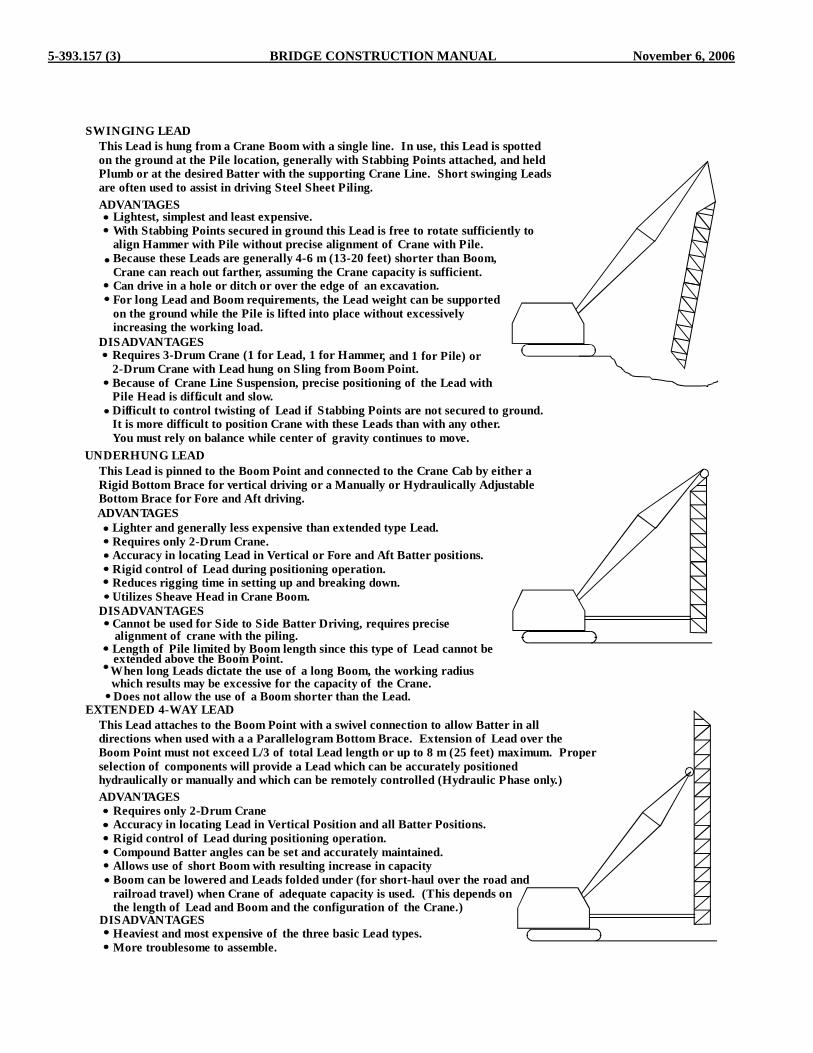
5-393.157 (3) BRIDGE CONSTRUCTION MANUAL November 6, 2006
SWINGING LEADThis Lead is hung from a Crane Boom with a single line. In use, this Lead is spottedon the ground at the Pile location, generally with Stabbing Points attached, and heldPlumb or at the desired Batter with the supporting Crane Line. Short swinging Leadsare often used to assist in driving Steel Sheet Piling.ADVANTAGES
ADVANTAGES
ADVANTAGES
Lightest, simplest and least expensive.With Stabbing Points secured in ground this Lead is free to rotate sufficiently toalign Hammer with Pile without precise alignment of Crane with Pile.Because these Leads are generally 4-6 m (13-20 feet) shorter than Boom,Crane can reach out farther, assuming the Crane capacity is sufficient.Can drive in a hole or ditch or over the edge of an excavation.For long Lead and Boom requirements, the Lead weight can be supportedon the ground while the Pile is lifted into place without excessivelyincreasing the working load.
DISADVANTAGES
DISADVANTAGES
DISADVANTAGES
Requires 3-Drum Crane (1 for Lead, 1 for Hammer, and 1 for Pile) or2-Drum Crane with Lead hung on Sling from Boom Point.Because of Crane Line Suspension, precise positioning of the Lead withPile Head is difficult and slow..Difficult to control twisting of Lead if Stabbing Points are not secured to ground.It is more difficult to position Crane with these Leads than with any other.You must rely on balance while center of gravity continues to move.
UNDERHUNG LEADThis Lead is pinned to the Boom Point and connected to the Crane Cab by either aRigid Bottom Brace for vertical driving or a Manually or Hydraulically AdjustableBottom Brace for Fore and Aft driving.
Lighter and generally less expensive than extended type Lead.Requires only 2-Drum Crane.Accuracy in locating Lead in Vertical or Fore and Aft Batter positions.Rigid control of Lead during positioning operation.Reduces rigging time in setting up and breaking down.Utilizes Sheave Head in Crane Boom.
Cannot be used for Side to Side Batter Driving, requires precise
Length of Pile limited by Boom length since this type of Lead cannot beextended above the Boom Point.When long Leads dictate the use of a long Boom, the working radiuswhich results may be excessive for the capacity of the Crane.Does not allow the use of a Boom shorter than the Lead.
EXTENDED 4-WAY LEADThis Lead attaches to the Boom Point with a swivel connection to allow Batter in alldirections when used with a a Parallelogram Bottom Brace. Extension of Lead over theBoom Point must not exceed L/3 of total Lead length or up to 8 m (25 feet) maximum. Properselection of components will provide a Lead which can be accurately positionedhydraulically or manually and which can be remotely controlled (Hydraulic Phase only.)
Requires only 2-Drum CraneAccuracy in locating Lead in Vertical Position and all Batter Positions.Rigid control of Lead during positioning operation.Compound Batter angles can be set and accurately maintained.Allows use of short Boom with resulting increase in capacity.Boom can be lowered and Leads folded under (for short-haul over the road andrailroad travel) when Crane of adequate capacity is used. (This depends onthe length of Lead and Boom and the configuration of the Crane.)
Heaviest and most expensive of the three basic Lead types.More troublesome to assemble.
alignment of crane with the piling.

November 6, 2006 BRIDGE CONSTRUCTION MANUAL 5-393.158
5-393.158 INSPECTION OF PILE DRIVING - TIMBER PILES As previously mentioned in 5-393.151, pile driving inspection is a very important function and is deserving of undivided attention. Some agencies specializing in piling go so far as to recommend that a trained soils engineer be present to approve each pile installation and to revise procedures as varying soil conditions are encountered. Certainly the inspector should have sufficient knowledge of soil types and characteristics so as to be able to relate the soils information shown on the survey sheet to the pile driving operations and difficulties. The inspector should be present at all times when piles are being driven. This is particularly true when driving timber piles because breakage below the ground surface may occur at any time and may be detected only by an alert inspector. It would also be true of any piles driven through or into hard strata, such as rock or hardpan, since the tips may be damaged by over-driving or carelessness unless a capable inspector is present. Treated timber piles are generally inspected for quality and treatment prior to delivery, and are impression-stamped so that the pile driving inspector will know that they have been inspected and approved. Occasionally a slightly under-size pile may get by the plant inspector. Specification 1503 states “all materials furnished shall be in conformance with the lines, grades, cross sections, dimensions, and material requirements, including tolerances, shown in the Plans indicated in the Specifications”. This gives the Engineer authority to use some discretion regarding acceptance of occasional borderline or slightly undersize piles. Piles which are slightly out of specifications for crooks or twists should be called to the attention of the foreman and accepted only if they can be satisfactorily driven without splitting or breaking. Untreated timber piles, except for treatment, are subject to the same inspection as are treated piles. However, these piles are often delivered to the jobsite without previous inspection; if so, complete inspection for type, quality, straightness, knots, peeling, density, and butt and tip diameters must be made at the site and reported on Form 2415. See Specification 3471. It is very important that timber piles in a bent be accurately located and properly driven, because little can be done to correct their alignment after driving without causing damage to the piles. The best procedure to assure accurate alignment is to drive the end piles for each bent first, using piles with the largest diameters, and then placing a heavy timber on each side long enough to extend beyond each end pile. These timbers should be tied to each other using bolts or scabs. The remaining piles in the bent can then be spotted and driven within this yoke or frame, which will assist in maintaining their alignment. A hole should be dug for each pile as a means of getting it started properly. Each pile should be observed very closely while it is being driven, to assure plumbness or specified batter. Also, when driving is hard, check closely for evidence of cracking, breaking or splitting, so that driving can be stopped before the pile is severely damaged.
The test pile for each unit is generally placed at one end so that the original pile number and spacing can be changed, if necessary to support the superimposed load. After the first unit has been driven, blocking can be used between this unit and the timber guides for the next unit. Extra care taken during the pile driving, with respect to the proper location of each pile, will minimize the problems encountered in placing the caps, bracing or backing. This is especially true with regard to the corner piles at abutments. Timber piles which do not line up properly after driving should be brought to line before making the cut-off, so that the top of the pile, after cut-off will be at correct elevation and plane and will provide full bearing for the pile cap. Wooden straight edges should be placed on each side of the pile bent to act as a guide for the saw, and the actual sawing should be done by experienced sawyers. Power saws are extremely difficult to control to the degree required for this type of work and should not be used except when the Contractor has demonstrated that the proper degree of accuracy can be obtained. Any portion of the top of the timber pile which projects outside of the front edge of the wing cap should be trimmed off with a sharp axe or adz in a neat manner to an approximate 45 degree slope down and outward from the front edge of the wing cap. Specifications (2452.3F) provide timber pile top cutoff requirements. Read these Specifications carefully, and use the method specified for the particular location. Regardless of the method used, the workmanship should be neat and systematic. Where zinc sheets are specified in the plans or special provisions for the tops of timber piles, the portion of the sheet which extends outside of the periphery of the pile should be folded down alongside the pile. The folds should then be creased and folded back against the pile. The folds should then be securely fastened to the pile with galvanized roofing nails. Rounding off the corners of a square sheet before placing will produce neater results than would otherwise be obtained. Fabric protection can be placed in much the same manner as described above for zinc sheets. Treatment of tops of timber piles with preservative is required prior to placement of zinc sheeting. 5-393.159 INSPECTION OF PILE DRIVING - STEEL PILES Steel pile is not inspected prior to delivery to the jobsite. Therefore, pile inspection must be performed by the project inspector. For Steel H-Piles and Steel Shells for Cast-In-Place Concrete piles, Specifications 3371 and 3372 require the Contractor to submit three copies of mill shipping papers and certified mill test reports for all steel piling prior to delivery of piling to the site. These mill test reports are provided by the

5-393.160 (1) BRIDGE CONSTRUCTION MANUAL November 6, 2006
producer steel mill and list physical properties and chemical analysis of each mill “heat” of steel involved, and specify domestic origin of steel and its manufacture. The contractor is responsible to verify that invoices and mill test reports correspond to piling delivered. Upon delivery, spot check identification markings on the steel to be certain the source and heat numbers match those on the mill test reports. At the same time, inspect the material for proper section size and gauge, physical defects such as kinks or buckles, and quality of welding. If any piece of piling is not marked with a heat number, the Project Engineer should have the Contractor test the material at an independent testing lab to ensure the pieces are associated with the mill test reports provided. Two tensile tests and one chemistry test should be conducted from one out of ten pieces of piling of the same size and thickness with unknown identity. Piles that are driven prior to material testing should be identified in the “Pile Driving Report”. Price adjustments or other determination can then be made at a later date, should this be necessary because of the deficiencies in the material. In any event, contractors should be made aware that piles driven prior to delivery of required materials information are subject to price adjustment until quality and domestic origin has been properly established. Welding for splices, except in isolated cases must be made by Mn/DOT certified welders. A typical exception might be when one or two unanticipated splices are necessary and a certified welder is not immediately available, but a reputable uncertified welder is available. Keep in mind that this should be interpreted as applying only to exceptional and isolated cases, and should not be general practice. See Section 5-393.155 for information regarding welding and welder certification. When trestle piles or pile bents are involved, painting requirements should be reviewed. Generally a complete prime coat is required for the full length of steel piles which extend above ground except for those sections below splices which are at least 600 mm (2 feet) below ground. Holes for handling steel H-piles should not be made in the flanges of the piles, except when they are made near the top of the pile and are to be included in the cut-off portion or in the portion which will be embedded in the concrete. Burning holes with a torch should not be permitted, even in the web of the pile, because of carelessness generally associated with the torch. It has been agreed, in a discussion with representatives of the Federal Highway Administration, that holes may be drilled in the webs near the longitudinal centerline of the pile, but that these holes should be no larger than necessary to accommodate the connector used for lifting the pile. In any event, caution must be observed when using holes in steel piles for handling purposes. Sharp or jagged edges may cut or fray the lifting cable, and thereby weaken it possibly causing premature failure. Although it is the Contractor’s responsibility to conduct his/her work in a safe manner, an alert inspector should report unsafe conditions to the foreman as well as to the Engineer in charge. Pile driving is an inherently dangerous operation, but precautionary measures can be done to improve
conditions. 5-393.160 PILE DRIVING FORMULAS Several methods have been developed to allow inspectors in the field to determine the capacity of a driven pile. One of the simplest methods allows the inspector to record certain pieces of data during pile driving (blows per foot (penetration), and energy) and by inputting this data into a mathematical formula, the pile capacity can be determined. This type of formula is often referred to as a "dynamic" pile formula because it converts the data from a dynamic process (pile driving) into a static force (the pile capacity or resistance). Different dynamic pile formulas are required, depending on the method used to design the bridge foundations. Prior to 2005 most bridge foundations in Minnesota were designed using the Allowable Stress Design (ASD) method. Starting in late 2005 the Load and Resistance Factor Design (LRFD) method was implemented for the design of foundations for most new trunk highway bridges. However, most non-trunk highway (county, city, township, etc.) bridges continue to be designed using the ASD method. The differences between these design methods can be explained as follows: The ASD method involves determining the load capacity for a given pile and reducing it by a safety factor to get what is called the allowable pile load. Then the design loads affecting the pile such as the weight of the concrete it supports, earth loads, traffic, etc. are added together, resulting in what is called the actual pile load. The actual pile load must be less than the allowable pile load in order for the design to be adequate. Some shortcomings of this method are:
• The safety factor is only applied to the capacity and not the load. ASD does not consider the fact different loads have different levels of uncertainty.
• Selection of the safety factor is subjective, and does not
consider the statistical probability of failure. This means that there is not a uniform level of safety for all designs.
When the ASD method is used, the bridge plan includes one pile load table for each substructure unit and the minimum load that piling should be driven to in the field is referred to as the “Design Load” in the table, see Figure A 5-393.160 for an example.
COMPUTED PILE LOADS - TONS/PILE D.L. & EARTH PRESSURE LIVE LOAD OVERTURNING * DESIGN LOAD
40.1 6.2 15.5 61.8
* 61.8 1.25
FIGURE A 5-393.160
= 49.5 REDUCTION AS PER AASHTO 3.22.1 GROUP III LOADING

November 6, 2006 BRIDGE CONSTRUCTION MANUAL 5-393.160 (2)
The LRFD method includes a safety factor on the loads applied to the pile and to the resistance of the pile. The safety factor applied to the load is called the load factor and increases the load based on the uncertainty of its magnitude. The safety factor applied to the resistance of a pile is called the resistance factor and reduces the resistance based on the uncertainty of its magnitude. The values used for the load and resistance factors are based on the statistical probability of failure and therefore provide a more uniform level of safety than the ASD method. For LRFD, the factored load must be less than the factored nominal pile bearing resistance in order for the pile design to be adequate. When the LRFD method is used, the bridge plans will include two pile load tables for each substructure unit. The first table will report the factored pile loads and the second table will report the load for driving, Rn , See Figure B 5-393.160 for an example.
PIER COMPUTED PILE LOAD –
TONS/PILE FACTORED DEAD LOAD 84.0
FACTORED LIVE LOAD 36.0
FACTORED OVERTURNING 0.0
* FACTORED DESIGN LOAD 120.0
* BASED ON STRENGTH I LOAD COMBINATION
PIER REQUIRED NOMINAL PILE BEARING RESISTANCE Rn
TONS/PILE FIELD CONTROL METHOD Фdyn *Rn Mn/DOT NOMINAL
RESISTANCE FORMULA 0.4 300.0
PDA 0.6 200.0
* Rn = FACTORED DESIGN LOAD / Фdyn
FIGURE B – 5-393.160 The inspector in the field will need to know which design methodology (ASD or LRFD) was used to design the bridge foundations, because each method uses a different dynamic formula to compute the pile capacity in the field. There are several ways to determine which design method was used on a particular bridge. The simplest is to review the "Construction Notes" on the first sheet of the bridge plans (this sheet shows the general plan and elevation of the bridge). If the foundations were designed using LRFD methodology the following note will appear "The pile load shown in the plans and the corresponding bearing capacity (Rn) was computed using LRFD methodology. Nominal pile bearing resistance determination in the field shall incorporate the methods and/or formulas described in the Special Provisions." The special provisions will include the nominal pile bearing resistance equation discussed in section 5-393.160B below. If the "Construction Notes" do not include the statements mentioned above, then the foundation was designed using the
ASD methodology and the inspector should use the dynamic formulas discussed in section 5-393.160A below. An alternative method to determine if the LRFD design methodology was used for the foundation design is to review the pile load tables shown in the bridge plans (the pile load table indicates the bearing resistance that the piles need to be driven to to support the structure). If the pile load tables are similar to that shown in Figure B 5-393.160, with a statement in the bottom table indicating "Required Nominal Pile Bearing Resistance Rn" then the foundation was designed using the LRFD design methodology and the special provisions will include the equation discussed in section 5-393.160B. If only one pile load table is shown for each substructure, and if it looks similar to that shown in Figure A 5-393.160 and it does not include the terminology "Required Nominal Pile Bearing Resistance Rn", then the inspector can assume that the foundation was designed using ASD methods and the dynamic formulas discussed in 5-393.160A should be used to determine the pile capacity in the field. A very significant difference between the two methods is the magnitude of the computed loads. Generally speaking, the loads computed using LFRD methodology will be approximately 3.0 - 3.5 times higher than loads computed using ASD methods. To better illustrate this, the table below indicates a range of "normal" capacities for several types of pile using each design method. ASD LRFD Rn Pile Type Load Range Load Range 12" CIP 60-75 tons 210 - 250 tons (0.25" Wall thickness) HP 10 x 42 60-75 tons 210 - 275 tons Because of the differences in the magnitude of the loads, the importance of using the correct dynamic formula in the field cannot be overstated. If you review the bridge plan for a particular project using the criteria and information provided above and are still not sure which design method was used, do not hesitate to call the Bridge Construction Unit for further assistance. Using the wrong dynamic formula to determine pile capacity in the field can result in the construction of an unsafe foundation. It is incumbent upon the inspector to be 100% sure that the correct dynamic formula is being used. Also, the inspector should always read the special provisions carefully, since in some cases the use of the pile driving analyzer may be required. Refer to section 5-393.166 of this manual for more information on the pile driving analyzer. A. Dynamic Formulas Used With Allowable Stress Design
(ASD) Dynamic pile driving formulas provide a means of converting resistance to a dynamic force to resistance to static force. Many variations of dynamic formulas are currently in use throughout the country, and most of them include the following factors: (1)

5-393.160 (3) BRIDGE CONSTRUCTION MANUAL November 6, 2006
the energy in Newton-meters (foot-pounds) delivered by the hammer, (2) the losses sustained through temporary compression of all parts below the top of the anvil including the soil surrounding the pile, (3) the resistance to penetration offered by the soils. The resistance offered by the soils while being disturbed by vibrations and displacement may be quite different than that which will subsequently be offered against long-time static loads. Some soils will readjust subsequent after completion of driving, so that the high resistance during driving may be only temporary. It is claimed by Chellis in his book on Pile Foundations that it has been reported that piles driven in saturated coarse-grained cohesionless soils have shown up to 50 percent decrease in resistance to driving during the first 24 hours after initial driving. Dynamic formulas can be used safely only when redriving results after rest are not significantly less than the results from the final original driving. In plastic soils, the resistance to driving will likely increase after a delay, but resistance may not increase significantly for granular soils. Therefore, it is prudent not to place too much reliance on anticipated build-up of driving resistance during a delay period. The most simple of all dynamic pile driving formulas is the one commonly known as the Engineering News Formula. This formula does not take into account the mass that must be set in motion by the ram, this assumes the loss to be constant regardless of the mass. Therefore, many states, including Minnesota, have adopted other formulas which do consider this, as well as other factors. This is not to say that we believe our formulas to be the final answer; as a matter of fact, it is fully recognized that even formulas that are considerably more sophisticated than those appearing in MnDOT Specifications still do not account for all of the variables in a pile driving system. The original Engineering News formula was developed to be used for pile driving with drop hammers, in the following form: Where
R = 2F
S + 1.0
R = resistance F = foot-pounds of force or energy imparted by the hammer S = set, or penetration in inches per blow 1.0 = assumed losses sustained due to temporary compression
in the pile cap, cushion, pile, and in the soil system. Since F is equal to WxH (weight of hammer in pounds times height of drop in feet) and S is measured in inches, it becomes necessary to reduce F to inch-pounds by multiplying F by 12. However, in order to account for all losses except temporary compression losses, as well as to provide some factor of safety, 2F is used arbitrarily instead of 12F, thereby introducing a “reduction factor” of 6.
Some variations in the above formulas have been used for power-driven hammers, but the reduction factors have been arbitrary and without consideration for the weight being driven or the response of different pile materials and types to driving. The original Mn/DOT formulas were adopted shortly after WWII as a means of introducing certain variables which have an influence on driving results, and which are accounted for only arbitrarily by a constant “reduction factor” in the Engineering News Formulas. For gravity (drop) hammers the following english form is used:
P = 3 WH
S + 0.5 x
W + 0.1 MW + M
For power-driven hammers with timber, concrete, and shell type piles, the following english form is used:
P = 3.5 E
S + 0.2 x
W + 0.1 MW + M
Where: P = Safe bearing capacity (resistance) in pounds W = Weight of striking part (ram) in pounds H = Height of fall in feet E = WxH for single acting power-driven hammers; it also
equals the foot pounds of energy per blow for each full stroke of either single acting or double acting hammers as given by the manufacturer’s rating for the speed at which the hammer operates.
S = Average penetration per blow (set) in inches per blow for the last 5 blows for gravity (drop) hammers and for the last 10 or 20 blows for power-driven hammers, except in cases where the pile may be damaged by this number of blows.
M = Total weight of pile and driving cap 0.5, 0.2 = Assumed losses sustained due to temporary
compression in the pile cap, cushion, pile and in the soil system.
For gravity dropped hammers the energy (WxH) was determined as follows: since H is given in feet and S is in inches, it becomes necessary to introduce 12 as a numerator in the first term. The first term thus becomes
12WHS + 0.5
.
It is recognized that losses sustained in a drop hammer due to line drag, friction against the leads and other factors, tend to reduce efficiency to approximately 75 percent. Therefore, 12WH becomes 9WH. Also, since it is desirable to provide a built-in safety factor of 3, 9WH becomes 3WH. For power-driven hammers the equation assumes more energy and less assumed losses.

November 6, 2006 BRIDGE CONSTRUCTION MANUAL 5-393.160 (4)
The W-M relationship in the second term, W + 0.1MW + M
recognizes that the damping effect on energy delivered by the hammer is related to the mass to be set in motion; that is, the larger the pile mass, the greater the damping effect, and the greater the reduction in energy delivered to the point of the pile to do the work. The effect of this term can readily be determined by referring to the pile bearing tables included in this section of the manual, and noting the reduction in bearings as you read from low to high pile weights at constant penetration per blow. An additional refinement using 0.2 instead of 0.1 in the second term numerator accounts for cushioning effect losses at impact, and recognizes that steel H-piles consume less impact energy through cushioning than do other types, particularly when driven with power-driven hammers and when using only steel shock blocks or caps. For gravity (drop) hammers the following form for metric bearing capacity is used:
P = 2.5 WHS + 13
x W + 0.1 M
W + M
For power-driven hammers with timber, concrete, and shell type piles, the following metric form is used:
P = 289 ES + 5
x W + 0.1 M
W + M
Where: P =Safe bearing capacity (resistance) in N W =Mass of striking part (ram) in kg H =Height of fall in mm E =WxHx0.00981 for single acting power-driven hammers. It is equal to the joules or newton-meters of energy per blow for each full stroke of either single acting or double acting hammers as given by the manufacturer’s rating for the speed at which the hammer operates. S =Average penetration per blow (set) in mm for last 5 blows for gravity (drop) hammers and for the last 10 or 20 blows for power-driven hammers, except in cases where the pile may be damaged by this number of loads. M =Total mass of pile and driving cap in kg 13, 5 =Assumed losses sustained due to temporary compression in the pile cap, cushion, pile and in the soil system.
Again, however, the static resistance at the time of driving does not necessarily reflect the true resistance to long time loads, or to soil set-up due to consolidation. B. Dynamic Formulas Used With Load and Resistance
Factor Design (LRFD) For foundations designed using LRFD methodology the nominal pile bearing resistance determination in the field can be determined by using yet another dynamic formula or by using the Pile Driving Analyzer (PDA). Section 5-393.166 provides further information on the pile driving analyzer. To determine the nominal pile bearing resistance of driven piles Mn/DOT uses the following single formula for timber, concrete, steel H-piling, and shell type piles, all driven with power-driven hammers:
MW
0.1MWx5S
867E(metric)Rn+
++
=
MW
M1.0Wx2.0S
E5.10)english(Rn+
++
=
Where: Rn =Nominal pile bearing resistance in Newtons
(pounds). W =Mass of the striking part of the hammer in
kilograms (pounds). H =Height of fall in millimeters (feet). S =Average penetration in millimeters (inches) per
blow for the last 10 or 20 blows, except in cases where the pile may be damaged by this number of blows.
M =Total mass of pile plus mass of the driving cap in kilograms (pounds).
*The following definition is for Metric units, see English
units below: E =WHx0.00981 for single acting power-driven
hammers. It is equal to the joules or newton-meters (joule = newton-meter) of energy per blow for each full stroke of either single acting or double acting hammers as given by the manufacturer's rating for the speed at which the hammer operates.
*The following definition is for English units: E =WH for single acting power-driven hammers. It is
equal to the foot pounds of energy per blow for each full stroke of either single acting or double acting hammers as given by the manufacturer's rating for the speed at which the hammer operates.

5-393.161 (1) BRIDGE CONSTRUCTION MANUAL November 6, 2006
C. Dynamic Formulas – Notes Regardless of which formula is used, when provisions are not made available for field determination of the energy output on a power-driven hammer, such as measurement of the drop for single-acting hammers, or such as pressure gauges or determination of energy on the basis of the frequency of the blows (cycles per minute) for double-acting hammers, the manufacturer's rated energy shall be reduced by 25 percent. This reduction is not intended to apply when determining the required hammer size (when qualifying a pile hammer). Double-acting hammers, for the purpose of these requirements, will include all hammers for which a power source is utilized for acceleration of the down-stroke of the ram. The dynamic formulas discussed previously are only applicable when: (a) The hammer (ram) has a free fall. (b) The head of the pile is free from broomed or crushed
fibre. (c) The penetration of the pile is at a reasonably uniform
rate. (d) There is not noticeable bounce after the blow. When
there is a noticeable bounce, twice the bounce height shall be deducted from H to determine the value of H in the formula.
The information recorded in the field by the inspector is the same no matter what Mn/DOT dynamic formula is used. So regardless of whether the bridge was designed using the ASD or LRFD methodology, the inspector records the same data during pile driving, but inputs the data into the appropriate formula, depending on the method used to design the foundation. 5-393.161 INSPECTION OF PILE DRIVING –
EQUIPMENT The pile hammer to be used for driving test piles, foundation piles, and trestle piles must meet certain minimum specification requirements for mass of ram and rated energy. In addition to these requirements, or in lieu of them, special requirements are sometimes written into the Special Provisions for the job. This helps to assure that adequate penetration and/or bearing capacity will be obtained. Design pile loads, especially for steel H-piles and for cast-in-place concrete piles, have been increased substantially in recent years, thereby creating an ever increasing demand for larger and better pile driving equipment. After thoroughly understanding the pile hammer requirements, the inspector in charge should discuss them with the Contractor. This may save time and embarrassment later, in the event of misinterpretation by either party, especially if the Contractor had been considering the use of a pile hammer which did not meet all of the requirements. Pile hammers which are at considerable variance with each other with respect to mass, energy rating, and frequency, may also produce variance in results. The inspector should determine whether or not the driving cap to be used is suited for the type and size of pile to be driven. An improper cap may cause damage to the top of the pile, thus resulting in substantial loss of driving energy to the pile. This
will result in a false resistance value, as well as undue waste of piling and excessive driving time. The importance of providing a pile cap which fits properly on the top of the pile can perhaps be better understood if you will visualize what might happen if the cap were removed and the ram were permitted to strike one edge or one corner of the pile. The same results could occur without the proper cap. In both cases the pile butt could be damaged, even without encountering high resistance. Some driving caps have provisions for cushion blocks, generally of hard wood or soft metal, to avoid excessive impact on the steel block and on the pile head. Pile caps for timber piles should be recessed so as to receive the pile head, which in turn should be trimmed to fit snugly into the recess. This offers protection against splitting and brooming, particularly when hard driving is encountered. The auger used for preboring holes through embankments, or through or into dense soils to obtain additional penetration should be checked for diameter dimension. Make certain that the prebored hole will be larger than the maximum diameter of the piles to be driven. A. Hammer Qualification Inquire as soon as possible as to the make and model of the pile hammer the Contractor proposes to use for the job. It is then advisable to determine immediately whether or not that hammer will be adequate for the pile weight to be driven and for the bearing required. Read the special provisions and Specification 2452.3C carefully as it applies to Equipment for Driving and for Penetration and Bearing. The special provisions will provide information regarding the method to be used to qualify a pile hammer if the LRFD design methodology (see section 5-393.160 of this manual) was used to design the piling. Generally speaking for LRFD designs, the contractor will be required to have a wave equation analysis completed. The wave equation is a recent development in determination of pile capacity that uses a one-dimensional wave equation computer program. After inputting pertinent information about the pile driving system and the soil types at the proposed site, the program uses a complicated mathematical model to predict the following information for one blow of the ram for the specified soil resistance; (1) stresses in the pile, (2) displacement of the pile (penetration), (3) static nominal load resistance of the pile for a specified resistance and distribution. The proposed pile driving system is analyzed to ensure that minimum bearing values can be achieved without over stressing the piling. Figure A 5-393.161 provides an example of a Pile and Driving Equipment Data Form that is used to collect information needed to perform a wave equation analysis. Review the project special provisions for complete details on the criteria and requirements that must be satisfied as part of the wave equation analysis.
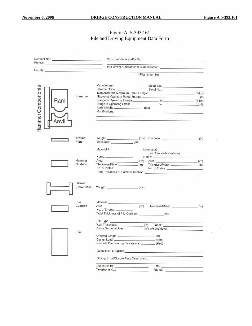
November 6, 2006 BRIDGE CONSTRUCTION MANUAL Figure A 5-393.161
Figure A 5-393.161 Pile and Driving Equipment Data Form

5-393.161 (2) BRIDGE CONSTRUCTION MANUAL November 6, 2006
For foundations designed using Allowable Service Design (see section 5-393.160 of this manual) the inspector should enter the pertinent information into the appropriate formula given under Determination of Bearing Capacity and determine whether or not the required bearing can be obtained at a penetration per blow that is not less than substantial refusal. Maximum rated energies for a number of commonly used pile hammers are listed in Table A 5-393.164. Physical properties of timber pile, steel shells, and H-pile are listed in Tables B-F 5-393.164. Example: The plans indicate that the piling were designed using the Allowable Stress Design (ASD) method. Review of the special provisions and specifications indicate that power driven hammers are required to yield a computed bearing of 130 percent (may be 160 percent in some cases, refer to the special provisions) of the design load at a penetration of not less than 1.3 mm (0.05 inch) per blow. Say Design Load = 100 ton 1.30 x 100 = 130 ton Single-Acting Diesel Hammer Max. Energy Rating = 43,200 ft. lbs. Note that no energy reduction is applied in the determination
of adequacy of the hammer. (Don't apply a 25% reduction in energy for unknown stroke).
Pile Mass (16" CIP 42.05 lbs @ 50') = 2102.5 lbs Cap Mass = 2150 lbs M = 4252.5 lbs Ram Mass (W) = 4190 lbs
( )( )
( )( )( )P =
3.5 x 43200
0.05 + .2 x
4190 + 0.2 x 4252.5
+ 4252.54190
P = (604800) x (.5970) P = 361066 (÷ 2000) P = 180 ton Therefore, the proposed hammer greatly exceeds the 130 ton requirements. If, however, the design load were 150 ton, the required bearing for substantial refusal would be 1.30 x 150 ton = 195 ton. Then, the proposed hammer would not qualify and a larger hammer would have to be furnished. The Specifications regarding pile hammers may vary somewhat from one edition of the Standard Specification book to the next, or even for different jobs under the same Standard Specifications. In addition, the inspector should always check the Special Provisions as well as Standard Specifications. Remember that the Special Provisions govern over the Standard Specifications. Although the Specifications have placed no upper limit on the size of hammer that may be used for pile driving, good judgment will dictate that every type and size of pile will have a limit as to
the amount of energy that it can absorb without becoming excessively damaged. Timber and precast concrete piles are the most susceptible, particularly when timber quality and size is marginal, or when driving is difficult. It would be advisable to try to discourage the Contractor from using a hammer with a ram mass greater than about 2200 kg (4850 lbs.) for timber piles. The inspector should consult with the Contractor and the Engineer whenever it becomes apparent that the hammer being used on the job is too large for the piles being driven, regardless of type or size. B. Energy Determination Perhaps one of the most baffling determinations an inspector encounters when making pile bearing computations is the determination of energy delivered by driving hammers. Keep in mind that the energy claimed by the manufacturer for power-driven hammers is almost always the maximum attainable under ideal conditions and with the pile at “refusal.” A “refusal” condition generally does not exist except when the tip of the pile is on rock. The following information is based on hammers which are functioning properly. If the hammer is malfunctioning, repairs should be made to restore it to proper operation or a replacement hammer is to be furnished by the Contractor. In no instance should driving be permitted with a hammer that is not functioning properly. Some double-acting hammers are rated on the basis of the number of cycles per minute, and some on the amount of pressure developed in the top chamber as measured by a special gauge. When the hammer speed versus energy charts or special provisions are provided, then the energy developed can be determined during driving. If no means is provided for field determination of energy, then a 25 percent reduction should be applied to the bearing computations; except when it is known that the tip of the pile is on bed rock, in which case the full energy rating may be used. For double-acting hammers where energy ranges are given by the manufacturers, the lower limit should be used as the rated energy unless details are furnished which justify using a higher rating. Single-acting power hammers are also rated by the manufacturer on the basis of maximum energy attainable. This is limited by the maximum length of stroke. The inspector should determine whether or not the maximum stroke is being obtained, and adjust the energy when it is not operating at the maximum stroke. This is particularly true of single-acting diesel hammers, where the stroke is dependent upon the force of the explosion, which is in turn dependent to some extent on the resistance being offered by the soils. Application of a 25 percent reduction may not be sufficient for these hammers. At times the length of the stroke may be only one-half of the maximum stroke and, therefore, a 50 percent reduction would be appropriate.

November 6, 2006 BRIDGE CONSTRUCTION MANUAL 5-393.162 (1)
If the length of stroke cannot be measured, but the hammer is operating close to the maximum stroke, the “manufacturer’s rated energy,” may be used with a 25 percent reduction in bearing values. Some single-acting diesel hammers have an “energy range” for manufacturers’ rated energy. Where this occurs, the stroke should be determined by the stroke indicator rod. When there is no stroke indicator attached to the hammer (and no other method of measuring stroke can be devised), the stroke can be determined by the formula: Stroke (feet) = 0.04t2 - 0.3 where t is the time (in seconds) required for 11 hammer blows (10 strokes) under operating conditions. This formula assumes vertical operation of the hammer and must be modified if driving piles battered flatter than 3 in 12. The rated energy is then determined by the ratio of the measured stroke to the maximum stroke times the upper limit of the “energy range.” The saximeter is a hand-held unit which uses sound recognition to automatically detect hammer blows. Background noise is managed through manual or automatic adjustment of the sound level at which a blow is detected. When the pile has penetrated one depth increment (such as 1 foot) the operator presses a button. The saximeter then displays the blows per increment (blows per foot) and the average hammer stroke over the increment. This makes filling out test pile reports much simpler as the saximeter automatically determines the stroke, which can be converted to energy by multiplying by the ram weight, and it also provides the blows per foot. Since the energy of drop hammers is determined by multiplying the weight of the ram (W) times the height of free-fall (H) times the acceleration of gravity. It may be necessary to reduce the energy if the fall is not completely “free,” i.e., friction between the hammer and leads. See Section 5-393.157 for additional information on drop hammers. 5-393.162 INSPECTION OF PILE DRIVING -
PROCESS Before pile driving is started, the excavation should be substantially complete, at least to the extent that bearing values will not be adversely affected by material which will later be removed. Also, except for cofferdams which are to be sealed with concrete, water within the excavation should be pumped out to the extent that pile placement and hammer operation will not be impaired. Underwater driving requires a “closed” hammer, with a rod attachment for penetration measurements. Punches or chasers are not permitted under any circumstances. Study the information on the Survey Sheet of the Plans to become completely familiar with the soil types and densities that will be encountered during the driving. Have an awareness of the existence and depth of layers of rocks and boulders and the depth to impenetrable hard pan or bed rock. With the above information in mind, the inspector will be in a better position to make quick and intelligent decisions should problems arise during driving. Also study the Plans and Special Provisions for special requirements, and for the location of underground utilities
and structures, including old road beds, pavements etc. The inspector should make certain that the pile driving foreman correctly interprets the working points from which the pile layout is staked. While the actual staking is the Contractor’s responsibility, a conscientious inspector would not proceed with the driving without verifying that the pile stakes had been properly placed. To be indifferent in matters of this importance would indicate a lack of responsibility on the part of the inspector. The end of the pile which is to receive the pile cap should be squared off normal to the longitudinal axis of the pile. Timber piles should also be trimmed at the butt end so as to fit into the cap. A. Test Piles Test piles should be marked off in 0.25 m (1 ft) increments for the full length of the piles, with special markings at 1.5 m (5 ft) increments, before they are placed in the leads, to provide a means for determining the number of blows required to drive each 0.25 m (1 ft). Markings on steel or dry timber can be made quickly and easily with yellow lumber crayon or spray paint, but for freshly treated timber piles roofing discs are often used, fastened with shingle nails. Driving a pile, particularly a test pile, should be as continuous as practical. Delays should be permitted only when they are unavoidable, or when authorized or directed by the Engineer. When it is necessary to drive piles through dense overburden, or to considerable depths through moderately heavy to heavy plastic soils, a delay in driving before reaching the required depth may permit the soil to "freeze" or "set-up" the pile sufficiently to prevent additional penetration when driving is resumed. Occasionally the Engineer may request that a pile be redriven a short distance after a delay period to determine whether or not resistance has built up during the delay period. Under some conditions the resistance is actually reduced during the delay, a phenomenon that may occur in course-grained, saturated soils. It is to be expected that test piles will usually be longer and will be driven harder than the remaining piles in the unit, since their purpose is to provide information for authorizing length for foundation piling. It serves no purpose to continue driving when it becomes obvious that minimal additional penetration will be obtained. Keep in mind that bearings computed using dynamic formulas are only a tool to be used in determining appropriate pile lengths. Comparison of computed bearings to “design bearings” is one basis for establishing a minimum acceptable pile penetration. Routinely, pile lengths are authorized longer than the length needed based on dynamic formulas. Driving of displacement type test piles should be continued until substantial refusal has been obtained or the driving resistance is so great there is concern regarding the capability of the pile to withstand further driving.

5-393.162 (2) BRIDGE CONSTRUCTION MANUAL November 6, 2006
In some cases, plans may require minimum tip elevations which must be obtained and may require driving beyond substantial refusal. Substantial refusal is defined by the Specifications and, unless modified by the special provisions, is the minimum resistance all test piles should be driven to, unless pile damage will result. The definition for substantial refusal is related to design load, type of driving hammer, and the energy developed by the hammer. The inspector should be familiar with the term and its implications. End bearing pile should be driven to the planned hard soil layer or rock using care not to damage the piling by overdriving. It is impossible from a practical standpoint to set hard and fast rules or Specifications that would cover all situations, and this is where sound judgment must govern. Unless the inspector has had considerable experience and background, it would be prudent to seek advice from the Engineer when there is doubt about minimum pile penetration or bearing. Before making a final judgment, be certain that you know the job requirements and that you are familiar with the available soils information. When it is found that timber test piles for a unit are of insufficient length to develop the required bearing value, and longer piles are on hand at the site for other units, it might be expedient to drive one or more of the longer piles for the unit in question. It would be advisable for the inspector to discuss such arrangements with the Project Engineer before proceeding unless there is a previous understanding regarding the inspector’s authority on these matters. In the case of steel H-piles, or steel shells, the contractor should have splicing material on hand so that the test piles can be extended if necessary to obtain sufficient bearing. In most cases, all test piles should be driven for a unit before authorizing the remaining piles for the unit. In the case of short-span pile-bent bridges, with one test pile per bent, test piles should be driven for as many bents as practicable before making pile length determinations. This is particularly desirable when the test pile locations are staggered for adjacent bents. The interior of steel shells should be visually inspected for damage prior to authorization of foundation pile lengths. The extent of damage must be included with information provided to the Bridge Office for pile length determinations. When the Contractor has a pile driving crew tied up waiting for delivery of piling after driving the test piles, it behooves the inspector to make special effort to expedite the authorization of foundation pile lengths. The Bridge Office will review test pile information and authorize lengths immediately when urgency is indicated. A complete record must be kept of the driving. If preboring is required for the piles which are to be authorized on the basis of results of the test piles, then preboring should also be required for the test piles. The diameter of the auger and the depth of preboring should be given when calling in test pile results and indicated on the test pile reports. The blow count should be noted for each 0.25 m (1 ft) and for any abrupt change within a given range. Complete notes may give important clues regarding possible damage to, or breakage of, the pile below the ground
surface. When a steel pile is driven to rock, especially a battered pile to sloping rock, the pile may “refuse” momentarily or may slow down, then bend and take off down the rock slope. An alert inspector who has studied the soils logs will often be able to detect this the moment it occurs. See Figure A, B, E, F 5-393.165 for examples of test pile reports. B. Foundation Piling When the test piles have been driven and the final lengths have been authorized, inspection of the foundation pile driving is still a very important function of the Bridge Construction Inspector. Not only does the inspector make certain that the piles are driven to adequate bearing and penetration, but also avoids excessive driving which may result in severe damage to the piles. Either extreme may render the piles useless, and could result in the failure of a foundation. In general, appropriate bearing capacity criteria for foundation piling is established from test pile data and application of criteria for substantial refusal to driving of foundation piling is not appropriate. Make certain that all piles for a unit have been satisfactorily driven, and redriven where required, before indicating approval of the driving for that unit. Do not delay the contractor unnecessarily, but do not let him pressure you into making a premature determination. If in doubt, consult with the Engineer. Establish cut-off elevation and measure and record the cut-off length for each pile. Require the specified preservative treatment of 2452.3F3 for the top of treated timber piles. Following is a list of some of the responsibilities and duties of the inspector on a pile driving operation. MAKE CERTAIN: 1. that the pile locations have been staked (by the contractor)
and checked (by the State) before driving is started. Where driving within a cofferdam, the pile lines should be marked off in both directions on the cofferdam walers and struts, with proper allowance for batter when necessary.
2. that the pile material has been inspected in accordance with
the requirements. The final inspection and acceptance will be at the site of the work. Even though the material may have passed previous inspection, it may have been damaged in handling or shipment (this is particularly true of timber piles). The thickness of the steel in H-piles and shells should be checked, and a visual inspection made of the general condition of the piles, including welds on welded Steel Shells, and the flange to web connections on H-piles.
Review the Mill Test Reports to verify that the material is of
domestic origin.

November 6, 2006 BRIDGE CONSTRUCTION MANUAL 5-393.162 (3)
3. that the equipment meets requirements (hammer is qualified).
4. that the piles are properly prepared for driving. 5. that the welder (if steel H-piles or shells are to be used) has
passed Mn/DOT qualifying tests. All splices should be made in accordance with approved standard details for the type of pile.
6. that the length and diameter of the pile is measured and
recorded before being placed in the leads. 7. that the pile is properly positioned (usually by digging a
small hole for the tip of the pile with a pointed shovel at the staked location for timber piles).
8. that the pile is plumb, or at the specified batter. 9. that the driving cap fits properly on the head of the pile. An
improperly fitting pile cap, particularly on a timber pile, could create a hazard in addition to damaging the pile. “Chasers” are not permitted as transmittal of hammer impact to the pile cannot be assured.
10. that the pile is properly supported laterally so as to avoid “whip” when driving, particularly if there is a noticeable bow in the length of the pile.
11. it is sometimes necessary to secure the leads with guy ropes
to control their position. 12. when possible, to insist on starting the pile with reduced
energy until the pile is well seated, particularly for timber piles.
13. to observe the action of the pile very closely as it starts
downward, and insist on immediate correction if it moves out of position, plumbness, or specified batter.
14. to observe the operation of pile hammers and determine
whether or not they are functioning properly when full power is supplied. Energy reductions in excess of 25 percent may be necessary if hammer is not operating properly.
15. to note whether or not the pile and the hammer are in
alignment. A pile can be easily damaged when not properly aligned with the hammer, and the damage may be blamed by the foreman to “overdriving.”
16. to observe the pile closely, especially timber piles, for
evidence of cracks, splits, or fractures, which may cause sudden failure and perhaps an accident. Timber piles may release splinters large enough to cause serious injury when dropping from considerable height.
17. to observe any strain that may be created on the equipment
due to high booms and/or heavy loads.
18. that “penetration per blow” readings are taken well in advance of final penetration, when this is possible or practical, particularly when approaching the “substantial refusal” range.
19. that timber piles are not driven to cut-off length since some
damage is done to the top wood fibers by the hammer impact even though this may not be visible. Provide for at least 150 mm (6 in.) of cut-off. Steel, piles or shells may be driven to cut-off if the top of the pile is in reasonably good condition.
20. that final penetration measurements are made by the
inspector and are not delegated to the worker. 21. to drive all piling to the bearing capacity satisfactory to the
Engineer, to substantial refusal or to the required penetration. Do not continue driving a pile after substantial refusal has been obtained merely to reduce cut-off length, unless a shallow hard layer is suspected, or unless the contract specifies a minimum depth of penetration.
22. to signal the foreman when the pile has been driven to the
required penetration or substantial refusal. If there is a failure to signal the operator immediately, and a failure occurs as a result, the accident is the contractor’s responsibility. As the Specifications are currently written, Mn/DOT will be responsible for any damage which occurs to the pile if there is an order to continue driving beyond substantial refusal.
23. as the top of the pile approaches cut-off elevation, inspect it
visually for evidence of damage, and avoid, if possible, the inclusion of damaged areas below cut-off. Slightly deformed steel sections are not necessarily considered as damaged.
24. to observe piles which have been driven to determine
whether or not they may be heaving when driving adjacent piles. Order redriving of piles which have heaved. Plastic soils sometimes have this characteristic, particularly with closely spaced tapered piles.
25. to require removal of earth that may have swelled above the
bottom of footing elevation during pile driving. Areas which were over-excavated may be backfilled with approved material and compacted or filled with concrete. See the appropriate section of Specification 2451.3.
26. when obstructions, such as rocks or boulders, are
encountered near the surface they should be removed. If this cannot be done, then the pile pattern may have to be modified. Consult the Project Engineer, or the Bridge Office, if necessary.

5-393.163 BRIDGE CONSTRUCTION MANUAL November 6, 2006
The inspection procedure for trestle type piles is much the same as for foundation piles, with the following additions: 1. Require that guides or templates be used when necessary in
order to keep the piles in proper alignment and at the correct batter. The tolerances are necessarily more rigid than are those for foundation piles.
2. Timber or plank guides, set to correct grade and slope,
should be used when timber pile cut-offs are made, since the pile cap should fit snugly on the pile without the use of shims or fills. Cutting off trestle piles should be done only by experienced sawyers or welders. Super-elevated roadways, or skewed bridges on grade, often require that the caps be placed on a slope, thereby necessitating that the cut-off guides also be placed on a slope.
5-393.163 PILE BEARING TABLES Pile bearings should be computed using the appropriate formula from Specification 2452.3D. Be sure to verify whether the foundation was designed using ASD or LRFD methodology, as different dynamic formulas will be used depending on the design methodology. As an aid in computing pile capacities a computer program has been developed that allows the user to input the required data and the program generates the bearing capacity (see Figure A 5-393.163). This computer program is available from the Bridge Office website at www.dot.state.mn.us/bridge Click on the “downloads” button and look for "Pile Capacity Program". Figure B 5-393.163 provides a tabulated conversion from blows per foot to penetration in inches per blow for input into the dynamic formulas. Figures C 5-393.163 and D 5-393.163 provide examples of tables that can be developed to determine pile capacity for various pile lengths and penetrations. Similar tables can be developed using a spreadsheet program also available on the Bridge Office website. Click on the "downloads" button and look for "Pile Bearing Table". 5-393.164 PILE INFORMATION TABLES Figure A 5-393.164 lists information regarding energy, ram weight, max stroke for many hammer types. This information was obtained from the GRLWEAP General Users’ Manual which is provided courtesy of Gobal, Rausch, Likins & Associates. Figures B-F 5-393.164 tabulate pertinent data relating to H-piles, timber piles and pipe pile dimensions. This may be used for pile mass or weight estimation by the inspector. 5-393.165 TEST PILE AND PILE DRIVING REPORTS Test pile driving results should be transmitted to the Bridge Construction Unit as promptly as possible after completion of driving, except when additional test piles are to be driven before an authorization can be made. Unless it is convenient to hand-carry the reports, the quickest method of obtaining a determination is to relay the test pile information by telephone, fax, or e-mail.
As soon as practical after phoning in the test pile results, the reports should be prepared and forwarded as per the distribution list on the back of the reports. A sketch should be shown on the back side of the report, indicating the location of the test pile covered by that report with relation to the footing lines. Also show direction by a North Arrow, the centerline of piers, the centerline of bearing for abutments, the centerline of bridge, and any dimensions necessary to determine the location of the test pile. If the test pile is a batter pile, indicate the direction of batter with a short arrow extending from the pile location. When test piles are redriven after a delay, as provided for in the Specifications under certain conditions, the length of time delay as well as computed bearings before and after redriving should be noted on the report. See Figures M-P 5-393.165 for examples. When preboring for test piles, be certain to note the depth prebored and the diameter of the auger used for preboring. The design load should be shown on all test pile reports. Be certain to follow the instructions on the reverse side of the Test Pile Report form. Reports are often received which clearly indicate that the person preparing them had not read these instructions, or did not understand them. If there is any question regarding the information requested, which cannot be resolved, please do not hesitate to call Bridge Construction Unit personnel. Examples of test pile reports are shown in Figures A, B and E, F and I, J and M, N 5-393.165. The pile driving report should be prepared as soon as the piles have been driven for a unit. See the distribution information on the reverse side of the reports for what to do with the finished reports. When the bridge carries railroad traffic, an additional copy should be made for each railroad involved, and should be sent to the Mn/DOT Office of Railroad Administration. In the event there is some question regarding the adequacy of the piles driven for a unit, the matter should be discussed immediately with your supervisor without waiting for a review of the reports by the Bridge Office. The instructions for preparing the report are defined on the reverse side of the form, and should be read and followed. Many reports are received which indicate the instructions have not been read. Examples of pile driving reports are shown in Figures C, D and G, H and K, L and O, P 5-393.165. For drop hammers, entries in the column headed Final Energy Per Blow should be equal to the weight of the hammer multiplied by the height of free fall. Appropriate reductions should be made for factors which tend to reduce the energy delivered by a drop hammer, such as noticeable bounce, heavy batter, line drag, poor hammer pile alignment, etc.

November 6, 2006 BRIDGE CONSTRUCTION MANUAL Figure A 5-393.163

Figure B 5-393.163 BRIDGE CONSTRUCTION MANUAL November 6, 2006
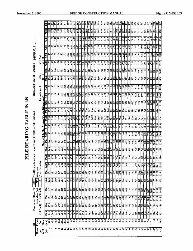
November 6, 2006 BRIDGE CONSTRUCTION MANUAL Figure C 5-393.163

Figure D 5-393.163 BRIDGE CONSTRUCTION MANUAL November 6, 2006
21 24 27 30 32 35 38 41 43 45 48 50 52 55 57 59 61 63 65 69 72 76 78 83 87 91 95 10
110
611
311
913
014
015
116
518
220
1
20 23 26 29 31 34 37 39 42 44 46 48 51 53 55 57 59 61 63 67 70 73 76 80 85 88 92 98 102
110
116
126
136
147
160
176
196
19 22 25 28 31 33 36 38 40 43 45 47 49 52 53 56 57 59 61 65 68 71 74 78 82 86 89 95 99 107
112
122
132
143
155
171
190
19 22 24 27 30 32 35 37 39 42 44 46 48 50 52 54 55 58 59 63 66 69 72 76 80 83 87 92 97 104
109
119
128
139
151
166
185
18 21 24 26 29 31 34 36 38 40 43 44 47 49 51 53 54 56 58 61 64 67 70 74 78 81 84 90 94 101
106
116
125
135
147
162
180
18 21 23 26 28 31 33 35 37 39 41 43 45 47 49 51 53 55 56 60 63 66 68 72 76 79 82 88 92 98 104
113
121
131
143
158
175
17 20 23 25 27 3 0 32 34 36 38 40 42 44 46 48 50 51 53 55 58 61 64 66 70 74 77 80 85 89 96 101
110
118
128
140
154
171
17 20 22 25 27 29 31 33 35 37 39 41 43 45 47 4 9 50 52 54 57 59 62 65 68 72 75 78 83 87 94 99 107
115
125
136
150
167
17 19 21 24 26 28 30 33 34 37 38 40 42 44 46 47 49 51 52 55 58 61 63 66 70 73 76 81 85 91 96 104
113
122
133
146
162
16 19 21 23 26 28 30 32 34 36 38 39 41 43 45 46 48 50 51 54 57 60 62 65 69 72 75 80 83 89 94 102
110
119
130
143
159
16 18 21 23 25 27 29 31 33 35 37 38 40 42 44 45 47 49 50 53 55 58 60 64 67 70 73 78 81 87 92 100
108
117
127
140
155
16 18 20 22 24 26 28 31 32 34 36 38 39 41 43 44 46 47 49 52 54 57 59 62 66 68 71 76 79 85 90 98 105
114
124
137
152
15 18 20 22 24 26 28 30 32 33 35 37 38 40 42 43 45 46 48 51 53 56 58 61 64 67 70 74 78 84 88 96 103
111
121
134
149
15 17 19 21 23 25 27 29 31 33 35 36 38 40 41 43 44 46 47 50 52 55 57 60 63 66 68 73 76 82 86 94 101
109
119
131
146
15 17 19 21 23 25 27 29 30 32 34 35 37 39 40 42 43 45 46 49 51 54 55 58 62 64 67 71 75 80 85 92 99 107
117
128
143
14 17 19 21 23 24 26 28 30 32 33 35 36 38 39 41 42 44 45 48 50 53 54 57 61 63 66 70 73 79 83 90 97 105
115
126
140
14 16 18 20 22 24 26 28 29 31 32 34 3 5 37 39 40 41 43 44 47 49 51 53 56 59 62 64 69 72 77 81 88 95 103
112
123
137
13 15 17 19 21 23 25 26 28 30 31 32 34 36 37 38 39 41 42 45 47 49 51 54 57 59 62 66 69 74 78 84 91 98 107
118
131
13 15 17 18 20 22 24 25 27 28 30 31 33 34 35 37 38 39 40 43 45 47 49 51 54 57 59 63 66 71 74 81 87 94 103
1 13
126
12 14 16 18 19 21 23 24 26 27 29 30 31 33 34 35 36 38 39 41 43 45 47 49 52 54 57 60 63 68 72 78 84 91 99 109
121
12 14 15 17 19 20 22 23 25 26 28 29 30 32 33 34 35 36 37 40 42 44 45 48 50 52 55 58 61 65 69 75 81 87 95 105
116
11 13 15 17 18 20 21 23 24 25 27 28 29 30 32 33 34 35 36 38 40 42 4 4 46 49 51 53 56 59 63 67 72 78 84 92 101
112
11 13 14 16 17 19 20 22 23 24 26 27 28 29 31 32 33 34 35 37 39 41 42 44 47 49 51 54 57 61 64 70 75 81 79 98 108
11 12 14 15 17 18 20 21 22 24 25 26 27 28 30 31 31 33 34 36 37 39 41 43 45 47 49 52 55 59 62 67 73 79 86 94 105
10 12 13 15 16 18 19 20 22 23 24 25 26 28 29 30 31 32 33 35 36 38 40 42 44 46 48 51 53 57 60 66 71 77 83 92 102
6 7 8 9 10 11 12 13 14 15 16 17 18 19 20 21 22 23 24 26 28 30 32 34 37 40 43 48 52 60 66 80 96 120
160
240
480
2.00
01.
714
1.50
01.
333
1.20
01.
091
1.00
00.
923
0.85
70.
800
0.75
00.
706
0.66
70.
632
0.60
00.
571
0.54
60.
522
0.50
00.
462
0.42
90.
400
0.37
50.
353
0.32
40.
300
0.27
90.
250
0.23
10.
200
0.18
20.
150
0.12
50.
100
0.07
50.
050
0.02
5
PILE
BEA
RIN
G T
AB
LE
IN T
ON
S C
APA
CIT
YM
ake
of H
amm
er _
____
____
____
_D
elm
ag D
-22
Rat
ed E
nerg
y Pe
r B
low
___
____
__ ft
. lb
.39
780
Ram
Wt._
____
__ lb
4840
Sing
le a
ctin
g - n
ot fi
eld
mea
sure
dFo
rmul
a us
ed:
x
x 0
.75
3.5
ES
+ 0.
2W
+ 0
.1 M
W +
M
Blo
ws
per
foot
Pene
t.Pe
rBl
ow(in
.)800
100012001400160018002000220024002600280030003200340036003800400045005000550060006500700075008000
M (W
eigh
t of P
ile P
lus W
eigh
t of C
ap)
1.0161.0201.0241.0281.0321.0361.0401.0431.0471.0511.0551.0581.0621.0661.0691.0731.0761.0851.0931.1021.1101.1181.1261.1341.142
Mul
tiply
ing
Fact
or fo
r St
eel H
Pile
s
**

November 6, 2006 BRIDGE CONSTRUCTION MANUAL Figure A 5-393.164 (1)

Figure A 5-393.164 (2) BRIDGE CONSTRUCTION MANUAL November 6, 2006

November 6, 2006 BRIDGE CONSTRUCTION MANUAL Figure A 5-393.164 (3)

Figure A 5-393.164 (4) BRIDGE CONSTRUCTION MANUAL November 6, 2006

November 6, 2006 BRIDGE CONSTRUCTION MANUAL Figure B 5-393.164
NominalSize and Weight
NominalSize and
Mass
Weightper Foot
(lb/ft)
Massper meter
(kg/m)
Depth(in.)
Depth(mm)
Flange
Flange
Width(in.)
Width(mm)
Thickness(in.)
Thickness(mm)
WebThickness
(in.)
WebThickness
(mm)
H Bearing Piles - Dimensions and Mass (Metric Units)
H Bearing Piles - Dimensions and Weight (English Units)
HP 14 x 117HP 14 x 102HP 14 x 89HP 14 x 73
HP 12 x 74HP 12 x 63HP 12 x 53
HP 10 x 57HP 10 x 42
HP 8 x 36
HP 360 x 174HP 360 x 152HP 360 x 132HP 360 x 108
HP 310 x 110HP 310 x 94HP 310 x 79
HP 250 x 85HP 250 x 62
HP 200 x 54
1171028973
746353
5742
36
174152132108
1109479
8562
54
14 1/41413 7/813 5/8
12 1/81211 3/4
10 9 3/4
8
361356351346
308303299
254246
204
14 7/814 3/414 3/414 5/8
12 1/412 1/812
10 1/410 1/8 8 1/8
378376373370
310308306
260256
207
13/1611/165/81/2
5/81/27/16
9/167/16
7/16
20.417.915.612.8
15.513.111.0
14.410.7
11.3
13/1611/165/81/2
5/81/27/16
9/167/16
7/16
20.417.915.612.8
15.413.111.0
14.410.5
11.3

Figure C 5-393.164 BRIDGE CONSTRUCTION MANUAL November 6, 2006
BUTT DIA. (mm)
APPROXIMATE MASS OF TREATED TIMBER PILES (kg)
5
6
7
8
9
10
11
12
14
16
18
20
22
24
200225250200225250200225250200225250200225250200225250200225250175200225175200225175200225175200175200175200150175
165180200195215240
170190205205225250
180200215215235255250275300287315345320355385360390430395430470390430470
Lengthmeters
185205225225245265260285310300325355335365400375410445410450490410450490
Tip Dia.mm 280 290 300 310 320 330 340 350 360 370 380 390 400
195210230235255275270295325310340370350380415390425460430465510430465510
205220240245265285285310335325355385365395430405440480445485525445485530520565615595650705670730745810820890820890
210230250255275300295320345335365395380412445420460495465505545465505550545590640620675730700760775845855925855930
220235255265285310305330360350380410395425460440475515480520565485525570565615665645700760725790810875890965895970
230245265275295320320345370365395425410445480455490530500540585505545590590640690675730790760820840910925
1000930
1010
235255275285305330330355385380410440425460495475510550520560605525570610615660715700755815790850875945965
1040972
1050
245265285295315340345370400395425455440475510490530570540580625545590635635685740730785845820885910980
1000108010151095
255275295305330355355385410405440470460495530510550590560600645570610655660715765755815875850915945
10201040112010551135
265285305315340365370395425420455485475510545530565610580625670590635680685740795785845905885950985
10551080116110951180
Note:Masses shown are based on720 kg/m , which is approximateaverage of commonly usedtypes of treated timber piles.These weights are consideredsufficiently accurate to be usedfor computing pile bearings.Massses for diameters whichdiffer from those shown maybe interpolated or extrapolatedas the case may be. See Specification 3471 for minimum diameterrequirements.
3
The above table may also be used for green, untreated softwood piles. For air-dry softwood piles, multiply by 0.80.

November 6, 2006 BRIDGE CONSTRUCTION MANUAL Figure D 5-393.164
BUTT DIA. (in.)
APPROXIMATE WEIGHT OF TREATED TIMBER PILES (lbs.)
89
1089
1089
1089
1089
1089
1089
1078978978978787867
360390430450490540
382420460470520570
400440480500550600620680740750820890870950
1040100010901190112012301340113012401360
420460500520570620660720780790860940920
10001090105011501250118012901400120013101430
440480520550600650690750820830900980970
1050114011001200131012401350147012601380150013901520165016201650180016401790177019301900207028502020
460500550580630680730790850870940
102010101100120011601260137013001420154013301450157014701600173016001740189017301880187020302000217019602130
490530570610660710760820890910990
107010701150125012201312143013701480161014001522165015401670181016801830198018201980196021302110228020702250
540580620670720780840900970
10001080117011701260136013401440155015101620175015501670180017101840198018602010217020202180217023402330251023002480
510550600640690750800860930960
1040112011201210130012801380149014401550168014801600173016201760190017701920207019202080207022402210240021802360
560600650700750810880940
101010501130122012301320142014001510162015801700182016301750189017901930207019502100226021202230228024502440263024202600
590630680730790840920980
106011001180127012801280148014701570169016501770190017101830197018802020216020502200236022202380239025702560275025402730
The above table may also be used for green, untreated softwood piles. For air-dry softwood piles, multiply by 0.80.
16
20
25
30
35
40
45
50
55
60
65
70
75
80
Length(ft.)
Tip Dia.(in.) 11 11 /1
2 12 12 /12 13 13 /1
2 14 14 /12 15 15 /1
2 16
Note:Weights shown are based on45 lb/ft , which is approximateaverage of commonly usedtypes of treated timber piles.These weights are consideredsufficiently accurate to be usedfor computing pile bearings.Weights for diameters whichdiffer from those shown maybe interpolated or extrapolatedas the case may be. See Specification 3471 for minimum diameterrequirements.
3

Figure E 5-393.164 BRIDGE CONSTRUCTION MANUAL November 6, 2006

November 6, 2006 BRIDGE CONSTRUCTION MANUAL Figure F 5-393.164

Figure A 5-393.165 BRIDGE CONSTRUCTION MANUAL November 6, 2006

November 6, 2006 BRIDGE CONSTRUCTION MANUAL Figure B 5-393.165

Figure C 5-393.165 BRIDGE CONSTRUCTION MANUAL November 6, 2006

November 6, 2006 BRIDGE CONSTRUCTION MANUAL Figure D 5-393.165

Figure E 5-393.165 BRIDGE CONSTRUCTION MANUAL November 6, 2006

November 6, 2006 BRIDGE CONSTRUCTION MANUAL Figure F 5-393.165

Figure G 5-393.165 BRIDGE CONSTRUCTION MANUAL November 6, 2006

November 6, 2006 BRIDGE CONSTRUCTION MANUAL Figure H 5-393.165

Figure I 5-393.165 BRIDGE CONSTRUCTION MANUAL November 6, 2006

November 6, 2006 BRIDGE CONSTRUCTION MANUAL Figure J 5-393.165

Figure K 5-393.165 BRIDGE CONSTRUCTION MANUAL November 6, 2006

November 6, 2006 BRIDGE CONSTRUCTION MANUAL Figure L 5-393.165

Figure M 5-393.165 BRIDGE CONSTRUCTION MANUAL November 6, 2006

November 6, 2006 BRIDGE CONSTRUCTION MANUAL Figure N 5-393.165

Figure O 5-393.165 BRIDGE CONSTRUCTION MANUAL November 6, 2006

November 6, 2006 BRIDGE CONSTRUCTION MANUAL Figure P 5-393.165
5-393.165 BRIDGE CONSTRUCTION MANUAL November 6, 2006
Sometimes all of the requested information is not shown; this is the case especially with the column headed Net Driving Time, where driving time should be shown for at least enough piles to give representative information. Other times the entries are such as to be suspect of “manufacture” after the driving was completed. Certainly it is much better to omit an entry than to falsify one, since an entry that can be shown to be false by an attorney during a court case, could also discredit other entries. Recording the actual driving time on the reports tends to discourage claims by contractors that inspectors are requiring overdriving. The pile driving foreman is not likely to use this as an excuse for a slow operation if our records will prove otherwise. The driving time record could also be very beneficial in determining price adjustments in the event of conditions different than those which were anticipated. The column headed Authorized Splices is intended to be used for recording those splices which are eligible for payment as defined under 2452.5B, unless otherwise noted under Remarks. The Specifications provide for payment for splices under three conditions, one of which is when it is necessary “to make up lengths longer than the length of the longest test pile shown in the Plan were authorized by the Engineer for a particular unit, and then only for any extra splices required.” This would mean that if the plan required 25 m (80 foot) test piles and the Contractor had 15 m (50 foot) lengths on hand, an “extra” splice would not be required unless foundation lengths longer than 30 m (100 feet) were authorized since it would be necessary for him/her to make a splice to furnish 25 m (80 feet) lengths. The column headed Remarks is sometimes unnecessarily filled with information that can better be shown elsewhere on the report, such as notations indicating “Batter Pile” which could readily be indicated by arrows on the sketch on the back side of the form. Also, since the “penetration per blow” is shown in a separate column, it is not necessary to note the penetration for the last 5, 10, or 20 blows under Remarks, although this information should be included somewhere on your working copy or field notes. The Butt and Tip diameters of timber piles should be shown in the Remarks column, or may be shown in other unused columns if the Remarks column is needed for other reasons. Remember, there are definite minimum diameter requirements for timber piles in Specification 3471. The depth of jetting or preboring and the diameter of the preboring auger should also be shown. Where there is insufficient space in the Remarks column to provide for notations, identify notes by (1), (2), etc., and place them at the end of the tabulation. When abbreviations are used, be certain that they are standard abbreviations, or at least that they can be readily interpreted. If there is any doubt about interpretation, explain the abbreviation at the end of the tabulation. Someone may have to interpret these reports many years after they were prepared, as is often done now in the design office with reports that were prepared forty to sixty years ago, and clarity is essential.
A. Pile Redriving As mentioned in section 5-393.160 of this manual, the resistance offered by soils while being disturbed by vibrations and displacement during pile driving may be quite different than that which will subsequently be offered against long-time static loads. Some soils will readjust after completion of driving and provide a high driving resistance after the soil has "set-up". In plastic (non-granular) soils the resistance will likely increase after a 24 hour delay, in some cases as much as 50 percent or more. Granular soils generally do not indicate large increases in resistance after similar waiting periods. In some cases the special provisions will require the Contractor to "redrive" the test piles after a specified waiting period to determine the capacity that can be obtained by including pile set-up. Subsequently, an additional number of foundation piles may be also be designated for redriving to verify that adequate bearing capacity has been achieved. Piles designated by the Engineer to be redriven shall have a required minimum time delay as stated in the special provisions between the initial driving and the redriving. During this time delay, no other piles shall be driven, unless authorized by the Engineer. All redriving shall be performed using a "warm" pile hammer. Generally, applying at least 20 blows to a previously driven pile or timber mats shall warm up the hammer. Redrive hammer strikes shall generally not exceed 20 blows for each pile. Piles shall not be trimmed to the Plan cut-off elevation until the Engineer has determined the need for redriving. No pile in any one substructure unit shall be filled with concrete until the Engineer decides that all piles in the unit have been driven to adequate bearing capacity and the pile shells have been trimmed to the cut-off elevation. When piles have been redriven after a delay as a means of determining whether or not set-up can be expected, the pile capacity before and after the delay period should be shown on the pile reports. Generally only a small percentage (5-10 percent) of the piling in a substructure unit will be redriven. However, the average results from the piling that have been redriven will be used as acceptance criteria for the remaining piling in the unit. The inspector should therefore add a note to the pile reports indicating the average increase in capacity due to set-up, such as "Based on 4 redrives performed after a 24 hour waiting period, the average increase in capacity at the West abutment is 30 percent". This type of note is particulaily important on reports where redriving is necessary to achieve the minimum design bearing specified in the plans. Without such a note it may appear the piling were driven and accepted at bearing capacties less than required by the plans. Examples of a test pile and pile driving report that incorporate pile redrives are shown in Figures M, N & O, P 5-393.165.
November 6, 2006 BRIDGE CONSTRUCTION MANUAL 5-393.166
5-393.166 PILE DRIVING ANALYZER The pile driving analyzer (PDA) is a device to measure and analyze the effect of hammer impact on the pile and determine bearing capacity. Strain gauges are attached to the exposed portion of pile and electronic instruments record the strain pattern as the hammer impacts the pile. Soil resistance will affect the measurement and calibration is necessary for each site. A laptop computer is programmed to analyze the strain pattern and can give information on maximum bearing value, hammer efficiency, and possible pile damage. This equipment is best suited to projects with a very large quantity of piling or piles with very high loads. Special training is required for operation of the equipment. For piling designed using LRFD methodology (see section 5-393.160 of this manual) the pile driving analyzer may be used in lieu of a dynamic formula to determine the ultimate bearing capacities in the field. If the special provisions require that the PDA be used to determine pile capacity, in most cases the Contractor will be required to provide the equipment and the necessary services will generally be provided by a geotechnical subconsultant. See your job specific special provisions for more information and further requirements. 5-393.167 PILE LOAD TESTS Pile load tests are recognized as the most reliable method of determining the capacity of a pile to carry a static load. They are, however, costly and time consuming, and can only be justified when large numbers of piles are required in an area where the soils conditions are reasonably uniform, or when it is necessary or desirable to load piles much higher than their normally accepted capacity. We therefore, as a general practice, rely on dynamic formulas. A pile load test may be required by the Contract for the purpose of justifying a design load which is higher than normally permitted for the type and size of piles specified and for ensuring adequate support from the material into which they are to be driven. Pile load tests may also be used as a means of determining the safe capacity of the pile by applying an appropriate factor of safety after the ultimate capacity has been determined. Specification 2452.3D3 requires that a total load be applied which is not less than 200 percent of the design pile load for a Type 1 Load Test and a total load of 400 percent for a Type 2 Load Test and that the applications of the load be in increments which are defined as percent of the total load. It also provides for holding these loads for a specified period of time after a settlement of less than 250 µm (1/100 in.) during a 15 minute interval. Before proceeding with a pile load test on the basis of the requirements of 2452.3D3, review the Plans and Special Provisions to determine whether or not they contain additions to, or modifications of, the general requirements. The Type 2 Load Test was developed in accordance with procedures of the Texas Highway Department and additional information on these procedures is available in the users manual entitled “The Texas
Quick-Load Method for Foundation Load Testing.” Chellis, in his book on Pile Foundations states that: “Basically, therefore, a pile load test can determine only the ultimate bearing capacity and not the settlement characteristics of the pile group.” This is because settlement is related to time, and even though a pile load test is a better indicator in this respect than are any of the dynamic pile driving formulas, long time settlement must still rely on soil mechanics computations for a more reliable answer. Cohesive soils are more susceptible to long term settlement than are granular soils. Several methods of applying load to the top of a pile have been satisfactorily used, and the method to be used for a particular load test is usually determined by the Contractor on the basis of available materials, equipment, and conditions. The most common method is providing a reaction by driving piles at locations adjacent to the pile to be load tested and connecting a reaction beam across the top of these piles, over the load test pile. A calibrated hydraulic jack of adequate capacity is then placed on the pile and the load applied in increments by jacking against the reaction beam. Calibration requirements are contained in 2452.3D3a. Sometimes jacking is done against a load, such as a quantity of steel H-piles which will subsequently be used on the project, or against a piece of heavy equipment or other material. Regardless of the type of reaction used, whenever load is applied to the pile by jacking, the gauges must be observed at close time intervals to ensure against any significant relaxation of load due to pile settlement or due to leakage in the jacking system. A second method of loading is to provide a platform over the pile onto which materials (sand, concrete, steel, or any other material) can be placed in the required load increments, while the platform is supported solely by the pile. The load can also be applied by incremental filling of a water tank supported by the pile. Pile settlement readings should be determined by the use of Ames dials furnished, placed, and read by Department personnel, and for which the Contractor is required to provide and install the necessary supports. It is essential that any posts or other supports be unaffected by the pile load test, so that reliable readings will be obtained. (Note: in handling the Ames dials, avoid releasing the plunger shaft abruptly as this is likely to bend or break the indicator needle). As a back-up for the Ames dial readings, and as a check on their support system, level readings should be taken either by instrument or by stretching a piano wire over two temporary bench marks which are free from disturbance. In this way, if anything should happen to the dials, the test can be continued by referring to the back-up system.

Figure A 5-393.167 BRIDGE CONSTRUCTION MANUAL November 6, 2006

November 6, 2006 BRIDGE CONSTRUCTION MANUAL Figure B 5-393.167
Loa
d on
Pile
- kN
5 10 15 20 25 30 35 40 45 50 55
020
040
060
080
010
0012
0014
0016
0018
00
Ulti
mat
eB
earin
gC
apac
ity
Slop
e =
0.14
mm
/kN
Plun
ging
Fai
lure
Loa
d
Gross Settlement -mm
EXAMPLE OF PILE LOAD TESTTYPE 2
PILE
LO
AD
TES
T N
o.__
____
____
_BR
IDG
E N
o.__
__ D
es. L
d___
_kN
Uni
t No.
____
___
Dat
e___
____
____
_Pr
oj. E
ng._
____
____
____
____
____
_In
spec
tor_
____
____
____
____
____
_Co
ntra
ctor
____
____
____
____
____
_Co
mm
ents:
____
____
_ ___
____
____
____
____
____
____
____
____
____
_
U
ltim
ate
bear
ing
capa
city
140
0 kN

Figure C 5-393.167 BRIDGE CONSTRUCTION MANUAL November 6, 2006
EXAMPLE OF GRAPHICAL PLOTTING OF PILE LOAD TEST
Percent of Total Load Apllied
40%
50%
60%
70%
80%
90%
100%
=140
0 kN
0
1
2
4
5
6
7
8
9
10
11
12
13
14
3
Settl
emen
t at T
op o
f Pile
(mm
)
Pile Load Test No. 1 Br. No. xxxxPier No. x Design Load 700 kNProj. Engr.InspectorContractorComments: Approaching failure @ 1400 kN700 kN design load okay. S.F.=2By Date
0.085 mm
/kN slope Design Load = 700 kN
S.F. = 2
Assuming Elastic Shortening = Rebound
Rebound
0.085 mm
/kN slope
F orm
218
10, S
oil B
earin
g Te
st G
rap h
, may
be
used
for t
his p
u rpo
se b
y ch
angi
n g th
e tit
le (a
ndth
e va
lues
as m
ay b
e ne
cess
ary)
.
6 hrs. @ 100%
12 hrs. @ 100% Load

November 6, 2006 BRIDGE CONSTRUCTION MANUAL 5-393.168
When setting the Ames dials, the plunger shaft should be depressed very nearly the full 50 mm (2 inches) of travel, and the needle zeroed by turning the adjustment knob at the bottom of the plunger shaft. Thus, when the pile settles, the plunger shaft will extend by spring action and the amount of extension can be read directly from the face of the dial. The equipment should be protected from the sun and the weather to maintain reasonably uniform temperatures. The reference in the Specifications to failure at 50 mm (2 inches) of settlement is only for the purpose of terminating the load test, and is not intended as an indication than the pile has not failed until that settlement is reached. The determination as to the load at which failure of the pile was reached will be made by the Engineer, in consultation with the Bridge Office based on a plotting of the results. Pile Load Test reports should include Pile Load Test Data, Pile Load Test Log, and Graphical Plotting sheets, as shown in Figures A-C 5-393.167. If immediate determination is essential, the information may be called in to the appropriate Regional Bridge Construction Engineer in advance of preparing the reports. 5-393.168 PAYMENT FOR PILING Test piling is paid for as plan quantity item per each pile. No deductions are made if piling is shorter than planned length. All costs of material, delivery and installation are included. Many contractors include their “fixed costs” for all pile driving in this item to ensure recovery of these costs in the event foundation pile quantities underrun. If lengths longer than shown in the plan are authorized, payment for extra length is made under items “Piling Delivered” and “Piling Driven.” Foundation piles are paid for under two pay items. For most projects these items are “Piling Delivered” and “Piling Driven” with “Piling Driven” including all costs other than material and delivery. On some contracts the items are “Pile Placement” and “Piling Furnished and Driven” (see 5-393.153 for additional information). Quantities for “Piling Delivered” would be the total of the “Final Authorized” column on the pile driving report excluding test pile quantities. “Piling Delivered” is increased for extra test pile length authorized and decreased if the fabrication pile length in leads is less than final authorized length (see Figures C and G 5-393.165). Quantities for “Piling Driven” would be the total of the “Penetration Below Cutoff” (meters) (feet) column on the pile driving report excluding test pile quantities (adjustments for extra test pile would be added to this total). Quantities for Mn/DOT cutoffs driven and authorized splices are listed separately for payment. 5-393.169 ADJUSTMENT OF AUTHORIZED PILE LENGTHS When a pile that is shorter than the initial authorized length is placed in the leads and is driven to required bearing (pile is accepted at less than initial authorized length), show the final authorized length equal to actual length in the leads (see Figure
A 5-393.169 - pile no. 2 and Figure G 5-393.165 pile No. 1). The Contractor should not drive beyond the authorized length without approval of the Inspector. When a pile longer than the initial authorized length is placed in the leads and is driven beyond the initial authorized length as directed by the Inspector in order to obtain required bearing,, show the final authorized length equal to the length below cut-off (see Figure A 5-393.169 - pile no. 3). When the Inspector orders the Contractor to use Mn/DOT cut-offs, the required splices will be paid for by Mn/DOT and the following procedure is recommended. Show the final authorized length as the actual length in the leads minus the length of Mn/DOT cut-off used as noted in the "Remarks" column. Show the number of authorized splices used and the length of Mn/DOT cut-off driven. The cut-off from the pile, if any, is shown in both the actual and Mn/DOT columns (see Figure A 5-393.169 - pile no. 4).

Figure A 5-393.169 BRIDGE CONSTRUCTION MANUAL November 6, 2006
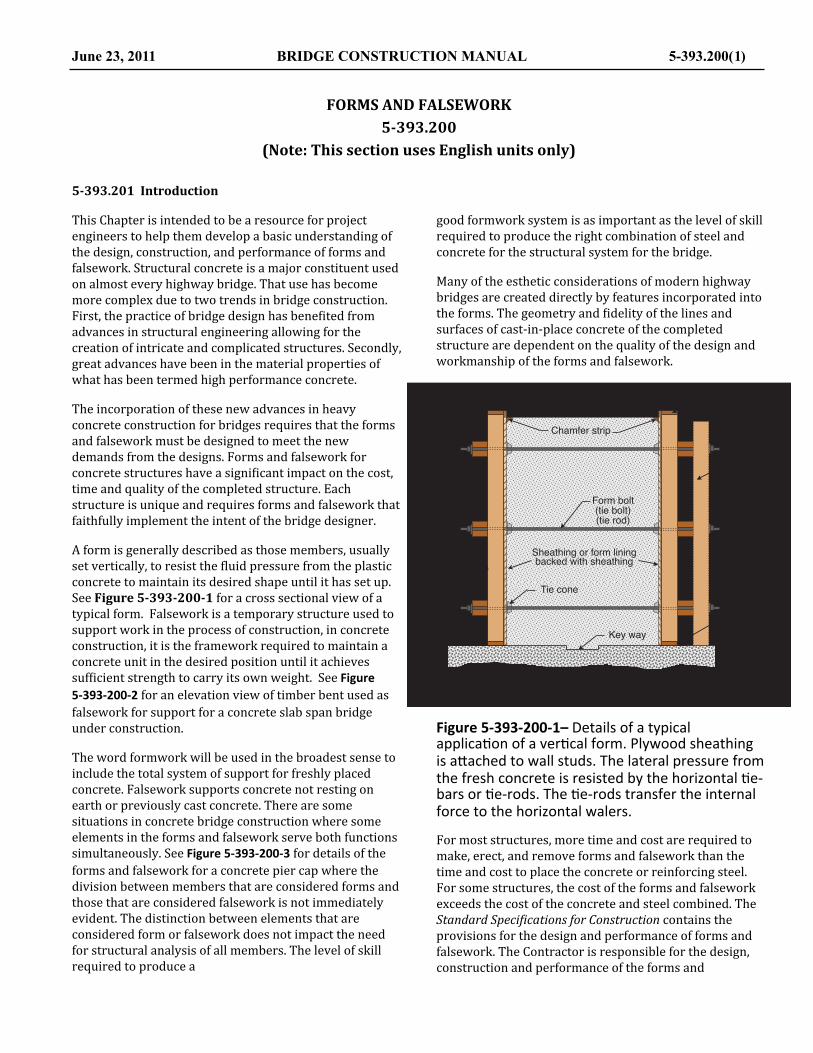
FORMS AND FALSEWORK5-‐393.200
(Note: This section uses English units only)
5-‐393.201 Introduction
This Chapter is intended to be a resource for project engineers to help them develop a basic understanding of the design, construction, and performance of forms and falsework. Structural concrete is a major constituent used on almost every highway bridge. That use has become more complex due to two trends in bridge construction. First, the practice of bridge design has bene@ited from advances in structural engineering allowing for the creation of intricate and complicated structures. Secondly, great advances have been in the material properties of what has been termed high performance concrete.
The incorporation of these new advances in heavy concrete construction for bridges requires that the forms and falsework must be designed to meet the new demands from the designs. Forms and falsework for concrete structures have a signi@icant impact on the cost, time and quality of the completed structure. Each structure is unique and requires forms and falsework that faithfully implement the intent of the bridge designer.
A form is generally described as those members, usually set vertically, to resist the @luid pressure from the plastic concrete to maintain its desired shape until it has set up. See Figure 5-‐393-‐200-‐1 for a cross sectional view of a typical form. Falsework is a temporary structure used to support work in the process of construction, in concrete construction, it is the framework required to maintain a concrete unit in the desired position until it achieves suf@icient strength to carry its own weight. See Figure 5-‐393-‐200-‐2 for an elevation view of timber bent used as falsework for support for a concrete slab span bridge under construction.
The word formwork will be used in the broadest sense to include the total system of support for freshly placed concrete. Falsework supports concrete not resting on earth or previously cast concrete. There are some situations in concrete bridge construction where some elements in the forms and falsework serve both functions simultaneously. See Figure 5-‐393-‐200-‐3 for details of the forms and falsework for a concrete pier cap where the division between members that are considered forms and those that are considered falsework is not immediately evident. The distinction between elements that are considered form or falsework does not impact the need for structural analysis of all members. The level of skill required to produce a
good formwork system is as important as the level of skill required to produce the right combination of steel and concrete for the structural system for the bridge.
Many of the esthetic considerations of modern highway bridges are created directly by features incorporated into the forms. The geometry and @idelity of the lines and surfaces of cast-‐in-‐place concrete of the completed structure are dependent on the quality of the design and workmanship of the forms and falsework.
Figure 5-‐393-‐200-‐1– Details of a typical applica.on of a ver.cal form. Plywood sheathing is a9ached to wall studs. The lateral pressure from the fresh concrete is resisted by the horizontal .e-‐bars or .e-‐rods. The .e-‐rods transfer the internal force to the horizontal walers.
For most structures, more time and cost are required to make, erect, and remove forms and falsework than the time and cost to place the concrete or reinforcing steel. For some structures, the cost of the forms and falsework exceeds the cost of the concrete and steel combined. The Standard Speci,ications for Construction contains the provisions for the design and performance of forms and falsework. The Contractor is responsible for the design, construction and performance of the forms and
June 23, 2011 BRIDGE CONSTRUCTION MANUAL 5-393.200(1)
!"#$%&'()*$
+,$)*,-./&"%&0"%1&(-.-./&2)34$5&#-*,&6,$)*,-./
+*%"./2)34&7)6&.$3$66)%89
:-$&3".$
;"%1&2"(*7*-$&2"(*97*-$&%"59
<,)10$%&6*%-'
<".3%$*$&6*%-4$="00&$($>)*-".?''$%&'()*$
@)($%
+*A5
:-$&'()*$&7#)6,$%9
!"#$$%$&!'(#)%#*%'+,(!-.%/&"'(!-.%*#"0$
B$8&#)8

falsework. This arrangement allows the Contractor discretion in the design and construction of the forms and falsework. Performance-‐based speci@ications for formwork do not prohibit the Contractor from exercising ingenuity in the design, construction and economical selection of materials.
The structural design of the formwork for modern highway bridges can be a very complicated and intricate process. This chapter discusses a wide range of possible con@igurations of formwork. Some formwork applications do not warrant the use of all the possible re@inements. Several simpli@ications of the design process can be used for modest sized structural applications. Most of those simpli@ications can be handled by making a couple of key assumptions to rede@ine the design conditions that actually control the @inal con@iguration. The key assumptions used must generate a more conservative result than the more comprehensive analysis calculations. It is the responsibility of the engineer designing the forms and falsework to determine if the simpli@ications contained in this manual are appropriate for the analysis of his design.
Figure 5-‐393-‐200-‐2– Details of a typical .mber pile bent used for concrete slab-‐span construc.on. The spacing between bents and the pile spacing within the bents are design variables dependent on project condi.ons.
This chapter contains an overview of the design process for forms and falsework. It is not intended to be an exhaustive discourse, rather it is intended to provide information about formwork in two general areas. First, there are examples of the typical application of forms and falsework that can be used on typical highway bridges. The types of form and falsework featured represent those that engineers may encounter on typical projects. Next, there is some basic technical information presented. This
information is used to support the design examples given at the end of the chapter. This technical information is only the minimum needed to work through and follow the example problems.
At the end of the chapter is a list of reference books and other sources for those users who want additional detailed information. There is also a glossary containing words unique to forms and falsework and a list of the symbols and notations used along with the appropriate units of measure at the end of this chapter.
5-‐393.202 General Requirements
Forms are required for all cast-‐in-‐place concrete except portions of footings that extend into solid rock. Concrete is never to be cast against the side of an earth excavation. Concrete not supported on earth or previously cast concrete must be supported by falsework. The need for forms and falsework is self-‐evident in every construction circumstance. This issue is not negotiable. All forms and falsework must be designed to resist all of the imposed loads and pressures without undo distortion.
A. Contractor Responsibilities
The Contractor is responsible for the design and construction of the forms and falsework necessary for the successful completion of the project as contained in the plans and speci@ications. All of the forms and falsework for bridges must be designed by a registered engineer. If requested by the Engineer, the Contractor must submit detailed design calculations and plan drawings certi@ied by a Registered Engineer. The Engineer designing the forms and falsework will be considered the Responsible Engineer. Those calculations must comply with the requirements of the applicable provisions of the Standard Speci,ications for Construction as published by the Minnesota Department of Transportation. If requested by the Engineer, the Contractor shall submit a certi@ication that the forms and falsework were constructed pursuant to the calculations and plans, and that the forms and falsework was inspected by the Responsible Engineer prior to the placement of any concrete.
It is the Contractor’s responsibility to provide the Engineer the speci@ications and technical details including safe-‐load values for any new or unused system or device that they propose to use for formwork. This includes materials with unknown strength properties. It is the Contractor’s responsibility to verify to the Engineer’s satisfaction that the strength and safety of any device or system and the workability of the device or system can safely produce the desired end-‐product. This veri@ication can be provided in the form of:
5-393.200 (2) BRIDGE CONSTRUCTION MANUAL June 23, 2011
!"#$%&'()&'*+,-./(#$'+(0+1!(*2##-.!+3(,$!4(3.$5+1(#$'+*
!"#$%&'($&)'*&+),-./,
0",$,&"/&12#.,
3/24$&12' 02#.&5)1,1#25.&1"2'$
6"/7.#
8+)9&7/)5.,
02#.&5)1 02#.&5($&"448$/2':./,8-.)$-2':!/2*:2':

Figure 5-‐393-‐200-‐3– Details of typical form and falsework used for the construc.on of concrete pier caps.
1. Full scale @ield test
2. Tests by a reputable testing laboratory
3. Certi@ied design calculations
4. Manufacturers literature
5. A combination of the above items
B. Engineer’s Responsibilities
The Engineer’s responsibilities with respect to the forms and falsework can be initiated in two general ways. First, the terms of the contact for certain levels of construction will explicitly require the Contractor to submit plans and design calculations for the formwork. The contract for those types of project may also explicitly require the
Responsible Formwork Engineer to inspect the completed formwork prior to placement of concrete and certify that the forms and falsework have been constructed in accordance with the plans and calculation initially submitted by the Contractor.
In the other method, the Engineer may request calculations and plan details from the Contractor for the forms and falsework. Once the plans and calculations have been received by the Engineer, they should be reviewed as to strength, method of construction, safety, potential problems, and ability to produce the desired product. Approval to use such plans should be noted as being approved as to type of construction and should also bear a note that such acceptance is conditionally based on making changes that the Engineer has noted on the plans. When evaluating a new or untried device or system, approval (if given) should be given only on a performance basis. Such approval of plans does not relieve the
June 23, 2011 BRIDGE CONSTRUCTION MANUAL 5-393.200(3)
!"#$%&'(#$)*()')+&!$,-
&
&
! "!# ! "!#
$% "!#
&' "!#
& "(#")*+,-.-/0.12*3+45
6/*3.*78"9744+/
& ":;#$<'#"=41>7/,?"94+@@"A
&#"B"'#"C":!#"DE9E:<&#" "97*4"F74."G*.H"'#"B"I#"G+@H-/"@2+3-)"C"' ";#
&"-+E"&#"B"!#"0G+4-/@5
:;#
&""&#
(#' "B"( "B"$<'#"
=41>7/,?"94+@@"A
&#"B"!#"B":; "J78K"C":;#"DE9E
L=":&BI$"
6/*3.*78"9744+/
$ ":;#
.)%!$,-(&/&
$"(#
&#"B"'#"M/+3-"C"' "DE9E"F7.H"@*)-@

Contractor of the responsibility for results obtained by use of the plans (see Standard Speci,ications for Construction as published by the Minnesota Department of Transportation).
For certain types of structures, a review by the Contractor’s Responsible Formwork Engineer is required prior to acceptance of the completed formwork. The Engineer should be present during this review of the formwork. No use of the formwork should be permitted until the Responsible Formwork Engineer has completed the review and has authorized its use. This authorization should be in the form of a written certi@ication that formwork has been constructed in compliance with the original design calculations and plans.
A continuing inspection should be made during placement of forms and falsework members to assure conformance with the approved plans (if used), to assure structural soundness and accuracy, and to minimize the need for last minute corrections.
Concrete pours are to be made in accordance with approved pour sequences. Where approval of pour sequences is not required, pours should be as per the form or falsework design and should provide balanced loading to the extent possible. A follow-‐up inspection during and after concrete placement should be made to assure that the forms and/or falsework function as intended with regard to de@lection, tolerances, etc.
5-‐393.203 Types of Forms and Falsework
The number of types, styles and con@igurations of concrete form and falsework is almost as numerous as there are concrete structures. Even with all of the possible variations, most applications can be conveniently placed into one of a few categories. The @irst natural division is form or falsework. This division is based on whether the work primarily con@ines the fresh concrete with a boundary, called a form, or whether the temporary work supports the fresh concrete from resting on the ground or on previously placed concrete, and is referred to as falsework. Additionally, most forms and falsework are referred to by names that are based on the actual structural element being created, such as pier cap or wing wall.
A. Formwork:
Most forms are vertical, and create a visible concrete surface in the @inished structure. These forms are designed to resist the internal pressure produced by the fresh concrete plus any additional forces caused by or associated with the placement of the concrete. One of the most signi@icant factors controlling the pressure exerted
by the fresh concrete is the rate at which the form is @illed with the concrete. This is usually referred to as the “rate-‐of-‐pour.” The following are brief descriptions of the more common forms used in bridge construction.
1. Vertical Forms: See Figure 5-‐393-‐200-‐1, page 5-‐393.200(1), for an illustration of a typical application of this type of construction. This type of form formwork has a sheathing normally employing a plywood-‐like product called Plyform, that actually comes in contact with the fresh concrete. That sheathing is attached to vertical wood members, called studs and thus form the walls of the completed form. The horizontal pressure from the fresh concrete on these walls is resisted by horizontal tie-‐bars that terminate at a waler on each side of the element being cast. These rods or bars have nuts, washers, and bearing plates at each end that press against horizontal wood members, called walers. The walers normally consist of two members with a space between them to accommodate the tie bars, that bear against the studs. The structural stability of most forms is provided by the more or less equal pressure on each wall of the form. This requires that the forms be @illed symmetrically with approximately equal depth of concrete on each wall as the form is @illed with concrete.
2. Pier Cap Forms: A typical application of formwork is for concrete pier caps. See Figure 5-‐393-‐200-‐3, page 5-‐393.200(3), for an illustration of this type of formwork. This type of formwork also requires falsework. The sheathing under the cap serves as both form and falsework. It is analyzed as an element of the falsework.
3. Abutment Wall Forms: Concrete abutments require rather complicated formwork. The dimension and function of the various sections of the abutment change over the height of the abutment. See Figure 5-‐393-‐200-‐4 for details of a typical abutment formwork. Most concrete is poured in stages with slightly different form designs for each stage that re@lect the needs and requirements unique to each stage.
B. Falsework:
This type of temporary work is primarily designed to support weight. There are almost an in@inite number of combinations of spans, weights, and materials. This multitude possibilities can be covered by only a few typical applications that represent the type of work that is used on a majority of highway bridges. Additionally, once the principals of design and construction of these applications are understood, they can be applied to a wide range of materials, components, and loads.
5-393.200 (4) BRIDGE CONSTRUCTION MANUAL June 23, 2011

Figure 5-‐393-‐200-‐4– Details of typical formwork used in concrete abutment construc.on.
1. Falsework Pile Bents: These are used to support the falsework for the construction slab-‐span concrete bridges. See Figure 5-‐393-‐200-‐2 ,page 5-‐393.200(2), for details of a typical timber pile bent falsework.
2. Pier Cap Falsework: Concrete pier caps require both forms and falsework in their construction. A typical example of this type of construction can be seen in Figure 5-‐393-‐200-‐3, page 5-‐393.200(3).
3. Steel Beam — Typical Slab and Overhang Falsework: One of the most commonly used falsework is to support concrete deck construction. Concrete deck construction requires support for the fresh concrete between the girders and for the overhang outside of the fascia girder. See Figure 5-‐393-‐200-‐5 for a few examples for this type of construction with steel beams.
4. Concrete Beam — Typical Slab and Overhang Falsework: Construction of bridges with prestressed concrete girders use many of the same construction techniques used for steel beam bridges, but with slightly different details. See Figure 5-‐393-‐200-‐6 for typical construction details involving bridges with prestressed girders
5. Slab-‐span Falsework: There are several commonly accepted methods of supporting slab-‐span bridge construction. Several companies produce and sell tubular steel scaffolding and shoring systems that are used. One other method is to use driven piles, either steel or timber. See Figure 5-‐393-‐200-‐2 for details of that type of construction.
6. Additional Falsework Applications: Bridge construction projects sometimes involve types of construction not covered by the above examples. These projects could include Box Girders, Tunnels and Tunnel Portals, Shoring associated with railroad crossings, and Cofferdam construction. These projects use specialized material and construction techniques. Engineers should contact the Minnesota Department of Transportation (MN/DOT) Bridge Of@ice for information and assistance for these projects.
5-‐393.204 Forms and Falsework Materials
A. General:
Forms and falsework material described below are listed with either an allowable maximum working stress or a basis for determining the safe load. The working stress or allowable stress shown is based on the use of sound material for temporary construction. The word temporary, as used here, denotes the time-‐frame of use and should not be interpreted to infer any re@lection on the quality of construction. In general, previously used material is permitted, provide it is in good condition.
B. Falsework Piling:
The material requirements for falsework piling are stated in the Standard Speci,ications for Construction as published by the Minnesota Department of Transportation. Maximum allowable loads, in tons, are shown in Table 5-‐393-‐200-‐1.
C. Lumber: General requirements for lumber for falsework and forms are speci@ied in the appropriate provisions contained in Standard Speci,ications for Construction. Lumber that has been planed on a planing machine is said to be “dressed lumber or surfaced lumber.” That planing or surfacing can be on either one side (S1S) or on two sides (S2S) or two edges (S2E) or any combination therefore including complete planing (S4S). See Table 5-‐393-‐200-‐2 for a list of the nominal and surfaced dimensions of most common sizes of lumber.
Lumber that has not been surfaced or dressed is said to be “rough lumber.” Lumber that was originally sawn to dimensions larger that the nominal dimensions so that
June 23, 2011 BRIDGE CONSTRUCTION MANUAL 5-393.200(5)
!"#$%&'(&)*!+,-!(+&$-(.&''(/01+2
!"#$%
&'()*+,-./0#-0#*1.100-(2
3#04-.10#5
#6#7% 89:%#;<2=)(>#
?<-00#@
6%#A#7%#0'BC0#5#!6%#DE?E
F,<E#6%#A#"%#G-<1(
!96%# #.)H<#,)<'I#.)H<#'H10I#-*C#8%#A#04-.1C#5#8 #$%
4(1JH)B0<2#.-0'#.)*.(1'1

Figure 5-‐393-‐200-‐5– Details of several typical configura.ons used to support both roadway slab and overhang construc.on on bridges with steel beams.
5-393.200 (6) BRIDGE CONSTRUCTION MANUAL June 23, 2011
!"#$%&
!"#$ %&''()
*+,-./+-.-0&'1()0("2304+,-.
5,##()0+'0.+60+70("2304+,-.
!(18(-
9#(".0:6)(7()";#<0+'0;+.30-,1(-0+70("2306+-.=
>&66+).,'80;+#.-07+)0'((1#(0;("?
@((1#(0;("?0:1+&;#(0?(?;()=
>3(".3,'8 >.),'8()-
*+,-.
/+-.-0&'1()0("2304+,-.
!""#$%&'%$#($#)*+*$$(&,
-%&.)/*&$
01'23*#41.$%
-5*(%5.)/6()/*& 6()/*&
711"#18*&5()/2&(+9*%#:.%55()/*&#$';;1&%
!"#$%&
-';;1&%.)/#213%-';;1&%.)/#213%<1$%
6()/*&#=13%
!""#$%&'%$#($#)*+*$$(&,
-%&.)/*&$
01'23*#41.$%
-5*(%5.)/6()/*&
-%**3#17*&5()/2&(+8*%#9.%55()/*&#$'::1&%
!"#$%&
6()/*&6()/*&#;13%
!"#$%&'()*+%&**)+,-%&%.&**)+-/*01'23(0'45*&+67&11'23*0+%$,,-0&
!"#$%&
8-)&+&10$+6*(
.&0723*0%.1*'&1723
!""+6*"3*%+61*2+%&0$&&723+-9+9'%47'+(*':+7%+2*4*%%'0;+<(-&1+*2"%=
>-$()*+:*:(*0%
>-$()*+?-7%&
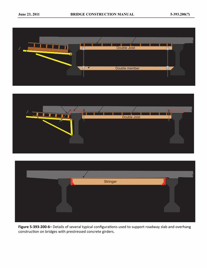
Figure 5-‐393-‐200-‐6– Details of several typical configura.ons used to support roadway slab and overhang construc.on on bridges with prestressed concrete girders.
June 23, 2011 BRIDGE CONSTRUCTION MANUAL 5-393.200(7)
!"#$%&'#(!)'*")$%&
+,-./'01,$("
+,-./'02'2.'#
345-("*./'0("''/06,("(!-66,#"07,#0("''/0.#*89'"(!"''/0,:'#)*%&0.#*89'"0
(-66,#"'40.;0.,/"0$%0.'*20<'.
!"#$%&
!"#$%&'#(!)'*")$%&
+,-./'01,$("
!"''/0,2'#)*%&0.#*34'"0(-55,#"'60.70)*%&'#0.,/"
!"#$%&
8*%&'#8*%&'#09,/"
!"#$%"&'(
!%)&'(#)
*+)(,"$'(#)-.#)"$'(,/$01#2+)3,1&4&0$),%+,%56#,7,+),8
!"#$%&
*+)(,"$'(#)

Table 5-‐393-‐200-‐1– Maximum allowable loads in tons for driven piles used for falsework construc.on as a func.on of pile diameter.
upon drying the resulting lumber has the same dimensions as nominal, is said to be “full-‐sawn lumber.” The dimensions of rough lumber can vary signi@icantly and the Engineer must check the actual dimensions to see if they comply with the Contractor’s forms and falsework plans. This is particularly true when laminated veneer lumber (LVL) or parallel strand lumber (PSL) is used, as this material is normally ripped out of wide billets and may not be sawn to dimensions that match the standard nominal or dressed lumber sizes.
In addition to these general requirements, it is speci@ically recommended that material for studs and walers be sized and dressed to at least S2E to provide for true concrete lines.
Lumber that must withstand stress should be checked for conformance with the appropriate allowable stresses shown in Table 5-‐393-‐200-‐3 for allowable working stresses. The following notes apply to the use of information in this table:
1. New Lumber: Each piece of graded lumber is stamped with a grade stamp. On new material, information as to timber specie and stress grade can be obtained from this stamp for use with the allowable stress table in this section of the manual.
2. Used Lumber: In the event the grade stamp is missing or is unreadable, the species and grade or stress rating must be determined by visual examination or judgment or an assumed
identi@ication must be applied. In case of uncertainty, assume the lumber in question to be Red (Norway) Pine, and with a stress grade, such as No. 1 to be on the conservative side.
3. Additional Considerations: Regardless of whether new or used, a visual check should be made of stressed members with these considerations in mind:
a. Any reduction in cross section at or near the middle 1/3 of the length of a beam reduces the capacity to resist bending. Such reduction in section could be a damaged area, large knots, notches, or holes in the lower 1/3 of the section. If such pieces are used for beams, only the sound portions of the section can be considered as effective for calculation of stresses.
b. Notches or reduction in beam depth near the support point will reduce the beams capacity to resist horizontal shear stress. Special considerations and calculations are necessary to determine the horizontal shear stress when such pieces are used.
c. When forms or falsework are constructed of previously used material that is judged to be not equal in strength to sound material, the allowable stresses in the table should be reduced by an appropriate amount.
5-393.200 (8) BRIDGE CONSTRUCTION MANUAL June 23, 2011
MAXIMUM ALLOWABLE PILE LOADS
Pile Dia, Steel Piles Steel PilesAt Cut-off Timber Piles Friction Point Bearing(inches) (tons) (tons) (tons)
Butt diameterssmaller than 8 in.are not permitted
8 16 16 9,000 lb. per sq.10 20 20 inch of point area12 24 24 (or at least cross-14 28 28 sectional area of16 32 the pile)

Table 5-‐393-‐200-‐2– Sec.on of proper.es of standard lumber sizes for both dressed lumber sizes and full sawn lumber sizes.
June 23, 2011 BRIDGE CONSTRUCTION MANUAL 5-393.200(9)
Section Properties of Standard Lumber Sizes
MOMENT OF INERTIA SECTION MODULUSNOMINAL DIMENSIONS OF DRESSED LUMBER SIZE S4S
Area Weightb d b d b xd S4S Full Sawn S4S Full Sawn
(in.) (in.) (in.) (in.) (in.2) (#/lin.ft.) (in.4) (in.4) (in.3) (in.3)12 1 11 1/4 3/4 8.44 2.3 0.40 1.00 1.05 2.00
1-1/4 1 11.25 3.1 0.94 1.95 1.88 3.131-1/2 1-1/4 14.06 3.9 1.83 3.38 2.93 4.50
2 1-1/2 16.88 4.7 3.16 8.00 4.22 8.002 4 1-1/2 3-1/2 5.25 1.5 5.36 10.67 3.06 5.33
6 5-1/2 8.25 2.3 20.80 36.00 7.56 12.008 7-1/4 10.88 3.0 47.63 85.33 13.14 21.3310 9-1/4 13.88 3.9 98.93 166.67 21.39 33.3312 11-1/4 16.88 4.7 177.98 288.00 31.64 48.0014 13-1/4 19.88 5.5 290.78 457.33 43.89 65.33
3 4 2-1/2 3-1/2 8.75 2.4 8.93 16.00 5.10 8.006 5-1/2 13.75 3.8 34.66 54.00 12.60 18.008 7-1/4 18.13 5.0 79.39 128.00 21.90 32.0010 9-1/4 23.13 6.4 164.89 250.00 35.65 50.0012 11-1/4 28.13 7.8 296.63 432.00 52.73 72.0014 13-1/4 33.13 9.2 484.62 686.00 73.15 98.00
4 4 3-1/5 3-1/2 12.25 3.4 12.51 21.33 7.15 10.676 5-1/2 19.25 5.3 48.53 72.00 17.65 24.008 7-1/4 25.38 7.0 111.15 170.67 30.66 42.6710 9-1/4 32.38 9.0 230.84 333.33 4.91 66.6712 11-1/4 39.38 10.9 415.28 576.00 73.83 96.0014 13-1/4 46.38 12.9 678.48 914.67 102.41 130.6716 15-1/4 53.38 14.8 1,034.42 1,365.33 135.66 170.67
6 6 5-1/2 5-1/2 30.25 8.4 76.26 108.00 27.73 36.008 7-1/4 39.88 11.1 174.66 256.00 48.18 64.0010 9-1/4 50.88 14.1 362.75 500.00 78.43 100.0012 11-1/4 61.88 17.2 652.59 864.00 116.02 144.0014 13-1/4 72.88 20.2 1,066.18 1,372.00 160.93 196.0016 15-1/4 83.88 23.3 1,625.51 2,048.00 213.18 256.00
8 6 7-14 5-1/2 39.88 11.1 100.52 144.00 36.55 48.008 7-1/4 52.56 14.6 230.22 341.33 63.51 85.3310 9-1/4 67.06 18.6 478.17 666.67 103.39 133.3312 11-1/4 81.56 22.7 860.23 1,152.00 152.93 192.0014 13-1/4 96.06 26.7 1,405.41 1,829.33 212.14 261.3316 15-1/4 110.56 30.7 2,142.72 2,730.67 281.01 341.33
10 6 9-1/4 5-1/2 50.88 14.1 128.25 180.00 46.64 60.008 7-1/4 67.56 18.6 293.75 426.67 81.03 106.6710 9-1/4 85.56 23.8 610.08 833.33 131.91 166.6712 11-1/4 104.06 28.9 1,097.53 1,440.00 195.12 240.0014 13-1/4 133.56 34.0 1,793.11 2,286.67 270.66 326.6716 15-1/4 141.06 39.2 2,733.82 3,413.33 358.53 426.67
12 6 11-1/4 5-1/2 61.88 17.2 155.98 216.00 556.72 72.008 7-1/4 81.56 22.7 357.26 512.00 98.55 128.0010 9-1/4 104.06 28.9 741.99 1,000.00 160.43 200.0012 11-1/4 126.56 35.2 1,334.84 1,728.00 237.3 288.0014 13-1/4 149.06 41.4 2,180.82 2,744.00 329.18 392.0016 15-1/4 171.56 47.7 3,324.92 4,096.00 436.05 512.00

D. Allowable Stresses:
All of the engineering analysis of forms and falsework for work on projects under the Standard Speci,ications for Construction as published by the Minnesota Department of Transportation is based on the Allowable Stress Design (ASD) method. The allowable stresses and the modulus of elasticity (E) values listed in the tables contained herein are modi@ied in accordance ACI Committee 347, Guide to Formwork for Concrete as published by the American Concrete Institute.
Some of the appropriate tabulate stresses (except E and compression perpendicular to grain) have been increased by 25% (CD = 1.25) due to the anticipated short-‐term duration of the applied loads in most forms and falsework applications. See Table 5-‐393-‐200-‐3 for allowable stresses for several of the common stress grades used for forms and falsework. Stresses for species or grades not listed in the accompanying tables should be obtained from the Of@ice of Bridges and Structures at Mn/DOT and must conform to AASHTO Speci@ications.
The strength of wood column is dependent on several factors. The most signi@icant factor is the column action: factor, CP. The determination of the allowable working stress starts with the end bearing values and is modi@ied by the ratio of the length divided by the least dimension of the column. This is called the “l over d Ratio” and is abbreviated (l/d). The (l/d) for a wood column must never exceed 50. The allowable compression parallel to grain (end bearing) in a wood column will be which ever is the least:
F’c = the allowable end bearing, psi, listed in Table 5-‐393-‐200-‐3, page 5-‐393.200(11)
Or
F 'c =0.30Eld( )
2
where:
d = dimension of least side of column, in
l = unsupported length of column, in
E = modulus of elasticity, psi
The maximum allowable compressive stress for Douglas Fir columns and Red (Norway) Pine columns (as determined using the above criteria) may be obtained
from Chart 5-‐393-‐200-‐1. Additionally, for convenience in making calculations involving dimension lumber, a tabulation of standard lumber sizes and their respective section properties are included in Table 5-‐393-‐200-‐2.
E. Plywood Sheathing:
General requirements for plywood sheathing are speci@ied in the Standard Speci,ications for Construction as published by the Minnesota Department of Transportation. The plywood sheathing most commonly used is Douglas Fir Exterior “Plyform,” which is available in three strength grades known as Class I, Class II, and Structural I. Plyform is a wood product like plywood that is made specially for concrete forms. All Classes are fabricated using exterior glue and have sanded grade B face plies. New panels of Plyform can be identi@ied by the grade marks stamped on each panel as shown in Figure 5-‐393-‐200-‐7, page 5-‐393.200(13).
In considering the bending strength, rolling shear strength or de@lection of a panel, only those plies that have their grain perpendicular to the supporting joist or studs are assumed to be resisting the load. The safe span length is therefore dependent not only on the Class of Plyform that is used but also on whether the grain of the face plies run across supports (perpendicular to the joist or studs), or parallel to supports (parallel to the joist or stud). When plywood or Plyform is used with the face grain running across the supports it is said that it is in the “strong direction” and when it is used with the grain of the face plies parallel to the supports it is used in the “weak direction.” See Figure 5-‐393-‐200-‐8 and Figure 5-‐393-‐200-‐9 for details.
Section properties for Plyform Class I, Class II, and Structural I can be found in Table 5-‐393-‐200-‐6. The material properties for Plyform are shown in Table 5-‐393-‐200-‐7. The data in Table 5-‐393-‐200-‐4 and Table 5-‐393-‐200-‐5 and Figure 5-‐393-‐200-‐15 may be used for quickly determining safe spacing of joist and studs when using Plyform Class I under two different loading conditions.
With the brand name or grade stamp on the plywood being used, the requirements of the Standard Speci,ications for Construction can be quickly veri@ied. When no grade stamp is visible, it is the Contractor’s responsibility to verify to the satisfaction of the Engineer that the concrete grade plywood has been furnished.
When it is determined that form grade plywood has been furnished but the speci@ic Class of plywood is unknown, the following limiting stress values will apply:
5-393.200 (10) BRIDGE CONSTRUCTION MANUAL June 23, 2011

Table 5-‐393-‐200-‐3– Allowable working stresses for common species of wood used for construc.on of forms and falsework.
Maximum allowable bending stress, Fb : 1,500 psi
Maximum allowable shear stress, Frv : 70 psi
Modulus of elasticity, E: 1,600,000 psi
Maximum compression perpendicular, Fc: 285 psi
Plywood section properties, which will be necessary for checking stresses when not using Plyform Charts that are tabulated in Table 5-‐393-‐200-‐8, page 5-‐393.200(16).
The reuse of plywood sheathing will be dependent on its condition with respect to damage due to prior use, amount of permanent set from prior use, amount of face ply separation and the nature of the concrete surface being formed (exposed or not exposed, etc.). Plywood that
is not longer suitable for its intended purpose must be rejected.
F. Structural Composite Lumber (SCL):
Structural Composite Lumber (SCL) is a term used to refer to three different wood-‐based manufactured structural products. The @irst type of SCL is Glued-‐laminated timber, generally referred to as “Glulam.” Glulam members are large structural members manufactured by gluing together 2 inch lumber using a exterior adhesives and pressure. Glulam members can be manufactured as either a beam element or column. They are identi@ied by a unique Combination Symbol, which are similar to stress grades in lumber. The material properties for glulam member can be found in the National Design Speci,ications for Wood Construction (NDS). Glulam members have been in general use since
June 23, 2011 BRIDGE CONSTRUCTION MANUAL 5-393.200(11)
ALLOWABLE WORKING STRESSES
Bending Horizontal Side End Modulus ofSpecies and Size Stress Shear Bearing Bearing Elasticity, E
Commercial Grade Restrictions (psi) (psi) (psi) (psi) (psi)
Douglas Fir-Larch 2 to 4" thickNo. 1 < 10" width 1,375 220 625 1,875 1,700,000No. 2 < 10" width 1,250 220 625 1,700 1,600,000
Southern Pine 2 to 4" thickNo. 1 < 10" width 1,625 220 565 2,000 1,700,000No. 2 < 10" width 1,300 220 565 1,875 1,600,000
Red Pine (Norway) 2" to 4" thickNo. 1 < 10" width 1,065 175 335 1,250 1,100,000
Laminated Veneer Lumber (LVL)Douglas Fir - 2.0E 3,500 350 480 3,400 2,000,000
Southern Pine - 2.0E 3,650 350 525 3,800 2,000,000
NOTES:The values in this table are based on Reference Design Values for the Species and CommercialGrades from the National Design Specifications for Wood Construction, 2005 Edition.The bending and shear values have been adjusted using a Duration of Load Factor, CD = 1.25.All values have been adjusted for dry service conditions.The Douglas Fir-Larch bending values have been adjusted by a Size Factor, CF = 1.1.Bending values have been adjusted by a Repetitive Member Factor, Cr = 1.00.

Chart 5-‐393-‐200-‐1– Maximum allowable compress stress parallel to grain for Douglas No. 1 and Red Pine, No. 1 used as columns.
1940’s, but are used more frequently in permanent building construction.
Laminated Veneer Lumber (LVL) refers to wood structural members that have been manufactured by laminating thin layers of veneer (1/10 inch) using exterior adhesives under high clamping pressure and high temperature. These veneers are the same type of veneer plies that are used in the manufacture of plywood. However, in manufacture of LVL all of the plies run in the same direction, parallel to the longitudinal axis of the member. The edge view of LVL looks like plywood except all the plies run in the same direction. These elements are made in billets that are generally about 2 inches in thickness and with widths approximately 24 inches and lengths of 40 feet. These billets are generally “re-‐sawed” into smaller sizes similar to standard lumber.
There are several advantages to this material. First, the con@iguration of the veneers in the members create a timber member that has very low variability, this in turn provides high allowable strength properties. There are not generic tables of material properties for this type of material as each manufacturer of LVL has its own proprietary recipe for their material. However, all of the manufacturers print the signi@icant material properties in big letters on every piece of their material.
The most signi@icant material attribute for most timber structural elements is the modulus of elasticity, E. Most LVL have a large printed number such as 1.6 or 1.8 or 2.0. These numbers represent the modulus of elasticity in millions. Where 1.8 means the member has an E of 1,800,000 psi, and a piece of LVL with 2.0 printed on it has an E of 2,000,000 psi. The LVL members also have another number printed in smaller letters that state the allowable bending stress. There will be printing on the
5-393.200 (12) BRIDGE CONSTRUCTION MANUAL June 23, 2011
Lake Superior College 21
Maximum Allowable Compressive Stressfor Timber Columns
0200400600800
100012001400160018002000
5 10 15 20 25 30 35 40l/d
Allo
wab
le C
ompr
essi
ve S
tres
s fo
r col
umn
(psi
)
Doug Fir No. 1 Red Pine No. 1
Doug Fir, No. 1Red Pine, No. 1
d
l
The information presented in this chart was determined using the following:
fc =0.30E
2( )ld

LVL that looks like “Fb1600”, which means the allowable bending stress is 1,600 psi. Most of the strength attributes of wood structural members are closely correlated to the modulus of elasticity. Most strength attributes and use guidelines are readily available in the manufacturers published literature.
The next type of SCL is Parallel Strand Lumber (PSL). One type of parallel strand lumber is made from the same species of wood used for plywood (i.e., Douglas Fir and Southern Pine). It starts with a sheet of veneer that is then clipped into narrow strands that are approximately ½ inch in width and 8 feet in length. The strands are dried, coated with a waterproof adhesive, and bonded together under pressure and heat. Like other SCL products the major material properties are printed on the members. All strength properties and use guidelines are available in the manufacturers published literature.
Figure 5-‐393-‐200-‐7– Examples of grade stamps commonly used on Plyform material used for forms and falsework.
G. Form Lining:
General requirements for Form Liners, both as to material and usage, are speci@ied in detail in the Standard Speci,ications for Construction as published by the Minnesota Department of Transportation. Forms incorporating a form liner backed by sheathing will be used rarely except in the case of architectural treatment of concrete surfaces. Projects that require form linings will have the requirements contained in the contract documents.
H. Rolled Steel Shapes:
When angles, channels, wide @lange beams, H-‐piles or other rolled steel shapes are used in critical portions of the falsework, the section should be identi@ied by making complete measurements of the cross section. These dimensions can then be used to identify the member further by referring to the AISC Steel Construction Manual,
where all standard rolled sections are listed along with their dimensions, unit weights, and all the necessary design properties. Since this material cannot be visually identi@ied as to grade of steel, the following stress limits should be assumed, unless the Contractor furnishes satisfactory assurance that the steel is of a higher grade.
Rolled Steel Shapes (assume ASTM A36 steel)
Allowable bending stress, Fb’: 25,000 psi
Allowable compressive stress, Fc’:
F 'c =16,980 − 0.53×KLr
⎛
⎝⎜
⎞
⎠⎟2
where:
L = unsupported length, in
K = 1.0 for pined ends (ref: AISC Manual)
r = governing radius gyration, in
and:
L/r must not exceed 120
The values listed above will be suf@icient for checking most falsework problems involving rolled steel members. Any additional design considerations (such as steel falsework and other special cases) should conform to the provisions of the AASHTO Standard Speci@ications for Highway Bridges, as required in the Standard Speci,ications for Construction as published by the Minnesota Department of Transportation
When previously used material is to be incorporated into the work, the extent of damage (caused by prior usage) and corrosion should be evaluated. If corrosion is determined to have reduced the net thickness of the cross section, it is allowable to use the section properties of a similar rolled shape in the AISC manual with thickness dimensions compared to those of the net intact material. Additional requirements for use of structural shapes are given in the Standard Speci,ications for Construction as published by the Minnesota Department of Transportation.
I. Proprietary Products:
The increasing use of special devices, (made of material other than wood) for forms and falsework has, in general, resulted is a speed-‐up of work as well as improved quality of work. However, there is usually a degree of uncertainty about each new device until it is proven in use. A partial listing of devices which have been used successfully, and in some instances unsuccessfully, is as follows:
June 23, 2011 BRIDGE CONSTRUCTION MANUAL 5-393.200(13)
Lake Superior College 9
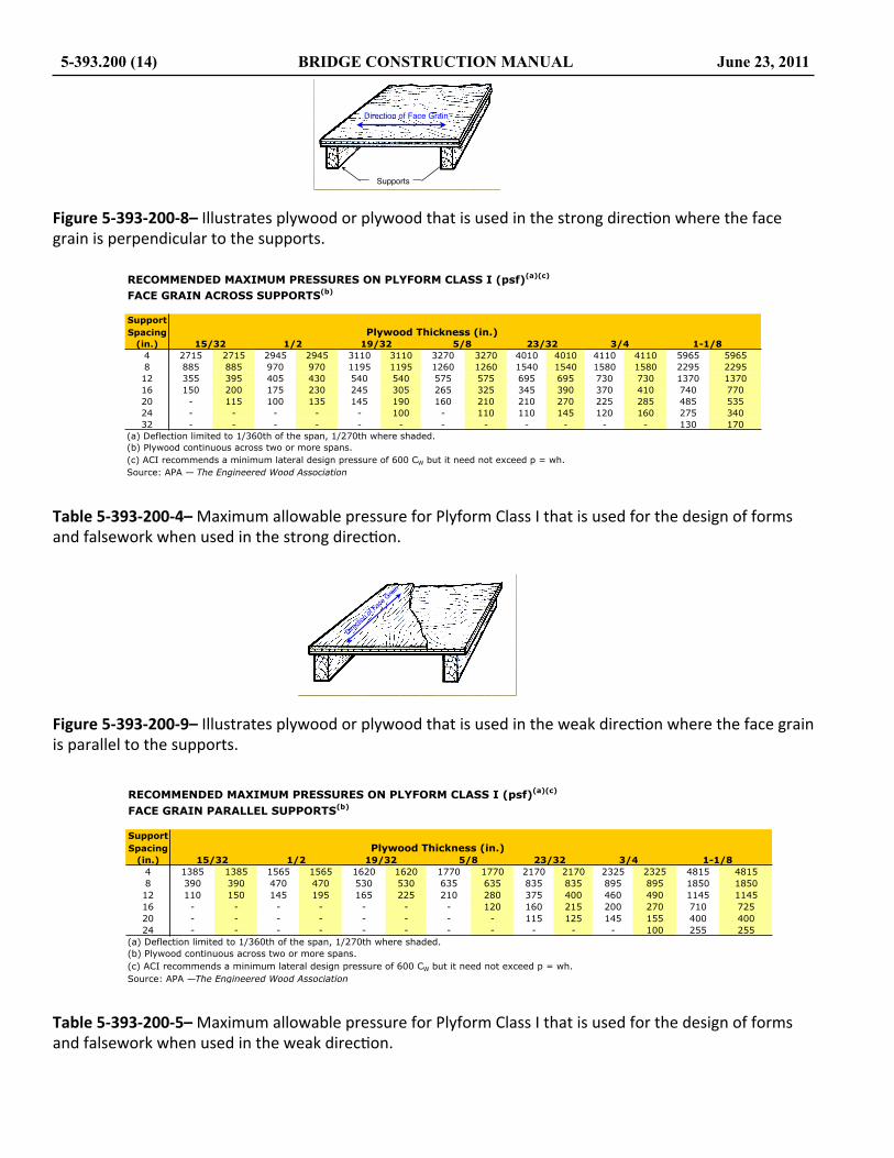
Figure 5-‐393-‐200-‐8– Illustrates plywood or plywood that is used in the strong direc.on where the face grain is perpendicular to the supports.
Table 5-‐393-‐200-‐4– Maximum allowable pressure for Plyform Class I that is used for the design of forms and falsework when used in the strong direc.on.
Figure 5-‐393-‐200-‐9– Illustrates plywood or plywood that is used in the weak direc.on where the face grain is parallel to the supports.
Table 5-‐393-‐200-‐5– Maximum allowable pressure for Plyform Class I that is used for the design of forms and falsework when used in the weak direc.on.
5-393.200 (14) BRIDGE CONSTRUCTION MANUAL June 23, 2011
Lake Superior College 9
Direction of Face Grain
Supports
RECOMMENDED MAXIMUM PRESSURES ON PLYFORM CLASS I (psf)(a)(c)
FACE GRAIN ACROSS SUPPORTS(b)
Support
Spacing Plywood Thickness (in.)(in.) 15/32 1/2 19/32 5/8 23/32 3/4 1-1/8
4 2715 2715 2945 2945 3110 3110 3270 3270 4010 4010 4110 4110 5965 5965
8 885 885 970 970 1195 1195 1260 1260 1540 1540 1580 1580 2295 2295
12 355 395 405 430 540 540 575 575 695 695 730 730 1370 1370
16 150 200 175 230 245 305 265 325 345 390 370 410 740 770
20 - 115 100 135 145 190 160 210 210 270 225 285 485 535
24 - - - - - 100 - 110 110 145 120 160 275 340
32 - - - - - - - - - - - - 130 170
(a) Deflection limited to 1/360th of the span, 1/270th where shaded.
(b) Plywood continuous across two or more spans.
(c) ACI recommends a minimum lateral design pressure of 600 CW but it need not exceed p = wh.
Source: APA — The Engineered Wood Association
Lake Superior College 10
Dire
ctio
n of
Fac
e G
rain
RECOMMENDED MAXIMUM PRESSURES ON PLYFORM CLASS I (psf)(a)(c)
FACE GRAIN PARALLEL SUPPORTS(b)
Support
Spacing Plywood Thickness (in.)(in.) 15/32 1/2 19/32 5/8 23/32 3/4 1-1/8
4 1385 1385 1565 1565 1620 1620 1770 1770 2170 2170 2325 2325 4815 4815
8 390 390 470 470 530 530 635 635 835 835 895 895 1850 1850
12 110 150 145 195 165 225 210 280 375 400 460 490 1145 1145
16 - - - - - - - 120 160 215 200 270 710 725
20 - - - - - - - - 115 125 145 155 400 400
24 - - - - - - - - - - - 100 255 255
(a) Deflection limited to 1/360th of the span, 1/270th where shaded.
(b) Plywood continuous across two or more spans.
(c) ACI recommends a minimum lateral design pressure of 600 CW but it need not exceed p = wh.
Source: APA —The Engineered Wood Association
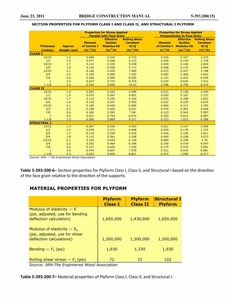
Table 5-‐393-‐200-‐6– Sec.on proper.es for Plyform Class I, Class II, and Structural I based on the direc.on of the face grain rela.ve to the direc.on of the supports.
Table 5-‐393-‐200-‐7– Material proper.es of Plyform Class I, Class II, and Structural I.
June 23, 2011 BRIDGE CONSTRUCTION MANUAL 5-393.200(15)
SECTION PROPERTIES FOR PLYFORM CLASS I AND CLASS II, AND STRUCTURAL I PLYFORM
Properties for Stress Applied Properties for Stress Applied
Parallel with Face Grain Perpendicular to Face Grain
Effective Rolling Shear Effective Rolling Shear
Moment Section Constant Moment Section Constant
Thickness Approx. of Inertia I Modulus KS lb/Q of Inertia I Modulus KS lb/Q
(inches) Weight (psf) (in.4/ft) (in.
3/ft (in.
2/ft) in.
4/ft (in.
3/ft) (in
2/ft)
CLASS I15/32 1.4 0.066 0.244 4.743 0.018 0.107 2.419
1/2 1.5 0.077 0.268 5.133 0.024 0.130 2.739
19/32 1.7 0.115 0.335 5.438 0.029 0.146 2.834
5/8 1.8 0.130 0.358 5.717 0.038 0.175 3.094
23/32 2.1 0.180 0.430 7.009 0.072 0.247 3.798
3/4 2.2 0.199 0.455 7.187 0.092 0.306 4.063
7/8 2.6 0.296 0.584 8.555 0.151 0.422 6.028
1 3.0 0.427 0.737 9.374 0.270 0.634 7.014
1-1/8 3.3 0.554 0.849 10.43 0.398 0.799 8.419
CLASS II15/32 1.4 0.063 0.243 4.499 0.015 0.138 2.434
1/2 1.5 0.075 0.267 4.891 0.020 0.167 2.727
19/32 1.7 0.115 0.334 5.326 0.025 0.188 2.812
5/8 1.8 0.130 0.357 5.593 0.032 0.225 3.074
23/32 2.1 0.180 0.430 6.504 0.060 0.317 3.781
3/4 2.2 0.198 0.454 6.631 0.075 0.392 4.049
7/8 2.6 0.300 0.591 7.99 0.123 0.542 5.997
1 3.0 0.421 0.754 8.614 0.220 0.812 6.987
1-1/8 3.3 0.566 0.869 9.571 0.323 1.023 8.388
STRUCTRAL I15/32 1.4 0.067 0.246 4.503 0.021 0.147 2.405
1/2 1.5 0.078 0.271 4.908 0.029 0.178 2.725
3/5 1.7 0.116 0.338 5.018 0.034 0.199 2.811
5/8 1.8 0.131 0.361 5.258 0.045 0.238 3.073
23/32 2.1 0.183 0.439 6.109 0.085 0.338 3.78
3/4 2.2 0.202 0.464 6.189 0.108 0.418 4.047
7/8 2.6 0.317 0.626 7.539 0.179 0.579 5.991
1 3.0 0.479 0.827 7.978 0.321 0.870 6.981
1-1/8 3.3 0.623 0.955 8.841 0.474 1.098 8.377
Source: APA — The Engineered Wood Association
MATERIAL PROPERTIES FOR PLYFORM
Plyform Plyform Structural I
Class I Class II PlyformModulus of elasticity — E
(psi, adjusted, use for bending
deflection calculation) 1,650,000 1,430,000 1,650,000
Modulus of elasticity — Ee
(psi, adjusted, use for shear
deflection calculations) 1,500,000 1,300,000 1,500,000
Bending — Fb (psi) 1,930 1,330 1,930
Rolling shear stress — Fs (psi) 72 72 102
Source: APA-The Engineered Wood Association

Table 5-‐393-‐200-‐8– Sec.on proper.es for Plywood based on the direc.on of the face grain rela.ve to the direc.on of the supports.
Table 5-‐393-‐200-‐9– Maximum allowable span lengths for Douglas Fir, No. 2 and Southern Pine, No. 2 framing lumber based on varying uniform loads.
5-393.200 (16) BRIDGE CONSTRUCTION MANUAL June 23, 2011
SECTION PROPERTIES OF PLYWOOD
Effective 12-in. wide, used with face grain 12-in. wide, used with face grain
Thickness perpendicular to supports perpendicular to supports
for Shear
All
Sanded Grades, Area for Moment Effective Rolling Area for Moment Effective Rolling
Plywood Using Tension of Section Shear Tension of Section Shear
Net Exteriior and Inertia Modulus Constant and Inertia Modulus Constant
Thickness Number Glue Compression I S I/Q Compression I S I/Q
(in.) of Plies (in.) (in.2) (in.
4) (in.
3) (in.) (in.
2) (in.
4) (in.
3) (in.)
1/4 3 0.241 1.680 0.013 0.091 0.179 0.600 0.001 0.016 -
3/8 3 0.305 1.680 0.040 0.181 0.309 1.050 0.004 0.044 -
1/2 5 0.450 2.400 0.080 0.271 0.436 1.200 0.016 0.096 0.215
5/8 5 0.508 2.407 0.133 0.360 0.557 1.457 0.040 0.178 0.315
3/4 5 0.567 2.778 0.201 0.456 0.687 2.200 0.088 0.305 0.393
7/8 7 0.711 2.837 0.301 0.585 0.704 2.893 0.145 0.413 0.531
1 7 0.769 3.600 0.431 0.733 0.763 3.323 0.234 0.568 0.632
1 1/8 7 0.825 3.829 0.566 0.855 0.849 3.307 0.334 0.702 0.748
Lake Superior College
Maximum Span Table
42
MAXIMUM SPANS FOR LUMBER FRAMING, INCHES — DOUGLAS-FIR NO. 2 OR SOUTHERN PINE NO. 2
Equivalent Continuous Over 2 or 3 Supports Continuous Over 4 or More Supports
Uniform (1 or 2 Spans) (3 or 4 Spans)
Load Nominal Size Nominal Size
(lb/ft) 2x4 2x6 2x8 2x10 4x4 4x6 4x8 2x4 2x6 2x8 2x10 4x4 4x6 4x8
200 48 73 92 113 64 97 120 56 81 103 126 78 114 140
400 35 52 65 80 50 79 101 39 58 73 89 60 88 116
600 29 42 53 65 44 64 85 32 47 60 73 49 72 95
800 25 36 46 56 38 56 73 26 41 52 63 43 62 82
1000 22 33 41 50 34 50 66 22 35 46 56 38 56 73
1200 19 30 38 46 31 45 60 20 31 41 51 35 51 67
1400 18 28 35 43 29 42 55 18 28 37 47 32 47 62
1600 16 25 33 40 27 39 52 17 26 34 44 29 44 58
1800 15 24 31 38 25 37 49 16 24 32 41 27 41 55
2000 14 23 29 36 24 35 46 15 23 30 39 25 39 52
2200 14 22 28 34 23 34 44 14 22 29 37 23 37 48
2400 13 21 27 33 21 32 42 13 21 28 35 22 34 45
2600 13 20 26 31 20 31 41 13 20 27 34 21 33 43
2800 12 19 25 30 19 30 39 12 20 26 33 20 31 41
3000 12 19 24 29 18 29 38 12 19 25 32 19 30 39
3200 12 18 23 28 18 28 37 12 19 24 31 18 29 38
3400 11 18 22 27 17 27 35 12 18 24 30 18 28 36
3600 11 17 22 27 17 26 34 11 18 23 30 17 27 35
3800 11 17 21 26 16 25 33 11 17 23 29 16 26 34
4000 11 16 21 25 16 24 32 11 17 22 28 16 25 33
4200 11 16 20 25 15 24 31 11 17 22 28 16 24 32
4400 10 16 20 24 15 23 31 10 16 22 27 15 24 31
4600 10 15 19 24 14 23 30 10 16 21 26 15 23 31
4800 10 15 19 23 14 22 29 10 16 21 26 14 23 30
5000 10 15 18 23 14 22 29 10 16 21 25 14 22 29
NOTE: Spans are based on the 2001 NDS allowable stress values. Where: CD = 1.25, Cr = 1.0. CM = 1.0
Deflection is limited to 1/360th of span with 1/4" maximum
Spans within the brown shaded boxes are controlled by deflection. Bending governs elsewhere.
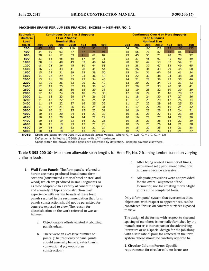
Table 5-‐393-‐200-‐10– Maximum allowable span lengths for Hem-‐Fir, No. 2 framing lumber based on varying uniform loads.
1. Wall Form Panels: The form panels referred to herein are mass-‐produced brand name form sections (constructed either of steel or steel and wood) which are produced in small segments so as to be adaptable to a variety of concrete shapes and a variety of types of construction. Past experience with certain brands of these form panels resulted in the recommendation that form panels construction should not be permitted for concrete exposed to view. The reason for dissatisfaction on the work referred to was as follows:
a. Objectionable offsets existed at abutting panels edges.
b. There were an excessive number of joints. (The frequency of panel joints should generally be no greater than in conventional plywood-‐form construction.)
c. After being reused a number of times, permanent set ( permanent de@lection) in panels became excessive.
d. Adequate provisions were not provided for the overall alignment of the formwork, nor for creating mortar-‐tight joints in the completed form.
Only a form panel system that overcomes these objections, with respect to appearances, can be considered for use on concrete surfaces exposed to view.
The design of the forms, with respect to size and spacing of members, is normally furnished by the manufacturer, either as part of the advertising literature or as a special design for the job along with a safe rate of pour for concrete in the form system. These should be carefully adhered to.
2. Circular Column Forms: Speci@ic requirements for circular column forms are
June 23, 2011 BRIDGE CONSTRUCTION MANUAL 5-393.200(17)
Lake Superior College
Maximum Span Table
43
MAXIMUM SPANS FOR LUMBER FRAMING, INCHES — HEM-FIR NO. 2
Equivalent Continuous Over 2 or 3 Supports Continuous Over 4 or More Supports
Uniform (1 or 2 Spans) (3 or 4 Spans)
Load Nominal Size Nominal Size
(lb/ft) 2x4 2x6 2x8 2x10 4x4 4x6 4x8 2x4 2x6 2x8 2x10 4x4 4x6 4x8
200 45 70 90 110 59 92 114 54 79 100 122 73 108 133
400 34 50 63 77 47 74 96 38 56 71 87 58 86 112
600 28 41 52 63 41 62 82 29 45 58 71 48 70 92
800 23 35 45 55 37 54 71 23 37 48 61 41 60 80
1000 20 31 40 49 33 48 64 20 32 42 53 37 54 71
1200 18 28 36 45 30 44 58 18 28 37 47 33 49 65
1400 16 25 33 41 28 41 54 16 26 34 43 29 45 60
1600 15 23 31 39 25 38 50 15 24 31 40 26 41 54
1800 14 22 29 37 23 36 48 14 22 30 38 24 38 50
2000 13 21 28 35 22 34 45 14 21 28 36 22 35 46
2200 13 20 26 33 20 32 42 13 20 27 34 21 33 43
2400 12 19 25 32 19 30 40 12 20 26 33 20 31 41
2600 12 19 25 30 18 29 38 12 19 25 32 19 30 39
2800 12 18 24 29 18 28 36 12 18 24 31 18 28 37
3000 11 18 23 28 17 26 35 11 18 24 30 17 27 36
3200 11 17 22 27 16 25 34 11 17 23 29 17 26 34
3400 11 17 22 27 16 25 32 11 17 22 29 16 25 33
3600 11 17 21 26 15 24 31 11 17 22 28 16 24 32
3800 10 16 21 25 15 23 31 10 16 22 28 15 24 31
4000 10 16 20 24 14 23 30 10 16 21 27 15 23 30
4200 10 15 20 24 14 22 29 10 16 21 27 14 22 30
4400 10 15 19 23 14 22 28 10 16 21 26 14 22 29
4600 10 15 19 23 13 21 28 10 15 20 26 14 21 28
4800 10 14 18 22 13 21 27 10 15 20 25 13 21 28
5000 10 14 18 22 13 20 27 10 15 20 24 13 21 27
NOTE: Spans are based on the 2001 NDS allowable stress values. Where: CD = 1.25, Cr = 1.0. CM = 1.0
Deflection is limited to 1/360th of span with 1/4" maximum
Spans within the brown shaded boxes are controlled by deflection. Bending governs elsewhere.

stated in the Standard Speci,ication for Construction. Such forms have been fabricated of steel, @iberglass, and paper or other @ibers, and all have been used with varying degrees of success.
Since some circular forms can be damaged through mishandling or improper storage, it is necessary to check the roundness and smoothness when making a judgment as to acceptability of each form. The form diameter or any axis should not be more than ½ inch less than the speci@ied diameter. This requirement is to assure proper cover of column reinforcement. The roundness of paper tubes is normally not so critical since concrete pressure during @illing will round out the tube.
Reusable steel forms are susceptible to damage in the form of small dents and kinks. These result in unsightly dimples on the concrete surface. Such forms should normally be required prior to permitting their use. In addition, abutting panels should be adjusted to eliminate offsets at panel joints.
Due to the possibility of very fast rates of concrete placement in column forms, the pressure at the bottom of the form can be extremely high. Fasteners for the vertical form-‐joint on segmental forms (such as steel or @iberglass column forms) can readily be checked for ability to withstand these pressures. These forms usually have provisions for a variable number of bolts or pins in these joints to allow a wide range of loading conditions.
Since circular paper or @iber forms are commercially mass-‐produced in several different strength grades, the adequacy of their design for a speci@ic case will normally be determined by checking the manufacturer’s literature. Note carefully whether this literature contains a safe loading, failure loading or bursting pressure. When only the bursting pressure is given, a safety factor must be applied to determine a safe load. Normally a safety factor of 2 is adequate.
If paper tubes have become wet prior to use, they should be inspected for weak areas in advance of concrete placement. Paper should also be checked to assure that no conspicuous seam ridges are present on the inside surfaces since these cause objectionable spiral ridges on the @inished concrete surface.
3. Friction Collars for Pier Caps: Friction collars are steel devices that are clamped around to the top of circular concrete columns to support the pier cap falsework and pier cap concrete. Serious failures have resulted because of inattention to the placement of these collars. Since the entire falsework, in this case, is dependent on the stability of the collar, the tightening of the collar must be properly performed. These collars must be level to assure bearing on the concrete. See Photograph 5-‐393-‐200-‐1 for a close-‐up of a typical friction collar used to support the forms and falsework for pier construction. The manufacturer’s literature should be used to determine the minimum necessary bolt tension. In addition, the total applied vertical load must not exceed the safe load speci@ied in the manufacturer’s literature.
Photograph 5-‐393-‐200-‐1– A view of fric.on collar used to support the falsework for the construc.on of a concrete pier cap.
Another type of product used to support falsework for this type of construction is similar to a friction collar except that it uses a steel bar placed into a steel pipe that was cast into the pier column. The entire vertical load on the collar is transferred to the pier column via a steel bar inside the steel pipe. The analysis of this type of construction should include the capacity of the steel bar and the bearing capacity of the embedded pipe in the pier column.
4. Slab Falsework—Interior Bays: Several types of slab falsework other than the all-‐wood
5-393.200 (18) BRIDGE CONSTRUCTION MANUAL June 23, 2011

designs, which have been successfully used by Contractors are as follows:
a. Adjustable Steel Post: This system basically replaces the wood legs of the wooden “horse” system with adjustable steel posts. These posts are normally supported on wood joists spanning between the bottom @langes of adjacent beams. The strength of this type of system will normally be controlled by the strength of the wood members used in the system. An example of this type of falsework can be see in TYPE 5 of Figure 5-‐393-‐200-‐6.
b. Steel Hangers: This is basically a hardware item that is laid transversely across the top @lange of the beam to receive a vertical bolt on either side of the @lange. The bolt in turn supports the main falsework member (joist). Safe working loads for steel hangers are listed in the manufacturers literature. See Figure 5-‐393-‐200-‐5 and Figure 5-‐393-‐200-‐6 for details. One other type of hardware used as joist hanger can be seen in Photograph 5-‐393-‐200-‐2.
c. Steel Bar Joists: This is a type of steel member for falsework that can be adjusted to a variety of lengths. Load capacity, allowable spacing and de@lection data are available from the manufacturer’s literature and should be used for checking the system. Such steel bar joists have been used as joists to support longitudinal falsework stringers, and are also used at closer spacing with sheathing placed directly on them. In the event the latter system is used, and no wood nailer is available to hold down the sheathing then system of wire ties or some other approved method of hold down will be necessary. Precautions must be taken to allow for residual camber in this type of falsework system. The amount of residual camber anticipated after placement of the concrete should be determined (by @ield tests if necessary) and adequate allowance made in setting stool heights to obtain the speci@ied slab thickness.
d. Corrugated Steel Forms: These are commercially mass-‐produced corrugated
sheet metal forms for the bottom of the slab that require no additional supporting falsework. Each unit spans transversely from beam to beam on the bridge and acts in the capacity of a complete structural entity of falsework and sheathing. These units are galvanized and are normally intended to remain in place at completion of the work. Safe loads and de@lections for each size of member are available in the manufacturer’s literature.
Photograph 5-‐393-‐200-‐2– A close-‐up of a typical steel joist hanger used as a bracket to support the ends on joists used for falsework for the interior bays roadway slab construc.on.
5. Slab Overhang Falsework: Several types of slab falsework other than the all-‐wood designs, which have been successfully used by Contractors are as follows:
a. Steel Overhang Brackets: Typical applications of steel overhang brackets are shown Figure 5-‐393-‐200-‐5 and Figure 5-‐393-‐200-‐6. See Photograph 5-‐393-‐200-‐3 for typical applications of steel overhang brackets. Details and design data pertaining to two commonly used overhang brackets (Capitol and Superior) are found in Figure 5-‐393-‐200-‐10 and Figure
June 23, 2011 BRIDGE CONSTRUCTION MANUAL 5-393.200(19)

5-‐393-‐200-‐11 and Figure 5-‐393-‐200-‐12. It is intended that spacing and de@lection of these brackets be determined by these details as furnished by the manufacturers. However, several precautions must be observed as described below. Information for the Capitol brackets states that the brackets should be spaced at 6’ – 0” centers. However, experience has shown that the 6’ – 0” spacing must be reduced under certain conditions. For example, when the strike-‐off rails are placed on the top of the coping forms or when a very wide slab overhang is speci@ied in the plans, a much higher load is applied to each bracket unless this spacing is reduced.
Photograph 5-‐393-‐200-‐3– A close-‐up of over hang brackets used to support the concrete overhang. Shown used on a bridge with steel beams.
When installing Capitol brackets, the 2” x 4” member placed in the top horizontal member of the bracket must be @irmly seated and the hanger “chain” must be tight. Poorly aligned concrete surface have resulted when seating occurred during concrete placement.
The in@luence lines shown in Figure 5-‐393-‐200-‐12, page 5-‐393.200(23) for checking the Superior brackets may be used with a variety of loading conditions. The actual load in the critical members
can be determined by use of this chart and checked against the safe working loads shown in the Figure.
A wood @iller block is required when using these brackets on prestressed concrete girders, see Figure 5-‐393-‐200-‐11.. This @iller must be @itted as necessary to provide a @lat bearing surface on the beam at the end of the top horizontal members and at the end of the diagonal member. The @iller must not bear on the vertical member of the Superior bracket.
The de@lection graphs given for each of these brackets should be used only as a guide, since the graph applies only to the speci@ic loading pictured on the manufacturer’s details. When unusual loading conditions are encountered a full-‐scale @ield test is recommended for either bracket. An over-‐load should be applied to assure that there is a safety factor.
Since cantilever brackets tend to rotate the fascia beam (push the bottom @lange inward), special bracing precautions, as speci@ied in the Standard Speci,ications, are occasionally necessary. This is particularly true when the length of the overhang is greater than the depth of the fascia beam.
For beams depths of 24” or less, the dif@iculty of obtaining good concrete lines increases when this type of overhang falsework is used, and serious consideration should be given to the use of the needle beams as shown as TYPE 1 on Figure 5-‐393-‐200-‐5.
b. Steel Hangers: These were described in 4 (b) above.
6. Tubular Steel Scaffolding: The basic components of this type of scaffold shoring are end frames of various designs and dimensions that are assembled with diagonal bracing and lock clamps. Vertical adjustments are made by adjustable jacks either at the bottom or top of the frames. Frames are normally @itted with @lat top plates or U-‐shaped heads for supporting the falsework and forms. See Photograph 5-‐393-‐200-‐4 for a view of typical application of tubular steel scaffolding used as falsework for concrete slab-‐span construction.
5-393.200 (20) BRIDGE CONSTRUCTION MANUAL June 23, 2011
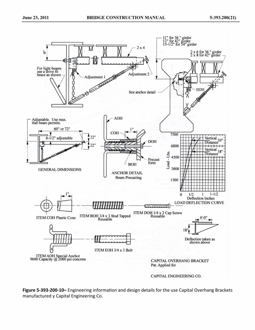
Figure 5-‐393-‐200-‐10– Engineering informa.on and design details for the use Capital Overhang Brackets manufactured y Capital Engineering Co.
June 23, 2011 BRIDGE CONSTRUCTION MANUAL 5-393.200(21)
Lake Superior College 37
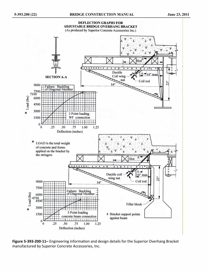
Figure 5-‐393-‐200-‐11– Engineering informa.on and design details for the Superior Overhang Bracket manufactured by Superior Concrete Accessories, Inc.
5-393.200 (22) BRIDGE CONSTRUCTION MANUAL June 23, 2011
Lake Superior College 38

Figure 5-‐393-‐200-‐12– Engineering informa.on and design details for the Superior Overhang Bracket manufactured by Superior Concrete Accessories, Inc.
June 23, 2011 BRIDGE CONSTRUCTION MANUAL 5-393.200(23)
Lake Superior College 39

Photograph 5-‐393-‐200-‐4– A view of the use of tubular steel scaffolding used as falsework for the construc.on of a concrete slab-‐span bridge.
These towers are rated by the load carrying capacity of either one leg or one frame (two legs). The manufacturer’s rated capacity should not be exceeded. Adequate rigid bracing involving several units of steel shoring should be provided. Full bearing for the base plates should be provided, such as being set in fresh mortar when resting on rock-‐like formations. Mudsills placed on yielding earth are not permitted for supports.
7. Void Tubes for Voided Slabs: These tubes are similar to the tubes used for column forms except that galvanized steel tubes are also permitted. The circumferential crushing pressure and straight crushing pressure of these tubes will normally be listed in the manufacturer’s literature. When checking stresses, it is necessary to determine if the manufacturer has listed a safe pressure or a failure pressure.
Since stress in the void tubes is very high at the tie-‐down points, a careful visual inspection is necessary at those locations. Wetting of paper tubes can result in isolated weak spots where the waterproof coating has been scratched or damaged and water has penetrated into the paper or @iber layers. Such pieces should be rejected unless they can be satisfactorily reinforced.
Void tubes must be mortar tight. When several lengths of tubes are necessary to make up the length of void shown in the Plan, each segment of tube should have sealed ends. Butting tube ends together and taping around the perimeter of the joint is normally unacceptable since deformation
of one of the jointed tubes during concrete placement would likely rupture a tape splice.
8. Nails: Nails are the most commonly used connectors for wood forms and falsework. The resistance to lateral loads on nails and spikes is directly correlated to the diameter of the nail or spike. See Figure 5-‐393-‐200-‐14 for a diagram of the size of nails and spikes. Table 5-‐393-‐200-‐11 contains the allowable lateral loads on various sizes of nails and spikes when used in several different species of wood. Many of the newer power nailing devices use nails that do not necessarily match the diameters of the traditional nail sizes as identi@ied by the “penny weight”, denoted by a small letter d. The actual diameter of the nails used should be measured with a caliper.
9. Form Bolts: General requirements governing bolts or form tie are given in the relevant provisions contained in the Standard Speci,ications for Construction as published by the Minnesota Department of Transportation. One speci@ic provision is that a major portion of the tie device must remain permanently in the concrete. The device must also be designed so that all material in the device to a depth of 1 inch can be disengaged and removed without spalling or damaging the concrete. Several types of commercially available form ties meeting this description are shown in Figure 5-‐393-‐200-‐13.
Figure 5-‐393-‐200-‐13– Details of some of the more commonly used form bolts and form .es.
5-393.200 (24) BRIDGE CONSTRUCTION MANUAL June 23, 2011
Lake Superior College 40
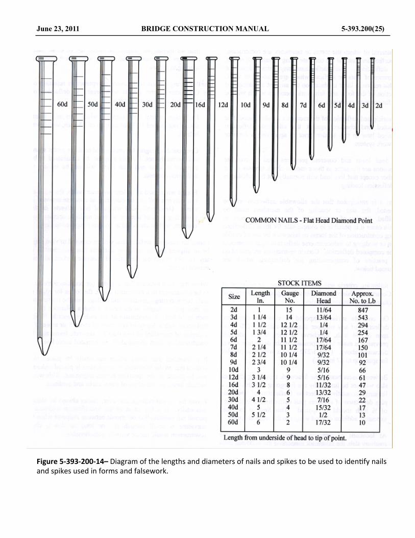
Figure 5-‐393-‐200-‐14– Diagram of the lengths and diameters of nails and spikes to be used to iden.fy nails and spikes used in forms and falsework.
June 23, 2011 BRIDGE CONSTRUCTION MANUAL 5-393.200(25)
Lake Superior College 41

Table 5-‐393-‐200-‐11– Allowable lateral loads on nails based on fastener diameter, length, and species of wood where used.
5-393.200 (26) BRIDGE CONSTRUCTION MANUAL June 23, 2011
ALLOWABLE LATERAL LOADS ON NAILSDriven into the side grain of seasoned wood. Load applied in any lateral direction.
*SAFE LATERAL LOAD ON EACH, IN LBS.At penetration in diameter noted for each group, TIMBER
SIZE LENGTH DIAMETER into the piece holding the point. SPECIESPENNY (note 1) "D" GROUP I GROUP II GROUP III GROUP IV GROUPS
WEIGHT (in.) (in.) 10 X D 11 X D 13 X D 14 X DGROUP I
COMMON NAILS (Flat Head, Diamond Point) Ash, Elm,Note (1) Length from underside of head to tip of point. Maple, Oak
6d 2 0.113 104 84 68 548d 2-1/2 0.131 129 104 86 68 GROUP II10d 3 0.148 154 126 102 82 Douglas Fir,12d 3-1/4 0.148 154 126 102 82 Larch,16d 3-1/2 0.162 176 142 118 93 Southern
PineSPIKS (Countersunk Head, Diamond Point)Note (1) Length overall GROUP III
10d 3 0.192 228 186 151 121 Hemlock12d 3-1/4 0.192 228 186 151 121 Red16d 3-1/2 0.207 254 206 168 134 Pine
DUPLEX HEAD NAILS (Heavy Double Head, Diamond Point) GROUP IVNote (1) Length from underside of lower head to tip of point. Cedar,
6d 1-3/4 0.113 104 84 68 54 White &8d 2-1/4 0.131 129 104 86 68 Balsam10d 2-3/4 0.148 154 126 102 82 Fir,16d 3 0.162 176 142 118 93 White20d 3-1/2 0.192 228 186 151 121 Sugar30d 4 0.207 254 206 168 134 Ponderosa
andSMOOTH BOX NAILS (Large Flat Head, Diamond Point) LodgepoleNOTE (1) Length from underside of head to tip of point. Pines
6d 2 0.099 84 68 56 44 Cottonwood,7d 2-1/4 0.099 84 68 56 44 Spruce,8d 2-1/2 0.113 104 84 68 54 Yellow10d 3 0.138 136 101 83 67 Poplar
COOLERS (Flat Head, Diamond Point), SINKERS (Flat Counter Head,Diamond Point) as per BOX NAILS except length overall is 1/8" less than shown.
Basic Formulas: Safe Load = 1.33 x K X D 3/2
where: Group I: K = 2040, Group II: K = 1650Group III: K = 1350, Group IV: K = 1080
The values shown in this table, which are for normal load duration of 10 years havebeen increased by 1/3 due to short duration of static load on falsework.

Figure 5-‐393-‐200-‐15– Diagrams used for determining the allowable uniform loads on Plyform based on Plyform thickness, spacing of supports, direc.on of face grain rela.ve to direc.on of supports and grade of material.
June 23, 2011 BRIDGE CONSTRUCTION MANUAL 5-393.200(27)
Lake Superior College 37

Normally the manufacturer’s literature will list the safe load that may be applied. However, when the load capacity is questionable or unknown, laboratory test are necessary to determine the safe load. In this event, the safe load may be calculated by determining the cross-‐sectional area of the member and the yield point of the steel by tension test in the laboratory. The applied load should not exceed 70% of the yield strength of the device. NOTE: The yield point of the steel (measured in psi) is not the same as the yield strength of a particular bolt or device.
On portions of the structure exposed to view, form bolts must be designed so that all the metal can be removed to a depth of not less than 1 inch. Wire ties may only be used in locations where they do not extend through surfaces exposed to view in the @inished work.
The hardware used to secure form bolts against the forms is usually reusable. This hardware is normally designed to be stronger than the portion of the device that remains in the concrete and therefore will not be the limiting factor in the form tie.
Crimp ties or snap ties are wire form ties with a notch or reduced cross-‐section at the point of break-‐back. These ties are not reusable. After the concrete is set, the portion of the wire, that extends outside of the concrete surface is twisted off and removed. A washer is sometimes welded to the wire at the face of the form to act as a form spreader. On concrete surfaces exposed to view, a plastic cone should be used in place of the washer since satisfactory patching of the shallow depression left by the washer is very dif@icult.
These ties do not always break off at the intended point, but sometime break instead at the face of the concrete. They also do not provide a rigid member for the support of workers, for these reasons they are not recommended for use on heavy construction. Their use is primarily restricted to light work such as box culverts.
5-‐393.205 Engineering Mechanics
Engineering Mechanics is the science that considers the action of forces on material bodies. Statics considers forces in equilibrium or of bodies held in equilibrium by the forces acting on them. Kinetics considers the relations between forces on bodies in motion. This Chapter only
deals with bodies held in equilibrium, bodies in which there is no motion. Forces on forms and falsework are the results of loads applied to the structural elements of the formwork.
When a force acts on a body, two things happen. First, internal forces that resist the external forces are set up in the body. These internal resisting forces are called stresses. Secondly, the external forces produce deformation or changes in shape of the body.
Strength of material is the study of the properties of material bodies that enable them to resist the action of external forces, the study of the stresses within the bodies and deformations that result from the external forces.
Loads applied to structural members may be of various types sources. Most of the loads on forms and falsework are considered to be static loads. These are loads that are gradually applied and equilibrium is reached in a relatively short time. An example of these types of loads are the loads and pressures from the fresh concrete being restrained by the form members and the live load from the workers placing and @inishing the concrete. These loads are considered static loads. Loads that are constant over a long period of time are considered sustained loads. The earth pressure behind the main wall of bridge abutments is an example of a sustained load. Forms and falsework are rarely subjected to sustained loads. A load that is rapidly applied is called am impact load. Forms and falsework are normally very rarely subjected to impact loads. Forms and falsework are designed to resist loads in the middle ground between impact loads and long-‐term sustained loads.
Loads are also classi@ied with respect to the area over which the load is applied. A concentrated load is one that can be considered to be applied only at a point. Any load that is applied to a relatively small area can be considered a concentrated load. This could be the load from a single joist resting on a beam. A distributed load is a load that is distributed along the length of a beam or spread over an area. The distribution may be uniform or non-‐uniform. Non-‐uniform loads are sometime referred to as uniformly varying loads. An example of an non-‐uniformly varying load is the weight of the concrete in the overhang of most bridges, where it is thinner at the outside edge of the bridge, the coping, and thicker at the fascia beam.
Loads can be further classi@ied with respect to the location and method of application to structural members. A load in which the resultant concentrated load passes through the centroid (geometrical center) of the resisting cross-‐section is referred to as centric loads. If the resultant concentrated forces passes through the centroids of all of resisting sections, the loading is called
5-393.200 (28) BRIDGE CONSTRUCTION MANUAL June 23, 2011

axial. A load that is applied transversely to the longitudinal axis of the member is referred to as a bending or @lexural load. A member subjected to bending loads de@lects along its length. A load that subjects a member to a twisting moment is called a torsional load. The load that a bridge deck overhang bracket applies to the fascia beam of a bridge is an example of a torsional load. A condition where two or more of the types of loads as previously described act simultaneously is called a combined load.
A. Concept of Stress
Stress, like pressure, is a term used to describe the intensity of a force. Stress is the quantity of a force that acts on a unit of area. Direct stresses are those stresses that are uniform over the entire cross section of the member. Force, in structural design, has little signi@icance until something is known about the resisting material, cross-‐sectional properties and the size of the element resisting the force. The unit stress, the average value of the axial stress, may be represented mathematically as:
f = PA=
axial _ forceperpendicular _ resisting_area
where:
f = the symbol(s) representing unit stress; usually expressed as pounds per square inches or psi
P =applied force or load (axial); usually expressed in pounds, lb
A = resisting cross-‐sectional area perpendicular to load direction, units normally are square inches or in2
B. Standard Notation
All of the examples and explanations for those examples contained in this Chapter are based on the standard notation used in the Allowable Stress Design (ASD) procedure. The use of standard notation is important for a number of very good reasons. There are two reasons that deserve ampli@ication. First, there are two generally accepted design procedures, Allowable Stress Design (ASD) and Load and Resistance Factored Design (LRFD), the former gradually being replaced by the later. Each of these two design methods has developed their own distinctive format to their calculations. The second advantage of adhering to the conventions in each of the standard notations is that it is much easier for reviewers to understand calculations and avoids misunderstandings.
As stated above, all of the examples and explanations utilize the standard notations of ASD procedures. As the name implies this method of design uses stress created by the actual loads and compares them against the Allowable Working Stress. The actual stresses calculated in all of the different members are abbreviated using the italic lower case letter f. This lower case letter f, is almost always followed by a subscript letter, such as b, v, c that indicates what type of stress in involved. For example a calculated bending stress will be noted as fb = 1,300 psi. This speci@ic notation tells us that the calculated bending stress in this particular member is 1,300 pounds per square inch. If the stress is denoted as fv, this is a shear stress.
The calculated bending moment in a member is always denoted with an upper case italic letter M. The section modulus of a structural member is always denoted with an upper case letter italic S. The cross-‐sectional area of a member is denoted with an upper case italic letter A.
Stresses identi@ied as material properties are always denoted with a upper case italic letter F, additionally the upper case letter F has a subscript letter that indicates the category of stress, such as b for bending stress, v for shear stress, and c for compressive stress. Also, in addition to the subscript letter the upper case F is sometimes followed by an apostrophe that indicates that the stress is the fully adjusted working stress. For example, the allowable bending stress would be denoted as Fb’ and the allowable shear stress is denoted by Fv’.
C. Types of Stress
There are few basic ways that material resists forces imposed on them. Those forces are then resisted by the stresses resulting in the material. Those cases where the stresses are uniform over the cross-‐sectional area are referred to as direct stresses. The four common direct stresses are as follows:
1. Compressive stress
2. Tensile stress
3. Bearing stress
4. Shear stress
Compressive Stress:
Compressive stress results from forces on a structural element that tends to shorten that element. Structural elements that typically resist compressive forces are columns and piles. In timber members compressive stress in normally assumed to be acting parallel to the direction of grain of the wood in the member. Compressive stress can be represented by the following formula:
June 23, 2011 BRIDGE CONSTRUCTION MANUAL 5-393.200(29)
fc =PA
where:
fc = unit compressive stress, psi
P = Applied load, lb
A = Resisting area normal (perpendicular) to P, in2
Tensile Stress:
Tensile stress results from forces on a structural element that tend to stretch or lengthen that element. The bottom chord of a typical truss is a common tensile element. Tensile stress can be represented by the following formula:
ft =PA
where:
ft = unit tensile stress, psi
P = applied tensile load, lbs
A = resisting area normal (perpendicular) to P, in2
Bearing Stress:
Bearing stress is the resulting stress from forces that are acting perpendicular to the exposed surface of the member. These stresses result from bearing plates or under washers. In timber structural elements this type of stress is assumed to be acting perpendicular to the direction of grain of the wood within the member. This type of compressive stress can be represented by the following formula:
fp =PA
where:
fp = unit bearing stress, psi
P = applied load, lb
A = bearing contact area, in2
Shear Stress:
A shearing stress results when two parallel forces having opposite directions act on a body, tending to cause one
part of the body to slide past an adjacent part. One common example is that of a horizontal beam supporting a load. The magnitude of the shear is represented by V; because in most cases the shear forces are acting vertically. The vertical shear in a horizontal beam varies in magnitude at different locations along the beam’s length and is easily visualized when shown in a shear diagram. The actual shear stress in steel and concrete structural elements can be represented by the following formula:
fv =VA
where:
fv = unit shear stress, psi
V = vertical shear, lb
A = cross-‐sectional area parallel to load direction, lbs
The calculation of shear stress in wood members requires different considerations. Wood is much weaker in shear resistance along the direction of grain. Therefore, when wood fails in shear it will shear along the direction of grain. The determination of the vertical shear, V, is the same for wood members as for steel and concrete members. It is assumed that the shear force, V, is acting perpendicular to the direction of the grain in the wood member. The actual shear stress in timber bending members can be determined with the following formula:
fv =3V2bd
where:
fv = unit shear stress in wood member, psi
V = vertical shear force, lb
b = width of wood member, in
d = depth of wood member, in
D. Material Properties
The general term material properties refers to several aspects of a material to resist forces. The strength of a material is its ability to resist the three basic stresses; compression, tension, and shear. Some materials exhibit different strength properties for each of the different types of stress to which the material is subjected. As an example, the compressive and tensile strength of structural steel are about equal, whereas cast iron is
5-393.200 (30) BRIDGE CONSTRUCTION MANUAL June 23, 2011

strong in compression and relatively weak in tension. Additionally, wood exhibits much different strength characteristics not only for the different types of stress, but different strength values relative to the direction of the force with respect to the direction of the grain of the wood.
The ultimate strength of a material is the unit stress that causes failure or rupture. The term elastic strength is generally applied to the greatest unit stress a material can resist without a permanent change in shape.
The stiffness of a material is that property that enables it to resist deformation. If, for instance, blocks of steel and wood of equal size are subjected to equal compressive loads, the wood block will become shorter than the steel block. The deformation (shortening) of the wood block will probably be about 20 time that of the steel, and we say, the steel is stiffer than the wood.
Elasticity is that property of a material that enables it to return to its original size and shape when the load to which it has been subjected is removed. This property varies in different materials. This property is called the modulus of elasticity and is represented by MOE or E. For certain materials there is a unit stress beyond which the material does not regain its original dimensions when the load is removed. The magnitude of this unit stress is called the elastic limit of that material. In many cases, the allowable working load unit stresses for such a material should be well below the elastic limit. Every material changes its size and shape when subjected to loads. For the materials used in bridge construction the actual unit stresses should be such that the deformations for direct stresses are in direct proportion to the applied loads. Or in other words, the working stresses should be below the elastic limit of the material.
Plasticity is the opposite quality to elasticity. A perfectly plastic material is a material that does not return to its original dimensions when the load causing the deformation is removed. There are probably no perfectly plastic materials. Modeling clay and lead are examples of plastic materials.
Ductility is that property of a material that permits it to undergo plastic deformation when subjected to a tensile force. A material that may be drawn into wires is a ductile material. A chain made of ductile material is preferable to a chain in which the material is brittle.
A material having the property that permits plastic deformation when subjected to a compressive force is a malleable material. Materials that may be hammered into sheets are examples of malleable material. Ductile materials are generally malleable. A material, such as cast
iron, for instance, that is neither malleable nor ductile is called brittle.
Whenever a body is subjected to a force there is always a change in the shape or size of the body. These changes in dimensions are called deformations. A block subjected to a compressive force shortens in length and the decrease in length is its deformation. When a tensile force is applied to a rod, the original length of the rod is increased and the lengthening or elongation is its deformation. A loaded beam resting on two supports at its ends tends to become concave on its upper surface; we say the beam bends.
The deformation that accompanies the bending is called de,lection. The amount of de@lection can be expressed in two ways. First, the actual de@lection can be measured in units of length, generally in inches. The amount of de@lection an also be expressed as a ratio of the span length. This is sometimes referred to as the span-‐to-‐de,lection (L/D) ratio. It is very common for the actual amount of de@lection for a loaded beam be limited to some ratio, such as 1/240 of the span length. Sometimes the de@lection of a beam is represented by the Greek letter delta, Δ, the span-‐to-‐de@lection ratio might be shown as L/Δ.
Strain:
When stresses occur in a body, there is always an accompanying deformation. The deformation often is so small that it is not apparent to the naked eye; nevertheless, it is always present. The term strain is sometime used as a synonym for deformation. The relationship between stress and strain is a key concept. The terms stress and strain can and will be used in a couple of different forms, it can be shown as stress/strain, or as stress and deformation, all of which refer to the same concept.
The modulus of elasticity, as stated earlier, is a measure of the stiffness of a material. The modulus of elasticity is de@ined as the ratio of the unit stress to the unit deformation. It is generally represented by the letter E and is a measure of the stiffness of a material. It can berepresented mathematically by the following formula:
E = unit _ stressunit _deformation
Thus the modulus of elasticity is the unit stress divided by the unit deformation. Further, since the unit stress is in units of pounds per square inch (psi) and the unit deformation is an abstract number (inches divided by inches); therefore, the modulus of elasticity is in units of pounds per square inch.
June 23, 2011 BRIDGE CONSTRUCTION MANUAL 5-393.200(31)

From previous de@initions we can express modulus of elasticity in several different ways as follows:
E = unit _ stressunit _deformation
=fs
fs=PAel=PA÷el=PA×le=PlAe
∴
e = PLAE
where:
E = modulus of elasticity, psi
P = applied force, lb
f = unit stress in member, psi
A = area of cross section, in2
l = length of member, in
e = total deformation, in
s = unit deformation in/in
By these formulas, we are able to determine the deformation of a member subjected to stresses, provided that we know the modulus of elasticity of the material and the unit stress does not exceed the elastic limit of the material.
Cross Sectional Properties:
The design and understanding of members that are subjected to loads that tend to bend the member require knowledge in several additional areas. Unlike members subjected to compressive, tensile, and shear stresses members subjected to bending loads do not have uniform stresses spread over the cross sectional area. The stresses from bending loads are concentrated at various locations and the magnitude of those stresses are not only related to the size of the member, but are also related to the shape of the cross sectional area.
The shape and proportion of a beam’s cross section is critical in keeping the bending and shear stress within the allowable limits and moderating the amount of de@lection that will result from the loads. Why does a 2” x 8” joist standing on edge de@lect less than when loaded at mid-‐span than the same 2” x 8” when used @lat-‐wise as a plank? The difference in performance of the same
structural element is controlled by the different section properties of the piece in two different positions.
There are four different section properties for every structural member that are used for structural analysis. These four section properties are:
1. area
2. center of gravity (centroid)
3. section modulus
4. moment of inertia
The area of the cross section of most structural members used in formwork can easily be calculated or found in any one of many readily available tables. The center of gravity of a solid is an imaginary point at which all of its weight may be considered to be concentrated or the point through which the resultant weight passes. Since an area has no weight, it has no center of gravity. The point of a plane area that corresponds to the center of gravity of a very tin homogeneous plate of the same area and shape is called the centroid of the area.
Bending and Shear Stress in Beams:
When a simple beam is subjected to forces that tend to cause it to bend, the @ibers above a certain plane in the beam are in compression and those below the plane are in tension. This plane is called the neutral surface. For a cross section of the beam the line corresponding to the neutral surface is called the neutral axis. The neutral axis passes through the centroid of the cross section; thus it is important that we know the exact position of the centroid of any structural member we are using. The position of the centroid for a symmetrical shape is readily determined.
The moment of inertia of an area is an abstract term that is the summation of the products of all of the tiny areas multiplied by the square of the distance from the neutral axis. It is normally represented by the letter I and is de@ined by the following equation:
I = az2∑
where:
I = moment of inertia, in4
a = in@initely small areas, in2
z = distance from neutral axis to centroid of small areas, in
5-393.200 (32) BRIDGE CONSTRUCTION MANUAL June 23, 2011

There are numerous tables available that give the section properties, including moment of inertia, for almost all common construction materials. Additionally, there are many sources that provide the formulas for calculating the moment of inertia for most common shapes of cross sectional areas. For instance, the formula for calculating the moment of inertia for members with rectangular cross section is:
Ix−x =bd 2
12
where:
I x-‐x = moment of inertia relative to x-‐x axis, in4
b = width of beam, in
d = depth of beam, in
One of the properties of cross sections constantly used by designers is a quantity called the section modulus. Its use in the design of beams will be explained later, for the present it is only necessary to know that if I is the moment of inertia of a cross section about an axis passing through the centroid and if c is the distance of the most remote @iber of the cross section from the neutral axis, the section modulus equals:
S = Ic
where;
S = section modulus, in3
I = moment of inertia, in4
c = distance from neutral axis to most remote @iber, in
Using the formula for the moment of inertia for a rectangular beam and the relationship of the section modulus for the same cross section we can derive the formula for the section modulus as follows:
S = bd3
12÷d2=bd 3
12×2d∴
S = bd2
6
where:
S = section modulus, in3
b = width of beam, in
d = depth of beam, in
Again, there are many tables available that list all of the section properties for most common construction materials. Table 200-‐2 lists the section modulus and moment of inertia for most common sizes of lumber.
There are a number of tools and techniques that have been developed over the years that can be used in the analysis of beams. One of the most useful techniques for the examination of structural members is the use of a free body diagram (FBD). A free body diagram is nothing more than a simplistic diagram of the member showing only the essential information in its relative position. These diagrams are very useful in determining which of all of the available design aids are appropriate to use in the solution of the problem.
There are many FBD published that cover a great many of the possible con@igurations for beams. These published diagrams are called “Beam Diagrams and Formulas”, the American institute of Steel Construction (AISC) in their Manual of Steel Construction publishes the most complete listing. That publication also contains a complete listing of the section properties of rolled steel shapes. The published diagrams and formulas provide formulas for the calculation of the maximum bending moments, the maximum shear, and the de@lections associated with the given loading conditions. See Figure 200-‐16 for beam formulas for some commonly used load cases. There are other design aids that can be used in the analysis and checking of forms and falsework plans. Three design aids for calculating the effective bearing areas for different con@igurations are shown in Figure 200-‐17.
5-‐393.206 Concrete Pressure
Concrete exerts loads on forms and falsework in two general ways. First, concrete exerts dead load anywhere the fresh concrete is restrained vertically. The magnitude of this load does not change over time. The second way in which fresh concrete exerts loads on formwork is from the lateral pressure from the concrete in a plastic state. This occurs any place where the fresh concrete is restrained horizontally.
When concrete is @irst mixed, it has properties lying between a liquid and a solid. Fresh concrete is generally de@ined as a plastic material. As time passes from the initial time of mixing, concrete loses its plasticity and gradually changes into a solid. This change from a semiliquid state to a solid state is the result of two actions within the concrete.
June 23, 2011 BRIDGE CONSTRUCTION MANUAL 5-393.200(33)

The @irst action results from the setting of the cement, which may start within 30 minutes after the concrete is mixed. This action may continue for several hours dependent on the temperature. The warmer the temperature the quicker the setting occurs. The other action is the development of internal friction between the particles of aggregate in the concrete that restrains them from moving freely with respect to other particles in the mixture.
A. Concrete Lateral Loads
The American Concrete Institute (ACI) has developed methods for the calculation of lateral pressure from concrete. The pressure exerted laterally on forms is controlled by several or all of the following factors:
1. Rate of placing concrete in forms2. Temperature of concrete3. Weight or density of concrete4. Cement type or blend used in the concrete5. Method of consolidating concrete6. Method of placement of the concrete7. Depth of placement8. Height of form
ACI has identi@ied the maximum pressure on formwork as the full hydrostatic lateral pressure, as given by the following equation:
Pm = wh
where:
Pm = maximum lateral pressure, psf
w = unit weight of placed concrete, pcf
h = depth of plastic concrete, ft
For concrete that is placed rapidly, such as columns, h should be taken as the full height of the form. There are no minimum values given for the pressure calculated above. The maximum hydrostatic lateral pressure as de@ined above is generally not used for the design of concrete forms (see next section).
For the purpose of structural design of forms for vertical structural elements are separated into one of two categories based on the con@iguration of the elements, namely; walls and columns. A wall section is de@ined as a vertical structural element with at least one plan-‐view dimension greater than 6.5 feet. Those vertical structural vertical elements with all dimensions in a plan-‐view less than 6.5 feet. are classi@ied as columns.
B. Lateral Pressure from Concrete on Wall Forms
There are two formulas for calculating the lateral pressure from concrete on wall forms. The @irst equation applies to a wall with a rate of placement less than 7 feet per hour and a placement height of 14 feet or less. The other equation applies to all walls with a placement rate of 7 to 15 feet per hour, and to walls placed at less than 7 feet. per hour but having a placement height greater than 14 feet. Both equations apply to concrete with a 7 inch maximum slump. For walls with a rate of placement greater than 15 feet per hour, or when forms will be @illed rapidly, before any stiffening of the concrete occurs, then the pressure should be taken as the full hydrostatic pressure given by the following formula, Pm =wh (see section above).
For wall forms with a concrete placement of less than 7feet per hour and a placement height not exceeding 14 feet lateral pressure can be calculated by the following formula with a minimum of 600CW psf, but in on case greater than wh.
Pm = CWCC 150 + 9,000R /T[ ]
Where:
Pm = maximum lateral pressure, psfCw = unit weight coef@icient as given in Table 5-‐393-‐200-‐13Cc = chemistry coef@icient as given in Table 5-‐393-‐200-‐12
Table 5-‐393-‐200-‐12– Chemistry Coefficient, CC to be used with the formulas for calcula.on of lateral pressure from fresh concrete.
5-393.200 (34) BRIDGE CONSTRUCTION MANUAL June 23, 2011
CHEMISTRY COEFFICIENT, CC
Admixtures - Retarders, Water Reducers CC
Types 1, II and III without retarders 1.0Types 1, II and III with a retarder 1.2Other types or blendswithout retarders*containing less than 70% slag or lessthan 40% fly ash 1.2Other types or blend with a retarder*containing less than 70% slag or lessthan 40% fly ash 1.4Blends containing more than 70% slag or40% fly ash 1.4
* Retarders include any admixtures such as a retarder, retarding water reducer, retarding mid-range water reducing admixture, or retarding high-range water reducing admixtures (superplasticizer)that delays setting of concrete.

Table 5-‐393-‐200-‐13– Unit Weight Coefficient, CW to be used with the formulas for calcula.on of lateral pressure from fresh concrete.
R = rate of @ill of concrete, ft. per hour
T = temperature of concrete, degrees F°
Minimum value of Pm is 600Cw, but in no case greater than wh.
For all wall forms with concrete placement rate from 7 feet to 15 feet per hour, and for walls where the placement rate is less than 7 feet per hour and the placement height exceeds 14 feet lateral pressure can be calculated by the following formula:
Pm = CWCC 150 +43,400T
+ 2,800R /T⎡
⎣⎢⎤
⎦⎥
where:
Pm =maximum lateral pressure, psf
Cw = unit weight coef@icient as given in Table 5-‐393-‐200-‐13
Cc = chemistry coef@icient as given in Table 5-‐393-‐200-‐12
R = rate of placement of concrete, ft. per hour
T = temperature of concrete, degrees F°
Minimum value of Pm is 600Cw, but in no case greater than wh.
C. Lateral Pressure from Concrete on Column Forms
The ACI methods for determining the pressure on formwork makes a distinction in vertical structural elements based on the greatest plan-‐view dimension. Those vertical elements that do not have a plan-‐view dimension greater than 6.5 ft. are classi@ied as a column. Additionally, the ACI recommends that formwork be
designed for the full hydrostatic pressure in situations where the concrete is placed rapidly and where self-‐consolidating concrete is used. In the case of tapered pier shafts, the minimum plan-‐view dimension will govern in determining the classi@ication of the vertical element as either a wall section or column.
Calculation of the lateral pressure for concrete with a slump of 7 inches or less and placed by normal internal vibration can be based on the following formula:
Pm = CWCC 150 +9,000RT
⎡
⎣⎢⎤
⎦⎥
where:
Pm = calculated lateral pressure, psf
Cw = unit weight coef@icient as given in Table 5-‐393-‐200-‐13
Cc = chemistry coef@icient as given in Table 5-‐393-‐200-‐12
R = rate of placement of concrete, ft. per hour
T = temperature of concrete, F°
Minimum value of Pm is 600Cw, but in no case greater than wh
With modern techniques of placing and intensive vibration, it is possible with rapid rates of @illing forms to have concrete remaining in a @luid condition for the full duration of the pour, in which case theoretically the only pressure limit will be wh.
5-‐393.207 Engineering Analysis
Practically all falsework members act either as columns or as beams. If the members are called elements, both words can be used interchangeably. The internal stresses and de@lections in these members are due to the effects of the various construction loads. These loads are divided into two distinct categories, namely, dead loads and live loads. Dead loads consist of the weight of the actual forms and falsework, the weight of the concrete, and the pressure produced by the fresh concrete. Live loads are from the weight of the work crews and the equipment used in the construction and used for placements and @inishing of the concrete. The combined effect of all of these various loads on structural members in the forms and falsework can be determined by standard engineering mechanics as covered earlier in section
June 23, 2011 BRIDGE CONSTRUCTION MANUAL 5-393.200(35)
UNIT WEIGHT COEFFICIENT, CW
Concrete Unit WeightsConcrete weighing less than 140 pcf
CW = 0.5(1 + w/145)but not less than 0.80Concrete weighing 140 to 150 pcf
CW = 1.0Concrete weighing more than 150 pcf
CW = w/145

5-‐393.206 Engineering Mechanics. The stresses produced by these loads are then compared to the allowable working stresses for each member to determine the adequacy of the structural design of the forms and falsework.
A. Important Background Information:
The contract provisions of some bridge projects will require the Contractor to provide plans for his proposed forms and falsework that have been prepared and certi@ied by a licensed engineer. Contract provisions for other less complicated bridges may not require sealed falsework plans. Whether or not the contract requires the Contractor to provide plans sealed by an Engineer, does not in any way relieve the Contractor of total responsibility for the performance of the forms and falsework.
The roles and responsibilities of the engineer can change in the review of the design and inspection of the completed formwork. If the Contract provisions require the Contractor to provide plans for the forms and falsework the Engineer will have the bene@it of a plan to guide his inspection. However, whether or not a sealed plan is required to be furnished on any particular bridge, it is extremely important that the Engineer have some understanding of the analysis of forms and falsework.
The information presented in this Chapter has been drafted in two important ways to help the Engineer develop a basic understanding of the subject. First, all of the information presented in both the text portion of the manual and in the example problems uses “Standard Notation” through out this Chapter. This is done to emphasize the similarities between many of the various terms, principals, properties and values. Next, wherever possible the procedures have been simpli@ied. Simpli@ications were generally done in the conservative direction, which results in solutions that are less ef@icient than results arrived at using more rigorous analytic methods. The purpose of this Chapter is to provide Engineers with a basic understanding of the process and the ability to check some aspects of forms and falsework plans, not to become falsework Engineers.
The Engineer must be satis@ied that the Contractor’s falsework plan or scheme is in conformance with the Standard Speci,ications for Construction as published by the Minnesota Department of Transportation. A common method to do this is to compute the maximum de@lection and maximum stresses (bending, bearing, compression, shear, etc.) based on plans of the proposed falsework and assumed loading conditions. These stresses and de@lections are then compared with the allowable values.
If the computed stress and de@lection is less than or equal to the allowable value, the member quali@ies for use.
B. Deblection and Alignment:
De@lection will occur in all form and falsework members in which beam action is involved, regardless of the design used or the material of which the forms and falsework are constructed. The surfaces and lines of the concrete being formed will re@lect these de@lections. Such de@lections may detract from the appearance of lines and surfaces that are exposed to view. For this reason, a limit is placed on the amount of anticipated de@lection of the forms and falsework members, which will be applied for concrete surfaces exposed to view.
The anticipated de@lection of members involved should be computed and checked against the allowable de@lection as described later in this section prior to approving a form or falsework system. The loads and concrete pressures used to compute de@lection are the same as those used to calculate the stresses in the members, except that the live load will normally not be included in the loading used for de@lection.
When it is anticipated that the allowable de@lection will be exceeded, the size or spacing of the members must be modi@ied. In lieu of such modi@ication of the members, in certain cases it is possible to compensate for these de@lections during construction of the forms and falsework by the use of pro@ile strips or wedging to induce reverse de@lection equal to the amount of the computed de@lection. This reverse de@lection used to off-‐set anticipated de@lection is called “camber.” Certain restrictions are placed on this practice of compensating for de@lection, which will be discussed below.
1. Falsework Deblections for Surfaces Exposed to View: The following criteria will govern acceptance or rejection of the Contractor’s falsework details with regard to de@lection:
(a.) On concrete surfaces exposed to view, the computed de@lection of any member shall not exceed 1/270 of its span or ¼ inch, whichever is least., unless adequate provision is made to compensate for the de@lection as was described above. (The 1/270 criteria will be applied for spans up to 67 inches.)
(b .) Between fascia beams, the falsework supporting the deck slab will not be limited by the foregoing. In this area, a limiting cumulative de@lection (de@lection of sheathing plus de@lection of stringers plus de@lection of the joists, etc.) of ½ inch should be applied. This
5-393.200 (36) BRIDGE CONSTRUCTION MANUAL June 23, 2011

Figure 5-‐393-‐200-‐16– Beam formulas for calcula.ng reac.ons, moments, shears and deflec.ons based on different configura.ons and loading condi.ons.
limit is to avoid excessive additional dead load weight to the superstructure.
(c.) At locations of transverse construction joints in the roadway slab, the falsework supporting the bulkhead must be suf@iciently strong to reduce the computed bulkhead de@lection to no more than 1/16 inch.
(d.) The de@lection of slab overhang falsework must be compensated for by wedging or raising the outside edge of the overhang falsework by an amount equal to that of the anticipated de@lection. The anticipated cumulative de@lection of the overhang falsework must not exceed ½ inch even though compensated for. When the main overhang falsework supporting members (the overhang bracket, needle beams or equivalent systems) are spaced at least 48 inches, the anticipated de@lection of these members must not exceed S/100, where S = member spacing in inches.
2. Falsework Deblections for Surfaces Not Exposed to View: The following criteria will govern acceptance of the Contractor’s form details with regard to de@lection:
(a.) De@lection in any form member that acts as a beam should not exceed 1/270 of its span or 1/8 inch, whichever is least.
(b.) Concrete diaphrams for prestressed concrete girder spans will normally not, for this purpose, be considered to be exposed to view, and their forms will not be subjected to de@lection controls.
(c.) Except when used as pedestrian underpasses, the walls of box culverts will not be classi@ied as concrete exposed to view. Head walls and wing walls of box culverts, or the projecting ends of interior walls of multiple opening box culverts, will be classi@ied as concrete exposed to view.
3. Form Alignment: The following criteria will govern for the acceptance of the Contractor’s form details with regard to alignment:
June 23, 2011 BRIDGE CONSTRUCTION MANUAL 5-393.200(37)
l
w
l
w
l
l
w
ll
l
w
Load Case max. R max. M max. V max. !
wl2
wl2
8wl2
5wl4
384EI
Simple Span, uniformly loaded
Two Continuous Spans, uniformly loaded
Three or More Spans, uniformly loaded
Cantilever Beam Span, uniformly loaded
3wl8
R1=
5wl4
R2= wl2
8M2=
wl2
14.2M3=
5wl8
V2=
3wl8
V1=wl4
185EI!3=
R1= 0.4wl
R2= 1.1wl
M3= 0.08wl2
M2= 0.10wl2
V1= 0.4wl
V2= 0.6wl0.0069wl4
EI!3=
R1= wl wl2
2M1= V1= wl wl4
8EI!2=

Figure 5-‐393-‐200-‐17– Engineering and design informa.on for determining the contact area and bearing stress adjustment factors for several different common construc.on connec.ons.
5-393.200 (38) BRIDGE CONSTRUCTION MANUAL June 23, 2011
Lake Superior College 35
CONTACT AREAS AND ALLOWABLE STRESS INCREASE FACTORS
STUD
WIDTH WIDTH OF ONE WALLER (in.)
(in.) 1-1/2 2 2-1/2 3 3-1/2 4
(1) 4.50 6.00 7.50 9.00 10.50 12.00
1-1/2 (2) 1.25 1.19 1.15 1.13 1.11 1.09
(1) 6.50 8.00 10.00 12.00 14.00 16.00
2 (2) 1.19 1.19 1.15 1.13 1.11 1.09
(1) 7.50 10.00 12.50 15.00 17.50 20.00
2-1/2 (2) 1.15 1.15 1.15 1.13 1.11 1.09
(1) 9.00 12.00 15.00 18.00 21.00 24.00
3 (2) 1.13 1.13 1.13 1.13 1.11 1.09
(1) 10.50 14.00 17.50 21.00 24.50 28.00
3-1/2 (2) 1.11 1.11 1.11 1.11 1.11 1.09
(1) 12.00 16.00 20.00 24.00 28.00 32.00
4 (2) 1.09 1.09 1.09 1.09 1.09 1.09
Bearing Area Shown Hatched
3/4
” M
in.
Stud Width
Wa
ler
Wid
thLake Superior College 36
CONTACT AREAS AND ALLOWABLE STRESS INCREASE FACTORS
FOR WALERS AND TIE PLATES
L Y X CONTACT AREA ALLOWABLE STRESS
(in.) (in.) (in.) (sq. in.) INCREASE FACTOR, Cb
3-1/4 3-3/4 3/4 9.75 1.12
5 3-1/4 3/4 12.50 1.08
3-3/4 3-1/2 3/4 10.31 1.10
3 *3-3/4 3/4 9.00 1.13
5 *3/3/4 3/4 15.00 1.08
5-1/4 *3-3/4 3/4 15.75 1.07
5-3/4 *3-3/4 3/4 17.25 1.00
6 *3-3/4 3/4 18.00 1.00
6-1/4 *3-3/4 3/4 18.75 1.00
6-3/4 *3-3/4 3/4 20.25 1.00
5 3-3/4 1 13.75 1.08
5 4 1 15.00 1.08
5-1/4 4 1 15.75 1.07
5-3/4 4 1 17.25 1.00
6 4 1 18.00 1.00
6-1/4 4 1 18.75 1.00
6-3/4 4 1 20.25 1.00
*or more
1–
1/2
”
Waler assumed to be 2
@ 2” nominal width
Tie Plate
L
Y
X
1–
1/2
”
X + 3”
Lake Superior College
Bearing Area Factor, Cb
34
BEARING AREA IN SQ. IN. BETWEEN CAPS AND PILES OF VARIOUS SIZES
Diameter
of Pile at (Piles assumed to be circular)
Cut-off ACTUAL WIDTH OF CAP IN INCHES
(in.) 6 7-1/2 8 9-1/2 10 11-1/2 12 13-1/2 14
14 81.4 99.7 105.6 121.9 127 140.4 144.2 152.7 153.9
13-1/2 78.2 95.8 101.3 116.7 121.4 133.6 136.9 143.1
13 75.1 91.8 97 111.4 115.7 126.6 129.4 132.7
12-1/2 72 87.8 92.7 106 109.9 119..4 121.5 122.7
12 68.9 83.7 88.3 100.6 104.1 111.9 113.1
11-1/2 65.7 79.7 83.9 95.1 98.1 103.9
11 62.6 75.6 79.5 89.4 91.9 95
10-1/2 59.4 71.4 75 83.6 85.5 86.6
10 56.2 67.2 70.4 77.5 78.5
9-1/2 52.9 62.9 65.7 70.9
9 49.7 58.6 60.8 63.6
8-1/2 46.4 54 55.8 56.7
8 43 49.3 50.3
NOTE: Bearing area at right end of each line
is the area of pile at cut-off of the
diameter shown at left. Use when
cap width equals or exceeds pile diameter.
Cap Width
Bearing area shown hatched
pile diameter
W = cap width
R = radius of pileh
! = W/2R
h = R cos!
area = wh + (!/90)!R2

(a.) De@lection in any form member that acts as a beam should not exceed 1/270 of its span or 1/8 inch, whichever is least.
(b.) When the Plans indicates that a bridge (or portions thereof) is to be constructed in a horizontal curve, the forms for the edges of the slabs, curbs, copings, medians and railings must be constructed to their proper degree of curvature within a tolerance of 1/8 inch in 10 feet. Mid-‐ordinates of 1/8 inch or more in 10 feet will occur with a degree of curvature of about 5 Degrees or more. For a degree of curvature of less than 5 Degrees, concrete forms may be constructed on short chords along the intended curve line. It is intended that forms that can easily be placed to a scribed line on the falsework or on previously placed concrete will be placed on the speci@ied curved alignment. This would include forms for the edge of slabs, curbs, and medians.
(c.) No offsets should exist at abutting joints of sheathing or at abutting form panels.
(d.) The variation from plumb or from the speci@ied batter in the line and surfaces of columns, piers, and walls, should not exceed ¼ inch per 10 feet of height and in any event shall not exceed ½ inch.
June 23, 2011 BRIDGE CONSTRUCTION MANUAL 5-393.200(39)

5-393.200 (40) BRIDGE CONSTRUCTION MANUAL June 23, 2011
This page was intentionally left blank.

5-‐393.208 Examples
EXAMPLE 1—PIER CAP FALSEWORK
This is a check of the pier cap falsework details in the @igure shown below. This will require the following investigations:
June 23, 2011 BRIDGE CONSTRUCTION MANUAL 5-393.200(41)
!"#$%&'(#$)*()')+&!$,-
&
&
! "!# ! "!#
$% "!#
&' "!#
& "(#")*+,-.-/0.12*3+45
6/*3.*78"9744+/
! "#$%&'(%")*+,-./0"1*233"4
!%"5"(%"6"#7%"8919#'!%" "1-:*";-*<"=:<>"(%"5"?%"=23>@."3A2B@C"6"( "$%
!"@29"!%"5"7%"D=2*@.3E
#$%
!""!%
F%
( "5"F "5"&'(%")*+,-./0"1*233"4
!%"5"7%"5"#$ "G-HI"6"#$%"8919
J)"#!5?&"
K.:B<:-H"1-**2.
& "#$%
!"#$%&'()*)
&"F%
!%"5"(%"L.2B@"6"( "8919";-<>"3:C@3

1. Plyform for bottom of pier cap
a. Bending stress
b. Rolling shear stress
c. de@lection
2. Joists
a. Bending stress
b. Horizontal shear stress
c. de@lection
3. Main supporting beams (HP 12x53)
a. Bending stress
b. Shear stress
c. de@lection
4. Friction collar
a. Check against manufacturer’s safe carrying capacity
b. Required torque for collar bolts
The necessary calculations for this example items are as follows:
1.Plyform for bottom of pier cap:
Determine total unit applied uniform load for the plyform, w:
Concrete: 3.67 ft a 150 lb/ft3 = 550 lb/ft2
Plyform: 0.06 ft x 40 lb/ft3 = 3 lb/ft2
Live load: = 50 lb/ft2
Total unit load: = 603 lb/ft2
There are a couple of ways that the adequacy of the Plyform sheathing can be checked. First, there are graphic
solutions. The charts in Figure 5-‐393-‐200-‐15, on page 5-‐393.200(27) can be used. The Plyform speci@ied in the example is Class 1 and is used in the weak direction, meaning that the face grain runs parallel to the supports, joists. The chart in the upper right corner of Figure 5-‐393-‐200-‐15, on page 5-‐393.200(27) cover that condition. To use the chart @ind the total unit load, 603 lb/ft2 on the vertical scale on the left side of the chart. Then follow that line, 603 lb/ft2 across the chart until it intersect the line representing ¾” Plyform. Then go vertically downward to the bottom of the chart and read the maximum spacing for the joist spacing which is just a little less than 12 inches. The spacing of the joist given in the example is 10 inches, so the ¾” Plyform is adequate.
When conditions and con@igurations of the design proposed do not match the range offered by the charts it may be necessary to do some calculations. The following is that type of calculations. It is assumed that the Plyform is continuous over 3 or more spans and the beam formulas for continuous conditions will be used. See Figure 5-‐393-‐200-‐16, on page 5-‐393.200(37) for beam formulas.
a. Bending Stress:
fb =MS
where:
M = 0.10 wl2
= 0.10 x 603 lb/ft2 x (10 in )2 x 1ft/12in
= 503 in-‐lb
Section modulus: S = 0.306 in3 (ref. Table 5-‐393-‐200-‐6, on page 5-‐393.200(15))
fb =MS=503inlb0.306in3
= 1,644 psi ≤ 1,930psi OK!
This stress is higher than the allowable stress of 1,500 psi (which would when the class of the plywood is unknown, see page 5-‐393.200(11). Therefore, care must be taken in determining types of Plyform used. Note, the allowable stress of 1,930 psi can only be used when it has been determined that a concrete from grade of Plyform Class I is being used. See Table 5-‐393-‐200-‐7, page 5-‐393.200(15).
b. Rolling Shear Stress:
5-393.200 (42) BRIDGE CONSTRUCTION MANUAL June 23, 2011
!"#$#%"&'()*
+,-"./01'23
4'*5/#67(*#8'59:#;#<#%=+#/>,1*!
?="@'()*#)A5B(7C
8'59#9(5C253#1'2#*DE#./01'23#1'2#>'**'3#'1#A(E2#B5AF
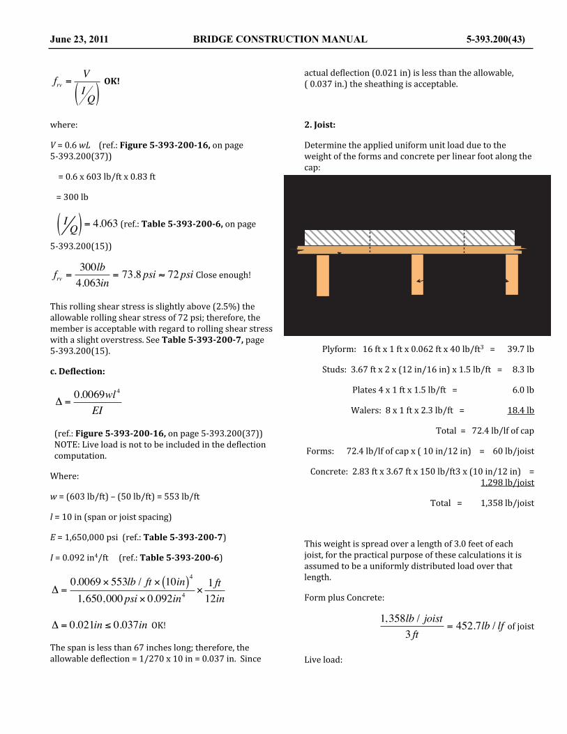
frv =VIQ( )
OK!
where:
V = 0.6 wL (ref.: Figure 5-‐393-‐200-‐16, on page 5-‐393.200(37))
= 0.6 x 603 lb/ft x 0.83 ft
= 300 lb
I Q( ) = 4.063 (ref.: Table 5-‐393-‐200-‐6, on page 5-‐393.200(15))
frv =300lb4.063in
= 73.8psi ≈ 72psi Close enough!
This rolling shear stress is slightly above (2.5%) the allowable rolling shear stress of 72 psi; therefore, the member is acceptable with regard to rolling shear stress with a slight overstress. See Table 5-‐393-‐200-‐7, page 5-‐393.200(15).
c. Deblection:
Δ =0.0069wl 4
EI
(ref.: Figure 5-‐393-‐200-‐16, on page 5-‐393.200(37))NOTE: Live load is not to be included in the de@lection computation.
Where:
w = (603 lb/ft) – (50 lb/ft) = 553 lb/ft
l = 10 in (span or joist spacing)
E = 1,650,000 psi (ref.: Table 5-‐393-‐200-‐7)
I = 0.092 in4/ft (ref.: Table 5-‐393-‐200-‐6)
Δ =0.0069 × 553lb / ft × 10in( )4
1,650,000psi × 0.092in4×1 ft12in
Δ = 0.021in ≤ 0.037in OK!
The span is less than 67 inches long; therefore, the allowable de@lection = 1/270 x 10 in = 0.037 in. Since
actual de@lection (0.021 in) is less than the allowable,( 0.037 in.) the sheathing is acceptable.
2. Joist:
Determine the applied uniform unit load due to the weight of the forms and concrete per linear foot along the cap:
Plyform: 16 ft x 1 ft x 0.062 ft x 40 lb/ft3 = 39.7 lb
Studs: 3.67 ft x 2 x (12 in/16 in) x 1.5 lb/ft = 8.3 lb
Plates 4 x 1 ft x 1.5 lb/ft = 6.0 lb
Walers: 8 x 1 ft x 2.3 lb/ft = 18.4 lb
Total = 72.4 lb/lf of cap
Forms: 72.4 lb/lf of cap x ( 10 in/12 in) = 60 lb/joist
Concrete: 2.83 ft x 3.67 ft x 150 lb/ft3 x (10 in/12 in) = 1,298 lb/joist
Total = 1,358 lb/joist
This weight is spread over a length of 3.0 feet of each joist, for the practical purpose of these calculations it is assumed to be a uniformly distributed load over that length.
Form plus Concrete:
1,358lb / joist3 ft
= 452.7lb / lf of joist
Live load:
June 23, 2011 BRIDGE CONSTRUCTION MANUAL 5-393.200(43)
!"#$%&'()'*+,&-.
/#)0)1#2%&'(
345#6789%:;
<%(+7)=%+>)*?:)$%&'()@)!A31")7B4$%&'(
C&>(D)%9)+**7&?>)7%+>)@)!")&-
=%+>)>&+.:+;)9%:)(D?)/#)0)1#)$%&'()'E**%:(&-.)(D?)9%:;)B%((%;F

50lbft 2
×10in12in
= 41.7lb / lf of joist
Weight of joist: 2.3 lb/lf of joist
(ref.: Table 5-‐393-‐200-‐2 on page 5-‐393.200(9))
Total uniform load, w = 497 lb/ft
a. Bending Stress:
For beams with a very wide bearing area (such as the 12 inch wide beam @lange in this example), it is reasonable to assume that the effective span begins about 2 inches back from the edge of the support. Applied to this example the effective span would be equal to (3’-‐10”) – 8” = 3’-‐2” = 3.17’. This assumption is considered conservative and results in a slightly higher calculated stress.
The maximum bending stress in this example occurs when there is no load on the cantilevered ends of the joists. So the bending moment will be calculated as a single simple span using the following formula:
M =wl2
8
497lb / ft × 3.17 ft( )2
8= 624 ftlb
(ref.: Figure 5-‐393-‐200-‐16 on page 5-‐393.200(37))
The Section Modulus of the 2 x 6 S4S joist is found in Table 5-‐393-‐200-‐2 on page 5-‐393.200(9). The value of the section modulus, S = 7.56 in3. The bending stress in the joist is calculated using the @lexure formula as follows:
fb =MS=624 ftlb7.56in3
×12in1 ft
= 990psi ≤1,065psi
The allowable bending stress (assuming the proposed from lumber is used material with no visible grade stamp, the allowable bending stress for red Pine will be used, F`b = 1,065 psi. This value can be found in Table 5-‐393-‐200-‐3 on page 5-‐393.200(11).
b. Horizontal Shear Stress:
Horizontal shear stress in timber elements is calculated using the following formula, ignoring the uniform load within a distance from each support equal the depth of the member:
fv =3V2bd
where:
V =w L − 2d( )
2=497 3.17 ft − 2 × 5.5 in12( )( )
2= 560lb
b = width of joist = 1.5 in
d = depth of joist = 5.5 in
fv =3V2bd
=3× 560lb
2 ×1.5in × 5.5in102psi ≤175psi
The horizontal shear stress of 102 psi is less than the allowable shear stress for the assumed material of Red Pine, that material has an allowable shear stress of 175 psi, and therefore is adequate for horizontal shear stress, see Table 5-‐393-‐200-‐3 on page 5-‐393.200(11).
c. Bearing stress in joist on the HP 12x53 beam:
First, determine the total vertical load on the end of each joist.
Form lumber:
72.4 × 10in12in( ) = 60.3lb joistConcrete:
2.83 ft × 3.67 ft ×150 lbft 3
×10in12in⎛
⎝⎜
⎞
⎠⎟ =1,298.3lb joist
5-393.200 (44) BRIDGE CONSTRUCTION MANUAL June 23, 2011
! "#$%
&''()*+,(-./+0*-01234-5-! "6%
6%-7-8%-9/+0*-01:-;-#$%-<:=:
>3+'/?@-4/2AB-5-CDE-FGH'*
! "$%-IJ0(-! "6%K6% 6%
LM-#67N!
OF23P(-B+A*Q-5-#6%
4/2A-A+2P?2@-'/?-*Q(-6%-7-8%-./+0*-0J11/?*+3P-*Q(-'/?@-G/**/@-J0(A-'/?-A(*(?@+3+3P-*Q(-G(3A+3P-@/@(3*-+3-*Q(-./+0*:-

Live load: 50 lb ft 2 × 8 ft ×10in12in⎛
⎝⎜
⎞
⎠⎟ = 333.3lb joist
Weight of joist:
2.3lb ft ×10 ft = 23.0lbjoist
Total weight per joist: 1,715 lb/joist
The bearing weight at each support:
1,715 lb joist2
= 858lb
Bearing Stress:
fp =PA
where:
P = 858 lb
A = 1.5 in x 12 in = 18.0 in2
fp =858lb18in2
= 47.7psi ≤ 335psi
This is less than the allowable side bearing stress of 335 psi of Red Pine, see (ref.: Table 5-‐393-‐200-‐3 on page 5-‐393.200(11)).
d. Deblection of joist:
Assume similar loading condition to that which causes the maximum bending stress.
Δ =5wL4
384EI
where:
w = 497 lb/ft (see page 5-‐393-‐200-‐(44))
L = 38 in
E = 1,100,000 psi (ref.: Red Pine— Table 5-‐393-‐200-‐3 on page 5-‐393.200(11))
I = 20.80 in4 (ref.: 2 x 6 S4S— Table 5-‐393-‐200-‐2 on page 5-‐393.200(9))
Δ =5 × 497 lb ft × 38in( )4
384 ×1,100,000psi × 20.80in4×1 ft12in⎛
⎝⎜
⎞
⎠⎟ = 0.049in
Δ = 0.049in ≤ 0.141in OK!
The allowable de@lection = 1/270 x 38 in = 0.141 in. Since the actual de@lection is less than the allowable, the member is acceptable.
3. Main Support Beam (HP12x53):
Loads will be as determined for the bearing stress in Item 2 c. above except that the live load can be reasonably reduced to 50 psf on only the horizontal concrete surface for this member. Determine dead load on each joist which bears on the two HP12x53 beams.
Form lumber: 60.3 lb/joist
Concrete: 1,298 lb/joist
Weight of joist: 23 lb
Total Applied Dead Load: 1,381 lb/joist
Convert all of these joist loads to an equivalent uniformly distributed load on each HP12x53 beam.
Dead load:
1,381lb joist2
×12in10in⎛⎝⎜
⎞⎠⎟= 829 lb ft
Live load:
50 lb ft 2 ×2.83 ft2
⎛
⎝⎜
⎞
⎠⎟ = 71lb ft
Weight of beam:
June 23, 2011 BRIDGE CONSTRUCTION MANUAL 5-393.200(45)
!"#$%&'()
*+*%&,
-.%/%0.%1'"23%45 65.%"7%&$7839
* 65.
:$()%&'()%;%&"#$%&'()- 645.
*+*%&,
!'()%)"(8<(=%>'<%39$%)$3$<="7"78%39$%,$(<"78%23<$22%"7%39$%1'"23%?9$<$%2@AA'<3$)%,B%39$%23$$&%,$(=2C

= 53 lb/ft
w = 953 lb/ft
a. Bending Stress:
fb =MS
Bending stress in a beam con@igured like the beam in this example must be checked at two points because there is both positive and negative bending moment. The beam extends beyond the supports creating a cantilevered beam. The bending stress must checked at mid-‐span between the supports, called point 2, and then at the supports, called point 1. There are no available formulas to determine these moments directly. Therefore, moments will be determined by combining two known loading conditions in the AISC Steel Construction Manual as follows: Figure 5-‐393-‐200-‐16 on page 5-‐393.200(37).
M1 =wL2
2=953lb ft × 6.5 ft( )2
2= 20,132 ftlb
M 2 =wL2
8=953lb ft = 24.5 ft( )2
8= 71,505 ftlb
Section modulus for HP12x53 ( from AISC Manual).
S = 66.8 in3
Use bending moments from the summarized in diagram:
At location number 1:
fb1 =M1
S
5-393.200 (46) BRIDGE CONSTRUCTION MANUAL June 23, 2011
!""#$%&'()*&'+,*-.*$
!"#$%&'$()*$%#+%*"'%,-))-.#+/%0'+1#+/%2-2'+*%1#3/&32$4
/.,01,)2'0)33*.'"#44).1"
56'789:;
<'='>:?'3@AB1
C:CD8'3@E FEG
C:CD8'3@E FEG8? FEG
E FEGE FEG 8? FEG
<'='>:?'3@AB1
=E FEGE FEG 8? FEG
<'='>:?'3@AB1
H
!""#$%&'()*&'+,*-.*$
I)$%21'+,*-.*$
I)$%21'+,*-.*$
8JK7:;'B1F3@
E FEGE FEG 8? FEG
<'='>:?'3@AB1
I)$%21'+,*-.*$
L7K:CJ'B1F3@
:7K?8L'B1F3@
()*&'&,*-.*$"'B).'1M%'"1%%3'@%*$"'"#44).1,2-'1M%'4,%.'0*4'#"%&'1)'&%1%.$,2%'1M%'@%2&,2-'$)$%21',2'1M%'@%*$D

fb1 =20,132 ftlb × 12in1 ft( )
66.8in3= 3,617psi ≤ 25,000psi
At location number 2:
fb2 =M 2
S
fb2 =51,373 ftlb × 12in1 ft( )
66.8in3= 9,228psi ≤ 25,000psi
Assuming that the steel pile material would likely be ASTM A 36 grade, the allowable temporary bending stress is 25,000 psi (ref.: page 5-‐393.200(13)). Therefore, this member quali@ied in bending.
b. Shear Stress in HP12x53:
fv =Vdtw
Only the web portion of the H pile resists the vertical shear.
where:
V = vertical shear at point in question
d = depth of beam = 11.78 in
tw = web thickness of beam = 0.435 in
Maximum shear from shear diagram at point 1:
V1 = 6.5 ft x 953 lb/ft = 6,195 lb
Maximum shear from diagram at point 2:
V2 = 953 lb/ft x (24.5 ft/2) = 11,674 lb
Maximum shear stress:
fv2 =V2dtw
fv2 =11,674lb
11.78in × 0.435in= 2,278psi ≤ 15,000psi
This is less than the allowable temporary shear stress of 15,000 psi ( see page 5-‐393-‐200-‐(13)).
c. Deblection of HP12x53:
The loading diagram will be similar to that used for shear shown above with the exception that the live load will not be included for the de@lection computations.
w = (953 lb/ft) – (71 lb/ft ) = 882 lb/ft
De@lection must be determined at two points for this con@iguration. The de@lection will be calculated at the ends of the cantilever, identi@ied as point 1, and at mid-‐span between the two supports, identi@ied as point 2. There are a couple of options that can be used to calculate the required de@lections. The @irst option would be to combine the results obtained as used above for calculating the bending moment. The other option, that will be used here, is to select a published Beam Diagram and Formulas contained in the AISC Steel Construction Manual, that is based on a loading condition that is representative of the problem at hand. The following is an example that could be used for determining the de@lection with suf@icient precision.
Since there are no readily available formulas for determining these de@lection directly, this loading situation may be accommodated by combining two of the available loading diagrams in the AISC Steel Construction Manual (see Figure 5-‐393-‐200-‐16 on page 5-‐393.200(37)).
June 23, 2011 BRIDGE CONSTRUCTION MANUAL 5-393.200(47)!"#$%&'(
! )!*! )!* #+ )!*
,&-&./+&'(012
34567&896:76;
<=6>&896:76;
!"#$%&'(
%%"!?@&'(
%%"!?@&'(
<=6>&6A>&B4567&>96:76;B&1=7&245&B255'&(56;B&BCDD=729A:&245&D957&E6D&CB5>&2=&>5257;9A5&245&B4567&B275BB&9A&(56;F
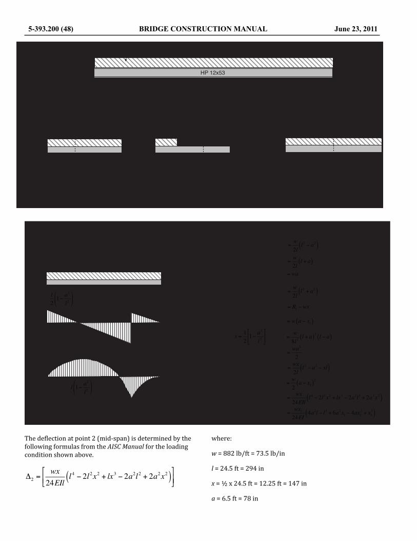
The de@lection at point 2 (mid-‐span) is determined by the following formulas from the AISC Manual for the loading condition shown above.
Δ2 =wx24EIl
l 4 − 2l2x2 + lx3 − 2a2l2 + 2a2x2( )⎡
⎣⎢⎤
⎦⎥
where:
w = 882 lb/ft = 73.5 lb/in
l = 24.5 ft = 294 in
x = ½ x 24.5 ft = 12.25 ft = 147 in
a = 6.5 ft = 78 in
5-393.200 (48) BRIDGE CONSTRUCTION MANUAL June 23, 2011
!""#$%&'()*&'+,*-.*$
/.,01,)2'0)33*.'"#44).1"
56'789:;
<'='>:?'3@AB1
C:CD8'3@E FEG
C:CD8'3@E FEG8? FEG
E FEGE FEG 8? FEG
<'='>:?'3@AB1
=
E FEGE FEG 8? FEG
<'='>:?'3@AB1
H
!""#$%&'()*&'+,*-.*$
E FEGE FEG 8? FEG
<'='>:?'3@AB1
()*&'&,*-.*$"'B).'1I%'"1%%3'@%*$"'"#44).1,2-'1I%'4,%.'0*4'
!"#$%&'($)%$*
+,&-&.,/&/&/&/&/&/&/&/&/&/&/&/&/&/&/&/&/
+0&-&.0&1&.2/&/&/&/&/&/&/&/&/&/&/&/&/
.0&/&/&/&/&/&/&/&/&/&/&/&/&/&/&/&/&/&/&/&/
.2&/&/&/&/&/&/&/&/&/&/&/&/&/&/&/&/&/&/&/&/
.3&&&45#67##8&9:;;<%69=/&/&/&/
.3,&&4><%&<?#%"$8)=/&/&/&/&/&/&/&/
@,&&&4$6&&&&&&&&&&&&&&&&&&&&&&/&/&/&/&/&/
@0&&&4$6&+0=/&/&/&/&/&/&/&/&/&/&/&/&/&/
@3&&45#67##8&9:;;<%69=/&/&/&/
@3,&&4><%&<?#%"$8)=/&/&/&/&/&/&/&
3&&45#67##8&9:;;<%69=/&/&/&/
3,&&&4><%&<?#%"$8)=&/&/&/&/&/&/&/
!!!"
"! #!" #
!!!"
" $ #" #
!!!"
"! $ #!" #
! !#
! $" !%
! ! # %"" #
!!#"!
" $ #" #! " #" #% ! "!" #!
"!
!!#!
!
!!%!"
"! #! %"" #
!!%"!$&'
$#!" " % $ &#!%" $#%"! $ %"
%" #
!!!# %"" #!
!!%!$&'"
" $ !"!%! $ "%% !#!"! $ !#!%!" #
"!" #!
"!
!" #
!$%&"'#(
+, +0
., .0
.2
A<$B&'($)%$*
!"#$%&'"()#*+,*+%&*"%-.//&(01.*,2&($34%5,-0(,!.0"5%3
@,
@0" " #!
"!
@<*#86&'($)%$*

E = 29,000,000 psi
I = 393 in4
Δ2 =73.5 lb in ×147in
24 × 29,000,000psi × 393in4 × 294in×
2944 − 2 × 2942 ×1472( ) + 294 ×1473( ) + 2 × 782 ×1472( )( )
Δ2 = 0.663in ≥ 0.25in
= 0.663 in ≥ ¼ in NOT OK!
The maximum allowable de@lection in this member will be ¼ inch. See section on de@lection on page 5-‐393-‐200-‐(36) for further details. Since the allowable de@lection at this point is exceeded, the member must either be increased in size or wedges must be placed to compensate for this de@lection.
The de@lection at point 1, the end of the cantilever, may be determined with suf@icient accuracy by using the formula in the diagram from the AISC Steel Construction Manual, shown above.
Δ1 =wa24EI
4a2l − l 3 + 6a3 − 4a3 + a3( )
where:
a = x1 = 6.5 ft = 78 in
Δ1 =73.5 lb in × 78in
24 × 29,000,000psi × 393in4×
4 × 782 × 294 − 2943 + 6 × 783 − 4 × 782 + 783( )
Δ1 = −0.353in ≥ 0.25in
Since this exceeds the allowable de@lection of ¼ inches, compensation (by wedging or other means), must be made in the falsework construction, in order to obtain true lines in the completed concrete. Note: The minus sign indicates an upward de@lection of the end of the HP12x53 as indicated in the diagram of the elastic curve of the structural member.
June 23, 2011 BRIDGE CONSTRUCTION MANUAL 5-393.200(49)
! "!#! "!# $% "!#
&'()'*+,('-./-0.+12(3-4(5-/*,0),.(-0.++4*3
67
89!!:#
89:;:#
! "!#$% "!#
&'('))$'*+,-.
/001234'*564'4768962'-59'.:3'0.33*'+3620'01;;59.7<8'.:3'

5-393.200 (50) BRIDGE CONSTRUCTION MANUAL June 23, 2011
This page was intentionally left blank.

EXAMPLE 2—ROADWAY SLAB FALSEWORK
For the purpose of this example, assume the Contractor has proposed the slab falsework details shown in the diagram shown below. Assume also that the rail for the strike-‐off machine is supported by the fascia beams. The following investigations will then be necessary to determine the acceptability of the proposed method:
June 23, 2011 BRIDGE CONSTRUCTION MANUAL 5-393.200(51)
! "#$%&'()*+,-./ "01$
2345-6%#$%7%0#$%8%9 %"%1$%:;<;#$%7%=$%80#$%:;<;>4)6?*3?%3@6?A,BC
D?,+E6'%8%9 %"%1$
/FG$%H-(I3?JK%<-,LL%M
!$%N*B;%'A*+EB6LL%+3B+?6'6%L-,5#$%7%G$%80 %"%1$%:;<;
!
!
"#$%%&%'"()$*&$+&,'"-&+!.%'/$#-
O,BC6?%8%9 %"%1$%:;<;
<3BL'?4+'*3B%P6',*-L%C*@6B%I3?%H?35-6J%Q3;%#;
!"#$%&'#()%*+&,--#*.&*/,(,#-012345"#6078./9:#;01--#<
="#>#?"#@#A="#B';'="#>#A="
A4="#C%1'#*.%0#2.0(D%()#3"#>#5"#D1-),/
E F#G" E F#G"
!"#$%&'()*)H00#0I92,/#(.#2,#C.IJ01-#K%/:#L.'#A
;.&-(/I*(%.&#M,(1%0-#J%N,./#6/.20,9#L.'#='

Interior Bays
1. Plywood Sheathing
a. Bending stress
b. Rolling shear stress
c. De@lection
2. Stringers
a. Bending stress
b. Horizontal shear stress
c. Bearing stress
d. De@lection
3. Joists (double 2”x12” member)
a. Bending stress
b. Horizontal shear stress
c. Bearing stress from washer
d. De@lection
Slab Overhang Falsework
1. Plywood Sheathing
a. Bending stress
b. Rolling shear stress
c. De@lection
2. Stringers
a. Bending stress
b. Horizontal shear stress
c. Bearing stress
d. De@lection
3. Steel overhang bracket
a. Safe load
b. De@lection
4. Hanger
a. Direct tension on bolt
b. Capacity of hanger
INTERIOR BAYS
1. Plywood Sheathing:
Determine the applied unit load, w:
Concrete: 0.67 ft x 1 ft x 150 lb/ft3 = 100.5 lb/ft
Plywood: 0.06 ft x 1 ft x 40 lb/ft3 = 2.5 lb/ft
Live load: = 50 lb/ft
w = 153.0 lb/ft
The requirements to evaluate items a, b, and c— Bending, Rolling Shear, and De@lection for the plywood sheathing can be checked using two different design aids contained in this manual. Both design aids automatically check all three of the criteria listed. The @irst method uses the Charts contained in Figure 5-‐393-‐200-‐15 on page 5-‐393.200(27). According to the conditions of this example, 12 inch support spacing for ¾ inch Plyform Class I will safely support about 550 pounds per square-‐foot, psf, using the chart in the upper right corner of Figure 5-‐393-‐200-‐15. Additionally, Table 5-‐393-‐200-‐4 (page 5-‐393-‐200-‐(14)), can also be used to check the structural adequacy of the sheathing used in this example.
2. Stringers:
5-393.200 (52) BRIDGE CONSTRUCTION MANUAL June 23, 2011
!"#$#%"#&'()*+#,!"#-./.
012"3456'78
9'*:4#;<(*#=':>?#@#A#,B0.C#4D16*
,!"E'()*#)F:G(<H
=':>#>(:H7:8#6'7#*IJ#3456'78#6'7#D'**'8#'6#7':>@:5#)4:D#6:4)J@'7K.
!"#$%&'()*&+,-./'()
"#+0+1#$%&'()*&
234#56789&:
;('%+69.<+9(+,%&'()*&+=+>+!?2@A+6B38%"+
C'<%D+98+.--6'*<+69.<+>+!"+'(
E9.<+<'.)&.:+89&+%D*+"#+0+1#+,%&'()*&+F,*<+%9+'<*.6'G*+%D*+.--6'*<+F('%+69.<@

Determine the applied load, w per foot of stringer.
Concrete, plywood and live load: = 153.0 lb/ft
Weight of member (2x6 S4S) = 2.3 lb/ft
Total, w = 155.3 lb/ft
a. Bending Stress:The members used for this application are normally 16 feet in length that span over 3 or 4 supports, therefore we will use the following formula from Figure 5-‐393-‐200-‐16 on page 5-‐393.200(37).
Bending Moment:
M = 0.10wL2
where:
w = 155.3 lb/ft
L = 5 ft
M = 0.10 × 155.3 lb × (5.0 ft)2 = 388 ft-‐lb
Section Modulus, S = 7.56 in3
Bending Stress:
fb =MS=388 ftlb7.56in3
×12in1 ft
⎛
⎝⎜
⎞
⎠⎟ = 616psi
fb = 616 psi ≤ 1,375 psi OK!
The actual bending stress is less than the allowable stress of 1,375 psi for Douglas Fir, No. 1 material as shown in Table 5-‐393-‐200-‐3 on page 5-‐393.200(11).
b. Horizontal Shear Stress:
Assuming the stringers are continuous over 3 supports the following formula will be used for calculating the
maximum vertical shear, V. See Figure 5-‐393-‐200-‐16 on page 5-‐393.200(37) for the formula.
V =5wl8
=5 ×155.3lb ft × 4.08 ft
8= 396lb
where:
l = L – 2d = 5.0 ft-‐(2 × 5.5 in)/12 = 4.08 ft
b = 1.5 in
d = 5.5 in
fv =3V2bd
=3× 396lb
2 ×1.5in × 5.5in= 72psi ≤ 220psi OK!
The allowable horizontal shear stress for Douglas Fir, No. 1 is 220 psi (ref.: Table 5-‐393-‐200-‐3 on page 5-‐393.200(11)).
c. Bearing Stress:
The maximum bearing force is from two spans continuous for the stringer, the maximum P will be at the center reaction point. See Figure 5-‐393-‐200-‐16 on page 5-‐393.200(37) for the formula.
June 23, 2011 BRIDGE CONSTRUCTION MANUAL 5-393.200(53)
!"#"$%%&'"()*+,
-."/"0."1"$-."2&3&
% 4"5. % 4"5. 678)(9")9:;"<=:>?@A
B7:C"C?:AD:;"+7D",E9"-."/"0."<,D?@A9D"8<9C",7"C9,9D;?@9",E9")9@C?@A";7;9@,"?@",E9"<,D?@A9D<&
!"!#$%
$%"&"'%"()*+,-.*
/.0*+,-"12*304.51607.78
!"!#$%
$"9"$%"&"!$%:;2<=.">;+1)
!"!#$%
:.)0+=";3"<.0*+,-"12*304.";3"1)*+,-.*1";,")6."7;2<=.">;+1)?

P = 5wL4
=5 ×155.3lb ft × 5.0 ft
4= 971lb
fp =PA=
971lb2(1.5in ×1.5in)
= 216psi ≤ 625psi OK!
The temporary allowable bearing stress perpendicular to grain for Douglas Fir is 625 psi so this con@iguration is adequate.
Other project conditions could result in the actual bearing stresses that exceed the allowable side bearing stress for the material used. Under those conditions the allowable bearing stress can be increased by factors contained in the charts contained in Figure 5-‐393-‐200-‐17 on page 5-‐393.200(38). In this particular example the allowable bearing stress could be increased by a factor of 1.25, which is found in the top chart on Figure 5-‐393-‐200-‐17. The allowable stress increase factor need not be @igured in this example since this stress is much less than the allowable stress of 625 psi.
c. Deblection of Stringers:
The de@lection is based on the assumption that the stringers are continuous over three supports. The formula is found in Figure 5-‐393-‐200-‐16 on page 5-‐393.200(37). Additionally, the de@lection is based on dead load only.
Δ =wL4
185EI
Δ =105.3lb ft × 5.0 ft( )4 × 12in( )3
185 ×1,700,000psi × 20.80in4= 0.017in
where:
w = 155.3 lb/ft – 50 lb/ft (live load) = 105.3 lb/ft
L = 5.0 ft.
E = 1,700,000 psi (ref.: Table 5-‐393-‐200-‐3)
I = 20.80 in4 (ref.: Table 5-‐393-‐200-‐2)
The surface being formed is not exposed to view and is therefore, not subject to the normal de@lection limitations. However, this value will be used later to determine the cumulative de@lection of the falsework.
3. Joist (double 2 x 10 members):
The loads, both dead load and live load are applied to this member through eight 2 x 6 stringers. As a general rule, when the concentrated loads are applied through 3 or more crossing members, the assumption of a uniform loading may be used.
Determine uniform load on the each joist:
Concrete:
8in × 1 ft12in( ) ×1 ft × 5.0 ft ×150 lb ft 3 = 500.0lbPlyform:
0.0625 ft x 1 ft x 40 lb/ft3 x 5.0 ft = 12.5 lb
Stringers:
8 x 2.3 lb/ft x 5.0 ft x (1/7.33) = 12.6 lb
Double 2 x 10 Joist:
2 x 3.9 lb/lf = 7.8 lb
Live load:
50 lb/ft2 x 5.0 ft x 1.0 ft = 250.0 lb
Total, w = 782.9 lb/lf
a. Bending Stress:
First calculate the bending moment in the double joist.
5-393.200 (54) BRIDGE CONSTRUCTION MANUAL June 23, 2011
8"'3.,*79*:*;79*<*= *>*?9*@6!6
A >79*B%CD)(-.E
F >G9*B!"#(&,%,*(-&&),+*3C*H")$%E
;?9
A9
I+,-.)J-%)"#*"1*("#(&,%,*."-+*(-&&),+*3C*%K,*+"'3.,*H")$%6
!"#"$%&'(")*+,-
&"."&/"0"1&/"2345*)6"7489-:"
$ .;/
<995=6>")4?>">8?@A?=",4A"-B6">6-6A=8C8C@"-B6"*6C>8C@"=4=6C-"8C"-B6">45*)6"7489-"95DD4A-6>"?-"6?EB"6C>'

M =wL2
8=782.9lb / lf × 7.33 ft( )2
8= 5,258 ftlb
Determine the section modulus for the double 2 x 10’s, either calculate the section modulus with the standard formula, or look up the value in Table 5-‐393-‐200-‐2 on page 5-‐393.200(9).
S = 2 x 21.39 in3 = 42.78 in3.
Bending Stress:
fb =MS=5,258 ftlb × 12in1 ft( )
42.78in3= 1,475psi ≈ 1,375psi
The allowable bending stress for Douglas Fir, No. 1 is 1,375 psi (ref.: Table 5-‐393-‐200-‐3. These members are moderately over stress by 100 psi or about 7%. This is within a reasonable tolerance. The Contractor should be noti@ied of this situation.
b. Horizontal Shear Stress:
The formula for determining horizontal shear stress in rectangular timber members is as follows:
fv =3V2bd
where:
V =w L − 2d( )
2
V =782.9lb / ft × 7.33 ft − 2 × 9.25in × 1 ft12in( )( )⎛
⎝⎜
⎞⎠⎟
2= 2,266lb
V = 2,266 lb
b = 1.5 in
d = 9.25 in
Horizontal Shear Stress:
fv =3V2bd
fv =3× 2,266lb
2 × 2 ×1.5in × 9.25in=122.5psi ≤ 220psi
The allowable horizontal shear stress for Douglas Fir, No. 1 is 220 psi (ref.: Table 5-‐393-‐200-‐3) therefore, the double 2 x 10 joist is adequate for horizontal shear.
c. Bearing Stress on Washer:
First, calculate the bearing force P, on the washer.
P = 782.9lb / ft × 7.33 ft2
= 2,869.3lb
With a 3” x 4” washer placed as shown in the detail and assume a ¾ inch space is used between the 2” x 10” members the area can be obtained from Figure 5-‐393-‐200-‐17 on page 5-‐393.200(38) using the center chart or calculate the area directly as below.
A = 3 in x 3 in. = 9.0 in2
fp =PA=2,869.3lb9in2
= 318.8psi ≤ 625psi
The allowable compression perpendicular to the grain, side bearing, for Douglas Fir is 625 psi so the washer is adequate to transfer the force from the double 2 x 10 members. However, under different conditions the actual bearing stress could exceed the allowable side bearing, if that is the case the allowable bearing stress can be increased by the factor shown in the center chart in Figure 5-‐393-‐200-‐17. That factor for the conditions in this example is 1.13. This would result in an adjusted allowable stress of 1.13 x 625 psi equaling 706 psi.
June 23, 2011 BRIDGE CONSTRUCTION MANUAL 5-393.200(55)
!"!#$%!"!#$%
&'()*+",-".')/*01"23/-)4'",-"(5'"6%"7"8%"9)25'/",0"(5'":,3.+'";,*2(<
6#8%
6%
8%

d. Deblection:
The de@lection is based only on the dead load supported by these members, so the live load is deducted from the total. See Figure 5-‐393-‐200-‐16 on page 5-‐393.200(37) for the formula.
Δ =5wL4
384EI
where:
w = 782.9 lb/ft –(50 psf x 5.0 ft) = 532.9 lb/ft
L = 7’ – 4” = 7.33ft
E = 1,700,000 psi (ref.: Table 5-‐393-‐200-‐3)
I = 2 x 98.93 in4 = 197.86 in4 (ref.: Table 5-‐393-‐200-‐2)
Δ =5 × 532.9lb / ft × 7.33 ft( )4 × 12in1 ft( )
3
384 ×1,700,000psi ×197.86in4= 0.103in
The cumulative de@lection of the falsework in the interior bays is limited to about ½ inch (see page 5-‐393-‐200-‐(36)). It can be seen that the cumulative de@lection of the stringers (0.017 in) plus de@lection of the double joist (0.103 in) is only 0.120 inches (approximately 1/8 inch) and is, therefore acceptable.
4. Hanger Rods:
The load on each hanger rod will be equal to the bearing load on the plate washers, 2,869.3 pounds. The ½ inch diameter coil bolts for the hangers are manufactured in various strengths such as 6,000 pound capacity, 9,000 pound capacity, etc. When required, the Contractor should furnish evidence of the safe capacity of the proposed coil bolts.
In addition to checking the coil bolt, the hanger must be checked for rated capacity. Most hangers are rated for the load carrying capacity for the entire hanger. The load on either side should not exceed one-‐half of this value.
SLAB OVERHANG FALSEWORK
1. Plywood Sheathing:
Maximum stress in the sheathing will occur adjacent to the beam, at the point where the concrete depth is a maximum. Assume the concrete stool height plus @lange thickness at the maximum depth will be 3 inches. Where this value is known to be greater, use the known maximum value.
Determine uniform dead load on the sheathing based on this maximum thickness:
Concrete:
11in × 1 ft12in( )×1 ft ×150lb / ft 3 =137.5lb / ftPlyform:
0.0625 ft x 1 ft x 40 lb/ft2 = 2.5 lb/ft
Live Load:
= 50.0 lb/ft
Total ,w = 190.0 lb/ft
The structural adequacy of the sheathing can be checked using two design aids in this manual. First, the Chart in the upper right corner of Figure 5-‐393-‐200-‐15 on page 5-‐393.200(27), can be used for checking the maximum uniform load for Plyform, Class I used in the weak direction for a range of spans. Based on the span length of 1’ – 0”, the maximum allowable uniform load is approximately 550 pounds per square-‐foot. Additionally, the sheathing can be checked using Table 5-‐393-‐200-‐4 on page 5-‐393.200(14).
2. Stringer:
The second stringer from the right will be the controlling stringer for design. The @irst stringer only carries about one-‐half as much load. The average slab thickness at this controlling stringer can be determined by calculation or by scaling the drawings. In this case, an average thickness of 10 ¼ inches was scaled. The uniform load on this stringer will be:
5-393.200 (56) BRIDGE CONSTRUCTION MANUAL June 23, 2011
!"#$#%"#&'()*+,(
-.#-/0"
123,45
- #$#."
67*8(,',#9,:';#<7(#';,#87*'(7==)*+#>'()*+,(#)*#';,#73,(;?*+4

Concrete:
10.25in × 1 ft12in( )×1 ft ×150lb / ft 3 =128.1lb / ftPlyform:
0.0625 ft x 1 ft x 40 lb/ft3 = 2.5 lb/ft
Stringer:
= 2.3 lb/ft
Live Load:
= 50.0 lb/ft
Total, w = 182.9 lb/ft
The uniform load on interior stringers was 155 lb/ft. Since stringers on the overhang have the same span length as the stringers on the interior bays, their stresses may be quickly checked by ratios as follows:
a. Bending Stress:
The bending stress is calculated as follows:
fb =182.9lb / ft155lb / ft
× 616psi = 727psi ≤1,375psi
The actual bending stress is less than the allowable stress of 1,375 psi for Douglas Fir, No. 1 material as shown in Table 5-‐393-‐200-‐3 on page 5-‐393.200(11).
b. Horizontal Shear Stress:
The horizontal shear stress is calculated as follows:
fv =182.9lb / ft155lb / ft
× 72psi = 85psi ≤ 220psi
The allowable horizontal shear stress for Douglas Fir is 220 psi (ref.: Table 5-‐393-‐200-‐3 on page 5-‐393.200(11)).
c. Bearing Stress:
The general formula for calculating the bearing stress is as follows:
fp =PA
Using the Superior Bracket as recommended by the manufacturer with a slotted 2” x 6” top bearing surface, the bearing area, A is:
June 23, 2011 BRIDGE CONSTRUCTION MANUAL 5-393.200(57)
!"#$%%&"'()*'$")+",-"(+$).,$(/"0,&1(2%3"4%.51$,$)%-"5135%+(+"%-&67
!89
8 ":";<9=9
=9
=9
!89
;<";>?9
@";>A9
="8>?9
A9
B?9"CD%5".(.E(3"%2"+15(3)%3"E3,4F($G
?9
; ":"<9; ":"<9 ; ":"<9
; ":"<9
H($,)&+"%2"4%-43($("$')4F-(++",$"0,3)%1+"5%)-$+",&%-*"$'("/(4F"%0(3',-*7

A = (5 ½” – 1 ½”) x 1 ½” = 6.0 in2
P = 182.9lb / ft155lb / ft
× 969lb =1,143lb
fp =1,143lb6.0in2
=191psi ≤ 625psi
The temporary allowable bearing stress perpendicular to grain for Douglas Fir is 625 psi so this con@iguration is adequate.
Other project conditions could result in actual bearing stresses that exceed the allowable side bearing stress for the material used. Under those condition the allowable bearing stress can be increased by factors contained in the charts contained in Figure 5-‐393-‐200-‐17 on page 5-‐393.200(38). In this particular example the allowable bearing stress could be increased by a factor of 1.19, which is found in the top chart on Figure 5-‐393-‐20-‐17. The allowable stress increase factor need not be @igured in this example since this stress is much less than the allowable stress of 625 psi.
d. Deblection of Stringers:
The uniform load is the only factor that differs from the calculation of the interior stringers. For this member, w = 182.9 lb/ft – 50.0 lb/ft(live load) = 132.0 lb/ft. De@lection of the overhang can be determined by using ratio of the uniform loads.
Δ =132.9lb / ft105lb / ft
× 0.017in = 0.0215in
Since this surface is considered to be exposed to view, and the span length is less than 67 inches, the maximum allowable de@lection will be:
L270 =
5.0 ft × 12in1 ft( )270
= 0.222in ≥ 0.215in OK!
The actual de@lection, 0.022 inches is less than L/270 of the span length and is acceptable.
3. Steel Overhang Bracket:
Superior brackets may be checked using the in@luence lines in Figure 5-‐393-‐200-‐12 on page 5-‐393.200(23). To use this chart, the load on individual stringers must be determined and the distance from the outboard end of the bracket to each stringer must be determined. The following calculations are based on the diagrams below.
Calculation of uniform loads for each stringer:
Plyform:
34 in( )× 1 ft12in( )×1 ft × 40lb / ft 2 = 2.5lb / ft
Stringer load (2” x 6” S4S):
= 2.3 lb/ft
5-393.200 (58) BRIDGE CONSTRUCTION MANUAL June 23, 2011
!"#$#%"#&'()*+,(
!"#$#%"#-.)/,(#0)'1#2,*',(#3/4'
5#56!"#7)8,#3/4'
94*'.2'#3:(;.2,<31.8,8=
5#56!"
>#56!"
!"#$%&!'
()*"$%&!'?,'.)/3#4;#'1,#@,.()*+#3:(;.2,3#4;#'1,#3'()*+,(3#3:AA4(',8#
@B#'1,#'4A#C,C@,(#4;#.#&:A,()4(#@(.2D,'E
Detail showing the location of loads on the overhang bracket.
Spacing of brackets = 5 - 0”
2”ABCDE
50”
14”
38”26”
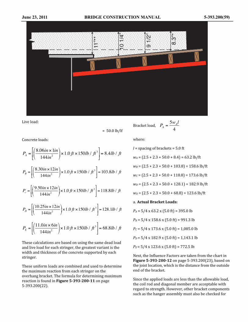
Live load:
= 50.0 lb/lf
Concrete loads:
PA =8.06in ×1in144in2
⎛
⎝⎜
⎞
⎠⎟×1.0 ft ×150lb / ft 3
⎡
⎣⎢
⎤
⎦⎥= 8.4lb / ft
PB =8.30in ×12in144in2
⎛
⎝⎜
⎞
⎠⎟×1.0 ft ×150lb / ft 3
⎡
⎣⎢
⎤
⎦⎥=103.8lb / ft
Pc =9.50in ×12in144in2
⎛
⎝⎜
⎞
⎠⎟×1.0 ft ×150lb / ft 3
⎡
⎣⎢
⎤
⎦⎥=118.8lb / ft
PD =10.25in ×12in
144in2⎛
⎝⎜
⎞
⎠⎟×1.0 ft ×150lb / ft 3
⎡
⎣⎢
⎤
⎦⎥=128.1lb / ft
PE =11.0in × 6in144in2
⎛
⎝⎜
⎞
⎠⎟×1.0 ft ×150lb / ft 3
⎡
⎣⎢
⎤
⎦⎥= 68.8lb / ft
These calculations are based on using the same dead load and live load for each stringer, the greatest variant is the width and thickness of the concrete supported by each stringer.
These uniform loads are combined and used to determine the maximum reaction from each stringer on the overhang bracket. The formula for determining maximum reaction is found in Figure 5-‐393-‐200-‐11 on page 5-‐393.200(22).
Bracket load, PA =5wAl4
where:
l = spacing of brackets = 5.0 ft
wA = (2.5 + 2.3 + 50.0 + 8.4) = 63.2 lb/ft
wB = (2.5 + 2.3 + 50.0 + 103.8) = 158.6 lb/ft
wC = (2.5 + 2.3 + 50.0 + 118.8) = 173.6 lb/ft
wD = (2.5 + 2.3 + 50.0 + 128.1) = 182.9 lb/ft
wD = (2.5 + 2.3 + 50.0 + 68.8) = 123.6 lb/ft
a. Actual Bracket Loads:
PA = 5/4 x 63.2 x (5.0 ft) = 395.0 lb
PB = 5/4 x 158.6 x (5.0 ft) = 991.3 lb
PC = 5/4 x 173.6 x (5.0 ft) = 1,085.0 lb
PD = 5/4 x 182.9 x (5.0 ft) = 1,143.1 lb
PE = 5/4 x 123.6 x (5.0 ft) = 772.5 lb
Next, the In@luence Factors are taken from the chart in Figure 5-‐393-‐200-‐12 on page 5-‐393.200(23), based on the joist location, which is the distance from the outside end of the bracket.
Since the applied loads are less than the allowable load, the coil rod and diagonal member are acceptable with regard to strength. However, other bracket components such as the hanger assembly must also be checked for
June 23, 2011 BRIDGE CONSTRUCTION MANUAL 5-393.200(59)
!!"## $"
!%&!'("
)&!'*"
$+,"#
!"#$
#&-./&$+,%"&0/123./&45.6&57&68/&1591:/6/&./16;59&;.&65&68/&</76&57&=5;96&>+##&?655<&8/;@86&;.&/.6;426/A&,"&75:&154=3626;59&=3:=5./.&59<B+
C/62;<.&57&68/&1591:/6/&A/=68&26&=5;96.&;9&68/&A/1D&5E/:829@++

strength requirements as per manufacturer’s allowable loads as published in their literature.
b. Deblection of Overhang Bracket:
The manufacturer’s literature indicates that the de@lection is determined by summarizing the total vertical weight on the bracket. Only the weight of the concrete need be applied since the de@lection due to dead load of the falsework may assumed to have already occurred prior to the placement of the concrete.
Total weight of concrete:
8in +11in2
⎛
⎝⎜
⎞
⎠⎟× 3.33 ft × 5.0 ft ×150lb / ft 3 × 1 ft12in( ) =1,977lb
De@lection of the bracket is determined by using Figure 5-‐393-‐200-‐12 on page 5-‐393.200(23). That chart indicates that the de@lection from a load of 1,977 pounds will be 3/16 inch. The cumulative de@lection of the overhang may now be summarized as follows:
De@lection of sheathing: negligible
De@lection of stringer: 0.022 in
De@lection of bracket: 0.190 in
Seating of wood members (2 x 1/16 in)* 0.120 in
Total de@lection at center of stringer span: 0.332 in
*Abutting faces of wood members are assumed to crush 1/16 inch when heavy load is applied. This value will be less for tightly constructed falsework. In addition, wood @iller used against the web as used on prestressed concrete girder must be uniformly @itting and seated to prevent overhang de@lection.
The falsework along the edge of coping should, therefore, be set about 3/8 inch above the @inal grade to compensate for the anticipated de@lection.
5. Hanger:
a. Direct Tension on Bolt:
The bolt for this hanger is actually the 45° coil rod which was checked in Item 3 above. Note that the manufacturer speci@ies a 9,000 pounds capacity coil bolt.
Hangers are normally rated based on the vertical load carrying capacity. The vertical component of the load along the coil rod on this hanger can be determined as follows:
P = (cos45°) x 7,780.6 lb = 0.707 x 7,780.6 lb = 5,502 lb
b. Capacity of Hanger:
This value should not exceed ½ of the safe working load for the total hanger. Preferably, the manufacturer should furnish information as to the safe load along the 45° angle for the overhung hangers. Note: The safe working load ascribed to these hangers only applies when the device has full bearing contact on the top @lange of the beam and when the hanger bolts are @lush with the edge of the beam @lange.
5-393.200 (60) BRIDGE CONSTRUCTION MANUAL June 23, 2011
!!!!!!!!!!!!!!!"#$%!&'!()*!+#,-!.#% !!!!!!!!!!"#$%!&'!/,$0#'$-!123425
65$7829 ()*!+#,-!.#% 65$7829 /,$0#'$-
:95,'025 "#$% ;'<-=2'72 "#$% "#$% ;'<-=2'72 "#$%
;%2'9,<,7$9,#' >?#='%@A B$79#5 >?#='%@A >?#='%@A B$79#5 >?#='%@A
! CD) EFG HIJEKFJJ CD) EFL HIHJGFJJ
" DDHFC EFH EIJLHFKJ DDHFC HF( HICLKFLJ
# HIJL)FJJ HFL HID)CFJJ HIJL)FJJ JFDJ DKGF)J
$ HIH(CFHJ HF) HIKH(FKJ HIH(CFHJ JF)J )KHFGJ
% KKEF) HFC HIJJ(FCJ KKEF) JFH KKFCJ
M&MN"!O KIKLJFGJ M&MN"!O (IHHDFHJ
1$'=<$79=525P@!N--#Q$4-2!"#$%R DIJJJFJJ (IKCCFJS
S!MT,@!-#$%!,@!#'-U!<#5!#V25T$'0!45$7829@!#'!@922-!42$3@F
!"#$%&'(")$")*)+,#,&-+(-.()/0&1#2)+,(1)",&'#2(2-#3(-+(%#+4)"5
2-#3(-+('-&2(6-2,
7879:5;(26
<(=(>8>:?(26
@>A
1)",&'#2(2-#3(-+(%#+4)"

EXAMPLE 3—SLAB SPAN FALSEWORK
For the purpose of this example, assume the Contractor has proposed the falsework scheme shown in the diagram shown below. In addition, assume they have stated that a strike-‐off machine weighing 8,000 pounds will be used and the strike-‐off rails will be located as shown in the @igure (outside beam):
June 23, 2011 BRIDGE CONSTRUCTION MANUAL 5-393.200(61)
!
!
!" #$#"%!" #$#"% !" #$#"%
&'()*+,+#-./0 123%#4.56'*7#-8+/,89(:
&#;<=='*,9(:#*/9.#6'*-,*9>+$'66#7/)89(+?
@970+*#=9.+-0<,,#A9/B#!C%
!C%#D#!C%#49.+#)/=
C%#D#E%#F'9-,#G#! #$#"%#HB&B!$I%
J%#D#!3%#K+/7-#G#L #$#"%#HB&B
K'.,-
C%#D#!C%#K*/)9(:
M*96,#=9(-
"#$%%&%'"()$*&$+&%,!-&+!,%'.$#/
!"#$%&'())
!"#$%&'&()*+,
-./(0(-./(12*&($+3 ./(0(-./(
4%+$2#5
-6 (7(6/ -6 (7(6/ -6 (7(6/
829,&%(32*&),:''(;2+<(-./
=/(0(->/(4&+9)(?(@ (7(6/
./(0(A/(B"2)'(?(- (7(6/(C<!<
DE>/(1*FG"%9()H&+'H2#5

The following stress investigation would be necessary:
1. Plywood Sheathing
a. Bending stress
b. Rolling shear stress
c. De@lection
2. Joist (2 x 8)
a. Bending stress
b. Horizontal shear stress
c. Bearing stress
d. De@lection
3. Beams (6 x 14)
a. Bending stress
b. Horizontal shear stress
c. De@lection
4. Pile Cap
a. Bending stress
b. Horizontal shear stress
c. Bearing stress
d. De@lection
5. Pile—total reaction
6. Strike-‐off machine support
a. Bending stress
b. Horizontal shear stress
c. Bearing stress
d. De@lection
1. Plyform Sheathing:
Calculation are as follows:
Determine applied uniform:
Concrete:
21in × 1 ft12in( )×1 ft ×150lb / ft 3 = 262.5lb / ftPlyform:
0.0625 ft x 1 ft x 40 lb/ft2 = 2.5 lb/ft
Live Load:
= 50.0 lb/ft
Total ,w = 315.0 lb/ft
Figure 5-‐393-‐200-‐15 on page 5-‐393.200(27) indicates that even the lowest grade of Plyform (Class II) placed in the weak direction will safely support about 500 psf; therefore, the sheathing is acceptable.
2. Joist (2 x 8):
Since these members are spaced at 1’ – 0”, the applied uniform load is:
w = 315 lb/ft + 3.0 lb/lf (weight of the joist) = 318.0 lb/ft
a. Bending Stress:
First, calculate the bending moment in the joist.
M =wl2
8=318.0lb / ft × 5.0 ft( )2
8= 993.8 ftlb
where:
M = bending moment in joist = 993.8 ft-‐lb
w = uniform load = 318 lb/ft
l = span length, = 5.0 ft
Determine the section modulus of the 2 x 8 joist using Table 5-‐393-‐200-‐2.Section modulus: S = 13.14 in3
Calculate bending stress:
fb =MS
fb =993.8 ftlb13.14in3
× 12in1 ft( ) = 907.6psi ≤1,250psiThe allowable bending stress for Douglas Fir, No. 2 is 1,250 psi as shown in Table 5-‐393-‐200-‐3.
b. Horizontal Shear Stress:
To determine horizontal shear stress you must @irst determine the vertical shear force using the following formula for two continuous spans found in Figure 5-‐393-‐200-‐16 on page 5-‐393.200(37).
5-393.200 (62) BRIDGE CONSTRUCTION MANUAL June 23, 2011

The span length used is reduced by two times the depth of the member.
V =5wl8
V =5w l − 2d( )
8
V =5 × 318lb / ft × 5.0 ft − 2 × 7.25in 1 ft12in( )( )⎛
⎝⎜
⎞⎠⎟
8= 753.6lb
where:
l = 5.0 ft
w = 318.0 lb/ft
d = 7.25 in
Now calculate horizontal shear stress using the following formula:
fv =3V2bd
where:
V = 753.6 lb
d = 7.25 in
b = 1.5 in
fv =3× 753.6lb
2 ×1.5in × 7.25in=103.9psi ≤ 220psi
The allowable horizontal shear stress for Douglas Fir, No. 2 is 220 psi as shown in Table 5-‐393-‐200-‐3.
c. Bearing Stress:
Determine bearing stress of the 2 x 8 joist on the 6 x 14 beam. For two continuous spans the maximum P is at the center support. See Figure 5-‐393-‐200-‐16 on page 5-‐393.200(37) for the formula to determine the maximum V = P.
P = R2 =5wl4
=5 × 318.0lb / ft × 5.0 ft
4=1,987.5lb
where:
w = 318.0 lb/ft
l = 5.0 ft
Calculate bearing stress using the following formula:
fp =PA=1,987.5lb1.5in × 6.0in
= 220.8psi ≤ 625psi
where:
P = 1,987.5 lb
A = area of contact (1.5 in x 6.0 in) = 9.0 in2
The allowable compression perpendicular to grain, side bearing, for Douglas Fir, No. 2 is 625 psi as shown in Table 5-‐393-‐200-‐3 on page 5-‐393.200(11).
d. Deblection of 2” x 8” Joist:
Calculate the de@lection using the following formula based on the dead load only:
Δ =wl 4
185EI
where:
w = 318.0 lb/ft – 50 lb/ft(live load) = 268.0 lb/ft
l = 5.0 ft
E = 1,600,000 psi (ref.: Table 5-‐393-‐200-‐3)
I = 47.63 in4 (ref.: Table 5-‐393-‐200-‐2)
June 23, 2011 BRIDGE CONSTRUCTION MANUAL 5-393.200(63)
!"#$%&'()*()*(#+"(,"$-%./('0-*$1"()*(#+"(2)%'#().(#+"(,"$34
56(7(896(:"$3:"$-%./'0-*$1"
;6(7(<6(=)%'#

Δ =268lb / ft × 5 ft( )4 × 12in1 ft( )
3
185 ×1,600,000psi × 47.63in4= 0.021in ≤ 0.22in
The limiting de@lection is:
l270 =
5.0 ft × 12in1 ft( )270
= 0.22in ≥ 0.021in
Since the actual de@lection of 0.021 inches is less than the allowable of 0.22 inches, the member is acceptable.
3. Beam (6 x 14):
Assume the Contractor has stated that these full sawn beams will be furnished in 22 foot lengths. These beams will generate two continuous spans for design purposes. See Figure 5-‐393-‐200-‐16, for the beam formulas. The @irst step is to calculate the applied uniform loads:
Live load, concrete, sheathing and joist:
318.0 lb/ft2 x 5.0 ft = 1,590.0 lb/ft
Weight of 6 x 14 member (full sawn)”
6 in x 14 in x(1 ft2/144in2) x 40 lb/ft3 = 23.3 lb/ft
Total = 1,613.3 lb/ft
It can be assumed that the ends of the joists will be staggered so that the critical load determined in Item 2c above will occur on any one beam.
a. Bending Stress:
First step is to calculate the bending moment in the beam using the following formula:
M =wl2
8=1,613.3lb / ft × 10 ft( )2
8= 20,166 ftlb
Determine the section modulus of the full sawn 6” x 14” beam using Table 5-‐393-‐200-‐2:
S = 196.0 in3 (rough cut 6 x 14)
Calculate bending stress using the following formula:
fb =MS
fb =20,166 ftlb × 12in1 ft( )
196.0in3= 1,234.7psi ≤ 1,250psi
The allowable bending stress is 1,250 psi; therefore, this member meets the bending strength requirements.
b. Horizontal Shear Stress for 6 x 14 Beam:
To determine horizontal shear stress you must @irst determine the vertical shear force using the following formula for two continuous spans found in Figure 5-‐393-‐200-‐16. The span length used is reduced by two times the depth of the member.
V =5wl8
V =5w l − 2d( )
8
V =5 ×1,613.3lb / ft × 10 ft − 2 ×14 1 ft12in( )( )⎛
⎝⎜
⎞⎠⎟
8
V = 7,730lb
where:
l = 10.0 ft
w = 1,613.3 lb/ft
d = 14 in
Now calculate horizontal shear stress using the following formula:
fv =3V2bd
where:
V = 7,730 lb
d = 14 in
b = 7 in
fv =3V2bd
=3× 7,730lb2 × 6in ×14in
=138.0psi ≤ 220
5-393.200 (64) BRIDGE CONSTRUCTION MANUAL June 23, 2011

The allowable horizontal shear stress for Douglas Fir is 220 psi as shown in Table 5-‐393-‐200-‐3.
c. Bearing Stress:
Determine bearing stress of the 6 x 14 joist on the 12 x 12 pier cap. For two continuous spans the maximum P is at the center support. See Figure 5-‐393-‐200-‐16 for the formula to determine the maximum V = P.
P = R2 =5wl4
=5 ×1,613.3lb / ft ×10 ft
4= 20,166lb
where:
w = 1,613.3 lb/ft
l = 10.0 ft
Calculate bearing stress using the following formula:
fp =PA=20,166lb6in ×12.0in
= 280psi ≤ 625psi
where:
P = 20,166 lb
A = area of contact (6 in x 12 in) = 72.0 in2
The allowable compression perpendicular to grain, side bearing, for Douglas Fir is 625 psi as shown in Table 5-‐393-‐200-‐3.
d. Deblection of 6” x 14” Beam:
Calculate the de@lection using the following formula based on the dead load only for two continuous spans:
Δ =wl 4
185EI
where:
w = 1,613 .3 lb/ft – 50 lb/ft x 5 ft(live load) = 1,363.3 lb/ft
l = 10.0 ft
E = 1,600,000 psi (ref.: Table 5-‐393-‐200-‐2)
I = 1,372 in4 (rough cut) (ref.: Table 5-‐393-‐200-‐3)
Δ =1,363.3lb / ft × 10 ft( )4 × 12in1 ft( )
3
185 ×1,600,000psi ×1,372in4= 0.058in
Δ = 0.058in ≤ 0.25in OK
This is less than the allowable de@lection of ¼ inch for the member, but the member must also be checked later as part of the cumulative de@lection.
4. Pile Cap (12 x 12):
The reaction of the 6 x 14 beams on the pile cap will be determined as follows:
NOTE: A simple span reaction will be used since the higher reaction R2, determined in step 3c above will occur at random locations rather than all on one cap. This simpli@ication is also in agreement with ACI recommendations.
Live load, concrete, sheathing, joist and beam: w = 1,613.3 lb/ft
Load on pile cap: P = 1,613.3 lb/ft x 10 ft = 16,133 pounds per beam
June 23, 2011 BRIDGE CONSTRUCTION MANUAL 5-393.200(65)
!"#$%$&#'(#)%"*%+&),-(%.&/-%0#.1
234%5%234%6&),-(%.&/-%0#.
7%8%9:%/,;*+%<$=-%+"%7-&'>+%"*%.&/-%0#.?
2@A2BB%/,
2: %C%:4
2@A2BB%/, 2@A2BB%/, 2@A2BB%/, 2@A2BB%/,
2: %C%:4<.&/-%D.#0&E'? <.&/-%D.#0&E'?

Assume the Contractor has stated that pile caps will be furnished in 20 foot lengths. Two continuous spans will apply for design. The following loading diagram will be typical of each two span segment.
a. Bending Stress in Pile Cap:
Maximum bending stress must be checked at two points shown on the diagram below. Determine the bending moment in the cap with two different load diagrams, one from the AISC Manual and one that can be seen in Figure 5-‐393-‐200-‐16 of this manual.
The load from the 6” x 14” beams directly over the piles are not shown since they do not cause bending in the pile cap.
M1 =1364
PL⎛
⎝⎜
⎞
⎠⎟−
12
332
PL⎛
⎝⎜
⎞
⎠⎟
⎛
⎝⎜
⎞
⎠⎟+
wl2
14.2⎛
⎝⎜
⎞
⎠⎟
M1 =1364
×16,133lb ×10 ft⎛
⎝⎜
⎞
⎠⎟−
12
33216,133lb ×10 ft
⎛
⎝⎜
⎞
⎠⎟
⎛
⎝⎜
⎞
⎠⎟+
40lb / ft × 10 ft( )14.2
⎛
⎝⎜
⎞
⎠⎟ = 25,236lbft
M1 = 25,236 ft-‐lb
M 2 = 2 × 332
PL⎛
⎝⎜
⎞
⎠⎟+
wl2
8
M 2 = 2 × 33216,133lb ×10 ft
⎛
⎝⎜
⎞
⎠⎟+
5-393.200 (66) BRIDGE CONSTRUCTION MANUAL June 23, 2011
!!
"#$%%&'()
!"#$%&'($)%$*
+,-(.$/#01&2$3-/$%&45$6&7&7&7
89&:&;97&7&7&7&7&7&7&7&7&7&7&7&7&7&7&7&7
8<&:&;<&=&;>7&7&7&7&7&7&7&7&7&7&7&7&7
8>&:&;>&7&7&7&7&7&7&7&7&7&7&7&7&7&7&7&7
;<&7&7&7&7&7&7&7&7&7&7&7&7&7&7&7&7&7&7&7&7
?*$@7&A$1&B5(01&5C&/5$6D&7&7&7&7&
?$@7&AE7FGE!"C%5*&89D&7&7&7&7&7
!!"#!
!!""$
!
!""$
!
!!!!%
!
!!&"$
!
!!"%'
!
!()(!*!" "
#$
!89 8<
;9
;<
;>
45$6&'($)%$*
!"#$%#&"&'()*+,-$."(*/&+0('1+#'-!"#!*#$2+$*3(+$(!*#$*2("4("#*('1+#
??$@7
?9
?5*#01&'($)%$*
8>!
!"# !"#H

40.0lb / ft × 10.0 ft( )2
8= 30,749lbft
M2 = 30,749 lb-‐ft > 25,490 lb-‐ft
M2 = 30,749 lb-‐ft Controls
Bending Stress in Pile Cap:
Calculate bending stress using the following formula:
fb =MS
fb =30,749 ftlb × 12in1 ft( )
288in3= 1,281psi
fb = 1,281 psi > 1,250 psi Close Enough
where:
Section modulus (12 x 12 rough cut): S = 288 in3
The allowable bending stress of Douglas Fir, No. 2 is 1,250 psi. The actual bending stress is 1,281 psi that is about 2.5 % over the allowable, which for this purpose is acceptable.
b. Horizontal Shear Stress in Pile Cap:
This stress will be the maximum over the center support. See the Beam Formulas above. First, summarize the vertical shear forces for the three diagrams used to determine bending moments.
V =1932
P + 12
332
P⎛
⎝⎜
⎞
⎠⎟
⎛
⎝⎜
⎞
⎠⎟+5w L − 2d( )
8
V =193216,133lb +
12
33216,133lb
⎛
⎝⎜
⎞
⎠⎟
⎛
⎝⎜
⎞
⎠⎟+
5 × 40lb / ft 10 ft − 2 ×12in 1 ft12in( )⎛⎝
⎞⎠
⎛⎝⎜
⎞⎠⎟
8= 10,535lb
Horizontal Shear Stress in Pile Cap:
Next, calculate the actual horizontal shear stress using the following formula:
fv =3V2bd
=3×10,535lb2 ×12in ×12in
= 109.7psi ≤ 220psi
Where:
b = 12 in
d = 12 in
The allowable horizontal shear stress for Douglas Fir, No. 2 is 220 psi, see Table 5-‐393-‐200-‐3.
c. Bearing Stress in Pile Cap:
Calculate the bearing stress of the cap on the top of the piles using the following formula:
fp =PA=38,816lb113.1in2
= 343psi ≤ 625psi
where:
The maximum P will be over the center support. Using the applicable formulas for reactions for the load diagrams used to determine bending moments.
P = R2 = 2 ×1116
P + load _ from _beam( ) + 5wl4
P = 2 × 1116
×16,133lb +
16,133lb +
5 × 40lb / ft ×10 ft4
= 38,816lb
Assume a 12 inch diameter piles under the 12 x 12 cap, the contact area would be:
= 113.1 in2
The allowable compression perpendicular to grain, side bearing, for Douglas Fir, No. 2 is 625 psi, see Table 5-‐393-‐200-‐3, this is grater than the actual of 343 psi, so the member is adequate for bearing on the piles.
d. Deblection of Pile Cap:
The exact de@lection of the pile cap cannot be readily determined since a formula to cover this load situation is
June 23, 2011 BRIDGE CONSTRUCTION MANUAL 5-393.200(67)

not available in the AISC Manual. However, formulas are available to determine an approximate value of the de@lection, assuming a simple span loading condition as shown below: (NOTE: This de@lection will be slightly greater than the actual de@lection of the two continuous spans in the pier cap.
The de@lection between piles will be:
Δ =PL3
48EI+5wL4
384EI
13,633lb × 10 ft( )3 × 12in1 ft( )3
48 ×1,600,000psi ×1,728in4+
5 × 40 × 10 ft( )4 × 12in1 ft( )3
384 ×1,600,000psi ×1,728in4= 0.181in
where:
P = Total reaction minus live load
w = 40 lb/lf
P = 16,133 lb –( 50 lb/ft2 x 5 ft x 10 ft) = 13,633 lb
L = 10 ft
E = 1,600,000 psi ref.: Table 5-‐393-‐200-‐3
I = 1,728 in4 (full sawn) ref.: Table 5-‐393-‐200-‐2
The maximum cumulative de@lection of the joists, beams and pile caps will be as follows:
Joist: 0.035 in
Beams: 0.058 in
Pile cap: 0.181 in (conservative value)
Total: 0.274 in Close enough!
It can be concluded that de@lections approach a value of ¼ inch at the points of maximum de@lection. Each of the individual members (joists, beam, and pile cap) are within the limited de@lection value of ¼ inch and the cumulative de@lection is also close enough to this value to be acceptable.
5. Pile Load:
The maximum pile load as shown in Item 4c above, P = 38,816 lb = 19.41 tons. This is not a average pile load, but rather represents the most severe conditions within the two span continuous action of the pile caps.
The average load per pile is as follows (assume each pile supports a 10 foot square area above it since the piles are spaced at 10 feet in both directions):
Sheathing, concrete and live load:
315 lb/ft2 x 10 ft x 10 ft = 31,500 lb
Joists:
12 each x 10 ft x 3.0 lb/ft = 360 lb
Beams;
2 each x 10 ft x 23.3 lb/ft = 467 lb
Pile cap:
1 each x 10 ft x 40 lb/ft = 400 lb
Total: = 32,727 lb = 16.36 tons
Table 5-‐393-‐200-‐1, indicates that piles having 10 inch diameter butts may be used for loads of up to 20 tons, 12 inch butts may be used for loads of up to 24 tons and piles having 14 inch butts may be used for loads up to 28 tons. In consideration of these values, the design proposed is well within the allowable capacities for timber piles with a minimum butt diameter of 12 inches.
6. Strike-‐off Machine:
Assume the Contractor (for this example) has provided information regarding the strike-‐off machine that indicates a total weight of 8,000 pounds. Assume also that the machine wheel-‐base is 5’ – 0” and that the posts for supporting the strike-‐off rail are spaced at 5’ – 0”. The maximum loads on the 6 x 14 beams supporting the strike-‐off machine can be determined.
Beam No. 1 will support full design loads determined in Part 3 of this section. With the edge of the slab ending midway between beams No. 2 and No. 3, and assuming the joists are simple spans, it can be shown that beam No.
5-393.200 (68) BRIDGE CONSTRUCTION MANUAL June 23, 2011
!" #$#"%%
&#'#("#)*+,-
.//0123#)453#3657851#,48#-61*28#96)2#:59#&6-;#825:-64<#,841#=%#>#!(%#*251#599)623#5-#163#/95<#*2-&22<#-&4#96)2/?
@#'#!=A!BB#)*#16<0/#)6C2#)453#'#!BA=BB#)*
!D%#>#!D%#@6)2#:59

2 will carry about 7/8 of the load carried by beam No. 1, and beam No. 3 will carry about 1/8 of the load carried by beam No. 1 plus the weight of the strike-‐off machine.
The position of the strike-‐off machine shown in the load diagram will result in the maximum bending stress and maximum de@lection of the 6 x 14 beam. Note that the rail support posts are placed in locations that will have approximately equal de@lections. This is preferable to placing one post over the non-‐de@lecting pier cap and having the remaining post fall at mid-‐span where the de@lection is the greatest.
The strike-‐off machine will not appreciably affect the falsework joists since the rail supports fall directly over the 6 x 14 beams. In addition, the strike-‐off machine will not cause bending, de@lection or horizontal shear in the pile cap, since the supporting beams are placed directly over the outside rows of piles. Therefore, only the 6 x 14 beams (beam No. 3) will be investigated. To simplify calculations, this will be assumed to be a simple span rather than two spans continuous. (Use the left half of the load diagram shown.)
a. Bending Stress in 6 x 14 Beam:
First, calculation of the bending moment in the 6 x 14 beam will be done by combining the bending moment from two concentrated loads from the strike-‐off machine and the bending moment from the uniform load of the weight of the 6 x 14 beam.
M =wL2
8+ Pa
M =202lb / ft × 10 ft( )2
8+ 2,000lb × 2.5 ft = 7,525 ftlb
Determine the section modulus of the rough cut 6 x 14 beam from Table 5-‐393-‐200-‐2.
Section modulus, S = 196.0 in3
Calculate bending moment:
fb =MS
fb =7,525 ftlb × 12in1 ft( )
196in3= 461psi ≤ 1,250psi
The actual bending stress is less than the allowable of 1,250 psi.
b. Horizontal Shear Stress in 6 x 14 Beam:
First, calculation of the maximum vertical shear force, V:
V = 2,000lb +
202lb / ft × 10 ft( ) − 2 ×14in × 1 ft12in( )( )⎛⎝⎜
⎞⎠⎟
2= 2,774lb
V = 2,774 lb
Next, calculate the horizontal shear stress:
fv =3V2bd
=3× 2,774lb2 × 6in ×14in
= 49.5psi
The horizontal shear stress in the 6 x 14 beam is less than the allowable of 220 psi.
c. Bearing Stress in 6 x 14 Beam:
June 23, 2011 BRIDGE CONSTRUCTION MANUAL 5-393.200(69)
!"#$%&'()'*&+#,"-())'./0%#1"'2'34555'67
89':';<9'="/.*>'? '-'59'@ABA
C#6"'0/D
B(10+"&"'*6/7
E9':'39'F(#*&
G/6*"H(+,'D#6"*
I(/J'(1'7"/.2';48;K'67L)&
I(/J'(1'7"/.2';4<;;'67L)&
I(/J'(1'7"/.2'E5E'67L)&
!"#$$%$&!'(#)%#*%*+,$&-#".%)&+"%&/0&%#*%$,+1
!"#$%&'(%)*(#+,-'&&%."/0#1,
2*(#+,-'&&%."/0#1,
345%6%345%7#$,%/"8
!"#$%)988'(*%8')*)
:5%6%3;5%<,".
="$),>'(+%8#$,
4?@@@%$A 4?@@@%$A >%B%4@4%$A
!"!#$%&'()'*)+!$,
$--.,!/)01&%&0$")"'$/)*'1)+!$,)
3@ %-%@5 3@ %-%@5
4 %-%:5 4 %-%:5C %-%@5

This critical bearing would occur with the strike-‐off machine centered over a pile cap. The following loading diagram will apply:
Assume two simple spans:
P = R2 = 2 ×PaL
⎛
⎝⎜
⎞
⎠⎟+ 2 ×
wL2
⎛
⎝⎜
⎞
⎠⎟
where:
a = 10 ft – 2’ – 6” = 7’ – 6” = 7.5’
(First portion of formula from AISC Manual)
P = 2 × 2,000lb × 7.5 ft10 ft
⎛
⎝⎜
⎞
⎠⎟+
2 × 202 ×10 ft2
⎛
⎝⎜
⎞
⎠⎟ = 5,020lb
Calculate bearing stress using the following formula:
5-393.200 (70) BRIDGE CONSTRUCTION MANUAL June 23, 2011
!"#$%&'($)%$*
+,&-&.,&/&*$01&2"#3&$&4&5&6&1&1&1&1&1&1&1&1&1&1
+7&-&.7&/*$01&2"#3&$&8&5&6&1&1&1&1&1&1&1&1&1&1&
.0&&/&2"#3&0&8&$&$39&4&/:&;&566&1&1&1&1&1&1&1&1&1&&
<,&&/*$01&2"#3&$&8&5&6&1&1&1&1&1&1&1&1&1&1&1&1&1&
<7&&/*$01&2"#3&$&4&5&6&1&1&1&1&1&1&1&1&1&1&1&1&1&
<0&&/*$01&2"#3&0&4&$&6&1&1&1&1&1&1&1&1&1&1&1&1&1&&
<0&&/2"#3&0&8&$&$39&4&/:&;&566&1&1&1&1&1&1&1&1&
!!"" # " $# $
!!"" $ " ## $
! %!#
!!"$ ## $
! %"$
! %!&
! %!& ! & ## $
!+, +7
.,
.7
=>$9&'($)%$*
!"#$%&'(&)#*+,-'&./)%'0-10&1+2)+&3'%-)3!'/1!4##&+2"0)%%4'
<,<7
<>*#3?&'($)%$*
"
#
$
@ @
!"###$%& !"###$%&
!"#$%&'()"&$%*%"&(+",(-",%."&*#!(/-0#,(%&(10#2(
'$($!#!$%&
)# $*$#+ )# $*$#+! $*$,+ ! $*$,+
-) -!
.$/0%1&12345

fp =PA=5,020lb72in2
= 69.7psi ≤ 625psi
where:
A = area of 6 x 14 beam on pile cap = 6 in x 14” = 72 in2
This bearing stress is less than the allowable side bearing stress for Douglas Fir.
d. Deblection of 6 x 14 Beam under Strike-‐off Machine:
Assume simple span with the same loading condition used for calculation of maximum bending stress.
Δ =5wl 4
384EI+
Pa24EI
3l2 − 4a2( )
where:
w = 20 lb/ft
l = 10 ft
a = 2.5 ft
E = 1,600,000 psi ref.: Table 5-‐393-‐200-‐3
I = 1,372 in4 ref.: Table 5-‐393-‐200-‐2
P = 2,000 lb
Δ =5 × 202lb / ft × 10 ft( )4 × 12in1 ft( )
3
384 ×1,600,000psi ×1,372in4+
2000lb × 2.5 ft 12in1 ft( )24 ×1,600,000psi ×1,372in4
3× 10 ft( )2 − 4 2.5 ft( )2( )
Δ = 0.021in ≤1 / 32in
The calculated de@lection is less than 1/32 inch and can be ignored. However, provisions should be made for the seating of wood members (about 1/16 inch per wood interface) when setting the strike-‐off rail to grade.
June 23, 2011 BRIDGE CONSTRUCTION MANUAL 5-393.200(71)
!"#$%&'($)%$*
+,-(.$/#01&2$3-/$%&45$6&7&7&7&7&7&7&7&7&7&7
8&9&:&7&7&7&7&7&7&7&7&7&7&7&7&7&7&7&7&7&7&7&7&7&7&7&7&
;*$<7&&=3#1>##0&/5$6?@&7&7&7&7&7&7&7&7&7&7&7&&&
;<&&=>"#0&<&A&$&@&7&7&7&7&7&7&7&7&7&7&7&7&7&7&7&7&&&
*$<7&&=$1&B#01#%@&7&7&7&7&7&7&7&7&7&7&7&7&7&7&7&7&&
<&&=>"#0&<&A&$&@&7&7&7&7&7&7&7&7&7&7&7&7&7&7&7&7&&
<&&=>"#0&<&C&$&$06&A&=/D$@&@&7&7&7&7&7&7&7&&
!!!"#
! !
! !$
! !"
!!""#%&
$#" #""" #
!!$%%&
$#" $"" $"" #
!!"%%&
$#$ $$" """ #
!8 8
:E
:F
45$6&'($)%$*
!"#$%&'(&)#*+,-'&./)%'0-10&1+2)+&3'%-)3!'!4##&+2"0)%%4'
;E;F
;5*#01&'($)%$*
!
"
#
G G

EXAMPLE NO. 4—NEEDLE BEAM
Assume that a Contractor is submitting slab falsework plans for a bridge that has shallow steel beams. Due to the dif@iculty of preventing rotation of the fascia beam that would occur with a cantilevered overhang bracket, they proposed a scheme that includes the needle beam falsework shown in the diagram below. Assume the strike-‐off machine will be run on the fascia beams. The following stressed items must be investigated:
5-393.200 (72) BRIDGE CONSTRUCTION MANUAL June 23, 2011
!"#"!$"%"&!$"'"( "#")$"*+,+
- "#")$ . "#"&)$
./0$"123+"45670$"%"($"839:;<
!$"%"=$">5297"'"&=$"*+,+
8"!0%&)0
?266;<"@637;
?2<97"2A7;<25<4;3B
,5AC<;7;
=$.$
!$"%"0$"D597"'"( "#")$"*+,+
( "#".$."#"!$
0$"%"=$"EFAA;<
G$
./0$"D6HI5<B,6399"JJ
0$"%"=$"EFAA;<
8;KL;9?39C23"4;3B
!
!
!$"%"=$"D637;
!$"%"0$"D597"'"( "#")$"*+,+
MF@@5<72AL"4567
&$"%"0$
! "#"$% ! "#"$%
&'()'*&+,-.$,
+%"-",%"/0*1*
20345'1'"*6789:'71:;3)+%"-"<%"=0;*1*">".<%"?@2@
A574;3)"B7*"3'4'**75CD
,%"-",%"EF33'5
+"#"+%"-".+%"G''(6'"8'7H 9FII051;3)"8061
!"#$%&'()*)
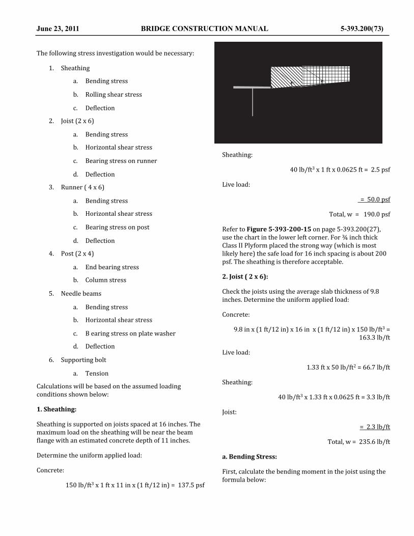
The following stress investigation would be necessary:
1. Sheathing
a. Bending stress
b. Rolling shear stress
c. De@lection
2. Joist (2 x 6)
a. Bending stress
b. Horizontal shear stress
c. Bearing stress on runner
d. De@lection
3. Runner ( 4 x 6)
a. Bending stress
b. Horizontal shear stress
c. Bearing stress on post
d. De@lection
4. Post (2 x 4)
a. End bearing stress
b. Column stress
5. Needle beams
a. Bending stress
b. Horizontal shear stress
c. B earing stress on plate washer
d. De@lection
6. Supporting bolt
a. Tension
Calculations will be based on the assumed loading conditions shown below:
1. Sheathing:
Sheathing is supported on joists spaced at 16 inches. The maximum load on the sheathing will be near the beam @lange with an estimated concrete depth of 11 inches.
Determine the uniform applied load:
Concrete:
150 lb/ft3 x 1 ft x 11 in x (1 ft/12 in) = 137.5 psf
Sheathing:
40 lb/ft3 x 1 ft x 0.0625 ft = 2.5 psf
Live load:
= 50.0 psf
Total, w = 190.0 psf
Refer to Figure 5-‐393-‐200-‐15 on page 5-‐393.200(27), use the chart in the lower left corner. For ¾ inch thick Class II Plyform placed the strong way (which is most likely here) the safe load for 16 inch spacing is about 200 psf. The sheathing is therefore acceptable.
2. Joist ( 2 x 6):
Check the joists using the average slab thickness of 9.8 inches. Determine the uniform applied load:
Concrete:
9.8 in x (1 ft/12 in) x 16 in x (1 ft/12 in) x 150 lb/ft3 = 163.3 lb/ft
Live load:
1.33 ft x 50 lb/ft2 = 66.7 lb/ft
Sheathing:
40 lb/ft3 x 1.33 ft x 0.0625 ft = 3.3 lb/ft
Joist:
= 2.3 lb/ft
Total, w = 235.6 lb/ft
a. Bending Stress:
First, calculate the bending moment in the joist using the formula below:
June 23, 2011 BRIDGE CONSTRUCTION MANUAL 5-393.200(73)
!"
#$%&'()*+,*%-$*&))./$0*(+&0'12*3+10'%'+1*,+4*%-$*,&()$5+46*).77+4%'12*%-$*+8$4-&129
:;*+,*<"*=*<"*>.11$4)?"
;+134$%$*).77+4%$0*+1*'1)'0$*4.11$4*@*A *B*<"C"
;+134$%$*).77+4%$0*+1*+.%)'0$*4.11$4*
@*D *B*E"
F9!"
? *B*D"
A *B*G"A *B*G"
H"
AA"

M =wL2
8=235.6lb / ft × 3.67 ft( )2
8= 396.7 ftlb
where:
L = 3’ – 2” = 3.167’
Next calculate the bending stress using the formula below:
fb =MS=396.7 ftlb × 12in1 ft( )
7.56in3= 630psi
Where:
S = section modulus = 7.56 in3
This is less than the allowable bending stress of 1,250 psi and is, therefore, acceptable.
b. Horizontal Shear Stress:
First, calculate the maximum vertical shear force using the formula below:
V =w L − 2d( )
2
V =235.6lb / ft × 3.167 ft − 2 × 5.5in × 1 ft12in( )( )⎛
⎝⎜
⎞⎠⎟
2
V = 265.1lb
where:
L = span length = 3.167 ft
d = depth of member = 3.5 in
Next, calculate the horizontal shear stress using the formula below:
fv =3V2bd
fv =3× 265.1lb
2 ×1.5in × 5.5in= 48.2psi ≤ 220
where:
V = maximum vertical shear force = 265.1 lb
b = width of joist = 1.5 in
d = depth of joist = 5.5
The actual horizontal shear stress is less than the allowable of 220 psi and is, therefore, acceptable.
c. Bearing Stress on Runner:
Determine the reaction on the outer runner by assuming that the outer 2’ – 0” of the slab concrete is supported on this runner as indicated in the previous sketch.
Concrete:
9.9in + 8in2
⎛
⎝⎜
⎞
⎠⎟× 1 ft12in( )× 2 ft ×150lb / ft 3 = 223.8lb / ft
Sheathing: (for both falsework and for edge of slab form)
5.0 ft x 0.0625 ft x 40 lb/ft3 = 12.5 lb/ft
Joist (2 x 4) for falsework and edge of slab form)
7 lf/ft x 2.3 lb/ft = 16.1 lb/ft
Runner: (4 x 6)
= 5.3 lb/ft
Live load:
50 lb/ft2 x 2 ft = 100.0 lb/ft
Total, w = 357.7 lb/ft
Since the joists are spaced at 16 inches or 1.33 ft, the reaction per joist is:
P = 1.333 ft x 357.7 lb/ft = 476.8 lb
A = contact area = 1.5 in x 3.5 in = 5.25 in2
Calculate bearing stress:
fb =PA=476.8lb5.25in2
= 90.6psi ≤ 625psi OK!
This is much less than the allowable of 625 psi and is, therefore acceptable.
d. Deblection of Joist:
Use the same loading criteria for de@lection that was used for determining bending stress except that live load is deleted from the uniform load.
5-393.200 (74) BRIDGE CONSTRUCTION MANUAL June 23, 2011

Δ =5wl 4
384EI
where:
w = 235.6 lb/ft – 66.7 lb/ft = 168.9lb/ft
l = 3’ – 2” = 3.167 ft
E = 1,600,000 psi ref.: Table 5-‐393-‐200-‐3
I = 5.36 in4 ref.: Table 5-‐393-‐200-‐2
Δ =5 ×168.9lb / ft × 3.167 ft( )4 × 12in1 ft( )
384 ×1,600,000psi × 20.80in4
Δ = 0.011in ≤ 0.141in OK!
This surface that is exposed to view, therefore the allowable de@lection for it is:
l270
=3.167 ft × 12in1 ft( )
270= 0.141in
3. Runners ( 4 x 6 ):
Approximately 3 joists will bear on each runner span; therefore, assume the joists produce a uniform load on the runners. This uniform load has been determined in part c above.
w = 357.7 lb/ft
a. Bending Stress in Runners:
Assume the runners will be furnished in lengths of two spans or more. In following the recommended ACI design simpli@ications, simple span design will be used. First, determine the bending moment using the following formula.
M =wL2
8
where:
w = 357.7 lb/ft
L = 5.0 ft
M =357.7lb / ft × 5 ft( )2
8= 1,117.8 ftlb
Determine the Section modulus of the (4 x 6) runner:
S = 17.65 in3
Calculate bending stress:
fb =MS=1,117.8 ftlb × 12in1 ft( )
17.65in3= 760psi
fb = 760psi ≤ 1,250psi OK!
Since the bending stress in the runners is less than the allowable, therefore, the member is acceptable in bending.
b. Horizontal Shear Stress in Runners:
First, calculate the maximum vertical shear force in the runners.
V =w L − 2d( )
2
where:
L = 5.0 ft
b = 3.5 in
d = 5.5 in
V =357.7lb / ft × 5 ft − 2 × 5.5in × 1 ft12in( )⎛
⎝⎞⎠
⎛⎝⎜
⎞⎠⎟
2= 730.3lb
Calculate the horizontal shear stress:
fv =3V2bd
fv =3× 730.3lb
2 × 3.5in × 5.5in= 56.9psi ≤ 220psi OK!
The actual horizontal shear stress is less than the allowable shear stress, therefore the runner is acceptable for horizontal shear stress.
c. Bearing Stress From 2 x 4 Post:
June 23, 2011 BRIDGE CONSTRUCTION MANUAL 5-393.200(75)
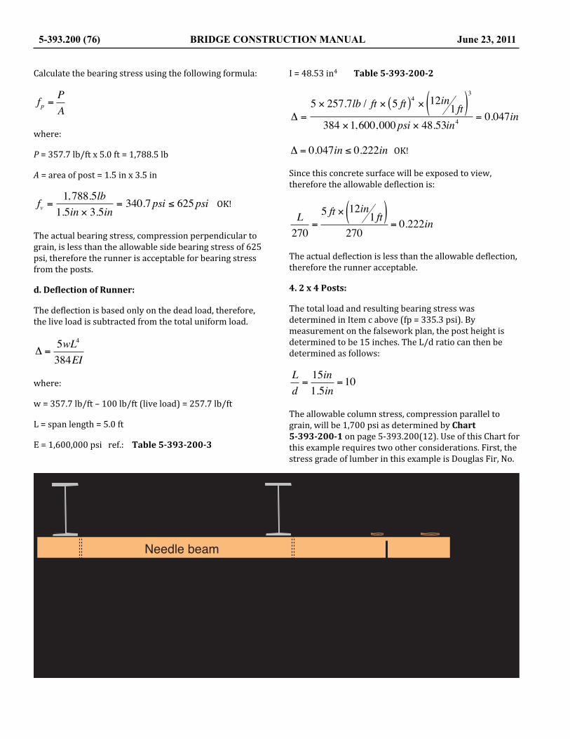
Calculate the bearing stress using the following formula:
fp =PA
where:
P = 357.7 lb/ft x 5.0 ft = 1,788.5 lb
A = area of post = 1.5 in x 3.5 in
fv =1,788.5lb1.5in × 3.5in
= 340.7psi ≤ 625psi OK!
The actual bearing stress, compression perpendicular to grain, is less than the allowable side bearing stress of 625 psi, therefore the runner is acceptable for bearing stress from the posts.
d. Deblection of Runner:
The de@lection is based only on the dead load, therefore, the live load is subtracted from the total uniform load.
Δ =5wL4
384EI
where:
w = 357.7 lb/ft – 100 lb/ft (live load) = 257.7 lb/ft
L = span length = 5.0 ft
E = 1,600,000 psi ref.: Table 5-‐393-‐200-‐3
I = 48.53 in4 Table 5-‐393-‐200-‐2
Δ =5 × 257.7lb / ft × 5 ft( )4 × 12in1 ft( )
3
384 ×1,600,000psi × 48.53in4= 0.047in
Δ = 0.047in ≤ 0.222in OK!
Since this concrete surface will be exposed to view, therefore the allowable de@lection is:
L270
=5 ft × 12in1 ft( )
270= 0.222in
The actual de@lection is less than the allowable de@lection, therefore the runner acceptable.
4. 2 x 4 Posts:
The total load and resulting bearing stress was determined in Item c above (fp = 335.3 psi). By measurement on the falsework plan, the post height is determined to be 15 inches. The L/d ratio can then be determined as follows:
Ld=15in1.5in
=10
The allowable column stress, compression parallel to grain, will be 1,700 psi as determined by Chart 5-‐393-‐200-‐1 on page 5-‐393.200(12). Use of this Chart for this example requires two other considerations. First, the stress grade of lumber in this example is Douglas Fir, No.
5-393.200 (76) BRIDGE CONSTRUCTION MANUAL June 23, 2011
!"#$%"&'(")!%*#+&%,+(*%-*'(")
./00-*+%,1&'-2+
3 &4&567((82(&'(")
9(+"%2#&-:&+;(&2-$"+%-,&-:&+;(&"002%$"+%-,&-:&2-"8#&+-&+;(&,((82(&'(")<
=2"+(>"2?@"A
5<BB
C<DCE<BB
F<CF
>(%1;+&-:&)()'(*

2, but Chart 5-‐393-‐200-‐1 has data for only Douglas Fir, No. 1. The allowable End Bearing Stress, compression parallel to grain for Douglas Fir, No. 2 can be found in Figure 5-‐393-‐200-‐3, to be 1,700 psi. So, the allowable end bearing stress for columns could be interpolated based on the value for Douglas Fir, No. 1.
Secondly, the allowable end bearing stress for any column with an L/d ratio less than 15.0 is equal to the unadjusted End Bearing value.
The allowable column stress of 1,700 psi, as determined above, is greater than the actual compression parallel to grain stress (fc = 335.3 psi), therefore the post is acceptable as a column in this example.
5. Needle Beam:
Assume each needle beam supports 5 feet of falsework. (Although the runners are continuous members they are quite @lexible; therefore, simple span reactions can be safely used to determine the applied load on the needle beam.)
The loading diagram for the needle beam is as follows:
Determine unit loads on the needle beam:
Concrete, live load, sheathing, joist, and runner:
357.7 lb/ft x 5.0 ft = 1,788.5 lb
Post:
1.5 lb/ft x 1.3 ft = 2.0 lb
2 x 6 plate:
2.3 lb/ft x 5.0 ft = 11.5 lb
Total reaction at plate: = 1,802 lb
2 x 8 walk plank:
3.0 lb/ft x 5.0 lb = 15.0 lb
Live load on walkway:
0.67 sq ft x 5.0 ft x 50 psf = 167.5 lb
Total reaction at walkway: = 182.5 lb
Weight of cantilevered beam:
4.7 lb/ft x 2 x 6.0 ft = 56.4 lb
a. Bending Stress in Needle Beam:
The maximum bending moment will be at the supporting bolt. The bending moment for each load is equal to the reaction times the distance from the supporting bolt to the line of action of the load (lever arm). The calculation of the bending moment is as follows:
Reaction x Distance = Moment
1,802.0 lb x 2.92 ft = 5,261.8 ft-‐lb
182.5 lb x 5.25 ft = 958.1 ft-‐lb
56.4 lb x 3.00 ft = 169.2 ft-‐lb
2,040.9 lb x M = 6,389.1 ft-‐lb
Determine the Section Modulus of the needle beam using Table 5-‐393-‐200-‐2.
S for two 2 x 12’s: S = 31.64 in3 x 2 = 63.28 in3
Calculate the actual bending stress using the formula shown below:
fb =MS
fb =6,389.1 ftlb × 12in1 ft( )
63.28in3= 1,211.6psi ≤ 1,250psi
The actual bending stress is less than the allowable bending stress for Douglas Fir, No. 2, see Table 5-‐393-‐200-‐3, therefore, the needle beam is acceptable for bending stress.
b. Horizontal Shear Stress in Needle Beam:
The shear stress in this member can be most easily visualized by drawing a shear diagram. To do this, the reaction, P at the @irst beam must be determined.
P = ML=6,389.1 ftlb8.5 ft
= 751.7lb
The maximum vertical shear, V will be 2,038.4 pounds. Since there is no signi@icantly large uniform load, the shear is not noticeably reduced by using the shear at a distance equal to the depth of the beam, d from the support.
Calculate horizontal shear stress using the formula shown below:
June 23, 2011 BRIDGE CONSTRUCTION MANUAL 5-393.200(77)

fv =3V2bd
fv =3× 2,040.9lb
2 × 2 ×1.5in ×11.25in= 90.7psi ≤ 220psi ≤
The actual horizontal shear in the needle beam is less than the allowable, therefore the member is acceptable for horizontal shear.
c. Bearing Stress on Plate Washer:
The bearing reaction, as determined from the shear diagram constructed above, will be:
P = 751.7 lb + 2,040.9 lb = 2,792.9 lb
The contact area for a 4” x 5” plate washer, as determined from the center Chart in Figure 5-‐393-‐200-‐17 on page 5-‐393.200(38), is as follows:
A = 15.0 sq in
Calculate the bearing stress on the plate washer using the formula below:
fp =PA=2,792.6.2lb15in2
= 186.2psi ≤ 625psi
This is less than the allowable stress of 625 psi, therefore the washer size is adequate.
d. Deblection of Needle Beam:
The needle beam can be set to the plan elevation after the de@lection due to the weight of the members has occurred. Therefore, the calculations for de@lection must only
determine the additional amount of de@lection due to the weight of the concrete applied through the runner.
The uniform weight of the concrete on the outside runner has already been determined to be 223.8 pounds per foot. The concrete loads and reactions on each needle beam will be as follows:
P = 223.8 lb/ft x 5.0 ft = 1,119.0 lb
R1 x 8.5 ft = 1,119.0 lb x 2.9167 ft
R1 = -‐384.0 lb
R2 = 1,119.0 + 384.0 lb
R2 = 1,503.0 lb
The formula determining the de@lection of the needle beam can be found in the diagram from the AISC Manual, as follows:
5-393.200 (78) BRIDGE CONSTRUCTION MANUAL June 23, 2011
!"#$%&'($)%$*&+,%&-"#&.,$'#'&/##'.#&0#$*1
2&&3$.45$67#%,&8"#$%
9
2&&&:(%8-&(/-#%(,%&0#$*9
2&&;<//#%
=>?1=&.0 =>?1=&.0
2&&&!<@@,%-(/)&0,.-,/&+$8A($&0#$*9
BCDED1F&.0
?CG>G1E&.0
?GB1>&.0
9
!"#$%"&'(")!%*#+&%,+(*%-*'(")
./0
1((23(&'(")
4-"2&2%"5*")&",2&(3"#+%$&$6*7(&-8&,((23(&'(")/
93"+(
:;
:<
</=<
;>;;=/?&3'

Δ =Pa2
3EIl + a( )
where:
P = 1,119.0 lb
L = 8.5
a = 2.9167 ft
E = 1,600,000 psi
I = (two 2 x 12s) = 2 x 177.98 in4 = 355.96 in4
Δ =Pa2
3EIl + a( )
Δ =1,119.0lb × 2.9167 ft × 12in1 ft( )( )
2
3×1,600,000psi × 355.96in4×
8.5 ft + 2.9167 ft 12in1 ft( )( ) = 0.11inThe falsework should be set 0.11 inches higher at the outer runner to compensate for de@lection of the needle
beam. In addition, @ive or more wood to wood surfaces should exist in the support falsework, all of which will tend to seat (de@lection downward) when the concrete load is applied. A commonly used practice is to set the falsework “high” by 1/16 inch per interface or 5/16 inch in this example. The net height adjustment to the outer runner would them be:
0.11 in + 0.31 in = 0.42 in (above plan elevation)
June 23, 2011 BRIDGE CONSTRUCTION MANUAL 5-393.200(79)
!"#$%&'($)%$*
+,&-&.,/&/&/&/&/&/&/&/&/&/&/&/&/&/&/&/&/&/&/&/&/&/&/&/&/&/&/
+0&-&.,&1&.0/&/&/&/&/&/&/&/&/&/&/&/&/&/&/&/&/&/&/&/&/&/&/
.0&/&/&/&/&/&/&/&/&/&/&/&/&/&/&/&/&/&/&/&/&/&/&/&/&/&/&/&/&/&/&/
2*$3/&&4$5&+06/&/&/&/&/&/&/&/&/&/&/&/&/&/&/&/&/&/&/&/&/&/&/
23&&&47#58##9&:;<<=%5:6/&/&/&/&/&/&/&/&/&/&/&/&/&/
23,&&4>=%&=?#%"$9)6/&/&/&/&/&/&/&/&/&/&/&/&/&/&/&/&/&/
*$3/&&47#58##9&:;<<=%5:&$5&3&-&&&&&&&6&&/&/&/
*$3/&&4>=%&=?#%"$9)&$5&3,&-&$&6&/&/&/&/&/&/&/&/&/
3&&47#58##9&:;<<=%5:&6&/&/&/&/&/&/&/&/&/&/&/&/&/&/
3,&&4>=%&=?#%"$9)&6&/&/&/&/&/&/&/&/&/&/&/&/&/&/&/&/&/&
!!"#
!!## " "# $
! !"
! !
!!"$#
! ! " $!# $
! "#"$%!& !"%'
&'
!!"'
(&'# " "# $
!!"$$&'#
#' $'# $
!!$!$&'
'"# " ("$! $!'# $
!
" #
!$
+, +0
.,
.0
@=$A&'($)%$*
!"#$%&'"()#*+,*+%&*"%-.//&(012&*2"*0(#0"3%4%#0%"*3%&5%&'"()#*+
2*$3/
2=*#95&'($)%$*
B
#(

EXAMPLE NO. 5—COLUMN APPLICATIONS
1. Wood Columns2. Steel Columns
1. Wood Columns:
A Douglas Fir, No. 1, 6” x 8” S4S member will be used as a falsework column to support a load of 16,000 pounds. The unsupported length of the column is 14 feet. To determine if this member is acceptable with regard to calculated stress, the following computations are necessary:
The actual compressive stress in the member is:
fc =PA=
16,000lb5.5in × 7.25in
= 401.3psi
The allowable compressive is dependent on the l/d ratio.
ld=14 ft × 12in1 ft( )
5.5in= 30.55
From Chart 5-‐393-‐200-‐1 on page 5-‐393.200(12), the allowable compressive stress for a Douglas Fir, No. 1, column with an l/d ratio of 30.55 is 550 psi. Since the actual compressive stress parallel to grain, as calculated above is 401.3 psi, which is less than the allowable stress, to column is acceptable.
2. Steel Columns:
A length of new HP 10x42 piling will be used as a falsework column to support a load of 40,000 pounds. The unsupported length of the column is 16 feet. The following calculations are necessary to determine acceptability of this column.
The actual compressive stress in the member is calculated using the following formula:
fc =40,000lb12.4in2
= 3,226psi
where:
The area of a HP 10x42 = 12.4 in2 (ref.: AISC Manual)
r = 2.41 in (ref.: AISC Manual, use smallest value)
K = 1.0 (ref.: AISC Manual)
The allowable stress is determined by the appropriate formula from page 5-‐393.200(13) of this manual.
Fc =16,980psi − 0.53×KLr
⎛
⎝⎜
⎞
⎠⎟2
Fc =16,980psi − 0.53×192in2.41in⎛
⎝⎜
⎞
⎠⎟2
=13,616psi
This member will obviously qualify for use regarding compressive stress.
5-393.200 (80) BRIDGE CONSTRUCTION MANUAL June 23, 2011
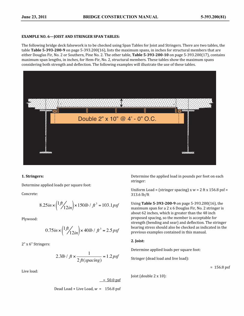
EXAMPLE NO. 6—JOIST AND STRINGER SPAN TABLES:
The following bridge deck falsework is to be checked using Span Tables for Joist and Stringers. There are two tables, the table Table 5-‐393-‐200-‐9 on page 5-‐393.200(16), lists the maximum spans, in inches for structural members that are either Douglas Fir, No. 2 or Southern, Pine No. 2. The other table, Table 5-‐393-‐200-‐10 on page 5-‐393.200(17), contains maximum span lengths, in inches, for Hem-‐Fir, No. 2, structural members. These tables show the maximum spans considering both strength and de@lection. The following examples will illustrate the use of these tables.
1. Stringers:
Determine applied loads per square foot:
Concrete:
8.25in × 1 ft12in( )×150lb / ft 3 =103.1psfPlywood:
0.75in × 1 ft12in( )× 40lb / ft 3 = 2.5psf2” x 6” Stringers:
2.3lb / ft × 12 ft(spacing)
=1.2psf
Live load:
= 50.0 psf
Dead Load + Live Load, w = 156.8 psf
Determine the applied load in pounds per foot on each stringer:
Uniform Load = (stringer spacing) x w = 2 ft x 156.8 psf = 313.6 lb/ft
Using Table 5-‐393-‐200-‐9 on page 5-‐393.200(16), the maximum span for a 2 x 6 Douglas Fir, No. 2 stringer is about 62 inches, which is greater than the 48 inch proposed spacing, so the member is acceptable for strength (bending and sear) and de@lection. The stringer bearing stress should also be checked as indicated in the previous examples contained in this manual.
2. Joist:
Determine applied loads per square foot:
Stringer (dead load and live load):
= 156.8 psf
Joist (double 2 x 10):
June 23, 2011 BRIDGE CONSTRUCTION MANUAL 5-393.200(81)
!"#$%&'(%)"#*+,%-).$*/)0,#*1"&*2&"3.,4*5"6*76
8"'3.,*9:*;*<=:*>*? *@*=:*A6!6
B *@*7:
?*$C$6*>*9 *@*=:*D9:*;*7:*$%&)#/,&$E
F*<G?:
4)#6
B:B:
F *@*F:H: H:

2 × 3.9lb / ft × 14 ft(spacing)
= 2.0psf
Total: w, = 158.8 psf
Determine the applied load in pounds per foot of joist:
Uniform Load = (joist spacing) x w = 4.0 ft x 158.8 psf = 635.2 lb/ft
Again, using Table 5-‐393-‐200-‐9 on page 5-‐393.200(16), the maximum span for the double 2 x 10 joist is determined by dividing the uniform load by two, as there are two members and the table is based on a single member. Reading the maximum spacing based on 318 lb/ft, one @inds 96 inches. The effective span is 104 inches that is slightly greater than the allowable. The spacing of the joist should be reduced slightly in this example. Additionally, the bearing stress in the lumber and the stress in the hanger hardware should be checked as indicated elsewhere in this manual.
5-393.200 (82) BRIDGE CONSTRUCTION MANUAL June 23, 2011

EXAMPLE NO. 7—PIER CAP FORM:
Assume the Contractor has proposed that the pier cap used in Example No. 1, seen on page 5-‐393.200(41), will be used. Further assume, that all lumber used will be Douglas @ir, No. 1. The members that will require stress investigation are as follows: (NOTE: Items de@ined as falsework were checked in Example No. 1.)
June 23, 2011 BRIDGE CONSTRUCTION MANUAL 5-393.200(83)
!"#$%#&#'()"*+
(
(
! "!# ! "!#
$% "!#
&' "!#
& "(#")*+,-.-/
0/*1.*23"4255+/
! "#$%&'(%")*+,-./0"1*233"4
!%"5"(%"6"#7%"8919#'!%" "1-:*";-*<"=:<>"(%"5"?%"=23>@."3A2B@C"6"( "$%
!"@29"!%"5"7%"D=2*@.3E
#$%
!""!%
F%
( "5"F "5"&'(%")*+,-./0"1*233"4
!%"5"7%"5"#$ "G-HI"6"#$%"8919
J)"#!5?&""5"($ "*-HI
K.:B<:-H"1-**2.
& "#$%
!"#$%&'()*)
&"F%
!%"5"(%"L.2B@"6"( "8919";-<>"3:C@3

The following stress investigation would be necessary:
1. Sheathing
a. Bending stress
b. Rolling shear stress
c. De@lection
2. Studs ( 2 x 4)
a. Bending stress
b. Horizontal shear stress
c. Bearing on walers
d. De@lection
3. Walers
a. Bending stress
b. Horizontal shear stress
c. Bearing stress for tie plates
d. De@lection
4. Tie Rods
a. Tension stress or manufacturer safe load
Calculations follow:
The lateral concrete pressure is only load applied on the forms. About 17 cubic yards of concrete are required for the pier cap. Assume the Contractor anticipates placing this concrete in about a thirty minute period.
The rate of placement would be:
R = 3.67 ft30minutes
= 7.34 feet / hour
The formula for walls with a height less than 14 feet and with a rate of pour exceeding 7 feet/hour will apply.
where:
T = 70°F
CC = 1.0
CW = 1.0
R = 7.34 ft/hr
pmax = CCCW 150 + 43,400T
+2,800RT
⎡
⎣⎢⎤
⎦⎥≤ wh
pmax = 150 +43,40070
+2,800 × 7.34 ft / hr
70⎡
⎣⎢⎤
⎦⎥=1,064 psf
pmax = 1,064 psf (maximum pressure at any depth)
wh = 150 lb/ft3 x 3.67 ft = 550.5 psf (Controls)
Use p = 550 psf
p = 150h = 150 x 3.67 ft = 550 psf (at bottom of cap form)
The following graph illustrates the relationship between height and pressure represented by the @irst equation as presented as a pressure diagram. Only the cross-‐hatched portion of the pressure diagram applies in this example.
1. Sheathing:
When a triangular shaped pressure diagram is involved, check the sheathing for the maximum pressure. In this case, check the sheathing for a pressure of 550 psf on a stud spacing of 16 inches. The sheathing material is 7/8 inch Plyform Class I. The chart for face grain across the supports (the strong direction), Figure 5-‐393-‐200-‐15 on page 5-‐393.200(27), indicates that 7/8 inch Plyform with 16 inch stud spacing can safely carry just 550 psf. It must be veri@ied later that the Contractor actually places the Plyform the “strong way.”
2. Studs (2 x 4):
The studs in this example should be checked as a simple span. In the following sketches, the studs will be shown horizontal to more clearly illustrate its beam action.
a. Bending Stress:
The pressure at mid span (275.0 psf) may be used as a uniform load for computing bending moments. The results will be slightly more conservative than would result from use of the actual loading.
Calculate uniform load on each stud:
5-393.200 (84) BRIDGE CONSTRUCTION MANUAL June 23, 2011
!"#$%&'(")$")*)+,#,&-+(-.(-.(,%)(.-"/01#$(2(345%(2(345(6(789:(.,(2(445($*.(
$/#6(2(3;59<($*.
%(2(5=>-$(-.('-+'"),)?
%(2(789:(.,=@-,,-/(-.($&)"('#$?
$(2(445($*.
$(2(5

w = 275.0 psf x 16 in x ( 1 ft/12 in) = 366.7 lb/ft
Calculate bending moment in stud:
M =wl2
8=366.7lb / ft × 2.167 ft( )2
8= 215.2 ftlb
Determine the Section Modulus of the 2 x 4 S4S stud using Table 5-‐393-‐200-‐2.
S = 3.06 in3
fb =MS=215.2 ftlb × 12in1 ft( )
3.06in3= 843.9psi ≤1,375psi
The actual bending stress is less than the allowable for Douglas Fir, No. 1, see Table 5-‐393-‐200-‐3.
b. Horizontal Shear Stress:
This should be checked by assuming the load at the left support (450 psf) extends uniformly across the simple span for calculating the maximum vertical shear force. Results will be slightly more conservative than would result from the use of the actual loading.
First, convert the pressure load to a uniform load for the studs spaced at 16 inches.
w = 450psf ×16in × 1 ft12in( ) = 600lb / ftCalculate the maximum vertical shear:
V =w L − 2d( )
2
V =600lb / ft × 2.167 ft − 2 × 3.5in × 1 ft12in( )( )⎛
⎝⎜
⎞⎠⎟
2= 475.1lb
Calculate the horizontal shear stress.
fv =3V2bd
fv =3× 475.1lb
2 ×1.5in × 3.5in=135.7 ≤ 220psi
The actual horizontal shear stress is less than the allowable for Douglas Fir, No. 1, see Table 5-‐393-‐200-‐3, the studs are adequate for horizontal shear.
c. Bearing Stress of Studs on Walers:
The maximum reaction will be at the lower waler. Actual reactions at each waler can be determined as follows:
June 23, 2011 BRIDGE CONSTRUCTION MANUAL 5-393.200(85)
!"#$%#&$%'()**+()%$,#-(#.%/"(%0#11%*2+$%/"(%3,)(%4#3%/"(.5
67%8%97%*2+$:6;%3*/
6<;%3*/%=%.,$%*3#&
9;>%3*/;;>%3*/
?7
: %@%:7: %@%:7
6 %@%67 :>7
A%B#1)(*!
!"#$$%"#&'()&*+')&),'-"'.&/+"&)#0#".,(,(-&*+')&+(&1'*#"$2
34 567 35
58297
482:7
:26; &<&==74>:=928&*?
567@7
4>:=928&*?
4A7
4=297
62;7

Then total weight of the pressure block on each studs is:
550lb / ft × 3.67 ft2
⎛⎝⎜
⎞⎠⎟×16in × 1 ft12in( ) = 1,345.7lb
The centroid of the pressure triangle is 1/3 of the distance from the base.
44.0in3
≈ 14.5in
Calculate the reaction from the pressure triangle on the lower waler.
1,345.7 lb x 19.3 in = R1 x 26 in
R1 = P = 998.9 lb
R2 = 1,345.7 lb – 998.9 lb = 346.8 lb
Determine the contact area using Figure 5-‐393-‐200-‐17.
Contact area, A = 4.5 in2
Calculate bearing stress:
fp =PA=998.9lb4.5in2
= 222.0psi ≤ 625psi OK!
The bearing stress of the studs on the waler is less than the allowable side bearing stress of 625 psi.
d. Deblection of Stud:
Use the same loading condition used for determining the maximum bending stress.
Δ =5wl 4
384EI
where:
w = 366.7 lb/ft
l = 2.167 ft
E = 1,700,000 psi
I = 5.36 in4
Δ =5wl 4
384EI
Δ =366.7lb / ft × 2.167 ft( )4 × 12in1 ft( )
2
384 ×1,700,000psi × 5.36in4= 0.004in
Calculate allowable de@lection:
2.167 ft × 12in1 ft( )270
= 0.096in ≥ 0.004in OK!
The studs are, therefore, acceptable with regard to de@lection.
3. Walers:
The bottom waler will be checked since the higher stud reaction was found to exist at that location. A condition of uniform loading may be assumed to exist since three studs bear on each waler span (between tie rods).
The maximum reaction for a stud on the bottom waler was determined in Item 2 c above to be 998.9 lb. The stud spacing is 16 inches so the maximum reaction must be converted to a uniform load on the waler.
w = 998.9lb × 12in16in( ) = 749.2lb / ft a. Bending Stress in Waler:
The waler span length is equal to the tie rod spacing (4 feet). This member will be continuous over two or more spans. In keeping with the recommended simpli@ications, the assumption of simple spans may be used here.
Determine the bending moment:
M =wl2
8=749.2lb / ft × 4.0 ft( )2
8= 1,498.4 ftlb
Determine the Section Modulus using Table 5-‐393-‐200-‐2:
Section Modulus for two 2 x 6s : S = 2 x 7.56 in3 = 15.12 in3
Calculate bending stress using the following formula:
fb =MS
5-393.200 (86) BRIDGE CONSTRUCTION MANUAL June 23, 2011

fb =1,498.4 ftlb × 12in1 ft( )
15.12in3= 1,189.2psi ≤ 1,375psi
The actual bending stress is less than the allowable bending stress for Douglas Fir, No. 1, see Table 5-‐393-‐200-‐3.
b. Horizontal Stress in Waler:
First, calculate the maximum vertical shear force on the lower waler.
V =w l − 2d( )
2
V =749.2lb / ft × 4.0 ft − 2 × 5.5in × 1 ft12in( )⎛
⎝⎞⎠
⎛⎝⎜
⎞⎠⎟
2= 1,155.0lb
Calculate the horizontal shear stress in the lower waler:
fb =3V2bd
fb =3×1,155.0lb
2 × 2 ×1.5in × 5.5in= 105psi ≤ 220psi
This is less than the allowable horizontal shear stress for Douglas Fir, No. 1, see Table 5-‐393-‐200-‐3.
c. Bearing Stress in Waler from Plate Washer:
First, calculate the maximum reaction from lower waler on the plate washer.
P = 749.2 lb/ft x 4.0 ft = 2,997 lb
Using the center chart contained in Figure 5-‐393-‐200-‐17 on page 5-‐393.200(38), determine the contact area for a 4 in by 5 in plate washer.
Contact area, A = 15.0 in2
Calculate the bearing stress using the formula below:
fv =PA=2,997.8lb15.0in2
= 199.8psi ≤ 625psi
This is less than the allowable compression perpendicular to grain stress, side bearing stress, for Douglas Fir, No.1. see Table 5-‐393-‐200-‐3.
d. Deblection of Waler:
De@lection will be calculated assuming the waler to be a simple span.
Δ =5wl 4
384EI
where:
w = 749.2 lb/ft
l = 4.0 ft (spacing of tie rods)
E = 1,700,000 psi ( Douglas Fir, No. 1, see Table 5-‐393-‐200-‐3)
I = 2 x 20.80 in4 = 41.60 in4 (Table 5-‐393-‐200-‐2)
5 × 749.2lb / ft × 4.0 ft( )4 × 12in1 ft( )3
384 ×1,700,000psi × 41.60in4= 0.061in ≤ 0.125in
This surface is exposed to view. The allowable de@lection of the span will be 1/8 inch since the L/270 value for this span is greater than 1/8 inch.
L270
=4.0 ft × 12in1 ft( )
270= 0.178in
The actual de@lection is less than the allowable de@lection; therefore, the member is acceptable with regard to de@lection.
4. Tie Rods:
The maximum load on the tie rod was calculated as the reaction on the plate washer in Item 3 c above, P = 2,247.6 pounds.
The form plan indicates that ½ inch diameter coil bolts (and coil ties) will be used as form ties. The manufacturer’s literature must indicate a load capacity of at least 2,997 pounds for the coil bolts and coil ties.
June 23, 2011 BRIDGE CONSTRUCTION MANUAL 5-393.200(87)

EXAMPLE NO. 8—ABUTMENT WALL FORM:
A check for the abutment forms as shown in the included diagram would require the following investigations. The anticipated rates of concrete placement are indicated on the @igure.
The following stress investigation would be necessary:
1. Sheathing
a. Bending stress
b. Rolling shear stress
c. De@lection
2. Studs ( 2 x 6)
a. Bending stress
b. Horizontal shear stress
c. Bearing on walers
d. De@lection
3. Walers
a. Bending stress
b. Horizontal shear stress
c. Bearing stress from tie plates
d. De@lection
4. Tie Rods
a. Tension stress or manufacturers safe load
The stress investigations listed above will be necessary for both the main wall and the parapet wall forms.
Calculations for the main wall forms are as follows:
First determine the amount of pressure from the fresh concrete on the forms. The Contractor has indicated a
5-393.200 (88) BRIDGE CONSTRUCTION MANUAL June 23, 2011
!"#$$%$&!'(#)%#*%+,-'.&)'%.+()%/+00%*#".$
!"#$%
&'()*+,-./0#-0#*1.100-(2
3#04-.10#5
#6#$% 37"%#892:)(;#
<9-00#=
6%#>#$%#0'?@0#5#!6%#AB<B
C,9B#6%#>#"%#D-91(
!76%# #.)E9#,)9'F#.)E9#'E10F#-*@#G%#>#04-.1@#5#H #I%
"GI#40:
!#)!"&'&%1"&$$-"&%2(+3"+.J0'E;-'1@#.)*.(1'1#'1;41(-'?(1#K#3LM
(B
LB$
4(1NE)?092#.-0'#.)*.(1'1

proposed rate of pour of 3 feet per hour in this example. Assume this concrete will be placed in mid-‐July, an anticipated temperature of 75° F may be used. Additionally, assume that the pressure coef@icients CW and CC both can be considered equal to 1.0.
The formula for walls with a height greater than 14 feet and with a rate of pour less than 7 feet/hour will apply.
Assume: T = 75°F, CC = 1.0, CW = 1.0
R = 3 ft/hr
pmax = CCCW 150 + 43,400T
+2,800RT
⎡
⎣⎢⎤
⎦⎥≤ wh
pmax = 150 +43,40075
+2,800 × 3.0 ft / hr
75⎡
⎣⎢⎤
⎦⎥= 840psf
pmax = 840 psf (maximum pressure at any depth)
wh = 150 lb/ft3 x 18.5 ft = 2,775 psf
design pressure, p = 840 psf
h = 840psf150psf
= 5.6 ft
1. Sheathing:
The pressure diagram indicates that the design uniform pressure is 840 psf. The sheathing material is 7/8 inch Plyform Class I. The chart for face grain across the supports (the strong direction), is found in the upper right corner of Figure 5-‐393-‐200-‐15 on page 5-‐393.200(37). That chart indicates that 7/8 inch Plyform Class I with 12 inch stud spacing can safely carry a little less than 800 psf. The imposed load of 840 psi is about 5% greater than chart value. This is close enough and the proposed sheathing can be used. It must be veri@ied later that the Contractor actually places the Plyform the “strong way.”
2. Studs:
The 2 x 6 studs are spaced at one foot with a uniform load of 840 psf. The span length is 2’ – 6” (spacing of the walers). Assume the studs are continuous for more than three spans.
a. Bending Stress in Studs:
First, calculate the bending moment using the following formula:
M= 0.1wl2 ref.: Figure 5-‐393-‐200-‐16
M = 0.1× 840lb / ft × 2.5 ft( )2 = 525 ftlb
Determine the Section Modulus of the 2 x 6 studs:
S = 7.56 in3 ref.: Table 5-‐393-‐200-‐2
Calculate the bending stress:
fb =MS=525 ftlb × 12in1 ft( )
7.56in3= 833.3psi ≤1,250psi
The actual bending stress is less than the allowable bending stress for Douglas Fir, No. 2, therefore the member is acceptable with regard to bending.
b. Horizontal Shear Stress in Studs:
First, calculate the maximum vertical shear force in the stud using the following formula:
V = 0.6w l − 2d( )
ref.: Figure 5-‐393-‐200-‐16 on page 5-‐393.200(37)
V = 0.6 × 840psf × 2.5 ft − 2 × 5.5in × 1 ft12in( )( )⎛⎝⎜
⎞⎠⎟ = 800lb
Calculate horizontal shear stress:
fv =3V2bd
fv =3× 800lb
2 ×1.5in × 5.5in=145.5psi ≤ 220psi
The actual horizontal shear stress is less than the allowable horizontal shear stress for Douglas Fir, No. 2, therefore, the member is acceptable with regard to horizontal shear.
c. Bearing Stress of Stud on Waler:
First, calculate the reaction of the stud on the waler using the following formula:
P = 1.1wl = 1.1 x 840 lb/ft x (2.5 ft) = 2,310 lb
A = 1.5 in x 1.5 in x 2 = 4.5 in2
Calculate the bearing stress:
June 23, 2011 BRIDGE CONSTRUCTION MANUAL 5-393.200(89)

fp =PA=2,310lb4.5in2
= 513psi ≤ 625psi
This is less than the allowable side bearing stress for Douglas Fir, No. 2.
d. Deblection of Studs:
Calculate the de@lection using the following formula:
Δ =0.0069wl 4
EI
where:
w = 840 lb/ft
l = 2.5 ft
E = 1,600,000 psi
I = 20.80 in4
Δ =0.0069 × 840lb / ft × 2.5 ft( )4 × 12in1 ft( )
3
1,600,000psi × 20.80in4= 0.012in
The allowable de@lection is:
L270
=2.5 ft × 12in1 ft( )
270= 0.111in ≥ 0.012in OK!
Since the actual de@lection is less than the allowable, the studs are acceptable with regard to de@lection. However, cumulative de@lection of the sheathing plus stud plus the walers must not exceed 1/8 inch to meet alignment and stiffness criteria.
3. Walers:
Tie rods are spaced at 3’ – 0”. Assume walers will be continuous for three spans or more and use the three span continuous formulas. Since studs are spaced at 12 inches, there are at least 3 studs on each waler span and condition of uniform load may be assumed on the walers.
First, calculate the uniform load on the waler.
Uniform load, w = 840 lb/ft x 2.5 ft = 2,100 lb/ft of waler
a. Bending Stress in Waler:
Calculate bending stress in waler:
M = 0.01wl2 = 0.01 x 2,100 lb/ft x (3.0 ft)2 = 189.0 ft-‐lb
Calculate Bending Stress using the following formula:
fb =MS
where:
M = 189.0 ft-‐lb
l = 3.0 ft
S = 2 x 13.14 in3 = 26.28 in3
fb =MS=189.0 ftlb × 12in1 ft( )
26.28in3= 86.3psi ≤1,250psi
This is less than the allowable bending stress for Douglas Fir, No. 2, therefore, the walers are acceptable with regard to bending.
b. Horizontal Shear Stress in Waler:
First, calculate the maximum vertical shear force on the waler using the following formula:
V = 0.6w(l-‐2d)
V = 0.6 x 2,100 lb/ft x (3.0 ft –( 2 x 7.25 in) x (1 ft/ 12 in)) = 2,257.5 lb
Next, calculate horizontal shear stress using the following formula:
fv =3V2bd
=3× 2,257.5lb
2 × 2 ×1.5in × 7.25in=155.7psi ≤ 220psi
The actual horizontal shear stress is less than the allowable horizontal shear stress for Douglas Fir, No. 2, therefore, the member is adequate with respect to horizontal shear.
c. Bearing on Tie Plate:
First, calculate the maximum reaction on the tie rod plate:
P = R2 = 1.1wl ref.: Figure 5-‐393-‐200-‐16
P = 1.1 x 2,100 lb/ft x 3.0 ft = 6,930 lb
Next, determine the contact area of the washer on the waler using the center chart in Figure 5-‐393-‐200-‐17. The contact area for a 4” x 5” plate washer with a ¾ inch space between the waler members, A = 9.0 in2.
5-393.200 (90) BRIDGE CONSTRUCTION MANUAL June 23, 2011

Calculation of bearing stress:
fv =PA=6,930lb13.75in2
= 504 psi ≤ 625psi
This is less than the allowable side bearing stress for Douglas Fir, No. 2, therefore, the member is acceptable with regard to side bearing.
d. Deblection of Waler:
Calculation the de@lection of the waler using the following formula:
Δ =0.0069wl 4
EI
where:
w = 2,100 lb/ft
l = 3.0 ft
E = 1,600,000 psi
I = 2 20.80 in4 = 41.60 in4
Δ =0.0069 × 2,100lb × 3.0 ft( )4 × 12in1 ft( )
3
1,600,000psi × 41.60in4= 0.03in
The allowable de@lection is:
L270
=3.0 ft × 12in1 ft( )
270= 0.133 ≥ 0.030in
Since the actual de@lection is less than the allowable, 0.133 in, the walers are acceptable with regard to de@lection. However, cumulative de@lection of the sheathing plus stud plus waler must not exceed 1/8 inch ( 0.125 inch) to meet alignment and stiffness criteria.
De@lection of sheathing is negligible
De@lection of stud = 0.012 in
De@lection of waler = 0.030 in
Cumulative de@lection = 0.042 in < 0.125 in OK!
4. Tie Rods—Tensile Stress:
Tie load calculated for the reaction on the plate washer, 6,930 pounds, in Item 3c above will be used for the tensile load on the tie rod. The form details indicates that ½ inch diameter coil bolt and coil tie will be used. The manufacturer’s literature must be checked to determine that these bolts and ties will carry the 6,930 pound load.
Parapet Wall Forms:
Calculations for checking the parapet wall forms shown in the diagram are as follows:
June 23, 2011 BRIDGE CONSTRUCTION MANUAL 5-393.200(91)
!"#$#%"#&'()&#*#+ #,"#-./.
01%"#2345678#/39&&#:
%#&;9<=&#*#+#+,"
>"
?#>"
+1!"#<6@3#'@=&#A@'B#0"#$#%"#A9&B=7#&;9<=)#*#! #>"
CD3.#!"#$#>"#A93=7&
!"#$$%$&!'(#)%#*%+,",+&'%-,..%*#"/$
+E,B
!#)!"&'&%+"&$$0"&%1(,2",/F&'@89'=)#<6G<7='=#'=8;=79'(7=#H#I,JK9'=#65#;6(7#H#%#5'.1B7.
%.%0
>>%#;&5

First determine the amount of pressure from the fresh concrete on the forms. The form plan indicates a proposed rate of concrete placement of 4 feet per hour. Assuming concrete placement will be in late August, a concrete temperature of 70°F may reasonably be used. The formula for placement of concrete in wall less than 14 feet in height with a rate of @ill less than 7 feet per hour will be used.
pmax = CWCC 150 +9,000RT
⎛
⎝⎜
⎞
⎠⎟
⎡
⎣⎢
⎤
⎦⎥ ≤ wh
where:
CW = 1.0
CC = 1.0
R = 4
T = 70°F
h = 8.5 ft
pmax = 150 +9,000 × 4 ft
70⎛
⎝⎜
⎞
⎠⎟
⎡
⎣⎢
⎤
⎦⎥= 664
wh = 150 psf x 8.5 ft = 1,275 psf > 664 psf
p = 664 psf (maximum pressure at any depth)
The design pressure, p = 664 psf
Solve for h: h = 664 psf/150 psf = 4.43 feet
The resulting concrete pressure diagram is shown in the details shown for this example. The actual stress calculations for the parapet wall forms will be similar to those for the main wall forms and, therefore, will not be repeated in this example. However, it would be necessary to perform these calculations sine the concrete pressure and member spacing differ from those of the main wall forms.
5-393.200 (92) BRIDGE CONSTRUCTION MANUAL June 23, 2011

5-‐393.209 Glossary
ANCHOR—form anchors are devices used to secure formwork to previously placed concrete of adequate strength, normally embedded in concrete during placement
BASE PLATE—a device used between post, leg, or screw jack and foundation to distribute the axial load
BATTEN (BATTEN STRIP)—a narrow strip of wood placed on the back side of a vertical joint of sheathing or paneling, or used on the inside form surface used to produce architectural affects in the concrete; also called a cleat
BATTER—inclination from vertical, generally stated as offset in inches per foot vertically
BEAM HANGER—a wire, strap, or other hardware device that supports formwork from structural members such as bridge beams
BENT—two-‐dimensional frame which is self-‐supporting within these dimensions. It has at least two legs and is usually placed at right angles to the structure which it carries.
BLOCK—a solid piece of wood or other material used to @ill spaces between formwork members
BUGHOLES—small regular or irregular voids in the formed concrete surface, resulting from air trapped during placement and consolidation of concrete; also called blowholes.
BULKHEAD—a partition in the forms blocking fresh concrete from a section of the forms or closing the end of the form, such as a construction joint.
CAMBER—a slight (usually) upward curvature of a truss, beam, or form to improve appearance or to compensate for anticipated dead load de@lection.
CATWALK—a narrow elevated walkway
CENTER MATCHED—tongue-‐and-‐groove (T&G) lumber with the tongue and groove at the center of the piece rather than offset as in standard matched
CHAMFER—refers to a beveled corner which is formed in the concrete work by placing a three-‐cornered piece of wood in the form corner
CHAMFER STRIP—triangular or curved insert placed in inside corner of form to produce rounded or beveled corner; also called ,illet or cantstrip
CLEANOUT—an opening in a form for removal of refuse and is closed before the concrete is placed
COATING—material applied by brushing, dipping, mopping, or spraying, etc. to preserve form material and to facilitate stripping
COLUMN CLAMP—any of various types of tying or fastening units used to hold column form sides together
CONTRACTION JOINT—formed, saw-‐cut or tooled groove in concrete structure to regulate location of shrinkage cracks
CONSTRUCTION JOINT—the surface where two successive placements of concrete meet, frequently with a keyway or reinforcement across the joint
CRUSH PLATE—an expendable strip of wood attached to the edge of a form or intersection of @itted forms, to protect the form from damage during prying, pulling, or other stripping operations, the term is also used to designate a wrecking strip.
DECK—the form upon which concrete for a slab is placed
DECKING—sheathing material for a deck or slab form
DIAGONAL BRACING—supplementary (not horizontal or vertical) formwork members designed to resist lateral load
DRESSED LUMBER—meaning lumber that has been surfaced (planed) to standard dressed sizes. If surfaced on all four sides is denoted as S4S, if surfaced on two sides is denoted as S2S
DRIP—a cutout in the under side of a projecting piece of concrete to prevent water from working its way back to the supporting element
DRY TIE—form tie that holds sides of forms in position in an area where no concrete is placed, for example at the top of a wall form above a construction joint
FALSEWORK—the temporary structure to support work in the process of construction, in concrete construction is considered to be the framework required to maintain a concrete unit in the desired position (when it cannot be supported on the ground, as a footing or on previously cast concrete) until the concrete is strong enough to carry its own dead weight
FASCIA—a @lat member or band at the exposed face of the deck of a bridge or the edge beam on a bridge
FILLER—material used to @ill an opening in forms
June 23, 2011 BRIDGE CONSTRUCTION MANUAL 5-393.200(93)

FILLET—see chamfer strip
FIN—narrow linear projection from formed concrete surface, resulting from mortar @lowing into or through horizontal or vertical joints in the formwork
FORMS—those members (usually vertical) that required to maintain plastic concrete in its desired shape until it has set up, forms resist the @luid pressure of the plastic concrete, the additional @luid pressure generated by mechanical vibration of the concrete and the impact of placing the concrete
FORM FINISH—@inish of a concrete surface that has not been altered since removal of the forms, also referred to as an as-‐cast ,inish
FORMWORK—the total system of support for freshly placed concrete including the mold or sheathing as well as all supporting members, hardware, and necessary bracing
FORMWORK ENGINEER—responsible profession engineer in charge of the design and construction of the formwork
FULL SAWN LUMBER—meaning lumber that was sawn green to sizes greater than the standard sawn sizes so that in use the lumber will be same as the nominal size.
GLUED LAMINATED TIMBER (GLULAM)—an assembly of selected suitably prepared lumber laminations bounded together with adhesives, with the grain of the laminations approximately parallel longitudinally, that are fabricated in compliance with ANSI/AITC A190.1
HANGER—a device used for suspending one object from another, such as hardware used to support joists from the upper @lange of bridge beams
HAUNCH—that portion girder, arch, or deck that is thickened near the support, also a bracket on a wall or column, used to support a load outside the wall or column, also referred to as a corbel
HONEYCOMB—irregular voids left at a formed concrete surface where the mortar fails to effectively @ill spaces between coarse aggregate particles
HORIZONTAL BRACING—horizontal load-‐carrying members attached to formwork components to increase lateral load resistance; when attached to shores they may also reduce the shores’ unsupported length, thereby increasing load capacity and stability
INVERT—lowest visible surface; the @loor of a drain, sewer, or gutter line at front face of curbs
JACK—mechanical device used for adjusting elevation of forms or form supports
JOIST—a horizontal member supporting deck form sheathing, usually rests on stringers or ledgers
KEYED—fastened or @ixed in position in a notch or other recess
KEYWAY—a recess or groove in one lift or placement of concrete which is @illed with concrete of the next lift, giving shear strength to the joint; also called a key
KICKER—a piece of wood (block or board) or metal attached to formwork member to take the trust of another member; sometime called a cleat
KNEE BRACE— brace between horizontal and vertical members in a formwork to make the formwork more stable; in formwork it acts as a haunch
LACING—horizontal brace between shoring members
LAGGING—designates heavier timber sheathing used between soldier piles; used in retaining walls and underground work to resist soil pressure; see soldier piles and lagging
LAMINATED VENEER LUMBER (LVL)—a structural composite lumber product manufactured from veneers that typically is about 1/8 in. thick, laminated so that the grain of all veneers runs parallel to the axis of the member; bonded with an exterior adhesive
LEDGER— horizontal formwork members, especially one attached to a beam side that supports the joist; also may be called girt, sill, purlin, stringer
LINING—any sheet, plate, or layer of material attached directly to the inside face of the forms to improve or alter the surface texture and quality of the @inished concrete; also called liner
NOMINAL LUMBER DIMENSIONS—the cross-‐section dimensions of lumber in inches as a full sawn piece (dimension prior to surfacing).
MOLD—the cavity or surface against which fresh concrete is cast to give it a desired shape; sometimes used interchangeably with form
MUDSILL—a plank, frame, or small footing on the ground used as a base for a shore or post in formwork
NAILER—strip of wood or other @itting attached to or set in concrete, or attached to steel, to facilitate making nailed connections
5-393.200 (94) BRIDGE CONSTRUCTION MANUAL June 23, 2011

NEAT LINE—a line de@ining the proposed or speci@ied limits of an excavation or structure
NOSING—a projection, such as the projection of the tread of a stair over the riser
OFFSET—an abrupt change in alignment or dimension, either horizontally or vertically
ORIENTED STRAND BOARD (OSB)—a panel product made of layers of thin wood strands bonded with waterproof resin under heat and pressure. Strands of each layer are aligned parallel to one another, but perpendicular to those in adjacent layers.
OVERBREAK—excavation beyond the neat line of a tunnel or other structure
PANEL—a section of form sheathing, constructed from boards plywood, metal sheets, etc., that can be erected and stripped as a unit
PARAPET—the part of the wall that extends above the roof level, or above the bridge seat
PARALLEL STRAND LUMBER (PSL)—a structural composite lumber wood product made by gluing together, parallel to the products length, long strands of wood that have been cut from softwood veneer
PERMANENT FORM—any form that remains in place after the concrete has developed its design strength. The form may or may not become an integral part of the structure. Also may be called a stay-‐in-‐place form.
PILASTER—column built within a wall usually projecting from the wall
PLATE—@lat horizontal member at the top and/or bottom of studs or posts
PLUMB—vertical, or the act making vertical
POST—vertical formwork member used as a brace, also shore, prop, jack
PLYFORM—is an exterior-‐type plywood designed to be used as form material
PLYWOOD —is a panel wood product consisting of odd numbers of plies, each placed at right angles to the adjacent plies and bonded together with glue
REVAL—the side of an opening in a wall
RIBS—parallel structural members backing sheathing
ROUGH SAWN LUMBER—lumber that has been sawn to sizes that are approximately 1/8 inch larger that the standard lumber sizes
RUSTICATION—a groove or series of grooves in a concrete surface
RUSTICATION STRIP—a strip of wood or other material attached to a form surface to produce a groove or rustication in the concrete
SCAB—a small piece of wood fastened to two formwork members to secure a butt joint
SCAFFOLD or SCAFFOLDING—a temporary elevated platform (````````````````` ``supported or suspended) and its supporting structure used to support workers, tool, and materials
SCREED—tow or more strips set at the desired elevation so that the concrete may be leveled by drawing a straightedge over their surface
SCREEDING—the operation of pulling a straightedge over the surface of the screeds thus leveling the concrete
SCREWJACK—a load-‐carrying device composed of a threaded screw and an adjusting handle used for vertical adjustment of shoring and formwork
SHEATHING—the supporting layer of formwork closest to the concrete; either in direct contact with the concrete or separated from it by a liner
SHORE—a temporary vertical or inclined support for formwork and fresh concrete. Also called prop, post, strut
SHORING—system of vertical or inclined supports for forms; may be wood or metal posts, scaffold-‐type frame, or various patented members
SLIPFORM—also referred to as sliding form. A form which moves, usually continuously, during placing of the concrete
SNAP TIE—concrete wall form tie, the end of which can be twisted or snapped off after the forms have been removed
SOFFIT—the underside of a subordinate part or member, such as the deck overhang
SOLDIER PILES AND LAGGING—steel H piles driven to the required depth before excavation. As excavation proceeds horizontal timber lagging is placed against the face of the excavation and wedged between the @langes of the H piles.
June 23, 2011 BRIDGE CONSTRUCTION MANUAL 5-393.200(95)

SOLDIERS—vertical wales used for strengthening or alignment
STIFFBACK—see strongback
STRINGER—horizontal structural member usually (in slab forming) supporting joists and resting on vertical supports
STRONGBACK—a frame or member attached to the back of a form to stiffen or reinforce it; additional vertical wales placed outside horizontal wales for added strength or better alignment; are also called stif@back
STRUCTURAL COMPOSITE LUMBER—a generic term that describes a family of engineered wood products in which veneer sheets, strands, or other small wood elements are bonded together with exterior structural adhesives to form lumber-‐like materials
STUD—a member of appropriate size and spacing to support the sheathing of concrete forms; commonly used vertical
SWAY BRACE—a diagonal brace used to resist wind or other lateral force
TELLTALE—any device designed to indicate movement of formwork
TIE—a concrete form tie is a tensile unit adapted to holding concrete forms secure against lateral pressure of unhardened concrete, with or without provisions for spacing the forms a de@inite distance apart, and with or without provision for removal of metal to a speci@ied distance back from the @inished concrete surface
TIE HOLE—void in a concrete surface left when a tie end is snapped off, broken off or otherwise removed
TEMPLATE—thin plate or board frame used as a guide in positioning or spacing form parts, reinforcement, anchors, etc.
TOENAIL—to drive a nail at an angle thru the end of a wood member into another wood member, used to connect studs to the plate
TOLERANCE—the permitted variation from a given dimension, quantity, location, or alignment
WALE—a long horizontal formwork member (commonly double) used to gather loads from several (vertical) studs or similar members to allow wider spacing of restraining ties; when used with prefabricated panel forms. This member is used to maintain alignment; also called waler or ranger
WRECKING STRIP—small piece or panel @itted into formwork assembly in such a way that it can be easily removed ahead of main panels or forms, making it easier to strip these major form components
X-‐BRACE—paired set of (tension) sway braces
5-393.200 (96) BRIDGE CONSTRUCTION MANUAL June 23, 2011

5-‐393.2010 Symbols and Units of Measurements
The following symbols, abbreviations and units of measurements will apply to Chapter 200—Forms and Falsework.
A = area, in2
a = dimension in beam diagrams, ft, in
b = width of beam, in
c = distance from neutral axis, in
CC = Chemistry Coef@icient used pressure calculations
CD = Duration of load factor
Cr = Repetitive member factor
CW = Unit Weight Coef@icient used in pressure calculations
d = depth of beam, in
d = penny weight used to measure nails
e = total deformation, in
E = modulus of elasticity, psi
f = unit stress in member, psi
fb = actual bending stress, psi
fc = actual compressive stress, psi
fp = actual bearing stress, psi
fv = actual shear stress, psi
frv = actual rolling shear stress, psi
F’b = allowable bending stress, psi
F’c = allowable compressive stress, psi
F’v = allowable shear stress, psi
h = depth of concrete, ft
I = moment of inertia, in4
K = column end coef@icient
L = span length, in, ft
l = span length, in, ft
M = bending moment, ft-‐lb, in-‐lb
P = concentrated load, lb
R = rate of concrete pour, hr
R1 = reaction at beam support, lb
S = span length, in, ft
s = unit deformation, in/in
T = temperature,°F
t = thickness, in
tw = web thickness, in
w = unit weight, lb/ft
Δ = calculated de@lection, in
June 23, 2011 BRIDGE CONSTRUCTION MANUAL 5-393.200(97)

5-‐393.211 References
1. ACI Committee 347, Guide to Formwork for Concrete, American Concrete Institute, Detroit, MI, 2004
2. ANSI/AF&PA NDS-‐2005, American Forest & Paper Association, National Design Speci,ication for Wood Construction, Washington, DC, 2005
3. American Association of State Highway and Transportation Of@icials, Guide Design Speci,ications for Bridge Temporary Works, 2008 Interim Revisions, Washington, DC, 1995
4. American Association of State Highway and Transportation Of@icials, Construction Handbook for Bridge Temporary Works, 2008 Interim Revisions, Washington, DC, 1995
5. Minnesota Department of Transportation, Bridge Of@ice, LRFD Bridge Design Manual 5-‐392, Oakdale, MN, September 2008
5-393.200 (98) BRIDGE CONSTRUCTION MANUAL June 23, 2011

November 1, 2005 BRIDGE CONSTRUCTION MANUAL 5-393.250
METAL REINFORCEMENT 5-393.250
5-393.251 GENERAL Specification 2472 describes the requirements for furnishing and placing metal reinforcing bars in concrete structures other than pavements. Until recently, reinforcing bars were specified and marked with a number that denoted the bar diameter in eights of an inch, i.e., a 1/2" diameter bar was denoted as a #4 bar (1/2" = 4/8"). In the late 1990's the industry converted to metric designations so now the first two digits of each bar mark indicate the bar number which approximates the nominal diameter of the bar in millimeters (mm). Specification 3301 requires that, if not otherwise specified, reinforcement bars for use in any part of a concrete bridge, box culvert, or retaining wall shall be deformed billet steel bars with a minimum yield strength of 420 MPa (60,000 psi). This strength is designated as Grade 420. Grade 420 reinforcement corresponds to Grade 60 in the inch-pound reinforcement specifications. The inspector should make certain that the proper grade of steel has been supplied as soon as it is received and before placement has started. See Figure A 5-393.261 for identification markings. Reinforcement bars, steel fabric, and other such materials are usually sampled and tagged by the Mn/DOT Materials Office prior to shipment to the project. The inspector should look for these tags when the material arrives at the job site and record the information in his or her diary. Reinforcement bars also carry tags indicating the bar numbers and the unit for which they are intended. When bars arrive at the site without sampling tags, it will be necessary to check with the Materials Section to verify inspection and, if not previously sampled, samples must be submitted as specified in the Materials Manual. 5-393.252 CUTTING AND BENDING Bar bending dimensions are not generally checked prior to shipment and should, therefore, be verified upon arrival. See Figure B and C 5-393.261 for bends, dimensions, etc. It is the Contractor’s responsibility to furnish bars with properly made bends and of specified lengths, but an alert inspector can sometimes save time and money for both the Contractor and the State by detecting bending errors in time so that a correction can be made without delaying the progress of the work. Bars should also be inspected at bend points, particularly the larger bars, to determine whether or not cracks or fractures have occurred at these points due to the bending operations. Galvanized or epoxy coated bars should be carefully checked at bends for damage to coating.
Occasionally, the plans will provide for some bars to be cut or bent in the field. Such field work will be permitted but bending must be done without heating if possible. Uncoated hot bent bars shall not be heated above the dull cherry-red range (a maximum of 650E C) and shall not be quenched. Bars bent in the field should be checked to see that the bends and dimensions are correct. Epoxy coated reinforcement bars shall not be heated or flame cut. After the epoxy bars are cut or bent, a field application or touch up of the coating should be made. 5-393.253 EPOXY COATED BARS Specifications for coated bars generally require padding to protect the coating. Bar coating should be inspected for scratches, holidays and chips or other damage. Any damage should be repaired prior to long term storage. Repairs are required if damage exceeds an area 6 mm by 6 mm (1/4" x 1/4"). All bars with total damage greater than 2 percent of bar surface area shall be rejected and removed. Field cutting of epoxy-coated reinforcing bars should be avoided and only if permitted by the engineer. If cutting is allowed it should only be done by the use of hydraulically powered cutters, friction cutting tools (chop saw) or hack saws. Never should the use of a cutting torch be allowed. When patching cut ends the coating materials shall be handled, stored and applied in accordance with the manufacturer's recommendations, or as directed by an authorized representative of the coating manufacturer. The patch compounds usually consist of a two part epoxy material that can be applied only after the surface is moisture free and cleaned of any oil, grease, dust, scale and rust. All visible damage must be repaired before concrete is poured. If you are in doubt, repair it. Use epoxy repair material recommended by the coating manufacturer. Remove all rust and contaminants from the damaged area with a wire brush. Mix the epoxy prior to use according to the manufacturer’s recommended mixing procedures. Check the pot life. The instructions furnished by the patching material manufacturer on how patching or touch-up material is applied should be strictly followed. Be sure to allow the patch sufficient curing time as specified by the material’s instructions before pouring concrete, (Some patch materials require a minimum of 8 hours to cure).

5-393.254 BRIDGE CONSTRUCTION MANUAL November 1, 2005
5-393.254 STORAGE AND PROTECTION Reasonable care should be exercised by the Contractor’s workers when unloading or handling reinforcement bars to avoid kinking or otherwise damaging them. Long bars should be supported at several points when being handled and should not be dragged on the ground. Epoxy coated bars should be unloaded with padded slings to prevent damage to the coating. When the bars are unloaded, they should be placed on suitable blockings, well off the ground, in an area that has been cleared of brush, tall grass, and other growth, and which will be kept drained. It is good practice on the part of the Contractor to separate the different bar types so that they can be readily checked for bending and quantity, and so that they are readily available when needed. Non coated bars which are to be stored for a long period of time should be protected to minimize rusting. Rust, itself, should not be cause for rejection; but rusting to the extent that the bar becomes pitted reduces its strength and is definitely cause for rejection. Normal handling of the bars will usually remove rust which is loose enough to cause loss of bond. Reinforcement bars which have become irreparably damaged due to improper handling, storage, bending, or for any other reason, or which have become excessively rusted or pitted, should be rejected and removed from the site. Bars may be checked for loss of section by weighing. Store epoxy-coated reinforcing bars as close as possible to the area where they will be placed in the structure to keep handling operations to a minimum. This is most easily accomplished by planning for: location, accessibility, stacking methods and duration of storage. Schedule delivery to minimize long-term storage of epoxy-coated reinforcing bars at the job site. Coating color may fade slightly from bright sun. This does not change the corrosion protection properties of the epoxy coating. If storage in direct sunlight is expected to exceed two months, the bars should be protected. If protective sheeting is used, allow for adequate air circulation around the bars to minimize condensation under the sheeting. 5-393.255 PLACING, SUPPORTING AND TYING REINFORCEMENT BARS The condition of the reinforcement bars should be rechecked immediately prior to placement to make certain that they are free of dirt, grease, oil, paint, heavy rust, or any other foreign matter which would tend to destroy the bond between the concrete and the reinforcement. If the forms have not already been treated with form oil (in the case of wood forms), this should be done before the reinforcement bars are placed. The bars should not be dragged across or laid directly on forms which have recently been treated with form oil.
The positioning of the bars should be in accordance with the plans. It is generally good practice on the part of the Contractor to mark off the bar spacing on the forms with chalk prior to starting placement. The inspector should be alert to such activity and check the spacing before placement is started, so errors can be detected. Alertness of this type promotes better relations with the Contractor, provided it is carried on in the proper spirit. Attention must be given to the positioning of the various layers of bars in bridge slabs and similar sections, since a deviation of a few millimeters reduces the strength of the section. Also, adequate concrete cover must be maintained to protect the bars from exposure to air, moisture, and salt action. Check the plans for the amount of cover specified. Detailing by Bridge Designers does not always make allowances for fabrication tolerances. Therefore, in some cases, it may not be possible to obtain minimum cover even if bars meet dimensional requirements. When this occurs, placement should be accepted as “substantial compliance” and actual minimum cover noted on the “as built” plans. The strike-off should be moved over a slab section before concrete placement is started and the depth of cover carefully checked, as required in the Specifications. Figures D and E 5-393.261 show typical support systems for deck slab reinforcement. Unless otherwise specified in the plans or special provisions, reinforcing bars should be placed within the following tolerances: 1. Tolerance for minimum clear concrete cover in flexural
members (bridge decks), walls and columns should be as follows:
d=slab depth, wall
thickness or column diameter
Tolerance on minimum concrete
cover
d ≤ 200 mm (8 in.) d › 200 mm (8 in.)
- 10 mm (3/8 in.) - 12 mm (½ in.)
Except that the tolerance for the clear distance to edge of
slab should be -6 mm (1/4 in.), and the tolerance for cover should not exceed minus one-third of the minimum cover required on the plans.
2. Tolerance for the longitudinal location of bends and ends
of bars should be ± 50 mm (2 in.) except at discontinuous ends of members where the tolerance should be ± 12 mm (½ in.).
3. As long as the total number of bars specified is
maintained, a reasonable tolerance in spacing individual bars is ± 50 mm (2 in.), except where openings, inserts, embedded items, etc., might require some additional shifting of bars.
4. Tolerance for length of laps in lap splices should be ±
25 mm (1 in.).

November 1, 2005 BRIDGE CONSTRUCTION MANUAL 5-393.256
The bars should be securely tied so that their position will not be changed by workers walking or climbing on them, or by placement of concrete against them. The Specifications are quite explicit in their requirements for supporting and tying reinforcement bars. A table in Specification 2472.3C shows the maximum spacing for slab bolsters and continuous type high chairs for bridge slabs, as well as maximum tie spacing. Note that additional ties are required for coated bars. For all interior bays on beam span bridges, slab bolsters and upper continuous high chairs shall be placed within 150 mm (6 inches) of the edge of beam flanges. The maximum spacing of all slab bolsters and upper continuous high chairs shall be 915 mm (3 feet) for #10 and #13 bars, and 1220 mm (4 feet) for #16 - #22 bars. Also, additional bar chairs or exact location may be required if a finishing screed that rides on the rebar is used. The inspector should keep in mind, however, that these spacings are the maximum permitted, and that closer spacing may be necessary in order to achieve stability in the bar mats, as well as in the individual bars. Enforcement of these Specifications will eliminate sloppily placed, inadequately supported, or poorly tied reinforcement. Coated bars must be tied with coated ties to provide protection against corrosion. Coated bar supports are also required. The bottom layer of longitudinal reinforcement bars for slab span bridges, cast-in-place concrete girders, beams, struts, and similar sections shall be supported on beam bolsters or heavy beam bolsters commensurate with the mass to be supported. Precast concrete block or brick supports will not be permitted on formed surfaces. Subsequent layers of longitudinal bottom reinforcement, except for those bars which can be tied to vertical bars, shall be supported by upper beam bolsters or upper heavy beam bolsters. Epoxy coated reinforcing bars require a compatible support system coated entirely with a dielectric material such as epoxy or plastic or made completely from a dielectric material such as plastic. Uncoated "black" steel reinforcing bars or other uncoated steel products or materials shall not be used to support epoxy coated reinforcing. Contractors commonly use plastic slab bolsters to support the bottom transverse bars of slabs supported on beams. Such bolsters are permissible as long as they meet the general requirements described in the Concrete Reinforcing Steel Institute (CRSI) Manual of Standard Practice. Cases have been encountered in the past where the Contractor has been in the process of placing concrete for a bridge deck, or preparing to do so, with inadequate supporting and tying systems. This will not happen if the inspection is performed correctly and on time. Considerable emphasis has been placed on this phase of the work during Department Bridge Seminars, but enforcement can only be done on the job.
Considerable care should be exercised in the placement, alignment, projection, supporting, and fastening of dowel bars. Dowel alignment should be determined from a line of known accuracy, such as the centerline of bearing, coping line, etc., and should be maintained in proper position by substantial frame work. These bars should not be disturbed once they are in their correct position, especially after the concrete has been placed and vibrated around them. Any disturbance will tend to destroy their bond with the concrete and consequently the value of the bar itself. Inserting dowel bars after the concrete has been placed is not good practice and should be permitted only in special cases. Bars with hooked ends should never be inserted into concrete that has been placed. Dried mortar should be removed from the exposed portion of the bars before the next section of concrete is placed. Workers often walk on reinforcement bars which have been placed for sidewalks, curbs, and medians in order to perform their work. Because these bars are relatively small, they tend to bend rather easily and are sometimes found to have shifted from their correct position. The Contractor should be required to provide plank walkways outside of or over such reinforcement, both for the protection of the work and for the safety of the workers. Walking on reinforcement bars which are partly embedded in concrete that has started to set should not be permitted. To avoid this situation, walkways should be provided which are supported directly on the forms or on the structural members. 5-393.256 SPLICING REINFORCEMENT BARS Except when otherwise noted or shown in the plans, the bars should be lapped 36 bar diameters for bars up to #22 (#7) and 40 bar diameters for bars #25 (#8) and over. In other words, the length of lap for joining two #22 (#7) bars would be 800 mm (32 in.) and for two #25 (#8) bars would be 1020 mm (40 in.). In general, splices should not be made in reinforcement bars except as shown in the plans or as approved by the Bridge Design Engineer. (See Figure F 5-393.261 for bar lap table.) There are times when splicing of rebar in a manner other than lapping is necessary. Examples include: 1. Complicated placement where the cage could be tied off
site, in sections, and set in place 2. Reinforcement cages for drilled shafts 3. Situations where an existing rebar is not long enough to develop strength by lapping

5-393.257 BRIDGE CONSTRUCTION MANUAL November 1, 2005
An example might be during the removal of an existing curb on a bridge deck widening project, existing rebar is either cut with the saw or broken during concrete demolition. In this case additional demolition would be needed to provide a lap development length. Currently, several couplers are manufactured which can be used to mechanically splice rebar. Mechanical splicing for the above conditions may be approved. Mechanical splices shall develop 125% of the reinforcing bar’s yield strength. Consideration for splice usage must be initiated by the Contractor. The project engineer should review that request with the Bridge Construction Engineer. Many mechanical coupling devices are available for use with epoxy-coated reinforcing bar. Couplers should be precoated with fusion-bonded epoxy coating. Repair any coating damage on the couplers as necessary after installation. 5-393.257 WELDING Welding reinforcement bars should not be permitted except when required by the plans or specifically approved by the engineer. Bar steel should be of a type suitable for welding and low hydrogen weld rods such as E7016 must be used. All welds having structural significance shall be performed by a Department Certified Welder. See section 5-393.415 for information regarding welding and welder certification. 5-393.258 WELDED WIRE FABRIC Welded wire fabric is not normally used as reinforcement for cast-in-place structures, but it is often used in precast box culverts. The special provisions and the plans will define the requirements in detail. 5-393.259 PRESTRESSING STEEL Prestressing steel is seven wire, uncoated, stress-relieved or low relaxation strand which is used in both pretensioned and post-tensioned construction. The majority of this material is used for precast prestressed concrete beams which are inspected by the Materials Office. Placement and tensioning requirements for strands in prestressed concrete beams are given in Specification 2405. Placement and tensioning requirements for all other pretensioned and post-tensioned concrete are given in the plans and specifications. At the time of transfer of the prestressing force from the jacks to the permanent anchors, large compressive forces must be resisted by the concrete. Concrete members will shorten due to these forces and this shortening must be taken into account in placement of the bearing plates. Final prestress forces will be less than jacking forces, due to shortening of members, slippage of anchors and friction. Temperature differences at time of tensioning and at time of concrete placement must also be considered for pretensioned concrete.
The inspector must verify the accuracy of tension forces at time of prestress transfer since the strength of the finished structure is dependent on these forces. Precast prestressed concrete items are susceptible to damage during transportation and handling and should be carefully inspected at the project site. 5.393-260 PAY QUANTITIES Reinforcing steel is generally a “plan quantity” item (see Specification 1901). The plan quantity is the final quantity for which payment will be made unless there is a plan revision or corrections are made due to plan errors. Information relative to bending details and dimensions, for use in computing the total length of bent bars, is included in this section and may be used if the plans do not provide the necessary details. (See Figure B and C 5-393.261.) Also included are tables showing mass of spiral reinforcement based on diameter of the steel rod, diameter of the spiral, and the pitch. (See Figure H 5-393.261.) 5-393.261 REFERENCES AND MATERIALS INFORMATION The Concrete Reinforcing Steel Institute (CRSI) handbook entitled “Placing Reinforcement Bars” contains an abundance of information concerning terminology, fabrication, uses, types, and methods of placing reinforcement bars. A copy of this book may be purchased for a nominal fee from the Concrete Reinforcing Steel Institute, 933 North Plum Grove Road, Schaumburg, Illinois 60173-4758. The CRSI “Design Handbook” is also available through the sources indicated above. This handbook deals with the technical design features, but also contains numerous charts, tables and other useful construction information. www.crsi.org. The Concrete Reinforcing Steel Institute also publishes a “Manual of Standard Practice” from which some of the information contained in this manual was obtained. The American Concrete Institute, PO Box 9094, Farmington Hills, Michigan 48333, publishes codes for concrete structures. Their “Manual of Concrete Practice” for detailing reinforced concrete structures is referenced in Specification 2472 as ACI 315.

November 1, 2005 BRIDGE CONSTRUCTION MANUAL Figure A 5-393.261
Inch-Pound Bars Metric Bars
CONTINUOUS LINE SYSTEM - GRADE MARKS
NUMBER SYSTEM - GRADE MARKS
Inch-Pound Bars Metric Bars
Grade 60Grade 40, 50 Grade 420 Grade 300
Main ribs
Letter orsymbol of
producing mill
Bar size
Type steel
Grade line(one line only)
H
11
S
H
11
S
H
36
S
H
36
S
Grade 60
Main ribsLetter of
producing mill
Bar size
Type steel
Grade mark
H
11
S
60Grade 420
H
36
S
4
AMERICAN STANDARD BAR MARKS
Symbols include the following: S - Billet (A615),(A615M) - Rail (A616),(A616M) A - Axle (A617),(A617M) W - Low Alloy (A706),(A706M) R - For rail meeting supplementary requirements S1 (A616),(A616M)
Grade mark lines are smaller and between the two mainribs which are on opposite sides of all American Bars
Type steel
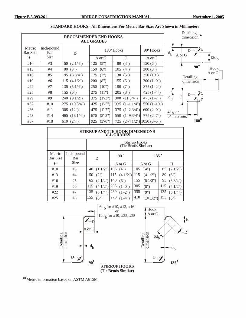
Figure B 5-393.261 BRIDGE CONSTRUCTION MANUAL November 1, 2005
RECOMMENDED END HOOKS,ALL GRADES
STANDARD HOOKS - All Dimensions For Metric Bar Sizes Are Shown in Millimeters
Inch-poundBarSize
Inch-poundBarSize
MetricBar Size
MetricBar Size
DA or G J A or G
180 Hooks 90 Hooks
#3
#3
#10
#10
(2 1/4")60 (5")125(6")150(7")175(8")200(10")250(11")275(1'-3")375(1'-5")425(1'-7")475(2'-3")675(3'-0")925
(3")80(4")105(5")130(6")155(7")180(8")205(11 3/4")300(1'-1 1/4")335(1'-2 3/4")375(1'-9 3/4")550(2'-4 1/2")725
(6")150(8")200(10")250(1'-0")300(1'-2")375(1'-4")425(1'-7")475(1'-10")550(2'-0")600(2'-7")775(3'-5")1050
(3")80(3 3/4")95(4 1/2")115(5 1/4")135(6")155(9 1/2")240(10 3/4")275(12")305(18 1/4")465(24")610
#4
#4
#13
#13
#5
#5
#16
#16
#6
#6
#19
#19
#7
#7
#22
#22
#8
#8
#25
#25
#9#29#10#32#11#36#14#43#18#57
Detailingdimension
Detailingdimension
Det
ailin
gdi
men
sion
Det
ailin
gdi
men
sion
HookA or G
12d
6d for #10, #13, #16or
12d for #19, #22, #25
D
D
D
D
H
D D
d
d
d d
6d
b
b
b
b b
b
b
b
b
4d or64 mm min.
180
90
90STIRRUP HOOKS(Tie Bends Similar)
Metric information based on ASTM A615M.
135
J
A or G
A or G
HookA or G
D 90
STIRRUP AND TIE HOOK DIMENSIONSALL GRADES
Stirrup Hooks(Tie Bends Similar)
135
A or GA or G H(1 1/2") (2 1/2")(2") (3")(2 1/2") (3 3/4")(4 1/2") (4 1/2")(5 1/4") (5 1/4")(6") (6")
(4") (4")(4 1/2") (4 1/2")(6") (5 1/2")(1'-0") (8")(1'-2") (9")(1'-4") (10 1/2")
405065
115135155
105115155305355410
105115140205230270
658095
115135155
*
*
*

November 1, 2005 BRIDGE CONSTRUCTION MANUAL Figure C 5-393.261
STANDARD FABRICATION - CUTTING & BENDING TOLERANCES
STANDARD FABRICATION - CUTTING & BENDING TOLERANCES
Bar sizes #10 through #36(Metric Units)
Bar sizes #10 through #36(English Units)
Length (plus or minus 25 mm)
Length (plus or minus 1")
Dimension (plus or minus 25 mm)
Dimension (plus or minus 1")
13 m
m-+
1/2"
-+13
mm
-+1/
2"-+
Dimension (plus or minus 25 mm)
Dimension (plus or minus 1")
plus zero or minus 13 mm
plus zero or minus 1/2"
HH
Spiral orcircular tie
Spiral orcircular tie
Tie orstirrup
Tie orstirrup
906d hooks
906d hooks
Plus orminus 13 mm
Plus orminus 1/2"
# 16 bar or smaller
# 16 bar or smaller
# 19 bar or largerAll sizes if grosslength _ 300 mm
# 19 bar or largerAll sizes if gross
length _ 12"
>
>
Plus orminus 25 mm
Plus orminus 1"
Plus orminus 13 mm
Plus orminus 1/2"
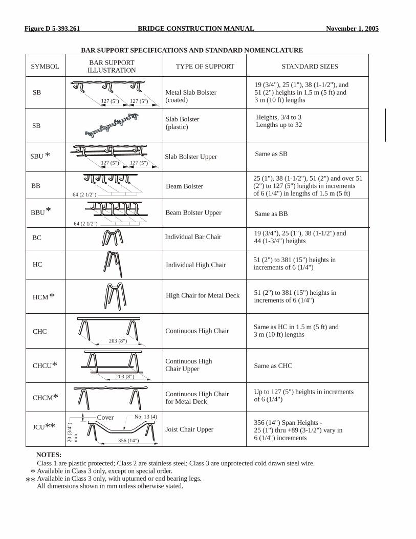
Figure D 5-393.261 BRIDGE CONSTRUCTION MANUAL November 1, 2005
BAR SUPPORT SPECIFICATIONS AND STANDARD NOMENCLATURE
SYMBOL BAR SUPPORTILLUSTRATION TYPE OF SUPPORT STANDARD SIZES
SB
SBU
BB
BBU
HC
HCM
CHC
CHCU
CHCM
JCU
NOTES:Class 1 are plastic protected; Class 2 are stainless steel; Class 3 are unprotected cold drawn steel wire.Available in Class 3 only, except on special order.Available in Class 3 only, with upturned or end bearing legs.All dimensions shown in mm unless otherwise stated.
Metal Slab Bolster(coated)
Slab Bolster Upper
Slab Bolster(plastic)
Beam Bolster
Beam Bolster Upper
Individual Bar Chair
Individual High Chair
High Chair for Metal Deck
Continuous High Chair
Continuous HighChair Upper
Continuous High Chairfor Metal Deck
Joist Chair Upper
19 (3/4"), 25 (1"), 38 (1-1/2"), and 51 (2") heights in 1.5 m (5 ft) and 3 m (10 ft) lengths
Heights, 3/4 to 3 Lengths up to 32
Same as SB
25 (1"), 38 (1-1/2"), 51 (2") and over 51(2") to 127 (5") heights in increments of 6 (1/4") in lengths of 1.5 m (5 ft)
Same as BB
19 (3/4"), 25 (1"), 38 (1-1/2") and 44 (1-3/4") heights
51 (2") to 381 (15") heights inincrements of 6 (1/4")
51 (2") to 381 (15") heights in increments of 6 (1/4")
Same as HC in 1.5 m (5 ft) and 3 m (10 ft) lengths
Same as CHC
Up to 127 (5") heights in increments of 6 (1/4")
356 (14") Span Heights -25 (1") thru +89 (3-1/2") vary in 6 (1/4") increments
*
*
*
*
*
**
***
64 (2 1/2")
64 (2 1/2")
203 (8")
203 (8")
No. 13 (4)
356 (14")20 (3
/4")
min
.
Cover
127 (5")
127 (5")
127 (5")
127 (5")
BC
SB

November 1, 2005 BRIDGE CONSTRUCTION MANUAL Figure E 5-393.261 November 1, 2005 BRIDGE CONSTRUCTION MANUAL Figure E 5-393.261

Figure E 5-393.261 BRIDGE CONSTRUCTION MANUAL November 1, 2005
REINFORCING BAR DIAMETERS
Diameters of deformed bars are nominal, with the actual overall diameters being somewhat greater than the nominal diameter.The overall diameter may be important when selecting the size of members of the bar support system, or when allowing for theminimum cover requirements. Approximately 2 mm for #10, #13 & #16 bars (1/16" for #3, #4 & #5 bars); 3 mm for #19, #22,#25 & #29 bars (1/8" for #6, #7, #8 & #9 bars); 5 mm for #32, #36 & #43 bars (3/16" for #10, #11 & #14 bars) and 6 mm for#57 bars (1/4" for #18 bars) should be added to the nominal bar diameter for the height of the deformations.
Nom.Dia.
(mm)
Approx. Dia.of Outside
Deformations (mm)
A A
Section A-A
OverallDiameter
Inch-poundBarSize
MetricBar Size
1013161922252932354457
1114172225293237414864
#3#4#5#6#7#8#9
#10#11#14#18
#10#13#16#19#22#25#29#32#36#43#57

November 1, 2005 BRIDGE CONSTRUCTION MANUAL Figure F 5-393.261
ASTM STANDARD REINFORCING BARS
Nominal Mass,kg/m
Nominal Weight,(lbs/ft)
Nominal Dimensions - Round Sections
Diametermm (in.)
Cross SectionalArea
mm (in. )2 2
Perimetermm (in.)
NOTES: NOTES:Minimum lap equals 12 in. Figured to next larger whole inch.Lap splices not permitted for bars larger than #36.
Minimum lap equals 310 mm Figured to next larger ten millimeters.Lap splices not permitted for bars larger than #36.
* *
#10 #3 0.560 (0.376) 9.5 (0.375)12.7 (0.500)15.9 (0.625)19.1 (0.750)22.2 (0.875)25.4 (1.000)28.7 (1.128)32.3 (1.270)35.8 (1.410)43.0 (1.693)57.3 (2.257)
71 (0.11)129 (0.20)199 (0.31)284 (0.44)387 (0.60)510 (0.79)645 (1.00)819 (1.27)
1006 (1.56)1452 (2.25)2581 (4.00)
29.8 (1.178)39.9 (1.571)50.0 (1.963)60.0 (2.356)69.7 (2.749)79.8 (3.142)90.2 (3.544)
101.5 (3.990)112.5 (4.430)135.1 (5.320)180.0 (7.090)
0.994 (0.668)1.552 (1.043)2.235 (1.502)3.042 (2.044)3.973 (2.670)5.060 (3.400)6.404 (4.303)7.907 (5.313)
11.38 (7.650)20.24 (13.60)
#13 #4#16 #5#19 #6#22 #7#25 #8#29 #9#32 #10#36 #11#43 #14#57 #18
INCHES OF LAP CORRESPONDING TONUMBER OF BAR DIAMETERS
MILLIMETERS OF LAP CORRESPONDING TONUMBER OF BAR DIAMETERS
English Units
Inch-poundBar Size
Numberof
Diameters
Numberof
Diameters
Metric Units
MetricBar Size
----------------------------------------121213141515
#10------------12121313141415151617181920
#12------------310310320330350360370390410440460490510
#1313141415151617171819192022232425
#16320340350370390400420430450470480510540580610640
#1615161718181920212122232426272930
#19390400420440460480500520540560580620650690730770
#1918192021212223242526272830323435
#22450470490510540560580600630650670710760800850890
#2220212223242526272829303234363840
#25510540560590610640660690720740770820870920970
1020
#2523242526272930313233343639414345
#29580610640660690720750780810840870920980
104010901150
#2926272830313233353637384144464951
#32650680710750780810840880910940970
10401100117012301300
#3229303133343637384041434648515457
#36720760790830860900930970
10101040108011501220129013601440
#36----------------------------------------310310330350360380
#1020212223242526272829303234363840
20212223242526272829303234363840
* *
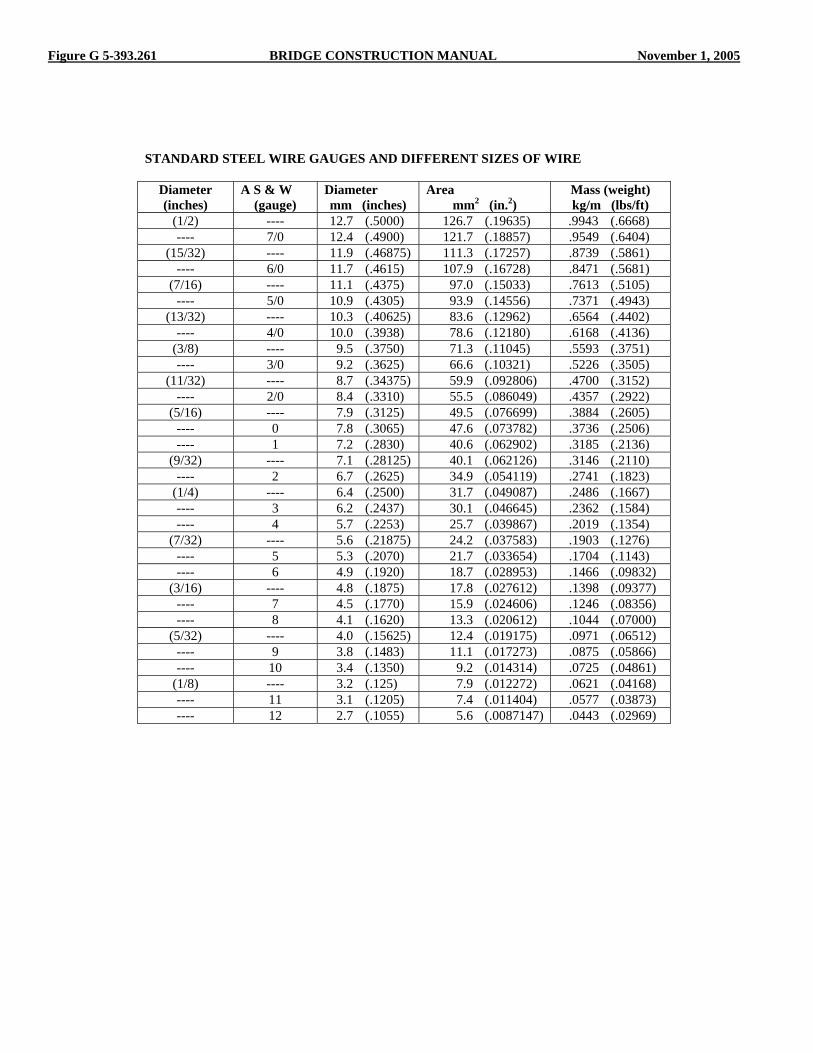
Figure G 5-393.261 BRIDGE CONSTRUCTION MANUAL November 1, 2005
STANDARD STEEL WIRE GAUGES AND DIFFERENT SIZES OF WIRE
Diameter (inches)
A S & W (gauge)
Diameter mm (inches)
Area mm2 (in.2)
Mass (weight) kg/m (lbs/ft)
(1/2) ---- 12.7 (.5000) 126.7 (.19635) .9943 (.6668) ---- 7/0 12.4 (.4900) 121.7 (.18857) .9549 (.6404)
(15/32) ---- 11.9 (.46875) 111.3 (.17257) .8739 (.5861) ---- 6/0 11.7 (.4615) 107.9 (.16728) .8471 (.5681)
(7/16) ---- 11.1 (.4375) 97.0 (.15033) .7613 (.5105) ---- 5/0 10.9 (.4305) 93.9 (.14556) .7371 (.4943)
(13/32) ---- 10.3 (.40625) 83.6 (.12962) .6564 (.4402) ---- 4/0 10.0 (.3938) 78.6 (.12180) .6168 (.4136)
(3/8) ---- 9.5 (.3750) 71.3 (.11045) .5593 (.3751) ---- 3/0 9.2 (.3625) 66.6 (.10321) .5226 (.3505)
(11/32) ---- 8.7 (.34375) 59.9 (.092806) .4700 (.3152) ---- 2/0 8.4 (.3310) 55.5 (.086049) .4357 (.2922)
(5/16) ---- 7.9 (.3125) 49.5 (.076699) .3884 (.2605) ---- 0 7.8 (.3065) 47.6 (.073782) .3736 (.2506) ---- 1 7.2 (.2830) 40.6 (.062902) .3185 (.2136)
(9/32) ---- 7.1 (.28125) 40.1 (.062126) .3146 (.2110) ---- 2 6.7 (.2625) 34.9 (.054119) .2741 (.1823)
(1/4) ---- 6.4 (.2500) 31.7 (.049087) .2486 (.1667) ---- 3 6.2 (.2437) 30.1 (.046645) .2362 (.1584) ---- 4 5.7 (.2253) 25.7 (.039867) .2019 (.1354)
(7/32) ---- 5.6 (.21875) 24.2 (.037583) .1903 (.1276) ---- 5 5.3 (.2070) 21.7 (.033654) .1704 (.1143) ---- 6 4.9 (.1920) 18.7 (.028953) .1466 (.09832)
(3/16) ---- 4.8 (.1875) 17.8 (.027612) .1398 (.09377) ---- 7 4.5 (.1770) 15.9 (.024606) .1246 (.08356) ---- 8 4.1 (.1620) 13.3 (.020612) .1044 (.07000)
(5/32) ---- 4.0 (.15625) 12.4 (.019175) .0971 (.06512) ---- 9 3.8 (.1483) 11.1 (.017273) .0875 (.05866) ---- 10 3.4 (.1350) 9.2 (.014314) .0725 (.04861)
(1/8) ---- 3.2 (.125) 7.9 (.012272) .0621 (.04168) ---- 11 3.1 (.1205) 7.4 (.011404) .0577 (.03873) ---- 12 2.7 (.1055) 5.6 (.0087147) .0443 (.02969)

November 1, 2005 BRIDGE CONSTRUCTION MANUAL Figure H 5-393.261
Weight of Spiral Reinforcement
WEIGHTS IN POUNDS PER FOOT OF HEIGHT
3/8" DIA. ROD 1/2" DIA. ROD O.D. SPIRAL
(in) 6" PITCH
(lb/ft)
F
(lb)
3" PITCH
(lb/ft)
F
(lb)
24 4.72 7.1 16.79 12.60
26 5.12 7.7 18.19 13.65
28 5.51 8.3 19.59 14.70
30 5.91 8.9 20.99 15.75
32 6.30 9.5 22.38 16.80
34 6.69 10.1 23.78 17.85
36 7.09 10.7 25.18 18.90
38 7.48 11.2 26.58 20.00
40 7.87 11.8 27.98 21.00
42 8.27 12.4 29.38 22.00
44 8.66 13.0 30.78 23.10
46 9.06 13.6 32.18 24.10
48 9.45 14.2 33.58 25.20
50 9.84 14.8 34.98 26.20
52 10.24 15.4 36.38 27.30
54 10.63 15.9 37.77 28.30
56 11.02 16.5 39.17 29.40
58 11.42 17.1 40.57 30.40
60 11.81 17.7 41.97 31.50
62 12.21 18.3 43.37 32.50
64 12.60 18.9 44.77 33.60
66 12.99 19.5 46.17 34.60
68 13.39 20.1 47.57 35.70
For more complete coverage, see CRSI Design Handbook. Total weight = (wt. per ft x height) + F F = weight to add for finishing (this includes 11/2 turns at the top and 11/2 turns at the bottom of spiral) For additional information see Mn/DOT 2472 and AASHTO LRFD 5.10.6.2

November 1, 2005 BRIDGE CONSTRUCTION MANUAL 5-393.300
CONCRETE 5-393.300
5-393.301 GENERAL The discussion in this section applies to the proper control of procedures and operations used to produce concrete in its plastic state. Placing, consolidating, finishing, curing and protecting the mixed concrete are discussed in 5-393.350 Concrete Bridge Construction under the specific work items such as substructures, girders, slabs, railings and wearing courses. Procedures for sampling, testing and inspecting the cement, aggregate, admixtures and concrete are included in the Concrete Manual and specific references to that manual are made in the following text. 5-393.302 CONCRETE MIX All concrete used for bridges is given a mix designation commonly referred to as a concrete mix number (See Specification 2461 and Concrete Manual 5-694.200). Concrete Manual Table A 5-694.312 tabulates the various mixes in general use for specific parts of a bridge. The bridge plans will list the different mixes required for that particular bridge in the summary of estimated quantities, and the various detailed bridge plan sheets usually show the mix to be used for the various parts of the structure. The use of these mixes is required except that higher strength mixes may sometimes be substituted. In the case of slope paving, the concrete type and minimum strength grade will be shown in the construction notes on the standard slope paving plan sheet. The concrete mix for cast-in-place steel shell piles is given in Specification 2452.2D2. Estimated mix proportions for each concrete mix are furnished to the field engineer by the Concrete Engineer, Office of Materials (see Concrete Manual 5-694.300). Soon after a bridge contract has been awarded, Materials Engineering will forward a blank 2416, “Concrete Information,” to the Project Engineer for completion (see Concrete Manual 5-694.300). The Project Engineer or inspector will then request proportions for the concrete mix number shown in the bridge plans, and complete Form 2416 based on information supplied by the Contractor and his or her supplier of concrete materials. In some cases, the project plans or special provisions will require the Contractor to develop their own mix design for a particular concrete element or component. In this case you should refer to the project special provisions and consult with the Concrete Engineer if you have questions.
5-393.303 MATERIAL REQUIREMENTS All concrete and concrete materials are subject to testing and inspection and come under the general requirements of Specifications 1603 and 1604, “Materials: Specifications, Samples, Tests and Acceptance” and “Plant Inspection-Commercial Facility” respectively. The detailed specification requirements for concrete are contained in Specification 2461, “Structural Concrete,” with current modifications shown in the Special Provisions for the particular bridge under contract. Each bridge contract proposal includes a copy of the “Schedule for Materials Control” mentioned in Specification 1603. The extent of sampling will vary depending on Contract requirements which may specify a “certification” process with quality control sampling by the concrete supplier. Detailed certification,inspection, sampling and field testing procedures for concrete and concrete materials are contained in the Concrete Manual prepared by the Materials Section. The Project Engineer should decide as early as practicable whether materials will be inspected and tested at the source or at the bridge site and arrange for all testing equipment and supplies to be on hand at the proper location. Regardless of where the materials are inspected and tested, the inspector should bear in mind the following sentence of Specification 1603 - “Final inspection and acceptance of materials will be made only at the site of the work, after all required tests have been met.” Specification 1601 states that all materials required for the work shall be furnished from reliable sources capable of producing and delivering uniformly acceptable products. An example of a non-uniform product is concrete produced by a ready-mix plant using two different brands of cement having different colors. It sometimes happens, where concrete production for other jobs may be in progress, that the brand of cement used for a particular bridge may be exhausted and permission to substitute another brand is requested. For concrete not exposed to view a change in color is not objectionable. When non-uniform colors are used on exposed surfaces, a special surface finish may be required to hide the variation. For additional information see Concrete Manual 5-694.100. 5-393.304 CONCRETE QUANTITIES Specification 2401 under “Method of Measurement” provides as follows: 1. Concrete will be measured, as indicated in the Proposal,
by volume or by area, based on the dimensions shown in the Plans.

5-393.304 BRIDGE CONSTRUCTION MANUAL November 1, 2005
2. Each mix of concrete will be measured separately. It is
general practice to disregard keyways between pours using different mixes, in the computation of the quantities.
3. No deductions will be made in concrete quantities for the
volume displaced by metal reinforcement, structural steel, floor drains, conduits, pile heads, chamfer strips with side dimensions of 50 mm (2 inches) or less or for variations in camber and deflections from that which is indicated in the plans.
4. No increase will be allowed for any concrete used to
secure true conformity to the plan requirements for the elevation profile and cross section in the finished roadway slab.
The pay quantity of concrete for a bridge may be computed in advance of placement and differs from some other items of highway work where the quantity must be measured and computed after the item of work is in place. It is important that the concrete quantity required for each concrete pour in a bridge be computed well in advance of concrete placement. Computations of concrete quantities by pours in advance serve several useful purposes which are as follows: 1. Quantity computations familiarize the inspector with the
detail plans. The plans will show the total estimated quantity of each concrete mix required for each unit (pier, abutment, superstructure, etc.). If the summation of the inspector’s quantities for each placement totals the estimated plan quantity for the unit, it is reasonably certain that he has interpreted the plans correctly.
2. The quantity required for each placement is useful in
coordinating the concrete delivery and production rate, with the rate of rise within the forms, finishing operations, and available time for the placement.
3. The quantities may be used for computation of yields and
progress estimates besides being used as pay quantities in the final estimate.
4. Differences in computed and “as delivered” quantities
which arise from shortages or overruns are easier to resolve at the time of placement.
In the computation of the estimated concrete quantities shown on plans, concrete volumes are shown to the nearest cubic meter (cubic yard) so as to avoid errors in bidding. Field computations are to be made to the accuracy and on the form described in the Documentation Manual issued by the Office of Construction. When there are unexplained discrepancies between field quantity computations and the plan estimated quantity, the
Project Engineer can request a copy of the plan estimated quantity computation from the Bridge Designer for comparison. Specification 1901 states that the plan quantity will be accepted for payment except for the following conditions: (a) incorrect plan quantities, (b) plan alterations, or (c) other method of measurement provisions of the contract. Field quantity computations should be submitted with the final even if the plan quantity is the basis for payment. Examples of conditions when the proposal quantity will be revised are as follows: 1. A discrepancy between the field computed quantity and
the estimated plan quantity indicates a mathematical error made during the computation of the estimated plan quantity.
2. A plan alteration was made during construction such as
lowering a footing one-half meter (1.5 feet) below the plan elevation because bed rock conditions were not as anticipated.
3. The provision in Specification 2451 requiring rock
excavation to be paid for as the actual measured quantity is used.
November 1, 2005 BRIDGE CONSTRUCTION MANUAL 5-393.350
CONCRETE BRIDGE CONSTRUCTION 5-393.350
5-393.351 PREPARATIONS FOR CONCRETE PLACE-
MENT Well in advance of each concrete placement, the inspector should review the operations and be assured that nothing has been overlooked that may influence the success of the proposed pour. In general, this review should be made with the Contractor. The Contractor is the responsible party and should give the orders for any corrections or preparations necessary. The review should include items contained in the following list, some of which may have been made before the initial placement. 1. The time of day that the placement is to be started should
be determined and the completion time estimated. 2. Approved concrete materials in quantities adequate to
complete the placement must be available. The aggregates must be approved, cement must be the proper brand and either approved or sampled according to the Concrete Manual. A small quantity of the air entraining agent, retarder or other admixture used should be available at the bridge site when Type 3 (air-entrained) concrete is mixed away from the site.
3. Time-settlement delays after embankment construction at
abutments or piers may be required by the Special Provisions. A check should be made to ensure that any such requirements are fulfilled prior to footing placements. In addition, the soil must be compacted as required in Specification 2451.3 B, C and D for all spread footings placed on soil; this includes footings on natural soil as well as footings on embankments.
4. Pumps, with sumps outside the formed area, should be
provided when necessary to keep footing areas dewatered. The water level must be kept below the bottom of the proposed pour for succeeding casts. All concrete, except concrete seals, should be placed “in the dry” except as permitted by Plan or Special Provision.
5. Concrete mixing equipment should be checked as
required in 5-694.400 of the Concrete Manual. 6. The concrete delivery or production rate should be
coordinated with the rate of placement permitted by the form plans or coordinated with a rate of placement that will permit proper finishing with available personnel and equipment. The Special Provisions may require a minimum rate of placement for placements of large seals, decks or piers. In this case, equipment and personnel must be available and the forms must be designed so that the minimum rate of placement can be maintained.
7. The rate of delivery should be fairly uniform. Ready-mix
trucks should be scheduled to leave the plant at spaced intervals, not in groups. A check should be made on the
cubic yards required up to the cut-off point when a delay is required in concrete placement. An example might be the top of pier columns when the pier cap is to be placed monolithically with the columns. The extent of the delay period will depend on the setting time of the concrete and the rate of pour. The minimum delay period of one hour, required by Specifications should be scheduled for hot weather and a slow to medium (up to 1.5 m per hour) rate of pour. A maximum delay period of 1 1/2 hours should be used for higher rates of pour and/or lower temperatures. The purpose of this delay is to permit maximum water release and consolidation of the concrete in the columns or walls prior to placement of concrete in the cap.
8. The use of concrete additives such as retarders for deck
placements and Type III cement for cold weather placements should be discussed with the Concrete Engineer. All admixtures including air entraining must be approved.
9. Placing equipment should be reviewed to ensure that
proper methods of placing are used. The possibility of a break-down in placement equipment should be discussed, as well as the availability of replacement equipment. If concrete is being placed for a critical falsework design (slab span, box girder, rigid frame or concrete arch) by means of a pump, the contractor may be required by the engineer to have a standby pump at the site.
10. Approved finishing tools and equipment must be
provided. Strike-offs must have the proper crown or straightness. Longitudinal floats and straightedges must be true. The necessity for small tools such as darbies, hand floats, trowels, edgers and brooms, together with bridges to work from, must not be overlooked. Lack of an edger or specified radius for curbs and sidewalks can be very troublesome, and edgers are almost impossible to improvise on short notice. Edgers should be long enough and wide enough to permit slight variations in pressure without causing dips and gouges.
11. The number of concrete finishers necessary should be
discussed, since this directly affects the rate of finishing. 12. When finishing must be done in poorly windowed
housing, or it is anticipated that finishing may be required at night, adequate artificial lighting should be provided.
13. Procedures to follow in case of rainfall before the
concrete has set up should be discussed with the Contractor. Deck slabs should be given careful consideration due to the large area that may be exposed and the extensive damage that may result from running water. Plastic sheeting or other protective covering should be on hand at the bridge site.

5-393.351 BRIDGE CONSTRUCTION MANUAL November 1, 2005
14. Curing materials (burlap, plastic curing blankets, etc.) should be at the site in sufficient quantity to cover the placement. It is very difficult to adequately seal concrete with curing blankets when dowels or other reinforcement bars project from the surface. It may be necessary to arrange to cure such areas with wet burlap.
15. When temperatures below 4EC (40EF) are anticipated or
can be expected before completion of curing, cold weather protection materials should be at the jobsite prior to placement. Requirements for cold weather protection are given in Specification 2401.3C2. Arrangements should be made to preheat the forms, reinforcement bars and abutting concrete surfaces when they have been subjected to freezing temperatures. Required curing and the need for form insulation or housing and heating should be discussed. Unformed upper surfaces must be protected during finishing operations until the concrete is set up enough to bear the upper insulating material. Heat applied directly to fresh concrete must be provided by vented heaters. Combustion products from unvented heaters cause a weak layer of calcium carbonate on the surface of the concrete that interferes with cement hydration. The result is a soft, chalky surface that dusts off under traffic.
16. The need for taking control test cylinders should be
considered and discussed with the Contractor. These cylinders would be in addition to cylinders required for acceptance of materials. Control cylinders are normally used when cold weather curing is anticipated. See Specification 2401.3G for further details.
17. A water supply for wetting forms and providing a fog
spray should be discussed with the Contractor. The need for fog spray nozzles at the jobsite should be pointed out at that discussion.
Specification 2461.4A states that concrete production shall not be started until the Engineer has approved all preparations for concrete placement. The following items should be carefully checked during the pre-placement inspection. 1. The forms should be checked for conformance with the
Plan dimensions, elevations and alignment. Surveying instruments are often necessary for checking the alignment or elevations of forms. Form lines should always be checked visually, but a blind dependence should not be placed on them. Chamfer or cove strips should be checked for location, size, warping and adequate nailing every 150 mm to 200 mm (6-8 inches). Forms and falsework plans should also be checked to see that the construction conforms to the approved Plans. It is assumed that the size, spacing and materials used have been checked for compliance with the approved form plans, and that any changes necessary have been made during construction. See Section 5-393.250 of this manual for inspection of reinforcement bars, mesh, etc.
2. Panel forms for substructure units should be treated with an approved form release agent before erection. Forms for deck slabs should be treated in advance of placing reinforcement bars. The removable portion of form bolts should be coated before placing to facilitate removal. A resin-coated form-grade plywood is available, which is said to be non-staining.
3. The face of the forms that will be in contact with concrete
should be clean and all debris removed from within the forms. This may require that openings be cut through the form near the bottom, the debris removed, and the opening closed. On deck slabs, flushing the forms with water to move the debris to several central locations for removal is an excellent method of cleaning within the forms. The inspector should pay particular attention to see that paper, chips, sawdust, etc., are removed from “hard to get” locations. Industrial type vacuum cleaners or compressed air blowers are useful at such locations. A magnet tied to the end of a rod can be used for picking up metal objects such as nails and wires.
4. Deck slab forms usually take some time to construct.
Wood forms that were constructed tightly may shrink, especially during hot weather, and develop openings through which mortar may leak. Thoroughly flushing the forms a day in advance of pouring will usually tighten up the forms. (Note: Flushing with water for cleaning or tightening the forms is, in addition to the Specification requirement for flushing immediately in advance of concrete placement). A close inspection should be made for holes or cracks through which mortar may leak. On steel beam spans with stools (haunches), the wedges holding the sheathing tightly against the underside of the beam flange should be checked and snugged up. Holes in vertical forms may be plugged with a piece of cork cut flush with the face of the form in contact with concrete. Holes or cracks in the forms for the underside of deck slabs may be covered with tin nailed in place. Covering holes with tin on vertical forms, where the concrete will be exposed to view, is not advisable as the slight depression will show up and a concrete patch will not adhere in such a shallow depression. Adjacent sheets of plyform sheathing or other form lining on vertical forms must be close fitting with smooth joints. If the joints are not close fitting, the crack should be filled with a non-staining putty or other suitable material to reduce the amount of ordinary surface finish work.
5. All reinforcement, inserts, anchorages and sleeves which
are to be cast in should be checked for proper positioning, projection and minimum concrete cover.
6. Expansion devices should be carefully adjusted as
discussed under Section 5-393.370 of this manual. 7. When temporary wood spreaders are used within vertical
forms, a wire tied around the spreader and extending to

November 1, 2005 BRIDGE CONSTRUCTION MANUAL 5-393.352 (1)
the top of the form may prevent them from being inadvertently cast into the concrete.
8. Slipforming equipment should be given a “dry run” to
ensure clearance and minimum concrete cover over reinforcement.
5-393.352 CONCRETE PLACEMENT EQUIPMENT Chutes Chutes are constructed of metal in a semicircular shape or of wood in a rectangular shape. They should be mortar tight. Aluminum chutes should never be permitted since the coarse aggregate will wear off particles of aluminum and cause gassing in the concrete mix. The amount of segregation in concrete discharged from a chute will increase as the length and slope of the chute increases. No definite rule can be laid down as to the length and slope of a straight chute that may be used without segregation. The slope is usually 1 vertical to 2 or 2 1/2 horizontal. The important thing for the inspector to remember is that, if segregation is apparent in chutes, baffles must be installed or shorter chutes that reverse the direction of the flow of concrete must be used. These corrections will slow down the coarse aggregate and permit the mortar to “catch up.” At the end of a chute the coarse aggregate will discharge ahead of the mortar and segregation will result. The segregation is aggravated where the concrete hits the side of a form or mat of reinforcement bars. For this reason, if segregation is evident, the direction of discharge of concrete into the forms must change to vertical by means of a baffle or a hopper with a short length of downspout. The most satisfactory method of ensuring a vertical drop is by passing the concrete through a short section of pipe. Baffle plates are not always satisfactory as sometimes they merely change the direction of separation. This may apply to sloping discharges from mixers and truck mixers, as well as longer chutes. It does not apply when concrete is discharged into another chute
or onto a conveyor belt. See the following sketch from an American Concrete Institute publication. Chutes normally carried with ready mix trucks to discharge concrete are classified as short chutes. There is some segregation associated with their use and the segregation increases as the chute angle increases. When the concrete is chuted directly into forms, baffles or hoppers may be necessary to change the direction of the flow to prevent segregation. When ready-mix trucks are used to discharge concrete into deck slab or sidewalk forms, the chute should be moved in as large an arc as possible when discharging to minimize segregation. See Concrete Manual 5-694.622. Downspouts Downspouts are sometimes referred to as “drop chutes” when made of metal or as “elephant trunks” when made of rubber. Nominal diameters vary from 200 mm to 400 mm (8 to 16 inches). Commonly used downspouts are made of sheet metal and are constructed in sections. Each section usually makes a downspout 1.3 m (4 feet) long. The sections are made in the shape of a truncated cone and are placed with the smaller end down. Hooks and chains are provided to hold the sections together. Each lower section overlaps the upper section and is suspended from it. A steel hopper completes the upper end of the downspout. This hopper is usually constructed with a short section of downspout into which the concrete is discharged. With the hopper resting on a suitable framework on top of the form, the downspout is constructed initially to a length such that the lower end will be 1.3 m (4 feet) or less from the bottom of the concrete. As the concrete level approaches the end of the downspout, a 1.3 m (4 feet) section is removed and this procedure is repeated until the concrete level is 1.3 m (4 feet) or less from the finished surface, at which time the spout and hopper may be removed. When large areas of concrete such as walls are being poured through downspouts, better results will be obtained if a number of downspouts are provided. The concrete can then be maintained approximately level by depositing a small amount of concrete in each spout successively rather than using one downspout and moving it from one location to another to maintain level lifts of 300 mm (1 foot) or less. A downspout in each column of a pier in which the cap is cast monolithic with the columns is preferred. Equal lifts of concrete can then be placed alternately in each column with several advantages: the overall rate of pour is faster (the rate must not exceed the rate for which the forms were designed); the degree of set is practically the same for each column when the concrete level reaches the tops of the columns at the start of the delay period; and the forms may be maintained in better alignment.
Control Of Concrete Segregation At The End Of Chutes
CORRECTThe above arrangement prevents segregation, no matter how long the chute. Whetherconcrete is being discharged into hoppers,buckets, trucks, or forms.
INCORRECTImproper or lack of control at end of any concrete chute, no matter how short. Usually a baffle merely changes the direction of segregation.
600
mm
(2 ft
.) m
in.
head
room
for
dow
npip
e
No separationmortar
Rock
BaffleMortar

5-393.352 (2) BRIDGE CONSTRUCTION MANUAL November 1, 2005
In some cases, due to the location of the reinforcement bars or the limited space between forms, downspouts cannot be used. In these cases, it may be necessary to cut a series of openings in the back side of the form to place the concrete. The openings are closed when the concrete level approaches the bottom of the opening and the procedure is repeated to the next higher level. Concrete Buckets Concrete buckets are used as a crane attachment to transport concrete from one location or level to another. The size commonly used on bridge work vary from 0.5 cubic meters capacity up to 1.5 cubic meters (0.65 to 2.0 cubic yards). They are constructed with manually operated discharge gates. The rate of discharge may be varied by manually varying the gate opening which discharges the concrete. Concrete buckets are usually designed to be self-cleaning but the inspector should check the bucket occasionally to see that it is clean and that there is no progressive build-up of mortar in the bucket. It is necessary to rest the bucket on a sheet of plywood or other material when it is being filled to prevent contamination with dirt. Concrete buckets should be filled as shown in the sketch below taken from an American Concrete Institute publication. A temporary expedient which can be used if segregation has not been eliminated in filling buckets is shown in the following sketch, taken from an American Concrete Institute publication. Correction in filling the bucket should be made as soon as possible to eliminate the segregation. Most concrete buckets are designed to handle concrete of the consistency normally used on bridge work. If concrete of specified slump cannot be properly discharged from the bucket used, the bucket, rather than the slump, should be changed. The discharge gate should not be suddenly opened to full width, but should gradually be opened and the discharge controlled to prevent excessive impact on the forms.
Discharging a 2 cubic meter (2.6 cy) bucket suddenly would drop approximately 5 metric tons (5.5 tons) of concrete into the forms. In addition, the bucket should be as close to the forms as possible to reduce the impact from dropping the concrete. Pump Placement The modern mobile pump with hydraulic placing boom is economical to use in placing both large and small quantities of concrete. These units are used to convey concrete directly from a truck unloading point to the concrete placement area. Typically, pumps are initially flushed with a thin water/cement paste mixture to coat the lines. This slurry must be wasted and the lines charged with the project mix before beginning. Observe and be sure initial pump charge is thoroughly removed from the pipelines. Other points to watch for include: 1. Always pump at a constant rate and keep pipelines full of
concrete. High air loss can occur when concrete is allowed to free-fall inside pump lines.
2. Avoid, if at all possible, having steep angles in the pump
pipelines. Steep angles and slow placement rates are probably the worst conditions for minimizing air loss and segregation.
When using pumps, concrete should not be pumped through aluminum pipe. Aluminum can be eroded by the moving concrete in sufficient quantity to cause a reaction between it and the lime in the cement which leads to the generation of hydrogen. This has the same effect as excessive air entrainment and the strength of the concrete may be drastically reduced. Problems arise in the adverse reaction of concrete with aluminum, not from the placement of concrete with pumps. All samples should be taken at the discharge end. Concrete for test cylinders should also be collected at the discharge end.
Filling Concrete Bucket
CORRECTDropping ofconcrete directlyover gate opening.
INCORRECTDropping ofconcrete onsloping sides ofbucket.
Temporary Expedient
CORRECTTurn bucket so thatseparated rock falls onconcrete where it maybe readily worked intomass.
INCORRECTDumping so thatfree rock fallsout on forms or subgrade.
Directionof spreading
Rock pockets format bottom of slab

November 1, 2005 BRIDGE CONSTRUCTION MANUAL 5-393.352 (3)
For additional information on pumping see “Pumpcrete”, 5-694.624 in the Concrete Manual. Concrete Buggies There are two types of buggies used for placing concrete. They are commonly referred to as hand buggies and power buggies. 1. Hand buggies are two wheeled with rubber tires and have
capacities of approximately 0.2 cubic meters (0.25 cy). They are pushed and dumped manually.
2. Power buggies are usually three or four wheeled, with
rubber tires, and capacities vary from 0.3 cubic meters to 0.7 cubic meters (0.4 to 1.0 cy). They are self propelled and the rate of discharge may be controlled.
Concrete buggies require runways when they cannot operate on previously placed concrete. When used for concrete placement on piers, abutments or walls, the runway should rest on falsework that is independent of the concrete forms or falsework. Runways and the supporting falsework should be checked for structural adequacy using loadings provided by the manufacture of the power buggy. When they are used to place concrete on deck slabs, the runway is supported on cross-frames whose legs rest on the forms. The legs of the cross-frame must be long enough to allow the cross joist of the frame to clear the deck rebars. The runways are constructed in sections and the sections must be removed as the pour progresses. When runways are necessary with buggies, the placement must start at the far end of the section and progress toward the end where the buggies are loaded. In some sectional pours, the buggies must cross deck slabs poured the day before or several days previously. This is not objectionable provided the curing materials are protected from abrasion and some provision is made to distribute the load and reduce impact. With hand buggies, boards laid on the curing material over the area to be used as a runway is usually sufficient. Sections of prefabricated runway or heavy planks should be placed on the curing material when power buggies are used to distribute the load and reduce impact. The runway should be free of abrupt vertical offsets and obstructions. Due to the mass of a loaded power buggy, its lack of springing action and the speed traveled, a noticeable shock wave will be transmitted to the concrete when a buggy crosses a board in its path. It may also be advisable to require reduced speeds to avoid cracking on previously cast concrete. Power buggies have been successfully used on long deck slab pours where a bridge finishing machine was required. A runway is centered on the roadway slab and is connected to a short ramp leading up to a transverse unloading platform. This platform is equipped with flanged wheels which rest on the rails on which the finishing machine operates. The unloading platform permits the buggies to unload transversely without additional runways and with very little shoveling. Sections of the main runway are taken up and the loading
platform rolled back as the pour progresses. The head of the concrete is thus maintained approximately parallel to the finishing machine screed. When placing concrete from buggies, the concrete should be dumped into the face of concrete in place, rather than away from the concrete in place: see the sketch below, taken from an American Concrete Institute publication. This should prevent separation of rock and mortar. Gantry Cranes Gantry cranes have been adapted to transport form materials, reinforcement bars, and concrete for the deck slabs of longer span bridges. They are self-propelled, very heavy, and run on the same rails used for the bridge deck finishing machine. A concrete bucket is suspended from the power operated crane which moves transversely on the supporting framework. One end of the gantry frame-work overhangs the deck. In operations, the bucket is moved to the overhang, lowered to the ground or barge to be filled, and is then raised. The crane may be moved along the rails as the bucket is raised or the bucket may be raised, centered on the gantry, and the gantry is then moved. Large, undesirable stresses and differential deflections may be set up in the bridge structure due to the mass of the gantry, impact of the moving load and the movement due to the overhanging load. Each bridge is a special case and no blanket approval or limitation on the use of a gantry crane is practical. If the use of this machine is anticipated, an investigation of resulting stresses and deflections should be made. Tremis A tremie consists of a watertight metal tube not less than 250 mm (10 inch) in diameter and of sufficient strength to perform the work. The lower end of the tremie is equipped with a suitable valve or device which can be tightly closed while the tremie is being charged and lowered into position and which can be fully opened in the lowered position. A typical tremie tube may be constructed of 300 mm (12 inch) O.D. steel shell pile section with a welded hopper which is either conical or rectangular with a sloping bottom. The control cables for the valve may extend from the valve through the tremie tube up to the top of the hopper. If sectional tremie tubes are used, water tight gaskets must be used where sections are bolted together.
Placing Slab Concretefrom Buggies
CORRECTTo dump concreteinto face of concretein place.
INCORRECTTo dump concrete away from concrete in place.

5-393.353 (1) BRIDGE CONSTRUCTION MANUAL November 1, 2005
The tube should be long enough so that the hopper will be well above the water surface when the bottom of the tube is at the bottom of the excavation. Concrete Conveyor Belts Conveyor belts have been used to transport concrete. Segregation will usually result at the discharge end of the belt unless a suitable hopper with vertical downspout is used. A belt that is too flat will spill mortar over the sides. Belt scrapers are mandatory. See the sketch on the following page, taken from an American Concrete Institute publication.
5-393.353 CONCRETE PLACEMENT Concrete placement in bridges is governed by Specification 2401. Methods for controlling segregation for the various types of placement equipment are discussed under the previous section 5-393.352. The basic requirements of Specification 2401 regarding prevention of segregation of mortar and coarse aggregate are as follows: 1. The height of freefall of the concrete from the end of a
chute, downspout, hopper or bucket, to its final position in the forms shall not exceed 1.3 meters (4 ft).
2. Concrete shall be deposited as near its final position as
possible and vibrators shall not be used to move the concrete horizontally within the forms.
3. Pipes, belts or chutes that are inclined may be used only
when approved means of preventing segregation are provided. Inclined pipes, chutes and belts (either inclined or horizontal), shall discharge into hoppers with vertical downspouts.
The Specifications require that all concrete used on bridges, except cofferdam seals or cast-in-place concrete piles, must be vibrated by the use of internal vibrators. The requirements for vibration and spading are covered completely in Specification 2401.3D with supplemental information in 5-694.600 of the Concrete Manual. Over-vibration tends to segregate the concrete. Incomplete vibration, where part of the concrete is not vibrated, may show honeycomb and insufficient consolidation when lower slump concrete is used. The vibrator should penetrate the previous lift of concrete. Systematic vibration of each new lift is shown in the sketch below, taken from an American Concrete Institute publication. When a vibrator is allowed to contact the forms, sand streaks may occur. When the vibrator is allowed to contact reinforcing bars, the vibrations are transmitted to the bars and, if they extend into “green” concrete, bond between the bars and concrete may be destroyed. Vibration of concrete does not take the place of spading concrete along the forms but does reduce the amount required. Spading should always be done along bulkheads in deck slab pours, along the edge of the roadway slab, curb, coping and railing forms. The reaction of the forms and falsework under the concrete load should also be watched. The end result of a good form plan, but careless construction practice, can be poor. The Contractor should be required to provide “form-watchers” on piers, abutments and other large wall pours. The “form-watchers” should climb the forms as the pour progresses, checking form bolts and observing the behavior of the forms under load. When excessive bulging is noticed, or if a form bolt should snap, pouring should cease until corrective measures can be taken. Sometimes due to carelessness the holes drilled through the sheathing for form bolts do not line up between opposing forms. When the form bolts are placed, they are sometimes bent to pass through the misaligned holes. The bent folds may straighten as the load is applied which tends to place a greater load on adjacent bolts, perhaps causing
CORRECTVertical penetration ofvibrator a few inchesinto previous lift (whichshould not yet be rigid)at systematic regularintervals found to giveadequate consolidation.
INCORRECTHaphazard randompenetration of the vibratorat all angles and spacingswithout sufficient depthto assure monolithiccombination of the twolayers.
Systematic VibrationOf Each New Lift
Control of Segregation of ConcreteAt The End Of Conveyor Belts
CORRECTThe above arrangement prevents segregation of concrete whetherit is being discharged into hoppers, buckets, trucks, or forms.
INCORRECTImproper or lack of control at end of any belt.Usually a baffle or shallowhopper merely changes the direction of segregation.
Prov
ide
600
mm
(2 ft
.)he
adro
om fo
rdo
wnp
ipe
No separation Rock
Baffle
No baffle
Mortar
Counter weighted rubber scraper

November 1, 2005 BRIDGE CONSTRUCTION MANUAL 5-393.353 (2)
a serious overstress on these bolts even though the design is entirely adequate. The plumbness of substructure units must be maintained. A description of methods for holding the forms plumb, inspecting plumbness and a discussion of tolerances are as follows: 1. The plumbness of the pier forms may be maintained by
the use of: (a) guy cables and turnbuckles attached to the walers or strongbacks on the pier forms at the one end and a substantial anchorage at the other end, or (b) by pushbraces (shores) with wedges for adjustment, or (c) by cross cables with turnbuckles fastened at one end to the falsework caps and at the other end to hairpin bars cast in the footing. On piers adjacent to railway tracks, bracing may have to be confined to one side of the pier and a combination of cables and pushbraces may be required.
2. In many cases on land, such as the piers of a grade
separation bridge, offset lines may be run and the plumbness of a unit checked with a transit. When the plumbness of a pier is checked with a transit, an offset line from the pier centerline is usually used. The offset distance must be sufficient to clear the walers, strongbacks and form bolts. Usually one meter (3 feet) from the face of concrete is adequate. Horizontal wood strips (lookouts) are nailed to the studs at several locations and, measuring from the outside of the sheathing, a nail is set vertically in the lookout at the offset distance. On piers with columns, at least two points should be set at each column, one about 1/4 the height of the column above its footing and one near the top of the column. More points should be required on high columns. A lookout point should be placed near the top of the pier cap forms over each column.
3. With the transit on the offset line, each lookout point is
observed before the pour and the forms adjusted to be truly vertical. The inspector should verify that the transit offset line and the nails set in the lookouts are the same offset distance from the pier centerline. Intermittent observations are also taken on the points as the placement progresses. A weaving action may occur in which the forms will list slightly in one direction, then in the other, as the placement progresses. Plumb-bobs suspended from outriggers may also be used to check on plumbness during the placement.
4. With all of the concrete in place, the top of the forms
should be within the plumb tolerances specified in Section 5-393.203. Generally, all the lookouts in a horizontal line should show approximately the same deviation or wavy concrete lines may result.
The elevation of the top of pier caps or other units supported on falsework should be determined in the following manner. Grade nails or vee strips to which the concrete surface is finished may be preset with the estimated deflection included,
but this estimated elevation should not be considered as final grade. See 5-393.203 for estimating the false work deflection. When the concrete level approaches 150 mm to 300 mm (6 to 12 inches) of the top of the pier cap, one of two things should be done: (a) recheck grade nails, reset to true elevation when necessary, then place chamfer strips or (b) when chamfer strips are preset with temporary nailing, check and realign to true grade and fasten securely. It is important for true bearing areas that this check and resetting of the top grades be made after most of the concrete is placed. Vertical forms for bridge substructures, retaining walls, etc., are usually designed to resist a certain maximum concrete pressure. The pressure used in the form design is based on the rate of pour and concrete temperature anticipated. See 5-393.200 of this manual. The inspector should check concrete temperatures as the concrete is placed in the form. The rate of placement should be reduced when lower than anticipated concrete temperatures will cause an excessive increase in pressure. Actual placement rates should also be checked and should not be permitted to exceed the design rate. The Plans usually show a permissible construction joint between pier caps and columns. If the Contractor elects to pour the cap monolithic with the pier columns, a time delay of 30 minutes to 90 minutes should elapse between placing column concrete and cap concrete (see Specification 2401.3C1). Before starting the cap portion of the placement, the tops of the columns should be cleaned of laitance and any loose or porous concrete. Concrete shrinks and settles very rapidly in its early stages of setting up. The purpose of the delay is to allow most of this consolidation to occur in the column before the cap concrete is placed. No delay, or an insufficient delay period, may cause visible cracks or low strength concrete at the top of the column. These cracks will not generally extend around the column but will extend from the top of the column on diagonal lines up into the pier cap at about the angle of repose of green concrete. The cap concrete over the column settles with the column and the adjacent cap concrete supported on falsework cannot settle. Excessive, slow crushing of the falsework combined with a slow rate of pour in the cap could cause the same type of crack. Single diaphragms on prestressed girders which encase the ends of girders in adjacent spans are required to be poured monolithic with the slab. The diaphragm is poured monolithic with the slab in an attempt to have the diaphragm concrete plastic while the girder ends rotate due to slab dead load deflection. This method of construction reduces compression stresses in the ends of the girders. See the following sketch:
Rotation into diaphragm
CORRECTUnrestrained condition(diaphragm plastic)
High compression stress
INCORRECTRestrained condition(diaphragm set)
Compression Stresses Due to Restraint

5-393.354 (1) BRIDGE CONSTRUCTION MANUAL November 1, 2005
5-393.354 CONCRETE PLACEMENT IN COFFER-DAMS
Requirements for cofferdams are given in Specification 2451.3A3. In most cases, the Engineer will want to review the Contractor’s plans for the cofferdam to ensure adequate roomfor the concrete seal (if required), pile driving and footing concrete. Safety for Mn/DOT inspectors must also be considered and the construction of cofferdams of inadequate depth or without sufficient bracing should not be permitted. It is the Contractor’s responsibility to provide a safe and adequate cofferdam; however, it is in everyone’s best interest to bring obvious deficiencies to the Contractor’s attention prior to beginning construction. Special requirements for cofferdams may be given in the Plan and/or Special Provisions. Concrete seals are specified in the Plan when it is anticipated that a cofferdam cannot be safely dewatered to the bottom of the footing elevation. If the conditions of the bottom are such that no appreciable penetration can be effected into the bottom and, if friction between the outside submerged soil and the sheet piling cannot be depended upon, then a concrete seal sufficiently heavy to prevent uplift from hydrostatic pressure is required. The following sketch shows one situation where a seal is required. The Plans will show which units require concrete seals and also the seal dimensions. Usually seals are 0.5 meter (1-2 feet) larger on all sides than the footing dimensions of the pier to provide for construction room. The seal thickness depends on the depth of water above the bottom of the seal because a concrete seal is designed to resist hydrostatic uplift with its mass. The friction on the sheet piling and foundation piling also resist uplift due to hydrostatic pressure. This friction is generally ignored in
design and creates an additional safety factor. The inside dimensions of the cofferdam usually conform to the horizontal dimensions of the seal. When conditions are encountered that make it impractical to dewater a cofferdam prior to placement of concrete, a foundation seal may be provided by the Contractor. Concrete seals are used to provide some or all of the following: to resist buoyancy, to minimize infiltration of water through permeable soil, to act as a lower support for the sheet piles, to tie the driven piles together to resist uplift and to provide subsequent support for the construction of the pier footing. The size and thickness of the concrete seal should be sufficient to permit subsequent dewatering without the risk of failure due to “blow out” from water pressure. Specification 2451.3A3b provides for placement of a concrete seal when no seal is indicated in the Plans, if the Contractor so desires. In this event, the cost of the seal would be covered by the Contractor. The Contractor would then be required to submit the proposal to the Engineer for approval. The Engineer should then contact the Bridge Construction and Maintenance Section for concurrence and the change could be covered by a Change Order. With the cofferdam in place and before driving foundation piles (if they are required), excavation should be completed to the bottom of the seal. Soundings are taken to determine excavation progress by measuring the depth from the water surface to the bottom of seal. The elevation of the water surface is determined and the theoretical distance from the water surface to the established bottom of seal is computed. A benchmark is made on the cofferdam sheets near the water surface at a known elevation for checking excavation and seal elevations. The final elevation of the bottom as determined by soundings should not vary more than about 150 mm (6 inches) between the different soundings and the average elevation of the bottom should not be higher than the established bottom of the seal elevation. A prod or measuring pole for sounding may be constructed using a 20 mm (3/4 inch) pipe with a 150 mm (6 inch) diameter board or plate fastened to one end. A mark is made on the pole at a distance above the plate equal to the distance from top of water elevation to plan bottom of seal elevation. Marks are also made above and below the original mark at 0.05 m (2 inch) intervals. The pole is lowered vertically into the water until the plate touches bottom and the depth is noted. On fairly deep seals the pole may become too heavy and awkward to lift up and transfer from one cofferdam bay to another. Flat steel plates with a ring welded to the center of the plate and suspended on a light link chain have been used in lieu of the pole for sounding. Areas near and under cofferdam struts, that may be high due to difficulty getting an excavating bucket under them, should always be checked. When foundation piling is required in the footing, a precaution is necessary because the soil in the cofferdam may swell or be displaced upward during pile driving. Generally, contractors will excavate below the bottom of seal elevation anticipating
Soil
Rock
FoundationPiling
Seal
Footing
Sheet PileCofferdam
Water
Cofferdam With Seal

November 1, 2005 BRIDGE CONSTRUCTION MANUAL 5-393.354 (2)
such swell and will backfill to grade after the piles are driven. Allowance for swell of foundation material may vary from nothing to 600 mm (2 feet) or more, depending on the soil type and pile spacing. The depth must be determined by the Contractor because it is their responsibility to provide the proper foundation grade. Steel H-type bearing piles will cause muchless ground swell than will timber or steel shell piles because of their relatively small cross sectional area. Immediately after the piles are driven, the Contractor should check the bottom elevation of the excavation so that corrections can be made. If the bottom of the excavation is below the established bottom of seal elevation, the Contractor may elect to backfill with suitable sand-gravel material rather than fill with concrete. If the Contractor elects to fill the void with concrete, it will be at their expense. After corrections are made, the Contractor should again sound and record the elevation of the bottom of the excavation. Seal concrete must be placed as near its final position as possible by means of a tremie or by pumping. The water in the cofferdam should be relatively still and undisturbed at the point of deposit. The concrete should, unless otherwise specified, be placed to full depth in one continuous operation, completing the work to grade progressively from one end of the cofferdam to the other. The tremie pipe or pump line should be kept in the puddle at all times, being withdrawn only at the completion of each day or as may be required by the cofferdam bracing. The level of the concrete in the tremie tube should be kept approximately at the level of the water outside of the tube. After withdrawing, the tremie should be recharged with concrete above water and lowered to the new position where the discharge end can be set into the concrete puddle. In operation, the tremie suspended from a crane line with the valve closed and out of the water is fully filled or charged with concrete. It is then lowered to the bottom near one end of the cofferdam and raised a small amount to allow the valve to be opened. As the concrete is discharged, the concrete level in the tremie will lower. As the concrete level in the tremie approaches water level, the valve should be closed so that the concrete level in the tremie is never below water level. The tremie is then recharged and the operation repeated. It may be necessary to raise and lower the tremie slightly to assist in discharging the concrete, but the bottom of the tremie should not be raised out of the concrete. Usually a valve opening of 150 mm (6 inches) or less together with the raising and lowering of the tremie is sufficient for discharge. The tremie is then moved laterally with its lower end still in the concrete. If cofferdam struts are present, lateral movement of the tremie is restricted. In this case the tremie should be completely discharged, recharged above water and placed on the other side of the strut (or other obstruction). It is then discharged in previously placed concrete whenever possible. The operation is based on exposing as little concrete surface as possible to the eroding action of the water. Some loss of cement is anticipated; therefore, a rich mix (1X62) is used. A
higher than normal slump (120 mm-150 mm) (5-6 inches) is used to facilitate lateral flow of the concrete. Loss of cement from the mix is also minimized if the water in the cofferdam is still and the equipment is moved slowly in the water or concrete. Frequent soundings must be taken to obtain a reasonably level top surface on the seal. The same equipment used to check the excavation elevation can also be used for this purpose. The water level may rise in a tight cofferdam as the concrete displaces the water. The benchmark originally set on the cofferdam sheets for checking the excavation elevation may be used to check the elevation of the seal. Additional information on concrete seals is contained in 5-694.835 of the Concrete Manual. The inspector should record water temperatures during the placement and several times daily thereafter until the cofferdam is dewatered. The water temperature desired is the temperature at the surface of the seal. Based on these temperatures, the length of the curing period should be determined (see Specification 2451.3A3c). Dewatering should not be done within a sealed cofferdam until the seal has been placed and cured since the foundation soils may be seriously disturbed. After the cofferdam is dewatered, the pile cut-off is made and the top of the seal within the footing thoroughly cleaned of laitance and loose material. If the top of the seal projects above plan grade far enough to displace the reinforcement mat upwards, it must be cut down. It should also be cut down around pile heads so that the piles will project into the footing as planned. Any leaks that show up in the seal should be plugged so that the footing can be poured “in the dry.” It is sometimes necessary to leave the struts of a cofferdam in place and cast the concrete around the struts. This condition frequently occurs adjacent to railroad tracks or in water, where the removal of the struts in advance of pouring may cause collapse. When cofferdams struts are to be left in place, they must be of steel and generally should be cast into the concrete. Specification 2451 permits boxing out braces or struts only upon written approval of the Engineer. If the Contractor requests boxing out around struts or braces, the Bridge Office should be contacted for a recommendation. When the concrete has gained sufficient strength, the cofferdam sheets may be braced against it or may be held in position by back filling. The struts can then be cut off. If the struts are below final ground elevation or below low water elevation, they may be burned off close to the concrete surface. If above these elevations, a recess 75 mm (3 inches) deep should be formed out around the strut. The strut is burned off about 25 mm (1 inch) from the face of the recess and the recess then filled with a cement mortar or an epoxy

5-393.355 BRIDGE CONSTRUCTION MANUAL November 1, 2005
mortar, to provide 50 mm (2 inches) cover over the end of the strut. 5-393.355 REMOVAL OF FORMS The Specifications permit forms to remain in place as a curing media but they must not be permitted to become dry. If the Contractor elects to use this method of cure, the forms must remain in place until the curing requirements are met or the curing must be continued by other methods. The Specifications also specify a minimum length of time that the forms and falsework supporting the underside of bridge members of various types must remain in place. The length of time required is based on concrete strength gain as computed under Specification 2401.3G or by control cylinders if cured under adverse weather conditions. The soffit railing form for the cast-in-place concrete railing and the concrete base used with ornamental metal railing may be removed when 45% of concrete compressive strength is attained. Surface finishing requirements may provide for form removal as soon as concrete has set sufficiently to retain its molded shape. The forms for the battered front face of curbs or sidewalks may be removed as soon as the concrete has set sufficiently to retain the molded shape but in no case later than 48 hours after casting. See Specification 2401.3F2d. Formwork (including formbolts) should be removed in a manner that will not damage the concrete surface. Particular care must be taken if forms are to be removed while the concrete is still green (first or second day of cure). In this case, metal tools such as crow bars or pry bars should not be permitted to bear directly on the concrete surface. Some parts of the structure may require rustication grooves or vertical panels in exposed surfaces. The corner, formed by the strip or panel and the concrete surface, is sharp edged without chamfer and may be easily chipped or spalled if the rustication strip or panel is removed with the wall form. Forms for the rustication grooves or panels should be fastened to the wall form with double headed nails, screws or bolts. These may be removed before the wall form is removed, leaving the rustication form in place. Be certain that rustication forms fit tightly against the wall forms to prevent entry of mortar into the joint. This creates fins and thin shells which result in spalled corners. Recesses in curbs at floor drains should be similarly treated. Steel column forms for circular columns should not be removed by partially opening and lifting the form vertically. This method of removal leaves objectionable marks on the columns which are very difficult to remove. The form should be completely opened and each half removed separately.
5-393.356 SURFACE FINISHES Specification 2401 gives complete requirements for ordinary surface finish and the mortar mix for repairs. When an area must be repaired (due to any reason listed in Specification 2401), it is recommended that the minimum depth of the patch be 6 mm (1/4 in.). Feather-edged patches should be avoided. On exposed areas that must be patched after the concrete has set, neat lines should be cut around the perimeter of the area with a concrete saw. In suitable weather, filling of form bolt holes and repair of defective areas should be done immediately after the forms are stripped. When forms are used as a cold weather cure, the work may have to be delayed until the following spring. In this case, due to the advanced set of the concrete, the mortar in patched areas should be bonded to the concrete with an approved bonding agent. In addition, an epoxy mortar patch may be necessary when the patch would be difficult to cure. Bonding agents should also be used to repair concrete damaged during later construction operations. Information on approved bonding agents and epoxy mortar may be obtained from the Concrete Engineer. For units constructed inside of cofferdams, the filling of form bolt holes and any repair work necessary must obviously be done in advance of filling with water. This may necessitate work during cold weather. When repair areas will be under water, an asphalt mastic is recommended for minor repairs when the temperatures are below 0EC (32EF). Mortar used for patching should be mixed about an hour in advance of placing and remixed immediately before application, to reduce shrinkage. Patches that show shrinkage cracks around their perimeter after the mortar has set should be considered defective and the mortar replaced. Normally either epoxy mortar or cement mortar may be used for repairs. A list of approved epoxy materials can be obtained from the Concrete Engineer. Epoxy mortar should consist of 5 to 6 parts sand mixed with 1 part of epoxy by volume to obtain desired workability. After cleaning, the area to be repaired is primed with a coat of the same epoxy mixture which is used in making the epoxy mortar. Epoxy mortar patches do not need to be cured as required for cement mortar and will not shrink. In addition to mortar repairs, fins at sheathing joints, marks left by finishing tools, patches (after curing for at least 24 hours) and any other projections should be removed from exposed surfaces by rubbing with a dry stone. The amount of work required on exposed surfaces will depend to a large extent on the quality and workmanship of the forms. At construction joints that are to receive joint waterproofing, all sharp projections or mortar shells that may cut or interfere with proper placement of the waterproofing fabric should be removed.

November 1, 2005 BRIDGE CONSTRUCTION MANUAL 5-393.357
5-393.357 ARCHITECTURAL AND SPECIAL SURFACE FINISHES
The surfaces to receive special surface finish should first receive the ordinary surface finish as defined in Specification 2401.3F2a. This ordinary finish should be the same quality as required on formed surfaces which do not require further finishing. All conventionally formed concrete surfaces that are to receive the special surface finish, shall be sandblasted or water-sandblasted prior to the ordinary surface finish to break the surface film and to remove all laitance, form release agent, dirt and other foreign matter that may impede adhesion of the special finish. Prior to starting the special surface finish, the surface should be thoroughly wet down. Wetting should be continued so that the surface finishing will not be performed on a dry surface. The special surface finishing shall be performed using a department approved system of commercially packaged mortar, bonding agent, and 100% acrylic paint. The mortar, bonding agent, and water shall be blended in proportions specified by the manufacturer. The 100% acrylic paint shall be blended in at a rate of 3.8 L/22.7 kg (1 gallon/50 pound) of dry mortar mix. The 100% acrylic paint shall meet the requirements of 3584. The approval requirements for the special surface finish system along with the approved list are on file in the Concrete Engineering Unit. The materials used for the system shall produce a mixture suitable for spray application to vertical concrete surfaces at the specified coverage rate. The mixture shall be applied in a minimum of two coats by spraying. The initial coat shall cover the entire surface; it shall not be so thick as to cause runs, sags or a "plastered" effect. Follow all other manufacturer recommended application procedures. The total coverage rate for the two coats shall be 0.4m2 per L (16 square feet per gallon) of material. The special surface finishing shall be performed using a department approved system of commercially packaged mortar, bonding agent, and 100% acrylic paint. The mortar, bonding agent, and water shall be blended in proportions specified by the manufacturer. The 100% acrylic paint shall be blended in at a rate of 3.8 L/22.7 kg (1 gallon/50 pound) of dry mortar mix. The 100% acrylic paint shall meet the requirements of 3584. The approval requirements for the special surface finish system along with the approved list are on file in the Concrete Engineering Unit. The materials used for the system shall produce a mixture suitable for spray application to vertical concrete surfaces at the specified coverage rate. Finishing operations should be as continuous as possible. Interruptions in the operations result in variations of shade and texture giving a poor appearance.
Specification 2401 requires that surface finish be applied only under approved weather conditions, unless protection for the work is provided. The following guide lines may be used for application: 1. The air temperature at time of application should be 4EC
(40EF) or warmer. 2. Application should not be made on a frosted surface
regardless of the air temperature. The surface temperature of the concrete should be checked if low temperatures prevail especially on shaded surfaces. A surface temperature of 2EC (36EF) or higher should be required at time of application.
3. Freezing nighttime temperatures are not considered
objectionable. However, in order to allow some curing time prior to freezing, no application should be performed after 3:00 PM on days when an overnight freeze is anticipated.
4. For information regarding cold weather application of
special surface finish materials contact the Concrete Engineer.
5. Roller application is not permitted, however, rollers may
be used to produce a uniform texture after the special surface finish is applied using a sprayer.
For complete requirements for curb, sidewalk and median finish, see Specification 2401.3F2d. The top edge of the roadway curb, sidewalk or median must be edged or rounded to the radius specified in the Plans. The specified radius and specified curb batter usually require a special edging tool. The inspector should verify that a proper edging tool is available for curbs before any curb or sidewalk pour is started. In addition to a lip formed to the proper radius and batter, the curb edger should be fairly long 200 mm - 300 mm (8"-12") and the lip should not be so thick that a significant offset between the face of the curb form and the radius will occur. Curb edges are sometimes rounded to the required radius by using a wood cove for a form. The cove must be dressed to proper radius and batter, and the edges must be feathered out. When coves are used, the curb form will usually extend above the finished surface and the cove is set to proper elevation from grade nails set in the side of the curb form after it is placed in position. Due to the feather edge, care must be taken not to damage the cove previous to or during concrete operations. The cove should be well covered with a form coating material. The practice of providing a radius by the use of a chamfer strip and rubbing down the concrete edges with a rubbing stone should not be permitted. This usually results in an irregular radius because of encountering coarse aggregates.

5-393.358 (1) BRIDGE CONSTRUCTION MANUAL November 1, 2005
At edged joints the top of the form or bulkhead should always be set to the finished grade and the concrete struck off to the top of the form. After the initial strike-off, the edger should be placed at the top of the form and run along the joint to push the coarse aggregate back from the rounded edge. Successive strike-offs are then made, disregarding the rounded edge. When the water sheen starts to leave the surface, the edger can then be floated on the concrete surface without digging and at this time the joint should be edged. Joints that are edged when the concrete is too plastic will be wavy. After edging, trails left by the tool should be removed and the final broom or brush finish applied. A painted surface finish is currently used for Type “F” median barrier and inside face and top of Type “F” railing. Surfaces to be painted are sandblasted, given an ordinary surface finish (except slipformed surfaces for which sandblasting and ordinary surface finish are not required) and then painted with an approved latex or acrylic based paint. A sack rubbed finish may be required where uniform appearance of painted surfaces is necessary. The Special Provisions will contain this requirement if it is desired on a project. 5-393.358 PLACING BRIDGE ROADWAY SLABS Two basic requirements for a good riding surface on any roadway are a true grade line without deviations from grade and a smooth uniform surface without local bumps or depressions. The task of achieving a true grade line on bridge roadways is complicated by deflections: the deflection of falsework for cast-in-place concrete bridges and the deflection of the spanning members under the mass of the roadway slab. In addition, a long time continued deflection of concrete members, known as creep, occurs. Allowances for deflection and creep must be accurately predicted and constructed into the roadway surface to prevent undesirable deviations from a true grade line. On cast-in-place slab span and box girder bridges, a true grade line cannot be continuously maintained since the deflection is continually increasing as time passes. There are many complications in achieving a deck of uniform smoothness. There are space limitations on a bridge roadway for handling, placing and finishing concrete, and there is the lack of completely mechanized operations and a reliance placed on hand finishing methods. The best gauge the traveling public has for evaluating the riding quality of a bridge is to compare it to the riding quality of the roadway adjacent to the bridge. There is nothing about a bridge that is noticed by the traveling public so much as the riding quality of the deck. A structure which is satisfactory in all other respects will not be fully appreciated if the riding surface is rough or bumpy. Most concrete and asphaltic concrete pavements will have a smooth riding surface. The inspector must, therefore, pay close attention to setting grades and to the concrete placing and finishing operations to have
the riding quality of the bridge equal to the riding quality of the adjacent roadway. Bridge structural slabs are usually placed in one continuous placement. Contractors occasionally request permission to place a transverse construction joint even though a construction joint is not indicated in the Plans or Special Provisions. The usual reason for requesting the joint is that the Contractor cannot adequately place and finish the indicated area with their workforce in one continuous operation. The Engineer should consult the Bridge Construction and Maintenance Section when such requests are made. Joints in bridge curbs or sidewalks will usually be required over the construction joints in the slab to prevent cracking. Slab construction joints directly under a rail post anchorage assembly or within a concrete railpost are undesirable and should be avoided. See Section 5-393.366 of this manual for additional information regarding locating construction joints. Concrete overlays, typically consisting of low slump concrete, are used on bridges meeting any of the following criteria: 1. All bridges carrying interstate traffic 2. All interstate highway bridges at an interchange with
access to interstate 3. All bridges carrying trunk highway traffic within major
metropolitan areas and municipalities with populations of 5000 or greater
4. All bridges on trunk highways with 20 year projected ADT greater than 2000
Detailed requirements for materials, placement, finishing, and curing of concrete overlays are currently found in Specification 2404. Several additives or admixtures are commonly used to facilitate placing, finishing and curing. The latest list of approved products in Section 5-694.100 of the Concrete Manual should be checked prior to admixture use. If the proposed product is not listed, the Concrete Unit should be contacted for a recommendation. Commonly used additives or admixtures are as follows: 1. Water Reducing Agent - A water reducing agent
added to the concrete will act to increase the slump without increasing the water content. The higher slump facilitates placement of concrete in heavily reinforced portions of a structure.
2. Retarders - Retarders are admixtures used to delay
the setting time of the concrete. The Engineer may require a retarder on continuous slab placement. The retarder ensures that the concrete will remain plastic while dead load deflection is occurring, as early set of the concrete could result in slab cracks from the dead load deflection. (See Specification 2401.3.) Such retarders must be used with discretion on fast drying days because early drying of the concrete
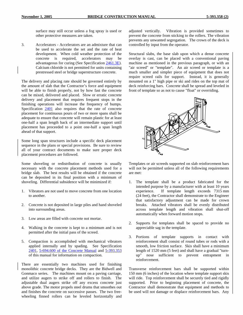
November 1, 2005 BRIDGE CONSTRUCTION MANUAL 5-393.358 (2)
surface may still occur unless a fog spray is used or other protective measures are taken.
3. Accelerators - Accelerators are an admixture that can
be used to accelerate the set and the rate of heat development. When cold weather protection of the concrete is required, accelerators may be advantageous for curing (See Specification 2461.3E). Calcium chloride is not permitted for units containing prestressed steel or bridge superstructure concrete.
The delivery and placing rate should be governed entirely by the amount of slab that the Contractor’s force and equipment will be able to finish properly, not by how fast the concrete can be mixed, delivered and placed. Slow or erratic concrete delivery and placement that requires frequent stops in the finishing operations will increase the frequency of bumps. Specification 2401 also requires that the rate of concrete placement for continuous pours of two or more spans shall be adequate to ensure that concrete will remain plastic for at least one-half a span length back of an intermediate support until placement has proceeded to a point one-half a span length ahead of that support. Some long span structures include a specific deck placement sequence in the plans or special provisions. Be sure to review all of your contract documents to make sure proper deck placement procedures are followed. Some shoveling or redistribution of concrete is usually necessary with the concrete placement methods used for a bridge slab. The best results will be obtained if the concrete can be deposited in its final position with a minimum of shoveling. Differential subsidence will be minimized if: 1. Vibrators are not used to move concrete from one location
to another. 2. Concrete is not deposited in large piles and hand shoveled
into surrounding areas. 3. Low areas are filled with concrete not mortar. 4. Walking in the concrete is kept to a minimum and is not
permitted after the initial pass of the screed. 5. Compaction is accomplished with mechanical vibrators
applied internally and by spading. See Specification 2401, 5-694.600 of the Concrete Manual and 5-393.353 of this manual for information on compaction.
There are essentially two machines used for finishing monolithic concrete bridge decks. They are the Bidwell and Gonmaco series. The machines mount on a paving carriage, and utilize augers to strike off and rollers to finish. The adjustable dual augers strike off any excess concrete just above grade. The motor propels steel drums that smoothes out and finishes the concrete on successive passes. The two free-wheeling finned rollers can be leveled horizontally and
adjusted vertically. Vibration is provided sometimes to prevent the concrete from sticking to the rollers. The vibration prevents any unwanted segregation. The crown of the deck is controlled by input from the operator. Structural slabs, the base slab upon which a dense concrete overlay is cast, can be placed with a conventional paving machine as mentioned in the previous paragraph, or with an "air screed" or "template". An air screed or template is a much smaller and simpler piece of equipment that does not require screed rails for support. Instead, it is generally mounted on a 1" high pipe or ski and rides on the top mat of deck reinforcing bars. Concrete shall be spread and leveled in front of template so as not to cause "float" or overriding. Templates or air screeds supported on slab reinforcement bars will not be permitted unless all of the following requirements are met: 1. The template shall be a product fabricated for the
intended purpose by a manufacturer with at least 10 years experience. If template length exceeds 7315 mm (24 feet), the Contractor shall demonstrate to the Engineer that satisfactory adjustment can be made for crown breaks. Attached vibrators shall be evenly distributed across template length and vibration shall shut-off automatically when forward motion stops.
2. Supports for templates shall be spaced to provide no
appreciable sag in the template. 3. Portions of template supports in contact with
reinforcement shall consist of round tubes or rods with a smooth, low friction surface. Skis shall have a minimum length of 1520 mm (5 feet) and shall have a gradual "turn-up" nose sufficient to prevent entrapment in reinforcement.
Transverse reinforcement bars shall be supported within 150 mm (6 inches) of the location where template support skis will ride. Top reinforcement shall be securely tied and rigidly supported. Prior to beginning placement of concrete, the Contractor shall demonstrate that equipment and methods to be used will not damage or displace reinforcement bars. Any
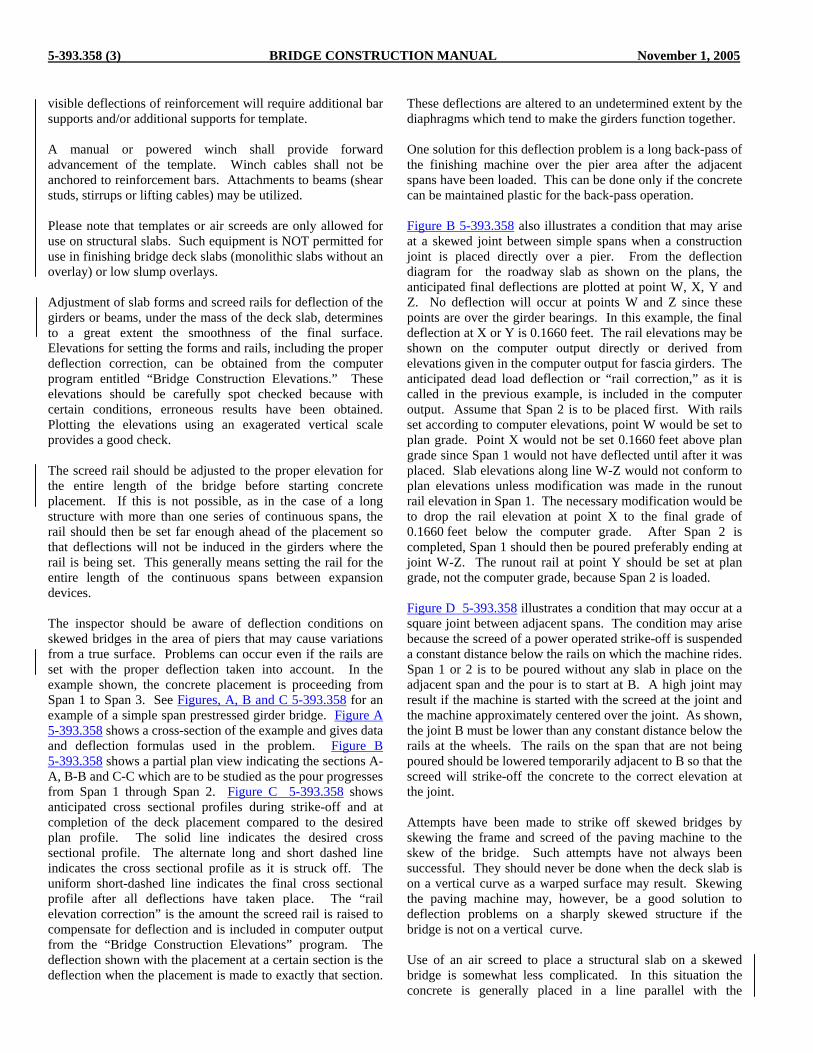
5-393.358 (3) BRIDGE CONSTRUCTION MANUAL November 1, 2005
visible deflections of reinforcement will require additional bar supports and/or additional supports for template. A manual or powered winch shall provide forward advancement of the template. Winch cables shall not be anchored to reinforcement bars. Attachments to beams (shear studs, stirrups or lifting cables) may be utilized. Please note that templates or air screeds are only allowed for use on structural slabs. Such equipment is NOT permitted for use in finishing bridge deck slabs (monolithic slabs without an overlay) or low slump overlays. Adjustment of slab forms and screed rails for deflection of the girders or beams, under the mass of the deck slab, determines to a great extent the smoothness of the final surface. Elevations for setting the forms and rails, including the proper deflection correction, can be obtained from the computer program entitled “Bridge Construction Elevations.” These elevations should be carefully spot checked because with certain conditions, erroneous results have been obtained. Plotting the elevations using an exagerated vertical scale provides a good check. The screed rail should be adjusted to the proper elevation for the entire length of the bridge before starting concrete placement. If this is not possible, as in the case of a long structure with more than one series of continuous spans, the rail should then be set far enough ahead of the placement so that deflections will not be induced in the girders where the rail is being set. This generally means setting the rail for the entire length of the continuous spans between expansion devices. The inspector should be aware of deflection conditions on skewed bridges in the area of piers that may cause variations from a true surface. Problems can occur even if the rails are set with the proper deflection taken into account. In the example shown, the concrete placement is proceeding from Span 1 to Span 3. See Figures, A, B and C 5-393.358 for an example of a simple span prestressed girder bridge. Figure A 5-393.358 shows a cross-section of the example and gives data and deflection formulas used in the problem. Figure B 5-393.358 shows a partial plan view indicating the sections A-A, B-B and C-C which are to be studied as the pour progresses from Span 1 through Span 2. Figure C 5-393.358 shows anticipated cross sectional profiles during strike-off and at completion of the deck placement compared to the desired plan profile. The solid line indicates the desired cross sectional profile. The alternate long and short dashed line indicates the cross sectional profile as it is struck off. The uniform short-dashed line indicates the final cross sectional profile after all deflections have taken place. The “rail elevation correction” is the amount the screed rail is raised to compensate for deflection and is included in computer output from the “Bridge Construction Elevations” program. The deflection shown with the placement at a certain section is the deflection when the placement is made to exactly that section.
These deflections are altered to an undetermined extent by the diaphragms which tend to make the girders function together. One solution for this deflection problem is a long back-pass of the finishing machine over the pier area after the adjacent spans have been loaded. This can be done only if the concrete can be maintained plastic for the back-pass operation. Figure B 5-393.358 also illustrates a condition that may arise at a skewed joint between simple spans when a construction joint is placed directly over a pier. From the deflection diagram for the roadway slab as shown on the plans, the anticipated final deflections are plotted at point W, X, Y and Z. No deflection will occur at points W and Z since these points are over the girder bearings. In this example, the final deflection at X or Y is 0.1660 feet. The rail elevations may be shown on the computer output directly or derived from elevations given in the computer output for fascia girders. The anticipated dead load deflection or “rail correction,” as it is called in the previous example, is included in the computer output. Assume that Span 2 is to be placed first. With rails set according to computer elevations, point W would be set to plan grade. Point X would not be set 0.1660 feet above plan grade since Span 1 would not have deflected until after it was placed. Slab elevations along line W-Z would not conform to plan elevations unless modification was made in the runout rail elevation in Span 1. The necessary modification would be to drop the rail elevation at point X to the final grade of 0.1660 feet below the computer grade. After Span 2 is completed, Span 1 should then be poured preferably ending at joint W-Z. The runout rail at point Y should be set at plan grade, not the computer grade, because Span 2 is loaded. Figure D 5-393.358 illustrates a condition that may occur at a square joint between adjacent spans. The condition may arise because the screed of a power operated strike-off is suspended a constant distance below the rails on which the machine rides. Span 1 or 2 is to be poured without any slab in place on the adjacent span and the pour is to start at B. A high joint may result if the machine is started with the screed at the joint and the machine approximately centered over the joint. As shown, the joint B must be lower than any constant distance below the rails at the wheels. The rails on the span that are not being poured should be lowered temporarily adjacent to B so that the screed will strike-off the concrete to the correct elevation at the joint. Attempts have been made to strike off skewed bridges by skewing the frame and screed of the paving machine to the skew of the bridge. Such attempts have not always been successful. They should never be done when the deck slab is on a vertical curve as a warped surface may result. Skewing the paving machine may, however, be a good solution to deflection problems on a sharply skewed structure if the bridge is not on a vertical curve. Use of an air screed to place a structural slab on a skewed bridge is somewhat less complicated. In this situation the concrete is generally placed in a line parallel with the

November 1, 2005 BRIDGE CONSTRUCTION MANUAL 5-393.358 (4)
substructure units and one or more air screeds are operated perpendicular to the centerline. In this situation care must be taken to ensure that the leading edge of concrete is not allowed to become excessively dry. Flared bridges with strike-off rails set on non-parallel girders present a problem. This is illustrated in Figure G 5-393.358. This problem occurs if the supporting wheels move out parallel to the bed of the machine as the machine operates in the flared area. One solution is to keep the slope of the machine or the transverse grade between the rails constant as the machine moves in the flared area. The computer elevations will have to be adjusted on the flared girder to maintain a constant grade between the rails. If the machine is moving from the narrow portion into the widened portion, the computer elevations would be adjusted as follows. The elevation of the rail as given by the computer should have an amount added to it equal to the product of the flare (distance “a” Figure G 5-393.358) times the crown (0.02 ft./ft.). From this, an amount equal to the product of the transverse slope of the machine times the flare width “a” is subtracted to obtain the correct rail elevation. If the machine moved from the wide portion to the narrow portion, the rail would have to be adjusted in a similar manner to maintain the slope of the machine constant and equal to the slope at the widest portion of the slab. Screeding equipment should be checked for trueness in cross sectional crown with a straightedge and corrected, if necessary, previous to each day’s pour. On larger bridges, a master straightedge should be requisitioned and kept at the bridge site for checking the equipment. After the screed rails have been set to correct elevation, the top reinforcement must be checked by the Contractor, in the presence of an inspector, for vertical position by operating the paving machine on the rails as required by Specification 2472.C2. The Specifications require that a filler strip, 6 mm (1/4 inch) less in thickness than the minimum concrete cover requirement, be attached to the bottom of the strike-off during this check as a means of detecting reinforcement bars which encroach on the required clearance. This requirement should be diligently enforced regardless of the type of machine that is used. If the cylinder type machine is used, some ingenuity may be required to use the required filler strip. One method is to attach the wood strip to the cylinder and hold the cylinder motionless with the wood strip on the bottom as it passes back and forth over the reinforcing. Other methods of attaching filler strips to cylinder machines may be used provided they will give a thorough check on the reinforcing placement. In addition, spot check measurements of the total slab thickness should be made during this dry run. Successful operation of the strike-off machine depends on the following items: 1. On bridge slabs, the amount of concrete to be placed
in the forms ahead of the strike-off is gauged by the foreman and puddlers. The first pass of the screed
should be considered a leveling or checking operation to assure a proper depth of concrete for the succeeding finishing passes. The screed should be stopped during the initial pass as necessary to shovel concrete into low areas. Shoveling concrete to depressions should not be left to be done on succeeding finishing passes. Excessively large rolls of concrete in front of the screed should be shoveled out or redistributed. When a large roll is carried in front of the screed, the roll should be shoveled out and revibrated before the screed is brought up to the new head. It will not be possible to define the end of previously vibrated concrete once the screed has passed over. See Figures E and F 5-393.358 for examples of correct and incorrect strike-off.
2. The finishing passes of the screed should be made at
a slow, uniform rate without stops and should cover as long a section as practicable. A continuous roll of concrete should always be carried ahead of the screed, and the size of the roll will usually decrease on successive passes.
The function of the longtudinal floating operation are as follows: 1. Compaction After the concrete is struck off, the aggregate particles
settle in the fluid concrete leaving the water on the top as shown in the sketches below.
This phenomenon of a water layer developing at the upper
concrete surface during subsidence or settlement is commonly known as bleeding. Bleeding is not normally a problem with a well designed air-entrained concrete mix and good slump control. As this surface water disappears, the concrete settles slightly into its final surface contour. The settlement may be more or less in different areas depending on how evenly the mortar is distributed. Areas with the most coarse aggregate will settle the least. This differential settlement is aggravated by reinforcement bars near the concrete surface of roadway slabs, as shown in the sketch following.
Section BeforeSettlement
Water layer
Section AfterSettlement
Influence of Top Baron Subsidence
Original surface Surface aftersubsidence

5-393.359 BRIDGE CONSTRUCTION MANUAL November 1, 2005
Cracks may develop directly above the reinforcement bars and a horizontal cleavage plane may develop at these reinforcement bars. Longitudinal floating at the proper time will recompact the top aggregate and the concrete mass adjacent to the bars. This will help prevent the cracking and formation of the cleavage plane. The longitudinal floating should be delayed as long as practicable but must be completed while the surface mortar is still plastic if optimum results are to be attained. Due to its length and its overlapping operation over the entire roadway surface, the float detects and removes ripples and other irregularities left by the screed. A typical manually operated longitudinal (Iowa) float may be a heavy plank equipped with plow handles at its ends for manipulation. The plank should be at least 3000 mm (10 feet) long and at least 180 mm (7 inches) wide. It should be braced or reinforced to resist warping so that the surface in contact with the concrete remains a plane surface. Suitable work bridges must be provided from which to operate the float. These work bridges should be readily movable and constructed to be reasonably free from wobble or excessive deflection when used by the float operators. The float should always be operated with its length parallel to the centerline of roadway regardless of the direction of the screeding operation (transverse or longitudinal). In operation, the manually-operated longitudinal float rests on the concrete surface at one curb line with its length parallel to the curb line. It is then sawed back and forth a short distance and at the same time moved transversely across the roadway slab toward the other curb line, similar to a screeding operation. The concrete should support the mass of the longitudinal float. The float should not be tilted on edge during this operation. The operation is then repeated by returning the float over the same area to the starting position. The float is then moved one-half its length toward the head of the concrete and the operation repeated. Successive overlapping passes are made until the entire length of the placement has been covered but always staying as far behind the strike-off as the set of the concrete will permit. The effectiveness of the longitudinal floating operation is largely dependent on timing. The operation should commence after most of the differential settlement has occurred in the concrete surface but before the initial set has hardened the concrete to such a degree that the float will not be effective. Although the motion of the longitudinal float is a screeding motion, screeds rest on rigid rails or guides whereas the manually operated longitudinal float is supported on the concrete surface. If the floating operation is performed too soon the float will dig, be unmanageable, and the surface smoothness may be impaired rather than improved. Specification 2401 requires longitudinal floating after most of the plastic shrinkage has taken place. A visual gauge indicating the progress of plastic shrinkage is the water sheen on the surface. When the water sheen begins to leave the surface, the proper degree of set has occurred, and the longitudinal floating should begin. On hot drying days, the
water sheen may appear and disappear in a short interval of time and should be watched very closely. When the operation is performed too soon, the bleed water may be worked back into the surface mortar, resulting in a very weak surface which will likely start scaling at an early age. When it is repeatedly necessary to cut large bumps with the longitudinal float, there is obviously something wrong in the screeding portion of the work. Modifications should be made in the screeding operation to alleviate the problem. Additional rail supports may be necessary if the problem is created by deflection between supports. 5-393.359 FINISHING BRIDGE ROADWAY SLABS Small finishing tools should be used only where necessary. The indiscriminiate use of hand floats, long handled floats, or darbies should not be permitted. Such tools may be used to remove trails or ridges left by the longitudinal float, to correct areas where a checking straightedge has detected irregularities and to finish areas adjacent to the curbs or screed rails if such areas cannot be finished with the longitudinal float. Repeated reworking of a surface which has already been properly finished will result in a thick mortar layer at the surface of the concrete. It may also result in the sealing of bleed water under the concrete surface which is undesirable. A 3 m (10 ft) long wooden straightedge should be used for checking the slab surface. This straightedge should be used for checking purposes only and not used as a scraping straightedge for finishing. The final check on the surface should be made immediately behind the longitudinal floating and also immediately behind the hand finishing at the gutter lines so that out-of-tolerance areas may be promptly corrected. The straightedge should be set on the slab longitudinally and the full width of the slab (usually from curb to curb) should be spot checked at various locations. In addition, the straightedge may be transversely placed near the curbs, where hand finishing is involved, to assure that the proper crown section has been obtained. The straightedge should be picked up each time it is moved so as not to mar the concrete unnecessarily. If the finishing has been conducted properly and in accordance with the Specifications, only occasional minor irregularities will be detected during this spot checking.

November 1, 2005 BRIDGE CONSTRUCTION MANUAL Figure A & B 5-393.358
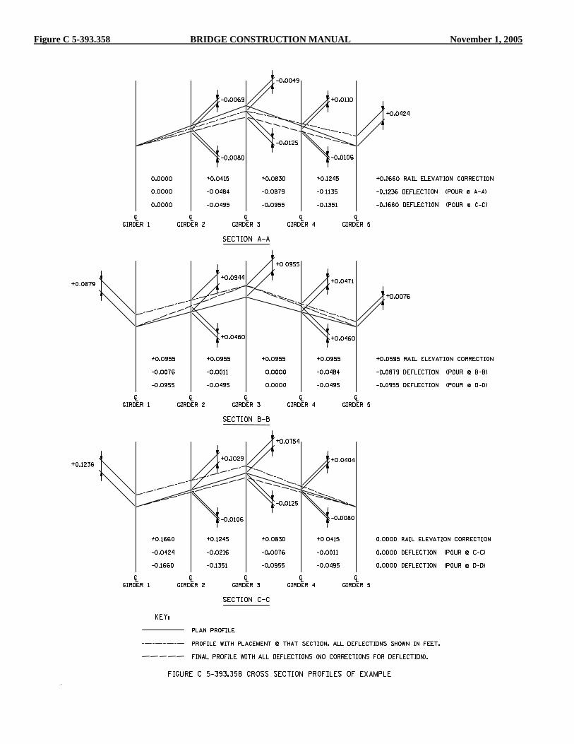
Figure C 5-393.358 BRIDGE CONSTRUCTION MANUAL November 1, 2005

November 1, 2005 BRIDGE CONSTRUCTION MANUAL Figure D, E & F 5-393.358
(Stop screed short of head of concrete, and do not permit mortar roll to be spilled overhead of concrete. Leave small rolls, mix large rolls with fresh concrete as it is deposited.)
(Make head of concrete parallel to screed before operating screed from A to B.)
Dotted Line A-B-C = Position of rails on which finishing machine travels before concrete slab is placed.Solid Line D-B-E = Desired position of rails with concrete slab in place on spans 1 & 2.
Fig. F CORRECT AND INCORRECT MORTAR ROLL
Fig. E PLAN VIEW OF CORRECT AND INCORRECT PLACEMENT
Fig. D RAIL POSITIONING FOR PLACEMENT STARTING AT A PIER
Screed Screed
Form Form
CORRECT INCORRECT
Mortar rollMortar rollHead of
concreteSlab Slab Head ofconcrete
Screed travelScreed travel
Head ofconcrete
Head ofconcrete
INCORRECTCORRECT
ScreedScreed
SlabSlab
AA BB
E
C
B
C Pier
Span 2Span 1
A
D
Wheel base offinishing machine
L

Figure G 5-393.358 BRIDGE CONSTRUCTION MANUAL November 1, 2005
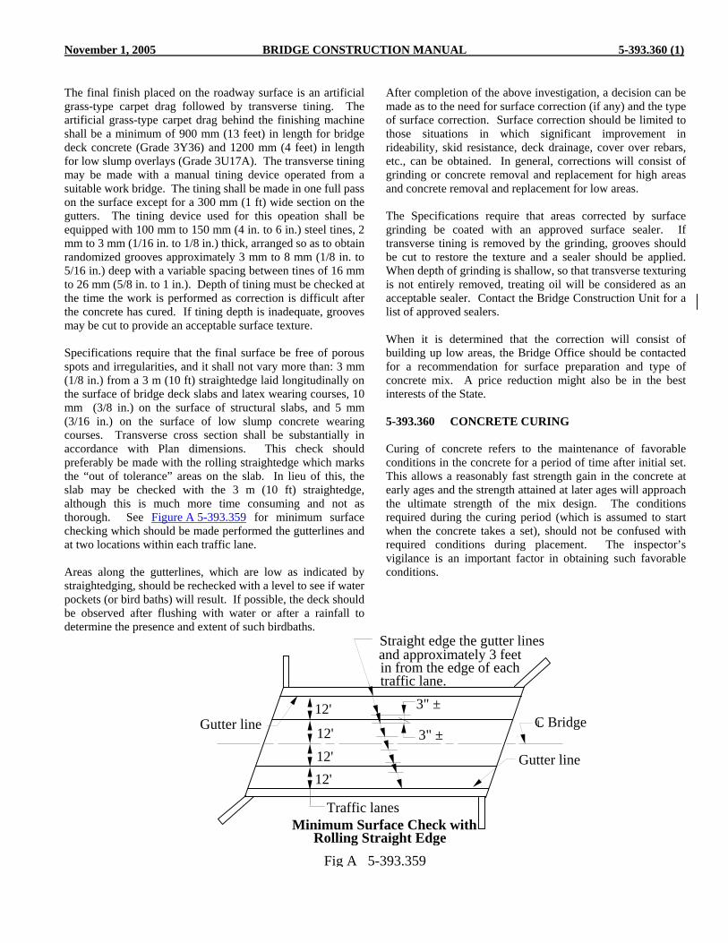
November 1, 2005 BRIDGE CONSTRUCTION MANUAL 5-393.360 (1)
The final finish placed on the roadway surface is an artificial grass-type carpet drag followed by transverse tining. The artificial grass-type carpet drag behind the finishing machine shall be a minimum of 900 mm (13 feet) in length for bridge deck concrete (Grade 3Y36) and 1200 mm (4 feet) in length for low slump overlays (Grade 3U17A). The transverse tining may be made with a manual tining device operated from a suitable work bridge. The tining shall be made in one full pass on the surface except for a 300 mm (1 ft) wide section on the gutters. The tining device used for this opeation shall be equipped with 100 mm to 150 mm (4 in. to 6 in.) steel tines, 2 mm to 3 mm (1/16 in. to 1/8 in.) thick, arranged so as to obtain randomized grooves approximately 3 mm to 8 mm (1/8 in. to 5/16 in.) deep with a variable spacing between tines of 16 mm to 26 mm (5/8 in. to 1 in.). Depth of tining must be checked at the time the work is performed as correction is difficult after the concrete has cured. If tining depth is inadequate, grooves may be cut to provide an acceptable surface texture. Specifications require that the final surface be free of porous spots and irregularities, and it shall not vary more than: 3 mm (1/8 in.) from a 3 m (10 ft) straightedge laid longitudinally on the surface of bridge deck slabs and latex wearing courses, 10 mm (3/8 in.) on the surface of structural slabs, and 5 mm (3/16 in.) on the surface of low slump concrete wearing courses. Transverse cross section shall be substantially in accordance with Plan dimensions. This check should preferably be made with the rolling straightedge which marks the “out of tolerance” areas on the slab. In lieu of this, the slab may be checked with the 3 m (10 ft) straightedge, although this is much more time consuming and not as thorough. See Figure A 5-393.359 for minimum surface checking which should be made performed the gutterlines and at two locations within each traffic lane. Areas along the gutterlines, which are low as indicated by straightedging, should be rechecked with a level to see if water pockets (or bird baths) will result. If possible, the deck should be observed after flushing with water or after a rainfall to determine the presence and extent of such birdbaths.
After completion of the above investigation, a decision can be made as to the need for surface correction (if any) and the type of surface correction. Surface correction should be limited to those situations in which significant improvement in rideability, skid resistance, deck drainage, cover over rebars, etc., can be obtained. In general, corrections will consist of grinding or concrete removal and replacement for high areas and concrete removal and replacement for low areas. The Specifications require that areas corrected by surface grinding be coated with an approved surface sealer. If transverse tining is removed by the grinding, grooves should be cut to restore the texture and a sealer should be applied. When depth of grinding is shallow, so that transverse texturing is not entirely removed, treating oil will be considered as an acceptable sealer. Contact the Bridge Construction Unit for a list of approved sealers. When it is determined that the correction will consist of building up low areas, the Bridge Office should be contacted for a recommendation for surface preparation and type of concrete mix. A price reduction might also be in the best interests of the State. 5-393.360 CONCRETE CURING Curing of concrete refers to the maintenance of favorable conditions in the concrete for a period of time after initial set. This allows a reasonably fast strength gain in the concrete at early ages and the strength attained at later ages will approach the ultimate strength of the mix design. The conditions required during the curing period (which is assumed to start when the concrete takes a set), should not be confused with required conditions during placement. The inspector’s vigilance is an important factor in obtaining such favorable conditions.
Minimum Surface Check withRolling Straight Edge
Straight edge the gutter lines and approximately 3 feet in from the edge of each traffic lane.
Gutter line
Gutter line
Traffic lanes
C Bridge 3" ±
3" ±
12'
12'
12' 12'
L
Fig A 5-393.359

5-393.360 (2) BRIDGE CONSTRUCTION MANUAL November 1, 2005
Favorable conditions that must be maintained during the curing period are: 1. Sufficient water for hydration of the cement must be
present. Sufficient water will be available if evaporation of the mixing water is prevented or minimized. Curing of unformed surfaces should start as soon as the curing material can be placed without marring the surface. On formed surfaces that are stripped for surface finishing before the end of the curing period, the surface finishing should be done without delay and the curing resumed immediately.
2. The concrete must be protected from the effects of
low temperatures, high temperatures and extremely rapid temperature changes. Permanent damage will result if the concrete is frozen in the early stages of cure. The temperature should be maintained at the required temperature or higher during the curing period because of the loss in durability and slow strength gain at lower temperatures. At the end of the curing period, when protection from low temperatures has been provided, the concrete temperature must be lowered gradually to avoid contraction stresses and possible cracks. Large differential temperatures between the surface and the interior of a concrete unit must be minimized for the same reason. See Specification 2401.3G for limitations on the rate of temperature decrease.
3. During the early part of the curing period when the
concrete has little strength, it must also be protected from excessive vibrations, heavy shocks or application of loads.
The period of time during which favorable conditions for a gain in strength and durability is maintained is referred to as the “curing period.” The curing period must start at the time the concrete takes a set and ideally be continuous throughout the specified duration. Certain finishing operations and unpredictable temperature variations may break the continuity of the curing period, but these interruptions should be limited to a few hours. In general, the curing method shall provide temperatures above the specified minimum and shall prevent loss of the original moisture from the concrete. The method to be used is optional for the Contractor except for restrictions which are placed on the use of membrane curing compound. Curing compounds cannot be applied until the free water has disappeared from the surface of the deck. Methods which are considered to be satisfactory are as follows: 1. Burlap Curing Blanket Plastic sheeting over a layer of wet burlap or a wet burlap
curing blanket is a method of cure in which the loss of
mixing water is minimized due to the tight nature of the cover. The plastic sheeting or plastic blankets must overlap at the seams to maintain a reasonably air tight seal. On substructure units they should be held in this position by wire or rope fasteners. They should be held in position on roadway and sidewalk slabs by holding down the blankets with sand or lumber at the joints and edges. When used as a method of cure for roadway slabs or sidewalks, the plastic sheeting should preferably be white. This color will reflect heat and reduce surface cracking due to high temperatures. Black plastic blankets may be desirable for cold weather protection when additional heat is beneficial.
Burlap is desirable since it has the ability to act as a wick
to distribute moisture uniformly over the surface. Burlap must be placed in close contact with the concrete and water must be added as necessary to assure that the concrete surface is moist at all times.
When plastic sheeting or plastic blankets are used over
areas where reinforcement dowels have been placed, it is very difficult to obtain an air tight seal in contact with the concrete surface. One method of cure at such locations is to place wet burlap in the dowel bar area, drape plastic over the tops of the dowels, and weigh down the plastic adjacent to the dowel areas. Another method is to puncture the plastic sheeting and place it directly over the burlap with the dowels projecting through the plastic sheeting. The important thing is that the burlap should not be permitted to dry out during the curing period.
2. Water Spray The amount of water applied in the water spray method
should be limited to the amount that will keep the concrete wet without running sheets or streams. The location of the sprays should be such that there are no skips or holidays on the concrete surface. This may be accomplished with soaker hoses or sprinklers. Mineral and/or organic compounds in the water may stain the concrete and require corrective action.
3. Membrane Curing Compound Membrane Curing Compound (Specification 3754) is a
liquid membrane forming compound suitable for approved sprayer application to retard the loss of water in concrete during the early strength gaining period. The common types in use for pavement, sidewalk, curb and gutter, and low slump concrete wearing courses is a resin based, white pigment membrane curing compound. The approved sprayer shall have a recirculating by-pass system which provides for continuous agitation of the reservoir material, separate hose and nozzle filters and a multiple or adjustable nozzle system that will provide for variable spray patterns. The membrane curing compound shall be sprayed on the concrete after finishing operations have been completed and as soon as surfacing conditions permit. Low slump concrete wearing courses require spraying within 30 minutes. The sprayed areas shall present a white, uniform surface, and any imperfections

November 1, 2005 BRIDGE CONSTRUCTION MANUAL 5-393.360 (3)
shall be resprayed. The rate of application shall be approximately 4 m2/L (150 ft2/gal.).
Approved linseed oil curing compounds or emulsions
(Specification 2401.3G) shall be applied on bridge decks except those which are to receive latex or low slump wearing course. Presently the only materials approved are linseed oil curing emulsions. The approved emulsions are water based and must be protected from freezing. The linseed oil curing emulsion is to be applied by power sprayers only. This curing method is temporary and conventional curing (wet curing, blankets, etc.) shall be applied as soon as possible.
Specification 2401.3G permits membrane curing
compounds for such items as slope paving, footings and other sections that are to be covered with backfill materials. For those applications, conventional wet curing methods are not required after the membrane curing has been applied. Membrane curing compounds will act as a parting agent. Therefore, it cannot be used where subsequent bonded concrete will be placed or for surfaces that are to be waterproofed, treated with concrete treating oil, or are to receive a special surface finish.
All materials sprayed on the surface of the concrete for
water retention are to be applied at the approximate rate of 4 m2/L (150 ft2/gal.). This is easily determined by placing a known quantity in the sprayer, applying uniformly, and measuring the area covered after the known quantity has been used. Additional coverage shall be required if it is not placed at the required rate or if skips or holidays are present.
Plastic shrinkage of concrete during setting may cause surface cracks to appear about the time the concrete is ready to be finished. Such cracking may develop at any time when circumstances produce an evaporation rate greater than the bleeding rate. The major difficulty occurs in the summer on deck placements, particularly if the humidity is low and evaporation is accelerated by the wind. The following conditions tend to produce high evaporation rates: 1. Large surface areas such as deck slabs 2. Concrete of low bleeding tendency (This is not meant to
suggest that bleeding, which is undesirable for other reasons, should be encouraged to prevent plastic cracking.)
3. Low humidity 4. High concrete surface temperature 5. Wind
Methods of alleviating rapid evaporation include cooling the mixing water, avoiding excessive mixing, prompt placement, erecting wind breaks, the use of fog sprays to maintain high humidity directly over the concrete or applying a spray-on monomolecular film. See Specification 2401 for requirements on the use of fog spray. The use of a fog spray should be initiated at the first indication of surface dryness. Any delay after surface dryness is noted will almost certainly result in crack development. To help determine when a fog spray may be necessary, the American Concrete Institute has developed a nomograph to determine the approximate rate of evaporation based on current weather conditions, see Figure A 5-393.360. The following weather conditions and temperatures must be observed to use the graph to determine the amount of evaporation: 1. Air Temperature 2. Relative humidity 3. Surface temperature of the concrete 4. Wind velocity Concrete bleeding rates generally lie in the range of about 0.5-1.5 kg per square meter per hour (0.1-0.3 lb/ft2 hr). When the evaporation rate exceeds the lower of these figures, there is a potential for plastic cracking. Conditions which produce evaporation rates of 1.0-1.5 kg per square meter per hour (0.2-0.3 lb/ft2 hr) make the use of precautionary measures such as the fog spray almost mandatory. In lieu of the fog spray, the Contractor may be permitted to apply an approved membrane curing compound to reduce evaporation. The use of this material should be encouraged. Specification 2401.3G requires curing to continue until a specified “Anticipated Compressive Strength” has been attained. This strength is computed from Table 2401-1 which gives the incremental percentage of strength gain in 24 hours for various concrete surface temperatures. As surface temperatures vary within a 24 hour curing period, the average temperature is computed from measurements taken on the concrete surface at different times of the day. The average temperatures for each 24 hour curing period is computed separately. Once the average temperature has been determined, the incremental strength gain for the first 24 hours is selected from Table 2401-1. The average temperature for the second 24 hour period is used to select the percent of strength gain for the second period and this percent is added to the strength gain for the first period to determine the total percent of strength gain after 48 hours. This process is repeated using the average temperature for the third 24 hour period and the 48 hour strength gain, the average temperature for the fourth 24 hour period and the 72 hour strength gain,
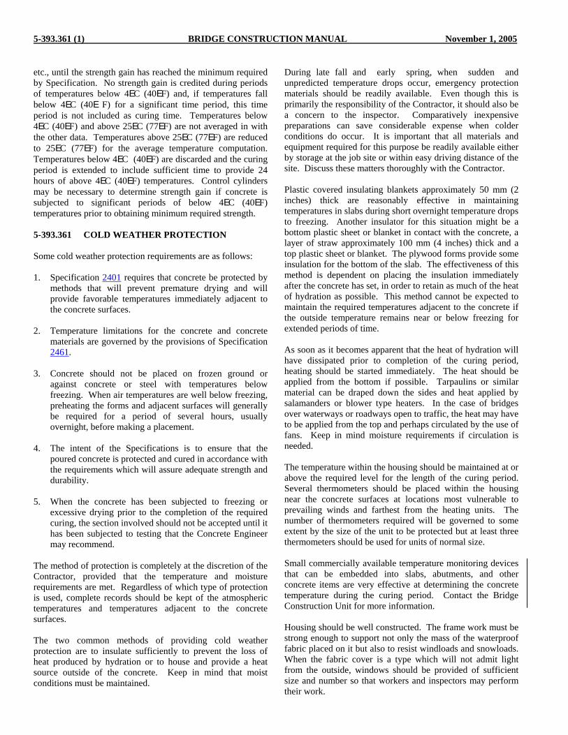
5-393.361 (1) BRIDGE CONSTRUCTION MANUAL November 1, 2005
etc., until the strength gain has reached the minimum required by Specification. No strength gain is credited during periods of temperatures below 4EC (40EF) and, if temperatures fall below 4EC (40E F) for a significant time period, this time period is not included as curing time. Temperatures below 4EC (40EF) and above 25EC (77EF) are not averaged in with the other data. Temperatures above 25EC (77EF) are reduced to 25EC (77EF) for the average temperature computation. Temperatures below 4EC (40EF) are discarded and the curing period is extended to include sufficient time to provide 24 hours of above 4EC (40EF) temperatures. Control cylinders may be necessary to determine strength gain if concrete is subjected to significant periods of below 4EC (40EF) temperatures prior to obtaining minimum required strength. 5-393.361 COLD WEATHER PROTECTION Some cold weather protection requirements are as follows: 1. Specification 2401 requires that concrete be protected by
methods that will prevent premature drying and will provide favorable temperatures immediately adjacent to the concrete surfaces.
2. Temperature limitations for the concrete and concrete
materials are governed by the provisions of Specification 2461.
3. Concrete should not be placed on frozen ground or
against concrete or steel with temperatures below freezing. When air temperatures are well below freezing, preheating the forms and adjacent surfaces will generally be required for a period of several hours, usually overnight, before making a placement.
4. The intent of the Specifications is to ensure that the
poured concrete is protected and cured in accordance with the requirements which will assure adequate strength and durability.
5. When the concrete has been subjected to freezing or
excessive drying prior to the completion of the required curing, the section involved should not be accepted until it has been subjected to testing that the Concrete Engineer may recommend.
The method of protection is completely at the discretion of the Contractor, provided that the temperature and moisture requirements are met. Regardless of which type of protection is used, complete records should be kept of the atmospheric temperatures and temperatures adjacent to the concrete surfaces. The two common methods of providing cold weather protection are to insulate sufficiently to prevent the loss of heat produced by hydration or to house and provide a heat source outside of the concrete. Keep in mind that moist conditions must be maintained.
During late fall and early spring, when sudden and unpredicted temperature drops occur, emergency protection materials should be readily available. Even though this is primarily the responsibility of the Contractor, it should also be a concern to the inspector. Comparatively inexpensive preparations can save considerable expense when colder conditions do occur. It is important that all materials and equipment required for this purpose be readily available either by storage at the job site or within easy driving distance of the site. Discuss these matters thoroughly with the Contractor. Plastic covered insulating blankets approximately 50 mm (2 inches) thick are reasonably effective in maintaining temperatures in slabs during short overnight temperature drops to freezing. Another insulator for this situation might be a bottom plastic sheet or blanket in contact with the concrete, a layer of straw approximately 100 mm (4 inches) thick and a top plastic sheet or blanket. The plywood forms provide some insulation for the bottom of the slab. The effectiveness of this method is dependent on placing the insulation immediately after the concrete has set, in order to retain as much of the heat of hydration as possible. This method cannot be expected to maintain the required temperatures adjacent to the concrete if the outside temperature remains near or below freezing for extended periods of time. As soon as it becomes apparent that the heat of hydration will have dissipated prior to completion of the curing period, heating should be started immediately. The heat should be applied from the bottom if possible. Tarpaulins or similar material can be draped down the sides and heat applied by salamanders or blower type heaters. In the case of bridges over waterways or roadways open to traffic, the heat may have to be applied from the top and perhaps circulated by the use of fans. Keep in mind moisture requirements if circulation is needed. The temperature within the housing should be maintained at or above the required level for the length of the curing period. Several thermometers should be placed within the housing near the concrete surfaces at locations most vulnerable to prevailing winds and farthest from the heating units. The number of thermometers required will be governed to some extent by the size of the unit to be protected but at least three thermometers should be used for units of normal size. Small commercially available temperature monitoring devices that can be embedded into slabs, abutments, and other concrete items are very effective at determining the concrete temperature during the curing period. Contact the Bridge Construction Unit for more information. Housing should be well constructed. The frame work must be strong enough to support not only the mass of the waterproof fabric placed on it but also to resist windloads and snowloads. When the fabric cover is a type which will not admit light from the outside, windows should be provided of sufficient size and number so that workers and inspectors may perform their work.

November 1, 2005 BRIDGE CONSTRUCTION MANUAL Figure A 5-393.360
0
5 (3)
10 (6)
15 (9)
20 (12)
25 (16)
35 (22)
30 (19)
0
0.5 (0.1)
1.0 (0.2)
1.5 (0.3)
2.0 (0.4)
2.5 (0.5)
3.0 (0.6)
3.5 (0.7)
4.0 (0.8)
Rat
e of
Eva
pora
tion
kg/m
/hr
(lb
/ft /
hr)
22
Surface Evaporation From Concrete
To estimate evaporation rate:
1. Enter chart at appropriate airtemperature and relative humidity above.
2. Move right to line corresp-onding to the concretetemperature.
3. Move down to lineapproximating the windvelocity.
4. Read evaporation rateon scale to left of this point.
5 (41) 10 (50) 15 (59) 20 (68) 25 (77) 30 (86)
100
9080
7060
5040
30
20
10
035 (95)
Air Temperature C ( F)
5 (41)10 (50)
15 (59)
20 (68)
25 (77)
30 (86)
35 (95)
Wind Velocity km/hr (mph)
Surface Temperatureof Concrete C ( F)
Relative Humidity %
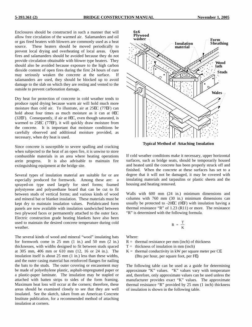
5-393.361 (2) BRIDGE CONSTRUCTION MANUAL November 1, 2005
Enclosures should be constructed in such a manner that will allow free circulation of the warmed air. Salamanders and oil or gas fired heaters with blowers are commonly used as a heat source. These heaters should be moved periodically to prevent local drying and overheating of local areas. Open fires and salamanders should be avoided because they do not provide circulation obtainable with blower type heaters. They should also be avoided because exposure to the high carbon dioxide content of open fires during the first 24 hours of cure may seriously weaken the concrete at the surface. If salamanders are used, they should be blocked up to avoid damage to the slab on which they are resting and vented to the outside to prevent carbonation damage. Dry heat for protection of concrete in cold weather tends to produce rapid drying because warm air will hold much more moisture than cold air. To illustrate, air at 25EC (77EF) can hold about four times as much moisture as it can at 0EC (32EF). Consequently, if air at 0EC, even though saturated, is warmed to 25EC (77EF), it will quickly draw moisture from the concrete. It is important that moisture conditions be carefully observed and additional moisture provided, as necessary, when dry heat is used. Since concrete is susceptible to severe spalling and cracking when subjected to the heat of an open fire, it is unwise to store combustible materials in an area where heating operations arein progress. It is also advisable to maintain fire extinguishing equipment at the bridge site. Several types of insulation material are suitable for or are especially produced for formwork. Among these are: a sprayed-on type used largely for steel forms; foamed polystyrene and polyurethane board that can be cut to fit between studs of vertical forms; and various kinds of wood and mineral bat or blanket insulation. These materials must be kept dry to maintain insulation values. Prefabricated form panels are now available with insulation sandwiched between two plywood faces or permanently attached to the outer face. Electric construction grade heating blankets have also been used to maintain the desired concrete temperature during cold weather. The several kinds of wood and mineral “wool” insulating bats for formwork come in 25 mm (1 in.) and 50 mm (2 in.) thicknesses, with widths designed to fit between studs spaced at 305 mm, 406 mm or 610 mm (12, 16 or 24 in.). The insulation itself is about 25 mm (1 in.) less than these widths, and the outer casing material has reinforced flanges for nailing the bats to the studs. The outer covering or encasement may be made of polyethylene plastic, asphalt-impregnated paper or a plastic-paper laminate. The insulation may be stapled or attached with batten strips to sides of the form framing. Maximum heat loss will occur at the corners; therefore, these areas should be examined closely to see that they are well insulated. See the sketch, taken from an American Concrete Institute publication, for a recommended method of attaching insulation at corners.
If cold weather conditions make it necessary, upper horizontal surfaces, such as bridge seats, should be temporarily housed and heated until the concrete has been properly struck off and finished. When the concrete at these surfaces has set to a degree that it will not be damaged, it may be covered with insulating materials and tarpaulins or plastic sheets and the housing and heating removed. Walls with 600 mm (24 in.) minimum dimensions and columns with 760 mm (30 in.) minimum dimensions can usually be protected to -20EC (0EF) with insulation having a thermal resistance “R” of 1.23 (R11) or more. The resistance “R” is determined with the following formula.
R = TK
Where: R = thermal resistance per mm (inch) of thickness T = thickness of insulation in mm (inch) K = thermal conductivity in kW per square meter per CE (Btu per hour, per square foot, per FE) The following table can be used as a guide for determining approximate “K” values. “K” values vary with temperature and, therefore, only approximate values can be used unless the manufacturer provides exact “K” values. The approximate thermal resistance “R” provided by 25 mm (1 inch) thickness of insulation is shown in the following table.
Typical Method of Attaching Insulation
6x6Plywoodwasher
Insulationmaterial
FormSheathing
WoodlathStuds
Wales
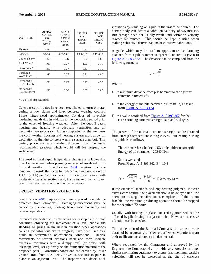
November 1, 2005 BRIDGE CONSTRUCTION MANUAL 5-393.362 (1)
MATERIAL
APPRX “K” PER
mm THICK-NESS
APPRX “K” PER 1 INCH THICK-NESS
“R” PER mm
THICK-NESS
“R” PER 1 INCH THICK-NESS
Plywood 4.5 0.80 0.22 1.25 Concrete 30-50 6.00-9.00 0.03-0.02 0.17-0.11 Cotton Fiber * 1.50 0.26 0.67 3.85 Rock Wool * 1.00 0.27 1.00 3.70 Glass Wool * 1.50 0.27 0.67 3.70 Expanded Wood Fiber 1.40 0.25 0.71 4.00
Polystyrene (High Density) 1.30 0.23 0.77 4.35
Polystyrene (Low Density) 1.50 0.26 0.67 3.85
* Blanket or Bat Insulation Calendar cut-off dates have been established to ensure proper curing of low slump and latex concrete wearing courses. These mixes need approximately 30 days of favorable hardening and drying in addition to the wet curing period prior to the onset of freezing weather. After the cut-off dates, housing and heating with adequate ventilation and air circulation are necessary. Upon completion of the wet cure, the cold weather housing and heating system must allow air circulation so that the concrete wearing surface dries out. This curing procedure is somewhat different from the usual recommended practice which would call for keeping the surface wet. The need to limit rapid temperature changes is a factor that must be considered when planning removal of insulated forms in cold weather. Specification 2401 requires that the temperature inside the forms be reduced at a rate not to exceed 10EC (20EF) per 12 hour period. This is most critical with moderately massive sections and, for massive units, a slower rate of temperature reduction may be necessary. 5-393.362 VIBRATION PROTECTION Specification 2401 requires that newly placed concrete be protected from vibrations. Damaging vibrations may be caused by pile driving, blasting, heavy road machinery and railroad operations. Empirical methods such as observing water ripples in a small container, observing the movement of a level bubble and standing on piling in the unit in question when operations causing the vibrations are in progress, have been used as a guide in determining objectionable vibrations. Bubble movements of several divisions back and forth indicate excessive vibrations with a dumpy level (or transit with telescope level) set up firmly on the foundation material of the proposed pour. Sometimes vibrations are carried by lower ground strata from piles being driven in one unit to piles in place in an adjacent unit. The inspector can detect such
vibrations by standing on a pile in the unit to be poured. The human body can detect a vibration velocity of 0.5 mm/sec. But damage does not usually result until vibration velocity reaches 50 mm/sec. This should be kept in mind when making subjective determinations of excessive vibrations. A guide which may be used to approximate the damping distance from a pile hammer to “green” concrete is given in Figure A 5-393.362. The distance can be computed from the following formula:
D = EF
Where: D = minimum distance from pile hammer to the “green”
concrete in meters (ft). E = the energy of the pile hammer in N·m (ft-lb) as taken
from Figure A 5-393.164. F = a value obtained from Figure A 5-393.362 for the
corresponding concrete strength gain and soil type. The percent of the ultimate concrete strength can be obtained from strength temperature curing curves. An example using this guide is as follows: The concrete has obtained 16% of its ultimate strength. Energy of pile hammer - 20340 N·m Soil is wet sand From Figure A 5-393.362 F = 10.8
D = 2034010.8
= 142.610.8
= 13.2 m, say 13 m
If the empirical methods and engineering judgment indicate excessive vibration, the placement should be delayed until the operation causing the vibration is completed. If this is not feasible, the vibration producing operation should be stopped for the required 72 hours. Usually, with footings in place, succeeding pours will not be affected by pile driving in adjacent units. However, excessive vibration can be checked. The cooperation of the Railroad Company can sometimes be obtained by requesting a “slow order” when vibrations from their traffic are considered to be detrimental. Where requested by the Contractor and approved by the Engineer, the Contractor shall provide seismographs or other similar monitoring equipment to assure that maximum particle velocities will not be exceeded at the site of concrete

5-393.362 (2) BRIDGE CONSTRUCTION MANUAL November 1, 2005
placement operations. Monitoring equipment shall be securely attached next to, or on, the freshly placed concrete at a location of maximum exposure to the source of vibrations. The actual measuring point should either be buried in the soil adjacent to the structure, or grouted or mechanically fastened (bolted) to the structure or form. The following maximum peak particle velocities are considered safe for newly placed concrete (“maximum” refers to the maximum of three mutually perpendicular transducer components).
Concrete Age (hrs) Allowable Maximum Peak Particle Velocity (mm/sec)
0-3 NA
3-12 25
12-24 38
24-48 63
48- * CP 100
*Completion of required curing period. The above vibration limits are intended for the protection of newly poured concrete only. These limits do not relieve the Contractor from complying with any other vibration limits that may be in force on the project, nor do they relieve the Contractor from responsibility for damage to any existing structures (on or off the right-of-way) that may be affected by the vibration producing activity. While the above vibration levels are considered safe for newly placed concrete, they are higher than what is normally allowed for older buildings and structures. If damage occurs, such as cracking of the concrete or deterioration of support rock below footings, at less than the maximum particle velocities allowed above, the Contractor shall suspend the activity causing detrimental vibrations until necessary protection for the concrete has been installed. Seismographic equipment is not required when operations that may be detrimental to concrete during the curing period are not conducted so near the concrete to cause noticeable shocks or vibrations. As a general rule, vibration levels will not be of concern until they reach a level where they are clearly perceptible by a person standing adjacent to the structure in question. Specification 2401 prohibits the operation of heavy equipment which causes detrimental shock waves during placement and curing of concrete. The inspector should be careful to prohibit the use of any equipment on the deck during the specified time interval that may cause disturbing vibrations in areas where the concrete has not attained the minimum required strength.
Attention is directed to Specification 1513 for limitations and requirements on construction equipment crossing or operating on new or old bridges. Permission to use ready-mix trucks to discharge concrete directly into curb or railing forms on steel beam or prestressed girder spans should not be granted until the following requirement is met. Strength gain computations or control cylinders cast with the last pour must show strengths of not less than 65 percent of anticipated 28 day compressive strength (70 percent during adverse weather). On simple spans, the strength requirement should be applied to the span on which the truck operates and to the span on either side. This same criteria should be applied to truck loads of reinforcement bars, form lumber, etc. The turning of ready-mix trucks on bridge decks should be avoided. If the truck must return to the same end of the bridge for successive loads, the truck is usually driven to the point of discharge, unloaded and then backed off the bridge or vice versa. Speeds should be slow and the sudden application of brakes avoided. Mixers should be restricted to agitating speeds. In general, the use of a crane on a bridge deck should be discouraged because of the many indeterminate factors in the stress analysis and the rigid enforcement required during the operation. Under certain conditions the use of a crane on the bridge deck may be the only feasible method of construction. The Bridge Construction and Maintenance Section should then be contacted and an analysis of the Contractor's proposed scheme will be made by the Bridge Design Section. If permission is granted to operate a crane on the deck of an in place bridge, the crane should be positioned to minimize stresses in the slab and beams. See the following sketch titled, “Plan View Showing a Possible Crane Location.”
Plan View Showing a Possible Crane Location
C PierL
C BeamsL
Outrigger pads
Horizontal boom angle

November 1, 2005 BRIDGE CONSTRUCTION MANUAL Figure A 5-393.362
1.0
0.1
5.0
0.5
10.0
1.0
50.0
5.0
100.0
10.0
100
100
10
10
1
1
2
2
20
20
40
40
60
60
80
80
4
4
6
6
8
8
0.6
0.6
F=
F=
Energy N m
Energy ft lb
Distance m
Distance ft
Perc
ent o
f 28
Day
Con
cret
e St
reng
th C
ured
at 2
3 C
Perc
ent o
f 28
Day
Con
cret
e St
reng
th C
ured
at 7
3 F
Wet Sand
Wet Sand
Dry Sand
Dry Sand
Clay
Clay
.
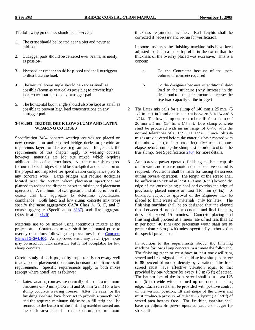
5-393.363 BRIDGE CONSTRUCTION MANUAL November 1, 2005
The following guidelines should be observed: 1. The crane should be located near a pier and never at
midspan. 2. Outrigger pads should be centered over beams, as nearly
as possible. 3. Plywood or timber should be placed under all outriggers
to distribute the load. 4. The vertical boom angle should be kept as small as
possible (boom as vertical as possible) to prevent high load concentrations on any outrigger pad.
5. The horizontal boom angle should also be kept as small as
possible to prevent high load concentrations on any outrigger pad.
5-393.363 BRIDGE DECK LOW SLUMP AND LATEX WEARING COURSES Specification 2404 concrete wearing courses are placed on new construction and repaired bridge decks to provide an impervious layer for the wearing surface. In general, the requirements of this chapter apply to wearing courses; however, materials are job site mixed which requires additional inspection procedures. All the materials required for normal size bridges should be stockpiled at one location on the project and inspected for specification compliance prior to any concrete work. Large bridges will require stockpiles located near the section where placement operations are planned to reduce the distance between mixing and placement operations. A minimum of two gradations shall be run on the coarse and fine aggregate to determine specification compliance. Both latex and low slump concrete mix types specify the same aggregates: CA70 Class A, B, C, and D coarse aggregate (Specification 3137) and fine aggregate (Specification 3126). Materials are to be mixed using continuous mixers at the project site. Continuous mixers shall be calibrated prior to overlay operations following the procedures in the Concrete Manual 5-694.400. An approved stationary batch type mixer may be used for latex materials but is not acceptable for low slump concrete. Careful study of each project by inspectors is necessary well in advance of placement operations to ensure compliance with requirements. Specific requirements apply to both mixes (except where noted) are as follows: 1. Latex wearing courses are normally placed at a minimum
thickness of 40 mm (1 1/2 in.) and 50 mm (2 in.) for a low slump concrete wearing course. After the rails for the finishing machine have been set to provide a smooth ride and the required minimum thickness, a fill strip shall be secured to the bottom of the finishing machine screed and the deck area shall be run to ensure the minimum
thickness requirement is met. Rail heights shall be corrected if necessary and re-run for verification.
In some instances the finishing machine rails have been
adjusted to obtain a smooth profile to the extent that the thickness of the overlay placed was excessive. This is a concern:
a. To the Contractor because of the extra
volume of concrete required b. To the designers because of additional dead
load to the structure (Any increase in the dead load to the superstructure decreases the live load capacity of the bridge.)
2. The Latex mix calls for a slump of 140 mm ± 25 mm (5
1/2 in. ± 1 in.) and an air content between 3 1/2% and 6 1/2%. The low slump concrete mix calls for a slump of 20 mm ± 5 mm (3/4 in. ± 1/4 in.). Low slump concrete shall be produced with an air range of 6-7% with the normal tolerances of 6 1/2% ±1 1/2%. Since job site mixes are delivered before the materials have reacted with the mix water (or latex modifier), five minutes must elapse before running the slump test in order to obtain the true slump. See Specification 2404 for more details.
3. An approved power operated finishing machine, capable
of forward and reverse motion under positive control is required. Provisions shall be made for raising the screeds during reverse operation. The length of the screed shall be sufficient to extend at least 150 mm (6 in.) beyond the edge of the course being placed and overlap the edge of previously placed course at least 150 mm (6 in.). A bulkhead subject to approval of the Engineer may be placed to limit waste of materials, only for latex. The finishing machine shall be so designed that the elapsed time between deposit of the concrete and final finishing does not exceed 15 minutes. Concrete placing and finishing shall proceed at a linear rate of not less than 12 m per hour (40 ft/hr) and placement width shall not be greater than 7.3 m (24 ft) unless specifically authorized in the special provisions.
In addition to the requirements above, the finishing
machine for low slump concrete must meet the following; The finishing machine must have at least one oscillating screed and be designed to consolidate low slump concrete to 98 percent of rodded density by vibration. The front screed must have effective vibration equal to that provided by one vibrator for every 1.5 m (5 ft) of screed. The bottom face of the front screed shall be at least 125 mm (5 in.) wide with a turned up or rounded leading edge. Each screed shall be provided with positive control of the vertical position, tilt and shape of the crown and must produce a pressure of at least 3.2 kg/m2 (75 lb/ft2) of screed area bottom face. The finishing machine shall have an adjustable power operated paddle or auger for strike off.

August 30, 2002 BRIDGE CONSTRUCTION MANUAL 5-393.364
4 Immediately prior to overlay placement, the deck surface shall be cleaned and then sandblasted. After sandblasting, all spent sand, dust and debris shall be removed from the surface by air blast. The air supply system must have a suitable oil trap between the storage tank and the air hose nozzle. Any oil drippings from equipment, concrete buggies, etc., during overlay placement shall be removed from the surface by re-sandblasting or bush hammering.
5. For latex concrete, the surface shall be dampened with
water after sandblasting; however, standing water or puddles shall not be permitted. Properly mixed latex composition shall be brushed into the dampened surface and spent aggregate removed for disposal. All vertical and horizontal surfaces shall be uniformly coated and the overlay shall be placed and finished while the bonding grout is still wet.
For low slump concrete, the surface shall be clean and
dry. The bonding grout shall consist of equal masses of sand and cement and sufficient water to form a creamy slurry. The grout shall be thoroughly scrubbed into all surfaces on which the overlay will be placed or abutted. A very important function of the inspection is to keep the grouting operation close to the placement of the overlay concrete. The grout must not be permitted to dry out before the concrete is placed.
6. Overlays are restricted to placement between April 15th
and September 15th (October 1st south of the 46th parallel) and are subject to temperature restrictions in the summer. It may be possible to place an overlay during the winter by heating and housing the deck according to Specification 2404.3A.
Latex overlays shall not be placed when the air
temperature is lower than 7EC (45EF) nor can latex or low slump overlays be placed when the daytime temperature is expected to reach 28EC (80EF) or higher. When the temperature is predicted by the National Weather Service to reach or exceed 28EC (80EF), the placement shall be rescheduled or started between the hours of 7:00 PM and 5:00 AM. Placements started during this period when the air temperature is rising and reaches 28EC (80EF) shall be terminated. The Contractor shall advise the Engineer when night pours are being scheduled and shall provide suitable night illumination. Illumination provisions shall include the necessity for inspection of both surface preparation and concrete pours.
7. After placement and consolidation, low slump overlay
wearing courses are finished as prescribed in Specification 2404.3.
8. Low slump concrete surfaces shall receive membrane
curing compound as specified in Specification 2404.3C3. The surface shall be covered with conventional curing materials (wet burlap or curing blankets) as required by Specification 2401.3G. No impact equipment shall be
operated in the adjacent lane during the first 72 hours. The cure shall be continued for a minimum period of 96 hours. After the 96 hour curing period has terminated, traffic may be permitted. If daily mean temperatures have been below 15EC (60EF) during this 96 hour period, additional curing time will be needed at the discretion of the Engineer.
Bonded wearing courses require special curing
procedures. Membrane curing compounds are not permitted for latex overlays. They shall be covered with a single layer of wet burlap as soon as the surface can support it without deformation. The wet burlap shall be covered with a layer of polyethylene film for a period of not less than 48 hours. The curing material shall remain in place at the discretion of the Engineer if the ambient temperature falls below 13EC (55EF) during the curing period. After removal of the curing material, the latex overlay shall be dried for a period of 72 hours before traffic shall be permitted.
9. Bridges with roadway widths in excess of 24 feet will
require multiple passes of the overlay paving machine. However, specification 2404 states that no impact equipment shall be operated in the adjacent lane during the first 72 hours after concrete overlay placement. Since the overlay paving machine uses significant vibration to help consolidate the low slump concrete mixture, it is considered to be "impact equipment". Hence, placement of overlay concrete adjacent to previously placed overlay is prohibited until the previously placed overlay is at least 72 hours old.
5-393.364 DIAPHRAGMS Steel diaphragms, if allowed, are shown on the Plans for prestressed beam structures. Shop drawings are required for steel diaphragms showing details of beam layouts, location of the diaphragms and location of mounting holes. High strength bolts for steel diaphragms shall be tightened by Turn-of-Nut method or the use of Direct Tension Indicators. See Section 5-393.414 for more information. 5-393.365 ANCHOR BOLTS Special care should be given to the finishing of bridge seats, pier caps, etc., so that full and uniform bearing with the masonry plates will be obtained and the bearing areas are at the correct elevation. Also, the location of anchor bolts must be accurately laid out before the concrete is cast. If the anchor bolts are to be cast into the pour, they must be rigidly held at the correct position, alignment and depth of embedment. If the anchor bolts are to be drilled into the hardened concrete and anchored with melted lead or a grout, the position of the bolts should be checked by the use of a template and the reinforcing steel adjusted as necessary to avoid interference with the bolt locations.

5-393.366 (1) BRIDGE CONSTRUCTION MANUAL August 30, 2002
Specification 2402.3H requires that holes for anchor bolts shall be drilled except where otherwise specified in the contract. Before the substructure concrete is placed, the location of drill holes for anchor bolts should be checked because corrections are difficult to make after completion of the substructure. The placement of substructure reinforcement bars should be checked carefully so that the proper clearances between the anchor bolt holes and reinforcement bars are provided. Also, the Plans and Shop Drawings for bearing devices should be checked to ensure that dimensions are the same and that minimum distance to edge of bridge seat can be obtained. Placing anchor bolts using a Portland Cement grout should be done only when the air temperature is favorable. After drilling, anchor bolts should be inserted into the dry holes to check proper fit and projection and then removed. The holes for the bolt should then be filled about 2/3 full of grout and the bolt should be immediately inserted and forced down until the top of the bolt is at the correct height above the bridge seat. The anchor bolt holes should be filled with grout flush with the bridge seat. All excess grout which may have been forced out of the hole, including that which may be in the expansion slots or on any metal surface, should be removed. The grout mix should consist of one part standard Portland Cement and one part clean fine grained sand and should be mixed with enough water so as to flow freely but not so wet to cause undue shrinkage. When it is necessary to place anchor bolts during freezing weather, a commercial product approved by the Engineer should be used in place of grout. The anchor bolt holes should be dry and the anchor bolts and concrete adjacent to the holes should be preheated. The anchor bolts should be warm when the grout material is poured to defer the cooling process until the material reaches the bottom of the void. The anchor bolts should be in correct position. The top of the anchor bolt should be at the correct height above the bridge seat and the grout material should completely fill the void between the bolt and the edge of the hole. When anchor bolts are to be set prior to placing concrete for the substructure units, they should be held and supported securely inplace. The correct position, including the projection above the bridge seat, should be carefully checked before and after concrete placement. During freezing weather, anchor bolt holes that have been drilled but not filled should be provided with adequate protection. If water is allowed to freeze in anchor bolt holes, it could cause critical damage to the substructure unit. An elastic type closed cell foam-like material, such as neoprene, vinyl or butyl rubber rod stock or similar materials, may be used to fill the open holes or void space around an anchor bolt which has not been permanently set and grouted inplace. The
material should be installed so that it will remain securely in place until the anchor bolts are permanently set. Anchor bolt nuts are seldom used but, where required, should be checked for proper adjustment. Most questions regarding the placement of anchor bolt nuts can be answered by carefully checking the Bridge Plan details. After the anchor bolt nut is adjusted, it should be secured by center punching to upset the threads at the outer face of the nut. 5-393.366 CONSTRUCTION JOINTS IN CONCRETE Construction joints, as distinguished from other concrete joints, are not intended primarily to permit movement between sections of the structure. They are necessary either because of a change in concrete mixes at that location, or other construction requirements. Construction joints, therefore, generally have reinforcing bars extending through the joint. Permissible construction joints are permitted as a convenience to the contractor when large pours, or difficult forming, would otherwise be necessary. Their use is optional with the contractor. The Plans will label these joints as “permissible construction joint,” except for permissible construction joints in roadway slabs which are described in the Special Provisions. Permissible construction joints in deck slabs resting on prestressed girders or steel beams may be constructed at the locations shown in the following sketches, unless indicated otherwise in the plans. Keyways are mandatory in all slab construction joints and should be similar to the sketch labeled “Typical Slab Keyway.”
Direction of pour
C Construction Jt.
C Construction Jt.
0.3L (Approx.)
Steel Beams or Prestressed Girderswith Single Diaphragm at Pier
Prestressed Girders withDouble Diaphragms at Piers
L
L
L

August 30, 2002 BRIDGE CONSTRUCTION MANUAL 5-393.366 (2)
The slab construction joint should be placed parallel to the transverse slab reinforcement for skews of 20° or less. On bridges skewed 20° or more, the joint should be placed parallel to the skew or stepped as shown in the sketch labeled “Plan View of Stepped Joint.” If a stepped joint is used, the longitudinal portion would be preferably located directly over the centerline of the beams or girders. The stepped joint should never be closer than 300 mm (1 foot) to the required saw cut which is made over the centerline of the pier. See the drawing labeled “Plan View of Stepped Joint” on the next page.
Emergency construction joints may be necessary due to equipment breakdown, delay in concrete delivery, or for other reasons. Every effort should be made to repair or replace equipment in case of a breakdown in order to avoid using the emergency joint. A “cold joint” can sometimes be avoided by covering the concrete surface with wet burlap, or by applying thin coats of job-mixed mortar (2 parts sand to 1 part cement). The following is given only as a general guide for emergency construction joints. Each joint must be treated individually as the necessity arises. 1. Joints in walls and columns should be placed level (if
possible, otherwise stepped) and provisions made for a neat straight line on all exposed surfaces. Joints shouldbe placed normal to the side forms, except that slab construction joints should be placed parallel to transverse reinforcement for skews of 20° or less and stepped or
skewed for skews greater than 20°. Keyways, and sometimes dowels, are necessary in emergency construction joints to resist shearing forces.
2. The Bridge Construction and Maintenance Section should
be contacted for advice, if possible, as soon as the need for an emergency construction joint is known. Have a copy of the Plans available and take measurements to indicate the location of the joint before making the call.
The Plans will label a mandatory construction joint as a “construction joint.” The joints are placed, to control cracks due to shrinkage, to separate concrete of different mixes, or to permit deflection in part of a superstructure before placing additional concrete. Because the elimination of such joints would adversely affect the structure, their construction is mandatory and they must be placed at the location shown in the Plans and in accordance with Plan details. Longitudinal joints are undesirable because of the unequal deflections and resulting stresses. If a longitudinal joint is necessary, the Bridge Construction and Maintenance Section should be contacted for a recommendations. Keyways are required at all vertical and horizontal construction joints to transmit shear forces. Most keyways are 1/3 the depth or width of the structure member. This provides the maximum shear section when forces are applied to either side of the member. See the Typical Keyway with Saw Cut Location sketch. An exception to this rule is the keyways in certain horizontal construction joints which are designed to resist horizontal shearing forces (the tendency for the adjacent concrete sections to slip over each other under load). A hollow concrete box girder bridge in which the top slab and web wall are constructed in separate pours is an example. In this type of bridge, the transverse keyways are placed at a variable spacing depending on the magnitude of the shearing force. The sides of all keyway forms should be beveled, but not more than one to twelve. This permits removal without spalling the concrete, except as previously discussed for horizontal shear. The dimensions of keyways shown on the Plans may be assumed to be nominal when such dimensions fit a standard lumber size. For example, a 2" x 6" keyway may be formed from a S4S piece of lumber with actual dimensions of 1 1/2 in. x 5 1/2 in. The concrete surface at horizontal construction joints should be consolidated, and should be free of laitance, loose or porous concrete, dirt, sawdust, and all other foreign material. When the surface is free of these defects, and is approximately to grade, the inspector may not require any further finish. Specification 2401.3 describes in detail the finish required in the construction joint between the slab and curbs, sidewalks or medians.
25 mm (1 inch) nominal50 mm (2 inches)nominal
Typical Slab Keyway
Plan View of Stepped Joint
Required sawcut on pre-stressed girderbridges withdoublediaphragms
Longitudinaljoint generallyalong C ofbeams or girders
Stepped joint
300 mm (1 foot)
Min.
C Pier
L
L

5-393.367 BRIDGE CONSTRUCTION MANUAL November 1, 2005
Saw cuts as described in Specification 2401.3 are required at every slab construction joint. The purpose of the saw cut is to permit sealing of a potentially leaky construction joint in the slab. To effectively saw on the centerline of this construction joint, the joint must be clearly located when the closing concrete pour is made. This may be done by scoring a line with a trowel along the joint in the plastic concrete. See the sketch below. Chamfered corners (13 mm (1/2 inch) sides) are required on all construction joints that are exposed to view and which are not required to be edged. See Specification 2401.3. 5-393.367 JOINTS DESIGNED FOR MOVEMENT Deflection, contraction and expansion joints are all designed to permit movement between sections of the structure without spalling or crushing of adjacent surfaces. These joints function as follows: (a) deflection joints provide relief for bending or flexing movements, (b) contraction joints provide relief during shortening or contraction movements, and (c) expansion joints provide for movement during shortening (contraction) and lengthening (expansion) movements. These joints differ from construction joints in that either an open joint or a flexible joint filler material separates the adjacent concrete surfaces and reinforcing does not generally extend through the joint. It is important that mortar or concrete does not bridge over these joints. When such a condition exists, any slight differential movement of the concrete sections on either side of the joint may cause spalling. Joints in sidewalks shall have the first of the two abutting surfaces painted in accordance with Plan Notes. It is necessary to form the joint by placing a bulkhead at the joint location in advance of the first pour. No reinforcement shall project through this joint. Curb joints may be constructed as described above for sidewalks, or the joint may be formed by a removable metal sheet. In this case the concrete sections on each side of the
joint may be placed in the same placement and painting or bulkheading is not necessary. The plate must be well coated with a form release agent and held firmly in position by vee strips and/or saw cuts in the side forms. Concrete should be deposited equally on each side of the plate to prevent distortion. Care must be exercised as the plate is withdrawn to prevent spalling or cracking in the adjacent concrete. Cork joints are shown in present details for all cast-in-place railing types with continuous concrete rail bases and concrete traffic barriers. The concrete railing or traffic barrier may be placed in alternate sections between cork joints or it may be poured continuously. In either case, copper nails must be used to retain the cork in the joint. Generally, contractors elect to place a railing or traffic barrier in a continuous pour to save the expense of placing and stripping bulkheads. Better concrete lines are also maintained when the railing or barrier is placed in a continuous placement. Cork has very little resistance to sideways deflection and careful attention must be given to maintain the cork in a vertical plane during the pour. The cork is held in position at each face by chamfer strips, and at the top by wood strips. To prevent bows in the cork, a sheet metal plate or a piece of 3mm (1/8 in.) tempered pressed wood is placed along one side of the cork before any concrete is placed. The concrete is then placed in equal layers on each side of the plate and cork. Vibration or spading proceeds simultaneously with the removal of the plate, as the concrete level rises in the section. Slipforming of Type F railing requires saw cutting the top portion of the joints and sealing with an approved sealant. The Special Provisions should be consulted for detailed requirements when slipforming is used. Slabs are generally continuous between expansion devices. Past experience has shown that, on prestressed girder bridges, a transverse crack occurs in the slab over the piers. Saw cuts in the slab over the pier (as described in Specification 2401) have been required in an attempt to control the location of this crack. When this works as intended, the crack coincides with the saw cut and the crack may be effectively sealed with concrete joint sealer. This joint deviates from conventional contraction or deflection joints in that reinforcing extends through the joint. Emphasis is placed on the Plan Notes which require that saw cuts be made over the centerline of piers as soon as the cutting can be done without raveling the concrete. During hot weather it may be possible to make the saw cut on the same day as the placement. This is the ideal situation, but in most cases it will not be possible to saw until the following morning before shrinkage causes cracking to occur. Prior to placing the deck treating oil or sealer, the area adjacent to the saw cut should be carefully inspected to determine the actual location of the crack. When this slab crack falls outside of the saw cut, corrective work is required as follows; (a) cracks within 13 mm (1/2 inch) of the saw cut
Typical Keyway with Saw Cut Location
C construction joint& score lineLRound corner with
small radius edger
Firstpour
Closingpourd/
3 d

November 1, 2005 BRIDGE CONSTRUCTION MANUAL 5-393.368
should be chipped back to the saw cut and filled with concrete joint sealer and (b) cracks more than 13 mm (1/2 inch) from the saw cut should be sealed with an epoxy penetrant sealer. 5-393.368 JOINTS AT ABUTMENTS Abutments function as both earth retaining structures and as vertical load carrying components. Abutment types used in Minnesota can generally be classified into 2 different types; parapet and integral. Parapet type abutments allow the superstructure to expand and contract independent of the substructure by using strip seal or modular expansion devices between the concrete deck and the abutment end block (see sketch below). Integral abutments rigidly attach the superstructure to the substructure and the temperature movement of the bridge is accommodated through flexure of the piling and movement at the roadway end of the approach panel (see sketch below). Parapet type abutments can be further subdivided into low parapet type and high parapet type. Low parapet type abutments commonly have a fairly thick but narrow footing with the front and back row of piling battered away from each other. Low parapet type abutments usually have contraction inserts to provide a plane of weakness in the bridge seats and parapet walls. These are detailed in the Plan and require metal inserts on horizontal surfaces (bridge seat) and vertical surfaces (see sketch below). High parapet type abutments are taller, have a thinner but wider footing, may have more than 2 rows of piling, and generally the back row of piling is not battered (see sketch below). To help control shrinkage and reduce cracking in high parapet type abutments, construction joints are detailed at a maximum horizontal spacing of about 9.75 m (32 feet). The reinforcement generally runs continuous through the joint. In this case, the construction joint also serves as a contraction joint. Free standing cast-in-place concrete retaining walls also have vertical construction joints, but the reinforcement does not pass through the joint. Instead, dowels with a cork filler or shear blocks are used to keep the adjacent wall segments in alignment. Integral type abutments consist of a wall supported by a single line piles. The superstructure beams or slab bear on the wall. And end diaphragm is cast with the slab which encases the beams and is rigidly attached the lower portion of the abutment making the superstructure integral with the abutment. This abutment type is only used on bridges less than 300 feet long with skews less than or equal to 20 degrees.
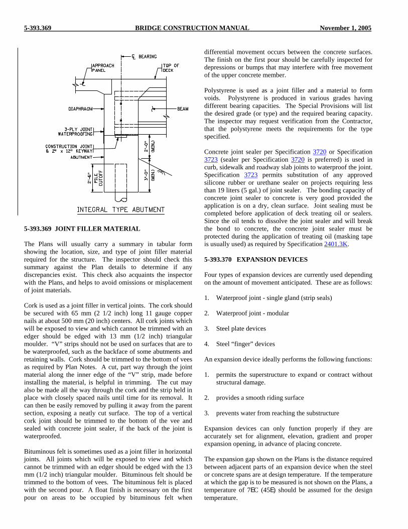
5-393.369 BRIDGE CONSTRUCTION MANUAL November 1, 2005
5-393.369 JOINT FILLER MATERIAL The Plans will usually carry a summary in tabular form showing the location, size, and type of joint filler material required for the structure. The inspector should check this summary against the Plan details to determine if any discrepancies exist. This check also acquaints the inspector with the Plans, and helps to avoid omissions or misplacement of joint materials. Cork is used as a joint filler in vertical joints. The cork should be secured with 65 mm (2 1/2 inch) long 11 gauge copper nails at about 500 mm (20 inch) centers. All cork joints which will be exposed to view and which cannot be trimmed with an edger should be edged with 13 mm (1/2 inch) triangular moulder. “V” strips should not be used on surfaces that are to be waterproofed, such as the backface of some abutments and retaining walls. Cork should be trimmed to the bottom of vees as required by Plan Notes. A cut, part way through the joint material along the inner edge of the “V” strip, made before installing the material, is helpful in trimming. The cut may also be made all the way through the cork and the strip held in place with closely spaced nails until time for its removal. It can then be easily removed by pulling it away from the parent section, exposing a neatly cut surface. The top of a vertical cork joint should be trimmed to the bottom of the vee and sealed with concrete joint sealer, if the back of the joint is waterproofed. Bituminous felt is sometimes used as a joint filler in horizontal joints. All joints which will be exposed to view and which cannot be trimmed with an edger should be edged with the 13 mm (1/2 inch) triangular moulder. Bituminous felt should be trimmed to the bottom of vees. The bituminous felt is placed with the second pour. A float finish is necessary on the first pour on areas to be occupied by bituminous felt when
differential movement occurs between the concrete surfaces. The finish on the first pour should be carefully inspected for depressions or bumps that may interfere with free movement of the upper concrete member. Polystyrene is used as a joint filler and a material to form voids. Polystyrene is produced in various grades having different bearing capacities. The Special Provisions will list the desired grade (or type) and the required bearing capacity. The inspector may request verification from the Contractor, that the polystyrene meets the requirements for the type specified. Concrete joint sealer per Specification 3720 or Specification 3723 (sealer per Specification 3720 is preferred) is used in curb, sidewalk and roadway slab joints to waterproof the joint. Specification 3723 permits substitution of any approved silicone rubber or urethane sealer on projects requiring less than 19 liters (5 gal.) of joint sealer. The bonding capacity of concrete joint sealer to concrete is very good provided the application is on a dry, clean surface. Joint sealing must be completed before application of deck treating oil or sealers. Since the oil tends to dissolve the joint sealer and will break the bond to concrete, the concrete joint sealer must be protected during the application of treating oil (masking tape is usually used) as required by Specification 2401.3K. 5-393.370 EXPANSION DEVICES Four types of expansion devices are currently used depending on the amount of movement anticipated. These are as follows: 1. Waterproof joint - single gland (strip seals) 2. Waterproof joint - modular 3. Steel plate devices 4. Steel “finger” devices An expansion device ideally performs the following functions: 1. permits the superstructure to expand or contract without
structural damage. 2. provides a smooth riding surface 3. prevents water from reaching the substructure Expansion devices can only function properly if they are accurately set for alignment, elevation, gradient and proper expansion opening, in advance of placing concrete. The expansion gap shown on the Plans is the distance required between adjacent parts of an expansion device when the steel or concrete spans are at design temperature. If the temperature at which the gap is to be measured is not shown on the Plans, a temperature of 7EC (45E) should be assumed for the design temperature.
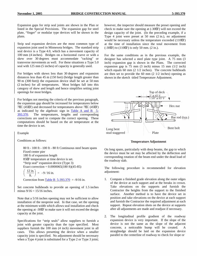
November 1, 2005 BRIDGE CONSTRUCTION MANUAL 5-393.370
Expansion gaps for strip seal joints are shown in the Plan or listed in the Special Provisions. The expansion gap for steel plate, “finger” or modular type devices will be shown in the plans. Strip seal expansion devices are the most common type of expansion joint used in Minnesota bridges. The standard strip seal device is a Type 4.0, which has a movement capacity of 100 mm (4 inches). Bridges on a horizontal curve or with a skew over 30 degrees must accommodate "racking" or transverse movements as well. For these situations a Type 5.0 seal with 125 mm (5 inches) of capacity is generally used. For bridges with skews less than 30 degrees and expansion distances less than 45 m (150 feet) (bridge length greater than 90 m (300 feet)) the expansion device shall be set at 50 mm (2 inches) for all temperatures. Most bridges fall into this category of skew and length and hence simplifies setting joint openings for most bridges. For bridges not meeting the criteria of the previous paragraph, the expansion gap should be increased for temperatures below 7EC (45EF) and decreased for temperatures above 7EC (45EF) as indicated by the algebraic sign in Table A and B 5-393.370. The temperatures, lengths and corresponding corrections are used to compute the correct opening. These computations should be based on the air temperature at the time the device is set. Example Conditions as follows: 80 ft - 100 ft - 100 ft - 80 ft Continuous steel beam spans Fixed center pier 180 ft of expansion length 85EF temperature at time device is set. “Strip seal” expansion device (Type 3)
Exact correction = 0.0000065(180 ft)(45-85)
12 in.ft.
= - 9 / 16 in.⎛⎝⎜
⎞⎠⎟
Correction from Table B 5-393.370 = -9/16 in. Set concrete bulkheads to provide an opening of 1.5 inches minus 9/16 = 15/16 inches. Note that a 5/16 inches opening may not be sufficient to allow installation of the neoprene seal. In that case, set the opening at the minimum width which allows seal installation and check the opening at -30EF to make sure it will not exceed the design capacity at the joint. Specifications for “strip seals” allow suppliers to furnish a joint with greater capacity than the type specified. Most suppliers furnish the 100 mm (4 inch) movement joint in all cases. This allows presetting the device when a smaller capacity joint is specified. No adjustment should be necessary when a Type 4 joint is substituted for a Type 2 or Type 3 joint;
however, the inspector should measure the preset opening and check to make sure the opening at (-30EF) will not exceed the design capacity of the joint. (In the preceding example, if a Type 4 joint were preset at 50 mm (2 in.), no adjustment would be necessary unless the temperature exceeded (110EF) at the time of installation since the total movement from (-30EF) to (110EF) is only 50 mm. (2 in.). For the same conditions as in the previous example, the designer has selected a steel plate type joint. A 75 mm (3 inch) expansion gap is shown in the Plans. The corrected expansion gap is 75 mm (3 inch) minus 15 mm (1/2 inch) which equals 60 mm (2 1/2 inches). The concrete bulkheads are then set to provide the 60 mm (2 1/2 inches) opening as shown in the sketch titled Temperature Adjustment.
On long spans, particularly with deep beams, the gap to which the device must be set may be affected by the deflection and corresponding rotation of the beam end under the dead load of the roadway slab. The following procedure is recommended for elevation adjustment: 1. Compute a finished grade elevation along the outer edges
of the device at each support and at the breaks in crown. Take elevations on the supports and furnish the Contractor the heights from the support to the finished surface. Another method is to have the device set in position and take elevations on the device at each support and furnish the Contractor the required adjustment at each support. Repeat elevation shots on the device at supports after all adjustments are made and readjust if necessary.
2. The longitudinal profile gradient of the roadway
expansion device is very important. If the slope of the device is not the same as the slope of the adjacent concrete, a noticeable bump will be created. A straightedge should be laid on the expansion device parallel to the centerline of roadway to check for slope or
Temperature Adjustment
Long bentstud staggered Plate
Top of deck
Hex nut
Bar rod (typ.)
Bent bolt
2" at 45º F1 3/8" at 85º F

5-393.371 BRIDGE CONSTRUCTION MANUAL November 1, 2005
gradient when the device is being adjusted for elevation. The strike-off machine should be set to plan crown and passed over the expansion device during the pre-pour inspection to check for any deviations from plan at the device. This can serve as an effective check on the earlier adjustments.
3. The deflection of the adjacent spans under the dead load
force of the roadway slab must also be considered. As the spans deflect, the ends of the beams will rotate, therefore the two parts of an expansion device should show a plane surface or slightly concave surface before the slab is poured. The surface should never indicate a convex surface. Also on overlapping plates, the bottom edge of top plate should be in contact with the lower plate after dead load rotation occurs. Since predetermination of beam rotation is quite difficult, the Plans may require slab construction joints about 1500 mm (5 ft) from each side of an expansion device where steel plate, “finger,” or modular type devices are specified. This permits the Contractor to straightedge across the device to adjacent inplace concrete. The final adjustment of the device is then made after dead load rotation has occurred.
5-393.371 SIDEWALK AND CURB PLATES Sidewalk expansion plates sometimes slide in a recess or notch in the concrete of the adjacent span. A notch approximately 6 mm (1/4 in.) wide should be provided at the ends of the plates to prevent spalling due to any differential movement of the spans, as shown in the following sketches. This is particularly important at plates in end spans over abutments, where the expansion of the span sideways may differ from the expansion of the abutment concrete. On curved and sharply skewed bridges the Plans will normally require polystyrene behind the vertical curb plate. The polystyrene will normally have a minimum thickness of 12 mm (1/2 inch). The purpose of this is to form a large enough opening to prevent cracking due to the racking movements which result from expansion and contraction of the structure.
Modular expansion joints with multiple neoprene glands are being utilized on long structures where the “strip seal” joints do not provide for sufficient movement and where a waterproof joint is desired. Modular joint openings should be set in accordance with shop drawings, with adjustments made for temperature as shown in tables contained in the drawings. Careful installation in accordance with manufacturer’s instructions is essential for this type of joint. Openings in strip seal joints must provide sufficient room for installation of the gland, which is inserted after placement of the concrete around the joint anchorages. Glands are to be installed in accordance with manufacturer’s instructions using a lubricant adhesive recommended by the manufacturer. Skewed bridges may require the installation of snow plow fingers which are welded to the top surface of the grip after the gland is installed. Careful welding is required to protect the gland from damage due to excessive heat because the weld area is limited. A sand layer is often placed on the gland as a protective measure during welding. There is a tendency to install the strip seal joint lower than detailed in the Plan to be on the safe side. This practice should be avoided as it results in a rough riding joint, and reduces the effectiveness of the snow plow fingers which should be flush with the roadway surface.
Section Thru SidewalkOption 1
Gutter line
Plate Block outflared area Top of
deck
Section Thru SidewalkOption 2
Gutter line
Plate Block outflared area Top of
deck
Inside Curb Plate Elevation
Plate Bentbolt
Top ofdeck
Blocked outflared area
Traffic

November 1, 2005 BRIDGE CONSTRUCTION MANUAL Figure A 5-393.370
MOVEMENT OF CONCRETE SUPERSTRUCTURES(EXPANSION COEFFICIENT OF 1.08 x 10 )-5 *
TEMP C.
20 m-6-5-4-3-2-1
23456789
30 m-9-7-6-4-3-1
24679101214
40 m-12-10-8-6-3-1
3571012141618
50 m-15-12-10-7-4-2
469
1215172023
60 m-18-15-12-8-5-2
58111417212427
70 m-21-17-14-10-6-2
59
131720242832
80 m-24-20-16-11-7-3
610151923283236
90 m-27-22-17-13-8-3
712172126303641
35302520151070-5-10-15-20-25-30-35
Desired Width of Joint Openings at 7 C
Join
t wid
th d
ecre
ases
by
Join
t wid
th in
crea
ses b
y
MOVEMENT OF CONCRETE SUPERSTRUCTURES(EXPANSION COEFFICIENT OF 6.0 x 10 )-6
TEMP F.
60'-3/16"-3/16"-1/8"
-1/16"-1/16"
1/16"1/16"1/8"
3/16"3/16"1/4"
5/16"
100'-3/8"
-5/16"-3/16"-1/8"
-1/16"
1/16"1/8"
3/16"5/16"3/8"
7/16"1/2"
140'-1/2"-7/16"-5/16"-3/16"-1/8"
1/8"3/16"5/16"7/16"1/2"5/8"
11/16"
180'-5/8"-1/2"-3/8"-1/4"-1/8"
1/8"1/4"3/8"1/2"5/8"3/4"
15/16"
220'-13/16"-5/8"-1/2"-5/16"-3/16"
3/16"5/16"1/2"5/8"
13/16"15/16"1-1/8"
260'-15/16"-3/4"-9/16"-3/8"-3/16"
3/16"3/8"9/16"3/4"
1-5/16"1-1/8"1-5/16"
300'-1-1/16"
-7/8"-5/8"
-7/16"-3/16"
3/16"7/16"5/8"7/8"
1-1/16"1-5/16"1-1/2"
9585756555453525155-5
-15-25
Desired Width of Joint Openings at 45 F
Join
t wid
th d
ecre
ases
by
Join
t wid
th in
crea
ses b
y
This table contains bridge movements for various lengths between expansion joints due totemperature changes. Joint openings established during construction must be corrected (decreasedon temperatures above 7 C (45 F) and increased on temperatures less than 7 C (45 F)) accordingly.
Formula for computing values not shown on table: Opening width (at right angles to thejoint) = Width desired @ 7 C (45 F) + [Movement length in mm (in.) x Coefficient of expansion x[7 C (45 F) - Temperature]]
Joint openings have dimensions of mm unless otherwise noted.*
1.
2.
3.
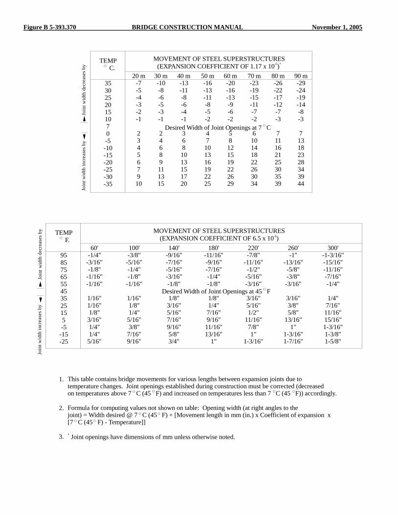
Figure B 5-393.370 BRIDGE CONSTRUCTION MANUAL November 1, 2005
MOVEMENT OF STEEL SUPERSTRUCTURES(EXPANSION COEFFICIENT OF 1.17 x 10 )-5 *
TEMP C.
20 m-7-5-4-3-2-1
234567910
30 m-10-8-6-5-3-1
24689111315
40 m-13-11-8-6-4-1
3681013151720
50 m-16-13-11-8-5-2
47
101316192225
60 m-20-16-13-9-6-2
58121519222629
70 m-23-19-15-11-7-2
610141822263034
80 m-26-22-17-12-7-3
711162125303539
90 m-29-24-19-14-8-3
713182328343944
35302520151070-5-10-15-20-25-30-35
Desired Width of Joint Openings at 7 C
Join
t wid
th d
ecre
ases
by
Join
t wid
th in
crea
ses b
y
MOVEMENT OF STEEL SUPERSTRUCTURES(EXPANSION COEFFICIENT OF 6.5 x 10 )-6
TEMP F.
60'-1/4"
-3/16"-1/8"
-1/16"-1/16"
1/16"1/16"1/8"
3/16"1/4"1/4"
5/16"
100'-3/8"
-5/16"-1/4"-1/8"
-1/16"
1/16"1/8"1/4"
5/16"3/8"
7/16"9/16"
140'-9/16"-7/16"-5/16"-3/16"-1/8"
1/8"3/16"5/16"7/16"9/16"5/8"3/4"
180'-11/16"-9/16"-7/16"-1/4"-1/8"
1/8"1/4"7/16"9/16"11/16"13/16"
1"
220'-7/8"
-11/16"-1/2"-5/16"-3/16"
3/16"5/16"1/2"
11/16"7/8"1"
1-3/16"
260'-1"
-13/16"-5/8"-3/8"-3/16"
3/16"3/8"5/8"
13/16"1"
1-3/16"1-7/16"
300'-1-3/16"-15/16"-11/16"-7/16"-1/4"
1/4"7/16"11/16"15/16"1-3/16"1-3/8"1-5/8"
9585756555453525155-5
-15-25
Desired Width of Joint Openings at 45 F
Join
t wid
th d
ecre
ases
by
Join
t wid
th in
crea
ses b
y
This table contains bridge movements for various lengths between expansion joints due totemperature changes. Joint openings established during construction must be corrected (decreasedon temperatures above 7 C (45 F) and increased on temperatures less than 7 C (45 F)) accordingly.
Formula for computing values not shown on table: Opening width (at right angles to thejoint) = Width desired @ 7 C (45 F) + [Movement length in mm (in.) x Coefficient of expansion x[7 C (45 F) - Temperature]]
Joint openings have dimensions of mm unless otherwise noted.*
1.
2.
3.

November 1, 2005 BRIDGE CONSTRUCTION MANUAL 5-393.372
5-393.372 BEARING ASSEMBLIES Bearings are generally placed between the bridge superstructure and substructure and provide two main functions; support the gravity loads (dead load and live loads) and to accommodate the changes in length of the bridge resulting from temperature variations and rotations caused by bending. The concrete in the area of the bearing surface directly under the bottom plate of the bearing must be finished to a true horizontal plane. Careful finishing of this area will result in a true surface which will eliminate much corrective work. The surface shall be power ground so the surface variance is less than 2 mm (1/16 in.). Prior to setting the bearings, the bearing area should be checked for full bearing and level surface by laying a carpenter’s or mason’s level in several positions on the area. Irregular surfaces should be bush hammered or ground down to provide a level and uniform surface. Shallow depressions may be filled with an epoxy mortar, and roughened areas where concrete is removed should also be smoothed with an epoxy mortar. See the Steel Construction Section 5-393.400 of this manual for a description of bearing surfaces for steel bridges. Elevations should be taken as soon as the bearing surfaces are finished. For continuous steel beam bridges, the Bridge Construction and Maintenance Section should be contacted for a recommendation when any bridge seats deviate from plan elevation by more than 6 mm (1/4 in.). For prestressed girder bridges, the Bridge Construction and Maintenance Section should be contacted for a recommendation when there is a deviation from plan bearing elevation greater than 13 mm (1/2 in.). For cast-in-place concrete bridges the elevation of the bridge seat should not deviate from plan by more than 6 mm (1/4 in.). Elastomeric bearings are made of synthetic rubber called Neoprene. This type of bearing allows the superstructure to translate and rotate, but also resists loads in the longitudinal, transverse and vertical directions. As loads are applied, movement is accommodated by distorting the pad. Elastomeric bearings are generally more economical, easier to maintain and to install than conventional metallic bearings. Elastomeric bearings may consist of unreinforced pieces of neoprene (generally no more than 1/2" thick) often used for integral abutment bridge bearings. Generally elastomeric bearings thicker than 1/2" are reinforced with 1/8" thick steel plates sandwiched between layers of elastomer. Fixed bearing assemblies for prestressed girders and steel beams are fastened to the bridge seats with anchor bolts which are drilled in after beam or girder erection. For additional information on placing anchor bolts, see 5-393.365 of this manual.
Anchor bolts are sometimes cast in bridge seats of pedestrian bridges where they are required to resist uplift forces produced by wind. Hold down bolt assemblies may also be cast in abutments on steel beam spans when hold downs are used in lieu of counter weights. Care must be exercised in setting these bolts to ensure proper location and projection. A template should be used to hold these bolt assemblies rigidly in position.


November 1, 2005 BRIDGE CONSTRUCTION MANUAL 5-393.400
STEEL BRIDGE CONSTRUCTION 5-393.400
5-393.401 GENERAL This section deals primarily with field inspection procedures relative to structural steel, but applies also to other structural metals which may be required for completion of a structure. Information is included which applies to shop fabrication, so field inspectors will have some knowledge of work that has been done prior to delivery of these materials to the job site. In addition to structural members, such miscellaneous items as drains, ice breakers, bearing assemblies, metal railings and posts, name plates, protection angles, etc. should also be included within the scope of steel construction. 5-393.402 FABRICATION Fabrication of structural metals consists of the operations necessary to prepare members or groups of members for use in structures. It includes the procuring of the required materials prior to shop operations, actual shop operations, and loading for delivery of the fabricated parts to the bridge site. Fabrication should be in accordance with approved shop detail drawings; and, generally, all structural metal materials will be inspected under the supervision of the Structural Metals Engineer (Bridge Office). 5-393.403 SHOP DETAIL DRAWINGS As specified in Specification 2471, the Contractor shall furnish shop detail drawings for the complete fabrication of all structural metals required by the Contract. These drawings, when approved by the Fabrication Methods Engineer, become part of the Contract and work must be done in accordance with them. Shop drawings should show all pertinent dimensions and details, together with any other information required during fabrication and erection, including types of connections, types, sizes and lengths of welds, bolt sizes and lists. Also included is a match marking diagram which shows the correct positioning of the various members which are not interchangeable and which should be followed explicitly in order that the best possible “make-up” of sections will be obtained. Each sheet of the shop detail drawings should be examined for the Fabrication Methods Engineer’s approval. Changes and corrections are frequently made on shop drawings, and these sometimes change construction requirements or pay quantities. Shop detail drawings should be checked before work is done that could be affected by these drawings; for example, railing shop detail drawings should be checked before concrete is placed which secures cast-in-place anchorages for the railposts.
The Fabrication Methods Engineer should be consulted regarding questions pertaining to shop detail drawings which cannot be resolved in the field. 5-393.404 STRUCTURAL METALS SHOP
INSPECTION A policy has been adopted for handling inspection and inspection reports which result in documented assurance that all metal parts of a structure have been inspected and approved. The following instructions apply only to those metal materials which are to be inspected by the Bridge Office, Structural Metals Inspection Unit. They do not apply to materials for which sampling and inspection is by manufacturer’s certification or performed by project personnel. The Engineer, who has been assigned the project, should promptly remind the Contractor (by letter or during the pre-construction conference) that information relative to the source of materials should be forwarded to him or her within the allotted time. Upon receipt of information from the Contractor of the source of materials, copies should be sent by the Project Engineer to the Materials Engineer and to the Structural Metals Engineer. It is very important that this information be forwarded as quickly as possible after the contract has been awarded, if the procedure outlined within this manual is to function effectively. When the Structural Metals Engineer has been notified by the Project Engineer of the source of the various metal parts, the Structural Metals Engineer will assume responsibility for their inspection. The Metals Quality Inspectors, after having completed shop inspection of the unit or assembly, will attach a shipping tag directly to the shipper’s documents. The Site Inspector should verify that no material has been shipped in addition to what is listed on the tag. Two types of tags are currently used as shown in Figures A and B 5-393.404. The smaller tag, Figure A is typically used when all shop activities (fabrication, blasting, coating) are done at one location. The larger tag, Figure B is typically used when these activities are done at more than one location. If the Inspector’s signature is on the tag, all activities have been inspected. If an item happens to be shipped to the job site before all shop activities are inspected, the Inspector’s initials will not be in all the activity boxes and their signature will not be on the tag. If the Inspector’s signature is not on the tag, or if material is received without a tag, the material should not be incorporated into the work. In this case, the site Inspector should call the Structural Metals Inspection Unit to discuss how inspection will be accomplished. Whenever possible, the Structural Metals Inspection Unit will notify the Project Engineer that material is being shipped to the job site without final shop inspection.

Figure A & B 5-393.404 BRIDGE CONSTRUCTION MANUAL November 1, 2005
Figure A 5-393.404
Figure B 5-393.404

November 1, 2005 BRIDGE CONSTRUCTION MANUAL Figure C 5-393.404

Figure D 5-393.404 BRIDGE CONSTRUCTION MANUAL November 1, 2005

November 1, 2005 BRIDGE CONSTRUCTION MANUAL Figure E 5-393.404

5-393.405 BRIDGE CONSTRUCTION MANUAL November 1, 2005
Final inspection and acceptance of structural metals is the responsibility of the Project Engineer. If material without a signed inspection tag is incorporated into the work, written notification is to be provided by the Project Engineer. Whenever it is necessary to make field inspection of structural metal items, be certain to prepare Form 2415 (see Figure C 5-393.404) as a documentation of the inspection and forward a copy to the Structural Metals Engineer. This form is used when there is a single vendor of structural metal items. When there are multiple vendors of structural metal items, prepare Form 2403 (see Figure D 5-393.404). After all materials on a project are inspected and tagged, a confirmation letter will be generated by the Structural Metals Inspection Unit that lists the items inspected, their quantities, and the date of inspection. A copy of this form (see Figure E 5-393.404) will be sent to the Project Engineer. Through the use of tags and inspection reports, the Structural Metals Inspection Unit will endeavor to keep the Inspector at the job site fully informed of all inspections performed by them. If the job site inspector has any doubts about whether or not materials have been shop inspected or are supposed to be inspected by the Structural Metals Inspection Unit, they should contact the Structural Metals Engineer for verification. The following is a list of some of the most common items that Structural Metals Inspection Unit is responsible for inspecting: 1. Pedestrian Bridges 2. Anchor bolts and assemblies 3. Bearing Assemblies 4. Drains 5. Expansion joints 6. Galvanizing 7. Hardware 8. High mast light poles 9. Light poles 10. Metal traffic barriers 11. Miscellaneous steel items 12. Overhead signs 13. Pins 14. Railings 15. Coatings (paint, galvanizing, metallizing) 16. Signal poles 17. Sole plates 18. Steel bridge superstructures 19. Steel diaphragms 20. Elastomeric Bearing Pads 5-393.405 FIELD INSPECTION OF MATERIALS In general, all structural metals will have been inspected by representatives of the Structural Metals Inspection Unit prior to shipment. The material may arrive on the job site before a report of this inspection has been received in the field, but should not be incorporated in the work until the shop inspection has been verified. (See 5-393.404 for additional information.) All materials, even though previously inspected, should be given a thorough visual inspection at the time of delivery. The Specifications clearly provide that the “Final
inspection and acceptance of materials will be made only at the site of the work.” Frequently materials are damaged or change in quality while in storage or during transit, and for that reason shop inspection and approval cannot be considered as assurance of final acceptance. See 5-393.416, Straightening Bent Material, and Specification 2402.3 regarding repair of bent or damaged members. Corrections should be made before proceeding with any erection or assembly that would result in more difficult repair or replacement of deficient materials. Structural metals inspection includes coatings inspection. Site Inspectors should carefully inspect the coated items for damage and require repair of damaged areas. Structural metals are usually transported to the job site by truck or railroad cars. Prior to unloading, each piece should, if possible, be given a complete visual inspection by the Site Inspector and any damaged pieces should be noted. Pictures taken of damaged pieces may be very useful at a later date. The Inspector should check the fabricator’s invoices against the material received, and note any discrepancies. Unloading and handling must be accomplished by methods that will not damage the members. Cable slings around the member, using soft-wood protection blocks, is the recommended method of pick-up. Finished holes, field connection holes or girder attachments should not be used as points of pickup. A well drained area in the vicinity of the bridge site, free of excessive vegetation, should be selected for storage. The members should be placed on timber blockings, skids, or platforms above probable high water. Beams and girders should be handled and stored in an upright position and securely shored to prevent over-turning. Metal items which are delivered to the job site, and for which no shop inspection has been made, should receive a complete inspection as soon after arrival as is practicable. In this case, the Site Inspector should call the Structural Metals Inspection Unit as soon as possible to discuss how inspection will be accomplished. If the inspection is to be made by the field inspector, information should be obtained from the Structural Metals Inspection Unit regarding the extent of inspection, documentation required, etc. Whenever it is necessary to make a field inspection of structural metals items, be certain to prepare Form 2415 (see Figure C 5-393.404) as a documentation of the inspection and forward a copy to the Structural Metals Engineer. Structural metals furnished by the Maintenance Area should be reported on Form 2415. If bridge pins or other structurally significant items are furnished, the inspector should call the Structural Metals Engineer to arrange for inspection. The bridge number or project number from which the material was salvaged should be listed for used materials. 5-393.406 FIELD LAYOUT Soon after the Contractor has completed concrete placement for an abutment or a pier cap, the surfaces which are to receive

November 1, 2005 BRIDGE CONSTRUCTION MANUAL 5-393.407
bearings should be closely checked for irregularities. It is normally expected that some correction will be required to obtain a suitable bearing surface, as required by Specification 2401. The Contractor should be notified as soon as possible to determine which areas will require correction and the approximate extent of the correction. Bearing surfaces should be true and smooth to provide full and uniform bearing. Elevations should be taken as soon as the bearing surfaces are finished so that the need for shims or fill plates can be determined. Filling with concrete or other materials, to raise the final elevations or level of a bearing area, should be avoided. Neat cement may be used to smooth roughness created by the float finish, to fill minor irregularities and to provide a tight seal. The field layout of substructure units is covered in section 5-393.050 of this manual. This section should be reviewed before the final centerline of the bridge and centerline of the unit are marked. The data for all span distances should be tabulated so that any minor adjustments can be made advantageously. When the final location of the centerline of bearing has been determined, it should be so marked on the top of the pier. Pencil marks on the concrete will usually be satisfactory if they are to be used within a few days, but a more permanent marking obtained with a red or blue chalk line or by scribing a line with the corner of a file or other sharp tool is usually preferable. 5-393.407 FALSEWORK The applicable requirements of Specification 2401.3B, together with section 5-393.200 of this Manual, are the basis for the design and construction of falsework and forms. Steel is assumed to have a mass of 7850 kg/m3 (490 lb/ft3). A. Plans The Contractor should prepare plans of the falsework design. When the Special Provisions require the submittal of the falsework plans to the Engineer for approval, the inspector should review these plans and make his or her comments and recommendations, prior to the submittal to the Engineer for approval. Special attention must be given to vertical and horizontal clearances, so that the work may be accomplished without disturbing the falsework as erected. B. Construction Falsework construction should conform to Specification 2401.3B, to the extent applicable, together with Section 5-393.200 of this manual and the following: 1. Falsework bents should be constructed to provide a
minimum clearance of 600 mm between the falsework caps and lower flanges or members of the structure which are to be supported thereon to provide enough space for the jacking and bolting of such members.
2. The bearing capacity of falsework piles should be checked by the Contractor’s forces as they are driven to make certain that they will support the load to be imposed. A record of the driving should then be furnished to the Engineer. It should be understood that any records kept by the inspector in this regard are for informational purposes only, and that it is the responsibility of the Contractor to provide safe and adequate construction.
Erection drawings may contain only a match marking diagram, particularly for simple structures. For more complicated structures, however, drawings should be furnished which show the exact erection sequence and procedure. These drawings should indicate, by steps, the sequence of erection, types of equipment to be used, mass of equipment which is to be placed on any part of the structure, and complete details for falsework bents and spans. When the erection drawings indicate procedures which may place temporary loads on the bridge which may be in excess of design loads, a complete analysis of the stresses should be supplied by the Contractor. These stresses may be checked by the Engineer in the field or, if complicated analysis is involved, the drawings may forwarded to the Bridge Section for review and checking. No loads which would create stresses in excess of those indicated under Design Data on the plans should be permitted, except when specifically authorized by the Bridge Engineer. 5-393.408 GENERAL ERECTION Before starting erection, the Inspector should read and study thoroughly all Specifications, Contract Plans, Shop Drawings and Special Provisions pertaining to the work. If discrepancies exist between them, it must be remembered that the Special Provisions govern over the Plans and Specifications, and that the Plans govern over the Specifications. Refer to Specification 1504 to clarify issues related to coordination between Plans, Specifications and Special Provisions. It is good practice to underline notes or specifications of particular concern, so that they will be less likely to be overlooked during erection. Make sure to check the layout and elevations before erection is started. The layout should be verified by rechecking the location of the center line of each substructure unit or the location of “Working Points” as shown in the Plans and as specified in the “Survey and Staking” Section of this manual. Also, elevations which could affect the fit of members to be erected should be rechecked to detect possible errors or to determine if settlement of the substructure units has taken place. Convenient reference points or lines should be established to enable the Inspector to continuously check the accuracy of alignment, length, and elevations during erection. Some of these reference points or lines may be scribed on the

5-393.409 BRIDGE CONSTRUCTION MANUAL November 1, 2005
substructure units. The inspector should verify the location of these reference points with the Contractor (possibly an erecting contractor). Check match markings before erection is started. Match markings, lengths, sizes, and weights of the members should be compared with those shown on the shop detail drawings. As the erection progresses, the inspector should compare the diagram of assembled members’ match markings to verify that the members have been placed in their correct position. The Inspector should make a study to determine which surfaces should be painted before erection. Surfaces which will be difficult to access after erection should be spot coated and painted with the required field coats before erection. All painting and sandblasting of contact surfaces should be done in the shop. Painting should be done according to the Contract requirements. See Surface Preparation and Painting Structural Steel, Section 5-393.450 of this manual for additional information. Before erection is started, the inspector should discuss the method of erection with the Contractor. Special emphasis should be placed on the use of safe construction practices. Some dangerous practices are: (1) lifting too heavy a load for the capacity of the lifting or carrying equipment; (2) booming crane out too far with load; (3) ignoring the manufacturers recommended practice for operation of erection equipment; (4) dropping members; (5) insufficient guying and bracing of members against wind pressure; and (6) leaving a single girder unsupported for extended time periods. Regardless of any suggestions the inspector may offer, the Contractor remains responsible for the safe handling of the structural members. The Contractor must, at all time, provide handrails, safety nets, or cable systems for attachment of safety belts and other measures adequate to provide reasonably safe working conditions for inspectors. Inspectors should wear approved hard hats at all times when in the contractor’s work area. To avoid collapse of an unsupported girder, a minimum of two girders should be connected together prior to suspending operations for the day. Handling and movement of structural members frequently requires or encourages supporting these members at points other than those for which design stresses were computed, and in some cases completely reverses the stresses. Therefore, it is important that consideration be given to these activities. A member may, for instance, support a considerable load in addition to its own mass when supported at each end, but may fail when picked up at midpoint. Members should not be dropped, nor should they be lifted using connection holes at attachments. A recommended method of pick-up is to use cable slings around the member with wood blocks to prevent damage. Most members of near uniform cross section can be safely picked up, using a two sling attachment, at about the one-fifth point from each end of the members. For members of unusual
size or shape, advice should be obtained to verify pick up points and safe handling methods. 5-393.409 ERECTION PINNING AND BOLTING OF
FIELD CONNECTIONS During erection, drift pins are used to insure proper alignment of the connecting parts and erection bolts are used to insure close contact of the connecting parts. Most connections or splices are pinned and erection-bolted at or near their final position, but some connections are pinned and bolted on the ground and the members later moved to their final location in the structure. Before erection, holes should be given a careful inspection as to size, shape and alignment. All holes should be true to the shape and size specified, clean-cut, perpendicular to the axis of the member, and free from all burrs and distorted, torn or jagged edges. Any holes which are undersized or distorted should be marked for reaming. It is good practice to keep a record of the location of these holes. This record should be referred to prior to bolting to make certain that the reaming has been done. For a bolt, the minimum distance from the center of the hole to a rolled or a machine finished edge should be 1 1/2 times the diameter of the bolt. For sheared or flame cut edges this distance should be increased by 6 mm (1/4 in.). Contact the Structural Metals Engineer, Bridge Office, if holes are in the wrong location or more than ten percent of the holes are undersized, oversized or distorted. Drift pins and erection bolts should be used in equal proportions and should be located to effectively hold the connecting members in close contact and in correct position during all bolting operations. Important connections in simple beams, girders, floor systems, etc., should have at least 50 percent of the holes filled with drift pins and erection bolts. The number of drift pins and erection bolts for continuous and cantilevered beam or girder spans will be determined by the Engineer for the stresses developed in the connection during erection. A325 high-strength bolts may be used for erection bolts, and then reused for the final connection unless damaged. The Inspector should check the high-strength bolts used for erection bolts before they are incorporated in the connection. The diameter of the drift pins should not be larger than the diameter of the connection holes and should not be smaller than the diameter of the connection holes, less 1 mm (1/32 in.). The erection bolts should be the same nominal diameter as the bolts. Erection washers should generally be used with erection bolts. After pinning and erection bolting of all connections, all holes that do not freely admit a bolt should be cleared by reaming.
November 1, 2005 BRIDGE CONSTRUCTION MANUAL 5-393.410
The use of drift pins in lieu of reaming to enlarge holes should not be permitted. 5-393.410 ERECTION OF BEARING ASSEMBLIES. Follow these guidelines: 1. A bearing assembly is a device for transferring
superstructure loads to the bridge seat. Included in this category are masonry bearing plates, shoes, rockers and rollers, elastomeric pads, pot and disk bearings and their various combinations.
2. Prior to setting the bearing assemblies, the inspector
should check the bridge seats to insure that they provide a uniform bearing surface at the proper elevation. Preparation of bearing areas is covered in Section 5-393.406, of this manual. Also check the bottom of the bearing assembly for warpage during fabrication.
3. Immediately prior to assembly, temporary protective
coatings should be removed from pins and pin holes and all extraneous material should be removed from contact surfaces. After cleaning, the pins and pin holes, should be given a coat of specified prime, and the pins should be inserted in the holes. This procedure should be used except where bronze brushings are used.
4. Unless otherwise indicated in the Plans, bearing
assemblies such as rockers, roller nests and hangers for suspended spans should be set so as to be plumb, or at the designated tilt, at a temperature of 7EC (45EF).
5. Pot and disk bearings shall be set for the centerline of
bearing to be centered at a temperature of 7EC (45EF). 6. Anchor rods must be installed to the full depth as shown
in the plans. If anchor rod location hits rebar, contact the Bridge Office.
Prior to erecting beams, girders, diaphragms, etc. the Engineer should verify that all members have been shop inspected and approved. See Section 5-393.404 of this manual. 5-393.411 ERECTION OF BEAMS, GIRDERS,
DIAPHRAGMS, ETC. See Specification 2402.3 for the extent of erection required before starting placement of permanent fasteners, and for the requirements for erection of pins and bolts. Elevations should be taken on the steel at splice points prior to starting placement of permanent fasteners to determine the necessity for vertical adjustment. This is particularly true when there is a field splice on each side of a support. Plan control dimensions are based on beams theoretically straight and of tubular dimensions. No allowance is made in plans for dead load deflection or rolling tolerances within a given section. Slight variation may result from these factors which
will not require adjustment, but if adjustment is necessary the following should be considered: (a) both points should vary from the plan position by the same amount and in the same direction; (b) top and bottom flanges of beams should be brought into vertical alignment; (c) adjustment of elevations can be made by jacking at the low splice or by temporarily loading the beams at the location of the high splice. The position of the erection bolts should be checked during or after the jacking or loading operations to insure that undesirable stresses have not been introduced into the members. Binding of the free erection bolts and heavy resistance to jacking or loading would indicate that erection stresses have been introduced, and these stresses must be relived prior to placement of permanent connectors. Steel members should be at their final relative elevation and in proper alignment prior to placement of permanent connectors. 5-393.412 ERECTION OF EXPANSION DEVICES When the Contractor erects and adjusts the expansion devices, the parts should be accurately assembled as shown on the plans and all match-marks should be followed. The materials should be carefully handled so that no parts will be bent, broken, or otherwise damaged. Bearing surfaces and surfaces to be in permanent contact should be cleaned before the members are assembled. Unless otherwise indicated in the plans, expansion devices should be set so as to have the specified opening at 7EC (45EF). Additional information on expansion devices can be found in Section 5-393.370 of this manual. Finger joints should be aligned to permit free movement without lateral contact. Immediately prior to placing any deck concrete, recheck expansion devices for (1) correct elevation (2) correct amount of opening at the temperature during the check and (3) any foreign material which may have entered the joint during construction. In cases where large deflections occur in deep girders, rotation of the top end of the girder may cause the two extrusions to expand apart during deck construction. The Contractor shall provide movement capability for this joint during deck placement, and set initial opening to compensate for expected deflection. 5-393.413 ERECTING METAL RAILING When erecting metal railing and prior to placement of concrete in the rail base, consideration of any necessary adjustment of the metal rail anchorages is critical.

5-393.414 BRIDGE CONSTRUCTION MANUAL November 1, 2005
The spacing of the rail post anchorages should be in accordance with approved shop detail drawings. For curved bridges, the inspector should ascertain along which curved line the rail post spacings are dimensioned. Lateral clearances and projection of the rail post anchorages should be closely checked. Cast-in-place anchorages for metal rail posts should be supported rigidly to prevent movement during concrete placement. To ensure proper fit, exact field measurements of anchorage locations are needed by the fabricator and are generally furnished by the contractor. The bearing areas under the rail post base should be finished to provide a uniform contact surface. Any grout which is left on the threads of the anchorages during concrete operations should be cleaned off immediately. Drilled in anchorages are permissible for most railings and are necessary where the slip form method of construction is used. A template is necessary for drilling if anchorages are drilled prior to placement of railing. Shims should be used to properly align the posts. The edge of the base plate should be caulked for tightness after the posts have been bolted in their final position. No voids should be left which would permit admission of water. 5-393.414 BOLTING OF PERMANENT FIELD
CONNECTIONS Except when otherwise specifically required by the contract, permanent field connections may be made using bolts meeting the requirements of the Standard Specifications. Bolting is covered under Specification 2402 and includes conventional “A325 high-strength” bolts and “pin bolt.” A490 high-strength bolts are not normally used in structural connections. Welded connections are only used when specified by the Contract or when specifically permitted by the Engineer and are covered under Specification 2471. Regardless of the type of connectors used, placement of the permanent connectors should not be started until the various parts of a joint have been properly aligned and drawn into full contact. See Field Fit-up under Specification 2402. When high-strength bolts are to be used for the connection, the same bolts may be used for fit-up by applying partial tension, then final tensioning these bolts after the remaining bolts for that connection have been placed. The requirements for the use of pin bolts specify that the driving tool be capable of partial swaging; this will permit the use of the same pin bolts for fit-up, with the final swaging applied after the remaining bolts for that connection have been placed and fully swaged. The use of the same bolts for fit-up as will be used for permanent bolting is permitted as an expedient and is not intended as a requirement should the Contractor desire to use conventional erection bolts for that purpose.
Bolts (“high-strength” or “pin bolts”) should be installed with the heads on the outside face at web splices on fascia beams and girders, and with the heads down on flange splices on all beams and girders spanning a highway. The principle of high-strength bolting is that the bolts are tightened to a high tension, producing clamping forces which enable the faying surfaces to carry loads by friction. The two accepted methods of tightening high-strength bolts to provide the necessary clamping force are the turn-of-nut and direct tension indicator methods. Direct tension indicators are typically specified for all field connections. Conditions which must exist before bolting is started are as follow: 1. Bolts, nuts and washers must have been approved by the
Materials Lab or the Structural Metals Engineer. (See Tables C - H 5-393.414 for information on bolts, nuts, and washers.) "Metric bolts" are currently not permitted for use on Department projects as tightening procedures have not yet been established for metric thread configurations. Information on metric sizes is included, however, as it is anticipated that procedures will be available in the near future.
2. It is important to visually inspect bolts and nuts when they
are first delivered to the job and each day during the bolting operation. For galvanized nuts, the nut threads must contain a dyed lubricant. Also, nuts should be tested to show that they are able to be hand-threaded on the bolt. If the lubricant is missing or the nut cannot be hand-threaded onto the bolt, stop the bolting operation until this is corrected. Insufficient lubrication can result in inadequate tightening of the bolt and make it difficult to reach the required tension.
Bolts, nuts and washers should be free from rust, dirt or
other foreign material which may have an influence on the torque-tension ratio, and which would produce greatly varying stresses in bolts with comparable torque values. Use of proper lubricant is especially important for galvanized bolts. Bolt and nut threads should be given a visual inspection to determine whether or not they have been damaged, and that the threads are properly formed. Only A325M bolts may be reused once unless damaged.
3. Contact surfaces shall be free of grease, oil, dirt, sand or
other extraneous material. Holes for bolts shall be aligned by the use of drift pins and spud wrenches so that the bolts can be placed through the holes without being driven with a tool.
4. A torque wrench, properly calibrated and of a sufficient
size to measure maximum torque loads must be available to the inspector for use as he or she deems necessary. The inspector should follow the inspection procedures outlined in Specification 2402.3G.

November 1, 2005 BRIDGE CONSTRUCTION MANUAL 5-393.414 (2)
5. A hardened washer should always be used under the nut or bolt head element being turned, regardless of the method of tightening used, to prevent galling of the faying surface. A hardened washer under both bolt head and nut is required where full sized holes have been punched. A beveled washer is required if the outer face of bolted parts has a slope of more than 1:20 with respect to a plane normal to the bolt axis.
6. An adequate supply of power to drive the impact
wrenches is an absolute necessity. Compressed air delivered at a minimum pressure of 620 kPa (90 psi) is usually adequate for bolts 22 mm (7/8 in.) diameter and smaller; but higher pressure is needed for larger bolts. When a large number of wrenches are being driven by the same power supply, an auxiliary tank will be needed in order to provide adequate and uniform pressure.
7. Before the bolting operation begins, it is important for the
inspector to have the Contractor establish the tightening procedure that will be used. The procedure should be checked anytime the inspector feels the condition of the lubricant has changed. In this way, we are assuring that a proper tensioned connection can be made. Calibrated wrench tightening is no longer a permitted method of tensioning high-strength bolts. Laboratory testing and field experience showed that bolt tension varies considerably using this method.
8. Turn-of-Nut Tightening should follow these guidelines. a. At least three typical bolts from each lot shall be
tested in a Skidmore-Wilhelm device furnished by the Contractor to verify minimum bolt tension. (See Table A 5-393.414) The Bridge Office should be consulted if minimum tension is not achieved by the specified nut rotation (See Table B 5-393.414).
b. When the turn-of-nut method is used to provide the
required bolt tension it is important that the bolts be brought to a “snug tight” condition prior to final tightening. This will ensure that the connected parts are brought into contact with each other, and will provide a starting point from which to measure the required amount of turn. Tightening should begin near the center of a group of bolts and progress toward the edges. “Snug tight” is defined as 15 percent of the specified bolt tension by 2402.3G2d(1). The inspector must ensure that bolts are not overtightened in a “snug tight” condition as this would result in overstressing the bolt when using the turn-of-nut method. The contractor’s impact wrenches should be adjusted to give a “snug tight” condition during the Skidmore-Wilhelm testing. The job inspection wrench may be used to check for “snug tight” condition.
c. After all bolts in the connection have been brought to
“snug tight”, they shall be given the applicable turn of nut specified in Specification 2402.3G (See Table
B 5-393.414). During this rotation it is important that there be no rotation of the opposing part (head or nut). Impact wrench sockets should be marked each 90 degrees on the outer surface to enable the operator to easily measure nut rotation. If the wrench is equipped with a torque cut-off device, this device should be eliminated or bypassed during final rotation of nut.
d. Turn-of-nut tightening can be inspected by (1)
observing the rotation of each nut or bolt head, (2) requiring the impact wrench operator to mark each nut or bolt head and adjacent surface after the snug tight condition has been achieved, or (3) using a job inspection wrench as described in Specification 2402.3G. Close examination of nuts after application of required tightening will generally disclose marks near the edge of each flat surface and slight burnishing of the edges.
9. Direct Tension Indicator (DTI) Tightening a. Direct tension indicators are specially fabricated
washers with slight protrusions projecting above the flat bearing surface. The DTI shall be placed under the non-turned end of the fastener. These protrusions flatten out under load and the amount of flattening is used to measure the bolt tension. A feeler gage measures the gap remaining after tightening. Direct tension indicators are to be installed in accordance with the manufacturer’s directions except the feeler gage shall be able to be inserted into at least one space between the protrusions. Specification 2402.3G requires verification of minimum bolt tension (see Table A 5-393.414) from each lot of bolts and direct tension indicators using the Skidmore-Wilhelm device.
Prior to starting installation of pin bolts, at least three bolts of each size and length, from each lot of bolts to be used in the work, should be tested in a device (furnished by the Contractor) capable of indicating actual tension in the bolt. The indicated tension at the time the pin tail breaks off must not be less than the tension required for high-strength bolts of the same size. See Table A 5-393.414. Prior to installation of pin bolts, the holes must be checked for proper alignment (See Specification 2471). The pin bolt is placed in the properly prepared hole. See 5-393.409 for special requirements concerning direction of head. A special power tool clamps onto the pin tail as the power is triggered, and draws the connected parts together. As the tension increases, an anvil in the nose of the power tool swages the collar into the locking grooves on the body of the pin bolt. The tool continues to draw the pin tail, until failure occurs at a circumferential groove fabricated into the pin to reduce the net section. (See Specification 2402, Field Fit-up, and 5-393.409, regarding drawing the parts into full contact before making the permanent connection).

Tables A & B 5-393.414 BRIDGE CONSTRUCTION MANUAL November 1, 2005
Bolt Length(as measured from
underside of head toextreme end of point)
Both faces normalto bolt axis
One face normal to boltaxis and other face sloped
not more than 1:20(bevel washer not used)
Both faces sloped notmore than 1:20 fromnormal to bolt axis
(bevel washers not used)
Disposition of Outer Faces of Bolted Parts
Up to and including4 diameters
Over 4 diametersbut not exceeding12 diameters
1/3 turn
1/2 turn
1/2 turn
2/3 turn
2/3 turn
5/6 turn
Nut Rotation From Snug Tight Conditiona
b
Note:These relationships have not been determined for metric sizes.
Nut rotation is relative to bolt, regardless of the element (nut or bolt) being turned.Tolerance on rotation is 1/6 turn (60 F) over and nothing under.
When bolt lengths exceed 12 diameters, the required rotation must be determined by actual tests in asuitable tension device simulating the actual conditions.b
a
Table B 5-393.414
Bolt Sizein.
Fastener Tension
Minimum Fastener Tensionfor A325 bolts
kips
1/25/83/47/81
1 1/81 1/41 3/81 1/2
over 1 1/2
1219283951567185103
0.7xT.S.
Note: Equal to 70 percent of specified minimum tensile strength of bolts, rounded off to the nearest kip.
Table A 5-393.414
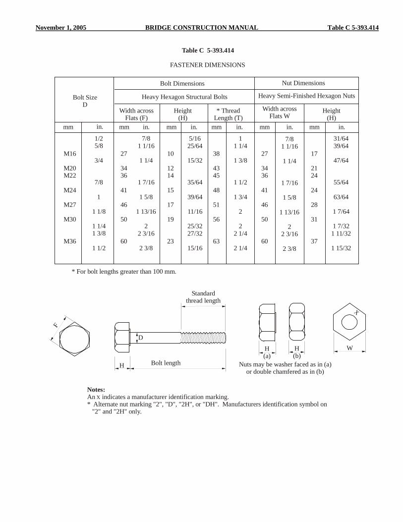
November 1, 2005 BRIDGE CONSTRUCTION MANUAL Table C 5-393.414
Bolt SizeD
Width across Flats (F)
Height(H)
* Thread Length (T)
* For bolt lengths greater than 100 mm.
Height(H)
Width acrossFlats W
mm mm mm mm mm mmin. in. in. in. in.in.
Table C 5-393.414
Bolt Dimensions Nut Dimensions
1/25/8
3/4
7/8
1
1 1/8
1 1/41 3/8
1 1/2
7/81 1/16
1 1/4
1 7/16
1 5/8
1 13/16
22 3/16
2 3/8
5/1625/64
15/32
35/64
39/64
11/16
25/3227/32
15/16
11 1/4
1 3/8
1 1/2
1 3/4
2
22 1/4
2 1/4
7/81 1/16
1 1/4
1 7/16
1 5/8
1 13/16
22 3/16
2 3/8
31/6439/64
47/64
55/64
63/64
1 7/64
1 7/321 11/32
1 15/32
M16
M20M22
M24
M27
M30
M36
27
3436
41
46
50
60
10
1214
15
17
19
23
38
4345
48
51
56
63
27
3436
41
46
50
60
17
2124
24
28
31
37
Heavy Hexagon Structural Bolts Heavy Semi-Finished Hexagon Nuts
FASTENER DIMENSIONS
H(a)
H(b)
Nuts may be washer faced as in (a)or double chamfered as in (b)
H
D
Bolt length
Standardthread length
X
Notes:An indicates a manufacturer identification marking. * Alternate nut marking "2", "D", "2H", or "DH". Manufacturers identification symbol on "2" and "2H" only.
X
F
W

Table D 5-393.414 BRIDGE CONSTRUCTION MANUAL November 1, 2005
Minimum gripMaximum grip
Standardthread length
Length of incomplete thread
Projection
* For metric sizes with the bolt lengths exceeding 100 mm add 7 mm to the thread length.
Bolt SizeD
Standard ThreadLength *
AvailableProjections mm
AvailableProjections in.
mm mm min. min.in. in. max. max.
1/25/8
3/4
7/8
1
1 1/8
1 1/41 3/8
1 1/2
11 1/4
1 3/8
1 1/2
1 3/4
2
22 1/4
2 1/4
3/327/32
7/32
7/32
11/32
15/32
11/3215/32
11/32
8/3213/32
13/32
13/32
17/32
21/32
17/3221/32
17/32
M16
M20M22
M24
M27
M30
M36
31
3638
41
44
49
56
1.00
1.251.25
1.5
1.5
1.75
2.00
3.00
3.753.75
4.50
4.50
5.25
6.00
NominalBolt Length
mm in.
Bolt Diameter
1 1/2
2
2 1/2
3
3 1/2
4
4 1/2
5
5 1/2
66 1/2
77 1/2
88 1/2
9
9/16-3/4
1 1/16-1 1/4
1 9/16-1 3/4
2 1/16-2 1/4
2 9/16-2 3/4
3 1/16-3 1/4
3 9/16-3 3/4
4 1/16-4 1/4
4 9/16-4 3/4
5 1/16-5 1/45 9/16-5 3/4
6 1/16-6 1/46 9/16-6 3/4
7 1/16-7 1/47 9/16-7 3/48 1/16-8 1/4
-
9/16-3/4
1 1/16-1 1/4
1 9/16-1 3/4
2 1/16-2 1/4
2 9/16-2 3/4
3 1/16-3 1/4
3 9/16-3 3/4
4 1/16-4 1/4
4 9/16-4 3/45 1/16-5 1/4
5 9/16-5 3/46 1/16-6 1/4
6 9/16-6 3/47 1/16-7 1/47 9/16-7 3/4
-
-
9/16-3/4
1 1/16-1 1/4
1 9/16-1 3/4
2 1/16-2 1/4
2 9/16-2 3/4
3 1/16-3 1/4
3 9/16-3 3/4
4 1/16-4 1/44 9/16-4 3/4
5 1/16-5 1/45 9/16-5 3/4
6 1/16-6 1/46 9/16-6 3/47 1/16-7 1/4
50
60
70
80
90100
110
120
130
140150
170
200
250300
13-19
23-29
33-39
43-49
53-5963-69
66-72
76-82
86-92
96-102106-112
126-132
156-162
206-212256-262
-
14.5-22
24.5-32
34.5-42
44.5-5254.5-62
57.5-65
67.5-75
77.5-85
87.5-9595.5-105
117.5-125
147.5-155
197.5-205247.5-255
-
10-19
20-29
30-39
40-4950-59
53-62
63-72
73-82
83-9293-102
113-122
143-152
193-202243-252
-
-
10.5-21
20.5-31
30.5-4140.5-51
43.5-54
53.5-64
63.5-74
73.5-8483.5-94
103.5-114
133.5-144
183.5-194233.5-244
1/2" M16 M22 7/8" M24 M30 1 1/4"
Range of Grip Lengths (in.) (mm)
Grip Lengths for A325M and A325 Bolts(includes allowance for one hardened washer)
Table D 5-393.414

November 1, 2005 BRIDGE CONSTRUCTION MANUAL Tables E & F 5-393.414
App
roxi
mat
ely
8m
m(5
/16i
n.)
AmericanStandardBeam orChannel
(with16 2/3%slope)
According to Specifications for this type of section, a16 2/3% slope, bevel washer must be used on thesloped surface of the flange under bolt head or nut.
Hardened Bevel Washers
Bolt Size Hole Diametermm in. mm in.
1/25/8
3/4
7/8
1
1 1/8
1 1/4
9/1611/16
13/16
15/16
1 1/16
1 1/4
1 3/8
M16
M20M22
M24
M27
M30
M36
18
2224
26
30
33
39
16 2/3% slope bevelwasher for American
Standard Beam or Channel
Note:A 44 mm (1 3/4 in.) square washer is furnished for bolt diameters up to and including M24 (1 in.).A 57 mm (2 1/4 in.) square washer is furnished for M27-M36 (1 1/8 in. and 1 1/4 in.) diameter bolts.
A325M8S
X
Type 1
X
A325M8S
Type 2
X
A325M8S3
Type 3
3
Type 3
3M
Type 3
A325X
Type 1
XA325
Type 3Type 2
XA325
3
Type 3Type 1
8S3
Type 3
X
X X
M
Type 1
X
X
2
Type 2 *Type 1
X
8S
X
Type 2
8S
Metric EnglishBolts
Nuts
Washers
TYPICAL FASTENER MARKINGSFOR A325 AND A325M BOLTS
Table E 5-393.414
Table F 5-393.414

Tables G & H 5-393.414 BRIDGE CONSTRUCTION MANUAL November 1, 2005
B44 (1 3/4 in.)
44 (1
3/4
in.)
Bolt Size Hole Diametermm in. mm mmin. in.
1/25/8
3/4
7/8
7/169/16
11/16
25/32
9/1611/16
13/16
15/16
M16
M20M22
M24
18
2224
26
14.0
17.519.2
21.0
B *
ID ID
OD
OD
T T C
Bolt Size Outside Diameter(OD)
Inside Diameter(ID)
Thickness (T)
mm in. mm mm mm mm mmin. in. in. in. in.
1/25/8
3/4
7/8
1
1 1/8
1 1/4
1 1/161 3/8
1 1/2
1 3/4
2
2 1/4
2 1/2
17/3211/16
13/16
15/16
1 1/16
1 1/4
1 3/8
.097
.122
.122
.136
.136
.136
.136
.177
.177
.177
.177
.177
.177
.177
7/169/16
21/32
25/32
7/8
1
1 3/32
M16
M20M22
M24
M27
M30
M36
33
4143
49
55
59
71
18
2224
26
30
33
39
3.1
3.13.4
3.4
3.4
3.4
3.4
4.6
4.64.6
4.6
4.6
4.6
4.6
14.0
17.519.2
21.0
23.6
26.2
31.5
Min. Max.C
Hardened Clipped Bevel Washers
Table G 5-393.414
Table H 5-393.414
Hardened Round Washers

November 1, 2005 BRIDGE CONSTRUCTION MANUAL 5-393.415 (1)
The inspector should make certain that proper fit-up has been made before permitting final swaging of any pin bolts in a joint, since there is no second chance to do so as with conventional high-strength bolts. The inspector should also observe the installation from time to time to make certain that the power-tool is not used in a way to break the pin tail prematurely by applying bending stresses in addition to direct tension. Additionally, the anvil and die of the power tool should be checked for excessive wear that might result in improperly formed collars. As previously mentioned, the inspector should observe that the bolting begins near the center of a group of bolts and progress toward the free edges. 5-393.415 WELDING The material covered in this section of the manual is limited to field welding. Field welding is defined as that welding which is performed after the shop fabricated material is delivered to the bridge site. Quality Control (QC) is the responsibility of the Contractor. As a minimum, the Contractor shall perform inspection and testing prior to assembly, during assembly, during and after welding, and additionally, as necessary to assure that materials and workmanship conform to the requirements of the contract documents. No welding including weld repair should be permitted unless shown in the plans or approved by the Engineer. Field welding on primary stress carrying members for the purpose of providing supports for falsework brackets, etc., will not be permitted. Welding may be permitted on shear lugs or other appurtenances which are not an integral part of the primary stress carrying member. Screed rail supports may be welded to the top flange with 6 mm (1/4 in.) fillet welds in the positive moment area, but not in the negative moment area (Area “A”.) Furthermore, if any welding is to be performed on major structural components as defined in 2471.3A1, the Inspector should contact the Structural Metals Engineer for welding requirements before the welding is performed. The Inspector should study the steel design plans and shop drawings in advance to become familiar with the construction details and provisions for welding. Weld symbols are shown in Figure A 5-393.415. Welding should not be allowed when the ambient temperature is lower than 78EC (0EF), when surfaces are wet or exposed to rain, snow, or high wind velocities, nor when welders are exposed to inclement conditions. Immediately prior to any welding, the Inspector must determine that dimensions are correct, fit-up at joints is proper, and that surfaces and edges to be welded are smooth, uniform, and free from fins, tears, cracks, and other discontinuities which would adversely affect the quality or strength of the weld. Surfaces to be welded and surfaces
adjacent to a weld should also be free from loose or thick scale, slag, rust, moisture, grease, paint, galvanizing, and other foreign material that would prevent proper welding or produce objectionable fumes. The base metal temperature shall be a minimum of 10EC (50EF) before welding will be allowed to be performed. Except as modified by the project plan, all welding shall be performed in accordance with 2471.3C. Except for stud welding using a stud welding gun, all field welding on MnDOT projects require the use of certified welders. MnDOT has a test procedure for field welders. Field welders who pass the MnDOT welder qualification test are certified for work on our projects. A wallet size card is issued (cards must be renewed periodically) to each certified welder. A list of welders currently certified is on file in the Bridge Office. Inspectors should request proof of current certification before the welder is allowed to weld. In addition, the welder is required to follow an approved Welding Procedure Specification (WPS). The Contractor shall submit all WPS's to the Metals Quality Engineer for approval before starting any welding. The WPS shall describe the type of joint being welded, current and amperage allowed, electrode and preheat required, and other essential variables needed to produce an acceptable weld. Inspectors are required to have a copy of the WPS and make sure it is being followed. A welder certification card and report card is shown in Figure B 5-393.415. Any questions regarding welder certification or weld procedures should be directed to the Metals Quality Engineer. The Inspector should obtain from the Contractor certified copies of test reports made on electrodes of the same class, size and brand, and which were manufactured by the same process and the same materials as the electrodes being used on the project. These test reports should be submitted to the Metals Quality Engineer. To facilitate inspection of welding, the Contractor is required by the Specifications to provide all necessary hand shields, glasses, etc., for the Inspector. Structural defects resulting in weak welds, may be in the form of porosity, slag inclusions, incomplete fusion, inadequate penetration, undercutting, and cracking. The correction for all of these defects would be to completely remove the defective portion of the weld to sound metal and reweld. The Contractor shall submit a repair WPS to the Structural Metals Engineer for approval. The removal of welds should be accomplished without damage to the adjacent metal. Porosity is the entrapment of voids in the weld and is generally caused by the use of excessive welding heats or incorrect manipulation of the welding electrode. Slag inclusions are best avoided by use of proper welding techniques and cleaning procedures, both before and during welding. Incomplete fusion is the failure to unite together, through fusion, adjacent layers of weld metal or weld metal and base metal. Inadequate penetration is a condition where the weld metal and base metal are not fused together for the full depth of the

5-393.415 (2) BRIDGE CONSTRUCTION MANUAL November 1, 2005
joint. Undercutting is the melting or burning away of the base metal at the toe of the weld, which results in a reduction in cross-section of the metal. Cracking of welded joints is the result of internal stresses, within the weld, exceeding the ultimate strength value. Figure C 5-393.415 shows examples of good welds and the results of poor welding techniques. If there are any questions on the acceptability of a weld or if a crack occurs on a major structural component, the Metals Quality Engineer should be contacted. The inspector should, at suitable intervals, observe the welding techniques and performance of each welder to make certain that applicable requirements are met. The inspector must make certain that the size, length and location of all welds conform to the requirements of the contract and that no unspecified welds have been added without approval. The size and contour of welds can be measured using suitable gauges. Visual inspection for cracks in welds, and base metal, and for other discontinuities should be aided by strong light magnifiers or such other devices as may be helpful. In addition, the Inspector must make certain that approved weld procedures are being followed. The Inspector should observe the welding operation to see that the weld is made in a manner creating fusion of the metal without boiling, running or excessive spatter. Check tests of qualified welders may be required at any time the welding inspector directs and as may be determined and ordered by the Engineer. Only one arc should be operated from a single power source. The Inspector should watch for arc strikes outside the area of permanent welds on any base metal. Cracks or blemishes caused by arc strikes must be ground to remove all of the defect. If arc strikes occur on a major structural component, the Metals Quality Engineer should be contacted. Before welding over previously deposited metal, all slag must be removed and the weld and adjacent base metal must be brushed clean. After all slag is removed, the finished welds should be checked as to size, shape, and quality. All welds should be free of defects such as cracks, undercutting, overlapping, objectionable irregularities, etc. The use of oversize fillet welds should be discouraged. An incorrect weld profile may indicate such weld defects as overlap, excess convexity, or excess concavity. Overlap, which may be attributed to improper technique or improper welding heat, is a weld defect in which little or no penetration occurs at the point of overlap. Excess convexity tends to produce harmful stress concentrations under load by stiffening the section unnecessarily. Correction may be accomplished by grinding to correct weld profile. Excess concavity is merely a weld of insufficient size and therefore insufficient strength. Surface irregularities such as varying widths and heights, depressions, etc., may not of themselves be weld defects. They do indicate a lack of good workmanship on the part of
the welder and they may be objectionable from the point of view of appearance. Studs are commonly used to transmit shear forces from the deck slab to steel beams. Due to OSHA related safety concerns, the studs must be field welded. Special automatic welding equipment is used for stud welding. Any automatically timed electric welding equipment of sufficient capacity to produce complete fusion between the end of the stud and the beam flange may be used. In addition, the equipment should be capable of producing a continuous weld metal fillet for the full perimeter of the stud. The welding gun, while in operation, should not be moved until the weld has solidified. At the time of welding, the studs and the areas of the beam to be welded shall be free from rust, rust pits, scale, oil, paint, moisture, or other deleterious matter. The stud base shall not be painted, galvanized, nor cadmium-plated prior to welding. Studs which do not meet this requirement should be rejected. Areas of the beam to be welded should be cleaned by surface grinding. Stud welding should not be permitted when the ambient temperature or the temperature of the beam is below 78EC (0EF) or when the surface is wet or exposed to falling rain or snow. The arc shields or ferrules must be kept dry. Any arc shields which show signs of surface moisture from dew or rain shall be oven dried at 120EC (250EF) for at least two hours before use. Before welding with a particular set-up (operator, position, amps, volts, etc.) and with a given size and type of stud, and at the beginning of each work day or shift, testing must be performed on the first two studs that are welded. The test studs should be visually examined and must exhibit full 360 degree flash. In addition to visual examination, the test consists of bending the studs after they are allowed to cool, to an angle of approximately 30 degrees from their original axes by either striking the studs on the head with a hammer or placing a pipe or other suitable hollow device over the stud and manually or mechanically bending the stud. At temperatures below 10EC (50EF), bending should preferably be done by continuous slow application of load. If on visual examination the test studs do not exhibit 360 degree flash, or if on testing, failure occurs in the weld zone of either stud, the procedure must be corrected, and two more studs be welded and tested. If either of the second two studs fails, additional welding is to be continued on separate plates of the same material, thickness and surface condition until two consecutive studs are tested and found to be satisfactory. Two consecutive studs should then be welded to the beam, tested, and found to be satisfactory before any more studs are welded to the beam. If failure occurs in the stud shank, the Metals Quality Engineer should be consulted.

November 1, 2005 BRIDGE CONSTRUCTION MANUAL Figure A 5-393.415
(N)
R
FA
L-PS(E)T
Number of spot, stud, orprojection weldsBasic weld symbol
or detail reference
(Tail omittedwhen referencenot used)
Specification, process,or other reference
Depth of preparation; size orstrength for certain welds
Groove weld size
Root opening;depth of fillingfor plug and slot welds
Contour symbol
Finish symbolGroove angle; includedangle of countersunkfor plug welds
Length of weld
Field weld symbol
Arrow connecting reference line toarrow side member ofjoint or arrow sideof joint
Weld-all-around symbolReference line
Tail
(Bot
h
Si d
es)
Arr
ow
S ide
Oth
e rS i
de
Elements in thisarea remain as
shown when tailand arrow are
reversed
Weld allaround Field Weld
MeltThrough
ConsumableInsert
(Square)
Backingor
Spacer(Rectangle)
CountourFlushor Flat Convex Concave
Groove
Square Scarf V Bevel U J Flare-V Flare-bevel
Pitch (center to center spacing of weld)
FilletPlugor
SlotStud
Spotor
ProjectionSeam
Backor
BackingSurfacing
Flange
Edge Corner

Figure B 5-393.415 BRIDGE CONSTRUCTION MANUAL November 1, 2005
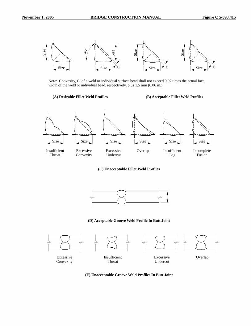
November 1, 2005 BRIDGE CONSTRUCTION MANUAL Figure C 5-393.415
(A) Desirable Fillet Weld Profiles
(C) Unacceptable Fillet Weld Profiles
(D) Acceptable Groove Weld Profile In Butt Joint
(E) Unacceptable Groove Weld Profiles In Butt Joint
(B) Acceptable Fillet Weld Profiles
Note: Convexity, C, of a weld or individual surface bead shall not exceed 0.07 times the actual facewidth of the weld or individual bead, respectively, plus 1.5 mm (0.06 in.)
Size
Size
Size
Size
Size
ExcessiveConvexity
ExcessiveConvexity
Size
Size
InsufficientThroat
InsufficientThroat
Size
Size
Overlap
Overlap
Size
Size
InsufficientLeg
Size
IncompleteFusion
Size
ExcessiveUndercut
ExcessiveUndercut
Size
C CC
450

5-393.416 BRIDGE CONSTRUCTION MANUAL November 1, 2005
Studs that fail the test on the bridge beam should be removed and the area ground flush to remove any defects. The inspector should make a visual inspection of all welded stud shear connectors. After welding, arc shields must be broken free from studs to be embedded in concrete, and where practical, from all other studs. The studs, after welding, must be free of any discontinuities or substances that would interfere with their intended function. In addition, each stud should be given a light blow with a hammer and the inspector should test bend at least one stud in each 100 studs welded, to an angle of 15E. Any stud which does not have a complete end weld (360E of continuous expelled metal around base of stud), any stud which does not emit a ringing sound when given a light blow with a hammer, any stud that has been repaired by welding, or any stud which has less than normal reduction in height due to welding, should be struck with a hammer and bent 15E in the direction that will place the defective portion of the weld in the greatest tension. The studs tested that show no sign of failure should be left in the bent position. Studs that crack in the fusion zone should be removed and replaced as defined above. Studs that crack in the shank should be replaced as directed by the Engineer. Occasional minor discontinuities in the weld fillet of the studs may be repaired by adding a 8 mm (5/16 in.) fillet weld using a shielded metal-arc process with low-hydrogen electrodes in accordance with the requirements of Spec. 2471.3J4b1. Certified welders are required for repair welding. However, repeated defects should not be permitted and corrective measures as outlined above should be taken as soon as it becomes evident that modifications of the established welding procedure are needed. All containers of studs shall be identified by the heat number of the steel from which the studs were produced. Field inspectors checklist for inspection of structural metals.
Action Yes No Copies of piling mill test reports were sent to Structural Metals Unit.
Copies of approved weld procedures were sent to Structural Metals Unit.
Structural metals items had a shop inspection tag or were reported on form 2415.
Copies of welding electrode certifications were sent to Structural Metals Unit.
A list of all welders that welded on the job was sent to the Structural Metals Unit.
Action Yes No Contractor’s painting quality control form listing painter’s name, temperatures, humidity, profile, paint thickness, etc was sent to Structural Metals Unit if field painting was done.
Copy of torque and tension values obtained for turn-of-the-nut certification test was sent to the Structural Metals Unit.
5-393.416 STRAIGHTENING BENT MATERIAL Members which have become bent, crimped, or otherwise damaged should not be erected until they have been straightened or repaired to the satisfaction of the Engineer. Technical advice will be provided by the Structural Metals Engineer regarding permissible methods of straightening or repairing bent materials, and concerning conditions that may be a cause for rejection of materials. The Structural Metals Engineer should always be contacted in cases involving damage to main structural members. Only qualified personnel should be allowed to perform the work of straightening and repairing damaged structural members. Damaged sections should be straightened by methods that will not shear, fracture, or prestress the bolts, welds, or connecting members. Generally, all material should be straightened cold, if practicable. Plated, galvanized, enameled, heat treated, cold drawn, copper alloy, malleable iron, tempered aluminum, and similar materials that cannot be satisfactorily straightened cold, should be returned to the fabricator for repair or replacement. Mild steel and structural grade steel may be heated when necessary to accomplish straightening. Temperature crayons may be required to avoid overheating. Other carbon steels and low allow steels should not be heated unless specific approval is granted by the Structural Metals Engineer.
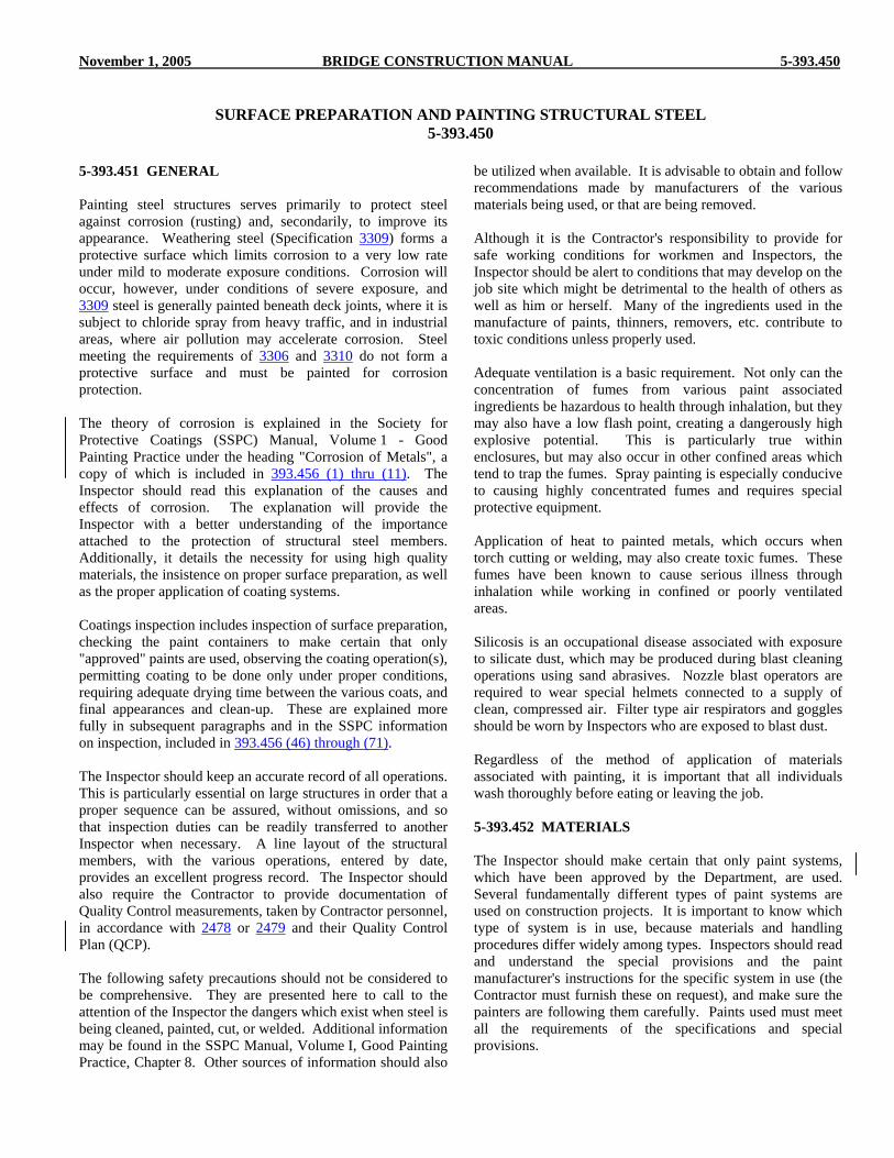
November 1, 2005 BRIDGE CONSTRUCTION MANUAL 5-393.450
SURFACE PREPARATION AND PAINTING STRUCTURAL STEEL 5-393.450
5-393.451 GENERAL Painting steel structures serves primarily to protect steel against corrosion (rusting) and, secondarily, to improve its appearance. Weathering steel (Specification 3309) forms a protective surface which limits corrosion to a very low rate under mild to moderate exposure conditions. Corrosion will occur, however, under conditions of severe exposure, and 3309 steel is generally painted beneath deck joints, where it is subject to chloride spray from heavy traffic, and in industrial areas, where air pollution may accelerate corrosion. Steel meeting the requirements of 3306 and 3310 do not form a protective surface and must be painted for corrosion protection. The theory of corrosion is explained in the Society for Protective Coatings (SSPC) Manual, Volume 1 - Good Painting Practice under the heading "Corrosion of Metals", a copy of which is included in 393.456 (1) thru (11). The Inspector should read this explanation of the causes and effects of corrosion. The explanation will provide the Inspector with a better understanding of the importance attached to the protection of structural steel members. Additionally, it details the necessity for using high quality materials, the insistence on proper surface preparation, as well as the proper application of coating systems. Coatings inspection includes inspection of surface preparation, checking the paint containers to make certain that only "approved" paints are used, observing the coating operation(s), permitting coating to be done only under proper conditions, requiring adequate drying time between the various coats, and final appearances and clean-up. These are explained more fully in subsequent paragraphs and in the SSPC information on inspection, included in 393.456 (46) through (71). The Inspector should keep an accurate record of all operations. This is particularly essential on large structures in order that a proper sequence can be assured, without omissions, and so that inspection duties can be readily transferred to another Inspector when necessary. A line layout of the structural members, with the various operations, entered by date, provides an excellent progress record. The Inspector should also require the Contractor to provide documentation of Quality Control measurements, taken by Contractor personnel, in accordance with 2478 or 2479 and their Quality Control Plan (QCP).
The following safety precautions should not be considered to be comprehensive. They are presented here to call to the attention of the Inspector the dangers which exist when steel is being cleaned, painted, cut, or welded. Additional information may be found in the SSPC Manual, Volume I, Good Painting Practice, Chapter 8. Other sources of information should also
be utilized when available. It is advisable to obtain and follow recommendations made by manufacturers of the various materials being used, or that are being removed. Although it is the Contractor's responsibility to provide for safe working conditions for workmen and Inspectors, the Inspector should be alert to conditions that may develop on the job site which might be detrimental to the health of others as well as him or herself. Many of the ingredients used in the manufacture of paints, thinners, removers, etc. contribute to toxic conditions unless properly used. Adequate ventilation is a basic requirement. Not only can the concentration of fumes from various paint associated ingredients be hazardous to health through inhalation, but they may also have a low flash point, creating a dangerously high explosive potential. This is particularly true within enclosures, but may also occur in other confined areas which tend to trap the fumes. Spray painting is especially conducive to causing highly concentrated fumes and requires special protective equipment. Application of heat to painted metals, which occurs when torch cutting or welding, may also create toxic fumes. These fumes have been known to cause serious illness through inhalation while working in confined or poorly ventilated areas. Silicosis is an occupational disease associated with exposure to silicate dust, which may be produced during blast cleaning operations using sand abrasives. Nozzle blast operators are required to wear special helmets connected to a supply of clean, compressed air. Filter type air respirators and goggles should be worn by Inspectors who are exposed to blast dust. Regardless of the method of application of materials associated with painting, it is important that all individuals wash thoroughly before eating or leaving the job. 5-393.452 MATERIALS The Inspector should make certain that only paint systems, which have been approved by the Department, are used. Several fundamentally different types of paint systems are used on construction projects. It is important to know which type of system is in use, because materials and handling procedures differ widely among types. Inspectors should read and understand the special provisions and the paint manufacturer's instructions for the specific system in use (the Contractor must furnish these on request), and make sure the painters are following them carefully. Paints used must meet all the requirements of the specifications and special provisions.

5-393.453 BRIDGE CONSTRUCTION MANUAL November 1, 2005
The most common paint systems currently used on new steel bridge elements are zinc-rich primers (organic or inorganic) with an epoxy mid-coat and a urethane top coat. The mid-coat and top coat may also be applied over hot-dip galvanizing with proper surface preparation. The primer, intermediate, and top coats shall be by the same manufacturer. Each of the paints used in these systems consist of two or more components that are mixed in limited batches just before use. Exact mixing of components is essential and the Contractor's procedures for mixing should be reviewed to verify that accurate batching is achieved. Bridge elements may be delivered to the job site unpainted, with only the prime coat, or with a full shop paint system. Components that are fully shop painted may need to be touched up after erection due to shipping and handling damage. The plan and special provisions may also require the fasteners to be painted after installation. Components that have only a shop-applied prime coat will be field painted with the other coats as directed in the special provisions. Most shop priming for later field top coating is done with an inorganic zinc-rich paint. Inorganic primers should not be applied in the field. Handling damage shall be touched up with organic epoxy zinc-rich primer prior to applying the remaining coats. All field painting requires the inspector to closely monitor the procedures found in the paint manufacturer's instructions and the special provisions. The organic zinc-rich primer system can be used where an SSPC-SP10-Near-White Blast Cleaning surface preparation or SSPC-SP6-Commercial Blast Cleaning, surface preparation has been used. Only paint systems approved by Mn/DOT shall be used. If the Contractor wants to use an unapproved paint system, he must get written approval from the Structural Metals Engineer. 5-393.453 SURFACE PREPARATION Surface preparation of structural steel members is undoubtedly the most important step in obtaining maximum protection against corrosion. Regardless of the quality of the paint system and the care exercised by the painters in applying the paint, an improperly prepared surface will almost certainly result in an early paint failure, and will require costly maintenance. Therefore, it is essential that a thorough inspection be made of both painted and unpainted steel surfaces immediately prior to starting painting. The Contractor can often eliminate considerable work by hosing down the steel under a deck slab during and immediately after a deck pour, rather than waiting until the start of painting. Fresh mortar can be easily flushed off, but it is usually difficult to remove after it has dried and hardened. In any event, the Inspector should make certain that the cleaning has been completed before painting is permitted on these surfaces.
Foreign matter should be removed by means which will not be detrimental to the steel, and which will not leave a residual film on the surface that cannot be wiped off. Regardless of the degree of surface operations, grease and oil films should first be removed by the use of solvents or other effective methods. Solvents cover a wide range of materials, such as mineral spirits, naphtha, coal tar solvents, alcohols, ethers, mixed alcoholic-ether compounds, petroleum fractions and many others. Many solvents give off toxic fumes and require adequate ventilation and other precautions during their use. The manufacturer's recommendations should be available, and should be followed, whenever any of these materials are used. More detailed information on surface preparation, as well as other phases of painting, can be found in The Society for Protective Coatings Manual, Volume I, "Good Painting Practice", which is available at the District Offices. All visible oil, grease, soil, drawing and cutting compounds and other soluble contaminants should be removed from surfaces to be painted prior to hand tool cleaning, power tool cleaning, or blast cleaning. Heavy deposits should be removed with a scraper followed by scrubbing or wiping with an appropriate cleaning solution. All visible traces of contaminants are to be removed with final wiping performed with clean rags and clean solvent. A discussion of solvent cleaning methods and Specification SSPC-SP1-"Solvent Cleaning" are included in Figure 5-393.456 (12) thru (13). Surfaces of steel members for which blast cleaning is specified must be blasted in accordance with the requirements of the specifications. Painting metal structures requires that structural steel members for superstructures be blast cleaned on those surfaces which are accessible for blast cleaning; and that those surfaces of these members which are not accessible should be hand-tool cleaned. Blast cleaning should be in accordance with SSPC-SP10-"Near White Blast Cleaning", a copy of which is included as 393.456 (26) thru (31). "Accessible surfaces" should be considered to mean those surfaces which would be accessible for blast cleaning in the erected structure, using conventional rigging. Specification 2479, for painting with inorganic zinc-rich paint systems, requires that all surfaces to be prime coated shall be blast cleaned in accordance with SSPC-SP10. Prime coats are required for all contact surfaces including bolted splices, which must be blast cleaned and primed at the fabricator's shop unless specific approval is obtained from the Project Engineer for field painting. If field painting is allowed, splice plates and contact surfaces of steel diaphragms, "X" bracing, etc. must be blast cleaned and painted prior to erection as these areas are not accessible in the erected position. Surface preparation meeting requirements of SSPC-SP10 is critical at

November 1, 2005 BRIDGE CONSTRUCTION MANUAL 5-393.454
the time of paint application for zinc-rich systems as these paints depend on intimate contact with bare steel to provide galvanic protection. A surface profile (roughness) requirement is frequently used for zinc-rich systems. The Special Provisions may require blast cleaning in accordance with SSPC-SP6, unpainted 3309 steel. Blast cleaning is often required on bolted splice plates to improve friction characteristics. Where uniform appearance of unpainted steel is important, such as on fascia beams, blast cleaning may be required to promote uniform rusting and avoid a "spotty" appearance. Specification 1717 requires that the Contractor take necessary precautions to prevent pollution of flowing and impounded waters. It further requires compliance with all applicable regulations of the Minnesota Pollution Control Agency and Minnesota Department of Natural Resources. The Special Provisions will contain any specific requirements pertaining to the project. Sand blasting and painting shall be done to minimize the escape of paint solvents, and cleaning solutions into public waters or the atmosphere. The primary emphasis should be on containment within the project area rather than on recovery systems such as floating booms, skimmers, etc. Paint chips and sand, if readily recoverable, are to be cleaned up and transported to a sanitary landfill. 5-393.454 APPLICATION OF INDUSTRIAL COATINGS Included in 5-393.456 (31) thru (45) are copies of sections of the SSPC Manual dealing with the application of industrial coatings. They are for the Inspector's information and guidance, and for his or her use, providing they are consistent with Mn/DOT Specifications. The Specifications should be followed in the event there is a discrepancy between the Specifications and the SSPC. The various paint systems in use on bridge elements have system-specific requirements for application. To ensure successful painting results, the painters must follow the requirements of temperature, humidity, surface preparation and cleanliness for each component of the paint system. These and other requirements are addressed in the paint manufacturer's instructions, the Standard Specifications, and the special provisions. For the zinc-rich systems (specification 2478), the specifications require a technical representative of the paint manufacturer to be on-site or on call during paint application. Inspectors should refer questions about the system requirements to this representative, preferably in a pre-painting conference. An important area in which the technical representative can help the Inspector(s) is in recognizing a properly prepared and cleaned surface. Intermediate coat & top coat paints may be applied directly to a galvanized surface after thorough cleaning and light sweep
blasting as per special provisions. Cleaning shall consist of removal of soil, cement mortar, and other surface dirt with a stiff brush, scraper or other suitable tool. Oil or grease is removed by wiping or scrubbing the surface with rags or brushes wetted with a suitable solvent in accordance with SSPC-SP1-Solvent Cleaning [See 5-393.456 (12) thru (13)]. A light sand blasting sufficient to roughen the surface should be performed. Paint shall not be applied to metal surfaces when weather conditions are unsatisfactory for the work or the conditions include an air temperature below 4EC (40EF), metal surfaces less than 3EC (5EF) above the dew point, air that is misty, or metal surfaces that are damp or frosted. Primer may be applied to rivet heads and to bolt heads and nuts during cold, dry weather, to preserve them against corrosion. These areas should be inspected prior to subsequent coating. If any area is found to be defective, it should be removed. Best results are usually obtained when painting is done during dry, warm weather, with a light breeze. While the ideal combination of these conditions is desirable, it is not realistically attainable insofar as specification requirements are concerned. Whether it is to be applied at the fabricating plant or elsewhere, the prime coat must be applied immediately after surface preparation, usually the same day. Blast cleaned surfaces, depending upon humidity conditions and the degree of surface brightness of the steel, will develop surface corrosion almost immediately after cleaning. Therefore it is imperative that delays in starting prime coat painting be avoided. If delays are encountered in application of the prime coat, which permits "flash rust" to form on newly cleaned steel, it is necessary to require additional cleaning to remove the newly formed rust. It is important that "touch up" areas, which are primed after field welding, be thoroughly cleaned by scrubbing and washing with warm water. A mild (5 percent) solution of phosphoric acid followed by water rinsing and drying may also be used. From the standpoint of protection against corrosion, the prime coat of paint is the most important of the several coats of paint applied to the steel surfaces. It is particularly necessary that special attention be given to its application. The dry film thickness shall be in accordance with the manufacturer's Product Data Sheet (PDS). Special gages have been purchased and distributed to the Districts for use by the painting Inspector(s). Diligent usage should be made of these instruments to assure that the dry film thickness (dft) of the primer coat has been met. It is important that the coverage be uniform, both in thickness and appearance, since poor workmanship in application of the

5-393.455 BRIDGE CONSTRUCTION MANUAL November 1, 2005
prime coat will be reflected in subsequent coats. Required thickness of paint may vary and specifications/special provisions should be consulted for each project. Small cracks and cavities between abutting or mating members or parts, which have not been sealed against admission of moisture prior to applying the second coat, should be filled with approved caulking before the final application. Spot coating of damaged areas is required prior to application of the finish coat. Damage may result from handling, shipping, erection, welding, bolting and/or falsework or form construction. Damaged areas should be cleaned, as necessary, to meet the surface preparation requirements for the type of paint system. Before applying any subsequent coat of paint, the previous coat must be cured "to recoat" in accordance with the manufacturer's Product Data Sheet (PDS). When it has been determined that the previous coat has cured "to recoat", the Inspector should make certain that the surfaces to be painted is first cleaned of dust, dirt, sand, and mortar, and all other foreign matter that may have come upon it since the previous coat was applied. Painting should not be permitted when the wind velocity carries objectionable amounts of dust, sand, and debris. Dusty road surfaces in the area may require treatment or occasional watering. The top coat shall not be started until after the deck slab concrete has been placed, because of damage resulting from form removal, mortar leakage, and other causes. The DFT shall be measured with a properly calibrated thickness gage in accordance with SSPC-PA2-measurement of dry coating thickness with magnetic gages. If the coating thickness cannot be satisfactorily determined, a destructive test shall be used in accordance with 2478.3F1. 1. Measuring Devices Various measuring devices are available for determining the DFT. [For additional information see 393.456 (61) through (67).] Rotating dial magnetic type gages are available at District Offices for thickness measurements. This gage, when properly used, can be a valuable tool for measuring coating thicknesses on magnetic steel. This gage is expensive and warrants careful handling. Secure anchor cord prior to using. The rotation of the gage dial in a clockwise direction increases spring tension against the magnetic force holding gate probe to the steel. The thicker the paint coating the weaker the magnetic contact.
2. Use of Magnetic Gage a. Hold the gage very steady against the steel to be tested. Any movement of the gage or vibration in the steel surface will yield readings that are too high. b. Rotate the gage dial in a counter-clockwise direction until the red probe goes to the down position and stays in that position as dial rotation is reversed. c. Slowly, in a steady continuous motion, rotate the dial in a clockwise direction until magnetic contact is broken. d. Note dial reading, reverse dial and take a second reading. 3. Other Gages Other types of gages are available from the Bridge Office, Office of Construction and Materials Engineering, and some District Offices. Instructions for use of gages should be obtained and reviewed prior to their use. 4. Calibration Procedure for Thickness Gages While other procedures could be used, this procedure tends to cancel out gage errors and is recommended by the Steel Structures Painting Council. a. Correction Factor (after sandblasting and prior to painting). Use a 76 micron (3 mil) plastic shim, take thickness readings on each unpainted beam face at 3 locations. Take 3 readings at each location (within a 6 inch circle). Subtract 76 microns (3 mils) from the thickness reading to obtain the correction factor for prime coat thickness measurements. The Correction Factor is an approximate measurement of the profile or roughness of the steel surface due to sandblasting. b. Repeat 4.a. using a 127 micron (5 mil) shim to determine correction factor for total paint thickness measurement. c. After the prime coat has been applied, take thickness readings at approximately the same locations measured in 4.a. (Without shim). Subtract prime-coat correction factor. d. After the required top-coats have been applied, repeat readings and subtract correction factor for total paint thickness measurement. e. Calibration - Periodic reading should be taken both with and without the above mentioned shims on a polished smooth surface steel plate [minimum dimensions 75 mm (3 inches) x 150 mm (6 inches) x 13 mm (1/2 inch]. This will assure that the gage has not changed its calibration. 5-393.455 FINAL CLEANUP AND MISCELLANEOUS It is the responsibility of the contractor to remove paint from surfaces which have become stained or blemished

November 1, 2005 BRIDGE CONSTRUCTION MANUAL 5-393.456
by the painting operations. It is better to discuss this with the superintendent or foreman in advance of starting to paint, so that he will be aware of the consequences of carelessness. Some areas such as slope paving, may be covered with tarps, plastic sheets, or other fabric, and thus prevent the need for extensive and difficult cleaning later. In most cases, proper precautions and painting procedures will minimize the amount of cleanup required, and will result in a neater looking job. Carelessness in paint application is also apt to create a problem in public relations, as well as cause contamination of leaf type vegetables, grasses, fruit trees, and pollution of nearby waters. All practicable means should be used which would help avoid these problems, even to the extent of changing application methods when necessary. 5-393.456 STEEL STRUCTURES PAINTING COUNCIL EXCERPTS The following pages are from SSPC Manual - Volume 1 - "Good Painting Practice, Fourth Edition" and Volume 2 - "Systems and Specifications, 2005 Edition" and are reprinted with the written permission of the Society for Protective Coatings, 40 24th Street, Pittsburgh, Pa. 15222, for the Inspector's information and guidance. It should be understood, however, that recommendations made therein are enforceable only to the extent that they are consistent with the Mn/DOT specifications which apply. Index to the Society of Protective Coatings Manuals excerpts
Corrosion of Metals 5-399.456 (1) thru (11) SSPC-SP 1 - Solvent Cleaning 5-393.456 (12) thru (13) SSPC-SP 2 - Hand Tool Cleaning 5-393.456 (14) thru (15) SSPC-SP 6/NACE No. 3 - Commercial Blast Cleaning 5-393.456 (16) thru (20) SSPC-SP 7/NACE No. 4 - Brush-Off Blast Cleaning 5-393.456 (21) thru (25) SSPC-SP 10/NACE No. 2 - Near-White Blast Cleaning 5-393.456 (26) thru (30) Application of Industrial Coatings 5-393.456 (31) thru (45) Inspection 5-393.456 (46) thru (71)

5-393.456 (1) BRIDGE CONSTRUCTION MANUAL November 1, 2005
Chapter 1.1 Corrosion of Metals
James F. Jenkins and Richard W. Drisko Introduction
This chapter describes in basic terms the causes and mechanisms of corrosion. Corrosion is defined as “the chemical or electrochemical reaction between a metal and its environment resulting in the loss of the material and its properties.” 1 Various types of corrosion are discussed and the basic principles behind the use of protective coatings and cathodic protection for corrosion control are also covered. The strategies used in corrosion control by design are briefly discussed as well. This basic knowledge helps in understanding how protective coatings, cathodic protection, and other corrosion control methods can best be used as part of a total corrosion control program. Further information on these corrosion control methods can be found in subsequent chapters.
Why Metals Corrode With few exceptions, metallic elements are
found in nature in chemical combination with other elements. For example, iron is usually found in nature in the form of an ore, such as iron oxide. This com- bined form has a low chemical energy content and is very stable. Iron can be produced from iron ore by a high temperature smelting process. The heat that is added during smelting breaks the chemical bond between the iron and the oxygen. As a result, the iron and other metals used in structural applications have a higher energy content than they do in their original state, and are relatively unstable.
Corrosion is a natural process. Just like water flows to seek the lowest level, all natural processes tend towards the lowest possible energy states. Thus, iron and steel have a natural tendency to combine with other chemical elements to return to their lower energy states. In order to do this, iron and steel will frequently combine with oxygen, present in most natural environ- ments, to form iron oxides, or “rust,” similar chemically to the original iron ore. Figure 1 illustrates this cycle of refining and corrosion of iron and steel.
When rust forms on an iron or steel structure, metal is lost from the surface, reducing cross section
and strength. Rust is also unsightly and can cause contamination of the environment and industrial products. It is further detrimental in that it is not a stable base for coatings.
Figure 1. The corrosion cycle.
Immunity and Passivity Some metals such as gold and platinum have
lower energy levels in their metallic form than when combined with other chemical elements. These metals are often found in nature in the metallic form and do not tend to combine with other elements. They are thus highly resistant to corrosion in most natural environments. These materials are said to be immune to corrosion in those natural environments.
Other metals and alloys, while in a high energy state in their metallic forms, are resistant to corrosion due to formation of passive films (usually oxides) on their surfaces. These films form through a natural process similar to corrosion, and are usually invisible to the naked eye. They are, however, tightly adherent and continuous and serve as a barrier between the underlying metal and the environment. Stainless steels, aluminum alloys, and titanium are examples of metals that are in a high energy state in their metallic forms, but are relatively resistant to corrosion due to the formation of passive films on their surfaces. However, particularly in the case of stainless
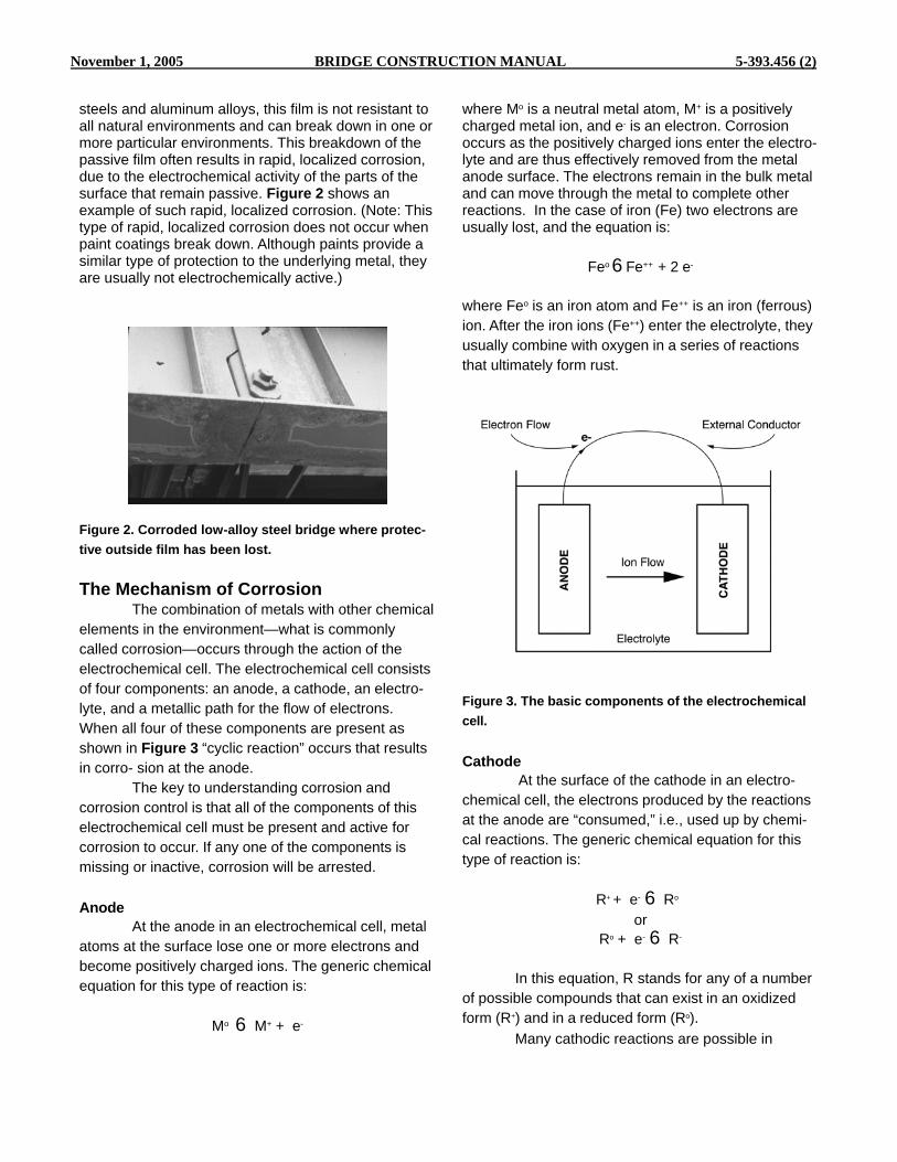
November 1, 2005 BRIDGE CONSTRUCTION MANUAL 5-393.456 (2)
steels and aluminum alloys, this film is not resistant to all natural environments and can break down in one or more particular environments. This breakdown of the passive film often results in rapid, localized corrosion, due to the electrochemical activity of the parts of the surface that remain passive. Figure 2 shows an example of such rapid, localized corrosion. (Note: This type of rapid, localized corrosion does not occur when paint coatings break down. Although paints provide a similar type of protection to the underlying metal, they are usually not electrochemically active.)
Figure 2. Corroded low-alloy steel bridge where protec- tive outside film has been lost.
The Mechanism of Corrosion The combination of metals with other chemical
elements in the environment—what is commonly called corrosion—occurs through the action of the electrochemical cell. The electrochemical cell consists of four components: an anode, a cathode, an electro- lyte, and a metallic path for the flow of electrons. When all four of these components are present as shown in Figure 3 “cyclic reaction” occurs that results in corro- sion at the anode.
The key to understanding corrosion and corrosion control is that all of the components of this electrochemical cell must be present and active for corrosion to occur. If any one of the components is missing or inactive, corrosion will be arrested.
Anode At the anode in an electrochemical cell, metal
atoms at the surface lose one or more electrons and become positively charged ions. The generic chemical equation for this type of reaction is:
Mo 6 M+ + e-
where Mo is a neutral metal atom, M+ is a positively charged metal ion, and e- is an electron. Corrosion occurs as the positively charged ions enter the electro- lyte and are thus effectively removed from the metal anode surface. The electrons remain in the bulk metal and can move through the metal to complete other reactions. In the case of iron (Fe) two electrons are usually lost, and the equation is:
Feo 6 Fe++ + 2 e-
where Feo is an iron atom and Fe++ is an iron (ferrous) ion. After the iron ions (Fe++) enter the electrolyte, they usually combine with oxygen in a series of reactions that ultimately form rust.
Figure 3. The basic components of the electrochemical cell. Cathode
At the surface of the cathode in an electro- chemical cell, the electrons produced by the reactions at the anode are “consumed,” i.e., used up by chemi- cal reactions. The generic chemical equation for this type of reaction is: R+ + e- 6 Ro
or Ro + e- 6 R-
In this equation, R stands for any of a number
of possible compounds that can exist in an oxidized form (R+) and in a reduced form (Ro).
Many cathodic reactions are possible in

5-393.456 (3) BRIDGE CONSTRUCTION MANUAL November 1, 2005
natural environments. The cathodic reactions that actually occur are dependent on the chemical compo- sition of the electrolyte. In many instances where the electrolyte is water, the cathodic reaction is:
2H2O+O2+4e64OH-
In this reaction, two water molecules (H2O) combine with one oxygen molecule (O2) and four electrons to form four hydroxide ions (OH-). In this case, the water and oxygen are reduced as in the generic cathodic reaction above. These hydroxide ions tend to create an alkaline environment at active cathodic areas.
Metallic Path
A metallic path between the anode and the cathode allows electrons produced at the anode to flow to the cathode. A metallic path is required in the corrosion cell because the electrolyte cannot carry free electrons. In many cases, where the anode and cathode are on the same piece of metal, the metal itself is the “metallic path” that carries the electrons from the anode to the cathode.
Electrolyte
The electrolyte serves as an external conduc- tive media and a source of chemicals for reactions at the cathode, and as a reservoir for the metal ions and other corrosion products formed at the anode. Within the electrolyte, a flow of charged ions balances the flow of electrons through the metallic path. Under atmospheric conditions, the electrolyte consists of just a thin film of moisture on the surface, and the electro- chemical cells responsible for corrosion are localized within this thin film. Under immersion conditions, however, much more electrolyte is present, and the electrochemical cells responsible for corrosion can involve much larger areas.
Rate of Reaction
Many factors can affect corrosion, but the bottom line is that the rate at which corrosion occurs is limited by the rate of reaction at the least active component of the electrochemical cell. For example, if there is an incomplete metallic path, this may be the limiting factor in the overall corrosion reaction. In this case, the electrochemical cell responsible for corrosion is similar to that in a flashlight battery when the
flashlight is switched off (see Figure 4). When a battery is installed in a circuit such as a flashlight, no current flows until the flashlight is switched on. The high effective resistance of the open switch prevents current flow and the electrochemical discharge of the battery. Similarly, an incomplete metallic path prevents corrosion. The nature of the electrolyte may also affect the overall corrosion reaction. If the available electro- lyte is very pure water that has relatively few ions, the ion flow can be the limiting factor. In many cases of corrosion under immersion conditions, the amount of oxygen available for the cathodic reaction is the limiting factor. Many methods for controlling corrosion target only one component of the overall electrochemi- cal cell. By controlling the rate of just one of the reactions involved in the overall electrochemical cell, the overall rate of corrosion can be controlled.
It should be noted that temperature has an effect on the rate of the corrosion reaction. However, this effect is very complex, and is beyond the scope of this text. In the case of dissimilar metal corrosion, the potential difference between the metals also has an effect on reaction rate. This is discussed in the gal- vanic corrosion section of this chapter.
Figure 4. The dry cell battery.
Measuring Corrosion There are many methods of measuring
corrosion: Weight Loss
Weight loss is one of the most widely used methods of measuring corrosion. A sample is first carefully cleaned to remove all surface contamination. After cleaning, it is weighed. It is then exposed to the

November 1, 2005 BRIDGE CONSTRUCTION MANUAL 5-393.456 (4)
environment in question and then recleaned and reweighed after a given period of time. If no corrosion has occurred, there will be no weight loss.
Size Measurement The dimensions of the sample are measured
before and after exposure. No change in dimensions indicates that no corrosion has occurred.
Visual Observation Even minor amounts of corrosion are readily
visible due to roughening of the surface.
Chemical Analysis Surface deposits and the environments are
tested for corrosion products. If surface deposits and the environment test negative for corrosion products (i.e., none present), it can be assumed that no corro- sion has occurred.
Forms of Corrosion
No Attack As stated in section immunity and passivity,
some metals and alloys are essentially unaffected by corrosion in certain environments. This may be either because they are more stable in their metallic forms than in a combined forms or because they form natural protective films on their surfaces that provide com- pletely effective passivity. However, just because a given metal or alloy is essentially unaffected by corrosion in one or more environments does not mean that it is resistant to corrosion in all environments. That no corrosion has occurred can be verified by one of the methods described in the previous section.
Uniform Corrosion Uniform corrosion is a form of corrosion in
which a metal is attacked at about the same rate over the entire exposed surface. While considerable surface roughening can take place in uniform corro- sion, when the depth of attack at any point exceeds twice the average depth of attack, the corrosion is no longer considered to be uniform.
When a metal is attacked by uniform corro- sion, the location of anodic and cathodic areas shifts from time to time, i.e., every point on the surface acts as both an anode and a cathode at some time during the exposure. A schematic representation of uniform
corrosion is shown in Figure 5, where anodic and cathodic sites periodically reverse. In this case, the metallic path is through the metal itself. The electrolyte may either be a thin film of moisture in atmospheric exposure, a liquid in which the surface is immersed, or water contained in moist earth.
The amount of uniform corrosion is usually measured by weight loss. If weight loss is determined over a given period of time, it can also be used to calculate an average rate of metal loss over the entire surface. This corrosion rate is usually expressed in mils (0.001 inch) per year (mpy) or millimeters per year (mm/yr).
This is a good way to measure the amount and rate of corrosion if the corrosion is truly uniform; however, these average rates can give misleading results if the corrosion is not uniform over the entire surface. (See the section on pitting for further informa- tion.) Direct measurement of metal loss through metal thickness is also sometimes performed and can be used to determine corrosion rate in mpy or mm/yr.
Figure 5. The corrosion cell on a metal surface.
Since corrosion rates commonly vary with time (e.g., slower as corrosion products form protective films), they are usually measured over several different intervals. Corrosion rates can also be measured continuously for extended periods, using electrochemi- cal techniques to determine how the rates are affected by time.
A coating is a very effective tool in combating uniform corrosion because corrosion usually proceeds slowly at local sites where the coating breaks down or is damaged. These areas can therefore be repaired before significant damage occurs, assuming that

5-393.456 (5) BRIDGE CONSTRUCTION MANUAL November 1, 2005
inspection identifies the defects at an early stage. Galvanic Corrosion
When two or more dissimilar metals are connected by a metallic path and exposed to an electrolyte, galvanic corrosion can occur as shown in Figure 6. This dissimilar metal corrosion is driven by the difference in electrical potential between the metals. An electrochemical cell is formed in which the more active metal acts as an anode and the less active metal acts as a cathode. In galvanic corrosion, the more active metal corrodes more than if it were not electrically coupled, and the less active metal corrodes less than if it were not electrically coupled.
A “galvanic series” table that lists metals in order of their electrical potential in a given environment can be used to determine which metal in a given
In atmospheric exposures, the anodic area and cathodic area involved in galvanic corrosion are usually about equal in size. This is because the electrical resistance of the thin film of moisture acting as the electrolyte is very large over distances much more than 1/8 inch or so (1-2 mm). Under immersion conditions, however, the effective resistance of the electrolyte is much less and galvanic corrosion effects have a much greater range. The cathodic reaction is often the limiting factor in corrosion under immersion conditions due to the limited availability of dissolved oxygen.
As described in cathode section, in many instances where the electrolyte is water, the cathodic reaction is:
2H2O+O2+4e64OH-
2 combination will act as an anode and which will act as a cathode. Table 1 is a galvanic series derived from exposure of common metals to seawater. The galvanic activity of metals in other environments is similar to that in seawater, but significant differences may occur. It should be noted that in North America, galvanic series are listed with the most active metals at the top, but the opposite may be true in other parts of the world. To determine which convention has been used in a particular galvanic series table, look for active metals like zinc, magnesium or aluminum and see if they are listed at the top or at the bottom. It should also be noted that some metals, such as the 300 Series stainless steel, are listed twice.
Figure 6. Galvanic corrosion cell.
Thus, the rate at which electrons can be consumed at the cathode limits the rate of galvanic attack in these situations.
Table 1. Galvanic Series Derived from Exposure of Common Metals to Seawater.
The amount of galvanic corrosion that occurs in a given situation can be measured indirectly by monitoring the current flow between the anodes and cathodes. It can also be measured directly by deter- mining the weight loss of the anodic and cathodic materials, or by some other direct means of measure- ment such as pitting depths or thickness measure- ments as appropriate to the form of attack.
Relative rates of galvanic attack can be

November 1, 2005 BRIDGE CONSTRUCTION MANUAL 5-393.456 (6)
assessed by looking at the distance between the metals in a galvanic series. For example, steel is farther from copper than it is from lead in the galvanic series, so the rate of galvanic attack on a piece of steel would be expected to be higher if coupled to a piece of copper than if coupled to a piece of lead, all other things being equal.
Actual rates of galvanic attack are difficult to predict. They depend on the potential difference between the metals involved and the relative areas of affected anodic and cathodic surface. However, the relative areas of affected anode and cathode surface can, and often do, have a greater effect on galvanic corrosion than the potential difference between the metals involved. If the anode is large and the cathode is small, the low rate at which electrons can be con- sumed at the cathode results in little acceleration of corrosion on the larger anodic surface. (Figure 7) On the other hand, if the anode is small and the cathode is large, a relatively large number of electrons can be consumed at the cathode and this effect is concen- trated over a smaller anode, resulting in a substantial acceleration of corrosion at the small anodic area. In this case, there is a large acceleration of corrosion at the anode. The effect of area ratio on galvanic corro- sion is shown more graphically in Figure 8.
Figure 7. Rate of corrosion.
The area ratio effect is important when using coatings as a means of corrosion control. Coatings
can effectively isolate most of the surface of a metal from the electrolyte and can therefore be used to control galvanic corrosion. If galvanic corrosion is active, coating of the anode alone can result in having a small anode and large cathode with catastrophic results. This is because a small break in the coating on the anode will create a small anode-large cathode situation.
Even though the cathodic material may be highly corrosion resistant, it is the galvanic corrosion of the anodic material that is important in such cases. When in doubt, the entire system should be coated; the mistake should not be made of coating only the anodic material and thereby creating an adverse area ratio. When only the cathode is coated, the effective anode/cathode area ratio is increased thus reducing corrosion at the anode.
Figure 8. The area effect in galvanic corrosion. Top: “Benign” area ratio—small cathode has little effect on large anode. Bottom: “Adverse” area ratio—large cathode has great effect on small anode.

5-393.456 (7) BRIDGE CONSTRUCTION MANUAL November 1, 2005
Pitting
Pitting corrosion (also called simply “pitting”)
measurement of pitting corrosion rates. In some cases, uniform corrosion rates in mpy or mm/yr are
occurs when the amount of corrosion at one or more points on a metal is much greater than the average amount of corrosion. In some cases, the entire surface is corroded, but unevenly. In other cases, some areas are essentially unattacked. Figure 9 shows an ex- ample of pitting corrosion being measured. Pitting can occur through several mechanisms. Metals are not chemically or physically homogeneous. Some areas may have more of a tendency to be anodic than others and the shifting of anodic and cathodic areas that is necessary for uniform corrosion does not occur. This lack of homogeneity may be due to inclusions within the metal or to the combination of metallurgical phases that are naturally present in many alloys.
Figure 9. Diver using a depth gauge to measure pit depths. Courtesy Underwater Engineering Services, Inc.
Another mechanism of pitting occurs by local
breakdown of passive films on a metal. In this case, the area with the passive film is cathodic to the area without the passive film and a type of galvanic (dis- similar metal) corrosion occurs. The potential differ- ence between areas with the passive films and sites lacking the passive film allows active corrosion to occur. This can be seen in Table 1 for 300 Series stainless steel where the 300 Series stainless steels occupy two positions, one much more active than the other. The more active position is occupied by material that is not protected by a passive film and the less active position is occupied by material that is protected by a passive film.
Since pitting attack is, by definition, non- uniform, weight loss is not a suitable method for
given for metals that actually have corroded by local- ized attack such as pitting. Such corrosion rates often greatly understate the actual depth of penetration of corrosion into the metal. In some applications, such as a structural beam, scattered pitting may not cause too much trouble, but a single pit through a tank wall or pipe handling a hazardous liquid can be disastrous even though most of the surface may be relatively unaffected.
The amount of pitting is established by direct measurement of the depth of pits and the number of pits that occur in a given surface area. Pitting is essentially a random process; therefore, statistical sampling and analysis are often performed. Pit depths may be measured in several ways. One of the simplest ways is with a pit depth gauge that uses a dial mi- crometer and a pointed probe. For pitting corrosion, weight losses are only determined to establish that the deepest pit has more than twice the average metal loss based on weight loss, which is the point where uneven uniform corrosion becomes, by definition, pitting corrosion.
Where pitting occurs at a significant rate, localized corrosion can have disastrous effects (e.g., in the case of a tank). In such cases, coatings alone are seldom effective in controlling corrosion as coating defects and degradation are inevitable. However, when coatings are combined with other forms of corrosion control, particularly cathodic protection, effective control of pitting corrosion is possible. Concentration Cell Corrosion
Concentration cell corrosion is often called crevice corrosion because the differences in environ- ment that drive this type of corrosion are often located in and adjacent to crevices. These crevices commonly occur at joints and attachments. Crevices can be formed at metal-to-metal joints or metal to non-metal joints. Deposits of debris or corrosion products can also form crevices.
Concentration cell corrosion commonly occurs by one of two different mechanisms. Figure 10 illustrates these two types of concentration cell corro- sion. The most common is oxygen concentration cell corrosion. In this type of corrosion, the availability of oxygen is less inside the crevice than it is outside the crevice.

November 1, 2005 BRIDGE CONSTRUCTION MANUAL 5-393.456 (8)
This affects the cathodic reaction:
2H2O+O2+4e-64OH-
Low oxygen concentration inhibit this reaction
by limiting the availability of one of the reactants. Any factor that inhibits the cathodic reactions on a surface will make the anodic reactions on that surface more prevalent. Thus, in oxygen concentration cell corro- sion, the surfaces inside the crevice are exposed to a lower oxygen environment and become anodic with respect to the surfaces outside the crevice and corro- sion occurs inside the crevice area. In some cases, the corrosion of the surface outside the crevice is reduced.
together. Like galvanic corrosion, concentration cell corrosion is normally accelerated under immersion conditions.
Another possible mechanism of concentration cell corrosion is based on differences in metal ion concentration. In this case, the limited circulation inside the crevice causes a buildup of corrosion products. A buildup of metal ions (M+) will inhibit the generic anodic reaction:
Mo 6 M++ e-
This is because a buildup of reaction products (M+) inhibits the reaction. Any factor that inhibits the anodic reaction will cause the area to become more cathodic. In metal ion concentration cell corrosion, the area inside the crevice becomes the cathode and the area outside becomes the anode. This is opposite to the distribution of attack in oxygen concentration cell crevice attack. This form of crevice attack is usually less severe than oxygen concentration cell corrosion because the anode/cathode area ratio is not adverse in this case. There is a large anodic area outside the crevice and only a small cathodic area inside the crevice.
Figure 10. Concentration cell corrosion. Top: Oxygen concentration cell. Bottom: Metal ion concentration cell.
As in galvanic corrosion, oxygen concentration
cell corrosion is accelerated by the adverse area ratio between the anode and the cathode. For example, the crevice area formed under a bolt head is usually small with respect to the area of the material being fastened
The type of crevice corrosion that occurs in a given situation depends on the metals involved and the environments to which they are exposed. Stainless steels are particularly sensitive to oxygen concentra- tion cell attack and copper alloys are commonly susceptible to metal ion concentration cell attack. Iron and steel show relatively minor effects of crevice corrosion. For iron and most other steels, crevices corrode more than adjacent surfaces under atmo- spheric conditions primarily because they remain wet more of the time.
Sealants, which are intended to keep the environments out of crevice areas, are sometimes successful in preventing crevice corrosion under atmospheric conditions, but are relatively ineffective in preventing crevice corrosion under immersion condi- tions. Coating of the external surfaces (the area surrounding the crevice), however, can reduce the intensity of oxygen concentration cell attack by reduc- ing the cathodic area. Stray Current Corrosion
Stray current corrosion is most commonly encountered in underground environments but can

5-393.456 (9) BRIDGE CONSTRUCTION MANUAL November 1, 2005
also occur under immersion conditions. In stray current corrosion, an electrical current flowing in the environ- ment adjacent to a structure causes one area on the structure to act as an anode and another area to act as a cathode. Direct current (DC) is the more damag- ing type of stray current, but alternating current (AC) can also cause stray current attack. In underground soil environments, stray current corrosion can be caused by currents arising from direct current railway systems, mining operations using direct current, welding operations, and underground cathodic protec- tion systems. Stray currents can also be induced naturally on long underground pipelines. This is due to the interaction between the electrically conductive pipeline and the earth’s magnetic field. Stray currents can also be induced through improper grounding of electrical systems in buildings. Figure 11 shows a typical stray current situation caused by an electric railway.
Figure 11. Stray current caused by electric railway.
In this example, the pipeline becomes a low
resistance path for the current returning from the train to the power source. Wherever the pipeline is caused to be more positive by the stray current, corrosion occurs at a higher rate.
Stray currents can be detected by electrical measurements. If stray currents are found to be a problem, they can be reduced or eliminated by several techniques including: reducing the current flow in the ground by modifying the current source; electrical bonding to control the current flow; and application of cathodic protection to counterbalance the stray current
flow. Coatings are very useful in controlling stray currents as they can effectively electrically isolate the buried structure from the environment so that it does not become a low resistance path. If the structure is coated only in the more positive (anodic) areas, corrosion may become concentrated at defects in these areas, as in the case of galvanic corrosion. This is because the effective cathodic area will be large and the effective anodic areas at coating defects will be small. Very rapid corrosion can occur if stray currents are present and only the anodic areas are coated. Other Forms of Corrosion
There are many other forms of corrosion, such as: Dealloying Intergranular attack Stress corrosion cracking Hydrogen embrittlement Corrosion fatigue Erosion corrosion Cavitation corrosion Fretting Corrosion
However, these forms of corrosion are not
commonly controlled or affected by the application of protective coatings. More information on these forms of corrosion can be found in References 1 through 3.
Methods for Corrosion Control Many different methods can be used to control
corrosion. By combining some of these methods, the cost of corrosion and its effect on the function of the structure can be minimized. Protective Coatings
Protective coatings are widely used to control corrosion. In the broadest sense, any material that forms a continuous film on the surface of a substrate can be considered to be a protective coating. Protec- tive coatings control corrosion primarily by providing a barrier between the metal and its environments. This barrier reduces the activity of the chemical reactions responsible for corrosion by slowing the movement of the reactants and reaction products involved. Organic Coatings. Organic coatings are usually liquid applied coatings that are converted to a solid film after application. The barrier action responsible for the

November 1, 2005 BRIDGE CONSTRUCTION MANUAL 5-393.456 (10)
primary protective action of organic coatings is often enhanced by the addition of chemicals that inhibit corrosion, or by loading with zinc to provide galvanic (cathodic) protection to the underlying metal.
Metallic Coatings. Metallic coatings are thin films of metal applied to a substrate. These coatings can be applied by dipping the metal to be coated in a molten metal bath (e.g., galvanizing), by electroplating, and by thermal spray. There are two generic types of metallic coatings, those that are anodic to the underlying metal (called here “anodic metallic coatings”) and those that are cathodic to the underlying metal (called here “cathodic metallic coatings”). Both of these generic types provide barrier protection, but they differ in their ability to provide corrosion protection when they are damaged or defective.
Cathodic Protection Cathodic protection can provide effective
control of corrosion in underground and immersion conditions. In its simplest form, (a sacrificial anode system), cathodic protection is essentially an inten- tional galvanic corrosion cell designed so that the structure to be protected acts as a cathode. It there- fore has a reduced corrosion rate. The anodic material that is intentionally added to the system corrodes at an accelerated rate. Impressed current systems are similar, but instead of using sacrificial anodes, they provide protection by inducing a current in the system from an external power supply.
Cathodic protection, combined with the use of appropriate protective coatings, can provide better control of corrosion than either method used alone. The barrier action provided by the coating reduces the surface area to be protected by cathodic protection. This in turn reduces the cost of the cathodic protection system by decreasing the amount of anodic material that is consumed in sacrificial anode systems, or the amount of current that must be supplied in an im- pressed current system. It should be noted that the effectiveness of the coating system is also improved because corrosion does not occur at coating defects or damaged areas.
Good Design Many of the factors that affect how corrosion
will attack a given system can be addressed at the design stage. For example, corrosion can be con-
trolled to some degree by avoiding structural features that trap and hold moisture, by avoiding joints that cannot be effectively protected by coatings, and by avoiding sharp edges where coatings are to be used. Particularly in cases where protective coatings are used as a part of the total corrosion control system, another important design factor is to allow for easy coating maintenance. Good design also provides for easy access for coating inspection, surface prepara- tion, and coating application. Materials Selection. The compatibility of materials with their environments should be a basic consideration in any engineering design. However, it is not always practical or possible to use materials that are highly resistant to corrosion. Materials selection is only one aspect of the overall design process. Other design considerations besides materials selection include the ability of the various types of corrosion control mea- sures to reduce the effects of corrosion and the effect of corrosion on overall system function. A good design balances all of these factors to obtain the desired system performance and lifetime at the least cost.
Figure 12. A Munters rental dehumidifier setup to protect the hotwell of the condenser in a power generation plant. Dry air circulates through the equipment, prevent- ing corrosion from occuring. Courtesy Munters Moisture Control Services. Corrosion Allowance. Except in cases where special
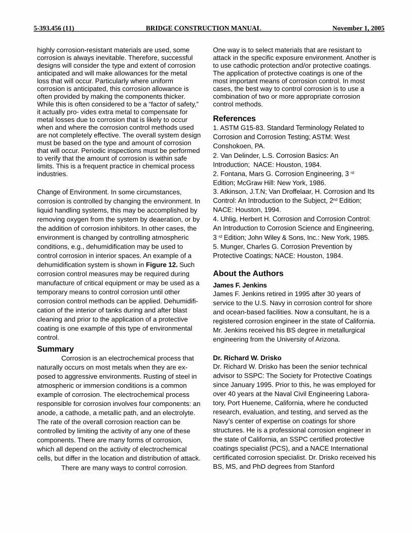
5-393.456 (11) BRIDGE CONSTRUCTION MANUAL November 1, 2005
highly corrosion-resistant materials are used, some corrosion is always inevitable. Therefore, successful designs will consider the type and extent of corrosion anticipated and will make allowances for the metal loss that will occur. Particularly where uniform corrosion is anticipated, this corrosion allowance is often provided by making the components thicker. While this is often considered to be a “factor of safety,” it actually pro- vides extra metal to compensate for metal losses due to corrosion that is likely to occur when and where the corrosion control methods used are not completely effective. The overall system design must be based on the type and amount of corrosion that will occur. Periodic inspections must be performed to verify that the amount of corrosion is within safe limits. This is a frequent practice in chemical process industries.
Change of Environment. In some circumstances, corrosion is controlled by changing the environment. In liquid handling systems, this may be accomplished by removing oxygen from the system by deaeration, or by the addition of corrosion inhibitors. In other cases, the environment is changed by controlling atmospheric conditions, e.g., dehumidification may be used to control corrosion in interior spaces. An example of a dehumidification system is shown in Figure 12. Such corrosion control measures may be required during manufacture of critical equipment or may be used as a temporary means to control corrosion until other corrosion control methods can be applied. Dehumidifi- cation of the interior of tanks during and after blast cleaning and prior to the application of a protective coating is one example of this type of environmental control.
Summary Corrosion is an electrochemical process that
naturally occurs on most metals when they are ex- posed to aggressive environments. Rusting of steel in atmospheric or immersion conditions is a common example of corrosion. The electrochemical process responsible for corrosion involves four components: an anode, a cathode, a metallic path, and an electrolyte. The rate of the overall corrosion reaction can be controlled by limiting the activity of any one of these components. There are many forms of corrosion, which all depend on the activity of electrochemical cells, but differ in the location and distribution of attack.
There are many ways to control corrosion.
One way is to select materials that are resistant to attack in the specific exposure environment. Another is to use cathodic protection and/or protective coatings. The application of protective coatings is one of the most important means of corrosion control. In most cases, the best way to control corrosion is to use a combination of two or more appropriate corrosion control methods. References 1. ASTM G15-83. Standard Terminology Related to Corrosion and Corrosion Testing; ASTM: West Conshokoen, PA. 2. Van Delinder, L.S. Corrosion Basics: An Introduction; NACE: Houston, 1984. 2. Fontana, Mars G. Corrosion Engineering, 3 rd
Edition; McGraw Hill: New York, 1986. 3. Atkinson, J.T.N; Van Droffelaar, H. Corrosion and Its Control: An Introduction to the Subject, 2nd Edition; NACE: Houston, 1994. 4. Uhlig, Herbert H. Corrosion and Corrosion Control: An Introduction to Corrosion Science and Engineering, 3 rd Edition; John Wiley & Sons, Inc.: New York, 1985. 5. Munger, Charles G. Corrosion Prevention by Protective Coatings; NACE: Houston, 1984.
About the Authors James F. Jenkins James F. Jenkins retired in 1995 after 30 years of service to the U.S. Navy in corrosion control for shore and ocean-based facilities. Now a consultant, he is a registered corrosion engineer in the state of California. Mr. Jenkins received his BS degree in metallurgical engineering from the University of Arizona. Dr. Richard W. Drisko Dr. Richard W. Drisko has been the senior technical advisor to SSPC: The Society for Protective Coatings since January 1995. Prior to this, he was employed for over 40 years at the Naval Civil Engineering Labora- tory, Port Hueneme, California, where he conducted research, evaluation, and testing, and served as the Navy’s center of expertise on coatings for shore structures. He is a professional corrosion engineer in the state of California, an SSPC certified protective coatings specialist (PCS), and a NACE International certificated corrosion specialist. Dr. Drisko received his BS, MS, and PhD degrees from Stanford

November 1, 2005 BRIDGE CONSTRUCTION MANUAL 5-393.456 (12)
SSPC: The Society for Protective Coatings SURFACE PREPARATION SPECIFICATION NO. 1
Solvent Cleaning 1. Scope
1.1 This specification covers the requirements for
the solvent cleaning of steel surfaces. 2. Definition
2.1 Solvent cleaning is a method for removing all
visible oil, grease, soil, drawing and cutting compounds, and other soluble contaminants from steel surfaces.
2.2 It is intended that solvent cleaning be used prior to
the application of paint and in conjunction with surface preparation methods specified for the removal of rust, mill scale, or paint.
3. Surface Preparation Before and After Solvent Cleaning
3.1 Prior to solvent cleaning, remove foreign matter
(other than grease and oil) by one or a combination of the following: brush with stiff fiber or wire brushes, abrade, scrape, or clean with solutions of appropriate cleaners, provided such cleaners are followed by a fresh water rinse.
3.2 After solvent cleaning, remove dirt, dust, and
other contaminants from the surface prior to paint application. Acceptable methods include brushing, blow off with clean, dry air, or vacuum cleaning.
4. Methods of Solvent Cleaning
4.1 Remove heavy oil or grease first by scraper.
Then remove the remaining oil or grease by any of the following methods:
4.1.1 Wipe or scrub the surface with rags or brushes
wetted with solvent. Use clean solvent and clean rags or brushes for the final wiping.
4.1.2 Spray the surface with solvent. Use clean
solvent for the final spraying.
4.1.3 Vapor degrease using stabilized chlorinated hydrocarbon solvents.
4.1.4 Immerse completely in a tank or tanks of
solvent. For the last immersion, use solvent which does not contain detrimental amounts of contaminant.
4.1.5 Emulsion or alkaline cleaners may be used in place of
the methods described. After treatment, wash the surface with fresh water or steam to remove detrimental residues.
4.1.6 Steam clean, using detergents or cleaners and follow by steam or fresh water wash to remove detrimental residues. 5. Inspection
5.1 All work and materials supplied under this standard shall be subject to timely inspection by the purchaser or his authorized representative. The contractor shall correct such work or replace such material as is found defective under this standard. In case of dispute the arbitration or settlement procedure established in the procurement documents, if any, shall be followed. If no arbitration or settlement procedure is established, then a procedure mutually agreeable to purchaser and contractor shall be used.
5.2 The procurement documents covering work or purchase should establish the responsibility for testing and for any re- quired affidavit certifying full compliance with the standard.
6. Disclaimer
6.1 While every precaution is taken to ensure that all information furnished in SSPC standards and specifications is as accurate, complete, and useful as possible, SSPC cannot assume responsibility nor incur any obligation resulting from the use of any materials, coatings, or methods specified herein, or of the specification or standard itself.
6.2 This specification does not attempt to address prob- lems concerning safety associated with its use. The user of this specification, as well as the user of all products or practices described herein, is responsible for instituting appropriate health and safety practices and for ensuring compliance with all governmental regulations.
7. Note
Notes are not requirements of this specification.
7.1 A Commentary Section is available and contains ad- ditional information and data relative to this specification. The Surface Preparation Commentary, SSPC-SP COM, is not part

5-393.456 (13) BRIDGE CONSTRUCTION MANUAL November 1, 2005
of this specification . The table below lists the subjects discussed relevant to solvent cleaning and the appropriate Commentary section.
Section Subject SSPC-SP COM Section
Solvents and Cleaners .................... 5.1.1 through 5.1.3 Steam Cleaning ......................................................5.1.4 Threshold Limit Values ...........................................5.1.5

November 1, 2005 BRIDGE CONSTRUCTION MANUAL 5-393.456 (14)
SSPC: The Society for Protective Coatings SURFACE PREPARATION SPECIFICATION NO. 2
Hand Tool Cleaning 1. Scope
1.1 This standard covers the requirements for hand tool
cleaning steel surfaces. 2. Definitions
2.1 Hand tool cleaning is a method of preparing steel
surfaces by the use of non-power hand tools.
2.2 Hand tool cleaning removes all loose mill scale, loose rust, loose paint, and other loose detrimental foreign matter. It is not intended that adherent mill scale, rust, and paint be removed by this process. Mill scale, rust, and paint are consid- ered adherent if they cannot be removed by lifting with a dull putty knife.
2.3 SSPC-VIS 3 or other visual standard of surface prepa-
ration agreed upon by the contracting parties may be used to further define the surface (see Note 8.1).
3. Referenced Standards
3.1 The latest issue, revision, or amendment of the refer-
enced standards in effect on the date of invitation to bid shall govern, unless otherwise specified. Standards marked with an asterisk (*) are referenced only in the Notes, which are not requirements of this standard.
3.2 If there is a conflict between the requirements of any
of the cited reference standards and this standard, the require- ments of this standard shall prevail.
3.3 SSPC SPECIFICATIONS:
SP 1 Solvent Cleaning
*SP 3 Power Tool Cleaning *SP 11 Power Tool Cleaning to Bare
Metal *SP 15 Commercial Grade Power Tool
Cleaning VIS 3 Guide and Reference Photographs
for Steel Surfaces Prepared by for Power- and Hand-Tool Cleaning
3.4 INTERNATIONAL ORGANIZATION FOR STANDARD-
IZATION (ISO):
* 8501-1 Preparation of steel substrates before appli- cation of paints and related products: Visual assessment of surface cleanliness—Part I.
4. Surface Preparation Before and After Hand Tool Cleaning
4.1 Before hand tool cleaning, visible deposits of oil, grease, or other materials that may interfere with coating adhesion shall be removed in accordance with SSPC-SP 1 or other agreed- upon methods. Nonvisible surface contaminants such as soluble salts shall be treated to the extent specified by the procurement documents [project specifications] (see Note 8.2).
4.2 After hand tool cleaning and prior to painting, reclean the surface if it does not conform to this standard.
4.3 After hand tool cleaning and prior to painting, remove dirt, dust, or similar contaminants from the surface. Accept- able methods include brushing, blow off with clean, dry air, or vacuum cleaning. 5. Methods of Hand Tool Cleaning
5.1 Use impact hand tools to remove stratified rust (rust scale).
5.2 Use impact hand tools to remove all weld slag.
5.3 Use hand wire brushing, hand abrading, hand scrap- ing, or other similar non-impact methods to remove all loose mill scale, all loose or non-adherent rust, and all loose paint.
5.4 Regardless of the method used for cleaning, if specified in the procurement documents, feather the edges of remaining old paint so that the repainted surface can have a reasonably smooth appearance.
5.5 If approved by the owner, use power tools or blast cleaning as a substitute cleaning method for this standard.
5-393.456 (15) BRIDGE CONSTRUCTION MANUAL November 1, 2005
6. Inspection
6.1 Unless otherwise specified in the procurement docu-
ments, the contractor or material supplier is responsible for quality control to assure that the requirements of this document are met. Work and materials supplied under this standard are also subject to inspection by the purchaser or an authorized representative. Materials and work areas shall be accessible to the inspector.
6.2 Conditions not complying with this standard shall be
corrected. In the case of a dispute, an arbitration or settlement procedure established in the procurement documents (project specification) shall be followed. If no arbitration or settlement procedure is established, then a procedure mutually agree- able to purchaser and material supplier (or contractor) shall be used.
7. Disclaimer
7.1 While every precaution is taken to ensure that all in-
formation furnished in SSPC standards and specifications is as accurate, complete, and useful as possible, SSPC cannot assume responsibility nor incur any obligation resulting from the use of any materials, coatings, or methods specified herein, or of the specification or standard itself.
7.2 This standard does not attempt to address problems
concerning safety associated with its use. The user of this stan- dard, as well as the user of all products or practices described
herein, is responsible for instituting appropriate health and safety practices and for ensuring compliance with all governmental regulations.
8. Notes
Notes are not requirements of this standard.
8.1 Note that the use of visual standards in conjunction with this standard is required only when they are specified in the procurement documents (project specification) covering the work. It is recommended, however, that the use of visual stan- dards be made mandatory in the procurement documents.
SSPC-VIS 3 provides a suitable comparative visual stan- dard for SSPC-SP 2, SSPC-SP 3, SSPC-SP 11, and SSPC-SP 15. ISO 8501-1 may also serve as a visual standard.
8.2 The SSPC Surface Preparation Commentary (SSPC- SP COM) contains additional information and data relevant to this specification. The Commentary is non-mandatory and is not part of this specification. The table below lists the subjects discussed relevant to hand tool cleaning and the appropriate Commentary Section.
Subject Commentary Section Film Thickness ................................................. 10 Maintenance Painting...................................... 4.2 Rust, Stratified Rust, Pack Rust, and Rust Scale .......................... 4.3.1 Visual Standards .............................................. 11 Weld Spatter................................................. 4.4.1

November 1, 2005 BRIDGE CONSTRUCTION MANUAL 5-393.456 (16)
SSPC: The Society for Protective Coatings
JOINT SURFACE PREPARATION SPECIFICATION
SSPC-SP 6/NACE NO. 3
Commercial Blast Cleaning
This SSPC: The Society for Protective Coatings and NACE International standard represents a consensus of those indi- vidual members who have reviewed this document, its scope and provisions. Its acceptance does not in any respect preclude anyone, having adopted the standard or not, from manufactur- ing, marketing, purchasing, or using products, processes, or procedures not in conformance with this standard. Nothing contained in this standard is to be construed as granting any right, by implication or otherwise, to manufacture, sell, or use in connection with any method, apparatus, or product covered by Letters Patent, or as indemnifying or protecting anyone against liability for infringement of Letters Patent. This standard represents minimum requirements and should in no way be interpreted as a restriction on the use of better procedures or materials. Neither is this standard intended to apply in all cases relating to the subject. Unpredictable circumstances may negate the usefulness of this standard in specific instances. SSPC and NACE assume no responsibility for the interpretation or use of this standard by other parties and accept responsibility for only those official interpretations issued by SSPC or NACE in accordance with their respective governing procedures and policies, which preclude the issuance of interpretations by individual volunteers.
Users of this standard are responsible for reviewing ap- propriate health, safety, and regulatory documents and for determining their applicability in relation to this standard prior to its use. This SSPC/NACE standard may not necessarily ad- dress all potential health and safety problems or environmental hazards associated with the use of materials, equipment and/or operations detailed or referred to within this standard. Users of this standard are also responsible for establishing appropriate health, safety, and environmental protection practices, in con- sultation with appropriate regulatory authorities, if necessary, to achieve compliance with any existing applicable regulatory requirements prior to the use of this standard.
CAUTIONARY NOTICE: SSPC/NACE standards are sub- ject to periodic review and may be revised or withdrawn at any time without prior notice. SSPC and NACE require that action be taken to reaffirm, revise, or withdraw this standard no later than five years from the date of initial publication. The user is cautioned to obtain the latest edition. Purchasers may receive current information on all standards and other publications by contacting the organizations at the addresses below:
©SSPC: The Society for Protective Coatings 40 24th Street, Sixth Floor Pittsburgh, PA 15222 (telephone +1 412/281-2321) ©NACE International 1440 South Creek Houston, TX 77084-4906 (telephone +1 281/228-6200) Foreword
This joint standard covers the use of blast cleaning abra- sives to achieve a defined degree of cleaning of steel surfaces prior to the application of a protective coating or lining system. This standard is intended for use by coating or lining specifiers, applicators, inspectors, or others whose responsibility it may be to define a standard degree of surface cleanliness.
The focus of this standard is commercial blast cleaning. White metal blast cleaning, near-white blast cleaning, industrial blast cleaning, and brush-off blast cleaning are addressed in separate standards.
Commercial blast cleaning provides a greater degree of cleaning than industrial blast cleaning (SSPC-SP 14/NACE No. 8), but less than near-white blast cleaning (SSPC-SP 10/NACE No. 2).
Commercial blast cleaning is used when the objective is to remove all visible oil, grease, dust, dirt, mill scale, rust, coating, oxides, corrosion products and other foreign matter, leaving staining or shadows on no more than 33 percent of each unit area of surface as described in Section 2.2.
The difference between a commercial blast and a near- white blast is in the amount of staining permitted to remain on the surface. Commercial blast allows stains or shadows on 33 percent of each unit area of surface. Near-white blast allows staining or shadows on only 5 percent of each unit area.
The difference between a commercial blast and an industrial blast is that a commercial blast removes all visible oil, grease, dust, dirt, mill scale, rust, coating, oxides, corrosion products and other foreign matter from all surfaces and allows stains to remain on 33 percent of each unit area of surface, while industrial blast allows defined mill scale, coating, and rust to remain on less than 10 percent of the surface and allows defined stains to remain on all surfaces.
5-393.456 (17) BRIDGE CONSTRUCTION MANUAL November 1, 2005
This joint standard was prepared by the SSPC/NACE Task
Group A on Surface Preparation by Abrasive Blast Cleaning. This joint Task Group includes members of both the SSPC Surface Preparation Committee and the NACE Unit Committee T-6G on Surface Preparation (now STG 04).
1. General
1.1 This joint standard covers the requirements for com- mercial blast cleaning of unpainted or painted steel surfaces by the use of abrasives. These requirements include the end condition of the surface and materials and procedures neces- sary to achieve and verify the end condition.
1.2 The mandatory requirements are described in Sections 1 to 9 as follows:
Section 1 General Section 2 Definition Section 3 Referenced Standards Section 4 Procedures Before Blast Cleaning Section 5 Blast Cleaning Methods and Operation Section 6 Blast Cleaning Abrasives Section 7 Procedures Following Blast Cleaning and
Immediately Prior to Coating Section 8 Inspection Section 9 Safety and Environmental Requirements
NOTE: Section 10, “Comments” and Appendix A, “Explanatory Notes” are not mandatory requirements of this standard.
2. Definition
2.1 A commercial blast cleaned surface, when viewed without magnification, shall be free of all visible oil, grease, dust, dirt, mill scale, rust, coating, oxides, corrosion products, and other foreign matter, except for staining as noted in Sec- tion 2.2.
2.2 Random staining shall be limited to no more than
33 percent of each unit area of surface as defined in Section 2.6, and may consist of light shadows, slight streaks, or minor discolorations caused by stains of rust, stains of mill scale, or stains of previously applied coating.
2.6 Unit area for determinations shall be approximately 5776 mm2 (9 in2) (i.e., a square 76 x 76 mm [3 in x 3 in]).
2.7 SSPC-VIS 1 may be specified to supplement the writ- ten definition. In any dispute, the written standards shall take precedence over visual standards and comparators. Additional information on visual standards and comparators is available in Section A.4 of Appendix A. 3. Referenced Standards
3.1 The latest issue, revision, or amendment of the refer- enced standards in effect on the date of invitation to bid shall govern unless otherwise specified.
3.2 If there is a conflict between the requirements of any of the cited reference standards and this standard, the require- ments of this standard shall prevail.
3.3 SSPC: THE SOCIETY FOR PROTECTIVE COATINGS STANDARDS:
AB 1 Mineral and Slag Abrasives AB 2 Cleanliness of Recycled Ferrous
Metallic Abrasives AB 3 Ferrous Metallic Abrasives PA Guide 3 A Guide to Safety in Paint Applica-
tion SP 1 Solvent Cleaning VIS 1 Guide and Reference Photographs
for Steel Surfaces Prepared by Dry Abrasive Blast Cleaning
4. Procedures Before Blast Cleaning
4.1 Before blast cleaning, visible deposits of oil, grease, or other contaminants shall be removed in accordance with SSPC-SP 1 or other agreed upon methods.
4.2 Before blast cleaning, surface imperfections such as sharp fins, sharp edges, weld spatter, or burning slag should be removed from the surface to the extent required by the procure- ment documents (project specification). Additional information on surface imperfections is available in Section A.5 of Appendix A.
2.3 Acceptable variations in appearance that do not affectsurface cleanliness as defined in Section 2.1 include variationscaused by type of steel, original surface condition, thickness ofthe steel, weld metal, mill or fabrication marks, heat treating,heat affected zones, blasting abrasives, and differences dueto blasting technique.
2.4 When a coating is specified, the surface shall be rough-
ened to a degree suitable for the specified coating system.
2.5 Immediately prior to coating application, the entiresurface shall comply with the degree of cleaning specifiedherein.
4.3 If a visual standard or comparator is specified to
supplement the written standard, the condition of the steel prior to blast cleaning should be determined before the blasting commences. Additional information on visual standards and comparators is available in Section A.4 of Appendix A.
5. Blast Cleaning Methods and Operation 5.1 Clean, dry compressed air shall be used for nozzle
blasting. Moisture separators, oil separators, traps, or other equipment may be necessary to achieve this requirement.

November 1, 2005 BRIDGE CONSTRUCTION MANUAL 5-393.456 (18)
5.2 Any of the following methods of surface preparation may be used to achieve a commercial blast cleaned surface:
5.2.1 Dry abrasive blasting using compressed air, blast
nozzles, and abrasive.
5.2.2 Dry abrasive blasting using a closed-cycle, recir- culating abrasive system with compressed air, blast nozzle, and abrasive, with or without vacuum for dust and abrasive recovery.
5.2.3 Dry abrasive blasting using a closed cycle, recircu-
lating abrasive system with centrifugal wheels and abrasive.
5.3 Other methods of surface preparation (such as wet abrasive blasting) may be used to achieve a commercial blast cleaned surface by mutual agreement between those responsible for performing the work and those responsible for establishing the requirements. NOTE: Information on the use of inhibitors to prevent the formation of rust immediately after wet blast cleaning is contained in Section A.9 of Appendix A.
6. Blast Cleaning Abrasives
6.1 The selection of abrasive size and type shall be based on the type, grade, and surface condition of the steel to be cleaned, type of blast cleaning system employed, the finished surface to be produced (cleanliness and roughness), and whether the abrasive will be recycled.
6.2 The cleanliness and size of recycled abrasives shall
be maintained to ensure compliance with this specification.
6.3 The blast cleaning abrasive shall be dry and free of oil, grease, and other contaminants as determined by the test methods found in SSPC-AB 1, AB 2 and AB 3.
6.4 Any limitations on the use of specific abrasives, the
quantity of contaminants, or the degree of allowable embed- ment shall be included in the procurement documents (project specification) covering the work, because abrasive embedment and abrasives containing contaminants may not be acceptable for some service requirements. NOTE: Additional information on abrasive selection is given in Section A.2 of Appendix A.
7. Procedures Following Blast Cleaning and Immediately Prior to Coating
7.1 Visible deposits of oil, grease, or other contaminants shall be removed according to SSPC-SP 1 or another method agreed upon by those parties responsible for establishing the requirements and those responsible for performing the work.
7.2 Dust and loose residues shall be removed from pre-
pared surfaces by brushing, blowing off with clean, dry air, vacuum cleaning, or other methods agreed upon by those responsible for establishing the requirements and those re- sponsible for performing the work. NOTE: The presence of toxic metals in the abrasives or paint being removed may place restrictions on the methods of cleaning permitted. Comply with all applicable regulations. Moisture separators, oil separators, traps, or other equipment may be necessary to achieve clean, dry air.
7.3 After blast cleaning, surface imperfections that remain (e.g., sharp fins, sharp edges, weld spatter, burning slag, scabs, slivers, etc.) shall be removed to the extent required in the procurement documents (project specification). Any damage to the surface profile resulting from the removal of surface imperfections shall be corrected to meet the require- ments of Section 2.4. NOTE: Additional information on surface imperfections is contained in Section A.5 of Appendix A.
7.4 Any visible rust that forms on the surface of the steel after blast cleaning shall be removed by recleaning the rusted areas to meet the requirements of this standard before coat- ing. NOTE: Information on rust-back (re-rusting) and surface condensation is contained in Sections A.6, A.7, and A.8 of Appendix A. 8. Inspection
8.1 Work and materials supplied under this standard are subject to inspection by a representative of those responsible for establishing the requirements. Materials and work areas shall be accessible to the inspector. The procedures and times of inspection shall be as agreed upon by those responsible for establishing the requirements and those responsible for performing the work.
8.2 Conditions not complying with this standard shall be corrected. In the case of a dispute, an arbitration or settlement procedure established in the procurement documents (project specification) shall be followed. If no arbitration or settlement procedure is established, then a procedure mutually agreeable to purchaser and supplier shall be used.
8.3 The procurement documents (project specification) should establish the responsibility for inspection and for any required affidavit certifying compliance with the specifica- tion. 9. Safety and Environmental Requirements
9.1 Because abrasive blast cleaning is a hazardous opera- tion, all work shall be conducted in compliance with applicable occupational and environmental health and safety rules and

5-393.456 (19) BRIDGE CONSTRUCTION MANUAL November 1, 2005
regulations. NOTE: SSPC-PA Guide 3, “A Guide to Safety in Paint Application,” addresses safety concerns for coating work.
10. Comments 10.1Additional information and data relative to this standard
are contained in Appendix A. Detailed information and data are presented in a separate document, SSPC-SP COM, “Surface Preparation Commentary.” The recommendations contained in Appendix A and SSPC-SP COM are believed to represent good practice, but are not to be considered requirements of the standard. The sections of SSPC-SP COM that discuss subjects related to commercial blast cleaning are listed below.
Subject Commentary Section Abrasive Selection ............................................ 6 Film Thickness ................................................ 10 Wet Abrasive Blast Cleaning .......................... 8.2 Maintenance .................................................. 4.2 Rust-back (Re-rusting) ................................... 4.5 Surface Profile................................................ 6.2 Visual Standards ..............................................11 Welds and Weld Spatter.............................. 4.4.1
Appendix A. Explanatory Notes
A.1 FUNCTION: Commercial blast cleaning (SSPC-SP 6/NACE No. 3) provides a greater degree of cleaning than brush-off blast cleaning (SSPC-SP 7/NACE No. 4), but less than near-white blast cleaning (SSPC-SP 10/NACE No. 2). It should be specified only when a compatible coating will be applied. The primary functions of blast cleaning before coating are: (a) to remove material from the surface that can cause early failure of the coating system and (b) to obtain a suitable surface roughness and to enhance the adhesion of the new coating system. The hierarchy of blasting standards is as follows: white metal blast cleaning, near-white blast clean- ing, commercial blast cleaning, industrial blast cleaning, and brush-off blast cleaning.
A.2 ABRASIVE SELECTION: Types of metallic and non-
metallic abrasives are discussed in the Surface Preparation Commentary (SSPC-SP COM). It is important to recognize that blasting abrasives may become embedded in or leave residues on the surface of the steel during preparation. While normally such embedment or residues are not detrimental, care should be taken to ensure that the abrasive is free from detrimental amounts of water-soluble, solvent-soluble, acid-soluble, or other soluble contaminants (particularly if the prepared steel is to be used in an immersion environment). Criteria for selecting and evaluating abrasives are given in SSPC-AB 1, “Mineral and Slag Abrasives,” SSPC-AB 2, “Cleanliness of Recycled
Ferrous Metallic Abrasives,” and SSPC-AB 3, “Ferrous Metallic Abrasives.”
A.3 SURFACE PROFILE: Surface profile is the roughness of the surface which results from abrasive blast cleaning. The profile depth (or height) is dependent upon the size, shape, type, and hardness of the abrasive, particle velocity and angle of impact, hardness of the surface, amount of recycling, and the proper maintenance of working mixtures of grit and/or shot. The allowable minimum/maximum height of profile is usu- ally
dependent upon the thickness of the coating to be applied. Large particle sized abrasives (particularly metallic) can produce a profile that may be too deep to be adequately covered by a single thin film coat. Accordingly, it is recommended that the use of larger abrasives be avoided in these cases. However, larger abrasives may be needed for thick film coatings or to facilitate removal of thick coatings, heavy mill scale, or rust. If control of profile (minimum/maximum) is deemed to be sig- nificant to coating performance, it should be addressed in the procurement documents (project specification). Typical profile heights achieved with commercial abrasive media are shown in Table 5 of the Surface Preparation Commentary (SSPC-SP COM). Surface profile should be measured in accordance with NACE Standard RP0287 (latest edition), “Field Measurement of Surface Profile of Abrasive Blast Cleaned Steel Surfaces Using Replica Tape,”or ASTM(1) D 4417 (latest edition), “Test Method for Field Measurement of Surface Profile of Blast Cleaned Steel.”
A.4 VISUAL STANDARDS: SSPC-VIS 1, "Guide and Reference Photographs for Steel Surfaces Prepared by Dry Abrasive Blast Cleaning" provides color photographs for the various grades of surface preparation as a function of the initial condition of the steel. The A-SP 6, B-SP 6, C-SP 6, D-SP 6, and G-SP 6 series of photographs depict surfaces cleaned to a commercial blast. Other available visual standards are described in Section 11 of SSPC-SP COM.
A.5 SURFACE IMPERFECTIONS: Surface imperfec- tions can cause premature failure when the service is severe. Coatings tend to pull away from sharp edges and projections, leaving little or no coating to protect the underlying steel. Other features that are difficult to properly cover and protect include crevices, weld porosities, laminations, etc. The high cost of the methods to remedy surface imperfections requires weigh- ing the benefits of edge rounding, weld spatter removal, etc., versus a potential coating failure.
Poorly adhering contaminants, such as weld slag residues, loose weld spatter, and some minor surface laminations may be removed during the blast cleaning operation. Other surface defects (steel laminations, weld porosities, or deep corrosion pits) may not be evident until the surface preparation has been completed. Therefore, proper planning for such surface repair work is essential because the timing of the repairs may occur
(1) ASTM International, 100 Barr Harbor Drive, West Conshohocken, PA 19428-2959.

November 1, 2005 BRIDGE CONSTRUCTION MANUAL 5-393.456 (20)
before, during, or after the blast cleaning operation. Section 4.4 of SSPC-SP COM and NACE Standard RP0178 (latest edition), “Fabrication Details, Surface Finish Requirements, and Proper Design Considerations for Tanks and Vessels to be Lined for Immersion Service” contain additional information on surface imperfections.
A.6 CHEMICAL CONTAMINATION: Steel contaminated
with soluble salts (e.g., chlorides and sulfates) develops rust-back rapidly at intermediate and high humidities. These soluble salts can be present on the steel surface prior to blast cleaning as a result of atmospheric contamination. In addition, contaminants can be deposited on the steel surface during blast cleaning if the abrasive is contaminated. Therefore, rust-back can be minimized by removing these salts from the steel surface and eliminating sources of recontamination during and after blast cleaning. Wet methods of removal are described in SSPC-SP 12/NACE No. 5. Identification of the contaminants along with their concentrations may be obtained from laboratory and field tests as described in SSPC-Guide 15, "Field Methods for Retrieval and Analysis of Soluble Salts on Steel and Nonporous Substrates.”
A.7 RUST-BACK: Rust-back (re-rusting) occurs when
freshly cleaned steel is exposed to moisture, contamination, or a corrosive atmosphere. The time interval between blast cleaning and rust-back will vary greatly from one environ- ment to another. Under mild ambient conditions, if chemical contamination is not present (see Section A.6), it is best to blast clean and coat a surface the same day. Severe condi- tions may require more expedient coating application to avoid contamination from fallout. Chemical contamination should be removed prior to coating (see Section A.6).
A.8 DEW POINT: Moisture condenses on any surface
that is colder than the dew point of the surrounding air. It is, therefore, recommended that the temperature of the steel surface be at least 3°C (5°F) above the dew point during dry blast cleaning operations. It is advisable to visually inspect for
moisture and periodically check the surface temperature and dew point during blast cleaning operations and to avoid the application of coating over a damp surface.
A.9 WET ABRASIVE BLAST CLEANING: Steel that is wet abrasive blast cleaned may rust rapidly. Clean water should be used for rinsing. It may be necessary that inhibitors be added to the water or applied to the surface immediately after blast cleaning to temporarily prevent rust formation. The use of inhibitors or the application of coating over slight discoloration should be in accordance with the requirements of the coating manufacturer. CAUTION: Some inhibitive treatments may interfere with the performance of certain coating systems.
A.10 FILM THICKNESS: It is essential that ample coating be applied after blast cleaning to adequately cover the peaks of the surface profile. The dry film thickness of the coating above the peaks of the profile should equal the thickness known to be needed for the desired protection. If the dry film thickness over the peaks is inadequate, premature rust-through or failure will occur. To assure that coating thicknesses are properly measured the procedures in SSPC-PA 2 (latest edition), “Measurement of Dry Coating Thickness with Magnetic Gauges” should be used.
A.11 MAINTENANCE AND REPAIR PAINTING: When this standard is used in maintenance painting, specific instructions should be given on the extent of surface to be blast cleaned or spot blast cleaned to this degree of cleanliness. In these cases, the cleaning shall be performed across the entire area specified. For example, if all weld seams are to be cleaned in a maintenance operation, this degree of cleaning shall be applied 100% to all weld seams. If the entire structure is to be prepared, this degree of cleaning shall be applied to 100% of the entire structure. SSPC-PA Guide 4 (latest edition), “Guide to Maintenance Repainting with Oil Base or Alkyd Painting Systems,” provides a description of accepted practices for retaining old sound coating, removing unsound coating, feath- ering, and spot cleaning.

5-393.456 (21) BRIDGE CONSTRUCTION MANUAL November 1, 2005
SSPC: The Society for Protective Coatings JOINT SURFACE PREPARATION SPECIFICATION
SSPC-SP 7/NACE NO. 4 Brush-Off Blast Cleaning
This SSPC: The Society for Protective Coatings and NACE
International standard represents a consensus of those indi- vidual members who have reviewed this document, its scope and provisions. Its acceptance does not in any respect preclude anyone, having adopted the standard or not, from manufactur- ing, marketing, purchasing, or using products, processes, or procedures not in conformance with this standard. Nothing contained in this standard is to be construed as granting any right, by implication or otherwise, to manufacture, sell, or use in connection with any method, apparatus, or product covered by Letters Patent, or as indemnifying or protecting anyone against liability for infringement of Letters Patent. This standard represents minimum requirements and should in no way be interpreted as a restriction on the use of better procedures or materials. Neither is this standard intended to apply in all cases relating to the subject. Unpredictable circumstances may negate the usefulness of this standard in specific instances. SSPC and NACE assume no responsibility for the interpretation or use of this standard by other parties and accept responsibility for only those official interpretations issued by SSPC or NACE in accordance with their respective governing procedures and policies, which preclude the issuance of interpretations by individual volunteers.
Users of this standard are responsible for reviewing ap- propriate health, safety, and regulatory documents and for determining their applicability in relation to this standard prior to its use. This SSPC/NACE standard may not necessarily ad- dress all potential health and safety problems or environmental hazards associated with the use of materials, equipment and/or operations detailed or referred to within this standard. Users of this standard are also responsible for establishing appropriate health, safety, and environmental protection practices, in con- sultation with appropriate regulatory authorities, if necessary, to achieve compliance with any existing applicable regulatory requirements prior to the use of this standard.
CAUTIONARY NOTICE: SSPC/NACE standards are sub- ject to periodic review and may be revised or withdrawn at any time without prior notice. SSPC and NACE require that action be taken to reaffirm, revise, or withdraw this standard no later than five years from the date of initial publication. The user is cautioned to obtain the latest edition. Purchasers may receive current information on all standards and other publications by contacting the organizations at the addresses below:
©SSPC: The Society for Protective Coatings 40 24th Street, Sixth Floor Pittsburgh, PA 15222 (telephone +1 412/281-2331) ©NACE International 1440 South Creek Houston, TX 77084-4906 (telephone +1 281/228-6200)
Foreword
This joint standard covers the use of blast cleaning abra- sives to achieve a defined degree of cleaning of steel surfaces prior to the application of a protective coating or lining system. This standard is intended for use by coating or lining specifiers, applicators, inspectors, or others whose responsibility it may be to define a standard degree of surface cleanliness.
The focus of this standard is brush-off blast cleaning. White metal blast cleaning, near-white blast cleaning, commercial blast cleaning, and industrial blast cleaning are addressed in separate standards.
Brush-off blast cleaning provides a lesser degree of clean- ing than industrial blast cleaning (SSPC-SP 14/NACE No. 8). The difference between an industrial blast and a brush-off blast is that the objective of a brush-off blast is to allow as much of an existing coating to remain as possible, and to roughen the surface prior to coating application while the purpose of the industrial blast is to remove most of the coating, mill scale and rust, when the extra effort required to remove every trace of these is determined to be unwarranted.
This joint standard was prepared by the SSPC/NACE Task Group A on Surface Preparation by Abrasive Blast Cleaning. This joint Task Group includes members of both the SSPC Surface Preparation Committee and the NACE Unit Committee T-6G on Surface Preparation (now STG 04). 1. General
1.1 This joint standard covers the requirements for brush- off blast cleaning of unpainted or painted steel surfaces by the use of abrasives. These requirements include the end condi- tion of the surface and materials and procedures necessary to achieve and verify the end condition.

November 1, 2005 BRIDGE CONSTRUCTION MANUAL 5-393.456 (22)
1.2 This joint standard allows tightly adherent rust, mill scale and/or old coating to remain on the surface.
1.3 The mandatory requirements are described in Sections
1 to 9 as follows: Section 1 General Section 2 Definitions Section 3 Referenced Standards Section 4 Procedures Before Blast Cleaning Section 5 Blast Cleaning Methods and Operation Section 6 Blast Cleaning Abrasives Section 7 Procedures Following Blast Cleaning and
Immediately Prior to Coating Section 8 Inspection Section 9 Safety and Environmental Requirements
NOTE: Section 10, “Comments” and Appendix A, “Explanatory Notes” are not mandatory requirements of this standard.
2. Definition
2.1 A brush-off blast cleaned surface, when viewed without magnification, shall be free of all visible oil, grease, dirt, dust, loose mill scale, loose rust, and loose coating. Tightly adher- ent mill scale, rust, and coating may remain on the surface. Mill scale, rust, and coating are considered tightly adherent if they cannot be removed by lifting with a dull putty knife after abrasive blast cleaning has been performed.
2.2 The entire surface shall be subjected to the
abrasive blast. The remaining mill scale, rust, or coating shall be tight. Flecks of the underlying steel need not be exposed whenever the original substrate consists of intact coating.
2.3 When a coating is specified, the surface shall be rough-
ened to a degree suitable for the specified coating system.
2.4 Immediately prior to coating application, the entire surface shall comply with the degree of cleaning as specified herein.
2.5 SSPC VIS 1 may be specified to supplement the writ-
ten definition. In any dispute, the written standards shall take precedence over visual standards and comparators. Additional information on visual standards is available in Section A.4 of Appendix A.
3. Referenced Standards
3.1 The latest issue, revision, or amendment of the refer- enced standards in effect on the date of invitation to bid shall govern unless otherwise specified.
3.2 If there is a conflict between the requirements of any of the cited reference standards and this standard, the
requirements of this standard shall prevail.
3.3 SSPC: THE SOCIETY FOR PROTECTIVE COATINGS STANDARDS:
AB 1 Mineral and Slag Abrasives AB 2 Cleanliness of Recycled Ferrous Metallic
Abrasives AB 3 Ferrous Metallic Abrasives PA Guide 3 A Guide to Safety in Paint Application SP 1 Solvent Cleaning VIS 1 Guide and Reference Photographs for Steel
Surfaces Prepared by Dry Abrasive Blast Cleaning
4. Procedures Before Blast Cleaning
4.1 Before blast cleaning, visible deposits of oil, grease, or other contaminants shall be removed in accordance with SSPC-SP 1 or other agreed upon methods.
4.2 Before blast cleaning, surface imperfections such as sharp fins, sharp edges, weld spatter, or burning slag should be removed from the surface to the extent required by the procurement documents (project specification). Additional information on surface imperfections is available in Section A.5 of Appendix A.
4.3 If a visual standard or comparator is specified to supplement the written standard, the condition of the steel prior to blast cleaning should be determined before the blasting commences. Additional information on visual standards and comparators is available in Section A.4 of Appendix A. 5. Blast Cleaning Methods and Operation
5.1 Clean, dry compressed air shall be used for nozzle blasting. Moisture separators, oil separators, traps, or other equipment may be necessary to achieve this requirement.
5.2 Any of the following methods of surface preparation may be used to achieve a brush-off blast cleaned surface:
5.2.1 Dry abrasive blasting using compressed air, blast nozzles, and abrasive.
5.2.2 Dry abrasive blasting using a closed-cycle, recir- culating abrasive system with compressed air, blast nozzle, and abrasive, with or without vacuum for dust and abrasive recovery.
5.2.3 Dry abrasive blasting using a closed cycle, recircu- lating abrasive system with centrifugal wheels and abrasive.
5.3 Other methods of surface preparation (such as wet abrasive blasting) may be used to achieve a brush-off blast cleaned surface by mutual agreement between those responsible for performing the work and those responsible for
5-393.456 (23) BRIDGE CONSTRUCTION MANUAL November 1, 2005
establishing the requirements. NOTE: Information on the use of inhibitors to prevent the formation of rust immediately after wet blast cleaning is contained in Section A.9 of Appendix A.
6. Blast Cleaning Abrasives
6.1 The selection of abrasive size and type shall be based on the type, grade, and surface condition of the steel to be cleaned, type of blast cleaning system employed, the finished surface to be produced (cleanliness and roughness), and whether the abrasive will be recycled.
6.2 The cleanliness and size of recycled abrasives
shall be maintained to ensure compliance with this specification.
6.3 The blast cleaning abrasive shall be dry and free
of oil, grease, and other contaminants as determined by the test methods found in SSPC-AB 1, AB 2, and AB 3.
6.4 Any limitations on the use of specific abrasives,
the quantity of contaminants, or the degree of allowable embedment shall be included in the procurement documents (project specification) covering the work, because abrasive embedment and abrasives containing contaminants may not be acceptable for some service requirements. NOTE: Additional information on abrasive selection is given in Section A.2 of Appendix A.
7. Procedures Following Blast Cleaning and Immediately Prior to Coating
7.1 Visible deposits of oil, grease, or other contaminants shall be removed according to SSPC-SP 1 or another method agreed upon by those parties responsible for establishing the requirements and those responsible for performing the work.
7.2 Dust and loose residues shall be removed from
prepared surfaces by brushing, blowing off with clean, dry air, vacuum cleaning, or other methods agreed upon by those responsible for establishing the requirements and those responsible for performing the work. NOTE: The presence of toxic metals in the abrasives or paint being removed may place restrictions on the methods of cleaning permitted. The method chosen shall comply with all applicable regulations. Moisture separators, oil separators, traps, or other equipment may be necessary to achieve clean, dry air.
7.3 After blast cleaning, surface imperfections that remain
(e.g., sharp fins, sharp edges, weld spatter, burning slag, scabs, slivers, etc.) shall be removed to the extent
required in the procurement documents (project specification). Any damage to the surface profile resulting from the removal of surface imperfections shall be corrected to meet the require- ments of Section 2.4. NOTE: Additional information on surface imperfections is contained in Section A.5 of Appendix A.
8. Inspection
8.1 Work and materials supplied under this standard are subject to inspection by a representative of those responsible for establishing the requirements. Materials and work areas shall be accessible to the inspector. The procedures and times of inspection shall be as agreed upon by those responsible for establishing the requirements and those responsible for performing the work.
8.2 Conditions not complying with this standard shall be corrected. In the case of a dispute, an arbitration or settlement procedure established in the procurement documents (project specification) shall be followed. If no arbitration or settlement procedure is established, then a procedure mutually agreeable to purchaser and supplier shall be used.
8.3 The procurement documents (project specification) should establish the responsibility for inspection and for any required affidavit certifying compliance with the specifica- tion. 9. Safety and Environmental Requirements
9.1 Because abrasive blast cleaning is a hazardous opera- tion, all work shall be conducted in compliance with applicable occupational and environmental health and safety rules and regulations. NOTE: SSPC-PA Guide 3, “A Guide to Safety in Paint Application,” addresses safety concerns for coating work. 10. Comments
10.1Additional information and data relative to this standard are contained in Appendix A. Detailed information and data are presented in a separate document, SSPC-SP COM, “Surface Preparation Commentary.” The recommendations contained in Appendix A and SSPC-SP COM are believed to represent good practice, but are not to be considered requirements of the standard. The sections of SSPC-SP COM that discuss subjects related to brush-off blast cleaning are listed below.
Subject Commentary Section
Abrasive Selection ............................................ 6 Film Thickness .................................................10 Wet Abrasive Blast Cleaning ..............................8 Maintenance ...................................................4.2 Rust-back (Re-rusting) ....................................4.5 Surface Profile.................................................6.2 Visual Standards .............................................. 11 Welds and Weld Spatter...............................4.4.1

November 1, 2005 BRIDGE CONSTRUCTION MANUAL 5-393.456 (24)
Appendix A. Explanatory Notes
A.1 FUNCTION: Brush-off blast cleaning (SSPC-SP 7/NACE No. 4), provides a lesser degree of cleaning than industrial blast cleaning (SSPC-SP 14/NACE No. 8). It should be used when the service environment is mild enough to permit tight mill scale, coating, rust, and other foreign matter to remain on the surface. The primary functions of blast cleaning before coating are (a) to remove material from the surface that can cause early failure of the coating and (b) to obtain a suitable surface roughness and to enhance the adhesion of the new coating system. The hierarchy of blasting standards is as follows: white metal blast cleaning, near-white blast cleaning, commercial blast cleaning, industrial blast cleaning, and brush-off blast cleaning.
A.2 ABRASIVE SELECTION: Types of metallic and non-
metallic abrasives are discussed in the Surface Preparation Commentary (SSPC-SP COM). It is important to recognize that blasting abrasives may become embedded in or leave residues on the surface of the steel during preparation. While normally such embedment or residues are not detrimental, care should be taken to ensure that the abrasive is free from detrimental amounts of water-soluble, solvent-soluble, acid-soluble, or other soluble contaminants (particularly if the prepared steel is to be used in an immersion environment). Criteria for selecting and evaluating abrasives are given in SSPC-AB 1, “Mineral and Slag Abrasives,” SSPC-AB 2, “Cleanliness of Recycled Ferrous Metallic Abrasives,” and SSPC-AB 3, "Ferrous Metallic Abrasives”
A.3 SURFACE PROFILE: Surface profile is the roughness
of the surface which results from abrasive blast cleaning. The profile depth (or height) is dependent upon the size, shape, type, and hardness of the abrasive, particle velocity and angle of impact, hardness of the surface, amount of recycling, and the proper maintenance of working mixtures of grit and/or shot. The allowable minimum/maximum height of profile is usually dependent upon the thickness of the coating to be applied. Large particle sized abrasives (particularly metallic) can produce a profile that may be too deep to be adequately covered by a single thin film coat. Accordingly, it is recommended that the use of larger abrasives be avoided in these cases. However, larger abrasives may be needed for thick film coatings or to facilitate removal of thick coatings, heavy mill scale, or rust. If control of profile (minimum/maximum) is deemed to be significant to coating performance, it should be addressed in the procurement documents (project specification). Typical profile heights achieved with commercial abrasive media are shown in Table 5 of the Surface Preparation Commentary (SSPC-SP COM). Surface profile should be measured in accordance with NACE Standard RP0287 (latest edition), “Field Measurement of Surface Profile of Abrasive Blast Cleaned Steel Surfaces
Using Replica Tape, “ or ASTM(1) D 4417 (latest edition), “Test Method for Field Measurement of Surface Profile of Blast Cleaned Steel.”
A.4 VISUAL STANDARDS: SSPC-VIS 1 "Guide and Reference Photographs for Steel Surfaces Prepared by Dry Abrasive Blast Cleaning," provides color photographs for the various grades of surface preparation as a function of the initial condition of the steel. The series A-SP 7, B-SP 7, C-SP 7, D-SP 7 and G-SP 7 depict surfaces cleaned to brush-off blast grade. Other available visual standards are described in Section 11 of SSPC-SP COM.
A.5 SURFACE IMPERFECTIONS: Surface imperfec- tions can cause premature failure when the service is severe. Coatings tend to pull away from sharp edges and projections, leaving little or no coating to protect the underlying steel. Other features that are difficult to properly cover and protect include crevices, weld porosities, laminations, etc. The high cost of the methods to remedy surface imperfections requires weigh- ing the benefits of edge rounding, weld spatter removal, etc., versus a potential coating failure.
Poorly adhering contaminants, such as weld slag residues,
loose weld spatter, and some minor surface laminations may be removed during the blast cleaning operation. Other surface defects (steel laminations, weld porosities, or deep corrosion pits) may not be evident until the surface preparation has been completed. Therefore, proper planning for such surface repair work is essential because the timing of the repairs may occur before, during, or after the blast cleaning operation. Section 4.4 of SSPC-SP COM and NACE Standard RP0178 (latest edition), “Fabrication Details, Surface Finish Requirements, and Proper Design Considerations for Tanks and Vessels to be Lined for Immersion Service” contain additional information on surface imperfections.
A.6 CHEMICAL CONTAMINATION: Steel contaminated with soluble salts (e.g., chlorides and sulfates) develops rust-back rapidly at intermediate and high humidities. These soluble salts can be present on the steel surface prior to blast cleaning as a result of atmospheric contamination. In addition, contaminants can be deposited on the steel surface during blast cleaning if the abrasive is contaminated. Therefore, rust-back can be minimized by removing these salts from the steel surface, preferably before blast cleaning, and eliminating sources of recontamination during and after blast cleaning. Wet methods of removal are described in SSPC-SP 12/NACE No. 5. Identification of the contaminants along with their con- centrations may be obtained from laboratory and field tests as described in SSPC-TU 4 "Field Methods for Retrieval and Analysis of Soluble Salts on Substrates.”

5-393.456 (25) BRIDGE CONSTRUCTION MANUAL November 1, 2005
A.7 RUST-BACK: Rust-back (re-rusting) occurs when freshly cleaned steel is exposed to moisture, contamination, or a corrosive atmosphere. The time interval between blast cleaning and rust-back will vary greatly from one environment to another. Under mild ambient conditions, if chemical contamination is not present (see Section A.6), it is best to blast clean and coat a surface the same day. Severe conditions may require more expedient coating application to avoid contamination from fallout. Chemical contamination should be removed prior to coating (see Section A.6).
A.8 DEW POINT: Moisture condenses on any surface
that is colder than the dew point of the surrounding air. It is, therefore, recommended that the temperature of the steel surface be at least 3°C (5°F) above the dew point during dry blast cleaning operations. It is advisable to visually inspect for moisture and periodically check the surface temperature and dew point during blast cleaning operations and to avoid the application of coating over a damp surface.
A.9 WET ABRASIVE BLAST CLEANING: Steel that
is wet abrasive blast cleaned may rust rapidly. Clean water should be used for rinsing. It may be necessary that inhibitors be added to the water or applied to the surface immediately after blast cleaning to temporarily prevent rust formation. The coating should then be applied before any rusting is visible. The use of inhibitors or the application of coating over slight discoloration should be in accordance with the requirements of the coating manufacturer.
CAUTION: Some inhibitive treatments may interfere with the performance of certain coating systems.
A.10 FILM THICKNESS: It is essential that ample coating be
applied after blast cleaning to adequately cover the peaks of the surface profile. The dry film thickness of the coating above the peaks of the profile should equal the thickness known to be needed for the desired protection. If the dry film thickness over the peaks is inadequate, premature rust-through or failure will occur. To assure that coating thicknesses are properly measured the procedures in SSPC-PA 2 (latest edition), “Measurement of Dry Coating Thickness with Magnetic Gauges” should be used.
A.11 MAINTENANCE AND REPAIR COATING: When this standard is used in maintenance painting, specific instructions should be given on the extent of surface to be blast cleaned or spot blast cleaned to this degree of cleanliness. In these cases, the cleaning shall be performed across the entire area specified. For example, if all weld seams are to be cleaned in a maintenance operation, this degree of cleaning shall be applied 100% to all weld seams. If the entire structure is to be prepared, this degree of cleaning shall be applied to 100% of the entire structure. SSPC-PA Guide 4 (latest edition), “Guide to Maintenance Repainting with Oil Base or Alkyd Painting Systems,” provides a description of accepted practices for retaining old sound coating, removing unsound coating, feath- ering, and spot cleaning.
(1) ASTM International, 100 Barr Harbor Drive, West Conshohocken, PA 19428-2959.

November 1, 2005 BRIDGE CONSTRUCTION MANUAL 5-393.456 (26)
SSPC: The Society for Protective Coatings
JOINT SURFACE PREPARATION SPECIFICATION SSPC-SP 10/NACE NO. 2
Near-White Blast Cleaning
This SSPC: The Society for Protective Coatings and NACE
International standard represents a consensus of those indi- vidual members who have reviewed this document, its scope and provisions. Its acceptance does not in any respect preclude anyone, having adopted the standard or not, from manufactur- ing, marketing, purchasing, or using products, processes, or procedures not in conformance with this standard. Nothing contained in this standard is to be construed as granting any right, by implication or otherwise, to manufacture, sell, or use in connection with any method, apparatus, or product covered by Letters Patent, or as indemnifying or protecting anyone against liability for infringement of Letters Patent. This standard represents minimum requirements and should in no way be interpreted as a restriction on the use of better procedures or materials. Neither is this standard intended to apply in all cases relating to the subject. Unpredictable circumstances may negate the usefulness of this standard in specific instances. SSPC and NACE assume no responsibility for the interpretation or use of this standard by other parties and accept responsibility for only those official interpretations issued by SSPC or NACE in accordance with their respective governing procedures and policies, which preclude the issuance of interpretations by individual volunteers.
Users of this standard are responsible for reviewing ap- propriate health, safety, and regulatory documents and for determining their applicability in relation to this standard prior to its use. This SSPC/NACE standard may not necessarily ad- dress all potential health and safety problems or environmental hazards associated with the use of materials, equipment and/or operations detailed or referred to within this standard. Users of this standard are also responsible for establishing appropriate health, safety, and environmental protection practices, in con- sultation with appropriate regulatory authorities, if necessary, to achieve compliance with any existing applicable regulatory requirements prior to the use of this standard.
CAUTIONARY NOTICE: SSPC/NACE standards are sub- ject to periodic review and may be revised or withdrawn at any time without prior notice. SSPC and NACE require that action be taken to reaffirm, revise, or withdraw this standard no later than five years from the date of initial publication. The user is cautioned to obtain the latest edition. Purchasers may receive current information on all standards and other publications by contacting the organizations at the addresses below:
©NACE International 1440 South Creek Houston, TX 77084-4906 (telephone +1 281/228-6200) © SSPC: The Society for Protective Coatings 40 24th Street, Sixth Floor Pittsburgh, PA 15222 (telephone +1 412/281-2331)
Foreword
This joint standard covers the use of blast cleaning abra- sives to achieve a defined degree of cleaning of steel surfaces prior to the application of a protective coating or lining system. This standard is intended for use by coating or lining specifiers, applicators, inspectors, or others whose responsibility it may be to define a standard degree of surface cleanliness.
The focus of this standard is near-white metal blast clean- ing. White metal blast cleaning, commercial blast cleaning, industrial blast cleaning and brush-off blast cleaning are ad- dressed in separate standards.
Near-white blast cleaning provides a greater degree of cleaning than commercial blast cleaning (SSPC-SP 6/NACE No. 3), but less than white metal blast cleaning (SSPC-SP 5/NACE No. 1).
Near-white blast cleaning is used when the objective is to remove all rust, coating, and mill scale, but when the extra effort required to remove all stains of these materials is determined to be unwarranted. Staining shall be limited to no more than 5 percent of each unit area of surface.
Near-white blast cleaning allows staining on only 5 percent of each unit area of surface, while commercial blast cleaning allows staining on 33 percent of each unit area of surface. White metal blast cleaning does not permit any staining to remain on the surface.
This joint standard was prepared by the SSPC/NACE Task Group A on Surface Preparation by Abrasive Blast Cleaning. This joint Task Group includes members of both the SSPC Surface Preparation Committee and the NACE Unit Committee T-6G on Surface Preparation (now STG 04).

5-393.456 (27) BRIDGE CONSTRUCTION MANUAL November 1, 2005
1. General
1.1 This joint standard covers the requirements for near-
white blast cleaning of unpainted or painted steel surfaces by the use of abrasives. These requirements include the end condition of the surface and materials and procedures neces- sary to achieve and verify the end condition.
1.2 This joint standard allows random staining to remain
on no more than 5 percent of each unit area of surface as defined in Section 2.6.
1.3 The mandatory requirements are described in Sections
1 to 9 as follows: Section 1 General Section 2 Definition Section 3 References Section 4 Procedures Before Blast Cleaning Section 5 Blast Cleaning Methods and Operation Section 6 Blast Cleaning Abrasives Section 7 Procedures Following Blast Cleaning and
Immediately Prior to Coating Section 8 Inspection Section 9 Safety and Environmental Requirements
NOTE: Section 10, “Comments” and Appendix A, “Explanatory Notes” are not mandatory requirements of this standard.
2. Definition
2.1 A near-white metal blast cleaned surface, when viewed
without magnification, shall be free of all visible oil, grease, dust, dirt, mill scale, rust, coating, oxides, corrosion products, and other foreign matter, except for staining as noted in Sec- tion 2.2.
2.2 Random staining shall be limited to no more than
5 percent of each unit area of surface as defined in Section 2.6, and may consist of light shadows, slight streaks, or minor discolorations caused by stains of rust, stains of mill scale, or stains of previously applied coating.
2.3 Acceptable variations in appearance that do not affect
surface cleanliness as defined in Section 2.1 include variations caused by type of steel, original surface condition, thickness of the steel, weld metal, mill or fabrication marks, heat treating, heat affected zones, blasting abrasives, and differences in the blast pattern.
2.4 When a coating is specified, the surface shall be rough-
ened to a degree suitable for the specified coating system.
2.5 Immediately prior to coating application, the entire surface shall comply with the degree of cleaning specified herein.
2.6 Unit area for determinations shall be approximately 5776 mm2 (9 in2) (i.e., a square 76 mm x 76 mm [3 in x 3 in]).
2.7 SSPC-VIS 1 photographs A SP-10, B SP-10, C SP-10 or D SP-10 may be specified to supplement the written definition. In any dispute, the written standards shall take precedence over visual standards and comparators. Additional information on visual standards and comparators is available in Section A.4 of Appendix A. 3. Referenced Standards
3.1 The latest issue, revision, or amendment of the refer- enced standards in effect on the date of invitation to bid shall govern unless otherwise specified.
3.2 If there is a conflict between the requirements of any of the cited reference standards and this standard, the require- ments of this standard shall prevail.
3.3 SSPC: THE SOCIETY FOR PROTECTIVE COAT- INGS STANDARDS:
AB 1 Mineral and Slag Abrasives AB 2 Cleanliness of Recycled Ferrous Metallic
Abrasives AB 3 Ferrous Metallic Abrasives PA Guide 3 A Guide to Safety in Paint Application SP 1 Solvent Cleaning VIS 1 Guide and Reference Photographs for Seel
Surfaces Prepared by Dry Abrasive Blast Cleaning
4. Procedures Before Blast Cleaning
4.1 Before blast cleaning, visible deposits of oil, grease, or other contaminants shall be removed in accordance with SSPC-SP 1 or other agreed upon methods.
4.2 Before blast cleaning, surface imperfections such as sharp fins, sharp edges, weld spatter, or burning slag should be removed from the surface to the extent required by the procurement documents (project specification). Additional information on surface imperfections is available in Section A.5 of Appendix A.
4.3 If a visual standard or comparator is specified to supplement the written standard, the condition of the steel prior to blast cleaning should be determined before the blasting commences. Additional information on visual standards and comparators is available in Section A.4 of Appendix A.

November 1, 2005 BRIDGE CONSTRUCTION MANUAL 5-393.456 (28)
5. Blast Cleaning Methods and Operation
5.1 Clean, dry compressed air shall be used for nozzle
blasting. Moisture separators, oil separators, traps, or other equipment may be necessary to achieve this requirement.
5.2 Any of the following methods of surface preparation
may be used to achieve a near-white blast cleaned surface:
5.2.1 Dry abrasive blasting using compressed air, blast nozzles, and abrasive.
5.2.2 Dry abrasive blasting using a closed-cycle, recir-
culating abrasive system with compressed air, blast nozzle, and abrasive, with or without vacuum for dust and abrasive recovery.
5.2.3 Dry abrasive blasting using a closed cycle, recircu-
lating abrasive system with centrifugal wheels and abrasive.
5.3 Other methods of surface preparation (such as wet abrasive blasting) may be used to achieve a near-white blast cleaned surface by mutual agreement between those parties responsible for establishing the requirements and those re- sponsible for performing the work. NOTE: Information on the use of inhibitors to prevent the formation of rust immediately after wet blast cleaning is contained in Section A.9 of Appendix A.
6. Blast Cleaning Abrasives
6.1 The selection of abrasive size and type shall be based
on the type, grade, and surface condition of the steel to be cleaned, type of blast cleaning system employed, the finished surface to be produced (cleanliness and roughness), and whether the abrasive will be recycled.
6.2 The cleanliness and size of recycled abrasives shall
be maintained to ensure compliance with this specification.
6.3 The blast cleaning abrasive shall be dry and free of oil, grease, and other contaminants as determined by the test methods found in SSPC-AB 1, AB 2 and AB 3.
6.4 Any limitations on the use of specific abrasives, the
quantity of contaminants, or the degree of allowable embed- ment shall be included in the procurement documents (project specification) covering the work, because abrasive embedment and abrasives containing contaminants may not be acceptable for some service requirements. NOTE: Additional information on abrasive selection is given in Section A.2 of Appendix A.
7. Procedures Following Blast Cleaning and Immediately Prior to Coating
7.1 Visible deposits of oil, grease, or other contaminants shall be removed according to SSPC-SP 1 or another method agreed upon by those parties responsible for establishing the requirements and those responsible for performing the work.
7.2 Dust and loose residues shall be removed from pre- pared surfaces by brushing, blowing off with clean, dry air, vacuum cleaning, or other methods agreed upon by those responsible for establishing the requirements and those re- sponsible for performing the work. NOTE: The presence of toxic metals in the abrasives or paint being removed may place restrictions on the methods of cleaning permitted. Comply with all applicable regulations. Moisture separators, oil separators, traps, or other equipment may be necessary to achieve clean, dry air.
7.3 After blast cleaning, surface imperfections that remain (e.g., sharp fins, sharp edges, weld spatter, burning slag, scabs, slivers, etc.) shall be removed to the extent required in the procurement documents (project specification). Any damage to the surface profile resulting from the removal of surface imperfections shall be corrected to meet the require- ments of Section 2.4. NOTE: Additional information on surface imperfections is contained in Section A.5 of Appendix A.
7.4 Any visible rust that forms on the surface of the steel after blast cleaning shall be removed by recleaning the rusted areas to meet the requirements of this standard before coat- ing. NOTE: Information on rust-back (re-rusting) and surface condensation is contained in Sections A.6, A.7, and A.8 of Appendix A. 8. Inspection
8.1 Work and materials supplied under this standard are subject to inspection by a representative of those responsible for establishing the requirements. Materials and work areas shall be accessible to the inspector. The procedures and times of inspection shall be as agreed upon by those responsible for establishing the requirements and those responsible for performing the work.
8.2 Conditions not complying with this standard shall be corrected. In the case of a dispute, an arbitration or settlement procedure established in the procurement documents (project specification) shall be followed. If no arbitration or settlement procedure is established, then a procedure mutually agreeable to purchaser and supplier shall be used.

5-393.456 (29) BRIDGE CONSTRUCTION MANUAL November 1, 2005
8.3 The procurement documents (project specification)
should establish the responsibility for inspection and for any required affidavit certifying compliance with the specifica- tion.
9. Safety and Environmental Requirements
9.1 Because abrasive blast cleaning is a hazardous opera- tion, all work shall be conducted in compliance with applicable occupational and environmental health and safety rules and regulations. NOTE: SSPC-PA Guide 3, “A Guide to Safety in Paint Application,” addresses safety concerns for coating work.
10. Comments
10.1Additional information and data relative to this standard
are contained in Appendix A. Detailed information and data are presented in a separate document, SSPC-SP COM, “Surface Preparation Commentary.” The recommendations contained in Appendix A and SSPC-SP COM are believed to represent good practice, but are not to be considered requirements of the standard. The sections of SSPC-SP COM that discuss subjects related to near-white blast cleaning are listed below.
Subject Commentary Section Abrasive Selection ................................................ 6 Film Thickness .................................................... 10 Wet Abrasive Blast Cleaning .............................. 8.2 Maintenance Repainting .................................... 4.2 Rust-back (Re-rusting) ......................................... 8. Surface Profile.................................................... 6.2 Visual Standards ................................................. 11 Weld Spatter.................................................... 4.4.1
Appendix A. Explanatory Notes
A.1 FUNCTION: Near-white blast cleaning (SSPC-SP
10/NACE No. 2) provides a greater degree of cleaning than commercial blast cleaning (SSPC-SP 6/NACE No. 3) but less than white metal blast cleaning (SSPC-SP 5/NACE No. 1). It should be used when a high degree of blast cleaning is required. The primary functions of blast cleaning before coating are: (a) to remove material from the surface that can cause early failure of the coating system and (b) to obtain a suitable surface roughness and to enhance the adhesion of the new coating system. The hierarchy of blasting standards is as follows: white metal blast cleaning, near-white blast clean- ing, commercial blast cleaning, industrial blast cleaning, and brush-off blast cleaning.
A.2 ABRASIVE SELECTION: Types of metallic and non-
metallic abrasives are discussed in the Surface Preparation
Commentary (SSPC-SP COM). It is important to recognize that blasting abrasives may become embedded in or leave residues on the surface of the steel during preparation. While normally such embedment or residues are not detrimental, care should be taken to ensure that the abrasive is free from detrimental amounts of water-soluble, solvent-soluble, acid-soluble, or other soluble contaminants (particularly if the prepared steel is to be used in an immersion environment). Criteria for selecting and evaluating abrasives are given in SSPC-AB 1, “Mineral and Slag Abrasives,” SSPC-AB 2, “Cleanliness of Recycled Ferrous Metallic Abrasives,” and SSPC-AB 3, “Ferrous Metallic Abrasives
A.3 SURFACE PROFILE: Surface profile is the roughness of the surface which results from abrasive blast cleaning. The profile depth (or height) is dependent upon the size, shape, type, and hardness of the abrasive, particle velocity and angle of impact, hardness of the surface, amount of recycling, and the proper maintenance of working mixtures of grit and/or shot. The allowable minimum/maximum height of profile is usu- ally
dependent upon the thickness of the coating to be applied. Large particle sized abrasives (particularly metallic) can produce a profile that may be too deep to be adequately covered by a single thin film coat. Accordingly, it is recommended that the use of larger abrasives be avoided in these cases. However, larger abrasives may be needed for thick film coatings or to facilitate removal of thick coatings, heavy mill scale, or rust. If control of profile (minimum/maximum) is deemed to be sig- nificant to coating performance, it should be addressed in the procurement documents (project specification). Typical profile heights achieved with commercial abrasive media are shown in Table 5 of the Surface Preparation Commentary (SSPC-SP COM). Surface profile should be measured in accordance with NACE Standard RP0287 (latest edition), “Field Measurement of Surface Profile of Abrasive Blast Cleaned Steel Surfaces Using Replica Tape,” or ASTM(1) D 4417 (latest edition), “Test Method for Field Measurement of Surface Profile of Blast Cleaned Steel.”
A.4 VISUAL STANDARDS: SSPC-VIS 1, "Guide and Reference Photographs for Seel Surfaces Prepared by Dry Abrasive Blast Cleaning," provides color photographs for the various grades of surface preparation as a function of the initial condition of the steel. The series A-SP 10, B-SP 10, C-SP 10, D-SP 10 and G-SP 10 photographs depict surfaces cleaned to a near-white blast grade. Other available visual standards are described in Section 11 of SSPC-SP COM.
A.5 SURFACE IMPERFECTIONS: Surface imperfec- tions can cause premature failure when the service is severe. Coatings tend to pull away from sharp edges and projections, leaving little or no coating to protect the underlying steel. Other features that are difficult to properly cover and protect include crevices, weld porosities, laminations, etc. The high cost of
(1) ASTM, 100 Barr Harbor Drive, West Conshohocken, PA 19428-2959.

November 1, 2005 BRIDGE CONSTRUCTION MANUAL 5-393.456 (30)
the methods to remedy surface imperfections requires weigh- ing the benefits of edge rounding, weld spatter removal, etc., versus a potential coating failure.
Poorly adhering contaminants, such as weld slag residues, loose weld spatter, and some minor surface laminations may be removed during the blast cleaning operation. Other surface defects (steel laminations, weld porosities, or deep corrosion pits) may not be evident until the surface preparation has been completed. Therefore, proper planning for such surface repair work is essential because the timing of the repairs may occur before, during, or after the blast cleaning operation. Section 4.4 of SSPC-SP COM and NACE Standard RP0178 (latest edition), “Fabrication Details, Surface Finish Requirements, and Proper Design Considerations for Tanks and Vessels to be Lined for Immersion Service” contain additional information on surface imperfections.
A.6 CHEMICAL CONTAMINATION: Steel contaminated
with soluble salts (e.g., chlorides and sulfates) develops rust-back rapidly at intermediate and high humidities. These soluble salts can be present on the steel surface prior to blast cleaning as a result of atmospheric contamination. In addition, contaminants can be deposited on the steel surface during blast cleaning if the abrasive is contaminated. Therefore, rust-back can be minimized by removing these salts from the steel surface,, and eliminating sources of recontamination during and after blast cleaning. Wet methods of removal are described in SSPC-SP 12/NACE No. 5. Identification of the contaminants along with their concentrations may be obtained from laboratory and field tests as described in SSPC-Guide 15, "Field Methods for Retrieval and Analysis of Soluble Salts on Steel and Other Nonporous Substrates.”
A.7 RUST-BACK: Rust-back (re-rusting) occurs when
freshly cleaned steel is exposed to moisture, contamination, or a corrosive atmosphere. The time interval between blast cleaning and rust-back will vary greatly from one environ- ment to another. Under mild ambient conditions, if chemical contamination is not present (see Section A.6), it is best to blast clean and coat a surface the same day. Severe condi- tions may require more expedient coating application to avoid contamination from fallout. Chemical contamination should be removed prior to coating (see Section A.6).
A.8 DEW POINT: Moisture condenses on any surface
that is colder than the dew point of the surrounding air. It is, therefore, recommended that the temperature of the steel surface be at least 3 °C (5 °F) above the dew point during dry blast cleaning operations. It is advisable to visually inspect for moisture and periodically check the surface temperature and dew point during blast cleaning operations and to avoid the application of coating over a damp surface.
A.9 WET ABRASIVE BLAST CLEANING: Steel that is wet abrasive blast cleaned may rust rapidly. Clean water should be used for rinsing. It may be necessary that inhibitors be added to the water or applied to the surface immediately after blast cleaning to temporarily prevent rust formation. The use of inhibitors or the application of coating over slight discoloration should be in accordance with the requirements of the coating manufacturer. CAUTION: Some inhibitive treatments may interfere with the performance of certain coating systems.
A.10 FILM THICKNESS: It is essential that ample coating be applied after blast cleaning to adequately cover the peaks of the surface profile. The dry film thickness of the coating above the peaks of the profile should equal the thickness known to be needed for the desired protection. If the dry film thickness over the peaks is inadequate, premature rust-through or failure will occur. To assure that coating thicknesses are properly measured the procedures in SSPC-PA 2 (latest edition), “Measurement of Dry Coating Thickness with Magnetic Gauges” should be used.
A.11 MAINTENANCE AND REPAIR PAINTING: When this standard is used in maintenance painting, specific instructions should be given on the extent of surface to be blast cleaned or spot blast cleaned to this degree of cleanliness. In these cases, the cleaning shall be performed across the entire area specified. For example, if all weld seams are to be cleaned in a maintenance operation, this degree of cleaning shall be applied 100% to all weld seams. If the entire structure is to be prepared, this degree of cleaning shall be applied to 100% of the entire structure. SSPC-PA Guide 4 (latest edition), “Guide to Maintenance Repainting with Oil Base or Alkyd Painting Systems,” provides a description of accepted practices for retaining old sound coating, removing unsound coating, feath- ering, and spot cleaning.

5-393.456 (31) BRIDGE CONSTRUCTION MANUAL November 1, 2005
Chapter 5.1 Application of Industrial Coatings
Frank W. G. Palmer Introduction
Proper application of coatings is as critical as their selection and surface preparation in producing long-term protective films. The new low-VOC products are especially difficult to apply. This chapter describes different recommended methods of applying industrial coatings. A detailed specification covering the general requirements for high-performance paint application is given in SSPC-PA 1.1 Applicator Training Bulletins published in the Journal of Protective Coatings and Linings provide additional information on coating application.2 Publications of spray equipment manufac- turers were also used in preparing this chapter.3-7
Application of coatings to concrete structures, not covered in this chapter, is described in SSPC’s The Fundamentals of Cleaning and Coating Concrete.8
Preparing Coatings for Application
Mixing
During storage, the relatively heavy pigments in coatings tend to settle and cake at the bottom of cans. Coatings in this condition must be mixed thor- oughly and uniformly so that they can be applied in an even, continuous film. Improper or inadequate mixing can result in inadequate or non-uniform film thickness, uneven color, limited adhesion, and checking or cracking of the film.
Mixing can be done manually or mechanically. Mechanical mixing is usually preferred because it is faster and more efficient, especially with large volumes and viscous materials. In both cases, it is necessary to first break up clumps with a wooden paddle by rubbing them against the interior can wall and then lift settled materials from the bottom of the can. Also, any surface skins must be removed.
When stirring mechanically: Use appropriately sized equipment (e.g., for a 55-
gallon drum, a 1/2 hp motor that drives a three-bladed propeller, eight inches in diameter on a 36-inch shaft). Form a relative small vortex in the coating Use slow speed stirrer (never a mechanical shaker)
Entrapment of air bubbles (foaming) during mixing can result in bubbles, craters, and voids in cured films. Water-borne coatings are especially susceptible, because they contain wetting agents (dispersants). Also, some of the bubbles can escape if the mixed coating is allowed to sit for an extended period of time before use. Thinning (Reducing) Mixed Coatings
Most coatings are formulated for application without thinning under normal conditions. Thinning may be required on cold days because viscosity is inversely related to temperature. Two-package coatings should be thinned only after combining and mixing the components. If thinning is necessary, the coating manufacturer’s recommendations for the type and amount of thinner should be followed. Also, thinning must not cause the coating to exceed VOC limits. Overthinning can result in a runny consistency that may produce less than the desired film thickness. Use of the wrong thinner can cause the coating to gel or have other adverse effects. Tinting
Adjacent coatings in a multiple-coat systems are sometimes tinted differently in order to more easily detect skips in the topcoat film. In such cases, the coating manufacturer’s instructions should be fol- lowed, since not all tints are compatible with all coatings. It is safer to obtain adjacent coatings in different colors. Straining
Paints should always be strained whenever it becomes apparent that lumps, skins, or other non- uniformities are present. Inorganic zinc-rich coatings should always be strained to remove coarse or ag- glomerated zinc particles. Straining is the last step before application. It should be done using a fine (e.g., 80-mesh) sieve or a commercial paint strainer.

November 1, 2005 BRIDGE CONSTRUCTION MANUAL 5-393.456 (32)
Brush Application Brushes are available with natural and syn-
thetic fibers such as nylon or polyester. Typically, natural bristle brushes are used for applying solvent- based coatings, and synthetic fiber brushes are used for applying water-based coatings. Organic solvents will attack and degrade synthetic fibers, and water slowly degrades natural fibers.
Use of high-quality natural bristle brushes such as Chinese hog bristles will result in better quality work. The flagged (split) ends of these bristles hold more paint and thus increase greater productivity. Some tips for optimum brush application are: Before painting, shake loose any unattached fibers
by spinning between the palms of the hands Remove any stray fibers with a putty knife Dip the brush in the paint to cover no more than one-
half of the bristle length Remove excess paint by tapping the brush on the
edge of the can Apply even strokes lightly with the bristle tips Hold the brush at a 75o angle, much like holding a
pencil Apply paint from top to bottom always finishing in the
same direction Start and finish at natural boundaries and always
keep a wet edge to minimize lap marks
Typically, brush application is the slowest of all methods used for applying coatings, and has the potential to apply the coating with the most irregular mil thickness and the greatest amount of surface texture (e.g., brush marks). The brush application method has the advantage of being the cheapest equipment to purchase, requires the least amount of time and effort to clean up, and can be applied to surfaces in close contact to other surfaces without needing to tape or cover those surfaces. Brushes are used to apply stripe coats to edges and welds prior to spray application as paint will draw back from an edge or will not fill the voids found in welds applied by spray. The advantages and limitations are:
Advantages Good transfer efficiency No overspray Good for tight and irregular areas Inexpensive, light-weight equipment Used for striping
L imitations
Low application rate Difficult to apply uniformly thick film Difficult to apply many high-performance coatings Roller Application
Applying coatings with a roller is typically done when large, flat, or curved surfaces are to be coated and when spray application is prohibited or uneconomical. Roller application may be as much as four times faster than brush application. The finish obtained by a roller is not of even mil thickness, as may be obtained by spray application. Rollers, if used carefully, can also be effective when it is critical that the surrounding areas do not receive any of the applied coating in an overspray.
A paint roller consists of a cylindrical sleeve or cover that slips over a rotatable cage with an attached handle. Rollers vary in width from 1-18 inches (25-450 mm) in the nap of lambswool, nylon, polyester, Dynel, or Dacron fiber cover. The nap fiber length typically varies from 1/4 to 3/4 inch (6 to 18 mm). The core of the roller is usually made from either phenolic- reinforced fiberboard or metallic fiberboard.
Rollers can be dipped directly into a pail of coating and the surplus paint worked off on a grid or screen in the pail, or the coating can be taken from a tray that has a grid to remove surplus paint.
The use of rollers may be limited if the coating being applied contains extremely strong or fast- evaporating solvents, or if the loss of some of the roller fibers into the coating jeopardizes its integrity or performance.
Rollers also lack the ability to force the coating into the pores or profile of a surface and have the resins wet out on the surface. In addition, rollers have the potential to load air into the coating just as it is being deposited on the surface. If the air is unable to escape from the coating, it has the potential to form voids and cause a premature loss of coating or fail an inspection for holidays. The advantages and limitations of roller applications are:
Advantages
Good transfer efficiency No overspray Better application rate that brush application on
flat spaces Inexpensive, light-weight equipment

5-393.456 (33) BRIDGE CONSTRUCTION MANUAL November 1, 2005
Limitations
Slower application rates than spraying Difficult to apply uniform thicknesses and thick
coatings Difficult to apply many high-performance coatings
(mostly used for oil-based and water based paints)
Spray (General)
Spray application is the process by which coatings are atomized into fine particles and deposited upon a surface. It is considered to be the most effec- tive method of applying coatings to produce continu- ous, smooth, aesthetically pleasing protective barriers. The two basic types of spray systems are air spray (conventional) and airless spray. All other spray systems are variations of these.
Spray application has inherent dangers to both humans and the environment. The worker must be aware of these dangers and take proper precautions during application using any type of spray system. There are also regulations that govern the use and operation of spray equipment in order to offer protec- tion to the surrounding air, water, and soil. A worker skilled with the spray gun practices four basic principles: Keeping the gun at the distance from the surface
recommended by the gun manufacturer (typically, 6-8 inches [15-20 cm] for conventional air and 12-14 inches [30-35 cm] for airless spray ) Holding the gun perpendicular to the surface; arcing
will result in varying film thicknesses Overlapping strokes 50% will result in a smooth film
of uniform thickness Triggering the strokes (The trigger is pulled just
before the gun reaches the edge of the work and is released just after the gun passes the other edge of the work.)
Conventional (Air) Spray To understand conventional spraying, it is very
important to understand the role of the compressed air used. Whichever power source is used (electricity or gasoline) to operate the compressor, it is nonetheless compressed air that operates the spray equipment. Compressed air is a very powerful source of energy. When used in conventional spraying, it moves material from the container to the gun and atomizes it at the spray gun head.
Applicators, when spraying with conventional
systems, require compressed air to be maintained at a specific pressure. Not only is a specific air pressure required, but the ratio of air volume to spray coatings must be correctly set. Pressure is defined in pounds per square inch (psi) and volume is identified in cubic feet per minute (cfm). It is important to maintain both the correct volume and pressure at the spray gun head to ensure correct material application. Incorrect settings of either the volume or pressure will result in a faulty spray pattern.
The air cap at the gun head is the only compo- nent of the spray system that uses compressed air; therefore, the air cap must be matched to the size of the compressor output. All spray equipment manufacturers will identify the amount of air volume that each individual air cap requires. It is important that information be obtained from individual suppliers to establish the size of the compressor required for each individual air cap. The advantages and limitations of conventional air spray are: Advantages Finer atomization and finish More operator control and versatility (use of air only for
minor blow-down, easier change of fan width and amount of material for tight places, etc.) Lower initial investment Usually better with filled (e.g., textured) coatings Easier change of colors by changing suction cups
Limitations Lower transfer efficiency Lower application rate More overspray Viscous materials may be more difficult to spray
A conventional spray system consists of a
spray gun, a material container, a compressor, fluid and air hoses, and air-controlling devices. Spray Gun
The spray gun delivers specific amounts of paint and atomizing air to the gun nozzle, producing a controllable pattern of atomized coating. In external mixing guns (most commonly used) the compressed air and paint are mixed as they are sprayed from the air cap and fluid tip. In internal mixing guns, the air and paint are mixed inside the air cap as spraying occurs. Gun components are discussed next.

November 1, 2005 BRIDGE CONSTRUCTION MANUAL 5-393.456 (34)
Air Cap Air caps direct the jets of compressed air into
the holes in the horns of the air cap as well.
the stream of material from the fluid tip to atomize the coating and form the spray pattern and are either an internal or an external mix type. The air cap fits over the fluid tip and is connected to the gun by a threaded ring. The air cap and fluid tip are selected according to the type of coating to be used and the desired application rate. The external mix air cap can be identified by the protruding sides, commonly called horns, that extend from the air cap. Air from the holes found on the face of the air cap partially atomizes the paint, and the air from the horn holes completes the atomization and shapes the spray pattern.
Fluid Tip and Needle The fluid tip is a nozzle directly behind the air
cap that meters and directs the material into the air streams. The fluid tip forms a seat for the fluid needle, which shuts off the flow of material. Fluid tips are available in a variety of nozzle sizes to properly handle materials of various types and to pass the required volume of material for different speeds of application.
When the trigger is pulled, the needle is drawn out of the fluid tip and the paint is allowed to flow to the air cap. When the trigger is released, the needle seats itself in the fluid tip, stopping the flow of the coating. Flow rate adjustments may be made by either increas- ing or decreasing the air pressure to the paint tank, or by changing to another size of fluid tip and needle. The fluid adjustment valve can be used when the operator needs to make minor adjustments to reduce or in- crease the paint flow.
Trigger The trigger operates the air valve and the fluid
needle. It acts as a switch to turn the atomizing air and fluid on and off.
Air Valve The air valve controls the movement of air
through the spray gun. It is the stem directly behind the trigger that is moved by the trigger. The air valve is the “on and off” control for the atomizing air.
Spreader Adjustment Valve The spreader adjustment valve controls the air
supply within the air cap and also controls the size and shape of the spray pattern. It controls the air flow to
Air and Fluid Inlets The air inlet on the gun handle connects the
atomizing air hose to the air supply, which is either a compressor or a transformer. The fluid inlet connects the material supply container or hose to the fluid inlet behind the air cap on the spray gun. Material Containers
The material for conventional spraying is supplied by a suction- or pressure-feed attached cup or pressure-feed remote pot. Suction-feed cups are used when colors must be changed frequently and when only small amounts of coating are needed.
Pressure-feed systems are assembled with zero, one, or two regulators and require two independent supplies of compressed air. One source of compressed air is used to pressurize the container to move the coating into and out of the gun. The other supply is used at the gun as the atomizing air source. With both regulators situated at the pot, the material is easier to control. For materials with heavy pigments (e.g., a zinc-rich coating), use a container equipped with an agitator. Compressor
Compressors are needed to generate the energy used to move and atomize the coating. There are several different air compressor designs— diaphragm, piston, vane, screw, and turbine—all of which are effective for operating a conventional spray system. The most commonly used compressors are the piston, vane, and screw. Compressors must generate enough volume and pressure of clean, dry air to operate the system properly. Fluid and Air Hoses
The fluid and air hoses carry specific volumes of atomizing air or coating. These hoses are specially constructed with liners that protect the hoses from attack by the strong solvents used in coatings and by any moisture or oil from a faulty compressor. Air hoses are usually red and material hoses are black. Air-Controlling Devices
Regulators, transformers, separators, and filters are used in conventional spray systems between the compressor, the material container, and the gun.

5-393.456 (35) BRIDGE CONSTRUCTION MANUAL November 1, 2005
Table 1a. Problems Encountered During Application of Coatings with a Conventional Spray System.
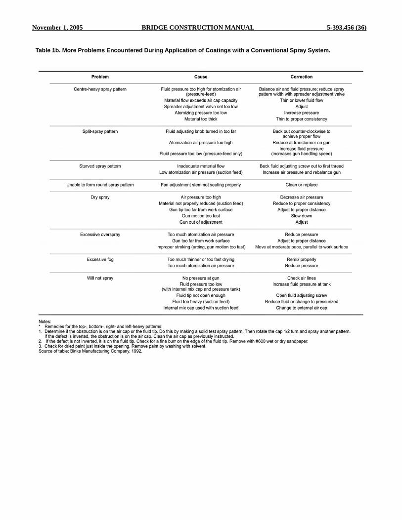
November 1, 2005 BRIDGE CONSTRUCTION MANUAL 5-393.456 (36)
Table 1b. More Problems Encountered During Application of Coatings with a Conventional Spray System.

5-393.456 (37) BRIDGE CONSTRUCTION MANUAL November 1, 2005
Regulators and transformers are used to control air pressure and to allow for multiple compressor hook- ups. Separators and filters are used to clean oil and dirt from the air supply and to extract moisture in the air.
Airless Spray
Airless, or hydraulic, spray painting gets its name from the fact that no compressed air is used with the paint to form the spray. Instead, atomization occurs when the paint is pumped at high pressures (up to 7,400 psi [51,800 kPa]) through a small orifice in the gun nozzle. The pressure in airless spray painting is created by fluid pumps that are able to deliver between 28 oz. and 7 gallons of paint per minute. These pumps drive the paint through high-pressure hoses (typically 3/8-inch inside diameter) specifically designed for the airless system. The advantages and limitations of airless spray are:
Advantages High application rate Higher transfer efficiency (less overspray) than
conventional air spray Easier than conventional air systems to use with
high-viscosity materials Limitations Hazardous spray pressures Reduced operator control Reduced quality of finish More expensive to maintain
The basic components of the airless spray
system are an electric-, air-, or gasoline-powered fluid pump, high-pressure fluid (material) static-dissipating hose filters and screens, and the airless spray gun. Basic equipment designs of electric- and air-powered airless spray systems are very similar.
Airless Spray Fluid Pumps
Airless spray fluid pumps have gears, a diaphragm, or pistons to draw the paint from the container, and force it through the paint hoses and airless spray gun. Piston design pumps are more common than other pumps because they are better able to resist the abrasive and corrosive actions of the paint. The fluid pump may be mounted on a lid that can be attached to a paint drum; on a wheeled cart so
that the pump head can be set inside a paint container; or the pump may use a siphon hose to draw the paint from the container. Pump Classification
Airless spray pumps are identified by the ratio of paint pressure produced to that of the air pressure used. For example, a pump that delivers paint at a pressure of 4 psi (28 kPa) for each 1 psi (7 kPa) of air pressure would be identified as having a 4:1 ratio. Some fluid pumps in the painting industry will use 80 psi (560 kPa) of air pressure to generate a paint pressure of 2400 psi (16,800 kPa), resulting in a 30:1 pump ratio. Pumps are also classified by the volume of paint delivered per minute. A heavy-duty pump may be capable of delivering as much as 7 gallons of paint per minute. Paint pressure is regu- lated by adjusting the pressure regulator on the pump. The pressures on airless spray equipment cannot be regulated as precisely as that on conventional air spray equipment. Electric Fluid Pump
An electrically driven pump motor can be plugged into a standard grounded outlet. The electric fluid pumps have adjustable paint pressure settings. In one type of electric pump, the motor moves a piston sunk in an oil chamber. The pressure thrust on the oil by the piston opens and closes a diaphragm that draws the paint into the paint chamber, where it is pressurized. Spray Tip
The selection of a spray tip is based on the volume of fluid produced by the paint pump, i.e., there must be a match between the pump volume produced and the tip spraying rate. The pump must be capable of delivering more than the tip can use. This permits the pump to run slower than its maximum speed and thus reduce wear on its parts, while providing a reserve capacity of pressure in case a change is made to a larger spray tip or a longer hose. A reversible tip has a key than can turn 180o to blow out clogs.
The larger the spray tip orifice, the more speed and spray coverage that will be possible. Therefore, the airless spray painter chooses the spray tip according to the type of paint being used and the film thickness desired. An orifice that is too large used with a low viscosity paint, for example, would cause

November 1, 2005 BRIDGE CONSTRUCTION MANUAL 5-393.456 (38)
the paint to flood the surface. Generally, the paint manufacturer will list recommended spray tip orifice sizes for use with specific coating materials. Each airless tip is defined by the three numbers located on it, such as 517: The first number (5) when doubled (10) indicates the
approximate fan width in inches when spraying 12 inches (300 cm) from the surface. The second number indicates the tip has a flow rate
in water equal to a 17 mil (0.43 mm) diameter hole. The coating flow rate through the tip will vary with the orifice size. It will also vary with the coating pressure and viscosity.
High-Pressure Fluid Hoses and Fittings The paint hoses used in airless spray painting
are specially constructed to withstand high-fluid pressure. The materials passing through airless hoses at high pressures and speeds build up static electricity through friction. For this reason, these hoses have a grounding wire located in the outer skin to dissipate the static electricity. The hose connections and couplings used for airless spray work are also designed for use on high-pressure equipment.
Filters and Screens Airless spray systems require that the material
sprayed is free of lumps of extra-heavy pigment. Because the orifice size of the spray tip is small, filters or screens are placed: At the base of the siphon hose Inside the surge tank In the material hose Sometimes behind the spray tip
It is important that the screens or filters are
sized to the orifice in the spray tip.
Gun The airless gun is not adjusted unless the tip is
changed. The size and shape of the tip will determine the fan size and shape. There are two safety features on all guns: a tip guard to keep fingers away from the high-pressure spray and a trigger lock to prevent accidentally activating the trigger.
Airless Spray Techniques Because the airless spray system produces a
heavy application of coating, the airless spray painter
must develop proper spraying techniques to avoid runs and sags. One such technique is to hold the spray gun farther from the surface than a conventional air spray gun, usually a distance of 12 to 14 inches.
Since the shape of the airless spray pattern is determined by the built-in angle of the fluid tip, the operator must change the spray tip in order to change the shape of the spray pattern. In general, airless spray patterns have cleaner, sharper edges than conventional air spray patterns, because all the paint particles in the airless spray system travel at the same speed while air spray paint particles tend to lose speed at the outside edges of spray patterns.
Insufficient application pressure will result in tails (fingers), an incomplete fan with coating concen- trated at the top and bottom. Increasing the pressure will resolve this problem.
Figure 1. Air-assisted airless gun. Air-Assisted Airless Spray
The air-assisted airless concept uses a combination of the air and airless methods. A pump is used to force material through a small orifice or tip at low hydrostatic pressure.
Air-assisted airless sprayers operate at pressures under 950 psi. However, most materials cannot attain quality atomization at these low spray pressures and fan patterns are usually incomplete, with “tails” formed at each end. To complete the atomization and eliminate the “tails,” low-pressure (10– 30 psi [70–210 kPa]) compressed air is added to the airless spray through an air cap. The chief advantages of air-assisted airless spray are: Finer atomization and finish than airless spray

5-393.456 (39) BRIDGE CONSTRUCTION MANUAL November 1, 2005
Better operator control than airless spray Better transfer efficiency than conventional air spray Application rates comparable to airless spray
Figure 2. Air-assisted airless guns. Note tip guard, trigger lock, and reversible (switch) tip on bottom gun.
Parts of Air-Assisted Airless Gun The basic parts of an air-assisted airless gun
are: Gun body—Contains air and fluid passages Trigger—Opens air and material valves Trigger safety lock—Prevents discharge from gun
not in use Air inlet—Connects to air supply Air control valve—Controls amount of air at air cap Pattern-adjusting valve—Controls spray pattern Fluid inlet—Connects to material supply Fluid needle—Forms seat with fluid valve seat Fluid Tip—Directs material into air stream Air cap—Forms the spray pattern Air separator—Filters and directs air
Gun Body
The gun body is made of forged aluminum and the fluid passages are stainless steel. Fluid and air inlet ports, the hanger hook, and the trigger safety lock are located on the gun body. The hanger hook pro- vides for proper storage when the gun is not in use.
Trigger
allowing fluid to flow. The trigger assembly is designed to produce a “lead-and-lag” air flow. As the trigger is pulled, air is turned on before the fluid flow begins. As the trigger is released, air is turned off after the fluid stops flowing. The “lead and lag” can be felt when the trigger is pulled. This feature helps to keep the top of the tip free and the air horns cleaner. Trigger Safety Lock
The trigger safety lock is permanently affixed to the gun handle. The trigger cannot be pulled when set in this position. To release, push the lever toward the trigger and to a vertical position. Air Inlet
Air enters the gun body handle through a specially designed fitting. Air Control Valve
The air control valve is located in the handle of the gun body, directly behind the trigger. A positive return spring on the stem keeps the valve closed until the trigger is pulled. When the trigger is pulled, the valve opens, allowing air to flow. The air control valve provides no air pressure regulation. When the valve is closed, no air enters the front portion of the gun. When the valve is opened, full air pressure is admitted. The air pressure is controlled entirely by a pressure regulator located between the compressor and the gun. Pattern-Adjusting Valve
The maximum width of the spray pattern is typically determined by the pattern width specification of the fluid tip. The pattern-adjusting valve can decrease this dimension, but cannot increase the tip specification. This valve is located above the gun handle. The knurled adjusting knob is directly behind the hanger hook.
The stem of the pattern-adjusting valve seats in the air separator chamber in the front of the gun body. When the valve is turned counter-clockwise (closed), the pattern will be at maximum width. When it is turned clockwise (open), the pattern width will be reduced.
The trigger has a two-finger design. It opens the air control valve, allowing air to flow into the gun and it unseats the fluid needle from the valve seat,
Fluid Inlet Fluid enters the stainless steel fluid passages of
the gun body through the specially designed fluid

November 1, 2005 BRIDGE CONSTRUCTION MANUAL 5-393.456 (40)
inlet. The fluid is contained in the forward portion of the body by three pieces of packing, the ball of the needle, and the cone of the seat. Pressure of the needle spring against the packing assembly ensures proper seal of the fluid. Pulling the trigger engages the needle assembly and pulls the ball of the needle off the cone of the valve seat assembly, allowing the fluid to flow.
highest quality and efficiency with the air-assisted airless gun. Fluid delivery requirements (ounces/ minimum) and fan pattern widths to accommodate production requirements are the basic criteria. Operating pressures are considerably lower than normal airless spray so material viscosity and fluid pressure will affect the delivery rates of the fluid tip.
Table 2. Airless Spray Pattern Shape Problems.
Air Cap
The atomizing holes of the air cap are typically
Table 3. Pump Delivery.
Fluid Needle The fluid needle consists of four main parts:
Needle stem and ball Spring Hex nut Air needle nut
The air needle nut fits over the hex nut and the
stem of the air control valve. When the trigger is pulled, the air needle nut moves back.
Fluid Tips
The proper fluid tip is necessary to achieve the
located in the horns of the cap, and the pattern- adjusting holes are typically located in the cap’s face. The spray pattern can be adjusted to vertical or horizontal by loosening the safety-retaining ring and rotating the air cap 90°. The tip will rotate with the air cap. Air Separator
An air separator divides the pattern air and atomizing air. It is made of a durable material and screws onto the front of the gun body. The air cap fits onto the separator, which has a snap ring seal.
Electrostatic Spray Systems
Electrostatic spraying permits the application of coatings to irregularly shaped, electrically conductive structures and components with a very high transfer efficiency. Non-conductive surfaces (e.g., wood, plastics, and composites) may receive a surface treatment or coating to render them conductive. Although all coatings may be electrostatically sprayed, some formulations must first be modified to improve their electrical properties. Electrostatic spray has these advantages and limitations:
Advantages
Wrap-around of edges High transfer efficiency More uniform application Material savings Limitations
High initial/maintenance costs More suited for automation work Skilled operator required Safety precautions required Normally limited to one coat Limited to exterior surfaces Require conductive surface

5-393.456 (41) BRIDGE CONSTRUCTION MANUAL November 1, 2005
Table 4. Airless Nozzle Selection Guide for Electrostatic Spraying.
Electrostatic spray guns are available that apply the electrostatic charge by either one of these two processes: The paint is electrically atomized and charged as it
leaves the edge of a spinning bell The electrical charge is applied to paint particles
already atomized either by air spray or airless meth- ods, or applied to the paint stream just prior to atomi- zation
Spinning-Bell Method
Most solvent-based, free-flowing paints may be applied by the spinning-bell method. The flow of coating to the bell is provided by the usual regulated paint supply system. An electric motor in the gun rotates the atomizing bell so that the material flows uniformly to its outer edge. Atomization occurs under the influence of the electrostatic field as the paint flows from the edge of the bell, forming a spray pattern of electrically charged particles. These charged particles move at slow speeds and tend to deposit on the object at points of maximum electrostatic attraction. The paint applications will thus be thinner in cavities and depressions on the surface, and heavy on edges or protruding points. This represents a definite advantage when applying protective coatings. Non-electrostatic methods of painting application (brush or spray) tend to leave thin coatings on edges, where early coating failure usually occurs.
Paint application rates by the spinning bell method are too limited for most high production rate
applications of maintenance paints and protective coatings. The bell with the largest capacity (6 inches) has an approximate maximum paint delivery rate of 6 oz/min. However, these rates are ample for painting open grills, chain link fences, etc.
Figure 3. Electrostatic spray guns. Air Atomizing and Airless Electrostatic Spray Methods
Air atomizing and airless electrostatic spray methods are more suitable for the field application of maintenance paints and coatings since higher deliveries are possible. The forces of electrostatic attraction result in a more uniform coverage over regular surfaces than is otherwise obtained, and furthermore, these guns may be used as ordinary spray guns whenever desired. Such electrostatic spray methods exhibit all the inherent advantages of the conventional

November 1, 2005 BRIDGE CONSTRUCTION MANUAL 5-393.456 (42)
air and airless spray methods, with the added advan- tages of electrostatic attraction, paint savings, little if any fog and overspray, and less cleanup and protec- tion of nearby objects.
The electrostatic charge is applied either by an electrode protruding in front of the gun and extending into the paint atomizing zone, or by an electrode extending into the paint stream in the gun just before atomization. Depending upon the manufacturer, ionizing voltages range from 30,000–90,000, with approximately 60,000 volts employed by several prominent manufacturers. These are usually fixed voltages that cannot be varied. Air spray and airless electrostatic guns may be fed by conventional paint pumps or pressure tanks. However, special electrostatically conductive hoses must be employed.
When electrostatic spray equipment is operat- ing properly and the paint conductivity is within the range suitable for electrostatic spraying, a marked wrap-around effect occurs. If there is only a weak wrap-around or none at all, the paint conductivity may be too high, the power supply may not be operating, or there may be some electrical trouble with the high- voltage cable or gun.
Safety Features of Electrostatic Spray Systems Although high voltages are used, the equip-
ment, when property set up, is safe to operate. There is no voltage applied to the gun electrode when the trigger is not pulled. Upon pulling the trigger, high voltage is present, but with most equipment this decreases as the electrode approaches a grounded object until, when contact is made, the voltage difference becomes zero. Consequently, holding the gun in one hand and touching the electrode with the other will produce no shock. The fluid hose must contain a special grounding wire or the jacket must be conductive to electrostatic charges. In air-atomized spray, the fluid hose contains a conductive ground wire embedded in the carcass.
The painter is grounded when gripping the gun handle since the handle is connected to ground through the high-voltage cable as well as through the hose. Consequently, the painter cannot wear gloves, which would insulate hands from the gun handle, unless the palm of the glove is cut out to ensure contact with the handle.
There is very little paint fire hazard with modern electrostatic spray equipment that has been
properly installed and is operated as recommended. Although gun voltages are high, only microamperes of current are required to charge the paint particles. It has been demonstrated that there is so little energy present in a spark from the gun electrode on some equipment that tests have failed to ignite hexane vapors.
However, the control of energy in the electro- static equipment does not apply to nearby conductive objects that may be insulated from ground. These objects can develop high voltages with appreciable energy as they are contacted by charged air molecules and paint particles. A spark from such objects may easily contain sufficient energy to ignite solvent vapors. Consequently, it is essential that all electrically conductive objects, including personnel, be grounded when located within 10–15 feet of the gun operating area. In addition to grounding the power supply, it is recommended that the unit be located as far as possible from the spray area (at least 20 feet).
Metallic items must be removed from pockets (e.g., coins, keys, pencils, nail clips, etc.). There have been occasions where these overlooked items have acquired a sufficient charge to ignite solvent vapors as they sparked through the pocket when the painter moved close to the grounded paint bucket. Application Procedure
Application techniques are, in many ways, simpler with electrostatic spraying than with straight air or airless spraying. Lapping is less critical in applying an even coat, and, for many applications, careful attention to triggering is not necessary. Overspray is essentially eliminated by the electrostatic attraction of the coatings.
With air electrostatic spraying, lower atomizing air pressures are required, both because of thinning and because the electrostatic charge aids in paint particle formation. Likewise, considerably lower fluid pressures are necessary with airless electrostatic spraying, and the degree of atomization is usually finer than without the electrostatic charge. Because the viscosity of most paints to be applied electrostatically has been adjusted to the desired range, only two or three spray nozzle setups satisfy most air electrostatic application requirements. A selection of airless spray nozzles is needed, however, depending upon the object shape and application rates desired.
The inclusion of an orifice spray insert is

5-393.456 (43) BRIDGE CONSTRUCTION MANUAL November 1, 2005
helpful with paints that are difficult to atomize to a fine spray without using excessive fluid pressure. The insert tends to reduce the forward velocity of the paint through the nozzle, providing a “softer” spray with increased electrostatic efficiency. An insert may be useful for spraying tubular and open items. The spray insert orifice size should be equal to or slightly larger than the nozzle size, but never smaller.
When painting, it is recommended to hold the electrostatic gun at the manufacturer’s recommended distance from the surface (e.g., 6–10 inches with air spraying and when using the spinning bell gun, and 8– 12 inches for airless atomization). The distance should never be much greater than 12 inches; otherwise, the sprayed paint particles may be attracted preferentially to the painter’s grounded hand rather than to the object being painted. This is one reason for the somewhat longer gun barrel on air and airless electrostatic spray guns.
Paints must be kept from accumulating on the electrode wire and on the face of the nozzle. Paint deposits may be removed with a bristle brush and solvent, but only after the high voltage has been turned off. For more extensive maintenance and service of electrostatic spray equipment, refer to the manufacturers’ service manuals.
Solvents Recommended for Coatings Applied by Electrostatic Spray Systems
The standard formulations of most solvent- based paints can be sprayed successfully by air and airless electrostatic spray methods, providing that the paint conductivity is not so high as to form a grounding path for the high voltage. Paints are conductive either because conductive (polar) solvents are used or metallic pigments are present.
Paints that have solvents too conductive for air and airless electrostatic spray application can seldom be successfully modified in the field by adding non- conductive (non-polar) solvents. The paint formulation must be revised by the supplier. All water-based paints and many paints with metallic pigments cannot be applied by electrostatic hand guns because of their conductivities.
In addition to considerations of paint conduc- tivity, it has been found that optimum electrostatic attraction results when the paint viscosity is adjusted from 20–24 seconds with a No. 2 Zahn cup (or 14– 22 seconds with a No. 4 Ford cup). This is lighter than
the viscosity of most paints supplied for conventional spraying. Xylene, or other nonpolar or low-polar solvents compatible with the paint system, are recommended for thinning purposes.
Since lower spray pressures are generally used, the charged paint particles move more slowly to the surface being painted than when applied by conventional methods. Consequently, slower-drying solvents must be used in the paint formulation to ensure that a wet paint film is being applied. Furthermore, a paint particle that dries enroute to the surface quickly loses its charge and so will not be electrostatically attracted to the surface.
Figure 4. Plural-component proportioning system. Plural-Component Spray
The plural component method of spraying coatings combines at the nozzle those components of thermosetting coatings that cure by chemical reaction. Each component is automatically proportioned as recommended by the manufacturer and combined in either a manifold/mixing chamber immediately before spraying or immediately after spraying with an airless

November 1, 2005 BRIDGE CONSTRUCTION MANUAL 5-393.456 (44)
or conventional air spray gun. The basic components of plural-component spray systems are: Coating material feed system for each component High-performance proportioning pump Appropriately sized, chemically resistant hoses for
unmixed components Mixer manifold assembly Whip hose Airless or conventional air spray gun Solvent-purge system Filters Heaters (optional) Off-ratio alarm/shut-down (optional)
Figure 5. Manifold of plural-component system.
Fixed-ratio systems are used most often in production plants where the same operation is per- formed daily with no variance. Industrial coating contractors more commonly use a variable-ratio system because they apply, either in the shop or in the field, a variety of plural-component coatings with different mixing ratios. Typical plural-component materials applied include, but are not limited to, coatings with resins of epoxy, polyurethane, polysulfide, and silicone.
The spray system may be airless or conven- tional, or a combination of both. In many applications, the material is heated to reduce the viscosity. Use of this equipment requires special training and extra safety precautions.
Technology has made available control devices to monitor and control the mix ratio of the plural-component materials used in a variety of applications. These devices measure the positive displacement of the volume of solids flowing through the system, and automatically adjust the mix ratio to
keep it within selected tolerances. If the desired mix ratio cannot be maintained, delivery of the material is stopped and an alarm message is issued.
Figure 6. HVLP spray gun.
High-Volume, Low-Pressure Spray High-volume, low-pressure (HVLP) spray
systems require a high volume of low pressure air to atomize the material being applied. The chief reason for developing HVLP spray was to produce a high transfer-efficiency system and thus reduce the amount of coating used and the amount of organic solvent entering the atmosphere.
In exterior appearance, HVLP spray equipment resembles a conventional air spray system, especially the actual spray gun. The air cap, fluid needle, fluid tip, fluid adjusting screw, spreader adjusting valve trigger, and gun body are similar. Spray application is slower, although some units (with the proper combination of air cap, fluid tip, and fluid needle) will deliver up to 18 oz/min. (0.5 L/min.). This delivery can be compared to using a 74:1 airless spray pump with a large orifice opening in the spray tip, which will deliver approximately 1.25 gal/min. (4.98 L/ minute). Because of the high volume (at least 20 cfm) of air required with some industrial HVLP spray systems, a two-stage compressor is required if the system is to be productive.
In the process of applying industrial coatings to large areas, such as storage vessels, ships, etc.,

5-393.456 (45) BRIDGE CONSTRUCTION MANUAL November 1, 2005
HVLP cannot accomplish the high application rate that is possible with high-volume airless equipment. However, HVLP is used extensively in the wood finishing, farm equipment manufacturing, and automotive industries, and for commercial and residential application, but will not achieve the production level of other spray systems. The advantages and limitations of HVLP are: Advantages Good transfer efficiency Reduced overspray and bounceback Good with high-solids coatings Good gun control
Limitations Reduced application speed High initial/maintenance costs May require special training
References 1. SSPC PA 1. Shop, Field, and Maintenance Painting of Steel; SSPC: Pittsburgh. 2. Applicator Training Bulletins in the Journal of Protective Coatings and Linings; TPC: Pittsburgh. 3. ABCs of Spray Finishing; DeVilbiss: New York, 1999. 4. Airless Spray Coating Technology, Including Air- Assisted Airless Spray Technology; Graco, Minneapolis, 1995. 5. Safety; Graco: Minneapolis, 1995. 6. Concept and Theory Training Module on Safety; Graco: Minneapolis, 1995. 7. Electrostatic Spray Finishing; Graco: Minneapolis, 1995. 8. The Fundamentals of Cleaning and Coating Concrete; Randy Nixon and Richard W. Drisko, eds.; SSPC: Pittsburgh, 2001.
About the Author
Frank Palmer This information has been prepared by Frank Palmer of Frank Palmer Consultants Limited and Cheryl McArthur of Perfect Words, both of Calgary, Alberta. Frank Palmer has specialized in designing training programs and seminars and writing specifications for more than 20 years. He has over 25 years of practical industry experience and was the first Canadian to obtain an SSPC protective coatings specialist (PCS) certification.

November 1, 2005 BRIDGE CONSTRUCTION MANUAL 5-393.456 (46)
Chapter 7 Inspection
Kenneth A. Trimber and William D. Corbett Introduction
The purpose of this chapter is to outline the inspections required to assure quality coating work. In addition, paint inspection equipment is described and summarized.
The Function of the Coating Inspector
Throughout this discussion the term “inspector” shall be used to indicate an individual or a group of individuals whose job it is to witness, report, and document coating work in a formal fashion. While painters themselves may conduct informal inspections, this will not be discussed. Instead inspectors providing a quality control (QC) function, or first line inspection of each aspect of the coating work will be described.
QC inspectors are specially trained contractor personnel or employees of a third-party hired by the contractor or owner to provide QC services. The quality assurance (QA) personnel working for the facility or company can also perform spot checks of work or any or all of the steps addressed herein.
The inspector’s purpose is to verify that the requirements of the coating specification are met. This is analogous to that of a police officer: the inspector enforces the rules (specification) without exception even if these rules are deemed inadequate. An authorization to deviate from the specification is the responsibility of the “judge,” usually the specification writer, contract administrator, or engineer in charge of the job. The inspector certainly may venture an opinion to the engineer and provide recommendations, but cannot unilaterally deviate from the specifications at the working level.
Besides specification enforcement, a QC coatings inspector provides thorough project documentation including a commentary on the type and adequacy of equipment at the job site, the rate of work progress, information regarding ambient conditions and controls, and verification that the surface preparation, coating application, coating thickness, and curing are as required. This is supplemented with any other information deemed
to be of consequence to the quality and progress of the work.
The amount and type of QA inspection on behalf of the facility owner often varies according to the size of the project and the type of application contract. There are a number of types of contracts, but for simplicity two general categories, “fixed price” and “cost plus” will be addressed.
QA inspection under a “fixed price” application contract takes place to ensure that the contractor does not “cut corners” in order to hurry the job. While an evaluation of the equipment, work procedures, and sequence, etc. is important, the equipment and methods by which the contractor accomplishes the job are essentially at the contractor’s discretion, provided the requirements of the specifications are met. When performing QA inspection services for a “cost plus” application contract, a knowledgeable inspector must be able to evaluate the contractor’s equipment for adequacy and assess whether the rate of progress is reasonable.
Safety Considerations
Safety is paramount on any job. Coating inspectors should be aware of basic safety requirements and should have received personal protection training. If lighting, scaffolding, or equipment malfunctions present safety hazards, or appropriate protection from toxic substances or falls is not provided, the appropriate safety personnel should be notified. Paint application inherently presents dangers because the solvents used can be flammable and because many objects to be painted are relatively high or difficult to access. The inspector must be assured of the safety of these appurtenances before becoming involved.
Inspection Sequence
Inspection often begins with a pre-job conference where the ground rules are set. The inspector is responsible for witnessing, verifying, inspecting, and documenting the work at various

5-393.456 (47) BRIDGE CONSTRUCTION MANUAL November 1, 2005
inspection points: Inspecting Pre-Surface Preparation Measuring Ambient Conditions and Surface
Temperature Evaluating Compressor (Air Cleanliness) and
Surface Preparation Equipment Determining Surface Preparation (Cleanliness and
Profile) Inspecting Application Equipment Witnessing Coating Mixing Inspecting Coating Application Techniques Determining Wet and Dry Film Thickness Evaluating Cleanliness Between Coats Testing for Pinholes and Holidays Testing Adhesion Evaluating Cure
Inspecting Pre-Surface Preparation
Prior to surface preparation or other coating activities, it may be necessary to confirm that the work is ready to be prepared and painted. Heavy deposits of grease, soil, dust, dirt, cement splatter, and other contaminants must be removed, according to SSPC- SP 1, so that they are not redeposited onto freshly cleaned surfaces. This is particularly important when recycled abrasives are used so the abrasive itself does not become contaminated.
The specification may require that weld splatter be ground or otherwise removed and that sharp edges be rounded. Laminations in plate steel, if detected prior to blast cleaning, may have to be opened and, if deep enough, could require weld filling. If sufficient deterioration has occurred to the structure, replacing some structural members, “fish plating,” or other repair may be necessary. Responsibility for such repair should be specified in procurement documents. Although this work is not ordinarily considered to be part of the coating contract, the inspector should confirm that it has been performed before the surface preparation and painting work. As a prelude to most painting operations, taping and masking is used to protect adjoining surfaces not to be painted. The NACE Visual Comparator for Surface Finishing of Welds Prior to Coating, as referenced by NACE RP 0178, may be used to inspect lap and butt welds, primarily for immersion service lining systems.
If the work involves maintenance painting, a determination of the percentage of rusting in an area may be helpful. Assessments can be made in
accordance with SSPC-Vis 2, Standard Method of Evaluating Degree of Rusting on Painted Steel Surfaces.
Perhaps the best method of determining coating compatibility is a test patch application of the new coating over the old, a few months or more in advance of production painting. The test patch is then evaluated for adhesion, and examined for signs of wrinkling, lifting, or other evidence of incompatibility.
Details regarding overcoating and test patch assessments can be found in SSPC TU 3, Overcoating, and ASTM D5064, Practice for Conducting a Patch Test to Assess Coating Compatibility.
Measurement Of Ambient Conditions
It is implicit that surface preparation and coating work be done only under suitable ambient conditions of temperature, humidity, and dew point. For most catalyzed coatings, specific minimum temperatures must be met. Many inorganic zinc-rich coatings (ethyl silicate), or moisture-cure urethanes require minimum humidity levels as well. The inspector should be cognizant of weather forecasts (particularly if coating work is to be done outdoors) and the temperature and humidity restrictions of the specific coating material(s) being applied to the surfaces.
Other ambient conditions that might affect painting operations should be noted such as potential industrial or chemical airborne contamination, water spray downwind from a cooling tower, leaking steam or chemical lines, and contamination from normal plant or adjacent operations.
Often, heating or dehumidification equipment is used to control (and maintain) ambient conditions for painting operations within tanks or contained areas. Ideally, a heater should be indirect fired so it does not contaminate the surface with products of combustion. Ventilation, if required, should provide for sufficient air flow and adequate ventilation of all areas where work is being performed. Most solvents are heavier than air; thus, the dangers of explosion and flammability are frequently the greatest in low-lying areas. Control of airborne contaminants such as dust and abrasive must also be effective in order to prevent contamination of the painted surfaces or unacceptable worker exposures.
While much of the above is inspected visually or with specially designed equipment for determining

November 1, 2005 BRIDGE CONSTRUCTION MANUAL 5-393.456 (48)
solvent concentrations, the ambient conditions of air temperature, relative humidity, and dew point for surface preparation and painting quality are determined using instrumentation. This includes psychrometers (Figure 1 and 2) or instruments that give direct read-out recordings of humidity (Figure 3) and dew point. Measurements with these instruments are taken before the work begins each day and periodically throughout the day. A suggested minimum frequency is every four hours, or sooner if weather conditions appear to be worsening.
Figure 1. Sling psychrometer used for measuring wet and dry bulb temperatures in order to establish relative humidity and dew point. The instrument is spun in the air to reach termperature stabilization.
Figure 2. An electric psychrometer uses a fan to draw air across therrmometer bulbs, providing the wet and dry bulb temperature readings.
The psychrometer consists of two identical
tube thermometers, one of which is covered with a wick or sock that is saturated with water. The covered thermometer is called the “wet bulb” and the other is the “dry bulb.” The dry bulb gives the ambient air temperature while the wet bulb temperature provides results from the latent heat loss of water evaporation from the wetted sock. The faster the rate of water evaporation, the lower the humidity and dew point. There are generally two types of psychrometers: the
sling psychrometer, shown in Figure 1, and the fan or motor-driven psychrometer, shown in Figure 2. Electronic psychrometers are also gaining in popularity.
When using the sling psychrometer as detailed in ASTM E 337, the wet bulb sock is saturated with water, the instrument whirled rapidly for approximately 20 seconds, and a reading of the wet bulb quickly taken. The cycle is repeated (spinning/ reading without additional wetting) until the wet bulb temperature stabilizes. Stabilization occurs when three consecutive readings of the wet bulb remain the same. At this time both the dry and wet bulb temperatures are recorded.
When using the fan-operated psychrometer, the wet bulb sock is saturated with water and the fan is started. Approximately two minutes are required for stabilization, and one need only observe the wet bulb thermometer and record both temperatures when the wet bulb temperature remains unchanged.
When the instruments are used in air temperatures less than freezing—32ºF (0°C), the accuracy of the readings is questionable. The wet bulb thermometer will drop below 32ºF (0ºC) to a certain point (e.g., 27ºF [-2.7°C]), then “heat up” rapidly to the freezing point. Quite often when using a sling psychrometer, this will take place as the instrument is whirled; therefore, a wet bulb temperature of 32ºF (0°C) may always be obtained. When using the motor-driven psychrometer, one can observe the wet bulb temperature drop below freezing, then rise rapidly to 32ºF (0°C). However, the low value may still be incorrect. Thus if the temperature is below 32ºF (0°C), the ambient conditions will have to be established by other means. This could be accomplished by obtaining the dew point and relative humidity on a direct read-out instrument using more sophisticated equipment (Figure 3). Alternatively, the tube psychrometers can be supplimented with inexpensive direct reading humidity indicators. The psychrometer would be used only to determine the ambient temperature (dry bulb). These two values (dry bulb and humidity) can then be used to determine the wet bulb and dew point temperatures by plotting out this information “in reverse” on charts or tables.
After the dry bulb and wet bulb temperatures are determined, a psychrometric chart or table is used to determine the relative humidity and dew point temperatures. Charts require plotting the dry bulb and

5-393.456 (49) BRIDGE CONSTRUCTION MANUAL November 1, 2005
wet bulb temperatures on different lines and interpolating the relative humidity and dew point from their intersection.
Figure 3. A digital hygrothermometer gives instant readout of air temperature, relative humidity, and dewpoint.
The U.S. Department of Commerce Weather
Bureau has created individual psychrometric tables for relative humidity and dew point. To use the tables, the wet bulb temperature is subtracted from the dry bulb temperature and the difference found along the top row of the table labeled “depression of the wet bulb thermometer.” The dry bulb (air) temperature is found down the left column and the intersection of the two is either the humidity or the dew point, depending upon which table is used. The U.S. Department of Commerce NOAA-WSTA B-0-6E (5-72) Relative Humidity and Dew Point Table includes both sets of information on one table.
Dew point is defined as the temperature at which moisture will condense. Dew point is important in coating work because moisture condensation on the surface will cause freshly blast cleaned steel to rust, or a thin, often invisible film of moisture trapped between coats may cause premature coating failure. Accordingly, the industry has established a dew point/ surface temperature safety factor. Surface preparation
and coating application should not take place unless the dew point is 5°F (-15°C).
Figure 4. A surface temperature thermometer estab- lishes the temperature of substrates during blast cleaning and painting.
Different field instruments are used for deter- mining surface temperature. One of the most common is a surface temperature thermometer (Figure 4), which consists of a bimetallic sensing spring that is shielded from drafts. The instrument includes two magnets on the sensing side to attach to ferrous substrates. For non-ferrous surfaces, attach the thermometer using tape across the face of the gauge. A minimum of two minutes is required for temperature stabilization. Other field instruments for determining surface temperature are direct reading thermocouple/ thermisters (Figure 5a). These instruments utilize a sensing probe that is touched to the surface, resulting in a direct temperature readout. Only a few seconds are required for a temperature reading to stabilize. Non-contact infrared (IR) thermometers are also available for use (Figure 5b). Accurate temperature readings can be obtained from a few inches to many feet away from the surface by simply pointing the IR beam at the surface. Some models contain a laser sighting.
With any of the instruments used for determining ambient conditions and surface temperatures, the readings should be taken at the actual locations of the work. For general readings where dew point is the concern, however, one should

November 1, 2005 BRIDGE CONSTRUCTION MANUAL 5-393.456 (50)
consider the coldest point on the structure because a surface temperature/dew point relationship problem will occur there first. Air and surface temperature considerations are also important to ensure that coatings are not applied outside of their temperature limitations—in areas too cool or too warm. Accordingly, readings for this purpose should be made at the coolest or warmest areas.
Typical requirements for ambient painting conditions are given in SSPC-PA 1. Specific requirements are provided in the project specification and/or the coating manufacturer’s product data sheets.
Figure 5a. Direct reading thermocouple/thermister.
Figure 5b. Non-contact infrared (IR) thermometer.
Evaluating Surface Preparation Equipment
The air compressor and other equipment used for blast cleaning and any hand or power tools should be inspected. The inspector need not have an extensive technical background on the equipment, but should have enough familiarity to verify its suitability. Air Compressor and Air Cleanliness
When an air compressor is used for blast cleaning, power tool cleaning, or spraying equipment, the compressor should be appropriately sized and have a suitable volume (ft.3/min.) to maintain the required air pressures. Abrasive blast cleaning equipment suppliers have charts and data available that are excellent aids for determining required sizes of compressors, air and abrasive lines, nozzles, and so forth.
The compressed air used for blast cleaning, blowdown, and air atomization for spray application should be checked for contaminants. Adequate moisture and oil traps should be used on all lines to assure that the air is sufficiently dry and oil-free in order to avoid interfering with the quality of the work.
A simple test for determining air cleanliness requires positioning an “absorbent collector” (clean white piece of blotter paper) within 24 inches of the air supply, downstream of moisture and oil separators.
ASTM cautions the tester to avoid personal contact with the air stream. Therefore, it is helpful to mount the paper on a rigid frame (e.g., 1/2-inch plywood) using duct tape. The air is permitted to blow on the blotter paper for a minimum of one minute followed by inspection for signs of moisture or oil contamination on the blotter. Obviously, if there is no discoloration on the blotter paper, the quality of the air is excellent, while streams of moisture and oil running down the sheet indicate unsatisfactory air.
Unfortunately, the point where good air becomes “bad” is difficult to determine. However, by using blotter paper (or a clean cloth), one can make judgments as to the air quality. Inspec the surface thoroughly for moisture or oil contamination after preparation or painting and correlate these results with the results of the blotter test.
In addition, the proper functioning of in-line moisture and oil traps can be evaluated on a comparative basis from the results of the blotter test. For work requiring that absolutely no moisture or oil be

5-393.456 (51) BRIDGE CONSTRUCTION MANUAL November 1, 2005
permitted in the compressed air, oil-less compressors and sophisticated air drying equipment are available.
Blast Cleaning Machine The blast cleaning machine mixes the
abrasive with the air stream. The abrasive metering valve regulating the flow of abrasive into the air stream is perhaps one of the most overlooked but important considerations affecting the rate of production. Generally, too much abrasive is fed into the air stream, resulting in both decreased production and increased abrasive costs. The machine must be equipped for “dead man” capability so that it automatically shuts down if the nozzle is dropped [OSHA 29 CFR 1910.244(b)]. It should also be equipped with moisture and oil separators, or external separators should be provided. Since the tank of the blast cleaning machine is a pressure vessel, it should be constructed according to pressure vessel codes.
Abrasive There are a wide variety of abrasives available
for blast cleaning. The size, type, and hardness have a significant impact on the surface profile and speed of cleaning. Metallic shot and grit abrasives are commonly used for rotary wheel blast cleaning because they can be recycled. Iron and steel shot, grit, aluminum oxide, and non-traditional abrasives such as glass beads can be recycled and used in field operations as well, provided appropriate equipment is available to separate fines, paint, rust, and mill scale from the collected abrasive. Various slag abrasives are widely used in field applications, and in some cases, silica sand is still being used. However, its use as a blast cleaning abrasive is declining because of the potential silicosis hazards. Sand and slag abrasives are expendable and should not be recycled.
It is important that all abrasives be clean and free of moisture at the time of use. Abrasives should be stored off the ground and protected from the elements. Only expendable abrasives that have been washed at the manufacturing and packaging plant should be used. The washing should be done using fresh water only; if brackish water is used, chloride contamination of the cleaned surface can result, with subsequent rust bloom in humid environments as well as the potential for osmotic blistering of the coating film once in service.
Although there is no inspection apparatus for
Figure 6. Testing for the presence chlorides. determining the cleanliness of the abrasive used, a visual inspection can be made to ensure that it is not damp or contaminated. When abrasive recycling systems are used, a simple test for the presence of oil or grease contamination can be conducted by dropping some of the abrasive (e.g., a handfull) into a small vial of water (e.g., 8 ounces) and shaking the vial vigorously. The top of the water is inspected for a film of grease or oil which will be present if the abrasive is contaminated. Dirt and dust in the abrasive can be assessed in the same manner. Small abrasive “fines” will be held by surface tension at the meniscus, and a dirty abrasive will color the water or cause turbidity. However, water-soluble contaminants such as salt will not be detected using this test. If water-soluble contaminants are present, a litmus paper test of the water in the vial will tell if they are acidic or alkaline. If neutral, a drop of 5% silver nitrate solution can be added to the water. The formation of a white precipitate will indicate the presence of chlorides. Alternatively, allow the water to evaporate and look for salt crystals, or use a chloride indicator strip to quantify the amount of chloride present in the water extract (Figure 6). Another field method for determining the presence of soluble salts in the abrasive involves the use of a conductivity meter to test a mixture of water

November 1, 2005 BRIDGE CONSTRUCTION MANUAL 5-393.456 (52)
and the abrasive. This test is described in ASTM D 4940. Commercially available kits specifically designed for the detection of chloride contamination on abrasive media and in wash water (used during pressure washing, waterjetting, or wet abrasive blast cleaning) can also be employed (Figures 7a and 7b).
Figures 7a and b. Commercial tests kits for detecting chloride contamination on abrasive media (a) and in wash water (b).
Forced Air and Abrasive Hoses
Sharp constrictions or bends in these lines should be eliminated, and they should be kept as short as possible to avoid friction and loss of pressure. For safety purposes, the couplings must be wired together to ensure secure closure and to prevent the connections from working loose and coming apart. Wire cables (whip checks) are also used to help maintain safety, in the event that the hoses come uncoupled during blast cleaning. Blast hoses must also be equipped with static wire grounding, as a considerable amount of friction is generated by
abrasive flowing though the blast hose. Blast Cleaning Nozzles And Nozzle Pressure
A great variety of nozzle sizes, types, and lengths are available for cleaning purposes. The specific nozzle chosen will depend upon the specific cleaning job. Venturi type nozzles provide a higher abrasive velocity and a larger blast pattern than straight barrel types of the same orifice size. In general, the longer the barrel and the larger the orifice, the faster the cleaning rate provided an ample volume of compressed air is available to maintain high pressures at the nozzle. Cracked nozzles and worn nozzles, even if not cracked, will reduce the rate of blast cleaning. As a rule of thumb, a nozzle that has been worn beyond 25% of its original inside diameter (I. D.) should not be used. A nozzle orifice gauge (Figure 8) is available for determining the orifice size after use. The number etched on the nozzle housing indicates the size when new (in sixteenths of an inch). For example, a No. 8 nozzle is equivalent to 1/2 inch inside diameter, when new.
Figure 8. Nozzle orifice gauge (right) measures the nozzle orifice and indicates CFM of air required for the size. Hypodermic needle pressure gauge (left) measures air pressure at the nozzle when the needle is inserted through the blast hose.
The amount of air pressure at the blast nozzle is a determining factor in cleaning rate production. The optimum nozzle pressure is 90 to 100 psig for most

5-393.456 (53) BRIDGE CONSTRUCTION MANUAL November 1, 2005
abrasives, although there are some exceptions. Optimum pressures when using steel grit, for example, may be 125 psig or even higher. The blast cleaning air pressure should be determined at the nozzle rather than at the gauge on the compressor because there will be pressure drops in the system due to hose length, bends, restrictions, air fed to the blast pot, moisture traps, and multiple blasters using the same compressed air source. Air pressure at the blast nozzle can be determined using a hypodermic needle air pressure gauge.
The gauge needle is inserted through the blast hose as close to the nozzle as is practical. The direction of needle placement should be toward the nozzle. Pressure readings are taken with the nozzle in operation (abrasive flowing). At the same time, all other pneumatic equipment using the same compressor system must be in operation, and multiple blasters must operate their nozzles simultaneously, in order to obtain an accurate measurement.
Rotary Wheel Blast Cleaning Equipment Many fabricating shops and painting sites are
equipped with rotary wheel blast cleaning equipment in order to efficiently prepare a surface for painting. The number of wheels directly affects the area that can be cleaned, and the type of structural shapes that can be cleaned.
Adjustments can be made to direct the abrasive stream from each wheel to the desired location in order to provide a uniform cleaning pattern. The speed through the machine determines the degree of cleaning; the slower the material goes through the machine, the greater the degree of cleaning.
Complex structural shapes are particularly hard to clean using automated equipment. The interior of box girders, enclosed shapes, and shielded mem- bers cannot be cleaned, unless cleaning is done prior to fabrication. In many instances, fabricators will employ handheld blast cleaning equipment in tandem with the automated equipment to reach the limited access areas.
Surface preparation methods such as vacuum blast cleaning, water blasting with and without abrasive injection, wet abrasive blast cleaning, and hand and power tool cleaning are discussed in other chapters of this book.
Determining Surface Preparation Cleanliness and Profile Cleanliness
All surfaces should be inspected after surface preparation to ensure compliance with the specification. SSPC’s surface preparation specifications describe hand and power tool cleaning, abrasive blast cleaning, waterjetting, etc., including the type and percentage of residues permitted to remain on the surface. It is important that this inspection be timely, in order to avoid any rusting of cleaned surfaces prior to applying the primer (Figure 9).
Figure 9. A selection of SSPC visual standards.
The written definitions for abrasive blast cleaned surfaces are supplemented by SSPC Vis1, which photographically depicts the surface appearance of various grades of blast cleaning over four initial mill scale and rust conditions on steel. The standards are visually compared with the prepared surface to determine the degree of cleanliness. ISO also has visual standards for evaluating surface cleanliness.
Agreement on the desired appearance of a cleaned surface using commercially available reference photographs is often difficult to achieve because of shadows and hues caused by the abrasive used, the pattern and degree of prior rusting, and numerous other factors unique to each project. As a result, job site standards are often developed to reach agreement on the appearance prior to beginning production work. Sections of the structure (or test panels of a similar nature) are prepared and all parties involved ultimately select the panels or areas that are representative of the desired end result. When

November 1, 2005 BRIDGE CONSTRUCTION MANUAL 5-393.456 (54)
inspecting the quality of surface preparation, much of the effort should be spent on areas that are difficult to access such as the back sides or undersides of angles or supporting steel.
Cleanliness after surface preparation must also be examined. Residual traces of abrasive must be blown, swept, or vacuumed from the surface prior to primer application. It is also important to ensure that dust is removed from the surface prior to painting, particularly the “fine” film of dust-like spent abrasive often held to the blast cleaned surface by static electricity. Any scaffolding, staging, or support steel above the area to be coated must be blown down and cleaned to prevent abrasive and debris from dropping onto the freshly cleaned surface, or later contaminating the freshly primed surface. Adjacent blast cleaning and painting should not be perfomed concurrently unless permitted by the governing specification, and provided the blast cleaning operations are adequately isolated to prevent contamination of the freshly painted surfaces. The surface may also be inspected to determine if it is chemically clean and free of detrimental concentrations of soluble salts. This is discussed in a separate chapter of this book.
Profile
sophisticated laboratory methods include a profilometer and a depth measuring microscope. SSPC’s Surface Profile for Anti-Corrosion Paints discusses a standardized method of measuring profile using a microscope.
Figure 10. The surface profile comparator consists of a lighted magnifier and reference disk (shown) for visually comparing the anchor pattern of blast cleaned steel. Reference disks are available for sand, grit, or shot abrasives.
The surface profile, anchor pattern, or roughness is defined as the maximum average peak- to-valley depth (or valley-to-peak height) created during surface preparation. The terms are most commonly associated with abrasive blast cleaning and are the result of the impact of the abrasive onto the substrate. A white metal blast can have a 1, 2, 3, or 4 mil profile; likewise, a commercial blast can have a 1, 2, 3, or 4 mil profile. Specifying a certain blast cleanliness says nothing of the profile requirement. It must be addressed separately.
Surface profile is important because it increases the surface area to which the coatings can adhere, and provides a mechanical anchor to enhance coating adhesion. As a general rule, heavier coatings require a deeper surface profile than thinner coatings. Surface profile determinations are generally made in the field or shop using one of three instruments: a surface profile comparator, a depth micrometer, or replica tape. All three methods are described in ASTM D 4417. Magnetic measurements of surface profile have been attempted with little success. More
Figure 11. Surface comparator in use measuring surface profile.
The most common surface profile comparator is the Keane-Tator Surface Profile Comparator (Figures 10 and 11), which consists of a reference disc and a 5-power illuminated magnifier. The disc is held magnetically against the magnifier, through which
5-393.456 (55) BRIDGE CONSTRUCTION MANUAL November 1, 2005
prepared surface and disc segments can be viewed simultaneously. The reference disc has five separate leaves or segments, each of which is assigned a number representative of the profile depth of the particular leaf. Each disc is a high purity nickel electroformed copy of a master. The master disc was measured microscopically at SSPC to establish its profile depth.
The reference disc is compared with the surface through the 5-power magnifier. The leaf or leaves that most closely approximate the roughness of the surface are considered to be the profile of that surface. For example, the profile may be 2 mils, or perhaps from 2 to 3 mils if the surface roughness appears to lie between the 2 and 3 mil leaves.
There are three reference discs available. The one to use for measurement depends upon the type of abrasive. Different abrasives generate a different surface profile appearance, although the peak-to- valley depths may be identical. For example, shot is round when compared with a more angular grit. In order to achieve similar profile depths, shot, by virtue of its shape, will generally result in greater lateral distances between the peaks than grit provides, resulting in a lower peak count per given area. The optical effect provides an illusion that the profile of the shot-blast cleaned surface is deeper than the grit-blast cleaned surface (because the peaks are wider apart), even when the depths are essentially identical. Therefore, it is critical that the correct reference disc be selected.
The designations for the three reference discs available with the instrument are: S for sand; G/S for metallic grit or slag; and SH for shot. The numbering system on each leaf consists of a number followed by a letter designation, then another number. The first number represents the profile depth of that leaf, the letter(s) represents the abrasive type used (sand, grit/ slag, or shot), and the final number represents the year that the master disc was formed. For example, 1S70 indicates that that leaf was prepared to a 1 mil profile using sand as the abrasive and that the master disc was formed in 1970. The year that the master disc was formed is only significant if it were to be replaced at a later date. Another field instrument used for this purpose is a pit depth finder.
Surface profile depth can also be determined by using replica tape. Replica tape consists of compressible foam attached to a uniform 2 mil film of
mylar. The tape is pressed onto the blast cleaned surface, foam side down, and the mylar rubbed vigorously with a blunt instrument, such as a swizzle stick or burnishing tool. The peaks and valleys of the profile conform to the compressible foam and the peaks will ultimately touch, but not alter the thickness of the mylar, as the mylar is non-compressible. The tape is removed and measured using a light spring-loaded micrometer, which provides a reading from the upper or outermost surface of the mylar to the high spots on the foam (corresponding with the valleys of the profile). The total micrometer reading is adjusted for the thickness of the mylar by subtracting 2 mils from the result to provide a direct reading of the maximum average profile. The tape is available in four ranges: “coarse” for profile measurements from 0.8 to 2.0 mils; “paint grade” for measurements from 1.3 to 3.3 mils; “x-coarse” for measurements from 1.5 to 4.5 mils; and “x-coarse plus” for measurements from 4 to approximately 6.5 mils.
The replica tape will retain the impression indefinitely, provided it is stored in a cool area with no pressure ever applied. Conceivably, replicas of profile depths could be kept on file permanently for future reference.
It is important that the inspector realize that each method has its limitations. For example, the comparator can be subjective, and persons using it could be biased by the results of others. The peaks of the profile may be too close together to permit the projecting pin of the surface profile gauge (depth micrometer) to reach the valleys, or the surface might be irregular or wavy, holding the base of the instrument slightly above the plane of the profile, giving erroneously high readings. Replica tape cannot be used for profile depths less than 0.8 mil nor exceeding 6.5 mils, and if there is any dirt or dust contamination on the surface, it will be picked up and incorrectly read as additional profile depth on a spring- loaded micrometer. Finally, it is important to realize that there may not be exact correlation among each of the above methods because each takes in a different peak count or surface area for its measurement. Therefore, it is advisable that all parties concerned agree upon the method that will be used to determine the surface profile and not deviate from it. Coating manufacturers will occasionally supply a profile reference coupon representative of the roughness necessary for their product or alternatively may specify

November 1, 2005 BRIDGE CONSTRUCTION MANUAL 5-393.456 (56)
the use of a specific instrument. Oftentimes project specifications will dictate the method (and frequency) of surface profile measurements.
Inspecting Application Equipment
The inspector must also be familiar with the methods and equipment used for coatings application.
Spray Application Equipment
Spray equipment for traditional industrial coatings is classified as either air atomized or airless. With air atomization equipment, the paint is fed through the fluid line at relatively low pressures, and compressed air is directed at the fluid stream through an air cap to atomize it. Adjusting the fluid stream and air pressure enables the painter to adjust the spray pattern. Only the minimum pressures necessary to adequately atomize the paint should be used. The proper fluid tip and needle must be chosen, as well as an air cap design, all based on the coating manufacturer’s recomendations. Because the compressed air mixes with the coating, filters must be used to ensure a clean air supply.
In airless spraying, hydraulic pressure (1000-3000 psi and higher) is used to atomize the paint through a small diameter spray tip, much in the same manner as water is dispersed into droplets when passing through a garden hose spray nozzle. For airless spray, variations in the spray pattern can be attained only by changing the spray tip (fluid orifice), although some adjustable tips are available. Choice of the appropriate tip, as well as variation in fluid pressure, can result in a wide range of spray patterns suitable for almost any application. As a general rule, airless spray tips have an identification number indicating the orifice size and spray pattern size. For example, a 4017 tip is 0.017 inch in size and produces an 8 inch spray patten (2x the first I.D. number) at a 12 inch distance from the spray tip to the surface to be coated.
The coating manufacturer’s application instructions usually recommend the appropriate spray tips and air caps for air spray and spray tip sizes and fluid pressures for airless application. These are only recommendations and under certain conditions, other tip or air cap combinations may be more appropriate. Care should be taken when cleaning the tip and air caps as the orifices can be easily damaged.
The predominant malfunction of spray
equipment is attributable to lack of cleanliness, both of the spray gun itself and of fluid lines. Paint chips or agglomerations and blast cleaning abrasive particles are of sufficient size to clog the small diameter orifices.
Additionally, cleanliness of mixing pots, spray pots, spray lines, spray guns, or other application equipment is necessary for good paint application. Dirty equipment can cause new paint to become contaminated with old. Dislodged particles can clog the spray gun, perhaps allowing the pot life to be exceeded, or even result in the deposition of incompatible traces of previously applied material in the new paint film. Cleanliness of all spray application equipment should be verified prior to mixing the paint to avoid problems with clogging or contamination. Spray Pot
The spray pot should be clean and in good working order prior to use. Many types of paints, particularly zinc-rich primers, require the use of an agitated pot (one equipped with a stirring paddle) in order to keep the paint components in suspension. Air and fluid pressure gauges should be available and functional on conventional (air) spray pots. The pressure release valve should also be operative. The conventional pot should be equipped with diaphragm pressure regulators, making it possible to control both air and fluid pressure to the spray gun from the pot. A variation of conventional spray equipment, high- volume low-pressure (HVLP) spray guns, are typically equipped with a pressure regulator close to the spray gun with the atomization pressure maintained between 0.1 and 10 psi.
Mixing Paint Material
Mixing is perhaps one of the most important, yet one of the most underappreciated operations. Improper mixing or thinning can affect the coating’s ability to perform. However, mixing is not always specified as an inspection “hold point” in painting contracts. Regardless, there should be some means to ensure that all components of a multi-component paint system have been added, that mixing is thorough and proper, and that any required induction times have been met. Leaking or damaged containers should not be used, particularly with catalyzed paints as some of the components necessary for complete cure may have leaked out or evaporated and proper proportioning may not be achievable. Containers with

5-393.456 (57) BRIDGE CONSTRUCTION MANUAL November 1, 2005
illegible labels should not be used. Mixing should continue until the paint becomes smooth, homogeneous, and free of surface “swirls” or pigment lumps or agglomerations. Unless prohibited by the manufacturer, use mechanical stirrers. Some paints tend to settle out upon prolonged storage, so “boxing” is beneficial to ensure that all pigment settled on the bottom of the container is incorporated in the mixed paint.
When adding zinc dust to the vehicle of zinc-rich primers, it is good practice to sift the zinc dust through a screen into the liquid portion while mixing. This helps to reduce a problem when spraying two-component zinc-rich primers; that is, gun clogging caused by pigment agglomerations that are not properly dispersed. For such heavily pigmented coatings, it is also important that the spray pot agitator is operable to keep the zinc in suspension.
Figure 12. Zahn viscosity cup.
Only complete kits of multi-component paints should be mixed. If this cannot be done, the manufacturer must be consulted to ensure that partial mixing of their material is permitted. If allowed, it is imperative that the components be carefully measured using graduated containers or even scales. Most manufacturers now prohibit partial mixing of kits.
Thinners (if required) and should be well mixed into the paint material. The type and amount of thinner should be in accordance with the coating manufacturer’s recommendations. The inspector should record the amount of thinner used, as the addition of any thinner effectively reduces the volume solids content of the mixed paint and affects the target wet film thickness.
Measuring viscosity helps ensure that the proper amounts of thinner are used and that the thinning has not changed significantly from pot to pot. A common viscosity cup (Zahn), as shown in Figure 12, is simply a small cup of known volume with a precisely sized orifice in the bottom center.
Generally five orifice sizes are available and so numbered. The coating manufacturer can be consulted as to the orifice size to use for the material, and the time (in seconds) for the volume of properly thinned material held by the cup to pass through the orifice. For example, the manufacturer might stipulate that the material should be thinned such that it will pass through a No. 3 Zahn cup in 20-30 seconds at a given liquid paint temperature.
The clean cup is fully immersed in the coating material and withdrawn quickly. A timer is started at the precise moment that the top of the cup leaves the level of the liquid. The material will flow steadily through the orifice. When the solid stream first breaks at the base of the cup, the timer is stopped instantly. It is important to hold the cup 1 or 2 inches above the surface of the liquid so that it remains in the solvent atmosphere and away from drafts. The amount of thinner in the mixed paint is adjusted accordingly so that volume of paint held by the cup will flow through the orifice within the stipulated time range. The viscosity of some high-build thixotropic coatings cannot be measured with the Zahn cup, but other viscometers can be used. In this case, the coating manufacturer should be contacted for a recommendation.
Viscosity measurements are of value for quick field determinations of thinning and will reveal if significant changes in the viscosity occurred from pot to pot of material. While the paint applicator is generally the best judge of the proper amount of thinner to add to ensure the application of a smooth wet coat without runs or sags, the coating manufacturer’s maximum thinner amount should never be exceeded. The coating, at application, must also comply with VOC regulations. Adding a thinner

November 1, 2005 BRIDGE CONSTRUCTION MANUAL 5-393.456 (58)
effectively increases the quantity of solvent emissions into the atmosphere. Restrictions on the type and amount of solvent emissions vary from area to area, and local air quality regulations must be followed. As a result, VOC regulations may prohibit adding thinners to a coating, even though the manufacturer recommends it.
Coating Application
The actual application of the coating is the most visible aspect of the painting project, and is equally as important as surface preparation. Accordingly, the coating inspector should be familiar with various application techniques.
When spraying with air atomized (conventional or HVLP) equipment, the spray gun should typically be held from 6 to 10 inches from the surface and maintained perpendicular to the surface throughout the stroke. For airless application, the distance should be from 12 to 18 inches. At the end of each pass, the gun trigger should be released. Each spray pass should overlap the previous one by 50%, and where possible, a cross-hatch technique should be used. This requires a duplicate series of passes 90° to the first series to ensure complete and uniform coverage.
In brush application, the brush should be dipped approximately two-thirds of its bristle length into the coating. The bristle tips should be brushed lightly against the side of the container to prevent dripping, maintaining as fully loaded a brush as possible. Brushing is more effective than spraying for working paint into depressed irregularities, pits, or crevices, and is effective for striping welds and around rivets, bolt heads, and nuts. However, care should be taken when striping edges to ensure that the coating is not brushed out too thin and actually pulled away from the surface.
Other application methods include plural- component spray, rolling, using mitts or pads, dipping, electrostatic spraying, powder coating (using fluidized bed or electrostatic spray), and roller coating using automated facilities for flat sheets. Each has its own specific technique as described elsewhere in this book.
Besides ensuring proper application technique, additional care is necessary when inspecting coating work where atmospheric contamination is present. Often water washing between coats or application of the topcoat within a
minimum time interval is necessary. Otherwise, contaminants often invisible to the unaided eye may be coated over, leading to reduced coating life or premature coating failure.
Deficient and excessive coating thicknesses in multicoat systems should be observed. In cases where a topcoat is applied over a generically similar (e.g., non-rust inhibitive) primer, deficient primer thickness can be “built up” by additional topcoat thickness. However, where the primer contains rust inhibitors or is a different generic type, an additional coat of the primer or previously applied coating must be used before the topcoat can be applied.
Another common practice is to use coatings of a different color, or to tint each coat. This is an excellent aid to the applicator and inspector to ensure that complete coverage is achieved. Upper thickness limits are also specified in some cases. When paint thickness exceeds that specified, the excess should be removed by grinding or sanding, as appropriate. After this, reapply a thin coat to seal irregularities. Excessive or unsightly runs, sags, drips, and other film deficiencies should be brushed out during application or removed after drying. This again is done by grinding or sanding. In some cases, complete removal of the excessive coating (by abrasive blast cleaning) is required.
Determining Wet Film Thickness
Wet film thickness readings are used to aid the painter (and in some cases the inspector) in determining how much material to apply in order to achieve the specified dry film thickness. Wet film thicknesses on steel and most other metallic substrates are considered “guideline” thicknesses, with the dry film thickness being the thickness of record. However, when coating concrete or nonmetallic substrates, the wet film thickness is often used as the accepted value.
The wet film thickness gauge is generally a standard “notch” configuration (Figure 13), although circular dial gauges are also available. The notch gauge consists of two end points on the same plane with progressively deeper notched steps in between. Each step is designated by a number representing the distance in mils (or microns) between the step and the plane created by the two end points. The instrument is pressed firmly into the wet film perpendicular to the substrate and withdrawn. In every case, the two end

5-393.456 (59) BRIDGE CONSTRUCTION MANUAL November 1, 2005
points will be wetted by the coating material. The wet film thickness is considered as being between the last wetted step and the next adjacent higher dry one. For example, if the “3 mil’ step is wetted and the “4 mil” step is dry, the wet film thickness is between 3 and 4 mils. If none of the steps or all of the steps in between the end points are wetted, it is necessary to turn the gauge to a different face, as the wet film thickness is outside of that particular range.
When using this instrument, it is necessary to stay away from any surface irregularities that could distort the readings. If determinations are being made on curved surfaces, it is important that the gauge be used along the length of the curve rather than across its width, as the curve itself could cause irregular wetting. The gauge must also be cleaned thoroughly after each use to ensure the accuracy of future measurements.
Wet film thickness gauges are of value only if the applicator knows how heavy a wet film to apply. The wet film thickness/dry film thickness ratio is based on the percent solids by volume of the specific material being applied.
The theory of doubling the desired dry film thickness to determine the wet film to be applied is only correct if the solids by volume of the coating material is 50% and no field thinner is added. The solids by volume of the coating material is information readily available from the manufacturer and is commonly included in their product data sheets. The basic formula is:
Dry Film Thickness = Wet Film Thickness X % Solids By Volume
Because the dry film target is known and the
wet film target is the unknown value, a more workable formula showing the required wet film thickness for the desired dry film thickness is:
The above formula is accurate provided the solids by volume of material is accurate. The percentage will change, however, if any thinner is added to the coating. When thinner is added, the total volume of the material is increased without any corresponding increase in the amount of solids.
Therefore, the thinned material will result in a lower percentage of solids by volume. Thus, when comparing thinned versus unthinned material in order to achieve a comparable dry film thickness, a heavier wet film application of the thinned material will be required. This formula, which incorporates the “adjusted” solids by volume should be used to determine the required wet film thickness when the coating is thinned:
For example, assume a coating contains 78%
solids by volume and is to be applied in one coat to a dry film thickness of 8 mils. Without thinner added, the required wet film thickness is determined:
If the coating in the previous example is thinned 20%, the adjusted wet film is calculated as:
Thus, without thinning, 10.25 wet mils are
required to obtain 8 mils dry. After thinning, the solids by volume drops from 78% to 65% and the required wet film thickness increases by 2 mils.
Figure 13. “Notch” wet film thickness gauge.
Because the use of the wet film thickness gauge is dependent on the solids by volume, and the solids by volume is considered to be the “in can” percentage, it is essential that wet film thickness readings be taken as soon as a film is applied to the

November 1, 2005 BRIDGE CONSTRUCTION MANUAL 5-393.456 (60)
of a contrasting color of the same paint, compatible felt tip marking pens, chalk or other material that can be readily removed, or graphic plotting and notations on charts and records.
surface. Actually, during spray application, some of the solvents will already have evaporated by the time the material that has left the gun reaches the surface, thus changing the percent of solids by volume slightly. For practical applications when measuring wet film thickness, this change is not very significant. However, the longer one waits before taking a reading, the less accurate that reading becomes. For highly pigmented coatings (such as zinc-rich), or very fast drying coatings, wet film thickness readings may
be unreliable.
Determining Dry Film Thickness
Dry film thickness readings on steel substrates are commonly obtained non-destructively using magnetic gauges. For non-ferrous metallic substrates, eddy current equipment is used. Calibrate magnetic thickness gauges in accordance with SSPC-PA 2, Method for Measurement of Dry Paint Thickness with Magnetic Gages. Although the standard is written for magnetic gauges, many of the principles of operation and calibration apply to eddy current instruments as well.
Determining the thickness of each coat in a multicoat system should be an inspection “hold point.” When using magnetic gauges to measure multi-coat systems, the average of the first coat must be determined prior to applying the second coat. Readings taken after the second coat is applied will obviously be the cumulative thickness of the two coats combined, and the specific thickness of the second coat can only be determined by subtracting the average thickness obtained from the first coat reading. The second coat thickness cannot be determined precisely, however, because it is highly unlikely that specific readings taken on the second coat will be over an area of the first coat that is coincidentally the first coat average. Therefore, with magnetic gauges, unless precise locations are measured for each coat, it is nearly impossible to specifically determine the thicknesses of coats applied after the first. For example, if the specification requires 2-4 mils of primer, 4-6 mils of intermediate coat, and 2-3 mils of topcoat, the inspector should ensure the coating thickness is between 2 and 4 mils for the first coat, 6- 10 mils for the primer and intermediate coat combined, and 8-13 mils for all three coats combined.
It is often a good idea, where practical, to provide a means to indicate coating thickness in areas
where it is either thin or thick, so appropriate repair can be done. Possible methods are brush application
Thickness readings are taken to provide reasonable assurance that the specified or desired dry film thickness has been achieved. However, it is not possible to measure every square inch of the surface. SSPC-PA 2 states that when using magnetic gauges, five separate spot measurements should be made over every 100 ft.2 in area. Each spot measurement consists of an average of three gauge readings next to one another. The average of the five spot measurements must be within the specified thickness, while the spot measurements (average of three gauge readings) are permitted to underrun or overrun the specified thickness by 20% (i.e., must be no less than 80% of the specified minimum thickness, nor any greater than 120% of the specified maximum thickness for each coat).
The single gauge readings making up the spot measurement can underrun or overrun by a greater amount. For example, a specification calls for 10 to 12 mils. The five spot measurements (each a cluster of three gauge readings) are: Spot 1 (10,11,12; average 11); Spot 2 (7, 8, 9; average 8); Spot 3 (12, 12, 12; average 12); Spot 4 (7,12,11; average 10); Spot 5 (12, 13, 11; average 12). This measured area would be acceptable because the average of the five spots is 10.6 mils and within specification. According to SSPC-PA 2, unless otherwise specified, the 8 mil spot measurement would be acceptable because “no single spot measurement . . . shall be less than 80% of the specified thickness” (8 mils is exactly 80%), and the 7 mil reading is acceptable because “single gauge readings . . . may underrun by a greater amount.”
Dry film thickness instruments fall into four basic categories: magnetic pull-off, magnetic-constant pressure probe, eddy current-constant pressure probe, and destructive. Each of the four categories is addressed separately. Magnetic Pull-Off Gauges
The Mikrotest (Figure 14), PosiTest, or Elcometer 211 magnetic pull-off gauges consist of a lever running through the center of a scale dial that houses a helical spring. The scale dial is located at the

5-393.456 (61) BRIDGE CONSTRUCTION MANUAL November 1, 2005
fulcrum point of the lever. One end of the spring is attached to the lever and the other end to the scale dial. One side of the lever contains a permanent magnet while the opposite end contains a counterbalance (Figures 15 and 16).
Figure 14. Mikrotest magnetic pull-off gauge.
Figure 15. Principle of magnetic pull-off gauge.
To operate, the scale dial is turned counterclockwise and the magnet brought into direct contact with the metal substrate (through the coating or non-magnetic barrier). Next, the scale ring is turned clockwise (manually or automatically), increasing the spring tension, which applies a pulling force onto the
magnet. Ultimately, the spring tension overcomes the attraction of the magnet to the substrate, lifting the magnet from the surface. The spring tension is calibrated so that the point where the magnet breaks contact with the surface can be equated to the distance of the magnet from the surface. This distance is read directly from the scale dial or digital read-out in mils (or microns). The calibrated spring tension is an inverse logarithmic relationship of the distance between the magnet and the substrate (i.e., the greater the spring tension required to remove the magnet, the thinner the coating).
Figure 16. Inside of Mikrotest magnetic pull-off gauge with components corresponding to schematic in previous figure.
Note that the thickness reading shown on the gauge when the magnet breaks contact with the surface represents the gap between the magnet and the substrate. This gap is considered to be the coating thickness. However, it could also be comprised of voids, rust, embedded contaminates, etc. Therefore, one must include a thorough visual inspection during the work to ensure that the coating is applied over a clean surface and does not become contaminated during drying. Also, coating thickness gauges measure galvanizing as coating thickness, as they are not capable of distinguishing one layer from another (galvanizing is non-magnetic). Therefore, if the inspector only wants to measure only the “coating” thickness, baseline measurements of the galvanizing must be obtained prior to coating application, then subtracted from the gauge readings to obtain coating thickness values exclusive of galvanizing.
The Mikrotest, PosiTest, and Elcometer 211 gauges should be calibrated, or at least have their

November 1, 2005 BRIDGE CONSTRUCTION MANUAL 5-393.456 (62)
calibration verified prior to, during, and after each use to ensure that they are measuring accurately. SSPC-PA 2 defines the pull-off instruments as Type 1 gauges. Calibration test blocks similar to those supplied by the National Institute of Standards and Technology (NIST), chrome and copper plated steel, are used to verify the accuracy of Type 1 gauges. The use of plastic shims is not recommended. It is essential that the instrument is verified for accuracy in the desired thickness range of use. If a coating is being measured in the thickness range of 2 to 4 mils, calibration should be verified in that range rather than at 20 mils.
Calibration with NIST plates requires that the gauge reading be matched against the readings on the plates. Next, a series of gauge readings on the bare, uncoated substrate is obtained after blast cleaning (or other surface preparation). The instrument will generally read between 1/10 and 2/10 of a mil up to 1 mil or more over the bare steel. Therefore, any coating thickness readings taken must be corrected by this base metal reading, or BMR in order to determine the coating thickness above the peaks of the profile. Adjust subsequent thickness readings by subtracting the BMR. For example, if the instrument is calibrated to a 4 mil NIST Standard, and a 0.5 mil BMR is measured, a paint thickness reading of 3.5 mils indicates that the true coating thickness above the peaks of the surface profile is actually only 3 mils. The BMR does not represent surface profile depth. Rather, it represents the effect of the surface profile on a paint thickness gauge. It is very important that the inspector not subtract the surface profile measurement from the coating thickness, as the thickness will be reported as being too low. Using this example, if the surface profile measured with the Keane-Tator Comparator is 2 mils, and this were subtracted from the thickness reading, it would be assumed that the coating thickness was 1.5 mils, rather than the true 3 mils.
Another type of magnetic pull-off gauge, based on a similar principle is the pencil pull-off gauge (Figure 17). Basically, the instrument housing is similar to a large pencil with a magnet at the bottom. An extension spring is attached to the magnet and to the top of the instrument housing. The instrument is held perpendicular to the surface and the magnet brought into contact with the substrate. As the housing is lifted, the magnet remains attached to the substrate until the spring tension overcomes the attraction of the
Figure 17. Pencil pull-off gauge. magnet, popping it from the surface. The tension on the spring required to lift the magnet is read from the scale in mils or microns (Figure 18). This instrument cannot be adjusted, although calibration should be verified. In this case, however, a calibration correction curve is necessary if the instrument does not read correctly on the standards. The preferred method for verifying calibration is the use of calibration test blocks (e.g., NIST). Pencil-style gauges provide a quick check of coating thickness, but for most of these gauges, considerable judgment is involved in determining the point at which the magnet breaks from the surface, as most do not retain the measurement once the magnet is detached.
Special precautions are necessary when using any instrument that involves a magnet. First, the magnet is exposed and therefore susceptible to attracting iron filings, or steel shot and grit particles. The magnet must be cleaned of any contaminants during use, or the contaminant will incorrectly be read as coating thickness. This is extremely important in shop work where grinding operations are common. Iron filings attach to the exposed magnet often requiring that the magnet and coating surface be cleaned before each thickness reading. If the instrument is used on a soft film, allowing the magnet to sink into the surface, a thinner coating thickness will be recorded. This is because the coating itself may be tacky, holding the magnet beyond the point where the spring should have lifted it from the surface, or the coating under the depression caused by the magnet actually will be thinner. In this case, place a plastic shim on top of the surface to prevent the magnet from deforming the coating and subtract the shim thickness from any subsequent readings. In addition, if there are

5-393.456 (63) BRIDGE CONSTRUCTION MANUAL November 1, 2005
Figure 19. Elcometer 456.
Figure 18. Principle of pencil pull-off gauge.
any vibrations in the area of instrument use, they could cause the magnet to be detatched from the surface prematurely, giving an erroneously high thickness reading. Finally, residual magnetism in the structure on which the coating is measured can have an adverse effect on the readings.
Scale dial instruments have an additional “human error” problem during use. It is easy to continue to turn the dial beyond the point that the magnet has lifted from the surface giving an incorrect thickness reading. It is imperative then that the dial be stopped as soon as the magnet lifts from the surface. Automatic versions of the Mikrotest have addressed this problem by incorporating a self-winding mechanism that automatically retracts the thumb wheel.
Constant Pressure Probe Gauges SSPC-PA 2 describes constant pressure
probe gauges as “Type 2” gauges. They include the Elcometer 456 (Figure 19), Positector 6000 (Figure 20), QuaNix 2200 (Figure 21), QuaNix Keyless (Figure 22), QuaNix 1500 (Figure 23), eXacto (Figure 24), Minitest 4100 (Figure 25), Elcometer 355 (Figure 26). Type 2 gauges also must be verified
Figure 20. Positector 6000. for calibration prior to use. Calibration verification is accomplished using the non-magnetic shim method described here or the NIST calibration plates described previously. When calibrating using the plastic shim method, verify the shim thickness with a micrometer. Hold the shim firmly on the bare cleaned substrate and measure it with the instrument. If the instrument does not read the shim thickness, adjust the gauge or address the discrepancy according to the manufacturer’s instructions, keeping in mind that some gauges cannot be field calibrated. Check the calibration by using shims of lesser and greater thickness to determine the range of accuracy. The

November 1, 2005 BRIDGE CONSTRUCTION MANUAL 5-393.456 (64)
Figure 21. QuaNix 2200.
Figure 22. QuaNix Keyless.
Figure 23. QuaNix 1500.
Figure 24. eXacto.
Figure 25. Minitest 4100.
Figure 26. Elcometer 355.

5-393.456 (65) BRIDGE CONSTRUCTION MANUAL November 1, 2005
instrument is now ready to measure thicknesses within that range over the same substrate and surface preparation. If a section of the bare substrate is unavailable, clean small steel test panels (e.g., 1/ 8X4X6 inches) to obtain the same or a similar anchor pattern and cleanliness, protect them from corrosion using a rust-inhibitive paper or other suitable means, and use the panels for calibration. The instrument will correctly record the thickness of the coating material. Any effect of surface roughness is calibrated into the instrument because it was adjusted over the bare steel, thus eliminating the need for a BMR correction factor.
These gauges experience some of the same problems as pull-off gauges: lower than actual thickness readings on soft or tacky films and difficulty in keeping the magnet clean. In addition, SSPC-PA 2 cautions the user to stay at least 1 inch in from all edges, unless the gauge has been specifically calibrated for these locations.
Figure 27. PosiTest 100 ultrasonic gauge.
Eddy Current Gauges Eddy current instruments—PosiTector 6000N
and the QuaNix Keyless, among many others— measure the thickness of non-conductive coatings on non-ferrous metal substrates. The probe is energized by alternating current, inducing eddy currents in the metal. These currents create opposing alternating magnetic fields within the metal, modifying the electrical characteristics of the probe coil. The extent
of these changes is determined by the distance of the probe from the substrate and is shown on a display as coating thickness. Eddy current instruments are calibrated using the plastic shim method. Most gauge manufacturers supply gauges that will measure coating thickness on both ferrous and non-ferrous metal surfaces.
Figure 28. Tooke scratch gauge for determining dry film thickness by cutting a cross-section through the film and viewing it under magnification.
Figure 29. Modified Tooke gauge with all three cutting tips mounted on the instrument body and three bulbs to improve lighting. Ultrasonic Coating Thickness Gauges
Coating thickness measurements over non- ferrous, nonmetallic surfaces such as concrete and

November 1, 2005 BRIDGE CONSTRUCTION MANUAL 5-393.456 (66)
wood can be obtained non-destructively using a coating thickness gauge that operates on an ultrasonic principle. The PosiTest 100 (Figure 27) can measure total coating thickness on these surfaces, and in some cases can distinguish coating layers. A gel or couplant must be applied to the probe prior to measurement, and must be wiped from the coated surface to prevent contamination when applying subsequent coats.
Figure 31. Pocket-sized 30X microscope with integral light source.
Figure 30. A hand-held, spring-loaded micrometer useful for measuring the thickness of coating chips.
Destructive Coating Thickness Instruments Destructive thickness testing includes the use
of the Tooke, or paint inspection, gauge (PIG) (Figures 28 and 29), micrometers (Figure 30), or microscopes (Figure 31). The Tooke gauge consists of a 50X microscope that is used to look at scribes in the coating made by precision cutting tips supplied with the instrument. The principle of the Tooke gauge is basic trigonometry. By making a cut through the coating at a known angle and viewing perpendicular to that cut, the actual coating thickness can be determined by measuring the width of the cut from a scale in the eyepiece of the microscope. The instrument can be used for determining the thickness of underlying coats in multicoat systems and eliminates many of the drawbacks of the magnetic instruments caused by magnetic fields, proximity to edges, irregular surfaces, magnetic effect of the substrate, profile, and so forth. The instrument can be used on coating thicknesses up to 50 mils provided the coating is not too brittle or elastic for a smooth cut.
Figure 32. Measurement principle of Tooke gauge.
Cutting tips of different angles are available. They are designated as either 1X, 2X, or 10X. The tip used determines the thickness equivalent for each line or division in the microscope eyepiece. The number of divisions corresponding with the coating is divided by the number of the tip used. Therefore, 1 division when using the 1X tip is equivalent to 1/1 or 1 mil; 1 division with the 2X tip is 1/2 or .5 mil; and 1 division with the 10X tip is 1/10 of 1 mil (0.1). Thus, if the coating cross-section covers 7 divisions and the 2X tip is used,

5-393.456 (67) BRIDGE CONSTRUCTION MANUAL November 1, 2005
the thickness is 7/2 or 3.5 mils (Figures 32 and 33). Another means of destructively measuring
coating thickness is to remove a sample of the coating from the substrate and measure the thickness using a standard micrometer. The coating chips could also be returned to a laboratory for microscopic thickness determinations. The Tooke gauge may also be used for this purpose. When viewing the edge (cross section) of a disbonded chip through the Tooke gauge lens, each division of the microscope is equivalent to 1.0 mil.
Figure 33. View through Tooke gauge microscope. The interface of the coating/substrate is one division to the left of .06 on the scale. Coating thickness is measured from this point on the left ending at the black bench mark at .05.
Cleanliness Between Coats
Where more than one coat is to be applied, an important inspection “hold point” is determining surface cleanliness immediately prior to applying the next coat. In addition to dirt and dust, dry spray or overspray can cause overcoat problems.
All contaminants should removed because their presence can result in reduced adhesion between coats and coating film porosity, rendering the coating less resistant to the effects of the service environment. The surface should also be inspected for any contamination from the environment (e.g., residue from chemical facilities, salt, etc.)
Pinhole and Holiday Detection After all coats of paint have been applied, the
inspector should verify that the appropriate clean-up is done, and that any abrasions, nicks, or scrapes are repaired. Often holiday, pinhole, or spark testing is used to find nicks, scrapes, and pinholes in the coating film, particularly if the coating is intended for immersion service. A “holiday” is a skip or missed area on the structure. Holiday testing may be required after application of either the next to last, or the last coat of paint. When performed between coats, however, there is the risk of spreading contamination that could influence the performance of the subsequently applied coat. Usually when such testing is specified, it is done before final cure has occurred so that any repair will successfully bond to the underlying coat.
Figure 34. Tinker-Rasor low-voltage wet sponge holiday detector used for finding pinholes and holidays in non- conductive paint films up to 20 mils thick when applied to conductive substrates.
Pinhole and holiday detectors fall into three categories: low-voltage wet sponge (Figures 34 and 35), DC high-voltage (Figures 36 and 37), and AC electrostatic types.
The low voltage wet sponge holiday detectors are used for locating discontinuities in nonconductive

November 1, 2005 BRIDGE CONSTRUCTION MANUAL 5-393.456 (68)
Figure 35. Using a low-voltage wet sponge holiday detector to locate discontinuities in non-conductive coatings applied to conductive metal substrates.
coatings applied to conductive metal surfaces. The low voltage detector is suitable for use on coatings up to 20 mils. The basic unit consists of the detector itself, a ground cable, and a sponge electrode. The ground cable is firmly attached to the bare substrate and the sponge electrode is saturated with tap water. The electrode (wetted sponge) is moved across the entire surface, the water permitting a small current to flow through the pinholes down to the substrate. Once the current reaches the substrate, the circuit is completed to the detector unit and an audible signal can be heard indicating that a pinhole or discontinuity is present. When coatings are in the range of 0 to 20 mils, a non-sudsing wetting agent (such as Eastman Kodak Photo-Flo) may be added to the water to increase the wetting properties. If the coating system is found to be greater than 20 mils, high-voltage holiday detection equipment should be used.
High-voltage detectors consist of a testing unit capable of producing various voltage outputs, a ground cable, and an electrode made of conductive materials such as neoprene, brass, or steel. High-
Figure 36. Spy high-voltage holiday detector for uncovering flaws in thick coating systems. Voltages are available up to 22,000 volts DC. A spark jumps from the electrode through the coating at deficient areas.
Figure 37. D.E. Stearns high-voltage holiday detector used for non-conductive coatings applied to conductive substrates. voltage units are available up to 35,000 volts and are used for nonconductive coatings applied to conductive substrates. The ground wire is firmly attached to a section of the bare substrate and the electrode is passed over the entire surface. A spark will jump from the electrode through the air gap down to the substrate at pinholes, holidays, or missed areas, simultaneously triggering audible and/or visual signaling device on the unit. It is important to use only the voltage level recommended by the coating manufacturer for the coating thickness. Otherwise, damage to “good” coating could occur. A rule of thumb is to apply

5-393.456 (69) BRIDGE CONSTRUCTION MANUAL November 1, 2005
100–125 volts per mil of coating. For exterior pipeline work, many times the
ground wire of the holiday detector is permitted to drag across the earth provided the pipe itself is grounded to the earth. However, the preferred method of testing is to attach the ground wire directly to the substrate whenever possible.
When testing conductive linings applied over steel substrates (i.e., conductive rubber linings), the AC Tesla coil electrostatic tester is generally used. It has a variable voltage output (preferably, the voltage is indicated) but does not require the use of a ground wire.
The unit constantly emits a blue corona, but emits a white spark whenever it passes over a break in the lining. Note that surface contaminants or dampness may also cause a color change or spark; therefore, it is advisable to clean and retest questionable areas to confirm that a holiday or pinhole is truly present.
Field Adhesion Testing
Occasionally, there is a need to test coating adhesion after application. In flame spray and electric arc metallizing, adhesion testing is common. The different types of adhesion testing methods used range from a simple penknife to more elaborate testing units. A penknife generally requires a subjective evaluation of the coating adhesion based on some previous experience. Generally, one cuts through the coating and probes at it with the knife blade, trying to lift it from the surface to ascertain whether or not the adhesion is adequate. ASTM D 6677 describes this method with a rating scale.
A more common field method for adhesion testing is the tape and knife test as described in ASTM D 3359, Measuring Adhesion by Tape Test. This testing consists of cutting an “X” or a number of small “squares” through the coating down to the substrate. Tape is rubbed vigorously onto the scribed area and removed firmly and quickly. The test area is evaluated according to the amount of coating removed. The “X” cut (Method A) is used for coatings in excess of 5 mils and the “cross-cut” (Method B) is used for coatings less than 5 mils, although the cross-cut can be used for heavier coatings if the spacing between cuts is adjusted. The distance between the parallel knife cuts for Method B is based on the thickness of the coating being tested (0–2 mils = 1 mm spacing; 2–5 mils =
2 mm spacing). Although not addressed in the ASTM standard, spacing of 5 mm is common for coatings heavier than 5 mils.
There are also instruments available for testing the tensile (pull-off) adhesion strength of coatings. They apply a value to the adhesion strength in pounds per square inch (psi), kilopascals (kPA), or megapascals (mPA), thus eliminating some of the subjectivity of the other tests. Instruments for tensile testing include mechanical, pneumatic, and hydraulic adhesion testers (Figure 38). The tensile adhesion test kits consist of the test unit itself and aluminum or stainless steel pull stubs. The pull stubs are cemented to the coating surface with adhesive. After the adhesive has cured, the test instrument is attached to the pull stub. It applies a pulling force on the stub, ultimately breaking it from the surface. The point of the break is read from the scale on the instrument, then converted to psi, kPA, or mPA. This method is described in ASTM D 4541.
Figure 38. Tensile adhesion test kit.
Not only is the numerical value of importance when using this method, but also the type of break. For example, there is a significant difference in the test results if one finds a clean break to the substrate or between coats, compared to finding a cohesive break within a coat. Adhesive failure may also occur. This then establishes that the coating tensile adhesion strength is at least as good as that pressure that broke the adhesive. Attaching a second set of pull stubs may be necessary, depending on the value obtained.
It is generally recommended that two-component epoxy adhesives are used instead of single-component fast drying cyanoacrylates. When testing zinc-rich coatings, for example, it has been found that the thin cyanoacrylates may have a tendency to penetrate and bond the zinc particles together, resulting in a much higher tensile pull than

November 1, 2005 BRIDGE CONSTRUCTION MANUAL 5-393.456 (70)
should be expected. In other cases, the adhesive appears to soften and cause premature coating system failure. Adhesives that cure by UV light are also available and show promise for conducting tests within minutes of attaching the pull stub.
dry film thicknesses, and final coating continuity and integrity. The instruments all have advantages and limitations, but the overriding factor in their successful use is the knowledge and ability of the individual using them.
Evaluating Cure
The applied coating film must be allowed to cure for a given length of time prior to being placed into service. This cure time is generally shown on the manufacturer’s product information sheet. Alternately, forced-heat curing may be used to reduce the time between final curing and service.
Determining the cure is generally difficult. When most coatings are suitably cured, rubbing them with sandpaper will produce a fine dust. If the sandpaper gums up, depending upon the coating, it may not be thoroughly cured. Certain phenol-containing coatings may discolor upon heating—and the cure of phenolic tank lining coatings is often determined by comparing their color with color reference coupons supplied by the coating manufacturer.
Pencil hardness (ASTM D 3363) is recommended by some coating manufacturers as a method for determining cure, and ASTM D 4752 describes a solvent rub test (using methyl ethyl ketone or MEK) for characterizing the cure of ethyl silicate inorganic zinc-rich primers. ASTM D 5402 describes a similar solvent rub test for use on organic coatings and ASTM D 1640 describes another cure test.
Because a coating is “dry” or hard does not necessarily mean that it is cured. In fact, for most coatings, hardness is not synonymous with cure. The only coating types for which this is true are solvent- deposited coatings, such as chlorinated rubbers and vinyls. Even then, residual retained solvents (and moisture in water-borne coatings), under certain atmospheric conditions of temperature and/or humidity may take a long time to escape from the paint film. Final film properties require satisfactory solvent evaporation. In some cases, this evaporation process may take as long as two or three weeks or more, depending on the prevailing conditions.
Conclusions
There are a wide variety of inspection instruments available to help ensure the adequacy of the ambient conditions, surface preparation, wet and
It is important that the instruments be cared for, calibrated, and used properly. However, inspection using instrumentation is only part of the total process. It must be combined with good common sense and visual inspections of misses, skips, runs, sags, surface contaminants, overspray, dry spray, and any other defects that may be objectionable for the intended service. Finally, all of the results of any inspection should be thoroughly documented (in writing) to prove that the specified requirements have been met. Future maintenance or the removal and maintenance of a failed coating system may be dependent on the factual reporting of every phase of the work.

5-393.456 (71) BRIDGE CONSTRUCTION MANUAL November 1, 2005
Acknowledgements The authors and SSPC gratefully acknowledge Steve Pinney’s peer review of this document.
About the Authors
Kenneth A. Trimber Kenneth A. Trimber is the president of KTA-Tator, Inc. He has more than 25 years of experience in the industrial painting field, is a past president of the SSPC board of governors and chair of the SSPC committees on surface preparation and visual standards and the task group on containment. He is also past chair of ASTM D1 on paints and related coatings, materials, and applications. Mr. Trimber authored The Industrial Lead Paint Removal Handbook and coauthored Volume 2 of the Project Design Handbook. He is a principal instructor for SSPC’s Supervisor/Competent Person for Deleading Projects Course (C-3) and the NHI/FHWA courses Bridge Coatings Inspection and Hazardous Bridge Coatings: Design and management of Maintenance and Removal Operations. An SSPC protective coatings specialist (PCS) and NACE certificated coatings inspector, he is certified at level III coating inspection capability in accordance with ANSI N45.2.6 and an NBR nuclear coatings specialist. He is also past technical editor of the Journal of Protective Coatings and Linings.
William D. Corbett Bill Corbett is the corporate products manager for KTA-Tator, Inc. An SSPC protective coatings specialist (PCS) and NACE certificated coatings inspector, he is a principal instructor for the NHI/FHWA courses Bridge Coatings Inspection and Hazardous Bridge Coatings: Design and Management of Maintenance and Removal Operations. Mr. Corbett is certified at level I nuclear coatings inspection capability and has authored or coauthored many industry publications including a chapter of SSPC’s The Inspection of Coatings and Linings.

November 1, 2005 BRIDGE CONSTRUCTION MANUAL 5-393.500
TIMBER CONSTRUCTION 5-393.500
5-393.501 GENERAL Properly constructed timber structures have a long and useful life and should be erected with this in mind. Thorough inspection and erection in conformance with plans, special provisions, and specifications is required. 5-393.502 MATERIALS The treated timber to be incorporated in the structure will be inspected at the fabrication plant by independent commercial inspection agencies. Certificate of Compliance, inspection reports and treating reports should accompany each shipment of treated timber. Until these documents are received, treated timber should not be incorporated into the work and any use of such material is considered unauthorized work. Material stamped with the following “Marks” may be used subject to receipt of appropriate documentation. Untreated timber, hardware and nails or spikes are often delivered without prior inspection and should be field inspected. All materials should be checked against plan dimensions and be given an inspection as to class, soundness and galvanizing. All field inspected materials should be reported on standard inspection forms and a permanent record should be kept of delivery and placement. Creosote and other preservative oils should be inspected at source. If uninspected materials are delivered, a sample should be transmitted to the Laboratory (see 5-691.219 for sampling schedule) and approval received before the materials are used. Care should be taken during the process of unloading and placing timber materials so as not to deform or damage the timber. When timbers are moved they should be lifted by methods which will prevent damage. If timbers are to be stored prior to use, they should be piled in such a manner as to minimize warpage. They should be piled on suitable blocking at least 300 mm above dry ground, and the area should be clear of weeds and debris. If timber is to be stored out of doors for a period of several months, untreated timber should be open stacked and treated timber should be close stacked.
All hardware, nails and spikes should be stored above ground in suitable containers and, unless galvanized, should be kept in a dry, weather proof room or shack. 5-393.503 PILE BENTS See Section 5-393.158 for Timber Pile Driving Details. 5-393.504 FRAMING The fabricators of the various timbers will, in general, cut and drill them to the dimensions shown on the plans, but some pieces may require cutting or drilling in the field. If the timber is treated, the newly opened surface should be treated with preservative applied in accordance with the manufacturer’s directions. See Section 5-393.509 for additional information. Drift bolts holding caps, piles or stringers should be driven with the chisel point across the grain so as not to split the timbers.
A
BW P
TPM1
R
The specified lengths of various bolts may be found to be too long or too short. This condition generally occurs where bracing or caps are bolted to piling. Bolt projections exceeding 25 mm should be cut back to provide just enough projection for the washer and nut, plus approximately 6 mm. The cut ends should then be painted with aluminum paint so that the appearance will harmonize with the galvanized surface. If the bolt projection is so great as to cause the nut to run to the end of the thread without tightening against the timber, an additional washer may be added. It is, however, preferable to require that a shorter bolt be supplied than to stack too many washers, particularly for those connections where the bolts will be exposed to view. Should it become necessary to cut additional thread on a bolt, the freshly cut surface should be covered with zinc paint before running on the nut. If the bolts are too short for proper bolting, longer bolts should be used rather than notching into the timbers. When the plans require that a strut block be placed on the under-side of the pier cap between the end pile at the upstream end of a pier and the next pile, care should be taken in trimming or cutting this strut so that a snug fit is obtained. The purpose of this strut is to transfer part of the ice-flow load from the upstream pile to the adjacent pile, thus giving added assurance against failure. Improper fitting of the strut would defeat its purpose and would tend to promote a hazardous condition.

5-393.505 BRIDGE CONSTRUCTION MANUAL November 1, 2005
5-393.505 WEARING COURSE Planks that are used for the wearing course should be laid longitudinally. Breaking joints in each longitudinal line should be at least 600 mm from joints in adjacent longitudinal lines. The end of the planks should be squared to keep the joint opening at a minimum. All planks used for wearing course should be surfaced on at least one side and one edge. Any plank having heart center appearing on one side should be surfaced on the heart side and the plank should be laid heart side (surfaced side) down. The planks should be nailed into place using 40 d galvanized barbed nails, spaced not over 250 mm and staggered across the surface of the plank. Not less than two nails should be used at each end plank. Planks of the same width should be used in each longitudinal line of flooring. For detailed specifications see 2403.3N. Before permanently bolting the curb timbers to the scupper blocks and flooring, they should be laid out for the full length of the bridge so that any adjustment which may be required can be made with a minimum of cutting and/or redrilling. The spacing of the holes for both the scupper bolts and the rail post bolts should be checked for accuracy of alignment. Major changes should be referred back to the fabricating plant. Minor corrections may be made at the site, but care should be taken to make certain that the specifications are complied with regarding preservative coating. Indiscriminate cutting and notching of treated timber should not be permitted. During the placing of vertical laminated flooring, frequent checks should be made and corrective measures taken to keep the work properly squared. Tight nailing and careful selection of material for uniform thickness in each lamination should prevent unequal gain. The number of nails or spikes required by the plans and specifications is the minimum that should be used, however, it may be necessary to use additional nails or spikes to draw the planks tightly into place. Flashing is placed under scuppers and edges of bituminous wearing surfaces to protect steel stringers from moisture. Requirements for flashing are given in 2403.3P. 5-393.506 GLUE LAMINATED TIMBER Glulam is an engineered, stress-rated product of a timber-laminating plant. It consists of selected and prepared lumber laminations that are bonded together on their wide faces with structural adhesive. Glulam has been used successfully as a structural material in Europe since the early 1900's. In the United States, it has been used with excellent performance in bridges since the mid 1940's. An important point about glulam is that it is an engineered timber product rather than simply wood glued together. Laminated beams made with pieces of lumber that are nailed and glued together should not be confused with glulam.
The national product standard for glulam is the American National Standard for Wood Products-Structural Glued Laminated Timber, ANSI/AITC A190.1. This standard, which as approved by the American National Standards Institute (ANSI) in 1983, contains nationally recognized requirements for the production, inspection, testing, and certification of structural glulam. It also provides material producers, suppliers, and users with a basis for a common understanding of the characteristics of glulam. The requirements in ANSI/AITC A190.1 are intended to allow the use of any suitable method of manufacture that will produce a product equal or superior in quality to that specified, provided the methods of manufacture are approved in accordance with requirements of the standard. ANSI/AITC A190.1 requires that each glulam manufacturer maintain a strict quality control program for the production of glulam. This program must include continuing inspection and evaluation in areas related to manufacturing procedures, material testing, and quality control records. The inspections must be supervised by an independent third party to the manufacturer that meets specific qualification requirements outlined in the standard. The AITC operates a continuing quality program for its members; however, any independent inspection agency may be used, provided it meets the requirements of the ANSI/AITC standard. In addition to quality marks, straight or slightly curved glulam beams must be stamped TOP at both ends to indicate the proper orientation of the beam. Because the bending strength of glulam beams is often different for the tension and compression zones, this marking is important to ensure that the member is correctly placed. See the following sketch for an example of a product quality mark.
AI CQUALITY
INSPECTED
P-143
ANSI/AITCA190.1-1983R
AITC designation ofqualified licensed plant
Indicates standard conformance
5-393.507 CONNECTORS Joints in timber can be made much stronger by the use of connectors rather than with conventional bolt and plate fastenings. Several different types of connectors are manufactured and their use varies with the type and purpose of the joint. See Figure A 5-393.507 for illustration of various connectors and information on nails and spikes.

November 1, 2005 BRIDGE CONSTRUCTION MANUAL 5-393.508
The split ring and toothed ring types are the most common of timber-to-timber connectors. The claw plate and shear plate types are used for timber-to-steel as well as timber-to-timber connection, and they have the advantage of being framed flush with the member. Spike grids are used largely in trestle bracing and are made in different shapes for various types of connections. The split ring, claw plate and shear plate type connectors require regrooving which must be done accurately to proper depth and close fit. In pregrooving for the split ring, the groove is made slightly larger to facilitate installation and provide a slight opening in the ring at the split, resulting in bearing on both sides of the ring. The claw plate is pregrooved to the depth of the connector less its teeth. The tooth ring and spike grid type connectors do not require pregrooving of the members and they depend on pressure for embedment. This is often accomplished by means of a high tensile bolt with special long nuts and ball bearing washers. After the connector is embedded, the special bolt is replaced with the regular bolt. The method of securing the timber deck to the steel or timber stringers will be shown in the plans. Various connection systems are shown in Figure B and C 5-393.507. 5-393.508 HARDWARE In general, hardware items will be inspected before shipment to the project, when shipments are made from the Twin Cities area. The inspector should check the dimensions of the various hardware items and compare these dimensions with those shown in the plans. In the event that any item does not equal the dimensions or mass shown in the plans, or if the mass is not shown, the Engineer should be notified. The hardware item in question should not be used in the work until approved. The final hardware quantity should be computed in the field and should be compared with the quantity shown in the plans. If considerable variance is found, the computations should be rechecked before using them in the final estimate. Hardware is measured by mass based on the unit mass shown in the plans. 5-393.509 FIELD TREATMENT Field cuts in treated timber should be coated with a compatible preservative in accordance with 2403.3E. Surfaces which are to be painted, such as railings and rail posts, should not be coated with preservative. Preservatives should be applied to holes using an approved type of bolt hole treater.
5-393.510 PLACING RIPRAP FOR TIMBER STRUCTURES Particular care should be exercised when placing riprap stone around timber substructure units, to prevent damage to the members. Any members which are damaged should be replaced, when possible, or otherwise repaired and re-treated to the satisfaction of the Engineer. The contractor is responsible for the proper execution of work but advice or warning from the inspector can sometimes avert damage and costly repairs.

Figure A 5-393.510 BRIDGE CONSTRUCTION MANUAL November 1, 2005
CONNECTORS
NAIL AND SPIKE SIZES
Pennyweight
inches inches inches inches inches
LengthWire
Box NailsDia.
Common WireNailDia.
ThreadedHardened-Steel
Nails Dia.
Common WireSpikesDia.
mm mm mm mm mm6d8d
10d12d16d20d30d40d50d60d70d80d90d5/163/83/8
22 1/2
33 1/43 1/2
44 1/2
55 1/2
67897
8 1/210
0.0990.1130.1280.1280.1350.1480.1480.162
--------
0.1130.1310.1480.1480.1620.1920.2070.2250.2440.263
------
--
0.1920.1920.2070.2250.2440.2630.2830.283
---
0.3120.3750.375
0.1200.1200.1350.1350.1480.1770.1770.1770.1770.1770.2070.2070.207
---
5164768389102114127140152178203229178216254
2.52.93.33.33.43.83.84.1--------
2.93.33.83.84.14.95.35.76.26.7------
3.13.13.43.43.84.54.54.54.54.55.35.35.3---
--
4.94.95.35.76.26.77.27.2 ---
7.99.59.5
Flanged Plain
Claw Plate
Front Back
Pressed-Steel
Front Back
Malleable Iron
Shear Plate
Split RingToothed Ring
Ring
Shear Plate ConnectorWood to Wood Connection
Bearing on wood
Bearing on bolt
Shear plate
Direction of force
Shear Plate ConnectorWood to Metal Connection
Bearing on wood
Bearing on bolt
Shear plate
Direction of force
Metal plateSplit Ring Connector
Bearing on core
Shear Plane of core
Wedge shape split ring
Bearing
Direction of force

November 1, 2005 BRIDGE CONSTRUCTION MANUAL Figure B 5-393.510
"C" clip for fastening deck to steel stringers
Adjustable bracket for fastening deck to steel stringer
Bracket for fastening deck to wood or steel stringer
CONNECTORS - DECK TO STRINGERS

Figure C 5-393.510 BRIDGE CONSTRUCTION MANUAL November 1, 2005
WASHER NUTOne-piece washer-and-nut.Eliminates separate washer.Seals water out of bolt hole.Hole in washer for nail to prevent loosening.
SPRING LOCKMaintains tension onHook Bolts and bracing bolts even as timberchanges by weather orwear. Thackery crimpdistributes load evenly.
EVER TGHTDECKING ASSEMBLYDecking assembly fastenerfor wherever rail ties ortimbers are secured tosteel beams.
E.T. Spring
E.T. Offset Shoe
E.T. shim
E.T. Washer
DOME HEAD DRIVE SPIKEFastens timbers and plank decking on bridges.Wide, smooth head eliminates counter boring, seal openings, wears well.
GUARD RAIL DOME HEAD BOLTWide, smooth head for bridges, fender systems anddocks. No counter-boring to weaken timbers. Finsprevent turning. One person can install.
WASHER HEAD TIMBER BOLTFor all timber construction. One-piece forgedhead helps prevent rot and rust. Fins preventturning for one-person installation.
HOOK BOLTFastens timbers and ties to steel beams. Easy to install, long life. Fins prevent turning. Spring lock holds tension.
WASHER HEAD TIMBER DRIVE SPIKEFastens highway crossing planks, bridge guard railsand general timber construction. One-piece head.
WASHER HEAD LAG SCREWFor all timber construction. One-piece headincorporates washer to seal out moistureand prevent rotting.
TYPICAL TIMBER CONNECTION SYSTEM

November 1, 2005 BRIDGE CONSTRUCTION MANUAL 5-393.550
CONSTRUCTION ON RAILROAD RIGHT OF WAY 5-393.550
5-393.551 GENERAL The Project Engineer and the Bridge Inspector should familiarize themselves with the Plans, Specifications and Special Provisions pertaining to the construction as it affects the Railroad. A copy of the Agreement between the Railroad and Mn/DOT covering the project should be obtained for information as to how railroad work will be carried out, maintained, removed and paid for. The inspector and Engineer should strive for cooperation and coordination with the Railroad. They should become familiar with provisions of the FHWA PPM 30-3, and should obtain names and addresses of railroad authorities to be contacted for information or notified in case of emergency. They should also become acquainted with railroad personnel responsible for maintenance and operation of the section of Railroad involved and coordinate the various phases of work with them. Information contained in the Maintenance Manual, Section 5-791.358, Maintenance of Safety and Traffic Control Devices (Signals), should be reviewed as it may pertain to grade crossings on the job. Particular attention is called to Specification 1708 and Special Provisions for railroad work. 5-393.552 DIARIES AND REPORTS Railroad force account work should be written in the daily diary in such a way as to be readily identified. It should indicate the number of men and hours worked, materials and equipment used and work performed. The Weekly Construction Diary (Form TP-02120-02) should be submitted to the Office of Freight and Commercial Vehicle Operations, Rail Administration Section, covering periods of work with the Railroad doing the force account work listed as the Contractor. Differences between the inspector’s records and the Railroad report should be settled while issues are current. Additional notes regarding phases of work should be placed on the report by the Engineer. A record of the Railroad’s inspecting engineers and officials should be kept, along with any discussions, decisions, or instructions pertaining to the work. 5-393.553 SURVEYING The Railroad should be notified as far in advance as possible before lay out and staking of centerline and the subgrade elevations of the shoofly embankment and track alignment. Coordinate with the Railroad for centerlines and grades on all temporary structures.
Alignment and elevations for permanent work should be compared and coordinated with plans for railroad facilities, prior to construction. 5-393.554 CLEARANCES Specification 1708 as it pertains to notification of railroads for private crossings and work on railroad right of way must be followed explicitly. Legal side and overhead clearances, as shown in the Plans, must be observed and, when encroachments are necessary, approval must be obtained by submission of 10 prints of proposed methods of construction to the Railroad. Prints of proposed methods of construction must be approved by the Railroad and by the Mn/DOT Director of Railroad Administration prior to construction involving temporary encroachment on plan clearances. All provisions for warning of restricted clearances such as signs, lights, tell tales or other means of protection shown on the approved working drawings must be strictly complied with. Operation of equipment and movement of materials, in the vicinity of the tracks, requires close attention. Such operations must not be permitted when encroachment on minimum clearances is likely except with the knowledge and approval of the Railroad. The inspector should observe the track and trainmen’s walk area when construction operations are nearby. Any fallen debris in this area should be removed by the Contractor immediately. 5-393.555 PILE DRIVING The kind, length and size of piling, the length driven below cut-off elevation, and the computed safe bearing of all piling driven, should be recorded. This information is required for both temporary and permanent structures, whether driven by the Railroad or a contractor. Pile driving reports (see Section 5-393.150) must be completed for each unit requiring piling. The original should be transmitted to the Mn/DOT Bridge Office. One copy should be sent to the Railroad company. Pile driving must be carried out so that it does not endanger train operations. Flagging protection, including the proper personnel, must be maintained through arrangements with the Railroad whenever necessary. (See Section 5-393.557.)

5-393.556 BRIDGE CONSTRUCTION MANUAL November 1, 2005
5-393.556 EXCAVATION Protective measures such as barricades, handrails, covering, lights and other means must be used as protection when excavations are made on Railroad right-of-way. When cofferdams or temporary bridging are to be used under or in the vicinity of railroad trackage, the Contractor must submit 10 prints of proposed methods of construction. These prints must be approved by the Railroad and the Department prior to starting the work (See Specification 1708 and the Special Provisions). 5-393.557 FLAGGING PROTECTION Flagging protection should be provided as required under Specification 1708 whenever operations create close side or overhead clearances, traffic obstruction, or other hazards to the Railroad’s property and equipment. Unless otherwise provided in the Special Provisions, it is the Contractor’s obligation to bear the cost of flagging required as a result of his or her operations. It is also the Contractor’s responsibility to make advance arrangements with the Railroad when flagging services are necessary. 5-393.558 MATERIAL RECORDS Material records should be very precise and thorough. Some force account construction by the Railroad is of a temporary nature and, after removal, cannot be accounted for without a complete record. Joint inventories with the Railroad are very helpful in this respect. Inventory of all track, signal, communication and electrical materials in place should be made prior to starting any work. It would be prudent to include in the inventory an area somewhat larger than that for which the work is planned. Track material can best be recorded with the assistance of a single line drawing as indicated in example Figure A 5-393.558. Where rail joints are staggered, station pluses should be taken as an average, along centerline of track. Ties, rails, spikes, tie plates, angle bars etc. may be checked easily. Track thrown, track removed, track replaced and new track placed should be recorded in the notes by track feet and stationing, and should also be shown on the sketch. When track ballast is furnished by the Railroad, it should be recorded as brought to the site, with car numbers, amounts, and dates received and unloaded. Material furnished by the Railroad for temporary trestles should be recorded, and the quantity and quality agreed upon with the Railroad Bridge Foreman or other authorized representative of the Railroad. Signal, communication and electric line changes should be recorded. Old lines removed, new lines placed and permanent lines restored should all be indicated, with station pluses and distances shown in the notes and on the sketch.
Buildings, water and sewer lines etc. which are altered or constructed should be recorded in notes and shown on sketch. Salvage from railroad materials used in temporary and/or permanent construction is to be accounted for either as suitable for reuse or as scrap as the Railroad company may decide. A joint review by representatives of the Railroad company and the Department will be necessary to properly record the classification of these items. In some instances the Railroad Agreement or Special Provisions will stipulate that certain materials are to be disposed of by the Department or Contractor. Records shall be kept of such materials. In some cases, records will be kept by the Office of Railroad Administration when work is performed by the Railroad. In this event, the name of the Mn/DOT representative should be noted in the project file. 5-393.559 FORCE ACCOUNT AND LABOR The Railroad labor force should be recorded in the daily diary each day, showing the number of men, classifications, hours worked, and phase of the work performed. 5-393.560 EQUIPMENT AND RENTAL Use of equipment should be recorded in the daily diary showing type of equipment, hours used and hours on the job. When equipment not owned by the Railroad is to be used by them for force account work, authorization must be obtained from the Department and the Federal Highway Administration (when Federal funds are involved) unless specifically provided for in the written agreement with the Railroad. 5-393.561 WORK NOT COVERED BY AGREEMENT When work not included or covered by the agreement with the Railroad becomes necessary, all parties to the Agreement should be contacted for approval. After approval has been obtained, work may be done by the Railroad, by contract awarded to the lowest bidder, or work may be done by the contractor as Extra Work. 5-393.562 CERTIFICATION AND FINAL FORCE ACCOUNT BILLS A final bill will be submitted to the Railroad Administration Section, Office of Freight and Commercial Vehicle Operations, by the Railroad, listing quantities of material, labor and equipment used. The various billings must be grouped under headings shown in the Agreement estimate, and in accordance with PPM 30-3 sample bill. The Railroad Administration Section will check the final bill and, if there are discrepancies or possible discrepancies, these items will be called to the attention of the State’s Auditor for checking at time of audit.

November 1, 2005 BRIDGE CONSTRUCTION MANUAL 5-393.562
The Project Engineer or authorized representative of the Office of Freight and Commercial Vehicle Operations, Rail Administration section shall certify that the work contemplated by the agreement has been properly completed by the Railroad company.

Figure A 5-393.562 BRIDGE CONSTRUCTION MANUAL November 1, 2005
Dou
ble
Trac
k Sh
oo-fl
y
Sing
le T
rack
Sho
o-fly
Stat
e to
furn
ish a
dditi
onal
R/W
for s
hoof
ly w
here
requ
ired
Stat
e to
furn
ish
addi
tiona
l R/W
for s
hoof
ly w
here
requ
ired
Shoo
fly a
lignm
ent
Con
stru
ct te
mpo
rary
trest
le if
requ
ired
P.C.P.C.
P.T.P.T.
P.T.P.T.
P.C.P.C.
P.C.P.C.
P.T.P.T. 14'14'
R.R. 107+00=Hy. 120+00R.R. 107+00=Hy. 120+00
C be
twee
n la
nes o
fpr
opos
ed h
ighw
ay
C be
twee
n la
nes o
fpr
opos
ed h
ighw
ay
P.T.
P.T.
P.C.P.C.
WB
WB
EB
123
123
122
119
11912
2
EB
114114
100100
110
109
110
109
105105
R.R
. R/W
Lin
e
R.R
. R/W
Lin
e
?
?
Inte
rsec
tion
angl
e
Inte
rsec
tion
angl
e
Rem
ove
abou
t 300
' of t
rack
to p
erm
it co
nstru
ctio
n of
brid
ge
Rem
ove
abou
t 300
'of
trac
k to
per
mit
cons
truct
ion
of b
ridge
Rem
ove
Rem
ove
Min
. 100
'
Min
. 100
'
Min
. 100
'
Min
. 100
'
Thro
w b
oth
track
s
Thro
w tr
ack
Thro
w b
oth
track
s
Thro
w tr
ack
Leav
e po
rtion
of
track
in p
lace
14'
14'
4+ -
4+ -
4+ -4
+ -
4+ -
4+ -
4+ -4
+ -
To (R
.R. s
tatio
n?)
To (R
.R. s
tatio
n?)
To (R
.R. s
tatio
n?)
To (R
.R. s
tatio
n?)
50'+ -
100'+-
70'+-70'+-
50'+ -
LL
Exis
ting
track
to b
e le
ft in
pla
ce, o
rsw
itch
plac
ed a
t P.T
. and
trac
kus
ed a
s a c
onst
ruct
ion
spur
. Lo
cate
spur
with
trai
ling
poin
t sw
itch
whe
repo
ssib
le.
Not
e:It
may
be
desi
rabl
e to
use
one
con
tinuo
usce
nter
cur
ve o
r thr
ee c
urve
s ins
tead
of f
our.
Deg
ree
of c
urva
ture
to b
e us
ed is
dep
ende
nton
trai
n sp
eed
requ
ired
by R
.R.
Prop
osed
shoo
fly

November 1, 2005 BRIDGE CONSTRUCTION MANUAL 5-393.600
CONDUIT SYSTEMS 5-393.600
5-393.601 CONDUIT SYSTEMS Conduits provide a secure pathway for wires and cables of an electrical system that traverses a bridge. Metal and non-metallic conduits are used for raceways for bridge deck lighting, sign lighting, signals, and surveillance cameras. Materials furnished for and methods of constructing conduit systems are to be in accordance with the requirements of the Specifications, the Special Provisions, the Plans, the National Electric Code (NEC) and the Mn/DOT Utilities Manual. Before permitting the work to start, the inspector should ascertain that the materials to be used have been approved. The three major conduit types are rigid steel conduit (RSC), intermediate metal conduit (IMC), and non-metallic conduit (NMC). The Specifications allow for IMC as an alternate whenever RSC is specified. However, this substitution is not allowed for conduit runs under roadbeds with vehicular traffic. Most conduit systems on bridge structures require the use of RSC, the contract documents will specify if any alternate material types are allowed. The inspector should be aware that all fixtures and fittings should be the type intended for the type of conduit used. For example, fixtures for metal conduit shall be galvanized, cast or malleable iron. Fixtures for NMC shall be non-metallic intended for use with the type of NMC used. Inspection should be made during the placing to determine that the conduit is in satisfactory condition and properly installed. Typical items for the inspector to look for include: 1. Field bends in the conduit should be made with the proper
tools; the bends should be smooth and uniform and should not reduce the diameter of the conduit. Damaged conduit having sharp kinks or reduced cross section is to be rejected.
2. Conduit embedded in concrete should normally have a
minimum cover of 75 mm (3 in.) and should be pitched to drain, preferably to a junction or pull box. Space is often tight near areas of conduit installations, and there can be problems with conduit fit and required clearances. These problems are typically solved by the Contractor with approval of the field inspector.
3. When conduit is installed for a future systems’ use, it is
important that an appropriate pull wire or rope be installed and that the ends are tightly plugged or capped.
4. The ends of each conduit system shall be identified as to
the type of system, i.e. lighting, signals, telephone, etc., by the use of embossed metal tags or other durable means approved by the inspector.
5. Conduit installation should be made at the appropriate time to preserve the conduit from damage and to provide for its proper incorporation into the bridge. Conduit that will be encased in concrete shall be rigidly held in position during the placement of the concrete.
Where the conduit crosses an expansion joint in the structure, an expansion/deflection fitting is required in the conduit. Single fittings generally provide for a maximum total movement of 100 mm (4 in.). The fittings are required to be provided with a bonding jumper unless NMC. Some expansion fittings are designed with an internal bonding jumper as an integral part of the fitting; while other types require an external bonding jumper. The inspector should determine which type of fitting is furnished and make sure that it is installed properly. Those fittings with an internal bonding jumper should not be twisted during installation. Pull boxes and junction boxes are used with conduit to provide access to and facilitate placing wires in long conduit runs. On structures, junction boxes are generally galvanized cast iron boxes with accessible covers and are of the size and type specified. They are installed at the location and in the manner shown on the Plans. When pedestrian traffic goes over the boxes, the covers shall be made with a raised pattern surface for safety. The junction boxes should have waterproof covers and equipped with a drain. Utility installations on highway structures are allowed by utility permit or may be provided for by agreement when installed in conjunction with highway construction. The utility is responsible for obtaining a permit or agreement and for the design of its facility, which are both subject to Mn/DOT approval. The State limits parallel pipe line installations on highway structures to water, steam, sewer, cable TV, telephone, fiber optic lines, electrical power lines, and natural gas distribution pipelines. All will be installed in accordance with the latest applicable codes.

November 1, 2005 BRIDGE CONSTRUCTION MANUAL 5-393.650
QUALITY CONTROL 5-393.650
5-393.651 Quality Control Quality products are achieved through the efforts of properly qualified individuals using their skills effectively to produce quality results. The objectives of a quality program are to satisfy all project requirements in a cost-efficient manner, and to continuously seek ways to improve the quality of a product. Quality programs include the use of Quality Control and Quality Assurance. Refer to the National Policy on the Quality of Highways on this page. Quality Control refers to those actions, procedures, and methods that should be routinely employed at the project level, usually within the technical disciplines of the contractor and under the jurisdiction of the project superintendent to produce the desired result of quality in the final product. Quality Assurance refers to those actions, procedures and methods to be employed by Mn/DOT to observe and assure that each project employs prudent quality controls and produces the desired result of a quality product as required by the contract Plans and Special Provisions. National Policy on the Quality of Highways The National Transportation Policy charts a course for leading the United States’ transportation system into the 21st century. The Nation’s highway network is an essential element of our transportation infrastructure and its quality is critical to America’s economic growth and its ability to compete in the world marketplace. The United States is a world leader in providing quality highways to the customer, the highway user. To maintain this leadership role, this policy is intended to fulfill the requirements of the highway user by providing durable, smooth, safe, aesthetically pleasing, environmentally sensitive, efficient, and economical highway system, in balance with other modes of transportation. In support of these principles, therefore, the National Policy on the Quality of Highways was implemented in 1992 and is making a continuing commitment for quality products, information, and services through: Proper design, construction specifications related to
performance, adherence to specifications, use of quality materials, use of qualified personnel, and sufficient maintenance;
Constant improvement of highway engineering technology by increasing emphasis on cooperative research, implementation, and technology sharing;
Flexibility, coupled with responsibility, for designers, contractors, workers, and suppliers;
Adequate assurances of quality achievement in planning, design, and construction by owner agencies;
Incentives that reward achievements and innovations in providing a demonstrated level of value-added quality; and
Cooperative development of quality management systems and specifications between Federal, State, and local agencies, academia, and industry.
The development and preservation of a high-quality system requires a close partnership between all stakeholders; therefore, the following organizations have cooperatively developed this national policy and will strive to fulfill its principles. American Association of State Highway and Transportation Officials (AASHTO) Federal Highway Administration American Road & Transportation Builders Association Associated General Contractors of America American Concrete Pavement Association National Asphalt Pavement Association American Consulting Engineers Council National Ready Mixed Concrete Association

November 1, 2005 BRIDGE CONSTRUCTION MANUAL 5-393.700 (1)
A ABUTMENT (ABUT.) - A substructure which supports the end of a single span of the extreme end of a multi-span superstructure, retains the approach roadway embankment, and supports the end of the approach panel. Different types of abutments include pile bent abutments and parapet abutments. A. SINGLE LINE PILE BENT ABUTMENT - Consists of a concrete cap on top of a single line of piles. Used only on small
skews and lengths under 100 meters (300 ft). Expansion and contraction allowed by deflection of piles. B. PARAPET ABUTMENT - Consists of a large concrete seat which supports the beams, and a smaller parapet from the seat
to the roadway, which retains the approach soil. Typically has two rows of piling with the front row battered. The abutment remains stationary and the superstructure moves on expansion bearings for temperature changes.
ANCHORAGE (Anch.) - A fastener or assemblage used to secure railings or other attachments to a concrete member. Also used to tie new concrete to inplace concrete on repair projects. Types of anchorages include mechanical, adhesive, grouted and cast in place. ANCHOR BOLT - A threaded bolt fitted with nut and washer used to secure a beam or a bearing assembly to the substructure. ANCHOR ROD - Threaded or non-threaded rods used to anchor barriers, light pole bases, and other structures to concrete base. APPROACH PANEL - A reinforced concrete slab placed on the approach roadway which rests on the back wall of an abutment. It transfers wheel loads to the abutment and provides a smooth transition from the roadway to the bridge. APPROACH TREATMENT - A well-graded, compacted granular fill placed behind an abutment to minimize settlement and to provide good drainage.
B BACK FACE (B.F.) - The side of an abutment or retaining wall against the earth. BACKFILL - Material placed next to an abutment, pier, footing, or wingwall to fill open areas of a foundation excavation. BACKSLOPE - Portion of ground beyond the ditches which rejoins the inplace groundline. BALLAST - Filler material used either to stabilize a structure (as in filling a crib) or to transmit a vertical load to a lower level (as with railroad track ballast). BAR CHAIR - A device used to support reinforcing bars above the surface of the form before the concrete is poured. BASE PLATE - A plate-shaped piece of steel made an integral part of the base portion of a column, pedestal or other member. It transmits and distributes load to the structure or to another member. BATTER - The inclination of a surface in relation to a horizontal or a vertical plane or occasionally in relation to an inclined plane. Batter is designated upon bridge detail plans as X mm (in.) vertical to 1 mm (ft.) horizontal. BEAM (BM.) - A structural member which supports the loads from a bridge deck. A beam is supported at its ends and/or at intermediate points by the piers and abutments. A. ROLLED STEAL BEAM - Made in a steel mill with flanges continuously connected to web through a hot rolling process.
Shapes include wide flange (W), American standard beams (S) and channels (C). Available in depths up to 920 mm (36 in.). B. WELDED BEAM - Fabricated into an “I” shape by welding flange plates and web plates together. These are used when a
rolled steal beam has insufficient capacity or becomes uneconomical for supporting the loads. C. PRESTRESSED CONCRETE BEAM (PCB) - An “I” shaped concrete beam in which 13 mm (1/2 in.) or 15 mm (0.60 in.)
diameter strands are pretensioned in the forms then concrete is poured and cured. The strands are then cut and the beam is placed in the desired location.

5-393.700 (2) BRIDGE CONSTRUCTION MANUAL November 1, 2005
D. POST-TENSIONED CONCRETE BEAM - Post-tensioning is a method of prestressing in which conduits are placed in the beam form prior to casting. After the concrete has reached a specified strength, prestressing strands are inserted in the conduits and tensioning force is applied. These beams are cast in place at the desired location.
E. REINFORCED CONCRETE BEAM - Reinforced concrete beam is a method of construction where the tensile stresses
(whether resulting from bending and/or shear) are by design carried by the metal reinforcement. The concrete takes compression (and some shear) only. It is commonly rectangular to Tee-shaped, with its depth dimension greater than its stem width.
BEARING (BRG.) - Structural assemblies used to transfer all reactions from the superstructure to the substructure. Fixed bearings resist both vertical and horizontal reactions or movements, and expansion bearings allow longitudinal and sometimes lateral movements of the superstructure. BENCH MARK (B.M.) - A point of known elevation, either at a disk or at a field mark, such as a nail or chiseled “X” in concrete. BOLTED JOINT - A connection in a steel or timber member that is fastened with bolts. BOND - The grip of concrete on reinforcing bars, preventing slippage of the bars. Also the force developed between two concrete masses when one is cast against an inplace mass. BRIDGE SEAT - The top surface of an abutment or pier upon which the bearings and the beams are placed and the superstructure supported. BRUSH CURB - A poured concrete strip, usually 225 mm (9 in.) or less, which prevents a vehicle from brushing against the railing or parapet. BUTT WELD - A weld joining the ends of two steel members to form one continuous member.
C CAISSON - A watertight box of wood or steel sheeting or a cylinder of steel and concrete used for the purpose of making an excavation. Caissons may be either open (open to free air) or pneumatic (under compressed air). CAMBER - The slightly upward arched form in a beam or other member to compensate for dead load deflection and vertical curvature. This gives a better appearance than would a sagged member. CANTILEVER - A projecting beam or slab supported at one end only, or a projecting end counterbalanced by the loads extending beyond the support in the opposite direction. CAST-IN PLACE CONCRETE PILE - A pile formed by driving a steel shell and then filling the shell with concrete. Very thin shell piles can be driven with a temporary support called a mandrel. The mandrel is then removed and the shell filled with concrete. CHANNEL CHANGE - A man-made change in the path of a waterway. CHANNEL PROFILE - Longitudinal cross-section of a channel. CLEARANCE (CLR.) A. The unobstructed width and height of the roadway or waterway under a structure. B. The clear space between reinforcement bars or between a reinforcing bar and a concrete surface.

November 1, 2005 BRIDGE CONSTRUCTION MANUAL 5-393.700 (3)
COEFFICIENT OF THERMAL EXPANSION - The unit strain produced in a material by a change of one degree in temperature. COFFERDAM - A temporary, watertight, dam-like enclosure, usually consisting of interlocking steel-sheet piles. It is constructed in rivers, etc., and then pumped dry so that the bridge foundation may be constructed in dry conditions. COLD JOINT - A joint in a concrete structure made by placing fresh concrete against hardened or partially hardened concrete. A joint made by placing hot bituminous mixture against a bituminous mixture that has cooled. COLLISION STRUT - A structural member on a pier designed to withstand an impact force from a train and/or car. COLUMN (COL.) - An upright structural element which primarily supports compressive loads. COMPRESSION - A force which causes a member to shorten in the direction of the applied force. COMPRESSION SEALS - A preformed, compartmented, elastomeric (neoprene) device, which is capable of constantly maintaining a compressive force against the joint interfaces in which it is inserted. CONCRETE (CONC.) - A composite material consisting of cement, fine and coarse aggregate, water and admixtures. When allowed to harden, the material becomes a solidified structural mass. CONSTRUCTION JOINT (CONSTR. JT.) - A joint or break between successive pours of concrete, usually due to a change in concrete mix at that location or the limits of a single pour. CONTINUOUS SPAN - A beam or truss type structure designed to extend continuously over one or more intermediate supports. CONTRACTION JOINT (CONTR. JT.) - A plane of weakness which provides stress relief from expansion or contraction. It permits movement between sections of the structure without spalling or crushing of adjacent surfaces. CONTROL POINT - Any station in a horizontal and vertical grid that is identified on a plan and used for correlating the data shown on that plan. CROSS FRAMES - Transverse bracings between two main longitudinal members. See also DIAPHRAGM. CROWN (of a roadway) - The highest point on a cross-section of a roadway, where the slope in either direction is downward. It is also a measure of the vertical distance between the crown point and the gutter. CURB - A stone, concrete or wooden barrier paralleling the side limit of the roadway to guide the movement of vehicle wheels and safeguard bridge structures outside the roadway limit.
D DEAD LOAD (D.L.) - A static load due to the weight of the structure itself. DECK - That portion of a bridge which provides direct support for vehicular and pedestrian traffic. The deck may be a reinforced concrete slab, timber flooring, steel plate or grating, or the top surface of abutting concrete members or units. While typically distributing load to a system of beams and stringers, a deck may also be the main supporting element of a bridge. DEFLECTION (DEFL.) - Elastic movement or sagging of a loaded structural member. DEFLECTION JOINT (DEFL. JT.) - A plane of weakness in the railing of a bridge which provides stress relief during expansion or contraction. DESIGN LOAD - The combination of weight and/or other forces a structure is designed to sustain. DIAPHRAGM (DIAPH.) - A reinforcing plate or member placed between beams to distribute stresses, improve strength and give rigidity. Diaphragms may be either steel or reinforced concrete.
5-393.700 (4) BRIDGE CONSTRUCTION MANUAL November 1, 2005
DOLPHINS - A group of piles or sheet piling driven adjacent to a pier. Their purpose is to prevent extensive damage or possible collapse of a pier from a collision with a ship or barge. Circular sheet pile structures, filled with gravel or rock and capped with concrete are often used as dolphins. DOWEL (DWL.) - A steel pin or bar which extends into two members of a structure (i.e. truss members, footing and column) or two pavement slabs to connect them together. DRAIN - A channel or pipe which carries groundwater or surface water from a structure. DRIFT PIN - A round, tapered metal rod that is driven into matching bolt holes of two metal members for bringing them into alignment. DRILLED SHAFT - A foundation that provides structural support in the form of a cylindrical excavation filled with reinforced concrete. DRIP, V-DRIP - A channel or groove on the underside of a coping or other protruding, exposed portion of a masonry structure. It is intended to arrest the downward flow of rain water and cause it to drip off freely, preventing contact with surfaces below the projection.
E ELASTOMERIC - Made of an elastomer, which is a natural or synthetic rubber-like material. ELASTOMERIC BEARING PAD - A rectangular pad composed of alternating layers of steel plates and rubber-like material (chloroprene) used as a bearing with prestresed or steel beams. These pads deflect laterally to accommodate superstructure movement and transfer vertical loads evenly to the substructure. ELEVATION (ELEV. or El.) A. A view looking at an object from the side; B. The height above sea level; sea level being 0. END BLOCK A A block of reinforced concrete at the end of a bridge deck that sits on top of the abutment parapet, usually holding one side of
an expansion joint device. B. On a prestressed concrete beam, the thickening of the web or increase in beam width at the end to provide adequate
anchorage bearing for the post-tensioning wires, rods, or strands. Sometimes called an “end web.” END POST - The enlarged section of railing at the corner of a bridge which serves to provide guardrail anchorage. A separate end post is required if an expansion joint is provided at the end of a bridge. EPOXY - A synthetic resin which cures or hardens by chemical reaction between components which are mixed together shortly before use. EPOXY COATED REINFORCING BAR - Refers to bar steel reinforcement, coated with a powdered epoxy resin, which prevents corrosion of the bar steel. EXPANSION BEARING (EXP. BRG.) - A device which supports a beam and allows longitudinal movement without transmitting horizontal forces to the substructure. In general, provision is made for a movement equal to 32 mm in 30 m (1 1/4 in. 100 ft), allowing for temperature change and irregularities in field erection and adjustment. EXANSION JOINT (EXP. JT.) - A joint designed to provide means for expansion and contraction movements produced primarily by temperature changes.

November 1, 2005 BRIDGE CONSTRUCTION MANUAL 5-393.700 (5)
F FALSEWORK - A temporary wooden or metal framework built to support (without appreciable settlement and deformation) the mass of a structure during its construction and until it becomes self-supporting. In general, the arrangement of its details are devised to facilitate the construction operations and provide for economical removal and salvaging of material suitable for reuse. FASCIA OR FACIA - An outside covering member designed on the basis of architectural effect rather than strength and rigidity, although its function may involve both. Thus the “fascia beam” is the outside beam. FILL - Material, usually earth, used to raise or change the surface contour of an area, or for constructing an embankment. FILLER PLATE - In structural steel construction, a piece used to fill a space beneath a splice plate, gusset, connection angles, stiffener or other element. FILLET WELD - A weld joining intersecting members by depositing weld metal to form a near-triangular or fillet shaped junction of the members so joined. This weld serves to unite the intersecting surface of two elements of a member. FILTER BLANKET - A layer of porous material designed to let the water through while keeping the soil behind in its place. It is often placed in a 225 mm (9 in.) thick layer under 450 mm (18 in.) of random riprap to prevent erosion of the soil under the riprap. FINISHED GRADE - See profile grade. FIXED BEARING (FIX. BRG.) - A device designed to transmit to the substructure the vertical and horizontal loads from the superstructure, while not allowing horizontal movement. FLANGE - The part of a rolled I-shaped beam or a welded beam extending transversely across the top and bottom edges of the web. The flanges carry the compressive and tensile forces that comprise the internal resisting moment of the beam, and may consist of angles, plates or both. FLAT SLAB - A reinforced concrete superstructure that has a uniform depth throughout. FLOOR BEAM - A beam located transversely to the general alignment of the bridge and having its ends framed upon the columns of bents and towers or upon the trusses or beams of a superstructure. A floor beam at the extreme end of a beam or truss span is commonly termed an “end floor beam.” FLOOR SYSTEM - The complete framework of floor beams, stringers or other members supporting the bridge deck dead load and live load. FLOW LINE (THALWEG) - The line defining the lowest points along the length of a water course. FOOTING (FTG.) - The enlarged, or spread-out, lower portion of a substructure which distributes the structure load either to the earth or to supporting piling. FORMS - Wooden or metal framework used to hold concrete in place while it hardens. FOUNDATION - The supporting material upon which the substructure portion of a bridge is placed, usually reinforced concrete. FOUNDATION SEAL - A mass of concrete placed underwater within a cofferdam for the base portion of an abutment, pier, retaining wall or other structure to close or seal the cofferdam against incoming water from foundation springs, fissures, joints or other water carrying channels. FROST HEAVE - The upward movement of, and force exerted by, soil due to alternate freezing and thawing of retained moisture.
G GRADE OR GRADIENT - The rate of inclination of the roadway or sidewalk surface from horizontal . It is commonly expressed as a percentage relation of vertical to horizontal dimensions.

5-393.700 (6) BRIDGE CONSTRUCTION MANUAL November 1, 2005
GROUT - A mortar having a sufficient water content to render it a free-flowing mass. It is used for filling (grouting) the spaces between the stone or the stone fragments (spalls) used in the “backing” portion of stone masonry, for fixing anchorages and anchor rods and for filling cored spaces in castings, masonry or other spaces where water may accumulate. GUARD RAIL (G.R.) - A fence-like barrier or protection built within the roadway shoulder area. It is intended to function as a combined guide or guard for the movement of vehicular and/or pedestrian traffic and to prevent or hinder the accidental passage of such traffic beyond the berm line of the roadway. GUSSET - A plate serving to connect the elements of a member or the members of a structure and to hold them in correct alignment or position at a joint. GUTTER LINE - The edge of a roadway, usually delineated by the inside edge of a curb or a railing.
H H-PILE - A structural steel pile with an H-shaped cross section. HAMMERHEAD PIER - A pier which has only one column with a cantilever cap and is somewhat similar to the shape of a hammer. HAND HOLE - A hole provided in built-up box sections for construction and maintenance purposes. HAUNCH - A deepening of a beam or column, the depth usually being greatest at the support and vanishing towards or at the center. The curve of the lower flange or surface may be circular, elliptic, parabolic, straight or stepped.
I IMPACT - Forces produced by the movement of a live load. INSERTS - Metal devices put in a concrete member during casting to provide means for fastening other parts to the member later. INTERMITTENT WELD - A noncontinuous weld commonly composed of a series of short welds with spaces in between them.
J JOINT (JT.) - A point at which concrete construction is discontinuous. It is placed to control cracks that result from changes in temperature, to separate concrete of different mixes, and to allow deflections between sections of the structure.
K KEEPER - A metal plate used to prevent the beam from separating or moving from the bearing assembly. The keeper plate is bolted or welded to the sole plate or base plate. KEYWAY - A projection or depression designed to prevent movement of adjoining parts of a structure. KNEE BRACE - A member, usually short in length, engaging at its ends two other members, which are joined to form a right angle or a near-right angle. It serves to strengthen and make the connecting joint more rigid.
L LAMINATED TIMBER - Wooden planks glued together to form a larger member. LAP - The overlapping of two reinforcement bars to form a splice. LATERAL BRACING (Lateral System) - A system of secondary structural members engaging the chords and inclined end posts of trusses and the flanges of the plate girder spans in the horizontal or inclined planes of these members. Its function is to resist the transverse forces resulting from wind, lateral vibration, and traffic movement.

November 1, 2005 BRIDGE CONSTRUCTION MANUAL 5-393.700 (7)
LATEX MODIFIED - Concrete which has been altered by the addition of a chemical for increased strength. LIVE LOAD - A load which moves, most commonly vehicular traffic. LOW SLUMP CONCRETE - Concrete which has low slump and a low water/cement ratio for increased strength and durability.
M MEDIAN - The portion of a divided highway separating traffic in opposite directions. MOBILIZATION - Preparatory work on project including the movement of personnel, equipment, and supplies to the project. It also includes the establishment of offices and other facilities at the project site. NORMAL - Perpendicular, or at right angles.
O OFFSET - The distance between a straight line, which is tangent to a curve, and the curve. It is measured perpendicular to the straight line for a horizontal curve and vertically for a vertical curve. OUT TO OUT - The outermost dimension of the length, width or other measurement of a member. OVERLAY - A concrete or bituminous layer of varying or uniform thickness designed to provide a smooth roadway surface.
P PANEL - See approach panel. PARAPET (BACKWALL) - The vertical wall above the bridge seat of an abutment used to retain the embankment at the ends of the beams. Also, a concrete barrier at the edge of a bridge which prevents traffic from falling over the side of the bridge. PAVING BRACKET - A portion of the top of the parapet upon which the approach panel rests. PIER - A structure which supports the superstructure of a bridge at intermediate points between the abutments. A. Column Pier - A pier with round, square, or rectangular columns. B. Hammerhead Pier - A pier with a wide shaft and a long cap. C. Pile Pier or Pile Bent - A pier consisting of piles and a cap. D. Rigid Frame Pier - A pier with two or more columns and a horizontal beam on top constructed to act like a frame. PIER CAP - The top or horizontal portion of a pier on which the beams rest. PILE - A shaft of steel, concrete, steel and concrete, or timber driven into the ground to transfer structure loads through weak soil to soil capable of supporting the loads. A. Bearing Pile - A pile which is supported by soil or rock at the tip of the pile. B. Friction Pile - A pile which is supported by the friction between the soil and the surfaces of the pile. C. Sheet Pile - A wide, flat pile which interlocks with other sheet piles to form a wall. PILE SPLICE - A means of connecting piles end-to-end to provide greater penetration length.
5-393.700 (8) BRIDGE CONSTRUCTION MANUAL November 1, 2005
PIN PLATE - A steel plate attached to the web plate of girders at hinge points to strengthen the web of the girders at the hinge locations. PINTLE - A small steel pin between two plates of a bearing which prevents horizontal movement, but allows rotation. PITCH - The longitudinal spacing of bolts, studs, holes, rivets, etc. PLATE GIRDER - An I-shaped beam composed of a solid web plate with either flange plates or flange angles bolted, riveted, or welded on its edges. Additional cover plates may be attached to the flanges to provide greater flange cross-sectional area. PLUG WELD - A weld produced by depositing weld material within holes cut through one or more members. POINT OF COMPOUND CURVATURE (P.C.C.) - The point of tangency common to two curves having different radii. POINT OF CURVATURE (P.C.) - The point where alignment changes from a straight line to a circular curve. POINT ON CURVE (P.O.C.) - A point on a circular curve. POINT OF INTERSECTION (P.I.) - The point where two tangents or straight lines intersect. POINT OF TANGENCY (P.T.) - The point where the alignment changes from a circular curve to a straight line. POINT ON TANGENT (P.O.T.) - A point on a straight line. POST-TENSIONING - A method of prestressing in which the tendon is tensioned after the concrete has cured. PRESTRESSED CONCRETE - Reinforced concrete in which internal stresses (usually created by tensioned strands) have been introduced to reduce potential tensile stresses in concrete resulting from loads. PRETENSIONING - Any method of prestressing in which the strands are tensioned before the concrete is placed. PRIME COAT (Base Coat) - The first coat of paint applied to the metal or other material of a bridge. For metal structures this is quite commonly a fabrication shop application and is, therefore, termed the “shop coat.” PROFILE GRADE (P.G.) - A longitudinal line on a roadway at the finished surface of the roadway. It is formed by a combination of straight lines and vertical curves.
R RADIAL DIMENSION - A distance along the radius of a circle. RAILING - A wall or fence-like structure at the edge of a bridge to prevent traffic from going over the side of the bridge. REBAR OR REINFORCING BAR - A steel bar, plain or with a deformed surface, which bonds to the concrete and supplies tensile strength to the concrete. RETAINING WALL - A structure designed to restrain a mass of earth. These structures are usually constructed of reinforced concrete. RIPRAP - Brickbats, stones, or blocks of concrete which are deposited upon river or stream beds to prevent erosion and scour by water flow. Riprap is normally placed under a bridge which goes over a waterway, in particular, at the slopes which drop from the abutments to the river or stream banks. ROADWAY (RDWY.) - The portion of a bridge deck surface from gutter line to gutter line which is intended for use by vehicular traffic.

November 1, 2005 BRIDGE CONSTRUCTION MANUAL 5-393.700 (9)
RUSTICATION - A decorative treatment used on exposed concrete bridge surfaces to provide a more rustic or natural appearance. This is usually done by installing beveled or square wooden strips or boards to the inside of wooden concrete forms. After the concrete has cured and the forms are removed, the imprint of the rustication strips remains in the finished concrete surface. Common areas to receive this treatment are wingwalls, outside railing faces, and retaining wall surfaces.
S SCOUR - An erosion of a river, stream, tidal inlet, lake or other water bed area by a current, wash or other water in motion. Scour produces a deepening of the overlying water, or a widening of the lateral dimension of the flow area. This is a major problem with bridges because there is a tendency for water currents to wash away the river or stream bed from around and eventually underneath the bridge pier footings, thereby undermining the structure. To combat this effect, pier footings in stream beds are normally constructed quite deep beneath the river or stream bed. SHEAR - A stress which occurs at a section where one part of a body tends to slide with respect to the adjacent part. SHEAR STUD - Bolts which are welded to the top flange of a steel beam and act to resist shear forces between the beam and the concrete bridge slab. SHEET-PILE - Interlocking steel sheets which are driven as piling to produce a wall-like barrier. These are used for various purposes: as a type of retaining wall or to form an enclosed cofferdam around an area to be occupied by a pier in a river. This provides a watertight seal and enables construction to take place in dry conditions. SKEW ANGLE - As applied to oblique bridges: the skew angle, angle of skew or simply “skew” is the acute angle subtended by a line normal to the longitudinal axis of the structure and a line parallel to or coinciding with the alignment of its substructures. SLAB - A reinforced concrete bridge deck, usually 225 mm - 250 mm (9 in. - 10 in.) thick which spans longitudinal beams to form a roadway for traffic. SLAB BRIDGE - A bridge having a superstructure composed of a reinforced concrete slab constructed either as a single unit or a series of narrow slabs placed parallel with the roadway alignment and spanning the space between the supporting abutments or other substructure parts. The former is commonly constructed in place but the latter may be precast. SLOPE - A change in elevation measured per linear meter (foot) perpendicular to the centerline of the roadway. Example: 0.010m/m (0.010 ft/ft). SLOPE PAVING - Concrete slope protection. SLOPE PROTECTION - A thin surfacing of stone (riprap), concrete, aggregate, or other material installed upon the sloped surface underneath a bridge. Slope paving runs from the front of the abutment down the river bed or roadway ditch. SOLE PLATE - A plate attached to the bottom flange at the end of a beam distributing the reaction of the bearing to the beam. SPALL - A circular or oval depression in concrete caused when roadway salt penetrates a concrete roadway causing corrosion of the steel reinforcement. The steel bar then expands, and forces the concrete to break apart. A spall may also be caused by freeze-thaw cycles of weak aggregate which absorbs moisture. SPAN A. The length from one support to another, for example from pier to pier or beam to beam. B. The structure between two supports. SPLICE - Often reinforcement bars are joined longitudinally to produce a length in excess of the shorter bars. The length of the splice is determined by the diameter of the bar and design considerations. Steel beams are sometimes spliced to produce greater length. They are bolted together using splice plates. SPREAD FOOTING - A footing that is directly supported by soil or rock.
5-393.700 (10) BRIDGE CONSTRUCTION MANUAL November 1, 2005
STAGE CONSTRUCTION - A construction method used when uninterrupted traffic flow is a major consideration. It is usually used when widening or replacing an inplace bridge. A sequence is used whereby each stage of construction keeps lanes of traffic flowing over the inplace or new bridge deck sections. STATION (STA.) - A distance measured in (one hundred meters) (one hundred feet) increments along the centerline of roadway used in referencing construction plans. STIFFENER - Usually a plate or angle welded or bolted to the web of a welded beam to transfer loads and/or to prevent buckling or other deformation. STIRRUP - In reinforced concrete, usually a U-shaped bar placed vertically in beams, slabs or similar construction to resist diagonal tension stresses. STOOL - Thin layer of concrete (usually about 50 mm thick) (2") between the top of the beam and the bottom of the concrete deck slab which has the same width as the beam top flange. The stool allows for beam fabrication and construction tolerances and accommodates the variable dimension between profile grade and the cambered beams. STRANDS - Wire ropes or cables which are stretched to a high state of stress in the manufacture of prestressed concrete. STRESS - Internal force exerted by either of two adjacent parts of a body upon the other across an imagined plane of seperation. When the forces are parallel to the plane, the stress is called shear stress; when the normal stress is directed toward the part on which it acts, it is called compressive stress; when it is directed away from the part on which it acts, it is called tensile stress. Unit stress is the amount of stress per unit of area as measured in Megapascal or Newton per square millimeter (pounds per square inch, psi). STRINGER - A longitudinal beam supporting the bridge deck, and in large bridges or truss bridges, frames into or upon the floor beams. STRIP SEAL - Waterproof expansion joint device consisting of steel extruded shapes embedded in the edge of the concrete deck slab which grip a neoprene gland that seals the expansion opening between the steel extrusions. The maximum expansion opening capacity is approximately 100 mm (4 inches). STRUCTURAL CONCRETE (STRUC. CONC.) - A pay item usually followed by a concrete mix designation. Plans usually indicate the concrete mix for each portion of a structure [Structural Concrete (1A43) typical for footings] and the basis for payment cubic meters, square meters, (cubic yards or square feet). SUPERELEVATION (Curve Banking) - The transverse inclination of the roadway surface within a horizontal curve and the adjacent transitions from the normal roadway crown. Superelevation allows a vehicle to safely negotiate curves at higher speeds by providing a means of resisting or overcoming higher centrifugal forces than would otherwise be possible. The sharper the curve, the greater the superelevation. SWAY BRACE A. A piece in an inclined position designed to add rigidity to an assemblage. It is bolted or otherwise secured to the side of a
pile or frame bent between the cap and ground surface or the cap and sills. B An inclined member in a tier of bracing forming a part of a timber, metal, or reinforced concrete bent or tower. C. One of the inclined members of the sway bracing system of a metal girder or truss span. In plate girder construction the term
“X-brace” is sometimes used.
T TACK WELD - Usually a small or intermittent fillet weld intended only to fix an element of a member or a member of a structure in correct adjustment and position prior to fully welding or final attachment by other means. TEMPORARY BRIDGE (TEMP. BR.) - A structure built for interim or emergency use to replace a previously existing bridge or to provide bridge service for a relatively short time period until a new bridge is constructed. Mn/DOT temporary bridge number is 99XXX.

November 1, 2005 BRIDGE CONSTRUCTION MANUAL 5-393.700 (11)
TENSION - An axial force or stress caused by equal and opposite forces pulling on a member, tending to cause elongation of the member. TEST PILES (T.P.) - Test piles are used to determine the required or “authorized” length of the remaining piles for a structure or for a portion of a structure. They are always carried as a separate pay item (or items if more than one length or type are involved) in the contract. Information gained from driving test piles should be compared with the borings on the Bridge Survey Plan and Profile sheet or sheets of the plans to confirm planned foundation and estimated pile lengths. TOE OF SLOPE - The line defined by the intersection of the sloped surface of a fill slope, embankment cut or other sloped area with the natural ground or finished ground surface. TRESTLE - A bridge structure consisting of beam, girder, or truss spans supported on bents. The bents may be of the pile or of the frame type, composed of timber, reinforced concrete or metal. When of framed timbers, metal or reinforced concrete they may involve two or more tiers in their construction. Trestles structures are designated as “wooden,” “frame,” “metal,” “concrete,” “wooden pile,” “concrete pile,” etc., depending on the material and characteristics of their principal members.
U UNDERPINNING - The addition of new permanent support to existing foundations, to provide either greater capacity or greater depth.
V VOIDED UNIT - A precast concrete deck unit containing voids to reduce dead load.
W WALE, WALE PIECE, WALER - A wooden or metal piece, or an assemblage of pieces, placed inside, outside or both, inside and outside, the wall portion of a crib, cofferdam or similar structure, usually in a horizontal position, to maintain its shape and increase its rigidity, stability and strength. WEARING COURSE (W.C.) - The top layer of material applied to the deck slab surface which directly receives the traffic loading. It is intended to protect the bridge deck from normal traffic wear and protect the slab reinforcement from salt and other de-icer chemicals. WEB - The usually vertical portion of a beam, girder or truss located between and connected to the flanges or chords. The web primarily resists shear as compared to the flanges which primarily resist bending. WEEP HOLE - An open hole or an embedded pipe in a retaining wall, abutment, arch or other portion of a concrete or masonry structure to provide means of drainage of the backfill or retained soil. WELD - The process used to join metal parts by means of heat and pressure which causes fusion of the parts (resistance welding) or by heating the metal to the fusion temperature, with or without the addition of weld metal (fusion welding). Fusion welding usually employs either an electric arc or an oxyacetylene flame to heat the metal to fusion temperature. The electric arc is used for most structural welding. Welds are also classified according to their type (groove, fillet, plug and slot) and to the position of the weld during welding (flat, horizontal, vertical and overhead). WIDE FLANGE (W.F.) - A rolled steel member having an H-shaped cross section as differentiated from an I-beam which has narrower flanges. WIND BRACING - Usually diagonal members that do not carry primary gravity loads. These members form bracing systems in beam and truss spans and in towers and bents with the primary function of resisting wind loads. WINGWALL (W.W.) - The retaining wall extension of an abutment intended to confine the side slope material of the roadway embankment at the ends of a bridge. Some general forms of wingwalls are: A. Straight - continuation of the main abutment backwall usually normal to the bridge centerline. B. Parallel - placed parallel to the alignment of the approach roadway.

5-393.700 (12) BRIDGE CONSTRUCTION MANUAL November 1, 2005
C. Flared - forming an angle with the main abutment backwall and the approach roadway. Commonly, the angle is set at 45E. WORKING LINE - Straight line established to facilitate the field layout of the bridge. For straight bridges it is usually at the centerline or survey line. For curved bridges, a line tangent to the centerline or survey line intersection with another survey line is usually used. WORKING POINTS (W.P.) - The working points are used for field staking and layout. They are dimensioned throughout the plan for both substructure and superstructure units. Sheet 2 in most bridge plans shows a working point layout with stations, elevations and dimensions between working points. Three working points are usually defined at each substructure unit. The fascia beam centerline intersection with the centerline of substructure and the working line intersection with the centerline of substructure usually define the three points.