Boundary element formulation for plane problems in couple stress elasticity
19
INTERNATIONAL JOURNAL FOR NUMERICAL METHODS IN ENGINEERING Int. J. Numer. Meth. Engng 2012; 89:618–636 Published online 12 August 2011 in Wiley Online Library (wileyonlinelibrary.com). DOI: 10.1002/nme.3256 Boundary element formulation for plane problems in couple stress elasticity A. R. Hadjesfandiari and G. F. Dargush * ,† Department of Mechanical and Aerospace Engineering, University at Buffalo, State University of New York, Buffalo, NY 14260, U.S.A. SUMMARY Couple-stresses are introduced to account for the microstructure of a material within the framework of con- tinuum mechanics. Linear isotropic versions of such materials possess a characteristic material length l that becomes increasingly important as problem dimensions shrink to that level (e.g., as the radius a of a criti- cal hole reduces to a size comparable to l/. Consequently, this size-dependent elastic theory is essential to understand the behavior at micro- and nano-scales and to bridge the atomistic and classical continuum theo- ries. Here we develop an integral representation for two-dimensional boundary value problems in the newly established fully determinate theory of isotropic couple stress elastic media. The resulting boundary-only formulation involves displacements, rotations, force-tractions and moment-tractions as primary variables. Details on the corresponding numerical implementation within a boundary element method are then pro- vided, with emphasis on kernel singularities and numerical quadrature. Afterwards the new formulation is applied to several computational examples to validate the approach and to explore the consequences of size-dependent couple stress elasticity. Copyright © 2011 John Wiley & Sons, Ltd. Received 8 September 2010; Revised 7 June 2011; Accepted 11 June 2011 KEY WORDS: couple stress; size-dependent elasticity; boundary element method; fundamental solution; micromechanics; nanomechanics 1. INTRODUCTION Cosserat and Cosserat [1] were the first to incorporate couple-stresses and oriented material point triads into a continuum theory for elastic materials. In their original couple stress theory, which did not receive much attention at the time, displacements and rotations are unrelated quantities. How- ever, couple stress theory was revived during the 1960s in a form that may be called constrained Cosserat theory because the rotations are derived from the displacements. This approach, labeled couple-stress theory, employs a true continuum representation in which all gradients derive directly from the displacement field, by defining rotation vector as half of the curl of the displacement field. The original version of this couple-stress theory has been developed by Toupin [2], Mindlin and Tiersten [3], Koiter [4], and others. Unfortunately, the resulting theory suffers from some difficul- ties in the formulations. Perhaps the most disturbing troubles are the indeterminacy of the spherical part of the couple-stress tensor and the appearance of the body couple in the constitutive relation for the force-stress tensor [3,4]. As a result, a number of alternative theories have been developed, which can be categorized as micropolar and second gradient theories. Micropolar theories have recourse to the original assumption of the Cosserats [5–7], where a microrotation vector is hypothesized to exist at each point of the media, independent of the classi- cal continuum mechanical rotation, which can be considered as the macrorotation. However, these *Correspondence to: G. F. Dargush, Department of Mechanical and Aerospace Engineering, University at Buffalo, State University of New York, Buffalo, NY 14260, U.S.A. † E-mail: [email protected] Copyright © 2011 John Wiley & Sons, Ltd.
-
Upload
sunybuffalo -
Category
Documents
-
view
0 -
download
0
Transcript of Boundary element formulation for plane problems in couple stress elasticity

INTERNATIONAL JOURNAL FOR NUMERICAL METHODS IN ENGINEERINGInt. J. Numer. Meth. Engng 2012; 89:618–636Published online 12 August 2011 in Wiley Online Library (wileyonlinelibrary.com). DOI: 10.1002/nme.3256
Boundary element formulation for plane problems in couplestress elasticity
A. R. Hadjesfandiari and G. F. Dargush*,†
Department of Mechanical and Aerospace Engineering, University at Buffalo, State University of New York, Buffalo,NY 14260, U.S.A.
SUMMARY
Couple-stresses are introduced to account for the microstructure of a material within the framework of con-tinuum mechanics. Linear isotropic versions of such materials possess a characteristic material length l thatbecomes increasingly important as problem dimensions shrink to that level (e.g., as the radius a of a criti-cal hole reduces to a size comparable to l/. Consequently, this size-dependent elastic theory is essential tounderstand the behavior at micro- and nano-scales and to bridge the atomistic and classical continuum theo-ries. Here we develop an integral representation for two-dimensional boundary value problems in the newlyestablished fully determinate theory of isotropic couple stress elastic media. The resulting boundary-onlyformulation involves displacements, rotations, force-tractions and moment-tractions as primary variables.Details on the corresponding numerical implementation within a boundary element method are then pro-vided, with emphasis on kernel singularities and numerical quadrature. Afterwards the new formulationis applied to several computational examples to validate the approach and to explore the consequences ofsize-dependent couple stress elasticity. Copyright © 2011 John Wiley & Sons, Ltd.
Received 8 September 2010; Revised 7 June 2011; Accepted 11 June 2011
KEY WORDS: couple stress; size-dependent elasticity; boundary element method; fundamental solution;micromechanics; nanomechanics
1. INTRODUCTION
Cosserat and Cosserat [1] were the first to incorporate couple-stresses and oriented material pointtriads into a continuum theory for elastic materials. In their original couple stress theory, which didnot receive much attention at the time, displacements and rotations are unrelated quantities. How-ever, couple stress theory was revived during the 1960s in a form that may be called constrainedCosserat theory because the rotations are derived from the displacements. This approach, labeledcouple-stress theory, employs a true continuum representation in which all gradients derive directlyfrom the displacement field, by defining rotation vector as half of the curl of the displacement field.The original version of this couple-stress theory has been developed by Toupin [2], Mindlin andTiersten [3], Koiter [4], and others. Unfortunately, the resulting theory suffers from some difficul-ties in the formulations. Perhaps the most disturbing troubles are the indeterminacy of the sphericalpart of the couple-stress tensor and the appearance of the body couple in the constitutive relationfor the force-stress tensor [3, 4]. As a result, a number of alternative theories have been developed,which can be categorized as micropolar and second gradient theories.
Micropolar theories have recourse to the original assumption of the Cosserats [5–7], where amicrorotation vector is hypothesized to exist at each point of the media, independent of the classi-cal continuum mechanical rotation, which can be considered as the macrorotation. However, these
*Correspondence to: G. F. Dargush, Department of Mechanical and Aerospace Engineering, University at Buffalo, StateUniversity of New York, Buffalo, NY 14260, U.S.A.
†E-mail: [email protected]
Copyright © 2011 John Wiley & Sons, Ltd.

BOUNDARY ELEMENT FORMULATION FOR PLANE COUPLE STRESS ELASTICITY 619
theories exhibit inconsistencies, because microrotation is not a true continuum mechanical concept.The effect of the discontinuous microstructure of matter cannot mathematically be represented byan extraneous continuous microrotation.
On the other hand, second gradient theories introduce gradients of strain, rotation or variouscombinations thereof (e.g., [8]). Although these theories are based on using the true continuumrepresentations of deformation, the virtual work principle shows that the resulting formulations arenot consistent with proper boundary condition specifications [9]. In particular, the new measuresof deformation for curvature introduced in second-gradient theories are not the correct energy con-jugates of couple stresses. One side feature of this is often the appearance of many extraneousmaterial parameters.
The primary objective in size-dependent continuum mechanics should be to find one consistenttheory, independent of constitutive equations. Recently, by using ideas from virtual work, along withkinematical considerations, the present authors have developed the consistent size-dependent couplestress theory for solids [9], which can be considered the completion of the original developmentsstarted by Mindlin and Tiersten [3] and Koiter [4]. The result is a viable continuum representa-tion that could be useful for examining small-scale elastic response, while also forming a basis forcorresponding size-dependent theories of plasticity and damage. Of course, analytical solutions arerare and, consequently, numerical formulations are needed to solve more general boundary valueproblems. With that in mind, infinite space Green’s functions for isotropic size-dependent couplestress elastic media are derived in [10], thus paving the way for the present development of the cor-responding boundary element formulation for small deformation linear response. While the kernelfunctions for both two-dimensional and three-dimensional bodies are available from [10], here wefocus exclusively on the plane problem.
It should be mentioned that there have been a number of articles employing boundary elementmethods to solve elastic problems within the framework of the previous theories. For example, Dasand Chaudhuri [11], Liang and Huang [12], and Shmoylova et al. [13] focus on micropolar for-mulations, while Polyzos et al. [14], Tsepoura et al. [15] and Karlis et al. [16–18] concentrate onsecond-gradient theories. However, all of these inherit the weaknesses of their underlying formula-tions, as noted above and with more detail in [9]. This severely limits the applicability of all previousboundary element methods for meaningful engineering analysis. In contrast, the present work rep-resents the first boundary element formulation based upon a consistent size-dependent theory ofelasticity. Consequently, this new boundary element method can serve as the basis for linear anal-ysis of material behavior at the finest continuum scales and as a bridge to atomistic-based methodsfor analysis at even smaller scales.
In the following section, we present the governing equations for couple stress elastostatic responseof an isotropic medium. Then, in Section 3, we develop the boundary integral representation anddefine the two-dimensional kernel functions. Afterwards, we discuss the numerical implementationof the couple-stress boundary element method in Section 4. The resulting algorithm is applied inSection 5 to several computational examples to validate the formulation and to investigate a num-ber of interesting characteristics of size-dependent couple stress elastic media. Finally, we provideconclusions in Section 6.
2. GOVERNING EQUATIONS
Under quasistatic conditions, the differential equations describing force and moment equilib-rium can be written, respectively, in the following form at any point within a three-dimensionalvolume V :
�j i ,j CFi D 0 (1a)
�j i ,j C "ijk�jk D 0 (1b)
where �j i represents the force-stress, �j i denotes the couple-stress, Fi is the body force density and"ijk symbolizes the Levi–Civita alternating tensor. In Equations (1a,b), and throughout this paper,
Copyright © 2011 John Wiley & Sons, Ltd. Int. J. Numer. Meth. Engng 2012; 89:618–636DOI: 10.1002/nme
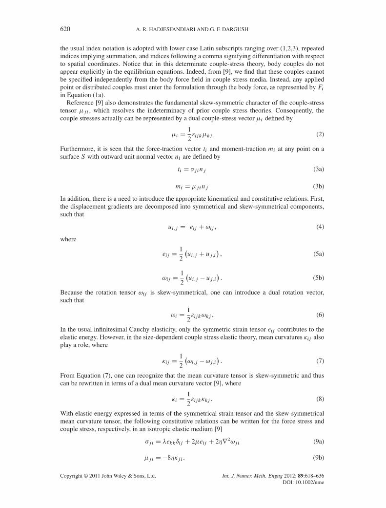
620 A. R. HADJESFANDIARI AND G. F. DARGUSH
the usual index notation is adopted with lower case Latin subscripts ranging over (1,2,3), repeatedindices implying summation, and indices following a comma signifying differentiation with respectto spatial coordinates. Notice that in this determinate couple-stress theory, body couples do notappear explicitly in the equilibrium equations. Indeed, from [9], we find that these couples cannotbe specified independently from the body force field in couple stress media. Instead, any appliedpoint or distributed couples must enter the formulation through the body force, as represented by Fiin Equation (1a).
Reference [9] also demonstrates the fundamental skew-symmetric character of the couple-stresstensor �j i , which resolves the indeterminacy of prior couple stress theories. Consequently, thecouple stresses actually can be represented by a dual couple-stress vector �i defined by
�i D1
2"ijk�kj (2)
Furthermore, it is seen that the force-traction vector ti and moment-traction mi at any point on asurface S with outward unit normal vector ni are defined by
ti D �j inj (3a)
mi D �j inj (3b)
In addition, there is a need to introduce the appropriate kinematical and constitutive relations. First,the displacement gradients are decomposed into symmetrical and skew-symmetrical components,such that
ui ,j D eij C!ij , (4)
where
eij D1
2
�ui ,j C uj ,i
�, (5a)
!ij D1
2
�ui ,j � uj ,i
�. (5b)
Because the rotation tensor !ij is skew-symmetrical, one can introduce a dual rotation vector,such that
!i D1
2"ijk!kj . (6)
In the usual infinitesimal Cauchy elasticity, only the symmetric strain tensor eij contributes to theelastic energy. However, in the size-dependent couple stress elastic theory, mean curvatures �ij alsoplay a role, where
�ij D1
2
�!i ,j �!j ,i
�. (7)
From Equation (7), one can recognize that the mean curvature tensor is skew-symmetric and thuscan be rewritten in terms of a dual mean curvature vector [9], where
�i D1
2"ijk�kj . (8)
With elastic energy expressed in terms of the symmetrical strain tensor and the skew-symmetricalmean curvature tensor, the following constitutive relations can be written for the force stress andcouple stress, respectively, in an isotropic elastic medium [9]
�j i D �ekkıij C 2�eij C 2�r2!j i (9a)
�j i D�8��j i . (9b)
Copyright © 2011 John Wiley & Sons, Ltd. Int. J. Numer. Meth. Engng 2012; 89:618–636DOI: 10.1002/nme

BOUNDARY ELEMENT FORMULATION FOR PLANE COUPLE STRESS ELASTICITY 621
Here, � and � are the usual Lamé elastic moduli, while � is the sole additional parameter.Interestingly, the ratio
�
�D l2 (10)
specifies a characteristic material length l , which is absent in Cauchy elasticity, but is fundamentalto the small deformation size-dependent elasticity theory under consideration here.
It should be mentioned that these relations are similar to those defined for the indeterminatecouple-stress theory in [3, 4], when �0 D ��. This equality makes the couple-stress tensor skew-symmetric in the former theory and thus resolves the indeterminacy. Furthermore, Equation (9b)can be written alternatively in terms of dual vectors as
�i D�8��i (11)
After substituting Equations (4), (7), and (9) into Equation (1b) and ultimately into Equation (1a),we can rewrite the governing differential equations in terms of the displacement and body forcedensity fields as �
�C�C �r2�uk,ki C .�� �r
2/r2ui CFi D 0 (12)
Equation (12) holds at all points in the volume V of the three-dimensional couple stress elastic body.We suppose now that the couple stress media occupies a cylindrical region, such that the axis
of the cylinder is parallel to the x3-axis. Furthermore, we assume the body is in a state of planedeformation parallel to this plane, such that
u˛,3 D 0, u3 D 0 in V (13a,b)
where all Greek indices, here and throughout the remainder of the paper, will vary only over (1,2).Also, beginning with Equation (13a,b), V and S represent, respectively, the cross section of thebody in the x1x2-plane and its bounding edge in that plane.
As a result of these assumptions, all quantities are independent of x3. Then, throughout thedomain
!˛ D 0, e3i D ei3 D 0, �3 D 0 (14a-c)
and
�3˛ D �˛3 D 0, �3 D �21 D 0 . (15a,b)
Introducing the abridged notation for the nonzero component of rotation
! D !3 (16)
the nonzero stress components are written as
�˛3 D 4�!,˛ (17a)
�ˇ˛ D �e��ı˛ˇ C 2�e˛ˇ � 2�"ˇ˛r2!, (17b)
where "ˇ˛ is the two-dimensional alternating symbol with
"12 D�"21 D 1, "11 D "22 D 0. (18)
All the other stresses are zero, apart from �33 and �3˛ , which are given as
�33 D ���� (19a)
�3˛ D�4�!,˛ , (19b)
Copyright © 2011 John Wiley & Sons, Ltd. Int. J. Numer. Meth. Engng 2012; 89:618–636DOI: 10.1002/nme

622 A. R. HADJESFANDIARI AND G. F. DARGUSH
where the material parameter � represents the usual Poisson’s ratio with � D �=.2.�C�//. It shouldbe noticed that these stresses in Equation (19), acting on planes parallel to the x1x2-plane, do notenter directly into the solution of the boundary value problem.
For the plane problem, the stresses must satisfy the three equilibrium equations
�ˇ˛,ˇ CF˛ D 0 (20a)
�ˇ3,ˇ C "˛ˇ�˛ˇ D 0 (20b)
with the obvious requirement F3 D 0. We also notice that the force traction reduces to
t˛ D �ˇ˛nˇ (21)
and the moment traction has only one component m3. This can be conveniently denoted by theabridged symbol m, where
mDm3 D �ˇ3nˇ D 4�!,ˇnˇ D 4�@!
@n(22)
As in plane Cauchy elasticity problems, one may specify displacements u˛ or force tractions t˛within the x1x2-plane. For example, let
u˛ D Ou˛ on Su (23a)
t˛ D Ot˛ on St (23b)
with
Su [ St D S and Su \ St D¿ (24a,b)
In addition, for the two-dimensional problem, either the rotation ! or the moment traction mshould be specified. Therefore, let
! D O! on S! (25a)
mD Om on Sm (25b)
with
S! [ Sm D S and S! \ Sm D¿. (26a,b)
Thus, at each boundary point in a well-posed plane problem, a total of three boundary conditionsmust be specified and, of course, there will remain three degrees of freedom to be determined.
3. INTEGRAL REPRESENTATION
Consider two separate plane solutions ¹u.1/˛ , t .1/˛ ,!.1/,m.1/,F .1/˛ º and ¹u.2/˛ , t .2/˛ ,!.2/,m.2/,F .2/˛ ºin couple stress elasticity for the same body. By applying the reciprocal theorem for these elastostaticsolutions, as derived in [9], we may writeZ
S
ht .1/˛ u.2/˛ Cm
.1/!.2/i
dS CZV
hF .1/˛ u.2/˛
idV
D
ZS
ht .2/˛ u.1/˛ Cm
.2/!.1/i
dS CZV
hF .2/˛ u.1/˛
idV
(27)
Copyright © 2011 John Wiley & Sons, Ltd. Int. J. Numer. Meth. Engng 2012; 89:618–636DOI: 10.1002/nme

BOUNDARY ELEMENT FORMULATION FOR PLANE COUPLE STRESS ELASTICITY 623
To obtain the boundary integral representation for the two-dimensional isotropic problem, letsolution (1) represent the infinite space fundamental solution due to a point force, while solu-tion (2) corresponds to the actual boundary value problem under consideration. Thus, we con-sider the following definition of the infinite space Green’s function to represent the first solution¹U F˛ˇ.x, �/,T F
˛ˇ.x, �/,F
ˇ.x, �/,MF
ˇ.x, �/, ı˛ˇ ı.x � �/º, where ı˛ˇ is the plane counterpart of the
usual Kronecker delta and ı.x/ is the two-dimensional Dirac delta function. Here, U F˛ˇ.x, �/ is the
displacement in the ˛-direction at x due to a unit point force in the ˇ-direction at � . Meanwhile,T F˛ˇ.x, �/, F
ˇ.x, �/ and MF
ˇ.x, �/ represent the corresponding force-traction in the ˛-direction,
rotation, and moment traction, respectively, at x. For the second solution, we assume zero bodyforces, drop the superscript designation and simply use ¹u˛ , t˛ ,!,m, 0º, as the solution of theboundary value problem. After substituting these two solutions into the reciprocal theorem definedabove in Equation (27) and making use of the sifting property of the Dirac delta function, we maywrite the following boundary integral representation for displacements at any point � inside S :
uˇ .�/C
ZS
T F˛ˇ .x, �/ u˛ .x/ dS.x/CZS
MFˇ .x, �/ ! .x/ dS.x/
D
ZS
U F˛ˇ .x, �/ t˛ .x/ dS.x/CZS
Fˇ .x, �/m .x/ dS.x/(28a)
If we let � approach the surface S from inside the body, then because of the character of the funda-mental solutions, several of the integrands in Equation (28a) become singular and, in particular, wemust consider the integral involving T F
˛ˇin the Cauchy principal value sense. Consequently, for �
on S , we may write
c˛ˇ .�/u˛ .�/C
ZS
� TF˛ˇ .x, �/ u˛ .x/ dS.x/C
ZS
MFˇ .x, �/ ! .x/ dS.x/
D
ZS
U F˛ˇ .x, �/ t˛ .x/ dS.x/CZS
Fˇ .x, �/m .x/ dS.x/(29a)
where c˛ˇ .�/ depends upon the local geometry at � and takes a value identical to that for Cauchyelasticity. For � on a smooth portion of S , c˛ˇ .�/ assumes the value 1
2ı˛ˇ . Additionally,
RS� signifies
Cauchy principal value integration on the surface S .In a similar manner, we may develop the integral representation for rotations by taking the
curl of (28a) with respect to � or by letting solution (1) in the reciprocal theorem representthe infinite space fundamental solution due to a point couple. With the latter approach, we take®UC˛ .x, �/,T C˛ .x, �/,C .x, �/,MC .x, �/, 1
2"˛ˇ ı,ˇ .x � �/
¯, where ı,ˇ .x � �/ signifies the spatial
gradient of the two-dimensional Dirac delta function with respect to xˇ . For this case, UC˛ .x, �/represents the displacement in the ˛-direction at x due to a unit point couple about the x3-axis at� . Furthermore, T C˛ .x, �/, C .x, �/ and MC .x, �/ denote, respectively, the corresponding forcetraction in the ˛-direction, rotation and moment traction at x due to this point couple. Using this inthe reciprocal theorem, along with ¹u˛ , t˛ ,!,m, 0º, produces the following integral representationfor rotations at any point � interior to S :
! .�/C
ZS
T C˛ .x, �/ u˛ .x/dS.x/CZS
MC .x, �/ ! .x/ dS.x/
D
ZS
UC˛ .x, �/ t˛ .x/ dS.x/CZS
C .x, �/m .x/dS.x/(28b)
Copyright © 2011 John Wiley & Sons, Ltd. Int. J. Numer. Meth. Engng 2012; 89:618–636DOI: 10.1002/nme
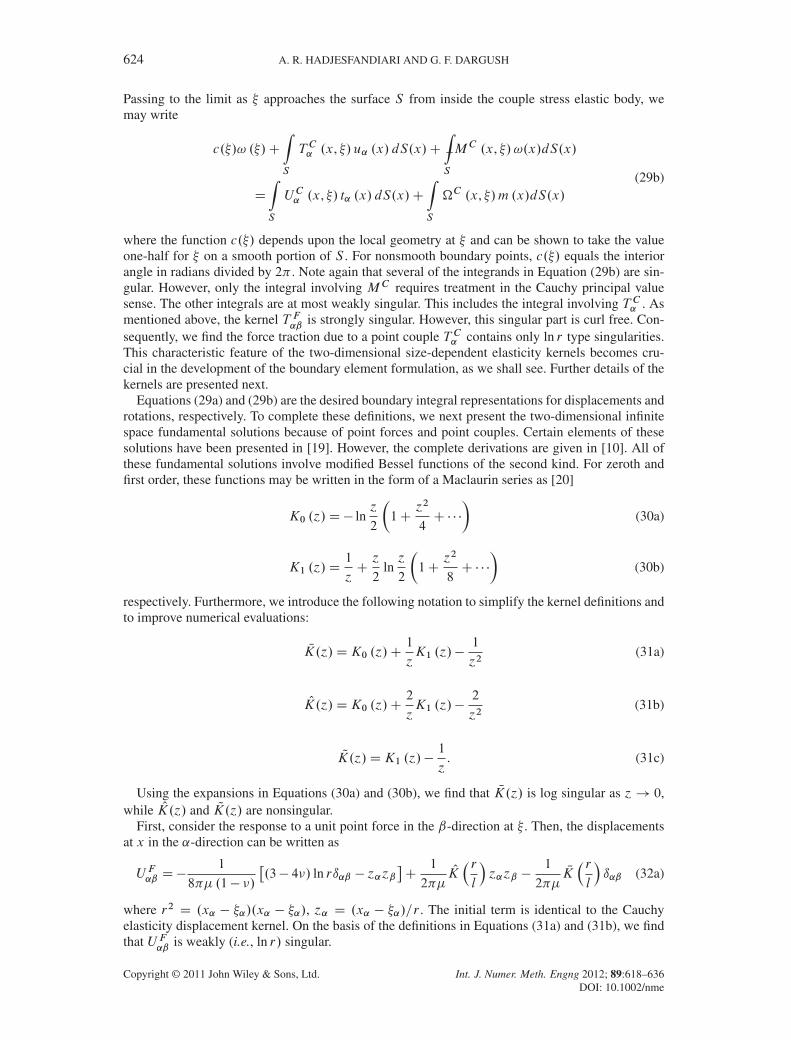
624 A. R. HADJESFANDIARI AND G. F. DARGUSH
Passing to the limit as � approaches the surface S from inside the couple stress elastic body, wemay write
c.�/! .�/C
ZS
T C˛ .x, �/ u˛ .x/ dS.x/CZS
�MC .x, �/ !.x/dS.x/
D
ZS
UC˛ .x, �/ t˛ .x/ dS.x/CZS
C .x, �/m .x/dS.x/(29b)
where the function c.�/ depends upon the local geometry at � and can be shown to take the valueone-half for � on a smooth portion of S . For nonsmooth boundary points, c.�/ equals the interiorangle in radians divided by 2 . Note again that several of the integrands in Equation (29b) are sin-gular. However, only the integral involving MC requires treatment in the Cauchy principal valuesense. The other integrals are at most weakly singular. This includes the integral involving T C˛ . Asmentioned above, the kernel T F
˛ˇis strongly singular. However, this singular part is curl free. Con-
sequently, we find the force traction due to a point couple T C˛ contains only ln r type singularities.This characteristic feature of the two-dimensional size-dependent elasticity kernels becomes cru-cial in the development of the boundary element formulation, as we shall see. Further details of thekernels are presented next.
Equations (29a) and (29b) are the desired boundary integral representations for displacements androtations, respectively. To complete these definitions, we next present the two-dimensional infinitespace fundamental solutions because of point forces and point couples. Certain elements of thesesolutions have been presented in [19]. However, the complete derivations are given in [10]. All ofthese fundamental solutions involve modified Bessel functions of the second kind. For zeroth andfirst order, these functions may be written in the form of a Maclaurin series as [20]
K0 .´/D� ln´
2
�1C
´2
4C � � �
�(30a)
K1 .´/D1
´C´
2ln´
2
�1C
´2
8C � � �
�(30b)
respectively. Furthermore, we introduce the following notation to simplify the kernel definitions andto improve numerical evaluations:
NK.´/DK0 .´/C1
´K1 .´/�
1
´2(31a)
OK.´/DK0 .´/C2
´K1 .´/�
2
´2(31b)
QK.´/DK1 .´/�1
´. (31c)
Using the expansions in Equations (30a) and (30b), we find that NK.´/ is log singular as ´! 0,while OK.´/ and QK.´/ are nonsingular.
First, consider the response to a unit point force in the ˇ-direction at � . Then, the displacementsat x in the ˛-direction can be written as
U F˛ˇ D�1
8� .1� �/
�.3� 4�/ ln rı˛ˇ � ´˛´ˇ
�C
1
2�OK�rl
´˛´ˇ �
1
2�NK�rl
ı˛ˇ (32a)
where r2 D .x˛ � �˛/.x˛ � �˛/, ´˛ D .x˛ � �˛/=r . The initial term is identical to the Cauchyelasticity displacement kernel. On the basis of the definitions in Equations (31a) and (31b), we findthat U F
˛ˇis weakly (i.e., ln r/ singular.
Copyright © 2011 John Wiley & Sons, Ltd. Int. J. Numer. Meth. Engng 2012; 89:618–636DOI: 10.1002/nme
BOUNDARY ELEMENT FORMULATION FOR PLANE COUPLE STRESS ELASTICITY 625
To complete the kinematical response, the corresponding rotations due to the point force can bewritten as
F1 D�1
4�lQK�rl
´2 (32b)
F2 DC1
4�lQK�rl
´1. (32c)
From Equation (31c), we find that Fˇ
has no singularity.Meanwhile, for the force tractions on a surface with outer normal unit normal n˛ at x, we find
T F˛ˇ D�1
4 .1� �/ r
�.1� 2�/
�´˛nˇ C ı˛ˇ´�n� � ´ˇn˛
�C 2´˛´ˇ´�n�
�
C1
rOK�rl
�´˛nˇ C ´ˇn˛ C ı˛ˇ´�n� � 4´˛´ˇ´�n�
�C
1
lK1
�rl
�nˇ � ´ˇ´�n�
�´˛
(32d)
where the first term represents the usual Cauchy elasticity traction kernel. As mentioned above, T F˛ˇ
contains a strong 1=r singularity, which in the boundary integral representation must be treated inthe Cauchy principal value sense, just as in the usual Cauchy elasticity theory.
Finally, the moment tractions on a surface at x can be written as
MF1 DC
1
OK�rl
.´2n1 � ´1n2/ ´1C
1
NK�rl
n2 (32e)
MF2 D�
1
OK�rl
.´1n2 � ´2n1/ ´2 �
1
NK�rl
n1 . (32f)
These terms are weakly singular because of the presence of the NK terms.Next, consider the response to a unit point couple at � . The resulting displacements at x in the
˛-direction are completely nonsingular and can be written as
UC1 DC1
4�lQK�rl
´2 (33a)
UC2 D�1
4�lQK�rl
´1 (33b)
while the corresponding weakly singular rotation solution becomes
C DC1
8�K0
�rl
. (33c)
Additionally, the force tractions become
T C1 DC1
4l2OK�rl
Œ.´1´1 � ´2´2/ n2 � 2´1´2n1�C
1
4l2K0
�rl
n2 (33d)
T C2 D�1
4l2OK�rl
Œ.´2´2 � ´1´1/ n1 � 2´1´2n2��
1
4l2K0
�rl
n1 (33e)
and the moment traction assumes the form
MC D�1
2lK1
�rl
´�n� (33f)
Copyright © 2011 John Wiley & Sons, Ltd. Int. J. Numer. Meth. Engng 2012; 89:618–636DOI: 10.1002/nme
626 A. R. HADJESFANDIARI AND G. F. DARGUSH
These force-tractions are weakly singular, while the moment-traction in Equation (33f) contains astrong 1=r singularity.
This completes the definition of the integral representation for two-dimensional isotropic lin-early elastic couple stress media. The boundary integral equations for displacement and rotation aregiven above in Equations (29a) and (29b), respectively, while the kernel functions are specified inEquations (32) and (33).
4. BOUNDARY ELEMENT IMPLEMENTATION
The integral representations defined in the previous section can be used as the basis for a boundaryelement method. For the case with zero body forces, the boundary integral relations can be writtenin matrix form as
"c˛ˇ .�/u˛ .�/
c.�/! .�/
#C
ZS
�
24 T F
˛ˇ.x, �/ MF
ˇ.x, �/
T C˛ .x, �/ MC .x, �/
35" u˛ .x/
! .x/
#dS.x/
D
ZS
24 U F
˛ˇ.x, �/ F
ˇ.x, �/
UC˛ .x, �/ C .x, �/
35" t˛ .x/
m .x/
#dS.x/
(34)
From the definitions in Section 3, we can identify several interesting characteristics of the kernelfunctions in Equation (34). First, we note that the kernel matrix on the right-hand side has weaklysingular diagonal blocks and nonsingular off-diagonal blocks. Second, the kernel matrix on the left-hand side contains strongly singular diagonal blocks, which must be treated in the Cauchy principalvalue sense, while the off diagonal blocks are only weakly singular.
To elucidate the boundary element formulation, we may rewrite Equation (34) using a compactindex notation as
cIQ.�/ uI .�/C
ZS
�TIQ .x, �/ uI .x/ dS.x/DZS
UIQ .x, �/ tI .x/ dS.x/ (35)
where now upper case Latin indices vary from one to three. Then, the generalized displacements uIand generalized tractions tI that appear in Equation (35) include rotation ! and moment m, respec-tively, as the third component. Of course, these are no longer vectors in the strict sense, nor are thekernels UIQ and TIQ tensors. However, this notation simplifies the equations and the resulting formis reminiscent of the boundary integral formulations for coupled field problems in thermoelasticityand poroelasticity [21, 22]. Consequently, a similar numerical implementation can be followed todevelop the boundary element method for size-dependent couple stress elasticity.
For the present development, we use two and three-noded boundary elements with linear andquadratic geometric variation, respectively, to discretize the entire surface. Within each element alinear or quadratic variation of generalized displacements and tractions is employed for the func-tional representation. A global set of algebraic equations is then developed through a process ofcollocation at each of the functional boundary nodes, along with numerical integration of the result-ing kernel-shape function products. The modified Bessel functions are calculated in double precisionusing the routines by Ooura [23]. For small arguments, the functions NK.´/, OK.´/, and QK.´/are determined directly from series expansions. Nonsingular integrals are evaluated by standardGaussian integration, with graded subsegmentation introduced for near-singular cases. All weaklysingular integrals are computed using log-gauss formulas, while the strongly singular terms aredetermined indirectly by satisfying rigid body motion. Translational rigid body motion is enforcedto indirectly evaluate the diagonal terms associated with T F
˛ˇ. On the other hand, the diagonal ele-
ments involving the strongly singular MC kernels are determined by imposing rigid body rotationcentered about the collocation point � .
Copyright © 2011 John Wiley & Sons, Ltd. Int. J. Numer. Meth. Engng 2012; 89:618–636DOI: 10.1002/nme

BOUNDARY ELEMENT FORMULATION FOR PLANE COUPLE STRESS ELASTICITY 627
At the end of this process, the problem has been reduced to a set of linear algebraic equations,such that
TuD Ut (36)
where T and U are the matrices emanating from the left-hand and right-hand sides of Equation (35),respectively, while u represents the nodal displacements and rotations and t is the vector of force-and moment-tractions. After imposing the boundary conditions, Equation (36) can be rewrittensimply as
AxD b (37)
where x is now the vector of unknown boundary quantities. In the present implementation, Equation(37) is solved by a blocked LU decomposition algorithm with partial pivoting.
5. COMPUTATIONAL EXAMPLES
In this section, we consider the application of the proposed boundary element method to severalexamples. First, we investigate problems involving simple tension and simple shear and show thatin these examples the couple-stresses do indeed vanish, as expected. Afterwards, we examine theproblem of a flat plate bent into a cylindrical shell, which involves nonzero mean curvature andcouple-stresses. Then, we investigate the response of a plate with either a circular hole or an ellipti-cal hole, where significant deviations from Cauchy elasticity theory may occur depending upon thecouple stress length scale parameter. Finally, we consider the deformation of a plane ring, where theboundary element results are compared with the closed form size-dependent couple stress solution.
5.1. Uniaxial tension
For the initial example, we consider an isotropic elastic block in uniaxial tension under plane strainconditions, as illustrated in Figure 1. The material is defined in terms of the elastic modulus E,Poisson’s ratio � and the length scale parameter l . Two separate cases are examined for this squareblock of overall planar dimension 2L� 2L. In Case 1, the symmetry boundaries have zero momenttractions specified, while for Case 2, these two edges have zero rotation imposed. The exact solutionin both cases is identical to that under Cauchy elasticity for which all rotations are zero through-out the block. Furthermore, we may write the maximum axial extension and corresponding lateralcontraction as
.u1/Amax D
�1� �2
�t0L=E (38a)
Figure 1. Uniaxial tension.
Copyright © 2011 John Wiley & Sons, Ltd. Int. J. Numer. Meth. Engng 2012; 89:618–636DOI: 10.1002/nme

628 A. R. HADJESFANDIARI AND G. F. DARGUSH
.u2/Amin D�� .u1/
Amax = .1� �/ (38b)
respectively.For the boundary element analysis, each of the four edges is represented by a single three-
noded quadratic element. Thus, the problem involves a total of eight nodes and 24 unknowns.In the numerical implementation, we set Gaussian integration order and subsegmentation param-eters at somewhat higher levels than typically used for classical elasticity to capture accurately thekernel behavior.
The resulting numerical solutions are summarized in Table I for Poisson’s ratio � D 1=4 andseveral values of the scaling ratio l=L in each of the two cases. The data presented for l=L D 0
corresponds to the classical elastic boundary element analyses. For the exact solutions, all values incolumns three through six should be zero. Notice that these boundary element solutions do indeedreduce to their Cauchy elasticity counterparts and that in all categories excellent results are obtained,having at least six digits of accuracy.
5.2. Simple shear
As a second example, a square block of dimension L �L is considered under simple shear condi-tions. Tangential displacements are specified on each edge with a maximum deflection �0 on theupper edge, as shown in Figure 2. Normal tractions are assumed to be zero. Within both the classi-cal and couple stress theories of infinitesimal elasticity, this enforces a state of constant shear straineA12 D�0=2L, shear stress �A12 D�0 �=L and rotation !A12 D !
A D�0=2L throughout the body.
Table I. Uniaxial tension.
Case l=L
ˇ̌̌.u1/
BEmax�.u1/
Amax
ˇ̌̌ˇ̌̌.u1/
Amax
ˇ̌̌ˇ̌̌.u2/
BEmin�.u2/
Amin
ˇ̌̌ˇ̌̌.u2/
Amin
ˇ̌̌ j!jBEmaxLˇ̌̌
.u1/Amax
ˇ̌̌ jt2jBEmaxt0
1 0 6� 10�16 2� 10�15 — 9� 10�16
1 10�4 5� 10�9 5� 10�9 1� 10�6 5� 10�10
1 10�2 8� 10�9 1� 10�8 3� 10�8 4� 10�9
1 1 5� 10�9 5� 10�9 2� 10�9 7� 10�9
2 0 6� 10�16 2� 10�15 — 9� 10�16
2 10�4 6� 10�9 8� 10�9 1� 10�6 1� 10�8
2 10�2 7� 10�9 1� 10�8 3� 10�8 5� 10�9
2 1 4� 10�9 8� 10�9 2� 10�9 5� 10�9
Figure 2. Simple shear.
Copyright © 2011 John Wiley & Sons, Ltd. Int. J. Numer. Meth. Engng 2012; 89:618–636DOI: 10.1002/nme

BOUNDARY ELEMENT FORMULATION FOR PLANE COUPLE STRESS ELASTICITY 629
From the analytical solution, we find that the rotation is uniform and couple stresses are zero in thepresent size-dependent theory.
For the boundary element analysis, we again use a single three-noded quadratic element alongeach edge and examine the solution for a range of values of the scaling ratio l=L. The results pro-vided in Table II indicate very small deviations from the analytical results for boundary rotations !and tangential force (shear) tractions ts . In all cases, the boundary element solutions are accurate toat least eight digits.
5.3. Cylindrical bending of a flat plate
The exact solution for the pure bending of a flat plate into a cylindrical shell is presented for size-dependent elastic materials under infinitesimal deformation theory in [9]. The problem, which isdepicted in Figure 3, involves the application of a linear variation of force tractions with maximumt0 and constant moment tractions m0 along the edges at x1 D ˙L, while the upper and lower sur-faces are traction-free. Form0 D 2 .1� �/ l2
t0h
, this loading produces a displacement field with thefollowing variation:
u1 D�1
Rx1x2, u2 D
1
2
1
Rx21 C
1
2
�
1� �
1
Rx22 , u3 D 0 (39a-c)
leading to a state of constant mean curvature, such that
�31 D��2 D1
2R(40)
with
RD2�
1� �
h
t0(41)
These displacements are exactly those for pure bending in plane strain Cauchy elasticity, where onlythe linear force-traction distribution part of the loading is applied. For size-dependent elasticity withboth force-tractions and moment-tractions applied, the state of stresses can be written as
�11 D�2�
1� �
x2
RD�
t0
hx2 (42a)
Table II. Simple shear.
l=L
ˇ̌̌.!/BE�.!/A
ˇ̌̌maxˇ̌̌
.!/Aˇ̌̌
ˇ̌̌.ts/
BE�.ts/Aˇ̌̌maxˇ̌̌
.ts/Aˇ̌̌
0 — 2� 10�15
10�4 1� 10�9 9� 10�9
10�2 2� 10�9 8� 10�9
1 5� 10�10 2� 10�8
Figure 3. Cylindrical bending of flat plate.
Copyright © 2011 John Wiley & Sons, Ltd. Int. J. Numer. Meth. Engng 2012; 89:618–636DOI: 10.1002/nme

630 A. R. HADJESFANDIARI AND G. F. DARGUSH
�2 D 4�
RDm0 (42b)
everywhere. Then, the normal force tractions and moment tractions on the central x2–x3 plane witha leftward pointing normal (i.e., n1 D�1,n2 D n3 D 0/ become
t1 .0, x2/Dt0
hx2 , (43a)
m.0, x2/D�m0, (43b)
respectively.For the boundary element formulation, we employ half-symmetry as shown in Figure 3 and
impose zero normal displacements u1 D 0 and rotation ! D 0 on the plane of symmetry. Onceagain a simple mesh of four three-noded quadratic boundary elements is used to capture the behav-ior. Table III presents a comparison of the boundary element results with the analytical solutionsfrom Equations (39b), (43a), and (43b) for � D 1=4, L=h D 2 and different values of the lengthscale ratio l=h. Notice that the numerical solutions are accurate to at least seven digits for the entirerange of length scales, even for this problem with nonzero mean curvature and couple-stresses.
Both force-tractions and moment-tractions must be applied to deform the plate into the cylindricalshape with constant mean curvature. The boundary element results for plates under these conditionswith aspect ratios of L=h D 2, L=h D 4 and L=h D 8 are provided in Table IV for t0 D 1.0 andm0=l D 1.5. Again, quite accurate results are obtained, even for the higher aspect ratio domains.
Now we continue this problem by investigating the effect of using approximate boundary con-ditions on the edges at x1 D ˙L by specifying only normal force-tractions. These applied forcetractions generate the same total moment as the combined force-traction and moment-traction dis-tribution in the analytical solution. In this case, t0 D 5.5 andm0=l D 0.0. For low aspect ratio plates(i.e., L=h D 2/, the traction resultants on the central x1 D 0 plane deviate significantly from theanalytical solution, as indicated in Table IV. However, as the aspect ratio of the plate increases (i.e.,L=hD 4 and L=hD 8/, the boundary element tractions on the x2–x3 plane approach the solutionsin Equations (43a) and (43b). Thus, we see in this example an illustration of Saint-Venant’s principlefor size-dependent couple stress elastic materials.
5.4. Plate with circular hole
Next, we examine the uniaxial extension of an infinite plate with a circular hole of radius a for whichthe size-dependent response deviates significantly from the classical elastic solution. The problem
Table III. Cylindrical bending of a flat plate (� D 1=4,L=hD 2/.
l=h
ˇ̌̌.ju2j/
BEmax�.ju2j/
Amax
ˇ̌̌ˇ̌̌.ju2j/
Amax
ˇ̌̌ˇ̌̌.jt1j/
BEmax�.jt1j/
Amax
ˇ̌̌ˇ̌̌.jt1j/
Amax
ˇ̌̌ˇ̌̌.jmj/BE
max�.jmj/Amax
ˇ̌̌ˇ̌̌.jmj/Amax
ˇ̌̌
10�2 6� 10�9 4� 10�9 4� 10�7
10�1 4� 10�9 4� 10�9 6� 10�9
100 7� 10�9 6� 10�8 6� 10�9
101 9� 10�9 9� 10�8 1� 10�8
Table IV. Cylindrical bending of a flat plate (� D 1=4, l=hD 1/.
L=h t0 m0=l t1.0, h/BE=t1.0,h/A m.0,h/BE=m.0, h/A
2 1.0 1.5 1.0000 1.00002 5.5 0.0 0.8988 0.89214 1.0 1.5 1.0000 1.00004 5.5 0.0 1.0043 0.99858 1.0 1.5 1.0000 1.00008 5.5 0.0 0.9977 0.9997
Copyright © 2011 John Wiley & Sons, Ltd. Int. J. Numer. Meth. Engng 2012; 89:618–636DOI: 10.1002/nme
BOUNDARY ELEMENT FORMULATION FOR PLANE COUPLE STRESS ELASTICITY 631
was first considered by Mindlin [24] within the context of the indeterminate couple-stress theory.Reference [9] shows that his solution for the stress concentration factor remains valid in the deter-minate theory and will be used here for comparison with our boundary element solutions. From theMindlin formulation [24]
.�11/max D t03C
1C (44)
where t0 is the applied traction at infinity and
D8 .1� �/
4C a2
l2C 2a
lK0.a=l/K1.a=l/
(45)
Thus, the analytical stress concentration factor becomes
SCFA D3C
1C (46)
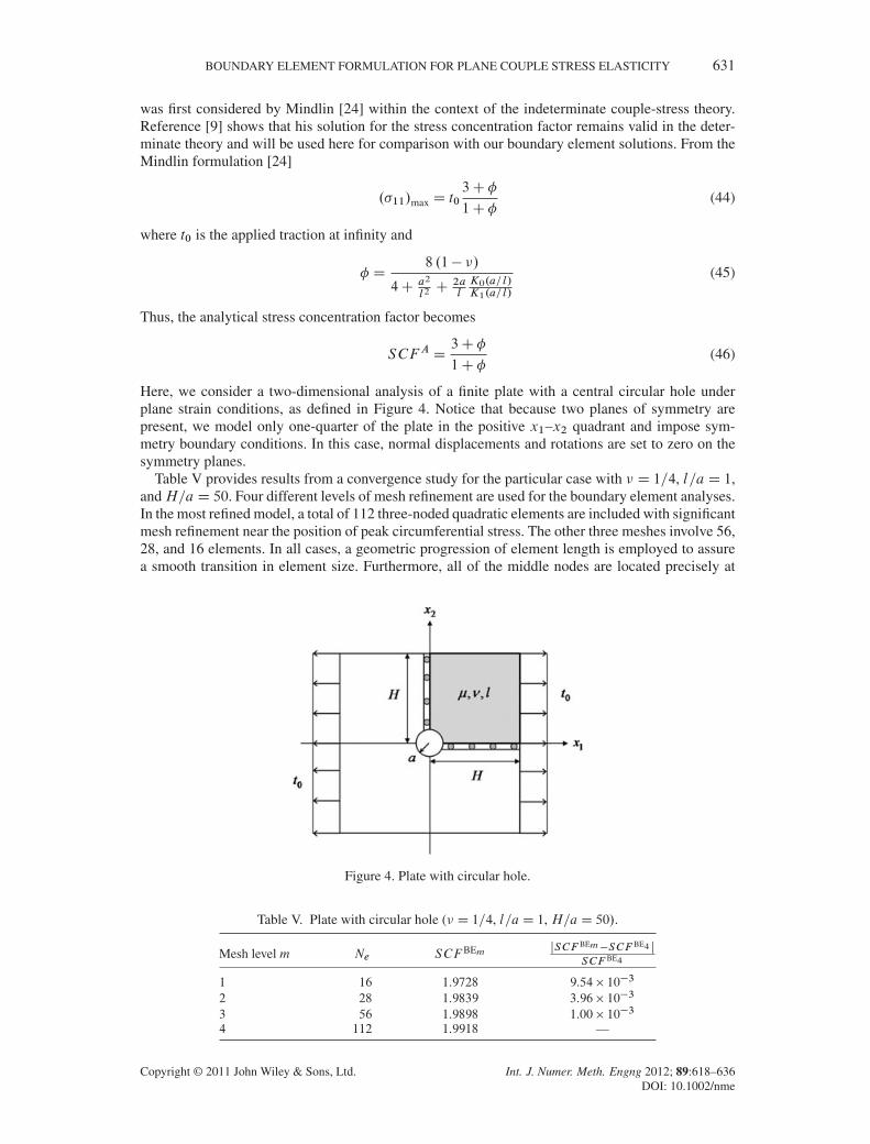
Here, we consider a two-dimensional analysis of a finite plate with a central circular hole underplane strain conditions, as defined in Figure 4. Notice that because two planes of symmetry arepresent, we model only one-quarter of the plate in the positive x1–x2 quadrant and impose sym-metry boundary conditions. In this case, normal displacements and rotations are set to zero on thesymmetry planes.
Table V provides results from a convergence study for the particular case with � D 1=4, l=aD 1,andH=aD 50. Four different levels of mesh refinement are used for the boundary element analyses.In the most refined model, a total of 112 three-noded quadratic elements are included with significantmesh refinement near the position of peak circumferential stress. The other three meshes involve 56,28, and 16 elements. In all cases, a geometric progression of element length is employed to assurea smooth transition in element size. Furthermore, all of the middle nodes are located precisely at
Figure 4. Plate with circular hole.
Table V. Plate with circular hole (� D 1=4, l=aD 1, H=aD 50/.
Mesh level m Ne SCF BEm jSCF BEm�SCF BE4 jSCF BE4
1 16 1.9728 9.54� 10�3
2 28 1.9839 3.96� 10�3
3 56 1.9898 1.00� 10�3
4 112 1.9918 —
Copyright © 2011 John Wiley & Sons, Ltd. Int. J. Numer. Meth. Engng 2012; 89:618–636DOI: 10.1002/nme

632 A. R. HADJESFANDIARI AND G. F. DARGUSH
the element center. Notice that excellent convergence is achieved for the stress concentration factor,even with a mesh of only 28 quadratic elements. However, in all subsequent analyses, we use thefinest level mesh consisting of 112 elements.
Table VI gives a comparison between the stress concentration factors obtained from Equation(46) and the present boundary element formulation. First, the numerical solutions for classical elas-ticity with � D 1=4 and l=a D 0 are compared with the analytical infinite plate result SCFA D 3.Notice that as the size of the plate increases, the boundary element solutions approach this limit. Forexample, withHBE=aD 500, the boundary element stress concentration factor is accurate to within0.3% of the analytical result.
Next, we investigate the size dependency in terms of the ratio l=a. Here, we find that the stressconcentration factor decreases substantially with an increase in the dimensionless parameter l=a. Inall instances, accuracy remains within 0.3% of the exact value. Similar results are also obtained forthe boundary element analyses with � D 0. Increased integration precision, through use of higherorder Gaussian quadrature and refined subsegmentation, does not improve these results. Conse-quently, it appears that the level of accuracy in this problem is determined primarily by the finiteplate assumption. Clearly, however, the present formulation is able to resolve the peak stressesaround the hole quite accurately within the size-dependent couple stress theory.
5.5. Plate with elliptical hole
Now, we consider the stress concentration factor for an elliptical hole. The problem definition isgiven in Figure 5. Notice again that quarter symmetry is employed and only the positive quadrant isincluded in the boundary element model, which consists of 224 quadratic elements. A finer mesh is
Table VI. Infinite plate with circular hole.
� l=a HA=a SCFA HBE=a SCF BE jSCF BE�SCFAjSCFA
1=4 0 1 3.0000 20 2.8691 4.36� 10�2
1=4 0 1 3.0000 50 2.9422 1.93� 10�2
1=4 0 1 3.0000 200 2.9840 5.33� 10�3
1=4 0 1 3.0000 500 2.9928 2.40� 10�3
1=4 1=4 1 2.6380 500 2.6337 1.63� 10�3
1=4 1=2 1 2.3046 500 2.2997 2.13� 10�3
1=4 1 1 2.0322 500 2.0272 2.46� 10�3
1=4 2 1 1.8897 500 1.8849 2.54� 10�3
0 0 1 3.0000 500 2.9926 2.47� 10�3
0 1 1 1.8888 500 1.8838 2.65� 10�3
Figure 5. Plate with elliptical hole.
Copyright © 2011 John Wiley & Sons, Ltd. Int. J. Numer. Meth. Engng 2012; 89:618–636DOI: 10.1002/nme

BOUNDARY ELEMENT FORMULATION FOR PLANE COUPLE STRESS ELASTICITY 633
used for elliptical holes, when compared with the previous example for circular holes, to representadequately the highly localized stress variations near the tip of the major radius. Additionally, agraded mesh is developed using a geometric progression with element arc lengths established fromthe incomplete elliptic integrals of the second kind [25]. To maximize accuracy, the middle nodesof all elements are positioned precisely at the center of the element as measured along the surfaceof the ellipse.
The analytical value of the stress concentration factor associated with an elliptical hole in an infi-nite plate within Cauchy elasticity theory is known to be SCFA D 1C 2a=b [26]. We find fromTable VII that the corresponding boundary element solution for a finite plate with HBE=a D 500
and � D 1=4 approximates well this result. (Note that the results for the circular hole in Table VIIare slightly more accurate than those shown in Table VI because of the increased mesh refinementin the present example.) Table VII also includes the boundary element results for the present size-dependent theory with l=a D 1 and several elliptical hole aspect ratios. In all instances, the stressconcentration factor reduces substantially under size-dependent couple stress theory. Finally, noticethat the stress concentration factor reduces further as plate size decreases, a trend that is present inclassical elasticity as well.
5.6. Deformation of a plane ring
As the final example, we consider the plane ring shown in Figure 6, rigidly fixed on the externalcircular boundary at r D b, under deformation because of a rigid displacement of the internal cir-cular boundary at r D a with magnitude U in the x1 direction. We take the moment traction m tovanish on the whole boundary. This problem was initially considered in [27] within the context of
Table VII. Plate with elliptical hole (� D 1=4/.
a=b l=a HA=a SCFA HBE=a SCF BE jSCF BE�SCFAjSCFA
1 0 1 3.0000 500 3.0025 8.33� 10�4
1 1 1 — 500 2.0281 —2 0 1 5.0000 500 4.9898 2.04� 10�3
2 1 1 — 500 2.8570 —4 0 1 9.0000 500 8.9801 2.21� 10�3
4 1 1 — 500 4.5386 —4 1 1 — 100 4.5026 —4 1 1 — 20 4.3287 —4 1 1 — 4 3.5222 —
Figure 6. Deformation of a plane ring.
Copyright © 2011 John Wiley & Sons, Ltd. Int. J. Numer. Meth. Engng 2012; 89:618–636DOI: 10.1002/nme
634 A. R. HADJESFANDIARI AND G. F. DARGUSH
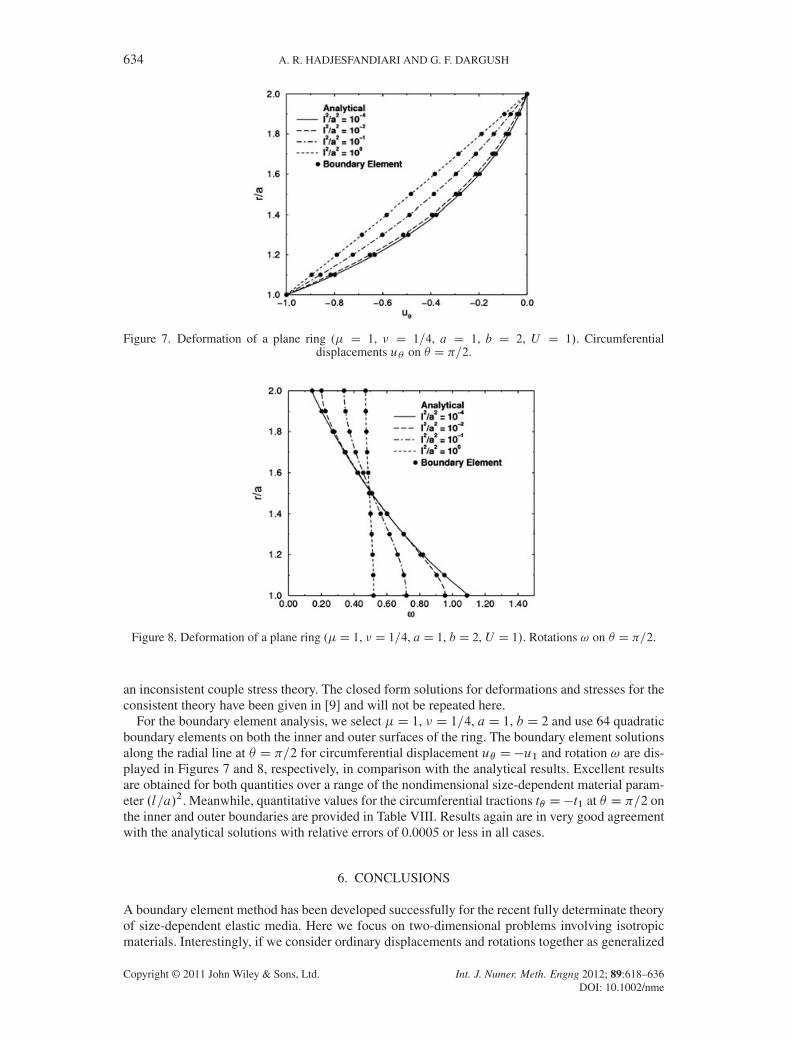
Figure 7. Deformation of a plane ring (� D 1, � D 1=4, a D 1, b D 2, U D 1/. Circumferentialdisplacements u� on � D =2.
Figure 8. Deformation of a plane ring (�D 1, � D 1=4, aD 1, b D 2, U D 1/. Rotations ! on � D =2.
an inconsistent couple stress theory. The closed form solutions for deformations and stresses for theconsistent theory have been given in [9] and will not be repeated here.
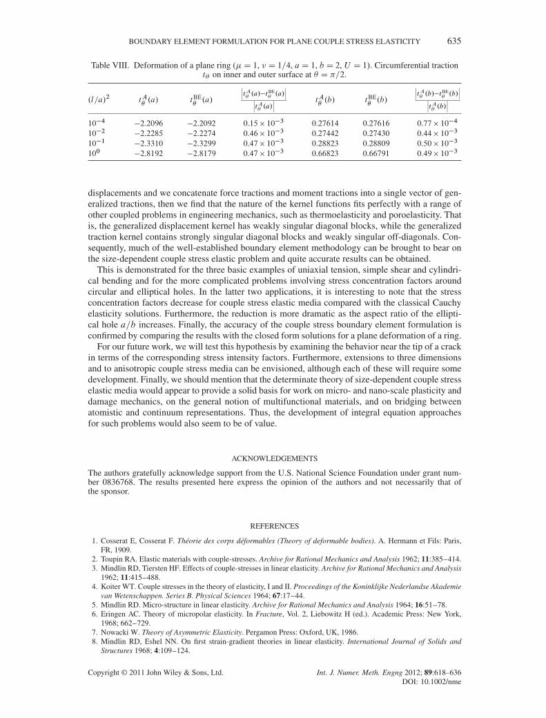
For the boundary element analysis, we select �D 1, � D 1=4, aD 1, b D 2 and use 64 quadraticboundary elements on both the inner and outer surfaces of the ring. The boundary element solutionsalong the radial line at � D =2 for circumferential displacement u� D�u1 and rotation ! are dis-played in Figures 7 and 8, respectively, in comparison with the analytical results. Excellent resultsare obtained for both quantities over a range of the nondimensional size-dependent material param-eter .l=a/2. Meanwhile, quantitative values for the circumferential tractions t� D�t1 at � D =2 onthe inner and outer boundaries are provided in Table VIII. Results again are in very good agreementwith the analytical solutions with relative errors of 0.0005 or less in all cases.
6. CONCLUSIONS
A boundary element method has been developed successfully for the recent fully determinate theoryof size-dependent elastic media. Here we focus on two-dimensional problems involving isotropicmaterials. Interestingly, if we consider ordinary displacements and rotations together as generalized
Copyright © 2011 John Wiley & Sons, Ltd. Int. J. Numer. Meth. Engng 2012; 89:618–636DOI: 10.1002/nme
BOUNDARY ELEMENT FORMULATION FOR PLANE COUPLE STRESS ELASTICITY 635
Table VIII. Deformation of a plane ring (�D 1, � D 1=4, aD 1, b D 2, U D 1/. Circumferential tractiont� on inner and outer surface at � D =2.
.l=a/2 tA�.a/ tBE
�.a/
ˇ̌̌tA�.a/�tBE
�.a/
ˇ̌̌ˇ̌̌tA�.a/
ˇ̌̌ tA�.b/ tBE
�.b/
ˇ̌̌tA�.b/�tBE
�.b/
ˇ̌̌ˇ̌̌tA�.b/
ˇ̌̌
10�4 �2.2096 �2.2092 0.15� 10�3 0.27614 0.27616 0.77� 10�4
10�2 �2.2285 �2.2274 0.46� 10�3 0.27442 0.27430 0.44� 10�3
10�1 �2.3310 �2.3299 0.47� 10�3 0.28823 0.28809 0.50� 10�3
100 �2.8192 �2.8179 0.47� 10�3 0.66823 0.66791 0.49� 10�3
displacements and we concatenate force tractions and moment tractions into a single vector of gen-eralized tractions, then we find that the nature of the kernel functions fits perfectly with a range ofother coupled problems in engineering mechanics, such as thermoelasticity and poroelasticity. Thatis, the generalized displacement kernel has weakly singular diagonal blocks, while the generalizedtraction kernel contains strongly singular diagonal blocks and weakly singular off-diagonals. Con-sequently, much of the well-established boundary element methodology can be brought to bear onthe size-dependent couple stress elastic problem and quite accurate results can be obtained.
This is demonstrated for the three basic examples of uniaxial tension, simple shear and cylindri-cal bending and for the more complicated problems involving stress concentration factors aroundcircular and elliptical holes. In the latter two applications, it is interesting to note that the stressconcentration factors decrease for couple stress elastic media compared with the classical Cauchyelasticity solutions. Furthermore, the reduction is more dramatic as the aspect ratio of the ellipti-cal hole a=b increases. Finally, the accuracy of the couple stress boundary element formulation isconfirmed by comparing the results with the closed form solutions for a plane deformation of a ring.
For our future work, we will test this hypothesis by examining the behavior near the tip of a crackin terms of the corresponding stress intensity factors. Furthermore, extensions to three dimensionsand to anisotropic couple stress media can be envisioned, although each of these will require somedevelopment. Finally, we should mention that the determinate theory of size-dependent couple stresselastic media would appear to provide a solid basis for work on micro- and nano-scale plasticity anddamage mechanics, on the general notion of multifunctional materials, and on bridging betweenatomistic and continuum representations. Thus, the development of integral equation approachesfor such problems would also seem to be of value.
ACKNOWLEDGEMENTS
The authors gratefully acknowledge support from the U.S. National Science Foundation under grant num-ber 0836768. The results presented here express the opinion of the authors and not necessarily that ofthe sponsor.
REFERENCES
1. Cosserat E, Cosserat F. Théorie des corps déformables (Theory of deformable bodies). A. Hermann et Fils: Paris,FR, 1909.
2. Toupin RA. Elastic materials with couple-stresses. Archive for Rational Mechanics and Analysis 1962; 11:385–414.3. Mindlin RD, Tiersten HF. Effects of couple-stresses in linear elasticity. Archive for Rational Mechanics and Analysis
1962; 11:415–488.4. Koiter WT. Couple stresses in the theory of elasticity, I and II. Proceedings of the Koninklijke Nederlandse Akademie
van Wetenschappen. Series B. Physical Sciences 1964; 67:17–44.5. Mindlin RD. Micro-structure in linear elasticity. Archive for Rational Mechanics and Analysis 1964; 16:51–78.6. Eringen AC. Theory of micropolar elasticity. In Fracture, Vol. 2, Liebowitz H (ed.). Academic Press: New York,
1968; 662–729.7. Nowacki W. Theory of Asymmetric Elasticity. Pergamon Press: Oxford, UK, 1986.8. Mindlin RD, Eshel NN. On first strain-gradient theories in linear elasticity. International Journal of Solids and
Structures 1968; 4:109–124.
Copyright © 2011 John Wiley & Sons, Ltd. Int. J. Numer. Meth. Engng 2012; 89:618–636DOI: 10.1002/nme
636 A. R. HADJESFANDIARI AND G. F. DARGUSH
9. Hadjesfandiari AR, Dargush GF. Couple stress theory for solids. International Journal of Solids and Structures 2011;48:2496–2510.
10. Hadjesfandiari AR, Dargush GF. Fundamental solutions for isotropic size-dependent couple stress elasticity.arXiv:1107.2912.
11. Das AN, Chaudhuri PK. A note on boundary elements for micropolar elasticity. International Journal of EngineeringScience 1992; 30:397–400.
12. Liang K-Z, Huang F-Y. Boundary element method for micropolar elasticity. International Journal of EngineeringScience 1996; 34:509–521.
13. Shmoylova E, Potapenko S, Rothenburg L. Boundary element analysis of stress distribution around a crack in planemicropolar elasticity. International Journal of Engineering Science 2007; 45:199–209.
14. Polyzos D, Tsepoura KG, Tsinopoulos SV, Beskos DE. A boundary element method for solving 2D and 3D staticgradient elastic problems, part I: integral formulation. Computer Methods in Applied Mechanics and Engineering2003; 192:2845–2873.
15. Tsepoura KG, Tsinopoulos SV, Polyzos D, Beskos DE. A boundary element method for solving 3D static gradi-ent elastic problems, part II: numerical implementation. Computer Methods in Applied Mechanics and Engineering2003; 192:2875–2907.
16. Karlis GF, Tsinopoulos SV, Polyzos D, Beskos DE. Boundary element analysis of mode I and mixed mode(I and II) crack problem of 2-D gradient elasticity. Computer Methods in Applied Mechanics and Engineering 2007;196:5092–5103.
17. Karlis GF, Tsinopoulos SV, Polyzos D, Beskos DE. 2D and 3D boundary element analysis of mode-I cracks ingradient elasticity. CMES: Computer Modelling in Engineering and Sciences 2008; 26:189–208.
18. Karlis GF, Charalambopoulos A, Polyzos D. An advanced boundary element method for solving 2D and 3Dstatic problems in Mindlin’s strain-gradient theory of elasticity. International Journal for Numerical Methods inEngineering Science 2010; 83:1407–1427.
19. Huilgol RR. On the concentrated force problem for two-dimensional elasticity with couple stresses. InternationalJournal of Engineering Science 1967; 5:81–93.
20. Abramowitz M, Stegun IA. Handbook of Mathematical Functions with Formulas, Graphs, and Mathematical Tables.Dover: New York, 1964.
21. Dargush GF, Banerjee PK. Development of the boundary element method for time-dependent planar thermoelasticity.International Journal of Solids and Structures 1989; 25:999–1021.
22. Chen J, Dargush GF. Boundary element method for dynamic poroelastic and thermoelastic analyses. InternationalJournal of Solids and Structures 1995; 32:2257–2278.
23. Ooura T. Ooura’s mathematical software packages, 2006. Available from: http://www.kurims.kyoto-u.ac.jp/~ooura/.24. Mindlin RD. Influence of couple-stresses on stress-concentrations. Experimental Mechanics 1963; 3:1–7.25. Press WH, Teukolsky SA, Vetterling WT, Flannery BP. Numerical Recipes in Fortran. The Art of Scientific
Computing. Cambridge University Press: Cambridge, 1992.26. Inglis CE. Stresses in a plate due to the presence of cracks and sharp corners. Transactions of the Royal Institution
of Naval Architects 1913; 55:219–230.27. Kulesh MA, Matveenko VP, Shardakov IN. Parametric analysis of analytical solutions to one- and two-dimensional
problems in couple-stress theory of elasticity. Zeitschrift für Angewandte Mathematik und Mechanik 2003;83:238–248.
Copyright © 2011 John Wiley & Sons, Ltd. Int. J. Numer. Meth. Engng 2012; 89:618–636DOI: 10.1002/nme