Weight-bearing or non-weight-bearing after surgical treatment ...
Upload
khangminh22Category
view
2download
0
INTRODUCTION
Recent systematic reviews and clinical trials have demonstrated that fracture of direct composite fillings is one of the most prevalent causes of failure in posterior restorations1,2). This pertains to many factors such as material properties, placement techniques and amount of tissue replaced3). Generally, the more extensive a restoration is, the greater the susceptibility is to non-restorable fractures that extend below the cementoenamel junction and cause the tooth to be extracted4). Also, large restorations require placement of several 2 mm layers of composite, which imposes risks, such as incorporation of voids, contamination and bond failure between the layers5).
Hence, in large direct posterior restorations (multi-surface or endodontically treated teeth) crack propensity and methods of application can compromise their longevity6).
Furthermore, materials known as bulk fill composites have been introduced to the market. They are intended to be placed in bulk-increments of 4 mm thickness, thus decreasing the risk of voids and saving time spent in layering techniques. The increased translucency, as well as the inclusion of additional photo-initiator systems, account for improvement in depth-of-cure7-9). It is reported that low-viscosity (flowable) bulk fill materials (FBF) can have lower polymerization shrinkage. This decreases polymerization stress and cuspal strain, which could improve their long-term clinical success5,10). A well-known material from this category is under brand name of Smart Dentin Replacement (SDR), which is
intended to be used as a dentin replacement in posterior restorations11).
Additionally, efforts to improve the longevity of posterior restorations have been made by improving the overall structural integrity of the restoration-tooth-complex. This becomes possible partly due to fiber reinforcement of resin composites3). In particular, discontinuous fiber reinforced composite (FRC) shows improvement in fracture toughness and can be placed in bulk thickness of 4 mm8,12). One material from this category uses the brand name of everX Posterior, which is also intended to be used as a bulk-base material13). Studies have shown promising mechanical properties such as hindrance and deflection of crack propagation, when used as a reinforcing base in larger restorations14-16). However, both these base materials are indicated to be “capped” with a layer of conventional particulate filler composite (PFC)7,13). This is due to the lower wear resistance, surface roughness and hardness of these materials when compared to conventional PFC used as occlusal material17,18).
The introduction of a different material as an occlusal layer raises the question of its effect on the bilayered restoration as a whole; the thickness of the final occlusal or surface layer could have an effect on load bearing capacity19). Furthermore, factors such as quality of adhesion at the composite-composite interface are also considered vital for the survival of such bilayered restorations20). Owing to the polymerization cascade and contact with atmospheric oxygen, a layer of un-reacted composite monomer (oxygen inhibition layer; OIL), forms on the surface of a freshly light-cured composite resin21). It is known that this layer could affect the quality of adhesion between the composite layers,
Bonding interface affects the load-bearing capacity of bilayered compositesTarek A. OMRAN1, Sufyan GAROUSHI1, Lippo LASSILA1, Akikazu SHINYA2 and Pekka K. VALLITTU1,3
1 Department of Biomaterials Science and Turku Clinical Biomaterials Center-TCBC, Institute of Dentistry, University of Turku, Turku, Finland2 Department of Crown and Bridge, School of Life Dentistry at Tokyo, The Nippon Dental University, Tokyo, Japan3 City of Turku Welfare Division, Oral Health Care, Turku, FinlandCorresponding author, Tarek A. OMRAN; E-mail: [email protected]
This study evaluated the effect of material type, thickness and composite-composite interfacial adhesion on the load-bearing capacity of the bilayered composite structures. Bilayered cylindrical specimens (diameter=7 mm, height=5 mm) were prepared having three surface-layer thicknesses (1, 1.5, 2 mm) of Gænial Posterior to overlay base-composites [everX Posterior or Smart Dentin Replacement (SDR)]. Adhesion between surface and base composite-layers was based on an O2-inhibited layer for optimal-adhesion (OA) or polished surface for deteriorated-adhesion (DA). Specimens (n=10) were light-cured before static-loading with a steel-ball until fracture. Stress distribution in the same designs of mechanical test was calculated by finite element analysis (FEA). Static-loading demonstrated that in both base materials, thickness and adhesion had an effect on load-bearing capacity (p<0.05). FEA showed less strain distribution for everX groups than SDR.With OA, everX Posterior demonstrated higher load-bearing capacity even with thin surface-composite layer. DA made the load-bearing capacity more sensitive to surface-layer thickness.
Keywords: Bilayered composite restoration, Fiber-reinforced composite, Bulk-fill composite, Composite-composite adhesion
Color figures can be viewed in the online issue, which is avail-able at J-STAGE.Received Sep 11, 2018: Accepted Jan 27, 2019doi:10.4012/dmj.2018-304 JOI JST.JSTAGE/dmj/2018-304
Dental Materials Journal 2019; 38(6): 1002–1011

Table 1 The materials used in this study
Material (Shade)
Code name
Lot No. Manufacturer TypeMatrix
compositionInorganic filler
content
Young’s modulus
(GPa)
G-ænial Posterior(A3)
GP 1501071GC Dental Products, Tokyo, Japan
Micro-hybrid conventional
UDMA,Methacrylate monomers
Prepolymerized fillers with silicafiller content 65 vol%
8.2
EverX Posterior™
FRC 1601081GC Dental Products
Discontinuous fiber reinforced composite
Bis-GMA, PMMA, TEGDMA
Short E-glass fiber filler, barium glass 74.2 wt%, 53.6 vol%
12.3
SDR™ FBF 1611111Dentsply, Milford, DE, USA
Flowable bulk-fill
TEGDMA, EBADMA
68 wt%, 44 vol%, barium borosilicate glass
7
PMMA, polymethyl methacrylate; bis-GMA, bisphenol-A-glycidyl methacrylate; TEGDMA, triethyleneglycol dimethacrylate; UDMA, urethane dimethacrylate; EBADMA, ethoxylated bisphenol-A-dimethacrylate; wt%, weight percentage; vol%, volume percentage
Fig. 1 Schematic drawing of test specimen and study design.
instigate adhesive failure and likely affect the longevity of the restoration22). However, the effect of adhesion quality at interface between surface PFC and bulk-base composites on the fracture resistance and behavior needs to be further investigated. Additionally, the different composite materials vary in filler content and type, and therefore exhibit a different micro-structure and mechanical properties. It is likely that such difference in micro-structure can influence the mechanical behavior of the bilayered composite structure.
Therefore, this study aimed to investigate the effects of the aforementioned factors: (i) thickness of different materials within a bilayered structure, (ii) composite-composite adhesion interface and (iii) the materials’ Young modulus, on the fracture behavior and resistance (load bearing capacity) and stress distribution by finite element analysis (FEA) of bilayered composite structures.
MATERIALS AND METHODS
Specimen preparationA total of 180 cylindrical specimens having a bilayered composite structure were prepared (diameter=7 mm, height=5 mm). Each specimen included a combination of two different materials i.e. a surface PFC material (top layer) and a base composite material (bottom layer). Gænial Posterior (GP) was used as the surface PFC material in all specimens, whilst the base composite material was either FRC (everX Posterior) or FBF (SDR). For each base composite material, 90 cylindrical specimens were fabricated in total.
In this study, three top surface thicknesses were prepared; 1, 1.5 and 2 mm. However, the total height of bilayered specimen was standardized at 5 mm. Furthermore, the specimens at each thickness were subject to two different preparation procedures to simulate different qualities of adhesion between the top and bottom layers. The adhesion between the layers was
based on either: (1) a conventional O2-inhibited layer to simulate optimal-adhesion (OA), whereby the subsequent top surface layer was immediately placed after light-curing of the bottom layer; or (2) a polished (wet-ground) surface to simulate deteriorated-adhesion (DA). In total, there are 12 groups (n=15) involving 3 surface PFC thicknesses, 2 base materials and 2 interface bonding conditions. Study design and materials investigated in this study can be viewed in Fig. 1 and Table 1.
Moreover, the two layers were light-cured independently from the top aspect, perpendicular to the
1003Dent Mater J 2019; 38(6): 1002–1011
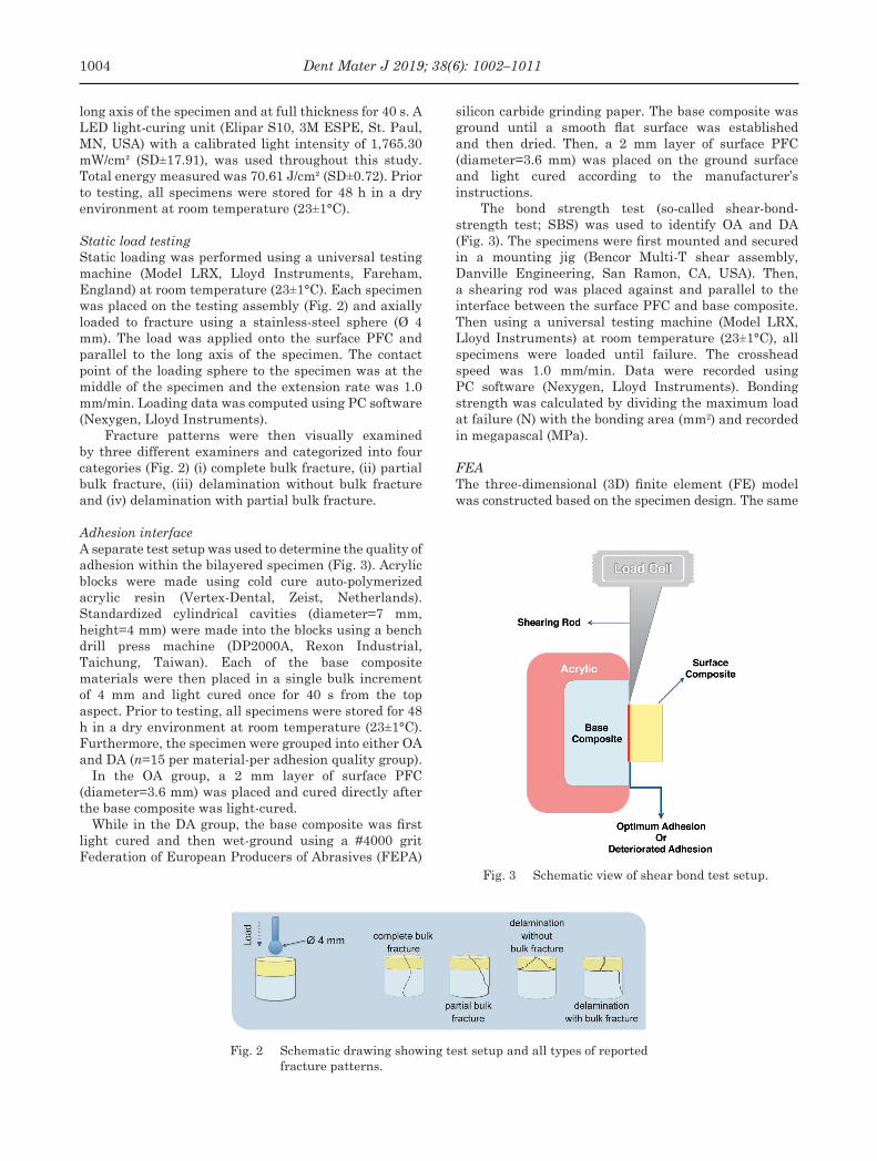
Fig. 2 Schematic drawing showing test setup and all types of reported fracture patterns.
Fig. 3 Schematic view of shear bond test setup.
long axis of the specimen and at full thickness for 40 s. A LED light-curing unit (Elipar S10, 3M ESPE, St. Paul, MN, USA) with a calibrated light intensity of 1,765.30 mW/cm² (SD±17.91), was used throughout this study. Total energy measured was 70.61 J/cm² (SD±0.72). Prior to testing, all specimens were stored for 48 h in a dry environment at room temperature (23±1°C).
Static load testingStatic loading was performed using a universal testing machine (Model LRX, Lloyd Instruments, Fareham, England) at room temperature (23±1°C). Each specimen was placed on the testing assembly (Fig. 2) and axially loaded to fracture using a stainless-steel sphere (Ø 4 mm). The load was applied onto the surface PFC and parallel to the long axis of the specimen. The contact point of the loading sphere to the specimen was at the middle of the specimen and the extension rate was 1.0 mm/min. Loading data was computed using PC software (Nexygen, Lloyd Instruments).
Fracture patterns were then visually examined by three different examiners and categorized into four categories (Fig. 2) (i) complete bulk fracture, (ii) partial bulk fracture, (iii) delamination without bulk fracture and (iv) delamination with partial bulk fracture.
Adhesion interfaceA separate test setup was used to determine the quality of adhesion within the bilayered specimen (Fig. 3). Acrylic blocks were made using cold cure auto-polymerized acrylic resin (Vertex-Dental, Zeist, Netherlands). Standardized cylindrical cavities (diameter=7 mm, height=4 mm) were made into the blocks using a bench drill press machine (DP2000A, Rexon Industrial, Taichung, Taiwan). Each of the base composite materials were then placed in a single bulk increment of 4 mm and light cured once for 40 s from the top aspect. Prior to testing, all specimens were stored for 48 h in a dry environment at room temperature (23±1°C). Furthermore, the specimen were grouped into either OA and DA (n=15 per material-per adhesion quality group).
In the OA group, a 2 mm layer of surface PFC (diameter=3.6 mm) was placed and cured directly after the base composite was light-cured.
While in the DA group, the base composite was first light cured and then wet-ground using a #4000 grit Federation of European Producers of Abrasives (FEPA)
silicon carbide grinding paper. The base composite was ground until a smooth flat surface was established and then dried. Then, a 2 mm layer of surface PFC (diameter=3.6 mm) was placed on the ground surface and light cured according to the manufacturer’s instructions.
The bond strength test (so-called shear-bond-strength test; SBS) was used to identify OA and DA (Fig. 3). The specimens were first mounted and secured in a mounting jig (Bencor Multi-T shear assembly, Danville Engineering, San Ramon, CA, USA). Then, a shearing rod was placed against and parallel to the interface between the surface PFC and base composite. Then using a universal testing machine (Model LRX, Lloyd Instruments) at room temperature (23±1°C), all specimens were loaded until failure. The crosshead speed was 1.0 mm/min. Data were recorded using PC software (Nexygen, Lloyd Instruments). Bonding strength was calculated by dividing the maximum load at failure (N) with the bonding area (mm2) and recorded in megapascal (MPa).
FEAThe three-dimensional (3D) finite element (FE) model was constructed based on the specimen design. The same
1004 Dent Mater J 2019; 38(6): 1002–1011

Fig. 4 Bond strength test values (MPa±SD) between the surface and base composite layers at different qualities of adhesion.
Fig. 5 Load-bearing capacities (N±SD) of tested specimens at different thicknesses and quality of adhesion between the surface PFC and base composites.
three top surface thicknesses were prepared; 1, 1.5 and 2 mm using same base materials, FRC and FBF. The total height of bilayered specimen was also standardized at 5 mm. Materials’ Young modulus used in this study are shown in Table 1. The materials were assumed to be isotropic, homogeneous, and linear elastic.
All solid models were derived from a single mapping mesh pattern that generated 2564 twenty-node brick elements (Solid 95 in ANSYS) and 4050 nodes. The force was applied to the center of top surface and load values were constant 600 N. The central point of the bottom surface was fixed in all directions. 3D FE analysis was presumed to be linear static and was performed on a personal work station (Z820 Work Station, Hewlett-Packard, Palo Alto, CA, USA) using FE analysis software ANSYS 15 (ANSYS, Houston, TX, USA). The locations and magnitudes of stress distribution (MPa) were identified and used for evaluating the mechanical behavior.
Statistical analysisValues reported for both the static loading and the adhesion interface tests are presented as mean (±standard deviation). Statistically significant differences were analyzed using three-way analysis of variance (ANOVA) followed by Tukey’s post hoc analysis at the (p<0.05) significance level, using SPSS software (Statistical Package for Social Science, SPSS, Chicago, IL, USA). Pearson’s correlation was utilized to identify the significance of trends between the specimen groups investigated. Chi-square test at a significance level of 5% was used to analyze the differences between fracture types and their correlation to the different bilayered configurations.
RESULTS
Adhesion interfaceThe bond strength test results collected from testing the different quality of adhesions are shown in Fig. 4. Statistically significant differences in bond strength values (p<0.05) were found between OA and DA in both FBF (14.7 and 6.1 MPa) and FRC (18.8 and 7.0 MPa).
Static load testingThe static load test results, at different thicknesses and quality of adhesion between the surface PFC and base composites, are summarized in Fig. 5. Tukey’s post hoc test results are shown in Table 2. In general, poor adhesion interface had a negative effect when using 1 mm thin surface PFC, but the effect of poor adhesion decreased as the surface PFC thickness was increased to 2 mm.
Three-way ANOVA revealed statistically significant differences in static loading values acquired in factors; thickness (p<0.05), quality of adhesion (p<0.05), while the material type did not show a statistically significant difference (p>0.05). However, the fracture pattern between different base materials was significantly different (p<0.05).
Pearson correlation analysis showed a statistically significant negative correlation (p<0.05) between load and thickness, when using the FRC base material with OA which can be seen in Fig. 5. In contrast, all the other groups tested in this study demonstrated a statistically significant positive correlation (p<0.05), i.e. the increase
1005Dent Mater J 2019; 38(6): 1002–1011

Table 2 Static load values (N) of the investigated specimens with different adhesion interfaces in relation to different thicknesses (1 vs 1.5 vs 2 mm)
Adhesion interfaceBase
material
Surface-layer thickness
1 mm 1.5 mm 2 mm
OptimalFBFFRC
2,052 (±222) Aa
2,554 (±130) Ab
2,161 (±240) Aab
2,315 (±386) ABa
2,499 (±262) Ba
2,173 (±210) Bab
DeterioratedFBFFRC
1,405 (±403) Ac
1,203 (±204) Ac
1,898 (±404) Bb
1,385 (±215) Ac
2,051 (±431) Bb
2,168 (±258) Bab
Tukey’s post hoc analysis presented as letters.Same superscript upper-case letter in a row represents non-statistically significant differences (p>0.05). Same superscript lower-case letter in a column represents non-statistically significant differences (p>0.05).
Fig. 6 Load-defection curves of tested specimens showing the initial failure points† and final fracture points during loading‡.
of surface PFC thickness caused an increase in load bearing capacity. Typical load deflection graphs for all the tested groups are shown in Fig. 6. In OA, FRC groups showed an initial failure point which was then followed by the final fracture at a higher load value. In contrast, FBF groups showed uninterrupted load-deflection curves before the fracture. In DA, the FRC and FBF groups followed the same trend, i.e. only specimens with 1 mm thick PFC layer showed an initial failure point.
Chi square analysis showed that the base material itself had a significant effect on failure type (p<0.05). Failure modes of the specimen after static loading test
are shown in Table 3.For FBF groups: during OA, the type of failure was
exclusively complete bulk fracture (100%), while during DA, the type of failure was predominantly following a delaminating manner, i.e. causing fracture only for the surface PFC. However, as the surface PFC thickness increased (1.5 and 2 mm) there was an increase incidence of base material partial fracture (10 and 30%, respectively).
For FRC groups: during OA, the type of failure was mixed with some incidences of partial bulk fracture. As the surface PFC increment thickness increased (1, 1.5
1006 Dent Mater J 2019; 38(6): 1002–1011

Fig. 7 FEA of tested specimens showing the strain distribution in vertical cross section.
a: FBF+1 mm PFC, b: FBF+1.5 mm PFC, c: FBF+2 mm PFC, d: FRC+1 mm PFC, e: FRC+1.5 mm PFC, f: FRC+2 mm PFC. Horizontal red line represents interface between surface PFC and base material.
Fig. 8 FEA of tested specimens showing the stress distribution in vertical cross section.
a: FBF+1 mm PFC, b: FBF+1.5 mm PFC, c: FBF+2 mm PFC, d: FRC+1 mm PFC, e: FRC+1.5 mm PFC, f: FRC+2 mm PFC. Horizontal red line represents interface between surface PFC and base material.
Table 3 Results of failure pattern assessment for all composite groups
Adhesion interface
Base material
Thickness of surface
composite (mm)
Percentage of different types of failure (%)
Complete bulk fracture
Partial bulk fracture
Delaminatingfracture
Delaminating with partial bulk fracture
Optimum
FBF11.52
100100100
———
———
———
FRC11.52
705030
305070
———
———
Deteriorated
FBF11.52
——20
———
1009050
—1030
FRC11.52
——10
———
100100
30
——60
1007Dent Mater J 2019; 38(6): 1002–1011

and 2 mm) there was an increase in the prevalence of partial bulk fracture (30, 50 and 70%, respectively), while during DA, the type of failure predominantly followed a delaminating manner, i.e. causing fracture only for the occlusal material. However, at surface PFC thickness 2 mm there was an increased incidence of base material partial fracture (60%). Pearson’s chi-square test revealed that the failure type of FRC and FBF in the deteriorated group was changed by incremental thickness (p<0.05).
FEAFor all specimen models, differences in strain and stress distributions were observed using FE modeling. The highest stress was located under the loading point for all models. Strain distribution (Fig. 7) showed FBF (a and b) having a high strain area that reaches the interface when using 1 and 1.5 mm surface PFC thickness. However, at 2 mm surface PFC the high strain area was confined to the top surface layer away from the interface (c). FRC groups showed less strain distribution than FBF.
Stress distributions (Fig. 8) revealed similar stress distribution irrespective of material and surface PFC thickness. High stress area is present at the interface when using 1 mm surface PFC. At 1.5 mm surface PFC, the high stress area was in close proximity to the interface line. At 2 mm surface PFC, high stress areas did not reach the interface line.
DISCUSSION
The results of the current study confirmed that the mechanical behavior of bilayered composite structures are influenced by: (i) adhesion between the surface and base composite-layers, (ii) changing the thicknesses of the base and surface composite materials, and (iii) the difference in Young modulus between composites.
In the light of the current body of evidence, it has been established that the mechanical behavior of posterior composite restorations is indeed multifactorial and a complex process23). Therefore, in efforts to improve the predictability of such materials, a systematic approach from different angles is needed. Hence, in this study we aimed to study the currently trending bilayered composites in relation to the following factors.
Adhesion between the surface and base composite materialsIn the clinical setting, a constant challenge dentists face when restoring deep cavities is optimum isolation of the cavities. It is important to avoid any compromise by saliva contamination or mechanical disturbances during the restoration process as this leads to a poor prognosis for the composite resin restorations involved24).
According to the data we acquired, the composite-composite interface had a significant influence on the load bearing capacity of the bilayered structures. When comparing the loading values from all the groups with OA, it was evident that the deteriorated quality of adhesion caused a significant reduction in the load-bearing capacity (Fig. 5). As the layers become less
bonded to one another, the bilayered specimen starts to lose structural integrity and the load bearing capacity of the whole system is jeopardized. In principle, the weakest failure point for such bilayered structure lies at the adhesion interface as described in a previous study25). In this study, DA was simulated by wet grinding. This also causes removal of the OIL which potentially affects optimal chemical adhesion22,26). Adhesion quality was confirmed with the bond strength test (Fig. 4). In OA groups the surface PFC was placed immediately after light-curing the base composite, thus simulating optimal conditions and avoiding any possible degradation to the OIL.
Within each material thickness, FBF and FRC groups showed lower load-bearing capacity at DA in comparison to OA. Between both base materials investigated, there was statistical difference in the load values at 1 mm in the OA group (Table 2). Hence, the quality of this interface is of high significance and should be kept at optimum quality to ensure the maximum performance of such bilayered composite structures.
In DA, the fracture type was predominantly delaminating fracture whereby the fracture was solely confined to the surface PFC. As previously stated in several studies regarding bonding interface, the point of initial failure is through separation at the deteriorated composite- composite adhesion interface (weakest point)27,28). Such a phenomenon and the rare involvement of the base material can be explained by analysis of the FE stress distribution (Figs. 8a and d). At 1 mm PFC group, high stress region is concentrated at the interface area. Hence, in DA the deteriorated interface does not allow the stresses to dissipate appropriately to the base layer. As a result, the surface layer acts independently of the base material underneath and delamination fracture occurs at a lower load. This can be seen from the load deflection graphs, whereby the initial failure point starts at a lower load value until it reaches a higher loading value that is fracture point (Fig. 6).
In contrast, 2 mm surface PFC (Figs. 8c and g) shows that the high stress region is well away from the interface. Consequently, lower stress is able to diffuse towards and beyond the deteriorated interface. Thus, the bilayered specimen are able to withstand higher loads before failure. Fracture eventually occurs within the surface PFC and the crack front can further propagate to include the base material. With 2 mm PFC thickness, the effect of interface quality decreases and becomes insignificant in FRC groups, which can be seen from the load bearing values (Table 2). However, FBF groups were more sensitive and adhesion quality had a significant effect on the load bearing values at the 2 mm thickness (Table 2).
In OA, the fracture type varied between either complete bulk fractures (FBF and FRC groups) or partial bulk fractures (FRC only). Both these types demonstrate that the bilayered specimen behaved as single structure, hence fracture was involving both composite layers. However, it is worth pointing out that partial bulk fracture type, was a distinct behavior
1008 Dent Mater J 2019; 38(6): 1002–1011

of FRC groups. This can be explained by the nature of the glass fiber reinforcement within the resin matrix18). Such crack hindering and deviation properties could be clinically useful in deep restorations as stated in previous studies12,29,30). Therefore, the data in this study strongly suggests optimum composite-composite adhesion interface conditions to fully utilize potential strengthening properties of fiber reinforcement in FRC.
Thickness of the base composite and surface PFC materialsBilayered restorations raise the question of whether changes in the thickness of either the base material or surface PFC would have an effect on the mechanical properties, and if so, how does it affect the bilayered structure as a whole. To the knowledge of the authors, such data is not sufficiently available in the literature. According to the results, it was found that there are statistically significant correlations when changing the thicknesses of the materials within the specimen. In general, the thickness had an anticipated pattern. That is, with the increase of the surface PFC thickness (1, 1.5 and 2 mm), there was an increase in the load bearing capacity of the bilayered structures. This positive correlation was observed in three groups: FBF (OA) FBF (DA) and FRC (DA).
Conversely, an unexpected pattern was observed when the FRC (OA) group was loaded. As surface PFC thickness increased, the load bearing capacity of the bilayered specimen decreased. The trend was the opposite of all the other groups and there was a statistically significant correlation.
This inverse phenomenon has also been reported in a previous study by Garoushi et al., where it has been found that the thinner the layer of surface PFC, the more the toughness and fracture resistance, in bilayered structures with FRC base material19). This highlights the possibility that 1 mm thin occlusal composites can safely be used to cover FRC base material and therefore be of utility when restoring deep cavities in the clinical setting.
In OA, there were complete bulk fractures at every thickness when using FBF as a base material. In addition, fractures were catastrophic (shattering in many pieces), rendering the impossibility of repair, for instance, in a clinical situation. Since, both FBF and conventional composites are only particulate fillers reinforced composites, the fracture behavior was similar. These findings are in line with previous studies investigating bulk filling material and mechanical loading behavior17,31).
Conversely, when using FRC as a base material and in OA, the thickness had a noticeable effect on the fracture behavior. An increasing incidence of partial fractures (30, 50 and 70%) correlated with the increase in surface PFC thickness (1, 1.5 and 2 mm, respectively). This interesting finding could be further explained by closely observing the load bearing capacities acquired at those thicknesses. As the thickness of surface PFC increased (1, 1.5 and 2 mm) the load at which fracture
occurred decreased, meaning the load that the fibers had to resist was also decreased. Therefore, at lower loads the fibers were able to appropriately deflect and resist the propagation of crack front. On the same note, the load deflection graph of FRC can also provide an insight into the crack front. The curves had an initial failure point followed by final fracture which is a possible demonstration of the initial failure of the surface PFC and consequently the enforcing behavior of the fiber reinforced base material before the final fracture. According to a similar study by Rocca et al., investigating the effect of fiber reinforced restorations covered with an overlaying CAD/CAM composite restoration, it was observed that the crack front was first initiated from the contact loading area and then propagated downwards into the rest of the restoration material32). Such laboratory static loading tests would generate a crack front with a very high stored energy which runs rapidly through the bulk of the restoration with little resistance32). Similarly, in this study, the loading values experienced by the composite bilayered structures were also high and reached about 2,500 N, while in reality, the human teeth could experience 500–800 N of maximal unilateral occlusal force33,34). Bear in mind that teeth are subjected to more complicated loading, which includes wedging through the cusps as well as compressive loads. Additionally, the modulus of elasticity could have an effect as shown in the FE strain distribution analysis (Fig. 7). When the surface PFC was 1 mm, FBF deforms more than FRC. When the surface PFC was 1.5 mm, FBF still experiences deformation whereas FRC deformation is negligible. FBF (7 GPa) is having a quite low modulus so it is not supporting surface PFC as FRC (12.3 GPa).
Moreover, in DA, specimens with both FBF and FRC base materials had an exclusive incidence of delaminating fracture whereby the surface PFC material shattered individually. However, as the surface PFC material thickness increased, the fracture was more likely to involve the base material (Table 3). This phenomenon could be explained by the loading value at which the fracture happened and a crack front with a high stored energy. Thus, as the thickness of surface PFC increased, the load bearing capacity increased and hence there was a higher chance for the fracture to propagate beyond the surface PFC and also involve the bulk base composite. This behavior is also found from FE analysis.
To summarize, in an attempt to explain the fracture behavior and type of failures observed between the materials, it is vital to consider the micro-structure of both the investigated base composites. FBF is a flowable micro-hybrid composite material. Fundamentally, it is anticipated to behave like other conventional micro-hybrid composite materials and fracture extensively (complete bulk fracture)35). FRC has a fiber-reinforced framework that has twice the fracture toughness (2.4 MPa m½) of FBF and is hence anticipated to behave differently13,14) At loads of about 2,000 N, the fibers could redirect the crack away from the center of the bilayered specimen and towards the peripheries. Thus increasing the likelihood of repair in the clinical situation
1009Dent Mater J 2019; 38(6): 1002–1011

(partial bulk fracture)3,36,37). The correlation of such laboratory findings to the clinical environment has been investigated in a recent systematic review by Heintze et al., whereby it was found that fracture toughness as a laboratory parameter was mostly correlated with clinical fracture38).
Nonetheless, it is worth mentioning that the tests were conducted through a standardized laboratory protocol, and the clinical situation is variable in terms of handling and placement of material. Furthermore, to further clinically validate the results of this study a fatigue study should be conducted to quantify the long-term effects of repetitive low occlusal forces on bilayered composite structures.
CONCLUSION
Within the limitations of this study, the results suggest that bilayered composite structures are sensitive to the quality of adhesion between the base and surface composite layers. Fracture behavior is expected to improve when using FRC as the base material in stress bearing areas.
ACKNOWLEDGMENTS
Testing materials were provided by the manufacturing companies, which is greatly appreciated. This study belongs to the research activity of BioCity Turku Biomaterials Research Program (www.biomaterials.utu.fi) and it was supported by Stick Tech LTD —Member of the GC Group. We would like to deeply thank Dr. Mike NELSON for his help in revising the manuscript.
CONFLICTS OF INTERESTS
Author PV consults for Stick Tech —Member of GC group in R&D and training.
REFERENCES
1) Opdam NJ, van de Sande FH, Bronkhorst E, Cenci MS, Bottenberg P, Pallesen U, et al. Longevity of posterior composite restorations. J Dent Res 2014; 93: 943-949.
2) Ástvaldsdóttir Á, Dagerhamn J, van Dijken JW, Naimi-Akbar A, Sandborgh-Englund G, Tranæus S, et al. Longevity of posterior resin composite restorations in adults —A systematic review. J Dent 2015; 43: 934-954.
3) Nicola S, Alberto F, Riccardo MT, Allegra C, Massimo SC, Damiano P, et al. Effects of fiber-glass-reinforced composite restorations on fracture resistance and failure mode of endodontically treated molars. J Dent 2016; 53: 82-87.
4) Fernandes AS, Dessai GS. Factors affecting the fracture resistance of post-core reconstructed teeth: a review. Int J Prosthodont 2001; 14: 355-363.
5) Yap AU, Pandya M, Toh WS. Depth of cure of contemporary bulk-fill resin-based composites. Dent Mater J 2016; 35: 503-510.
6) Batalha-Silva S, de Andrada MA, Maia HP, Magne P. Fatigue resistance and crack propensity of large MOD composite resin restorations: Direct versus CAD/CAM inlays. Dent Mater 2013;29: 324-331.
7) Lassila LV, Nagas E, Vallittu PK, Garoushi S. Translucency
of flowable bulk-filling composites of various thicknesses. Chin J Dent Res 2012; 15: 31-35.
8) Omran TA, Garoushi S, Abdulmajeed AA, Lassila LV, Vallittu PK. Influence of increment thickness on dentin bond strength and light transmission of composite base materials. Clin Oral Investig 2017; 21: 1717-1724.
9) Bucuta S, Ilie N. Light transmittance and micro-mechanical properties of bulk fill vs. conventional resin based composites. Clin Oral Investig 2014; 18: 1991-2000.
10) Rosatto CM, Bicalho AA, Veríssimo C, Bragança GF, Rodrigues MP, Tantbirojn D, et al. Mechanical properties, shrinkage stress, cuspal strain and fracture resistance of molars restored with bulk-fill composites and incremental filling technique. J Dent 2015; 43: 1519-1528.
11) Abdelmegid F, Salama F, Albogami N, Albabtain M, Alqahtani A. Shear bond strength of different dentin substitute restorative materials to dentin of primary teeth. Dent Mater J 2016; 35: 782-787.
12) Abouelleil H, Pradelle N, Villat C, Attik N, Colon P, Grosgogeat B. Comparison of mechanical properties of a new fiber reinforced composite and bulk filling composites. Restor Dent Endod 2015; 40: 262-270.
13) Garoushi S, Säilynoja E, Vallittu PK, Lassila L. Physical properties and depth of cure of a new short fiber reinforced composite. Dent Mater 2013; 29: 835-841.
14) Bijelic-Donova J, Garoushi S, Lassila LVJ, Keulemans F, Vallittu PK. Mechanical and structural characterization of discontinuous fiber-reinforced dental resin composite. J Dent 2016; 52: 70-78.
15) Fonseca RB, de Almeida LN, Mendes GAM, Kasuya AVB, Favarão IN, de Paula M S. Effect of short glass fiber/filler particle proportion on flexural and diametral tensile strength of a novel fiber-reinforced composite. J Prosthodont Res 2016; 60: 47-53.
16) Tsujimoto A, Nagura Y, Barkmeier WW, Watanabe H, Johnson WW, Takamizawa T, et al. Simulated cuspal deflection and flexural properties of high viscosity bulk-fill and conventional resin composites. J Mech Behav Biomed Mater 2018; 87: 111-118.
17) Ilie N, Bucuta S, Draenert M. Bulk-fill resin-based composites: an in vitro assessment of their mechanical performance. Oper Dent 2013; 38: 618-625.
18) van Dijken JW, Sunnegårdh-Grönberg K. Fiber-reinforced packable resin composites in Class II cavities. J Dent 2006; 34: 763-769.
19) Garoushi S, Lassila LV, Tezvergil A, Vallittu PK. Load bearing capacity of fibre-reinforced and particulate filler composite resin combination. J Dent 2006; 34: 179-184.
20) Kwon Y, Ferracane J, Lee IB. Effect of layering methods, composite type, and flowable liner on the polymerization shrinkage stress of light cured composites. Dent Mater 2012; 28: 801-809.
21) Eliades GC, Caputo AA. The strength of layering technique in visible light-cured composites. J Prosthet Dent 1989; 61: 31-38.
22) Bijelic-Donova J, Garoushi S, Lassila LVJ, Vallittu PK. Oxygen inhibition layer of composite resins: Effects of layer thickness and surface layer treatment on the interlayer bond strength. Eur J Oral Sci 2015; 123: 53-60.
23) Demarco FF, Corrêa MB, Cenci MS, Moraes RR, Opdam NJ. Longevity of posterior composite restorations: Not only a matter of materials. Dent Mater 2012; 28: 87-101.
24) Eiriksson SO, Pereira PN, Swift EJ Jr, Heymann HO, Sigurdsson A. Effects of saliva contamination on resin-resin bond strength. Dent Mater 2004; 20: 37-44.
25) Barreto BCF, Van Ende A, Lise DP, Noritomi PY, Jaecques S, Sloten JV, et al. Short fibre-reinforced composite for extensive direct restorations: a laboratory and computational assessment. Clin Oral Investig 2016; 20: 959-966.
1010 Dent Mater J 2019; 38(6): 1002–1011

26) Truffier-Boutry D, Place E, Devaux J, Leloup G. Interfacial layer characterization in dental composite. J Oral Rehabil 2003; 30: 74-77.
27) Hatta M, Shinya A, Vallittu PK, Shinya A, Lassila LV. High volume individual fibre post versus low volume fibre post: The fracture load of the restored tooth. J Dent 2011; 39: 65-71.
28) Taha NA, Palamara JE, Messer HH. Fracture strength and fracture patterns of root-filled teeth restored with direct resin composite restorations under static and fatigue loading. Oper Dent 2014; 39: 181-188.
29) Dere M, Ozcan M, Göhring TN. Marginal quality and fracture strength of root-canal treated mandibular molars with overlay restorations after thermocycling and mechanical loading. J Adhes Dent 2010; 12: 287-294.
30) Garoushi SK, Hatem M, Lassila LVJ, Vallittu PK. The effect of short fiber composite base on microleakage and load-bearing capacity of posterior restorations. Acta Biomater Odontol Scand 2015; 14: 6-12.
31) de Assis FS, Lima SN, Tonetto MR, Bhandi SH, Pinto SC, Malaquias P, et al. Evaluation of bond strength, marginal integrity, and fracture strength of bulk- vs incrementally-filled restorations. J Adhes Dent 2016; 18: 317-323.
32) Rocca GT, Saratti CM, Cattani-Lorente M, Feilzer AJ, Scherrer S, Krejci I. The effect of a fiber reinforced cavity
configuration on load bearing capacity and failure mode of endodontically treated molars restored with CAD/CAM resin composite overlay restorations. J Dent 2015; 43: 1106-1115.
33) Ledogar JA, Dechow PC, Wang Q, Gharpure PH, Gordon AD, Baab KL, et al. Human feeding biomechanics: performance, variation, and functional constraints. Peer J 2016: 4; e2242.
34) Röhrle O, Saini H, Ackland DC. Occlusal loading during biting from an experimental and simulation point of view. Dent Mater 2018; 34: 58-68.
35) Isufi A, Plotino G, Grande NM, Ioppolo P, Testarelli L, Bedini R, et al. Fracture resistance of endodontically treated teeth restored with a bulkfill flowable material and a resin composite. Ann Stomatol (Roma) 2016; 7: 4-10.
36) Ozsevik AS, Yildirim C, Aydin U, Culha E, Surmelioglu D. Effect of fibre-reinforced composite on the fracture resistance of endodontically treated teeth. Aust Endod J 2016; 42: 82-87.
37) Bijelic-Donova J, Uctasli S, Vallittu PK, Lassila L. Original and repair bulk fracture resistance of particle filler and short fiber-reinforced composites. Oper Dent 2018; 43: E232-E242.
38) Heintze SD, Ilie N, Hickel R, Reis A, Loguercio A, Rousson V. Laboratory mechanical parameters of composite resins and their relation to fractures and wear in clinical trials —A systematic review. Dent Mater 2016; 33: e101-e114.
1011Dent Mater J 2019; 38(6): 1002–1011
Copyright © 2022 FDOKUMEN