bit 2104 - Masomo Msingi Publishers
98
P.O>Box 342-01000 Thika Email: [email protected] Web: www.ku.ac.ke DEPATMENT OF INFORMATION TECHNOLOGY COURSE CODE: BIT 2104 COURSE TITLE: BUSINESS INFORMATION SYSTEMS ANALYSIS AND DESIGN Instructional manual for BBIT- Distance Learning www.masomomsingi.com
-
Upload
khangminh22 -
Category
Documents
-
view
1 -
download
0
Transcript of bit 2104 - Masomo Msingi Publishers

P.O>Box 342-01000 Thika
Email: [email protected]
Web: www.ku.ac.ke
DEPATMENT OF INFORMATION TECHNOLOGY
COURSE CODE: BIT 2104
COURSE TITLE: BUSINESS INFORMATION SYSTEMS ANALYSIS AND DESIGN
Instructional manual for BBIT- Distance Learning
www.m
asom
omsing
i.com
Contents CHAPTER ONE ............................................................................................................................................... 8
INFORMATION AND SYSTEMS .................................................................................................................. 8
INFORMATION AND DATA .................................................................................................................... 8
1.3 TYPES OF INFORMATION ................................................................................................................ 9
1.4 SYSTEMS THEORY .......................................................................................................................... 11
1.5 OBJECTIVES OF A SYSTEM ............................................................................................................. 12
1.6 INFORMATION SYSTEMS ............................................................................................................... 13
1.7 TYPES OF INFORMATION SYSTEM ................................................................................................. 13
CHAPTER TWO ............................................................................................................................................ 15
THE SYSTEMS DEVELOPMENT LIFE CYCLE ............................................................................................... 15
2.1 INTRODUCTION ............................................................................................................................. 15
2.2 THE WATERFALL MODEL ............................................................................................................... 17
2.3 ADVANTAGES OF THE SDLC .......................................................................................................... 19
2.4 DISADVANTAGES OF THE SDLC ..................................................................................................... 19
CHAPTER THREE .......................................................................................................................................... 21
SYSTEM SPECIFICATION .......................................................................................................................... 21
3.1 INTRODUCTION ............................................................................................................................. 21
3.2 STATEMENT OF REQUIREMENTS .................................................................................................. 23
3.3 THE PERSONNEL INVOLVED .......................................................................................................... 25
3.4 SYSTEMS INVESTIGATION ............................................................................................................. 28
3.5 THE FEASIBILITY OR INITIAL STUDY ............................................................................................... 34
3.6 REQUIREMENTS SPECIFICATION ................................................................................................... 39
CHAPTER FOUR ........................................................................................................................................... 40
SYSTEM DESIGN ...................................................................................................................................... 40
4.1 LOGICAL AND PHYSICAL DESIGN ................................................................................................... 40
4.2 THE DESIGN STAGE ....................................................................................................................... 41
www.m
asom
omsing
i.com
4.3 SYSTEM DESIGN SPECIFICATION ................................................................................................... 43
4.4 DESIGN CONSIDERATIONS ............................................................................................................ 45
4.5 HUMAN-COMPUTER INTERFACE .................................................................................................. 46
CHAPTER FIVE ............................................................................................................................................. 50
APPROACHES TO SYSTEMS ANALYSIS AND DESIGN ................................................................................ 50
5.1 STRUCTURED SYSTEMS ANALYSIS AND DESIGN METHOD (SSADM) ............................................ 50
5.2 OBJECT-ORIENTED ANALYSIS AND DESIGN (OOAD) ..................................................................... 53
5.3 WEB INFORMATION SYSTEMS DEVELOPMENT............................................................................. 54
5.4 RAPID APPLICATION DEVELOPMENT (RAD) .................................................................................. 55
5.5 JOINT APPLICATION DEVELOPMENT (JAD) ................................................................................... 55
5.6 PROTOTYPING ............................................................................................................................... 55
5.7 CASE TOOLS ................................................................................................................................... 57
CHAPTER SIX ................................................................................................................................................ 59
DATA FLOW DIAGRAM ............................................................................................................................ 59
6.1 INTRODUCTION ............................................................................................................................. 59
6.2 AN EXAMPLE SYSTEM.................................................................................................................... 59
6.3 DATA FLOW DIAGRAMS (DFDS) .................................................................................................... 60
6.4 LEVELS OF DATA FLOW DIAGRAM ................................................................................................ 64
6.5 DRAWING DATA FLOW DIAGRAMS ............................................................................................... 66
6.6 PHYSICAL AND LOGICAL DFDS ....................................................................................................... 68
6.7 ADVANTAGES AND DISADVANTAGES OF DFDS ............................................................................ 69
CHAPTER SEVEN .......................................................................................................................................... 70
DATA MODELLING ................................................................................................................................... 70
7.1 INTRODUCTION ............................................................................................................................. 71
7.2 ENTITIES, ATTRIBUTES AND RELATIONSHIPS ................................................................................ 71
7.3 ENTITY RELATIONSHIPS ................................................................................................................. 72
7.4 OPTIONAL AND MANDATORY RELATIONSHIPS ............................................................................ 74
7.5 MANY-TO-MANY RELATIONSHIPS ................................................................................................. 75
7.6 DATA DICTIONARIES ...................................................................................................................... 76
7.7 INTERRELATIONSHIP BETWEEN THE DFD, ENTITY RELATIONSHIP ................................................ 77
CHAPTER TEN .............................................................................................................................................. 78
STANDARDS AND DOCUMENTATION ..................................................................................................... 78
www.m
asom
omsing
i.com
10.1 INTRODUCTION ........................................................................................................................... 78
10.2 TYPES OF STANDARDS ................................................................................................................. 79
CHAPTER ELEVEN ........................................................................................................................................ 82
SYSTEM IMPLEMENTATION .................................................................................................................... 82
11.1 THE IMPLEMENTATION PROCESS ............................................................................................... 82
11.2 USER INVOLVEMENT ................................................................................................................... 85
11.3 CHANGEOVER STRATEGIES ......................................................................................................... 86
11.4 TRAINING .................................................................................................................................... 89
CHAPTER TWELVE ....................................................................................................................................... 90
SYSTEMS MAINTENANCE ............................................................................................................................ 90
12.1 MAINTENANCE PROBLEMS ......................................................................................................... 90
12.2 SYSTEM ENHANCEMENTS ........................................................................................................... 92
12.3 NEED FOR SYSTEM SECURITY ...................................................................................................... 92
SAMPLE EXAMS QUESTIONS ....................................................................................................................... 94
www.m
asom
omsing
i.com

COURSE OUTLINE
PPuurrppoossee ooff tthhee ccoouurrssee :: To present fundamental methodology and process for the analysis and design of a
computer based business information systems to the learner.
1 Information and Systems
Information and Data
Information Needs
Types of Information
Management Information
Systems Theory
Objectives of a System
Information Systems
Types of Information System
2 The Systems Development Life Cycle
The SDLC
The Waterfall Model
Advantages of the SDLC
Disadvantages of the SDLC
3 System Specification
Introduction
The Development Life Cycle
Statement of Requirements
The Personnel Involved
Systems Investigation
The Feasibility or Initial Study
Requirements Specification
4 System Design
Logical and Physical Design
The Design Stage
System Design Specification
Design Considerations
Human-Computer Interface
5 Approaches to Systems Analysis and Design
Introduction
Structured Systems Analysis and Design Method (SSADM)
Object-Oriented Analysis and Design (OOAD)
Web Informations Systems Development
BUSINESS INFORMATION SYSTEMS ANALYSIS AND DESIGN
www.m
asom
omsing
i.com
Rapid Application Development (RAD)
Joint Application Development (JAD)
Prototyping
CASE Tools
6 Data Flow Diagrams
Introduction
An Example System
Data Flow Diagrams (DFDs)
Levels of Data Flow Diagram
Drawing Data Flow Diagrams
Physical and Logical DFDs
Advantages and Disadvantages of DFDs
7 Data Modelling
Introduction
Entities, Attributes and Relationships
Entity Relationships
Optional and Mandatory Relationships
Many-to-Many Relationships
Data Dictionaries
8 DFD and ERD
Introduction
Interrelationship between the DFD, Entity-Relationship Model
9 Standards and Documentation
Introduction
Role and Scope of Standards
Other Documentation
10 Standards and Documentatio
Application of standards
Types of standards
Documentation
11 System Implementation
The Implementation Process
User Involvement
Changeover Strategies
Training
12 System Maintenance and Security
Systems Maintenance
Database Maintenance
System Enhancements
Need for System Security
AAsssseessssmmeennttss
Continuous Assessment Tests (CATs) (30%)
End of semester examination (70%) Total = 100%
www.m
asom
omsing
i.com

RReeqquuiirreedd tteexxtt bbooookkss
A. Vision D. & Fitz Gerald D, Information systems development: methodologies techniques and tools,
McGraw Hill
Kenneth E. Kendall J.E, Systems Analysis and Design, Prentice Hall
TTeexxtt bbooookkss ffoorr ffuurrtthheerr rreeaaddiinngg
Bennett, MC Roib, Object Oriented Systems Analysis and design using UML McGraw Hill
Other support materials
- Various application manuals and journals
Compiled by : Joshua Agola
www.m
asom
omsing
i.com
CHAPTER ONE
INFORMATION AND SYSTEMS
INFORMATION AND DATA
It is important that you understand the difference between information and data.
Data is raw facts; for example, a group of figures, a list of names and such like. By itself, data tells us
nothing. Consider the following numbers:
212 263 189 220
In that form, the numbers could have a thousand different meanings. But if we add £ to the
figures: £212 £263 £189 £220
We can now see that they are monetary values. If we add some dates:
January = £212
February = £263
March = £189
April = £220
Now we see that they demonstrate some kind of trend. They then convey information.
Information is raw data processed so as to convey a new meaning.
1.2 INFORMATION NEEDS In organizations, information is required as the basis of taking action – essentially by managers.
Role of Managers
Managers normally have two roles
decision maker; and
controller.
Learning objectives:
By the end of the chapter a student shall be able to: Information and Data
Information Needs
Types of Information
Management Information
Systems Theory
Objectives of a System
Information Systems
Types of Information System
www.m
asom
omsing
i.com
Stated simply, the processes involved in these roles is for managers to make a decision, check the
outcome and either confirm or modify the decision in the light of events. This is a standard control
process, involving five stages:
(a) Establish a plan.
(b) Record the plan.
(c) Implement the plan.
(d) Compare actual performance with the plan.
(e) Evaluate and decide further action.
You will readily see that information is needed at (a) in order to establish the plan, and at (d) to see how
things are working out. There is a constant flow of information.
Quality of Information
Quality information needs to be relevant, reliable and robust.
Relevant means it is pertinent to the recipient, who will then operate more effectively with the
information than without it.
Reliable means that the information is timely, accurate and verifiable.
Robust means that the information will stand the test of time and failures of handling whether
human, system or organizational.
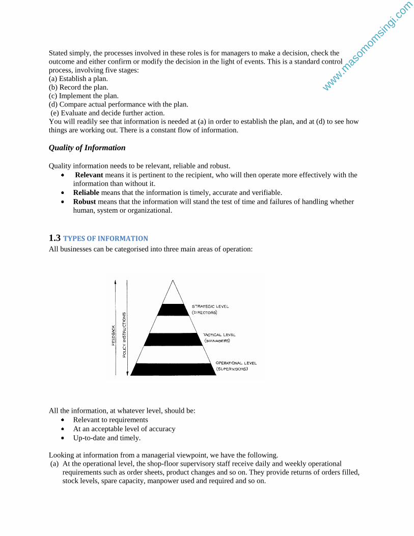
1.3 TYPES OF INFORMATION All businesses can be categorised into three main areas of operation:
All the information, at whatever level, should be:
Relevant to requirements
At an acceptable level of accuracy
Up-to-date and timely.
Looking at information from a managerial viewpoint, we have the following.
(a) At the operational level, the shop-floor supervisory staff receive daily and weekly operational
requirements such as order sheets, product changes and so on. They provide returns of orders filled,
stock levels, spare capacity, manpower used and required and so on.
www.m
asom
omsing
i.com
(b) Such information as above is used in summary form by managers at the tactical level in the actioning f
reports on performance, budget versus actual and so on.
(c) At the strategic (director) level, information is much more global, having been highly summarised. It
is at this level that policy making decisions, short- and long-term, are taken and passed down to the
tactical level for actioning by the management.
Operating Information
Operating information is used to instruct the employees of the business to ensure that they all know what
is required of them. Despatch instructions to the warehouse, for example, state what is to be despatched
and where it is to be sent.
Operating information – which can also be called routine information – contains the facts of what has
been done, to provide a history of the actions carried out. A stores issue note records the fact that a
quantity of raw materials has been given out to be used in production. This type of information can flow
to and from the outside world – orders received from customers, invoices sent to customers, or bank
statements.
Without this information, the business could not operate. It is often termed "paperwork" since
most operating information is presented in the form of paper documents. When companies start to use
computerised data processing, it is normally used first for the production of operating information.
However, microcomputers are beginning to change this, particularly in very small companies where the
amount of paperwork to be handled is relatively small and often very varied. In such circumstances,
management techniques such as the use of spreadsheets often play a prominent role in the computer
utilisation. Word processing also tends to dominate the small business area because of its universal
application.
Management Information
All three categories of information can be collectively seen as management information.
(a) Firstly, we have those decisions associated with the day-to-day running of the business:
"What action must be taken to bring the sales level up to the budget estimate?"
"Will overtime be needed to complete a job?"
Most of these decisions are taken by junior levels of management – for example, by supervisors – and
usually require that the information contains very detailed facts about the activities for which the manager
is responsible. This information will come in the form of reports giving detailed summaries and analyses
of the current situation. This type of information is often categorised as operational information.
(b) Secondly, middle management is responsible for the overall running of the business on a week-to-
week and month-to-month basis. They must compare actual expenditure and sales with the targets
provided by senior management, and require information to back up explanations of any divergences
from the budgeted figures. They must also prepare the terms of reference to which junior
management is to operate. We can thus say that the information requirements of middle management are
not so detailed, but they are wider-ranging – they will need to know about the outside world, as well as
www.m
asom
omsing
i.com
the progress of the business itself. This type of information is generally categorised as tactical
information.
(b) Finally, the senior management needs to plan into the future, often as far as five years ahead, and
possibly further. They provide a framework for middle management by defining the policies to be
followed and setting yearly budgets and targets. Their information requirements are therefore more
general and each decision they take will have far-reaching effects. This type of information is
generally categorised as strategic information. An organisation needs to collect data about items not
immediately related to the running of the organisation – i.e. future prices of raw materials,
competitive products, personnel skills, national statistics, new processes, new equipment, etc. A
considerable volume of this data is to be found within any organisation and exists in many different
forms. This data is used in considering strategy in medium- to long-term plans.
1.4 SYSTEMS THEORY
A dictionary definition of "system" is: "Anything formed of parts placed together or adjusted into a
regular and connected whole."
System Properties Systems receive input and produce output.
Systems consist of sub-systems which are themselves systems performing some function on behalf of the
larger system. A fully integrated system consists of sub-systems, each of which has, as input, the output
of another sub-system so that all the sub-systems together fulfil the overall objective of the whole system.
A system must have a boundary; outside the boundary is the environment. The environment of a
computer system includes any people or business activities which interact with it, the sources of the data
which forms its input and the recipients of the information it provides. The art of systems analysis is
being able to define system boundaries – to decide which parts should be included within a particular
study, so that a logical and convenient model can be prepared.
Another definition of system is "the method by which an individual, organisation or mechanism
accomplishes the tasks necessary to achieve its objectives". The method used will be made up of a
number of related procedures, and – in a large system – there may be groups of procedures called sub-
systems. Figure 1.2 shows a business system consisting of four main sub-systems, each of which can be
divided – as shown for accounting – into a number of smaller sub-systems.
A system can thus be thought of as hierarchical, and this hierarchical nature extends both ways, in that
the system being described can also be looked at as being a sub-system of a larger or wider system.
Staying with our accounting example, a sales ledger system is composed of a number of subsections,
whilst itself being a sub-system of the total accounting system of the organisation.
Probabilistic and Deterministic Consider a slot machine. Here you place your coin in the machine and, provided the machine is stocked,
the required item will be delivered automatically. The outcome is completely predictable; a slot machine
is an example of a deterministic system. Whenever we take a particular action, the result or resulting
action will invariably be the same, providing that the system is working correctly. Every step in the
system has this feature and so the total system is deterministic in nature.
www.m
asom
omsing
i.com
A computer can be considered to be a deterministic system since it automatically follows the series of
instructions it has been given. At least this is true for traditional computer systems, which includes the
vast majority of those currently in use and certainly all those used for data processing.
Alternatively there are probabilistic systems whose predictability is less than that of deterministic
systems. If, instead of always getting an item out of a slot machine, you sometimes got nothing – for
example, from a fruit machine or some other gambling device – then this system would be probabilistic.
Stated simply, we can never be certain of how such a system will work, but we can assume that a specific
action will take place, based on our previous experience or knowledge.
An example of a probabilistic system is a game of cards or the pricing system of an organisation.
Open and Closed
When a system is isolated from its surrounding environment it is a closed system. When a system
responds to input from its environment and provides output to the environment, it is an open system. The
same system can be seen as closed or open when viewed from different perspectives. For example, a
payroll system is closed when viewed from an organisational position, but is open when seen from inside
the payroll section.
Quantitative and Qualitative
A quantitative system will process and output actual values. All financial systems are quantitative.
A qualitative system processes and outputs less measurable quantities such as "a better service to clients".
1.5 OBJECTIVES OF A SYSTEM
Objectives are the goals towards which a system is working. In an organisation the overall objectives are
seen differently in the separate departments, each of which tends to have its own objectives.
The overall objective that has been established for a system must be one that can be achieved. Although
the objective may at times seem difficult or nearly impossible, it is of prime importance that in the long
run it is achievable.
Objectives of a Wider Context
We have said that individual systems form part of a larger system. It is essential when setting out systems
objectives that account is taken of the objectives of the next higher system. It is better if the objectives of
the higher systems are known before those of the sub-systems are established. The communication of the
objectives from the higher to the lower systems is of great importance.
How Objectives are Created The overall objective of a system is created firstly by listing all possible objectives. Many of these will be
in open conflict and it is therefore necessary to weight, in order of importance, the objectives so far
specified.
www.m
asom
omsing
i.com
1.6 INFORMATION SYSTEMS
This is a system which processes data and produces information. We have already
The inputs and outputs to and from an information system are not physical things like food or
fuel, but are items of data and information, numbers and words and characters. The amazing thing is that
the same principles apply to an information system as to the other systems we have mentioned. The
component parts of an information system are not physical things like the gearbox or the brakes, but are
processes which are performed on the data to transform it.
Information systems provide information to managers and whoever else requires it. It is difficult to
classify information systems as deterministic or probabilistic. They are programmable (i.e. can be
computerised) and thus appear deterministic. From the user viewpoint, however, there may sometimes be
no satisfactory output, thus making them appear probabilistic. In the same way, they can be seen as both
open and closed. However, as we shall always want information systems to evolve, they are primarily
open. They do need to be quantitative though. The user needs concrete information on which to
base decisions.
An efficient and effective information system will always give:
the right information
to the right person
at the right time
at the right cost.
1.7 TYPES OF INFORMATION SYSTEM
Transaction Processing Systems
Office Systems
Knowledge Work Systems
Management Information Systems
Decision Support Systems
Executive Support Systems
Transaction Processing Systems
Transaction Processing Systems are the basic operational level systems such as order processing, payroll,
stock control. Their input consists of basic transactions such as orders, hours worked, number of parts
received, and their outputs are detailed reports, lists and summaries.
Office Systems
Office Systems are now a way of life in organisations. They are used by everyone and include word
processing, spreadsheets, databases, email. They can be classified as knowledge-level systems.
Knowledge Work Systems
Knowledge Work Systems are again often classified at the knowledge level. They are used by technical
and professional staff, and include modelling and simulation software, computeraided design,
sophisticated desk-top publishing applications and other technically-oriented systems.
www.m
asom
omsing
i.com
Management Information Systems
Management Information Systems tend to be used by middle managers. They take the summary
transaction data from Transaction Processing Systems as input and produce summary and exception
reports. This type of information system was described in more detail in Section D of this unit.
Decision Support Systems
Decision Support Systems are a very important tool. They are used extensively by professionals and staff
managers, but can be used at all levels. A spreadsheet can be used as a decision support system. As the
name suggests, they are used to provide information to help people make decisions. Input can range from
low-volume data to very large databases which can then be analysed using simulations and statistics. The
user can interact with the system to see where various paths may lead.
Executive Support Systems
Executive Support Systems are not as specific as the other types of system. Executive Support Systems
are used by senior managers and they address the strategic level of an organisation. They use internal data
produced as output from each of the other types of information system, but they also use external data
about the stock market, competitors, economic trends, etc. They help with strategic questions like "Are
we selling the right products?", "How should we go about raising cash?". They use sophisticated graphics
to present information from multiple sources to senior managers.
FURTHER READING
A. Vision D. & Fitz Gerald D, Information systems development: methodologies techniques and tools,
McGraw Hill
REVIEW QUESTIONS
1. Differentiate between traditional system development and structured
system development method
2. Discuss six types of information systems?
www.m
asom
omsing
i.com

CHAPTER TWO
THE SYSTEMS DEVELOPMENT LIFE CYCLE
2.1 INTRODUCTION
Developing an information system is usually a large project. All projects need to be planned and
managed. The SDLC shows the main activities normally associated with information systems
development. It shows where to start, what to do next and where to end. Having said that, it is a cycle so it
never really ends. As you work through later units, you will see that there are, in fact, a number of ways
in which systems are developed, using different methodologies and techniques. The SDLC has been
around since the early 1970s and has a number of strengths and weaknesses. Most of the other approaches
were developed to overcome these weaknesses, but the SDLC is really the starting point for all of them. It
is a highly logical and structured concept and, in this course, it will be used as a means of introducing the
various methodologies and techniques.
The SDLC
There are several variants of the SDLC, but the basic principles are the same. Systems development is
divided into phases and you will see different diagrams which show between four and over twenty phases.
Figure 2.1 shows a typical diagram of the basic SDLC, and, as you can see, the cycle consists of 6 distinct
phases:
Learning objectives:
By the end of the chapter a student shall be able to: Understand and apply the steps of SDLC
The Waterfall Model
Advantages of the SDLC
Disadvantages of the SDLC
www.m
asom
omsing
i.com
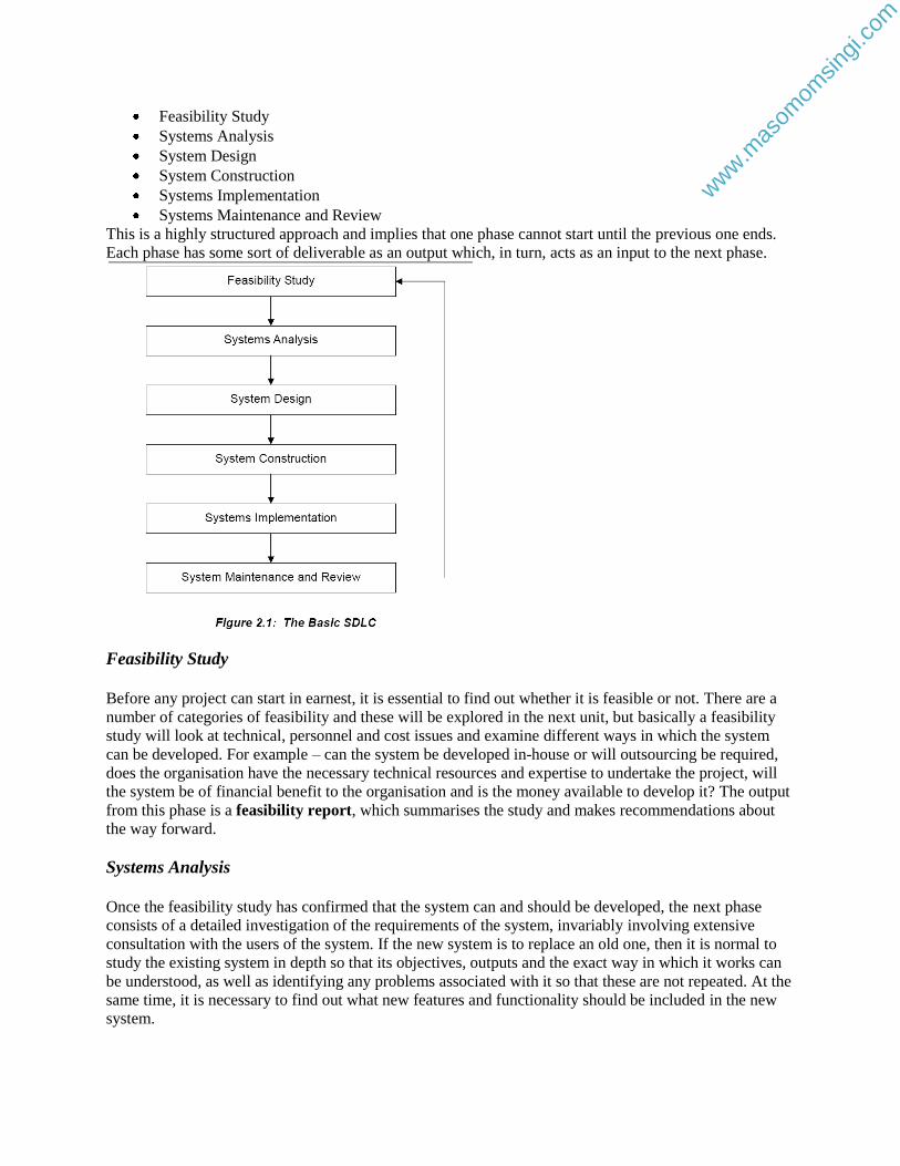
Feasibility Study
Systems Analysis
System Design
System Construction
Systems Implementation
Systems Maintenance and Review
This is a highly structured approach and implies that one phase cannot start until the previous one ends.
Each phase has some sort of deliverable as an output which, in turn, acts as an input to the next phase.
Feasibility Study
Before any project can start in earnest, it is essential to find out whether it is feasible or not. There are a
number of categories of feasibility and these will be explored in the next unit, but basically a feasibility
study will look at technical, personnel and cost issues and examine different ways in which the system
can be developed. For example – can the system be developed in-house or will outsourcing be required,
does the organisation have the necessary technical resources and expertise to undertake the project, will
the system be of financial benefit to the organisation and is the money available to develop it? The output
from this phase is a feasibility report, which summarises the study and makes recommendations about
the way forward.
Systems Analysis
Once the feasibility study has confirmed that the system can and should be developed, the next phase
consists of a detailed investigation of the requirements of the system, invariably involving extensive
consultation with the users of the system. If the new system is to replace an old one, then it is normal to
study the existing system in depth so that its objectives, outputs and the exact way in which it works can
be understood, as well as identifying any problems associated with it so that these are not repeated. At the
same time, it is necessary to find out what new features and functionality should be included in the new
system.
www.m
asom
omsing
i.com
The output from this phase is a requirements specification. Many analysts view this phase as the most
important. It is all very well building a sophisticated system which looks good and produces impressive
output, but if these outputs are not what the users want, the system is a waste of time.
System Design
This phase takes the requirements specification and converts it into a system design specification. This
involves the design of inputs, outputs, databases, computer programs and user interfaces.
The design phase is normally split into logical and physical design. Logical design concentrates on the
business aspects of the system and is theoretically independent of any hardware or software. Physical
design takes the logical design specification and applies it to the implementation environment. Most often
the choice of programming language and database is already decided and these technologies are taken
into account in physical design.
The system design specification contains all the detail required for the system builders to construct the
system.
System Construction
This phase is where the system is actually built. The system specifications are turned into a working
system by writing, testing and, in due course, documenting the programs which will make up the whole
system. Once the individual programs have been tested, the whole system needs to be put together and
tested as a whole. This whole phase requires extensive user involvement.
The output from this phase consists of detailed program and file specifications which, in total, describe
exactly how the new system works.
Systems Implementation
The objective of this phase is to produce a fully functioning and documented system. It involves training
users, transferring data from the old system to the new and actually putting the new system into operation
– "going live". There are a number of different approaches to this, as we shall see later in the course.
A final system evaluation will also need to be performed to make sure the system works according to
expectations.
System Maintenance and Review
During the life of a system, continual review and maintenance will need to be performed in order to
maintain its functionality. For example, new requirements may need to be implemented and errors in the
system need to be rectified. Such maintenance is really a repetition of the other phases of the life cycle as
a new requirement or a fix for an error needs to be analyzed, designed and implemented.
Eventually all systems become outdated and need to be replaced, so the cycle starts again, with the way in
which the old system is operating and the requirements which now apply forming the backdrop to a new
feasibility study to examine whether a new system should be developed.
2.2 THE WATERFALL MODEL
The basic SDLC in Figure 2.1 implies a purely linear approach in that one phase finishes before
another one starts and there is no going back. In practice, of course, this is unrealistic. When working
www.m
asom
omsing
i.com
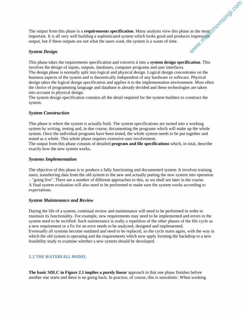
though a phase, it is often the case that something does not work out as planned or that there is an error or
omission in the previous phase. It is, therefore, necessary to go back and modify the previous phase.
So, there is an iterative nature to the SDLC, and this is shown in Figure 2.2. This approach is often called
the Waterfall Model, and the dotted lines on the diagram show the interaction between phases, with the
possibility of returning to a previous phase to make adjustments always available.
As already mentioned, there a many different methodologies and techniques used in developing systems.
SSADM, for example, is a structured methodology which follows the SDLC very closely, and we shall
examine this in later units. In object-oriented systems development, the boundary between the analysis
and design phases is often indistinct. In the prototyping approach, analysis, design and construction are all
often done together.
The techniques used in each phase also differ.
Structured methods separate processes and data and model them using different techniques. Processes are
modelled by data flow diagrams and data by entity relationship diagrams. In object-oriented methods,
processes and data are not separate, but are combined into something called an object. However, whatever
www.m
asom
omsing
i.com

approach is adopted and whatever techniques are used, any system development needs to go through
feasibility, analysis, design, construction, implementation, maintenance and review. It is the way this is
done that differs.
The SDLC is often termed the "conventional" or "traditional" approach to systems analysis and design
and although it is rarely used in its entirety nowadays, its influence is very apparent and many of its
features play a prominent part in the various approaches which abound today.
2.3 ADVANTAGES OF THE SDLC
Whatever the drawbacks of the SDLC, it was highly successful in the 1980s and 1990s. Its main
advantages are that it lends itself to project management techniques, produces well documented
systems and uses tried and tested techniques.
Project management
Breaking down a project into phases has distinct advantages in that each stage can be specified, planned
and evaluated before moving on to the next planned stage. This enables the whole project to be closely
managed, and is the same approach extensively used in engineering projects such as building a bridge,
and the same principles apply.
In some structured approaches such as SSADM, each phase is further sub-divided into stages, stages into
steps, and steps into tasks. Each task, step, stage and phase can then be estimated for duration and cost,
staff can be allocated to them, and then they can be monitored and adjusted accordingly. With today's
project management software this becomes quite straightforward. As each phase has a start and end point,
this provides opportunities for quality assurance of the outputs before the next phase is allowed to start. It
is particularly relevant to large projects such as those involving government departments and it is no
surprise therefore that SSADM originated in the UK Treasury!
Documentation
Because of the benefits of project management, the SDLC tends to be associated with thorough
documentation. Each stage has its own documentation standards and these make the quality assurance
processes much easier. CASE tools are available which can be used to produce all of the diagrams and
forms and integrate them into a project repository.
Tried and Tested Techniques
The SDLC tends to be associated with structured methodologies such as SSADM. Not only do these
methodologies break a project down into manageable parts, they also provide tried and tested techniques
to use along the way. Data flow diagrams, entity relationship diagrams and entity life histories are all
widely accepted techniques which have been used in thousands of projects.
2.4 DISADVANTAGES OF THE SDLC
In the 1980s and 1990s, technology, programming techniques and the demands of organisations advanced
to such an extent that the SDLC became unwieldy. It became regarded as inflexible, narrow in focus, not
www.m
asom
omsing
i.com

responsive enough to the needs of organisations, and using old-fashioned techniques. Projects took too
long to develop and were frequently over-budget.
Inflexibility
Because the SDLC has distinct, sequential phases it was regarded as inflexible, especially for smaller
systems. With the appearance of the Internet in the 1990s, businesses started to use information systems
for competitive advantage rather than simply for automating background business processes. The demand
for systems to be developed quickly became a priority and the SDLC approach was just too rigid and
inflexible.
Narrow focus
Again, as business philosophy developed in the 1990s, information systems became regarded as tools to
support business objectives, rather than objectives in their own right. The SDLC tended to be used to
develop low level operational systems and largely ignored the needs of middle and senior management.
Old-fashioned techniques
The SDLC is associated with structured techniques and many of these have been found to be
inappropriate for today's modern systems, particularly Internet based systems. Object-oriented techniques
have now largely superseded structured techniques, especially when modelling systems processes.
Time and cost overruns
Although this is a criticism often levelled at the SDLC, it is common in many large projects. You often
hear of government projects which cost many times more than originally estimated and take much longer
than originally planned. It is as true of major building works as of information systems. In reality, this is
basically down to poor project management, rather than anything intrinsic to the development process
itself.
However, as the SDLC was used on so many large-scale developments which ran into trouble, the SDLC
became tarnished with a reputation for inefficiency.
REVIEW QUESTIONS
1. Differentiate between waterfall and RAD model
2. State the advantages and disadvantages of waterfall model?
3. Discuss all steps of SDLC
www.m
asom
omsing
i.com

FURTHER READING
A. Vision D. & Fitz Gerald D, Information systems development: methodologies techniques and tools,
McGraw Hill
CHAPTER THREE
SYSTEM SPECIFICATION
3.1 INTRODUCTION
Each organisation will have a favoured or preferred approach which has evolved through the experience
of the systems manager and his or her predecessors, the nature of the organisation and the environment in
which it operates. It is also important to be aware of the whole system into which the subsystem under
development will fit, even if the sub-system is extremely large itself.
Whatever methodology or approach is used, the system must undergo some definition process. This is an
important topic, so we shall start our study of the development process in the very first project stages and
examine the specification of a system through the initial investigation and feasibility study.
First of all, though, we shall briefly review the whole development process.
The Development Life cycle
Learning objectives:
By the end of the chapter a student shall be able to understand: Statement of Requirements
The Personnel Involved
Systems Investigation
The Feasibility or Initial Study
Requirements Specification
www.m
asom
omsing
i.com
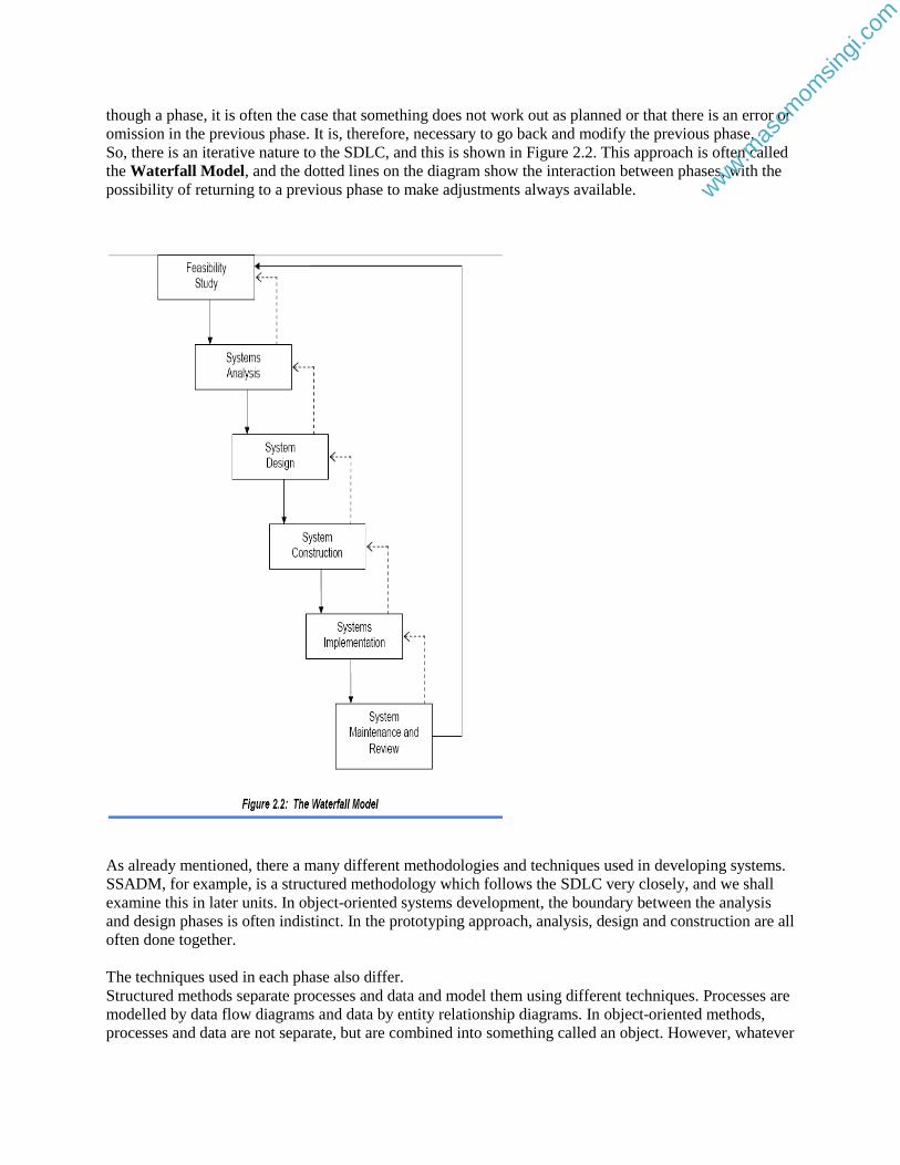
We have already looked at the life-cycle stages in an earlier unit, and saw that development work should
proceed in orderly steps, with the output from each step being checked against the definition of that step
before work proceeds.
Notwithstanding this point, though, we also saw that there must be some recycling, reworking of a
previous stage in the light of subsequent work, and constant referral back to the requirements
specification. In other words, it is an iterative process.
Figure 3.1 repeats the SDLC diagram from the previous unit and shows how the stages are interrelated
and how the whole cycle constantly involves referring back and going back to what has already been
done.
Key points and their Output
There are certain key points within the life cycle, for example:
Agreement of the specification of requirements (the key output of the Systems Analysis phase),
which should be clear, consistent and unambiguous to users as well as computer specialists.
Systems testing and hand-over to the users, as the key output of the Systems Implementation
phase.
These key points must be clearly identified and the outputs associated with them need to be:
(a) specified before work on the phase starts; and
(b) agreed as having fulfilled this specification before the phase is completed.
The detailed production of specified items at each stage allows monitoring to take place against the
schedule of key points. This not only demonstrates progress, but it also highlights any areas where
www.m
asom
omsing
i.com
problems might develop. It is most important that errors are discovered as early as possible, since their
continuation into later stages can cause major
problems, and particularly with the development of software, errors found at the operational
stage can cost fifty to a hundred times as much to correct as if they had been found at the
design stage.
Key points are sometimes called milestones and it is important that their position, and what
is to be delivered at that stage, are agreed with both purchaser and supplier. (Note that
purchaser and supplier may both be within the same company – for example, a user
department and the computer department.) If the supplier is external, it is important that the
actual people who will eventually be using the system are involved in its specification and
acceptance.
The Importance of Documentation
Documentation should be going on in parallel with the other activities and, at least at the
early stages, documents will be the items produced as output. These will need to be referred
to at later stages. For example, the requirements specification will need to be checked
against parts of the feasibility study and any major changes in plan discussed and agreed.
This requirements specification will be the basis against which the design is checked. This does not mean
that, once agreed, there can be no changes to the specification. Work carried out at the design stage may
show how improvements can be made. The specification, after full steering committee and user
consultation, will be altered to accommodate the improvements.
3.2 STATEMENT OF REQUIREMENTS
The first stage of all development cycles is a statement of requirements from the eventual user
department. As such, then, it is also known as the user requirement document and this forms the basis
on which the feasibility study will be conducted
This statement should specify what is required of the system, both functionally and financially. Note that
it does not suggest how these requirements will be achieved. Rather, it provides a general description of
the system which has to be designed, and acts as a general guide for the more detailed analysis and design
that will come later. Three elements can be seen as key to this statement:
(a) What is the system expected to do?
This must be a precise and full statement of the objectives of the system – mere generalisations are
insufficient. Wherever possible, the objectives should be given some measure so that the success of the
system, when operational, can be assessed.
(b) Who will use the system?
It is always important to identify clearly the eventual owners of the system. This is likely to be a
particular user department or section and this department/section will be responsible for accepting and
approving each stage of development. The identified department/section will be the primary contact for
the involvement of and consultation with users by the development team.
(c) What is the minimum the system must do?
It is important for the user department to specify the minimum requirements. Apart from reinforcing
ownership of the system at the outset, it also gives a better and more focussed outline of the requirements
and keeps the designer from developing an overcomplex system that does as much as possible rather than
just what is required. However, this initial statement should not be merely a technical statement, but
should also provide a context for the new system – demonstrating the effect that the system should have
System Selection
www.m
asom
omsing
i.com
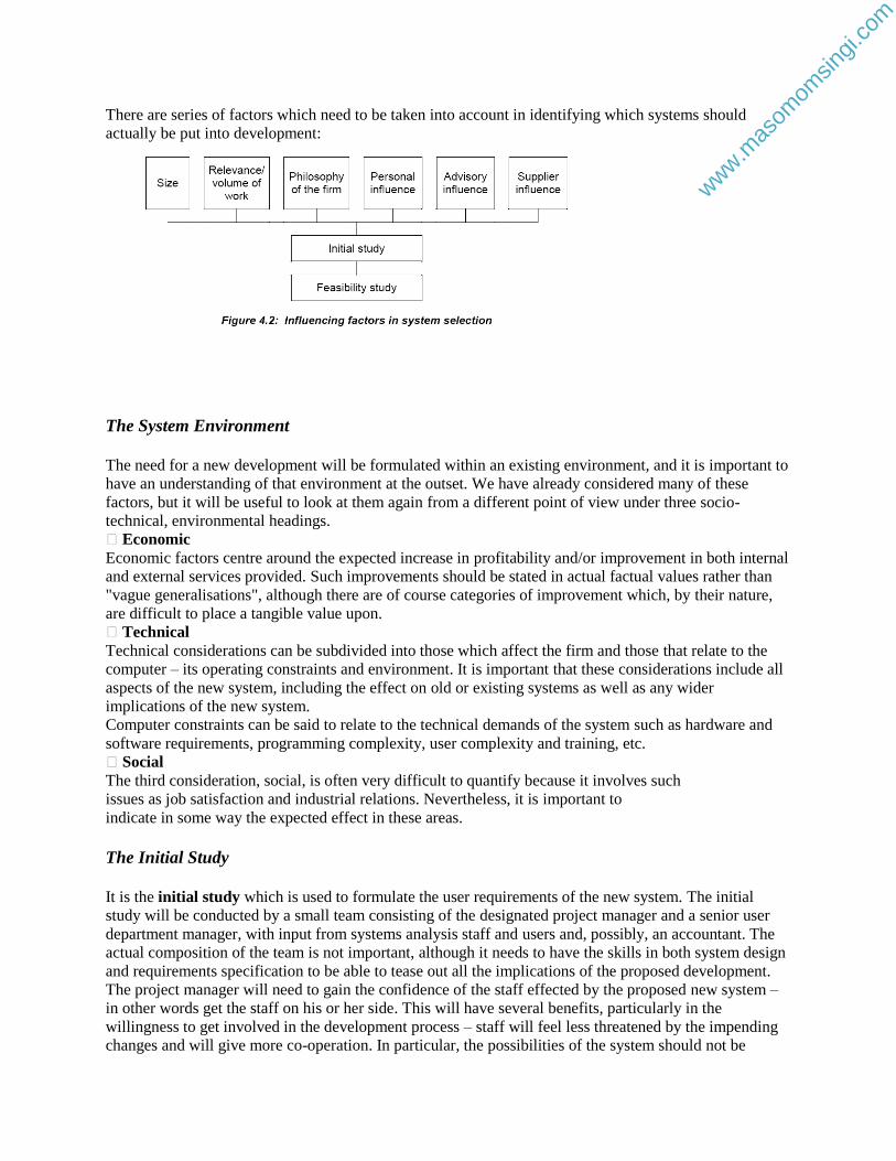
There are series of factors which need to be taken into account in identifying which systems should
actually be put into development:
The System Environment
The need for a new development will be formulated within an existing environment, and it is important to
have an understanding of that environment at the outset. We have already considered many of these
factors, but it will be useful to look at them again from a different point of view under three socio-
technical, environmental headings.
Economic
Economic factors centre around the expected increase in profitability and/or improvement in both internal
and external services provided. Such improvements should be stated in actual factual values rather than
"vague generalisations", although there are of course categories of improvement which, by their nature,
are difficult to place a tangible value upon.
Technical
Technical considerations can be subdivided into those which affect the firm and those that relate to the
computer – its operating constraints and environment. It is important that these considerations include all
aspects of the new system, including the effect on old or existing systems as well as any wider
implications of the new system.
Computer constraints can be said to relate to the technical demands of the system such as hardware and
software requirements, programming complexity, user complexity and training, etc.
Social
The third consideration, social, is often very difficult to quantify because it involves such
issues as job satisfaction and industrial relations. Nevertheless, it is important to
indicate in some way the expected effect in these areas.
The Initial Study
It is the initial study which is used to formulate the user requirements of the new system. The initial
study will be conducted by a small team consisting of the designated project manager and a senior user
department manager, with input from systems analysis staff and users and, possibly, an accountant. The
actual composition of the team is not important, although it needs to have the skills in both system design
and requirements specification to be able to tease out all the implications of the proposed development.
The project manager will need to gain the confidence of the staff effected by the proposed new system –
in other words get the staff on his or her side. This will have several benefits, particularly in the
willingness to get involved in the development process – staff will feel less threatened by the impending
changes and will give more co-operation. In particular, the possibilities of the system should not be
www.m
asom
omsing
i.com

overstated and information provided about the outcomes must be accurate and realistic. Raising people's
expectations and then not meeting them can demotivate staff and make them distrustful. On the other
hand, if staff on the current system are really heavily loaded, the prospect of improvements being made
could make a great deal of difference to people's attitudes.
User Involvement
This is another aspect that we have already noted, and we will return to it again. However, it is probably
one of the most important features of modern system development, and it is, of course, of particular
importance at this early stage. It is essential for the potential user of the future system to work with the
system analyst from the very beginning. This provides clear advantages, including:
acceptance of every stage of the development;
ensuring the design meets the user needs;
making the provision of training easier as there is a user representative who understands the
system.
Other advantages are training within user areas of development staff and establishing good relations
between all computing staff and the users. Thus, not only do the development staff understand the user's
requirements, but the user understands the project as well.
3.3 THE PERSONNEL INVOLVED
The Computer Professionals
There are three key groups of specialist computer professionals involved in systems development –
systems analysts, systems designers and programmers. However, the exact demarcation lines between
analysis, design and programming are not very precise and vary from organisation to organisation. In
some companies the programmers will design detailed file and report layouts, working from an overall
specification provided by the systems designers. As the use of programming aids becomes more
widespread, and the work involved in detailed coding is therefore reduced, this division between different
kinds of computer professionals will become even more blurred. It is, though, a useful distinction to
draw in order to consider the roles involved at different stages in the development process.
(a) The Systems Analyst
We can say that the general role of systems analysts is continually to update the information system of an
organisation. They will maintain a continual survey of information requirements and propose changes in
(or design new) systems, control the implementation of the designs and monitor their operation.
Systems analysts are responsible for the analysis, specification and implementation of computing or
computing-related projects assigned to them. It is thus essential that the analyst has both computer and
business knowledge and experience. The job has a very wide scope, and perhaps there is a need to divide
it into two – an investigator with business training and a designer with a background in computers.
(b) The Systems Designer
System designing can be defined as the act of analysing and documenting existing systems, and – more
particularly – the act of creating new systems meeting defined objectives. Systems designers can work in
one of two ways:
(a) converting an existing system (usually clerical) into another (usually computerised) system; or
www.m
asom
omsing
i.com

(b) creating an entirely new system to meet an entirely new need.
It is obvious, therefore, that the specification of requirements stage is again very important. If
management is looking for a sophisticated, far-seeing system but does not specify this, then what it may
find itself provided with is merely the existing system mechanised or computerised.
Essentially, the activities of system designers centre around converting what is to be done (given by the
requirement specification) into how it is to be done. They will thus have to undertake the following tasks:
Study the requirement specification and determine the overall system in terms of input, output,
processing and storage.
Design, in detail, the layouts of all output documents, reports and displays to be produced by the
system and define their expected frequencies and volumes, where these are not clearly expressed in the
requirement specification.
Determine the processing logic of the system; this will define the programs which are required, the
functions they will carry out and the order in which they will run.
Very carefully determine all the control, validation and audit procedures needed in the system, so that
these can be incorporated into the design at the appropriate places.
Design the input data layouts and define expected volumes, frequencies, etc.
Specify and design the secondary memory files; this will include detailed record design, file
organisation decisions, estimated volumes, update frequencies, retention periods, security and control
procedures.
Finalise the data specifications for input, output and storage to ensure nothing has been overlooked.
Design the manual procedures associated with the new system.
Define the system test requirements which are to be used, to ensure that the system is operating
correctly.
(c) The Programmer
Programmers take the very precise design specifications and turn them into computer code which can be
understood by the computer.
It is very important that they work closely with the design and code it as written and specified.
The programmer will run the tests of the code as set down by the designer. Any problems will be reported
back to the designer for changes to be made to the design.
The programmer will also be involved in the actual implementation of the system in order to provide any
necessary last minute coding changes.
A major area of work for programmers is in systems maintenance. During the operating life of all
systems, various bugs will appear in the code. A programmer is responsible for correcting these in
consultation with the designer. From time to time, enhancements will be proposed for the system and
again the programmer will be closely involved in coding the design changes.
Users as Clients
Gone are the days when computing staff were the sole technical experts and the people who relied on
their systems were known as "users", although you will have noticed that we continue to refer to "users"
in this course. Information Technology staff now use systems engineering techniques to develop products
for the requirements of users as clients – i.e. to meet what they, the eventual users, require. Such products
may even operate on the client's own hardware or may form part of a total facilities management service
provided by the IT department or external contractor.
A feature of business today is "total quality" and this introduces concepts such as:
Get it right first time/zero defects.
www.m
asom
omsing
i.com
Internal clients (other departments in the company).
Continual improvement.
It is now, therefore, more important than ever that the client participates fully in the design, development,
implementation and operation of the product.
We have already reviewed the structure project teams for this process. For the purposes of this study unit,
however, we shall consider the following categories of client:
senior management
junior management
client staff.
Depending upon the size of system and organisation, there will be more or less overlap between these
categories. In a small business one person may perform all roles, whereas in a large organisation many
people may be involved.
(a) Senior Management
The client should be represented at a senior level by one person who is the final decision maker on all
matters relating to the project. He or she will make the "go/no go" decision at the end of each stage of the
development process, but is unlikely to be involved in the day-to-day activities of the project team.
Senior management's responsibilities can be summarised as:
agreeing terms of reference for the project
defining critical success factors
reviewing progress on a regular basis
"signing off" each major deliverable
agreeing budgets and schedules.
(b) Junior Management
These are the people who will have regular contact with, and may even be part of, the project team.
Working closely with the IT development staff they will need an appropriate degree of "IT literacy" and
have a good understanding of the methodologies being used. That is not to say they should be IT experts
since a good methodology will be readily understandable by most people.
They are likely to be managers/supervisors from the departments most affected by the introduction of the
new system and thus in a good position to define the detailed requirements. During the operational phase
of the system they will be key players in ensuring its success.
The responsibilities of junior management can be summarised as:
Defining detailed objectives.
Confirming "deliverables" meet client requirements.
Making recommendations to senior management.
Assisting in quality assurance.
Participating in client acceptance.
Helping to design training procedures.
Participating in training activities.
Assisting the implementation process.
Using the implemented system.
(c) Client Staff
www.m
asom
omsing
i.com

These are the people who will be using the system on a day-to-day basis. Some may be involved in the
development process as part of the project team but their main responsibilities will be to:
Assist the development process.
Undertake training.
Assist in client acceptance testing.
Use the implemented system.
Provide input to the post-investment appraisal.
Ensuring that the system is being designed to meet the "right" requirements is a key element of any
successful project. The client has a major responsibility in this process not only in confirming the critical
success factors, but also at a more detailed level.
The various development methodologies place great emphasis on diagrams on the basis that "a picture is
worth a thousand words". The methodology can thus help the client as well as the IT staff to confirm that
the design is aimed at meeting requirements. It is very much an individual decision on the level of detail
one can expect a client to confirm, with the norm being that such involvement is restricted to the top two
or perhaps three levels of the structure.
In the case of especially important aspects of the design it may be necessary to involve the client in much
more detail and, if the client is willing to devote the appropriate level of resources, the more one is able to
do this the greater should be the eventual benefit. Such involvement does not, of course, absolve the IT
staff from responsibility. The client's main role is to confirm what is required; the IT developers have
responsibility for confirming this is the case and also how best to achieve those defined objectives.
In terms of this initial stage, the client will confirm acceptance of the following prior to commencement
of the next stage of the project cycle:
statement of requirements/terms of reference
feasibility report
requirements definition.
As the development project progresses, whilst IT staff will have responsibility for ensuring that the
necessary project control systems are in place, clients will assist in the continual review of the process
through on-going by involvement in the detail of the project. Thus, for example, once an amendment has
been identified and the implications for cost and schedule are known, an appropriate client representative
should confirm agreement or otherwise to the change taking place. Junior management may "sign-off"
individual changes to certain limits, with significant variations requiring senior management approval. All
changes should eventually be submitted for formal review and approval by the senior client
representative. It would be unusual for even the simplest of projects to reach completion without some
problems arising and when these do, all participants, both developers and clients, should seek appropriate
solutions. Whether the client has forgotten to define a particular requirement, or the IT staff have
underestimated the time for a particular task, the situation is perhaps best resolved by discussions at an
appropriate level in the project team structure.
3.4 SYSTEMS INVESTIGATION
The actual project development begins with a very full investigation by the systems analyst. To establish
requirements and constraints, the systems analyst must elicit all the necessary facts from potential users
and all other interested parties.
The feasibility study, the production of a specification of requirements and the design of the system, all
require a considerable amount of investigation. The results of the investigation must be fully recorded.
The Scope of Fact Finding
www.m
asom
omsing
i.com
"Investigation" is concerned with the review of what is known now, the discovery of the previously
unknown, and the structuring of experiments to find out facts about known areas and unknown ones.
Merely finding out about what is known is insufficient. Systems investigation should include such
activities as model building, "brainstorming" and simulation, as well as experimentation- techniques,
therefore, that are often regarded as going beyond the fairly straightforward concepts of the interview, the
questionnaire, observation and document analysis.
(a) Problems
The most essential feature of any fact-finding technique is that the facts so found must be correct. A
number of factors can distort the truth of facts discovered:
The facts may be distorted, intentionally but more likely unintentionally, by the person presenting
the information.
The communication containing the facts must be interpreted by the person receiving it and the
interpretation may distort the truth.
The written word creates potential difficulties when the writer and readers do not know each
other.
Observation of the actions of people does not always reveal the true facts, as again it is subject to
the interpretation of the observer; also, the person observed can disguise what is actually being
done – how else does the conjurer operate?
These problems can be overcome provided systems analysts take steps to ensure that all facts are
thoroughly checked. They must also be aware of the distortion they themselves may impose.
(b) Sources of Information
Each project may be concerned with different sources of information – some may rely on internal, others
on external data.
As far as the current system is concerned, users are the most important source. It is they who are aware of
the significant and trivial facts. However, a worker within the system may easily have been misinformed
or have misunderstood the duties of a colleague; conflicting information about a system is not at all
uncommon. The supervisor may not know all the procedures undertaken by staff; duplication of effort is
common.
Most investigations start by looking at the current system, and documentation for this will vary greatly in
quality. Occasionally, it is found to be correct to the smallest detail, or alternatively, it may be almost
non-existent.
(c) What Facts are Required?
If it were possible to list the facts that should be obtained during a systems investigation, then a systems
analyst's job would be easy. This cannot be done because no two systems are alike, but it is possible to
give guidelines that pertain to most commercial applications. Systems analysts must use their common
sense when following these guidelines.
The organisation's range
This includes not only the products or services supplied, but also the number of people employed, the
number of suppliers' and customers' accounts serviced, etc. – in other words, any items relevant to the
area under investigation.
www.m
asom
omsing
i.com
Details of items in the range
The quantities, values, descriptions and fluctuations are required. In addition, the
type of code numbers and their range are very important.
Volumes
Once the type of data has been established, the volumes, receipt and dispatch of documents, peaks and
troughs in data flow, etc. must be recorded.
Calculations
It is necessary to record precisely the calculations performed, particularly with regard to fractions,
rounding-off, and the degree of accuracy required.
Movement
Documents will move between departments in the organisation and also in from, and out to, other
organisations. These movements will probably be shown diagrammatically.
Exceptions
It is relatively easy to record what the usual procedures are. Because the exceptions occur infrequently
and unpredictably, it may be difficult to identify them. Most of the problems that occur after the computer
system has been implemented result from the exceptions that were not recorded during the systems
investigation.
Staff
An organisation chart will be helpful, and details of the number of different grades of staff and a brief
description of what they do should be obtained. In this context it is important to ensure that the data
gathered reflects the actual situation in force. In other words, care needs to be exercised to ensure that the
organisation chart and supporting documentation have been accurately updated upon each change in
organisational structure.
(d) How are These Facts Gathered?
Asking
This is the holding of discussions, whether formal or informal, between the investigator and the staff who
operate the system. Interviewing may be one method here, although this suggests a more formal and
stereotyped approach. Often, many useful ideas and suggestions can be obtained by an informal chat.
Before systems analysts commence this work, they should arrange, via the department head, a convenient
time to approach staff and have at least an outline (or, better still, a list) of the facts required. It may be
impracticable to visit personally all the staff involved, because they may be at branches scattered
throughout the country or there may be too many of them. If the facts required are of a relatively simple
nature, a questionnaire could be drawn up and despatched.
Observation
www.m
asom
omsing
i.com

Systems analysts will spend a great deal of time in the department being investigated; they will be asking
questions, examining records, etc. During this time, they will be in a position to observe what is
happening. For example, they may notice:
(i) excessive staff movement
(ii) some very busy clerks and others with much spare time
(iii) frequency of file usage
(iv) communication problems both within the department and outside.
Reading
There may have been previous investigations of the department at present under scrutiny.
Systems analysts should read these records to help them understand the current system. However, too
great a reliance should not be placed on these documents, particularly if they were prepared some time
ago.
Other documents, such as policy statements, standing instructions, memoranda and letters pertaining to
the investigation should also be read.
Measuring and counting
The number of items, documents, transactions, people and time taken for individual processes should be
measured, either to confirm facts already recorded or to establish the current position. Sampling may be
used, but care should be taken to avoid bias. The frequency of different activities and events should also
be recorded.
The organisational structure
The organisational chart of the user department will often highlight features useful to the investigation
and individual job descriptions will identify an individual's area of responsibility.
(e) Relevance and Verification
You may think that it is obvious that only relevant facts should be gathered. However, it is not always
easy to see what is relevant and what must be discarded. It is easy to gather large volumes of facts, but not
so easy to glean the important ones. Systems analysts should constantly refer to their terms of reference or
other documents setting down the areas to be investigated. Ideally, every single fact obtained should be
checked. Practically, this is not possible, and a degree of tact and diplomacy is often required where facts
are being questioned.
Analysts can find themselves in a consultative role if user staff are able to carry out the fact finding
themselves. Provided that the facts are being obtained correctly, this method is to be encouraged. It
involves the user staff right from the start, and enables them to look at their work objectively. They will
need encouragement to suggest changes, but they will most likely accept changes that they have initiated.
Interviewing
Personal interviewing is the most satisfactory method of obtaining information. It will yield the best
results provided it is carried out properly. The interviewers' approach, whilst being disciplined, can be as
flexible as the occasion demands, and they can pursue any lead provided by the respondent to obtain the
maximum amount of information. A good interviewer will achieve a balance between discipline and
flexibility in order to draw maximum benefit from the interview.
This method is often the only means of obtaining opinions from senior people, particularly where the
subject under discussion is highly technical. Such information is usually qualitative. Personal interviews
may also be the best means of obtaining a large amount of quantitative information from respondents.
Only a personal visit allows the researcher to see written material which the respondent may otherwise
forget or ignore.
Personal interviews are, however, time-consuming and expensive. Their use may, therefore, be limited to
a few key interviews, if the remaining information can be obtained in other ways.
www.m
asom
omsing
i.com
(a) Advantages
The main advantages of interviewing are:
The written word and its associated problems are eliminated.
An interview is a dialogue, which enables both parties to ensure that the other is not
misinterpreting what is being said; immediate correction is possible.
Important side issues raised during the discussion can be followed through immediately and
placed in context.
Since analysts are face to face with the other party, they can use appropriate language for the
discussion (this, of course, may demand considerable ability in the use of language by the
analyst)
(b) Disadvantages
The main disadvantages of interviewing are:
It may be necessary to interview a number of people in order to eliminate anydistortions caused
by each single interviewee; this can be very time-consumingfor the analyst.
During the interview, interviewees will be unable to carry out their normal tasks.
The technique relies heavily upon the skill of the analyst in creating a suitable environment to put
the interviewee at ease and to elicit the necessary facts. For example, if the interviewees feel that
their livelihood is at stake, they may be unwilling to co-operate or may deliberately give
misleading information in order to protect themselves.
Difficult situations can arise when a particular operation is not carried out at the "office floor"
level in the way managers think it is being carried out; the analyst's report must contain the true
facts of the situation, but the managers may, as a result, feel it is attacking their position and
competence.
Observation
A second method of fact finding available to the analyst is simple observation. Often, many more facts
can be obtained by watching a particular operation than by mere interviewing alone. But observation must
be accompanied by other methods, and analysts must know what they are looking for, prior to the period
of observation.
The technique can obviously be applied only when there is something to observe. Thus, it can be used
only to investigate existing systems, and then only to observe the actual working of the system. It cannot
be used to find out abstract information, such as the objectives or constraints. When investigating existing
systems, observations can act as a very useful cross-check on facts gained by other techniques.
A major problem with observation is that an analyst can never be sure that the operation he or she is
watching is not affected by his or her own presence. The person being observed will be conscious of the
analyst's presence and may work more carefully or quickly or slowly, depending upon his or her attitude
to the purpose of the observations.
Questionnaires
(a) Written Questionnaires
www.m
asom
omsing
i.com
Sending written questions to people may appear as an attractive technique, in that it saves the time needed
for interviewing. However, it is fraught with major problems.
It is extremely difficult to phrase questions which are unambiguous and make it clear exactly
what information is sought.
The replies to questions are subject to misinterpretation by the analyst, for similar reasons.
The analyst can never be sure that the questionnaire was completed seriously by the recipient. For
example, has the recipient really checked the facts written, or merely guessed?
Many recipients of questionnaires simply throw them in their waste-paper bins.
The results may thus not be a valid sample of certain opinions or facts. Expert advice on framing
questionnaires should be sought by the analyst, and possibly a junior member of the analyst's team should
help the recipients complete them. These two actions can alleviate some of the problems.
Questionnaires are a last resort method, to be used only when other methods are too time-consuming,
uneconomic or not practicable for other reasons. They are useful when a large number of responses is
sought.
(b) Use of Questionnaires in an Interview
A questionnaire may be required when collecting information from respondents by personal interview, for
the following reasons:
To ensure consistency of approach
Use of a standard questionnaire will ensure that the same questions are asked in the same way throughout
an assignment. This is particularly important when more than one interviewer is involved. The
questionnaire need not be rigidly structured, but it should always provide a guide for the interviewer. This
will enable a standardised approach to each interview to be adopted.
To achieve a logical flow of questions
It is often important to ask questions in a particular sequence in order to obtain accurate results. Some
questions should be asked only in the middle or at the end of an interview to avoid influencing a
respondent's replies to earlier questions. The interviewer often does not want to give too much
information at the beginning of an interview, as this would probably bias the respondent's
opinion.
To avoid omissions
It is essential to ask all the questions for which answers are required at every interview. An interviewer
can easily omit important questions during an interview if he or she is not working in a systematic way. It
may be difficult and time consuming to go back to the respondent once the interview has been terminated.
A questionnaire serves as a check-list of key questions, and thus avoids omissions.
To ensure data is collected in a form suitable for tabulation
Collecting information is not an end in itself. It must be processed, analysed and presented in a useful
form. The discipline involved in designing a questionnaire with a view to tabulating the answers, ensures
a logical flow of the questions that it is essential to ask, and eliminates the unnecessary ones.
www.m
asom
omsing
i.com
Sampling
Analysts will need to obtain some quantitative information about the systems they are studying. They
need to know the amount of time spent on particular aspects of the work:
How many invoices are processed each day?
What is the average number of items per invoice?
And the maximum number?
It is impossible for analysts to sit for hours on end, watching and recording every movement of the staff.
Neither do they have the time to examine many thousands of invoices in an attempt to get an accurate
count of the items of interest.
In each case, analysts will want to take a few figures, a sample, and use these figures as a basis for
calculation.
The fundamental problem is, how many figures is "a few", and how should the analyst obtain them? How
reliable are figures based on samples?
Using the theory of probability and the mathematics associated with it, it is possible to take a sample and,
from the characteristics, draw conclusions about the characteristics of the system from which we have
taken it. Since the theoretical knowledge required is fairly extensive, we cannot describe it here, and if
sampling is to be used to any extent, the analyst should take advice from a statistician. However, we will
briefly describe the ideas involved in sampling so that you are aware of the possibilities of using these
techniques in an investigation.
Sampling is a method for reducing the amount of observation which analysts have to do, as well as giving
them a "feel" for the numerical information which can be obtained from records.
The main lesson to learn is that averages are not a sound basis upon which to work.
When selecting a sample from a larger population, there are two main points to note:
The number of items in the sample must be large enough to avoid any abnormal items having an
undue effect on the average of the sample.
Every item in the population must have the same chance as any other of being in the selected
sample.
3.5 THE FEASIBILITY OR INITIAL STUDY
As a result of gathering and analysing facts about the existing system, the analyst will draw up a
feasibility study. This is an extremely important document as it is used to justify (or not) expenditure on
the development of a new system.
The proposals for new systems generally come from user departments. They draw up a short document,
the user requirements, setting out what is wanted. This is submitted to the steering group, who will pass it
to a small team for initial investigation.
The initial selection will have been based on relatively scant information, but the people carrying out the
feasibility study need terms of reference, which will be drawn up by management and based on the user
requirement.
Aims
www.m
asom
omsing
i.com
The aims of the study are to investigate the proposed system and produce a feasibility report which will
contain the results of the study and indicate possible methods of achieving the requirements. The
alternatives will be accompanied by cost/benefit comparisons, to assist the steering committee in deciding
which solution to adopt.
A very detailed investigation is usually unnecessary at this stage, as only broad estimates are required.
This also keeps the cost of the investigation to a minimum.
There are three aspects to the question of feasibility. We have already discussed these from the
perspective of influence on the proposed system:
(a) Technical
Is the current state of hardware and software technology capable of supporting the idea of the system?
(b) Personnel
Is the expertise of the systems development section sufficiently advanced to tackle (and successfully
achieve) the production of the system? Such a question must also be asked of an outside agency if it is to
produce the system. If the answer is "No", can the expertise be obtained by hiring new staff or training
existing staff? Is the cost of this justifiable?
Many modern systems are run by users themselves who may, or may not, have the support of an IT
department. With a small business system, it may be necessary to go back to the supplier if support is
required. In both cases, it is necessary to consider the personnel within the user departments when
deciding on the feasibility of a particular approach.
(c) Financial
Even if the system does provide an acceptable return on investment, is the capital available for outlay on
the project?
Determining the Main Requirements of the System
The assignment brief will have specified in general terms the requirements of the proposed system.
However, even at this preliminary stage, detailed requirements must be determined, otherwise the analyst
will be unable to envisage the total scope of the problem and thereby suggest possible solutions.
Initially, therefore, the team will conduct a survey of all interested parties to find out exactly what will be
required of the system.
(a) Main Characteristics
These will be defined in terms of the output information required. At this preliminary stage, the detailed
layouts and methods of presentation will not be needed, but the team will need to find out:
Volumes of output required.
Frequencies of the output.
Geographical location of the receivers of the information.
Response times to requests for information if on-demand output is required.
When the outputs have been determined, the team will be able to ascertain – again in general terms – the
volume, frequency, etc. of input data and the volume of stored data necessary to produce the output.
www.m
asom
omsing
i.com
(b) Main Constraints
Not only must the requirements of the system be known, but also any constraints on its operation. We
have indicated one of these above – that of geographical location.
Others might include:
Limitations caused by associated existing systems.
Financial and staffing considerations.
Statutory constraints.
Auditing requirements.
IT policies governing the inclusion of ultra-new technology (many firms will only use tried and
tested technologies – many "fingers have been burnt" by pioneering organisations).
Current computer equipment.
Environmental constraints.
Time, especially when information must be available at a particular time (as in a payroll system).
Performance in terms of throughput, response times with a given number of
users, etc.
Accuracy of output information.
Control and security procedures.
(c) Input Data
This section will describe all the input data. It will indicate the type of data, its quantity and frequency. If
relevant, it will define the structure and layout of the data when the design of input data documents is
outside the control of the systems designer. The medium for input may be a specific requirement.
(d) Output Information
All the output to be produced by the system will be specified in this section. Unless there is a specific
requirement, it may be left to the systems designer to prepare the actual layouts and presentation of the
information. However, this section will specify the elements of information required for each output, the
frequency and volume of output, together with the medium on which the output is to be presented.
(e) Validation Requirements
The data input to any automatic data processing system must be correct. It is important that the validation
procedures to be adopted in the new system are specified fully so that the designer can incorporate them
in the design.
This section will specify both the validation procedures to be adopted, and the ranges of values and other
associated information for every data element used by the system.
For example, a name must be given a maximum length, a code number, its check digit mechanism and the
range of values it can adopt.
In addition, if the system is to be on-line with direct data entry from keyboards, then the methods of
indicating errors and the action to be taken by the system should be specified, especially if the user is to
be allowed to make immediate corrections to any data erroneously input.
(f) File Requirements
Unless the system uses files created by other systems, it is usual to leave the file requirements to the
system designer. If the system does use existing files, then their details will be included in this section.
www.m
asom
omsing
i.com
This is a fundamentally important point with existing files increasingly being used to promote integration
throughout systems methodology.
(g) Enhancements
It is quite usual for a system to be specified with the intention of enhancing its facilities at a later date, or
for there to be a future system envisaged which will use the output or files of the specified system.
The system designer, in studying this section of the requirement specification, will be able to allow for
such enhancements and facilitate their inclusion in the future.
Considering Alternatives
When all the relevant facts have been collected, differing approaches to solving the problem can be
considered. The team should investigate solutions which have been found for systems with similar
requirements both within and outside the organisation.
Cost/Benefit Analysis
This is the most important aspect of the feasibility study as its results will be the main information from
which future decisions concerning the viability of the project will be determined.
Cost/benefit analysis is frequently used in management accountancy in order to compare solutions to a
given problem and, by using value judgements, to assess savings and losses made by various parts of the
system. Essentially, such an analysis attempts to place a monetary value on all aspects of a system. Some
aspects will create a cost (e.g. the purchase of computer equipment) and others will create income or
reduce cost (e.g. an increase in the number of transactions handled or the scrapping of existing computing
machinery).
The method is not as straightforward as it at first appears since some items – usually benefits – are greatly
influenced by subjective evaluation. For example, what is the benefit of providing a better service to
customers? How much will sales increase if the sales director has more information on which to base
marketing decisions?
When each aspect of each alternative has been given a monetary value, then their costs and benefits can
be compared. We can therefore identify three main parts to such an analysis:
(a) Determine the costs
These may be divided into four parts:
Computing costs – which start with the salaries and associated overheads for the systems
analysts as they perform the feasibility study and investigate the requirements of the new system
and then go on to develop and implement the system. This work may be carried out by people
from an outside company, in which case the costs will be easier to itemise. Also under this
heading comes the cost of any new computer hardware and any "bought-in" software. These can
be regarded as capital costs of the new system.
User department costs incurred during the investigation and implementation stages, which
include wasted productive time as a result of the investigation disturbing the normal flow of
business, education and training costs and "phasing in" costs when, for example, parallel running
may make some overtime necessary. These again can be regarded as capital costs.
www.m
asom
omsing
i.com
Operational costs, which include salaries and overheads of the people running the system (who
may be IT or user staff or both), consumable materials such as special stationery and disks,
communication costs (for example, telephone, if the system has some remote users) and hardware
and software maintenance.
Other costs – all systems must be monitored throughout their life to ensure that they continue to
fulfil the original requirements, or to check that the requirements still apply. The system may thus
require modification if it is found not to be achieving the best results. This evaluation and
modification is often termed "system maintenance" and can involve major expense, especially if
the design is poor and ease of maintenance was not allowed for in the system.
(c) Determine the benefits
These may be assessed under three headings:
Direct savings, which can be defined as a definite reduction in cost as a result of changing from
an old to a new system. These are fairly easy to identify and attach a monetary value to, and
because of this they are sometimes used as the sole measure of benefit. However, this is incorrect,
as the other two groups of benefits often give rise to much greater returns on the investment in the
new system.
Measurable benefits, which can be defined as "a monetary or financial return which accrues to
the organisation as a result of the operation of the new system". These are by far the most
important benefits to be balanced against the costs of the new system. They are often difficult to
assess, yet effort should be expended to assess their monetary value. One example is a purchase
ordering system which may produce great benefits by ensuring that the best possible terms for
bulk purchase discounts and early payment discounts are obtained.
Intangible benefits, which are those to which no monetary value can be attached. A new system
will usually provide improved information. For example, an on-line order processing system will
expedite the despatch of goods to customers. The organisation will thus provide a better service
than its competitors, and this should mean higher sales, but the level will be difficult to assess.
(d) Perform a comparison to determine the "best" approach
The most important comparison is between the measured costs and benefits of the alternative systems.
One might assume that this is a simple task of adding all the costs, subtracting this from the total of the
benefits, and the system showing the largest net benefit is the one to choose.
However, factors such as return on investment, inflation and risk have to be taken into account.
The Report
We can now list the contents of a typical feasibility report produced by the team of systems analysts on
completion of their investigation. These are as follows:
Restatement of the terms of reference.
Summary of the investigation (often the detailed findings are attached as an appendix to the
report).
www.m
asom
omsing
i.com
Identification of the requirements and constraints.
Descriptions of the solutions.
Detailed costings and benefits of each solution.
Summary comparisons.
Recommendations.
This report will be sent to that part of management which requested it; it must enable them to determine
the next course of action. Assuming that one of the proposed approaches is selected, then the next stage of
the project will be authorised.
3.6 REQUIREMENTS SPECIFICATION
The Requirements Specification is the output from the Systems Analysis phase. It should contain all the
information needed for the next phase, System Design. The detailed contents of the Specification will
depend upon which approach is being used for systems development. We shall use structured systems
analysis as an example.
The specification should include enough detail for the designers to design the computer processing, the
databases, the navigation and the user interfaces. In structured analysis, these would be supplied by:
A requirements catalogue
A set of required data flow diagrams
A set of process descriptions to support the bottom level data flow diagrams
A required entity relationship diagram
Entity descriptions
User roles
Function definitions
A matrix linking users to functions
Input/output structure diagrams and descriptions
Entity life histories.
It is these documents and diagrams that the designer uses to construct a logical design of the system.
Other approaches will use different techniques. Object-oriented systems, for example, will incorporate
"use cases" instead of data flow diagrams and class diagrams instead of entity relationship diagrams.
FURTHER READING
REVIEW QUESTIONS
1. What is system requirement?
2. State and explain the types of feasibility study
3. What is the role of a system analyst?
www.m
asom
omsing
i.com

A. Vision D. & Fitz Gerald D, Information systems development: methodologies techniques and tools,
McGraw Hill
CHAPTER FOUR
SYSTEM DESIGN
4.1 LOGICAL AND PHYSICAL DESIGN
The design of the logical system will take as its starting-point an outline model of user requirements.
Assuming that this is in the form of a data flow diagram, the process of logical design involves successive
refinement of the model until it meets all of the user requirements. The refinement normally starts with
the outputs of the system and works back via files (or stored data) to inputs and procedures, taking into
account the objectives and constraints that the system has to accommodate.
When the logical system has been defined to the satisfaction of the user, work can begin on detailed
physical system design, i.e. detailed specification of the way the system will operate in a specific
environment, using specific equipment and specific people. There are lots of tasks involved in physical
system design, covering all aspects of computer-based systems. For the sake of simplicity we will break
them down into a series of separate tasks, though, in practice, they would not be carried out separately or
in isolation.
The tasks we can identify are output design, input design, file design, program design, user procedure
design, forms and dialogue design, and security and controls. Any approach to computer system design
will involve all of these aspects in an integrated way. The design of files, for example, will be tied in with
the design of input; input must closely relate to forms and dialogues; all data (input, file and output) has
to be considered in relation to programs, and programs in relation to user procedures. In other words, they
all relate to one another and cannot be carried out without these relationships being optimized
.
Learning objectives:
By the end of the chapter a student shall be able to understand: Logical and Physical Design
The Design Stage
System Design Specification
Design Considerations
Human-Computer Interface
www.m
asom
omsing
i.com
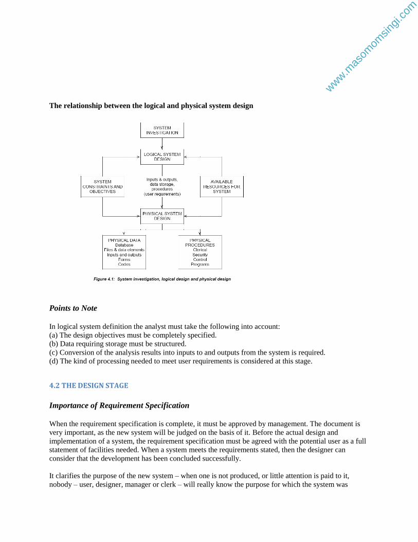
The relationship between the logical and physical system design
Points to Note
In logical system definition the analyst must take the following into account:
(a) The design objectives must be completely specified.
(b) Data requiring storage must be structured.
(c) Conversion of the analysis results into inputs to and outputs from the system is required.
(d) The kind of processing needed to meet user requirements is considered at this stage.
4.2 THE DESIGN STAGE
Importance of Requirement Specification
When the requirement specification is complete, it must be approved by management. The document is
very important, as the new system will be judged on the basis of it. Before the actual design and
implementation of a system, the requirement specification must be agreed with the potential user as a full
statement of facilities needed. When a system meets the requirements stated, then the designer can
consider that the development has been concluded successfully.
It clarifies the purpose of the new system – when one is not produced, or little attention is paid to it,
nobody – user, designer, manager or clerk – will really know the purpose for which the system was
www.m
asom
omsing
i.com
intended. It also has a major advantage for the designers in that they can design a system without
interference. (Without an agreed requirement specification, the user will often not accept that what is
produced is what was asked for, and will keep thinking of "improvements" to the system.)
The design stage of development should thus not be started until a formal agreement is reached on the
requirement specification. Ideally, the user department management and the commissioning management
should sign a written statement of agreement.
Influences on Design
Whether packages are used or a new system developed from scratch, inevitably the desired aims could
probably be achieved in several different ways, and so the final design is almost bound to be a
compromise based on a whole set of influences: cost, accuracy, control, security, availability, reliability,
and so on. The design must be acceptable to programmers and users.
(a) Cost
This will involve:
Development cost, including the current design stage. (The feasibility and analysis stages are
separately funded.)
Operations cost, including data preparation, output handling supplies and maintenance.
(b) Accuracy
This means appropriate accuracy, resulting from a compromise between error avoidance and the cost of
this.
(c) Control
The design must permit management control over activities, one facility of this type being the provision
of control data in the form of exception reporting.
(d) Security
This is a fairly complicated aspect of design, largely concerning data security and confidentiality. We
shall be referring to this later.
(e) Availability
This refers to availability of the resources which will comprise the operational system (staff, stationery,
software, space, etc.). This is the responsibility of the analyst in the sense that he or she must be sure that,
at the time of implementation, these are available.
(f) Reliability
The design has to be reliable, that is sufficiently strong in itself to withstand operational problems. In
addition, there must be alternative computing facilities as "back-up" in the case of breakdown, and
sufficient staff to deal with peaking of workload.
The Design Process
www.m
asom
omsing
i.com
System design is essentially a creative process, involving much conceptual thinking. Almost anyone with
a basic knowledge of computing should be able to design a computer system which would produce the
right results. However, there is a much more difficult part – namely to design a system which can be
implemented and controlled in practice, and which will not only produce the right results but will
additionally produce them to time and (especially) do so economically. It is in these latter areas that the
expert knowledge of the designer manifests itself, and it is these aspects which must be readily discernible
in the detail of the system specification.
We now take a quick look at the way in which we might approach the design process.
(a) Start with the Results
One approach to design is to consider the output requirement first; this is the main vehicle for achieving
the objectives. We look at the output from the point of view of content (the information to be produced)
and of format (the way in which this information is to be presented).
(a) Organise the Data
We need to input the variable and fixed information for each procedure we want to carry out. Derived
information will be produced by the computer and constant information such as report headings, etc. can
be built into the computer program.
(b) Design the logical system
(c) Design the physical system
The logical design will be shown to the user for approval or suggestions. When approval is obtained, the
physical design is prepared by the designer. It will consist of:
Screen presentations;
Input understandings;
Output understanding;
Processing descriptions.
The physical design implements the logical design in the technical specifications of the proposed system
so as to optimise the use of hardware and software. All the service requirements must be achieved, both
technical and administrative.
4.3 SYSTEM DESIGN SPECIFICATION
The designer receives the requirements specification and produces the systems design specification.
The requirement specification describes what is required from the system. The next stage is to decide
exactly how the system will be developed and implemented to meet these requirements.
A typical system design specification will contain an introduction, briefly highlighting the main
system requirements, and the following sections.
(a) General Overview
www.m
asom
omsing
i.com
This will define, in not too much detail, the facilities which the system provides. It will contain a system
diagram, and will give the environment and basic operations philosophy of the system and describe its
interface with existing systems. Facilities will be presented in terms of the input, output and storage
provisions of the system.
(b) System Operation
Systems should serve distinct business processes. Thus there should be individual systems for each
business process and sub-systems for each activity within the business process.
The detailed specification of the logic of the system will be given. Essentially, this will show how the
input data is converted into output information and when the files are updated. Each program will be
shown and placed in relation to the other programs. Exact details of volumes of data and frequencies of
processing will be described, together with any special requirements for recovery and restart in the event
of system failure.
(c) Hardware and Software Requirements
This section will define in detail the hardware and systems software which must be available to enable the
new applications system to operate successfully. In particular, it will specify any new hardware or
systems software which must be obtained. If the new system is to operate within an existing computer
system, there may be little in this section, unless it requires additional hardware or software.
(d) Output Layouts
This section will contain detailed plans of the layouts of every output produced by the system.
(e) Input Layouts
This section will contain detailed plans of the layouts of all input to the system. This will also include
layouts for all documents to be used to collect data.
(f) Data Storage Specifications
Exact plans for every record to be used by the system will be specified, and the structure of the files or
database will be given.
(g) Detailed Specifications
This section of the design specification will be divided into a number of subsections. For each program or
module the following will be given:
A general functional description specifying the facilities to be provided by the program;
Details of input;
Details of output;
A detailed specification of any particular processing required, e.g. actions in the event of errors
validation procedures, any formulae to be applied, any standard subroutines to be used.
(h) Manual Procedures
www.m
asom
omsing
i.com
This section of the system design specification will define the clerical procedures for the new system.
(i) Test Requirements
Before a system can become operational it must be thoroughly tested to ensure that (as far as possible) it
contains no errors in the software, and that it meets the requirements laid down in the requirement
specification. This section will define in detail the tests to which the system will be subjected, to prove
that it has been correctly manufactured.
(j) System Set-Up Procedures
Unless a system is completely new, it will be replacing an existing computer or manual system. All the
stored data of the existing system will thus have to be transferred to the new system. This will be a once-
and-for-all task, but an essential one. The mechanisms for the transfer must be carefully designed. Their
design will be written in this section of the specification.
The mechanisms will be both manual and computerised, requiring the definition of special forms,
programs, clerical procedures, etc. – so much so that this section becomes a miniature design specification
in its own right.
(k) Glossary of Terms
A design specification will use jargon terms in order to be precise. The jargon used must be defined in
this section.
(l) Index
In a complex system, the specification will be very large, and an index to it will be a great aid.
4.4 DESIGN CONSIDERATIONS
Input Design
As you are already aware, commercial data processing comprises four main functions: input, output,
processing and storage. The systems designer will consider each and decide the most appropriate method
to be adopted. The designer must specify a complete mechanism from the origination of the data through
to its input to the computer. SIX important factors must be considered:
(a) The data capture system must be reliable and reduce the potential for error to a minimum. The
more separate stages there are, the greater the chance of error.
(b) The system must be cost-effective; the cost of reliability must not exceed the cost of errors,
should they occur. For example, there is little point in spending £10,000 per year on a very
reliable system which is error-free when a £5,000 system would eliminate most errors and the
errors would cost only £1,000 per year to correct.
(c) The geographical location of the places at which the data is originated will have a great effect on
the method chosen.
www.m
asom
omsing
i.com
(d) The response time for output must be considered. The faster the response time, the faster the data
capture system must be.
So, what kind of objectives should the systems analyst have as far as data capture and output are
concerned? We may categorise them like this:
to minimise the total volume of input, as far as is practicable;
to minimise the extent of manually prepared input;
to design input to the system so that the work in preparing it is as simple as possible;
to minimise the number of steps between origin of the data and its input to the computer.
Output Design
A screen display would thus be the most appropriate output. On the other hand, employee wage packets
must be printed as a permanent record for the employee.
4.5 HUMAN-COMPUTER INTERFACE
Between the user and the machine is what we call the human-computer interface or HCI. The interface
should be as clear and accessible as possible; consistent in how the approach to the machine is made and
how the machine responds; comfortable to use; and common sense should guide use of the machine.
Various styles of interface are available.
Command-driven Interfaces
With this type of interface, the user types in a command and the system responds with the appropriate
action. These interfaces are simple to design and use the keyboard for input. Command processing
languages have been developed which are based on simple system commands. For instance, the shell
language in UNIX is a very powerful command processing language and complex commands can be built
from a sequence of simple demands.
Usually there are abbreviations which mean the user does not have to spend extra effort in typing.
Alternatively, commands may be stored in files and different activities invoked by the user by executing
the files.
There are disadvantages in that users have to learn the command language and they are likely to make
errors when keying commands. These also require additional software to handle errors and diagnostics,
otherwise they are not popular.
These interfaces are not suitable for inexperienced users. It takes time to learn them. Careful
considerations have to be made in the choice of system commands. Meaningful abbreviations need to be
used while keeping typing to a minimum, although some systems allow users to redefine the command
names. Users who utilise more than one machine find this useful.
Menu-driven Interfaces
In a menu-based system, users have to select one of a number of possible choices. The user may type the
name, or an abbreviation for the choice, through the keyboard or use a mouse to indicate the choice. With
some touch-sensitive screens, choice can be made by placing a finger at the selection.
www.m
asom
omsing
i.com

These systems are popular for a number of reasons:
Users do not have to remember individual commands
Typing is minimal even for those who cannot type
It is impossible to make an incorrect choice and crash the system
Help can be provided at each stage and in context
Experienced users may find menu systems are slower than command-driven systems.
There are two types of menu in use, the pull-down and the pop-up.
The pull-down menu is on continuous display and picking up a title with a mouse causes the
menu to appear. Inappropriate options are displayed in grey and may not be selected.
The pop-up menu appears at the cursor position when the mouse button is pressed.
Graphical User Interfaces (GUI)
GUIs are now the most common type of interface. Most operate on a WIMPs basis where the user selects
the required options from the screen using the mouse. It is now common for new application system
developments to include a GUI interface.
One of the major benefits of the GUI approach is that the look and feel can be made consistent. This cuts
the times to learn a new package and it is also claimed that GUIs are instinctive, and experienced users
can easily switch between systems.
GUI and WIMP interfaces are popular because they are easy to learn. The user has multiple screen
interaction, and full-screen interaction is also allowed rather than the line-orientated interaction allowed
by command-driven systems.
Voice
This method of input is still not particularly common. The ability to recognise commands tends to rely on
the user speaking very slowly and clearly. The number of commands which can be recognised is still
quite limited.
Screen Design in Practice
Most modern computer systems include at least some input and output via a display screen and keyboard,
with programs running interactively and the user entering data at the keyboard in response to messages
appearing on the screen. The layout of the information on the screen, and the order in which it is
presented, is a most important part of the design of a system.
(a) Presentation of the Information
Seven points are important here:
How the procedures can be divided into suitable "interactive screens" so that data is input in a
logical order with only relevant responses being provided.
Layout, so that important information is not lost amongst the data appearing on the screen.
The order in which data is entered – this should not only be logical, but should also correspond
(wherever possible) with its layout on the source document.
www.m
asom
omsing
i.com
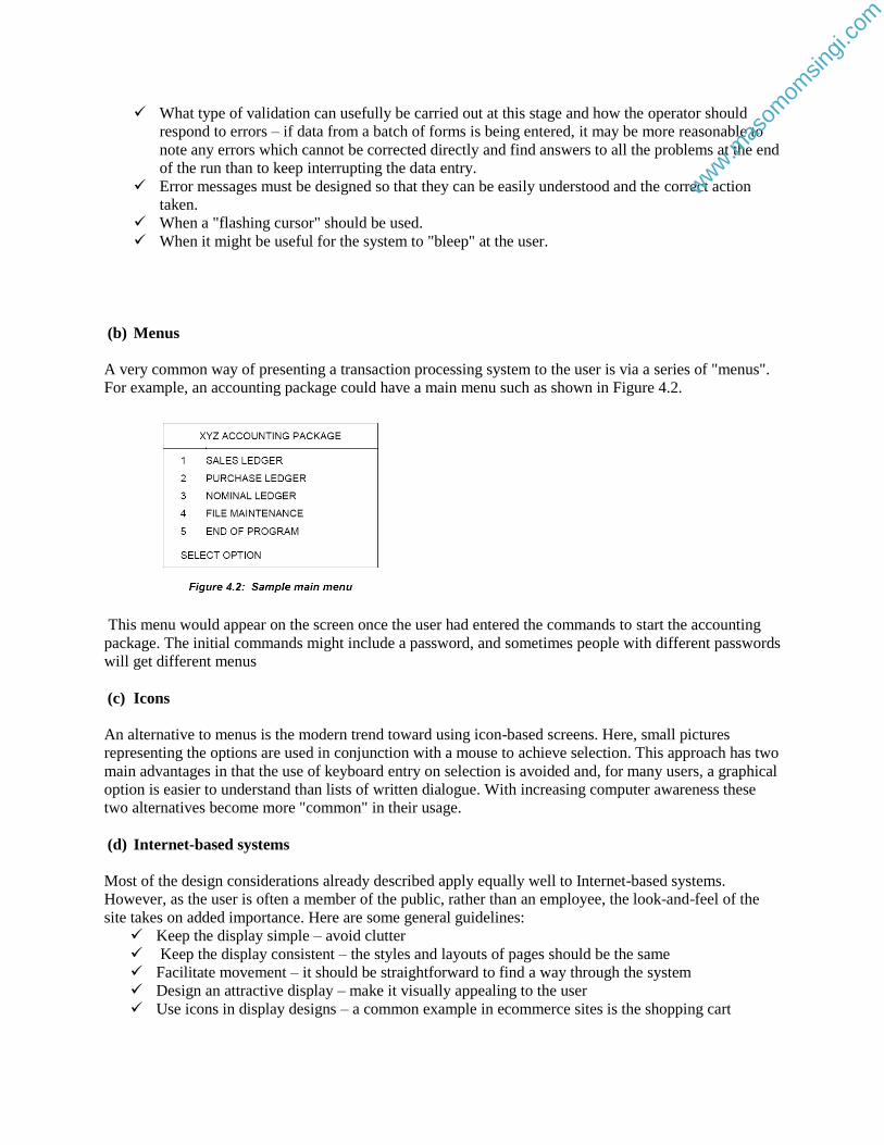
What type of validation can usefully be carried out at this stage and how the operator should
respond to errors – if data from a batch of forms is being entered, it may be more reasonable to
note any errors which cannot be corrected directly and find answers to all the problems at the end
of the run than to keep interrupting the data entry.
Error messages must be designed so that they can be easily understood and the correct action
taken.
When a "flashing cursor" should be used.
When it might be useful for the system to "bleep" at the user.
(b) Menus
A very common way of presenting a transaction processing system to the user is via a series of "menus".
For example, an accounting package could have a main menu such as shown in Figure 4.2.
This menu would appear on the screen once the user had entered the commands to start the accounting
package. The initial commands might include a password, and sometimes people with different passwords
will get different menus
(c) Icons
An alternative to menus is the modern trend toward using icon-based screens. Here, small pictures
representing the options are used in conjunction with a mouse to achieve selection. This approach has two
main advantages in that the use of keyboard entry on selection is avoided and, for many users, a graphical
option is easier to understand than lists of written dialogue. With increasing computer awareness these
two alternatives become more "common" in their usage.
(d) Internet-based systems
Most of the design considerations already described apply equally well to Internet-based systems.
However, as the user is often a member of the public, rather than an employee, the look-and-feel of the
site takes on added importance. Here are some general guidelines:
Keep the display simple – avoid clutter
Keep the display consistent – the styles and layouts of pages should be the same
Facilitate movement – it should be straightforward to find a way through the system
Design an attractive display – make it visually appealing to the user
Use icons in display designs – a common example in ecommerce sites is the shopping cart
www.m
asom
omsing
i.com

Use colour in display design – use contrasting colours for foreground and background and use
colour to highlight important fields. However do not overdo it.
FURTHER READING
A. Vision D. & Fitz Gerald D, Information systems development: methodologies techniques and tools,
McGraw Hill
REVIEW QUESTIONS
Compare logical design and physical design
www.m
asom
omsing
i.com
CHAPTER FIVE
APPROACHES TO SYSTEMS ANALYSIS AND DESIGN
5.1 STRUCTURED SYSTEMS ANALYSIS AND DESIGN METHOD (SSADM)
The Structured Systems Analysis and Design Method (SSADM), developed originally in 1980 for central
government use, provided a sound procedural framework for systems development from the beginning.
Since the early days of commercial computing, thousands of people have been involved in the production
of computer systems. Their results range from acceptable to disastrous. In general, there has been a great
deal of dissatisfaction amongst users of computer systems at the products they have been asked, or forced,
to accept.
Most of these were produced using "traditional methods" of development, usually meaning hardly any
method at all. Statements of requirements were produced in a rather sketchy manner, and as quickly as
possible in order to get on with what was perceived to be the real work – writing programs and
performing other activities associated with producing computer systems. In other words, producing a
physical solution before the problem had been fully understood. The results of this approach can be seen
in the form of systems which do not satisfy users' real requirements and which are difficult and sometimes
impossible to change.
Having been implemented, these systems usually consume significant amounts of computer department
resources in attempts to make amendments. This is known as "maintenance". Perhaps a better name for
much of it would be "retrospective analysis and design" since it is largely concerned with tacking on
processes and data which should have been incorporated, had they been discovered, during development
rather than after implementation.
Learning objectives:
By the end of the chapter a student shall be able to understand: Structured Systems Analysis and Design Method (SSADM)
Object-Oriented Analysis and Design (OOAD)
Web Information Systems Development
Rapid Application Development (RAD)
Joint Application Development (JAD)
Prototyping
CASE Tools
www.m
asom
omsing
i.com
It was because there has been an eventual realisation of the need to improve the product, that more
structured and rigorous methods of analysis and design were developed. One of these is the Structured
Systems Analysis and Design Method, more popularly known as SSADM.
Its purpose is to provide the analyst and designer with the tools and procedures to enable the production
of computer systems which provide what people want, and which are robust and capable of amendments
to cope with future changes. SSADM evolved through a number of versions during the 1980s and early
1990s, and the version described here is the most recent – SSADM4+.
SSADM consists of five modules, three of which have one stage and two of which have two stages:
1. Feasibility Study
2. Requirements Analysis
2.1 Investigation of Current Environment
2.2 Business System Options
3. Requirements Specification
4. Logical Systems Specification
4.1 Technical System Options
4.2 Logical Design
5. Physical Design
Each stage is broken down into steps – which are named and have unique numeric identifiers – and these
steps are further subdivided into tasks, which are identified by numbers within the appropriate step. This
is known as the default structural model which should then be modified to fit the particular
circumstances of the project. For example, for some projects, certain stages, steps and tasks may be
missed out completely, or certain steps and tasks may be modified. If you look back at the SDLC in Unit
2, you will see that SSADM covers the first three phases of the SDLC – feasibility study, systems
analysis and system design. It does not cover construction, implementation or maintenance and review.
What SSADM Will Do
Many computer departments and development teams engaged in the production of a new computer
system without the use of a standard development method, find themselves struggling with a
communication problem. Communication between themselves, that is, let alone user departments! How
do we communicate if not by the use of a common language?
If the language used is one which allows description of a physical computer system using such
documentation as program specification, system flowcharts, runcharts, program logic charts, etc., then
little communication is possible before the proposed system is designed, often in great detail and perhaps
even with some programs already written. At this time the die is very nearly cast when problems are
encountered in the design, changes are often difficult and complicated.
SSADM provides the means by which to communicate knowledge and perceptions about the
requirements right from the initial stages of system investigations when changes are relatively easy to
cope with. To achieve this, the method utilises techniques, such as data flow diagrams (DFDs), entity
relationship diagrams (or logical data structures, LDS) and entity life histories (ELHs), to provide
pictorial views of systems which can be used as both development and discussion aids. These three
techniques will be examined in detail in the following units.
Since these techniques provide views of systems from different perspectives – DFDs providing the
processing view, LDS the underlying logic of the data structure and ELHs the effect of time on the system
www.m
asom
omsing
i.com
– an amount of cross checking is available between the different views, invariably resulting in an
increased understanding of the requirements. This understanding is further enhanced by involving users
throughout development, the principle being that the common language resulting from the application of
SSADM can be understood by non-computer people.
The specification of requirements which emerges from the use of SSADM, describes the required system
in terms independent of any physical hardware and software constraints and characteristics, allowing the
decisions about physical implementation to be made quite separately.
SSADM is concerned with the production of a logical design which provides a basis for physical design
and implementation, with the aim of fulfilling the known requirements and also providing a design which
is amenable to change, enabling future needs to be incorporated with the minimum of effort and expense.
What SSADM Will Not Do
SSADM undoubtedly provides a sound procedural framework for systems development. Within this
framework lies the application of some very useful techniques. What the method does not do, is replace
the skills and expertise of the systems analyst and designer. Given these skills, the use of SSADM will
almost certainly produce better systems – those which meet the current need and are able to cope with
future needs. It is, therefore, a mistake to view the method, as some organisations have done, as a
substitute for trained and experienced staff. To do so is to invite disaster in the form of projects which
grossly overrun their planned time-scale and, in some cases, are never ending, i.e. abandoned.
Since one of the overriding principles of the method is that users should be involved throughout the
development life-cycle, it follows that there must exist an atmosphere of cooperation and enthusiasm for
the approach. SSADM cannot engender this. It must be created within the organisation, firstly by
management acceptance and secondly by adequate training and education. Only in this way can the
people involved gain an understanding of what can be achieved, their role in achieving it and the
commitment to make it happen.
SSADM is a method of analysis and design. The final output, essentially, is a physical data design,
program specifications and a plan for the programming and implementation phases.
It does not produce coding nor does it cover the use of program design methods. It is not intended to. It
also does not cover a whole range of activities associated with computer systems design and
implementation, such as equipment procurement, site preparation, etc., which must take place in parallel
to the SSADM tasks.
Impact on Project Time-Scales
It is often assumed that the use of the method will almost certainly extend the time-scale of the project
being undertaken. There is no real evidence that this assumption is true. Since it is unlikely that
information will be available as to how long a given project would have taken without the use of
SSADM, as opposed to with it, then usually no comparison can be made.
What is evident, however, is that a more complete system encompassing more of the users' requirements,
should emerge from the use of the method. What is also evident is that the taking of short cuts to
implementation becomes more difficult since, using SSADM, the development of a physical system in
terms of programs and files is likely to begin much later in the project life-cycle than would be the case
without its use. This severely restricts the developers' opportunity for implementing something which
satisfies only part of the requirement in the hope that the rest can be added later in that part of the life-
cycle referred to previously as "maintenance".
www.m
asom
omsing
i.com

Although SSADM is not a project control method, it is well suited to environments in which formal
methods of controlling projects are used. The decomposition of the work involved in developing systems
into specific stages, steps and tasks has two distinct advantages to the project controller – it provides a
basis for estimating and, through the existence of formal products signifying completion to a certain
point, a means of monitoring progress.
5.2 OBJECT-ORIENTED ANALYSIS AND DESIGN (OOAD)
During the 1990s there was a fundamental shift in the way information systems were developed. New
programming languages appeared on the scene such as C++, JAVA, C# and Visual Basic.NET. These are
object-oriented languages and are very different to the procedural languages of the 1970s and 1980s such
as COBOL and PL1. In order to analyse and design systems for object-oriented languages, new
techniques and methodologies were developed. These are much more dynamic and iterative than
structured approaches. These techniques use a modeling language called UML – the Unified Modelling
Language.
An object-oriented systems development life cycle will then be introduced – the
Unified Process Life Cycle.
The UPLC consists of four phases: inception, elaboration, construction and transition. Each phase
includes one or more iterations of analysis, design, implementation and testing of parts of the system.
(a) The Inception Phase
As this is the first phase, the emphasis is on business modelling, requirements, project management and
environment. The environment is about the way the development team will operate – what facilities will
be used, where they will work, how they will communicate with each other, what development tools are
needed, what training is required. There is normally only one iteration in the inception phase. Some parts
of the system may be designed and implemented, but this is usually to confirm that the planned
technology will work and that user requirements can be met. These prototypes are often then "thrown
away".
(b) The Elaboration Phase
www.m
asom
omsing
i.com

This usually involves a number of iterations and, during this phase, the core elements of the system are
designed and implemented. This involve several iterations of the requirements discipline to make sure
that the core elements are right. After this is done, the effort required for the rest of the project becomes
clearer and the estimates become more precise. Also the main purpose of the system – the business case –
is finalised.
(c) The Construction Phase
Now that the core elements of the system are complete, the construction phase deals with the rest of it.
Again, it will take several iterations. The user interfaces are finalised, controls are put in place, routine
functions are designed and implemented, help functions are introduced.
(d) The Transition Phase
The final phase involves one or more iterations and concentrates on the testing and deployment
disciplines more than the others. The users get involved in final user testing and the system is prepared for
implementation. After that of course, the system must be maintained and reviewed.
Comparison of the SDLC and the UPLC These two life cycles are very different. The SDLC is sequential and rigorous with one step finishing
before another starts. The UPLC is more dynamic and works in a continuous cycle of the development
process, evolving and refining as the cycle progresses. As with the SDLC, the UPLC should be adapted to
fit in with the needs of an organisation. There are a number of simplified approaches to the UPLC which
have a lighter touch and these are often referred to as agile development.
5.3 WEB INFORMATION SYSTEMS DEVELOPMENT
A typical web information system design methodology is made up of the following phases:
Requirements Analysis
Conceptual Design
Navigation Design
Adaptation Design
Presentation Design
.
A methodology which is more comprehensive is WISDM – Web Information Systems Development
Methodology. It is derived from Multiview, a methodology which attempts to fuse soft systems
approaches such as SSM with hard approaches. In WISDM, a project is considered as being made up of
five aspects, each of which can be treated alone or together with the others at different stages of a project.
These aspects are:
Organisational analysis – involving a range of stakeholders and concentrating on strategy
Information analysis – really a specification of requirements
Work design – attempting to address user satisfaction
Technical design – designing the software
Human-computer interface (HCI) – which addresses the user interface and relates work design
and technical design
This methodology is much more comprehensive and all-encompassing than the other design
methodologies. However, it remains to be seen which approach becomes the most successful.
www.m
asom
omsing
i.com
5.4 RAPID APPLICATION DEVELOPMENT (RAD)
Until fairly recently, all project development work was a lengthy and very slow process. The development
life cycle dictated a highly structured, standardised approach in order to cover each element precisely.
Over the last twenty years, though, the cycle has been broken down by the application of new methods
and techniques which may be grouped together under the general title of Rapid Application Development
(RAD).
There are four principal approaches within RAD:
Joint Application Development;
Skilled small team development, or SWAT (Skilled With Advanced Tools) teams;
Prototyping;
Computer Aided Software Engineering (CASE).
Underlying all RAD approaches is the active participation of the user in development. The user should be
involved in all structured development techniques. However, SSADM, for example, only requires the
user's approval of the separate stages; and sometimes to act as a reference point to clear up requirement
ambiguities. On the other hand, RAD requires the user to be part of the actual development team and not
just an approval/reference point. It is this involvement which enhances the speed of development.
5.5 JOINT APPLICATION DEVELOPMENT (JAD)
JAD is a technique particularly applicable to the requirements gathering stage of the life cycle.
It usually involves a series of intensive workshops between the users and the developers and it replaces
the conventional interview/questionnaire fact-finding activities. During the workshops the exact
requirements are identified by those who have the authority to agree them. The development staff, who
will also be expert in business applications, will help with technical design matters which arise and then
record the agreed requirements, often using CASE software tools.
Following the JAD sessions, the development staff will prepare detailed models of the proposed system
using the agreed requirements. These models are then presented at further JAD meetings and the decision
to go ahead will only made at these meetings.
It is important to get the right mix of people together at these workshops, most notably involving a range
of stakeholders, people who have knowledge of and commitment to the system, and others who have the
authority to agree to the way forward.
One of the main advantages is that the JAD team members take ownership of the system and commit
themselves to its successful implementation.
5.6 PROTOTYPING
www.m
asom
omsing
i.com
The models which are prepared following either detailed structured methods or the JAD sessions are
essentially pictorial representations of the system. They may be used to build a prototype, or initial
working version of the system.
Prototyping is a useful development tool. It is a screen-based development tool, the two main features of
which are:
(a) Users should be involved in development.
(b) Users do not know what they want until they see it.
The concept is that we view data as an important entity in its own right. So the first consideration is the
data. Alongside this we consider the type of structure that will hold the data. By manipulation of a screen
interface, the data and the data structures are fashioned to particular requirements.
Techniques and Usage
Prototyping uses a special generator package. The construction is rapid, enabling the generator to go
through many interactions until the user sees a screen layout and dialogue which suits him or her. This
will, in fact, represent a data structure and data definition.
The technique involves sitting the user in front of a screen and, working closely with the systems
designer, evolving a screen interface satisfactory to the user.
The systems designer then goes away and develops the real system based on the prototype, using other
development tools and, in particular, a graphics package. Occasionally, the prototype is itself adopted as
the real system, but this is normally avoided because the prototype is generally inefficient in its use of
computer resources and, usually, will not contain all the features required by the user.
The prototyping technique has come a long way from its early days. Originally it was used for fairly
simple systems and to develop straightforward screen formats. Later it was realized that by getting the
screen correct, the designer had, in fact, developed an interface with the system itself. This made
prototyping a powerful tool as, with such a large user involvement, and bringing the system to a point
where it responds directly to the user, the designer was able to meet directly the requirements
specification as perceived by the user.
The designer is often keen to exploit this advantage and to use prototyping in even more complex project
developments. Not only that, but by using prototyping, and its necessary user involvement, at every stage
of development, the designer is able to enhance the project management and aim for a "getting it right
first time" approach, or as it is nowadays labelled, the "total quality approach".
Types of Prototyping
There are two types of prototype, depending upon the stage at which the technique is first
used.
If the prototype is used to define further the user requirements, the resulting whole system will be
coded, maybe even in a different language to that used for the prototype. This then replaces the
prototype, which is known as a "throw away prototype".
The second type of prototype is that favoured in a RAD environment. The prototype is repeatedly
refined until the final system evolves. This is "evolutionary or incremental prototyping".
Advantages and Disadvantages
Prototyping has many benefits:
www.m
asom
omsing
i.com

Most of all, it satisfies users, especially if it grows out of JAD sessions, as users are fully
involved;
It is quicker. It has only very necessary documentation and training occurs during the prototyping
sessions;
It produces a working solution;
It eases communication problems between users and development staff.
It does, though, have disadvantages:
The process is difficult to handle at first because of development staff inexperienced in the
technique, their lack of control during prototyping sessions and the probable lack of reasonable
prior planning;
It is difficult to prototype large systems because of their complexity;
Users usually want to use the prototype immediately without the necessary background support
work.
5.7 CASE TOOLS
CASE stands for Computer-aided Systems Engineering or sometimes Computer-aided Software
Engineering. CASE tools are really any software tool that can help in the development of an information
system. They can range from a simple diagramming tool such as Microsoft Visio to fully integrated
development environments such as those supplied by major companies such as Microsoft and Oracle.
Lower CASE tools help program design, coding, testing and documentation whereas Upper CASE tools
assist strategy planning, analysis and design activities.
CASE tools are used by professionals – programmers and system developers. However, nowadays, the
general public are developing their own web-sites and databases, some of them very sophisticated. A
number of tools have arisen to help with this – for example, Dreamweaver for web-site design or
Microsoft Access for database design. These tools are used by professionals as well, but are readily
available to everyone, and one can only see this sort of capability becoming more and more widespread.
A typical CASE tool provides a range of individual tools which can be combined in various ways to meet
the particular requirements of the development project. The minimum necessary components will be:
A graphical tool to enable the analysis and design models to be displayed and manipulated on
screen;
A data dictionary to hold common data definitions and hence avoid repeating this task;
An application generator to produce program code;
Management tools to aid the monitoring of the project and to produce the necessary
documentation.
Other facilities which can be provided by CASE tools are:
Maintaining and verifying consistency during development;
Prototyping directly with the user to produce acceptable screen interfaces.
Use of CASE
The benefits achieved in using CASE certainly outweigh the upheaval and cost of its introduction. System
development is much more streamlined and standardised due to the integration of all the development
activities. With the increasing complexity of systems and of new applications, organisations are beginning
to realise that integration of all the methods used is essential.
www.m
asom
omsing
i.com
CASE tools are of most use when linked to a development method. In doing this, the existing method
must be reassessed to accommodate CASE, with consequent retraining of technical staff.
CASE tools are particularly useful in keeping the compatibility between the models and the code. This
accounts for their usefulness in prototyping.
The one drawback, at present, is that the standardisation required throughout the industry is not yet in
place. As CASE operates through a variety of environments, from PCs to mainframes, it cannot be fully
adopted until full standardisation is agreed.
Integrated Development Environments (IDEs)
An IDE is provided by a software vendor to help in the planning, construction and maintenance of a
particular software product. They have built-in CASE tools which are specifically designed for the
software product. A good example is Microsoft's Visual Studio .NET, which includes development tools
to support a web-based development strategy.
Another example is Oracle Designer which goes alongside Oracle's widely-used database management
system. This models business processes and data and can eventually generate finished applications.
FURTHER READING
A. Vision D. & Fitz Gerald D, Information systems development: methodologies techniques and tools,
McGraw Hill
REVIEW QUESTIONS
1. Discuss at least three information systems development
approaches you know
2. In what environment would you apply the prototype
development model and why?
www.m
asom
omsing
i.com
CHAPTER SIX
DATA FLOW DIAGRAM
6.1 INTRODUCTION
Communication and information lines are vitally important to the smooth running of any organisation.
Where documents are passed through several departments or sections, the flow of information cannot be
easily described by narrative alone and is best shown through the use of different types of diagram.
A data flow diagram is a common and powerful way of showing this and is a fundamental part of
structured analysis.
6.2 AN EXAMPLE SYSTEM
Before we look at data flow diagrams, it will be useful to go back over some basic concepts.
You will remember that a system has inputs, outputs, processes and a boundary. The
Learning objectives:
By the end of the chapter a student shall be able to understand: Data Flow Diagrams (DFDs)
Levels of Data Flow Diagram
Drawing Data Flow Diagrams
Physical and Logical DFDs
Advantages and Disadvantages of DFDs
Joint Application Development (JAD)
Prototyping
CASE Tools
www.m
asom
omsing
i.com
processes can themselves be considered as sub-systems of the overall system.
Activity 1
Read the description of a purchasing system which follows:
The Department of Computer Science must purchase many items for staff and students. The
list of items is diverse and ranges from low value goods such as pencils (for staff to chew
thoughtfully!) to expensive computers (on which students will diligently produce high quality
assignments!).
When supplies of an item become low, staff will request that an item is purchased. The
request is first evaluated and, if accepted, a purchase order is produced by the purchase
order clerk. This is then sent to the favoured supplier for that item. A copy of the purchase
order is kept on file.
The supplier will then send the goods, together with an invoice for payment to the Computer
Science building. The items received are initially checked for damage. They are then
checked back to the purchase order to make sure only those items ordered were sent. The
invoice is also checked back to the purchase order to check that only those items ordered
are paid for. So there is a three way check between the purchase order, the goods received
and the invoice.
If there are discrepancies between what was ordered, what was received and what was
being charged for, then the supplier is contacted and the problem resolved. If all three are
consistent, then a payment will be made to the supplier. The member of staff who made the
request is then contacted so that they can collect the goods.
Assume that the members of staff who request items and the suppliers are outside the
boundary of the purchasing system and send and receive data and information across this
boundary.
Tasks:
(a) List the inputs to and outputs from the system. These should be documents or messages which
contain items of data or information. At this point in time, you can also list physical things.
(b) List the main processes in the purchasing system. (This may be difficult if you have never done it
before, but have a go anyway for now.)
6.3 DATA FLOW DIAGRAMS (DFDS)
Data flow diagrams are used to represent the system being analysed. There are a number of different
conventions for drawing DFDs depending upon the methodology being used. However, they all follow
the same basic principles. In this unit we shall use SSDAM conventions.
DFDs use four symbols:
www.m
asom
omsing
i.com
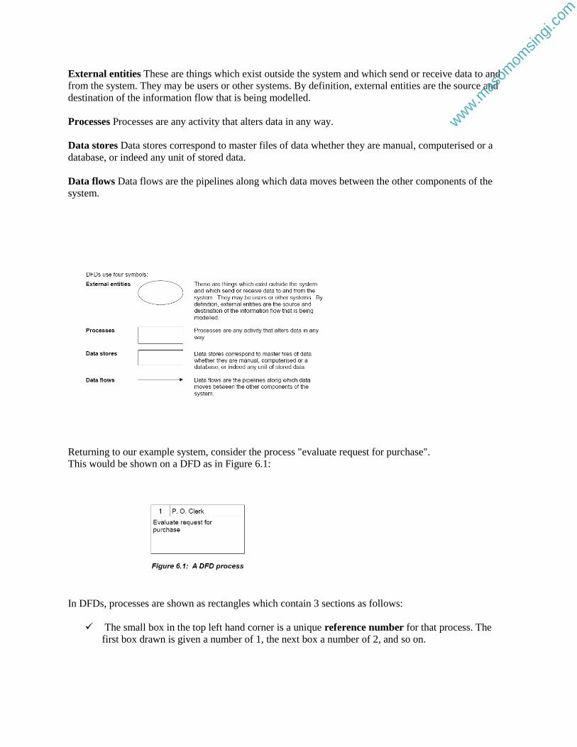
External entities These are things which exist outside the system and which send or receive data to and
from the system. They may be users or other systems. By definition, external entities are the source and
destination of the information flow that is being modelled.
Processes Processes are any activity that alters data in any way.
Data stores Data stores correspond to master files of data whether they are manual, computerised or a
database, or indeed any unit of stored data.
Data flows Data flows are the pipelines along which data moves between the other components of the
system.
Returning to our example system, consider the process "evaluate request for purchase".
This would be shown on a DFD as in Figure 6.1:
In DFDs, processes are shown as rectangles which contain 3 sections as follows:
The small box in the top left hand corner is a unique reference number for that process. The
first box drawn is given a number of 1, the next box a number of 2, and so on.
www.m
asom
omsing
i.com
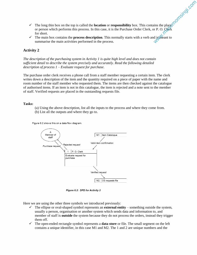
The long thin box on the top is called the location or responsibility box. This contains the place
or person which performs this process. In this case, it is the Purchase Order Clerk, or P. O. Clerk
for short.
The main box contains the process description. This normally starts with a verb and is meant to
summarise the main activities performed in the process.
Activity 2
The description of the purchasing system in Activity 1 is quite high level and does not contain
sufficient detail to describe the system precisely and accurately. Read the following detailed
description of process 1 – Evaluate request for purchase.
The purchase order clerk receives a phone call from a staff member requesting a certain item. The clerk
writes down a description of the item and the quantity required on a piece of paper with the name and
room number of the staff member who requested them. The items are then checked against the catalogue
of authorised items. If an item is not in this catalogue, the item is rejected and a note sent to the member
of staff. Verified requests are placed in the outstanding requests file.
Tasks:
(a) Using the above description, list all the inputs to the process and where they come from.
(b) List all the outputs and where they go to.
Here we are using the other three symbols we introduced previously:
The ellipse or oval-shaped symbol represents an external entity – something outside the system,
usually a person, organisation or another system which sends data and information to, and
member of staff is outside the system because they do not process the orders, instead they trigger
them off.
The open-ended rectangle symbol represents a data store or file. The small segment on the left
contains a unique identifier, in this case M1 and M2. The 1 and 2 are unique numbers and the
www.m
asom
omsing
i.com

"M" means that the file is manual. If they were computer files the symbols would be D1 and D2
where "D" stands for database. The rest of the space is taken up with the name of the file.
The labelled arrowed lines are data flows. They show the data which flows between external
entities, processes and data stores and the direction in which they flow. A common mistake is to
actually put a process on the data flow line – for example, students new to data flow diagrams
would sometimes put "File verified request" as a data flow instead of "Verified request". This is a
mistake. The data flow contains the data which actually flows from the process to the data store.
Filing is part of the process within the process box.
Activity 3
Read the following detailed description of Process 2 – "produce purchase order".
Every Monday and Wednesday, the P. O. Clerk takes all the unactioned verified requests from the
Outstanding Requests file and makes out a purchase order for each one. A standard pre-printed form
is used which includes a carbon duplicate.
For each verified request, the P. O. Clerk considers the items required. A list of suppliers is
checked and the best supplier identified. The supplier's name and address is written on the
purchase order. To add the items to the purchase order, the correct model number must be used. Once
again, the P. O. Clerk must look up the catalogue of authorised items where a model number is listed
against a description of the item. The model number and quantity required are added to the purchase
order. The P.O. Clerk then sends the green top copy of the purchase order to the supplier and files the
yellow carbon duplicate for future reference.
The verified request is marked as actioned and returned to the outstanding requests file.
Task:
Repeat the process you undertook in Activity 2 by listing the inputs, outputs, sources and destinations.
This time, though, construct a fragment of a data flow diagram as for the first process.
We can now combine the two data flow diagram fragments from Figure 6.2 and the answer to
Activity 3 into one, to show the completed process. Note that the two diagram fragments overlap, with
data stores M1 and M2 appearing in both diagrams. In the combined diagram these data stores should
only appear once.
The combined data flow diagram is shown in Figure 6.3.
www.m
asom
omsing
i.com
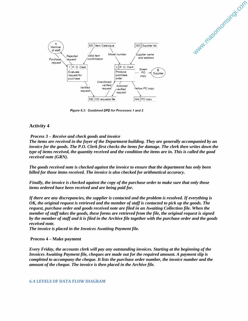
Activity 4
Process 3 – Receive and check goods and invoice
The items are received in the foyer of the Department building. They are generally accompanied by an
invoice for the goods. The P.O. Clerk first checks the items for damage. The clerk then writes down the
type of items received, the quantity received and the condition the items are in. This is called the good
received note (GRN).
The goods received note is checked against the invoice to ensure that the department has only been
billed for those items received. The invoice is also checked for arithmetical accuracy.
Finally, the invoice is checked against the copy of the purchase order to make sure that only those
items ordered have been received and are being paid for.
If there are any discrepancies, the supplier is contacted and the problem is resolved. If everything is
OK, the original request is retrieved and the member of staff is contacted to pick up the goods. The
request, purchase order and goods received note are filed in an Awaiting Collection file. When the
member of staff takes the goods, these forms are retrieved from the file, the original request is signed
by the member of staff and it is filed in the Archive file together with the purchase order and the goods
received note.
The invoice is placed in the Invoices Awaiting Payment file.
Process 4 – Make payment
Every Friday, the accounts clerk will pay any outstanding invoices. Starting at the beginning of the
Invoices Awaiting Payment file, cheques are made out for the required amount. A payment slip is
completed to accompany the cheque. It lists the purchase order number, the invoice number and the
amount of the cheque. The invoice is then placed in the Archive file.
6.4 LEVELS OF DATA FLOW DIAGRAM
www.m
asom
omsing
i.com
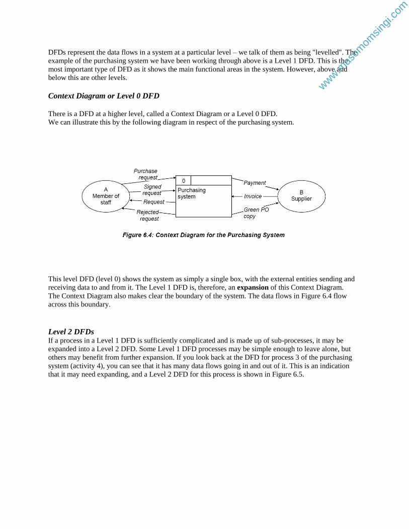
DFDs represent the data flows in a system at a particular level – we talk of them as being "levelled". The
example of the purchasing system we have been working through above is a Level 1 DFD. This is the
most important type of DFD as it shows the main functional areas in the system. However, above and
below this are other levels.
Context Diagram or Level 0 DFD
There is a DFD at a higher level, called a Context Diagram or a Level 0 DFD.
We can illustrate this by the following diagram in respect of the purchasing system.
This level DFD (level 0) shows the system as simply a single box, with the external entities sending and
receiving data to and from it. The Level 1 DFD is, therefore, an expansion of this Context Diagram.
The Context Diagram also makes clear the boundary of the system. The data flows in Figure 6.4 flow
across this boundary.
Level 2 DFDs If a process in a Level 1 DFD is sufficiently complicated and is made up of sub-processes, it may be
expanded into a Level 2 DFD. Some Level 1 DFD processes may be simple enough to leave alone, but
others may benefit from further expansion. If you look back at the DFD for process 3 of the purchasing
system (activity 4), you can see that it has many data flows going in and out of it. This is an indication
that it may need expanding, and a Level 2 DFD for this process is shown in Figure 6.5.
www.m
asom
omsing
i.com
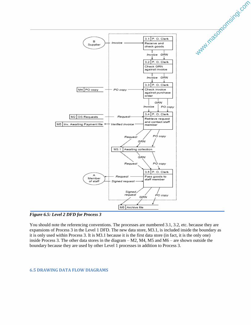
Figure 6.5: Level 2 DFD for Process 3
You should note the referencing conventions. The processes are numbered 3.1, 3.2, etc. because they are
expansions of Process 3 in the Level 1 DFD. The new data store, M3.1, is included inside the boundary as
it is only used within Process 3. It is M3.1 because it is the first data store (in fact, it is the only one)
inside Process 3. The other data stores in the diagram – M2, M4, M5 and M6 – are shown outside the
boundary because they are used by other Level 1 processes in addition to Process 3.
6.5 DRAWING DATA FLOW DIAGRAMS
www.m
asom
omsing
i.com
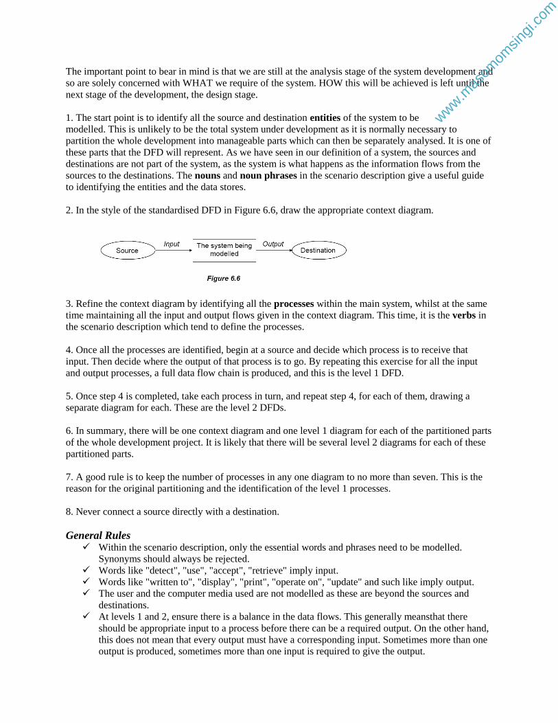
The important point to bear in mind is that we are still at the analysis stage of the system development and
so are solely concerned with WHAT we require of the system. HOW this will be achieved is left until the
next stage of the development, the design stage.
1. The start point is to identify all the source and destination entities of the system to be
modelled. This is unlikely to be the total system under development as it is normally necessary to
partition the whole development into manageable parts which can then be separately analysed. It is one of
these parts that the DFD will represent. As we have seen in our definition of a system, the sources and
destinations are not part of the system, as the system is what happens as the information flows from the
sources to the destinations. The nouns and noun phrases in the scenario description give a useful guide
to identifying the entities and the data stores.
2. In the style of the standardised DFD in Figure 6.6, draw the appropriate context diagram.
3. Refine the context diagram by identifying all the processes within the main system, whilst at the same
time maintaining all the input and output flows given in the context diagram. This time, it is the verbs in
the scenario description which tend to define the processes.
4. Once all the processes are identified, begin at a source and decide which process is to receive that
input. Then decide where the output of that process is to go. By repeating this exercise for all the input
and output processes, a full data flow chain is produced, and this is the level 1 DFD.
5. Once step 4 is completed, take each process in turn, and repeat step 4, for each of them, drawing a
separate diagram for each. These are the level 2 DFDs.
6. In summary, there will be one context diagram and one level 1 diagram for each of the partitioned parts
of the whole development project. It is likely that there will be several level 2 diagrams for each of these
partitioned parts.
7. A good rule is to keep the number of processes in any one diagram to no more than seven. This is the
reason for the original partitioning and the identification of the level 1 processes.
8. Never connect a source directly with a destination.
General Rules Within the scenario description, only the essential words and phrases need to be modelled.
Synonyms should always be rejected.
Words like "detect", "use", "accept", "retrieve" imply input.
Words like "written to", "display", "print", "operate on", "update" and such like imply output.
The user and the computer media used are not modelled as these are beyond the sources and
destinations.
At levels 1 and 2, ensure there is a balance in the data flows. This generally meansthat there
should be appropriate input to a process before there can be a required output. On the other hand,
this does not mean that every output must have a corresponding input. Sometimes more than one
output is produced, sometimes more than one input is required to give the output.
www.m
asom
omsing
i.com

The different levels must be consistent with each other. In other words, the data flows going into
and out of a process at Level 1 must all go into and out of the expansion of that process at
Level 2.
6.6 PHYSICAL AND LOGICAL DFDS
The sets of DFDs drawn so far in this unit are current physical DFDs. They model the current or existing
system, and they are physical as they show who physically performs the processes, what physical
documents flow around the system and what physical files are used. They show how the system operates.
Current Logical DFDs
It is normal practice to convert a current physical DFD into a current logical DFD. In a logical DFD, all
physical constraints are removed. They show what the system does, what is the purpose or policy behind
the system. So, for example, the fact that a copy of the purchase order is green is a physical thing. The
physical data flow "green P.O. copy" would be replaced by the logical data flow "P.O. data". Also, the
physical data stores M2, M4, M5 and M6 can all be replaced by one logical data store called purchasing
database, which contains purchase orders at various stages of their life together with associated invoice
and payment details.
Figure 6.7 shows a logical current DFD of the physical one in the final representation of the
purchasing system (in activity 4).
Figure 6.7: Current logical DFD for the purchasing system
You will see that the logical DFD is simpler than the physical DFD. Many processes are separated in
physical DFDs because of necessary time delays. For example, outstanding requests are collected and
filed because the clerk raises purchase orders only on a Monday and a Wednesday. This is a physical
reason. There is no logical reason why the purchase orders cannot be raised as soon as the request is
approved. Hence, processes 1 and 2 in the physical DFD are merged into one process in the logical DFD.
www.m
asom
omsing
i.com
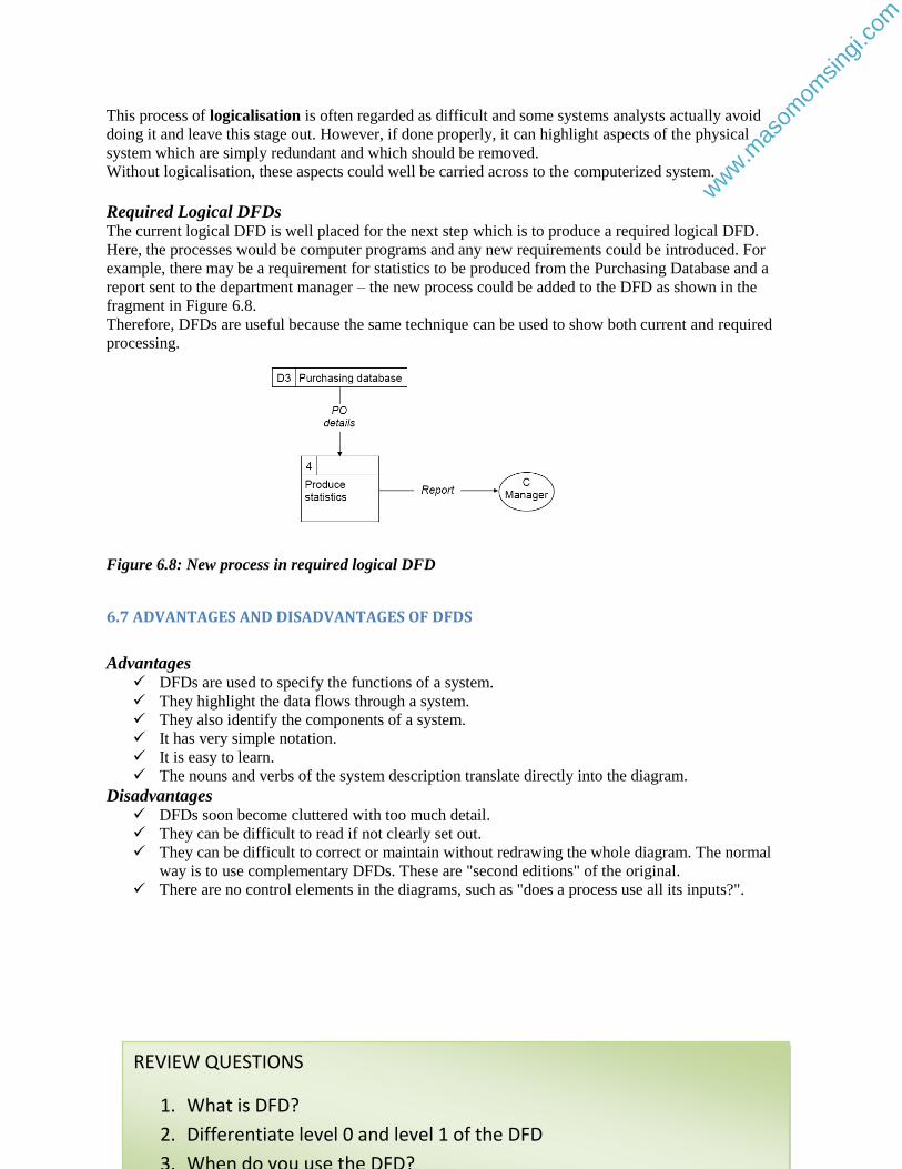
This process of logicalisation is often regarded as difficult and some systems analysts actually avoid
doing it and leave this stage out. However, if done properly, it can highlight aspects of the physical
system which are simply redundant and which should be removed.
Without logicalisation, these aspects could well be carried across to the computerized system.
Required Logical DFDs The current logical DFD is well placed for the next step which is to produce a required logical DFD.
Here, the processes would be computer programs and any new requirements could be introduced. For
example, there may be a requirement for statistics to be produced from the Purchasing Database and a
report sent to the department manager – the new process could be added to the DFD as shown in the
fragment in Figure 6.8.
Therefore, DFDs are useful because the same technique can be used to show both current and required
processing.
Figure 6.8: New process in required logical DFD
6.7 ADVANTAGES AND DISADVANTAGES OF DFDS
Advantages DFDs are used to specify the functions of a system.
They highlight the data flows through a system.
They also identify the components of a system.
It has very simple notation.
It is easy to learn.
The nouns and verbs of the system description translate directly into the diagram.
Disadvantages DFDs soon become cluttered with too much detail.
They can be difficult to read if not clearly set out.
They can be difficult to correct or maintain without redrawing the whole diagram. The normal
way is to use complementary DFDs. These are "second editions" of the original.
There are no control elements in the diagrams, such as "does a process use all its inputs?".
REVIEW QUESTIONS
1. What is DFD?
2. Differentiate level 0 and level 1 of the DFD
3. When do you use the DFD?
www.m
asom
omsing
i.com
FURTHER READING
A. Vision D. & Fitz Gerald D, Information systems development: methodologies techniques and tools,
McGraw Hill
CHAPTER SEVEN
DATA MODELLING
Learning objectives:
By the end of the chapter a student shall be able to understand: Entities, Attributes and Relationships
Entity Relationships
Optional and Mandatory Relationships
Many-to-Many Relationships
www.m
asom
omsing
i.com
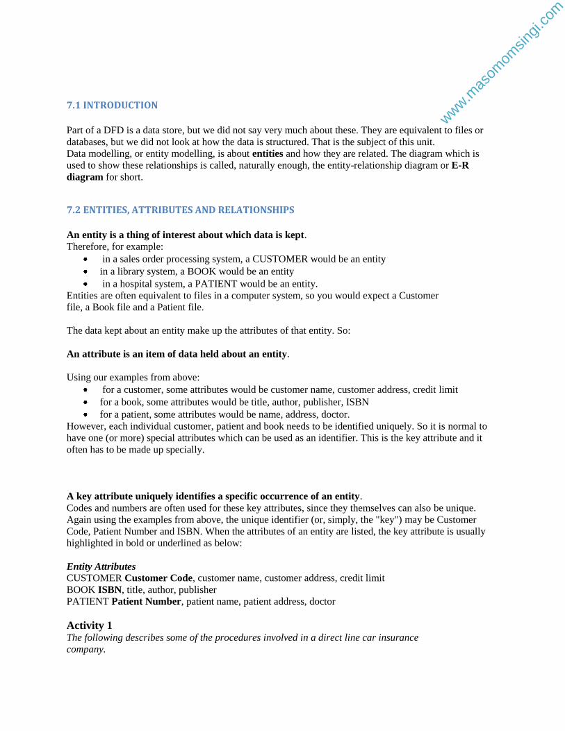
7.1 INTRODUCTION
Part of a DFD is a data store, but we did not say very much about these. They are equivalent to files or
databases, but we did not look at how the data is structured. That is the subject of this unit.
Data modelling, or entity modelling, is about entities and how they are related. The diagram which is
used to show these relationships is called, naturally enough, the entity-relationship diagram or E-R
diagram for short.
7.2 ENTITIES, ATTRIBUTES AND RELATIONSHIPS
An entity is a thing of interest about which data is kept.
Therefore, for example:
in a sales order processing system, a CUSTOMER would be an entity
in a library system, a BOOK would be an entity
in a hospital system, a PATIENT would be an entity.
Entities are often equivalent to files in a computer system, so you would expect a Customer
file, a Book file and a Patient file.
The data kept about an entity make up the attributes of that entity. So:
An attribute is an item of data held about an entity.
Using our examples from above:
for a customer, some attributes would be customer name, customer address, credit limit
for a book, some attributes would be title, author, publisher, ISBN
for a patient, some attributes would be name, address, doctor.
However, each individual customer, patient and book needs to be identified uniquely. So it is normal to
have one (or more) special attributes which can be used as an identifier. This is the key attribute and it
often has to be made up specially.
A key attribute uniquely identifies a specific occurrence of an entity.
Codes and numbers are often used for these key attributes, since they themselves can also be unique.
Again using the examples from above, the unique identifier (or, simply, the "key") may be Customer
Code, Patient Number and ISBN. When the attributes of an entity are listed, the key attribute is usually
highlighted in bold or underlined as below:
Entity Attributes
CUSTOMER Customer Code, customer name, customer address, credit limit
BOOK ISBN, title, author, publisher
PATIENT Patient Number, patient name, patient address, doctor
Activity 1 The following describes some of the procedures involved in a direct line car insurance
company.
www.m
asom
omsing
i.com
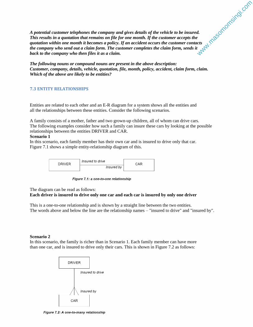
A potential customer telephones the company and gives details of the vehicle to be insured.
This results in a quotation that remains on file for one month. If the customer accepts the
quotation within one month it becomes a policy. If an accident occurs the customer contacts
the company who send out a claim form. The customer completes the claim form, sends it
back to the company who then files it as a claim.
The following nouns or compound nouns are present in the above description:
Customer, company, details, vehicle, quotation, file, month, policy, accident, claim form, claim.
Which of the above are likely to be entities?
7.3 ENTITY RELATIONSHIPS
Entities are related to each other and an E-R diagram for a system shows all the entities and
all the relationships between these entities. Consider the following scenarios.
A family consists of a mother, father and two grown-up children, all of whom can drive cars.
The following examples consider how such a family can insure these cars by looking at the possible
relationships between the entities DRIVER and CAR.
Scenario 1
In this scenario, each family member has their own car and is insured to drive only that car.
Figure 7.1 shows a simple entity-relationship diagram of this.
The diagram can be read as follows:
Each driver is insured to drive only one car and each car is insured by only one driver
This is a one-to-one relationship and is shown by a straight line between the two entities.
The words above and below the line are the relationship names – "insured to drive" and "insured by".
Scenario 2
In this scenario, the family is richer than in Scenario 1. Each family member can have more
than one car, and is insured to drive only their cars. This is shown in Figure 7.2 as follows:
www.m
asom
omsing
i.com
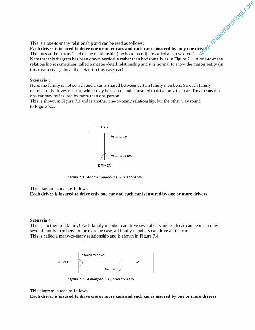
This is a one-to-many relationship and can be read as follows:
Each driver is insured to drive one or more cars and each car is insured by only one driver
The lines at the "many" end of the relationship (the bottom end) are called a "crow's foot".
Note that this diagram has been drawn vertically rather than horizontally as in Figure 7.1. A one-to-many
relationship is sometimes called a master-detail relationship and it is normal to show the master entity (in
this case, driver) above the detail (in this case, car).
Scenario 3
Here, the family is not so rich and a car is shared between certain family members. So each family
member only drives one car, which may be shared, and is insured to drive only that car. This means that
one car may be insured by more than one person.
This is shown in Figure 7.3 and is another one-to-many relationship, but the other way round
to Figure 7.2.
This diagram is read as follows:
Each driver is insured to drive only one car and each car is insured by one or more drivers
Scenario 4
This is another rich family! Each family member can drive several cars and each car can be insured by
several family members. In the extreme case, all family members can drive all the cars.
This is called a many-to-many relationship and is shown in Figure 7.4.
This diagram is read as follows:
Each driver is insured to drive one or more cars and each car is insured by one or more drivers
www.m
asom
omsing
i.com
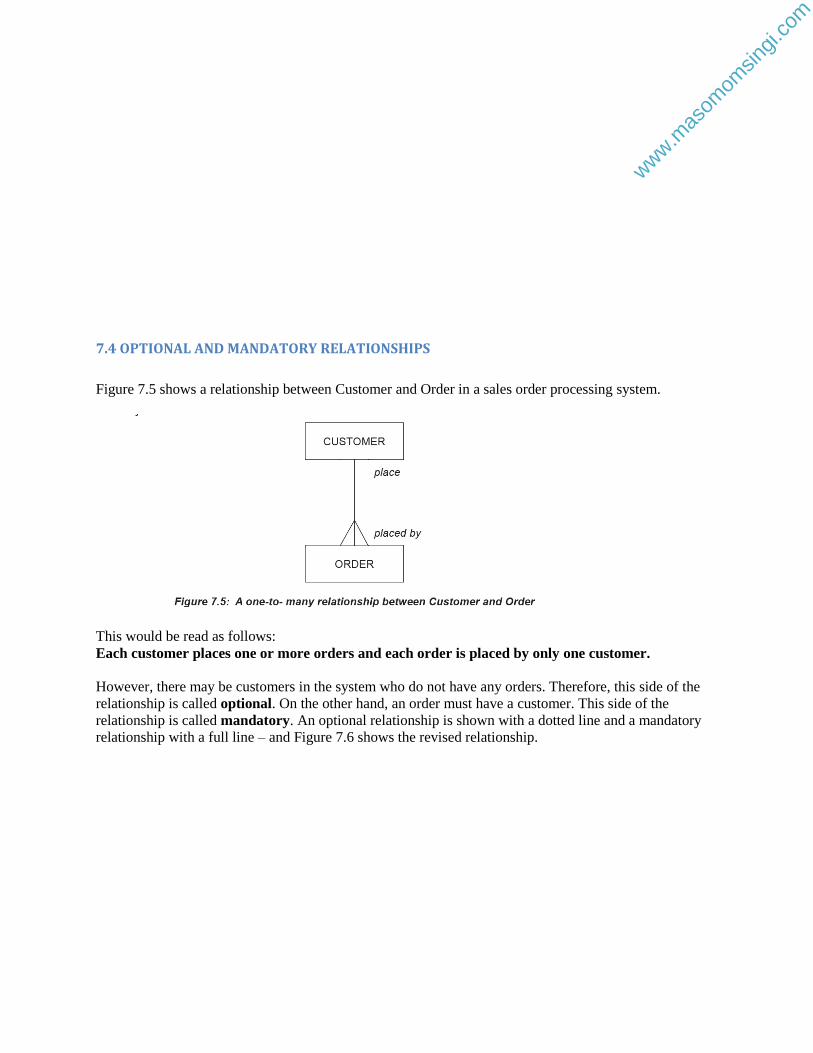
7.4 OPTIONAL AND MANDATORY RELATIONSHIPS
Figure 7.5 shows a relationship between Customer and Order in a sales order processing system.
This would be read as follows:
Each customer places one or more orders and each order is placed by only one customer.
However, there may be customers in the system who do not have any orders. Therefore, this side of the
relationship is called optional. On the other hand, an order must have a customer. This side of the
relationship is called mandatory. An optional relationship is shown with a dotted line and a mandatory
relationship with a full line – and Figure 7.6 shows the revised relationship.
www.m
asom
omsing
i.com
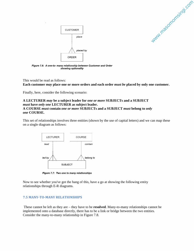
This would be read as follows:
Each customer may place one or more orders and each order must be placed by only one customer.
Finally, here, consider the following scenario:
A LECTURER may be a subject leader for one or more SUBJECTs and a SUBJECT
must have only one LECTURER as subject leader.
A COURSE must contain one or more SUBJECTs and a SUBJECT must belong to only
one COURSE.
This set of relationships involves three entities (shown by the use of capital letters) and we can map these
on a single diagram as follows:
Now to see whether you've got the hang of this, have a go at showing the following entity
relationships through E-R diagrams.
7.5 MANY-TO-MANY RELATIONSHIPS
These cannot be left as they are – they have to be resolved. Many-to-many relationships cannot be
implemented onto a database directly, there has to be a link or bridge between the two entities.
Consider the many-to-many relationship in Figure 7.8.
www.m
asom
omsing
i.com
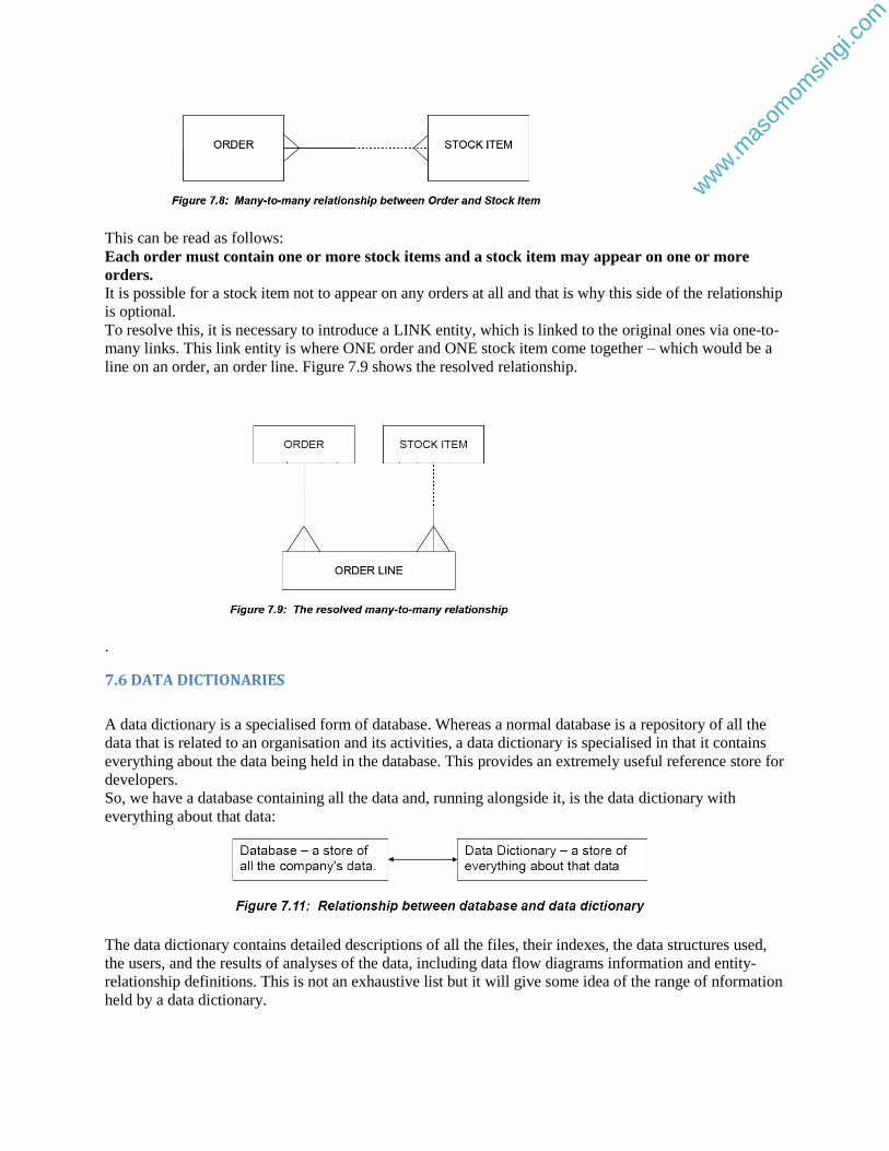
This can be read as follows:
Each order must contain one or more stock items and a stock item may appear on one or more
orders.
It is possible for a stock item not to appear on any orders at all and that is why this side of the relationship
is optional.
To resolve this, it is necessary to introduce a LINK entity, which is linked to the original ones via one-to-
many links. This link entity is where ONE order and ONE stock item come together – which would be a
line on an order, an order line. Figure 7.9 shows the resolved relationship.
.
7.6 DATA DICTIONARIES
A data dictionary is a specialised form of database. Whereas a normal database is a repository of all the
data that is related to an organisation and its activities, a data dictionary is specialised in that it contains
everything about the data being held in the database. This provides an extremely useful reference store for
developers.
So, we have a database containing all the data and, running alongside it, is the data dictionary with
everything about that data:
The data dictionary contains detailed descriptions of all the files, their indexes, the data structures used,
the users, and the results of analyses of the data, including data flow diagrams information and entity-
relationship definitions. This is not an exhaustive list but it will give some idea of the range of nformation
held by a data dictionary.
www.m
asom
omsing
i.com

Because everything about the information that flows through the company is held by the data dictionary,
it makes it an ideal tool when analysing a new system. It will reveal considerable information about the
existing system and, together with the data flow diagram technique, a
full analysis of any of the company's systems is possible.
7.7 INTERRELATIONSHIP BETWEEN THE DFD, ENTITY RELATIONSHIP
The data of the system which constitutes the entity-relationship model is the data contained in the data
stores of the DFD.
The Data Flow Diagram represents the flow of information within a system. It consists of: external
entities (source/recipient), data flows, processes, and data stores. While the diagram is very powerful,
there is still a need for some documentation to avoid any possible ambiguities in its interpretation.
The Entity Relationship Model describes the information actually held by the system and its
interrelationships. It consists of entities and relationships. Every entity consists of a specific list of
attributes that define it.
FURTHER READING
A. Vision D. & Fitz Gerald D, Information systems development: methodologies techniques and tools,
McGraw Hill
REVIEW QUESTIONS
1. What is ERD?
2. When can you apply the ERD?
3. Discuss the types of the ERD
www.m
asom
omsing
i.com
CHAPTER TEN
STANDARDS AND DOCUMENTATION
10.1 INTRODUCTION
It is perfectly natural to group standards and documentation together. This is because standards are
communicated and enforced through the documentation. To many data processing personnel, standards
mean documentation standards because, in many organisations, these are the only ones in existence.
Standards are uniform practices which govern the methods by which systems are developed and operated,
and provide a basis for assessing both system and personnel performance in terms of quality and quantity.
They give a clear understanding of what is required to both management and data processing staff.
Standard procedures have to be established for the development and operation of computer systems, but
this is not enough. Once set up and agreed, they must also be enforced. As new methods of working are
introduced, standards have to be updated to suit the new environment – enforcing out-of-date standards is
counterproductive.
Learning objectives:
By the end of the chapter a student shall be able to understand: The importance of standards and documentation
www.m
asom
omsing
i.com
Of course, documentation is much more than the communication and enforcement of standards. Modern
system development methods rely upon full and comprehensive documentation. Every step is fully
documented and all through the designs, the coding and the testing, information on each of the steps is set
out in manuals. Subsequently, the auditors, manager and quality assurance people can check the
documentation to obtain information on the steps. After implementation, the documentation will greatly
aid the maintenance staff.
10.2 TYPES OF STANDARDS
One of the benefits claimed for structured systems analysis is that it has a defined method of use which
produces a systems methodology standard. Similarly, defined methodologies with regard to structured
programming may form the programming methodology standard.
Documentation standards can run to many volumes. It is an extremely valuable asset to any organisation
to have a set of standards which set out in detail what is required to be documented on completion of each
activity.
All aspects of an IT Department's work should be standardised, in particular controls on development
projects, expected level of performance and operating methods.
Development Controls
Project control standards specify the method of planning and controlling the progress and quality of
systems development. They are concerned with the content of the work rather than its method of
execution.
Performance Standards
Performance standards set base lines against which actual performance is measured. In this sense,
performance standards are not estimates of how long tasks will take, but are used to specify how long
tasks should take. Their primary use is for comparison with actual performance to pinpoint deviations
that call for investigation and, possibly, action.
Operating Standards The operating environment is, in many ways, a more difficult function than systems and programming for
management control. Operating standards will need to cover:
Physical security procedures
File security procedures
Work log procedures
Error log procedures
Definition of staff responsibilities (probably complete job specifications)
Data control procedures
Computer operating procedures.
Benefits of Standards (a) Saving Time
www.m
asom
omsing
i.com
Elimination of indecision and the consequent economy in time are major benefits of standards. Good
standards reduce the amount of repetitive work and leave more time for the more challenging aspects of
development work – for example, problem analysis.
Suppose a project team is beginning the analysis activity, the major output of which will be the structured
system specification. The standards can immediately answer a whole series of questions such as:
What would be in the specification? and
Who authorises the work?
(b) Management Control
The management of all aspects of the department is greatly assisted by the use of standards.
All work is carried out to a prescribed quality that can be measured.
Monitoring of progress of work is easy, since all tasks follow a defined sequence.
Precise responsibilities can be allocated to staff.
Estimates of time-scales can be more accurately predicted.
Schedules of work can be prepared more easily.
Staffing levels can be determined.
(c) Improved System Design and Development
Standard procedures provide a checklist to ensure that important aspects of the development of a
system are not ignored.
Adequate documentation is produced at all stages.
Standard design methods ensure that similar systems are designed in similar ways, thus aiding
maintenance.
Programming standards ensure that reliable and well-controlled software is produced, and that
standard problems are solved in a standard way.
Well-defined maintenance procedures ensure that this expensive aspect of software development
is well controlled.
(d) Computer Operations
The standards in this area ensure that all computer and related operations are carried out correctly,
reliably and fully.
(e) Other Advantages
Training
When a set of standards is in force, the training of new staff is greatly eased since all aspects of the work
have been defined – the actual content of a training programme is clear.
Reduction of Dependence on Individuals
In a data processing department there is a fairly high rate of turnover of staff, especially in the systems
and programming areas. It is essential that the absence of an individual does not have a catastrophic effect
on the work of the department. The adoption of standards means that it will not be difficult for another
member of staff to take over, since the correct documentation will be present.
Improved Communication
(i) Standard presentation of information reduces misunderstandings.
(ii) A well-defined set of procedures ensures that all parties who should receive
information will, in practice, actually receive it.
User Documentation User documentation is a reference manual for experienced users, who will need to refer to it when queries
or exceptional circumstances arise; it also provides the basics for training of new staff.
Some modern on-line systems include "help" facilities, which reduce user documentation, but
do not make it completely unnecessary.
In general, users require documentation which tells them:
www.m
asom
omsing
i.com
What the system does and how it works.
How to provide input data to the system and how to control it.
How to identify and correct errors.
What are their particular responsibilities.
As described above, each user manual must be tailored to suit the system and the particular users but, in
general, the contents will include:
(a) An introduction giving a simple overview of the system.
(b) Running the system; when users run the system themselves, the user guide must
include details of how to switch on the equipment, call up the programs they use, and
also how to end sessions. In some cases, instructions for taking back-up copies of
data, etc. will need to be included.
(c) Input requirements: with some users, data input forms will need to be completed and
sent to the data input department. In other cases, users will themselves input the data,
either from individual source documents or in batches which have been assembled in
the user department.
(d) Output with examples of all the different types relevant to the particular users. Some of
these will be screen displays whilst others will be printed reports available either as
standard output or on request.
(e) Error messages: an explanation of all the error messages which might occur, together
with the appropriate action to be taken. This section should include details of the
person to contact if problems are experienced.
(f) Logging procedures: each installation should set up standards for manual logging of
any exceptional occurrences, with details of the action taken.
(g) A glossary of terms used.
(h) Index: all except the shortest of manuals should have a comprehensive index, since
the experienced user is likely to refer to it only occasionally but wants to be able to find
the specific item quickly.
FURTHER READING
A. Vision D. & Fitz Gerald D, Information systems development: methodologies techniques and tools,
McGraw Hill
REVIEW QUESTIONS
1. Discuss how and nature of standards can be used in system design
2. What is the importance of documentation in system analysis and
design
www.m
asom
omsing
i.com
CHAPTER ELEVEN
SYSTEM IMPLEMENTATION
11.1 THE IMPLEMENTATION PROCESS
The purpose of implementation is to put the theoretical design into practice. It can involve the installation
of a complete system or the introduction of a small subsystem. A particular project was selected. Its
objectives, requirements and constraints were defined in the requirement specification. A designer, or a
Learning objectives:
By the end of the chapter a student shall be able to understand: The Implementation Process
Changeover Strategies
Training
www.m
asom
omsing
i.com
team of designers, has specified a suitable system, in the systems design specification. Now, the designed
system must be developed and implemented. So, we can say that the aim of this phase is:
to implement a fully-documented operational system which meets the original requirements
according to the design given in the systems design specification.
Implementation involves the following activities:
(a) Writing, documentation and testing of all the programs required.
(b) Creation of all the master files required in the system.
(c) Preparation of user and data processing department operating instructions.
(d) Commissioning of the new system.
(e) Education and training of all staff who will use the system.
Implementation of a Package We have said that the possibility of using a ready-made package should always be investigated before the
decision is taken to write a tailor-made system. If it is possible to use a package, activity step (a) will not
be required. There may, however, be some subsidiary programs to write to supplement the package and,
often, these will be produced by the supplier. Some of the operating instructions will be supplied as part
of the package but these will probably require "personalising" to suit the individual company. In
particular, methods of collecting and entering data, and the control procedures connected with these
activities, will be unique to the company and, therefore, they will still have to be produced.
All the other activities, (b) to (e), will have to be carried out, and it may look as if we are not saving much
effort by choosing a package. This is not true, however, since the short description given under (a), often
covers months (or even years) of work. With a package, all the other activities can build on the foundation
of a tried and tested set of programs which can often be seen operating in another company before work
starts.
System Testing
The transfer to operational status should begin with a positive written statement by the project leader and
system designer to the effect that the system is fit for operation. This, of course, is the whole purpose of
the testing procedures.
System testing will follow a similar pattern to the testing of programs. First, simple files will be created
and the sequence of the data flow diagram followed. The output from each program will be scrutinised to
see that the data has been processed correctly.
One of the main errors that may come to light is the misinterpretation of the design specification, so that,
although a program works correctly in its individual tests, its input or output is not compatible with
another program. For example, one program may expect a data item to be three digits without allowing a
space at the beginning of a two-digit number (so that, for example, 12 has to be entered as 012), while
another will allow a space.
When the programs can pass data reliably between themselves, then the data is made more complex, until
there is sufficient confidence to use live data.
Systems testing builds up the confidence and experience of the users and data processing staff. Wherever
possible, data should be prepared on the new system's input forms.
File Conversion/Creation
When a new system is to be implemented, it is likely that the master files either do not exist, or, if they
do, that they are not organised as required by the new system. Before the system becomes operational, the
master files must be created. This can be a major task, and it may involve the production of a file-
www.m
asom
omsing
i.com
conversion system, with its own programs. This is expensive, because the conversion will be a once-and-
for-all operation, and the programs will be used only once.
With many systems, it is possible to enter the static data into the new files over an extended period of
time prior to the changeover to the new system, leaving only the dynamic data for later entry. For
example, product descriptions, code number, supplier details, etc. could all be entered into a product file
quite a long time before the stock levels.
When the time comes to enter the active (or "volatile") data, the data files must be "frozen", so that the
time chosen to do this is often over a weekend or other non-working period. Any transactions and
amendments that occur while the file is being created will then have to be entered.
As with the entry of static data, control totals should be used but manual checking of a listing of the files
will usually be necessary. Even so, however good the original data collection and the subsequent data
entry, some errors must definitely be expected. These will be straightforward mistakes, and also
omissions and conflicting data items. Therefore, a procedure for handling these as they are discovered
must be devised prior to the file-creation stage.
The users have to extract the required data from their manual records but, after it has been put on to the
computer, they have to check it for accuracy. If a system starts with inaccurate data, the confidence of the
users will very quickly be undermined, so it is most important that adequate time is allowed for this part
of the work.
Education and Training
An essential feature of the implementation of a new computer system is the education and training of all
staff associated with it. All staff must appreciate the objectives of the new system, and how it will
operate, as well as the facilities it will provide. Those staff who prepare data, operate the system and use
the output will require detailed training and practice.
The detailed training must be supported by adequate documentation. This will be the user manual which
is written by the system designer. There must be practice in the training programme. Special practice
sessions must be arranged, especially where there is a direct changeover, when there is no "running-in"
practice period of pilot or parallel running.
Training must also cover the procedures to be followed when something goes wrong. Many are the stories
of back-up copies being taken scrupulously every day, only to find, when they are really needed, that the
"recovery program" cannot read them. Training procedures should, thus, cover loss of data during a
session, owing to a disk which cannot be read.
Also, what happens if there is a failure in the electricity supply? Even if recovery is very simple, the first
time a screen goes blank in the middle of an operation, it can easily lead to panic.
Implementation Planning
The successful implementation of any system is based upon the following points:
A project control monitoring time, cost and quality of output.
www.m
asom
omsing
i.com
Managerial commitment and involvement at all levels.
Analysts who are good communicators and have a thorough knowledge of the organisation's
operations and applications.
The users' knowledge of and agreement with the system objectives.
Recognition of user responsibilities in the system development.
A computer manager capable of getting user support and of instilling confidence in users.
The planning must be very thorough and include all activities and related responsibilities to
make the new system work and to withdraw the old one with its documentation. In larger installations a
co-ordination committee will be appointed. Their purpose is to ensure a smooth implementation. The
analyst will be the committee secretary and will have the major responsibility. A timescale is established
and regular progress meetings are held to ensure the timescale is being kept to.
Implementation Personnel
As well as the specialist computing staff responsible for the implementation of a system, other personnel
have an essential role:
The business manager and user group, including those involved in the prototyping, will be
brought in to make the final test.
The technical manager will assist the users with the mechanics of actually running the
machine(s).
Hardware representatives will be consulted over problems and for general advice.
Consultants will be available for specialist advice on larger projects.
The administrative section will be advised of new personnel, job and responsibility changes and
all the necessary clerical backup; again this is applicable to larger projects.
11.2 USER INVOLVEMENT
The object of the transfer to operational status is to shift responsibility for the system from development
staff to the users. So users need to be involved in both testing and then transfer.
.
User Involvement in System Testing
Line managers will submit their own data and check the results of testing. This is incidentally, the most
difficult area of testing, owing to the need for the current procedure to continue until the new system is
proved and staff feel confident to undertake new tasks. There is also the problem of how staff can carry
out normal duties, while at the same time being concerned with their new roles.
User testing and carrying out totally new tasks may well involve evening and weekend working.
Checking outputs is not a familiar task, and the sheer amount of work involved may be daunting.
Managers may find it hard to check output which is in an unfamiliar form.
Despite such problems, though, attempts must be made to carry out tests involving the user as much as
possible.
User Involvement in Implementation
At the implementation stage, managers will formally accept the system. They will be closely involved in
clerical procedures and in staff training.
www.m
asom
omsing
i.com
In operation of the system, the line management must know the new duties that their staff will be required
to perform. They have to make sure that:
(a) Input data is being prepared correctly, and on time.
(b) New reports are being properly used.
(c) Their staff are able to use and understand the system.
During the project development period, the user management will have a great deal more work to do in
helping with the new system.
11.3 CHANGEOVER STRATEGIES
Importance of Successful Changeover
We now move on to consider the actual changing over of the systems. We are changing from a
development environment (old system working, new system being developed) to a maintenance
environment (old system abandoned, new system working).
The changeover implies changes in working practices: from clerical to computerised, from centralised
computing to distributed computing; from one type of machine to another; and so on. Staff tend to resent
change, and so to ease the way they must be kept fully informed, and in a direct manner. Any individuals
adversely affected must be told personally.
A perfectly sound system can be completely destroyed by poor changeover. To be successful, remember,
changeover has to have the support and involvement of managers and the co-operation of systems
staff and users.
Thus, prior to changeover, management must verify that the system does actually satisfy defined
information needs; that the equipment, software and staff necessary for successful changeover are
available; that control and audit procedures are in existence to ensure
It is the analyst's responsibility to ensure that staff information is complete and accurate, the object being
to obtain co-operation and a smooth, trouble-free changeover.
There are two basic methods of changeover – direct and parallel – and some variations of
these.
Direct Changeover Using direct changeover, at a specified time the old system is switched off and the new
switched on. This is advantageous in that resources are spared – the method involves the immediate
discontinuance of the old system. However, the new system must have been thoroughly tested so as to
minimise risks in initial operation. Should the new system meet with unexpected problems – hardware,
software, or design – then the old system may not be able to be retrieved.
As you will realise, this technique is potentially dangerous since it implies transfer of dependence from a
current working system to a new system which, although tested, has not been used in a real situation.
However, there are several situations where the technique is applicable or unavoidable:
In very small systems it is often not worthwhile considering any other technique, owing to the
inherent simplicity of the system.
In very large systems it is sometimes not feasible to maintain two systems simultaneously (as in
parallel and pilot running) owing to the work involved.
www.m
asom
omsing
i.com

Where there is little similarity between the old and new systems, the simultaneous running of
both systems may be unhelpful.
When direct changeover has been decided upon, it is usual to carry it out at a time when work is slack, to
assist staff to concentrate upon it. In direct changeover it is also important that everyone has confidence in
the new system. However, direct changeover is probably the most fearsome for staff and it is not
uncommon for absenteeism to rise sharply on the day of direct changeover or immediately thereafter.
Parallel Changeover
In parallel changeover the old and new systems are run with the same data until there is confidence in the
new system, whereupon the old system is dropped.
Parallel changeover or parallel running of the old and the new systems simultaneously allows a
comparison of output to be made between them. Any shortcomings of the new system can be rectified,
and continuous cross-checks made. This is the most common method of changeover, but it is important to
identify objectives, and a timescale must be established.
This method may be regarded as an extension of the testing of the new system, but this is really only a
sound approach if the two systems are really comparable, a somewhat unusual condition in real life.
There may be problems in the cross-checks. What, for instance, is the significance of any differences
between the old system and the new one which are discovered? Which is right and which is wrong?
Unhappily there is a tendency to put the blame for differences onto the new system! It may be that
differences arise merely from the greater sophistication of the new system.
Parallel changeover is often used so that the old system may still be operated when there is a breakdown
in the new system. If this is the main reason then there must be a specific limit to the number of
production cycles for which the parallel runs are to be carried out. What has to be remembered in this
particular context is that running in parallel means double the cost.
Another problem concerns the staff and other resources used to run the two systems together. There may
well need to be separate controls for the two systems, to be maintained and then reconciled. Where the
reconciliation is difficult, the period of parallel running may have to be prolonged. A delay such as this
could create tension and strain for the user department(s) because of the need to undertake two operations.
The objective should be to terminate the running of the old system as soon as is conveniently possible.
Phased Changeover
Within the two basic methods discussed above we find a number of variations, of which the most
common is phased changeover, where the new system is introduced in phases or stages as each stage is
implemented and operating correctly. The phases continue until the whole system is in operation.
This method would be used for very large information systems which possess many complex components
and which cross organisational frontiers.
The method consists of a series of direct changes. The implementation of each phase can be controlled,
and risk to the user department is thus reduced considerably.
www.m
asom
omsing
i.com
This method allows easier transfer of staff and is probably the most satisfactory method of working,
where it is possible. It permits thorough testing under real conditions while limiting the risk of system
failure. It requires, however, that part of the system functioning can be conveniently separated from the
rest. It also requires some additional clerical effort in handling two different systems simultaneously. This
method is sometimes called 'pilot running' (see later), although note that pilot running can also be
achieved under the parallel running method.
The great disadvantage of using any phased or pilot implementation is that users often have to wait many
months, or even years, for a system to be available to them which completely fulfils their needs. Their
needs may well change during the implementation period, and if their new needs are to be featured in the
system, the final system may never be seen. This 'moving target' phenomenon experienced in many
phased changeover implementations does much to frustrate and annoy both user staff and data processing
staff, and suggests that the original system as a whole was ill-conceived.
Pilot Running
Pilot running is usually used to mean where the new system is run under controlled conditions using old
data, where a small representative part of the old system is used as a test area
This is a similar concept to parallel running but is less disruptive – data from one or more previous
periods is run first on the old system and then on the new one. Timings are thus less critical, although
realistic timing and data capture/conversion are not simulated.
Changeover Methods Compared
We will now give a brief list of the main advantages and disadvantages for each of the above changeover
approaches.
(a) Direct Changeover
Advantages:
This is the simplest method: stop one system, start another. It is usually only undertaken over a
weekend or holiday period.
No extra work in running two systems together for a time.
Disadvantage:
Very high-risk – if the new system is disastrously wrong, it is difficult to recreate the old system.
(b) Parallel Changeover
Advantages:
This is a safer method as the old system is kept operational while the new system is brought in.
Much greater security.
Disadvantages:
Greater effort is needed to run the two systems and to compare the outputs.
It may not be very easy to revert to the old system should things go wrong. The new system may
handle the information differently, making it awkward to compare outputs.
The responsibilities of staff may well change between systems, leading to confusion.
Knowing when to make the actual changeover. This is usually a compromise between too short a
time, keeping costs to a minimum, and too long a time, allowing for extensive testing.
(c) Phased Changeover
www.m
asom
omsing
i.com
Advantage:
There is considerable control as only manageable chunks are being changed over at a time.
Disadvantages:
The system may not easily be split into phases.
The phases may well be different in the two systems.
The interfaces between remaining old system phases and the new system
phases already changed over, are extremely difficult to control.
(d) Pilot running
This is often the preferred method.
Advantage:
Considerable control is retained and no risks are taken even if direct changeover is applied to
each area.
Disadvantages:
Time is needed to collect and collate the data to be used.
The two systems may handle the data differently, making comparison of outputs difficult.
11.4 TRAINING
End-users will expect thorough training as part of their acceptance of the new system, and it is also in the
interests of the organisation that their staff should be properly trained in its use.
There are three aspects to be considered in developing effective training:
Who should be trained?
How should they be trained?
What levels of training are needed?
These questions can only be completely answered with a full knowledge of the system involved.
But generally:
Those who just need knowledge can attend a manufacturer's training school or attend targeted in-
house courses.
Those requiring a skill can go on specialist training courses, which can be conducted internally or
by the product manufacturer.
The training should be provided in relays, i.e. only so many staff at a time, whilst the others continue to
operate the old system and receive information and instructions relating to the new system. With careful
planning, the training should not create many problems. At all times, care should be taken with staff
problems and worries.
REVIEW QUESTIONS
Discuss different types of systems changeover
www.m
asom
omsing
i.com

FURTHER READING
A. Vision D. & Fitz Gerald D, Information systems development: methodologies techniques and tools,
McGraw Hill
CHAPTER TWELVE
SYSTEMS MAINTENANCE
12.1 MAINTENANCE PROBLEMS
Maintenance of systems cannot be avoided but it can be made easier if ease of maintenance is designed in
at the early stages of system development. In fact, maintenance is the principal reason for the employment
of analysts.
Maintenance activities must be fully documented to assist future maintenance
programmers.
When systems are changed, they become rather more complicated, cumulatively. Then, the user's
requirements change, so that they no longer conform to those specified when the original systems were
Learning objectives:
By the end of the chapter a student shall be able to understand: Different techniques of maintenance
www.m
asom
omsing
i.com
implemented. This, in turn, means that maintenance tends to be progressively harder, and uses more and
more resources as the systems become older. As a rule, we can say that experience teaches that a system
which is five to six years old is likely to need complete replacement, rather than modification.
This means that organisations which adopted computerised systems 20 years ago (or even a
decade ago) have many "vintage" versions. While users simply see a service which is
steadily worsening, the DP department is painfully aware that more and more of its efforts go
towards maintenance – often 50%, or even more!
Program Maintenance
Programmers tend to dislike maintenance as it can be very routine, repetitive and tedious. It
is necessary though.
Whilst predictable changes should be built-in to the system, unpredictable changes such as latent bugs,
law changes, changes in business practice will all have to be dealt with.
Maintenance Team
Large installations will probably have a distinct maintenance team. They have the responsibility to check
the documentation of new systems at the handover stage and to act as a quality control unit on the work
produced by the development team.
The maintenance team is an excellent training ground for new programmers and analysts.
Sometimes the development staff rotate with the maintenance team for specific projects.
This has the effect of spreading good ideas right through the development group.
In smaller installations, outside contractors are sometimes employed. In other instances a more ad-hoc
approach is used with whoever happens to be available being allocated the maintenance task. This lacks
continuity and is probably the worst option.
Database Back-up and Recovery
Databases are subject to much activity of a complex nature. From time to time, something
will go wrong.
A transaction error such as the wrong record being retrieved or a programming error being
highlighted.
The whole system going down due to power loss or software failure.
Complete or partial database destruction due to some natural disaster or major operator error.
Whichever fault occurs, it is necessary that the database be recovered. To make this possible, a back-up
strategy is necessary and a simple model is regularly to dump the database contents in a safe area (e.g.
copy it to separate disks), and to keep a log of all subsequent transactions to the next dump, and so on.
Clearly, the more frequent the dump, the faster and more complete the recovery. On the other hand,
normal database processing activities must be suspended during the dump, thus inhibiting the processing.
It is the Data Manager's responsibility to decide on a balance between frequent dumping and
uninterrupted processing. The balance will depend upon the nature of the data held and its security
sensitivity; the number of data updates made as opposed to simple accessing of the data; and the urgency
of uninterrupted processing.
The following recovery techniques, are in general use:
Following a transaction error, roll the database back (back out) to the state prior to the
transaction using the original unaltered versions of the records and start again.
www.m
asom
omsing
i.com

Following a whole system failure roll back the database, as for a transaction error, through all the
uncompleted transactions and start again.
Whilst it may be necessary to reapply failed transactions manually so as to avoid the original problem, the
back-up and recovery mechanisms are contained within the DBMS and are activated automatically.
12.2 SYSTEM ENHANCEMENTS
Once a system is live, users frequently become more ambitious for their system. They will then ask the
computer staff to add on extra functions. This would be an enhancement of the system.
Computer staff tend to be rather wary of such proposals, as they will be only too well aware of the uneasy
balance that exists in any system, especially at an early stage of its life.
Every system will require enhancement. There is the choice of producing and developing an entirely new
system. But even then, changes may be required to existing programs, as the new system will have to
incorporate the previous system, and it will be sensible to use already prepared software.
Sooner or later, a choice must be made between enhancement (of the existing system) and development
(of a new system).
(a) Reasons for Change
Several reasons for change lead to this point. Examples could be:
General frustration with the limitations of the present system.
The attraction of new technology.
A relatively new system that has several severe design faults.
Management decision on an expansion of the computing function.
It will depend very much on the particular circumstances.
(b) Points to Consider
There are several points to consider.
Enhancement entails less risk, as it involves a proven system.
Documentation is easier – most is already in use.
Documentation can be quite informal, as staff are already familiar with the system.
However, amending and testing existing code is far more time-consuming than writing brand new
code.
After some time with a mature system, several enhancements may well have been made.
Eventually, the user may be faced with inevitable development of a new system. Successive
enhancements will tend to distort the original system quite considerably. An example of this would be a
batch processing system that has been entirely converted to immediate access.
The original system will have had other activities timetabled into it when the batch runs were
not being done. There will now be considerable upset with the system going entirely open.
12.3 NEED FOR SYSTEM SECURITY
Publicity is frequently given to damage to computer equipment through fire or flood, and to computer-
related crimes. These breaches of security bring to our attention the need to protect computer systems.
Breaches such as minor accidents, omissions and errors may seem insignificant in each individual case,
but these can accumulate into serious loss. It is the responsibility of the design team to design systems
which are secure against such events.
www.m
asom
omsing
i.com
A computer-based system is a combination of many resources, all of which are required for the efficient
operation of the system. These resources include hardware, systems software, applications software, files
and data, documentation, people, data transmission facilities, etc.
A computer system cannot be 100% secure, but measures must be taken to reduce the risk to an
acceptable level.
Categories of Threat
There are two main categories of threat to security – accidental and deliberate threats.
These can be split into the following sub-categories:
(a) Accidental Threats
These include:
Malfunctioning of a hardware component
Modification of software
Naturally occurring threats such as fire/flood/earthquake, and interruptions or surges in power
supply
Death or injury of people, affecting their capacity to do normal work
Interruption of data transmission lines
(b) Deliberate Threats
These are:
Removal or corruption of programs/data
Disclosure of information
Withdrawal of labour
The following order of threats was produced as the result of a study by IBM. It is significant in that over
50% of all threats originate from errors and omissions:
Errors and omissions (over 50%)
Dishonest employees
Fire
Disgruntled employees
Water
Intruders and others (less than 5%)
REVIEW QUESTIONS
Differentiate the following types of maintenance:
1. Corrective maintenance
2. Perfective maintenance
3. Adaptive maintenance
www.m
asom
omsing
i.com
FURTHER READING
A. Vision D. & Fitz Gerald D, Information systems development: methodologies techniques and tools,
McGraw Hill
SAMPLE EXAMS QUESTIONS
BIT 2104: Business information System Analysis and Design
DATE: TIME: 2 HOURS
Answer question ONE and ANY other TWO
QUESTION ONE
a) In the context of information systems, state the nine characteristics of a system
b) An information system is essentially a group of components working together to
capture and deliver information to users.
What are these components?
c) Define the following terms as used during systems analysis project
i. prototyping
ii. fact-finding
(2 marks)
www.m
asom
omsing
i.com
d) The system analyst is sure to confront a number of problems including resolving
conflict user objectives. Identify and explain any three other problems
(4 marks)
e) There are a number of categories of system users with whom the system analyst
may interact with during information gathering process. Who is a system user?
Who are these users?
(4 marks)
f) The system development life cycle, SDLC, is principally a four-stage process.
Describe this cycle
(4 marks)
g) What is a system changeover? State any two methods of system changeover and
explain their application
(6 marks)
h) What is problem recognition?
(1 mark)
QUESTION TWO
a) Explain what is meant by tangible and non-tangible benefits citing an example
in each
(4 marks)
b) Identify and explain any three skills an analyst should posses
(6 marks)
c) What is structured analysis? Explain its importance
www.m
asom
omsing
i.com
(4 marks)
d) The DFD and Data Dictionary are some of tools used in structured analysis.
Define and explain the importance of these tools in system analysis project
(6 marks)
QUESTION THREE
a) Define and explain the significance of the following information gathering tools
i. interviews
ii. observation
(4 marks)
b) Why is it important that the analyst learns about an organization's policies and
objectives when carrying out system analysis?
(3 marks)
c) From the following narrative, construct an appropriate decision table.
It is necessary to keep good track of stock levels at the warehouse. If the stock
level is above reorder level, then the manager need not worry, but just take note of
that. If the stock level and reorder level are the same, the manager prepares quick
orders to keep the stock at desired level above the reorder level. If however the
stock level is below reorder level, there is a serious mishap and fast orders must be
processed. It is not allowed that the level of stock fall below certain level above the
reorder level. The warehouse management allows fortnight reorder only and during
the operation period, no order should be made unless the stock level is below
reorder level
( 7 marks)
d) State and briefly explain the following design tools
i. ERD
www.m
asom
omsing
i.com
ii. DFD
iii. decision table
(6 marks)
QUESTION FOUR
a) Define the term feasibility study
(2 marks)
b) Explain the appropriateness of economic and behavioral feasibilities
(6 marks)
c) Give detailed differences between a Data Flow Diagram and an Entity
Relationship Diagram
(6 marks)
d)The waterfall model applied to system analysis and design project has a number
of limitations or preferably, criticisms. Explain any three
(6 marks)
QUESTION FIVE
a) Construct the context diagram and level 1 DFD for the scenario below
“ Students apply for CD rental card. They fill out a form and provide a means of
varying their identity. They are issued a CD rental card. Students rent CDs by
giving the clerk their CD rental card and the CDs. The clerk total the amount of
rental, which is received from the students. Students are given a receipt with the
due date on it. A record is created for each item rented. Students return CDs, if the
item is returned late a note and the amount of the late fee is made on the record. If
www.m
asom
omsing
i.com

a student has a late fee, he/she is required to pay the amount the next time an item
is rented. The company has several special policies to provide a competitive edge
in the CD rental market. Once a month the student rental records are reviewed for
students who have rented more than the bonus level, currently set at ksh 50 bonus,
students are sent a letter thanking them for their business as well issuing them
several free rental coupons (depending on the amount of rental for the month).
Once a year the student records are examined for students who have rented more
than a yearly bonus level (currently at ksh 250). A letter, free rental coupons and a
certificate for a free CD (if a student has rented over two times the bonus level) are
sent to the student”
( 15 marks)
b) List and explain any 5 user interface design principles
(5 marks)
www.m
asom
omsing
i.com