binils - Anna University App on Play Store - Binils.com
50
Catalog DEFINITION···································································································································································· 1 Systems of Units ····························································································································································· 3 FLUID PROPERTIES ····················································································································································· 5 CONCEPT OF FLUID STATIC PRESSURE ················································································································ 26 PRESSURE MEASUREMENTS BY MANOMETERS ·································································································· 29 FORCES ON PLANES ················································································································································· 41 BUOYANCY AND FLOATATION ································································································································· 46 binils.com binils - Anna University App on Play Store Free PDF Study Materials binils.com - Anna University, Polytechnic & Schools
-
Upload
khangminh22 -
Category
Documents
-
view
5 -
download
0
Transcript of binils - Anna University App on Play Store - Binils.com

Catalog
DEFINITION···································································································································································· 1
Systems of Units ····························································································································································· 3
FLUID PROPERTIES ····················································································································································· 5
CONCEPT OF FLUID STATIC PRESSURE ················································································································ 26
PRESSURE MEASUREMENTS BY MANOMETERS ·································································································· 29
FORCES ON PLANES ················································································································································· 41
BUOYANCY AND FLOATATION ································································································································· 46
binils.com
binils - Anna University App on Play Store
Free PDF Study Materialsbinils.com - Anna University, Polytechnic & Schools

CE8302 FLUID MECHANICS
1.1 FLUID - DEFINITION
Introduction: In general matter can be distinguished by the physical forms known as
solid, liquid, and gas. The liquid and gaseous phases are usually combined and given
a common name of fluid. Solids differ from fluids on account of their molecular
structure (spacing of molecules and ease with which they can move). The
intermolecular forces are large in a solid, smaller in a liquid and extremely small in
gas.
Fluid mechanics is the study of fluids at rest or in motion. It has traditionally
been applied in such area as the design of pumps, compressor, design of dam and
canal, design of piping and ducting in chemical plants, the aerodynamics of airplanes
and automobiles. In recent years fluid mechanics is truly a ‘high-tech’ discipline and
many exciting areas have been developed like the aerodynamics of multistory
buildings, fluid mechanics of atmosphere, sports, and micro fluids.
Definition of Fluid: A fluid is a substance which deforms continuously under the
action of shearing forces, however small they may be. Conversely, it follows that: If a
fluid is at rest, there can be no shearing forces acting and, therefore, all forces in the
fluid must be perpendicular to the planes upon which they act.
Figure 1.1.1 Deformation of a Solid and a Fluid Exposed to an applied Force
[Source: “https://en.wikiversity.org/wiki/Fluid_Mechanics_for_Mechanical_Engineers/Introduction”]
Fluid deforms continuously under the action of a shear force
Shear stress in a moving fluid:
Although there can be no shear stress in a fluid at rest, shear stresses are developed
when the fluid is in motion, if the particles of the fluid move relative to each other so
that they have different velocities, causing the original shape of the fluid to become
distorted. If, on the other hand, the velocity of the fluid is same at every point, no
binils.com
binils - Anna University App on Play Store
Free PDF Study Materialsbinils.com - Anna University, Polytechnic & Schools
CE8302 FLUID MECHANICS
shear stresses will be produced, since the fluid particles are at rest relative to each
other.
Differences between solids and fluids: The differences between the behaviour of
solids and fluids under an applied force are as follows:
i. For a solid, the strain is a function of the applied stress, providing that the elastic
limit is not exceeded. For a fluid, the rate of strain is proportional to the applied
stress.
ii. The strain in a solid is independent of the time over which the force is applied
and, if the elastic limit is not exceeded, the deformation disappears when the force
is removed. A fluid continues to flow as long as the force is applied and will not
recover its original form when the force is removed.
Differences between liquids and gases:
Although liquids and gases both share the common characteristics of fluids, they have
many distinctive characteristics of their own. A liquid is difficult to compress and, for
many purposes, may be regarded as incompressible. A given mass of liquid occupies
a fixed volume, irrespective of the size or shape of its container, and a free surface is
formed if the volume of the container is greater than that of the liquid.
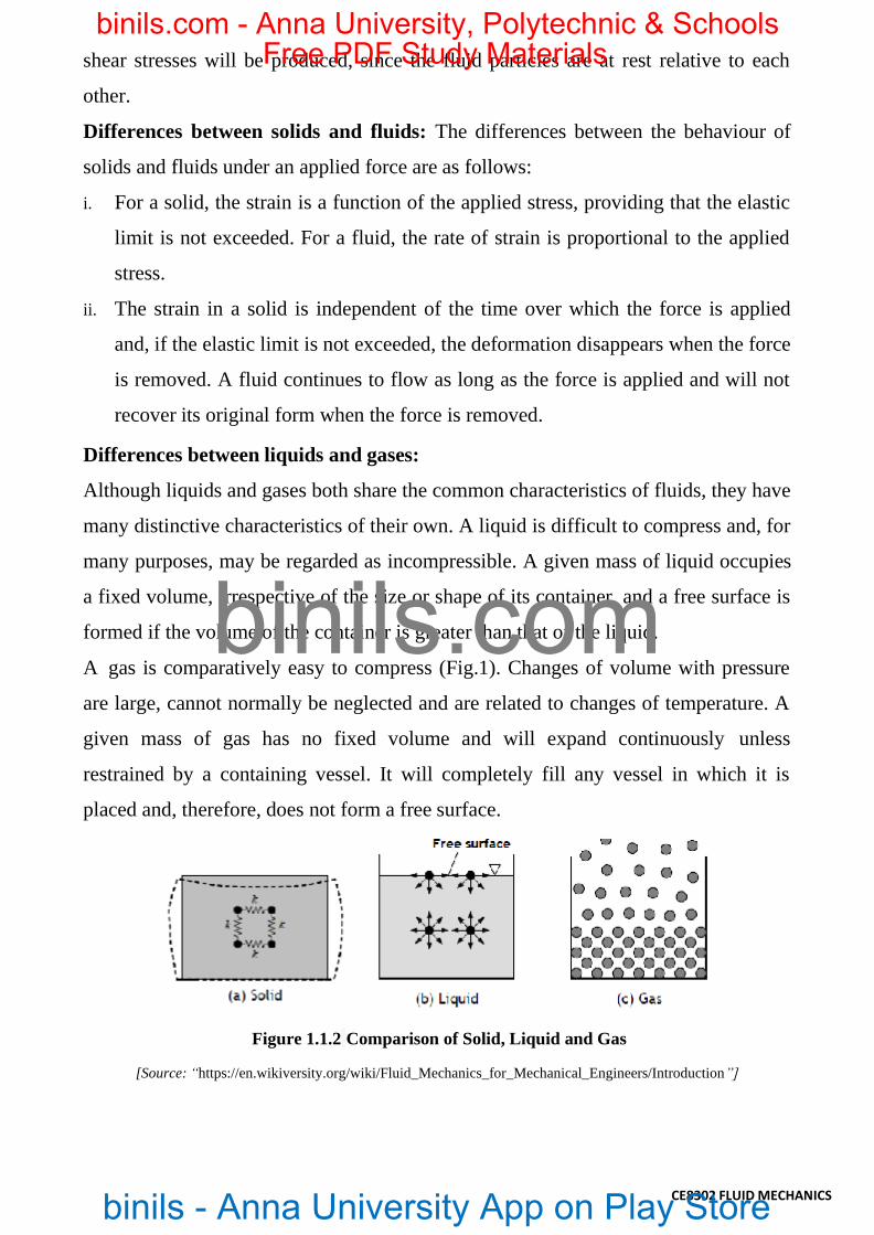
A gas is comparatively easy to compress (Fig.1). Changes of volume with pressure
are large, cannot normally be neglected and are related to changes of temperature. A
given mass of gas has no fixed volume and will expand continuously unless
restrained by a containing vessel. It will completely fill any vessel in which it is
placed and, therefore, does not form a free surface.
Figure 1.1.2 Comparison of Solid, Liquid and Gas
[Source: “https://en.wikiversity.org/wiki/Fluid_Mechanics_for_Mechanical_Engineers/Introduction”]
binils.com
binils - Anna University App on Play Store
Free PDF Study Materialsbinils.com - Anna University, Polytechnic & Schools

CE8302 FLUID MECHANICS
Quantity Unit
Mass in Kilogram kg
Length in Meter m
Time in Second s or as sec
Temperature in Kelvin K
Mole mol
Quantity Unit
Force in Newton (1 N = 1 kg.m/s2) N
Pressure in Pascal (1 Pa = 1 N/m2) N/m2
Work, energy in Joule ( 1 J =1 N.m)
J
Power in Watt (1 W = 1 J/s) W
1.2 Systems of Units
The official International System of Units (System International Units). Strong
efforts are underway for its universal adoption as the exclusive system for all
engineering and science, but older systems, particularly the CGS and FPS
engineering gravitational systems are still in use and probably will be around for
some time. The chemical engineer finds many physiochemical data given in CGS
units; that many calculations are most conveniently made in fps units; and that SI
units are increasingly encountered in science and engineering. Thus it becomes
necessary to be expert in the use of all three systems.
SI system:
Primary quantities: Derived quantities:
CGS Units:
The older centimeter-gram-second (CGS) system has the following units for
derived quantities:
Quantity Unit
Force in dyne (1 dyn = 1 g.cm/s2) dyn
Work, energy in erg ( 1 erg = 1 dyn.cm = 1 x
10-7 J ) erg
Heat Energy in calorie ( 1 cal = 4.184 J) cal
binils.com
binils - Anna University App on Play Store
Free PDF Study Materialsbinils.com - Anna University, Polytechnic & Schools

CE8302 FLUID MECHANICS
Dimensions: Dimensions of the primary quantities:
Fundamental
dimension Symbol
Length L
Mass M
Time t
Temperature T
Dimensions of derived quantities can be expressed in terms of the fundamental
dimensions.
Quantity Representative
symbol Dimensions
Angular velocity t-1
Area A L2
Density M/L3
Force F ML/t2
Kinematic
viscosity
L2/t
Linear velocity v L/t
binils.com
binils - Anna University App on Play Store
Free PDF Study Materialsbinils.com - Anna University, Polytechnic & Schools

CE8302 FLUID MECHANICS
1.2 FLUID PROPERTIES:
1. Density or Mass density() : Density or mass density of a fluid is defined as the
ratio of the mass of a fluid to its volume. Thus mass per unit volume of a fluid is
called density.
The unit of density in S.I. unit is kg/m3. The value of density for water is 1000kg/m.
With the increase in temperature volume of fluid increases and hence mass density
decreases in case of fluids as the pressure increases volume decreases and hence mass
density increases.
2. Specific weight or weight density (): Specific weight or weight density of a fluid
isthe ratio between the weight of a fluid to its volume. The weight per unit volume of
a fluid is called weight density.
The unit of specific weight in S.I. units is N/m3. The value of specific weight or
weightdensity of water is 9810N/m3.
With increase in temperature volume increases and hence specific weight
decreases.
With increases in pressure volume decreases and hence specific weight increases.
Note: Relationship between mass density and weight density:
binils.com
binils - Anna University App on Play Store
Free PDF Study Materialsbinils.com - Anna University, Polytechnic & Schools

CE8302 FLUID MECHANICS
3. Specific Volume ( ): Specific volume of a fluid is defined as the volume of a
fluidoccupied by a unit mass or volume per unit mass of a fluid.
As the temperature increases volume increases and hence specific volume increases.
As the pressure increases volume decreases and hence specific volume decreases.
4. Specific Gravity(S): Specific gravity is defined as the ratio of the weight density
of afluid to the weight density of a standard fluid.
Unit: It is a dimensionless quantity and has no unit.
In case of liquids water at 4oC is considered as standard liquid. water = 1000 kg/m3
Problem1: Calculate specific weight, mass density, specific volume and specific
gravity of a liquid having a volume of 4m3 and weighing 29.43 kN. Assume missing
data suitably.
binils.com
binils - Anna University App on Play Store
Free PDF Study Materialsbinils.com - Anna University, Polytechnic & Schools

CE8302 FLUID MECHANICS
Problem2: Calculate specific weight, density, specific volume and specific gravity
and if one liter of Petrol weighs 6.867N.
binils.com
binils - Anna University App on Play Store
Free PDF Study Materialsbinils.com - Anna University, Polytechnic & Schools

CE8302 FLUID MECHANICS
Problem 3: Specific gravity of a liquid is 0.7 Find i) Mass density ii) specific weight.
Also find the mass and weight of 10 Liters of liquid.
binils.com
binils - Anna University App on Play Store
Free PDF Study Materialsbinils.com - Anna University, Polytechnic & Schools

CE8302 FLUID MECHANICS
5. Viscosity: Viscosity is the property by virtue of which fluid offers resistance
against the flow or shear deformation. In other words, it is the reluctance of the fluid
to flow. Viscous force is that force of resistance offered by a layer of fluid for the
motion of another layer over it.
In case of liquids, viscosity is due to cohesive force between the molecules of
adjacent layers of liquid. In case of gases, molecular activity between adjacent layers
is the cause of viscosity.
Newton’s law of viscosity:
Let us consider a liquid between the fixed plate and the movable plate at a distance
‘Y’ apart, ‘A’ is the contact area (Wetted area) of the movable plate, ‘F’ is the force
required to move the plate with a velocity ‘U’ According to Newton’s law shear
stress is proportional to shear strain.
Figure 1.3.1 Definition diagram of Liquid viscosity
[Source: “https://en.wikiversity.org/wiki/Fluid_Mechanics_for_Mechanical_Engineers/fluid Properties”]
binils.com
binils - Anna University App on Play Store
Free PDF Study Materialsbinils.com - Anna University, Polytechnic & Schools

‘’ is the constant of proportionality called Dynamic Viscosity or Absolute Viscosity
or Coefficient of Viscosity or Viscosity of the fluid.
CE8302 FLUID MECHANICS
‘’ is the force required; Per Unit area called ‘Shear Stress’. The above equation is
called Newton’s law of viscosity.
Velocity gradient or rate of shear strain:
It is the difference in velocity per unit distance between any two layers.
If the velocity profile is linear then velocity gradient is given by 𝑈/𝑌 . If the velocity
profile is non – linear then it is given by 𝑑𝑢/𝑑𝑦
Unit of force (F): N
Unit of distance between the twp plates (Y): m
Unit of velocity (U): m/s
Unit of velocity gradient : U
= m / s
= / s = s-1
Y m
Unit of dynamic viscosity (): = u
y
Effect of Pressure on Viscosity of fluids:
Pressure has very little or no effect on the viscosity of fluids.
Effect of Temperature on Viscosity of fluids:
❖ Effect of temperature on viscosity of liquids: Viscosity of liquids is due to
cohesive force between the molecules of adjacent layers. As the temperature
binils.com
binils - Anna University App on Play Store
Free PDF Study Materialsbinils.com - Anna University, Polytechnic & Schools

increases cohesive force decreases and hence viscosity decreases.
❖ Effect of temperature on viscosity of gases: Viscosity of gases is due to molecular
CE8302 FLUID MECHANICS
activity between adjacent layers. As the temperature increases molecular activity
increases and hence viscosity increases.
Kinematics Viscosity: It is the ratio of dynamic viscosity of the fluid to its mass
density.
Unit of Kinematics Viscosity
Kinematic Viscosity = m2 / s
NOTE: Unit of kinematics Viscosity in CGS system is cm2/s and is called stoke (S)
If the value of KV is given in stoke, multiply it by 10-4 to convert it into m2/s.
binils.com
binils - Anna University App on Play Store
Free PDF Study Materialsbinils.com - Anna University, Polytechnic & Schools

Problem 4: Viscosity of water is 0.01poise. Find its kinematics viscosity if specific
gravity is 0.998.
CE8302 FLUID MECHANICS
Problem 5: A Plate at a distance 0.0254mm from a fixed plate moves at 0.61m/s and
requires a force of 1.962N/m2 area of plate. Determine dynamic viscosity of liquid
between the plates.
binils.com
binils - Anna University App on Play Store
Free PDF Study Materialsbinils.com - Anna University, Polytechnic & Schools

CE8302 FLUID MECHANICS
Problem 6 : A plate having an area of 1m2 is dragged down an inclined plane at 450
to horizontal with a velocity of 0.5m/s due to its own weight. Three is a cushion of
liquid 1mm thick between the inclined plane and the plate. If viscosity of oil is 0.1
PaS find the weight of the plate.
binils.com
binils - Anna University App on Play Store
Free PDF Study Materialsbinils.com - Anna University, Polytechnic & Schools

CE8302 FLUID MECHANICS
Problem 7: A flat plate is sliding at a constant velocity of 5 m/s on a large horizontal
table. A thin layer of oil (of absolute viscosity = 0.40 N-s/m2) separates the plate from
the table. Calculate the thickness of the oil film (mm) to limit the shear stress in the
oil layer to 1 kPa.
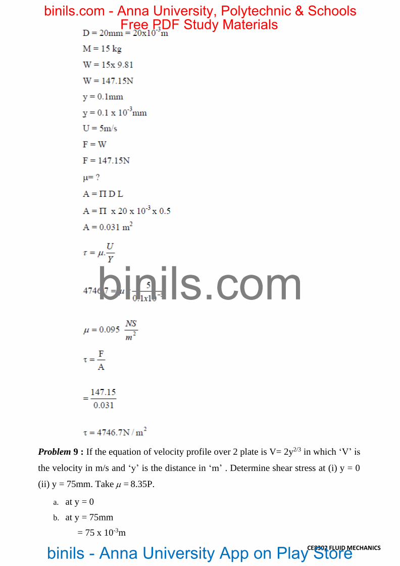
Problem 8: A shaft of 20mm and mass 15kg slides vertically in a sleeve with a
velocity of 5 m/s. The gap between the shaft and the sleeve is 0.1mm and is filled
with oil. Calculate the viscosity of oil if the length of the shaft is 500mm.
binils.com
binils - Anna University App on Play Store
Free PDF Study Materialsbinils.com - Anna University, Polytechnic & Schools
CE8302 FLUID MECHANICS
Problem 9 : If the equation of velocity profile over 2 plate is V= 2y2/3 in which ‘V’ is
the velocity in m/s and ‘y’ is the distance in ‘m’ . Determine shear stress at (i) y = 0
(ii) y = 75mm. Take = 8.35P.
a. at y = 0
b. at y = 75mm
= 75 x 10-3m
binils.com
binils - Anna University App on Play Store
Free PDF Study Materialsbinils.com - Anna University, Polytechnic & Schools

CE8302 FLUID MECHANICS
Problem 10 : A circular disc of 0.3m dia and weight 50 N is kept on an inclined
surface with a slope of 450. The space between the disc and the surface is 2 mm and
is filled with oil of dynamics viscosity 1N/Sm2.What force will be required to pull
the disk up the inclined plane with a velocity of 0.5m/s.
binils.com
binils - Anna University App on Play Store
Free PDF Study Materialsbinils.com - Anna University, Polytechnic & Schools

CE8302 FLUID MECHANICS
Problem 10 : Two large surfaces are 2.5 cm apart. This space is filled with glycerin
of absolute viscosity 0.82 NS/m2. Find what force is required to drag a plate of area
0.5m2 between the two surfaces at a speed of 0.6m/s. (i) When the plate is equidistant
from the surfaces, (ii) when the plate is at 1cm from one of the surfaces.
binils.com
binils - Anna University App on Play Store
Free PDF Study Materialsbinils.com - Anna University, Polytechnic & Schools

CE8302 FLUID MECHANICS
Let F1 be the force required to overcome viscosity resistance of liquid above
the plate and F2 be the force required to overcome viscous resistance of liquid below
the plate. In this case F1 = F2. Since the liquid is same on either side or the plate is
equidistant from the surfaces.
binils.com
binils - Anna University App on Play Store
Free PDF Study Materialsbinils.com - Anna University, Polytechnic & Schools

CE8302 FLUID MECHANICS
Total force required to drag the plate =F1 +F2 = 19.68+19.68
F= 39.36N
Case (ii) when the plate is at 1cm from one of the surfaces
Here F1 ≠F2
F/A=49.2
F1=49.2x0.5
F1=24.6N
F2 /A=32.8
F2=32.8x0.5
F2=16.4N
Total Force F = F1 + F2 = 24.6 + 16.4
F = 41N
6. Capillarity :
Capillarity is the phenomena by which liquids will rise or fall in a tube of small
diameter dipped in them. Capillarity is due to cohesion adhesion and surface tension
of liquids. If adhesion is more than cohesion then there will be capillary rise. If
cohesion is greater than adhesion then will be capillary fall or depression. The surface
tensile force supports capillary rise or depression.
binils.com
binils - Anna University App on Play Store
Free PDF Study Materialsbinils.com - Anna University, Polytechnic & Schools

CE8302 FLUID MECHANICS
Figure 1.3.2 Capillarity
[Source: “https://en.wikiversity.org/wiki/Fluid_Mechanics_for_Mechanical_Engineers/fluid Properties”]
Problem 11 : Capillary tube having an inside diameter 5mm is dipped in water at 200.
Determine the heat of water which will rise in tube. Take =0.0736N/m at 200 C.
Problem 12 : Calculate capillary rise in a glass tube when immersed in Hg at 200C.
Assume for Hg at 200C as 0.51N/m. The diameter of the tube is 5mm. = 1300c.
binils.com
binils - Anna University App on Play Store
Free PDF Study Materialsbinils.com - Anna University, Polytechnic & Schools

CE8302 FLUID MECHANICS
Problem 13: Calculate the capillary effect in millimeters a glass tube of 4mm
diameter, when immersed in (a) water (b) mercury. The temperature of the liquid is
200 C and the values of the surface tension of water and mercury at 200 C in contact
with air are 0.073575 and 0.51 N/m respectively. The angle of contact for water is
zero that for mercury 1300. Take specific weight of water as 9790 N / m3..
Capillary effect for water
Capillary effect for mercury:
7. Surface Tension:
Surface tension is defined as the tensile force acting on the surface of a liquid in
contact with a gas or on the surface between two two immiscible liquids such that the
contact surface behaves like a membrane under tension
binils.com
binils - Anna University App on Play Store
Free PDF Study Materialsbinils.com - Anna University, Polytechnic & Schools

CE8302 FLUID MECHANICS
Excess Pressure inside a Water Droplet:
Pressure inside a Liquid droplet: Liquid droplets tend to assume a spherical shape
since a sphere has the smallest surface area per unit volume.
The pressure inside a drop of fluid can be calculated using a free-body diagram of a
spherical shape of radius R cut in half, as shown in Figure below and the force
developed around the edge of the cut sphere is 2R. This force must be balance with
the difference between the internal pressure pi and the external pressure p acting on
the circular area of the cut. Thus,
Figure 1.3.3 Surface Tension inside a Water Droplet
[Source: “https://en.wikiversity.org/wiki/Fluid_Mechanics_for_Mechanical_Engineers/fluid Properties”]
The excess pressure within a Soap bubble:
The fact that air has to be blown into a drop of soap solution to make a bubble should
suggest that the pressure within the bubble is greater than that outside. This is in fact
the case: this excess pressure creates a force that is just balanced by the inward pull of
the soap film of the bubble due to its surface tension.
Figure 1.3.4 Surface Tension within a Soap bubble
[Source: “https://en.wikiversity.org/wiki/Fluid_Mechanics_for_Mechanical_Engineers/fluid Properties”]
Consider a soap bubble of radius r as shown in Figure 1. Let the external pressure be
binils.com
binils - Anna University App on Play Store
Free PDF Study Materialsbinils.com - Anna University, Polytechnic & Schools

Po and the internal pressure P1. The excess pressure P within the bubble is therefore
given by: Excess pressure P = (P1 – P0)
Consider the left-hand half of the bubble. The force acting from right to left due to
the internal excess pressure can be shown to be PA, where A is the area of a section
through the centre of the bubble. If the bubble is in equilibrium this force is balanced
by a force due to surface tension acting from left to right. This force is 2x2πr (the
factor of 2 is necessary because the soap film has two sides) where ‘’ is the
coefficient of surface tension of the soap film. Therefore
CE8302 FLUID MECHANICS
2x2πr = pA = pπr2 giving:
Excess pressure in a soap bubble (P) = 4/r
8. Compressibility:
Compressibility is the reciprocal of the bulk modulus of elasticity, Kwhich is defined
as the ratio of compressive stress to volumetric strain.
Bulk Modulus (K):
When a solid or fluid (liquid or gas) is subjected to a uniform pressure all over
the surface, such that the shape remains the same, then there is a change in volume.
Then the ratio of normal stress to the volumetric strain within the elastic limits is
called as Bulk modulus. This is denoted by K.
where p = increase in pressure; V = original volume; V = change in volume
The negative sign shows that with increase in pressure p, the volume decreases by V
i.e. if p is positive, V is negative. The reciprocal of bulk modulus is called
compressibility.
S.I. unit of compressibility is N–1m2 and C.G.S. unit is dyne–1 cm2.
binils.com
binils - Anna University App on Play Store
Free PDF Study Materialsbinils.com - Anna University, Polytechnic & Schools

Problem 13: The surface tension of water in contact with air at 20°C is 0.0725 N/m.
The pressure inside a droplet of water is to be 0.02 N/cm2 greater than the outside
pressure. Calculate the diameter of the droplet of water.
CE8302 FLUID MECHANICS
Vapour pressure is a measure of the tendency of a material to change into the gaseous
or vapour state, and it increases with temperature. The temperature at which the
vapour pressure at the surface of a liquid becomes equal to the pressure exerted by
Problem 14: Find the surface tension in a soap bubble of 40mm diameter when
inside pressure is 2.5 N/m2 above the atmosphere.
9. Vapour Pressure
the surroundings is called the boiling point of the liquid.
Vapor pressure is important to fluid flows because, in general, pressure in a flow
decreases as velocity increases. This can lead to cavitation, which is generally
destructive and undesirable. In particular, at high speeds the local pressure of a liquid
sometimes drops below the vapor pressure of the liquid. In such a case, cavitation
occurs. In other words, a "cavity" or bubble of vapor appears because the liquid
vaporizes or boils at the location where the pressure dips below the local vapor
pressure.
binils.com
binils - Anna University App on Play Store
Free PDF Study Materialsbinils.com - Anna University, Polytechnic & Schools

Cavitation is not desirable for several reasons. First, it causes noise (as the
cavitation bubbles collapse when they migrate into regions of higher pressure).
Second, it can lead to inefficiencies and reduction of heat transfer in pumps and
turbines (turbo machines). Finally, the collapse of these cavitation bubbles causes
pitting and corrosion of blades and other surfaces nearby. The left figure below
CE8302 FLUID MECHANICS
shows a cavitating propeller in a water tunnel, and the right figure shows cavitation
damage on a blade.
Figure 1.3.5 Vapour Pressure
[Source: “https://www.hkdivedi.com/2017/12/vapour-pressure-and-cavitation.html”] binils.com
binils - Anna University App on Play Store
Free PDF Study Materialsbinils.com - Anna University, Polytechnic & Schools

1.4 Fluid Statics: Concept of Fluid Static Pressure
Fluid is a state of matter which exhibits the property of flow. When a certain mass of
fluids is held in static equilibrium by confining it within solid boundaries, it exerts
force along direction perpendicular to the boundary in contact. This force is called
fluid pressure (compression).
CE8302 FLUID MECHANICS
Figure 1.4.1 Definition of Pressure
[Source: “https://en.wikiversity.org/wiki/Fluid_Mechanics_for_Mechanical_Engineers/fluid Statics”]
In fluids, gases and liquids, we speak of pressure; in solids this is normal
stress. For a fluid at rest, the pressure at a given point is the same in all directions.
Differences or gradients in pressure drive a fluid flow, especially in ducts and pipes.
Definition of Pressure: Pressure is one of the basic properties of all fluids. Pressure
(p) is the force (F) exerted on or by the fluid on a unit of surface area (A).
Mathematically expressed:
The basic unit of pressure is Pascal (Pa). When a fluid exerts a force of 1 N over an
area of 1m2, the pressure equals one Pascal, i.e., 1 Pa = 1 N/m2.Pascal is a very small
unit, so that for typical power plant application, we use larger units:
Units: 1 kilopascal (kPa) = 103 Pa, and
1 megapascal (MPa) = 106 Pa = 103 kPa.
Pressure at a Point and Pascal’s Law:
Pascal’s Principle: Pressure extends uniformly in all directions in a fluid.
By considering the equilibrium of a small triangular wedge of fluid extracted from a
static fluid body, one can show (Fig.1.4.2) that for any wedge angle θ, the pressures
binils.com
binils - Anna University App on Play Store
Free PDF Study Materialsbinils.com - Anna University, Polytechnic & Schools

on the three faces of the wedge are equal in magnitude:
CE8302 FLUID MECHANICS
Figure 1.4.2 Pascal’s Law
[Source: “https://en.wikiversity.org/wiki/Fluid_Mechanics_for_Mechanical_Engineers/fluid Statics”]
Independent of px = py = pz independent of ‘’
Pressure at a point has the same magnitude in all directions, and is called isotropic.
This result is known as Pascal's law.
Pascal’s Law: In any closed, static fluid system, a pressure change at any one point is
transmitted undiminished throughout the system.
Application of Pascal’s Law:
Figure 1.4.2 Application of Pascal’s Law
[Source: “https://en.wikiversity.org/wiki/Fluid_Mechanics_for_Mechanical_Engineers/fluid Statics”]
binils.com
binils - Anna University App on Play Store
Free PDF Study Materialsbinils.com - Anna University, Polytechnic & Schools

• Pressure applied to a confined fluid increases the pressure throughout by the same
CE8302 FLUID MECHANICS
amount.
• In picture, pistons are at same height:
• Ratio A2/A1 is called ideal mechanical advantage.
binils.com
binils - Anna University App on Play Store
Free PDF Study Materialsbinils.com - Anna University, Polytechnic & Schools
CE8302 FLUID MECHANICS
1.5 PRESSURE MEASUREMENTS BY MANOMETERS
MANOMETER
A manometer is an instrument that uses a column of liquid to measure pressure,
although the term is currently often used to mean any pressure instrument.
Two types of manometer, such as
1. Simple manometer
2. Differential manometer
The U type manometer, which is considered as a primary pressure standard, derives
pressure utilizing the following equation:
Where:
P = Differential pressure
P1 = Pressure applied to the low pressure connection
P2 = Pressure applied to the high pressure connection
= is the height differential of the liquid columns between the two legs of the
manometer
ρ = mass density of the fluid within the columns
g = acceleration of gravity
SIMPLE MANOMETER
A simple manometer consists of a glass tube having one of its ends connected to a point
where pressure is to be measured and other end remains open to atmosphere. Common
types of simple manometers are:
1.Piezometer
2.U tube manometer
3.Single Column manometer
binils.com
binils - Anna University App on Play Store
Free PDF Study Materialsbinils.com - Anna University, Polytechnic & Schools
CE8302 FLUID MECHANICS
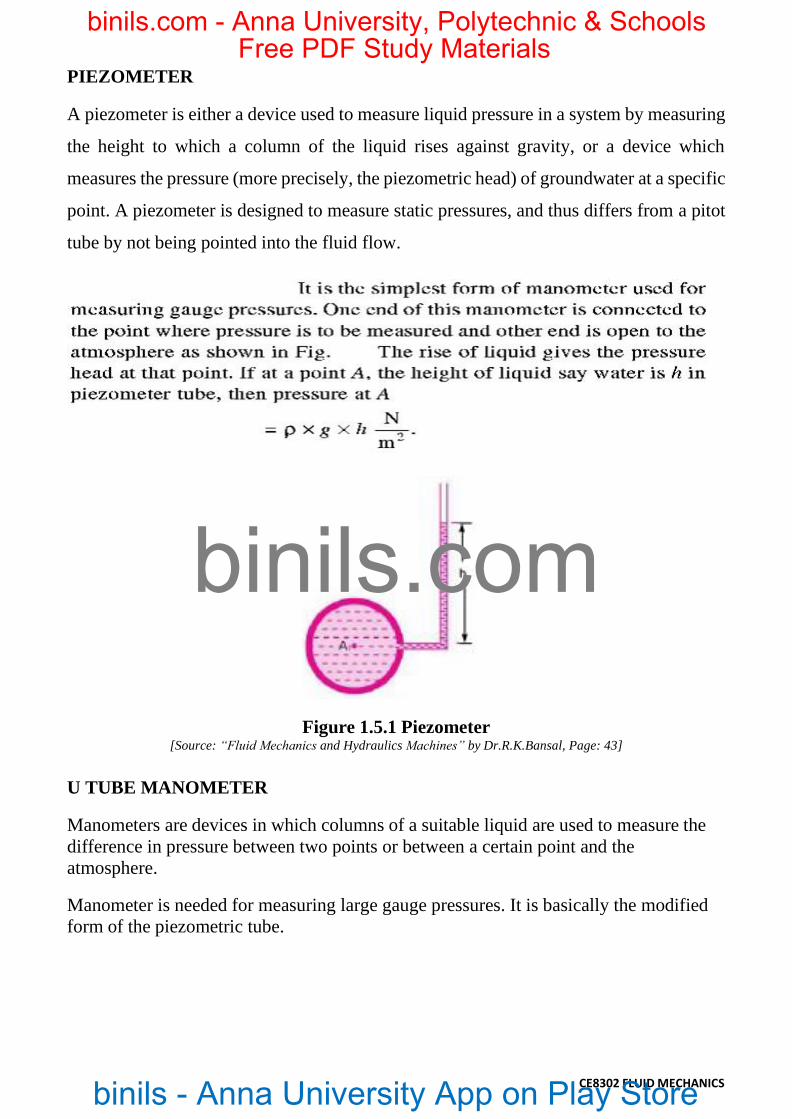
PIEZOMETER
A piezometer is either a device used to measure liquid pressure in a system by measuring
the height to which a column of the liquid rises against gravity, or a device which
measures the pressure (more precisely, the piezometric head) of groundwater at a specific
point. A piezometer is designed to measure static pressures, and thus differs from a pitot
tube by not being pointed into the fluid flow.
Figure 1.5.1 Piezometer [Source: “Fluid Mechanics and Hydraulics Machines” by Dr.R.K.Bansal, Page: 43]
U TUBE MANOMETER
Manometers are devices in which columns of a suitable liquid are used to measure the
difference in pressure between two points or between a certain point and the
atmosphere.
Manometer is needed for measuring large gauge pressures. It is basically the modified
form of the piezometric tube.
binils.com
binils - Anna University App on Play Store
Free PDF Study Materialsbinils.com - Anna University, Polytechnic & Schools

CE8302 FLUID MECHANICS
Figure 1.5.2 U Tube Manometer [Source: “Fluid Mechanics and Hydraulics Machines” by Dr.R.K.Bansal, Page: 43]
Single Column Manometer
Single column manometer is a modified form of a U-tube manometer in which one side
is a large reservoir and the other side is a small tube, open to the atmosphere.
There are two types of single column manometer:
1. Vertical single column manometer.
2. Inclined single column manometer.
binils.com
binils - Anna University App on Play Store
Free PDF Study Materialsbinils.com - Anna University, Polytechnic & Schools

CE8302 FLUID MECHANICS
1. Vertical single column Manometer
Figure 1.5.3 Vertical single column Manometer [Source: “Fluid Mechanics and Hydraulics Machines” by Dr.R.K.Bansal, Page: 49]
A>> a
Then:
binils.com
binils - Anna University App on Play Store
Free PDF Study Materialsbinils.com - Anna University, Polytechnic & Schools

CE8302 FLUID MECHANICS
2. Inclined single column Manometer
This manometer is more sensitive. Due to the inclination the distance moved by the
heavy liquid in the right limb will be more.
Figure 1.5.4 Inclined single column Manometer
[Source: “Fluid Mechanics and Hydraulics Machines” by Dr.R.K.Bansal, Page: 49]
From the eq.
By substituting the value of h2, We get:
DIFFERENTIAL MANOMETER
Differential Manometers are devices used for measuring the difference of pressure
between two points in a pipe or in two different pipes . A differential manometer
consists of a U-tube, containing a heavy liquid, whose two ends are connected to the
points, which difference of pressure is to be measure.
Most commonly types of differential manometers are:
1.U-tube differential manometer.
2.Inverted U-tube differential manometer
binils.com
binils - Anna University App on Play Store
Free PDF Study Materialsbinils.com - Anna University, Polytechnic & Schools

CE8302 FLUID MECHANICS
1.U-tube differential Manometer
Figure 1.5.5 U-tube differential Manometer
[Source: “Fluid Mechanics and Hydraulics Machines” by Dr.R.K.Bansal, Page: 51]
binils.com
binils - Anna University App on Play Store
Free PDF Study Materialsbinils.com - Anna University, Polytechnic & Schools

2.Inverted U-tube differential Manometer
It consists of inverted U-tube, containing a light liquid. The two ends of the tube are
connected to the points whose difference of pressure is to be measured. It is used for
CE8302 FLUID MECHANICS
measuring differences of low pressures.
Figure 1.5.6 Inverted U-tube differential Manometer
[Source: “Fluid Mechanics and Hydraulics Machines” by Dr.R.K.Bansal, Page: 53]
Problem1:The right limb of a simple U – tube manometer containing mercury is
open to the atmosphere, while the left limb is connected to a pipe in which a fluid of
sp.gr.0.9 is flowing. The centre of pipe is 12cm below the level of mercury in the
right limb. Find the pressure of fluid in the pipe, if the difference of mercury level in
the two limbs is 20 cm.
Given, Sp.gr. of liquid S1= 0.9
Density of fluid 𝜌1 = S1 × 1000 = 0.9 × 1000
=900 kg/ m 3
Sp.gr. of mercury S2 = 13.6
Density of mercury 𝜌2 =13.6× 1000 = 13600
kg/m3
binils.com
binils - Anna University App on Play Store
Free PDF Study Materialsbinils.com - Anna University, Polytechnic & Schools

Difference of mercury level h2 = 20cm = 0.2m
Height of the fluid from A – A h1 = 20 – 12 = 8cm = 0.08 m
Let ‘P’ be the pressure of fluid in pipe
CE8302 FLUID MECHANICS
Given,
Sp.gr of fluid S1 = 0.8
Sp.gr. of mercury S2 = 13.6
Density of the fluid = S1 × 1000 = 0.8 × 1000 = 800
Density of mercury = 13.6 × 1000
Equating pressure at A – A, we get p + 𝜌1gh1 = 𝜌2gh2
p + 900 × 9.81 × 0.08 = 13.6 × 1000 × 9.81 × 0.2
p = 13.6 × 1000 × 9.81 × 0.2 – 900 × 9.81 × 0.08
p = 26683 – 706
p = 25977 N/m2
p = 2.597 N/cm2
Pressure of fluid = 2.597 N/ cm2
Problem2: A simple U – tube manometer containing mercury is connected to a pipe in
which a fluid of sp.gr. 0.8 And having vacuum pressure is flowing. The other end of the
manometer is open to atmosphere. Find the vacuum pressure in pipe, if the difference of
mercury level in the two limbs is 40cm. and the height of the fluid in the left tube from
the centre of pipe is 15cm below.
Difference of mercury level h2 = 40cm = 0.4m
Height of the liquid in the left limb = 15cm =0.15m
Let the pressure in the pipe = p
Equating pressures above datum line A—A
𝜌2gh2 + 𝜌1gh1 + P = 0
P = - [𝜌2gh2 + 𝜌1gh1] = - [13.6 ×1000 × 9.81 × 0.4 + 800 × 9.81 × 0.15]
= 53366.4 + 1177.2 = -54543.6 N/m2
P = - 5.454 N/cm2
binils.com
binils - Anna University App on Play Store
Free PDF Study Materialsbinils.com - Anna University, Polytechnic & Schools

Problem 3: A single column manometer is connected to the pipe containing liquid of
sp.gr.0.9. Find the pressure in the pipe if the area of the reservoir is 100 times the area
CE8302 FLUID MECHANICS
of the tube of manometer. sp.gr. of mercury is 13.6. Height of the liquid from the centre
of pipe is 20cm and difference in level of mercury is 40cm.
Given,
Sp.gr. of liquid in pipe S1 = 0.9
Density 𝜌1= 900 kg/ m 3
Sp.gr. of heavy liquid S2 = 13.6
Density 𝜌2= 13600
Height of the liquid h1 = 20cm = 0.2m
Rise of mercury in the right limb h2 = 40cm = 0.4m
Pressure in pipe A= 5.21 N/ cm2
Problem 4: A pipe contains an oil of sp.gr.0.9. A differential manometer is connected at
the two points A and B shows a difference in mercury level at 15cm. find the difference
of pressure at the two points.
Given:
Sp.gr. of oil S1 = 0.9: density 𝜌1 = 0.9 x 1000 = 900 kg/ m 3
Difference of level in the mercury h = 15cm = 0.15 m
Sp.gr. of mercury = 13.6, Density = 13.6 × 1000 = 13600 kg/m3
The difference of pressure pA – pB = g × h × (𝜌𝑔 - 𝜌1)
= 9.81 x 0.15 (13600 – 900)
pA – pB = 18688 N/ m2
binils.com
binils - Anna University App on Play Store
Free PDF Study Materialsbinils.com - Anna University, Polytechnic & Schools

Problem 5: A differential manometer is connected at two points A and B .At B air
pressure is 9.81 N/cm2 . Find absolute pressure at A.
CE8302 FLUID MECHANICS
Pressure above X – X in the right limb
= 1000 × 9.81 × 0.6 + pB = 5886 + 98100 = 103986
Pressure above X – X in the left limb
= 13.6 × 103 × 9.81 × 0.1 +0900 × 9.81 × 0.2 + pA
= 13341.6 +1765.8 +pA
Equating the two pressures heads
103986 = 13341.6 + 1765.8 + pA
= 15107.4 + pA
pA = 103986 – 15107.4
= 88878.6 N/m2
pA = 8.887 N/cm
Problem 6: Water is flowing through two different pipes to which an inverted
differential manometer having an oil of sp.gr. 0.8 is connected. The pressure head in the
pipe A is 2m of water. Find the pressure in the pipe B for the manometer readings
shown in fig.
Given:
Density of air = 0.9 × 1000 = 900 kg/m3
Density of mercury = 13.6 × 10³ kg/ m3.
Let pressure at A is pA
Taking datum as X – X
binils.com
binils - Anna University App on Play Store
Free PDF Study Materialsbinils.com - Anna University, Polytechnic & Schools

Given:
CE8302 FLUID MECHANICS
Pressure below X – X in the left limb
= pA - 𝜌1gh1
= 19620 – 1000 × 9.81 × 0.3
= 16677 N/m2
Pressure below X – X in the right limb
= pB – 1000 × 9.81 × 0.1 – 800 × 9.81 × 0.12
= pB – 981 – 941.76 = pB – 1922.76
Equating the two pressures, we get,
16677 = pB - 1922.76
pB = 16677 + 1922.76
pB = 18599.76 N/m2
Problem 7: A different manometer is connected at two points A and B of two pipes.
The pipe A contains liquid of sp.gr. = 1.5 while pipe B contains liquid of sp.gr. = 0.9.
The pressures at A and B are 1 kgf/cm2 and 1.80 Kg f/cm2 respectively. Find the
difference in mercury level in the differential manometer.
binils.com
binils - Anna University App on Play Store
Free PDF Study Materialsbinils.com - Anna University, Polytechnic & Schools

Sp.gr. of liquid at A S1 = 1.5
CE8302 FLUID MECHANICS
Sp.gr. of liquid at B S2 == 0.9
Pressure at A pA= 1 kgf/c m2 = 1 × 10⁴ × kg/m2 = 1 × 104 × 9.81N/m2
Pressure at B pB = 1.8 kgf/cm2 = 1.8 × 104 × 9.81 N/m2 [1kgf = 9.81 N]
Density of mercury = 13.6 × 1000 kg/m3
Taking X – X as datum line
Pressure above X – X in left limb
= 13.6 × 1000 × 9.81 × h + 1500 × 9.81(2+3) + (9.81 x 10⁴ )
Pressure above X – X in the right limb = 900 × 9.81(h + 2) + 1.8 × 9.81 × 104
Equating the two pressures, we get
13.6 × 1000 × 9.81h + 1500 × 9.81 × 5 + 9.81 × 104 = 900 × 9.81(h + 2) + 1.8 × 9.81 × 104
Dividing both sides by 1000 × 9.81
13.6 h + 7.5 +10 = 0.9(h+2) + 18
(13.6 – 0.9) h = 1.8 + 18 – 17.5 = 19.8 – 17.5 =2.3
h = 2.3 / 12.7 = 0.181m
h = 18.1 cm
binils.com
binils - Anna University App on Play Store
Free PDF Study Materialsbinils.com - Anna University, Polytechnic & Schools

CE8302 FLUID MECHANICS
1.6 FORCES ON PLANES
Total Pressure and Centre of Pressure
Total Pressure: It is defined as the force exerted by static fluid on a surface (either plane
or curved) when the fluid comes in contact with the surface. This force is always at right
angle (or normal) to the surface.
Centre of Pressure: It is defined as the point of application of the total pressure on the
surface. Now we shall discuss the total pressure exerted by a liquid on the immersed
surface. The immersed surfaces may be: 1. Horizontal plane surface
2. Vertical plane surface
3. Inclined plane surface
4. Curved surface
Figure 1.6.1 Vertical plane Immersed surface [Source: “Fluid Mechanics and Hydraulics Machines” by Dr.R.K.Bansal, Page: 70]
Let us consider the small strip of thickness dh, width b and at a depth of h from free
surface of liquid as displayed here in above figure.
Where,
ρ = Density of liquid (Kg/m3)
Intensity of pressure on small strip, dp = ρgh
Area of strip, dA = b x dh
Total pressure force on small strip, dF = dP x dA
Total pressure force on small strip, dF = ρgh x b x dh Total pressure force on whole surface, F = Integration of dF
Derivation of total pressure
In order to determine the total pressure, we will consider the object in terms of small
strips as displayed here in following figure. We will determine the force acting on small
strip and then we will integrate the forces on small strips for calculating the total
pressure or hydrostatic force on object.
binils.com
binils - Anna University App on Play Store
Free PDF Study Materialsbinils.com - Anna University, Polytechnic & Schools
CE8302 FLUID MECHANICS
g = Acceleration due to gravity (m/s2)
A = Area of surface (m2) ħ = Height of C.G from free surface of liquid (m)
Unit of total pressure
As total pressure is basically a hydrostatic force and therefore total pressure will be
measured in terms of N or KN.
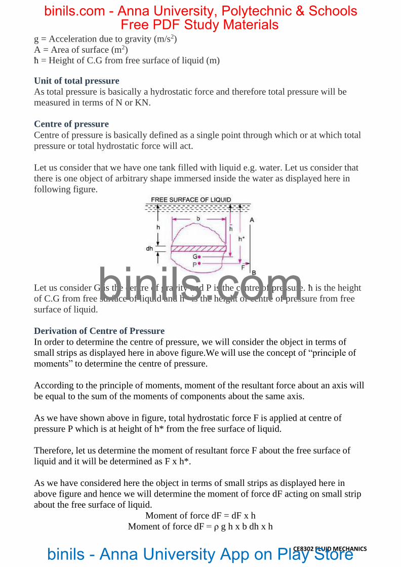
Centre of pressure
Centre of pressure is basically defined as a single point through which or at which total
pressure or total hydrostatic force will act.
Let us consider G is the centre of gravity and P is the centre of pressure. ħ is the height
of C.G from free surface of liquid and h* is the height of centre of pressure from free
surface of liquid.
Derivation of Centre of Pressure
In order to determine the centre of pressure, we will consider the object in terms of
small strips as displayed here in above figure.We will use the concept of “principle of
moments” to determine the centre of pressure.
According to the principle of moments, moment of the resultant force about an axis will
be equal to the sum of the moments of components about the same axis.
As we have shown above in figure, total hydrostatic force F is applied at centre of
pressure P which is at height of h* from the free surface of liquid.
Therefore, let us determine the moment of resultant force F about the free surface of
liquid and it will be determined as F x h*.
As we have considered here the object in terms of small strips as displayed here in
above figure and hence we will determine the moment of force dF acting on small strip
about the free surface of liquid.
Moment of force dF = dF x h
Moment of force dF = ρ g h x b dh x h
Let us consider that we have one tank filled with liquid e.g. water. Let us consider that
there is one object of arbitrary shape immersed inside the water as displayed here in
following figure.
binils.com
binils - Anna University App on Play Store
Free PDF Study Materialsbinils.com - Anna University, Polytechnic & Schools

CE8302 FLUID MECHANICS
Total Pressure and Centre of Pressure for Inclined Plane Surface Immersed in a
Liquid
Centre of pressure for inclined plane surface submerged in liquid will be given by
Let us sum of all moments of such small forces about the free surface of liquid and it
will be written as mentioned here.
Figure 1.6.2 Inclined Immersed surface [Source: “Fluid Mechanics and Hydraulics Machines” by Dr.R.K.Bansal, Page: 86]
binils.com
binils - Anna University App on Play Store
Free PDF Study Materialsbinils.com - Anna University, Polytechnic & Schools

CE8302 FLUID MECHANICS
Let us consider that we have following data from above figure.
A = Total area of inclined surface
ħ = Height of centre of gravity of inclined area from free surface
h* = Distance of centre of pressure from free surface of the liquid θ = Angle made by the surface of inclined plane with free surface of the liquid
Total pressure which is basically defined as the hydrostatic force applied by a static
fluid on a plane or curved surface when fluid will come in contact with the surfaces.
Total pressure for inclined plane surface submerged in liquid will be given by following
formula as mentioned here. Total pressure = ρ g A ħ
Centre of pressure is basically defined as a single point through which or at which total
pressure or total hydrostatic force will act.
Centre of pressure for inclined plane surface submerged in liquid will be given by
following formula as mentioned here.
Let us consider a curved surface AB sub-merged in a static liquid as displayed here in
following figure.
Figure 1.6.3 Curved surface sub-merged in a static liquid [Source: “Fluid Mechanics and Hydraulics Machines” by Dr.R.K.Bansal, Page: 98]
Let us consider one small strip area dA at a depth of h from free surface of liquid. We
have following data from above figure.
A = Total area of curved surface
ρ = Density of the liquid g = Acceleration due to gravity
Pressure intensity on small area dA = ρ g h
binils.com
binils - Anna University App on Play Store
Free PDF Study Materialsbinils.com - Anna University, Polytechnic & Schools

Hydrostatic force on small area dA will be given by following formula as mentioned
here.
CE8302 FLUID MECHANICS
dF= ρ g h x dA
Direction of this hydrostatic force will be normal to the curved surface and will vary
from point to point. Therefore, in order to secure the value of total hydrostatic force we
will not integrate the above equation.
We will secure the value or expression for total hydrostatic force on curved surface by
resolving the force dF in its two components or we can say that dF force will be
resolved in X direction i.e. dFx and in Y direction i.e. dFy.
dFx = dF Sin θ = ρ g h x dA Sin θ
dFy = dF Cos θ = ρ g h x dA Cos θ
Total force in X- direction and in Y- direction will be given as mentioned here.
Let us analyze the above equation
FG will be dA Sin θ or vertical projection of area dA. Therefore, the expression for Fx
will be total pressure force on the projected area of the curved surface on the vertical
plane.
Fx = Total pressure force on the projected area of the curved surface on the vertical
plane
EG will be dA Cos θ or horizontal projection of dA. Therefore, the expression for Fy
will be the weight of the liquid contained between the curved surface extended up to
free surface of liquid.
Fy = Weight of the liquid contained between the curved surface extended up to free
surface of liquid
binils.com
binils - Anna University App on Play Store
Free PDF Study Materialsbinils.com - Anna University, Polytechnic & Schools

CE8302 FLUID MECHANICS
1.7 BUOYANCY AND FLOATATION
Buoyancy or buoyancy force
When a body is immersed in fluid, an upward force is exerted by the fluid on the body.
This force will be equal to the weight of the fluid displaced by the body and this force
will be termed as force of buoyancy or buoyancy.
Let us consider we have one container filled with water as displayed here in following
figure. We have one object of weight 7 N. Let us think that we are now immersing the
object in to the liquid i.e. water.
Once object will be immersed in the water, some amount of water will be displaced by
the object and one upward force will be applied over the object by the water.
Weight of the displaced water will be equal to this upward force which will be exerted
by the water on the object. As we can see from above figure that, water of weight 3N is
displaced here and one upward force of 3N is exerted by the water over the object.
Conclusion for buoyancy force
Buoyancy force is the force which will be exerted on the object by the surrounding
fluid. When one object will be immersed in the water, object will push the water and
water will push back the object with as much force as it can.
Force of buoyancy = Weight of the displaced fluid
Force of buoyancy = Weight of the object in air – Weight of the object in given water
Positive buoyancy
Force of buoyancy will be greater than the weight of the object. Hence, object will float
and this case will be termed as positive buoyancy.
binils.com
binils - Anna University App on Play Store
Free PDF Study Materialsbinils.com - Anna University, Polytechnic & Schools

CE8302 FLUID MECHANICS
Neutral buoyancy
Force of buoyancy will be equal to the weight of the object. Hence, object will be
suspended in the fluid and this case will be termed as neutral buoyancy.
Negative buoyancy
Force of buoyancy will be less than the weight of the object. Hence, object will be sunk
and this case will be termed as negative buoyancy.
Centre of buoyancy
As we know that when a body is immersed in fluid, an upward force is exerted by the
fluid on the body. This force will be equal to the weight of the fluid displaced by the
body and this force will be termed as force of buoyancy or buoyancy.
Buoyancy force will act through the centre of gravity of the displaced fluid and that
point i.e. centre of gravity of the displaced fluid will be termed as centre of buoyancy.
Therefore we can define the term centre of buoyancy as the point through which the
force of buoyancy is supposed to act.
Centre of buoyancy = Centre of gravity of the displaced fluid = Centre of gravity of the
portion of the body immersed in the liquid
Let us explain the term centre of buoyancy
Let us consider one vessel as displayed here in following figure. Weight of vessel will
be distributed throughout the length of vessel and will act downward over the entire
structure of vessel.
But, what do we consider?
We consider that complete weight of the vessel will act downward vertically through
one point and that point will be termed as the centre of gravity of that vessel.
In similar way, buoyancy force will be supposed to act vertically in upward direction
through a single point and that point will be termed as centre of buoyancy.
binils.com
binils - Anna University App on Play Store
Free PDF Study Materialsbinils.com - Anna University, Polytechnic & Schools

CE8302 FLUID MECHANICS
Meta-centre
Meta-centre is basically defined as the point about which a body in stable equilibrium
will start to oscillate when body will be displaced by an angular displacement.
We can also define the meta-centre as the point of intersection of the axis of body
passing through the centre of gravity and original centre of buoyancy and a vertical line
passing through the centre of buoyancy of the body in tilted position.
Let us consider a body which is floating in the liquid. Let us assume that body is in
equilibrium condition. Let us think that G is the centre of gravity of the body and B is
the centre of buoyancy of the body when body is in equilibrium condition.
Figure 1.7.1 Meta-centre [Source: “Fluid Mechanics and Hydraulics Machines” by Dr.R.K.Bansal, Page: 136]
In equilibrium situation, centre of gravity G and centre of buoyancy B will lie on same
axis which is displayed here in above figure with a vertical line.
Let us assume that we have given an angular displacement to the body in clockwise
direction as displayed here in above figure.
Centre of buoyancy will be shifted now towards right side from neutral axis and let us
assume that it is now B1.
Line of action of buoyancy force passing through this new position will intersect the
normal axis passing through the centre of gravity and centre of buoyancy in original
binils.com
binils - Anna University App on Play Store
Free PDF Study Materialsbinils.com - Anna University, Polytechnic & Schools

CE8302 FLUID MECHANICS
position of the body at a point M as displayed here in above figure. Where, M is the
meta-centre.
Meta-centric height
Meta-centric height is basically defined as the distance between the meta-centre of the
floating body and the centre of gravity of the body.
Therefore, MG in above figure will be termed as meta-centric height.
binils.com
binils - Anna University App on Play Store
Free PDF Study Materialsbinils.com - Anna University, Polytechnic & Schools