BID OF - City of Madison, Wisconsin
562
BID OF 2016 PROPOSAL, CONTRACT, BOND AND SPECIFICATIONS FOR ENGINEERING OPERATIONS BUILDING ADDITION CONTRACT NO. 7685 MUNIS NO. 10308 IN MADISON, DANE COUNTY, WISCONSIN AWARDED BY THE COMMON COUNCIL MADISON, WISCONSIN ON CITY ENGINEERING DIVISION 1600 EMIL STREET MADISON, WISCONSIN 53713 https://bidexpress.com/login
-
Upload
khangminh22 -
Category
Documents
-
view
0 -
download
0
Transcript of BID OF - City of Madison, Wisconsin

BID OF
2016
PROPOSAL, CONTRACT, BOND AND SPECIFICATIONS
FOR
ENGINEERING OPERATIONS BUILDING ADDITION
CONTRACT NO. 7685
MUNIS NO. 10308
IN
MADISON, DANE COUNTY, WISCONSIN
AWARDED BY THE COMMON COUNCIL MADISON, WISCONSIN ON
CITY ENGINEERING DIVISION 1600 EMIL STREET
MADISON, WISCONSIN 53713
https://bidexpress.com/login

Rev. 2/08/2016-7685contractBoilerplateSBE v5.doc i
ENGINEERING OPERATIONS BUILDING ADDITION CONTRACT NO. 7685
INDEX
SECTION A: ADVERTISEMENT FOR BIDS AND INSTRUCTIONS TO BIDDERS ................................. A-1 SECTION B: PROPOSAL SECTION ......................................................................................................... B-1 SECTION C: SMALL BUSINESS ENTERPRISE ..................................................................................... C-1 SECTION D: SPECIAL PROVISIONS ...................................................................................................... D-1 SECTION E: BIDDER’S ACKNOWLEDGEMENT ..................................................................................... E-1 SECTION F: DISCLOSURE OF OWNERSHIP & BEST VALUE CONTRACTING ................................... F-1 SECTION G: BID BOND ........................................................................................................................... G-1 SECTION H: AGREEMENT ...................................................................................................................... H-1 SECTION I: PAYMENT AND PERFORMANCE BOND ............................................................................. I-1 SECTION J: PREVAILING WAGE RATES ................................................................................................ J-1
This Proposal, and Agreement have been prepared by:
CITY ENGINEERING DIVISION
CITY OF MADISON MADISON, DANE COUNTY, WISCONSIN
Robert F. Phillips, P.E., City Engineer RFP: ks

Rev. 02/08/2016-7685contractBoilerplateSBE v4.doc A-1
SECTION A: ADVERTISEMENT FOR BIDS AND INSTRUCTIONS TO BIDDERS
REQUEST FOR BID FOR PUBLIC WORKS CONSTRUCTION CITY OF MADISON, WISCONSIN
A BEST VALUE CONTRACTING MUNICIPALITY
PROJECT NAME: ENGINEERING OPERATIONS BUILDING
ADDITION CONTRACT NO.: 7685 SBE GOAL 11% BID BOND 5% Pre-Bid Walk Through (1:00 P.M.) 2/23/2016 PRE BID MEETING (1:00 P.M.) 2/26/2016 PREQUALIFICATION APPLICATION DUE (1:00 P.M) 2/26/2016 BID SUBMISSION (1:00 P.M.) 3/4/2016 BID OPEN (1:30 P.M.) 3/4/2016 PUBLISHED IN WSJ 2/19/2016 & 2/26/2016 PRE BID MEETING Representatives of the Affirmative Action Department will be present to discuss the Small Business Enterprise requirements on Friday, February 26, 2016 at 1:00 P.M. at 1600 Emil Street, Madison Wisconsin. PRE-BID WALK THROUGH A pre-bid conference will be conducted for the purposes of a pre-bid walk through and all bidding contractors are encouraged to attend.
1. The meetings will be held on Tuesday, February 23, 2016 and the agenda will begin at 1:00 pm. 2. Please meet in the Engineering Operations Facility Training Room located at 1600 Emil Street
before 1:00 pm. 3. This will be the only opportunity for bidding contractors to walk through the site. An alternate date
may be selected in the event of inclement weather as determined solely at the discretion of the City Project Manager.
4. City Staff will be on hand to conduct the building walk through, discuss the plans, specifications and expectations of the contract.
QUESTIONS, CLARIFICATIONS, AND REQUESTS FOR ALTERNATES: If needed, the City of Madison shall publish addenda no later than 1:00 pm on Wednesday, March 2, 2016 to respond to any questions, clarifications, or requests for alternates.
1. Any questions or requests for clarifications regarding plans and specifications shall be submitted directly to the City Project Manager. a. The City Project Manager will further distribute questions to the appropriate consultant or City
Staff as needed. b. All responses will be published by the City of Madison in the form of a bidding addendum. c. See the contract contact information at the end of Section D-Special Provisions for contact
information. All questions shall be sent via email, reference Engineering Contract No. 7685 in the subject line.
2. Requests for alternates or substitutions shall be done according to Specification 01 25 13 Product Substitution Procedures and other specifications as necessary.

Rev. 02/08/2016-7685contractBoilerplateSBE v4.doc A-2
a. Use the form at the end of the specification. Submit all materials to the City Project Manager via email. Point of Contact information is on the last page of Bid Tab “D” – Special Provisions prior to the technical specification document.
b. Contractors are cautioned to review all specifications and note whether substitutions for specific products will be allowed or not.
3. The deadline for receiving all questions, clarifications, and requests for alternates shall be 12:00pm (noon) on Monday, February 29, 2016. a. No additional questions, clarifications, or requests for alternates will be received after this
deadline. PREQUALIFICATION APPLICATION: Forms are available on our website, www.cityofmadison.com/business/pw/forms.cfm. If not currently prequalified in the categories listed in Section A, an amendment to your Prequalification will need to be submitted prior to the same due date. Postmark is not applicable. BIDS TO BE SUBMITTED by hand to 1600 EMIL ST., MADISON, WI 53713 or online at www.bidexpress.com. THE BID OPENING is at 1600 EMIL ST., MADISON, WI 53713. STANDARD SPECIFICATIONS
The City of Madison’s Standard Specifications for Public Works Construction - 2015 Edition, as supplemented and amended from time to time, forms a part of these contract documents as if attached hereto. These standard specifications are available on the City of Madison Public Works website, www.cityofmadison.com/Business/PW/specs.cfm. The Contractor shall review these Specifications prior to preparation of proposals for the work to be done under this contract, with specific attention to Article 102, “BIDDING REQUIREMENTS AND CONDITIONS” and Article 103, “AWARD AND EXECUTION OF THE CONTRACT.” For the convenience of the bidder, below are highlights of three subsections of the specifications. SECTION 102.1: PRE-QUALIFICATION OF BIDDERS
In accordance with Wisconsin State Statutes 66.0901 (2) and (3), all bidders must submit to the Board of Public Works proof of responsibility on forms furnished by the City. The City requires that all bidders be qualified on a biennial basis. Bidders must present satisfactory evidence that they have been regularly engaged in the type of work specified herein and they are fully prepared with necessary capital, materials, machinery and supervisory personnel to conduct the work to be contracted for to the satisfaction of the City. All bidders must be pre-qualified by the Board of Public Works for the type of construction on which they are bidding prior to the opening of the bid. In accordance with Section 39.02(9)(a)l. of the General Ordinances, all bidders shall submit in writing to the Affirmative Action Division Manager of the City of Madison, a Certificate of Compliance or an Affirmative Action Plan at the same time or prior to the submission of the proof of responsibility forms. The bidder shall be disqualified if the bidder fails to or refuses to, prior to opening of the bid, submit a Certificate of compliance, Affirmative Action Plan or Affirmative Action Data Update, as applicable, as defined by Section 39.02 of the General Ordinances (entitled Affirmative Action) and as required by Section 102.11 of the Standard Specifications.

Rev. 02/08/2016-7685contractBoilerplateSBE v4.doc A-3
SECTION 102.4 PROPOSAL
No bid will be accepted that does not contain an adequate or reasonable price for each and every item named in the Schedule of Unit Prices. A lump sum bid for the work in accordance with the plans and specifications is required. The lump sum bid must be the same as the total amounts bid for the various items and it shall be inserted in the space provided. All papers bound with or attached to the proposal form are considered a part thereof and must not be detached or altered when the proposal is submitted. The plans, specifications and other documents designated in the proposal form will be considered a part of the proposal whether attached or not. A proposal submitted by an individual shall be signed by the bidder or by a duly authorized agent. A proposal submitted by a partnership shall be signed by a member/partner or by a duly authorized agent thereof. A proposal submitted by a corporation shall be signed by an authorized officer or duly authorized registered agent of such corporation, and the proposal shall show the name of the State under the laws of which such corporation was chartered. The required signatures shall in all cases appear in the space provided thereof on the proposal. Each proposal shall be placed, together with the proposal guaranty, in a sealed envelope, so marked as to indicate name of project, the contract number or option to which it applies, and the name and address of the Contractor or submitted electronically through Bid Express (www.bidexpress.com). Proposals will be accepted at the location, the time and the date designated in the advertisement. Proposals received after the time and date designated will be returned to the bidder unopened. The Bidder shall execute the Disclosure of Ownership form. REFER TO SECTION F. SECTION 102.5: BID DEPOSIT (PROPOSAL GUARANTY)
All bids, sealed or electronic, must be accompanied with a Bid Bond equal to at least 5% of the bid or a Certificate of Annual/Biennial Bid Bond or certified check, payable to the City Treasurer. Bid deposit of the successful bidders shall be returned within forty-eight (48) hours following execution of the contract and bond as required. PREVAILING WAGE RATES
Prevailing Wage Rates may be required and are attached in Section J of the contract. See Special Provisions to determine applicability.

Rev. 02/08/2016-7685contractBoilerplateSBE v4.doc A-4
Bidders for this Contract(s) must be Pre-Qualified for at least one of the following type(s) of construction denoted by an
Building Demolition 101 Asbestos Removal 110 Building Demolition 120 House Mover Street, Utility and Site Construction 201 Asphalt Paving 270 Retaining Walls, Reinforced Concrete 205 Blasting 275 Sanitary, Storm Sewer and Water Main
Construction 210 Boring/Pipe Jacking 215 Concrete Paving 276 Sawcutting 220 Con. Sidewalk/Curb & Gutter/Misc. Flat Work 280 Sewer Lateral Drain Cleaning/Internal TV Insp. 221 Concrete Bases and Other Concrete Work 285 Sewer Lining 222 Concrete Removal 290 Sewer Pipe Bursting 225 Dredging 295 Soil Borings 230 Fencing 300 Soil Nailing 235 Fiber Optic Cable/Conduit Installation 305 Storm & Sanitary Sewer Laterals & Water Svc. 240 Grading and Earthwork 310 Street Construction 241 Horizontal Saw Cutting of Sidewalk 315 Street Lighting 242 Infrared Seamless Patching 318 Tennis Court Resurfacing 245 Landscaping, Maintenance 320 Traffic Signals 250 Landscaping, Site and Street 325 Traffic Signing & Marking 251 Parking Ramp Maintenance 332 Tree pruning/removal 252 Pavement Marking 333 Tree, pesticide treatment of 255 Pavement Sealcoating and Crack Sealing 335 Trucking 260 Petroleum Above/Below Ground Storage
Tank Removal/Installation 340 Utility Transmission Lines including Natural Gas,
Electrical & Communications 262 Playground Installer 399 Other 265 Retaining Walls, Precast Modular Units Bridge Construction 501 Bridge Construction and/or Repair Building Construction 401 Floor Covering (including carpet, ceramic tile installation,
rubber, VCT 437 Metals
440 Painting and Wallcovering 402 Building Automation Systems 445 Plumbing 403 Concrete 450 Pump Repair 404 Doors and Windows 455 Pump Systems 405 Electrical - Power, Lighting & Communications 460 Roofing and Moisture Protection 410 Elevator - Lifts 464 Tower Crane Operator 412 Fire Suppression 461 Solar Photovoltaic/Hot Water Systems 413 Furnishings - Furniture and Window Treatments 465 Soil/Groundwater Remediation 415 General Building Construction, Equal or Less than $250,000 466 Warning Sirens 420 General Building Construction, $250,000 to $1,500,000 470 Water Supply Elevated Tanks 425 General Building Construction, Over $1,500,000 475 Water Supply Wells 428 Glass and/or Glazing 480 Wood, Plastics & Composites - Structural &
Architectural 429 Hazardous Material Removal 430 Heating, Ventilating and Air Conditioning (HVAC) 499 Other 433 Insulation - Thermal 435 Masonry/Tuck pointing
State of Wisconsin Certifications 1 Class 5 Blaster - Blasting Operations and Activities 2500 feet and closer to inhabited buildings for quarries, open pits and
road cuts. 2 Class 6 Blaster - Blasting Operations and Activities 2500 feet and closer to inhabited buildings for trenches, site
excavations, basements, underwater demolition, underground excavations, or structures 15 feet or less in height. 3 Class 7 Blaster - Blasting Operations and Activities for structures greater than 15 ' in height, bridges, towers, and any of
the objects or purposes listed as “Class 5 Blaster or Class 6 Blaster”. 4 Petroleum Above/Below Ground Storage Tank Removal and Installation (Attach copies of State Certifications.) 5 Hazardous Material Removal (Contractor to be certified for asbestos and lead abatement per the Wisconsin Department
of Health Services, Asbestos and Lead Section (A&LS).) See the following link for application: www.dhs.wisconsin.gov/Asbestos/Cert. State of Wisconsin Performance of Asbestos Abatement Certificate must be attached.
6 Certification number as a Certified Arborist or Certified Tree Worker as administered by the International Society of Arboriculture
7 Pesticide application (Certification for Commercial Applicator For Hire with the certification in the category of turf and landscape (3.0) and possess a current license issued by the DATCP)
8 State of Wisconsin Master Plumbers License.

Rev. 02/08/2016-7685contractBoilerplateSBE v4.doc B-1
SECTION B: PROPOSAL
Please refer to the Bid Express Website
at https://bidexpress.com look up contract number
and go to Section B: Proposal Page
You can access all City of Madison bid solicitations for FREE at www.bidexpress.com Click on the “Register for Free” button and follow the instructions to register your company and yourself. You will be asked for a payment subscription preference, since you may wish to bid online someday. Simply choose the method to pay on a ‘per bid’ basis. This requires no payment until / unless you actually bid online. You can also choose the monthly subscription plan at this time. You will, however, be asked to provide payment information. Remember, you can change your preference at anytime. You will then be able to complete your free registration and have full access to the site. Your free access does not require completion of the ‘Digital ID’ process, so you will have instant access for viewing and downloading. To be prepared in case you ever do wish to bid online, you may wish to establish your digital ID also, since you cannot bid without a Digital ID. If you have any problems with the free registration process, you can call the bidexpress help team, toll free at 1-888-352-2439 (option 1, option1).

Rev. 02/08/2016-7685contractBoilerplateSBE v4.doc C-1
SECTION C: SMALL BUSINESS ENTERPRISE
Instructions to Bidders City of Madison
SBE Program Information 2 Small Business Enterprise (SBE) Program Information 2.1 Policy and Goal
The City of Madison reaffirms its policy of nondiscrimination in the conduct of City business by maintaining a procurement process which remains open to all who have the potential and ability to sell goods and services to the City. It is the policy of the City of Madison to allow Small Business Enterprises (SBE) maximum feasible opportunity to participate in City of Madison contracting. The bidder acknowledges that its bid has been submitted in accordance with the SBE program and is for the public’s protection and welfare. Please refer to the “ADVERTISEMENT FOR BIDS” for the goal for the utilization of SBEs on this project. SBEs may participate as subcontractors, vendors and/or suppliers, which provide a commercially useful function. The dollar value for SBE suppliers or ‘materials only’ vendors shall be discounted to 60% for purposes of meeting SBE goals. A bidder which achieves or exceeds the SBE goal will be in compliance with the SBE requirements of this project. In the event that the bidder is unable to achieve the SBE goal, the bidder must demonstrate that a good faith effort to do so was made. Failure to either achieve the goal or demonstrate a good faith effort to do so will be grounds for the bidder being deemed a non-responsible contractor ineligible for award of this contract. A bidder may count towards its attainment of the SBE goal only those expenditures to SBEs that perform a commercially useful function. For purposes of evaluating a bidder's responsiveness to the attainment of the SBE goal, the contract participation by an SBE is based on the percentage of the total base bid proposed by the Contractor. The total base bid price is inclusive of all addenda. Work performed by an SBE firm in a particular transaction can be counted toward the goal only if it involves a commercially useful function. That is, in light of industry practices and other relevant considerations, does the SBE firm have a necessary and useful role in the transaction, of a kind for which there is a market outside the context of the SBE Program, or is the firm's role a superfluous step added in an attempt to obtain credit towards goals? If, in the judgment of the Affirmative Action Division, the SBE firm will not perform a commercially useful function in the transaction, no credit towards goals will be awarded. The question of whether a firm is performing a commercially useful function is completely separate from the question of whether the firm is an eligible SBE. A firm is eligible if it meets the definitional criteria and ownership and control requirements, as set forth in the City of Madison's SBE Program. If the City of Madison determines that the SBE firm is performing a commercially useful function, then the City of Madison must then decide what that function is. If the commercially useful function is that of an SBE vendor / supplier that regularly transacts business with the respective product, then the City of Madison will count 60% of the value of the product supplied toward SBE goals.

Rev. 02/08/2016-7685contractBoilerplateSBE v4.doc C-2
To be counted, the SBE vendor / supplier must be engaged in selling the product in question to the public. This is important in distinguishing an SBE vendor / supplier, which has a regular trade with a variety of customers, from a firm which performs supplier-like functions on an ad hoc basis or for only one or two contractors with whom it has a special relationship. A supplier of bulk goods may qualify as an eligible SBE vendor / supplier if it either maintains an inventory or owns or operates distribution equipment. With respect to the distribution equipment; e.g., a fleet of trucks, the term "operates" is intended to cover a situation in which the supplier leases the equipment on a regular basis for its entire business. It is not intended to cover a situation in which the firm simply provides drivers for trucks owned or leased by another party; e.g., a prime contractor, or leases such a party's trucks on an ad hoc basis for a specific job. If the commercially useful function being performed is not that of a qualified SBE vendor / supplier, but rather that of delivery of products, obtaining bonding or insurance, procurement of personnel, acting as a broker or manufacturer's representative in the procurement of supplies, facilities, or materials, etc., only the fees or commissions will apply towards the goal. For example, a business that simply transfers title of a product from manufacturer to ultimate purchaser; e. g., a sales representative who re-invoices a steel product from the steel company to the Contractor, or a firm that puts a product into a container for delivery would not be considered a qualified SBE vendor / supplier. The Contractor would not receive credit based on a percentage of the cost of the product for working with such firms. Concerning the use of services that help the Contractor obtain needed supplies, personnel, materials or equipment to perform a contract: only the fee received by the service provider will be counted toward the goal. For example, use of a SBE sales representative or distributor for a steel company, if performing a commercially useful function at all, would entitle the Contractor receiving the steel to count only the fee paid to the representative or distributor toward the goal. This provision would also govern fees for professional and other services obtained expressly and solely to perform work relating to a specific contract. Concerning transportation or delivery services: if an SBE trucking company picks up a product from a manufacturer or a qualified vendor / supplier and delivers the product to the Contractor, the commercially useful function it is performing is not that of a supplier, but simply that of a transporter of goods. Unless the trucking company is itself the manufacturer or a qualified vendor / supplier in the product, credit cannot be given based on a percentage of the cost of the product. Rather, credit would be allowed for the cost of the transportation service. The City is aware that the rule's language does not explicitly mention every kind of business that may contribute work on this project. In administering these programs, the City would, on a case-by-case basis, determine the appropriate counting formula to apply in a particular situation.
2.2 Contract Compliance
Questions concerning the SBE Program shall be directed to the Contract Compliance Officer of the City of Madison Department of Civil Rights, Affirmative Action Division, 210 Martin Luther King, Jr. Blvd., Room 523, Madison, WI 53703; telephone (608) 266-4910.

Rev. 02/08/2016-7685contractBoilerplateSBE v4.doc C-3
2.3 Certification of SBE by City of Madison
The Affirmative Action Division maintains a directory of SBEs which are currently certified as such by the City of Madison. Contact the Contract Compliance Officer as indicated in Section 2.2 to receive a copy of the SBE Directory or you may access the SBE Directory online at www.cityofmadison.com/dcr/aaTBDir.cfm. All contractors, subcontractors, vendors and suppliers seeking SBE status must complete and submit the Targeted Business Certification Application to the City of Madison Affirmative Action Division by the time and date established for receipt of bids. A copy of the Targeted Business Certification Application is available by contacting the Contract Compliance Officer at the address and telephone indicated in Section 2.2 or you may access the Targeted Business Certification Application online at www.cityofmadison.com/dcr/aaTBDir.cfm. Submittal of the Targeted Business Certification Application by the time specified does not guarantee that the applicant will be certified as a SBE eligible to be utilized towards meeting the SBE goal for this project.
2.4 Small Business Enterprise Compliance Report
2.4.1 Good Faith Efforts
Bidders shall take all necessary affirmative steps to assure that SBEs are utilized when possible and that the established SBE goal for this project is achieved. A contractor who self performs a portion of the work, and is pre-qualified to perform that category of work, may subcontract that portion of the work, but shall not be required to do so. When a bidder is unable to achieve the established SBE goal, the bidder must demonstrate that a good faith effort to do so was made. Such a good faith effort should include the following:
2.4.1.1 Attendance at the pre-bid meeting. 2.4.1.2 Using the City of Madison’s directory of certified SBEs to identify
SBEs from which to solicit bids. 2.4.1.3 Assuring that SBEs are solicited whenever they are potential
sources. 2.4.1.4 Referring prospective SBEs to the City of Madison Affirmative Action
Division for certification. 2.4.1.5 Dividing total project requirements into smaller tasks and/or
quantities, where economically feasible, to permit maximum feasible SBE participation.
2.4.1.6 Establishing delivery schedules, where requirements permit, which will encourage participation by SBEs.
2.4.1.7 Providing SBEs with specific information regarding the work to be performed.
2.4.1.8 Contacting SBEs in advance of the deadline to allow such businesses sufficient time to prepare a bid.
2.4.1.9 Utilizing the bid of a qualified and competent SBE when the bid of such a business is deemed reasonable (i.e. 5% above the lowest bidder), although not necessarily low.
2.4.1.10 Contacting SBEs which submit a bid, to inquire about the details of the bid and confirm that the scope of the work was interpreted as intended.
2.4.2 Reporting SBE Utilization and Good Faith Efforts
The Small Business Enterprise Compliance Report is to be submitted by the bidder with the bid: This report is due by the specified bid closing time and date. Bids submitted without a completed SBE Compliance Report as outlined below

Rev. 02/08/2016-7685contractBoilerplateSBE v4.doc C-4
shall be deemed non-responsible and the bidder ineligible for award of this contract.
2.4.2.1 If the Bidder meets or exceeds the goal established for SBE
utilization, the Small Business Enterprise Compliance Report shall consist of the following:
2.4.2.1.1 Cover Page, Page C-6; and 2.4.2.1.2 Summary Sheet, C-7.
2.4.2.2 If the bidder does not meet the goal established for SBE utilization,
the Small Business Enterprise Compliance Report shall consist of the following:
2.4.2.2.1 Cover Page, Page C-6; 2.4.2.2.2 Summary Sheet, C-7; and 2.4.2.2.3 SBE Contact Report, C-8 and C-9. (A separate Contact
Report must be completed for each applicable SBE which is not utilized.)
2.5 Appeal Procedure
A bidder which does not achieve the established goal and is found non-responsible for failure to demonstrate a good faith effort to achieve such goal and subsequently denied eligibility for award of contract may appeal that decision to the Small Business Enterprises Appeals Committee. All appeals shall be made in writing, and shall be delivered to and received by the City Engineer no later than 4:30 PM on the third business day following the bidder’s receipt of the written notification of ineligibility by the Affirmative Action Division Manager. Postmark not acceptable. The notice of appeal shall state the basis for the appeal of the decision of the Affirmative Action Division Manager. The Appeal shall take place in accordance with Madison General Ordinance 33.54.
2.6 SBE Requirements After Award of the Contract
The successful bidder shall identify SBE subcontractors, suppliers and vendors on the subcontractor list in accordance with the specifications. The Contractor shall submit a detailed explanation of any variances between the listing of SBE subcontractors, vendors and/or suppliers on the subcontractor list and the Contractor’s SBE Compliance Report for SBE participation. No change in SBE subcontractors, vendors and/or suppliers from those SBEs indicated in the SBE Compliance Report will be allowed without prior approval from the Engineer and the Affirmative Action Division. The contractor shall submit in writing to the City of Madison Affirmative Action Division a request to change any SBE citing specific reasons which necessitate such a change. The Affirmative Action Division will use a general test of reasonableness in approving or rejecting the contractor’s request for change. If the request is approved, the Contractor will make every effort to utilize another SBE if available. The City will monitor the project to ensure that the actual percentage commitment to SBE firms is carried out.

Rev. 02/08/2016-7685contractBoilerplateSBE v4.doc C-5
2.7 SBE Definition and Eligibility Guidelines
A Small Business Enterprise is a business concern awarded certification by the City of Madison. For the purposes of this program a Small Business Enterprise is defined as:
A. An independent business operated under a single management. The business
may not be a subsidiary of any other business and the stock or ownership may not be held by any individual or any business operating in the same or a similar field. In determining whether an entity qualifies as a SBE, the City shall consider all factors relevant to being an independent business including, but not limited to, the date the business was established, adequacy of its resources for the work in which it proposes to involve itself, the degree to which financial, equipment leasing and other relationships exist with other ineligible firms in the same or similar lines of work. SBE owner(s) shall enjoy the customary incidents of ownership and shall share in the risks and profits commensurate with their enjoyment interests, as demonstrated by an examination of the substance rather than form or arrangements that may be reflected in its ownership documents.
B. A business that has averaged no more than $4.0 million in annual gross receipts
over the prior three year period and the principal owner(s) do not have a personal net worth in excess of $1.32 million.
Firm and/or individuals that submit fraudulent documents/testimony may be barred from doing business with the City and/or forfeit existing contracts. SBE certification is valid for one (1) year unless revoked.

Rev. 02/08/2016-7685contractBoilerplateSBE v4.doc C-6
ENGINEERING OPERATIONS BUILDING ADDITION CONTRACT NO. 7685
Small Business Enterprise Compliance Report
This information may be submitted electronically through
Bid Express or submitted with bid in sealed envelope.
Cover Sheet Prime Bidder Information
Company: Address: Telephone Number: Fax Number: Contact Person/Title: Prime Bidder Certification
I, , of Name Title certify that the information Company contained in this SBE Compliance Report is true and correct to the best of my knowledge and belief. Witness’ Signature Bidder’s Signature Date

Rev. 02/08/2016-7685contractBoilerplateSBE v4.doc C-7
ENGINEERING OPERATIONS BUILDING ADDITION CONTRACT NO. 7685
Small Business Enterprise Compliance Report
Summary Sheet
SBE Subcontractors Who Are NOT Suppliers
Name(s) of SBEs Utilized Type of Work % of Total Bid Amount
%
%
%
%
%
%
%
%
%
%
%
%
%
Subtotal SBE who are NOT suppliers: % SBE Subcontractors Who Are Suppliers
Name(s) of SBEs Utilized Type of Work % of Total Bid Amount
%
%
%
%
%
%
Subtotal Contractors who are suppliers: % x 0.6 = % (discounted to 60%) Total Percentage of SBE Utilization: %.

Rev. 02/08/2016-7685contractBoilerplateSBE v4.doc C-8
ENGINEERING OPERATIONS BUILDING ADDITION CONTRACT NO. 7685
Small Business Enterprise Compliance Report
SBE Contact Report
Submit separate copy of this form for each SBE which you are not able to utilize towards meeting the SBE goal for this project. Attach separate sheets if necessary. SBE Information
Company: Address: Telephone Number: Contact Person/Title: 1. Outline below all efforts to solicit a bid from the above SBE. Include date, means of contact, who
from your company made this contact and the result. 2. Describe the information provided to the aforementioned SBE regarding the scope of work for
which he/she was to provide a bid.
Is this the same scope of work on which the subcontractor you intend to utilize based his/her bid?
Yes No 3. Did this SBE submit a bid? Yes No 4. Is the General Contractor pre-qualified to self-perform this category of work?
Yes No

Rev. 02/08/2016-7685contractBoilerplateSBE v4.doc C-9
5. If you responded “Yes” to Question 3, please check the items below which apply and provide the requested detail. If you responded “No” to Question 3, please skip ahead to item 6 below.
The SBE listed above is unavailable for work on this project for the following reasons.
Provide specific detail for this conclusion.
The SBE listed above is unqualified for work on this project. Provide specific details for this conclusion.
The SBE listed above provided a price that was unreasonable (i.e. more than 5% above
the lowest bidder). Provide specific detail for this conclusion including the SBE’s price and the price of the subcontractor you intend to utilize.
A contract with the SBE listed above may constitute a breach of the bidder’s collective
bargaining agreements. Provide specific detail for this conclusion including, but not limited to, correspondence from the SBE indicating it will not sign a project labor agreement and/or correspondence from the applicable trade union indicating a project labor agreement will not be allowed at the time of project bidding.
Other; please specify reason(s) other than listed above which made it impossible for you
to utilize this SBE on this project.
6. Describe any other good faith efforts:

Rev. 02/08/2016-7685contractBoilerplateSBE v4.doc D-1
SECTION D: SPECIAL PROVISIONS
ENGINEERING OPERATIONS BUILDING ADDITION CONTRACT NO. 7685
It is the intent of these Special Provisions to set forth the final contractual intent as to the matter involved and shall prevail over the Standard Specifications and plans whenever in conflict therewith. In order that comparisons between the Special Provisions can be readily made, the numbering system for the Special Provisions is equivalent to that of the Specifications. Whenever in these Specifications the term “Standard Specifications” appears, it shall be taken to refer to the City of Madison Standard Specifications for Public Works Construction and Supplements thereto. SECTION 102.9 BIDDER’S UNDERSTANDING
Tax Exempt Status: Effective with all contracts executed after January 1, 2016, the sales price from the sale, storage, use or other consumption of tangible personal property that is used in conjunction with a public works improvement for a tax exempt entity (including the City of Madison), is exempt from State sales tax. Said property must become a component of the project owned by the tax exempt entity and includes: any building; shelter; parking lot; parking garage; athletic field; storm sewer; water supply system; or sewerage and waste water treatment facility, but does not include a highway, street or road. The contractor shall ensure that the exemption for sales and use tax available under Wis. Stat. Sec. 77.54(9m) applies where available. The contractor shall provide all necessary documentation as required by the State of Wisconsin and the City of Madison to comply with this exemption. SECTION 102.10 PREVAILING WAGE
For this project, payment of prevailing wages (white sheet) shall be required unless the box indicating prevailing wages are not required is checked below.
Prevailing wages shall not be required when this box is checked. If prevailing wages (white sheets) are required, the wages and benefits paid on the contract shall not be less than those specified in the Prevailing Wage Determination included with these contract documents for the following types of work:
Building or Heavy Construction Sewer, Water, or Tunnel Construction Local Street or Miscellaneous Paving Construction Residential or Agricultural Construction
When multiple boxes are checked, worker’s wages may vary according to the type and area of work performed. It is the responsibility of the Contractor to determine and apply the appropriate wage rate for the specific work assigned. SECTION 102.12 BEST VALUE CONTRACTING
This Contract shall be considered a Best Value Contract if the Contractor’s bid is equal to or greater than $56,500 for a single trade contract; or equal to or greater than $277,000 for a multi-trade contract pursuant to MGO 33.07(7). SECTION 102.14 Ban the Box – Arrest and Criminal Background Checks (Sec. 39.08, MGO) This provision applies to all prime contractors on contracts entered into on or after January 1, 2016, and all subcontractors who are required to meet prequalification requirements under MGO 33.07(7)(I), MGO

Rev. 02/08/2016-7685contractBoilerplateSBE v4.doc D-2
as of the first time they seek or renew pre-qualification status on or after January 1, 2016. The City will monitor compliance of subcontractors through the pre-qualification process. A. Definitions. For purposes of this section, “Arrest and Conviction Record” includes, but is not limited to, information indicating that a person has been questioned, apprehended, taken into custody or detention, held for investigation, arrested, charged with, indicted or tried for any felony, misdemeanor or other offense pursuant to any law enforcement or military authority. “Conviction record” includes, but is not limited to, information indicating that a person has been convicted of a felony, misdemeanor or other offense, placed on probation, fined, imprisoned or paroled pursuant to any law enforcement or military authority. “Background Check” means the process of checking an applicant’s arrest and conviction record, through any means. B. Requirements. For the duration of this Contract, the Contractor shall: 1. Remove from all job application forms any questions, check boxes, or other inquiries regarding an applicant’s arrest and conviction record, as defined herein. 2. Refrain from asking an applicant in any manner about their arrest or conviction record until after conditional offer of employment is made to the applicant in question. 3. Refrain from conducting a formal or informal background check or making any other inquiry using any privately or publicly available means of obtaining the arrest or conviction record of an applicant until after a conditional offer of employment is made to the applicant in question. 4. Make information about this ordinance available to applicants and existing employees, and post notices in prominent locations at the workplace with information about the ordinance and complaint procedure using language provided by the City. 5. Comply with all other provisions of Sec. 39.08, MGO. C. Exemptions: This section shall not apply when: 1. Hiring for a position where certain convictions or violations are a bar to employment in that position under applicable law, or 2. Hiring a position for which information about criminal or arrest record, or a background check is required by law to be performed at a time or in a manner that would otherwise be prohibited by this ordinance, including a licensed trade or profession where the licensing authority explicitly authorizes or requires the inquiry in question. To be exempt, Contractor has the burden of demonstrating that there is an applicable law or regulation that requires the hiring practice in question, if so, the contractor is exempt from all of the requirements of this ordinance for the position(s) in question. ARTICLE 103 AWARD AND EXECUTION OF THE CONTRACT This bid consists of a Base Bid and four (4) Alternate Bid items. The contractor must completely fill in the lumps sum for the Base Bid and the lumps sum for each of the four (4) Alternate Bid items. The contract shall be awarded to the lowest bidding contractor in the following manner:
1. The City will establish a Construction Budget Dollar Value for the overall project. 2. The City will award the contract based on the sub totals of the Base Bid plus Alternate Bid one (1)
and Alternate Bid two (2), etc. until the sub total exceeds the predetermined Construction Budget Dollar Value.
The City shall have the right to proceed or not proceed with any alternate regardless of how the bid was awarded. The City shall have the right to reject all bids regardless of the value of the bids submitted.
Rev. 02/08/2016-7685contractBoilerplateSBE v4.doc D-3
The awarded Contractor shall completely execute the signing of all contract documents and submit them to City prior to 12:00pm on March 30, 2015. No exceptions or extensions to the above dates will be permitted. ARTICLE 104 SCOPE OF WORK This contract is for the construction of an addition to the existing Engineering Operations Vehicle Storage Building located at 1600 Emil Street. The contractor shall refer to specification 01 10 00 – Summary for additional project summary details. The scope of work includes the furnishing of all labor, materials, equipment, tools, and other services necessary to complete the work in accordance with the intent of this contract. The Contractor shall use properly functioning equipment capable of performing the tasks required. The Contractor shall furnish workers who perform quality work and who are experienced and knowledgeable in the work proposed. SECTION 104.1 LANDS FOR WORK Lands for work shall include all of the following: All lands for work shall be located at 1600 Emil Street, also known as the Larry D. Nelson Engineering Operations Facility The project limits are identified on sheet C203 (Erosion Control Plan) of the plan set. The project site is located in an active Public Works yard shared by multiple City agencies and includes a citizen yard waste drop-off site. It is critical that all operations be maintained for the duration of the project. The Contractor shall confined its work to the building addition footprint as much as is feasible. See Cooperation of the Contractor for additional information and requirements. The Public Work Yard needs to be secured at all times. The contractor may use the existing fence and gates for this purpose until the new actual fence and gate included as are erected and fully functional. The contractor’s job trailer shall be parked on the street. Contractor shall coordinate location of trailer with owner and obtain required permit for street occupancy. SECTION 104.2 INTENT AND COORDINATION OF CONTRACT DOCUMENTS The contract documents are complimentary of each other and consist of all of the following: • The City Standard Specification, 2015 Edition • These Special Provisions including all plans and specifications as noted by the exhibits list below • The plans and specifications as provided by the City of Madison • All Addendums to the bidding documents • Any supplemental instructions, details, or specifications issued during the course of the contract. SECTION 105.1 AUTHORITY OF THE ENGINEER
The Engineer shall resolve all questions which arise as to the quality and acceptability of materials furnished, work performed, manner of performance, rate of progress of the work, interpretation of the plans and Specifications, acceptable fulfillment of the contract, compensation, and disputes and mutual rights between Contractors under the Specifications. The Engineer shall determine the amount and quantity of work performed and materials furnished. All decisions of the Engineer shall, when so requested, be rendered in writing. They shall be final and conclusive in all matters unless within ten (10) days after such decision the Contractor applies in writing to the Board of Public Works for a review of such decision. Any change proposed by a Contractor in SBE subcontractors, vendors or suppliers from those SBEs indicated on the SBE Compliance Report must be approved by the Engineer and the City’s Manager of the Affirmative Action Division (hereafter, AAD). When requested, such decision shall be rendered in

Rev. 02/08/2016-7685contractBoilerplateSBE v4.doc D-4
writing. Such decisions shall be final and conclusive in all matters unless within ten (10) days after such decision the Contractor or the affected SBE applies in writing to the Board of Public Works for a review of such decision. In the event the Engineer and the AAD disagree over the proper decision to be made regarding an SBE, the Mayor shall appoint a third person to resolve the disagreement, within 30 days of appointment. The decision thus rendered may be reviewed by the Board of Public Works upon request of the Contractor or the affected SBE as set forth in Sections 105.1 and 105.2 of the City’s standard specifications. SECTION 105.5 INSPECTION OF WORK The Contractor shall coordinate directly with any and all regulatory agencies having jurisdiction over the licensing, permitting, and inspection, of work as described in these construction documents. The Contractor shall be familiar with Specification 01 45 16-Field Quality Control Procedures regarding City of Madison policies and procedures for Quality Assurance and Quality Control. SECTION 105.6 CONTRACTORS RESPONSIBILITY FOR WORK The Contractor shall not take advantage of any discrepancy in the plans or specifications. This shall include but not be limited to apparent errors, omissions, and interpretations involving codes, regulations, and standards. Any Contractor who identifies such a discrepancy during the bidding process shall notify the Project Architect and City Project Manager of the discrepancy prior to the “Questions and Clarifications Deadline” as noted in Section A of the bid documents. Any Contractor who identifies such a discrepancy during the abatement process shall immediately notify the Project Architect and City Project Manager in writing and request clarification on how to proceed. See Specification 01 26 13-Request for Information (RFI). If a conflict exists within the Specifications or exists within the Drawings, the Contractor shall perform the work that most closely fits the City’s intent of this contract. SECTION 105.7 CONTRACT DOCUMENTS The General Contractor is responsible for reproducing all construction documents necessary to complete the Work at their own cost. This shall include plans, specifications, addenda for the General Contractor and all Sub-contractors. SECTION 105.9 SURVEYS, POINTS AND INSTRUCTIONS The General Contractor is responsible for providing all survey, benchmarks, points, and elevations required for this project. SECTION 105.12 COOPERATION BY THE CONTRACTOR The project site is located in an active Public Works yard shared by multiple City agencies and includes a citizen yard waste drop-off site. It is critical that all yard operations remain fully operational for the duration of the project. The Contractor shall confine its work as well as storage of materials and equipment to the building addition footprint as much as is feasible. The Contractor shall phase work so as to minimize the time it is working outside the building addition footprint. The Contractor shall provide the City Project Manager and the Project Architect with a minimum of five (5) working days notice when it becomes necessary to do work or occupy lands outside of the building addition footprint. The City Project Manager shall coordinate such work with the Streets Division. The Contractor shall use care around existing trees, plantings, fences, walls, steps, driveways and curb that are indicated on the plans to remain. Damage to these items during construction shall be repaired or replaced at the Contractor’s expense. No trees, other than those shown on the plan to be removed, shall

Rev. 02/08/2016-7685contractBoilerplateSBE v4.doc D-5
be cut without the approval of the Engineer and the City Forester; the abutting property owners shall be notified in accordance with the City’s Administrative Procedure Memorandum No. 6-2. The Contractor shall maintain access for property owners, mail delivery and garbage/recycling pickup for all properties in the project area. Special coordination for the project shall be as follows: The Contractor shall coordinate work with Engineering Operations to ensure that the sanitary and storm sewer labeled “INSTALLED BY OPERATIONS”, and located to the north of the project, are installed before connection of sanitary and storm lateral from the proposed building. SECTION 105.15 SUBSTANTIAL COMPLETION For the purposes of this contract the term “Substantial Completion” shall be defined as that point in the contract where all contractual obligations are complete and all deliverables have been turned-in, reviewed-by, and accepted by the appropriate agency. Deliverables shall include but not be limited to: O&M manuals, as-builts, punch list completion, test reports, owner training, attic stock, and other such deliverables as defined in Division 1 of the General Requirements and other divisions within the Technical Specifications. “Substantial Completion” is not “Owner Occupancy”. SECTION 107.1 PUBLIC CONVENIENCE AND SAFETY Access to businesses and commercial driveways shall be maintained at all times. The Contractor shall coordinate with parking lot property owners to maintain access and notify residents of access routes. The Contractor shall properly barricade and light all work areas. Sidewalk forms, form pins and other items incidental to the work shall not be left or stored on the sidewalk or in the sidewalk area. The Contractor shall backfill along both sides of the newly poured sidewalk immediately following removal of the sidewalk forms. SECTION 107.4(i) INSURANCE FOR THE CONSTRUCTION OF BUILDINGS The Contractor shall purchase and maintain, property insurance written on a builder’s risk “all-risk” or equivalent policy form in the amount of the initial Contract sum, plus the value of subsequent Contract modifications and cost of materials supplied or installed by others, comprising total value for the entire project at the site on a replacement cost basis. Such insurance shall be maintained, unless otherwise agreed in writing by all persons and entities who are beneficiaries of such insurance, until final payment has been made, or until no person or entity other than the City has an insurable interest in the property required by this section to be covered, whichever is earlier. This insurance shall include interests of the City, the Contractor and subcontractors. This insurance does not include Contractor’s or subcontractor’s property which is not intended to be incorporated into the work such as tools, sheds, hoists, canvasses, tarpaulins, mixers, scaffolding, staging towers owned or rented, or similar property not expended in the completion of, or to become a permanent part of the installation of the work. Such insurance shall be on an “all-risk” builder’s risk or equivalent policy form and shall include, without limitation, insurance against the perils of fire (with extended coverage) and physical loss or damage including, without duplication of coverage, theft, vandalism, malicious mischief, collapse, earthquake, flood, windstorm, falsework, testing and startup, temporary buildings and debris removal including demolition occasioned by enforcement of any applicable legal requirements, and shall cover reasonable compensation for architect’s and contractor’s services and expense required as a result of such insured loss. If the property insurance requires deductibles, the Contractor shall pay costs not covered because of such deductibles. This insurance shall cover portions of the work stored off-site, and also portions of the work in transit. The Contractor shall carry sufficient all risk insurance on both the owned and leased equipment at the site

Rev. 02/08/2016-7685contractBoilerplateSBE v4.doc D-6
of work and enroute to and from the site of work to fully protect Contractor. The Contractor shall require the same coverage of subcontractors. It is expressly understood and agreed that the City shall bear no responsibility for any loss or damage to such equipment. Partial occupancy or use shall not commence until the insurance company or companies providing insurance have consented to such partial occupancy or use by endorsement or otherwise. The City and Contractor shall take reasonable steps to obtain consent of the insurance company or companies and shall, without mutual written consent, take no action with respect to partial occupancy or use that would cause cancellation, lapse or reduction of insurance. SECTION 107.6 DUST PROOFING The Contractor shall take all necessary steps to control dust arising from operations connected with this contract. When ordered by the Engineer, the Contractor shall dust proof the construction area by using power sweepers and water. Dust proofing shall be incidental with operations connected with this contract. SECTION 107.2 PROTECTION AND RESTORATION OF PROPERTY AND PROPERTY
OWNERS The Contractor shall follow these general guidelines while performing work associated with this contract:
• Care shall be taken not to disturb property irons, sod areas and retaining walls on that are indicated on the plans to remain.
• See Specification 01 76 00-Protecting Installed Construction for more information. • All damage, not consistent with requirements of the contract documents, shall be repaired or
replaced to the original or better condition at the Contractor’s expense. • The Contractor shall be responsible for protecting all mature trees including limbs and branches
during all exterior construction activities. This shall include the use of any equipment required to assist work being completed under this contract.
o This shall also apply to trees directly across the street from the construction site as well as trees on adjacent properties.
o The Contractor shall replace any damaged tree with similar specimen and size as directed by the City of Madison at the Contractor’s expense.
SECTION 108.2 PERMITS The Contractor shall be required to provide to apply, pay for and obtain all permits or licenses that may be required by these contract documents regardless of ordinance, statute, or other regulatory requirement. The City of Madison has submitted a DNR Notice of Intent (NOI) to obtain coverage under a Construction Site General Permit for the project. The Contractor shall meet the conditions of the permits by properly installing and maintaining the erosion control measures shown on the plans, specified in these Special Provisions, or as directed by the Construction Engineer or his designees. This materials, labor, and equipment, needed to install required erosion control devices shall be paid for under the lump sum bid item. A copy of the permit is available at the City of Madison, Engineering Division office. This permit covers trench dewatering to a maximum of 70 gallons/minute from the project, provided appropriate control measures are in place. The City’s obtaining this permit is not intended to be exhaustive of all permits that may be required to be obtained by the Contractor for construction of this project. It shall be the responsibility of the Contractor to identify and obtain any other permits needed for construction.

Rev. 02/08/2016-7685contractBoilerplateSBE v4.doc D-7
SECTION 109.7 TIME OF COMPLETION Work shall begin only after the contract is completely executed and the start work letter is received. It is anticipated that the start work letter shall be issued on or about April 25th, 2016. The Contractor shall review Specifications 01 29 76 Progress Payment Procedures and 01 77 00 Closeout Procedures and be completely familiar with progress payment milestones and definitions related to construction closeout and contract closeout. The Contractor shall have reached a level of Construction such that the building envelope and all site work are completed NO LATER THAN October 28, 2016. The Contractor shall have reached a level suitable for a Certificate of Occupancy NO LATER THAN January 30, 2017. This milestone by definition in the specifications includes Owner Occupancy of the Engineering Operations Building Addition. The Contractor shall have reached a level of Contract Closeout NO LATER THAN March 31, 2017. SECTION 109.9 LIQUIDATED DAMAGES The fixed, agreed and liquidated damages for failure to complete work by deadlines specified in Section 109.7 shall be $1355.00 per calendar day for each calendar day in which the work remains incomplete. SECTION 500 SEWERS AND SEWER STRUCTURES The sewer designer for the project is Eric Dundee. He may be contacted at (608) 266-4913 or [email protected]. SANITARY SEWER GENERAL Sanitary sewer pipe work is minimal and shall include installing roughly approximately 10 feet of new 6” sanitary sewer lateral SDR 35 at locations that are specified on the plan set and in accordance with the Standard Specifications. All lateral connections shall be field cored to accommodate existing conditions and shall be considered incidental to the construction of the building. All sewer main and/or laterals not slated for replacement that are damaged during construction shall be replaced by the Contractor and shall be considered incidental to the project. All benches and flowlines shall have a smooth trowel finish.
It is advised that the Contractor visit the site prior to bidding to determine the type of trench protection that will be necessary for the sanitary sewer main installation.
STORM SEWER AND SEWER STRUCTURES GENERAL STORM SEWER GENERAL Storm sewer pipe work shall include installing approximately 220 feet of new 8” storm sewer at locations that are specified on the plan set and in accordance with the Standard Specifications. Reconnection of existing pipes at new or existing structures, or new pipes at new or existing structures, shall be considered to be part of the work required to construct the new structure or to construct the new sewer pipe and shall not be rewarded with additional compensation. However, if the structure being removed is larger than the new structure, thus requiring additional pipe, the new pipe shall be paid under the appropriate bid item and the connection of the old pipe to the new pipe shall be accomplished with a concrete collar.

Rev. 02/08/2016-7685contractBoilerplateSBE v4.doc D-8
Where a new structure is to be constructed at an existing pipe, it is expected that the contractor shall saw cut the existing pipe in the required location to accommodate the placement of the new structure. If the contractor for his or her convenience deems it more suitable to remove the existing pipe to a full joint, the additional pipe and concrete collar required to reconnect to the new structure stall be the contractor’s responsibility and shall not be compensated. Connection of new pipes to existing structures shall be considered incidental to the installation of the storm sewer pipe. Precast structures are only allowed where field poured structures are not specifically called for, and no precast structures are allowed until ULO’s are completed and approval of the design engineer has been received. UTILITY TRENCH PATCH TYPE III / IV Utility trench patches shall be utilized where restoration of the existing surface is needed to avoid any impact on the operations in the yard and shall be completed in accordance with Article 502 of the Standard Specifications. All materials, labor, and equipment necessary to complete the work shall be considered incidental to the backfilling of the trench. SANITARY SEWER LATERAL (SDR 26 & SDR 35) Sanitary sewer laterals shown on the construction plans were located by City television inspection and records only. Where the existing sanitary sewer laterals are being extended to connect to the new sanitary sewer main (being installed in a different location as the existing main), pipe plugs shall be required to plug the existing sanitary sewer main on both sides of the old lateral location. The pipe plugs shall be considered incidental to the installation of the sanitary sewer lateral. All work associated item shall comply with Article 503 of the Standard Specifications. SEWER ELECTRONIC MARKERS With regard to the City of Madison Standard Specifications for Public Works Construction 2015 Edition Section 503.3(c), each sanitary lateral shall have a minimum of two (2) electronic markers with the City providing the Contractor with the required number of electronic markers. A marker ball shall be installed directly above the sanitary or storm lateral at the location indicated on the plan set or above any bends, wyes, or connection to a sanitary or storm sewer main. NON STANDARD BID ITEMS BID ITEM 90001 – BASE BID DESCRIPTION: The BASE BID shall include the complete installation of all building, mechanical, site, and utility components; the accepted testing, and commissioning of all systems; and the completion, and turn-in of all deliverables as outlined in the plans and specifications. METHOD OF MEASUREMENT: The BASE BID shall be measured as Lump Sum of the required construction and installations described in the plans and specifications. Partial Payments shall be requiested as indicated in Specifications 01 29 73-Schedule of Values and 01 29 76-Progress Payment Procedures.

Rev. 02/08/2016-7685contractBoilerplateSBE v4.doc D-9
BASIS OF PAYMENT: The BASE BID shall be paid at the contract unit price. Partial payments shall be reviewed and authorized as described in the above referenced specifications BID ITEM 90002 – ALTERNATE BID ITEM 1 – ADD SOLARWALL DESCRIPTION: The ALTERNATE BID ITEM 1 – ADD SOLARWALL shall add all materials, labor and equipment required to furnish and install the Solarwall and associated HVAC (Fan SF-1, VFD-SF 1, Damper MD-4, Airflow Meter AFM-4, associated controls and ductwork, etc.) as specified in Division 23 and shown on the plans. The Base bid shall all materials, labor and equipment to install the building strucure required to allow for future installation of the solarwall. This includes, but is not limited to, girts spaced not more than 5' behind the solarwall area. BID ITEM 90003 – ALTERNATE BID ITEM 2 – ADD FENCE AND GATE DESCRIPTION: The ALTERNATE BID ITEM 2 – ADD FENCE AND GATE shall add all materials, labor and equipment required to furnish and install the Metal Fence and Gate (without operator) as specified in Section 32 31 19 and shown on the plans. The Base bid shall include all materials, labor and equipment required to furnish and install detection loops, electrical wiring and conduits from electrical service to gate location. BID ITEM 90004 – ALTERNATE BID ITEM 3 – ADD CRANE DESCRIPTION: The ALTERNATE BID ITEM 3 – ADD CRANE shall add all materials, labor, and equipment required to furnish and install the Crane specified in Section 41 22 13.13 and shown on the plans. The Base bid shall include all materials, labor and equipment required to furnish and install the building structure, footing and electrical, etc. necessary to allow for future installation of 2-ton crane. BID ITEM 90005 – ALTERNATE BID ITEM 4 – ADD TRELLIS DESCRIPTION: The ALTERNATE BID ITEM 4 – ADD TRELLIS shall add all materials, labor and equipment required to furnish and install the trellis and associated concrete pads as specified and as shown on the plans. The base bid shall include all materials, labor and equipment required to furnish and install the building structure and attachment points necessary required to allow for future installation of the trellis. POINTS OF CONTACT We ask all Contractors with questions and concerns regarding the bidding of these contract documents to do so by email so we may properly log, track and respond to all issues. Reference Engineering Operations Building Addition Contract 7685 in the subject line of all emails. The Project Manager for City Engineering for this contract is: Kay Schindel, P.E. City of Madison Engineering Division PH: (608) 266-4091 Email: [email protected]

SPECIFICATION INDEX
DIVISION 00 – PROCUREMENT AND CONTRACTING
00 31 46 - PERMITS
DIVISION 01 — GENERAL REQUIREMENTS
01 10 00 - SUMMARY 01 25 13 - PRODUCT SUBSTITUTION PROCEDURES 01 26 13 - REQUEST FOR INFORMATION (RFI) 01 26 46 - CONSTRUCTION BULLETIN (CB) 01 26 57 - CHANGE ORDER REQUESTS (COR) 01 26 63 - CHANGE ORDER (CO) 01 29 73 - SCHEDULE OF VALUES 01 29 76 - PROGRESS PAYMENT PROCEDURES 01 31 13 - PROJECT COORDINATION 01 31 19 - PROJECT MEETINGS 01 31 23 - PROJECT MANAGEMENT WEB SITE 01 32 16 - CONSTRUCTION PROGRESS SCHEDULES 01 32 26 - CONSTRUCTION PROGRESS REPORTING 01 32 33 - PHOTOGRAPHIC DOCUMENTATION 01 33 23 - SUBMITTALS 01 35 29 - HEALTH SAFETY AND EMERGENCY RESPONSE PROCEDURES 01 40 00 - QUALITY REQUIREMENTS 01 41 00 - REGULATORY REQUIREMENTS 01 42 00 - REFERENCES 01 43 39 - MOCKUPS 01 45 16 - FIELD QUALITY CONTROL PROCEDURES 01 50 00 - TEMPORARY FACILITIES AND CONTROLS 01 58 13 - TEMPORARY PROJECT SIGNAGE 01 60 00 - PRODUCT REQUIREMENTS 01 61 16 - VOLATILE ORGANIC COMPOUND (VOC) CONTENT RESTRICTIONS 01 64 00 - OWNER FURNISHED PRODUCTS 01 66 00 - PRODUCT AND HANDLING REQUIREMENTS 01 73 00 - EXECUTION 01 73 29 - CUTTING AND PATCHING 01 74 13 - PROGRESS CLEANING 01 74 19 - CONSTRUCTION WASTE MANAGEMENT AND DISPOSAL 01 76 00 - PROTECTING INSTALLED CONSTRUCTION 01 77 00 - CLOSEOUT PROCEDURES 01 78 23 - OPERATION AND MAINTENANCE DATA 01 78 36 - WARRANTIES 01 78 39 - AS-BUILT DRAWINGS 01 78 43 - SPARE PARTS AND EXTRA MATERIALS 01 79 00 - DEMONSTRATION AND TRAINING
DIVISION 02 — EXISTING CONDITIONS
02 30 00 - SUBSURFACE INVESTIGATION 02 40 00 - DEMOLITION
DIVISION 03 — CONCRETE
03 10 00 - CONCRETE FORMING AND ACCESSORIES 03 20 00 - CONCRETE REINFORCING 03 24 00 - FIBROUS REINFORCING 03 30 00 - CAST-IN-PLACE CONCRETE 03 35 00 - CONCRETE FINISHING 03 41 00 - PRECAST STRCUTURAL CONCRETE
DIVISION 04 — MASONRY
Engineering Operations Building AdditionContract 7685 / Project 10308

04 20 00 - UNIT MASONRY
DIVISION 05 — METALS
05 12 00 - STRUCTURAL STEEL FRAMING 05 30 00 - METAL DECKING 05 50 00 - METAL FABRICATIONS
DIVISION 06 — WOOD, PLASTICS, AND COMPOSITES
06 20 00 - FINISH CARPENTRY
DIVISION 07 — THERMAL AND MOISTURE PROTECTION
07 05 00 – COMMON WORK RESULTS FOR THERMAL AND MOISTURE PROTECTION 07 10 00 – DAMPPROOFING AND WATERPROOFING 07 21 00 – THERMAL INSULATION 07 21 16 – BLANKET INSULATION FOR METAL BUILDINGS 07 22 16 – ROOF BOARD INSULATION 07 54 23 – THERMOPLASTIC-POLYOLEFIN ROOFING 07 62 00 – SHEET METAL FLASHING AND TRIM 07 72 53 - SNOW GUARDS 07 84 00 - FIRESTOPPING 07 90 00 – JOINT PROTECTION
DIVISION 08 — OPENINGS
08 05 00 – COMMON WORK RESULTS FOR OPENINGS 08 11 13 – HOLLOW METAL DOORS AND FRAMES 08 31 00 - ACCESS DOORS AND PANELS 08 36 13 - SECTIONAL DOORS 08 51 23 - STEEL WINDOWS 08 54 13 - FIBERGLASS WINDOWS 08 71 00 - DOOR HARDWARE 08 81 00 - GLASS GLAZING 08 91 19 – FIXED LOUVERS
DIVISION 09 — FINISHES
09 90 00 - PAINTING AND COATINGS
DIVISION 10 — SPECIALTIES
10 82 13 – EXTERIOR GRILLES AND SCREENS
DIVISION 13 — SPECIAL CONSTRUCTION
13 34 19 - METAL BUILDING SYSTEMS
DIVISION 21 — FIRE SUPPRESSION
21 05 00 - COMMON WORK RESULTS FOR FIRE SUPPRESSION 21 10 00 - WATER-BASED FIRE-SUPPRESSION SYSTEMS 21 05 29 - HANGERS AND SUPPORTS FOR FIRE-SUPPRESSION PIPING AND EQUIPMENT
DIVISION 22 — PLUMBING
22 05 00 – COMMON WORK RESULTS FOR PLUMBING 22 05 23 - GENERAL-DUTY VALVES FOR PLUMBING PIPING 22 05 29 - HANGERS AND SUPPORTS FOR PLUMBING PIPING AND EQUIPMENT 22 07 00 – PLUMBING INSULATION 22 11 00 – FACILITY WATER DISTRIBUTION 22 11 23 - DOMESTIC WATER PUMPS 22 13 00 – FACILITY SANITARY SEWERAGE 22 13 19 - SANITARY WASTE PIPING SPECIALTIES 22 14 00 – FACILITY STORM DRAINAGE 22 14 23 - STORM DRAINAGE PIPING SPECIALTIES
DIVISION 23 — HEATING VENTILATING AND AIR CONDITIONING
Engineering Operations Building AdditionContract 7685 / Project 10308

23 05 00 – COMMON WORK RESULTS FOR HVAC 23 05 13 – COMMON MOTOR REQUIREMENTS FOR HVAC EQUIPMENT 23 05 19 – METERS AND GAGES FOR HVAC 23 05 23 – GENERAL DUTY VALVES FOR HVAC PIPING 23 05 29 – HANGERS AND SUPPORT FOR HVAC PIPING AND EQUIPMENT 23 05 48 – VIBRATION AND SEISMIC CONTROL FOR HVAC 23 07 00 – HVAC INSULATION 23 09 00 – INSTRUMENTATION AND CONTROL FOR HVAC 23 09 13.43 - CONTROL DAMPERS 23 11 00 – FACILITY FUEL PIPING 23 23 00 – REFRIGERANT PIPING 23 31 00 – HVAC DUCT AND CASINGS 23 33 00 – AIR DUCT ACCESSORIES 23 34 13 – AXIAL HVAC FANS 23 34 39 – AIR DESTRATIFICATION FANS 23 37 13 – DIFFUSERS, REGISTERS AND GRILLES 23 37 16 - FABRIC AIR DISTRIBUTION DEVICES 23 37 23 – HVAC GRAVITY VENTILATORS 23 41 00 – PARTICULATE AIR FILTRATION 23 55 33.16 – GAS-FIRED UNIT HEATERS 23 56 23 – SOLAR AIR-HEATING PANELS 23 72 13 - HEAT-WHEEL AIR-TO-AIR ENERGY-RECOVERY EQUIPMENT 23 73 00 – INDOOR CENTRAL-STATION AIR-HANDLING UNITS 23 73 39 – INDOOR DIRECT GAS-FIRED HEATING AND VENTILATION UNITS 23 81 26 – SPLIT SYSTEM AIR-CONDITIONERS 23 82 39 - UNIT HEATERS
DIVISION 26 — ELECTRICAL
26 05 00 – COMMON WORK RESULTS FOR ELECTRICAL 26 05 19 - LOW-VOLTAGE ELECTRICAL POWER CONDUCTORS AND CABLES 26 05 26 - GROUNDING AND BONDING FOR ELECTRICAL SYSTEMS 26 05 29 - HANGERS AND SUPPORTS FOR ELECTRICAL SYSTEMS 26 05 33.13 - CONDUIT FOR ELECTRICAL SYSTEMS 26 05 33.16 - BOXES FOR ELECTRICAL SYSTEMS 26 05 33.23 - SURFACE RACEWAYS 26 05 53 - IDENTIFICATION FOR ELECTRICAL SYSTEMS 26 05 83 - WIRING CONNECTIONS 26 09 16 - ELECTRIC CONTROLS AND RELAYS 26 09 19 - ENCLOSED CONTACTORS 26 21 16 - LOW-VOLTAGE UNDERGROUND ELECTRICAL SERVICE ENTRANCE 26 22 13 - LOW-VOLTAGE DISTRIBUTION TRANSFORMERS 26 24 16 - PANELBOARDS 26 27 16 - ELECTRICAL CABINETS AND ENCLOSURES 26 27 26 - WIRING DEVICES 26 28 13 - FUSES 26 28 16.16 - ENCLOSED SWITCHES 26 29 13 - ENCLOSED CONTROLLERS 26 32 00 - PACKAGED ENGINE GENERATOR ASSEMBLIES 26 36 23 - ENCLOSED TRANSFER SWITCHES 26 41 00 - FACILITY LIGHTNING PROTECTION 26 43 13.30 - EXTERNAL SURGE PROTECTIVE DEVICE 26 50 00 - LIGHTING
DIVISION 31 — EARTHWORK
31 00 00 - EARTHWORK FOR BUILDING 31 00 05 - CIVIL GENERAL REQUIREMENTS 31 05 00 - COMMON WORK RESULTS FOR EARTHWORK (OUTSIDE BUILDING FOOTPRINT) 31 23 19 - DEWATERING 31 25 00 - EROSION CONTROL
Engineering Operations Building AdditionContract 7685 / Project 10308

DIVISION 32 — EXTERIOR IMPROVEMENTS
32 05 00 - COMMON WORK RESULTS FOR EXTERIOR IMPROVEMENTS 32 11 23 33 - DENSE GRADED BASE 32 12 00 - ASPHALTIC PAVEMENT 32 13 00 - CONCRETE WORK OUTSIDE THE BUILDING ENVELOPE 32 16 13 - CONCRETE CURB AND GUTTER 32 31 19 - METAL FENCES AND GATES
DIVISION 33 — UTILITIES
33 11 00 - WATER UTILITY DISTRIBUTION PIPING 33 30 00 - SANITARY SEWERAGE UTILITIES 33 40 00 - STORM DRAINAGE UTILITIES
DIVISION 41 – MATERIAL PROCESSING AND HANDLING
41 22 13.13 – BRIDGE CRANES
APPENDIX A – GEOLOGICAL EXPLORATION REPORT
Engineering Operations Building AdditionContract 7685 / Project 10308

CITY OF MADISON
00 31 46 - 1 PERMITS
SECTION 00 31 46 1
PERMITS 2
3
PART 1 – GENERAL ............................................................................................................................................................................ 1 4
1.1. SCOPE ............................................................................................................................................................................ 1 5
1.2. REFERENCES .................................................................................................................................................................. 1 6
1.3. GENERAL CONTRACTORS REQUIREMENTS ................................................................................................................... 1 7
8
PART 1 – GENERAL 9
1.1. SCOPE 10
A. Each project has varying requirements for permits, inspections, and fees based on the scope, size, and location of the 11
project. 12
B. The City of Madison (Owner) is subject to all permits, inspections and associated fees for construction, demolition, 13
utility connection, storm water management, and other similar requirements that may be required to complete the 14
scope of work associated with these contract documents. 15
C. The General Contractor (GC) shall be responsible for obtaining all permits, inspections and paying for all associated fees 16
unless specifically identified within this specification. 17
18
1.2. REFERENCES 19
A. The following references are not intended to be all inclusive. It shall be the GC’s responsibility to determine all 20
requirements based on the scope of work in the contract documents. 21
B. City of Madison Ordinances: Review all ordinances that may require a permit or fee that may be connected with a required 22
permit. Contact the following City Agencies to determine the exact requirements during bidding: 23
1. Building Inspection 24
2. Zoning 25
3. Engineering 26
4. Water Utility 27
5. Traffic Engineering 28
6. Utilities 29
7. Others as may be specified by the contract documents. 30
C. State Statutes 31
D. Other Regulatory Regulations 32
E. Other Agencies or companies that may have related requirements 33
1. Madison Metropolitan Sewerage District 34
2. Local gas and electric utility companies 35
3. Other utility companies 36
37
1.3. GENERAL CONTRACTORS REQUIREMENTS 38
A. The GC shall be responsible for all of the following: 39
1. Execute application for all required permits as may be required by the scope of work described within the contract 40
documents. 41
2. Paying all fees associated with the application of any required permits. 42
3. Scheduling and pay for all required inspections that may be conditions of any required permits. 43
4. Obtain all permits and pay all fees required by local utilities for permanent electric and gas service. 44
5. Contractor shall obtain copies of all required permits and certificates of inspection applicable to the work. 45
B. The GC shall provide high quality scanned images of all required permits and inspections and upload them to the Contract 46
Documents-Regulatory Documents Library on the Project Management Web Site. 47
A. Owner will obtain plan approvals and pay all fees required by the Wisconsin Department of Safety and Professional 48
Services. 49
50
END OF SECTION 51
Engineering Operations Building AdditionContract 7685 / Project 10308

01 10 00 - 1 SUMMARY
SECTION 01 10 00 1
SUMMARY 2
3
PART 1 – GENERAL ............................................................................................................................................................................ 1 4
1.1 PROJECT DESCRIPTION .................................................................................................................................................. 1 5
1.2 CONTRACT DESCRIPTION .................................................................................................................................................... 1 6
1.3 OWNER OCCUPANCY .......................................................................................................................................................... 1 7
1.4 CONTRACTOR USE OF SITE AND PREMISES ......................................................................................................................... 1 8
PART 2 PRODUCTS - NOT USED ......................................................................................................................................................... 1 9
PART 3 EXECUTION - NOT USED ........................................................................................................................................................ 1 10
11
PART 1 – GENERAL 12
13
1.1 PROJECT DESCRIPTION 14
A. Project Name: Engineering Operations Vehicle Storage Addition 15
B. Owner's Name: City of Madison. 16
C. This Project is an addition to the existing Engineering Vehicle Storage Building at 1600 Emil Street. The addition 17
consists of a 22,500 square pre-engineering metal building; 7,000 square feet of mezzanine space; and alteration 18
of 3,500 square feet of existing space. 19
D. The project is located as shown on the drawings. 20
21
1.2 CONTRACT DESCRIPTION 22
A. Contract Type: A single prime contract based on a Stipulated Price as described in Section G -Agreement. 23
24
1.3 OWNER OCCUPANCY 25
A. Schedule the Work to accommodate Owner occupancy on or before the date indicated in Section D (Special 26
Provisions), Section 109.7 Time of Completion. 27
B. Refer to the following specification sections for additional requirements: 28
1. Section 01 29 76 Progress Payment Procedures 29
2. Section 01 77 00 Closeout Procedures 30
31
1.4 CONTRACTOR USE OF SITE AND PREMISES 32
A. Construction Operations: Limited to areas noted on Drawings. 33
B. Project Meetings: Shall be held in the Engineering Operations Facility Conference Room. 34
C. Provide access to and from site as required by law and by Owner: 35
1. Do not obstruct roadways, sidewalks, or other public ways without permit. 36
D. Work Restrictions: 37
1. Nonsmoking Building: Smoking is not permitted within the building or within 25 feet of entrances, operable 38
windows, or outdoor air intakes. 39
40
PART 2 PRODUCTS - NOT USED 41
42
PART 3 EXECUTION - NOT USED 43
END OF SECTION 44
Engineering Operations Building AdditionContract 7685 / Project 10308

CITY OF MADISON
01 25 13 - 1 PRODUCT SUBSTITUTION PROCEDURES
SECTION 01 25 13 1
PRODUCT SUBSTITUTION PROCEDURES 2
3
PART 1 – GENERAL ............................................................................................................................................................................ 1 4
1.1. SCOPE ............................................................................................................................................................................ 1 5
1.2. REFERENCES .................................................................................................................................................................. 1 6
PART 2 - PRODUCTS .......................................................................................................................................................................... 1 7
2.1. SUBSTITUTION REQUEST FORM .................................................................................................................................... 1 8
PART 3 – EXECUTION ......................................................................................................................................................................... 1 9
3.1. REQUESTING A SUBSTITUTION DURING BIDDING ......................................................................................................... 1 10
3.2. REQUESTING A SUBSTITUTION AFTER AWARD OF CONTRACT ..................................................................................... 2 11
3.3. UNAUTHORIZED SUBSTITUTIONS .................................................................................................................................. 2 12
13
PART 1 – GENERAL 14
1.1. SCOPE 15
A. The City of Madison uses a specific list of preferred products for various specification items to establish standards of quality, 16
utility, and appearance required. 17
B. The City of Madison will not allow substitutions for specified Products except as follows: 18
1. The Product is no longer produced or the product manufacturer is no longer in business. 19
2. The manufacturer has significantly changed performance data, product dimensions, or other such design criteria for the 20
specified Product(s). 21
3. Products specified by naming one or more Products or manufacturer’s and “or approved equal” or “approved 22
equivalent.” 23
C. The City of Madison will not allow substitutions for specified Products as follows: 24
1. For Products specified by naming only one Product and manufacturer, no substitute product will be considered. 25
2. For Products specified by naming several Products or manufacturers select any one of the products or manufacturers 26
named, which complies with the specifications. No substitute product will be considered. 27
D. Whenever a particular manufacturer's product is named, it is intended to establish a level of quality and performance 28
requirements unless more explicit restrictions are stated to apply. 29
E. Request for substitutions from any party other than the General Contractor (GC) will not be accepted. 30
31
1.2. REFERENCES 32
A. Work under this section depends on applicable provisions from other sections and the plan set in this contract. Examples of 33
related sections include, but are not limited to: 34
1. Section 01 26 13 - Request for Information (RFI) 35
2. Section 01 31 23 - Project Management Web Site 36
3. C. Section 01 33 23 - Submittals 37
38
PART 2 - PRODUCTS 39
2.1. SUBSTITUTION REQUEST FORM 40
A. During bidding all contractors (General and Sub-contractors) and suppliers of materials or products shall provide hard copy 41
of the Substitution Request form and all required attachments directly to the Owner. Contractors and suppliers prepare a 42
form similar to the screen shot of the form located at the end of this specification for all pre-bid substitution requests. 43
B. After bidding only the GC shall submit a request and shall use the form located on the Project Management Web Site. 44
45
PART 3 – EXECUTION 46
3.1. REQUESTING A SUBSTITUTION DURING BIDDING 47
A. In the event that a substitution is requested during the bidding phase the Contractor or Supplier shall meet the substitution 48
request deadline listed in the bidding documents. No substitution request will be considered during the bidding period 49
after the stated substitution request deadline. In general this procedure shall be as follows: 50
1. Submit the Substitution Request Form including all required supporting documentation to the City Project Manager City 51
Project Manager by the substitution request deadline specified in Section A of the Contract Documents. Utilize the 52
Substitution Request Form found at the end of this Section. 53
2. Submit a Substitution Request Form for each product, supported with complete data, drawings and samples as 54
appropriate, including: 55
a. Comparison of qualities of the proposed substitutions with that specified. 56
b. Changes required in other elements of the Work because of the substitution. 57
c. Effect on the construction schedule. 58
d. Cost data comparing the proposed substitution with the Product specified. 59
e. Any required license fees or royalties. 60
f. Availability of maintenance service and source of replacement materials. 61
3. The Owner and City Project Manager will review the Substitution Request Form and if approved the City of Madison will 62
publish a bidding addendum authorizing the replacement. The Owner and City Project Manager may reject any 63
substitution request without providing specific reasons. 64
Engineering Operations Building AdditionContract 7685 / Project 10308

CITY OF MADISON
01 25 13 - 2 PRODUCT SUBSTITUTION PROCEDURES
B. Substitutions submitted and approved during the bidding phase shall be announced by the City of Madison by addenda 1
prior to the bid due date. 2
3
3.2. REQUESTING A SUBSTITUTION AFTER AWARD OF CONTRACT 4
A. A substitution request will only be considered after award of contract if it meets the qualifying provisions as described 5
above. 6
B. The GC shall submit a substitution request using the digital form on the Project Management Web Site located in the 7
Construction Administration-Substitution Request library. 8
9
3.3. UNAUTHORIZED SUBSTITUTIONS 10
A. Any Contractor who substitutes products without proper authorization by the Owner and City Project Manager will be 11
required to immediately remove and replace the product and all costs required to conform to the Contract Documents shall 12
be borne by the General Prime Contractor. 13
14
15 16
END OF SECTION 17
Engineering Operations Building AdditionContract 7685 / Project 10308

CITY OF MADISON
01 26 13 - 1 REQUEST FOR INFORMATION (RFI)
SECTION 01 26 13 1
REQUEST FOR INFORMATION (RFI) 2
3
PART 1 – GENERAL ............................................................................................................................................................................ 1 4
1.1. SCOPE ............................................................................................................................................................................ 1 5
1.2. REFERENCES .................................................................................................................................................................. 1 6
1.4. QUALITY ASSURANCE .................................................................................................................................................... 1 7
1.5. PERFORMANCE REQUIREMENTS ................................................................................................................................... 1 8
PART 3 – EXECUTION ......................................................................................................................................................................... 1 9
3.1. CONTRACTOR INITIATED RFI ......................................................................................................................................... 1 10
3.2. RFI RESPONSES .............................................................................................................................................................. 1 11
3.3. COMMENCEMENT OF WORK RELATED TO AN RFI ........................................................................................................ 2 12
13
PART 1 – GENERAL 14
1.1. SCOPE 15
A. Contractors shall use the RFI form/process to request additional information or clarification regarding the construction 16
documents. 17
B. All RFI documentation will be processed through the through the Construction Administration-Request for Information 18
Library on the Project Management Web Site (PMWS). 19
20
1.2. REFERENCES 21
A. Work under this section depends on applicable provisions from other sections and the plan set in this contract. Examples of 22
related sections include, but are not limited to: 23
1. Section 01 26 46 - Construction Bulletin (CB) 24
2. Section 01 26 57 - Change Order Request (COR) 25
3. Section 01 26 63 - Change Order (CO) 26
4. Section 01 31 23 - Project Management Web Site (PMWS) 27
28
1.3. QUALITY ASSURANCE 29
A. The GC shall be responsible for all of the following: 30
1. Ensure that any request for additional information is valid and the information being requested is not addressed in the 31
construction documents. 32
2. Ensure that all requests are clearly stated and the RFI form is completely filled out. 33
3. Ensure that all Work associated an RFI response is carried out as intended. 34
B. The CPM shall be responsible for the following: Ensure that all responses to contractor initiated RFIs are properly 35
responded to in a timely fashion. 36
a. The CPM, Owner, consulting staff, and other City staff shall be responsible for the initial review of the RFI. The CPM 37
shall be responsible for codifying all consultant and Owner/City staff comments into a unified RFI response. 38
39
1.4. PERFORMANCE REQUIREMENTS 40
A. RFI issues initiated by any contractor shall be done through the General Contractor (GC). 41
B. RFIs submitted by any Sub-contractor under the GCs control shall be returned with no response. 42
C. Submit a new RFI for each issue. Only multiple questions that are of a similar nature may be combined into one RFI shall be 43
allowed and responded to. 44
45
PART 3 – EXECUTION 46
3.1. CONTRACTOR INITIATED RFI 47
A. Immediately on discovery of the need for additional information or interpretation of the Contract Documents any 48
contractor may initiate an RFI for additional information or clarification through the GC. 49
B. The GC shall select the “Submit an RFI” link on the Project Management Web Site and completely fill out the form as 50
follows: 51
1. Contract related information will be automatically populated on the form. 52
2. Thoroughly explain the issue at hand, provide backup information (photographs, sketches, drawings, data, etc) as 53
necessary, and clearly state the question or problem that requires a resolution. Combine like or related issues but do 54
not include multiple issues on one form. 55
a. Example. If a duct interferes with other critical piping and electrical work include all issues into one RFI. 56
b. Example. If you have a question regarding the chiller and another regarding toilet partitions create separate RFIs. 57
3. Check all relevant boxes for trades affected. This will assist the design team in determining who should be reviewing 58
the RFI. 59
60
3.2. RFI RESPONSES 61
A. Responses to simple RFI issues shall use the response section of the RFI form. 62
B. Responses to more complex issues may require additional time or may require a Construction Bulletin to be published. The 63
following GC generated RFIs will be returned without action: 64
Engineering Operations Building AdditionContract 7685 / Project 10308

CITY OF MADISON
01 26 13 - 2 REQUEST FOR INFORMATION (RFI)
1. Requests for approval of submittals 1
2. Requests for approval of substitutions 2
3. Requests for approval of Contractor’s means and methods. 3
4. Requests for coordination information already indicated in the Contract Documents. 4
5. Requests for adjustments in the Contract Time or the Contract Sum. 5
6. Requests for interpretation of A/E’s actions on submittals. 6
7. Incomplete RFI or inaccurately prepared RFI. 7
8
3.3. COMMENCEMENT OF WORK RELATED TO AN RFI 9
A. The GC shall only proceed with the Work of an RFI where, additional information is not required. 10
B. The GC shall not proceed with any Work associated with an RFI while it is under review. 11
C. The GC shall not proceed with any Work associated with an RFI that clearly states a CB will be issued in response to the RFI. 12
D. The GC will be required to immediately remove and replace unauthorized Work and all costs required to conform to the 13
Contract Documents shall be borne by the GC. 14
15
END OF SECTION 16
Engineering Operations Building AdditionContract 7685 / Project 10308
CITY OF MADISON
01 26 46 - 1 CONSTRUCTION BULLETIN (CB)
SECTION 01 26 46 1
CONSTRUCTION BULLETIN (CB) 2
3
PART 1 – GENERAL ............................................................................................................................................................................ 1 4
1.1. SCOPE ............................................................................................................................................................................ 1 5
1.2. REFERENCES .................................................................................................................................................................. 1 6
1.3. RESPONSIBILITES ........................................................................................................................................................... 1 7
8
PART 1 – GENERAL 9
1.1. SCOPE 10
A. Construction Bulletins (CB) are formal published construction documents that modify the original contract bid documents 11
after construction has commenced. CBs may be published for many reasons, including but not limited to the following: 12
1. Clarification of existing construction documents including specifications, plans, and details 13
2. Change in product or equipment 14
3. A response to a Request for Information 15
4. Change in scope of the contract as either an add or a deduct of work 16
B. CBs provide a higher degree of detail in response to a Request for Information (RFI) through directives, revised 17
plans/details, and specifications as necessary. 18
C. The CB may change the original contract documents through additions or deletions to the Work. 19
D. Where the directives of a CB are significant enough to warrant a Change Order Request (COR) the GC shall use all 20
information provided in the CB to assemble all required back-up documentation for additions and deletions of materials, 21
labor and other related contract costs for the COR. 22
E. All CB documentation will be processed through the through the Construction Administration-Construction Bulletin Library 23
on the Project Management Web Site (PMWS). 24
25
1.2. REFERENCES 26
A. Work under this section depends on applicable provisions from other sections and the plan set in this contract. Examples of 27
related sections include, but are not limited to: 28
1. Section 01 26 13 - Request for Information (RFI) 29
2. Section 01 26 57 - Change Order Request (COR) 30
3. Section 01 26 63 - Change Order (CO) 31
4. Section 01 31 23 - Project Management Web Site 32
33
1.3. RESPONSIBILITES 34
A. PROJECT CITY PROJECT MANAGER (CPM): The CPM shall be the only person authorized to publish a CB. 35
B. GENERAL CONTRACTOR: The GC shall be responsible for the following as needed: 36
1. Acknowledge receipt of the CB on the Project Management Web Site. 37
2. Notify all Sub-contractors of the CB and publish the CB to all field sets of drawings and specifications as appropriate. 38
3. The GC shall execute the directives of the CB or submit COR documentation as necessary during the execution and 39
implementation of the CB. 40
41
END OF SECTION 42
Engineering Operations Building AdditionContract 7685 / Project 10308

CITY OF MADISON
01 26 57 - 1 CHANGE ORDER REQUESTS (COR)
SECTION 01 26 57 1
CHANGE ORDER REQUESTS (COR) 2
3
PART 1 – GENERAL ............................................................................................................................................................................ 1 4
1.1. SCOPE ............................................................................................................................................................................ 1 5
1.2. REFERENCES .................................................................................................................................................................. 1 6
1.3. DEFINITIONS AND STANDARDS ..................................................................................................................................... 2 7
1.4. CONTRACT EXTENSION ................................................................................................................................................. 2 8
1.5. OVERHEAD AND PROFIT MARKUP ................................................................................................................................ 3 9
1.6. PERFORMANCE REQUIREMENTS ................................................................................................................................... 3 10
PART 2 – EXECUTION ......................................................................................................................................................................... 3 11
2.1. ESTABLISHING A CHANGE ORDER REQUEST ................................................................................................................. 3 12
2.2. CHANGE ORDER REQUEST REVIEW, APPROVAL, AND PROCESSING ............................................................................. 3 13
2.3. EMERGENCY CHANGE ORDER REQUEST ....................................................................................................................... 3 14
15
PART 1 – GENERAL 16
1.1. SCOPE 17
A. Except in cases of emergency no changes in the Work required by the Contract Documents may be made by the General 18
Contractor (GC) without having prior approval of the City Engineer or his representative. 19
B. The City may at any time, without invalidating the Contract and without Notice to Sureties, order changes in the Work by 20
written Change Order (CO). Such changes may include additions and/or deletions. 21
C. Where the City desires to make changes in the Work through use of written Change Order Request (COR), the following 22
procedures apply: 23
1. If requested by the City, the GC shall prepare and submit a detailed proposal, including all cost and time adjustments to 24
which the GC believes it will be entitled if the change proposed is incorporated into the Contract. The City shall be 25
under no legal obligation to issue a Change Order for such proposal. 26
2. The parties shall attempt in good faith to reach agreement on the adjustments needed to the Contract to properly 27
incorporate the proposed change(s) into the Work. In the event that the parties agree on such adjustments, the City 28
may issue a Change Order and incorporate such changes and agreed to adjustments, if any. 29
3. In some instances, it may be necessary for the City to authorize Work or direct changes in Work for which no final and 30
binding agreement has been reached and for which unit prices are not applicable. In such cases the following shall 31
apply. 32
a. Upon written request by the City, the GC shall perform proposed Work 33
b. The cost of such change may be determined in accordance with this specification. 34
c. In the event agreement cannot be accomplished as contemplated herein, the City may authorize the Work to be 35
performed by City forces or to hire others to complete the Work. Such action on the part of the City shall not be the 36
basis of a claim by the GC for failure to allow it to perform the changed Work. 37
D. Where changes in the Work are made by the City through use of a force account basis, the GC shall as soon as practicable, 38
and in no case later than 10 working days from the receipt of such order, unless another time period has been agreed to by 39
both parties, give the City written Notice, stating: 40
1. The date, circumstances and source of the extra work; and, 41
2. The cost of performing extra work described by such Order, if any; and, 42
3. Effect of the order on the required completion date of the Project, if any. 43
E. The giving of each Notice by the GC as prescribed by this specification, shall be a requirement to liability of the City for 44
payment of any additional costs incurred by the GC in implementing changes in the Work. Under this specification, no order 45
or statement of the City shall be treated as a Change Order, or shall entitle the GC to an equitable adjustment of the terms 46
of this Contract or damages for costs incurred by the GC on any activity for which the Notice was not given. 47
F. In the event Work is required due to an emergency as described in this specification the GC must request an equitable 48
adjustment as soon as practicable, and in no case later than 10 working days of the commencement of such emergency. 49
G. All GC requests for equitable adjustment shall be submitted to the CPM per the specifications below. Such requests shall set 50
forth with specificity the amount of and reason(s) for the proposed adjustment and shall be accompanied by supporting 51
information and documents. 52
H. No adjustment of any kind shall be made to this Contract, if asserted by the GC for the first time, after the date of final 53
payment. 54
I. All COR documentation will be processed through the through the Construction Administration-Change Order Request 55
Library on the Project Management Web Site (PMWS). 56
57
1.2. REFERENCES 58
A. Work under this section depends on applicable provisions from other sections and the plan set in this contract. Examples of 59
related sections include, but are not limited to: 60
1. Section 01 26 13 - Request for Information (RFI) 61
2. Section 01 26 46 - Construction Bulletins (CB) 62
3. Section 01 26 63 - Change Order (CO) 63
4. Section 01 31 23 - Project Management Web Site 64
Engineering Operations Building AdditionContract 7685 / Project 10308

CITY OF MADISON
01 26 57 - 2 CHANGE ORDER REQUESTS (COR)
B. Parts of this specification will reference articles within “The City of Madison Standard Specifications for Public Works 1
Construction”. Use the following link to access the Standard Specifications web page: 2
http://www.cityofmadison.com/business/pw/specs.cfm 3
1. Click on the “Part” chapter identified in the specification text. For example if the specification says “Refer to City of 4
Madison Standard Specification 210.2” click the link for Part II, the Part II PDF will open. 5
2. Scroll through the index of Part II for specification 210.2 and click the text link which will take you to the referenced 6
text. 7
8
1.3. DEFINITIONS AND STANDARDS 9
A. LABOR: The amount of time and cost associated with the performance of human effort for a defined scope of Work. Labor 10
is further defined as follows: 11
1. Labor rate is the total rate which includes the base rate, taxes, insurance and fringe benefits required by agreement or 12
custom. 13
2. Unit labor is the labor hours anticipated to install the corresponding unit of material. 14
3. Labor cost is the labor hours multiplied by the hourly labor rates. 15
B. MATERIAL: Actual material cost is the amount paid, or to be paid, by the GC for materials, supplies and equipment entering 16
permanently into the Work, including cost of transportation and applicable taxes. The cost shall not exceed the usual and 17
customary cost for such items available in the geographical area of the project 18
C. LARGE TOOLS AND MAJOR EQUIPMENT: Large tools and major equipment are those with an initial cost greater than 19
$1,000, whether from the GC or other sources. 20
1. Tool and equipment use and time allowed is only for extra work associated with change orders. 21
a. Rental Rate is the machine cost associated with operating a piece of equipment for a defined length of time (hour, 22
day, week, or month) and shall not exceed the usual and customary amount for such items available in the 23
geographical area of the project. 24
b. Rental cost is the rental rate multiplied by the anticipated duration the equipment shall be required. 25
2. The GC shall provide a breakdown of all rental rates to indicate what items and costs are associated with the rate. 26
Examples of items to include in the breakdown would be fuel consumption, lubrication, maintenance and other similar 27
expenses but not including profit and overhead. 28
3. When large tools and equipment needed for Change Order work are not already at the job site, the actual cost to get 29
the item there is also reimbursable. 30
D. BOND COST: The cost shall be calculated at 1% of the total proposed change order. 31
E. SUB-CONTRACTOR COSTS: Sub-contractor costs are for those labor, material, and equipment costs required by 32
subcontracted specialties to complete the Change Order work including allowable markups as outlined within this 33
specification. 34
F. OVERHEAD AND PROFIT Markup: The allowable markup percentage to a COR by the GC and Sub-contractors for overhead 35
and profit. All of the following are expenses associated with overhead and profit and shall not be reimbursable as individual 36
items on any COR: 37
1. CHANGE ORDER PREPARATION: All costs associated with the preparing and processing of the change order. 38
2. DESIGN, ESTIMATING, AND SUPERVISION: All such efforts, unless specifically requested by Owner as additional Work to 39
be documented as a COR or portion thereof. 40
3. INSTALLATION LAYOUT: The layout required for the installation of material and equipment, and the installation design, 41
is the responsibility of the GC. 42
4. SMALL TOOLS AND SUPPLIES: The cost of small hand tools with an initial cost of $1,000 or less, along with consumable 43
supplies and expendable items such as drill bits, saw blades, gasoline, lubricating or cutting oil, and similar items. 44
5. GENERAL EXPENSE: The general expense, which is those items that are a specific job cost not associated with direct 45
labor and material such as job trailers, foreman truck, and similar items. 46
6. RECORD DRAWINGS: The preparation of record or as-built drawings. 47
7. OTHER COSTS: Any miscellaneous cost not directly assessable to the execution of the Change Order including but not 48
limited to the following: 49
a. All association dues, assessments, and similar items. 50
b. All education, training, and similar items. 51
c. All drafting and/or engineering, unless specifically requested by Owner as additional Work to be documented as a 52
Change Order proposal or portion thereof. 53
d. All other items including but not limited to review, coordination, estimating and expediting, field and office 54
supervision, administrative work, etc. 55
G. CONTRACT EXTENSION: The necessary amount of time to be added to the contract deadlines for the completion of a 56
change order. 57
58
1.4. CONTRACT EXTENSION 59
A. If the GC feels a contract extension is warranted he/she shall provide sufficient scheduling information that shows how the 60
COR being requested impacts the critical path of the project. 61
62
Engineering Operations Building AdditionContract 7685 / Project 10308

CITY OF MADISON
01 26 57 - 3 CHANGE ORDER REQUESTS (COR)
1.5. OVERHEAD AND PROFIT MARKUP 1
A. Pursuant to the City of Madison Standard Specifications for Public Works Construction, Section 104.7, Extra Work, the 2
following maximum allowable markups shall be strictly enforced on all change orders associated with the execution of this 3
contract. The total maximum overhead and profit shall not exceed fifteen percent (15%) of the total costs. 4
B. The total maximum overhead and profit shall be distributed as follows: 5
1. For work performed and materials provided solely by the General Contractor, fifteen percent (15%) of the total costs. 6
2. For work performed and materials provided solely by Sub-contractors and supervised by the General Contractor: 7
a. Supervision of the GC, five percent (5%) of the total Sub-contractor cost. 8
b. Sub-contractors work and materials ten percent (10%) of the total Sub-contractor cost. 9
10
1.6. PERFORMANCE REQUIREMENTS 11
A. The GC shall become thoroughly familiar with this specification as it will identify procedures and expenses that are or are 12
not allowed under the Change Order and Change Order Request process. 13
B. The GC shall be responsible for all of the following: 14
1. Carefully reviewing the CB that is associated with the COR. 15
2. Collect required supporting documentation from all contractors that quantify the need for a COR. 16
a. Labor hours and wage rates 17
b. Material costs 18
c. Equipment costs 19
C. The following shall apply to establishing prices for labor, materials, and equipment costs: 20
1. Where Work to be completed has previously been established by individual bid items in the contract bid proposal the 21
GC shall use the unit bid prices previously established. 22
2. Where Work to be completed was bid as a Lump Sum without individual bid items the GC shall provide a breakdown of 23
all labor, materials, equipment including unit rates and quantities required. 24
D. The completion date is determined by Owner. The schedule, however, is the responsibility of the GC. Time extensions for 25
extra Work will be considered when a schedule analysis of the critical path shows that the Change Order Request places the 26
Work beyond the completion date stated in the Contract. 27
E. The GC shall be responsible for ensuring that all COR supporting documentation meets the following requirements prior to 28
completing the COR form on the Project Management Web Site: 29
1. Sufficiently indicates labor, material, and other expenses related to completing the intent of the CB. 30
2. No costs exceed the usual and customary amount for such items available in the geographical area of the project, and 31
no costs exceed those established under the contract. 32
33
PART 2 – EXECUTION 34
2.1. ESTABLISHING A CHANGE ORDER REQUEST 35
A. Upon receipt of a Construction Bulletin (CB) where the GC believes a significant change in contract scope warrants the 36
submittal of a COR the GC shall do all of the following within 10 working days after receipt of the CB: 37
1. Review the CB with all necessary trades and sub-contractors required by the change in scope. 38
a. Additions or deletions to the contract scope shall be as directed within the CB. 39
b. Additions or deletions of labor and materials shall be determined by the GC based on the directives of the CB. 40
2. Assemble all required back-up documentation for additions and deletions of materials, labor and other related contract 41
costs as previously outlined in this specification. 42
3. Submit a COR request form on the Project Management Web Site. 43
B. Submitting a COR does not obligate the GC to complete the work associated with the COR nor does it obligate the Owner to 44
approve the COR as a change to the contract. 45
46
2.2. CHANGE ORDER REQUEST REVIEW, APPROVAL, AND PROCESSING 47
A. If required the GC and CPM, shall in good faith, further negotiate the COR with the GC as necessary. All amendments to any 48
COR shall be documented within the Project Management Web Site software. 49
B. After final review of the COR the CPM and Owner may accept the COR. 50
C. The GC shall not act upon any accepted COR until it has received final approval through the Public Works process as an 51
official CO to the Work unless instructed to do so by the CPM. Proceeding without the final approval of a fully authorized 52
Change Order is at the GC’s own risk. 53
54
2.3. EMERGENCY CHANGE ORDER REQUEST 55
A. In the event Work is required due to an emergency as described in the Contract Documents, the GC must request an 56
equitable adjustment as soon as practicable, and in no case later than ten (10) working days of the commencement of such 57
emergency. 58
B. The GC shall provide full documentation of all labor, materials and equipment used during the period of emergency as part 59
of the COR submittal. 60
61
END OF SECTION 62
Engineering Operations Building AdditionContract 7685 / Project 10308

CITY OF MADISON
01 26 63 - 1 CHANGE ORDER (CO)
SECTION 01 26 63 1
CHANGE ORDER (CO) 2
3
PART 1 – GENERAL ............................................................................................................................................................................ 1 4
1.1. SCOPE ............................................................................................................................................................................ 1 5
1.2. REFERENCES .................................................................................................................................................................. 1 6
1.3. BOARD OF PUBLIC WORKS PROCEDURE ....................................................................................................................... 1 7
PART 2 – EXECUTION ......................................................................................................................................................................... 1 8
2.1. EXECUTION OF THE CHANGE ORDER ............................................................................................................................ 1 9
10
PART 1 – GENERAL 11
1.1. SCOPE 12
A. Except in cases of emergency, no changes in the Work required by the Contract Documents may be made by the General 13
Contractor (GC) without having prior approval of the City Project Manager (CPM). 14
B. The City may at any time, without invalidating the Contract and without Notice to Sureties, order changes in the Work by 15
written Change Order. Such changes may include additions and/or deletions. 16
C. The Change Order (CO) is a Board of Public Works (BPW) form that is reviewed and approved by a specific process. 17
D. The CO form is typically made up of multiple Change Order Requests (CORs) and/or Bid Items as appropriate depending on 18
the type of project and how the contract was bid. 19
E. All CO documentation shall be processed through the Construction Administration-Change Order Library and digital 20
workflow on the Project Management Web Site (PMWS). 21
22
1.2. REFERENCES 23
A. Work under this section depends on applicable provisions from other sections and the plan set in this contract. Examples of 24
related sections include, but are not limited to: 25
1. Section 01 26 13 - Request for Information (RFI) 26
2. Section 01 26 46 - Construction Bulletin (CB) 27
3. Section 01 26 63 - Change Order Request (COR) 28
4. Section 01 31 23 - Project Management Web Site 29
30
1.3. BOARD OF PUBLIC WORKS PROCEDURE 31
A. The procedure for the review and approval of all change orders associated with any Public Works Contract as follows: 32
1. The Supervisory Chain of the CPM shall review and approve any CO under $10,000 provided it does not include either of 33
the following: 34
2. The CO does not request a time extension to the contract. 35
3. The CO does not cause the contract contingency sum to be exceeded. 36
B. The Board of Public Works generally meets every other week and only once in August and December. The GC is cautioned 37
that, under normal scheduling, a CO requiring a BPW review will take a minimum of 2 weeks to achieve final approval. The 38
City shall not be responsible for additional delays to the Work caused by the scheduling constraints of the Board of Public 39
Works. 40
C. The GC is cautioned to never proceed unless told to do so by the CPM. Only in rare instances may the CPM give a written 41
notice to proceed on a COR without an approved CO. Proceeding without the written notice of the CPM or an approved CO 42
is at the GC’s own risk. 43
D. The GC and/or CPM may be required to attend the BPW meeting to address specific information as it relates to the Work 44
and/or materials associated with the CO. 45
46
PART 2 – EXECUTION 47
2.1. EXECUTION OF THE CHANGE ORDER 48
A. Upon by the Project Management Web Site, the GC shall do the following: 49
1. Open the appropriate CO form in the Construction Administration-Change Order Library and review all items on the 50
form. 51
2. The GC shall notify the CPM immediately of any errors or discrepancies on the form and shall not sign or save it. 52
3. If/when the GC concurs with the CO form as drafted the GC shall digitally sign the form and click SAVE. 53
B. After the GC digitally signs/saves the CO it shall be routed through the Project Management Web Site for additional review 54
and/or approvals. 55
C. Upon final approval of the CO the GC may proceed with executing the Work associated with the CO. 56
57
END OF SECTION 58
Engineering Operations Building AdditionContract 7685 / Project 10308

CITY OF MADISON
01 29 73 - 1 SCHEDULE OF VALUES
SECTION 01 29 73 1
SCHEDULE OF VALUES 2
3
PART 1 – GENERAL ............................................................................................................................................................................ 1 4
1.1. SCOPE ............................................................................................................................................................................ 1 5
1.2. REFERENCES .................................................................................................................................................................. 1 6
PART 2 – EXECUTION ......................................................................................................................................................................... 1 7
3.1. AIA DOCUMENT G702 – APPLICATION AND CERTIFICATE FOR PAYMENT .................................................................... 1 8
3.2. AIA DOCUMENT G703 – CONTINUATION SHEET ........................................................................................................... 2 9
3.3. INITIAL SCHEDULE OF VALUES SUBMITTAL ................................................................................................................... 2 10
3.4. SOV FOR PROGRESS PAYMENT REQUESTS .................................................................................................................... 2 11
12
PART 1 – GENERAL 13
1.1. SCOPE 14
A. The Schedule of Values (SOV) is a Contractor provided statement that allocates portions of the total contract sum to various 15
portions of the contracted work and shall be the basis for reviewing the Contractors Progress Payment Requests. 16
B. AIA Document G702 – Application and Certificate for Payment and AIA Document G703 Continuation Sheet shall be filled 17
out in sufficient detail to be used as a guideline in determining work completed and materials stored on site when verifying 18
Progress Payment Requests. 19
C. The General Contractor shall be responsible for filling out, updating, and providing these work sheets with each Progress 20
Payment Request. 21
22
1.2. REFERENCES 23
A. Work under this section depends on applicable provisions from other sections and the plan set in this contract. Examples of 24
related sections include, but are not limited to: 25
1. Section 01 26 63 - Change Order (CO) 26
2. Section 01 29 76 - Progress Payment Procedures 27
3. Section 01 31 23 - Project Management Web Site 28
4. Section 01 32 26 - Construction Progress Reporting 29
5. Section 01 33 23 - Submittals 30
B. Parts of this specification will reference articles within “The City of Madison Standard Specifications for Public Works 31
Construction”. Use the following link to access the Standard Specifications web page: 32
1. http://www.cityofmadison.com/business/pw/specs.cfm 33
2. Click on the “Part” chapter identified in the specification text. For example if the specification says “Refer to City of 34
Madison Standard Specification 210.2” click the link for Part II, the Part II PDF will open. Scroll through the index of Part 35
II for specification 210.2 and click the text link which will take you to the referenced text. 36
C. The following documents shall be used as the basis for initiating and maintaining the SOV worksheets throughout the 37
execution of this contract. 38
1. Drawing documents and specifications (including general provisions) as provided with the bid set documents and any 39
published addendums. 40
2. Documents associated with revisions or clarifications after awarding of the contract, including but not limited to: 41
a. Construction Bulletins 42
b. Request for Information 43
c. Approved Change Orders 44
3. The latest daily/weekly Construction Progress Report 45
46
PART 2 – EXECUTION 47
2.1. AIA DOCUMENT G702 – APPLICATION AND CERTIFICATE FOR PAYMENT 48
A. The Contractor shall use AIA Document G-702 Application and Certificate for Payment with each Progress Payment 49
Request. 50
B. Completely fill out the Project Information section as follows: 51
1. TO OWNER; provide all owner related information as provided in the contract documents. 52
2. PROJECT; provide all contract information including contract number, title and address. 53
3. FROM CONTRACTOR; provide all contractor related information. 54
4. VIA ARCHITECT; provide all the architect’s related information including the architect’s project reference number if 55
different from the owners. 56
5. Indicate the current APPLICATION NO., PERIOD TO date, and CONTRACT DATE. 57
C. Completely fill out the Contractors Application for Payment section. 58
1. Fill out lines 1 through 9 to reflect the current status of the contract through the payment date being requested. 59
2. The City of Madison calculates retainage on Public Works Contracts as follows: 60
a. In general, across the duration of the contract, 2.5% of the total contract sum, including change orders, is withheld 61
for retainage as referenced from the City of Madison Standard Specification 110.2: 62
i. Beginning with Progress Payment 1, 5% retainage will be withheld until such time that 50% of the total contract 63
sum has been paid out. 64
Engineering Operations Building AdditionContract 7685 / Project 10308

CITY OF MADISON
01 29 73 - 2 SCHEDULE OF VALUES
ii. No additional retainage will be withheld after 50% of the total contract sum has been paid, unless additional 1
change orders have been approved after the 50% milestone has been reached. Per City of Madison Standard 2
Specification 110.2, additional retainage up to 10%, may be held in the event there are holds placed by 3
Affirmative Action or liquidated damages by BPW. 4
iii. Retainage for additional change orders after the 50% milestone will be withheld at the rate of 2.5% of the total 5
cost of the change order. 6
iv. Retainage is based on the change orders posted to the City’s contract worksheet at the time the progress 7
payment is processed. 8
D. Completely fill out the Change Order Summary section. Only change orders that have been finalized and posted to the City 9
of Madison’s Application for Partial Payment worksheet may be itemized into the SOV documents. 10
E. The Contractor shall sign and date the application and it shall be properly notarized. 11
F. The Contractor shall not fill in any information in the Architects Certificate for Payment section. 12
13
2.2. AIA DOCUMENT G703 – CONTINUATION SHEET 14
A. The Contractor shall use AIA Document G-703 Continuation Sheet to itemize his/her SOV for this contract. Provide 15
additional sheets as necessary. 16
B. Provide information in Column A (Item No.), Column B (Description of Work), and Column C (Scheduled Value) by any 17
method that allocates portions of the total contract sum to various portions of the contracted work. Possible methods 18
include combinations of the following: 19
1. By division of work 20
2. By contractor, sub-contractor, sub sub-contractor 21
3. By specialty item or group 22
4. Other methods of breakdown as may be requested by the City Project Manager or City Construction Manager at the 23
pre-construction meeting. 24
C. Provide total cost of the item/description of work including proportionate shares of profit and overhead related to the 25
item. 26
27
2.3. INITIAL SCHEDULE OF VALUES SUBMITTAL 28
A. The Contractor shall upload his/her initial SOV to the Project Management Web Site, Submittals Library, no later than five 29
(5) working days after the Pre-construction Meeting. 30
1. The initial SOV shall provide information in Column A (Item No.), Column B (Description of Work), and Column C 31
(Scheduled Value) only. 32
2. The level of detail shall be as described above. 33
B. The Project City Project Manager (CPM) shall review the SOV as any other submittal and may require modifications to 34
reflect additional detail as necessary. 35
C. The Contractor shall resubmit the SOV as necessary until such time as the PPA and CPM have sufficient detail for assessing 36
and approving future Progress Payment Applications. 37
D. Progress Payment Application 1 will not be processed until such time as the Contractor has met this requirement regardless 38
of the amount of work completed per the application. 39
40
2.4. SOV FOR PROGRESS PAYMENT REQUESTS 41
A. The Contractor shall update the initial SOV with each Progress Payment Application as follows: 42
1. Initial items and values listed above will not be adjusted once the original Schedule of Values submittal has been 43
approved. 44
2. Change orders shall be added as additional items and values at the bottom of the SOV as they become approved and 45
posted to the City’s contract worksheet. The value for each change order shall be the value indicated on the SOV and 46
shall stand alone. Values shall not be split out or combined with other existing items with similar work descriptions on 47
the original SOV. 48
3. Fill out Columns D, E, F and G to properly reflect the work completed and materials received since the last Progress 49
Payment Application. 50
4. Only materials delivered and stored on the project site may be reflected on SOV progress updates. 51
B. Provide updated G702 and G703 sheets with each Progress Payment application. 52
53
END OF SECTION 54
Engineering Operations Building AdditionContract 7685 / Project 10308

CITY OF MADISON
01 29 76 - 1 PROGRESS PAYMENT PROCEDURES
SECTION 01 29 76 1
PROGRESS PAYMENT PROCEDURES 2
PART 1 – GENERAL ............................................................................................................................................................................ 1 3
1.1. SCOPE ............................................................................................................................................................................ 1 4
1.2. REFERENCES .................................................................................................................................................................. 1 5
1.3. PROGRESS PAYMENT MILESTONES ............................................................................................................................... 1 6
1.4. PROGRESS PAYMENT SUBMITTAL ................................................................................................................................. 2 7
PART 2 – EXECUTION ......................................................................................................................................................................... 3 8
2.1. GENERAL CONTRACTOR PROCEDURE ........................................................................................................................... 3 9
10
PART 1 – GENERAL 11
1.1. SCOPE 12
A. The General Contractor (GC) shall review this and all related specifications prior to submitting progress payment requests. 13
B. Progress payment requests (Partial Payment-PP) for this contract shall be uploaded digitally by the GC to the Project 14
Management Web Site 15
C. The Project City Project Manager (CPM) and City Project Manager (CPM) shall review and amend or approve the PP on the 16
Project Management Web Site. 17
D. After approval of the PP by the CPM, he/she shall forward the PP to the appropriate agencies for BPW contractual review 18
and payment processing. 19
20
1.2. REFERENCES 21
A. Work under this section depends on applicable provisions from other sections and the plan set in this contract. Examples of 22
related sections include, but are not limited to: 23
1. Section 01 26 63 - Change Order (CO) 24
2. Section 01 29 73 - Schedule of Values 25
3. Section 01 31 19 - Progress Meetings 26
4. Section 01 31 23 - Project Management Web Site 27
5. Section 01 32 16 - Construction Progress Schedules 28
6. Section 01 32 26 - Construction Progress Reporting 29
7. Section 01 33 23 - Submittals 30
8. Section 01 45 16 - Field Quality Control Procedures 31
9. Section 01 77 00 - Closeout Procedures 32
10. Section 01 78 13 - Completion and Correction List 33
11. Section 01 78 23 - Operation and Maintenance Data 34
12. Section 01 78 36 - Warranties 35
13. Section 01 78 39 - As-Built Drawings 36
14. Section 01 78 43 - Spare Parts and Extra Materials 37
15. Section 01 79 00 - Demonstration and Training 38
B. The following documents shall be used when evaluating PP requests. 39
1. Daily and weekly construction progress reports filed since the last payment request. 40
2. Contractors Schedule of Values as updated from the last payment request. See Specification 01 29 73. 41
3. Any document that may be required to be submitted for review and approval, or the Progress Payment Milestone 42
Schedule in Section to achieve a required bench mark of contract progression or contract requirement. 43
44
1.3. PROGRESS PAYMENT MILESTONES 45
A. The Progress Payment Milestone Schedule is not an all inclusive list. Multiple agencies review progress payment requests 46
and contract closeout requests. Missing, incomplete, or incorrect documentation for any agency may be a cause for not 47
processing progress payments. It shall be the sole responsibility of the Contractor for providing documentation as required 48
or requested to the appropriate agencies. 49
B. The milestone schedule is based on the contract total sum and shall be valid for most contracts. Milestone submittals will 50
be required with whatever progress payment hits the percentage of contract total indicated in the schedule. 51
C. The CPM shall review the milestone schedule with each progress payment request and at his/her option may elect to hold 52
processing the progress payment until such time as the contractor has met the requirements for providing construction 53
specific documentation. 54
D. It shall be the General Contractors responsibility to comply with all BPW Contract Administration requirements and related 55
deadlines as outlined in the Award Letter, Award Checklist, and Start Work Letter. 56
Progress Payment (PP) Milestone Schedule
Milestone Description Due Before Remarks
Workforce profiles
Best Value Contracting Documentation
Sub-contractors prequalification approval &
Affirmative Action plans
Other as may be required
PP-1, or
start work
as
applicable
For GC and Sub-contractors before PP-1 regardless of
scheduling
Sub-contractors (if applicable), due 10 days before
they may start work
Sub-contractors (if applicable), due 10 days before
they may start work
Engineering Operations Building AdditionContract 7685 / Project 10308

CITY OF MADISON
01 29 76 - 2 PROGRESS PAYMENT PROCEDURES
Progress Payment (PP) Milestone Schedule
Milestone Description Due Before Remarks
Contractors Project Directory
PP-1
Specification 01 31 23
Specification 01 29 73
Specification 01 32 19
Specification 01 74 19
Specification 01 77 00
Specification 01 78 36
Schedule of Values
Submittals Schedule
Waste Management Plan
Closeout Requirement Checklist
Warranty Checklist
Early submittals, per submittal schedule
Detailed Contract Schedules
Progress Schedules
Submittals/Re-submittals (ongoing)
Schedule of Values
Progress Reporting
LEED Documentation
Waste Management documentation
QMOs are being addressed and closed
Progress Cleaning
As-Built Drawings
Each future
PP
Specification 01 32 16
Specification 01 33 23
Specification 01 29 73
Specification 01 32 26
All specifications with LEED documentation
requirements
Specification 01 74 19
Specification 01 45 16
Specification 01 74 13
Specification 01 78 39
* All of the above are being updated on the Project Management Web Site as required
Weekly payroll reports
Best Value Contracting Reports
SBE Reports
25% CT
or
PP 2
Construction/Contract Closeout Meeting #1
Submittals/Re-submittals complete 50% CT
Specification 01 31 19
Specification 01 33 23
Operation and Maintenance (O & M) drafts 60% CT Specification 01 78 23
Construction/Contract Closeout Meeting #2
Construction closeout checklist 70% CT
See specification 01 31 19
Specification 01 77 00
BPW Contract Administration Documentation
Request Finalization Review from BPW
Construction Progress Milestones
Operation and Maintenance (O & M) finals, accepted
All major QMO issues resolved
As-Built Drawings, Division Trades ready for GC review
80% CT
This is a recommendation to the GC and is not a
requirement of this PP.
Specification 01 77 00
Specification 01 78 23
Specification 01 45 16; Items that could prevent
occupancy
Specification 01 78 39
All of the following shall be completed for this PP:
Regulatory Inspections completed
All QMO reports closed
Demonstration and Training completed
Attic Stock completed
Final Cleaning
90% CT
Contractor to determine the proper order of
completion:
Governing ordinances and statutes
Specification 01 45 16
Specification 01 79 00
Specification 01 78 43
Specification 01 74 13
Construction Closeout Procedures: 100% CT
Completion
of this
begins the
one year
warranty.
See Specification 01 77 00
Letter of Substantial Compliance sent to BI and DHS as
needed Generated/Signed by the Architect
Certificate of Occupancy issued Building Inspection
As-Built Drawings, finals, accepted Specification 01 78 39
City Letter of Substantial Completion
Warranty letters dated and issued
Signed by the City Engineer
Specification 01 78 36
BPW Contract Administration Documentation Contract
Closeout Procedures
Construction Closeout has been completed
Contractor requests final payment of retainage
All BPW contractual requirements are verified
Final
See Specification 01 77 00
Contractor must provide any missing BPW
Contractural Documentation
NOTE: CT = Contract Total less held retainage
1
1.4. PROGRESS PAYMENT SUBMITTAL 2
A. Each progress payment submittal shall be Digital in colored PDF format 3
B. In general the following shall apply to all PP requests: 4
1. Materials or products: 5
a. On order, being shipped, etc. may not be invoiced. 6
Engineering Operations Building AdditionContract 7685 / Project 10308

CITY OF MADISON
01 29 76 - 3 PROGRESS PAYMENT PROCEDURES
b. Received and stored on the project site may be invoiced. 1
c. Being manufactured off site at any location may not be invoiced (example: cabinetry, ductwork, etc.) 2
2. Only completed installations may be invoiced to 100% based on the Schedule of Values. 3
C. DO NOT submit BPW Contract Administration Documentation for review with Progress Payment Requests, submit them 4
directly to the correct agency and in the correct format as instructed from information in your BPW Contract Award Packet 5
instructions. 6
7
PART 2 – EXECUTION 8
2.1. GENERAL CONTRACTOR PROCEDURE 9
A. The General Contractor (GC) shall scan all of the documents listed below in the order shown, save the scan as a single PDF 10
file for each PP request. 11
1. City cover sheet – Application and Certificate for Payment 12
2. City tabulation sheet(s) 13
3. AIA G702 - Application and Certificate for Payment 14
4. AIA G703 - Continuation Sheet(s) 15
5. Any miscellaneous documents that may be requested as backup documentation for the pay request. 16
a. Lien waivers are not required and shall not be submitted. 17
b. Do not provide contractural administrative documents such as pay reports with pay requests. 18
c. Do not supply progress deliverables with pay requests. 19
B. Upload the pay request PDF to the Contract Documents-GC Partial Pay Apps library on the Project Management Web Site. 20
21
END OF SECTION 22
Engineering Operations Building AdditionContract 7685 / Project 10308

CITY OF MADISON
01 31 13 - 1 PROJECT COORDINATION
SECTION 01 31 13 1
PROJECT COORDINATION 2
3
PART 1 – GENERAL ............................................................................................................................................................................ 1 4
1.1. SCOPE ............................................................................................................................................................................ 1 5
1.2. REFERENCES .................................................................................................................................................................. 1 6
1.3. GENERAL REQUIREMENTS............................................................................................................................................. 1 7
1.4. GENERAL CONTRACTOR PERFORMANCE REQUIREMENTS ........................................................................................... 2 8
1.5. SUB-CONTRACTOR PERFORMANCE REQUIREMENTS .................................................................................................... 2 9
1.6. COORDINATION MEETING ............................................................................................................................................ 2 10
11
PART 1 – GENERAL 12
1.1. SCOPE 13
A. Project Coordination covers many areas within the execution of the Contract Documents and the requirements of proper 14
coordination are the applicable to all contractors executing the Work of this contract. 15
B. This specification provides general information regarding project coordination for the General Contractor and all Sub-16
contractors. All contractors shall be familiar with project coordination requirements and responsibilities that may be 17
defined in other specification within these Contract Documents. 18
C. The General Contractor shall at all times be responsible for the project, project site, and execution of the Contract 19
Documents. 20
21
1.2. REFERENCES 22
A. Work under this section depends on applicable provisions from other sections and the plan set in this contract. Examples of 23
related sections include, but are not limited to: 24
1. Section 01 29 76 - Progress Payment Procedures 25
2. Section 01 31 19 - Progress Meetings 26
3. Section 01 31 23 - Project Management Web Site 27
4. Section 01 32 16 - Construction Progress Schedules 28
5. Section 01 32 19 - Submittals Schedule 29
6. Section 01 33 23 - Submittals 30
7. Section 01 43 39 - Mockups 31
8. Section 01 45 16 -Field Quality Control Procedures 32
9. Section 01 60 00 - Product Requirements 33
10. Section 01 77 00 - Closeout Procedures, including all specifications referenced therein 34
35
1.3. GENERAL REQUIREMENTS 36
A. The following general requirements shall applicable to all contractors: 37
1. Cooperate with the Owner, all authorized Owner Representatives, City Project Manager and all consultants of the 38
Owner. 39
2. Materials, products, and equipment shall be new, as specified and to industry standards except where otherwise noted. 40
3. Labor and workmanship shall be of a high quality and to industry standards. 41
B. Existing conditions: 42
1. Verify all existing conditions noted in the contract documents with actual filed locations. Verify dimensions, sizes and 43
locations, of structural, equipment, mechanical and utility components. 44
2. Report any inconsistencies, errors, omissions, or code violations in writing to the General Contractor (GC) immediately. 45
3. Annotate any inconsistencies, errors, omissions on the GC As-Built record drawings immediately for future reference. 46
C. Contract Documents: 47
1. The Contract Documents are intended to include everything necessary to perform the work. Every item required may 48
not be specifically mentioned, shown, or detailed. 49
a. Except where specifically stated all systems and equipment shall be complete, installed, and fully operable. 50
b. If a conflict exists within the contract documents the contractor shall furnish the item, system, or workmanship of 51
the highest quality, largest, largest quantity, or most closely fits the intent of the contract documents. 52
c. Manufacturers recommended installation details shall be verified and used prior to installation of products and 53
equipment so as to not void warranties. 54
D. Errors and Omissions 55
1. No Contractor shall take any advantage of any apparent error or omission in the construction documents. 56
2. The City of Madison shall be permitted to make such corrections and interpretations as may be deemed necessary for 57
the fulfillment of the intent of the construction documents. 58
E. COORDINATION DRAWING: The Contractor and Trade Subcontractors shall prepare coordination drawings. The following, 59
in descending order, is the precedence assigned the work items for space priority. An exception to the precedence listing 60
would be the gravity flow requirements for plumbing, waste and roof drainage. 61
1. Recessed light fixtures 62
2. Ductwork and appurtenances 63
3. Plumbing waste and roof drainage 64
Engineering Operations Building AdditionContract 7685 / Project 10308

CITY OF MADISON
01 31 13 - 2 PROJECT COORDINATION
4. Fire protection (sprinkler system) 1
5. HVAC piping 2
6. Plumbing vent, water and compressed air piping 3
7. Electrical conduit 4
F. CLEARANCE COORDINATION: Each device requiring clearance shall have a label attached outlining clearance requirements. 5
This shall include but not be limited to manufacturer’s clearance drawings, indication of distances and other information 6
helpful for other trades to not interfere with the clearance requirements. Label shall be clearly visible and durable for 7
construction site conditions. 8
9
1.4. GENERAL CONTRACTOR PERFORMANCE REQUIREMENTS 10
A. Assume the responsibility for all Work specified in the Contract Documents except where specifically identified to be 11
performed by the Owner or other contractor separately hired by the Owner. Coordinate all work by Owner, equipment 12
provided Owner, or contractor hired by the Owner into the project schedule. 13
B. Provide all construction management responsibilities including but not limited to: 14
a. Scheduling of work 15
b. Coordination of work between other Trades and Sub-contractors 16
c. Construction administration and management 17
d. Site layout, cleanliness, and protection of completed work/stored materials 18
e. Waste Management 19
f. Quality Assurance and Quality Control 20
C. Use Diggers Hotline and private utility locating companies to accurately locate all public and private utilities on the property 21
as needed. The GC is responsible for any repair or replacement to any public or private utility damaged during the 22
execution of the Work 23
D. Report any inconsistencies, errors, omissions, or code violations in writing to the City Project Manager immediately. Failure 24
to report inconsistencies prior to beginning work shall indicate that the GC accepted all existing conditions. 25
E. The GC shall be responsible for assigning work and related responsibilities where the Contract Documents may not clearly 26
state who is responsible for providing the work, material, or product. 27
28
1.5. SUB-CONTRACTOR PERFORMANCE REQUIREMENTS 29
A. Be familiar with all of the contract documents as they pertain to your Work, adjacent work and the overall progress of the 30
project. 31
B. Coordinate your Work with all adjacent work and existing conditions. 32
1. Perform your work in proper sequence according to the GC’s project schedule and in relation to the work of other 33
trades. 34
2. Notify other sub-contractors and trades whose work may be connected to, combined with, or influenced by your work 35
and allow them reasonable time and access to complete their work. 36
3. Join your work to the work of others in accordance with the intent of the Contract Documents. 37
4. Order materials and schedule deliveries to facilitate the general progress of the Work. 38
C. Cooperate with all other trades to facilitate the general progress of the work. This shall include providing every reasonable 39
opportunity for the installation of work by others and the storage of their materials and equipment. 40
1. In no case shall any contractor exclude from the premises or work any Sub-contractor or their employees. 41
2. In no case shall any contractor interfere with the execution or installation of Work by any other Sub-contractor or their 42
employees. 43
D. Arrange your work, equipment, and materials and dispose of your construction waste so as to not interfere with the work 44
or storage of materials of others. 45
E. Coordinate all work as indicated during pre-installation meetings with Owner Representatives, the GC and other trades. 46
Any work improperly coordinated shall be relocated as designated by the Owner Representative at no additional cost to the 47
City. 48
49
1.6. COORDINATION MEETING 50
A. Prior construction, Contractor shall schedule a meeting with the Subcontractors responsible for the work items listed 51
above. The meeting shall introduce the coordination program and determine its implementation in relation to the project 52
schedule. 53
B. Using the Construction Documents as a reference, the HVAC Subcontractor, shall draw, to scale, the proposed installation 54
showing duct sizes, equipment layouts and dimensions from column center lines and from finished floors to bottom of 55
ducts. Ductwork shall be maintained as tight as possible to the underside of floor slabs and/or beams. In congested areas, 56
the HVAC subcontractor will, in addition, prepare drawings in section view. During this phase of the program, it shall be the 57
Electrical Subcontractor’s responsibility to furnish the HVAC Contractor with recessed lighting installation and clearance 58
requirements. This information will be outlined on the drawings by the HVAC Subcontractor. 59
C. When the ductwork drawings have been completed, the HVAC subcontractor will provide the General Contractor with an 60
electronic version of the drawings for each participant in the effort. The General Contractor will distribute the electronic 61
version of the drawings to the participating Trade Subcontractors for their use in drawing thereon the major components 62
for their proposed installations using the general scheme shown on the Construction Documents as a guide. 63
D. The major components to be indicated include (but are not limited to): 64
Engineering Operations Building AdditionContract 7685 / Project 10308

CITY OF MADISON
01 31 13 - 3 PROJECT COORDINATION
1. Roof drain leaders 1
2. Waste piping 2
3. Sprinkler mains 3
4. Heating mains 4
5. Cooling mains 5
6. Lighting 6
7. Conveying systems 7
8. Significant conduit runs 8
9. Duct mains and branches 9
E. Within a period not to exceed 1 week after distribution of the drawings, The General Contractor shall schedule a meeting 10
with the participating Trade Subcontractors at which time, the drawing will be overlaid to identify areas of conflict. All 11
parties shall cooperate in resolving any identified conflicts. The above drawing, review and coordination process will be 12
repeated until all areas on the project have been coordinated as determined by the General Contractor. 13
F. If a Change Order request is issued, the affected Trade Subcontractors shall review the coordination drawings and bring to 14
the attention of the General Contractor any revisions necessary to the work of others not directly affected by the Change 15
Order. 16
17
END OF SECTION 18
Engineering Operations Building AdditionContract 7685 / Project 10308

CITY OF MADISON
01 31 19 - 1 PROJECT MEETINGS
SECTION 01 31 19 1
PROJECT MEETINGS 2
3
PART 1 – GENERAL ............................................................................................................................................................................ 1 4
1.1. SCOPE ............................................................................................................................................................................ 1 5
1.2. REFERENCES .................................................................................................................................................................. 1 6
PART 2 – EXECUTION ......................................................................................................................................................................... 1 7
2.1. PRECONSTRUCTION MEETING ...................................................................................................................................... 1 8
2.2. PROJECT MANAGEMENT WEB SITE – TUTORIAL MEETING ........................................................................................... 1 9
2.3. CONSTRUCTION PROGRESS MEETINGS ......................................................................................................................... 1 10
2.4. PRE-INSTALLATION MEETINGS ...................................................................................................................................... 2 11
2.5 PRE-CONTRACT CLOSEOUT MEETINGS ......................................................................................................................... 2 12
2.6 OTHER SPECIAL MEETINGS ............................................................................................................................................ 2 13
14
PART 1 – GENERAL 15
1.1. SCOPE 16
A. The purpose of this specification is to identify various project related meetings and the responsible parties for scheduling, 17
agendas, minutes, and required attendance. 18
B. This specification is not intended to be inclusive of all meeting types or a complete list of required meetings. 19
C. This specification is not intended to cover planning and execution meetings between the General Contractor (GC) and 20
his/her sub-contractors. 21
D. Representatives of Contractors, Subcontractors, and suppliers attending meetings shall be qualified and authorized to act 22
on behalf of the entity each represents. 23
24
1.2. REFERENCES 25
A. Work under this section depends on applicable provisions from other sections and the plan set in this contract. Examples of 26
related sections include, but are not limited to: 27
1. 01 31 23 - Project Management Web Site 28
2. 01 32 16 - Construction Progress Schedules 29
3. 01 43 39 - Mockups 30
31
PART 2 – EXECUTION 32
2.1. PRECONSTRUCTION MEETING 33
A. After execution of the Contract the City Project Manager (CPM) shall schedule and conduct the Preconstruction Meeting at 34
the Owner’s facilities. The CPM shall be responsible for the final agenda. 35
B. The CPM shall take notes on the meeting and post completed meeting minutes. 36
C. Attendance shall be required by all of the following: 37
1. General Contractor and applicable subcontractors and suppliers 38
2. City Quality Management Staff 39
3. Others, as may be invited for particular agenda items. 40
D. Topics of the Preconstruction Meeting shall include but not be limited to the following: 41
1. Staff and contractor introductions 42
2. Completion Date 43
3. BPW Administrative requirements and due outs 44
a. Small Business Enterprise (SBE) (if applicable) 45
b. Certified payroll forms 46
c. Workforce profiles 47
d. Best Value Contracting (BVC) 48
4. Construction Schedule 49
50
2.2. PROJECT MANAGEMENT WEB SITE – TUTORIAL MEETING 51
A. The CPM shall schedule and conduct a tutorial presentation of the PMWS prior to the beginning of construction. 52
B. The CPM shall be responsible for the final agenda, there will be no minutes. 53
C. The required attendance list in 3.1. shall apply. 54
D. It is recommended that all contractors bring their lap top, tablet or other internet capable device and internet connection. 55
56
2.3. CONSTRUCTION PROGRESS MEETINGS 57
A. Representatives of Contractors, Subcontractors, and suppliers attending meetings shall be qualified and authorized to act 58
on behalf of the entity each represents. 59
B. The General Contractor Project Manager (GCPM) shall: 60
1. Schedule and conduct all construction progress meetings biweekly or more frequently as required. 61
2. Prepare agenda for meetings including, but not limited to the following: 62
a. Safety 63
b. Current Schedule, including review of the critical path and 6-week look ahead schedule 64
Engineering Operations Building AdditionContract 7685 / Project 10308

CITY OF MADISON
01 31 19 - 2 PROJECT MEETINGS
c. Status of project related documentation (Submittals, RFIs, CBs, etc.) 1
d. Quality Observation Log and status of correction of deficient items 2
e. Project questions and issues from meeting attendees 3
f. BPW Administration Check 4
g. Other as needed 5
h. Status of CORs and COs to be reviewed outside the standard progress meeting time. 6
3. Make physical arrangements for meetings. 7
4. GCPM to post meeting agendas to the appropriate libraries on the Project Management Web Site (PMWS) no less than 8
2 working days prior to the scheduled meeting. Notify all required attendees, applicable parties to the contract, and 9
others affected of the posted meeting agenda. 10
5. Preside at meetings. 11
6. Route a meeting attendance roster for attendees to sign-in on. 12
7. GCPM to record the minutes of the meeting; include significant proceedings and decisions. Post meeting minutes to 13
the PMWS no more than two (2) working days after the completed meeting. Meeting minutes shall include a scanned 14
copy of the attendance sign-in sheet. Notify all required meeting attendees, applicable parties to the contract, and 15
others affected by decisions made at the meetings. 16
8. The above requirements do not apply to GC/sub-contractor meetings. 17
18
2.4. PRE-INSTALLATION MEETINGS 19
A. The GCPM shall schedule and conduct all pre-installation meetings, including mockup reviews, before each construction 20
activity that requires coordination with other trades. 21
B. The GCPM shall be responsible for the final agenda and meeting minutes. 22
C. The GCPM will work with all concerned parties to resolve issues as needed and submit RFI’s if necessary. 23
D. Required attendance shall be personnel having a stake in the outcome of the installation or knowledge of the system being 24
installed. 25
E. In the event the Contractor installs equipment or materials without a pre-installation meeting the Contractor shall be solely 26
responsible for removing, replacing, repositioning materials and equipment as instructed by owner at no additional cost to 27
the City. 28
29
2.5 PRE-CONTRACT CLOSEOUT MEETINGS 30
A. 2 Pre-contract Closeout Meetings shall be held to review the closeout procedures, requirements, and contract deliverables. 31
1. Pre-contract Closeout Meeting #1 shall be scheduled prior to the 50% Progress Payment Request is being requested. 32
This meeting shall discuss items such as closing out QMO reports, providing O&M drafts and finals, payroll and 33
Affirmative Action documentation, and other contract deliverables. 34
2. Pre-contract Closeout Meeting #2 shall be scheduled prior to the 80% Progress Payment Request is being requested. 35
This meeting shall discuss, but not be limited to, the status of scheduling final regulatory inspections, cleaning up 36
outstanding QMO’s, demonstration and training, attic stock; and finalization review of payroll and other related 37
documents. 38
B. The GCPM shall schedule, coordinate, and make physical arrangements for both meetings. 39
C. All of the following shall be required to attend both meetings: 40
1. The GCPM and the GC Field superintendent 41
2. All Subcontractor Project Managers regardless of the current status of their work. 42
a. The GCPM may excuse a Subcontractor PM if he is confident that all contractural requirements for closeout by the 43
subcontractor have been completed and/or delivered to the GCPM. The list of attendees shall be reviewed and 44
agreed upon with CPM ahead of the meeting. 45
b. At the option of these project managers the field supervisors may also attend. 46
3. The City Project Manager and at least one design consultant from each discipline represented by the plans and 47
specifications to address open QMOs, final tests, reports, etc. 48
4. The CPM 49
5. Quality Management staff as needed to address open QMOs, final tests, reports, etc. 50
6. The Commissioning Agent 51
D. The CPM shall publish an agenda and chair the meeting. 52
53
2.6 OTHER SPECIAL MEETINGS 54
A. The Contractor shall schedule special meetings per the requirements of the LEED Specification, the Project Quality 55
Management Plan, the Commissioning Plan and as indicated by other specifications. 56
B. Special meetings include but are not limited to the following: 57
1. Waste Management Conference 58
2. Equipment start up meetings 59
3. Testing and balancing meetings 60
4. Commissioning meetings 61
5. Other meetings as necessitated by the contract documents 62
63
END OF SECTION 64
Engineering Operations Building AdditionContract 7685 / Project 10308

CITY OF MADISON
01 31 23 - 1 PROJECT MANAGEMENT WEB SITE (PMWS)
SECTION 01 31 23 1
PROJECT MANAGEMENT WEB SITE (PMWS) 2
PART 1 – GENERAL ............................................................................................................................................................................ 1 3
1.1. SCOPE ............................................................................................................................................................................ 1 4
1.2. REFERENCES .................................................................................................................................................................. 1 5
1.3. SHAREPOINT PROCEDURE OVERVIEW .......................................................................................................................... 1 6
PART 2 – EXECUTION ......................................................................................................................................................................... 2 7
2.1. POST BID-OPENING ....................................................................................................................................................... 2 8
2.2. POST PRE-CONSTRUCTION MEETING ............................................................................................................................ 2 9
10
PART 1 – GENERAL 11
1.1. SCOPE 12
A. The City of Madison (CoM) uses a web based Project Management Tool (PMT) using a Microsoft product SharePoint (SP). 13
B. Contractor shall use SP as instructed 14
15
1.2. REFERENCES 16
A. Work under this section depends on applicable provisions from other sections and the plan set in this contract. Examples of 17
related sections include, but are not limited to: 18
1. 01 26 13 - Request for Information (RFI) 19
2. 01 26 46 - Construction Bulletins (CB) 20
3. 01 26 57 - Change Order Request (COR) 21
4. 01 26 63 - Change Order (CO) 22
5. 01 29 76 - Progress Payment Procedures 23
6. 01 31 19 - Project Meetings 24
7. 01 32 16 - Construction Progress Schedules 25
8. 01 32 26 - Construction Progress Reporting 26
9. 01 32 33 - Photographic Documentation 27
10. 01 33 23 - Submittals 28
11. 01 45 16 - Field Quality Control Procedures (Owner) 29
30
1.3. SHAREPOINT PROCEDURE OVERVIEW 31
A. The following libraries and sub-libraries on the PMWS are provided for specific workflows and contract documentation. 32
Related specification numbers are in “( )” if applicable. 33
34
Contract Documents Construction
Administration
Construction Progress Quality Control Construction Closeout
Signed Contract Change Order Requests
(COR Form) (01 26 57)
Schedules
(01 32 16)
Regulatory Inspections Misc Closeout Documents
GC Partial Pay Apps
(01 29 76)
Change Orders (CO Form)
(01 26 63)
Progress Meetings
(01 31 19)
Commissioning
Checklists
& M Manuals
(01 78 23)
Construction
Documents
Construction Bulletins (CB
Form) (01 26 46)
Daily Journal (DJ Form)
(01 32 26)
System Performance
Tests
Product Warranties /Guarantees
(01 78 36)
Regulatory Documents Request for Information
(RFI Form) (01 26 13)
Quality Management
Observation (QMO
Form) (01 45 16)
As-Builts
(01 78 39)
Testing Contract Submittals (SUB Form) (01
33 23)
Safety and Incident
Reports
Attic Stock
(01 78 23)
Material Testing &
Field Reports
Demonstration and Training
(01 79 00)
Warranty Issues (WI Form)
(01 78 23)
35
B. A tutorial document on the web based PMT will be provided to the General Contractor (GC) and Sub-Contractors (SC). 36
C. The PMT has predefined work flows that channel automated alerts as documents are uploaded, reviewed, and completed. 37
These workflows are designed for inbound information from the contractor as well as outbound information from the 38
Architectural/Engineer consultant and the Owner. 39
D. The GC will be required to receive email notifications, access the internet to review related documentation and be able to 40
upload/download documentation to the various project libraries. 41
E. The SC’s will be required (at a minimum) to receive email notifications and access the internet to review related 42
documentation. Prior to setting up the final PMT the GC and CPM shall meet to review all SP workflows, the GC will 43
determine to what level over the minimum requirements the SC’s will be involved. 44
Engineering Operations Building AdditionContract 7685 / Project 10308

CITY OF MADISON
01 31 23 - 2 PROJECT MANAGEMENT WEB SITE (PMWS)
F. The tool will continually be updated and workflows will be added. Contractor shall adapt to changes. Sharepoint works best 1
with Microsoft Internet Explorer. 2
3
PART 2 – EXECUTION 4
2.1. POST BID-OPENING 5
A. City Project Manager (CPM) will contact the GC to provide the following information. 6
1. Project Management Software Tutorial. This tutorial is in a PDF printable format with screen shots and associated 7
instructions on how to access and use the PMT. 8
a. Tutorial instructions will include but not be limited to the following: 9
i. Descriptions of various libraries, documents, and forms that will be used throughout the construction project. 10
ii. Uploading procedures for various types of documents including standardized naming conventions. 11
2. A blank Project Directory in an Excel spread sheet format. The contractor shall provide the following information for GC 12
and SC staffs as indicated on the spreadsheet. This will generally be the Project Manager for the GC as well as the Sub-13
contractors and the GC Site Supervisor. 14
a. Last Name, First Name 15
b. Company Name 16
c. Email address (valid, work related) 17
d. Work Phone Number (required, include area code) 18
e. Cell Phone Number (not required, include area code) 19
3. The GC shall provide the above information for all SC’s where the GC is not self-performing the work. 20
4. The GC may provide project foreperson information for work being self performed if he/she so desires. 21
22
2.2. POST PRE-CONSTRUCTION MEETING 23
A. The GCPM will return the completed Project Directory spread sheet to the CPM no later than the Pre-construction meeting. 24
B. All GC/SC staff will be notified through an automated email from CoM IT that logins and passwords are available. It is the 25
responsibility of each GC/SC to call the CoM-IT number provided in the email to receive his/her login/password over the 26
phone. Logins and passwords will not be released via email. 27
C. Once the GCPM has received his/her login/password uploading of contract related documents can begin. This would 28
include but not be limited to project schedules, submittals, RFI’s, and other documents as needed. 29
D. All workflows, review of documentation, and general archiving of construction related documentation will be conducted on 30
the PMWS. These documents will generally not be emailed. 31
E. The following documents related to the execution of the contract will not be part of the PMWS: 32
a. All documentation related to executing the contract 33
b. Sub Contractors list 34
c. Affirmative Action documentation 35
d. Bonding documentation 36
e. Documentation associated with payroll verification 37
f. Final documentation associated with closing out the contract 38
F. Any documentation required/generated by ordinance, code or statute, such as; 39
1. Erosion Control inspections 40
2. Building Inspection Department inspections 41
42
END OF SECTION 43
Engineering Operations Building AdditionContract 7685 / Project 10308

CITY OF MADISON
01 32 16 - 1 CONSTRUCTION PROGRESS SCHEDULES
SECTION 01 32 16 1
CONSTRUCTION PROGRESS SCHEDULES 2
3
PART 1 – GENERAL ............................................................................................................................................................................ 1 4
1.1. SCOPE ............................................................................................................................................................................ 1 5
1.2. REFERENCES .................................................................................................................................................................. 1 6
PART 2 – EXECUTION ......................................................................................................................................................................... 1 7
2.1. OVERALL PROJECT SCHEDULE (OPS) ............................................................................................................................. 1 8
2.2. 6 WEEK LOOK-OUT SCHEDULES (LOS) ........................................................................................................................... 1 9
10
PART 1 – GENERAL 11
1.1. SCOPE 12
A. This specification is to identify various project related schedules associated with indicating construction progress and 13
outlook. The following schedules are the responsibility of the General Contractor (GC). 14
B. Overall Project Schedule 15
C. 6 Week Look-out Schedule 16
D. This specification is not intended to include internal schedules generated by the contractors during their planning and 17
execution of the contract. 18
E. The GC shall upload all project schedules and updates to the PMWS in an original PDF version of the scheduling document. 19
Scans will not be permitted. 20
21
1.2. REFERENCES 22
A. Work under this section depends on applicable provisions from other sections and the plan set in this contract. Examples of 23
related sections include, but are not limited to: 24
1. Section 01 29 76 - Progress Payment Procedures 25
2. Section 01 31 23 - Project Management Web Site 26
3. Section 01 31 19 - Progress Meetings 27
4. Section 01 74 13 - Progress Cleaning 28
5. Section 01 77 00 - Closeout Procedures 29
6. Section 01 78 23 - Operation and Maintenance Data 30
7. Section 01 78 36 - Warranties 31
8. Section 01 78 39 - As-Built Drawings 32
9. Section 01 78 43 - Spare Parts and Extra Materials 33
10. Section 01 79 00 - Demonstration and Training 34
35
PART 2 – EXECUTION 36
2.1. OVERALL PROJECT SCHEDULE (OPS) 37
A. The GC shall prepare an OPS that covers the duration of the contract from the pre-construction meeting through the end of 38
construction to final contract closeout. 39
B. The GC shall review Specification 01 77 00 Closeout Procedures to become familiar with definitions, differences, and 40
requirements for closing out the construction and contract including the association with progress payments. 41
C. The GC shall provide copies and lead a discussion on the OPS during the pre-construction meeting. 42
D. The OPS shall indicate start and end dates of each task associated with the project. 43
E. The OPS shall clearly indicate the critical path of the project. 44
F. The GC shall update the OPS as often as necessary during the duration of the project. Updates will be briefed as needed 45
during bi-weekly progress meetings. 46
47
2.2. 6 WEEK LOOK-OUT SCHEDULES (LOS) 48
A. The GC shall prepare the initial LOS to include detail of daily tasks for the first six (6) weeks of construction in depth for the 49
Pre-construction meeting. The LOS shall be compatible and complimentary to the OPS. 50
B. The GC shall provide copies and lead a discussion on the LOS during the pre-construction meeting. 51
C. The LOS shall indicate start and end dates of each major task, associated related sub-tasks, and required parallel or pre-52
requisite tasks required to complete the major task on time. 53
D. The LOS shall also include identifying and scheduling such events as: 54
1. Pre-installation meetings and mock-up review meetings. 55
2. Quality management reviews of installations before they are covered. 56
3. Owner provided equipment as designated by the contract documents. 57
4. Work by others as designated by the contract documents. 58
5. Critical submittal dates. 59
E. The GC shall update the LOS prior to each bi-weekly progress meeting to indicate the next 6 weeks of scheduled work. 60
Updates will be briefed during each bi-weekly progress meeting. 61
62
END OF SECTION 63
Engineering Operations Building AdditionContract 7685 / Project 10308
CITY OF MADISON
01 32 26 - 1 CONSTRUCTION PROGRESS REPORTING
SECTION 01 32 26 1
CONSTRUCTION PROGRESS REPORTING 2
3
PART 1 – GENERAL ............................................................................................................................................................................ 1 4
1.1. SCOPE ............................................................................................................................................................................ 1 5
1.2. REFERENCES .................................................................................................................................................................. 1 6
1.3. PERFORMANCE REQUIREMENTS ................................................................................................................................... 1 7
PART 2 – EXECUTION ......................................................................................................................................................................... 1 8
3.1. DAILY PROGRESS JOURNAL ........................................................................................................................................... 1 9
3.2. CONSTRUCTION PROGRESS MEETINGS ......................................................................................................................... 1 10
11
PART 1 – GENERAL 12
1.1. SCOPE 13
A. Daily records of project activities, resources used, weather conditions, and other information related to the ongoing 14
progress of the project are extremely important at all levels of Construction Management. 15
B. Daily records provide the base for weekly progress reports and updating progress schedules. 16
17
1.2. REFERENCES 18
A. Work under this section depends on applicable provisions from other sections and the plan set in this contract. Examples of 19
related sections include, but are not limited to: 20
1. Section 01 31 19 - Project Meetings 21
2. Section 01 31 23 - Project Management Web Site 22
3. Section 01 32 23 - Photographic Documentation 23
24
1.3. PERFORMANCE REQUIREMENTS 25
A. The General Contractor (GC) shall be responsible for all Construction Progress Reporting as outlined in this and other 26
specifications as noted. 27
B. The GC shall maintain daily progress journals in a format of his/her choosing provided it is legible and contains the 28
information as outlined in Section3.1 below. 29
C. The journal shall be located in the job trailer and shall be reviewable by the City Project Manager if so requested. 30
31
PART 2 – EXECUTION 32
3.1. DAILY PROGRESS JOURNAL 33
A. The GC shall maintain a daily progress journal of daily Work activities for each day on which Work is performed by any 34
employee or entity for which the GC is responsible. Such reports shall include all relevant data concerning the progress of 35
Work activities the GC and Subcontractors are responsible for and the effect of that activity on the time of performance of 36
the Contract. 37
B. Journal entries shall be made on the Daily Work Report Form located in the Construction Progress-Daily Journal Library on 38
the Project Management Web Site. The form consists of the following areas: 39
1. Weather; include temperature, humidity, precipitation, wind and other related information such as significant storm 40
events, times, and details. 41
2. Work completed by trade 42
3. Delays encountered 43
4. Deliveries received or delayed 44
5. Hot issues that need to be addressed 45
6. Safety issues 46
7. Photograph progress and upload to the Photo Library on the Project Management Web Site. 47
8. Other including inspections, testing, etc. 48
9. Space for attaching documents 49
C. Daily Work activity reports shall be completed and signed by the GC’s Job Superintendent or other on-site representative 50
authorized by the GC confirming each such report is current, accurate and complete. 51
D. If applicable the GC shall include schedules of quantities and costs, progress schedules, wage rates, reports, estimates, 52
invoices, records and other data as requested by the CPM concerning Work performed or to be performed under this 53
Contract if the CPM determines such information is needed to substantiate Change Order proposals, claims, or to resolve 54
disputes. 55
56
3.2. CONSTRUCTION PROGRESS MEETINGS 57
A. The GC shall provide a verbal summary of the previous two (2) weeks progress reports at each bi-weekly construction 58
progress meeting. 59
60
END OF SECTION 61
Engineering Operations Building AdditionContract 7685 / Project 10308

CITY OF MADISON
01 32 33 - 1 PHOTOGRAPHIC DOCUMENTATION
SECTION 01 32 33 1
PHOTOGRAPHIC DOCUMENTATION 2
3
PART 1 – GENERAL ............................................................................................................................................................................ 1 4
1.1. SCOPE ............................................................................................................................................................................ 1 5
1.2. REFERENCES .................................................................................................................................................................. 1 6
1.3. SUBMITTALS ........................................................................................................ ERROR! BOOKMARK NOT DEFINED.1 7
1.4. QUALITY ASSURANCE .......................................................................................... ERROR! BOOKMARK NOT DEFINED.1 8
1.5. PERFORMANCE REQUIREMENTS ......................................................................... ERROR! BOOKMARK NOT DEFINED.1 9
1.6. WARRANTY .......................................................................................................... ERROR! BOOKMARK NOT DEFINED.1 10
1.7. ENVIRONMENTAL AND INDOOR AIR QUALITY IMPACT ...................................... ERROR! BOOKMARK NOT DEFINED.1 11
1.8. EXTRA MATERIAL................................................................................................. ERROR! BOOKMARK NOT DEFINED.1 12
PART 2 - PRODUCTS ................................................................................................................ ERROR! BOOKMARK NOT DEFINED.1 13
PART 3 – EXECUTION ......................................................................................................................................................................... 1 14
3.1. INSTALLATION ..................................................................................................... ERROR! BOOKMARK NOT DEFINED.1 15
16
PART 1 – GENERAL 17
1.1. SCOPE 18
A. The General Contractor (GC) shall be required to take weekly digital photographs of construction progress and upload the 19
photos directly to the Project Management Web Site (PMWS). 20
B. Owner may direct contractors to take additional pictures to document work progress and verify proper installation. 21
22
1.2. REFERENCES 23
A. Work under this section depends on applicable provisions from other sections and the plan set in this contract. Examples of 24
related sections include, but are not limited to: 25
1. Section 01 31 23 - Project Management Web Site 26
2. Section 01 32 26 - Construction Progress Reporting 27
28
PART 2 – EXECUTION 29
2.1. REQUIREMENTS FOR DIGITAL PHOTOGRAPHS 30
A. All digital photographs shall be taken with a good quality digital camera, cell phone, tablet, and other such digital device. 31
B. Digital photographs shall be properly zoomed in/out to capture a specific level of detail as necessary. 32
C. Digital photographs shall be formatted to achieve a good, clear, and detailed image. 33
D. The camera default naming convention is acceptable. The GC does not need to rename or specifically identify pictures in 34
the title. 35
E. All digital photographs shall be saved in a JPEG (.jpg) format and uploaded directly to the PMWS. 36
37
2.2. PICTURE CONTENT 38
A. The GC shall take exterior photographs from at least 2 different angles. 39
1. This requirement shall only be applicable when there is exterior work connected with the project. 40
2. When applicable this requirement shall begin prior to commencing any site work. 41
3. This requirement shall end when the exterior work has been substantially completed. 42
4. This requirement may be suspended due to weather conditions or substantial delays in exterior progress. 43
B. The GC shall take interior photographs of interior construction, equipment installation, rough-ins and other such progress 44
that helps document weekly progress reporting. Interior photographs should focus on specific significant installations as 45
well as general progress throughout the progress of the contract. 46
47
END OF SECTION 48
Engineering Operations Building AdditionContract 7685 / Project 10308

CITY OF MADISON
01 33 23 - 1 SUBMITTALS
SECTION 01 33 23 1
SUBMITTALS 2
3
PART 1 – GENERAL ............................................................................................................................................................................ 1 4
1.1. SCOPE ............................................................................................................................................................................ 1 5
1.2. REFERENCES .................................................................................................................................................................. 1 6
1.3. SUBMITTAL REQUIREMENTS ......................................................................................................................................... 1 7
1.4. ADMINITRATIVE SUBMITTALS ....................................................................................................................................... 2 8
PART 2 – EXECUTION ......................................................................................................................................................................... 2 9
2.1. GENERAL PROCEDURES ................................................................................................................................................. 2 10
11
PART 1 – GENERAL 12
1.1. SCOPE 13
A. The General Contractor (GC) shall be responsible for providing submittals for review of all contractors and sub-contractors 14
as designated in the construction documents. Submittals shall include but not be limited to all of the following: 15
1. Equipment specified and pre-approved in the specification; to ensure quality, construction, and performance 16
specifications have not changed since final design. 17
2. Equipment specified by performance in the specification; to ensure that the intended quality, construction, and 18
performance specified is met by the selected material or product. 19
3. Shop, piece, erection, and other such drawings as indicated in the specifications to ensure all structural, dimensional, 20
and assembly requirements are being met. 21
4. Submittals indicating installation sequencing 22
5. Submittals indicating control sequencing 23
6. Contractor licensing, certification, and other such regulatory documentation when required by a specification. 24
7. Other submittals as may be required by individual specifications. 25
B. The submittal process shall not be used to determine alternates to specified products or equipment. All considerations 26
shall be reviewed during the bidding process and acceptable alternates shall be acknowledged by addendum prior to the 27
closing of bidding. See bidding instructions for the information on submitting alternates for consideration. 28
C. In the event that a manufacturer has significantly changed a product (discontinued a model, changed dimension or 29
performance data changed available colors, etc.) since bid opening the GC shall submit a Request for Information (RFI) to 30
the City Project Manager requesting other approved alternates prior to uploading a digital submittal. 31
D. The Owner reserves the right to request documentation on any materials, equipment, or product being installed where a 32
submittal is not on file. If the material, equipment, or product installed is determined not to meet the intent of the 33
specification the contractor/sub-contractor shall be required to remove and replace the items involved. The GC shall be 34
solely responsible for all costs associated with the removal and replacement. 35
E. The initial Submittals Schedule shall be based on the original contract documents used at the time of bidding and any 36
posted addenda through awarding of the contract. The Submittal Schedule may be appended during the execution of the 37
contract based on amendments to the contract in the form of Change Orders, Construction Bulletins, and other related 38
documents that add, or change the scope of the work. 39
40
1.2. REFERENCES 41
A. Work under this section depends on applicable provisions from other sections and the plan set in this contract. Examples of 42
related sections include, but are not limited to: 43
1. Section 01 29 76 - Progress Payment Procedures 44
2. Section 01 31 23 - Project Management Web Site 45
3. Section 01 32 19 - Submittals Schedule 46
4. Section 01 32 26 - Construction Progress Reporting 47
B. All Technical Specifications, contract documents, construction drawings, and any published addendums during the bidding 48
process. 49
C. All contract documents generated during the execution of the contract including but not limited to Requests for 50
Information (RFI) and Construction Bulletins (CB). 51
52
1.3. SUBMITTAL REQUIREMENTS 53
A. Digital submittal shall be original PDF of manufacturer’s data sheets or high quality color scan if no original available. 54
B. Submittals shall not include sales fliers or other similar documents that typically do not provide complete manufacturers 55
data. 56
C. At the beginning of each submittal the contractor shall identify the plan reference (WC-1, EF-3, etc.) in RED block letters 57
that the submittal is for. Where multiple model numbers appear in a table the contractor shall identify the specific model 58
being submitted by using a RED square, box, or other designation to distinguish the correct model from others on the page. 59
D. Information shall include but not be limited to the following: 60
1. Dimensional data 61
2. Performance data 62
3. Resource requirements, power, water, waste, etc 63
4. Clearance and maintenance requirements 64
Engineering Operations Building AdditionContract 7685 / Project 10308

CITY OF MADISON
01 33 23 - 2 SUBMITTALS
5. Finish information, colors, textures, etc. 1
6. Warranty information 2
E. Where a submittal includes material samples (carpet, tile, paint draw downs, etc.) the contractor shall do the following: 3
1. The Contractor shall submit the sample(s) as indicated in the specification. 4
2. The Contractor shall include a quality photograph(s) meeting photographic documentation requirements of the product 5
F. Do not upload submittals under a broad category or division (I.E. HVAC 23 00 00). Always upload by the specific 6
specification that identifies a required product or performance to be met. 7
G. Group related items together if the specification is written that way. (I.E. all of the plumbing fixtures and trim relative to 8
one specific specification should be submitted together). 9
10
1.4. ADMINITRATIVE SUBMITTALS 11
A. The GC shall upload the following submittals within 15 working days of receipt of the City of Madison Start Work Letter. All 12
Administrative Submittals shall be approved prior to requesting Progress Payment Number 1. 13
1. Contractors Project Directory, see specification 01 31 23, discuss requirements with CPM 14
2. Schedule of Values, see Specification 01 29 73 15
3. Submittals Schedule, see Specification 01 32 19 16
4. Waste Management Plan, see Specification 01 74 19 17
5. Closeout Requirement Checklist, see Specification 01 77 00 18
6. Warranty Checklist, see Specification 01 78 36 19
20
PART 2 – EXECUTION 21
2.1. GENERAL PROCEDURES 22
A. All required submittals will be uploaded to the Construction Administration-Submittal Drawings Library on the Project 23
Management Web Site (PMWS) by the GC. Uploading the submittal indicates that the GC has reviewed and approved the 24
submittal against the contract document requirements. 25
1. The GC shall prepare a new Submittal Form for each required submittal from the Submittals schedule. 26
2. Fill in required information on the form that will be used for routing the review and comments. 27
3. Attach all documentation as described in Section 1.3 above. 28
B. The GC shall discuss submittal status at all progress meetings and shall monitor submittal review/approval/re-submittal so 29
as to not incur delays in the project schedule. 30
C. The GC and sub-contractors shall provide re-submittals as required. 31
D. Upon completion of the internal review the City Project Manager shall review all internal review comments, confer with the 32
CPM as needed and determine the appropriate disposition status for the submittal (approved or resubmit). A completed 33
Final Review status initiates the PMWS to notify the GC and appropriate sub-contractor(s) that the review of the submittal 34
has been completed. 35
E. All contractors shall be responsible for reviewing the drawings and specifications within their Divisions of Work to provide a 36
complete and comprehensive list of submittals to the General Contractor. 37
F. Each list shall indicate the title of the submittal, the associated specification of the submittal, whether the submittal can be 38
considered an early/middle/late submittal, the anticipated date the submittal will be provided and the anticipated date the 39
submittal needs to be approved. 40
G. Contractors shall be aware that the goals for submittal review by the City Project Manager staff and City staff will be as 41
follows: 42
1. For items on the Critical Path as identified by the GC, five (5) working days 43
2. For most other submittals ten (10) working days 44
3. Additional time may be needed for complex submittals or if re-submittals are required. 45
4. The general format of the Submittal Schedule shall be tabular as per this example: 46
Title Specification Critical Path (Y or
N)
Date provided Date required Remarks
Concrete Mix Design 03 30 00 Y Oct 1, 2014 Oct 15, 2014
Paint Draw Downs 09 90 00 N Jan 2, 2015 Jan 20, 2015
H. The General Contractor shall be responsible for all of the following: 47
1. Consolidating all submittal lists from individual contractors into one master list. 48
2. Reviewing all submitted lists for completeness, timing with the overall contract, etc. The GC shall meet with individual 49
contractors to make changes as necessary. 50
3. Upload the completed Submittals Schedule to the Submittal Library on the Project Management Web Site for review as 51
SD 003.0. See Specification 01 33 23 Submittals for more information on this procedure. 52
4. Resubmit the schedule as needed after initial reviews have been completed. 53
I. The GC shall work with other contractors to amend the Submittals Schedule throughout the execution of the project based 54
on changes and modifications as needed. 55
J. The GC City Project Manager shall be responsible for reviewing and briefing the submittal schedule and submittals status at 56
each bi-weekly construction meeting. 57
58
END OF SECTION 59
Engineering Operations Building AdditionContract 7685 / Project 10308

CITY OF MADISON
01 35 29 - 1 HEALTH, SAFETY, AND EMERGENCY RESPONSE PROCEDURES
SECTION 01 35 29 1
HEALTH, SAFETY, AND EMERGENCY RESPONSE PROCEDURES 2
3
PART 1 – GENERAL ............................................................................................................................................................................ 1 4
1.1. SCOPE ............................................................................................................................................................................ 1 5
1.2. REFERENCES .................................................................................................................................................................. 1 6
1.3. SUBMITTALS .................................................................................................................................................................. 1 7
1.4. GENERAL PROCEDURES ................................................................................................................................................. 1 8
PART 2 - PRODUCTS .......................................................................................................................................................................... 2 9
2.1. PERSONAL PROTECTIVE EQUIPMENT (PPE) .................................................................................................................. 2 10
PART 3 – EXECUTION ......................................................................................................................................................................... 2 11
3.1. ELECTRICAL WORK ........................................................................................................................................................ 2 12
3.2. DUST CONTROL ............................................................................................................................................................. 3 13
3.3. INDOOR AIR QUALITY .................................................................................................................................................... 3 14
3.4. FALL PROTECTION ......................................................................................................................................................... 3 15
16
PART 1 – GENERAL 17
1.1. SCOPE 18
A. This section includes information common to health and safety and to emergency responses and applies to the entire 19
contract. 20
B. Contractor shall provide all labor, materials, equipment, services and supervision required to maintain work sites that meet 21
the safety and health (S&H) requirements and protect the safety and health of all visitors and staff on site and the general 22
public. Owner can request additional safety protection measures at any time. 23
C. Contractor shall provide a qualified onsite S&H Representative with the authority to enforce all of the safety requirements 24
and implement the contractor’s Injury and Illness Prevention Program and Hazard Abatement Plan. The representative shall 25
conduct safety inspections of the project operations, materials, and equipment frequently throughout the day to ensure 26
that all safety deficiencies are identified and corrected. 27
28
1.2. REFERENCES 29
A. Work under this section depends on applicable provisions from other sections and the plan set in this contract. Examples of 30
related sections include, but are not limited to: 31
B. OSHA – Occupational Safety and Health Administration 32
C. All applicable municipal, state and federal guidelines 33
D. All industry-specific guildelines 34
35
1.3. SUBMITTALS 36
A. REPORTING: regardless of perceived severity, all unsafe acts, conditions, damage, spills, accidents, injuries and near-misses 37
must be immediately reported to the owner. For OSHA recordable injuries, furnish a copy of the OSHA Form 301(or 38
equivalent) to owner within five days of the injury. Contractor shall promptly report to owner any spill, deposit, leak, 39
drainage, debris, residue, spoil, residual, and/or by-product. 40
B. Safety, Health and Emergency Response Plan 41
C. Activity Hazard Analysis and Hazard Abatement Plan 42
D. Fire Protection And Prevention Program 43
44
1.4. GENERAL PROCEDURES 45
A. Develop a “Safety, Health and Emergency Response Plan” that includes but is not limited to all the below items: 46
1. All applicable aspects that are part of this specification 47
2. Construction contractor responsibilities. 48
3. Contractor’s disciplinary procedures. 49
4. Confined Space Entry 50
5. Hazard Communication Program. 51
6. Site specific Emergency Response, First Aid, & Medical Services. Identify employees with CPR/First Aid certification 52
available at the work site. 53
7. Fire Protection and Prevention 54
8. Inspection, Maintenance, and Certification of Heavy Equipment, Cranes, and Motor Vehicles 55
9. Construction Safety Training 56
10. Refer to the Manual of Accident Prevention in Construction, published by the Associated General Contractors of 57
America. 58
B. A comprehensive “Activity Hazard Analysis and Hazard Abatement Plan” shall be established including but not be limited 59
to: 60
1. Description of work phase or activity 61
2. Identification of potential hazards associated with the activity 62
3. A list of the contractor’s planned controls to mitigate the identified hazards 63
Engineering Operations Building AdditionContract 7685 / Project 10308

CITY OF MADISON
01 35 29 - 2 HEALTH, SAFETY, AND EMERGENCY RESPONSE PROCEDURES
4. Designate meeting/rally points for evacuation and designate severe weather shelters. 1
5. Roofing 2
6. 3
7. Hoisting and handling of materials 4
8. Excavations 5
9. Trenching and drilling 6
10. Concrete placement and false work 7
11. Welding 8
12. Steel erection 9
13. Work performed six feet or higher above ground 10
14. Electrical work 11
15. Demolition 12
16. Work in confined spaces 13
17. Work that causes the release of silica such as demolition or drilling of concrete or work with materials that contain 14
silica. 15
18. Work with epoxy coatings 16
19. Work with or around hazardous materials 17
20. Work on hilly terrain 18
21. Use and handling of flammable materials 19
C. WORK SITE ORIENTATION: Each employee shall receive initial orientation prior to performing any work on the project. The 20
contractor shall maintain on the work site a detailed outline of the orientation and a roster of all employees who have 21
completed the project EHS indoctrination. The orientation for visitors shall, at a minimum, cover the following points: 22
1. First aid and medical facilities. 23
2. Site and project specific hazards. 24
3. Hazard recognition and procedures for reporting or correcting unsafe conditions or practices. 25
4. Procedures for reporting accidents and incidents. 26
D. ALCOHOL AND DRUG ABUSE POLICY: No person on construction site shall be under the influence of any alcohol or drugs. 27
Persons in violation will be banned from construction site for the duration of the project. 28
E. FIRE PROTECTION AND PREVENTION: 29
1. The contractor shall develop and maintain an effective “Fire Protection And Prevention Program” at the job site through 30
entire project. Contractor shall ensure the accessibility and availability of fire protection and suppression equipment. 31
2. Smoking is be prohibited everywhere on the job site – no exceptions. Signs shall be posted. In visible locations. 32
3. Combustible waste shall be removed immediately or stored in fire resistive containers until disposed of in an approved 33
manner. 34
4. Contractor shall provide during the entire construction period, a minimum of 3 fire extinguishers on each floor level, 35
including basement of the building, and 1 in temporary office. Extinguishers shall be nonfreezing type such as A-B-C 36
rated dry chemical, of not less than 10-pound capacity each. In addition, any enclosed shed shall have similar fire 37
extinguisher. 38
5. Fire watch personnel in sufficient number shall monitor all locations where fire is used. The fire watch personnel shall 39
remain on the job at least thirty minutes after such operations are completed. Fire safety personnel may be installers or 40
welders. 41
6. Noncombustible shields or covers shall be provided to protect building structures, equipment and personnel from 42
sparks and fragments of hot metal. Also take these precautions for grinding, drilling or sawing operations. 43
7. Fire fighting and other emergency procedures shall be include local warning and evacuation systems. 44
F. The plans and programs shall be updated to reflect new knowledge and uncovered deficiencies. 45
46
PART 2 - PRODUCTS 47
2.1. PERSONAL PROTECTIVE EQUIPMENT (PPE) 48
A. Contractor shall be provided PPE to all employees and shall enforce use. 49
B. PPE shall be provided in sufficient number to site visitors (owner staff, shippers, etc.) near the main entrances to the 50
jobsite. This shall include but not be limited to hard hats, eye protection and reflective vests 51
C. High visibility vests or other clothing shall be worn 100% of the time. 52
D. Hard hats must be worm 100% of time. Employee hard hats shall display name in front. 53
E. Eye protection must be worn 100% of time. Dark glasses are not allowed indoors. 54
F. Face Protection shall be worn during all cutting or grinding operations. 55
G. Hearing protection must be worn when sound levels are at or above 85 dB(A) 56
H. Long pants and sturdy footwear shall be worn at all times. 57
I. Respirators shall be used when dry-cutting or other dusty activities occur. This is in addition to all other dust-control 58
measures. 59
60
PART 3 – EXECUTION 61
3.1. ELECTRICAL WORK 62
A. Energized electrical work within panels and equipment is not allowed. 63
Engineering Operations Building AdditionContract 7685 / Project 10308

CITY OF MADISON
01 35 29 - 3 HEALTH, SAFETY, AND EMERGENCY RESPONSE PROCEDURES
B. Workers shall be qualified to perform electrical tasks in accordance with OSHA 29 CFR 1910 and 1926 requirements. 1
C. Work practices must be compliant with NFPA 70E, newest edition – Standard for Electrical Safety in the Workplace. 2
D. Lock Out/Tag Out (LOTO) 3
4
3.2. DUST CONTROL 5
A. CONTROL OF CRYSTALLINE SILICA DUST: The subcontractor shall provide all necessary control measures at the work site to 6
keep worker exposure to crystalline silica dust within the OSHA Established Permissible Exposure Limits (PEL’s). Dust control 7
measures may require spraying of water or engineering controls at the dust generating points. It also may include the use 8
of respirators, industrial grade HEPA vacuums, and HEPA filtered locally exhausted tools. Construction operations known to 9
cause the release of silica dusts include, but are not limited to: 10
1. Chipping, sawing, grinding, hammering, and drilling of concrete, rock, or brick. 11
2. Work with cementitious materials such as grout, mortar, stucco, gunnite, etc. 12
3. Dry sweeping of dust originating from concrete or rock 13
14
3.3. INDOOR AIR QUALITY 15
A. During construction the recommended control measures of the Sheet Metal and Air Conditioning Contractors National 16
Association (SMACNA) IAQ guidelines for occupied buildings under construction, (1995, chapter 3) must be met or 17
exceeded. 18
B. In case permanent air handlers are used, filtration media with a Minimum efficiency Reporting Value (MERV) of 8 shall be 19
used at each return air grille. Contractor shall replace all filtration media immediately prior occupancy. 20
C. All to be installed ductwork, air handlers and other equipment later connected to the indoor air path are to be protected 21
from dirt and debris. 22
23
3.4. FALL PROTECTION 24
A. Fall Protection needs to be used for any work 6’ or higher above ground: 25
B. Lifts: full body harness must be worn 100% of time 26
C. Extension ladders must extend 3 feet past the landing point. Step Ladders must be used in open position. The two top 27
steps of any ladder shall not be used to stand or sit at any time. 28
D. Scaffolding systems needs to be inspected and documented before use. No riding or surfing on rolling scaffolds is allowed. 29
30
END OF SECTION 31
Engineering Operations Building AdditionContract 7685 / Project 10308

CITY OF MADISON
01 40 00 - 1 QUALITY REQUIREMENTS
SECTION 01 40 00 1
QUALITY REQUIREMENTS 2
3
PART 1 – GENERAL ............................................................................................................................................................................ 1 4
1.1. SCOPE ............................................................................................................................................................................ 1 5
1.2 DEFINITIONS .................................................................................................................................................................. 1 6
1.3 CONFLICTING REQUIREMENTS ...................................................................................................................................... 1 7
1.4 SUBMITTALS .................................................................................................................................................................. 2 8
1.5. QUALITY ASSURANCE .................................................................................................................................................... 2 9
1.6 QUALITY CONTROL ........................................................................................................................................................ 2 10
1.7. DRAWINGS, SPECIFICATIONS AND OTHER DESIGN DOCUMENTS ................................................................................. 3 11
1.8. CONTRACTOR’S RESPONSIBILITY PRIOR BIDDING ......................................................................................................... 4 12
1.9. DESIGN BY CONTRACTOR .............................................................................................................................................. 4 13
PART 2 – EXECUTION ......................................................................................................................................................................... 4 14
2.1 REPAIR AND PROTECTION ............................................................................................................................................. 4 15
16
PART 1 – GENERAL 17
1.1. SCOPE 18
A. This Section includes administrative and procedural requirements for quality assurance and quality control. 19
B. Testing and inspecting services are required to verify compliance with requirements specified or indicated. These services 20
do not relieve Contractor of responsibility for compliance with the Contract Document requirements. 21
C. Specified tests, inspections, and related actions do not limit Contractor's other quality assurance and -control procedures 22
that facilitate compliance with the Contract Document requirements. 23
D. Requirements for Contractor to provide quality-assurance and -control services required by designer, Owner, or authorities 24
having jurisdiction are not limited by provisions of this Section. 25
E. This section establishes minimum qualification levels required. Individual Specification Sections specify additional 26
requirements. 27
F. QUALIFICATION OF BIDDER: By submitting the bid, the bidder and each subcontractor certifies as to meeting the following 28
requirements: 29
1. Has completed one projects of at least 50% of the size or value of the division of work being bid and the type of work 30
completed is similar to that being bid. Additional requirements will be described in the appropriate technical section of 31
these specifications. 32
2. Has access to all necessary equipment and has organizational capacity and technical competence necessary to do the 33
work properly and expeditiously. 34
3. Maintains a permanent place of business. 35
G. Starting of work by the Contractor shall imply acceptance of existing conditions. 36
37
1.2 DEFINITIONS 38
A. QUALITY-ASSURANCE SERVICES: Activities, actions, and procedures performed before and during execution of the Work to 39
guard against defects and deficiencies and substantiate that proposed construction will comply with requirements. 40
B. QUALITY-CONTROL SERVICES: Tests, inspections, procedures, and related actions during and after execution of the Work to 41
evaluate that actual products incorporated into the Work and completed construction comply with requirements. 42
C. PRECONSTRUCTION TESTING: Tests and inspections that are performed specifically for the Project before products and 43
materials are incorporated into the Work to verify performance or compliance with specified criteria. 44
D. PRODUCT TESTING: Tests and inspections that are performed by an NRTL, an NVLAP, or a testing agency qualified to 45
conduct product testing and acceptable to authorities having jurisdiction, to establish product performance and compliance 46
with industry standards. 47
1. NRTL: A nationally recognized testing laboratory according to 29 CFR 1910.7. 48
2. NVLAP: A testing agency accredited according to NIST's National Voluntary Laboratory Accreditation Program. 49
E. SOURCE QUALITY-CONTROL TESTING: Tests and inspections that are performed at the source, i.e., mill, factory, or shop. 50
F. FIELD QUALITY-CONTROL TESTING: Tests and inspections that are performed on-site. 51
G. TESTING AGENCY: Entity engaged in specific tests, inspections, or both. Testing laboratory shall mean the same. 52
H. INSTALLER/APPLICATOR/ERECTOR: Contractor or another entity engaged by Contractor as an employee, Subcontractor, or 53
Sub-subcontractor, to perform a particular construction operation, including installation, erection, application, and similar 54
operations. 55
I. EXPERIENCED: When used with an entity, "experienced" means having successfully completed a minimum of five previous 56
projects similar in size and scope to this Project; being familiar with special requirements indicated; and having complied 57
with requirements of authorities having jurisdiction. 58
59
1.3 CONFLICTING REQUIREMENTS 60
A. If compliance with two or more standards is specified and the standards establish different or conflicting requirements for 61
minimum quantities or quality levels, comply with the most stringent requirement. Refer uncertainties and requirements 62
that are different, but apparently equal, to City Project Manager for a decision before proceeding. 63
Engineering Operations Building AdditionContract 7685 / Project 10308

CITY OF MADISON
01 40 00 - 2 QUALITY REQUIREMENTS
B. MINIMUM QUANTITY OR QUALITY LEVELS: The quantity or quality level shown or specified shall be the minimum provided 1
or performed. The actual installation may comply exactly with the minimum quantity or quality specified, or it may exceed 2
the minimum within reasonable limits. To comply with these requirements, indicated numeric values are minimum or 3
maximum, as appropriate, for the context of requirements. Refer uncertainties to City Project Manager for a decision 4
before proceeding. 5
6
1.4 SUBMITTALS 7
A. QUALIFICATION DATA: For testing agencies specified in "Quality Assurance" Article to demonstrate their capabilities and 8
experience. Include proof of qualifications in the form of a recent report on the inspection of the testing agency by a 9
recognized authority. 10
B. REPORTS: Prepare and submit certified written reports that include the following: 11
1. Date of issue. 12
2. Project title and number. 13
3. Name, address, and telephone number of testing agency. 14
4. Dates and locations of samples and tests or inspections. 15
5. Names of individuals making tests and inspections. 16
6. Description of the Work and test and inspection method. 17
7. Identification of product and Specification Section. 18
8. Complete test or inspection data. 19
9. Test and inspection results and an interpretation of test results. 20
10. Record of temperature and weather conditions at time of sample taking and testing and inspecting. 21
11. Comments or professional opinion on whether tested or inspected Work complies with the Contract Document 22
requirements. 23
12. Name and signature of laboratory inspector. 24
13. Recommendations on retesting and reinspecting. 25
C. PERMITS, LICENSES, AND CERTIFICATES: For Owner's records, submit copies of permits, licenses, certifications, inspection 26
reports, releases, jurisdictional settlements, notices, receipts for fee payments, judgments, correspondence, records, and 27
similar documents, established for compliance with standards and regulations bearing on performance of the Work. 28
29
1.5. QUALITY ASSURANCE 30
A. INSTALLER QUALIFICATIONS: A firm or individual experienced in installing, erecting, or assembling work similar in material, 31
design, and extent to that indicated for this Project, whose work has resulted in construction with a record of successful in-32
service performance. 33
B. MANUFACTURER QUALIFICATIONS: A firm experienced in manufacturing products or systems similar to those indicated for 34
this Project and with a record of successful in-service performance, as well as sufficient production capacity to produce 35
required units. 36
C. FABRICATOR QUALIFICATIONS: A firm experienced in producing products similar to those indicated for this Project and with 37
a record of successful in-service performance, as well as sufficient production capacity to produce required units. 38
D. PROFESSIONAL ENGINEER QUALIFICATIONS: A professional engineer who is legally qualified to practice in jurisdiction where 39
Project is located and who is experienced in providing engineering services of the kind indicated. Engineering services are 40
defined as those performed for installations of the system, assembly, or product that is similar to those indicated for this 41
Project in material, design, and extent. 42
E. SPECIALISTS: Certain sections of the Specifications require that specific construction activities shall be performed by entities 43
who are recognized experts in those operations. Specialists shall satisfy qualification requirements indicated and shall be 44
engaged for the activities indicated. Requirement for specialists shall not supersede building codes and regulations 45
governing the Work. 46
F. FACTORY-AUTHORIZED SERVICE REPRESENTATIVE QUALIFICATIONS: An authorized representative of manufacturer who is 47
trained and approved by manufacturer to inspect installation of manufacturer's products that are similar in material, 48
design, and extent to those indicated for this Project. 49
G. TESTING AGENCY QUALIFICATIONS: An NRTL, an NVLAP, or an independent agency with the experience and capability to 50
conduct testing and inspecting indicated, as documented according to ASTM E 548; and with additional qualifications 51
specified in individual Sections; and where required by authorities having jurisdiction, that is acceptable to authorities. 52
53
1.6 QUALITY CONTROL 54
A. Tests and inspections not explicitly assigned to Owner are Contractor's responsibility. Unless otherwise indicated, provide 55
quality-control services specified and those required by authorities having jurisdiction. Perform quality-control services 56
required of Contractor by authorities having jurisdiction, whether specified or not. 57
1. Where services are indicated as Contractor's responsibility, engage a qualified testing agency to perform these quality-58
control services. 59
2. Notify testing agencies at least 24 hours in advance of time when Work that requires testing or inspecting will be 60
performed. 61
3. Where quality-control services are indicated as Contractor's responsibility, submit a certified written report, in 62
duplicate, of each quality-control service. 63
Engineering Operations Building AdditionContract 7685 / Project 10308
CITY OF MADISON
01 40 00 - 3 QUALITY REQUIREMENTS
4. Testing and inspecting requested by Contractor and not required by the Contract Documents are Contractor's 1
responsibility. 2
5. Submit additional copies of each written report directly to authorities having jurisdiction, when they so direct. 3
B. MANUFACTURER'S FIELD SERVICES: Where indicated, engage a factory-authorized service representative to inspect field-4
assembled components and equipment installation, including service connections. Report results in submittal. 5
C. RETESTING/REINSPECTING: Regardless of whether original tests or inspections were Contractor's responsibility, provide 6
quality-control services, including retesting and re-inspecting, for construction that replaced Work that failed to comply 7
with the Contract Documents. 8
D. TESTING AGENCY RESPONSIBILITIES: Cooperate with City Project Manager and Contractor in performance of duties. Provide 9
qualified personnel to perform required tests and inspections. 10
1. Notify City Project Manager and Contractor promptly of irregularities or deficiencies observed in the Work during 11
performance of its services. 12
2. Determine the location from which test samples will be taken and in which in-situ tests are conducted. 13
3. Conduct and interpret tests and inspections and state in each report whether tested and inspected work complies with 14
or deviates from requirements. 15
4. Submit a certified written report of each test, inspection, and similar quality-control service through Contractor. 16
5. Do not release, revoke, alter, or increase the Contract Document requirements or approve or accept any portion of the 17
Work. 18
E. ASSOCIATED SERVICES: Cooperate with agencies performing required tests, inspections, and similar quality-control services, 19
and provide reasonable auxiliary services as requested. Notify agency sufficiently in advance of operations to permit 20
assignment of personnel. Provide the following: 21
1. Access to the Work. 22
2. Incidental labor and facilities necessary to facilitate tests and inspections. 23
3. Adequate quantities of representative samples of materials that require testing and inspecting. Assist agency in 24
obtaining samples. 25
4. Facilities for storage and field curing of test samples. 26
5. Delivery of samples to testing agencies. 27
6. Preliminary design mix proposed for use for material mixes that require control by testing agency. 28
7. Security and protection for samples and for testing and inspecting equipment at Project site. 29
F. COORDINATION: Coordinate sequence of activities to accommodate required quality-assurance and -control services with a 30
minimum of delay and to avoid necessity of removing and replacing construction to accommodate testing and inspecting. 31
Schedule times for tests, inspections, obtaining samples, and similar activities. 32
33
1.7. DRAWINGS, SPECIFICATIONS AND OTHER DESIGN DOCUMENTS 34
A. Details and drawings are diagrammatic and may not be all inclusive. All sizes are approximations and have to be field-35
verified by contractor. In case of a discrepancy within and between the drawings that would cause and awkward or 36
improper installation the owner has to be notified for clarification prior to installation. 37
B. If items are too large to fit into existing space Contractor shall provide smaller model of same type upon approval by 38
owner at no cost to owner. 39
C. Items are shown approximately to scale and attempt to show how these items should be integrated with building 40
construction. Before locating items, confer with the owner as to desired location in the various areas. Items shall not be 41
located by scaling drawings. Contractor must relocate items and bear cost of redoing work or other trades’ work 42
necessitated by failure to comply with this requirement. 43
D. Information pertaining to existing conditions that are described in this contract is based on available records. There is no 44
expressed or implied guarantee that conditions indicated are entirely representative of actual condition. 45
E. Where site observation or documents indicate existing underground or covered utilities/services in close proximity (within 46
4’ horizontally and/or vertically) to necessary new construction work, the Contractor shall be responsible to test, probe or 47
otherwise determine exact locations so as to prevent damage to such utilities/services. Verify all existing conditions, 48
dimensions, sizes and locations, of structural, equipment, mechanical and utility components. 49
F. If the Contractor encounters conditions at the site that differ materially from those indicated in the Contract Documents or 50
unknown physical conditions of an unusual nature, that differ materially from those ordinarily found to exist and generally 51
recognized as inherent in construction activities of the character provided for in the Contract Documents, the Contractor 52
shall provide notice to the Owner before conditions are disturbed and in no event later than 5 days after first observance. 53
Annotate any inconsistencies, errors, omissions on the GC As-Built record drawings immediately for future reference. 54
G. Electronic design files may be provided by the owner at its digression as they are needed for the contractor to perform the 55
work. Contractor shall use electronic design files on their own risk and assume all liability. Electronic documents are not 56
contract documents and significant discrepancies may exist between these electronic files and contract documents and 57
actual site conditions. Signing of a liability waiver may be required. 58
H. Using datum, the lot lines and present levels have been established as shown on the drawings. Other grades, lines, levels 59
and benchmarks, shall be established and maintained by the Contractor, who shall be responsible for them. As work 60
progresses, the Contractor shall lay out on forms and floor, the locations of all partitions, walls and fix column centerlines 61
as a guide to all trades. The Contractor shall make provision to preserve property line stakes, benchmarks, or datum point. 62
Information delineated will be distance from column center lines, pipe/equipment size and distance from finished floor to 63
bottom of pipe/equipment. 64
Engineering Operations Building AdditionContract 7685 / Project 10308

CITY OF MADISON
01 40 00 - 4 QUALITY REQUIREMENTS
I. No Contractor shall take any advantage of any apparent error or omission in the construction documents. Owner shall be 1
permitted to make such corrections and interpretations as may be deemed necessary for the fulfillment of the intent of 2
the construction documents. Contractor shall report any inconsistencies, errors, omissions, or code violations in writing to 3
the owner immediately. Failure to report inconsistencies prior to beginning work shall indicate that the GC accepted all 4
existing conditions. 5
6
1.8. CONTRACTOR’S RESPONSIBILITY PRIOR BIDDING 7
A. Contractor shall check all bid documents for possible interferences, errors, omissions and shall notify the owner. Bidders 8
shall bring inadequacies, omissions or conflicts to owner’s attention at least 10 days before the date set for bid submission. 9
Prompt clarification will be supplied to all bidders of record by addendum. Failure to request clarification or interpretation 10
of the drawings and specifications will not relieve the successful Bidder of responsibility. Signing of the contract will be 11
considered as implicitly denoting that the Contractor has thorough understanding of the scope of work, existing 12
conditions, and comprehension of the contract documents. Owner is not responsible for verbal instructions. 13
B. During bidding owner will allow contractors to visit the site to familiarize themselves with the existing conditions and to 14
ask questions for clarification. Failure to attend the scheduled walkthrough implies that the contractor accepts all existing 15
conditions and includes all work to handle existing conditions in this contract. 16
C. Prior bidding, bidder must obtain information on payment conditions, discounts, shipping charges, and other cost from 17
vendor and/or manufacturer of the products specified. Owner will not pay for such cost unless specifically stated in this 18
contract. 19
20
1.9. DESIGN BY CONTRACTOR 21
A. Contractor shall provide design of elements to meet performance requirements. Design by contractor includes, but is not 22
limited to, Structural design of structural steel elements, pre-cast concrete elements, rebar, and attachment systems. 23
B. Contractor shall be responsible for meeting code, permit, and other approval required. Design shall be certified by Person 24
legally authorized to practice in the jurisdiction where the project is located and who is experienced in providing 25
engineering services to the kind indicated that have resulted in installations similar to those required on this project and 26
with a record of successful in-service performance. 27
C. Contractor alone shall be responsible for all errors of detailing, fabrication, and for the correct fitting. 28
29
PART 2 – EXECUTION 30
2.1 REPAIR AND PROTECTION 31
A. On completion of testing, inspecting, sample taking, and similar services, repair damaged construction and restore 32
substrates and finishes. 33
1. Provide materials and comply with installation requirements specified in other Specification Sections. Restore patched 34
areas and extend restoration into adjoining areas with durable seams that are as invisible as possible. 35
2. Comply with the Contract Document requirements for Division 01 Section "Cutting and Patching." 36
B. Protect construction exposed by or for quality-control service activities. 37
C. Repair and protection are Contractor's responsibility, regardless of the assignment of responsibility for quality-control. 38
39
END OF SECTION 40
Engineering Operations Building AdditionContract 7685 / Project 10308
CITY OF MADISON
01 41 00 - 1 REGULATORY REQUIREMENTS
SECTION 01 41 00 1
REGULATORY REQUIREMENTS 2
3
PART 1 – GENERAL ............................................................................................................................................................................ 1 4
1.1. SCOPE ............................................................................................................................................................................ 1 5
1.2. PROCEDURES ................................................................................................................................................................. 1 6
2.1. CONCEALED OR UNKNOWN CONDITIONS .................................................................................................................... 2 7
8
PART 1 – GENERAL 9
1.1. SCOPE 10
A. Unless otherwise specifically directed by Contractor each Subcontractor and each Sub-subcontractor shall comply with 11
provisions of this Section as required for proper execution and completion of their Work or portions thereof 12
13
1.2. PROCEDURES 14
A. Comply with and give notices required by applicable laws, statutes, ordinances, codes, rules, and regulations, and lawful 15
orders of public authorities having jurisdiction applicable to performance of the Work. Comply with and give notices 16
required by Owner’s and Contractor’s insurance companies, local utilities and labor regulations relating to the 17
performance of the Work, the protection of adjacent property, and the maintenance of passage ways, guard fences and 18
other protective facilities. 19
B. The Contractor shall acquire all permits, licenses, and approvals necessary for the execution of this Contract and 20
performance of the Work and provide evidence of such applicable permits, licenses, and approvals at the Pre-Construction 21
Meeting or before commencement of the Work. 22
C. Where Contract Documents require abatement of asbestos containing materials, prior written Notice to the State of 23
Wisconsin, Department of Natural Resources is required. The Contractor shall provide evidence of such Notice prior to 24
commencement of the Work. 25
D. Procure all certificates of inspection, use, and occupancy, and all permits and licenses, pay all charges and fees and give all 26
notices necessary and incidental to the due and lawful prosecution of the Work. Certificates of inspection, use and 27
occupancy shall be delivered to the Owner upon completion of the Work in sufficient time for occupation of the Project in 28
accordance with the approved schedule for the Work. The costs of such procurement, payment and delivery shall be 29
included within the Base Bid. 30
E. Exercise precaution at all times for the protection of persons (including employees) and property. Observe the safety 31
provisions of applicable laws, building and construction codes. Refer to the Manual of Accident Prevention in 32
Construction, published by the Associated General Contractors of America. 33
F. It is not Contractor’s responsibility to ascertain that the Contract Documents are in accordance with applicable laws, 34
statutes, ordinances, codes, and rules and regulations. However, if Contractor observes that portions of the Contract 35
Documents are at variance therewith, Contractor shall promptly notify A/E and Owner in writing, and necessary changes 36
shall be accomplished by appropriate Modification. 37
G. If Contractor performs Work knowing it to be contrary to applicable laws, statutes, ordinances, codes, rules and 38
regulations, or lawful orders of public authorities having jurisdiction, the Contractor shall assume full responsibility for 39
such Work and shall bear the costs attributable to correction. 40
H. Applicable provisions of Public Law, Laws and Statutes of the State of Wisconsin, municipal ordinances and the codes and 41
regulations of governmental departments are hereby referred to and made a part of this contract. This also includes 42
requirements by all Jurisdictions Having Authority (JHA). All work performed shall be in accordance with such laws, 43
regulations and the latest edition or supplement or amendment thereto in effect at the time of submittal of bid. 44
Contractor is expected to know or to ascertain, in general and in detail, the requirements of all codes and ordinances, and 45
all rulings and interpretations of code requirements being made by all authorities having jurisdiction over the work 46
performed by them. 47
A. Comply with and give notices required by applicable laws, statutes, ordinances, codes, rules, and regulations, and lawful 48
orders of public authorities having jurisdiction applicable to performance of the Work. Comply with and give notices 49
required by Owner’s and Contractor’s insurance companies, local utilities and labor regulations relating to the performance 50
of the Work, the protection of adjacent property, and the maintenance of passage ways, guard fences and other protective 51
facilities. Where Contract Documents require abatement of hazardous material, prior written Notice to JHA is required. The 52
Contractor shall provide evidence of such Notice prior to commencement of the Work. If necessary, file and maintain 53
Notification of Demolition and/or Renovation and Application for Permit Exemption with DNR. 54
B. The Contractor must maintain all licenses required for the work performed and required by authorities. The Contractor 55
must submit proof of holding the license or certificate upon request. If a Contractor loses a license for whatever reason he 56
must inform the owner immediately. 57
C. Where ADA equipment is indicated, install equipment to meet applicable sections of IBC and ICC A117.1. Specifications and 58
plans may indicate how accessibility is achieved, but contractor is responsible for meeting JHA’s requirements and 59
interpretations of the code. 60
D. Refer to the Sections of the Work for referenced codes, standards, tests, etc., applicable to the Work. 61
62
Engineering Operations Building AdditionContract 7685 / Project 10308

CITY OF MADISON
01 41 00 - 2 REGULATORY REQUIREMENTS
1.3. CONCEALED OR UNKNOWN CONDITIONS 1
A. If the Contractor encounters conditions at the site are (1) subsurface or otherwise concealed physical conditions that differ 2
materially from those indicated in the Contract Documents or (2) unknown physical conditions of an unusual nature, that 3
differ materially from those ordinarily found to exist and generally recognized as inherent in construction activities of the 4
character provided for in the Contract Documents, the Contractor shall promptly provide notice to the Owner and the City 5
Project Manager before conditions are disturbed and in no event later than 21 days after first observance of the 6
conditions. The City Project Manager will promptly investigate such conditions and, if the City Project Manager 7
determines that they differ materially and cause an increase or decrease in the Contractor’s cost of, or time required for, 8
performance of any of the Work, will recommend and equitable adjustment in the Contract Sum or Contract Time, or both. 9
If the City Project Manager determines that the conditions at the site are not materially different from those indicated in 10
the Contract Documents and that no change in the terms of the Contract is justified, the City Project Manager shall 11
promptly notify the Owner and Contractor in writing, stating the reasons. 12
B. If, in the course of the Work, the Contractor encounters human remains or recognizes the existence of burial markers, 13
archaeological sites, or wetlands not indicated in the Contract Documents, the Contractor shall immediately suspend any 14
operations that would affect them and shall notify the Owner and Architect. Upon receipt of such notice, the Owner shall 15
promptly take any action necessary to obtain governmental authorization required to resume operations. The Contractor 16
shall continue to suspend operations until otherwise instructed by the Owner but shall continue with all other operations 17
that do not affect those remains or features. 18
19
END OF SECTION 20
Engineering Operations Building AdditionContract 7685 / Project 10308

CITY OF MADISON
01 42 00 - 1 REFERENCES
SECTION 01 42 00 1
REFERENCES 2
3
PART 1 – GENERAL ............................................................................................................................................................................ 1 4
1.1. SCOPE ............................................................................................................................................................................ 1 5
1.2. REFERENCES .................................................................................................................................................................. 1 6
1.3. REFERENCE STANDARDS ............................................................................................................................................... 1 7
1.4. DEFINITIONS .................................................................................................................................................................. 3 8
1.5. STANDARD SPECIFICATIONS ......................................................................................................................................... 3 9
10
PART 1 – GENERAL 11
1.1. SCOPE 12
A. This section includes information common to abbreviations, acronyms, definitions and reference standards and applies to 13
the entire contract. 14
B. If a conflict exists within the Specifications or within the Drawings, the Contractor shall furnish the item, system, or 15
workmanship, which is the highest quality, largest, largest quantity or most closely fits the owner’s intent. 16
C. Portions of these specifications are of the abbreviated, simplified type and may include incomplete sentences. Omitted 17
words or phrases shall be supplied by inference in the same manner, as they are when a note occurs on the drawings. 18
D. All specifications and drawings are intended to include everything necessary to perform the entire work properly. Unless 19
expressly stated, all systems and equipment shall be complete and operable. All devices and installation methods necessary 20
for a functioning system are considered included in this contract even if a detail is missing or unclear. Contractor shall 21
furnish all labor, material, equipment and software not specifically referred to herein or on the plans, that is required to 22
meet the functional intent of this specification. 23
24
1.2. REFERENCES 25
A. Work under this section depends on applicable provisions from other sections and the plan set in this contract. 26
27
1.3. REFERENCE STANDARDS 28
A. The newest version of a code or standard shall apply even if an older version is adopted by the Jurisdiction Having 29
Authority. Exceptions are adopted codes that are more stringent than a newer not adopted version. 30
B. Standard References incorporated in the requirements by reference shall be those of the latest edition at time of receiving 31
bids, unless otherwise specified. The manufacturers, producers and their agents of required materials shall have such 32
specifications available for reference and are fully familiar with their requirements as they pertain to their product or 33
material. 34
C. Applicable standards include, but are not limited to: 35
1. AA - Aluminum Association 36
2. AABC - Associated Air Balance Council 37
3. AATCC - American Association of Textile Chemists and Colorists 38
4. AAMA – American Architectural Manufacturers Association 39
5. ABMA - American Boiler Manufacturers Association 40
6. ACPA - American Concrete Pipe Association 41
7. ACI – American Concrete Institute 42
8. ADC - Air Diffusion Council 43
9. AGA – American Gas Association 44
10. AHRI – Air Conditioning, Heating and Refrigeration Institute 45
11. AISC - American Institute of Steel Construction 46
12. AISI – American Iron and Steel Institute 47
13. ALSC – American Lumber Standard Committee 48
14. ABMA – American Bearing Manufacturer Association 49
15. AMCA - Air Movement and Control Association 50
16. AMMA - American Architectural Manufacturers Association 51
17. ANSI – American National Standards Institute 52
18. APA – American Plywood Association 53
19. ARI - Air Conditioning and Refrigeration Institute 54
20. ASCE - American Society of Civil Engineers 55
21. ASME – American Society of Mechanical Engineers 56
22. ASPE - American society of Plumbing Engineers 57
23. ASSE – American Society of Safety Engineers 58
24. ASHRAE – American Society of Heating, Refrigeration and Air Conditioning Engineers 59
25. ASTM - American Society for Testing and Materials 60
26. AWS – American Welding Society 61
27. AWWA - American Water Works Association 62
28. BHMA - Builders Hardware Manufacturers Association 63
29. BIA - Brick Industry Association 64
Engineering Operations Building AdditionContract 7685 / Project 10308

CITY OF MADISON
01 42 00 - 2 REFERENCES
30. CDA - Copper Development Association 1
31. CFSEI - Cold-Formed Steel Engineers Institute 2
32. CGA - Compressed Gas Association 3
33. CICCA - Ceiling and Interior Systems Construction Association 4
34. CISPI - Cast Iron Soil Pipe Institute 5
35. CMAA – Crane Manufacturers Association of America 6
36. CRSI – Steel Reinforced Concrete Institute 7
37. CS - Commercial Standards, Products Standards Sections 8
38. CTI - Cooling Tower Institute 9
39. DHI – Door and Hardware Institute 10
40. EN – European Norm 11
41. EPA - Environmental Protection Agency 12
42. ETL - Electrical Testing Laboratories, Inc. 13
43. FGMA - Flat Glass Manufacturers Association 14
44. FM – Factory Mutual 15
45. FS – Federal Specifications 16
46. GA – Gypsum Association 17
47. GANA - Glass Association Of North America 18
48. IAPMO - International Association of Plumbing & Mechanical Officials 19
49. IBC – International Building Code 20
50. ICC – International Code Council 21
51. ICC-ES – International Code Council Evaluation Services 22
52. ICS – International Classification of Standards 23
53. IEEE - Institute of Electrical and Electronics Engineers 24
54. IES - Illuminating Engineering Society 25
55. IFC - International Fire Code 26
56. IGMA - Insulating Glass Manufacturers Alliance 27
57. ISA - Instrument Society of America 28
58. ISO – International Organization for Standardization 29
59. JCI – Japanese Concrete Institute 30
60. LGSEA - Light Gauge Steel Engineers Association 31
61. LPI - Lightning Protection Institute 32
62. LSGA - Laminators Safety Glass Association 33
63. MBMA - Metal Building Manufacturers Association 34
64. MCA - Mechanical Contractors Association 35
65. MHI – Material Handling Institute 36
66. MICA - Midwest Insulation Contractors Association 37
67. MSS - Manufacturer's Standardization Society of the Valve & Fitting Industry, Inc. 38
68. NAAMM - National Association Of Architectural Metal Manufacturers 39
69. NADCA Mechanical Cleaning of Non-Porous Air Conveyance System Components National Air Duct Cleaners Association 40
70. NAIME – North American Insulation Manufacturers Association 41
71. NARA - National Archives And Records Administration 42
72. NEBB - National Environmental Balancing Bureau 43
73. NEC - National Electric Code 44
74. NECA - National Electrical Contractor Association 45
75. NEIS - National Electrical Installation Standards 46
76. NEMA - National Electrical Manufacturers Association 47
77. NESC - National Electrical Safety Code 48
78. NBS - National Bureau of Standards 49
79. NCMA - National Concrete Masonry Association 50
80. NFPA - National Fire Protection Association 51
81. NFRC – National Fenestration Rating Council 52
82. NRCA – National Roofing Contractor Association 53
83. OSHA – Occupational Safety and Health Administration 54
84. RCSC - Research Council on Structural Connections 55
85. SDI – Steel Deck Institute 56
86. SDI – Steel Door Institute 57
87. SFBC – South Florida Building Code 58
88. SFIA - Steel Framing Industry Association 59
89. SJI - Steel Joist Institute 60
90. STI - Steel Tank Institute 61
91. SMA - Screen Manufacturers Association 62
92. SMACNA - Sheet Metal and Air Conditioning Contractors National Association 63
93. SPC - Society of Protective Coatings (Formerly Steel Structures Painting Council) 64
Engineering Operations Building AdditionContract 7685 / Project 10308

CITY OF MADISON
01 42 00 - 3 REFERENCES
94. SPRI - Single Ply Roofing Institute 1
95. SPS - State of Wisconsin Dept. of Safety and Professional Services 2
96. SSMA - Steel Stud Manufacturer’s Association 3
97. SSPC - Steel Structures Painting Council 4
98. TABB – Testing Adjusting and Balancing Bureau 5
99. TCNA – Tile Council of North America 6
100. TMS- The Masonry Society 7
101. WDMA – Window and Door Manufacturer Association 8
102. WWI - Wood Work Institute 9
103. UL – Underwriters Laboratory 10
104. WDMA Window and Door Manufacturers Association 11
105. WH- Warnock Hersey 12
13
1.4. DEFINITIONS 14
A. FURNISH / INSTALL / AS REQUIRED / PROVIDE: shall mean the same in a sense that the Contractor shall provide and install 15
all the necessary materials, apparatus, and devices to complete the equipment and systems installation. This also includes 16
that the contractor demolishes and disposes an existing item if demolition is required to install the new item, even if 17
demolition drawings or specification don’t mention demolition of the specific item. If an item is either called for in the 18
specifications or shown on the plans, it shall be considered sufficient for the inclusion of said item in this contract. 19
B. CITY / OWNER / CITY / CITY OF MADISON / CITY ENGINEER / PROJECT MANAGER / CITY ENGINEER: shall mean the same in a 20
sense that different individuals may be granted authority to make decisions. 21
C. CONTRACTOR / SUBCONTRACTOR / GENERAL CONTRACTOR: shall mean the same in a sense that the owner has a contract 22
with the general contractor (GC) only GC ultimately will be held responsible for any items listed as to be done by any of 23
their subs. All directions given in this contract shall mean “by contractor” unless noted otherwise. 24
D. APPROVED / REVIEWED / EQUAL / AS DIRECTED / AS PERMITTED / ACCEPTABLE / SATISFACTORY: shall mean the same as it 25
is implied the owner (or its designee) will decide. 26
27
1.5. STANDARD SPECIFICATIONS 28
A. The City of Madison Standard Specification for Public Works Construction (Edition at publication date of this bid) forms a 29
part of these contract documents as if attached hereto. These Standard Specifications are available from the City Engineer, 30
City Engineering Division, Room 115, City County Building, 210 Martin Luther King Jr. Blvd., Madison, WI 53710 or 31
electronically from the City Website http://www.cityofmadison.com/business/pw/specs.cfm. The Contractor shall review 32
these standard specifications prior to preparation of proposal for the work to be done under this contract. Failure to do so 33
does not relive the Contractor from meeting all requirements. All provisions, including provisions indicating they would 34
apply to Public Right Away only, apply to this contract unless superseded by provisions giving owner an advantage. 35
36
END OF SECTION 37
Engineering Operations Building AdditionContract 7685 / Project 10308

CITY OF MADISON
01 43 39 - 1 MOCKUPS
SECTION 01 43 39 1
MOCKUPS 2
3
PART 1 – GENERAL ............................................................................................................................................................................ 1 4
1.1. SCOPE ............................................................................................................................................................................ 1 5
1.2. REFERENCES .................................................................................................................................................................. 1 6
PART 2 - PRODUCTS .......................................................................................................................................................................... 1 7
2.1. MATERIALS .................................................................................................................................................................... 1 8
PART 3 – EXECUTION ......................................................................................................................................................................... 1 9
3.1. MOCKUP CONSTRUCTION ............................................................................................................................................. 1 10
11
PART 1 – GENERAL 12
1.1. SCOPE 13
A. DEFINITION: Mockups are field samples constructed, applied, or assembled at the project site for review by the Owner, 14
Owners Representative, City Project Manager and Consultants. Mockups are three dimensional, true scale models that 15
illustrate materials and methods, equipment, workmanship, or location; based on plans, details, and assemblies. 16
B. Approved mockups establish the standard of quality by which the final work will be judged. 17
C. Approved mockups shall be properly documented and entered into the Submittal Library on the Project Management Web 18
Site like any other required submittal. 19
D. All Contractors shall be responsible for providing and constructing mockups as specified in their Division of Work in the 20
plans and specifications. Owner may request additional mockups at any time. 21
E. Materials to be used shall be as specified in the construction documents, full sized and properly assembledMockups shall be 22
of sufficient size to show various material adjacencies, connectivity, patterns, and other such related features. 23
F. The General Contractor (GC) shall be responsible for coordinating all of the following as needed: 24
1. Designating the location for the mockup construction 25
2. Coordinating the work of all contractors and materials required to complete the mockup 26
3. Ensuring that the mockup meets the intent of the construction documents before scheduling the mockup review 27
meeting. 28
29
1.2. REFERENCES 30
A. Work under this section depends on applicable provisions from other sections and the plan set in this contract. Examples of 31
related sections include, but are not limited to: 32
1. Section 01 26 13 - Request for Information (RFI) 33
2. Section 01 26 46 - Change Bulletin (CB) 34
3. Section 01 26 63 - Change Order (CO) 35
4. Section 01 31 19 - Project Meetings 36
5. Section 01 32 16 - Construction Progress Schedules 37
6. Section 01 33 23 - Submittals 38
7. Section 01 45 00 - Quality Control 39
B. The following documents shall be used for preparing mockups. 40
1. All plans, specifications, and details including those derived as revisions (RFI, CB, CO). 41
2. Construction Progress Schedules. Mockups shall be done and completed in a timely fashion for review and approval so 42
as to not impact the Contractors project schedule. 43
3. Any Manufacturers installation/assembly instructions. 44
45
PART 2 - PRODUCTS 46
2.1. MATERIALS 47
A. Materials used in mockups shall be only materials indicated in the plans, specifications, and favorably reviewed submittals. 48
B. Mockups shall be made of full scale materials as delivered to the project site. 49
C. All materials associated with a particular detail, construction method, manufacturer’s installation instructions shall be 50
properly represented and visible in the mockup. This includes but is not limited to finished mortar joints, sealants, backer 51
rods, tie bars, rebar, etc. 52
53
PART 3 – EXECUTION 54
3.1. MOCKUP CONSTRUCTION 55
A. Mockups shall be constructed in a layered fashion so that all products being used can be seen and evaluated (s. image) 56
B. Mockups that will be built and remain in place, if favorably reviewed, will be installed in an area easily accessible for review. 57
C. Mockups that will not be built in place or will not remain will be constructed in a space on the project site protected from 58
weather, construction traffic, and other such disturbances until such time as the associated work has been completed. 59
D. Insure all products being represented in the mockup meet the plans, specifications, and any published changes. 60
E. The General Contractor and all associated Sub-contractors shall meet with the Owner, City Project Manager and Design 61
Team as necessary to review the mock-up. Contractors shall be prepared to answer questions on materials and methods as 62
necessary. Improvements or adjustments shall be discussed as needed. 63
Engineering Operations Building AdditionContract 7685 / Project 10308

CITY OF MADISON
01 43 39 - 2 MOCKUPS
F. If the mockup is incomplete or does not show sufficient detail of products and workmanship, GCs hall resubmit a new 1
mockup. No Change Orders will be processed for additional time or materials associated with re-submitting a mockup for 2
approval. 3
G. The field approved mockup shall be submitted by the General Contractor as any other submittal for project documentation 4
purposes. The mockup submittal shall consist of the following: 5
1. As many detailed photos as necessary to capture the complexity of the mockup. 6
2. Provide a written summary of the approved mockup. Include all recommended adjustments, level of expected 7
workmanship, and other such detail as discussed during the mockup review. 8
H. In the event that a submitted mockup meets the criteria of the contract documents but does not meet the expectations of 9
the design team and alternative methods or materials are discussed the following procedure shall be used: 10
1. Project City Project Manager shall publish a Construction Bulletin (CB) to detail the required/recommended changes. 11
2. The GC shall prepare and submit a new mockup. 12
13 14
END OF SECTION 15
Engineering Operations Building AdditionContract 7685 / Project 10308

CITY OF MADISON
01 45 16 - 1 FIELD QUALITY CONTROL PROCEDURES
SECTION 01 45 16 1
FIELD QUALITY CONTROL PROCEDURES 2
3
PART 1 – GENERAL ............................................................................................................................................................................ 1 4
1.1. SCOPE ............................................................................................................................................................................ 1 5
1.2. REFERENCES .................................................................................................................................................................. 1 6
1.3. PERFORMANCE REQUIREMENTS ................................................................................................................................... 1 7
PART 2 – EXECUTION ......................................................................................................................................................................... 1 8
2.1. QUALITY MANAGEMENT RESPONSIBILITIES.................................................................................................................. 1 9
10
PART 1 – GENERAL 11
1.1. SCOPE 12
A. Quality Management Program begins with contract signing and runs through contract closeout to ensure the best quality 13
materials, workmanship, and product are delivered for the contracted Work. 14
B. The Quality Management Observation (QMO) is an ongoing observation of the construction process as it progresses. The 15
QMO process acts as an “in progress punch list”. 16
C. This specification is not intended to conflict with Specification 01 40 00 Quality Requirements or other specifications 17
requiring testing and inspecting services. 18
D. This specification does not relieve the GC from any requirements associated with regulatory inspections performed by the 19
City of Madison Building Inspection Unit, or inspectors from other agencies as required by code. 20
E. Any testing performed by an Owner’s Representative does not relieve the GC from performing any testing that may be 21
required by the construction documents. 22
23
1.2. REFERENCES 24
A. Work under this section depends on applicable provisions from other sections and the plan set in this contract. Examples of 25
related sections include, but are not limited to: 26
1. Section 01 26 13 - Request for Information (RFI) 27
2. Section 01 29 76 - Progress Payment Procedures 28
3. Section 01 31 13 - Project Coordination 29
4. Section 01 31 23 - Project Management Web Site 30
5. Section 01 40 00 - Quality Requirements 31
6. Section 01 77 00 - Closeout Procedures 32
7. Section 01 78 13 - Completion and Correction List 33
34
1.3. PERFORMANCE REQUIREMENTS 35
A. All contractors shall be responsible for a proper quality assurance/quality control (QA/QC) program throughout the 36
execution of the Work defined within the construction documents, including all recognized construction industry standards 37
and all applicable regulatory codes. 38
B. The GC shall be responsible for all of the following: 39
1. Monitor the quality of all workmanship, supplies, materials, and products being installed by all contractors and 40
installers to ensure they meet or exceed the minimum requirements set forth by the construction documents. 41
2. Submit a Request for Information (RFI) whenever manufacturers’ instructions or referenced standards conflict with the 42
construction documents before proceeding with the Work. 43
3. Ensure that Work requiring special, training, qualification, certifications or licensing is being performed by is being 44
performed and supervised by personnel that meet the appropriate requirements. Ensure that all certificates and 45
licenses are current throughout the execution of the project. 46
4. All materials, equipment, and products shall be new, clean, undamaged, and meet the performance specifications 47
defined within the construction documents including favorably reviewed submittals. Any material, equipment, or 48
product that does not meet the requirements of the construction documents shall be removed and replaced, including 49
any adjacent and related work, at the GCs expense. 50
5. Providing access to updated as-builts, addenda, submittals, bulletins and other related construction documents at the 51
project site. 52
6. Include owner’s QM team and invite to pre-installation meetings, allow delivery review, and invite to startups, testing 53
and installation. 54
55
PART 2 – EXECUTION 56
2.1. QUALITY MANAGEMENT RESPONSIBILITIES 57
A. The Quality Management Observation report or QMO is used as a QA/QC tool by those entities responsible for QA/QC 58
activities, including but not limited to, the GC, CoM, CPM, CX agent, etc. It is on the Project Management Web Site. 59
B. If a contract non-conformance appears, a QMO report shall be initiated to begin the documentation process. The observer 60
will attempt to discuss the issue with the applicable trade and the superintendent. 61
C. The Project Management Website will email notifications to the GC and selected sub-contractors. 62
D. All contractors receiving email notification of a QMO Observation shall review the details of the observation. 63
Engineering Operations Building AdditionContract 7685 / Project 10308

CITY OF MADISON
01 45 16 - 2 FIELD QUALITY CONTROL PROCEDURES
E. The GC shall be responsible for determining the course of action required to remedy the non-conforming issue and shall 1
coordinate and direct the contractor(s) responsible for any work related to the observation. 2
F. All contractors assigned to remedy the observation by the GC shall provide follow-up responses on the QMO report as the 3
problem is remedied. Contractors shall acknowledge the issue, provide solution and timeline. Update on progress of 4
remedy, such as material ordered etc. 5
G. The GC shall inspect the work to ensure that all assigned contractors have remedied the observation to the intent of the 6
construction documents. 7
H. Once the person who initiated the QMO has closed the item the CPM shall review and verify with the CPM that the 8
Observation has been properly remedied and provide final closure on the QMO. 9
10
END OF SECTION 11
Engineering Operations Building AdditionContract 7685 / Project 10308

CITY OF MADISON
01 50 00 - 1 TEMPORARY FACILITIES AND CONTROLS
SECTION 01 50 00 1
TEMPORARY FACILITIES AND CONTROLS 2
3
PART 1 – GENERAL ............................................................................................................................................................................ 1 4
1.1. SCOPE ............................................................................................................................................................................ 1 5
1.2. REFERENCES .................................................................................................................................................................. 1 6
1.3. QUALITY ASSURANCE .................................................................................................................................................... 1 7
1.4 SUBMITTALS .................................................................................................................................................................. 1 8
1.5. WATER SERVICE ............................................................................................................................................................ 2 9
1.6. TEMPORARY ELECTRICAL INSTALLATION ...................................................................................................................... 2 10
1.7. TEMPORARY HEAT ........................................................................................................................................................ 2 11
1.8. TELECOMMUNICATIONS SERVICES ............................................................................................................................... 3 12
1.9. TEMPORARY SANITARY FACILITIES ................................................................................................................................ 3 13
1.10. BARRIERS ....................................................................................................................................................................... 3 14
1.11. FENCING ........................................................................................................................................................................ 3 15
1.12. EXTERIOR ENCLOSURES ................................................................................................................................................. 3 16
1.13. SECURITY ....................................................................................................................................................................... 3 17
1.14. VEHICULAR ACCESS AND PARKING ............................................................................................................................... 3 18
1.15. FIELD OFFICES................................................................................................................................................................ 3 19
1.6. ACCESS .......................................................................................................................................................................... 3 20
PART 2 - PRODUCTS .......................................................................................................................................................................... 3 21
2.1. TEMPORARY PARTITIONS .............................................................................................................................................. 3 22
2.2. EQUIPMENT .................................................................................................................................................................. 4 23
PART 3 – EXECUTION ......................................................................................................................................................................... 4 24
3.1. TEMPORARY FIRE PROTECTION .................................................................................................................................... 4 25
3.2. ENVIRONMENTAL PROTECTION .................................................................................................................................... 4 26
3.3. REMOVAL OF TEMPORARY UTILITIES, FACILITIES, AND CONTROLS .............................................................................. 4 27
28
PART 1 – GENERAL 29
1.1. SCOPE 30
A. This Section includes general procedural requirements for temporary facilities and controls. 31
32
1.2. REFERENCES 33
A. Work under this section depends on applicable provisions from other sections and the plan set in this contract. Examples of 34
related sections include, but are not limited to: 35
1. Section 01 31 19 - Progress Meetings 36
2. Section 01 31 23 - Project Management Web Site 37
3. Section 01 74 19 - Construction Waste Management and Disposal 38
4. Division 26 - Electrical 39
40
1.3. QUALITY ASSURANCE 41
A. Regulations: Comply with industry standards and applicable laws and regulations if authorities having jurisdiction, including 42
but not limited to: 43
1. Building Code requirements 44
2. Health and safety regulations 45
3. Utility company regulations 46
4. Police, Fire Department and Rescue Squad rules 47
5. Environmental protection regulations 48
B. Standards: Comply with NFPA 241 "Standard for Safeguarding Construction, Alterations, and Demolition Operations," ANSI 49
A10 Series standards for "Safety Requirements for Construction and Demolition," and NECA Electrical Design Library 50
"Temporary Electrical Facilities". 51
C. Electrical Service: Comply with NEMA, NECA, and UL standards and regulations for temporary electric service. Install service 52
in compliance with NFPA 70 "National Electric Code". 53
D. Tests and Inspections: Arrange for authorities having jurisdiction to test and inspect each temporary utility before use. 54
Obtain required certifications and permits. 55
56
1.4 SUBMITTALS 57
A. SITE PLAN: Show temporary facilities, utility hookups and staging areas. 58
B. FIRE-SAFETY PROGRAM: Identify personnel responsible for management of fire-prevention program. 59
C. MOISTURE-PROTECTION PLAN: Describe procedures and controls for protecting materials and construction from water 60
absorption and damage. 61
1. Describe delivery, handling, and storage provisions for materials subject to water absorption or water damage. 62
2. Indicate procedures for discarding water-damaged materials, protocols for mitigating water intrusion into completed 63
Work, and replacing water-damaged Work. 64
Engineering Operations Building AdditionContract 7685 / Project 10308

CITY OF MADISON
01 50 00 - 2 TEMPORARY FACILITIES AND CONTROLS
3. Indicate sequencing of work that requires water and describe plans for dealing with water from these operations. Show 1
procedures for verifying that wet construction has dried sufficiently to permit installation of finish materials. 2
D. DUST- AND HVAC-CONTROL PLAN: Submit coordination drawing and narrative that indicates the dust- and HVAC-control 3
measures proposed for use, proposed locations, and proposed time frame for their operation. Identify further options if 4
proposed measures are later determined to be inadequate. Include the following: 5
1. Locations of dust-control partitions at each phase of work. 6
2. HVAC system isolation schematic drawing. 7
3. Location of proposed air-filtration system discharge. 8
4. Waste handling procedures. 9
5. Other dust-control measures. 10
11
1.5. WATER SERVICE 12
A. Water is available from existing building services. 13
B. Contractors shall provide their own hoses and use trigger-operated nozzles for water hoses, to avoid waste of water. 14
C. The cost of water consumed shall be paid by the Owner. 15
16
1.6. TEMPORARY ELECTRICAL INSTALLATION 17
A. Electrical contractor shall be responsible for all aspects of the temporary power and light unless noted otherwise. 18
B. Electrical contractor shall provide temporary light and power from a new temporary electric service. Existing Office and 19
West Garage electrical panels shall not be used for temporary construction power. Temporary service shall comply with 20
OSHA requirements. 21
C. The Electrical Contractor shall make all required arrangements with the local electric utility for the temporary service and 22
upon completion of project pay for removal of temporary service. 23
D. Any charges by the local electric utility to provide and remove the temporary electrical service shall be paid by the Owner. 24
Owner shall pay for cost of power used on temporary electrical service. 25
E. ELECTRICAL OUTLETS: Electrical Contractor shall provide properly configured NEMA polarized outlets to prevent insertion of 26
110-120 volt plugs into higher voltage outlets. Provide receptacle outlets equipped with ground-fault circuit interrupters, 27
reset button and pilot light, for connection of power tools and equipment. 28
F. ELECTRICAL POWER CORDS: Contractors requiring power cords shall provide grounded extension cords; use "hard-service" 29
cords where exposed to abrasion and traffic. Provide waterproof connectors to connect separate lengths of electric cords, if 30
single lengths will not reach areas where construction activities are in progress. Do not exceed safe length-voltage ratio. 31
G. Lamps and Light Fixtures: Electrical Contractor shall provide general service incandescent lamps of wattage required for 32
adequate illumination. Provide guard cages or tempered glass enclosures, where exposed to breakage. Provide exterior 33
fixtures where exposed to moisture. 34
H. TEMPORARY LIGHTING: 35
1. Install and operate temporary lighting that fulfills security and protection requirements without operating entire 36
system. 37
2. Provide temporary lighting with local switching that provides adequate illumination for construction operations, 38
observations, inspection and security requirements. Illumination shall be 5 foot-candles minimum in all areas and, in 39
addition, shall meet or exceed the requirements of 29 CFR 1926.56 Illumination (OSHA regulations). 40
I. Either at the option of the Electrical Contractor or by direction of the project superintendent and only when the permanent 41
electric service, main service equipment and metering facilities are installed and ready for operation, the Electrical 42
Contractor shall make conversion from temporary electrical facilities to permanent so that new equipment provided under 43
this contract may be employed for temporary light and power during construction. The project superintendent shall 44
establish permanent lighting fixtures to be lamped and used during construction. Permanent lighting fixtures use for 45
temporary lighting shall be cleaned and relamped as part of final completion. 46
J. The use and operation of any permanent electrical facilities of any nature including permanent electric service, main service 47
equipment, transformers, metering facilities, distribution equipment, raceway system, wiring, utilization equipment 48
including lighting fixtures, and miscellaneous equipment shall in no way be interpreted to mean acceptance of such parts of 49
the installation or relieve the Electrical Contractor from his responsibility for the complete installation of any part. 50
51
1.7. TEMPORARY HEAT 52
A. General Contractor shall provide temporary heat required by construction activities, for curing or drying of completed 53
installations or protection of installed construction from adverse effects of low temperatures or high humidity. Select safe 54
equipment that will not have a harmful effect on completed installations or elements being installed. Coordinate ventilation 55
requirements to produce the ambient condition required and minimize consumption of energy. 56
B. Heating Facilities: Except where use of the permanent system is authorized, provide vented self-contained natural gas, LP 57
gas or fuel oil heaters with individual space thermostatic control. Use of gasoline-burning space heaters, open flame, or 58
salamander type heating units is prohibited. 59
C. All heating units and fuel required to provide cold weather protection will be provided by and paid for by the General 60
Contractor. 61
62
Engineering Operations Building AdditionContract 7685 / Project 10308

CITY OF MADISON
01 50 00 - 3 TEMPORARY FACILITIES AND CONTROLS
1.8. TELECOMMUNICATIONS SERVICES 1
A. Provide, maintain, and pay for telecommunications services to field office at time of project mobilization through 2
construction closeout. Enable GC project manager and superintendent to communicate electronically. 3
4
1.9. TEMPORARY SANITARY FACILITIES 5
A. Provide and maintain required facilities and enclosures. Provide at time of project mobilization. 6
B. Temporary toilets: Comply with regulations and health codes for the type, number, location, operation, and maintenance of 7
fixtures and facilities. Install where facilities will best serve the Project's needs. 8
1. Provide toilet tissue, paper towels, paper cups, and similar disposable materials for each facility. Provide covered waste 9
containers for used material. 10
2. Toilets: Install self-contained toilet units. Shield toilets to ensure privacy. 11
C. Maintain daily in clean and sanitary condition 12
13
1.10. BARRIERS 14
A. Provide barriers to prevent unauthorized entry to construction areas, to prevent access to areas that could be hazardous to 15
workers or the public and to protect existing facilities and adjacent properties from damage from construction operations 16
and demolition. 17
18
1.11. FENCING 19
A. The General Contractor shall erect and maintain a security fence at the construction perimeter at all times. The fence shall 20
be appropriate to the security risks and hazards of the site. The fence shall be 6-8 galvanized chain link fencing with 2 21
active gates in same locations as existing gates. 22
B. The Contractor may, at its option, use the existing fence and gates along Emil Street to maintain security along the Emil 23
Street project frontage. 24
25
1.12. EXTERIOR ENCLOSURES 26
A. Provide temporary weather tight closure of exterior openings to accommodate acceptable working conditions and 27
protection for Products, to allow for temporary heating and maintenance of required ambient temperatures identified in 28
individual specification sections, and to prevent entry of unauthorized persons. Provide access doors with self-closing 29
hardware and locks. 30
31
1.13. SECURITY 32
A. Provide security and facilities to protect Contractors own materials and executed work, existing facilities, and Owner's 33
operations from unauthorized entry, vandalism, or theft. 34
B. Furnish and install temporary construction cylinders for exterior perimeter doors. Replace temporary construction cylinders 35
with permanent cylinders upon completion of contract or as otherwise directed by Architect. 36
37
1.14. VEHICULAR ACCESS AND PARKING 38
A. Comply with regulations relating to use of streets and sidewalks, access to emergency facilities, and access for emergency 39
vehicles. 40
B. Coordinate access and haul routes with governing authorities and Owner. 41
C. Provide and maintain access to fire hydrants, free of obstructions. 42
D. No off-street parking is available for construction personnel. 43
44
1.15. FIELD OFFICES 45
A. Office: Weather tight, with lighting, electrical outlets, heating, cooling equipment, and equipped with sturdy furniture, 46
drawing rack and drawing display table. 47
B. Field Office shall be located in the public right-of way on Emil Street. GC shall be responsible for obtaining the required 48
Street Occupancy permit for this use of the public right-of-way. 49
50
1.6. ACCESS 51
A. Contractor shall furnish and maintain temporary stairs, fixed ladders, scaffolding, ramps, chutes, and runways as required 52
for proper execution of work by all trades, and shall remove them on completion of the work. The Contractor shall erect 53
permanent stair framing as soon as possible. Provide stairs with temporary treads, handrails, and shaft protection. 54
Contractor shall provide and pay for its own hoist/crane or other apparatus necessary for unloading/setting or moving their 55
equipment and materials. 56
B. Elevators may be used on a limited basis with the owner’s permission. The Contractor will pay costs of warranty extensions 57
and additional service work required. Appropriate protection must be provided by contractor and contractor shall be 58
responsible for any structural, mechanical or finish damage to the elevator and its parts and to adjoining building finishes 59
and components. 60
61
PART 2 - PRODUCTS 62
2.1. TEMPORARY PARTITIONS 63
A. Provide dustproof partitions to limit dust and dirt migration and to separate occupied areas from fumes and noise. 64
Engineering Operations Building AdditionContract 7685 / Project 10308

CITY OF MADISON
01 50 00 - 4 TEMPORARY FACILITIES AND CONTROLS
B. Wood stud framing, 6-mil polyethylene 1
2
2.2. EQUIPMENT 3
A. TEMPORARY LIFTS AND HOISTS: Contractors requiring temporary lifts and hoists shall provide it. 4
B. First Aid Supplies: General Contractor shall provide first aid supplies complying with governing regulations. 5
6
PART 3 – EXECUTION 7
3.1. TEMPORARY FIRE PROTECTION 8
A. Until fire protection needs are supplied by permanent facilities, General Contractor shall install and maintain temporary fire 9
protection facilities of the types needed to protect against reasonably predictable and controllable fire losses. 10
B. Comply with NFPA 10 "Standard for Portable Fire Extinguishers," and NFPA 241 "Standard for Safeguarding Construction, 11
Alterations and Demolition Operations”. 12
C. Locate fire extinguishers where convenient and effective for their intended purpose. General Contractor shall provide and 13
maintain in working order hand-carried, portable UL-rated, fire extinguishers of NFPA recommended classes for the 14
exposures, extinguishing agent and size required by location and class of fire exposure. 15
D. Store combustible materials in containers in fire-safe locations. 16
E. Maintain unobstructed access to fire extinguishers, fire hydrants, temporary fire protection facilities, stairways and other 17
access routes for fighting fires. 18
F. Prohibit smoking or any other tobaccos use on the premises. 19
G. Supervise welding operations, combustion-type temporary heating units, and similar sources of fire ignition according to 20
requirements of authorities having jurisdiction. 21
H. Develop and supervise an overall fire-prevention and -protection program for personnel at Project site 22
I. Review needs with local fire department and establish procedures to be followed. Instruct personnel in methods and 23
procedures. Post warnings and information. 24
25
3.2. ENVIRONMENTAL PROTECTION 26
A. Provide protection, operate temporary facilities and conduct construction in ways and by methods that comply with 27
environmental regulations, and minimize the possibility that air, waterways and subsoil might be contaminated or polluted, 28
or that other undesirable effects might result. 29
B. Avoid use of tools and equipment which produce harmful noise. 30
C. Restrict use of noise making tools and equipment to hours that will minimize complaints from persons or firms near the 31
site. 32
33
3.3. REMOVAL OF TEMPORARY UTILITIES, FACILITIES, AND CONTROLS 34
A. Remove temporary utilities, equipment, facilities, and materials prior to Substantial Completion inspection. 35
B. Remove underground installations to a minimum depth of 2 feet (600 mm). Grade site as indicated. 36
C. Clean and repair damage caused by installation or use of temporary work. 37
D. Restore existing facilities used during construction to original condition. 38
E. Restore new permanent facilities used during construction to specified condition. 39
40
END OF SECTION 41
Engineering Operations Building AdditionContract 7685 / Project 10308

CITY OF MADISON
01 58 13 - 1 TEMPORARY PROJECT SIGNAGE
SECTION 01 58 13 1
TEMPORARY PROJECT SIGNAGE 2
3
PART 1 – GENERAL ............................................................................................................................................................................ 1 4
1.1. SCOPE ............................................................................................................................................................................ 1 5
1.2. QUALITY ASSURANCE .................................................................................................................................................... 1 6
1.3. SUBMITTALS .................................................................................................................................................................. 1 7
PART 2 - PRODUCTS .......................................................................................................................................................................... 1 8
2.1. SIGN .............................................................................................................................................................................. 1 9
PART 3 – EXECUTION ......................................................................................................................................................................... 1 10
3.1. INSTALLATION AND REMOVAL ...................................................................................................................................... 1 11
12
PART 1 – GENERAL 13
1.1. SCOPE 14
A. This section includes information common to Project identification sign. 15
B. No other signs are allowed without Owner permission except those required by law. 16
17
1.2. QUALITY ASSURANCE 18
A. Design sign and structure to withstand 50 miles/hr wind velocity. 19
B. SIGN PAINTER: Experienced as a professional sign painter for minimum three years. 20
C. FINISHES, PAINTING: Adequate to withstand weathering, fading, and chipping for duration of construction. 21
22
1.3. SUBMITTALS 23
A. Shop Drawing: Show content, layout, lettering, color, structure, sizes. 24
25
PART 2 - PRODUCTS 26
2.1. SIGN 27
A. STRUCTURE AND FRAMING: New, wood, structurally adequate. 28
B. SIGN SURFACES: Exterior grade plywood with medium density overlay, minimum ¾” thick, standard large sizes to minimize 29
joints. 30
C. ROUGH HARDWARE: Galvanized. 31
D. SIZE: 32ft², bottom 6 feet above ground. 32
E. Content: 33
1. Project title, City of Madison Engineering logo and name of Owner as indicated on Contract Documents. 34
2. Names of the following contractors: 35
a. General Contractor 36
b. HVAC Subcontractor 37
c. Electrical Subcontractor 38
d. Plumbing Subcontractor 39
e. Fire Protection Subcontractor 40
41
PART 3 – EXECUTION 42
3.1. INSTALLATION AND REMOVAL 43
A. Install project identification sign within 30 days after date fixed by Notice to Proceed. 44
B. Erect at designated location visible for public and near site entrance. 45
C. Install sign surface plumb and level, with butt joints. Anchor securely. 46
D. Remove signs, framing, supports, and foundations at completion of Project and restore the area. 47
48
END OF SECTION 49
Engineering Operations Building AdditionContract 7685 / Project 10308

CITY OF MADISON
01 61 16 - 1 VOLATILE ORGANIC COMPOUND (VOC) CONTENT RESTRICTIONS
SECTION 01 61 16 1
VOLATILE ORGANIC COMPOUND (VOC) CONTENT RESTRICTIONS 2
3
PART 1 – GENERAL ............................................................................................................................................................................ 1 4
1.1. SCOPE ............................................................................................................................................................................ 1 5
1.2. REFERENCES .................................................................................................................................................................. 1 6
1.3 DEFINITIONS .................................................................................................................................................................. 1 7
1.4. SUBMITTALS .................................................................................................................................................................. 1 8
PART 2 - PRODUCTS .......................................................................................................................................................................... 2 9
2.1. MATERIALS .................................................................................................................................................................... 2 10
2.2. MAXIMUM VOC CONTENT ............................................................................................................................................ 2 11
12
PART 1 – GENERAL 13
1.1. SCOPE 14
A. VOC restrictions for product categories listed below under "DEFINITIONS." 15
B. All products of each category that are installed in the project must comply; Owner's project goals do not allow for partial 16
compliance. 17
C. Owner reserves the right to reject non-compliant products, whether installed or not, and require their removal and 18
replacement with compliant products at no extra cost to Owner. 19
D. All additional costs to restore indoor air quality due to installation of non-compliant products will be borne by Contractor. 20
21
1.2. REFERENCES 22
A. Work under this section depends on applicable provisions from other sections and the plan set in this contract. Examples of 23
related sections include, but are not limited to: 24
1. Section 01 33 00 - Administrative Requirements: Submittal procedures. 25
2. Section 01 40 00 - Quality Requirements: Procedures for testing and certifications. 26
3. Section 01 57 21 - Indoor Air Quality Controls: Procedures and testing. 27
B. CAL (CHPS LEM) - Low-Emitting Materials Product List; California Collaborative for High Performance Schools (CHPS); 28
current edition at www.chps.net/. 29
C. CAL (VOC) - Standard Practice for the Testing of Volatile Organic Emissions From Various Sources Using Small-Scale 30
Environmental Chambers (including Addendum 2004-01); State of California Department of Health Services; 2004 31
D. CRI (GLCC) - Green Label Testing Program - Approved Product Categories for Carpet Cushion; Carpet and Rug Institute; 32
Current Edition. 33
E. CRI (GLP) - Green Label Plus Carpet Testing Program - Approved Products; Carpet and Rug Institute; Current Edition. 34
F. Green Seal GS-36 - Commercial Adhesives; Green Seal, Inc.; 2000; www.greenseal.org. 35
G. Green Seal GS-11 - Paints and Coatings; Green Seal, Inc.; 1993; www.greenseal.org. 36
H. Green Seal GC-03 - Anticorrosive Paints, 2nd Edition, 1997; www.greenseal.org. 37
I. SCAQMD 1113 - South Coast Air Quality Management District Rule No.1113; 2004; www.aqmd.gov. 38
J. SCAQMD 1168 - South Coast Air Quality Management District Rule No.1168; current edition; www.aqmd.gov. 39
K. SCS (CPD) - SCS Certified Products; Scientific Certification Systems; current listings at www.scscertified.com. 40
41
1.3 DEFINITIONS 42
A. VOC-Restricted Products: All products of the following categories when installed or applied on-site in the building interior: 43
1. Adhesives, sealants, and sealer coatings. 44
2. Carpet. 45
3. Carpet tile. 46
4. Resilient floor coverings. 47
5. Paints and coatings. 48
6. Insulation. 49
7. Gypsum board. 50
8. Acoustical ceilings and panels. 51
9. Cabinet work. 52
10. Wall coverings. 53
11. Composite wood and agrifiber products used either alone or as part of another product. 54
B. INTERIOR OF BUILDING: Anywhere inside the exterior weather barrier. 55
C. ADHESIVES: All gunnable, trowelable, liquid-applied, and aerosol adhesives, whether specified or not; including flooring 56
adhesives, resilient base adhesives, and pipe jointing adhesives. 57
D. SEALANTS: All gunnable, trowelable, and liquid-applied joint sealants and sealant primers, whether specified or not; 58
including firestopping sealants and duct joint sealers. 59
E. TESTING AGENCY QUALIFICATIONS: Independent firm specializing in performing testing and inspections of the type 60
specified in this section. 61
62
1.4. SUBMITTALS 63
A. EVIDENCE OF COMPLIANCE: Submit for each different product in each applicable category. 64
Engineering Operations Building AdditionContract 7685 / Project 10308

CITY OF MADISON
01 61 16 - 2 VOLATILE ORGANIC COMPOUND (VOC) CONTENT RESTRICTIONS
B. For each VOC-restricted product used in the project, submit product data showing compliance. 1
C. Installer Certifications for Accessory Materials: Require each installer of any type of product (not just the products for which 2
VOC restrictions are specified) to certify that either 1) no adhesives, joint sealants, paints, coatings, or composite wood or 3
agrifiber products have been used in the installation of his products, or 2) that such products used comply with these 4
requirements. 5
6
PART 2 - PRODUCTS 7
2.1. MATERIALS 8
A. ADHESIVES AND JOINT SEALANTS: Provide only products having volatile organic compound (VOC) content not greater than 9
required by South Coast Air Quality Management District Rule No.1168. Evidence of Compliance: 10
1. Report of laboratory testing performed in accordance with requirements. 11
2. Published product data showing compliance with requirements. 12
B. AEROSOL ADHESIVES: Provide only products having volatile organic compound (VOC) content not greater than required by 13
GreenSeal GS-36. Evidence of Compliance: Acceptable types of evidence are: 14
1. Current GreenSeal Certification. 15
2. Report of laboratory testing performed in accordance with GreenSeal GS-36 requirements. 16
3. Published product data showing compliance with requirements. 17
C. PAINTS AND COATINGS: Provide paints and coatings that comply with the most stringent requirements specified in the 18
following: 19
1. Architectural paints and coatings: Green Seal Standard GS-11, Paints, 1st Edition, May20, 1993. 20
2. Anti-corrosive and anti-rust paints: Green Seal Standard GC-03, Anti-Corrosive Paints, 2nd Edition, January 7, 1997. 21
3. Clear wood finishes floor coatings, stains, primers, and shellacs: South Coast Air Quality Management District Rule 1113, 22
Architectural Coatings, rules in effect on January 1, 2004. 23
4. Determination of VOC Content: Testing and calculation in accordance with 40 CFR 59, Subpart D (EPA Method 24), 24
exclusive of colorants added to a tint base and water added at project site; or other method acceptable to authorities 25
having jurisdiction. 26
5. Evidence of Compliance: Acceptable types of evidence are: 27
a. Report of laboratory testing performed in accordance with requirements. 28
b. Published product data showing compliance with requirements. 29
D. CARPET AND ADHESIVE: Provide products having VOC content not greater than that required for CRI Green Label Plus 30
certification. Evidence of Compliance: Acceptable types of evidence are: 31
1. Current Green Label Plus Certification. 32
2. Report of laboratory testing performed in accordance with requirements. 33
E. CARPET TILE AND ADHESIVE: Provide products having VOC content not greater than that required for CRI Green Label Plus 34
certification. Evidence of Compliance: Acceptable types of evidence are: 35
1. Current Green Label Plus Certification. 36
2. Report of laboratory testing performed in accordance with requirements. 37
F. COMPOSITE WOOD AND AGRIFIBER PRODUCTS AND ADHESIVES USED FOR LAMINATING THEM: Provide products having no 38
added urea-formaldehyde resins. Adhesives used on and off site shall comply. 39
G. Hard surface flooring including vinyl, linoleum, laminate flooring, wood flooring, ceramic flooring, rubber flooring and wall 40
base must be FloorScore compliant. Evidence of Compliance: Acceptable types of evidence are: 41
1. Published product data showing compliance with requirements. 42
H. OTHER PRODUCT CATEGORIES: Comply with limitations specified elsewhere. 43
44
2.2. MAXIMUM VOC CONTENT 45
A. Unless other requirements are more strict, the below VOC values shall be maximum values: 46
B. ADHESIVES AND SEALANTS: 47
1. Wood Glues: 30 g/L. 48
2. Metal-to-Metal Adhesives: 30 g/L. 49
3. Adhesives for Porous Materials (Except Wood): 50 g/L. 50
4. Subfloor Adhesives: 50 g/L. 51
5. Plastic Foam Adhesives: 50 g/L. 52
6. Carpet Adhesives: 50 g/L. 53
7. Carpet Pad Adhesives: 50 g/L. 54
8. VCT and Asphalt Tile Adhesives: 50 g/L. 55
9. Cove Base Adhesives: 50 g/L. 56
10. Gypsum Board and Panel Adhesives: 50 g/L. 57
11. Rubber Floor Adhesives: 60 g/L. 58
12. Ceramic Tile Adhesives: 65 g/L. 59
13. Multipurpose Construction Adhesives: 70 g/L. 60
14. Fiberglass Adhesives: 80 g/L. 61
15. Contact Adhesive: 80 g/L. 62
16. Structural Glazing Adhesives: 100 g/L. 63
17. Wood Flooring Adhesive: 100 g/L. 64
Engineering Operations Building AdditionContract 7685 / Project 10308

CITY OF MADISON
01 61 16 - 3 VOLATILE ORGANIC COMPOUND (VOC) CONTENT RESTRICTIONS
18. Structural Wood Member Adhesive: 140 g/L. 1
19. Single-Ply Roof Membrane Adhesive: 250 g/L. 2
20. Special Purpose Contact Adhesive (contact adhesive that is used to bond melamine covered board, metal, unsupported 3
vinyl, rubber, or wood veneer 1/16 inch or less in thickness to any surface): 250 g/L. 4
21. Top and Trim Adhesive: 250 g/L. 5
22. Plastic Cement Welding Compounds: 250 g/L. 6
23. ABS Welding Compounds: 325 g/L. 7
24. CPVC Welding Compounds: 490 g/L. 8
25. PVC Welding Compounds: 510 g/L. 9
26. Adhesive Primer for Plastic: 550 g/L. 10
27. Sheet Applied Rubber Lining Adhesive: 850 g/L. 11
28. Aerosol Adhesive, General Purpose Mist Spray: 65 percent by weight. 12
29. Aerosol Adhesive, General Purpose Web Spray: 55 percent by weight. 13
30. Special Purpose Aerosol Adhesive (All Types): 70 percent by weight. 14
31. Other Adhesives: 250 g/L. 15
32. Architectural Sealants: 250 g/L. 16
33. Non-membrane Roof Sealants: 300 g/L. 17
34. Single-Ply Roof Membrane Sealants: 450 g/L. 18
35. Other Sealants: 420 g/L. 19
36. Sealant Primers for Nonporous Substrates: 250 g/L. 20
37. Sealant Primers for Porous Substrates: 775 g/L. 21
38. Modified Bituminous Sealant Primers: 500 g/L. 22
39. Other Sealant Primers: 750 g/L. 23
C. INSIDE PAINTS AND COATINGS: 24
1. Flat Paints, Coatings, and Primers: VOC not more than 50 g/L. 25
2. Nonflat Paints and Coatings: VOC not more than 150 g/L. 26
3. Dry-Fog Coatings: VOC not more than 400 g/L. 27
4. Primers, Sealers, and Undercoaters: VOC not more than 200 g/L. 28
5. Anticorrosive and Antirust Paints applied to Ferrous Metals: VOC not more than 250 g/L. 29
6. Zinc-Rich Industrial Maintenance Primers: VOC not more than 340 g/L. 30
7. Pretreatment Wash Primers: VOC not more than 420 g/L. 31
8. Clear Wood Finishes, Varnishes: VOC not 1 more than 350 g/L. 32
9. Clear Wood Finishes, Lacquers: VOC not more than 550 g/L. 33
10. Floor Coatings: VOC not more than 100 g/L. 34
11. Shellacs, Clear: VOC not more than 730 g/L. 35
12. Shellacs, Pigmented: VOC not more than 550 g/L. 36
13. Stains: VOC not more than 250 g/L. 37
38
END OF SECTION 39
Engineering Operations Building AdditionContract 7685 / Project 10308

CITY OF MADISON
01 64 00 - 1 OWNER FURNISHED PRODUCTS
SECTION 01 64 00 1
OWNER FURNISHED PRODUCTS 2
3
PART 1 – GENERAL ............................................................................................................................................................................ 1 4
1.1. SCOPE ............................................................................................................................................................................ 1 5
1.2. QUALITY ASSURANCE .................................................................................................................................................... 1 6
1. 3. WORK NOT INCLUDED .................................................................................................................................................. 1 7
PART 2 - PRODUCTS .......................................................................................................................................................................... 1 8
2.1 EQUIPMENT .................................................................................................................................................................. 1 9
2.2 NOT IN CONTRACT ........................................................................................................................................................ 1 10
PART 3 – EXECUTION ......................................................................................................................................................................... 1 11
3.1 RECEIVING/UNLOADING ............................................................................................................................................... 1 12
13
PART 1 – GENERAL 14
1.1. SCOPE 15
A. Work included: Receive, unload, store and install Owner furnished equipment as shown on the plans and called 16
B. for in the Specifications. 17
C. Related Work: 18
1. Documents affecting work of this Section include, but are not necessarily limited to, General Conditions, Supplementary 19
Conditions, and Sections in Division 1 of the Specifications. 20
2. 26 32 00 – Packaged Generator Assemblies 21
3. 26 36 23 – Automatic Transfer Switches 22
23
1.2. QUALITY ASSURANCE 24
A. Use adequate numbers of skilled workers necessary to handle, receive and install Owner Furnished Equipment. 25
B. Upon written acknowledgment by Contractor of receipt in proper condition, the Contractor shall maintain responsibility for 26
proper storage of the equipment. 27
28
1. 3. WORK NOT INCLUDED 29
A. The Owner shall pay the net cost of shipping owner furnished equipment F.O.B. job site. 30
31
PART 2 - PRODUCTS 32
2.1. EQUIPMENT 33
A. Owner furnished Equipment includes the following items purchased by the Owner and shipped to the job site: 34
1. Kohler Natural Gas Generator - Model 300RZXB 35
2. Automatic Transfer Switch 36
B. See plans and other sections of these specifications for items designated O.F.I.C. (Owner Furnished Installed by Contractor) 37
and for item designated O.F.I. (Owner Furnished and Installed). 38
39
2.2. NOT IN CONTRACT 40
A. "N.I.C." (Not In Contract) indicates equipment furnished by the Owner and installed under another construction contract or 41
by another Contractor, or operations at the site not included as part of this Contract, unless the drawings or specifications 42
require installation under this Contract. 43
B. Any questions concerning the scope of intent of any N.I.C. items during the bidding period shall be referred to the Owner. 44
C. The Owner reserves the right to let other contracts for work at the site. 45
46
PART 3 – EXECUTION 47
3.1. RECEIVING/UNLOADING 48
A. The Contractor shall be responsible for noting any damage and/or short count on the Bill of Loading for any Owner 49
Furnished Equipment received by him, such listing of damages or short count being required to establish the Owner's 50
potential claim against the carrier. The Contractor shall also notify the Owner directly on any such damage and/or short 51
count. 52
B. Unload Owner Furnished Equipment at the job site using necessary care and equipment as required to handle the 53
equipment in a safe manner. 54
C. Install Owner Furnished Equipment as called for in the Drawings or in these Specifications. 55
56
END OF SECTION 57
Engineering Operations Building AdditionContract 7685 / Project 10308

CITY OF MADISON
01 66 00 - 1 RODUCT STORAGE AND HANDLING REQUIREMENTS
SECTION 01 66 00 1
PRODUCT STORAGE AND HANDLING REQUIREMENTS 2
3
PART 1 – GENERAL ............................................................................................................................................................................ 1 4
1.1. SCOPE ............................................................................................................................................................................ 1 5
1.2. REFERENCES .................................................................................................................................................................. 1 6
PART 2 – EXECUTION ......................................................................................................................................................................... 1 7
2.1. GENERAL CONTRACTOR REQUIREMENTS ..................................................................................................................... 1 8
3.2. BULK MATERIAL ............................................................................................................................................................ 2 9
3.3. DRY PACKAGED MATERIAL ............................................................................................................................................ 2 10
3.4. STRUCTURAL AND FRAMING MATERIAL ....................................................................................................................... 2 11
3.5. EQUIPMENT .................................................................................................................................................................. 2 12
3.6. FINISH PRODUCTS ......................................................................................................................................................... 2 13
3.7. DUCTWORK, PIPING, AND CONDUIT ............................................................................................................................. 3 14
3.8. OWNER PROVIDED, CONTRACTOR INSTALLED EQUIPMENT ......................................................................................... 3 15
16
PART 1 – GENERAL 17
1.1. SCOPE 18
A. The purpose of this specification is to provide general guidelines and responsibilities related to the receiving, handling, and 19
storage of all materials and products from arrival on the job site through installation. 20
1. Immediate inspection of delivered goods means a timely replacement if damaged. 21
2. Proper storage helps prevent damage and loss by weather, vandalism, theft, and job site accidents. 22
3. Proper storage helps with job site performance and safety. 23
B. 2. Proper handling helps prevent damage and job site accidents. 24
C. Each Contractor shall be directly responsible for the receiving, handling, and storage of all materials and products 25
associated with the Work of their Division or Trade. 26
D. Each Contractor responsible for Work associated with Owner provided materials or products shall be responsible for the 27
receiving, handling and storage of the material/product as outlined in Section 3.8 below.. 28
29
1.2. REFERENCES 30
A. Work under this section depends on applicable provisions from other sections and the plan set in this contract. Examples of 31
related sections include, but are not limited to: 32
1. Section 01 57 21 - Indoor Air Quality 33
2. Section 01 74 13 - Progress Cleaning 34
3. Section 01 76 00 - Protecting Installed Construction 35
B. Parts of this specification will reference articles within “The City of Madison Standard Specifications for Public Works 36
Construction”. http://www.cityofmadison.com/business/pw/specs.cfm 37
1. Click on the “Part” chapter identified in the specification text. For example if the specification says “Refer to City of 38
Madison Standard Specification 210.2” click the link for Part II, the Part II PDF will open. Scroll through the index of Part 39
II for specification 210.2 and click the text link which will take you to the referenced text. City Standard Detail Drawings 40
(SDD) may be located from the index in Part VIII. 41
42
PART 2 – EXECUTION 43
2.1. GENERAL CONTRACTOR REQUIREMENTS 44
A. Designate specific areas of the site for delivery and storage of materials to be used during the execution of the Work. 45
Designated areas shall not be located so as to interfere with the installation of any Work including Work by others such as 46
the installation of utilities or the maintenance of existing utilities. This shall include not storing items in active utility 47
easements as designated by the site plan. 48
B. Arrange for openings in the building as needed to allow delivery and installation of large items. Openings shall be 49
appropriately sized to include the use of booms, slings, and other such lifting devices that may be larger than the item being 50
installed. When openings are required in completed Work (new or existing) the GC shall be responsible for providing an 51
appropriate opening and for restoring the opening to the original or better condition upon completion. 52
C. The GC shall be responsible for any damage and replacement because of mishandling or excessive handling. 53
D. The GC shall be responsible for ensuring that these minimum storage and handling requirements are met by all contractors 54
on the project site. 55
E. Receiving deliveries of materials, products, and equipment. 56
1. Inspect all deliveries upon arrival for damage, completeness, and compliance with the construction documents. 57
Deliveries shall remain in original packaging or crates, shipping manifest shall be kept with the delivery and the 58
packaging shall have visible identification of the items within the packaging. 59
2. Immediately report any damaged products or equipment to the GC, begin arrangements for immediate replacement. 60
3. Materials or equipment that have been damaged, are incomplete, or do not comply with the construction documents 61
shall not be permitted to be installed. 62
Engineering Operations Building AdditionContract 7685 / Project 10308

CITY OF MADISON
01 66 00 - 2 RODUCT STORAGE AND HANDLING REQUIREMENTS
F. Only store the amount of material necessary for upcoming operations so as not to interfere with other construction 1
activities and access to Work by the Owner and Architect. Any offsite storage shall be at the expense of the contractor 2
storing the material or product. All offsite storage requirements shall comply with this specification. 3
G. LIFTING: Equipment rating shall be greater than the loading requirements of the item being lifted. Comply with: 4
1. Only designated and/or designed lift points shall be used. 5
2. Large items shall have tag lines and handlers at all times during lifting operations. 6
3. Lift at multiple points as needed to prevent bending. 7
H. Materials and products stored inside of the structure shall comply with all of the following: 8
1. Storage shall not be allowed to impede the flow of work in progress. 9
2. Storage shall not be allowed to hide completed work from review and inspections. 10
3. Storage shall not exceed the design loads of the structural components it is being stored upon. 11
I. All materials and products shall be stored according the manufacturers minimum recommended requirements. All of the 12
following shall be considered before storing any product or material: 13
1. Dust and dirt 14
2. Moisture and humidity, including rain and snow 15
3. Excessive temperatures, direct sun, etc 16
4. Product or material weight and size 17
5. Potential for breakage 18
6. Product incompatibility with other products such as corrosiveness, chemical reactions, flammability, etc. 19
7. Product or material value and replacement cost 20
J. Provide fully functional tarps or plastic wrap, to protect materials and products from the weather. All coverings shall be 21
free of large holes and tears, and shall be tied, strapped, or weighted down to resist blowing. 22
K. The Contractor shall provide any temporary heating, cooling, or other utility requirement that may be associated with the 23
storage of a material or product. 24
L. The Contractor shall be responsible for securing materials and products of value such as copper, A/V equipment, etc. Such 25
items shall be stored in securable shipping containers, job trailers or other such storage devices. 26
M. The GC shall inspect the job site daily to ensure that all products and materials stay weather tight and are secured against 27
vandalism or theft as required by this specification. 28
N. The Owners Representative may at any time request improvements regarding storage of any material or product being 29
provided under these construction documents. 30
31
3.2. BULK MATERIAL 32
A. Bulk material such as sand, gravel, top soil and other types of fill shall be stored away from the construction area and shall 33
be stock piled as follows: 34
1. All bulk material shall be piled safely and efficiently in as small an area as practical. 35
2. All stock piles shall have silt fence/sock properly installed around the perimeter to prevent erosion and loss of material. 36
3. Fine grained material shall be protected with tarps to prevent blowing. Tarps shall be weighted or staked to stay in 37
place. 38
B. Brick, concrete block, stone, and other palletized materials shall be stored on original shipping pallets until ready for use. 39
40
3.3. DRY PACKAGED MATERIAL 41
A. Dry packaged material such as cement, mortar, etc shall be stored on pallets, on slightly elevated ground or clear stone pad 42
to keep water away from the base of the material being stored. Protect from moisture. 43
44
3.4. STRUCTURAL AND FRAMING MATERIAL 45
A. All structural and framing material shall be stored in an organized manner arranged by type, size and dimension. Materials 46
shall be stored on pallets or timbers as necessary and shall not be allowed to lie directly on the ground. 47
B. Long and heavy items shall be supported at several points to prevent bending and warping. 48
49
3.5. EQUIPMENT 50
A. Equipment delivered to the site shall be stored away from all construction activities until the item can either be moved 51
inside or properly installed. 52
B. Store on slightly elevated ground or clear stone pad to keep water away from the base of the equipment. 53
54
3.6. FINISH PRODUCTS 55
A. Finish products such as flooring, tile, counters, lockers, toilets, partitions, lighting, and other similar items should not be 56
delivered and stored until the structure has been enclosed, is weather tight, temperature controlled and the contractor is 57
ready for such items to be installed. Storage of finished products outside for any length of time shall not be allowed. 58
B. Products that cannot be stored inside the structure shall be stored in secured containers or job trailers until such time as 59
they are ready to be installed. 60
C. Products with a high potential for breakage such as glass, mirrors, tiles, toilet fixtures, etc. shall be stored with additional 61
protection as necessary. Store in original shipping containers until ready for installation. Do not store in high traffic areas. 62
Shield with other materials such as cardboard, plywood, or similar products. 63
64
Engineering Operations Building AdditionContract 7685 / Project 10308

CITY OF MADISON
01 66 00 - 3 RODUCT STORAGE AND HANDLING REQUIREMENTS
3.7. DUCTWORK, PIPING, AND CONDUIT 1
A. All piping and conduit shall be stored horizontally unless otherwise specified elsewhere. 2
1. Do not store directly on grade. 3
2. Cover metal pipes and tubes to prevent rust and corrosion, allow ventilation to prevent condensation. 4
3. Whenever possible use pipe stands for storing pipe and conduit to prevent tripping and rolling hazards. 5
B. All ductwork shall be stored horizontally or vertically as necessary unless otherwise specified elsewhere. 6
1. During storage, both ends of each duct shall be protected with plastic sheathing to prevent dust and dirt from getting 7
inside the duct. Sheathing shall be sufficiently taped to the duct. 8
2. After installation, free/open ends shall remain protected with taped plastic sheathing and or temporary filters as 9
specified by division or Trade specifications. 10
11
3.8. OWNER PROVIDED, CONTRACTOR INSTALLED EQUIPMENT 12
A. The Owner or Owners Representative shall do the following: 13
1. Inspect all deliveries upon receipt and notify manufacturer of any issues directly. 14
2. Review the received shipment with the contractor. 15
3. Only provide products or materials to the contractor that were not damaged through shipping or handling. 16
4. Confirm missing products or materials and anticipated delivery schedule if known. 17
B. The Contractor responsible for the installation of Work associated with Owner provided materials or products shall “take 18
ownership” and provide safe and secure storage and handling as previously described within this specification. The 19
Contractor shall be liable for the repair or replacement of any material or product damaged after taking ownership of the 20
product from receipt through final acceptance. 21
C. This shall apply to all equipment being provided by the Owner but shipped directly to any sub-contractor or the project site 22
for installation under the contract. 23
1. The GC and/or Contractor responsible for the Work associated with the Owner provided materials or products shall do 24
the following: 25
a. Inspect all deliveries upon receipt and notify the Owner or Owners Representative of any issues directly. 26
b. Review the received shipment with the Owner or Owners Representative 27
2. The Contractor shall “take ownership” and provide safe and secure storage and handling as previously described within 28
this specification. The Contractor shall be liable for the repair or replacement of any material or product damaged after 29
taking ownership of the product from receipt through final acceptance. 30
31
END OF SECTION 32
Engineering Operations Building AdditionContract 7685 / Project 10308

CITY OF MADISON
01 73 00 - 1 EXECUTION
SECTION 01 73 00 1
EXECUTION 2
3
PART 1 – GENERAL ............................................................................................................................................................................ 1 4
1.1. SCOPE ............................................................................................................................................................................ 1 5
PART 2 – EXECUTION ......................................................................................................................................................................... 1 6
2.1. EXAMINATION ............................................................................................................................................................... 1 7
2.2. CONSTRUCTION LAYOUT ............................................................................................................................................... 1 8
2.3. CONTINUITY OF SERVICES AND TRAFFIC ....................................................................................................................... 2 9
2.4. INSTALLATION ............................................................................................................................................................... 2 10
2.5. STARTING AND ADJUSTING ........................................................................................................................................... 3 11
2.6. CORRECTION OF THE WORK ......................................................................................................................................... 3 12
13
PART 1 – GENERAL 14
1.1. SCOPE 15
A. This Section includes general procedural requirements governing execution of the Work including, but not limited to, the 16
following: 17
1. Construction layout. 18
2. Field Engineering 19
3. General installation of products. 20
4. Progress cleaning. 21
5. Starting and adjusting. 22
6. Protection of installed construction. 23
7. Correction of the Work. 24
B. The Contractor shall provide and pay for field engineering services required for the Project: 25
1. Land surveying services required to execute the Work, to include building addition location and layout, and location and 26
layout of pavements and all proposed site improvements. 27
2. Verification of existing building dimensions, elevations, and relationship to proposed additions. 28
3. Professional Engineering services to execute Contractor's construction methods. 29
4. Registered Professional Engineer in the State of Wisconsin to determine the load capacity of the existing structure for 30
use of Contractors temporary facilities, equipment, lifts, machinery, material storage, etc. 31
32
PART 2 – EXECUTION 33
2.1. EXAMINATION 34
A. The existence and location of site improvements, utilities, and other construction indicated as existing are not guaranteed. 35
Before beginning work, investigate and verify the existence and location of mechanical and electrical systems and other 36
construction affecting the Work. Before construction, verify the location and points of connection of utility services 37
B. The existence and location of underground and other utilities and construction indicated as existing are not guaranteed. 38
Before beginning sitework, investigate and verify the existence and location of underground utilities and other construction 39
affecting the Work. 40
C. EXISTING UTILITY INFORMATION: Furnish information to Owner that is necessary to adjust, move, or relocate existing utility 41
structures, utility poles, lines, services, or other utility appurtenances located in or affected by construction. Coordinate 42
with authorities having jurisdiction. 43
D. FIELD MEASUREMENTS: Take field measurements as required to fit the Work properly. Recheck measurements before 44
installing each product. Where portions of the Work are indicated to fit to other construction, verify dimensions of other 45
construction by field measurements before fabrication. Coordinate fabrication schedule with construction progress to avoid 46
delaying the Work. 47
E. SPACE REQUIREMENTS: Verify space requirements and dimensions of items shown diagrammatically on Drawings. 48
F. Review of Contract Documents and Field Conditions: Immediately on discovery of the need for clarification of the Contract 49
Documents, submit a request for information to Architect. Include a detailed description of problem encountered, together 50
with recommendations for changing the Contract Documents. 51
G. Examine substrates, areas, and conditions, with Installer or Applicator present where indicated, for compliance with 52
requirements for installation tolerances and other conditions affecting performance. Record observations. 53
1. Verify compatibility with and suitability of substrates, including compatibility with existing finishes or primers. 54
2. Examine roughing-in for mechanical and electrical systems to verify actual locations of connections before equipment 55
and fixture installation. 56
3. Examine walls, floors, and roofs for suitable conditions where products and systems are to be installed. 57
4. Proceed with installation only after unsatisfactory conditions have been corrected. 58
5. Proceeding with the Work indicates acceptance of surfaces and conditions. 59
60
2.2. CONSTRUCTION LAYOUT 61
A. VERIFICATION: Before proceeding to lay out the Work, verify layout information shown on Drawings, in relation to the 62
property survey and existing benchmarks. If discrepancies are discovered, notify City Project Manager promptly. 63
Engineering Operations Building AdditionContract 7685 / Project 10308

CITY OF MADISON
01 73 00 - 2 EXECUTION
B. SITE IMPROVEMENTS: Locate and lay out site improvements, including pavements, grading, fill and topsoil placement, 1
utility slopes, and invert elevations. 2
C. BUILDING LINES AND LEVELS: Locate and lay out control lines and levels for structures, building foundations, column grids, 3
and floor levels, including those required for mechanical and electrical work. Transfer survey markings and elevations for 4
use with control lines and levels. Level foundations and piers from two or more locations. 5
D. RECORD LOG: Maintain a log of layout control work. Record deviations from required lines and levels. Include beginning and 6
ending dates and times of surveys, weather conditions, name and duty of each survey party member, and types of 7
instruments and tapes used. Make the log available for reference by Architect. 8
E. REFERENCE POINTS: Locate existing permanent benchmarks, control points, and similar reference points before beginning 9
the Work. Preserve and protect permanent benchmarks and control points during construction operations. Do not change 10
or relocate existing benchmarks or control points without prior written approval of Architect. Report lost or destroyed 11
permanent benchmarks or control points promptly. Report the need to relocate permanent benchmarks or control points 12
to City Project Manager before proceeding. Replace lost or destroyed permanent benchmarks and control points promptly. 13
Base replacements on the original survey control points. 14
F. BENCHMARKS: Establish and maintain a minimum of two permanent benchmarks on Project site, referenced to data 15
established by survey control points. Comply with authorities having jurisdiction for type and size of benchmark. Record 16
benchmark locations, with horizontal and vertical data, on Project Record Documents. Where the actual location or 17
elevation of layout points cannot be marked, provide temporary reference points sufficient to locate the Work. Remove 18
temporary reference points when no longer needed. Restore marked construction to its original condition. 19
20
2.3. CONTINUITY OF SERVICES AND TRAFFIC 21
A. BUILDING ACCESS: Maintain existing access and egress throughout construction period. Maintain ANSI A117 compliant 22
access, delivery access, emergency vehicle access, and emergency egress. Do not interrupt access and egress without 23
approval by owner. 24
B. TRAFFIC: Do not interrupt or change existing traffic, delivery, or parking without prior written approval from owner. When 25
interruption is required, coordinate schedule with the Owner agency to minimize disruptions. When working in public 26
right-of-way, obtain all necessary approvals and permits from applicable municipalities and WISDOT. When Contractor’s 27
activities impede or obstruct traffic flow, Contractor shall provide traffic control devices, signs and flaggers in accordance 28
with other Contract Documents and the current version of the MUTCD, or as shown on the Drawings. 29
C. UTILITIES: Verify the locations of any water, drainage, gas, sewer, electric, drainage, gas, sewer, electric, 30
telephone/communication, fuel, steam lines or other utilities and site features which may be encountered in any 31
excavations or other sitework. All these shall be protected, properly underpinned and supported to avoid disruption of 32
service. 33
D. HVAC: If the building is occupied and continues operation during construction, retrofit or demolition, Contractor must 34
maintain ventilation, heating and air conditioning for as large parts of the building as technically feasible. Where 35
maintaining space conditioning is not feasible with the existing system, the Contractor shall provide temporary sufficient air 36
conditioning, heating and ventilation in coordination with the owner. The regular on-site energy provided by owner can be 37
used (i.e. local natural gas) with all connections provided by contractor. Space temperatures in occupied spaces shall be 38
equal to typical design temperatures and contractor has to provide more capacity upon request by owner. 39
E. For occupied buildings contractor shall provide and maintain continuous service (power, controls, fire alarm, fire 40
suppression, alarms, communication, elevators, HVAC, roads etc.) during the entire construction period. Shutdowns need to 41
be conform to the following: 42
1. Any outage must be scheduled 72 hours in advance and when the interruption causes the least interference with 43
owner’s operation and might be scheduled during after-hours if regular business hours are not acceptable to the 44
owner. No extra costs will be paid to the Contractor for such work outside of regular weekly working hours. 45
Postponement of scheduled shutdowns by the owner shall not constitute a basis for additional charges to the owner. 46
Cost to the utility is paid by Owner. 47
2. Prior to the shutdown the Contractor shall provide the following: 48
a. Proof of receipt of all materials required for the shutdown or a written commitment from the responsible. 49
b. A list of the qualified Contractor personnel assigned to perform the work. 50
c. Analysis of any effect on the utility or building energy system(s) and the estimated duration of the shutdown. 51
d. A 24-hour emergency callback phone number for any problems or concerns after the Contractor has left the site. 52
53
2.4. INSTALLATION 54
A. Install in accordance with recognized industry practices, code requirements and manufacturer's latest recommendations. 55
This explicitly includes documented recommendations and best practices by the manufacturer and is not limited to actual 56
requirements. 57
B. Provide carpentry, cutting, patching, and core drilling required for installation of material and equipment. 58
C. Locate the Work and components of the Work accurately, in correct alignment and elevation, as indicated. Make vertical 59
work plumb and make horizontal work level. Where space is limited, install components to maximize space available for 60
maintenance and ease of removal for replacement. 61
D. Install products at the time and under conditions that will ensure the best possible results. Maintain conditions required for 62
product performance until Substantial Completion. 63
Engineering Operations Building AdditionContract 7685 / Project 10308

CITY OF MADISON
01 73 00 - 3 EXECUTION
E. Conduct construction operations so no part of the Work is subjected to damaging operations or loading in excess of that 1
expected during normal conditions of occupancy. 2
F. TEMPLATES: Obtain and distribute to the parties involved templates for work specified to be factory prepared and field 3
installed. Check Shop Drawings of other work to confirm that adequate provisions are made for locating and installing 4
products to comply with indicated requirements. 5
G. ANCHORS AND FASTENERS: Provide anchors and fasteners as required to anchor each component securely in place, 6
accurately located and aligned with other portions of the Work. 7
1. Mounting Heights: Where mounting heights are not indicated, mount components at heights directed by Architect. 8
2. Allow for building movement, including thermal expansion and contraction. 9
3. Coordinate installation of anchorages. Furnish setting drawings, templates, and directions for installing anchorages, 10
including sleeves, concrete inserts, anchor bolts, and items with integral anchors, that are to be embedded in concrete 11
or masonry. Deliver such items to Project site in time for installation. 12
H. JOINTS: Make joints of uniform width. Where joint locations in exposed work are not indicated, arrange joints for the best 13
visual effect. Fit exposed connections together to form hairline joints. 14
I. HAZARDOUS MATERIALS: Use products, cleaners, and installation materials that are not considered hazardous. 15
J. The Contractor shall notify the owner of structural members, piping, conduit, or equipment not indicated for removal that 16
may cause interference with the work. Work shall not proceed in the affected area until instructions have been issued. Do 17
not drill or penetrate existing structures without prior permission. The removal of existing work shall be by methods that 18
will not jeopardize the integrity of structures or systems that are to remain. 19
K. CONSTRUCTION LOADS: During the construction period, the Contractor shall provide means for the adequate distribution of 20
concentrated loads so that the carrying capacity of any member is not exceeded. Review plans and consult with engineer or 21
manufacturer to determine allowable uniform live loads. Contractor shall hire a Professional Engineer to determine the 22
adequacy of concentrated loads (e.g. construction equipment and material) point or wheel loads. The Contractor assumes 23
full responsibility for damage. 24
25
2.5. STARTING AND ADJUSTING 26
A. Start and test equipment, controls and operating components to confirm proper operation. Remove malfunctioning units, 27
replace with new units, and retest. 28
B. Once the equipment has been run, maintain lubrication in accordance with the manufacturer's instructions until the work 29
is accepted by owner. Maintain a log of all lubricants used and frequency of lubrication. 30
C. Adjust operating components for proper operation without binding. Adjust equipment for proper operation. 31
32
2.6. CORRECTION OF THE WORK 33
A. Repair or remove and replace defective construction. Restore damaged substrates and finishes. 34
B. Repairing includes replacing defective parts, refinishing damaged surfaces, touching up with matching materials, and 35
properly adjusting operating equipment. 36
C. Restore permanent facilities used during construction to their specified condition. 37
D. Remove and replace damaged surfaces that are exposed to view if surfaces cannot be repaired without evidence of repair. 38
E. Repair components that do not operate properly. Remove and replace operating components that cannot be repaired. 39
F. Remove and replace chipped, scratched, and broken glass or reflective surfaces. 40
41
END OF SECTION 42
Engineering Operations Building AdditionContract 7685 / Project 10308

CITY OF MADISON
01 73 29 - 1 CUTTING AND PATCHING
SECTION 01 73 29 1
CUTTING AND PATCHING 2
3
PART 1 – GENERAL ............................................................................................................................................................................ 1 4
1.1. SCOPE ............................................................................................................................................................................ 1 5
1.2. REFERENCES .................................................................................................................................................................. 1 6
1.3. QUALITY ASSURANCE .................................................................................................................................................... 1 7
1.4. WARRANTY .................................................................................................................................................................... 2 8
PART 2 - PRODUCTS .......................................................................................................................................................................... 2 9
2.1. GENERAL ....................................................................................................................................................................... 2 10
PART 3 – EXECUTION ......................................................................................................................................................................... 2 11
3.1. EXAMINATION AND PREPARATION ............................................................................................................................... 2 12
3.2. CLEANUP AND RESTORATION ....................................................................................................................................... 2 13
14
PART 1 – GENERAL 15
1.1. SCOPE 16
A. This section includes information common to cutting and patching and applies to all sections in this contract. 17
B. DEFINITIONS: 18
1. Cutting: Removal of in-place construction necessary to permit installation or performance of other Work. 19
2. Patching: Fitting and repair work required to restore surfaces to original conditions after installation of other Work. 20
21
1.2. REFERENCES 22
A. Work under this section depends on applicable provisions from other sections and the plan set in this contract. Examples of 23
related sections include, but are not limited to: 24
1. Divisions 02 through 48 Sections for specific requirements and limitations applicable to cutting and patching individual 25
parts of the Work. 26
2. 07 84 00 - FIRESTOPPING 27
28
1.3. QUALITY ASSURANCE 29
A. STRUCTURAL ELEMENTS: Do not cut and patch structural elements in a manner that could change their load-carrying 30
capacity or load-deflection ratio. 31
B. OPERATIONAL ELEMENTS: Do not cut and patch operating elements and related components in a manner that results in 32
reducing their capacity to perform as intended or that may result in increased maintenance or decreased operational life or 33
safety. 34
C. MISCELLANEOUS ELEMENTS: Do not cut and patch miscellaneous elements or related components in a manner that could 35
change their load-carrying capacity that results in reducing their capacity to perform as intended, or that may result in 36
increased maintenance or decreased operational life or safety. Some miscellaneous elements include the following: 37
1. Water, moisture, or vapor barriers 38
2. Membranes and flashings 39
3. Exterior curtain-wall construction 40
4. Equipment supports 41
5. Piping, ductwork, vessels, and equipment 42
6. Noise and vibration control elements and systems 43
D. VISUAL REQUIREMENTS: Do not cut and patch construction in a manner that results in visual evidence of cutting and 44
patching. Do not cut and patch construction exposed on the exterior or in occupied spaces in a manner that would, in 45
Architect's opinion, reduce the building's aesthetic qualities. Remove and replace construction that has been cut and 46
patched in a visually unsatisfactory manner. 47
E. Employ skilled workers to perform cutting and patching. Proceed with cutting and patching at the earliest feasible time, and 48
complete without delay. 49
F. Cut in-place construction to provide for installation of other components or performance of other construction, and 50
subsequently patch as required to restore surfaces to their original condition. 51
G. CUTTING: Cut in-place construction by sawing, drilling, breaking, chipping, grinding, and similar operations, including 52
excavation, using methods least likely to damage elements retained or adjoining construction. If possible, review proposed 53
procedures with original Installer; comply with original Installer's written recommendations. In general, use hand or small 54
power tools designed for sawing and grinding, not hammering and chopping. Cut holes and slots as small as possible, 55
neatly to size required, and with minimum disturbance of adjacent surfaces. Temporarily cover openings when not in use. 56
1. Finished Surfaces: Cut or drill from the exposed or finished side into concealed surfaces. 57
2. Concrete or Masonry: Cut using a cutting machine, such as an abrasive saw or a diamond-core drill. 58
3. Excavating and Backfilling: Comply with requirements in applicable Division 3l Sections where required by cutting and 59
patching operations. 60
4. Mechanical and Electrical Services: Cut off pipe or conduit in walls or partitions to be removed. Cap, valve, or plug and 61
seal remaining portion of pipe or conduit to prevent entrance of moisture or other foreign matter after cutting. 62
5. Proceed with patching after construction operations requiring cutting are complete. 63
Engineering Operations Building AdditionContract 7685 / Project 10308

CITY OF MADISON
01 73 29 - 2 CUTTING AND PATCHING
H. PATCHING: Patch construction by filling, repairing, refinishing, closing up, and similar operations following performance of 1
other Work. Patch with durable seams that are as invisible as possible. Provide materials and comply with installation 2
requirements specified in other Sections. 3
I. INSPECTION: Where feasible, test and inspect patched areas after completion to demonstrate integrity of installation. 4
5
1.4. WARRANTY 6
A. EXISTING WARRANTIES: Remove, replace, patch, and repair materials and surfaces cut or damaged during cutting and 7
patching operations, by methods and with materials so as not to void existing warranties. 8
B. All cutting and patching work performed under this contract shall be warranted like new work as defined by the 9
Specification governing the work. 10
11
PART 2 - PRODUCTS 12
2.1. GENERAL 13
A. Comply with requirements specified within other sections of the Specifications. 14
B. IN-PLACE MATERIALS: Use materials identical to existing in-place materials. For exposed surfaces use materials that 15
visually match in-place adjacent surfaces to the fullest extent possible. If identical materials are unavailable or cannot be 16
used, use materials that, when installed, will match the visual and functional performance of in-place materials. 17
18
PART 3 – EXECUTION 19
3.1. EXAMINATION AND PREPARATION 20
A. Examine surfaces to be cut and patched and conditions under which cutting and patching are to be performed. 21
1. Compatibility: Before patching, verify compatibility with and suitability of substrates, including compatibility with in-22
place finishes or primers. 23
2. Proceed with installation only after unsafe or unsatisfactory conditions have been corrected. 24
B. Before any drilling, cutting or other type of opening the contractor shall verify that no conduits, wires, pipes or other items 25
are in or near opening area. X-ray or ground-penetrating radar technology shall be employed to survey ceilings, slabs or 26
walls when potentially damaging opening techniques are employed. Existing available data and records may not be 27
accurate regarding exact location of structural steel, pipes or conduit. This work shall be performed at least a week prior to 28
give owner the opportunity to resolve any issues by rebar or other obstacles in unexpected locations. Do not pierce 29
structural elements without owner’s permission and then only as directed in writing. 30
C. TEMPORARY SUPPORT: Provide temporary support of Work to be cut. 31
D. PROTECTION: Protect in-place construction during cutting and patching to prevent damage. Provide protection from 32
adverse weather conditions for portions of Project that might be exposed during cutting and patching operations. 33
E. ADJOINING AREAS: Avoid interference with use of adjoining areas or interruption of free passage to adjoining areas. 34
F. EXISTING UTILITY SERVICES AND MECHANICAL/ELECTRICAL SYSTEMS: Where existing services/systems are required to be 35
removed, relocated, or abandoned, bypass such services/systems before cutting to eliminate interruption to occupied 36
areas. 37
38
3.2. CLEANUP AND RESTORATION 39
A. Restore exposed finishes of patched areas and extend finish restoration into retained adjoining construction in a manner 40
that will eliminate evidence of patching and refinishing. 41
1. Clean piping, conduit, and similar features before applying paint or other finishing materials. 42
2. Restore damaged pipe covering to its original condition. 43
3. Floors and Walls: Where walls or partitions that are removed extend one finished area into another, patch and repair 44
floor and wall surfaces in the new space. Provide an even surface of uniform finish, color, texture, and appearance. 45
Remove in-place floor and wall coverings and replace with new materials, if necessary, to achieve uniform color and 46
appearance. 47
4. Where patching occurs in a painted surface, apply primer and intermediate paint coats over the patch and apply final 48
paint coat over entire unbroken surface containing the patch. Provide additional coats until patch blends with adjacent 49
surfaces. 50
5. Ceilings: Patch, repair, or re-hang in-place ceilings as necessary to provide an even-plane surface of uniform 51
appearance. 52
6. Exterior Building Enclosure: Patch components in a manner that restores enclosure to a weather tight condition. 53
7. Cleaning: Clean areas and spaces where cutting and patching are performed. Completely remove paint, mortar, oils, 54
putty, and similar materials. 55
56
END OF SECTION 57
Engineering Operations Building AdditionContract 7685 / Project 10308

CITY OF MADISON
01 74 13 - 1 PROGRESS CLEANING
SECTION 01 74 13 1
PROGRESS CLEANING 2
3
PART 1 – GENERAL ............................................................................................................................................................................ 1 4
1.1. SCOPE ............................................................................................................................................................................ 1 5
1.2. REFERENCES .................................................................................................................................................................. 1 6
1.3. QUALITY ASSURANCE .................................................................................................................................................... 1 7
PART 2 - PRODUCTS .......................................................................................................................................................................... 1 8
2.1. CLEANING MATERIALS AND EQUIPMENT...................................................................................................................... 1 9
PART 3 – EXECUTION ......................................................................................................................................................................... 1 10
3.1. SAFETY CLEANING ......................................................................................................................................................... 1 11
3.2. PROJECT SITE CLEANING ............................................................................................................................................... 2 12
3.3. PROGRESS CLEANING .................................................................................................................................................... 2 13
3.4. FINAL CLEANING ............................................................................................................................................................ 2 14
3.5. CALL BACK WORK .......................................................................................................................................................... 3 15
16
PART 1 – GENERAL 17
1.1. SCOPE 18
A. Throughout the execution of this contract all contractors shall be responsible for maintaining the project site in a standard 19
of cleanliness as described in this specification. 20
B. All contractors shall also comply with the requirements for cleaning as described in other specifications. 21
C. Work included in this specification shall include but not be limited to: 22
1. Safety Cleaning 23
2. Project Site Cleaning 24
3. Progress Cleaning 25
4. Final Cleaning 26
27
1.2. REFERENCES 28
A. Work under this section depends on applicable provisions from other sections and the plan set in this contract. Examples of 29
related sections include, but are not limited to: 30
1. Section 01 35 00 - Special Procedures 31
2. Section 01 60 00 - Product Requirements 32
3. Section 01 74 19 - Construction Waste Management and Disposal 33
4. Section 01 76 00 - protecting Installed Construction 34
35
1.3. QUALITY ASSURANCE 36
A. The General Contractor (GC) shall conduct daily inspections, more often if necessary, of the entire project site to ensure the 37
requirements of cleanliness are being met as described within these specifications. 38
B. All contractors shall comply with other regulatory requirements as they apply to waste recycling, reuse, hauling, and 39
disposal requirements of any governmental authority having jurisdiction. 40
C. The Owner reserves the right to have work done by others in the event any contractor fails to perform cleaning as 41
described within these specifications. The cost of any Owner provided cleaning shall be charged to the contractor through 42
a deduct change order. 43
44
PART 2 - PRODUCTS 45
2.1. CLEANING MATERIALS AND EQUIPMENT 46
A. The Contractor shall provide all required personnel, equipment, and materials necessary to maintain the required level of 47
cleanliness as described in this specification. 48
B. Use only cleaning materials and equipment that are compatible with the surface being cleaned, as recommended by the 49
manufacturer, or as approved by the A/E. 50
C. Use only cleaning materials, equipment, and methods as recommended in the manufacturers care and use guide of the 51
material, finish or equipment being cleaned. 52
D. Employ experienced personnel or professional cleaners for final cleaning as necessary for the areas or equipment being 53
cleaned. 54
55
PART 3 – EXECUTION 56
3.1. SAFETY CLEANING 57
A. All Contractors shall be responsible for safety cleaning as required by OSHA and other regulatory requirements. 58
B. Safety Cleaning shall include but not be limited to the following: 59
1. All work areas, passageways, ramps, and stairs shall be kept free of debris, scrap materials, pallets, and other large 60
items that would obstruct exiting routes. Small items such as tools, electrical cords, etc are picked up when not in use. 61
2. Form and scrap lumber shall have nails/screws removed or bent over. Lumber shall be neatly stacked in an area 62
designated by the GC. 63
Engineering Operations Building AdditionContract 7685 / Project 10308

CITY OF MADISON
01 74 13 - 2 PROGRESS CLEANING
3. Spills of oil, grease, and other such liquids shall be cleaned immediately or sprinkled with sand/oil-dry first, then 1
cleaned. 2
4. Oily, flammable, or hazardous items shall be stored in appropriate covered containers and storage devices unless 3
actively being used. 4
5. Oily, or flammable rags, and other such waste shall only be disposed of in authorized covered containers. 5
6. Disposal by burning shall not be allowed at any time. 6
7
3.2. PROJECT SITE CLEANING 8
A. EXTERIOR PROJECT SITE AREAS: 9
1. The overall appearance of the project site is neat and orderly. Defined areas for material storage, material waste, job 10
trailers, and the project area are clean and well maintained. 11
2. The construction fence is maintained, erect with no gaps, and properly posted per all regulatory requirements. 12
3. All erosion control measures are properly maintained, cleaned, and repaired as necessary. 13
4. All loose materials (construction or waste) are properly tied or weighted down to resist blowing. 14
5. All construction materials are properly covered with fully functional tarps or plastic wrap, protected from the weather, 15
coverings are tied, strapped, or weighted down to resist blowing. 16
6. Dust control is applied as necessary or as required by any regulatory requirement. 17
B. INTERIOR PROJECT SITE AREAS: 18
1. The overall appearance of the project site is neat and orderly. Defined areas for material storage, material waste, and 19
project area are clean and well maintained. 20
2. Stored materials are kept in original shipping containers whenever possible. Stored materials not in shipping containers 21
are properly stored and protected according to other applicable specifications. 22
3. All scraps and debris shall be properly disposed of as often as necessary to keep work areas, passageways, stairs, and 23
ramps free of debris and clear for emergency exiting. 24
4. Boxes, pallets, and other such shipping containers, are broken down, stored in a consolidated area or, disposed of as 25
often as is necessary. 26
5. Hand tools, supplies, materials, electrical cords not being used are picked up and stored in gang boxes, not left as 27
walking hazards in work areas, passageways, etc. 28
C. JOB TRAILER: The interior of the job trailer shall be kept clean and available as a work space at all times. 29
D. CONCEALED SPACES: Remove debris from concealed spaces before enclosing the space. 30
31
3.3. PROGRESS CLEANING 32
A. For the purposes of this section “clean” shall be defined as a level of cleanliness free of dust and other material capable of 33
being removed by use of reasonable effort using a good quality janitor broom and shop-vac. 34
B. Daily cleanings shall be conducted by all contractors at the end of the work day as follows: 35
1. Debris in excavated areas shall be removed prior to backfill and compaction. 36
2. Debris in wall cavities, chase spaces, etc shall be removed prior to enclosing the spaces. 37
3. Large items shall be properly stored, returned to designated areas, or disposed of as necessary. 38
4. Loose materials shall be properly secured. 39
5. Flammable or hazardous materials are properly stored or disposed of. 40
C. Weekly cleaning shall be conducted by all contractors as designated by the GC. Weekly cleanings shall include all the above 41
for a daily cleaning and other necessary cleaning as designated by the GC. 42
D. Surfaces receiving finishes shall be thoroughly cleaned prior to contractors applying finish materials. The GC shall be 43
responsible for inspecting the area and surfaces being cleaned for finish prior to the sub-contractor applying the finish. This 44
shall include but not be limited to the following: 45
1. Wall surfaces shall be wiped clean of dirt and oily residues, vacuumed free of dust, and shall be free of surface 46
imperfections prior to painting or installing wall coverings. 47
2. Metal surfaces shall be wiped clean of dirt and oily residues, and be free of surface imperfections prior to painting. 48
3. Flooring shall be broom swept of large and loose items then vacuumed clean of dust and small particles, and damp 49
mopped clean and dried prior to installing any flooring finish. Additional cleaning may be required depending on the 50
preparation requirements recommended by the flooring material manufacturer. 51
E. Progress Cleaning after the installation of finishes, fixtures, and trim: 52
1. For the purposes of this section “clean” shall be defined as a level of cleanliness free of dust and other material capable 53
of damaging or visually disfiguring finished work, finishes, fixtures, and trim. 54
2. Dust, dirt, etc shall be swept and vacuumed off of finish flooring and trim. 55
3. Liquid spills shall be cleaned up according to the spill type. This shall include drips and spills caused by paint, stain, 56
sealants, and other such items. 57
F. The Contractor(s) at no additional cost to the Owner shall be responsible for replacing any finished work, finishes, fixtures, 58
and trim damaged or disfigured because of inadequate or improper cleaning. 59
60
3.4. FINAL CLEANING 61
A. For the purposes of this section “clean” shall be defined as a level of cleanliness generally provided by skilled cleaners using 62
commercial quality building maintenance equipment and materials. 63
B. Cleaning equipment used shall be commercial grade equipment commonly used by professional cleaners. 64
Engineering Operations Building AdditionContract 7685 / Project 10308
CITY OF MADISON
01 74 13 - 3 PROGRESS CLEANING
C. Cleaning equipment and materials shall be cleaned, rinsed, or replaced to ensure a uniform level of cleanliness is being 1
maintained during the final cleaning. This shall include but not be limited to the following: 2
1. Vacuum cleaner bags and/or filters are changed and/or cleaned as often as necessary. 3
2. Dust & wipe down rags are washed, rinsed, or replaced before starting each room. 4
3. Mopping equipment 5
a. Mop water for washing shall have cleaning solution added to the amount and temperature per manufacturer’s 6
recommendations. Mop washing water shall be replaced often to maintain the levels of the cleaning solution and 7
temperature required. 8
b. Mop water for rinsing shall remain clean, clear, and be replaced as often as necessary. 9
c. Mop heads shall be rinsed often and replaced as necessary. 10
d. Mop heads and buckets shall be thoroughly rinsed with each change of water. 11
e. Only new mop heads shall be used for rinsing. 12
D. Exterior Cleaning shall include but not be limited to the following: 13
1. All exterior glazing surfaces have been professionally cleaned and are free of dust and streaking. 14
2. Metal roofs, siding, and other surfaces shall be clean of dirt and free of splashed or excess materials such as sealants, 15
mortar, paint, etc. 16
3. All exterior furnishings shall be clean, waste receptacles shall be empty. 17
4. Paved areas shall be clean, free of dirt, oily stains and other such blemishes 18
5. Exterior lights and diffusers are clean and free of dust. 19
E. Interior Cleaning shall include but not be limited to the following: 20
1. Remove all labels, stickers, tags, and other such items which are not required by code as permanent labels. 21
2. All interior glazing surfaces, including mirrors, have been professionally cleaned and are free of dust and streaking. 22
3. All interior surfaces have been cleaned of excess materials such as paint, sealants, etc and have been wiped free of 23
dust. 24
4. Interior metals, fixtures, and trim have been cleaned free of dust and oily residues 25
5. Carpet flooring has been thoroughly cleaned; vacuumed free of dust, excess glues and other stains removed per 26
manufacturers use and care instructions. 27
6. Resilient flooring has been thoroughly cleaned; vacuumed free of dust, excess glues and other stains removed, mopped 28
and buffed per manufacturers use and care instructions. 29
7. Interior non-occupied concrete floors shall be broom cleaned, vacuumed free of dust, excess glues and other stains 30
removed per manufacturers use and care instructions. 31
8. Light fixtures, lamps, diffusers and other such items have been dusted and cleaned as necessary. 32
33
3.5. CALL BACK WORK 34
A. The GC shall be responsible for ensuring that any contractor returning to the project site for completion or correction work 35
has re-cleaned and restored the area to the levels described in section 3.4 above upon completion of the work. This shall 36
include but not be limited to the following: 37
1. The immediate area(s) where work was completed. 38
2. Adjacent areas where dust or debris may have traveled. 39
3. Other areas occupied during the completion of the call back work. 40
4. Path of entrance/exit, to/from the area(s) of work. 41
42
END OF SECTION 43
Engineering Operations Building AdditionContract 7685 / Project 10308

CITY OF MADISON
01 74 19 - 1 CONSTRUCTION WASTE MANAGEMENT AND DISPOSAL
SECTION 01 74 19 1
CONSTRUCTION WASTE MANAGEMENT AND DISPOSAL 2
3
PART 1 – GENERAL ............................................................................................................................................................................ 1 4
1.1. SCOPE ............................................................................................................................................................................ 1 5
1.2. REFERENCES .................................................................................................................................................................. 1 6
1.3. DEFINITIONS .................................................................................................................................................................. 1 7
1.4. PERFORMANCE REQUIREMENTS ................................................................................................................................... 2 8
1.5. WASTE MANAGEMENT PLAN ........................................................................................................................................ 2 9
PART 3 – EXECUTION ......................................................................................................................................................................... 3 10
3.1. HAZARDOUS AND TOXIC WASTE ................................................................................................................................... 3 11
3.2. RECYCLABLE, RE-USABLE, AND SALVAGEABLE WASTE .................................................................................................. 4 12
3.3. GUIDELINES FOR DISPOSAL OF WASTES ....................................................................................................................... 4 13
14
PART 1 – GENERAL 15
1.1. SCOPE 16
This specification includes administrative and procedural requirements for the recycling, re-use, salvaging, and disposal of non-17
hazardous construction and demolition waste. 18
B. The General Contractor (GC) shall be fully responsible for complying with all applicable ordinances and other such 19
regulatory requirements during the execution of this contract. 20
21
1.2. REFERENCES 22
A. Work under this section depends on applicable provisions from other sections and the plan set in this contract. Examples of 23
related sections include, but are not limited to: 24
1. 01 29 76 - Progress Payment Procedures 25
2. 01 31 23 - Project Management Web site 26
3. 01 32 19 - Submittals Schedule 27
4. 01 33 23 - Submittals 28
5. 01 77 00 - Closeout Procedures 29
B. There are 2 Madison General Ordinances (MGO) that the City of Madison has regarding construction and demolition waste. 30
1. MGO 10.185, Recycling and Reuse of Construction and Demolition Debris, describes the requirements associated with 31
this ordinance including definitions, documentation requirements, and penalties. 32
2. MGO 28.185, Approval of Demolition (Razing, Wrecking) and Removal, describes the requirements associated with 33
applying for and receiving a demolition permit. 34
35
1.3. DEFINITIONS 36
A. CLEAN: Untreated and unpainted material, free of contamination caused by oils, solvents, caulks, and other chemicals. 37
B. CONSTRUCTION AND DEMOLITION DEBRIS: Materials resulting from the construction, remodeling, repair, and demolition of 38
utilities, structures, buildings, and roads. 39
C. DISPOSAL: Off-site removal of construction and demolition debris and the subsequent sale, recycling, reuse, or deposit in 40
authorized landfill or incinerator. 41
D. HAZARDOUS: Exhibiting the characteristics of hazardous substance, i.e. ignitability, corrosiveness, toxicity, or reactivity and 42
including but not limited to asbestos containing materials, lead, mercury and PCBs. 43
E. NON-HAZARDOUS: Exhibiting none of the characteristics of a hazardous substance. 44
F. NONTOXIC: Not immediately poisonous to humans or poisonous after a long period of exposure. 45
G. RECYCLABLE: The ability of a product or material to be recovered at the end of its life cycle and remanufactured into a new 46
product. 47
H. RECYCLE: Any process by which construction or demolition debris is diverted from final disposal as solid waste at a 48
permitted landfill and instead is collected, separated, and/or processed into raw materials for new, reused, or reconstituted 49
products; or for the recovery of materials for energy production processes. 50
I. RECYCLER: Any recycling facility, transfer station, or other waste handling facility which accepts construction and demolition 51
debris for recycling, or for other transferring to a recycling facility. 52
J. Recycling: The process of sorting, cleaning, treating, or reconstituting solid waste and other discarded materials for the 53
purpose of preparing the material to be recyclable. Recycling does not include burning, incinerating or thermally destroying 54
waste. 55
K. RETURN: To give back reusable items or unused products to vendors for credit. 56
L. REUSE: Shall mean any of the following: 57
1. The on-site use of reprocessed construction and demolitions debris. 58
2. The off-site redistribution of a material, for use in the same manner or similar manner at another location. 59
3. The use of non-toxic, clean wood as an alternative fuel source. 60
M. SALVAGE: To remove a waste material from the project site for resale or reuse by the Owner or others. 61
N. TOXIC: Poisonous to humans either immediately or after a long period of exposure. 62
O. TRASH: Any product or material unable to be re-used, returned, recycled, or salvaged. 63
Engineering Operations Building AdditionContract 7685 / Project 10308
CITY OF MADISON
01 74 19 - 2 CONSTRUCTION WASTE MANAGEMENT AND DISPOSAL
P. WASTE: Extra materials or products that have reached the end of its useful life or its intended use. Waste includes 1
salvageable, returnable, recyclable and re-useable construction and demolition materials, and trash. 2
3
1.4. PERFORMANCE REQUIREMENTS 4
A. The GC shall develop a Waste Management Plan that results in end-of-project rates for salvage/recycling/reuse of 75% 5
(minimum) by weight of the total waste generated by the Work. 6
B. The GC shall salvage or recycle 100% of all uncontaminated packaging materials including but not limited to the following: 7
1. Paper 8
2. Cardboard 9
3. Beverage containers 10
4. Boxes 11
5. Plastic Sheet and film 12
6. Polystyrene packaging 13
7. Wood crates and pallets 14
8. Plastic pails and buckets 15
C. Use all reasonable means to divert construction waste from landfills and incinerators through recycling, reuse, or salvage as 16
appropriate. 17
D. WASTE MANAGEMENT COORDINATOR: The GC shall designate a Waste Management Coordinator. Coordinator may be any 18
member of the GC staff having knowledge of proper waste management procedures and all applicable regulations. 19
E. REGULATORY REQUIREMENTS: comply with all hauling and disposal regulations of authorities having jurisdiction. 20
F. Waste Management Conference at the job site shall include but not be limited to the following: 21
1. Identify the Waste Management Coordinator; provide trade contractors with name, phone, and email information. 22
2. Review and discuss the Waste Management Plan and the roles of the Coordinator. 23
3. Review the requirements for documenting and reporting procedures of each type of waste and its disposition. 24
4. Review procedures for material separation; indicate availability and locations of containers and bins. 25
G. Review procedures for periodic waste collection and transportation to recycling and disposal facilities. 26
H. Review waste management procedures specific to each trade. 27
I. REFRIGERANT RECOVERY TECHNICIAN QUALIFICATIONS: Certified by EPA-approved certification program. 28
J. Recycle all paper and beverage containers used by workers, sub-contractors, suppliers and visitors to the project site. 29
K. All revenues, savings, rebates, tax credits, and other such incentives received from recycling, reusing, or salvaging waste 30
materials shall accrue to the GC unless specified otherwise in the contract documents. 31
L. Separate recyclable, reusable, and salvageable waste from other waste materials, trash, and debris: 32
1. Separate by type in appropriate containers or designated areas according to the approved waste management plan 33
away from the construction area. Do not store within the drip lines of existing trees. 34
2. Inspect containers and bins frequently for contamination and inappropriately sorted materials. Remove contaminated 35
materials and resort as necessary. 36
3. Stockpile bulk materials such as sand, topsoil, stone, etc., on site away from the construction area and without 37
intermixing with other materials. Place, grade, and shape stockpiles to drain surface water, and cover to prevent 38
windblown dust. Do not store within the drip lines of existing trees. 39
4. Whenever possible store items off the ground and/or protect them from the weather. 40
M. Burying or burning waste materials on-site will not be permitted. Washing waste materials down sewers or into waterways 41
will not be permitted. 42
43
1.5. WASTE MANAGEMENT PLAN 44
A. Develop and submit a plan consisting of waste identification, a waste reduction work plan, and cost/revenue analysis. 45
Indicate quantities by weight or volume. Use the same units of measure throughout the waste management plan. 46
1. Waste Identification: Indicate anticipated types and quantities of site clearing, demolition waste, and construction 47
waste that will be generated during the execution of this contract. Include assumptions for the estimates. 48
2. Waste Reduction Work Plan: The work plan shall consist of but not be limited to all of the following: 49
a. Identify methods for reducing construction waste. Re-using, framing and forming materials, re-planning material 50
cuts to minimize waste, etc. 51
b. Identify what types of materials will be recycled. Provide lists of local companies that receive and/or process the 52
materials. Include names, addresses, and phone numbers. 53
c. Identify what types of materials will be disposed of and whether it will be disposed of in a landfill facility or by 54
incineration facility. Provide lists of local companies that receive and/or process the materials. Include names, 55
addresses, and phone numbers. 56
d. Identify methods to be used on site for separating waste including all of the following: 57
i. Sizes of containers to be used. 58
ii. Labels to be used on the containers to identify the type of waste allowed in the container. 59
iii. Designated locations on the project site for waste material containers. 60
3. If a Waste Management Disposal Company that allows comingled and unsorted waste materials is used, include with 61
Waste Management Plan the following: 62
a. Name, address, phone number, state permitting information, and other pertinent information about the disposal 63
company. 64
Engineering Operations Building AdditionContract 7685 / Project 10308

CITY OF MADISON
01 74 19 - 3 CONSTRUCTION WASTE MANAGEMENT AND DISPOSAL
b. Documentation from the disposal company indicating company policies and procedures regarding comingled and 1
unsorted waste materials to include: 2
c. Disposal company procedures for receiving, sorting, recycling, and disposing of comingled and unsorted waste 3
material. 4
B. Management Summary Log: Indicate receipt and acceptance by individuals or organizations and if the organization is tax 5
exempt. 6
1. Records of Donations 7
2. Records of Sales 8
3. Recycling and Processing Facility Records: Include manifests, weight tickets, receipts and invoices. 9
4. Landfill and Incinerator Disposal Records: Include manifests, weight tickets, receipts and invoices. 10
5. Statement of Refrigerant Recovery: indicate all of the following: 11
a. All recovery was performed according to EPA Regulations. 12
b. All refrigerant present was recovered; indicate the total quantity recovered by unit. 13
c. Date of Recovery. 14
d. Name, address, company name, and phone number of technician performing the recovery. 15
e. Technician shall sign and date the statement. 16
C. If project requires demolition incorporate the ordinance required (MGO 28.185) Recycling and Reuse Plan into the Waste 17
Management Plan. 18
D. Provide all of the following for the Waste Management Coordinator: Name, employer, employer address, phone number, 19
and email address of the designated coordinator. The GC shall also provide this information with the required Project 20
Directory Submittal at the beginning of the project. 21
E. Provide adequate containers, storage space, signage, transportation and other items required to implement the plan during 22
the execution of this contract. 23
F. Train all workers, sub-contractors, and suppliers on proper waste management procedures as appropriate for the work 24
being conducted on the project site. Conduct additional training as needed during the execution of the contract to keep a 25
positive focus on the waste management plan. 26
G. Distribute the waste management plan to everyone concerned including new workers, sub-contractors, and suppliers when 27
they first appear on the project site. 28
H. Conduct waste management operations to ensure minimum interference with roads, streets, walks, walkways, and other 29
adjacent and used facilities. 30
1. Designate and label specific areas on the project site necessary for separating materials to be salvaged, recycled, 31
reused, donated, and sold. 32
2. Comply with any specification or regulatory requirements pertaining to dust, dirt, environmental protection, and noise 33
control. 34
I. The GC and Waste Management Coordinator shall be responsible for monitoring and reporting the status of the Waste 35
Management Plan and shall monitor the waste management practices on site as frequently as needed. 36
37
PART 3 – EXECUTION 38
3.1. HAZARDOUS AND TOXIC WASTE 39
A. The Owner shall be responsible under separate contract for the removal of any asbestos related materials. All other 40
materials shall be removed by the GC. 41
B. All hazardous and toxic waste shall be separated, stored, and disposed of according to all applicable regulations. 42
C. All hazardous and toxic materials on site shall have a Material Safety and Data Sheet (MSDS) available that indicates storage 43
requirements, emergency information, and disposal requirements as necessary. 44
D. Contractor removes, collects and stores, and disposes of hazardous substances on site if those substances were known to 45
be present and mentioned in bid documents. If hazardous substances are found during construction, the owner assumes 46
responsibility for additional cost due to removal, collection and storage on site. Owner may hire 3rd
party contractor and 47
this contractor shall cooperate with 3rd
party contractor and adjust schedule as part of this contract at no additional cost to 48
owner. 49
E. Contractor will assume that all electronic components, machinery, refrigeration devices, appliances and other common 50
devices to be removed under this contract contain hazardous substances and include disposal of such in bid price even if 51
those substances are not mentioned separately. 52
F. ASBESTOS: Contractor's shall follow guidelines in WAC NR 447, WAC HSS 159 and the Occupational Safety and Health Act in 53
general, part 1926.1101--ASBESTOS in particular. Contractor is responsible for compliance with all applicable regulations 54
when the work includes fastening to or coring through Asbestos Containing Materials and disturbance of asbestos 55
containing caulking and mastics. 56
G. LEAD BASED PAINT: Conform with OSHA and EPA recommended worker safety requirements when removing lead based 57
paint or material bearing lead based paint or material contaminated with lead by the demolition process. Follow 58
Occupational Safety and Health Act (OSHA) in general and particularly to 29 CFR 1910 (LEAD STANDARD) and to CFR 1926 59
(LEAD EXPOSURE IN THE CONSTRUCTION INDUSTRY). Dispose of refuse containing lead based paint or paint contaminated 60
with lead by the demolition process in conformance with State of Wisconsin Hazardous Waste Regulations set forth by the 61
Department of Natural Resources and in conformance with OSHA and EPA recommended worker safety requirements. 62
H. PCB: Contractor shall assume all ballasts and transformers not specifically labeled as “no PCB” to contain PCB and dispose of 63
PCB. 64
Engineering Operations Building AdditionContract 7685 / Project 10308

CITY OF MADISON
01 74 19 - 4 CONSTRUCTION WASTE MANAGEMENT AND DISPOSAL
I. MERCURY-CONTAINING DEVICES: Mercury containing devices including but not limited to building controls and switches, 1
thermometers, and lamps shall be recycled by certified contractor. Lamps are stored in accordance with EPA universal 2
waste regulation 40 CFR part 273 including storing them in containers with labels describing the contents and the start date 3
of accumulation. Disposal of mercury devices visible on surface (i.e. thermostat) are part of this contract. 4
5
3.2. RECYCLABLE, RE-USABLE, AND SALVAGEABLE WASTE 6
A. ASPHALT PAVING: Break-up into transportable pieces or grind, transport to an authorized recycling facility. 7
B. CARPET AND PAD: Separate carpet and pad scraps, containerize and transport to an authorized recycling facility. 8
C. CEILING SYSTEM COMPONENTS: Suspended ceiling system components shall be sorted by material type as follows: 9
1. Broken, cut, or damaged tiles shall be containerized, transport to an authorized recycling facility. 10
2. Damaged, or cut tracks, trim and other metal grid system components shall be sorted with other metals of similar 11
types, palletize, transport to an authorized recycling facility. 12
D. CLEAN FILL: When allowed by Division 31 Specifications; concrete, masonry, stone, asphalt pavement, sand and other such 13
materials may be used as clean fill on this project site. The GC shall verify with the Project Architect, Structural Engineer, or 14
Civil Engineer as necessary prior to using any materials as clean fill. Materials shall be processed, placed, and compacted as 15
specified. If not being re-used on site, transport to an authorized recycling facility. 16
E. CLEAN WOOD MATERIALS: Including but not limited framing cutoffs, wood sheathing or paneling materials, structural or 17
engineered wood products, and pallets or crates. Clean Wood shall be free of paints, stains, oils, preservatives and other 18
such contaminates. 19
1. Useable pieces shall be sorted by type and dimension, bundled reused by the GC or returned to the supplier. 20
2. Non-useable pieces shall be palletized or containerized, transport to an authorized recycling facility. 21
3. Clean, uncontaminated sawdust and wood shavings shall be bagged, transport to an authorized recycling facility. 22
F. CONCRETE: Break-up into transportable pieces, remove all reinforcing and other metals, transport to an authorized 23
recycling facility. 24
G. GLASS PRODUCTS: Shall be sorted by types, do not include light fixture lamps and bulbs. Products broken in shipment shall 25
be returned to the supplier. Broken or cracked items still in frames shall be taped to prevent further breakage and injury to 26
workers. Transport to an authorized recycling facility. 27
H. GYPSUM BOARD: Stack large clean pieces on wooden pallets or container, store in a dry location, transport to an 28
authorized recycling facility. 29
I. LIGHT FIXTURE LAMPS AND BULBS: Fluorescent tubes shall be containerized, transport to an authorized recycling facility. 30
J. MASONRY AND CMU: Remove all metal reinforcing, anchors, and ties, clean undamaged pieces and neatly stack on pallets, 31
transport damaged pieces to an authorized recycling facility. 32
K. METALS: Sort metals by type as follows, this does not include piping: 33
1. Architectural metals including but not limited to siding, soffit, and roofing panels shall be sorted by material, palletize or 34
bundle as needed and transport to an authorized recycling facility. 35
2. Structural steel, sort by size and type; palletize and transport to an authorized recycling facility. 36
3. Miscellaneous metals such as aluminum, brass, bronze, etc. shall be sorted by type, containerized or palletized as 37
necessary, transport to an authorized recycling facility. 38
L. PACKAGING AND SHIPPING MATERIALS: 39
1. Cardboard boxes and containers: Breakdown all cardboard boxes and containers into flat sheets. Bundle and store in a 40
dry location until transported for recycling. 41
2. Pallets: 42
a. Whenever possible require deliveries using pallets to remove them from the project site. 43
b. Neatly stack pallets in preparation for reusing them or providing them to other companies for salvage or re-use. 44
c. Break down pallets into component wood pieces that comply with the requirements for recycling clean wood 45
materials. Neatly stack or palletize pieces in preparation for transportation. 46
3. Crates: Break down crates into component wood pieces that comply with the requirements for recycling clean wood 47
materials. Neatly stack or palletize pieces in preparation for transportation. 48
4. Polystyrene Packaging: Separate and bag materials. 49
M. PIPING AND CONDUIT: Reduce all piping and conduit to straight lengths, sort and store by size, material and type. Remove 50
supports, hangers, valves, boxes, sprinkler heads, and other such components, sort and store by size, material and type. 51
Transport to authorized recycling facilities according to material types. 52
N. ROOFING: Roofing materials shall be sorted and containerized by type, transport to authorized recycling facilities according 53
to material types. 54
O. SITE-CLEARING WASTE: Sort all site waste by type. 55
1. Only stockpile soils types and quantities required for re-use on the project site. All remaining quantities shall be 56
transported off site to an authorized facility that receives such materials. 57
2. Brush, branches, and trees with no marketable re-use shall be transported to facilities for chipping into mulch. 58
3. Trees with a marketable re-use shall be salvaged and transported to facilities that specialize in processing trees for 59
future use as wood products. 60
61
3.3. GUIDELINES FOR DISPOSAL OF WASTES 62
A. The following guidelines shall be adjusted as needed by the methods and procedures identified in the Waste Management 63
Plan. 64
Engineering Operations Building AdditionContract 7685 / Project 10308

CITY OF MADISON
01 74 19 - 5 CONSTRUCTION WASTE MANAGEMENT AND DISPOSAL
B. Any waste that is contaminated, organic, or cannot be recycled, re-used, or salvaged shall be legally disposed of in an 1
authorized landfill or incinerator. Disposal methods shall follow all applicable regulatory requirements. 2
C. No burning of any kind of waste material shall be permitted on this project site at any time. 3
D. PAINT AND STAIN: Paints, stains, and their containers shall be disposed of as follows: 4
1. Whenever possible containers should be thoroughly cleaned immediately after emptying and sorted with as 5
appropriate (metal or plastic) for recycling 6
2. Empty containers, regardless of type or base material, may be disposed of with lids off with general garbage. 7
3. Latex paint may be placed with general garbage if properly solidified as follows: 8
a. Small amounts (an inch or less in can): Remove lids and allow paint to dry out in the can and harden. Protect cans 9
from rain and freezing. 10
b. Large amounts (more than one inch): Mix paint with equal amounts of cat litter, stir and allow to completely dry. 11
Alternate method: mix with commercial paint hardener. 12
4. Oil-based or combustible paints and stains, regardless of liquid or solid, shall be transported to an approved facility that 13
takes such items such as Dane County Clean Sweep Sites. 14
E. TREATED WOOD MATERIALS: Treated wood materials including but not limited to wood that has been painted, stained, or 15
chemically treated shall not be recycled or incinerated. 16
F. Comply with requirements in NFPA 241 for removal of combustible waste materials and debris. 17
G. Do not hold materials more than 7 days during normal weather or 3 days if the temperature is expected to rise above 80°F. 18
19
END OF SECTION 20
Engineering Operations Building AdditionContract 7685 / Project 10308

CITY OF MADISON
01 76 00 - 1 PROTECTING INSTALLED CONSTRUCTION
SECTION 01 76 00 1
PROTECTING INSTALLED CONSTRUCTION 2
3
PART 1 – GENERAL ............................................................................................................................................................................ 1 4
1.1. SCOPE ............................................................................................................................................................................ 1 5
1.2. REFERENCES .................................................................................................................................................................. 1 6
1.3. QUALITY ASSURANCE .................................................................................................................................................... 1 7
PART 2 - PRODUCTS .......................................................................................................................................................................... 2 8
2.1. FENCING MATERIALS AND BARRICADES ....................................................................................................................... 2 9
PART 3 – EXECUTION ......................................................................................................................................................................... 2 10
3.1. PROTECT ADJACENT PROPERTIES.................................................................................................................................. 2 11
3.2. PROTECT LANDSCAPING FEATURES .............................................................................................................................. 3 12
3.3. PROTECT UTILITIES ........................................................................................................................................................ 3 13
3.4. PROTECT PUBLIC RIGHT OF WAY .................................................................................................................................. 3 14
3.5. PROTECT WORK - EXTERIOR .......................................................................................................................................... 3 15
3.6. PROTECT WORK - INTERIOR .......................................................................................................................................... 4 16
17
PART 1 – GENERAL 18
1.1. SCOPE 19
A. The purpose of this specification is to provide clear responsibilities, guide lines, and requirements related to providing 20
protection to already installed construction. 21
B. Already installed construction shall include but not be limited to the following: 22
1. Any existing site feature such as pavement, curbs, drainage features, utilities, landscaping features (trees, shrubbery, 23
plantings, flagpoles, etc) and other such exterior items not associated with the building whether on or adjacent to the 24
project site. 25
2. Any existing structure on or adjacent to the project site. 26
3. Any existing interior work that may be adjacent to the new work including all paths of ingress/egress to areas 27
associated with accessing the Work. 28
4. Any existing feature of any kind within the public right-of-way that may be on the project site property, adjacent to the 29
project site or across the street from the project site. 30
C. The requirements noted within this specification do not relieve any contractor of the responsibility for compliance with any 31
code, statute, ordinance, or other such regulatory requirement having jurisdictional authority. 32
33
1.2. REFERENCES 34
A. Work under this section depends on applicable provisions from other sections and the plan set in this contract. Examples of 35
related sections include, but are not limited to: 36
1. Section 01 60 00 - Product Requirements 37
2. Section 01 74 13 - Progress Cleaning 38
B. Parts of this specification will reference articles within “The City of Madison Standard Specifications for Public Works 39
Construction”. http://www.cityofmadison.com/business/pw/specs.cfm 40
1. Click on the “Part” chapter identified in the specification text. For example if the specification says “Refer to City of 41
Madison Standard Specification 210.2” click the link for Part II, the Part II PDF will open. Scroll through the index of Part 42
II for specification 210.2 and click the text link which will take you to the referenced text. 43
44
1.3. QUALITY ASSURANCE 45
A. Every contractor and worker on the project to be diligent in protecting all existing work, and newly installed construction. 46
B. General Contractors’ (GC) shall be responsible to provide all reasonable protection methods, materials, or precautionary 47
measures required to protect new or existing construction of this project as a whole. The GC shall be responsible that any 48
damaged new or existing construction is repaired or replaced at no additional cost to owner. 49
C. GC shall ensure that all materials being used to protect installed construction are compatible with, and/or adjacent to, the 50
materials being protected. This shall include but not be limited to the material used as covering, tapes used to fasten 51
protective materials, etc. 52
D. The GC may direct other contractors to provide and maintain protection of completed work associated. I.E.: The carpet 53
installer may be required by the GC to provide carpet protection along traveled paths, ingress/egress, etc after installation. 54
E. Except where noted in other areas of the construction documents or this specification the responsible contractor: 55
1. Shall not provide the cheapest or least effective method as an effort to meet any protection requirement. 56
2. Shall provide materials of sufficient quality, and durability to provide adequate protection based on the seasonal 57
conditions and the anticipated duration at the time the protection will be needed. 58
3. Shall provide sufficient quantity of protection material to protect the construction as needed. 59
F. Prior to installing protective measures, the responsible contractor shall propose to City Project Manager (CPM) the 60
proposed plan for protection, materials to be used and samples as necessary. CPM reserves the right to disapprove any 61
proposed method and/or material and/or make alternate proposals. 62
G. The GC shall also be responsible for the following: 63
Engineering Operations Building AdditionContract 7685 / Project 10308

CITY OF MADISON
01 76 00 - 2 PROTECTING INSTALLED CONSTRUCTION
1. Reporting any incident of damage to existing property, right-of-way, or utility to the CPM immediately upon rendering 1
the incident safe, and notifying emergency response teams, and emergency utility crews as needed. 2
2. Conduct a site walk through prior to leaving at the end of each day to assess protection measures are properly in place, 3
provide correction actions as necessary. Report any damage to CPM and repair/replace as needed. 4
3. Ensure all contractors and workers are being diligent in protecting existing work, and newly installed construction. 5
6
PART 2 - PRODUCTS 7
2.1. FENCING MATERIALS AND BARRICADES 8
A. The responsible contractor may provide any of the following that sufficiently provide a sturdy physical barrier and/or visual 9
barrier as necessary for the intended application. 10
1. Standard orange construction barrels each with a standard rubber base ring and reflective tape. Provide flashing amber 11
lights as needed to increase night time visibility 12
2. Steel “T” style fence posts 13
3. 4’0” high standard orange construction fence 14
4. Traffic barricades 15
5. Jersey barriers 16
6. Other types of fencing or barricades typically used in the construction industry 17
B. The contractor responsible for providing the fencing materials and barricades shall also be responsible for maintaining 18
them. This shall include but not limited to fixing damaged fencing, standing up barrels that have been knocked over, 19
realigning barrels, and ensuring flashing lights are fully operational at all times. 20
C. The following fencing and barricade designations, and their use descriptions shall be used throughout this specification to 21
provide uniformity in describing protection requirements. 22
1. Type A, Jersey Barriers, to be used as permanent blocking devices to deny access to alternate project site entrances or 23
exits. 24
2. Type B, Traffic Barricades, to be used as temporary blocking devices to deny access to alternate project site entrances 25
or exits. 26
3. Type C, Construction Barrels without construction fencing shall be used for lane closures, temporary blocking devices to 27
deny access and the protection of single locations (I.E. identify the location of an access structure) that do not require 28
fencing. 29
4. Type D, Construction Barrels with construction fencing where it becomes necessary to surround an object with a 30
complete visual barricade and it is impractical or unacceptable to install fence posts. The surround shall be constructed 31
in such a manner as to provide a buffer zone around and access to the item being protected. 32
5. Type E, Steel “T” Fence Posts with construction fencing to surround an object with a complete visual barricade and it is 33
practical to install fence posts. The surround shall be constructed in such a manner as to provide a buffer zone around 34
and access to the item being protected. 35
6. Type X, Other fencing or barricade types that may be designated and detailed within the construction documents shall 36
use additional alpha numeric designations. 37
38
PART 3 – EXECUTION 39
3.1. PROTECT ADJACENT PROPERTIES 40
A. Whenever possible the Owner shall have previously provided notice to adjacent property owners that work will be 41
occurring on or near their property. The Owner shall also have obtained any permanent or temporary easements that may 42
be necessary to complete any Work on adjacent properties. 43
B. It shall be the responsibility of the GC to do the following for all Work on or adjacent to the property line: 44
1. Contact the adjacent property owner and provide him/her with information on the work to be done, equipment to be 45
used, and estimated duration of the work. Information to be updated and communicated to property owner(s) as 46
construction progresses and site conditions change. If any adjacent property is a rented or leased space the GC shall 47
provide the same information to the tenants. 48
2. Determine from the owner and/or tenants if there are any concerns for children, pets, special plantings, or other 49
concerns. 50
3. Discuss the following with all contractors performing work on or near the property line. 51
a. Work to be completed and timeline. 52
b. Concerns of adjacent property owners/tenants from item 1 above. 53
c. Protective measures will necessary to protect adjacent properties and address the concerns of adjacent property 54
owners/tenants. 55
4. Ensure all protective measures are placed and maintained during the execution of Work on or adjacent to the property 56
line. Interact with the adjacent property owners/tenants as needed. 57
C. The GC shall be responsible for restoring any damage to structure and property located on or adjacent to the property line. 58
1. Restoration shall include but not be limited to repair or replacement using like materials and finishes to its original 59
condition or better. 60
2. Restoration of landscaping materials shall include watering of any seed, sod, or other planting of any kind for a 61
reasonable period of time to encourage germination and root development. 62
D. The GC shall keep the CPM informed directly to any issues pertaining to adjacent property owners and tenants. 63
64
Engineering Operations Building AdditionContract 7685 / Project 10308

CITY OF MADISON
01 76 00 - 3 PROTECTING INSTALLED CONSTRUCTION
3.2. PROTECT LANDSCAPING FEATURES 1
A. The following minimal protection requirements shall apply under this section: 2
1. Whenever possible do not install new landscape features until exterior building construction has been completed, 3
equipment such as scaffolding and lifts are no longer needed and have been removed, and heavy equipment operation 4
is no longer required. 5
2. Whenever possible remove and temporarily store all existing landscape features such as benches, waste receptacles, 6
signage, and other such features that will be within the area of Work that can be removed. 7
3. Landscape features that cannot be removed such as flag poles, light poles, light bollards, etc. shall be protected with 8
Type D fencing for areas on pavement or Type E fencing for areas on soil. 9
4. Planting beds shall be protected using Type E fencing around the exposed perimeter of the planting bed as needed. 10
11
3.3. PROTECT UTILITIES 12
A. The contractor shall be responsible for notifying all utilities to determine emergency response procedures and protection 13
requirements prior to installing any construction protection. This includes requesting utility marking through Diggers 14
Hotline. http://www.diggershotline.com/ Contact the Owner and CPM for any available private utility information on the 15
property that may be available prior to calling a private utility locating company. 16
B. Hydrants, lamp posts, electrical transformers, and other utility pedestals shall be protected with Type D fencing for areas on 17
pavement or Type E fencing for areas on soil. Fence posts shall be located so as to not be directly over the utility main. 18
C. Storm sewer structures in pavement shall have proper inlet protection according to City of Madison Standard Specification 19
210.1(g) and Type C Construction Barrels when necessary. 20
D. Storm sewer structures in turf and other landscaped areas shall have proper inlet protection according to City of Madison 21
Standard Specification 210.1(g) and Type E fencing for areas on soil. 22
E. Stormwater management features such as greenways, retention/detention ponds, bio-filtration ponds and other such 23
features shall be properly protected according to the appropriate erosion control measure specified on the Erosion Control 24
Plan. See multiple sections of City of Madison Standard Specification 210.1 25
1. For the protection of hard to see items such as structures, castings, inlets, etc. in grassy areas provide Type E fencing for 26
areas on soil. 27
2. For the protection of storm water management features having special soils and plants such as bio-filtration ponds 28
provide Type E fencing for areas on soil. 29
F. Other structures and covers including but not limited to cleanouts, wiring hand holes, valve boxes, access structures, grease 30
trap structures, etc shall be protected as follows: 31
1. Provide Type E fencing for areas on soil. 32
2. When paving operations are complete provide a construction barrel or cone near structures as necessary depending on 33
required heavy construction traffic. 34
35
3.4. PROTECT PUBLIC RIGHT OF WAY 36
A. All public right-of-way shall remain open and accessible except during periods of active work. At such times the public right 37
of way shall be properly closed and signed as referenced in City of Madison Standard Specification 107.9. 38
B. Bus stops and bus stop structures shall remain accessible at all times. 39
C. Traffic signage and traffic signals, traffic control boxes shall be protected with Type D fencing for areas on pavement or 40
Type E fencing for areas on soil. Protection at traffic signage/signals shall not obstruct the viewing of the sign/signal for its 41
intended purpose at any time. 42
D. When additional protection for traffic control is required, the use of barricades, guardrails, lane closures and other such 43
procedures will be detailed within the construction documents. 44
E. When additional protection for overhead sidewalk cover is required the contract documents shall indicate the specific 45
location and structural requirements of the protective structure. 46
47
3.5. PROTECT WORK - EXTERIOR 48
A. Provide all temporary services that may be required to protect the installed material from heat, cold, humidity, etc, while 49
materials such as concrete, mortar, sealants, paints, etc, are drying and/or curing. 50
B. Open trenches, pits, and other such excavations shall be properly covered, lined, or shored as needed during periods of 51
inclement weather to prevent the caving of soils onto existing work in progress. Refer to the appropriate specifications 52
and/or regulatory requirements governing this type of work as necessary. 53
C. Provide adequate protection at all openings with heavy duty tarps, plastic sheathing, or wood framing and sheathing as 54
needed to protect interior work in progress from inclement weather as needed. 55
D. Protect exterior finishes of all kinds with heavy duty tarps or plastic sheathing as needed while landscaping is being installed 56
through full germination of seeded areas or installation of filter fabric and mulches to keep dust, dirt, and mud off of 57
finished exterior surfaces. 58
E. Designate specific curb mounting points and provide wood blocking where small vehicles, skid loaders and other such 59
equipment may need access to areas being landscaped. 60
F. Provide plywood turning pads for skid loaders to turn on to prevent tire marking on new pavement. 61
G. Do not permit the parking of vehicles with any kind of fluid leaks to park on new pavement. 62
H. The contractor shall be responsible for cleaning, repairing, or replacing any completed work or work in progress under this 63
specification as deemed necessary by the CPM without additional cost to the contract. 64
Engineering Operations Building AdditionContract 7685 / Project 10308

CITY OF MADISON
01 76 00 - 4 PROTECTING INSTALLED CONSTRUCTION
1
3.6. PROTECT WORK - INTERIOR 2
A. The GC shall do all of the following: 3
1. Provide all temporary services that may be required to protect the installed material from heat, cold, humidity, etc, 4
while materials such as concrete, mortar, sealants, paints, etc, are drying and/or curing. 5
2. Provide adequate visual and/or physical protection as needed to protect newly completed interior work such as paint, 6
flooring material, sealants, grouts, etc. that may be drying and/or curing. 7
3. Provide adequate space and materials for cleaning boots, tool boxes, supplies, and other items coming into the project 8
site once finish work has begun. 9
4. Clean dirtied areas and repair/replace damaged areas immediately. 10
B. Protect vinyl composite, rubber composite, painted/stained concrete, and tiled flooring as follows: 11
1. Define foot traffic areas and protect with Ramboard Temporary Floor Protection products as a minimum basis of design 12
or other protection product(s) compatible with installed flooring product if Ramboard is not compatible. Products to be 13
used shall be new. 14
a. Tape all edges, seams, etc with a good quality tape that does not leave sticky residue. Do not allow any debris or 15
other material between the installed flooring and the protection material. 16
C. Repair tears immediately, replace worn areas with like material as necessary. 17
D. Protect carpeted areas as follows: 18
1. Define foot traffic areas and protect with a minimum of 6mil, clear, polyethylene sheeting 3 feet wide. Products to be 19
used shall be new. 20
2. Tape all edges, seams, etc with a good quality tape that does not leave sticky residue. Do not allow any debris or other 21
material between the installed flooring and the protection material. 22
3. Repair tears immediately, replace worn areas with like materials as necessary. 23
E. Protect all finished walls in high traffic areas with Ramboard Temporary Wall protection products or approved equal. 24
1. Tape all edges, seams, etc with a good quality tape that does not leave sticky residue. Do not allow any debris or other 25
material between the installed flooring and the protection material. 26
2. Repair tears immediately, replace worn areas with like materials as necessary. 27
F. Protect counter tops, cabinets, and other finished surfaces with large sheets of thick cardboard or Ramboard products. Do 28
not allow toolboxes, finish materials, parts and other such items to be placed on finished materials. 29
G. All protection shall stay in place until the CPM and GC mutually deem the project is ready for Final Cleaning. The contractors 30
responsible for protecting the work shall be responsible for removing the protection and removing any adhesive residue at 31
that time. Contractors shall only use manufacturer authorized cleaning materials for removing adhesives, etc. 32
H. Contractors doing work in un-protected areas of finished work shall be required to provide drop cloths and other protection 33
as noted within this specification for the duration of their work. 34
1. Finished areas shall be sufficiently covered to accommodate all equipment, and materials being used to complete the 35
work being done. 36
2. Finished areas shall be sufficiently covered to prevent splatters, over spray, etc when doing touch-up work. 37
3. Contractors who do not provide sufficient protection under this sub-section shall be responsible for any costs 38
associated with cleaning, repairing or replacing already finished construction at no additional cost to the contract. 39
40
END OF SECTION 41
Engineering Operations Building AdditionContract 7685 / Project 10308

CITY OF MADISON
01 77 00 - 1 CLOSEOUT PROCEDURES
SECTION 0 1
CLOSEOUT PROCEDURES 2
3
PART 1 – GENERAL ............................................................................................................................................................................ 1 4
1.1. SCOPE ............................................................................................................................................................................ 1 5
1.2. REFERENCES .................................................................................................................................................................. 1 6
1.3. DEFINITIONS .................................................................................................................................................................. 1 7
PART 2 – EXECUTION ......................................................................................................................................................................... 1 8
2.1. CONSTRUCTION CLOSEOUT CHECKLIST ........................................................................................................................ 1 9
2.2. CONSTRUCTION CLOSEOUT REQUIREMENTS................................................................................................................ 2 10
2.3. CONTRACT CLOSEOUT REQUIREMENTS ........................................................................................................................ 2 11
12
PART 1 – GENERAL 13
1.1. SCOPE 14
A. The purpose of this specification is to clearly define and quantify the requirements associated with closing a City of Madison 15
Public Works Contract. 16
B. All contracts have two distinct but related paths. Each path needs to be properly closed independently in order to close the 17
contract as a whole. 18
1. Construction closeout is related to closing out all of the Work associated with the construction documents. 19
Construction Closeout must be completed before Contract Closeout can begin. 20
2. Contract closeout is related to closing out all of the administrative aspects of the contract in general. 21
22
1.2. REFERENCES 23
A. Work under this section depends on applicable provisions from other sections and the plan set in this contract. Examples of 24
related sections include, but are not limited to: 25
1. Section 01 29 76 - Progress Payment Procedures 26
2. Section 01 31 23 - Project Management Web Site 27
3. Section 01 32 26 - Construction Progress Reporting 28
4. Section 01 45 16 - Field Quality Control Procedures 29
5. Section 01 74 13 - Progress Cleaning 30
6. Section 01 45 16 - Construction Waste Management and Disposal 31
7. Section 01 76 00 - Protecting Installed Construction 32
8. Section 01 78 13 - Completion and Correction List 33
9. Section 01 78 23 - Operation and Maintenance Data 34
10. Section 01 78 36 - Warranties 35
11. Section 01 78 39 - As-Built Drawings 36
12. Section 01 78 43 - Spare Parts and Extra Materials 37
13. Section 01 79 00 - Demonstration and Training 38
39
1.3. DEFINITIONS 40
A. SUBSTANTIAL COMPLIANCE: A letter provided to the City of Madison Building Inspection and signed by the designing 41
professional indicating that all Work has been completed to a level that would allow Owner Occupancy and that all 42
construction is in compliance with the construction documents. This letter does not represent construction closeout. 43
B. CERTIFICATE OF OCCUPANCY: The Regulatory letter from the City of Madison Building Inspection Department indicating 44
that all regulatory requirements and inspections have been completed and the building may now be occupied for its 45
intended use. This letter does not represent construction closeout. 46
C. CERTIFICATE OF SUBSTANTIAL COMPLETION: A letter provided by the Department of Public Works, signed by the City 47
Engineer indicating that Construction activities are substantially complete. This letter does represent construction closeout 48
and the date of this letter begins the date of the Warranty Period. 49
D. CONSTRUCTION CLOSEOUT: The point in the contract where all contractual requirements associated the execution of the 50
Work as described in the plans, specifications, and other documents have been successfully met. 51
E. FINAL PROGRESS PAYMENT: The progress payment associated with achieving Construction closeout as described above. At 52
this point the contractor may request all monies associated with the contract be paid with the exception of held retainage. 53
F. CONTRACT CLOSEOUT: The point in the contract where all contractual requirements associated with the City of Madison, 54
Board of Public Works contract has been successfully met. 55
G. FINAL PAYMENT: The final contract payment submittal that may be approved by the City of Madison after all contractual 56
requirements of the Public Works Contract have been met and any remaining monies (retainage) due to the contractor may 57
be released for the Final Payment. 58
59
PART 2 – EXECUTION 60
2.1. CONSTRUCTION CLOSEOUT CHECKLIST 61
A. All contractors shall be responsible for reviewing the drawings and specifications within their Divisions of Work to provide a 62
complete and comprehensive list of all Construction Closeout Requirements to the GC. 63
Engineering Operations Building AdditionContract 7685 / Project 10308

CITY OF MADISON
01 77 00 - 2 CLOSEOUT PROCEDURES
1. The checklist shall include all items identified within the construction documents that require any of the following (and 1
examples) prior to moving into Contract Closeout Procedures: 2
a. Documents indicating a specified level of performance has been achieved, such as: 3
i. Test reports of all types 4
ii. Startup reports 5
b. Required documentation, such as: 6
i. As-builts and record drawings 7
ii. Operation and maintenance data 8
c. Physical items to be turned over to the owner, such as: 9
i. Attic stock 10
ii. Keys 11
d. Required maintenance completed, such as: 12
i. Ducts cleaned 13
ii. Filters replaced 14
e. Commissioning and LEED related items and submittals 15
f. Owner and Maintenance Training 16
B. Each list shall indicate the title of the closeout requirement, the associated specification of the requirement, the required 17
result or deliverable, the responsible contractor(s), and a column to verify the item has been turned in and completed. 18
C. The GC shall be responsible for all of the following: 19
1. Consolidating all the closeout lists into one master Construction Closeout Checklist. The checklist shall be in a tabular 20
data format similar to the sample below 21
2. Upload the completed checklist to the Contract Closeout-Miscellaneous Documents Library on the Project Management 22
Web Site for review. 23
3. Resubmit the checklist as needed after initial reviews have been completed. 24
D. The GC shall work with all contractors to amend the Construction Closeout Checklist throughout the execution of the 25
project based on changes and modifications as necessary. 26
27
2.2. CONSTRUCTION CLOSEOUT REQUIREMENTS 28
A. The GC shall be responsible for all of the following: 29
1. Ensuring that all contractors have met the construction closeout requirements associated with their Work. 30
2. Coordinate the collection of all construction closeout deliverables from all contractors, provide the deliverables to the 31
City Project Manager for review as necessary, and ensure all contractors correct deficiencies of deliverables and 32
resubmit as needed for final acceptance. 33
3. Ensure all closeout requirements identified in the Construction Closeout Checklist below have been completed as 34
intended by the construction documents. 35
B. The GC and all major Subcontractors, and CPM, shall review all requirements during 2 special meetings. 36
1. The first meeting shall be held at the 50% Contract Total Payment milestone and shall discuss the requirements 37
associated with various construction/contract closeout documentation and events with respect to progress payments. 38
2. The second meeting shall be held at the 70% Contract Total Payment milestone and shall review the contractors 39
progress regarding the closeout checklist, begin making plans for upcoming deadlines such as scheduling training, 40
where to put attic stock, and when they are due with respect to progress payments. 41
C. Upon successful completion and final acceptance of all Construction Closeout Requirements the GC may submit to the CPM 42
the request for Final Progress Payment (100% contract total, less retainage). 43
D. The GC and all subcontractors shall finalize all warranty letters associated with their Work using the date noted on the City 44
Letter of Substantial Completion, and provide the CPM with all warranties. Upon receipt and final approval of the 45
Warranties the CPM may initiate final processing of the Final Progress Payment (100% contract total, less retainage). 46
47
2.3. CONTRACT CLOSEOUT REQUIREMENTS 48
A. The City of Madison, Department of Civil Rights (DCR) monitors contract compliance for construction and procurement 49
contracts to ensure that local, state and federal regulations are followed by contractors working on City of Madison Public 50
Works (PW) projects. Contractors will be required to submit reporting paperwork throughout the PW project process. Visit 51
http://www.cityofmadison.com/Business/PW/contractCompliance.cfm Questions regarding the process should be directed 52
to parties and offices as identified on the various forms, documents, and instructions or contact: 53
B. The documents required for submittal to the City of Madison for Contract Closeout may include any/all of the items listed 54
below depending on contract type. It is the sole responsibility of all contractors to know and submit the required and 55
complete documentation in a timely fashion. 56
1. Weekly Payroll Reports 57
2. Employee Utilization Reports 58
3. Agent or Subcontractor Affidavit of Compliance with Prevailing Wage Rate Determination 59
4. Prime Contractor Affidavit of Compliance with Prevailing Wage Rate Determination 60
5. Documentation required for Small Business Enterprise (SBE) goals 61
6. Other documents as maybe required or requested through the Finalization Review Process 62
Engineering Operations Building AdditionContract 7685 / Project 10308

CITY OF MADISON
01 77 00 - 3 CLOSEOUT PROCEDURES
C. The GC and all sub-contractors shall follow all requirements associated with documenting contract compliance and provide 1
documentation as required or requested by DCR or PW staff. All contractors are encouraged to stay current with 2
submissions of the following documentation: 3
1. Weekly Payroll Reports no later than the Progress Payment equal to 50% of the contract total. 4
2. Employee Utilization Reports 5
3. Agent or Subcontractor Affidavit of Compliance with Prevailing Wage Rate Determination 6
4. Prime Contractor Affidavit of Compliance with Prevailing Wage Rate Determination 7
5. Documentation required for Small Business Enterprise (SBE) goals 8
6. Other documents as maybe required or requested through the Finalization Review Process 9
D. Near the Progress Payment equal to 80% of the contract total the GC shall request in writing a Finalization Review. At that 10
time DCR or PW staff shall prepare a report of all contract documentation submitted to date. A list of missing items or 11
outstanding issues will be emailed to the GC. No additional follow-up will be generated by DCR or PW Staff. 12
E. The Contract Closeout Procedure will not begin until the Construction Closeout Procedure has been completed. 13
F. When the GC feels he/she has successfully met all of the Contract Closeout Requirements associated with Section 3.3 above 14
the GC may submit to the request for Final Payment to the CPM. 15
G. The CPM shall sign and submit the Final Payment request for processing. 16
H. The GC shall be notified directly by DCR or PW Staff of any documentation that may still be missing, have incomplete 17
information, or other outstanding issues. It shall be the responsibility of the GC to continue follow-up with DCR and PW 18
staff until all documentation has been successfully submitted and accepted. 19
I. When all required documentation associated with Contract Closeout has been successfully submitted and accepted by DCR 20
and PW Staff the City of Madison shall process the Final Payment of any remaining monies including retainage. 21
22
END OF SECTION 23
Engineering Operations Building AdditionContract 7685 / Project 10308
CITY OF MADISON
01 78 23 - 1 OPERATION AND MAINTENANCE DATA
SECTION 01 78 23 1
OPERATION AND MAINTENANCE DATA 2
3
PART 1 – GENERAL ............................................................................................................................................................................ 1 4
1.1. SCOPE ............................................................................................................................................................................ 1 5
1.2. REFERENCES .................................................................................................................................................................. 1 6
1.3. O&M DATA REQUIREMENTS ......................................................................................................................................... 1 7
PART 2 – EXECUTION ......................................................................................................................................................................... 2 8
2.1. O&M DATA DRAFT SUBMITTAL ..................................................................................................................................... 2 9
2.2. O&M DATA FINAL SUBMITTAL ...................................................................................................................................... 2 10
11
PART 1 – GENERAL 12
1.1. SCOPE 13
A. The purpose of this specification is to provide clear responsibilities and guide lines related to providing well documented 14
and complete Operation and Maintenance (O&M) Data related to general facility use, equipment, systems, finishes, and 15
materials to City of Madison Staff (Owner, Owner Representatives, Maintenance, and Custodial Personnel) as needed. 16
B. OPERATION AND MAINTENANCE DATA: Generally shall mean the owner manual that provides information on start-up, 17
shut-down, operation, troubleshooting, maintenance, parts, and other such documentation as it pertains to all equipment 18
and systems installed under the Work. 19
C. USE AND CARE INSTRUCTIONS: Where applicable use and care instructions shall also be considered O&M for such things as 20
flooring, tile, partitions, and other such finishes and trim related items, installed under the Work. 21
22
1.2. REFERENCES 23
A. Work under this section depends on applicable provisions from other sections and the plan set in this contract. Examples of 24
related sections include, but are not limited to: 25
1. Section 01 29 76 - Progress Payment Procedures 26
2. Section 01 31 23 - Project Management Web Site 27
3. Section 01 77 00 - Closeout Procedures 28
4. Section 01 78 19 - Maintenance Contracts 29
5. Section 01 78 36 - Warranties 30
6. Section 01 79 00 - Demonstration and Training 31
32
1.3. O&M DATA REQUIREMENTS 33
A. All contractors shall provide O&M Data for each piece of equipment, system, or finish installed in this contract. 34
B. O&M Data shall be provided in digital PDF format as follows: 35
1. PDF files shall be complete original consumer useable PDF documents as provided by any of the following: 36
a. Product manufacturer 37
b. Supplier of product 38
c. Product manufacturer internet site 39
2. Acceptable PDF files shall have the following functionality: 40
a. Word searchable 41
b. Key areas are bookmarked 42
c. Table of Contents and/or Index linked to content is preferred whenever possible. 43
3. Scanned printed material, with word searchable capabilities, saved as a PDF, is not acceptable and will be rejected 44
without further review. 45
C. Rename each individual PDF file as follows. 46
1. Do not use special characters such as #, %, &, /, etc. These characters are reserved by the Project Management Web 47
Site software the City of Madison uses; however the under-score (or under-bar) ‘_’ is an allowed character. 48
2. Use the following format and examples for renaming your file: 49
a. Format: Equipment name_What_Project name_Contract number_Year 50
i. Equipment Name represents the name of any equipment, system, material or finish as designated in the 51
Contract Documents. 52
ii. What represents what the file is about 53
iii. Project Name represents the title of the project or contract. A shortened version of the title may be identified 54
by the City Project Manager to be used by all contractors. 55
iv. Contract number is the specific identification number the Work was bid under and appears on the plan set title 56
sheet and in each sheet title block 57
v. Year represents the year the contract will be closed out 58
b. Examples of file names 59
i. AHU 2_Operation Manual_Fire Admin_1234_2015 60
ii. CPT 2_Use and Care_MPD West_9876_2011 61
D. O&M Data shall include but not be limited to the following manufacturers’ published information as appropriate for the 62
equipment, system, material, or finish: 63
1. Installation instructions 64
Engineering Operations Building AdditionContract 7685 / Project 10308

CITY OF MADISON
01 78 23 - 2 OPERATION AND MAINTENANCE DATA
2. Parts lists, assembly diagrams, explosion diagrams 1
3. Wiring diagrams 2
4. Start-up, shut-down, troubleshooting and other related operation procedures 3
5. Lubrication, testing, parts replacement, and other such maintenance procedures 4
6. General use, care, and cleaning instructions 5
7. Special precautions and safety requirements 6
8. A list of certified equipment vendors, service companies, parts suppliers including company name, address, and phone 7
number 8
9. A list of the recommended spare parts to have on hand at all times 9
10. A list by type of all recommended lubes, oils, packing material, and other maintenance supplies 10
11. Copies of final test reports, balance reports, and other related documentation 11
12. Warranty information for equipment and systems 12
E. O&M Data Draft submittals will be reviewed for content, procedure, and compliance only. A general critique with 13
recommendations for improvement will be made but re-submittals will not be required. 14
F. O&M Data Final submittals will be reviewed for content, procedure, and compliance. Re-submittals will be required until 15
such time as each submittal is accepted. 16
G. Acceptance of O&M Data Final submittals is required to be complete prior to scheduling and conducting owner related 17
training and construction closeout. 18
19
PART 2 – EXECUTION 20
2.1. O&M DATA DRAFT SUBMITTAL 21
A. All contractors shall prepare and submit the following for an O&M Data Draft review submittal. Review all specifications 22
within his/her Division of Work and prepare a complete O&M Data checklist listing all equipment, systems, materials, or 23
finishes. Checklist shall be in tabular form similar to the example below and shall indicate the title (and plan identifier when 24
applicable) of the O&M Data, the associated specification, and a column to verify the item has been turned in and 25
completed. 26
B. The GC review all contractors’ samples and checklists for compliance with this specification and shall return any to the 27
originating contractor that are insufficient for re-submittal. When acceptable to the GC, he/she shall upload each O&M 28
Data draft submittal file to the O&M Draft library on the Project Management Web Site. 29
30
2.2. O&M DATA FINAL SUBMITTAL 31
A. Upon favorable review of draft submittal, a final OM manual shall be submitted. 32
B. The GC spot check all contractors’ submittals for completeness against their checklists and for compliance with this 33
specification and shall return any to the originating contractor that are insufficient for re-submittal. When acceptable to the 34
GC, he/she shall upload each O&M Data final submittal file to the O&M Final library on the Project Management Web Site. 35
C. Submittals shall be accepted or rejected as individual PDF files. 36
D. Contractors shall re-submit entire O&M submittal if any portion is rejected or incomplete. 37
38
END OF SECTION 39
Engineering Operations Building AdditionContract 7685 / Project 10308

CITY OF MADISON
01 78 36 - 1 WARRANTIES
SECTION 01 78 36 1
WARRANTIES 2
3
PART 1 – GENERAL ............................................................................................................................................................................ 1 4
1.1. SCOPE ............................................................................................................................................................................ 1 5
1.2. REFERENCES .................................................................................................................................................................. 1 6
1.3. DEFINITIONS .................................................................................................................................................................. 1 7
1.4. GENERAL CONTRACTORS RESPONSIBILITIES ................................................................................................................. 2 8
PART 2 – EXECUTION ......................................................................................................................................................................... 2 9
2.1. WARRANTY CHECKLIST .................................................................................................................................................. 2 10
2.2. LETTERS OF WARRANTY ................................................................................................................................................ 2 11
2.3. WARRANTY NOTIFICATION, RESPONSE, EXECUTION AND FOLLOW-UP ....................................................................... 3 12
13
PART 1 – GENERAL 14
1.1. SCOPE 15
A. The purpose of this specification is to provide clear responsibilities and guide lines related to providing all Warranties and 16
Guarantees related to the Work, workmanship, materials, equipment, and other such items required by the Construction 17
Documents. 18
B. Manufacturers’ disclaimers and limitations on product warranties do not relieve any contractor of the warranty on the 19
Work that includes the product. 20
C. Manufacturers’ disclaimers and limitations on product warranties do not relieve suppliers, manufacturers and any 21
contractor required to provide special warranties under the contract documents. 22
23
1.2. REFERENCES 24
A. Work under this section depends on applicable provisions from other sections and the plan set in this contract. Examples of 25
related sections include, but are not limited to: 26
1. Section 01 29 76 - Progress Payment Procedures 27
2. Section 01 31 23 - Project Management Web Site 28
3. Section 01 77 00 - Closeout Procedures 29
4. Section 01 78 23 - Operation and Maintenance Data 30
31
1.3. DEFINITIONS 32
A. See specification 01 77 00 for the definitions of the following terms that may also be used in this specification: 33
1. Substantial Compliance 34
2. Certificate of Occupancy 35
3. Certificate of Substantial Completion 36
4. Construction Closeout 37
5. Contract Closeout 38
B. EMERGENCY REPAIR: The Owner reserves the right to make emergency repairs as required to keep equipment or materials 39
in operation or to prevent damage to property and injury to persons without voiding the contractors warranty or bond or 40
relieving the contractor of his/her responsibilities during the warranty period. 41
C. INSTALLER: The company or contractor hired to install a finished product that was manufactured and supplied specifically 42
for the Work within this contract. The Installer may or may not be the same company that supplied the product 43
D. SUPPLIER: Any company that makes a specific finished product for the Work from information within the Contract 44
Documents. Examples of suppliers would include custom cabinets, steel stairs and railings, etc. A supplier would not be a 45
company that distributes items manufactured by others such as an electrical or plumbing supplier. 46
E. WARRANTY: A written guarantee from the manufacturer to the owner on the integrity of a product and its installation, and 47
the manufacturers’ responsibility to repair or replace the defective product or components within a specified time from the 48
date of ownership. Warranty may also be used interchangeably with Guarantee. The following warranty types may be part 49
of any specification within the Work associated with the Construction Documents: 50
1. Expressed Warranty: A warranty that provides specific repair or replacement for covered components of a product 51
over a specified length of time. 52
2. Implied Warranty: A warranty that is not stated explicitly by a seller or manufacturer that the product is merchantable 53
and fit for the intended purpose. 54
3. Standard Product Warranty: Preprinted written warranties published by individual manufacturers for particular 55
products and are specifically endorsed by the manufacturer to the Owner. Standard warranties may be for any amount 56
of time but shall not be for anything less than one (1) year from the warranty date. 57
4. Special Warranty: A written warranty required by the Contract Documents either to extend the time limit provided 58
under a standard warranty or to provide greater rights to the Owner. 59
F. WARRANTY DATE: The effective date that begins all warranty periods required for products, installations, and workmanship 60
associated with the execution of the Work for this contract. The Warranty Date shall be the date the Certificate of 61
Substantial Completion was signed by the City Engineer. 62
Engineering Operations Building AdditionContract 7685 / Project 10308

CITY OF MADISON
01 78 36 - 2 WARRANTIES
G. RELATED DAMAGES AND LOSSES: When correcting failed or damaged Warranted Work, remove and reinstall (or replace if 1
necessary) the construction that has been damaged as a result of the failure or the construction that must be removed and 2
replaced to obtain access for the correction of Warranted Work. 3
H. REINSTATEMENT OF WARRANTY: When Work covered by a warranty has failed and been corrected reinstate the warranty 4
by a new written endorsement. The reinstated warranty shall be equal to the original warranty with an equitable 5
adjustment for depreciation unless specifically noted otherwise in a specification. 6
I. REPLACEMENT COST: All costs that may be associated with Work being replaced under warranty including but not limited 7
to the following: 8
1. Related damages and losses 9
2. Labor, material and equipment 10
3. Permits and inspection fees 11
4. This shall be regardless of any benefit the Owner may have had from the Work through any portion of its anticipated 12
useful service life. 13
J. REPLACEMENT WORK: All materials, products, required labor, and equipment necessary to replace failed or damaged 14
warranted to an acceptable condition that complies with the requirements of the original Construction Documents. 15
K. OWNERS RECOURSE: Expressed warranties made to the Owner are in addition to implied warranties and shall not limit the 16
duties, obligations, rights, and remedies otherwise available under the law. Expressed warranty periods shall not be 17
interpreted as limitations on the time in which the Owner can enforce such other duties, obligations, rights, and remedies. 18
1. Rejection of Warranties: The Owner reserves the right to reject any warranty and to limit the selection of products with 19
warranties not in conflict with the requirements of the contract documents. 20
2. Where the Contract Documents require a Special Warranty or similar commitment on the Work or product, the Owner 21
reserves the right to refuse acceptance of the Work until the Contractor presents evidence the entities required to 22
countersign such required commitments have done so. 23
24
1.4. GENERAL CONTRACTORS RESPONSIBILITIES 25
A. The General Contractor (GC) shall be responsible to remedy, at his/her expense, any defect in the Work and any damage to 26
City owned or controlled real or personal property when the damage is a result of: 27
1. The GC’s failure to conform to Contract Document requirements. Any substitutions not properly approved and 28
authorized may be considered defective. 29
2. Any defect in workmanship, materials, equipment, or design furnished by the GC or Sub-contractors. 30
B. The GC’s warranty with respect to Work repaired or replaced, including restored or replaced Work due to damage, will run 31
for 1 year from the date of Owner Acceptance of said repair or replacement. This shall be regardless of any benefit the 32
Owner may have had from the Work through any portion of its anticipated useful service life. 33
C. GC shall receive all required warranties (digital PDF and any original documents) from all contractors, suppliers, installers 34
and manufacturers. The GC shall inventory all received warranties with the Warranty Submittal List to ensure all required 35
warranties have been received and all warranty periods are correct according to the specifications. 36
1. Provide with each Operation and Maintenance Manual a complete copy of any associated warranty. 37
2. Organize the PDF file into an orderly sequence based on the table of contents of the Specifications. 38
3. Provide a typed Table of Contents for the entire file at the front of the document. 39
4. Provide bookmarks and links to each individual PDF to enable quick navigation through the PDF document. 40
5. Upload the warranty submittal to the appropriate document library on the Project Management Web Site. 41
42
PART 2 – EXECUTION 43
2.1. WARRANTY CHECKLIST 44
A. All contractors shall be responsible for reviewing the drawings and specifications within their Divisions of Work to provide a 45
complete and comprehensive list of all Warranty Requirements to the GC. 46
B. Each list shall indicate the title (and plan identifier when applicable) of the warranted item, the associated specification of 47
the warranted item, the terms of the warranty (years), and a column to verify the item has been turned in and completed. 48
C. GC shall Consolidate all the warranty lists into one master Warranty Checklist. The checklist shall be in a tabular data format 49
similar to the sample below. Resubmit the schedule as needed after initial reviews have been completed. 50
D. The GC shall work with all contractors to amend the Warranty Checklist throughout the execution of the project based on 51
changes and modifications as necessary. 52
53
2.2. LETTERS OF WARRANTY 54
A. All letters of warranty shall be in a typed letter format and provide the following information: 55
1. The letter shall be on official company stationary including company name, address, and phone number. 56
2. Indicate project name, contract number, and contract address the warranty is for on the reference line. 57
3. Provide a description of the warranty(ies) being provided. 58
a. Include Division, Trade, or Specification information as necessary. 59
b. Only combine warranties of related Divisional Work together 60
4. Indicate the effective Warranty Date. The Warranty Date shall be the date the Certificate of Substantial Completion 61
was signed by the City Engineer. 62
5. Contractor Letters of Warranty shall only be signed by a principal officer of the company scanned to high quality color 63
PDF. 64
Engineering Operations Building AdditionContract 7685 / Project 10308

CITY OF MADISON
01 78 36 - 3 WARRANTIES
B. THE GENERAL CONTRACTOR: shall provide warranty letters for all Work that was self-performed under the contract 1
documents, identify all trades or Divisions of Work. 2
C. SUB-CONTRACTORS: shall provide warranty letters for Work performed under the contract documents; identify all trades or 3
Divisions of Work. 4
D. SUPPLIERS: The terms and conditions of the Supplier Letter of Warranty shall be as defined by the specifications associated 5
with the Work but shall not be less than the industry standard of repair, or replace defective materials and workmanship 6
within 1 year of the warranty date. When the supplier is also the installer a single written letter may be submitted 7
identifying both the warranty for the manufacture of the product and the warranty for the installation of the product. 8
E. INSTALLERS: The terms and conditions of the Installer Letter of Warranty shall be as defined by the specifications associated 9
with the Work but shall not be less than the industry standard of repair, or replace defective materials and workmanship 10
associated with the installation of the product within one (1) year of the warranty date. 11
F. Special Letters of Warranty shall be required from any contractor, supplier, installer or manufacturer who agrees to provide 12
warranty services required by any Division Specification in excess of their Standard Product Warranty. 13
G. STANDARD PRODUCTS MANUFACTURERS: Provide the manufacturer name and model number of the product if not 14
specified within the warranty. Provide the plan identifier (LAV-1, WC-2, etc) when applicable. 15
16
2.3. WARRANTY NOTIFICATION, RESPONSE, EXECUTION AND FOLLOW-UP 17
A. WARRANTY NOTIFICATION: 18
1. The Project Management Web Site, uses an email notification system for all warranty related issues. The GC will be 19
required to provide, and keep current during the warranty period, a minimum of 2 email addresses and phone numbers 20
of current employees to receive email notifications and provide response regarding Work associated with these 21
construction documents. 22
2. In the event a Warranty Issue is deemed by the City of Madison to be an emergency, the GC shall first receive a phone 23
call with a follow-up email from the Project Management Web Site. 24
3. The GC shall open each warranty issue form, review the issue description and any attached documentation or photos. 25
4. The GC shall notify any other sub-contractor, supplier, or installer that may be required to review the warranty issue. 26
B. WARRANTY RESPONSE: The GC shall upon notification by the City of Madison provide warranty response as follows: 27
1. Critical Systems or equipment: Where damage to equipment and other building components, or injury to personnel is 28
probable provide immediate emergency shut-down information and an on-site response team as soon as possible but 29
in no case shall on-site response exceed 24 hours. 30
2. For non-critical responses where damage or injury is unlikely provide on-site response no later than next business day. 31
3. Where Technical Assistance support is part of the written warranty provide all assistance necessary as indicated by the 32
warranty. If issues cannot be resolved provide on-site response no later than the next business day. 33
4. If the request cannot be supported in sufficient time as outlined above the Owner reserves the right to contact other 34
contractors or service companies having similar capability to expedite the repair or replacement and shall invoice all 35
associated costs to the Owner back to the GC. 36
C. WARRANTY EXECUTION: 37
1. The GC shall provide all repairs or replacements as necessary to restore broken or damaged Work to the original level of 38
acceptance as intended by the Contract Documents. Provide all materials, equipment, products, and labor necessary to 39
complete the repair or replacement associated with the Warranty Issue. 40
2. Provide all cleaning services as may be required before, during, and after the repair or replacement as per Specification 41
01 74 13 Progress Cleaning. 42
3. Provide any protection necessary for existing construction as per Specification 01 76 00 Protecting Installed 43
Construction 44
4. Provide new letters of warranty when required. 45
D. WARRANTY FOLLOW-UP: 46
1. The GC shall provide complete documented responses of all logged Warranty Issues. Responses shall provide a 47
description of work completed, by who, inclusive dates, and photos of completed or repaired work. Provide call back 48
response if work is not acceptable. The City Project Manager shall review the submitted response. 49
2. Quarterly reviews shall be scheduled at 3 months, 6 months, and 11 months after the effective date of the warranty: 50
a. The GC shall be responsible for scheduling quarterly on-site review with all of the following: 51
b. City Project Manager, and other City staff as needed 52
i. Owner and Owner Tenant Representative 53
ii. Plumbing, Heating, Electrical Sub-contractors 54
iii. Other Sub-contractors that may be responsible for open Warranty issues 55
iv. Review the status of all open Warranty Issues, determine course of action and estimated date of completion. 56
c. In the appropriate quarter, provide shut-down, start-up, testing, and training of off-season equipment as required 57
by the contract documents. 58
d. The 11th month review shall review all open Warranty Issues, final plan for resolution, and all Warranty Issues 59
where a new letter of warranty may have been issued. 60
61
END OF SECTION 62
Engineering Operations Building AdditionContract 7685 / Project 10308

CITY OF MADISON
01 78 39 - 1 AS-BUILT DRAWINGS
SECTION 01 78 39 1
AS-BUILT DRAWINGS 2
3
PART 1 – GENERAL ............................................................................................................................................................................ 1 4
1.1. SCOPE ............................................................................................................................................................................ 1 5
1.2. REFERENCES .................................................................................................................................................................. 1 6
1.3. PERFORMANCE REQUIREMENTS ................................................................................................................................... 1 7
PART 2 - PRODUCTS .......................................................................................................................................................................... 2 8
2.1. OFFICE SUPPLIES ........................................................................................................................................................... 2 9
PART 3 – EXECUTION ......................................................................................................................................................................... 2 10
3.1. SITE SURVEY AS-BUILT ................................................................................................................................................... 2 11
3.2. MASTER AS-BUILT DOCUMENT SET .............................................................................................................................. 3 12
3.3. AS-BUILT REVIEW AND ACCEPTANCE ............................................................................................................................ 3 13
14
PART 1 – GENERAL 15
1.1. SCOPE 16
A. This specification is intended to provide clear guidelines and identify the responsibilities of all contractors as they pertain to 17
City of Madison contract procedures regarding the accurate recording of the Work associated with the execution of this 18
contract. This shall include but not be limited to work that will be hidden, concealed, or buried. 19
B. Each contractor shall be responsible for maintaining an accurate record of all installations, locations, and changes to the 20
contract documents during the execution of this contract as it may relate to their specific division or trade. 21
C. The General Contractor (GC) shall be responsible for ensuring all contractors provide as-built record information to the 22
Master As-Built Document Set as described in this specification. 23
24
1.2. REFERENCES 25
A. Work under this section depends on applicable provisions from other sections and the plan set in this contract. Examples of 26
related sections include, but are not limited to: 27
1. 00 31 21 - Survey Information 28
2. 01 26 13 - Request for Information 29
3. 01 31 23 - Construction Bulletin 30
4. 01 32 33 - Photographic Documentation 31
5. 01 26 63 - Change Orders 32
6. 01 29 76 - Progress Payment Procedures 33
7. 01 31 23 - Project Management Web Site 34
8. 01 33 23 - Submittals 35
9. I. 01 77 00 Closeout Procedures 36
B. Other related documents shall include but not be limited to the following: 37
1. Bidding documents including drawings, specifications, and addenda. 38
2. Required regulatory documents of conditional approval. 39
3. Field orders, verbal or written by inspectors having regulatory jurisdiction. 40
4. Shop drawings and installation drawings. 41
42
1.3. PERFORMANCE REQUIREMENTS 43
A. The GC shall be responsible for maintaining the “Master As-Built Document Set” in the job trailer at all times during the 44
execution of this contract. This document set shall include all of the following: 45
1. Master As-Built Plan Set 46
2. Master As-Built Specification Set 47
3. Other Document Sets 48
B. The GC shall designate one person of the GC staff to be responsible for maintaining the Master As-Built Document Set at 49
the job trailer. This shall include, posting updates, revisions, deletions and the monitoring of all contractors posting as-built 50
information as described in this specification. 51
C. The GC shall be responsible for all of the following: 52
1. Spot checking all sub-contractors field documents to insure daily information is being recorded as work progresses. 53
2. Discuss as-built recording to the plan set at weekly job meetings with all sub-contractors on site. 54
3. Schedule time with sub-contractors in the job trailer for recording as-built information to the plan set. 55
4. Insure that all sub-contractors are providing clear and accurate information to the plan set in a neat and organized 56
manner. 57
5. Insure sub-contractors who have completed work have finalized recording all as-built information to the plan set before 58
releasing them from the project site. 59
D. The Project Architect, the City Project Manager, and other design team staff will perform random checks of the Master As-60
Built Document Set during the execution of this contract to ensure as-built information is being recorded in a timely fashion 61
as the Work progresses. An updated and current Master As-Built Document Set is a stipulation for approval of the progress 62
payment. 63
Engineering Operations Building AdditionContract 7685 / Project 10308

CITY OF MADISON
01 78 39 - 2 AS-BUILT DRAWINGS
E. The GC and all Sub-contractors shall be responsible for keeping their own field set of as-built documents including plans, 1
specifications and published changes. 2
F. Field sets shall be kept dry and in good condition at all times. 3
G. No Work shall be buried, covered, or hidden, by any additional Work, regardless of Contractor or Trade, until locations of all 4
materials and equipment has been properly documented as described below. 5
H. All contractors shall be required to record the following as-built information: 6
1. Notes on the daily installation of materials and equipment. 7
2. Sketches, corrections, and markups indicating final location, positioning, and arrangement of materials and equipment 8
such as pipes, conduits, valves, cleanouts, pull boxes and other such items. Note all final locations on plan sheets, 9
indicate dimension off identifiable building features. Riser diagrams need only be corrected for significant changes in 10
locations, routing or configuration. The use of photographs in lieu of hand drawn sketches is acceptable. 11
3. Identify by the use of existing plan symbology and notes the size, type, quantity, and use as applicable of materials such 12
as pipes, valves, conduits, etc. 13
4. Note whether horizontal runs are below slab or above ceiling, include dimensions above or below finished floor 14
elevation. 15
I. All contractors shall update the GC Master Plan Set as often as necessary, but not less than once per work week. 16
J. All updates shall be done only in red ink. Place a “cloud” around small areas of correction to call attention to the change. 17
K. Whenever possible place general work notes, field sketches, supplemental details, photos, and other such information on 18
the reverse side of the preceding sheet. Installation notes including dates shall be kept neatly organized in chronological 19
order as necessary. 20
L. Accurately locate items on the plan set as follows: 21
1. For items that are located as dimensioned provide a check mark or circle indicating the dimension was verified. 22
2. For items that are within 5 feet of the location indicated on the plans leave as shown and: 23
3. Provide correct dimensions to existing dimension strings or, 24
4. Accurately locate with new dimension strings. For items that are more than 2 feet from the location indicated on the 25
plans 26
5. Accurately draw the items in the new location as installed and, 27
6. Accurately locate with new dimension strings and, 28
7. Note that the existing location is void. 29
8. Include dimensioned locations for items that will be buried, concealed, or hidden in the ground, under floors, in walls or 30
above ceilings. 31
9. Dimensions shall be pulled from identifiable building features, not from centers of columns or other buried features. 32
10. When necessary pull more dimensions as needed from opposing directions to properly locate single items. 33
34
PART 2 - PRODUCTS 35
2.1. OFFICE SUPPLIES 36
A. The GC shall provide a sufficient supply of office products in the job trailer at all times for all contractors to use in recording 37
as-built information into the plan set. This shall include but not be limited to the following: 38
1. Red ink pens, medium point. Pens that bleed through paper, markers, and felt tips will not be accepted. 39
2. The use of highlighters is acceptable. Assign colors to various trades for consistency in recording information. 40
3. Straight edges of various lengths for drawing dimension, extension and other lines. 41
4. Civil and Architectural scales 42
5. Clear transparent, non-yellowing, single sided tape. 43
6. Correction tape or correction fluid for correcting small errors. 44
45
PART 3 – EXECUTION 46
3.1. SITE SURVEY AS-BUILT 47
A. The Land Surveyor Sub-Contractor shall provide digital as-built information including but not be limited to the following: 48
1. Connection points at all mains 49
2. Storm discharge points to open air 50
3. All corners and bends regardless of angle, large radius sweeps shall have multiple point locations sufficient to define the 51
sweep. 52
4. All vertical drops 53
5. All wells 54
6. Private buried utilities such as buried electrical cables, irrigation systems, etc. 55
7. Other information that may need to be located in the future by the owner prior to digging 56
8. Record all surface features including but not limited to the following: 57
a. Building corners, pavement edges, and other permanent structural features. 58
b. All surface covers for inlets, catch basins, cleanouts, access structures, curb stops and other such devices. 59
c. Other permanent surface features such as hydrants, lamp posts, and other permanent site amenities. 60
9. The following data shall be recorded while locating items in sub-sections 3.2.a and 3.2.b above: 61
a. Flow lines at both ends of pipes 62
b. Pipe sizes and material types 63
c. Rim elevations for all covers 64
Engineering Operations Building AdditionContract 7685 / Project 10308

CITY OF MADISON
01 78 39 - 3 AS-BUILT DRAWINGS
d. Sump elevations and invert elevations of all structures 1
e. Spot elevations for all pads, driveways, walks, stoops, and floors 2
B. The Surveyor shall provide the final digital as-built on a media and in a format specified in Specification 00 31 21 Survey 3
Information to the GC for turn in to the City Project Manager and the Civil Engineer. 4
C. The Surveyor shall provide two printed as-built site plans to the GC for inclusion in the Master As-Built Plan Set as follows: 5
1. One sheet to show all features (but not contour information) with text neatly organized for each item identified. 6
2. One sheet showing contours, contour labels, and features from item 1 above, but with no additional text. 7
8
3.2. MASTER AS-BUILT DOCUMENT SET 9
A. The GC shall be responsible for maintaining the Master As-Built Document Set in the job trailer at all times. The Master As-10
Built Plan Set (Plan Set) shall begin with one complete bid confirmed set of drawings (including published addenda). The 11
cover sheet shall be titled as the “Master As-Built Plan Set” in large bold red letters approximately 2” in height and shall not 12
be used for any other purpose. 13
B. The Plan Set shall be kept up to date with new revisions within 2 working days of supplemental drawings being issued. 14
Revisions shall be posted as follows: 15
1. Insert new, revised sheets into the plan set. Void old sheets but do not remove them from the plan set. Indicate date 16
received and what document (RFI, CB, CO, etc) caused the change. 17
2. Insert new, revised individual details into the plan set. Void old details, tape new details over the old details with a 18
“tape hinge” to allow them to be viewed. Indicate date received and what document (RFI, CB, CO, etc) caused the 19
change. 20
3. Add new details in appropriate white space on relevant sheets. If no space is available use the back side of the previous 21
sheet or insert a new sheet. Indicate date received and what document (RFI, CB, CO, etc) caused the change. 22
C. The Spec Set shall be provided in three “D” ring type binders of sufficient thickness to accommodate the specification set. 23
Label the front cover and binding edge with “Master As-Built Specifications” in bold red letters. Provide other information 24
as necessary to distinguish the contents of multi-volume sets. 25
D. Other Document Sets may be kept at the GCs option in three “D” ring type binders of sufficient thickness to accommodate 26
the documentation. Other documentation sets may include but not be limited to RFIs, CBs, COs, etc. 27
28
3.3. AS-BUILT REVIEW AND ACCEPTANCE 29
A. The GC shall provide the Master As-Built Plan Set to the City Project Manager (CPM) and other design team staff for content 30
review prior to the Progress Payment Milestone indicated in Specification 01 29 76 Progress Payment Procedures. The 31
submitted plan set shall include the digital survey information. 32
B. If the plan set is not approved: 33
1. The CPM shall only be required to generalize deficiencies by trade there shall be no requirement or expectation to 34
generate a “punch list” of required corrections. 35
2. The GC and Sub-contractors shall be responsible for inspecting the installation and correcting the drawings as needed. 36
3. The GC shall re-submit the plan set for review. 37
C. No Contractor shall be responsible for making changes to the As-Built record documents after acceptance by the CPM 38
except when necessitated by changes resulting from any Work made by the Contractor as part of his/her guarantee. 39
40
END OF SECTION 41
Engineering Operations Building AdditionContract 7685 / Project 10308

CITY OF MADISON
01 78 43 - 1 SPARE PARTS AND EXTRA MATERIALS
SECTION 01 78 43 1
SPARE PARTS AND EXTRA MATERIALS 2
3
PART 1 – GENERAL ............................................................................................................................................................................ 1 4
1.1. SCOPE ............................................................................................................................................................................ 1 5
1.2. REFERENCES .................................................................................................................................................................. 1 6
1.3. DEFINITIONS .................................................................................................................................................................. 1 7
1.4. PERFORMANCE REQUIREMENTS ................................................................................................................................... 1 8
PART 2 – EXECUTION ......................................................................................................................................................................... 1 9
2.1. PACKAGING AND LABELING .......................................................................................................................................... 1 10
2.2. INVENTORY AND STORAGE ........................................................................................................................................... 2 11
2.3. CLOSEOUT PROCEDURE ................................................................................................................................................ 2 12
13
PART 1 – GENERAL 14
1.1. SCOPE 15
A. This specification is intended to provide clear guidelines and identify the responsibilities of all contractors as they pertain to 16
City of Madison contract procedures regarding spare parts, special tools, special materials, and extra materials. 17
B. Each contractor shall be responsible for knowing the specific requirements of their Division Specifications as they may 18
relate to the general information provided in this specification. 19
C. The General Contractor (GC) shall be responsible for ensuring all contractors provide spare parts and extra materials as 20
described in this specification. 21
22
1.2. REFERENCES 23
A. Work under this section depends on applicable provisions from other sections and the plan set in this contract. Examples of 24
related sections include, but are not limited to: 25
1. 01 29 76 - Progress Payment Procedures 26
2. 01 31 23 - Project Management Web Site 27
3. 01 77 00 - Closeout Procedures 28
29
1.3. DEFINITIONS 30
A. SPARE PARTS: Any component of a product or assembly that comes pre-packaged or was specially ordered for the explicit 31
use of the product or assembly. This shall include but not be limited to fastening devices, mounting brackets, replacement 32
parts, wheels, pulleys, wiring, alternate assembly pieces, etc. 33
A. SPECIAL TOOLS: Any tool of any kind that was pre-packaged or specially ordered, and is required to be used for the 34
installation or maintenance of an installed product or assembly as part of this contract. This shall include but not be limited 35
to fastening devices, mounting brackets, replacement parts, wheels, pulleys, wiring, alternate assembly pieces, etc. 36
B. SPECIAL MATERIALS: Any oil, lubricant, glue, touch-up paint, or other such material that comes pre-packaged or was 37
specially ordered and is required to be used for the installation or maintenance of an installed product or assembly as part 38
of this contract. 39
C. EXTRA MATERIALS (ATTIC STOCK): Any surplus materials in new and useable condition that was installed a part of this 40
contract. Included not be limited to the following: ceiling tiles, paint, stain, floor coverings, ceramic tiles, light bulbs/lamps, 41
filters, strainers, etc. This shall include partially opened bulk items and additional unopened quantities. 42
43
1.4. PERFORMANCE REQUIREMENTS 44
B. All contractors shall be responsible for consolidating spare parts, special tools, special materials, and attic stock as it 45
pertains to the specific Work within their Division or Trade. 46
C. All contractors shall use this specification as a general guideline regarding the requirements for turning spare parts, special 47
tools, special materials, and attic stock over to the owner. Contractors shall explicitly follow specification requirements 48
within their own Division of Trade. 49
D. The General Contractor (GC) shall be responsible for all of the following: 50
1. Coordinate the location for and the delivery of all spare parts, special tools, special materials, and attic stock being 51
provided by all contractors under this contract to one centralized location as designated by the Owner. 52
2. Verify that all items being delivered are: 53
a. Clean, new, and in a usable condition. 54
b. Properly sealed, protected, and labeled 55
c. Properly documented 56
57
PART 2 – EXECUTION 58
2.1. PACKAGING AND LABELING 59
A. Whenever possible all surplus items should remain in their original packaging such as parts envelopes. 60
B. Package small parts in re-sealable plastic bags (Ziploc) or envelopes with clasp fasteners. Do not use envelopes that seal 61
with glue or tape envelopes closed. Do not leave packaging unsealed. 62
C. Package like parts together for products or assemblies. I.E. keep all spare parts for flushometers together. 63
D. Many small packages may be grouped together into a larger container by trade. 64
Engineering Operations Building AdditionContract 7685 / Project 10308

CITY OF MADISON
01 78 43 - 2 SPARE PARTS AND EXTRA MATERIALS
E. Do not use unrelated boxes or containers for packaging spare items. I.E. do not use a light fixture box for spare breakers, 1
or flushometers parts. 2
F. Whenever possible the original labeling indicating part numbers and other pertinent information shall remain. If original 3
labeling is not available, contractor shall label all parts and packages using tape or labels and permanent black markers. 4
G. Labels shall include the name of the product or equipment the item belongs to, part number and/or name, and any other 5
information that would assist maintenance personnel in identifying the piece and related product. 6
H. Labels shall include plan or specification designations (WC-1, LAV-3, DF-2, CPT-1, etc.) that identify the particular product or 7
finish material it represents. 8
I. Labels for parts stored in clear re-sealable plastic bags may be placed inside the bag. Label shall face out and be able to be 9
read from one side. Multiple bags shall be numbered individually for identification. 10
J. Label the outside of large containers with the trade name (Plumbing, Electrical, etc.). 11
12
2.2. INVENTORY AND STORAGE 13
A. The cover sheet shall indicate the Contractors name, address, phone number, identify that the document is the “Spare 14
Parts and Extra Materials Inventory”, and identify the Division or Trade the inventory is for. 15
B. Provide an inventory in a tabular format of all items being provided under this and other specifications. The minimum 16
information to be provided for each item on the inventory shall be as follows: 17
1. Bag or container number, all items of one bag or container shall be grouped together on the inventory 18
2. Item description 19
3. Item size (if applicable) 20
4. Total quantity provided 21
5. Identify if item is a spare part, tool, special material, or attic stock 22
C. The GC shall consolidate inventories from all sub-contractors into one tabular data sheet organized by Trade. 23
D. Upon completing the consolidated list the GC shall upload the completed inventory to Project Management Web Site. 24
E. Prior to the 80% Progress Payment milestone the GC shall coordinate with the City Project Manager and Maintenance 25
Personnel where spare parts, special tools, special materials, and attic stock shall be stored. 26
F. The GC shall be responsible for ensuring the storage area is kept neat and orderly as follows: 27
1. Like items are stored together by material, product, or trade as necessary. 28
2. Liquids are stored in sealable containers and the lids have been properly installed to prevent drying out, spillage, etc. 29
3. All labels are clearly visible and provide the required information. 30
G. Large items shall be stored so as not to damage other items. Do not stack heavy items or items with distinct 31
shapes/outlines on softer items that may get crushed or imprinted. 32
33
2.3. CLOSEOUT PROCEDURE 34
A. Prior to the 90% Progress Payment milestone the GC shall review all attic stock already stored by the contractors to ensure 35
the following: 36
1. Materials are stored in the proper location(s). 37
2. All boxes, containers and items are properly labeled according to the submitted/approved inventory. 38
3. Quantities are correct according to the submitted/approved inventory. 39
4. Provide Special Tools and Material. 40
B. The GC shall ensure that all deficiencies are corrected prior to conducting Demonstration and Training Sessions. 41
C. GC shall review with Maintenance Staff all inventories and labeling during the scheduled Demonstration and Training 42
Sessions. 43
D. Discrepancies associated with Attic Stock shall be resolved and verified prior to the CPM releasing the 90% CT progress 44
payment. 45
46
END OF SECTION 47
Engineering Operations Building AdditionContract 7685 / Project 10308

CITY OF MADISON
01 79 00 - 1 DEMONSTRATION AND TRAINING
SECTION 01 79 00 1
DEMONSTRATION AND TRAINING 2
3
PART 1 – GENERAL ............................................................................................................................................................................ 1 4
1.1. SCOPE ............................................................................................................................................................................ 1 5
1.2. REFERENCES .................................................................................................................................................................. 1 6
PART 2 – EXECUTION ......................................................................................................................................................................... 1 7
2.1. COORDINATING AND SCHEDULING THE TRAINING ....................................................................................................... 1 8
2.2. TRAINING OBJECTIVES................................................................................................................................................... 1 9
2.3. DEMONSTRATION AND TRAINING PROGRAM PREPARATION ...................................................................................... 2 10
2.4 CONDUCTING A DEMONSTRATION AND TRAINING SESSION ....................................................................................... 2 11
2.5. CLOSEOUT PROCEDURE ................................................................................................................................................ 3 12
13
PART 1 – GENERAL 14
1.1. SCOPE 15
A. The purpose of this specification is to provide clear responsibilities and guidelines related to providing Demonstration and 16
Training (D&T) Sessions related to general facility use, equipment, systems, finishes, and materials to City of Madison Staff 17
(Owner, Owner Representatives, Maintenance, and Custodial Personnel) as needed. 18
B. All D&T shall be coordinated through the General Contractor (GC)and City Project Manager (CPM), and will be based on or 19
customized to the needs of City of Madison Staff being trained. 20
C. All contractors shall have the responsibility of preparing for and conducting D&T sessions as determined by this and other 21
Division or Trade related specifications, Owner Operation and Maintenance Manuals, and other such documentation 22
related to the Work. 23
24
1.2. REFERENCES 25
A. Work under this section depends on applicable provisions from other sections and the plan set in this contract. Examples of 26
related sections include, but are not limited to: 27
1. Section 01 29 76 - Progress Payment Procedures 28
2. Section 01 78 13 - Completion and Correction List 29
3. Section 01 78 19 - Maintenance Contracts 30
4. Section 01 78 23 - Operation and Maintenance Data 31
5. Section 01 78 36 - Warranties 32
6. Section 01 78 39 - As-Built Drawings 33
7. Section 01 78 43 - Spare Parts and Extra Materials 34
35
PART 2 – EXECUTION 36
2.1. COORDINATING AND SCHEDULING THE TRAINING 37
A. The GC and CPM, shall review all Training and Demonstration requirements during 2 special meetings. 38
B. The first meeting shall be held at the 50% Contract Total Payment. During this meeting the following shall be discussed: 39
1. Preliminary schedule of training dates to be completed prior to beginning construction closeout. 40
2. List of documentation and items that need to be completed and available before and during the training session. 41
3. Who (Owner, Maintenance, etc) will be attending what training session(s). 42
C. The second meeting shall be held at the 80% Contract Total Payment. This meeting shall review due outs that have not yet 43
been completed for the 90% Contract Total Payment and the requirements necessary for Construction Closeout. All 44
Demonstration and Training sessions shall be completed prior to receiving the 90% progress payment and beginning 45
Construction Closeout Procedures (see Specification 01 77 00). This does not include any requirement associated with off 46
season equipment preparation and/or demonstration and Training Sessions. 47
D. All of the Construction Work shall be operationally ready prior to conducting training as follows: 48
1. All contractors shall have their As-Built Drawing Records available for reviewing locations of system components during 49
training. 50
2. All final and approved Operations and Maintenance Data shall be completed no less than two (2) full weeks prior to the 51
scheduled training. 52
3. All systems shall have been started, functionally tested, balanced, and fully operational, and all piping and equipment 53
labeling complete at least two (2) days prior to the scheduled training. Seasonal equipment shall not be trained out of 54
season. Contractors having seasonal equipment shall work with the GC and CPM for coordinating additional training 55
sessions as appropriate for seasonal equipment. 56
E. Correction list items that prevent a piece of equipment or system from being fully operational for training shall be corrected 57
prior to conducting the training. 58
59
2.2. TRAINING OBJECTIVES 60
A. For each piece of equipment or system installed train on the following objectives/topics as applicable: 61
1. System design, concept, and capabilities 62
2. Review of related contractor as-built drawings 63
3. Facility walkthrough to identify key components of the system 64
Engineering Operations Building AdditionContract 7685 / Project 10308

CITY OF MADISON
01 79 00 - 2 DEMONSTRATION AND TRAINING
4. System operation and programming including weekly, monthly, annual test procedures 1
5. System maintenance requirements 2
6. System troubleshooting procedures 3
7. Testing, inspection, and reporting requirements associated with any regulatory requirements 4
8. Identification of any correction list items still outstanding 5
9. Review of system documentation including the following: 6
a. Operation and maintenance data 7
b. Warranties 8
c. Valve charts, tags, and pipe identification markers 9
B. For each piece of specialty equipment train on the following objectives/topics as applicable: 10
1. Manufacturers operations instructions 11
2. Manufacturers use and care instructions 12
3. Manufacturers maintenance and troubleshooting instructions 13
4. System operation and programming including weekly, monthly, annual test procedures 14
5. Identification of any correction list items still outstanding 15
6. Review of system documentation including the following: 16
a. Operation and maintenance data 17
b. Warranties 18
C. End User Orientation 19
1. Facility walkthrough 20
2. Security and emergency features 21
3. General facility operation procedures 22
D. Facility General Use and Custodial Services – if requested 23
1. Facility walkthrough 24
2. Security and emergency features 25
3. General facility operation procedures 26
4. Care and maintenance of specialty items, finishes, etc as requested 27
5. Attic stock inventory and material designations 28
29
2.3. DEMONSTRATION AND TRAINING PROGRAM PREPARATION 30
A. Each contractor having a responsibility for providing D&T sessions shall meet with the GC, CPM, and other City Staff as 31
needed to review the extent of the Training Objectives needed for each piece of equipment, system, finish, etc. This 32
meeting shall occur no less than 4 weeks prior to the anticipated training session. 33
B. The contractor shall prepare a formal training program for each piece of equipment or system based on the Training 34
Objectives. 35
1. The formal training program shall include the following information: 36
a. Session title 37
b. List of systems, equipment, use, care, etc. to be covered during the session 38
c. Provide the following for each systems, equipment, use, care, etc. to be covered during the session: 39
i. Name and affiliation of each instructor to be used. As needed and discretion of the Owner the GC to require 40
attendance by the installing technician, installing Contractor and the appropriate trade or manufacturer’s 41
representative. 42
ii. Qualifications of each instructor to be used. Practical building operation expertise as well as in-depth 43
knowledge of all modes of operation of the specific piece of equipment as installed in this project is required by 44
the training personnel. If Owner determines training was not adequate, the training shall be repeated until 45
acceptable to Owner. 46
iii. A checklist of all documentation and system/equipment requirements necessary to complete a successful 47
training session and the current status of each 48
iv. Any additional documents, training aids, video or other items to be used to complete the training 49
v. Any special requirements or needs associated with item iv above to complete the training 50
d. The intended audience for the training 51
e. The approximate duration of each objective or topic to be covered 52
2. Submit the completed training program to the GC for review and approval by the CPM. 53
54
2.4 CONDUCTING A DEMONSTRATION AND TRAINING SESSION 55
A. All contractors shall conduct their required D&T Sessions as follows: 56
1. Begin with a classroom session 57
a. Provide a sign in sheet indicating all training to be conducted, instructors, etc. 58
b. Provide an overview of the training to be conducted including the approximate schedule. 59
2. Conduct a general walk-through of the site. 60
a. Point out locations of various equipment, valves, charts, and other related items. 61
b. Use the Division or Trade As-Built record drawings to indicate locations of hidden or buried items. 62
3. Provide a demonstration of general equipment/system operation including using the O&M manual. 63
a. Startup and shutdown procedures. 64
Engineering Operations Building AdditionContract 7685 / Project 10308

CITY OF MADISON
01 79 00 - 3 DEMONSTRATION AND TRAINING
b. Normal operational levels as depicted by any gauges, software, etc. 1
c. Indicate warning devices, signs etc. and demonstrate emergency shut-down procedures. 2
4. Provide a demonstration of all owner level maintenance using the O&M manual. 3
a. Indicate frequency of maintenance. 4
b. Provide and review all spare parts, special tools, and special materials. 5
5. Provide and review all spare parts, special tools, special materials, or attic stock as applicable. 6
6. While conducting D&T sessions: 7
a. Allow hands on training whenever practical. 8
b. Answer questions promptly 9
c. Repeat demonstrations and procedures as necessary. 10
B. Within 2 working days of completing the D&T session the contractor responsible for the session shall turn-in any 11
documentation generated including the sign in roster to the GC. 12
C. The GC shall turn over all training documentation to the CPM upon completion of D&T sessions. 13
D. Re-schedule any training that has been determined to be inadequate or inappropriate for any reason including but not 14
limited to any of the following; 15
1. Unqualified instructor 16
2. System installation incomplete or untested to the specifications 17
3. Equipment failure during demonstration 18
4. Un-expected cancellation 19
E. Invite representatives that may include any of the following depending on the Work of the Contract: 20
1. Owner – end users 21
2. Facility Maintenance personnel 22
a. Facility general operation procedures including custodial services 23
b. Electrical 24
c. Mechanical 25
d. Plumbing 26
e. Site 27
3. Information Technology (IT) Department 28
4. Traffic Engineering – Radio Shop 29
5. Architects, Engineers and Facility Management staff as project completion overview 30
31
2.5. CLOSEOUT PROCEDURE 32
A. Prior to receiving the 90% Progress payment the GC shall: 33
1. Verify with the CPM that each Demonstration and Training Session was conducted properly and according to the 34
submitted plan. 35
2. Any required “Off Season” equipment testing, balancing, and Demonstration and Training Sessions have been 36
tentatively scheduled with the GC, necessary sub-contractors, instructors and Owner/Owner Representatives as 37
necessary. 38
39
END OF SECTION 40
Engineering Operations Building AdditionContract 7685 / Project 10308

CITY OF MADISON
02 30 00 - 1 SUBSURFACE INVESTIGATION
SECTION 02 30 00 1
SUBSURFACE INVESTIGATION 2
3
PART 1 – GENERAL ............................................................................................................................................................................ 1 4
1.1. DESCRIPTION ................................................................................................................................................................. 1 5
1.2 QUALITY ASSURANCE .................................................................................................................................................... 1 6
7
PART 1 – GENERAL 8
9
1.1. DESCRIPTION 10
A. Test borings have been made and boring data is available for review in the appendix of this specification 11
(Appendix A); however, these records do not form a part of the Contract Documents, but are provided for 12
information only. 13
B. Neither the Owner, nor the Architect/Engineer guarantee continuity of conditions indicated at the boring 14
locations. 15
C. Contractor will have to interpret the soil boring data and be satisfied as to the materials to be excavated and 16
materials upon which fill or other materials may be placed. 17
D. Bidders should visit the site and acquaint themselves with all existing conditions. Prior to bidding, bidders may 18
make their own subsurface investigations to satisfy themselves as to site and subsurface conditions, but all such 19
investigations shall be performed only under time schedules and arrangements approved in advance by the 20
Architect/Engineer. 21
22
1.2 QUALITY ASSURANCE 23
A. Adjustment of Work: 24
1. Readjust all work performed that does not meet technical or design requirements, but make no 25
deviations from the Contract Documents without specific and written approval from the 26
Architect/Engineer. 27
2. Soils Engineer will be retained by the Contractor to observe performance of work in connection with 28
excavating, filling, backing and grading. 29
30
END OF SECTION 31
32
END OF SECTION 33
Engineering Operations Building AdditionContract 7685 / Project 10308

CITY OF MADISON
02 40 00 - 1 DEMOLITION
SECTION 02 40 00 1
DEMOLITION 2
3
PART 1 – GENERAL ............................................................................................................................................................................ 1 4
1.1. SCOPE ............................................................................................................................................................................ 1 5
1.2. REFERENCES .................................................................................................................................................................. 1 6
1.3. SUBMITTALS .................................................................................................................................................................. 1 7
1.4. QUALITY ASSURANCE .................................................................................................................................................... 1 8
1.7. ENVIRONMENTAL AND INDOOR AIR QUALITY IMPACT ................................................................................................ 2 9
PART 2 - PRODUCTS .......................................................................................................................................................................... 2 10
2.1. REPAIR MATERIALS ....................................................................................................................................................... 2 11
PART 3 – EXECUTION ......................................................................................................................................................................... 2 12
3.1. GENERAL BUILDING DEMOLITION ................................................................................................................................. 2 13
3.2. ELECTRICAL DEMOLITION .............................................................................................................................................. 2 14
15
PART 1 – GENERAL 16
1.1. SCOPE 17
A. This section includes information common to demolition and applies to the entire contract. 18
B. Remove items indicated, for salvage, relocation, recycling, and removal from premises. 19
C. Obtain required permits. 20
D. Take precautions to prevent catastrophic or uncontrolled collapse of structures to be removed; do not allow worker or 21
public access within range of potential collapse of unstable structures. 22
E. Perform all demolition as indicated on the drawings to accomplish new work. Demolition Drawings are based on casual field 23
observation and/or existing record documents. Verify field measurements and circuiting arrangements as shown on 24
Drawings, verify that abandoned wiring, piping, ducting and equipment serve only abandoned facilities. Report 25
discrepancies to owner before disturbing existing installation. Beginning of demolition means contractor accepts existing 26
conditions. 27
F. Demolition all abandoned services and devices in areas affected by this contract, even if not shown on plans. This includes 28
but is not limited to wiring, conduits, ductwork, piping, and equipment. Disconnect all services in a manner which allows for 29
future connection to that service. Disconnect services to equipment at unions, flanges, valves, or fittings wherever possible. 30
Abandon gas, electric and communication utilities in accordance with local utility company requirement. 31
G. Patch holes and openings caused by removal of material and equipment, or formerly covered by such, with like material 32
and texture of surrounding surface. Paint to match surroundings. 33
34
1.2. REFERENCES 35
A. Work under this section depends on applicable provisions from other sections and the plan set in this contract. Examples of 36
related sections include, but are not limited to: 37
1. 01 74 19 - CONSTRUCTION WASTE MANAGEMENT AND DISPOSAL 38
B. OSHA – Occupational Safety and Health Administration 39
1. CFR 1926 - U.S. Occupational Safety and Health Standards. 40
C. NFPA - National Fire Protection Association 41
1. NFPA 241 - Standard for Safeguarding Construction, Alteration, and Demolition Operations 42
43
1.3. SUBMITTALS 44
A. PRE-DEMOLITION PHOTOGRAPHS: Record existing conditions by use of preconstruction photographs. Show existing 45
conditions of adjoining construction and site improvements, including finish surfaces that might be misconstrued as 46
damage cause d by selective demolition operations. 47
B. PROJECT RECORD DOCUMENTS: Accurately record actual locations of capped and active utilities and subsurface 48
construction. 49
50
1.4. QUALITY ASSURANCE 51
A. Coordinate work with owner to minimize disruption to the existing building occupants. 52
B. Dismantle each structure in an orderly manner to provide complete stability of the structure at all times. Provide bracing 53
and shoring where necessary to avoid premature collapse of structure. Where necessary to prevent collapse of any 54
construction, install temporary shores, underpinning, struts or bracing. Do not commence demolition work until all 55
temporary construction is complete. 56
C. Verify the locations of, and protect, any buildings, structures, utilities, paved surfaces, signs, streetlights, utilities, 57
landscaping and all other such facilities that are intended to remain or be salvaged. Make such explorations and probes as 58
necessary to ascertain any required protection measures that shall be used before proceeding with demolition. 59
D. Explosives shall not be used for demolition. 60
E. Do not demolish or damage equipment and material that is to stay in place. The Contractor shall restore all disturbed areas 61
in accordance with the drawings and specifications. If plans and specifications do not address restoration of specific areas, 62
these areas will be restored to pre-construction conditions as approved by owner. 63
Engineering Operations Building AdditionContract 7685 / Project 10308

CITY OF MADISON
02 40 00 - 2 DEMOLITION
F. Masonry and concrete shall be demolished in small sections. Use braces and shores as necessary to support the structure of 1
the building or structure and protect it from damage. Where limits of demolition are exposed in the finished work, cutting 2
shall be made with saws, providing an absolutely straight line, plumb, true and square. Operate equipment so as to cause a 3
minimum of damage to plaster which is to remain, and so as to keep dust and dirt to a minimum. 4
5
1.7. ENVIRONMENTAL AND INDOOR AIR QUALITY IMPACT 6
A. Minimize dust, noise and other nuisances to greatest extent possible. 7
8
PART 2 - PRODUCTS 9
2.1. REPAIR MATERIALS 10
A. Use repair materials identical to existing materials. 11
1. If identical materials are unavailable or cannot be used for exposed surfaces, use materials that visually match existing 12
adjacent surfaces to the fullest extent possible. 13
2. Use materials whose installed performance equals or surpasses that of existing materials. 14
B. Comply with material and installation requirements specified in individual Specification Sections. 15
16
PART 3 – EXECUTION 17
3.1. GENERAL BUILDING DEMOLITION 18
A. Proceed with demolition in a systematic manner, from top of structure to ground. Complete demolition work above each 19
floor or tier before disturbing supporting members on lower levels. 20
B. Remove structural framing members and lower to ground by hoists, derricks or other suitable means. 21
C. Locate demolition equipment and remove structure so as to not impose excessive loads to supporting walls, floors or 22
framing. 23
D. Break up and remove concrete slabs-on-grade, unless otherwise shown to remain. 24
E. Demolish foundation walls and other below grade features in accordance with the plans. Unless otherwise noted, remove 25
all below grade features to a point 4’ below adjoining existing grade, or proposed grade, whichever is lower. Basement 26
and/or lowest level floors more than 4’ below existing grade need not be removed, but must be broken up to permit 27
drainage. 28
F. Backfill and compact below grade areas and voids resulting from demolition of structures and other abandonment and 29
demolition. Backfilling shall not begin until demolition and abandonment has been approved and documented by owner. 30
Prior to placement of fill materials, ensure that areas to be filled are free of standing water, frost, frozen materials, trash 31
and debris. 32
G. Carefully protect and/or replace drain tiles encountered during demolition which are necessary to maintain site drainage 33
conditions. Immediately repair or replace any drain tiles not scheduled for demolition, but damaged. Report damage to 34
owner. 35
H. Repairs to drain tile or replacement drain tile shall be comparable or better than the existing drain tile system. 36
I. Test drain lines with water to assure free flow before covering. Remove all obstructions, retest until satisfactory. 37
38
3.2. ELECTRICAL DEMOLITION 39
A. All disconnected wiring shall be removed from all raceway systems, panels, enclosures pull boxes, junction boxes etc. 40
irrespective of whether the removal is specified in the construction documents or not. The empty raceway systems shall be 41
tagged spare on both ends of each termination. 42
43
END OF SECTION 44
Engineering Operations Building AdditionContract 7685 / Project 10308

CITY OF MADISON
03 10 00 - 1 CONCRETE FORMING AND ACCESSORIES
SECTION 03 10 00 1
CONCRETE FORMING AND ACCESSORIES 2
3
PART 1 – GENERAL ............................................................................................................................................................................ 1 4
1.1. SCOPE ............................................................................................................................................................................ 1 5
1.2. REFERENCES .................................................................................................................................................................. 1 6
1.3. QUALITY ASSURANCE .................................................................................................................................................... 1 7
PART 2 - PRODUCTS .......................................................................................................................................................................... 2 8
2.1. MATERIALS .................................................................................................................................................................... 2 9
PART 3 – EXECUTION ......................................................................................................................................................................... 2 10
3.1. ERECTION ...................................................................................................................................................................... 2 11
3.2. REMOVAL OF FORMS .................................................................................................................................................... 3 12
3.3. FORM RE-USE ................................................................................................................................................................ 4 13
3.4. REPAIRS ......................................................................................................................................................................... 4 14
15
PART 1 – GENERAL 16
1.1. SCOPE 17
A. This section includes information common to concrete formwork and applies to all sections in this Division. 18
B. Work Included: 19
C. Furnish and install temporary formwork and shoring for all cast-in-place concrete including all work, materials, labor, 20
equipment and supervision. 21
1. Provide box-outs and openings for other trades. 22
2. Furnish and install dovetail slots, anchor inserts and waterstops. 23
3. Install anchor bolts, plates and inserts furnished by other trades. 24
4. Removal of all temporary formwork and shoring. 25
26
1.2. REFERENCES 27
A. Work under this section depends on applicable provisions from other sections and the plan set in this contract. Examples of 28
related sections include, but are not limited to: 29
1. Section 03 30 00 - Cast-in-Place Concrete 30
31
1.3. QUALITY ASSURANCE 32
A. All work shall be in accordance with applicable manufacturer's and supplier's instructions. 33
B. Applicable Specifications: Latest issue of following specifications and recommended practices shall become part of this 34
specification as if written herein. Wherever requirements conflict, the more stringent shall govern. 35
1. "Forms for Architectural Concrete", published by Portland Cement Association. 36
2. ACI 301 "Specifications for Structural Concrete for Buildings" 37
3. ACI 318 "Building Code Requirements for Reinforced Concrete" 38
4. ACI 117 "Specifications for Tolerances for Concrete Construction and Materials and Commentary" 39
5. ACI 347 "Recommended Practice for Concrete Formwork" 40
6. "National Design Specification for Wood Construction and Supplement," National Forest Products Association (NFPA) 41
7. "Plywood Design Specification," American Plywood Association (APA) 42
8. OSHA Standard "Safety and Health Regulations for Construction, Part 1926, subpart Q: "Concrete and Masonry 43
Construction" 44
9. ANSI A10.9, "Safety Requirements for Concrete Construction and Masonry Work" 45
10. Specifications cited in Section 03 30 00. 46
11. ASME A17.1 "Safety Code for Elevators and Escalators" 47
C. Design: 48
1. Contractor shall be responsible for the design, engineering, construction, shoring and reshoring of all concrete 49
formwork and bracing as required by Specification Section 03 30 00 and ACI 347, "Recommended Practice for Concrete 50
Formwork". Wherever requirements conflict, the more stringent shall govern. 51
2. Design forms, shores and bracing to withstand all the following: 52
a. Fluid Pressures: 150 lbs. per cubic foot. 53
b. Live-Load Allowance: 50 lbs. per square foot of horizontal surface. (75 psf if motorized carts are used.) 54
c. Impact of placing, vibrating, rodding and moving of workers, materials and equipment. 55
d. Structural stability, including bracing for gravity and wind effects. 56
e. Any other loads, e.g., equipment loads, wind loads, height of concrete drop, vibrations, etc. 57
f. Design formwork to prevent leakage of concrete. 58
g. Design for slow-setting mixes, e.g. mass concrete. 59
D. Qualified workers shall be on duty during placing of concrete to correct faulty formwork and insure that there is no 60
movement of shores, braces or other supports. Contractor shall be responsible for adequate design and construction of all 61
forms wherever load on forms exceeds 150 lbs. per square foot, where power buggies are used or two (2) stage shores are 62
used. 63
Engineering Operations Building AdditionContract 7685 / Project 10308

CITY OF MADISON
03 10 00 - 2 CONCRETE FORMING AND ACCESSORIES
E. Allowable Tolerances: Construct formwork to provide completed cast-in-place concrete surfaces complying with the 1
tolerances specified in Article entitled "Tolerances", in Section 03 30 00. Select formwork to produce finish specified. See 2
Architectural documents for concrete finishes. Where finish is not specified: 3
1. Formwork irregularities for exposed surfaces shall conform to ACI 347, Class A. A surface is considered exposed if the 4
concrete texture can be seen in the completed structure. 5
2. Formwork irregularities for other surfaces shall conform to ACI 347, Class B. 6
3. Provide smooth form finish on the exterior face of walls (e.g. basements and tunnels) to receive membrane 7
waterproofing. 8
9
PART 2 - PRODUCTS 10
2.1. MATERIALS 11
A. WOOD FORMS: 12
1. Unexposed Surfaces: No. 2 Grade or better lumber. 13
2. Exposed Surfaces: Plywood or with linings as specified: On walls, plywood forms shall be large sheets symmetrically 14
arranged. 15
B. PLYWOOD: APA Grade B-B, Plyform, Class 1: Exterior conforming to U.S.P.S. 1: Minimum five (5) ply 5/8" thick. 16
C. Form Lining: 17
1. Plywood: HDO-Ext-DFPA, Group 5, 5/16" thick (with high density overlay). 18
2. Fiberboard: Treated, hardpressed fiberboard having low degree of water absorptivity: 3/16" thick: one (1) side smooth. 19
D. Form TIES: Approved devices for internal ties for wood or metal forms, arranged that no metal will be within 1" (2.5 cm) of 20
any finished surface. 21
1. For exposed concrete, ties shall be snap off type (break point 1" or more from surface) with plastic cones added to form 22
a 1-1/4" dia., 1-1/2" deep recess around tie which shall be grouted flush to match adjacent concrete surface. Provide 23
form-release agent with rust inhibitor for steel form-facing materials. 24
2. No wire ties or site fabricated ties permitted. 25
3. Furnish ties with integral water-barrier plates to walls indicated to receive dampproofing or waterproofing. 26
E. FORM COATINGS: Provide commercial formulation form-coating compounds that will not absorb moisture, bond with, stain 27
or adversely affect concrete surfaces and will not impair subsequent treatment of concrete surfaces requiring bond or 28
adhesion or impede the wetting of surfaces to be cured with curing compound. Provide form-release agent with rust 29
inhibitor for steel forms. 30
F. METAL FORMS: As approved, producing surfaces equal to wood forms. 31
G. Cylindrical Fiber Forms: Round section fiber form with proprietary interior coating for smooth, seamless, column surfaces. 32
Use wherever columns are exposed. "Sonotube" Smooth Fiber Form 33
H. CORRUGATED PAPER FORM MATERIALS: Corrugated paper void form materials and accessories to create a temporary 34
support for the placement of concrete (e.g. grade beams) over soils, with moisture resistant exterior, installed per 35
manufacturer’s recommendations. 36
1. “Wall Void, Form Void, Trench Void, Trap Void, Column Wrap, Arc Void, Seam Pads and End Caps”, Sure Void Products, 37
Inc., Englewood, CO. 38
2. “Beam Void”, Void Form International Ltd., Winnepeg, Manitoba. 39
I. CHAMFER STRIPS: Wood, metal, PVC, or rubber strips, 3/4 by 3/4 inch, minimum. 40
41
PART 3 – EXECUTION 42
3.1. ERECTION 43
A. Verify lines, levels and centers before proceeding with formwork. Ensure that dimensions agree with drawings. 44
B. Erect, support, brace and maintain formwork to support vertical and lateral loads that might be applied until such loads can 45
be supported by the concrete structure. Construct formwork so concrete members and structures are of correct size, 46
shape, alignment, elevation and position. 47
C. Construct forms to sizes, shapes, lines and dimensions shown and to obtain accurate alignment, location and grades. Level 48
and plumb work. Use selected materials to obtain required finishes. Solidly butt joints and provide back-up at joints to 49
prevent leakage of cement paste. Secure against warping, bulging and deflection. 50
D. Set and maintain designated lines until concrete has set. 51
E. Provide vertical supports of adequate strength to carry all loads. 52
F. Support shores resting on ground or mud sills of proper size and design to prevent settlement. If suitable mud sills cannot 53
be installed, furnish truss supports for forms. 54
G. Do not set shores or forms on frozen ground. 55
H. Arrange braces and ties to permit tightening and bracing while pouring concrete so as to avoid bulging or deflection. 56
I. Remove all fasteners and thoroughly clean all forms intended for re-use. Keep in good condition as to accuracy, shape and 57
strength. 58
J. Fabricate forms for easy removal without hammering or prying against the concrete surfaces. Provide crush plates or 59
wrecking plates where stripping may damage concrete surfaces. Provide top forms for inclined surfaces where slope is too 60
steep to place concrete with bottom forms only. Kerf wood inserts for forming keyways, reglets, recesses and the like to 61
prevent swelling and for easy removal. 62
K. Formwork for Grade Beams and Footings: Side forms are required. 63
L. Construction joints shall only be installed at locations approved by Structural Engineer. 64
Engineering Operations Building AdditionContract 7685 / Project 10308

CITY OF MADISON
03 10 00 - 3 CONCRETE FORMING AND ACCESSORIES
M. Chamfers: Chamfer exposed corners and edges of exposed to view structural elements, including columns, walls and 1
beams, fabricated to produce uniform smooth lines and tight edge joints. Chamfer corners of exterior walls to receive 2
membrane waterproofing. 3
N. Built-in Work: Build into construction all wall ties, anchors, dowels, inserts, wood blocks, nailing strips, grounds, anchor 4
slots, reglets, as required. Set all anchors, in forms as furnished and located by other trades or other Contractors for 5
support of various items of work. "Box-outs" shall be provided by this Contractor. Have all locations approved and verified 6
after placement by each respective Contractor. 7
1. Provide for openings, offsets, sinkages, keyways, recesses, moldings, rustications, reglets, chamfers, blocking, screeds, 8
bulkheads, anchorages and inserts and other features required in work. 9
O. Before concrete placement, check the lines and levels of erected form work. Make corrections and adjustments to ensure 10
proper size and location of concrete members and stability of forming system. During concrete placement, check formwork 11
and related supports to ensure that forms are not displaced and that completed work will be within specified tolerances 12
and finish. 13
P. Cleanouts: Provide cleanouts at bottom and proper intervals of wall, beam and girder forms and column bottoms. Provide 14
temporary openings where interior area of formwork is inaccessible for cleanout, for inspection before concrete placement 15
and for placement of concrete. Securely brace temporary openings and set tightly to forms to prevent loss of concrete 16
mortar. Locate temporary openings on forms at inconspicuous locations. 17
Q. Metal Forms: 18
1. Of design and thickness meeting design strength requirements. 19
2. Must line up accurately and present a uniformly smooth surface. 20
3. Clamps, pins or connecting devices designed to hold forms rigidly together and allow removal without injury to 21
concrete. 22
4. Keep forms free from rust, grease or other foreign matter that discolors concrete. 23
R. Cylindrical Fiber Forms: Install in accordance with manufacturer's recommendations. 24
S. Form Coatings: 25
1. Coat form contact surfaces with form-coating compound before reinforcement is placed. Do not allow excess form 26
coating material to accumulate in the forms or to come into contact with surfaces which will be bonded to fresh 27
concrete, including reinforcing steel and waterstops. Apply in compliance with manufacturer's instructions and comply 28
with EPA/OSHA. Coat steel forms with a non-staining, rust preventative form oil or otherwise protect against rusting. 29
Rust stained steel formwork is not acceptable. 30
T. Alignment: After concrete is placed and before initial set, true forms to line and level by means of adjustable shores, jacks, 31
shims or other approved method. If bulging, sagging or deflection cannot be corrected to satisfaction of Architect, they 32
must be removed immediately, forms reset and braced against further movement. 33
U. Slots, chases, recesses, keys, etc. constructed as shown on drawings and as required by work of other trades. Build 34
bulkheads with keys in walls and footings for stopping concrete. Box out for all permanent and temporary openings, such as 35
hoists, shafts, etc. Build forms to seal up when and as required. 36
V. Install ties so portion remaining within concrete after removal is at least 1" inside concrete and will not leave holes larger 37
than 1" diameter. Remove so that after removal surrounding concrete is not disfigured and cleanout hole remains to be 38
patched. 39
W. Joints and Edge Forms: 40
1. Locate construction joints as shown on drawings or as approved by the Engineer. Form with keyway. Place 41
perpendicular to main reinforcement. Continue reinforcement through joint except slabs-on-grade and locate joint so 42
as not to affect structural integrity or appearance of the structure. Includes joint between wall and footing. 43
2. Set edge forms or bulkheads and intermediate screed strips for slabs to obtain the required elevations and contours in 44
the finished slab surface. Provide and secure units of sufficient strength to support the types of screeds required. Align 45
the concrete surface to the elevation of the screed strips by the use of the strike-off templates or accepted compacting 46
type screeds. 47
48
3.2. REMOVAL OF FORMS 49
A. Remove in such a manner and at such time as to insure complete safety of structure and prevent damage to concrete 50
surfaces. 51
B. In no case shall supporting forms or shoring be removed until members have acquired sufficient strength to safely support 52
their weight and load thereon. Coordinate removal with work of other trades. Maintain curing and protection after removal 53
of formwork. Strength of concrete shall be established by site cured test cylinders. If stripping is to occur before standard 54
cylinder test reports as specified in Section 03 30 00 are available, additional cylinders shall be taken for this purpose at the 55
expense of the Contractor. Coordinate concrete mix design with stripping requirements. Contractor shall provide special 56
insulated curing boxes for the storage of the concrete test cylinders. These boxes shall have holes to prevent heat build-up. 57
The test cylinders shall be cured on the top of the poured slab. 58
C. Remove forms according to ACI-347. Do not remove forms until concrete has attained 80 percent of minimum design 59
strength, except where 100 percent is indicated. If field cured cylinders are not prepared to determine concrete strength, 60
then the following schedule shall govern the minimum waiting period after placing concrete before bottom forms, and 61
shores of similar falsework supporting flexural members such as girders, beams, joists, slabs, etc. may be disturbed or 62
stripped. Below schedule applies to daily curing temperatures above 50 degrees. For lower daily curing temperatures, 63
increase waiting period. Above schedule does not apply to mass concrete. 64
Engineering Operations Building AdditionContract 7685 / Project 10308

CITY OF MADISON
03 10 00 - 4 CONCRETE FORMING AND ACCESSORIES
Structural Members Waiting Period 1
Walls (less than 2'-0" thick), columns 12 hours 2
Sides of beams and girders 12 hours 3
Spans less than 12 ft., oneway slabs & beam bottoms 7 days 4
Spans greater than 12 ft., oneway slabs & beam bottoms 14 days 5
Spans greater than 22 ft.- beam bottoms 21 days 6
Spans greater than 40 ft.- beam bottoms 28 days or 100% min. design strength 7
8
3.3. FORM RE-USE 9
A. Clean, remove laitance and repair surfaces of forms to be re-used in the Work. Split, frayed, delaminated or otherwise 10
damaged form facing material will not be acceptable. Align and secure joints to avoid offsets and tighten to close all joints. 11
B. Apply new form coating compound material to concrete contact surfaces as specified for successive concrete placement. 12
C. Do not use "patched" forms for exposed concrete surfaces. 13
14
3.4. REPAIRS 15
A. After stripping forms for all ceiling, slab edge, wall and column surfaces, this Contractor shall remove all nails, fins, 16
protrusions and form materials. 17
18
END OF SECTION 19
Engineering Operations Building AdditionContract 7685 / Project 10308

CITY OF MADISON
03 20 00 - 1 CONCRETE REINFORCING
SECTION 03 20 00 1
CONCRETE REINFORCING 2
3
PART 1 – GENERAL ............................................................................................................................................................................ 1 4
1.1. SCOPE ............................................................................................................................................................................ 1 5
1.2. REFERENCES .................................................................................................................................................................. 1 6
1.3. SUBMITTALS .................................................................................................................................................................. 1 7
1.4. QUALITY ASSURANCE .................................................................................................................................................... 2 8
PART 2 - PRODUCTS .......................................................................................................................................................................... 2 9
2.1. MATERIALS .................................................................................................................................................................... 2 10
PART 3 – EXECUTION ......................................................................................................................................................................... 3 11
3.1. PREPARATION ............................................................................................................................................................... 3 12
3.2. PLACING ........................................................................................................................................................................ 3 13
3.3. SPLICES .......................................................................................................................................................................... 4 14
3.4. EMBEDDED ITEMS ......................................................................................................................................................... 4 15
3.5. CUTTING ........................................................................................................................................................................ 4 16
3.6. WELDED WIRE FABRIC (WWF) ...................................................................................................................................... 4 17
3.7. DRILLED AND GROUTED OR EPOXY DOWEL INSTALLATION .......................................................................................... 4 18
3.8. ALLOWANCES ................................................................................................................................................................ 5 19
20
PART 1 – GENERAL 21
1.1. SCOPE 22
A. This section includes information common to concrete reinforcing and applies to all sections in this Division. 23
24
1.2. REFERENCES 25
A. Work under this section depends on applicable provisions from other sections and the plan set in this contract. Examples of 26
related sections include, but are not limited to: 27
1. Section 03 10 00 - Concrete Formwork 28
2. Section 03 30 00 - Cast-in-Place Concrete 29
3. Section 04 20 00 - Unit Masonry 30
B. ACI SP-66 - ACI Detailing Manual 31
C. ACI 117 - Standard tolerances for concrete construction and materials 32
D. ACI 301 - Specifications for Structural Concrete 33
E. ACI 315 - Manual of Standard Practice for Details and Detailing of Concrete Reinforcement 34
F. ACI 318 - Building code requirements for reinforced concrete 35
G. ACI 544.3R - Guide for Specifying, Proportioning and Production of Fiber Reinforced Concrete 36
H. AWS D1.4 - Structural Welding Code - Reinforcing Steel 37
I. ASTM A82 - Standard Specification for Cold-Drawn Steel Wire for Concrete Reinforcement 38
J. ASTM A185 - Standard Specification for Welded Steel Wire Reinforcement for Concrete Reinforcement 39
K. ASTM A615 - Standard specification for Deformed and Plain Billet Steel Bars for Concrete Reinforcement 40
L. ASTM A706 - Standard specification for low-alloy steel Deformed Bars for concrete Reinforcement 41
M. ASTM A775 - Standard Specification for epoxy-coated reinforcing steel bars 42
N. ASTM A820 - Standard Specification for Steel Fibers for Fiber Reinforced Concrete 43
O. ASTM A884 - Standard Specification for Epoxy-Coated Steel Wire and Welded Wire Reinforcement 44
P. ASTM D3963 - Standard Specification for Fabrication and Jobsite Handling of Epoxy Coated Reinforcing Steel Bars 45
Q. CRSI DA4 - Manual of Standard Practice 46
R. CRSI P1 - Placing Reinforcing Bars 47
S. CRSI 63 - Recommended Practice for Reinforcing Materials Bars 48
T. CRSI 65 - Recommended Practice for Placing Bar Supports, Specification and Nomenclature 49
50
1.3. SUBMITTALS 51
A. Shop Drawings for reinforced concrete and masonry construction showing dimensions, bar schedules, lap requirements, 52
bending details, stirrup spacing, location of any mechanical, plumbing or electrical openings and all other details shall be 53
submitted for approval before beginning of fabrication of reinforcing materials in accord with requirements of General 54
Conditions. 55
1. Provide elevation views of all reinforced walls; indicate top of footing, wall and ledge elevations. 56
2. Provide section views for various reinforcing conditions to completely detail project. Duplicate all applicable sections 57
from structural drawings and key into plans for each submittal. Failure to do so is cause for rejection of drawings. 58
3. All lap splices shall develop the full strength of the bar unless lesser laps are permitted by the drawings. Increase laps 59
for epoxy-coated bars per ACI 318. Indicate laps on shop drawings. 60
4. Where a column or pier is monolithic with a wall, run wall horizontal steel continuous through column or pier. 61
5. Unless noted otherwise, provide dowels of same size and spacing as wall, beam or column to tie adjacent elements 62
together. 63
Engineering Operations Building AdditionContract 7685 / Project 10308

CITY OF MADISON
03 20 00 - 2 CONCRETE REINFORCING
6. Provide all additional reinforcement as required at construction joints. Coordinate exact location with Contractor and 1
show on shop drawings. 2
7. Reinforcing bars for which Shop Drawings have not been reviewed and approved shall not be fabricated. 3
B. Product Data: Submit manufacturer's product data for review with application and installation instructions for proprietary 4
materials and items used for this project, including: speed dowels and fibers in concrete. 5
C. When it is necessary to relocate reinforcement to avoid conflicts with other reinforcement, conduits or imbedded items, 6
submit the resulting arrangement of reinforcement to the A/E for acceptance. 7
D. When minimum concrete cover requirements cannot be maintained due to reinforcement size and geometry, notify the 8
owner prior to placing concrete. 9
10
1.4. QUALITY ASSURANCE 11
A. Reinforcing Steel Detailer: Minimum of 5 years experience preparing and detailing reinforcing shop drawings on projects of 12
comparable size and complexity. 13
B. Reinforcing Steel Installer: Minimum of 5 years experience installing steel on projects of comparable size and complexity. 14
C. Unacceptable Workmanship: Reinforcement with any of the following defects will not be permitted in the work: 15
1. Bar lengths, depths and bends exceeding specified fabrication tolerances. 16
2. Bends or kinks not indicated on Drawings or final Shop Drawings. 17
3. Bars with reduced cross section due to excessive rusting or other cause. 18
D. Epoxy-coated reinforcing suppliers shall participate in the "CRSI Fusion Bonded Epoxy Coating Applicator Certification 19
Program." 20
E. Inspection Service: Owner shall engage an Inspection Service (e.g., Material Testing Agency) for all reinforcing bar 21
inspections during construction for reinforced concrete and masonry. 22
1. Inspector shall have experience in concrete reinforcing bar inspections and be knowledgeable regarding ACI 23
requirements. Certification as a Reinforced Concrete Inspector by the ACI certification program, or other accepted 24
organization, meets the experience requirement. Inspector shall be thoroughly familiar with plans, sections, shop 25
drawings and specification. Provide qualifications to Structural Engineer for review. 26
2. Notify Architect, Structural Engineer, and Reinforcing Bar Inspector at least 7 days prior to concrete pour. 27
3. Inspector shall verify reinforcing bar size, number and spacing, clear cover, splice locations and laps, special details and 28
conformance to the Design Documents. 29
4. Frequency of Inspections: All rebar shall be inspected. All reinforcing bars shall be in place for an inspection prior to a 30
concrete pour or masonry grouting. 31
5. Structural Engineer will be notified immediately if any deficiencies are encountered. 32
6. No concrete or grout shall be poured until all corrections identified by the Inspector or Structural Engineer have been 33
made and re-inspected. 34
7. Inspector shall submit inspection reports to Structural Engineer. 35
F. Store at site in racks to keep steel at least 6" above ground. 36
G. Protect as required against excessive rusting or mechanical injury. 37
H. Equipment for handling epoxy-coated bars shall have protected contact areas. Bundles of coated bars shall be lifted at 38
multiple pick-up points to minimize bar-to-bar abrasion from sags in the bundles. Coated bars or bundles of coated bars 39
shall not be dropped or dragged. Coated bars shall be stored on protective cribbing. 40
41
PART 2 - PRODUCTS 42
2.1. MATERIALS 43
A. METAL REINFORCEMENT: Metal reinforcement shall conform to current standard specifications of ASTM. 44
B. REINFORCING BARS: ASTM A615, deformed Grade 60 for billet steel bars for concrete reinforcement. All reinforcing steel 45
required to be welded shall conform to ASTM A706. 46
C. Epoxy-coated reinforcement, including dowels, top and bottom bars and stirrups, shall conform to ASTM A775. In addition, 47
required coating thickness shall be 7 to 12 mils, with no single measurement less than 80% of the minimum, in 48
conformance with AASHTO M284. Provide where specified on drawings and as specified below: 49
1. Any horizontal flatwork including beams, joists and slabs subject to salt deterioration, including slabs on grade, stoops, 50
islands, curbs, etc. including welded wire mesh for supported construction. Welded wire mesh for slabs on grade need 51
not be epoxy coated unless noted otherwise on the drawings. 52
2. Tunnels, box conduits, culverts or ductbanks, including electrical and steam, and tanks. 53
D. EPOXY PATCHING OR TOUCHUP MATERIAL: conform to ASTM A775. Touch up all cuts. 54
E. Smooth dowel bars for expansion joints: conform to ASTM A306, Grade 36. 55
F. PLASTIC SLIP DOWEL SLEEVE: Where indicated, provide a plastic sleeve dowel cap (with reusable plastic base) to permit 56
longitudinal movement of dowel within concrete section at construction and expansion joints. 57
1. "Speed Dowel" or "Speed Load" with base, Greenstreak Group, Inc., St. Louis, MO. 58
2. "Speed Dowels" with base, Dalco Industries, Inc. 59
3. Approved equal. 60
G. Provide support bars and stirrups as required to support specified reinforcing without excessive deflection. Provide stirrups 61
in beams, etc. to support reinforcement where no other bars are specified. Use minimum #5 carrier bars where required. 62
Accessories such as bolsters, spacers, ties and chairs shall be furnished to permit proper placing of steel. Except for footing 63
applications, the use of bent reinforcing bar "standies" is not allowed. Conform to CRSI. Tie Wire: Minimum 16 gauge, 64
Engineering Operations Building AdditionContract 7685 / Project 10308

CITY OF MADISON
03 20 00 - 3 CONCRETE REINFORCING
annealed type. Provide plastic supports in corrosive environments or plastic-tipped for exposed-to-view concrete surfaces. 1
For sandblasted or bushhammered concrete provide stainless steel protected or special stainless bar supports. Over 2
waterproof membrane, including tunnels, use chairs with epoxy-coated plates to prevent penetration of the membrane. 3
Use of cement bricks is not allowed for tunnels. 4
1. Where epoxy-coated bars are used, accessories shall be either epoxy-coated metallic, non-metallic, dielectric or other 5
corrosion-resistant material. Tie Wire: Minimum 16 gauge, annealed type, nylon, epoxy or plastic coated. 6
2. Provide epoxy-coated or plastic spacers in walls to maintain specified cover against forms in corrosive, tunnel, or 7
exterior construction. 8
3. Where mechanical couplers are used for column splices, provide two ties above and two ties below the splice, (4 total). 9
H. Fabric shall be manufactured to meet ASTM A82, ASTM A185, and ASTM A884, where specified, 65 KSI yield strength. Fabric 10
shall be manufactured of cold drawn wire of size specified on drawings and welded at intersections. Furnish flat sheets only. 11
Unless noted otherwise provide: 12
1. Slabs on Grade: Reinforcing bars as shown on drawings. 13
2. Topping: Macrofiber. 14
3. Composite Deck Slabs: Macrofiber. 15
I. MECHANICAL SPLICES: Shall meet all ACI-318, ACI-349 and ICBO requirements and shall develop in tension and compression 16
at least 160 percent of the specified yield strength. Splices shall be ACI Type 2 and shall develop 100% of the specified 17
ultimate tensile strength of the bar. Spliced bars shall perform equivalent to continuous bars in tension and compression at 18
service, yield and ultimate loads. Follow all details of installation per manufacturer's recommendations, ICC reports and per 19
drawings. Provide thread protectors, and related accessories. Where rebar is epoxy coated, mechanical splices shall be also. 20
1. Sleeve type with ferrous filler material: 21
a. "Cadweld" T-Series, Lenton Concrete Reinforcing Products, Erico International 22
b. Approved Equal 23
2. Threaded bar type with couplers: 24
a. "BPI Barsplicer System", Barsplice Products Inc., (subsidiary of FC Industries) 25
b. "Position Coupler", "Transition Coupler", "Standard Coupler", "Form Saver", Lenton Concrete Reinforcing Products, 26
Erico International 27
c. "Taper-Lock Coupler", Dayton Superior 28
d. Approved Equal 29
3. Cold swaged mechanical connector: 30
a. "BPI Grip System, Bargrip Series", Barsplice Products Inc., (subsidiary of FC Industries) 31
b. "Grip-Twist" 32
c. Approved Equal 33
4. Sleeve type with shear screws for in-line connections of plain rebar: 34
a. "ZAP Screwlock", Barsplice Products Inc., (subsidiary of FC Industries) 35
b. "Bar-Lock Coupler", Bar-Lock (MBT) Coupler Systems 36
c. "Lenton Lock", Erico International 37
d. Approved Equal 38
5. End Anchor Disks: Used for end anchoring of #11 or smaller rebar to replace hooked bars, 4Ab net headed bearing area. 39
a. "Taper-Lock End Anchor Disk", Dayton Superior 40
b. "Lenton Terminator Rebar End Anchor", Erico International 41
c. Approved Equal 42
6. Type of splice system subject to Engineer's approval. Provide all manufacturers product literature. 43
J. Fabricate concrete reinforcing in accordance with CRSI - Manual of Standard Practice, ACI SP-66 - ACI Detailing Manual, ACI 44
117, and ACI 318. All bars shall be shop fabricated and cut to required lengths. 45
K. Bars with reduced cross-section, kinks, twists or bends other than shown by approved shop drawings shall not be used. 46
L. All reinforcement shall be bent cold unless otherwise permitted by Structural Engineer. 47
M. Welding of reinforcement is permitted only with the specific approval of Structural Engineer. Perform welding in 48
accordance with AWS D1.4 using reinforcing conforming with ASTM A706. 49
N. Fabricate and handle epoxy-coated reinforcing in accordance with ASTM D3963. 50
O. Locate reinforcing splices not indicated on drawings at point of minimum stress. 51
52
PART 3 – EXECUTION 53
3.1. PREPARATION 54
A. All reinforcing shall be free from loose rust, scale, grease or other coating which might prevent proper bond. 55
B. Provide means at site for cleaning before placement. 56
C. Where there is delay in depositing concrete, reinforcement shall be reinspected, and when necessary, cleaned and re-tied. 57
D. Inspection: Examine the formwork and other conditions under which concrete reinforcement is to be placed and notify 58
Formwork Contractor of unsatisfactory conditions. Do not proceed with the work until unsatisfactory conditions have been 59
corrected. 60
61
3.2. PLACING 62
A. Placing of reinforcing shall be in strict accordance with Concrete Reinforcing Steel Institute, Specifications for Placing of 63
Reinforcements, within tolerances specified in ACI 117. 64
Engineering Operations Building AdditionContract 7685 / Project 10308

CITY OF MADISON
03 20 00 - 4 CONCRETE REINFORCING
B. All reinforcing shall be placed accurately and held in position to prevent its displacement during concrete operations by 1
using annealed wire of not less than No. 16 gauge at intersections. Set wire ties so ends are directed into concrete, not 2
toward exposed concrete surfaces. Reinforcing shall be supported by metal chairs or spacers. Bars shall be placed to the 3
tolerance specified in ACI 318 and ACI 117. Welding of crossing bars (tack welding) for assembly of reinforcement is 4
prohibited. 5
C. All placing and spacing of reinforcement shall be as shown on drawings. Place reinforcement to maintain specified concrete 6
cover from finished surface. 7
D. Footings, Wall, Beam, Girder and Slab Reinforcement: 8
1. Unless otherwise shown, cover reinforcing with concrete as called for in Chapter 7, Details in Reinforcement, ACI 318. 9
2. Support reinforcing at proper intervals and distances from forms by means of welded wire spacers or chairs. 10
3. Separate multiple layers with approved spacers. 11
4. Provide Class B laps, per ACI 318, where strip footings run into adjacent footings. 12
5. Do not damage, penetrate or rupture membranes or vapor barrier/retarder. 13
E. Repair of Epoxy Coating: 14
1. Epoxy coating damage to reinforcing due to handling, shipment and placing need not be repaired in cases where the 15
damaged area is 0.063 square inches or smaller (1/4" x 1/4"). Damaged areas larger than 0.063 square inches shall be 16
repaired with patching/touchup material in strict accordance with manufacturer's recommendations. 17
2. The maximum amount of damage including repaired and unrepaired areas shall not exceed two percent (2%) of the 18
surface area of each bar. Total damage in excess of the two percent (2%) limit is cause for rejection of the bar. 19
3. Touch up all ends of cut reinforcing. 20
4. Touch up damaged coating at bar bends. 21
22
3.3. SPLICES 23
A. Provide splices as shown on the drawings. Minimize the quantity of splices to the extent possible. Lap at splices shall be 24
sufficient to transfer stress between bars by bond and shear. Furnish reinforcing bars in full lengths as indicated on the 25
Contract Drawings and approved Shop Drawings. 26
B. Do not splice bars unless indicated on the Contract Drawings or approved by the Engineer in writing. When authorized, 27
make splices in accordance with ACI 318. Splices generally shall be avoided at points of maximum stress. Provide Class B lap 28
for bars unless noted otherwise. 29
C. Mechanical Splices: When required or permitted, install in strict accordance with the splice device manufacturer's 30
instructions. 31
1. Subject to Structural Engineer's review and approval. 32
2. Stagger splice location of adjacent bars 2'-6". 33
3. After installing mechanical connections on epoxy coated reinforcing bars, epoxy-coating damage shall be repaired as 34
specified above. All parts of mechanical connections used on coated bars, including steel splice sleeves, bolts and nuts 35
shall be coated with the same material used for repair of damaged coating. 36
4. May be used at Contractor's option to eliminate bar laps or hooks in concrete or masonry. 37
D. Unless otherwise noted, welding of reinforcement to complete splices shall not be permitted. 38
39
3.4. EMBEDDED ITEMS 40
A. The Contractor shall provide for the installation of all items embedded in the concrete, such as coil rod inserts, anchor bolts, 41
dowels, etc., as shown on the Contract Drawings or as provided for in other Divisions of these specifications. All dowel bars 42
shall be tied securely in place before pouring concrete. Provide for clearances with appurtenant materials and devices. 43
44
3.5. CUTTING 45
A. Minimize field cutting of bar. 46
B. Do not flame cut epoxy coated bar. 47
C. When epoxy coated bar is cut in the field, coat the ends of the bars with epoxy coating. Apply epoxy coating in accordance 48
with manufacturer requirements. 49
50
3.6. WELDED WIRE FABRIC (WWF) 51
A. Provide and install WWF in the longest practicable length. 52
B. Provide supports as necessary to maintain reinforcing in a level, uniform orientation that is free of sags. 53
C. Lap adjoining sheets one full mesh and tie. Extend WWF to within 2" of all edges of slabs or sections. Do not extend fabric 54
across expansion joints. 55
D. Do not make laps midway between supporting beams. 56
E. Offset laps in adjacent sheets. 57
58
3.7. DRILLED AND GROUTED OR EPOXY DOWEL INSTALLATION 59
A. Existing concrete which will be incorporated into new work and requiring integration with new concrete will be doweled as 60
indicated on the Contract Drawings in strict accordance with grout or epoxy manufacturer's instructions and as follows: 61
1. Drill and prepare the hole in existing concrete per manufacturer’s requirements. Incline the hole in the concrete such 62
that the non-shrink grout or epoxy will be retained in the hole. 63
2. Fill hole with non-shrink grout or epoxy. 64
Engineering Operations Building AdditionContract 7685 / Project 10308

CITY OF MADISON
03 20 00 - 5 CONCRETE REINFORCING
3. Immediately place dowel bar into hole. 1
4. Allow grout or epoxy to take initial set before disturbing dowel bar. 2
3
3.8. ALLOWANCES 4
A. Where reinforcing is not indicated or defined, include for bid purposes: 5
1. Walls: #5 each way each face. Spacing in inches = 140/(wall thickness in inches) but not over 18" o.c. 6
2. Beams: 1-#9 cont. T&B for each 100 square inches of beam cross sectional area and #4 stirrups spaced at 1/4 of beam 7
depth full length of beam. 8
3. Columns/Piers: 1-#9 vert. per 50 square inches of cross sectional area (4 bars minimum) and #3 sets of ties @ 9", 9
conforming to ACI 318. 10
4. Structural Slabs: #5 each way T&B spaced at 12" on center. 11
5. Notify Structural Engineer for additional information and clarification prior to shop drawings. 12
13
END OF SECTION 14
Engineering Operations Building AdditionContract 7685 / Project 10308

CITY OF MADISON
03 24 00 - 1 FIBROUS REINFORCING
SECTION 03 24 00 1
FIBROUS REINFORCING 2
PART 1 – GENERAL ............................................................................................................................................................................ 1 3
1.1. SCOPE ............................................................................................................................................................................ 1 4
1.2. REFERENCES .................................................................................................................................................................. 1 5
1.3. SUBMITTALS .................................................................................................................................................................. 1 6
1.4. QUALITY ASSURANCE .................................................................................................................................................... 1 7
1.5. DELIVERY, STORAGE, AND HANDLING........................................................................................................................... 1 8
PART 2 - PRODUCTS .......................................................................................................................................................................... 1 9
2.1. SYNTHETIC FIBER REINFORCEMENT .............................................................................................................................. 1 10
PART 3 – EXECUTION ......................................................................................................................................................................... 2 11
3.1. INSTALLATION ............................................................................................................................................................... 2 12
13
PART 1 – GENERAL 14
1.1. SCOPE 15
A. This section includes information common to and applies to all sections in this Division. 16
17
1.2. REFERENCES 18
A. Work under this section depends on applicable provisions from other sections and the plan set in this contract. Examples of 19
related sections include, but are not limited to: 20
1. 03 30 00 - CAST-IN-PLACE CONCRETE 21
B. ACI – American Concrete Institute 22
1. ACI 304 Guide for Measuring,Mixing,Transporting and Placing Concrete. 23
2. ACI 506 Guide for Shotcrete. 24
C. ASTM - American Society for Testing and Materials 25
1. ASTM C 94 - Standard Specification for Ready-Mixed Concrete. 26
2. ASTM C 1116 - Standard Specification for Fiber-Reinforced Concrete and Shotcrete. 27
3. ASTM C 1399 StandardTest Method for ObtainingAverage Residual-Strength of Fiber-Reinforced Concrete. 28
4. ASTM C 1436 Standard Specification for Materials for Shotcrete. 29
5. ASTM C 1550 StandardTest Method for FlexuralToughness of Fiber Reinforced Concrete. 30
6. ASTM C 1609/C 1609M StandardTest Method for Flexural Performance of Fiber-Reinforced. 31
D. JCI - Japanese Concrete Institute 32
1. JCI-SF4 Method of Test for Flexural Strength and Flexural Toughness of Fiber Reinforced Concrete. 33
34
1.3. SUBMITTALS 35
A. Submit manufacturer’s product data, including application rate and mixing instructions. 36
B. Submit manufacturer’s sample of synthetic fiber reinforcement. 37
C. Manufacturer’s Certification: 38
1. Submit manufacturer’s certification that synthetic fiber reinforcement complies with specified requirements. 39
2. Submit evidence of manufacturer’s ISO 9001:2000 certification. 40
3. Submit evidence of satisfactory performance history of synthetic fiber reinforcement. 41
42
1.4. QUALITY ASSURANCE 43
A. Synthetic fiber reinforcement manufactured in ISO 9001:2000 certified facility. 44
B. Satisfactory performance history of specified synthetic fiber reinforcement. 45
46
1.5. DELIVERY, STORAGE, AND HANDLING 47
A. Deliver synthetic fiber reinforcement in manufacturer’s original, unopened, undamaged containers and packaging, with 48
labels clearly identifying product name, unique identification number, code approvals, directions for use, manufacturer, and 49
weight of fibers. 50
B. Store synthetic fiber reinforcement in clean, dry area indoors in accordance with manufacturer’s instructions. 51
C. Keep packaging sealed until ready for use. 52
D. Protect synthetic fiber reinforcement during handling to prevent contamination. 53
54
PART 2 - PRODUCTS 55
2.1. SYNTHETIC FIBER REINFORCEMENT 56
A. BASIS OF DESIGN : Propex Concrete Systems Corp Novomesh 950 or approved equal 57
B. MATERIAL: Blend of polypropylene/polyethylene macro-monofilament fibers with sinusoidal deformations and 100 percent 58
virgin polypropylene micro-synthetic fibers, containing no reprocessed olefin materials. 59
C. CONFORMANCE: ASTM C 1116, Type III. 60
D. POLYPROPYLENE COMPONENT: 61
1. Fiber Length: Multi-design gradation. 62
2. Alkali Resistance: Alkali proof. 63
3. Absorption: Nil. 64
Engineering Operations Building AdditionContract 7685 / Project 10308

CITY OF MADISON
03 24 00 - 2 FIBROUS REINFORCING
4. Specific Gravity: 0.91. 1
5. Melt Point: 324 degrees F (162 degrees C). 2
E. COARSE MACRO-MONOFILAMENT POLYPROPYLENE COMPONENT: 3
1. Fiber Length: 2.0 inches (50 mm). 4
2. Nominal Filament Diameter: 0.033 inches (0.83 mm). 5
3. Alkali Resistance: Alkali proof. 6
4. Absorption: Nil. 7
5. Specific Gravity: 0.91. 8
6. Melt Point: 328 degrees F (164 degrees C). 9
10
PART 3 – EXECUTION 11
3.1. INSTALLATION 12
A. Install in accordance with manufacturer's instructions and all code requirements. 13
B. Add synthetic fiber reinforcement to concrete mixture in accordance with manufacturer’s instructions. 14
C. Add degradable bags of synthetic fiber reinforcement into concrete mixer after batching other concrete materials or 15
during addition of aggregates and water. 16
D. Application Rate: Add synthetic fiber reinforcement at minimum application rate of one 5-pound degradable bag per cubic 17
yard (3.0 kg/m3) of concrete. 18
E. Mix synthetic fiber reinforcement in concrete mixer for a minimum of 5 minutes at maximum mixing speed in accordance 19
with ASTM C 94. 20
F. Burn off surface fibers after curing completed. 21
22
END OF SECTION 23
Engineering Operations Building AdditionContract 7685 / Project 10308

CITY OF MADISON
03 30 00 - 1 CAST-IN-PLACE CONCRETE
SECTION 03 30 00 1
CAST-IN-PLACE CONCRETE 2
3
PART 1 – GENERAL ............................................................................................................................................................................ 1 4
1.1. SCOPE ............................................................................................................................................................................ 1 5
1.2. REFERENCES .................................................................................................................................................................. 1 6
1.3. SUBMITTALS .................................................................................................................................................................. 2 7
1.4. QUALITY ASSURANCE .................................................................................................................................................... 3 8
PART 2 - PRODUCTS .......................................................................................................................................................................... 3 9
2.1. CONCRETE MATERIALS .................................................................................................................................................. 3 10
2.2. MISCELLANEOUS MATERIALS ........................................................................................................................................ 5 11
2.3. MIXES AND DELIVERY .................................................................................................................................................... 6 12
PART 3 – EXECUTION ......................................................................................................................................................................... 8 13
3.1. FIELD QUALITY CONTROL .............................................................................................................................................. 8 14
3.2. PREPARATION ............................................................................................................................................................... 9 15
3.3. CONCRETE PLACEMENT ................................................................................................................................................ 9 16
3.4. CONCRETE JOINTS ....................................................................................................................................................... 11 17
3.5. EXPANSION/ISOLATION JOINTS, CONTROL JOINTS AND WATERSTOPS ...................................................................... 11 18
3.6. CONCRETE CURING AND PROTECTION ....................................................................................................................... 12 19
3.8. UNDER-SLAB VAPOR BARRIER/RETARDER .................................................................................................................. 13 20
3.9. SLABS ........................................................................................................................................................................... 14 21
3.10. STAIRS ......................................................................................................................................................................... 15 22
3.11. CONCRETE SURFACE REPAIRS ..................................................................................................................................... 15 23
3.12. CONCRETE FINISHES OTHER THAN FLOOR FINISH ...................................................................................................... 15 24
3.13. MISCELLANEOUS CONCRETE AND CEMENT WORK ..................................................................................................... 15 25
3.14. FIELD CUTTING AND CORING ...................................................................................................................................... 16 26
27
PART 1 – GENERAL 28
1.1. SCOPE 29
A. This section includes information common to cast-in-place conrete and applies to all sections in this Division. 30
B. Work Included: Cast-in-place concrete required for this Work is indicated on the drawings and includes, but is not 31
necessarily limited to: 32
1. Footings and foundations 33
2. Formed concrete, toppings 34
3. Slabs on grade 35
4. Sidewalks and porches 36
5. Exterior flatwork 37
6. Footings for sign and exterior lighting 38
7. Concrete curbs, equipment pads and other miscellaneous 39
8. All other concrete work indicated on drawings 40
C. Foundations are designed for soil pressure indicated. If bearing capacity of soil varies, foundations may be redesigned after 41
excavation has been made. 42
D. Backfill against inside of exterior walls, against pit walls and all footings to underside of floor slabs with bankrun gravel or 43
sand. 44
E. Level off and tamp earth at proper grade over all areas where concrete floor slabs will be placed on gravel or sand fill. 45
F. Cooperate with other trades regarding installation of embedded items. Templates and instructions will be provided for 46
items not set in forms. 47
48
1.2. REFERENCES 49
A. Work under this section depends on applicable provisions from other sections and the plan set in this contract. Examples of 50
related sections include, but are not limited to: 51
1. 03 10 00 - CONCRETE FORMING AND ACCESSORIES 52
2. 03 20 00 - CONCRETE REINFORCING 53
3. 03 35 00 - Concrete Hardener/Sealer - 54
4. 05 12 00 - Structural Steel 55
5. 07 05 00 – COMMON WORK RESULTS FOR THERMAL AND MOISTURE PROTECTION 56
6. 07 21 00 – THERMAL INSULATION 57
7. 07 26 00 – VAPOR RETARDERS 58
8. 07 84 00 - FIRESTOPPING 59
9. Division 31 00 00 - Earthwork 60
B. ACI 117 - Specifications for Tolerances for Concrete Construction and Materials and Commentary. 61
C. ACI 211.1 - Recommended Practice for Selecting Proportions for Normal Mass and Heavyweight Concrete. 62
D. ACI 212 - Chemical Admixtures for Concrete. 63
E. ACI 214 - Recommended Practice for Evaluation of Results of Tests used to Determine the Strength of Concrete. 64
Engineering Operations Building AdditionContract 7685 / Project 10308

CITY OF MADISON
03 30 00 - 2 CAST-IN-PLACE CONCRETE
F. ACI 301 - Specifications for Structural Concrete for Buildings. 1
G. ACI 302.1 - Guide for Concrete Floor and Slab Construction. 2
H. ACI 302.2 - Guide for Concrete Slabs that Receive Moisture-Sensitive Flooring Materials. 3
I. ACI 303.1 - Standard Specification for Cast-In-Place Architectural Concrete. 4
J. ACI 304 - Recommended Practice for Measuring, Mixing, Transporting and Placing Concrete. 5
K. ACI 304.2R - Placing Concrete by Pumping Method 6
L. ACI 305.1 - Specification for Hot Weather Concreting 7
M. ACI 306 - Cold Weather Concreting. 8
N. ACI 306.1 - Standard Specification for Cold Weather Concreting. 9
O. ACI 308.1 - Standard Specification for Curing Concrete. 10
P. ACI 309 - Recommended Practice for Consolidation of Concrete. 11
Q. ACI 318 - Building Code Requirements for Reinforced Concrete. 12
R. ACI 330.1 - Specification for Unreinforced Concrete Parking Lots. 13
S. ASTM C 31 - Method of Making and Curing Concrete Specimens in the Field. 14
T. ASTM C 33 - Standard Specification for Concrete Aggregate. 15
U. ASTM C 39 - Test Method for Compressive Strength of Cylindrical Concrete Specimens. 16
V. ASTM C 94 Standard Specification for Ready-Mixed Concrete. 17
W. ASTM C 138 - Standard Method of Test for Weight per Cubic Foot, Yield, and Air Content (Gravimetric) of Concrete. 18
X. ASTM C 143 - Standard Method of Test for Slump of Portland Cement Concrete. 19
Y. ASTM C 150 - Specification for Portland Cement. 20
Z. ASTM C 171 - Sheet Materials for Curing Compound. 21
AA. ASTM C 172 - Method of Sampling Fresh Concrete. 22
BB. ASTM C 173 - Standard Method of Test for Air Content of Freshly Mixed Concrete by the Volumetric Method. 23
CC. ASTM C 192 - Standard Method of Making and Curing Concrete Test Specimens in the Laboratory. 24
DD. ASTM C 231 - Standard Method of Test for Air Content of Freshly Mixed Concrete by the Pressure Method. 25
EE. ASTM C 260 - Specification for Air-Entraining Admixtures for Concrete. 26
FF. ASTM C 309 - Standard Specification for Liquid Membrane-Forming Compounds for Curing Concrete 27
GG. ASTM C 476 – Standard Specification for Grout for Masonry 28
HH. ASTM C 494 - Specification for Chemical Admixtures for Concrete. 29
II. ASTM C 595 - Specification for Blended Hydraulic Cements. 30
JJ. ASTM C 618 - Specification for Fly Ash and Raw or Calcinated Natural Pozzolan for Use as a Mineral Admixture in Portland 31
KK. Cement Concrete. 32
LL. ASTM C989 - Standard Specification For Slag Cement For Use in Concrete and Mortars. 33
MM. ASTM C1017 - Standard Specification for Chemical Admixtures for Use in Producing Flowing Concrete. 34
NN. ASTM D 2103 - Standard Specification for Polyethylene Film and Sheeting. 35
OO. ASTM E-1155 - Standard Test Method for Determining FF Floor Flatness and FL Floor Levelness Numbers. 36
PP. ASTM C-1611 - Standard Test Method for Slump Flow for Self-Consolidating Concrete. 37
QQ.ASTM E-1643 - Standard Practice for Water Vapor Retarders used in contact with Earth on Granular Fill under Concrete 38
Slabs. 39
RR. ASTM E-1745 - Standard Specification for Water Vapor Retarders used in contact with Soils or Granular Fill under Concrete 40
Slabs. 41
SS. OSHA Standard "Safety and Health Regulations for Construction", Part 1926 Subpart Q: "Concrete and Masonry 42
Construction." 43
TT. ANSI A10.9 "Safety Requirements for Concrete Construction and Masonry Work." 44
UU. Standard Specification for Highway and Structure Construction, State of Wisconsin. 45
VV. City of Madison Standard Specifications for Public Works Construction 46
47
1.3. SUBMITTALS 48
A. Materials LIST: complete list of all materials proposed to be furnished and installed under this portion of the Work, showing 49
manufacturer's name and catalog number of all items such as admixture and membrane, and the name and address of 50
transit-mix concrete supplier. Prior to starting construction, General Contractor shall also furnish a statement to Architect 51
giving source, sieve analysis and specific gravity of both fine and coarse aggregate, proportions by weight (dry) of cement, 52
fine and coarse aggregates, admixtures, and water that will be used in the manufacture of each class of concrete specified. 53
B. CONCRETE MIX DESIGN: 54
1. Required cylindrical compression strength for f'c (28 day). 55
2. Structural element (footings, walls, beams, etc.) in which each class (strength of concrete) will be used. 56
3. Cylinder compressive strength test results or complete standard deviation analysis in accordance with ACI 318 Section 57
5.3. 58
4. Proportions of Materials. 59
5. Source of materials - Cement (type and brand), gravel pit. 60
6. Aggregate size and certification from an independent testing lab that gradation, specific gravity, soundness, absorption, 61
and impurities meet ASTM requirements. 62
7. Admixture brand, dosage, literature. 63
8. Air content. 64
Engineering Operations Building AdditionContract 7685 / Project 10308

CITY OF MADISON
03 30 00 - 3 CAST-IN-PLACE CONCRETE
9. Water content and target slump. 1
10. Range of ambient temperature and humidity for which design is valid. 2
11. Special characteristics of mix which require precautions in mixing, placing, or finishing techniques to achieve finished 3
product specified. 4
12. Coordination with Concrete Surface Treatment suppliers. 5
C. Submit manufacturer's product data for review with application and installation instructions for proprietary materials and 6
items including: patching compounds, epoxies, grouts, waterstops, joint systems, curing compounds, hardeners, sealers etc. 7
for all items specified in materials list and used for this project. 8
D. CONSTRUCTION JOINTS: Submit drawing of proposed construction joints for review for slabs on grade, structural floors, 9
roofs and walls, if different from those shown on drawings or if none shown on drawings. 10
1. Length to width ratio of a concrete floor pour shall not exceed 2.5 to 1, including slabs on metal deck. 11
2. Concrete on metal deck: 10,000 SF with maximum dimension of 100 ft. 12
3. Do not provide control joints in floor slabs supported by metal deck, or precast composite toppings. 13
E. TRANSIT-MIX DELIVERY SLIPS: With each load of concrete delivered to job, there shall be furnished by ready-mixed concrete 14
producer. Delivery tickets shall provide following information: 15
1. Date 16
2. Name of ready-mixed concrete plant 17
3. Job location 18
4. Contractor 19
5. Type (Standard, A.E. or H.E.S.) and brand name of cement 20
6. Class and specified cement content in pounds per cubic yard (.76 m3) of concrete 21
7. Truck number 22
8. Time dispatched 23
9. Amount of concrete in load in cubic yards (.76 m3) 24
10. Admixtures in concrete 25
11. Maximum size of aggregate 26
12. Water added at job, if any. 27
13. Make the record available to Architect for inspection upon request. 28
F. Provide copies of all quality assurance testing reports. 29
30
1.4. QUALITY ASSURANCE 31
A. QUALIFICATIONS OF WORKERS: 32
1. Provide at least one person who will be present at all times during execution of this portion of the work who is 33
thoroughly trained and experienced in placing the types of concrete specified and who will direct all work performed 34
under this Section. 35
2. Concrete field tests for water content, slump, air content, yield and strength cylinders shall be conducted by a certified 36
Wisconsin Concrete Technician, or technician of equivalent certification. 37
B. CORRECTION OF DEFECTIVE WORK: All concrete work which does not conform to the requirements of the Contract 38
Documents and ACI 301, including function, durability, appearance, strength, cracking, tolerances and finishing, shall be 39
corrected as directed by Architect at Contractor's expense. Additional testing, engineering, reinforcement and removal and 40
replacement of defective concrete shall be paid for by Concrete Contractor. Contractor shall also be responsible for the cost 41
of corrections to any other work affected by or resulting from corrections to the concrete work. 42
1. Concrete repairs including, but not limited to, patching, epoxy injection, routing and sealing, shall be performed by a 43
specialty repair/restoration contractor, certified by the material supplier. 44
a. Provide qualifications to Architect and Structural Engineer for review and approval. 45
b. Restoration contractor shall provide material lists, and describe means and methods to Architect and Structural 46
Engineer for review, prior to commencement of work. 47
c. Acceptance of units, repaired pursuant to written approval, is contingent upon repairs being skillfully done so as to 48
be sound, permanent, flush with adjacent surfaces and, when exposed, of color and texture matching similar 49
adjoining surfaces and showing no apparent line of demarcation between original and repaired work. 50
C. UNDER-SLAB VAPOR BARRIER/RETARDER INSPECTION AND REPORT: Material Testing Agency hired by the Owner shall 51
review and approve installation prior to concrete placement. Contractor shall make necessary corrections. Provide written 52
report to Architect and Structural Engineer. 53
D. Protection: Use all means necessary to protect cast-in-place concrete materials before, during and after installation and to 54
protect the installed work and materials of all other trades. 55
E. Replacements: In the event of damage, immediately make all repairs and replacements necessary to the approval of 56
Architect at no additional cost to Owner. 57
F. Do not use aluminum pipe if concrete is to be transported by means of pumping. Aluminum will not be allowed in concrete. 58
59
PART 2 - PRODUCTS 60
2.1. CONCRETE MATERIALS 61
A. All concrete, unless otherwise specifically permitted by Architect, shall be transit-mixed in accordance with ASTM C 94. 62
Source Limitations: Obtain each type or class of cementitious material of the same brand from the same manufacturer's 63
plant, each aggregate from one source, and each admixture from the same manufacturer. 64
Engineering Operations Building AdditionContract 7685 / Project 10308

CITY OF MADISON
03 30 00 - 4 CAST-IN-PLACE CONCRETE
B. PORTLAND CEMENT: 1
1. Standard Portland Cement: ASTM C 150, Type 1. 2
2. High Early Strength Portland Cement: ASTM C 150, Type 3. 3
C. AGGREGATES: 4
1. In general, comply with ASTM C 33. 5
2. Fine natural sand, clean, hard, strong, durable, uncoated grains, free from all injurious, deleterious substances passing 6
No. 4 sieve. 7
3. Coarse gravel or crushed stone, clean, hard, strong, durable, uncoated pieces free from deleterious substances. 8
a. 1-1/2" (3.8 cm) maximum size aggregate shall conform to gradation for size No. 4 and 3/4" (1.9 cm) aggregate to 9
size No. 67 in Table II of ASTM C 33. 10
b. When 1-1/2" (3.8 cm) size is used, it shall be proportioned with 3/4" (1.9 cm) aggregate so as to produce gradation 11
conforming to size No. 467 in Table II of ASTM C 33. 12
c. For slabs-on-grade, provide well graded aggregates without gaps, with combined aggregate gradation 8%-18% for 13
large top size aggregates (1-1/2 in.) or 8%-22% for smaller top size aggregates (1 in. or 3/4 in.) retained on each 14
sieve below the top size and above the No. 100. Aggregates shall be graded to try to achieve a coarseness factor 15
close to 70, workability factors of 35, and mortar factors less than 54. 16
i. Use the largest size of specified and properly graded aggregate available, e.g. aggregate up to 1/3 the slab 17
thickness, 2" maximum, or #2 stone. 18
ii. Coarse aggregate should comprise approximately 60% of the total aggregate in the mix. 19
iii. Crushed limestone is preferable to natural stone. 20
iv. A natural sand with a fineness modulus of 2.70 to 2.90 is preferable. 21
4. Where concrete is exposed to view, aggregate shall not contain iron or other staining elements. 22
5. For exterior exposed surfaces, sidewalks, drives, etc. and parking structures, do not use fine or coarse aggregates 23
containing spalling-causing substances. The amount of chert with a specific gravity less than 2.40 shall be limited to 24
1.0% of the weight of the coarse aggregate. 25
D. FLY ASH: ASTM C-618 Class "C", the product of only one manufacturer using one source of coal. Maximum loss of ignition 26
shall not exceed three percent (3%). 27
E. SLAG CEMENT: ASTM C 989, Grade 100 or Grade 120 ground granulated blast-furnace slag. 28
F. CHEMICAL ADMIXTURES: 29
1. Admixtures shall not contain intentionally-added chlorides. The addition of calcium chloride to the concrete mix is 30
prohibited. 31
2. Water Reducing Admixtures - conform to ASTM C 494, Type A: "Eucon A+", Euclid Chemical Co, "Pozzolith" Series, BASF 32
"WRDA with HYCOL" or "WRDA - 82", W.R. Grace, "Catexol 1000N", Axim, “Plastocrete 161” or “Sikament 686”, Sika 33
Corp. 34
3. Water Reducing, Retarding Admixture - conform to ASTM C 494, Type D: "Eucon Retarder - 75" or "Eucon DS" Series, 35
Euclid Chemical Co., "Pozzolith" Series or "Delvo" Series, BASF, "Daratard - 17", W.R. Grace, "Catexol 1000R", Axim, 36
“Plastiment ES”, Sika Corp. 37
4. High Range Water Reducing Admixture (Superplasticizer) - conform to ASTM C 494, Type F or G (retarding), site applied 38
only: "Eucon 37/1037" or Plastol Series, Euclid Chemical Co., "Rheobuild 1000" or "Glenium" Series, BASF, "Viscocrete 39
2100", Sika Chemical Corp., "Daracem" or "ADVA" Series, W.R. Grace, "Catexol 1000SP-MN", Axim 40
5. Mid-Range Water Reducing Admixture (MRWR) - conform to ASTM C 494, Type A., "Eucon MR", "Eucon X15" or "Plastol 41
341" Euclid Chemical Co., "Polyheed" Series, BASF, "Daracem" or "Mira" Series, W.R. Grace & Co., “Sikament 686”, Sika 42
Corp. 43
6. Non-Corrosive, Non-Chloride Accelerator - conform to ASTM C 494, Type C or E. The admixture manufacturer shall 44
provide long-term, non-corrosive test data from an independent testing laboratory (of at least 1 year duration) using an 45
acceptable accelerated corrosion test method such as that using electrical potential measures, within the intended 46
dosage range. Maximum dosage of 0.2% sodium thiocyanate per mass of cement: "Accelguard 80, 90 or NCA", Euclid 47
Chemical, "Polarset", W.R. Grace, "Pozzolith NC 534" or "Pozzutec 20+", BASF, "Catexol 2000RHE", Axim, “Sikaset NC”, 48
Sika Corp. 49
7. Air Entraining Admixture - conform to ASTM C 260: "Air-mix" or "Air-mix 200", Euclid Chemical Co., "Daravair" or 50
"Darex" Series, W.R. Grace, "MBAE 90", "MBVR", or "Micro-Air", BASF, "Catexol AE260", Axim, “Sika AEA-14” or “Multi 51
Air”, Sika Corp. 52
8. Certification: Written conformance to the above mentioned requirements and the chloride ion content of the 53
admixture is required from the admixture manufacturer. 54
G. Evaporation Retardant: "Confilm", BASF, "Eucobar", Euclid Chemical Co., "Sealtight Evapre", W.R. Meadows, Inc. 55
H. Water: ASTM C-1602, potable 56
I. Curing Compound: 57
1. Curing compounds shall be used for interior applications which require dissipating materials that are compatible with 58
and allow proper installation of paint, resilient tile, flooring, hardeners, or other finish surfaces. 59
2. Liquid type, membrane forming curing compound complying with ASTM C 309, Type 1, Class A & B with 25% solids, VOC 60
compliant. 61
a. Provide test data from an independent testing laboratory indicating a maximum moisture loss of 0.55 grams per sq. 62
cm. when applied at a coverage rate of 200 sq. ft. per gallon. 63
Engineering Operations Building AdditionContract 7685 / Project 10308

CITY OF MADISON
03 30 00 - 5 CAST-IN-PLACE CONCRETE
b. Colorless, clear or with fugitive dye or pigment, non-yellowing, U.V. resistant, strippable, self-dissipating, non-1
penetrating, resin-based, not wax-based or chlorinated rubber: "Sealtight 1100 Series, Resin and Waterbased", W.R. 2
Meadows, Inc., "Kurez DR VOX", "Kurez RC" or "Kurez RC Off", Euclid Chemical 3
c. Contractor shall verify compatibility of any curing compound with floor covering supplier. 4
J. Curing and Sealing Compound: 5
1. Curing and sealing compounds shall be used for interior or exterior applications where concrete is left exposed with no 6
other finish coating or hardener. Compound shall be compatible with paint or striping applications. 7
2. Liquid type, membrane forming curing and sealing compound complying with ASTM 1315 Type 1, Class A with 25% 8
solids, VOC compliant. 9
a. Provide test data from an independent testing laboratory indicating a maximum moisture loss of 0.04 grams per sq. 10
cm. when applied at a coverage rate of 300 sq. ft. per gallon. 11
b. Colorless, clear or with fugitive dye or pigment, non-yellowing, U.V. resistant, resin based, not wax based: "Sealtight 12
Vocomp-25", W.R. Meadows, Inc. (Interior or exterior use - water base), "Super Aqua Cure VOX", Euclid Chemical, 13
"Super Diamond Clear VOX", Euclid Chemical, "Kure-N-Seal 25LV", Sonneborn, Div. of BASF 14
3. Refer to the Room Finish Schedule for liquid hardeners/sealers to be used as per Section 03 35 00. 15
K. For stairs, landings, platforms and where otherwise indicated in Room Finish Schedule as "non-skid" or "nonslip", provide 16
non-slip, abrasive aggregate to be 100 percent aluminum oxides (A1203) applied at manufacturer's recommended 17
application rates. Use material that is factory-graded, packaged, rust-proof, and non-glazing, and is unaffected by freezing, 18
moisture, and cleaning materials. Submit samples for Architect's approval: "Alundum", Norton Co., "Carborundum C", 19
"Non-slip Aggregate", Euclid Chemical Co., "Frictex", BASF 20
L. Anchorage Items: Slots and inserts for anchoring masonry and mechanical equipment to concrete of standard manufacture. 21
Inserts for bonding glazed tile to concrete shall be "Tie-To", as manufactured by K&M Building Products Company, 22
Milwaukee, or approved equal. 23
24
2.2. MISCELLANEOUS MATERIALS 25
A. EXPANSION/ISOLATION JOINTS: 26
1. Premolded expansion joint strips for concrete slab-ongrade construction (also referred to as expansion felt), 3/8" thick 27
minimum or as specified on drawings, premolded resilient, compressible, re-expanding, nonextruding, bituminous 28
asphalt or fiber materials, conforming to ASTM D 994 or ASTM D 1751. May be used for cold or hot-applied joint 29
sealing compounds: “Sealtight” Asphalt or fiber expansion joints, W.R. Meadows, Masco 30
2. As a contractor option to asphalt or fiber joint strips, expansion joint filler strips shall be flexible foam premolded joint 31
filler, thickness and width as required. Use for cold-applied joint sealing compounds: “Sealtight Ceramar”, W.R. 32
Meadows, “Sealtight Deck-o-foam”, W.R. Meadows 33
3. Joint Sealants: Polyurethane joint sealant for slabon-grade control and construction joints required for all exposed 34
concrete including interior vehicle parking and maintenance areas, exterior construction and parking structures. Provide 35
backer rod when shown on plans or as required by Manufacturer: "Sikaflex 2CSL", Sika, "THC-900", Tremco, level 36
surfaces, "Vulkem 245SL", Tremco, "THC-901", Tremco, sloped surfaces, "Eucolastic II", Euclid Chemical, "Sonolastic 37
SL2", BASF 38
B. WATERSTOPS: Provide waterstops at construction joints and other joints as shown. Waterstops to accommodate expansion 39
movement of up to 1/2 inch. 40
1. Virgin Polyvinyl chloride dumbbell or centerbulb type conforming to Corp. of Engineers CRD-C572, 6" minimum width, 41
typical unless noted otherwise: Amico Division, Alabama Metal Industries, Meadows "Sealtight" PVC Waterstop, 42
Vinlylex, Greenstreak 43
2. Bentonite Waterproofing Compound conforming to HSF 61. Use where shown on plans. May not be used as a substitute 44
for PVC waterstops: "Volclay-RX", American Colloid Co., "Superstop" and "Parastop II", Paramount, "Waterstop-RX", 45
CETCO, Option to Bentonite Waterstops: "SikaSwell S", Sika Corp. 46
3. Option to PVC or Bentonite Waterstops: "Adeka Ultra-seal", OCM, Inc., "Adcor ES," W.R. Grace & Co., 47
C. UNDER-SLAB VAPOR BARRIER: 48
1. Meet or exceed the requirements of ASTM E-1745 Class "A", ASTM E-154, ASTM E-96, with water vapor permeance of 49
0.01 perms or less after mandatory conditioning tests per ASTM E-1745. 50
2. Provide manufacturer product literature and samples to engineer for review. 51
3. Material: Minimum 15 mil polyolefin non-reinforced film with virgin resins and no recycled materials. Single ply 52
polyethylene is prohibited: "Stego Wrap (15 mil)" film, Stego Industries, "Vapor Block 15 (15 mil)" film, Raven Industries, 53
"Perminator (15 mil)" film, W.R. Meadows, "Viper VaporCheck II (15 mil)" film, Insulation Solutions, 54
4. Flashing Tape: Air-Shield 25mil Flashing Tape: Self-adhering, flexible membrane flashing. Minimum roll size 3” x 75’. 55
Prime surfaces as required by manufacture. By W.R. Meadows or equal. 56
5. Accessories: Seam tape, repair tape, mastic, detail strips and pipe boots supplied by manufacturer. 57
D. Grout: 58
1. Dry pack to plastic state, ready-to-use, non-shrink, non-metallic grouting material requiring only mixing with water at 59
job site. Conform to ASTM C1107, Grade A or better. When placed at a fluid consistency, grout shall achieve 95% 60
bearing under a 4' x 4' base plate. Use for base plates, setting plates, dowels and other locations noted on Drawings in 61
accordance with manufacturer's requirements: "Set Grout", BASF, "Five-Star Grout", U.S. Grout Company, "Euco-NS", 62
Euclid Chemical, "Sikagrout 212", Sika Chemical Co., "CG-86", W.R. Meadows Sealtight 63
Engineering Operations Building AdditionContract 7685 / Project 10308

CITY OF MADISON
03 30 00 - 6 CAST-IN-PLACE CONCRETE
2. High Flow Grout: Where high fluidity and/or increase placing time is required use high flow grout. The factory pre-1
mixed, non-shrink grout shall conform to ASTM C1107 Grades B and C. In addition, the grout manufacturer shall furnish 2
test data from an independent laboratory indicating that the grout when placed at a fluid consistency shall achieve 95% 3
bearing under a 18" x 36" base plate: "Euco Hi-Flow Grout", Euclid Chemical Co., "Masterflow 928", BASF, "Duragrout", 4
L&M Construction Chemicals, "Five-Star Grout", U.S. Grout Company, "Sikagrout 328", Sika Chemical Co., "CG-86", W.R. 5
Meadows Sealtight 6
E. SLEEVES, ANCHORS, INSERTS AND PIPE OPENINGS: 7
1. Except as otherwise shown or specified, provide and install all sleeves, anchors, inserts, wood block, grounds, bolts, 8
nuts, washers and ties of every description to be cast into concrete and permit passage of other work through concrete. 9
Install dovetail slot anchors in all concrete walls where masonry walls abut. 10
2. Set anchor bolts and all miscellaneous items according to template and setting diagrams furnished by other trades and 11
Contractors for casting into concrete to accommodate their work. 12
3. Provide additional reinforcement for the concrete as directed due to the size of the unit being cast in the concrete. 13
4. Inserts for hangers for piping, mechanical fixtures, etc. will be furnished by mechanical trades. Install as directed. 14
5. Conduits, pipes and sleeves of any material not harmful to concrete and within limitations of this paragraph and 15
structural drawings may be embedded in concrete walls, subject to the review and approval of Engineer. No conduits or 16
pipes may be embedded in post-tensioned slabs for parking structures. Conduits, pipes, sleeves, etc. placed within 17
concrete columns, slabs, beams and joists are not allowed. Location of the reinforcing steel shall have priority over the 18
location of all conduit, pipes or sleeves. In case of conflicts between the reinforcing and conduit, pipes or sleeves, this 19
Contractor shall notify Architect immediately. If Contractor fails to request interpretation, all required changes shall be 20
made without additional cost to Owner. 21
F. EDGE FORMS AND SCREEDS: Proper wood or metal screeds, accurately leveled and securely fastened, shall be provided to 22
bring the floor and other slabs to the required elevation for the concrete strikeoff operation. 23
G. MOISTURE ABSORPTIVE COVER: Burlap cloth made from jute or kenaf, weighing approximately 9 oz. per sq. yd., complying 24
with AASHTO M 182, Class 2. 25
H. MOISTURE RETAINING COVER: One of the following, complying with ASTM C 171, for moist-curing concrete: 26
1. Waterproof Paper 27
2. Polyethylene sheet not less than 6 mills thick 28
3. Polyethylene-coated burlap 29
I. BONDING COMPOUND: Polyvinyl acetate or acrylic base, re-wettable type, for cosmetic nonstructural repairs: "Euco Weld", 30
Euclid Chemical, "Weldcrete", Larsen Co., "Thorobond", BASF 31
J. Epoxy Products: Two component material suitable for use on dry or damp surface, complying with ASTM C 881, for use in 32
all structural concrete repairs. 33
1. Products for Crack Repair: "Eucopoxy Injection Resin" or "Dural 50", Euclid, "Concresive Standard LVI", BASF, "Product 34
R303", Concrete Injection Resin, "Rescon", Technology Corp., “Sikadur 35 Hi Mod LV", Sika Chemical Company 35
2. Products for Epoxy Mortar Patches, Interior use: "Concresive LPL Liquid", BASF, "Euco Epoxy #452" or "Duralcrete 36
System", Euclid, "Product R616, Concrete Bonder" or "Product R404, Epoxy Mortar Resin", Rescon Technology, "Sikadur 37
21 Lo Mod LV", Sika Chemical Company, "Sikadur 23 Lo Mod Gel", (overhead, vertical) 38
3. Products for Epoxying Bolts or Reinforcing Steel into Concrete: See Specification 05 05 30. 39
K. Polymer Modified Mortars with Corrosion Inhibitor, Exterior for corrosive environments including parking structures and 40
pools: "Thin Top Supreme, Concrete Top Supreme" horizontal repairs, Euclid Chemical, "Verticoat/Verticoat Supreme", 41
vertical repairs, Euclid Chemical, "Sikatop 122 Plus"; horizontal repairs, Sika Chemical Company, "Sikatop 123 Plus"; vertical 42
repairs, Sika Chemical Company, "SD2 Repair Mortar", horizontal repairs, BASF, "HB2 Repair Mortar", vertical/overhead 43
repairs, BASF 44
L. Polymer Modified Mortars for interior or exterior concrete surface repairs including spalls and patches in noncorrosive 45
environments: "Sika Repair 222 with Sikalatex R"; horizontal repairs Sika Chemical Corp., "Sika Repair 223 with Sikalatex R"; 46
vertical repairs, Sika Chemical Corp., "Euco Verticoat Supreme" or "Speed Crete Red Line", Euclid Chemical, "Euco Thin Top 47
Supreme" or "Tammspatch II", Euclid Chemical, "Emaco R310 CI", horizontal repairs, BASF, "Gel Patch", vertical/overhead 48
repairs, BASF 49
M. Self-Leveling Mortars for Slab Fill Repair Products, Interior use, Structural Wear Surface: "Flo-top" or "Super Flo-top", Euclid 50
Chemical, "Sikatop 111", Sika Chemical Co., "Mastertop Topping 112", BASF 51
N. Self-leveling Mortars for Slab Fill, Exterior use with corrosion inhibitors: "Sikatop 111 Plus", Sika Chemical Co., "Duraltop 52
Flowable Mortar", Euclid Chemical, "Emaco R310 CI", BASF 53
O. Reglets: Where resilient or elastomeric sheet flashing or bituminous membranes are terminated in reglets, provide reglets 54
of not less than 26 gage galvanized sheet steel. Fill reglet or cover face opening to prevent intrusion of concrete or debris. 55
56
2.3. MIXES AND DELIVERY 57
A. CONCRETE MIX: Ready-mixed concrete shall be subject to the following: 58
1. Concrete must meet all requirements of the ASTM C 94, ACI 211, ACI 318 Chapter 4 Durability Requirements, and those 59
herein specified for materials, proportioning, mixing and other details of manufacturer, quality and deliver. 60
2. Submit suitable evidence as to experience, equipment and capacity of plant to Architect for approval. 61
B. Mix Proportioning: Furnish ready-mixed concrete in accordance with the following: 62
Construction Min. Comp.
Strength
Max.
Slump
Max.
Agg. in
Min Cement
lb/yd³
Air
Entrained
Foot
Notes
Engineering Operations Building AdditionContract 7685 / Project 10308

CITY OF MADISON
03 30 00 - 7 CAST-IN-PLACE CONCRETE
(U.N.O.) PSI in.
All Footings 4000 2-4 1.5 470 No
Interior Elevated Slabs, Beams, Grade Beams,
Walls, Stairs and Precast Toppings
4000 2-4 0.75 540 No
All Exterior Walls, Piers, Grade Beams, Trench
Footings
4500 2-4 0.75 646 Yes 1
Columns, Piers internal 4000 2-4 0.75 564 No 1
Columns, Piers external 4500 2-4 0.75 646 Yes 1
Interior Slab on Grade 4000 2-4 -- 540 No 2,5
Exterior Slab on Grade 4000 2-4 -- 587 Yes 1,2,5
Masonry Grout 3000 8-10 0.375 494 No 4
Floors on Metal Form Deck 4000 2-4 0.75 470 No
Miscell. Non-Sched. 4000 2-4 0.75 540 No
Interior Concrete Work, Watertight Construction
(Pools, Tanks, Tunnels etc.)
4500 0-2 0.75 646 Yes 3,6
1. Air entrained concrete: Use for all exterior slabs, walls, walks, platforms, ramps, steps, all portions of parking ramps, and
all other concrete exposed to freezing and thawing. Maximum water/cementitious ratio = 0.45.
2. Minimum compressive strength at 3 days: 1800 psi. Maximum aggregate size shall not exceed one third of the slab on
grade thickness. Coordinate with Contractor as to project schedule. Reduce water/cementitious ratio to 0.40, with
MRWR or HRWR, to achieve required water vapor emission rates for installation of finish materials.
3. Use superplasticizer for all concrete with specified minimum compressive strength greater than 4500 PSI and/or w/cm of
0.45 or less. For all other concretes, specified maximum slump may only be exceeded through the use of a MRWR or
HRWR. Maximum slump = 6" after addition of plasticizer, (at end of discharge hose if pumped).
4. MRWR required.
5. For slabs on grade, provide a low shrink, low curl mix with well-graded aggregates without gaps, lower sand in mix, and a
proven history of performance. Reduce water/cementitious ratio (0.40 to 0.50) as required. Use high quality admixtures
with lower shrinkage and curl properties compared to comparable alternatives. Coordinate with and receive written
approval from supplier of floor hardeners and any other finish floor material for mix design and materials. Test
performance of cements from various suppliers.
6. Maximum water/cementitious ratio = 0.42 for Watertight Construction. Provide Crystalline Waterproofing Admixture at
a dosage of 2-1/2% by weight of Portland cement plus 2-1/2% by weight of slag, or as recommended by manufacturer,
whichever is greater. For tunnel bottom slab, rate may be reduced to 2% by weight where nominal slab thickness is 36"
or greater, or as recommended by manufacturer, whichever is greater. Air entrainment may be omitted when not
subject to freeze/thaw.
C. ADDITIONAL MIX REQUIREMENTS: Cement content specified above is minimum, except: 1
1. If concrete mix test results in accordance with ACI 318 Section 5.3 indicate strength greater than that specified, 2
reduction of specified cement content is allowed. 3
2. Should test results indicate strength below that specified, additional cement shall be added without cost to Owner. 4
3. Fly Ash may be used as a pound for pound replacement of cement up to 20% of the total cementitious content, 25% for 5
footings, except for finished flatwork during winter construction, subject to Architect's approval. Mixes shall develop 6
sufficient strength to meet contractor's schedule for flatwork finishing and formwork removal. Adjust proportions of fly 7
ash as required. 8
4. Combinations of Slag and Fly Ash, (with a minimum ratio of 1 part slag to 1 part fly ash, higher proportions of slag are 9
acceptable), may be used as a pound-for-pound replacement of cement as follows: 10
a. Footings: 50% of the total cementitious content. 11
b. All other: 30% of the total cementitious content, except for finished flatwork during winter construction. 12
c. Mixes shall develop sufficient strength to meet contractor's schedule for flatwork finishing and formwork removal. 13
Adjust proportions of fly ash and slag as required. 14
5. Air-Entrained Concrete: Concrete requiring air entrainment shall contain six (6) percent plus or minus one and a half 15
(1.5) percent air by volume, (at end of discharge hose if pumped) for 3/4" dia. aggregate. Conform to ACI 318, Chapter 16
4. Give proper consideration to the reduction of air content when fly ash is used. Hard-troweled interior floors shall not 17
contain more than 3% entrained or entrapped air. 18
6. Where synthetic or steel fibers are used in slabs, mix designer shall adjust the admixture dosage and/or water content 19
to maintain the specified slump and adjust mix for increase in air content from fibers. 20
D. ADMIXTURE USAGE: 21
1. All concrete must contain the specified water-reducing admixture or water-reducing -retarding admixture and/or the 22
specified high-range water-reducing admixture (superplasticizer). 23
2. Specified cement contents shall be increased 10 percent (10%) when no water-reducing admixtures are used. 24
3. When temperature is at or below 40 degrees F when placing or within next 24 hours, all concrete, less than 8" in 25
thickness, shall contain the specified non-corrosive, non-chloride accelerator. 26
4. All concrete required to be air entrained shall contain an approved air entraining admixture. 27
5. All pumped concrete, concrete for industrial slabs, synthetic fiber concrete, architectural concrete, concrete for wall 28
pours exceeding 14 feet in height or with high rebar congestion which makes consolidation difficult (bars at 4" on 29
Engineering Operations Building AdditionContract 7685 / Project 10308

CITY OF MADISON
03 30 00 - 8 CAST-IN-PLACE CONCRETE
center or less), concrete required to be watertight and concrete with a water/cementitious ratio below 0.41 shall 1
=contain the specified site applied high-range water-reducing admixture (Superplasticizer). Mid-range plasticizers may 2
be substituted for high-range when watercementitious ratios exceed 0.41. Do not use HRWR or MRWR at the batch 3
plant. 4
6. When high temperatures and/or placing conditions dictate and/or when concrete temperatures exceed 80 degrees F. 5
use a water-reducing- retarding admixture (Type D) in lieu of the water-reducing admixture (Type A). 6
7. Admixture Certifications must be submitted with the proposed mix design for review by the Architect. 7
8. No other admixtures will be permitted without prior approval from the Structural Engineer. 8
E. MEASURING MATERIALS: Cement, aggregates, water and admixtures shall be measured and combined strictly in 9
accordance with ASTM Specification C 94. 10
F. Mixing and Delivery: 11
1. Ready-mixed concrete shall be mixed and delivered to point designated by means and standards set forth by ASTM 12
Specification C 94. 13
2. Mixers and agitators may be examined by a representative of Owner for changes in conditions due to accumulation of 14
hardened concrete or mortar or through wear of blades. 15
3. When concrete is mixed in a truck mixer loaded to its maximum rated capacity, number of revolutions of drums or 16
blades at a mixing speed shall not be less than 70 or more than 100. 17
4. When a truck mixer or a truck agitator is used for transporting concrete, concrete shall be delivered to site of work, and 18
discharge shall be completed within one and one-half (1-1/2) hours or before drum has revolved a total of 300 19
revolutions, whichever comes first, after introduction of mixing water to the cement and aggregates, or mixing of 20
cement and aggregates, unless a longer time is specifically authorized by Architect. In hot weather, or under conditions 21
contributing to quick stiffening of concrete, concrete delivery and discharge shall be completed within 45 minutes. 22
5. Water may be added one time on the job site in the presence of a testing laboratory representative, to bring the slump 23
to the specified level, but not to exceed 1 gallon per cubic yard and prior to any superplasticizer use. Such addition shall 24
not increase the water-cementicious materials ratio above the maximum permitted by the specifications. For concrete 25
with w/c less than 0.41, and for concrete exceeding 4,600 PSI strength, concrete supplier's representative and 26
Structural Engineer shall provide approval prior to addition of any water. Mixing time shall be appropriately increased 27
with a minimum of twenty (20) revolutions of the drum. The maximum slump shall not be exceeded with the addition 28
of water. Concrete with higher slumps will be rejected. Contractor may exceed specified slump only if a superplasticizer 29
is used. Amount of water added on the jobsite shall be recorded on each delivery ticket and concrete test report. All 30
slump tests shall be taken after all water has been added. Water shall not be added to the batch at any later time. 31
6. Drivers may not wash concrete trucks, or discharge water at any time into pump hoppers used for concrete pumping 32
operation. 33
G. The General Contractor shall include in his bid additional concrete required to provide a flat top surface, within tolerances, 34
for metal deck slabs to account for deck, joist or steel beam deflection. Slab thickness specified on drawings is the minimum 35
nominal thickness. 36
37
PART 3 – EXECUTION 38
3.1. FIELD QUALITY CONTROL 39
A. The individuals who sample and test concrete to determine if the concrete is being produced in accordance with this 40
specification, and that slump, air content, temperature and cylinder tests are in conformance with this Specification shall 41
have demonstrated a knowledge and ability to perform the necessary test procedures equivalent to the ACI Minimum 42
Guidelines for Certification of Concrete Field Testing Technicians, Grade 1. A current certificate shall be presented upon 43
request by Architect. 44
B. All preparing of specimens and testing shall be performed by an independent laboratory hired by the Owner. Test reports 45
shall be sent to Architect with copies to Contractor and ready mixed concrete producer. 46
1. This Contractor shall cooperate in taking of test samples and shall make adjustments in mix based on results of tests as 47
directed by Architect. 48
2. Technician shall have full knowledge of required specifications prior to performance of field tests. Any non-49
conformance to specification shall be reported by email or fax immediately to Structural Engineer prior to field 50
placement of concrete. 51
C. Samples of concrete shall be obtained in accordance with ASTM Method C 172 and shall be transported to a place on site 52
where cylinders can be made and stored without being disturbed during first 24 hours. 53
D. Slump tests shall be performed in accordance with ASTM C143. Make one slump test of the first truck of each mix, each 54
day, one test for each compression test and other tests as often as required thereafter, whenever consistency changes. 55
E. When air-entrained concrete is used and for industrial floors, air content tests shall be made from the first truck of each 56
mix, each day and when-ever test cylinders are made, in accordance with ASTM C 173 or ASTM C231. Test more often when 57
required air contents are not achieved. 58
1. For pumped concrete, air content tests shall be performed at point of discharge in addition to at the truck; once at the 59
beginning of each pour and whenever the pumping orientation is significantly altered. Air contents shall be adjusted at 60
the batching point as required. 61
2. Air entraining admixture may be added at the jobsite when air content tests too low. 62
F. Concrete Temperature: Test hourly when air temperature is 40 Degrees F (4 Degrees C) and below, and when 80 Degrees F 63
(27 Degrees C) and above; and each time a set of compression test specimens is made. 64
Engineering Operations Building AdditionContract 7685 / Project 10308

CITY OF MADISON
03 30 00 - 9 CAST-IN-PLACE CONCRETE
G. If measured slump, air content, or concrete temperature falls outside limits specified, a check test shall be made 1
immediately on another portion of same sample. In event of a second failure, concrete shall be considered to have failed to 2
meet requirements of specifications and shall not be used in structure. Notify Architect immediately. 3
H. Cylinders for strength tests shall be made in accordance with ASTM Method C 31. During first 24 hours all laboratory test 4
specimens shall be covered and kept at air temperatures between 60 and 80 degrees F. (16 and 27 C). At the end of 24 5
hours, specimens shall be carefully transported to testing laboratory where molds shall be removed and cylinders shall be 6
cured in a moist condition of 65 to 75 degrees F. (18 to 24 C.) until time of test. Strength tests shall be made frequently at 7
direction of Architect. In no case shall any given class of concrete be represented by less than five (5) tests for entire job. 8
I. A strength test for any class of concrete shall consist of standard cylinders made from a composite sample secured from a 9
single load of concrete in accordance with ASTM C-172. All concrete less than 6000 psi: 10
1. After 24 hours four cylinders shall be carefully transported to the testing laboratory for moist curing. 11
2. One laboratory cured cylinder shall be tested at 7 days and two laboratory cured cylinders to be tested at 28 days; 12
retain one cylinder for later testing, if necessary. 13
J. Strength tests shall be made for each of the following conditions: 14
1. Each day's pour, 15
2. Each class of concrete, 16
3. Each change of supplies or source, 17
4. Each 150 cubic yards of concrete or fraction thereof 18
5. Each 5000 square feet of surface area for slabs or walls. 19
K. To conform to requirements of this Specification, the strength level shall be considered satisfactory so long as the average 20
of all sets of three (3) consecutive strength test results equals or exceeds the specified f'c and no individual strength test 21
result falls below the specified strength f'c by more than 500 psi when f'c is 5000 psi or less; or by more than 0.10f'c when 22
f'c is more than 5000 psi. Architect shall be notified immediately of nonconformance. 23
L. A record shall be made by a representative of testing laboratory of delivery ticket number for particular batch of concrete 24
tested and exact location in work at which each load represented by a strength test is deposited. 25
M. Additional field-cured cylinder tests, in-place cylinders, non-destructive testing, and/or maturity testing may be performed, 26
at Contractor's option and expense, to determine early strength of concrete to facilitate form or shoring removal and 27
shorten construction schedules. 28
N. If, in the opinion of Architect, concrete of poor quality has been placed, additional tests shall be made as directed. Concrete 29
quality shall be based on visual inspection of the concrete and review and analysis of the cylinder strengths. Additional tests 30
shall be at the expense of Contractor. Tests may be compression tests on cored cylinders obtained by the Testing 31
Laboratory per ASTM C42 or load tests per ACI 318 or as recommended by the Testing Laboratory and directed by the 32
Architect. All testing costs chargeable to Contractor will be obtained from him by means of a credit change order to the 33
Contract. 34
O. In addition to quality control performed by owner, contractor will be responsible for the outcome of the work and for its 35
own quality control. 36
37
3.2. PREPARATION 38
A. Notification: 39
1. Upon completion of forms and placing of reinforcing steel and before concrete is poured, notify all Contractors and 40
Rebar Inspector allowing them Reasonable time to complete their work. 41
2. Notify Architect at least 48 hours in advance before pouring any unit of structure. 42
B. Protection of Adjacent Work: 43
1. This Contractor shall be responsible to see that due care is exercised to avoid staining any adjacent finished material 44
during concrete work. Any such damage shall be repaired in a manner subject to approval by A/E and Owner by this 45
Contractor without expense to the Owner. 46
2. Contractor shall be responsible for protection of footings subject to freezing temperatures by covering completed 47
and/or existing work at footing level with sufficient temporary or permanent cover as required to Protect footings and 48
adjacent subgrade against the possibility of freezing; maintain cover for the time period as necessary. 49
C. Before Placing Concrete: 50
1. Clean all mixing and transporting equipment. 51
2. Remove all ice, snow, dirt, chips and other debris from forms or place to receive concrete. 52
3. Flush and wet down forms thoroughly to close any cracks between boards. 53
4. Wet down subgrade with as much water as it will absorb readily. Remove standing water. 54
5. Do not place concrete in dry forms or on dry subgrade. 55
56
3.3. CONCRETE PLACEMENT 57
A. Before placing concrete, verify that installation of formwork, reinforcement, and embedded items is complete and that 58
required inspections have been performed. 59
B. Deposit concrete continuously in one layer or in horizontal layers of such thickness that no new concrete will be placed on 60
concrete that has hardened enough to cause seams or planes of weakness. If a section cannot be placed continuously, 61
provide construction joints as indicated. Deposit concrete to avoid segregation. 62
1. Deposit concrete in horizontal layers of depth to not exceed formwork design pressures and in a manner to avoid 63
inclined construction joints. 64
Engineering Operations Building AdditionContract 7685 / Project 10308

CITY OF MADISON
03 30 00 - 10 CAST-IN-PLACE CONCRETE
2. Place all concrete in accordance with ACI 304, ACI 304.2R and ACI 302 for slabs. Consolidate placed concrete with 1
mechanical vibrating equipment according to ACI 301. 2
3. Do not use vibrators to transport concrete inside forms. Insert and withdraw vibrators vertically at uniformly spaced 3
locations to rapidly penetrate placed layer and at least 6 inches into preceding layer. Do not insert vibrators into lower 4
layers of concrete that have begun to lose plasticity. At each insertion, limit duration of vibration to time necessary to 5
consolidate concrete and complete embedment of reinforcement and other embedded items without causing mixture 6
constituents to segregate. 7
4. Crane or dump bucket may be used to transport concrete where concrete cannot be delivered to forms directly from 8
chutes, into forms, wheelbarrows or 2-wheeled concrete carts. 9
5. Specified superplasticizers, or approved alternative admixtures, are required in the concrete mix if concrete pumping is 10
used for placement. 11
6. Delivery carts or buggies and/or pumping equipment shall be kept on temporary runways built over floor systems. 12
Runway supports shall not bear on reinforcing steel or fresh concrete. 13
7. Concreting operation shall not alter location of reinforcing bars. Extreme care by workmen is required. Do not drag or 14
drop equipment, such as pumping hose on reinforcement. 15
8. In no case shall concrete be delivered or placed with a free fall exceeding 7 feet for concrete containing superplasticizer, 16
or 4 feet for other concrete. For walls greater than that limit, separate pours and lap re-enforcement bars as required. 17
Spreading of concrete with hoes and shovels for distance greater than 6'0" from delivery end of chutes, carts or buggies 18
will not be permitted. Contractor shall ensure and be responsible for concrete to be compacted properly and to not 19
separate. 20
9. Consistency of concrete to be such that it will be: 21
a. Uniform throughout with mortar clinging to coarse aggregate; 22
b. Plastic enough that concrete will work readily into corners and angles of forms and around reinforcement without 23
excessive puddling or spading and without segregation of material or collecting of free water on surface while 24
transporting or placing; 25
c. Of sufficient mortar content in mass to fill all voids, prevent harshness or honeycombing in the structure and 26
uniform distribute coarse aggregate. 27
10. Concrete shall be deposited in such a manner as to secure most thorough consolidation. Vibration with an approved 28
"spud" type internal vibrator with flexible shaft shall be used where possible. Use and type of vibrators shall conform to 29
ACI 309. 30
C. Deposit and consolidate concrete for floors and slabs in a continuous operation, within limits of construction joints, until 31
placement of a panel or section is complete. 32
1. Consolidate concrete during placement operations so concrete is thoroughly worked around reinforcement and other 33
embedded items and into corners. 34
2. Maintain reinforcement in position on chairs during concrete placement. 35
3. Screed slab surfaces with a straightedge and strike off to correct elevations. 36
4. Slope surfaces uniformly to drains where required. 37
5. begin initial floating using bull floats or darbies to form a uniform and open-textured surface plane, before excess 38
bleedwater appears on the surface. Do not further disturb slab surfaces before starting finishing operations. 39
D. Concreting In Cold Weather: Follow ACI 306R and 306.1 for mixing, placing and protection, and as follows. Protect concrete 40
work from physical damage or reduced strength that could be caused by frost, freezing actions, or low temperatures. 41
1. When temperature is at or below 40 degrees F. (4 C.) when placing and for at least 72 hours afterward. 42
2. temperature of all surfaces in contact with newly placed contact (including formwork, rebar, subgrade) shall be a 43
minimum of 37ºF and shall not be more than 10ºF higher than minimum concrete placement temperatures specified in 44
ACI 306R. 45
3. Provide heated concrete material with temperature of concrete when placed as recommended by ACI guidelines. 46
4. Only the specified non-corrosive non-chloride accelerator shall be used. Calcium chloride is not permitted. 47
5. Do not place on frozen subgrades. 48
6. Do not place concrete when the air temperature does not exceed 10°F during the day. 49
7. Provide adequate housing covering and heating for freshly placed concrete for a minimum period of 72 hours after 50
placing; maintain temperatures above 55oF. Do not allow carbon dioxide from heating units to contact freshly placed 51
concrete surfaces for a minimum of 48 hours. Vent all heaters outside of any enclosure. 52
8. All footings, walls, grade beams, piers and slabs on grade shall be protected from the penetration of frost by use of 53
heaters, insulation, backfill, enclosures or other means. This protection shall Exist throughout the entire construction 54
period. Architect may inspect the frost penetration during construction. If frost is within 6 inches of the bottom of any 55
construction in place, the Contractor shall take immediate steps to insulate or heat to prevent further frost penetration. 56
9. If the protection provided by Contractor is inadequate and frost penetration extends beneath the bottom of the 57
construction, this shall be a basis for rejecting that portion of the work. This rejected work shall be removed and 58
properly replaced at the expense of Contractor. 59
10. Contractor's Responsibility: Repair or replace, in manner acceptable to Architect, all concrete work damaged due to 60
water, snow, freezing, excessive heating and too rapid drying out. 61
E. Hot Weather Concreting: 62
1. Conditions warranting hot weather concreting practices are defined as any combination of high air temperature, low 63
relative humidity and wind velocity tending to impair the quality of fresh or hardened concrete or otherwise result in 64
Engineering Operations Building AdditionContract 7685 / Project 10308

CITY OF MADISON
03 30 00 - 11 CAST-IN-PLACE CONCRETE
abnormal properties. Place concrete, cure and protect in compliance with ACI 305.1, Specification for Hot Weather 1
Concreting. Do not place concrete when the air temperature is expected to reach 90o F or greater when placing or 2
within next 24 hours. 3
2. Temperature of concrete when placed shall not be less than 50°F nor exceed 85°F. Control by: 4
a. Cooling aggregates; 5
b. Using cement with maximum temperature of 170°F (77°C); 6
c. Using cold water or ice. 7
3. Sprinkle forms, subgrade and reinforcing with cool water prior to placing concrete. Keep buggies, chutes and other 8
equipment shaded. 9
4. Cover reinforcing steel with water-soaked burlap if it becomes too hot, so that the steel temperature will not exceed 10
the ambient air temperature immediately before embedment in concrete. 11
5. Mixing, Placing and Protection: 12
a. Keep mixing to minimum requirement which will insure adequate quality. 13
b. Do not expose mixers to hot sun. 14
c. Use concrete promptly. 15
d. Provide fog spraying operation immediately following placement and prior to final curing. 16
e. Finish promptly. 17
f. Protect and cure properly. 18
g. Do not use retarding agents unless approved by Architect. 19
h. Maintain concrete temperature not less than 50 degrees F nor more than 90 degrees F for the first three days after 20
placing. Protect from temperatures over 90 degrees F for the next five days. 21
6. When high temperatures and/or placing conditions dictate, use a water-reducing-retarding admixture (Type D) in lieu of 22
the water-reducing admixture (Type A). 23
F. Evaporation Retardant: During rapid drying conditions (high concrete or ambient temperatures, low humidity, high winds, 24
direct sunlight, etc.) apply a concrete evaporation retardant to minimize plastic cracking. The compound may be required to 25
be applied one or more times during the finishing operation. The initial application is usually made after the strike-off 26
operation. 27
1. Use is subject to approval of membrane or sealer manufacturer. 28
29
3.4. CONCRETE JOINTS 30
A. Use and location of expansion, contraction, control and construction joints as approved by Structural Engineer or as shown 31
on drawings. Location shall be indicated on the Shop Drawings. Construct joints true to line with faces perpendicular to 32
surface plane of concrete. All exposed concrete joints shall be tooled and sealed. 33
B. plumb bulkheads with keys at least 1-1/2" deep shall be used at all joints. 34
C. In no case shall pours be stopped at points that would impair strength of structure. Horizontal joints are not permitted 35
within the height of a structural member, e.g. columns, footings, beams, floor systems. 36
1. Place joints perpendicular to main reinforcement. Continue reinforcement across construction joints, unless otherwise 37
indicated. Do not continue reinforcement through sides of strip placements of floors and slabs. 38
2. Locate joints for beams, slabs, joists, and girders in the middle third of spans, unless noted otherwise. Offset joints in 39
girders a minimum distance of twice the beam width from a beam-girder intersection. 40
3. Locate horizontal joints in walls and columns at underside of floors, slabs, beams, and girders and at the top of footings 41
or floor slabs. 42
D. Clean and roughen concrete surface to a 1/2" amplitude for wet concrete, to 1/4" amplitude for set concrete. Slush with 43
neat cement grout immediately before placing additional concrete. 44
E. Install specified waterstop in all construction joints for below-grade basement walls in contact with earth. 45
46
3.5. EXPANSION/ISOLATION JOINTS, CONTROL JOINTS AND WATERSTOPS 47
A. At joints between slabs on earth and vertical surfaces, including columns, piers and walls, provide premolded joint filler 48
strips. Before placing concrete, set isolation joint material in designated areas. Top of joint material shall be level to 1/4" 49
below finished surface of concrete. Provide adequate means to maintain proper positioning of joint material during 50
concrete placement. The minimum depth of isolation joint material shall be equal to the smaller of the concrete slab 51
thickness with which it comes in contact. 52
B. Control (contraction) joints shall be provided in all slabs on earth by means of 1/8" to 1/4" wide saw cuts to a depth of 1/4 53
slab thickness when using conventional saws, 1.25" for soft cut saws, as directed by Architect or as shown on structural 54
drawings, whichever is more restrictive. Where joints are filled with polyurethane sealants, minimum 1/4" wide joints are 55
required. Saw cutting of concrete shall be minimized. If necessary, saw cut while concrete is "green" to minimize dust and 56
provide for better quality control. Provide dust barriers during cutting operations. Vacuum/clean surfaces following cutting 57
operations to reduce residual concrete dust. 58
C. Where joint compound is indicated for control and construction joints, install premolded expansion joint filler strips topped 59
with tapered, dressed, oiled wood strip to form groove at least 1" (2.5 cm) deep unless shown otherwise. After concrete 60
has set, per manufacturer's exact specification, remove strip, grind or sandblast surfaces, prime, and fill groove with 61
specified elastomeric sealant. Required at exposed concrete surfaces including interior slabs, exterior driveways, 62
warehouses, garages, plant or manufacturing areas, parking areas and parking structure slabs on grade, except for 63
industrial building slabs on grade where semi-rigid joint filler is required. 64
Engineering Operations Building AdditionContract 7685 / Project 10308

CITY OF MADISON
03 30 00 - 12 CAST-IN-PLACE CONCRETE
D. Building expansion joints shall be constructed as detailed. Install specified waterstop, joint filler and compound In 1
accordance with manufacturer's specifications. 2
E. Waterstops: 3
1. Store waterstops under cover to protect from moisture, sunlight, dirt, oil, and other contaminants. 4
2. Install per manufacturer's requirements. 5
3. Place in continuous lengths on top of footings where shown on plans in position shown on drawings to provide seal 6
between wall and slab. 7
4. Locate as detailed in all construction and expansion joint types as specified. 8
5. Butt joints and miters shall be joined in field by heat sealing in accordance with manufacturer's instructions. 9
6. Attach firmly to reinforcement and/or formwork to insure that waterstop will not be displaced or bent during 10
concreting operations. 11
12
3.6. CONCRETE CURING AND PROTECTION 13
A. Protect freshly placed concrete from premature drying and excessive cold or hot temperatures in conformance with ACI 14
301 and ACI 308. After placement and prior to finishing of slabs, contractor shall use evaporation retardants, fogging, 15
windscreens, etc. to prevent plastic shrinkage cracking caused by excessive drying of the top surface. For surfaces floated 16
and broomed, place curing compound Immediately where allowed. 17
B. Start initial curing as soon as free water has disappeared from concrete surface after placing and finishing. Keep 18
continuously moist for not less than 24 hours. 19
C. Begin final curing procedures immediately following initial curing and before concrete has dried. Continue final curing for at 20
least 7 days in accordance with ACI procedures. Avoid rapid drying at end of final curing period. 21
D. CURING METHODS: Perform curing of concrete by curing compound, curing and sealing compound, by moist curing, by 22
moisture-retaining cover curing and by combinations thereof, as herein specified. 23
1. Provide moist curing by following methods: 24
a. Keep concrete surface continuously wet by covering with water. 25
b. Continuous water-fog spray. 26
c. Cover concrete surface with specified burlap absorptive cover, thoroughly saturating cover with water and keeping 27
continuously wet. Place absorptive cover to provide coverage of concrete surfaces and edges with 4" lap over 28
adjacent absorptive covers. 29
2. Provide moisture-retaining cover curing as follows: Cover concrete surfaces with moisture-retaining cover for curing 30
concrete, placed in widest practicable width sides and ends lapped at least 3" and sealed by waterproof tape or 31
adhesive. Immediately repair any holes or tears during curing period using cover material and waterproof tape. 32
3. Provide curing compound or curing and sealing compound to slabs as follows: 33
a. Apply curing compound, per manufacturer's specification, to concrete slabs, including construction joints, after 34
form removal as soon as final finishing operations are complete (within two hours). Apply uniformly in continuous 35
operation by power-spray or roller in accordance with manufacturer's directions. Recoat areas subjected to rainfall 36
within three (3) hours after initial application. Maintain continuity of coating and repair damage during curing 37
period. Cover with moisture retaining cover for 48 hours. 38
b. Exterior slabs shall have fugitive dye or pigment. Interior slabs may be clear or with pigment as required by 39
Architect. 40
c. Apply at dosage rates per Manufacturer's written recommendation. 41
d. Remove by Blastrac when flooring adhesives or bonding agents are used. 42
E. Coordinate curing methods with finish flooring contractor and manufacturer. Unless permitted in writing by finish flooring 43
manufacturer, and approved by Architect, only moist curing is permitted during initial curing period for Multipurpose 44
Rooms, Gymnasiums, for polished concrete, for all floors where terrazzo, urethane, epoxy floor coatings or chemical 45
hardener are scheduled, and for floors to receive moisture sensitive flooring materials. 46
F. Final cure concrete surfaces to receive liquid floor hardener by use of moisture-retaining cover, unless otherwise directed. 47
See Room Finish Schedule and Section 03 35 00. 48
G. Final cure, by use of moisture-retaining cover, floors scheduled to receive moisture-sensitive Flooring materials including 49
ceramic or quarry tile, vinyl composition tile, carpet or other "glue-down" finish flooring. Test and prepare in conformance 50
with ACI 302.2, other sections of this specification, flooring manufacturer and industry recommendations. 51
H. Curing Formed Surfaces: Cure formed concrete surfaces, including undersides of beams, Supported slabs and other similar 52
surfaces by moist curing with forms in place for full curing period or until forms are removed. If forms are removed, 53
continue curing by methods specified above, as applicable. Vertical construction such as walls, columns, beam sides, etc. 54
shall, if forms are removed in less than seven (7) days, be given a spray coat of liquid curing compound at rate 55
recommended by manufacturer. 56
I. Curing Unformed Surfaces: Cure unformed surfaces, such as slabs, floor toppings and other flat surfaces by application of 57
appropriate curing method. 58
59
3.7. TOLERANCES 60
A. The construction tolerances for cast-in-place concrete shall meet the requirements of ACI 117 and 347 and the special 61
project tolerance requirements listed in this section. Where requirements conflict, the more stringent shall govern. 62
1. Tolerances are not cumulative. The most restrictive tolerance shall control. 63
2. Linear and Vertical Lines (When Forms are Stripped): 64
Engineering Operations Building AdditionContract 7685 / Project 10308

CITY OF MADISON
03 30 00 - 13 CAST-IN-PLACE CONCRETE
a. Perimeter column centerlines shall be within + or - 1" of established lines, when column edge is interior to slab 1
edge. When column edge matches slab edge: match slab edge tolerance. 2
b. Perimeter slab edges shall be within + or - 1/2" of established lines. 3
c. Floor to floor dimension shall be within + or - 1/4" of established dimension. 4
d. Structural framing around elevator openings shall be within + or - 1/4" of established lines, or as required by 5
Elevator Supplier. 6
3. Plumb (when forms are stripped, except where otherwise specified: 7
a. Lines and surfaces of columns and walls shall be within 0.3% times the clear height. 8
b. ACI 117 Requirements for buildings less than or equal to 83'-4" in height, shall apply to the full height of the 9
structure. Upon completion of building, the entire height shall be plumb to the lesser of 0.3% times the height 10
above top of foundations or +/-1", except exposed columns and walls shall be plumb to 1/2". 11
4. Elevations: 12
a. Top of slab at columns shall be within + or - 3/8" of established elevations. 13
b. Top of slab at perimeter edge shall be within + or – 3/8" of established elevations. 14
c. The top of slab at the center of a span shall be within + or – 3/8" of established elevations. 15
d. The top of slab at the center of a bay shall be within + or – 3/8” of established elevations. 16
e. For shored construction, values apply before forms and shores are stripped. 17
5. Formed Opening: 18
a. Lesser of window or door tolerances or: 19
b. Width or height: + or -1/2" 20
c. Size: +1/2" or -1/4" 21
d. Centerline location: + or -1/2" 22
6. Embed plate location: + or -1" for vertical or horizontal alignment. 23
7. Slab Thickness: - 1/4" maximum. 24
8. Construct and align formwork for elevator hoistway in accordance with ASME A17.1, not to exceed +1", and not less 25
than the clear dimensions shown on elevator shop drawings, or as allowed by Elevator Supplier. 26
9. Conflicts between concrete tolerances and structural deflections, structural steel tolerances, window and curtain wall 27
requirements, elevators and cladding shall be resolved with Architect and respective suppliers in a pre-construction 28
meeting. Failure to do so shall negate any monetary compensation for change orders, or any schedule extensions. 29
B. Floor Slab Flatness and Levelness Tolerances: Finished floor slabs are required to meet the following Specified Overall 30
Values (SOV) and Minimum Local Values (MLV). 31
Floor use Category Examples Flatness,
FF: SOV
Flatness,
FF: MLV
Levelness, FL:
SOV
Levelness,
FL: MLV
Supported Floors with Improved
Flatness and Levelness
Thin-set Flooring, Resilient
Floor Covering
35 25 25 17
Slabs-On- Grade with Improved
Flatness and Levelness
Thin-set Flooring, Resilient
Floor Covering
35 25 25 17
Interior & Exterior Slabs-On-
Grade for Vehicle Traffic
Parking and Drive Areas 20 12 15 9
1. “Supported Floors”, as used in this Specification, shall mean any floor above the slab on grade; concrete, precast or
steel construction; shored or unshored.
a. The FL values listed for supported floors only apply to shored construction.
b. For unshored construction:
i. 80% of the elevation points measured on an unshored slab shall fall within a 3/4-inch envelope centered on the
mean of the data collected using ASTM E1155.
ii. The mean of the elevation data collected shall be within 3/8-inch of the design elevation.
2. During concreting, provide additional concrete to account for deflection of structural members under the dead load of
the concrete. Set perimeter forms and check finished surface with optical or laser instruments. Do not set screeds to
maintain a uniform slab thickness. For unshored, elevated surfaces, use rigid screeds instead of wet screeds. Set
screeds at high points. Place slabs level as slab deflects. Use 10 foot straightedges.
3. Testing Agency, hired by the Contractor shall measure, verify and report floor flatness in accordance with ASTM E1155
within 24 hours after concreting operation. For floors with FF _ 50, floors shall be tested immediately with an F-min.
profiler or profilegraph. Provide written reports to Architect and Structural Engineer.
4. Concrete contractor is responsible for the cost of grinding and leveling after concrete has cured.
5. Conform to F-numbers specified for floor areas within 2 feet of construction and isolation joints, in lieu of ASTM E1155
requirements excluding these areas.
32
3.8. UNDER-SLAB VAPOR BARRIER/RETARDER 33
A. Location: Under all interior slabs on grade 34
B. Subgrade Preparation: Installation shall not begin until a proper base has been prepared to accept the membrane lining. 35
Subgrade drainage fill shall be installed, compacted, suitably smoothed with sand so as to prevent perforation and free of 36
ruts, tested, and approved by Geotechnical Engineer in conformance with the Earthwork Section of this specification. 37
C. Installation: In strict accordance with manufacturer's instructions and specifications and ASTM E-1643, in order to create a 38
monolithic membrane, including: 39
Engineering Operations Building AdditionContract 7685 / Project 10308

CITY OF MADISON
03 30 00 - 14 CAST-IN-PLACE CONCRETE
1. Unroll Vapor Barrier with the longest dimension parallel with the direction of the pour. Completely cover the floor area. 1
2. Lap Vapor Barrier over footings, turn up edges, and seal to interior columns, foundation walls and piers with 2
manufacturer's tape. 3
3. Overlap joints a minimum of 6 inches and seal with manufacturer's tape. Repair as required. 4
4. Seal all penetrations (including pipes, other utilities, and columns) with manufacturer's pipe boot or other approved 5
methods. 6
5. Where tape or other material is used, surfaces shall be clean and dry, free from dust, dirt, and moisture to allow 7
maximum adhesion. When taping, surfaces shall be 50-60°F. At lower temperatures, external heat may be applied to 8
maintain such temperature for 24 hours. Do not install tape when temperatures are below 32°F. 9
6. No penetration of the vapor barrier is allowed. Do not drive stakes through vapor barrier. All pipe, ducting, rebar, wire 10
penetrations and blockouts shall be sealed. 11
7. Use only concrete brick type reinforcing bar supports or provide 6 x 6 in. protective pads recommended by 12
manufacturer to protect from puncture. 13
8. Repair damaged areas by cutting patches of vapor barrier, overlapping damaged area a minimum of 6 inches in all 14
directions and taping all four sides with tape. 15
9. Repair any surfaces or taped edges damaged during construction activity or concrete placement. Membrane shall be 16
dry prior to concreting operations. 17
10. Workers, including concrete finishers, shall not poke holes in vapor barrier. 18
11. Vapor Barrier installation must be approved prior to concrete placement by Testing Agency with a report to Architect 19
and Structural Engineer. See Section 31 00 00. 20
21
3.9. SLABS 22
A. Obtain Architect's approval of all underslab gravel beds, formwork, reinforcement and any work that will be embedded in 23
concrete before placing concrete. 24
B. Make necessary allowance so that all floor finish material can be installed within finish floor levels designated. 25
C. Provide recesses for urinals as directed by Plumbing Contractor, for mortar set tile, at recessed entries, etc., coordinate 26
with architect for location. 27
D. Strike and level concrete. Provide additional concrete as required to account for structural deflections for slabs on metal 28
deck systems. Slab thickness specified on the drawings is the minimum nominal thickness. Allow to set before floating. Bull 29
float on disappearance of water sheen. Hand float areas inaccessible to bull float. Applicable to all flat work to obtain 30
smooth, uniform, granular texture. Floors shall conform to specified tolerances including flatness and levelness except 31
where drains occur or sloped floors are indicated, in which case the tolerance applies to the planes indicated. 32
E. Provide necessary pitch to drains. Coordinate with Architect for rate of pitch, unless specified. Floors shall slope as required 33
to floor drains to eliminate ponding of water. Areas which do not drain properly shall be removed and replaced at the 34
Contractor's expense. 35
F. Conform to ACI 302.2 where moisture-sensitive flooring materials are used. Moisture, Relative Humidity (RH) and Ph testing 36
shall conform to ASTM standard test methods performed by qualified testing technicians. Test results shall not exceed 37
flooring manufacturer's limits. 38
G. Slabs on Gravel Beds: 39
1. Make sure all underslab work is completed. 40
2. Check gravel underbed for compaction by proofrolling, proper levels and pitches to drains as required. 41
3. Place insulation and underslab vapor barrier/retarder. 42
4. Pour slabs to required levels and thickness shown in one (1) monolithic operation with joints as designated and as 43
before specified. 44
H. Topping and Wearing Courses: 45
1. Over precast concrete construction where shown. Clean surface and install topping as per Precaster's requirements to 46
develop necessary bond. 47
2. Over membrane waterproofing; 48
3. Topping and wearing courses shall be placed as soon as waterproofing membrane or insulation is in place. 49
I. Finishes: (See Room Finish Schedule) 50
1. All slabs where waterproofing membranes, resilient tile, epoxy terrazzo, thin set ceramic tile or cement finish is 51
scheduled, follow up immediately with machine float troweling and finish to a smooth uniform level, free from 52
depressions and tool marks. 53
2. Floors scheduled for urethane finish shall have a light broom finish. 54
3. Exposed concrete floors shall be steel troweled to a surface within slab flatness and levelness tolerances. Check 55
drawings for slab depression to bring floors to correct elevation. Do not hard trowel exterior, airentrained concrete. 56
4. Where standard terrazzo or mortar set ceramic tile floors are scheduled, slabs shall be screed finished. 57
5. Broom finish exterior walks, ramps, drives and stairs, parking slabs. Broom slabs transverse to the main direction of 58
traffic. Finish to be approved by Architect. See architectural for special finishes, trowel edge paving borders, patterns, 59
etc. 60
6. Edge Forms and Screeds for all finish floors shall be accurately, instrument set and finish floors shall be free of any 61
irregularities and depressions. Any such irregularities shall be corrected by this Contractor and depressions filled with 62
latex cement or high spots ground down before ceramic or resilient tile work is installed. 63
Engineering Operations Building AdditionContract 7685 / Project 10308

CITY OF MADISON
03 30 00 - 15 CAST-IN-PLACE CONCRETE
J. Where a trowelled finish is specified instead of broom finish, provide non-slip aggregate for entrance platforms, stairs and 1
landings. Wet aggregate before applying and distribute evenly over surface at minimum rate of one-quarter (1/4) pound 2
per square foot (1.25 kg/m2) of cement area and trowel. 3
4
3.10. STAIRS 5
A. Interior: 6
1. Of reinforced concrete as detailed, poured monolithically and finished as specified for slabs with resilient tile finish. 7
2. Metal Stairs: Fill pans with concrete, same as specified for topping and reinforce with 2" x 2" (5 x 5 cm), 14/14 W.W.M. 8
Trowel smooth for application of rubber treads. 9
3. Install non-slip nosings as furnished under Section 05 50 00 and non-slip aggregate. 10
4. Construct rough concrete stair slabs as shown on drawings making proper allowance for risers and stringers. 11
B. Exterior: 12
1. Construct with coves at all intersections and nosings slightly rounded. Slope risers in at bottom and pitch treads and 13
platforms to drain. 14
2. Apply non-slip abrasive aggregate to all stairs, landings and platforms to be trowelled finish instead of broom finished. 15
3. Set sleeves for railing. 16
17
3.11. CONCRETE SURFACE REPAIRS 18
A. Immediately after stripping formwork, inspect all surfaces of concrete. Face and corners of members to show smooth and 19
sound throughout. 20
B. Repair tie holes and surface defects immediately after formwork removal. Where the concrete surface will be textured by 21
sandblasting or bush-hammering, repair surface defects before texturing. 22
C. Definition - Defective Areas: 23
1. Formed Surfaces: Concrete surfaces requiring repairs shall include all honeycombs, rock pockets and voids exceeding 24
1/4" in any dimension, holes left by tie rods or bolts, cracks in excess of 0.01" and any other defects that affect the 25
durability or structural integrity of the concrete. 26
2. Unformed Surfaces: Concrete surfaces requiring repair shall include all surface defects such as crazing, cracks in excess 27
of 0.0625" wide or cracks which penetrate to reinforcement or through the member, popouts, spalling and 28
honeycombs. 29
D. Classification: 30
1. Structural Concrete Repair: Major defective areas in concrete members that are load carrying shall require structural 31
repairs. Structural concrete repairs shall be made using a two part epoxy bonder and/or epoxy mortar. Location of 32
structural concrete repairs shall be determined by the Engineer. Contractor is responsible for engineering costs to 33
provide repair details and specifications. 34
2. Cosmetic Concrete Repair: Defective areas in concrete members that are non-load carrying and minor defective areas in 35
load carrying concrete members shall require cosmetic concrete repair. Cosmetic concrete repairs may be made using a 36
non-epoxy non-shrink patching mortar and bonding agent. Rout and seal with approved crack-filling compound large 37
cracks in slabs on grade and slabs on metal deck. The location of cosmetic concrete repair required shall be determined 38
by the Engineer. Cosmetic concrete repair in exposed-to-view surfaces will require Engineer's approval prior to 39
patching operation. 40
3. Slab Repairs: High areas in concrete slabs shall be repaired by grinding after concrete has cured at least 14 days. Low 41
areas shall be filled using self-leveling mortars. Repair of slab spalls and other surface defects shall be made using epoxy 42
products as specified. Follow manufacturer's instructions including minimum thickness, supplemental aggregates and 43
curing. 44
E. Outline honeycombed or otherwise defective concrete with a 1/2 to 3/4 in. deep saw cut and remove such concrete down 45
to sound concrete. When chipping is necessary, leave chipped edges perpendicular to the surface or slightly undercut. 46
F. Do not feather edges. Dampen the area to be patched, plus another 6 in. around the patch area perimeter. Prepare 47
bonding grout according to ACI 301 and thoroughly brush grout into the surface. 48
G. Contractor shall repair any excessively large cracks that are unacceptable to finish flooring installer. 49
50
3.12. CONCRETE FINISHES OTHER THAN FLOOR FINISH 51
A. Patching: 52
1. Leave entire surface of concrete smooth, even and uniform in color. 53
2. Use specified bonding compound or epoxy adhesive. 54
3. Fill form tie holes. 55
B. Leave entire surface of concrete smooth, even and uniform in color. 56
C. Tops of concrete walls and ledges on which brick or stone will be placed to be finished to a level uniform surface with darby 57
and float. 58
59
3.13. MISCELLANEOUS CONCRETE AND CEMENT WORK 60
A. Openings in concrete slabs and walls for passage of ducts, etc. shall be as shown or detailed. Close entire open spaces 61
between ducts and edges of concrete with stiff cement mortar as required. If area is too great to support mortar, install 2-62
1/2" (6.35 cm) concrete slab with proper forms and 3/4" (1.9 cm) rib lath or bar reinforcement. 63
Engineering Operations Building AdditionContract 7685 / Project 10308

CITY OF MADISON
03 30 00 - 16 CAST-IN-PLACE CONCRETE
B. In all mechanical equipment rooms, provide minimum 4" (10 cm) high concrete curb around all openings through floor 1
slabs, monolithic with floor slab or topping. 2
C. Provide equipment bases where shown on drawings. (Check Mechanical, Electrical, Plumbing and other Specialty Plans.) Set 3
anchor bolts, as may be required. 4
D. Non-Shrink Grouting: 5
1. Mixing shall be in strict conformity with manufacturer's specification. 6
a. Grout shall be comprised only of ready-to-use grouting material. 7
b. Use only minimum amount of water to produce flowable grout. 8
2. Placing: 9
a. Clean underside of column base plates of grease and oil and concrete surfaces of all laitance, debris, etc. 10
b. Grout shall be placed quickly and continuously by whatever means most practical. 11
c. Grout shall completely fill space to be grouted, be thoroughly compacted and free of air pockets. 12
d. After grout has acquired initial set, all exposed edges shall be cut off vertical with base plate. 13
3. Cure in strict accordance with manufacturer's specification. Maintain temperature at a minimum of 40 degrees F. (4 14
degrees C.) until grout reaches 3000 psi. 15
E. Grout elevator entrance sills with Portland Cement Mortar consisting of 1 part cement and 3 parts sand. 16
F. Exterior and interior concrete sills and stools as detailed. Trowel finished. 17
G. Area walls as shown with top trowel finished. 18
H. Install reglets to receive waterproofing, or flashings in outer face of concrete frame at exterior walls, where flashing is 19
shown at lintels, relieving angles, and other conditions. 20
21
3.14. FIELD CUTTING AND CORING 22
A. For new or existing construction, all field cutting or coring of openings shall be approved by the Structural Engineer and 23
Testing Agency. 24
1. Locations of openings shall conform to structural plans where shown. 25
2. Contractor shall hire a Testing Laboratory to exactly locate reinforcement using X-rays or other approved methods. 26
3. Do not cut through any beams or joists, or through any concrete reinforcement, unless specifically approved by 27
structural engineer. 28
4. Do not over-cut openings. Do not cut deeper than required. 29
5. If over-cuts occur, reinforcement or structural members are cut, or the structure is damaged, the contractor making the 30
saw-cuts or coring shall be responsible for all repair costs including engineering services. 31
6. These requirements shall apply to all trades doing such work including mechanical, electrical and plumbing. 32
33
END OF SECTION 34
Engineering Operations Building AdditionContract 7685 / Project 10308

CITY OF MADISON
03 35 00 - 1 CONCRETE FINISHING
SECTION 03 35 00 1
CONCRETE FINISHING 2
3
PART 1 – GENERAL ............................................................................................................................................................................ 1 4
1.1. SCOPE ............................................................................................................................................................................ 1 5
1.2. REFERENCES .................................................................................................................................................................. 1 6
1.3. SUBMITTALS .................................................................................................................................................................. 1 7
1.4. QUALITY ASSURANCE .................................................................................................................................................... 1 8
1.5. WARRANTY .................................................................................................................................................................... 1 9
PART 2 - PRODUCTS .......................................................................................................................................................................... 1 10
2.1. HARDENER / SEALER ..................................................................................................................................................... 1 11
PART 3 – EXECUTION ......................................................................................................................................................................... 2 12
3.1. INSTALLATION ............................................................................................................................................................... 2 13
14
PART 1 – GENERAL 15
1.1. SCOPE 16
A. This section includes information common to concrete finishing and applies to all sections in this Division. 17
18
1.2. REFERENCES 19
A. Work under this section depends on applicable provisions from other sections and the plan set in this contract. Examples of 20
related sections include, but are not limited to: 21
1. 03 30 00 - CAST-IN-PLACE CONCRETE 22
23
1.3. SUBMITTALS 24
A. Submit material requirements for concrete to which hardener/sealer is to be applied, including cement type, water-25
cementitious ratio, type of trowel finish, limitations on admixtures, pigments, bonding agents, and bond breakers, etc. 26
B. Provide manufacturer's data sheets, including product specifications, test data, preparation instructions and 27
recommendations, storage and handling requirements and recommendations, and installation methods. 28
29
1.4. QUALITY ASSURANCE 30
A. Coordinate work with concrete contractor. Only continuous moisture curing of concrete slabs for 7 days is permitted for 31
slabs where a concrete hardener/sealer is scheduled. If a strippable curing compound is approved and used, surface shall 32
be shot-blasted prior to hardener/sealer installation. 33
B. Deliver hardener/sealer product in factory numbered and sealed drums, with numbers recorded for Owner's records. 34
C. Store hardener/sealer products in manufacturer's unopened drums until ready for installation. 35
D. Deliver strippable curing compound in manufacturer's sealed packaging, including application instructions. 36
E. No satisfactory procedures are available to remove petroleum or rust stains from concrete. Prevention is therefore 37
essential. Take precautions to prevent staining of concrete prior to application of hardener/sealer and for minimum of 38
three months after application: 39
1. Prohibit parking of vehicles on concrete slab. 40
2. If vehicles must be temporarily parked on slab, place drop cloths under vehicles during entire time parked. 41
3. If construction equipment must be used for application, diaper all components that might drip oil, hydraulic fluid, or 42
other liquids. 43
4. Prohibit pipe cutting using pipe cutting machinery on concrete slab. 44
5. Prohibit temporary placement and storage of steel members on concrete slab. 45
6. Do not install products under environmental conditions outside manufacturer's absolute limits. 46
47
1.5. WARRANTY 48
A. SEALANT / HARDENER: Provide manufacturer's warranty that a structurally sound concrete surface prepared and treated 49
according to the manufacturer's directions will remain permanently dustproof, hardened and water repellent. If after the 50
specified sealing period the treated surface does not remain dustproof, hardened and water repellent, re-apply sealant. 51
52
PART 2 - PRODUCTS 53
2.1. HARDENER / SEALER 54
A. MANUFACTURER: L&M Construction Chemicals, Inc., "Seal Hard", Curecrete Chemical Co. "Ashford Formula", Euclid 55
Chemical Co. "Diamond Hard" 56
B. High performance, deeply penetrating concrete densifier; odorless, colorless, non-yellowing siliconate based solution 57
designed to harden, dustproof and protect concrete floors subjected to heavy vehicular traffic and to resist black rubber 58
tire marks on concrete surfaces. The compound must contain a minimum solids content of 20% of which 50% is siliconate. 59
C. Liquid Sealer Densifier shall be applied in strict accordance with the written directions of the manufacturer and the project 60
specifications, including application rates. 61
D. Liquid Sealer Densifier Finish: Apply this compound on exposed interior floors subjected to vehicular abrasion and shake on 62
hardener slabs as indicated on the drawings. Application shall be made in strict accordance with the directions of the 63
manufacturer and just prior to completion of construction. Spray, squeegee or roll on liquid densifier to clean, dry concrete 64
Engineering Operations Building AdditionContract 7685 / Project 10308

CITY OF MADISON
03 35 00 - 2 CONCRETE FINISHING
surface. The liquid should be scrubbed into the surface with a mechanical scrubber. Keep the surface wet with the densifier 1
during the application process. When the product thickens, but not more than 60 minutes after initial application, the 2
surface shall then be squeegeed or vacuumed to remove all excess liquid. 3
E. Clean floor regularly in accordance with manufacturer's recommendations because water will accelerate the sealing and 4
scrubbing will impart a shine. 5
6
PART 3 – EXECUTION 7
3.1. INSTALLATION 8
A. Install in accordance with manufacturer's instructions and all code requirements. 9
B. Remove all residue, laitance and other contaminants. Test concrete surfaces for proper preparation. Place water drops on 10
surface. If water beads rather than being absorbed, the surface is not prepared properly. Shot-blast as required. 11
C. Do not permit traffic over unprotected floor surface. 12
D. Protect installed floors until chemical reaction process is complete, at least three months. 13
E. Clean up spills immediately and spot-treat stains with good degreaser or oil emulsifier. 14
F. Precautions and cleaning are the responsibility of the Contractor until Substantial Completion. 15
16
END OF SECTION 17
Engineering Operations Building AdditionContract 7685 / Project 10308

CITY OF MADISON
03 41 00 - 1 PRECAST STRCUTURAL CONCRETE
SECTION 03 41 00 1
PRECAST STRCUTURAL CONCRETE 2
3
PART 1 – GENERAL ............................................................................................................................................................................ 1 4
1.1. SCOPE ............................................................................................................................................................................ 1 5
1.2. REFERENCES .................................................................................................................................................................. 1 6
1.3. SUBMITTALS .................................................................................................................................................................. 2 7
1.4. QUALITY ASSURANCE .................................................................................................................................................... 2 8
1.5. PERFORMANCE REQUIREMENTS ................................................................................................................................... 2 9
PART 2 - PRODUCTS .......................................................................................................................................................................... 3 10
2.1. MATERIALS .................................................................................................................................................................... 3 11
PART 3 – EXECUTION ......................................................................................................................................................................... 4 12
3.1. PREPARATION .................................................................................................................................................................... 4 13
3.2. ERECTION ...................................................................................................................................................................... 4 14
15
PART 1 – GENERAL 16
1.1. SCOPE 17
A. This section includes information common to precast structural concrete and applies to all sections in this Division. 18
B. These Specifications cover precast and precast pre-stressed structural concrete construction, including product design not 19
shown on Contract Drawings, manufacture, transportation, erection, and other related items, such as: anchorage, bearing 20
pads, storage and protection of precast concrete. Include cast-in-place concrete to develop connections and cast-in 21
anchorage and alignment items required to accomplish completion of pre-tensioned portions of the structure as shown and 22
specified including bearing plates. 23
C. The pre-caster to supply forms, drawings and calculations as required for Wisconsin Dept. of Industry Services approvals. 24
D. Each precast concrete member shall be designed by a registered professional engineer employed by the Manufacturer and 25
licensed in the State of WI. The structure will be designed for the loads shown on the Drawings and the design will meet the 26
requirements of ACI 318. Design units for fire ratings as shown on drawings. 27
E. The Drawings show a layout of the precast plank and panels that is preferred by the Architect. Any changes in member size 28
and location, location of joints, changes in the aesthetic appearance of the members, etc. must be approved by the 29
Architect prior to bidding. The precast contractor will submit drawings to indicate these changes and will receive written 30
approval from the Architect before bidding the job. 31
F. The precast contractor will make known to the Architect, prior to bidding, any and all changes in the structural systems 32
supporting precast members, which may be required to allow for installation of the contractor’s pre-cast systems. The pre-33
caster will review the supporting structure, designed by the Architect, and the loads shown on the Drawings to verify that 34
they apply to the proposed precast system. 35
36
1.2. REFERENCES 37
A. Work under this section depends on applicable provisions from other sections and the plan set in this contract. Examples of 38
related sections include, but are not limited to: 39
1. 03 30 00 - CAST-IN-PLACE CONCRETE 40
B. ACI - American Concrete Institute 41
1. ASTM 301, Specifications for Structural Concrete for Buildings. 42
2. ASTM 315, Manual of Standard Practice for Detailing Reinforced Concrete Structures 43
3. ASTM 318 Building Code Requirements for Reinforced Concrete 44
4. ASTM 525, Minimum Requirements for Thin-Section Precast Concrete Construction 45
C. AWS - American Welding Society 46
1. AWS D 1, Code for Welding in Building Construction 47
2. AWS D 1.1, Structural Welding Code 48
3. AWS D 1.4, Reinforced Steel Welding Code, Reinforcing Steel, Metal Inserts and Connections in Reinforced Concrete 49
Construction. 50
D. ASTM - American Society for Testing and Materials 51
1. ASTM A 36, Structural Steel 52
2. ASTM A 153, Zinc Coating (Hot-Dip) on Iron and Steel Hardware 53
3. ASTM A 815, Welded Steel Wire Fabric for Concrete Reinforcement 54
4. ASTM A 416, Uncoated Seven-Wire Stress-Relieved Strand for Prestressed Concrete 55
5. ASTM A 615, Deformed and Plain Billet-Steel Bars for Concrete Reinforcement 56
6. ASTM C 33, Concrete Aggregates 57
7. ASTM C 150, Portland Cement 58
8. ASTM C 260, Air-Entraining Admixtures for Concrete 59
9. ASTM C 494, Chemical Admixture for Concrete 60
10. ASTM E 119 for fire rated construction 61
E. PCI - Prestressed Concrete Institute 62
1. PCI MNL-116, Manual for Quality Control for Plants and Production of Precast Prestressed Concrete Products. 63
2. PCI MNL-127, Recommended Practice for Erection of Precast Concrete 64
Engineering Operations Building AdditionContract 7685 / Project 10308

CITY OF MADISON
03 41 00 - 2 PRECAST STRCUTURAL CONCRETE
1
1.3. SUBMITTALS 2
A. ERECTION DRAWINGS: 3
1. Plans and/or elevations locating and defining all material furnished by Manufacturer. 4
2. Sections and details showing connection, cast-in-items and their relation to the structure. 5
3. Description of all loose, cast-in and field hardware. 6
4. Field installed anchor location drawings. 7
5. Bearing elevations of all field built support structures. 8
6. Show location of precast pre-stressed sections with same identification marks used in fabrication. 9
7. Manufacturer's instructions for handling, transporting and erecting. 10
B. PRODUCTION DRAWINGS: 11
1. Elevation view of each member. 12
2. Sections and details to indicate quantities and position of reinforcing steel, anchors, inserts, connections accessories, 13
joints and openings. 14
3. Lifting and erection inserts. 15
4. Dimensions and finishes. 16
5. Pre-stress for strand and concrete strengths. 17
6. Estimated cambers. 18
7. Method of transportation. 19
8. Chamfer and radius of corners. 20
9. Welds. 21
10. Tensioning and de-tensioning sequence and schedule. 22
C. Test Reports: Reports of test on concrete as requested by the Architect. 23
D. Certificates: Manufacturer's certificates of material compliance with Specifications. 24
E. Submit complete sets of drawings and calculations stamped and sealed by the design engineer for submission to the Dept. 25
of Industry Services 26
27
1.4. QUALITY ASSURANCE 28
A. MANUFACTURERS: A company specializing in providing precast and precast prestressed concrete products and services 29
normally associated with the industry for at least five years. When requested by the Architect, written evidence shall be 30
submitted to show experience, qualifications and adequacy of plant capability and facilities for performance of Contract. 31
B. ERECTOR QUALIFICATIONS: 32
1. Precast pre-stressed Section Manufacturer's erection crew. 33
2. Provide at least one person who shall be present at all times during execution of this portion of the Work and who shall 34
be thoroughly trained and experienced in placing and erecting the type of concrete described herein and who shall 35
direct all work performed under this Section. 36
C. QUALIFICATIONS OF WELDERS AND TACKERS: AWS D 1. Qualified within the past year. 37
D. DELIVERY AND HANDLING OF MATERIALS: 38
1. Transport and handle precast concrete units with equipment to protect from dirt and damage. 39
2. Do not place units in position which will cause overstress, wrap or twist. 40
3. Precast concrete members shall be lifted and supported during manufacturing, stockpiling, transporting and erection 41
operations only at the lifting or supporting points, or both, as shown on the Contract and Shop Drawings, and with 42
approved lifting devices. All lifting devices shall have a minimum safety factor of 4. 43
4. Transportation, site handling, and erection shall be performed with acceptable equipment and methods, and by 44
qualified personnel. 45
E. STORAGE OF MATERIALS: 46
1. Store units off ground. 47
2. Place stored units so that identification marks are discernible. 48
3. Separate stacked members by battens across full width of each bearing point. 49
4. Stack so that lifting devices are accessible and undamaged. 50
5. Do not use upper member of stacked tier as storage area for shorter members or heavy equipment. 51
6. Store only in areas set aside by the Project Manager. 52
7. Units will not be stored on top of any slab or other structural member already employed in the project. 53
F. REPLACEMENTS: In the event of damage, immediately make all repairs and replacements necessary to the approval of the 54
Architect and at no additional cost to the Owner. 55
G. Make one compression test for each day's production of concrete. 56
57
1.5. PERFORMANCE REQUIREMENTS 58
A. PRODUCT DESIGN CRITERIA 59
1. Loadings for design 60
a. Initial handling and erection stresses. 61
b. All dead and live loads as specified on the Contract Drawings. 62
c. All other loads specified for member where they are applicable. 63
Engineering Operations Building AdditionContract 7685 / Project 10308

CITY OF MADISON
03 41 00 - 3 PRECAST STRCUTURAL CONCRETE
2. Design calculations of products not completed on the Contract Drawings shall be performed by a registered engineer 1
experienced in precast pre-stressed concrete design, employed by the Manufacturer and licensed in the State of WI. 2
Submit calculations to Architect for review. 3
3. Design shall be in accord with applicable codes, ACI 318, or AASHTO Standard Specifications for Highway Bridges. 4
Design units for fire rating as shown on structural plan. 5
4. Permissible design deviations. 6
a. Design deviations will be permitted only after the Architect's written approval of the Manufacturer's proposed 7
design supported by complete design calculations and Drawings. 8
b. Design deviations shall provide an installation equivalent to the basic intent without incurring additional cost to the 9
Owner. 10
B. ALLOWABLE TOLERANCES: 11
1. Width or thickness 12
a. Under 7 inches: + 1/8 inch. 13
b. 7 inches to 16 inches: ± 3/16 inch. 14
c. 16 inches to 36 inches: ± 1/4 inch. 15
d. Over 36 inches: ± 3/8 inch. 16
2. Length: 17
a. Under 20 feet: ± 3/8 inch. 18
b. 20 feet to 30 feet: ± 3/8 inch. 19
c. 30 feet to 40 feet: ± 1/2 inch. 20
d. 40 feet to 50 feet: + 5/8 inch. 21
e. Over 50 feet: ± 3/4 inch. 22
3. Camber or sweep: 23
a. ± (3/8 inch plus span length/960). 24
b. Variation in camber between adjacent and abutting members: 1/2 of total variation. 25
4. Ends out of square: 26
a. Dimensions 12 inches or less: 1/32 of dimension of width or depth. 27
b. Dimension over 12 inches: 3/16 inch plus 1/64 of dimension of width or depth over 12 inches. 28
5. Structural panel units not out of square more than 1/8 inch In 6 feet over 1/4 inch total. 29
6. Inserts, bolts, and pipe sleeves: Maximum ± 3/8-inch deviation from Drawing location. 30
7. MNL-116. 31
C. FINISHES: 32
1. Smooth finish underside: resulting from casting against approved forms using good industry practice in cleaning of 33
forms, design of concrete mix, placing and curing. Small surface holes caused by air bubbles, normal color variations, 34
normal form joint marks, and minor chips and spalls will be tolerated, but not major or unsightly imperfections, 35
honeycomb, or other defects will be permitted. 36
2. Standard top: Result of vibrating screed and additional hand finishing at projections. Normal color variations, minor 37
indentation, minor chips and spalls will be permitted. No major imperfections, honey comb, or defects will be 38
permitted. 39
3. Exposed vertical ends: Strands shall be recessed and the ends of the member will receive sacked finish. 40
D. FASTENERS: The Manufacturer shall cast in structural inserts, bolts and plates as detailed in the Contract Drawings. 41
E. HOLES: Holes for mechanical openings larger than 10 inches by 10 inches shall be cast in by the Manufacturer in accord with 42
approved Shop Drawings. All other holes shall be field cut or cored by the trades after the Precast Contractor has approved 43
the layout of the holes in the field. This Contractor will be responsible to give the Mechanical Contractor guidance in hole 44
location in the field so as to avoid any structural problems. 45
46
PART 2 - PRODUCTS 47
2.1. MATERIALS 48
A. PORTLAND CEMENT: 49
1. ASTM C150, Standard Gray Portland Cement. 50
2. Use same brand, type and source of supply throughout. 51
B. AGGREGATES: 52
1. Provide fine and coarse aggregates. They shall be clean, hard, strong, durable and inert, free of staining or deleterious 53
material. Water absorption 0 2% minimum. No iron oxide content in course aggregate. 54
2. Normal weight aggregate shall conform to ASTM C 33, for fine to course gradation. 55
C. WATER: Potable or free from foreign materials in amounts harmful to concrete. 56
D. REINFORCING STEEL: 57
1. Deformed billet steel: ASTM A 615, grade 40 or 60. 58
2. Wire fabric: Welded steel, ASTM A 185. 59
E. TENDONS: Pre-tensioning: Uncoated, stress-relieved strand, ASTM A 416, grade 270. 60
F. ANCHORS AND INSERTS: 61
1. Material: Structural steel: ASTM A 36. Strap steel plate design as detailed on Architectural sections. 62
2. Finish: Hot-dipped galvanized: ASTM A 153. 63
G. GROUT: 64
Engineering Operations Building AdditionContract 7685 / Project 10308

CITY OF MADISON
03 41 00 - 4 PRECAST STRCUTURAL CONCRETE
1. Cement grout: One part Portland cement, 2-1/2 parts sand, sufficient water for placement and hydration. 1
2. Non-shrink grout: Premixed, packaged ferrous aggregate shrink-resistant grout. 2
H. BEARING PADS: 3
1. Tempered hardboard, 1/8-inch-thick, smooth on both sides. 4
2. Chloroprene(Neoprene): Conform to Division II, Section 25 of AASHTO Standard Specifications for Highway Bridges. 5
I. Welded Headed Studs: Conform to Section 4, Part VI, of AWS D 1.1. 6
J. MIXING PROCEDURES: Same as for cast-in-place concrete, Section 03 30 00. 7
K. CONCRETE PROPERTIES: 8
1. Air-entrainment: Minimum 3%; maximum 6%. 9
2. 28 day compressive strength: Minimum of 5,000 psi. 10
3. Release strength: Minimum of 3500 psi. 11
4. Do not use calcium chloride or other salts. 12
13
PART 3 – EXECUTION 14
3.1. PREPARATION 15
A. Verify that structure and anchorage inserts are within required tolerances. 16
B. Check that bearing surfaces are smooth and level for installation of precast members. 17
C. Determine field conditions by actual measurements. 18
D. Verify that the Work of this Section may be performed in strict accord with all pertinent codes and regulations, the original 19
design, and the Manufacturers' recommendations for the items being installed. 20
E. Supply the Concrete Contractor with all anchor bolts, setting plates, bearing pads or other built-in items required for this 21
Work. 22
F. the Concrete Contractor shall be responsible for: 23
1. Providing true, level bearing surfaces on all field-placed bearing walls and other field placed supporting members. 24
2. Placement and accurate alignment of anchor bolts, plates or dowels in column footings, grade beams and other field-25
placed supporting members. 26
3. Site Access: Providing suitable access to the building and firm level bearing for the hauling and erection equipment to 27
operate under their own power. 28
29
3.2. ERECTION 30
A. Strictly adhere to all provisions and recommendations in MNL-127. 31
B. Installation of precast pre-stressed concrete shall be performed by the Manufacturer or a competent erector. Members 32
shall be lifted by means of suitable lifting devices at points provided by the Manufacturer. Temporary shoring and bracing, if 33
necessary, shall comply with Manufacturer's recommendations. 34
C. Install precast concrete work in accord with approved Shop Drawings and details. Exposed concrete units shall not be 35
erected until approved by the Architect for appearance. Units will not be delivered to the site any sooner than they are 36
needed. Remove lifting devices flush with concrete surfaces. 37
D. Set units dry, without mortar, attaining specified joint dimension with lead or plastic spacers. 38
E. Fasten precast units in place by bolting or welding. 39
F. Tighten bolted connections with equal torque. 40
G. Provide temporary erection anchorage for welded anchorage system. 41
H. Clean field welds and protect with coat of rust inhibiting paint. 42
I. ALIGNMENT: 43
1. Members shall be properly aligned and leveled as required by the approved Shop Drawings. Variations between 44
adjacent members shall be reasonably leveled out by jacking, loading, or any other feasible method as recommended 45
by the Manufacturer and acceptable to the Architect. 46
2. Noncumulative erection tolerances 47
a. Joint dimension: Nominal 3/8 inch; to vary not more than + 3/16 “or - 1/4 “. 48
b. Edge alignment and offset: Not to exceed 1/4 inch. 49
3. Adjust differential camber between units to within tolerance before final connection is made. 50
4. Level differential elevation of horizontal joints with grout to slope not steeper than 1:12. 51
J. FIELD WELDING: Field welding is to be done by qualified welders using equipment and materials compatible to the base 52
metal. 53
K. GROUTING: After the frame is approved, grout all connections and bearing points requiring same. Advise other trades as to 54
time required before frame may be loaded to the design loads. 55
L. ATTACHMENTS: Subject to approval of the Architect, precast pre-stressed products may be drilled or "shot" provided no 56
contact is made with the pre-stressing steel. Should spalling occur, it shall be repaired by the trade doing the drilling or the 57
shooting. 58
M. PATCHING: 59
1. Patch damaged units to match adjacent area. 60
2. Add patch to concrete with bonding agent. 61
3. Cut off lifting device and grout – Plastic Covers or Inserts will not be accepted in lieu Grout. 62
4. Spot paint damaged metal finishes. 63
Engineering Operations Building AdditionContract 7685 / Project 10308

CITY OF MADISON
03 41 00 - 5 PRECAST STRCUTURAL CONCRETE
N. After installation, clean soiled portions of precast concrete surfaces with detergent and water, using fiber brush and 1
sponge, and rinse thoroughly with clean water. Contractor is responsible to protect adjacent work prior to and during 2
cleaning. 3
O. Clean soiled portions of precast concrete panels with acid-free commercial cleaners. 4
P. Use acid to clean particularly stubborn stains only after more conservative methods have been tried unsuccessfully. 5
Q. Use extreme care to prevent damage to precast concrete surfaces and to adjacent materials. 6
R. Rinse thoroughly with clean water immediately after using cleaner. 7
8
END OF SECTION 9
Engineering Operations Building AdditionContract 7685 / Project 10308

CITY OF MADISON
04 20 00 - 1 UNIT MASONRY
SECTION 04 20 00 1
UNIT MASONRY 2
3
PART 1 – GENERAL ............................................................................................................................................................................ 1 4
1.1. SCOPE ............................................................................................................................................................................ 1 5
1.2. REFERENCES .................................................................................................................................................................. 1 6
1.3. QUALITY ASSURANCE .................................................................................................................................................... 1 7
PART 2 - PRODUCTS .......................................................................................................................................................................... 2 8
2.1. MATERIALS .................................................................................................................................................................... 2 9
PART 3 – EXECUTION ......................................................................................................................................................................... 3 10
3.1. SURFACE CONDITIONS .................................................................................................................................................. 3 11
3.2. COORDINATION............................................................................................................................................................. 3 12
3.3. INSTALLATION ............................................................................................................................................................... 4 13
3.4. FIELD QUALITY CONTROL .............................................................................................................................................. 5 14
3.5. CLEANING UP ................................................................................................................................................................ 5 15
16
PART 1 – GENERAL 17
1.1. SCOPE 18
A. Work Included: Unit Masonry required for the work is indicated on the Drawings and includes, but is not limited to: 19
1. Load bearing and nonload bearing interior concrete block. 20
2. Exterior Face Brick. 21
3. Architectural Faced Block trim units. 22
4. Furnish and install wall reinforcement and anchorages. 23
5. Install items furnished by other Sections of the Work. 24
6. Furnish and install masonry accessories. 25
7. Install reinforcement in bond beams and fill with concrete. 26
8. Install reinforcement in bond beam lintels less than 3'-8" and fill with mortar. 27
9. Fill cells of block at pilasters and for grouted wall construction. 28
10. Grout under base and bearing plates on masonry walls. 29
11. Slush full all jambs of hollow metal frames. 30
31
1.2. REFERENCES 32
A. Work under this section depends on applicable provisions from other sections and the plan set in this contract. Examples of 33
related sections include, but are not limited to: 34
B. ASTM - American Society of Testing and Materials 35
1. ASTM A 82, Cold Drawn Steel Wire for Concrete Reinforcement. 36
2. ASTM A 153, Zinc Coating (Hot-Dip) on Iron and Steel Hardware. 37
3. ASTM A 615, Deformed Billet-Steel Bars for Concrete Reinforcement 38
4. ASTM C 90, Load Bearing Concrete Masonry Units. 39
5. ASTM C 129, Hollow non-load Bearing Concrete Masonry Units. 40
6. ASTM C 270, Mortar for Unit Masonry. 41
7. ASTM C 387, Packaged Dry, Combined Materials for Mortar and Concrete. 42
C. FS - Federal Specifications 43
1. FS QQ-W-461, Carbon Steel Wire. 44
45
1.3. QUALITY ASSURANCE 46
A. QUALIFICATIONS OF WORKMEN: 47
1. For the actual cutting and placing of concrete masonry units, use only skilled journeyman masons who are thoroughly 48
familiar with the design requirements. 49
2. In acceptance or rejection of installed concrete masonry units, no allowance will be made for lack of skill on the part of 50
workmen. 51
3. Provide one skilled journeyman mason who shall be present at all times during execution of the work of this Section 52
and who shall personally direct the execution of this portion of the Work. 53
B. TOLERANCES: Walls to be erected in accord with standard industry practices and written guidelines of ACI Standard for 54
concrete masonry and BIA Standards for brick masonry. 55
C. Requirements of Regulatory Agencies: Work of this Section shall comply with all applicable building codes and as 56
supplemented in subsequent articles contained herein. 57
D. Comply with the following standards of masonry installation described in: 58
1. Masonry construction and materials shall conform to all requirements of (ACI-530). 59
2. "Specifications for the Design and Construction of Load Bearing Concrete Masonry", by the National Concrete Masonry 60
Association (NCMA). 61
3. Recommended practices of the International Masonry Industry All-Weather Council. 62
E. MODULAR SYSTEM: Sizes of masonry units and brick: Modular sizes, whether so indicated or not, so that materials specified 63
in this Section will be as per Modular Planning Standards. 64
Engineering Operations Building AdditionContract 7685 / Project 10308

CITY OF MADISON
04 20 00 - 2 UNIT MASONRY
F. Protection: 1
1. Use all means necessary to protect the materials of this Section before, during and after installation and to protect the 2
installed work and materials of all other trades. 3
2. Stack masonry for facing work on platforms; cover or store in an approved manner that will protect them from contact 4
with soil, weather exposure. Exercise care in handling masonry units to avoid chipping, breakage. Locate storage piles, 5
stacks or bins to avoid being disturbed, or barricade to protect materials from damage. Stack units immediately upon 6
delivery to job, under cover, or otherwise protect from weather conditions. 7
3. Protect anchors, ties and reinforcement from elements. 8
4. Mortar Materials 9
a. Deliver and store manufactured products in original unopened containers. 10
b. Keep water free of harmful materials. 11
G. REPLACEMENTS: In the event of damage, immediately make all repairs and replacements necessary to the approval of the 12
designer and at no additional cost to the Owner. 13
H. COLD WEATHER PROTECTION (ambient temperatures below 32°F): 14
1. Preparation: 15
a. Remove ice or snow formed on masonry bed by carefully applying heat until top surface is dry to touch. 16
b. Remove frozen or damaged masonry. 17
c. Use dry masonry units. 18
d. Do not use frozen units. 19
2. Mortar: Heat mixing water when air temperature is below 40°F and heat aggregates when air temperature is below 20
32°F, to assure mortar temperatures between 40°F and 120°F until used. Do not heat water or sand above 120°F. 21
3. Use heaters or other heat sources on both sides of walls under construction. 22
4. Provide enclosures and auxiliary heat to maintain air temperature above 32 degrees F. 23
5. Protection Requirements for Completed Masonry and Masonry not Being Worked on: 24
a. Mean daily air temperature 48°F to 32°F: Protect masonry from rain or snow for 24 hours by covering with non-25
staining weather-resistive membrane. 26
b. Mean daily air temperature 32°F to 25°F degrees: Completely cover masonry with nonstaining weather-resistive 27
membrane for 24 hours. 28
c. Mean daily air temperature 25°F to 20°F: Completely cover masonry with insulating blankets or equal protection for 29
24 hours. 30
d. Mean daily air temperature 20°F and below: Maintain masonry temperature above 32°F for 24 hours by enclosure 31
and supplementary heat, electric heating blankets, infra-red lamps, or other acceptable methods. 32
e. Cover top of walls with nonstaining waterproof coverings at end of each day or shutdown. 33
f. Cover partially completed walls with nonstaining waterproof membrane when work is not in progress. 34
g. Provide minimum 2 foot overhand of protective covering on each side of wall securely anchored. 35
h. Do not apply uniform floor or roof loading for at least 12 hours after completing masonry columns or walls. 36
i. Do not apply concentrated loads for at least three days after completing masonry columns or walls. 37
I. Hot Weather Protection: Protect masonry construction from direct exposure to wind and sun when erected in an ambient 38
air temperature of 99°F in the shade with relative humidity less than 50%. 39
40
PART 2 - PRODUCTS 41
2.1. MATERIALS 42
A. MORTAR 43
1. ASTM C 387, color as selected by Architect. 44
2. Color as selected. 45
3. Mixes: Mix mortar materials to product mortar cubes having the following compressive strength when tested in accord 46
with compressive strength test, ASTM C 270. 47
Mortar Type Compressive strength (psi) Water Retention Max. Air Content
M 2500 75 18
S 1800 75 18
B. CONCRETE MASONRY UNITS 48
1. Load Bearing Units: 49
a. ASTM C 90, Type II Grade N 50
b. Nominal face dimensions: 8 inches by 16 inches. 51
2. Hollow Nonload Bearing Units: 52
a. ASTM C 129, Type II 53
b. Nominal face dimensions: 8 inches by 16 inches. 54
3. Provide light weight aggregate units on mezzanines. 55
4. Bond: running 56
C. THIN BRICK VENEER WALL SYSTEM ON CONCRETE: 57
1. Verify concrete wall maximum variation from plane is ¼” in 10ft. 58
2. Apply liquid damp proofing or waterproofing to concrete wall as indicated in construction documents. 59
3. Install rainscreen mat to concrete wall horizontally, with fabric side out. Adhere to concrete wall with dabs of 60
construction adhesive spaced every 2’-0”. 61
Engineering Operations Building AdditionContract 7685 / Project 10308

CITY OF MADISON
04 20 00 - 3 UNIT MASONRY
4. Attach ¼” self-furring expanded 3.4 lb/sq yd metal lath complying with ASTM C487 to concrete with approved concrete 1
fasteners. 2
5. Extend movement joints through thickness of entire veneer assembly, for full length or height of veneer. Place 3
movement joints no more than 18-0” either vertically or horizontally. Areas between movement joints should not 4
exceed 144 sq ft and have a maximum length-to-height or height-to-length ratio of 2½ to 1. 5
6. Install weep screed. 6
7. Scratch and bond coats shall be Type S mortar. Apply scratch coat to lath to nominal thickness of 1/2” Apply bond coat 7
to nominal thickness of 1/8” and groove with notched trowel. 8
8. Attach thin bricks and grout joints in accordance with manufacturer’s recommendations. 9
D. SETTING MATERIAL FOR BASE AND BEARING PLATES: Mortar shall be same as used in all construction. 10
E. ANCHORS AND TIES: 11
1. Welded Wire:- 16” o.c. maximum 12
a. Type: truss 13
b. Longitudinal wire: 14
i. Style: single 15
ii. Treatment: deformed 16
iii. Wire: ASTM A 82 17
iv. Size: 9 gauge 18
c. Transverse wires: 19
i. Wire ASTM A 82 20
ii. Size: 9 gauge 21
d. Finish: Galvanized, FS QQ-W-461, Finish No. 5, Class No.3. 22
e. Installation to conform to Chapter 21 of the International Building Code 23
2. Corrugated Metal: 24
a. Type: plain end. 25
b. Material: galvanized steel 26
c. Size: 27
i. Thickness: 22 Gauge. 28
ii. Length: System required to pass thru 3" insulation and 3" into stone. 29
iii. Width: 3/4 inch 30
d. Finish: Galvanized, ASTM A 153, Class B-2. 31
F. REINFORCEMENT: 32
1. Billet Steel Deformed Bars: ASTM A 615, Grade 60 33
2. Brick Veneer Over Concrete: Use seismic-Notch, masonry-veneer dovetail anchor designed to engage a continuous 34
3/16" diameter wire embedded in the face brick veneer mortar joint, fitted to engage 12 gauge dovetail anchor. Units 35
shall be equivalent to Hohmann & Barnard, Inc. #303 SV Seismic-Notch Anchor. Include coated continuous wire. 36
G. WEEPHOLE MATERIAL: Plastic or rubber tube. 24" o.c. at masonry terminations at concrete or steel. 37
H. Flashing: Butyl rubber membrane locate where detailed on Drawings or standard masonry practice to relieve water 38
penetration brick veneer. 39
I. CLEANING AGENTS: As recommended by block supplier. 40
J. GROUT: All grout shall be transit-mixed in accord with ASTM C 94 and shall consist of one part portland cement, 2-1/2 parts 41
sand, two parts pea gravel, and adequate water to produce a concrete of approximately ten inches slump, and shall have an 42
ultimate compressive strength of at least 2000 psi in 28 days. 43
K. CONTROL JOINT RESILIENT KEYS: Control joint resilient keys: Factory-fabricated solid section of natural or synthetic rubber, 44
combination thereof, plastic, or other rubber-like material. Durometer hardness shall be not less than 70 when tested in 45
conformance with ASTM Specification D 2240. The key shall be of the shape indicated and of dimensions to completely fill 46
and fit neatly, but without forcing, into masonry-unit jamb-sash grooves and to provide control-joint width of 3/8 inch with 47
tolerance of 1/6 inch. Shear section shall be 5/8 inch minimum thickness. 48
49
PART 3 – EXECUTION 50
3.1. SURFACE CONDITIONS 51
A. Inspection 52
1. Prior to all Work of this Section the mason contractor shall inspect related installed work of other trades, notify the 53
Project Manager who shall verify that such work is complete to the point where portions of the masonry installation 54
may properly commence. 55
2. Verify that unit masonry may be completed in accord with the referenced standards and the contract documents. 56
B. Discrepancies 57
1. In the event of discrepancy, immediately notify the Project Manager and the Architect for clarification. 58
2. Do not proceed with installation in areas of discrepancy until all such discrepancies have been completely resolved. 59
60
3.2. COORDINATION 61
A. Carefully coordinate with all other trades to insure proper and adequate interface of the work of other trades with the work 62
of this Section. 63
64
Engineering Operations Building AdditionContract 7685 / Project 10308

CITY OF MADISON
04 20 00 - 4 UNIT MASONRY
3.3. INSTALLATION 1
A. Protection: Protect masonry surfaces not being worked during construction work. At such time as rain or snow is imminent, 2
work is discontinued; protect work with water proof membrane, well secured. Overlap covering two feet each side of wall. 3
B. Temperature: Do not erect masonry when ambient temperature has dropped below 45 degrees F., unless it is rising; at no 4
time when it has dropped below 40 degrees F., except by written permission. When masonry work is authorized during 5
temperatures below 40 degrees F., make provisions for heating and drying materials. Protect completed work as per 6
recommended practices for cold weather masonry construction by the International Masonry Industry All-weather Council. 7
C. At completion of each day's work, all masonry should be cleaned with brushes and as required to keep work neat and clean 8
at all times; covered and protected from weather. 9
D. Do not permit mortar to touch aluminum surfaces to be exposed. 10
E. Do not use chopped or broken units; if any such units are discovered in the finished wall, the Architect will require their 11
immediate removal and replacement with new units at no additional cost to the Owner. 12
F. Lay masonry plumb, true to line, with level, accurately spaced courses. Keep bond plumb throughout. Lay corners, reveals, 13
plumb, true. Exposed block to be running bond. Set in ties, "Durowall" or "AA Wire" reinforcing, etc. 14
G. Building-In: Unless otherwise required, fill solidly with mortar, spaces around metal door frames, and other built-in items. 15
Built-in work required to be built-in with masonry, Including anchors, wall plugs, accessories, as erection progresses. 16
H. Cutting, patching: For cutting, patching of masonry required to accommodate work of others use masonry mechanics. Use 17
masonry saws to cut and fit masonry units. 18
I. Adjust masonry unit to final position while mortar is soft and plastic. 19
J. If units are displaced after mortar has stiffened, remove, clean joints and units of mortar and relay with fresh mortar. 20
K. Adjust shelf angles to keep masonry level and at proper elevation. 21
L. Provide pressure-relieving joints by placing a continuous 1/8 inch foam neoprene pad under the shelf angle and seal joint 22
with sealant specified in Division 7. 23
M. When joining fresh masonry to set or partially set masonry construction, clean exposed surface of set masonry and remove 24
loose mortar prior to laying fresh masonry. 25
N. If necessary to stop off a horizontal run of masonry, rack back one-half block length in each course. 26
O. Do not use toothing to join new masonry to set or partially set masonry when continuing a horizontal run. 27
P. Anchors, ties and reinforcement: Remove all dirt, ice, loose rust and scale prior to installation. 28
Q. Placement of loads (i.e. floors and upper walls) on completed sections of masonry construction shall not proceed until 7 29
days have elapsed from the completion of that particular construction. Placement of such loads may be made in advance of 30
this time period provided that prism tests show that the construction has achieved sufficient strength and also subject to 31
the approval of the Architect. 32
R. Installing Control Joints 33
1. Provide expansion and control joints as shown on Drawings. Sealants and backing will be by Sealant Contractor. 34
2. Control joints shall extend through bond beams unless otherwise indicated. 35
S. Setting Base and Bearing Plates: For those base and bearing plates set by masons, place grout under plates to thoroughly fill 36
all the space under the plates. Plates to be set level. 37
T. Mixing Mortar 38
1. General 39
a. Use a mechanical mixer of one sack minimum capacity. 40
b. Mix mortar at least three minutes after all materials have been added. 41
c. Mix only as much mortar as can be used in one hour after water has been first mixed into batch. 42
2. Retempering: Retemper mortar only within 2-1/2 hours of mixing. Discard unused mortar that has begun to set or that 43
is more that 2-1/2 hours old. 44
U. Built-in Items 45
1. Build in, around, items required, as indicated. Set loose lintels, small beam plates, bearing strips, in locations required, 46
as indicated. Loose lintels, small beam plates, bearing strips furnished under "Structural Steel" Section. Set anchors, 47
anchor bolts for parapet, fascia, cap, door frames, flashing, etc. 48
2. Avoid cutting and patching. 49
3. Solidly grout spaces around built-in items. 50
V. Blockwork 51
1. General 52
a. Lay only dry units. Wetting the units shall not be permitted except when hot and dry weather exists causing the 53
units to be warm to the touch, and then the surface only may be wetted with a light fog spray. 54
b. Bond: Running bond with vertical joints located at center of masonry units in alternate course below. 55
2. Reinforcement 56
a. Install all reinforcement as indicated on the Drawings. 57
b. Fully embed reinforcement in grout, not in mortar or mortar joints. 58
c. Furnish and install all required metal accessories to insure accurate alignment of steel during grout filling 59
operations. 60
3. Mortar Beds 61
a. Hollow Units: 62
i. Lay with full mortar coverage on horizontal and vertical face shells. 63
ii. Provide full mortar coverage on horizontal and vertical face shells and webs in 64
Engineering Operations Building AdditionContract 7685 / Project 10308

CITY OF MADISON
04 20 00 - 5 UNIT MASONRY
W. all courses of following: 1
1. Piers, columns and pilasters. 2
2. Starting course on footings and solid foundation walls. 3
3. Where adjacent to cells or cavities to be filled with grout. 4
a. Solid Units: Lay with full mortar coverage on horizontal and vertical joints. 5
4. Joints: 6
a. Horizontal and vertical face joints. 7
i. Nominal thickness: 3/8 inch. 8
ii. Construct uniform joints. 9
iii. Shove vertical joints tight. 10
iv. Strike joints flush in surfaces to be plastered, stuccoed, or covered with other masonry, or other surface-applied 11
finish other than paint. 12
v. Point joints tight in unparged masonry below ground. 13
vi. Tool joints in exposed or to-be-painted surfaces when thumb-print hard with round jointer. 14
vii. Remove mortar protruding into cells of cavities to be reinforced or filled. 15
viii. Fill horizontal joints with mortar between top of masonry partitions and underside of concrete slabs or beams 16
5. Grouting 17
a. Timing: Do not grout until masonry has cured at least 24 hours. 18
b. Consolidation: Consolidate all grout at time of pouring by puddling with a mechanical vibrator, filling all cells of the 19
masonry, and then reconsolidating later by puddling before the plasticity is lost. 20
6. Pointing and Cleaning 21
a. At final completion of unit masonry work fill holes in joints and tool. 22
b. Do not fill weepholes. 23
c. Cut out and repoint defective joints. 24
d. Dry brush masonry surface after mortar has set, at end of each day's work and after final pointing. 25
e. Leave work and surrounding surfaces clean and free of mortar spots and drippings. 26
27
3.4. FIELD QUALITY CONTROL 28
A. PRISM TESTING: 29
1. These requirements generally meet NCMA or BIA. The required 28 day strength, f'm, is shown on the Drawings for each 30
class of masonry construction. The actual strength of the masonry construction shall be determined by the prism 31
method. 32
2. One prism test consisting of three specimens for each class of masonry shall be made in advance of construction to 33
confirm f'm. Prisms made at the job site shall be carefully handled so as to preclude damage during both handling 34
operations and transportation to testing lab per ASTM E 447. 35
a. Of the three specimens used in the advance test, two shall be tested at 28 days and one shall be tested at 7 days. 36
3. As part of the advance test procedure, six 2 inch by 2 inch by 2 inch mortar cubes shall be fabricated and tested with 37
the three prism specimens. Two tests shall be at 7 days and four at 28 days. 38
4. As a part of the advance test procedure, tests on three masonry units shall be made at the same time as the 28 day 39
prism test. 40
5. After prism testing and during the construction process, additional prism tests will be required. Prism tests are as 41
defined above and one test shall be made for each 5000 square feet of wall constructed. Subject to written approval of 42
the Architect, test of units and mortar cubes may be made in lieu of prism test. Cubes shall be as described above. 43
Three unit tests will be required at the testing of each set of mortar cubes. For bidding purposes, assume that prism 44
tests will be required during the construction phase. 45
B. MORTAR TESTS: The Architect may at his sole discretion order test on mortar at any time during the construction to insure 46
compliance with the Property requirements of Part 2 even though laboratory test data has been submitted. Mason 47
Contractor shall cooperate with the testing laboratory during the taking of samples. 48
49
3.5. CLEANING UP 50
A. Inspection and Adjustment: Upon completion of the Work of this Section, make a thorough inspection of all installed 51
masonry and verify that all units have been installed in accord with the provisions of this Section. Make all necessary 52
adjustments. 53
B. CLEANING: 54
1. Clean, point and wash down brick and concrete block surfaces. Clean as units are being set and again upon completion. 55
Use all cleaning agents in strict conformance with the Manufacturer's instructions. Make ready for application of the 56
specified finishes. 57
2. Remove surplus mortar and leave surface of all masonry clean and finished. Remove large particles of mortar with putty 58
knife or chisel before cleaning walls. Remove sharp burrs on exposed block mortar joints with rubbing stone. 59
3. Remove shoring, supports, centering, scaffolding, mason's wedges, false work and protection. Remove mortar 60
spatterings from sills, walls and finished work of other trades and contractors. Take special care during cleaning 61
operations not to damage glass, window frames, shrubbery or other similar completed adjacent construction. 62
63
END OF SECTION 64
Engineering Operations Building AdditionContract 7685 / Project 10308

CITY OF MADISON
05 12 00 - 1 STRUCTURAL STEEL FRAMING
SECTION 05 12 00 1
STRUCTURAL STEEL FRAMING 2
3
PART 1 – GENERAL ............................................................................................................................................................................ 1 4
1.1. SCOPE ............................................................................................................................................................................ 1 5
1.2. REFERENCES .................................................................................................................................................................. 1 6
1.3. SUBMITTALS .................................................................................................................................................................. 1 7
1.4. QUALITY ASSURANCE .................................................................................................................................................... 1 8
PART 2 - PRODUCTS .......................................................................................................................................................................... 2 9
2.1. MATERIALS .................................................................................................................................................................... 2 10
2.2. FABRICATION ................................................................................................................................................................ 2 11
PART 3 – EXECUTION ......................................................................................................................................................................... 3 12
3.1. SURFACE CONDITIONS AND PREPARATION .................................................................................................................. 3 13
3.2. ERECTION ...................................................................................................................................................................... 3 14
15
PART 1 – GENERAL 16
1.1. SCOPE 17
A. This section includes information common to Structural Framing including but not limited to Columns, Beams, and Lintels. 18
B. Testing agency will be provided by the Owner. 19
20
1.2. REFERENCES 21
A. Work under this section depends on applicable provisions from other sections and the plan set in this contract. Examples of 22
related sections include, but are not limited to: 23
1. Section 03 41 00 - Precast concrete 24
2. Section 04 20 00 - Masonry 25
3. Section 05 30 00 - Metal Decking 26
4. Section 05 50 00 - Metal Fabrications 27
5. Section 09 90 00 - Finish Painting 28
6. Section 13 34 19 - Metal Building Systems 29
30
1.3. SUBMITTALS 31
A. Show all shop and erection details including cambers, cuts, copes, connections, holes, threaded fasteners, rivets and welds. 32
All welds, both shop and field, shall be indicated by AWS "Welding Symbols" A 2.0. 33
B. ERECTION PROCEDURE: Submit descriptive data to illustrate the structural steel erection procedure, including the sequence 34
of erection and temporary staying and bracing. 35
C. WELDING PROCEDURE: Submit written description as required to illustrate each welding procedure to be performed in the 36
specified work. Submit description of each type of welding stud and arc shield. 37
D. FIELD WELDING EQUIPMENT: Submit descriptive data for field welding equipment, including type, voltage and amperage. 38
E. Submit a written description of fabrication ability including facilities, personnel and list of similar completed projects. 39
40
1.4. QUALITY ASSURANCE 41
A. STEEL FABRICATOR QUALIFICATION: Fabricator shall have not less than 5 years’ experience in the fabrication of structural 42
steel. 43
B. STEEL ERECTIOR QUALIFICATION: Erector shall have not less than 5 years’ experience in the erection of structural steel. 44
C. WELDING: All welding shall be performed by operators who have been recently qualified as prescribed in "Qualification 45
Procedure" of the American Welding Society. 46
D. Design connections not detailed on the Drawings under direct supervision of a professional structural engineer experienced 47
in design of this work and licensed in the State of Wisconsin. 48
E. In addition to complying with all pertinent codes and regulations, comply with: 49
1. "Specifications for the Design, Fabrication, and Erection of Structural Steel for Buildings" of the American Institute of 50
Steel Construction. 51
2. "Code for Welding in Building Construction" of the American Welding Society. 52
3. Specifications for Structural Joints Using ASTM A 325 or A 490 Bolts, approved by the Research Council on Riveted and 53
Bolted Joints of the Engineering Foundation. 54
4. Specification of the Structural Steel Painting Council. 55
5. Applicable Building Code. 56
6. In the event of conflict between pertinent codes and regulations and the requirements of the referenced standards or 57
these Specifications, the provisions of the more stringent shall govern. 58
F. SOURCE QUALITY CONTROL: 59
1. Material Compliance: Manufacturer will supply on request of Architect, certificates showing mechanical, physical and 60
strength properties of all materials supplied. 61
2. Inspection of shop assembled high strength bolted construction. 62
3. Inspection of field assembled high strength bolted construction shall be in accord with Section 6, AISC Specification for 63
Structural Joints. 64
Engineering Operations Building AdditionContract 7685 / Project 10308

CITY OF MADISON
05 12 00 - 2 STRUCTURAL STEEL FRAMING
4. Inspection of shop welds shall be in accordance with Section 6 of AWS Building Code and as follows: 1
a. Visual inspection of shop welds in accordance with Article 605. 2
b. Stud welding inspection of shop welded studs in accordance with Article 433. 3
5. Testing Agency shall perform the following: Inspection of shop fabricated structural steel members and assemblies for 4
conformance with the requirements specified. 5
G. PROTECTION: Use all means necessary to protect structural steel before, during and after installation and to protect the 6
installed work and materials of all other trades. 7
H. Anchor bolts and other anchorage devices which are embedded in cast-in-place concrete or masonry construction shall be 8
delivered to the project site in time to be installed before the start of cast-in-place concrete operations or masonry work. 9
I. Storage of Materials 10
1. Structural steel members which are stored at the project site shall be above ground on platforms, skids or other 11
supports. 12
2. Steel shall be protected from corrosion. 13
3. Other materials shall be stored in a weather tight and dry place, until ready for use in the work. 14
4. Packaged materials shall be stored in their original unbroken package or container. 15
J. REPLACEMENTS: In the event of damage, immediately make all repairs and replacements necessary to the approval of the 16
Architect and at no additional cost to the Owner. 17
18
PART 2 - PRODUCTS 19
2.1. MATERIALS 20
A. Steel Shapes, Bars and Plates 21
1. Wide flange shapes – ASTM A992 (50 ksi) 22
2. All other shapes – ASTM A 36 23
B. Structural Steel Tubing: Fy 46 ksi cold-formed round, ASTM A 500, Grade B. 24
C. Headed Stud Type, Shear Connectors: 25
1. Cold finished carbon steel, ASTM A 108, forged steel, uncoated. 26
2. Dimensions of shear connectors shall conform to Figure M-1 of AWS Building Code. 27
D. Anchor Bolts: conform to Section l. C. of ASTM F-1554 Grade 36. 28
E. High-Strength Threaded Fasteners: ASTM A 325. 29
1. Use high strength bolts for all bolted connections. 30
2. Bolt Holes: 1/16" larger than bolt diameter. 31
3. All bolts to have threads excluded from shear plane. 32
F. Filler Metals for Welding: Shielded metal-arc welding: AWS A 5.1. 33
G. Accessories: Include bridging, headers, end and side wall anchors, ceiling extensions, etc. to provide a complete installation. 34
H. Shop Paint Primer: Standard primer: SSPC Paint 13. 35
I. Sliding Bearing Plates: Teflon coated. 36
J. Grout: Non-shrink type, pre-mixed compound consisting of non-metallic aggregate, cement, water reducing and plasticizing 37
additives, capable of developing a minimum compressive strength of 4,000 psi at 28 days. 38
K. Other Materials: All other materials, not specifically described but required for a complete and proper installation of 39
structural steel, shall be new, free from rust, first quality of their respective kinds, and subject to the approval of the 40
Architect. 41
42
2.2. FABRICATION 43
A. Fabricate Structural Steel in accord with the Shop Drawings and reference standards with the modifications and additional 44
requirements specified in this Section. 45
B. CONNECTIONS: 46
1. Shop Connections: Welded or bolted. 47
2. Field Connections: 48
a. Provide bolted connections as follows: 49
3. High strength threaded fasteners shall be used for bolted connections, except where standard threaded fasteners are 50
permitted. 51
4. High strength bolted construction assembly: tightening shall be done in accord with Section 5 of Specifications for 52
Structural Joints. 53
5. Fabricator is responsible for design and strength of connections unless otherwise noted on the Drawings. 54
C. HOLES: 55
1. Punch holes as required for connection of other work per templates and directions of such trades. 56
2. Steel requiring accurate alignment shall be provided with slotted holes and shims for trueing up steel, as required for 57
alignment. 58
D. WELDED CONSTRUCTION: 59
1. Welding process shall be limited to one or a combination of the following: Manual shielded-arc 60
2. Welded assemblies shall be stress relieved by heat treatment. 61
3. Use equipment which will supply proper current in order that operator may produce satisfactory welds. Welding 62
machine: 200 to 400 amperes, 25-40 volts capacity. 63
4. Field welding: by direct current. Remove paint within two inches of weld. 64
Engineering Operations Building AdditionContract 7685 / Project 10308

CITY OF MADISON
05 12 00 - 3 STRUCTURAL STEEL FRAMING
E. Column bases shall be milled and attached to columns. 1
F. BEARING PLATES: 2
1. Bearing plates shall be provided under beams, girders and trusses resting on footings, piers and walls. 3
2. Bearing plates shall be either attached or loose. 4
G. SHEAR CONNECTORS: 5
1. Welded to beam or girders in composite construction; spaced as indicated. 6
2. Headed stud type shear connectors shall be automatically end welded in accord with Articles 431 and 432 of AWS 7
Building Code. 8
H. SHOP PAINTING: Shop paint all steel work, field welded, and high strength bolted. 9
10
PART 3 – EXECUTION 11
3.1. SURFACE CONDITIONS AND PREPARATION 12
A. INSPECTION: 13
1. Prior to installation of the work of this Section, carefully inspect the installed work of all other trades and verify that all 14
such work is complete to the point where this installation may properly commence. 15
2. Verify that all structural steel may be fabricated and erected in strict accord with the original design, the approved Shop 16
Drawings, and the referenced standards. 17
B. DISCREPANCIES: 18
1. In the event of discrepancy, immediately notify the Architect. 19
2. Do not proceed with fabrication or installation in areas of discrepancy until all such discrepancies have been fully 20
resolved. 21
C. FIELD MEASUREMENTS: Take field measurements to verify or supplement dimensions. Be responsible for accurate fit of all 22
work. 23
24
3.2. ERECTION 25
A. COLUMN BASES AND BEARING PLATES: 26
1. Attached column bases and bearing plates for beams and similar structural members shall be aligned with wedges or 27
shims. 28
2. Loose column bases and bearing plates which are too heavy to be placed without a derrick or crane shall be set and 29
wedged or shimmed. 30
B. Erection Tolerances: Individual pieces shall be erected so that the deviation from plumb, level and alignment shall not 31
exceed 1 to 500. 32
C. FIELD ASSEMBLY: 33
1. Structural steel frames shall be accurately assembled to the lines and elevations indicated, within the specified erection 34
tolerances. 35
2. The various members forming parts of a complete frame or structure after being assembled shall be aligned and 36
adjusted accurately before being fastened. 37
3. Fastening of splices of compression members shall be done after the abutting surfaces have been brought completely 38
into contact. 39
4. Bearing surfaces and surfaces which will be in permanent contact shall be cleaned before the members are assembled. 40
5. Splices shall be permitted only where indicated. 41
6. Use drift pins only for bringing members into position, not to enlarge or distort holes. 42
7. Erection bolts used in welded construction shall be tightened and left in place. 43
8. Give special attention to steel handling during construction to avoid overloading green floor slabs, adhere to Architect's 44
instructions when criticisms are made in this regard. 45
9. Provide temporary bracing as necessary, and leave in place as long as may be required. 46
D. GAS CUTTING: 47
1. Field correcting of fabrication by gas cutting shall not be permitted on any major member in the structural framing 48
without prior approval of the Architect. 49
2. Cut out and reinforce, as indicated and/or required, holes through webs of members for mechanical work. Verify exact 50
locations with heating and ventilating contractor. 51
E. After erection, prime welds, abrasions and surfaces not shop primed, except surfaces to be in contact with concrete and 52
surface of crane rail. 53
54
END OF SECTION 55
Engineering Operations Building AdditionContract 7685 / Project 10308

CITY OF MADISON
05 30 00 - 1 METAL DECKING
SECTION 05 30 00 1
METAL DECKING 2
3
PART 1 – GENERAL ............................................................................................................................................................................ 1 4
1.1. SCOPE ............................................................................................................................................................................ 1 5
1.2. REFERENCES .................................................................................................................................................................. 1 6
1.3. SUBMITTALS .................................................................................................................................................................. 1 7
1.4. QUALITY ASSURANCE .................................................................................................................................................... 1 8
PART 2 - PRODUCTS .......................................................................................................................................................................... 2 9
2.1 MATERIALS .................................................................................................................................................................... 2 10
2.2 FABRICATION ................................................................................................................................................................ 2 11
PART 3 – EXECUTION ......................................................................................................................................................................... 2 12
3.1 INSPECTION ................................................................................................................................................................... 2 13
3.2 INSTALLATION ............................................................................................................................................................... 3 14
3.3 PROTECTION ................................................................................................................................................................. 3 15
16
PART 1 – GENERAL 17
1.1. SCOPE 18
A. This Section Include all materials, equipment and labor necessary for the installation of metal floor and roof decking. 19
20
1.2. REFERENCES 21
A. Work under this section depends on applicable provisions from other sections and the plan set in this contract. Examples of 22
related sections include, but are not limited to: 23
1. Section 03 30 00 - Cast in Place Concrete 24
2. Section 05 12 00 - Structural Metal Framing 25
3. Section 09 90 00 - Painting 26
4. Section 13 34 19 - Metal Building Systems 27
B. ASTM - American Society for Testing and Materials 28
1. ASTM A 446, Steel Sheet, Zinc-Coated (Galvanized) by the Hot-Dip Process, Structural Quality. 29
C. AWS - American Welding Society 30
1. D 1.1, Structural Welding Code. 31
D. SDI - Steel Deck Institute 32
1. Basic Design Specifications: SDI Standard No. 1 33
2. Steel Roof Deck Manual. 34
35
1.3. SUBMITTALS 36
A. Deck layout, framing and supports, with unit dimensions and sections, including acoustical and composite units. 37
B. Type and location of welds. 38
C. Details of accessories, showing sump pans, cant strips, ridge and valley plates, closure strips and insulation supports. 39
D. Manufacturer's recommended installation instructions. 40
E. Certificates: Manufacturer's certificate that painted decking passes 100 hour salt spray test, Method 6061, FED-STD 141. 41
42
1.4. QUALITY ASSURANCE 43
A. QUALIFICATIONS OF MANUFACTURERS: 44
1. Regularly engaged in the production of metal decking. 45
2. The fabricator shall be a member of the Steel Deck Institute. 46
B. ERECTOR QUALIFICATION: Minimum of 5 years’ experience on comparable metal deck projects. 47
C. WELDING: All welding shall be performed by operators who have been recently qualified as prescribed in "Qualification 48
Procedure" of the American Welding Society. 49
D. DESIGN CRITERIA: 50
1. Decking under 3 inches in depth and not over 10 feet in length: SDI Steel Roof Deck Design Manual. 51
2. Decking over 3 inches in depth or over 10 feet in length, AISI Specification for the Design of Cold-Formed Steel 52
Structural Members. 53
3. Maximum unit design stress: 0.606 by minimum yield strength of steel. 54
4. Maximum working stress: 20,000 psi. 55
5. Moment coefficient: 56
a. Simple and dual spans: 1/8. 57
b. Three or more spans: 1/10. 58
6. Deflection coefficient: 59
a. Simple span: 5/384. 60
b. Two or more spans: 3/384. 61
7. Maximum deflection: 62
a. Roof deck: Under live load - 1/240 span length, center to center of supports. 63
b. Floor Deck: Under total uniform live and dead load - 1/360 span length, center to center of supports. 64
Engineering Operations Building AdditionContract 7685 / Project 10308

CITY OF MADISON
05 30 00 - 2 METAL DECKING
8. Anchorage to resist gross uplift loading: 1
a. Eave overhangs: 45 psf less dead load. 2
b. Other roof areas: 30 psf less dead load. 3
9. Design to be based upon loads indicated on Drawings. 4
E. ALLOWABLE TOLERANCES: Maximum variation in unit alignment - 1/4 inch in 40 feet. (1/1920). 5
F. SOURCE OF QUALITY CONTROL: Inspection of welds shall be in accord with Section 6 of AWS Building Code. 6
G. PROTECTION: Use all means necessary to protect metal decking before, during and after installation and to protect the 7
installed work and materials of all other trades. 8
H. STORAGE OF MATERIALS: 9
1. Do not bend or mar decking. 10
2. Store off ground with one end elevated for drainage. 11
3. Cover deck with waterproof material. 12
4. Do not deliver to site any sooner than needed for erection. 13
5. Steel shall be protected from corrosion. Any deck showing signs of rust will be rejected by the Architect. 14
I. REPLACEMENTS: In the event of damage, immediately make all repairs and replacements necessary to the approval of the 15
Architect and at no additional cost to the Owner. 16
17
PART 2 - PRODUCTS 18
2.1 MATERIALS 19
A. MANUFACTURERS: 20
1. Canam Metal Deck 21
2. Epic Metals Corporation 22
3. New Millennium Building Systems 23
4. United States Steel Corp. 24
5. Vulcraft 25
6. Wheeling Corrugating Co. 26
B. Galvanized Metal Composite Floor Deck: ASTM A 653, Grade A at mezzanine deck as shown on plans. 27
1. Electrogalvanized Finish – ASTM A 653, Class G90. 28
2. Glavanized Repair Paint – MIL-P-21035 29
C. Flexible Closure Strips – As provided by deck manufacturer. 30
D. Joint Sealant Material: Nonskinning, gun-grade, bulk compound as recommended by deck Manufacturer. 31
32
2.2 FABRICATION 33
A. Form deck units in length to span three or more support spaces, with flush, telescoped or nested 2 inch end laps and 34
nesting side laps. 35
B. SDI Standard Deck Configurations: Composite Form Deck: 36
1. Depth: as shown on drawings. 37
2. Coverage: 36 inches. 38
3. Finish: Galvanized. 39
4. Gage: As shown on drawings. 40
C. Can’t Strips: 41
1. Fabricate from galvanized sheet steel of same quality as deck units. 42
2. Minimum thickness before galvanizing: 0.0359 inches (20 gauge). 43
3. Bend can’t strips to form 45 degree slope not less than 5 inches wide, with top and bottom flanges not less than 3 44
inches wide. 45
D. Metal Closure Strips: 46
1. Fabricate of galvanized sheet steel of same quality as deck units. 47
2. Bend to provide tight-fitting closures at open ends and sides of decking. 48
E. Cover Plates: 49
1. Sheet steel of same quality as deck units. 50
2. 18 gauge minimum thickness before coating. 51
F. Roof Sump Pans: 52
1. Fabricate from single piece of galvanized sheet steel of same quality as deck units. 53
2. Minimum thickness: 0.747 inches (14 gauge) before galvanizing. 54
55
PART 3 – EXECUTION 56
3.1 INSPECTION 57
A. SURFACE CONDITIONS: Carefully inspect the installed work of all other trades and verify that all such work is complete and 58
that the work of this Section can be installed in accord with the original design and approved Shop Drawings. In the event of 59
discrepancies, notify Architect immediately for clarification. 60
B. Check supporting member for correct layout and alignment. Verify that surfaces to receive roof deck are free of debris. Do 61
not proceed with installation until defects are corrected. 62
C. DISCREPANCIES: Do not proceed with installation in areas of discrepancy until all such discrepancies have been fully 63
resolved. 64
Engineering Operations Building AdditionContract 7685 / Project 10308

CITY OF MADISON
05 30 00 - 3 METAL DECKING
1
3.2 INSTALLATION 2
A. Install metal deck units and accessories in accord with Manufacturer's recommendations and Shop Drawings. 3
B. SCHEDULING: Coordinate the schedule for erection of metal decking with the schedules for related work to ensure prompt 4
erection of the decking as soon as supporting elements are in place. 5
C. PLACING METAL DECK UNITS: 6
1. Position floor deck units on supporting steel framework and adjust to final position with ends bearing on supporting 7
members and accurately aligned end to end before being permanently fastened. Follow Manufacturer's 8
recommendations for bearing length. 9
2. Lap ends not less than 2 inches. 10
3. Do not stretch or contract the side lap interlocks. 11
4. Place deck units flat and square and secure to adjacent framing without warp or deflection. 12
D. FASTENING DECK UNITS: Floor 13
1. Secure floor deck units to supporting members with fastening type and pattern shown on the drawing. 14
2. Welding to conform to AWS D 1.0. 15
3. Lock side laps between adjacent deck units at intervals not over 30 inches on center or as shown on drawings. 16
E. JOINT SEALING: 17
1. Remove dust, dirt and moisture from joint surfaces. 18
2. Apply sealant in accord with Manufacturer's instructions. 19
F. CUTTING AND FITTING: 20
1. Cut and fit floor deck units and accessories around projections through floor decking. 21
2. Make cuts neat, square and trim. 22
3. Cut openings in floor deck true to dimensions using metal saws drills or cutting torches. 23
4. Do not used cutting torches if neat appearance is required. 24
G. CAN’T STRIPS: 25
1. Weld cant strips to top surface of roof decking at 12 inches on center. 26
2. Lap end joints not less than 3 inches. 27
H. CLOSURE STRIPS: Floor 28
1. Install metal closure strips at all open uncovered ends and edges of floor decking, and in voids between decking and 29
other construction. 30
2. Weld into position to provide complete decking installation. 31
I. DAMAGED DECK: Repair or replace all damaged deck. 32
J. BROKEN WELDS: All broken welds must be repaired. 33
K. TOUCH-UP PAINTING: 34
1. Wire brush, clean and paint scarred areas, welds and rust spots on top and bottom surfaces of deck units and 35
supporting steel members. 36
2. Touch-up galvanized surfaces with galvanizing repair paint applied in accord with Manufacturer's instructions. 37
3. Touch-up shop painted surfaces with same paint used in shop, and apply as recommended by Manufacturer. 38
4. Touch-up paint to match existing paint in exposed areas. 39
40
3.3 PROTECTION 41
A. Do not use deck units for storage or working platforms until permanently secured in position. 42
B. Assure that construction loads do not exceed carrying capacity of deck. 43
44
45
END OF SECTION 46
Engineering Operations Building AdditionContract 7685 / Project 10308

CITY OF MADISON
05 50 00 - 1 METAL FABRICATIONS
SECTION 05 50 00 1
METAL FABRICATIONS 2
3
PART 1 – GENERAL ............................................................................................................................................................................ 1 4
1.1. SCOPE ............................................................................................................................................................................ 1 5
1.2. REFERENCES .................................................................................................................................................................. 1 6
1.3. SUBMITTALS .................................................................................................................................................................. 1 7
1.4. QUALITY ASSURANCE .................................................................................................................................................... 1 8
PART 2 - PRODUCTS .......................................................................................................................................................................... 2 9
2.1 MATERIALS .................................................................................................................................................................... 2 10
2.2 FABRICATION ................................................................................................................................................................ 2 11
PART 3 – EXECUTION ......................................................................................................................................................................... 3 12
3.1. SURFACE CONDITIONS .................................................................................................................................................. 3 13
3.2. ERECTION ...................................................................................................................................................................... 3 14
3.3. CLEANING ...................................................................................................................................................................... 3 15
16
PART 1 – GENERAL 17
1.1. SCOPE 18
A. This section includes information common to Metal Fabrications. Metal fabrications required for this work are indicated on 19
the Drawings and include, but are not necessarily limited to: 20
1. Handrails and railings 21
2. Miscellaneous metal fabrications 22
3. Metal Stairways 23
4. Metal Canopies 24
25
1.2. REFERENCES 26
A. Work under this section depends on applicable provisions from other sections and the plan set in this contract. Examples of 27
related sections include, but are not limited to: 28
1. Section 03 30 00 - Concrete 29
2. Section 04 20 00 - Masonry 30
3. Section 05 12 00 - Structural Metal Framing 31
4. Section 05 30 00 - Metal Decking 32
5. Section 09 90 00 - Finish Painting 33
6. Section 13 34 19Metal Building Systems 34
B. ASTM - American Society for Testing and Materials 35
1. ASTM A 36, Structural Steel 36
2. ASTM A 325, High Strength Bolts for Structural Steel Joints Including Suitable Nuts and Plain Hardened Washers. 37
3. ASTM A 501, Hot-Formed Welded and Seamless Carbon Steel Structural Tubing. 38
4. ASTM F 1554, Anchor Bolts, Steel, 36, 55, and 105-ksi Yield Strength. 39
C. AWS - American Welding Society 40
1. D 1.1, Structural Welding Code. 41
D. FS - Federal Specifications: 42
1. TT-P-645, Primer, Paint Zinc Chromate, Alkyd Type. 43
E. SSPC - Structural Steel Painting Council 44
1. Paint 13, Number 13 Red or Brown One-Coat Shop Paint. 45
46
1.3. SUBMITTALS 47
A. Show all shop and erection details including cuts, copes, connections, holes, threaded fasteners, rivets, and welds. All 48
welds, both shop and field, shall be indicated by AWS "Welding Symbols" A 2.0. Indicate all required field measurements. 49
B. Procure from manufactures of exposed metals, recommendations describing procedures for maintaining, including cleaning 50
materials, application methods and precautions as to use of materials which may be detrimental to finish when improperly 51
applied. 52
53
1.4. QUALITY ASSURANCE 54
A. FABRICATOR: Fabricator shall have not less than 5 years experience in the fabrication of metal fabrications. 55
B. WELDING: All welding shall be performed by operators who have been recently qualified as prescribed in "Qualification 56
Procedure" of the American Welding Society. 57
C. In addition to complying with all pertinent codes and regulations, comply with: 58
1. "Code for Welding in Building Construction" of the American Welding Society. 59
2. Specifications for Structural Joints Using ASTM A 325 or A 490 Bolts, approved by the Research Council on Riveted and 60
Bolted Joints of the Engineering Foundation. 61
3. Specifications of the Structural Steel Painting Council. 62
4. Applicable Building Code. All railings to meet requirements. 63
Engineering Operations Building AdditionContract 7685 / Project 10308

CITY OF MADISON
05 50 00 - 2 METAL FABRICATIONS
5. In the event of conflict between pertinent codes and regulations and the requirements of the referenced standards or 1
these Specifications, the provisions of the more stringent shall govern. 2
D. Source Quality Control: Inspection of shop welds shall be in accord with Section 6 of AWS Building Code. 3
E. PROTECTION: Use all means necessary to protect metal fabrications before, during and after installation and to protect the 4
installed work and materials of all other trades. 5
F. Delivery of Materials to be Installed Under Other Sections: 6
1. Anchor bolts and other anchorage devices which are embedded in cast-in-place concrete or masonry construction shall 7
be delivered to the project side in time to be installed before the start of cast-in-place concrete operations or masonry 8
work. 9
2. Provide setting drawings, templates, and directions for the installation of the anchor bolts and other devices. 10
G. STORAGE OF MATERIALS: 11
1. Metal fabrications which are stored at the project site shall be above ground on platforms, skids or other supports. 12
2. Steel shall be protected from corrosion. 13
3. Other materials shall be stored in a weather tight and dry place, until ready for use in the work. 14
4. Packaged materials shall be stored in their original unbroken package or container. 15
H. REPLACEMENTS: In the event of damage, immediately make all repairs and replacements necessary to the approval of the 16
Architect and at no additional cost to the Owner. 17
18
PART 2 - PRODUCTS 19
2.1 MATERIALS 20
A. STEEL: ASTM A 36. 21
B. Bolts, Nuts and Washers: High strength type recommended for structural steel joints; ASTM A 325. 22
C. WELDING MATERIALS: Applicable AWS D1.1, type required for materials being welded. 23
D. ANCHOR BOLTS: conform to ASTM F-1554 - 36. 24
E. STEEL BAR: 25
1. Carbon Steel 26
a. Shape: round, square or rectangular 27
b. ASTM A 501 28
2. Fittings 29
a. Carbon Steel: ASTM A 36, 1010 low carbon plate. 30
b. Lead: FS QQ-C-40, type I grade AA, form ingots. 31
c. Machine screws: FS FF-S-92, type III style 2c. 32
d. Cement: Hydraulic, quick-setting, ASTM C 595, factory prepared with accelerator. 33
F. RAILINGS: Tube stock per details. 34
G. Metal pan stairs and landings: tube or bar railings; stair as detailed. Pipe rail as detailed. 35
1. Nosings 36
a. For concrete and concrete filled metal pan stairs. 37
b. 3" wide safety treads fabricated from 6063-T5 extruded aluminum base with 60% aluminum oxide abrasive slip 38
resistant filler in epoxy binder. Color as selected by Architect from manufacturer's standard colors. Nosing shall 39
terminate no more than 4" from ends of steps for poured concrete stairs and shall be full length of steps, less 1/8", 40
for metal pan stairs. Nosings shall be set in new concrete stairs before initial set of concrete occurs. 41
2. Approved Manufacturers 42
a. American Safety Tread, "Type BF-311D" 43
b. Wooster, "Type WP3J" for metal pan stairs. 44
H. SHOP PAINT PRIMER: Standard primer: SSPC Paint 13. 45
I. GALVANIZED COATING: For materials called out as ‘galvanized’, provide G-90 hot-dipped coating per ASTM A-123. 46
J. OTHER MATERIALS: All other materials not specifically described but required for a complete and proper installation of 47
metal fabrications, shall be new, free from rust, first quality of their respective kinds, and subject to the approval of the 48
Architect. Fabricate and supply to concrete or masonry subcontractor all cast-in weld plates to anchor railings. See 49
Drawings for toe guards. 50
51
2.2 FABRICATION 52
A. Fabricate metal fabrications in accord with the Shop Drawings and reference standards with the modifications and 53
additional requirements specified in this Section. Fabricate items with joints nearly fitted and properly secured. Fit and shop 54
assemble in largest practical sections, for delivery to site. 55
B. Connections: 56
1. Shop Connections: Welded or bolted. 57
2. Field Connections: Provide bolted connections as follows: 58
C. High strength threaded fasteners shall be used for bolted connections, except where standard threaded fasteners are 59
permitted. 60
D. High strength bolted construction assembly: tightening shall be done in accord with Section 5 of Specifications for Structural 61
Joints. 62
E. Fabricator is responsible for design and strength of connections unless otherwise noted on the Drawings. 63
Engineering Operations Building AdditionContract 7685 / Project 10308

CITY OF MADISON
05 50 00 - 3 METAL FABRICATIONS
1. Exposed Mechanical Fastenings: Flush countersunk screws of bolts unobtrusively located consistent with design of 1
structure, except where specifically noted otherwise. 2
2. Make exposed joints flush butt type hair line joints where mechanically fastened. 3
3. Supply components required for proper anchorage of metal fabrications. Fabricate anchorage and related components 4
of same material and finish as metal fabrication, unless otherwise specified. 5
6
F. Holes: 7
1. Punch holes as required for connection of other work per templates and directions of such trades. 8
2. Steel requiring accurate alignment shall be provided with slotted holes and shims for trueing up steel, as required for 9
alignment. 10
G. Welded Construction: 11
1. Welding process shall be limited to one or a combination of the following: 12
a. Manual shielded-arc 13
b. Submerged arc 14
c. Gas metal-arc 15
d. Flux cored arc 16
e. Electroslag 17
f. Electrogas 18
2. Welded assemblies shall be stress relieved by heat treatment. 19
3. Use equipment which will supply proper current in order that operator may produce satisfactory welds. Welding 20
machine: 200 to 400 amperes, 25-40 volts capacity. 21
4. Field welding: by direct current. Remove paint within two inches of weld. 22
5. Grind exposed welds smooth and flush with adjacent finished surface. 23
H. Pipe and Tube Railings 24
1. Cut pipe square within 2 degrees and to lengths within 1/8 inch. 25
2. Remove butts from cut edges. 26
3. Form and assemble joints which will be exposed to the weather so as to exclude water. 27
I. Shop Painting: Shop paint all steel work unless noted as ‘galvanized’. 28
29
PART 3 – EXECUTION 30
3.1. SURFACE CONDITIONS 31
A. INSPECTION: 32
1. Prior to installation of the Work of this Section, carefully inspect the installed work of all other trades and verify that all 33
such work is complete to the point where this installation may properly commence. 34
2. Verify that metal fabrications may be fabricated and erected in strict accord with the original design, the approved Shop 35
Drawings and the reference standards. 36
B. DISCREPANCIES: In the event of discrepancy, immediately notify the Architect. 37
C. FIELD MEASUREMENTS: Take field measurements to verify or supplement dimensions. Be responsible for accurate fit of all 38
work. 39
40
3.2. ERECTION 41
A. Metal fabrications shall be accurately assembled to the lines and elevations indicated, within the specified erection 42
tolerances. 43
B. The various members forming parts of a complete frame or structure after being assembled shall be aligned and adjusted 44
accurately before being fastened. 45
C. Bearing surfaces and surfaces which will be in permanent contact shall be cleaned before the members are assembled. 46
D. Provide temporary bracing as necessary, and leave in place as long as may be required. 47
E. Obtain Architect's review prior to site cutting or making adjustments, which are not part of scheduled work. 48
F. After installation, touch-up field welds and scratches and damaged. Use a primer consistent with shop coat. 49
50
3.3. CLEANING 51
A. Metals to receive paint 52
1. Wash thoroughly using clean water and soap; rinse with clean water. 53
2. Do not use acid solution, steel wool or other harsh abrasive. 54
3. If stain remains after washing, remove finish and restore in accord with recommendations of fabricator. 55
56
END OF SECTION 57
Engineering Operations Building AdditionContract 7685 / Project 10308

06 20 00 - 1 FINISH CARPENTRY
SECTION 06 20 00 1
FINISH CARPENTRY 2
3
PART 1 – GENERAL ............................................................................................................................................................................ 1 4
1.1 SCOPE ............................................................................................................................................................................ 1 5
1.2 RELATED WORK ............................................................................................................................................................. 1 6
1.3 QUALITY ASSURANCE .................................................................................................................................................... 1 7
PART 2 - PRODUCTS ......................................................................................................................................................................... 1 8
2.1 FINISH HARDWARE ........................................................................................................................................................ 1 9
PART 3 - EXECUTION ........................................................................................................................................................................ 1 10
3.1 EXAMINATION ............................................................................................................................................................... 1 11
3.2 PREPARATION ............................................................................................................................................................... 1 12
3.3 INSTALLATION, GENERAL .............................................................................................................................................. 1 13
3.4 CLEANING ...................................................................................................................................................................... 1 14
3.5 PROTECTION ................................................................................................................................................................. 1 15
16
PART 1 – GENERAL 17
18
1.1 SCOPE 19
A. This Section includes the following: 20
1. Finish Hardware Installation. 21
22
1.2 RELATED WORK 23
A. Division 1 Specification Sections, apply to this Section. 24
B. Section 08 70 00 – Finish Hardware. 25
26
1.3 QUALITY ASSURANCE 27
A. Installer Qualifications: Engage an experienced installer who has completed finish carpentry similar in material, 28
design, and extent to that indicated for this Project and with a record of successful in-service performance. 29
30
PART 2 - PRODUCTS 31
32
2.1 FINISH HARDWARE 33
A. See Division 08 70 00. 34
35
PART 3 - EXECUTION 36
37
3.1 EXAMINATION 38
A. Examine substrates, with installer present, for compliance with requirements for installation tolerances and 39
other conditions affecting installation and performance of finish carpentry. Do not proceed with installation until 40
unsatisfactory conditions have been corrected. 41
3.2 PREPARATION 42
A. Clean substrates of projections and substances detrimental to application. 43
44
3.3 INSTALLATION, GENERAL 45
A. Install according to specified requirements. 46
47
3.4 CLEANING 48
A. Clean finish carpentry on exposed and semi-exposed surfaces. Touch up factory-applied finishes to restore 49
damaged or soiled areas. 50
3.5 PROTECTION 51
A. Provide final protection and maintain conditions that ensure finish carpentry is without damage or deterioration 52
at the time of Substantial Completion. 53
54
END OF SECTION 55
Engineering Operations Building AdditionContract 7685 / Project 10308

CITY OF MADISON
07 05 00 - 1
COMMON WORK RESULTS FOR THERMAL
AND MOISTURE PROTECTION
SECTION 07 05 00 1
COMMON WORK RESULTS FOR THERMAL AND MOISTURE PROTECTION 2
3
PART 1 – GENERAL ............................................................................................................................................................................ 1 4
1.1. SCOPE ............................................................................................................................................................................ 1 5
1.2. REFERENCES .................................................................................................................................................................. 2 6
1.3. SUBMITTALS .................................................................................................................................................................. 2 7
1.4. QUALITY ASSURANCE .................................................................................................................................................... 2 8
1.5. PERFORMANCE REQUIREMENTS ................................................................................................................................... 3 9
1.6. ENVIRONMENTAL AND INDOOR AIR QUALITY IMPACT ................................................................................................ 3 10
PART 2 - PRODUCTS .......................................................................................................................................................................... 3 11
2.1. MISCELLANEOUS MATERIAL .......................................................................................................................................... 3 12
PART 3 – EXECUTION ......................................................................................................................................................................... 3 13
3.1. INSTALLATION ............................................................................................................................................................... 3 14
3.2. PENETRATIONS SUBJECT TO WATER INTRUSION .......................................................................................................... 3 15
16
PART 1 – GENERAL 17
1.1. SCOPE 18
A. This division includes information common to thermal and moisture protection systems and applies to entire project. 19
B. Labor and materials required to furnish and install thermal, vapor, air and water control layers and acoustical insulation. 20
Included are all fasteners and accessories required for a complete and proper installation. 21
C. Plan details and specifications may not cover every little aspect, detail and condition of the project. The scope of the work 22
is to provide same level of barrier as described for the entire project. Contractor shall apply upon approval materials and 23
methods of manufacturers listed here and of similar quality to achieve the overall scope of a water, air and vapor-tight 24
enclosure. 25
D. Inspect perimeter for air leakage paths such as the fluted deck itself, truss and structural beam penetrations above and 26
below the top of the wall, open mortar joints, and conduit and pipe penetrations. Use smoke tester kits to identify and 27
locate leakage. Provide continuous air, vapor, thermal and water barrier at including but not limited to the following 28
locations: 29
1. All building enclosure incl. but not limited to foundation, slab, basement walls, roofs, above-grade walls. 30
2. MEP: Where mechanical and electrical services penetrate the enclosure. 31
3. WINDOWS: Window head, jamb and sill areas. Window frame at columns. Curtain wall systems at window and 32
metal panels. Ensure continuity of air and vapor seal between wall and window frame in accordance with the 33
requirements of CSA A440.4 Windows standard. 34
4. DOOR: At door jambs and heads and threshold. 35
5. ROOF: Wall/roof junctions at drain scuppers, and at other mechanical equipment including vent stacks located 36
on the roof. Various roof locations including penetrations of all kinds and roof to fascia junctions. All roof/wall 37
junctions e.g. to join parapet upstand and metal wall liner at top of insulated metal wall system. Roof drain 38
collars at single ply or built-up roof drain areas. Junction of roof air/vapor barrier and wall air/vapor barrier. 39
Where deck flutes run perpendicular to the wall, foam the open flutes completely out to the fascia. Where 40
closed flutes occur, punch flutes and inject foam through holes. Locate holes as close to wall as possible so that 41
the plane of injected and cured foam within the closed flute is level with the plane of the exposed foam in the 42
open flutes. Where the steel deck is parallel to the wall, fill the void with either one-component or two-43
component material, depending on gap size. Various roof areas including sloped roof/wall junctions, 44
penetrations of all kinds and roof/wall junctions. 45
6. All basement, corridor and parking garage penetrations made vertically through floor or horizontally through 46
walls. 47
7. Plumbing and duct penetrations in corridors and behind fire hose cabinets. 48
8. Junctions between block walls. 49
9. At expansion joints. 50
10. at intermediate slab and low roof junctions. 51
11. At intervals in the cavity wall to achieve compartmentalization. 52
12. Exterior soffit overhangs in cavity wall construction. 53
13. All basement, corridor and parking garage penetrations made vertically through floors or horizontally through 54
walls. 55
14. At junctions between block walls, steel columns and metal walls. 56
15. At girt angles and pre-formed metal flashing where the insulated wall meets the floor slab. 57
16. Where gypsum board meets the roof slab and floor slab. 58
17. In masonry, stone or curtain wall systems at window perimeters and at metal panel interface locations. 59
18. All basement, corridor and parking garage penetrations made vertically through floors or horizontally through 60
walls. 61
62
Engineering Operations Building AdditionContract 7685 / Project 10308

CITY OF MADISON
07 05 00 - 2
COMMON WORK RESULTS FOR THERMAL
AND MOISTURE PROTECTION
1.2. REFERENCES 1
A. Work under this section depends on applicable provisions from other sections and the plan set in this contract. Examples of 2
related sections include, but are not limited to: 3
1. 07 84 00 - FIRESTOPPING 4
B. The following are included by reference: 5
C. ASTM International (ASTM): 6
1. ASTM C203-[99]: Test Methods for Breaking Load and Flexural Properties of Block-Type Thermal Insulation. 7
2. ASTM C1029-[05]: Specification for Spray-Applied Rigid Cellular Polyurethane Thermal Insulation. 8
3. ASTM C1289-[06]: Specification for Faced Rigid Cellular Polyisocyanurate Thermal Insulation Board. 9
4. ASTM D1621-[04a]: Test Method for Compressive Properties of Rigid Cellular Plastics. 10
5. ASTM D1622-[03]: Test Method for Apparent Density of Rigid Cellular Plastics. 11
6. ASTM D2126-[99]: Test Method for Response of Rigid Cellular Plastics to Thermal and Humid Aging. 12
7. ASTM E84-[05]: Test Method for Surface Burning Characteristics of Building Materials. 13
8. ASTM E96/E96M-[05]: Test Method for Water Vapor Transmission of Materials. 14
9. ASTM E331-[00]: Test Method for Water Penetration of Exterior Windows, Curtain Walls and Doors by Uniform Static 15
Air Pressure Difference 16
10. ASTM E 2357-[05]: Test Method for Determining Air Leakage of Air Barrier Assemblies. 17
D. Factory Mutual (FM): 18
1. FM 4880: Class I Wall and Ceiling Panels Building Corner Fire Test. 19
E. Underwriters Laboratories Inc. (UL): 20
1. UL 723: Surface Burning Characteristics of Building Materials. 21
F. National Fire Protection Association (NFPA): 22
1. NFPA 285 [2006]: Standard Method of Test for the Evaluation of Flammability Characteristics of Exterior Non-Load-23
Bearing Wall Assemblies Containing Combustible Components Using the Intermediate-Scale, Multistory Test 24
Apparatus 25
26
1.3. SUBMITTALS 27
A. Submit Test Reports, summarized by Manufacturer of material(s), verifying qualities of thermal and air barrier wall system 28
components meet or exceed specified requirements. Include results of ASTM E2357 air barrier system testing and ASTM 29
E331 water penetration tests. 30
B. Insulation panel 12” square and insulation fasteners, tape etc. 31
C. Thermal and Air Barrier Wall System Manufacturer Contractor Accreditation 32
D. Submit locations that require protection and list proposed products and methods 33
34
1.4. QUALITY ASSURANCE 35
A. Furnish all control layer components from a single manufacturer or manufacturer shall approve of substitutes. Approvals of 36
substitute manufacturers and products will depend on the overall system performance. 37
B. All reference to R-Values shall mean aged R-Values in accordance with CAN/ULC-S770, a 15 year time-weighted average. 38
C. Furnish and install a continuous layer that effectively controls temperature, vapor, air and water. 39
D. CONNECTIONS TO ADJACENT MATERIALS: Provide connections to prevent air leakage and vapor migration at the following 40
locations: 41
1. Foundation and walls, including penetrations, ties and anchors. 42
2. Walls, windows, curtain walls, storefronts, louvers or doors. 43
3. Different wall assemblies, and fixed openings within those assemblies. 44
4. Wall and roof connections. 45
5. Floors over unconditioned space. 46
6. Walls, floor and roof across construction, control and expansion joints. 47
7. Walls, floors and roof to utility, pipe and duct penetrations. 48
8. Seismic and expansion joints. 49
9. All other leakage pathways in the building enclosure. 50
E. Provide mockup of each application for each typical location and for each system product. 51
F. Select appropriate product for different ambient conditions. If heating of substrate is necessary, ensure heating is provided 52
during entire curing time as recommended by manufacturer. 53
G. Fire Performance Evaluation as a component of an NFPA 285 approved wall assembly per the requirements of IBC. 54
H. All joints, penetrations and gaps of the thermal and air barrier wall system shall be made watertight and air-tight. 55
I. INSTALLER QUALIFICATIONS: 56
1. Installer shall be a Certified Installer recognized by the System Manufacturer (Certified Installer). 57
2. Certified Installers shall perform or directly supervise all air/vapor barrier work on the project. Each Certified Installer 58
can supervise a maximum of five workers. 59
60
Engineering Operations Building AdditionContract 7685 / Project 10308

CITY OF MADISON
07 05 00 - 3
COMMON WORK RESULTS FOR THERMAL
AND MOISTURE PROTECTION
1.5. PERFORMANCE REQUIREMENTS 1
J. AIR BARRIER PERFORMANCE: When tested in accordance with ASTM E2357, at a test pressure of not less than 6.24 psf, air 2
infiltration shall not exceed 0.04 cfm per square foot (0.2 L/s*m2) of fixed envelope area. 3
K. WATER PENETRATION: 4
1. When tested in accordance with ASTM E331, no uncontrolled water penetration shall occur at a minimum differential 5
pressure of 6.24 psf for minimum test duration of 2hrs. 6
2. Static Water Infiltration: (ASTM E331). At 15.0 psf (77.5 mph wind and 2.88" H20, with a water spray rate of five gallons 7
per hour per square foot minimum for 15 minutes, no uncontrolled water infiltration on room side. 8
3. Dynamic Water Infiltration: (AAMA 501.1) with a 100 mph slip stream velocity creating a pressure on the wall 9
equivalent to 15 psf. Water to be applied at a rate of five gallons per hour per square foot for 15 minutes, no 10
uncontrolled water infiltration on room side. 11
L. MOLD RESISTANCE: All components shall provide non-food source for fungal growth. 12
13
1.6. ENVIRONMENTAL AND INDOOR AIR QUALITY IMPACT 14
A. When using fibrous insulation, provide adequate ventilation during and immediately after installation. 15
B. Ventilate spaces when sealants, caulk, sprayfoam and other materials are applied. 16
C. Use only HCFC-Free insulation Zero Ozone Depletion (ODP) as in compliance with the US EPA requirements. 17
18
PART 2 - PRODUCTS 19
2.1. MISCELLANEOUS MATERIAL 20
A. THROUGH WALL MEMBRANE FLASHING: Henry Blueskin TWF 21
B. SEALING COMPUND: Henry Polybitume 570-05 Polymer Modified Sealing Compound 22
C. STAINLESS-STEEL SHEET FLASHING: ASTM A167, Type 304, soft annealed, with No. 2D finish; minimum, 0.0156 inch (0.4 23
mm) thick. 24
D. ADHESIVE: 25
1. General Construction Adhesive: Dow Enerbond Foam Adhesive 26
2. Insulation Adhesive: Dow Enerfoam Professional Sealant 27
a. Apply around edges of board to prevent peeling off of edges. 28
b. Apply on Board center and general board area in lines not more than 10” apart. 29
30
PART 3 – EXECUTION 31
3.1. INSTALLATION 32
A. Follow all manufacturer instructions. 33
B. Clean work area prior application. Verify that substrate surfaces to receive spray polyurethane foam are free of frost, oil, 34
grease, oxidation, dirt, loose paint, loose scale, or other deleterious material that impairs bond. Apply primers for special 35
conditions as recommended by manufacturer. 36
C. Verify substrate is visibly dry and free of moisture. Test for capillary moisture by plastic sheet method according to 37
ASTM D 4263 and take suitable measures until substrate passes moisture test. 38
D. Verify Concrete surfaces are cured and dry, smooth without large voids, spalled areas or sharp protrusions. Verify masonry 39
joints are flush and completely filled with mortar, and all excess mortar sitting on masonry ties has been removed. 40
E. Do not install in snow, rain, fog, or mist, or when the temperature of substrate surfaces and surrounding air temperatures 41
are below those recommended by the manufacturer. 42
F. Do not use polysulphide or polyurethane in conjunction with bitumen sheet materials or when adjacent surfaces are 43
bitumen based. 44
G. Protect control layers from damage during application and remainder of construction period. 45
H. Clean spillage and soiling from adjacent construction using cleaning agents and procedures recommended by 46
manufacturer of affected construction and acceptable to the primary material manufacturer. 47
48
3.2. PENETRATIONS SUBJECT TO WATER INTRUSION 49
A. For penetrations (both rated and non-rated) in floors subject to water intrusion or in rooms housing electrical equipment 50
(but not within walls) provide one of the following: 51
1. Pipe penetration where steel pipe sleeve is used extend steel sleeve 2” above the floor. 52
2. Pipe penetration where cast in place fire stopping device/sleeve is used, extend device/sleeve 2” above the floor 53
(provided it meets the device’s UL listing). 54
3. Pipe penetration where there is no steel sleeve or cast in place fire stopping device/sleeve, provide 2”x 2” x 1/8” 55
galvanized steel angles fastened to floor surrounding the penetration or group of penetrations to prevent water from 56
getting to penetration. Provide urethane caulk between angles and floor and fasten angles to floor minimum 8”on 57
center. Seal corners water tight with urethane caulk. 58
4. Duct penetrations. Provide 2”x 2” x 1/8” galvanized steel angles fastened to floor surrounding the penetration or group 59
of penetrations to prevent water from getting to penetration. Provide urethane caulk between angles and floor and 60
fasten angles to floor minimum 8”on center. Seal corners water tight with urethane caulk. 61
B. Floors subject to water intrusion or rooms housing electrical equipment include the following locations: 62
Engineering Operations Building AdditionContract 7685 / Project 10308

CITY OF MADISON
07 05 00 - 4
COMMON WORK RESULTS FOR THERMAL
AND MOISTURE PROTECTION
1. Food Service/Kitchen Areas 1
2. Walk In Coolers/Freezers 2
3. Laundries 3
4. Restrooms 4
5. Locker/Shower Rooms 5
6. Janitor Rooms w/ Sinks 6
7. Wet Laboratories 7
8. Mechanical/Plumbing Equipment Rooms 8
9. Swimming Pool Rooms/Pool Equipment Rooms 9
10. Chemical/Hazardous Waste Storage 10
11. Maintenance/Industrial Shops 11
12. Vehicle Storage and Parking Ramps 12
13. Greenhouses 13
14. Data/Telecommunications Rooms 14
15. Electrical Equipment Rooms 15
16
END OF SECTION 17
Engineering Operations Building AdditionContract 7685 / Project 10308

CITY OF MADISON
07 10 00 - 1 DAMPPROOFING AND WATERPROOFING
SECTION 07 10 00 1
DAMPPROOFING AND WATERPROOFING 2
3
PART 1 – GENERAL ............................................................................................................................................................................ 1 4
1.1. SCOPE ............................................................................................................................................................................ 1 5
1.2. REFERENCES .................................................................................................................................................................. 1 6
PART 2 - PRODUCTS .......................................................................................................................................................................... 1 7
2.1. WATERPROOFING ......................................................................................................................................................... 1 8
2.2. DAMPPROOFING ........................................................................................................................................................... 2 9
10
PART 1 – GENERAL 11
12
1.1. SCOPE 13
A. This section includes information common to damp and waterproofing systems and applies to entire project. 14
15
1.2. REFERENCES 16
A. Work under this section depends on applicable provisions from other sections and the plan set in this contract. Examples of 17
related sections include, but are not limited to: 18
1. 07 05 00 – COMMON WORK RESULTS FOR THERMAL AND MOISTURE PROTECTION 19
2. 07 84 00 - FIRESTOPPING 20
21
PART 2 - PRODUCTS 22
2.1. WATERPROOFING 23
A. LIQUID APPLIED: 24
1. Henry CM 100 25
2. Application Temperature: 37°F (3°C) 26
3. Coverage: 0.32 m²/l (13 ft²/ US Gal) at 120 mils 27
4. High Build Reinforced System: High Build Fabric reinforced systems consist of two applications of Henry CM100 28
reinforced with Henry Polyfab Polyester Fabric. Use Henry 990-25 membrane where flashing sheets are required. 29
5. Hydrostatic Pressure Resistance (ASTM D5893): 231 feet (70 m of water) 30
6. In areas with necessary quick backfill, Henry Aquabloc QS. Limit this application to areas with no alternative for using 31
CM 100. 32
B. SHEET APPLIED: 33
1. Henry Blueskin WP200, CCMC listed 34
2. Level uneven surfaces with Henry Aquabloc 2P 35
3. 60 mils (1.5 mm) 36
4. Application Temperature: 23°F (-5°C) and above 37
5. Lap Peel Strength @ 40°F (ASTM D1876) : 3.3 lbf/in (580 N/m) 38
6. Hydrostatic Head (ASTM D5385): 231 feet (70 m of water) 39
7. Moisture Absorption (ASTM D570-81): 0.1% maximum 40
8. Use only Henry 925 BES Sealant for terminations and penetration sealant. All cracks in concrete 1/16” to 1/8” wide 41
are to be pre-treated with a flush application of Henry 925 BES Sealant filling crack. Alternately, apply a 6” wide strip 42
of Blueskin WP200 centered over crack. 43
9. Prime with Henry Aquatac not more than 1 hour before sheet application. 44
C. WATERSTOP NON-SWELLING: 45
1. Henry Synko-Flex 46
2. Hydrostatic Head 68 ft of water 47
3. Fed. Spec SSS-210 48
4. Apply Synkoflex Primer. Use Synkoflex Emulsion Primer (low VOC) for green concrete or if ambient temperatures 49
allow. 50
D. WATERSTOP SWELLING: 51
1. Henry Hydroflex 52
2. Apply Synkoflex Primer. Use Synkoflex Emulsion Primer (low VOC) for green concrete or if ambient temperatures 53
allow. 54
E. DRAINAGE BOARD – MODERATE FLOW 55
1. Henry DB 220 56
2. Thickness: 1/2” 57
3. Polymeric films attached to membrane (back) side provide additional protection for softer waterproofing systems. 58
4. Attach to vertical surfaces using Henry cold applied adhesives 59
5. Compressive Strength: 10,800 psf 60
6. Flowrate: 9 gpm/ft 61
F. DRAINAGE BOARD – HIGH FLOW 62
1. Henry DB 520 63
2. Thickness: 7/16” 64
Engineering Operations Building AdditionContract 7685 / Project 10308

CITY OF MADISON
07 10 00 - 2 DAMPPROOFING AND WATERPROOFING
3. Polymeric films attached to membrane (back) side provide additional protection for softer waterproofing systems. 1
4. Attach to vertical surfaces using Henry cold applied adhesives 2
5. Compressive Strength: 15,00 psf 3
6. Flowrate 16 gpm / ft 4
G. DRAINAGE BOARD – HORIZONTAL HIGH STRENGTH 5
1. Henry DB 350 6
2. Thickness: 1/2” 7
3. Compressive Strength: 15,00 psf 8
4. Flowrate 9 gpm / ft 9
H. DRAINAGE BOARD – HORIZONTAL HIGH STRENGTH – HIGH FLOW 10
1. Henry DB 650 11
2. Thickness: 7/16” 12
3. Compressive Strength: 21,00 psf 13
4. Flowrate 18 gpm / ft 14
15
2.2. DAMPPROOFING 16
A. NON PERMEABLE – CONCRETE AND CMU 17
1. Henry HE793 or 794 Foundation Coating 18
2. On CMU use parge-coat system with 2 coats. On concrete use 2-coat system with Henry #910 Primer 19
B. PERMEABLE – CAVITY WALL 20
1. HE789 - FIB ASPHALT EMULSION DAMPPROOFING 21
2. On CMU use parge-coat system with 2 coats. On concrete use 2-coat system with Henry #910 Primer. On cavity wall 22
use membrane system Henry # 183 Glass Fabric. 23
24
END OF SECTION 25
Engineering Operations Building AdditionContract 7685 / Project 10308

CITY OF MADISON
07 21 00 - 1 THERMAL INSULATION
SECTION 07 21 00 1
THERMAL INSULATION 2
3
PART 1 – GENERAL ............................................................................................................................................................................ 1 4
1.1. SCOPE ............................................................................................................................................................................ 1 5
1.2. REFERENCES .................................................................................................................................................................. 1 6
PART 2 - PRODUCTS .......................................................................................................................................................................... 1 7
2.1. EXTERIOR WALL INSULATION ........................................................................................................................................ 1 8
2.2. INTERIOR INSULATION .................................................................................................................................................. 2 9
2.3. SPRAY FOAM INSULATION ............................................................................................................................................ 3 10
2.4. SLAB CONCRETE INSULATION ....................................................................................................................................... 3 11
2.5. INSULATION PLACED IN CAST-IN-PLACE CONCRETE ..................................................................................................... 4 12
13
PART 1 – GENERAL 14
1.1. SCOPE 15
A. This section includes information common to insulation systems and applies to entire project. 16
17
1.2. REFERENCES 18
A. Work under this section depends on applicable provisions from other sections and the plan set in this contract. Examples of 19
related sections include, but are not limited to: 20
1. 07 05 00 – COMMON WORK RESULTS FOR THERMAL AND MOISTURE PROTECTION 21
2. 07 84 00 - FIRESTOPPING 22
23
PART 2 - PRODUCTS 24
2.1. EXTERIOR WALL INSULATION 25
A. ABOVE GRADE RIGID INSULATION (POST INSTALLED ANCHOR SYSTEM: Typically used on Stud walls and existing Masonry or 26
concrete walls. 27
1. Glass-fiber-reinforced enhanced polyisocyanurate foam core sheathing faced with nominal 4-mil embossed acrylic-28
coated aluminum on one side and 1.25-mil embossed aluminum on the other side, complying with ASTM C1289: 29
a. Basis of Design: The Dow Chemical Company “THERMAX™ ci” Exterior Insulation. 30
b. Compressive Strength (ASTM D1621): 25 psi, minimum 31
c. Thermal Resistance (ASTM C518, measured at mean temperature of 75 degrees F): R-6.5 (RSI 1.14) per inch 32
thickness 33
d. Water Absorption (ASTM C209): Maximum 0.1 percent by volume 34
e. Water Vapor Permeance (ASTM E96): <0.03 perms 35
f. Shiplap profile on two edges on thicknesses of 1.55 inches and greater. 36
2. FLASHING TAPE: board insulation manufacturer’s compatible joint tape for sealing joints, seams and façade tie 37
penetrations through the insulation layer and sealing window and door wall openings at head, sill and jambs. 38
a. Basis of Design: The Dow Chemical Company “WEATHERMATE™” Straight Flashing” 39
b. Adhesive: Butyl rubber (non-asphalt) 40
c. Facer: High density polyethylene 41
d. Self-sealing 42
e. Water Vapor Transmission (ASTM E96): <1 perm 43
3. Temporary Fasteners: 44
a. Stud construction: Rodenhouse, Inc. “Grip-Deck” screws and 1 3/4 inch diameter “Plasti-Grip CBW” plastic 45
washers 46
b. Masonry or concrete: Rodenhouse, Inc. 1 3/4 inch diameter “Plasti-Grip III” with pre-spotting stem plastic 47
washers and “Plasti-Grip PMF” fasteners. Alternatively adhere with DOW GREAT STUFF PRO WALL & FLOOR 48
ADHESIVE 49
4. Sealing between a concrete foundation and sill plate: Dow “WEATHERMATE™ SILL SEAL Foam Gasket. 50
5. Install insulation/sheathing panels horizontally with blue aluminum facing to exterior. Use maximum lengths to 51
minimize number of joints. Locate edge joints parallel to and on framing. Center end joints over supports and stagger 52
in each course. Provide additional framing wherever panel joints do not bear against framing, plates or sill members. 53
Abut panels tightly together and around openings and penetrations. Do not install more insulation than can be 54
permanently fastened with vertical cold-formed steel box girts in the same day. 55
6. Fasten panels to each support with fasteners spaced 12 inches on center at perimeter and 16 inches on center in 56
panel field. Set back perimeter fasteners 3/8" from edges and ends of panel units. Drive fasteners to bear tight and 57
flush with surface of insulation. Do not countersink. Perimeter fasteners can be detailed to bridge the gap of abutting 58
board joints due to the 1.75” diameter of the washer used to fasten the board to the studs. Maximum of two board 59
joints may be bridged per fastener. 60
7. Install flashing joint tape at end and edge joints with sufficient hand pressure to ensure seal and in accordance with 61
sheathing manufacturer's joint sealing recommendations. Install 4” flashing joint tape at end and edge joints and 62
behind wall tie and mechanical fastening assemblies for rain screen claddings. 63
Engineering Operations Building AdditionContract 7685 / Project 10308

CITY OF MADISON
07 21 00 - 2 THERMAL INSULATION
8. Seal sheathing joints and penetrations of sheathing in accordance with manufacturer's recommendations. 1
9. Install Flashing tape 6” or 9”, to the exterior sheathing and lapped over the top edge of the base flashing. 2
B. ABOVE GRADE RIGID INSULATION (PREINSTALLED ANCHOR SYSTEM): Typically used for new Masonry walls when anchors 3
can be installed at time of Masonry wall erection. Use stainless steel anchors and brick ties. 4
1. MANUFACTURER: Dow Cavitymate or approved equal 5
2. FLASHING: Weathermate Straigth Flashing 6
3. GAPFILLER: Dow Greatstuff Pro 7
4. INSULATION properties: 8
a. Vapor permeance: 1.5 at 1” thickness 9
b. R-value: 10.8 at 1.75”thickness and 40°F mean temperature. 10
5. Install per manufacturers recommendations and as described as above for post-installed anchor system. 11
C. BELOW GRADE SPRAYFOAM: 12
1. FROTH-PAK™ ULTRA Premium Foam 13
2. Insulation R6.5 / in 14
3. Compressive Strength 21.7 psi 15
4. Water Vapor Permeance, ASTM E96, perm, max. 2.7 16
5. Water absorption: < 5% 17
D. BELOW GRADE EXTRUDED POLYSTYRENE (XPS): 18
1. Tape all gaps. Foam all larger gaps. Use Dow Thermax Aluminum Foil Tape 19
2. Dow STYROFOAM™ Brand Ultra SL Insulation 20
3. R5 / in 21
4. Compressive Strength 25 psi 22
5. Water Absorption, ASTM C272, % by volume, max. 0.3% 23
6. Water Vapor Permeance(3) , ASTM E96, perm, max. 1.5 24
7. Flame Spread ASTM E84 0: 0 25
8. Smoke Developed, ASTM E843: 155 26
E. BELOW GRADE POLYISOCYANURATE (POLYISO): 27
1. Tape all gaps. Foam all larger gaps. Use Dow Thermax Aluminum Foil Tape 28
2. THERMAX™ Sheathing 29
3. R6.5 / in 30
4. Compressive Strength 25 psi 31
5. Water Absorption, ASTM C272, % by volume: max. 0.1% 32
6. Water Vapor Permeance , ASTM E96, perm: max. 0.03 33
7. Reflective foil facers on both sides 34
F. FIBROUS INSULATION: 35
1. Thermafiber Rainbarrier HD 36
2. R 4.2/in 37
3. ASTM C 612 RainBarrier® HD Type IA, IB, II, III, IVA 38
4. ASTM E 96 Unfaced, 50 Perms as tested 39
5. ASTM E 84 Flame Spread 0, Smoke Developed 0 40
6. ASTM C 1104 Absorbs 0.03% water by volume 41
7. Friction fit batts securely. Butt ends of blankets closely together and fill all voids without excessively compressing 42
insulation. 43
44
2.2. INTERIOR INSULATION 45
A. EXTRUDED POLYSTYRENE (XPS): Tape all gaps. Foam all larger gaps. Use Dow Thermax Aluminum Foil Tape 46
1. Styrofoam SM", Dow Chemical Company 47
2. R5 / in 48
3. Compressive Strength 25 psi 49
4. Water Absorption, ASTM C272, % by volume, max. 0.3% 50
5. Water Vapor Permeance(3) , ASTM E96, perm, max. 1.5 51
6. Tongue and Groove. 52
B. POLYISOCYANURATE (POLYISO): Tape all gaps. Foam all larger gaps. Use Dow Thermax Aluminum Foil Tape 53
1. Dow TUFF-R 54
2. R6.5 / in 55
3. Compressive Strength 25 psi 56
4. Water Absorption, ASTM C272, % by volume, max. 0.1% 57
5. Water Vapor Permeance(3) , ASTM E96, perm, max. 0.03 58
6. Reflective foil facers on both sides 59
C. FIBROUS ACOUSTICAL INSULATION 60
1. Thermafiber, "ThermaTech" 61
2. R4/in 62
3. ASTM E 84 Flame spread 0 and smoke index 0 63
Engineering Operations Building AdditionContract 7685 / Project 10308

CITY OF MADISON
07 21 00 - 3 THERMAL INSULATION
4. ASTM C 1104 Absorbs less than 1%water by volume 1
5. NRC of 0.95 at 2”. 1.2 at 6” 2
6. Friction fit batts securely. Butt ends of blankets closely together and fill all voids without excessively compressing 3
insulation. 4
5
2.3. SPRAY FOAM INSULATION 6
A. CLOSED CELL SPRAY FOAM: Dow “Styrofoam” Two-component spray polyurethane cellular plastic foam: 7
1. Core Density (ASTM D1622): 2.3pcf 8
2. Thermal Resistance (ASTM C518): R 6.5/in. 9
3. Flame Spread (ASTM E84, Class A): 25 or less 10
4. Smoke Developed (ASTM E84, Class A): 450 or less 11
5. Compressive Strength Minimum (ASTM D1621, 10 percent parallel to rise): 21.7 psi 12
6. Closed Cell Content (ASTM D2856): minimum 90 percent 13
7. Water Absorption by Volume Maximum (ASTM D2842): 5 percent 14
8. Water Vapor Permeability Maximum (ASTM E96): 2.7 perm-inches 15
9. Ambient and substrate Temperature for 24 hrs > 45°F: CM 2045 16
10. Ambient and substrate Temperature for 24 hrs > 30°F: CM 2030 17
B. OPEN CELL SPRAY FOAM: Certain Teed 18
1. Core Density (ASTM D1622): 0.45-0.65 pcf 19
2. Thermal Resistance (ASTM C518): R 3.7/in. 20
3. Flame Spread (ASTM E84, Class A): 25 or less 21
4. Smoke Developed (ASTM E84, Class A): 450 or less 22
5. Compressive Strength Minimum (ASTM D1621, 10 percent parallel to rise): 2.4 psi 23
6. Open Cell Content (ASTM D2856): minimum 95 percent 24
7. Water Absorption by Volume Maximum (ASTM D2842): 5 percent 25
8. Water Vapor Permeability Maximum (ASTM E96): 33 perm-inches 26
C. FOAM SEALANT: For use as a foam insulating sealant to fill cavities, wall and floor penetrations, cracks and expansion joints 27
1. Basis of Design: Dow Chemical Company, "FROTH-PAK 120 Kit" 28
2. R4 / in. 29
3. 80% closed cell content 30
4. 9.3 psi compressive strength 31
D. WINDOW AND DOOR SEALANT: GREAT STUFF PRO™ Window & Door Insulating Foam Sealant 32
1. R4 / in. 33
2. 88% open cell content 34
3. 5.2 psi compressive strength 35
E. Do not proceed with installation of spray polyurethane foam until sheathing substrate construction is complete and 36
openings and penetrating items have been installed and sealed. Cover wide joints with transition sheet membrane. 37
F. Do not proceed with installation of spray polyurethane foam until substrate surface temperatures accepting the spray 38
polyurethane are above the manufacturer’s recommended minimum surface temperatures. 39
G. Provide temporary enclosures to prevent spray and noxious vapors from contaminating air beyond application area. 40
H. Protect adjacent surfaces and equipment from damage by overspray, fall-out, and dusting of insulation materials. 41
I. Verify that items required to penetrate the thermal wall system are placed and penetration gaps and cracks are properly 42
sealed before installation of spray foam. 43
J. Apply foam in accordance with ASTM C1029 and manufacturer’s installation guidelines: 44
1. Apply spray foam by picture framing around the interior studs at insulation/sheathing – steel stud interface. Apply 45
spray foam in overlapping layers, in a manner to obtain a smooth, uniform surface. 46
2. Finish applying spray polyurethane foam with one pass not exceeding 1.5 inches in thickness. 47
3. Allow the layer applied first to cool to the max. substrate temperature before applying 2nd layer. 48
4. Avoid formation of sub-layer air pockets. 49
5. Maintain 3 in clearance around chimneys, heating vents, steam pipes, recessed lighting fixtures and other heat sources. 50
6. Do not apply spray polyurethane foam to inside of exit openings or electrical junction boxes. 51
7. Maintain a continuous layer of spray foam from floor to floor to roof to complete air barrier. 52
K. Site Tolerances: Maximum Variation in Applied Thickness - minus 1/4 inch, plus 5/8 inch 53
54
2.4. SLAB CONCRETE INSULATION 55
A. Below slabs on or below grade, exterior plazas, or above structural slabs, where insulation is 9" thick or less, provide 56
extruded polystyrene insulation, 60 psi minimum compressive strength, exceed ASTM C578 Type VII. 57
1. Basis of Design: "Styrofoam Highload 60", Dow Chemical Company; "Foamular 600", Owens Corning; 58
2. R5 / in 59
3. Compressive Strength 60 psi (or as indicated on plans) 60
4. Water Absorption, ASTM C272, % by volume, max. 0.3% 61
5. Water Vapor Permeance(3) , ASTM E96, perm, max. 0.8 62
6. Coefficient of Linear Thermal Expansion, ASTM D696, in/in-°F: 3.5x10^5 63
Engineering Operations Building AdditionContract 7685 / Project 10308

CITY OF MADISON
07 21 00 - 4 THERMAL INSULATION
7. Flexural Strength, ASTM C203, psi, min.:60 (for 40 psi), 75 (for 60 psi type; 100 (for 100 psi type) 1
8. Comply with ASTM C578 type VI (40 pis), VII (60 psi), V (100 psi) 2
9. Stagger layers by at least 2’ 3
B. R-value: R5 per inch 4
C. Use higher load capacity type if indicated on plans. 5
D. INSULATION AGAINST WALLS: Extruded polystyrene (XPS) insulation board. ASTM C578, Type IV, 25 psi minimum 6
compressive strength, 2" thick, R=10. 7
1. Basis of Design: "Styrofoam SM", Dow Chemical Company 8
2. R5 / in 9
3. Compressive Strength 25 psi 10
4. Water Absorption, ASTM C272, % by volume, max. 0.3% 11
5. Water Vapor Permeance(3) , ASTM E96, perm, max. 1.5 12
6. Tongue and Groove or shiplap to ensure complete isolation 13
7. When backfill is being placed and before floor slabs are poured, install specified insulation of thickness shown on 14
drawings. Install in 1" (2.5 cm) thick layers with all joints offset. 15
8. Insulation shall extend vertically on walls as shown on drawings. 16
9. Apply against walls using specified adhesive if necessary to hold in place. 17
10. Apply after waterproofing membrane is in place. 18
19
2.5. INSULATION PLACED IN CAST-IN-PLACE CONCRETE 20
A. MANUFACTURER: Thermomass CIP 21
B. Refer to Division 3 for concrete specifications 22
C. INSULATION: 23
1. Provide polyisocyanurate board insulation: rigid, cellular polyisocyanurate thermal insulation with core formed by 24
using hydrocarbons as blowing agents; square edged; complying with ASTM C 1289, Type I, with provisions as follows: 25
2. Compressive resistance: 25 psi minimum at yield or at 10 percent deformation per ASTM D 1621. 26
3. Water absorption: 0.02 percent maximum by weight. 27
4. Aged R-value: 6.5°F-ft2-h/Btu per inch at 75° F minimum per ASTM C 518/ C 236. Maximum use temperature of 28
190°F. 29
5. Polyisocyanurate insulation with an aluminum/polyester facer shall provide: 30
a. Water vapor permeance, ASTM E96, 1”, <0.01 perm, maximum. 31
b. Un-exposed metallic facing that is not susceptible to corrosion or chemical reaction with the concrete. 32
6. Pre-installed, high-strength, polymer twist-lock retainers, designed to position the fiber composite connector within 33
the pre-fabricated insulation sheets. The retainers’ are factory set tightly against the surface of the insulation boards 34
in a pre-engineered pattern to transfer lateral and gravity loads from the exterior layer to the structural layer. 35
7. Protect insulation from open flame and heat sources greater than 195 °F. 36
8. Avoid contact with petroleum-based solvents. 37
D. CONNECTORS: Provide fiber composite connectors having the following physical properties and attributes: 38
1. Non-conductive, non-corrosive, fiber-composite connectors having a minimum tensile strength of 120,000 psi, 39
minimum glass fiber content of 76% (by weight), in a thermoset vinyl-ester resin matrix. 40
2. The vinyl-ester resin matrix impregnates the fiber strands, creating a composite material that has been tested and 41
shown to be resistant to chemical attack. 42
3. Upon request, connector supplier shall provide documentation of alkali resistance of connector and long-term shear 43
capacity of connector. 44
4. Coefficient of thermal expansion: 3.9x10⁻⁶ in/in/°F, nominal. 45
5. Central body of connector shall be provided with a flange to limit insertion depth into insulation. 46
6. Central body of connector shall have serrated profile to provide interference fit with pre-formed holes in the 47
insulation so as to prevent connector from backing out of insulation after installation. 48
7. Thermal Conductivity: 6.9 Btu/ (°F•ft2•h) per inch of length. 49
E. CORNERS: use mitered insulation 50
F. COCNRETE: 51
1. Slump of 6-7” and spread of 26”-29” 52
2. Aggregate size not larger than 5/8” 53
3. Compact by vibration 54
4. Coordinate with concrete specs and meet all structural and other requirements. 55
G. Set formwork in accordance with standard assembly practices, including form ties. 56
H. Before installation of the insulation sheets in the forms, tape the individual sheets together per the drawings supplied by 57
manufacturer. Install the tape on both sides of the insulation. Apply the tape only to clean, dry surfaces. 58
I. Install the insulation assembly in the form. 59
J. Install the connectors. 60
1. Insert the connector in the rectangular hole in the twist-lock assembly. 61
2. Push the connector through the thickness of the insulation until the wing comes to rest against the face of the twist-62
lock assembly. 63
Engineering Operations Building AdditionContract 7685 / Project 10308

CITY OF MADISON
07 21 00 - 5 THERMAL INSULATION
3. Using the wing for leverage, use the thumb and index finger to twist the connector in the directions indicated by the 1
arrows on the face of the twist-lock assembly. Note that the connectors will rotate 90 degrees until internal detent in 2
the retainer stops the rotation. 3
4. Continue this process for all of the connectors for a panel. 4
K. Using the notches on the fiber composite connectors, the sufficient connectors to the structural reinforcing bars to hold the 5
insulation in place. Alternately, the connectors can be pre-installed and the insulation system can be pre-wired to the 6
reinforcing cage before installation in the form. 7
8
END OF SECTION 9
Engineering Operations Building AdditionContract 7685 / Project 10308
CITY OF MADISON
07 21 16 - 1
BLANKET INSULATION FOR METAL
BUILDINGS
SECTION 07 21 16 1
BLANKET INSULATION FOR METAL BUILDINGS 2
3
PART 1 – GENERAL ............................................................................................................................................................................ 1 4
1.1. SCOPE ............................................................................................................................................................................ 1 5
1.2. REFERENCES .................................................................................................................................................................. 1 6
1.3. SUBMITTALS .................................................................................................................................................................. 1 7
1.4. QUALITY ASSURANCE .................................................................................................................................................... 1 8
1.5. PERFORMANCE REQUIREMENTS ................................................................................................................................... 1 9
1.6. ENVIRONMENTAL AND INDOOR AIR QUALITY IMPACT ................................................................................................ 2 10
PART 2 – PRODUCTS .......................................................................................................................................................................... 2 11
2.1. MANUFACTURER ........................................................................................................................................................... 2 12
2.2. INSULATION .................................................................................................................................................................. 2 13
2.3. FABRIC ........................................................................................................................................................................... 2 14
2.4. ACCESSORIES ................................................................................................................................................................. 2 15
PART 3 – EXECUTION ......................................................................................................................................................................... 3 16
3.1. INSTALLATION ............................................................................................................................................................... 3 17
18
PART 1 – GENERAL 19
1.1. SCOPE 20
A. This section includes information common to blanket insulation for metal buildings. 21
22
1.2. REFERENCES 23
A. Work under this section depends on applicable provisions from other sections and the plan set in this contract. Examples of 24
related sections include, but are not limited to: 25
B. ASTM - American Society for Testing of Materials 26
1. ASTM C991 - Standard Specification for Flexible Fibrous Glass Insulation for Metal Buildings. 27
2. ASTM C1136 - Standard Specification for Flexible, Low Permeance Vapor Retarders for Thermal Insulation. 28
3. ASTM E 84 - Standard Test Method for Surface Burning Characteristics of Building Materials. 29
4. ASTM E 96 - Standard Test Method for Water Vapor Transmission of Materials in Sheet Form (Procedure A). 30
C. NAIMA - North American Insulation Manufacturers Association 31
1. NAIMA 202-96(R) (Rev. 2000) STANDARD For Flexible Fiberglass Insulation to be Laminated for Use in Metal Buildings 32
D. NFPA National Fire Protection Association 33
1. NFPA 255 - Standard Method of Test of Surface Burning Characteristics of Building Materials. 34
E. UL - Underwriters Laboratories 35
1. UL 723 - Test for Surface Burning Characteristics of Building Materials. 36
37
1.3. SUBMITTALS 38
A. Roof installation instructions 39
B. Wall installation instructions 40
C. Product data sheet 41
D. Design considerations guide 42
E. Provide shop drawings that indicate the following: 43
1. Liner fabric layout 44
2. Insulation Layout and cut list 45
F. Thermal data inc. thermal bridging for the specific construction 46
47
1.4. QUALITY ASSURANCE 48
A. Installer Qualifications: Companies shall be familiar with the installation practices associated with banded liner systems. 49
B. Do not install outside of the temperature, humidity, ventilation and environmental limits recommended by the 50
manufacturer. Products should be kept covered and dry at temperatures less than 100°F prior to installation. 51
C. All system components shall be supplied by one manufacturer. 52
53
1.5. PERFORMANCE REQUIREMENTS 54
A. Required overall U-values shall take into account thermal bridging due to structure and fasteners 55
B. Wall assembly U-Factor: 0.049 Btu/hr-°F 56
1. ¼” Foam Tape 57
2. R30 (min.) fiberglass insulation in cavity. Fill out entire cavity (i.e. 9” insulation for 9” girts) 58
C. Roof Assembly U-Factor: 0.044 Btu/hr-°F 59
1. R5 Thermal Break Spacer 60
2. R19 upper insulation Layer 61
3. R19 (min.) lower insulation layer. Fill out entire cavity (i.e. 8” insulation for 8” purlins) 62
63
Engineering Operations Building AdditionContract 7685 / Project 10308

CITY OF MADISON
07 21 16 - 2
BLANKET INSULATION FOR METAL
BUILDINGS
1
1.6. ENVIRONMENTAL AND INDOOR AIR QUALITY IMPACT 2
A. Insulation shall be: 3
1. GREENGUARD Indoor Air Quality Certified®. 4
2. GREENGUARD Gold Certified. 5
6
PART 2 – PRODUCTS 7
2.1. MANUFACTURER 8
A. Basis of Design: Owens Corning Insulating Systems - Optiliner Banded Liner System with bi-directional Banding Option 9
10
2.2. INSULATION 11
A. MBI Plus Metal Building Insulation 12
1. Flame Spread Index <25 and Smoke Developed Index <50 when tested in accordance with ASTM E 84, NFPA 255 and UL 13
723. 14
2. Certified by SCS Global Services to contain a minimum of 65% recycled glass content, 18% pre-consumer and 47% post-15
consumer. 16
3. Thermal Resistance: Available R-Values = R10, R11, R13, R16, R19, R25 or R30. 17
4. Unfaced. 18
19
2.3. FABRIC 20
A. BASIS OF DESIGN: Owens corning type 1070 Vapor Retarder Fabric 21
B. Fabric liner facing/vapor barrier composed of woven high-density polyethylene coated on both sides with polyethylene. 22
C. ASTM C1136, Types I through Type VI 23
D. Type I-IV exception for dimensional stability (value is < 2.0%.) 24
E. Perm rating: ≤ 0.02 when tested in accordance with ASTM E 96 Procedure A. 25
F. Flame Spread Index < 25 and Smoke Developed Index < 50 when tested in accordance with ASTM E 84. 26
G. Color: White 27
H. Reflectance: > 80% 28
I. Cleanable with soap water 29
J. ASTM D5034 Tensile Strength (Strip): Warp 445 N (100 lb.); Weft.404 N (91 lb.) 30
31
2.4. ACCESSORIES 32
A. VAPOR BARRIER ADHESIVE: Application temperature 10°F to 110° F 33
B. DOUBLE SIDED VAPOR BARRIER TAPE: 34
1. Width 0.75” 35
2. Rubber based and free film 36
C. PATCH TAPE: 37
1. Adhesive added to one side 38
2. Installation temperature from 10°F to 110°F 39
3. 3" width 40
D. METAL BANDING/STRAPS: 41
1. Coated steel 42
2. 1.0" wide 43
3. Structural Steel Grade 50 per ASTM C 653 44
4. Exposed color to match vapor barrier 45
5. Backing – gray 46
E. THERMAL BREAKS: 47
1. Closed cell polyethylene foam tape for wall applications: 48
a. 0.125" thick to 0.375" thick 49
b. 3.0" wide 50
2. Thermal spacer blocks: 51
a. Extruded polystyrene (XPS) 52
b. Minimum width 3.0" 53
c. Thickness 1.0" 54
F. LIGHT GAGE STEEL FASTENERS: 55
1. Zinc plated cold forged steel 56
2. Head color to match vapor barrier 57
3. Contain rubber sealing washer 58
G. HEAVY GAGE STEEL FASTENERS: 59
1. Zinc plated cold forged steel 60
2. Head color to match vapor barrier 61
3. Contain rubber sealing washer 62
H. INSULATION HANGARS: Insul-hold insulation hangars 63
Engineering Operations Building AdditionContract 7685 / Project 10308

CITY OF MADISON
07 21 16 - 3
BLANKET INSULATION FOR METAL
BUILDINGS
1
PART 3 – EXECUTION 2
3.1. INSTALLATION 3
A. Install in accordance with manufacturer's instructions and all code requirements. 4
B. Examine the areas and conditions under which work of this section will be installed. Verify that adjacent materials are dry 5
and ready to receive insulation. Verify structure, bracing, and concealed building systems have been tested and inspected. 6
C. Provide written report listing conditions detrimental to performance of work in this section. Do not proceed with 7
installation until unsatisfactory conditions have been corrected. 8
D. Install liner system in accordance with manufacturer’s installation instructions and approved Shop Drawings. 9
E. Purlin and girt attachment surfaces should be clean and dry prior to attaching two-faced tape or sealing adhesive. 10
F. Installed fiberglass insulation should fit snugly against purlin and girt walls in the cavity space. Avoid gaps, voids and any 11
excess compression. 12
G. Clean dirt from vapor barrier fabric using a soft cloth with soap and water or non-abrasive household cleaner. Solvent-13
based cleaners and abrasive pads should be avoided. 14
H. Refer to the Owens Corning publications listed below for product information, including uses, descriptions, physical 15
properties, performance, specification compliance and application recommendations. Copies of these documents can be 16
found at www.owenscorning.com. 17
1. OptiLiner® Banded Liner System Product Data Sheet – Owens Corning Publication 10011681 18
2. OptiLiner® Wall Installation Instructions – Owens Corning Publication 10011266 19
3. OptiLiner® Roof Installation Instructions – Owens Corning Publication 10011267 20
4. OptiLiner® Bi-Directional Banding Option – Owens Corning Publication 10011602 21
22
END OF SECTION 23
Engineering Operations Building AdditionContract 7685 / Project 10308

CITY OF MADISON
07 22 16 - 1 ROOF BOARD INSULATION
SECTION 07 22 16 1
ROOF BOARD INSULATION 2
3
PART 1 – GENERAL ............................................................................................................................................................................ 1 4
1.1. SCOPE ............................................................................................................................................................................ 1 5
1.2. REFERENCES .................................................................................................................................................................. 1 6
1.3. SUBMITTALS .................................................................................................................................................................. 1 7
1.4. QUALITY ASSURANCE .................................................................................................................................................... 1 8
PART 2 - PRODUCTS .......................................................................................................................................................................... 1 9
2.1. INSULATION UNDER MEMBRANE SYSTEMS .................................................................................................................. 1 10
2.2. INSULATION ABOVE MEMBRANE SYSTEMS .................................................................................................................. 1 11
PART 3 – EXECUTION ......................................................................................................................................................................... 1 12
3.1. INSTALLATION UNDER MEMBRANE SYSTEMS............................................................................................................... 1 13
14
PART 1 – GENERAL 15
1.1. SCOPE 16
A. This section includes information common to roof board insulation systems and applies to entire project. 17
18
1.2. REFERENCES 19
A. Work under this section depends on applicable provisions from other sections and the plan set in this contract. Examples of 20
related sections include, but are not limited to: 21
1. 07 05 00 – COMMON WORK RESULTS FOR THERMAL AND MOISTURE PROTECTION 22
2. 07 84 00 - FIRESTOPPING 23
24
1.3. SUBMITTALS 25
A. Where sloping is required, submit sloped insulation plan. 26
27
1.4. QUALITY ASSURANCE 28
A. Roofing manufacturer warranty may require insulation to be from roofing manufacturer. Any such insulation shall mee the 29
below criteria. 30
B. Insulation fasteners or adhesive shall be approved by insulation and roofing system manufacturer. 31
C. “Cricket” and “Saddle” tapered board shall be factory supplied and tapered as required and/or specified to properly 32
direction water flow to the nearest drain or scupper. On-site fabricated “cricket” or “saddle” tapered insulation 33
installations are not acceptable and shall be cause for rejection of the Work. 34
35
PART 2 - PRODUCTS 36
2.1. INSULATION UNDER MEMBRANE SYSTEMS 37
A. EXTRUDED POLYSTYRENE (XPS): 38
1. Dow STYROFOAM™ DECKMATE™ 39
2. R5 / in 40
3. Compressive Strength 25 psi 41
4. Water Absorption, ASTM C272, % by volume, max. 0.3% 42
5. Water Vapor Permeance(3) , ASTM E96, perm, max. 1.5 43
B. POLYISOCYANATE (POLYISO): 44
1. Firestone ISO 95+ 45
2. R6 / in 46
3. Compressive Strength 20 psi 47
4. Water Absorption, ASTM C209, % by volume, max. 1% 48
5. Water Vapor Permeance(3) , ASTM E96, perm, max. 1 49
50
2.2. INSULATION ABOVE MEMBRANE SYSTEMS 51
A. EXTRUDED POLYSTYRENE (XPS): 52
1. Dow STYROFOAM™ ROOFMATE™ 53
2. R5 / in 54
3. Compressive Strength 25 psi 55
4. Water Absorption, ASTM C272, % by volume, max. 0.3% 56
5. Water Vapor Permeance(3) , ASTM E96, perm, max. 1.5 57
58
PART 3 – EXECUTION 59
3.1. INSTALLATION UNDER MEMBRANE SYSTEMS 60
A. Install insulation in a manner that will not compromise the vapor retarder integrity. 61
B. Install only as much insulation as can be covered with the completed roofing system before the end of the day's work or 62
before the onset of inclement weather. 63
Engineering Operations Building AdditionContract 7685 / Project 10308

CITY OF MADISON
07 22 16 - 2 ROOF BOARD INSULATION
C. Neatly and tightly fit insulation to all penetrations, projections, and nailers, with gaps not greater than 1/4 inch (6 mm). 1
Fill gaps greater than 1/4 inch (6 mm) with acceptable insulation. Do not leave the roofing membrane unsupported over 2
a space greater than 1/4 inch (6 mm). 3
D. Loose Laid Installation: Install insulation by laying loose over substrate without mechanical securement of any kind. 4
E. Mechanical Fastening: Using specified fasteners and insulation plates engage fasteners through insulation into deck 5
(existing metal roof) to depth and in pattern required by membrane manufacturer. 6
7
END OF SECTION 8
Engineering Operations Building AdditionContract 7685 / Project 10308

CITY OF MADISON
07 54 23 - 1
THERMOPLASTIC-POLYOLEFIN ROOFING
(TPO)
SECTION 07 54 23 1
THERMOPLASTIC-POLYOLEFIN ROOFING (TPO) 2
3
PART 1 – GENERAL ............................................................................................................................................................................ 1 4
1.1. SCOPE ............................................................................................................................................................................ 1 5
1.2. REFERENCES .................................................................................................................................................................. 1 6
1.3. SUBMITTALS .................................................................................................................................................................. 1 7
1.4. QUALITY ASSURANCE .................................................................................................................................................... 2 8
1.5. PERFORMANCE REQUIREMENTS ................................................................................................................................... 2 9
1.6. WARRANTY .................................................................................................................................................................... 2 10
PART 2 - PRODUCTS .......................................................................................................................................................................... 2 11
2.1. MEMBRANE MATERIALS ............................................................................................................................................... 2 12
2.2. ACCESSORIES ................................................................................................................................................................. 3 13
PART 3 – EXECUTION ......................................................................................................................................................................... 3 14
3.1. INSTALLATION ............................................................................................................................................................... 3 15
3.2. FLASHING AND ACCESSORIES INSTALLATION................................................................................................................ 4 16
3.3. CLEANING ...................................................................................................................................................................... 4 17
18
PART 1 – GENERAL 19
1.1. SCOPE 20
A. This section includes information common to Fully adhered thermoplastic membrane roofing system. 21
B. TPO Roof flashing work required by work of this project on new and existing roofs. 22
23
1.2. REFERENCES 24
A. Work under this section depends on applicable provisions from other sections and the plan set in this contract. Examples of 25
related sections include, but are not limited to: 26
1. 07 05 00 – COMMON WORK RESULTS FOR THERMAL AND MOISTURE PROTECTION 27
2. 07 21 00 – THERMAL INSULATION 28
3. 07 84 00 - FIRESTOPPING 29
B. ASTM - American Society for Testing and Materials 30
1. ASTM B209 - Aluminum and Aluminum-Alloy Sheet and Plate 31
2. ASTM C177 - Standard Test Method for Steady-State Heat Flux Measurements and Thermal Transmission Properties by 32
Means of the Guarded-Hot-Plate Apparatus 33
3. ASTM C208 - Standard Specification for Cellulosic Fiber Insulating Board 34
4. ASTM C209 - Standard Test Methods for Cellulosic Fiber Insulating Board 35
5. ASTM C518 - Standard Test Method for Steady-State Thermal Transmission Properties by Means of the Heat Flow 36
Meter Apparatus 37
6. ASTM C578 - Preformed, Cellular Polystyrene Thermal Insulation 38
7. ASTM C1289 - Standard Specification for Faced Rigid Cellular Polyisocyanurate Thermal Insulation Board 39
8. ASTM C1549 - Standard Test Method for Determination of Solar Reflectance Near Ambient Temperature Using a 40
Portable Solar Reflectometer 41
9. ASTM D1079 – Roofing Terminology 42
10. ASTM D638 - Standard Test Method for Tensile Properties of Plastics 43
11. ASTM D1004 - Standard Test Method for Initial Tear Resistance of Plastic Film and Sheeting 44
12. ASTM D1079 - Standard Terminology Relating to Roofing, Waterproofing, and Bituminous Materials 45
13. ASTM D1621 - Standard Test Method for Compressive Properties Of Rigid Cellular Plastics 46
14. ASTM D1622 - Standard Test Method for Apparent Density of Rigid Cellular Plastics 47
15. ASTM D3273 - Standard Test Method for Resistance to Growth of Mold on the Surface of Interior Coatings in an 48
Environmental Chamber 49
16. ASTM D4601/D4601M - Standard Specification for Asphalt-Coated Glass Fiber Base Sheet Used in Roofing 50
17. ASTM D6878/D6878M - Standard Specification for Thermoplastic Polyolefin Based Sheet Roofing 51
C. APA – American Plywood Association 52
1. Voluntary Product Standard PS 1 for Structural Plywood 53
D. ALSC – American Lumber Standard Committee 54
1. Voluntary Product Standard PS 20 55
E. NRCA – National Roofing Contractors Association 56
1. NRCA Roofing Manual 57
58
1.3. SUBMITTALS 59
A. Membrane manufacturer's data sufficient to show all components of roofing system, including insulation and fasteners, 60
comply with the specified requirements and with the membrane manufacturer's requirements and recommendations for 61
the system type specified; include data for each product used in conjunction with roofing membrane. 62
Engineering Operations Building AdditionContract 7685 / Project 10308

CITY OF MADISON
07 54 23 - 2
THERMOPLASTIC-POLYOLEFIN ROOFING
(TPO)
B. Submit samples of each product to be used. 1
C. Letter from manufacturer attesting that the roofing installer meets the specified qualifications. 2
D. Submit tapering plan detailing all taper, flat and cricket pieces used. 3
4
1.4. QUALITY ASSURANCE 5
A. Installer shall have: 6
1. Current Manufacturer’s Licensed Contractor status. 7
2. Firestone- Red Shield Licensed Contractor or Carlisle- Centurian Licensed Contractor 8
3. Current approval, license, or authorization as applicator by the manufacturer. 9
4. At least five years experience in installing specified system. 10
B. Manufacturer shall: 11
1. Be specializing in manufacturing the roofing system to be provided. 12
2. Have minimum ten years of experience manufacturing the roofing system to be provided. 13
3. Be able to provide a no dollar limit, single source roof system warranty 14
4. ISO 9002 certified. 15
C. Inspection by Manufacturer: Provide final inspection of the roofing system by a Technical Representative employed by 16
roofing system manufacturer specifically to inspect installation for warranty purposes (i.e. not a sales person). 17
D. Where construction traffic must continue over finished roof membrane, provide durable protection and replace or repair 18
damaged roofing to original condition. 19
E. Follow guidelines for material and detail as set by FIRESTONE http://technicaldatabase.fsbp.com/guides/designguides/ 20
F. Where available, use equipment and material provided by membrane manufacturer. 21
22
1.5. PERFORMANCE REQUIREMENTS 23
A. AIR INFILTRATION: Maximum 0.03 cfm/sq. ft. per ASTM E 1680 at a static-air-pressure difference of 4 lbf/sq. ft. 24
B. WATER PENETRATION STATIC PRESSURE: No uncontrolled water penetration at a static pressure of 6.4 lbf/sq. ft. when 25
tested per ASTM E 1646. 26
27
1.6. WARRANTY 28
A. Comply with all warranty procedures required by manufacturer, including notifications, scheduling, and inspections. Adjust 29
material and methods as required to meet the required warranty. 30
B. The following warranties for roofing system apply: 31
1. ALTERATIONS TO EXISTING ROOFS (When none of the approved manufacturer provides warranty) 32
a. 5 year contractor warranty for all material and workmanship 33
b. Non-pro-rated 34
2. NEW ROOF INSTALLATION: 35
a. 30 year Manufacturer’s No-dollar-limit warranty 36
3. Coverage: 37
a. Ordinary wear and tear of the elements. 38
b. Manufacturing defect in materials. 39
c. Defective workmanship used to install these materials. 40
d. Damage due to winds up to 55 mph (88 km/h). 41
C. Metal Roof Edging / Decorative Fascia: Provide 20 year warranty for painted finish covering color fade, chalk, and film 42
integrity. 43
44
PART 2 - PRODUCTS 45
2.1. MEMBRANE MATERIALS 46
A. Acceptable Manufacturer: Carlisle, Firestone Building Products, GAF 47
B. Roofing System: Thermoplastic Olefin (TPO) single-ply membrane. 48
C. Membrane Attachment: Fully adhered. 49
D. Membrane thickness: 80 mil unless noted differently on plans 50
E. Membrane: Flexible, heat weldable sheet composed of thermoplastic polyolefin polymer and ethylene propylene rubber; 51
complying with ASTM D6878, with polyester weft inserted reinforcement and the following additional characteristics: 52
1. Thickness: +/- 10 percent, with coating thickness over reinforcement of 0.024 inch (0.61 mm) plus/minus 10 percent. 53
2. Puncture Resistance: 265 lbf (1174 N), minimum, when tested in accordance FTM 101C Method 2031. 54
3. Solar Reflectance: 0.79, minimum, when tested in accordance with ASTM C1549. 55
4. Color: White. Unless noted differently on plans 56
5. Acceptable Product: UltraPly TPO by Firestone or SureWeld TPO by Carlisle. 57
F. Membrane Fasteners: Type and size as required by roof membrane manufacturer for roofing system and warranty to be 58
provided; use only fasteners furnished by roof membrane manufacturer. 59
G. Curb and Parapet Flashing: Same material as membrane, with encapsulated edge which eliminates need for seam sealing 60
the flashing-to-roof splice; precut to 18 inches (457 mm) wide. 61
Engineering Operations Building AdditionContract 7685 / Project 10308

CITY OF MADISON
07 54 23 - 3
THERMOPLASTIC-POLYOLEFIN ROOFING
(TPO)
H. Formable Flashing: Non-reinforced, flexible, heat weldable sheet, composed of thermoplastic polyolefin polymer and 1
ethylene propylene rubber. 2
1. Thickness: as membrane 3
2. Tensile Strength: 1550 psi (10.7 MPa), minimum, when tested in accordance with ASTM D638 after heat aging. 4
3. Elongation at Break: 650 percent, minimum, when tested in accordance with ASTM D638 after heat aging. 5
4. Tearing Strength: 12 lbf (53 N), minimum, when tested in accordance with ASTM D1004 after heat aging. 6
5. Color: White unless noted differently on plans 7
I. Tape Flashing: 5-1/2 inch (140 mm) nominal wide TPO membrane laminated to cured rubber polymer seaming tape, 8
overall thickness 0.065 inch (1.6 mm) nominal; “TPO QuickSeam Flashing” / “TPO Pressure Sensitive Cover” 9
J. Pourable Sealer: Two-part polyurethane, two-color for reliable mixing; by Firestone or “SureWeld” by Carlisle. 10
K. Seam Plates: Steel with barbs and Galvalume coating; corrosion-resistance complying with FM 4470. 11
L. Termination Bars: Aluminum bars with integral caulk ledge; 1.3 inches (33 mm) wide by 0.10 inch (2.5 mm) thick; 12
M. Cut Edge Sealant: Synthetic rubber-based, for use where membrane reinforcement is exposed; UltraPly TPO Cut Edge 13
Sealant by Firestone or SureWeld Cut Edge Sealant by Carlisle. 14
N. General Purpose Sealant: EPDM-based, one part, white general purpose sealant; UltraPly TPO General Purpose Sealant by 15
Firestone or SureWeld TPO Sealant by Carlisle. 16
O. Coated Metal Flashing and Edgings: Galvanized steel with roofing manufacturer's bonded TPO coating; UltraPly TPO 17
Coated Metal by Firestone or SureWeld Coated Metal by Carlisle. 18
P. Molded Flashing Accessories: Unreinforced TPO membrane pre-molded to suit a variety of flashing details, including pipe 19
boots, inside corners, outside corners, etc.; “UltraPly TPO Small and Large Pipe Flashing” or “SureWeld PreMolded Pipe 20
Flashings” 21
Q. Water Block Seal: Butyl rubber sealant for use between two surfaces, not exposed; “Water Block Seal” or “Water-Cut-Off 22
Mastic” 23
24
2.2. ACCESSORIES 25
A. METAL ROOF EDGING AND FASCIA: Continuous metal edge member serving as termination of roof membrane and retainer 26
for metal fascia; watertight with no exposed fasteners; mounted to roof edge nailer. 27
1. Manufactured by roof membrane manufacturer. 28
2. Wind Performance: 29
a. Membrane Pull-Off Resistance: 100 lbs/ft (1460 N/m), minimum, when tested in accordance with ANSI/SPRI ES-1 30
Test Method RE-1, current edition. 31
b. Fascia Pull-Off Resistance: At least the minimum required when tested in accordance with ANSI/SPRI ES-1 Test 32
Method RE-2, current edition. 33
3. Description: Two-piece; 45 degree sloped galvanized steel sheet edge member securing top and bottom edges of 34
formed metal fascia; Firestone EdgeGard or SecureEdge by Carlisle . 35
4. Fascia Face Height: approximately 8 ½” inches (127 mm). or greater as determined by existing field conditions or in 36
order to cover additional blocking heights requirements. 37
5. Edge Member Height Above Nailer: Flush with nailer. 38
6. Fascia Material and Finish: 24 gage, 0.024 inch (0.06 mm) galvanized steel with Kynar 500 finish in manufacturer's 39
standard color; matching concealed joint splice plates; factory-installed protective plastic film. 40
7. Length: 144 inches (3650 mm). 41
8. Functional Characteristics: Fascia retainer supports while allowing for free thermal cycling of fascia. 42
9. Aluminum Bar: Continuous 6063-T6 alloy aluminum extrusion with pre-punched slotted holes; miters welded; 43
injection molded EPDM splices to allow thermal expansion. 44
10. Anchor Bar Cleat: 20 gage, 0.036 inch (0.9 mm) G90 coated commercial type galvanized steel with pre-punched holes. 45
11. Curved Applications: Factory modified. 46
12. Fasteners: Factory-provided corrosion resistant fasteners, with drivers; no exposed fasteners permitted. 47
13. Special Shaped Components: Provide factory-fabricated pieces necessary for complete installation, including miters, 48
scuppers, and end caps; minimum 14 inch (355 mm) long legs on corner pieces. 49
B. WOOD NAILERS: PS 20 dimension lumber, Structural Grade No. 2 or better Southern Pine, Douglas Fir; or PS 1, APA 50
Exterior Grade plywood; pressure preservative treated. 51
1. Width: 5-1/2 inches (90 mm), nominal min., or as wide as the nailing flange of the roof accessory to be attached to it. 52
2. Thickness: Build up to same thickness as roof insulation 53
54
PART 3 – EXECUTION 55
3.1. INSTALLATION 56
A. Install in accordance with manufacturer's instructions and all code requirements. 57
B. Install roofing membrane only when surfaces are clean, dry, smooth and free of snow or ice; do not apply roofing 58
membrane during inclement weather or when ambient conditions will not allow proper application; consult manufacturer 59
for recommended procedures during cold weather. Do not work with sealants and adhesives when material temperature 60
is outside the range of 45 °F (85°C). 61
Engineering Operations Building AdditionContract 7685 / Project 10308

CITY OF MADISON
07 54 23 - 4
THERMOPLASTIC-POLYOLEFIN ROOFING
(TPO)
C. Protect adjacent construction, property, vehicles, and persons from damage related to roofing work; repair or restore 1
damage caused by roofing work. 2
1. Protect from spills and overspray from bitumen, adhesives, sealants and coatings. 3
2. Particularly protect metal, glass, plastic, and painted surfaces from bitumen, adhesives, and sealants within the range 4
of wind-borne overspray. 5
3. Protect finished areas of the roofing system from roofing related work traffic and traffic by other trades. 6
D. Until ready for use, keep materials in their original containers as labeled by the manufacturer. 7
E. Consult membrane manufacturer's instructions, container labels, and Material Safety Data Sheets (MSDS) for specific 8
safety instructions. Keep all adhesives, sealants, primers and cleaning materials away from all sources of ignition. 9
F. Examine roof deck to determine that it is sufficiently rigid to support installers and their mechanical equipment and that 10
deflection will not strain or rupture roof components or deform deck. 11
G. Verify that surfaces and site conditions are ready to receive work. Correct defects in the substrate before commencing 12
with roofing work. Examine roof substrate to verify that it is properly sloped to drains. 13
H. Verify that the specifications and drawing details are workable and not in conflict with the roofing manufacturer's 14
recommendations and instructions; start of work constitutes acceptable of project conditions and requirements. 15
I. Verify that wood nailers have been properly installed. 16
J. Prior to proceeding, prepare roof surface so that it is clean, dry, and smooth, and free of sharp edges, fins, roughened 17
surfaces, loose or foreign materials, oil, grease and other materials that may damage the membrane. 18
K. Fill all surface voids in the immediate substrate that are greater than 1/4 inch (6 mm) wide with fill material acceptable 19
insulation to membrane manufacturer. 20
L. Seal, grout, or tape deck joints, where needed, to prevent bitumen seepage into building. 21
M. Beginning at low point of roof, place membrane without stretching over substrate and allow to relax at least 30 minutes 22
before attachment or splicing; in colder weather allow for longer relax time. 23
N. Lay out the membrane pieces so that field and flashing splices are installed to shed water. 24
O. Install membrane without wrinkles and without gaps or fishmouths in seams; bond and test seams and laps in accordance 25
with membrane manufacturer's instructions and details. 26
P. Edge Securement: Secure membrane at all locations where membrane terminates or goes through an angle change 27
greater than 2 in 12 inches (1:6 ) using mechanically fastened reinforced perimeter fastening strips, plates, or metal edging 28
as indicated or as recommended by roofing manufacturer. 29
1. Exceptions: Round pipe penetrations less than 18 inches (460 mm) in diameter and square penetrations less than 4 30
inches (200 mm) square. 31
2. Metal edging is not merely decorative; ensure anchorage of membrane as intended by roofing manufacturer. 32
33
3.2. FLASHING AND ACCESSORIES INSTALLATION 34
A. Install flashings, including laps, splices, joints, bonding, adhesion, and attachment, as required by membrane 35
manufacturer's recommendations and details. 36
B. Metal Accessories: Install metal edgings, gravel stops, and copings in locations indicated on the drawings, with horizontal 37
leg of edge member over membrane and flashing over metal onto membrane. 38
1. Follow roofing manufacturer's instructions. 39
2. Remove protective plastic surface film immediately before installation. 40
3. Install water block sealant under the membrane anchorage leg. 41
4. Flash with manufacturer's recommended flashing sheet unless otherwise indicated. 42
5. Where single application of flashing will not completely cover the metal flange, install additional piece of flashing to 43
cover the metal edge. 44
6. When the roof slope is greater than 1:12, apply seam edge treatment along the back edge of the flashing. 45
46
3.3. CLEANING 47
A. Clean all contaminants generated by roofing work from building and surrounding areas, including bitumen, adhesives, 48
sealants, and coatings. 49
B. Repair or replace building components and finished surfaces damaged or defaced due to the work of this section; comply 50
with recommendations of manufacturers of components and surfaces. 51
C. Remove leftover materials, trash, debris, equipment from project site and surrounding areas. 52
53
END OF SECTION 54
Engineering Operations Building AdditionContract 7685 / Project 10308

CITY OF MADISON
07 62 00 - 1 SHEET METAL FLASHING AND TRIM
SECTION 07 62 00 1
SHEET METAL FLASHING AND TRIM 2
3
PART 1 – GENERAL ............................................................................................................................................................................ 1 4
1.1. SCOPE ............................................................................................................................................................................ 1 5
1.2. REFERENCES .................................................................................................................................................................. 1 6
1.3. SUBMITTALS .................................................................................................................................................................. 1 7
1.4. QUALITY ASSURANCE .................................................................................................................................................... 1 8
1.5. PERFORMANCE REQUIREMENTS ................................................................................................................................... 2 9
1.6. WARRANTY .................................................................................................................................................................... 2 10
PART 2 - PRODUCTS .......................................................................................................................................................................... 2 11
2.1. SHEET METAL MATERIALS ............................................................................................................................................. 2 12
2.2. FASTENERS .................................................................................................................................................................... 2 13
2.3. FLASHING ...................................................................................................................................................................... 2 14
2.4. ROOF EDGING AND PERIMTERS .................................................................................................................................... 5 15
2.5. COPINGS ........................................................................................................................................................................ 5 16
PART 3 – EXECUTION ......................................................................................................................................................................... 6 17
3.1. INSTALLATION ............................................................................................................................................................... 6 18
19
PART 1 – GENERAL 20
1.1. SCOPE 21
A. This section includes information common to Flashing and Sheetmetal systems and applies to all sections in this project. 22
23
1.2. REFERENCES 24
A. Work under this section depends on applicable provisions from other sections and the plan set in this contract. Examples of 25
related sections include, but are not limited to: 26
1. 07 05 00 – COMMON WORK RESULTS FOR THERMAL AND MOISTURE PROTECTION 27
2. 07 84 00 - FIRESTOPPING 28
B. ASTM - American Society for Testing and Materials 29
1. ASTM A308 - Steel Sheet, Terne (Lead-Tin Alloy) Coated by the Hot-Dip Process 30
2. ASTM A361 - Steel Sheet, Zinc-Coated (Galvanized) by the Hot-Dip Process for Roofing and Siding 31
3. ASTM A446 - Steel Sheet, Zinc-Coated, (Galvanized) by the Hot-Dip Process, Structural (Physical) Quality 32
4. ASTM A525 - General Requirements for Steel Sheet, Zinc-Coated (Galvanized) by the Hot-Dip Process 33
5. ASTM A653 - Specification for Steel Sheet, Zinc-Coated or Zinc-Iron Alloy Coated (Galvanized) by the Hot-Dip Process 34
6. ASTM A792 - General Requirements for Aluminum-Zinc Coated Sheet 35
7. ASTM B32 - Solder Metal. 36
8. ASTM B101 - Lead-Coated Copper Sheet and Strip for Building Construction 37
9. ASTM B137 - Test Method for Measurement of Coating Mass Per Unit Area of Anodically Coated Aluminum. 38
10. ASTM B209 - Aluminum and Aluminum-Alloy Sheet and Plate 39
11. ASTM B370 - Specification for Copper Sheet and Strip for Building Construction 40
12. ASTM C920 – Elastomeric Joint Sealants 41
13. ASTM D2244 – Test Method for Calculation of Color Differences from Instrumentally Measured Color Coordinates. 42
14. ASTM D4214 – Test Methods for Evaluating Degree of Chalking of Exterior Paint Films. 43
15. ASTM E1592 - “Test Method for Structural Performance of Sheet Metal Roof and Siding Systems” 44
16. ASTM E1646 - “Test Method for Water Penetration of Exterior Metal Roof Panel Systems” 45
17. ASTM E1680 - “Test Method for Rate of Air Leakage through Exterior Metal Roof Panels Systems,” 46
C. CDA - Copper Development Association 47
D. FM – Factory Mutual 48
1. Roof Assembly Classifications 49
E. NRCA – National Roofing Contractor Association 50
1. NRCA - Roofing and Waterproofing Manual 51
F. SMACNA - Sheet Metal and Air Conditioning Contractors National Association 52
1. SMACNA - Architectural Sheet Metal Manual 53
54
1.3. SUBMITTALS 55
A. List of all materials used on the project, identified by manufacturer's name, size, thickness, type or grade. 56
B. Manufacturer’s color sample cut sheet. 57
C. Latest version of the manufacturer’s handbook including details and technical information concerning application 58
techniques for all system materials required by the work. 59
60
1.4. QUALITY ASSURANCE 61
A. Within the past 5 years, the contractor shall be able to document the successful completion of a minimum of 3 projects of 62
similar size and scope of the work specified in this section. 63
Engineering Operations Building AdditionContract 7685 / Project 10308

CITY OF MADISON
07 62 00 - 2 SHEET METAL FLASHING AND TRIM
B. Stack preformed material to prevent twisting, bending or abrasion and to provide ventilation. 1
C. Prevent contact with materials during storage, which may cause discoloration, staining or damage. 2
3
1.5. PERFORMANCE REQUIREMENTS 4
A. Make all work weather and watertight throughout; provide allowances for material expansion and contraction. 5
6
1.6. WARRANTY 7
A. Contractor shall provide 5 year guarantee warranting all roofing and flashing required under contract, to be watertight and 8
free from defects in materials or workmanship. 9
10
PART 2 - PRODUCTS 11
2.1. SHEET METAL MATERIALS 12
A. PREFINISHED GALVANIZED: ASTM A653, G-90; 24 gauge galvanized steel coated with a minimum 70% Kynar (Kynar 500) 13
flouropolymer resin of 0.9-1.1 mil total dry film thickness and primed on the reverse side a wash coat of 0.3-0.4 mil dry 14
film thickness. Color to be chosen from the manufacturer's standard color selection at the preconstruction meeting. 15
Texture shall be smooth. 16
1. Manufacturers: 17
a. Ryerson, "ColorKlad" 18
b. Petersen Aluminum, "Pac-Clad" 19
c. Firestone Metal Products. "Una-Clad" Steel 20
d. Fabral 21
e. McElroy Metal 22
2. Kynar 500 based finish coating shall conform to the following tests and standards: 23
a. Hardness-F Minimum NCCA Technical Bulletin II-12. 24
b. Adhesion, Cross Hatch - 1/16" (no removal): NCCA Technical Bulletin II-5. 25
c. Formability, 2T Bend (no cracking or removal): 2T Bend (no cracking or removal): ASTM D522-60. 26
d. Reverse Impact, No removal when taped: NCCA Technical Bulletin I-6 (impact force - 70 in. lbs.). 27
e. Kynar shall not show a color change greater than 5 NBS color units per ASTM D2244-79 and not show chalking in 28
excess of 8 per ASTM D659-80. 29
B. GALVANIZED: ASTM A653, G-90; galvanized steel. Thickness as follows: 30
1. 22 gauge galvanized steel for continuous cleats. 31
2. 24 gauge for metal edge, coping, flashing, seamless-gutter/downspouts, expansion joint, pourable sealer pans, 32
sleeves and hoods. 33
3. 22 gauge galvanized steel for continuous cleats. 34
C. PREFINISHED ALUMINUM: ASTM B209, Series 3000, Temper H-14; 0.040” pre-finished aluminum coated with a minimum 35
70% Kynar (Kynar 500) flouropolymer resin of 0.9-1.1 mil total dry film thickness and primed on the reverse side a wash 36
coat of 0.3-0.4 mil dry film thickness. Color to be chosen from the manufacturer's standard color selection at the 37
preconstruction meeting. Texture shall be smooth. 38
1. 0.040” for metal edge, coping, flashing, seamless-gutter/downspouts, expansion joint, pourable sealer pans, sleeves 39
and hoods. 40
D. STAINLESS STEEL: AISI, Type 304, No. 26 gauge stainless steel.] 41
E. COPPER: ASTM B370, Temper H00 42
1. Cleats shall be formed from 20 oz. material, most other profiles from 16 oz. 43
F. TCS - TERNE-COATED STAINLESS STEEL: ASTM A308, Coating minimum LT40; 26 gauge 44
45
2.2. FASTENERS 46
A. Where not specified, size fasteners to suit conditions. 47
B. Metal to Wood, at exposed locations: #10 x 1-1/2" stainless steel screws with metal capped neoprene or PVC washers. 48
C. Metal to Wood (concealed locations): 1-3/4" hot-dipped galvanized roofing nails. 49
D. Copper to Wood (concealed locations): 1-3/4" copper roofing nails.] 50
E. Metal to Metal: #10 x 3/4" stainless steel sheet metal screws with pan or hex heads. 51
F. Metal to Concrete or Masonry: Zinc-alloy expansion shields with hardened steel pins. 52
G. Screws, bolts and other accessories shall be aluminum or non-magnetic stainless steel. 53
54
2.3. FLASHING 55
A. Unless noted differently, adhere to SMACNA Architectural Sheet Metal Manual Chapter 4. 56
B. Install appropriate flashings at all exhausts, vents and penetrations not specifically called out but required. 57
C. WATERPROOF MEMBRANE: Minimum 40 mil thick, cold applied, self-adhering membrane composed of high strength 58
polyethylene film coated on one side with a thick layer of adhesive consistency rubberized asphalt. Adhesive shall be 59
covered with release paper. 60
1. W.R. Grace "Ice and Water Shield" 61
2. GAF "Weather Watch" 62
Engineering Operations Building AdditionContract 7685 / Project 10308

CITY OF MADISON
07 62 00 - 3 SHEET METAL FLASHING AND TRIM
3. Protecto Wrap "Jiffy Seal" 1
4. CertainTeed "WinterGuard" 2
5. Celotex "Celo-Guard" 3
6. Tamco, "TW Moisture Guard" 4
7. Owens Corning, “WeatherLock” 5
D. PIPE FLASHING: EPDM boot bonded to aluminum base with manufacturers 20 year warranty. Buildex Decktite or as 6
acceptable to roof system manufacturer. 7
E. ICE DAM FLASHING: By same manufacturer as synthetic underlayment ‘Titanium PSU 30’ or ‘Sharkskin SA’. 8
F. FLEXIBLE FLASHING: 0.045" EPDM or 0.020" vinyl. 9
G. FLASHING: 24 gauge prefinished galvanized steel. 10
1. Provide flashing where shown on drawings, where required and at Lintels over exterior openings. Install appropriate 11
flashings at all exhausts, vents and penetrations not specifically called out but required. 12
2. Provide minimum 1-1/2" high end dams at longitudinal ends of flashing over lintels to prevent moisture from running 13
inside cavity. Apply sealant to all end dam seams. 14
3. End joints of all flashing shall be interlocked. 15
4. Remount and secure all rooftop equipment. Use threaded fasteners. 16
5. Fit flashings tight in place. Make corners square, surfaces true and straight in planes, and lines accurate to profiles. 17
Seal all joints watertight. 18
6. Fasten counter flashing to receiver with stainless steel sheet metal screws @ 24" O.C. 19
7. Notch and lap joints 3" between sections; bayonet joints are unacceptable. Do not fasten joints between sections. 20
8. Counter flashing shall be creased longitudinally just enough to provide a spring action that will hold bottom edge firmly 21
against base flashing. Notch and lap all joints a minimum of three (3) inches. Counter flashing shall extend down 22
minimum of 4" over base flashing and shall extend minimum of 3/4" into masonry joint. Turn edge up and out at 45 23
degrees. Wedge with lead plugs and seal. Where shown, flashings shall be inserted into reglet, wedged and sealed with 24
specified sealant. 25
H. COUNTER FLASHING INSERTED INTO REGLET: 26
1. Provide new reglet into an existing masonry joint. Reglet shall be 1½ inches deep by full joint width. Clean joint of dust 27
and loose masonry when finished. 28
2. Make up straight runs using 8'-0" or 10'-0" long sheets. Counter flashing shall be creased longitudinally just enough to 29
provide a spring action that will hold bottom edge firmly against roof flashing. 30
3. Form counter flashing with a back leg 1/4 inch longer than joint width, bent upwards 120 degrees. Provide 1½ inches 31
between back leg and counter flashing leg brake points. 32
4. Unless otherwise noted, counter flashing shall be run in a straight line and shall lap top of flashing by a minimum of 33
three (3) inches. 34
5. Counter flashing shall be notched and lapped 1-1/2 inches at inside corners. At joints, remove hem 1½" and taper cut 35
drip on underlying piece, lap joints 1½". Outside corners shall be notched and seamed. 36
6. Notch and lap counter flashing 1-1/2 inches. 37
7. Insert new counter flashing and hold with lead wedges 8" o.c., or lead expansion fasteners 12" o.c. Wedges and/or 38
expansion fasteners shall be fully inserted into reglet. Fill and seal reglet with caulking, force sealant into all voids and 39
tool joint when finished. 40
I. COUNTERFLASHING RECEIVER: 41
1. Install new receiver as detailed or where required. 42
2. Notch and lap joints 3" between sections. 43
3. Apply sealant at the joint between the receiver and the masonry wall where receiver is not part of a thru-wall flashing; 44
DO NOT APPLY SEALANT between masonry and thru-wall flashings. 45
J. COUNTER FLASHING ATTACHED TO AN EXISTING RECEIVER: 46
1. Make up straight runs using 8'-0" or 10'-0" long sheets. Counter flashing shall be creased longitudinally just enough to 47
provide a spring action that will hold bottom edge firmly against roof flashing. 48
2. Unless otherwise noted, counter flashing shall be run in a straight line and shall lap top of flashing by a minimum of 49
three (3) inches. 50
3. Counter flashing shall be notched and lapped 1-1/2 inches at inside corners. At joints, remove hem 1½" and taper cut 51
drip on underlying piece, lap joints 1½". Outside corners shall be notched and seamed. 52
4. Fasten counter flashing to receiver with stainless steel sheet metal screws 24” o.c. maximum. Do not fasten through 53
joints, stagger joints between counter flashing and receiver. 54
5. Notch and lap joints 3" between sections; bayonet joints are unacceptable. Do not fasten joints between sections. 55
6. Counterflashing shall be creased longitudinally just enough to provide a spring action that will hold bottom edge firmly 56
against flashing.] 57
K. WALL FLASHING: (For through-wall flashings for masonry cavity walls.) 58
1. Fabricate wall flashing to conform to actual dimensions of wall and as follows: 59
Engineering Operations Building AdditionContract 7685 / Project 10308

CITY OF MADISON
07 62 00 - 4 SHEET METAL FLASHING AND TRIM
2. Exposed portion of flashing, when installed, shall break surface of wall uniformly. 1
3. Concealed portion of flashing shall have a minimum 4” vertical back dam; bend between back dam and horizontal shall 2
be slightly greater than 90 degrees. End dams shall be a minimum of 1-1/2” in height. 3
4. Exposed portion of flashing shall have a ¾” hemmed drip. 4
5. Provide prefabricated continuous pieces at all internal/external corners; pieces shall be a minimum of 18” in length, in 5
both directions from the corner. 6
6. Notch and lap joints 3" between sections. Apply a continuous bead of sealant within the lap. 7
L. ICE DAM FLASHING MEMBRANE AND UNDERLAYMENT: 8
1. Self-Adhering Ice & Water Backup Protection Membrane: 9
a. If weather is below 400F, store material for a minimum of 24 hours above 60
0F prior to installation. Use product 10
within one hour of removal from heated storage. If material does not sufficiently seal contractor may be require to 11
provide supplemental hot air during installation to enhance adhesion. 12
b. Install over entire area per specifications and in accordance with the manufacturer's additional detailed 13
instructions, directly to the thermal barrier substrate. 14
c. Prime thermal barrier if required by manufacturer. 15
d. Deck Penetrations: Over deck, one (1) course wide around all penetration in the field of the roof including curbs, 16
plumbing, mechanical or electrical piping, dormers, other vertical field or roof installations. One (1) course width at 17
all roof to wall locations or other vertical installations. Membrane shall turn up onto all vertical penetrations 4” 18
minimum. 19
e. Underlayment shall be installed per manufacturer’s printed instructions. Overlap 4 inch minimum horizontal laps 20
and 12 inch minimum vertical laps. 21
f. Prior to membrane installation, sweep the entire roof deck to remove loose nails, fasteners, wood dust/particles 22
and other debris and verify that all nails or other fasteners in decking are flush to deck substrate. 23
2. Self-Adhering Ice & Water Backup Protection Membrane: Install per specifications and in accordance with the 24
manufacturer's additional detailed instructions, directly to the deck substrate as follows: 25
a. Eave Edge: Over deck, starting at 1-1/2” beyond the eave and rake edge, up slope a minimum of 5'-0” (two (2) 26
courses) from the roof eave, or more, to achieve a minimum of no-less than a 3’-0” width deck coverage up the 27
slope beyond the exterior finished (heated area) wall of the building. 28
b. Continue through valley areas to be a minimum of 2’-0” beyond centerline of valley onto the opposite slope, both 29
directions. 30
c. Rake Edge: Over deck, starting at 0’-6” minimum lap onto the eave edge self-adhering ice & water backup 31
protection membrane application and 1-1/2” beyond the rake edge and adhered to fascia, up slope and over the 32
ridge onto the opposite side slope, 0’-6” minimum. 33
d. Deck Penetrations: Over deck, one (1) course wide around all penetration in the field of the roof including curbs, 34
plumbing, mechanical or electrical piping, dormers, other vertical field or roof installations. One (1) course width at 35
all roof to wall locations or other vertical installations. Membrane shall turn up onto all vertical penetrations 4” 36
minimum. 37
e. Valley: Over deck, two (2) courses wide up the valley, 1st course side lapped 0’-6” minimum beyond centerline of 38
valley onto the opposite slope decking, 2nd
course side lapped 0‘-4” minimum onto 1st
course membrane application 39
and both course shall continue up slope over the ridge onto the opposite slope, intersecting roof slope or up 40
intersecting wall 1’-0” minimum to achieve watertight installation. 41
f. Fill in voids in decking at valley deck material butt joints prior to membrane installation to achieve a true, tight void 42
less surface. 43
g. Valleys over 20’ in length shall receive two (2) additional course width installations, side lapped 0‘-4” minimum onto 44
previous course membrane, continuing up slope and terminating at a point half the length of the valley run. 45
h. Membrane shall be cut, lapped and properly adhered and lapped minimum of 2” onto fascia at bottom of 46
valley/deck to provide a void-less and complete watertight closure. 47
M. VALLEY METAL FLASHING: 48
1. Valley metal shall be installed over self-adhering ice & water backup protection membrane and starter piece shall 49
continue across edge metal flashing. Field hem eave-end of valley metal flashing a minimum 3/4”. Install and slide 50
starter valley metal flashing into place with hemmed edge fit over eave edge-metal flashing. 51
2. Eave Termination: valley membrane and metal flashing terminations shall be installed without voids and be watertight. 52
3. Valley metal to be prefinished 22 gauge, minimum 18” wide stock. 53
4. Fabricate valley metal with a one inch high inverted “V” down the center for open-style valleys 54
5. Fasten valley metal sections along top edge only. Lap sheets a minimum of 8” and seal seams with 2 beads of sealant. 55
Notch ¾” lock seams on underlying sheet to facilitate laps. 56
6. Apply ice protection membrane and felt underlayment as detailed or required elsewhere. 57
7. Metal Roof Systems Valley: 58
Engineering Operations Building AdditionContract 7685 / Project 10308

CITY OF MADISON
07 62 00 - 5 SHEET METAL FLASHING AND TRIM
a. Secure sections to deck with 2” wide by 3” long cleats with ¾” hook on one end. Hook cleats into valley seam @ 1
24” O.C. and secure to deck with 2 nails; fold tab over nail heads. 2
b. 3/4” single-lock seams along the sides on metal roof systems. 3
4
2.4. ROOF EDGING AND PERIMTERS 5
A. Unless noted differently, adhere to SMACNA Architectural Sheet Metal Manual Chapter 2. 6
B. PREFORMED FASCIA SYSTEM: Two component snap-on fascia system manufactured from .040 aluminum with kynar 500 7
base finish. Color as selected by Owner. System shall have no exposed fasteners and shall hold roof membrane securely at 8
roof level. 9
1. Metal-Era "Edge Systems One" 10
2. Petersen Aluminum "Pac-Tite Angular Fascia" 11
3. W.P. Hickman Company "Econosnap" 12
C. GRAVEL STOPS: 13
1. 24 gauge prefinished galvanized steel. 14
2. Gravel Stops: 15
a. Provide continuous minimum 24 gauge cleat nailed to wood nailer, 12" o/c to form drip. 16
b. Form gravel stop to hook at least 3/4" over cleat and provide a ridge full height of roofing material with flange 17
extending no less than 4" onto roof. Joints shall be loose lock, seam filled with mastic. 18
D. ROOF EDGE /FASCIA COVER/SOFFIT PANELS: 19
1. Securely fasten new continuous cleat @ 12" O.C. 20
2. Install flexible flashing over outside edges as detailed; seam joints between pieces. 21
3. Secure fascia cover with fasteners @ 24" O.C. located high enough to be concealed by the roof edge. 22
4. Secure roof edge with specified fasteners through the center of the section only. As an alternative, sections may be 23
secured with specified fasteners through slotted holes @ 24" O.C. Fasteners shall be located on the inside sloped 24
face as detailed; fasteners on the outside face or top surface are unacceptable and will be cause for rejection of the 25
work. 26
5. Install with 1/2" gap between adjacent sections. 27
6. Joints between adjacent sections shall be concealed with 6" exposed coverplates formed accurately to fit the profile 28
of the installed section. Coverplates shall be hooked over the cleat, sealed with two (2) beads of sealant on both 29
sides of the joint under the coverplate and secured through coverplate in the gap between sections. [Stagger joints 30
between fascia cover and roof edge. 31
7. Where roof edge abuts a higher wall, turn metal up a minimum of 3” and counterflash. 32
8. Provide soffit panels where shown on drawings. Secure soffit panels in place. 33
9. Provide trim as required around recessed window openings. 34
10. Install reinforced EPDM strip prior to the waterdam portion of the edge assembly. 35
11. Secure waterdam over outside edge as detailed and secure with specified fasteners @ 6" O.C. through horizontal and 36
vertical faces. 37
12. Fully adhere field sheet over waterdam. 38
13. Install concealed splice plates, snap-on fascia cover and associated hardware in accordance with the manufacturer's 39
detailed instructions. 40
41
2.5. COPINGS 42
A. Unless noted differently, adhere to SMACNA Architectural Sheet Metal Manual Chapter 3. Comply with ANSI/SPRI 43
Standard ES-1. 44
B. On side away from roof, provide continuous minimum 24 gauge cleat nailed to wood nailer, 12" (39 cm) o/c to form drip. 45
C. Over blocking, place waterproof membrane prior to installing coping. 46
D. Form coping to hook at least 3/4" over cleat, pitch 1" per foot toward roof and include drip on roof side. Fasten coping on 47
roof side with screws and washers in slotted or oversized holes spaced 24" on center. (See SMACNA Manual Figure 3-1.) 48
Joints shall be loose lock, seam filled with mastic. 49
E. Wood blocking shall have a solid non-flexable surface, free of voids and sloped to interior to allow coping metal a solid 50
surface and drainage. This type of solid construction eliminates need for drive cleat at joints over 6”. 51
F. Fasteners used to secure wood blocking shall be anchored securely and be countersunk into the wood blocking to avoid 52
damage to the membrane and metal coping fabrication. 53
G. Minimum 45-mil membrane shall be required over the wood blocking and continue down the full width of the blocking to 54
the start of the hem, or as detailed. Seam seal membrane joints. 55
H. Securely fasten new continuous cleat @ 12" O.C. 56
I. Secure coping with specified fasteners through the center of the section only. As an alternative, sections may be secured 57
with specified fasteners through slotted holes @ 24" O.C. Fasteners shall be located on the inside sloped or vertical face as 58
detailed. 59
J. Fasteners on the outside face or top surface are unacceptable and will be cause for rejection of the work. 60
Engineering Operations Building AdditionContract 7685 / Project 10308

CITY OF MADISON
07 62 00 - 6 SHEET METAL FLASHING AND TRIM
K. Install with 1/2" gap between adjacent sections. 1
L. Joints between adjacent sections shall be concealed with 6" exposed coverplates formed accurately to fit the profile of the 2
installed section. Coverplates shall be hooked over the cleat, sealed with two (2) beads of sealant on both sides of the 3
joint under the coverplate and secured through coverplate in the gap between sections. 4
M. Where coping abuts a higher wall, turn metal up a minimum of 3” and counterflash. 5
6
PART 3 – EXECUTION 7
3.1. INSTALLATION 8
A. Install in accordance with manufacturer's instructions and all code requirements. 9
B. Form sections true to shape, in size, square and free from distortion or defects. Don’t “punch” metal at brake points. 10
C. Fabricate items in maximum lengths with minimum number of joints. 11
D. Unless detailed otherwise, hem exposed edges on underside 1/2"; fabricate vertical faces with bottom edge formed 12
outward 3/4" at 45 degrees and hemmed to form drip. 13
E. Outside corners shall be prefabricated such that the outside face of section is broken at corner; seam at corner is 14
unacceptable. Miter and seam top of outside and inside corners using rivets and specified polyurethane or manufacturer 15
recommended and approved sealant. Corner pieces shall be a minimum of 18” in length, in both directions from the 16
corner. 17
F. Contractors workers shall carry a container or apron to deposit all metal cut offs, droppings or other debris created by the 18
work. Waste shall not be dropped to the roof and ground. 19
G. Sections shall be uniform, accurately fitted so as to line up straight and true and rigidly secured in place, without kinks or 20
buckles. Joints at corners and angles shall be smooth, tight and neatly mitered and seamed. 21
H. Unless detailed otherwise, lap all vertical joints between adjacent sections a minimum of 2". 22
I. Where metal is hooked to a continuous cleat, crimp metal to cleat along entire length. 23
J. Work shall be equal to best standards of practice in modern sheet metal shops, accurately formed to sizes, shapes and 24
dimensions indicated and detailed with all angles and lines in true alignment, straight, sharp, erected plumb, level and in 25
proper plane without bulges or waves. Cope or flange intersections to accurately fit. 26
K. Form, fabricate and erect sheet metal work to perform satisfactorily and be water and weathertight. 27
L. Provide necessary expansion joints, etc., to prevent undue buckling of metal. 28
29
END OF SECTION 30
Engineering Operations Building AdditionContract 7685 / Project 10308

CITY OF MADISON
07 72 53 - 1 SNOW GUARDS
SECTION 07 72 53 1
SNOW GUARDS 2
3
PART 1 – GENERAL ............................................................................................................................................................................ 1 4
1.1. SCOPE ............................................................................................................................................................................ 1 5
1.2. REFERENCES .................................................................................................................................................................. 1 6
1.3. SUBMITTALS .................................................................................................................................................................. 1 7
1.4. QUALITY ASSURANCE .................................................................................................................................................... 1 8
PART 2 - PRODUCTS .......................................................................................................................................................................... 1 9
2.1. STANDING SEAM ROOF SNOWGUARDS ........................................................................................................................ 1 10
PART 3 – EXECUTION ......................................................................................................................................................................... 1 11
3.1. INSTALLATION ............................................................................................................................................................... 1 12
13
PART 1 – GENERAL 14
1.1. SCOPE 15
A. This section includes information common to snowguards. 16
B. Coordinate with the installation of the roof to assure proper placement of the snow guards. 17
C. Provide appropriate snow guard and fasteners for the roof system 18
19
1.2. REFERENCES 20
A. Work under this section depends on applicable provisions from other sections and the plan set in this contract. Examples of 21
related sections include, but are not limited to: 22
1. 07 05 00 – COMMON WORK RESULTS FOR THERMAL AND MOISTURE PROTECTION 23
2. 07 62 00 – SHEET METAL FLASHING AND TRIM 24
25
1.3. SUBMITTALS 26
A. Submit manufacturer's specifications, standard detail drawings, installation instructions, and recommended layout. 27
28
1.4. QUALITY ASSURANCE 29
A. Spacing to be recommended by manufacturer or building engineer. 30
B. Installer to be experienced in the installation of specified roofing material and snow guards for not less than 5 years in the 31
area of the project. 32
33
PART 2 - PRODUCTS 34
2.1. STANDING SEAM ROOF SNOWGUARDS 35
A. BASIS OF DESIGN: Alpine, Metal roof innovations, Ltd. Snogem is acceptable substitute when optioned to meet the 36
requirements 37
B. ASG4025 Snow guard that does not penetrate the roof using clamp to seam. 38
C. Snow Guard Bracket: 6000 Series Aluminum. 39
D. Tubing: Aluminum – 6000 Series, 1” outside diameter and .120” wall thickness, extruded. 40
E. Couplings: Aluminum – 6000 Series 41
1. Internal and concealed coupling 3” long. 42
2. External and exposed coupling which can also serve as an expansion mechanism 5” long. 43
F. End Caps - 304 Stainless Steel. 44
G. End Collars: 6000 Series Aluminum. 45
H. Ice Flags: 6000 Series Aluminum 3” wide x length (as needed) 46
I. FINISH: Mill Finish 47
J. Install a minimum of (3) set screws per snow guard. 48
K. Adjust the above for the specific type of roof and coordinate with roofing contractor on the seams used to ensure equal 49
quality product as described herein. 50
51
PART 3 – EXECUTION 52
3.1. INSTALLATION 53
A. Install in accordance with manufacturer's instructions and all code requirements. 54
B. Inspect structure on which snow guard system is to be installed and verify that it will withstand any additional loading that 55
it may incur. 56
C. Verify that roofing material has been installed correctly prior to installing snow guards. 57
D. Clean areas to receive attachments; remove loose and foreign matter that could interfere with installation or 58
performance. 59
E. Workers shall carry a container or apron to deposit all metal cut offs, droppings or other debris created by the work. 60
Waste shall not be dropped to the roof and ground. 61
Engineering Operations Building AdditionContract 7685 / Project 10308

CITY OF MADISON
07 72 53 - 2 SNOW GUARDS
F. Sections shall be uniform, accurately fitted so as to line up straight and true and rigidly secured in place, without kinks or 1
buckles. Joints at corners and angles shall be smooth, tight and neatly mitered and seamed. 2
G. Unless detailed otherwise, lap all vertical joints between adjacent sections a minimum of 2". 3
H. Fabricate and install all material in accordance with the latest edition of SMACNA, the best-accepted practices 4
of the industry and these specifications. 5
I. Form sections true to shape, accurate in size, square and free from distortion or defects. Do not “punch” metal at brake 6
points. 7
8
END OF SECTION 9
Engineering Operations Building AdditionContract 7685 / Project 10308

CITY OF MADISON
07 84 00 - 1 FIRESTOPPING
SECTION 07 84 00 1
FIRESTOPPING 2
3
PART 1 – GENERAL ............................................................................................................................................................................ 1 4
1.1. SCOPE ............................................................................................................................................................................ 1 5
1.2. REFERENCES .................................................................................................................................................................. 1 6
1.3. SUBMITTALS .................................................................................................................................................................. 2 7
1.4. QUALITY ASSURANCE .................................................................................................................................................... 2 8
1.5. PERFORMANCE REQUIREMENTS ................................................................................................................................... 2 9
1.6. ENVIRONMENTAL AND INDOOR AIR QUALITY IMPACT ................................................................................................ 3 10
PART 2 - PRODUCTS .......................................................................................................................................................................... 3 11
2.1. MANUFACTURERS ......................................................................................................................................................... 3 12
2.2. PENETRATION FIRE STOPPING ...................................................................................................................................... 3 13
2.2. FIRE-RESISTIVE JOINT FIRE STOPPING ........................................................................................................................... 4 14
PART 3 – EXECUTION ......................................................................................................................................................................... 4 15
3.1. INSTALLATION ............................................................................................................................................................... 4 16
17
PART 1 – GENERAL 18
1.1. SCOPE 19
A. This Section includes firestop systems for penetrations and joints through fire-resistance-rated constructions, including 20
both empty openings and openings containing penetrating items. 21
B. Contractor shall provide Firestopping per code requirement and to satisfaction of Jurisdication Having Authority. Plans will 22 show fire rated walls, floors and ceilings and may or may not prescribe a detail or method for firestopping. Contractor shall 23 include all required firestopping in bid and shall be knowledgeable of IBC, NFPA, IFC and other requirements. 24
C. Provide air seal/firestop systems at following locations, without being limited to: 25
1. Penetrations through fire-resistance-rated floor assemblies, floor/ceiling assemblies, roof/ceiling assemblies and roof 26
assemblies requiring protected openings including both empty openings and openings that contain penetrations. 27
2. Penetrations through fire-resistance-rated wall assemblies including both empty openings and openings that contain 28
penetrations. 29
3. Membrane penetrations in fire-resistance-rated wall assemblies where items penetrate one side of the barrier. 30
4. Joints in fire-resistance-rated assemblies to allow independent movement. 31
5. Perimeter joints between fire-resistance-rated floor assemblies, floor/ceiling assemblies, roof/ceiling assemblies or 32
roofs and exterior wall assemblies. 33
6. Joints, through penetrations, and membrane penetrations in Smoke Barriers and Smoke Partitions. At all openings, 34
voids and penetrations through all floor slabs except openings within shafts constructed with a fire resistance rating 35
and slabs on granular fill. 36
37
1.2. REFERENCES 38
A. Work under this section depends on applicable provisions from other sections and the plan set in this contract. Examples of 39
related sections include, but are not limited to: 40
1. 07 05 00 – COMMON WORK RESULTS FOR THERMAL AND MOISTURE PROTECTION 41
B. ASTM - American Society for Testing and Materials 42
1. ASTM E 84 Test Method for Surface Burning Characteristics of Building Materials. 43
2. ASTM E 119 Test Method for Fire Tests of Building Construction and Materials. 44
3. ASTM E 136 Test Method for Behavior of Materials in a Vertical Tube Furnace at 750F. 45
4. ASTM E 814 Fire Tests of Through-Penetration Fire Stops. 46
5. ASTM E 1399 Cyclic Movement and Measuring Minimum and Maximum Joint Widths. 47
6. ASTM E 1966 Test Method for Resistance of Building Joint. 48
7. ASTM E 2174 Standard Practice for On-Site Inspection of Installed Fire Stops. 49
8. ASTM E 2393 Standard Practice for On-Site Inspection of Installed Fire Stop Joint Systems. 50
9. ASTM E 2307 Standard Test Method for Determining the Fire Endurance of Perimeter Fire Barrier Systems Using the 51
Intermediate-Scale, Multi Story Test Apparatus (ISMA). 52
10. ASTM G 21 Standard Practice for Determining Resistance of Synthetic Polymeric Materials to Fungi. 53
C. NFPA - National Fire Protection Association 54
1. NFPA 70 National Electric Code. 55
2. NFPA 101 Life Safety Code. 56
3. NFPA 221 Standard for High Challenge Firewalls, Firewalls, and Fire Barriers Walls 57
4. NFPA 251 Tests of Fire Resistance of Building Construction and Materials. 58
D. UL – Underwriters Laboratory 59
1. UL 263 Fire Tests of Building Construction and Materials. 60
2. UL 555 Fire Dampers. 61
3. UL 723 Surface Burning Characteristics of Building Materials. 62
4. UL 1479 Fire-Tests of Through-Penetration Fire Stops. 63
5. UL 2079 Tests for Fire Resistance of Building Joint Systems. 64
Engineering Operations Building AdditionContract 7685 / Project 10308

CITY OF MADISON
07 84 00 - 2 FIRESTOPPING
1
1.3. SUBMITTALS 2
A. Product Data Sheets and material safety data sheets (MSDS) for each type of product selected. 3
B. Where there is no specific third party tested and listed, classified firestop system available for a particular firestop 4
configuration, the contractor shall obtain from the firestop manufacturer, an Engineering Judgment (EJ) or Equivalent Fire 5
Resistance Rated Assembly (EFRRA) for submittal following the “Recommended International Firestop Council Guidelines 6
for Evaluating Firestop Systems in Engineering Judgments”. 7
C. Firestopping schedule: Listing agency approved installation detail for each type of penetration treatment with drawing 8
reference of where each is used (type of penetration). 9
D. Certification that Firestop Material is asbestos free and complies with local regulations. 10
E. Certification by fire stopping manufacturer that products supplied comply with specified requirements for volatile organic 11
compounds (VOC’s) and are nontoxic to building occupants. 12
F. Contractor qualifications as noted in “Quality Assurance” article, including certification of manufacturer’s training. 13
14
1.4. QUALITY ASSURANCE 15
A. Provide Fire-resistive System Listing by a testing and inspection agency in accordance with the appropriate ASTM 16
Standard(s) listed. A qualified testing and inspection agency may be UL, FM Research, Intertek Testing Services, Omega 17
Point Laboratories (OPL) or another agency performing testing and follow-up inspection services for fire-resistive system 18
materials that is acceptable to the authority having jurisdiction. 19
B. Contractor Qualifications: A firm experienced in installing fire stopping systems similar in material, design, and scope to 20
that indicated for this Project, and who has a record of completing past projects. Qualifications include having three years 21
of fire stopping installation experience, staff, and training to install manufacturer's products per specified requirements. 22
Provide statement from manufacturer certifying contractor’s staff has successfully completed manufacturer’s training on 23
installation requirements of fire stopping systems that will be used on this Project. 24
C. Materials made by different manufacturers shall not be intermixed in the same opening. 25
D. Tested and listed, classified fire-resistive systems are to be used. 26
E. If another manufacturer has a tested and listed system, then that system shall be considered before an Equivalent Fire 27
Resistance Rated Assembly (EFRRA) is considered. 28
F. Provide mockup for review for complex fire stops or as required by owner. 29
G. Manufacturers of fire stopping shall have been successfully producing and supplying these products for a period of not less 30
than 3 years, and shall be able to show evidence of at least 10 projects where similar products have been installed and 31
accepted. 32
H. Ensure compatibility of materials used in the system including materials used in or on penetrations as well as all adjoining 33
building materials. 34
35
1.5. PERFORMANCE REQUIREMENTS 36
A. FIRE OR SMOKE RATED CONSTRUCTION REQUIREMENTS: Maintain barrier containment and structural floor fire resistance 37
ratings including resistance to smoke at all penetrations, connections with other surfaces or types of construction, at 38
separations required to permit building movement and at other fire or smoke rated construction gaps. Provide fire 39
stopping systems that resist the spread of fire and the passage of smoke and other gases according to the requirements 40
indicated, including but not limited to the following: 41
B. PENETRATIONS: 42
1. Firestop all penetrations passing through fire resistance rated construction or smoke barriers. 43
2. Provide and install complete penetration fire stopping systems that have been tested and approved by a third party 44
testing agency. 45
3. F - Rated Through-Penetration Firestop Systems: Provide through-penetration firestop systems with F Flame spread 46
ratings indicated, as determined per ASTM E 814, but not less than one hour or the fire-resistance rating of the 47
construction being penetrated. 48
4. T - Rated Through-Penetration Firestop Systems: Provide firestop systems with T Thermal Transmission ratings, in 49
addition to F ratings, as determined per ASTM E 814, where required by code and as otherwise indicated. 50
5. L – Rated Through-Penetration Firestop Systems: Provide firestop systems with L Air Leakage ratings, in addition to F 51
and T ratings, as determined per UL 1479, where required by code and as otherwise indicated. 52
6. W – Rated Through-Penetration Firestop Systems: Provide firestop systems with W Water Resistance ratings, in 53
addition to F, T and L ratings, as determined per UL 1479, where indicated. 54
7. Penetration Fire stopping Assembly: Assemblies are specified generally under UL system categories by penetrating 55
item. Manufacturers' product applications shall have specific UL system designations. 56
UL Through Penetration Classifications
Fire Stopping System Construction Penetrated Type of Construction System Identification
No Penetrating Items F, W, C A, B, J, K, L 0001-0999
Metallic Pipes, Conduit or Tubing F, W, C A, B, J, K, L 1001-1999
Nonmetallic Pipe, Conduit or Tubing F, W, C A, B, J, K, L 2001-3999
Electric Cables F, W, C A, B, J, K, L 4001-4999
Cable, Trays with Electric Cables F, W, C A, B, J, K, L 5001-5999
Engineering Operations Building AdditionContract 7685 / Project 10308

CITY OF MADISON
07 84 00 - 3 FIRESTOPPING
Insulated Pipes F, W, C A, B, J, K, L 6001-6999
Electrical Bus duct Penetrations F, W, C A, B, J, K, L 7001-7999
Mechanical Ductwork Penetrations F, W, C A, B, J, K, L 8001-8999
Multiple Penetrations Through Common
Openings
F, W, C A, B, J, K, L 9001-9999
F = Floor
W = Wall
C = Floor or Wall
A = concrete floors 5” or less
B = concrete floors greater than 5”
J = concrete or masonry walls 8” or less
K = concrete or masonry walls greater than 9”
L = framed wall
C. JOINTS AND PERIMETER SYSTEMS: 1
1. Firestop all connections with other surfaces or types of construction, at separations required to permit building 2
movement and at other fire rated or smoke barrier construction gaps. 3
2. Provide and install complete fire stopping systems that have been tested and approved by a third party testing 4
agency. 5
3. Provide fire-resistive joint systems with fire and smoke resistance ratings indicated and as determined per ASTM E 6
1966 or UL 2079, but not less than the fire or smoke resistance rating of the construction in which the joint occurs. 7
4. Provide perimeter fire barrier systems with fire and smoke resistance ratings indicated and as determined per ASTM E 8
2307, but not less than the fire or smoke resistance rating of the floor construction. 9
UL Joint & Curtainwall Classifications
System Type Movement Capability Joint Width
Floor to Floor (FF): S, D 0000-0999
Wall to Wall (WW): S, D 0000-0999
Floor to Wall (FW): S, D 0000-0999
Head of Wall (HW): S, D 0000-0999
Floor to Wall (FW): S, D 0000-0999
Curtain Wall (CW): S, D 0000-0999
S = Static
D = Dynamic
0000-0999 <= 2”
1000-1999 = >2”, =6”
2000-2999 = > 6”, <=12”
3000-3999 = >12”, <= 24”
4000-4999 = > 24”
A. SMOKE PARTITION PENETRATIONS AND JOINTS: Fully seal penetrations and joints to prevent the passage of smoke. 10
B. Provide products that upon curing do not re-emulsify, dissolve, break down or deteriorate from exposure to atmospheric 11
moisture or moisture characteristic to construction. 12
13
1.6. ENVIRONMENTAL AND INDOOR AIR QUALITY IMPACT 14
A. VOC CONTENT: Penetration fire stopping sealants and sealant primers shall comply with the following limits for VOC 15 content when calculated according to 40 CFR 59, Subpart D (EPA Method 24): 16
1. Sealants: 250 g/L. 17 2. Sealant Primers for Nonporous Substrates: 250 g/L. 18 3. Sealant Primers for Porous Substrates: 775 g/L. 19
20
PART 2 - PRODUCTS 21
2.1. MANUFACTURERS 22
A. Manufacturers: 3M, Hilti, Tremco, or approved equal. 23
B. All firestopping systems shall be provided by the same manufacturer and shall be UL listed. 24 25
2.2. PENETRATION FIRE STOPPING 26
B. PENETRATIONS IN FIRE-RESISTANCE-RATED WALLS: Provide penetration fire stopping with the following ratings 27 determined per ASTM E 814 or UL 1479: 28
1. Fire-resistance-rated walls include fire walls and fire-barrier walls. 29 2. F-Rating: Not less than the fire-resistance rating of constructions penetrated. 30
C. PENETRATIONS IN HORIZONTAL ASSEMBLIES: Provide penetration fire stopping with the following ratings determined per 31
ASTM E 814 or UL 1479: 32 1. Horizontal assemblies include floor assemblies, floor/ceiling assemblies, roof/ceiling assemblies and roof assemblies. 33 2. F-Rating: At least 1 hour, but not less than the fire-resistance rating of constructions penetrated. 34
3. T-Rating: At least 1 hour, but not less than the fire-resistance rating of constructions penetrated except for floor 35 penetrations within the cavity of a wall or shaft enclosure above the floor or below the floor. 36
4. Provide 4" sheet metal escutcheon around duct on both sides of partition or floor to cover annular space. 37
5. 38 D. PENETRATIONS IN SMOKE BARRIERS: Provide penetration fire stopping with the following ratings determined per UL 1479 39
with required “L” rating: L-Rating: Air leakage rate of the penetration assemblies measured at .30 inches of water column 40
in both the ambient temperature and elevated temperature tests shall not exceed 5.0 cfm/square foot of penetration 41
Engineering Operations Building AdditionContract 7685 / Project 10308

CITY OF MADISON
07 84 00 - 4 FIRESTOPPING
opening for each through penetration fire stop system or a total cumulative leakage of 50 cfm for any 100 sf of wall or 1 floor area. 2
E. PENETRATIONS IN SMOKE PARTITIONS: Seal penetrations with mildew resistant water based latex smoke and acoustic 3 sealant with flame-spread smoke-developed rating of less than 25 as tested in accordance with ASTM E84. 4
F. PENETRATIONS WITH INSULATED PIPING OR DUCTWORK: Provide penetration fire stop systems designed for continuous 5
insulation except when penetrating piping is constructed of plastic which shall penetrate fire stop without insulation. 6 G. PENETRATIONS IN FLOORS WITH ANNULAR SPACES EXCEEDING 4” AND EXPOSED TO LOADING AND TRAFFIC: Provide 7
approved means of supporting floor loads and protecting firestop systems. 8
H. PENETRATIONS FOR TELECOM EQUIPMENT ROOMS OR WHERE CABLE TRAY IS DISCONTINUOUS: Provide a manufactured 9 re-enterable system that features a built-in fire and smoke sealing system that allows cables to be added or removed 10 without the need to remove or reinstall fire stopping materials. Examples of such systems are the STI EZ Path and HILTI 11
Speed Sleeve. 12 I. PENETRATIONS FOR ALL OTHER COMMUNICATION CABLING APPLICATIONS 2” DIAMETER AND LARGER: Provide a system 13
that utilizes removable and reusable fire stop material. Examples of such systems are the 3M Pass-Through Device, STI FP 14
fire stop plug and HILTI CFS-PL fire stop plug. 15 J. PENETRATIONS DESIGNED FOR FUTURE PENETRANTS: Provide removable non-sealant fire stop for spare penetrations. 16 K. Flame Spread and Smoke Developed Ratings: Provide products with flame-spread and smoke-developed indexes of 25 and 17
450 or less, respectively, or 25 and 50 or less in air plenums, as determined per ASTM E 84. 18 L. ACCESSORIES: Provide components for each penetration fire stopping system that are needed to install fill materials and to 19
maintain ratings required. Use only those components specified by penetration fire stopping manufacturer and approved 20
by qualified testing and inspecting agency for fire stopping indicated. 21
M. Protect fire stopping systems, including those raised 2” above surrounding floor, from damage due to construction 22
activities. 23
24
2.2. FIRE-RESISTIVE JOINT FIRE STOPPING 25
A. Where required, provide fire-resistive joint fire stopping that is produced and installed to resist spread of fire according to 26 code and requirements indicated, resist passage of smoke and other gases, and maintain original fire-resistance rating of 27
assemblies in or between which fire-resistive joint stopping is installed. Fire-resistive joint fire stopping shall 28 accommodate building movements without impairing its ability to resist the passage of fire and hot gases. 29
B. JOINTS IN OR BETWEEN FIRE-RESISTANCE-RATED CONSTRUCTION: Provide fire-resistive joint systems with the following 30
ratings determined per ASTM E 1966 or UL 2079: 31 1. Joints include those installed in or between fire-resistance-rated walls, floor or floor/ceiling assemblies, and roofs or 32
roof/ceiling assemblies. 33
2. Fire-Resistance Rating: Equal to or exceeding the fire-resistance rating of construction they will join. 34 C. JOINTS AT EXTERIOR CURTAIN WALL/FLOOR INTERSECTIONS AND PERIMETER FIRE BARRIERS: Provide fire-resistive joint 35
systems and perimeter fire barrier systems with the following rating determined by ASTM E 2307. 36
1. Fire-Resistance Rating: Equal to or exceeding the fire-resistance rating of the floor assembly. 37 D. JOINTS IN SMOKE BARRIERS: 38
1. Fire-resistive Rated Construction: Provide fire-resistive joint systems with the following ratings determined per UL 39
2079 with required “L” rating. 40 2. L-Rating: Not exceeding 5.0 cfm/ft (0.00775 cu. m/s x m) of joint at 0.30 inch wg (74.7 Pa) at both ambient and 41
elevated temperatures. 42
E. JOINTS IN SMOKE PARTITIONS: Seal joints with mildew resistant water based latex smoke and acoustic sealant with flame-43 spread smoke-developed rating of less than 25 as tested in accordance with ASTM E84. 44
F. FLAME SPREAD AND SMOKE DEVELOPED RATINGS: Provide products with flame-spread and smoke-developed indexes of 45
25 and 450 or less, respectively, or 25 and 50 or less in air plenums, as determined per ASTM E 84. 46 G. ACCESSORIES: Provide components of fire-resistive joint systems and perimeter fire barrier systems, including primers and 47
forming materials, which are needed to install fill materials and to maintain ratings required. Use only components 48
specified by fire-resistive joint system manufacturer and approved by the qualified testing agency for systems indicated. 49
H. Install tested and listed classified systems that result in fire-resistive joint and perimeter fire barrier materials: 50
1. Directly contacting and fully wetting joint substrates. 51
2. Completely filling recesses provided for each joint configuration, 52
3. Providing uniform, cross-sectional shapes and depths relative to joint width that optimize movement capability and 53
meet tested and listed system requirements. 54
I. Tool non-sag materials immediately after their application and prior to the time skinning begins. Form smooth, uniform 55
beads of configuration indicated or required to: 56
1. Produce fire-resistance rating 57
2. To eliminate air pockets 58
3. To ensure contact and adhesion with sides of joint. 59
60
PART 3 – EXECUTION 61
3.1. INSTALLATION 62
A. PREPARATION 63
1. Cleaning and Preparation: Clean and prepare surfaces as recommended by system manufacturer. 64
2. Verify system components are clean, dry, and ready for installation. 65
3. Verify field dimensions are as shown on the Drawings, are as tested and listed for classified systems, and meet 66
manufacturer requirements and recommendations. 67
B. IDENTIFICATION 68
Engineering Operations Building AdditionContract 7685 / Project 10308

CITY OF MADISON
07 84 00 - 5 FIRESTOPPING
1. Identify fire stopping with preprinted labels. Attach labels permanently to surfaces adjacent to and within 6 inches 1
(152 mm) of fire stopping edge so labels will be visible to anyone seeking to remove penetrating items or fire 2
stopping. Use mechanical fasteners or self-adhering-type labels with adhesives capable of permanently bonding 3
labels to surfaces on which labels are placed. Include the following information on labels: 4
a. “FIRESTOPPED PENETRATION” 5
b. Installed Product 6
c. UL System Number 7
d. Date of Installation 8
e. Installing Contractor and Phone Number 9
2. Fire walls, fire barriers, fire partitions, smoke barriers and smoke partitions or any other wall required to have 10
protected openings or penetrations shall be effectively and permanently identified with signs or stenciling which 11
include the hourly rating. Such identification shall: 12
a. Be located in accessible concealed floor, floor-ceiling or attic spaces; 13
b. Be located within 15 feet of the end of each wall and at intervals not exceeding 30 feet measured horizontally 14
along the wall or partition. 15
c. Include lettering not less than 3 inches in height with a minimum 3/8 inch stroke in a contrasting color 16
incorporating the wording. 17
d. “FIRE AND/OR SMOKE BARRIER—PROTECT ALL OPENINGS, _ HOURLY RATING” 18
C. Maintains integrity of insulation and vapor barriers. Verify that sufficient space is available for the penetration to be 19
effectively fire and smoke stopped. 20
D. Accessories to include but are not limited to permanent forming/damming/backing materials, temporary forming 21
materials, substrate primers, collars, and steel sleeves. 22
E. Use non-combustible damming boards for temporary or permanent dams. 23
F. Install mortar by pumping, trowelling or hand packing into openings to thicknesses required by ULC firestop system. 24
G. Install insulating air sealant backing material in accordance with CAN/ULC S711.2 (Application Standard). 25
H. Completely fill and seal voids with air seal/firestop and smoke seal materials. Remove excess air seal/firestop material 26
promptly as the work progresses and upon completion. 27
I. Tool or trowel exposed surfaces. 28
J. Allow materials to cure. Do not cover up materials until full curing has taken place. 29
K. Clean off excess fill materials and sealants adjacent to openings and joints as work progresses. Use methods and cleaning 30
materials approved by manufacturers of fire stopping products and or assemblies in which openings and joints occur. 31
32
END OF SECTION 33
Engineering Operations Building AdditionContract 7685 / Project 10308

CITY OF MADISON
07 90 00 - 1 JOINT PROTECTION
SECTION 07 90 00 1
JOINT PROTECTION 2
3
PART 1 – GENERAL ............................................................................................................................................................................ 1 4
1.1. SCOPE ............................................................................................................................................................................ 1 5
1.2. REFERENCES .................................................................................................................................................................. 1 6
1.3. SUBMITTALS .................................................................................................................................................................. 1 7
1.4. QUALITY ASSURANCE .................................................................................................................................................... 1 8
1.5. PERFORMANCE REQUIREMENTS ................................................................................................................................... 1 9
1.6. WARRANTY .................................................................................................................................................................... 2 10
1.7. ENVIRONMENTAL AND INDOOR AIR QUALITY IMPACT ................................................................................................ 2 11
PART 2 - PRODUCTS .......................................................................................................................................................................... 2 12
2.1. POROUS AND NON-POROUS MATERIAL SEALANT ........................................................................................................ 2 13
2.2. HORIZONTAL SURFACE SEALANT .................................................................................................................................. 2 14
2.3. PAINTABLE SEALANT ..................................................................................................................................................... 2 15
2.4. BATHTUB / TILE SEALANT .............................................................................................................................................. 2 16
2.5. ACOUSTICAL SEALANT ................................................................................................................................................... 2 17
2.6. ACCESORIES ................................................................................................................................................................... 2 18
PART 3 – EXECUTION ......................................................................................................................................................................... 2 19
3.1. INSTALLATION ............................................................................................................................................................... 2 20
21
PART 1 – GENERAL 22
1.1. SCOPE 23
A. Section covers all sealant and caulking materials and their application, wherever required for complete installation of 24
building materials or systems, unless otherwise noted. This includes but is not limited to: 25
1. Exterior Sealing: Clean out, caulk and seal exterior joints at the following locations. 26
a. Metal air intakes and louvers 27
b. Items projecting through or against walls or floors; building expansion joints 28
c. Door and window frames, including lintels 29
d. Building control joints. 30
e. Other locations where sealing is required by material or product manufacturers. 31
2. Interior Caulking: 32
a. Metal-to-masonry and metal-to-gypsum board at metal frames caulked with paintable sealant. 33
b. Joint between windows and window stools 34
c. Joint between plumbing fixtures and adjacent surfaces. 35
d. Building control joints. 36
e. All other locations where caulking is required by material and product manufacturers even though not specifically 37
mentioned herein. 38
39
1.2. REFERENCES 40
A. Work under this section depends on applicable provisions from other sections and the plan set in this contract. Examples of 41
related sections include, but are not limited to: 42
1. 07 84 00 - FIRESTOPPING 43
B. ASTM - American Society for Testing and Materials 44
1. ASTM C834 - Standard Specification for Latex Sealants 45
2. ASTM C919 - Standard Practice for Use of Sealants in Acoustical Applications 46
3. ASTM C920 - Standard Specification for Elastomeric Joint Sealants 47
4. ASTM C1193 - Standard Guide for Use of Joint Sealants. 48
49
1.3. SUBMITTALS 50
A. Materials list of items proposed to be furnished under this Section. 51
B. Manufacturer's specifications and other data needed to prove compliance with the specified requirements. 52
C. Cured samples of exposed sealants for each color where required to match adjacent material. 53
54
1.4. QUALITY ASSURANCE 55
A. Mockups: Before installing, apply joint sealants to a designated mockup to verify selections made under sample Submittals 56
and to demonstrate aesthetic effects and qualities of materials and execution. 57
B. Do not proceed with installation of joint sealants until contaminants capable of interfering with adhesion are removed from 58
joint substrates. 59
60
1.5. PERFORMANCE REQUIREMENTS 61
A. Long lasting joint protection throughout the natural expansion and contraction cycles of the building materials. 62
B. Air and water tight joints 63
Engineering Operations Building AdditionContract 7685 / Project 10308
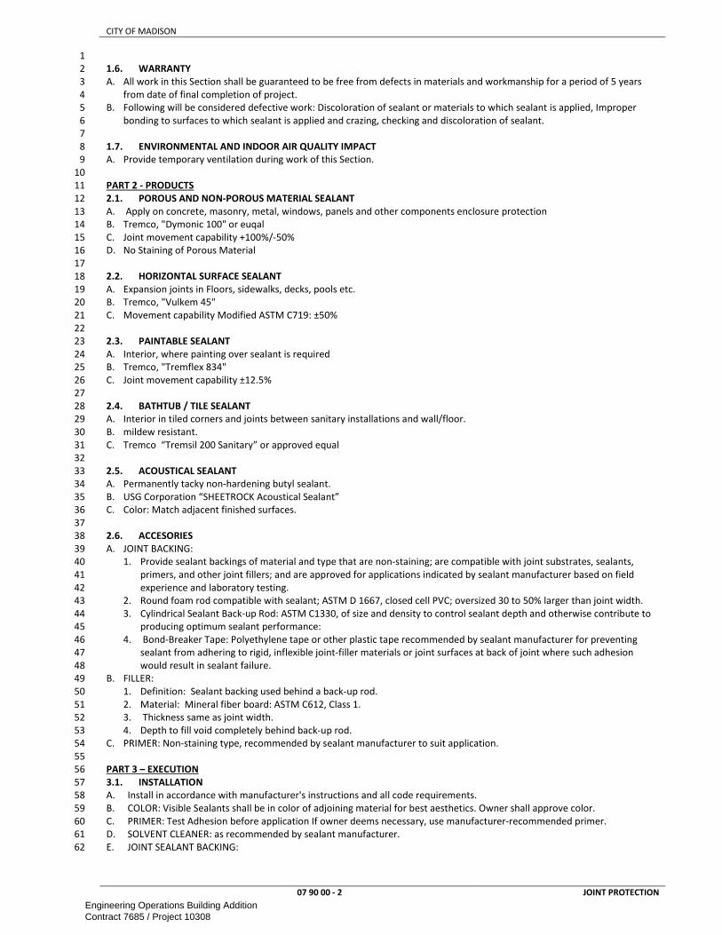
CITY OF MADISON
07 90 00 - 2 JOINT PROTECTION
1
1.6. WARRANTY 2
A. All work in this Section shall be guaranteed to be free from defects in materials and workmanship for a period of 5 years 3
from date of final completion of project. 4
B. Following will be considered defective work: Discoloration of sealant or materials to which sealant is applied, Improper 5
bonding to surfaces to which sealant is applied and crazing, checking and discoloration of sealant. 6
7
1.7. ENVIRONMENTAL AND INDOOR AIR QUALITY IMPACT 8
A. Provide temporary ventilation during work of this Section. 9
10
PART 2 - PRODUCTS 11
2.1. POROUS AND NON-POROUS MATERIAL SEALANT 12
A. Apply on concrete, masonry, metal, windows, panels and other components enclosure protection 13
B. Tremco, "Dymonic 100" or euqal 14
C. Joint movement capability +100%/-50% 15
D. No Staining of Porous Material 16
17
2.2. HORIZONTAL SURFACE SEALANT 18
A. Expansion joints in Floors, sidewalks, decks, pools etc. 19
B. Tremco, "Vulkem 45" 20
C. Movement capability Modified ASTM C719: ±50% 21
22
2.3. PAINTABLE SEALANT 23
A. Interior, where painting over sealant is required 24
B. Tremco, "Tremflex 834" 25
C. Joint movement capability ±12.5% 26
27
2.4. BATHTUB / TILE SEALANT 28
A. Interior in tiled corners and joints between sanitary installations and wall/floor. 29
B. mildew resistant. 30
C. Tremco “Tremsil 200 Sanitary” or approved equal 31
32
2.5. ACOUSTICAL SEALANT 33
A. Permanently tacky non-hardening butyl sealant. 34
B. USG Corporation “SHEETROCK Acoustical Sealant” 35
C. Color: Match adjacent finished surfaces. 36
37
2.6. ACCESORIES 38
A. JOINT BACKING: 39
1. Provide sealant backings of material and type that are non-staining; are compatible with joint substrates, sealants, 40
primers, and other joint fillers; and are approved for applications indicated by sealant manufacturer based on field 41
experience and laboratory testing. 42
2. Round foam rod compatible with sealant; ASTM D 1667, closed cell PVC; oversized 30 to 50% larger than joint width. 43
3. Cylindrical Sealant Back-up Rod: ASTM C1330, of size and density to control sealant depth and otherwise contribute to 44
producing optimum sealant performance: 45
4. Bond-Breaker Tape: Polyethylene tape or other plastic tape recommended by sealant manufacturer for preventing 46
sealant from adhering to rigid, inflexible joint-filler materials or joint surfaces at back of joint where such adhesion 47
would result in sealant failure. 48
B. FILLER: 49
1. Definition: Sealant backing used behind a back-up rod. 50
2. Material: Mineral fiber board: ASTM C612, Class 1. 51
3. Thickness same as joint width. 52
4. Depth to fill void completely behind back-up rod. 53
C. PRIMER: Non-staining type, recommended by sealant manufacturer to suit application. 54
55
PART 3 – EXECUTION 56
3.1. INSTALLATION 57
A. Install in accordance with manufacturer's instructions and all code requirements. 58
B. COLOR: Visible Sealants shall be in color of adjoining material for best aesthetics. Owner shall approve color. 59
C. PRIMER: Test Adhesion before application If owner deems necessary, use manufacturer-recommended primer. 60
D. SOLVENT CLEANER: as recommended by sealant manufacturer. 61
E. JOINT SEALANT BACKING: 62
Engineering Operations Building AdditionContract 7685 / Project 10308

CITY OF MADISON
07 90 00 - 3 JOINT PROTECTION
1. Provide sealant backings of material and type that are non-staining; are compatible with joint substrates, sealants, 1
primers, and other joint fillers; and are approved for applications indicated by sealant manufacturer based on field 2
experience and laboratory testing. 3
2. Use Closed-cell polyethlyene backer rods backing material to control depth of sealant bead. Where space for back-up 4
rod does not exist, install bond breaker tape strip at bottom (or back) of joint so sealant bonds only to two opposing 5
surfaces. Take all necessary steps to prevent three sided adhesion of sealants. Do not apply sealant directly against 6
mortar in a joint. 7
3. Cylindrical Sealant Back-up Rod: ASTM C1330, of size and density to control sealant depth. Install filler to fill void 8
behind back-up rod at full joint thickness. Fillermaterial: Mineral fiber board: ASTM C612, Class 1. 9
4. Bond-Breaker Tape: Polyethylene tape or other plastic tape recommended by sealant manufacturer for preventing 10
sealant from adhering to rigid, inflexible joint-filler materials or joint surfaces at back of joint where such adhesion 11
would result in sealant failure. 12
5. Insert backer material uniformly into the joint cavity so that joint depth does not exceed one half (1/2) joint width. 13
F. PREPARATORY WORK 14
1. Prepare joints in accordance with manufacturer's instructions. Verify required proportion of joint width to depth. 15
2. Clean surfaces of joint to receive caulking or sealants leaving joint dry to the touch, free from frost, moisture, grease, 16
oil, wax, lacquer paint, or other foreign matter that would tend to destroy or impair adhesion. 17
a. Clean porous joint substrate surfaces to produce a clean, sound substrate capable of developing optimum bond 18
with joint sealants. 19
b. Remove laitance and form-release agents from concrete. Remove loose particles remaining from above cleaning. 20
Porous joint surfaces include concrete, masonry glass, metal, porcelain enamel and unglazed surfaces of ceramic 21
tile. 22
G. APPLICATION OF SEALANT: 23
1. Follow requirements of ASTM C1193 and manufacturer's instructions and tool to a concave surface. 24
2. Apply sealant by means of a pressure gun with nozzle diameter equal to width of joint. Firmly press sealant into joint 25
to ensure complete wetting of bonding surface and obtain good adhesion. 26
3. Where practical, mask joints and do not remove tape until joint has been tooled and initial cure has taken place. 27
H. Seal all joints including, but not limited to, air intakes and louvers, Items projecting through or against walls or floors; 28
building expansion and control joints, Door and window frames, including lintels, Building control joints, Metal-to-masonry 29
and metal-to-gypsum board at metal frames caulked with paintable sealant, Joint between windows and window stools, 30
Joint between plumbing fixtures and adjacent surfaces. All other locations where caulking is required by material and 31
product manufacturers. 32
I. Perform work in accordance with ASTM C1193, "Standard Guide for Use or Joint Sealants", and Sealant, Waterproofing & 33
Restoration Institute (SWR Institute), "Sealants: The Professional’s Guide." 34
J. Do not apply sealants when surfaces are frosty, damp or wet or when temperatures are below 40°F without written 35
approval from sealant manufacturer. 36
37
END OF SECTION 38
Engineering Operations Building AdditionContract 7685 / Project 10308

CITY OF MADISON
08 50 00 - 1 COMMON WORK RESULTS FOR OPENINGS
SECTION 08 50 00 1
COMMON WORK RESULTS FOR OPENINGS 2
3
PART 1 – GENERAL ............................................................................................................................................................................ 1 4
1.1. SCOPE ............................................................................................................................................................................ 1 5
1.2. REFERENCES .................................................................................................................................................................. 1 6
1.5. PERFORMANCE REQUIREMENTS ................................................................................................................................... 1 7
PART 2 - PRODUCTS .......................................................................................................................................................................... 1 8
PART 3 – EXECUTION ......................................................................................................................................................................... 1 9
10
PART 1 – GENERAL 11
1.1. SCOPE 12
A. This section includes information common to openings and applies to all sections in this contract. 13
B. Openings shall be the responsibility of the Contractor requiring the openings even if such openings are not shown on 14
drawings. 15
16
1.2. REFERENCES 17
A. Work under this section depends on applicable provisions from other sections and the plan set in this contract. Examples of 18
related sections include, but are not limited to: 19
20
1.5. PERFORMANCE REQUIREMENTS 21
A. All openings shall be made as airtight, watertight, fireproof, smoke-tight, thermally insulated as the wall they are in. Patch 22
wall around sleeve to match adjacent wall construction and finish. In finished spaces where penetration through wall is 23
exposed to view, sheet metal sleeve shall be installed flush with face of wall. Grout area around sleeve in masonry 24
construction. Paint the surface to match existing surface including texture. 25
B. Penetrations through floors in mechanical rooms and wet locations (all rooms with water tap or connection, Parking ramps, 26
kitchens, sleeping rooms, food service areas, pumping stations, swimming pools, chemical storage, storage of liquids or 27
locations that can get wet by accident or failure of a component etc.), shall receive extended galvanized sleeves 2” above 28
floor to prevent water penetration. Provide urethane caulk between sleeve and floor and fasten sleeve to floor. Seal 29
corners water tight with urethane caulk. Size sleeve to allow insulation and paint the sleeve. In existing floor galvanized 30
steel angles (1.5”x1.5”x 0.125”) fastened to floor may be used if properly and permanently sealed. 31
32
PART 2 - PRODUCTS 33
34
PART 3 – EXECUTION 35
36
END OF SECTION 37
Engineering Operations Building AdditionContract 7685 / Project 10308

CITY OF MADISON
08 11 13 - 1 HOLLOW METAL DOORS AND FRAMES
SECTION 08 11 13 1
HOLLOW METAL DOORS AND FRAMES 2
3
PART 1 – GENERAL ............................................................................................................................................................................ 1 4
1.1. SCOPE ............................................................................................................................................................................ 1 5
1.2. REFERENCES .................................................................................................................................................................. 1 6
1.3. SUBMITTALS .................................................................................................................................................................. 2 7
1.4. QUALITY ASSURANCE .................................................................................................................................................... 2 8
1.5. PERFORMANCE REQUIREMENTS ................................................................................................................................... 2 9
PART 2 - PRODUCTS .......................................................................................................................................................................... 3 10
2.1. FABRICATION ................................................................................................................................................................ 3 11
2.2. DOORS ........................................................................................................................................................................... 4 12
2.3. FRAMES ......................................................................................................................................................................... 4 13
2.4. SMOKE DOORS .............................................................................................................................................................. 5 14
2.5. FIRE RATED DOORS ....................................................................................................................................................... 5 15
2.6. SOUND RATED DOORS .................................................................................................................................................. 6 16
2.7. INSULATED DOORS AND FRAMES ................................................................................................................................. 6 17
2.8. FINISH ............................................................................................................................................................................ 6 18
PART 3 – EXECUTION ......................................................................................................................................................................... 6 19
3.1. INSTALLATION ............................................................................................................................................................... 6 20
21
PART 1 – GENERAL 22
1.1. SCOPE 23
A. This section includes information common to standard, fire-rated, sound-rated and insulated hollow metal doors and 24
frames. 25
26
1.2. REFERENCES 27
A. Work under this section depends on applicable provisions from other sections and the plan set in this contract. Examples of 28
related sections include, but are not limited to: 29
1. DIVISION 03 — CONCRETE 30
2. DIVISION 04 — MASONRY 31
3. DIVISION 05 — METALS 32
4. 07 05 00 – COMMON WORK RESULTS FOR THERMAL AND MOISTURE PROTECTION 33
5. 07 84 00 – FIRESTOPPING 34
6. 07 90 00 – JOINT PROTECTION 35
7. 08 81 00 - GLASS GLAZING 36
8. DIVISION 26 — ELECTRICAL 37
B. ANSI – American National Standards Institute 38
1. ANSI A117.1 - American National Standard for Accessible and Usable Buildings and Facilities; International Code Council 39
2. ANSI A250.8 - SDI-100 Recommended Specifications for Standard Steel Doors and Frames 40
3. ANSI A250.10 - Test Procedure and Acceptance Criteria for Prime Painted Steel Surfaces for Steel Doors and Frames 41
C. ASTM - American Society for Testing and Materials 42
1. ASTM A 153-82(87) - Standard Specification for Zinc Coating (Hot-Dip) on Iron and Steel Hardware 43
2. ASTM A 366/A 366M-96 - Standard Specification for Steel, Sheet, Carbon, Cold-Rolled, Commercial Quality 44
3. ASTM A 525-93 - Standard Specification for General Requirements for Steel Sheet, Zinc-Coated (Galvanized) by the Hot 45
Dip Process 46
4. ASTM A 526/A 526M-90 - Standard Specification for Steel Sheet, Zinc-Coated (Galvanized) by the Hot-Dip Process, 47
Commercial Quality 48
5. ASTM A 568/A 568M-95 - Standard Specification for Steel, Sheet, Carbon, and High-Strength, Low-Alloy, Hot-Rolled and 49
Cold-Rolled, General Requirements for 50
6. ASTM A 569/A 569M-91a - Standard Specification for Steel, Carbon (0.15 Maximum, Percent), Hot-Rolled Sheet and 51
Strip Commercial Quality 52
7. ASTM A 591/A 591M-89 - Standard Specification for Steel Sheet, Electrolytic Zinc-Coated, for Light Coating Mass 53
Applications 54
8. ASTM A653/A653M - Standard Specification for Steel Sheet, Zinc-Coated (Galvanized) or Zinc-Iron Alloy-Coated 55
(Galvannealed) by the Hot-Dip Process 56
9. ASTM C 236-89(93) - Standard Test Method for Steady-State Thermal Performance of Building Assemblies by Means of 57
a Guarded Hot Box 58
10. ASTM E 152-81a - Standard Methods of Fire Tests of Door Assemblies 59
11. ASTM E 329 - Standard Specification for Agencies Engaged in Construction Inspection and/or Testing 60
12. ASTM E 548 - Standard Guide for General Criteria Used for Evaluating Laboratory Competence 61
D. BHMA - builders hardware manufacturers association 62
1. BHMA A156.115 - Hardware Preparation in Steel Doors and Steel Frames 63
Engineering Operations Building AdditionContract 7685 / Project 10308

CITY OF MADISON
08 11 13 - 2 HOLLOW METAL DOORS AND FRAMES
E. DHI – Door and Hardware Institute 1
1. DHI A115 Series - Specifications for Steel Door and Frame Preparation for Hardware 2
F. NAAMM - National Association Of Architectural Metal Manufacturers 3
1. NAAMM HMMA 840 - Guide Specifications for Installation and Storage of Hollow Metal Doors and Frames 4
G. NFPA - National Fire Protection Association 5
1. NFPA 80 - Standard for Fire Doors and Other Opening Protectives 6
2. NFPA 105 - Standard for the Installation of Smoke Door Assemblies and other Opening Protectives; 7
H. SDI – Steel Door Institute 8
1. SDI 100-1991 - Recommended Specifications: Standard Steel Doors and Frames; Steel Door Institute 9
2. SDI 105-92 - Recommended Erection Instructions for Steel Frames; Steel Door Institute 10
I. SSPC - Steel Structures Painting Council 11
1. SSPC-SP1 - Solvent Cleaning 12
2. SSPC-SP8 - Pickling 13
J. UL – Underwriters Laboratory 14
1. UL (BMD) - Building Materials Directory; Underwriters Laboratories Inc. 15
2. UL 10C - Standard for Positive Pressure Fire Tests of Door Assemblies 16
17
1.3. SUBMITTALS 18
A. Submit shop drawings for the fabrication and installation of hollow metal work. Include details of each frame type, 19
elevations of door design types, borrow lights and window types, conditions at openings, details of construction, location 20
and installation requirements of finish hardware and reinforcement, and details of joints and connections. 21
B. Provide a schedule of doors and frames using same reference numbers for details and openings as those used on the 22
contract drawings. 23
C. Label Construction Hollow Metal Work: Submit manufacturer's certification for oversize fire-rated doors and frames that 24
each assembly has been constructed with materials and methods equivalent to requirements for labeled construction. 25
D. Manufacturer's Certifications: 26
1. Certify that products meet or exceed specified requirements. 27
2. Certify that manufacturer has reviewed specified hardware and confirmed that all components will fit in doors and 28
frames provided under Work of this Section. 29
30
1.4. QUALITY ASSURANCE 31
A. Deliver hollow metal work cartoned or crated to provide protection during transit and job storage. 32
B. Inspect hollow metal work upon delivery for damage. Minor damages may be repaired provided the finish items are equal 33
in all respects to new work and acceptable to the Construction Manager; otherwise, remove and replace damaged items as 34
directed. 35
C. MANUFACTURER: 36
1. Company specializing in manufacturing the products specified in this section with minimum 3 years documented 37
experience. 38
2. Member of the Steel Door Institute 39
D. INSTALLERS: An employer of workers trained and approved by the manufacturer. 40
E. TESTING AGENCY: An independent agency qualified according to ASTM E 329 for testing indicated, as documented 41
accroding to ASTM E 548. 42
F. SOURCE LIMITATIONS: 43
1. Exterior Doors and Frames: Through one source from a single manufacturer. 44
2. Interior Doors and Frames except for sound rated assemblies: Through one source from a single manufacturer. 45
46
1.5. PERFORMANCE REQUIREMENTS 47
A. EXTERIOR DOORS: 48
1. AIR INFILTRATION: For a single door 3’-0" x 7’-0", test specimen shall be tested in accordance with ASTM E 283 at 49
pressure differential of 6.24 psf. Door shall not exceed 0.90 cfm per linear foot of perimeter crack. 50
2. WATER RESISTANCE: For a single door 3’-0" x 7’-0", test specimen shall be tested in accordance with ASTM E 331 at 51
pressure differential of 7.50 psf. Door shall not have water leakage. 52
3. HURRICANE TEST STANDARDS, Single Door with Single-Point Latching: 53
a. Uniform Static Load, ASTM E 330: Plus or minus 75 pounds per square foot. 54
b. Forced Entry Test, 300 Pound Load Applied, SFBC 3603.2 (b)(5): Passed. 55
c. Cyclic Load Test, SFBC PA 203: Plus or minus 53 pounds per square foot. 56
d. Large Missile Impact Test, SFBC PA 201: Passed. 57
4. Blast Test, Doors and Frames, ASTM F 1642-04, 6 psi / 41 psimsec: Minimal Hazard 58
5. Swinging Security Door Assembly, Doors and Frames, ASTM F 476: Grade 40. 59
6. Salt Spray, Exterior Doors and Frames, ASTM B 117: Minimum of 500 hours. 60
7. Sound Transmission, Exterior Doors, STC, ASTM E 90: Minimum of 25. 61
8. Water Absorption, FRP Doors and Panels, Nominal Value, ASTM D 570: 0.20 percent after 24 hours. 62
B. Swinging Door Cycle Test, Doors and Frames, ANSI A250.4: Minimum of 25,000,000 cycles. 63
Engineering Operations Building AdditionContract 7685 / Project 10308

CITY OF MADISON
08 11 13 - 3 HOLLOW METAL DOORS AND FRAMES
C. Cycle Slam Test Method, NWWDA T.M. 7-90: Minimum 5,000,000 Cycles 1
D. Surface Burning Characteristics, Class A Option On Interior Faces of Exterior Panels and Faces of Interior Panels, ASTM E 2
84: 3
1. Flame Spread: Maximum of 25. 4
2. Smoke Developed: Maximum of 450. 5
E. FIRE-RATED ASSEMBLIES: 6
1. Wherever a fire-resistance classification is shown or scheduled for hollow metal work, provide fire-rated hollow metal 7
doors and frames investigated and tested as a fire door assembly, complete with type of door hardware to be used. 8
Identify each fire door and frame with recognized testing laboratory labels, including applicable fire rating of both 9
door and frame. 10
2. Construct assemblies to comply with N.F.P.A. Standard No. 80, labeled per ASTM E 152 by agency acceptable to 11
governing authorities, and as herein specified. 12
3. Temperature rise rating: For fire rated doors in stairwell enclosures, provide door construction tested and certified to 13
limit temperature rise in thirty minutes to 450 °F. 14
15
PART 2 - PRODUCTS 16
2.1. FABRICATION 17
A. ACCEPTABLE MANUFACTURERS: Assa Abloy, Ceco Manufacturing Co, Fenestra Corporation, Overly Mfg. Co., Pioneer 18
Industries, Superior Fireproof Door, Inc. , Trussbilt, Inc. 19
B. MATERIALS 20
1. Hot-Rolled Steel Sheets and Strips: Commercial quality carbon steel, pickled and oiled, complying with ASTM A 569 21
and ASTM A 568. 22
2. Cold-Rolled Steel Shapes: Commercial quality carbon steel, complying with ASTM A 366 and ASTM A 568. 23
3. Galvanized Steel Sheets: Zinc-coated carbon steel sheets of commercial quality, complying with ASTM A526, with 24
ASTM 525, G60 zinc coating, mill phosphatized. 25
4. Supports and Anchors: Fabricate on not less than l6 gauge sheet metal. Galvanize after fabrication of units to be built 26
into exterior walls, complying with ASTM A 153, Class B. 27
5. Seal top and bottom edges integrally with door construction, or use minimum 16 gage steel channels to form flush 28
closure. 29
6. Inserts, Bolts and Fasteners: Manufacturer's standard units, except hot-dip galvanize items to be built into exterior 30
walls, complying with ASTM A 153, Class C or D as applicable. 31
7. Shop-Applied Paint: For steel surfaces, use zinc-rich primer for exterior doors and rust-inhibitive primer for interior 32
doors, either air-drying or baking, suitable as a base for specified finish paints. 33
C. FABRICATION 34
1. Fabricate hollow metal units to be rigid, neat in appearance and free from defects, warp or buckle. Accurately form 35
metal to required sizes and profiles. Wherever practicable, fit and assemble units in the manufacturer's plant. Clearly 36
identify work that cannot be permanently factory-assembled before shipment to assure proper assembly at the 37
project site. Weld exposed joints continuously, grind, dress and make smooth, flush and invisible. Metallic filler to 38
conceal manufacturing defects is not accepted. 39
2. Fabricate exterior doors, panels, and frames from galvanized sheet steel. Close top and bottom edges of exterior 40
doors as integral pat of door construction or by addition of inverted steel channels. 41
3. Exposed Fasteners: Unless otherwise indicated, provide countersunk flat Phillips or Jackson heads for exposed screw 42
and bolts. 43
D. HARDWARE: 44
1. Mortise, reinforce, drill and tap frames at the factory for fully templated mortised hardware in accord with approved 45
hardware schedule and templates provided by hardware contractor. Where surface-mounted hardware is to be 46
applied, provide reinforcing plates only. Drilling and tapping will be done by others. 47
2. Minimum thickness of hardware reinforcing plates shall be as follows: 48
a. Hinge and pivot reinforcements - 7 gauge. 49
b. Strike reinforcements - 16 gauge. 50
c. Flush bolt reinforcements - 12 gauge. 51
d. Closer reinforcements - 14 gauge. 52
e. Reinforcements for: 53
i. surface-mounted hardware - 12 gauge. 54
ii. hold-open arms - 16 gauge. 55
iii. surface panic devices - 16 gauge. 56
3. Finish Hardware Preparation: 57
a. Prepare hollow metal units to receive mortised and concealed finish hardware, including cutouts, reinforcing, 58
drilling and tapping in accordance with final Door Hardware specified and templates provided by hardware 59
supplier. Comply with applicable requirements of ANSI A115 "Specifications for Door and Frame Preparation for 60
Hardware". 61
b. For concealed overhead door closures, provide space, cutouts, reinforcing and provisions for fastening in top 62
rails of doors or head of frames, as applicable. 63
Engineering Operations Building AdditionContract 7685 / Project 10308

CITY OF MADISON
08 11 13 - 4 HOLLOW METAL DOORS AND FRAMES
c. Reinforce hollow metal units to receive surface-applied hardware. Drilling and tapping for surface-applied finish 1
hardware may be done at project site. 2
d. Locate finish hardware as shown on final shop drawings, or if not shown, in accordance with "Recommended 3
Locations for Builder's Hardware", published be the National Builder's Hardware Association. 4
5
2.2. DOORS 6
A. Provide flush design doors, 1-3/4 inch thick, seamless hollow construction of design indicated on the Drawings. 7
B. For single-acting swing doors, bevel vertical lock edges 1/8 inch in 2 inch. 8
C. Provide sound insulation filler of fiberboard, mineral-wool board, or other approved noncombustible material solidly 9
packed full door height to fill the voids between inner core reinforcing members. 10
D. Reinforce doors with rigid tubular frame where stiles and rails are less than 8 inches wide. Form tubular frame with 16 11
gauge steel, welded to outer sheets. 12
E. Fabricate doors of two (2) outer cold-rolled, stretcher-leveled steel sheets of gages indicated on Schedule. Construct doors 13
with smooth, flush surfaces, without visible joints or seams on exposed faces or stile edges, except around glazed or 14
louvered panel inserts. 15
F. Reinforce inside of doors with vertical, hot-rolled, not less than 16 gauge steel channel-shaped sections or interlocking Z-16
shaped steel sections. Space vertical reinforcing 6 in o.c. and extend full door height. Spot-weld at not more than 5 in o.c. 17
to both face sheets. 18
G. Continuous truss-form inner core of 16 gauge sheet metal reinforcing may be provided as inner reinforcement in lieu of 19
above. Shop-weld truss-form reinforcement 3 in o.c. vertically and horizontally over entire surface of both sides. 20
H. Reinforce tops and bottoms of doors with 16 gauge, horizontal steel channels, welded continuously to the outer sheets. At 21
exterior doors, provide steel channel with legs down, closing tip of doors, joints sealed to retaining and penetration of 22
water. 23
I. Finish Hardware Reinforcement: Reinforce doors for required finish hardware, as follows: 24
J. Hinges: Steel plate 3/16 inches thick x 1-1/2 inches wide x 6 inches longer than hinge, secured by not less than 6 spot-25
welds. 26
K. Mortise Locksets and Dead Bolts: 14 gauge steel sheet, secured with not less than 2 spot-welds. 27
L. Concealed Closers: Removable steel access plate, 12 gauge internal reinforcement of size and shape required and 28
enclosed housing to keep closer pocket free of mortar or other material. 29
30
2.3. FRAMES 31
A. Interior Openings: Commercial grade cold-rolled steel conforming to ASTM A 366 or commercial grade hot-rolled and 32
pickled steel conforming to ASTM A569. Metal thickness to be not less than 14 gauge. 33
B. Exterior Openings: Commercial grade cold rolled steel conforming to ASTM A 366 or hot-rolled, pickled and oiled steel 34
conforming to ASTM A 569, not less than 14 gauge with a zinc coating applied by the hot-dip process conforming to ASTM 35
A 526 with a coating weight of not less than 0.60 ounces per square foot (.030 os/ ft² per side). 36
C. Comply with the requirements of grade specified for corresponding door, except: 37
1. ANSI A250.8 Level 1 and 2 Doors: 16 gage frames. 38
2. ANSI A250.8 Level 3 Doors: 14 gage frames. 39
3. Frames for Wood Doors: Comply with frame requirements specified in ANSI A250.8 for Level 1, 18 gage 40
D. Frames Wider than 48 Inches: 41
1. Reinforce with steel channel fitted tightly into frame head, flush with top or increase thickness by at least two 42
standard gauges. Head Reinforcing: 43
2. In masonry wall openings, provide continuous steel channel or angle stiffener, not less than 12 gauge for full width of 44
opening, welded to back of frame at head. 45
E. Frames Installed Back-to-Back: Reinforce with steel channels anchored to floor and overhead structure. 46
F. Provide hollow metal frames for doors, transoms, side-lights, borrowed-lights, windows and other openings, of size, gauge 47
and profile as indicated. 48
G. Steel frames shall have mitered and welded corners. Knock-down type hollow metal frames are not acceptable. 49
H. Finish Hardware Reinforcement: Reinforce frames for required finish hardware as follows: 50
I. Hinges: Steel plate 3/16 inches thick x 1-1/2 inches wide x 6 inches longer than hinge, secured by not less than 6 spot-51
welds. 52
J. Strike Plate Clips: Steel plate 3/16 inches thick x 1-1/2 inches wide x 3 inches long. 53
K. Concealed Closers: 12 gauge steel sheet, secured with not less than 6 spot-welds. 54
L. Mullions and Transom Bars: Provide closed or tubular mullions and transom bars where indicated. Fasten mullions and 55
transom bars at crossings and to jambs be butt welding. Reinforce joints between frame members with concealed clip 56
angles or sleeves same metal and thickness as frame. 57
M. Head Reinforcing: Where installed in masonry, leave mullions in frames open at the top so they can be filled with grout. 58
N. Provide dust cover boxes (or mortar guards) of not thinner than 26 gauge steel at all hardware mortises on frames to be 59
set in masonry partitions. 60
O. Provide all frames with a steel spreader temporarily attached to the feet of both jambs to serve as a brace during shipping 61
and handling. The steel spreader is not to be used for installation purposes. 62
Engineering Operations Building AdditionContract 7685 / Project 10308

CITY OF MADISON
08 11 13 - 5 HOLLOW METAL DOORS AND FRAMES
P. Provide three (3) Glynn-Johnson, "No. 64" pneumatic rubber silencers installed in strike jamb of single doors and head of 1
pairs of doors. 2
A. Loose glazing beads: Cold rolled steel, minimum 20 gauge, butted at the corners and secured to the frame with self- Meet 3
all above requirements. 4
Q. tapping corrosion resistant sheet metal screws. 5
R. Provide electrical conduit in frames for all electric and magnetic locks, keeper switches and door position indicator 6
switches. 7
S. Raceways: Rigid metal conduit and intermediate metal conduit (IMC) shall be steel, galvanized inside and outside. 8
Minimum 3/4" trade size conduit shall be used. Minimum 1/2" trade size conduit may be used incorporating wiring for one 9
device. 10
T. Raceway Fittings: Fittings for steel conduit shall be galvanized or other corrosion resistant material. Fittings for rigid 11
conduit and IMC shall be galvanized steel threaded couplings. Locknuts and bushings shall be steel or malleable iron. 12
U. ANCHORS: 13
1. Jamb Anchors: Furnish jamb anchors as required to secure frames to adjacent construction, formed of not less than 14
12 gauge galvanized steel at masonry. 15
2. Provide frames for installation in masonry walls with adjustable jamb anchors of the T-strap. The number of anchors 16
provided on each jamb shall be as follows: 17
a. Frames up to 7'-6" height - 3 anchors. 18
b. Frames 7'-6" to 8'-0" height - 4 anchors. 19
c. Frames over 8'-0" height - 1 anchor for each 2' or fraction thereof in height. 20
3. Provide frames for installation in stud partitions with steel anchors of suitable design securely welded inside each 21
jamb as follows: 22
a. Frames up to 7'-6" height - 4 anchors 23
b. Frames 7'-6" to 8'-0" height - 5 anchors. 24
c. Frames over 8'-0" height - 5 anchors plus one additional for each 2' or fraction thereof over 8'-0". 25
4. Masonry Construction: Adjustable, flat or corrugated or perforated, T-shaped to suit frame size with leg not less than 26
2 inches wide x 18 inches long or as shown on the Drawings. Furnish anchors at jamb 16 in o.c. vertically. 27
5. Floor Anchors: Provide floor anchors for each jamb and mullion which extends to the floor, formed of not less than 28
14 gauge for studs and 12 gauge at masonry, galvanized steel sheet, as follows: 29
6. Monolithic Concrete Slab: Clip type anchors, with 2 holes to receive fasteners, welded to bottom of jambs and 30
mullions. 31
7. Head Strut Supports: Provide 3/8 inches x 2 inch vertical steel struts extending from top of frame at each jamb to 32
supporting construction above, unless frame is anchored to masonry or to other structural support at each jamb. 33
Bend top of struts to provide flush contact for securing to supporting construction above. Provide adjustable bolted 34
anchorage to frame jamb members. 35
8. Spreader Bars: Provide removable spreader bar across bottom of frames, tack-welded to jambs and mullions. 36
9. Rubber Door Silencers: Drill stop to receive and provide three (3) silencers on single-door frames and four (4) 37
silencers on double-door frames. 38
10. Plaster Guards: Provide 26 gauge steel plaster guards or dust cover boxes, welded to frame, at back of finish 39
hardware cutouts where mortar or other materials might obstruct hardware installation. 40
V. STOPS AND MOLDINGS 41
1. Form fixed stops and moldings integral with frame. Provide fixed stops on inside of hollow metal units exposed to 42
exterior and on corridor side of interior units. 43
2. Provide removable stops and molds at glazing side of borrow lights. Secure with countersunk tamper-proof (spanner 44
head) machine screws. 45
46
2.4. SMOKE DOORS 47
B. Meet these requirements in addition to above requirements. 48
C. Close top and vertical edges flush. 49
D. Provide seamless vertical edges. 50
E. Apply Steel astragal to the meeting style at the active leaf of pair of doors or double egress doors. 51
F. Provide clearance at head, jamb and sill as specified in NFPA 80. 52
G. Comply with NFPA 105 53
54
2.5. FIRE RATED DOORS 55
A. Meet these requirements in addition to above requirements. 56
B. Conform to NFPA 80 when tested by Underwriters Laboratories, Inc., Inchcape Testing Services, or Factory Mutual for the 57
class of door or door opening shown. 58
C. Fire rated labels of metal, with raised or incised markings of approving laboratory shall be permanently attached to doors. 59
D. Close top and vertical edges of doors flush. Vertical edges shall be seamless. Apply steel astragal to the meeting stile of the 60
active leaf of pairs of fire rated doors, except where vertical rod exit devices are specified for both leaves swinging in the 61
same direction. 62
Engineering Operations Building AdditionContract 7685 / Project 10308

CITY OF MADISON
08 11 13 - 6 HOLLOW METAL DOORS AND FRAMES
E. Construct fire rated doors in stairwell enclosures for maximum transmitted temperature rise of 230°C (450°F) above 1
ambient temperature at end of 30 minutes of fire exposure when tested in accordance with ASTM E152. 2
3
2.6. SOUND RATED DOORS 4
A. Meet these requirements in addition to above requirements. 5
B. Meet SDI 114. 6
C. Sound Transmission Class minimum of 45 when tested in accordance with ASTM E90. 7
D. Doors complete with integral spring type automatic door bottom seal and with integral continuous gaskets on the frames. 8
E. Fabricate vision panels to receive double glazing where shown. 9
F. Coat inside (concealed surfaces) of all interior door frames, in wall construction, with plaster. Coating shall cover concealed 10
surfaces to the fullest extent possible. Apply over shop primer to a minimum 1/2 inch thickness and allow to cure before 11
handling 12
G. Silencers: Resilient rubber, fitted into drilled hole; 3 on strike side of single door, 3 on center mullion of pairs, and 2 on head 13
of pairs without center mullions. 14
15
2.7. INSULATED DOORS AND FRAMES 16
A. Meet these requirements in addition to above requirements. 17
B. Use for all exterior doors in conditioned buildings. 18
C. Thermal-Rated (Insulating) Assemblies: At exterior locations and elsewhere as shown on or scheduled, provide doors 19
which have been fabricated as thermal insulating door and frame assemblies and tested in accordance with ASTM C 236. 20
D. BASIS OF DESIGN: 21
1. ASSA ABLOY / Ceco Trio-E Door system with broken frame and broken threshold. 22
2. ASTM C1363 complete assembly U 0.29 23
3. Air Infiltration <= 0.04 cfm/ft² when tested according to ASTM E283 24
25
2.8. FINISH 26
A. Finish per ANSI A250.8. 27
B. Clean, treat and paint exposed surfaces of fabricated hollow metal units, including galvanized surfaces. 28
C. Clean steel surface of all mill scale, rust, oil, grease, dirt and other foreign materials before the application of the shop coat 29
of paint. 30
D. Apply pretreatment to cleaned metal surfaces, using cold phosphate solution (SSPC-PT 2), hot phosphate solution (SSPC-PT 31
4) or basic zinc chromate-vinyl butyral solution (SSPC-PT 3). 32
E. Apply shop coat of prime paint within time limits recommended be pretreatment manufacturer. Apply a smooth coat of 33
even consistency to provide a uniform dry film thickness of not less than 2.0 mils. 34
35
PART 3 – EXECUTION 36
3.1. INSTALLATION 37
A. Install hollow metal units and accessories in accordance with the final shop drawings, manufacturer's data, and as herein 38
specified. Adhere to provisions of SDI 105 and ANSI/DHI A115. 39
B. Plumb, align and brace frames securely until permanent anchors are set. 40
1. Use triangular bracing near each corner on both sides of frames with temporary wood spreaders at midpoint. 41
2. Use wood spreaders at bottom of frame if the shipping spreader is removed. 42
3. Protect frame from accidental abuse. 43
4. Where construction will permit concealment, leave the shipping spreaders in place after installation, otherwise 44
remove the spreaders after the frames are set and anchored. 45
5. Remove wood spreaders and braces only after the walls are built and jamb anchors are secured. 46
C. Floor Anchors: 47
1. Anchor the bottom of door frames to floor with two 6 mm (1/4 inch) diameter expansion bolts. Use 9 mm (3/8 inch) 48
bolts on lead lined frames. 49
2. Power actuated drive pins may be used to secure frame anchors to concrete floors. 50
D. Jamb Anchors: 51
1. Anchors in masonry walls: Embed anchors in mortar. Fill space between frame and masonry wall with grout or mortar 52
as walls are built. 53
2. Coat frame back with a bituminous coating prior to lining of grout filling in masonry walls. 54
3. Secure anchors to sides of studs with two fasteners through anchor tabs. Use steel drill screws to steel studs. 55
4. Frames set in prepared openings of masonry or concrete: Expansion bolt to wall with 6 mm (1/4 inch) expansion bolts 56
through spacers. Where subframes or rough bucks are used, 6 mm (1/4 inch) expansion bolts on 600 mm (24 inch) 57
centers or power activated drive pins 600 mm (24 inches) on centers. Secure two piece frames to subframe or rough 58
buck with machine screws on both faces. 59
E. Install anchors for labeled fire rated doors to provide rating as required. 60
F. Frames for Sound Rated Doors: Coordinate to line frames for sound rated doors with insulation. 61
Engineering Operations Building AdditionContract 7685 / Project 10308

CITY OF MADISON
08 11 13 - 7 HOLLOW METAL DOORS AND FRAMES
G. Overhead Bracing (Lead Lined Frames): Where jamb extensions extend to structure above, anchor clip angles with not less 1
than two, 9 mm (3/8 inch) expansion bolts or power actuated drive pins to concrete slab. Weld to steel overhead 2
members. 3
H. Setting Masonry Anchorage Devices: 4
1. Provide masonry anchorage devices where required for securing hollow metal frames to in-place concrete or masonry 5
construction. 6
2. Set anchorage devices opposite each anchor location, in accordance with details on final shop drawings and 7
anchorage device manufacturer's instructions. Leave drilled holes rough, not reamed, and free from dust and debris. 8
3. Floor anchors may be set with powder-actuated fasteners instead of masonry anchorage devices and machine screws, 9
if so indicated of final shop drawings. 10
I. Placing Frames: 11
1. Set frames accurately in position, plumbed, aligned, and braced securely until permanent anchors are set. After wall 12
construction is complete, remove temporary braces and spreaders leaving surfaces smooth and undamaged. 13
2. In masonry construction building-in of anchors and grouting of frames is included in Division 4 of these specifications. 14
3. At in-place concrete or masonry construction, set frames and secure in place with machine screws and masonry 15
anchorage devices. 16
4. Place frames at fire-rated openings in accordance with N.F.P.A. Standard No.80. 17
5. Make field splices in frames as detailed on final shop drawings, welded and finished to match factory work. 18
6. Remove spreader bars only after frames or bucks have been properly set and secured. 19
J. Door Installation: Fit hollow metal doors accurately in their respective frames, with the following clearances: 20
1. Jambs and Heads: 3/32 inches. 21
2. Meeting Edges, Pairs of Doors: 1/8 inch. 22
3. Bottom: 3/8 inch, where no threshold; 1/8 inch at threshold. 23
4. Place fire-rated doors with clearances as specified in N.F.P.A. Standard No. 80. 24
K. ADJUST AND CLEAN 25
1. Final Adjustments: Check and readjust operating finish hardware items in hollow metal work just prior to final 26
inspection. Leave work in complete and proper operating condition. Remove and replace defective work, including 27
doors and frames, which are warped, bowed or otherwise unacceptable. 28
2. Prime Coat Touch-up: Immediately after erection, sand smooth rusted or damaged areas of prime coat and apply 29
touch-up of compatible air-drying primer. 30
31
END OF SECTION 32
Engineering Operations Building AdditionContract 7685 / Project 10308
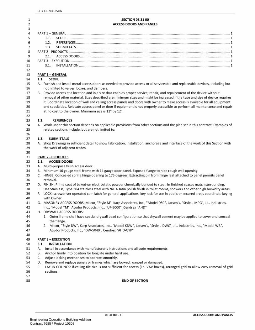
CITY OF MADISON
08 31 00 - 1 ACCESS DOORS AND PANELS
SECTION 08 31 00 1
ACCESS DOORS AND PANELS 2
3
PART 1 – GENERAL ............................................................................................................................................................................ 1 4
1.1. SCOPE ............................................................................................................................................................................ 1 5
1.2. REFERENCES .................................................................................................................................................................. 1 6
1.3. SUBMITTALS .................................................................................................................................................................. 1 7
PART 2 - PRODUCTS .......................................................................................................................................................................... 1 8
2.1. ACCESS DOORS .............................................................................................................................................................. 1 9
PART 3 – EXECUTION ......................................................................................................................................................................... 1 10
3.1. INSTALLATION ............................................................................................................................................................... 1 11
12
PART 1 – GENERAL 13
1.1. SCOPE 14
A. Furnish and install metal access doors as needed to provide access to all serviceable and replaceable devices, including but 15
not limited to valves, boxes, and dampers. 16
B. Provide access at a location and in a size that enables proper service, repair, and repalcement of the device without 17
removal of other material. Sizes described are minimum sizes and might be increased if the type and size of device requires 18
it. Coordinate location of wall and ceiling access panels and doors with owner to make access is available for all equipment 19
and specialties. Relocate access panel or door if equipment is not properly accessible to perform all maintenance and repair 20
at no cost to the owner. Minimum size is 12" by 12". 21
22
1.2. REFERENCES 23
A. Work under this section depends on applicable provisions from other sections and the plan set in this contract. Examples of 24
related sections include, but are not limited to: 25
26
1.3. SUBMITTALS 27
A. Shop Drawings in sufficient detail to show fabrication, installation, anchorage and interface of the work of this Section with 28
the work of adjacent trades. 29
30
PART 2 - PRODUCTS 31
2.1. ACCESS DOORS 32
A. Multi-purpose flush access door. 33
B. Minimum 16 gauge steel frame with 14 gauge door panel. Exposed flange to hide rough wall opening. 34
C. HINGE: Concealed spring hinge opening to 175 degrees. Extracting pin from hinge leaf attached to panel permits panel 35
removal. 36
D. FINISH: Prime coat of baked-on electrostatic powder chemically bonded to steel. In finished spaces match surrounding. 37
E. Use Stainless, Type 304 stainless steel with No. 4 satin polish finish in toilet rooms, showers and other high humidity areas. 38
F. LOCK: screwdriver operated cam latch for general applications, key lock for use in public or secured areas coordinate keying 39
with Owner. 40
G. MASONRY ACCESS DOORS: Milcor, "Style M", Karp Associates, Inc., "Model DSC", Larsen's, "Style L-MPG", J.L. Industries, 41
Inc., "Model TM", Acudor Products, Inc., "UF-5000", Cendrex "AHD" 42
H. DRYWALL ACCESS DOORS: 43
1. Outer frame shall have special drywall bead configuration so that drywall cement may be applied to cover and conceal 44
the flange. 45
2. Milcor, "Style DW", Karp Associates, Inc., "Model KDW", Larsen's, "Style L-DWC", J.L. Industries, Inc., "Model WB", 46
Acudor Products, Inc., "DW-5040", Cendrex "AHD-GYP" 47
48
PART 3 – EXECUTION 49
3.1. INSTALLATION 50
A. Install in accordance with manufacturer's instructions and all code requirements. 51
B. Anchor firmly into position for long life under hard use. 52
C. Adjust locking mechanism to operate smoothly. 53
D. Remove and replace panels or frames which are bowed, warped or damaged. 54
E. LAY-IN CEILINGS: if ceiling tile size is not sufficient for access (i.e. VAV boxes), arranged grid to allow easy removal of grid 55
sections. 56
57
END OF SECTION 58
Engineering Operations Building AdditionContract 7685 / Project 10308

CITY OF MADISON
08 36 13 - 1 SECTIONAL DOORS
SECTION 08 36 13 1
SECTIONAL DOORS 2
3
PART 1 – GENERAL ............................................................................................................................................................................ 1 4
1.1. SCOPE ............................................................................................................................................................................ 1 5
1.2. REFERENCES .................................................................................................................................................................. 1 6
1.3. SUBMITTALS .................................................................................................................................................................. 1 7
1.4. QUALITY ASSURANCE .................................................................................................................................................... 1 8
1.5. PERFORMANCE REQUIREMENTS ................................................................................................................................... 1 9
1.6. WARRANTY .................................................................................................................................................................... 1 10
PART 2 - PRODUCTS .......................................................................................................................................................................... 1 11
2.1. SECTIONAL DOORS ........................................................................................................................................................ 1 12
2.2. OPERATOR ..................................................................................................................................................................... 2 13
2.3. CONTROLS ..................................................................................................................................................................... 2 14
2.4. DRIVER SIGNALING ........................................................................................................................................................ 2 15
2.5. VEHILE LOOP DETECTOR ............................................................................................................................................... 2 16
2.6 INSULATED SECTIONAL OVERHEAD DOORS .................................................................................................................. 2 17
2.7. WASHBAY RATED DOORS .............................................................................................................................................. 3 18
PART 3 – EXECUTION ......................................................................................................................................................................... 3 19
3.1. INSTALLATION ............................................................................................................................................................... 3 20
21
PART 1 – GENERAL 22
1.1. SCOPE 23
A. This section includes information common to sectional overhead doors, electric operators, warning lights, and controls. 24
25
1.2. REFERENCES 26
A. Work under this section depends on applicable provisions from other sections and the plan set in this contract. Examples of 27
related sections include, but are not limited to: 28
1. DIVISION 03 — CONCRETE 29
2. DIVISION 04 — MASONRY 30
3. DIVISION 05 — METALS 31
4. DIVISION 07 — THERMAL AND MOISTURE PROTECTION 32
5. DIVISION 09 — FINISHES 33
6. DIVISION 26 — ELECTRICAL 34
B. ANSI – American National Standards Institute 35
1. ANSI/DASMA 102 - American National Standard Specifications for Sectional Overhead Type Doors. 36
37
1.3. SUBMITTALS 38
A. SHOP DRAWINGS: Indicate plans and elevations including opening dimensions and required tolerances, connection details, 39
anchorage spacing, hardware locations, and installation details. 40
41
1.4. QUALITY ASSURANCE 42
A. Provide doors, tracks, motors, and accessories from one manufacturer for each type of door. Provide secondary 43
components from source acceptable to manufacturer of primary components. 44
B. MANUFACTURER QUALIFICATIONS: Company specializing in manufacturing products specified in this section with minimum 45
five years documented experience. 46
C. INSTALLER QUALIFICATIONS: Authorized representative of the manufacturer with minimum five years documented 47
experience. 48
D. PRODUCTS REQUIRING ELECTRICAL CONNECTION: Listed and classified by Underwriters Laboratories, Inc. acceptable to 49
authority having jurisdiction as suitable for purpose specified. 50
E. Store materials in a dry, ventilated weathertight location. 51
52
1.5. PERFORMANCE REQUIREMENTS 53
A. WIND LOADS: Design and size components to withstand loads caused by pressure and suction of wind acting normal to 54
plane of wall as calculated in accordance with applicable code. 55
56
1.6. WARRANTY 57
A. Manufacturer’s door and operators System warranty for 10 year against delamination of polyurethane foam from steel face 58
and all other components for 3 years or 20,000 cycles, whichever comes first. 59
60
PART 2 - PRODUCTS 61
2.1. SECTIONAL DOORS 62
A. MANUFACTURER: Overhead Door Corp or approved equal 63
B. FINISH: 2-coat baked-on polyester. White on interior and exterior unless noted differently 64
Engineering Operations Building AdditionContract 7685 / Project 10308

CITY OF MADISON
08 36 13 - 2 SECTIONAL DOORS
C. HARDWARE: Galvanized steel hinges and fixtures. Ball bearing rollers with hardened steel races. 1
D. TRACK: Provide 3” track as recommended by manufacturer to suit loading required and clearances available. Provide 2
Standard, Vertical, high, low headroom or other type lift as shown on plans or required for clearances and accessibility. 3
Coordinate with other trades to not interfere with their installation around the doors before ordering. 4
E. ELECTRIC MOTOR OPERATION: 5
F. END STILES: 16 gauge single end stiles provided on doors up to and including 16 feet 2 inches wide; 16 gauge double end 6
stiles provided on doors greater than 16 feet 2 inches wide up to and including 26 feet 2 inches; 14 gauge double end stiles 7
provided on doors greater than 26 feet 2 inches wide. Provide with thermal break to prevent heat/cold transfer. 8
G. SPRING COUNTERBALANCE: Sized to weight of the door, with a helically wound, oil tempered torsion spring mounted on a 9
steel shaft; cable drum of diecast aluminum with high strength galvanized aircraft cable. Sized with a minimum 7 to 1 safety 10
factor. High cycle spring: 100,000 cycles. 11
12
2.2. OPERATOR 13
A. BASIS OF DESIGN: Liftmaster Elite Series GT or GH with brake, sealed roller bearings and 25 cycles/hour constant load 14
rating. 15
B. Operator shall be track mounted or side-mounted as shown on plans. 16
C. Size and type as recommended by manufacturer to move door in either direction at not less than 2/3 foot nor more than 1 17
foot per second. Operator shall meet UL325/2010 requirements for continuous monitoring of safety devices. 18
19
2.3. CONTROLS 20
A. Entrapment Protection: Required for momentary contact, includes radio control operation. 21
1. Pneumatic sensing edge up to 18 feet (5.5 m) wide. Constant contact only complying with UL 325/2010. 22
2. Photoelectric sensors monitored to meet UL 325/2010. Provide Sender and receiver (no mirrored system) 23
B. Operator Controls: 24
1. Push-button operated control stations with open, close, and stop buttons. Installed on inside unless noted otherwise. 25
2. Vehicle detector operation if shown on plans. Allow turning on and off of the loop function. 26
3. Radio control operation. 27
4. Card reader control. Provide a contact point for card reader provided by owner or other contractor. 28
5. Door timer operation to allow automatic closing of door after no vehicle is detected. Allow time settings. 29
6. Explosion and dust ignition proof control wiring in areas marked as explosion-proof 30
C. Photoelectric sensors monitored to meet UL 325/2010. Install diagonally to detect vehicles of different heights. 31
32
2.4. DRIVER SIGNALING 33
A. Where indicated on plans, provide Trilight 24V Red/Green Stop light at Exit and Entrance Locations on driver side in 6-8’ 34
height or as required by owner. 35
B. Square D Class 9007 Type C limit switch with wobble stick to turn on green LED when door is fully open and turn on red LED 36
at non-fully-open position of door. 37
38
2.5. VEHILE LOOP DETECTOR 39
A. MANUFACTURER: Marsh Products or approved equal 40
B. Provide controller 610 to relay signal to door operator. Coordinate controller location with owner. 41
C. New concrete slab: Model 865 42
D. Existing concrete (saw-cut) model 867 43
E. Fully encapsulate wire in PVC tube; seal with 100% silicone to prevent water penetration 44
F. Install per manufacturer instructions: 45
1. Positions per plans and adjust as needed to allow vehicle detection. 46
2. Install no deeper than 2” below concrete surface. Provide standoffs. 47
3. Maintain clearance to metal objects including re-bar and metallic radiant tubing. Coordinate with concrete and radiant 48
tubing and other installers. 49
4. Extend PVC tubing to wall where it will continue as metal conduit to the controller. 50
51
2.6 INSULATED SECTIONAL OVERHEAD DOORS 52
A. Where indicated on plans, provide insulated sectional doors per these requirements. 53
B. BASIS OF DESIGN: Thermacore AP Model 850 Insulated Steel Doors by Overhead Door Corporation 54
C. DOOR ASSEMBLY: Metal/foam/metal sandwich panel construction, with 1-3/4 inch wide PVC thermal break and patents 55
pending weather-tight Dual Barrier tongue-in-groove meeting joints. 56
D. PANEL THICKNESS: 3 inches (76.2 mm). 57
E. EXTERIOR SURFACE: Microgroove, textured. 58
F. EXTERIOR STEEL: .015 inch (.38 mm), hot-dipped galvanized. 59
G. INSULATION: CFC-free and HCFC-free polyurethane, fully encapsulated. Calculated R-value of 26 (U-value 0.038). 60
H. INSTALLED U-FACTOR: 0.14 Btu/hr/SF degrees F. 61
I. AIR INFILTRATION: 0.09 cfm at 15 mph. 62
J. SOUND TRANSMISSION RATING: STC 22 63
K. High-Usage Package 64
Engineering Operations Building AdditionContract 7685 / Project 10308

CITY OF MADISON
08 36 13 - 3 SECTIONAL DOORS
L. PARTIAL GLAZING OF STEEL PANELS: 1
1. 5/8 inch (15.87 mm) Triple-Wall Polycarbonate (clear). 2
2. Color matched frame 3
M. WEATHERSTRIPPING: 4
1. PVC retainer with EPDM bulb seal. 5
2. Factory installed Flexible Header seal. 6
3. Exclusive Advanced Performance Jamb seal. 7
8
2.7. WASHBAY RATED DOORS 9
A. Sectional doors in washbays and other corrosive environments shall be furnished to withstand this environment. 10
B. Manufacturer shall certify all components are rated for this environment. Typically this will require galvanizing of all 11
hardware and using stainless steel hardware. 12
13
PART 3 – EXECUTION 14
3.1. INSTALLATION 15
A. Install in accordance with manufacturer's instructions and all code requirements. 16
B. Coordinate installation with adjacent work to ensure proper clearances and allow for maintenance. 17
C. Anchor assembly to wall construction and building framing without distortion or stress. 18
D. Securely brace door tracks suspended from structure. Secure tracks to structural members only. 19
E. Fit and align door assembly including hardware. 20
F. Adjust door assembly to smooth operation and in full contact with weatherstripping. 21
G. Touch-up, damaged coatings and finishes and repair minor damage before Substantial Completion. 22
H. All wiring shall be in metal conduit. 23
I. Provide transformer to provide 24VAC to power controls, signaling and detectors. 24
25
END OF SECTION 26
Engineering Operations Building AdditionContract 7685 / Project 10308

CITY OF MADISON
08 51 23 - 1 STEEL WINDOWS
SECTION 08 51 23 1
STEEL WINDOWS 2
3
PART 1 – GENERAL ............................................................................................................................................................................ 1 4
1.1. SCOPE ............................................................................................................................................................................ 1 5
1.2. REFERENCES .................................................................................................................................................................. 1 6
1.3. SUBMITTALS .................................................................................................................................................................. 1 7
1.4. QUALITY ASSURANCE .................................................................................................................................................... 1 8
PART 2 - PRODUCTS .......................................................................................................................................................................... 1 9
2.1. MATERIALS .................................................................................................................................................................... 1 10
2.2. FINISH ............................................................................................................................................................................ 2 11
PART 3 – EXECUTION ......................................................................................................................................................................... 2 12
3.1. INSTALLATION ............................................................................................................................................................... 2 13
14
PART 1 – GENERAL 15
1.1. SCOPE 16
A. This section includes information common to Steel Windows. 17
18
1.2. REFERENCES 19
A. Work under this section depends on applicable provisions from other sections and the plan set in this contract. Examples of 20
related sections include, but are not limited to: 21
1. 07 84 00 - FIRESTOPPING 22
2. 07 90 00 – JOINT PROTECTION 23
3. 08 05 00 – COMMON WORK RESULTS FOR OPENINGS 24
4. 08 81 00 - GLASS GLAZING 25
B. ANSI – American National Standards Institute 26
1. Z97.1-09 Glazing Materials Used in Buildings, Safety Performance Specifications and Methods of Test. 27
C. ASME – American Society of Mechanical Engineers 28
1. ASME B18.6.3 (2013) Machine Screws, Tapping Screws, and Machine Drive Screws (Inch Series) 29
D. ASTM - American Society for Testing and Materials 30
1. A123-09 - Zinc (Hot-Dip Galvanized) Coatings on Iron and Steel Products. 31
2. ASTM A167 - Standard Specification for Stainless and Heat-Resisting Chromium-Nickel Steel Plate, Sheet, and Strip 32
3. ASTM A653/A653M - Standard Specification for Steel Sheet, Zinc-Coated (Galvanized) or Zinc-Iron Alloy-Coated 33
(Galvannealed) by the Hot-Dip Process 34
4. ASTM A1011/A1011M - Standard Specification for Steel, Sheet, and Strip, Hot-Rolled, Carbon, Structural, High-Strength 35
Low-Alloy and High-Strength Low-Alloy with Improved Formability and Ultra-High Strength 36
5. B633-07 - Electrodeposited Coatings of Zinc on Iron and Steel 37
6. C509-06 - Elastomeric Cellular Preformed Gasket and Sealing Material. 38
7. D2287-96 - Non-rigid Vinyl Chloride Polymer and Copolymer Molding and Extrusion Compounds 39
E. NFPA - National Fire Protection Association 40
1. NFPA 80-10 - Standard for Fire Doors and Windows. 41
F. SSPC - Steel Structures Painting Council 42
1. SSPC-SP1 - Solvent Cleaning 43
2. SSPC-SP8 - Pickling 44
45
1.3. SUBMITTALS 46
A. Construction details and fabrication methods. 47
B. Profiles and dimensions of individual components. 48
C. Layout and installation details, including anchors, support framing and sheet metal trim members. 49
50
1.4. QUALITY ASSURANCE 51
A. Deliver window units and related components in manufacturer’s original, unopened protective packaging labeled for 52
identification with manufacturer's name and brand and contents. Use padded blankets or other approved protective 53
wrapping for glass, decorative metal work, and other exposed elements. 54
B. Do not deliver steel window units until work is ready for their installation. 55
C. Inspect components for damage upon delivery. Do not install window units with dimples or dents. 56
D. Store steel window units and related components, in positions necessary to prevent twisting, in weathertight and dry 57
storage facility in their original shipping containers with protective wrapping or 58
59
PART 2 - PRODUCTS 60
2.1. MATERIALS 61
A. FRAME: Formed from 2.3 mm (12 gauge) galvanized sheet steel. 62
B. MULLIONS AND TRANSOM BARS: Mullions and transom barts shall withstand a uniform wind load of 960 Pa (20 psf) of 63
window area without deflecting more than 1/175 of span. 64
Engineering Operations Building AdditionContract 7685 / Project 10308

CITY OF MADISON
08 51 23 - 2 STEEL WINDOWS
C. Windows shall be factory glazed prior to delivery to project site. 1
D. Fabricate in accordance with approved shop drawings. Form sections in one piece, straight, true and smooth. Prior to 2
fabrication, all hot rolled steel sections shall be cleaned by shot blasting. 3
E. Attachment of manufacturer's metal nameplates, shall not be permitted on any window surface. 4
F. FRAME: Members shall be modified channel shapes. Corners of frame and ventilators shall be mitered or coped then solidly 5
welded. Head and jamb members shall have integral screen-stops. Integrally roll continuous flange at jambs and heads to 6
form a caulking stop between facing and backing masonry. Exposed and contact surfaces shall be finished smooth, flush, 7
with adjacent surfaces. 8
G. SILLS: Sills shall have stepped rebates to receive lower sash bottom rail, which shall be kept clear of sill wash. Sills shall not 9
be perforated at any point in their full length. Weld strap anchors to underside of sill, or screw to tapped lugs welded 10
thereto. 11
H. SASH: Rails shall be tubular. Stiles may be tubular or modified channel shape. Stiles and rails shall be formed in one piece 12
from single strips. Make sash rebates minimum 15 mm (19/32 inch). Make interior horizontal top surfaces of both meeting 13
rails flat and in same plane. Meeting rails shall have tight contact with wedge blocks at jambs when sash is closed. Cope, 14
end-lap and weld all corners of sash. 15
I. MUNTINS: Steel tee muntin sections shall be tenoned and welded to perimeter frame. Muntin intersections shall be slotted 16
and cross notched. 17
J. GLAZING: Design windows for interior glazing. Provide continuous removable snap-in metal glazing beads to suit specified 18
glazing. 19
K. MULLIONS: Provide manufacturer's standard or a structural shape mullion at multiple unit openings. Make mullions full 20
height of opening and embed them to minimum depth of 125 mm (5 inches) into sill, or securely anchor at head and sill 21
with zinc-coated sheet steel extensions, standard bent-clips or offset shapes of 1.7 mm (14 gauge) zinc-coated steel. 22
L. If windows and interior metal window trim are installed as complete units, mullions may be anchored at head by means of 23
5 mm (3/16 inch) steel plate clip bolted to mullion and welded to lintel, and supported at sill with 2.3 mm (12 gauge) zinc-24
coated steel bent clips welded to mullion. 25
M. WELDING: Dress all exposed welds and joints, flush and smooth. 26
N. FASTENERS FOR ANCHORING: Where type, size or spacing of fasteners for securing windows and accessories to building 27
construction is not shown or specified, use expansion or toggle bolts or screws, recommended by manufacturer for 28
construction material adjacent to window units. Bolts or screws: Minimum 6 mm (1/4 inch) diameter and spaced not over 29
600 mm (24 inches) on centers. Expansion shield and bolt assemblies shall provide holding power beyond tensile and 30
shearing strength of bolt. Power actuated drive pins may be used for securing anchors to concrete if recommended by 31
manufacturer. Screws, shields, plugs or other fastenings into building construction shall be in accordance with 32
manufacturer’s recommendations. 33
O. TRIM: Form window trim of zinc-coated sheet steel. Use 1.2 mm (18 gauge) for heads and jambs, 2.33 mm (12 gauge) for 34
stools and 1.0 mm (20 gauge) for moldings. Make trim of welded assembly with hairline mitered corners, dressed flush and 35
smooth. Trim to be used for plaster key, shall have flanges expanded or perforated and provided with attachments for 36
anchorage. Slightly round exposed edges. Coat back side of trim to masonry. Make provisions for fastening of metal 37
plastering base. 38
39
2.2. FINISH 40
A. Prime Coat: After fabrication, steel windows, fins, mullions, cover plates and associated parts shall be cleaned, properly 41
treated, prime painted with manufacturer’s standard prime paint. 42
B. Factory Finish: After fabrication, for type of factory finish selected, steel windows and associated components shall be 43
cleaned, and given following treatments: 44
C. Pretreatment: Zinc phosphate treated. 45
D. Primer: Manufacturer’s special epoxy primer and oven cured. 46
E. Finish Coat: Manufacturer’s standard color coat finish and oven cured. 47
F. Touch-up abraded surfaces with enamel as specified for factory finish coat, except that it shall be Class A (Air-Drying), 48
same as original. 49
50
PART 3 – EXECUTION 51
3.1. INSTALLATION 52
A. Install in accordance with manufacturer's instructions and all code requirements. 53
B. Set units plumb, level and true to line, without warp or rack of frames. 54
C. Anchor units securely to surrounding construction with a minimum of three adjustable, asphalt coated or galvanized steel 55
anchors with approved fasteners in accordance with manufacturer’s recommendations. 56
D. Joints between sash, trim and mullions shall be properly sealed watertight with an approved sealant as specified 57
elsewhere and neatly pointed. 58
E. Upon complete installation of all windows and accessories, and before acceptance of work, adjust all movable sash and 59
operating mechanism for free and easy operation, and defects of any nature. 60
F. Furnish certificate, signed by both contractor and window manufacturer, stating that installation of windows was done by 61
installers approved by manufacturer of windows. 62
63
END OF SECTION 64
Engineering Operations Building AdditionContract 7685 / Project 10308

CITY OF MADISON
08 54 13 - 1 FIBERGLASS WINDOWS
SECTION 08 54 13 1
FIBERGLASS WINDOWS 2
3
PART 1 – GENERAL ............................................................................................................................................................................ 1 4
1.1. SCOPE ............................................................................................................................................................................ 1 5
1.2. REFERENCES .................................................................................................................................................................. 1 6
1.3. SUBMITTALS .................................................................................................................................................................. 2 7
1.4. QUALITY ASSURANCE .................................................................................................................................................... 2 8
1.5. PERFORMANCE REQUIREMENTS ................................................................................................................................... 2 9
1.6. WARRANTY .................................................................................................................................................................... 2 10
PART 2 - PRODUCTS .......................................................................................................................................................................... 2 11
2.1. WINDOWS ..................................................................................................................................................................... 2 12
2.2. INSECT SCREENS ............................................................................................................................................................ 3 13
2.3. ACCESSORIES ................................................................................................................................................................. 3 14
PART 3 – EXECUTION ......................................................................................................................................................................... 3 15
3.1. INSTALLATION ............................................................................................................................................................... 3 16
3.1. TESTING ......................................................................................................................................................................... 4 17
18
PART 1 – GENERAL 19
1.1. SCOPE 20
A. This section includes information common to fiberglass windows. 21
22
1.2. REFERENCES 23
A. Work under this section depends on applicable provisions from other sections and the plan set in this contract. Examples of 24
related sections include, but are not limited to: 25
1. 07 05 00 – COMMON WORK RESULTS FOR THERMAL AND MOISTURE PROTECTION 26
2. 07 27 00 – AIR BARRIERS 27
3. 07 62 00 – SHEET METAL FLASHING AND TRIM 28
4. 07 90 00 – JOINT PROTECTION 29
5. 08 05 00 – COMMON WORK RESULTS FOR OPENINGS 30
B. AMMA - American Architectural Manufacturers Association 31
1. AAMA 502 - Voluntary Specification for Field Testing of Windows and Sliding Doors. 32
2. AAMA 613 - Voluntary Performance Requirements and Test Procedures for Organic Coatings on Plastic Profiles. 33
3. AAMA 623 - Voluntary Performance Requirements and Test Procedures for Organic Coatings on Fiber Reinforced 34
Thermoset Profiles. 35
4. AAMA 624 07 – Voluntary Specification, Performance Requirements and Test Procedures for High Performance Organic 36
Coatings on Fiber Reinforced Thermoset Profiles 37
5. AAMA 625 07 – Voluntary Specification, Performance Requirements and Test Procedures for Superior Performance 38
Organic Coatings on Fiber Reinforced Thermoset Profiles 39
C. ASTM - American Society for Testing and Materials 40
1. ASTM C 1036 - Flat Glass. 41
2. ASTM C 1048 - Heat-Treated Flat Glass--Kind HS, Kind FT Coated and Uncoated Glass. 42
3. ASTM C 1363 – Standard Test Method for Thermal Performance of Building Materials and Envelope Assemblies by 43
Means of a Hot Box Apparatus. 44
4. ASTM D 3656 - Insect Screening and Louver Cloth Woven from Vinyl-Coated Glass Yarns.ASTM E283; Standard Test 45
Method for Determining Rate of Air Leakage Through Exterior Windows, Curtain Walls, and Doors Under Specified 46
Pressure Differences Across the Specimen 47
5. ASTM E 283 - Rate of Air Leakage Through Exterior Windows, Curtain Walls and Doors Under 48
6. Specified Pressure Difference Across the Specimen. 49
7. ASTM E330; Standard Test Method for Structural Performance of Exterior Windows, Doors, Skylights and Curtain Walls 50
by Uniform Static Pressure Difference 51
8. ASTM E331; Standard Test Method for Water Penetration of Exterior Windows, Skylights, Doors, and Curtain Walls by 52
Uniform Static Air Pressure Difference 53
9. ASTM E547; Standard Test Method for Water Penetration of Exterior Windows, Skylights, Doors, and Curtain Walls by 54
Cyclic Static Air Pressure Difference 55
10. ASTM E 1886; Standard Test Method for Performance of Exterior Windows, Curtain Walls, Doors, and Impact Protective 56
Systems Impacted by Missile(s) and Exposed to Cyclic Pressure Differentials 57
11. ASTM E 1996; Standard Specification for Performance of Exterior Windows, Curtain Walls, Doors and Impact Protective 58
Systems Impacted by Windborne Debris in Hurricanes 59
D. NFRC – National Fenestration Rating Council 60
1. NFRC 100; Procedure for Determining Fenestration Thermal Properties 61
2. NFRC 200; Solar Heat Gain Coefficient and Visible Transmittance 62
E. Florida Building Code 63
Engineering Operations Building AdditionContract 7685 / Project 10308

CITY OF MADISON
08 54 13 - 2 FIBERGLASS WINDOWS
1. FBC Section 1626: High Velocity Hurricane Zones – Impact Tests for Windborne Debris 1
F. SMA - Screen Manufacturers Association 2
1. SMA 1201 - Specifications for Insect Screens for Windows, Sliding Doors and Swinging Doors. 3
G. WDMA – Window and Door Manufacturer Association 4
1. WDMA - NAFS-02 - Voluntary Performance Specification for Windows, lSkylights and Glass Doors. 5
2. WDMA - I.S.2 – Standard / Specification for Windows, Doors, and Unit Skylights. 6
3. WDMA - I.S.2 – North American Fenestration Standard/Specification for Windows, Doors, and Unit Skylights. 7
8
1.3. SUBMITTALS 9
A. Submit manufacturer's shop drawings, indicating dimensions, construction, component connections and locations, 10
anchorage methods and locations, hardware locations, and installation details. 11
B. Details for flashing, sealing, and thermal bridge avoidance 12
C. Samples: 13
1. Color samples: Minimum 1 x 3 inch (25 mm x 76 mm) samples of Fiberglass with coating or Metal with coating 14
2. Glass, showing specified color. 15
16
1.4. QUALITY ASSURANCE 17
A. Provide sample installation for field testing window performance requirements and to determine acceptability of window 18
installation methods. Approved mockup shall represent minimum quality required for the Work. 19
B. Deliver materials to site undamaged in manufacturer's unopened containers and packaging, with labels clearly identifying 20
manufacturer, product name and thermal and visual data. 21
C. Glass: Float Glass: ASTM C 1036, Quality 1. 22
D. Manufacturer Qualifications: 23
1. Member American Architectural Manufacturers Association (AAMA) and the National Fenestration Rating Council 24
(NFRC) 25
2. IGCC Certified for fabrication of insulated glazing units with suspended film. 26
3. Minimum 5 years experience fabricating insulated glazing units using suspended film. 27
E. Product Qualifications: 28
1. AAMA: Windows shall be Gold Label certified with label attached to frame per AAMA requirements. 29
2. NFRC: Windows shall be NFRC certified with temporary U-factor label applied to glass and an NFRC tab added to 30
permanent AAMA frame label. 31
F. Provide test reports from an AAMA accredited laboratory certifying the performance as specified in section 1.04 of this 32
specification. Valid test reports shall be no more than four years old. 33
G. Protect the windows and accessories from the elements, construction activities, and other hazards until the project is 34
complete. 35
H. Store materials in an upright position and in accordance with manufacturer's instructions. 36
I. Store materials off ground and under cover. 37
J. Protect materials from weather, direct sunlight, and construction activities. 38
39
1.5. PERFORMANCE REQUIREMENTS 40
A. Window Air Leakage, ASTM E 283: when tested at 1.57 psf (25 mph) shall be 0.01 cfm/ft2 of frame or less. 41
B. Window Water Penetration, ASTM E 547: No water penetration through window when tested under static pressure of 12 42
psf (179 mph) after 4 cycles of 5 minutes each, with water being applied at a rate of 5 gallons per hour per square foot. 43
C. Forced entry resistance not to exceed limits defined by the standard AAMA/WDMA/CSA 101/I.S.2/A440-05. [Grade 40] 44
D. Field testing to verify compliance shall be performed on units of comparable size to gateway test sizes for designated 45
Performance Classes as listed in Table 1 of Section 4.3 of AAMA/WDMA/CSA 101/I.S.2/A440-05 46
E. Windows shall meet whole-unit U-Value and SHGC Performance determined in accordance with NFRC 100. 47
F. Windows shall accommodate the following opening tolerances: 48
1. Vertical Dimensions Between High and Low Points: Plus 1/4-inch, minus 0 inch. 49
2. Width Dimensions: Plus 1/4-inch, minus 0 inch. 50
3. Building Columns or Masonry Openings: Plus or minus 1/4-inch from plumb. 51
52
1.6. WARRANTY 53
A. 10 year guarantee. 54
B. Guarantee windows against defects in materials and workmanship 55
56
PART 2 - PRODUCTS 57
2.1. WINDOWS 58
A. BASIS OF DESIGN: 59
1. Alpen 725 series 60
2. Weathershield Endurashield window with Zo-e-shield-8 w/Argon and fiberglass on interior and exterior will be accepted 61
as substitute. 62
B. ASSEMBLY 63
Engineering Operations Building AdditionContract 7685 / Project 10308

CITY OF MADISON
08 54 13 - 3 FIBERGLASS WINDOWS
1. Fabricate frames and sash with mitered and mechanically joined corners. Mitered seams shall be sealed thoroughly to 1
prevent air or water penetration 2
2. Provide metal or composite reinforcement in sash or frame for attaching operating or locking mechanisms 3
3. Factory glazed, inside, with snap on PVC or Fiberglass glazing stops. Note: Field glazing is required for large window 4
units (over 40sf (3.72 m2 )). Insulating glass units shall be reglazable without dismantling sash framing. 5
4. The windows shall be assembled in a secure and professional manner to perform as herein specified and to assure neat 6
and weather tight construction. All main framing joints shall be sealed with sealants meeting the requirement of AAMA 7
803 or 809. 8
C. EDGE SEALANTS: 9
1. Primary: Polyisobutylene (PIB) sealant complying with ASTM E 774 for glassto-spacer seals 10
2. Secondary: Polyurethane sealant for perimeter moisture barrier 11
3. Seal durability: conformance to ASTM E 774; visible ALI certification for CBA rating level. Perimeter seals shall maintain 12
a hermetically-sealed, dehydrated condition for the duration of the product warranty. 13
D. FRAME: 14
1. Chambered, foam insulated, pultruded fiberglass 15
2. Interior Exposed Surfaces: Factory applied coating [Oak Veneer] [VG Fir Veneer] 16
3. Overall Frame Depth: 3-1/4 inch (83 mm) 17
E. SIGHTLINEs: edge of frame to tip of glazing tower or glass line 1 ½” (39 mm) 18
F. Simulated-Divided-Lite (SDL) Grids 7/8” (Optional) 19
1. Interior (room side) grids: Solid [Oak] [VG Fir] 20
2. Exterior Grids: Extruded Aluminum 21
G. PERFORMANCE CLASS STRUCTURAL: Commercial CW-PG70 for 60”x60” and smaller or CW-PG45 for >60”x60” to 72”x96” 22
H. 2 Krypton gas filled cavities with suspended coated film 23
I. THERMAL PERFORMANCE: 24
1. Meet below requirements for windows that are scheduled as either solar protected (low SHGC) or not solar protected 25
(high SHGC) 26
Fixed U (Btu/ft²-°F) 0.14
SHGC 0.29
VT 0.51
Awning U (Btu/ft²-°F) 0.17
SHGC 0.23
VT 0.4
J. FINISH: 27
1. Factory-applied two part urethane paint, complies with AAMA 623. 28
2. Choice of 15 colors, refer to schedule for specific color 29
30
2.2. INSECT SCREENS 31
A. Supply with operable windows 32
B. Provide tight-fitting screen for operating sash with hardware to allow easy removal. 33
C. Screen Cloth: Charcoal colored fiberglass mesh 34
D. FRAME: 35
1. Roll formed or extruded aluminum (Interior placement) 36
2. Pull tabs for handling 37
38
2.3. ACCESSORIES 39
A. FLASHING/SEALANT TAPE: 40
1. Aluminum-foil-backed butyl window and door flashing tape. 41
2. Maximum Total Thickness: 0.013 inch. 42
3. UV resistant. 43
4. Verify sealant compatibility with sealant manufacturer. 44
B. INSULATING-FOAM SEALANT: Dow Window & Door. 45
46
PART 3 – EXECUTION 47
3.1. INSTALLATION 48
A. Install in accordance with manufacturer's instructions and all code requirements. 49
B. Install windows in accordance with AAMA 2400 and manufacturer's instructions. 50
C. Install windows to be weather-tight and freely operating. 51
D. Maintain alignment with adjacent work. 52
E. Secure assembly to framed openings, plumb and square, without distortion. 53
F. Integrate window system installation with exterior water-resistant barrier using flashing/sealant tape. Apply and integrate 54
flashing/sealant tape with water-resistant barrier using watershed principles in accordance with window manufacturer's 55
instructions. 56
Engineering Operations Building AdditionContract 7685 / Project 10308

CITY OF MADISON
08 54 13 - 4 FIBERGLASS WINDOWS
G. Place interior seal around window perimeter to maintain continuity of building thermal and air barrier using insulating-1
foam sealant. 2
H. Seal window to exterior wall cladding with sealant and related backing materials at perimeter of assembly. (Continuous at 3
the head and jambs. Discontinuous at the sill.) 4
I. Protect installed windows to ensure that, except for normal weathering, windows will be without damage or deterioration 5
at time of substantial completion. 6
7
3.1. TESTING 8
A. Field Testing: Field-test windows in accordance with AAMA 502, Test Method 9
B. Field tested units shall be of comparable size to gateway sizes listed in AAMA/WDMA/CSA 101/I.S.2/A440-05 10
11
END OF SECTION 12
Engineering Operations Building AdditionContract 7685 / Project 10308

CITY OF MADISON
08 71 00 - 1 DOOR HARDWARE
SECTION 08 71 00 1
DOOR HARDWARE 2
3
PART 1 – GENERAL ............................................................................................................................................................................ 1 4
1.1. SCOPE ............................................................................................................................................................................ 1 5
1.2. REFERENCES .................................................................................................................................................................. 1 6
1.3. SUBMITTALS .................................................................................................................................................................. 1 7
1.4. QUALITY ASSURANCE .................................................................................................................................................... 2 8
1.5. DELIVERY, STORAGE, AND HANDLING........................................................................................................................... 2 9
1.6. COORDINATION............................................................................................................................................................. 3 10
1.7. WARRANTY .................................................................................................................................................................... 3 11
1.8. MAINTENANCE SERVICE ................................................................................................................................................ 3 12
PART 2 - PRODUCTS .......................................................................................................................................................................... 3 13
2.1. DOOR HARDWARE SCHEDULE ....................................................................................................................................... 3 14
2.2. ACCESS CONTROL SYSTEMS N.I.C. ................................................................................................................................. 4 15
PART 3 – EXECUTION ......................................................................................................................................................................... 4 16
3.1. INSTALLATION ............................................................................................................................................................... 4 17
18
PART 1 – GENERAL 19
1.1. SCOPE 20
A. This section includes information common to door hardware and applies to all sections in this Division. 21
B. Included are Mechanical door hardware, Electromechanical door hardware, power supplies, back-ups and surge 22
protection, and Cylinders. 23
24
1.2. REFERENCES 25
A. Work under this section depends on applicable provisions from other sections and the plan set in this contract. Examples of 26
related sections include, but are not limited to: 27
1. DIVISION 07 — THERMAL AND MOISTURE PROTECTION 28
2. 08 11 13 – HOLLOW METAL DOORS AND FRAMES 29
3. DIVISION 26 — ELECTRICAL 30
B. ANSI – American National Standards Institute 31
1. ANSI A117.1 - Accessible and Usable Buildings and Facilities. 32
2. ANSI A156 - Certified Product Standards 33
A. NFPA - NFPA - National Fire Protection Association 34
3. NFPA 70 – National Electrical Code 35
4. NFPA 80 - Fire Doors and Windows. 36
5. NFPA 101 - Life Safety Code. 37
6. NFPA 105 - Installation of Smoke Door Assemblies. 38
39
1.3. SUBMITTALS 40
A. Manufacturer's product data sheets including installation details, material descriptions, dimensions of individual 41
components and profiles, operational descriptions and finishes. 42
B. DOOR HARDWARE SCHEDULE: Prepared by or under the supervision of supplier, detailing fabrication and assembly of door 43
hardware, as well as procedures and diagrams. Coordinate the final Door Hardware Schedule with doors, frames, and 44
related work to ensure proper size, thickness, hand, function, and finish of door hardware. 45
1. Comply with scheduling sequence and vertical format in DHI's "Sequence and Format for the Hardware Schedule." 46
2. Organize the Door Hardware Schedule into door hardware sets indicating complete designations of every item 47
required for each door or opening. 48
3. Include the following information: 49
a. Type, style, function, size, label, hand, and finish of each door hardware item. 50
b. Manufacturer of each item. 51
c. Fastenings and other pertinent information. 52
d. Location of door hardware set, cross-referenced to Drawings, both on floor plans and in door and frame 53
schedule. 54
e. Explanation of abbreviations, symbols, and codes contained in schedule. 55
f. Mounting locations for door hardware. 56
g. Door and frame sizes and materials. 57
C. Details of electrified access control hardware indicating the following: 58
1. Wiring Diagrams: Upon receipt of approved schedules, submit detailed system wiring diagrams for power, signaling, 59
monitoring, communication, and control of the access control system electrified hardware. Differentiate between 60
manufacturer-installed and field-installed wiring. Include the following: 61
2. Elevation diagram of each unique access controlled opening showing location and interconnection of major system 62
components with respect to their placement in the respective door openings. 63
3. Complete (risers, point-to-point) access control system block wiring diagrams. 64
Engineering Operations Building AdditionContract 7685 / Project 10308

CITY OF MADISON
08 71 00 - 2 DOOR HARDWARE
4. Electrical Coordination: Coordinate with related Division 26 Electrical Sections the voltages and wiring details required 1
at electrically controlled and operated hardware openings. 2
D. KEYING SCHEDULE: Prepared under the supervision of the Owner, separate schedule detailing final keying instructions for 3
locksets and cylinders in writing. Include keying system explanation, door numbers, key set symbols, hardware set 4
numbers and special instructions. Owner to approve submitted keying schedule prior to the ordering of permanent 5
cylinders. 6
7
1.4. QUALITY ASSURANCE 8
A. MANUFACTURERS QUALIFICATIONS: Minimum 5 years of documented experience in producing hardware and equipment 9
similar to this project and that have a proven record of successful in-service performance. Supplier to have on staff a 10
certified Architectural Hardware Consultant (AHC) available during the course of the Work to consult with Contractor, 11
Architect, and Owner concerning both standard and electromechanical door hardware and keying. 12
B. INSTALLER QUALIFICATIONS: Installers, trained by the primary product manufacturers, with a minimum 3 years 13
documented experience installing hardware similar in material, design, and extent to that indicated for this project. 14
C. SOURCE LIMITATIONS: Obtain each type and variety of Door Hardware specified in this Section from a single source, 15
qualified supplier unless otherwise indicated. 16
D. Where indicated to comply with accessibility requirements, comply with Americans with Disabilities Act (ADA), 17
"Accessibility Guidelines for Buildings and Facilities (ADAAG)," ANSI A117.1 as follows: 18
1. Handles, Pulls, Latches, Locks, and other Operating Devices: Shape that is easy to grasp with one hand and does not 19
require tight grasping, tight pinching, or twisting of the wrist. 20
2. Door Closers: maximum opening-force requirements: Interior Hinged Doors: 5 lbf applied perpendicular to door. 21
E. FIRE DOORS: Minimum opening force allowable by authorities having jurisdiction. Thresholds: Not more than 1/2 inch 22
high. Bevel raised thresholds with a slope of not more than 1:2. 23
F. NFPA 101: Comply with the following for means of egress doors: 24
1. Latches, Locks, and Exit Devices: Not more than 15 lbf to release the latch. Locks shall not require the use of a key, 25
tool, or special knowledge for operation. 26
2. Thresholds: Not more than 1/2 inch high. 27
G. FIRE-RATED DOOR ASSEMBLIES: Provide door hardware for assemblies complying with NFPA 80 that are listed and labeled 28
by a testing and inspecting agency acceptable to authorities having jurisdiction, for fire ratings indicated, based on testing 29
according to NFPA 252 (neutral pressure at 40" above sill) or UL-10C. Test Pressure: Positive pressure labeling. 30
H. Each unit to bear third party permanent label demonstrating compliance with the referenced standards. 31
I. KEYING CONFERENCE: Keying conference to incorporate the following criteria into the final keying schedule document: 32
1. Function of building, purpose of each area and degree of security required. 33
2. Plans for existing and future key system expansion. 34
3. Requirements for key control storage and software. 35
4. Installation of permanent keys, cylinder cores and software. 36
5. Address and requirements for delivery of keys. 37
J. PRE-SUBMITTAL CONFERENCE: Conduct coordination conference with attendance by representatives of Supplier(s), 38
Installer(s), and Contractor(s) to review proper methods and the procedures for receiving, handling, and installing door 39
hardware. 40
1. Prior to installation of door hardware, arrange for manufacturers' representatives to hold a project specific training 41
meeting to instruct the installing contractors' personnel on the proper installation and adjustment of their respective 42
products. Product training to be attended by installers of door hardware (including electromechanical hardware) for 43
aluminum, hollow metal and wood doors. Training will include the use of installation manuals, hardware schedules, 44
templates and physical product samples as required. 45
2. Inspect and discuss electrical roughing-in, power supply connections, and other preparatory work performed by other 46
trades. 47
3. Review sequence of operation narratives for each unique access controlled opening. 48
4. Review and finalize construction schedule and verify availability of materials. 49
5. Review the required inspecting, testing, commissioning, and demonstration procedures 50
K. At completion of installation, provide written documentation that components were applied to manufacturer's 51
instructions and recommendations and according to approved schedule. 52
L. Field Inspection: Supplier will perform a final inspection of installed door hardware and state in report whether work 53
complies with or deviates from requirements, including whether door hardware is properly installed, operating and 54
adjusted. 55
56
1.5. DELIVERY, STORAGE, AND HANDLING 57
A. Inventory door hardware on receipt and provide secure lock-up and shelving for door hardware delivered to Project site. 58
Do not store electronic access control hardware, software or accessories at Project site without prior authorization. 59
B. Tag each item or package separately with identification related to the final Door Hardware Schedule, and include basic 60
installation instructions with each item or package. 61
C. Deliver, as applicable, permanent keys, cylinders, cores, access control credentials, software and related accessories 62
directly to Owner via registered mail or overnight package service. Instructions for delivery to the Owner shall be 63
established at the "Keying Conference". 64
Engineering Operations Building AdditionContract 7685 / Project 10308

CITY OF MADISON
08 71 00 - 3 DOOR HARDWARE
1
1.6. COORDINATION 2
A. Templates: Obtain and distribute to the parties involved templates for doors, frames, and other work specified to be 3
factory prepared for installing standard and electrified hardware. Check Shop Drawings of other work to confirm that 4
adequate provisions are made for locating and installing hardware to comply with indicated requirements. 5
B. Door Hardware and Electrical Connections: Coordinate the layout and installation of scheduled electrified door hardware 6
and related access control equipment with required connections to source power junction boxes, low voltage power 7
supplies, detection and monitoring hardware, and fire and detection alarm systems. 8
C. Door and Frame Preparation: Related Division 08 Sections (Steel, Aluminum and Wood) doors and corresponding frames 9
are to be prepared, reinforced and pre-wired (if applicable) to receive the installation of the specified electrified, 10
monitoring, signaling and access control system hardware without additional in-field modifications. 11
D. Coordinate with Owner for installation of Card Access System. 12
13
1.7. WARRANTY 14
A. Repair and replace failed parts. Failures include, but are not limited to, the following: 15
1. Structural failures including excessive deflection, cracking, or breakage. 16
2. Faulty operation of the hardware. 17
3. Deterioration of metals, metal finishes, and other materials beyond normal weathering. 18
4. Electrical component defects and failures within the systems operation. 19
B. Provide the following warranty: 20
1. Extra heavy duty cylindrical (bored) locks and latches: 10 years 21
2. Exit hardware: 5 years 22
3. Manual door closers: 20 years 23
4. Electromechanical door hardware: 2 years 24
25
1.8. MAINTENANCE SERVICE 26
A. Maintenance Tools and Instructions: Furnish a complete set of specialized tools and maintenance instructions as needed 27
for Owner's continued adjustment, maintenance, and removal and replacement of door hardware. 28
B. Continuing Service: Beginning at Substantial Completion, and running concurrent with the specified warranty period, 29
provide continuous 6 months full maintenance including repair and replacement of worn or defective components, 30
lubrication, cleaning, and adjusting as required for proper door opening operation. Provide parts and supplies as used in 31
the manufacture and installation of original products. 32
33
PART 2 - PRODUCTS 34
2.1. DOOR HARDWARE SCHEDULE 35
A. The hardware sets represent the design intent and direction of the owner. They are a guideline only and should not be 36
considered a detailed hardware schedule. Discrepancies, conflicting hardware and missing items should be brought to the 37
attention of the architect with corrections made prior to the bidding process. Omitted items not included in a hardware 38
set should be scheduled with the appropriate additional hardware required for proper application and functionality. 39
Set 01 - Exterior Insulated
Qty Description Catalog No. Finish Manufacturer
1 Continuous Hinge 780-224HD 26D HAGER
1 Electric Strike 9600 26D HES
1 Surface Closer 4111CUSH 26D LCN
1 Thermal Barrier Saddle 273x3AFG Mill Finish Aluminum PEMKO
1 Permanent Core w/cylinder 1C7 (keying as required) 26D BEST
1 Door Sweep 200NA Mill Finish Aluminum National Guard Products Inc
1 Head Seal 700S Mill Finish Aluminum National Guard Products Inc
1 Jamb Seal 160S Mill Finish Aluminum National Guard Products Inc
1 Exit Device with Night Latch Pull Trim 99NL 26D Von Duprin
1 Kick Plate 8400 - 10" high 26D Rockwood
1 Continuous Hinge 780-224HD 26D HAGER
N.I.C - Card reader, power supplies, door contacts, request to exit devices and related wiring to be provided and installed
under separate contract. Contractor will need to coordinate related work with Owner.
40
Set 02 - Interior Double fire-rated
Qty Description Catalog No. Finish Manufacturer
2 1 1/2 Pair 5 Knuckle Ball Bearing
Hinges, Heavy Weight
5BB1HW 26D Ives
1 Electric Strike 1006 26D HES
2 Surface Closer 4000 Series 26D LCN
1 Threshold 513HD Mill Finish Aluminum National Guard Products Inc
2 Exit Device 9975-F 26D Von Duprin
1 Electric Power Transfer EPT10 26D Von Duprin
Engineering Operations Building AdditionContract 7685 / Project 10308

CITY OF MADISON
08 71 00 - 4 DOOR HARDWARE
(Chase in door required) 1 Coordinator COR52 26D Ives
1 Filler bar FL20 26D Ives
2 Mounting Bracket MB2 26D Ives
1 Permanent Core w/cylinder 1C7 (keying as required) 26D BEST
1 Door Sweep 200NA Mill Finish Aluminum National Guard Products Inc
1 Head Seal 700S Mill Finish Aluminum National Guard Products Inc
1 Jamb Seal 160S Mill Finish Aluminum National Guard Products Inc
1 Metal Z Astragel 572 National Guard Products Inc
2 Kick Plate 8400 - 10" high 26D Rockwood
2 Auto-flush bolts 2842 26D Rockwood
N.I.C - Card reader, power supplies, door contacts, request to exit devices and related wiring to be provided and installed
under separate contract. Contractor will need to coordinate related work with Owner. Chase in door required for Electric
Power Transfer.
1
Set 03 - Interior Single
Qty Description Catalog No. Finish Manufacturer
1 1 1/2 Pair 5 Knuckle Ball Bearing
Hinges, Heavy Weight
5BB1HW 26D Ives
1 Electric Strike 9600 26D HES
1 Surface Closer 4000 Series 26D LCN
1 Threshold 513HD Mill Finish Aluminum National Guard Products Inc
1 Exit Device 99NL 26D Von Duprin
1 Permanent Core w/cylinder 1C7 (keying as required) 26D BEST
1 Door Sweep 200NA Mill Finish Aluminum National Guard Products Inc
1 Head Seal 700S Mill Finish Aluminum National Guard Products Inc
1 Jamb Seal 160S Mill Finish Aluminum National Guard Products Inc
1 Kick Plate 8400 - 10" high 26D Rockwood
2
Set 04 - Interior Single fire-rated
Qty Description Catalog No. Finish Manufacturer
1 1 1/2 Pair 5 Knuckle Ball Bearing
Hinges, Heavy Weight
5BB1HW 26D Ives
1 Surface Closer 4000 Series 26D LCN
1 Threshold 513HD Mill Finish Aluminum National Guard Products Inc
1 Exit Device 99NL-F 26D Von Duprin
1 Permanent Core w/cylinder 1C7 (keying as required) 26D BEST
1 Door Sweep 200NA Mill Finish Aluminum National Guard Products Inc
1 Head Seal 700S Mill Finish Aluminum National Guard Products Inc
1 Jamb Seal 160S Mill Finish Aluminum National Guard Products Inc
1 Kick Plate 8400 - 10" high 26D Rockwood
3
SET 05 - Interior Double
Qty Description Catalog No. Finish Manufacturer
2 1 1/2 Pair 5 Knuckle Ball Bearing
Hinges, Heavy Weight
5BB1HW 26D Ives
1 Threshold 513HD Mill Finish Aluminum National Guard Products Inc
1 Exit Only Lock 9K Series YD 26D Best
2 Manual Flush Bolts 550 26D Rockwood
1 Permanent Core w/cylinder 1C7 (keying as required) 26D BEST
1 Door Sweep 200NA Mill Finish Aluminum National Guard Products Inc
1 Head Seal 700S Mill Finish Aluminum National Guard Products Inc
1 Jamb Seal 160S Mill Finish Aluminum National Guard Products Inc
1 Metal Z Astragel 572 National Guard Products Inc
2 Kick Plate 8400 - 10" high 26D Rockwood
2 Door stop w/keeps 476 26D Rockwood
4
2.2. ACCESS CONTROL SYSTEMS N.I.C. 5
A. Access Control System to be furnished and installed by the owner. Contractor shall coordinate with owner and access 6
system installer and make all necessary preparation. Manufacturer of access Control system is Keyscan. 7
8
PART 3 – EXECUTION 9
3.1. INSTALLATION 10
A. Install in accordance with manufacturer's instructions and all code requirements. 11
B. Examine scheduled openings, with Installer present, for compliance with requirements for installation tolerances, labeled 12
fire door assembly construction, wall and floor construction, and other conditions affecting performance. 13
Engineering Operations Building AdditionContract 7685 / Project 10308

CITY OF MADISON
08 71 00 - 5 DOOR HARDWARE
C. Install each item of mechanical and electromechanical hardware and access control equipment to comply with 1
manufacturer's written instructions and according to specifications. 2
D. MOUNTING HEIGHTS: Mount door hardware units at heights indicated in following applicable publications, unless 3
specifically indicated or required to comply with governing regulations: 4
1. Standard Steel Doors and Frames: DHI's "Recommended Locations for Architectural Hardware for Standard Steel 5
Doors and Frames." 6
2. Where indicated to comply with accessibility requirements, comply with ANSI A117.1 "Accessibility Guidelines for 7
Buildings and Facilities." 8
E. RETROFITTING: Install door hardware to comply with manufacturer's published templates and written instructions. Where 9
cutting and fitting are required to install door hardware onto or into surfaces that are later to be painted or finished in 10
another way, coordinate removal, storage, and reinstallation of surface protective trim units with finishing work specified 11
in Division 9 Sections. Do not install surface-mounted items until finishes have been completed on substrates involved. 12
F. THRESHOLDS: Set thresholds for exterior and acoustical doors in full bed of sealant complying with requirements specified 13
in Division 7 Section "Joint Sealants." 14
G. INITIAL ADJUSTMENT: Adjust and check each operating item of door hardware and each door to ensure proper operation 15
or function of every unit. Replace units that cannot be adjusted to operate as intended. Adjust door control devices to 16
compensate for final operation of heating and ventilating equipment and to comply with referenced accessibility 17
requirements. 18
H. Clean adjacent surfaces soiled by door hardware installation. 19
I. Clean operating items as necessary to restore proper finish. and provide final protection and maintain conditions that 20
ensure door hardware is without damage or deterioration at time of owner occupancy. 21
22
23
END OF SECTION 24
Engineering Operations Building AdditionContract 7685 / Project 10308

CITY OF MADISON
08 81 00 - 1 GLASS GLAZING
SECTION 08 81 00 1
GLASS GLAZING 2
3
PART 1 – GENERAL ............................................................................................................................................................................ 1 4
1.1. SCOPE ............................................................................................................................................................................ 1 5
1.2. REFERENCES .................................................................................................................................................................. 1 6
1.3. SUBMITTALS .................................................................................................................................................................. 2 7
1.4. QUALITY ASSURANCE .................................................................................................................................................... 2 8
1.5. PERFORMANCE REQUIREMENTS ................................................................................................................................... 2 9
1.6. WARRANTY .................................................................................................................................................................... 2 10
PART 2 - PRODUCTS .......................................................................................................................................................................... 2 11
2.1. FLOAT GLASS ................................................................................................................................................................. 2 12
2.2. SAFETY GLASS ................................................................................................................................................................ 2 13
2.3. FIRE RATED GLASS ......................................................................................................................................................... 3 14
2.4. INTERIOR GLASS ............................................................................................................................................................ 3 15
2.5. INSULATING GLASS ........................................................................................................................................................ 3 16
2.6. ACCESSORIES ................................................................................................................................................................. 3 17
PART 3 – EXECUTION ......................................................................................................................................................................... 4 18
3.1. INSTALLATION ............................................................................................................................................................... 4 19
20
PART 1 – GENERAL 21
1.1. SCOPE 22
A. This section includes information common to Glass Glazing and applies to all sections in this Division. 23
24
1.2. REFERENCES 25
A. Work under this section depends on applicable provisions from other sections and the plan set in this contract. Examples of 26
related sections include, but are not limited to: 27
1. 07 05 00 – COMMON WORK RESULTS FOR THERMAL AND MOISTURE PROTECTION 28
2. 07 90 00 – JOINT PROTECTION 29
3. 08 05 00 – COMMON WORK RESULTS FOR OPENINGS 30
B. ANSI – American National Standards Institute 31
1. ANSI Z97.1 Safety Glazing Materials Used in Buildings – Safety Performance Specifications and Methods of Test 32
C. ASTM - American Society for Testing and Materials 33
1. ASTM C1036 - Standard Specification for Flat Glass 34
2. ASTM C1048 - Standard Specification for Heat-Treated Flat Glass - Kind HS, Kind FT Coated and Uncoated Glass 35
3. ASTM C1172 - Standard Specification for Laminated Architectural Flat Glass 36
4. ASTM C1184 - Standard Specification for Structural Silicone Sealants 37
5. ASTM C509 - Elastomeric Cellular Preformed Gasket and Sealing Material 38
6. ASTM C864 - Dense Elastomeric Compression Seal Gaskets, Setting Blocks, and Spacers 39
7. ASTM C920 - Standard Specification for Elastomeric Joint Sealants 40
8. ASTM D2287 - Nonrigid Vinyl Chloride Polymer and Copolymer Molding and Extrusion Compounds 41
9. ASTM D395 - Standard Test Methods for Rubber Property - Compression Set 42
10. ASTM D4802 - Poly(Methyl Methacrylate) Acrylic Plastic Sheet 43
11. ASTM E119 - Standard Test Methods for Fire Tests of Building Construction and Materials 44
12. ASTM E1300 - Determining Load Resistance of Glass in Buildings 45
13. ASTM E2226 - Standard Practice for Application of Hose Stream 46
14. ASTM E413 - Rating Sound Insulation 47
15. ASTM E90 - Standard Test Method for Laboratory Measurement of Airborne Sound Transmission Loss of Building 48
Partitions and Elements 49
D. FGMA - Flat Glass Manufacturers Association 50
1. FGMA Glazing Manual 51
E. GANA - Glass Association Of North America 52
1. GANA Glazing Manual Glazing Manual 53
2. GANA Sealant Manual Sealant Manual 54
3. GANA Standards Manual Tempering Division's Engineering Standards Manual 55
F. IGMA - Insulating Glass Manufacturers Alliance 56
1. IGMA TB-3001 - Guidelines for Sloped Glazing 57
2. IGMA TM-3000 - North American Glazing Guidelines for Sealed Insulating Glass Units for Commercial & Residential Use 58
3. IGMA TR-1200 - Guidelines for Commercial Insulating Glass Dimensional Tolerances 59
G. LSGA - Laminators Safety Glass Association 60
1. LSGA Laminated Glass Design Guide 61
H. NARA - National Archives And Records Administration 62
1. NARA 16 CFR 1201 - Safety Standard for Architectural Glazing Materials 63
I. NFPA - National Fire Protection Association 64
Engineering Operations Building AdditionContract 7685 / Project 10308

CITY OF MADISON
08 81 00 - 2 GLASS GLAZING
1. NFPA 252 - Standard Methods of Fire Tests of Door Assemblies 1
2. NFPA 257 - Standard on Fire Test for Window and Glass Block Assemblies 2
3. NFPA 80 - Standard for Fire Doors and Other Opening Protectives 3
J. NFRC – National Fenestration Rating Council 4
1. NFRC 100 - Procedure for Determining Fenestration Product U-Factors 5
2. NFRC 200 - Procedure for Determining Fenestration Product Solar Heat Gain Coefficient and Visible Transmittance at 6
Normal Incidence 7
K. UL – Underwriters Laboratory 8
1. UL 752 - Standard for Bullet-Resisting Equipment 9
2. UL MEAPD - Mechanical Equipment and Associated Products Directory 10
11
1.3. SUBMITTALS 12
A. Submit manufacturer’s product literature, specifications and data sheets. 13
B. Performance documentation for all glass types 14
C. Submit 300 mm x 300 mm sized samples of each type of glass, clearly labelled with manufacturer's name and glass type. 15
Reference glass types to those scheduled and specified herein. 16
D. Drawings showing complete details of the proposed setting methods, mullion details, edge blocking, size of openings, frame 17
details, materials, and types and thickness of glass. 18
E. Prepare a stress analysis on all glass. 19
20
1.4. QUALITY ASSURANCE 21
A. Insulating glass units shall be certified by the Insulated Glass Manufacturers Alliance (IGMA) 22
B. Suitably protect glass products to prevent damage from weather and breakage. Individually wrap accessory materials to 23
protect them from damage. 24
C. Store glass vertically, off the ground, on "A" frames, braced or blocked to prevent racking, twisting, or sagging. 25
D. Take special care to protect edges of insulating glass units from damage but do not apply tape or other materials to edges. 26
E. Do not start glazing work until the outdoor temperature is above 4 °C (40 °F) and rising, unless procedures recommended 27
by the glass manufacturer and approved by the Contracting Officer are made to warm the glass and rabbet surfaces. 28
Provide ventilation to prevent condensation of moisture on glazing work during installation. Do not perform glazing work 29
during damp or rainy weather. 30
31
1.5. PERFORMANCE REQUIREMENTS 32
A. Fabricate and install watertight and airtight glazing systems to withstand thermal movement and wind loading without glass 33
breakage, gasket failure, deterioration of glazing accessories, or defects in the work. 34
B. Glazed panels must comply with the safety standards, in accordance with ANSI Z97.1, and comply with indicated wind/snow 35
loading in accordance with ASTM E1300. 36
C. Design to prevent the transfer of stress in the setting frames to the glass. Springing, twisting, or forcing of units during 37
setting will not be permitted. 38
39
1.6. WARRANTY 40
A. INSULATING GLASS: Warranty insulating glass units against development of material obstruction to vision (such as dust, 41
fogging, or film formation on the inner glass surfaces) caused by failure of the hermetic seal, other than through glass 42
breakage, for a 10-year period following acceptance of the work. Provide new units for any units failing to comply with 43
terms of this warranty within 45 working days. 44
45
PART 2 - PRODUCTS 46
2.1. FLOAT GLASS 47
A. Clear Glass: ASTM C1036, Type 1 transparent flat, Class 1 clear, Quality q3 glazing select. 48
B. Clear Tempered Float Glass: ASTM C1048, Type 1 transparent flat, Class 1 clear, Quality q3 glazing select, Kind FT fully 49
tempered. 50
C. Approved Manufacturers: 51
1. Cardinal 52
2. Guardian Industries Corp. 53
3. Oldcastle 54
4. PPG 55
5. Pilkington 56
6. ACH Glass Operations 57
58
2.2. SAFETY GLASS 59
A. In doors and sidelights, provide safety glazing material conforming to: 60
1. Building Code Requirements 61
2. 16 CFR 1201. 62
3. ANSI Z97.1 63
4. ASTM C 1172 64
Engineering Operations Building AdditionContract 7685 / Project 10308

CITY OF MADISON
08 81 00 - 3 GLASS GLAZING
5. ASTM C 1048 1
2
2.3. FIRE RATED GLASS 3
A. Provide UL listed glass for fire-rated windows, doors and assemblies rated per schedule when tested in accordance with 4
ASTM E2226. Wired glass must be Type II flat type. 5
B. Entire assembly must be rated. 6
C. Wire mesh must be polished stainless steel Mesh square. Wired glass for fire-rated windows must bear an identifying UL 7
label or the label of a nationally recognized testing agency, and be rated when tested in accordance with NFPA 257. Wired 8
glass for fire-rated doors must be tested as part of a door assembly in accordance with NFPA 252. 9
D. Install glass for fire doors in accordance with installation requirements of NFPA 80. 10
11
2.4. INTERIOR GLASS 12
A. Use double-strength sheet float glass for opening sizes: 13
1. <= 1.39 m² (15 ft²): 3 mm (1/8”) 14
2. <= 2.79 m² (30 ft²) 4.5 mm (3/16”) 15
3. 2.79 m² (30 ft²) – 4.18m² (45 ft²): 6 mm (1/4”) 16
B. Rated Safety glass in doors, transoms and sidelights up to 6 ft height. 17
18
2.5. INSULATING GLASS 19
A. This glazing is to be used for all envelope elements that don’t specify a certain glass type. This includes but is not limited to 20
doors, storefront and curtainwall systems. 21
1. Old Castle or approved equal 22
2. U-value Winter: <= 0.16 23
3. U-value Summer: <= 0.19 24
4. SHGC: <= 0.26 25
5. VT: >= 0.6 26
B. Do not grind, nip, or cut edges or corners of units after the units have left the factory. Springing, forcing, or twisting of 27
units during setting will not be permitted. Handle units so as not to strike frames or other objects. Installation must 28
conform to applicable recommendations of IGMA TB-3001 and IGMA TM-3000. 29
30
2.6. ACCESSORIES 31
A. SETTING AND SEALING MATERIALS: Provide as specified in the GANA Glazing Manual, IGMA TM-3000, IGMA TB-3001, and 32
manufacturer's recommendations, unless specified otherwise herein. Do not use metal sash putty, nonskinning compounds, 33
nonresilient preformed sealers, or impregnated preformed gaskets. Materials exposed to view and unpainted must be gray 34
or neutral color. 35
B. PUTTY AND GLAZING COMPOUND: Provide glazing compound as recommended by manufacturer for face-glazing metal 36
sash. Putty must be linseed oil type. Do not use putty and glazing compounds with insulating glass or laminated glass. 37
C. SETTING BLOCKS AND EDGE BLOCKS: Closed-cell neoprene setting blocks must be dense extruded type conforming to ASTM 38
C509 and ASTM D395, Method B, Shore A durometer between 70 and 90. Edge blocking must be Shore A durometer of 50 39
(plus or minus 5). Provide silicone setting blocks when blocks are in contact with silicone sealant. Profiles, lengths and 40
locations must be as required and recommended in writing by glass manufacturer. Block color must be black. 41
D. GLAZING COMPOUND: Use for face glazing metal sash. Do not use with insulating glass units or laminated glass. 42
E. SEALANTS: ASTM C920, Type S, Grade NS, Class 12.5, Use G. Use for channel or stop glazing sash. Sealant must be 43
chemically compatible with setting blocks, edge blocks, and sealing tapes, with sealants used in manufacture of insulating 44
glass units. Color of sealant must be white. 45
1. For cap beads and other glazing not in contact with insulated glass seal or PVB interlayer of laminated glass. 46
a. Tremco, "Proglaze" 47
b. GE, "Silglaze II SCS2800" 48
c. Dow Corning, "999-A" 49
2. Sealants in contact with insulating glass seal and sealants in contact with PVB interlayer of laminated glass shall be one 50
part neutral cure silicone. 51
a. Tremco, "Spectrem 2" 52
b. GE, "Silpruf SCS-2000" 53
c. Dow Corning, "799" 54
F. STRUCTURAL SEALANT: ASTM C1184, Type S. 55
G. JOINT BACKER: Joint backer must have a diameter size at least 25 percent larger than joint width; type and material as 56
recommended in writing by glass and sealant manufacturer. 57
H. PREFORMED CHANNELS: Neoprene, vinyl, or rubber, as recommended by the glass manufacturer for the particular 58
condition. Channels for bullet-resistant glass must be synthetic rubber, ASTM C864, not less than 6 mm 1/4 inch thick and 59
sufficiently resilient to accommodate expansion and contraction while maintaining a vaportight seal between glass and 60
frame. Channels must be chemically compatible with plastic sheet. 61
I. SEALING TAPES: Preformed, semisolid, PVC-based material of proper size and compressibility for the particular condition, 62
complying with ASTM D2287. Use only where glazing rabbet is designed for tape and tape is recommended by the glass or 63
Engineering Operations Building AdditionContract 7685 / Project 10308

CITY OF MADISON
08 81 00 - 4 GLASS GLAZING
sealant manufacturer. Provide spacer shims for use with compressible tapes. Tapes must be chemically compatible with the 1
product being set. 2
J. SPACER SHIMS: neoprene, 80 durometer hardness, 75 mm long x minimum 6 mm thick. Do not use metal, plastic, or wood 3
shims. 4
K. GLAZING GASKETS: Glazing gaskets must be extruded with continuous integral locking projection designed to engage into 5
metal glass holding members to provide a watertight seal during dynamic loading, building movements and thermal 6
movements. Glazing gaskets for a single glazed opening must be continuous one-piece units with factory-fabricated 7
injection-molded corners free of flashing and burrs. Glazing gaskets must be in lengths or units recommended by 8
manufacturer to ensure against pull-back at corners. Provide glazing gasket profiles as recommended by the manufacturer 9
for the intended application. 10
1. Fixed Glazing Gaskets: Fixed glazing gaskets must be closed-cell (sponge) smooth extruded compression gaskets of 11
cured elastomeric virgin neoprene compounds conforming to ASTM C509, Type 2, Option 1. 12
2. Wedge Glazing Gaskets: Wedge glazing gaskets must be high-quality extrusions of cured elastomeric virgin neoprene 13
compounds, ozone resistant, conforming to ASTM C864, Option 1, Shore A durometer between 65 and 75. 14
3. Aluminum Framing Glazing Gaskets Glazing gaskets for aluminum framing must be permanent, elastic, non-shrinking, 15
non-migrating, watertight and weathertight. 16
L. GLAZING SPLINES AND GASKETS: manufacturer's standard dry neoprene glazing splines and gaskets. Provide keyed type 17
for fixed glazing stops and keyed or roll-in type for removable glazing retaining devices. Except where otherwise specified, 18
colour shall match frame colour. 19
M. GLAZING TAPE: preformed butyl tape, 10 15 durometer hardness, with integral neoprene shim, 80 durometer hardness, 20
paper release, match frame color where visible. 21
N. ACCESSORIES: Provide as required for a complete installation, including glazing points, clips, shims, angles, beads, and 22
spacer strips. Provide noncorroding metal accessories. Provide primer-sealers and cleaners as recommended by the glass 23
and sealant manufacturers. 24
25
PART 3 – EXECUTION 26
3.1. INSTALLATION 27
A. Comply with the manufacturer's warranty and written instructions, except as indicated. Install units with the heat-28
absorbing glass to the exterior. Secure glass in place with bolts and spring clips. The minimum clearance between bolts and 29
edge of glass unit must be 4.75 mm 3/16 inch. The glass must be edged with 4.75 mm 3/16 inch thick continuous 30
neoprene, vinyl, or other approved material. Trim edging after installation. The channel shapes or strips must be firmly 31
held against the glass by the spring action of the extruded metal moldings. Resilient setting blocks, spacer strips, clips, 32
bolts, washers, angles, applicable glazing compound, and resilient channels or cemented-on materials must be as 33
recommended in the written instructions of the glass manufacturer, as approved. 34
B. PREPARATION: Preparation, unless otherwise specified or approved, must conform to applicable recommendations in the 35
GANA Glazing Manual, GANA Sealant Manual, IGMA TB-3001, IGMA TM-3000, and manufacturer's recommendations. 36
Determine the sizes to provide the required edge clearances by measuring the actual opening to receive the glass. Grind 37
smooth in the shop glass edges that will be exposed in finish work. Leave labels in place until the installation is approved, 38
except remove applied labels on heat-absorbing glass and on insulating glass units as soon as glass is installed. Securely fix 39
movable items or keep in a closed and locked position until glazing compound has thoroughly set. 40
C. GLASS SETTING: Shop glaze or field glaze items to be glazed using glass of the quality and thickness specified or indicated. 41
Glazing, unless otherwise specified or approved, must conform to applicable recommendations in the GANA Glazing 42
Manual, GANA Sealant Manual, IGMA TB-3001, IGMA TM-3000, and manufacturer's recommendations. Aluminum 43
windows, wood doors, and wood windows may be glazed in conformance with one of the glazing methods described in the 44
standards under which they are produced, except that face puttying with no bedding will not be permitted. Handle and 45
install glazing materials in accordance with manufacturer's instructions. Use beads or stops which are furnished with items 46
to be glazed to secure the glass in place. Verify products are properly installed, connected, and adjusted. 47
D. Install in accordance with manufacturer's instructions and all code requirements. 48
E. Clean sealing surfaces at perimeter of glass and sealing surfaces of rabbets and stop beads before applying tapes, splines 49
or gaskets. Use solvents and cleaning agents recommended by manufacturer of sealing materials. 50
F. Install glazing tapes, splines and gaskets uniformly with accurately formed corners and bevels. Ensure that proper contact 51
is made with glass and rabbet interfaces. 52
G. Continuously and uniformly compress length of dry glazing splines and gaskets 38 50 mm per 1200 mm during installation. 53
H. Set glass on setting blocks, spaced as recommended by glass manufacturer. Provide at least one setting block at quarter 54
points from each corner. 55
I. Centre glass in glazing rabbet to maintain required clearances at perimeter on all four sides. 56
J. Use spacers and shims in accordance with glass manufacturer's recommendations. 57
K. Remove dirt, scum, plaster, paint spatter and other harmful or deleterious matter from glass promptly and completely, 58
before they establish tight adhesion. Use clean water or proprietary glass cleaning solutions that will not damage glass 59
surfaces. Avoid using abrasives, steel wool, razor blades, solvents, alkaline or other harsh cleaning agents. 60
L. Identify glazed openings immediately following glass installation, using liquid shoe wax in a sponge topped bottle or similar 61
easy-to-remove product. 62
M. Protect glass against scratches, pitting and other surface damage. 63
64
Engineering Operations Building AdditionContract 7685 / Project 10308

CITY OF MADISON
08 81 00 - 5 GLASS GLAZING
END OF SECTION 1
Engineering Operations Building AdditionContract 7685 / Project 10308

CITY OF MADISON
08 91 19 - 1 FIXED LOUVERS
SECTION 08 91 19 1
FIXED LOUVERS 2
3
PART 1 – GENERAL ............................................................................................................................................................................ 1 4
1.1. SCOPE ............................................................................................................................................................................ 1 5
1.2. REFERENCES .................................................................................................................................................................. 1 6
1.3. SUBMITTALS .................................................................................................................................................................. 1 7
1.5. PERFORMANCE REQUIREMENTS ................................................................................................................................... 1 8
1.6. WARRANTY .................................................................................................................................................................... 1 9
PART 2 - PRODUCTS .......................................................................................................................................................................... 1 10
2.1. LOUVER CONSTRUCTION .............................................................................................................................................. 1 11
2.2. FINISH ............................................................................................................................................................................ 1 12
PART 3 – EXECUTION ......................................................................................................................................................................... 2 13
3.1. INSTALLATION ............................................................................................................................................................... 2 14
15
PART 1 – GENERAL 16
1.1. SCOPE 17
A. This section includes information common to fixed louvers. 18
19
1.2. REFERENCES 20
A. Work under this section depends on applicable provisions from other sections and the plan set in this contract. Examples of 21
related sections include, but are not limited to: 22
1. 23 05 00 – COMMON WORK RESULTS FOR HVAC 23
2. 23 31 00 – HVAC DUCT AND CASINGS 24
B. AMCA - AIR MOVEMENT AND CONTROL ASSOCIATION 25
1. AMCA 511 - Certified Ratings Program Product Rating Manual for Air Control Devices 26
27
1.3. SUBMITTALS 28
A. Shop Drawings incorporating key plans, elevations, sections and details showing profiles, angles and spacing of louver 29
blades and frames; unit dimensions related to wall openings and construction; and, anchorage details and locations. 30
B. Kynar colors 31
C. Pressuredrop data 32
D. Water Penetration data 33
34
1.5. PERFORMANCE REQUIREMENTS 35
A. MIN FREE AREA: 36
1. 24”x24”: 1.77 ft² 37
2. 48”x48”: 9.41 ft² 38
3. 96”x96”: 41.49 ft² 39
B. MAXIMUM AIRFLOW RESISTANCE: 40
1. 500 fpm free air velocity: 0.036 in-w.c. (intake) or 0.034 in-w.c. (exhaust) 41
2. 1000 fpm free air velocity: 1.5 in-w.c. (intake or 1.4 in-w.c. (exhaust) 42
C. WATER PENETRATION: 43
1. per AMCA Water Penetration Test on 48”x48” sample 44
2. Beginning point of water penetration: 1,077 fpm free air velocity 45
46
1.6. WARRANTY 47
A. Kynar Finsihs: 10 years 48
49
PART 2 - PRODUCTS 50
2.1. LOUVER CONSTRUCTION 51
A. MANUFACTURER: Greenheck ESD-635 52
B. FRAME: Heavy gauge extruded 6063-T5 aluminum, 6 in. x 0.081 in. nominal wall thickness 53
C. BLADES: Drainable design, heavy gauge extruded 6063T5 aluminum, 0.081 in. nominal wall thickness, positioned at 37° 54
angles 4”o.c. 55
D. BIRDSCREEN: 3/4 in. x 0.051 in. flattened expanded aluminum in removable frame, outside mount (front) 56
57
2.2. FINISH 58
A. 2-coat 70% KYNAR 500®/HYLAR 5000® AAMA 2605 59
B. Dry film thickness 1,2 mil (AKA: Duranar®, Fluoropon®, Trinar®, Flouropolymer, Polyvinylidene Fluoride, PVDF2) 60
C. Color per schedule or chosen by owner. 61
62
Engineering Operations Building AdditionContract 7685 / Project 10308

CITY OF MADISON
08 91 19 - 2 FIXED LOUVERS
PART 3 – EXECUTION 1
3.1. INSTALLATION 2
A. Install in accordance with manufacturer's instructions and all code requirements. 3
4
END OF SECTION 5
Engineering Operations Building AdditionContract 7685 / Project 10308

CITY OF MADISON
09 90 00 - 1 PAINTING AND COATINGS
SECTION 09 90 00 1
PAINTING AND COATINGS 2
3
PART 1 – GENERAL ............................................................................................................................................................................ 1 4
1.1. SCOPE ............................................................................................................................................................................ 1 5
1.2. REFERENCES .................................................................................................................................................................. 1 6
1.3. SUBMITTALS .................................................................................................................................................................. 1 7
1.4. QUALITY ASSURANCE .................................................................................................................................................... 1 8
PART 2 - PRODUCTS .......................................................................................................................................................................... 2 9
2.1 PAINT MATERIALS ................................................................................................................................................................. 2 10
PART 3 – EXECUTION ......................................................................................................................................................................... 2 11
3.1. INSTALLATION ............................................................................................................................................................... 2 12
3.2. PAINTING SCHEDULE ..................................................................................................................................................... 3 13
14
PART 1 – GENERAL 15
1.1. SCOPE 16
A. This section includes information common to painting and coating and applies to the entire project. 17
B. Work Included: All exterior and interior exposed surfaces listed on the Painting Schedule in Part 3 - Execution of this 18
Section, in accordance with the types of finish specified herein and as shown on the Drawings. 19
C. Priming or priming and finishing of certain surfaces are specified to be factory performed or installer performed under 20
pertinent other Sections. Do not include painting which is specified under other Sections. 21
D. Unless otherwise indicated, painting is not required on surfaces in concealed areas and inaccessible areas such as furred 22
spaces, foundation spaces, utility tunnels, pipe spaces, and duct shafts. 23
E. Metal surfaces of anodized aluminum, stainless steel, chromium plate, copper, bronze, and similar finished materials will 24
not require painting under this Section except as may be specified herein. 25
F. Do not paint any moving parts of operating units; mechanical or electrical parts such as valve operators, linkages, sinkages, 26
sensing devices, and motor shafts, unless otherwise indicated. 27
G. Do not paint over any required labels or equipment identification, performance rating, name, or nomenclature plates. 28
H. The term "paint", as used herein, means all coating systems materials including primers, emulsions, epoxy, enamels, 29
sealers, fillers and other applied materials whether used as prime, intermediate or finish coats. 30
31
1.2. REFERENCES 32
A. Work under this section depends on applicable provisions from other sections and the plan set in this contract. Examples of 33
related sections include, but are not limited to: 34
1. 01 61 16 - VOLATILE ORGANIC COMPOUND (VOC) CONTENT RESTRICTIONS 35
36
1.3. SUBMITTALS 37
A. Complete materials list of all items proposed to be furnished and installed under this Section. 38
B. Manufacturer's specifications and other data required to demonstrate compliance with the specified requirements. 39
C. SAMPLES: Provide two samples of each color and each gloss for each material on which the finish is specified to be applied. 40
41
1.4. QUALITY ASSURANCE 42
A. MANUFACTURER: Product used in the work of this Section shall be produced by manufacturers regularly engaged in the 43
manufacture of similar items and with a history of successful production acceptable to the Architect/Engineer. 44
B. QUALIFICATION OF WORKERS: At least one person who shall be present at all times during execution of the work of this 45
Section, who shall be thoroughly familiar with the specified requirements and the materials and methods needed for their 46
execution, and who shall direct all work performed under this Section. 47
C. PAINT COORDINATION: 48
1. Provide finish coats which are compatible with the prime coats used. 49
2. Review other Sections of these Specifications as required, verifying the prime coats to be used and ensuring 50
compatibility of the total coating system for the various substrata. 51
3. Provide barrier coats over incompatible primers, or remove the primer and re-prime as required. 52
D. SURFACE TEMPERATURES: Do not apply solvent-thinned paints when the temperature of surfaces to be painted and the 53
surrounding air temperatures are below 45°F, unless otherwise permitted by the manufacturer's printed instructions. 54
WEATHER CONDITIONS: Do not apply paint in snow, rain, fog, or mist; or when the relative humidity exceeds 85%; or to 55
damp or wet surfaces; unless otherwise permitted by the manufacturer's printed instructions. 56
E. Deliver all materials to the Project site in original, new, and unopened containers bearing the manufacturer's name and 57
label showing the following information: 58
1. Manufacturer name; type of material 59
2. Thinning and mixing instructions. 60
3. Manufacturer's stock number and batch number 61
4. Application instructions. 62
5. Color: name and number. 63
6. Contents by volume of major pigment and vehicle constituents 64
Engineering Operations Building AdditionContract 7685 / Project 10308

CITY OF MADISON
09 90 00 - 2 PAINTING AND COATINGS
F. For application of the approved paint, use only such equipment as is recommended for application of the particular paint 1
by the manufacturer of the particular paint, and as approved by the Architect/Engineer. 2
G. All other materials, not specifically described, but required for a complete and proper installation of the work of this 3
Section, shall be new, first-quality of their respective kinds, and as selected by the General Contractor subject to the 4
approval of the Architect/Engineer. 5
H. Mix and prepare painting materials in strict accordance with the manufacturer's recommendations. 6
7
PART 2 - PRODUCTS 8
2.1 PAINT MATERIALS 9
A. MANUFACTURERS: Devoe (ICI Dulux), Glidden (ICI Dulux), Hallman Lindsay, Pittsburg Paints, Sherwin-Williams, Diamond 10
Vogel Paint Products 11
B. COLORS AND GLOSSES: Owner will select colors to be used in the various types of paint specified and will be the sole judge 12
of acceptability of the various glosses obtained from materials proposed to be used by the Contractor. 13
C. UNDERCOATS AND THINNERS: Provide undercoat paint produced by the same manufacturer as the finish coat. Use only 14
the thinners recommended by the paint manufacturer, and use only to the recommended limits. Insofar as practicable, 15
use undercoat, finish coat, and thinner material as parts of a unified system of paint finish. 16
17
PART 3 – EXECUTION 18
3.1. INSTALLATION 19
A. Install in accordance with manufacturer's instructions and all code requirements. 20
B. Prior to installation of the work of this Section, carefully inspect the installed work of all other trades and verify that all 21
such work is complete to the point where this installation may properly commence. 22
C. Remove all removable items which are in place and are not scheduled to receive paint finish, or provide surface applied 23
protection prior to surface preparation and painting operations. Following completion of painting in each space or area, 24
reinstall the removed items by using workers skilled in the necessary trades. 25
D. PREPARATION OF WOOD SURFACES: 26
1. Clean all wood surfaces until they are free from dirt, oil, and all other foreign substances. 27
2. Smooth all finished wood surfaces exposed to view, using the proper sandpaper and spackling compound. Where so 28
required, use varying degrees of coarseness in sandpaper to produce a uniformly smooth and unmarred wood 29
surface. 30
3. Do not proceed with painting of wood surfaces until the moisture content of the wood is 12% or less as measured by 31
a moisture-meter approved by the Architect/Engineer. 32
E. PREPARATION OF METAL SURFACES: 33
1. Thoroughly clean all surfaces until they are completely free from dirt, oil, and grease. 34
2. On galvanized surfaces, use solvent for the initial cleaning and then treat the surface thoroughly with phosphoric acid 35
etch. Remove all etching solution before proceeding. 36
3. Allow to dry thoroughly before application of paint. 37
4. Aluminum Conduit: Interior, Non-Immersion Surface Preparation: SSPC-SP1 “Solvent Cleaning”, and dry. 38
5. Exterior Metal, Ferrous: Surface Preparation: SSPC-SP6 “Commercial Blast Cleaning” – Field. 39
6. Interior Metal, Ferrous: Surface Preparation: SSPC-SP3 “Power Tooled Cleaning” and Solvent Wiped Field. 40
7. Steel Joists - Interior Exposure: Surface Preparation: Clean and dry, and SSPC-SP2 “Hand Tool Cleaning” – Field. 41
F. PREPARATION OF CONCRETE AND MASONRY BLOCK: 42
1. Fill cracks and irregularities with portland cement grout to provide uniform surface texture. 43
2. Fill concrete masonry unit surfaces with block filler. 44
3. Surface shall be cured, clean, and dry. 45
G. Apply paint, enamel, stain, and varnish with suitable brushes, rollers, or spraying equipment. Rate of application shall not 46
exceed that as recommended by paint manufacturer for the surface involved less than 10% allowance for losses. Keep 47
brushes, rollers, and spraying equipment clean, dry, free from contaminates and suitable for the finish required. 48
H. Apply stain by brush. 49
I. Comply with recommendation of product manufacturer for drying time between succeeding coats. 50
J. Sand and dust between each coat to remove defects visible from a distance of five feet. 51
K. Finish coats shall be smooth, free of brush marks, streaks, laps or pile up of paints, and skipped or missed areas. Finished 52
metal surfaces shall be free of skips, voids or pinholes in any coat when tested with a low voltage detector. 53
L. PAINTED WORK: 54
1. Back prime all interior trim. 55
2. Runs on face shall not be permitted. 56
M. Cleaning: 57
1. Touch-up and restore finish where damaged. 58
2. Remove spilled, splashed or splattered paint from all surfaces. 59
3. Do not mar surface finish or item being cleaned. 60
4. Leave storage space clean and in condition required for equivalent spaces in Project. 61
N. Completed work shall match the approved samples for color, texture, and coverage. Remove, refinish, or repaint all work 62
not in compliance with specified requirements. 63
Engineering Operations Building AdditionContract 7685 / Project 10308

CITY OF MADISON
09 90 00 - 3 PAINTING AND COATINGS
O. Do not apply additional coats until completed coat has been inspected by the Architect/Engineer. Only inspected coats of 1
paint will be considered in determining number of coats applied. 2
P. Leave all parts of moldings and ornaments clean and true to details with no undue amount of paint in corners and 3
depressions. 4
Q. Make edges of paint adjoining other materials or colors clean and sharp with no overlapping. 5
R. Apply primer on all work before glazing. 6
S. Change colors at doors where colors differ between adjoining spaces or rooms and where door frames match wall colors. 7
T. Refinish entire wall where portion of finish has been damaged or is not acceptable. 8
9
3.2. PAINTING SCHEDULE 10
A. EXTERIOR METAL, FERROUS: 11
1. First Coat: Sherwin-Williams Kem Kromik Universal Metal Primer. 12
2. Finish Coats: Two coats of Sherwin-Williams Industrial Enamel (B54Z Series). 13
B. INTERIOR METAL, FERROUS: 14
1. First Coat: Sherwin-Williams Kem Kromik Universal Metal Primer. 15
2. Finish Coat: Two coats of Sherwin-Williams Industrial Enamel (B54Z Series). 16
C. STRUCTURAL STEEL FRAMES, GIRTS, BRIDGE CRANE FRAME, OVERHEAD SECTIONAL DOOR STEEL FRAMES, LOUVERS AND 17
MECHANICAL PENETRATIONS; HOLLOW METAL DOORS, HOLLOW METAL DOOR FRAMES AND WINDOW FRAMES; METAL 18
STAIRS AND RAILS, GUARDRAILS, LADDERS AND HANDRAILS: 19
1. First Coat: Sherwin-Williams Kem Kromik Universal Metal Primer. 20
2. Second Coat: Two coats of Sherwin-Williams Industrial Enamel (B54Z Series). 21
D. INTERIOR MASONRY AND COCNRETE EXPOSED TO VIEW: Top of masonry wall down to finish floor: 22
1. Primer: Sherwin Williams Loxon Block Surfacer A24W200 Series 23
2. First Coat: Sherwin Williams High Performance Epoxy B67-200 Series 24
3. Second Coat: Sherwin Williams High Performance Epoxy B67-200 Series 25
E. DOOR LOUVERS: 26
1. First Coat: Sherwin-Williams Kem Kromik Universal Metal Primer. 27
2. Second Coat: Two coats of Sherwin-Williams Industrial Enamel (B54Z Series). 28
F. EXPOSED MECHANICAL AND ELECTRICAL SYSTEM (directly attached to painted structure): 29
1. Two coats of Sherwin-Williams Super Save-Lite Hi-Tec Dryfall Eg-Shel. 30
31
END OF SECTION 32
Engineering Operations Building AdditionContract 7685 / Project 10308

CITY OF MADISON
10 82 13 - 1 EXTERIOR GRILLES AND SCREENS
SECTION 10 82 13 1
EXTERIOR GRILLES AND SCREENS 2
3
PART 1 – GENERAL ............................................................................................................................................................................ 1 4
1.1. SCOPE ............................................................................................................................................................................ 1 5
1.2. REFERENCES .................................................................................................................................................................. 1 6
1.3. SUBMITTALS .................................................................................................................................................................. 1 7
1.4. QUALITY ASSURANCE .................................................................................................................................................... 1 8
PART 2 - PRODUCTS .......................................................................................................................................................................... 1 9
2.1. PANELS .......................................................................................................................................................................... 1 10
2.2. ACCESSORIES ................................................................................................................................................................. 1 11
2.3. FINISH ............................................................................................................................................................................ 2 12
PART 3 – EXECUTION ......................................................................................................................................................................... 2 13
3.1. INSTALLATION ............................................................................................................................................................... 2 14
15
PART 1 – GENERAL 16
1.1. SCOPE 17
A. This section includes information common to wire panel system used for trellising, fencing, architectural screening and 18
vertical plant support applications. 19
20
1.2. REFERENCES 21
A. Work under this section depends on applicable provisions from other sections and the plan set in this contract. Examples of 22
related sections include, but are not limited to: 23
1. DIVISION 03 — CONCRETE 24
2. DIVISION 05 — METALS 25
26
1.3. SUBMITTALS 27
A. Provide list of fittings being provided with descriptions and either photographs or drawings for each type. 28
B. Submit Shop Drawings for fabrication and installation. Include the following: 29
1. Plans, elevations, and detail sections showing sizes, critical dimensions, panel layout constraints using a 2 x 2 inch 30
modular grid, and details and locations of accessories. 31
2. Indicate materials, methods, finishes, fittings, fasteners, anchorages, and accessory items. 32
C. Welded wire grid panel, 6 in. x 6 in., with one edge of channel trim and one edge of angle trim, all as one unit. 33
D. Color Submittals: Submit metal chips, 2 in. x 3-1/2 in. minimum, showing color and texture to be provided. 34
35
1.4. QUALITY ASSURANCE 36
A. Manufacturer: Minimum 5 years experience in manufacturing and supplying welded wire panel systems of the type 37
required for this Project. 38
B. Store panels flat. Provide edge protection when strapping is used. Do not apply loads to panel edges. 39
40
PART 2 - PRODUCTS 41
2.1. PANELS 42
A. MANUFACTURER: Greenscreen, www.greenscreen.com 43
1. Contractor may fabricate system that meets all the requirements and does not differ from the specified system. 44
Manufactured system shall not differ in quality from above manufacturer samples. 45
B. Panels shall be rigid, three dimensional welded wire grid fabricated of 14 gage galvanized steel wire. 46
C. METALLIC-COATED STEEL WIRE: Welded-wire, galvanized in accordance with ASTM A641. 47
D. FACE GRID: Wires shall be welded at each intersection to form a 2 x 2 inch face grid on the front and back of panels, 48
E. TRUSSES: Face grids shall be separated by bent wire trusses spaced at 2-inch centers and welded to front and back face 49
grids at each truss apex. 50
F. THICKNESS: 3” or as shown on Drawings. 51
G. LENGTH AND WIDTH: As indicated on the Drawings. 52
H. TOLERANCE: 1/8 inch in width and 1/8 inch in length. 53
I. CURVED PANELS: All curved panels shall be fabricated in the factory using approved “Cut-to-Curve” or “Crimped-to-Curve” 54
procedures as recommended by manufacturer for diameter of curve and conditions of use prior to application of powder 55
coat finish to ensure that all wire edges are coated and protected. The use of “Cut-to-Curve” or “Crimped-to-Curve” 56
fabrication technique is dependent on the specific radius and the direction of the curve relative to the flat panel layout. 57
58
2.2. ACCESSORIES 59
A. TRIM: 60
1. Fabricate from 20-gage ASTM A879 galvanized steel. 61
2. Channel Trim: Thickness of panel x ½ inch legs. 62
3. Angle Trim: ½ inch x ½ inch legs. 63
4. Weld trim to panels and grind smooth exterior surfaces of welds. 64
Engineering Operations Building AdditionContract 7685 / Project 10308

CITY OF MADISON
10 82 13 - 2 EXTERIOR GRILLES AND SCREENS
B. CLIPS AND STRAPS: Provide manufacturer’s standard types of clips and straps suitable for mounting conditions. Fabricate 1
from ASTM A879 galvanized steel. Adjustable clips shall have ¼ inch diameter 18-8 stainless steel bolt, washer, and nut. 2
C. PLASTIC SPACERS: Provide ½ inch thick black Ultra High Molecular Weight polyethylene (UHMW) washers [to hold clips 3
away from mounting surface]. 4
D. FENCE POSTS: 3” (2-7/8” OD ASTM A500) or square (ASTM A500, Grade B) steel tube. The steel strip used in the 5
manufacture of the post shall conform to ASTM A1011. Minimum yield strength shall be 45,000 psi. Provide steel post 6
caps. Overall post length shall be as indicated on the Drawings. 7
E. FASTENERS FOR MOUNTING CLIPS TO FENCE POSTS: Self drilling, self tapping hex washer head screws, with strength of 8
Type 410 stainless steel, and corrosion resistance of Type 304 stainless steel. 9
F. FASTENERS FOR ATTACHMENT TO STRUCTURE PULL OUT VALUE: 480 lbs. Increase value according to structural 10
requirements if required. 11
12
2.3. FINISH 13
A. Metal components (except fasteners) shall receive commercial grade finish system after fabrication. 14
B. FINISH SYSTEM: 15
1. Pretreat with general purpose, alkaline, water based cleaner / degreaser applied at 240 degrees F. 16
2. Prime with fusion bond epoxy powder coat. 17
3. Topcoat with TGIC polyester or polyester-urethane powder coat with a minimum total dry film thickness of not less 18
than 6 mils (0.15 mm). 19
C. SALT SPRAY RESISTANCE: Finish shall remain rust free when tested 1680 hours in accordance with ASTM B117. 20
D. FINISH AND COLOR: Color selected by owner or per plan. 21
E. TOUCH-UP PAINT: Provide high quality, exterior-grade spray paint suitable for conditions of use. 22
23
PART 3 – EXECUTION 24
3.1. INSTALLATION 25
A. Install in accordance with manufacturer's instructions and all code requirements. 26
B. Verify actual openings by field measurements before fabrication; show recorded measurements on shop drawings. 27
C. Verify alignment, support dimensions, and tolerances are correct. 28
D. Install panels plumb and square, centered within area designated for panels, and aligned to maintain modular grid. 29
E. Avoid cutting panels in field. Where field cutting is essential, clean and dry area and apply touch-up paint to cut edges. 30
F. Install securely with fasteners located to meet manufacturer’s requirements. 31
G. Repair bent or damaged panels. If panels cannot be repaired to satisfaction of owner, remove from jobsite and replace 32
with new panels. 33
H. Install welded wire panel plant support system by setting posts as indicated on the Drawings and fastening panels to posts 34
according to manufacturer's written instructions. 35
I. ADJUSTING AND CLEANING: 36
1. Remove temporary coverings and protection of adjacent work areas. Clean installed products in accordance with 37
manufacturer's instructions before Owner's acceptance. 38
2. Do not use abrasive cleaners. 39
3. Remove from project site and legally dispose of construction debris associated with this work. 40
41
END OF SECTION 42
Engineering Operations Building AdditionContract 7685 / Project 10308

CITY OF MADISON
13 34 19 - 1 METAL BUILDING SYSTEMS
SECTION 13 34 19 1
METAL BUILDING SYSTEMS 2
3
PART 1 – GENERAL ............................................................................................................................................................................ 1 4
1.1. SCOPE ............................................................................................................................................................................ 1 5
1.2. REFERENCES .................................................................................................................................................................. 2 6
1.3. SUBMITTALS .................................................................................................................................................................. 4 7
1.4. QUALITY ASSURANCE .................................................................................................................................................... 4 8
1.5. PERFORMANCE REQUIREMENTS ................................................................................................................................... 5 9
1.6. WARRANTY .................................................................................................................................................................... 6 10
PART 2 - PRODUCTS .......................................................................................................................................................................... 6 11
2.1. MATERIALS .................................................................................................................................................................... 6 12
2.2. PRIMARY FRAMING ....................................................................................................................................................... 7 13
2.3. SECONDARY FRAMING .................................................................................................................................................. 8 14
2.5. BRACING ........................................................................................................................................................................ 9 15
2.6. FASTENERS .................................................................................................................................................................... 9 16
2.7. FLASHING, TRIM, AND CLOSURE ................................................................................................................................... 9 17
2.8. WALL PANELS .............................................................................................................................................................. 10 18
2.9. ROOF PANELS .............................................................................................................................................................. 10 19
2.10. ACCESSORIES ............................................................................................................................................................... 10 20
PART 3 – EXECUTION ....................................................................................................................................................................... 11 21
3.1. FABRICATION .............................................................................................................................................................. 11 22
3.2. ERECTION .................................................................................................................................................................... 12 23
24
PART 1 – GENERAL 25
1.1. SCOPE 26
A. This section includes information common to Metal Building Systems. Included but not limited to are the material for and 27
the fabrication of metal buildings as described herein and shown on the Drawings. The materials to be furnished and 28
installed shall include the structural framing, roofing panels, wall panels, fasteners, sealants, and/or caulking, accessories, 29
anchor bolts, connections, gutters, downspouts, roof leaders, sleeves, reinforcing at mechanical equipment, insulation, 30
and any other component parts for the metal building. This Contractor will also obtain approvals from all regulatory 31
agencies and provide erection of the complete building. The structural design shall include bracing and reinforcing for all 32
crane and conveyor loads, suspended mezzanine loads, and solar panel array loads. 33
B. Description of System: 34
1. Clear span rigid frame. 35
2. Primary Framing: Rigid frame of rafter beams, and columns, canopy beams, braced end frames, end wall columns, 36
and wind bracing. 37
3. Secondary Framing: Purlins, girts, eave struts, flange bracing, sill supports, clips, and other items detailed. 38
C. DEFINITIONS: 39
1. Metal Building System: A building system that will employ: 40
a. Either continuous or simple-span ‘Z’ or ‘C’-shaped cold-formed purlins or open-web steel joists for support of the 41
roof cladding. 42
b. Simple-span ‘Z’ or ‘C’-shaped cold-formed purlins or open-web steel joists for support of the steel wall cladding. 43
c. Three-plate, built-up rigid space frames and/or cold-formed ‘C’ or hot-rolled I-shaped post-and-beam framing to 44
support the roof and wall secondary members. 45
d. All systems (cladding, roof and wall secondary, lateral primary framing, and longitudinal bracing) work together 46
to provide resistance to vertical and lateral loading demands. 47
2. Gable Symmetrical: A continuous frame building with the ridge in the center of the building, consisting of tapered or 48
straight columns and tapered or straight rafters. The sidewall girts may be continuous (by-passing the columns) or 49
simple span (inset in the column line). The rafters may or may not have interior columns. 50
3. Gable Asymmetrical: A continuous frame building with an off-center ridge, consisting of tapered or straight columns 51
and tapered or straight rafters. The eave height and roof slope may differ on each side of the ridge. The sidewall girts 52
may be continuous (by-passing the columns) or simple span (flush in the column line). The rafters may or may not 53
have interior columns. 54
4. Single-Slope: A continuous frame building which does not contain a ridge, but consists of one continuous slope from 55
side to side. The building consists of straight or tapered columns and tapered or straight rafters. The sidewall girts 56
may be continuous (by-passing the columns) or simple span (flush in the column line). The rafters may or may not 57
have interior columns. 58
5. Lean-To (LTO): A building extension, which does not contain a ridge, but consists of one continuous slope from side to 59
side. These units usually have the same roof slope and girt design as the building to which they are attached and 60
supported by. 61
6. Roof Slope: Pitch expressed as inches of rise for each 12" of horizontal run. 62
7. Building Width: Measured from outside to outside of sidewall secondary structural member (girt). 63
8. Building Eave Height: A nominal dimension measured from the finished floor to top flange of eave strut. 64
Engineering Operations Building AdditionContract 7685 / Project 10308

CITY OF MADISON
13 34 19 - 2 METAL BUILDING SYSTEMS
9. Building Length: Measured from outside to outside of endwall secondary structural member. 1
10. Auxiliary Loads: Dynamic loads induced by cranes, conveyors, or other material handling systems. 2
11. Collateral Loads: The weight of any non-moving equipment or material, such as ceilings, electrical or mechanical 3
equipment, sprinkler systems, plumbing, or ceilings. 4
12. Dead Load: The actual weight of the building system (as provided by the metal building supplier) supported by a given 5
member. 6
13. Floor Live Loads: Loads induced on a floor system by occupants of a building and their furniture, equipment, etc. 7
14. Roof Live Loads: Loads produced by maintenance activities, rain, erection activities, and other movable or moving 8
loads but not including wind, snow, seismic, crane, or dead loads. 9
15. Roof Snow Loads: Gravity load induced by the weight of snow or ice on the roof, assumed to act on the horizontal 10
projection of the roof. 11
16. Seismic Loads: Loads acting in any direction on a structural system due to the action of an earthquake. 12
17. Wind Loads: The loads on a structure induced by the forces of wind blowing from any horizontal direction. 13
14
1.2. REFERENCES 15
A. Work under this section depends on applicable provisions from other sections and the plan set in this contract. Examples of 16
related sections include, but are not limited to: 17
1. DIVISION 03 — CONCRETE 18
2. DIVISION 04 — MASONRY 19
3. DIVISION 05 — METALS 20
4. DIVISION 07 — THERMAL AND MOISTURE PROTECTION 21
5. DIVISION 08 — OPENINGS 22
6. DIVISION 22 — PLUMBING 23
7. DIVISION 23 — HEATING VENTILATING AND AIR CONDITIONING 24
8. DIVISION 26 — ELECTRICAL 25
B. AA - Aluminum Association 26
C. ADM-105 (2005; Errata 2005) Aluminum Design Manual 27
D. ASD1 (2009) Aluminum Standards and Data 28
E. AMMA - American Architectural Manufacturers Association 29
F. AAMA/WDMA/CSA 101/I.S.2/A440 (2011) Standard/Specification for Windows, Doors, and Skylights 30
G. AISC - American Institute of Steel Construction 31
1. AISC Specification for Structural Steel Buildings. 32
2. AISC Serviceability Design Considerations for Low-Rise Buildings 33
H. AISE - Association for Iron & Steel Technology 34
1. AISE 13 – Specifications for Design and Construction of Mill Buildings. 35
I. AISI – American Iron and Steel Institute 36
1. AISC/AISI 121 Standard Definitions for Use in the Design of Steel Structures 37
2. AISI SG03-3 Cold-Formed Steel Design Manual Set 38
3. AISI North American Specification for the Design of Cold-Formed Steel Structural Members 39
J. ASCE - American Society of Civil Engineers 40
K. ASCE 7 2010 Minimum Design Loads for Buildings and Other Structures 41
L. ASTM - American Society for Testing and Materials 42
1. ASTM A 36 – Standard Specification for Carbon Structural Steel 43
2. ASTM A 48 – Specification for Gray Iron Castings 44
3. ASTM A123/A123M Specification for Zinc (Hot-Dip Galvanized) Coatings on Iron and Steel Products 45
4. ASTM A153/A153M Specification for Zinc Coating (Hot-Dip) on Iron and Steel Hardware 46
5. ASTM A193/A193M Specification for Alloy-Steel and Stainless Steel Bolting Materials for High-Temperature Service and 47
Other Special Purpose Applications 48
6. ASTM A307 Specification for Carbon Steel Bolts and Studs, 60 000 PSI Tensile Strength 49
7. ASTM A325 Specification for Structural Bolts, Steel, Heat Treated, 120/105 ksi Minimum Tensile Strength 50
8. ASTM A325M Specification for Structural Bolts, Steel, Heat Treated, 830 MPa Minimum Tensile Strength (Metric) 51
9. ASTM A 354 – Standard Specification for Quenched and Tempered Alloy Steel Bolts, Studs, and Other Externally 52
Threaded Fasteners 53
10. ASTM A463/A463M Specification for Steel Sheet, Aluminum-Coated, by the Hot-Dip Process 54
11. ASTM A475 Specification for Zinc-Coated Steel Wire Strand 55
12. ASTM A 490 – Specification for Structural Bolts, Alloy Steel, Heat Treated, 150 ksi Minimum Tensile Strength 56
13. ASTM A500/A500M Specification for Cold-Formed Welded and Seamless Carbon Steel Structural Tubing 57
14. ASTM A501 Specification for Hot-Formed Welded and Seamless Carbon Steel Structural Tubing 58
15. ASTM A529/A529M Specification for High-Strength Carbon-Manganese Steel of Structural Quality 59
16. ASTM A53/A53M Specification for Pipe, Steel, Black and Hot-Dipped, Zinc-Coated, Welded and Seamless 60
17. ASTM A563 Specification for Carbon and Alloy Steel Nuts 61
18. ASTM A563M Specification for Carbon and Alloy Steel Nuts (Metric) 62
19. ASTM A572/A572M Specification for High-Strength Low-Alloy Columbium-Vanadium Structural Steel 63
Engineering Operations Building AdditionContract 7685 / Project 10308

CITY OF MADISON
13 34 19 - 3 METAL BUILDING SYSTEMS
20. ASTM A606/A606M Specification for Steel Sheet and Strip, High-Strength, Low-Alloy, Hot-Rolled and Cold-Rolled, with 1
Improved Atmospheric Corrosion Resistance 2
21. ASTM A 563 – Specification for Carbon and Alloy Steel Nuts 3
22. ASTM A755/A755M Specification for Steel Sheet, Metallic Coated by the Hot-Dip Process and Pre-painted by the Coil-4
Coating Process for Exterior Exposed Building Products 5
23. ASTM A792/A792M Specification for Steel Sheet, 55% Aluminum-Zinc Alloy-Coated by the Hot-Dip Process 6
24. ASTM A992/A992M Specification for Structural Steel Shapes 7
25. ASTM A1008/A1008M Specification for Steel, Sheet, Cold-Rolled, Carbon, Structural, High-Strength Low-Alloy and High-8
Strength Low-Alloy with Improved Formability, Solution Hardened, and Bake Hardened 9
26. ASTM A1011/A1011M Specification for Steel, Sheet, and Strip, Hot-Rolled, Carbon, Structural, High-Strength Low-Alloy 10
and High-Strength Low-Alloy with Improved Formability and Ultra-High Strength 11
27. ASTM A 1039 – Specification for Steel, Sheet, Hot Rolled, Carbon, Commercial, Structural, and High-Strength Low-Alloy, 12
Produced by Twin-Roll Casting Process 13
28. ASTM B117 Practice for Operating Salt Spray (Fog) Apparatus 14
29. ASTM B209 Specification for Aluminum and Aluminum-Alloy Sheet and Plate 15
30. ASTM B209M Specification for Aluminum and Aluminum-Alloy Sheet and Plate (Metric) 16
31. ASTM B221 Specification for Aluminum and Aluminum-Alloy Extruded Bars, Rods, Wire, Profiles, and Tubes 17
32. ASTM B221M Specification for Aluminum and Aluminum-Alloy Extruded Bars, Rods, Wire, Profiles, and Tubes 18
33. ASTM B695 Specification for Coatings of Zinc Mechanically Deposited on Iron and Steel 19
34. ASTM C1289 Specification for Faced Rigid Cellular Polyisocyanurate Thermal Insulation Board 20
35. ASTM C1363 Test Method for Thermal Performance of Building Materials and Envelope Assemblies 21
36. ASTM C273/C273M Shear Properties of Sandwich Core Materials 22
37. ASTM C518 Steady-State Thermal Transmission Properties by Means of the Heat Flow Meter Apparatus 23
38. ASTM C920 Standard Specification for Elastomeric Joint Sealants 24
39. ASTM D1056 Specification for Flexible Cellular Materials - Sponge or Expanded Rubber 25
40. ASTM D1308 Effect of Household Chemicals on Clear and Pigmented Organic Finishes 26
41. ASTM D1621 Compressive Properties of Rigid Cellular Plastics 27
42. ASTM D1622 Apparent Density of Rigid Cellular Plastics 28
43. ASTM D1667 Flexible Cellular Materials - Poly (Vinyl Chloride) Foam (Closed-Cell) 29
44. ASTM D2244 Calculation of Color Tolerances and Color Differences from Measured Color Coordinates 30
45. ASTM D2247 Testing Water Resistance of Coatings in 100% Relative Humidity 31
46. ASTM D2794 Resistance of Organic Coatings to the Effects of Rapid Deformation (Impact) 32
47. ASTM D3363 Film Hardness by Pencil Test 33
48. ASTM D4214 Test Method for Evaluating the Degree of Chalking of Exterior Paint Films 34
49. ASTM D522 Mandrel Bend Test of Attached Organic Coatings 35
50. ASTM D523 Test Method for Specular Gloss 36
51. ASTM D6226 Test Method for Open Cell Content of Rigid Cellular Plastics 37
52. ASTM D714 Evaluating Degree of Blistering of Paints 38
53. ASTM D822 Filtered Open-Flame Carbon-Arc Exposures of Paint and Related Coatings 39
54. ASTM D968 Abrasion Resistance of Organic Coatings by Falling Abrasive 40
55. ASTM DEFONLINE ASTM Online Dictionary of Engineering Science and Technology 41
56. ASTM E84 Test Method for Surface Burning Characteristics of Building Materials 42
57. ASTM E96 / E96M – Standard Test Methods for Water Vapor Transmission of Materials. 43
58. ASTM E108—Spread-of Flame Testing: Class 1A Rating. 44
59. ASTM E119 Test Methods for Fire Tests of Building Construction and Materials 45
60. ASTM E168 General Techniques of Infrared Quantitative Analysis 46
61. ASTM E283 Determining the Rate of Air Leakage Through Exterior Windows, Curtain Walls, and Doors 47
62. ASTM E331 Water Penetration of Exterior Windows, Skylights, Doors, and Curtain Walls 48
63. ASTM E136 Behavior of Materials in a Vertical Tube Furnace at 750 Degrees C 49
64. ASTM E1592 Structural Performance of Sheet Metal Roof and Siding Systems 50
65. ASTM E1646 Test Method for Water Penetration of Exterior Metal Roof Panel Systems 51
66. ASTM E 1680 – Test Method for Rate of Air Leakage Through Exterior Metal Roof Panel Systems 52
67. ASTM E 2140 – Test Method for Water Penetration of Metal Roof Panel Systems by Static Water Pressure Head 53
68. ASTM F 1145 – Specification for Turnbuckles, Swaged, Welded, Forged 54
69. ASTM F1554 Specification for Anchor Bolts, Steel, 36, 55, and 105-ksi Yield Strength 55
70. ASTM F1852 Specification for "Twist Off" Type Tension Control Structural Bolt/Nut/Washer Assemblies, Steel, Heat 56
Treated, 120/105 ksi Minimum Tensile Strength 57
71. ASTM F436 Hardened Steel Washers 58
72. ASTM F436M Hardened Steel Washers (Metric) 59
73. ASTM F844 Washers, Steel, Plain (Flat), Unhardened for General Use 60
74. ASTM G152 Operating Open Flame Carbon Arc Light Apparatus for Exposure of Nonmetallic Materials 61
75. ASTM G153 Operating Enclosed Carbon Arc Light Apparatus for Exposure of Nonmetallic Materials 62
M. AWS - American Welding Society 63
1. AWS D1.1 / D1.1M – Structural Welding Code – Steel. 64
Engineering Operations Building AdditionContract 7685 / Project 10308

CITY OF MADISON
13 34 19 - 4 METAL BUILDING SYSTEMS
2. AWS D1.3 / D1.3M – Structural Welding Code – Sheet Steel 1
N. CSA – Canadian Standards Association 2
O. CWB – Canadian Welding Bureau 3
P. FM – Factory Mutual 4
1. FMRC Standard 4471 – Approval Standard for Class 1 Roofs for Hail Damage Resistance, Combustibility, and Wind Uplift 5
Resistance. 6
Q. IAS – International Accreditation Service 7
R. LGSI – Light Gauge Steel Institute 8
S. MBMA - Metal Building Manufacturers Association 9
1. MBMA MBSM Metal Building Systems Manual 10
T. NAAMM - National Association of Architectural Metal Manufacturers 11
1. NAAMM AMP 500 Metal Finishes Manual 12
U. NFPA - National Fire Protection Association 13
1. NFPA 252 Standard Methods of Fire Tests of Door Assemblies 14
2. NFPA 80 Standard for Fire Doors and Other Opening Protectives 15
V. NRCA – National Roofing Contractor Association 16
1. NRCA RoofMan The NRCA Roofing Manual 17
W. SMACNA - Sheet Metal and Air Conditioning Contractors National Association 18
1. SMACNA 1793 Architectural Sheet Metal Manual,7th Edition 19
X. SJI – Steel Joist Institute 20
Y. SPC - Society of Protective Coatings (Formerly Steel Structures Painting Council) 21
1. SSPC Paint 15 Steel Joist Shop Primer 22
2. SSPC Painting Manual Good Painting Practice, Steel Structures Painting Manual, Volume 1 23
3. SSPC SP 2 Hand Tool Cleaning 24
Z. UL – Underwriters Laboratory 25
1. UL 580 Tests for Uplift Resistance of Roof Assemblies 26
2. UL Bld Mat Dir Building Materials Directory 27
28
1.3. SUBMITTALS 29
A. SHOP DRAWINGS: Provide complete erection drawings for the proper identification and assembly of all building 30
components. Drawings will show anchor bolt settings, transverse cross-sections, sidewall, endwall and roof framing, 31
flashing and sheeting, and accessory installation details. 32
B. STRUCTURAL STEEL: Show all shop and erection details including cuts, copes, connections, holes, cambers, loads, threaded 33
fasteners, rivets, and welds. All welds, both shop and field, shall be indicated by AWS "Welding Symbols" A 2.0. Separate 34
drawing sheet showing anchor bolt locations and installation. 35
C. ERECTION PROCEDURE: Submit descriptive data to illustrate the structural steel erection procedure, including the sequence 36
of erection and temporary staying and bracing. 37
D. WELDING PROCEDURE: Submit written description as required to illustrate each welding procedure to be performed in 38
specified Work. 39
E. CALCULATIONS: submit one set of design calculations for review and to State of Wisconsin for approval. 40
F. Submit certification verifying that the metal roof system has been tested and approved by Underwriter’s Laboratory as 41
Class 90. 42
G. Submit certification verifying that the metal standing seam roof system has been tested in accordance with ASTM E 1592 43
test protocols. 44
45
1.4. QUALITY ASSURANCE 46
A. MANUFACTURER: All primary products specified in this section will be supplied by a single IAS AC 472 Accredited 47
Manufacturer /Fabricator with a minimum of five (5) years’ experience. 48
1. American Buildings Co., Eufaula, AL 49
2. Behlen Mfg. Co., Columbus, NE 50
3. Butler Manufacturing Co., Kansas City, MO 51
4. Nucor Building Systems, Waterloo, IN 52
5. Varco Pruden Buildings, Memphis, TN 53
B. INSTALLER: 54
1. 5 years experience in the sale and erection of metal building type specified. 55
2. A licensed supplier of the Manufacturer whose system is selected for the Work. 56
3. Incorporated to do work in the State of Wisconsin. 57
4. Qualifications of Welders: Qualify procedures and personnel according to AWS A5.1/A5.1M, AWS D1.1/D1.1M, and 58
AWS D1.3/D1.3M. 59
C. SOURCE QUALITY CONTROL: 60
1. Material Compliance: Manufacturer will supply on request of Architect, certificates showing mechanical, physical and 61
strength properties of all materials supplied. 62
2. Inspection of Welds shall be in accord with AWS Building Code. 63
3. Inspection of Shop Painting: 64
Engineering Operations Building AdditionContract 7685 / Project 10308

CITY OF MADISON
13 34 19 - 5 METAL BUILDING SYSTEMS
4. Surface preparation prior to painting shall be visually evaluated for degree of cleaning by comparison with SSPC 1
pictorial standards. 2
5. Measurement of dry film thickness of each coat of ship applied paint shall be in accord with ASTM D 1005. 3
6. Inspection of field assembled high strength bolted construction shall be in accord with Section 6, AISC Specification for 4
Structural Joints. 5
D. WELDMENTS/WELDER/WELD INSPECTION QUALIFICATIONS: (US) Welding inspection and welding inspector qualification for 6
structural steel shall be in accordance with AWS D1.1, “Structural Welding Code – Steel”, latest edition. Welding inspection 7
and welding inspector qualification for cold-formed steel shall be in accordance with AWS D1.3, “Structural Welding Code – 8
Sheet Steel”, latest edition. 9
E. DETAILING WORK: The basis for construction details is the “Nucor Product and Engineering Manual” at 10
http://www.nucorbuildingsystems.com/nbsproductandengineeringmanual/ . All situations not covered in this manual or in 11
the plan details, shall meet the spirit of the design manual regarding weather tightness, longevity and overall quality of the 12
product. Listing this manufacturer’s details does not prevent other approved manufacturers to provide their own details if 13
the requirements are met in an equal or better way. Any deviation of manufacturer details shall be coordinated with the 14
designer and affected contractors. 15
16
1.5. PERFORMANCE REQUIREMENTS 17
A. STRUCTURAL DESIGN: The entire building system shall be designed by a Registered Professional Engineer employed by the 18
Manufacturer. Any system requiring State of Wisconsin approval shall bear the stamp of a professional engineer registered 19
in Wisconsin. 20
B. Metal Building Systems Contractor is responsible for the entire building system including Division 5. Framing shown on the 21
contract drawings for the solar panel array, suspended main building mezzanine, and shop mezzanines can be constructed 22
as shown incorporating all connections to the metal building system. Alternatively, the Metal Building Designer can design 23
those components for the loads shown on the drawings. 24
C. General 25
1. The building manufacturer will use standards, specifications, recommendations, findings and/or interpretations of 26
professionally-recognized groups such as AISC, AISI, AWS, ASTM, CSA, CWB, MBMA, Federal Specifications, and 27
unpublished research by MBMA as the basis for establishing design, drafting, fabrication, and quality criteria, 28
practices, and tolerances. The Manufacturer's design, drafting, fabrication and quality criteria, practices, and 29
tolerances shall govern, unless specifically countermanded by the contract documents. 30
2. Design structural mill sections and built-up plate sections in accordance with code-appropriate edition of AISC's 31
"Specification for the Design, Fabrication and Erection of Structural Steel for Buildings", ANSI/AISC 360 ASD method. 32
3. Cold-Formed steel structural members and panels will generally be designed in accordance with "Specifications for 33
the Design of Cold-Formed Steel Structural Members", 2007 Edition, ANSI/AISI S-100-07 or CAN CSA S136-07. 34
4. Design weldments per the following: 35
a. Structural Welding Design per AWS D1.1, “Structural Welding Code – Steel”, Latest Edition. 36
b. Cold-Formed Welding Design per AWS D1.3, “Structural Welding Code – Sheet Steel”, Latest Edition. 37
D. LOADING: 38
1. Initial handling and erection stresses. 39
2. All dead and live loads as specified on the Contract Drawings and as required by the State of Wisconsin Building Code. 40
3. All other loads specified for members where they are applicable. 41
4. Wind load: Applied to the main frame as specified in the "Metal Building Systems Manual" of the Metal Building 42
Manufacturers Association; ASCE 7, and the State of Wisconsin Building Code. 43
5. Load combinations shall be as required by applicable building codes. 44
6. Crane loads, conveyor loads, and equipment loads etc. shown on Roof Framing Plan. 45
7. No live load reductions allowed in computing column loads for future floors. 46
E. STRUCTURAL PERFORMANCE - ENGINEER ASSEMBLIES TO MEET THE FOLLOWING DEFLECTION LIMITS: 47
1. Deflection Limits shall be in accordance with the applicable provisions of the Metal Building Systems Manual (MBMA), 48
latest edition or Engineer assemblies to meet the following Deflection Limits (whichever is more stringent): 49
2. Vertical Deflections: 50
a. Roof Secondary (Purlins/Rafters) – L/240. 51
b. Main Frame roof beams – L/180. 52
c. Roof panels – L/240 53
3. Horizontal Deflections: 54
a. Wall Secondary (Girts) – L/240. 55
b. Main Frames – H/60. 56
c. Wall Panels – L/240 57
4. Vertical deflection limits apply for snow load (50-year mean-recurrence interval) plus collateral load, or the code 58
required live load. The horizontal drift and deflections limits apply for the loads induced by a basic wind speed 59
corresponding to a 10 year mean-recurrence interval. 60
5. Design secondary framing system to accommodate deflection of primary building structure and construction 61
tolerances, and to maintain clearances at openings. Provide metal panel assemblies capable of withstanding the 62
effects of loads and stresses indicated, based on testing according to ASTM E1592. 63
F. AIR INFILTRATION: 64
Engineering Operations Building AdditionContract 7685 / Project 10308

CITY OF MADISON
13 34 19 - 6 METAL BUILDING SYSTEMS
1. Roof Panel: Air leakage through assembly must not exceed 0.3 L/s per sq. m (0.06 cfm/sq.ft.) of roof area when tested 1
according to ASTM E168 at negative test-pressure difference of[ 75 Pa 1.57 lb/sq.ft. 2
2. Air leakage through assembly of not more than[ 0.3 L/s per sq. m (0.06 cfm/sq.ft.) of wall area when tested according 3
to ASTM E283 at static-air-pressure difference of[ 300 Pa 6.24 lbf/sq.ft. 4
G. WATER PENETRATION: 5
1. Roof Panels: No water penetration when tested according to ASTM E1646 at test-pressure difference of 137 Pa (2.86 6
lbf/ft²) 7
2. Wall Panels: No water penetration when tested according to ASTM E331 at a minimum differential pressure of 20 8
percent of inward-acting, wind-load design pressure of not less than 300 Pa (6.24 lbf/ft²) 9
H. THERMAL MOVEMENT: Provide metal panel systems that allow for thermal movements resulting from the following 10
maximum change (range) in ambient and surface temperatures by preventing buckling, opening of joints, overstressing of 11
components, failure of joint sealants, failure of connections, and other detrimental effects. Base engineering calculation on 12
surface temperatures of materials due to both solar heat gain and nighttime-sky heat loss on 100°C (180°F) temperature 13
range. 14
I. SURFACE-BURNING CHARACTERISTICS: Provide metal panels having material with the following surface-burning 15
characteristics as determined by testing identical products according to ASTM E84 by a qualified testing agency. Identify 16
products with appropriate markings of applicable testing agency showing: 17
1. Flame-Spread Index: 25 or less. 18
2. Smoke-Developed Index: 450 or less. 19
J. PERMISSIBLE DESIGN DEVIATIONS: 20
1. Design deviations will be permitted only after the Architect's written approval of the Manufacturer's proposed design 21
supported by complete design calculations and Drawings. 22
2. Design deviations shall provide an installation equivalent to the basic intent without incurring additional cost to the 23
Owner. 24
K. ALLOWABLE TOLERANCES: American Institute of Steel Construction, "Code of Standard Practice of Steel Buildings and 25
Bridges". 26
27
1.6. WARRANTY 28
A. STANDING SEAM ROOF WEATHERTIGHTNESS WARRANTY: 29
1. Furnish manufacturer’s weathertightness warranty for 20 years against leaks in standing seam roof panels, arising 30
out of or caused by ordinary wear and tear under normal weather and atmospheric conditions. 31
B. ROOF AND WALL PAINT FINISH WARRANTY: 32
1. Paint Systems: 33
a. Furnish manufacturer’s standard warranty for the metal panel paint system against chipping, peeling, blistering, 34
fading in excess of 5 NBS Hunter units as set forth in ASTM-D-2244, and chalking in excess of 8 units as set forth 35
in ASTM-D-4214. 36
b. The warranty shall be for a period of 35 years from the date of shipment for PVDF paint systems. 37
c. The warranty shall be for a period of 25 years from the date of shipment for silicone-polyester paint systems. 38
2. Galvalume® systems 39
a. Furnish manufacturer’s standard warranty for the Galvalume® panels against rupture, structural failure, or 40
perforation due to normal atmospheric conditions. 41
b. The warranty shall be for a period of 20 years from the date of shipment for Galvalume® systems. 42
43
PART 2 - PRODUCTS 44
2.1. MATERIALS 45
A. PRIMARY FRAMING STEEL: 46
1. Steel for hot rolled shapes must conform to the requirements of ASTM Specifications A-36, A-572 or A-992, with 47
minimum yield of 36 or 50 ksi, respectively. 48
2. Steel for built-up sections must conform to the requirements of ASTM A-1011, A-1018, A-529, A-572 or A-36 as 49
applicable, with minimum yield of 42, 46, 50, or 55 ksi as indicated by the design requirements. 50
3. Round Tube must conform to the requirements of ASTM A-500 Grade B with minimum yield strength of 42 ksi. 51
4. Square and Rectangular Tube must conform to the requirements of ASTM A-500 Grade B with a minimum yield 52
strength of 46 ksi. 53
5. Steel for Cold-Formed Endwall "C" sections must conform to the requirements of ASTM A-1011 or A-1039 Grade 55, 54
or ASTM A-653 Grade 55 with minimum yield strength of 55 ksi. 55
6. X-bracing will conform to ASTM A-36 or ASTM A-529 for rod and angle bracing or ASTM A-475 for cable bracing. 56
B. SECONDARY FRAMING STEEL: 57
1. Steel used to form purlins, girts and eave struts must meet the requirements of ASTM A-1011 or ASTM A-1039 Grade 58
55 for primed material or ASTM A-653 Grade 55 for galvanized material with a minimum yield of 55 ksi. 59
2. Design Thicknesses – Gauge to be determined by design to meet specified loading conditions. 60
C. PANELS: 61
1. Roll-formed Galvalume®, pre-painted Galvalume® or Galvanized G90 Exterior-Side and G60 Interior-Side. In Canada, 62
Galvanized panel will have a coating thickness of G90 on both sides. 63
Engineering Operations Building AdditionContract 7685 / Project 10308

CITY OF MADISON
13 34 19 - 7 METAL BUILDING SYSTEMS
2. Standing Seam Panels must have 50% minimum aluminum-zinc alloy- coating and conform to ASTM A-792 or ASTM A-1
653 with a minimum yield of 50 ksi. 2
3. Through-fastened panels must have 50% minimum aluminum-zinc alloy coating and conform to ASTM A-792 or ASTM 3
A-653 with a minimum yield of 50 ksi. 4
4. Panel Finish: 5
a. SP Finish: Modified Siliconized Polyester paint system with a 25-year finish warranty. 6
b. PVDF Finish: 70% PVDF paint system with a 30-year finish warranty. 7
D. PANEL FASTENERS: 8
1. For Galvalume® and Painted finished roof panels: Long Life Cast Zinc head. 9
2. For wall panels: Coated carbon steel. 10
3. Color of exposed fastener heads to match the wall and roof panel finish. 11
4. Concealed Fasteners: Self-drilling type, of size required. 12
E. FLASHING AND TRIM: Match material, finish, and color of adjacent components. Provide trim at rakes, including peak and 13
corner assemblies, high and low eaves, corners, bases, framed openings and as required or specified to provide 14
weathertightness and a finished appearance. 15
F. ROOF CLIPS: 16
1. All clips must have factory-applied mastic and designed so that movement between the panel and the clip does not 17
occur. 18
2. Short or Tall Fixed clips; shall be either 3 ½ inches (89mm) or 4 ½ inches (114mm) in height. Used for applications 19
where only a moderate amount of thermal expansion and contraction in the roof panel is expected. 20
3. Short or Tall Sliding clips: shall be either 3 ½ inches (89mm) or 4 ½ inches (114mm) in height and provide either 1-7/8 21
inches or 3 7/8 inches of travel for panel thermal expansion and contraction, depending on clip choice. 22
G. SEALANT AND CLOSURES: 23
1. Sidelaps: Factory applied non-skinning Butyl mastic. 24
2. Endlaps, Eave, Ridge Assembly, and Gable Flashings: Field applied 100% solids butyl-based elastomeric tape sealant, 25
furnished in pre-cut lengths. 26
3. Outside Closures: Closed-cell, plastic or metal 27
4. Inside Closures: Closed-cell, plastic or metal 28
29
2.2. PRIMARY FRAMING 30
A. Manufacturer's standard structural primary framing system includes transverse and lean-to frames; rafter, rakes, and 31
canopy beams; sidewall, intermediate, end-wall, and corner columns; and wind bracing designed to withstand required 32
loads and specified requirements. Provide frames with attachment plates, bearing plates, and splice members. Provide 33
frame span and spacing AS indicated. 34
B. Shop fabricate framing components by welding or by using high-strength bolts to the indicated size and section with base-35
plates, bearing plates, stiffeners, and other items required. Cut, form, punch, drill, and weld framing for bolted field 36
erection. 37
1. Rigid Clear-Span Frames: I-shaped frame sections fabricated from shop-welded, built-up steel plates or structural-38
steel shapes. Interior columns are not permitted. 39
2. Rigid Modular Frames: I-shaped frame sections fabricated from shop-welded, built-up steel plates or structural-steel 40
shapes. Provide interior columns fabricated from steel round pipe or steel tube. shop-welded, built-up steel plates. 41
3. Frame Design: Gable Symmetrical, Gable Unsymmetrical, Single Slope, or Lean-To per plans. 42
4. Frame Type: Clear-Span, or Multi-Span per plans. 43
C. RIGID FRAME COLUMNS: Straight/Uniform depth or tapered per plans 44
D. RIGID FRAME RAFTERS: Straight/Uniform depth or tapered per plans 45
E. ENDWALL FRAMES / ROOF BEAMS: Fabricated as mill-rolled sections or built-up "I" sections depending on design 46
requirements. Fabricate endwall columns of cold-formed "C" sections, mill-rolled sections, or built-up "I" sections 47
depending on design requirements. 48
F. INTERIOR COLUMNS: Columns supporting rafters of mainframes shall be of the following cross-section type(s): 49
1. Pipe (Round HSS). 50
2. Tube (Square HSS). 51
3. "I"-Shaped (Built-Up or Mill-Rolled depending on design requirements). 52
G. FINISH: Red-Oxide or Gray Primer, or galvanized (pre coated galvanized cold-form, hot-dipped otherwise). 53
H. FIELD BOLTED CONNECTIONS: All field bolted connections shall be designed and detailed utilizing ASTM A-325 or A-490 54
depending on design requirement. 55
I. W-SHAPES: ASTM A992/A992M; ASTM A572/A572M or ASTM A529/A529M. 56
J. CHANNEL, ANGLES, M-SHAPES AND S-SHAPES: ASTM A36/A36M; ASTM A572/A572M or ASTM A529/A529M. 57
K. PLATE AND BAR: ASTM A36/A36M, ASTM A572/A572M or ASTM A529/A529M. 58
L. STEEL PIPE: ASTM A36/A36M, ASTM A53/A53M, ASTM A572/A572M or ASTM A529/A529M. 59
M. COLD-FORMED AND HOT FORMED HOLLOW STRUCTURAL SECTIONS: ASTM A500/A500M or ASTM B221, ASTM B221M. 60
Hot-formed: ASTM A501. 61
N. STRUCTURAL-STEEL SHEET: Hot-rolled, ASTM A1011/A1011M or cold-rolled, ASTM A1008/A1008M. 62
O. METALLIC-COATED STEEL SHEET: ASTM A653/A653M, ASTM A606/A606M. 63
P. METALLIC-COATED STEEL SHEET PRE-PAINTED WITH COIL STOCK COATING: 64
Engineering Operations Building AdditionContract 7685 / Project 10308

CITY OF MADISON
13 34 19 - 8 METAL BUILDING SYSTEMS
1. Steel sheet metallic coated by the hot-dip process and pre-painted by the coil-coating process to comply with ASTM 1
A755/A755M. Zinc-Coated (Galvanized) Steel Sheet: ASTM A653/A653M, and ASTM A123/A123M. 2
2. Aluminum-Zinc Alloy-Coated Steel Sheet: ASTM A792/A792M, and ASTM A463/A463M. 3
Q. HIGH-STRENGTH BOLTS, NUTS, AND WASHERS: 4
1. ASTM A325M ASTM A325, heavy hex steel structural bolts; ASTM A563M, ASTM A563 heavy hex carbon-steel nuts; 5
and ASTM F436M ASTM F436 hardened carbon-steel washers. Finish: Hot-dip zinc coating, ASTM A153/A153M 6
2. Tension-Control, High-Strength Bolt-Nut-Washer Assemblies: 7
a. ASTM F1852, heavy-hex-head steel structural bolts with spline 8
b. Finish: Mechanically deposited zinc coating, ASTM B695 9
R. NON-HIGH-STRENGTH BOLTS, NUTS, AND WASHERS: ASTM A307, ASTM A563M ASTM A563, and ASTM F844. Finish: ASTM 10
A153/A153M 11
S. ANCHOR RODS: ASTM F1554. 12
1. Configuration: Per Metal Building Designer 13
2. Nuts: ASTM A563M ASTM A563 heavy hex carbon steel. 14
3. Plate Washers: ASTM A36/A36M carbon steel. 15
4. Washers: ASTM F436 hardened carbon steel. 16
5. Finish: Hot-dip zinc coating, ASTM A153/A153M 17
T. THREADED RODS: 18
1. ASTM A36/A36M. 19
2. Nuts: ASTM A563M ASTM A563 heavy hex carbon steel. 20
3. Washers: ASTM F436 hardened. 21
4. Finish: Hot-dip zinc coating, ASTM A153/A153M 22
5. Primer: SSPC-Paint 15, Type I, red oxide. 23
U. Plates, Stiffeners and Related Members: Factory weld base plates splice plates, cap plates, and stiffeners into place on the 24
structural members. 25
V. Bolt Holes and Related Machining: Shop fabricate base plates, splices and flanges to include bolt connection holes. Shop 26
fabricated webs to include bracing holes. 27
W. Secondary structural connections (purlins and girts) to be ordinary bolted connections, which may include welded clips. 28
X. Manufacturer is responsible for all welding inspection in accordance with the manufacturer's IAS Accreditation or CAN/CSA 29
A660 Certification. Special inspection by the buyer or owner may be done in the manufacturer's facility and must be noted 30
on the Contract Documents. 31
Y. Non-Destructive Testing (NDT) - NDT shall be performed and documented as required by the governing building code for 32
this project. 33
34
2.3. SECONDARY FRAMING 35
A. PURLINS AND GIRTS: Purlins and girts shall be cold-formed "Z" sections with stiffened flanges. Flange stiffeners shall be 36
sized to comply with the requirements of the latest edition of AISI and LGSI. They shall be pre-punched at the factory to 37
provide for field bolting to the rigid frames. They shall be simple or continuous span as required by design. Connection 38
bolts will install through the purlin/girt webs, not purlin/girt flanges. 39
B. PURLINS (EXCLUDING OPEN WEB JOISTS): Horizontal structural members which support roof coverings. 40
1. Depth: To be determined by design (8”, 10” or 12”) 41
2. Maximum Length: To be determined by design. 42
3. Finish: Red Oxide Primer. 43
C. GIRTS: Horizontal structural members that support vertical panels. Form ends of Z-sections with stiffening lips angled 40° - 44
50° to flange minimum depth required to comply with system performance requirements. 45
1. Depth: To be determined by design (8”, 10”, or 12”) 46
2. Maximum Length: To be determined by design. 47
3. Finish: Red Oxide Primer. 48
D. EAVE STRUTS: Unequal flange, cold-formed "C" sections or “Z” purlins. 49
1. Depth: To be determined by design (8”, 10” or 12”) 50
2. Maximum Length: To be determined by design. 51
3. Finish: Red Oxide Primer. 52
E. BASE FRAMING: Base members to which the base of the wall covering may be attached to the perimeter of the slab or 53
kneewall. Secured to the concrete with mechanical anchors. 54
1. Formed base sill. 55
2. Base channel: With flashing. 56
3. Base angle: With flashing. 57
4. Base girt: With flashing. 58
5. Finish: Zinc-coated (galvanized) steel sheet 59
F. BUILDING SYSTEMS ROOF JOIST SYSTEM: 60
1. Open web, parallel chord, simple span load carrying members suitable for the direct support of roof systems utilizing 61
material sizes and yield strengths as required. 62
2. ClearBay™ roof joist system with reduced bridging on qualified “CFR” projects. 63
3. Bridging: All Bolted or Welded 64
Engineering Operations Building AdditionContract 7685 / Project 10308

CITY OF MADISON
13 34 19 - 9 METAL BUILDING SYSTEMS
4. Joist attachment: All Bolted Welded 1
5. Open web members shall be fabricated of material that conforms to the material specifications designated by the 2
Steel Joist Institute as acceptable for this product. 3
6. Purlins for ‘long-bay’ building layouts shall consist of open-web bar joists designed under Steel Joist Institute (SJI) 4
specifications by an SJI-Certified Joist Manufacturer for the prescribed loads. 5
G. Shop fabricate framing components by roll-forming or break-forming to the indicated size and section with base-plates, 6
bearing plates, stiffeners, and other plates required for erection. Cut, form, punch, drill, and weld secondary framing for 7
bolted field connections to primary framing. 8
1. Sag Bracing: Structural-steel angles. 9
2. Purlin and Girt Clips: Steel sheet. Provide galvanized clips where clips are connected to galvanized framing members. 10
3. Secondary End-Wall Framing: Manufacturer's standard sections fabricated from zinc-coated (galvanized) steel sheet 11
4. Framing for Openings: Channel shapes; fabricated cold-formed, structural-steel sheet or structural-steel shapes. 12
Frame head and jamb of door openings, and head, jamb, and sill of other openings. 13
5. Miscellaneous Structural Members: Manufacturer's standard sections fabricated from cold-formed, structural-steel 14
sheet; built-up steel plates; or zinc-coated (galvanized) steel sheet; designed to withstand required loads. 15
16
2.5. BRACING 17
A. Provide adjustable wind bracing 18
B. RODS: ASTM A36/A36M; ASTM A572/A572M; or ASTM A529/A529M threaded a minimum of 1/8 length at each end. 19
C. CABLE: ASTM A475, extra-high-strength grade, zinc-coated, strand-steel with threaded end anchors 20
D. ANGLES: Fabricated from structural-steel shapes to match primary framing, of size required to withstand design loads. 21
E. RIGID PORTAL FRAMES: Fabricate from shop-welded, built-up steel plates or structural-steel shapes to match primary 22
framing; of size required to withstand design loads. 23
F. FIXED-BASE COLUMNS: Fabricate from shop-welded, built-up steel plates or structural-steel shapes to match primary 24
framing; of size required to withstand design loads. 25
G. DIAPHRAGM ACTION OF METAL PANELS: Design metal building to resist wind forces through diaphragm action of metal 26
panels. 27
H. DIAGONAL BRACING: 28
1. Wind bracing in the roof and/or walls need not be furnished where it can be shown that the diaphragm strength of the 29
roof and/or wall covering is adequate to resist the applied wind or seismic forces. Diagonal bracing in the roof and 30
sidewalls may be used to resist longitudinal loads (wind, crane, etc.) in the structure if diaphragm action cannot be 31
used. 32
2. Diagonal bracing will be furnished to length and equipped with hillside washers and nuts at each end. It may consist of 33
rods threaded each end or galvanized cable with suitable threaded end anchors. If load requirements so dictate, bracing 34
may be of structural angle and/or pipe, bolted in place. 35
I. Special Bracing: When diagonal bracing is not permitted in the sidewall, a rigid frame type portal or fixed base column will 36
be used. Shear walls can also be used where adequate to resist the applied wind or seismic forces. 37
J. Flange Braces: The compression flange of all primary framing must be braced laterally with angles connecting to the 38
bottoms chords of purlins or to the webs of girts so that the flange compressive stress is within allowable limits for any 39
combination of loading. 40
K. BRIDGING: Laterally bridge the top and bottom chords of the open-web bar joists as required by design thereof and 41
specified on the building erection drawings. 42
43
2.6. FASTENERS 44
A. Type, material, corrosion resistance, size and sufficient length to penetrate the supporting member a minimum of 25.4 mm 45
1 inch with other properties required to fasten miscellaneous metal framing members to substrates in accordance with the 46
metal panel manufacturer's and ASCE 7 requirements. 47
B. EXPOSED FASTENERS: Fasteners for metal panels to be corrosion resistant coated steel, aluminum, stainless steel, or nylon 48
capped steel compatible with the sheet panel or flashing and of a type and size recommended by the manufacturer to 49
C. Meet the performance requirements and design loads. Fasteners for accessories to be the manufacturer's standard. 50
Provide an integral metal washer matching the color of attached material with compressible sealing EPDM gasket 51
approximately .09 mm 3/32 inch thick. 52
D. SCREWS: Screws to be corrosion resistant coated steel, aluminum and/or stainless steel being the type and size 53
recommended by the manufacturer to meet the performance requirements. 54
E. RIVETS: Rivets to be closed-end type, corrosion resistant coated steel, aluminum or stainless steel where watertight 55
connections are required. 56
F. ATTACHMENT CLIPS: Fabricate clips from steel hot-dipped galvanized in accordance with ASTM A653/A653M or Series 300 57
stainless steel. Size, shape, thickness and capacity as required meeting the insulation thickness and design load criteria 58
specified. 59
60
2.7. FLASHING, TRIM, AND CLOSURE 61
A. Shop fabricate sheet metal flashing and trim where practicable to comply with recommendations in SMACNA 1793 that 62
apply to design, dimensions, metal, and other characteristics of item indicated. Obtain field measurements for accurate fit 63
before shop fabrication. 64
Engineering Operations Building AdditionContract 7685 / Project 10308

CITY OF MADISON
13 34 19 - 10 METAL BUILDING SYSTEMS
B. Fabricate sheet metal flashing and trim without excessive oil canning, buckling, and tool marks and true to line and levels 1
indicated, with exposed edges folded back to form hems. 2
C. Comply with performance requirements, manufacturer's written installation instructions, and SMACNA 1793. Provide 3
concealed fasteners where possible, and set units true to line and level as indicated. Install work with laps, joints, and 4
seams that will be permanently watertight and weather resistant. 5
D. Sheet metalwork is to be accomplished to form weather-tight construction without waves, warps, buckles, fastening 6
stresses or distortion, and allow for expansion and contraction. Cutting, fitting, drilling, and other operations in connection 7
with sheet metal required to accommodate the work of other trades is to be performed by sheet metal mechanics. 8
9
2.8. WALL PANELS 10
A. Panel shall have profile, gage, size and finish per schedule and plans. 11
B. If no specific information is provided on plans, provide: 12
1. Profile: Nucor Classic Wall 36”x1.25” or similar alternative from other approved metal building manufacturer 13
2. Gauge: 26 14
3. Finish: SP; color to be chosen by owner 15
16
2.9. ROOF PANELS 17
A. Panel shall have profile, gage, size and finish per schedule and plans. 18
B. If no specific information is provided on plans, provide: 19
1. Profile: Nucor CFR 36”x1.25” or similar alternative from other approved metal building manufacturer 20
2. A mechanically seamed trapezoidal standing seam roof panel with concealed clips. Installed directly over purlins. 21
Tested in accordance with ASTM E 1646 and E 1680 for water penetration and air infiltration, and per ASTM E1592 for 22
wind uplift capacity. 23
3. Gauge: 24 24
4. Finish: PVDF white 25
C. One side of the panel is configured as female, having factory applied hot-melt mastic inside the female seam. The female 26
side will hook over the male side and when seamed creates a continuous lock, forming a weathertight seam. 27
D. Panels are factory notched at both ends so that field installation can commence or terminate from either end of the 28
building. Panels cannot start at both ends of the building and work towards each other. 29
E. ENDLAPS: 30
1. Endlaps must have a 16 gauge backup plate and have the four endlap joint fasteners installed in four pre-punched 31
holes in the flat. 32
2. Apply mastic between the panels and secured with #17-14 x 1 1/4 inch (32mm) self-tapping fasteners through the 33
panels, and backup plate to form a compression joint. 34
3. "Through-the-Roof" fasteners may only be used at endlaps and eaves. 35
F. INTEGRATED PRISMATIC SKYLIGHT: 36
1. Skylight installed as part of the roofing panel installation without curbs. 37
2. Panel size: 2’x10’ 38
3. Lens: Polycarbonate 39
4. SHGC: <=0.42 40
5. VT: >= 0.64 41
6. U-Factor: >=0.74 Btu/hr-°F 42
7. Hail Rating: Class 4 (2”) 43
G. GUTTER AND DOWNSPOUT: 44
1. Provided by Metal building Manufacturer and installed per standard manufacturer detail 45
2. Material: Galvanized 46
3. Size: per plans 47
4. Finish: same color and quality as wall panel unless noted otherwise 48
H. Mechanically seam. Apply 360° Seam if uplift requirements require. 49
50
2.10. ACCESSORIES 51
A. CANOPIES: Projecting roof structures off the wall with the extreme end unsupported. Plan will show shape. Color of 52
canopy roof and sidewall shall match wall siding cover unless noted otherwise. 53
B. ROOF LINE TRIM: Simple Eave/Rake Trim, Sculptured Eave/Rake Trim, or Low-Eave Gutter / Sculptured Rake Trim per plans 54
C. PURLIN EXTENSIONS: Overhanging or projecting roof structure at the end of a building. 55
D. SOFFIT PANEL: same as wall panel 56
E. FACADES: Decorative structural and panel system projecting from the face of a wall panel. 57
F. PARAPET WALLS: Wall panels below the roof line that extend above the roof line to a given elevation. Parapet walls 58
include 14 gauge pre-galvanized parapet gutter (gutter liner and drainage members by others) when located on a sidewall 59
(except at the high side of a Single-Slope or Lean-to building). 60
G. VALLEY GUTTER: Gutter used to carry off water from attached buildings or multi-gabled buildings. Standard valley gutter is 61
14 gauge pre-galvanized 10 foot (3048mm) sections, field welded in place (gutter liner and drainage members by others). 62
H. ROOF CURBS: Welded units fabricated for Metal Roof application. Minimum 18 gauge Galvalume™ coated steel, with 63
welds cleaned and treated with protective coating compatible with the Galvalume™ substrate. 64
Engineering Operations Building AdditionContract 7685 / Project 10308

CITY OF MADISON
13 34 19 - 11 METAL BUILDING SYSTEMS
1. Top of curb to be level, with 1 ½” top flange. 1
2. Curb walls insulated with 1 ½”-3lb.density fiberglass insulation. 2
3. Welded cricket on upslope side of curb to divert water. 3
4. Metal rib covers supplied loose for flexibility when installing curb. 4
5. Standard sub-frame shall be minimum 16 gauge steel. 5
6. All fasteners and sealants required for installation shall be furnished by metal building manufacturer. 6
7. Adjust curb fro sloping roofs to ensure the equipment or device mounted is level. 7
I. PIPE FLASHINGS: Aluminum base with EPDM boot. The base flange must bend to form a seal with surface irregularities or 8
roof pitch. Basis of Design: DEKS Dektite Premium. Select appropriate model for flue gas penetration. 9
J. GUTTER AND DOWNSPOUT: Use metal building manufacturer’s corrugated system. Unless noted otherwise, at minimum 10
meet the following requirements: 11
1. Galvanized 26 ga steel 12
2. Painted in wall color to same standards as the wall panels 13
3. Downspout with open-front 14
15
PART 3 – EXECUTION 16
3.1. FABRICATION 17
A. Fabricate all Work in accord with the approved Shop Drawings and referenced standards. 18
1. Fabricate and finish metal panels and accessories at the factory to greatest extent possible, by manufacturer's standard 19
procedures and processes and as necessary to fulfill indicated performance requirements. 20
2. Comply with indicated profiles with dimensional and structural requirements Provide metal panel profile, including 21
major ribs and intermediate stiffening ribs, if any, for full length of panel. Aluminum and aluminum-alloy sheet and 22
plate must conform to ASTM B209. 23
3. Fabricate metal panel side laps with factory-installed captive gaskets or separator strips that provide a tight seal and 24
prevent metal-to-metal contact, in a manner that will seal weather-tight and minimize noise from movements within 25
panel assembly. 26
4. Sheet Metal Accessories: Fabricate flashing and trim to comply with recommendations in SMACNA 1793 that apply to 27
the design, dimensions, metal, and other characteristics of item indicated: 28
1. Form exposed sheet metal accessories that are without excessive oil canning, buckling, and tool marks and that are 29
true to line and levels indicated, with exposed edges folded back to form hems. 30
2. End Seams: Fabricate nonmoving seams with flat-lock seams. Form seams and seal with epoxy seam sealer. Rivet 31
joints for additional strength. 32
3. Sealed Joints: Form non-expansion but movable joints in metal to accommodate elastomeric sealant to comply with 33
SMACNA standards. 34
4. Conceal fasteners and expansion provisions where possible. Exposed fasteners are not allowed on faces of 35
accessories exposed to view. 36
5. Fabricate cleats and attachment devices of size and metal thickness recommended by SMACNA or by metal building 37
system manufacturer for application, but not less than thickness of metal being secured. 38
5. Shop-fabricate all framing members for field bolted assembly. The surfaces of the bolted connections must be smooth 39
and free from burrs or distortions. 40
6. Shop connections must conform to the manufacturer's standard design practices as defined in this section. Certification 41
of welder qualifications will be furnished when required and specified in advance. 42
7. All framing members must carry an identifying mark. 43
B. CONNECTIONS: 44
1. Shop Connections: Welded or bolted. 45
2. Field Connections: 46
1. High strength threaded fasteners shall be used for bolted connections, except where standard threaded fasteners 47
are permitted. 48
2. High strength bolted construction assembly: tightening shall be done in accord with Section 5 of Specifications for 49
Structural Joints. 50
3. Fabricator is responsible for design and strength of connections unless otherwise noted on the Drawings. 51
3. Holes : 52
1. Punch holes as required for connection of other Work per templates and directions of such trades. 53
2. Steel requiring accurate alignment shall be provided with slotted holes and shims for truing up steel, as required for 54
alignment. 55
4. Welded Construction: 56
1. Welding process shall be limited to one or a combination of the following: 57
2. Manual shielded-arc 58
3. Submerged arc 59
4. Welded assembles shall be stress relieved by heat treatment. 60
5. Use equipment which will supply proper current in order that operator may produce satisfactory welds. Welding 61
machine: 200 to 400 amperes, 25-40 volts capacity. 62
6. Field welding: by direct current. Remove paint within two inches of weld. 63
5. Column bases shall be milled and attached to columns. 64
Engineering Operations Building AdditionContract 7685 / Project 10308

CITY OF MADISON
13 34 19 - 12 METAL BUILDING SYSTEMS
6. Bearing plates: 1
1. Bearing plates shall be provided under beams, girders, columns and trusses resting on footings, piers and walls. 2
2. Bearing plates shall be either attached or loose. 3
C. IDENTIFYING MARKS: All fabricated or purchased items shall have an identifying number corresponding to marking shown 4
on erection drawings. The marking shall be stamped, stenciled, tagged, or printed on these items after shop paint has been 5
applied. 6
D. PAINTING: 7
1. Prior to painting, the fabricator shall clean the steel of loose rust, loose mill scale, dirt, and other foreign material. 8
Unless otherwise specified the fabricator shall not sandblast, flame clean or pickle prior to painting. The fabricator shall 9
then factory coat all steel with one coat of zinc chromate alkyd primer (red oxide zinc chromate may be ordered as an 10
alternate) formulated to equal or exceed the performance requirements of Federal Specifications TT-P-636. 11
1. All purlins shall be dip tank coated by an electro-deposition method (light color only). 12
2. All other structural steel components and sub-assembly parts shall be spray painted. 13
2. The shop coat of paint is a primer and is intended to protect the steel for a short period of exposure. Subsequent finish 14
painting, if required, is to be performed in the field by others. 15
16
3.2. ERECTION 17
A. Erect metal building system according to manufacturer's written erection instructions, approved shop drawings and other 18
erection documents in accordance with MBMA MBSM - "Metal Building Systems Manual". Do not field cut, drill, or alter 19
structural members without written approval from metal building system manufacturer's professional engineer and the 20
owner. 21
B. Set structural framing accurately in locations and to elevations indicated and according to AISC 325 specifications. Maintain 22
structural stability of frame during erection. 23
C. Provide temporary shores, guys, braces, and other supports during erection to keep structural framing secure, plumb, and 24
in alignment against temporary construction loads equal in intensity to design loads. Remove temporary supports when 25
permanent structural framing connections and bracing are in place, unless otherwise indicated. 26
D. Clean and roughen concrete and masonry bearing surfaces prior to setting plates. Clean bottom surface of plates. 27
E. Align and adjust structural framing before permanent bolt-up and connections. Perform necessary adjustments and 28
alignment to compensate for changes or discrepancies in elevations. 29
F. Maintain erection tolerances of structural framing in accordance with AISC 360. 30
G. COLUMN BASES AND BEARING PLATES: 31
1. Attached column bases and bearing plates for beams and similar structural members shall be aligned with wedges or 32
shims. 33
2. Loose column bases and bearing plates which are too heavy to be placed without a derrick or crane shall be set and 34
wedged or shimmed. 35
3. Set column base plates with non-shrink grout to full plate bearing. 36
H. FRAMING: 37
1. Erect framing in accord with AISC Specifications. 38
2. Provide for erection and wind loads. Provide temporary bracing to maintain structure plumb and in alignment until 39
completion of erection and installation of permanent bracing. Locate braced bays to avoid fixed equipment or 40
mechanical systems. 41
3. Structural steel frames shall be accurately assembled to the lines and elevations indicated, within the specified erection 42
tolerances. 43
4. The various members forming parts of a complete frame or structure after being assembled shall be aligned and 44
adjusted accurately before being fastened. 45
5. Fastening of splices of compression members shall be done after the abutting surfaces have been brought completely 46
into contact. 47
6. Bearing surfaces and surfaces which will be in permanent contact shall be cleaned before the members are assembled. 48
7. Splices shall be permitted only where indicated. 49
8. Use drift pins only for bringing members into position, not to enlarge or distort holes. 50
9. Erection bolts used in welded construction may be either tightened securely and left in place or removed and the holes 51
filled with plug welds. 52
10. Give special attention to steel handling during construction to avoid overloading green floor slabs; adhere to 53
Architect's instructions when criticisms are made in this regard. 54
11. Gas Cutting: 55
a. Field correcting of fabrication by gas cutting shall not be permitted on any major member in the structural framing 56
without prior approval of the Architect. 57
b. Cut out and reinforce, as indicated and/or required, holes through webs of members for mechanical Work. Verify 58
exact locations with mechanical plans. 59
I. CRANE RUNWAYS: 60
1. Erect complete with all columns, beams, bracing, crane rails, crane stops, and other requirements. 61
2. The gage, alignment and elevation of crane rails shall be accurate to a tolerance of plus or minus 3/16 inch. 62
3. Crane rail joints shall be staggered on opposite sides of the runway and shall not coincide with the crane girder joints. 63
4. The top of crane rails shall be flush at all joints. 64
Engineering Operations Building AdditionContract 7685 / Project 10308

CITY OF MADISON
13 34 19 - 13 METAL BUILDING SYSTEMS
J. At completion of erection touch-up prime coat of paint at all welds, abrasions, bolts etc. with same material used for shop 1
coat. 2
3
END OF SECTION 4
Engineering Operations Building AdditionContract 7685 / Project 10308

CITY OF MADISON
21 05 00 - 1 COMMON WORK RESULTS FOR FIRE SUPPRESSION
SECTION 21 05 00 1
COMMON WORK RESULTS FOR FIRE SUPPRESSION 2
3
PART 1 – GENERAL ............................................................................................................................................................................ 1 4
1.1. SCOPE ............................................................................................................................................................................ 1 5
1.2. REFERENCES .................................................................................................................................................................. 1 6
1.3. SUBMITTALS .................................................................................................................................................................. 2 7
1.4. QUALITY ASSURANCE .................................................................................................................................................... 2 8
PART 2 – EXECUTION ......................................................................................................................................................................... 2 9
2.1. SLEEVES ......................................................................................................................................................................... 2 10
2.2. IDENTIFICATION ............................................................................................................................................................ 2 11
12
PART 1 – GENERAL 13
1.1. SCOPE 14
A. This section includes information common to two or more technical fire protection specification sections or items that are 15
of a general nature, not conveniently fitting into other technical sections. 16
B. This section applies to all Division 21 sections. 17
C. Comply with requirements of State of Wisconsin, NFPA Standards and local Fire Chief or Fire Marshal (AHJ, Authority Having 18
Jurisdiction) regarding design, materials and installation. 19
D. Prepare engineering drawings and submit to Authority Having Jurisdiction for plan review, pay all Plan review fees. 20
E. SYSTEM DESCRIPTION: 21
1. Provide new wet fire protection system as described below and on scope fire protection plans. 22
2. Install new 8” buried outside fire protection main and fire hydrant. 23
3. Remodel existing fire protection riser as needed for new work. 24
4. Remodel existing piping system as needed. 25
5. Relocate FDC and riser drain/test. 26
F. Obtain and pay for all required State or local installation inspections except those provided by the Architect/Engineer in 27
accordance with City of madison and State of Wisconsin. Deliver originals of these certificates to the Owners construction 28
representative. Include copies of the certificates in the Operating and Maintenance Instructions. 29
30
1.2. REFERENCES 31
A. Work under this section depends on applicable provisions from other sections and the plan set in this contract. Examples of 32
related sections include, but are not limited to: 33
1. 07 84 00 - FIRESTOPPING 34
B. ANSI - American National Standards Institute 35
1. ANSI A21.4 36
2. ANSI A21.11 37
3. ANSI A21.51 38
4. ANSI B16.1 - Cast Iron Pipe Flanges and Flanged Fittings 39
5. ANSI B16.3 - Malleable Iron Threaded Fittings 40
6. ANSI B16.4 - Cast Iron Threaded Fittings 41
7. ANSI B16.5 - Pipe Flanges and Flanged Fittings 42
8. ANSI B16.9 - Factory Made Wrought Steel Buttweld Fittings 43
9. ANSI B16.11 - Forged Steel Fittings, Socket Welded and Threaded 44
C. ASME - American Society of Mechanical Engineers 45
D. ASTM - American Society for Testing and Materials 46
1. ASTM A53 - Pipe, Steel, Black and Hot-Dipped, Zinc Coated Welded and Seamless 47
2. ASTM A105 - Forgings, Carbon Steel, for Piping Components 48
3. ASTM A126 - Gray Cast Iron Castings for Valves, Flanges, and Pipe Fittings 49
4. ASTM A135 - Electric Resistance Welded Steel Pipe 50
5. ASTM A181 - Forgings, Carbon Steel for General Purpose Piping 51
6. ASTM A536 - Ductile Iron Castings 52
7. ASTM A795 - Black and Hot Dipped Zinc Coated (Galvanized) Welded and Seamless Steel Pipe for Fire Protection Use 53
E. AWWA - American Water Works Association 54
F. AWS - American Welding Society 55
1. AWS D10.9 - Qualification of Welding Procedures and Welders for Piping and Tubing, Level AR3 56
G. CGA - Compressed Gas Association 57
H. CS - Commercial Standards, Products Standards Sections, Office of Engineering Standards Service, NBS 58
I. EPA - Environmental Protection Agency 59
J. FS - Federal Specifications, Superintendent of Documents, U.S.Government Printing Office 60
K. IAPMO - International Association of Plumbing & Mechanical Officials 61
L. IEEE - Institute of Electrical and Electronics Engineers 62
M. ISA - Instrument Society of America 63
N. MCA - Mechanical Contractors Association 64
Engineering Operations Building AdditionContract 7685 / Project 10308

CITY OF MADISON
21 05 00 - 2 COMMON WORK RESULTS FOR FIRE SUPPRESSION
O. MICA - Midwest Insulation Contractors Association 1
P. MSS - Manufacturer's Standardization Society of the Valve & Fitting Industry, Inc. 2
1. MSS SP-58 3
2. MSS SP-69 4
Q. NBS - National Bureau of Standards 5
R. NEC - National Electric Code 6
S. NEMA - National Electrical Manufacturers Association 7
T. NFPA - National Fire Protection Association 8
1. NFPA 13 - Installation of Sprinkler Systems. 9
2. NFPA 14 - Installation of Standpipe and Hose Systems. 10
3. NFPA 20 - Installation of centrifugal fire pumps. 11
U. UL - Underwriters Laboratories Inc. 12
V. FM - Factory Mutual Approved 13
14
1.3. SUBMITTALS 15
A. List piping material types, ASTM number, schedule or pressure class, joint type, manufacturer and model number where 16
appropriate. List valves, specialties and equipment with manufacturer and model number. Submittals shall be sent to the 17
local Fire Chief or Fire Marshal for review prior to the Architect/Engineer. Include copy of review/approval letter in 18
submission to Architect/Engineer. 19
B. Submit plans indicating water supply location and size, piping layout and size, sprinkler locations and type, hanger locations 20
and type, equipment locations and type, valve locations and type, occupancy classes, hydraulic reference points, design 21
areas and discharge densities. 22
C. Submit hydraulic calculations for water supply and sprinkler systems. Include summary sheet and detailed work sheets. 23
Describe characteristics of water supply and location of effective point used in calculations. Include graph illustration of 24
water supply, hose demand, sprinkler demand and in-rack sprinkler demand. Where a fire pump is used, graph primary 25
rating point, secondary rating point and churn pressure of pump and combined water supply. 26
D. Submit fire protection layout record drawings and hydraulic calculations on originals prepared by the installing 27
contractor/subcontractor. Include copies of these record drawings and calculations with the Operating and Maintenance 28
manuals. 29
30
1.4. QUALITY ASSURANCE 31
A. Where equipment or accessories are used which differ in arrangement, configuration, dimensions, ratings, or engineering 32
parameters from those indicated on the contract documents, the contractor is responsible for all costs involved in 33
integrating the equipment or accessories into the system and for obtaining the intended performance from the system into 34
which these items are placed. 35
36
PART 2 – EXECUTION 37
2.1. SLEEVES 38
A. Provide galvanized sheet metal sleeves for fire rated pipe penetrations through interior and exterior walls to provide a 39
backing for sealant or firestopping. Patch wall around sleeve to match adjacent wall construction and finish. Grout area 40
around sleeve in masonry construction. In finished spaces where pipe penetration through wall is exposed to view, sheet 41
metal sleeve shall be installed flush with face of wall. In existing poured concrete walls where penetration is core drilled, 42
pipe sleeve is not required. Seal holes directly around steel pipe. 43
B. Pipe sleeves are not required in interior non-rated drywall, plaster or wood partitions and sleeves are not required in 44
existing poured concrete walls where penetrations are core drilled. 45
46
2.2. IDENTIFICATION 47
A. STENCILS: Not less than1/2" high letters for pipe sizes 1" through 2-1/2" and 1 inch high letters/numbers for pipe sizes 3" 48
and above for marking pipe and equipment. Apply flow arrows to piping. 49
B. ADHESIVE LABELS: Pressure-sensitive, adhesive backed, vinyl pipe markers with applicable labeling, ¾” min. size for 50
lettering and surrounding tape on both ends. With flow arrows on piping. Conforming to ANSI, ANSI and NFPA standards. 51
Seton Opti-Code, MSI, Brady or approved equal. Clean piping before application. 52
C. SIGNS: Metal construction, baked porcelain enamel finish signs, sizes conforming to NFPA 13 and 7-1.2, with holes and s-53
hooks/chains for hanging or securing. With applicable labeling. MSI, Seton, W.H. Brady or equal. 54
D. Identify equipment in mechanical equipment rooms by stenciling equipment number and service with one coat of black 55
enamel against a light background or white enamel against a dark background. Use a primer where necessary for proper 56
paint adhesion. 57
E. Identify interior piping not less than once every 30 feet, not less than once in each room, adjacent to each access door or 58
panel, and on both side of the partition where accessible piping passes through walls or floors. Use one coat of black 59
enamel against a light background or white enamel against a dark background. 60
F. Where stenciling is not appropriate for equipment identification, engraved name plates may be used. 61
G. Identify valves with signs per NFPA rulings. 62
Engineering Operations Building AdditionContract 7685 / Project 10308
CITY OF MADISON
21 05 00 - 3 COMMON WORK RESULTS FOR FIRE SUPPRESSION
H. Provide hydraulic design information sign of permanently marked weatherproof metal or engraved nameplate material. 1
Secure to alarm valve with brass chain. Information to include location of the design areas, discharge densities, required 2
flow and residual pressure at the base of riser, hose stream demand and sprinkler demand. 3
4
END OF SECTION 5
Engineering Operations Building AdditionContract 7685 / Project 10308

CITY OF MADISON
21 05 29 - 1
HANGERS AND SUPPORTS FOR FIRE-SUPPRESSION PIPING AND
EQUIPMENT
SECTION 21 05 29 1
HANGERS AND SUPPORTS FOR FIRE-SUPPRESSION PIPING AND EQUIPMENT 2
3
PART 1 – GENERAL ............................................................................................................................................................................ 1 4
1.1. SCOPE ............................................................................................................................................................................ 1 5
1.2. SUBMITTALS .................................................................................................................................................................. 1 6
1.3. PERFORMANCE REQUIREMENTS ................................................................................................................................... 1 7
PART 2 - PRODUCTS .......................................................................................................................................................................... 1 8
2.1. SUPPORT MATERIAL ...................................................................................................................................................... 1 9
PART 3 – EXECUTION ......................................................................................................................................................................... 2 10
3.1. INSTALLATION ............................................................................................................................................................... 2 11
3.2. HANGER AND SUPPORT SPACING ................................................................................................................................. 2 12
13
PART 1 – GENERAL 14
1.1. SCOPE 15
A. This sections includes specifications for supports of all fire protection equipment and materials as well as piping system 16
anchors. 17
18
1.2. SUBMITTALS 19
A. Schedule of all hanger and support devices indicating attachment methods and type of device for each pipe size and type of 20
service. Provide details on the working drawings submitted for approval with all pertinent information listed. 21
22
1.3. PERFORMANCE REQUIREMENTS 23
A. Materials and application of pipe hangers and supports shall be in accordance with MSS Standard Practice SP-58 and SP-69 24
unless noted otherwise. 25
B. Materials and application of pipe hangers and supports shall be in accordance with NFPA rulings and be UL/FM listed and 26
approved. 27
C. Piping connected to pumps, compressors, or other rotating or reciprocating equipment is to have vibration isolation 28
supports for a distance of one hundred pipe diameters or three supports away from the equipment, whichever is greater. 29
Standard pipe hangers/supports as specified in this section are required beyond the 100 pipe diameter/3 support distance. 30
D. Provide all supporting devices as required for the installation of mechanical equipment and materials. All supports and 31
installation procedures are to conform to the latest requirements of the ANSI Code for building piping. 32
E. Do not hang any mechanical item directly from a metal deck or run piping so its rests on the bottom chord of any truss or 33
joist. 34
F. Fasteners depending on soft lead for holding power or requiring explosive powder actuation will not be accepted. 35
G. Support apparatus and material under all conditions of operation, variations in installed and operating weight of equipment 36
and piping, to prevent excess stress, and allow for proper expansion and contraction. 37
38
PART 2 - PRODUCTS 39
2.1. SUPPORT MATERIAL 40
A. MANUFACTURERS: B-Line, Anvil, Pate, Piping Technology, Roof Products & Systems or approved equal. 41
B. Provide all supporting steel required for the installation of mechanical equipment and materials, including angles, channels, 42
beams, etc. to suspended or floor supported tanks and equipment. All of this steel may not be specifically indicated on the 43
drawings. 44
C. HANGERS FOR PIPE SIZES 1/2" THROUGH 4": 45
1. Carbon steel, adjustable swivel ring with 3/8" min. UL/FM approved hanger rods. B-Line B3170NF, Anvil 69 or 70. 46
2. Carbon steel, adjustable clevis, standard, with UL/FM approved size hanger rods. B-Line B3100, Anvil 260. 47
D. HANGERS FOR PIPE SIZES 4" THROUGH 8": 48
1. Carbon steel adjustable swivel ring with ½" min. UL/FM approved hanger rods. B-Line B3170NF, Anvil 69 or 70. 49
2. Carbon steel, adjustable clevis, standard with UL/FM approved size hanger rods. B-Line B3100, Anvil 260. 50
E. MULTIPLE OR TRAPEZE HANGERS: Manufactured steel channel system with manufacturers slotted interlocking pipe clamps 51
with screw/nut securing and threaded hanger rods or steel channels with welded spacers and threaded hanger rods. 52
F. WALL SUPPORT: 53
1. Carbon steel welded bracket with hanger. B-Line 3060 Series, Anvil 190 Series. 54
2. Steel channels with pipe clamps. 55
G. VERTICAL SUPPORT: Carbon steel riser clamp. B-Line B3373, Anvil 261 for above floor use. 56
H. FLOOR SUPPORT: Carbon steel pipe saddle, stand and bolted floor flange. B-Line B3088T/B3093. 57
I. STEEL HANGER RODS: 58
1. Threaded both ends, threaded one end, or continuous threaded, complete with adjusting and lock nuts. 59
2. Size rods for individual hangers and trapeze support as indicated in the following schedule. 60
Pipe Size Diameter of Rod
Up to and Including 4” 3/8”or 9.5mm Min
5”, 6” and 8” 1/2” or 12.7mm Min
Engineering Operations Building AdditionContract 7685 / Project 10308

CITY OF MADISON
21 05 29 - 2
HANGERS AND SUPPORTS FOR FIRE-SUPPRESSION PIPING AND
EQUIPMENT
J. BEAM CLAMPS: 1
1. MSS SP-69 Types 19 & 23 malleable black iron clamp for attachment to beam flange to 0.62 inches thick with a retaining 2
ring and threaded rod of 3/8, 1/2, and 5/8 inch diameter. Furnish with a hardened steel cup point set screw. B-Line 3
B3036L/B3034, Anvil 86/92. 4
2. MSS SP-69 Type 28 or Type 29 forged steel jaw type clamp with a tie rod to lock clamp in place, suitable for rod sizes to 5
1-1/2 inch diameter. B-Line B3054, Anvil 228. 6
K. CONCRETE INSERTS: DRILLED FASTENERS: Carbon steel expansion anchors, vibration resistant, with ASTM B633 zinc 7
plating. Use drill bit of same manufacturer as anchor. Hilti, Rawl, Redhead. 8
L. ANCHORS: Use welding steel shapes, plates, and bars to secure piping to the structure. 9
M. EQUIPMENT STANDS: Use structural steel members welded to and supported by pipe supports. Clean, prime and coat with 10
three coat rust inhibiting alkyd paint or one coat epoxy mastic. Where exposed to weather, treat with corrosive atmosphere 11
coatings. 12
N. CORROSIVE ATMOSPHERE COATINGS: Factory coat supports and anchors used in corrosive atmospheres with hot dip 13
galvanizing after fabrication, ASTM A123, 1.5 ounces/square foot of surface each side. Mechanical galvanize threaded 14
products, ASTM B695 Class 50, 2.0 mil coating. Field cuts and damaged finishes to be field covered with zinc rich paint of 15
comparable thickness to factory coating. Corrosive atmospheres include the following locations: Washbay areas 16
17
PART 3 – EXECUTION 18
3.1. INSTALLATION 19
A. Size, apply and install supports and anchors in compliance with manufacturers recommendations. 20
B. Install supports to provide for free expansion of the piping system. Support all piping from the structure using concrete 21
inserts, beam clamps, ceiling plates, wall brackets, or floor stands. Fasten ceiling plates and wall brackets securely to the 22
structure and test to demonstrate the adequacy of the fastening. 23
C. Coordinate hanger and support installation to properly group piping of all trades. 24
D. Where piping can be conveniently grouped to allow the use of trapeze type supports, use standard structural shapes or 25
continuous insert channels for the supporting steel. Where continuous insert channels are used, pipe supporting devices 26
made specifically for use with the channels may be substituted for the specified supporting devices provided that similar 27
types are used and all data is submitted for prior approval. 28
E. Perform welding in accordance with standards of the American Welding Society. 29
F. RISER CLAMPS: Support vertical piping with clamps secured to the piping and resting on the building structure or secured to 30
the building structure below at each floor. Use method of securing the vertical risers to the building structure below in 31
stairwell locations. 32
G. ANCHORS: Install where indicated on the drawings and details. Where not specifically indicated, install anchors at ends of 33
principal pipe runs and at intermediate points in pipe runs. Make provisions for preset of anchors as required to 34
accommodate both expansion and contraction of piping. 35
36
3.2. HANGER AND SUPPORT SPACING 37
A. Use hangers with minimum vertical adjustment. 38
B. Where several pipes can be installed in parallel and at the same elevation, provide multiple or trapeze hangers. 39
C. Support riser piping independently of connected horizontal piping. 40
D. Adjust hangers to obtain the slope specified in the piping section of these specification. 41
E. Space hangers for pipe as follows: 42
Pipe Hanger Spacing
Pipe Material Pipe Size Max Horiz Spacing Max Vert Spacing
Steel 1”through 1-1/4” 12’-0” 15’-0”
Steel 1-1/2” through 8” 15’-0” 15’-0”
Steel 8” through 12” 15’-0” 20’-0”
43
Unsupported length from the last hanger and an end sprinkler for steel piping shall be as follows:
Pipe Size Spacing
1”piping Not Greater than 36”
1-1/4” piping Not greater than 48”
1-1/2” piping or larger Not greater than 60”
44
END OF SECTION 45
Engineering Operations Building AdditionContract 7685 / Project 10308

CITY OF MADISON
21 10 00 - 1 WATER-BASED FIRE-SUPPRESSION SYSTEMS
SECTION 21 10 00 1
WATER-BASED FIRE-SUPPRESSION SYSTEMS 2
3
PART 1 – GENERAL ............................................................................................................................................................................ 1 4
1.1. SCOPE ............................................................................................................................................................................ 1 5
1.2. SUBMITTALS .................................................................................................................................................................. 1 6
1.3. QUALITY ASSURANCE .................................................................................................................................................... 1 7
PART 2 - PRODUCTS .......................................................................................................................................................................... 1 8
2.1. ABOVE GROUND STEEL PIPE ......................................................................................................................................... 1 9
2.2. UNIONS AND FLANGES .................................................................................................................................................. 2 10
2.3. MECHANICAL GROOVED PIPE CONNECTIONS ............................................................................................................... 2 11
2.4. SPRINKLER HEADS ......................................................................................................................................................... 2 12
2.5. VALVES AND SWITHCES (INTERIOR ABOVE GROUND PIPING) ...................................................................................... 2 13
PART 3 – EXECUTION ......................................................................................................................................................................... 3 14
3.1. INSTALLATION ............................................................................................................................................................... 3 15
3.2. PIPING SYSTEM LEAK TESTS .......................................................................................................................................... 4 16
17
PART 1 – GENERAL 18
1.1. SCOPE 19
A. This section contains specifications for fire protection pipe and pipe fittings for this project. 20
21
1.2. SUBMITTALS 22
A. Schedule from the contractor indicating the ANSI/ASTM specification number of the pipe being proposed along with its type 23
and grade, if known at the time of submittal, and sufficient information to indicate the type and rating of fittings for each 24
service. 25
26
1.3. QUALITY ASSURANCE 27
A. Order all copper and steel pipe with each length marked with the name or trademark of the manufacturer and type of pipe; 28
with each shipping unit marked with the purchase order number, metal or alloy designation, temper, size, and name of 29
supplier. 30
B. Cover pipe to prevent corrosion or deterioration while allowing sufficient ventilation to avoid condensation. Do not store 31
materials directly on grade. Protect pipe, tube, and fitting ends so they are not damaged. Where end caps are provided or 32
specified, take precautions so the caps remain in place. Protect fittings, flanges, and unions by storage inside or by durable, 33
waterproof, above ground packaging. 34
C. Use only new material, free of defects, rust and scale, and meeting the latest revision of ASTM specifications as listed in this 35
specification. 36
D. Construct all piping systems for the highest pressures and temperatures in the respective system but not less than 175 psig. 37
E. Where weld fittings or mechanical grooved fittings are used, use only long radius elbows having a centerline radius of 1.5 38
pipe diameters. 39
F. Where ASTM A53 or A795 type F pipe is specified, grade A type E or S, or grade B type E or S may be substituted at 40
Contractor's option. Where ASTM A135 grade A pipe is specified, grade B pipe may be substituted at Contractor's option. 41
Where the grade or type is not specified, Contractor may choose from those commercially available. 42
G. Welding procedures, welders, and welding operators for all building service piping to be in accordance with certified 43
welding procedures of the National Certified Pipe Welding Bureau and Section 927.5 of ASME B31.9 Building Services Piping 44
or AWS 10.9 Qualification of Welding Procedures and Welders for Piping and Tubing. Before any metallic welding is 45
performed, Contractor to submit his Standard Welding Procedure Specification together with the Procedure Qualification 46
Record as required by Section 927.6 of ASME B31.9 Building Services Piping. 47
48
PART 2 - PRODUCTS 49
2.1. ABOVE GROUND STEEL PIPE 50
A. Black steel pipe welded and seamless, Type F, Grade A, ASTM A53; black welded and seamless steel pipe for fire protection 51
use, Type F, ASTM A795; electric resistance welded steel pipe, Grade A, ASTM A135. 52
B. Threaded lightwall pipe is not acceptable. 53
C. Pipe Wall Thickness: Schedule 40 for welded, rolled groove, cut groove and threaded. Schedule 30 for welded, rolled 54
groove, 8" and larger cut groove and 8" and larger threaded piping. Schedule 10 up to and including 6" for rolled groove 55
and welded 56
D. Fittings: 2" and Under - Cast iron threaded fittings, Class 125 or 250, ASTM A126/ANSI B16.4. Malleable iron threaded 57
fittings, Class 150 or 300, ASTM A197/ANSI B16.3. Standard weight seamless carbon steel weld fittings, ASTM A234 grade, 58
ANSI B16.9. Mechanical grooved fittings with EPDM gaskets, ASTM A536 ductile iron, ASTM A47 malleable iron or ASTM 59
A53 fabricated steel. 60
E. Welding Materials: Comply with Section II, Part C, ASME Boiler and Pressure Vessel Code for welding materials. Make all 61
welded joints by fusion welding in accordance with ASME Codes, ANSI B31, and State Codes where applicable. "Weldolets" 62
and "Threadolets" may be used for branch takeoffs up to one-half (1/2) the diameter of the main. 63
Engineering Operations Building AdditionContract 7685 / Project 10308

CITY OF MADISON
21 10 00 - 2 WATER-BASED FIRE-SUPPRESSION SYSTEMS
F. THREADED PIPE JOINTS: Use a thread lubricant or teflon tape when making joints; no hard setting pipe thread cement or 1
caulking will be allowed. 2
3
2.2. UNIONS AND FLANGES 4
A. 2" and Smaller Steel: ASTM A197/ANSI B16.3 malleable iron unions with brass seats. Use black malleable iron on black steel 5
piping and galvanized malleable iron on galvanized steel piping. 6
B. 2-1/2" and Larger: ASTM A181 or A105, Class 150, grade 1 hot forged steel flanges of threaded, welding neck, or slip-on 7
pattern on black steel and threaded only on galvanized steel. ANSI B16.1 or ANSI B16.5, Class 150 cast iron threaded 8
flanges. Use raised face flanges ANSI B16.5 for mating with other raised face flanges or equipment with flat ring or full face 9
gaskets. Use ANSI B16.1 flat face flanges with full face gaskets for mating with other flat face flanges on equipment. 10
C. Install a union, flange or grooved coupling combination at each connection to each piece of equipment and at other items 11
which may require removal for maintenance, repair, or replacement. Where a valve is located at a piece of equipment, 12
locate the flange or union or grooved coupling combination connections on the equipment side of the valve. Concealed 13
unions, flanges or couplings are not acceptable. 14
15
2.3. MECHANICAL GROOVED PIPE CONNECTIONS 16
A. Mechanical grooved pipe couplings and fittings, ASTM F1476, as manufactured by Victaulic, Anvil or Star Fittings may be 17
used with steel pipe. Mechanical grooved components and assemblies to be rated for minimum 175 psi working pressure 18
unless noted otherwise. 19
B. All mechanical grooved pipe material including gaskets, couplings, fittings and flange adapters to be from the same 20
manufacturer. 21
C. Couplings and fittings to be malleable iron, ASTM A47, or ductile iron A536 with painted finish. Fittings used on galvanized 22
steel pipe to have galvanized finish, ASTM A153. 23
D. Gaskets to be EPDM, ASTM D2000. Gaskets for dry systems to be flush seal design. Heat treated carbon steel oval neck 24
track bolts and nuts, ASTM A-183, with zinc electroplated finish. 25
E. Flange adapters to be ductile iron, ASTM A536; except at lug type butterfly valves where standard threaded flanges shall be 26
used. 27
F. Credit for the inherent flexibility of mechanical grooved pipe connections when used for expansion joints or flexible 28
connectors may be allowed upon specific application by the Contractor. Three flexible couplings at first three connection 29
points both upstream and downstream of pumps may be used in lieu of flexible connectors. Request for expansion joints 30
shall be made in writing and shall include service, location, line size, proposed application and supporting calculations for 31
the intended service. 32
G. Use pipe factory grooved in accordance with the coupling manufacturer's specifications or field grooved pipe in accordance 33
with the same specifications using specially designed tools available for the application. Lubricate pipe and coupling gasket, 34
align pipe, and secure joint in accordance with the coupling manufacturer's specifications. 35
36
2.4. SPRINKLER HEADS 37
A. Manufacturer: Sprinkler head model numbers establish type and style of head. Products of the following manufacturers 38
determined to be equal by the Architect/Engineer will be accepted: Central Sprinkler Corporation, Tyco, Reliable, Star 39
Sprinkler, Victaulic and Viking. 40
B. Fusible link or glass bulb type, cast brass or bronze construction. Provide heads with nominal 1/2" discharge orifice except 41
where greater than normal density requires large orifice. 42
C. Select fusible link or glass bulb temperature rating to not exceed maximum ambient temperature rating allowed under 43
normal conditions at installed location. Provide ordinary temperature (165 degree) fusible link or glass bulb type except at 44
skylights, sealed display windows, unventilated attics and roof spaces, over cooking equipment, adjacent to diffusers, unit 45
heaters, uninsulated heating pipes or ducts, mechanical rooms, storage rooms, or where otherwise indicated. 46
D. Provide quantity of spare heads as noted below and 1 wrench for each type of head and each temperature range installed. 47
Provide 6 spare heads per 300 or less installed heads, 12 per 1000 or less and 24 for more than 1000. Provide steel cabinet 48
for storage of heads and wrenches. 49
E. HEAD TYPES: 50
1. Office with ceilings: Provide concealed type, quick response pendent heads with white covers. 51
2. Mechanical/Storage spaces without ceilings: Provide upright, quick response, brass finish with regular or extended 52
coverage. 53
3. Office without ceilings: Use white pendent heads, piping will be exposed. 54
F. Locate sprinkler heads with in the center of ceiling tiles see scope sprinkler head layout plans and reflected ceiling plans for 55
layout. Maintain minimum clearances from obstructions, ceilings and walls. 56
G. Install sprinkler heads level in locations not subject to spray pattern interference. Provide fire sprinkler head installations 57
below ductwork, soffits, etc. 58
59
2.5. VALVES AND SWITHCES (INTERIOR ABOVE GROUND PIPING) 60
A. MANUFACTURERS: Kennedy, Milwaukee, Nibco, Stockham, Victaulic, Viking, and Watts. 61
B. BALL VALVES: 2" and smaller: Bronze, 2-piece, threaded or sweat ends, standard port, blowout proof stem, chrome plated 62
ball, glass reinforced seats, UL approved @ 250 psi. Watts No. B-6000 UL. 63
C. GATE VALVES: 64
Engineering Operations Building AdditionContract 7685 / Project 10308

CITY OF MADISON
21 10 00 - 3 WATER-BASED FIRE-SUPPRESSION SYSTEMS
1. 2" and smaller: Outside screw and yoke gate valves, 175 psig, bronze body, bronze mounted, screwed bonnet, rising 1
stem, solid wedge, with normally open tamper switch with double wire leads. 2
2. 2-1/2" and larger: Outside screw and yoke gate valves, 175 psig, cast iron body, bronze mounted, bolted bonnet, rising 3
stem, solid wedge, with normally open tamper switch with double wire leads. 4
D. BUTTERFLY VALVES: 5
1. 2" and smaller: Bronze body butterfly valve, 175 psig, geared operator, visible position indicator, normally open tamper 6
switch with double wire leads, Buna or Viton seat, stainless steel disc and stem. 7
2. 2" and larger: Cast or ductile iron body butterfly valve, lug style or grooved, 175 psig, geared operator, visible position 8
indicator, normally open tamper switch with double wire leads, EPDM resilient seat, EPDM seals, nickel plated ductile 9
iron disc. Valve assembly to be bubble tight to 175 psig with no downstream flange/pipe attached. Use cap screws for 10
removal of downstream piping while using the valve for system shutoff. 11
E. SUPERVISORY/TAMPER SWITCHES: For O S & Y valve or butterfly valve installations, UL/FM listed/approved, to monitor 12
position of valve, tamper resistant cover screws, single or double SPDT switch contacts, corrosion resistant, for indoor or 13
outdoor use, NEMA 4 & 6P enclosures. 14
F. CHECK VALVES: 15
1. 3" and smaller: Bronze body, threaded end, Y-pattern, regrindable bronze seat, renewable bronze disc, 175 psig, 16
suitable for installation in a horizontal or vertical line with flow upward. 17
2. 2-1/2" and larger: Cast or ductile iron body, flanged or grooved ends, bronze trim, bolted cap, renewable bronze seat 18
and disc, 175 psig, suitable for installation in a horizontal or vertical line with flow upward. 19
3. Provide 1/2" automatic drip drain on inlet of fire dept. connection check valve. 20
G. SPRING LOADED CHECK VALVES: 21
1. 2" and smaller: Bronze body, threaded ends, bronze trim, stainless steel spring, stainless steel center guide pin, 175 22
psig, teflon seat unless only bronze available. 23
2. 2-1/2" and larger: Cast or ductile iron body, wafer or globe type, bronze trim, bronze or EPDM seat, stainless steel 24
spring, stainless steel stem if stem is required, 175 psig. 25
H. DRAIN VALVES: 3/4" min. two or three piece bronze body ball valve; threaded ends, chrome plated bronze ball; glass filled 26
teflon seat; teflon packing and threaded packing nut; blowout-proof stem; 400 psig WOG, with hose thread outlet and cap. 27
I. DOUBLE CHECK VALVES: 28
1. Manufacturers: Beeco, Cla-Val, Conbraco, Febco, Watts, and Wilkinson. 29
2. ASSE 1015 double check backflow preventer with 2 independent spring loaded check valves, 2 isolation ball or gate 30
valves with normally open tamper switch with double wire leads, 4 valved test ports. Constructed of bronze, epoxy 31
coated cast iron or stainless steel body with bronze and plastic internal parts, stainless steel springs, silicone rubber 32
valve discs, bronze seats, rated for 175 psig. 33
J. Properly align piping before installation of valves. 34
1. Do not support weight of piping system on valve ends. 35
2. Mount valves in locations which allow access for operation, servicing and replacement. Install all valves with the stem in 36
the upright or horizontal position. 37
3. Valves installed with the stems down will not be accepted. 38
4. Provide a riser shutoff valve and a capped hose thread drain valve at the bottom of each riser. 39
5. Provide capped hose thread drain valves to allow draining of each portion of piping. 40
41
PART 3 – EXECUTION 42
3.1. INSTALLATION 43
A. Install pipe and fittings in accordance with reference standards, manufacturers recommendations and recognized industry 44
practices. 45
B. Cut pipe ends square. Ream ends of piping to remove burrs. Clean scale and dirt from interior and exterior of each section 46
of pipe and fitting prior to assembly. 47
C. Install all piping parallel to building walls and ceilings and at heights which do not obstruct any portion of a window, 48
doorway, stairway, or passageway. Where interferences develop in the field, offset or reroute piping as required to clear 49
such interferences. Coordinate locations of fire protection piping with piping, ductwork, conduit and equipment of other 50
trades to allow sufficient clearances. In all cases, consult drawings for exact location of pipe spaces, ceiling heights, ceiling 51
grid layout, light fixtures and grilles before installing piping. 52
D. Provide 3/32" min. thickness steel nailing plates behind or on either side of piping where the possibility of penetration from 53
nails or drywall screws exists. 54
E. Maintain piping in clean condition internally during construction. 55
F. Provide clearance for access to valves and piping specialties. 56
G. Provide anchors, expansion joints, swing joints and/or expansion loops so that piping may expand and contract without 57
damage to itself, equipment, or building. 58
H. Install piping so that system can be drained. Where possible, slope to main drain valve. Slope dry pipe and pre-action 59
systems subject to freezing at minimum 1/4"/10' on mains and 1/2"/10' on branches. Where piping not susceptible to 60
freezing cannot be fully drained, install nipple and cap for drainage of less than 5 gallons or ball valve with hose thread 61
outlet and cap for drainage over 5 gallons. Pipe main drain valve to grade or to air gap sewer receptor. 62
I. Mitered ells, notched tees, and orange peel reducers are not acceptable. On threaded piping, bushings are not acceptable. 63
J. Do not route piping within exterior walls. 64
Engineering Operations Building AdditionContract 7685 / Project 10308

CITY OF MADISON
21 10 00 - 4 WATER-BASED FIRE-SUPPRESSION SYSTEMS
K. Do not route piping through transformer vaults or above transformers, panelboards, or switchboards, including the 1
required service space for this equipment, unless the piping is serving this equipment. 2
L. Install all valves and piping specialties, including items furnished by others, as specified and/or detailed. Provide access to 3
valves and specialties for maintenance. Make connections to all equipment, fixtures and systems installed by others where 4
same requires the piping services indicated in this section. 5
M. Install fire protection system components in accordance with NFPA rulings, listings and manufacturers recommendations. 6
Locate where accessible for servicing and replacement. 7
N. Outside Fire Protection Main Piping 8
1. Install Outside Piping per NFPA 13 9
2. Conform to Standard Water Main Construction for this Piping system 10
11
3.2. PIPING SYSTEM LEAK TESTS 12
A. Conduct pressure test with test medium of water. If leaks are found, repair the area with new materials and repeat the test; 13
caulking will not be acceptable. 14
B. Test piping in sections or entire system as required by sequence of construction. Do not conceal pipe until it has been 15
successfully tested. If required for the additional pressure load under test, provide temporary restraints at fittings or 16
expansion joints. Entire test must be witnessed by the Owner's representative. 17
C. Use clean water and remove air from the piping being tested where possible. Measure and record test pressure at the high 18
point in the system. 19
D. Test system at 200 psi for 2 hours showing no leakage. Where system design is in excess of 150 psig, test at a pressure 50 20
psig above system design pressure. 21
E. All pressure tests are to be documented on NFPA Contractor's Material and Test Certificate forms. 22
23
END OF SECTION 24
Engineering Operations Building AdditionContract 7685 / Project 10308

CITY OF MADISON
22 05 00 - 1 COMMON WORK RESULTS FOR PLUMBING
SECTION 22 05 00 1
COMMON WORK RESULTS FOR PLUMBING 2
3
PART 1 – GENERAL ............................................................................................................................................................................ 1 4
1.1. SCOPE ............................................................................................................................................................................ 1 5
1.2. REFERENCES .................................................................................................................................................................. 1 6
1.3. SUBMITTALS .................................................................................................................................................................. 2 7
1.4. ENVIRONMENTAL AND INDOOR AIR QUALITY IMPACT ................................................................................................ 2 8
1.5. QUALITY ASSURANCE .................................................................................................................................................... 2 9
1.6. DEFINITIONS .................................................................................................................................................................. 2 10
PART 2 – PRODUCTS .......................................................................................................................................................................... 3 11
2.1. IDENTIFICATION ............................................................................................................................................................ 3 12
2.2. PIPE PENETRATIONS ...................................................................................................................................................... 4 13
PART 3 – EXECUTION ......................................................................................................................................................................... 4 14
3.1. DEMOLITION ................................................................................................................................................................. 4 15
3.2. INSTALLATION ............................................................................................................................................................... 4 16
3.3. EXCAVATION AND BACKFILL .......................................................................................................................................... 5 17
3.4. SHEETING, SHORING AND BRACING.............................................................................................................................. 5 18
3.5. DEWATERING ................................................................................................................................................................ 6 19
20
PART 1 – GENERAL 21
1.1. SCOPE 22
A. This section includes information common to Plumbing and applies to all sections in this Division. 23
B. Included are all code-required items even if not specifically shown on plans or mentioned in specifications. This includes 24
but is not limited to traps, cleanouts, isolation valves etc. 25
26
1.2. REFERENCES 27
A. Work under this section depends on applicable provisions from other sections and the plan set in this contract. Examples of 28
related sections include, but are not limited to: 29
1. 07 05 00 – COMMON WORK RESULTS FOR THERMAL AND MOISTURE PROTECTION 30
2. 07 84 00 – FIRESTOPPING 31
3. DIVISION 26 - ELECTRICAL 32
B. ACI – American Concrete Institute 33
1. ACI 614 - Recommended Practice for Measuring, Mixing and Placing of Concrete 34
C. ANSI - American National Standards Institute 35
1. ANSI A112.14.1 - Backwater Valves 36
2. ANSI A112.21.1 - Floor Drains. 37
3. ANSI A112.21.2 - Roof Drains. 38
4. ANSI A112.6.1M - Supports for Off-the Floor Plumbing Fixtures for Public Use. 39
5. ANSI A112.18 - Finished and Rough Brass Plumbing Fixture Fittings. 40
6. ANSI A112.19.1 - Enameled Cast Iron Plumbing Fixtures. 41
7. ANSI A112.19.2 - Vitreous China Plumbing Fixtures. 42
8. ANSI A112.19.5 - Trim for Water Closet Bowls, Tanks and Urinals. 43
9. ANSI A112.26.1 - Water Hammer Arrestors 44
10. ANSI Z21.22 - Relief Valves and Automatic Gas Shutoff Devices for Hot Water Supply Systems. 45
D. ASSE - American Society of Sanitary Engineering 46
1. ASSE 1001 - Pipe Applied Atmospheric Type Vacuum Breakers 47
2. ASSE 1003 - Water Pressure Reducing Valves for Domestic Water Supply Systems 48
3. ASSE 1010 - Water Hammer Arrestors. 49
4. ASSE 1011 - Hose Connection Vacuum Breakers. 50
5. ASSE 1018 - Trap Seal Primer Valves. 51
6. ASSE 1019 - Wall Hydrants, Frost Proof Automatic Draining, Anti-Backflow Type. 52
E. ASTM - American Society for Testing and Materials 53
1. ASTM B650 - Electrodeposited Engineering Chromium Coatings on Ferrous Substrates 54
2. ASTM C76 - Reinforced Concrete Culvert, Storm Drain and Sanitary Pipe 55
3. ASTM C165 - Test Method for Compressive Properties of Thermal Insulations 56
4. ASTM C302 - Density of Preformed Pipe Insulation 57
5. ASTM C355 - Test Methods for Test for Water Vapor Transmission of Thick Materials 58
6. ASTM C518 - Heat Flux and Thermal Transmission Properties 59
7. ASTM C534 - Preformed Flexible Elastomeric Thermal Insulation 60
8. ASTM C547 - Mineral Fiber Preformed Pipe Insulation 61
9. ASTM C552 - Cellular Glass Block and Pipe Thermal Insulation 62
10. ASTM C921 - Properties of Jacketing Materials for Thermal Insulation 63
11. ASTM C1136 - Flexible Low Permeance Vapor Retarders for Thermal Insulation 64
Engineering Operations Building AdditionContract 7685 / Project 10308

CITY OF MADISON
22 05 00 - 2 COMMON WORK RESULTS FOR PLUMBING
12. ASTM D412 - Standard Test Methods for Vulcanized Rubber and Thermoplastic Elastomers-Tension 1
13. ASTM D1557 - Standard Test Method for Moisture-Density Relations of Soils 2
14. ASTM D1785 - Poly Vinyl Chloride (PVC) Plastic Pipe 3
15. ASTM D2466 - Poly Vinyl Chloride (PVC) Plastic Pipe Fittings, Schedule 40 4
16. ASTM D2513 - Thermoplastic Gas Pressure Pipe, Tubing and Fittings 5
17. ASTM D2665 - Poly Vinyl Chloride (PVC) Plastic Drain, Waste and Vent Pipe and Fittings 6
18. ASTM D2729 - Poly Vinyl Chloride (PVC) Sewer Pipe and Fittings 7
19. ASTM D2774 - Recommended Practice for Underground Installation of Thermoplastic Pressure Piping 8
20. ASTM D2855 - Making Solvent Cemented Joints with Poly Vinyl Chloride (PVC) Pipe and Fittings 9
21. ASTM D3034 - Type PSM Poly Vinyl Chloride (PVC) Sewer Pipe and Fittings 10
22. ASTM D3139 - Joints for Plastic Pressure Pipes Using Flexible Elastomeric Seals 11
23. ASTM D3212 - Joints for Drain and Sewer Plastic Pipes Using Flexible Elastomeric Seals 12
24. ASTM D3311 - Drain, Waste and Vent (DWV) Plastic Fitting Patterns 13
25. ASTM D2241 - Poly Vinyl Chloride (PVC) Pressure-Rated Pipe (SDR Series) 14
26. ASTM D2564 - Solvent Cements for Poly Vinyl Chloride (PVC) Plastic Pipe and Fittings 15
27. ASTM E814 - Standard Test Method for Fire Tests of Through-Penetration Fire Stops 16
28. ASTM E84 - Standard Test Method for Surface Burning Characteristics of Building Materials 17
29. ASTM F656 - Primers for Use in Solvent Cement Joints of Poly Vinyl Chloride (PVC) Plastic Pipe and Fittings 18
F. AWWA - American Water Works Association 19
1. AWWA C104 - Cement Mortar Lining for Ductile Iron Pipe and Fittings for Water 20
2. AWWA C105 - Polyethylene Encasement for Ductile Iron Piping for Water 21
3. AWWA C110 - Ductile Iron and Gray Iron Fittings, 3 In. Through 48 In., for Water and Other Liquids 22
4. AWWA C111 - Rubber Gasket Joints for Ductile Iron and Gray Iron Pressure Pipe and Fittings 23
5. AWWA C151 - Ductile Iron Pipe, Centrifugally Cast in Metal Molds or Sand-Lined Molds for Water or Other Liquids 24
6. AWWA C153 - Ductile Iron Compact Fittings, 3 In. Through 48 In., for Water and Other Liquids 25
7. AWWA C600 - Installation of Ductile Iron Water Mains and Their Appurtenances 26
8. AWWA C651 - Disinfecting Water Mains 27
9. AWWA C900 - Polyvinyl Chloride (PVC) Pressure Pipe, 4 In. Through 12 In., for Water Distribution 28
G. NSF - National Sanitation Foundation 29
H. PDI - Plumbing and Drainage Institute 30
I. UL - Underwriters Laboratories Inc. 31
1. UL1479 - Fire Tests of Through-Penetration Firestops 32
2. UL723 - Surface Burning Characteristics of Building Materials 33
34
1.3. SUBMITTALS 35
A. Records of tests performed a to certify compliance with system requirements 36
B. Manufacturer's wiring diagrams for electrically powered equipment 37
C. Certificates of inspection by regulatory agencies 38
D. Valve schedules 39
E. Lubrication instructions, including list/frequency of lubrication 40
F. Parts lists for fixtures, equipment, valves and specialties. 41
G. Manufacturers installation, operation and maintenance recommendations for fixtures, equipment, valves and specialties. 42
H. Certification product s comply with NSF 61 and NSF 372 (lead free) for potable water service 43
44
1.4. ENVIRONMENTAL AND INDOOR AIR QUALITY IMPACT 45
A. LEAD FREE REQUIREMENTS: All materials that contact potable water shall be lead free. Lead free refers to the wetted 46
surface of pipe, fittings and fixtures in potable water systems that have a weighted average lead content smaller than 47
required per the current Federal Safe Drinking Water Act. This requirement applies to all of the subsequent Plumbing 48
Specification and Plumbing Drawings and supersedes any part or model number that may conflict with this requirement. 49
Products shall comply with NSF 61 and NSF 372. 50
51
1.5. QUALITY ASSURANCE 52
A. Manufacturer Qualifications: ISO 9001 certified 53
B. REGULATORY REQUIREMENTS: 54
1. Comply with requirements of utility company supplying water. Include tapping of water mains and backflow prevention. 55
2. Comply with standards of authorities having jurisdiction for potable-water-service piping, including materials, 56
installation, testing, and disinfection. 57
3. Comply with standards of authorities having jurisdiction for fire-suppression water-service piping, including materials, 58
hose threads, installation, and testing. 59
C. Piping materials shall bear label, stamp, or other markings of specified testing agency. 60
61
1.6. DEFINITIONS 62
A. CWP: Cold working pressure. 63
B. EPDM: Ethylene propylene-diene terpolymer rubber. 64
Engineering Operations Building AdditionContract 7685 / Project 10308
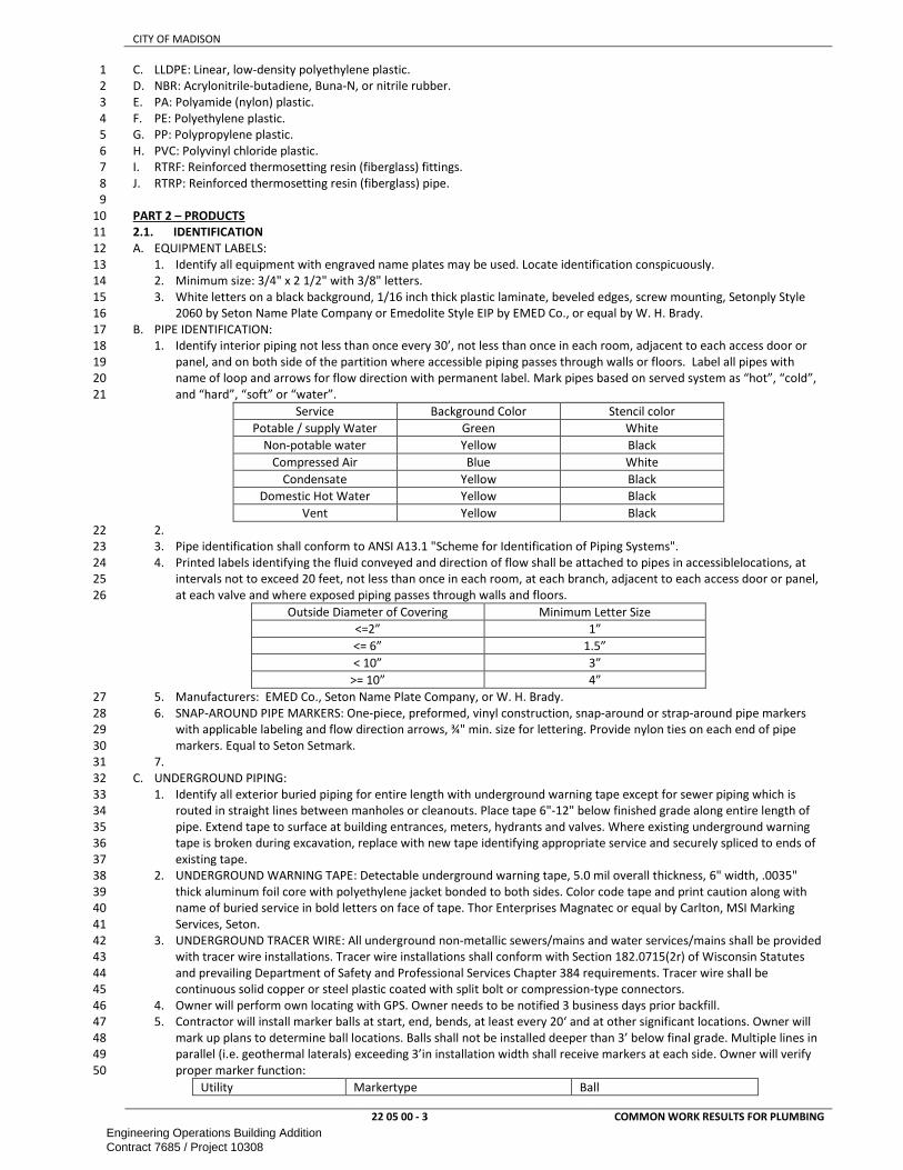
CITY OF MADISON
22 05 00 - 3 COMMON WORK RESULTS FOR PLUMBING
C. LLDPE: Linear, low-density polyethylene plastic. 1
D. NBR: Acrylonitrile-butadiene, Buna-N, or nitrile rubber. 2
E. PA: Polyamide (nylon) plastic. 3
F. PE: Polyethylene plastic. 4
G. PP: Polypropylene plastic. 5
H. PVC: Polyvinyl chloride plastic. 6
I. RTRF: Reinforced thermosetting resin (fiberglass) fittings. 7
J. RTRP: Reinforced thermosetting resin (fiberglass) pipe. 8
9
PART 2 – PRODUCTS 10
2.1. IDENTIFICATION 11
A. EQUIPMENT LABELS: 12
1. Identify all equipment with engraved name plates may be used. Locate identification conspicuously. 13
2. Minimum size: 3/4" x 2 1/2" with 3/8" letters. 14
3. White letters on a black background, 1/16 inch thick plastic laminate, beveled edges, screw mounting, Setonply Style 15
2060 by Seton Name Plate Company or Emedolite Style EIP by EMED Co., or equal by W. H. Brady. 16
B. PIPE IDENTIFICATION: 17
1. Identify interior piping not less than once every 30’, not less than once in each room, adjacent to each access door or 18
panel, and on both side of the partition where accessible piping passes through walls or floors. Label all pipes with 19
name of loop and arrows for flow direction with permanent label. Mark pipes based on served system as “hot”, “cold”, 20
and “hard”, “soft” or “water”. 21
Service Background Color Stencil color
Potable / supply Water Green White
Non-potable water Yellow Black
Compressed Air Blue White
Condensate Yellow Black
Domestic Hot Water Yellow Black
Vent Yellow Black
2. 22
3. Pipe identification shall conform to ANSI A13.1 "Scheme for Identification of Piping Systems". 23
4. Printed labels identifying the fluid conveyed and direction of flow shall be attached to pipes in accessiblelocations, at 24
intervals not to exceed 20 feet, not less than once in each room, at each branch, adjacent to each access door or panel, 25
at each valve and where exposed piping passes through walls and floors. 26
Outside Diameter of Covering Minimum Letter Size
<=2” 1”
<= 6” 1.5”
< 10” 3”
>= 10” 4”
5. Manufacturers: EMED Co., Seton Name Plate Company, or W. H. Brady. 27
6. SNAP-AROUND PIPE MARKERS: One-piece, preformed, vinyl construction, snap-around or strap-around pipe markers 28
with applicable labeling and flow direction arrows, ¾" min. size for lettering. Provide nylon ties on each end of pipe 29
markers. Equal to Seton Setmark. 30
7. 31
C. UNDERGROUND PIPING: 32
1. Identify all exterior buried piping for entire length with underground warning tape except for sewer piping which is 33
routed in straight lines between manholes or cleanouts. Place tape 6"-12" below finished grade along entire length of 34
pipe. Extend tape to surface at building entrances, meters, hydrants and valves. Where existing underground warning 35
tape is broken during excavation, replace with new tape identifying appropriate service and securely spliced to ends of 36
existing tape. 37
2. UNDERGROUND WARNING TAPE: Detectable underground warning tape, 5.0 mil overall thickness, 6" width, .0035" 38
thick aluminum foil core with polyethylene jacket bonded to both sides. Color code tape and print caution along with 39
name of buried service in bold letters on face of tape. Thor Enterprises Magnatec or equal by Carlton, MSI Marking 40
Services, Seton. 41
3. UNDERGROUND TRACER WIRE: All underground non-metallic sewers/mains and water services/mains shall be provided 42
with tracer wire installations. Tracer wire installations shall conform with Section 182.0715(2r) of Wisconsin Statutes 43
and prevailing Department of Safety and Professional Services Chapter 384 requirements. Tracer wire shall be 44
continuous solid copper or steel plastic coated with split bolt or compression-type connectors. 45
4. Owner will perform own locating with GPS. Owner needs to be notified 3 business days prior backfill. 46
5. Contractor will install marker balls at start, end, bends, at least every 20‘ and at other significant locations. Owner will 47
mark up plans to determine ball locations. Balls shall not be installed deeper than 3’ below final grade. Multiple lines in 48
parallel (i.e. geothermal laterals) exceeding 3’in installation width shall receive markers at each side. Owner will verify 49
proper marker function: 50
Utility Markertype Ball
Engineering Operations Building AdditionContract 7685 / Project 10308

CITY OF MADISON
22 05 00 - 4 COMMON WORK RESULTS FOR PLUMBING
Water Water blue 3M 1403-XR
Sanitary Wastewater green 3M 1404-XR
Storm Wastewater green 3M 1404-XR
D. ADHESIVE LABELS: Pressure-sensitive, adhesive backed, vinyl pipe markers with applicable labeling, ¾” min. size for 1
lettering and surrounding tape on both ends. With flow arrows on piping. Conforming to ANSI, ANSI and NFPA standards. 2
Seton Opti-Code, MSI, Brady or approved equal. Clean piping before application. 3
E. VALVES: 4
1. Identify valves with brass tags bearing a system identification and a valve sequence number. Identify medical gas and 5
vacuum valves with brass tags and wall or cabinet mounted color coded engraved nameplate with the following "(Type 6
of Gas) Shutoff Valve for (Location or Zone)". Valve tags are not required at a terminal device unless the valves are 7
greater than 10’ from the device, located in another room or not visible from device. 8
2. VALVE TAGS: Round brass tags with 1/2 inch numbers, 1/4 inch system identification abbreviation, 1-1/4 inch minimum 9
diameter, with brass jack chains, brass "S" hooks or one piece nylon ties around the valve stem, available from EMED 10
Co., Seton Name Plate Company, or W. H. Brady. 11
12
2.2. PIPE PENETRATIONS 13
A. RATED SURFACES: seal per firestopping 14
B. NON-RATED SURFACES: 15
1. At interior partitions where pipe penetrations are sealed, use Tremco Dymonic, Sika Corp. Sikaflex 1a, Sonneborn 16
Sonolastic NPI, or Mameco Vulken 116 urethane caulk to effect seal. Use galvanized sheet metal sleeves in hollow wall 17
penetrations. 18
2. Install stamped steel, chrome plated, hinged, split ring escutcheons or floor/ceiling plates where pipe penetrates non-19
fire rated surfaces in occupied spaces. Size units to accommodate insulation, where applicable. Escutcheons are not 20
required when insulation completely covers wall opening and insulation end is trimmed in a neat manner. Occupied 21
spaces for this Paragraph include only those rooms with finished ceilings and penetration occurs below ceiling. 22
3. In exterior wall openings below grade, place water-stop type wall sleeve before concrete pour or core drill opening 23
after pour. Assemble rubber links to proper size for pipe and tighten in place in accordance with manufacturer's 24
instructions. 25
C. Provide galvanized sheet metal sleeves for pipe penetrations through interior and exterior walls to provide a backing for 26
sealant or firestopping. Apply sealant to both sides of penetration in a manner that annular space between pipe sleeve and 27
pipe or insulation is completely blocked. Patch wall around sleeve to match adjacent wall construction and finish. Grout 28
area around sleeve in masonry construction. In finished spaces where pipe penetration through wall is exposed to view, 29
sheet metal sleeve shall be installed flush with face of wall. In existing poured concrete walls where penetration is core 30
drilled, pipe sleeve is not required. Pipe sleeves in new poured concrete construction shall be schedule 40 steel pipe (sized 31
to allow insulated pipe to run through sleeve), cast in place. 32
D. In all piping floor penetrations, fire rated and non-fire rated, top of sleeve shall extend 1 inch above the adjacent finished 33
floor. In existing floor penetrations, core drill sleeve opening large enough to insert schedule 40 sleeve and grout area 34
around sleeve with hydraulic setting, non-shrink grout. If the pipe penetrating the sleeve is supported by a pipe clamp 35
resting on the sleeve, weld a collar or struts to the sleeve that will transfer weight to existing floor structure. 36
37
PART 3 – EXECUTION 38
3.1. DEMOLITION 39
A. Perform all demolition as indicated on the drawings to accomplish new work. Where demolition work is to be performed 40
adjacent to existing work that remains in an occupied area, construct temporary dust partition to minimize the amount of 41
contamination of the occupied space. Where pipe is removed and not reconnected with new work, cap ends of existing 42
services as if they were new work. Coordinate work with the Owner to minimize disruption to the existing building 43
occupants. 44
B. All pipe, fixtures, equipment, wiring and associated conduit, insulation and similar items demolished, abandoned, or 45
deactivated are to be removed from the site by the Contractor except as specifically noted otherwise. All designated 46
equipment is to be turned over to the user agency for their use at a place and time so designated. Maintain the condition 47
of material and/or equipment that is indicated to be reused equal to that existing before work began. 48
49
3.2. INSTALLATION 50
A. Expansion and contraction of piping shall be provided for by expansion loops, bends, swing joints, or expansion joints to 51
prevent damage to connections, piping, equipment of the building. 52
B. Unions or flanges shall be installed on all by-passes, ahead of all traps, 1 adjacent to screw connection valves and at all 53
connections to equipment, whether or not shown on drawings. 54
C. Install all Work to permit removal (without damage to other parts) of all parts requiring periodic replacement or 55
maintenance. Arrange pipes and equipment to permit ready access to valves, cocks, traps, starters, motors, control 56
components and to clear the openings of swinging and overhead doors and of access panels. 57
D. Flashings on the roof shall be closely coordinated. Install flashings to insure proper vapor barrier. 58
E. Roof attachments, equipment supports, piping systems and other roof penetrations shall be waterproofed. 59
F. B. Install piping in concealed locations unless otherwise indicated and except in equipment rooms and service areas. 60
Engineering Operations Building AdditionContract 7685 / Project 10308

CITY OF MADISON
22 05 00 - 5 COMMON WORK RESULTS FOR PLUMBING
G. C. Install piping indicated to be exposed and piping in equipment rooms and service areas at right angles or parallel to 1
building walls. Diagonal runs are prohibited unless specifically indicated otherwise. 2
H. D. Install piping above accessible ceilings to allow sufficient space for ceiling panel removal. 3
I. E. Install piping to permit valve servicing. 4
J. F. Install piping at indicated slopes. 5
K. G. Install piping free of sags and bends. 6
7
3.3. EXCAVATION AND BACKFILL 8
A. Perform all excavation and backfill work necessary to accomplish indicated plumbing systems installation. Excavate to 9
bottom of pipe and structure bedding, 4" in stable soils, 6" in rock or wet trenches and 8" in unstable soil. Finish bottoms of 10
excavations to true, level surface. 11
B. Tunnel or remove sidewalk and curb in areas of excavation to the nearest joint. Remove pavements, curbs and gutters to 12
neat and straight lines to the limits of removal. Make sawcut lines parallel to existing joints, or parallel or perpendicular to 13
pavement edges to form a neat patch. Carefully remove remaining pavement within the sawcut area. Leave existing base 14
materials between the area disturbed by the work and the sawcut line undisturbed by the sawcutting, pavement removal, 15
or pavement replacement processes. 16
C. Strip topsoil from area to be excavated, free from subsoil and debris, and store for later respreading. 17
D. At no time place excavated materials where they will impede surface drainage unless such drainage is being safely rerouted 18
away from the excavation. 19
E. Excavate whatever materials are encountered as required to place at the elevations shown, all pipe, manholes, and other 20
work. Remove debris and rubbish from excavations before placing bedding and backfill material. 21
F. Remove surplus excavated materials from site. 22
G. Verify the locations of any water, drainage, gas, sewer, electric, telephone or steam lines which may be encountered in the 23
excavation. Underpin and support all lines. Cut off service connections encountered which are to be removed at the limits 24
of the excavation and cap. 25
H. Provide and maintain all fencing, barricades, signs, warning lights, and/or other equipment necessary to keep all excavation 26
pits and trenches and the entire subgrade area safe under all circumstances and at all times. No excavation shall be left 27
unattended without adequate protection. 28
I. Elevations shown on the plans are subject to such revisions as may be necessary to fit field conditions. No adjustment in 29
compensation will be made for adjustments up to two (2) feet above or below the grades indicated on the plans. 30
J. Install lines passing under foundations with minimum of 1-1/2 inch clearance to concrete and insure there is no disturbance 31
of bearing soil. 32
K. Bed pipe up to a point 12" above the top of the pipe. Take care during bedding, compaction and backfill not to disturb or 33
damage piping. 34
L. Mechanically compact bedding and backfill to prevent settlement. The initial compacted lift to not exceed 24" compacted 35
to 95% density per Modified Proctor Test (ASTM D-1557). Subsequent lifts under pavements, curbs, walks and structures 36
are not to exceed 12" and be compacted to 95% density per Modified Proctor Test. In all other areas where construction 37
above the excavation is not anticipated within 2 years, mechanically compact backfill in lifts not exceeding 24" to 90% 38
density per Modified Proctor Test. Route the equipment over each lift of the material so that the compaction equipment 39
contacts all areas of the surface of the lift. 40
M. Bedding up to a point 12" inches above the top of the pipe shall be thoroughly compacted sand or crushed stone chips 41
meeting the following gradations: 42
Gradation for Bedding Sand Gradation for Crushed Stone Chip Bedding
Sieve Size % Passing (by Wt) Sieve Size % Passing (by Wt)
1” 100 0.5” 100
No. 16 45-80 No. 4 75-100
No. 200 2-10 No. 100 10-25
N. Backfill above the bedding in lawn areas shall be thoroughly compacted excavated material free of large stones, organic, 43
perishable, and frozen materials. 44
O. Backfill above the bedding under existing and future utilities, paving, sidewalks, curbs, roads and buildings shall be granular 45
materials, pit run sand, gravel, or crushed stone, free from large stones, organic, perishable, and frozen materials. 46
P. ROCK EXCAVATION: Remove rock encountered in the excavation to a minimum dimension of 6 inches outside the pipe. 47
Rock excavation includes all hard, solid rock in ledges, bedded deposits and unstratified masses, all natural conglomerate 48
deposits so firmly cemented as to present all the characteristics of solid rock; which material is so hard or so firmly 49
cemented that in the opinion of the Engineer it is not practical to excavate and remove same with a power shovel except 50
after thorough and continuous drilling and blasting. Rock excavation includes rock boulders of 1/2 cubic yard or more in 51
volume. 52
Q. SURFACE RESTORATION: Completely restore the surface of all disturbed areas to a like condition of the surface prior to the 53
work. Level off all waste disposal areas and clean up all areas used for the storage of materials or the temporary deposit of 54
excavated earth. Remove all surplus material, tools and equipment. 55
56
3.4. SHEETING, SHORING AND BRACING 57
A. Provide shoring, sheet piling and bracing in conformance with the Wisconsin Administrative Code to prevent earth from 58
caving or washing into the excavation. Shore and underpin to properly support adjacent or adjoining structures. Abandon 59
Engineering Operations Building AdditionContract 7685 / Project 10308

CITY OF MADISON
22 05 00 - 6 COMMON WORK RESULTS FOR PLUMBING
in place shoring, sheet piling and underpinning below the top of the pipe, or, if approved in advance by the engineer, 1
maintained in place until other permanent support approved by the engineer is provided. 2
3
3.5. DEWATERING 4
A. Provide, operate and maintain all pumps and other equipment necessary to drain and keep all excavation pits, trenches and 5
the entire subgrade area free from water under all circumstances. Obtain general permit from the Wisconsin Department 6
of Natural Resources district office for discharge of construction dewatering effluent. Obtain well permit from the 7
Wisconsin Department of Natural Resources district office for dewatering wells discharging more than 70 GPM. Comply 8
with permit requirements. 9
10
END OF SECTION 11
Engineering Operations Building AdditionContract 7685 / Project 10308

CITY OF MADISON
22 05 23 - 1
GENERAL-DUTY VALVES FOR PLUMBING
PIPING
SECTION 22 05 23 1
GENERAL-DUTY VALVES FOR PLUMBING PIPING 2
3
PART 1 – GENERAL ............................................................................................................................................................................ 1 4
1.1. SCOPE ............................................................................................................................................................................ 1 5
1.2. REFERENCES .................................................................................................................................................................. 1 6
1.3. SUBMITTALS .................................................................................................................................................................. 1 7
1.4. QUALITY ASSURANCE .................................................................................................................................................... 1 8
PART 2 - PRODUCTS .......................................................................................................................................................................... 1 9
2.1. BALL VALVES.................................................................................................................................................................. 1 10
2.2. CHECK VALVES ............................................................................................................................................................... 2 11
2.3. MISCELLANEOUS VALVES .............................................................................................................................................. 2 12
2.4. VALVE BOXES................................................................................................................................................................. 3 13
2.5. WATER PRESSURE REDUCING VALVES .......................................................................................................................... 3 14
2.6. SAFETY RELIEF VALVES .................................................................................................................................................. 3 15
PART 3 – EXECUTION ......................................................................................................................................................................... 3 16
3.1. INSTALLATION ............................................................................................................................................................... 3 17
18
PART 1 – GENERAL 19
1.1. SCOPE 20
A. This section includes information common to plumbing valves and applies to all sections in this Division. 21
22
1.2. REFERENCES 23
A. Work under this section depends on applicable provisions from other sections and the plan set in this contract. Examples of 24
related sections include, but are not limited to: 25
B. ANSI – American National Standard Institute 26
1. ANSI Z21.22 - Relief Valves and Automatic Gas Shutoff Devices for Hot Water Supply Systems. 27
C. ASME – American Society of Mechanical Engineers 28
1. ASME B1.20.1 for threads for threaded end valves. 29
2. ASME B16.1 for flanges on iron valves. 30
3. ASME B16.5 for flanges on steel valves. 31
4. ASME B16.10 and ASME B16.34 for ferrous valve dimensions and design criteria. 32
5. ASME B16.18 for solder-joint connections. 33
6. ASME B31.9 for building services piping valves. 34
D. ASSE - American Society of Safety Engineers 35
1. ASSE 1003 - Water Pressure Reducing Valves for Domestic Water Supply Systems. 36
37
1.3. SUBMITTALS 38
A. Schedule of all valves indicating type of service, dimensions, materials of construction, and pressure/temperature ratings 39
for all valves to be used on the project. Temperature ratings specified are for continuous operation. 40
41
1.4. QUALITY ASSURANCE 42
A. Valves to be line size unless specifically noted otherwise. 43
B. Bronze valves shall be made with dezincification-resistant materials. Bronze valves made with copper alloy (brass) 44
containing more than 15 percent zinc are not permitted. 45
C. All water system valves to be rated at not less than 200 psi CWP or higher if required. 46
D. END CONNECTIONS: 47
1. Copper pipe / bronze valve: soldered or flanged. 48
2. Steel pipe / valve: flanged or threaded. 49
50
PART 2 - PRODUCTS 51
2.1. BALL VALVES 52
A. Acceptable Manufacturers: Milwaukee, Nibco, Watts 53
B. All shutoff valves shall be ball valves unless required otherwise by local Water Utility specifications. 54
C. PORT: Full. 55
D. SEATS: PTFE. 56
E. STEM: Stainless steel. 57
F. BALL: Stainless steel, vented. 58
G. Provide Lever extension on insulated pipes to clear insulation. 59
H. GEAR ACTUATOR: For quarter-turn valves 4” and larger 60
I. BRONZE VALVES: 61
1. Standard: MSS SP-110. 62
2. CWP Rating: 600 psig (4140 kPa). 63
Engineering Operations Building AdditionContract 7685 / Project 10308

CITY OF MADISON
22 05 23 - 2
GENERAL-DUTY VALVES FOR PLUMBING
PIPING
3. Body Design: Two piece. 1
4. Body Material: Bronze. 2
J. STEEL VAVLES: 3
1. Class 150, Steel Ball Valves 4
2. Standard: MSS SP-72. 5
3. CWP Rating: 285 psig (1964 kPa). 6
4. Body Design: Split body. 7
5. Body Material: Carbon steel, ASTM A 216, Type WCB. 8
K. SHUTOFF VALVES: Install shut-off valves at each piece of equipment, at each branch take-off from mains for isolation or 9
repair and elsewhere as indicated. Each individual fixture or piece of equipment shall have an independent shut-off valve 10
adjacent to fixture in addition to the required branch shut-off. 11
L. DRAIN VALVES: ¾” ball valve with integral threaded hose adapter, sweat or threaded inlet connections, with threaded cap 12
and chain on hose threads. Locations of drain valves include low points of piping systems, downstream of riser isolation 13
valves, equipment locations specified or detailed, other locations required for drainage of systems and elsewhere as 14
indicated. 15
16
2.2. CHECK VALVES 17
A. MANUFACTURERS: Milwaukee, Nibco, Watts 18
B. BRONZE LIFT CHECK VALVES (vertical upflow only) 19
1. Standard: MSS SP-80, Type 2. 20
2. Body Design: Vertical flow. 21
3. Body Material: ASTM B 61 or ASTM B 62, bronze. 22
4. Disc: NBR, PTFE. 23
5. Spring: Stainless Steel 24
C. BRONZE SWING CHECK VALVE: 25
1. Standard: MSS SP-80, Type 4. 26
2. Body Design: Horizontal flow. 27
3. Body Material: ASTM B 62, bronze. 28
4. Disc: PTFE. 29
D. IRON LIFT CHECK VALVES (vertical flow only): 30
1. Disc: NBR, PTFE. 31
2. Spring: Stainless Steel 32
3. Standard: MSS SP-71, Type I. 33
4. Body Material: ASTM A 126, gray iron with bolted bonnet. 34
5. Trim: Composition. 35
6. Seat Ring: Bronze. 36
7. Disc Holder: Bronze. 37
E. IRON SWING CHECK VALVES: 38
1. Standard: MSS SP-71, Type I. 39
2. Body Design: Clear or full waterway. 40
3. Body Material: ASTM A 126, gray iron with bolted bonnet. 41
4. Trim: Composition. 42
5. Seat Ring: Bronze. 43
6. Disc Holder: Bronze. 44
7. Disc: PTFE. 45
8. Gasket: Asbestos free. 46
47
2.3. MISCELLANEOUS VALVES 48
A. BALANCE VALVES: 2" and smaller: Two piece bronze body ball valve, sweat or threaded ends, chrome plated brass ball, 49
glass filled teflon seat, threaded packing nut, with adjustable memory stop position indicator and extended handle stem, 50
suitable for 400 psig water working pressure at 240 degrees F. Nibco S580-80-LF, Hammond UP8501-02 or UP8511-02, 51
Milwaukee UPBA-100MS or UPBA-150MS or equal by Apollo, Watts, 52
B. BURIED WATER SERVICE GATE VALVES: Cast iron body, resilient elastomer coated cast iron disc, permanently lubricated 53
stuffing box, bronze non-rising stem and stem nut, double O-ring stem seal, Delrin thrust bearings, electroplated nuts and 54
bolts, cast iron operating nut, AWWA C509, rated for 200 psi. Coat valve inside and out with fusion bonded epoxy, AWWA 55
C550. Clow F-6100, Kennedy 1571, Mueller A-2360, Waterous 500, Watts 406RW. 56
C. UNDERGROUND WATER SERVICE BUTTERFLY VALVES: 57
1. Rubber-seated butterfly valve meeting the requirements of AWWA C504, for Class 150B. Body and disc shall be 58
constructed of cast iron. Disc shall be lens shaped. 59
2. Interior and exterior surfaces of valve shall be provided with epoxy coating meeting the requirements of AWWA C550. 60
Disc shall be provided with a stainless steel disc edge. 61
3. Valve stem shall be stainless steel. Packing shall be permanent duty “chevron V-type” or “O-ring” type. Bearings shall 62
be permanent, non-metallic, and self-lubricating. 63
Engineering Operations Building AdditionContract 7685 / Project 10308

CITY OF MADISON
22 05 23 - 3
GENERAL-DUTY VALVES FOR PLUMBING
PIPING
4. Valve seat shall be a single piece of elastomeric material that is not penetrated by the valve shaft. 1
5. Provide manual operator that is suitable for underground service and includes a standard 2” square operating nut. 2
6. Valve shall be provided with mechanical joint connections. 3
7. Mueller, Clow, Henry Pratt, or approved equal. 4
D. CORPORATION STOP VALVES: 2" and smaller: Bronze body ground key valve, bronze plug, AWWA taper thread inlet and 5
copper flare outlet nut connections or compression type, AWWA C800. 6
E. CURB STOP VALVES: 7
8
2.4. CORPORATION AND CURB VALVES 9
A. 2" and smaller: Bronze body plug valve, bronze plug, quarter turn check, O-ring seals, copper flare nut connections or 10
compression type, AWWA C800. 11
B. SERVICE-SADDLE ASSEMBLIES: Comply with AWWA C800. Include saddle and valve compatible with tapping machine. 12
1. Service Saddle: Copper alloy with seal and AWWA C800, threaded outlet for corporation valve. 13
2. Corporation Valve: Bronze body and ground-key plug, with AWWA C800, threaded inlet and outlet matching service 14
piping material. 15
C. CURB VALVES: Comply with AWWA C800. Include bronze body, ground-key plug or ball, and wide tee head, with inlet and 16
outlet matching service piping material. 17
D. SERVICE BOXES FOR CURB VALVES: Similar to AWWA M44 requirements for cast-iron valve boxes. Include cast-iron 18
telescoping top section of length required for depth of burial of valve, plug with lettering "WATER," and bottom section 19
with base that fits over curb valve and with a barrel approximately 3 inches (75 mm) in diameter. 20
E. SHUTOFF RODS: Steel, tee-handle with one pointed end, stem of length to operate deepest buried valve, and slotted end 21
matching curb valve. 22
F. MANUFACTURERS: 23
1. Amcast Industrial Corporation; Lee Brass Co. 24
2. Ford Meter Box Company, Inc. (The); Pipe Products Div. 25
3. Jones, James Company. 26
4. Master Meter, Inc. 27
5. McDonald, A. Y. Mfg. Co. 28
6. Mueller Co.; Water Products Div. 29
7. Red Hed Manufacturing & Supply. 30
31
2.5. WATER PRESSURE REDUCING VALVES 32
A. Bronze body, diaphragm operated, with an integral thermal expansion bypass valve, inlet union, stainless steel strainer, 33
renewable monel or stainless steel seat and adjustable reduced pressure range, 300 psig at 160 degrees F. Pre-set for the 34
scheduled pressure. A. W. Cash, Conbraco, Watts, Wilkins. 35
B. Provide ball valve and strainer at inlet and ball valve at outlet. Install pressure gauges to indicate inlet and outlet pressure at 36
each pressure reducing valve. 37
C. Standard: ASSE 1003. 38
D. Manufacturer: 39
1. Cash Acme; a division of The Reliance Worldwide Corporation. 40
2. Watts Water Technologies, Inc. 41
42
2.6. SAFETY RELIEF VALVES 43
A. Bronze body, temperature and pressure actuated, stainless steel stem and spring, thermostat with non-metallic coating, 44
test lever. Meet AWWA C512 and ASME listed. 45
B. suitable for 125 psig water working pressure at 240 degrees F, sized for full BTUH input and operating pressure of 46
equipment, with valve capacity on metal label. Temperature and pressure relief valve shall be sized per AGA rating for 47
BTUH input, Re: SPS 382.40(5)(d). 48
C. Manufacturer: Bell & Gossett, A. W. Cash, Conbraco, Watts, Wilkins. 49
D. Install relief valves on all pressure vessels and elsewhere as indicated. Inlet and outlet piping connecting to valves must be 50
the same size as valve connections or larger. Pipe discharge to drain where indicated or to floor. 51
52
PART 3 – EXECUTION 53
3.1. INSTALLATION 54
A. Install in accordance with manufacturer's instructions and all code requirements. 55
B. Install valves with unions or flanges at each piece of equipment arranged to allow service, maintenance, and equipment 56
removal without system shutdown. 57
C. Properly align piping before installation of valves. Install and test valves in strict accordance with valve manufacturer's 58
installation recommendations. Do not support weight of piping system on valve ends. 59
D. Mount valves in locations which allow access for operation, servicing and replacement. 60
E. Provide valve handle extensions for all valves installed in insulated piping. 61
F. Install all valves with the stem in the upright or horizontal position. Prior to flushing of piping systems, place all valves in 62
the full-open position. 63
Engineering Operations Building AdditionContract 7685 / Project 10308

CITY OF MADISON
22 05 23 - 4
GENERAL-DUTY VALVES FOR PLUMBING
PIPING
G. Balance system to minimum flow in return piping branches needed to maintain even supply water temperature 1
throughout building. 2
3
END OF SECTION 4
Engineering Operations Building AdditionContract 7685 / Project 10308

CITY OF MADISON
22 05 29 - 1
HANGERS AND SUPPORTS FOR PLUMBING
PIPING AND EQUIPMENT
SECTION 22 05 29 1
HANGERS AND SUPPORTS FOR PLUMBING PIPING AND EQUIPMENT 2
3
PART 1 – GENERAL ............................................................................................................................................................................ 1 4
1.1. SCOPE ............................................................................................................................................................................ 1 5
1.2. REFERENCES .................................................................................................................................................................. 1 6
1.3. SUBMITTALS .................................................................................................................................................................. 1 7
1.4. QUALITY ASSURANCE .................................................................................................................................................... 1 8
1.5. PERFORMANCE REQUIREMENTS ................................................................................................................................... 1 9
PART 2 - PRODUCTS .......................................................................................................................................................................... 1 10
2.1. HANGERS AND SUPPORTS ............................................................................................................................................. 1 11
2.2. ROOF MOUNTED SUPPORTS ......................................................................................................................................... 2 12
PART 3 – EXECUTION ......................................................................................................................................................................... 3 13
3.1. INSTALLATION ............................................................................................................................................................... 3 14
15
PART 1 – GENERAL 16
1.1. SCOPE 17
A. This section includes information common to supports of all plumbing equipment, materials and piping system anchors 18
and applies to all sections in this Division. 19
20
1.2. REFERENCES 21
A. Work under this section depends on applicable provisions from other sections and the plan set in this contract. Examples of 22
related sections include, but are not limited to: 23
B. MSS - Manufacturer's Standardization Society of the Valve & Fitting Industry, Inc. 24
1. MSS SP-58 Materials, Design, Manufacture, Selection, Application, and Installation 25
2. SP-127 Bracing for Piping Systems Seismic-Wind-Dynamic Design, Selection, Application 26
27
1.3. SUBMITTALS 28
A. Schedule of all hanger and support devices indicating shields, attachment methods, and type of device for each pipe size 29
and type of service. 30
31
1.4. QUALITY ASSURANCE 32
A. Provide all supporting devices as required for the installation of mechanical equipment and materials. All supports and 33
installation procedures are to conform to the latest requirements of the ANSI Code for pressure piping. 34
B. Don’t hang any mechanical item directly from a metal deck or run piping to rests on the bottom chord of any truss or joist. 35
C. Support apparatus and material under all conditions of operation, variations in installed and operating weight of 36
equipment and piping, to prevent excess stress, and allow for proper expansion and contraction. 37
D. Protect insulation at all hanger points 38
E. Provide all supporting steel required for the installation of mechanical equipment and materials, whether or not it is 39
specifically indicated or sized, including angles, channels, beams, etc. to suspend or floor support tanks and equipment. 40
F. Piping supported by laying on the bottom chord of joists or trusses will not be accepted. 41
G. Fasteners depending on soft lead for holding power or requiring powder actuation will not be accepted. 42
43
1.5. PERFORMANCE REQUIREMENTS 44
A. Materials and application of pipe hangers and supports shall be in accordance with MSS Standard Practice SP-58 and SP-69 45
unless noted otherwise. 46
B. Piping connected to pumps, compressors, or other rotating or reciprocating equipment is to have vibration isolation 47
supports for a distance of one hundred pipe diameters or three supports away from the equipment, whichever is greater. 48
Standard pipe hangers/supports as specified in this section are required beyond the 100 pipe diameter/3 support distance. 49
C. Design supports of strength and rigidity to suit loading, service and manner which do not unduly stress the building 50
construction. Where support is from concrete construction, take care not to weaken concrete or penetrate waterproofing. 51
Fasten supports and hangers to building steel framing wherever practical. Do not use another pipe for support. Do not use 52
perforated iron, chain or wire as hangers. 53
D. Hangers, supports and support methods other than those specified shall not be used without obtaining approval on method 54
of support by the Structural Engineer prior to installing piping systems. Submit support method arrangement, pipe weight 55
and spacing scheme for approval. 56
57
PART 2 - PRODUCTS 58
2.1. HANGERS AND SUPPORTS 59
A. Anvil, B-Line, Fee and Mason, Kindorf, Michigan Hanger, Pipe Shields, Unistrut, or approved equal. 60
B. HORIZNTAL SUPPORT: 61
1. Cold pipe: B-Line B3104CTC - Clevis Hanger - PVC Coated or approved equal. 62
2. Hot Pipe: 63
Engineering Operations Building AdditionContract 7685 / Project 10308
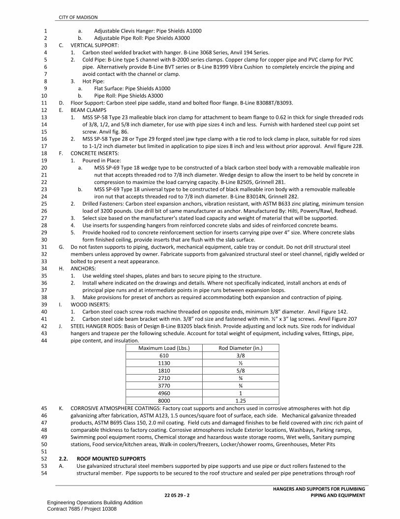
CITY OF MADISON
22 05 29 - 2
HANGERS AND SUPPORTS FOR PLUMBING
PIPING AND EQUIPMENT
a. Adjustable Clevis Hanger: Pipe Shields A1000 1
b. Adjustable Pipe Roll: Pipe Shields A3000 2
C. VERTICAL SUPPORT: 3
1. Carbon steel welded bracket with hanger. B-Line 3068 Series, Anvil 194 Series. 4
2. Cold Pipe: B-Line type S channel with B-2000 series clamps. Copper clamp for copper pipe and PVC clamp for PVC 5
pipe. Alternatively provide B-Line BVT series or B-Line B1999 Vibra Cushion to completely encircle the piping and 6
avoid contact with the channel or clamp. 7
3. Hot Pipe: 8
a. Flat Surface: Pipe Shields A1000 9
b. Pipe Roll: Pipe Shields A3000 10
D. Floor Support: Carbon steel pipe saddle, stand and bolted floor flange. B-Line B3088T/B3093. 11
E. BEAM CLAMPS 12
1. MSS SP-58 Type 23 malleable black iron clamp for attachment to beam flange to 0.62 in thick for single threaded rods 13
of 3/8, 1/2, and 5/8 inch diameter, for use with pipe sizes 4 inch and less. Furnish with hardened steel cup point set 14
screw. Anvil fig. 86. 15
2. MSS SP-58 Type 28 or Type 29 forged steel jaw type clamp with a tie rod to lock clamp in place, suitable for rod sizes 16
to 1-1/2 inch diameter but limited in application to pipe sizes 8 inch and less without prior approval. Anvil figure 228. 17
F. CONCRETE INSERTS: 18
1. Poured in Place: 19
a. MSS SP-69 Type 18 wedge type to be constructed of a black carbon steel body with a removable malleable iron 20
nut that accepts threaded rod to 7/8 inch diameter. Wedge design to allow the insert to be held by concrete in 21
compression to maximize the load carrying capacity. B-Line B2505, Grinnell 281. 22
b. MSS SP-69 Type 18 universal type to be constructed of black malleable iron body with a removable malleable 23
iron nut that accepts threaded rod to 7/8 inch diameter. B-Line B3014N, Grinnell 282. 24
2. Drilled Fasteners: Carbon steel expansion anchors, vibration resistant, with ASTM B633 zinc plating, minimum tension 25
load of 3200 pounds. Use drill bit of same manufacturer as anchor. Manufactured By: Hilti, Powers/Rawl, Redhead. 26
3. Select size based on the manufacturer's stated load capacity and weight of material that will be supported. 27
4. Use inserts for suspending hangers from reinforced concrete slabs and sides of reinforced concrete beams. 28
5. Provide hooked rod to concrete reinforcement section for inserts carrying pipe over 4” size. Where concrete slabs 29
form finished ceiling, provide inserts that are flush with the slab surface. 30
G. Do not fasten supports to piping, ductwork, mechanical equipment, cable tray or conduit. Do not drill structural steel 31
members unless approved by owner. Fabricate supports from galvanized structural steel or steel channel, rigidly welded or 32
bolted to present a neat appearance. 33
H. ANCHORS: 34
1. Use welding steel shapes, plates and bars to secure piping to the structure. 35
2. Install where indicated on the drawings and details. Where not specifically indicated, install anchors at ends of 36
principal pipe runs and at intermediate points in pipe runs between expansion loops. 37
3. Make provisions for preset of anchors as required accommodating both expansion and contraction of piping. 38
I. WOOD INSERTS: 39
1. Carbon steel coach screw rods machine threaded on opposite ends, minimum 3/8” diameter. Anvil Figure 142. 40
2. Carbon steel side beam bracket with min. 3/8” rod size and fastened with min. ½” x 3” lag screws. Anvil Figure 207 41
J. STEEL HANGER RODS: Basis of Design B-Line B3205 black finish. Provide adjusting and lock nuts. Size rods for individual 42
hangers and trapeze per the following schedule. Account for total weight of equipment, including valves, fittings, pipe, 43
pipe content, and insulation. 44
Maximum Load (Lbs.) Rod Diameter (in.)
610 3/8
1130 ½
1810 5/8
2710 ¾
3770 ¾
4960 1
8000 1.25
K. CORROSIVE ATMOSPHERE COATINGS: Factory coat supports and anchors used in corrosive atmospheres with hot dip 45
galvanizing after fabrication, ASTM A123, 1.5 ounces/square foot of surface, each side. Mechanical galvanize threaded 46
products, ASTM B695 Class 150, 2.0 mil coating. Field cuts and damaged finishes to be field covered with zinc rich paint of 47
comparable thickness to factory coating. Corrosive atmospheres include Exterior locations, Washbays, Parking ramps, 48
Swimming pool equipment rooms, Chemical storage and hazardous waste storage rooms, Wet wells, Sanitary pumping 49
stations, Food service/kitchen areas, Walk-in coolers/freezers, Locker/shower rooms, Greenhouses, Meter Pits 50
51
2.2. ROOF MOUNTED SUPPORTS 52
A. Use galvanized structural steel members supported by pipe supports and use pipe or duct rollers fastened to the 53
structural member. Pipe supports to be secured to the roof structure and sealed per pipe penetrations through roof 54
Engineering Operations Building AdditionContract 7685 / Project 10308

CITY OF MADISON
22 05 29 - 3
HANGERS AND SUPPORTS FOR PLUMBING
PIPING AND EQUIPMENT
specifications as specified in this section. Apply two coats of zinc rich paint to cut edges of all galvanized steel elements. 1
Flash and Counterflash. 2
C. For longest support member 36” and shorter: minimum support height 18” 3
D. For longest support member 36” and longer: minimum support height 36” 4
5
PART 3 – EXECUTION 6
3.1. INSTALLATION 7
A. Multiple or Trapeze Hangers: Where several pipes are running parallel and pitching in the same direction, strut style 8 support may be used. Steel channel, 12-gauge thickness, Dura-Green epoxy coating or electro-plated, B-Line B11. 9
B. Roof Penetrations: Install curbed roof penetration housing VAULT www.roofpenetrationhousings.com Flash and 10
Counterflash. 11 C. Secure pipe in place to prevent vibration, maintain proper slope and provide for expansion and contraction. 12
D. Use inserts for suspending hangers from reinforced concrete slabs wherever practical. Where inserts are not practical, 13
provide channels or angles from which to suspend hangers/supports. Fasten structural steel to concrete with expansion 14
bolts. 15
E. Place a hanger within 12 inches of each horizontal elbow, valve, strainer, or similar piping specialty item. Space Hangers as 16 follows: 17
Pipe Material Pipe Size Max. Horiz.
Spacing
Max. Vert.
Spacing
Cast Iron 2" and larger 5'-0" 15'-0"
Copper 1/2" through 3/4" 5'-0" 10'-0"
Copper 1" through 1-1/4" 6'-0" 10'-0"
Copper 1-1/2" through 2-1/2" 8'-0" 10'-0"
Copper 3" 10'-0" 10'-0"
Copper 4" and larger 12'-0" 10'-0"
Ductile Iron All 10'-0" 20'-0"
Glass Per Pipe Mfr. 8'-0" 12'-0"
Steel 1/2" through 1-1/4" 7'-0" 15'-0"
Steel 1-1/2" through 6" 10'-0" 15'-0"
Steel 8" through 12" 14'-0" 20'-0"
Steel 14" and over 20'-0" 20'-0"
Plastic Drain and Vent 4'-0" 10'-0"
Plastic 1" or less 32" 4'-0"
Plastic 1-1/4" and over 4'-0" 6'-0"
Plastic Pure Water 1-1/2” or less Continuous 5’-0”
F. Make provisions for preset of anchors as required to accommodate both expansion and contraction of piping. 18
G. Allow sufficient space between adjacent pipes for insulation, valve operation, routine maintenance, etc. 19
H. CORROSIVE ATMOSPHERE COATINGS: 20
1. Factory coat supports and anchors used in corrosive atmospheres with hot dip galvanizing after fabrication, ASTM 21
A123, 1.5 ounces/square foot of surface each side. Mechanical galvanize threaded products, ASTM B695 Class 50, 2.0 22
mil coating. Field cuts and damaged finishes to be field covered with zinc rich paint of comparable thickness to factory 23
coating. 24
2. Corrosive atmospheres include the following locations: 25
a. Wash Bay 26
27
END OF SECTION 28
Engineering Operations Building AdditionContract 7685 / Project 10308

CITY OF MADISON
22 07 00 - 1 PLUMBING INSULATION
SECTION 22 07 00 1
PLUMBING INSULATION 2
3
PART 1 – GENERAL ............................................................................................................................................................................ 1 4
1.1. SCOPE ............................................................................................................................................................................ 1 5
1.2. REFERENCES .................................................................................................................................................................. 1 6
1.3. SUBMITTALS .................................................................................................................................................................. 1 7
1.4. QUALITY ASSURANCE .................................................................................................................................................... 1 8
1.5. PERFORMANCE REQUIREMENTS ................................................................................................................................... 2 9
1.6. DEFINITIONS .................................................................................................................................................................. 2 10
PART 2 - PRODUCTS .......................................................................................................................................................................... 2 11
2.1. INSULATION .................................................................................................................................................................. 2 12
2.2. ADHESIVES .................................................................................................................................................................... 4 13
2.3. MASTICS ........................................................................................................................................................................ 4 14
2.4. SEALANTS ...................................................................................................................................................................... 5 15
2.5. JACKETS ......................................................................................................................................................................... 5 16
2.6. FABRIC-REINFORCED MESH AND CLOTHES ................................................................................................................... 7 17
2.7. TAPES ............................................................................................................................................................................ 7 18
2.8. SECUREMENTS .............................................................................................................................................................. 8 19
2.9. PROTECTIVE SHIELDING GUARDS .................................................................................................................................. 8 20
PART 3 – EXECUTION ......................................................................................................................................................................... 8 21
3.1. INSTALLATION ............................................................................................................................................................... 8 22
3.2. PENETRATIONS .............................................................................................................................................................. 9 23
3.3. FINISHES ...................................................................................................................................................................... 10 24
25
PART 1 – GENERAL 26
1.1. SCOPE 27
A. This section includes information common to insulation of plumbing equipment and piping and applies to all sections in 28
this Division. 29
30
1.2. REFERENCES 31
A. Work under this section depends on applicable provisions from other sections and the plan set in this contract. Examples of 32
related sections include, but are not limited to: 33
1. 07 84 00 - FIRESTOPPING 34
35
1.3. SUBMITTALS 36
A. Manufacturer’s technical data sheets for each product with the following information: 37
1. Density 38
2. Thermal characteristics and water-vapor permeance 39
3. Temperature limitations 40
4. Jacket type 41
5. Materials of composition 42
6. Material safety data sheets 43
B. Schedule of all insulating materials to be used including: 44
1. Application / intended use of each insulation type 45
2. Insulation type and thickness 46
3. Jacket type 47
4. Fastening methods and adhesive type 48
C. Shop Drawings: Include plans, elevations, sections, details, and attachments to other work. 49
1. Detail application of protective shields, saddles, and inserts at hangers for each type of insulation and hanger. 50
2. Detail attachment and covering of heat tracing inside insulation. 51
3. Detail insulation application at pipe expansion joints for each type of insulation. 52
4. Detail insulation application at elbows, fittings, flanges, valves, and specialties for each type of insulation. 53
5. Detail removable insulation at piping specialties, equipment connections, and access panels. 54
6. Detail application of field-applied jackets. 55
7. Detail application at linkages of control devices. 56
57
1.4. QUALITY ASSURANCE 58
A. Install insulation materials in accordance with the latest edition of MICA (Midwest Insulation Contractors Association) 59
Standard and manufacturer's installation instructions. 60
B. All products shall be applied in ambient temperatures and conditions per manufacturer’s recommendations. 61
C. No pipe shall be covered until after it has been installed, inspected, tested and approved. 62
D. All surfaces shall be clean, dry and without foreign material prior to installing any insulation. 63
E. All installation shall be performed by skilled labor regularly engaged in this type of work. 64
Engineering Operations Building AdditionContract 7685 / Project 10308

CITY OF MADISON
22 07 00 - 2 PLUMBING INSULATION
F. Insulating materials shall be moisture and mildew resistant, and vermin proof. Insulation shall be suitable to receive jackets, 1
adhesives and coatings as indicated. 2
G. Surface-Burning Characteristics: For insulation and related materials, as determined by testing identical products according 3
to ASTM E 84 by a testing agency acceptable to authorities having jurisdiction. Factory label insulation and jacket materials 4
and adhesive, mastic, tapes, and cement material containers, with appropriate markings of applicable testing agency. 5
1. Insulation Installed Indoors: Flame-spread index of 25 or less, and smoke-developed index of 50 or less. 6
2. Insulation Installed Outdoors: Flame-spread index of 75 or less, and smoke-developed index of 150 or less. 7
H. Supply and Drain Protective Shielding Guards: ICC A117.1. 8
I. Products that come in contact with stainless steel shall have a leachable chloride content of less than 50 ppm when tested 9
according to ASTM C 871. 10
J. Insulation materials for use on austenitic stainless steel shall be qualified as acceptable according to ASTM C 795. 11
K. Install accessories compatible with insulation materials and suitable for the service. Install accessories that do not corrode, 12
soften, or otherwise attack insulation or jacket in either wet or dry state. 13
14
1.5. PERFORMANCE REQUIREMENTS 15
A. Application of insulation to piping equipment shall be done in accordance with the manufacturer's installation 16
recommendations, building codes and industry standards. Where thickness of insulation is not specified, use thickness 17
recommended by manufacturer or required by applicable Codes. 18
B. Use composite insulation systems (insulation, jackets, sealants, mastics, and adhesives) that have a flame spread rating of 19
25 or less and smoke developed rating of 50 or less. 20
21
1.6. DEFINITIONS 22
A. CONCEALED: Shafts, furred spaces, space above finished ceilings, utility tunnels and crawl spaces. Other areas, including 23
walk-through tunnels, shall be considered as exposed. 24
B. EXPOSED: unfinished spaces with piping exposed to occupants. This includes but is not limited to tunnels, garages, shops, 25
wash-bays etc. 26
C. EXPOSED TO WEATHER: Located outdoors, either on grade, on a wall, or on a roof, in location where sun, wind, rain, snow 27
and other elements will come in contact with it. 28
D. UNCONDITIONED SPACES: Unheated or non-cooled attics, utility tunnels and crawl spaces were ambient emperatures may 29
rise above 90°F, or drop below 50°F. 30
31
PART 2 - PRODUCTS 32
2.1. INSULATION 33
A. MANUFACTURERS: Armstrong, Halstead, Johns-Manville, Knauf, or Owens-Corning. Armacell, Certainteed, Manson, 34
Childers, Dow, Extol, Fibrex, .Foster Brand, B. Fuller, Imcoa, Partek, 35
B. FIBERGLASS INSULATION: Inorganic, incombustible, foamed or cellulated glass with annealed, rigid, hermetically sealed 36
cells. Minimum nominal density of 3 lbs / ft3. rated for service to 450 °F. 37
1. RIGID FIBERGLASS INSULATION:.thermal conductivity of not more than 0.23 at 75 °F, minimum compressive strength of 38
25 PSF at 10% deformation. 39
2. SEMI-RIGID FIBERGLASS INSULATION: thermal conductivity of not more than 0.28 at 75 °F, minimum compressive 40
strength of 125 PSF at 10% deformation. Insulation fibers perpendicular to jacket and scored for wrapping cylindrical 41
surfaces. 42
3. BLOCK INSULATION: ASTM C 552, Type I. 43
4. SPECIAL-SHAPED INSULATION: ASTM C 552, Type III. 44
5. PREFORMED PIPE INSULATION WITHOUT JACKET: Comply with ASTM C 552, Type II, Class 1. 45
6. PREFORMED PIPE INSULATION WITH FACTORY-APPLIED JACKET: Comply with ASTM C 552, Type II, Class 2. 46
7. Factory fabricate shapes according to ASTM C 450 and ASTM C 585. 47
8. Insulation Installation on Straight Pipes and Tubes: 48
a. Secure each layer of insulation to pipe with wire or bands and tighten bands without deforming insulation 49
materials. 50
b. Where vapor barriers are indicated, seal longitudinal seams, end joints, and protrusions with vapor-barrier mastic 51
and joint sealant. 52
c. For insulation with factory-applied jackets on above-ambient services, secure laps with outward clinched staples at 53
6 inches (150 mm) o.c. 54
d. For insulation with factory-applied jackets on below-ambient services, do not staple longitudinal tabs. Instead, 55
secure tabs with additional adhesive as recommended by insulation material manufacturer and seal with vapor-56
barrier mastic and flashing sealant. 57
9. Insulation Installation on Pipe Flanges: 58
a. Install preformed pipe insulation to outer diameter of pipe flange. 59
b. Make width of insulation section same as overall width of flange and bolts, plus twice the thickness of pipe 60
insulation. 61
c. Fill voids between inner circumference of flange insulation and outer circumference of adjacent straight pipe 62
segments with cut sections of cellular-glass block insulation of same thickness as pipe insulation. 63
Engineering Operations Building AdditionContract 7685 / Project 10308

CITY OF MADISON
22 07 00 - 3 PLUMBING INSULATION
d. Install jacket material with manufacturer's recommended adhesive, overlap seams at least 1 inch (25 mm), and seal 1
joints with flashing sealant. 2
10. Insulation Installation on Pipe Fittings and Elbows: 3
a. Install preformed sections of same material as straight segments of pipe insulation when available. Secure 4
according to manufacturer's written instructions. 5
b. When preformed sections of insulation are not available, install mitered sections of cellular-glass insulation. Secure 6
insulation materials with wire or bands. 7
11. Insulation Installation on Valves and Pipe Specialties: 8
a. Install preformed sections of cellular-glass insulation to valve body. 9
b. Arrange insulation to permit access to packing and to allow valve operation without disturbing insulation. 10
c. Install insulation to flanges as specified for flange insulation application. 11
C. FLEXIBLE ELASTOMERIC INSULATION: Closed-cell, sponge- or expanded-rubber materials. Comply with ASTM C 534, Type I 12
for tubular materials. “K" Value of 0.255 at 75°F and 0.26 at 90°F, maximum Service Temperature of 220°F and minimum 13
service temperature of minus 40°F, maximum Flame Spread of 25, maximum Smoke Developed of 50. 14
1. Product: 15
a. Aeroflex USA, Inc.; Aerocel. 16
b. Armacell LLC; AP Armaflex. 17
c. K-Flex USA; Insul-Lock, Insul-Tube, and K-FLEX LS. 18
2. Seal longitudinal seams and end joints with manufacturer's recommended adhesive to eliminate openings in insulation 19
that allow passage of air to surface being insulated. 20
3. Insulation Installation on Pipe Flanges: 21
a. Install pipe insulation to outer diameter of pipe flange. 22
b. Make width of insulation section same as overall width of flange and bolts, plus twice the thickness of pipe 23
insulation. 24
c. Fill voids between inner circumference of flange insulation and outer circumference of adjacent straight pipe 25
segments with cut sections of sheet insulation of same thickness as pipe insulation. 26
d. Secure insulation to flanges and seal seams with manufacturer's recommended adhesive to eliminate openings in 27
insulation that allow passage of air to surface being insulated. 28
4. Insulation Installation on Pipe Fittings and Elbows: 29
a. Install mitered sections of pipe insulation. 30
b. Secure insulation materials and seal seams with manufacturer's recommended adhesive to eliminate openings in 31
insulation that allow passage of air to surface being insulated. 32
5. Insulation Installation on Valves and Pipe Specialties: 33
a. Install preformed valve covers manufactured of same material as pipe insulation when available. 34
b. When preformed valve covers are not available, install cut sections of pipe and sheet insulation to valve body. 35
Arrange insulation to permit access to packing and to allow valve operation without disturbing insulation. 36
c. Install insulation to flanges as specified for flange insulation application. 37
d. Secure insulation to valves and specialties and seal seams with manufacturer's recommended adhesive to eliminate 38
openings in insulation that allow passage of air to surface being insulated. 39
D. Insulate elbows and other corners with 22.5° pieces or use factory made insulation fittings. Use factory-made fittings for 40
Tee, and other fittings. 41
E. Fittings, valves, unions, flanges, couplings and specialties may be insulated with factory molded or built up insulation of the 42
same thickness as adjoining insulation. All insulation ends are to be tapered and sealed regardless of service. 43
F. Install insulation with longitudinal seams at top and bottom of horizontal runs. 44
G. Install multiple layers of insulation with longitudinal and end seams staggered. 45
H. Do not weld brackets, clips, or other attachment devices to piping, fittings, and specialties. 46
I. Keep insulation materials dry during application and finishing. 47
J. Install insulation with tight longitudinal seams and end joints. Bond seams and joints with adhesive recommended by 48
insulation material manufacturer. 49
K. Cut insulation in a manner to avoid compressing insulation more than 75 percent of its nominal thickness. 50
L. Locate insulation and cover seams in the least visible location. All surface finishes shall be extended in such a manner as to 51
protect all raw edges, ends and surfaces of insulation. 52
M. Use full length material wherever possible. Scrap piecing of insulation or pieces stretched to fit will not be accepted. 53
N. All insulation shall be continuous through walls, ceiling or floor openings and through sleeves except where firestop or 54
firesafing materials are required. Vapor barriers shall be maintained continuous through all penetrations. 55
O. Attachments to cold surfaces shall be insulated and vapor sealed to prevent condensation. 56
P. Install insulation continuous through hangers and supports with hangers and supports on the exterior of insulation. Where 57
riser clamps are required to be attached directly to piping requiring vapor barrier, extend insulation and vapor barrier 58
jacketing/coating around riser clamp 59
Q. Unless otherwise indicated, do not install insulation on the following: 60
1. Drainage piping located in crawl spaces. 61
2. Cold water underground piping. 62
3. Chrome-plated pipes and fittings unless there is a potential for personnel injury. 63
4. Water hammer arrestors. 64
Engineering Operations Building AdditionContract 7685 / Project 10308

CITY OF MADISON
22 07 00 - 4 PLUMBING INSULATION
5. Piping unions and flanges for systems not requiring a vapor barrier. 1
R. Provide insulation on all piping and equipment installed as part of this contract and as noted elsewhere: 2
INDOOR PIPING
Service Insulation Vapor
Barrier
Insulation Thickness by Pipe Size
<= 2” >=2.5”
Domestic Hot Rigid Fiberglass 1.5” 2”
Domestic Cold
Water
Rigid Fiberglass X 0.5” 1”
Storm / Roof Drain Rigid Fiberglass X 1” 1”
Storage Tanks Semi-Rigid Fiberglass 2”
Water Meter Elastomeric 0.5”
Water Softener Elastomeric 0.5”
Water Filters Elastomeric 0.5”
R.P.B.P Elastomeric 0.5”
S. OUTDOOR, UNDERGROUND PIPING INSULATION: Where Heat Tracing Is Installed 2” elastomeric 3
4
2.2. ADHESIVES 5
A. Materials shall be compatible with insulation materials, jackets, and substrates and for bonding insulation to itself and to 6
surfaces to be insulated, unless otherwise indicated. If available, adhesives shall be from insulation manufacturer. 7
B. For indoor applications, adhesive shall have a VOC content of 50 g/L or less when calculated according to 40 CFR 59, 8
Subpart D (EPA Method 24). 9
C. CELLULAR-GLASS ADHESIVE: Two-component, thermosetting urethane adhesive containing no flammable solvents, with a 10
service temperature range of minus 100°F (-73°C) to 200°F (93°C). 11
1. Foster Brand, Specialty Construction Brands, Inc., a business of H. B. Fuller Company; 81-84. 12
D. FLEXIBLE ELASTOMERIC AND POLYOLEFIN ADHESIVE: Comply with MIL-A-24179A, Type II, Class I. 13
1. Aeroflex USA, Inc.; Aeroseal. 14
2. Armacell LLC; Armaflex 520 Adhesive. 15
3. Foster Brand, Specialty Construction Brands, Inc., a business of H. B. Fuller Company; 85-75. 16
4. K-Flex USA; R-373 Contact Adhesive. 17
E. MINERAL-FIBER ADHESIVE: Comply with MIL-A-3316C, Class 2, Grade A. 18
1. Childers Brand, Specialty Construction Brands, Inc., a business of H. B. Fuller Company; CP-127. 19
2. Eagle Bridges - Marathon Industries; 225. 20
3. Foster Brand, Specialty Construction Brands, Inc., a business of H. B. Fuller Company; 85-60/85-70. 21
4. Mon-Eco Industries, Inc.; 22-25. 22
F. PHENOLIC ADHESIVE: Solvent-based resin adhesive, with a service temperature range of -75°F (-59°C) to 300°F (59°C). 23
1. Childers Brand, Specialty Construction Brands, Inc., a business of H. B. Fuller Company; CP-96. 24
2. Foster Brand, Specialty Construction Brands, Inc., a business of H. B. Fuller Company; 81-33. 25
G. ASJ ADHESIVE, AND FSK JACKET ADHESIVE: Comply with MIL-A-3316C, Class 2, Grade A for bonding insulation jacket lap 26
seams and joints. 27
1. Childers Brand, Specialty Construction Brands, Inc., a business of H. B. Fuller Company; CP-82. 28
2. Eagle Bridges - Marathon Industries; 225. 29
3. Foster Brand, Specialty Construction Brands, Inc., a business of H. B. Fuller Company; 85-20. 30
4. Mon-Eco Industries, Inc.; 22-25. 31
H. PVC Jacket Adhesive: Compatible with PVC jacket. 32
a. Dow Corning Corporation; 739, Dow Silicone. 33
b. Johns Manville; Zeston Perma-Weld, CEEL-TITE Solvent Welding Adhesive. 34
c. P.I.C. Plastics, Inc.; Welding Adhesive. 35
d. Speedline Corporation; Polyco VP Adhesive. 36
I. LAGGING ADHESIVES 37
1. Comply with MIL-A-3316C, Class I, Grade A, and shall be compatible with insulation materials, jackets, and substrates. 38
2. Fire-resistant, water-based lagging adhesive and coating for use indoors to adhere fire-resistant lagging cloths over pipe 39
insulation. 40
3. Service Temperature Range: 0°F (-18°C) to plus 180°F 82°C). 41
4. Color: White. 42
5. Product: 43
a. Childers Brand, Specialty Construction Brands, Inc., a business of H. B. Fuller Company; CP-50 AHV2. 44
b. Foster Brand, Specialty Construction Brands, Inc., a business of H. B. Fuller Company; 30-36. 45
c. Vimasco Corporation; 713 and 714. 46
47
2.3. MASTICS 48
A. Materials shall be compatible with insulation materials, jackets, and substrates; comply with MIL-PRF-19565C, Type II. 49
B. VAPOR-BARRIER MASTIC: Water based; suitable for indoor use on below-ambient services. 50
Engineering Operations Building AdditionContract 7685 / Project 10308

CITY OF MADISON
22 07 00 - 5 PLUMBING INSULATION
1. Water-Vapor Permeance: ASTM E 96/E 96M, Procedure B, 0.013 perm (0.009 metric perm) at 43-mil (1.09-mm) dry film 1
thickness. 2
2. Service Temperature Range: -20°F (-29°C) to 180°F (82°C). 3
3. Solids Content: ASTM D 1644, 58 percent by volume and 70 percent by weight. 4
4. Color: White. 5
5. Products: 6
a. Foster Brand, Specialty Construction Brands, Inc., a business of H. B. Fuller Company; 30-80/30-90. 7
b. Vimasco Corporation; 749. 8
C. BREATHER MASTIC: Water based; suitable for indoor and outdoor use on above-ambient services. 9
1. Water-Vapor Permeance: ASTM F 1249, 1.8 perms (1.2 metric perms) at 0.0625-inch (1.6-mm) dry film thickness. 10
2. Service Temperature Range: -20°F (-29°C) to 180°F (82°C). 11
3. Solids Content: 60 percent by volume and 66 percent by weight. 12
4. Color: White. 13
5. Product: 14
a. Childers Brand, Specialty Construction Brands, Inc., a business of H. B. Fuller Company; CP-10. 15
b. Eagle Bridges - Marathon Industries; 550. 16
c. Foster Brand, Specialty Construction Brands, Inc., a business of H. B. Fuller Company; 46-50. 17
d. Mon-Eco Industries, Inc.; 55-50. 18
e. Vimasco Corporation; WC-1/WC-5. 19
20
2.4. SEALANTS 21
A. For indoor applications, sealants shall have a VOC content of 420 g/L or less when calculated according to 40 CFR 59, 22
Subpart D (EPA Method 24). 23
B. JOINT SEALANTS: 24
1. Childers Brand, Specialty Construction Brands, Inc., a business of H. B. Fuller Company; CP-76. 25
2. Eagle Bridges - Marathon Industries; 405. 26
3. Foster Brand, Specialty Construction Brands, Inc., a business of H. B. Fuller Company; 30-45. 27
4. Mon-Eco Industries, Inc.; 44-05. 28
5. Pittsburgh Corning Corporation; Pittseal 444. 29
C. PERMANENTLY FLEXIBLE, ELASTOMERIC SEALANT: 30
1. Service Temperature Range: -100 °F (-73°C) to 300°F (149°C). 31
2. Color: White or gray. 32
D. FSK AND METAL JACKET FLASHING SEALANTS: 33
1. Fire- and water-resistant, flexible, elastomeric sealant. 34
2. Service Temperature Range: -40 (-40°F) to 250°F (121°C). 35
3. Color: Aluminum. 36
4. Product: 37
a. Childers Brand, Specialty Construction Brands, Inc., a business of H. B. Fuller Company; CP-76. 38
b. Eagle Bridges - Marathon Industries; 405. 39
c. Foster Brand, Specialty Construction Brands, Inc., a business of H. B. Fuller Company; 95-44. 40
d. Mon-Eco Industries, Inc.; 44-05. 41
E. ASJ Flashing Sealants, and Vinyl, PVDC, and PVC Jacket Flashing Sealants: 42
1. Fire- and water-resistant, flexible, elastomeric sealant. 43
2. Service Temperature Range: -40 (-40°F) to 250°F (121°C). 44
3. Color: White. 45
4. Childers Brand, Specialty Construction Brands, Inc., a business of H. B. Fuller Company; CP-76. 46
47
2.5. JACKETS 48
A. FACTORY-APPLIED JACKETS: 49
1. ALL SERVICE JACKETS (ASJ): White, kraft-paper, fiberglass-reinforced scrim with aluminum-foil backing; complying with 50
ASTM C 1136, Type I. Heavy duty, fire retardant material with white kraft reinforced foil vapor barrier, factory applied 51
to insulation with a self-sealing pressure sensitive adhesive lap, maximum permeance of .02 perms and minimum beach 52
puncture resistance of 50 units. 53
2. ASJ-SSL: ASJ with self-sealing, pressure-sensitive, acrylic-based adhesive covered by a removable protective strip; 54
complying with ASTM C 1136, Type I. 55
3. FOIL SKRIM KRAFT: Aluminum-foil, fiberglass-reinforced scrim with kraft-paper backing; complying with ASTM C 1136, 56
Type II. 57
a. Draw jacket material smooth and tight. 58
b. Install lap or joint strips with same material as jacket. 59
c. Secure jacket to insulation with manufacturer's recommended adhesive. 60
d. Install jacket with 1-1/2-inch (38-mm) laps at longitudinal seams and 3-inch- (75-mm-) wide joint strips at end joints. 61
e. Seal openings, punctures, and breaks in vapor-retarder jackets and exposed insulation with vapor-barrier mastic. 62
4. Install insulation with factory-applied jackets as follows: 63
a. Draw jacket tight and smooth. 64
Engineering Operations Building AdditionContract 7685 / Project 10308

CITY OF MADISON
22 07 00 - 6 PLUMBING INSULATION
b. Cover circumferential joints with 3-inch- (75-mm-) wide strips, of same material as insulation jacket. Secure strips 1
with adhesive and outward clinching staples along both edges of strip, spaced 4 inches (100 mm) o.c. 2
c. Overlap jacket longitudinal seams at least 1-1/2 inches (38 mm). Install insulation with longitudinal seams at bottom 3
of pipe. Clean and dry surface to receive self-sealing lap. Staple laps with outward clinching staples along edge at [2 4
inches (50 mm)] [4 inches (100 mm)] o.c. 5
d. For below-ambient services, apply vapor-barrier mastic over staples. 6
e. Cover joints and seams with tape, according to insulation material manufacturer's written instructions, to maintain 7
vapor seal. 8
f. Where vapor barriers are indicated, apply vapor-barrier mastic on seams and joints and at ends adjacent to pipe 9
flanges and fittings. 10
B. Field-applied jackets shall comply with ASTM C 921, Type I, unless otherwise indicated. 11
C. PVC JACKET: High-impact-resistant, UV-resistant PVC complying with ASTM D 1784, Class 16354-C; thickness as scheduled; 12
roll stock ready for shop or field cutting and forming. FS LP-535D, Composition A, Type II, Grade GU. Ultraviolet inhibited 13
indoor/outdoor grade to be used where exposed to high humidity, ultraviolet radiation, in kitchens or food processing areas 14
or installed outdoors. Jacket thickness to be 20 mil. 15
1. Adhesive: As recommended by jacket material manufacturer. 16
2. Color: White 17
3. Factory-fabricated fitting covers to match jacket if available; otherwise, field fabricate. 18
4. Shapes: 45- and 90-degree, short- and long-radius elbows, tees, valves, flanges, unions, reducers, end caps, soil-pipe 19
hubs, traps, mechanical joints, and P-trap and supply covers for lavatories. 20
5. Product: 21
a. Johns Manville; Zeston. 22
b. P.I.C. Plastics, Inc.; FG Series. 23
c. Proto Corporation; LoSmoke. 24
d. Speedline Corporation; SmokeSafe. 25
6. install with 1-inch (25-mm) overlap at longitudinal seams and end joints. Seal with manufacturer's recommended 26
adhesive. Apply two continuous beads of adhesive to seams and joints, one bead under lap and the finish bead along 27
seam and joint edge. 28
D. METAL JACKET: 29
1. Galvanized Steel: 30
a. Childers Brand, Specialty Construction Brands, Inc., a business of H. B. Fuller Company; Metal Jacketing Systems. 31
b. ITW Insulation Systems; Aluminum and Stainless Steel Jacketing. 32
c. RPR Products, Inc.; Insul-Mate. 33
2. Aluminum Jacket: Comply with ASTM B 209 (ASTM B 209M), Alloy 3003, 3005, 3105, or 5005, Temper H-14. 34
a. Moisture Barrier for Indoor Applications: 3-mil- (0.075-mm-) thick, heat-bonded polyethylene and kraft paper 35
b. Moisture Barrier for Outdoor Applications: 2.5-mil- (0.063-mm-) thick polysurlyn. 36
c. Factory-Fabricated Fitting Covers: 37
i. Same material, finish, and thickness as jacket. 38
ii. Preformed 2-piece or gore, 45- and 90-degree, short- and long-radius elbows. 39
iii. Tee covers. 40
iv. Flange and union covers. 41
v. End caps. 42
vi. Beveled collars. 43
vii. Valve covers. 44
viii. Field fabricate fitting covers only if factory-fabricated fitting covers are not available. 45
3. Stainless-Steel Jacket: ASTM A 167 or ASTM A 240/A 240M. 46
a. Material, finish, and thickness are indicated in field-applied jacket schedules. 47
b. Moisture Barrier for Indoor Applications: 3-mil- (0.075-mm-) thick, heat-bonded polyethylene and kraft paper 48
c. Moisture Barrier for Outdoor Applications: 2.5-mil- (0.063-mm-) thick polysurlyn. 49
d. Factory-Fabricated Fitting Covers: 50
i. Same material, finish, and thickness as jacket. 51
ii. Preformed 2-piece or gore, 45- and 90-degree, short- and long-radius elbows. 52
iii. Tee covers. 53
iv. Flange and union covers. 54
v. End caps. 55
vi. Beveled collars. 56
vii. Valve covers. 57
viii. Field fabricate fitting covers only if factory-fabricated fitting covers are not available. 58
4. Install with 2” (50-mm) overlap at longitudinal seams and end joints. Overlap longitudinal seams arranged to shed 59
water. Seal end joints with weatherproof sealant recommended by insulation manufacturer. Secure jacket with 60
stainless-steel bands 12” (300 mm) o.c. and at end joints. 61
E. UNDERGROUND DIRECT-BURIED JACKET: 125-mil- (3.2-mm-) thick vapor barrier and waterproofing membrane consisting of 62
a rubberized bituminous resin reinforced with a woven-glass fiber or polyester scrim and laminated aluminum foil. 63
1. Pittsburgh Corning Corporation; Pittwrap. 64
Engineering Operations Building AdditionContract 7685 / Project 10308

CITY OF MADISON
22 07 00 - 7 PLUMBING INSULATION
2. Polyguard Products, Inc.; Insulrap No Torch 125. 1
F. FABRIC REINFORCED MASTIC JACKETS (FMJ): Glass fiber reinforcing fabric imbedded in weather barrier mastic as per 2
manufacturer’s recommended procedure for 2 coat application. 3
G. Glass fiber fabric shall be fitted without wrinkles. Glass fiber fabric shall be sized immediately upon application with lagging 4
adhesive and shall be capable of drying within 6 hrs. Apply adhesive and coating in accordance with manufacturer’s 5
recommendations. All seams shall overlap not less than 2”. 6
H. Vapor barrier jackets shall be applied with a continuous, unbroken vapor seal. For insulated drain pipe, the pipe may rest 7
directly on the hanger and the insulation to wrap around the hanger and pipe. 8
I. Provide finished edges at all access doors and end. 9
J. Lap seams and joints a minimum of 2 inches and continuously seal with welding solvent recommended by jacket 10
manufacturer. Lap slip joint ends 4" without fasteners where required to absorb expansion and contraction. For sections 11
where jacket requires routine removal, tack fasteners may be used. 12
K. Install jacket over all insulation material. For insulation with factory-applied jacket, install the field-applied jacket over the 13
factory-applied jacket. 14
L. PIPING CONCEALED: None unless noted otherwise 15
M. PIPING EXPOSED: PVC Jacketing unless noted otherwise 16
N. For underground direct-buried piping applications, install underground direct-buried jacket over insulation material. 17
18
2.6. FABRIC-REINFORCED MESH AND CLOTHES 19
A. WOVEN GLASS-FIBER FABRIC: 2 oz./yd². (68 g/m²) with thread count of 10x10 strands/in². for covering pipe and fittings. 20
1. Childers Brand, Specialty Construction Brands, Inc., a business of H. B. Fuller Company; Chil-Glas Number 10. 21
B. WOVEN POLYESTER FABRIC: 1 oz./yd². (34 g/m²) with a thread count of 10x10 strands/in²., in a Leno weave, for pipe. 22
1. Foster Brand, Specialty Construction Brands, Inc., a business of H. B. Fuller Company; Mast-A-Fab. 23
2. Vimasco Corporation; Elastafab 894. 24
C. WOVEN GLASS-FIBER FABRIC: Comply with MIL-C-20079H, Type I, plain weave, and presized a minimum of 8 oz./yd². (271 25
g/m²). 26
1. Alpha Associates, Inc.; Alpha-Maritex 84215 and 84217/9485RW, Luben 59. 27
28
2.7. TAPES 29
A. ASJ TAPE: White vapor-retarder tape matching factory-applied jacket with acrylic adhesive, complying with ASTM C 1136. 30
1. Width: 3 inches (75 mm). 31
2. Thickness: 11.5 mils (0.29 mm). 32
3. Adhesion: 90 ounces force/inch (1.0 N/mm) in width. 33
4. Elongation: 2 percent. 34
5. Tensile Strength: 40 lbf/inch (7.2 N/mm) in width. 35
6. Product: 36
a. ASJ Tape Disks and Squares: Precut disks or squares of ASJ tapeABI, Ideal Tape Division; 428 AWF ASJ. 37
b. Avery Dennison Corporation, Specialty Tapes Division; Fasson 0836. 38
c. Compac Corporation; 104 and 105. 39
d. Venture Tape; 1540 CW Plus, 1542 CW Plus, and 1542 CW Plus/SQ. 40
B. FSK TAPE: Foil-face, vapor-retarder tape matching factory-applied jacket with acrylic adhesive; complying with ASTM C 41
1136. 42
1. Width: 3 inches (75 mm). 43
2. Thickness: 6.5 mils (0.16 mm). 44
3. Adhesion: 90 ounces force/inch (1.0 N/mm) in width. 45
4. Elongation: 2 percent. 46
5. Tensile Strength: 40 lbf/inch (7.2 N/mm) in width. 47
6. FSK Tape Disks and Squares: Precut disks or squares of FSK tape. 48
7. Product: 49
a. ABI, Ideal Tape Division; 491 AWF FSK. 50
b. Avery Dennison Corporation, Specialty Tapes Division; Fasson 0827. 51
c. Compac Corporation; 110 and 111. 52
d. Venture Tape; 1525 CW NT, 1528 CW, and 1528 CW/SQ. 53
C. PVC TAPE: White vapor-retarder tape matching field-applied PVC jacket with acrylic adhesive; suitable for indoor and 54
outdoor applications. 55
1. Width: 2 inches (50 mm). 56
2. Thickness: 6 mils (0.15 mm). 57
3. Adhesion: 64 ounces force/inch (0.7 N/mm) in width. 58
4. Elongation: 500 percent. 59
5. Tensile Strength: 18 lbf/inch (3.3 N/mm) in width. 60
6. Product: 61
a. ABI, Ideal Tape Division; 370 White PVC tape. 62
b. Compac Corporation; 130. 63
c. Venture Tape; 1506 CW NS. 64
Engineering Operations Building AdditionContract 7685 / Project 10308

CITY OF MADISON
22 07 00 - 8 PLUMBING INSULATION
D. ALUMINUM-FOIL TAPE: Vapor-retarder tape with acrylic adhesive. 1
1. Width: 2 inches (50 mm). 2
2. Thickness: 3.7 mils (0.093 mm). 3
3. Adhesion: 100 ounces force/inch (1.1 N/mm) in width. 4
4. Elongation: 5 percent. 5
5. Tensile Strength: 34 lbf/inch (6.2 N/mm) in width. 6
6. Product: 7
a. ABI, Ideal Tape Division; 488 AWF. 8
b. Avery Dennison Corporation, Specialty Tapes Division; Fasson 0800. 9
c. Compac Corporation; 120. 10
d. Venture Tape; 3520 CW. 11
12
2.8. SECUREMENTS 13
A. BANDS: 14
1. Stainless Steel: ASTM A 167 or ASTM A 240/A 240M, Type 304 or Type 316 to match jacket; 0.015 inch (0.38 mm) thick, 15
[3/4 inch (19 mm) wide with closed seal. 16
2. Aluminum: ASTM B 209 (ASTM B 209M), Alloy 3003, 3005, 3105, or 5005; Temper H-14, 0.020 inch (0.51 mm) thick, 3/4 17
inch (19 mm) wide with closed seal. 18
3. ITW Insulation Systems; Gerrard Strapping and Seals. 19
4. RPR Products, Inc.; Insul-Mate Strapping and Seals. 20
B. Staples: Outward-clinching insulation staples, nominal 3/4-inch- (19-mm-) wide, stainless steel or Monel. 21
C. Wire: 0.080-inch (2.0-mm) nickel-copper alloy, 0.062-inch (1.6-mm) soft-annealed, stainless steel, or 0.062-inch (1.6-mm) 22
soft-annealed, galvanized steel to match jacket. 23
1. C & F Wire. 24
2.9. PROTECTIVE SHIELDING GUARDS 25
A. PROTECTIVE SHIELDING PIPE COVERS: Manufactured plastic wraps for covering plumbing fixture [hot-water supply] [hot- 26
and cold-water supplies] and trap and drain piping. Comply with Americans with Disabilities Act (ADA) requirements. 27
1. Engineered Brass Company. 28
2. Insul-Tect Products Co.; a subsidiary of MVG Molded Products. 29
3. McGuire Manufacturing. 30
4. Plumberex. 31
5. Truebro; a brand of IPS Corporation. 32
B. PROTECTIVE SHIELDING PIPING ENCLOSURES: Manufactured plastic enclosure for covering plumbing fixture hot- and cold-33
water supplies and trap and drain piping. Comply with ADA requirements. 34
1. Truebro; a brand of IPS Corporation. 35
2. Zurn Industries, LLC; Tubular Brass Plumbing Products Operation Z8946 Series 36
37
PART 3 – EXECUTION 38
3.1. INSTALLATION 39
A. Examine substrates and conditions for compliance with requirements for installation tolerances and other conditions 40
affecting performance of insulation application. Verify that systems to be insulated have been tested and are free of 41
defects and that surfaces to be insulated are clean and dry. 42
B. Where vapor barrier is indicated, seal joints, seams, and penetrations in insulation at hangers, supports, anchors, and 43
other projections with vapor-barrier mastic. 44
1. Install insulation continuously through hangers and around anchor attachments. 45
2. For insulation application where vapor barriers are indicated, extend insulation on anchor legs from point of 46
attachment to supported item to point of attachment to structure. Taper and seal ends at attachment to structure 47
with vapor-barrier mastic. 48
3. Install insert materials and install insulation to tightly join the insert. Seal insulation to insulation inserts with adhesive 49
or sealing compound recommended by insulation material manufacturer. 50
4. Cover inserts with jacket material matching adjacent pipe insulation. Install shields over jacket, arranged to protect 51
jacket from tear or puncture by hanger, support, and shield. 52
C. Finish installation with systems at operating conditions. Repair joint separations and cracking due to thermal movement. 53
D. Repair damaged insulation facings by applying same facing material over damaged areas. Extend patches at least 4 inches 54
(100 mm) beyond damaged areas. Adhere, staple, and seal patches similar to butt joints. 55
E. For above-ambient services, do not install insulation to the following: 56
1. Vibration-control devices. 57
2. Testing agency labels and stamps. 58
3. Nameplates and data plates. 59
4. Cleanouts. 60
F. INSULATION INSTALLATION ON FITTINGS, VALVES, STRAINERS, FLANGES, AND UNIONS: 61
1. Install insulation over fittings, valves, strainers, flanges, unions, and other specialties with continuous thermal and 62
vapor-retarder integrity unless otherwise indicated. 63
Engineering Operations Building AdditionContract 7685 / Project 10308

CITY OF MADISON
22 07 00 - 9 PLUMBING INSULATION
2. Insulate pipe elbows using preformed fitting insulation or mitered fittings made from same material and density as 1
adjacent pipe insulation. Each piece shall be butted tightly against adjoining piece and bonded with adhesive. Fill 2
joints, seams, voids, and irregular surfaces with insulating cement finished to a smooth, hard, and uniform contour 3
that is uniform with adjoining pipe insulation. 4
3. Insulate tee fittings with preformed fitting insulation or sectional pipe insulation of same material and thickness as 5
used for adjacent pipe. Cut sectional pipe insulation to fit. Butt each section closely to the next and hold in place with 6
tie wire. Bond pieces with adhesive. 7
4. Insulate valves using preformed fitting insulation or sectional pipe insulation of same material, density, and thickness 8
as used for adjacent pipe. Overlap adjoining pipe insulation by not less than two times the thickness of pipe 9
insulation, or one pipe diameter, whichever is thicker. For valves, insulate up to and including the bonnets, valve 10
stuffing-box studs, bolts, and nuts. Fill joints, seams, and irregular surfaces with insulating cement. 11
5. Insulate strainers using preformed fitting insulation or sectional pipe insulation of same material, density, and 12
thickness as used for adjacent pipe. Overlap adjoining pipe insulation by not less than two times the thickness of pipe 13
insulation, or one pipe diameter, whichever is thicker. Fill joints, seams, and irregular surfaces with insulating cement. 14
Insulate strainers so strainer basket flange or plug can be easily removed and replaced without damaging the 15
insulation and jacket. Provide a removable reusable insulation cover. For below-ambient services, provide a design 16
that maintains vapor barrier. 17
6. Insulate flanges and unions using a section of oversized preformed pipe insulation. Overlap adjoining pipe insulation 18
by not less than two times the thickness of pipe insulation, or one pipe diameter, whichever is thicker. 19
7. Cover segmented insulated surfaces with a layer of finishing cement and coat with a mastic. Install vapor-barrier 20
mastic for below-ambient services and a breather mastic for above-ambient services. Reinforce the mastic with 21
fabric-reinforcing mesh. Trowel the mastic to a smooth and well-shaped contour. 22
8. For services not specified to receive a field-applied jacket except for flexible elastomeric and polyolefin, install fitted 23
PVC cover over elbows, tees, strainers, valves, flanges, and unions. Terminate ends with PVC end caps. Tape PVC 24
covers to adjoining insulation facing using PVC tape. 25
9. Stencil or label the outside insulation jacket of each union with the word "union." Match size and color of pipe labels. 26
G. Insulate instrument connections for thermometers, pressure gages, pressure temperature taps, test connections, flow 27
meters, sensors, switches, and transmitters on insulated pipes. Shape insulation at these connections by tapering it to and 28
around the connection with insulating cement and finish with finishing cement, mastic, and flashing sealant. 29
H. Install removable insulation covers at locations indicated. Installation shall conform to the following: 30
1. Make removable flange and union insulation from sectional pipe insulation of same thickness as that on adjoining 31
pipe. Install same insulation jacket as adjoining pipe insulation. 32
2. When flange and union covers are made from sectional pipe insulation, extend insulation from flanges or union long 33
at least two times the insulation thickness over adjacent pipe insulation on each side of flange or union. Secure flange 34
cover in place with stainless-steel or aluminum bands. Select band material compatible with insulation and jacket. 35
3. Construct removable valve insulation covers in same manner as for flanges, except divide the two-part section on the 36
vertical center line of valve body. 37
4. When covers are made from block insulation, make two halves, each consisting of mitered blocks wired to stainless-38
steel fabric. Secure this wire frame, with its attached insulation, to flanges with tie wire. Extend insulation at least 2 39
inches (50 mm) over adjacent pipe insulation on each side of valve. Fill space between flange or union cover and pipe 40
insulation with insulating cement. Finish cover assembly with insulating cement applied in two coats. After first coat is 41
dry, apply and trowel second coat to a smooth finish. 42
5. Unless a PVC jacket is indicated in field-applied jacket schedules, finish exposed surfaces with a metal jacket. 43
44
3.2. PENETRATIONS 45
A. ROOF PENETRATIONS: Install insulation continuously through roof penetrations. 46
1. Seal penetrations with flashing sealant. 47
2. For applications requiring only indoor insulation, terminate insulation above roof surface and seal with joint sealant. For 48
applications requiring indoor and outdoor insulation, install insulation for outdoor applications tightly joined to indoor 49
insulation ends. Seal joint with joint sealant. 50
3. Extend jacket of outdoor insulation outside roof flashing at least 2 inches (50 mm) below top of roof flashing. 51
4. Seal jacket to roof flashing with flashing sealant. 52
B. UNDERGROUND EXTERIOR WALL PENETRATIONS: Terminate insulation flush with sleeve seal. Seal terminations with 53
flashing sealant. 54
C. ABOVEGROUND EXTERIOR WALL PENETRATIONS: Install insulation continuously through wall penetrations. 55
1. Seal penetrations with flashing sealant. 56
2. For applications requiring only indoor insulation, terminate insulation inside wall surface and seal with joint sealant. For 57
applications requiring indoor and outdoor insulation, install insulation for outdoor applications tightly joined to indoor 58
insulation ends. Seal joint with joint sealant. 59
3. Extend jacket of outdoor insulation outside wall flashing and overlap wall flashing at least 2 inches (50 mm). 60
4. Seal jacket to wall flashing with flashing sealant. 61
D. INTERIOR WALL AND PARTITION PENETRATIONS (Not Fire Rated): Install insulation continuously through walls and 62
partitions. 63
Engineering Operations Building AdditionContract 7685 / Project 10308

CITY OF MADISON
22 07 00 - 10 PLUMBING INSULATION
E. FIRE-RATED WALL AND PARTITION PENETRATIONS: Install insulation continuously through penetrations of fire-rated walls 1
and partitions. Comply with requirements in firestopping section. 2
F. FLOOR PENETRATIONS: 3
1. Pipe: Install insulation continuously through floor penetrations. 4
2. Seal penetrations through fire-rated assemblies. Comply with requirements in firestopping section. 5
6
3.3. FINISHES 7
A. INSULATION WITH ASJ, GLASS-CLOTH, OR OTHER PAINTABLE JACKET MATERIAL: Flat Acrylic Finish: 1 finish coats over a 8
primer that is compatible with jacket material and finish coat paint. Add fungicidal agent to render fabric mildew proof. 9
B. FLEXIBLE ELASTOMERIC THERMAL INSULATION: After adhesive has fully cured, apply two coats of insulation 10
manufacturer's recommended protective coating. 11
C. COLOR: 12
1. Unfinished spaces: white 13
2. Finished spaces: Final color as selected by owner. Typically to match adjacent finish 14
D. Do not field paint aluminum or stainless-steel jackets. 15
16
END OF SECTION 17
Engineering Operations Building AdditionContract 7685 / Project 10308

CITY OF MADISON
22 11 00 - 1 FACILITY WATER DISTRIBUTION
SECTION 22 11 00 1
FACILITY WATER DISTRIBUTION 2
3
PART 1 – GENERAL ............................................................................................................................................................................ 1 4
1.1. SCOPE ............................................................................................................................................................................ 1 5
1.2. REFERENCES .................................................................................................................................................................. 1 6
1.3. SUBMITTALS .................................................................................................................................................................. 2 7
1.4. QUALITY ASSURANCE .................................................................................................................................................... 2 8
PART 2 - PRODUCTS .......................................................................................................................................................................... 2 9
2.1. COPPER TUBE AND FITTINGS ........................................................................................................................................ 2 10
2.2 DUCTILE-IRON PIPE AND FITTINGS ................................................................................................................................ 3 11
2.3. SPECIAL PIPE FITTINGS .................................................................................................................................................. 3 12
2.4. PIPING SPECIALTIES ....................................................................................................................................................... 3 13
2.2. BELOW GROUND PIPING ..................................................................................... ERROR! BOOKMARK NOT DEFINED.4 14
2.3. PEX PIPING .................................................................................................................................................................... 4 15
2.5. BACKFLOW PREVENTION DEVICES ................................................................................................................................ 4 16
2.6. VACUUM BREAKERS ...................................................................................................................................................... 4 17
2.7. WASHING MACHINE WALL BOXES ................................................................................................................................ 5 18
2.8. HOSE BIB ....................................................................................................................................................................... 5 19
2.9. WATER HAMMERS SUPPRESSORS ................................................................................................................................. 5 20
2.10. STRAINERS ..................................................................................................................................................................... 5 21
PART 3 – EXECUTION ......................................................................................................................................................................... 5 22
3.1. INSTALLATION ............................................................................................................................................................... 5 23
3.2. HOT WATER RE-CIRCULATING SYSTEM ......................................................................................................................... 5 24
3.3. TESTING ......................................................................................................................................................................... 6 25
3.4. STERILIZATION OF WATER DISTRIBUTION SYSTEM ....................................................................................................... 6 26
27
PART 1 – GENERAL 28
1.1. SCOPE 29
A. This section includes information common to facility water distribution and applies to all sections in this Division. 30
B. Provide a domestic water distribution system including hot and cold water supply piping, hot water return piping, 31
tempered water piping, valves, fittings, hardware, and specialties. Connect to plumbing fixtures, specialties, and 32
equipment. 33
34
1.2. REFERENCES 35
A. Work under this section depends on applicable provisions from other sections and the plan set in this contract. Examples of 36
related sections include, but are not limited to: 37
B. ANSI - American National Standards Institute 38
1. ANSI Standard 14 Plastics Piping System Components and Related Materials 39
2. ANSI Standard 61 Drinking Water System Components — Health Effects 40
3. ANSI A112.26.1/PDI WH-201 - Water Hammer Arrestors 41
4. ANSI/NSF Standard 359 Valves for Crosslinked Polyethylene (PEX) Water Distribution Systems 42
5. ANSI B16.3 Malleable Iron Threaded Fittings 43
6. ANSI B16.4 Cast Iron Threaded Fittings 44
7. ANSI B16.5 Pipe Flanges and Flanged Fittings 45
8. ANSI B16.22 Wrought Copper and Wrought Copper Alloy Solder Joint Pressure Fittings 46
9. ANSI B16.29 Wrought Copper and Wrought Copper Alloy Solder Joint Drainage Fittings - DWV 47
C. ASSE - American Society of Sanitary Engineering 48
1. ASSE 1001 - Pipe Applied Atmospheric Type Vacuum Breakers 49
2. ASSE 1010 -Water Hammer Arrestors 50
3. ASSE 1011 - Hose Connection Vacuum Breakers 51
4. ASSE 1013 - Reduced Pressure Principle Backflow Preventers 52
5. ASSE 1019 - Wall Hydrants, Frost Proof Automatic Draining, Anti-Backflow Type 53
D. ASTM - American Society for Testing and Materials 54
1. ASTM A53 Pipe, Steel, Black and Hot-Dipped, Zinc Coated Welded and Seamless 55
2. ASTM A105 Forgings, Carbon Steel, for Piping Components 56
3. ASTM A126 Gray Cast Iron Castings for Valves, Flanges, and Pipe Fittings 57
4. ASTM A234 Pipe Fittings of Wrought Carbon Steel and Alloy Steel for Moderate and Elevated Temperatures 58
5. ASTM B32 Solder Metal 59
6. ASTM B88 Seamless Copper Water Tube 60
7. ASTM B280 Seamless Copper Tube for Air Conditioning and Refrigeration Field Service 61
8. ASTM B813 Liquid and Paste Fluxes for Soldering Applications of Copper and Copper Alloy Tube 62
9. ASTM D1785 Poly Vinyl Chloride (PVC) Plastic Pipe 63
10. ASTM D2241 Poly Vinyl Chloride (PVC) Pressure-Rated Pipe (SDR Series) 64
Engineering Operations Building AdditionContract 7685 / Project 10308

CITY OF MADISON
22 11 00 - 2 FACILITY WATER DISTRIBUTION
11. ASTM D2464 Threaded Poly Vinyl Chloride (PVC) Plastic Pipe Fittings, Schedule 80 1
12. ASTM D2466 Poly Vinyl Chloride (PVC) Plastic Pipe Fittings, Schedule 40 2
13. ASTM D2513 Thermoplastic Gas Pressure Pipe, Tubing, and Fittings 3
14. ASTM D2564 Solvent Cements for Poly Vinyl Chloride (PVC) Plastic Pipe and Fittings 4
15. ASTM D2657 Heat Fusion Joining of Polyolefin Pipe and Fittings 5
16. ASTM D2774 Recommended Practice for Underground Installation of Thermoplastic Pressure Piping 6
17. ASTM D2855 Making Solvent Cemented Joints with Poly Vinyl Chloride (PVC) Pipe and Fittings 7
18. ASTM D3139 Joints for Plastic Pressure Pipes Using Flexible Elastomeric Seals 8
19. ASTM D3222 Unmodified Poly Vinylidene Fluoride (PVDF) Molding Extrusion and Coating Materials 9
20. ASTM D4101 Propylene Plastic Injection and Extrusion Materials 10
21. ASTM F437 Threaded Chlorinated Poly Vinyl Chloride (CPVC) Plastic Pipe Fittings, Schedule 80 11
22. ASTM F438 Socket Type Chlorinated Poly Vinyl Chloride (CPVC) Plastic Pipe Fittings, Schedule 40 12
23. ASTM F441 Chlorinated Poly Vinyl Chloride (CPVC Plastic Pipe, Schedules 40 and 80 13
24. ASTM F493 Solvent Cements for Chlorinated Poly Vinyl Chloride (CPVC) Plastic Pipe and Fittings 14
25. ASTM F656 Primers for Use in Solvent Cement Joints of Poly Vinyl Chloride (PVC) Plastic Pipe and Fittings 15
26. ASTM F876 Standard Specification for Cross-linked Polyethylene (PEX) Piping 16
27. ASTM F877 Standard Specification for Cross-linked Polyethylene (PEX) Plastic Hot- and Cold-Water Distribution Systems 17
28. ASTM F1960 Standard Specification for Cold Expansion Fittings with PEX Reinforcing Rings for Use with Cross-linked 18
Polyethylene (PEX) Piping 19
29. ASTM F2023 Standard Test Method for Evaluating the Oxidative Resistance of Cross-linked Polyethylene (PEX) Piping 20
and Systems to Hot Chlorinated Water 21
30. ASTM F2657 Standard Test Method for Outdoor Weathering Exposure of Cross-linked Polyethylene (PEX) Piping 22
E. AWS – American Welding Society 23
1. AWS A5.8 Brazing Filler Metal 24
F. AWWA - American Water Works Association 25
1. AWWA C104 Cement Mortar Lining for Ductile Iron Pipe and Fittings for Water 26
2. AWWA C105 Polyethylene Encasement for Ductile Iron Piping for Water 27
3. AWWA C110 Ductile Iron and Gray Iron Fittings, 3 In. Through 48 In., for Water and Other Liquids 28
4. AWWA C111 Rubber Gasket Joints for Ductile Iron and Gray Iron Pressure Pipe and Fittings 29
5. AWWA C151 Ductile Iron Pipe, Centrifugally Cast in Metal Molds or Sand-Lined Molds for Water or Other Liquids 30
6. AWWA C153 Ductile Iron Compact Fittings, 3 In. Through 48 In., for Water and Other Liquids 31
7. AWWA C600 Installation of Ductile Iron Water Mains and Their Appurtenances 32
8. AWWA C651 Disinfecting Water Mains 33
9. AWWA C900 Polyvinyl Chloride (PVC) Pressure Pipe, 4 In. Through 12 In., for Water Distribution 34
10. AWWA C904 Cross-Linked Polyethylene (PEX) Pressure Pipe, 1⁄2" (12mm) through 3" (76mm) for Water Service 35
36
1.3. SUBMITTALS 37
A. Submit piping material type for each piping service on the project, ASTM number, schedule or pressure class, joint type, 38
manufacturer and model number where appropriate. List valves and specialties for each piping service, fixture and 39
equipment with manufacturer and model number. 40
B. Schedule of all valves indicating type of service, dimensions, materials of construction, and pressure/temperature ratings 41
for all valves to be used on the project. Temperature ratings specified are for continuous operation. Valves to be line size 42
unless specifically noted otherwise. 43
C. Include materials of construction, dimensional data, ratings/capacities/ranges, approvals, test data, and identification as 44
referenced in this section and/or on the drawings. 45
46
1.4. QUALITY ASSURANCE 47
A. Order all pipe with each length marked with the name or trademark of the manufacturer and type of pipe; with each 48
shipping unit marked with the purchase order number, metal or alloy designation, temper, size, and name of supplier. 49
B. All materials that contact potable water shall be lead free per current Federal Safe Drinking Water Act. This requirement 50
applies to all of the subsequent Plumbing Specification Sections and Plumbing Drawings and supersedes any part or model 51
number that may conflict with this requirement. 52
C. Plumbing products requiring approval by the State of Wisconsin Dept. of Safety and Professional Services must be approved 53
or have pending approval at the time of shop drawing submission. 54
D. Pressure Seal fittings are not acceptable. 55
56
PART 2 - PRODUCTS 57
2.1. COPPER TUBE AND FITTINGS 58
A. ASTM B 88, Type K (ASTM B 88M, Type A) and ASTM B 88, Type L (ASTM B 88M, Type B), water tube, annealed temper. 59
B. COPPER, SOLDER-JOINT FITTINGS: ASME B16.18, cast-copper-alloy or ASME B16.22, wrought-copper, solder-joint pressure 60
type. Furnish only wrought-copper fittings. 61
C. BRONZE FLANGES: ASME B16.24, Class 150, with solder-joint end. Furnish Class 300 flanges if required to match piping. 62
D. COPPER UNIONS: MSS SP-123, cast-copper-alloy, hexagonal-stock body with ball-and-socket, metal-to-metal seating 63
surfaces, and solder-joint or threaded ends. 64
Engineering Operations Building AdditionContract 7685 / Project 10308

CITY OF MADISON
22 11 00 - 3 FACILITY WATER DISTRIBUTION
E. BRAZING FILLER METALS: AWS A5.8, BCuP Series. 1
2
2.2 DUCTILE-IRON PIPE AND FITTINGS 3
A. Ductile iron pipe, mechanical or push on joint, thickness Class 52, AWWA C151; with standard thickness cement mortar 4
lining, AWWA C104; ductile iron or gray iron mechanical joint cement mortar lined fittings, Class 250, AWWA C110; ductile 5
iron mechanical joint compact fittings, Class 350, AWWA C153; rubber gasket joints with non-toxic gasket lubricant, AWWA 6
C111. Provide 7
8
2.3. SPECIAL PIPE FITTINGS 9
A. DUCTILE-IRON RIGID EXPANSION JOINTS: Three-piece, ductile-iron assembly consisting of telescoping sleeve with gaskets 10
and restrained-type, ductile-iron, bell-and-spigot end sections complying with AWWA C110 or AWWA C153. Select and 11
assemble components for expansion indicated. Include AWWA C111, ductile-iron glands, rubber gaskets, and steel bolts. 12
Pressure Rating: 250 psig (1725 kPa) minimum. 13
1. Josam Company; Josam Div. 14
2. MIFAB, Inc. 15
3. Smith, Jay R. Mfg. Co. 16
4. Tyler Pipe; Wade Div. 17
5. Watts; a Watts Water Technologies company. 18
6. Zurn Z 190 19
B. DUCTILE-IRON FLEXIBLE EXPANSION JOINTS: Compound, ductile-iron fitting with combination of flanged and mechanical-20
joint ends complying with AWWA C110 or AWWA C153. Include two gasketed ball-joint sections and one or more gasketed 21
sleeve sections. Assemble components for offset and expansion indicated. Include AWWA C111, ductile-iron glands, rubber 22
gaskets, and steel bolts. Pressure Rating: 250 psig (1725 kPa) minimum. 23
1. MIFAB, Inc. 24
2. Josam Company; Josam Div. 25
3. Smith, Jay R. Mfg. Co. 26
4. Tyler Pipe; Wade Div. 27
C. DUCTILE-IRON DEFLECTION FITTINGS: Compound, ductile-iron coupling fitting with sleeve and 1 or 2 flexing sections for up 28
to 15-degree deflection, gaskets, and restrained-joint ends complying with AWWA C110 or AWWA C153. Include AWWA 29
C111, ductile-iron glands, rubber gaskets, and steel bolts. Pressure Rating: 250 psig (1725 kPa) minimum. 30
1. EBAA Iron, Inc. 31
32
2.4. PIPING SPECIALTIES 33
A. TRANSITION FITTINGS: Manufactured fitting or coupling same size as, with pressure rating at least equal to and ends 34
compatible with, piping to be joined. 35
B. TUBULAR-SLEEVE PIPE COUPLINGS: Metal, bolted, sleeve-type, reducing or transition coupling, with center sleeve, gaskets, 36
end rings, and bolt fasteners and with ends of same sizes as piping to be joined. 37
1. Standard: AWWA C219. 38
2. Gasket Material: Natural or synthetic rubber. 39
3. Metal Component Finish: Corrosion-resistant coating or material. 40
4. Manufacturers: 41
a. Cascade Waterworks Manufacturing. 42
b. Dresser, Inc.; Dresser Piping Specialties. 43
c. Ford Meter Box Company, Inc. (The); Pipe Products Div. 44
d. Hays Fluid Controls; a division of ROMAC Industries Inc. 45
e. JCM Industries. 46
f. Smith-Blair, Inc. 47
g. Viking Johnson. 48
h. <Insert manufacturer's name.> 49
C. SPLIT-SLEEVE PIPE COUPLINGS: Metal, bolted, split-sleeve-type, reducing or transition coupling with sealing pad and closure 50
plates, O-ring gaskets, and bolt fasteners. 51
1. Standard: AWWA C219. 52
2. Gasket Material: O-rings made of EPDM rubber, unless otherwise indicated. 53
3. Metal Component Finish: Corrosion-resistant coating or material. 54
4. Manufacturers: Victaulic Depend-O-Lok. 55
D. FLEXIBLE CONNECTORS: 56
1. Nonferrous-Metal Piping: Bronze hose covered with bronze wire braid; with copper-tube, pressure-type, solder-joint 57
ends or bronze flanged ends brazed to hose. 58
2. Ferrous-Metal Piping: Stainless-steel hose covered with stainless-steel wire braid; with ASME B1.20.1, threaded steel 59
pipe nipples or ASME B16.5, steel pipe flanges welded to hose. 60
E. DIELECTRIC FITTINGS: 61
1. Assembly of copper alloy and ferrous materials with separating nonconductive insulating material. Include end 62
connections compatible with pipes to be joined. 63
2. Dielectric Unions: 64
Engineering Operations Building AdditionContract 7685 / Project 10308

CITY OF MADISON
22 11 00 - 4 FACILITY WATER DISTRIBUTION
a. Capitol Manufacturing Company. 1
b. Central Plastics Company. 2
c. Epco Sales, Inc. 3
d. Hart Industries International, Inc. 4
e. Watts; a Watts Water Technologies company. 5
f. Zurn 6
3. Dielectric Flanges: 7
a. Capitol Manufacturing Company. 8
b. Central Plastics Company. 9
c. Epco Sales, Inc. 10
d. Watts; a Watts Water Technologies company. 11
e. Zurn 12
4. Dielectric-Flange Insulating Kits: Nonconducting materials for field assembly of companion flanges. 13
a. Gasket: Neoprene or phenolic. 14
b. Bolt Sleeves: Phenolic or polyethylene. 15
c. Washers: Phenolic with steel backing washers. 16
5. Dielectric Nipples: 17
a. Standard: IAPMO PS 66 18
b. Electroplated steel nipple. complying with ASTM F 1545. 19
6. Install dielectric couplings at every connection between copper pipe and other metals. Use dielectric unions for 20
connecting copper and steel piping. 21
22
2.5. PEX PIPING 23
A. MANUFACTURER: Uponor or approved equal 24
B. Cross-linked per Engel or peroxide method (PEX-a) 25
C. FITTINGS: provided by pipe manufacturer 26
D. BURIED INSTALLATION: 27
1. Ecoflex Potable PEX pipe with with insulation and HDPE jacket 28
2. Install without fittings underground. Pressurize system to 20 psi above working pressure when burying 29
30
2.6. BACKFLOW PREVENTION DEVICES 31
A. APPROVED MANUFACTURERS: Cash-Acme, Chicago, Cla-Val, Conbraco, Febco, Nidel, Watts, Wilkins, or Woodford. Beeco. 32
B. REDUCED-PRESSURE-PRINCIPLE BACKFLOW PREVENTERS: 33
1. Air-Gap Fitting: ASME A112.1.2, matching backflow preventer connection. 34
2. Standard: ASSE 1013, CSA B64.4, IAPMO, USC FCCCHR, UL Listed, FMG approved, and AWWA C511. 35
3. Operation: Continuous-pressure applications. 36
C. DOUBLE-CHECK, BACKFLOW-PREVENTION ASSEMBLIES: 37
1. Standard: ASSE 1015. 38
D. REDUCED-PRESSURE-DETECTOR, FIRE-PROTECTION BACKFLOW PREVENTER ASSEMBLIES: 39
1. Standards: ASSE 1047 and UL listed or FMG approved. 40
2. Air-Gap Fitting: ASME A112.1.2, matching backflow preventer connection. 41
3. Bypass: With displacement-type water meter, shutoff valves, and reduced-pressure backflow preventer. 42
E. DOUBLE-CHECK, DETECTOR-ASSEMBLY BACKFLOW PREVENTERS: 43
1. Standards: ASSE 1048 and is FM Global approved or UL listed. 44
2. Bypass: With displacement-type water meter, shutoff valves, and reduced-pressure backflow preventer. 45
F. Locate vented backflow preventers where relief discharge spillage is not a hazard or problem. Where continuous pressure 46
backflow preventers are subject to inlet pressure fluctuations, add check valve upstream to avoid nuisance relief 47
discharges. 48
G. Where backflow preventers requiring Dept. of Safety and Professional Services registration are installed, provide initial 49
registration, testing and report filing required by Dept. of Safety and Professional Services. 50
H. Provide backflow devices as required by Code on water connections to HVAC equipment and other equipment. 51
I. Install strainer upstream. 52
53
2.7. VACUUM BREAKERS 54
A. Standard: ASSE 1020. 55
B. Operation: Continuous-pressure applications. 56
C. Hose thread inlet and outlet, non-removable hose connection, vacuum breaker for use on service sink faucets, Chicago 57
Faucet No. E27, ¾ inch. 58
D. HOSE CONNECTION VACUUM BREAKERS: ASSE 1011, brass or bronze construction, EPDM diaphragm and seat, rated for 125 59
psig and 180oF. Watts 8 (interior application). 60
E. Manufacturer: Watts, Wilkins, Zurn 61
F. Locate vented backflow preventers where relief discharge spillage is not a hazard or problem. Where continuous pressure 62
backflow preventers are subject to inlet pressure fluctuations, add check valve upstream to avoid nuisance relief 63
discharges. 64
Engineering Operations Building AdditionContract 7685 / Project 10308
CITY OF MADISON
22 11 00 - 5 FACILITY WATER DISTRIBUTION
1
2.8. WASHING MACHINE WALL BOXES 2
A. Manufacturers: Acorn, Bradley, Guy Gray, Oatey, Watts or approved equal. 3
B. Type 304 satin finish stainless steel construction recessed supply and waste outlet box for automatic washer connections. 4
With wall flange, anchor clips, cartridge type wheel handle operated valves, screwdriver stops, ¾” hose outlets, 2" waste 5
outlet, with vacuum breakers, 8-5/8" x 8-5/8' x 3-5/8" D. Acorn Mdl. #8186. 6
C. Install washing machine boxes in wall construction, secured to structure, directly behind proposed washing machine 7
location. Provide water hammer arrestors in supply piping. Mount box a min. of 36” above floor. 8
9
2.9. HOSE BIB 10
A. Mount hose bibs securely fastened to wall where indicated. Provide water hammer arrestor in line to hose bib. 11
12
2.10. WATER HAMMERS SUPPRESSORS 13
A. Acceptable manufacturers are MIFAB, PPP Industries, Sioux Chief, Wade and Watts. 14
B. Water supply piping serving fixtures, appliances, equipment and devices with quick closing and/or solenoid-actuated valves 15
shall be provided with water hammer arrestors. Also provide where indicated on the water supply piping as shown on the 16
water supply isometrics. Devices shall be mechanical arrestors installed in accordance with PDI Standard WH201. Air 17
chambers are not considered to be equal. 18
C. ANSI A112.26.1, ASSE 1010; sized in accordance with PDI WH-201, precharged piston type constructed of hard drawn Type 19
K copper, threaded brass adapter, brass piston with o-ring seals, FDA approved silicone lubricant, suitable for operation in 20
temperature range 35 to 150 degrees F, maximum 250 psig working pressure, 1500 psig surge pressure. Watts series 15. 21
D. Install water hammer arrestors where indicated and at quick closing valve installations. 22
E. Water hammer arrestors must be accessible for inspection and replacement. Provide access panel. 23
24
2.11. STRAINERS 25
A. Armstrong, Illinois, Keckley, Metraflex, Mueller Steam, Sarco, Watts. 26
B. Y type; cast bronze body, ASTM B62; 20 mesh stainless steel screens; bolted or threaded screen retainer tapped for a 27
blowoff valve; sweat, threaded or flanged body rated at not less than 150 psi WOG. 28
C. Y type; cast iron body, ASTM A126; 20 mesh stainless steel screens; bolted or threaded screen retainer tapped for a 29
blowoff valve; threaded or flanged ends; rated at not less than 150 psi WOG. 30
31
PART 3 – EXECUTION 32
3.1. INSTALLATION 33
A. Install in accordance with manufacturer's instructions and all code requirements. 34
B. Maintain piping system in clean condition during installation. Remove dirt and debris from assembly of piping as work 35
progresses. Cap open pipe ends where left unattended or subject to contamination. 36
C. Maintain minimum of 8' horizontal distance between 2-1/2" and larger water piping and sanitary sewer piping. 37
D. Maintain minimum of 30" horizontal and 12" vertical distance, water on top, between 2" and smaller water piping and 38
sanitary sewer piping. Where water piping crosses a sanitary sewer, provide minimum 18" vertical clearance and 39
waterproof PVC water pipe sleeve (reference sanitary sewer materials) sealed at both ends for distance of 10' from sewer 40
in both directions. 41
E. Install interior water piping with drain valves at low points of system to allow complete drainage. Piping shall be pitched to 42
drain entire system. Provide unions at equipment and valves. 43
F. No water piping shall be installed in exterior walls. 44
G. COPPER PIPE JOINTS: Remove all slivers and burrs remaining from the cutting operation by reaming and filing both pipe 45
surfaces. Clean fitting and tube with metal brush, emery cloth or sandpaper. Remove residue from the cleaning operation, 46
apply flux and assemble joint to socket stop. Apply flame to fitting until solder melts when placed at joint. Remove flame 47
and feed solder into joint until full penetration of cup and ring of solder appears. Wipe excess solder and flux from joint. 48
H. WELDED PIPE JOINTS: Make all welded joints by fusion welding in accordance with ASME Codes, ANSI B31, and State Codes 49
where applicable. "Weldolets" and "Threadolets" may be used for branch takeoffs up to one-half (1/2) the diameter of the 50
main. 51
I. THREADED PIPE JOINTS: Use a thread lubricant or teflon tape when making joints; no hard setting pipe thread cement or 52
caulking will be allowed. 53
J. Hot water and cold water lines shall be kept at least 6 inches apart whenever possible. 54
K. Bury piping with depth of cover over top at least [30 inches (750 mm), with top at least 12 inches (300 mm). Install 55
underground piping with restrained joints at horizontal and vertical changes in direction. Use restrained-joint piping, thrust 56
blocks, anchors, tie-rods and clamps, and other supports. 57
L. Use copper pipe for sizes up to 2.5” 58
59
3.2. HOT WATER RE-CIRCULATING SYSTEM 60
A. Install return system including check valves, balancing valves, and pumps. 61
B. Balance system to minimum flow in return piping branches needed to maintain even supply water temperature and to 62
provide continuous circulation throughout building. Provide balancing report along with O&M manual submittals. 63
64
Engineering Operations Building AdditionContract 7685 / Project 10308

CITY OF MADISON
22 11 00 - 6 FACILITY WATER DISTRIBUTION
3.3. BELOW GROUND WATE SERVICE PIPING 1
A. 3" AND SMALLER: Copper 2
B. 3" AND LARGER: Ductile iron pipe 3
C. Provide 8 mil tube or sheet polyethylene encasement of iron pipe and pipe fittings, AWWA C105. 4
D. THRUST RESTRAINTS FOR UNDERGROUND PIPING: Asphaltic or epoxy coated ductile iron follower gland mechanical joint 5
restraint with gripping wedge restraints and torque limiting twist-off nuts around the pipe circumference, low alloy steel T-6
bolts and UL listing or Factory Mutual approval. Restraint to have minimum pressure rating and safety factor equal to or 7
greater than pressure rating and safety factor of pipe and be designed specifically for the pipe material it’s applied on. 8
Provide thrust restraints for 3" and larger exterior water piping joints, hydrants, caps, plugs, fittings and bends of 22-1/2 9
degrees or more. Field apply continuous anti-corrosion coating to rodded restraint components. Protect mechanical joints, 10
nuts and bolts from concrete cover. Cover with 8 mil sheet or tube polyethylene material sleeve. 11
E. Install exterior water piping below predicted frost level in accordance with code, but in no case less than 6' bury depth to 12
top of pipe. Install 2” insulation (XPS or poly-iso) above pipe at 4’ width with pipe centered. 13
F. Do not use flanges or unions for underground piping. 14
G. Encasement for Underground Metal Piping: 15
1. Standards: ASTM A 674 or AWWA C105. 16
2. Material: 8 mil High-density, crosslaminated PE film. 17
18
3.5. TESTING 19
A. Hydro-statically pressure test water piping to 150 psig for 4 hours. No decrease in pressure is allowed.Provide pressure 20
gauge with shutoff and a bleeder valve at the highest point of the system tested. Inspect joints in system under test. 21
B. Systems with a combination water supply fire protection service shall have the service portion of the system tested per 22
NFPA24. 23
C. Do not conceal pipe until satisfactorily tested. 24
D. Testing with air will not be allowed. 25
26
3.6. STERILIZATION OF WATER DISTRIBUTION SYSTEM 27
A. As soon as the water distribution system has been flushed out as above specified, it shall be sterilized in accordance with 28
the requirements of the Madison/Dane County Health Department and Madison Water Utility. 29
B. After disinfecting the water distribution system, take water samples to check for bacteria.The number and location of 30
samples shall be representative of the system size and configuration and are subject to approval by Engineer. Send the 31
samples to the Wisconsin Departnent of Health Lab to sample for a safe water supply system. Test shall show the absence 32
of coliform bacteria. If test fails, repeat disinfection and testing procedures until no coliform bacteria are detected. Submit 33
test report indicating date and time of test along with test results. 34
35
END OF SECTION 36
Engineering Operations Building AdditionContract 7685 / Project 10308

CITY OF MADISON
22 11 23 - 1 DOMESTIC WATER PUMPS
SECTION 22 11 23 1
DOMESTIC WATER PUMPS 2
3
PART 1 – GENERAL ............................................................................................................................................................................ 1 4
1.1. SCOPE ............................................................................................................................................................................ 1 5
1.2. REFERENCES .................................................................................................................................................................. 1 6
1.3. SUBMITTALS .................................................................................................................................................................. 1 7
PART 2 - PRODUCTS .......................................................................................................................................................................... 1 8
2.1. AUTOMATIC CIRCULATION PUMP ................................................................................................................................. 1 9
PART 3 – EXECUTION ......................................................................................................................................................................... 1 10
3.1. INSTALLATION ............................................................................................................................................................... 1 11
12
PART 1 – GENERAL 13
1.1. SCOPE 14
A. This section includes information common to and applies to all sections in this Division. 15
16
1.2. REFERENCES 17
A. Work under this section depends on applicable provisions from other sections and the plan set in this contract. Examples of 18
related sections include, but are not limited to: 19
1. 22 05 00 – COMMON WORK RESULTS FOR PLUMBING 20
2. DIVISION 26 — ELECTRICAL 21
22
1.3. SUBMITTALS 23
A. For pumps include data concerning dimensions, capacities, materials of construction, ratings, weights, pump curves with 24 net positive suction head requirements, manufacturer's installation requirements, overall efficiencies, manufacturer's 25 performance limitations, and appropriate identification. Pump curves shall identify design point of operation. 26
27
PART 2 - PRODUCTS 28
2.1. AUTOMATIC CIRCULATION PUMP 29
A. MANUFACTURER: Grundfos UP10-16PM-A-BU/LC 30
B. CONTROL: 31
1. Pump measure supply and return temperature 32
2. Pump detects usage patterns and adapts schedule and runtime (AUTOADAPT) 33
C. POWER CONSUMPTION: max. 8.5 W 34
D. IMPELLER: Stainless Steel 35
E. BODY: Brass 36
F. SENSORS: Internal (return) and external (for supply) 37
38
PART 3 – EXECUTION 39
3.1. INSTALLATION 40
A. Install in accordance with manufacturer's instructions and all code requirements. 41
B. Support piping adjacent to pump such that no weight is carried on pump casings. 42
C. Decrease from line size at pump connections with long radius reducing elbows or concentric reducers/increasers in the 43
vertical piping, and eccentric reducers/increasers for horizontal piping. Install eccentric reducers/increasers with the top 44
of the pipe level 45
D. Install external sensor in supply pipe before pipe is insulated 46
47
END OF SECTION 48
Engineering Operations Building AdditionContract 7685 / Project 10308

CITY OF MADISON
22 13 00 - 1 FACILITY SANITARY SEWERAGE
SECTION 22 13 00 1
FACILITY SANITARY SEWERAGE 2
3
PART 1 – GENERAL ............................................................................................................................................................................ 1 4
1.1. SCOPE ............................................................................................................................................................................ 1 5
1.2. REFERENCES .................................................................................................................................................................. 1 6
1.3. SUBMITTALS .................................................................................................................................................................. 1 7
1.4. QUALITY ASSURANCE .................................................................................................................................................... 1 8
1.5. PERFORMANCE REQUIREMENTS ................................................................................................................................... 1 9
1.6. ENVIRONMENTAL REQUIREMENTS ............................................................................................................................... 1 10
PART 2 - PRODUCTS .......................................................................................................................................................................... 2 11
2.1. PVC PIPE AND FITTINGS ................................................................................................................................................ 2 12
PART 3 – EXECUTION ......................................................................................................................................................................... 2 13
3.1. INSTALLATION ............................................................................................................................................................... 2 14
15
PART 1 – GENERAL 16
1.1. SCOPE 17
A. This section includes information common interior sanitary waste and vent piping systems including branches, drains, 18
cleanouts, stacks, fittings and hardware. 19
B. Work under this section shall commence from 5 feet outside the building wall with connections to sanitary building sewer 20
lateral(s). 21
22
1.2. REFERENCES 23
A. Work under this section depends on applicable provisions from other sections and the plan set in this contract. Examples of 24
related sections include, but are not limited to: 25
1. 22 13 19 – SANITARY WASTE PIPING SPECIALTIES 26
B. ASTM - American Society for Testing and Materials 27
1. ASTM D1785 - Poly Vinyl Chloride (PVC) Plastic Pipe 28
2. ASTM D2241 - Poly Vinyl Chloride (PVC) Pressure-Rated Pipe (SDR Series) 29
3. ASTM D2466 - Poly Vinyl Chloride (PVC) Plastic Pipe Fittings, Schedule 40 30
4. ASTM D2564 - Solvent Cements for Poly Vinyl Chloride (PVC) Plastic Pipe and Fittings 31
5. ASTM D2665 - Poly Vinyl Chloride (PVC) Plastic Drain, Waste and Vent Pipe and Fittings 32
6. ASTM D2729 - Poly Vinyl Chloride (PVC) Sewer Pipe and Fittings 33
7. ASTM D2774 - Recommended Practice for Underground Installation of Thermoplastic Pressure Piping 34
8. ASTM D2855 - Making Solvent Cemented Joints with Poly Vinyl Chloride (PVC) Pipe and Fittings 35
9. ASTM D3034 - Type PSM Poly Vinyl Chloride (PVC) Sewer Pipe and Fittings 36
10. ASTM D3139 - Joints for Plastic Pressure Pipes Using Flexible Elastomeric Seals 37
11. ASTM D3212 - Joints for Drain and Sewer Plastic Pipes Using Flexible Elastomeric Seals 38
12. ASTM D3222 - Unmodified Poly Vinylidene Fluoride (PVDF) Molding Extrusion and Coating Materials 39
13. ASTM D3311 - Drain, Waste and Vent (DWV) Plastic Fitting Patterns 40
14. ASTM F656 Primers for Use in Solvent Cement Joints of Poly Vinyl Chloride (PVC) Plastic Pipe and Fittings 41
42
1.3. SUBMITTALS 43
A. Schedule indicating the ASTM, or CISPI specification number of the pipe along with its type and grade. 44
B. Ratings, capacities, approvals, test data, and identification. 45
46
1.4. QUALITY ASSURANCE 47
A. Order all pipe with each length marked with the name or trademark of the manufacturer and type of pipe; with each 48
shipping unit marked with the purchase order number, metal or alloy designation, temper, size and name of supplier. 49
B. Comply with NSF/ANSI 14, "Plastics Piping Systems Components and Related Materials," for plastic piping components. 50
Include marking with "NSF-dwv" for plastic drain, waste, and vent piping and "NSF-sewer" for plastic sewer piping. 51
52
1.5. PERFORMANCE REQUIREMENTS 53
A. Components and installation shall be capable of withstanding the following minimum working pressure: 54
1. Soil, Waste, and Vent Piping: 10-foot head of water (30 kPa) 55
2. Waste, Force-Main Piping: 100 psig (690 kPa) 56
57
1.6. ENVIRONMENTAL REQUIREMENTS 58
A. Adhesive primer shall have a VOC content of 550 g/L or less when calculated according to 40 CFR 59, Subpart D (EPA 59
Method 24). comply with the testing and product requirements of the California Department of Health Services' "Standard 60
Practice for the Testing of Volatile Organic Emissions from Various Sources Using Small-Scale Environmental Chambers." 61
B. PVC solvent cement shall have a VOC content of 510 g/L or less when calculated according to 40 CFR 59, Subpart D (EPA 62
Method 24). comply with the testing and product requirements of the California Department of Health Services' "Standard 63
Practice for the Testing of Volatile Organic Emissions from Various Sources Using Small-Scale Environmental Chambers." 64
Engineering Operations Building AdditionContract 7685 / Project 10308

CITY OF MADISON
22 13 00 - 2 FACILITY SANITARY SEWERAGE
1
PART 2 - PRODUCTS 2
2.1. PVC PIPE AND FITTINGS 3
A. UNDERGROUND PIPE AND FITTINGS: PVC plastic pipe, Schedule 40, Class 12454-B (PVC 1120), ASTM D1785; PVC plastic 4
drain, waste and vent pipe and fittings, ASTM D2665; socket fitting patterns, ASTM D3311; primer, ASTM F656; solvent 5
cement, ASTM D2564. 6
B. ABOVE GROUND PIPE AND FITTINGS: PVC, Schedule 40, Type I, ASTM D-1785 and PVC drain-waste-vent fittings, ASTM D-7
2665, with solvent weld joints, ASTM D2855. 8
C. Cellular-Core PVC Pipe: ASTM F 891, Schedule 40. 9
D. PVC Socket Fittings: ASTM D 2665, made to ASTM D 3311, drain, waste, and vent patterns and to fit Schedule 40 pipe. 10
E. SOLVENT JOINING: 11
1. Adhesive Primer: ASTM F 656. Colored for verification. 12
2. Solvent Cement: ASTM D 2564. 13
3. Install in accordance with ASTM D2855 "Making Solvent Cemented Joints with PVC Pipe and Fittings". Saw cut piping 14
square and smooth. Tube cutters may be used if they are fitted with wheels designed for use with PVC/CPVC pipe that 15
do not leave a raised bead on pipe exterior. Support and restrain pipe during cutting to prevent nicks and scratches. 16
Bevel ends 10-15° and deburr interior. Remove dust, drips, moisture, grease and other superfluous materials from pipe 17
interior and exterior. Check dry fit of pipe and fittings. Reject materials which are out of round or do not fit within close 18
tolerance. Use heavy body solvent cement for large diameter fittings. 19
4. Maintain pipe, fittings, primer and cement at 40- 100°F during application and curing. Apply primer and solvent using 20
separate daubers or clean natural bristle brushes about 1/2 the size of the pipe diameter. Apply primer to the fitting 21
socket and pipe surface with a scrubbing motion. Check for penetration and reapply as needed to dissolve surface to a 22
depth of 4-5 thousandths. Apply solvent cement to the fitting socket and pipe in an amount greater than needed to fill 23
any gap. While both surfaces are wet, insert pipe into socket fitting with a quarter turn to the bottom of the socket. 24
Solvent cement application and insertion must be completed in less than 1 minute. Minimum of 2 installers is required 25
on piping 4" and larger. Hold joint for 30 seconds or until set. Reference manufacturers recommendations for initial set 26
time before handling and for full curing time before pressure testing. Cold weather solvent/cement may be utilized only 27
under unusual circumstances and when specifically approved by owner. 28
F. Connect all drain and vent piping to each fixture and piece of equipment and install all required piping as shown on 29
drawings. Provide all necessary fittings and hardware to make required offsets and transitions. Changes in direction of 30
drainage piping shall be made by the appropriate use of 45 degree wyes, long or short sweep 1/4 bends, 1/6, 1/8, 1/16 31
bends or combination. 32
G. Fittings to be installed to make for the least possibility of stoppage. All horizontal drainage piping less than 3 inches shall be 33
pitched a minimum of 1/4 inch per foot of run. Pitch drainage piping 3 inch and larger a minimum of 1/8" per foot of run. 34
H. Connect to all drains, fixtures and equipment as required. 35
I. Prepare PVC pipe ends as recommended by manufacturer. 36
37
PART 3 – EXECUTION 38
3.1. INSTALLATION 39
A. Install in accordance with manufacturer's instructions and all code requirements. 40
B. TRAPS 41
1. Trap all fixtures and equipment. Trap seals shall be standard depth, except when deep seals are required by Code. 42
Traps shall be set true and level and located within the limits of the Code requirements. A trap shall not be used as a 43
separator, interceptor or other type of device to retain solids. All traps above grade shall be provided with approved 44
screw-type cleanout plugs. 45
2. Traps shall be protected during construction and sealed to prevent foreign matter from entering. Provide adjustable 46
expansion plug, plastic cap, or approved equivalent. 47
3. Install trap-seal protection barrier type on floor drains in mechanical rooms during trim out stage of floor drain 48
installation. 49
C. Install soil and waste drainage and vent piping at the following minimum slopes unless otherwise indicated: 50
1. Building Sanitary Drain: 2% downward in direction of flow 51
2. Vent Piping: 1% down toward vertical fixture vent or up toward vent stack. 52
D. TESTING: Hydro-statically pressure test all piping to 10 feet of water column pressure for 2 hours. No leaks allowed. 53
Provide mint test of entire system as required by local inspector. 54
55
END OF SECTION 56
Engineering Operations Building AdditionContract 7685 / Project 10308

CITY OF MADISON
22 13 19 - 1 SANITARY WASTE PIPING SPECIALTIES
SECTION 22 13 19 1
SANITARY WASTE PIPING SPECIALTIES 2
3
PART 1 – GENERAL ............................................................................................................................................................................ 1 4
1.1. SCOPE ............................................................................................................................................................................ 1 5
1.2. REFERENCES .................................................................................................................................................................. 1 6
1.3. SUBMITTALS .................................................................................................................................................................. 1 7
1.4. QUALITY ASSURANCE .................................................................................................................................................... 1 8
PART 2 - PRODUCTS .......................................................................................................................................................................... 1 9
2.1. CLEANOUTS ................................................................................................................................................................... 1 10
2.2. FLOOR DRAINS .............................................................................................................................................................. 2 11
2.3. TRENCH DRAINS ............................................................................................................................................................ 2 12
2.4. FLOORSINKS .................................................................................................................................................................. 3 13
2.5. HUB DRAINS .................................................................................................................................................................. 3 14
2.6. BACKWATER VALVES ..................................................................................................................................................... 3 15
2.7. SAFINGS ......................................................................................................................................................................... 3 16
2.8. FLASHING ...................................................................................................................................................................... 3 17
PART 3 – EXECUTION ......................................................................................................................................................................... 3 18
3.1. INSTALLATION ............................................................................................................................................................... 3 19
3.2. DRAINS AND CLEANOUTS INSTALLATION...................................................................................................................... 3 20
21
PART 1 – GENERAL 22
1.1. SCOPE 23
A. This section includes information common to Sanitary Piping Specialties and applies to all sections in this Division. 24
B. DEFINITIONS: 25
1. ABS: Acrylonitrile-butadiene-styrene plastic. 26
2. FOG: Fats, oils, and greases. 27
3. FRP: Fiberglass-reinforced plastic. 28
4. HDPE: High-density polyethylene plastic. 29
5. PE: Polyethylene plastic. 30
6. PP: Polypropylene plastic. 31
7. PVC: Polyvinyl chloride plastic. 32
33
1.2. REFERENCES 34
A. Work under this section depends on applicable provisions from other sections and the plan set in this contract. Examples of 35
related sections include, but are not limited to: 36
1. 22 13 00 – FACILITY SANITARY SEWERAGE 37
B. ANSI - American National Standards Institute 38
1. ANSI A112.14.1 - Backwater Valves 39
2. ANSI A112.21.1 - Floor Drains. 40
C. ASSE - American Society of Sanitary Engineering 41
1. ASSE 1012 - Backflow Preventers with Intermediate Atmospheric Vent 42
2. ASSE 1018 - Trap Seal Primer Valves 43
D. ASTM - American Society for Testing and Materials 44
45
1.3. SUBMITTALS 46
A. Include rated capacities, operating characteristics, and accessories. 47
48
1.4. QUALITY ASSURANCE 49
A. Drainage piping specialties shall bear label, stamp, or other markings of specified testing agency. 50
B. Electrical Components, Devices, and Accessories: Listed and labeled as defined in NFPA 70, Article 100, by a testing agency 51
acceptable to authorities having jurisdiction, and marked for intended use. 52
C. Comply with ANSI 14, "Plastics Piping Components and Related Materials," for plastic sanitary piping specialty components. 53
54
PART 2 - PRODUCTS 55
2.1. CLEANOUTS 56
A. APPROVED MANUFACTURERS: Josam, Smith, Wade, Watts, Zurn 57
B. SIZE: Size same as drainage piping up to NPS 4 (DN 100). Use NPS 4 (DN 100) for larger drainage piping unless larger 58
cleanout is indicated. 59
C. INTERIOR CONCRETE FLOOR AREAS: Enameled cast iron body with round or square adjustable scoriated polished nickel 60
bronze cover, tapered threaded ABS closure plug. Zurn ZN-1400- / ZN-1400-T. 61
D. INTERIOR CERAMIC TILE FLOOR AREAS: Enameled cast iron body with square adjustable scoriated nickel bronze cover, 62
tapered threaded ABS closure plug. Zurn ZN-1400-T. 63
Engineering Operations Building AdditionContract 7685 / Project 10308

CITY OF MADISON
22 13 19 - 2 SANITARY WASTE PIPING SPECIALTIES
E. INTERIOR VINYL TILE FLOOR AREAS: Enameled cast iron body with round adjustable scoriated nickel bronze cover, tapered 1
threaded ABS closure plug. Zurn ZN-1400. 2
F. INTERIOR CARPETED FLOOR AREAS: Enameled cast iron body with round adjustable scoriated nickel bronze cover and 3
secured carpet marker, tapered threaded ABS closure plug. Zurn Z-1400-CM. 4
G. INTERIOR FINISHED WALL AREAS: Line type cleanout tee with tapered threaded ABS cleanout plug, round polished stainless 5
steel access cover secured with machine screw. Zurn Z-1446- Screw shall not pass completely through the ABS plug, trim 6
screw as necessary. 7
H. INTERIOR EXPOSED VERTICAL STACKS: Line type cleanout tee with tapered threaded ABS closure plug. Zurn Z-1445. 8
I. INTERIOR HORIZONTAL LINES: Cast iron hub with tapped ferrule and tapered threaded ABS or PVC closure plug, or no-hub 9
coupling and blind plug. 10
J. EXTERIOR PAVED AREAS: Cast iron hub or plug with tapered threaded ABS or PVC closure plug, cast iron frost sleeve and 11
cover set in 24" square by 4" min. thick reinforced concrete pad top or surrounding pavement, crowned for drainage. 12
Neenah R-1976 with non-ferrous securing screw. 13
K. EXTERIOR UNPAVED AREAS: Cast iron hub or plug with tapered threaded ABS or PVC closure plug, cast iron or PVC frost 14
sleeve and cover set in 24” square by 4” min. thick reinforced concrete pad top. Neenah R-1976 with non-ferrous securing 15
screw. 16
L. BODY: PVC. 17
M. CLOSURE PLUG: PVC. 18
N. RISER: Drainage pipe fitting and riser to cleanout of same material as drainage piping. 19
O. Locate at each change in direction of piping greater than 45 degrees. 20
P. Locate at minimum intervals of 50 feet (15 m) for piping NPS 4 (DN 100) and smaller and 100 feet (30 m) for larger piping. 21
Q. Locate at base of each vertical soil and waste stack. 22
R. For floor cleanouts for piping below floors, install cleanout deck plates with top flush with finished floor. 23
S. For cleanouts located in concealed piping, install cleanout wall access covers, of types indicated, with frame and cover flush 24
with finished wall. 25
26
2.2. FLOOR DRAINS 27
A. BASIS-OF-DESIGN: Zurn (Model per schedule) or comparable product by Canplas LLC, IPS Corporation, Josam Company; 28
Josam Div., Oatey., Plastic Oddities; a division of Diverse Corporate Technologies, Sioux Chief Manufacturing Company, Inc. 29
B. STANDARD: ASME A112.6.3. 30
C. MATERIAL: PVC 31
D. SEEPAGE FLANGE: required where drain is not on lowest level 32
E. Clamping Device: Required where waterproofing of floor is required. 33
F. TOP OR STRAINER MATERIAL: Bronze unless scheduled differently 34
G. TOP OF BODY AND STRAINER FINISH: Nickel bronze unless scheduled differently 35
H. TOP SHAPE AND DIMENSION: Round or Square per plans 36
I. TRAP MATERIAL: same material as drainage piping. 37
J. TRAP PATTERN: Standard P-trap 38
K. Install floor drains at low points of surface areas to be drained. Set grates of drains flush with finished floor, unless 39
otherwise indicated. 40
1. Position floor drains for easy access and maintenance. 41
2. Set floor drains below elevation of surrounding finished floor to allow floor drainage. Set with grates depressed 42
according to the following drainage area radii: 43
a. Radius, 30 Inches (750 mm) or Less: Equivalent to 1 percent slope, but not less than 1/4-inch (6.35-mm) total 44
depression. 45
b. Radius, 30 to 60 Inches (750 to 1500 mm): Equivalent to 1 percent slope. 46
c. Radius, 60 Inches (1500 mm) or Larger: Equivalent to 1 percent slope, but not greater than 1-inch (25-mm) total 47
depression. 48
L. Install floor-drain flashing collar or flange so no leakage occurs between drain and adjoining flooring. Maintain integrity of 49
waterproof membranes where penetrated. 50
M. Install individual traps for floor drains connected to sanitary building drain, unless otherwise indicated. 51
N. Install deep-seal traps on floor drains and other waste outlets, if indicated. 52
O. Install floor-drain, trap-seal primer fittings on inlet to floor drains that require trap-seal primer connection. 53
1. Exception: Fitting may be omitted if trap has trap-seal primer connection. 54
2. Size: Same as floor drain inlet. 55
56
2.3. TRENCH DRAINS 57
A. BASIS-OF-DESIGN: Aco S100K or comparable product by Polymor Products, ABT, J.R. Smith 58
B. GRATE: Heavy duty ductile iron frame and grate with Power Loc locking devices. Din 19580 Class F longitudinal ductile iron 59
ASTM A536-84 Grade 65-45-112. 200,000 lbs/foot., 4,182 psi. ADA approved. 60
C. The trench system bodies shall be manufactured from polymer concrete with minimum properties as follows: 61
1. Compressive Strength: 14,000 psi 62
2. Flexural Absorption: 4,000 psi 63
3. Water Absorption Frost Proof: 0.07% 64
Engineering Operations Building AdditionContract 7685 / Project 10308

CITY OF MADISON
22 13 19 - 3 SANITARY WASTE PIPING SPECIALTIES
4. Salt Proof: 1
D. The nominal clear opening shall be 4.00” (100 mm) with overall width of 6.3” (160mm). Precast units shall be anufactured 2
with either an invert slope of 0.6% invert and have a wall thickness of at least 0.67% (16mm). Each unit will feature a full 3
radius in the trench bottom and a male to female interconnecting end profile. Units shall have horizontal cast in anchoring 4
features on the outside wall to ensure maximum mechanical bond to the surrounding bedding material and pavement 5
surface. The ductile iron edge rail will be integrally cast in by the manufacturer to ensure maximum homogeneity between 6
polymer concrete body and edge rail. Each rail shall be at least 1/4" (6mm) thick. 7
E. Include all necessary accessories and components for a complete installation. Provide all sections to lay out per the plans 8
and to allow drainage. Include end caps, joint connectors and other accessories as required. 9
F. Install trench drains at low points of surface areas to be drained. Set grates of drains flush with finished surface, unless 10
otherwise indicated. 11
12
2.4. FLOORSINKS 13
A. MANUFACTURER: Josam, Smith, Wade, Watts, Zurn. 14
15
2.5. HUB DRAINS 16
A. MANUFACTURER: Josam, Smith, Wade, Watts, Zurn. 17
18
2.6. BACKWATER VALVES 19
A. MANUFACTURERS: Josam 67500, Smith 7012, Watts BV-200, Zurn Z1090. 20
B. Hub and spigot or No-Hub inlet and outlet cast iron body, cast iron gasketed bolted access cover, bronze valve. Flapper to 21
hang in closed position during non-operation period. 22
C. Set backwater valves on undisturbed soil or compacted granular backfill, level and plumb with top adjusted to finished floor 23
elevation. Test and adjust valve for proper operation. Allow minimum 18" clearance for servicing. 24
25
2.7. SAFINGS 26
A. MANUFACTURERS: Noble, Oatey. 27
B. Chlorinated polyethylene sheeting, 40 mils thick, ASTM D4068, joined with CPE solvent; or 3 lb./sq. ft. sheet lead. 28
29
2.8. FLASHING 30
A. Manufacturers: Semco, Oatey. 31
B. Lead Sheet: ASTM B 749, Type L51121, copper bearing, with the following minimum weights and thicknesses, unless 32
otherwise indicated: 33
1. General Use: 4.0-lb/ft². (20-kg/sq. m), 0.0625-inch (1.6-mm) thickness. 34
2. Vent Pipe Flashing: 3.0-lb/ft² (15-kg/sq. m), 0.0469-inch (1.2-mm) thickness. 35
3. Burning: 6-lb/ft² (30-kg/sq. m), 0.0938-inch (2.4-mm) thickness.Single Ply Membrane Roofs: Flashing boot of material 36
compatible with roofing membrane with base flange for adhering to membrane and stainless steel drawband for 37
securing to vent pipe. 38
C. If project includes roofing work, the roofing contractor shall provide the vent-flashings per the roofing or other 39
specifications and plans. 40
41
PART 3 – EXECUTION 42
3.1. INSTALLATION 43
A. Install in accordance with manufacturer's instructions and all code requirements. 44
B. Install sleeve flashing device with each riser and stack passing through floors with waterproof membrane. 45
C. Install vent caps on each vent pipe passing through roof. 46
D. Install frost-resistant vent terminals on each vent pipe passing through roof. Maintain 1-inch (25-mm) clearance between 47
vent pipe and roof substrate. 48
E. Install expansion joints on vertical stacks and conductors. Position expansion joints for easy access and maintenance. 49
F. Install frost-proof vent caps on each vent pipe passing through roof. Maintain 1-inch (25-mm) clearance between vent pipe 50
and roof substrate. 51
G. Install wood-blocking reinforcement for wall-mounting-type specialties. 52
H. Protect drains during remainder of construction period to avoid clogging with dirt or debris and to prevent damage from 53
traffic or construction work. 54
I. Place plugs in ends of uncompleted piping at end of each day or when work stops. 55
56
3.2. DRAINS AND CLEANOUTS INSTALLATION 57
A. Set floor drains, roof drains, trench drains and cleanouts level and plumb adjusted to finished floor elevation, roof elevation 58
or finished wall location. 59
B. Locate where serviceable. 60
C. Allow minimum of 18" clearance around cleanouts for rodding. 61
D. Lubricate threaded cleanout plugs with graphite and oil, teflon tape or waterproof grease. 62
E. Install trap primer connections where indicated. 63
Engineering Operations Building AdditionContract 7685 / Project 10308

CITY OF MADISON
22 13 19 - 4 SANITARY WASTE PIPING SPECIALTIES
F. Provide deep seal traps on floor drains and hub drains installed in mechanical rooms, penthouses or rooms with excessive 1
positive or negative pressure. 2
3
END OF SECTION 4
Engineering Operations Building AdditionContract 7685 / Project 10308

CITY OF MADISON
22 14 00 - 1 FACILITY STORM DRAINAGE
SECTION 22 14 00 1
FACILITY STORM DRAINAGE 2
3
PART 1 – GENERAL ............................................................................................................................................................................ 1 4
1.1. SCOPE ............................................................................................................................................................................ 1 5
1.2. REFERENCES .................................................................................................................................................................. 1 6
1.3. SUBMITTALS .................................................................................................................................................................. 1 7
1.4. QUALITY ASSURANCE .................................................................................................................................................... 1 8
PART 2 - PRODUCTS .......................................................................................................................................................................... 1 9
2.1. PIPING ........................................................................................................................................................................... 1 10
PART 3 – EXECUTION ......................................................................................................................................................................... 2 11
3.1. INSTALLATION ............................................................................................................................................................... 2 12
3.2. SOLVENT WELDED PIPE JOINTS ..................................................................................................................................... 2 13
14
PART 1 – GENERAL 15
1.1. SCOPE 16
A. This section includes information common to Interior storm drainage, clear-water waste and vent piping systems including 17
branches, drains, cleanouts, stacks, fittings and hardware. 18
B. Work under this section shall commence from 5 feet outside the building wall with connections to storm building sewer 19
lateral(s). 20
21
1.2. REFERENCES 22
A. Work under this section depends on applicable provisions from other sections and the plan set in this contract. Examples of 23
related sections include, but are not limited to: 24
1. 22 14 23 – STORM DRAINAGE PIPING SPECIALTIES 25
B. ASTM - American Society for Testing and Materials 26
1. ASTM D1785 - Poly Vinyl Chloride (PVC) Plastic Pipe 27
2. ASTM D2241 - Poly Vinyl Chloride (PVC) Pressure-Rated Pipe (SDR Series) 28
3. ASTM D2466 - Poly Vinyl Chloride (PVC) Plastic Pipe Fittings, Schedule 40 29
4. ASTM D2564 - Solvent Cements for Poly Vinyl Chloride (PVC) Plastic Pipe and Fittings 30
5. ASTM D2665 - Poly Vinyl Chloride (PVC) Plastic Drain, Waste and Vent Pipe and Fittings 31
6. ASTM D2729 - Poly Vinyl Chloride (PVC) Sewer Pipe and Fittings 32
7. ASTM D2774 - Recommended Practice for Underground Installation of Thermoplastic Pressure Piping 33
8. ASTM D2855 - Making Solvent Cemented Joints with Poly Vinyl Chloride (PVC) Pipe and Fittings 34
9. ASTM D3034 - Type PSM Poly Vinyl Chloride (PVC) Sewer Pipe and Fittings 35
10. ASTM D3139 - Joints for Plastic Pressure Pipes Using Flexible Elastomeric Seals 36
11. ASTM D3212 - Joints for Drain and Sewer Plastic Pipes Using Flexible Elastomeric Seals 37
12. ASTM D3222 - Unmodified Poly Vinylidene Fluoride (PVDF) Molding Extrusion and Coating Materials 38
13. ASTM D3311 - Drain, Waste and Vent (DWV) Plastic Fitting Patterns 39
14. ASTM F656 Primers for Use in Solvent Cement Joints of Poly Vinyl Chloride (PVC) Plastic Pipe and Fittings 40
41
1.3. SUBMITTALS 42
A. Schedule indicating the ASTM, or CISPI specification number of the pipe along with its type and grade. 43
B. Ratings, capacities, approvals, test data, and identification. 44
45
1.4. QUALITY ASSURANCE 46
A. Order all pipe with each length marked with the name or trademark of the manufacturer and type of pipe; with each 47
shipping unit marked with the purchase order number, metal or alloy designation, temper, size, and name of supplier. 48
49
PART 2 - PRODUCTS 50
2.1. PIPING 51
A. UNDERGROUND PIPE AND FITTINGS: PVC, Schedule 40, Type I, ASTM D-1785 and PVC drain-waste-vent fittings, ASTM D-52
2665, with solvent weld joints, ASTM D2855. 53
B. ABOVE GROUND PIPE AND FITTINGS: PVC pipe, Schedule 40, Class 12454-B (PVC 1120), ASTM D1785; PVC drain, waste and 54
vent pipe and fittings, ASTM D2665; fitting patterns, ASTM D3311; primer, ASTM F656; solvent cement, ASTM D2564. 55
C. Connect all drain and vent piping to each fixture and piece of equipment. 56
D. Provide all necessary fittings and hardware to make required offsets and transitions. Changes in direction of drainage piping 57
shall be made by the appropriate use of 45 degree wyes, long or short sweep 1/4 bends, 1/6, 1/8, 1/16 bends or 58
combination. 59
E. Fittings to be installed to make for the least possibility of stoppage. 60
F. All horizontal drainage piping less than 3 inches shall be pitched a minimum of 1/4 inch per foot of run. Pitch drainage 61
piping 3 inch and larger a minimum of 1/8" per foot of run. 62
G. Prepare PVC pipe ends as recommended by manufacturer. Use a P-70 type primer (for PVC) and a PVC solvent cement 63
appropriate to the pipe size and temperature range. 64
Engineering Operations Building AdditionContract 7685 / Project 10308

CITY OF MADISON
22 14 00 - 2 FACILITY STORM DRAINAGE
1
PART 3 – EXECUTION 2
3.1. INSTALLATION 3
A. Install in accordance with manufacturer's instructions and all code requirements. 4
B. TESTING: Hydro-statically pressure test all piping to 10 feet of water column pressure for 2 hours. No leaks allowed. 5
Provide mint test of entire system as required by local inspector. 6
7
3.2. SOLVENT WELDED PIPE JOINTS 8
A. Install in accordance with ASTM D2855 "Making Solvent Cemented Joints With PVC Pipe and Fittings". Saw cut piping 9
square and smooth. Tube cutters may be used if they are fitted with wheels designed for use with PVC/CPVC pipe that do 10
not leave a raised bead on pipe exterior. Support and restrain pipe during cutting to prevent nicks and scratches. Bevel ends 11
10-15 degrees and deburr interior. Remove dust, drips, moisture, grease and other superfluous materials from pipe interior 12
and exterior. Check dry fit of pipe and fittings. Reject materials which are out of round or do not fit within close tolerance. 13
Use heavy body solvent cement for large diameter fittings. 14
B. Maintain pipe, fittings, primer and cement between 40 and 100 degrees during application and curing. Apply primer and 15
solvent using separate daubers (3" and smaller piping only) or clean natural bristle brushes about 1/2 the size of the pipe 16
diameter. Apply primer to the fitting socket and pipe surface with a scrubbing motion. Check for penetration and reapply as 17
needed to dissolve surface to a depth of 4-5 thousandths. Apply solvent cement to the fitting socket and pipe in an amount 18
greater than needed to fill any gap. While both surfaces are wet, insert pipe into socket fitting with a quarter turn to the 19
bottom of the socket. Solvent cement application and insertion must be completed in less than 1 minute. Minimum of 2 20
installers is required on piping 4" and larger. Hold joint for 30 seconds or until set. Reference manufacturers 21
recommendations for initial set time before handling and for full curing time before pressure testing. Cold weather 22
solvent/cement may be utilized only under unusual circumstances and when specifically approved by owner. 23
24
END OF SECTION 25
Engineering Operations Building AdditionContract 7685 / Project 10308

CITY OF MADISON
22 14 23 - 1 STORM DRAINAGE PIPING SPECIALTIES
SECTION 22 14 23 1
STORM DRAINAGE PIPING SPECIALTIES 2
3
PART 1 – GENERAL ............................................................................................................................................................................ 1 4
1.1. SCOPE ............................................................................................................................................................................ 1 5
1.2. REFERENCES .................................................................................................................................................................. 1 6
1.3. SUBMITTALS .................................................................................................................................................................. 1 7
1.4. QUALITY ASSURANCE .................................................................................................................................................... 1 8
PART 2 - PRODUCTS .......................................................................................................................................................................... 1 9
1.1. ROOF DRAINS ................................................................................................................................................................ 1 10
PART 3 – EXECUTION ......................................................................................................................................................................... 1 11
3.1. INSTALLATION ............................................................................................................................................................... 1 12
13
PART 1 – GENERAL 14
1.1. SCOPE 15
A. This section includes information common to storm drainage specialties and applies to all sections in this Division. 16
17
1.2. REFERENCES 18
A. Work under this section depends on applicable provisions from other sections and the plan set in this contract. Examples of 19
related sections include, but are not limited to: 20
1. 22 14 00 – FACILITY STORM DRAINAGE 21
B. ANSI - American National Standards Institute 22
1. ANSI A112.21.2 - Roof Drains. 23
24
1.3. SUBMITTALS 25
A. Include rated capacities, operating characteristics, and accessories. 26
27
1.4. QUALITY ASSURANCE 28
A. Drainage piping specialties shall bear label, stamp, or other markings of specified testing agency. 29
30
PART 2 - PRODUCTS 31
2.1. ROOF DRAINS 32
A. CAST-IRON, LARGE-SUMP, GENERAL-PURPOSE ROOF DRAINS : 33
1. Basis-of-Desig: Zurn Z 100 or comparable product by Josam Company, MIFAB, Inc., Smith, Jay R. Mfg. Co., Tyler Pipe, 34
Wade Div., Watts Water Technologies, Inc. 35
2. Standard: ASME A112.6.4, for general-purpose roof drains. 36
3. Body Material: dura-coated Cast iron 37
4. Dimension of Body: Nominal 14”(357-mm) 38
5. Combination Flashing Ring and Gravel Stop 39
6. Outlet: as required at location 40
7. Extension Collars: as required 41
8. Underdeck Clamp: as required 42
9. Sump Receiver Plate: as required 43
10. Dome Material: Stainless steel 44
11. Perforated Gravel Guard: on ballasted roofs only: Stainless steel 45
B. Install roof drains at low points of roof areas according to roof membrane manufacturer's written installation instructions. 46
1. Install flashing collar or flange of roof drain to prevent leakage between drain and adjoining roofing. Maintain integrity 47
of waterproof membranes where penetrated. 48
2. Install expansion joints, if indicated, in roof drain outlets. 49
3. Position roof drains for easy access and maintenance. 50
51
2.2. DRAINS AND CLEANOUTS 52
A. Drains and cleanouts manufactured by J.R. Smith, Josam, Wade, Watts, or Zurn. 53
B. INTERIOR CONCRETE FLOOR AREAS: Enameled cast iron body with round or square adjustable scoriated polished nickel 54
bronze cover, tapered threaded ABS closure plug. Zurn ZN-1400- / ZN-1400-T. 55
C. INTERIOR EXPOSED VERTICAL STACKS: Line type cleanout tee with tapered threaded ABS closure plug. Zurn Z-1445. 56
D. INTERIOR HORIZONTAL LINES: Cast iron hub with tapped ferrule and tapered threaded ABS or PVC closure plug, or no-hub 57
coupling and blind plug. 58
59
PART 3 – EXECUTION 60
3.1. INSTALLATION 61
A. Install in accordance with manufacturer's instructions and all code requirements. 62
63
END OF SECTION 64
Engineering Operations Building AdditionContract 7685 / Project 10308

CITY OF MADISON
23 05 00 - 1 COMMON WORK RESULTS FOR HVAC
SECTION 23 05 00 1
COMMON WORK RESULTS FOR HVAC 2
3
PART 1 – GENERAL ............................................................................................................................................................................ 1 4
1.1. SCOPE ............................................................................................................................................................................ 1 5
1.2. REFERENCES .................................................................................................................................................................. 1 6
1.3. SUBMITTALS .................................................................................................................................................................. 2 7
PART 2 - PRODUCTS .......................................................................................................................................................................... 2 8
2.1. IDENTIFICATION ............................................................................................................................................................ 2 9
2.2. SEALING AND FIRE STOPPING ....................................................................................................................................... 3 10
11
PART 1 – GENERAL 12
13
1.1. SCOPE 14
A. This section includes information common to HVAC systems and applies to all sections in this Division. 15
16
1.2. REFERENCES 17
A. Work under this section depends on applicable provisions from other sections and the plan set in this contract. Examples of 18
related sections include, but are not limited to: 19
1. DIVISION 26 — ELECTRICAL 20
2. 07 05 00 – COMMON WORK RESULTS FOR THERMAL AND MOISTURE PROTECTION 21
3. 07 84 00 – FIRESTOPPING 22
4. 07 90 00 – JOINT PROTECTION 23
B. AABC - Associated Air Balance Council 24
C. ABMA - American Boiler Manufacturers Association 25
D. ADC - Air Diffusion Council 26
E. AGA - American Gas Association 27
F. AMCA - Air Movement and Control Association 28
G. ANSI - American National Standards Institute 29
H. ARI - Air-Conditioning and Refrigeration Institute 30
I. ASME - American Society of Mechanical Engineers 31
J. ASTM - American Society for Testing and Materials 32
1. ASTM A527 - Specification for Steel Sheet, Zinc-Coated (Galvanized) by the Hot-Dipped Process, Lock-Forming Quality 33 2. ASTM A53 - Specification for Pipe, Steel, Black and Hot-Dipped, Zinc-Coated Welded and Seamless 34 3. ASTM A234 - Specification for Piping Fittings of Wrought Carbon Steel and Alloy Steel 35
4. ASTM B209 - Aluminum and Aluminum Alloy Sheet and Plate 36
5. ASTM D412 - Standard Test Methods for Vulcanized Rubber and Thermoplastic Elastomers-Tension 37
6. ASTM D1000 - Methods for Pressure-Sensitive Adhesive-Coated Tapes Used for Electrical and Electronic Applications 38
7. ASTM D2240 - Standard Test Method for Rubber Property—Durometer Hardness 39
8. ASTM E84 - Surface Burning Characteristics of Building Materials 40
9. ASTM E814 - Standard Test Method for Fire Tests of Penetration Firestop Systems 41
10. ASTM E2336 - Standard Test Methods for Fire Resistive Grease Duct Enclosure Systems 42
K. AWWA - American Water Works Association 43
L. AWS - American Welding Society 44
M. CGA - Compressed Gas Association 45
N. CTI - Cooling Tower Institute 46
O. EPA - Environmental Protection Agency 47
P. GAMA - Gas Appliance Manufacturers Association 48
Q. IEEE - Institute of Electrical and Electronics Engineers 49
R. ISA - Instrument Society of America 50
S. MCA - Mechanical Contractors Association 51
T. MICA - Midwest Insulation Contractors Association 52
U. MSS - Manufacturer's Standardization Society of the Valve & Fitting Industry, Inc. 53
1. MSS SP-58 Materials, Design, Manufacture, Selection, Application, and Installation 54
V. NADCA - Mechanical Cleaning of Non-Porous Air Conveyance System Components National Air Duct Cleaners Association 55
1. NADCA Understanding Microbial contamination in HVAC Systems 56
W. NAIME – North American Insulation Manufacturers Association 57
1. NAIMA - Cleaning Fibrous Glass Insulated Air Duct Systems 58
X. NBS - National Bureau of Standards 59
Y. NEBB - National Environmental Balancing Bureau 60
Z. NEC - National Electric Code 61
AA. NEMA - National Electrical Manufacturers Association 62
BB. NFPA - National Fire Protection Association 63
1. NFPA 54 - National Fuel Gas code 64
Engineering Operations Building AdditionContract 7685 / Project 10308

CITY OF MADISON
23 05 00 - 2 COMMON WORK RESULTS FOR HVAC
2. NFPA 225 - Surface Burning Characteristics of Building Materials 1
CC. SMACNA - Sheet Metal and Air Conditioning Contractors' National Association. Inc. 2
DD. TABB – Testing Adjusting and Balancing Bureau 3
1. TABB - Tab Procedural Guide, First Edition, 2003 4
EE. UL - Underwriters Laboratories Inc. 5
1. UL 181 - Standard for Factory-Made Air Ducts and Air Connectors 6 2. UL 586 - Standard for High Efficiency Particulate Air Filter Units 7
3. UL 723 - Surface Burning Characteristics of Building Materials 8
4. UL 795 - Commercial Industrial Gas Heating Equipment 9
5. UL 900 - Standard for Air Filter Units 10
11
1.3. SUBMITTALS 12
A. Before submitting electrically powered equipment, verify that the electrical power and control requirements for the 13
equipment are in agreement with the electrical design documents. Include a statement on the shop drawing transmittal 14
that the equipment submitted and the electrical design documents are in agreement or indicate any discrepancies 15
16
PART 2 - PRODUCTS 17
2.1. IDENTIFICATION 18
A. All labels shall be permanent, and machine generated. No handwritten or non-permanent labels are allowed. 19
B. EQUIPMENT: Identify all equipment with engraved name plates (White letters on a black background, 1/16 inch thick plastic 20
laminate, beveled edges, screw mounting, Setonply Style 2060 or Emedolite Style EIP or equal by W. H. Brady). Letters shall 21
not be smaller than 1”. Where stenciling is not appropriate for equipment identification, engraved name plates may be 22
used. 23
C. PIPING: Identify all piping with stencils or snap-around pipe marker Equal to Seton Setmark not less than once every 20 24
feet, not less than once in each room, not less than once per 6’ (or larger) section, adjacent to each access door or panel, 25
and on both side of the partition where accessible piping passes through walls or floors. Use one coat of black enamel 26
against a light background or white enamel against a dark background for stenciling, or provide snap-on pipe markers. 27
Outside Diameter of Covering Minimum Letter Size
<=2” 1”
<= 6” 1.5”
< 10” 3”
>= 10” 4”
D. Label all pipes with name of loop and arrows for flow direction with permanent label. Mark pipes based on served system 28
as “hot”, “cold”, and as “boiler”, “chilled”, “geothermal” and also as “glycol”, “hard”, “soft” or “water”. Label all gauges. 29
Use one coat of black enamel against a light background or white enamel against a dark background. 30
Service Background Color Stencil color
Chilled Water Green White
Potable / supply Water Green White
Non-potable water Yellow Black
Compressed Air Blue White
Condensate Yellow Black
Domestic Hot Water Yellow Black
Fire Protection Red White
Fuel Gas Yellow Black
Glycol Orange Black
Heating Yellow Black
Vent Yellow Black
E. VALVES: Identify with brass tags bearing a system identification and the normal position. Use round brass tags with 1/2 inch 31
numbers, 1/4 inch system identification abbreviation, 1-1/4 inch minimum diameter, with brass jack chains, brass "S" hooks 32
or one piece nylon ties around the valve stem, available from EMED Co., Seton Name Plate Company, or W. H. Brady. Valve 33
tags are not required at a terminal device unless the valves are greater than ten feet from the device, located in another 34
room or not visible from device. For balancing valves include balancing and detail the setting and flow set at time of 35
balancing. 36
F. Label fire, smoke and combination fire smoke dampers on the exterior surface of ductwork directly adjacent to access 37 doors using a minimum of 1” height lettering reading, “SMOKE DAMPER” or “FIRE DAMPER”. Utilize stencils or 38 manufactured labels. All labels shall be clearly visible from the ceiling access point. 39
G. UNDERGROUND: 40
1. Provide all buried utilities, conduit and pipes with detectable underground warning tape, 5.0 mil overall thickness, 6" 41
width, .0035" thick aluminum foil core with polyethylene jacket bonded to both sides. Color code tape and print 42
caution along with name of buried service in bold letters on face of tape. Manufacturers: Thor Enterprises Magnatec 43
or equal by Carlton, MSI Marking Services, Seton. Extend tape to surface at building entrances, meters, hydrants and 44
valves. Where existing underground warning tape is broken during excavation, replace with new tape identifying 45
appropriate service and securely spliced to ends of existing tape. 46
Engineering Operations Building AdditionContract 7685 / Project 10308

CITY OF MADISON
23 05 00 - 3 COMMON WORK RESULTS FOR HVAC
2. All underground non-metallic services/mains shall be provided with tracer wire installations. Tracer wire installations 1
shall conform to code. Tracer wire shall be continuous solid copper or steel plastic coated with split bolt or 2
compression-type connectors. 3
3. Underground Installation marking: 4
a. Owner will perform own locating with GPS. Owner needs to be notified 3 business days prior backfill. 5
b. Contractor will install marker balls at start, end, bends, at least every 20‘ and at other significant locations. 6
Owner will mark up plans to determine ball locations. Balls shall not be installed deeper than 3’ below final 7
grade. Multiple lines in parallel (i.e. geothermal laterals) exceeding 3’in installation width shall receive markers 8
at each side. Owner will verify proper marker function: 9
Utility Markertype Ball
Power Power red 3M 1402-XR
Water Water blue 3M 1403-XR
Sanitary Wastewater green 3M 1404-XR
Storm Wastewater green 3M 1404-XR
Gas Gas yellow 3M 1405-XR
Fiber Communication orange / black 3M 1407-XR
Telephone Telephone orange 3M 1421-XR/iD
CATV CATV orange / black 3M 1427-XR/iD
Geothermal General Purpose pink 3M 1408-XR
10
2.2. SEALING AND FIRE STOPPING 11
A. FIRE AND/OR SMOKE RATED PENETRATIONS: 12
1. Provide all fire stopping of fire rated penetrations and sealing of smoke rated penetrations in compliance with Division 13
07. 14
2. Provide sleeve required for fire dampers in fire-rated partitions and floors. 15
B. NON-RATED PENETRATIONS: 16
1. Pipe Penetrations Through Below Grade Walls: In exterior wall openings below grade, use a modular mechanical type 17
seal consisting of interlocking synthetic rubber links shaped to continuously fill the annular space between the 18
uninsulated pipe and the cored opening or a water-stop type wall sleeve. Assemble rubber links of mechanical seal to 19
the proper size for the pipe and tighten in place, in accordance with manufacturer's instructions. Install so that the bolts 20
used to tighten the seal are accessible from the interior of the building or vault. 21
2. Pipe Penetrations: At all interior walls and exterior walls, pipe penetrations are required to be sealed. At pipe 22
penetrations of non-rated interior walls, floors and exterior walls above grade, use urethane caulk in annular space 23
between pipe insulation and sleeve. For non-rated drywall, plaster or wood walls where sleeve is not required use 24
urethane caulk in annular space between pipe insulation and wall material. Apply sealant to both sides of the 25
penetration in such a manner that the annular space between the pipe sleeve or cored opening and the pipe or 26
insulation is completely blocked. 27
3. Duct Penetrations: Annular space between duct (with or without insulation) and the non-rated walls or floor opening 28
shall not be larger than 2". Where existing openings have an annular space larger than 2", the space shall be patched to 29
match existing construction to within 2" around the duct. Pack annular space with fiberglass batt insulation or mineral 30
wool insulation. Provide 4" sheet metal escutcheon around duct on both sides of partition or floor to cover annular 31
space. 32
C. PIPE SLEEVES: Provide galvanized sheet metal sleeves for pipe penetrations through interior and exterior walls to provide a 33
backing for sealant or firestopping. Pipe sleeves shall be schedule 40 steel pipe (sized to allow insulated pipe to run through 34
sleeve) 35
36
END OF SECTION 37
Engineering Operations Building AdditionContract 7685 / Project 10308

CITY OF MADISON
23 05 13 - 1
COMMON MOTOR REQUIREMENTS FOR
HVAC EQUIPMENT
SECTION 23 05 13 1
COMMON MOTOR REQUIREMENTS FOR HVAC EQUIPMENT 2
3
PART 1 – GENERAL ............................................................................................................................................................................ 1 4
1.1. SCOPE ............................................................................................................................................................................ 1 5
1.2. REFERENCES .................................................................................................................................................................. 1 6
1.3. SUBMITTALS .................................................................................................................................................................. 1 7
1.4. QUALITY ASSURANCE .................................................................................................................................................... 1 8
1.5. PERFORMANCE REQUIREMENTS ................................................................................................................................... 1 9
PART 2 - PRODUCTS .......................................................................................................................................................................... 2 10
2.1. AC MOTORS................................................................................................................................................................... 2 11
2.2. EC MOTORS (ECM) ........................................................................................................................................................ 2 12
2.3. INSULATION CLASS ........................................................................................................................................................ 2 13
PART 3 – EXECUTION ......................................................................................................................................................................... 2 14
3.1. INSTALLATION ............................................................................................................................................................... 2 15
16
PART 1 – GENERAL 17
18
1.1. SCOPE 19
A. This sections includes requirements for motors that are used with equipment specified in this Division. 20
21
1.2. REFERENCES 22
A. Work under this section depends on applicable provisions from other sections and the plan set in this contract. Examples 23
of related sections include, but are not limited to: 24
1. DIVISION 26 — ELECTRICAL 25
B. ANSI – American National Standards Institute 26
1. ANSI/IEEE 112 Test Procedure for Polyphase Induction Motors and Generators 27
2. ANSI/NEMA MG-1 Motors and Generators 28
3. ANSI/NFPA 70 National Electrical Code 29
30
1.3. SUBMITTALS 31
A. Include with the equipment which the motor drives the following motor information: motor manufacturer, horsepower, 32
voltage, phase, hertz, rpm, full load efficiency. Include project wiring diagrams prepared specifically for this work. 33
B. Lubrication instructions, including list/frequency of lubrication 34
C. Table noting full load power factor, service factor, NEMA design designation, insulation class and frame type for each 35
motor provided 36
37
1.4. QUALITY ASSURANCE 38
A. Coordinate with electrical installer for electrical sizing. Scheduled motor data may not be correct and need to be verified 39
and corrected prior ordering equipment. 40
B. Provide fuses sized for specific motor. 41
42
1.5. PERFORMANCE REQUIREMENTS 43
A. All motors must meet or exceed current NEMA premium efficiency requirements 44
B. Motors for use on VFD shall be rated to be compatible to work on VFD. 45
1. Meet NEMA MG 1-2011, Part 30, performance standards for general-purpose motors used with VFDs. When operated 46
under usual service conditions, no significant reduction in service life should occur if the peak voltage at the motor 47
terminals is limited to 1,000 V and rise times equal and exceed 2 microseconds. 48
2. If peak voltages are expected to exceed 1,000 V or rise times will be less than 2 microseconds, a definite-purpose, 49
inverter-duty motor and/or harmonic suppression filter, load reactor, or other voltage conditioning equipment are 50
required. 51
3. Ground input and output 52
4. Constant Torque applications: 53
a. Meet NEMA MG 1 Section IV, “Performance Standards Applying to All Machines,” Part 31, “Definite- Purpose 54
Inverter-Fed Polyphase Motors.” 55
b. Rated for inverter duty per NEMA MG 1-2011, Part 31 56
c. Designed to withstand 3.1 times the rate rated line-voltage 57
d. Rise time equal or larger than 0.1 microseconds or provide VFD filter 58
e. Capable of providing full torque at 59
f. Auxiliary Constant Speed Fan 60
g. Variable Torque applications (i.e. pumps, fans): Inverter ready motor 61
C. Motors shall be sized to not operate into motor service factor when operating under design conditions. 62
Engineering Operations Building AdditionContract 7685 / Project 10308

CITY OF MADISON
23 05 13 - 2
COMMON MOTOR REQUIREMENTS FOR
HVAC EQUIPMENT
1
PART 2 - PRODUCTS 2
2.1. AC MOTORS 3
A. Motor totally enclosed, fan-cooled with main dimensions to NEMA standard. Whenever available 3-phase motor is to be 4
used as opposed to single-phase. 5
B. All single phase motors to have inherent thermal overload protection. 6
7
2.2. EC MOTORS (ECM) 8
A. Motor shall be electronic commutation (EC) motor specifically designed for applications.AC induction type motors are not 9
acceptable. 10
B. Motors shall be permanently lubricated with heavy-duty ball bearings to match the load and prewired to the specific 11
voltage and phase. Internal motor circuitry shall convert AC power supplied to the fan to DC power to operate the motor. 12
Motor shall be speed controllable down to 20% of full speed (80% turndown). Speed shall be controlled by either a 13
potentiometer dial mounted on the motor or by a 0-10 VDC signal. Motor shall be a minimum of 85% efficient at all 14
speeds. 15
16
2.3. INSULATION CLASS 17
A. Motors for emergency smoke ventilation shall use insulation class F or H as noted below: 18
1. 302 °F (150 °C) for a minimum of 5 hours of operation requires class F insulation. 19
2. 482 °F (250 °C) for a minimum of 2 hours of operation requires class F insulation. 20
3. 500 °F (260 °C) for a minimum of 4 hours of operation requires class H insulation. 21
4. 572 °F (300 °C) for a minimum of 1 hour of operation requires class H insulation. 22
23
PART 3 – EXECUTION 24
3.1. INSTALLATION 25
A. Mount motors on a rigid base designed to accept a motor, using shims if required under each mounting foot to get a 26
secure installation. 27
B. When motor will be flexible coupled to the driven device, mount coupling to the shafts in accordance with the coupling 28
manufacturer's recommendations. Using a dial indicator, check angular misalignment of the two shafts; adjust motor 29
position as necessary so that the angular misalignment of the shafts does not exceed 0.002 inches per inch diameter of the 30
coupling hub. Again using the dial indicator, check the shaft for run-out to assure concentricity of the shafts; adjust as 31
necessary so that run-out does not exceed 0.002 inch. 32
C. When motor will be connected to the driven device by means of a belt drive, mount sheaves on the appropriate shafts in 33
accordance with the manufacturer's instructions. Use a straight edge to check alignment of the sheaves; reposition 34
sheaves as necessary so that the straight edge contacts both sheave faces squarely. After sheaves are aligned, loosen the 35
adjustable motor base so that the belt(s) can be added and tighten the base so that the belt tension is in accordance with 36
the drive manufacturer's recommendations. Frequently recheck belt tension and adjust if necessary during the first day of 37
operation and again after 80 hours of operation. 38
D. Verify the proper rotation of each three-phase motor as it is being wired or before the motor is energized for any reason. 39
E. Lubricate all motors requiring lubrication. Record lubrication material used and the frequency of use. Include this 40
information in the maintenance manuals. 41
42
END OF SECTION 43
Engineering Operations Building AdditionContract 7685 / Project 10308

CITY OF MADISON
23 05 19 - 1 METERS AND GAGES FOR HVAC
SECTION 23 05 19 1
METERS AND GAGES FOR HVAC 2
PART 1 – GENERAL ............................................................................................................................................................................ 1 3
1.1. SCOPE ............................................................................................................................................................................ 1 4
1.2. REFERENCES .................................................................................................................................................................. 1 5
PART 2 - PRODUCTS .......................................................................................................................................................................... 1 6
2.1. PIPE THERMOMETERS ................................................................................................................................................... 1 7
2.2. THERMOWELLS ............................................................................................................................................................. 1 8
2.3. P/T (PRESSURE/TEMPERATURE) TEST PLUGS ................................................................................................................ 1 9
2.4. PRESSURE GAUGES........................................................................................................................................................ 1 10
2.5. DUCT THERMOMETERS ................................................................................................................................................. 2 11
2.6. FILTER GAUGES ............................................................................................................................................................. 2 12
13
PART 1 – GENERAL 14
1.1. SCOPE 15
A. This section includes information common to temperature and pressure measuring devices and applies to all sections in 16
this Division. 17
18
1.2. REFERENCES 19
A. Work under this section depends on applicable provisions from other sections and the plan set in this contract. Examples of 20
related sections include, but are not limited to: 21
1. 23 21 13 – HYDRONIC PIPING 22
2. 23 31 00 – HVAC DUCT AND CASINGS 23
3. 23 09 00 – INSTRUMENTATION AND CONTROL FOR HVAC 24
25
PART 2 - PRODUCTS 26
2.1. PIPE THERMOMETERS 27
A. Basis of Design: Weiss 5VBM6, US Gauge ADJ-5 28
B. Stem Length 6” unless thermo well requires different length 29
C. 5”Adjustable Display; at owners choice a smaller display may be allowed for locations clearly visible. 30
D. Dual Scale °F and °C 31
E. Stianless Steel Stem 32
F. ½” NPT connection 33
Service Scale Range °F Scale Range °C Increment °F
Hot Water 0 - 200 -15 90 2
Chilled Water / Geothermal 0 - 120 -15 - 50 2
Condenser Water 0 - 120 -15 - 50 2
Domestic Water 0 - 200 -15 90 2
34
2.2. THERMOWELLS 35
A. Basis of Design: Trerice 76-4-J-C-2 or Weiss BN6 36
B. ¾” Thread 37
C. Lag Extension to provide for insulation 38
D. 0.26” bore diameter to accommodate above thermometers and temperature sensors 39
E. Stainless Steel for Plumbing Applications 40
F. Intersection Length: ~2” 41
G. Add Pipe Extension when Pipe Diameter is too small 42
H. Use Trerice 76-4-M-E-2 (9” Stem, 3” Extension) for pipes requiring more than 2”insulation. 43
44
2.3. P/T (PRESSURE/TEMPERATURE) TEST PLUGS 45
A. Basis of Design: Peterson Equipment Model 400 46
B. Stainless Steel plug with 1/4" NPT threads, EPDM or neoprene valve core, knurled cap with cap strap. Use extended length 47
plugs to clear insulated piping. Adaptors shall have 1/4" FPT connection for standard pressure gauges. 48
49
2.4. PRESSURE GAUGES 50
A. Basis of Design: Weiss TL45-4L 51
B. Cast aluminum case of not less than 4.5 inches in diameter, double strength glass window, black lettering on a white 52
background, phosphor bronze bourdon tube with bronze bushings, recalibration from the front of the dial, 99% accuracy 53
over the middle half of the scale, 98.5% accuracy over the remainder of the scale, with scale range as follows or as relief 54
valve range. At owners choice a smaller display may be allowed for locations clearly visible. 55
C. Dual Scale psi and kPa 56
Service Hot Water Cold Water Compressed Air
Scale Range, psig 0- 1.5 times relief valve setting 0-100 0-200
Engineering Operations Building AdditionContract 7685 / Project 10308

CITY OF MADISON
23 05 19 - 2 METERS AND GAGES FOR HVAC
Increments, psig 1 1 2
1
2.5. DUCT THERMOMETERS 2
A. Manufacturers: Ashcroft, Marsh, Taylor, H.O. Trerice, U.S. Gauge, Weiss, Weksler. 3
B. Description: insertion stem type, with black finish cast aluminum case, 9 inch scale, clear acrylic window, reversible 4
aluminum mounting flange, perforated aluminum sensor guard, adjustable angle brass stem with stem length adequate so 5
end of stem is near middle of duct, red indicating fluid and black lettering against white background having a minimum 6
increment of 2_degrees F. Scale ranges shall be as follows: 7
Service Scale Range °F
Outside Air -40 - 110
Mixed Air 30 - 80
Return Air 40 - 100
Supply Air 40 - 100
Exhaust Air 40 - 100
8
2.6. FILTER GAUGES 9
A. Manufacturers: Dwyer, or approved equal. 10
B. Direct reading, 3-1/2 inch dial type, diaphragm actuated, in a metal case. Lettering shall be black figures on white 11
background. Provide front recalibration adjustment. 12
C. Scale range 1 in-wg for MERV 8 and 2 in w.g. for higher filtration ratings 13
D. Installed to be read from outside of device. 14
15
END OF SECTION 16
Engineering Operations Building AdditionContract 7685 / Project 10308
CITY OF MADISON
23 05 23 - 1 GENERAL DUTY VALVES FOR HVAC PIPING
SECTION 23 05 23 1
GENERAL DUTY VALVES FOR HVAC PIPING 2
3
PART 1 – GENERAL ............................................................................................................................................................................ 1 4
1.1. SCOPE ............................................................................................................................................................................ 1 5
1.2. REFERENCE .................................................................................................................................................................... 1 6
1.3. SUBMITTALS .................................................................................................................................................................. 1 7
1.4. QUALITY ASSURANCE .................................................................................................................................................... 1 8
PART 2 - PRODUCTS .......................................................................................................................................................................... 1 9
2.1. ISOLATION VALVES ........................................................................................................................................................ 1 10
2.2. DRAIN VALVE ................................................................................................................................................................. 1 11
2.3. 3-WAY VALVE ................................................................................................................................................................ 2 12
2.4. CHECK VALVES ............................................................................................................................................................... 2 13
2.5. PRESSURE INDEPENDENT BALANCING VALVES ............................................................................................................. 2 14
2.6. WATER RELIEF VALVES .................................................................................................................................................. 2 15
2.7. PRESSURE REDUCING VALVES ....................................................................................................................................... 2 16
PART 3 – EXECUTION ......................................................................................................................................................................... 2 17
3.1. INSTALLATION .................................................................................................................................................................... 2 18
19
PART 1 – GENERAL 20
21
1.1. SCOPE 22
A. This section includes information common to HVAC systems and applies to all sections in this Division. 23
24
1.2. REFERENCE 25
A. Work under this section depends on applicable provisions from other sections and the plan set in this contract. Examples of 26
related sections include, but are not limited to: 27
1. 23 21 13 – HYDRONIC PIPING 28
29
1.3. SUBMITTALS 30
A. Contractors shall submit a schedule of all valves indicating type of service, Cv value and pressure drop data, dimensions, 31 materials of construction, and pressure/temperature ratings for all valves to be used on the project. Temperature ratings 32 specified are for continuous operation. 33
34
1.4. QUALITY ASSURANCE 35
A. All Devices rated 125 psi or higher at 353°F or higher 36
B. All valves must be full line size as indicated on the drawings. 37
C. If specific installation requires different type of valve than the basis of design valves, submit alternate valve for approval. 38
Alternate valve shall meet the intent of the basis-of-design valves regarding quality, longevity and efficiency. 39
40
PART 2 - PRODUCTS 41
2.1. ISOLATION VALVES 42
D. Use Ball valves unless noted otherwise 43
E. Chose valves with highest Cv value (lowest pressure drop) unless noted otherwise 44
F. Valves shall have Stainless Steel Stem and Ball 45
G. Flanged Valves: 46
1. Basis of Design: American Valve 4000D 47
2. Cast Iron with FDA approved epoxy-coating 48
3. Re-inforced Teflon Seats 49
4. Teflon-Fused Stainless Steel Ball 50
5. Locking Lever Handle 51
6. 125 psi WSP 52
7. Full Port through 6” 53
H. Soldered Valve 54
1. Basis of Design: Milwaukee UPBA450S-XH 55
a. Use UPBA400S-XH for threaded application if soldered application is not possible. Threaded connection requires 56
approval by design engineer. 57
2. Extended Lever for insulated pipes 58
59
2.2. DRAIN VALVE 60
A. Basis of Design: Nibco S-585-70-66-HC-3/4” 61 1. For Strainers and other devices with larger than 3/4” connection use larger valve of above “Soldered Valve” type. 62
B. Chain connected Cap over ¾” hose connection 63
Engineering Operations Building AdditionContract 7685 / Project 10308
CITY OF MADISON
23 05 23 - 2 GENERAL DUTY VALVES FOR HVAC PIPING
C. Provide drain valves for complete drainage of all systems. Locations of drain valves include low points of piping systems, 1 equipment locations specified or detailed including reheat coils, other locations required for drainage of systems. 2
3
2.3. 3-WAY VALVE 4
A. Basis of Design: Nibco S-585-70-66-W3 5
6
2.4. CHECK VALVES 7
A. SWING CHECK VALVES: 8
1. Soldered: 9
a. Basis of Design FNW 1242 10
2. Flanged: 11
a. Basis of Design: Watts 411 12
b. 175 psi CWP 13
c. Replaceable Seat and Repairable in line 14
d. Full Port 15
B. SPRING LOADED (SILENT) CHECK VALVES: 16
1. Stainless Steel Spring 17
2. Threaded: 18
a. Basis of Design: Nibco T-480 19
b. Bronze Body 20
3. Flanged: 21
a. Basis of Design: Watts ICVF-125, ABCO 600 or Nibco F-910 22
b. 200 psi CWP 23
c. Bronze disc, seat & bushing 24
25
2.5. PRESSURE INDEPENDENT BALANCING VALVES 26
A. Accuracy +/- 5% up to 60 psi 27
B. For pre-set flowrate: Bell & Gossett Circuit Sentry, Circuit Sentry Low Flow 28
C. For adjustable flowrate: Bell & Gossett Circuit Sentry Flo-Setter 29
30
2.6. WATER RELIEF VALVES 31
A. Iron or bronze body, direct pressure actuated, teflon seat, stainless steel stem and spring, suitable for 125 psig water 32
working pressure at 240° F and ASME stamped, with Btu capacity and set point as scheduled. 33
B. thermostat with non-metallic coating, test lever, 34
C. Bell & Gossett, Cash-Acme, Consolidated, Kunkle, Watts. 35
D. Use air pressure to clean piping prior to installation of safety relief valves. 36 E. Install relief valves in locations indicated on drawings, downstream of all pressure reducing valves, and on all boilers. 37
F. Install valves in the vertical position, with drain holes, including those from dip pan elbows, piped to the nearest drain. 38 G. Inlet and outlet piping connecting to valves must be the same size as valve connections or larger. 39 H. Vent steam safety valves to a location outside of building, in the most direct manner possible. Install drip pan elbow as 40
detailed at first vertical rise of the vent pipe. Keep pipe between safety valve and drip pan elbow as short and straight as 41 possible. 42
I. Support piping and drip pan elbow independently to prevent stress at connections to safety valves. Install vent pipe so that 43
its weight does not rest on the drip pan elbow. Extend drain line from drip pan elbow and relief valve to nearest drain. 44 J. Pipe discharge from water system relief valves to nearest drain. 45
K. Install relief valves on all pressure vessels and elsewhere as indicated. Inlet and outlet piping connecting to valves must be 46
the same size as valve connections or larger. Pipe discharge to drain where indicated or to floor. 47
48
2.7. PRESSURE REDUCING VALVES 49
A. Pressure Reducer B&G V55999N with Fast Fill Valve. 50
51
PART 3 – EXECUTION 52
3.1. INSTALLATION 53
A. Install in accordance with manufacturer's instructions and all code requirements. 54
B. Mount valves in locations which allow access for operation, servicing and replacement. 55
C. Install shut-off valves at all equipment, at each branch take-off from mains, and at each automatic valve for isolation or 56 repair. 57
D. Properly align piping before installation of valves. Install and test valves in strict accordance with valve manufacturer's 58
installation recommendations. Do not support weight of piping system on valve ends. 59
60
END OF SECTION 61
Engineering Operations Building AdditionContract 7685 / Project 10308

CITY OF MADISON
23 05 29 - 1
HANGERS AND SUPPORT FOR HVAC PIPING
AND EQUIPMENT
SECTION 23 05 29 1
HANGERS AND SUPPORT FOR HVAC PIPING AND EQUIPMENT 2
3
PART 1 – GENERAL ............................................................................................................................................................................ 1 4
1.1. SCOPE ............................................................................................................................................................................ 1 5
1.2. REFERENCES .................................................................................................................................................................. 1 6
1.3. SUBMITTALS .................................................................................................................................................................. 1 7
1.4. QUALITY ASSURANCE .................................................................................................................................................... 1 8
1.5. PERFORMANCE REQUIREMENTS ................................................................................................................................... 1 9
PART 2 - PRODUCTS .......................................................................................................................................................................... 1 10
2.1. HANGERS AND SUPPORTS ............................................................................................................................................. 1 11
2.2. ROOF MOUNTED SUPPORTS ......................................................................................................................................... 2 12
2.3. EQUIPMENT CURBS ....................................................................................................................................................... 2 13
PART 3 – EXECUTION ......................................................................................................................................................................... 3 14
3.1. INSTALLATION OF PIPING SUPPORT .............................................................................................................................. 3 15
16
PART 1 – GENERAL 17
18
1.1. SCOPE 19
A. This section includes specifications for supports of all HVAC equipment and materials as well as piping system anchors 20
included in this division. 21
22
1.2. REFERENCES 23
A. Work under this section depends on applicable provisions from other sections and the plan set in this contract. Examples 24
of related sections include, but are not limited to: 25
B. MSS - Manufacturer's Standardization Society of the Valve & Fitting Industry, Inc. 26
1. MSS SP-58 Materials, Design, Manufacture, Selection, Application, and Installation 27
2. SP-127 Bracing for Piping Systems Seismic-Wind-Dynamic Design, Selection, Application 28
29
1.3. SUBMITTALS 30
A. Schedule of all hanger and support devices indicating shields, attachment methods, and type of device for each pipe size 31
and type of service. 32
33
1.4. QUALITY ASSURANCE 34
A. Provide all supporting devices as required for the installation of mechanical equipment and materials. All supports and 35
installation procedures are to conform to the latest requirements of the ANSI Code for pressure piping. 36
B. Do not hang any mechanical item directly from a metal deck or run piping so it rests on the bottom chord of any truss or 37
joist. 38
C. Support apparatus and material under all conditions of operation, variations in installed and operating weight of 39
equipment and piping, to prevent excess stress, and allow for proper expansion and contraction. 40
D. Protect insulation at all hanger points 41
E. Provide all supporting steel required for the installation of mechanical equipment and materials, whether or not it is 42
specifically indicated or sized, including angles, channels, beams, etc. to suspend or floor support tanks and equipment. 43
44
1.5. PERFORMANCE REQUIREMENTS 45
A. Piping supported by laying on the bottom chord of joists or trusses will not be accepted. 46
B. Fasteners depending on soft lead for holding power or requiring powder actuation will not be accepted. 47
C. Allow sufficient space between adjacent pipes and ducts for insulation, valve operation, routine maintenance, etc. 48
D. Hangers shall be insulated and a load distribution shield or pipe or sturdy insulation shall prevent insulation collapse. 49
50
PART 2 - PRODUCTS 51
2.1. HANGERS AND SUPPORTS 52
A. Anvil, B-Line, Fee and Mason, Kindorf, Michigan Hanger, Pipe Shields, Unistrut, or approved equal. 53
B. Overhead Supports Basis of Design: 54
1. Adjustable Clevis Hanger: Pipe Shields A1000 (hot fluid) or A 2000 (chilled Fluid) 55
2. Adjustable Pipe Roll: Pipe Shields A3000 (hot fluid) or A 4000 (cold fluid) 56
C. Wall Support Basis of Design: 57
1. Carbon steel welded bracket with hanger. B-Line 3068 Series, Grinnell 194 Series. Perforated, epoxy painted finish, 58
16-12 gauge, min., steel channels securely anchored to wall structure, with interlocking, split-type, bolt secured, 59
galvanized pipe/tubing clamps. B-Line type S channel with B-2000 series clamps, Grinnell type PS 200 H with PS 1200 60
clamps. 61
2. Flat Surface: Pipe Shields A1000 (hot fluid) or A 2000 (chilled Fluid) 62
Engineering Operations Building AdditionContract 7685 / Project 10308

CITY OF MADISON
23 05 29 - 2
HANGERS AND SUPPORT FOR HVAC PIPING
AND EQUIPMENT
3. Pipe Roll: Pipe Shields A3000 (hot fluid) or A 4000 (cold fluid) 1
D. Vertical Support Basis of Design: 2
1. Pipe Shields E100 3
2. Secure to structure below each floor 4
E. Floor Support: Carbon steel pipe saddle, stand and bolted floor flange. B-Line B3088T/B3093. 5
F. BEAM CLAMPS 6 1. MSS SP-58 Type 23 malleable black iron clamp for attachment to beam flange to 0.62 in thick for single threaded rods 7
of 3/8, 1/2, and 5/8 inch diameter, for use with pipe sizes 4 inch and less. Furnish with hardened steel cup point set 8
screw. Anvil fig. 86. 9 2. MSS SP-58 Type 28 or Type 29 forged steel jaw type clamp with a tie rod to lock clamp in place, suitable for rod sizes 10
to 1-1/2 inch diameter but limited in application to pipe sizes 8 inch and less without prior approval. Anvil figure 228. 11
G. CONCRETE INSERTS 12
1. Poured in Place: 13
a. MSS SP-69 Type 18 wedge type to be constructed of a black carbon steel body with a removable malleable 14
iron nut that accepts threaded rod to 7/8 inch diameter. Wedge design to allow the insert to be held by 15
concrete in compression to maximize the load carrying capacity. B-Line B2505, Grinnell 281. 16
b. MSS SP-69 Type 18 universal type to be constructed of black malleable iron body with a removable 17
malleable iron nut that accepts threaded rod to 7/8 inch diameter. B-Line B3014N, Grinnell 282. 18
2. Drilled Fasteners: Carbon steel expansion anchors, vibration resistant, with ASTM B633 zinc plating, minimum tension 19
load of 3200 pounds. Use drill bit of same manufacturer as anchor. Manufactured By: Hilti, Powers/Rawl, Redhead. 20
H. Do not fasten supports to piping, ductwork, mechanical equipment, cable tray or conduit. Do not drill structural steel 21
members unless approved by owner. Fabricate supports from galvanized structural steel or steel channel, rigidly welded or 22
bolted to present a neat appearance. 23
I. WOOD INSERTS: 24
1. Carbon steel coach screw rods machine threaded on opposite ends, minimum 3/8” diameter . Anvil Figure 142. 25 2. Carbon steel side beam bracket with minimum 3/8” rod size and fastened with minimum ½” x 3” lag screws. Anvil 26
Figure 207 27
J. STEEL HANGER RODS: 28 1. Basis of Design B-Line B3205 black finish. Provide adjusting and lock nuts. 29 2. Size rods for individual hangers and trapeze support as indicated in the following schedule. Total weight of 30
equipment, including valves, fittings, pipe, pipe content, and insulation, are not to exceed the limits indicated. 31
Maximum Load (Lbs.) Rod Diameter (in.)
610 3/8
1130 ½
1810 5/8
2710 ¾
3770 ¾
4960 1
8000 1.25
K. CORROSIVE ATMOSPHERE COATINGS: Factory coat supports and anchors used in corrosive atmospheres with hot dip 32
galvanizing after fabrication, ASTM A123, 1.5 ounces/square foot of surface, each side. Mechanical galvanize threaded 33 products, ASTM B695 Class 150, 2.0 mil coating. Field cuts and damaged finishes to be field covered with zinc rich paint of 34 comparable thickness to factory coating. Corrosive atmospheres include Exterior locations, Washbays, Parking ramps, 35
Swimming pool equipment rooms, Chemical storage and hazardous waste storage rooms, Wet wells, Sanitary pumping 36 stations, Food service/kitchen areas, Walk-in coolers/freezers, Locker/shower rooms, Greenhouses, Meter Pits 37
38
2.2. ROOF MOUNTED SUPPORTS 39
A. Use for all pipe and ductwork on roof. Secure bottom of support flat on roof deck. Apply two coats of zinc rich paint to cut 40
edges of all galvanized steel elements. Flash and Counterflash. 41 B. Use galvanized structural steel members supported by pipe supports and use pipe or duct rollers fastened to the structural 42
member. Pipe supports to be secured to the roof structure and sealed per pipe penetrations through roof specifications as 43
specified in this section. 44 C. For longest support member 36”and shorter: minimum support height 18” 45 D. For longest support member 36”and longer: minimum support height 36” 46
47
2.3. EQUIPMENT CURBS 48
A. Prefabricated Metal Curb: Constructed of not less than 18 gauge galvanized steel reinforced so it is structurally capable of 49 supporting the intended load with no penetrations through the curb flashing, inside and outside corner sections that are 50 mitered and continuously welded, filled with 3 pound density rigid fiberglass insulation, integral deck mounting flange, 51
nominal two inch wood nailer, galvanized steel counter flashing. Do not use built-in metal base flashings or cants. Use 18 52 inch high equipment curbs where the curb completely surrounds the perimeter of the equipment and there is no roof 53 exposed to the weather. 54
B. Wood Build Sleeper Curb: Constructed of wood blocking and anchored to the deck. The curb must be structurally capable 55 of supporting the intended load with no penetrations through the curb flashing. Galvanized steel counter flashing. Do not 56 use built-in metal base flashings or cants. Use 18 inch high equipment curbs where the curb completely surrounds the 57
perimeter of the equipment and there is no roof exposed to the weather. 58
Engineering Operations Building AdditionContract 7685 / Project 10308

CITY OF MADISON
23 05 29 - 3
HANGERS AND SUPPORT FOR HVAC PIPING
AND EQUIPMENT
C. Secure bottom of support flat on roof deck. Secure equipment to curb in accordance with equipment manufacturer's 1 instructions. Flash and Counter-flash. Fill the entire void space with compressible fiberglass insulation. 2
3
PART 3 – EXECUTION 4
3.1. INSTALLATION OF PIPING SUPPORT 5
A. Multiple or Trapeze Hangers: Where several pipes are running parallel and pitching in the same direction, strut style 6
support may be used. Steel channel, 12-gauge thickness, Dura-Green epoxy coating or electro-plated, B-Line B11. 7 B. Multiple Pipe Roof Penetrations: An 8” high (minimum) curb height is required. The coping cap shall be constructed from 8
laminated acrylic clad thermoplastic (ABS) with graduated step boots to accommodate various size pipes, stainless steel 9
fastening screws for cover, stainless steel band clamps for securing boots around the pipe, and stainless steel band clamp or 10 mechanical locking seal for securing boots around the ABS coping cap flanges. Flash and Counterflash. 11
C. Single Pipe Roof Penetrations: A stack flashing penetration may be utilized for single pipe penetrations through built up 12
roofs and single ply membrane roofs. Utilize high temperature sealant for all high temperature applications. This includes 13 but is not limited to steam condensate vent piping, steam safety relief piping, and flues. A single pre-manufactured boot 14 may be utilized for single pipe penetrations through single ply membrane roofs only. Flash and Counterflash. 15
D. Place a hanger within 12 inches of each horizontal elbow, valve, strainer, or similar piping specialty item. Space Hangers as 16 follows: 17
Pipe Material Pipe Size Max. Hor. Spacing Spacing Max. Vertical Sapcing
Steel 0.5”- 1.25” 6.5’ Steel 1.5”- 6” 10’ Steel 8”- 12” 14’
Steel 14”and over 20’ Plastic All 6’ Copper 0.5”- 1.25” 5’
Copper 1.5” and larger 8’ E. Make provisions for preset of anchors as required to accommodate both expansion and contraction of piping. 18 F. Piping connected to base mounted pumps, compressors, or other rotating or reciprocating equipment is to have vibration 19
isolation supports for a distance of one hundred pipe diameters or three supports away from the equipment, whichever is 20 greater. Standard pipe hangers/supports as specified in this section are required beyond the 100 pipe diameter/3 support 21 distance. 22
G. Piping flexible connections and vibration isolation supports are required for piping connected to coils that are in a fan 23 assembly where the entire assembly is mounted on vibration supports; the vibration isolation supports are required for a 24 distance of one hundred pipe diameters or three supports away from the equipment, whichever is greater. Piping flexible 25
connection and vibration isolation supports are not required when the fan section is separately and independently isolated 26 by means of vibration supports and duct flexible connections. Standard pipe hangers/supports as specified in this section 27 are required when there are no vibration isolation devices in the piping and beyond the 100 pipe diameter/3 support 28
distance. 29
30
END OF SECTION 31
Engineering Operations Building AdditionContract 7685 / Project 10308

CITY OF MADISON
23 05 48 - 1
VIBRATION AND SEISMIC CONTROL FOR
HVAC
SECTION 23 05 48 1
VIBRATION AND SEISMIC CONTROL FOR HVAC 2
3
PART 1 – GENERAL ............................................................................................................................................................................ 1 4
1.1. SCOPE ............................................................................................................................................................................ 1 5
1.2. REFERENCES .................................................................................................................................................................. 1 6
1.3. SUBMITTALS .................................................................................................................................................................. 1 7
1.4. QUALITY ASSURANCE .................................................................................................................................................... 1 8
1.5. PERFORMANCE REQUIREMENTS ................................................................................................................................... 1 9
PART 2 - PRODUCTS .......................................................................................................................................................................... 2 10
2.1. MATERIALS .................................................................................................................................................................... 2 11
2.2. PAD ................................................................................................................................................................................ 2 12
2.3. FLOOR MOUNT .............................................................................................................................................................. 2 13
2.4. SPRING HANGER............................................................................................................................................................ 2 14
2.5. VERTICAL PIPE ANCHOR AND GUIDE ............................................................................................................................. 2 15
2.6. HORIZONTAL THRUST RESTRAINT ................................................................................................................................. 3 16
2.7. FLEXIBLE PIPE CONNECTORS ......................................................................................................................................... 3 17
2.8. FLEXIBLE DUCT CONNECTORS ....................................................................................................................................... 3 18
PART 3 – EXECUTION ......................................................................................................................................................................... 3 19
3.1. INSTALLATION ............................................................................................................................................................... 3 20
21
PART 1 – GENERAL 22
23
1.1. SCOPE 24
A. This section includes specifications for vibration isolation material for equipment, piping systems, and duct systems and 25
applies to all sections in this Division. 26
27
1.2. REFERENCES 28
A. Work under this section depends on applicable provisions from other sections and the plan set in this contract. 29
30
1.3. SUBMITTALS 31
A. Include isolator type, materials of construction, isolator free and operating heights, and isolation efficiency based on the 32
lowest operating speed of the equipment supported. 33
34
1.4. QUALITY ASSURANCE 35
A. Procedures and material are based on Mason industries bulletin VCS-100-13 36
B. Coordinate the selection of devices with the isolator and equipment manufacturers. 37
38
1.5. PERFORMANCE REQUIREMENTS 39
A. Isolate all motor driven mechanical equipment from the building structure and from the systems which they serve to 40
prevent equipment vibrations from being transmitted to the structure. Consider equipment weight distribution to provide 41
uniform isolator deflections. 42
B. For equipment with variable speed capability, select vibration isolation devices based on the lowest speed. 43
C. Provide flexible piping connections for all piping to rotating or reciprocating equipment mounted on vibration isolators 44
except do not use flexible piping connectors on any type of gas piping or with inline pumps. Piping connected to a coil 45
which is in an assembly mounted on vibration isolators is to have flexible piping connections and piping vibration hangers 46
as specified below. Piping connected to a coil which is in an assembly where the fan is separately isolated by means of 47
vibration isolators and duct flexible connections does not require flexible piping connectors or piping vibration hangers. 48
Install flexible piping connections on the equipment side of shut-off valves. Pipe supports or hangers located between the 49
flexible piping connection and the equipment shall also be provided with vibration isolation devices. Suitable for pressure, 50
temperature, and fluid involved; minimum pressure rating for any system is 125 psig at the design temperature of the 51
fluid. Use 12-inch minimum line length of flexible hose or length required to absorb 3/4" lateral movement, whichever is 52
greater. 53
D. Select vibration isolation devices for minimum deflection as indicated below or to provide not less than 95% isolation 54
efficiency, whichever is greater. 55
Type of Equipment On Grade 20’ floor Span 30’ Floor Span 40’ Floor Span Note
Refrigeration 0.1” / Pad 0.75” / Floor
Mount
1.5” / Floor
Mount
1.5” / Floor
Mount
Pump base-mounted Bolt to Pad 0.75” / Floor
Mount
1.5” / Floor
Mount
1.5” / Floor
Mount
Air-cooled Condenser Bolt to Pad 0.75” / Floor
Mount
1.5” / Floor
Mount
2.5” / Floor
Mount
Engineering Operations Building AdditionContract 7685 / Project 10308

CITY OF MADISON
23 05 48 - 2
VIBRATION AND SEISMIC CONTROL FOR
HVAC
AHU Floor mounted <=
5hp
0.35” /
Floor
Mount
0.75” / Floor
Mount
0.75” / Floor
Mount
0.75” / Floor
Mount
Not required
for internally
isolated fans
AHU Floor mounted >=
5hp
0.35” /
Floor
Mount
1.5” / Floor
Mount
1.5” / Floor
Mount
1.5” / Floor
Mount
AHU suspended <= 5hp 1” / Spring
Hanger
1” / Spring
Hanger
1” / Floor M/
Spring Hanger
ount
AHU suspended >= 5hp 1.5” / Spring
Hanger
1.5” / Spring
Hanger
1.5” / Spring
Hanger
Compressor 1” / Floor
Mount
1.5” / Floor
Mount
2.5” / Floor
Mount
3.5” / Floor
Mount
Fan <= 224 rpm 0.35” 3.5” 4.5” 4.5” Floor Mount or
Spring Hanger Fan 225-299 rpm 0.35” 3.5” 3.5” 3.5”
Fan 300-374 rpm 0.35” 2.5” 2.5” 3.5”
Fan 375-499 rpm 0.35” 1.5” 2.5” 3.5”
Fan >= 500 rpm 0.35” 0.75” 1.5” 2.5”
1
PART 2 - PRODUCTS 2
2.1. MATERIALS 3
A. APPROVED MANUFACTURERS: Mason Industries, Amber/Booth Co., Vibration Mounting & Controls, Peabody Noise Control. 4
B. Use materials that will retain their isolation characteristics for the life of the equipment served. Use industrial grade 5
neoprene for elastomeric materials. 6
C. Treat all isolators to resist corrosion. For isolation devices exposed to the weather or used in high humidity areas, hot dip 7
galvanize steel parts, apply a neoprene coating on all steel parts, or use stainless steel parts; include limit stops to resist 8
wind. 9
D. Provide pairs of neoprene side snubbers or restraining springs where side torque or thrust may develop. 10
E. Use isolators with a ratio of lateral to vertical stiffness not less than 1.0 or greater than 2.0. 11
F. Provide rails and other material by same manufacturer. 12
13
2.2. PAD 14
A. BASIS OF DESIGN: Mason W-Neoprene Waffle Pad; 15
B. Ni-Ntrile Waffle pad for locations with exposure to oil, grease or gasoline. Locations called out to be shops or to store such 16
material require this type even if not called on plans. 17
C. For concentrated loads provide Mason WMSW (cemented with friction pad) or Mason MBSW (bolted) 18
19
2.3. FLOOR MOUNT 20
A. BASIS OF DESIGN: Mason SLR 21
B. INERTIA BASE: Rectangular structural beam or channel concrete form for floating foundation. Include support for suction 22
and discharge base ells for split case pump bases. Use perimeter steel members with a minimum depth equal to 1/12 of 23
the longest dimension of the base but not less than 6"; base depth need not exceed 12" unless specifically recommended 24
by the base manufacturer for mass or rigidity. Include concrete reinforcements consisting of steel angles or 1/2" bars 25
welded in place on 6" centers running in two layers perpendicular to each other and 1-1/2" above the bottom; provide 26
additional steel if required by the structural conditions. Furnish form with steel bolting templates and anchor bolt sleeves 27
to receive equipment anchor bolts where anchor bolts fall in concrete locations. Use height saving brackets in all mounting 28
locations to maintain a base clearance of at least 1" above the floor or housekeeping pad. Mason type KSL or BMK 29
30
2.4. SPRING HANGER 31
A. BASIS OF DESIGN: Mason PC30N 32
B. Design hanger with a release mechanism to free the spring after the installation is complete and the hanger is subjected to 33
its full load. Pre-compressed to the rated deflection to keep the piping or equipment at a fixed elevation during installation. 34
C. Applications not allowing horizontal movement: Mason HES 35
D. Duct isolation hangers (where required): Mason 30N 36
37
2.5. VERTICAL PIPE ANCHOR AND GUIDE 38
A. All directional acoustical pipe anchor and guide consisting of a telescopic arrangement of two sizes of steel tubing 39
separated by a minimum half inch thickness of heavy duty neoprene and duck or neoprene isolation material. Provide 40
vertical restraints of similar material to prevent vertical travel in either direction. Design isolation materials for a maximum 41
allowable load of 500 psi, balanced for equal resistance in any direction. Mason type ADA . 42
43
Engineering Operations Building AdditionContract 7685 / Project 10308

CITY OF MADISON
23 05 48 - 3
VIBRATION AND SEISMIC CONTROL FOR
HVAC
2.6. HORIZONTAL THRUST RESTRAINT 1
A. Spring element in series with a neoprene pad as described for Type 3 mount with the same deflection as specified for the 2
mounting or hanger. Design the assembly so the spring element is contained within a steel frame, so it can be preset for 3
thrust at the factory, and adjusted in the field for a maximum of 1/4" movement at start and stop. Include threaded rod 4
and angle brackets for attachment to both equipment and ductwork or equipment and structure. Mason type WB. 5
6
2.7. FLEXIBLE PIPE CONNECTORS 7
A. Multiple plies of nylon tire cord fabric reinforced with an EPDM cover and liner. Do not use steel wire or rings as pressure 8
reinforcement. Use soldered connections for sizes 2" and smaller and floating steel or ductile iron flanges for sizes 2-1/2" 9
and larger; design the steel flange end so the steel flange is recessed to lock a steel wire bead ring in the raised face of the 10
EPDM flange. Construct straight-through connections with twin spheres. Use control rods when recommended by the 11
manufacture 12
B. Large Expansion: Mason VFL 13
C. Small Expansion: Mason CPSB, FFL or equivalent. 14
15
2.8. FLEXIBLE DUCT CONNECTORS 16
A. BAIS OF DESIGN: Ventfabrics Ventglas (indoor) and Ventlon (outdoor) 17
B. Material to be fire retardant, be UL 214 listed, and meet the requirements of NFPA 90A. 18
C. Connections to be a minimum of 3 inches wide, crimped into metal edging strip, and air tight. Connections to have 19
adequate flexibility and width to allow for thermal expansion/contraction, vibration of connected equipment, and other 20
movement. 21
D. Use coated glass fiber fabric for all applications. Material for inside applications other than corrosive environments, fume 22
exhaust, or kitchen exhaust to be double coated with neoprene, air and water tight, suitable for temperatures between -23
10°F and 200°F, and have a nominal weight of 30 ounces per square yard. Material used for outdoor applications other 24
than corrosive environments, fume exhaust, or kitchen exhaust to be double coated with Hypalon, air and water tight, 25
suitable for temperatures between -10°F and 250°F, and have a nominal wight of 26 ounces per square yard. 26
E. For corrosive environments or fume exhaust applications indoors or outdoors, use a material coated with Teflon that is air 27
and water tight, suitable for temperatures between -20°F and 500°F, and has a nominal weight of 14 ounces per square 28
yard. Basis of Design: Ventfabrics Ventel. 29
F. Do not use connectors in kitchen exhaust ducts. Use upblast fans that are roof mounted on curbs and have no direct 30
connection between the exhaust duct and the fan housing. Connectors that have the temperature properties that may be 31
needed in this application will absorb the grease being conveyed; this could provide fuel to a fire if one developed. 32
G. Install at all duct connections to rotating or vibrating equipment, including air handling units (unless unit is internally 33
isolated), fans, or other motorized equipment in accordance with SMACNA Figure 2-19. Install thrust restraints to prevent 34
excess strain on duct flexible connections at fan inlets and outlets. 35
H. For applications in corrosive environments or fume exhaust systems, use a double layer of the Teflon¿ coated fabric when 36
making the connector. 37
38
PART 3 – EXECUTION 39
3.1. INSTALLATION 40
A. SUSPENDED FANS: Install horizontal thrust restraint if air thrust exceeds 10% of weight. Attach horizontal thrust restraints 41
at centerline of thrust and symmetrically on either side of unit. Thrust restraints are not required when fan section in not 42
isolated from remainder of ductwork or AHU by means of duct flexible connections. 43
B. VERTICAL PIPE RISERS GREATER THAN 30 FEET IN HEIGHT: 44
1. Use type 7 hangers at the top of the riser and type AG with pipe clamps at intermediate points. 45
C. DUCTWORK IN MECHANICAL EQUIPMENT ROOMS: 46
1. Use type 8 hanger with .75" minimum deflection for all ducts with a cross sectional area greater than 2.0 square feet 47
and, where either the air velocity is great than 3500 fpm or, the pressure class is 4" water column or higher. 48
D. ISOLATION DEVICES OUTDOORS OR IN HIGH HUMIDITY AREAS: 49
1. Use only hot dip galvanized, stainless steel, or neoprene coated steel parts. 50
E. PACKAGED AIR HANDLING UNITS AND CENTRIFUGAL FANS: 51
1. Attach horizontal thrust restraints at the centerline of thrust and symmetrically on either side of the unit. Thrust 52
restraints are not required when the fan section in not isolated from the remainder of the air handling unit by means of 53
duct flexible connections. 54
F. Do not allow installation practices to short circuit isolation devices. 55
56
END OF SECTION 57
Engineering Operations Building AdditionContract 7685 / Project 10308
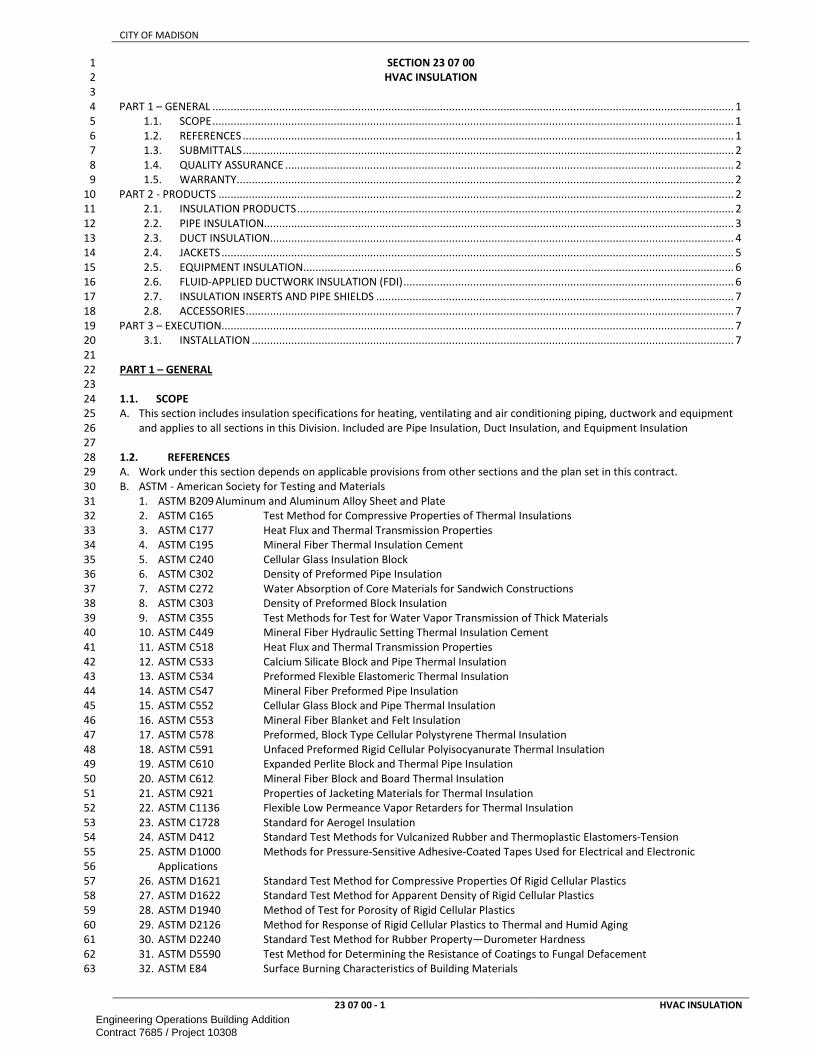
CITY OF MADISON
23 07 00 - 1 HVAC INSULATION
SECTION 23 07 00 1
HVAC INSULATION 2
3
PART 1 – GENERAL ............................................................................................................................................................................ 1 4
1.1. SCOPE ............................................................................................................................................................................ 1 5
1.2. REFERENCES .................................................................................................................................................................. 1 6
1.3. SUBMITTALS .................................................................................................................................................................. 2 7
1.4. QUALITY ASSURANCE .................................................................................................................................................... 2 8
1.5. WARRANTY .................................................................................................................................................................... 2 9
PART 2 - PRODUCTS .......................................................................................................................................................................... 2 10
2.1. INSULATION PRODUCTS ................................................................................................................................................ 2 11
2.2. PIPE INSULATION........................................................................................................................................................... 3 12
2.3. DUCT INSULATION......................................................................................................................................................... 4 13
2.4. JACKETS ......................................................................................................................................................................... 5 14
2.5. EQUIPMENT INSULATION .............................................................................................................................................. 6 15
2.6. FLUID-APPLIED DUCTWORK INSULATION (FDI) ............................................................................................................. 6 16
2.7. INSULATION INSERTS AND PIPE SHIELDS ...................................................................................................................... 7 17
2.8. ACCESSORIES ................................................................................................................................................................. 7 18
PART 3 – EXECUTION ......................................................................................................................................................................... 7 19
3.1. INSTALLATION ............................................................................................................................................................... 7 20
21
PART 1 – GENERAL 22
23
1.1. SCOPE 24
A. This section includes insulation specifications for heating, ventilating and air conditioning piping, ductwork and equipment 25
and applies to all sections in this Division. Included are Pipe Insulation, Duct Insulation, and Equipment Insulation 26
27
1.2. REFERENCES 28
A. Work under this section depends on applicable provisions from other sections and the plan set in this contract. 29
B. ASTM - American Society for Testing and Materials 30
1. ASTM B209 Aluminum and Aluminum Alloy Sheet and Plate 31
2. ASTM C165 Test Method for Compressive Properties of Thermal Insulations 32
3. ASTM C177 Heat Flux and Thermal Transmission Properties 33
4. ASTM C195 Mineral Fiber Thermal Insulation Cement 34
5. ASTM C240 Cellular Glass Insulation Block 35
6. ASTM C302 Density of Preformed Pipe Insulation 36
7. ASTM C272 Water Absorption of Core Materials for Sandwich Constructions 37
8. ASTM C303 Density of Preformed Block Insulation 38
9. ASTM C355 Test Methods for Test for Water Vapor Transmission of Thick Materials 39
10. ASTM C449 Mineral Fiber Hydraulic Setting Thermal Insulation Cement 40
11. ASTM C518 Heat Flux and Thermal Transmission Properties 41
12. ASTM C533 Calcium Silicate Block and Pipe Thermal Insulation 42
13. ASTM C534 Preformed Flexible Elastomeric Thermal Insulation 43
14. ASTM C547 Mineral Fiber Preformed Pipe Insulation 44
15. ASTM C552 Cellular Glass Block and Pipe Thermal Insulation 45
16. ASTM C553 Mineral Fiber Blanket and Felt Insulation 46
17. ASTM C578 Preformed, Block Type Cellular Polystyrene Thermal Insulation 47
18. ASTM C591 Unfaced Preformed Rigid Cellular Polyisocyanurate Thermal Insulation 48
19. ASTM C610 Expanded Perlite Block and Thermal Pipe Insulation 49
20. ASTM C612 Mineral Fiber Block and Board Thermal Insulation 50
21. ASTM C921 Properties of Jacketing Materials for Thermal Insulation 51
22. ASTM C1136 Flexible Low Permeance Vapor Retarders for Thermal Insulation 52
23. ASTM C1728 Standard for Aerogel Insulation 53
24. ASTM D412 Standard Test Methods for Vulcanized Rubber and Thermoplastic Elastomers-Tension 54
25. ASTM D1000 Methods for Pressure-Sensitive Adhesive-Coated Tapes Used for Electrical and Electronic 55
Applications 56
26. ASTM D1621 Standard Test Method for Compressive Properties Of Rigid Cellular Plastics 57
27. ASTM D1622 Standard Test Method for Apparent Density of Rigid Cellular Plastics 58
28. ASTM D1940 Method of Test for Porosity of Rigid Cellular Plastics 59
29. ASTM D2126 Method for Response of Rigid Cellular Plastics to Thermal and Humid Aging 60
30. ASTM D2240 Standard Test Method for Rubber Property—Durometer Hardness 61
31. ASTM D5590 Test Method for Determining the Resistance of Coatings to Fungal Defacement 62
32. ASTM E84 Surface Burning Characteristics of Building Materials 63
Engineering Operations Building AdditionContract 7685 / Project 10308

CITY OF MADISON
23 07 00 - 2 HVAC INSULATION
33. ASTM E814 Standard Test Method for Fire Tests of Penetration Firestop Systems 1
34. ASTM E2336 Standard Test Methods for Fire Resistive Grease Duct Enclosure Systems 2
C. MICA - National Commercial & Industrial Insulation Standards 3
D. NFPA – National Fire Protection Association 4
1. NFPA 225 Surface Burning Characteristics of Building Materials 5
E. UL – Underwriters Labroatory 6
1. UL 723 Surface Burning Characteristics of Building Materials 7
8
1.3. SUBMITTALS 9
A. Submit a schedule of all insulating materials to be used on the project, including adhesives, fastening methods, fitting 10
materials along with material safety data sheets and intended use of each material. Include manufacturer's technical data 11
sheets indicating density, thermal characteristics, jacket type, thickness and manufacturer's installation instructions. 12
13
1.4. QUALITY ASSURANCE 14
A. Label all insulating products delivered to the construction site with the manufacturer's name and description of materials. 15
B. Within the past 5 years, the contractor shall be able to document the successful completion of a minimum of 3 projects of 16
at least 50% of the size and similar scope of the work specified in this section. 17
A. Fluid-applied ductwork insulation is a roofing product that shall be applied only by qualified contractors. Contractor shall be 18
recognized by the manufacturer of the Polyurea 2-part liquid membrane system as an “approved” or “authorized” 19
applicator. Completed project requires installation inspection and approval by the manufacture of the Polyurea coating. 20
C. Install all insulation in accordance with the latest edition of MICA (Midwest Insulation Contractors Association) Standard 21
and manufacturer's installation instructions. 22
23
1.5. WARRANTY 24
A. FLUID APPLIED INSULATION: Provide written manufacturer’s (NDL) no-dollar-limit warranty covering installation required 25
under contract, to be watertight and free from defects in materials and workmanship of the Polyurea coating and other 26
system components supplied by the manufacturer for a period of 15 years from date of installation. 27
28
PART 2 - PRODUCTS 29
2.1. INSULATION PRODUCTS 30
A. Manufacturers: Armacell, Certainteed, Manson, Childers, Dow, Extol, Fibrex, Halstead, H.B. Fuller, Imcoa, Johns Manville, 31
Knauf, Owens-Corning, Partek, Pittsburgh Corning, Rubatex, VentureTape or approved equal. 32
B. Use composite insulation systems (insulation, jackets, sealants, mastics, and adhesives) that have a flame spread rating of 33
25 or less and smoke developed rating of 50 or less. Insulating materials shall be fire retardant, moisture and mildew 34
resistant, and vermin proof. Insulation shall be suitable to receive jackets, adhesives and coatings as indicated. 35
C. FLEXIBLE FIBERGLASS INSULATION: Minimum nominal density of 0.75 lbs / ft³., and thermal conductivity of not more than 36
0.3 at 75 °F, rated for service to 250 °F. 37
D. RIGID FIBERGLASS INSULATION: Minimum nominal density of 3 lbs / ft³., and thermal conductivity of not more than 0.23 at 38
75 °F, minimum compressive strength of 25 PSF at 10% deformation, rated for service to 450 °F. 39
E. SEMI-RIGID FIBERGLASS INSULATION: Minimum nominal density of 3 lbs / ft³., thermal conductivity of not more than 0.28 40
at 75 °F, minimum compressive strength of 125 PSF at 10% deformation, rated for service to 450 °F. Insulation fibers 41
perpendicular to jacket and scored for wrapping cylindrical surfaces. 42
F. CALCIUM SILICATE INSULATION: Rigid hydrous calcium silicate, ASTM C533, Type I, minimum dry density of 12.5 lbs / ft³, 43
thermal conductivity of not more than 0.44 at 300 degrees F, maximum water absorption of 90% by volume, minimum 44
compressive strength 140 psi at 5% deformation, rated for service range of 0 degrees F to 1,200 °F,. Material to be visually 45
coded or marked to indicate it is asbestos free. Use Type II insulation for temperatures above 1,200°F. 46
G. ELASTOMERIC INSULATION: Flexible closed cell, minimum nominal density of 5.5 lbs/ ft³., thermal conductivity of not more 47
than 0.27 at 75 °F, minimum compressive strength of 4.5 psi at 25% deformation, maximum water vapor permeability of 48
0.17 perm inch, maximum water absorption of 6% by weight, rated for service range of -20 °F to 220 °F on piping and 180 °F 49
where adhered to equipment. 50
H. POLYOLEFIN INSULATION: Flexible closed cell, minimum nominal density of 1.5 lbs / ft³, thermal conductivity of not more 51
than 0.24 at 75 °F, minimum compressive strength of 5 psi at 25% deformation, maximum water vapor permeability of 0.0 52
perm inch, maximum water absorption of 0% by weight and volume, rated for service range of -165 °F to 210 °F. 53
I. PHENOLIC INSULATION: Rigid closed cell, minimum nominal density of 2.2 lbs / ft³, thermal conductivity of not more than 54
0.13 at 75 °F, minimum compressive strength of 31 psi parallel and 18 psi perpendicular, maximum water vapor 55
permeability 0.117 perm inch, maximum water absorption of .5% by volume, rated for service range of -290 °F to 250 °F. 56
J. EXTRUDED POLYSTYRENE INSULATION: Rigid closed cell, minimum nominal density of 1.6 lbs / ft³, thermal conductivity of 57
not more than 0.285 at 75 degrees F, minimum compressive strength of 20 psi, maximum water vapor permeability of 1.5 58
perm inch, maximum water absorption of .5 % by volume, rated for service range of -290 °F to 165 °F. 59
K. URETHANE INSULATION: Rigid closed cell polyisocyanurate, minimum nominal density of 1.8 lbs / ft³, thermal conductivity 60
of not more than 0.19 at 75 degrees F aged 180 days, minimum compressive strength of 19 psi parallel and 10 psi 61
perpendicular, maximum water vapor transmission of 4 perm inch, maximum water absorption of .2% by volume, rated for 62
service range of -290 °F to 300 °F. 63
Engineering Operations Building AdditionContract 7685 / Project 10308

CITY OF MADISON
23 07 00 - 3 HVAC INSULATION
L. POLYISOCYANURATE INSULATION: Rigid closed cell polyisocyanurate, minimum nominal density of 2.0 lbs / ft³, thermal 1
conductivity of not more than 0.19 at 75 degrees F aged 180 days, minimum compressive strength of 24 psi parallel and 13 2
psi perpendicular, maximum water vapor permeability of 4 perm inch, maximum water absorption of 2% by volume, rated 3
for service range of -290 °F to 300 °F. 4
M. CELLULAR GLASS INSULATION: Rigid closed cell, minimum nominal density of 8.5 lbs / ft³, thermal conductivity of not more 5
than 0.36 at 50 degrees F, minimum compressive strength of 100 psi, maximum water vapor permeability of 0.0 perm inch, 6
maximum water absorption of .2% by volume, rated for service range of -450 °F to 900 °F. 7
N. MINERAL WOOL INSULATION: Rigid preformed mineral fiber, minimum nominal density of 8 lbs / ft³, thermal conductivity 8
of not more than 0.29 at 200 °F, minimum compressive strength of 3 psi, maximum wicking of 1%, maximum water 9
adsorption of 1% by volume, rated for service of -120 °F to 1200 °F. 10
O. MINERAL FIBER: Secure each 3’ section with three stainless steel bands or five 16 gauge stainless steel or annealed copper 11
tie wires evenly spaced and at ends. Twist wire ends, snip off excess and turn ends over into insulation. Stagger joints where 12
more than one layer is used. 13
P. ELASTOMERIC AND POLYOLEFIN: Where practical, slip insulation on piping during pipe installation when pipe ends are 14
open. Miter cut fittings allowing sufficient length to prevent stretching. Completely seal seams and joints for vapor tight 15
installation. For elastomeric insulation, apply full bed of adhesive to both surfaces. For polyeolefin, seal factory preglued 16
seams with roller and field seams and joints with full bed of hot melt polyolefin glue to both surfaces. Cover elastomeric 17
insulation on systems operating below 40 °F with vapor barrier mastic. 18
Q. EXTRUDED POLYSTYRENE AND POLYISOCYANURATE: Fittings, valves, unions, flanges, couplings and specialties shall be 19
insulated with factory molded insulation of the same thickness as adjoining insulation. Secure insulation sections with two 20
wraps of nylon filament tape 9”-12” on center. On single insulation layer systems and on the outer layer of double 21
insulation layer systems, apply a thin coat of elastomeric joint sealant rated for system operating temperatures to all 22
longitudinal and butt insulation joints covering entire face of joint. Allow sealant to fully cure before applying protective 23
covering. For piping service below 0oF, use two layers of insulation with inner and outer butt and longitudinal joints 24
staggered and offset 90 degrees. Where two layers of insulation are used, do not use sealant on the inner layer or adhere 25
the inner layer to the outer layer. Apply vapor stop bead of joint sealant between pipe and insulation on both sides of 26
valves, expansion/contraction joints, flanges, thermometers/gauges, attached vent and drain lines. Insulate attached non-27
circulated lines, control lines, vents, etc. for a minimum distance of 6” from pipe. Cover insulation with a protective jacket 28
as specified below. Do not penetrate protective covering or insulation with mechanical fasteners. 29
R. FIREPROOFING INSULATION: Mineral fiber with nominal density of 8 lbs / ft³, flame spread index of 25, fuel contribution 30
index of 0, and smoke developed index of 0, thermal conductivity of not more than 0.23 at 75 degrees F, rated for service of 31
-120 °F to 1200 °F. Use rigid or semi-rigid board for duct insulations. 32
S. VAPOR BARRIER: maximum permeance of .02 perms. Provide a continuous unbroken moisture vapor barrier on insulation 33
applied to systems requiring vapor barrier. Attachments to cold surfaces shall be insulated and vapor sealed to prevent 34
condensation. 35
T. FIRE-STOP INSULATION: Noncombustible, non-asbestos, non-ceramic fiber, high temperature blanket or board fireproofing 36
insulation, constructed of calcium silicate or calcium/magnesium/silica amorphous wool with 2-hour (or as required by 37
application) ASTM E814 “F” and “T” fire ratings, UL or equivalent third party listed, labeled and specifically evaluated for 38
such purpose in accordance with ASTM E2336. Foil-scrim-polyethylene fiberglass reinforced factory applied jacket. 39
U. FIRE RATED INSULATION: Noncombustible, non-asbestos, non-ceramic fiber, high temperature blanket or board 40
fireproofing insulation, constructed of calcium silicate or calcium/magnesium/silica amorphous wool with required ASTM 41
E814 “F” and “T” fire ratings, UL or equivalent third party listed, labeled and specifically evaluated for such purpose in 42
accordance with ASTM E2336. Foil-scrim-polyethylene fiberglass reinforced factory applied jacket. 43
44
2.2. PIPE INSULATION 45
A. Provide insulation on new and existing remodeled piping as per following schedule. Include asbestos-abated existing pipes: 46
Service Insulation Vapor Jacket Insulation Thickness by Pipe Size
<= 1.25” 1.5” 2”- 4” 4”- 6” >=8”
Warm Water Rigid Fiberglass ASJ 1.5” 1.5” 2” 2” 2”
Heating Hot Water Rigid Fiberglass ASJ 1.5” 2” 2” 3” 3”
Chilled Water /
Geothermal Fluid
Polyiso./Polysty X VRJ or SAJ 1.5” 2” 2” 3” 3”
Refrigerant Suction Ext Poly/Polyiso X VRJ or SAJ 2” 2.5” 2.5” 3” 4”
Remote Generator
Radiator Piping
Rigid Fiberglass
(indoors) /
Polyiso./Polyst
y (outdoors)
ASJ 1.5” 1.5” 2” 2” 2”
Storage Tanks (hot) Semi-Rigid Fiberglass ASJ/FMJ 2”
Storage Tank (chilled or
geothermal)
Elastomeric/Polyolefin ASJ 2” (unless manufacturer supplies factory-made
insulation for application)
R.P.B.P Elastomeric ASJ 0.5”
Generator exhaust pipe
and muffler
Calcium Silicate /
Fireproofing
PMJ
(exposed
3”
Engineering Operations Building AdditionContract 7685 / Project 10308

CITY OF MADISON
23 07 00 - 4 HVAC INSULATION
locations)
Hot Water Air
separators;
Buffertanks, Heat
Exchangers
Semi-Rigid
Fiberglass
ASJ/FMJ 2”
Chilled Water and
Geothermal Air
separators;
Buffertanks,
waterboxes,
evaporator shell,
condenser shell,
Heat Exchangers,
Pumps, Balancing
valves, valves
Elastomeric/Polyolefin X None 2” (unless manufacturer supplies factory-made
insulation for application)
B. INSULATION INSERTS AND PIPE SHIELDS: 1
1. Manufacturers: B-Line, Pipe Shields, Value Engineered Products 2
2. Provide pipe shields at all hanger and support locations. Rigid insulation inserts shall be installed between the pipe and 3
the insulation shields. Quantity and placement of inserts shall be according to the manufacturer’s installation 4
instructions. Inserts shall be of equal thickness to the adjacent insulation and shall be vapor sealed as required for 5
system. 6
C. Insulate elbows and other corners with 22.5° pieces or use factory made insulation fittings. Use factory-made fittings for 7
Tee, and other fittings. 8
D. FITTINGS AND VALVES: Fittings, valves, unions, flanges, couplings and specialties may be insulated with factory molded or 9
built up insulation of the same thickness as adjoining insulation. 10
E. Pipe insulation shall be performed in 2 half cylinder sections. Cut V-groove sheet insulation is not acceptable. Provide 3 11
stainless steel bands for each section of insulation. 12
13
2.3. DUCT INSULATION 14
A. Provide duct insulation on new and existing remodeled ductwork in the following schedule. Air ducts with temperatures of 15
the space equal to the air (i..e return air in plenum) don’t require insulation unless noted elsewhere: 16
Service Insulation Type Jacket Insulation Thickness
Outside air ducts Rigid Fiberglass FSJ 2”
Mixed air ducts Rigid Fiberglass FSJ 2”
Exposed supply ducts Rigid Fiberglass FSJ 2”
Concealed supply ducts Flexible Fiberglass FSJ 2”
All Ducts located in
unconditioned
attics/crawl spaces
Flexible Fiberglass FSJ 3”
Exhaust and relief ducts
downstream of
motorized backdraft
dampers
Rigid Fiberglass FSJ 2”
All ducts exposed to weather Ext. Polystyrene or fluid
Applied
SAJ 3”
Exhaust ducts downstream of
heat recovery units
and desiccant dryers
Rigid Fiberglass FSJ 2”
Grease ducts serving Type I
Kitchen hoods
Fire-Stop As required for hourly rating As required for hourly rating
Duct between equipment
such as AHU, ERV and
in non-airconditioned
spaces when duct
supplies cooled air.
Rigid Fiberglass FSJ 2”
Breech. and boiler wind
boxes
Fireproofing As required for hourly rating 3”
Louver blank-off panels Poly-iso SAJ 2”
AHU unit casing (unless
factory-insulated),
humidifier
Rigid Fiberglass ASJ 2”
Engineering Operations Building AdditionContract 7685 / Project 10308

CITY OF MADISON
23 07 00 - 5 HVAC INSULATION
B. Secure flexible duct insulation on sides and bottom of ductwork over 24" wide and all rigid duct insulation with weld pins. 1
Space fasteners 18” on center or less as required to prevent sagging. 2
C. Secure rigid board insulation to ductwork with weld pins. Apply insulation with joints firmly butted as close as possible to 3
the equipment surface. Pins shall be located a maximum of 3” from each edge and spaced no greater than 12” on center. 4
D. Install weld pins without damage to the interior galvanized surface of the duct. Clip pins back to washer and cover 5
penetrations with tape of same material as jacket. Firmly butt seams and joints and cover with 4” tape of same material as 6
jacket. Seal tape with plastic applicator and secure with staples. All joints, seams, edges and penetrations to be fully vapor 7
sealed. 8
E. Stop and point insulation around access doors and damper operators to allow operation without disturbing insulation or 9
jacket material. 10
F. Provide 4” overlap of external insulation over ends of acoustically lined sections. 11
G. Where insulated ductwork is supported by trapeze hangers, the insulation shall be installed continuous through the 12
hangers. Drop the supporting channels required to facilitate the installation of the insulation. Where rigid board or flexible 13
insulation is specified, install high density inserts to prevent the weight of the ductwork from crushing the insulation. 14
H. Where insulated low temperature (below 45ºF) ductwork is supported by steel metal straps or wire ropes that are secured 15
directly to the duct, the straps or ropes shall be completely covered with insulation and sealed to provide a complete vapor 16
barrier. 17
I. Where insulated duct risers are supported by steel channels secured directly to the duct, extend the insulation and vapor 18
barrier jacketing to encapsulate the support channels. 19
J. Where ductwork exposed to the weather is insulated with any product other than fluid-applied ductwork insulation, the top 20
surface of the insulation shall be sloped a minimum of ¼” per foot to eliminate ponding and create positive drainage off of 21
insulation. Refer to fluid-applied ductwork insulation section below for slope requirements. 22
K. BREECHING: Fasten insulation over weld pins and secure with washers. Space fasteners not less than 3” from edge or 23
corner and 12" on center longitudinally and 9" on center in the transverse direction. Clip pins back to washer and cover 24
penetrations with tape of same material as jacket. Firmly butt seams and joints and cover with 4” tape of same material as 25
jacket. Seal tape with plastic applicator and secure with staples. 26
L. GREASE DUCTS: Strictly adhere to manufacturer’s installation instructions and rating requirements for application of fire-27
stop insulation. Cover all exhaust ducts serving Type I kitchen hoods with fire-stop insulation from a point prior to 28
penetration of ceiling, wall, floor or concealment through building to termination at outside of building. Extend fire-stop 29
insulation through roof curbs. Enclose from the point of penetration of a ceiling, wall or floor to the outlet terminal in a 2-30
hour rated enclosure vented to the outside and constructed with 6”-12” clearance to the duct. 31
32
2.4. JACKETS 33
A. PVC FITTING COVERS AND JACKETS (PFJ): White PVC film, gloss finish one side, semi-gloss other side, FS LP-535D, 34
Composition A, Type II, Grade GU. Ultraviolet inhibited indoor/outdoor grade to be used where exposed to high humidity, 35
ultraviolet radiation, in kitchens or food processing areas or installed outdoors. Jacket thickness to be minimum .02” 36
indoors/.03”outdoors for piping 12” and smaller, .03” indoors/.04” outdoors for piping 15” and larger. PVC covers and 37
jackets have limited ability to resist water vapor transmission. On systems operating below 50 degrees F which use PVC 38
covers or jackets, insulation must first be covered with low permeance vapor barrier mastic/fabric or vapor barrier tape. 39
Lap seams and joints a minimum of 2 inches and continuously seal PVC with welding solvent recommended by jacket 40
manufacturer. Lap slip joint ends 4" without fasteners where required to absorb expansion and contraction. For sections 41
where vapor barrier is not required and jacket requires routine removal, tack fasteners may be used. Secure PVC fitting 42
covers with tack fasteners. For systems requiring a vapor barrier, apply a 1-1/2” band of mastic over ends, throat, seams 43
and penetrations. 44
B. ALL SERVICE JACKETS (ASJ): Heavy duty, fire retardant material with white kraft reinforced foil vapor barrier, factory applied 45
to insulation with a self-sealing pressure sensitive adhesive lap, maximum permeance of .02 perms and minimum beach 46
puncture resistance of 50 units. 47
C. FOIL SCRIM ALL SERVICE JACKETS (FSJ): Glass fiber reinforced foil kraft laminate, factory applied to insulation. Maximum 48
permeance of .02 perms and minimum beach puncture resistance of 25 units. 49
D. PROTECTIVE METAL JACKETS (PMJ): .016 inch thick aluminum or .010 inch thick stainless steel with safety edge. 50
E. Lap seams a minimum of 2 inches. Secure with metal bands for end to end joints, and rivets or sheet metal screws for 51
longitudinal joints. Rivets, screws, and bands to be constructed of the same material as the jacket. Locate seams on bottom 52
for exterior applications. 53
F. SELF-ADHERING JACKETS (SAJ): 5-ply, self-adhering multiple laminated waterproofing material with reflective aluminum 54
foil, high density polymer films and cold weather acrylic adhesive providing zero (0.0) permeability. Minimum 6 mils 55
material thickness, 35lb puncture resistance when tested in accordance with ASTM D1000 and flame spread/smoke 56
developed rating of 10/20 when tested in accordance with UL 723. Vapor retarding tape shall be specifically designed and 57
manufactured for use with the self-adhering jacket specified above. Tape shall be provided by the same manufacturer that 58
provides jacketing. Vapor retarding tapes used with self-adhering jackets shall have a maximum permeance of 0.0 perms. 59
Cut allowing minimum 4” overlap on ends and 6” on longitudinal joints. Align parallel to surface. Remove release paper and 60
press flat to surface to avoid wrinkles. Rub entire surface for full adhesion and sealing at joint overlaps. On exterior 61
applications, provide a bead of compatible caulk along exposed edges. Piping with self-adhering (SAJ) jackets shall have 62
elbows, fittings, valves and butt joints wrapped with 2 layers of vapor retarding tape. Piping with a PVC jacket (PFJ) installed 63
Engineering Operations Building AdditionContract 7685 / Project 10308

CITY OF MADISON
23 07 00 - 6 HVAC INSULATION
over the self-adhering (SAJ) jacket may be provided with a single, lapped layer of vapor retarding tape for elbows, fittings 1
and valves under the PVC jacket. Vapor retarding tape shall be compatible with the jacket material used. 2
G. FABRIC REINFORCED MASTIC JACKETS (FMJ): Glass fiber reinforcing fabric imbedded in weather barrier mastic as per 3
manufacturer’s recommended procedure for 2 coat application. Glass fiber fabric shall be fitted without wrinkles. Glass 4
fiber fabric shall be sized immediately upon application with lagging adhesive and shall be capable of drying within 6 hrs. 5
Apply adhesive and coating in accordance with manufacturer’s recommendations. All seams shall overlap not less than 2”. 6
H. VAPOR RETARDING JACKETS (VRJ): Polyvinylidene chloride (PVDC) vapor retarding jacket material with minimum 6 mils 7
material thickness and maximum permeance of 0.01 perms. Material shall not support the growth of mold or mildew. Dow 8
Saran or equivalent. Vapor retarding tape shall be specifically designed and manufactured for use with the vapor retarding 9
jacket specified above. Tape shall be provided by the same manufacturer that provides jacketing. Vapor retarding tapes 10
used with vapor retarding jackets shall have a maximum permeance of 0.01 perms. Piping with vapor retarding (VRJ) jackets 11
shall have elbows, fittings, valves and butt joints wrapped with 2 layers of vapor retarding tape. Piping with a PVC jacket 12
(PFJ) installed over the vapor retarding (VRJ) jackets may be provided with a single, lapped layer of vapor retarding tape for 13
elbows, fittings and valves under the PVC jacket. Vapor retarding tape shall be compatible with the jacket material used. 14
I. METAL JACKETS: .016 inch thick aluminum or .010 inch thick stainless steel with safety edge. 15
J. Protective jackets shall be used for pipe insulation exposed in food handling/kitchen areas, cold rooms, wet areas, exterior 16
installations or where insulation is subject to physical abuse. 17
K. Provide a protective PVC jacket (PFJ) for the following insulated piping: 18
1. Chilled water piping and valves in walk-thru tunnels and valve pits 19
2. Exposed piping in kitchens 20
3. Piping exposed in finished locations 21
4. Outdoors 22
L. Provide PFJ or FMJ jacket for all piping within mechanical rooms 23
M. Provide PMJ or SAJ jacket for the following insulated piping for Exterior refrigeration piping 24
N. Provide PMJ for the following insulated piping: Steam and condensate piping and fittings in walk-thru tunnels and pits 25
26
2.5. EQUIPMENT INSULATION 27
A. Do not insulate over equipment access manholes, nameplates or ASME stamps. Bevel and seal insulation at these 28
locations. 29
B. PROTECTIVE JACKETS: Provide a protective metal jacket (PMJ) for the following: Generator exhaust pipe (that is not 30
concealed in a shaft) and muffler. 31
C. SEMI-RIGID FIBERGLASS: Apply insulation to equipment shells using weld pins, bonding adhesive, banded and wired in 32
place. Fill all joints, seams and depressions with insulating cement to a smooth, even surface. Cover with reinforcing fabric 33
and 2 coats of mastic (FMJ). Use vapor barrier mastic on systems requiring a vapor barrier. 34
D. ELASTOMERIC/POLYOLEFIN: Apply full cover coat of adhesive to surface to be insulated, insulation and edge butt joints. 35
Place insulation with edge joints firmly butted pressing to surface for full adhesion. Seal seams and joints vapor tight. 36
E. REMOVABLE COVERS: Provide insulated easily removable galvanized steel metal boxes for routine service access on the 37
following equipment: 38
1. VAV boxes on both sides of heating coil 39
F. Equipment in ducts and pipes insulate with same insulation material and thickness as the connecting duct or pipe 40
41
2.6. FLUID-APPLIED DUCTWORK INSULATION (FDI) 42
B. Manufacturers: Technical Roofing Solutions, Inc; Volatile Free Inc.; BASF Corp.; Gaco Western Inc. or equal. 43
C. Coatings shall be U.L. Listed to retain existing system UL ratings when applied as specified in this project. 44
D. Polyurea: (approved polyurea coating) A two-component 1:1 ratio polyurea-urethane hybrid with excellent strength and 45
weathering characteristics. 46
E. Performance Values: 47
PHYSICAL PROPERTY ASTM TEST METHOD TYPICAL VALUE
Tensile Strength D 412 >1,600 psi
Elongation D 412 >300%
Shore A Hardness (inst-5 sec.) D 2240 85 - 90 Shore A
Tack-Free Time 10 to 30 Seconds
Service Temperature -40°F to 300°F
Application Temperature 40°F to 150°F
Tear Resistance D 264 Die C 125 Pli
Spread of Flame ASTM E-84 <75 (Smoke<450)
F. Performance Values: 48
PHYSICAL PROPERTY ASTM TEST METHOD TYPICAL VALUE
Density (nominal) ASTM D-1622 2.5 pcf
Compressive Strength (min) (parallel to rise) ASTM D-1621 40 psi
K Factor (Initial) ASTM C-177 0.15 btu.in/ft2.hr. °F
Closed Cell Content ASTM D-1940 90%
Dimensional Stability (aged 28 days, % volume change) ASTM D-2126 <2.5 @ 158oF/98% RH
Moisture (Perm/Inch) ASTM C-355 0.8
Engineering Operations Building AdditionContract 7685 / Project 10308

CITY OF MADISON
23 07 00 - 7 HVAC INSULATION
Spread of Flame (2“ thick sample) ASTM E-84 <75 (Smoke<450)
G. Final coating shall be a polyurea compatible, fire retardant coating (Flame spread <25 Smoke <50). 1
H. Primer, Cleaner, mastic and coating shall be approved by manufacturer. 2
3
2.7. INSULATION INSERTS AND PIPE SHIELDS 4
A. Manufacturers: B-Line, Pipe Shields, Value Engineered Products. 5
B. Construct inserts polyisocyanurate minimum 140 psi compressive strength. Provide galvanized steel shield. Insert and shield 6
to be minimum 180 degree coverage on bottom supported piping and full 360 degree coverage on clamped piping. On 7
roller mounted piping and piping designed to slide on support, provide additional load distribution steel plate. 8
9
2.8. ACCESSORIES 10
A. All products shall be compatible with surfaces and materials on which they are applied, and be suitable for use at operating 11
temperatures of the systems to which they are applied. 12
B. Adhesives, sealants, and protective finishes shall be as recommended by insulation manufacturer for applications specified. 13
C. Insulation bands to be 0.75” wide, constructed of aluminum or stainless steel. Minimum thickness to be .015 inch for 14
aluminum and .010 inch for stainless steel. 15
D. Tack fasteners to be stainless steel ring grooved shank tacks. Staples to be clinch style. 16
E. Insulating cement to be ANSI/ASTM C195, hydraulic setting mineral wool. Finishing cement to be ASTM C449. 17
F. Fibrous glass or canvas fabric reinforcing shall have a minimum untreated weight of 6 oz./sq. yd. 18
G. Bedding compounds to be non-shrinking and permanently flexible. 19
H. Vapor barrier coatings to have maximum applied water vapor permeance of .05 perms. 20
I. Fungicidal water base coating (Foster 40-20 or equal) to be compatible with vapor barrier coating. 21
J. equipment/piping, mastic must be anti-fungal and shall meet ASTM D 5590 with 0 growth rating (AF), water vapor 22
permeance shall be less than 0.013 perms at 43 mils dry film thickness per ASTM E 96 Procedure B: Foster 30-80AF Vapor 23
Safe Mastic or equal. 24
K. WEATHER BARRIER BREATHER MASTIC: Above ambient equipment/piping. permeance shall be greater than 1.0 perms at 25
1/16" dry film thickness per ASTM E96. Foster 46-50 Weatherite, Childers Vi-Cryl CP-10/CP-11, Vimasco WC-5. 26
L. LAGGING ADHESIVE / COATINGS: Indoors applications used in conjunction with canvas/glass cloth: Foster 30-36, Childers 27
CP-50 AMV1, Vimasco 713. 28
M. For all indoor applications, coating must be anti-fungal and shall meet ASTM D 5590 with 0 growth rating (AF): Foster 30-36 29
AF Seal Fas, Childers CP-137 AF Chil-Seal. 30
N. REINFORCING MESH: Foster 42-24 Mast A Fab, Childers Chil Glas #10 or Pittsburgh Corning PC 79. 31
O. METAL JACKETING SEALANT FOR ALL ALUMINUM JACKETING: Foster 95-44 Elastolar, Childers CP-76 Chil-Byl, Pittsburgh 32
Corning 727. 33
P. INSULATION JOINT SEALANT: (cellular glass, polyisocyanurate, phenolic) Used on all below ambient piping to prevent 34
moisture ingress. Foster 95-50 Flextra, Childers CP-76 Chil-Byl, Pittsburgh Corning CW Sealant. 35
36
PART 3 – EXECUTION 37
3.1. INSTALLATION 38
A. Install in accordance with manufacturer's instructions and all code requirements. 39
B. Verify that all piping, equipment, and ductwork are tested and approved prior to installing insulation. Do not insulate 40
systems until testing and inspection procedures are completed. Verify that all surfaces are clean, dry and without foreign 41
material before applying insulation materials. 42
C. All materials shall be installed by skilled labor regularly engaged in this type of work. All materials shall be installed in strict 43
accordance with manufacturer’s recommendations, building codes, and industry standards. Do not install products when 44
the ambient temperature or conditions are not consistent with the manufacturer’s recommendations. 45
D. Locate insulation and cover seams in the least visible location. All surface finishes shall be extended in such a manner as to 46
protect all raw edges, ends and surfaces of insulation. 47
E. Install insulation with smooth and even surfaces. Poorly fitted joints or use of filler in voids will not be accepted. Provide 48
neatly beveled and coated terminations at all nameplates, uninsulated fittings, or at other locations where insulation 49
terminates. 50
F. Install fabric reinforcing without wrinkles. Overlap seams a minimum of 2 inches. 51
G. Use full length material wherever possible. Scrap piecing of insulation or pieces stretched to fit will not be accepted. 52
H. All pipe and duct insulation shall be continuous through walls, ceiling or floor openings and through sleeves except where 53
firestop or firesafing materials are required. Vapor barriers shall be maintained continuous through all penetrations. 54
I. Install insulation with butt joints and longitudinal seams closed tightly. Provide minimum 2” lap on jacket seams and 2” 55
tape on butt joints, firmly cemented with lap adhesive. Additionally secure with staples along seams and butt joints. Coat 56
staples with vapor barrier mastic on systems requiring vapor barrier. 57
J. For systems with fluid temperatures 65° F or less, furnish and install removable elastomeric insulation covers, plugs or caps 58
for all mechanical equipment and devices that require access by balancing contractors or service and maintenance 59
personnel. Examples include but are not limited to: flow sensing devices, circuit setters, manual ball valve air vents, drain 60
valves, blowdown valves, pressure/temperature test plugs, grease fittings, pump bearing caps, equipment labels, etc. 61
Covers shall be tight fitting to ensure a complete vapor barrier. 62
Engineering Operations Building AdditionContract 7685 / Project 10308

CITY OF MADISON
23 07 00 - 8 HVAC INSULATION
1
END OF SECTION 2
Engineering Operations Building AdditionContract 7685 / Project 10308

CITY OF MADISON
SECTION 23 09 00- 1
INSTRUMENTATION AND CONTROL FOR
HVAC
SECTION 23 09 00 1
INSTRUMENTATION AND CONTROL FOR HVAC 2
PART 1 – GENERAL ............................................................................................................................................................................ 1 3
1.1. SCOPE ............................................................................................................................................................................ 1 4
1.2. REFERENCES .................................................................................................................................................................. 1 5
1.3. SUBMITTALS .................................................................................................................................................................. 1 6
1.4. QUALITY ASSURANCE .................................................................................................................................................... 2 7
1.5. PERFORMANCE REQUIREMENTS ................................................................................................................................... 2 8
PART 2 - PRODUCTS .......................................................................................................................................................................... 3 9
2.1. TEMPERATURE SENSORS ............................................................................................................................................... 3 10
2.2. PRESSURE SENSORS AND SWITCHES ............................................................................................................................. 4 11
2.3. CURRENT SENSORS AND SWITCHES .............................................................................................................................. 4 12
2.4. FLOW MEASURING DEVICES ......................................................................................................................................... 4 13
2.5. GAS SENSORS ................................................................................................................................................................ 4 14
2.6. HUMIDITY, DEWPOINT AND ENTHALPY SENSORS ........................................................................................................ 4 15
2.7. MOTION, DOOR AND WINDOW SENSORS .................................................................................................................... 5 16
2.8. ACTUATORS ................................................................................................................................................................... 5 17
2.9. VARIABLE FREQUENCY DRIVES ...................................................................................................................................... 5 18
2.10. WIRING .......................................................................................................................................................................... 6 19
PART 3 – EXECUTION ......................................................................................................................................................................... 6 20
3.1. INSTALLATION ............................................................................................................................................................... 6 21
3.2. ACCEPTANCE TESTING................................................................................................................................................... 6 22
3.3. OPERATOR INSTRUCTION, TRAINING ............................................................................................................................ 6 23
3.4. CONTROL SEQUENCES ................................................................................................................................................... 7 24
25
PART 1 – GENERAL 26
1.1. SCOPE 27
A. Furnish all labor, materials, equipment, and service necessary for a complete operating BAS, utilizing DDC as shown on the 28
diagramatic drawings and as described in Sequence of Operation. Provide Integration of system into existing WEBs 29
supervisor per owner instructions. 30
B. Acronyms used in this specification are as follows: 31
1. BAS Building Automation System 32
2. DDC Direct Digital Controls 33
3. GUI Graphical User Interface 34
4. IBC Interoperable BACnet Controller 35
5. IDC Interoperable Digital Controller 36
6. LAN Local Area Network 37
7. NAC Network Area Controller 38
8. OOT Object Oriented Technology 39
9. PICS Product Interoperability Compliance Statement 40
10. PMI Power Measurement Interface 41
11. POT Portable Operator’s Terminal 42
12. WAN Wide Area Network 43
13. WBI Web Browser Interface 44
45
1.2. REFERENCES 46
A. Work under this section depends on applicable provisions from other sections and the plan set in this contract. Examples of 47
related sections include, but are not limited to: 48
1. DIVISION 26 — ELECTRICAL 49
2. 23 09 13.33 - CONTROL VALVES 50
3. 23 09 13.43 - CONTROL DAMPERS 51
52
1.3. SUBMITTALS 53
A. Complete wiring and schematic diagrams, software descriptions, sequences of operation, protocol documentation, point 54
lists, calculations, and any other details required to demonstrate that the system has been coordinated and will properly 55
function. Terminal identification for all control wiring shall be shown on the shop drawings. Include a trunk cable 56
schematic diagram depicting control panel locations and a description of the communication type, media, and protocol. 57
B. WIRING: Load and voltage drop calculations inc. proposed wiring lengths and sizes. Provide transformer and fuse box data. 58
C. Include a copy of each of the graphics developed for the Graphic User Interface including a flowchart (site map) indicating 59
how the graphics are to be linked to one another for system navigation. 60
D. Complete set of electronic ‘as-built’ drawings and application software. Drawings shall be provided as dwg and Visio™ files. 61
62
Engineering Operations Building AdditionContract 7685 / Project 10308

CITY OF MADISON
SECTION 23 09 00- 2
INSTRUMENTATION AND CONTROL FOR
HVAC
1.4. QUALITY ASSURANCE 1
A. BASIS-OF-DESIGN: Honeywell WEBs-AX™ based on a hierarchical architecture incorporating the Niagara AX Framework™. 2
B. Contractor shall be certified and trained by BAS manufacturer and shall be ACI (Authorized Controls Integrator) Honeywell 3
Contractor. The firm must be specializing and experienced in DDC control system installation for no less than 10 years. 4
C. All engineering and commissioning work shall be done by qualified employees of this contractor, or qualified employees of 5
an Authorized Representative of that manufacturer. Installation of electrical components and wiring can be done by this 6
contractor or contractor meeting requirements of Division 26. 7
D. The contractor must have a service office within 20 miles of the building location. This requirement applies to the actual 8
office location the individuals working on controls work out of. Response Time During warrantee period must be four (4) 9
hours or less. 10
E. All products of the BAS shall have the following agency approvals: 11
1. UL/cUL (E87741) listed under UL916 (Standard for Open Energy Management Equipment) with plenum rating. 12
2. CSA (LR95329-3) Listed 13
3. Meets FCC Part 15, Subpart B, Class B (radiated emissions) requirements. 14
4. Meets Canadian standard C108.8 (radiated emissions). 15
5. Conforms to the following requirements per European Consortium standards: 16
a. EN 61000-6-1; 2001 (EU Immunity) 17
b. EN 61000-6-3; 2001 (EU Emissions) 18
F. Equipment must be capable of operation within expected conditions of the environment it is located in. 19
20
1.5. PERFORMANCE REQUIREMENTS 21
A. BAS shall be comprised of: 22
1. NAC within each facility shall connect to the owner’s LAN network. Access to the system shall be via standard Web 23
browsers and secure password. 24
2. Peer-to-peer networked, stand-alone, distributed control system with the capability to integrate ANSI/ASHRAE 25
Standard 135-2001 BACnet™, LonWorks™ technology, MODBUS ™, OPC, and other open and proprietary 26
communication protocols into one open, interoperable system. 27
3. platform shall be designed specifically to control HVAC Equipment and if available be specific to that type of equipment. 28
The controller shall provide options and advanced system functions, programmable and configurable using Niagara AX 29
Framework™, that allow standard and customizable control solutions required in executing the “Sequence of 30
Operation”. Standard controller is Honeywell Spyder or most current model capable of providing required control 31
sequences and points. 32
B. SPEED: A hierarchical topology is required to assure reasonable system response times and to manage the flow and sharing 33
of data. Maximum acceptable response time from any alarm occurrence (at the point of origin) shall not exceed 5 seconds. 34
C. ALARMS: 35
1. Alarm annunciation and acknowledgement shall indicate: in alarm, Return to normal, Fault condition 36
2. Allow a minimum of eight alarm classes for the purpose of routing types and/or classes of alarms, i.e.: fire, HVAC 37
3. Provide timed (schedule) routing of alarms by class, object, group, or node. 38
4. Provide alarms from “runtime” and/or event counts for equipment maintenance. 39
5. Controller and network failures shall be treated as alarms and annunciated. 40
6. Show acknowledge time, date, and user who issued acknowledgement. 41
7. Number of occurrences since last acknowledgement. 42
8. Provide a “query” feature to allow review of specific alarms by user defined parameters. 43
9. The user shall be able to define the specific system reaction for each point. Alarms shall be prioritized to minimize 44
nuisance reporting and to speed operator response to critical alarms. A minimum of three priority levels shall be 45
provided. 46
10. Users shall have the ability to inhibit alarm reporting for each point. User shall also be able to define conditions under 47
which point changes need to be acknowledged by an operator and/or logged for analysis at a later date. 48
11. Provide the ability to route and email alarms based on Day of week, Time of day, Recipient. Show Graphic with flashing 49
alarm object(s), Location (building, floor, zone, office number, etc.), Equipment (air handler #, access way, etc.) 50
D. LOGGING AND BACKUP CAPABILITY: 51
1. All log data shall be available as HTML, XML, Plain Text., Comma or tab separated values, PDF 52
2. A log of all alarms shall be maintained by the NAC and/or a server (if configured in the system) for review by the user. 53
3. An Error Log to record invalid property changes or commands shall be provided and available for review by the user. 54
4. Archive log data locally and/or on server frequently and automatically 55
5. A Audit Log that tracks all activities performed on the NAC. For each log entry, provide the Time and date, User ID and 56
Change or activity: i.e., Change setpoint, add or delete objects, commands, etc. 57
6. The database shall be backed up frequently. Copies of the current database and, at the most recently saved database 58
shall be stored in the NAC. 59
E. TRENDING: 60
1. Measured and calculated analog and binary data shall be assignable to user definable trends for the purpose of 61
collecting operator specified performance data over extended periods of time. 62
Engineering Operations Building AdditionContract 7685 / Project 10308

CITY OF MADISON
SECTION 23 09 00- 3
INSTRUMENTATION AND CONTROL FOR
HVAC
2. Sample intervals of 1 minute to 24 hoursshall be provided. Data shall be stored at the supervisory controller and 1
frequently up-loaded to the server. 2
F. GRAPHICS: The graphic shall provide a geographical overview of the multiple-site buildings. 3
1. All points shall be displayed including but not limited to the actual value, set-value and alarms. 4
2. Log of each value shall be accessible from the read value on display. All values shall be logged. 5
3. The graphic shall provide an accurate dimensional layout of the building floor(s); including all rooms, room numbers, 6
walls, elevators, doors, entrances, hallways, and stairwells. Room numbering and naming conventions shall be provided 7
by the architect/engineer. 8
4. Display and animate systems as 3-D objects including all sensors, heat exchangers, heating and cooling coils, dampers, 9
piping and pumps, humidifiers, flow directions, safety devices, and limit devices with fan, pump, damper, and valves. 10
5. For each device and zone the set point and actual value shall be displayed 11
6. The desired mode (i.e. winter occupied) shall be displayed 12
7. Temporary Override shall have a drop-down menu and provide timed override to allow automatic fall-back of 13
overridden value. Time intervals shall be 1-hour (default), 2 hours, 4-hours, 24 hours, 48 hours, and permanent. 14
G. ENERGY MANAGEMENT: 15
1. Current electric power draw of devices shall be totaled and displayed including data of sub-meters, VFD-data and other 16
device-data. Categorize in system types (i.e. chiller system). In addition, display: 17
a. Peak demand, with date and time stamp 18
b. 24-hour demand log 19
c. Accumulated KWH and therms for day 20
d. Sunday through Saturday KWH and therm usage 21
e. Demand KW annual history for past 12 periods 22
f. KWH and therm annual history for past periods 23
2. Heating degree days and heating fuel consumption comparison will be logged and a relationship developed. Based on 24
this, an indication in if the building performs as expected will be derived. 25
3. If shown elsewhere contractor shall arrange with the project electric utility for providing an isolation relay at the service 26
meter to allow independent pulse signals to be monitored by the DDC control system for electric utility KWH power 27
usage, natural gas usage, and peak KW demand. Owner will pay for utility fee, contractor shall pay for isolation relay 28
and associated wiring and provide power to meter as required. 29
H. The Owner shall be the named license holder of all software associated with any and all incremental work. In addition, the 30
Owner shall receive ownership of all job specific configuration documentation, data files, and application-level software 31
developed for the project. This shall include all custom, job specific software code and documentation for all configuration 32
and programming that is generated for a given project and/or configured for use with the NAC, BAS, and any related LAN / 33
WAN / Intranet and Internet connected routers and devices. Any and all required IDs and passwords for access to any 34
component or software program shall be provided to the owner. 35
I. POINTS: 36
1. Analog Points shall allow linear input and output of 2-10V. 0-5 VDC, or 4-20 mA acceptable if 2-10V not available. 37
2. Digital Points shall allow 24VAC input and output 38
39
PART 2 - PRODUCTS 40
2.1. TEMPERATURE SENSORS 41
A. SPACE TEMPERATURE WALL MODULE: Temperature sensing modules mounted on the wall in occupied spaces. 42
1. Manufacturers: Honeywell 43
2. User Adjustable: TR 71 44
3. Not adjustable in finished spaces: TR23 45
4. Not adjustable unfinished spaces: C7772 46
5. Wall module shall have a thermistor temperature sensor with operating range of 25 to 99 °F designed for mounting 47
on a standard electrical switch box. Accuracy shall be +/- 0.5 °F at 77 °F. 48
6. Where specified, wall module shall also have an after-hours override pushbutton and LED override indicator. 49
B. DUCT MOUNT, PIPE MOUNT, AND OUTSIDE AIR TEMPERATURE SENSORS: 50
1. Manufacturers: Alerton, ACI, Honeywell, Johnson Controls, Novar, Siemens Building Technologies, Trend 51
2. Outside air sensors shall include an integral sun shield. 52
3. Temperature sensors shall have an accuracy of plus or minus 1.0 °F. over operating range. 53
4. Duct sensors shall have sensor approximately in center of the duct, and shall have selectable lengths. 54
5. Pipe mount sensors shall have separable well per piping specifications. 55
C. TEMPERATURE LIMIT SWITCHES: 56
1. Manufacturers: Honeywell, Johnson Controls, Siemens Building Technologies, TAC 57
2. Safety low limit shall be manual reset twenty foot limited fill type responsive to the coolest section of its length. 58
a. Low Limit Setpoint shall be adjustable between 20 and 60 °F. (-5 and 15 °C.) 59
b. Ambient Temperature range -20 to 125 °F. (-11 to 52 °C.) 60
3. Safety high limit (fire stats) shall be manual reset type. 61
a. High Limit Setpoint shall be adjustable between 100 and 240 °F. (38 and 116 °C.) 62
Engineering Operations Building AdditionContract 7685 / Project 10308

CITY OF MADISON
SECTION 23 09 00- 4
INSTRUMENTATION AND CONTROL FOR
HVAC
b. Ambient Temperature range -20 to 190 °F. (-28 to 88 °C.) at case, and 350 °F (177 °C.) at the sensor. 1
2
2.2. PRESSURE SENSORS AND SWITCHES 3
B. MANUFACTURERS: ACI, Honeywell, RIB, Inc., Veris Industries 4
C. SENSING RANGE: 2 times of expected pressure. 5
D. Operating Temperature 5-104 °F ( -15 – 40°C), Operating Humidity 0-95% non-condensing 6
E. PRESSURE SWITCHES: operates when the pressure exceeds the adjustable trip point. Integral LED for trip indication. 7
F. PRESSURE SENSORS: Solid state, split core linear current sensors shall be provided where specified. 8
1. Scale sensors so that average operating current is between 20-80% full scale. 9
2. Accuracy plus or minus 1.0% (5-100% full scale) 10
11
2.3. CURRENT SENSORS AND SWITCHES 12
A. MANUFACTURERS: ACI, Honeywell, RIB, Inc., Veris Industries 13
B. SENSING RANGE: 2 times of expected current. 14
C. Operating Temperature 5-104 °F ( -15 – 40°C), Operating Humidity 0-95% non-condensing 15
G. CURRENT SWITCHES: operates when the current exceeds the adjustable trip point. Integral LED for trip indication. 16
D. CURRENT SENSORS: Solid state, split core linear current sensors shall be provided where specified. 17
1. Scale sensors so that average operating current is between 20-80% full scale. 18
2. Accuracy plus or minus 1.0% (5-100% full scale) 19
20
2.4. FLOW MEASURING DEVICES 21
A. AIR FLOW: Thermal dispersion air flow stations mounted in duct per manufacturer recommendations: 22 1. Manufacturers: Air Monitor Corporation, Ebtron, Ruskin 23 2. Probe Sensor Density per manufacturer recommendation. 24
3. Airflow Sensor Accuracy: ±2% of reading 25 4. Calibrated Range: 0-5000 FPM for duct applications 26 5. Temperature Sensor Accuracy: ±0.15°F 27
6. Temperature: -20°F to +140°F 28 7. Relative Humidity: 0 to 95% (non-condensing) 29 8. Provide access panels for cleaning of screen and probe. 30
B. WATER FLOW: 31
1. Manufacturer: Onicon 32
2. Hot-swap with ballvalve and hot-tap installation kit 33
3. Calibrate for expected design flow 34
4. Pipe sizes <= 2”: 35
a. Ultrasonic type F4600 series 36
b. Accuracy 2% at 100:1 turndown 37
c. Install flanged shut-off valves for replacement. 38
5. Pipe size >= 3”: 39
a. Electromagnetic Type F3500 series 40
b. Accuracy 1% at 2-20 ft/s 41
c. Minimums Flow: 0.1 ft/s 42
6. Install in design pipe size (no transition to smaller pipe excepted). Install in vertical or horizontal straight pipe with 20 43
pipe diameters straight pipe upstream and 5 pipe diameters downstream. 44
45
2.5. GAS SENSORS 46
A. MANUFACTURERS: Honeywell, TelAire, Vaisala 47
B. Sensor shall have an LCD display that displays the sensor reading and status. 48
C. Drift: <5% per year 49
D. Sensor Lifespan: > 4 years 50
E. Temperature Range: -4° - 122°F 51
F. CO2 SENSORS: 52
1. Carbon Dioxide sensors shall, with employ corrosion free gold-plated non-dispersive infrared sensing, designed for 53
duct or wall mounting. Utilize non-dispersive infrared (NDIR) technology. 54
2. Internal diagnostics for power, sensor, analog output checking, and automatic background calibration algorithm for 55
reduced maintenance. Sensor range shall be 0-2000 PPM with +/- 25 PPM accuracy at full scale. 56
G. CO/NO2 SENSORS: 57
1. Accuracy: 2% 58
59
2.6. HUMIDITY, DEWPOINT AND ENTHALPY SENSORS 60
A. Provide temperature, humidity, enthalpy, dewpoint and calculate all 4 values based on two measured values 61
B. MANUFACTURER: ACI, Kele, Honeywell, Siemens Building Technologies 62
C. HUMIDITY: +/- 3% between 20-95% RH NIST traceable calibration 63
Engineering Operations Building AdditionContract 7685 / Project 10308

CITY OF MADISON
SECTION 23 09 00- 5
INSTRUMENTATION AND CONTROL FOR
HVAC
D. DRY BULB: +/- 0.5°f 1
E. ENTHALPY: +/- 2 btu/lb 2
F. DEW POINT: +/- 1.8°F 3
4
2.7. MOTION, DOOR AND WINDOW SENSORS 5
A. Motion Sensors: 6
1. Manufacturers: WattStopper 7
2. Adjustable time-delay (standard set to 30 seconds) 8
3. Finished spaces: CI-200 9
4. Unfinished and large spaces: CX-100 10
5. Isolated relay rating 1A @ 24VDC, 0.5A @ 120V 11
6. Warranty 5 years 12
B. Overhead Door Sensor: 13
1. Manufacturer: GE 2315 series; Sentrol 2300 series 14
C. Window and Door Sensor: 15
1. Manufacturer: Honeywell 943WG 16
2. Color to match frame 17
18
2.8. ACTUATORS 19
A. MANUFACTURERS: Belimo, Honeywell 20
B. Size to operate loads with sufficient reserve power to provide smooth modulating or two-position action and tight close-off. 21
C. On/Off actuators shall include 2 end-switches 22
D. Modulating Actuators shall provide feedback and allow automatic calibration. Floating control is not acceptable. 23
E. Field-reversible spring return shall be provided on actuators scheduled to fail on open or closed position. 24
F. Manual power-off positioning lever for manual positioning during power loss or system malfunctions, including a gear-train 25
lock to prevent spring action. Upon power restoration after gear lock, normal operation shall automatically recur. 26
G. Clutch shall enable operation of controlled device without actuator activation. 27
28
2.9. VARIABLE FREQUENCY DRIVES 29
A. Manufacturer: Danfoss FC 100 series or other Danfoss product if required for the application. 30
B. VFD shall include built-in disconnect and fuses. 31
C. MOTOR PROTECTION: 32
1. If lead lengths exceed 500’, an LC filter shall be included 33
2. If peak voltages are expected to exceed 1,000 V or rise times will be less than 2 microseconds, a dV/dt filter shall be 34
included 35
D. VFD shall measure motor torque and shall detect failures of belt or other parts downstream of VFD. 36
E. VFD shall communicate via BACNet or LONWorks all measured values to BAS. 37
F. The unit shall be U.L. listed, solid state, micro processor-based with a pulse width modulated (PWM) output wave form. The 38
VFD shall employ a full wave bridge rectifier, to prevent line notching, with DC output bus choke, capacitors to minimize the 39
ripple of the rectified voltage to maintain near constant DC voltage. Insulated gate bipolar transistors (IGBT’s) shall be 40
employed as the output switching device. 41
G. PERFORMANCE: 42
1. Minimum Efficiency: 92% @ 50%; 99% @ 100% speed. 43
2. Power Factor: 0.95 through speed range. 44
3. Power Line Noise: Voltage distortion factor of 5% or less and a line notch depth of 25% or less. FCC compliant. 45
4. Ride through a momentary power outage of 15 cycles, 46
5. Start into a rotating load without damage to drive components or motor, 47
6. Capable of automatic restart into a rotating load after a preset, adjustable time delay following a power outage. 48
7. Full load output current available from drive shall not be less than motor nameplate amperage as required by NEC. 49
H. FEATURES: 50
1. Bypass Switch 51
2. Run/stop selector switch, auto/manual selector switch, fault light, power on light, ready light. 52
3. Automatic under voltage reset with adjustable time delay. 53
4. Over temperature protection. 54
5. Under voltage/over voltage protection. 55
6. Local speed control at the VFD 56
7. Adjustable acceleration and deceleration rate to adjust time period from start to full speed and from full speed to stop 57
8. Illuminated display keypad, display. 58
I. DIAGNOSTICS: Provide an English character display (no error codes) with indicators for Phase loss, Ground fault, 59
Overcurrent, Over-voltage, Under-voltage, Over temperature, Overload, DC bus status, Earth ground, Emergency stop, 60
System (component failure), Under voltage, Heat sink under temperature, Heat sink over temperature, Motor stalled, 61
Engineering Operations Building AdditionContract 7685 / Project 10308

CITY OF MADISON
SECTION 23 09 00- 6
INSTRUMENTATION AND CONTROL FOR
HVAC
Motor over temperature, Motor under load, Cooling fan failure, Inverter bridge over temperature, Analog input control 1
under current, Keypad failure, Other product unique monitored conditions 2
3
2.10. WIRING 4
A. Line Voltage Wiring shall comply with Electrical Specifications. 5
B. TRANSFORMERS: 6
1. Size transformers to not exceed capacity of connected devices design VA-rating 7
2. Open type. Transformers shall be installed outside cabinet to limit heat generation in cabinet. 8
3. Locate transformer near supplied controller or device. Electrical contractor shall provide line voltage to the required 9
locations. 10
4. Transformer shall have ambient temperature rating of at least 140°F 11
5. Over current Protection: Circuit Breaker on Low-Voltage side, Fuse on Line Voltage Side sized to 200% of design Current. 12
6. Dual Threaded Hub Mount to separate line and low-voltage 13
7. CONNECTED LOADS UP TO 100 VA: Use one 100 VA Class 2 transformer. Basis of Design RIB TR100VA002 (120 V 14
primary) or RIB TR100VA004 (Multi primary voltage). 15
8. CONNECTED LOADS OVER 100 VA: Use 300 VA Transformer and install fuse box on low voltage side with 4A fuses 16
limiting each line to Class 2. Basis of Design RIB TR300VA002. Install in Box. 17
C. All BAS wiring in exposed locations shall be in the conduit types specified in the Project Electrical Specifications. Only wiring 18
behind closed ceilings is allowed to be installed without conduit. Wire in plenums has to be plenum-rated. All conduit shall 19
be factory-white. All box covers shall be white and labeled “BAS”. 20
D. LABELING: All wiring and conduit shall be labeled to show points and device they are connected to. 21
E. WIRE: use #18AWG or larger 22
1. Size to provide at least 22V at device served under full design load unless devices require higher minimum voltage. 23
2. Limit distance from transformer to controller to 30 feet (60 ’total circuit length) on loads not exceeding 100 VA. If 24
longer distances are required, lower connected load and/or increase wire size to meet above voltage drop requirement. 25
3. Size wire from controller to field devices (actuators/ sensors etc.) to limit full load voltage drop to values acceptable by 26
manufacturer of such device. Take into account lower voltage at controller from upstream voltage drop. 27
F. DATA WIRING: Use manufacturer’s most strict recommendations for data and signal wiring. Typically use twisted pair and 28
shielded wire. Meet the requirements of the bus-standards. 29
30
PART 3 – EXECUTION 31
3.1. INSTALLATION 32
A. Furnish temperature control panels of code gauge steel with locking doors for mounting all devices as shown. Provide 33
engraved phenolic nameplates identifying all devices mounted on the face of control panels. 34
B. Network infrastructure shall conform to published guidelines for wire type, length, number of nodes per channel, 35
termination, and other relevant wiring and infrastructure criteria as published. Number of nodes per channel shall be no 36
more than 80% of the defined segment (logical or physical) limit in order to provide future system expansion with minimal 37
infrastructure modifications. 38
C. Install all sensors and devices in dustproof and moisture-proof enclosures. 39
40
3.2. ACCEPTANCE TESTING 41
A. Perform all necessary calibration, testing and de-bugging and perform all required operational checks to insure that the 42
system is functioning in full accordance with these specifications. 43
B. Repeat tests until proper performance results. This testing shall include a point-by-point log to validate 100% of the input 44
and output points of the DDC system operation. 45
C. Upon successful completion of the performance tests described above, repeat these tests, point by point as described in 46
the validation log above in presence of Owner. 47
48
3.3. OPERATOR INSTRUCTION, TRAINING 49
A. Operator training of the systems shall include, but not be limited to: 50
1. overall operation program, equipment functions, commands, systems generation, advisories, and appropriate operator 51
intervention required in responding to the System's operation. 52
2. A review of the as-built drawings and O&M manuals, a walk-through of the facility to identify control panels and device 53
locations. 54
3. Every screen shall be completely discussed, allowing time for questions. 55
4. The trainings will be tailored to the needs and skill-level of the trainees. 56
B. First Training shall take place after commissioning and startups are successfully completed and the system operates as 57
specified. 58
C. Deferred On-Site Training will be conducted on-site 6 months after occupancy and consist addressing specific topics that 59
trainees need to discuss and to answer questions concerning operation of the systems. These sessions shall cover topics as 60
requested by the owner such as; how to add additional points, create and gather data for trends, graphic screen generation 61
or modification of control routines. 62
Engineering Operations Building AdditionContract 7685 / Project 10308

CITY OF MADISON
SECTION 23 09 00- 7
INSTRUMENTATION AND CONTROL FOR
HVAC
1
3.4. CONTROL SEQUENCES 2
A. Detailed points, schematics and sequences are given elsewhere in addition to these guidelines. 3
B. All control points and sequences describe the overall functionality. It is the contractor’s responsibility to know what 4
equipment is required. Contractor shall coordinate with the equipment manufacturers and other contractors what options 5
the equipment need to be ordered with. This applies to and is not limited to required Modbus, BACNET or Lon cards, and 6
controllers that may be required to perform the appropriate control and monitoring functions. 7
C. OPTIMIZED START/STOP: Provide a start-stop time optimization to provide capability of starting equipment just early 8
enough to bring space conditions to desired conditions by the scheduled occupancy time. Stopp equipment before the 9
scheduled un-occupancy time just far enough ahead to take advantage of the building’s thermal capacity. 10
1. Average zone temperature may be 1°F outside deadband 11
2. Actual OAT is taken into account 12
3. Past days’ performance is taken into account 13
4. No ventilation during morning warmup or cool-down 14
D. ANTI-CYCLING: Prevent frequent cycling of equipment while maintaining reasonable conditions. Prevent excessive demand 15
situations during start-ups by automatically introducing time delays between successive start commands to electrical loads. 16
E. DEADBANDS: shall prevent hunting of output signals and simultaneous or alternating heating and cooling. 17
F. LOOPS: employing PID loops and other techniques equipment shall ramp up and down to prevent over-and undershoot, 18
cycling, discomfort and excessive wear. 19
G. MINIMUM SPEED: motors and other equipment shall operate at manufacturer-provided minimum speed. For example, 20
pump minimum speed may be 25% (15Hz) and fan speed may be 20% (12 Hz) depending on manufacturer. 21
H. LEAD/LAG: equipment to lead/lag shall switch lead device once a month on a Tuesday or Wednesday morning. Upon failure 22
of lead equipment or it not being able to achieve a given setpoint for a period of time, the lag equipment shall be activated 23
automatically. Time settings to fail over shall be set to avoid lag equipment operation if lead equipment is functional. 24
I. INTERLOCKS: equipment requiring action of another equipment before activation shall be interlocked to prevent such 25
device to operate before that required device operates. Examples include fans requiring dampers to open. 26
J. SCHEDULING: per owner, provide adjustable schedule for equipment and systems to schedule setpoints, equipment 27
operation etc. Typically, there will be occupied and unoccupied setpoints and ventilation only during occupied time. 28
K. FILTER ALARM: Measure pressure drop over filter, display dP, and allow user to set an alarm threshold. 29
L. LOAD SHEDDING: If shown elsewhere, provide a demand-limiting object that is capable of controlling demand for any 30
selected energy type. Monitor a demand value and predict the demand at the end of the user defined interval period. Upon 31
a prediction that demand will exceed the demand limit, issue shed commands to either turn off user specified loads or 32
modify equipment set points to shed load. Equipment will be shut off or limited based on priority list. Allow selection of 33
priorities, rotation, and maximum/minimum shed times. Upon suitable demand reduction, the demand-limiting object shall 34
restore the equipment that was shed in the reverse order in which it was shed. 35
M. CONSTANT SPEED MOTORS: Energize motor upon demand and measure current. Provide alarm when motor current is 36
outside user adjustable parameter for minimum and maximum current. 37
N. VARIABLE SPEED MOTOR: Enable and adjust speed to meet the setpoint via VFD (AC) or inverter (DC). Read out and display 38
all available data including but not limited to current, torque, speed, failure, status etc. 39
O. ANALOG ACTUATOR: modulate to meet setpoint. Provide alarm when feedback signal deviates by a user-adjustable % 40
P. DIGITAL ACTUATOR: Activate to open of close and provide alarm when endswitch doesn’t activate as required. 41
42
END OF SECTION 43
Engineering Operations Building AdditionContract 7685 / Project 10308

CITY OF MADISON
23 09 13.43 - 1 CONTROL DAMPERS
SECTION 23 09 13.43 1
CONTROL DAMPERS 2
PART 1 – GENERAL ............................................................................................................................................................................ 1 3
1.1. SCOPE ............................................................................................................................................................................ 1 4
1.2. REFERENCES .................................................................................................................................................................. 1 5
1.3. SUBMITTALS .................................................................................................................................................................. 1 6
1.4. QUALITY ASSURANCE .................................................................................................................................................... 1 7
PART 2 - PRODUCTS .......................................................................................................................................................................... 1 8
2.1. CONTROL DAMPERS ...................................................................................................................................................... 1 9
10
PART 1 – GENERAL 11
12
1.1. SCOPE 13
A. This section includes information common to control dampers and applies to all sections in this Division. 14
15
1.2. REFERENCES 16
A. Work under this section depends on applicable provisions from other sections and the plan set in this contract. Examples of 17
related sections include, but are not limited to: 18
1. 23 09 00 – INSTRUMENTATION AND CONTROL FOR HVAC 19
2. 23 31 00 – HVAC DUCT AND CASINGS 20
3. 23 33 00 – AIR DUCT ACCESSORIES 21
22
1.3. SUBMITTALS 23
A. DAMPER SCHEDULE: Damper and actuator sizing shall be performed, and a schedule created by the manufacturer. Include 24
Damper Identification Tag, Location, Damper Type, Damper Size, Duct Size, Arrangement, Blade Type, Velocity, Pressure 25
Drop, Fail Position, Actuator Identification Tag, Actuator Type, and Mounting. 26
27
1.4. QUALITY ASSURANCE 28
A. Provide all automatic control dampers in equipment (i.e. AHU) to meet these requirements. 29
30
PART 2 - PRODUCTS 31
2.1. CONTROL DAMPERS 32
B. MANUFACTURERS: Greenheck, Honeywell, Johnson Controls, Ruskin, Tamco 33
1. Made of extruded aluminum 34
2. Testing and ratings to be in accordance with AMCA Standard 500. 35
3. Blade and frame seals are extruded silicone, for reduced air leakage at colder temperatures. Blade and frame seals are 36
secured in an integral slot within the aluminum extrusions and are mechanically fastened to prevent shrinkage and 37
movement over the life of the damper. 38
4. Bearings are composed of a Celcon inner bearing (fixed around a 7 /16” (11.11 mm) aluminum hexagon blade pivot pin) 39
rotating within a polycarbonate outer bearing inserted in the frame. 40
5. Adjustable 7 /16” (11.11 mm) hexagonal drive rod, U-bolt fastener, and hexagonal retaining nuts are zinc-plated steel. 41
These provide a positive connection to blades and linkage. 42
6. Aluminum and corrosion-resistant zinc-plated steel linkage hardware is installed in the frame side, complete with cup-43
point trunnion screws for a slip-proof grip. 44
7. Rated for operation -40°F – 212°F. Use higher rated version for high-temp applications 45
8. All control dampers shall be leakage Class 1A. 46
9. Testing and ratings to be in accordance with AMCA Standard 500. 47
10. Shaft shall be hexagonal or other shape preventing actuator-slip. Round shaft shall not be acceptable. 48
11. Maintenance free (except cleaning) 49
12. Produced to exact size without blank-off. 50
C. BASIS OF DESIGN: 51
1. Insulated Dampers: Tamco 9000 BF-ECT series (thermally broken frame and silicone seal); flanged installation 52
2. Non-insulated Control Dampers: Tamco Series 1500 53
D. Dampers used for directed mixing of airstreams, i.e. outside air and return air, to be parallel blade type and blades shall be 54
arranged so that the air streams are directed at one another to facilitate mixing. 55
E. Dampers used for throttling or modulating applications other than air stream mixing to be opposed blade type. Two 56
position dampers shall be parallel blade type and shall be located far enough from coils to allow proper flow development 57
over entire coil surface. 58
F. Dampers used for isolation on the discharge of centrifugal fans shall have damper blades perpendicular to the fan shaft to 59 minimize system effect. Dampers mounted with blades vertically shall be designed for vertical blade orientation. 60
G. Provide adequate operating clearance and access to the operator. Install an access door adjacent to each control damper 61
for inspection and maintenance. 62
63
END OF SECTION 64
Engineering Operations Building AdditionContract 7685 / Project 10308

CITY OF MADISON
23 11 00 - 1 FACILITY FUEL PIPING
SECTION 23 11 00 1
FACILITY FUEL PIPING 2
3
PART 1 – GENERAL ............................................................................................................................................................................ 1 4
1.1. SCOPE ............................................................................................................................................................................ 1 5
1.2. REFERENCES .................................................................................................................................................................. 1 6
1.3. SUBMITTALS .................................................................................................................................................................. 1 7
1.4. QUALITY ASSURANCE .................................................................................................................................................... 1 8
PART 2 - PRODUCTS .......................................................................................................................................................................... 1 9
2.1. FUEL GAS PIPING ........................................................................................................................................................... 1 10
PART 3 – EXECUTION ......................................................................................................................................................................... 2 11
3.1. INSTALLATION ............................................................................................................................................................... 2 12
13
PART 1 – GENERAL 14
1.1. SCOPE 15
A. This section includes information common to fuel systems for facilities equipment, heating, plumbing and combustion 16
engines. All charges for the gas service as shown on the plans, including the connection from the main in the street or 17
other location to the gas meter, shall be paid by this Contractor, including setting of gas meter(s) and all work performed 18
by the gas company. 19
20
1.2. REFERENCES 21
A. Work under this section depends on applicable provisions from other sections and the plan set in this contract. 22
B. ANSI – American National Standards Institute 23
1. ANSI B16.3 Malleable Iron Threaded Fittings 24
2. ANSI B31.9 Pipe Material Requirements 25
C. ASTM - American Society for Testing and Materials 26
1. ASTM A53 Pipe, Steel, Black and Hot-Dipped, Zinc Coated Welded and Seamless 27
2. ASTM A234 Pipe Fittings of Wrought Carbon Steel and Alloy Steel for Moderate and Elevated Temperatures 28
D. NFPA - National Fire Protection Association 29
1. NFPA 54 National Fuel Gas Code 30
31
1.3. SUBMITTALS 32
A. Contractor shall submit schedule indicating the ASTM specification number of the pipe being proposed along with its type 33 and grade and sufficient information to indicate the type and rating of fittings for each service. 34
B. TYPE E OR S STEEL PIPE: Mill certification papers, also known as material test reports, for the pipe furnished for this project, 35
in English. Heat numbers on these papers to match the heat numbers stenciled on the pipe. Chemical analysis indicated on 36 the mill certification papers to meet or exceed the requirements of the referenced ASTM specification. 37
C. TYPE F STEEL PIPE: Statement from manufacturer on his letterhead that the pipe furnished meets the ASTM specification 38
contained in this section. 39
40
1.4. QUALITY ASSURANCE 41
A. Install gas pressure gauges at downstream of gas pressure regulators. 42
B. Copper is not allowed due to potential hydrogen sulfide contamination. 43
C. Order all Type E and Type S steel pipe with heat numbers rolled, stamped, or stenciled to each length or each bundle, 44
depending on the size of the pipe, and in accordance with the appropriate ASTM specification. 45
D. Use only new material, free of defects, rust and scale, and meeting the latest revision of ASTM specifications as listed in this 46
specification. 47
E. Construct all piping for the highest pressures and temperatures in the respective system in accordance with ANSI B31, but 48
not less than 125 psig unless specifically indicated otherwise. 49
F. Where weld fittings or mechanical grooved fittings are used, use only long radius elbows having a centerline radius of 1.5 50
pipe diameters. 51
G. Order all tube and pipe with each length marked with the name or trademark of the manufacturer and type of tube; with 52
each shipping unit marked with the purchase order number, metal or alloy designation, temper, size, and name of supplier 53
54
PART 2 - PRODUCTS 55
2.1. FUEL GAS PIPING 56
A. All items rated for natural gas applications. 57
B. PIPING INDOOR: 58
1. < 1 psig: Schedule 40 ASTM A53, type E or S, standard weight black steel pipe with ASTM A197/ANSI B16.3 class 150 59
black malleable iron threaded fittings or ASTM A234 grade WPB/ANSI B16.9 standard weight, seamless, carbon steel 60
weld fittings. 61
2. > 1 psig and larger: ASTM A53, type E or S, standard weight black steel pipe with ASTM A234 grade WPB/ANSI B16.9 62
standard weight, seamless, carbon steel weld fittings. 63
Engineering Operations Building AdditionContract 7685 / Project 10308

CITY OF MADISON
23 11 00 - 2 FACILITY FUEL PIPING
C. Equipment connection: Steel Pipe as above or Corrugated Stainless Steel Tubing (CSST) by Ward or approved equal. Install 1
with same-manufacturer fittings and bond per manufacturer recommendations. 2
D. PIPING UNDERGROUND: CSST meeting above requirements. Install in manufacturer recommended conduit and must be 3
sealed. If connection above grade is shown on plans, Polyethylene may be used outside and transitioned to steel pipe 4
before entering building. Bury at least 24” deep unless doe requires deeper burial. 5
E. SHUT-OFF VALVES: 6
1. 2” and smaller: Apollo 50GB with 1/8” side-tap 7
2. 2.5 - 3": Apollo 80-100 8
3. Install line size gas valve and union at each gas appliance connection upstream of regulator, Provide valved 9
connection at main and where shown on plans. 10
4. Install gas pressure tap upstream. 11
F. EXTERIOR BELOW GRADE SHUT-OFF VALVES: Plug or ball valve, body of same polyethylene type as piping system, pipe stub 12
ends, high strength plastic stem and operating nut, position indicator, polyethylene plug or polypropylene ball, Buna-N 13
seats and double stem seals, rated for 96 psi natural gas service (150 psi non-lethal service). 14
G. GAS PRESSURE REGULATORS: 15
1. Ventless 16
2. Maxitrol 325 series or approved equal 17
3. Install upright to allow operation of the ball check vent limiting device 18
4. Provide gas pressure measurement ports up and downstream of each regulator. 19
H. GAS PRESSURE GAUGES: 20
1. Manufacturers: Kunkle, Taylor or Taylor. 21
2. Trerice No. 860 with 3-1/2 face, stainless steel case, bronze bushing movement, white background and black figures. 22
On higher pressure side, scale range from 0 – 5 PSIG with 0.05 PSIG minor division. On low pressure side, scale range 23
from 0 – 30 inch WC with 0.50 inch WC minor division. 24
3. Install gas pressure gauges as shown on Drawings so face is readable by a person standing at floor level. 25
I. Pitch horizontal piping down 1" in 60 feet in the direction of flow. Install a 4" minimum depth dirt leg at the bottom of each 26
vertical run and at each appliance. When installing mains and branches, cap gas tight each tee or pipe end which will not be 27
immediately extended. All branch connections to the main shall be from the top or side of the main. 28
J. Use only long radius elbows with having a centerline radius of 1.5 pipe diameters. 29
K. Piping through a roof shall be run through an approved roof penetration with flashing and counter flashing. 30
L. Clean all piping before all regulators and control valves. Test by placing target cloth over piping and blow with compressed 31
air. Clean piping until target cloth is clean and free of debris. 32
M. Install 6” dirt traps before regulators and devices. Pipe shall run downward vertically and Tee off to device (horizontal). Trap 33
shall be straight end of Tee below the takeoff. 34
N. FLANGES: 35
1. 2" and Smaller: ASTM A197/ANSI B16.3 malleable iron unions with brass seats. Use black malleable iron on black 36
steel piping and galvanized malleable iron on galvanized steel piping. Use unions of a pressure class equal to or higher 37
than that specified for the fittings of the respective piping service but not less than 250 psi. 38
2. 2-1/2" and Larger: ASTM A181 or A105, grade 1 hot forged steel flanges of threaded, welding and of a pressure class 39
compatible with that specified for valves, piping specialties and fittings of the respective piping service. Flanges 40
smaller than 2-1/2" may be used as needed for connecting to equipment and piping specialties. Use raised face 41
flanges ANSI B16.5 for mating with other raised face flanges on equipment with flat ring or full face gaskets. Use ANSI 42
B16.1 flat face flanges with full face gaskets for mating with other flat face flanges on equipment. 43
3. Install a union or flange, as required, at each automatic control valve and at each piping specialty or piece of 44
equipment which may require removal for maintenance, repair, or replacement. Where a valve is located at a piece 45
of equipment, locate the flange or union connection on the equipment side of the valve. Concealed unions or flanges 46
are not acceptable. 47
48
PART 3 – EXECUTION 49
3.1. INSTALLATION 50
O. Remove all foreign material from interior and exterior of pipe and fittings. 51
P. Install all piping parallel to building walls and ceilings and at heights which do not obstruct any portion of a window, 52
doorway, stairway, or passageway. Where interferences develop in the field, offset or reroute piping as required to clear 53
such interferences. In all cases, consult drawings for exact location of pipe spaces, ceiling heights, door and window 54
openings, or other architectural details before installing piping. 55
Q. Provide anchors, expansion joints, swing joints and/or expansion loops so that piping may expand and contract without 56
damage to itself, equipment, or building. 57
R. Mitered ells, notched tees, and orange peel reducers are not acceptable. On threaded piping, bushings are not acceptable. 58
S. "Weldolets" and "Threadolets" may be used for branch takeoffs up to one-half (1/2) the diameter of the main. 59
T. Do not route piping through transformer vaults or above transformers, panelboards, or switchboards, including the 60
required service space for this equipment, unless the piping is serving this equipment 61
U. WELDED PIPE JOINTS: 62
Engineering Operations Building AdditionContract 7685 / Project 10308

CITY OF MADISON
23 11 00 - 3 FACILITY FUEL PIPING
1. Make all welded joints by fusion welding in accordance with ASME Codes, ANSI B31, and State Codes where 1
applicable. 2
2. Electrodes shall be Lincoln, or approved equal, with coating and diameter as recommended by the manufacturer for 3
the type and thickness of work being done. 4
3. THREADED PIPE JOINT: Use a Teflon based thread lubricant or Teflon tape when making joints; no hard setting pipe 5
thread cement or caulking will be allowed. Teflon tape is acceptable. 6
V. PIPING SYSTEM LEAK TESTS 7
1. Verify that the piping system being tested is fully connected to all components and that all equipment is properly 8
installed, wired, and ready for operation. If required for the additional pressure load under test, provide temporary 9
restraints at expansion joints or isolate them during the test. Verify that hangers can withstand any additional weight 10
load that may be imposed by the test. 11
2. Provide all piping, fittings, blind flanges, and equipment to perform the testing. 12
3. Conduct pressure test with air. If leaks are found, repair the area with new materials and repeat the test; caulking will 13
not be acceptable. Gradually increase the pressure to not more than one half of the test pressure; then increase the 14
pressure in steps of approximately one-tenth of the test pressure until the required test pressure is reached. Examine 15
all joints and connections with a soap bubble solution or equivalent method. After testing is complete, slowly release 16
the pressure in a safe manner. 17
4. Measure natural gas system test pressure with a water manometer or an equivalent device calibrated in increments 18
not greater than 0.1 inch water column. System will not be approved until it can be demonstrated that there is no 19
measurable loss of test pressure during the test period. Test at 100 psi for 24 hours. 20
5. On piping that cannot be tested because of connection to an active line, provide temporary blind flanges and 21
hydrostatically test new section of piping. After completion of test, remove temporary flanges and make final 22
connections to piping. Die penetrate test pass weld or x-ray the piping that was not hydrostatically tested up to the 23
active system. 24
25
END OF SECTION 26
Engineering Operations Building AdditionContract 7685 / Project 10308

CITY OF MADISON
23 23 00 - 1 REFRIGERANT PIPING
SECTION 23 23 00 1
REFRIGERANT PIPING 2
3
PART 1 – GENERAL ............................................................................................................................................................................ 1 4
1.1. SCOPE ............................................................................................................................................................................ 1 5
1.2. REFERENCES .................................................................................................................................................................. 1 6
1.3. SUBMITTALS .................................................................................................................................................................. 1 7
1.4. QUALITY ASSURANCE .................................................................................................................................................... 1 8
1.5. WARRANTY .................................................................................................................................................................... 1 9
PART 2 - PRODUCTS .......................................................................................................................................................................... 1 10
2.1. REFRIGERANT PIPING .................................................................................................................................................... 1 11
2.2. REFRIGERANT MONITORS ............................................................................................................................................. 2 12
PART 3 – EXECUTION ......................................................................................................................................................................... 2 13
3.1. REFRIGERANT PIPING TEST ........................................................................................................................................... 2 14
15
PART 1 – GENERAL 16
1.1. SCOPE 17
A. This section includes information common to refrigeration equipment and piping and applies to all sections in this Division. 18
19
1.2. REFERENCES 20
A. Work under this section depends on applicable provisions from other sections and the plan set in this contract. Examples of 21
related sections include, but are not limited to: 22
1. 23 07 00 – HVAC INSULATION 23
B. Abbreviations of standards organizations referenced in other sections are as follows: 24
C. ANSI – American National Standards Institute 25
1. ANSI B16.22 - Wrought Copper and Wrought Copper Alloy Solder Joint Pressure Fittings 26
D. ASME – American Society of Mechanical Engineers 27
1. ASME SEC 8 - Boiler and Pressure Vessel Code 28
E. ASTM - American Society for Testing and Materials 29
1. ASTM B88 - Seamless Copper Water Tube 30 2. ASTM B280 - Seamless Copper Tube for Air Conditioning and Refrigeration Field Service 31
F. ASHRAE – American Society of Heating, Refrigeration and Air Conditioning Engineers 32
1. ASHRAE 15 - Safety Code for Mechanical Refrigeration 33
2. ASHRAE 34 - Designation and Safety Classification of Refrigerants 34
35
1.3. SUBMITTALS 36
A. Contractor shall submit schedule indicating the ASTM specification number of the pipe being proposed along with its type 37
and grade and sufficient information to indicate the type and rating of fittings for each service. Statement from 38
manufacturer on his letterhead that the pipe furnished meets the ASTM specification. 39
40
1.4. QUALITY ASSURANCE 41
A. Manufacturer must have been producing and selling similar products in the USA for at least 10 years. 42
B. Installer needs to be EPA certified (section 608 of Clean Air Act) to handle and charge refrigerant and must have been 43
trained and approved by equipment manufacturer. 44
C. Refrigerant shall be R410A unless the plans show different option. Refrigerant must be made by Dow Chemicals or supplied 45
by equipment manufacturer. 46
D. Brazing is the only acceptable method of connection. All brazing joints to be ASTM Grade 4 or 5 and have a melting point of 47
approximately 1250 degrees F. Brazing impurities shall not exceed 0.15%. Tubing to be new and delivered to the job site 48
with the original mill end caps in place. Clean and polish all joints before soldering. Avoid prolonged heating and burning 49
during brazing. Purge all lines with nitrogen during soldering. Provide manual shut-off and check valves as required. 50
E. Do not route piping through transformer vaults or above transformers, panelboards, or switchboards, including the 51 required service space for this equipment, unless the piping is serving this equipment 52
F. Manufacturer shall design specific layout, piping size, oil-return etc. and shall startup and certify complete system 53
54
1.5. WARRANTY 55
A. Contractor guarantees for 1 year that the system has leak rates lower than leak rates established by EPA for the type of 56
refrigerant and amount used. During that time contractor fixes all leaks and refill the system with refrigerant. 57
58
PART 2 - PRODUCTS 59
2.1. REFRIGERANT PIPING 60
A. Use piping approved or provided by equipment manufacturer. 61
B. If equipment manufacturer doesn’t provide directions, use the following: 62
Engineering Operations Building AdditionContract 7685 / Project 10308
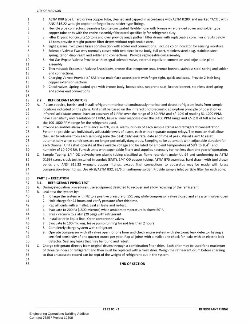
CITY OF MADISON
23 23 00 - 2 REFRIGERANT PIPING
1. ASTM B88 type L hard drawn copper tube, cleaned and capped in accordance with ASTM B280, and marked "ACR", with 1
ANSI B16.22 wrought copper or forged brass solder-type fittings. 2
2. Flexible pipe connectors: Seamless bronze corrugated flexible hose with bronze wire braided cover and solder type 3
copper tube ends with the entire assembly fabricated specifically for refrigerant duty. 4
3. Filter Dryers: For circuits 15 tons and over provide angle pattern filter dryers with replaceable core. For circuits below 5
15 tons provide straight pattern filter dryers without replaceable core. 6
4. Sight glasses: Two piece brass construction with solder end connections. Include color indicator for sensing moisture. 7
5. Solenoid Valves: Two way normally closed with two piece brass body, full port, stainless steel plug, stainless steel 8
spring, teflon diaphragm and solder end connections. Provide replaceable coil assembly. 9
6. Hot Gas Bypass Valves: Provide with integral solenoid valve, external equalizer connection and adjustable pilot 10
assembly. 11
7. Thermostatic Expansion Valves: Brass body, bronze disc, neoprene seat, bronze bonnet, stainless steel spring and solder 12
end connections. 13
8. Charging Valves: Provide ¼” SAE brass male flare access ports with finger tight, quick seal caps. Provide 2-inch long 14
copper extension sections. 15
9. Check valves: Spring loaded type with bronze body, bronze disc, neoprene seat, bronze bonnet, stainless steel spring 16
and solder end connections. 17
18
2.2. REFRIGERANT MONITORS 19
A. If plans require, furnish and install refrigerant monitor to continuously monitor and detect refrigerant leaks from sample 20
locations indicated on the plans. Unit shall be based on the infrared photo-acoustic absorption principle of operation or 21
infrared solid state sensor, have an accuracy of 1 PPM over the range of 0-50 PPM and +/- 10% of reading 51-1000 PPM, 22
have a sensitivity and resolution of 1 PPM, have a linear response over the 0-100 PPM range and +/- 2 % of full scale over 23
the 100-1000 PPM range for the refrigerant used. 24
B. Provide an audible alarm with silence switch, visual alarm, display of each sample status and refrigerant concentration. 25
System to provide two individually adjustable levels of alarm, each with a separate output relays. The monitor shall allow 26
the user to retrieve from each sampling zone the peak daily leak rate, date and time of peak. Visual alarm to reset 27
automatically when conditions are no longer potentially dangerous. Sampling to be automatic with adjustable duration for 28
each channel. Units shall operate at the available voltage and be rated for ambient temperature of 59oF to 104
oF and 29
humidity of 10-90% RH. Furnish units with expendable filters and supplies necessary for not less than one year of operation. 30
C. Sample Tubing: 1/4” OD polyethylene plastic tubing classified as flame retardant under UL 94 and conforming to ASTM 31
D1693 stress-crack test installed in conduit (EMT). 1/4” OD copper tubing, ASTM B75 seamless, hard drawn with tool drawn 32
bends and ANSI B16.22 wrought copper fittings, except final connections to apparatus may be made with brass 33
compression-type fittings. Use ANSI/ASTM B32, 95/5 tin antimony solder. Provide sample inlet particle filter for each zone. 34
35
PART 3 – EXECUTION 36
3.1. REFRIGERANT PIPING TEST 37
A. During evacuation procedures, use equipment designed to recover and allow recycling of the refrigerant. 38
B. Leak test the system by: 39
1. Charge the system with N2 to a positive pressure of 551 psig while compressor valves closed and all system valves open 40
2. Hold charge for 24 hours and verify pressure after this time. 41
3. Rap all joints with a mallet. Seal all leaks and re-test. 42
4. Evacuate to 200 Pa (1500 microns) while ambient temperature is above 60°F. 43
5. Break vacuum to 2 atm (29 psig) with refrigerant 44
6. Install drier in liquid line, Open compressor valves 45
7. Evacuate to 100 microns, leave pump running for not less than 2 hours 46
8. Completely charge system with refrigerant 47
9. Operate compressor with all valves open for one hour and check entire system with electronic leak detector having a 48
certified sensitivity of one quarter ounce per year. Rap all joints with a mallet and check for leaks with an electric leak 49
detector. Seal any leaks that may be found and retest. 50
C. Charge refrigerant directly from original drums through a combination filter-drier. Each drier may be used for a maximum 51
of three cylinders of refrigerant and then must be replaced with a fresh drier. Weigh the refrigerant drum before charging 52
so that an accurate record can be kept of the weight of refrigerant put in the system. 53
54
END OF SECTION 55
Engineering Operations Building AdditionContract 7685 / Project 10308

CITY OF MADISON
23 31 00 - 1 HVAC DUCT AND CASINGS
SECTION 23 31 00 1
HVAC DUCT AND CASINGS 2
3
PART 1 – GENERAL ............................................................................................................................................................................ 1 4
1.1. SCOPE ............................................................................................................................................................................ 1 5
1.2. REFERENCES .................................................................................................................................................................. 1 6
1.3. SUBMITTALS .................................................................................................................................................................. 2 7
1.4. QUALITY ASSURANCE .................................................................................................................................................... 2 8
1.5. PERFORMANCE REQUIREMENTS ................................................................................................................................... 2 9
PART 2 - PRODUCTS .......................................................................................................................................................................... 3 10
2.1. DUCTWORK ................................................................................................................................................................... 3 11
2.2. DUCTWORK FOR OVER 2” W.C. ..................................................................................................................................... 3 12
2.3. KITCHEN HOOD EXHAUST DUCT CONSTRUCTION ......................................................................................................... 3 13
2.4. DISHWASHER EXHAUST DUCT CONSTRUCTION ............................................................................................................ 4 14
2.5. EXHAUST DUCT (MOISTURE LADEN AIR) ....................................................................................................................... 4 15
2.6. FUME EXHAUST DUCT CONSTRUCTION ........................................................................................................................ 4 16
2.7. DUST COLLECTION EXHAUST DUCT ............................................................................................................................... 4 17
2.8. DUCT SEALANT .............................................................................................................................................................. 4 18
PART 3 – EXECUTION ......................................................................................................................................................................... 5 19
3.1. INSTALLATION ............................................................................................................................................................... 5 20
3.2. TESTING ......................................................................................................................................................................... 5 21
22
PART 1 – GENERAL 23
1.1. SCOPE 24
A. This section includes information common to ductwork and associated equipment and applies to all sections in this 25
Division. 26
27
1.2. REFERENCES 28
A. Work under this section depends on applicable provisions from other sections and the plan set in this contract. Examples of 29
related sections include, but are not limited to: 30
1. 23 05 29 – HANGERS AND SUPPORT FOR HVAC PIPING AND EQUIPMENT 31
2. 23 05 48 – VIBRATION AND SEISMIC CONTROL FOR HVAC 32
3. 23 07 00 – HVAC INSULATION 33
4. 23 09 00 – INSTRUMENTATION AND CONTROL FOR HVAC 34
5. 23 09 13.43 - CONTROL DAMPERS 35
6. 23 33 00 – AIR DUCT ACCESSORIES 36
7. 23 37 13 – DIFFUSERS, REGISTERS AND GRILLES 37
8. 23 41 00 – PARTICULATE AIR FILTRATION 38
B. Abbreviations of standards organizations referenced in other sections are as follows: 39
C. AMCA - Air Movement and Control Association 40
1. AMCA 203 - AMCA Fan Application Manual - Troubleshooting 41
2. AMCA 210 - Laboratory Method of Testing Fans for Rating 42
3. AMCA 300 - Reverberant Room Method for Sound Testing of Fans 43
D. ANSI – American National Standards Institute 44
1. ANSI SS-EN 485-2 - Aluminum and Aluminum Alloys-Sheet, Strip and Plate-Part 2: Mechanical Properties 45
E. ARI - Air Conditioning and Refrigeration Institute 46
1. ARI - ADC Standard 880 47
F. ASHRAE – American Sicety of Heating, Refrigeration and Air Conditioning Engineers 48
1. ASHRAE - Standard 70, 113, 130 49
G. ASTM - American Society for Testing and Materials 50
1. ASTM B209 - Specification for Aluminum and Aluminum-Alloy Sheet and Plate 51
2. ASTM A90 - Test Method for Weight of Coating on Zinc-Coated (Galvanized) Iron or Steel Articles 52
3. ASTM A167 - Specification for Stainless and Heat-Resisting Chromium-Nickel Steel Plate, Sheet, and Strip 53
4. ASTM A623 - Standard Specification for Steel Sheet, Zinc-Coated (Galvanized) by the Hot-Dip Process 54
5. ASTM A527 - Specification for Requirements for Steel Sheet, Zinc-Coated (Galvanized) by the Hot-Dip Process 55
6. ASTM 924 - Standard Specification for General Requirements for Sheet Steel, Metallic-coated by the Hot-dip Method 56
7. ASTM C 1071 - Specification for Fibrous Glass Duct Lining Insulation 57
8. ASTM C 411 - Test Method for Hot Surface Performance of High Temperature Thermal Insulation 58
9. ASTM E 84 - Test Method for Surface Burning Characteristics of Building Materials 59
10. ASTM C 1338 - Test Method for Determining Fungal Resistance of Insulation Materials and Facings 60
11. ASTM G 21 - Standard Practice for Determining Resistance of Synthetic Polymeric Materials to Fungi 61
12. ASTM C 916 - Standard Specification for Adhesives for Duct Thermal Insulation 62
H. NAIME – North American Insulation Manufacturers Association 63
Engineering Operations Building AdditionContract 7685 / Project 10308

CITY OF MADISON
23 31 00 - 2 HVAC DUCT AND CASINGS
1. NAIMA - Fibrous Glass Duct Liner Standard 1
I. NFPA - National Fire Protection Association 2
1. NFPA 90A - Standard for the Installation of Air Conditioning and Ventilating Systems 3
J. SMACNA - Sheet Metal and Air Conditioning Contractors National Association 4
1. SMACNA - HVAC Duct Construction Standards - Metal and Flexible, 2nd Edition, 1995 5
K. UL – Underwriters Laboratory 6
1. UL 181 - Standard for Safety for Factory Made Air Ducts and Air Connectors. 7
2. UL 214 - Standard Test for Flame Propagation of Fabrics and Films 8
3. UL 705 - Underwriters Laboratory for emergency smoke control systems 9
4. UL 762 - Underwriters Laboratory for restaurant grease exhaust 10
5. UL 555 - Standard for Fire Dampers and Ceiling Dampers 11
6. UL 555S - Leakage Rated Dampers for Use in Smoke Control Systems 12
13
1.3. SUBMITTALS 14
A. Fabrication and installation drawings. 15
B. Schedule of duct systems including material of construction, gauge, pressure class, system class, method of reinforcement, 16
joint construction, fitting construction, and support methods, all with details as appropriate. 17
C. Duct sealant and gasket material. 18
D. Duct liner including data on thermal conductivity, air friction correction factor, and limitation on temperature and velocity. 19
20
1.4. QUALITY ASSURANCE 21
A. Construct all ductwork to be free from vibration, chatter, objectionable pulsations and leakage under specified operating 22 conditions. 23
B. Use material, weight, thickness, gauge, construction and installation methods as outlined in the following SMACNA 24 publications, unless noted otherwise: 25
1. HVAC Duct Construction Standards, Metal and Flexible, Newest Edition 26
2. HVAC Air Duct Leakage Test Manual, Newest Edition 27 3. HVAC Systems - Duct Design, Newest Edition 28 4. Rectangular Industrial Duct Construction Standard, Newest Edition 29
5. Round Industrial Duct Construction Standards, Newest Edition 30 6. Thermoplastic Duct (PVC) Construction Manual, Newest Edition 31
C. Use products which conform to NFPA 90A, possessing a flame spread rating of not over 25 and a smoke developed rating no 32
higher than 50. 33 D. Where inlet and outlet ductwork is field modified from that shown on Drawings, Adjust all required fans, motor, drive and 34
wiring required due to increased static pressure or baffling necessary to prevent uneven airflow or improve mixing. 35
E. Protect Ductwork by storing inside or by durable, waterproof, above ground packaging. Do not store material on grade. 36 Protect Ductwork from dirt, dust, construction debris and foreign material. Where end caps/packaging are provided, take 37 precautions so caps/packaging remain in place and free from damage. 38
39
1.5. PERFORMANCE REQUIREMENTS 40
A. All duct design and installation is based on SMACNA “HVAC Duct Construction Standards” ANSI/SMACNA 006-2006. 41
B. If no duct pressure classifications are given, design for the following pressures: 42
1. Main supply trunk up to Variable Air Volume devices or balancing dampers (in constant volume systems): + 4” w.c. 43
2. Main supply trunk without dampers and control (i.e. MAU direct discharge): + 2”w.c. 44
3. Duct downstream of above VAV or balancing dampers: + 1” w.c. 45
4. Return or exhaust duct: - 2”w.c. 46
5. Transfer ducts: +/- 1” w.c. 47
C. Seal all duct regardless of pressure class in accordance with SMACNA seal class "A"; all seams, joints, and penetrations shall 48 be sealed. 49
D. Leakage Classes shall be: 50
1. Round and Oval Duct Duct: 2 51 2. Rectangular Duct: 4 52
E. Duct sizes indicated on plans are net inside dimensions; where duct liner is specified, dimensions are net, inside of liner. 53
F. Ductsizes indicated and calculated pressuredrops are based on using the below low-pressure design criteria. Plans may or 54 may not indicate the specific type of fitting and transition. As a general rule for all fittings and transitions the available type 55 with lowest pressure drop shall be used. Upon approval by engineer contractor may use large ductsizes to make up for 56
deficiencies in use of low-loss fittings and transitions. 57 G. FITTINGS: Types are listed in order of priority. If the more efficient type is not available in the size, use next type in list upon 58
approval by engineer. Refer To SMACNA HVAC systems duct Design appendix a for details. Fittings not listed shall follow the 59
overall idea of low pressure drop. 60 1. OFFSETS AND TRANSITIONS: 15° 61 2. ROND FITTINGS (and oval as applicable): 62
a. ELBOW: R/D >=2; Die-stamped for available sizes (typically up to 14”); 7 (or more if available) piece gored 63 for larger sizes. 64
b. TEE: Two 90° elbows meeting above requirements 65
i. BRANCH TAKEOFF: ASHRAE SD5-12 Lo-Loss Fitting; Conical wye (<=45° to main) 66 3. RECTANGUALR FITTINGS: 67
Engineering Operations Building AdditionContract 7685 / Project 10308
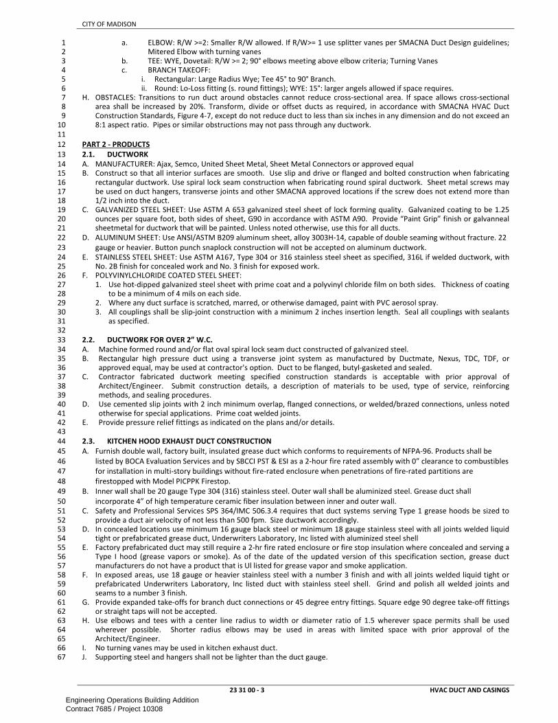
CITY OF MADISON
23 31 00 - 3 HVAC DUCT AND CASINGS
a. ELBOW: R/W >=2: Smaller R/W allowed. If R/W>= 1 use splitter vanes per SMACNA Duct Design guidelines; 1 Mitered Elbow with turning vanes 2
b. TEE: WYE, Dovetail: R/W >= 2; 90° elbows meeting above elbow criteria; Turning Vanes 3 c. BRANCH TAKEOFF: 4
i. Rectangular: Large Radius Wye; Tee 45° to 90° Branch. 5
ii. Round: Lo-Loss fitting (s. round fittings); WYE: 15°: larger angels allowed if space requires. 6 H. OBSTACLES: Transitions to run duct around obstacles cannot reduce cross-sectional area. If space allows cross-sectional 7
area shall be increased by 20%. Transform, divide or offset ducts as required, in accordance with SMACNA HVAC Duct 8
Construction Standards, Figure 4-7, except do not reduce duct to less than six inches in any dimension and do not exceed an 9 8:1 aspect ratio. Pipes or similar obstructions may not pass through any ductwork. 10
11
PART 2 - PRODUCTS 12
2.1. DUCTWORK 13
A. MANUFACTURER: Ajax, Semco, United Sheet Metal, Sheet Metal Connectors or approved equal 14 B. Construct so that all interior surfaces are smooth. Use slip and drive or flanged and bolted construction when fabricating 15
rectangular ductwork. Use spiral lock seam construction when fabricating round spiral ductwork. Sheet metal screws may 16 be used on duct hangers, transverse joints and other SMACNA approved locations if the screw does not extend more than 17 1/2 inch into the duct. 18
C. GALVANIZED STEEL SHEET: Use ASTM A 653 galvanized steel sheet of lock forming quality. Galvanized coating to be 1.25 19 ounces per square foot, both sides of sheet, G90 in accordance with ASTM A90. Provide “Paint Grip” finish or galvanneal 20 sheetmetal for ductwork that will be painted. Unless noted otherwise, use this for all ducts. 21
D. ALUMINUM SHEET: Use ANSI/ASTM B209 aluminum sheet, alloy 3003H-14, capable of double seaming without fracture. 22 22
gauge or heavier. Button punch snaplock construction will not be accepted on aluminum ductwork. 23
E. STAINLESS STEEL SHEET: Use ASTM A167, Type 304 or 316 stainless steel sheet as specified, 316L if welded ductwork, with 24 No. 2B finish for concealed work and No. 3 finish for exposed work. 25
F. POLYVINYLCHLORIDE COATED STEEL SHEET: 26
1. Use hot-dipped galvanized steel sheet with prime coat and a polyvinyl chloride film on both sides. Thickness of coating 27 to be a minimum of 4 mils on each side. 28
2. Where any duct surface is scratched, marred, or otherwise damaged, paint with PVC aerosol spray. 29
3. All couplings shall be slip-joint construction with a minimum 2 inches insertion length. Seal all couplings with sealants 30 as specified. 31
32
2.2. DUCTWORK FOR OVER 2” W.C. 33
A. Machine formed round and/or flat oval spiral lock seam duct constructed of galvanized steel. 34
B. Rectangular high pressure duct using a transverse joint system as manufactured by Ductmate, Nexus, TDC, TDF, or 35 approved equal, may be used at contractor's option. Duct to be flanged, butyl-gasketed and sealed. 36
C. Contractor fabricated ductwork meeting specified construction standards is acceptable with prior approval of 37
Architect/Engineer. Submit construction details, a description of materials to be used, type of service, reinforcing 38 methods, and sealing procedures. 39
D. Use cemented slip joints with 2 inch minimum overlap, flanged connections, or welded/brazed connections, unless noted 40
otherwise for special applications. Prime coat welded joints. 41 E. Provide pressure relief fittings as indicated on the plans and/or details. 42 43
2.3. KITCHEN HOOD EXHAUST DUCT CONSTRUCTION 44
A. Furnish double wall, factory built, insulated grease duct which conforms to requirements of NFPA-96. Products shall be 45
listed by BOCA Evaluation Services and by SBCCI PST & ESI as a 2-hour fire rated assembly with 0” clearance to combustibles 46
for installation in multi-story buildings without fire-rated enclosure when penetrations of fire-rated partitions are 47
firestopped with Model PICPPK Firestop. 48
B. Inner wall shall be 20 gauge Type 304 (316) stainless steel. Outer wall shall be aluminized steel. Grease duct shall 49
incorporate 4” of high temperature ceramic fiber insulation between inner and outer wall. 50
C. Safety and Professional Services SPS 364/IMC 506.3.4 requires that duct systems serving Type 1 grease hoods be sized to 51
provide a duct air velocity of not less than 500 fpm. Size ductwork accordingly. 52 D. In concealed locations use minimum 16 gauge black steel or minimum 18 gauge stainless steel with all joints welded liquid 53
tight or prefabricated grease duct, Underwriters Laboratory, Inc listed with aluminized steel shell 54
E. Factory prefabricated duct may still require a 2-hr fire rated enclosure or fire stop insulation where concealed and serving a 55 Type I hood (grease vapors or smoke). As of the date of the updated version of this specification section, grease duct 56 manufacturers do not have a product that is Ul listed for grease vapor and smoke application. 57
F. In exposed areas, use 18 gauge or heavier stainless steel with a number 3 finish and with all joints welded liquid tight or 58 prefabricated Underwriters Laboratory, Inc listed duct with stainless steel shell. Grind and polish all welded joints and 59 seams to a number 3 finish. 60
G. Provide expanded take-offs for branch duct connections or 45 degree entry fittings. Square edge 90 degree take-off fittings 61 or straight taps will not be accepted. 62
H. Use elbows and tees with a center line radius to width or diameter ratio of 1.5 wherever space permits shall be used 63
wherever possible. Shorter radius elbows may be used in areas with limited space with prior approval of the 64 Architect/Engineer. 65
I. No turning vanes may be used in kitchen exhaust duct. 66
J. Supporting steel and hangers shall not be lighter than the duct gauge. 67
Engineering Operations Building AdditionContract 7685 / Project 10308

CITY OF MADISON
23 31 00 - 4 HVAC DUCT AND CASINGS
K. Where welded joints are used with black steel duct, coat all external welded joints and seams with paint. Grind and polish 1 to #3 finish all exposed stainless steel joints and seams. 2
L. Apply bracing and reinforcement to the outside of the duct to prevent breathing, rattling, vibration or sagging of duct. 3 M. Install without forming dips, sag or traps which might collect residue by supporting at not greater than 5 foot intervals; 4
fasteners at hangers shall not penetrate the duct. Do not use sheet metal screws on supports; use bolted, riveted or 5
welded connections. Where ductwork is listed, install in accordance with listing. 6 N. Construct grease tight access doors of the same material and thickness as the duct and as large as possible, up to 24 inches 7
in any dimension. Locate on duct sides for ease of inspection and cleaning at each change in direction, not less than every 8
10 lineal feet of duct, including risers, and not less than 1-1/2 inches from the bottom of the duct. 9 O. Insulation or fire protection enclosure shall be removable at each access door and clean out. 10 P. Pitch horizontal ducts back to hood at 1 inch per foot. 11
12
2.4. DISHWASHER EXHAUST DUCT CONSTRUCTION 13
A. Use 18 gauge or heavier stainless steel with all seams and joints welded and ground smooth. In exposed areas, joints and 14
seams to be polished to a #3 finish (minimum). 15 B. Use elbows and tees as specified for the appropriate duct pressure class. 16 C. Provide expanded take-offs for branch duct connections or 45 degree entry fittings. Square edge 90 degree take-off fittings 17
or straight taps will not be accepted. 18 D. Provide water tight drain pan at low points or at locations where moisture may collect. Pipe drain pan to nearest floor 19
drain. 20
E. Pitch duct to drain back to equipment or exhaust grille. 21 22
2.5. EXHAUST DUCT (MOISTURE LADEN AIR) 23
A. Exhaust ducts conveying moisture laden air, other than dishwasher exhaust, contruct to same standards as Dishwasher 24 Exhaust Duct except: 25
1. Construct of sheet aluminum in accordance with SMACNA standards. 26 2. Seal all joints and seams watertight 27
28
2.6. FUME EXHAUST DUCT CONSTRUCTION 29
A. Select appropriate materials from among the following items: 30
1. Use PVC coated steel or stainless steel duct and fittings. Use stainless steel for all exposed installations below 31 suspended ceilings. 32
2. Use 316 stainless steel for flanged gasketed connections. 33
3. Use 18 gauge or heavier 316L stainless steel sheet for externally welded ductwork. Grind and polish joints and seams to 34 a #3 finish minimum. 35
4. Exhaust terminal duct assembly shall be constructed from a minimum of 24 gauge stainless steel and damper blade 36
constructed from a minimum of 22 gauge stainless steel. 37
5. Stainless steel damper blade shall be mounted to a stainless steel shaft having self-lubricated bearings. Shaft end shall 38
be marked to indicate damper position and shall have a built-in stop to prevent over stroking. Damper blade shall close 39
off against a butyl gasket to limit leakage to 10 cfm at 6.0 inches of differential static pressure. Damper linkage shall be 40
sized to accept at least 40 inch-pounds of torque to the damper shaft. Damper shaft shall be provided with a marking 41
indicating damper position. 42
B. For all rectangular duct and round duct 36 inch diameter and larger, apply a bead of PCD sealant at the corrosive side of the 43
gasket. For round duct less than 36-inch diameter, use slip coupling connection sealed with PCD sealant. 44 C. Apply duct sealer on male end connectors before insertion, and afterwards to cover the entire joint. 45 D. Use 316 stainless steel fasteners to provide mechanical strength at all couplings; galvanized mechanical fasteners will not 46
be accepted. Maximum screw spacing shall be 12 inches o. c. with a minimum of 3 equally spaced screws per joint. Do not 47 locate screws, rivets, or bolts on the bottom of the duct. Condensation can form in some fume exhaust systems. Since the 48 fumes being conveyed can be very corrosive, the condensation would be more likely to leak at a fastener location on the 49
bottom of the duct. Fasteners are acceptable "near" the bottom but should never be located at the six o'clock position. 50 E. Repair any damage to the PVC coating with a PVC aerosol spray or similar PVC product as soon as installation of the piece 51
with a damaged coating is completed. 52
53
2.7. DUST COLLECTION EXHAUST DUCT 54
A. Use material thickness and reinforcements for the static pressure classification and duct system classification specified. 55
B. Provide (partial/complete) penetration welds at all seams and joints. 56
C. All flanged connections shall be gasketed. Caulking is not allowed. 57
D. All flanges and stiffeners will be of compatible material to that of the attached ductwork. 58
E. Provide access doors and clean out doors where necessary for routine maintenance and replacement of parts or inspection 59 of items concealed in the ductwork. Construct access and cleanout doors of the same material and thickness as the duct. 60
Size as large as possible, up to 0.5 times the diameter of the ductwork, as measured along its circumference and a 61 maximum of 24 inches. Locate on duct sides for ease of inspection and cleaning at each change in direction, at junctions 62 with vertical ducts, and at devices requiring periodic inspection and maintenance. Locate not less than every 10 lineal feet 63
of duct, including risers. Removable caps may be installed at termination ends on ducts less than 12 inch in diameter. 64 65
2.8. DUCT SEALANT 66
A. Manufacturer: 3M 800, 3M 900, H.B. Fuller/Foster, Hardcast, Hardcast Peal & Seal, Lockformer cold sealant, Mon-Eco 67
Industries, United Sheet Metal, or approved equal. Silicone sealants are not allowed in any type of ductwork installation. 68
Engineering Operations Building AdditionContract 7685 / Project 10308

CITY OF MADISON
23 31 00 - 5 HVAC DUCT AND CASINGS
B. Install sealants in strict accordance with manufacturer's recommendations, paying special attention to temperature 1 limitations. Allow sealant to fully cure before pressure testing of ductwork, or before startup of air handling systems. 2
3
PART 3 – EXECUTION 4
3.1. INSTALLATION 5
A. Use Soft neoprene or butyl gaskets in combination with duct sealant for flanged joints 6
B. Provide frames constructed of angles or channels for coils, filters, dampers or other devices installed in duct systems, and 7 make all connections to such equipment including equipment furnished by others. Secure frames with gaskets and screws 8 or nut, bolts and washers. 9
C. Where two different metal ducts meet, the joint shall be installed in such a manner that metal ducts do not contact each 10 other by using proper seal or compound. 11
D. Do not install ductwork through dedicated electrical rooms or spaces unless the ductwork is serving this room or space. 12
E. Install at least 7” above suspended ceiling 13 F. Locate ducts with sufficient space around equipment to allow normal operating and maintenance activities. 14 G. Protect diffusers, registers and grilles with plastic wrap or some other approved form of protection to maintain dirt and 15
dust free and to prevent entry of dirt, dust and foreign material into the Ductwork. During construction provide temporary 16 closures of metal or taped polyethylene on open ductwork to prevent construction dust from entering ductwork system. 17
H. SLEEVES: Provide galvanized sheet metal sleeves for pipe or duct penetrations through interior and exterior walls to provide 18
a backing for sealant or firestopping. Pipe sleeves shall be schedule 40 steel pipe (sized to allow insulated pipe to run 19
through sleeve) and duct sleeves shall be equivalent rectangular material. Provide sleeve required for fire dampers in fire-20
rated partitions and floors. 21
I. Duct penetrations shall be filled with fiberglass insulation and sealed with at least 1”foam around the duct perimeter to air-22
seal the penetrations. A 4”sheet metal escutcheon shall cover both sides of the penetration. 23
24
3.2. TESTING 25
A. LEAKAGE TEST: 26 1. Test all ductwork upstream of variable volume devices in accordance with test methods described in SMACNA “HVAC 27
Air Duct Leakage Test Manual” ANSI/SMACNA 016-2012. Do not insulate ductwork until it has been successfully tested. 28
Test pressure shall be equal to the duct pressure class. 29 2. If excessive air leakage is found locate leaks, repair the duct in the area of the leak, seal the duct, and retest. 30 3. Leakage rate shall not exceed more that 1% of the system air quantity for high pressure ductwork, determined in 31
accordance with Appendix C of the SMACNA HVAC Air Duct Leakage Test Manual. 32 4. Submit a signed report to the Project Manager, indicating test apparatus used, results of the leakage test, and any 33
remedial work required to bring duct systems into compliance with specified leakage rates. 34
B. STRUCTURAL TEST 35 1. Random test all ductwork per owner direction. Do not insulate ductwork until it has been successfully tested. Test 36
pressure shall be equal to the duct pressure class. 37
2. Deflection limits shall not exceed those listed in accordance with Chapter 11 of SMACNA HVAC Duct Construction 38 Standards, 3.0 Performance Requirements. 39
3. Submit a signed report to the Division's Construction Representative, indicating test apparatus used, results of the 40
structural test, and any remedial work required. 41
42
END OF SECTION 43
Engineering Operations Building AdditionContract 7685 / Project 10308

CITY OF MADISON
23 33 00 - 1 AIR DUCT ACCESSORIES
SECTION 23 33 00 1
AIR DUCT ACCESSORIES 2
3
PART 1 – GENERAL ............................................................................................................................................................................ 1 4
1.1. SCOPE ............................................................................................................................................................................ 1 5
1.2. REFERENCES .................................................................................................................................................................. 1 6
1.3. SUBMITTALS .................................................................................................................................................................. 1 7
PART 2 - PRODUCTS .......................................................................................................................................................................... 1 8
2.1. MANUFACTURERS ......................................................................................................................................................... 1 9
2.2. MANUAL VOLUME DAMPERS ....................................................................................................................................... 1 10
2.3. FIRE DAMPERS............................................................................................................................................................... 2 11
2.4. SMOKE DAMPERS .......................................................................................................................................................... 2 12
2.5. COMBINATION FIRE/SMOKE DAMPERS ........................................................................................................................ 3 13
2.6. SOUND ATTENUATORS .................................................................................................................................................. 3 14
2.7. TURNING VANES ........................................................................................................................................................... 3 15
2.8. ACCESS DOORS .............................................................................................................................................................. 3 16
2.9. FLEXIBLE DUCT .............................................................................................................................................................. 4 17
2.10. DUCT LINING ................................................................................................................................................................. 4 18
2.11. DUCT PRESSURE RELIEF DOORS .................................................................................................................................... 4 19
2.12. BACKDRAFT DAMPERS .................................................................................................................................................. 4 20
21
PART 1 – GENERAL 22
1.1. SCOPE 23
A. This sections includes accessories used in the installation of duct systems and applies to all sections in this Division. 24
25
1.2. REFERENCES 26
A. Work under this section depends on applicable provisions from other sections and the plan set in this contract. Examples of 27
related sections include, but are not limited to: 28
1. 23 31 00 – HVAC DUCT AND CASINGS 29
B. Nationa Fire Protection Association 30
1. NFPA 90A Standard for Installation of Air Conditioning and Ventilating Systems 31
2. NFPA 80 - Fire Doors & Other Opening Protectives 32
3. NFPA 101 – Life Safety Code. 33
C. SMACNA - Sheet Metal and Air Conditioning Contractors National Association 34
1. SMACNA HVAC Duct Construction Standards - Metal and Flexible, 2nd Edition, 1995 35
D. UL – Underwriters Laboratory 36
1. UL 214 37
2. UL 555 Standard for Fire Dampers and Ceiling Dampers 38
3. UL 555S Leakage Rated Dampers for Use in Smoke Control Systems 39
40
1.3. SUBMITTALS 41
A. Submit for all accessories and include dimensions, capacities, ratings, installation instructions, and appropriate 42
identification. 43
B. Include certified test data on dynamic insertion loss, self-noise power levels, and aerodynamic performance of sound 44
attenuators. 45
C. Submit manufacturer's color charts where finish color is specified to be selected by the Architect/Engineer. 46
47
PART 2 - PRODUCTS 48
2.1. MANUFACTURERS 49
A. MANUFACTURERS: Air Balance, Advanced Air, American Warming And Ventilating, Ductmate, Greenheck, Phillips-Aire, 50
Prefco, Ruskin, Safe-Air 51
52
2.2. MANUAL VOLUME DAMPERS 53
A. BASIS OF DESIGN: Greenheck MBD and MBDR 54
B. FRAME AND SLEEVE: The damper frame and sleeve shall be of one piece design, made with 20 ga. galvanized steel and a 55
groove for added strength. 56
C. BLADES: Galvanized steel. 20 ga. 57
D. AXLES: Minimum ½ inch dia., material is plated steel. 58
E. BEARINGS: Axle bearings shall be synthetic (acetal) sleeve type. 59
F. ACTUATOR: Manual Quadrant with lever 60
G. Dampers must be accessible to allow inspection, adjustment, and replacement of components. 61
H. Install dampers square and free from racking. 62
I. Furnish bracing for multiple section assemblies to support assembly weight and to hold against system pressure. 63
Engineering Operations Building AdditionContract 7685 / Project 10308

CITY OF MADISON
23 33 00 - 2 AIR DUCT ACCESSORIES
J. Do not compress or stretch the damper frame into the duct or opening. 1
K. Attach multiple damper section assemblies together in accordance with manufacturer’s instructions. Install support 2
mullions as reinforcement between assemblies as required. 3
L. Handle dampers using the frame or sleeve. Do not lift or move dampers using blades, actuator or jackshaft. 4
M. Install a manual balancing damper in each branch duct and for each diffuser or grille. 5
6
2.3. FIRE DAMPERS 7
A. BASIS OF DESIGN: Greenehck DFD and DFDR Dynamic rated 8
B. Dampers shall meet requirements for fire dampers in accordance with: 9
1. NFPA 80, 90A and 101. 10
2. CSFM Fire (Dynamic) Damper Listing #3225-0981:103. 11
3. New York City MEA Listing 260-91-M Vol.III. 12
4. Applicable Building Codes. 13
5. Dampers shall be tested, rated, and labeled in accordance with: 14
6. UL 555 (Seventh Edition), Listing R13317 15
C. Damper blades must be 100% out of air stream; dampers with blades in air stream will not be accepted. Damper fire rating 16
to be compatible with rating of building surface in which damper is used. 17
D. Damper shall resist differential pressure per UL 555 of 4 in. w.c.or as noted on plans 18
E. Dampers shall have minimum UL 555 velocity rating of 2,000 fpm or 3,000 fpm for dampers larger than 30”x30” or as noted 19
on plans. 20
F. Provide fusible link at 165°F rating or as noted on plans. 21
G. Install dampers in accordance with manufacturer’s UL Installation Instructions, labeling, and NFPA 90A at locations 22
indicated on the drawings. Any damper installation that is not in accordance with the manufacturer’s UL Installation 23
Instructions must be approved prior to installation. 24
H. Dampers must be accessible to allow inspection, adjustment, and replacement of components. The sheet metal contractor 25
shall furnish any access doors in ductwork or plenums required to provide this access. The general contractor shall furnish 26
any access doors required in walls, ceilings, or other general building construction. 27
I. Install dampers square and free from racking. 28
J. Provide and install bracing for multiple section assemblies to support assembly weight and to hold against system pressure. 29
K. Do not compress or stretch the damper frame into the duct or opening. 30
L. Attach multiple damper section assemblies together in accordance with manufacturer’s instructions. Install support 31
mullions as reinforcement between assemblies as required. 32
M. Handle dampers using the frame or sleeve. Do not lift or move dampers using blades, actuator or jackshaft. 33
N. Provide closure springs and latches for horizontal damper installations. 34
O. Fire dampers installed in stainless steel or aluminum duct systems shall be constructed of stainless steel. 35
P. Factory provided integral damper sleeves are not acceptable. 36
Q. Install dampers in strict accordance with manufacturer's installation instructions. Install damper sleeves with retaining 37
angles on both sides of rated partition. Connections of ductwork to fire damper assemblies to be as specified on the 38
installation instructions. Where it is necessary to set dampers out from the rated wall, install a sleeve extension encased in 39
two hour rated fire proofing insulation. Install an access door at each fire damper, located to permit resetting the damper 40
replacing the fusible link. 41
R. Manually test each fire damper for proper operation by removing the fusible link. Repair or replace any fire damper that 42
does not close completely. Re-install fusible link after test. 43
44
2.4. SMOKE DAMPERS 45
A. BASIS OF DESIGN: Greenehck SMD and SMDR 46
B. Dampers shall meet requirements for smoke dampers in accordance with: 47
1. NFPA 92A, 92B, and 105. 48
2. CSFM Leakage (Smoke) Damper Listing. 49
3. New York City MEA Listing 260-91-M Vol. III. 50
4. Applicable Building Codes. 51
5. UL 555S (Fourth Edition), Listing R13317 52
6. Dampers shall bear the AMCA Certified Ratings Seal for Air Performance in accordance with AMCA 511. 53
C. Unless ratings are indicated elsewhere, dampers should be rated for minimum 2,000 fpm air velocity and 4” static pressure. 54
D. Damper shall have UL555S leakage rating of Class I unless noted differently on plans. 55
E. Dampers shall have UL555S elevated temperature of 250°F unless noted differently on plans. 56
F. Dampers shall have minimum UL 555S velocity rating of 2,000 fpm and 3,000 fpm for sizes 30”x30”or larger unless noted 57
differently on plans. 58
G. Provide 2-Posiion 24VAC actuator 59
H. Provide Momentary Testswitch for local testing 60
I. Provide no-flow smoke detector for velocities below 3,000 fpm or detector for higher velocities if required. Provide access 61
door. 62
J. Provide Quick-Connect universal breakaway 63
Engineering Operations Building AdditionContract 7685 / Project 10308
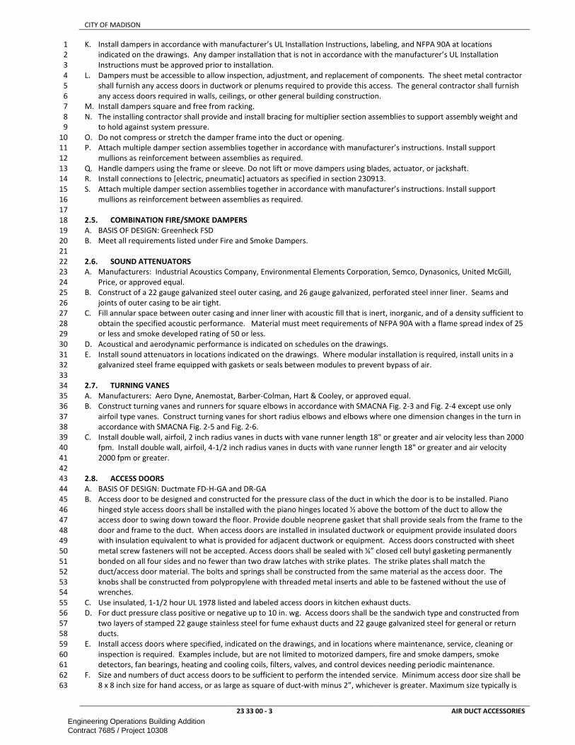
CITY OF MADISON
23 33 00 - 3 AIR DUCT ACCESSORIES
K. Install dampers in accordance with manufacturer’s UL Installation Instructions, labeling, and NFPA 90A at locations 1
indicated on the drawings. Any damper installation that is not in accordance with the manufacturer’s UL Installation 2
Instructions must be approved prior to installation. 3
L. Dampers must be accessible to allow inspection, adjustment, and replacement of components. The sheet metal contractor 4
shall furnish any access doors in ductwork or plenums required to provide this access. The general contractor shall furnish 5
any access doors required in walls, ceilings, or other general building construction. 6
M. Install dampers square and free from racking. 7
N. The installing contractor shall provide and install bracing for multiplier section assemblies to support assembly weight and 8
to hold against system pressure. 9
O. Do not compress or stretch the damper frame into the duct or opening. 10
P. Attach multiple damper section assemblies together in accordance with manufacturer’s instructions. Install support 11
mullions as reinforcement between assemblies as required. 12
Q. Handle dampers using the frame or sleeve. Do not lift or move dampers using blades, actuator, or jackshaft. 13
R. Install connections to [electric, pneumatic] actuators as specified in section 230913. 14
S. Attach multiple damper section assemblies together in accordance with manufacturer’s instructions. Install support 15
mullions as reinforcement between assemblies as required. 16
17
2.5. COMBINATION FIRE/SMOKE DAMPERS 18
A. BASIS OF DESIGN: Greenheck FSD 19
B. Meet all requirements listed under Fire and Smoke Dampers. 20
21
2.6. SOUND ATTENUATORS 22
A. Manufacturers: Industrial Acoustics Company, Environmental Elements Corporation, Semco, Dynasonics, United McGill, 23
Price, or approved equal. 24
B. Construct of a 22 gauge galvanized steel outer casing, and 26 gauge galvanized, perforated steel inner liner. Seams and 25
joints of outer casing to be air tight. 26
C. Fill annular space between outer casing and inner liner with acoustic fill that is inert, inorganic, and of a density sufficient to 27
obtain the specified acoustic performance. Material must meet requirements of NFPA 90A with a flame spread index of 25 28
or less and smoke developed rating of 50 or less. 29
D. Acoustical and aerodynamic performance is indicated on schedules on the drawings. 30
E. Install sound attenuators in locations indicated on the drawings. Where modular installation is required, install units in a 31
galvanized steel frame equipped with gaskets or seals between modules to prevent bypass of air. 32
33
2.7. TURNING VANES 34
A. Manufacturers: Aero Dyne, Anemostat, Barber-Colman, Hart & Cooley, or approved equal. 35
B. Construct turning vanes and runners for square elbows in accordance with SMACNA Fig. 2-3 and Fig. 2-4 except use only 36
airfoil type vanes. Construct turning vanes for short radius elbows and elbows where one dimension changes in the turn in 37
accordance with SMACNA Fig. 2-5 and Fig. 2-6. 38
C. Install double wall, airfoil, 2 inch radius vanes in ducts with vane runner length 18" or greater and air velocity less than 2000 39
fpm. Install double wall, airfoil, 4-1/2 inch radius vanes in ducts with vane runner length 18" or greater and air velocity 40
2000 fpm or greater. 41
42
2.8. ACCESS DOORS 43
A. BASIS OF DESIGN: Ductmate FD-H-GA and DR-GA 44
B. Access door to be designed and constructed for the pressure class of the duct in which the door is to be installed. Piano 45
hinged style access doors shall be installed with the piano hinges located ½ above the bottom of the duct to allow the 46
access door to swing down toward the floor. Provide double neoprene gasket that shall provide seals from the frame to the 47
door and frame to the duct. When access doors are installed in insulated ductwork or equipment provide insulated doors 48
with insulation equivalent to what is provided for adjacent ductwork or equipment. Access doors constructed with sheet 49
metal screw fasteners will not be accepted. Access doors shall be sealed with ¼” closed cell butyl gasketing permanently 50
bonded on all four sides and no fewer than two draw latches with strike plates. The strike plates shall match the 51
duct/access door material. The bolts and springs shall be constructed from the same material as the access door. The 52
knobs shall be constructed from polypropylene with threaded metal inserts and able to be fastened without the use of 53
wrenches. 54
C. Use insulated, 1-1/2 hour UL 1978 listed and labeled access doors in kitchen exhaust ducts. 55
D. For duct pressure class positive or negative up to 10 in. wg. Access doors shall be the sandwich type and constructed from 56
two layers of stamped 22 gauge stainless steel for fume exhaust ducts and 22 gauge galvanized steel for general or return 57
ducts. 58
E. Install access doors where specified, indicated on the drawings, and in locations where maintenance, service, cleaning or 59
inspection is required. Examples include, but are not limited to motorized dampers, fire and smoke dampers, smoke 60
detectors, fan bearings, heating and cooling coils, filters, valves, and control devices needing periodic maintenance. 61
F. Size and numbers of duct access doors to be sufficient to perform the intended service. Minimum access door size shall be 62
8 x 8 inch size for hand access, or as large as square of duct-with minus 2”, whichever is greater. Maximum size typically is 63
Engineering Operations Building AdditionContract 7685 / Project 10308

CITY OF MADISON
23 33 00 - 4 AIR DUCT ACCESSORIES
18”x18”. Install access doors near fire-and smoke dampers, both inlet and outlet sides of reheat coils as well as other duct 1
mounted coils and devices requiring service. 2
G. Man Access Door: Kees AD2-K. thickness to be thickness of adjacent insulation or thicker. Provide supporting frame. 3
4
2.9. FLEXIBLE DUCT 5
A. Manufacturers: Anco Products, Clevaflex, Thermaflex, Flexmaster or approved equal. 6
B. Only metallic duct. “M” type flex duct is allowed 7
C. Maximum length for flex duct is 3’ at or near final connection to terminal. 8 D. Install flexduct as straight as possible without kinks. 9 E. Factory fabricated , UL 181 listed as a class 1 duct, and having a flame spread of 25 or less and a smoke developed rating of 10
50 or under in accordance with NFPA 90A. 11
F. Suitable for pressures and temperatures involved but not less than a 180°F service temperature and ±2 inch pressure class 12
G. Duct to be composed of polyester film, aluminum laminate or woven and coated fiberglass fabric bonded permanently to 13
corrosion resistant coated steel wire helix. Two-ply, laminated, and corrugated aluminum construction may also be used. 14
H. Where duct is specified to be insulated, provide a minimum 1 inch fiberglass insulation blanket with maximum thermal 15
conductance of 0.23 K (75 degrees F.) and vapor barrier jacket of polyethylene or metalized reinforced film laminate. 16
Maximum perm rating of vapor barrier jacket to be 0.1 perm. 17
I. Where flexible duct is used, it shall be the minimum length required to make the final connections, but no greater than 3 18
feet in length, and have no more than one (1) 90 degree bend of a radius of at least 2 duct diamters. 19
J. Secure inner jacket of flexible duct in place with stainless steel metal band clamp. Secure insulation vapor barrier jacket in 20
place with steel or nylon draw band. Sheetmetal screws and/or duct tape will not be accepted. 21
K. Flexible duct used to compensate for misalignment of main duct or branch duct will not be accepted. 22
L. Individual sections of flexible ductwork shall be of one piece construction. Splicing of short sections will not be accepted. 23
24
2.10. DUCT LINING 25
A. Manufacturer: Manville, Owens-Corning, Knauf, Titus or approved equal. 26
B. 1 inch thick, flexible, mat faced insulation made from inorganic glass fibers bonded with a thermosetting resin with thermal 27
conductivity of .25 Btu inch / hour sq.ft. deg F. 28
C. Meet erosion and mold growth testing per UL 181 or ASTM C 1071 for 5000 fpm maximum air velocity. ASTM C 411 29
maximum operating temperature rating of 250 deg F. ASTM E84 flame spread less than 25 and smoke developed less than 30
50. 31
D. Meet requirements of ASTM C 1338 and ASTM G21 for fungi resistance. 32
E. Install liner using adhesive conforming to ASTM C 916. 33
F. Do not apply lining to the following ductwork: 34
1. Outside air ductwork. 35
2. Kitchen exhaust ductwork. 36
3. Dishwashing exhaust ductwork. 37
4. Shower exhaust ductwork. 38
5. Pool ventilation ductwork. 39
6. Supply, return and exhaust ductwork associated with shop ventilation systems where air handling units are located in 40
the shops. 41
7. Fume hood exhaust ductwork. 42
G. Install liner in compliance with the latest edition of NAIMA’s Fibrous Glass Duct Liner Standard. Locate longitudinal joints at 43
the corners of duct only. Cut and fit to assure lapped, compressed joints. Coat all transverse and longitudinal joints and 44
edges with adhesive. Provide metal nosing on leading edge where lined duct is preceded by unlined duct. Adhere liner to 45
duct with full coverage area of adhesive. Additionally secure liner to duct using mechanical fasteners spaced as 46
recommended by the liner manufacturer without compressing liner more than 1/8” with the fasteners. 47
48
2.11. DUCT PRESSURE RELIEF DOORS 49
A. Install wherever fan is able to create pressure 0.5”w.c. above (or -0.5”w.c. on suction side) the associated pressure class at 50
0 airflow. Size per manufacturer recommendations for that fan. 51
B. MANUFACTURER: Greenheck PRAD (positive) or VRAD (negative) 52
C. Construct with 12 gage galvanized [stainless] steel frame and hinged door with polyurethane or neoprene gasket. Provide 53
springs to automatically return door to closed position when pressure is relieved. Provide with release mechanism, springs 54
and parts out of the air stream. Provide sizes and pressure settings as indicated on the drawings. 55
56
2.12. BACKDRAFT DAMPERS 57
A. BASIS OF DESIGN: Tamco 7000 CW; 58
B. counterweigths adjusted per engineer’s specifications 59
60
61
END OF SECTION 62
Engineering Operations Building AdditionContract 7685 / Project 10308

CITY OF MADISON
23 34 13 - 1 AXIAL HVAC FANS
SECTION 23 34 13 1
AXIAL HVAC FANS 2
3
PART 1 – GENERAL ............................................................................................................................................................................ 1 4
1.1. SCOPE ............................................................................................................................................................................ 1 5
1.2. REFERENCES .................................................................................................................................................................. 1 6
1.3. SUBMITTALS .................................................................................................................................................................. 1 7
1.4. QUALITY ASSURANCE .................................................................................................................................................... 1 8
1.5. PERFORMANCE REQUIREMENTS ................................................................................................................................... 2 9
PART 2 - PRODUCTS .......................................................................................................................................................................... 2 10
2.1. FAN HOUSING AND OUTLET .......................................................................................................................................... 2 11
2.2 FAN IMPELLER ............................................................................................................................................................... 2 12
2.3 FAN MOTORS ................................................................................................................................................................ 2 13
PART 3 – EXECUTION ......................................................................................................................................................................... 2 14
3.1. INSTALLATION ............................................................................................................................................................... 2 15
16
PART 1 – GENERAL 17
1.1. SCOPE 18
A. This section includes information common to Axial Fans. 19
20
1.2. REFERENCES 21
A. Work under this section depends on applicable provisions from other sections and the plan set in this contract. Examples of 22
related sections include, but are not limited to: 23
1. 23 05 13 – COMMON MOTOR REQUIREMENTS FOR HVAC EQUIPMENT 24
2. 23 05 29 – HANGERS AND SUPPORT FOR HVAC PIPING AND EQUIPMENT 25
3. 23 05 48 – VIBRATION AND SEISMIC CONTROL FOR HVAC 26
4. 23 07 00 – HVAC INSULATION 27
5. 23 09 00 – INSTRUMENTATION AND CONTROL FOR HVAC 28
6. 23 31 00 – HVAC DUCT AND CASINGS 29
7. DIVISION 26 - ELECTRICAL 30
B. AMCA - Air Movement and Control Association 31
1. AMCA Standard 99-10, “Standards Handbook” 32 2. AMCA Standard 204-05, “Balance Quality and Vibration Levels for Fans” 33
3. AMCA 203 AMCA Fan Application Manual - Troubleshooting 34 4. AMCA 210 Laboratory Method of Testing Fans for Rating 35 5. AMCA Publication 211-05, “Certified Ratings Program – Product Rating Manual for Fan Air Performance” 36
6. AMCA 300 Reverberant Room Method for Sound Testing of Fans 37
C. ABMA – American Bearing Manufacturer Association 38
1. ABMA - Method of Evaluating Load Ratings of Bearings ANSI-11 (r1999). 39
A. ANSI ANSI – American National Standards Institute 40
2. ANSI/AMCA Standard 500-D-12, "Laboratory Methods of Testing Dampers for Rating" 41 D. OSHA – Occupational Safety and Health Administration 42
1. OSHA guideline 1910.212 – General requirements for Machine Guarding. (www.osha.gov) 43
2. OSHA guideline 1910.219 – General requirements for guarding safe use of mechanical power transmission apparatus. 44 3. OSHA guideline 1926.300 – General requirements for safe operation and maintenance of hand and power tools. 45
E. UL – Underwriters Laboratory 46
1. UL/cUL Standard 705, “Power Ventilators” 47
48
1.3. SUBMITTALS 49
A. Submit shop drawings including the following information: specific manufacturer and model numbers, submittal equipment 50
identification corresponding to project drawings and schedules, unit dimensional and weight data, materials of 51
construction, capacities and ratings, fan curves, fan type, drive and motor information, vibration isolation, coil performance 52
data, sound power levels, filter information, information for all accessories. 53
B. Indicate fan class, fan performance and motor electrical characteristics. Provide fan curves with specified operating point 54 clearly plotted. Include efficiency data for the design airflows, drive loss and bhp. 55
C. Provide calculated 8 octave maximum sound power levels at unit discharge and return connections, and maximum casing 56 radiated sound power levels. 57
58
1.4. QUALITY ASSURANCE 59
A. MANUFACTURERS: Greenheck or approved equal. 60
B. Units to be tested, rated and certified in accordance with ARI Standard 430 (AHU) and Standard 1060 (ERV). 61
C. The manufacturer shall have been designing and producing air handling units for a minimum of ten years. 62
D. Units to conform to NFPA 70, 90A, and 90B. 63
E. The unit(s) shall bear the ETL label and/or ISO-9000 certified 64
F. The unit(s) shall contain only UL listed components. 65
Engineering Operations Building AdditionContract 7685 / Project 10308

CITY OF MADISON
23 34 13 - 2 AXIAL HVAC FANS
G. Performance ratings: Conform to ANSI/AMCA Standards 210 and 300. Fan must be tested in accordance with AMCA 1
Publications 211 and 311 in an AMCA accredited laboratory and certified for air performance. Fan shall be licensed to bear 2
the AMCA ratings seal for air performance (AMCA 210). 3
H. Classification for Spark Resistant Construction shall conform to ANSI/AMCA Standard 99. 4
I. For applications in heat and/or smoke removal, fan shall be UL/cUL listed for such. 5
J. Fans shall bear the AMCA Certified Ratings Seal for Sound and Air Performance. 6
K. Any revisions made by the contractor or manufacturer to the inlet and outlet ductwork conditions from that shown on the 7
drawings shall not increase system effect and/or static pressure and shall not decrease mixing efficiencies. Contractor is 8
responsible for upgrading fan and motor to overcome above system effect. 9
10
1.5. PERFORMANCE REQUIREMENTS 11
A. Base fan performance at standard conditions (density 0.075 Lb. /ft3). 12
B. Fans selected shall be capable of accommodating static pressure and flow variations of +/-15% of scheduled values. 13
C. Each fan shall be direct driven in AMCA arrangement 4 with propeller secured to the motor shaft. 14
D. Use AMCA Type A spark resistant construction for all fans handling flammable or explosive vapors. 15
E. All fans handling grease laden vapors shall meet the requirements of UL 762 and NFPA 96. 16
17
PART 2 - PRODUCTS 18
2.1. FAN HOUSING AND OUTLET 19
A. Fan housing to be aerodynamically designed with integral punched flanges for sizes 20
B. Fan housing shall be constructed of rolled steel with a continuous seam weld. 21
C. Housing to be coated with a minimum of 3 mils of Permatector, an electrostatically applied and baked polyester urethane. 22
Finish color shall be gray. Coating must exceed 1,000-hour salt spray under ASTM B117 test method. 23
D. Motor support framework to be constructed of structural steel that is suitable to handle the weights of the motor and 24
propeller. Motor supports within the fan housing to be welded to the fan casing. Bolted construction is not acceptable. All 25
support framework to be coated with a minimum of 3 mils of Permatector, an electrostatically applied and baked polyester 26
urethane. Finish color shall be RAL 7023, concrete grey. Coating must exceed 1,000-hour salt spray under ASTM B117 test 27
method. 28
E. Include Vane section. 29
30
2.2 FAN IMPELLER 31
A. A taper lock bushing shall be used to mount the propeller to the motor shaft. 32
B. Fan propeller shall use cast aluminum airfoil blades. Blades to be adjustable within a cast aluminum hub to allow for 33
performance changes. The propeller shall be both statically and dynamically balanced. 34
C. The wheel and fan inlet shall be carefully matched and shall have precise running tolerances for maximum performance and 35
operating efficiency. 36
37
2.3 FAN MOTORS 38
A. Motors must be standard NEMA T-Frame designs that are readily available from motor vendors. 39
B. Extend any bearing lubrication points to the outside of the fan casing. 40
41
PART 3 – EXECUTION 42
3.1. INSTALLATION 43
A. Install unit to provide for adequate service access. Provide access door up and downstream of fan for inspection and repair. 44
B. Coordinate with other trades to assure fan does not infringe upon access or service clearances of other equipment. 45
C. Lubricate fan bearings. Verify fan isolators have proper deflection. 46
D. Upon completion of installation, start-up and operate equipment to demonstrate capability and compliance with 47
requirements. Field correct malfunctioning components, then retest to demonstrate compliance. 48
E. Provide flexible connection and thrust restraints at fan discharge connection to casing. 49
F. Statically and dynamically balance all fans so they operate without objectionable noise or vibration. 50
G. Provide a corrosion resistant coating on all surfaces exposed to fume and other corrosive exhaust air. 51
H. Provide one inch galvanized mesh inlet screens for fans without inlet ductwork. 52
53
END OF SECTION 54
Engineering Operations Building AdditionContract 7685 / Project 10308

CITY OF MADISON
23 34 49 - 1 AIR DESTRATIFICATION FANS
SECTION 23 34 49 1
AIR DESTRATIFICATION FANS 2
3
PART 1 – GENERAL ............................................................................................................................................................................ 1 4
1.1. SCOPE ............................................................................................................................................................................ 1 5
1.2. REFERENCES .................................................................................................................................................................. 1 6
1.3. SUBMITTALS .................................................................................................................................................................. 1 7
1.4. QUALITY ASSURANCE .................................................................................................................................................... 1 8
1.5. PERFORMANCE REQUIREMENTS ................................................................................................................................... 1 9
1.6. WARRANTY .................................................................................................................................................................... 1 10
PART 2 - PRODUCTS .......................................................................................................................................................................... 1 11
2.1. INDUSTRIAL FAN ........................................................................................................................................................... 1 12
PART 3 – EXECUTION ......................................................................................................................................................................... 2 13
3.1. INSTALLATION ............................................................................................................................................................... 2 14
15
PART 1 – GENERAL 16
17
1.1. SCOPE 18
A. This section includes information common to Ceiling Fans. 19
20
1.2. REFERENCES 21
A. Work under this section depends on applicable provisions from other sections and the plan set in this contract. Examples of 22
related sections include, but are not limited to: 23
1. 23 05 13 – COMMON MOTOR REQUIREMENTS FOR HVAC EQUIPMENT 24
2. 23 09 00 – INSTRUMENTATION AND CONTROL FOR HVAC 25
3. DIVISION 26 — ELECTRICAL 26
B. Reference HVAC Controls and Fire alarm and suppression sections of this contract for integration with said services. 27
C. UL - Underwriters Laboratories 28
1. UL 507 29
30
1.3. SUBMITTALS 31
A. Power and mounting requirements 32
B. Application Drawings: Submit plan, section, elevation and isometric views as necessary to convey the information required 33
to detail all installation conditions for each unit specified. 34
35
1.4. QUALITY ASSURANCE 36
A. Manufacturer of fans must have been designing and producing fans for ten years or more. 37
B. Contractor must be certified by manufacturer to install the fans. The individual attending manufacturer’s training and 38
certification must be the lead worker on site. 39
C. All equipment must be from fan manufacturer or be approved by manufacturer without voiding warranty. 40
41
1.5. PERFORMANCE REQUIREMENTS 42
A. Fan shall be capable of receiving a stop command from the fire panel, an ASD (Aspirating Smoke Detection) device, or any 43
number of smoke, flame or heat detectors. 44
B. The fan shall meet the air velocity requirements of FM Global’s 2.0 data sheet for ESFR sprinklers. 45
C. Fan shall be wired into the building’s fire suppression / alarm system so that the fan will automatically shut off within a 46
maximum of 90 seconds after sprinklers are activated or firle alarm is activated. Upon fire detection as described above, 47
the fans shall coast to stop as required by NFPA guidelines. 48
49
1.6. WARRANTY 50
A. Lifetime warranty on airfoils and mounting 51
B. 50,000-hour warranty on all other components, which include but are not limited to: 52
1. Motor 53
2. Integrated Drive 54
3. Controller/Remote 55
56
PART 2 - PRODUCTS 57
2.1. INDUSTRIAL FAN 58
A. BASIS OF DESIGN: Macroair, or approved equal. 59
B. IP 65 rated 60
C. AIRFOILS: 61
a. The airfoils shall consist of anodized 6061 T4 precision extruded aluminum 62
b. Finish: Anodized or Custom powder coated colors per Drylac RAL color chart if indicated on plans 63
Engineering Operations Building AdditionContract 7685 / Project 10308

CITY OF MADISON
23 34 49 - 2 AIR DESTRATIFICATION FANS
D. MOTOR: 1
a. Transverse Flux brushless DC motor designed for low speed high torque applications. 2
b. Aluminum housing 3
E. INTEGRATED DRIVE: 4
a. Operation: -10ºC to 60ºC 5
b. Humidity: 0-95% non-condensing 6
c. Cooling: Centrifugal cooling through blades 7
d. Operating Frequency: 20-50 KHz 8
e. Firmware Updates: Via RJ45 (Remote) connector 9
f. Dynamic acceleration and deceleration 10
g. Modbus 485 (19.2 8-N-1) 11
F. Network touch-screen option available with (include if noted on plans – typically not included for fans integrated in Building 12
Automation System) 13
a. Live fault code monitor 14
b. Live fan speed monitor 15
c. Impact and solvent resistant 16
d. IP65 rated 17
G. MOUNTING: 18
a. Adjustable mount for varying heights and I-beam, purlin and Glulam etc. as required. 19
b. Arrange final height with owner 20
c. Mount Finish: black powder coating 21
H. SAFETY SYSTEM: 22
a. The fan shall include one-piece airfoil retainer links to prevent airfoil separation from the motor housing and a 23
safety cable attached to the lowest point of the fan. Use guy wire if recommended by manufacturer 24
b. Safety Cable and Guy wire Material: Braided Steel sized by manufacturer. Use Stainless Steel in wet locations such 25
as washbays 26
c. Airfoil Retainer Link Material: 10 Gauge A36 Steel 27
d. Airfoil Retainer Link Finish: Black Zinc 28
I. U.L. listed, all metal construction, baked enamel finish with factory standard color selected by Owner. 29
J. Variable Speed EC motor with gearless fan drive. 30
K. Speed shall be externally controlled via Building Automation system or other user control as specified elsewhere. Provide 31
the required integration (Modbus etc.) and coordinate with controls contractor. 32
L. A Safety Cable shall provide an additional means of securing the fan assembly to the building structure. It shall be shipped 33
pre-assembled and installed per manufacturer’s instructions. 34
35
PART 3 – EXECUTION 36
3.1. INSTALLATION 37
1. Install at height indicated while maintaining manufacturer recommended clearances. The fan installation area must be free 38
of obstructions such as lights, cables, sprinklers or other building structures. The fan should not be installed where it will be 39
continuously subjected to wind gusts or in close proximity to the outputs of HVAC systems. 40
2. Attach to structure where indicated and per manufacturer’s instructions. 41
3. Balance blade assembly of destratification fans after installation for stable fan operation. 42
4. Install and coordinate location of speed controllers with owner 43
5. Good workmanship shall be evident in all aspects of construction. Field balancing of the foils shall not be necessary. 44
6. All safety and support features must be installed. These include any guy wires and safety cables as well as airfoil retainer 45
locking features. 46
7. Adjust unit as required for proper operation in accordance with manufacturer’s installation instructions. 47
8. Tie in with Building automation system and/or fire alarm and suppression system as noted on plans. 48
49
END OF SECTION 50
Engineering Operations Building AdditionContract 7685 / Project 10308

CITY OF MADISON
23 37 13 - 1 DIFFUSERS, REGISTERS AND GRILLES
SECTION 23 37 13 1
DIFFUSERS, REGISTERS AND GRILLES 2
3
PART 1 – GENERAL ............................................................................................................................................................................ 1 4
1.1. SCOPE ............................................................................................................................................................................ 1 5
1.2. REFERENCES .................................................................................................................................................................. 1 6
1.3. SUBMITTALS .................................................................................................................................................................. 1 7
1.4. PERFORMANCE REQUIREMENTS ................................................................................................................................... 1 8
PART 2 - PRODUCTS .......................................................................................................................................................................... 1 9
2.1. GENERAL PRODUCT DATA ............................................................................................................................................. 1 10
2.2. DUCT DIFFUSERS ........................................................................................................................................................... 1 11
2.3. LOUVERED GRILLES ....................................................................................................................................................... 2 12
2.4. FLOOR AIR INTAKE......................................................................................................................................................... 2 13
2.5. 3-WAY DISCHARGE ........................................................................................................................................................ 2 14
PART 3 – EXECUTION ......................................................................................................................................................................... 2 15
3.1. INSTALLATION ............................................................................................................................................................... 2 16
17
PART 1 – GENERAL 18
1.1. SCOPE 19
This section includes information common to HVAC systems and applies to all sections in this Division. 20
21
1.2. REFERENCES 22
A. Work under this section depends on applicable provisions from other sections and the plan set in this contract. Examples of 23
related sections include, but are not limited to: 24
1. 23 31 00 – HVAC DUCT AND CASINGS 25
B. ARI - Air Conditioning and Refrigeration Institute 26
1. ARI-ADC Standard 880 27
C. NFPA - National Fire Protection Association 28
1. NFPA 90A - Installation of Air Conditioning and Ventilation Systems. 29
D. UL – Underwriters Laboratory 30
1. UL 181 - Factory-Made Air Ducts and Connectors. 31
32
1.3. SUBMITTALS 33
A. All accessories and include dimensions, capacities, ratings, installation instructions, and appropriate identification. 34
B. Include certified test data on dynamic insertion loss, self-noise power levels, and aerodynamic performance of sound 35 attenuators. 36
C. Diffuser and grille performance data, noise data, finishes, frame styles 37
D. Physical samples for models not scheduled 38
39
1.4. PERFORMANCE REQUIREMENTS 40
A. All performance data shall be based on tests conducted in accordance with Air Diffusion Council Test Code 1062 GRD 84. 41
B. FINISH: 42
1. White Powder Coat unless noted differently on schedule. 43
2. Paint finish shall pass 500 hours of salt spray exposure with no measurable creep in accordance with ASTM D1654 and 44
1000 hours with no rusting or blistering per ASTM D610 and ASTM D714. 45
46
PART 2 - PRODUCTS 47
2.1. GENERAL PRODUCT DATA 48
A. Manufacturers: Carnes, Krueger, Titus, Metal-Aire, and E.H. Price. 49
B. Grilles, registers and diffusers shall be provided with appropriate frames compatible with ceiling types. Coordinate ceiling 50
types with other trades. 51
C. White, baked enamel finish or powder coat finish, unless otherwise indicated. Verify finishes with owner prior to ordering 52
grilles. Submit color charts for custom finishes were applicable. 53
D. Screw holes on surface counter sunk to accept recessed type screws. 54
E. Provide aluminum devices for areas serving high humidity rooms including shower and tub rooms. 55
56
2.2. DUCT DIFFUSERS 57
A. BASIS OF DESIGN: Price SDG-A- GV or AL (aluminum if scheduled) 58
B. ATTACHMENT: Countersunk screw holes 59
C. SIZE: per schedule, verify compatibility with duct size per manufacturer sizing rules. If smaller units are required, increase 60
number of diffuser to equal pressuredrop. engineer to review new layout. 61
D. The air-scoop shall be adjusted via the operator on the side frame. 62
63
Engineering Operations Building AdditionContract 7685 / Project 10308

CITY OF MADISON
23 37 13 - 2 DIFFUSERS, REGISTERS AND GRILLES
2.3. LOUVERED GRILLES 1
A. BASIS OF DESIGN: 2
1. RETURN: Price 530 (Steel), 630 (Aluminum), 730 (Stainless steel) 3
2. SUPPLY: Price 520 (Steel), 620 (Aluminum), 720 (Stainless steel) Double Deflection 4
B. Fixed 45° Deflection 5
C. 19 mm (0.75”) Louver Spacing. 6
D. Secure and neatly attache to building construction or sheet metal duct flanges. Mount to provide sight proof view. 7
8
2.4. FLOOR AIR INTAKE 9
A. Typical use for Shop and Garage return systems. 10
B. Shop-built by qualified sheetmetal contractor. Use galvanized steel unless noted otherwise. Use metal sheet of 11
appropriate size per SMACNA recommendation. See plan for details. 12
C. Provide ¾” Bird Screen that can be removed for cleaning 13
D. Manufacture and design to have bottom of intake section be ~1” AFF and the top not above 18”AFF. Adjust the angle as 14
necessary. 15
E. Where indicated on the plans add extension to rear or side to intake air from adjacent space. Cut through wall as required. 16
Blank off parts of the intake to balance air flow between the separate spaces. 17
18
2.5. 3-WAY DISCHARGE 19
A. Typically used for MAU direct discharge into space 20
B. Provided by MAU or other device manufacturer. 21
C. Size as indicated on plans and to keep pressure drop low at design airflow. 22
D. Provide adjustable discharge blades and adjust per engineer’s recommendations. 23
24
PART 3 – EXECUTION 25
3.1. INSTALLATION 26
A. Paint ductwork visible behind air outlets and inlets flat black with flat black enamel spray paint. 27
B. Where grilles, registers, or diffusers are permitted to be connected to duct system by flexible duct; inner non-metallic 28
metal duct shall be connected using a stainless steel drawband and outer insulation/vapor barrier shall be attached using a 29
plastic or stainless steel drawband. If plastic drawband is used it must be plenum rated. Use of duct tape or insulating tape 30
as means of attachment is not acceptable. 31
C. Seal connections between ductwork drops and diffusers/grilles airtight. 32
D. Adjust throw of diffusers to provide comfort in both heating and cooling season 33
34
END OF SECTION 35
Engineering Operations Building AdditionContract 7685 / Project 10308

CITY OF MADISON
23 37 16 - 1 FABRIC AIR DISTRIBUTION DEVICES
SECTION 23 37 16 1
FABRIC AIR DISTRIBUTION DEVICES 2
PART 1 – GENERAL ............................................................................................................................................................................ 1 3
1.1. SCOPE ............................................................................................................................................................................ 1 4
1.2. REFERENCES .................................................................................................................................................................. 1 5
1.3. SUBMITTALS .................................................................................................................................................................. 1 6
1.4. QUALITY ASSURANCE .................................................................................................................................................... 1 7
1.5. PERFORMANCE REQUIREMENTS ................................................................................................................................... 1 8
1.6. WARRANTY .................................................................................................................................................................... 1 9
PART 2 - PRODUCTS .......................................................................................................................................................................... 1 10
2.1. TEXTILE DISPERSION SYSTEM ........................................................................................................................................ 1 11
2.2. TEXTILE .......................................................................................................................................................................... 2 12
PART 3 – EXECUTION ......................................................................................................................................................................... 2 13
3.1. INSTALLATION ............................................................................................................................................................... 2 14
15
PART 1 – GENERAL 16
1.1. SCOPE 17
A. This section includes information common to Textile Air Dispersion Products. 18
B. Manufacturer shall design details of dispersion product to meet design criteria. This includes but is not limited to 19
perforations. 20
21
1.2. REFERENCES 22
A. Work under this section depends on applicable provisions from other sections and the plan set in this contract. Examples of 23
related sections include, but are not limited to: 24
25
26
1.3. SUBMITTALS 27
A. Submit manufacturer’s specifications on materials and manufactured products used for work of this section. 28
B. Submit UL file number under which product is Classified by Underwriter’s Laboratories for both NFPA 90-A and UL 2518. 29
C. Provide detailed drawings confirming configuration of Textile Dispersion System (diameter, lengths, airflow, pressure, and 30
textile permeability). 31
D. Provide detailed installation instructions for components to be installed. 32
33
1.4. QUALITY ASSURANCE 34
A. Product must be Classified by Underwriter’s Laboratories in accordance with the 25/50 flame spread / smoke developed 35
requirements of NFPA 90-A and UL 2518. 36
B. All product sections must be labeled with the logo and classification marking of Underwriter’s Laboratories. 37
C. Design & Quality Control 38
D. Manufacturer must have documented design support information including duct sizing; vent, orifice, and/or nozzle 39
location; vent, orifice, and/or nozzle sizing; length; and suspension. Parameters for design, including maximum air 40
temperature, velocity, pressure and textile permeability, shall be considered and documented. 41
E. Where possible, store products inside and protect from weather. Where necessary to store outside, store above grade and 42
enclose with a vented waterproof wrapping. 43
F. All products shall be supplied and approved by the same manufacturer. 44
45
1.5. PERFORMANCE REQUIREMENTS 46
A. Textile air diffusers shall be designed for 0.25” w.c. inlet pressure or as scheduled 47
B. Textile air diffusers shall be limited to design temperatures between 0°F and 180°F 48
C. System overall design; diameter, length, airflow, operating static pressure and dispersion shall be designed or approved by 49
the manufacturer. 50
51
1.6. WARRANTY 52
A. Manufacturer must provide a 15 Year Product Warranty for products supplied for the fabric portion of this system as well as 53
a Design and Performance Warranty. 54
55
PART 2 - PRODUCTS 56
2.1. TEXTILE DISPERSION SYSTEM 57
A. MANUFACTURER: DuctSox Corporation 58
B. BASIS OF DESIGN: SkeleCore Pull-Tight System: Air diffusers shall be constructed with both internal retention and external 59
tensioning. 60
C. System shall consist of internal tensioning baskets with cable or track stops that externally tension the system off of the 61
suspension system along with 360° internal retention hoops that are spaced 5’ o.c. between tensioning baskets. 62
D. Tensioning baskets are designed to self-lock when tension is applied to the system. 63
Engineering Operations Building AdditionContract 7685 / Project 10308

CITY OF MADISON
23 37 16 - 2 FABRIC AIR DISTRIBUTION DEVICES
E. All straight sections utilize both internal retention hoops and external tensioning with the use of the tension baskets, all 1
fittings(crosses, elbows, reducers, and tees) utilize internal retention hoops. Distance between consecutive tensioning 2
baskets should not be more than 40’. 3
F. System shall be installed with a one row suspension system located 1.5” above top-dead-center of the textile system. 4
G. System attachment to cable or U-Track shall be made using Gliders spaced no further than 12 inches apart. 5
H. Cable suspension hardware to include cable, eye bolts, thimbles, cable clamps, and turnbuckle(s) as required. 6
1. Wet Spaces (wash bay and other spaces with water spray): Galvanized steel cable 7
2. Dry Spaces (garages, and other spaces with little water spray): Stainless steel cable 8
9
2.2. TEXTILE 10
A. BASIS OF DESIGN: Sedona-Xm 11
B. TEXTILE CONSTRUCTION: Filament/filament twill polyester treated with a machine washable anti-microbial agent by the 12
fabric manufacturer, fire retardant in accordance with UL 2518. Non-linting filament yarn to meet the requirements of ISO 13
Class 3 environment. 14
C. AIR PERMEABILITY: 2 (+2/-1) CFM/ft2 per ASTM D737, Frazier 15
D. Weight: 6.8 oz. /yd2 per ASTM D3776 16
E. TEXTILE COLOR: white or as scheduled 17
F. Textile system to be constructed in modular lengths (zippered) with proper radial securing clips (inlets, endcaps and mid-18
sections) and top access zippers for tension lock attachments. 19
G. Integrated air dispersion shall be specified and approved by manufacturer. (select only those that apply) 20
H. LINEAR VENTS: 21
1. Air dispersion accomplished by linear vent and permeable fabric. Linear vents must be sized in 1 CFM per linear foot 22
increments (based on .5” SP), starting a 1 CFM through 90 CFM per linear foot. Linear vent is to consist of an array of 23
open orifices rather than a mesh style vent to reduce maintenance requirements of mesh style vents. Linear vents 24
should also be designed to minimize dusting on fabric surface. 25
2. Size of vent openings and location of linear vents to be specified and approved by manufacturer. 26
I. Inlet connection to metal duct via fabric draw band with anchor patches as supplied by manufacturer. Anchor patches to 27
be secured to metal duct via. zip screw fastener – supplied by contractor. 28
J. Inlet connection includes zipper for easy removal / maintenance. 29
K. Lengths to include required intermediate zippers as specified by manufacturer. 30
L. System to include Adjustable Flow Devices to balance turbulence, airflow and distribution as needed. Flow restriction 31
device shall include ability to adjust the airflow resistance from 0.06 – 0.60 in w.g. static pressure. 32
M. End cap includes zipper for easy maintenance. 33
N. Each section of the textile shall include identification labels documenting order number, section diameter, section length, 34
piece number, code certifications and other pertinent information. 35
36
PART 3 – EXECUTION 37
3.1. INSTALLATION 38
A. Install in accordance with manufacturer's instructions and all code requirements. 39
B. Clean air handling unit and ductwork prior installation. Clean external surfaces of foreign substance which may cause 40
corrosive deterioration of facing. 41
C. At ends of ducts which are not connected to equipment or distribution devices at time of ductwork installation, cover with 42
polyethylene film or other covering which will keep the system clean until installation is completed. 43
D. If duct become soiled during installation, they should be removed and cleaned following the manufacturers standard 44
terms of laundry. 45
46
END OF SECTION 47
Engineering Operations Building AdditionContract 7685 / Project 10308

CITY OF MADISON
23 37 23 - 1 HVAC GRAVITY VENTILATORS
SECTION 23 37 23 1
HVAC GRAVITY VENTILATORS 2
3
PART 1 – GENERAL ............................................................................................................................................................................ 1 4
1.1. SCOPE ............................................................................................................................................................................ 1 5
1.2. REFERENCES .................................................................................................................................................................. 1 6
PART 2 - PRODUCTS .......................................................................................................................................................................... 1 7
2.1. LOW SHILOUETTE VENTILATOR ..................................................................................................................................... 1 8
PART 3 – EXECUTION ......................................................................................................................................................................... 1 9
3.1. INSTALLATION ............................................................................................................................................................... 1 10
11
PART 1 – GENERAL 12
1.1. SCOPE 13
A. A. This section includes information common to Gravity Ventilators. 14
15
1.2. REFERENCES 16
A. Work under this section depends on applicable provisions from other sections and the plan set in this contract. Examples 17
of related sections include, but are not limited to: 18
1. DIVISION 07 — THERMAL AND MOISTURE PROTECTION 19
2. 07 84 00 – FIRESTOPPING 20
3. DIVISION 08 — OPENINGS 21
B. AMCA - Air Movement and Control Association Inc. 22
1. 99 - Standards Handbook 23
2. 200 - Publication, Air Systems 24
3. 202-88 - Publication, Troubleshooting 25
C. ASCE - American Society of Civil Engineers 26
D. 1. 7-02 - Minimum Design Loads for Building and Other Structures 27
E. ASTM - American Society for Testing and Materials 28
1. E330-02 - Standard Test Method for Structural Performance of Exterior Windows, Doors, Skylight and Curtain Walls by 29
Uniform Static Air Pressure Difference 30
31
PART 2 - PRODUCTS 32
2.1. LOW SHILOUETTE VENTILATOR 33
A. BASIS OF DESIGN: Greenheck FGR 34
B. Material Type: Aluminum 35
C. Hood Constructed of precision formed, arched panels with interlocking seams. Vertical end panels are fully locked into 36
hood end panels 37
D. Base height is standard of 5 inches 38
E. Curb cap is six inches larger then throat size. Curb cap has pre-punched mounting holes for installation 39
F. Birdscreen constructed of ½ inch Aluminum mesh mounted horizontally across the intake area of the hood 40
G. Hood Support: 41
H. Constructed of galvanized steel and fastened so the hood can either be removed completely from the base or hinged open 42
I. Roof Curbs: 43
1. Material: Aluminum 44
2. Insulation thickness: 2 inches 45
3. Design or chose to provide thermally insulated and water tight mounting. Detail for the specific roof accounting for 46
roof type and slope. 47
4. Extend Base as required to elevate hood 18” above snow line. 48
5. Curb Seal: Rubber seal between fan and the roof curb 49
50
PART 3 – EXECUTION 51
3.1. INSTALLATION 52
A. Coordinate work with roofing and mechanical contractor. Provide watertight flashing. 53
B. Connect ductwork to underside of ventilator and insulate. 54
55
END OF SECTION 56
Engineering Operations Building AdditionContract 7685 / Project 10308

CITY OF MADISON
23 41 00 - 1 PARTICULATE AIR FILTRATION
SECTION 23 41 00 1
PARTICULATE AIR FILTRATION 2
3
PART 1 – GENERAL ............................................................................................................................................................................ 1 4
1.1. SCOPE ............................................................................................................................................................................ 1 5
1.2. REFERENCES .................................................................................................................................................................. 1 6
1.3. SUBMITTALS .................................................................................................................................................................. 1 7
1.4. QUALITY ASSURANCE .................................................................................................................................................... 1 8
PART 2 - PRODUCTS .......................................................................................................................................................................... 1 9
2.1. PANEL FILTER HOUSING ................................................................................................................................................ 1 10
2.2. PLEATED PANEL FILTERS ................................................................................................................................................ 1 11
12
PART 1 – GENERAL 13
1.1. SCOPE 14
A. This section includes information common to filters and applies to all sections in this Division. 15
16
1.2. REFERENCES 17
A. Work under this section depends on applicable provisions from other sections and the plan set in this contract. 18
B. UL – Underwriters Laboratory 19
1. UL 900 20
21
1.3. SUBMITTALS 22
A. Submit pressure drop data 23
24
1.4. QUALITY ASSURANCE 25
A. Bag filters are not acceptable. 26
B. Media pack bonded to frame to avoid bypass 27
28
PART 2 - PRODUCTS 29
2.1. PANEL FILTER HOUSING 30
A. Manufactured by air handling unit manufacturer, filter media manufacturer, or contractor fabricated. Casing and tracks 31
constructed of galvanized or enameled steel or aluminum. Provide access to the media tracks from outside the casing so 32
media and be readily changed. Mounting tracks and access doors to have gaskets to minimize air bypass around the filters. 33
Housing assembly to be suitable for use in duct systems with 4.0 inches of water static pressure. Filter tracks shall be 34
constructed to provide a minimum clearance of 1” between the pre-filter and final-filter media to facilitate the installation 35
of static pressure tips. 36
37
2.2. PLEATED PANEL FILTERS 38
A. MANUFACTURER: American Air Filter or approved equal 39
B. Pleated panels, 100% synthetic, self supported media fully bonded and sealed in cardboard frame. 40
C. 1” w.c. recommended final resistance 41
D. MERV 8 Filter: 42
1. Use for all air intake and space-circulated air to protect equipment 43
2. Basis of Design: Use 2" thick PerfectPleat Ultra, PerfectPleat HD M8, Perfect Pleat HC M8 44
3. Media nominal rating to be 500 FPM face velocity, 0.23 inch WG initial resistance 45
E. MERV 13 Filter: 46
1. Basis of Design: 4" thick AmAir 1300 47
2. Media nominal rating to be 500 FPM face velocity, 0.22 in-w.c. initial resistance 48
49
END OF SECTION 50
Engineering Operations Building AdditionContract 7685 / Project 10308

CITY OF MADISON
23 55 33.16 - 1 GAS-FIRED UNIT HEATERS
SECTION 23 55 33.16 1
GAS-FIRED UNIT HEATERS 2
3
PART 1 – GENERAL ............................................................................................................................................................................ 1 4
1.1. SCOPE ............................................................................................................................................................................ 1 5
1.2. REFERENCES .................................................................................................................................................................. 1 6
1.3. QUALITY ASSURANCE .................................................................................................................................................... 1 7
1.4. PERFORMANCE REQUIREMENTS ................................................................................................................................... 1 8
PART 2 - PRODUCTS .......................................................................................................................................................................... 1 9
2.1. CONSTRUCTION ............................................................................................................................................................ 1 10
2.2. BURNER ......................................................................................................................................................................... 1 11
2.3. ELECTRICAL .................................................................................................................................................................... 2 12
2.4. NON-CONDENSING HEATER .......................................................................................................................................... 2 13
2.5. CONDENSING HEATER ................................................................................................................................................... 2 14
PART 3 – EXECUTION ......................................................................................................................................................................... 2 15
3.1. INSTALLATION ............................................................................................................................................................... 2 16
17
PART 1 – GENERAL 18
1.1. SCOPE 19
A. This section includes information common to and applies to all sections in this Division. 20
21
1.2. REFERENCES 22
A. Work under this section depends on applicable provisions from other sections and the plan set in this contract. Examples of 23
related sections include, but are not limited to: 24
1. 23 05 29 – HANGERS AND SUPPORT FOR HVAC PIPING AND EQUIPMENT 25
2. 23 05 48 – VIBRATION AND SEISMIC CONTROL FOR HVAC 26
3. 23 11 00 – FACILITY FUEL PIPING 27
4. DIVISION 26 — ELECTRICAL 28
B. ANSI - American National Standards Institute 29
1. ANSI Z83.8 “Gas Unit Heater and Gas-Fired Duct Furnaces” for safe operation, construction, and performance. 30
31
1.3. QUALITY ASSURANCE 32
A. PRIMARY HEAT EXCHANGER: 409 Stainless Steel 33
34
1.4. PERFORMANCE REQUIREMENTS 35
B. MINIMUM EFFICIENCY: 36
1. Non-condensing: 80% 37
2. Condensing: 93% 38
C. Venting of combustion air shall be provided by means of dedicated outdoor air supply (sealed combustion) with 39
manufacturer supplied concentric vent kit. 40
D. Flue-gas pipe shall be double-wall through entire run. Flue pipe and vent kit shall be rated to allow flashing boots etc. 41
42
PART 2 - PRODUCTS 43
2.1. CONSTRUCTION 44
A. Casing shall be constructed of not less than 20 gauge aluminized steel with minimization of exposed fasteners. 45
B. All exterior casing parts casing parts shall be cleaned of all oils and a phosphate coating applied prior to painting. All 46
exterior casing parts shall be painted with a electrostatically applied baked-on gray-green polyester powder paint (7-mil 47
thickness) for corrosion resistance. 48
C. LOUVERS: 49
1. Adjustable deflectors to provide for horizontal directional airflow control (up or down). 50
2. Optional downward hood with 30°, 60° and 90° option per plans. 51
D. The unit shall be equipped with tapped holes to accept 3/8"-16 threaded rod for suspension. 52
E. The unit shall be equipped with mounting brackets to allow for threaded rod suspension or to be bolted directly to the 53
ceiling support structure allowing 1" of top clearance. 54
F. Propeller unit to have 4 suspension points. 55
G. Blower unit to have 6 suspension points. 56
57
2.2. BURNER 58
A. Each heat exchanger tube shall be individually and directly flame-fired. 59
B. The heat exchanger tube shall be crimped to allow for thermal expansion and contraction. 60
C. The burner(s) shall be in-shot type, directly firing each heat exchanger tube individually and is (are) designed for good 61
lighting characteristics without noise of extinction for both natural and propane gas. 62
D. The ignition controller(s) shall be 100% shut-off with continuous retry. 63
E. The solid state ignition system shall directly light the gas by means of a direct spark igniter 64
Engineering Operations Building AdditionContract 7685 / Project 10308

CITY OF MADISON
23 55 33.16 - 2 GAS-FIRED UNIT HEATERS
F. An automatic reset high limit switch mounted in the air stream to shut off the gas supply in the event of overheating. 1
G. A time delay relay that delays the start of the fan to allow the heat exchanger a warm-up period after a call for heat. The 2
time delay relay shall also continue the air mover operation after the thermostat has been satisfied to remove any residual 3
heat in the heat exchanger. 4
H. The unit shall be orificed for the elevation above sea level at installation site. 5
6
2.3. ELECTRICAL 7
A. Provide transformer for controls 8
B. Provide transformers if available voltage is different than standard unit heater voltage. 9
10
2.4. NON-CONDENSING HEATER 11
A. BASIS OF DESIGN: Modine or approved equal by Sterling 12
B. Two-stage control of heater for 50% and 1005 fire. 13
14
2.5. CONDENSING HEATER 15
A. BASIS OF DESIGN: Modine Effinity 93 16
B. Secondary heat exchanger AL29-C Stainless Steel 17
C. A condensate drain line overflow switch that senses if the condensate line is clogged and shuts the unit heater down. 18
D. The flue collector box shall be made of 20 gauge AL29-4C stainless steel. 19
20
PART 3 – EXECUTION 21
3.1. INSTALLATION 22
A. Install in accordance with manufacturer's instructions and all code requirements. 23
B. SUSPENDED UNITS: Suspend unit heaters from structure with all-thread hanger rods and seismic restraint. Adjust hangers 24
so unit is level and plumb. 25
C. Install not higher than manufacturer’s recommended maximum height. In case of conflict consult with engineer. 26
27
END OF SECTION 28
Engineering Operations Building AdditionContract 7685 / Project 10308
CITY OF MADISON
23 56 23 - 1
SOLAR HEATING COLLECTORS
SECTION 23 56 23 1
SOLAR AIR-HEATING PANELS 2
3
PART 1 – GENERAL ............................................................................................................................................................................ 1 4
1.1. SCOPE ............................................................................................................................................................................ 1 5
1.2. REFERENCES .................................................................................................................................................................. 1 6
1.3. SUBMITTALS .................................................................................................................................................................. 1 7
1.4. QUALITY ASSURANCE .................................................................................................................................................... 1 8
1.5. PERFORMANCE REQUIREMENTS ................................................................................................................................... 1 9
1.6. WARRANTY .................................................................................................................................................................... 2 10
PART 2 - PRODUCTS .......................................................................................................................................................................... 2 11
2.1. SOLARWALL SINGLE STAGE SYSTEM ............................................................................................................................. 2 12
PART 3 – EXECUTION ......................................................................................................................................................................... 2 13
3.1. INSTALLATION ............................................................................................................................................................... 2 14
15
PART 1 – GENERAL 16
1.1. SCOPE 17
A. Solar air heating system that uses solar energy to heat and ventilate indoor spaces. System is comprised of vent-slit-18
perforated single stage metal wall system. Work includes detailed design by manufacturer to meet project requirements. 19
20
1.2. REFERENCES 21
A. Work under this section depends on applicable provisions from other sections and the plan set in this contract. Examples of 22
related sections include, but are not limited to: 23
1. DIVISION 07 — THERMAL AND MOISTURE PROTECTION 24
2. DIVISION 08 — OPENINGS 25
3. 23 31 00 – HVAC DUCT AND CASINGS 26
B. The following Standards, guidelines and Specifications are included by reference: 27
C. ASTM International (ASTM): 28
1. ASTM A653 Standard Specification for Steel Sheet, Zinc-Coated (Galvanized) or Zinc-Iron Alloy-Coated (Galvannealed) 29
by the Hot-Dip Process. 30
31
1.3. SUBMITTALS 32
A. Provide at Minimum the Following submittals. Owner may request additional submittals or supporting documentation at 33
any time: 34
1. Shop Drawings: Submit installation drawings that show the arrangement and orientation of panels. Include details of 35
stand-off components, panel joints, flashing and trim for closures. 36
2. Samples: 37
3. Submit color chart of manufacturer’s range of standard colors for specified finish. Submit color chip of color to be 38
selected. 39
4. Submit Solar A Mark certificate from Solar Air Heating World Industries Association (SAHWIA) 40
5. Submit SRCC Certificate 41
6. Submit ISO 9001:2008 Certificate of Registration 42
43
1.4. QUALITY ASSURANCE 44
A. Supplier Qualifications: Minimum of 20 years documented experience in both the design and manufacture of building 45
integrated solar air heating systems; and past experience in designing comparable sized-projects. 46
B. Solar A Mark: Quality assurance mark governing building-integrated solar air heating systems. 47
C. ISO 9001:2008 Certified: Quality management system for supplier of solar air heating system. 48
D. Store materials horizontally on a flat pallet in a dry, clean and shaded location protected from exposure to harmful 49
environmental conditions. Handle metal panels with care to avoid scratches, edge damage and puncturing. 50
51
1.5. PERFORMANCE REQUIREMENTS 52
A. Solar air heating system shall be certified and rated by SAHWIA and bear the Solar A Mark Certificate to demonstrate that 53
the system has been tested and the performance is independently verified. 54
B. Solar air heating system shall be SRCC OG 100 certified. Specified flow rate must be within the range of the tested 55
parameters. 56
C. Supplier of solar air heating system must be ISO 9001:2008 certified by an accredited registrar. 57
D. Solar collector array to be connected to fans delivering heated outside air to the building in accordance with Section 23 58
HVAC 59
E. Provide a panel system that will safely withstand dead and live loads Indicated on the drawings. 60
F. Design Solar air heater to meet the requirements including but not limited to: 61
1. Compatible with structural design of building and designed wall material 62
Engineering Operations Building AdditionContract 7685 / Project 10308

CITY OF MADISON
23 56 23 - 2
SOLAR HEATING COLLECTORS
2. Airtight to prevent intrusion of air that did not heat in the collector 1
3. Maintain thermal, vapor, water and air control layer of building 2
a. Insulate fasteners to prevent thermal bridging. 3
4
1.6. WARRANTY 5
A. Paint: 40 years for silicon modified polyester 6
7
PART 2 - PRODUCTS 8
2.1. SOLARWALL SINGLE STAGE SYSTEM 9
A. MANUFACTURER: Conserval Systems Inc. USA 10
B. PANEL TYPE: 11
1. Heating Stages: single 12
2. Galvanized steel, 26 gauge, ASTM A653 and ASTM A755. 13
3. Configuration: Standard roll-formed corrugated metal panels with high & low flats 14
C. STANDARD FINISH: Silicon modified polyester (SMP) with inorganic and ceramic pigmentation. Black 15
D. Solar Reflectance (SR) value of 0.06 or less or Solar Absorptivity of 0.94 or greater. 16
E. Stand-Off Components: galvanized steel components to support the panels in a manner as recommended by the 17
manufacturer. 18
F. Flashing: Provide flashing materials to match the metal and finish of the panels. 19
G. Fasteners: Provide corrosion resistant self-drilling screws and rivets as recommended by the manufacturer. Exposed 20
fasteners must be finished to match the panels. 21
H. Coordinate with mechanical to ensure SolarWall system is connected to fan inlet and ventilation system. 22
23
PART 3 – EXECUTION 24
3.1. INSTALLATION 25
A. Install in accordance with manufacturer's instructions and all code requirements. 26
27
END OF SECTION 28
Engineering Operations Building AdditionContract 7685 / Project 10308

CITY OF MADISON
23 72 13 - 1
HEAT-WHEEL AIR-TO-AIR ENERGY-RECOVERY
EQUIPMENT
SECTION 23 72 13 1
HEAT-WHEEL AIR-TO-AIR ENERGY-RECOVERY EQUIPMENT 2
3
PART 1 – GENERAL ............................................................................................................................................................................ 1 4
1.1. SCOPE ............................................................................................................................................................................ 1 5
1.2. REFERENCES .................................................................................................................................................................. 1 6
1.3. SUBMITTALS .................................................................................................................................................................. 1 7
1.4. QUALITY ASSURANCE .................................................................................................................................................... 1 8
1.5. EXTRA MATERIAL........................................................................................................................................................... 1 9
PART 2 – PRODUCTS .......................................................................................................................................................................... 1 10
2.1. ROTOR CASSETTE .......................................................................................................................................................... 1 11
2.2. ENTHALPY WHEEL ......................................................................................................................................................... 1 12
13
PART 1 – GENERAL 14
1.1. SCOPE 15
A. This section includes specifications for energy recovery wheels used in equipment specified elsewhere in this division. 16
17
1.2. REFERENCES 18
A. Work under this section depends on applicable provisions from other sections and the plan set in this contract. Examples of 19
related sections include, but are not limited to: 20
1. 23 05 13 – COMMON MOTOR REQUIREMENTS FOR HVAC EQUIPMENT 21
2. 23 73 00 – INDOOR CENTRAL-STATION AIR-HANDLING UNITS 22
23
1.3. SUBMITTALS 24
A. Include unit dimensions, weights, materials of construction, thermal characteristics, ratings, fabrication methods, 25
manufacturer's installation requirements, and appropriate identification. 26
27
1.4. QUALITY ASSURANCE 28
A. The wheel shall be AHRI certified by the energy recovery wheel supplier to AHRI Standard 1060 and must bear the AHRI 29
certification stamp. 30
B. Wheel to be approved and provided by manufacturer of the equipment it is installed in. 31
32
1.5. EXTRA MATERIAL 33
A. Provide spare belt for wheel 34
35
PART 2 – PRODUCTS 36
2.1. ROTOR CASSETTE 37
A. The rotor cassette shall be a sheet metal framework, which limits the deflection of the rotor due to air pressure. Cassettes 38
shall be fabricated of heavy duty reinforced galvanized steel or welded structural box tubing. 39
B. The rotor cassette shall be easily removable from the Energy Recovery Unit to facilitate rigging and ease of service. The 40
wheel cassette design shall use pillow block bearings. A nonadjustable purge sector shall be included in the cassette. 41
C. Bearings shall be inboard, zero maintenance, permanently sealed roller bearings, or alternatively, external flanged or 42
pillow block bearings. Drive systems shall consist of fractional horsepower AC drive motors with multi-link drive belts. 43
44
2.2. ENTHALPY WHEEL 45
A. BASIS OF DESIGN: Novaris or approved equal 46
B. Constructed of corrugated synthetic fibrous media, with a desiccant intimately bound and uniformly and permanently 47
dispersed throughout the matrix structure of the media. 48
C. Rotors with desiccants coated bonded, or synthesized onto the media are not acceptable due to delaminating or erosion of 49
the desiccant material. Media shall be synthetic to provide corrosion resistance and resistance against attack from 50
laboratory chemicals present in pharmaceutical, hospital, etc. environments as well as attack from external outdoor air 51
conditions. Coated aluminum is not acceptable. 52
D. Face flatness of the wheel shall be maximized in order to minimize wear on inner seal surfaces and to minimize cross 53
leakage. Rotor shall be constructed of alternating layers of flat and corrugated media. Wheel layers should be uniform in 54
construction forming uniform aperture sizes for airflow. Wheel construction shall be fluted or formed honeycomb 55
geometry so as to eliminate internal wheel bypass. Wheel layers that can be separated or spread apart by airflow are 56
unacceptable due to the possibility of channeling and performance degradation. The minimum acceptable performance 57
shall be as specified in the unit schedule. 58
E. DESICCANT MATERIAL: The desiccant material shall be a molecular sieve, and specifically a 4A or smaller molecular sieve to 59
minimize cross contamination. 60
Engineering Operations Building AdditionContract 7685 / Project 10308

CITY OF MADISON
23 72 13 - 2
HEAT-WHEEL AIR-TO-AIR ENERGY-RECOVERY
EQUIPMENT
F. The media shall have a flame spread of less than 25 and a smoke developed of less than 50 when rated in accordance with 1
ASTM E87. Thermal performance shall be certified by a qualified independent organization in accordance with ASHRAE 2
Standard 84 and ARI 1060. 3
G. WHEEL MEDIA SUPPORT SYSTEM: The wheel frames shall consist of evenly spaced steel spokes, galvanized steel outer 4
band and rigid center hub. The wheel construction should allow for post fabrication wheel alignment. 5
H. WHEEL SEALS: The wheel seals shall be full contact nylon brush seals or equivalent. Seals should be easily adjustable. 6
I. MAINTENANCE: wheel shall be removable and washable with water. 7
8
END OF SECTION 9
Engineering Operations Building AdditionContract 7685 / Project 10308

CITY OF MADISON
23 73 00 - 1
INDOOR CENTRAL-STATION AIR-HANDLING
UNITS
SECTION 23 73 00 1
INDOOR CENTRAL-STATION AIR-HANDLING UNITS 2
3
PART 1 – GENERAL ............................................................................................................................................................................ 1 4
1.1. SCOPE ............................................................................................................................................................................ 1 5
1.2. REFERENCES .................................................................................................................................................................. 1 6
1.3. SUBMITTALS .................................................................................................................................................................. 1 7
1.4. QUALITY ASSURANCE .................................................................................................................................................... 2 8
1.5. PERFORMANCE REQUIREMENTS ................................................................................................................................... 2 9
PART 2 – PRODUCTS .......................................................................................................................................................................... 2 10
2.1. INDOOR SEMI-CUSTOM AIRHANDLER ........................................................................................................................... 2 11
2.2. FILTERS .......................................................................................................................................................................... 3 12
PART 3 – EXECUTION ......................................................................................................................................................................... 3 13
3.1. INSTALLATION ............................................................................................................................................................... 3 14
15
PART 1 – GENERAL 16
17
1.1. SCOPE 18
A. This section includes specifications for modular indoor central station air handling units and their fans. 19
20
1.2. REFERENCES 21
A. Work under this section depends on applicable provisions from other sections and the plan set in this contract. Examples of 22
related sections include, but are not limited to: 23
1. 23 05 13 – COMMON MOTOR REQUIREMENTS FOR HVAC EQUIPMENT 24
2. 23 05 29 – HANGERS AND SUPPORT FOR HVAC PIPING AND EQUIPMENT 25
3. 23 05 48 – VIBRATION AND SEISMIC CONTROL FOR HVAC 26
4. 23 09 00 – INSTRUMENTATION AND CONTROL FOR HVAC 27
5. 23 09 13.43 - CONTROL DAMPERS 28
6. 23 31 00 – HVAC DUCT AND CASINGS 29
7. 23 41 00 – PARTICULATE AIR FILTRATION 30
8. 23 72 13 - HEAT-WHEEL AIR-TO-AIR ENERGY-RECOVERY EQUIPMENT 31
B. ABMA – American Bearing Manufacturer Association 32
1. ABMA 9 - Load Ratings and Fatigue Life for Ball Bearings. 33
C. AMCA - Air Movement and Control Association 34
1. AMCA 99 - Standards Handbook. 35
2. AMCA 210 - Laboratory Methods of Testing Fans for Rating Purposes. 36
3. AMCA 300 - Test Code for Sound Rating Air Moving Devices. 37
4. AMCA 500 - Test Methods for Louver, Dampers, and Shutters. 38
D. AHRI – Air Conditioning, Heating and Refrigeration Institute 39
1. AHRI 410 - Forced-Circulation Air-Cooling and Air-Heating Coils. 40
2. AHRI 430 - Central-Station Air-Handling Units. 41
3. AHRI 435 - Application of Central-Station Air-Handling Units. 42
4. AHRI Standard 1060 - Rating Air-to-Air Heat Exchangers for Energy Recovery Ventilation Equipment. 43
E. ASTM - American Society for Testing and Materials 44
1. ASTMB117 - Standard Practice for Operating Salt Spray Apparatus. 45
F. NFPA - National Fire Protection Association 46
1. NFPA 70 - National Electrical Code. 47
2. NFPA 90A - Standard for the Installation of Air Conditioning and Ventilating Systems. 48
3. NFPA 5000 - Building Construction and Safety Code. 49
G. SMACNA - Sheet Metal and Air Conditioning Contractors National Association 50
1. SMACNA - HVAC Duct Construction Standards - Metal and Flexible. 51
H. UL – Underwriters Laboratory 52
1. UL 723 - Test for Surface Burning Characteristics of Building Materials. 53
2. UL 900 - Test Performance of Air Filter Units. 54
3. UL 1995 - Standard for Heating and Cooling Equipment. 55
4. UL 94 - Test for Flammability of Plastic Materials for Parts in Devices and Appliances. 56
57
1.3. SUBMITTALS 58
A. Indicate assembly, unit dimensions, weight loading, required clearances, construction details, field connection details, and 59
electrical characteristics and connection requirements. Computer generated fan curves for each air handling unit shall be 60
submitted with specific design operating point noted. A computer generated psychometric chart shall be submitted for 61
each cooling coil with design points and final operating point clearly noted. Sound data for discharge, radiated and return 62
Engineering Operations Building AdditionContract 7685 / Project 10308

CITY OF MADISON
23 73 00 - 2
INDOOR CENTRAL-STATION AIR-HANDLING
UNITS
positions shall be submitted by octave band for each unit. Calculations for required baserail heights to satisfy condensate 1
trapping requirements of cooling coil shall be included. 2
3
1.4. QUALITY ASSURANCE 4
A. Manufacturer: Company specializing in manufacturing Air Handler products specified in this section must show a minimum 5
five years documented experience and complete catalog data on total product. 6
B. Air Handling units shall be cETLus safety listed to conform with UL Standard 1995 and CAN/CSA Standard C22.2 No. 236. 7
Units shall be accepted for use in New York City by the Department of Building, MEA 342-99-E. 8
C. Air handling unit water heating & cooling coils shall be certified in accordance with the forced circulation air cooling and air 9
heating coils certification program, which is based on AHRI Standard 410. 10
D. Units to be tested, rated and certified in accordance with ARI Standard 430 (AHU) 11
E. The manufacturer shall have been designing and producing air handling units for a minimum of ten years. 12
F. Units to conform to NFPA 70, 90A, and 90B. 13
G. The unit(s) shall bear the ETL label and/or ISO-9000 certified 14
H. The unit(s) shall contain only UL listed components. 15
I. Any revisions made by the contractor or manufacturer to the inlet and outlet ductwork conditions from that shown on the 16
drawings shall not increase system effect and/or static pressure and shall not decrease mixing efficiencies. Contractor is 17
responsible for upgrading fan and motor to overcome above system effect. 18
J. All of the air handling unit components, adhesives, sealants, insulations, vapor retarders, and films shall have a flame 19
spread index of not over 25 and a smoke developed index of not over 50 per ASTM-E84; NFPA-255 and UL-723. 20
21
1.5. PERFORMANCE REQUIREMENTS 22
A. Sound Transmission Loss of the panel assembly in accordance with ASTM E90 shall equal or exceed the following: 23
Octave Band Frequency Hz
125 250 500 1000 2000 4000
Transmission loss (dB) 21 28 34 44 51 53
24
PART 2 – PRODUCTS 25
2.1. INDOOR SEMI-CUSTOM AIRHANDLER 26
A. MANUFACTURER: Daikin Vision or approved equal. 27
B. UNIT CONSTRUCTION: 28
1. Fabricate unit with heavy gauge channel posts and panels secured with mechanical fasteners. All panels, access 29
doors, and ship sections shall be factory-sealed with permanently applied bulb-type gasket. 30
2. Panels and access doors shall be constructed as a 2-inch nominal thick; thermal broke double wall assembly, injected 31
with foam insulation with an R-value of not less than R-13. 32
3. The inner liner, outer liner, and floorplate shall be constructed of G90 galvanized steel. 33
4. Unit will be furnished with solid inner liners. 34
5. Panel deflection at the midpoint of the panel shall not exceed L/240 ratio at +/- 10 in-w.c. of static pressure. 35
6. Floor panel deflection shall not exceed L/240 ratio based upon a 300 lb concentrated load at the mid-span of the 36
panel. 37
7. The casing leakage rate shall not exceed .5 cfm/ft² of cabinet area at +5” w.c. or -6” w.c. 38
8. Module to module field assembly shall be accomplished with an overlapping, full perimeter internal splice joint that is 39
sealed with bulb type gasketing on both mating modules to minimize on-site labor and meet indoor air quality 40
standards. 41
9. A 6” formed G60 galvanized steel base rail shall be provided by the unit manufacturer for structural rigidity and 42
condensate trapping.. The base rail shall be constructed with 12-gauge nomina. 43
10. Each section shall have a turned up lip around the section perimeter with welded corners and continuously welded 44
seams and joints. Each section shall be capable of retaining a minimum of 1 ½” of water without leakage. Locate 45
drain connections at lowest point of each pan type floor section. Extend drain connection through the perimeter 46
base channel and weld water tight. Provide removable cap on each drain. 47
11. Install lifting lugs to perimeter steel along the longest length of unit or unit section. Lifting lugs shall be removable 48
after placement of equipment. 49
C. CASING PENETRATIONS: Install sealing collars to the interior and exterior of each penetration to prevent air leakage where 50
coil piping, humidifier piping, air vents, drain piping, and electrical conduits penetrate air handling unit casing. Silicone 51
sealants and duct sealants are not acceptable to seal pipe penetrations of the air handling unit casing. 52
D. ACCESS DOOR: 53
1. Access doors shall be flush mounted to cabinetry, with minimum of two six inch long stainless steel piano-type hinges, 54
latch and full size handle assembly. 55
2. Access doors shall swing outward for unit sections under negative pressure. Access doors on positive pressure 56
sections, shall have a secondary latch to relieve pressure and prevent injury upon access. Turnable handles shall allow 57
easy operation. 58
E. FAN: 59
Engineering Operations Building AdditionContract 7685 / Project 10308

CITY OF MADISON
23 73 00 - 3
INDOOR CENTRAL-STATION AIR-HANDLING
UNITS
1. Fan and motor shall be mounted internally on a steel base. Factory mount motor on slide base that can be slid out 1
the side of the unit if removal is required. Provide access to motor, drive, and bearings through hinged access door. 2
Fan and motor assembly shall be mounted on 2" deflection spring vibration type isolators inside cabinetry. 3
2. Refer to Motor Requirements specified elsewhere. 4
3. Refer to plans for fan type and number. 5
F. BEARINGS, SHAFTS, AND DRIVES: 6
1. Bearings: Basic load rating computed in accordance with AFBMA - ANSI Standards. The bearings shall be provided on 7
the motor with the fan wheel mounted directly on the motor shaft, AMCA arrangement 4. 8
2. Shafts shall be solid, hot rolled steel, ground and polished, keyed to shaft, and protectively coated with lubricating oil. 9
Hollow shafts are not acceptable. 10
3. The fan wheel shall be direct coupled to the motor shaft. The wheel width shall be determined by motor speed and 11
fan performance characteristics. 12
G. ADDITIONAL SECTIONS: 13
1. Access section shall be provided for access between components. 14
2. Plenum sections to be provided with openings as shown on unit drawings. 15
16
2.2. FILTERS 17
A. Provide rating per schedule and schematic. 18
B. If multiple sets of filters are required (i.e. pre and final filter), provide 1” gap for pressure tips in between filter banks. 19
C. Provide magnehelic gage for each filter bank. 20
D. Refer to Plans for type of filter 21
22
PART 3 – EXECUTION 23
3.1. INSTALLATION 24
A. Install in accordance with manufacturer's instructions and all code requirements. 25
B. Do not operate units for any purpose, temporary or permanent, until ductwork is clean, filters are in place, bearings 26
lubricated, and fan has been test run under observation. 27
28
END OF SECTION 29
Engineering Operations Building AdditionContract 7685 / Project 10308

CITY OF MADISON
23 73 39 - 1
INDOOR DIRECT GAS-FIRED HEATING AND
VENTILATION UNITS
SECTION 23 73 39 1
INDOOR DIRECT GAS-FIRED HEATING AND VENTILATION UNITS 2
3
PART 1 – GENERAL ............................................................................................................................................................................ 1 4
1.1. SCOPE ............................................................................................................................................................................ 1 5
1.2. REFERENCES .................................................................................................................................................................. 1 6
1.3. SUBMITTALS .................................................................................................................................................................. 1 7
1.4. QUALITY ASSURANCE .................................................................................................................................................... 1 8
PART 2 - PRODUCTS .......................................................................................................................................................................... 1 9
2.1. DIRECT FIRED MAKE-UP AIR UNITS ............................................................................................................................... 1 10
2.2. CABINET ........................................................................................................................................................................ 1 11
2.3. BURNER ......................................................................................................................................................................... 2 12
2.4. FAN ................................................................................................................................................................................ 2 13
2.5. CONTROLS ..................................................................................................................................................................... 2 14
2.6. FILTERS .......................................................................................................................................................................... 2 15
16
PART 1 – GENERAL 17
18
1.1. SCOPE 19
A. This section includes information common to indoor direct gas-fired systems. 20
21
1.2. REFERENCES 22
A. Work under this section depends on applicable provisions from other sections and the plan set in this contract. Examples of 23
related sections include, but are not limited to: 24
1. 23 05 13 – COMMON MOTOR REQUIREMENTS FOR HVAC EQUIPMENT 25
2. 23 05 19 – METERS AND GAGES FOR HVAC 26
3. 23 05 29 – HANGERS AND SUPPORT FOR HVAC PIPING AND EQUIPMENT 27
4. 23 05 48 – VIBRATION AND SEISMIC CONTROL FOR HVAC 28
5. 23 07 00 – HVAC INSULATION 29
6. 23 09 00 – INSTRUMENTATION AND CONTROL FOR HVAC 30
7. 23 09 13.43 - CONTROL DAMPERS 31
8. 23 11 00 – FACILITY FUEL PIPING 32
9. 23 31 00 – HVAC DUCT AND CASINGS 33
10. DIVISION 26 — ELECTRICAL 34
B. ANSI – American National Standards Institute 35
C. ANSI Z83.4 - Direct Gas Fired Makeup Air Heaters 36
37
1.3. SUBMITTALS 38
A. Complete fan performance curves for Supply Air, with system operating conditions indicated, as tested on an AMCA 39
Certified Chamber. 40
B. Sound performance data for Supply Air, as tested on an AMCA Certified chamber. 41
C. Motor ratings, electrical characteristics and motor and fan accessories. 42
D. Dimensioned drawings for each type of installation, showing isometric and plan views, to include location of attached 43
ductwork and service clearance requirements. 44
E. Estimated gross weight of each installed unit. 45
46
1.4. QUALITY ASSURANCE 47
A. ASME Compliance: Units must be tested for compliance with UL 795, "Commercial-Industrial Gas Heating Equipment." 48
B. Entire unit shall be ETL Certified per ANSI Z83.4 or ANSI Z83.18 and bear an ETL mark. 49
C. Obtain unit with Integral Heating with all appurtenant components or accessories from a single manufacturer. 50
D. Blower performance shall be factory tested for flow rate, pressure, power, air density, rotation speed and efficiency. 51
Ratings are to be established in accordance with AMCA 210, “Laboratory Methods of Testing Fans for Rating.” 52
E. Engage a factory authorized service representative to perform startup service. 53
54
PART 2 - PRODUCTS 55
2.1. DIRECT FIRED MAKE-UP AIR UNITS 56
A. MANUFACTURERS: Greenheck, Modine or approved equal. 57 58
2.2. CABINET 59
A. MATERIALS: Formed, double wall insulated metal cabinet. Underside of unit shall have formed metal panels covering base 60 panel insulation. 61
Engineering Operations Building AdditionContract 7685 / Project 10308

CITY OF MADISON
23 73 39 - 2
INDOOR DIRECT GAS-FIRED HEATING AND
VENTILATION UNITS
B. Outside casing: 18 gauge, galvanized (G90) steel meeting ASTM A653 for components that do not receive a painted finish. 1 Pre-painted components as supplied by the factory shall have polyester urethane paint on 18 gauge G60 galvaneal steel. 2
Base rail is 12 gauge, galvazined (G90) steel. 3 C. Internal assemblies: 24 gauge, galvanized (G90) steel except for motor supports which shall be minimum14 gauge 4
galvanized (G90) steel. 5
D. CABINET INSULATION: Comply with NFPA 90A and NFPA 90B and erosion requirements of UL 181. 6 1. Materials: Fiberglass insulation. If insulation other than fiberglass is used, it must also meet the Fire Hazard 7
Classification shown below. 8
2. Thickness: 1 inch (25 mm) 9 3. Fire Hazard Classification: Maximum flame spread of 25 and smoke developed of 50, when tested in accordance with 10
ASTM C 411. 11
4. Location and application: Full interior coverage of entire cabinet to include walls and roof of unit shall be semi-rigid 12 type and installed between inner and outer shells of all cabinet exterior components Full interior coverage from 13 Heating section all the way to air-intake. 14
E. ACCESS PANELS: Unit shall be equipped with [insulated] [removable/lift off] [hinged] access panels to provide easy access 15 to all major components. Access panels shall be fabricated of 18 gauge galvanized G90 steel. Specific type of steel and 16 finish should match “Cabinet Materials” above. 17
18
2.3. BURNER 19
A. Unit shall be factory assembled, piped and wired. Direct gas-fired system will be 92% efficient while supplying a burner that 20
is capable of providing 25:1 turndown. Unit will utilize a draw through design and incorporate adjustable burner baffles 21 plates for filed adjustments. Unit will have a direct spark ignition system. 22
B. Burner construction shall consist of a cast aluminum burner manifold and 400 series stainless steel mixing plates. No air 23
from the inside space shall be allowed to pass across the burner at any time. Flame sensing shall be provided by ultra-violet 24 scanner. A flame safeguard display shall be included. Burner control shall have a digital coded fault indicator capable of 25 storing the last five faults. 26
C. Shall be equipped for operation on natural gas with a maximum rated inlet gas pressure that is available at location. Provide 27 pressure regulator as required per specification elsewhere in this division. 28
D. Burner control options to include the following External signal for burner modulation with integral discharge temperature 29
limits using an external 2 - 10 VDC signal. 30 E. Shall include the following safety controls: 31 F. Manual Reset, High Limit Switch: Main gas valve closes if high-limit temperature is exceeded. 32
G. Include high and low gas pressure switches and visual indication gas valves-when applicable. 33 H. Hydraulic proof of close valves(s) shall be included. 34 I. Visual indication: Clear visual signal demonstrating the position of the main gas safety shutoff valves. 35
36
2.4. FAN 37
A. BLOWER ASSEMBLIES: Shall be statically and dynamically balanced and designed for continuous operation at maximum 38
rated fan speed and horsepower and must have [neoprene vibration isolation devices, minimum of 1 – 1/8 inches thick] 39
B. FAN: Airfoil plenum fan statically and dynamically balanced, AMCA certified for air and sound performance. If airfoil is not 40
available in unit size, use Backward Curved fan 41
42
2.5. CONTROLS 43
A. Unit shall be controlled by Building Automation System (BAS) unless noted differently. 44
B. BAS will measure DAT and modulate burner. 45
C. BAS will control fan speed. 46
47
2.6. FILTERS 48
A. Provide MERV 8 filters unless plans require higher MERV rating. 49
B. Filters shall meet requirements specified elsewhere in this division. 50
51
END OF SECTION 52
Engineering Operations Building AdditionContract 7685 / Project 10308

CITY OF MADISON
23 81 26 - 1 SPLIT SYSTEM AIR-CONDITIONERS
SECTION 23 81 26 1
SPLIT SYSTEM AIR-CONDITIONERS 2
3
PART 1 – GENERAL ............................................................................................................................................................................ 1 4
1.1. SCOPE ............................................................................................................................................................................ 1 5
1.2. REFERENCES .................................................................................................................................................................. 1 6
1.3. SUBMITTALS .................................................................................................................................................................. 1 7
1.4. QUALITY ASSURANCE .................................................................................................................................................... 1 8
PART 2 - PRODUCTS .......................................................................................................................................................................... 1 9
2.1. AIR COOLED SPLIT AC .................................................................................................................................................... 1 10
PART 3 – EXECUTION ......................................................................................................................................................................... 2 11
3.1. STARTUP AND FIRST YEAR TESTING .............................................................................................................................. 2 12
13
PART 1 – GENERAL 14
1.1. SCOPE 15
A. This section includes information common to split system air conditioners. 16
17
1.2. REFERENCES 18
A. Work under this section depends on applicable provisions from other sections and the plan set in this contract. Examples of 19
related sections include, but are not limited to: 20
1. DIVISION 07 — THERMAL AND MOISTURE PROTECTION 21
2. 23 23 00 – REFRIGERANT PIPING 22
3. 23 05 29 – HANGERS AND SUPPORT FOR HVAC PIPING AND EQUIPMENT 23
4. 23 05 48 – VIBRATION AND SEISMIC CONTROL FOR HVAC 24
5. DIVISION 26 — ELECTRICAL 25
B. Abbreviations of standards organizations referenced in other sections are as follows: 26
C. ARI - Air Conditioning and Refrigeration Institute 27
1. ARI 210/240 - Unitary Air Conditioning and Heat Pump Equipment 28
2. ARI 365 - Commercial and Industrial Unitary Air Conditioning Condensing Units 29
3. ARI 575 - Method of Measuring Machinery Sound Within an Equipment Space 30
31
1.3. SUBMITTALS 32
A. ARI certification inc. EER, IPLV, SEER, unload curves, ambient relief curves and other information necessary to determine 33
efficiency. Include total energy consumption including but not limited to motor starters, variable speed drives, oil heaters, 34
etc. required during normal operation. 35
B. Tons capacity (net cooling output after deducting cooling required for auxiliaries like oil cooler, purge, sound attenuation 36
etc.) and minimum operation point. 37
C. specific manufacturer and model numbers, dimensional and weight data, required clearances, materials of construction, 38
capacities and ratings, refrigerant type and charge, component information, size and location of piping connections, 39
electrical connections, wiring diagrams and information for all specialties and accessories. 40
D. Operating Sound Pressure Level in dBA measured in accordance with ARI standard. 41
42
1.4. QUALITY ASSURANCE 43
A. Manufacturer shall have service location within 50 miles of job site 44
B. Construct units in accordance with ASHRAE 15, UL standards and the NEC. Units shall carry the UL label. 45
C. Factory run test units to see that each control device operates properly. Pressure test, evacuate, charge with holding 46
charge of refrigerant and full oil charge prior to shipping from the factory. 47
D. Provide unit with R410A unless noted otherwise. 48
49
PART 2 - PRODUCTS 50
2.1. AIR COOLED SPLIT AC 51
A. MANUFACTURER: Mitsubishi M- or P-series per schedule 52
1. M-series for light duty operation at ambient temperatures down to 14°F 53
2. P-series for continuous operation at ambient temperatures down to -20°F (with a appropriate baffles). Provide 54
adequate baffles to meet required rating. 55
B. THERMOSTAT: 56
1. PAR31MAA for control without Building Automation System (BAS) 57
a. Enable fan-cycling (cutting of jumper required for M-series) 58
2. PAC-US444CN-1 for integration with BAS. Provide control points per Control Sequence 59
60
Engineering Operations Building AdditionContract 7685 / Project 10308

CITY OF MADISON
23 81 26 - 2 SPLIT SYSTEM AIR-CONDITIONERS
PART 3 – EXECUTION 1
3.1. STARTUP AND FIRST YEAR TESTING 2
A. Charge unit(s) with full oil charge and refrigerant charge based on the entire refrigeration system pipe size and length. 3
Energize oil sump heater and verify thermostat setting per manufacturer's specification. Follow manufacturer's instructions 4
with respect to evacuation, charging, positive pressure and/or vacuum testing. Pressure/vacuum testing to be in 5
accordance with manufacturer's instructions. Perform any repairs necessary to obtain a successful pressure test. 6
B. Adjust units for maximum operating efficiency, adjust all controls to required final settings and demonstrate that all 7
components are functioning properly. Submit written startup report following the initial start up. Include in the report: 8
work done to the system, all readings taken, a statement certifying that the refrigeration system(s) are leak free and a 9
statement certifying that the unit(s) have been placed in proper running condition as recommended by the manufacturer 10
and as intended in the drawings and specifications. 11
12
END OF SECTION 13
Engineering Operations Building AdditionContract 7685 / Project 10308

CITY OF MADISON
23 82 39 - 1 UNIT HEATERS
SECTION 23 82 39 1
UNIT HEATERS 2
3
PART 1 – GENERAL ............................................................................................................................................................................ 1 4
1.1. SCOPE ............................................................................................................................................................................ 1 5
1.2. REFERENCES .................................................................................................................................................................. 1 6
1.3. SUBMITTALS .................................................................................................................................................................. 1 7
1.4. QUALITY ASSURANCE .................................................................................................................................................... 1 8
PART 2 - PRODUCTS .......................................................................................................................................................................... 1 9
2.1. ELECTRIC RESISTANCE UNIT HEATER ............................................................................................................................. 1 10
PART 3 – EXECUTION ......................................................................................................................................................................... 1 11
3.1. INSTALLATION ............................................................................................................................................................... 1 12
13
PART 1 – GENERAL 14
1.1. SCOPE 15
A. This section includes information common to and applies to unit heaters. 16
17
1.2. REFERENCES 18
A. Work under this section depends on applicable provisions from other sections and the plan set in this contract. Examples of 19
related sections include, but are not limited to: 20
1. 23 05 29 – HANGERS AND SUPPORT FOR HVAC PIPING AND EQUIPMENT 21
2. 23 05 48 – VIBRATION AND SEISMIC CONTROL FOR HVAC 22
3. DIVISION 26 — ELECTRICAL 23
24
1.3. SUBMITTALS 25
A. Provide controls integration documents. 26
27
1.4. QUALITY ASSURANCE 28
A. Electrical Components, Devices, and Accessories: Listed and labeled as defined in NFPA 70, Article 100, by any nationally 29
recognized testing laboratory (NRTL) recognized under 29 CFR 1910.7. 30
31
PART 2 - PRODUCTS 32
2.1. ELECTRIC RESISTANCE UNIT HEATER 33
A. BASIS OF DESIGN: Dayton/Qmark per schedule or approved equal 34
B. An assembly including casing, coil, fan, and motor with adjustable discharge louvers. 35
C. Aluminum-finned, copper clad steel sheath heating element 36
D. CONTROL FEATURES: 37
1. Fan delay feature eliminates cold drafts. Element heats up before fan cuts in, then fan continues to distribute heat after 38
element shuts off. 39
2. Automatic reset linear thermal cut-out, capillary type, provides protection over entire length of element area. 40
3. Integrate option to enable the fan/heater by means of Building Automation System. Typically, this is done by dry 41
contact in lieu of internal thermostat. 42
4. Contractor shall coordinate exact method of integration with manufacturer and provide appropriate options and 43
modifications. 44
5. Coordinate with Controls contractor. 45
E. CABINET: Heavy gauge die-formed steel housing. Two-toned. 46
F. DISCHARGE LOUVER: 47
1. Adjustable fin diffuser for vertical units 48
2. Louver, Radial or no diffuser for horizontal units per schedule 49
G. MOTOR: Completely enclosed 50
H. CIRCUIT PROTECTION: One-time fuses in terminal box for overcurrent protection and limit controls for high-temperature 51
protection of heaters. 52
53
PART 3 – EXECUTION 54
3.1. INSTALLATION 55
A. Install in accordance with manufacturer's instructions and all code requirements. 56
B. SUSPENDED UNITS: Suspend unit heaters from structure with all-thread hanger rods and seismic restraint. Adjust hangers 57
so unit is level and plumb. 58
C. Install not higher than manufacturer’s recommended maximum height. In case of conflict consult with engineer. 59
60
END OF SECTION 61
Engineering Operations Building AdditionContract 7685 / Project 10308

CITY OF MADISON
26 05 00 - 1 COMMON WORK RESULTS FOR ELECTRICAL
SECTION 26 05 00 1
COMMON WORK RESULTS FOR ELECTRICAL 2
3
PART 1 – GENERAL ............................................................................................................................................................................ 1 4
1.1. SCOPE ............................................................................................................................................................................ 1 5
1.2. REFERENCES .................................................................................................................................................................. 1 6
1.3. SUBMITTALS .................................................................................................................................................................. 1 7
1.4. QUALITY ASSURANCE .................................................................................................................................................... 2 8
1.5. RESTRICTIONS IN ADDITION TO CODE REQUIREMENTS ................................................................................................ 2 9
PART 2 - PRODUCTS .......................................................................................................................................................................... 2 10
2.1. MATERIALS .................................................................................................................................................................... 2 11
PART 3 – EXECUTION ......................................................................................................................................................................... 2 12
3.1. PREPARATION ............................................................................................................................................................... 2 13
3.2. INSTALLATION ............................................................................................................................................................... 3 14
3.3. FIELD QUALITY CONTROL .............................................................................................................................................. 3 15
16
PART 1 – GENERAL 17
1.1. SCOPE 18
A. This section includes information common to electrical work and applies to all sections in this contract. 19
B. The mention of any article, operation or method requires that the Contractor shall provide same and work in complete 20
accordance with the conditions stated. The contractor shall provide all material, labor, equipment, tools and transportation 21
as needed to complete the project according to contract documents. This work includes all items to complete the electrical 22
installation of all items indicated on the drawings, specified herein, and needed for a complete and operable facility but not 23
specifically described in any other sections of this document. Among the items required are: 24
1. Temporary power and lighting. 25
2. Branch circuit panels for power and lighting. 26
3. Complete branch circuit wiring system for lighting, motors, receptacles, junction boxes and similar uses. 27
4. Wall switches, receptacles and similar items. 28
5. New electrical service per plans. 29
6. Distribution panels as shown on plans. Include selective coordination study and arc flash study. Label panels per arc 30
flash study as required by NEC, NFPA 70 and OSHA. Electrical contractor to provide field information for selective 31
coordination study and arc flash study as required. 32
7. Complete feeder system, in conduit, to power panels, large individual loads and branch circuit 33
8. Lighting fixtures. 34
9. Systems: 35
a. Emergency Generator: Provide emergency generator systems as required. 36
10. Necessary equipment as shown on plans. 37
11. All items and appurtenances necessary, reasonably incidental or customarily included, even though each and every item 38
is not specifically called out for or shown. 39
12. Demo work as required. Relocate existing items as required. See drawings and notes. 40
C. All work shall be installed in accordance with all state and local inspection authorities having jurisdiction together with the 41
recommendations of the manufacturer whose equipment is to be supplied and installed under this contract. 42
D. The contractor shall coordinate with the architect and establish exact locations of all materials and equipment to be 43
installed. Consideration shall be given to construction features, equipment of other trades and requirements of the 44
equipment. 45
E. Bids to include cost of all necessary permits and review fees. 46
47
1.2. REFERENCES 48
A. Work under this section depends on applicable provisions from other sections and the plan set in this contract. Examples of 49
related sections include, but are not limited to: 50
B. NFPA – National Fire Protection Agency 51
1. NFPA 70 National Electrical Code. 52
C. NECA - National Electrical Contractors Association 53
1. NECA "Standard of Installation." 54
D. All state and local codes. 55
56
1.3. SUBMITTALS 57
A. Shop drawings: 58
1. Distribution equipment including selective coordination and arc flash study 59
2. Light fixtures including lamp, ballast and driver data 60
3. Occupancy sensors 61
4. Lighting control panels 62
5. Generator equipment 63
6. Wiring devices 64
Engineering Operations Building AdditionContract 7685 / Project 10308

CITY OF MADISON
26 05 00 - 2 COMMON WORK RESULTS FOR ELECTRICAL
7. Any additional data requested 1
B. Show variations from contract documents. 2
C. The contractor shall not be relieved of responsibility for executing work in accord with contract documents, even though 3
such drawings have been approved. 4
D. AFFIDAVITS: The contractor shall execute the standard State Electrical Affidavit of Compliance with the Electrical Code and 5
safe practices. Notarize and file two copies with the owner before final payment is made. 6
7
1.4. QUALITY ASSURANCE 8
A. Furnish products listed and classified by Underwriters Laboratories, inc. as suitable for purpose specified and shown. 9
B. INSTALLERS: For the actual fabrication, installation and testing of the work of this section, use only thoroughly trained and 10
experienced personnel who are completely familiar with the requirements for this work and with the installation 11
recommendations of the Manufacturers of the specified items. 12
C. Perform work to meet all codes. 13
D. REPLACEMENTS: In the event of damage, immediately make all repairs and replacements necessary to the approval of the 14
Architect and at no additional cost to the Owner. 15
16
1.5. RESTRICTIONS IN ADDITION TO CODE REQUIREMENTS 17
A. The following restrictions detail methods and material that are not acceptable even if allowed under NEC: 18
1. Aluminum or aluminum-clad conductors are not acceptable. 19
2. Shared Neutrals between different branch circuits or other wiring are not acceptable. 20
3. Field-marking of cables is not acceptable. All wires need to be in manufactured color. 21
4. Combining lighting and other loads in one branch circuit is not acceptable. 22
5. Use of grounded circuit conductors metal conduit, raceway or cable trays as sole grounding conductor is not 23
acceptable. A separate grounding wire is required. 24
6. Omission of bonding jumpers in boxes, and omission of grounding/bonding wires in metal raceways and conduit is not 25
acceptable. 26
7. Underground wiring without conduit or raceway is not acceptable. 27
8. Underground wiring less than 24” deep regardless of concrete pads is not acceptable. 28
9. Exposed insulation is not acceptable. 29
10. Sizing of conductors at 100% of continuous load only is not acceptable. Conductors shall be sized without the code-30
allowed exceptions for overcurrent devices rated for operation at 100% of its rating. 31
11. Electric Nonmetallic Tubing (ENT) is not acceptable. 32
12. Knob and tube wiring is not acceptable. 33
13. Open wiring on insulators is not acceptable. 34
14. Overhead wiring without messenger support is not acceptable. 35
15. Device disconnect by circuit breaker only is not acceptable. Devices need separate disconnects. 36
16. Cast metal, split or gland type fittings are not acceptable. 37
17. Installation of line voltage and low-voltage (i.e. 24V) wires in one conduit is not acceptable. 38
39
PART 2 - PRODUCTS 40
2.1. MATERIALS 41
A. All equipment and materials shall be new, unless specifically noted otherwise and shall bear the Manufacturer's name, 42
trademark and ASME, UL and/or other labels in every case where a standard has been established for the particular item. 43
Equipment shall be the latest approved design of the standard product of a manufacturer regularly engaged in the 44
production of the required type of equipment and shall be supported by a service organization that is, in the opinion of the 45
architect reasonably convenient to the site. 46
47
PART 3 – EXECUTION 48
3.1. PREPARATION 49
A. Prior to all work of this section, carefully inspect the installed work of all other trades and verify that all such work is 50
complete to the point where this installation may properly commence. 51
B. Verify that all electrical installation may be made in complete accord with all pertinent codes, regulations, drawings and 52
specifications. 53
C. DISCREPANCIES: In the event of discrepancy, notify the Architect and/or Engineer immediately for clarification. Do not 54
proceed until discrepancies have been fully resolved. 55
D. CO-ORDINATION OF WORK: The Contractor shall compare the electrical drawings and specifications with the drawings and 56
specifications of other trades and report any discrepancies for changes necessary in the electrical work. The electrical work 57
shall be installed in cooperation with other trades installing interrelated work. Before installation, the Contractor shall make 58
proper provisions to avoid interferences. Changes required in the work of the Contractor caused by neglect to do so, shall 59
be made at the Contractor's own expense. 60
E. VERIFICATION OF DIMENSIONS: The contractor shall visit the premises to verify all dimensions in the field; and shall advise 61
the Architect and/or Engineer of any discrepancies before performing any work. 62
63
Engineering Operations Building AdditionContract 7685 / Project 10308

CITY OF MADISON
26 05 00 - 3 COMMON WORK RESULTS FOR ELECTRICAL
3.2. INSTALLATION 1
A. The contractor shall be responsible for the proper location of roughing in and connections by other trades. All changes shall 2
be made at no increase in the contract amount or additional costs to other trades. 3
B. The contractor shall support work and equipment plumb, rigid and true to line. The contractor shall study the general, 4
structural, mechanical and electrical drawings, shop drawings and catalog data to determine how equipment, fixtures, 5
conduit, etc. are to be installed and shall provide foundations, bolts, inserts, stands, hangers, brackets and accessories for 6
proper support whether or not shown on the drawings. 7
C. All materials and equipment shall be installed in accord with the approved recommendations of the manufacturer, the best 8
practices of the trade, and in conformance with contract documents. Should the contractor perform any work that does not 9
comply with the manufacturer's directions, the contractor shall bear all costs arising in correcting deficiencies. 10
D. INTERFERENCES: 11
1. Locations: Locations of conduit, equipment, fixtures, etc., shall be adjusted to accommodate the work to interferences 12
anticipated or encountered. Devices specifically dimensioned on the drawings are critical dimensions and shall installed 13
as shown. The contractor shall determine the exact route and locations of each conduit prior to installation. 14
2. Right-of-way: Lines which pitch shall have right-of-way over those which do not pitch. For example, plumbing drains 15
shall normally have right-of-way over lines whose elevations can be changed. 16
3. Offsets: Offsets and changes in direction in conduit shall be made as required to maintain proper head room and not 17
interfere with pitch of sloping lines whether or not indicated on the drawings. 18
E. Location of lighting switches, outlets and equipment as shown on drawings is approximate and exact locations will be 19
verified. 20
F. Minor modifications in location of switches, outlets and equipment is considered incidental up to a distance of 10 feet with 21
no additional compensation, provided necessary instructions are given prior to rough in. 22
G. Existing Conditions (if applicable): 23
1. Move or remove electrical connections, devices or equipment necessary for completion of project and reconnect 24
reused existing equipment or wiring removed to accommodate new work. 25
2. Existing electrical equipment indicated on the drawings as being removed, reworked or relocated, are shown for 26
guidance and estimating purposes only; additional work found in field or changes required but not shown shall be 27
included in the base bid. 28
3. Existing equipment that is removed shall remain the property of the owner. That which the owner does not want shall 29
be disposed of by the electrical contractor. 30
4. Work involving shutdown of present service and equipment now functioning in present area shall be done at such time 31
as to provide the least amount of inconvenience to the owner at times established by the owner. 32
5. Any existing electrical devices or equipment found at the job site, but not shown on the drawings shall be reconnected 33
to spare circuit breakers in new panels, if such circuits are necessary for operation of the remodeled portion of the 34
building. 35
6. Locations and elevations of utilities have been obtained from utility maps or other sources and are offered as a general 36
guide only without guarantee as to accuracy. The Contractor shall verify the location and elevation of utilities and their 37
relation to the work before beginning work. 38
H. Unless otherwise specified, job finish painting will be done by the painting contractor. Electrical equipment shall have a 39
baked enamel finish. The electrical contractor shall restore damaged painted surfaces of electrical equipment to its original 40
condition. 41
I. The electrical contractor shall daily remove crates, boxes, metal cuttings and debris from the building. At the end of the 42
project, all electrically related debris shall be removed and the building shall be left in a clean condition. 43
J. The electrical contractor shall leave all electrical equipment (interior and exterior), in a clean condition. 44
45
3.3. FIELD QUALITY CONTROL 46
A. Control circuits, branch circuits, feeders, motor circuits and transformers: 47
1. Megger check of phase-to-phase and phase-to-ground insulation levels. Do not megger check solid state equipment. 48
2. Continuity. 49
3. Short circuit. 50
4. Operational check. 51
B. Wiring devices: Test receptacles with Hubbell 5200, Woodhead 1750 or equal tester for correct polarity, proper ground 52
connection and wiring faults. 53
54
END OF SECTION 55
Engineering Operations Building AdditionContract 7685 / Project 10308

CITY OF MADISON
26 05 19 - 1 LOW-VOLTAGE ELECTRICAL POWER CONDUCTORS AND CABLES
SECTION 26 05 19 1
LOW-VOLTAGE ELECTRICAL POWER CONDUCTORS AND CABLES 2
3
PART 1 – GENERAL ............................................................................................................................................................................ 1 4
1.1. SCOPE ............................................................................................................................................................................ 1 5
1.2. REFERENCES .................................................................................................................................................................. 1 6
1.3. QUALITY ASSURANCE .................................................................................................................................................... 1 7
PART 2 - PRODUCTS .......................................................................................................................................................................... 1 8
2.1. BUILDING WIRE ............................................................................................................................................................. 1 9
PREPARATION PART 3 – EXECUTION ................................................................................................................................................. 2 10
3.1. PREPARATION ............................................................................................................................................................... 2 11
3.2. INSTALLATION ............................................................................................................................................................... 2 12
3.3. FIELD QUALITY CONTROL .............................................................................................................................................. 2 13
14
PART 1 – GENERAL 15
1.1. SCOPE 16
A. This section includes information common to and applies to all sections in this Division. Included is 17
1. Building wire. 18
2. Underground feeder and branch circuit wire. 19
3. Wiring connectors and connections. 20
21
1.2. REFERENCES 22
A. Work under this section depends on applicable provisions from other sections and the plan set in this contract. Examples of 23
related sections include, but are not limited to: 24
1. Section 26 05 33.13 - Conduit. 25
2. Section 26 05 33.16 - Boxes. 26
3. Section 26 05 53 - Identification. 27
28
1.3. QUALITY ASSURANCE 29
A. MANUFACTURER: Company specializing in manufacturing products in this Section with minimum 3 years’ experience. 30
B. Wire and cable routing shown on Drawings is approximate unless dimensioned. Route wire and cable as required to meet 31
Project Conditions. Where wire and cable routing is not shown, and destination only is indicated, determine exact routing 32
and lengths required. 33
C. Determine required separation between cable and other work. Determine cable routing to avoid interference with other 34
work. 35
36
PART 2 - PRODUCTS 37
2.1. BUILDING WIRE 38
A. MANUFACTURERS: Carol, Triangle, Southwire. 39
B. Conductor: Copper only (aluminum or aluminum-clad conductors are not allowed). 40
C. Insulation Voltage Rating: 600 volts. 41
D. Insulation: 42
1. ANSI/NFPA 70, Type THW,RHW, TW, THHN/THWN, XHHW. 43
2. Material rated 75 degrees C minimum for branch circuits or feeders in wet and damp locations. Material rated 90 44
degrees C for feeders in dry locations. 45
3. Insulation color: Color code power conductors of wiring systems by means of manufactured colored insulation. Field 46
marking or taping of conductors is not acceptable. Color code per following chart: 47
480Y/277 System 208Y/120V System
Phase A Brown Black
Phase B Yellow Red
Phase C Orange Blue
Neutral Gray White
Travelers Yellow
Equipment Ground Green Green
4. Neutral wire must be colored white/gray throughout entire length. 48
5. Switch leg shall have same color as their associated circuit. 49
6. Wrap tape not less than two full turns around conductor. 50
7. Color code must be strictly maintained for Normal System and each Emergency/Standby System with Normal System 51
colors carried through transfer switches to associated Emergency/Standby System conductors. 52
8. Equipment Grounding: Any conductor intended solely for equipment grounding purposes shall be green in color. 53
Conductors with white insulation shall be used only for the grounded neutral conductors. This requirement applies to 54
all power, lighting, and control circuits. 55
E. CONCEALED DRY INTERIOR LOCATIONS: Use only building wire Type THHN/THWN. 56
F. EXPOSED DRY INTERIOR LOCATIONS: Use only building wire Type THHN/THWN, XHHW insulation, in raceway. 57
Engineering Operations Building AdditionContract 7685 / Project 10308

CITY OF MADISON
26 05 19 - 2 LOW-VOLTAGE ELECTRICAL POWER CONDUCTORS AND CABLES
G. ABOVE ACCESSIBLE CEILINGS: Use only building wire Type THHN/THWN, XHHW insulation, in raceway as allowed by code. 1
H. WET OR DAMP INTERIOR LOCATIONS: Use only building wire Type THHN/THWN, XHHW insulation, in raceway. 2
I. EXTERIOR LOCATIONS: Use only building wire Type THHN/THWN, XHHW insulation, in raceway. 3
J. UNDERGROUND INSTALLATIONS: Use only building wire Type THW, THHN/THWN, XHHW insulation, in raceway. 4
K. Use solid or stranded conductors for feeders and branch circuits 10 AWG and smaller. 5
L. Use stranded conductors for control circuits. 6
M. WIRING CONNECTORS: manufacturers: Burndy, T&B, Blackburn, Panduit. 7
8
PREPARATION PART 3 – EXECUTION 9
3.1. PREPARATION 10
A. Verify that interior of building has been protected from weather. 11
B. Verify that mechanical work likely to damage wire and cable has been completed. 12
C. Completely and thoroughly swab raceway before installing wire. 13
14
3.2. INSTALLATION 15
A. All normal power and emergency power branch circuits shall have separate neutrals. No multiwire branch circuits are 16
allowed. Shared neutrals between different branch circuits or other wiring are not acceptable. 17
B. Use conductor not smaller than 12 AWG for power and lighting circuits. 18
C. Use conductor not smaller than 14 AWG for control circuits. 19
D. Use 10 AWG conductors for 20 ampere, 120 volt branch circuits longer than 50 feet. 20
E. Use 10 AWG conductors for 20 ampere, 277 volt branch circuits longer than 100 feet. 21
F. Size conductors for 2% voltage drop for circuits longer than 200 feet. 22
G. Pull all conductors into raceway at same time. 23
H. Use suitable wire pulling lubricant for building wire 4 AWG and larger. 24
I. Protect exposed cable from damage. 25
J. Support cables above accessible ceiling, using spring metal clips. Do not rest cable on ceiling panels. 26
K. Use suitable cable fittings and connectors. 27
L. Neatly train and lace wiring inside boxes, equipment, and panelboards. 28
M. Clean conductor surfaces before installing lugs and connectors. 29
N. Make splices, taps, and terminations to carry full ampacity of conductors with no perceptible temperature rise. 30
O. Use suitable reducing connectors or mechanical connector adaptors for connecting aluminum conductors to copper 31
conductors. 32
P. Use split bolt connectors for copper conductor splices and taps, 6 AWG and larger. Tape uninsulated conductors and 33
connector with electrical tape to 150 percent of insulation rating of conductor. 34
Q. Use solderless pressure connectors with insulating covers for copper conductor splices and taps, 8 AWG and smaller. 35
R. Use insulated spring wire connectors with plastic caps for copper conductor splices and taps, 10 AWG and smaller. 36
S. Combining lighting and other loads in one branch circuit is not acceptable. 37
T. Underground wiring without conduit or raceway is not acceptable. 38
U. Underground wiring less than 24" deep regardless of concrete pads is not acceptable. 39
V. Exposed insulation is not acceptable. 40
W. Sizing conductors at 100%of continuous load only is not acceptable. Conductors shall be sized without the code allowed 41
exceptions for overcurrent devices rated for operation at 100% of its rating. 42
X. Knob and tube wiring is not acceptable. 43
Y. Open wiring on insulators is not acceptable. 44
Z. Overhead wiring without messenger support is not acceptable. 45
AA. Installation of line voltage and low voltage (i.e. 24V) conductors in one conduit is not acceptable. 46
BB. Identify each conductor with its circuit number or other designation indicated on Drawings. 47
48
3.3. FIELD QUALITY CONTROL 49
A. Perform field inspection and testing. 50
B. Inspect wire and cable for physical damage and proper connection. 51
C. Measure tightness of bolted connections and compare torque measurements with 52
D. manufacturer's recommended values. 53
E. Verify continuity of all conductors. 54
55
END OF SECTION 56
Engineering Operations Building AdditionContract 7685 / Project 10308

CITY OF MADISON
26 05 26 - 1 GROUNDING AND BONDING FOR ELECTRICAL SYSTEMS
SECTION 26 05 26 1
GROUNDING AND BONDING FOR ELECTRICAL SYSTEMS 2
3
PART 1 – GENERAL ............................................................................................................................................................................ 1 4
1.1. SCOPE ............................................................................................................................................................................ 1 5
1.2. QUALITY ASSURANCE .................................................................................................................................................... 1 6
1.3. PERFORMANCE REQUIREMENTS ................................................................................................................................... 1 7
PART 2 - PRODUCTS .......................................................................................................................................................................... 1 8
2.1. GROUNDING MATERIAL ................................................................................................................................................ 1 9
PART 3 – EXECUTION ......................................................................................................................................................................... 1 10
3.1 INSTALLATION ............................................................................................................................................................... 1 11
12
PART 1 – GENERAL 13
1.1. SCOPE 14
A. This section includes information common to Grounding electrodes and conductors, Equipment grounding conductors, and 15
Bonding. This section applies to all sections in this Division. 16
17
1.2. QUALITY ASSURANCE 18
A. Manufacturer: Company specializing in manufacturing Products specified in this Section with minimum 3 years’ experience. 19
B. Inspect grounding and bonding system conductors and connections for tightness and proper installation. 20
C. Use suitable test instrument to measure resistance to ground of system. Perform testing in accordance with test 21
instrument manufacturer's recommendations using the fall of potential method. Record overall resistance to ground. 22
D. Accurately record actual locations of grounding electrodes. 23
24
1.3. PERFORMANCE REQUIREMENTS 25
A. Grounding System Resistance: 25 ohms. 26
B. Metal underground water pipe. 27
C. Metal frame of the building. 28
D. Concrete encased electrode. 29
E. Rod electrode. 30
31
PART 2 - PRODUCTS 32
2.1. GROUNDING MATERIAL 33
A. ROD ELECTRODE 34
1. Manufacturers: Appleton, Crouse-Hinds, Burndy. 35
2. Material: Copper clad steel. 36
3. Diameter: 3/4 inch . 37
4. Length: 10 feet. 38
B. MECHANICAL CONNECTORS: Material: Bronze. 39
C. EXOTHERMIC CONNECTIONS: Cad-Weld. 40
D. WIRE: Stranded copper. 41
E. Foundation Electrodes: per drawing. 42
F. Grounding Electrode Conductor: Size to meet NFPA 70 or local requirements. 43
44
PART 3 – EXECUTION 45
3.1 INSTALLATION 46
A. Verify that final backfill and compaction has been completed before driving rod electrodes. 47
B. Install rod electrodes at locations indicated. Install additional rod electrodes as required to achieve specified resistance to 48
ground. 49
C. Provide grounding electrode conductor and connect to reinforcing steel in foundation footing where indicated. Bond steel 50
together. 51
D. Provide bonding to meet Regulatory Requirements. 52
E. Bond together metal siding not attached to grounded structure; bond to ground. 53
F. Bond together reinforcing steel and metal accessories in pool and fountain structures. 54
G. Provide isolated grounding conductor for circuits supplying electronic equipment. 55
H. Equipment Grounding Conductor: Provide separate, insulated conductor within each raceway. Terminate each end on 56
suitable lug, bus, or bushing. Use of grounded metal conduit, raceway or cable trays as the sole grounding conductor is not 57
acceptable. 58
I. Ground each additional separate neutral to ground rods and water service. 59
J. Use 4 AWG minimum copper conductor to ground communications service. 60
K. Isolated ground: connect insulated ground conductor from service ground to device. 61
L. Omission of bonding jumpers in boxes, and omission of grounding/bonding wires in metal raceways is not acceptable. 62
63
END OF SECTION 64
Engineering Operations Building AdditionContract 7685 / Project 10308
CITY OF MADISON
26 05 29 - 1 HANGERS AND SUPPORTS FOR ELECTRICAL SYSTEMS
SECTION 26 05 29 1
HANGERS AND SUPPORTS FOR ELECTRICAL SYSTEMS 2
3
PART 1 – GENERAL ............................................................................................................................................................................ 1 4
1.1. SCOPE ............................................................................................................................................................................ 1 5
PART 2 - PRODUCTS .......................................................................................................................................................................... 1 6
2.1. PRODUCT REQUIREMENTS ............................................................................................................................................ 1 7
PART 3 – EXECUTION ......................................................................................................................................................................... 1 8
3.1. INSTALLATION ............................................................................................................................................................... 1 9
10
PART 1 – GENERAL 11
1.1. SCOPE 12
A. This section includes information common to hangers and supports for electrical systems and applies to all sections in this 13
Division. Included are conduit and equipment supports and anchors and fasteners 14
15
PART 2 - PRODUCTS 16
2.1. PRODUCT REQUIREMENTS 17
A. Provide materials, sizes, and types of anchors, fasteners and supports to carry the loads of equipment and conduit. 18
Consider weight of wire in conduit when selecting products. 19
B. ANCHORS AND FASTENERS: 20
1. Concrete Structural Elements: Use precast insert system, expansion anchors and preset inserts. 21
2. Steel Structural Elements: Use beam clamps. 22
3. Concrete Surfaces: Use self drilling anchors and expansion anchors. 23
4. Hollow Masonry, Plaster, and Gypsum Board Partitions: Use toggle bolts and hollow wall fasteners. 24
5. Solid Masonry Walls: Use expansion anchors and preset inserts. 25
6. Sheet Metal: Use sheet metal screws. 26
7. Wood Elements: Use wood screws. 27
C. STEEL CHANNEL 28
1. Manufacturer: Allied, B-Line, Kindorf. UniStrut, 29
2. Wet / Damp locations (inc. washbays): Galvanized 30
3. Dry location: painted steel 31
32
PART 3 – EXECUTION 33
3.1. INSTALLATION 34
A. Install products in accordance with manufacturer's instructions. 35
B. Provide anchors, fasteners, and supports in accordance with NECA "Standard of Installation". 36
C. Do not fasten supports to pipes, ducts, mechanical equipment, and conduit. 37
D. Do not use spring steel clips and clamps. 38
E. Do not use powder actuated anchors. 39
F. Obtain permission from Architect/Engineer before drilling or cutting structural members. 40
G. Fabricate supports from structural steel or steel channel. Rigidly weld members or use hexagon head bolts to present neat 41
appearance with adequate strength and rigidity. Use spring lock washers under all nuts. 42
H. Install surface mounted cabinets and panelboards with minimum of four anchors. 43
I. In wet and damp locations use steel channel supports to stand cabinets and panelboards one inch off wall. 44
J. Use sheet metal channel to bridge studs above and below cabinets and panelboards recessed in hollow partitions. 45
46
END OF SECTION 47
Engineering Operations Building AdditionContract 7685 / Project 10308

CITY OF MADISON
26 05 33.13 - 1 CONDUIT FOR ELECTRICAL SYSTEMS
SECTION 26 05 33.13 1
CONDUIT FOR ELECTRICAL SYSTEMS 2
3
PART 1 – GENERAL ............................................................................................................................................................................ 1 4
1.1. SCOPE ............................................................................................................................................................................ 1 5
1.2. REFERENCES .................................................................................................................................................................. 1 6
1.3. SUBMITTALS .................................................................................................................................................................. 1 7
PART 2 - PRODUCTS .......................................................................................................................................................................... 1 8
2.1. CONDUIT REQUIREMENTS ............................................................................................................................................ 1 9
2.2. METAL CONDUIT ........................................................................................................................................................... 2 10
2.3. PVC COATED METAL CONDUIT ...................................................................................................................................... 2 11
2.4. FLEXIBLE METAL CONDUIT ............................................................................................................................................ 2 12
2.5. LIQUIDTIGHT FLEXIBLE METAL CONDUIT ...................................................................................................................... 2 13
2.6. ELECTRICAL METALLIC TUBING (EMT) ........................................................................................................................... 2 14
PART 3 – EXECUTION ......................................................................................................................................................................... 3 15
3.1. INSTALLATION ............................................................................................................................................................... 3 16
17
PART 1 – GENERAL 18
1.1. SCOPE 19
A. This section includes information common to Metal conduit, Flexible metal conduit, Liquidtight flexible metal conduit, 20
Electrical metallic tubing and Fittings and conduit bodies. 21
B. This section applies to all sections in this Division. 22
23
1.2. REFERENCES 24
A. Work under this section depends on applicable provisions from other sections and the plan set in this contract. Examples of 25
related sections include, but are not limited to: 26
1. DIVISION 07 — THERMAL AND MOISTURE PROTECTION 27
Section 26 05 33.16 - Boxes. 28
2. Section 26 05 26 - Grounding and Bonding. 29
3. Section 26 05 29 - Supporting Devices. 30
4. Section 26 05 53 - Electrical Identification. 31
B. ANSI - American National Standards Institute 32
1. ANSI C80.1 - Rigid Steel Conduit, Zinc Coated. 33
a. ANSI C80.3 - Electrical Metallic Tubing, Zinc Coated. 34
b. ANSI/NEMA FB 1 - Fittings, Cast Metal Boxes, and Conduit Bodies for Conduit and Cable Assemblies. 35
c. ANSI/NFPA 70 National Electrical Code. 36
C. NECA - National Electrical Contractor Association 37
1. NECA "Standard of Installation." 38
D. NEMA - National Electrical Manufacturers Association 39
1. NEMA TC 2 Electrical Plastic Tubing (EPT) and Conduit (EPC 40 and EPC 80). 40
2. NEMA TC 3 PVC Fittings for Use with Rigid PVC Conduit and Tubing. 41
42
1.3. SUBMITTALS 43
A. Accurately record actual routing of conduits larger than 1" inches. 44
45
PART 2 - PRODUCTS 46
2.1. CONDUIT REQUIREMENTS 47
A. Conduit shall be color coded as follows: 48
Normal Power 277V/480V Clear. Labeled as “277/480Y”
Normal Power 120V/208V Clear. Labeled as “120/208Y”
Emergency Power Green, Labeled per Voltage used
Fire Alarm Red
DC Voltage (Solar etc.) Orange. Labeled as “600VDC” or per system rating
Building Automation System White. Labeled as “BAS”
Communication (CAT6. Fiber, Radio etc.) Clear. Labeled “COM”, “FIBER” or as directed by owner
B. Minimum Size: 3/4 inch 49
C. Underground Installations: 50
1. Site: Use PVC conduit per local code. Site conduits shall be at least 30" below grade. Utility conduit depth shall be per 51
utility requirements. 52
2. Under Slab on Grade: Use nonmetallic PVC conduit at least 18" below finished floor. 53
3. Minimum Size: 3/4 inch. 54
D. Outdoor Locations, Above Grade: Use rigid steel conduit. 55
E. In Slab Above Grade: 56
1. Use rigid steel conduit, intermediate metal conduit, or electrical metallic tubing conduit. 57
Engineering Operations Building AdditionContract 7685 / Project 10308

CITY OF MADISON
26 05 33.13 - 2 CONDUIT FOR ELECTRICAL SYSTEMS
2. Maximum Size Conduit in Slab: 1 inch. Maintain a minimum of 2" concrete covering. Run conduits within concrete 1
parallel to each other and spaced on center at least three times the conduit trade size. Conduits over 1 inch may not be 2
installed in slabs without approval of Architect. 3
F. Wet and Damp Interior Locations: Use PVC coated rigid steel or PVC (where not subject to damage) per code. 4
G. Dry Locations: 5
1. Concealed: Use rigid steel, intermediate metal conduit or electrical metallic tubing. 6
2. Exposed: Use rigid steel, intermediate metal conduit or electrical metallic tubing. 7
8
2.2. METAL CONDUIT 9
A. MANUFACTURERS: Allied, Republic Steel 10
B. Rigid Steel Conduit: ANSI C80.1. 11
C. Intermediate Metal Conduit (IMC): Rigid steel. 12
D. Fittings and Conduit Bodies: ANSI/NEMA FB 1; material to match body. 13
14
2.3. PVC COATED METAL CONDUIT 15
A. MANUFACTURERS: KorKap. 16
B. PVC Coated Rigid Steel Conduit: ANSI C80.1, UL 6, ETL PVC-001 3072346-004, CSA Certified C22.2 No. 45. 17
C. The PVC-coated, threaded conduit system is specifically designed to prevent corrosive conditions from causing early 18
replacement of the conduit. All the conduit, fittings, and supporting products shall be provided by the same manufacturer 19
to ensure that a five-year product warranty is achieved. 20
D. The PVC coated galvanized rigid conduit must be UL Listed and ETL Verified. Both the PVC and Zinc coating must have been 21
investigated by UL as providing primary corrosion protection for the rigid metal conduit. Ferrous fittings for general service 22
locations must be UL Listed with PVC as the primary corrosion protection. Hazardous location fittings, prior to plastic 23
coating must be UL listed. All conduit and fittings must be new, unused material. 24
E. PVC Externally Coated Conduit: Rigid heavy wall, schedule 40, steel conduit with external 40 mil (0.1 mm) PVC coating. 25
Conduit must be hot dipped galvanized inside and out including threads. Clear urethane coating over hot galvanized steel. 26
The PVC coating bond to the galvanized steel conduit shall be stronger than the tensile strength of the coating itself. 27
F. Fittings and Conduit Bodies: Threaded type, material to match conduit. PVC coated fittings and couplings shall have 28
specially formed sleeves to tightly seal to conduit PVC coating. The sleeves shall extend beyond the fitting or coupling a 29
distance equal to the pipe outside steel diameter or two inches (50 mm) whichever is greater. 30
G. A PVC sleeve extending one pipe diameter or two inches, whichever is less, shall be formed at every female fitting opening 31
except unions. The inside sleeve diameter shall be matched to the outside diameter of the conduit. The PVC coating on the 32
outside of conduit couplings shall have a series of longitudinal ribs 40 mils in thickness to protect the coating from tool 33
damage during installation. 34
H. Form 8 Condulets shall have a V-Seal tongue-in-groove gasket to effectively seal against the elements. The design shall be 35
equipped with a positive placement feature to ease and assure proper installation. Certified results confirming seal 36
performance at 15 psig (positive) and 25 in. of mercury (vacuum) for 72 hours shall be available. Form 8 Condulets shall be 37
supplied with plastic encapsulated stainless steel cover screws. 38
I. Urethane coating of nominal 2 mil thickness shall be uniformly and consistently applied to the interior of all conduit and 39
fittings. Conduit or fittings with thin or no coating shall be unacceptable. 40
J. The PVC exterior and urethane interior coatings applied to the conduit shall afford sufficient flexibility to permit field 41
bending without cracking or flaking at temperatures above 30°F (-1°C). 42
K. All female threads on fittings and couplings shall be protected by urethane coating. 43
L. Right angle beam clamps and U bolts shall be specially formed and sized to snugly fit the outside diameter of the coated 44
conduit. All U bolts will be supplied with plastic encapsulated nuts that cover the exposed portions of the threads. 45
M. All clamping, cutting, threading, bending, and assembly instructions from the manufacturer shall be vigorously followed. 46
47
2.4. FLEXIBLE METAL CONDUIT 48
A. MANUFACTURERS: Alflex Corp., Electri-Flex. 49
B. Description: Interlocked steel construction. 50
C. Fittings: ANSI/NEMA FB 1. 51
52
2.5. LIQUIDTIGHT FLEXIBLE METAL CONDUIT 53
A. MANUFACTURERS: Alflex Corp, Electri-Flex 54
B. Description: Interlocked steel construction with PVC jacket. 55
C. Fittings: ANSI/NEMA FB 1. 56
57
2.6. ELECTRICAL METALLIC TUBING (EMT) 58
A. MANUFACTURERS: Allied, Republic Steel 59
B. Description: ANSI C80.3; galvanized tubing. 60
C. Fittings and Conduit Bodies: ANSI/NEMA FB 1; steel set screw connectors and couplings may be used on interior EMT 61
conduit. Cast metal, split or gland type fittings are not acceptable. 62
63
Engineering Operations Building AdditionContract 7685 / Project 10308
CITY OF MADISON
26 05 33.13 - 3 CONDUIT FOR ELECTRICAL SYSTEMS
PART 3 – EXECUTION 1
3.1. INSTALLATION 2
A. Install conduit in accordance with NECA "Standard of Installation." 3
B. Install nonmetallic conduit in accordance with manufacturer's instructions. 4
C. Arrange supports to prevent misalignment during wiring installation. 5
D. Support conduit using coated steel or malleable iron straps, lay in adjustable hangers, clevis hangers, and split hangers. 6
E. Group related conduits; support using conduit rack. Construct rack using steel channel; provide space on each for 25 7
percent additional conduits. 8
F. Fasten conduit supports to building structure and surfaces under provisions of Section 26 05 29. 9
G. Do not support conduit with wire or perforated pipe straps. Remove wire used for temporary supports 10
H. Do not attach conduit to ceiling support wires. 11
I. Arrange conduit to maintain headroom and present neat appearance. 12
J. Route exposed conduit parallel and perpendicular to walls. 13
K. Route conduit installed above accessible ceilings parallel and perpendicular to walls. 14
L. Route conduit in and under slab from point to point. 15
M. Do not cross conduits in slab. 16
N. Maintain adequate clearance between conduit and piping. 17
O. Maintain 12 inch clearance between conduit and surfaces with temperatures exceeding 104 degrees F. 18
P. Cut conduit square using saw or pipe cutter; de burr cut ends. 19
Q. Bring conduit to shoulder of fittings; fasten securely. 20
R. Join nonmetallic conduit using cement as recommended by manufacturer. Wipe nonmetallic conduit dry and clean before 21
joining. Apply full even coat of cement to entire area inserted in fitting. Allow joint to cure for 20 minutes, minimum. 22
S. Use conduit hubs or sealing locknuts to fasten conduit to sheet metal boxes in damp and wet locations and to cast boxes. 23
T. Install no more than equivalent of three 90 degree bends between boxes. Use conduit bodies to make sharp changes in 24
direction, as around beams. Use hydraulic one shot bender to fabricate factory elbows for bends in metal conduit larger 25
than 2 inch size. 26
U. Avoid moisture traps; provide junction box with drain fitting at low points in conduit system. 27
V. Provide suitable fittings to accommodate expansion and deflection where conduit crosses control and expansion joints. 28
W. Provide suitable pull string in each empty conduit except sleeves and nipples. 29
X. Use suitable caps to protect installed conduit against entrance of dirt and moisture. 30
Y. All conduit to be concealed, except in mechanical rooms. If accessible walls and ceilings are present in mechanical rooms, 31
conduits and devices will also be concealed. Surface wiring to be used only were absolutely necessary. 32
Z. Electric Nonmetallic Tubing (ENT) is not acceptable. 33
AA. Installation of line voltage and low voltage (i.e. 24V) conductors in one conduit is not acceptable. 34
BB. Install conduit to preserve fire resistance rating of partitions and other elements, using materials and methods as 35
recommended by manufacturer and under the general provisions. All conduits penetrating non-rated walls shall be caulked. 36
CC. Route conduit through roof openings for piping and ductwork or through suitable roof jack with pitch pocket. Coordinate 37
location with roofing installer. 38
39
END OF SECTION 40
Engineering Operations Building AdditionContract 7685 / Project 10308

CITY OF MADISON
26 05 33.16 - 1 BOXES FOR ELECTRICAL SYSTEMS
SECTION 26 05 33.16 1
BOXES FOR ELECTRICAL SYSTEMS 2
3
PART 1 – GENERAL ............................................................................................................................................................................ 1 4
1.1. SCOPE ............................................................................................................................................................................ 1 5
1.2. REFERENCES .................................................................................................................................................................. 1 6
PART 2 - PRODUCTS .......................................................................................................................................................................... 1 7
2.1 OUTLET BOXES .............................................................................................................................................................. 1 8
2.2 FLOOR BOXES ................................................................................................................................................................ 1 9
2.3 PULL AND JUNCTION BOXES ......................................................................................................................................... 1 10
PART 3 – EXECUTION ......................................................................................................................................................................... 2 11
3.1. INSTALLATION ............................................................................................................................................................... 2 12
13
PART 1 – GENERAL 14
1.1. SCOPE 15
A. This section includes information common to wall and ceiling outlet boxes, floor boxes, pull and junction boxes. 16
B. This section applies to all sections in this Division. 17
18
1.2. REFERENCES 19
A. Work under this section depends on applicable provisions from other sections and the plan set in this contract. Examples of 20
related sections include, but are not limited to: 21
1. DIVISION 07 — THERMAL AND MOISTURE PROTECTION 22
2. DIVISION 08 — OPENINGS 23
3. Section 26 27 26 - Wiring Devices 24
4. Section 28 31 00 - Fire Alarm and Smoke Detection Systems 25
B. NECA - National Electrical Contractor Association 26
1. NECA Standard of Installation. 27
C. NEMA - National Electrical Manufacturers Association 28
1. NEMA FB 1 Fittings and Supports for Conduit and Cable Assemblies. 29
2. NEMA OS 1 Sheet steel Outlet Boxes, Device Boxes, Covers, and Box Supports. 30
3. NEMA OS 2 Nonmetallic Outlet Boxes, Device Boxes, Covers and Box Supports. 31
4. NEMA 250 Enclosures for Electrical Equipment (1000 Volts Maximum). 32
33
PART 2 - PRODUCTS 34
2.1 OUTLET BOXES 35
A. SHEET METAL OUTLET BOXES: NEMA OS 1, welded, galvanized steel,4” square minimum. Drawn boxes will not be 36
accepted. 37
1. Luminaire and Equipment Supporting Boxes: Rated for weight of equipment supported; include 1/2 inch male fixture 38
studs where required. 39
2. Concrete Ceiling Boxes: Concrete type. 40
B. CAST BOXES: NEMA FB 1, Type FD, aluminum. Provide gasketed cover by box manufacturer. Provide threaded hubs. 41
C. WALL PLATES FOR FINISHED AREAS: As specified in Section 26 27 26. 42
D. Locate outlet boxes to allow luminaires positioned as shown on reflected ceiling plan. 43
E. Coordinate mounting heights and locations of outlets mounted above counters, benches, and backsplashes. 44
F. Align adjacent wall mounted outlet boxes for switches, thermostats, and similar devices. 45
G. Use flush mounting outlet box in finished areas. 46
H. Use cast outlet box in exterior locations exposed to the weather and wet locations. 47
48
2.2 FLOOR BOXES 49
A. NEMA OS 1, fully adjustable, 1 1/2 inches deep or as shown on drawings. 50
B. MATERIAL: Cast metal, Formed steel or PVC per drawing. 51
C. SHAPE: Round, or rectangular as shown on drawings. 52
D. SERVICE FITTINGS: As specified in Section 26 27 26. 53
E. Use cast floor boxes for installations in slab on grade; formed steel boxes are acceptable for other installations. 54
F. Set floor boxes level. 55
G. Adjust floor box flush with finish flooring material. 56
57
2.3 PULL AND JUNCTION BOXES 58
A. SHEET METAL BOXES: NEMA OS 1, galvanized steel. 59
B. HINGED ENCLOSURES: As specified in Section 26 27 26. 60
C. SURFACE MOUNTED CAST METAL BOX: NEMA 250, Type 4; flat flanged, surface mounted junction box: 61
1. Material: Galvanized cast iron, Cast aluminum. 62
2. Cover: Furnish with ground flange, neoprene gasket, and stainless steel cover screws. 63
D. Large Pull Boxes: Use hinged enclosure in interior dry locations, surface mounted cast metal box in other locations. 64
Engineering Operations Building AdditionContract 7685 / Project 10308
CITY OF MADISON
26 05 33.16 - 2 BOXES FOR ELECTRICAL SYSTEMS
1
PART 3 – EXECUTION 2
3.1. INSTALLATION 3
A. Verify locations of floor boxes and outlets in offices, and work areas prior to rough in. 4
B. Install boxes in accordance with NECA "Standard of Installation." 5
C. Install in locations as shown on Drawings, and as required for splices, taps, wire pulling, equipment connections and 6
compliance with regulatory requirements. 7
D. Set wall mounted boxes at elevations to accommodate mounting heights indicated and specified in section for outlet 8
device. 9
E. Electrical boxes are shown on Drawings in approximate locations unless dimensioned. Adjust box location up to 5 feet if 10
required to accommodate intended purpose. 11
F. Orient boxes to accommodate wiring devices oriented as specified in Section 26 27 26. 12
G. Maintain headroom and present neat mechanical appearance. 13
H. Install pull boxes and junction boxes above accessible ceilings and in unfinished areas only. 14
I. Inaccessible Ceiling Areas: Install outlet and junction boxes no more than 6 inches from ceiling access panel or from 15
removable recessed luminaire. 16
J. Install boxes to preserve fire resistance rating of partitions and other elements, using materials and methods as required. 17
K. Locate flush mounting box in masonry wall to require cutting of masonry unit corner only. Coordinate masonry cutting to 18
achieve neat opening. 19
L. Do not install flush mounting box back to back in walls; provide minimum 6” separation. Provide minimum 24” separation 20
in acoustic rated walls. 21
M. Secure flush mounting box to interior wall and partition studs. Accurately position to allow for surface finish thickness. 22
N. Use stamped steel bridges to fasten flush mounting outlet box between studs. 23
O. Install flush mounting box without damaging wall insulation or reducing its effectiveness. 24
P. Use adjustable steel channel fasteners for hung ceiling outlet box. 25
Q. Do not fasten boxes to ceiling support wires. 26
R. Support boxes independently of conduit. 27
S. Use gang box where more than one device is mounted together. Do not use sectional box. 28
T. Use gang box with plaster ring for single device outlets. 29
U. Coordinate installation of outlet box for equipment connected under Section 26 05 33.16. 30
V. Adjust flush mounting outlets to make front flush with finished wall material. 31
W. Install knockout closures in unused box openings. 32
X. Clean interior of boxes to remove dust, debris, and other material. 33
Y. Clean exposed surfaces and restore finish. 34
35
END OF SECTION 36
Engineering Operations Building AdditionContract 7685 / Project 10308

CITY OF MADISON
26 05 33.23 - 1 SURFACE RACEWAYS
SECTION 26 05 33.23 1
SURFACE RACEWAYS 2
3
PART 1 – GENERAL ............................................................................................................................................................................ 1 4
1.1. SCOPE ............................................................................................................................................................................ 1 5
1.2. REFERENCES .................................................................................................................................................................. 1 6
PART 2 - PRODUCTS .......................................................................................................................................................................... 1 7
2.1 SURFACE METAL RACEWAY ........................................................................................................................................... 1 8
2.2 WIREWAY ...................................................................................................................................................................... 1 9
2.3 POWER/DATA POLE....................................................................................................................................................... 1 10
PART 3 – EXECUTION ......................................................................................................................................................................... 1 11
3.1. INSTALLATION ............................................................................................................................................................... 1 12
13
PART 1 – GENERAL 14
1.1. SCOPE 15
A. This section includes information common to surface metal raceways, multi outlet assemblies, wireways, wall duct, power 16
poles and applies to all sections in this Division. 17
18
1.2. REFERENCES 19
A. Work under this section depends on applicable provisions from other sections and the plan set in this contract. Examples of 20
related sections include, but are not limited to: 21
B. NECA - National Electrical Contractor's Association 22
1. NECA - Standard of Installation. 23
C. NEMA - National Electrical Manufacturers Association 24
1. NEMA WD 6 Wiring Device Configurations 25
26
PART 2 - PRODUCTS 27
2.1 SURFACE METAL RACEWAY 28
A. MANUFACTURERS: Hubbell, Wiremold V200, V500, V700, 4000 29
B. Sheet metal channel with fitted cover, suitable for use as surface metal raceway. 30
C. Finish: White or Ivory scuffcoat. 31
D. Fittings, Boxes, and Extension Rings: Furnish manufacturer's standard accessories. 32
E. Run surface raceway in a neat and workman like manner. Surface raceway will only be allowed on existing or non-accessible 33
walls where recessed devices can not be cut in. 34
35
2.2 WIREWAY 36
A. MANUFACTURERS: Hoffmann, Square D, Wiegmann 37
B. General purpose type wireway. 38
C. Knockouts: Manufacturer's standard or none. 39
D. Fittings: Lay in type with removable top, bottom, and side; captive screws, drip shield for wet locations. 40
E. Finish: Rust inhibiting primer coating with gray enamel finish. 41
42
2.3 POWER/DATA POLE 43
A. MANUFACTURERS: Wiremold 30TP-4. 44
B. Sheet metal channel with fitted cover, suitable for use as metal raceway. 45
C. Finish: Standard finish. 46
D. Fittings, Boxes, and Extension Rings: Furnish manufacturer's standard accessories. 47
E. Install power pole in a neat and workman like manner. Power poles will only be allowed in existing areas where recessed 48
floor devices cannot be cut in. 49
50
PART 3 – EXECUTION 51
3.1. INSTALLATION 52
A. Install Products in accordance with manufacturer's instructions. 53
B. Use flat head screws, clips, and straps to fasten raceway channel to surfaces. Mount plumb and level. 54
C. Use suitable insulating bushings and inserts at connections to outlets and corner fittings. 55
D. Wireway Supports: Provide steel channel as specified in Section 26 05 29. 56
E. Close ends of wireway and unused conduit openings. 57
F. Ground and bond raceway and wireway under provisions of Section 26 05 26. 58
G. Verify surface raceway routing in field. All surface raceway routing shall be approved by the architect. Installation shall 59
follow molding or floor wherever possible. Vertical runs to be located at corners of walls or sides of columns wherever 60
possible. Coordinate location with other trades. 61
62
END OF SECTION 63
Engineering Operations Building AdditionContract 7685 / Project 10308

CITY OF MADISON
26 05 53 - 1 IDENTIFICATION FOR ELECTRICAL SYSTEMS
SECTION 26 05 53 1
IDENTIFICATION FOR ELECTRICAL SYSTEMS 2
3
PART 1 – GENERAL ............................................................................................................................................................................ 1 4
1.1. SCOPE ............................................................................................................................................................................ 1 5
1.2. REFERENCES .................................................................................................................................................................. 1 6
PART 2 - PRODUCTS .......................................................................................................................................................................... 1 7
2.1 NAMEPLATES AND LABELS ............................................................................................................................................ 1 8
2.2 WIRE MARKERS ............................................................................................................................................................. 1 9
2.3 UNDERGROUND WARNING TAPE ................................................................................................................................. 2 10
PART 3 – EXECUTION ......................................................................................................................................................................... 2 11
3.1. INSTALLATION ............................................................................................................................................................... 2 12
13
PART 1 – GENERAL 14
1.1. SCOPE 15
A. This section includes information common to Nameplates and labels, and applies to all sections in this Division. 16
17
1.2. REFERENCES 18
A. Work under this section depends on applicable provisions from other sections and the plan set in this contract. Examples of 19
related sections include, but are not limited to: 20
1. Section 09900 Painting 21
22
PART 2 - PRODUCTS 23
2.1 NAMEPLATES AND LABELS 24
A. NAMEPLATES: Engraved three layer laminated plastic, black letters on white background. 25
B. LABELS: Embossed adhesive tape, with black letters on white background in shop/mechanical areas or black letters on clear 26
background in finished areas. 27
C. Locations: 28
1. Each electrical distribution and control equipment enclosure. 29
2. Communication cabinets. 30
D. Letter Size: 31
1. Use 1/4 inch letters for identifying individual equipment and loads. 32
2. Use 1/2 inch letters for identifying grouped equipment and loads. 33
34
2.2 WIRE MARKERS 35
A. Cable labels shall be engraved, laminated plastic plates suitable for use from -40 deg. F. to 150 deg. F., and shall be resistant 36
to oil, water and solvents. Nameplate shall be minimum size 1-1/2" x 4". Face shall be white and the letters shall be black. 37
Fasten label to cable with nylon tie-wraps. See paragraphs below for information type and label locations. 38
B. Label size shall be appropriate for the conductor or cable size(s), outlet faceplate layout and patch panel design. All labels 39
shall be self-laminating, white/transparent vinyl and be wrapped around the cable or sheath. Flag type labels are not 40
allowed. The labels shall be of adequate size to accommodate the circumference of the cable being labeled and properly 41
self-laminate over the full extent of the printed area of the label. 42
C. NAMEPLATES: Engraved three-layer laminated plastic, black letters on a white background. Emergency system shall use 43
white letters on red background. 44
D. TAPE (PHASE IDENTIFICATION ONLY): Scotch #35 tape in appropriate colors for system voltage and phase. 45
E. Cable Label shall be self-laminating white vinyl wrapped around cable or sheath. 46
F. Label voltage for each switch, box, switchboard etc. 47
G. Provide wire marker on each conductor in panelboard gutter, boxes and at load connections, identify branch circuit and 48
feeder number. Identify with 2-4" of termination. 49
H. Wiring devices (switches, receptacles, occupancy sensors, dimmers, device plates, boxes etc.) shall be identified with circuit 50
numbers and source. 51
I. Panelboard directories must be covered with clear plastic and have metal frame. 52
J. Adhesive type labels not permitted except for phase and wire identification. 53
K. Provide the following information on cable identification label. 54
1. Main feeder circuit breaker number 55
2. Phase 56
3. To and From Data 57
a. EXAMPLE: 58
b. FDR C.B.: 1 59
c. TO: CITY COUNTY BUILDING 60
d. FROM: MUNICIPAL BUILDING 61
L. Install cable labels on each conductor at each cable termination, each cable splice, in each manhole and in each pullbox. 62
Additionally, at these locations, provide one inch (1") colored vinyl plastic electrical tape warp identification, (Scotch 35 or 63
approved equal) around each conductor and cable as follows: 64
Engineering Operations Building AdditionContract 7685 / Project 10308

CITY OF MADISON
26 05 53 - 2 IDENTIFICATION FOR ELECTRICAL SYSTEMS
a. 5KV individual conductor system 1
2. A - phase: one (1) yellow wrap 2
3. B - phase: two (2) yellow wraps with 1/2" space between wraps 3
4. C - phase: three (3) yellow wraps with 1/2" space between wraps 4
a. 15KV individual conductor system 5
5. A - phase: one (1) red wrap 6
6. B - phase: two (2) red wraps with 1/2" space between wraps 7
7. C - phase: three (3) red wraps with 1/2" space between wraps 8
9
2.3 UNDERGROUND WARNING TAPE 10
A. Description: 4 inch wide (minimum) tape, colored yellow with suitable warning legend describing buried electrical lines; 11
HTU6Y-E Model as manufactured by Panduit or equal. 12
13
PART 3 – EXECUTION 14
3.1. INSTALLATION 15
A. Degrease and clean surfaces to receive nameplates and labels. 16
B. Install nameplate and/or label parallel to equipment lines. 17
C. Secure nameplate to equipment front using adhesive. 18
D. Secure nameplate to inside surface of door on panelboard that is recessed in finished locations. 19
E. Identify underground conduits using underground warning tape. Install one tape per trench at 12 inches above conduit. 20
21
22
END OF SECTION 23
Engineering Operations Building AdditionContract 7685 / Project 10308

CITY OF MADISON
26 05 83 - 1 WIRING CONNECTIONS
SECTION 26 05 83 1
WIRING CONNECTIONS 2
3
PART 1 – GENERAL ............................................................................................................................................................................ 1 4
1.1. SCOPE ............................................................................................................................................................................ 1 5
1.2. REFERENCES .................................................................................................................................................................. 1 6
PART 2 – EXECUTION ......................................................................................................................................................................... 1 7
2.1. INSTALLATION ............................................................................................................................................................... 1 8
9
PART 1 – GENERAL 10
1.1. SCOPE 11
A. This section includes information common to electrical connections and applies to all sections in this Division. 12
13
1.2. REFERENCES 14
A. Work under this section depends on applicable provisions from other sections and the plan set in this contract. Examples of 15
related sections include, but are not limited to: 16
B. NEMA - National Electrical Manufacturers Association 17
1. NEMA WD 1 General Purpose Wiring Devices. 18
2. NEMA WD 6 Wiring Device Configurations. 19
20
PART 2 – EXECUTION 21
2.1. INSTALLATION 22
A. Verify that equipment is ready for electrical connection, wiring, and energization. 23
B. Make electrical connections in accordance with equipment manufacturer's instructions. 24
C. Make conduit connections to equipment using flexible conduit. Use liquidtight flexible conduit with watertight connectors 25
in damp or wet locations. 26
D. Make wiring connections using wire and cable with insulation suitable for temperatures encountered in heat producing 27
equipment. 28
E. Provide receptacle outlet where connection with attachment plug is indicated. Provide cord and cap where field supplied 29
attachment plug is indicated. 30
F. Provide suitable strain relief clamps and fittings for cord connections at outlet boxes and equipment connection boxes. 31
G. Install disconnect switches, controllers, control stations, and control devices as indicated. 32
H. Modify equipment control wiring with terminal block jumpers as indicated. 33
I. Provide interconnecting conduit and wiring between devices and equipment where indicated. 34
J. Coolers and Freezers: Cut and seal conduit openings in freezer and cooler walls, floor, and ceilings. 35
36
END OF SECTION 37
Engineering Operations Building AdditionContract 7685 / Project 10308

CITY OF MADISON
26 09 16 - 1 ELECTRIC CONTROLS AND RELAYS
SECTION 26 09 16 1
ELECTRIC CONTROLS AND RELAYS 2
3
PART 1 – GENERAL ............................................................................................................................................................................ 1 4
1.1. SCOPE ............................................................................................................................................................................ 1 5
1.2. REFERENCES .................................................................................................................................................................. 1 6
1.3. SUBMITTALS .................................................................................................................................................................. 1 7
PART 2 - PRODUCTS .......................................................................................................................................................................... 1 8
2.1. CONTROL SWITCHES AND STATIONS ............................................................................................................................ 1 9
2.2 MAGNETIC CONTROL RELAYS........................................................................................................................................ 1 10
PART 3 – EXECUTION ......................................................................................................................................................................... 1 11
3.1. INSTALLATION ............................................................................................................................................................... 1 12
13
PART 1 – GENERAL 14
1.1. SCOPE 15
A. This section includes information common to Pushbutton and selector switches, control stations, and relays and applies to 16
all sections in this Division. 17
18
1.2. REFERENCES 19
A. Work under this section depends on applicable provisions from other sections and the plan set in this contract. Examples of 20
related sections include, but are not limited to: 21
B. NEMA - National Electrical Manufacturers Association 22
1. NEMA ICS 1 General Standards for Industrial Control Systems. 23
2. NEMA ICS 2 Standards for Industrial Control Devices, Controllers and Assemblies. 24
3. NEMA ICS 6 Enclosures for Industrial Controls and Systems. 25
4. NEMA ST 1 Standard for Specialty Transformers (Except General Purpose Type.) 26
27
1.3. SUBMITTALS 28
A. Submit to NEMA ICS 1 indicating control panel layouts, wiring connections and diagrams, dimensions, support points. 29
30
PART 2 - PRODUCTS 31
2.1. CONTROL SWITCHES AND STATIONS 32
A. MANUFACTURERS: Square D 30mm. 33
B. Contacts: NEMA ICS 2, Form C. 34
C. Contact Ratings: NEMA ICS 2, A150. 35
D. Selector Switches Operators: Two, Three position rotary selector switch. 36
E. Pushbutton Operator: Unguarded, Recessed, Shrouded, Shielded, Covered or lockable type per drawings. 37
F. Control Stations: Heavy duty oiltight type pushbutton station. 38
39
2.2 MAGNETIC CONTROL RELAYS 40
A. MANUFACTURERS: Square D 30mm. 41
B. Magnetic Control Relays: NEMA ICS 2, Class A300. 42
C. Contacts: NEMA ICS 2, Form C, per drawing. 43
D. Contact Ratings: NEMA ICS 2, Class A150, per drawing. 44
E. Coil Voltage: per drawing 45
46
PART 3 – EXECUTION 47
3.1. INSTALLATION 48
A. Install in accordance with manufacturer's instructions and all code requirements. 49
B. Install individual relays and time delay relays in enclosures. 50
C. Install cabinets under the provisions of Section 26 27 16. 51
D. Make electrical wiring interconnections as indicated. 52
53
END OF SECTION 54
Engineering Operations Building AdditionContract 7685 / Project 10308

CITY OF MADISON
26 09 19 - 1 ENCLOSED CONTACTORS
SECTION 26 09 19 1
ENCLOSED CONTACTORS 2
3
PART 1 – GENERAL ............................................................................................................................................................................ 1 4
1.1. SCOPE ............................................................................................................................................................................ 1 5
1.2. REFERENCES .................................................................................................................................................................. 1 6
1.3. SUBMITTALS .................................................................................................................................................................. 1 7
PART 2 - PRODUCTS .......................................................................................................................................................................... 1 8
2.1 GENERAL PURPOSE CONTACTORS ................................................................................................................................ 1 9
2.2 LIGHTING CONTACTORS ................................................................................................................................................ 1 10
2.3 ACCESSORIES ................................................................................................................................................................. 1 11
12
PART 1 – GENERAL 13
1.1. SCOPE 14
A. This section includes information common to general purpose and lighting contactors and applies to all sections in this 15
Division. 16
17
1.2. REFERENCES 18
A. Work under this section depends on applicable provisions from other sections and the plan set in this contract. Examples of 19
related sections include, but are not limited to: 20
B. NEMA - National Electrical Manufacturers Association 21
1. NEMA ICS 6 Enclosures for Industrial Controls and Systems. 22
2. NEMA ICS 2 Industrial Control Devices, Controllers, and Assemblies. 23
24
1.3. SUBMITTALS 25
A. Provide dimensions, size, voltage ratings and current ratings. 26
27
PART 2 - PRODUCTS 28
2.1 GENERAL PURPOSE CONTACTORS 29
A. MANUFACTURERS: Square D. 30
B. NEMA ICS 2, AC general purpose magnetic contactor. 31
C. Coil Voltage: 120 volts, 60 Hertz or As indicated. 32
D. Poles: As indicated. 33
E. Size: NEMA or IEC as indicated on drawings. 34
F. Accessories as indicated on drawings. 35
36
2.2 LIGHTING CONTACTORS 37
A. MANUFACTURERS: Square D. 38
B. NEMA ICS 2, magnetic lighting contactor. 39
C. Configuration: Electrically held or mechanically held, 2, 3 wire control as indicated on drawings. 40
D. 120 volts, 60 Hertz or as indicated on drawings. 41
E. Poles: As indicated on drawings. 42
F. Contact Rating: As indicated on drawings. 43
G. Enclosure: ANSI/NEMA ICS 6, Type 1, 3R, 4, or 12 as required to meet conditions of installation. 44
H. Accessories: As shown. 45
46
2.3 ACCESSORIES 47
A. Pushbuttons and Selector Switches: NEMA ICS 2, general duty type. 48
B. Indicating Lights: NEMA ICS 2, transformer push to test type. 49
C. Auxiliary Contacts: NEMA ICS 2, as required. 50
D. Accessories as indicated on drawings. 51
52
END OF SECTION 53
Engineering Operations Building AdditionContract 7685 / Project 10308
CITY OF MADISON
26 21 16 - 1 LOW-VOLTAGE UNDERGROUND ELECTRICAL SERVICE ENTRANCE
SECTION 26 21 16 1
LOW-VOLTAGE UNDERGROUND ELECTRICAL SERVICE ENTRANCE 2
3
PART 1 – GENERAL ............................................................................................................................................................................ 1 4
1.1. SCOPE ............................................................................................................................................................................ 1 5
1.2. SUBMITTALS .................................................................................................................................................................. 1 6
PART 2 - PRODUCTS .......................................................................................................................................................................... 1 7
2.1. METERING ..................................................................................................................................................................... 1 8
PART 3 – EXECUTION ......................................................................................................................................................................... 1 9
3.1. INSTALLATION ............................................................................................................................................................... 1 10
11
PART 1 – GENERAL 12
1.1. SCOPE 13
A. This section includes information common to Service racks, Metering transformer cabinets, and meter bases and applies to 14
all sections in this Division. 15
B. System Characteristics: Main building: 277/480Y, three phase, four wire, 60 Hertz per drawings. 16
C. Service Entrance: Underground. 17
D. Coordinate with utility as required and perform work as required by utility. Review service entrance requirements and 18
details with Utility Company representative. 19
20
1.2. SUBMITTALS 21
A. Submit Utility Company prepared drawings if required by utility 22
23
PART 2 - PRODUCTS 24
2.1. METERING 25
A. Description: Aluminum cabinet with hinged door, conforming to Utility Company requirements, with provisions for locking 26
and sealing on services above 200 Amp. Steel metering cabinet on 200 Amp services. 27
28
PART 3 – EXECUTION 29
3.1. INSTALLATION 30
A. Install in accordance with manufacturer's instructions and all code requirements. 31
B. Arrange with Utility Company to obtain permanent electric service to the Project. 32
C. Install service rack, weatherhead and/or metering as required by Utility Company. 33
34
END OF SECTION 35
Engineering Operations Building AdditionContract 7685 / Project 10308

CITY OF MADISON
26 22 13 - 1 LOW-VOLTAGE DISTRIBUTION TRANSFORMERS
SECTION 26 22 13 1
LOW-VOLTAGE DISTRIBUTION TRANSFORMERS 2
3
PART 1 – GENERAL ............................................................................................................................................................................ 1 4
1.1. SCOPE ............................................................................................................................................................................ 1 5
1.2. REFERENCES .................................................................................................................................................................. 1 6
1.3. SUBMITTALS .................................................................................................................................................................. 1 7
1.4. QUALITY ASSURANCE .................................................................................................................................................... 1 8
PART 2 - PRODUCTS .......................................................................................................................................................................... 1 9
2.1. ISOLATION TRANSFORMERS ......................................................................................................................................... 1 10
PART 3 – EXECUTION ......................................................................................................................................................................... 2 11
3.1. INSTALLATION ............................................................................................................................................................... 2 12
13
PART 1 – GENERAL 14
1.1. SCOPE 15
A. This section includes information common to trasnformers and applies to all sections in this Division. 16
17
1.2. REFERENCES 18
A. Work under this section depends on applicable provisions from other sections and the plan set in this contract. Examples of 19
related sections include, but are not limited to: 20
B. NEMA - National Electrical Manufacturers Association 21
1. NEMA ST 1 Specialty Transformers 22
2. NEMA ST 20 Dry Type Transformers for General Applications. 23
24
1.3. SUBMITTALS 25
A. Provide outline and support point dimensions of enclosures and accessories, unit weight, voltage, KVA, and impedance 26
ratings and characteristics, tap configurations, insulation system type, and rated temperature rise. 27
B. Test Reports: Indicate loss data, efficiency at 25, 50, 75 and 100 percent rated load, and sound level. 28
29
1.4. QUALITY ASSURANCE 30
A. MANUFACTURER: Company specializing in manufacturing Products specified in this Section with minimum 10 years’ 31
experience. 32
B. Deliver transformers individually wrapped for protection and mounted on shipping skids. 33
C. Store in a clean, dry space. Maintain factory wrapping or provide an additional heavy canvas or heavy plastic cover to 34
protect units from dirt, water, construction debris, and traffic. 35
D. Lift only with lugs provided for the purpose. Handle carefully to avoid damage to transformer internal components, 36
enclosure, and finish. 37
38
PART 2 - PRODUCTS 39
2.1. ISOLATION TRANSFORMERS 40
A. MANUFACTURERS: Square D. 41
B. Description: Energy efficient NEMA TP1-2002, factory assembled, air cooled dry type isolation transformers, ratings as 42
indicated. 43
C. Insulation system and average winding temperature rise for rated KVA as follows: 44
1. 10 15 KVA: Class 185 with 115°C rise. 45
2. 16 500 KVA: Class 220 with 150°C rise. 46
D. Case temperature: Do not exceed 50°C rise above ambient at warmest point. 47
E. Winding Taps: 48
1. Transformers Less than 15 KVA: Two 5 percent below rated voltage, full capacity taps on primary winding. 49
2. Transformers 15 KVA and Larger: Minimum of four 2.5 percent taps, two above and two below, full capacity taps on 50
primary winding. 51
F. Sound Levels: NEMA ST 20. Quiet type not exceeding NEMA standards. 52
G. Basic Impulse Level: 10 KV for transformers less than 300 KVA, 30 KV for transformers 300 KVA and larger. 53
H. Ground core and coil assembly to enclosure by means of a visible flexible copper grounding strap. 54
I. Provide electrostatic winding shield with separate insulated grounding connection if indicated on drawings. 55
J. Mounting: Suitable for wall , floor , or trapeze mounting, except transformers larger than 75 KVA, suitable for floor or 56
trapeze mounting. 57
K. Coil Conductors: Continuous windings with terminations brazed or welded. 58
L. Enclosure: NEMA ST 20, Type 1 ventilated, non ventilated. Provide lifting eyes or brackets. 59
M. Isolate core and coil from enclosure using vibration absorbing mounts. 60
N. Nameplate: Include transformer connection data. 61
62
Engineering Operations Building AdditionContract 7685 / Project 10308

CITY OF MADISON
26 22 13 - 2 LOW-VOLTAGE DISTRIBUTION TRANSFORMERS
PART 3 – EXECUTION 1
3.1. INSTALLATION 2
A. Verify that surfaces are suitable for installing transformer supports. 3
B. Install Products in accordance with manufacturer's instructions. 4
C. Set transformer plumb and level. 5
D. Use flexible conduit, under the provisions of Section 26 05 33.13, 2 ft minimum length, for connections to transformer case. 6
Make conduit connections to side panel of enclosure. 7
E. Mount transformers on vibration isolating pads suitable for isolating the transformer noise from the building structure. 8
F. Provide grounding and bonding in accordance with Section 26 05 26. 9
G. Check for damage and tight connections prior to energizing transformer. 10
H. Measure primary and secondary voltages and make appropriate tap adjustments. 11
12
END OF SECTION 13
Engineering Operations Building AdditionContract 7685 / Project 10308

CITY OF MADISON
26 24 16 - 1 PANELBOARDS
SECTION 26 24 16 1
PANELBOARDS 2
3
PART 1 – GENERAL ............................................................................................................................................................................ 1 4
1.1. SCOPE ............................................................................................................................................................................ 1 5
1.2. REFERENCES .................................................................................................................................................................. 1 6
1.3. SUBMITTALS .................................................................................................................................................................. 1 7
1.4. EXTRA MATERIAL........................................................................................................................................................... 1 8
PART 2 - PRODUCTS .......................................................................................................................................................................... 1 9
2.1 MANUFACTURERS ......................................................................................................................................................... 1 10
2.2 DISTRIBUTION PANELBOARDS ...................................................................................................................................... 1 11
2.3 BRANCH CIRCUIT PANELBOARDS .................................................................................................................................. 1 12
2.4 LOAD CENTERS .............................................................................................................................................................. 2 13
2.5. SELECTIVE COORDINATION ........................................................................................................................................... 2 14
2.6. ARC FLASH STUDY ......................................................................................................................................................... 2 15
PART 3 – EXECUTION ......................................................................................................................................................................... 2 16
3.1. INSTALLATION ............................................................................................................................................................... 2 17
18
PART 1 – GENERAL 19
1.1. SCOPE 20
A. This section includes information common to distribution panel boards and applies to all sections in this Division. 21
22
1.2. REFERENCES 23
A. Work under this section depends on applicable provisions from other sections and the plan set in this contract. Examples of 24
related sections include, but are not limited to: 25
B. NEMA - National Electrical Manufacturers Association 26
1. NEMA AB 1 Molded Case Circuit Breakers. 27
2. NEMA ICS 2 Industrical Control Devices, Controllers, and Assemblies. 28
3. NEMA KS 1 Enclosed Switches. 29
4. NEMA PB 1 Panelboards. 30
5. NEMA PB 1.1 Instructions for Safe Installation, Operation and Maintenance of Panelboards Rated 600 Volts or Less. 31
32
1.3. SUBMITTALS 33
A. Shop Drawings: Indicate outline and support point dimensions, voltage, main bus ampacity, integrated short circuit ampere 34
rating, circuit breaker and fusible switch arrangement and sizes. 35
36
1.4. EXTRA MATERIAL 37
A. Provide two of each panelboard key. 38
39
PART 2 - PRODUCTS 40
2.1 MANUFACTURERS 41
A. Square D. 42
43
2.2 DISTRIBUTION PANELBOARDS 44
A. PANELBOARDS: NEMA PB 1, circuit breaker type. 45
B. PANELBOARD BUS: Copper, ratings as indicated. Provide copper ground bus in each panelboard. 46
C. MINIMUM INTEGRATED SHORT CIRCUIT RATING: 10,000 amperes rms symmetrical for 240 volt panelboards or as indicated 47
on drawings; 18,000 amperes rms symmetrical for 480 volt panelboards or as indicated on drawings. 48
D. MOLDED CASE CIRCUIT BREAKERS: NEMA AB 1. Provide bolt-on circuit breakers with integral thermal and instantaneous 49
magnetic trip in each pole. Provide circuit breakers UL listed as Type HACR for air conditioning equipment branch circuits. 50
E. MOLDED CASE CIRCUIT BREAKERS WITH CURRENT LIMITERS: NEMA AB 1. Provide bolt-on circuit breakers with replaceable 51
current limiting elements, in addition to integral thermal and instantaneous magnetic trip in each pole. 52
F. CURRENT LIMITING MOLDED CASE CIRCUIT BREAKERS: NEMA AB 1. Provide bolt on circuit breakers with integral thermal 53
and instantaneous magnetic trip in each pole, coordinated with automatically reseting current limiting elements in each 54
pole. Interrupting rating 100,000 symmetrical amperes, let through current and energy level less than permitted for same 55
size Class RK 5 fuse. 56
G. Provide circuit breaker accessory trip units and auxiliary switches as indicated. 57
H. ENCLOSURE: NEMA PB 1, Type 1(indoor/dry) Type 3R (outdoor/wet/damp). 58
I. CABINET FRONT: Recessed or surface type. Provide hinged door with flush lock. Finish in manufacturer's standard gray 59
enamel. 60
61
2.3 BRANCH CIRCUIT PANELBOARDS 62
A. LIGHTING AND APPLIANCE BRANCH CIRCUIT PANELBOARDS: NEMA PB1, circuit breaker type. 63
B. PANELBOARD BUS: Copper, ratings as indicated. Provide copper ground bus in each panelboard. 64
Engineering Operations Building AdditionContract 7685 / Project 10308
CITY OF MADISON
26 24 16 - 2 PANELBOARDS
C. MINIMUM INTEGRATED SHORT CIRCUIT RATING: 22,000 amperes rms symmetrical for 240 volt panelboards; 18,000 1
amperes rms symmetrical for 480 volt panelboards, or as indicated. 2
D. MOLDED CASE CIRCUIT BREAKERS: NEMA AB 1, bolt on type thermal magnetic trip circuit breakers, with common trip 3
handle for all poles. Provide circuit breakers UL listed as Type SWD for lighting circuits. Provide UL Class A ground fault 4
interrupter circuit breakers where scheduled. Do not use tandem circuit breakers. 5
E. CURRENT LIMITING MOLDED CASE CIRCUIT BREAKERS: NEMA AB 1. Provide bolt-on circuit breakers with integral thermal 6
and instantaneous magnetic trip in each pole, coordinated with automatically reseting current limiting elements in each 7
pole. Interrupting rating 100,000 symmetrical amperes, let through current and energy level less than permitted for same 8
size Class RK 5 fuse. 9
F. ENCLOSURE: NEMA PB 1, Type 1 (indoor/dry), Type 3R (outdoor/wet/damp). 10
G. CABINET BOX: 6 inches deep, 20 inches wide. 11
H. CABINET FRONT: Flush or Surface cabinet front with concealed trim clamps, concealed hinge, and flush lock all keyed alike. 12
Finish in manufacturer's standard gray 13
14
2.4 LOAD CENTERS 15
A. Circuit breaker load center, with bus ratings as indicated. Load centers may only be used if indicated on the drawings. 16
B. MINIMUM INTEGRATED SHORT CIRCUIT RATING: 10,000 amperes RMS symmetrical. 17
C. MOLDED CASE CIRCUIT BREAKERS: NEMA AB 1, plug on type thermal magnetic trip circuit breakers, with common trip 18
handle for all poles. Provide circuit breakers UL listed as Type SWD for lighting circuits switched by circuit breakers. 19
Provide UL Class A ground fault interrupter circuit breakers where indicated. Do not use tandem circuit breakers. 20
D. ENCLOSURE: General Purpose or rainproof per drawings. 21
E. BOX: Flush or Surface type with door, and lock on door. Finish in manufacturer's standard gray enamel. 22
23
2.5. SELECTIVE COORDINATION 24
A. Provide a coordination study of the fully rated electrical system and recommend set points for all of the overcurrent and 25
ground fault trip adjustments on the equipment provided. Adjust circuit breaker types to achieve selective coordination as 26
required. The coordination study and set point recommendations shall be submitted to the consulting engineer for 27
approval. Submittal shall be on or before date of switchboard and panelboard equipment submittal. 28
29
2.6. ARC FLASH STUDY 30
A. Electrical distribution manufacturer to provide an arc flash study for the new 277/480Y service and the existing 120/208Y 31
service as shown on Sheet ED120 Detail 1. Provide arc flash labels on all electrical equipment per NFPA 70 and OSHA. 32
33
PART 3 – EXECUTION 34
3.1. INSTALLATION 35
A. Install in accordance with manufacturer's instructions and all code requirements. 36
B. Measure steady state load currents at each panelboard feeder; rearrange circuits in the panelboard to balance the phase 37
loads to within 20 percent of each other. Maintain proper phasing for multi wire branch circuits. 38
C. Visual and Mechanical Inspection: Inspect for physical damage, proper alignment, anchorage, and grounding. Check 39
proper installation and tightness of connections for circuit breakers, fusible switches, and fuses. 40
41
END OF SECTION 42
Engineering Operations Building AdditionContract 7685 / Project 10308

CITY OF MADISON
26 27 16 - 1 ELECTRICAL CABINETS AND ENCLOSURES
SECTION 26 27 16 1
ELECTRICAL CABINETS AND ENCLOSURES 2
3
PART 1 – GENERAL ............................................................................................................................................................................ 1 4
1.1. SCOPE ............................................................................................................................................................................ 1 5
1.2. REFERENCES .................................................................................................................................................................. 1 6
PART 2 - PRODUCTS .......................................................................................................................................................................... 1 7
2.1. HINGED COVER ENCLOSURES ........................................................................................................................................ 1 8
2.2. TERMINAL BLOCKS ........................................................................................................................................................ 1 9
2.3. ACCESSORIES ................................................................................................................................................................. 1 10
PART 3 – EXECUTION ......................................................................................................................................................................... 1 11
3.1. INSTALLATION ............................................................................................................................................................... 1 12
13
PART 1 – GENERAL 14
1.1. SCOPE 15
A. This section includes information common to electrical cabinets and enclosures and applies to all sections in this Division. 16
17
1.2. REFERENCES 18
A. Work under this section depends on applicable provisions from other sections and the plan set in this contract. Examples of 19
related sections include, but are not limited to: 20
B. NEMA - National Electrical Manufacturers Association 21
1. NEMA 250 Enclosures for Electrical Equipment (1000 Volts Maximum). 22
2. NEMA ICS 4 Terminal Blocks for Industrial Control Equipment and Systems. 23
24
PART 2 - PRODUCTS 25
2.1. HINGED COVER ENCLOSURES 26
A. MANUFACTURERS: Hoffman, Saginaw. 27
B. CONSTRUCTIOn: NEMA 250, Type 1, 3R, 4, 4x steel enclosure as required for application. 28
C. COVERS: Continuous hinge, held closed by flush latch operable by screwdriver. Outdoor enclosures to have hasp and staple 29
for padlock. 30
D. Provide interior metal panel for mounting terminal blocks and electrical components; finish with white enamel. 31
E. Enclosure Finish: Manufacturer's standard enamel. 32
33
2.2. TERMINAL BLOCKS 34
A. MANUFACTURERS: Allen-Bradley, General Electric, Square D. 35
B. TERMINAL BLOCKS: ANSI/NEMA ICS 4. 36
C. POWER TERMINALS: Unit construction type with closed back and tubular pressure screw connectors, rated 600 volts. 37
D. SIGNAL AND CONTROL TERMINALS: Modular construction type, suitable for channel mounting, with tubular pressure screw 38
connectors, rated 300 volts. 39
E. Provide ground bus terminal block, with each connector bonded to enclosure. Ground enclosure door. 40
41
2.3. ACCESSORIES 42
A. Plastic Raceway: Hoffman, Panduit, Tyton 43
B. Description: Slotted, light gray with cover. 44
45
PART 3 – EXECUTION 46
3.1. INSTALLATION 47
A. Install in accordance with manufacturer's instructions and all code requirements. 48
B. Install enclosures and boxes plumb. Anchor securely to wall and structural supports at each corner. 49
50
END OF SECTION 51
Engineering Operations Building AdditionContract 7685 / Project 10308

CITY OF MADISON
26 27 26 - 1 WIRING DEVICES
SECTION 26 27 26 1
WIRING DEVICES 2
3
PART 1 – GENERAL ............................................................................................................................................................................ 1 4
1.1. SCOPE ............................................................................................................................................................................ 1 5
1.2. REFERENCES .................................................................................................................................................................. 1 6
PART 2 - PRODUCTS .......................................................................................................................................................................... 1 7
2.1. WALL SWITCHES ............................................................................................................................................................ 1 8
2.2. RECEPTACLES ................................................................................................................................................................ 1 9
2.3. WALL PLATES ................................................................................................................................................................. 1 10
PART 3 – EXECUTION ......................................................................................................................................................................... 1 11
3.1. INSTALLATION ............................................................................................................................................................... 1 12
13
PART 1 – GENERAL 14
1.1. SCOPE 15
A. This section includes information common to wiring devices and applies to all sections in this Division. 16
17
1.2. REFERENCES 18
A. Work under this section depends on applicable provisions from other sections and the plan set in this contract. Examples of 19
related sections include, but are not limited to: 20
B. NEMA - National Electrical Manufacturers Association 21
1. NEMA WD 1 General Requirements for Wiring Devices. 22
2. NEMA WD 6 Wiring Device Dimensional Requirements. 23
24
PART 2 - PRODUCTS 25
2.1. WALL SWITCHES 26
A. 20 Amp commercial specification grade series unless noted otherwise 27
B. SINGLE POLE SWITCH: P&S CSB20AC1, Hubbell: CBS120 or Leviton: CSB1-20 28
C. Double Pole Switch: P&S CSB20AC2, Hubbell CSB220, Leviton CSB2-20 29
D. THREE WAY SWITCH: P&S CSB20AC3, Hubbell CSB320, Leviton CSB3-20 30
E. FOUR WAY SWITCH: P&S: CSB20AC4, Hubbell CSB420, Leviton CSB4-20 31
F. INDICATOR SWITCH: P&S PS20AC1-XSL, PS20AC3-XSL, Hubbell SNAP1221PL, Leviton 1221-PL, 1223-PL 32
G. LOCATOR SWITCH: P&S: PS20AC1-XPL, PS20AC3-XPL, Hubbell SNAP1221IL, Leviton: 1221-LH, 1223-LH 33
H. Color: Per architect and owner. Light switches on emergency power shall be red. 34
35
2.2. RECEPTACLES 36
A. 20 Amp commercial specification grade series unless noted otherwise 37
B. SINGLE CONVENIENCE RECEPTACLE: P&S TR5351, Hubbell HBL5361, Leviton 5891 38
C. DUPLEX CONVENIENCE RECEPTACLE (STANDARD): P&S CR20, Hubbell BR20LA Leviton BR20, 39
D. DUPLEX CONVENIENCE RECEPTACLE (TAMPER PROOF): P&S TR5352, Hubbell BR20LATR, Leviton TBR20 40
E. GFCI RECEPTACLE: 41
1. Interior: P&S 2095, 2095, 7899 42
2. Interior tamper resistant: P&S 2095TR, Hubbell 2095TR, Leviton X7899 43
3. Exterior weather resistant: P&S 2095WR, Hubbell 2095WR, Leviton WR899 44
4. Exterior weather and tamper resistant: P&S 2095TRWR, Hubbell 2095TRWR, Leviton WT899 45
5. Weather resistant in damp or wet locations. 46
F. ISOLATED GROUND RECEPTACLE: P&S 5362-IG, Leviton 5362-IG 47
G. COLOR: Per architect and owner. Receptacles on emergency power shall be red. 48
49
2.3. WALL PLATES 50
A. DECORATIVE COVER PLATE: Smooth Thermoplastic (nylon): P&S TP series, Hubbell NP series, Leviton 80700 series 51
B. METAL PLATE: Surface mount.Appleton: 8300 series or equal. 52
C. WEATHERPROOF COVER PLATE: Gasketed aluminum with hinged gasketed in-use aluminum device cover. 53
1. Red Dot: CKMG series wet location in-use receptacle cover or equal. 54
2. Red Dot: CCT series raintight switch cover or equal. 55
56
PART 3 – EXECUTION 57
3.1. INSTALLATION 58
A. Verify that branch circuit wiring installation is completed, tested. Verify that openings are at correct locations, neatly cut 59
and will be completely covered by wall plates. 60
B. Install switches with OFF position down. 61
C. Connect wiring device grounding terminal to outlet box with bonding jumper or branch circuit equipment grounding 62
conductor. 63
D. Install top of wall switch box 48 inches above finished floor. 64
Engineering Operations Building AdditionContract 7685 / Project 10308

CITY OF MADISON
26 27 26 - 2 WIRING DEVICES
E. Install bottom of receptacle box 18 inches above finished floor or 6 inches above counter. 1
2
END OF SECTION 3
Engineering Operations Building AdditionContract 7685 / Project 10308

CITY OF MADISON
26 28 13 - 1 FUSES
SECTION 26 28 13 1
FUSES 2
3
PART 1 – GENERAL ............................................................................................................................................................................ 1 4
1.1. SCOPE ............................................................................................................................................................................ 1 5
1.2. REFERENCES .................................................................................................................................................................. 1 6
PART 2 - PRODUCTS .......................................................................................................................................................................... 1 7
2.1. FUSES ............................................................................................................................................................................ 1 8
PART 3 – EXECUTION ......................................................................................................................................................................... 1 9
3.1. INSTALLATION ............................................................................................................................................................... 1 10
11
PART 1 – GENERAL 12
1.1. SCOPE 13
A. This section includes information common to fuses and applies to all sections in this Division. 14
15
1.2. REFERENCES 16
A. Work under this section depends on applicable provisions from other sections and the plan set in this contract. Examples of 17
related sections include, but are not limited to: 18
B. NEMA - National Electrical Manufacturers Association 19
1. NEMA FU 1 Low Voltage Cartridge Fuses 20
21
PART 2 - PRODUCTS 22
2.1. FUSES 23
A. MANUFACTURERS: Bussmann, Gould Shawmut, Littelfuse. 24
B. DIMENSIONS AND PERFORMANCE: NEMA FU 1, Class as specified or indicated. 25
C. VOLTAGE: Provide fuses with voltage rating suitable for circuit phase to phase voltage. 26
D. MAIN SERVICE SWITCHES LARGER THAN 600 AMPERES: Class L current limiting time delay. 27
E. MAIN SERVICE SWITCHES: Class RK1 time delay. 28
F. MOTOR LOAD FEEDER SWITCHES: Class RK1 time delay. 29
G. LIGHTING LOAD FEEDER SWITCHES: Class RK1 time delay. 30
H. MOTOR BRANCH CIRCUITS: Class RK1 time delay. 31
32
PART 3 – EXECUTION 33
3.1. INSTALLATION 34
A. Install in accordance with manufacturer's instructions and all code requirements. 35
B. Install fuse with label oriented such that manufacturer, type, and size are easily read. 36
37
END OF SECTION 38
Engineering Operations Building AdditionContract 7685 / Project 10308

CITY OF MADISON
26 28 16.16 - 1 ENCLOSED SWITCHES
SECTION 26 28 16.16 1
ENCLOSED SWITCHES 2
3
PART 1 – GENERAL ............................................................................................................................................................................ 1 4
1.1. SCOPE ............................................................................................................................................................................ 1 5
1.2. REFERENCES .................................................................................................................................................................. 1 6
1.3. SUBMITTALS .................................................................................................................................................................. 1 7
1.4. EXTRA MATERIAL........................................................................................................................................................... 1 8
PART 2 - PRODUCTS .......................................................................................................................................................................... 1 9
2.1. ENCLOSED SWITCHES .................................................................................................................................................... 1 10
2.2. FUSES ............................................................................................................................................................................ 1 11
PART 3 – EXECUTION ......................................................................................................................................................................... 1 12
3.1. INSTALLATION ............................................................................................................................................................... 1 13
14
PART 1 – GENERAL 15
1.1. SCOPE 16
A. This section includes information common to enclosed switches and applies to all sections in this Division. 17
18
1.2. REFERENCES 19
A. Work under this section depends on applicable provisions from other sections and the plan set in this contract. Examples of 20
related sections include, but are not limited to: 21
B. NEMA - National Electrical Manufacturers Association 22
1. NEMA KS 1 Enclosed Switches. 23
C. UL – Underwriters Laboratory 24
1. UL 198C High Interrupting Capacity Fuses; Current Limiting Type. 25
2. UL 198E Class R Fuses. 26
27
1.3. SUBMITTALS 28
A. Provide switch ratings and enclosure dimensions. 29
30
1.4. EXTRA MATERIAL 31
A. Provide three of each size and type fuse installed. 32
33
PART 2 - PRODUCTS 34
2.1. ENCLOSED SWITCHES 35
A. MANUFACTURERS: Square D 36
B. FUSIBLE SWITCH ASSEMBLIES: NEMA KS 1, Type HD load interrupter enclosed knife switch with externally operable handle 37
interlocked to prevent opening front cover with switch in ON position. Handle lockable in OFF position. Fuse clips: 38
Designed to accommodate Class R fuses. 39
C. NONFUSIBLE SWITCH ASSEMBLIES: NEMA KS 1, Type HD load interrupter enclosed knife switch with externally operable 40
handle interlocked to prevent opening front cover with switch in ON position. Handle lockable in OFF position. 41
D. ENCLOSURES: NEMA KS 1. 42
1. Interior Dry Locations: Type 1. 43
2. Exterior Locations: Type 3R. 44
3. Wash down Locations: Type 4,4X. 45
46
2.2. FUSES 47
A. Manufacturers: Bussmann, Gould Shawmut, Littelfuse. 48
B. Dual element, current limiting, time delay, one time fuse, 250, 600 volt, UL 198E, Class RK 1. 49
C. INTERRUPTING RATING: 200,000 rms amperes. 50
51
PART 3 – EXECUTION 52
3.1. INSTALLATION 53
A. Install in accordance with manufacturer's instructions and all code requirements. 54
B. Install disconnect switches where indicated. 55
C. Install fuses in fusible disconnect switches. 56
D. Provide adhesive label on inside door of each switch indicating UL fuse class and size for replacement. 57
E. Device disconnect by circuit breaker is not acceptable. Devices need separate disconnects. 58
59
END OF SECTION 60
Engineering Operations Building AdditionContract 7685 / Project 10308

CITY OF MADISON
26 29 13 - 1 ENCLOSED CONTROLLERS
SECTION 26 29 13 1
ENCLOSED CONTROLLERS 2
3
PART 1 – GENERAL ............................................................................................................................................................................ 1 4
1.1. SCOPE ............................................................................................................................................................................ 1 5
1.2. REFERENCES .................................................................................................................................................................. 1 6
1.3. SUBMITTALS .................................................................................................................................................................. 1 7
PART 2 - PRODUCTS .......................................................................................................................................................................... 1 8
2.1. CONTROLLERS ............................................................................................................................................................... 1 9
2.2. MANUAL CONTROLLERS ................................................................................................................................................ 1 10
2.3. AUTOMATIC CONTROLLERS .......................................................................................................................................... 1 11
2.4. DISCONNECTS ............................................................................................................................................................... 2 12
2.5. FUSES ............................................................................................................................................................................ 2 13
PART 3 – EXECUTION ......................................................................................................................................................................... 2 14
3.1. INSTALLATION ............................................................................................................................................................... 2 15
16
PART 1 – GENERAL 17
1.1. SCOPE 18
A. This section includes information common to motor starters and other controllers and applies to all sections in this Division. 19
20
1.2. REFERENCES 21
A. Work under this section depends on applicable provisions from other sections and the plan set in this contract. Examples of 22
related sections include, but are not limited to: 23
B. NEMA - National Electrical Manufacturers Association 24
1. NEMA AB 1 Molded Case Circuit Breakers. 25
2. NEMA ICS 2 Industrial Control Devices, Controllers, and Assemblies. 26
3. NEMA ICS 6 Enclosures for Industrial Controls and Systems. 27
4. NEMA KS 1 Enclosed Switches. 28
C. UL – Underwriters Laboratory 29
1. UL 198C High Interrupting Capacity Fuses; Current Limiting Type. 30
2. UL 198E Class R Fuses. 31
32
1.3. SUBMITTALS 33
A. Provide catalog sheets showing voltage, controller size, ratings and size of switching and overcurrent protective devices, 34
short circuit ratings, dimensions, and enclosure details. 35
36
PART 2 - PRODUCTS 37
2.1. CONTROLLERS 38
A. MANUFACTURERS: Square D. 39
B. AUXILIARY CONTACTS: NEMA ICS 2, contacts in addition to seal in contact as needed. 40
C. COVER MOUNTED PILOT DEVICES: NEMA ICS 2, standard duty oiltight type. 41
D. PILOT DEVICE CONTACTS: NEMA ICS 2, Form Z, rated A150. 42
E. PUSHBUTTONS: Recessed type or as shown on drawings. 43
F. INDICATING LIGHTS: Transformer, LED type. 44
G. SELECTOR SWITCHES: Rotary type. 45
H. RELAYS: NEMA ICS 2, as shown on drawings. 46
I. CONTROL POWER TRANSFORMERS: voltage as primary voltage. Provide fused primary and secondary, and bond unfused leg 47
of secondary to enclosure. 48
49
2.2. MANUAL CONTROLLERS 50
A. MANUAL MOTOR CONTROLLER: NEMA ICS 2, AC general purpose Class A manually operated, full voltage controller with 51
overload element, toggle operator. 52
B. FRACTIONAL HORSEPOWER MANUAL CONTROLLER: NEMA ICS 2, AC general purpose Class A manually operated, full 53
voltage controller for fractional horsepower induction motors, with thermal overload unit, and toggle operator. 54
C. MOTOR STARTING SWITCH: NEMA ICS 2, AC general purpose Class A manually operated, full voltage controller for 55
fractional horsepower induction motors, without thermal overload unit, with toggle operator. 56
D. ENCLOSURE: NEMA ICS 6; Type 1 or 4 as needed. 57
58
2.3. AUTOMATIC CONTROLLERS 59
A. Magnetic Motor Controllers: NEMA ICS 2, AC general purpose Class A magnetic controller for induction motors rated in 60
horsepower. 61
B. Reversing Controllers: Include electrical interlock and integral time delay transition between FORWARD and REVERSE 62
rotation. 63
C. Two Speed Controllers: Include interlock and integral time delay transition between FAST and SLOW speeds if needed. 64
Engineering Operations Building AdditionContract 7685 / Project 10308

CITY OF MADISON
26 29 13 - 2 ENCLOSED CONTROLLERS
D. Coil operating voltage: as shown on drawings. 1
E. Overload Relay: NEMA ICS; electronic. 2
F. Enclosure: NEMA ICS 6, Type 1, 3R, 4, 12 as needed. 3
4
2.4. DISCONNECTS 5
A. Combination Controllers: Combine motor controllers with fusible switch disconnect in common enclosure. 6
B. Thermal Magnetic Circuit Breakers: NEMA AB 1, with integral thermal and instantaneous magnetic trip in each pole. 7
8
2.5. FUSES 9
A. MANUFACTURERS: Bussmann. Gould Shawmut, Littelfuse. 10
B. DESCRIPTION: Dual element, current limiting, time delay, one time fuse, 250 or 600 volt, UL 198E, Class RK 1. 11
C. INTERRUPTING RATING: 200,000 rms amperes. 12
13
PART 3 – EXECUTION 14
3.1. INSTALLATION 15
A. HEIGHT: 5 ft to operating handle. 16
B. Install fuses in fusible switches. 17
C. Set electronic overloads in motor controllers to match installed motor characteristics. 18
D. Provide engraved plastic nameplates under the provisions of Section 26 05 53. 19
E. Provide neatly typed label inside each motor controller door identifying motor served, nameplate horsepower, full load 20
amperes, code letter, service factor, and voltage/phase rating. 21
F. Inspect and test each enclosed controller to NEMA ICS 2. 22
23
END OF SECTION 24
Engineering Operations Building AdditionContract 7685 / Project 10308

CITY OF MADISON
26 32 00 - 1 PACKAGED ENGINE GENERATOR ASSEMBLIES
SECTION 26 32 00 1
PACKAGED ENGINE GENERATOR ASSEMBLIES 2
3
PART 1 – GENERAL ............................................................................................................................................................................ 1 4
1.1. SCOPE ............................................................................................................................................................................ 1 5
1.2. REFERENCES .................................................................................................................................................................. 1 6
1.3. SUBMITTALS .................................................................................................................................................................. 1 7
1.4. QUALITY ASSURANCE .................................................................................................................................................... 1 8
PART 2 - PRODUCTS .......................................................................................................................................................................... 1 9
2.1. O.F.I.C. (OWNER FURNISHED INSTALLED BY CONTRACTOR) ......................................................................................... 1 10
PART 3 – EXECUTION ......................................................................................................................................................................... 3 11
3.1. INSTALLATION ............................................................................................................................................................... 3 12
13
PART 1 – GENERAL 14
1.1. SCOPE 15
A. This section includes information common to generators. 16
B. Generator is provided by owner and installed by contractor. Do not include cost of generator equipment in bid. 17
18
1.2. REFERENCES 19
A. Work under this section depends on applicable provisions from other sections and the plan set in this contract. Examples of 20
related sections include, but are not limited to: 21
1. Section 26 36 23 - Automatic Transfer Switch 22
B. NEMA - National Electrical Manufacturers Association 23
1. NEMA AB1 - Molded Case Circuit Breakers. 24
2. NEMA MG1 - Motors and Generators. 25
3. NEMA 250 - Enclosures for Electrical Equipment (1000 Volts Maximum.) 26
C. NFPA - National Fire Protection Association 27
1. NFPA 30 - Flammable and Combustible Liquids Code. 28
2. NFPA 70 - National Electrical Code. 29
3. NFPA 99 - Health Care Facilities. 30
4. NFPA 101 - Life Safety Code. 31
5. NFPA 110 - Emergency and Standby Power Systems. 32
33
1.3. SUBMITTALS 34
A. SHOP DRAWINGS: Indicate electrical characteristics and connection requirements. Show plan and elevation views with 35
overall and interconnection point dimensions, fuel consumption rate curves at various loads, ventilation and combustion air 36
requirements, electrical diagrams including schematic and interconnection diagrams. 37
B. Provide data showing dimensions, weights, ratings, interconnection points, and internal wiring diagrams for engine, 38
generator, control panel, battery, battery rack, battery charger, exhaust silencer, vibration isolators and day tank. 39
C. TEST REPORTS: Indicate results of performance testing. 40
D. MANUFACTURER'S INSTALLATION INSTRUCTIONS: Indicate application conditions and limitations of use stipulated by 41
Product testing agency. Include instructions for storage, handling, protection, examination, preparation, installation, and 42
starting of Product. 43
44
1.4. QUALITY ASSURANCE 45
A. MANUFACTURER: Company specializing in manufacturing the Products specified in this section with minimum 10 years 46
experience,and with service facilities within 100 miles of Project. 47
B. SUPPLIER: Authorized distributor of specified manufacturer with minimum 3 years experience. 48
49
PART 2 - PRODUCTS 50
2.1. O.F.I.C. (OWNER FURNISHED INSTALLED BY CONTRACTOR) 51
A. Owner provided: information given for information only. 52
B. MANUFACTURERS 53
1. Kohler Model 300RZXB, UL2200, latest emissions rating. 54
C. PACKAGE ENGINE GENERATOR SYSTEM 55
1. Description: NFPA 20, NFPA 110 engine generator system to provide source of power for emergency and non-56
emergency applications and conforming to all national, state and local codes. Generator wiring layout and generator 57
accessories may vary slightly from manufacturer to manufacturer. For example, control wiring/cable layout or block 58
heater size or phase may vary from the specified unit. Electrical contractor to include any changes and install a 59
complete working emergency generator system as required by the generator manufacturer they are using. 60
2. System Capacity: minimum continuous standby rating using engine-mounted radiator per drawing. Outdoor installation. 61
D. ENGINE 62
1. Type: radiator cooled V-10, four cycle, turbocharged Natural Gas internal combustion engine. 63
2. Fuel System: Natural Gas 64
Engineering Operations Building AdditionContract 7685 / Project 10308

CITY OF MADISON
26 32 00 - 2 PACKAGED ENGINE GENERATOR ASSEMBLIES
3. Engine speed: 1800 rpm minimum. 1
4. Governor: Isochronous type to maintain engine speed within 0.5 percent, steady state, and 5 percent, no load to full 2
load, with recovery to steady state within 2 seconds following sudden load changes. 3
5. Safety Devices: Warning alarms on high water temperature, low oil pressure, overspeed, and engine overcrank. Limits 4
as selected by manufacturer. Generator is not to shutdown during an alarm condition. 5
6. Engine Starting: DC starting system with positive engagement, number and voltage of starter motors in accordance with 6
manufacturer's instructions. Include remote starting control circuit, with MANUAL-OFF-REMOTE selector switch on 7
engine-generator control panel. 8
7. Engine Block Heater: 6000W, 480V, three phase. Electrical contractor to provide receptacle or hardwired connection 9
with disconnect switch as required. 10
8. Radiator: Radiator using glycol coolant, with blower type fan, sized to maintain safe engine temperature in ambient 11
temperature of 110 degrees F (43 degrees C). Radiator air flow restriction 0.5 inches of water (1.25 Pa) maximum. 12
9. Engine Accessories: Fuel filter, lube oil filter, intake air filter, lube oil cooler, fuel transfer pump, fuel priming pump, 13
gear-driven water pump. Include fuel pressure gauge, water temperature gauge, and lube oil pressure gauge on 14
engine/generator control panel. 15
10. Mounting: Provide unit with suitable spring-type vibration isolators and mount on structural steel base. 16
E. GENERATOR 17
1. Generator: Kohler 4M4019, 1350 peak motor starting KVA, 4 pole, rotating field, NEMA MG1, three phase, 12 lead, 18
reconnectible brushless synchronous generator with brushless exciter. 19
2. Rating: Per drawing at 0.8 power factor, 480Y/277 volts, 60 Hz at rated RPM. 20
3. Insulation Class: F. 21
4. Temperature Rise: 130 degrees C, 150 degrees C Standby. 22
5. Enclosure: NEMA MG1, open drip proof. 23
6. Voltage Regulation: Include generator-mounted volts per hertz exciter-regulator to match engine and generator 24
characteristics, with voltage regulation plus or minus 1 percent from no load to full load. Include manual controls to 25
adjust voltage droop, voltage level (plus or minus 5 percent) and voltage gain. 26
7. Generator strip heater: Suitable for operation on 120 Volts AC. Electrical contractor to provide GFCI receptacle or 27
hardwired connection with light switch disconnect switch as required. 28
F. ACCESSORIES 29
1. Exhaust Silencer: Critical type silencer, with muffler companion flanges and flexible stainless steel exhaust fitting, sized 30
in accordance with engine manufacturer's instructions. 31
2. Batteries: Heavy duty, diesel starting type lead-acid storage batteries, 950 cold cranking amps minimum. Match battery 32
voltage to starting system. Include necessary cables and clamps 33
3. Battery Tray and Strip Heater: Treated for electrolyte resistance, constructed to contain spillage. Include battery strip 34
heater for operation on 120 Volts AC. Electrical contractor to provide GFCI receptacle or hardwired connection with 35
light switch disconnect switch as required. 36
4. Battery Charger: Current limiting type designed to float at 2.17 volts per cell and equalize at 2.33 volts per cell. Include 37
overload protection, full wave rectifier, DC voltmeter and ammeter, and 120 volts AC fused input. Provide wall-38
mounted enclosure to meet NEMA 250, Type 1 requirements. 39
5. Engine-Generator Control Panel: Kohler Decision Maker 550 controller or equal for advanced control, additional system 40
monitoring and system diagnostics. A digital display and keypad will provide access to all data, including, but not limited 41
to the following: 42
i. Frequency Meter. 43
ii. AC Output Volts: 2 percent accuracy, with phase selection. 44
iii. AC Output Ammeter: 2 percent accuracy, with phase selection. 45
iv. Output voltage adjustment. 46
v. Alternator protection. 47
vi. Engine start/stop selector switch. 48
vii. Engine running time meter. 49
viii. Oil pressure. 50
ix. Water temperature. 51
x. Auxiliary Relay: 3PDT, operates when engine runs, with contact terminals prewired to terminal strip. 52
xi. Additional visual indicators and alarms as required by NFPA 110. 53
xii. Remote Alarm Contacts: Pre-wire SPDT contacts to terminal strip for remote alarm functions required by NFPA 54
110 and local code. 55
xiii. Fuel supply indication. 56
xiv. Ground fault indication. 57
xv. Any other requirements per code. 58
6. Remote surface mount annunciator panel meeting NFPA 110 including but not limited to the following: 59
i. Prealarm high engine temperature (alarm). 60
ii. High engine temperature (alarm). 61
iii. Battery Charger Fault (alarm). 62
iv. Line power. 63
v. Prealarm low oil pressure (alarm). 64
Engineering Operations Building AdditionContract 7685 / Project 10308

CITY OF MADISON
26 32 00 - 3 PACKAGED ENGINE GENERATOR ASSEMBLIES
vi. Low oil pressure (alarm). 1
vii. Low battery voltage (alarm). 2
viii. Generator power. 3
ix. Low water temperature (alarm). 4
x. Emergency stop (alarm). 5
xi. Auxiliary fault (alarm). 6
xii. System ready. 7
xiii. Low fuel (alarm). 8
xiv. Overspeed (alarm). 9
xv. Overcrank (alarm). 10
xvi. Generator switch not in auto (alarm). 11
xvii.Lamp test. 12
xviii. Silence/alarm/normal switch. 13
xix. Any other alarm as required per code. 14
7. Weather-protective Enclosure: Reinforced steel or aluminum housing allowing access to control panel and service 15
points, with lockable doors and panels. Include fixed louvers, subbase fuel tank, battery rack and critical silencer. 16
8. Provide three generated mounted circuit breakers in NEMA 1 enclosures. Size per drawing. One 600 Amp 100% rated 17
circuit breaker (35,000 AIC) for normal power loads and one 200 Amp 100% circuit breaker (35,000 AIC) for emergency 18
lighting loads. Manufacturer to supply emergency circuit breakers that are selectively coordinated for the electrical 19
system per NFPA 70. Circuit breaker may need to be a larger frame electronic type in order to coordinate. Generator 20
supplier to coordinate with building electrical distribution supplier. Building electrical distribution supplier to provide 21
coordination study for entire electrical system including generator circuit breaker. 22
9. Remote emergency stop push button in enclosure mounted on building. Emergency stop accessible by breaking glass 23
enclosure window. 24
10. Remote monitoring: Provide Kohler Power System Monitoring III monitoring and control software or equal. Generator 25
supplier to set up monitoring system with owner. Provide Ethernet connection to generator and/or transfer switches as 26
required by the manufacturer. 27
28
PART 3 – EXECUTION 29
3.1. INSTALLATION 30
A. FIELD QUALITY CONTROL 31
B. Field inspection and testing will be performed under provisions of Division One – General Requirements and local codes. 32
C. Provide full load test utilizing load bank. Simulate power failure including operation of transfer switch, automatic starting 33
cycle, and automatic shutdown and return to normal. 34
D. Record in 20 minute intervals during four hour test: 35
1. Kilowatts. 36
2. Amperes. 37
3. Voltage. 38
4. Coolant temperature. 39
5. Room temperature. 40
6. Frequency. 41
7. Oil pressure. 42
E. Test alarm and shutdown circuits by simulating conditions. 43
F. Adjust work under provisions of Division One - General Requirements. 44
G. Adjust generator output voltage and engine speed. 45
H. Balance loads as needed. 46
I. Clean engine and generator surfaces. Replace oil and fuel filters. 47
J. Describe loads connected to emergency standby system and restrictions for future load additions. 48
K. Simulate power outage by interrupting normal source, and demonstrate that system operates to provide emergency 49
standby power. 50
51
END OF SECTION 52
Engineering Operations Building AdditionContract 7685 / Project 10308

CITY OF MADISON
26 36 23 - 1 ENCLOSED TRANSFER SWITCHES
SECTION 26 36 23 1
ENCLOSED TRANSFER SWITCHES 2
3
PART 1 – GENERAL ............................................................................................................................................................................ 1 4
1.1. SCOPE ............................................................................................................................................................................ 1 5
1.2. REFERENCES .................................................................................................................................................................. 1 6
1.3. SUBMITTALS .................................................................................................................................................................. 1 7
PART 2 - PRODUCTS .......................................................................................................................................................................... 1 8
2.1. O.F.I.C. (OWNER FURNISHED INSTALLED BY CONTRACTOR) ......................................................................................... 1 9
PART 3 – EXECUTION ......................................................................................................................................................................... 2 10
3.1. INSTALLATION ............................................................................................................................................................... 2 11
12
PART 1 – GENERAL 13
1.1. SCOPE 14
A. This section includes information common to enclosed transfer switches and applies to all sections in this Division. 15
B. Transfer switches will be provided by owner to be installed by contractor. Contractor shall not include transfer switch cost 16
in bid. 17
18
1.2. REFERENCES 19
A. Work under this section depends on applicable provisions from other sections and the plan set in this contract. Examples of 20
related sections include, but are not limited to: 21
1. Section 26 32 00 - Package Engine-Generator System 22
B. NEMA - National Electrical Manufacturers Association 23
1. NEMA ICS 1 - General Standards for Industrial Control and Systems. 24
2. NEMA ICS 2 - Standards for Industrial Control Devices, Controllers, and Assemblies. 25
3. NEMA ICS 6 - Enclosures for Industrial Controls and Systems. 26
C. NFPA - National Fire Protection Association 27
1. NFPA 101 – Life Safety Code. 28
2. NFPA 110 – Emergency and Standby Power Systems 29
30
1.3. SUBMITTALS 31
A. Provide catalog sheets showing voltage, switch size, ratings and size of switching and overcurrent protective devices, 32
operating logic, short circuit ratings, dimensions, and enclosure details. 33
B. Indicate application conditions and limitations of use stipulated by Product testing agency specified under Regulatory 34
Requirements. Include instructions for storage, handling, protection, examination, preparation, installation, and starting of 35
Product. 36
C. Include instructions for operating equipment under emergency conditions. 37
38
PART 2 - PRODUCTS 39
2.1. O.F.I.C. (OWNER FURNISHED INSTALLED BY CONTRACTOR) 40
A. Transfer switches supplied by owner. This information if for information only. 41
B. MANUFACTURERS 42
1. Kohler KSS (standard transition) with MPAC 1200 solid state control for optional emergency automatic transfer switch 43
ATS2. Kohler KSS (standard transition) with MPAC 1200 solid state control for emergency load automatic transfer switch 44
ATS1. 45
2. Equal from Cummins. 46
C. AUTOMATIC TRANSFER SWITCH 47
1. Description: NEMA ICS 2, automatic transfer switch. 48
2. Configuration: Electrically operated, mechanically held transfer switch. 49
D. SERVICE CONDITIONS 50
1. Service Conditions: NEMA ICS 1. 51
2. Temperature: 68 degrees F. 52
3. Altitude: < 1000 ft. 53
E. RATINGS 54
1. Voltage: 277/480 volts, three phase, four wire, 60 Hz. 55
2. Switched Poles: 4 pole 56
3. Load Inrush Rating: Combination load. 57
4. Continuous Rating: per drawing. 58
5. Withstand Current Rating: 65,000 rms symmetrical amperes for 800 Amp transfer switch ATS2, 30,000 rms symmetrical 59
amperes for 200 Amp transfer switch ATS1 when used with a specific molded case circuit breaker. Use a larger Amp 60
transfer switch if required for 50,000 rms symmetrical amperes rating. 61
6. Switched neutral. 62
F. PRODUCT OPTIONS AND FEATURES 63
Engineering Operations Building AdditionContract 7685 / Project 10308

CITY OF MADISON
26 36 23 - 2 ENCLOSED TRANSFER SWITCHES
1. Indicating Lights: Mount in cover of enclosure to indicate NORMAL SOURCE AVAILABLE, ALTERNATE SOURCE 1
AVAILABLE, SWITCH POSITION. 2
2. Test Switch: Mount in cover of enclosure to simulate failure of normal source. 3
3. Return to Normal Switch: Mount in cover of enclosure to initiate manual transfer from alternate to normal source. 4
4. Transfer Switch Auxiliary Contacts: 2 normally open; 2 normally closed. 5
5. Normal Source Monitor: Monitor each line of normal source voltage and frequency; initiate transfer when voltage 6
drops below 85 percent or frequency varies more than 3 Hertz from rated nominal value. 7
6. Alternate Source Monitor: Monitor alternate source voltage and frequency; inhibit transfer when voltage is below 85 8
percent or frequency varies more than 3 Hertz from rated nominal value. 9
7. In-Phase Monitor: Inhibit transfer until source and load are within 15 electrical degrees. 10
8. Include Ethernet connection and monitor III software or equal. Setup software to provide a complete working 11
monitoring system on owner computer (office 123). Include up to four hours of training time for owner personnel. 12
G. AUTOMATIC SEQUENCE OF OPERATION 13
1. Initiate Time Delay to Start Alternate Source Engine Generator: Upon initiation by normal source monitor. 14
2. Time Delay To Start Alternate Source Engine Generator: .6 to 60 seconds, adjustable. 15
3. Initiate Transfer Load to Alternate Source: Upon initiation by normal source monitor and permission by alternate source 16
monitor. 17
4. Time Delay Before Transfer to Alternate Power Source: .6 to 60 seconds, adjustable (set at 1 sec). Power must be 18
restored in 10 seconds or less from normal power supply power outage. 19
5. Initiate Retransfer Load to Normal Source: Upon permission by normal source monitor. 20
6. Time Delay Before Transfer to Normal Power: 1 to 30 minutes (set at 15 min), adjustable; bypass time delay in event of 21
alternate source failure. 22
7. Time Delay Before Engine Shut Down: adjustable, usually set at five minutes, of unloaded operation. 23
8. Engine Exerciser: Start engine every 7 days; run for 30 minutes under actual load before shutting down. Bypass 24
exerciser control if normal source fails during exercising period. 25
9. Alternate System Exerciser: Transfer load to alternate source during engine exercising period. 26
H. ENCLOSURE 27
1. Enclosure: ICS 6, Type 1. 28
2. Finish: Manufacturer's standard enamel. 29
30
PART 3 – EXECUTION 31
3.1. INSTALLATION 32
A. Install in accordance with manufacturer's instructions and all code requirements. 33
B. Provide engraved plastic nameplates under the provisions of Section 16195. 34
C. Test per local code. 35
D. Demonstrate operation of transfer switch in normal and emergency modes. 36
37
END OF SECTION 38
Engineering Operations Building AdditionContract 7685 / Project 10308

CITY OF MADISON
26 41 00 - 1 FACILITY LIGHTNING PROTECTION
SECTION 26 41 00 1
FACILITY LIGHTNING PROTECTION 2
3
PART 1 – GENERAL ............................................................................................................................................................................ 1 4
1.1. SCOPE ............................................................................................................................................................................ 1 5
1.2. REFERENCES .................................................................................................................................................................. 1 6
1.3. SUBMITTALS .................................................................................................................................................................. 1 7
1.4. PERFORMANCE REQUIREMENTS ................................................................................................................................... 1 8
PART 3 – EXECUTION ......................................................................................................................................................................... 1 9
3.1. INSTALLATION ............................................................................................................................................................... 1 10
11
PART 1 – GENERAL 12
1.1. SCOPE 13
A. This section includes information common to designing, furnishing and installation of a complete lightning protection 14
system (UL master label not required). 15
16
1.2. REFERENCES 17
A. Work under this section depends on applicable provisions from other sections and the plan set in this contract. Examples of 18
related sections include, but are not limited to: 19
1. 07 62 00 – SHEET METAL FLASHING AND TRIM 20
B. NFPA - National Fire Protection Association 21
1. NFPA 780-11 Standard for the Installation of Lightning Protection Systems 22
C. UL – Underwriters Laboratory 23
1. UL 96-05 Lightning Protection Components 24
2. UL 96A-07 Installation Requirements for Lightning Protection Systems 25
3. UL 467-07 Standard for Grounding and Bonding Equipment 26
27
1.3. SUBMITTALS 28
A. Submit sufficient information to demonstrate compliance with drawings and specifications. 29
B. Show locations of air terminals, connections to required metal surfaces, down conductors, and grounding means. 30
C. Show the mounting hardware and materials used to attach air terminals and conductors to the structure. 31
32
1.4. PERFORMANCE REQUIREMENTS 33
A. Conform to NFPA 780 and UL 96. Design/build lighting protection system shall be furnished an installed in compliance with 34
provisions of the latest of Applicable codes and standards to obtain a UL Inc. "Master Label". Only qualified personnel with 35
a minimum of 3 years of lightning protection experience shall be used. 36
B. Air terminals shall be 1/2" x 18" solid copper and shall project at least 10" above the object to be protected. All air terminal 37
bases shall be cast copper/bronze with stainless steel bolt-pressure cable connectors. 38
C. Main Conductors: Main conductors shall consist of U.L. listed; Class 11, 115,000 CM, minimum 16 AWG strands, copper 39
wire installed in accordance with the U.L. Code. 40
D. Concealed Conductors: All concealed conductors shall be installed in Schedule 40 1" PVC conduit. Conduit to be furnished 41
an installed by the electrical contractor. 42
E. Down Conductors: Each main conductor shall be connected to at least 2 down conductors. The average distance between 43
down conductors shall not exceed 100 feet. 44
F. Fasteners: Conductor fasteners shall be an approved type of non-corrosive metal, have ample strength to support 45
conductors and shall be spaced not to exceed 3'-0" centers. Masonry type cable fasteners spaced every 3'-0" on masonry. 46
Adhesive type cable fasteners space every 3'-0" on flat surfaces. 47
G. Cable Connectors: All cable connectors shall be cast copper/bronze with bolt-pressure type stainless steel bolts and nuts. 48
Cast or stamped crimp fittings are not acceptable. 49
H. Ground Terminals: Ground rods shall be 3/4" in diameter and 10'-0" long and shall be driven to minimum depth of 10' or 50
more if necessary to reach permanent moisture. 51
I. Exothermic Welds: Exothermic welds shall be used for splicing the roof conductor to the down conductors, splices of the 52
down conductors, and for connection of the down conductors to ground rods, ground plates, and the ground ring. 53
54
PART 3 – EXECUTION 55
3.1. INSTALLATION 56
A. Install in accordance with manufacturer's instructions and all code requirements. 57
B. Installation shall be coordinated with the roofing manufacturer and installer. 58
C. Install the conductors as inconspicuously as practical. 59
D. Install the down conductors within the concealed cavity of exterior walls where practical. Run the down conductors to the 60
exterior at elevations below the finished grade. 61
E. Where down conductors are subject to damage or are accessible near grade, protect with down conductor guards to 2.4 m 62
(8 feet) above grade. Bond down conductors guards to down conductor at both ends. 63
F. Make connections of dissimilar metal with bimetallic type fittings to prevent electrolytic action. 64
Engineering Operations Building AdditionContract 7685 / Project 10308

CITY OF MADISON
26 41 00 - 2 FACILITY LIGHTNING PROTECTION
G. Install ground rods and ground plates not less than 600 mm (2 feet) deep and a distance not less than 900 mm (3 feet) nor 1
more than 2.5 m (8 feet) from the nearest point of the structure. Exothermically weld the down conductors to ground 2
rods and ground plates. 3
H. Bond down conductors to metal main water piping where applicable. 4
I. Bond down conductors to building structural steel. 5
J. Connect roof conductors to all metallic projections and equipment above the roof as indicated on the drawings. 6
K. Connect exterior metal surfaces, located within 900 mm (3 feet) of the conductors, to the conductors to prevent 7
flashovers. 8
L. Maintain horizontal or downward coursing of main conductor and insure that all bends have at least an 200 mm (8 inches) 9
radius and do not exceed 90 degrees. 10
M. Conductors shall be rigidly fastened every 900 mm (3 feet) along the roof and down to the building to ground. 11
N. Air terminals shall be secured against overturning either by attachment to the object to be protected or by means of a 12
substantial tripod or other braces permanently and rigidly attached to the building or structure. 13
O. Install air terminal bases, cable holders and other roof-system supporting means without piercing membrane or metal 14
roofs. 15
P. Use through-roof connectors for penetration of the roof system. Flashing shall be provided by roofing. 16
Q. Down conductors coursed on or in reinforced concrete columns or on structural steel columns shall be connected to the 17
reinforcing steel or the structural steel member at its upper and lower extremities. In the case of long vertical members an 18
additional connection shall be made at intervals not exceeding 30 M (100 feet). 19
R. Any counterpoise or ground ring shall be of No. 1/0 copper cable having suitable resistance to corrosion and shall be laid 20
around the perimeter of the structure in a trench not less than 600 mm (2 feet) deep at a distance not less than 900 mm (3 21
feet) nor more than 2.5 M (8 feet) from the nearest point of the structure. 22
S. On construction utilizing post tensioning systems to secure precast concrete sections, the post tension rods shall not be 23
used as a path for lightning to ground. 24
T. As applicable, use the structural steel framework or reinforcing steel as the down conductor. 25
1. Weld or bond the non electrically continuous sections together and make them electrically continuous. 26
2. Verify the electrical continuity by measuring the ground resistances to earth at the ground level, at the top of the 27
building or stack, and at intermediate points with a sensitive ohmmeter. Compare the resistance readings. 28
3. Connect the air terminals together with an exterior conductor connected to the structural steel framework at not 29
more than 18 m (60 foot) intervals. 30
4. Install ground connections to earth at not more than 18 m (60 foot) intervals around the perimeter of the building. 31
5. Weld or braze bonding plates to cleaned sections of the steel and connect the conductors to the plates. 32
6. Do not pierce the structural steel in any manner. Connections to the structural steel shall conform to UL 96A. 33
U. Connect to any existing lightning protection system as required. 34
V. Test the ground resistance to earth by standard methods, and conform to the ground resistance requirements specified in 35
Section 26 05 26 36
37
END OF SECTION 38
Engineering Operations Building AdditionContract 7685 / Project 10308

CITY OF MADISON
26 43 13.30 - 1 EXTERNAL SURGE PROTECTIVE DEVICE
SECTION 26 43 13.30 1
EXTERNAL SURGE PROTECTIVE DEVICE 2
3
PART 1 – GENERAL ............................................................................................................................................................................ 1 4
1.1. SCOPE ............................................................................................................................................................................ 1 5
1.2. REFERENCES .................................................................................................................................................................. 1 6
1.3. SUBMITTALS .................................................................................................................................................................. 1 7
1.4. QUALITY ASSURANCE .................................................................................................................................................... 1 8
1.5. WARRANTY .................................................................................................................................................................... 1 9
PART 2 - PRODUCTS .......................................................................................................................................................................... 1 10
2.1. SUPPRESSORS ................................................................................................................................................................ 1 11
2.2. SERVICE ENTRANCE SUPPRESSORS ............................................................................................................................... 2 12
2.3. PANELBOARD SUPPRESSORS ......................................................................................................................................... 2 13
PART 3 – EXECUTION ......................................................................................................................................................................... 2 14
3.1. INSTALLATION ............................................................................................................................................................... 2 15
16
PART 1 – GENERAL 17
1.1. SCOPE 18
A. This section includes information common to field-mounted SPDs for low-voltage (<1000 V) power distribution and control 19
equipment and applies to all sections in this Division. 20
B. DEFINITIONS: 21
1. VPR: Voltage Protection Rating. 22
2. SPD: Surge Protective Device(s) 23
3. I(n): Nominal Discharge Current 24
25
1.2. REFERENCES 26
A. Work under this section depends on applicable provisions from other sections and the plan set in this contract. Examples of 27
related sections include, but are not limited to: 28
29
1.3. SUBMITTALS 30
A. Product Data: For each type of product indicated. Include rated capacities, operating weights, electrical characteristics, 31
furnished specialties, and accessories. 32
B. Qualification Data: For qualified testing agency. 33
C. Product Certificates: For SPDs from manufacturer. 34
35
1.4. QUALITY ASSURANCE 36
A. ELECTRICAL COMPONENTS, DEVICES, AND ACCESSORIES: Listed and labeled as defined in NFPA 70, by a testing agency, and 37
marked for intended location and application. 38
B. The unit shall be UL 1449 Listed and CUL Approved as a Surge Protective Device and UL 1283 Listed as an Electromagnetic 39
Interference Filter 40
C. Comply with IEEE C62.41.2 and test devices according to IEEE C62.45. 41
D. SERVICE CONDITIONS: Rate SPDs for continuous operation under the following conditions unless otherwise indicated: 42
1. Maximum Continuous Operating Voltage (MCOV) of not less than 115% for 277/480V and 125% for 120/208V nominal 43
RMS operating system voltage. 44
2. Operating Temperature: 30 to 150 deg F (0 to 65 deg C). 45
3. Humidity: 0 to 95 percent, non-condensing. 46
47
1.5. WARRANTY 48
A. Manufacturer's standard form in which manufacturer agrees to repair or replace components of surge suppressors that fails 49
in materials or workmanship within specified warranty period. Warranty Period: 10 years from date of Substantial 50
Completion. 51
52
PART 2 - PRODUCTS 53
2.1. SUPPRESSORS 54
A. BASIS OF DESIGN: Surgelogic EMA/IMA Series Modular SPD 55
B. Surge Protective Devices shall be: 56
1. ANSI/UL 1449-2006 Listed. 57
2. Modular design (with field-replaceable modules). 58
3. Fuses, rated at 200-kA interrupting capacity. 59
4. Minimum ANSI/UL 1449-2006 withstand (In) rating to be 20kA per mode 60
5. Tested with the ANSI/IEEE Category CHigh exposure waveform (20kV-1.2/50μs, 10kA-8/20μs). 61
6. Pulse life test: Capable of protecting against and surviving 20,000 ANSI/IEEE Category CHigh transients without failure 62
or degradation of clamping voltage by more than 10%. 63
7. Bolted compression lugs for internal wiring. 64
Engineering Operations Building AdditionContract 7685 / Project 10308

CITY OF MADISON
26 43 13.30 - 2 EXTERNAL SURGE PROTECTIVE DEVICE
8. Coordinated thermal and surge current fusing. 1
9. Redundant suppression circuits. 2
10. Replaceable modules, 1 per phase minimum. 3
11. LED indicator lights for power and protection status. 4
12. Audible alarm, with silencing switch, to indicate when protection has failed. 5
13. Form-C contacts rated at 2 A and 24-V ac minimum, one normally open and one normally closed, for remote monitoring 6
of protection status. Contacts shall reverse on failure of any surge diversion module or on opening of any current-7
limiting device. Coordinate with building power monitoring and control system. 8
14. Six-digit transient-event counter set to totalize transient surges. 9
C. ENCLOSURES 10
1. Indoor Enclosures: NEMA 250, Type 1 11
2. Outdoor Enclosures: NEMA 250 Type 3R or Type 4X AS INDICATED ON DRAWINGS. 12
13
2.2. SERVICE ENTRANCE SUPPRESSORS 14
D. Peak Single-Impulse Surge Current Ratings to be selected by environment: 15
Category/Type Application Per Phase Per Mode
C Type 2 Service Entrance 240 kA 120 kA
B Type 2 High Exposure Locations (Distribution Equipment) 160 kA 80 kA
E. The ASNI/UL 1449 voltage protection rating (VPR) in grounded wye circuits, the SPDs shall not exceed the following: 16
Modes 208Y/120 480Y/277 600Y/347
L-N,L-G, N-G 800 1200 1500
L-L 1200 2000 2500
F. The ANSI /UL 1449 VPR for 240/120 V, 3-wire or 4-wire circuits with high leg shall not exceed the following: 17
Modes 240/120
L-N,L-G, N-G 1200/800
18
2.3. PANELBOARD SUPPRESSORS 19
A. Peak Single-Impulse Surge Current Rating: 20
Category/Type Application Per Phase Per Mode
B Type 2 High Exposure Locations (Distribution Equipment) 160 kA 80 kA
B Type 2 Branch Locations 120 kA 60 kA
B. The ASNI/UL 1449 voltage protection rating (VPR) in grounded wye circuits, the SPDs shall not exceed the following: 21
Modes 208Y/120 480Y/277 600Y/347
L-N,L-G, N-G 800 1200 1500
L-L 1200 2000 2500
C. The ANSI /UL 1449 VPR for 240/120 V, 3-wire or 4-wire circuits with high leg shall not exceed the following: 22
Modes 240/120
L-N,L-G, N-G 1200/800
23
PART 3 – EXECUTION 24
3.1. INSTALLATION 25
A. Install in accordance with manufacturer's instructions and all code requirements. 26
B. Install SPDs at the service entrance on the load side, with ground lead bonded to service entrance ground. 27
C. Install SPDs for panelboards and auxiliary panels with conductors or buses between suppressor and points of attachment 28
as short and straight as possible. Do not exceed manufacturer's recommended lead length. Do not bond neutral and 29
ground. 30
1. Provide a 60 Amp circuit breaker as a dedicated disconnecting means for SPD unless otherwise indicated. 31
2. The SPDs ground shall be connected to the power system ground. 32
D. Ensure that interiors are free of foreign materials and dirt. 33
E. Check and test switches, pushbuttons, meters for proper operation. 34
F. Check and test indicating lights for proper operation and color. 35
G. Perform manufacturer's on site field test procedures. 36
H. Do not perform insulation resistance (MEGGER) tests of the distribution wiring equipment with the SPDs installed. 37
Disconnect all wires, including neutral, before conducting insulation resistance tests, and reconnect immediately after the 38
testing is over. 39
I. Test the unit status by pressing the buttons below the Phase LED on the diagnostic panel. The LED will turn from Green to 40
Red while the button is pressed. The LED will return to Green upon release of the Phase button. 41
42
END OF SECTION 43
Engineering Operations Building AdditionContract 7685 / Project 10308

CITY OF MADISON
26 50 00 - 1 LIGHTING
SECTION 26 50 00 1
LIGHTING 2
3
PART 1 – GENERAL ............................................................................................................................................................................ 1 4
1.1. SCOPE ............................................................................................................................................................................ 1 5
1.2. QUALITY ASSURANCE .................................................................................................................................................... 1 6
1.3. EXTRA MATERIAL........................................................................................................................................................... 1 7
PART 2 - PRODUCTS .......................................................................................................................................................................... 1 8
2.1. MOTION AND PHOTO SENSORS .................................................................................................................................... 1 9
2.2. FIXTURE INTEGRATED COCNTROLS ............................................................................................................................... 2 10
2.3. ANALOG DIMMERS ....................................................................................................................................................... 2 11
2.4. TIMER ............................................................................................................................................................................ 2 12
2.5. INTERIOR LUMINAIRES AND ACCESSORIES ................................................................................................................... 2 13
2.6. EXTERIOR LUMINAIRES AND ACCESSOIRES .................................................................................................................. 3 14
2.7. EXIT SIGNS AND EMERGENCY LIGHTING ....................................................................................................................... 3 15
2.8. FIRE ALARM RELAY ........................................................................................................................................................ 3 16
17
PART 1 – GENERAL 18
1.1. SCOPE 19
A. This section includes information common to Lighting and Controls and applies to all sections in this Division. 20
21
1.2. QUALITY ASSURANCE 22
A. Installer: Trained by manufacturer to install and adjust lighting controls used 23
B. Equipment shall have a 5-year warranty. All equipment shall be UL and CUL listed. 24
C. All low voltage systems shall work with 24V or 10V for dimming signals. 25
D. Equipment shall operate on 85-300V 26
27
1.3. EXTRA MATERIAL 28
A. Provide 5% (or at least 1) spare parts of ballasts, lamps, relays (for time clocks etc.) and sensors of each type. 29
30
PART 2 - PRODUCTS 31
2.1. MOTION AND PHOTO SENSORS 32
A. Approved Manufacturers: Sensorswitch 33
B. All devices shall be rated to operate at temperatures of –40°F 34
C. If not specified furthermore a line-voltage version of a sensor or relay is to be used. 35
D. Occupancy sensors employ Infrared (IR) Technology, or passive microphonic (PM) or a combination of IR and PM (IR-PM). 36
The latter is referred to as Dual-Tec (DT). No ultrasonic technology shall be used. 37
E. All sensors shall have the following optional features: 38
1. Photosensor: Sensors shall be able to auto calibrate and to differentiate between artificial and natural light. Sunlight 39
discount factors, incremental setpoint adjustment and manual adjustments must be possible. Sensor must be 40
programmable in 1 fc steps up to 10 fc and in 10 fc steps up to 100 fc. Auto-Setpoint of lighting level must be possible. 41
10% dead band must prevent lights from turning off when lighting level is above setpoint. Adaptive 5-25 minute delay 42
must prevent system from cycling on cloudy days. 43
2. Fixture mount/ceiling mount, single zone/dual zone 44
3. Dimming Sensor must be On/Off & automatic dimming (capable of completely switching off ballast). 45
4. Mounting Bracket for deep fixtures 46
5. 2-pole operation (for 208V switching etc. to be included in bid) 47
6. Voltages from 120 V – 277 V 48
F. Timer for shut off shall be pre-set to 15 minutes after last detection of occupancy. That time shall be changeable to up to 2 49
hours. 50
G. Contractor is to determine if ceiling or fixture mounted sensor is to be used. All finished ceilings, such as suspended ceilings 51
and drywall ceilings, require ceiling mounted sensors. Industrial applications, such as high bay, shop areas, storage rooms, 52
may require fixture mount type sensor. Owner reserves the right to require different mounting options at no extra cost. 53
H. Sensors shall be located to enable early detection when person enters the zone and have to avoid detection from bypassing 54
persons in adjacent zones. Locations on drawings are not to be considered correct and may have to be adjusted to enable 55
proper function. 56
I. Sensors shall receive permanent label visible from space side indicating the model number. 57
J. All sensors with photo-option are to be installed and set in order to enable sufficient illumination on typical work surfaces 58
(i.e. desk) during all daylight conditions. If enough daylight is available they shall shut off light completely. Coordinate with 59
city on exact location and settings for sensor. Auto-calibrate sensor after all lighting is installed and operating. Sufficient 60
lighting levels have to be maintained with or without available daylight. 61
K. Flexible conduit behind suspended ceiling (i.e. acoustic, drywall) shall enable relocation of sensor by 5 feet in any direction. 62
L. OUTDOOR MOTION SENSOR: 63
Engineering Operations Building AdditionContract 7685 / Project 10308

CITY OF MADISON
26 50 00 - 2 LIGHTING
1. Approved manufacturers: RAB Lighting; Wattstopper EW 1
2. Sensor is to be mounted on a swivel or a box either on a wall, pole or ceiling. 2
3. Sensor shall be UL listed for wet location. 3
4. Photosensor shall be adjustable to 0.5 to 200 fc settings. 4
M. OUTDOOR PHOTOSENSOR: 5
1. Approved manufacturers: Fisher Pierce ES (energy saving) series, Dark-to-Light, Tork contactor 6
2. Select lighting contactor based on twice the expected load 7
8
2.2. FIXTURE INTEGRATED COCNTROLS 9
A. Where scheduled, provide fixture integrated controls 10
B. Select motion sensors for the mounting height: 11
1. Fixture manufacturer may offer low and high-bay sensors. 12
2. Chose the appropriate option for the application to allow detection on the ground. 13
14
2.3. ANALOG DIMMERS 15
A. Approved Manufacturer: Hunt Dimming 16
B. Color: Almond 17
C. Select 1-pole or 3-2ay model based on required control (per plans) 18
D. Continuous flicker-free dimming 1-100%; full off switch with 0% power consumption 19
E. Select model on controlled load based on manufacturers recommendation (LED or fluorescent approved) 20
F. The output of the controller shall be a steady DC voltage. When the control level is constant, the output shall not change by 21
more than +/-20mV. The output shall vary between 0 and 10 volts. The output voltage shall never be less than -0.5V and no 22
more than +10.50V. Output voltage levels are to be measured with a load of 20 kohm. 23
G. Controllers and output devices shall be provided with a blocking diode (or similar circuit) such that each output presents an 24
open circuit to any source voltage of more than itself. The blocking diodes allow multiple controllers or outputs to be 25
parallel to control the same dimmers or receivers on a "highest takes precedence" basis. 26
H. Controllers and output devices have current limiting on all outputs such that they are not damaged by short circuits to 27
signal common. The control signal and all control connector pins shall be isolated from AC mains (line and neutral) and 28
earth ground. 29
30
2.4. TIMER 31
A. Approved Manufacturer: Sensorswitch PTS 32
B. Color: almond 33
C. The switch shall be settable to 2min, 5, min, 10 min, 15 min, 30 min, 60 min (PTS 60) or 12 hr, 8 hr, 4 hr, 2 hr, 60 min, 30 34
min (PTS 720); maximum time shall be programmable 35
D. The delay timer shall have an OFF button to override time delay. 36
E. Switch shall be rated for 120/277V, 800W load. 37
F. LED shall indicate LOAD-on and approximate time remaining. 38
39
2.5. INTERIOR LUMINAIRES AND ACCESSORIES 40
A. Lighting fixtures shall include wiring channel, end plates, end caps, side panels, top reflectors, bottom closures, lamp 41
holders, lamps, ballasts, suspension stems, wiring and all other necessary materials and devices. The wiring channel, end 42
plates, and other sheet steel enclosure components shall be cold-rolled carbon sheet steel of commercial quality not less 43
than No. 20 USS gauge in thickness. Include all end caps and all other material necessary to provide a finished look. 44
B. Locations shown are approximate only. Install as required to coordinate with tile patterns, architectural features, and 45
Mechanical Work. Center Fixtures and provide even grid wherever possible. 46
C. It shall be the Contractor's responsibility to support all lighting fixtures adequately, providing extra steel work for the 47
support of fixtures if required. The Contractor shall provide any components necessary for mounting fixtures. No plastic, 48
composition or wood type anchors shall be used. If fixtures bend due to their own weight contractor shall adjust mounting 49
and provide additional support. 50
D. DIRECT-MOUNT FIXTURES: 51
1. Direct box or conduit connections shall be used for surface and recessed fixtures. Use flexible metal conduit from a J-52
box for recessed lay-in light fixtures. Flexible metal conduit shall be minimum 1/2" (10 mm) minimum diameter and six 53
foot (1.8 M) maximum length. 54
E. PENDANT MOUNT FIXTURES: 55
1. Provide pendant length required to suspend luminaire at indicated height. Use anchors suitable for structural material. 56
Do not drill holes into structural ceiling parts. Suspension method (pendant or chain) in fixture schedule or the same as 57
existing fixtures. 58
2. Hangers: Rigid type, not less than 5-thread engagement at each end, consisting of iron pipe, with brass or aluminum 59
tubing casing, or supporting tubing not less than 0.040 inches thick; place hangers every 4 feet or shorter. 60
F. CORD & PLUG FIXTURES: 61
1. Mount on hook for easy replacement and install safety wire. 62
2. Provide cord & plug within reach of fixture 63
Engineering Operations Building AdditionContract 7685 / Project 10308

CITY OF MADISON
26 50 00 - 3 LIGHTING
1
2.6. EXTERIOR LUMINAIRES AND ACCESSOIRES 2
A. Fixture must be water- and dust tight and corrosion resistant and UL listed for location. 3
B. Furnish poles as specified in schedule on Drawings. Poles shall be galvanized. Handhole in pole shall have removable 4
weatherproof cover. Anchor bolts as recommended by pole manufacturer. Provide template, flat washers, lock washers, 5
and hex nuts for each pole. 6
C. No precast bases for poles are permitted. Construct from reinforced concrete in sizes as shown on drawings and to meet 7
the minimum structural requirements of AASHTO (American Association of State Highway and Transportation Officials) or 8
as designed by a licensed structural engineer. The exposed surface area of the foundation shall have the forms removed 9
and the concrete rubbed out to a smooth finish. 10
D. Provide 3/4" X 10'0" ground rods in the pole foundation so that the ground rod projects 3" up into center of pole base. 11
E. Install lighting poles at locations indicated. Install poles plumb. Provide shims or double nuts to adjust plumb. Use belt slings 12
or non-chafing ropes to raise and set pre-finished luminaire poles. 13
F. Provide double nuts to adjust plumb. Grout around each base. 14
G. Bond each luminaire, each metal accessory, the ground rod and the pole to the branch circuit equipment ground conductor 15
with a separate ground wire sized per NEC or as shown on the drawings. 16
H. Minimum underground conduit size is 1 inch. 17
I. Underground and exterior wire shall be type XHHW-2 or USE. 18
J. Project anchor bolts 2 inches (50 mm) minimum above base. Install all anchor bolts and handhole fasteners with anti-seize 19
compound. 20
21
2.7. EXIT SIGNS AND EMERGENCY LIGHTING 22
A. Approved Manufacturer: Lithonia or approved equal 23
B. Model shall be rated for ambient conditions and batteries shall be rated to 24
C. Mounting Method: For ceiling, back, end mounting or recessed as required by location. 25
D. Finish: White face for both with clear baked enamel protective coating. 26
E. Number of Faces: As required at the location of the fixture while meeting all codes. 27
F. Self Diagnosis: EXIT sign shall have self-diagnosis button for testing. 28
G. Lamps: Light-emitting diode (LED), red color for EXIT signs. 29
H. Sign must be listed in accordance with UL 924. LEDs must have 25 years rated life. 30
I. For outdoor, wet or unheated areas an appropriate product listed as suitable or the location by the manufacturer must be 31
used. 32
J. Verify the operation per the manufacturers spec and run all of the diagnostic steps. 33
K. Connect all emergency lighting units and EXIT sign sense leads and battery charger leads ahead of any local switching. 34
Test/Monitor LED must be mounted to be visible by occupants. EXIT arrows must show safest and shortest exit way 35
according to all applicable codes. 36
L. Confirm operation: Entire fixture shall be switchable, lamps illuminate upon power failure, self test 37
M. Mounting height, in general, up 90 inches or one inch above door casing where mounted over doors, verify all exit sign 38
locations with Executive Architect-Engineer prior to installation of outlet boxes. 39
N. Mount EXIT and emergency light units on wall and provide all necessary wiring unless ceiling mounting is the only possible 40
mounting method. 41
42
2.8. FIRE ALARM RELAY 43
A. Light fixtures for code-required egress lighting (typically marked solid black) shall be wired with fire alarm relay to force on 44
lighting upon power failure and/or activation of fire alarm. Wiring to fire alarm panel contact is to be provided by 45
contractor. Wire to emergency power source as indicated on plans. 46
B. Relay shall be bodine BLCD-20B or other approved suitable device and shall override any local lighting control (switch, 47
occupancy sensor etc.). Relay shall be UL 924 rated as “Emergency Lighting Equipment” and UL 2043 plenum rated. Provide 48
suitable housing for wet locations. 49
C. For fixture-mounted sensors re-fit fixture to use above or other appropriate relay inside or external to the fixture. 50
51
END OF SECTION 52
Engineering Operations Building AdditionContract 7685 / Project 10308

CITY OF MADISON
31 00 00 - 1 EARTHWORK FOR BUILDING
SECTION 31 00 00 1
EARTHWORK FOR BUILDING 2
3
PART 1 – GENERAL ............................................................................................................................................................................ 1 4
1.1. DESCRIPTION ................................................................................................................................................................. 1 5
1.2. REFERENCE STANDARDS ............................................................................................................................................... 1 6
1.3. QUALITY ASSURANCE .................................................................................................................................................... 2 7
PART 2 - PRODUCTS .......................................................................................................................................................................... 3 8
2.1. FILL MATERIALS ............................................................................................................................................................. 3 9
2. 2. TOPSOIL ......................................................................................................................................................................... 4 10
2.3. MISCELLANEOUS ........................................................................................................................................................... 5 11
PART 3 – EXECUTION ......................................................................................................................................................................... 5 12
3. 1. GENERAL ....................................................................................................................................................................... 5 13
3.2. MAINTENANCE OF SITE AND BUILDING ACCESS/EGRESS.............................................................................................. 5 14
3. 3. PROTECTION ................................................................................................................................................................. 5 15
3. 4. EXISTING UTILITIES ........................................................................................................................................................ 6 16
3.5. SITE CLEARING AND GRUBBING .................................................................................................................................... 6 17
3.6. SITE GRADING ............................................................................................................................................................... 6 18
3.7. CUT AND FILL ................................................................................................................................................................. 7 19
3.8. EXCAVATION ................................................................................................................................................................. 7 20
3.9. DEWATERING ................................................................................................................................................................ 8 21
3.10. GEOTEXTILE FABRIC ...................................................................................................................................................... 8 22
3.11. BACKFILL AND FILL ........................................................................................................................................................ 8 23
3.12. COMPACTION .............................................................................................................................................................. 10 24
3.13. FINAL GRADING ........................................................................................................................................................... 10 25
3.14. GRAVEL SUB-BEDS ....................................................................................................................................................... 11 26
3.15. MAINTENANCE ............................................................................................................................................................ 11 27
3.16. DISPOSAL OF EXCESS AND WASTE MATERIALS ........................................................................................................... 11 28
3.17. CLEAN UP .................................................................................................................................................................... 11 29
3.18. CHANGES IN VOLUME OF EARTH EXCAVATION .......................................................................................................... 12 30
3.19. UNANTICIPATED SUBSURFACE CONDITIONS .............................................................................................................. 12 31
32
PART 1 – GENERAL 33
1.1. DESCRIPTION 34
A. Work Included: Furnish all work, labor, equipment, materials and supervision necessary to complete all earthwork within 35
building footprint, including area wells and retaining walls attached or adjacent to the building, and at least 6'-0" beyond, 36
including: 37
1. Site clearing, grubbing, stripping, and earth moving. 38
2. Excavation, filling, backfilling, compaction and grading. 39
3. Preparation of subgrade for slabs on grade, walks, pavements, roads and parking areas. 40
4. Proofrolling of Subgrade. 41
5. Furnish, apply and rough grade topsoil. 42
6. Removal of structures at or below grade. 43
7. Provide and pay for all necessary permits. 44
8. Shoring, cribbing and bracing to safely support excavations. 45
9. Contractor shall determine if the site "balances " and include in their bid any import or export of material including any 46
spoils from utilities. 47
10. Erosion control 48
11. Restoration of all disturbed areas. 49
B. Work Not Included: 50
1. Fine grading and spreading of topsoil (not in contract). 51
52
1.2. REFERENCE STANDARDS 53
A. Latest edition of following specifications and recommended practices shall become part of this specification as if 54
B. written herein. Wherever requirements conflict, the more stringent shall govern. 55
1. City of Madison Standard Specification for Public Works Construction. 56
2. ASTM A444 - Steel Sheet, Zinc-Coated (Galvanized) by the Hot-Dip Process for Culverts and Underdrains 57
3. ASTM C136 - Sieve Analysis of Fine and Coarse Aggregates 58
4. ASTM C207 - Hydrated Lime for Masonry Purposes 59
5. ASTM D1556 - Standard Test Method for Density of Soil in Place by the Sand-Cone Method 60
6. ASTM D1557 - Standard Test Method for Laboratory Compaction Chararcteristics of Soils Using Modified Method 61
7. ASTM D422 - Particle Size Analysis of Soils 62
8. ASTM D423 - Liquid Limit of Soils 63
9. ASTM D424 - Plastic Limit and Plasticity Index of Soils 64
Engineering Operations Building AdditionContract 7685 / Project 10308

CITY OF MADISON
31 00 00 - 2 EARTHWORK FOR BUILDING
10. ASTM D698 - Moisture-Density Relations of Soils and Soil-Aggregate. Mixtures using 5.5 lb. Rammer and 12 inch Drop 1
(Standard Proctor Test) 2
11. ASTM D1452 - Soil Investigation and Sampling by Auger Borings 3
12. ASTM D2167 - Density of Soil in Place by the Rubber-Balloon Method 4
13. ASTM D2487 – Classification of Soils for Engineering Purposes 5
14. ASTM D2922 - Standard Test Methods for Density of Soil and Soil-Aggregates in Place by Nuclear Methods (Shallow 6
Depth). 7
15. ASTM D3017 - Standard Test Methods for Water Content and Rock in Place by Nuclear Methods. 8
16. OSHA Standard “Safety and Health Regulations for Construction”, Part 1926. Standard Specification for Highway and 9
Structure Construction, State of Wisconsin, (SSHSC). 10
11
1.3. QUALITY ASSURANCE 12
A. Perform earthwork in compliance with local, state and OSHA requirements and codes. 13
B. All work shall be in accordance with manufacturer's and supplier's instructions. 14
C. Project Site Information: A geotechnical report has been prepared for this Project and is available for information only. The 15
report is not a part of the Contract Documents. The opinions expressed in this report are those of the geotechnical engineer 16
and represent interpretations of the subsoil conditions, tests, and results of analyses 17
D. conducted by the geotechnical engineer. Owner will not be responsible for interpretations or conclusions drawn from this 18
data by Contractor. 19
1. Make additional test borings and conduct other exploratory operations as necessary. 20
2. The geotechnical report is included elsewhere in the Project Manual. 21
E. Testing and Inspection Service: Owner shall engage soil testing and inspection service (Geotechnical Engineer) for quality 22
control testing during earthwork operations. 23
1. Testing agency representatives on the site are required to read and understand the requirements of 24
the Construction Documents, the Soil Report and this Section. Contractor shall verify this condition. 25
2. Approval of Fill Materials: Fifty (50) pound representative samples of each type of proposed fill material required shall 26
be submitted by Contractor to the testing laboratory for analysis and optimum moisture and maximum density 27
determinations. The cost of all retesting because of unacceptable proposed fill material or change in source of fill 28
material shall be borne by Contractor by means of a credit with a Contract Change Order. Approval by the laboratory 29
must be given prior to the start of any fill placement. 30
a. Approval of material based on laboratory tests may not guarantee compaction acceptability of material on site, 31
given time of year and climatic conditions. Contractor shall substitute materials as required and as approved by 32
Geotechnical Engineer to achieve specified requirements on the site. 33
b. Provide copies of material testing reports to Architect and Engineer. 34
3. Proofrolling, undercutting, and fill operations shall be performed under the observation of the Geotechnical Engineer. 35
4. Field density tests for determining the acceptability and compaction of existing soils and fill will be made frequently 36
during the progress of the work in accordance with standard recognized procedures for making such tests. 37
a. At a minimum, perform at least one test for the top of existing soils and each lift of fill material placed, and at least 38
one test for each 2500 square feet of area per lift, but in no case fewer than 3 tests. Take at least one compaction 39
test for each lift for every 25 feet for wall footings, and 50 feet for utility trenches. Perform one to four tests for 40
each column footing, depending on footing size. 41
b. All required testing will be performed by the testing laboratory. Contractor shall cooperate as required in the 42
making of these field tests. 43
c. Perform a passing retest at each prior failing test area. The costs of any retesting required because of the failure of 44
compacted areas to meet specification requirements shall be borne by Contractor by means of a credit with a 45
Contract Change Order. 46
5. Testing agency shall perform hand auger borings, minimum 1-1/2" diameter, to a depth of 4 feet below bearing 47
elevations or as required, dynamic cone, pocket penetrometer or other tests of excavations to verify soil bearing 48
pressures and acceptability. Test probes shall be performed at a maximum of 25 feet apart within continuous strip 49
footing trenches and at least one probe within each isolated column pad excavation. 50
6. Approval by Geotechnical Engineer must be given prior to the placing of any concrete or fill material, and whenever the 51
Soil Report or actual conditions encountered indicate loose or variable soil conditions, variable soil coloration, 52
unexpected materials, excessively wet soils, etc. Do not proceed if unsuitable conditions are encountered. Notify 53
Structural Engineer immediately. 54
7. Testing agency shall provide to Owner, Architect and Structural Engineer written field reports that topsoil and 55
unacceptable soils have been removed, reports of actual bearing pressures encountered, and all compaction tests. 56
Provide written verification that existing soils and fill materials achieve specified bearing capacity at all locations 57
including lawn and unpaved areas. 58
8. Provide Geotextile Fabric Information to Geotechnical Engineer for review. 59
9. Geotechnical Engineer shall review and approve required location and installation of geotextile fabric and provide 60
witten report to Structural Engineer. 61
10. Testing Agency shall provide written report to Architect and Structural Engineer that installation of Vapor 62
Barrier/Retarder conforms to these Specifications and Manufacturer's requirements. See Section 03 30 00. 63
Engineering Operations Building AdditionContract 7685 / Project 10308

CITY OF MADISON
31 00 00 - 3 EARTHWORK FOR BUILDING
11. Review and approval by the on-site Testing Agency Geotechnical Engineer is required for the acceptable installation of 1
anti-seep collars and concrete or clay cut-off walls. 2
F. Submittals: Provide copies of all quality assurance testing reports to Architect and Structural Engineer. 3
G. Construction Limits: Confine work to the Construction Limits as indicated on the drawings. In the absence of such a 4
designation on the drawings, confine work to the minimum area reasonably necessary to undertake the work as 5
determined by the Architect. All areas disturbed by excavation and grading, plus such additional areas as are disturbed by 6
construction related activities including construction access and storage and installation of materials shall be considered the 7
"Construction Area." In no case shall construction activities extend beyond property lines or construction easements. 8
H. The Contractor shall restore all disturbed areas in accordance with the drawings and specifications. If plans and 9
specifications do not address restoration of specific areas, these areas will be restored to pre-construction conditions as 10
approved by the Architect. 11
I. Wherever provisions of the Specification, Drawings, the Soil Report, including supplements and addenda, or the 12
requirements of Geotechnical Engineer conflict (e.g. compaction materials, required percent compaction, etc.), the more 13
stringent requirements shall govern unless approved in writing by Structural Engineer. 14
J. Conform to Federal, State and local ordinances with respect to excavations, disposal of waste, burning, air quality, noise, 15
erosion, water runoff, etc. 16
K. Record Drawings: Maintain record drawings of all underground utilities, drain tiles, or other structures encountered, and/or 17
earthwork made as part of this project on original drawings prepared by the installing Contractor/Subcontractor. 18
L. Earth Retention System: Contractor is completely responsible for the design and construction of adequate and safe 19
temporary shoring, bracing, retaining structures and excavations. All systems shall be designed for potential sand seams 20
and water, which may cause cave-ins, and/or require additional bracing, casing of bore holes, dewatering, etc. For deep 21
excavations and excavations adjacent to existing structures, roads, etc., where shoring, bracing, underpinning, sheetpiling, 22
etc. is required: 23
24
PART 2 - PRODUCTS 25
2.1. FILL MATERIALS 26
A. Structural/Engineered Fill: Well graded, granular material, bankrun sand and gravel, or crushed or natural stone, free of 27
shale, clay, friable materials and debris; tested in accordance with ANSI/ASTM C136 within the following limits: 28
1. Maximum size of aggregate shall be 2" with not more than 80% passing on a 3/4 inch sieve, with not less than 50% by 29
weight passing a No. 4 sieve. 30
2. Not more than 15% shall pass the No. 200 sieve, except that not more than 5% shall pass the No. 200 sieve for 31
basement wall backfill. Alternately, for basement and area well wall backfill, use 3/8" to 1-1/2" uniform crushed 32
aggregate (clear crushed stone), and provide geotextile against other soils and embankment, subject to Geotechnical 33
Engineer's approval. 34
3. For non-basement, building frost walls, suitable and approved clay backfill may be used only when existing soils are 35
clay, subject to Geotechnical and Structural Engineer approval. 36
4. Provide a clay "cap" at the top of granular backfill at building exterior walls, retaining walls and utility trenches, 1'-0" 37
thick minimum or as required by the Soil Report, whichever is greater. 38
5. Where sites are predominantly clay, or where clay fill is used, other than natural ground water, isolate any water 39
source, such as a pond or creek, from basement or retaining wall backfill with anti-seep collars, clay or concrete cut-off 40
walls or other means to completely eliminate horizontal water flow into granular backfill material and back to building. 41
6. When used for bedding under pipes, conduits or culverts, fill shall consist of material with greater than 50% by weight 42
passing a No. 4 sieve and all particles passing a l inch sieve. Bedding material shall be selected and placed in accordance 43
with the recommendations of the pipe manufacturers, and in accordance with Chapter 6.43 of Standard Specifications 44
for Sewer and Water Construction in Wisconsin, Latest Edition. 45
a. Fill above utilities shall be granular material (with clay caps if existing soils are clay). 46
b. Where sites are predominantly clay, or where clay fill is used, for all utilities and other excavations, provide anti-47
seep, concrete collars or cut-off walls, or other suitable means to cut off water where a water source could flow 48
back to building. 49
7. Structural/Engineered Fill shall achieve the required soil bearing pressure specified in the Contract Documents and Soil 50
Report. 51
B. Except for lean concrete, no other materials than as described above, may be used as structural fill within the building 52
footprint and within at least six feet beyond the perimeter walls, plus an additional width of one foot for each foot of 53
subcut required below bottom of footing (1H:1V oversizing). 54
C. For site material beyond structural fill at perimeter walls, except for backfill against basement and retaining walls and 55
except below pavements, other materials may be used as structural fill subject to Geotechnical Engineer's 56
recommendation, review and approval and Structural Engineer's review and approval. Material shall achieve specified 57
minimum net soil bearing capacity and compaction requirements. Geotechnical Engineer shall review the following: 58
1. Material description per the Unified Soil Classification System, liquid and plastic limits. Clay soils shall be low-expansive 59
with a Liquid Limit less than 45% and a Plasticity Index greater than 11% and less than 20%. 60
2. Gradation percentages. 61
3. Requirements for preparation of material. 62
4. Requirements for methods of compaction, including equipment. 63
5. Information regarding frost resistance and expansion characteristics compared to structural fill specified. 64
Engineering Operations Building AdditionContract 7685 / Project 10308

CITY OF MADISON
31 00 00 - 4 EARTHWORK FOR BUILDING
6. Unsatisfactory Soils: ASTM D2487 soil classification groups ML, MH, CH, OL, OH, and PT, or a combination of these 1
group symbols, and satisfactory soils not maintained within specified percent of optimum moisture content at time of 2
compaction. 3
D. Drainage Fill: Frost resistant, well graded, clean, angular/fractured, crushed stone or gravel (not sand), free of silt, clay, 4
loam, friable or soluble materials, and organic matter; tested in accordance with ANSI/ASTM C136 within the following 5
limits: 6
1. Not more than 5% shall pass the No. 200 sieve. 7
a. Slab on grade subgrade: ASTM C33, Size 67. 8
b. Building perimeter drain lines shall be surrounded with at least 12 inches of washed aggregate conforming to ASTM 9
C33, Size 67. 10
c. Perimeter drains at retaining walls shall be surrounded with at least 12 inches of washed aggregate conforming to 11
ASTM C33, Size 67. 12
E. Retaining Wall Fill: Backfill placed within the influence area of retaining walls must be classified as a clean free draining SW, 13
SP, GW or GP, granular soil per Unified Soil Classification System (ASTM D-2487) and shall meet the requirements of 14
drainage fill. 15
1. If 3/8" to 1-1/2" uniform crushed aggregate (clear crushed stone) is used, provide geotextile against other soils and 16
embankment, subject to Geotechnical Engineer's approval. 17
2. Backfill shall be compacted material which develops a maximum active equivalent fluid pressure of 40 pcf. 18
3. The influence area slopes upward at 60 degrees from the outside edge of the top of footing on the retained side of the 19
wall. 20
F. Exterior Pavement Subbeds (Base Coarse Aggregate): 21
1. Wisconsin DOT Standard Specifications Section 30 4, crushed stone or gravel gradation No. 2. 22
G. No. 2 Stone: Angular crushed limestone aggregate having uniform particle size of nominally 2 inches, essentially free of 23
fines. 24
H. Lean Concrete: Minimum 1,500 psi compressive strength at 28 days. 25
I. Controlled Low Strength Material (CLSM): Ready-mixed material consisting of Portland Cement, Class C Fly Ash, sand, gravel 26
and water. Minimum 100 psi, Maximum 300 psi compressive strength at 28 days. For Fly Ash, maximum loss of ignition shall 27
not exceed 3%. Material shall be fill or backfill in lieu of compacted soil and shall be excavatable using normal construction 28
excavation methods. The minimum thickness shall be 6". 29
J. Common Fill: Approved material from site, excavation or off- site, separated from materials which do not compact by 30
tamping or rolling. Crushed stone, bankrun gravel, or coarse sand or general earth material free of particles larger than 6 31
inches, debris, peat, roots, cinders, wood, trash, organic material or other objectionable material. 32
K. No construction materials, organic, deleterious, frozen or "contaminated" material may be used for backfilling or fill 33
material. 34
L. Geotextile Fabric: Conforming to WISDOT 645 and Soil Report with respect to Grab, Puncture and Burst Strength, 35
Trapezoidal Tear, Permativity, and Apparent Opening Size, as approved by Geotechnical Engineer. 36
1. Around stone surrounding draintile and trench drains: WISDOT 645.2.4 Type DF, Type A or better: 37
a. "Mirafi 140-N" 38
b. "ADS 5000" 39
c. "Amoco 4547" 40
d. "Contech C-45NW" 41
e. Approved equal 42
2. Under slab-on-grade drainage fill for all basements, when specified on plans, soil report, or as required by Geotechnical 43
Engineer based on field conditions encountered during construction: WISDOT 645.2.2 Type SAS: 44
a. "Mirafi 180-N" 45
b. "Mirafi FW404" 46
c. "ADS 8800" 47
d. "Amoco 4553" 48
e. "Contech C-80NW" 49
f. Terra Tex-N08" 50
g. Approved equal 51
3. Soil stabilization and subgrade reinforcement above poor soils, when specified on plans, soil report, or by Geotechnical 52
Engineer based on field conditions encountered during construction. Geotextile is required whenever clear stone is 53
used as a substitute for fill against a wall: WISDOT 645.2.3 Type MS: 54
a. "Mirafi HP370" 55
b. "Amoco 2016" 56
c. "Contech C-400" 57
d. Approved equal 58
M. Hydrated Lime (Calcium Hydroxide): Comply with ASTM C207. 59
60
2. 2. TOPSOIL 61
A. Existing topsoil on site will be stripped and stored by this Contractor. Topsoil remaining after all work is completed shall be 62
disposed of at no cost to Owner. 63
B. Topsoil to be Furnished: If quantity of stored topsoil is inadequate or if none has been salvaged from site, this 64
Engineering Operations Building AdditionContract 7685 / Project 10308

CITY OF MADISON
31 00 00 - 5 EARTHWORK FOR BUILDING
C. Contractor shall furnish sufficient topsoil to properly construct lawns. Topsoil furnished shall be a natural, fertile, friable 1
soil, possessing characteristics of representative productive soils in the vicinity. It shall be obtained from naturally, well-2
drained areas. It shall not be excessively acid or alkaline or contain toxic substances which may be harmful to plant growth. 3
Topsoil shall be without admixtures of stones, stumps, roots, debris or other objects 1" or more in diameter which might be 4
a hindrance to planting operations. Topsoil shall be placed to a minimum depth of 6" after compaction for seed and sod 5
areas. 6
7
2.3. MISCELLANEOUS 8
A. Traffic barricades, traffic signs, and warning devices shall meet the requirements of applicable OSHA standards and the 9
FHWA Manual on Uniform Traffic Control Devices (MUTCD), latest edition. 10
B. Weld metals in accordance with American Welding Society recommendations. 11
C. Furnish all necessary galvanized steel culverts of size as indicated on drawings. Culverts shall comply with State Highway 12
Administrative Specifications. 13
14
PART 3 – EXECUTION 15
3. 1. GENERAL 16
A. Establish all heights and grades to properly execute work from bench mark established by others. 17
B. Contractor shall provide all surveys to accurately locate the construction on the site. 18
C. Prior to start of work, Contractor shall be completely familiar with all conditions at the site, and shall account for conditions 19
that may affect the work including limitations on work access, space limitations, overhead obstructions, traffic patterns, 20
local requirements, adjacent activities, etc. Failure to consider these requirements shall not be cause for claim of job extras. 21
D. Inspect areas and conditions prior to clearing, excavating, filling, and grading. Do not proceed until unsatisfactory 22
conditions have been corrected. 23
E. Permits and Fees: 24
1. Apply for, pay for and secure all permits required in connection with the work under this section from the 25
governmental authorities having jurisdiction. 26
2. Pay all highway and dumping fees and repair damage to sidewalks, streets, or other public property, or to any public 27
utilities. 28
29
3.2. MAINTENANCE OF SITE AND BUILDING ACCESS/EGRESS 30
A. Unless otherwise shown or directed, maintain existing access and egress to the facility throughout construction. Maintain 31
ANSI A117 compliant access for disabled persons, delivery access, emergency vehicle access, and emergency egress. Do not 32
interrupt access and egress without prior written approval from the Architect. 33
B. Do not interrupt or change existing traffic, delivery, or parking without prior written approval from the Architect. When 34
interruption is required, coordinate schedule with the owner to minimize disruptions. When working in public right-of-way, 35
obtain all necessary approvals and permits from applicable municipalities having jurisdiction and WISDOT. 36
C. When Contractor's activities impede or obstruct traffic flow, Contractor shall provide traffic control devices, signs and 37
flaggers in accordance with other Contract Documents and the current version of the Federal Highway Administration 38
Manual on Uniform Traffic Control Devices, or as shown on the Drawings. 39
40
3. 3. PROTECTION 41
A. Protect structures, utilities, sidewalks, pavements, signs, and other facilities from damage caused by settlement, lateral 42
movement, undermining, washout and other hazards created by earthwork and dewatering operations. Protect and 43
maintain all lawns, beds, shrubs, trees, and other work that is to remain in place. 44
1. Should damage occur as a result of work performed under this Contract, restore to existing condition at no additional 45
cost to Owner, in a manner acceptable to Architect. 46
2. Repair or replace trees and vegetation indicated to remain which are damaged by construction operations, in manner 47
acceptable to Architect. 48
B. Conduct site clearing operations to ensure minimum interference with roads, streets, walks and other adjacent occupied or 49
used facilities. Do not close or obstruct roads or other occupied or used facilities without permission from Owner and 50
authorities having jurisdiction. 51
C. Carefully remove items indicated to be salvaged, and store on Owner's premises where indicated or directed. 52
D. Provide and maintain temporary fences, planking, lights, warning signs, barricades and guards necessary for protection of 53
premises and public. 54
E. Maintain cut at satisfactory slope which will prevent collapse of embankments. Provide bracing and shoring as required to 55
protect existing improvements, including outside contract limits, new construction or excavations. Contractor is solely 56
responsible for strength and adequacy of bracing or shoring and for safety. Conform to OSHA requirements. Restore any 57
damaged improvements to their original condition. 58
F. Do not load vehicles hauling debris excessively as to cause spillage on to streets and roadways. Do not allow spilled 59
materials to clog drainage of streets. 60
G. Keep sidewalks and streets adjoining the property broom clean and free of debris, excavated materials, rubbish, trash and 61
obstructions, which might affect the safety of streets, walks, utilities and property. Broom clean daily. 62
H. Use all means necessary to control dust on and near the work, if such dust is caused by the Contractor's operations during 63
performance of the work, or if resulting from the condition in which the Contractor leaves the site. 64
Engineering Operations Building AdditionContract 7685 / Project 10308

CITY OF MADISON
31 00 00 - 6 EARTHWORK FOR BUILDING
I. Provide positive protection (mat/sheet coverings) for all excavation slopes to protect slopes from instability and 1
deterioration due to rain, wind or snow/ice. 2
J. Construct, maintain and protect erosion and sedimentation controls. 3
4
3. 4. EXISTING UTILITIES 5
A. The Contract Drawings show such information as can reasonably be obtained regarding the location and nature of pipe 6
lines, storm sewers, water lines, natural gas lines, underground cables, etc. However, the accuracy or completeness of such 7
information is not guaranteed. It shall be Contractor's responsibility to locate such underground features sufficiently in 8
advance of operations to preclude damage to same. 9
B. Contact Diggers Hotline. Locate existing underground utilities in the areas of work. If utilities are to remain in place, provide 10
adequate means of support and protection during earthwork operations to avoid disruption of service. 11
C. Should uncharted or incorrectly charted, piping or other utilities be encountered during excavation, consult Architect and 12
appropriate utility company immediately for directions. Cooperate with Owner and utility companies for keeping respective 13
services and facilities in operation. Repair damaged utilities to satisfaction of utility company. 14
D. Do not interrupt existing utilities serving facilities occupied and used by Owner or others except when permitted in writing 15
by Architect and then only after acceptable temporary utility services have been provided. Provide minimum of 48-hour 16
written notice to Owner, and receive written notice to proceed before interrupting any utility. Describe the nature and 17
duration of outages and provide the name and number of Contractor's foreman or other contact. 18
E. Any service connections encountered which are to be removed shall be cut off at the limits of the excavation and capped in 19
accordance with the requirements of applicable codes and any specifications governing such removals. 20
F. Demolish and completely remove from site existing underground utilities indicated to be removed. Coordinate with utility 21
companies for shut-off of service if lines are active. 22
23
3.5. SITE CLEARING AND GRUBBING 24
A. Clear area within contract limits of trees, stumps, roots, brush, shrubs, vegetation, rubbish, debris, and other perishable or 25
objectionable matter. 26
1. Remove all cleared material from site. 27
2. Trees to be removed are indicated on drawings. 28
3. Existing bituminous and concrete paving, roads, walks, and curbs shown removed on drawings shall be removed by this 29
Contractor. 30
4. Completely remove stumps, roots, and other debris protruding through ground surface. Use only hand 31
B. methods for grubbing inside drip line of trees indicated to remain. 32
1. Remove existing above-grade and below-grade improvements, unsuitable fill, cinders, concrete, old foundations and 33
any other unsuitable material as indicated on Drawings, soil report or interfering with new construction. 34
2. Burying or burning of materials on the site is not permitted. 35
3. Trim limbs and branches of trees to be left in place which overhang roadbeds or structure to provide proper clearance. 36
C. To minimize erosion, limit heavy equipment travel only to that necessary to complete clearing and grubbing. 37
D. Repair damaged erosion control features immediately. 38
39
3.6. SITE GRADING 40
A. Topsoil: 41
1. Follow the requirements of plans and specifications. Where conflicts exist, the more restrictive requirements shall 42
govern. 43
2. Strip all topsoil to the full depth of all organic matter under all areas requiring cutting or filling, and areas of new 44
construction. 45
3. Remove heavy growths of grass from areas before stripping. 46
4. Where existing trees are indicated to remain, leave existing topsoil in place within drip lines or within a 15 foot radius, 47
whichever is greater, to prevent damage to root system. Area shall be free of construction work or traffic. 48
5. Stockpile topsoil on site in storage piles in areas indicated or directed. Coordinate with other contractors. Construct 49
storage piles to provide free drainage on site of surface water. Cover storage piles, if required, to prevent wind erosion. 50
See Division 1. 51
6. Dispose of unsuitable or excess topsoil same as specified for disposal of waste material. 52
7. Do not excavate, grade or work topsoil in frozen or muddy condition. 53
8. Minimize compaction of topsoil to the extent possible. 54
B. Plow, scarify, bench, or break up sloped surfaces steeper than 1 vertical to 4 horizontal so fill material will bond with 55
existing material. 56
C. Preparation of subgrades after stripping vegetation, organic or other unsuitable materials shall consist of: 57
1. Proof-rolling under the observation of an experienced Geotechnical Engineer or Technician to detect soft, wet, yielding 58
soils or other unstable materials. Proof rolling shall consist of rolling the subgrade with a heavily loaded rubber tired 59
vehicle such as a loaded scraper or tandem axle dump truck. 60
a. Undercut soft or unsuitable areas of subgrade 2 to 3 feet or as directed by Geotechnical Engineer. Backfill with 61
structural fill in maximum 8 inch loose lifts, and compact to the minimum required degree of compaction as 62
specified in Compaction Section. 63
Engineering Operations Building AdditionContract 7685 / Project 10308

CITY OF MADISON
31 00 00 - 7 EARTHWORK FOR BUILDING
b. Remove the top 18" of the subgrade where expansive clays (Liquid Limit greater than 50) are encountered. Replace 1
with granular structural fill or provide lime treatment. 2
c. Remove, as directed by Geotechnical Engineer, underlying bearing soils that are disturbed by construction, weather 3
or earthwork activities, and replace with structural, engineered fill. 4
d. In pavement areas, backfill half of undercut with No. 2 stone placed in 8" lifts and compacted until no further 5
vertical and lateral movement is observed. Backfill upper half of undercut with Base Coarse Aggregate placed in 8" 6
lifts and compacted as specified in Compaction Section. 7
e. Provide Geotextile Fabric before backfilling, if soft soils exist at bottom of excavation. 8
f. Proof-roll all drainage fill under slabs-ongrade and pavement sub-beds. 9
2. Scarify top 6 to 8 inches. 10
3. Moisture condition soils as required. 11
4. Recompaction to same minimum in-situ density required for similar materials. 12
D. Reconstruct subgrades damaged by freezing temperatures, frost, rain, accumulated water, or construction activities, as 13
directed by Architect or Geotechnical Engineer, without additional compensation. 14
E. All subgrades shall consist of and be: 15
1. Underlain by suitable bearing material. 16
2. Free of all organic, frozen or other deleterious material. 17
3. Observed, tested and approved by Geotechnical Engineer. 18
19
3.7. CUT AND FILL 20
A. Provide all necessary cutting and filling required to change existing grade specified or as shown on drawings. 21
1. Rough grade all seeded areas to 6" below finish grade elevation. Where topsoil of sufficient depth is encountered, 22
grade shall be brought to final established grade. Minimum depth of topsoil shall be 6". 23
2. All roads, etc. shall be rough graded to 13" below finish grade, or as required to install subgrade and finish pavement. 24
B. Fill in excess of 12" shall be constructed in 8" layers and shall be rolled with rubber tired equipment or sheepsfoot rollers, or 25
compacted with vibratory equipment, whichever is best suited for soil being compacted. 26
1. Fill under paved areas shall be compacted to 95 percent Modified Proctor, as per ASTM D 1557. 27
C. Where there is a great change in grade, a maximum slope of three to one (3:1) shall be maintained. 28
D. Do no grading until sewers, water mains and other utilities are installed. After backfill has settled and when directed, fill 29
shallow places to bring to proper grade. 30
E. Excess excavated material from trenches and other excavations will be piled on site if to be reused, or removed from site by 31
respective Contractors. Deposition and spreading shall be done by this Contractor. 32
1. Stockpile borrow soil materials and excavated satisfactory soil materials without intermixing. Place, grade, and shape 33
stockpiles to drain surface water. Cover to prevent windblown dust. 34
2. Stockpile soil materials away from edge of excavations. Do not store within drip line of remaining trees. 35
36
3.8. EXCAVATION 37
A. Excavate and remove whatever materials encountered, including existing pavements, abandoned building foundation walls, 38
footings and slabs, and unsuitable fill as required to place within finish elevations shown, all footings, walls, trenches, pits, 39
ground floor slabs, drain tiles inside and around basement to complete the project. 40
B. Extend excavations outside of footings, walls, etc. far enough to permit proper inspection, placing and completion of all 41
work. Where engineered fill is to be used between existing bearing soils and the bottom of footings or slabs, excavate 42
unsuitable material at a 45 degree angle downward, beginning 1'-0" beyond the outside edge of the foundation on all sides, 43
to bearing soil. 44
C. Level off the bottom of footing trenches and remove all loose soil to receive concrete work. 45
D. Excavated earth shall remain on site, if possible, and placed where directed. 46
1. After final grading work is complete, remove any excess earth from premises. Where site constraints dictate, excavated 47
earth shall be stored off-site or landfilled. 48
2. All surplus earth shall be removed from premises. 49
E. Additional Excavation: 50
1. When excavation has reached required subgrade elevation, notify Architect and Geotechnical Engineer for inspection of 51
conditions. 52
2. If unsuitable bearing materials are encountered where shallow foundations are used at the required subgrade 53
elevations, carry excavations deeper and replace with acceptable bearing material as directed by Geotechnical 54
Engineer. 55
F. Unauthorized Excavation: Consists of removal of materials beyond indicated subgrade elevations, limits or dimension 56
without specific direction of Geotechnical Engineer. Unauthorized excavation, as well as remedial work directed by 57
Architect and/or Geotechnical Engineer, shall be at Contractor's expense. Under foundation bases, grade beams, or 58
retaining walls, fill unauthorized excavations with lean concrete to bring elevations to proper position. 59
G. Frost Protection: All open footings, trenches and exposed floor slab areas must be protected against frost impregnation. No 60
footings or slabs shall be placed into or against subgrade containing free water, frost or ice. Should water or frost enter a 61
footing or structural excavation after subgrade approval, the subgrade shall be re-inspected by the Geotechnical Engineer 62
after removal of water, frost, or ice. 63
H. Stability of Excavations: 64
Engineering Operations Building AdditionContract 7685 / Project 10308

CITY OF MADISON
31 00 00 - 8 EARTHWORK FOR BUILDING
1. Slope sides or excavations to comply with governing codes and ordinances, including OSHA Subpart P of 29 CFR 1926, or 1
successor regulations. Shore and brace where sloping is not possible because of space restrictions or stability of 2
material excavated. Unless required otherwise by code or unless authorized by Geotechnical Engineer, slopes for 3
excavations 20 feet deep or less should not exceed 1:1 for soil Types A and B and 1-1/2 (horizontal):1 (vertical) for soil, 4
Type C. 5
2. Maintain side and slopes of excavations in a safe condition until completion of backfilling. 6
3. Do not allow sidewall soils to spall into excavation. 7
I. Do not place excavated materials where they will inconvenience the public, impede travel, or impede surface drainage 8
unless such drainage is being safely rerouted away from the excavation without causing other damage. Do not place 9
excavated materials close to a trench or excavation, unless shoring of adequate strength is provided to support the 10
additional loads that are imposed. 11
J. Remove and replace sidewalk and curb in areas of excavation to the nearest joint. Minimum removal shall be three feet 12
wide. Remove all pavements, including curbs and gutters, to neat and straight lines to the limits of removal by a two step 13
method. Limit the initial removal to the immediate area of the proposed work. Full depth sawcutting is not required for this 14
phase of the removal. After the work is completed, and immediately prior to the pavement replacement, make a full depth 15
sawcut to neat and straight lines outside the widest point of excavation. Make the lines of sawcut parallel to existing joints, 16
or parallel or perpendicular to pavement edges so as to form a neat patch. Carefully remove all remaining pavement within 17
the sawcut area to the lines of the sawcut. Do not disturb existing base materials between the area disturbed by the work 18
and the sawcut line during the sawcutting, pavement removal, or pavement replacement processes. 19
K. If field tile are encountered during the excavation, the Contractor shall make provisions for continuing the drainage on an 20
interim basis and immediately notify the Architect and Geotechnical Engineer. Field tiles shall be re-routed wherever 21
possible. 22
23
3.9. DEWATERING 24
A. Prevent surface water and ground water from entering excavations, from ponding on prepared subgrades, and from 25
flooding Project site and surrounding area. 26
B. Protect subgrades from softening, undermining, washout, and damage by rain or water accumulation. 27
1. Reroute surface water runoff away from excavated areas. Do not allow water to accumulate in excavations. Do not use 28
excavated trenches as temporary drainage ditches. 29
2. Install a dewatering system to keep subgrades dry and convey ground water away from excavations. Maintain until 30
dewatering is no longer required. 31
3. Provide control measures to prevent damage from flooding, erosion, and sedimentation to on-site and off-site areas. 32
C. Maintain pit or pits to which all excavated parts shall be drained. Provide, operate and maintain suction and discharge lines, 33
pumps and other equipment necessary to drain and keep all excavations, trenches and entire subgrade area free of water 34
under any and all circumstances which may arise. All water, snow or ice must be removed from excavation or trenches 35
before pouring concrete. 36
1. Flooding of any excavation after approval of the subgrade will be cause for complete removal of concrete mud slabs or 37
footings and complete repreparation and approval of the subgrade. 38
2. Notify Geotechnical Engineer if springs or water seepage are encountered during grading/foundation construction for 39
possible construction procedure revisions or inclusion of or revision to an underfloor drainage system. Coordinate with 40
Geotechnical Engineer. 41
3. If actual water flows are greater than expected, notify Geotechnical and Structural Engineer immediately. 42
43
3.10. GEOTEXTILE FABRIC 44
A. Install in accordance with this Specification, WISDOT 645, Soil Report and Manufacturer's Specification and Requirements 45
with a minimum overlap of two (2) feet. 46
1. Provide geotextile fabric below drainage fill at all basements or below grade areas. 47
2. Provide geotextile where required for soil stabilization, to separate existing soils from granular or gravel fill, as required 48
by this Specification, Soil Report, or as required by field conditions as determined by Geotechnical Engineer during 49
construction. 50
3. Provide geotextile around clear stone used as backfill against walls. 51
4. Provide around drain tile, wherever shown on drawings and/or recommended/specified in the Soil Report. 52
5. Where piping vertically intersects the Geotextile Fabric, run fabric up pipe and tape prior to backfilling. 53
6. Where horizontal piping is installed after and below the Geotextile, 54
a. Cut the Geotextile in a line centered on the pipe excavation and fold back. 55
b. After pipe installation, backfill to the bottom of the Geotextile, fold the fabric back, and tape the joint. 56
c. Tape a 4 foot wide strip of Geotextile, centered over the cut joint. 57
B. Installation of geotextile shall be reviewed and approved by Geotechnical Engineer. 58
59
3.11. BACKFILL AND FILL 60
A. General: Place acceptable tested and approved soil material in layers to required subgrade elevations, for each area 61
classification listed below. 62
1. Structural/Engineered Fill: 63
Engineering Operations Building AdditionContract 7685 / Project 10308

CITY OF MADISON
31 00 00 - 9 EARTHWORK FOR BUILDING
a. Use as fill or backfill in excavations against walls (except as noted in Item 2), under walks, steps and pavements and 1
under interior building slabs, except as noted in Item 3 below. 2
b. Where soil bearing pressures do not exceed 5000 psf, use as bearing material below footings and above natural 3
occurring bearing soil where unsuitable material has been removed. 4
i. Structural fill shall be placed in the foundation "influence zone". The "influence zone" begins 1'-0" from each 5
side of the bottom of the footing and slopes downward at a pitch of 1 horizontal to 1 vertical. 6
c. Where soil bearing pressures exceed 5000 psf: 7
i. Do not use structural fill below footings and foundations. Fill with lean concrete. 8
ii. If bearing soils are disturbed, or if footings are left unpoured overnight, remove and fill with 2" minimum 9
thickness lean concrete under footings. 10
iii. Construct footing excavations using backhoe buckets with smooth edges (i.e., no teeth). 11
d. Amount or width of structural fill against walls shall be per this specification, as shown on drawings, or as directed 12
by Geotechnical Engineer. The more stringent requirement shall be used. 13
2. Retaining Wall Fill: Use as fill or backfill in retaining wall zone of influence and excavations. 14
3. Drainage Fill: 15
a. Use as final 6" minimum layer (or greater as shown on Contract Documents or Soil Report) for granular sub-beds 16
under all interior and exterior floor slabs resting on earth and exterior sidewalks, and steps. 17
i. The subgrade shall be uniformly compacted and proof-rolled to ensure against settlement. 18
ii. The surface shall be maintained in a firm, clean, dry and smooth condition. 19
iii. Repair truck rutted or pumping areas prior to slab-on-grade placement. 20
b. Where vapor barrier/retarder or other membrane is specified to be placed above Drainage Fill: 21
c. Provide a minimal sand layer to fill stone voids and smooth stone edges. Foreign materials and protrusions shall be 22
removed, and all cracks and voids shall be filled and the surface made level, or uniformly sloping as indicated on the 23
drawings. The prepared surface shall be free from loose earth, rocks, rubble and other foreign matter. Generally, no 24
rock or other object larger than USCS sand (SP) should remain on the subgrade in order to provide an adequate 25
safety factor against puncture. 26
d. Use around all drain tile, piping, etc. prior to backfilling with structural fill. 27
4. Exterior Pavement Subbeds: Use as final 6" minimum layer (or greater as specified on Contract Documents or Soil 28
Report) for granular crushed stone sub-bed under exterior drives, parking areas, sidewalks, below concrete slabs, stairs 29
and ramps. Proof-roll sub-beds prior to pavement placement. See Soil Report for pavement design requirements. 30
5. Controlled Low Strength Material: May be fill or backfill in lieu of common fill or for approved alternate structural fills 31
where free-drainage is not required; e.g. below footings. 32
6. Lean Concrete: May be fill or backfill in lieu of common fill or for approved alternate structural fills where free-drainage 33
is not required; e.g. below footings. Use for concrete "mud mats" under footings where specified or required. 34
7. Common Fill: Use under unpaved exterior areas. 35
B. Prior to Backfill Placement: Backfill excavations as promptly as work permits but not until completion of the following: 36
1. Acceptance by Geotechnical Engineer of construction below finish grade. 37
2. Construction below finish grade including, where applicable, subdrainage, dampproofing, waterproofing, and perimeter 38
insulation. 39
3. Inspection, testing and approval of underground utilities and systems by trades, utilities and municipality having 40
jurisdiction. 41
4. Contractor shall survey locations of underground utilities for Record Documents. 42
5. Removal of shoring and bracing, and backfilling of voids with satisfactory materials. Cut off temporary sheet piling 43
driven below bottom of structures and remove in manner to prevent settlement of the structure or utilities, or leave in 44
place if required. 45
6. Removal of mud, water, caved-in, softened or disturbed soil, or frozen soil as directed by Geotechnical Engineer. 46
7. Removal of trash and debris. 47
8. Immediately prior to slab-on-grade construction, the exposed subgrade shall be proof-rolled as per Site Grading Section 48
of this Specification. 49
9. When existing ground surface has a density less than that specified under "Compaction" for the particular area 50
classification, break up the ground surface, pulverize, moisture-condition to the optimum moisture content, and 51
compact to required percentage of maximum 6density. 52
C. Placement and Compaction: 53
1. Place backfill and fill materials in layers not more than 8" in loose depth for material compacted by heavy compaction 54
equipment, and not more than 4" in loose depth for material compacted by hand-operated tampers. Equipment shall 55
be compatible with type of soil to be compacted. 56
2. Place backfill and fill materials evenly adjacent to structures to required elevations. Take care to prevent wedging action 57
of backfill against structures by carrying the material uniformly around structure to approximately same elevation in 58
each lift. Lifts should be placed horizontally and in uniform thicknesses. 59
3. Where fill is to be placed unbalanced against grade beams or retaining walls, provide adequate bracing prior to 60
placement of fill. Do not remove bracing until backfilling operations are complete. 61
4. Do not backfill against basement walls until the top of the wall is braced by the structural floor. Structural concrete floor 62
shall have cured a minimum of 7 days prior to backfilling. 63
5. Place backfill simultaneously on both sides of free- standing structures. 64
Engineering Operations Building AdditionContract 7685 / Project 10308

CITY OF MADISON
31 00 00 - 10 EARTHWORK FOR BUILDING
6. Extend fill a lateral distance of at least 1 foot for each foot of new fill required, with a minimum of six feet (6') beyond 1
the edge of buildings and foundations. Against basement walls, free-draininggranular structural backfill should extend a 2
lateral distance of at least 4 feet from the outside face of the wall, unless noted otherwise. 3
7. Provide drainage fill materials for retaining walls within the zone of influence. 4
8. Notify, coordinate and cooperate with Testing Agency regarding placement of fill. Each layer must be approved before 5
the next layer is started. 6
9. Provide concrete slurry under pavements. 7
8
3.12. COMPACTION 9
A. General: Control soil compaction during construction, providing minimum percentage of density specified for each area 10
classification. 11
B. It is the responsibility of the Contractor to provide all necessary compaction equipment and other grading equipment that 12
may be required to obtain the specified compaction. Compaction of controlled backfill by travel of grading equipment will 13
not be considered adequate for uniform compaction. Hand guided vibratory or tamping compactors will be required 14
whenever controlled backfill may be placed adjacent to walls, footings, columns or in confined areas. 15
C. Percentage of Maximum Density Requirements: 16
1. Compact soil to not less than the following percentages of maximum dry density determined in accordance with ASTM 17
D1557, Modified Proctor Test. For clay soils, use ASTM D698 Standard Proctor methods and add 3% to percentages 18
specified below, not to exceed 100%. 19
2. Foundations/Engineered Fill: For fills less than or equal to 8 feet thick, scarify and recompact the top 12" of existing 20
soils and each layer of backfill or fill material to 95% maximum dry density. For fills greater than 8 feet thick, compact to 21
100% maximum dry density. 22
3. Building Slabs and Steps: Scarify and recompact the top 6" of existing soils and each layer of backfill or fill material to 23
95% maximum dry density. 24
4. Against basement walls, retaining walls and other walls with unbalanced soil pressures: 90% maximum dry density, 25
except the top 5 feet below a driveway or loading dock shall be 95%. If crushed stone backfill is used, stone shall be 26
nested firmly as it is placed with additional compaction as required. Expected settlements shall be less than or equal to 27
other structural fill performance. 28
5. Lawn or Unpaved Areas: Scarify and recompact the top 6" of existing soils and each layer of backfill or fill material to 29
88% maximum dry density, except future expansion areas shall be 95% maximum dry density. 30
6. Sidewalks: Scarify and recompact the top 6" of existing soils and each layer of backfill or fill material to 95% maximum 31
dry density. 32
7. Pavements: Scarify and recompact the top 12" of existing soils and each layer of backfill or fill material to 95% 33
maximum dry density, or until additional passes over the crushed stone produce visually no additional compaction. Fill 34
over-excavations with slurry. 35
8. Utility trench backfill shall be compacted to at least 90% of the Modified Proctor (ASTM D1557) maximum dry density 36
from 1 foot above the top of the pipe or conduit up to final surface grade to minimize subsidence. Under structures and 37
pavements, compaction shall be at least 95%. Trench backfill should be placed in lifts of 12 inches or less. Placement 38
shall conform to Standard Specifications for Sewer and Water Construction in Wisconsin. 39
D. Moisture Control: 40
1. Where subgrade or layer of soil material must be moisture conditioned before compaction, uniformly apply water to 41
surface of subgrade, or layer of soil material. Scarify or disk as required to distribute water uniformly through soil. Apply 42
water in manner to prevent free water appearing on surface during or subsequent to compaction operations. The 43
moisture content of the soil should be within -1.0% to +2.5% for cohesive soils, -3% to +3% for cohesionless soils, of the 44
optimum moisture content as determined by ANSI/ASTM D1557. 45
2. Remove and replace, or scarify by repeatedly plowing and discing during favorable weather conditions to air dry, soil 46
material that is too wet to permit compaction to specified density. 47
3. Soil material that has been removed because it is too wet to permit compaction may be stockpiled or spread and 48
allowed to dry. Assist drying by discing, harrowing or pulverizing until moisture content is reduced to a satisfactory 49
value. 50
4. Clay soil bearing capacity and compaction levels are highly affected by water and construction activities. 51
a. Contractor shall place foundation concrete as soon as possible, use a crushed stone working mat in conjunction 52
with a geotextile, or cast a lean concrete mud slab at the base of the foundations immediately after excavation. 53
b. Clay soils may require continued moisture control, modification with Portland Cement or hydrated lime, and/or per 54
Maintenance Section of this specification until drainage subgrade and slab on grade are installed. 55
56
3.13. FINAL GRADING 57
A. General: Uniformly grade areas within limits of grading under this section, including adjacent transition areas. Smooth 58
finished surface, compact with uniform levels or slopes between points where elevations are shown, or between such 59
points and existing grades. If fill is to be placed and compacted at the edge of a slope steeper than 4H:1V, overfill a 60
minimum of 2 feet laterally beyond the final grade and trim back to design slope after achieving required degree of 61
compaction. 62
1. Contractor shall be solely responsible for determining all earthwork quantities based on the existing and proposed 63
elevations provided on the plans. 64
Engineering Operations Building AdditionContract 7685 / Project 10308
CITY OF MADISON
31 00 00 - 11 EARTHWORK FOR BUILDING
2. Contractor shall be solely responsible for balancing site materials. If onsite excavation and borrow operations do not 1
provide enough suitable material for fill areas, Contractor shall coordinate and pay for excavation, transport and 2
placement of imported material meeting the specifications of the contract documents. If excavation results in excess 3
materials, Contractor shall coordinate and pay for loading, transport and offsite disposal of excess materials. 4
B. Grading Outside Building Lines: Grade areas adjacent to building lines to drain away from structures and to prevent 5
ponding. Finish surfaces free from irregular surface changes. 6
1. All contours and/or spot elevations shown on Drawings are to finish grade (i.e. top of pavement, topsoil,etc.). 7
Contractor shall be responsible for making excavations or embankments to the subgrade elevations necessary such that 8
the addition of the pavement, topsoil or whatever surface improvement, will ensure that finished grades are met. 9
2. Contours indicated on drawings are the finished grade elevations. Review all grade elevations before commencing work 10
to insure that proper slopes for drainage, slopes for drives, walks, paving, etc., are maintained. If Contractor believes a 11
deficiency is apparent, he shall notify the Architect for clarification and correction. 12
3. Pavements: 13
a. Shape the surface of the areas under pavement to line, grade and cross-section, compacted as specified, and 14
graded to prevent ponding of water after rains. Rough grade tolerance shall conform to +0 in./-1 1/2 in. Fine 15
grading tolerance shall conform to +0 in./-3/4 in. 16
b. Include such operations as plowing, discing, and any moisture or aerating required to provide the optimum 17
moisture content for compaction. 18
c. Fill low areas resulting from removal of unsatisfactory soil material, obstructions, and other deleterious materials, 19
using structural fill material. Shape to line, grade, and cross-section as shown. 20
4. Ditches: Finish ditches to ensure proper flow and drainage. Conduct final rolling operations to produce a hard, uniform 21
and smooth cross-section. 22
C. Grading Surface of Fill Under Slabs: Grade smooth and even, free of voids, compacted as specified, and to required 23
elevation. Provide final grades within a tolerance of +0 in./-3/4 in. 24
D. Compaction: After grading, compact subgrade surfaces to the percentage of maximum density for each area classification. 25
E. Preparation for Seed and Sod Construction: Preparation of Subgrade: Grade and uniformly compact subgrade so that it will 26
be parallel to proposed finished grade. Loosen subgrade materials and mix to a depth of 8". Remove all stones over 1" in 27
size and remove all sticks and rubbish. Do not move heavy objects, except lawn rollers, over lawn areas after the subgrade 28
soil has been prepared unless subgrade soil is again graded and loosened, as specified above, before topsoil is spread. 29
30
3.14. GRAVEL SUB-BEDS 31
A. Grade Control: During construction, maintain lines and grades including crown and cross-slope of subbase course. Grade 32
and compact earth to required level to receive full depth of pavement or floor construction, including sub-beds, slab and 33
floor finish. 34
B. Shoulders: Place shoulders along edges of subbase course to prevent lateral movement. Construct shoulders of acceptable 35
soil materials, placed in such quantity to compact to thickness of each subbase course layer. Compact and roll at least 12 in. 36
(0.3 m) width of shoulder simultaneously with compacting and rolling of each layer of subbase course. 37
C. Placing: 38
1. Place subbase course material on prepared subgrade in layers of uniform thickness not to exceed 8", conforming to 39
indicated cross-section and thickness. Maintain optimum moisture content (within -1% to +3%) for compacting subbase 40
material during placement operations. 41
2. Wet down gravel sub-beds before pouring concrete. 42
3. Placing tolerance: +0 in./-3/4 in. 43
D. If tests by the Geotechnical Engineer indicate work does not meet specified requirements, recompact or remove work, 44
replace and retest at no cost to Owner. 45
46
3.15. MAINTENANCE 47
A. Protection of Graded Areas: 48
1. Protect newly graded areas from traffic and erosion. Keep free of trash and debris. 49
2. Repair and re-establish grades in settled, eroded, and rutted areas to specified tolerances. 50
B. Reconditioning Compacted Areas: Where completed compacted areas are disturbed by subsequent construction operations 51
or adverse weather, scarify surface, re-shape and compact to required density prior to further construction. 52
C. Settling: Where settling is measurable or observable at excavated areas during general project warranty period, remove 53
surface (pavement, lawn or other finish), add backfill material, compact, and replace surface treatment. Restore 54
appearance, quality, and condition of surface or finish to match adjacent work, and eliminate evidence of restoration to 55
greatest extent possible. 56
57
3.16. DISPOSAL OF EXCESS AND WASTE MATERIALS 58
A. Removal from Owner's Property: Remove excess and waste materials, including excavated material, trash and debris, and 59
dispose of it off Owner's property. 60
61
3.17. CLEAN UP 62
A. Level off all waste disposal areas and clean up all areas used for the storage of materials or the temporary deposit of 63
excavated earth. Remove all surplus material, tools and equipment. 64
Engineering Operations Building AdditionContract 7685 / Project 10308

CITY OF MADISON
31 00 00 - 12 EARTHWORK FOR BUILDING
B. Thoroughly clean all drainage ways, roads, parking lots, sidewalks, and paved surfaces and remove and dispose of all debris 1
and mud. 2
3
3.18. CHANGES IN VOLUME OF EARTH EXCAVATION 4
A. Increases or reductions in amounts of fill and backfill material resulting from changes in the dimensions of foundation 5
structures authorized by the Structural Engineer or removal of unspecified, unsuitable material shall be adjusted on a Time 6
and Materials Basis. Contractor shall hire an independent surveyor to verify all material quantities. 7
8
3.19. UNANTICIPATED SUBSURFACE CONDITIONS 9
A. Owner has had a subsurface exploration performed by Geotechnical Engineer, the results of which are contained in the 10
Consultant's report. The Consultant's report presents conclusions on the subsurface conditions based on the soil 11
exploration. Contractor acknowledges review of Consultant's report and any addenda thereto and that the bid for 12
earthwork operations is based on the subsurface conditions as described in that report. It is recognized that a subsurface 13
exploration may not disclose all conditions as they actually exist and that conditions may change, particularly groundwater 14
conditions, between the time of a subsurface exploration and the time of earthwork operations. In recognition of these 15
facts, this clause is entered into the Contract to provide a means of equitable additional compensation for Contractor if 16
adverse unanticipated conditions are encountered and to provide a means of rebate to Owner if the conditions are more 17
favorable than anticipated. 18
B. If Contractor encounters conditions that are different during earthwork, paving and foundation construction operations 19
than those anticipated by Geotechnical Engineer's report, this fact shall immediately (within 24 hours) be brought to 20
Owner's attention. If Owner's representative on the construction site observes subsurface conditions which are different 21
than those anticipated by the Soil Report, this fact shall immediately (within 24 hours) be brought to Contractor's attention. 22
Once unanticipated conditions have been identified, and Consultant has concurred, immediate negotiations will be 23
undertaken between Owner and Contractor to arrive at a change in contract price for additional work or reduction in work 24
because of the unanticipated conditions. Contractor agrees that unit prices as stated in the Bid Form shall apply for 25
additional or reduced work under the Contract. For changed conditions for which unit prices are not provided, the 26
additional work shall be paid for on a time-and-material basis. 27
28
END OF SECTION 29
Engineering Operations Building AdditionContract 7685 / Project 10308

CITY OF MADISON
31 00 05 - 1 CIVIL GENERAL REQUIREMENTS
SECTION 31 00 05 1
CIVIL GENERAL REQUIREMENTS 2
3
PART 1 – GENERAL ............................................................................................................................................................................ 1 4
1.1. RELATED WORK ............................................................................................................................................................. 1 5
1.2. DESCRIPTION ................................................................................................................................................................ 1 6
1.3. QUALITY ASSURANCE .................................................................................................................................................... 1 7
1.4. SUBMITTALS .................................................................................................................................................................. 2 8
1.5. JOB CONDITIONS ........................................................................................................................................................... 2 9
PART 2 - PRODUCTS .......................................................................................................................................................................... 2 10
2. 1. MATERIALS .................................................................................................................................................................... 2 11
PART 3 – EXECUTION ......................................................................................................................................................................... 2 12
3.1. GENERAL ....................................................................................................................................................................... 2 13
3. 2. CUTTING AND PATCHING .............................................................................................................................................. 2 14
3. 3. INSTALLATION OF UTILITIES .......................................................................................................................................... 3 15
3.4. FIELD QUALITY CONTROL .............................................................................................................................................. 3 16
17
PART 1 – GENERAL 18
1.1. RELATED WORK 19
A. 03 30 05 Cast-In-Place Concrete (Outside the Building Footprint) 20
B. 31 05 00 Common Work Results for Earthwork (Outside the Building Footprint) 21
C. 31 23 19 Dewatering 22
D. 31 25 00 Erosion Control 23
E. 32 05 00 Common Work Results for Exterior Improvement 24
F. 32 11 23.33 Dense Graded Base 25
G. 32 12 16.13 Plant Mix Asphalt Paving 26
H. 33 05 00 Common Work Results for Utilities 27
I. 33 11 00 Water Utility Distribution Piping 28
J. 33 30 00 Sanitary Sewerage Utilities 29
K. 33 40 00 Storm Drainage Utilities 30
31
1.2. DESCRIPTION 32
A. Work Includes: 33
1. Furnish all labor materials, tools, equipment, and services for all Civil/site work as indicated, in accord with provisions of 34
Contract Documents. 35
2. Completely coordinate with work of all other trades. 36
3. Although such work is not specifically called out on drawing, the contractor shall furnish and install all miscellaneous 37
items, appurtenances and devices incidental to or necessary for a sound, secure and complete installation. 38
4. Contractor shall include construction survey layout and as-built survey at completion of project in accordance with local 39
municipal requirements. 40
5. See Division 01 for General Requirements. 41
B. Drawings Use and Interpretation: 42
1. Drawings are diagrammatic and indicate general arrangement of site features, dimensions, utility tags are provided as a 43
courtesy. All lengths and dimensions shall be verified by Contractor in advance of bidding, otherwise, the more 44
expensive option shall be deemed to be included. 45
2. Field verify locations and arrangement of all existing site features. 46
3. If any errors or omissions appear in Drawings, Specifications, or other documents, bidding Contractor shall notify 47
Engineer no later than ten (10) days prior to submitting bid. Should conflict occur in or between drawings and 48
specifications, bidding contractor is deemed to have estimated more expensive way of doing work, unless he shall have 49
asked for and obtained written decision (addendum) before submission of bid as to which method or materials will be 50
required. 51
C. Installation of all systems and materials is subject to clarification as indicated in reviewed shop drawings and field 52
coordination drawings. 53
54
1.3. QUALITY ASSURANCE 55
A. Perform all work and install materials and equipment in full accordance with the latest applicable rules, regulations, 56
requirements, and specifications of the following: 57
1. State and Federal Laws 58
2. Local laws, codes and ordinances 59
3. American Society for Testing and Materials (ASTM) 60
4. American Water Works Association (AWWA) 61
5. Federal Highway Administration (FHA) 62
6. Environmental Protection Agency (EPA) 63
7. Standards for Construction Site Erosion & Sediment Control Erosion Control Product Acceptability List (“PAL”) 64
Engineering Operations Building AdditionContract 7685 / Project 10308

CITY OF MADISON
31 00 05 - 2 CIVIL GENERAL REQUIREMENTS
8. State of Wisconsin, Department of Transportation, Standard Specifications for Highway and Structure Construction 1
(SSHSC) 2
9. City of Madison Standard Specifications for Public Works Construction 3
B. Conflicts, if any, which may exist between the above items, the more restrictive shall govern. 4
5
1.4. SUBMITTALS 6
A. General: 7
1. The A/E's review of shop drawings or samples shall not relieve the Contractor of responsibility for any deviation from 8
the contract documents. The Contractor shall include with the shop drawings an index sheet detailing all deviations 9
from the contract documents, and will be held responsible for all deviations unless he has received written approval 10
from the A/E for the specific deviation, separate from general shop drawing approval. The A/E's review shall not relieve 11
the contractor from responsibility for errors or omissions in the shop drawings or samples. 12
B. Shop Drawings: 13
1. As indicated in Divisions 03, 31, 32, and 33. 14
2. The Contractor shall review the shop drawings and stamp with his approval prior to submitting shop drawings to A/E for 15
review. 16
3. Shop drawings shall be submitted electronically in one PDF format file. File name shall contain specification number and 17
product name. Each shop drawing shall contain the following: 18
a. Cover Sheet: The submittals shall contain a cover sheet, which shall include the following information: 19
i. Submittal Date 20
ii. Specification Section(s) 21
iii. Manufacturer's Representative (Contact Name, address, and telephone number) 22
iv. Project Name, Project City, Project State, and Project Address. 23
b. Product Data: Manufacturer's product data sheets, and description of all system components. These data sheets 24
shall be highlighted or suitably marked, so that included items and options are indicated. On data sheets that 25
include multiple products, products that are not used shall be crossed out. 26
C. Samples: 27
1. As indicated in Divisions 03, 31, 32, and 33. 28
D. Approval Documents: 29
1. Prepare and submit all drawings, calculations, and professional seals as required to Federal, State and local authorities 30
having jurisdiction. 31
32
1.5. JOB CONDITIONS 33
A. Cause as little interference or interruption of existing utilities and services as possible. Schedule work which will cause 34
interference or interruption in advance with Owner, Architect, authorities having jurisdiction and all affected trades. 35
B. Examine Contract Documents to determine how other work will affect execution of civil work. 36
C. Determine and verify locations of all existing utilities on or near site. 37
D. Make arrangements for and pay for necessary permits, licenses, and inspections. 38
E. Record drawings: 39
1. Keep a complete set of all civil drawings in job site office for showing actual locations of utilities and other features 40
encountered, modifications to proposed grades and site features, and other deviations from the original design. 41
2. Use this set of drawings for no other purpose. 42
3. Where any locations of utilities and other features encountered, modifications to proposed grades and site features, 43
and other deviations from the original design are installed differently from that shown, indicate differences clearly and 44
neatly using ink or indelible pencil. 45
4. At project completion, submit record set of drawings, including as-built survey (per municipal requirements). 46
47
PART 2 - PRODUCTS 48
2. 1. MATERIALS 49
A. Use only prime quality, new materials, apparatus and equipment. 50
51
PART 3 – EXECUTION 52
3.1. GENERAL 53
A. Use only thorough, highly skilled, and experienced workmen. Divisions 31, 32, and 33 grading and utilities shall be installed 54
in a neat and workmanlike manner. 55
B. When changes in location of any work are required, obtain approval of the Engineer before making change. Make changes 56
at no extra cost. 57
C. Do not change indicated sizes without written approval of Engineer. 58
59
3. 2. CUTTING AND PATCHING 60
A. Perform or pay for all cutting, fitting, repairing, patching and finishing of work of other sections where it is necessary to 61
disturb such work to permit installation of civil elements. Repair or replace existing or new work disturbed. 62
63
Engineering Operations Building AdditionContract 7685 / Project 10308
CITY OF MADISON
31 00 05 - 3 CIVIL GENERAL REQUIREMENTS
3. 3. INSTALLATION OF UTILITIES 1
A. Install all utilities in accord with manufacturer's recommendations. 2
3
3.4. FIELD QUALITY CONTROL 4
A. Perform indicated tests to demonstrate workmanship, operation, and performance. 5
1. Conduct tests in presence of Owner’s construction administration representative and, if required inspectors or agencies 6
having jurisdiction. 7
2. Arrange date of tests in advance with Owner’s representative, manufacturer, and installer. 8
3. Give all inspectors a minimum of 24 hour notice. 9
B. Repair or replace equipment and systems found inoperative or defective and retest. 10
1. If equipment or system fails retest, replace it with products conforming with Contract Documents. 11
2. Continue remedial measures and retests until satisfactory results are obtained. 12
C. Test equipment and systems as indicated for each item, unless otherwise recommended by manufacturer. 13
14
END OF SECTION 15
Engineering Operations Building AdditionContract 7685 / Project 10308

CITY OF MADISON
31 05 00 - 1 COMMON WORK RESULTS FOR EARTHWORK OUTSIDE BUILDING FOOTPRINT
SECTION 31 05 00 1
COMMON WORK RESULTS FOR EARTHWORK OUTSIDE BUILDING FOOTPRINT 2
3
PART 1 – GENERAL ............................................................................................................................................................................ 1 4
1.1. SCOPE ............................................................................................................................................................................ 1 5
1.2. REFERENCE STANDARDS ............................................................................................................................................... 1 6
1.3. QUALITY ASSURANCE .................................................................................................................................................... 2 7
1.4. SUBMITTALS .................................................................................................................................................................. 2 8
1.5. QUANTITIES ................................................................................................................................................................... 3 9
PART 2 - PRODUCTS .......................................................................................................................................................................... 3 10
2.1. FILL MATERIALS ............................................................................................................................................................. 3 11
2. 2. TOPSOIL ......................................................................................................................................................................... 4 12
PART 3 – EXECUTION ......................................................................................................................................................................... 4 13
3.1. GENERAL ....................................................................................................................................................................... 4 14
3.2. PROTECTION ................................................................................................................................................................. 4 15
3.3. EXISTING UTILITIES ........................................................................................................................................................ 5 16
3.4. SITE CLEARING AND GRUBBING .................................................................................................................................... 5 17
3.5. SITE GRADING ............................................................................................................................................................... 5 18
3.6. CUT AND FILL ................................................................................................................................................................. 6 19
3. 7. EXCAVATING ................................................................................................................................................................. 6 20
3. 8. GEOTEXTILE FABRIC ...................................................................................................................................................... 7 21
3.9. BACKFILL AND FILL ........................................................................................................................................................ 7 22
3.10. COMPACTION ................................................................................................................................................................ 8 23
3.11. FINAL GRADING ............................................................................................................................................................. 9 24
3.12. GRAVEL SUB-BEDS ......................................................................................................................................................... 9 25
3.13. MAINTENANCE .............................................................................................................................................................. 9 26
3.14. DISPOSAL OF EXCESS AND WASTE MATERIALS ........................................................................................................... 10 27
3.15. UNANTICIPATED SUBSURFACE CONDITIONS .............................................................................................................. 10 28
29
PART 1 – GENERAL 30
1.1. SCOPE 31
A. Work Included: Furnish all labor, equipment and materials to complete all earthwork including: 32
1. Site clearing, grubbing, stripping, and earth moving. 33
2. Excavation, filling, backfilling, compaction and grading. 34
3. Preparation of subgrade for slabs on grade, walks, pavements, roads and parking areas. 35
4. Proof-rolling of Subgrade. 36
5. Furnish, apply and rough grade topsoil. 37
6. Removal of structures at or below grade. 38
7. Provide and pay for all necessary permits. 39
8. Shoring, cribbing and bracing to safely support excavations. 40
9. Contractor shall determine if the site "balances" and include in their bid any import or export of material including any 41
spoils from utilities. 42
B. Work Not Included: Excavating and backfilling inside and outside of building as required for plumbing, heating and electric 43
work installed underground, including tanks, pits, manholes, catch basins and inlets, which are included in other Sections. 44
45
1.2. REFERENCE STANDARDS 46
A. ASTM A444 - Steel Sheet, Zinc-Coated (Galvanized) by the Hot-Dip Process for Culverts and Underdrains 47
B. ASTM C136 - Sieve Analysis of Fine and Coarse Aggregates 48
C. ASTM C207 - Hydrated Lime for Masonry Purposes 49
D. ASTM D1556 - Standard Test Method for Density of Soil in Place by the Sand - Cone Method 50
E. ASTM D422 - Particle Size Analysis of Soils 51
F. ASTM D423 - Liquid Limit of Soils 52
G. ASTM D424 - Plastic Limit and Plasticity Index of Soils 53
H. ASTM D698 - Moisture-Density Relations of Soils and Soil-Aggregate. Mixtures using 5.5 lb. Rammer and 12 inch Drop 54
(Standard Proctor Test) 55
I. ASTM D1452 - Soil Investigation and Sampling by Auger Borings 56
J. ASTM D1557 - Moisture Density Relations of Soils and Soil - Aggregate Mixtures using a 10 lb. Rammer and 18 inch Drop 57
(Modified Proctor Test) 58
K. ASTM D2167 - Density of Soil in Place by the Rubber-Balloon Method 59
L. ASTM D2487 – Classification of Soils for Engineering Purposes 60
M. ASTM D2922 - Standard Test Methods for Density of Soil and Soil-Aggregates in Place by Nuclear Methods (Shallow Depth). 61
N. Standard Specification for Highway and Structure Construction, State of Wisconsin. 62
63
Engineering Operations Building AdditionContract 7685 / Project 10308

CITY OF MADISON
31 05 00 - 2 COMMON WORK RESULTS FOR EARTHWORK OUTSIDE BUILDING FOOTPRINT
1.3. QUALITY ASSURANCE 1
A. Perform earthwork in compliance with local, state and OSHA requirements. 2
B. Project Site Information: A geotechnical report has been prepared for this Project and is available for information only. The 3
opinions expressed in this report are those of the geotechnical engineer and represent interpretations of the subsoil 4
conditions, tests, and results of analyses conducted by the geotechnical engineer. Owner will not be responsible for 5
interpretations or conclusions drawn from this data by Contractor. 6
1. Contractor shall make additional test borings and conduct other exploratory operations as necessary. 7
2. The geotechnical report is included in the Existing Conditions section of the Project Manual. 8
C. Testing and Inspection Service: Owner shall engage soil testing and inspection service (Geotechnical Engineer) for quality 9
control testing during earthwork operations. 10
1. Additional copies of testing reports shall be sent to the architect. 11
2. Testing agency representatives on the site are required to read and understand the requirements of the Construction 12
Documents, the Soil Report and this Section. Contractor shall verify this condition. 13
3. Approval of Fill Materials: Fifty (50) pound representative samples of each type of proposed fill material required shall 14
be submitted by Contractor to the testing laboratory for analysis and optimum moisture and maximum density 15
determinations. The cost of all retesting because of unacceptable proposed fill material or change in source of fill 16
material shall be borne by Contractor by means of a credit with a Contract Change Order. Approval by the laboratory 17
must be given prior to the start of any fill placement. 18
a. Approval of material based on laboratory tests may not guarantee compaction acceptability of material on site, 19
given time of year and climatic conditions. Contractor shall substitute materials as required and as approved by 20
Geotechnical Engineer to achieve specified requirements on the site. 21
4. Proofrolling, undercutting, and fill operations shall be performed under the observation of the Geotechnical Engineer. 22
5. Field density tests for determining the compaction of existing soils and fill will be made frequently during the progress 23
of the work in accordance with standard recognized procedures for making such tests. 24
a. At a minimum, perform at least one test for the top of existing soils and each lift of fill material placed, and at least 25
one test for each 2500 square feet of area per lift, but in no case fewer than 3 tests. Take at least one compaction 26
test for each lift for every 25 feet for wall footings, and 50 feet for utility trenches. Perform one to four tests for 27
each column footing, depending on footing size. 28
b. All required testing will be performed by the testing laboratory. Contractor shall cooperate as required in the 29
making of these field tests. 30
c. Perform a passing retest at each prior failing test area. The costs of any retesting required because of the failure of 31
compacted areas to meet specification requirements shall be borne by Contractor by means of a credit with a 32
Contract Change Order. 33
6. Approval by Geotechnical Engineer must be given prior to the placing of any concrete or fill material, and whenever the 34
Soil Report or actual conditions encountered indicate loose or variable soil conditions, variable soil coloration, 35
unexpected materials, etc. Do not proceed if unsuitable conditions are encountered. Notify Geotechnical Engineer 36
immediately. 37
7. Testing agency shall provide to Owner, Architect and Engineer written field reports that topsoil and unacceptable soils 38
have been removed, reports of actual bearing pressures encountered, and all compaction tests. Provide written 39
verification that existing soils and fill materials achieve specified bearing capacity at all locations including lawn and 40
unpaved areas. 41
8. Provide Geotextile Fabric Information to Geotechnical Engineer for review. 42
9. Review and approval by Geotechnical Engineer is required for anti-seep collars and concrete or clay cut-off walls. 43
D. Grading Limits: Confine work to the Construction Limits as indicated on the drawings. In the absence of such a designation 44
on the drawings, confine work to the minimum area reasonably necessary to undertake the work as determined by the 45
Engineer. All areas disturbed by excavation and grading, plus such additional areas as are disturbed by construction related 46
activities including construction access and storage and installation of materials shall be considered the "Construction 47
Area." 48
E. Wherever provisions of the Specification, Drawings, including supplements and addenda, or the requirements of 49
Geotechnical Engineer conflict (e.g. compaction materials, required percent compaction, etc.), the more stringent 50
requirements shall govern unless approved in writing by Engineer. 51
F. Conform to Federal, State and local ordinances with respect to excavations, disposal of waste, burning, air quality, noise, 52
erosion, water runoff, etc. 53
G. Record Drawings: Maintain record drawings of all underground utilities, drain tiles, or other structures encountered, and/or 54
earthwork made as part of this project on original drawings prepared by the installing Contractor/Subcontractor. 55
H. Earth Retention System: Contractor is completely responsible for the design and construction of adequate and safe 56
temporary shoring, bracing, retaining structures and excavations. All systems shall be designed for potential sand seams 57
and water, which may cause cave-ins, and/or require additional bracing, casing of bore holes, dewatering, etc. 58
59
1.4. SUBMITTALS 60
A. Submit shop drawings or material mixes for the following earthwork features (outside the building footprint) as indicated in 61
section 31 00 05 Civil General Requirements: 62
1. Fill materials (sample to be tested and approved by geotech) 63
Engineering Operations Building AdditionContract 7685 / Project 10308

CITY OF MADISON
31 05 00 - 3 COMMON WORK RESULTS FOR EARTHWORK OUTSIDE BUILDING FOOTPRINT
2. Geofabric (sample to be tested and approved by geotech) 1
2
1.5. QUANTITIES 3
A. Elevations provided on the plans are finished elevations including topsoil. Finish topsoil depth shall be as specified in this 4
section or as shown on the drawings, whichever is greater. 5
B. Contractor shall be solely responsible for determining all earthwork quantities based on the existing and proposed 6
elevations provided on the plans. Any geotechnical investigations provided by the Owner apply only to those locations that 7
the data was collected, and may not be indicative of conditions elsewhere on the site. The Contractor is responsible for 8
collecting any additional geotechnical or survey data he deems necessary to complete an accurate estimate of earthwork 9
quantities. 10
C. Contractor shall be solely responsible for balancing site materials. If onsite excavation and borrow operations do not 11
provide enough suitable material for fill areas, Contractor shall coordinate and pay for excavation, transport and placement 12
of imported material meeting the specifications of the contract documents. If excavation results in excess materials, 13
Contractor shall coordinate and remove all excess materials from the site (at no cost to the owner). Prior to Bidding the 14
contractor to coordinate with the owner to locate on-site locations for excess material. It shall not be assumed that excess 15
materials can remain on site. 16
D. If contractor finds the geotechnical information or existing or proposed elevations shown on the plans to be erroneous, he 17
shall notify the Project Manager immediately. 18
19
PART 2 - PRODUCTS 20
2.1. FILL MATERIALS 21
A. Structural Fill: Well graded, granular material, bankrun sand and gravel, or crushed or natural stone, free of shale, clay, 22
friable materials and debris; tested in accordance with ANSI/ASTM C136 within the following limits: 23
1. Maximum size of aggregate shall be 2" with not more than 80% passing on a 3/4 inch sieve, with not less than 50% by 24
weight passing a No. 4 sieve. 25
2. Not more than 15% shall pass the No. 200 sieve. 26
3. When used for bedding under pipes, conduits or culverts, fill shall consist of material with greater than 50% by weight 27
passing a No. 4 sieve and all particles passing a l inch sieve. Bedding material shall be selected and placed in accordance 28
with the recommendations of the pipe manufacturers, and in accordance with Chapter 6.43 of Standard Specifications 29
for Sewer and Water Construction in Wisconsin, Latest Edition. 30
a. Fill above utilities shall be clay where existing soils are clay. 31
b. For all utilities and other excavations, provide anti-seep, concrete collars or cut-off walls, or other suitable means to 32
cut off water where a water source could flow back to building. 33
4. Structural Fill shall achieve the required soil bearing pressure specified in the Contract Documents and Soil Report. 34
B. Fill placed in fabric or geogrid reinforced sub-grade areas in pavement areas shall be granular soil, such as 1-1/4 inch or 3/4 35
inch crushed stone aggregate, or other as recommended by the geotechnical engineer. Aggregate should not exceed the 36
maximum recommended by the geotextile manufacturer. 37
C. For site material beyond six feet of perimeter walls, except for backfill against basement and retaining walls, other 38
materials may be used as structural fill subject to Geotechnical Engineer's recommendation, review and approval and 39
Structural Engineer's review and approval. Material shall achieve specified minimum net soil bearing capacity and 40
compaction requirements. Geotechnical Engineer shall review the following: 41
1. Material description per the Unified Soil Classification System, liquid and plastic limits. Clay soils shall be low-expansive 42
with a Liquid Limit less than 45% and a Plasticity Index greater than 11% and less than 22%. 43
2. Gradation percentages. 44
3. Requirements for preparation of material. 45
4. Requirements for methods of compaction, including equipment. 46
5. Information regarding frost resistance and expansion characteristics compared to structural fill specified. 47
6. Unsatisfactory Soils: ASTM D2487 soil classification groups ML, MH, CH, OL, OH, and PT, or a combination of these 48
group symbols, and satisfactory soils not maintained within specified percent of optimum moisture content at time of 49
compaction. 50
D. Drainage Fill: Frost resistant, well graded, clean, angular/fractured, crushed stone or gravel (not sand), free of silt, clay, 51
loam, friable or soluble materials, and organic matter; tested in accordance with ANSI/ASTM C136 within the following 52
limits: 53
1. Not more than 5% shall pass the No. 200 sieve. 54
a. Slab on grade subgrade: ASTM C33, Size 67. 55
b. Building perimeter drain lines shall be surrounded with at least 12 inches of washed aggregate conforming to ASTM 56
C33, Size 67. 57
c. Perimeter drains at retaining walls shall be surrounded with at least 12 inches of washed aggregate conforming to 58
ASTM C33, Size 67. 59
E. No. 2 Stone: Angular crushed limestone aggregate having uniform particle size of nominally 2 inches, essentially free of 60
fines. 61
F. Lean Concrete: Minimum 1,500 psi compressive strength at 28 days. 62
Engineering Operations Building AdditionContract 7685 / Project 10308

CITY OF MADISON
31 05 00 - 4 COMMON WORK RESULTS FOR EARTHWORK OUTSIDE BUILDING FOOTPRINT
G. Common Fill: Approved material from site, excavation or offsite, separated from materials which do not compact by 1
tamping or rolling. Crushed stone, bank run gravel, or coarse sand or general earth material free of particles larger than 6 2
inches, debris, peat, roots, cinders, wood, trash, organic material or other objectionable material. 3
H. No organic, deleterious or frozen or "contaminated" material may be used for backfilling or fill material. 4
I. Geotextile Material: Conforming to WISDOT 645 and Soil Report with respect to Grab, Puncture and Burst Strength, 5
Trapezoidal Tear, Permativity, and Apparent Opening Size. 6
1. Around stone surrounding draintile and trench drains: WISDOT 645.2.4 Type DF, Type A or better: 7
2. "Mirafi 140-N" 8
3. "ADS 5000" 9
4. "Amoco 4547" 10
5. "Contech C-45NW" 11
6. Approved equal 12
7. Under slab-on-grade when specified on plans as required: WISDOT 645.2.2 Type SAS: 13
8. "Mirafi 180-N" 14
9. "Mirafi FW404" 15
10. "ADS 8800" 16
11. "Amoco 4553" 17
12. "Contech C-80NW" 18
13. Terra Tex-N08" 19
14. Approved equal 20
15. Soil stabilization and subgrade reinforcement above poor soils: WISDOT 645.2.3 Type MS: 21
16. "Tensar BX-1200” 22
17. Approved equal 23
24
2. 2. TOPSOIL 25
A. Existing topsoil on site will be stripped and stored by this Contractor. Topsoil remaining after all work is completed shall be 26
disposed of by Contractor at no cost to Owner. 27
B. Topsoil to be Furnished: If quantity of stored topsoil is inadequate or if none has been salvaged from site, this Contractor 28
shall furnish sufficient topsoil to properly construct lawns. Topsoil furnished shall be a natural, fertile, friable soil, 29
possessing characteristics of representative productive soils in the vicinity. It shall be obtained from naturally, well-drained 30
areas. It shall not be excessively acid or alkaline or contain toxic substances which may be harmful to plant growth. Topsoil 31
shall be without admixtures of stones, stumps, roots, debris or other objects 1" or more in diameter which might be a 32
hindrance to planting operations. Topsoil shall be placed to a minimum depth of 6" after compaction. 33
C. Earthwork contractor shall spread topsoil, fine grading of topsoil will be by Landscape Contractor. 34
35
PART 3 – EXECUTION 36
3.1. GENERAL 37
A. Contractor to review specific method of soil preparation as listed in the geotechnical report. 38
B. Contractor to establish all heights and grades to properly execute work from benchmark established by others (from 39
original survey work). It is strongly recommended that the original surveyor be contacted and used for all construction 40
layout as well as as-built surveys in an effort to avoid conflict between datums and horizontal control points used. Prior to 41
construction layout, existing and proposed finished floor elevations shall be checked with respect to current site 42
benchmarks to ensure elevations correspond with layout elevations. 43
C. Contractor shall provide all construction layout surveys to accurately locate the construction on the site. 44
D. Prior to start of work, Contractor shall be completely familiar with all conditions at the site, and shall account for conditions 45
that may affect the work including: Geotechnical recommendations and methods, limitations on work access, space 46
limitations, overhead obstructions, traffic patterns, local requirements, adjacent activities, etc. Failure to consider these 47
requirements shall not be cause for claim of job extras. 48
E. Inspect areas and conditions prior to clearing, excavating, filling, and grading. Do not proceed until unsatisfactory 49
conditions have been corrected. 50
F. Permits and Fees: 51
1. Apply for, pay for and secure all permits required in connection with the work under this section from the 52
governmental authorities having jurisdiction. 53
2. Pay all highway and dumping fees and repair damage to sidewalks, streets, or other public property, or to any public 54
utilities. 55
56
3.2. PROTECTION 57
A. Protect structures, utilities, sidewalks, pavements, and other facilities from damage caused by settlement, lateral 58
movement, undermining, washout and other hazards created by earthwork and dewatering operations. Protect and 59
maintain all lawns, beds, shrubs, trees, and other work that is to remain in place. 60
1. Should damage occur as a result of work performed under this Contract, restore to existing condition at no additional 61
cost to Owner, in a manner acceptable to Architect. 62
Engineering Operations Building AdditionContract 7685 / Project 10308

CITY OF MADISON
31 05 00 - 5 COMMON WORK RESULTS FOR EARTHWORK OUTSIDE BUILDING FOOTPRINT
2. Repair or replace trees and vegetation indicated to remain which are damaged by construction operations, in manner 1
acceptable to Architect. 2
B. Conduct site clearing operations to ensure minimum interference with roads, streets, walks and other adjacent occupied or 3
used facilities. Do not close or obstruct roads or other occupied or used facilities without permission from Owner and 4
authorities having jurisdiction. 5
C. Carefully remove items indicated to be salvaged, and store on Owner's premises where indicated or directed. 6
D. Provide and maintain temporary fences, planking, lights, warning signs, barricades and guards necessary for protection of 7
premises and public. 8
E. Maintain cut at satisfactory slope which will prevent collapse of embankments. Provide bracing and shoring as required to 9
protect existing improvements, including outside contract limits, new construction or excavations. Contractor is solely 10
responsible for strength and adequacy of bracing or shoring and for safety. Conform to OSHA requirements. Restore any 11
damaged improvements to their original condition. 12
F. Do not load vehicles hauling debris excessively as to cause spillage on to streets and roadways. Do not allow spilled 13
materials to clog drainage of streets. 14
G. Keep sidewalks and streets adjoining the property broom clean and free of debris, excavated materials, rubbish, trash and 15
obstructions, which might affect the safety of streets, walks, utilities and property. Broom clean daily. 16
H. Use all means necessary to control dust on and near the work, if such dust is caused by the Contractor's operations during 17
performance of the work, or if resulting from the condition in which the Contractor leaves the site. 18
I. Provide positive protection (mat/sheet coverings) for all excavation slopes to protect slopes from instability and 19
deterioration due to rain, wind or snow/ice. 20
J. Construct, maintain and protect erosion and sedimentation controls. 21
22
3.3. EXISTING UTILITIES 23
A. The Contract Drawings show such information as can reasonably be obtained regarding the location and nature of pipe 24
lines, storm sewers, water lines, natural gas lines, underground cables, etc. However, the accuracy or completeness of such 25
information is not guaranteed. It shall be Contractor's responsibility to locate such underground features sufficiently in 26
advance of operations to preclude damage to same. 27
B. Locate existing underground utilities in the areas of work. If utilities are to remain in place, provide adequate means of 28
support and protection during earthwork operations. 29
C. Should uncharted or incorrectly charted, piping or other utilities be encountered during excavation, consult Architect and 30
appropriate utility company immediately for directions. Cooperate with Owner and utility companies for keeping 31
respective services and facilities in operation. Repair damaged utilities to satisfaction of utility company. The cost of repair 32
of uncharted or incorrectly charted utilities will be paid on the basis of Changes In The Work defined in the Conditions of 33
the Contract. 34
D. Do not interrupt existing utilities serving facilities occupied and used by Owner or others except when permitted in writing 35
by Architect and then only after acceptable temporary utility services have been provided. Provide minimum of 48-hour 36
notice to Owner, and receive written notice to proceed before interrupting any utility. 37
E. Demolish and completely remove from site existing underground utilities indicated to be removed. Coordinate with utility 38
companies for shut-off of service if lines are active. 39
40
3.4. SITE CLEARING AND GRUBBING 41
A. Clear area within contract limits of trees, stumps, brush, shrubs, vegetation, rubbish and other perishable or objectionable 42
matter. 43
B. Remove all cleared material from site. 44
C. An effort has been made to show the majority of existing trees on-site on the plans, however, Contractor to visually verify 45
removal limits prior to bidding. 46
D. Existing bituminous and concrete paving, roads, walks, and curbs shown in areas of proposed improvements or reused 47
grades, shall be removed by this Contractor to a depth of at least 10” below the paved surface. 48
E. Completely remove stumps, roots, and other debris protruding through ground surface. Use only hand methods for 49
grubbing inside drip line of trees indicated to remain. 50
F. Remove existing above-grade and below-grade improvements, unsuitable fill, cinders, concrete, old foundations and any 51
other unsuitable material as indicated on Drawings, soil report or interfering with new construction. 52
G. Burying or burning of materials on the site is not permitted. 53
H. Trim limbs and branches of trees to be left in place which overhang roadbeds or structure to provide proper clearance. 54
55
3.5. SITE GRADING 56
A. Topsoil: 57
1. Strip all topsoil to the full depth of all organic material. 58
2. Remove heavy growths of grass from areas before stripping. 59
3. Where existing trees are indicated to remain, leave existing topsoil in place within drip lines to prevent damage to root 60
system. 61
4. Stockpile topsoil on site in storage piles (location to be agreed to by Owner) in areas indicated or directed. Construct 62
storage piles to provide free drainage on site of surface water. Stabilize top soil pile. 63
Engineering Operations Building AdditionContract 7685 / Project 10308

CITY OF MADISON
31 05 00 - 6 COMMON WORK RESULTS FOR EARTHWORK OUTSIDE BUILDING FOOTPRINT
5. Dispose of unsuitable or excess topsoil same as specified for disposal of waste material. 1
B. Plow, scarify, bench, or break up sloped surfaces steeper than 1 vertical to 4 horizontal so fill material will bond with 2
existing material. 3
C. Preparation of subgrades after stripping vegetation, organic or other unsuitable materials shall consist of: 4
1. Proof-rolling under the observation of an experienced Geotechnical Engineer or Technician to detect soft, wet, yielding 5
soils or other unstable materials. Proof rolling shall consist of rolling the subgrade with a heavily loaded rubber tired 6
vehicle such as a loaded scraper or tandem axle dump truck. 7
a. Undercut soft or unsuitable areas of subgrade 2 to 3 feet or as directed by Geotechnical Engineer. Backfill with 8
granular soil (as indicated in the geotechnical report) fill in maximum 8 inch loose lifts, and compact to the 9
minimum required degree of compaction as specified in Compaction Section. 10
b. Remove the top 18" of the subgrade where expansive clays (Liquid Limit greater than 50) are encountered. Replace 11
with granular structural fill. 12
c. Remove, as directed by Geotechnical Engineer, underlying bearing soils that are disturbed by construction, weather 13
or earthwork activities, and replace with structural, engineered fill. 14
d. In pavement areas, backfill half of undercut with No. 2 stone placed in 8" lifts and compacted until no further 15
vertical and lateral movement is observed. Backfill upper half of undercut with Base Coarse Aggregate placed in 8" 16
lifts and compacted as specified in Compaction Section. 17
e. Provide Geotextile Fabric before backfilling, if soft soils exist at bottom of excavation. 18
2. Scarify top 6 to 8 inches. 19
3. Moisture condition soils as required. 20
4. Recompaction to same minimum in-situ density required for similar materials. 21
5. Stone Base course shall be proof-rolled prior to placing pavement section as well. 22
D. Reconstruct subgrades damaged by freezing temperatures, frost, rain, accumulated water, or construction activities, as 23
directed by Architect, without additional compensation. 24
E. All subgrades shall consist of and be: 25
1. Underlain by suitable bearing material. 26
2. Free of all organic, frozen or other deleterious material. 27
3. Observed, tested and approved by Geotechnical Engineer. 28
29
3.6. CUT AND FILL 30
A. Provide all necessary cutting and filling required to change existing grade specified or as shown on drawings. 31
1. Note: A vibratory smooth drum roller should not be used on clay soils. 32
2. In areas under proposed pavement, consult with geotechnical engineer and report for construction methods. 33
3. Rough grade all seeded areas to 6" below finish grade elevation. Where topsoil of sufficient depth is encountered, 34
grade shall be brought to final established grade. Minimum depth of topsoil shall be 6". 35
4. All roads, drives, and parking areas etc. shall be rough graded to 15" below finish grade, or as required to install 36
subgrade and finish pavement. 37
B. Fill in excess of 12" shall be constructed in 8" layers and shall be rolled with rubber tired equipment or sheepsfoot rollers, 38
or compacted with vibratory equipment, whichever is best suited for soil being compacted. Fill under paved areas shall be 39
compacted to 95 percent Modified Proctor, as per ASTM D 1557. 40
C. Where there is a great change in grade, a maximum slope of three to one (3:1) shall be maintained. Reference Section 31 25 41
00 - Erosion Control for Specific Requirements. 42
D. Do no grading until sewers, water mains and other utilities are installed. After backfill has settled and when directed, fill 43
shallow places to bring to proper grade. 44
E. Excess excavated material from trenches and other excavations will be piled on site if to be reused, or removed from site by 45
respective Contractors. Deposition and spreading shall be done by this Contractor. 46
1. Stockpile borrow soil materials and excavated satisfactory soil materials without intermixing. Place, grade, and shape 47
stockpiles to drain surface water. Cover to prevent windblown dust. 48
2. Stockpile soil materials away from edge of excavations. Do not store within drip line of remaining trees. 49
50
3. 7. EXCAVATING 51
A. Excavate and remove whatever materials encountered, including existing pavements, abandoned building foundation walls, 52
footings and slabs, and unsuitable fill as required to place within finish elevations shown, all footings, walls, trenches, pits, 53
ground floor slabs, drain tiles inside and around basement to complete the project. 54
1. Remove rock to lines and grades indicated, to permit installation of permanent construction without exceeding the 55
following dimensions: 12 inches outside of concrete forms at footings. 56
2. 6 inches outside of minimum required dimensions of concrete cast against grade. 57
3. 6 inches beneath bottom of concrete slabs on grade. 58
B. Maintain pit or pits to which all excavated parts shall be drained. Provide, operate and maintain suction and discharge lines, 59
pumps and other equipment necessary to drain and keep all excavations, trenches and entire subgrade area free of water 60
under any and all circumstances which may arise. Notify Geotechnical Engineer if springs or water seepage are encountered 61
during grading for possible construction procedure revisions or inclusion of subgrade drainage system. 62
C. Excavated earth shall remain on site, if possible, and placed where directed. 63
Engineering Operations Building AdditionContract 7685 / Project 10308

CITY OF MADISON
31 05 00 - 7 COMMON WORK RESULTS FOR EARTHWORK OUTSIDE BUILDING FOOTPRINT
1. After final grading work is complete, remove any excess earth from premises. Where site constraints dictate, excavated 1
earth shall be stored off-site or landfilled. 2
2. All surplus earth shall be removed from premises. 3
D. Additional Excavation: When excavation has reached required subgrade elevation, notify Architect and Geotechnical 4
Engineer for inspection of conditions. 5
E. Unauthorized Excavation: Consists of removal of materials beyond indicated subgrade elevations, limits or dimension 6
without specific direction of Geotechnical Engineer. Unauthorized excavation, as well as remedial work directed by 7
Architect and/or Geotechnical Engineer, shall be at Contractor's expense. 8
F. Frost Protection: All open footings, trenches and exposed floor slab areas must be protected against frost impregnation. 9
G. Stability of Excavations: 10
1. Slope sides or excavations to comply with governing codes and ordinances, including OSHA Subpart P of 29 CFR 1926, or 11
successor regulations. Shore and brace where sloping is not possible because of space restrictions or stability of 12
material excavated. Unless required otherwise by code or unless authorized by Geotechnical Engineer, slopes for 13
excavations 20 feet deep or less should not exceed 1:1 for soil Types A and B and 1-1/2 (horizontal):1 (vertical) for soil, 14
Type C. 15
2. Maintain side and slopes of excavations in a safe condition until completion of backfilling. 16
H. Do not place excavated materials where they will inconvenience the public, impede travel, or impede surface drainage 17
unless such drainage is being safely rerouted away from the excavation without causing other damage. Do not place 18
excavated materials close to a trench or excavation, unless shoring of adequate strength is provided to support the 19
additional loads that are imposed. 20
I. Tunnel under, or remove and replace, sidewalk and curb in areas of excavation to the nearest joint. Remove all pavements, 21
including curbs and gutters, to neat and straight lines to the limits of removal by a two-step method. Limit the initial 22
removal to the immediate area of the proposed work. Full depth sawcutting is not required for this phase of the removal. 23
After the work is completed, and immediately prior to the pavement replacement, make a full depth sawcut to neat and 24
straight lines outside the widest point of excavation. Make the lines of sawcut parallel to existing joints, or parallel or 25
perpendicular to pavement edges so as to form a neat patch. Carefully remove all remaining pavement within the sawcut 26
area to the lines of the sawcut. Do not disturb existing base materials between the area disturbed by the work and the 27
sawcut line during the sawcutting, pavement removal, or pavement replacement processes. 28
J. If field tile are encountered during the excavation, the Contractor shall make provisions for continuing the drainage on an 29
interim basis and immediately notify the Architect and Geotechnical Engineer. Field tiles shall be re-routed wherever 30
possible. 31
32
3. 8. GEOTEXTILE FABRIC 33
A. Install in accordance with WISDOT 645, Soil Report and Manufacturer's Specification and Requirements with a minimum 34
overlap of two (2) feet. 35
1. Provide around drain tile, wherever shown on drawings and/or recommended/specified in the Soil Report. 36
2. Where piping vertically intersects the Geotextile Fabric, run fabric up pipe and tape prior to backfilling. 37
3. Where horizontal piping is installed after and below the Geotextile, 38
a. Cut the Geotextile in a line centered on the pipe excavation and fold back. 39
b. After pipe installation, backfill to the bottom of the Geotextile, fold the fabric back, and tape the joint. 40
c. Tape a 4 foot wide strip of Geotextile, centered over the cut joint. 41
B. Geotechnical Engineer shall review and approve installation and provide written report to Architect/Engineer. 42
43
3.9. BACKFILL AND FILL 44
A. General: Place acceptable tested and approved soil material in layers to required subgrade elevations, for each area 45
classification listed below. 46
1. Structural/Engineered Fill: 47
a. Use as fill or backfill in excavations against walls (except as noted in Item 2), under walks, steps and pavements and 48
under interior building slabs, except as noted in Item 3 below. 49
b. Use as bearing material below footings and above natural occurring bearing soil where unsuitable material has been 50
removed. 51
c. Amount or width of structural fill against walls shall be per this specification, as shown on drawings, or as directed 52
by Geotechnical Engineer. The more stringent requirement shall be used. 53
2. Drainage Fill: 54
a. Use as final 6" minimum layer (or greater as shown on Contract Documents or Soil Report) for granular sub-beds 55
under all exterior floor slabs resting on earth and exterior sidewalks, and steps. 56
b. Use around all drain tile, piping, etc. prior to backfilling with structural fill. 57
3. Exterior Pavement Subbeds: Use as final 6" minimum layer (or greater as specified on the plans, in Section 32 11 23.33 58
Dense Graded Base or Soil Report) for granular crushed stone sub-bed under exterior drives, parking areas and ramps. 59
See Soil Report for pavement design requirements. 60
4. Common Fill: Use under unpaved exterior areas. 61
B. Prior to Backfill Placement: Backfill excavations as promptly as work permits but not until completion of the following: 62
1. Acceptance by Geotechnical Engineer of construction below finish grade. 63
Engineering Operations Building AdditionContract 7685 / Project 10308

CITY OF MADISON
31 05 00 - 8 COMMON WORK RESULTS FOR EARTHWORK OUTSIDE BUILDING FOOTPRINT
2. Inspection, testing and approval of underground utilities and systems. 1
3. Removal of shoring and bracing, and backfilling of voids with satisfactory materials. Cut off temporary sheet piling 2
driven below bottom of structures and remove in manner to prevent settlement of the structure or utilities, or leave in 3
place if required. 4
4. Surveying locations of underground utilities for Record Documents. 5
5. Removal of mud, water, caved-in, softened or disturbed soil, or frozen soil as directed by Geotechnical Engineer. 6
6. Removal of trash and debris. 7
7. When existing ground surface has a density less than that specified under "Compaction" for the particular area 8
classification, break up the ground surface, pulverize, moisture-condition to the optimum moisture content, and 9
compact to required percentage of maximum density. 10
C. Placement and Compaction: 11
1. Place backfill and fill materials in layers not more than 8" in loose depth for material compacted by heavy compaction 12
equipment, and not more than 4" in loose depth for material compacted by hand-operated tampers. Equipment shall 13
be compatible with type of soil to be compacted. 14
2. Place backfill and fill materials evenly adjacent to structures, to required elevations. Take care to prevent wedging 15
action of backfill against structures by carrying the material uniformly around structure to approximately same 16
elevation in each lift. Lifts should be placed horizontally and in uniform thicknesses. 17
3. Extend fill a lateral distance of at least 1 foot for each foot of new fill required, with a minimum of six feet (6') beyond 18
the edge of buildings and foundations. Against walls, free-draining granular structural backfill should extend a lateral 19
distance of at least 4 feet from the outside face of the wall. 20
4. Notify, coordinate and cooperate with Testing Agency regarding placement of fill. Each layer must be approved before 21
the next layer is started. 22
23
3.10. COMPACTION 24
A. General: Control soil compaction during construction, providing minimum percentage of density specified for each area 25
classification. 26
B. It is the responsibility of the Contractor to provide all necessary compaction equipment and other grading equipment that 27
may be required to obtain the specified compaction. Compaction of controlled backfill by travel of grading equipment will 28
not be considered adequate for uniform compaction. Hand guided vibratory or tamping compactors will be required 29
whenever controlled backfill may be placed adjacent to walls, footings, columns or in confined areas. 30
C. Percentage of Maximum Density Requirements: 31
1. Compact soil to not less than the following percentages of maximum dry density determined in accordance with ASTM 32
D1557, Modified Proctor Test. For clay soils, use ASTM D698 Standard Proctor methods and add 3% to percentages 33
specified below, not to exceed 100%. 34
2. Foundations Fill: For fills less than or equal to 8 feet thick, compact the top 12" of existing soils and each layer of backfill 35
or fill material to 95% maximum dry density. For fills greater than 8 feet thick, compact to 100% maximum dry density. 36
3. Against basement walls, retaining walls and other walls with unbalanced soil pressures: 90% maximum dry density, 37
except the top 5 feet below a driveway or loading dock shall be 95%. If crushed stone backfill is used, stone shall be 38
nested firmly as it is placed with additional compaction as required. Expected settlements shall be less than or equal to 39
other structural fill performance. 40
4. Lawn or Unpaved Areas: Compact the top 6" of existing soils and each layer of backfill or fill material to 88% maximum 41
dry density, except future expansion areas shall be 95% maximum dry density. 42
5. Sidewalks: Compact the top 6" of existing soils and each layer of backfill or fill material to 95% maximum dry density. 43
6. Pavements: Compact the top 12" of existing soils and each layer of backfill or fill material to 95% maximum dry density, 44
or until additional passes over the crushed stone produce visually no additional compaction. 45
7. Utility trench backfill should be compacted to at least 90% of the Modified Proctor (ASTM D1557) maximum dry density 46
from 1 foot above the top of the pipe or conduit up to final surface grade to minimize subsidence. Under structures and 47
pavements, compaction should be at least 95%. Trench backfill should be placed in lifts of 12 inches or less. Placement 48
shall conform to Standard Specifications for Sewer and Water Construction in Wisconsin. 49
D. Moisture Control: 50
1. Where subgrade or layer of soil material must be moisture conditioned before compaction, uniformly apply water to 51
surface of subgrade, or layer of soil material. Scarify or disk as required to distribute water uniformly through soil. Apply 52
water in manner to prevent free water appearing on surface during or subsequent to compaction operations. The 53
moisture content of the soil should be within -1.0% to +2.5% for cohesive soils, -3% to +3% for cohesionless soils, of the 54
optimum moisture content as determined by ANSI/ASTM D1557. 55
2. Remove and replace, or scarify by repeatedly plowing and discing during favorable weather conditions to air dry, soil 56
material that is too wet to permit compaction to specified density. 57
3. Soil material that has been removed because it is too wet to permit compaction may be stockpiled or spread and 58
allowed to dry. Assist drying by discing, harrowing or pulverizing until moisture content is reduced to a satisfactory 59
value. 60
4. Clay soil bearing capacity and compaction levels are highly affected by water and construction activities. 61
a. Clay soils may require continued moisture control, modification with Portland Cement or hydrated lime, and/or per 62
Maintenance Section of this specification until drainage subgrade and slab on grade are installed. 63
Engineering Operations Building AdditionContract 7685 / Project 10308

CITY OF MADISON
31 05 00 - 9 COMMON WORK RESULTS FOR EARTHWORK OUTSIDE BUILDING FOOTPRINT
1
3.11. FINAL GRADING 2
A. General: Uniformly grade area within limits of grading under this section, including adjacent transition areas. Smooth 3
finished surface, compact with uniform levels or slopes between points where elevations are shown, or between such 4
points and existing grades. If fill is to be placed and compacted at the edge of a slope steeper than 4H:1V, overfill a 5
minimum of 2 feet laterally beyond the final grade and trim back to design slope after achieving required degree of 6
compaction. 7
B. Grading Outside Building Lines: Grade areas adjacent to building lines to drain away from structures and to prevent 8
ponding. Finish surfaces free from irregular surface changes. 9
1. All contours and/or spot elevations shown on Drawings are to finish grade, unless otherwise noted (i.e. top of 10
pavement, topsoil, etc.). Contractor shall be responsible for making excavations or embankments to the subgrade 11
elevations necessary such that the addition of the pavement, topsoil or whatever surface improvement, will ensure that 12
finished grades are met. 13
2. Contours indicated on drawings are the finished grade elevations. Review all grade elevations before commencing work 14
to insure that proper slopes for drainage, slopes for drives, walks, paving, etc., are maintained. If Contractor believes a 15
deficiency is apparent, he shall notify the Architect for clarification and correction. 16
3. Pavements: 17
a. Shape the surface of the areas under pavement to line, grade and cross-section, compacted as specified, and 18
graded to prevent ponding of water after rains. Rough grade tolerance shall conform to +0 in./-1 1/2 in. Fine 19
grading tolerance shall conform to +0 in./-3/4 in. 20
b. Include such operations as plowing, discing, and any moisture or aerating required to provide the optimum 21
moisture content for compaction. 22
c. Fill low areas resulting from removal of unsatisfactory soil material, obstructions, and other deleterious materials, 23
using structural fill material. Shape to line, grade, and crosssection as shown. 24
4. Ditches: Finish ditches to ensure proper flow and drainage. Conduct final rolling operations to produce a hard, uniform 25
and smooth cross-section. 26
C. Grading Surface of Fill Under Slabs: Grade smooth and even, free of voids, compacted as specified, and to required 27
elevation. Provide final grades within a tolerance of +0 in./-3/4 in. 28
D. Compaction: After grading, compact subgrade surfaces to the percentage of maximum density for each area classification. 29
E. Preparation for Lawn Construction: Preparation of Subgrade: Grade and uniformly compact subgrade so that it will be 30
parallel to proposed finished grade. Loosen subgrade materials and mix to a depth of 8". Remove all stones over 1" in size 31
and remove all sticks and rubbish. Do not move heavy objects, except lawn rollers, over lawn areas after the subgrade soil 32
has been prepared unless subgrade soil is again graded and loosened, as specified above, before topsoil is spread. 33
34
3.12. GRAVEL SUB-BEDS 35
A. Grade Control: During construction, maintain lines and grades including crown and cross-slope of subbase course. Grade 36
and compact earth to required level to receive full depth of pavement including sub-beds. 37
B. Shoulders: Place shoulders along edges of subbase course to prevent lateral movement. Construct shoulders of acceptable 38
soil materials, placed in such quantity to compact to thickness of each subbase course layer. Compact and roll at least 12 in. 39
(0.3 m) width of shoulder simultaneously with compacting and rolling of each layer of subbase course. 40
C. Placing: 41
1. Stone base course shall only be installed after successful proof-roll (immediately preceding), observed by geotechnical 42
engineer. 43
2. Place subbase course material on prepared subgrade in layers of uniform thickness not to exceed 8", conforming to 44
indicated cross-section and thickness. 45
3. Maintain optimum moisture content (within -1% to +3%) for compacting subbase material during placement 46
operations. 47
4. Wet down gravel sub-beds before pouring concrete (if applicable). 48
5. Placing tolerance: +0 in./-3/4 in. 49
D. If tests indicate work does not meet specified requirements, recompact or remove work, replace and retest at no cost to 50
Owner. 51
52
3.13. MAINTENANCE 53
A. Protection of Graded Areas: 54
1. Protect newly graded areas from traffic and erosion. Keep free of trash and debris. 55
2. Repair and re-establish grades in settled, eroded, and rutted areas to specified tolerances. 56
B. Reconditioning Compacted Areas: Where completed compacted areas are disturbed by subsequent construction operations 57
or adverse weather, scarify surface, re-shape and compact to required density prior to further construction. 58
C. Settling: Where settling is measurable or observable at excavated areas during general project warranty period, remove 59
surface (pavement, lawn or other finish), add backfill material, compact, and replace surface treatment. Restore 60
appearance, quality, and condition of surface or finish to match adjacent work, and eliminate evidence of restoration to 61
greatest extent possible. 62
63
Engineering Operations Building AdditionContract 7685 / Project 10308

CITY OF MADISON
31 05 00 -
10 COMMON WORK RESULTS FOR EARTHWORK OUTSIDE BUILDING FOOTPRINT
3.14. DISPOSAL OF EXCESS AND WASTE MATERIALS 1
A. Removal from Owner's Property: Remove excess and waste materials, including excavated material, excess topsoil, trash 2
and debris, and dispose of it off Owner's property. 3
4
3.15. UNANTICIPATED SUBSURFACE CONDITIONS 5
A. If Contractor encounters conditions that are different during earthwork, paving and foundation construction operations 6
than those anticipated, this fact shall immediately (within 24 hours) be brought to Owner's attention. If Owner's 7
representative on the construction site observes subsurface conditions which are different than those anticipated by the 8
Soil Report, this fact shall immediately (within 24 hours) be brought to Contractor's attention. Once unanticipated 9
conditions have been identified, and Consultant has concurred, immediate negotiations will be undertaken between Owner 10
and Contractor to arrive at a change in contract price for additional work or reduction in work because of the unanticipated 11
conditions. Contractor agrees that unit prices as stated in the Bid Form shall apply for additional or reduced work under the 12
Contract. 13
14
END OF SECTION 15
Engineering Operations Building AdditionContract 7685 / Project 10308
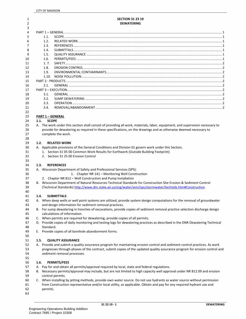
CITY OF MADISON
31 23 19 - 1 DEWATERING
SECTION 31 23 19 1
DEWATERING 2
3
PART 1 – GENERAL ............................................................................................................................................................................ 1 4
1.1. SCOPE ............................................................................................................................................................................ 1 5
1.2. RELATED WORK ............................................................................................................................................................. 1 6
1.3. REFERENCES .................................................................................................................................................................. 1 7
1.4. SUBMITTALS .................................................................................................................................................................. 1 8
1.5. QUALITY ASSURANCE .................................................................................................................................................... 1 9
1.6. PERMITS/FEES ............................................................................................................................................................... 1 10
1. 7. SAFETY ........................................................................................................................................................................... 2 11
1.8. EROSION CONTROL ....................................................................................................................................................... 2 12
1.9. ENVIRONMENTAL CONTAMINANTS .............................................................................................................................. 2 13
1.10. NOISE POLLUTION ......................................................................................................................................................... 2 14
PART 2 - PRODUCTS .......................................................................................................................................................................... 2 15
2.1. GENERAL ....................................................................................................................................................................... 2 16
PART 3 – EXECUTION ......................................................................................................................................................................... 2 17
3.1. GENERAL ....................................................................................................................................................................... 2 18
3.2. SUMP DEWATERING ..................................................................................................................................................... 2 19
3.3. OPERATION ................................................................................................................................................................... 2 20
3.4. REMOVAL/ABANDONMENT .......................................................................................................................................... 2 21
22
PART 1 – GENERAL 23
1.1. SCOPE 24
A. The work under this section shall consist of providing all work, materials, labor, equipment, and supervision necessary to 25
provide for dewatering as required in these specifications, on the drawings and as otherwise deemed necessary to 26
complete the work. 27
28
1.2. RELATED WORK 29
A. Applicable provisions of the General Conditions and Division 01 govern work under this Section. 30
1. Section 31 05 00 Common Work Results for Earthwork (Outside Building Footprint) 31
2. Section 31 25 00 Erosion Control 32
33
1.3. REFERENCES 34
A. Wisconsin Department of Safety and Professional Services (SPS): 35
1. Chapter NR 141 – Monitoring Well Construction 36
2. Chapter NR 812 – Well Construction and Pump Installation 37
B. Wisconsin Department of Natural Resources Technical Standards for Construction Site Erosion & Sediment Control 38
(Technical Standards) http://www.dnr.state.wi.us/org/water/wm/nps/stormwater/techstds.htm#Construction 39
40
1.4. SUBMITTALS 41
A. When deep wells or well point systems are utilized, provide system design computations for the removal of groundwater 42
and design information for sediment removal practices. 43
B. For sump dewatering in trenches of excavations, provide copies of sediment removal practice selection discharge design 44
calculations of information. 45
C. When permits are required for dewatering, provide copies of all permits. 46
D. Provide copies of daily monitoring and testing logs for dewatering practices as described in the DNR Dewatering Technical 47
Standard. 48
E. Provide copies of all borehole abandonment forms. 49
50
1.5. QUALITY ASSURANCE 51
A. Provide and submit a quality assurance program for maintaining erosion control and sediment control practices. As work 52
progresses through phases of the contract, submit copies of the updated quality assurance program for erosion control and 53
sediment removal processes. 54
55
1.6. PERMITS/FEES 56
A. Pay for and obtain all permits/approval required by local, state and federal regulations. 57
B. Necessary permits/approval may include, but are not limited to high capacity well approval under NR 812.09 and erosion 58
control permits. 59
C. When installing by jetting methods, provide own water source. Do not use hydrants as water source without permission 60
from Construction representative and/or local utility, as applicable. Obtain and pay for any required hydrant use and 61
permits. 62
63
Engineering Operations Building AdditionContract 7685 / Project 10308

CITY OF MADISON
31 23 19 - 2 DEWATERING
1. 7. SAFETY 1
A. Prevent public access to hazardous dewatering system components. 2
B. Abandon boreholes in accordance with applicable local, state and federal codes immediately following use. 3
4
1.8. EROSION CONTROL 5
A. Comply with the requirements of the specification sections listed under related work in part 1 of this section. 6
B. Selection, installation, operation, and maintenance of erosion control and sediment removal measures related to a 7
dewatering system shall be done in accordance with the DNR Dewatering Technical Standard or equivalent approved by the 8
WDNR. 9
C. Upon installation of the dewatering system, immediately remove any mud, sediment or drilling fluid generated by jetting or 10
rotary drilling operations. 11
D. When overland discharge of water is necessary, dissipate energy of water stream using nozzles, deflectors, riprap or other 12
methods. 13
E. Inspect dewatering system daily for signs of erosion and eliminate cause of erosion. 14
15
1.9. ENVIRONMENTAL CONTAMINANTS 16
A. Monitor dewatering system discharge regularly for signs of chemicals or other environmental contaminants. 17
B. If chemicals or environmental contaminants are observed, terminate dewatering system operation immediately and 18
contact the Construction Representative. 19
C. Prevent dewatering system from introducing contaminants into the soil or groundwater. 20
21
1.10. NOISE POLLUTION 22
A. Provide mufflers, housing, berms and fencing as necessary to minimize noise pollution resulting from dewatering system 23
operation. 24
25
PART 2 - PRODUCTS 26
2.1. GENERAL 27
A. All deepwell and wellpoint dewatering equipment and well construction/abandonment materials shall meet the 28
requirements of NR 141 and NR 812. 29
30
PART 3 – EXECUTION 31
3.1. GENERAL 32
A. Comply with all local, state and federal regulations. 33
B. When deep wells or well point systems are utilized, prepare a system design and obtain permits in accordance with NR 34
812.09 for high capacity wells as defined by NR 812.07(53). Design system to dewater site as necessary to complete 35
construction, but minimize impact on local water table. Monitor water levels in wells adjacent to construction site. Adjust 36
dewatering system configuration and operation as necessary if neighboring wells are adversely impacted. Do not adversely 37
impact neighboring private wells. 38
C. Coordinate installation of dewatering system with other contractors. Locate dewatering system components in locations 39
that do not interfere with site operations or other construction activities. 40
D. Pump groundwater at lowest rate necessary to dewater site as required to accommodate other sitework. 41
42
3.2. SUMP DEWATERING 43
A. Install collection sump in the low point of the excavation(s). 44
B. Provide filter material, trash screens and other devices around pump or intake to avoid pumping of sediment. 45
46
3.3. OPERATION 47
A. Provide personnel, equipment and power necessary to maintain and operate the dewatering system as required to 48
complete construction at the site. 49
B. Do not discharge water containing sediment, debris or contaminants into the sanitary sewer system or waters of the state. 50
51
3.4. REMOVAL/ABANDONMENT 52
A. Remove all dewatering system components immediately following use. 53
B. Clean receiving storm sewer system of any sediment or debris deposits resulting from dewatering system operation. 54
55
END OF SECTION 56
Engineering Operations Building AdditionContract 7685 / Project 10308

CITY OF MADISON
31 25 00 - 1 EROSION CONTROL
SECTION 31 25 00 1
EROSION CONTROL 2
3
PART 1 – GENERAL ............................................................................................................................................................................ 1 4
1.1. SCOPE ............................................................................................................................................................................ 1 5
1.2. RELATED WORK ............................................................................................................................................................. 1 6
1.3. PERMITS ........................................................................................................................................................................ 1 7
1.4. SUBMITTALS .................................................................................................................................................................. 1 8
1.5. EROSION CONTROL PLAN .............................................................................................................................................. 2 9
PART 2 - PRODUCTS .......................................................................................................................................................................... 2 10
2. 1. GENERAL ....................................................................................................................................................................... 2 11
2.2. STRAW BALE BARRIERS ................................................................................................................................................. 2 12
2.3. SILT FENCE ..................................................................................................................................................................... 2 13
2.4. EROSION MAT ............................................................................................................................................................... 2 14
2.5. STAPLES ......................................................................................................................................................................... 2 15
2.6. RIP-RAP ......................................................................................................................................................................... 2 16
2.7. FIELDSTONE COBBLES ................................................................................................................................................... 2 17
2.8. TRACKING PAD STONE .................................................................................................................................................. 2 18
2.9. SOIL STABILIZERS ........................................................................................................................................................... 2 19
2.10. SOIL TACKIFIERS ............................................................................................................................................................ 2 20
2.11. POLYMERS ..................................................................................................................................................................... 2 21
PART 3 – EXECUTION ......................................................................................................................................................................... 3 22
3.1. GENERAL ....................................................................................................................................................................... 3 23
3.2. GRADING AND EARTHWORK ......................................................................................................................................... 3 24
3.3. DRAINAGE ..................................................................................................................................................................... 3 25
3.4. TRACKING CONTROL ..................................................................................................................................................... 3 26
3.5. MAINTENANCE .............................................................................................................................................................. 3 27
28
PART 1 – GENERAL 29
1.1. SCOPE 30
A. The work under this section consists of providing all work, materials, labor, equipment, and supervision necessary to 31
provide and construct erosion control measures necessary to protect property and the environment. 32
33
1.2. RELATED WORK 34
A. Applicable provisions of Division 01 govern work under this Section. 35
B. Section 31 05 00 Common Work Results For Earthwork (Outside Building Footprint) 36
C. Section 31 23 19 Dewatering 37
D. Provide erosion control in accordance with the following references: 38
1. Wisconsin Department of Natural Resources Technical Standards For Construction Site Erosion and Sediment Control. 39
http://dnr.wi.gov/org/water/wm/nps/stormwater/techstds.htm 40
2. Erosion Control Product Acceptability List (“PAL”), current version as published by the WisDOT. 41
http://www.dot.wisconsin.gov/business/engrserv/pal.htm 42
E. Method of measurement and basis of payment sections in any referenced erosion control documents shall not apply to this 43
contract. 44
F. These documents are available from: State of Wisconsin Document Sales and Distribution 202 South Thornton Avenue; P.O. 45
Box 7840; Madison, WI 53707; 608-266-3358 46
47
1.3. PERMITS 48
A. Contractor shall be responsible for obtaining and maintaining all erosion control permits associated with the project. 49
50
1.4. SUBMITTALS 51
A. The Lead Contractor will submit the following to the A/E: 52
1. Contractor shall mark-up of the Erosion Control Plan that is included in these documents showing additional or 53
alternate erosion control measures as needed due to the Contractors means and methods throughout all phases of 54
construction. The Contractor may also be required to submit calculations and backup information showing the 55
proposed measures meet applicable regulations. 56
2. Submittals for materials used to implement the erosion control plan. 57
B. Submit shop drawings for the following erosion control features as indicated in Section 31 00 05 Civil General 58
Requirements: 59
1. Silt Fence 60
2. Inlet Sediment Guards 61
3. Erosion Mat 62
4. Fieldstone Cobbles (provide on-site sample) 63
64
Engineering Operations Building AdditionContract 7685 / Project 10308

CITY OF MADISON
31 25 00 - 2 EROSION CONTROL
1.5. EROSION CONTROL PLAN 1
A. The A/E has prepared an erosion control plan for the project and will apply for the required NOI permit. The Contractor will 2
provide the A/E with submittals for materials used to implement the erosion control plan, as well as any modifications to 3
the erosion control plan that are necessary due to the Contractor’s means and methods of construction. 4
B. Contractor shall comply with all the requirements of the erosion control plan, and if applicable, the Wisconsin Pollutant 5
Discharge Elimination System, WPDES. If applicable, the project specific WPDES Construction Site Stormwater Discharge 6
Permit for Erosion Control shall supersede the General Permit. 7
C. Erosion control and storm water management practices shall be installed and maintained in accordance with the WDNR 8
approved Technical Standards (or equivalent). 9
D. Contractor shall provide all erosion control practices necessary to protect property and the environment. Erosion control 10
and storm water management practices shall be installed and maintained in accordance with the WDNR approved 11
Technical Standards (or equivalent). 12
13
PART 2 - PRODUCTS 14
2. 1. GENERAL 15
A. Erosion mats, soil stabilizers, and tackifiers shall be listed on the Product Acceptability List for Multi-Modal 16
B. Applications (“PAL”) as published by the Wisconsin Department of Transportation. 17
C. When the design or contract includes permanent erosion control or stormwater control features, the contractor may 18
employ these items in his control of erosion and stormwater during his construction activities. However, these items shall 19
be fully cleaned, restored, and in every way fully functioning for its intended permanent use prior to acceptance of the 20
work. 21
22
2.2. STRAW BALE BARRIERS 23
A. Rectangular bales of hay or straw, tightly bound with twine, not wire. 24
B. Anchor stakes shall be “T” or “U” steel posts, or hardwood, 2.0 by 2.0 inches nominal. Rebar shall not be used to anchor 25
bales. 26
27
2.3. SILT FENCE 28
A. Fence fabric shall comply with the requirements of Standard Specifications for Highway Construction 628.2.6, in 3 foot tall 29
rolls, with 4’ tall 2" x 2" nominal cross section hardwood posts spaced a maximum of 10’ o.c.. Silt fence shall be Mirafi, 30
Trevira, Amoco, CFM, or approved equal. 31
32
2.4. EROSION MAT 33
A. A straw/coconut fiber mat encased in an accelerated photodegradable polypropylene top net. Erosion mat shall comply 34
with the requirements of Class I, Type A erosion mat as defined by Standard Specifications for Highway Construction and 35
the PAL. Erosion mat shall be American Excelsior, SI Geosolutions, Erosion Control Systems, North American Green, or 36
approved equal. 37
B. Concentrated Areas/Channels (as indicated on plans): This mat shall be North American Green SC150, or approved equal. 38
C. Erosion Mat at Storm Outlets: This mat shall be ProPex LandLok 300, or approved equal. 39
D. Erosion Mat in bio-filtration and raingarden areas shall be North American Green SC-150BN or approved equal. 40
41
2.5. STAPLES 42
A. Use biodegradable staples in accordance with manufacturer’s recommendations for materials being anchored. Wood and 43
metal staples are not allowed. 44
45
2.6. RIP-RAP 46
A. Rip rap shall be the class specified and shall conform to Standard Specifications for Highway Construction Section 606.2. 47
48
2.7. FIELDSTONE COBBLES 49
A. Stone shall be the size and type specified on plans. Contractor shall provide an on-site sample for approval prior to 50
installation. 51
52
2.8. TRACKING PAD STONE 53
A. The aggregate for tracking pads shall be 3 to 6 inch clear or washed stone. All materials shall be retained on a 3- inch sieve. 54
55
2.9. SOIL STABILIZERS 56
A. Soil stabilizers shall be non-asphalt-based products of the type specified, and meeting the requirements of the PAL. 57
58
2.10. SOIL TACKIFIERS 59
A. Soil tackifiers shall be non-asphalt-based products of the type specified, and meeting the requirements of PAL. 60
61
2.11. POLYMERS 62
A. Polymers used to settle suspended sediment shall meet the requirements of the WDNR Technical Standards. 63
64
Engineering Operations Building AdditionContract 7685 / Project 10308

CITY OF MADISON
31 25 00 - 3 EROSION CONTROL
PART 3 – EXECUTION 1
3.1. GENERAL 2
A. Install erosion control measures as required by the erosion control plan and contract documents. Provide additional erosion 3
control measures as dictated by Contractor’s means and methods, or by differing site conditions. Notify Construction 4
Representative of additional erosion control features that are provided, but not shown on the plan. 5
B. Contractor shall provide all erosion control measures necessary to protect property and the environment. Include all 6
erosion control measures as required by the most stringent of applicable sections of DNR Technical Standards or the 7
Standard Specifications for Highway Construction. 8
C. Perform all work in accordance with manufacturer's instruction where these specifications do not specify a higher 9
requirement. 10
D. Contractor shall comply with all the requirements of the erosion control plan, and if applicable, the WPDES Stormwater 11
Discharge Permit for Erosion Control, including required monitoring and documentation. 12
13
3.2. GRADING AND EARTHWORK 14
A. Install all temporary or permanent erosion control measures prior to any onsite grading or land disturbances. 15
B. Clear only those areas designated for the placement of improvements or earthwork before placement of the final cover. 16
Perform stripping of vegetation, grading, excavation, or other land disturbing activities in a logical sequence and manner 17
which will minimize erosion. If possible, schedule construction for times of the year when erosion hazards are minimal. 18
C. Do not clear the site of topsoil, trees, and other natural ground covers before the commencement of construction. Retain 19
natural vegetation and protect until the final ground cover is placed. 20
D. Temporary stockpiles are to be located greater than 25 feet from any roadway, parking lot, paved area, drainage structure, 21
or channel. 22
E. Provide temporary stabilization and control measures (seeding, mulching, covering, erosion matting, barrier fencing, etc.) 23
for the protection of disturbed areas and soil piles which will remain uncovered for a period of more than 7 consecutive 24
calendar days. 25
F. Remove surplus excavation materials from the site immediately after rough grading. The disposal site for the surplus 26
excavation materials shall also be subject to these erosion control requirements. 27
28
3.3. DRAINAGE 29
A. Minimize water runoff and retain or detain on-site whenever possible so as to promote settling of solids and groundwater 30
recharge. 31
B. Convey drainage to the nearest adequate stormwater facility. Do not discharge water in a manner that will cause erosion or 32
sedimentation of the site or receiving facility. 33
C. Protect storm sewer inlets and catch basins in accordance with the erosion control plan, if provided, alog with the WDNR 34
Technical Standards and PAL. If not specified, protect inlets with straw bale barriers, silt fencing, filter basket, or other 35
equivalent methods approved by the Engineer which provide the necessary erosion protection. 36
D. Divert roof drainage and runoff from all areas upslope of the site around areas to be disturbed or channel them through the 37
site in a manner that will not cause erosion. 38
E. Ditch checks are to be provided in swales or ditches to reduce the velocity of water in the channel. Construct in accordance 39
to DNR Technical Standards and PAL. 40
F. Minimize the pumping of sediments when dewatering. Discharge to a sedimentation basin/trap or sedimentation vessel to 41
reduce the discharge of sediments. Do not discharge water in a manner that will cause erosion or sedimentation of the site 42
or receiving facility. Refer to section 31 23 19 Dewatering for specifications. 43
44
3.4. TRACKING CONTROL 45
A. Construct and maintain tracking pads in accordance with the Technical Standards. Provide each entrance to the site with a 46
stone tracking pad at least 50 feet in length with a minimum thickness of 12 inches. The tracking pad shall be the full width 47
of the egress point. Inspect tracking pads on a daily basis and replace aggregate when no longer effective. 48
B. If necessary, provide a crushed aggregate paved parking area. 49
C. If applicable, wash water shall be discharged to sedimentation basins, sedimentation vessels, or other such control areas. 50
51
3.5. MAINTENANCE 52
A. Inspect all erosion control measures within 24 hours of the end of each rainfall event that exceeds 0.25”, or daily during 53
period of prolonged rainfall, or weekly during periods without rainfall. Immediately repair and/or replace any and all 54
damaged, failed, or inadequate erosion control measures. 55
B. Re-apply soil stabilizers, tackifiers, polymers and anionic polycrylamides as needed to prevent erosion of exposed soil. 56
C. Maintain records of all inspections and any remedial actions taken. 57
D. Maintain stockpile stabilization measures as necessary after rainfall events and heavy winds. Replace tarps, re-seed, and 58
reapply mulch, tackifiers and stabilizers as necessary. 59
E. Remove sediment from stormwater and erosion control structures, basins and vessels as necessary. 60
F. Repair or replace damaged inlet protection. 61
G. Replace or supplement stone tracking pads with additional stone when they become ineffective. 62
Engineering Operations Building AdditionContract 7685 / Project 10308

CITY OF MADISON
31 25 00 - 4 EROSION CONTROL
H. Remove any sediment reaching a public or private roadway, parking lot, sidewalk, or other paved. Do not remove tracked 1
sediments by flushing. Completely remove any accumulations not requiring immediate attention at least once daily at the 2
end of the workday. 3
I. Frequently dispose of all waste and unused construction materials in licensed solid waste or wastewater facilities. Do not 4
bury, dump, or discharge, any garbage, debris, cleaning wastes, toxic materials, or hazardous materials on the site, on the 5
land surface or in detention basins, or otherwise allow materials to be carried off the site by runoff onto adjacent lands or 6
into receiving waters or storm sewer systems. 7
8
END OF SECTION 9
Engineering Operations Building AdditionContract 7685 / Project 10308

CITY OF MADISON
32 05 00 - 1 COMMON WORK RESULTS FOR EXTERIOR IMPROVEMENTS
SECTION 32 05 00 1
COMMON WORK RESULTS FOR EXTERIOR IMPROVEMENTS 2
3
PART 1 – GENERAL ............................................................................................................................................................................ 1 4
1.1. SCOPE ............................................................................................................................................................................ 1 5
1.2. REFERENCES .................................................................................................................................................................. 1 6
PART 2 - PRODUCTS .......................................................................................................................................................................... 1 7
2.1. BARRICADES, SIGNS, AND WARNING DEVICES .............................................................................................................. 1 8
2.2. TEMPORARY PLASTIC BARRIER FENCING ...................................................................................................................... 2 9
PART 3 – EXECUTION ......................................................................................................................................................................... 2 10
3.1. MAINTENANCE OF SITE AND BUILDING ACCESS/EGRESS.............................................................................................. 2 11
3.2. CONTINUITY OF EXISTING TRAFFIC/PARKING AND TRAFFIC CONTROL ......................................................................... 2 12
3.3. PROTECTION AND CONTINUITY OF EXISTING UTILITIES ................................................................................................ 2 13
3.4. PROTECTION OF EXISTING WORK AND FACILITIES ........................................................................................................ 2 14
3.5. CONSTRUCTION LAYOUT ............................................................................................................................................... 2 15
3.6. STORMWATER/EXCAVATION WATER MANAGEMENT .................................................................................................. 2 16
17
PART 1 – GENERAL 18
1.1. SCOPE 19
A. This section includes information common to all site work and applies to the entire contract. 20
B. Unless otherwise noted in the Contract Documents, Contractor shall be responsible for obtaining and paying for all permits 21
necessary to complete the work. 22
C. Construction Limits are indicated on the drawings. In the absence of such a designation on the drawings, confine work to 23
the minimum area reasonably necessary to undertake the work as determined by the Construction Representative. In no 24
case shall construction activities extend beyond property lines or construction easements. 25
D. The Contractor shall restore all disturbed areas in accordance with the drawings and specifications. If plans and 26
specifications do not address restoration of specific areas, these areas will be restored to pre-construction conditions as 27
approved by the Construction Representative. 28
29
1.2. REFERENCES 30
A. Work under this section depends on applicable provisions from other sections and the plan set in this contract. Examples of 31
related sections include, but are not limited to: 32
1. DIVISION 31 — EARTHWORK 33
B. AASHTO - American Association of State Highway and Transportation Officials 34
C. ACPA - American Concrete Pipe Association 35
D. ANSI - American National Standards Institute 36
E. ASCE - American Society of Civil Engineers 37
F. ASME - American Society of Mechanical Engineers 38
G. ASTM - American Society for Testing and Materials 39
H. AWWA - American Water Works Association 40
I. AWS - American Welding Society 41
J. FHA - Federal Highway Administration 42
K. EPA - Environmental Protection Agency 43
L. NEC - National Electric Code 44
M. NEMA - National Electrical Manufacturers Association 45
N. NFPA - National Fire Protection Association 46
O. NSF - National Sanitation Foundation 47
P. OSHA - Occupational Safety and Health Administration 48
Q. STI - Steel Tank Institute 49
R. UL - Underwriters Laboratories Inc. 50
S. WDNR - State of Wisconsin Department of Natural Resources 51
T. WisDOT - State of Wisconsin Department of Transportation 52
U. Where reference is made to the "SSHSC", it shall mean the pertinent sections of the State of Wisconsin, Department of 53
Transportation, Standard Specifications for Highway and Structure Construction, current edition, and all supplemental and 54
interim supplemental specifications. Where reference is made to the “STANDARD SPECIFICATIONS”, it shall mean pertinent 55
sections of the City of Madison Standard Specifications for Public Works Construction, current edition. Where reference is 56
made to the “BMPH”, it shall mean the Wisconsin Construction Site Best Management Practice Handbook, current edition 57
as published by the WDNR. Method of measurement and basis of payment sections in referenced documents shall not 58
apply. 59
60
PART 2 - PRODUCTS 61
2.1. BARRICADES, SIGNS, AND WARNING DEVICES 62
A. Traffic barricades, traffic signs, and warning devices shall meet the requirements of applicable OSHA standards and the FHA 63
Manual of Uniform Traffic Control Devices (MUTCD). 64
Engineering Operations Building AdditionContract 7685 / Project 10308
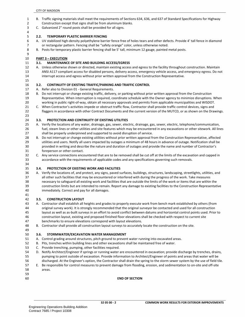
CITY OF MADISON
32 05 00 - 2 COMMON WORK RESULTS FOR EXTERIOR IMPROVEMENTS
B. Traffic signing materials shall meet the requirements of Sections 634, 636, and 637 of Standard Specifications for Highway 1
Construction except that signs shall be from aluminum blanks. 2
C. Galvanized 2" round posts shall be provided for all signs. 3
4
2.2. TEMPORARY PLASTIC BARRIER FENCING 5
A. UV stabilized high-density polyethylene barrier fence free of holes tears and other defects. Provide 4’ tall fence in diamond 6
or rectangular pattern. Fencing shall be “safety orange” color, unless otherwise noted. 7
B. Posts for temporary plastic barrier fencing shall be 5’ tall, minimum 12 gauge, painted metal posts. 8
9
PART 3 – EXECUTION 10
3.1. MAINTENANCE OF SITE AND BUILDING ACCESS/EGRESS 11
A. Unless otherwise shown or directed, maintain existing access and egress to the facility throughout construction. Maintain 12
ANSI A117 compliant access for disabled persons, delivery access, emergency vehicle access, and emergency egress. Do not 13
interrupt access and egress without prior written approval from the Construction Representative. 14
15
3.2. CONTINUITY OF EXISTING TRAFFIC/PARKING AND TRAFFIC CONTROL 16
A. Refer also to Division 01 - General Requirements. 17
B. Do not interrupt or change existing traffic, delivery, or parking without prior written approval from the Construction 18
Representative. When interruption is required, coordinate schedule with the Owner agency to minimize disruptions. When 19
working in public right-of-way, obtain all necessary approvals and permits from applicable municipalities and WISDOT. 20
C. When Contractor’s activities impede or obstruct traffic flow, Contractor shall provide traffic control devices, signs and 21
flaggers in accordance with other Contract Documents and the current version of the MUTCD, or as shown on the Drawings. 22
23
3.3. PROTECTION AND CONTINUITY OF EXISTING UTILITIES 24
A. Verify the locations of any water, drainage, gas, sewer, electric, drainage, gas, sewer, electric, telephone/communication, 25
fuel, steam lines or other utilities and site features which may be encountered in any excavations or other sitework. All lines 26
shall be properly underpinned and supported to avoid disruption of service. 27
B. Do not interrupt or change existing utilities without prior written approval from the Construction Representative, affected 28
utilities and users. Notify all users impacted by outages a minimum of 48 hours in advance of outage. Notification shall be 29
provided in writing and describe the nature and duration of outages and provide the name and number of Contractor’s 30
foreperson or other contact. 31
C. Any service connections encountered that are to be removed shall be cut off at the limits of the excavation and capped in 32
accordance with the requirements of applicable codes and any specifications governing such removals. 33
34
3.4. PROTECTION OF EXISTING WORK AND FACILITIES 35
A. Verify the locations of, and protect, any signs, paved surfaces, buildings, structures, landscaping, streetlights, utilities, and 36
all other such facilities that may be encountered or interfered with during the progress of the work. Take measures 37
necessary to safeguard all existing work and facilities that are outside the limits of the work or items that are within the 38
construction limits but are intended to remain. Report any damage to existing facilities to the Construction Representative 39
immediately. Correct and pay for all damages. 40
41
3.5. CONSTRUCTION LAYOUT 42
A. Contractor shall establish all heights and grades to properly execute work from bench mark established by others (from 43
original survey work). It is strongly recommended that the original surveyor be contacted and used for all construction 44
layout as well as as-built surveys in an effort to avoid conflict between datums and horizontal control points used. Prior to 45
construction layout, existing and proposed finished floor elevations shall be checked with respect to current site 46
benchmarks to ensure elevations correspond with layout elevations. 47
B. Contractor shall provide all construction layout surveys to accurately locate the construction on the site. 48
49
3.6. STORMWATER/EXCAVATION WATER MANAGEMENT 50
A. Control grading around structures, pitch ground to prevent water running into excavated areas. 51
B. Pits, trenches within building lines and other excavations shall be maintained free of water. 52
C. Provide trenching, pumping, other facilities required. 53
D. Notify Architect/Engineer if springs or running water are encountered in excavation; provide discharge by trenches, drains, 54
pumping to point outside of excavation. Provide information to Architect/Engineer of points and areas that water will be 55
discharged. At the Engineer's option, the Contractor shall drain the spring to the storm sewer system by the use of field tile. 56
E. Be responsible for control measures to prevent damage from flooding, erosion, and sedimentation to on-site and off-site 57
areas. 58
59
END OF SECTION 60
Engineering Operations Building AdditionContract 7685 / Project 10308

CITY OF MADISON
32 11 23.33 - 1 DENSE GRADED BASE
SECTION 32 11 23.33 1
DENSE GRADED BASE 2
3
PART 1 – GENERAL ............................................................................................................................................................................ 1 4
1.1. SCOPE ............................................................................................................................................................................ 1 5
1.2. REFERENCES .................................................................................................................................................................. 1 6
1.3. SUBMITTALS .................................................................................................................................................................. 1 7
PART 2 - PRODUCTS .......................................................................................................................................................................... 1 8
2.1. GENERAL ....................................................................................................................................................................... 1 9
2.2. BREAKER RUN AGGREGATE ........................................................................................................................................... 1 10
PART 3 – EXECUTION ......................................................................................................................................................................... 1 11
3.1. CONSTRUCTION ............................................................................................................................................................ 1 12
3.2. COMPACTION ................................................................................................................................................................ 3 13
3.3. UNDERCUTTING/EXCAVATION BELOW SUBGRADE (EBS) ............................................................................................. 3 14
3.4. CLEANUP ....................................................................................................................................................................... 3 15
16
PART 1 – GENERAL 17
1.1. SCOPE 18
A. This section includes information common to dense graded base using crushed stone or crushed gravel and applies to all 19
sections in this Division. 20
21
1.2. REFERENCES 22
A. Work under this section depends on applicable provisions from other sections and the plan set in this contract. Examples of 23
related sections include, but are not limited to: 24
1. DIVISION 31 — EARTHWORK 25
B. Wherever WisDOT or SSHSC appears in this specification it shall be construed to mean the pertinent sections of the State of 26
Wisconsin, Department of Transportation, Standard Specifications for Highway and Structure Construction (SSHSC), current 27
edition, and all supplemental and interim supplemental specifications, as they may pertain, except this contract shall be a 28
lump sum contract and measurement and basis of payment methods shall not apply. 29
30
1.3. SUBMITTALS 31
A. Provide copies of record drawings. 32
B. Provide copies of material testing reports. 33
C. Provide the following prior to construction: 34
1. Manufacturers product information (cut sheets) 35
2. Mix designs and specifications 36
3. Aggregate Gradations 37
D. Materials conforming to the WisDOT Standard Specifications for Highway and Structure Construction (Latest Edition, 38
hereafter called “Standard Specifications for Highway Construction” and supplied from a WisDOT approved source need not 39
be tested. The contractor shall furnish evidence of such WisDOT approval to the A/E and/or Construction Representative. 40
E. Maintain record drawings showing actual locations of utilities and other features encountered, modifications to proposed 41
grades and site features, and other deviations from the original design. 42
43
PART 2 - PRODUCTS 44
2.1. GENERAL 45
A. Use dense graded base. Materials shall conform to Section 301.2 of the WisDOT Standard Specifications for Highway and 46
Structure Construction. Material gradations shall conform to Section 305.2.2 of the WisDOT Standard Specifications for 47
Highway and Structure Construction unless specified elsewhere in the contract documents. 48
B. Base Course Gradation: 1-1/4” Crushed Aggregate 49
50
2.2. BREAKER RUN AGGREGATE 51
A. Crushed stone, rock or gravel meeting the requirements of either Breaker Run or Select Crushed material as defined in 52
Section 311.2 or Section 312.2 of Standard Specifications for Highway Construction, respectively. 53
54
PART 3 – EXECUTION 55
3.1. CONSTRUCTION 56
A. PREPARING THE PAVEMENT FOUNDATION (SUB-GRADE): 57
1. Prepare the foundation, or resurface the previously placed base layer, as specified in WisDOT Section 211 before 58
placing base. Do not place base foundations that are soft, spongy, or covered by ice or snow. Water and rework or re-59
compact dry foundations as necessary to ensure proper compaction, or as the representative designates. 60
a. In proposed pavement areas, all organic solid shall be removed. 61
b. Excavation shall be reasonably free of water prior to beginning filling. Do not place material on frozen surfaces or 62
use frozen material. 63
Engineering Operations Building AdditionContract 7685 / Project 10308

CITY OF MADISON
32 11 23.33 - 2 DENSE GRADED BASE
c. In areas of existing pavement to be modified or adjusted in grade, the existing pavement section shall be removed 1
by an acceptable method. The new pavement section shall match the construction details. 2
d. Place and compact material to minimize settlement and avoid damage to structures, pipes, utility lines and other 3
features. Handplace and compact material as necessary. 4
e. Moisture condition backfill material as necessary to achieve density required for given use. 5
f. Compact fill material as required for the given use. 6
g. It is the responsibility of the Contractor to provide all necessary compaction equipment and other grading 7
equipment that may be required to obtain the specified density. Vibratory plate or tamping type walk behind 8
compactors will be required whenever backfill is placed adjacent to structures, pipes, utility lines and other 9
features. 10
h. Where additional filling or excavation is necessary, or placement of base course will be delayed, roll surface of 11
proposed roadway or parking lot with a smooth drum roller to provide relatively impervious surface and promote 12
drainage. 13
2. Proof-roll all subgrade areas that are to receive aggregate base or pavement. Proof-roll with a loaded dump truck prior 14
to the placement of base courses to locate soft spots that yield under loading. Overexcavate (undercut) areas of soft 15
subgrade that will not compact readily when proof rolled or tamped. Backfill with breaker run or select crushed 16
material as approved by the project representative. 17
a. Prior to undercutting or excavating below subgrade (EBS) or placing any base course, contact the Construction 18
Representative to schedule inspection of subgrade and proof rolling. Provide minimum of 24 hrs confirmed notice. 19
All proof rolling shall be completed in the presence of the Construction Representative and Geotechnical 20
Consultant. 21
b. To complete proof rolling, entire roadway subgrade shall be provided with a relatively smooth surface, suitable for 22
observing soil reaction during proof rolling. 23
c. Contractor shall schedule and provide a fully loaded tri-axle dump truck for proof – rolling. Loaded truck shall have a 24
minimum gross operating weight of 30 tons. Test shall be conducted with “tag” or “pusher” axles retracted from the 25
ground. 26
d. Test rolling shall be accomplished in a series of traverses parallel to the centerline of the street or parking area. The 27
truck shall traverse the length of the street or parking area once for each 12’ of width. Additional passes along the 28
traverse shall be completed as directed by the Geotechnical Consultant, to further define unsatisfactory subgrade. 29
e. Soft areas, yielding areas, cracked areas or areas where rolling or wave action is observed shall be considered 30
indicative of an unsatisfactory subgrade. Such areas shall be undercut as outlined in Section 31 05 00. 31
f. Once the subgrade has been proof-rolled and approved, protect the soils from becoming saturated, frozen, or 32
adversely altered. 33
g. Contractor shall assume 15% of proposed paved areas may require undercutting. This work shall be included in base 34
bid. Undercut as outlined in Section 31 05 00. 35
B. STOCKPILING: 36
1. If continuous compliance with material specifications is questionable, the project representative may require the 37
contractor to supply material from a stockpile of previously tested material. Maintain a sufficiently large stockpile to 38
preclude the use of material not previously approved. 39
2. Build and maintain stockpiles using methods that minimize segregation and prevent contamination. If the contract 40
specifies location, place stockpiles where specified. Clear and prepare stockpile areas to facilitate the recovery of the 41
maximum amount of stockpiled material. 42
C. CONSTRUCTING BASE: 43
1. Place aggregate in a manner that minimizes hauling on the subgrade. Do not use vehicles or operations that damage 44
the subgrade or in-place base. Deposit material in a manner that minimizes segregation. 45
2. Construct the base to the width and section the plans show. Shape, and compact the base surface to within 0.04 feet 46
(12 mm) of the plan elevation. 47
3. Ensure there is adequate moisture in the aggregate during placing, shaping, and compacting to prevent segregation and 48
achieve adequate compaction. 49
4. Maintain the base until paving over it, or until the project representative accepts the work, if paving is not part of the 50
contract. The contractor is not responsible for maintaining material placed on detours, unless the special provisions 51
specify otherwise. 52
D. STANDARD COMPACTION: 53
1. Compact the base until there is no appreciable displacement, either laterally or longitudinally, under the compaction 54
equipment. Route hauling equipment uniformly over previously placed base. Compact each layer before placing a 55
subsequent layer. If the material is too dry to readily attain the required compaction, add water as necessary to achieve 56
compaction 57
E. SPECIAL COMPACTION: If the contract requires special compaction, compact each layer to 95 percent of maximum density, 58
or more, before placing the subsequent layer. The geotechnical engineer will determine the maximum density according to 59
AASHTO T 99 method C or D and in-place density according to AASHTO T 191. 60
F. CONTROLLING DUST: Apply water or other engineer-approved dust control materials to control dust during construction 61
and maintenance of the base and shoulders. 62
63
Engineering Operations Building AdditionContract 7685 / Project 10308

CITY OF MADISON
32 11 23.33 - 3 DENSE GRADED BASE
3.2. COMPACTION 1
A. Compact each base layer, including shoulder foreslopes, with equipment specified in WisDOT Section 301.3.1. Use standard 2
compaction conforming to WisDOT Section 301.3.4.2, unless the special provisions specify other methods. Final shaping of 3
shoulder foreslopes does not require compaction. 4
B. Compacting 1 1/4-Inch Base and 3/4-Inch Base. If using a pneumatic roller, do not exceed a compacted thickness of 6 inches 5
(150 mm) per layer. For the first layer placed over a loose sandy subgrade, the contractor may, with the geotechnical 6
engineer’s approval, increase the compacted layer thickness to 8 inches (200 mm). If using a vibratory roller, do not exceed 7
a compacted thickness of 8 inches (200 mm) per layer. 8
C. Compacting 3-Inch Base: Compact with a vibratory or pneumatic roller. Do not exceed a compacted thickness of 9 inches 9
(225 mm) per layer. 10
11
3.3. UNDERCUTTING/EXCAVATION BELOW SUBGRADE (EBS) 12
A. Undercutting/EBS shall be completed only when directed by the Geotechnical Consultant. The Contractor shall not be 13
compensated for any unauthorized undercutting/EBS. Measure and document undercut areas and depths in consultation 14
with Geotechnical Consultant. Work shall comply with Section 31 05 00. Contractor shall assume 15% of proposed paved 15
areas may require undercutting. This work shall be included in base bid. 16
17
3.4. CLEANUP 18
A. After the project is completed, thoroughly clean up all debris which may have accumulated during the placement of dense 19
graded base. Replace or repair as required, all surfaces and/or landscape features damaged or disturbed under this item of 20
work. 21
END OF SECTION 22
Engineering Operations Building AdditionContract 7685 / Project 10308

CITY OF MADISON
32 12 00 - 1 ASPHALTIC PAVEMENT
SECTION 32 12 00 1
ASPHALTIC PAVEMENT 2
3
PART 1 – GENERAL ............................................................................................................................................................................ 1 4
1.1. SCOPE ............................................................................................................................................................................ 1 5
1.2. REFERENCES .................................................................................................................................................................. 1 6
1.3. SUBMITTALS .................................................................................................................................................................. 1 7
1.4. QUALITY ASSURANCE .................................................................................................................................................... 1 8
PART 2 - PRODUCTS .......................................................................................................................................................................... 1 9
2.1. MATERIALS .................................................................................................................................................................... 1 10
2.2. RECYCLED ASPHALTIC MATERIALS ................................................................................................................................ 2 11
2.3. ASPHALT TACK COAT ..................................................................................................................................................... 2 12
PART 3 – EXECUTION ......................................................................................................................................................................... 2 13
3.1. SPREADING AND FINISHING .......................................................................................................................................... 2 14
3.2. COMPACTION ................................................................................................................................................................ 2 15
3.3. JOINTS ........................................................................................................................................................................... 3 16
3.4. ASPHALT PAVEMENT ..................................................................................................................................................... 3 17
18
PART 1 – GENERAL 19
1.1. SCOPE 20
A. This section includes information common to bituminous concrete paving work as shown on the drawings and applies to all 21
sections in this Division. 22
23
1.2. REFERENCES 24
A. Work under this section depends on applicable provisions from other sections and the plan set in this contract. Examples of 25
related sections include, but are not limited to: 26
1. DIVISION 31 — EARTHWORK 27
B. City of Madison Standard Specifications for Public Works Construction. 28
C. Part 4, “Pavements” of the latest edition of the Standard Specifications for Highway and Structure Construction of the State 29
of Wisconsin, Department of Transportation. 30
31
1.3. SUBMITTALS 32
A. Results from the Freeze / Thaw Test (AASHTO T103) for quarried course aggregates used in the work produced from 33
limestone/dolomite sources. The maximum percent loss for aggregates used in the work shall be four percent (4%). 34
B. Asphalt Pavement mix designs in accordance with the aforementioned Part 4 of the latest edition of the Standard 35
Specifications for Highway and Structure Construction of the State of Wisconsin, Department of Transportation. The 36
asphaltic materials used shall be PG 58-28 for E-0.3, E-1 and E-3 mixes, and PG64-22 for E-10 mixes unless otherwise 37
specified in the Special Provisions of the contract. D. 38
39
1.4. QUALITY ASSURANCE 40
A. Do not apply asphalt materials if subgrade is wet or excessively damp, if rain is imminent or expected before time required 41
for adequate cure, or if the following conditions are not met: 42
1. Tack Coat: Minimum surface temperature of 60°F. 43
2. Asphalt Base Course: Minimum surface temperature of 40°F and rising at time of placement. 44
3. Asphalt Surface Course: Minimum surface temperature of 60°F at time of placement. 45
B. Pavement Marking Paint: Proceed with pavement marking only on clean, dry surfaces and at a minimum ambient or surface 46
temperature of 40°F for oil-based materials, and not exceeding 95° F. 47
C. The paving crew shall be under the supervision of an experienced supervisor who shall be on the project at all times, and 48
who shall not operate equipment, such as paving machines or rollers, at any time during the paving operation. Under no 49
circumstances shall the workers, or others, be allowed to walk across recently laid asphalt mixture behind the paving 50
machine and ahead of the roller. 51
D. A mechanical vibratory plate compactor shall be available on the job site at all times during asphalt pavement placement 52
and shall be used for compaction around access structures, catchbasins, water valves and other castings which appear in 53
the paved areas. The mechanical vibratory plate compactor shall be equipped with a working water reservoir and shall be of 54
sufficient size and capability to attain the compaction requirements of these specifications. 55
E. Asphalt mixtures intended for use on City projects will be tested by the City in order to determine aggregate gradations, 56
asphalt content, air voids and VMA. Asphalt mixtures shall be tested per section 460.2.8 of the latest edition of the 57
Standard Specifications for Highway and Structure Construction of the State of Wisconsin, Department of Transportation 58
59
PART 2 - PRODUCTS 60
2.1. MATERIALS 61
A. The materials intended for use in base, lower, and upper layer mixtures, tack and seal coats, surface treatments, and similar 62
work, shall comply with the requirements of Part 4, “Pavements” of the latest edition of the Standard Specifications for 63
Engineering Operations Building AdditionContract 7685 / Project 10308

CITY OF MADISON
32 12 00 - 2 ASPHALTIC PAVEMENT
Highway and Structure Construction of the State of Wisconsin, Department of Transportation, except as modified herein or 1
in the Special Provisions of the contract. 2
B. The Contractor shall provide Asphalt Pavement mix designs in accordance with the aforementioned Part 4 of the latest 3
edition of the Standard Specifications for Highway and Structure Construction of the State of Wisconsin, Department of 4
Transportation. The asphaltic materials used shall be PG 58-28 for E-0.3, E-1 and E-3 mixes, and PG64-22 for E-10 mixes 5
unless otherwise specified in the Special Provisions of the contract. 6
C. The 2.25” binder layer shall be WisDOT Type E-0.3. 7
D. The 2” surface layer shall be WisDOT Type E-0.3. 8
9
2.2. RECYCLED ASPHALTIC MATERIALS 10
A. The contractor may use recycled asphaltic materials from FRAP, RAP, and RAS in HMA mixtures. Stockpile recycled materials 11
separately from virgin materials and list each as individual JMF components. 12
B. Control recycled materials used in HMA by evaluating the percent binder replacement, the ratio of recovered binder to the 13
total binder. Conform to the following: 14
Maximum Allowable Percentage Binder Replacement
Recycled Asphaltic Material Lower Layers Upper Layer
RAS if used alone 25 20
RAP and FRAP in any combination 40 25
RAS, RAP and FRAP in combination 35 25
When used in combination the RAS component cannot exceed 5 percent of the total weight of the aggregate blend.
C. This work shall consist of the construction of a plant mixed recycled asphalt mixture furnished and placed all in accordance 15
with Article 460 of the latest edition of the Standard Specifications for Highway and Structure Construction of the State of 16
Wisconsin, Department of Transportation, except as listed below. 17
D. The City of Madison shall approve the sources of recycled asphalt material, including shingles. 18
19
2.3. ASPHALT TACK COAT 20
A. Unless otherwise specified in the contract, or directed by the Engineer, the types and grades of asphalt materials and rates 21
of applications in gallons per square yard and shall be type MS-2, SS-1, SS-1h, CSS-1, or an approved modified emulsified 22
asphalt. 23
B. For existing concrete or asphalt pavements, the rate of application shall be between 0.05 and 0.10 gallons per square yard. 24
25
PART 3 – EXECUTION 26
3.1. SPREADING AND FINISHING 27
A. Pave at a constant speed, according to the paver specifications and mixture, for uniform spreading and strike-off with a 28
smooth, dense texture and no tearing or segregation. In any event, the speed of placing asphalt mixtures shall not exceed 29
that which coincides with the average rate of delivery to the paver, so as to provide as nearly as possible continuous 30
operation of the paver. 31
B. The roller shall pass over an unprotected end of freshly laid mixture only when the laying of the course is to be discontinued 32
long enough to permit the mixture to become cooled. In the event of such discontinuance, the end of the course shall be 33
treated as a transverse construction joint as specified below. 34
35
3.2. COMPACTION 36
A. Where the edges are not supported by a curb and gutter or similar structure, the outside edges of the lower and upper 37
layers shall be sloped and pressed in place by means of a self-adjusting constant pressure edge plate held in proper position 38
on the finishing machine. A string line shall be used as a guide for the finishing machine in order to maintain a uniform edge 39
alignment. If any other method is used, it shall meet the approval of the Engineer. The edge of the pavement shall be 40
sloped approximately one (1) inch from the vertical and no material shall extend beyond the limits of the base. Irregularities 41
in alignment along the outside edges and along the longitudinal joints shall be corrected by adding or removing paving 42
mixtures before the edges are rolled. 43
B. The mixture shall be spread sufficiently so that after compaction the finished surface shall be one-eighth (1/8) to one-fourth 44
(1/4) inch above the edges of curbs, gutters, access structures and similar structures. Each roller, while the paving is under 45
way, shall be kept as nearly as practicable in continuous operation and the speed shall at all times be slow enough to avoid 46
undue displacement of the mixture. When pneumatic-tired rollers are used, they shall be operated continuously at a rate of 47
speed which will not cause damage to the mat and which will provide the maximum number of coverages possible while 48
the temperature of the mat is conducive to densification and surface sealing. Rollers shall be operated with the drive roll or 49
wheels nearest the paver. 50
C. Each roller, while the paving is under way, shall be kept as nearly as practicable in continuous operation and the speed shall 51
at all times be slow enough to avoid undue displacement of the mixture. When pneumatic-tired rollers are used, they shall 52
be operated continuously at a rate of speed which will not cause damage to the mat and which will provide the maximum 53
number of coverages possible while the temperature of the mat is conducive to densification and surface sealing. Rollers 54
shall be operated with the drive roll or wheels nearest the paver. 55
Minimum Required Density
Layer Percent of Target Maximum Density
Mixture Type
Engineering Operations Building AdditionContract 7685 / Project 10308

CITY OF MADISON
32 12 00 - 3 ASPHALTIC PAVEMENT
E-0.3, E-1, E-3 E-10
Lower 91.5 92
Upper 91.5 92
1
3.3. JOINTS 2
A. Longitudinal joints including mainline interior joints for all pavement layers shall be “hot” joints. “Hot” joints will be defined 3
as joints with a temperature at or above the asphalt mixture compaction temperature. The Contractor shall provide the 4
compaction temperature as part of the mix design submittal. 5
B. Where reheating of joints is needed to create a “hot” joint, reheating equipment and methods shall be in accordance with 6
the latest edition of the Standard Specifications for Highway and Structure Construction of the State of Wisconsin, 7
Department of Transportation, specifically Reheating HMA Pavement Longitudinal Joints, Item 460.4100S. 8
C. Where “Michigan” joints are placed to allow traffic use, the joint shall be milled, reheated and tacked in accordance with 9
the above stated reheating specification before continuation of paving. 10
D. Contractor’s operations shall not result in additional transverse joints unless approved by the Engineer. 11
12
3.4. ASPHALT PAVEMENT 13
A. Unless otherwise specified or directed by the Engineer, asphalt driveways and asphalt terrace paving shall be constructed of 14
three (3) inches of upper layer pavement installed in one (1) lift on select fill, or as directed by the Engineer. E-0.3 mixture 15
with 9.5mm nominal aggregate size or an approved commercial mix shall be used, unless a substitute is approved by 16
engineer. 17
B. The composition for the various asphalt mixtures shall conform to the limits specified in Part 4 of the latest edition of the 18
Standard Specifications for Highway and Structure Construction of the State of Wisconsin, Department of Transportation, 19
except as modified herein or in the Special Provisions of the contract. Warm mix HMA is not approved. 20
C. The mixture shall be laid and compacted so that the average yields in pounds per square yard shall conform to the following 21
charts showing the various thicknesses of installation: 22
Upper & Lower Layer(s) Yield-#S.Y.
Thickness Min. Max.
1.5” 172 180
1.75” 201 210
2” 230 240
2.5” 287 300
3” 345 360
4” 460 480
5” 575 600
D. Unless otherwise specified in the contract, or directed by the Engineer, the upper layer mixtures shall be installed in one 23
course of one and one -half (1-3/4) inches in depth. 24
E. For installations of the upper layer which are specified to be other than one and one-half (1-1/2) inches in depth, the 25
allowable yields for such installations shall be in proportion to the allowable yields specified above. 26
F. Whenever the yields fall below the minimum allowable yields specified above, the Engineer shall determine the corrective 27
action to be taken. The corrective action may include removal and replacement of the area of deficient thickness, an 28
overlay with approved material of the area of deficient thickness, or such other action as the Engineer shall determine. The 29
area of deficient thickness shall be determined on the basis of project area or area overed in one day’s operation, 30
whichever is less. The Engineer’s determination will be based on the circumstances of the area involved, and will include a 31
determination of the distribution of costs of the corrective work required. 32
33
END OF SECTION 34
Engineering Operations Building AdditionContract 7685 / Project 10308

CITY OF MADISON
32 13 00 - 1 CONCRETE WORK OUTSIDE THE BUILDING ENVELOPE
SECTION 32 13 00 1
CONCRETE WORK OUTSIDE THE BUILDING ENVELOPE 2
3
PART 1 – GENERAL ............................................................................................................................................................................ 1 4
1.1. SCOPE ............................................................................................................................................................................ 1 5
1.2. REFERENCES .................................................................................................................................................................. 1 6
1.3. QUALITY ASSURANCE .................................................................................................................................................... 1 7
1.4. ENVIRONMENTAL AND INDOOR AIR QUALITY IMPACT ................................................................................................ 2 8
PART 2 - PRODUCTS .......................................................................................................................................................................... 3 9
2.1. CONCRETE ..................................................................................................................................................................... 3 10
2.2. REINFORCING STEEL ...................................................................................................................................................... 3 11
2.3. FORMS ........................................................................................................................................................................... 3 12
2.4. CONCRETE SLURRY ........................................................................................................................................................ 4 13
PART 3 – EXECUTION ......................................................................................................................................................................... 4 14
3.1. CONCRETE PLACING AND FINISHING ............................................................................................................................ 4 15
3.2. PROTECTION OF THE CONCRETE ................................................................................................................................... 5 16
17
PART 1 – GENERAL 18
1.1. SCOPE 19
A. This section includes information common to concrete outside the building and applies to all sections in this Division. 20
21
1.2. REFERENCES 22
A. Work under this section depends on applicable provisions from other sections and the plan set in this contract. Examples of 23
related sections include, but are not limited to: 24
1. DIVISION 03 — CONCRETE 25
2. DIVISION 31 — EARTHWORK 26
B. All concrete used on City of Madison Public Works projects shall comply with the following Subsections of Article 501, 27
“Concrete” of the latest edition of the Standard Specifications for Highway and Structure Construction of the State of 28
Wisconsin, Department of Transportation, Division of Highways, except as modified herein or in the Special Provisions of 29
the contract: 30
1. 1. 501.2 Materials 31
2. 2. 501.3 Construction 32
33
1.3. QUALITY ASSURANCE 34
A. Concrete tests shall be made as directed by the Engineer to assure compliance with these Specifications. Tests shall be 35
made in accordance with the requirements of Article 106 - Control of Materials, of these Specifications, and as specified 36
below. 37
B. SLUMP AND AIR TESTS: 38
1. Slump tests shall be made following the “Methods of Test for Slump of Portland Cement Concrete” (ASTM C-143). 39
Slump tests shall always be made from the same batch of concrete from which strength tests are made, and may be 40
made when strength tests are not made. 41
2. Air content tests shall be made in accordance with the “Method of Test for Air Content of Freshly Mixed Concrete by 42
the Pressure Method” (ASTM C-231). Air content may also be checked by the use of approved Air Content Indicators. 43
3. If the measured slump or air content falls outside the specified limits, a check test shall be made immediately on 44
another portion of the same sample. In the event of a second failure, the concrete shall be considered to have failed to 45
meet the Specifications and shall not be used in the work. Any concrete from the same batch from which the tests were 46
made which has been placed shall be removed and disposed of by the Contractor at the Contractor’s expense. 47
C. STRENGTH TESTS: 48
1. Strength tests shall be made for each of the following conditions: 49
a. each day’s pour; each class of concrete; 50
b. each change of source of supply; or 51
c. when ordered by the Engineer. 52
2. A strength test shall consist of a minimum of 2 standard 6 inch concrete cylinders for each 150 yd³ of concrete or 53
fraction thereof placed on any day. 54
3. The City representative shall make the cylinders following the “Method of Making and Curing Concrete Compression 55
and Flexure Test Specimens in the Field” (ASTM C-31). The cylinders will be tested by the City at its own expense at 7 56
days or at 28 days, unless otherwise specified, in accordance with the “Method of Test for Compressive Strength of 57
Molded Concrete Cylinders” (ASTM C-39). The Contractor shall furnish all materials, labor, and equipment necessary for 58
fabricating, preparing, protecting, and transporting all required samples, including concrete, cylinder molds, and 59
wooden boxes suitable for the protection and transportation of the samples. 60
4. In the event test cylinders show the compressive strength of the concrete to be below the specified compressive 61
strength of concrete, the following procedure shall be followed: 62
a. 3 cores shall be taken for each cylinder test below the specified compressive strength of concrete. Cores shall be 63
taken in accordance with the “Standard Methods of Securing, Preparing and Testing Specimens from Hardened 64
Engineering Operations Building AdditionContract 7685 / Project 10308

CITY OF MADISON
32 13 00 - 2 CONCRETE WORK OUTSIDE THE BUILDING ENVELOPE
Concrete for Compressive and Flexural Strengths” (ASTM C-42), from the area of the pour represented by the 1
defective cylinders. These cores shall be tested as prescribed in Section 4 of the “Method of Test for Compressive 2
Strength of Molded Concrete Cylinders” (ASTM C-39) in order to verify the cylinder tests. 3
b. Where the cores show the compressive strength of the concrete to equal or exceed the specified compressive 4
strength of concrete, the pour in question shall be accepted, and the costs of obtaining and testing cores shall be 5
borne by the City. 6
c. Where the average of the cores tested show the compressive strength of the concrete to be below the specified 7
compressive strength of concrete and equal to or greater than 85% of the specified compressive strength of 8
concrete and if no single core is less than 75% of the specified compressive strength of concrete, the City shall 9
deduct from any monies due or to become due the Contractor an amount equal 10% of the contract price of the 10
structure or portion thereof, in which the defective concrete is incorporated. The Contractor shall also bear the 11
costs of obtaining and testing the cores. 12
d. Where the average of the cores tested show the compressive strength of the concrete to be below 85% of the 13
specified compressive strength of concrete, or if a single core is less than 75% of the specified compressive strength 14
of concrete, the structure or portion thereof, in which the defective concrete is incorporated shall be removed and 15
disposed of by the Contractor at the Contractor’s expense. The Contractor shall also bear the costs of obtaining and 16
testing the cores. 17
D. Tests of the concrete proposed for use on the project shall be made at the direction of the Engineer in accordance with the 18
“Methods of Test for Compressive Strength of Molded Concrete Cylinders” (ASTM C-39) and the “Method of Making and 19
Curing Concrete Compression and Flexure Test Specimens in the Laboratory” (ASTM C-192). 6 standard 6 inch cylinders, 3 20
to be tested at 7 days and 3 to be tested at 28 days, shall be made with the proportioning and materials proposed to be 21
used in the major part of the project. 22
E. The slump should not be less than the greatest slump expected to be used in the structure. The tests made on the 23
aggregate required herein may be made a part of these tests if suitably referenced on the reports which shall be issued at 7 24
days and at 28 days. These tests shall be repeated as necessary due to changes in materials or unsatisfactory results. 25
26
1.4. ENVIRONMENTAL AND INDOOR AIR QUALITY IMPACT 27
A. This work consists of containment, collection, storage and proper disposal of concrete wastes generated by saw cutting or 28
grinding of existing concrete pavements or waste run-off generated during construction of new concrete pavements, 29
particularly exposed aggregate surfaces. Concrete wastes typically are strongly alkaline and may contain other 30
contaminants that can harm plants and are particularly harmful if allowed to enter streams, lakes wetlands or other water 31
bodies through the storm sewer system. 32
B. Contractor is alerted that there are local, state and federal regulations governing the handling and disposal of hazardous 33
materials and this Special Provision in no way relieves the Contractor of any responsibility to comply with such regulations. 34
The intent is to provide more specific guidelines for management of concrete wastes on this project. 35
C. Contractor may choose appropriate materials to suit his methods of management of wastes with the following minimum 36
requirements. Pre-fabricated washout containers shall be in sound condition and watertight. Site fabricated containment 37
structures shall be constructed below grade if feasible. If constructed above grade they shall be of sturdy materials and 38
designed to provide a minimum of 6 inches of freeboard based on the volume of liquid wastes to be generated between 39
clean-outs. Structure shall be lined with a waterproof plastic sheeting of minimum 10-mil thickness that has no holes or 40
tears. Above grade structures shall have a double layer lining. 41
D. Inlet liners used to convert an existing storm inlet into a containment structure shall be shop fabricated and shall consist of 42
a heavy-duty waterproof lining fitted to the inside of a commercially manufactured geotextile sediment trap. The 43
completed inlet containment structure shall be sound and watertight to prevent any leaching into the storm sewer system, 44
and shall be approved by the Engineer prior to accepting any concrete waste water. NOTE: a geotextile sediment trap by 45
itself is not acceptable as the leachate continues to be highly alkaline and contain dissolved contaminants. 46
E. If conditions are such that debris and slurry from sawcutting and grinding operations will remain on pavements and not run 47
off into gutters, they may be allowed to dry in place and be cleaned from pavement by sweeping or vacuum equipment. 48
Such wastes shall not be allowed to remain on pavements beyond the end of a day’s work. 49
F. Slurries from cutting or grinding or wash water from exposed aggregate construction may be directed to exposed (unpaved) 50
areas of the grade provided: 1) such areas are below the surface drainage grade and will not run off into watercourses, 51
gutters, inlets or storm sewers; 2) such areas are planned for pavement or other uses, such that residue following 52
evaporation / percolation will not adversely impact vegetation; 3) disposal area is approved by the Engineer prior to use. 53
G. If it is not practical to direct slurry to an appropriate unpaved disposal area it may be directed to a street gutter provided 54
sand bags or other devices are used to contain the slurry on the pavement and minimize the distance the slurry travels. 55
Contractor shall remove such slurry or residue from the pavement prior to the end of each work day by vacuum systems or 56
other methods. Slurry may be pumped to an approved containment structure for on-site storage. 57
H. On-site containment structures shall be emptied on a periodic basis, such that they do not exceed their design capacity, 58
including required freeboard. Contractor shall remove contaminated liquids from the site, using trucks fitted with water-59
tight gaskets to prevent leakage, or other similar methods. Wastes shall be properly disposed of off-site, in accordance with 60
applicable laws and regulations. 61
I. If it is not practical to construct or direct slurry to an above-grade containment structure, the contractor may utilize a storm 62
inlet for containment under the following conditions: 63
Engineering Operations Building AdditionContract 7685 / Project 10308

CITY OF MADISON
32 13 00 - 3 CONCRETE WORK OUTSIDE THE BUILDING ENVELOPE
1. There is no significant chance of precipitation, flows from upstream pipe connections or other reasons requiring the 1
inlet to function for storm water drainage during the period it is to be used for containment 2
2. The Construction Engineer provides prior written approval for each inlet proposed 3
3. Contractor fabricates and properly installs a waterproof liner for each inlet used, in accordance with the requirements 4
herein 5
4. Contractor maintains inlet liners in good condition and periodically empties such structures and disposes of wastes as 6
provided for on-site containment structures 7
5. Contractor completely removes liner and all wastes and restores inlet to its prior functioning condition after its use. 8
9
PART 2 - PRODUCTS 10
2.1. CONCRETE 11
A. All concrete used on City of Madison Public Works projects shall also comply with the following requirements, except as 12
modified in the Special Provisions of the contract. Where the following requirements conflict with the above latest edition 13
of the Standard Specifications for Highway and Structure Construction of the State of Wisconsin, Department of 14
Transportation, then these following requirements apply: 15
B. The minimum compressive strength at 28 days shall be 3,000 pounds per square inch. The minimum modulus of elasticity at 16
28 days shall be 3,120,000 psi. 17
C. The minimum cement content shall be six (6) bags per cubic yard, except for concrete mixes with fly ash. Each bag of 18
cement shall contain ninety-four (94) pounds net. 19
D. From the master limits of the job mix, adjusted as necessary for the specific gravities of the aggregate furnished, the 20
Contractor shall determine and submit to the City Engineer a job mix, using the lowest quantity or percentage of fine 21
aggregate within the range shown therefor which, without exceeding the maximum quantity of water permitted, will yield a 22
mix possessing the necessary workability. The Contractor may use concrete from a pre-approved Supplier without 23
submitting a mix design. Contractor shall submit a mix design for concrete annually, when a change of aggregate sources or 24
mix design is made or as directed by the Engineer. 25
E. All concrete shall be Air-Entrained, and shall contain 7% air by volume, plus or minus 1.5%. 26
F. All concrete for curb and gutter, sidewalks, floors, roof slabs, and other horizontal pours shall have a slump of not less than 27
2 inches and not more than 4 inches. All concrete for walls, columns, and other vertical pours shall have a slump of not less 28
than 3 inches and not more than 6 inches. 29
G. No water shall be added when placing concrete unless approved by the Engineer. If water is added without consent of the 30
Engineer, this shall be considered sufficient grounds for rejecting the concrete. 31
H. The maximum limit of light chert (specific gravity of 2.40 or less) allowed in coarse aggregate shall be three (3) percent by 32
weight. 33
I. Admixtures other than required for air entrainment shall not be used unless approved by the Engineer for a specific project. 34
J. The filler shall be non-extruding and have the same shape and dimensions as the section in which it is installed. 35
36
2.2. REINFORCING STEEL 37
A. All reinforcing bars shall be deformed, and the type used in the work under these Specifications shall be subject to the 38
approval of the Engineer. 39
B. Where epoxy coated reinforcing steel is specified by the contract, the Contractor shall have the option of using a concrete 40
additive in place of the epoxy coating. Specifically, the Contractor shall provide and incorporate to the concrete mix – 41
XYPEX ADMIX C-1000 to all concrete being used where epoxy coated steel was required by contract. The Contractor shall be 42
aware that this is not a mix and match option for a given structure. Once a decision is made to switch from epoxy coating to 43
an ADMIX for a given structure, the ADMIX shall be used for all pours and in all concrete for that structure. The ADMIX shall 44
be used at rates in the concrete mix in accord with the manufacturers recommendations. 45
C. Where directed by the Engineer the Contractor shall install reinforcing steel in concrete sidewalks, driveways, sidewalk 46
ramps, curb and gutter, special waterways, footings, walls, and other structures. 47
48
2.3. FORMS 49
A. Forms shall conform to the shape, lines and dimensions of the structure as called for on the plans. 50
B. For exposed concrete surfaces, forms shall be three-fourths (3/4) inch structural plywood or acceptable prefabricated 51
commercial wood or steel form panels. Forms used for exposed surfaces are subject to the approval of the Engineer. 52
C. Joints in forms shall be horizontal or vertical. For unexposed surface and rough work, undressed lumber may be used. 53
D. Forms shall conform to requirements defined in Division 3 54
E. Lumber once used in forms shall have nails drawn, and surfaces to be in contact with concrete shall be thoroughly cleaned 55
before being used again. All form work shall be checked for plumbness, alignment, and position by the Engineer before 56
concrete placement begins. 57
F. Forms shall be substantially tight to prevent leakage of mortar; they shall be properly braced or tied together so as to 58
maintain position and shape. If adequate foundation for shores cannot be secured, trussed supports shall be provided. 59
G. Unless otherwise specified or directed, suitable moulding or bevels shall be placed in the angles of forms to round or bevel 60
the edges of the concrete. 61
H. The inside of forms shall be coated with nonstaining mineral oil or other approved material before each use and thoroughly 62
wetted (except in freezing weather). Oil shall be applied before reinforcement is placed and shall be kept from contact with 63
concrete already placed to which fresh concrete is to be bonded. 64
Engineering Operations Building AdditionContract 7685 / Project 10308
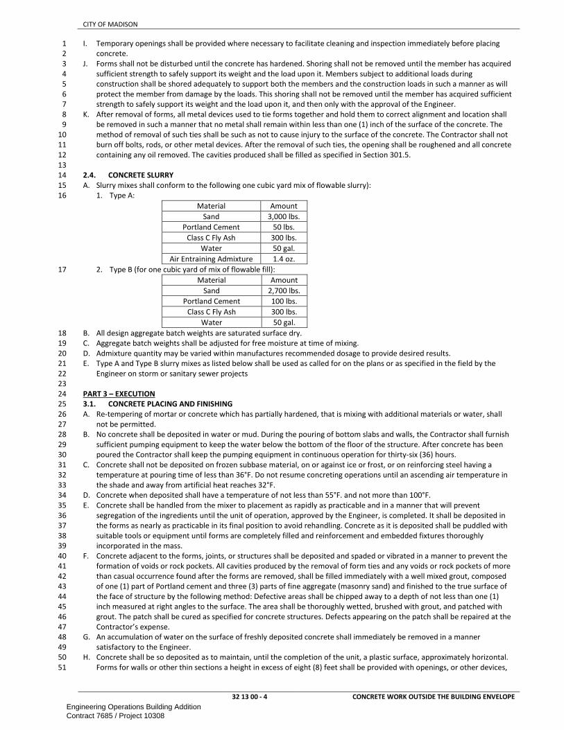
CITY OF MADISON
32 13 00 - 4 CONCRETE WORK OUTSIDE THE BUILDING ENVELOPE
I. Temporary openings shall be provided where necessary to facilitate cleaning and inspection immediately before placing 1
concrete. 2
J. Forms shall not be disturbed until the concrete has hardened. Shoring shall not be removed until the member has acquired 3
sufficient strength to safely support its weight and the load upon it. Members subject to additional loads during 4
construction shall be shored adequately to support both the members and the construction loads in such a manner as will 5
protect the member from damage by the loads. This shoring shall not be removed until the member has acquired sufficient 6
strength to safely support its weight and the load upon it, and then only with the approval of the Engineer. 7
K. After removal of forms, all metal devices used to tie forms together and hold them to correct alignment and location shall 8
be removed in such a manner that no metal shall remain within less than one (1) inch of the surface of the concrete. The 9
method of removal of such ties shall be such as not to cause injury to the surface of the concrete. The Contractor shall not 10
burn off bolts, rods, or other metal devices. After the removal of such ties, the opening shall be roughened and all concrete 11
containing any oil removed. The cavities produced shall be filled as specified in Section 301.5. 12
13
2.4. CONCRETE SLURRY 14
A. Slurry mixes shall conform to the following one cubic yard mix of flowable slurry): 15
1. Type A: 16
Material Amount
Sand 3,000 lbs.
Portland Cement 50 lbs.
Class C Fly Ash 300 lbs.
Water 50 gal.
Air Entraining Admixture 1.4 oz.
2. Type B (for one cubic yard of mix of flowable fill): 17
Material Amount
Sand 2,700 lbs.
Portland Cement 100 lbs.
Class C Fly Ash 300 lbs.
Water 50 gal.
B. All design aggregate batch weights are saturated surface dry. 18
C. Aggregate batch weights shall be adjusted for free moisture at time of mixing. 19
D. Admixture quantity may be varied within manufactures recommended dosage to provide desired results. 20
E. Type A and Type B slurry mixes as listed below shall be used as called for on the plans or as specified in the field by the 21
Engineer on storm or sanitary sewer projects 22
23
PART 3 – EXECUTION 24
3.1. CONCRETE PLACING AND FINISHING 25
A. Re-tempering of mortar or concrete which has partially hardened, that is mixing with additional materials or water, shall 26
not be permitted. 27
B. No concrete shall be deposited in water or mud. During the pouring of bottom slabs and walls, the Contractor shall furnish 28
sufficient pumping equipment to keep the water below the bottom of the floor of the structure. After concrete has been 29
poured the Contractor shall keep the pumping equipment in continuous operation for thirty-six (36) hours. 30
C. Concrete shall not be deposited on frozen subbase material, on or against ice or frost, or on reinforcing steel having a 31
temperature at pouring time of less than 36°F. Do not resume concreting operations until an ascending air temperature in 32
the shade and away from artificial heat reaches 32°F. 33
D. Concrete when deposited shall have a temperature of not less than 55°F. and not more than 100°F. 34
E. Concrete shall be handled from the mixer to placement as rapidly as practicable and in a manner that will prevent 35
segregation of the ingredients until the unit of operation, approved by the Engineer, is completed. It shall be deposited in 36
the forms as nearly as practicable in its final position to avoid rehandling. Concrete as it is deposited shall be puddled with 37
suitable tools or equipment until forms are completely filled and reinforcement and embedded fixtures thoroughly 38
incorporated in the mass. 39
F. Concrete adjacent to the forms, joints, or structures shall be deposited and spaded or vibrated in a manner to prevent the 40
formation of voids or rock pockets. All cavities produced by the removal of form ties and any voids or rock pockets of more 41
than casual occurrence found after the forms are removed, shall be filled immediately with a well mixed grout, composed 42
of one (1) part of Portland cement and three (3) parts of fine aggregate (masonry sand) and finished to the true surface of 43
the face of structure by the following method: Defective areas shall be chipped away to a depth of not less than one (1) 44
inch measured at right angles to the surface. The area shall be thoroughly wetted, brushed with grout, and patched with 45
grout. The patch shall be cured as specified for concrete structures. Defects appearing on the patch shall be repaired at the 46
Contractor’s expense. 47
G. An accumulation of water on the surface of freshly deposited concrete shall immediately be removed in a manner 48
satisfactory to the Engineer. 49
H. Concrete shall be so deposited as to maintain, until the completion of the unit, a plastic surface, approximately horizontal. 50
Forms for walls or other thin sections a height in excess of eight (8) feet shall be provided with openings, or other devices, 51
Engineering Operations Building AdditionContract 7685 / Project 10308

CITY OF MADISON
32 13 00 - 5 CONCRETE WORK OUTSIDE THE BUILDING ENVELOPE
that will permit the concrete to be placed in a manner that will avoid accumulation of hardened concrete on the forms or 1
metal reinforcement. Under no circumstances shall concrete that has partially hardened be deposited in the work. 2
I. When concrete is conveyed by chuting, the mixer shall be of such size and design as to insure a practically continuous flow 3
in the chute. The angle of the chute with the horizontal shall be such as to allow the concrete to flow without separation of 4
the ingredients. An angle of twenty-seven (27) degrees, or one (1) vertical to two (2) horizontal, is the minimum slope 5
which is considered permissible. Chuting through a vertical pipe is satisfactory when the lower end of the pipe is 6
maintained four (4) feet or less above the surface of the deposit. The delivery end of the chute shall be within four (4) feet 7
of the point of deposit. When the operation is intermittent, the spout shall discharge into a hopper. The chute shall be 8
thoroughly flushed with water before and after each run; the water used for this purpose shall be discharged outside the 9
forms but not into paved streets, walks, gutters or inlets. 10
J. All reinforced concrete shall be vibrated in place to the satisfaction of the Engineer with mechanical vibrators. Vibrators 11
shall also be required for non-reinforced concrete structures when other methods of compaction or “puddling” do not give 12
the desired results in the opinion of the Engineer. 13
K. Before depositing new concrete on or against concrete which has been set, the forms shall be retightened, the surface of 14
the set concrete shall be roughened as required by the Engineer, thoroughly cleaned of foreign material and saturated with 15
water. 16
L. Joints not indicated on the plans shall be so designed and located as to least impair the strength and appearance of the 17
structure. All joints shall provide sufficient resistance to shear to which they may be subjected. Horizontal joints required to 18
be watertight shall be constructed by forming continuous keyways in the lower portion of the concrete before the concrete 19
has hardened. Before placing the superimposed concrete, the joint shall be thoroughly cleaned of foreign material and 20
saturated with water. Vertical joints required to be watertight, and expansion joints shall be provided with suitable 21
keyways subject to the approval of the Engineer. 22
M. Top surfaces of roof slabs, unless otherwise specified, shall be smoothed with a wood float. Care shall be taken to avoid an 23
excess of water in the concrete, and to drain or otherwise promptly remove any water that comes to the surface. Dry 24
cement or a dry mixture of cement and sand, shall not be sprinkled directly on the surface. 25
N. Top surfaces of concrete floor slabs, unless otherwise specified, shall be wood floated and then troweled with a steel hand 26
trowel or a mechanically operated steel trowel to a smooth, dense finish. Steel troweling shall be done after the water has 27
disappeared from the surface. 28
O. Unless otherwise specified, all edges of concrete along joints and forms shall be finished with a steel edging tool of one-29
fourth (1/4) inch radius. 30
P. Where concrete is to be placed in two lifts, as for cunettes, pavements, and other structures with wire mesh 31
reinforcements, the concrete for the lower lift shall be placed, the required reinforcement positioned and secured and the 32
upper lift of concrete placed. Any portion of the lower lift of concrete not covered with the upper lift of concrete within 33
thirty (30) minutes after being placed, shall be removed. 34
Q. Concreting operations shall be discontinued due to insufficient natural light, unless an adequate and approved artificial 35
lighting system is provided and operated. 36
R. CURING: Exposed surfaces shall be protected from drying for a period of at least seven (7) days as per Section 415.3.12 of 37
the latest edition of the Standard Specifications for Highway and Structure Construction of the State of Wisconsin, 38
Department of Transportation, except as modified herein or in the Special Provisions of the contract. Curing compound 39
shall be white pigmented. 40
41
3.2. PROTECTION OF THE CONCRETE 42
A. COLD WEATHER PROTECTION: 43
1. All concrete used for sidewalk, curb and gutter, pavement, bridges, culverts, retaining walls, access structures, 44
catchbasins, inlets, or any other structure consisting wholly or in part of concrete, when placed during cold weather 45
shall be mixed, placed, and protected in accordance with the requirements prescribed in Subsection 501.3.9 “Mixing 46
and Protection During Cold Weather” of Standard Specifications for Highway and Structure Construction of the State of 47
Wisconsin, Department of Transportation. Section 415.3.15.2 of the Standard Specifications for Highway and Structure 48
Construction of the State of Wisconsin, Department of Transportation shall be revised as follows: 49
Predicted or Actual Temperature Minimum Equivalent Level of Protection
22 to32°F (-6 to 0°C) single layer of polyethylene
17 to 22°F (-8 to -6°C double layer of polyethylene
<17°F (<-8°C) 6” of loose dry straw or hay between 2 layers of polyethylene
2. Regardless of the precautions taken, the Contractor shall be responsible for the protection of the concrete placed, and 50
any concrete damaged by freezing or frost action during the first seven (7) days following its placement shall be 51
removed and replaced by the Contractor at the Contractor’s expense. 52
3. Under no circumstances shall concrete be ordered or delivered for the project, until such time as the equipment and 53
materials for protecting and heating the concrete, as described above, are on the job site in sufficient quantity to obtain 54
the desired results. 55
B. Opening Curb and Gutter, Sidewalk, Driveways, and Pavements to Traffic. 56
1. Traffic shall be excluded over or on newly constructed curb and gutter, sidewalk, driveways, and pavements for such 57
periods as are hereinafter designated. Where the term “pavement” appears below, it shall be taken to refer to the 58
particular type of construction involved. 59
Engineering Operations Building AdditionContract 7685 / Project 10308

CITY OF MADISON
32 13 00 - 6 CONCRETE WORK OUTSIDE THE BUILDING ENVELOPE
2. The Engineer reserves the right to determine the time when the pavement shall be opened to traffic either on the basis 1
of test cylinders or minimum time periods related to atmospheric temperatures. 2
3. When opening of the pavement to traffic is controlled by cylinder tests, the pavement may be opened, after expiration 3
of the curing period or cold weather protection period, as the case may be, when the tests of cylinders show a 4
compressive strength of the concrete of not less than 3,000 pounds per square inch. 5
4. At least two cylinders shall be tested in determining the attained strength of concrete for the purpose of opening the 6
pavement to traffic. The average of test results for the two cylinders shall be used to determine compliance, except that 7
neither cylinder may be more than ten percent below the required strength. The cylinders shall be cured under 8
conditions similar to those prevailing for the pavement which they represent. 9
5. When the opening is not controlled by cylinder tests, traffic shall be excluded from the newly constructed pavement for 10
such minimum periods as hereinafter designated: 11
a. For not less than seven (7) days when the atmospheric temperatures are generally 70°F. or higher during the 12
period. 13
b. For not less than ten days when the atmospheric temperatures are generally not lower than 60°F. during the 14
period. 15
c. For not less than such a length of time up to twenty-one (21) days as the Engineer may require, taking into 16
consideration the temperatures and protective measures, if any, when the atmospheric temperatures are generally 17
lower than 60°F. 18
6. When High-Early-Strength Concrete is used in the work, the above specific periods of seven (7), ten (10) and twenty-19
one (21) days may be reduced to three (3), four (4) and seven (7) days, respectively, under like conditions. 20
7. When Grade A-FA Concrete is used in the work, the specific periods of seven (7) and ten (10) days shall be increased to 21
ten (10) and fourteen (14) days respectively, under like conditions. 22
8. In all cases the pavement shall be cleaned, and the joints shall be cleaned and sealed as provided, before traffic of any 23
kind is permitted to use the pavement. 24
C. Catchbasins, Access Structures, and Headwalls 25
1. Traffic on or over these structures shall be curtailed until the concrete has reached full strength\ 26
2. Backfilling may proceed after seven (7) days for air entrained concrete or three (3) days for High-27
Early-Strength concrete. When the Contractor desires to backfill prior to the times specified then 28
the Contractor shall do so at the Contractor’s own risk. 29
30
END OF SECTION 31
Engineering Operations Building AdditionContract 7685 / Project 10308

CITY OF MADISON
32 16 13 - 1 CONCRETE CURB AND GUTTER
SECTION 32 16 13 1
CONCRETE CURB AND GUTTER 2
3
PART 1 – GENERAL ............................................................................................................................................................................ 1 4
1.1. SCOPE ............................................................................................................................................................................ 1 5
1.2. REFERENCES .................................................................................................................................................................. 1 6
PART 2 – EXECUTION ......................................................................................................................................................................... 1 7
2.1. PREPARATION OF FOUNDATION ................................................................................................................................... 1 8
2.2. FORMS ........................................................................................................................................................................... 1 9
2.3. PLACING AND FINISHING CONCRETE ............................................................................................................................ 1 10
2.4. JOINTS ........................................................................................................................................................................... 2 11
2.5. REINFORCEMENT .......................................................................................................................................................... 2 12
2.6. PROTECTION ................................................................................................................................................................. 2 13
2.7. HAND FORMED CURB AND GUTTER (TREE LOCATIONS - UNDISTURBED) ..................................................................... 2 14
15
PART 1 – GENERAL 16
1.1. SCOPE 17
A. This section includes information common to concrete curb and gutter and applies to all sections in this Division. 18
B. This work shall consist of constructing concrete curb and gutter, with or without reinforcement, of the dimensions and 19
design as indicated, and placed in one course on the prepared foundation or base, at the locations and to the required lines 20
and grades. 21
C. The Contractor shall mark the top of the curb where the sanitary sewer and water service cross the curb and gutter. The 22
mark may be made by sawcutting. The depth shall be a minimum of one-sixteenth (1/16”) inch deep. The laterals and 23
services will be located by the City. 24
D. All work done in the vicinity of any tree located in the terrace shall be completed in accordance with City of Madison 25
Standard Specifications for Public Works Construction Section 107.13 Tree Protection. 26
27
1.2. REFERENCES 28
A. Work under this section depends on applicable provisions from other sections and the plan set in this contract. Examples of 29
related sections include, but are not limited to: 30
1. DIVISION 03 — CONCRETE 31
2. DIVISION 31 — EARTHWORK 32
3. 32 13 00 - CONCRETE WORK OUTSIDE THE BUILDING ENVELOPE 33
B. City of Madison Standard Specifications for Public Works Construction 34
35
PART 2 – EXECUTION 36
2.1. PREPARATION OF FOUNDATION 37
A. The Contractor shall be responsible for replacement with 1-1/2” crushed stone, mechanically compacted, of any material 38
necessary to bring the subbase to grade, where the Contractor has undercut the subbase without the direction of the 39
Engineer. 40
41
2.2. FORMS 42
A. Curb and gutter forms shall be of steel construction and conform to the design of the type of curb and gutter being 43
installed. Wooden forms may be used only with the Engineer’s approval on short radius curves and in special cases where 44
accessibility is limited. All forms shall be free of hardened concrete, mud, dirt, and debris, and shall be free of bends and 45
twists which would make their use unacceptable on the project. 46
B. All forms shall be oiled to the satisfaction of the Engineer before depositing or placing concrete in them. 47
C. When concrete curb and gutter is constructed on a curve, flexible forms shall be used for all curves having a radius of two 48
hundred (200) linear feet or less. 49
50
2.3. PLACING AND FINISHING CONCRETE 51
A. Wherever directed by the Engineer, driveway gutters shall be built instead of regular curb and gutters. 52
B. The curb and gutter over ditches shall be installed in twenty (20) foot lengths centered over the ditch. A dummy joint shall 53
be cut at the center of the 20 foot section. 54
C. Unless otherwise specified, curb and gutter shall be installed in minimum lengths of six (6) feet and maximum lengths of 15 55
feet. 56
D. The Contractor shall install a header at the end of each pour. At no time shall the Contractor be allowed to spread excess 57
concrete as a base for the next or any succeeding pour. 58
E. Wherever different types of curb and gutter are employed, the Contractor shall take care that transitions from one type of 59
curb and gutter to another type are done smoothly without loss of flow line grade or curb head shape. 60
F. The reconnection of existing drains from adjacent properties to the curb and gutter shall be incidental to concrete curb and 61
gutter. 62
G. The slope of the curb and gutter shall not exceed 1” in 12” thru handicap accessible ramps. 63
64
Engineering Operations Building AdditionContract 7685 / Project 10308

CITY OF MADISON
32 16 13 - 2 CONCRETE CURB AND GUTTER
2.4. JOINTS 1
A. Full contraction joints shall be a minimum of three (3) inches in depth, and shall be uniformly spaced not less than six (6) 2
feet nor more than fifteen (15) feet apart unless otherwise directed by the Engineer. 3
B. If machine methods are used for forming and finishing curb and gutter the Contractor may saw contraction joints or planes 4
of weakness may be created by the insertion of approved partial depth separator plates having a minimum depth of three 5
(3) inches. The depth of cut and equipment used in sawing shall meet the approval of the Engineer. The sawing shall be 6
done as soon as practicable after the concrete has set sufficiently to preclude raveling during the sawing and before any 7
shrinkage cracking takes place in the concrete. If this method results in random cracking the Contractor shall be required to 8
use the partial depth separator plates. 9
C. Transverse expansion joints shall be one-half (1/2) inch in width and shall be placed across the curb and gutter 10
perpendicular to the curb line at all radius points of curves having a radius of two hundred (200) feet or less, and on both 11
sides of all inlets installed in curb and gutter. All expansion joints shall extend through the entire thickness of the curb and 12
gutter and shall be perpendicular to the surface. All expansion joints shall be formed by inserting during construction, and 13
leaving in place, the required thickness of joint filler which shall extend through the entire thickness of both curb and 14
gutter. 15
D. Where curb and gutter and concrete sidewalk or concrete driveways join, an expansion joint one (1) inch in width must be 16
constructed between walks and curb. 17
E. The joint filler in transverse joints shall be flush with the finished surface of the gutter. The concrete adjacent to these joints 18
shall be finished with a wooden float which is divided through the center and which will permit finishing on both sides of 19
the filler at the same time. Before the curb and gutter is opened to traffic, excess joint filler shall be cut off level with the 20
finished surface. 21
22
2.5. REINFORCEMENT 23
A. Where reinforcement is required it shall conform to and be placed in accordance with the Standard Detail Drawings, details 24
shown on the plans, as specified in the contract, or as directed by the Engineer. 25
B. Where directed by the Engineer, the Contractor shall install three (3) one-half (1/2) inch round reinforcing rods fifteen (15) 26
feet long in concrete curbs and gutters which span ditches. 27
28
2.6. PROTECTION 29
A. The curb and gutter must be protected from injury by traffic or other causes, and also from the rays of the sun until 30
completely set. 31
B. In the event that concrete sidewalk, drives or curb and gutter are placed in cold weather, “Cold Weather Protection”shall 32
be applied in accordance with The City of Madison Standard Specifications, Section 301.8(a) “Cold Weather Protection.” 33
34
2.7. HAND FORMED CURB AND GUTTER (TREE LOCATIONS - UNDISTURBED) 35
A. The work under this item shall consist of manually forming and pouring curb and gutter at tree locations or where other 36
structures prevent the use of a curb machine, as designated by the Engineer. Where the item Hand Formed Curb and Gutter 37
is to be used in the vicinity of any tree located in the terrace, work shall be completed in accordance with section 107.13 38
Tree Protection Specification. 39
40
END OF SECTION 41
Engineering Operations Building AdditionContract 7685 / Project 10308

CITY OF MADISON
32 31 19 - 1 METAL FENCES AND GATES
SECTION 32 31 19 1
METAL FENCES AND GATES 2
3
PART 1 – GENERAL ............................................................................................................................................................................ 1 4
1.1. SCOPE ............................................................................................................................................................................ 1 5
1.2. REFERENCES .................................................................................................................................................................. 1 6
1.3. SUBMITTALS .................................................................................................................................................................. 1 7
1.4. WARRANTY .................................................................................................................................................................... 1 8
PART 2 - PRODUCTS .......................................................................................................................................................................... 1 9
2.1. FENCE ............................................................................................................................................................................ 1 10
2.2. GATE .............................................................................................................................................................................. 2 11
PART 3 – EXECUTION ......................................................................................................................................................................... 3 12
3.1. FENCE INSTALLATION .................................................................................................................................................... 3 13
3.2. GATE INSTALLATION...................................................................................................................................................... 3 14
3.3. FENCE DETAIL ................................................................................................................................................................ 4 15
3.4. GATE DETAIL .................................................................................................................................................................. 4 16
17
PART 1 – GENERAL 18
1.1. SCOPE 19
A. This section includes information common to metal fences and gates. 20
21
1.2. REFERENCES 22
A. Work under this section depends on applicable provisions from other sections and the plan set in this contract. Examples of 23
related sections include, but are not limited to: 24
1. 31 00 00 - EARTHWORK 25
2. 03 00 00 – CONCRETE 26
B. ASTM - American Society for Testing and Materials 27
1. ASTM A653/A653M - Standard Specification for Steel Sheet, Zinc-Coated (Galvanized) or Zinc-Iron Alloy Coated 28
(Galvannealed) by the Hot-Dip Process. 29
2. ASTM B117 - Practice for Operating Salt-Spray (Fog) Apparatus. 30
3. ASTM B221 - Aluminum and Aluminum-Alloy Extruded Bars, Rods, Wire, Profiles and Tubes. 31
4. ASTM D523 - Test Method for Specular Gloss. 32
5. ASTM D714 - Test Method for Evaluating Degree of Blistering in Paint. 33
6. ASTM D822 - Practice for Conducting Tests on Paint and Related Coatings and Materials using Filtered Open-Flame 34
Carbon-Arc Light and Water Exposure Apparatus. 35
7. ASTM D1654 - Test Method for Evaluation of Painted or Coated Specimens Subjected to Corrosive Environments. 36
8. ASTM D2244 - Test Method for Calculation of Color Differences from Instrumentally Measured Color Coordinates. 37
9. ASTM D2794 - Test Method for Resistance of Organic Coatings to the Effects of Rapid Deformation (Impact). 38
10. ASTM D3359 - Test Method for Measuring Adhesion by Tape Test. 39
11. ASTM F2408 – Ornamental Fences Employing Galvanized Steel Tubular Pickets. 40
12. ASTM F1184 – Industrial & Commercial Horizontal Slide Gates 41
42
1.3. SUBMITTALS 43
A. The manufacturer’s submittal package consisting of fence and gate elevations, hardware details, and installation details, 44
shall be submitted prior to installation. 45
46
1.4. WARRANTY 47
A. All structural fence components (i.e. rails, pickets, and posts) shall be warranted within specified limitations, by the 48
manufacturer for a period of 20 years from date of original purchase. Warranty shall cover any defects in material finish, 49
including cracking, peeling, chipping, blistering or corroding. 50
B. Reimbursement for labor necessary to restore or replace components that have been found to be defective under the 51
terms of manufactures warranty shall be guaranteed for 5 years from date of original purchase. 52
53
PART 2 - PRODUCTS 54
2.1. FENCE 55
A. BASIS OF DESIGN: Ameristar® Montage Industrial Welded and Rackable (ATF – All Terrain Flexibility) Ornamental Steel, 56
Genesis design, extended picket bottom rail treatment, 3-Rail style. 57
B. Height: 8’0” 58
C. Color: Black 59
D. Steel material for fence panels and posts shall conform to the requirements of ASTM A653/A653M, with a minimum yield 60
strength of 45,000 psi (344 MPa) and a minimum zinc (hot-dip galvanized) coating weight of 0.60 oz/ft2 (184 g/m2), Coating 61
Designation G-60. A minimum of 62% of the steel material shall be derived from recycled scrap metal. 62
E. Material for pickets shall be 1” square x 16 Ga. tubing. The rails shall be steel channel, 1.75” x 1. 75” x .105”. Picket holes in 63
the rail shall be spaced 4.715” o.c. For fence systems up to and including 6 feet tall, posts shall be a minimum of 2-1/2” 64
Engineering Operations Building AdditionContract 7685 / Project 10308

CITY OF MADISON
32 31 19 - 2 METAL FENCES AND GATES
square x 14 Ga. For fence systems 7 feet tall and 8’ tall, posts shall be a minimum of 2-1/2” square x 12 Ga. Gate posts 1
shall meet the minimum requirements of Table 1. 2
F. Pickets, rails and posts shall be pre-cut to specified lengths. Rails shall be pre-punched to accept pickets. 3
G. Pickets shall be inserted into the pre-punched holes in the rails and shall be aligned to standard spacing using a specially 4
calibrated alignment fixture. The aligned pickets and rails shall be joined at each picket-to-rail intersection by Ameristar’s 5
proprietary fusion welding process, thus completing the rigid panel assembly (Note: The process produces a virtually 6
seamless, spatter-free good-neighbor appearance, equally attractive from either side of the panel). 7
H. The manufactured panels and posts shall be subjected to an inline electrodeposition coating (E-Coat) process consisting of a 8
multi-stage pretreatment/wash (with zinc phosphate), followed by a duplex application of an epoxy primer and an acrylic 9
topcoat. The minimum cumulative coating thickness of epoxy and acrylic shall be 2 mils (0.058 mm). The color shall be 10
Black. The coated panels and posts shall be capable of meeting the performance requirements for each quality 11
characteristic shown in Table 2 (Note: The requirements in Table 2 meet or exceed the coating performance criteria of 12
ASTM F2408). 13
Table 2 – Coating Performance Requirements
UQuality Characteristics UASTM Test Method UPerformance Requirements
Adhesion D3359 – Method B Adhesion (Retention of Coating) over 90% of test area (Tape and knife test).
Corrosion Resistance B117, D714 & D1654 Corrosion Resistance over 1,500 hours (Scribed per D1654; failure mode is
accumulation of 1/8” coating loss from scribe or medium #8 blisters).
Impact Resistance D2794 Impact Resistance over 60 inch lb. (Forward impact using 0.625” ball).
Weathering Resistance D822 D2244, D523 (60˚ Method) Weathering Resistance over 1,000 hours (Failure mode is 60% loss of
gloss or color variance of more than 3 delta-E color units).
I. The manufactured fence system shall be capable of meeting the vertical load, horizontal load, and infill performance 14
requirements for Industrial weight fences under ASTM F2408. 15
16
2.2. GATE 17
A. BASIS OF DESIGN: Ameristar® TransPort II gate system, Genesis style. 18
B. Height: 8’0” 19
C. Width: 30’0” 20
D. Color: Black 21
E. The materials used for cantilever gate framing (i.e., uprights, diagonal braces and pickets or pales) shall be manufactured 22
from ASTM B221 aluminum (designation 6063-T-6) with a yield strength of 25,000 PSI, a tensile strength of 30,000 PSI and a 23
standard mill finish. The TransPort® Fast-Trak™ rails shall be manufactured from ASTM B221 aluminum (designation 6063-T-24
6) with minimum yield strength of 25,000 PSI, a tensile strength of 30,000 PSI and a standard mill finish. 25
F. Material for diagonal bracing and uprights shall be 2” sq. x ¼” aluminum. The design of the top and bottom enclosed track 26
shall conform to the manufacturers 5” x 2” Fast-Trak system. Material for pickets shall be 1” x 1/8” wall aluminum. 27
G. Internal roller truck assembly shall be self-aligning swivel ball-and-socket type running on four bearing wheels. Internal 28
roller truck assembly shall be affixed to the hanger bracket by means of a 5/8” diameter industrial-grade rod end/center 29
bolt, with a minimum static load rating of 10,000 pounds. Attachment of the center bolt to the truck body shall be by 30
means of a swivel joint to ensure equivalent and consistent loading on all bearing wheels and internal track surfaces 31
throughout the travel of the gate. 32
H. Pickets, enclosed track, uprights and diagonal bracing shall be pre-drilled and labeled for easy assembly. All components 33
shall be precut to specified lengths. 34
I. Top and bottom rail extrusions shall be mechanically fastened to vertical uprights and reinforced with diagonal braces, as 35
required by drawing. 36
J. The manufactured components shall be subjected to the Ameristar thermal stratification coating process (high-37
temperature, in-line, multi-stage, and multi-layer) including, as a minimum, a six-stage pretreatment/wash and an 38
electrostatic spray application of a polyester finish. The topcoat shall be a “no-mar” TGIC polyester powder coat finish with 39
a minimum thickness of 2 mils (0.0508mm). The color shall Black. The stratification-coated framework shall be capable of 40
meeting the performance requirements for each quality characteristic shown in Table 3. 41
Table 3 – Coating Performance Requirements
Quality Characteristics ASTM Test Method Performance Requirements
Table 1 – Minimum Sizes for Montage Industrial Posts
UFence Posts UPanel Height
2-1/2” x 14 Ga. Up to & Including 6’ Height
2-1/2” x 12 Ga. Over 6’ Up to & Including 8’ Height
UGate Leaf UGate Height
UUp to & Including 4’ UOver 4’ Up to & Including 6’ UOver 6’ Up to & Including 8’
Up to 4’ 2-1/2” x 12 Ga. 3” x 12 Ga. 3” x 12 Ga.
4’1” to 6’ 3” x 12Ga. 4” x 11 Ga. 4” x 11 Ga.
6’1” to 8’ 3” x 12 Ga. 4” x 11 Ga. 6” x 3/16”
8’1” to 10’ 4” x 11 Ga. 6” x 3/16” 6” x 3/16”
10’1” to 12’ 4” x 11 Ga. 6” x 3/16” 6” x 3/16”
12’1” to 14’ 4” x 11 Ga. 6” x 3/16” 6” x 3/16”
14’1” to 16’ 6” x 3/16” 6” x 3/16” 6” x 3/16”
Engineering Operations Building AdditionContract 7685 / Project 10308

CITY OF MADISON
32 31 19 - 3 METAL FENCES AND GATES
Adhesion D3359 – Method B Adhesion (Retention of Coating) over 90% of test area (Tape and knife
test).
Corrosion Resistance B117, D714 & D1654 Corrosion Resistance over 3,500 hours (Scribed per D1654; failure
mode is accumulation of 1/8” coating loss from scribe or medium #8
blisters).
Impact Resistance D2794 Impact Resistance over 60 inch lb. (Forward impact using 0.625” ball).
Weathering Resistance D822 D2244, D523 (60˚ Method) Weathering Resistance over 1,000 hours (Failure mode is 60% loss of
gloss or color variance of more than 3 delta-E color units).
1
PART 3 – EXECUTION 2
3.1. FENCE INSTALLATION 3
A. All new installation shall be laid out by the contractor in accordance with the construction plans. 4
B. Fence post shall be spaced according to Table 4, plus or minus ½”. For installations that must be raked to follow sloping 5
grades, the post spacing dimension must be measured along the grade. Fence panels shall be attached to posts with 6
brackets supplied by the manufacturer. Posts shall be set in concrete footers having a minimum depth of 36” (Note: In 7
some cases, local restrictions of freezing weather conditions may require a greater depth). The “Earthwork” and 8
“Concrete” sections of this specification shall govern material requirements for the concrete footer. Posts setting by other 9
methods such as plated posts or grouted core-drilled footers are permissible only if shown by engineering analysis to be 10
sufficient in strength for the intended application. 11
Table 4 – Montage Industrial – Post Spacing By Bracket Type
Span For CLASSIC, GENESIS, & MAJESTIC 8’ Nominal (92-5/8” Rail)
Post Size 2-1/2” 3” 2-1/2” 3” 2-1/2” 3”
Bracket Type Industrial
Universal
2.5” (BB302)
3” (BB303)
Industrial
Flat Mount
(BB301)
Industrial
Swivel
(BB304)*
Post Settings
± ½” O.C. 96” 96-1/2” 96” 96-1/2” *96” *96-1/2”
*Note: When using BB304 swivel brackets on either or both ends of a panel installation, care must be taken to ensure the spacing between post and
adjoining pickets meets applicable codes. This will require trimming one or both ends of the panel. When using the BB301 flat mount bracket for
Invincible style, rail may need to be drilled to accommodate rail to bracket attachment.
C. When cutting/drilling rails or posts adhere to the following steps to seal the exposed steel surfaces; 1) Remove all metal 12
shavings from cut area. 2) Apply zinc-rich primer to thoroughly cover cut edge and/or drilled hole; let dry. 3) Apply 2 coats 13
of custom finish paint matching fence color. Failure to seal exposed surfaces per steps 1-3 above will negate warranty. 14
Ameristar spray cans or paint pens shall be used to prime and finish exposed surfaces; it is recommended that paint pens 15
be used to prevent overspray. Use of non-Ameristar parts or components will negate the manufactures’ warranty. 16
17
3.2. GATE INSTALLATION 18
A. All new gate installations shall be laid out by the contractor in accordance with the construction plans. 19
B. All hardware shall be installed in accordance with the Transport installation instructions. Transport cantilever gates shall be 20
installed so they comply with current ASTM F2200 & UL325 standards. 21
C. Gate post shall be spaced according to specified gate elevation. Posts shall be set in concrete footers having a minimum 22
depth of 48” with a minimum diameter of 12” (Note: In some cases, local restrictions of freezing weather conditions may 23
require a greater depth). The “Earthwork” and “Concrete” sections of this specification shall govern material requirements 24
for the concrete footer. Posts setting by other methods such as plated posts or grouted core-drilled footers are permissible 25
only if shown by engineering analysis to be sufficient in strength for the intended application. 26
27
Engineering Operations Building AdditionContract 7685 / Project 10308

CITY OF MADISON
3.3. FENCE DETAIL 1
2 3.4. GATE DETAIL 3
4 5
6
32 31 19 - 4
END OF SECTION
METAL FENCES AND GATES
Engineering Operations Building AdditionContract 7685 / Project 10308

CITY OF MADISON
33 11 00 - 1 WATER UTILITY DISTRIBUTION PIPING
SECTION 33 11 00 1
WATER UTILITY DISTRIBUTION PIPING 2
3
PART 1 – GENERAL ............................................................................................................................................................................ 1 4
1.1. SCOPE ............................................................................................................................................................................ 1 5
1.2. REFERENCES .................................................................................................................................................................. 1 6
1.3. SUBMITTALS .................................................................................................................................................................. 2 7
PART 2 - PRODUCTS .......................................................................................................................................................................... 2 8
2.1. DUCTILE IRON WATERMAIN .......................................................................................................................................... 2 9
2.2. VALVES .......................................................................................................................................................................... 3 10
2.3. HYDRANTS ..................................................................................................................................................................... 3 11
2.4. POLYETHYLENE ENCASEMENT BAG ............................................................................................................................... 3 12
2.5. BOARD INSULATION ...................................................................................................................................................... 4 13
2.6. LOCATOR TAPE .............................................................................................................................................................. 4 14
2.7. TRACER WIRE ................................................................................................................................................................ 4 15
2.8. CHLORINE ...................................................................................................................................................................... 4 16
PART 3 – EXECUTION ......................................................................................................................................................................... 4 17
3.1. INSTALLATION ............................................................................................................................................................... 4 18
3.2. CONTINUITY OF EXISTING WATER DISTRIBUTION SYSTEM ........................................................................................... 4 19
3.3. CONNECTIONS TO EXISTING WATERMAINS/TAPPING .................................................................................................. 4 20
3.4. BEDDING AND INITIAL COVER ....................................................................................................................................... 5 21
3.5. LAYING WATERMAIN..................................................................................................................................................... 5 22
3.6. INSTALLING FITTINGS, VALVES AND HYDRANTS ........................................................................................................... 5 23
3.7. FILLLING WATERMAIN ................................................................................................................................................... 6 24
3.8. TESTING AND DISINFECTION ......................................................................................................................................... 6 25
26
PART 1 – GENERAL 27
1.1. SCOPE 28
A. This section includes information common to water distribution system components and applies to all sections in this 29
Division. 30
B. Madison Water Utility shall be involved in the following tasks, but are not necessarily limited to, water main filling, flushing, 31
testing, and live-tap installations. Schedule all Water Utility supplemental construction services to occur between the hours 32
of 7:00 AM and 3:00 PM, Monday through Friday. Requests for construction services occurring outside of these hours will 33
be subject to any associated overtime charges being billed to the Contractor. Madison Water Utility reserves the right to 34
decline any construction services which are requested to occur outside of the approved hours. No live-tap installations shall 35
be scheduled to occur outside of the approved hours unless authorized in writing by Madison Water Utility. 36
C. Contractor shall be solely responsible for obtaining all permits necessary to complete the work. Contractor shall pay all fees 37
associated with obtaining permits. These include, but are not limited to permits for work within public right-of-way, street 38
opening permits, testing, utility connection permits, plumbing permits and municipal fees for completing work (e.g. live 39
taps and water connections to City main). 40
D. Construct watermain system in a manner that will facilitate future extension or connection. 41
E. Review plans prior to installation, and notify Construction Representative if proposed design does not appear to 42
accommodate future extension or connection. 43
F. Unless otherwise shown on the plans provide valves on “dead end” mains that will allow dry connection to the watermain 44
system. Terminate “dead end” mains with full length of pipe beyond the valve, and a ell end with restrained plug. 45
G. Surveyor will provide benchmarks or control points for the project. 46
H. Contractor shall be responsible for transferring bench marks, control points, lines and grades necessary to complete his 47
work. 48
49
1.2. REFERENCES 50
A. Work under this section depends on applicable provisions from other sections and the plan set in this contract. Examples of 51
related sections include, but are not limited to: 52
1. DIVISION 22 — PLUMBING 53
2. DIVISION 31 — EARTHWORK 54
B. ASTM - American Society for Testing and Materials 55
1. ASTM B88 Standard Specifications for Seamless Copper Water Tube 56
2. ASTM F477 Standard Specifications for Elastomeric Gaskets for Joining Plastic Pipe 57
3. ASTM D3139 Standard Specifications for Joints for Plastic Pressure Pipes Using Flexible Elastomeric Seals 58
4. ASTM D3350 Standard Specifications for Polyethylene Plastic Pipe and Fittings 59
C. AWWA - American Water Works Association 60
1. AWWA C104/ANSI A21.4-95 Standard for Cement-Mortar Lining for Ductile-Iron Pipe and Fittings for Water 61
2. AWWA C105/ANSI A21.5-99 Standard for Polyethylene Encasement for Ductile-Iron Piping for Water and Other Liquids 62
3. AWWA C111/ANSI A21.11-00 Standard for Rubber-Gasket Joints for Ductile Iron Pressure Pipe and Fittings 63
4. AWWA C151/ANSI A21.51-02 Standard for Ductile Iron Pipe, Centrifugally Cast for Water or Other Liquids 64
Engineering Operations Building AdditionContract 7685 / Project 10308

CITY OF MADISON
33 11 00 - 2 WATER UTILITY DISTRIBUTION PIPING
5. AWWA C153/ANSI A21.53-00 Standard for Ductile Iron Compact Fittings for Water or Other Liquids 1
6. AWWA C502-94 Dry Barrel Fire Hydrants 2
7. AWWA C504-00 Rubber-Seated Butterfly Valves 3
8. AWWA C509-01 Resilient-Seated Gate Valves for Water Supply Service 4
9. AWWA C515-01 Reduced Wall, Resilient Seated Gate Valves for Water Supply Service 5
10. AWWA C550-01 Protective Epoxy Interior Coatings for Valves and Hydrants 6
11. AWWA C800-01 Underground Service Line Valves and Fittings 7
12. AWWA C900-97 Polyvinyl Chloride Pressure Pipe, and Fabricated Fittings for Water Distribution (4”-12”) 8
13. AWWA C905-97 Polyvinyl Chloride Pressure Pipe, and Fabricated Fittings for Water Distribution (14”-48”) 9
14. AWWA C906-99 Polyethylene Pressure Pipe, and Fabricated Fittings for Water Distribution (4”-63”) 10
11
1.3. SUBMITTALS 12
A. Provide manufacturers product information (cut sheets) and O&M information for watermain materials as indicated in 13
Section 31 00 05 Civil General Requirements including: 14
1. Pipe 15
2. Fittings 16
3. Valves 17
4. Hydrants 18
5. Joint Restraint Materials 19
B. Provide reports that document pressure and continuity testing procedures and results. 20
C. Provide reports that document safe sample collection procedures and results. 21
D. Provide copies of record drawings. 22
E. Maintain record drawings that show the actual locations, sizes and types of utilities and other features encountered. 23
F. Note any modifications to proposed watermain size, alignment, or grades. Record any other deviations from the original 24
design. 25
26
PART 2 - PRODUCTS 27
2.1. DUCTILE IRON WATERMAIN 28
A. Centrifugally cast, cement mortar lined ductile iron watermain meeting the requirements of ANSI/AWWA C151/A21.51 and 29
ANSI/AWWA C104/A21.4. 30
B. Unless otherwise specified, ductile watermain shall be Class 52 as defined by ANSI/AWWA C151/A21.51. 31
C. Ductile iron watermain joints shall be rubber gasket push-on joint or mechanical joint meeting the requirements of 32
ANSI/AWWA C111/A21.11. 33
D. Pipe shall be provided with conductive bonding straps to provide electrical continuity. 34
E. Pipe shall be manufactured in the United States. 35
F. DUCTILE IRON WATERMAIN FITTINGS 36
1. Cement mortar lined mechanical joint fittings. Fittings shall be compact style fittings meeting the requirements of 37
ANSI/AWWA C153/A21.53 38
2. Fittings shall be manufactured in the United States. 39
G. JOINT RESTRAINTS 40
1. Retainer Glands for Ductile Iron Pipe 41
2. Wedge action retainer glands designed for use with ductile iron pipe. 42
3. Glands shall be constructed of ductile iron. Restraint shall be provided by a minimum of three wedges which are 43
tightened onto the exterior of the pipe using a threaded, torque limiting mechanism. 44
4. Glands shall be tested to provide restraint at 250 psi operating pressure. 45
5. Retainer glands shall be MEGA-LUG by EBAA Iron, or approved equal. 46
6. Watermain Clamps 47
7. Steel clamps specifically fabricated for use in pipe restraint systems. Watermain clamps shall be selected based on size 48
of the main. 49
8. Watermain clamps shall be conducted of flat steel stock, ½” thick x 2” wide minimum dimensions. 50
9. Astral, or approved equal. 51
10. Watermain Clamp Hardware 52
11. Corrosion resistant steel hardwater specifically fabricated for use in pipe restraint systems. 53
12. Astral, or approved equal. 54
13. Threaded Rod for Joint Restraint 55
14. ¾ “ diameter, threaded rod. Rod shall be constructed of carbon steel having a minimum tensile strength of 30 ksi. Rod 56
shall be zinc plated. 57
15. Unless otherwise noted, all fittings (bends, tees, crosses, caps, etc.), valves and hydrants shall be installed with 58
restrained joints. Additionally, branch runs of pipe shall be installed with restrained joints beginning at the fitting at the 59
main to the first valve. 60
16. Hydrant leads shall be provided with restrained joints beginning at the fitting at the main to the hydrant. 61
17. Joint restraint shall be provided using retainer glands. 62
18. If approved by the Construction Representative, watermain clamps and threaded rod may be used as an alternative 63
means of joint restraint. 64
Engineering Operations Building AdditionContract 7685 / Project 10308

CITY OF MADISON
33 11 00 - 3 WATER UTILITY DISTRIBUTION PIPING
19. Install all joint restraint products in accordance with Manufacturer’s recommendations and drawings. 1
20. If approved for use, watermain clamps, threaded rod and associated hardware shall be fully encased in polyethylene 2
encasement bag. 3
H. PIPE JOINT LUBRICANT: Petroleum free pipe lubricant formulated for use with potable water systems. Product shall meet 4
the requirements of ANSI/NSF Standard #61. 5
6
2.2. VALVES 7
A. RESILIENT WEDGE GATE VALVE: 8
1. Resilient seated wedge gate valve meeting the requirements of AWWA C509 and C515. Body, bonnet and gate shall be 9
constructed of ductile iron. Bolts shall be stainless steel. 10
2. Interior and exterior surfaces of valve shall be provided with epoxy coating meeting the requirements of AWWA C550. 11
Symetrical wedge shall be completely incapsulated with resilient material. 12
3. Valve stem shall be non-rising bronze. Stem collar shall be provided with thrust bearings both above and below, that 13
are protected by upper and lower O-ring seals. 14
4. Valve shall be left opening and be provided with standard 2” square operating nut. 15
5. Valve shall be provided with mechanical joint connections. 16
6. Mueller (A2360), Kennedy (K4571), American Flow Control (Series 500 or Series 2500), Clow (F6100), or approved equal. 17
B. TAPPING VALVE: 18
1. Resilient seated wedge gate tapping valve having 100% port, and meeting the requirements of AWWA C509 and C515 19
as well as Madison Water Utility. Body, bonnet and gate shall be constructed of ductile iron. Bolts shall be stainless 20
steel. 21
2. Interior and exterior surfaces of valve shall be provided with epoxy coating meeting the requirements of AWWA C550. 22
Symetrical wedge shall be completely incapsulated with resilient material. 23
3. Valve stem shall be non-rising bronze. Stem collar shall be provided with thrust bearings both above and below, that 24
are protected by upper and lower O-ring seals. 25
4. Valve shall be left opening and be provided with standard 2” square operating nut. 26
5. Valve shall be provided with flange connection on inlet side of valve and mechanical joint connections on outlet side of 27
valve. 28
6. Provide suitable companion tapping sleeve. 29
7. Mueller, American Flow Control, Clow, or approved equal. 30
C. VALVE BOXES: 31
1. Valve boxes shall be 5 1/4”, cast iron valve boxes. 32
2. Boxes shall be threaded, three-piece design with stay put “WATER” cover. Provide appropriately sized bonnet. 33
3. Provide valve box extensions as necessary to accommodate depth of cover shown on plans, or 6.5’ minimum. 34
4. Valve boxes shall be Tyler, or approved equal. 35
36
2.3. HYDRANTS 37
A. Fire hydrants shall be dry-bury type meeting the requirements of AWWA C502. 38
B. Hydrants shall be ductile iron, 250 psi rated working pressure. 39
C. Hydrants shall be traffic rated, and provided with breakaway feature. 40
D. Hydrants shall be provided with the following features: 41
1. 7’ bury (6.5’ cover over lead) 42
2. 6” mechanical joint inlet 43
3. 5 ¼” main valve opening 44
4. One 4 ½” pumper nozzle with National Standard Threads 45
5. Two 2 ½” hose nozzles with National Standard Threads 46
6. Nozzle caps with chains 47
7. 1 ½” operating nut, open left 48
8. Painted red with white nozzle caps 49
E. Hydrant type shall be: Kennedy Guardian K-81, Mueller Super Centurion A423, Waterous Pacer WB-67 50
F. Valves for hydrants shall be directly attached to the mechanical joint anchoring tees. 51
G. Hydrants shall be set to provide for a 21-inch clearance from the ground to the centerline of the nozzles. 52
H. All new hydrants shall be equipped with a reflective locating device. The device shall be the “Hydra-Finder” manufactured 53
by RoDon Corp. 54
55
2.4. POLYETHYLENE ENCASEMENT BAG 56
A. All ductile iron pipe, including mains, valves, fittings, ductile iron services, hydrant leads, and hydrant risers shall be 57
encased in 8 mil polyethylene installed in accordance with recommendations of the American National Standard for 58
Polyethylene Encasement for Ductile Iron Pipe Systems (ANSI/AWWA C105/A21.5 - Latest Revision. 59
B. The polyethylene shall be lapped and taped sufficiently to prevent the soil from coming in contact with the pipe. Care shall 60
be taken in backfilling to prevent tearing or puncturing of the polyethylene encasement. 61
C. Encasement bag shall meet the requirements of ANSI/AWWA C105/A21.5 62
63
Engineering Operations Building AdditionContract 7685 / Project 10308

CITY OF MADISON
33 11 00 - 4 WATER UTILITY DISTRIBUTION PIPING
2.5. BOARD INSULATION 1
A. Rigid, closed-cell, extruded polystyrene insulation. Insulation shall be suitable for buried installation. 2
B. Individual boards shall have minimum dimensions of 8’x4’x2”. 3
C. Insulation shall follow the requirements of Wisconsin Department of Safety and Professional Services Administrative Code 4
SPS 382. 5
D. Minimum strength 25 psi. 6
E. Dow Styrofoam or approved equal. 7
8
2.6. LOCATOR TAPE 9
A. Detectable metallic locator tape, specifically manufactured for marking utilities. 10
B. Tape shall be a minimum of 6” wide and designed to be detectable at a depth of 18”. 11
C. Tape shall be marked “WATER” and blue colored. 12
13
2.7. TRACER WIRE 14
A. Tracer wire shall be a minimum of 10 gauge, insulated, single-conductor copper wire or equivalent. 15
B. Tracer wire insulation color for watermain shall be blue. 16
C. Tracer wire shall be installed in accordance with all the following: 17
1. Tracer wire shall be installed along the length of the non-metallic pipe. 18
2. Tracer wire shall be located directly above and within 6" of the non-metallic pipe. 19
3. Exterior access locations shall include a means of protecting the tracer wire. 20
4. In ground sleeves shall be provided in accordance with COMM. Code 82.35. 21
5. Tracer wire conductivity shall be tested prior to use. 22
6. Conductor warning tape may not be utilized in lieu of tracer wire. 23
24
2.8. CHLORINE 25
A. Calcium hypochlorite tablets or granules. Calcium hypochlorite product shall meet all applicable AWWA and NSF standards 26
for use as watermain disinfectant. 27
28
PART 3 – EXECUTION 29
3.1. INSTALLATION 30
A. Complete exploratory excavations at utility crossings as shown on the plans and as necessary to complete the work. 31
B. Maintain clearances between watermains and existing or proposed sewer lines as follows: 32
1. 8’ horizontal separation (measured center to center) between watermains and existing or proposed sanitary or storm 33
sewers. 34
2. 6” vertical separation (measured from outsides of pipes) where watermains cross over sanitary or storm sewers. 35
3. 18” vertical separation (measured from outsides of pipes) where watermains cross under sanitary or storm sewers. 36
C. Notify the construction Representative of utility conflicts as soon as they are encountered. 37
D. Store and handle pipe in accordance with Manufacturer’s recommendations. Keep pipes clean of soil, debris and animals. 38
39
3.2. CONTINUITY OF EXISTING WATER DISTRIBUTION SYSTEM 40
A. Provide a construction schedule to Construction Representative, municipal water utility (if applicable) and local fire 41
department (if applicable) for review and approval prior to starting construction. Schedule shall indicate the date and time 42
of all required water supply interruptions. 43
B. Do not interrupt existing water supply without approval from Construction Representative, municipal water utility, and 44
local fire department. 45
C. Once approved, notify all distribution system users impacted by outages a minimum of 48 hours in advance of outage. 46
Notification shall be provided in writing and describe the nature and duration of outages, and provide the name and 47
number of Contractor’s foreman or other contact. 48
D. Watermain construction shall be completed in a manner that minimizes interruptions to existing services. 49
50
3.3. CONNECTIONS TO EXISTING WATERMAINS/TAPPING 51
A. Connect to existing watermains at the locations shown on the plans. Unless otherwise shown on the plans, connections 52
shall be made by "live tapping" the main. Contractor shall provide all materials, excavation/trenching and labor required to 53
complete the "live tap". The City of Madison Water Utility shall make the actual tap to the main, contractor to coordinate 54
and pay for this work. 55
B. Provide tapping sleeves, valves, cutting-in sleeves and other materials specifically manufactured for use with the type of 56
pipe to which the connection is being made. 57
C. Notify the Construction Representative if the proposed point of connection is located within 4' of an existing joint. 58
D. Whenever possible, connections shall be made at existing pipe stubs, valves or other fittings. 59
E. When connecting to existing mains, locate the proposed valve as close to the existing main as possible. Swab the interior 60
surfaces of all pipe, fittings, valves that will be exposed to the existing system. Swab solution shall consist of a 5% (by 61
weight) solution of calcium hypochlorite. 62
63
Engineering Operations Building AdditionContract 7685 / Project 10308

CITY OF MADISON
33 11 00 - 5 WATER UTILITY DISTRIBUTION PIPING
3.4. BEDDING AND INITIAL COVER 1
A. Provide bedding and initial cover in accordance with City of Madison watermain installation standards. 2
B. Watermain and water service piping shall be provided with 4” of bedding material and 12” of initial cover material (both 3
measured at the bell of the pipe). 4
C. Bedding and cover material for various types of pipe shall consist of the following: Ductile Iron Watermain: Bedding sand or 5
crushed stone screenings. 6
D. Backfill within paved areas of R.O.W. shall consist of aggregate slurry or mechanically compacted, crushed concrete 7
meeting the gradation requirements for granular material as specified in table 37 (section 8.43.4) of the Standard 8
Specifications for Sewer and Water Construction in the State of Wisconsin – Latest Edition, hereafter referred to as 9
“Standard Specifications” in this spec section. 10
11
3.5. LAYING WATERMAIN 12
A. Install watermain at locations and depths shown on the plans. Install locator tape per manufacturer's recommendations. 13
B. Provide a minimum of 6.0’ of cover over watermain, unless otherwise shown on the drawings or directed by the 14
Construction Representative. For watermains with less than 6.0’ of cover, provide insulation as shown on the drawings, or 15
as required by Commerce Plumbing Code 82.30. 16
C. Check watermain grades regularly using rotating level or other accurate method. Lay watermain at uniform grades between 17
deflection points shown on the plans; do not install watermains with intermediate high points. 18
D. Unless otherwise shown or approved by the Construction Representative, lay pipe with bell end facing the direction of pipe 19
laying. 20
E. For ductile iron watermain, place polyethylene encasement bag on watermain prior to lowering into trench. Once pipe is 21
joined, pull bag over entire length of pipe, overlap joint at adjacent pipe and secure using “Duct” tape or other approved 22
method. 23
F. Prepare pipe bell and gasket in accordance with Manufacturer’s requirements. Lubricate bell and/or pipe with AWWA/NSF 24
approved lubricant. 25
G. Push pipe home in accordance with manufacturer’s recommendations regarding tools and methods. 26
H. Pipe joint deflection shall not exceed Manufacturer’s requirements. 27
I. For ductile iron pipe, connect bonding straps or lugs to provide electrical continuity along entire watermain. Provide 28
exothermic weld to attach new bonding straps, when existing straps are missing or damaged. Follow manufacturer’s 29
requirements for exothermic welding procedures. 30
J. Disinfect pipe by placing calcium hypochlorite in each section of pipe as pipe laying progresses. Provide dosage as indicated 31
on Table 02530-1.(or municipal stardard if one exists). 32
Watermain Nominal Diameter (inches) Dose Calcium Hypochlorite* (oz/length pipe)
4-6 1
8 3
10 5
12 7
*Granular/tablet calcium hypochlorite with 68% (weight) available chlorine Table 02530-1
K. When required per Commerce Code, provide insulation in the thickness and width shown on the drawings. Unless 33
otherwise shown, insulation shall be provided at a minimum thickness of 2”. 34
L. Install insulation on compacted initial cover material 6” above the top of pipe. Stagger joints when placing multiple layers of 35
insulation. 36
M. Provide insulation with a minimum of 1’ of initial cover material. Place backfill material in manner that does not damage 37
insulation; replace damaged insulation. 38
N. Mark the location of dead-end mains with an 8’ long 4x4 timber and steel “U” fence post. 39
40
3.6. INSTALLING FITTINGS, VALVES AND HYDRANTS 41
A. Install fittings, valves and hydrants at locations shown on the drawings. 42
B. Unless otherwise shown, provide mechanical joint connections. Install materials in accordance with manufacturer’s 43
recommendations. 44
C. Maintain electrical continuity through all fittings, valves and hydrants. Provide and install suitable jumper cables for epoxy 45
coated valves. 46
D. Place hydrants and valves on 4”x8”x16” solid concrete masonry units set on compacted soil. 47
E. Install joint restraints in accordance with the requirements of this section. 48
F. Install valve box so that bonnet rests on compacted initial backfill material at the same elevation as the top of the valve 49
stuffing box. Center the valve box over the valve nut. 50
G. Install valve box plumb and level, backfilling evenly. Extend valve box to proposed final grade; provide valve box extensions 51
as necessary. Valve boxes that shift during backfilling or restoration shall be excavated and reset. 52
H. Mark all valve boxes with a steel “U” fence post to protect them from damage. 53
I. Install hydrants at elevation shown on plans or as required to provide a minimum of 6.5’ cover over the hydrant lead. 54
J. Place approximately ½ cy of clear stone bedding material from the base of the hydrant to 6” above the drain holes on the 55
hydrant elbow. Cover clear stone material with a “skirt” of polyethylene encasement bag material to prevent backfill 56
material from migrating into the clear stone. 57
K. Install hydrant plumb and level, backfilling all sides evenly. 58
Engineering Operations Building AdditionContract 7685 / Project 10308

CITY OF MADISON
33 11 00 - 6 WATER UTILITY DISTRIBUTION PIPING
L. Cover all new hydrants with a plastic garbage bag or similar cover until the main has been filled and placed in service. 1
2
3.7. FILLLING WATERMAIN 3
A. Fill watermain after main has been installed and completely backfilled. 4
B. Fill main slowly to limit entrapped air and evenly distribute calcium hypochlorite. Open all hydrants completely to allow air 5
to escape and monitor filling. 6
C. Once main is full, allow a minimum of 48 hour time for disinfection to occur before flushing. 7
8
3.8. TESTING AND DISINFECTION 9
A. Prior to filling and flushing new mains, CONTRACTOR shall backfill the trench to its full depth. All bends and special 10
connections to the main shall be adequately restrained prior to filling. Any damage caused to the water main or its 11
appurtenances during disinfection or testing shall be corrected by CONTRACTOR at his expense. 12
B. CONTRACTOR shall be responsible for notifying the municipal Water Utility 24 hours in advance of need for filling and 13
flushing main. CONTRACTOR shall make provisions to dechlorinate flush water, and stabilize splash zones from erosion. 14
C. Water Main Disinfection: CONTRACTOR shall furnish all material, equipment and labor necessary to disinfect all new water 15
mains and all existing mains disturbed by construction in accordance with AWWA C651. Sampling and testing will be 16
completed by the City. CONTRACTOR shall schedule this work to be completed within the Contract Times. Items of material 17
for testing shall be furnished in the size and quantity necessary to properly complete the test. Interruption or delay of 18
CONTRACTOR's work progress caused by testing and sampling shall not be cause for extra payment under the Contract nor 19
shall it be cause for extension of Contract Time. Costs for items furnished under this section shall be included as incidental 20
work under the various items included in the Bid. No water system improvements shall be put into service until safe 21
samples have been confirmed. CONTRACTOR shall obtain all necessary permits for disposal of water flushed from new 22
water mains. 23
D. CONTRACTOR shall keep a record of all tests performed. These records shall show the individual lengths of main tested and 24
test results. 25
E. Where connections are made to existing mains for testing, it shall be the responsibility of CONTRACTOR to provide the 26
necessary hydrostatic tests on all new mains installed. This may necessitate, but is not limited to, the installation of 27
temporary valves to isolate the new system from the existing system. All materials, work, and equipment necessary for this 28
work shall be furnished by CONTRACTOR at his expense. 29
F. Contractor shall apply a neutralizing chemical to the flushing water to thoroughly neutralize the chlorine residual in the 30
water. 31
G. WATER MAIN TESTING: 32
1. Leakage/Pressure Test: CONTRACTOR shall conduct hydrostatic pressure tests and leakage tests of all joints in 33
accordance with the requirements of AWWA C600. During performance of the hydrostatic pressure and leakage test 34
the main shall be subjected to a test pressure of 1-1/2 times normal static pressure (with a minimum pressure of 100 35
psi) for 2 hours. All air shall be removed from the water main prior to testing by flushing and by installing corporation at 36
high points as necessary. 37
2. Continuity Test: 38
a. All water main shall be tested for continuity. 39
b. CONTRACTOR shall provide all materials, labor, and equipment necessary to perform continuity test on water main 40
installed under this Contract. Test shall be performed in presence of ENGINEER. 41
c. Test segments shall be continuous between two fire hydrants. In areas where there are not hydrants available, test 42
sections shall be between valves or other locations subject to approval of ENGINEER. 43
d. CONTRACTOR shall use an ohmmeter or continuity tester to verify that electrical continuity exists across all joints. 44
3. In addition to the performance requirements noted here, Contractor shall conform to local jurisdictional agency 45
requirements and comply with these as part of the scope of the work. Any additional costs, tests, municipal observation 46
trips and field reports, are part of the contractor’s scope of work and costs. 47
48
END OF SECTION 49
Engineering Operations Building AdditionContract 7685 / Project 10308

CITY OF MADISON
33 30 00 - 1 SANITARY SEWERAGE UTILITIES
SECTION 33 30 00 1
SANITARY SEWERAGE UTILITIES 2
3
PART 1 – GENERAL ............................................................................................................................................................................ 1 4
1.1. SCOPE ............................................................................................................................................................................ 1 5
1.2. REFERENCES .................................................................................................................................................................. 1 6
1.3. SUBMITTALS .................................................................................................................................................................. 2 7
PART 2 - PRODUCTS .......................................................................................................................................................................... 2 8
2.1. PIPE ............................................................................................................................................................................... 2 9
2.2. PVC PIPE ........................................................................................................................................................................ 2 10
2.3. CONNECTIONS FOR DISSIMILAR PIPE MATERIALS......................................................................................................... 2 11
2.4. PIPE INSULATION........................................................................................................................................................... 2 12
PART 3 – EXECUTION ......................................................................................................................................................................... 3 13
3.1. BEDDING/INITIAL COVER............................................................................................................................................... 3 14
3.2. CONNECTIONS TO EXISTING STRUCTURES .................................................................................................................... 3 15
3.3. SEWER LATERALS .......................................................................................................................................................... 3 16
3.4. ELECTRONIC MARKERS OVER LATERAL ......................................................................................................................... 3 17
3.5. LEAKAGE TESTING ......................................................................................................................................................... 3 18
3.6. SEWER TELEVISING ........................................................................................................................................................ 3 19
3.7. ABANDON SEWER ......................................................................................................................................................... 3 20
21
PART 1 – GENERAL 22
1.1. SCOPE 23
A. This section includes information common to sanitary sewage utilites and applies to all sections in this Division. 24
B. This specification shall apply to all sanitary sewer work beginning at a point five 5’ outside of the building wall, unless 25
otherwise specified. 26
C. Construct sewer system in a manner that will facilitate future extension or connection. 27
D. Review plans prior to installation, and notify Construction Representative if proposed design does not appear to 28
accommodate future extension or connection. 29
E. When drawings indicate future connection at a manhole or other structure, install a full length of pipe beyond the 30
structure, providing plugged bell at terminal end of pipe. Provide marker board at terminal end of stubbed pipe. 31
F. Contractor, prior to excavation work, shall notify all utilities, governmental agencies, or entities, known to, or which can 32
reasonably be assumed to, have above or below ground pipe, conduit cables, structures or similar items within limits of 33
project, to locate and mark location of such items. The Contractor shall expose potential pipe conflicts prior to installation 34
of sewers to allow for any field changes to the design to be made. 35
36
1.2. REFERENCES 37
A. Work under this section depends on applicable provisions from other sections and the plan set in this contract. Examples of 38
related sections include, but are not limited to: 39
1. DIVISION 31 — EARTHWORK 40
B. ASTM - American Society for Testing and Materials 41
1. ASTM C425-04 Standard Specification for Compression Joints for Vitrified Clay Pipe and Fittings 42
2. ASTM C700-05 Standard Specification for Vitrified Clay Pipe, Extra Strength, Standard Strength, and Perforated 43
3. ASTM D1784-03 Standard Specification for Rigid Poly(Vinyl Chloride) (PVC) Compounds and Chlorinated 44
4. ASTM Poly(Vinyl Chloride) (CPVC) Compounds 45
5. ASTM D2235-04 Standard Specification for Solvent Cement for Acrylonitrile-Butadiene-Styrene (ABS) Plastic Pipe and 46
Fittings 47
6. ASTM D2564-04 Standard Specification for Solvent Cements for Poly(Vinyl Chloride) (PVC) Plastic Piping Systems 48
7. ASTM D2680-01 Standard Specification for Acrylonitrile-Butadiene-Styrene (ABS) and Poly(Vinyl Chloride) (PVC) 49
Composite Sewer Piping 50
8. ASTM D3034-04a Standard Specification for Type PSM Poly (VinylChloride) (PVC) Sewer Pipe and Fittings 51
9. ASTM D3212-96a(2003)e1 Standard Specification for Joints for Drain and Sewer Plastic Pipes Using Flexible Elastomeric 52
Seals 53
10. ASTM D3350-05 Standard Specification for Polyethylene Plastics Pipe and Fittings Materials 54
11. ASTM D4673-02 Standard Classification System for Acrylonitrile-Butadiene-Styrene (ABS) Plastics and Alloys Molding 55
and Extrusion Materials 56
12. ASTM F477-02e1 Standard Specification for Elastomeric Seals (Gaskets) for Joining Plastic Pipe 57
13. ASTM F679-03 Standard Specification for Poly Vinyl Chloride (PVC) Large-Diameter Plastic Gravity Sewer Pipe and 58
Fittings 59
C. AWWA - American Water Works Association 60
1. AWWA C104/ANSI A21.4-95 Standard For Cement-Mortar Lining for Ductile-Iron Pipe and Fittings for Water 61
2. AWWA C151/ANSIA21.53-00 Standard for Ductile Iron Pipe, Centrifugally Cast for Water or Other Liquids 62
3. AWWA C153/A21.53 Standard for Ductile Iron Compact Fittings for Water Service 63
Engineering Operations Building AdditionContract 7685 / Project 10308

CITY OF MADISON
33 30 00 - 2 SANITARY SEWERAGE UTILITIES
D. Where these specifications do not cover portions of the work to be undertaken, the City of Madison Standard Specifications 1
for Public Works Construction, current edition, shall govern the work, hereafter called “Standard Specifications” in this spec 2
section. 3
4
1.3. SUBMITTALS 5
A. Provide reports documenting pressure testing, mandreling, and televising. 6
B. Maintain record drawings that show the actual locations, sizes and types of utilities and other features encountered. 7
C. Note any modifications to proposed sewer system size, location or elevation. Record any other deviations from the drawings. 8
9
PART 2 - PRODUCTS 10
2.1. PIPE 11
A. Provide the size, type and class/schedule of pipe as indicated on the drawings. 12
B. Use only pipe supplied from the same manufacturer, and of the same type, unless otherwise specified or approved in 13
advance by the Engineer. 14
C. Only pipe, joints, material and installation approved by Wisconsin Department of Natural Resources and/or the Department 15
of Commerce for the intended use in the State of Wisconsin shall be used. 16
D. Install all pipe in accordance with ASTM specifications which pertain to the specified type of pipe material and the 17
installation situation. 18
E. Do not use any pipe or fittings cracked in cutting or handling or otherwise not free from defects. 19
F. Clean all pipe of any dirt and/or debris both inside and out prior to placing in the trench. 20
G. Make joints in accordance with manufacturer's directions with due care to avoid damaging pipe and/or disturbing 21
previously laid pipe. 22
H. Cut pipe only according to manufacturer's directions. 23
I. Lay all sewer pipes to horizontal alignment and grade shown on the plans with bell ends up hill. Establish and maintain 24
horizontal alignment using total station, transit or theodolite. Use pipe laser or level to establish and maintain grade of 25
pipe. Discrepancies from the required horizontal alignment or grade at any location shall not be greater than 0.10’ or 0.05’, 26
respectively. 27
J. Do not exceed specified trench widths. 28
29
2.2. PVC PIPE 30
A. Polyvinyl Chloride (PVC) pipe fittings shall meet the requirements for type PSM Polyvinyl Chloride (PVC) Sewer Pipe and 31
Fittings of ASTM D3034 for pipe sizes up through 15 inches and ASTM F679 for pipe sizes 18 inches through 36 inches. All 32
PVC sanitary sewer pipe shall have a maximum standard dimension ratio (SDR) of 35. 33
B. The wall thickness shall conform to requirements for a T-1 wall per ASTM F69-01. PVC material shall have cell classification 34
12454-B or 12454-C as defined in ASTM D1784 with minimum modulus of elasticity of 400,000 psi in tension. Pipe stiffness 35
shall be minimum 46 psi when tested in accordance with ASTM D2412. 36
C. Acceptance of piping shall be subject to tests conducted by an approved testing agency. 37
D. Pipe and fittings shall be the product of one manufacturer and the manufacturer shall have experience records 38
substantiating acceptable performance of the pipe to be furnished. 39
E. Fittings such as saddles, elbows, tees, wyes and others shall be of material and construction corresponding to and have a 40
joint design compatible with the adjacent pipe. Approved adapters shall be provided for transitions to other types of pipe. 41
Fittings shall be injection molded PVC. 42
F. Joints shall be of the elastomeric type. Elastomeric joints shall be a bell and spigot joint conforming to ASTM D3212 sealed 43
by a rubber gasket conforming to ASTM F477 so that the assembly will remain watertight under all conditions of service, 44
including the movements resulting from the expansion, contraction, settlement and deformation of the pipe. Bells shall be 45
formed integrally with the pipe and shall contain a factory installed positively restrained gasket. 46
47
2.3. CONNECTIONS FOR DISSIMILAR PIPE MATERIALS 48
A. Where new sewer connects to and existing dissimilar pipe, the connection shall be made with a no hub type coupling 49
meeting the requirements of CISPI 310. Couplings shall have neoprene gaskets with stainless steel shield, and multiple 50
stainless steel clamps with worm gear tightening device. The couplings shall be made specifically for the type and size of 51
pipe materials being connected. Couplings shall be Fernco or approved equal. 52
53
2.4. PIPE INSULATION 54
A. Rigid closed-cell extruded polystyrene insulation shall be suitable for buried insulation. 55
B. Individual boards shall have dimensions of 8” x 4” x 2”. 56
C. Insulation shall follow the requirements of COMM Code82. 57
D. Dow Styrofoam, or approved equal. 58
E. Provide insulation when indicated on the drawings, or where depth of cover is less than 6’. Unless otherwise noted, install 59
2” thick polystyrene board insulation. 60
F. Install insulation on compacted initial cover material, 6” above the top of pipe. Stagger joints where more than one layer of 61
insulation is required. Provide insulation with a minimum of 1’ of initial cover material. Place cover and backfill material in a 62
manner that does not damage insulation; replace any damaged insulation. 63
64
Engineering Operations Building AdditionContract 7685 / Project 10308

CITY OF MADISON
33 30 00 - 3 SANITARY SEWERAGE UTILITIES
1
PART 3 – EXECUTION 2
3.1. BEDDING/INITIAL COVER 3
A. Sanitary sewer and sewer services shall be provided with 4” of bedding material and 12” of initial cover material (both 4
measured at the bell of the pipe). 5
B. Crushed stone bedding shall be used for both bedding and initial cover. 6
C. Backfill within paved areas of R.O.W. shall consist of aggregate slurry. 7
8
3.2. CONNECTIONS TO EXISTING STRUCTURES 9
A. Make all necessary openings into existing structures or sewers including the reconstruction of existing inverts or benches, 10
as necessary. Patch all openings permanently watertight with concrete brick and mortar, or hydraulic cement and water 11
stops, or for sanitary sewer, hydraulic cement and flexible water tight boots. 12
13
3.3. SEWER LATERALS 14
A. Connect existing sewer laterals in accordance with all of the requirements of the sewer mains, including bedding, backfill, 15
compaction and jointing of the pipe. Connect sewer laterals to the sewer main by means of an approved “wye” fitting. 16
Connect the new pipe to the existing lateral material using a no-hub coupling or approved transition fitting. Coupling/fitting 17
shall be selected for the specific pipe material being connected. 18
B. Subject to local municipality requirements, cut-in type saddle wyes are permitted on existing sanitary sewers where service 19
laterals are to be connected to the sewer. Unless otherwise indicated, the saddle fitting shall be gasketed PVC with stainless 20
steel bands and hardware. 21
22
3.4. ELECTRONIC MARKERS OVER LATERAL 23
A. Each sanitary lateral shall have a minimum of 2 electronic markers: one shall be located above the wye on the sewer main 24
and one shall be located above the lateral at the property line. Additional markers shall be placed at each change in 25
horizontal direction. Markers shall be installed per manufacturer’s written instruction. 26
B. The key constraint is the maximum depth of the marker. The signal range of the 3M™ Electronic Marker System (EMS) 4” 27
EXTENDED RANGE 5’ BALL MARKER - WASTEWATER (MODEL 1404-XR) is 5 feet. 28
C. Upon completion, the City will test each electronic marker to confirm that it is installed and functioning properly. If it is 29
determined that the marker has not been installed correctly and/or is not functioning properly, the contractor will be 30
responsible for the all work associated with the installation of a properly functioning marker. 31
32
3.5. LEAKAGE TESTING 33
A. All new sanitary sewer lines shall be leakage tested in accordance the Standard Specifications. 34
35
3.6. SEWER TELEVISING 36
A. Sanitary sewers may be videotaped by OWNER. If videotaping reveals a defect that requires repair, CONTRACTOR shall 37
reimburse OWNER for cost of videotaping that section of pipe. All sanitary sewers with defects, including but not limited to 38
cracked or deformed pipe, misaligned joints, unsealed lift holes, and incorrect gradelines, as identified through videotaping, 39
shall be relaid or shall be paid for at 50% of the price bid. Relaying the pipe or reducing payment shall be at OWNER's 40
discretion. 41
B. The Contractor shall provide to the Construction Representative with 2 copies of the televising tape or DVD. 42
43
3.7. ABANDON SEWER 44
A. Where indicated on the plans, existing sewer to be left in 45
B. Place shall be abandoned in accordance with the Standard Specifications. Sewer shall not be abandoned until existing 46
services have been reconnected to the replacement sewer. Abandoning sewers is considered incidental to the construction. 47
C. In paved areas or current/future building pad areas, existing storm sewer facilities are required to be abandoned as follows: 48
1. Remove existing pipes or fill them with sand or grout and seal ends with a minimum 2-foot thick grout plug. 49
2. Remove existing inlets, catch basins, and manholes to at least 4 feet below finished grade. Provide a minimum 6-inch 50
hole in the bottom of the structure and fill the remaining portion with bedding stone. 51
52
END OF SECTION 53
Engineering Operations Building AdditionContract 7685 / Project 10308

CITY OF MADISON
33 40 00 - 1 STORM DRAINAGE UTILITIES
SECTION 33 40 00 1
STORM DRAINAGE UTILITIES 2
3
PART 1 – GENERAL ............................................................................................................................................................................ 1 4
1.1. SCOPE ............................................................................................................................................................................ 1 5
1.2. REFERENCES .................................................................................................................................................................. 1 6
1.3. SUBMITTALS .................................................................................................................................................................. 2 7
PART 2 - PRODUCTS .......................................................................................................................................................................... 2 8
2.1. PIPE (GENERAL) ............................................................................................................................................................. 2 9
2.2. REINFORCED CONCRETE PIPE ........................................................................................................................................ 2 10
2.3. PVC PIPE (SOLID) ........................................................................................................................................................... 2 11
2.4. HDPE PIPE (SOLID WALL AND SLOTTED) ....................................................................................................................... 3 12
2.5. CONNECTIONS FOR DISSIMILAR PIPE MATERIALS......................................................................................................... 3 13
2.6. INLETS ........................................................................................................................................................................... 3 14
2.7. ROUND CATCH BASINS .................................................................................................................................................. 3 15
2.8. CASTINGS ...................................................................................................................................................................... 4 16
2.9. APRON ENDWALLS ........................................................................................................................................................ 4 17
2.10. PIPE INSULATION........................................................................................................................................................... 5 18
PART 3 – EXECUTION ......................................................................................................................................................................... 5 19
3.1. LAYING PIPE................................................................................................................................................................... 5 20
3.2. BEDDING/INITIAL COVER............................................................................................................................................... 5 21
3.3. STRUCTURES (INLETS AND CATCH BASINS) ................................................................................................................... 5 22
3.4. CONNECTIONS TO EXISTING STRUCTURES .................................................................................................................... 5 23
3.5. ELECTRONIC MARKERS OVER LATERAL ......................................................................................................................... 5 24
3.6. DEFLECTION TESTING .................................................................................................................................................... 6 25
3.7. LEAKAGE TESTING ......................................................................................................................................................... 6 26
3.8. SEWER TELEVISISING ..................................................................................................................................................... 6 27
3.9. ABANDONMENT OF EXISTING STORM SEWER FACILITIES ............................................................................................ 6 28
29
PART 1 – GENERAL 30
1.1. SCOPE 31
A. This section includes information common to storm drainage utilities and applies to all sections in this Division. 32
B. The work under this section shall consist of providing all work, materials, labor, equipment, and supervision necessary to 33
provide for the storm sewer work required in these specifications and on the drawings. This specification shall apply to all 34
storm sewer work beginning at a point 5’ outside of the building wall, unless otherwise specified. 35
C. Construct sewer system in a manner that will facilitate future extension or connection. 36
D. Review plans prior to installation, and notify Construction Representative if proposed design does not appear to 37
accommodate future extension or connection. 38
E. When drawings indicate future connection at a manhole or other structure, install a full length of pipe beyond the 39
structure, providing plugged bell at terminal end of pipe. Provide marker board at terminal end of stubbed pipe. 40
F. Roadway to the north will be used by a future parcel to be developed at a later date. 41
G. Culvert under drive at north property line and surrounding swales will be used to convey some flow from the adjacent 42
property to the west and north to the regional detention facility to the east. 43
H. Contractor, prior to excavation work, shall notify all utilities, governmental agencies, or entities, known to, or which can 44
reasonably be assumed to, have above or below ground pipe, conduit cables, structures or similar items within limits of 45
project, to locate and mark location of such items. The Contractor shall expose potential pipe conflicts prior to installation 46
of sewers to allow for any field changes to the design to be made. 47
48
1.2. REFERENCES 49
A. Work under this section depends on applicable provisions from other sections and the plan set in this contract. Examples of 50
related sections include, but are not limited to: 51
1. DIVISION 31 — EARTHWORK 52
B. ASTM - American Society for Testing and Materials 53
1. ASTM C76-05b Standard Specification for Reinforced Concrete Culvert, Storm Drain, and Sewer Pipe 54
2. ASTM C425-04 Standard Specification for Compression Joints for Vitrified Clay Pipe and Fittings 55
3. ASTM C443-05a Standard Specification for Joints for Concrete Pipe and Manholes, Using Rubber Gaskets 56
4. ASTM C507-05a Standard Specification for Reinforced Concrete Elliptical Culvert, Storm Drain, and Sewer Pipe 57
5. ASTM C700-05 Standard Specification for Vitrified Clay Pipe, Extra Strength, Standard Strength, and Perforated 58
6. ASTM C877-02e1 Standard Specification for External Sealing Bands for Concrete Pipe, Manholes, and Precast Box 59
Sections 60
7. ASTM D1784-03 Standard Specification for Rigid Poly Vinyl Chloride (PVC) Compounds and Chlorinated Poly Vinyl 61
Chloride (CPVC) Compounds 62
8. ASTM D2235-04 Standard Specification for Solvent Cement for Acrylonitrile-Butadiene-Styrene (ABS) Plastic Pipe and 63
Fittings 64
Engineering Operations Building AdditionContract 7685 / Project 10308

CITY OF MADISON
33 40 00 - 2 STORM DRAINAGE UTILITIES
9. ASTM D2564-04 Standard Specification for Solvent Cements for Poly(Vinyl Chloride) (PVC) Plastic Piping Systems 1
10. ASTM D2680-01 Standard Specification for Acrylonitrile-Butadiene-Styrene (ABS) and Poly(Vinyl Chloride) (PVC) 2
Composite Sewer Piping 3
11. ASTM D3034-04a Standard Specification for Type PSM Poly(Vinyl Chloride) (PVC) Sewer Pipe and Fittings 4
12. ASTM D3212-96a(2003)e1 Standard Specification for Joints for Drain and Sewer Plastic Pipes Using Flexible Elastomeric 5
Seals 6
13. ASTM D3350-05 Standard Specification for Polyethylene Plastics Pipe and Fittings Materials 7
14. ASTM D4673-02 Standard Classification System for Acrylonitrile-Butadiene-Styrene (ABS) Plastics and Alloys Molding 8
and Extrusion Materials 9
15. ASTM F477-02e1 Standard Specification for Elastomeric Seals (Gaskets) for Joining Plastic Pipe 10
16. ASTM F679-03 Standard Specification for Poly(Vinyl Chloride) (PVC) Large-Diameter Plastic Gravity Sewer Pipe and 11
Fittings 12
C. AWWA - American Water Works Association 13
1. AWW C104/ANSI A21.4-95 Standard For Cement-Mortar Lining for Ductile-Iron Pipe and Fittings for Water 14
2. AWWA C111/A21.11-00 Rubber-Gasket Joints for Ductile-Iron Pressure Pipe and Fittings 15
3. AWWA C151/ANSIA21.53-00 Standard for Ductile Iron Pipe, Centrifugally Cast for Water or Other Liquids 16
D. AASHTO - American Association of State Highway and Transportation Officials 17
1. AASHTO M252 Corrugated Polyethylene Drainage Pipe 18
2. AASHTO M294 Corrugated Polyethylene Pipe, 12-to 48-in Diameter 19
E. Where these specifications do not cover portions of the work to be undertaken, the City of Madison Standard Specifications 20
for Public Works Construction, current edition, shall govern the work. 21
22
1.3. SUBMITTALS 23
A. Provide manufacturers product information, for storm sewer materials including Pipe, Fittings, Structure, Outfalls, Castings 24
B. Provide reports documenting any required testing. 25
C. Maintain record drawings that show the actual locations, sizes and types of utilities and other features encountered. 26
D. Note any modifications to proposed sewer system size, location or elevation. Record any other deviations from the 27
drawings. 28
29
PART 2 - PRODUCTS 30
2.1. PIPE (GENERAL) 31
A. Provide the size, type and class/schedule of pipe as indicated on the drawings. 32
B. Use only pipe supplied from the same manufacturer, and of the same type, unless otherwise specified or approved in 33
advance by the Engineer. 34
C. When applicable, only pipe, joints, material and installation approved by Wisconsin Department of Natural Resources 35
and/or the Wisconsin Department of Safety and Professional Services (SPS) for the intended use in the State of Wisconsin 36
shall be used. 37
38
2.2. REINFORCED CONCRETE PIPE 39
A. Pipe and fittings shall conform to ASTM C-76 for circular pipe and ASTM C-507 for elliptical pipe. Unless otherwise specified, 40
provide Class III for circular pipe and Class HE-III for elliptical pipe. 41
B. Joints for reinforced concrete pipe shall be bell and spigot or tongue and groove. Joints shall be provided with rubber 42
gaskets conforming to ASTM C433. Joints for elliptical pipe shall be provided with trowelable impervious bituminous joint 43
sealer that is manufactured for sealing reinforced concrete sewer pipe joints. 44
C. When required, external sealing bands shall meet the requirements of ASTM C877 (Type II), and shall be Mar Mac Mac 45
Wrap, or approved equal. 46
47
2.3. PVC PIPE (SOLID) 48
A. Conform to ASTM D-3034 with solvent weld or elastomeric joints. Pipe shall be SDR-35, unless otherwise noted. Pipe over 49
15 inches in diameter shall meet the requirements of ASTM F679-03. 50
B. The wall thickness shall conform to requirements for a T-1 wall. PVC material shall have cell classification 12454-B or 12454-51
C as defined in ASTM D1784 with minimum modules of elasticity of 400,000 psi in tension. The pipe wall shall be 52
homogeneous and contain no seams. Minimum pipe stiffness per ASTM D2412 shall be 60 psi for pipe sizes through 18-inch 53
and 46 psi for 21-inch and larger pipe sizes. Pipe shall withstand impact of 210 foot-pounds for pipe sizes through 8-inch 54
and 220 foot-pounds on larger sizes. 55
C. Pipe and fittings shall be the product of one manufacturer and the manufacturer shall have experience records 56
substantiating acceptable performance of the pipe to be furnished. 57
D. Fittings shall be injection molded. Fittings such as saddles, elbows, tees, wyes and others shall be of material and 58
construction corresponding to and have a joint design compatible with the adjacent pipe. Approved adapters shall be 59
provided for transitions to other types of pipe. 60
E. Joints shall be of the elastomeric type. Elastomeric joints shall be a bell and spigot joint conforming to ASTM D3212 sealed 61
by a rubber gasket conforming to ASTM F477 so that the assembly will remain watertight under all conditions of service, 62
including the movements resulting from the expansion, contraction, settlement and deformation of the pipe. Bells shall be 63
formed integrally with the pipe and shall contain a factory installed positively restrained gasket. 64
Engineering Operations Building AdditionContract 7685 / Project 10308

CITY OF MADISON
33 40 00 - 3 STORM DRAINAGE UTILITIES
F. All exposed end sections shall be provided with steel apron end walls. 1
2
2.4. HDPE PIPE (SOLID WALL AND SLOTTED) 3
A. Conform to ASTM-D-3350 for PE material with a cell classification of 335434C or better. Pipe shall be thermal butt fusion in 4
accordance with manufacturer's recommendation. 5
B. Perforates pipe shall be Slotted HDPE pipe; ADS N12 with AASHTO Class I perforations, or approved equal. 6
7
2.5. CONNECTIONS FOR DISSIMILAR PIPE MATERIALS 8
A. Where new sewer connects to and existing dissimilar pipe, the connection shall be made with a no hub type couplings 9
meeting the requirements of CISPI 310. Couplings shall have neoprene gaskets with stainless steel shield, and multiple 10
stainless steel clamps with worm gear tightening device. The couplings shall be made specifically for the type and size of 11
pipe materials being connected. Couplings shall be Fernco Husky or approved equal. 12
13
2.6. INLETS 14
A. General 15
1. Provide precast concrete inlets unless otherwise shown or required. 16
2. Submit manufacturer's preproduction (shop) drawings for approval prior to the start of manufacturing. 17
3. Contractor shall carefully locate all pipe locations, sizes, orientation and elevation prior to ordering inlets. 18
B. Precast Inlets 19
1. Precast inlets, shall meet the requirements of ASTM C478. 20
2. Provide inlets of the size and type indicated on the drawings. If field conditions require a larger structure contact the 21
DSF Construction Representative or Engineer. 22
3. Pre-cast inlet wall thickness shall be minimum of 5”. 23
4. Provide pre-cast inlet base. Inlet bottom section may be pre-cast with integral base. 24
C. Joints 25
1. Inlets requiring separate base and riser sections, must be provided with standard pipe tongue and groove joints. 26
2. Seal joints watertight with prefabricated rubber or plastic gaskets or formed in place butyl rubber seal. 27
3. Joint sealers shall be Kent Seal, ConSeal or approved equal circular o-ring conforming to ASTM C443: Ramnek, Mas-Stik, 28
butyl rubber gasket, or butyl rubber rope. 29
D. Connections 30
1. Provide custom knock-outs/cut-outs based on project and location specific conditions. 31
2. A minimum of 2” of the precast structure is required between the top of a knock-out/cut-out and the top of the 32
structure. A minimum of 2” of precast structure is required between the side of a knock-out/cut-out and the inside face 33
of an adjacent sidewall. 34
E. Flowline 35
1. Provide either pre-cast or cast-in-place flowline that provides positive flow through the structure. Provide bench that 36
directs water towards the flowline. 37
F. 2. Flowlines and benches shall be formed with gradual, uniform sweeps directed towards the downstream pipe. Provide 38
smooth, troweled finish for flowlines. 39
G. Adjusting Rings 40
1. Adjusting rings shall be injection molded high density polyethylene (HDPE), manufactured by Ladtech, IPEX, or equal. 41
Joints shall be sealed with approved silicone or butyl sealant in accordance with manufacturer's recommendations. 42
Materials shall conform to ASTM D-1248 using 100% recycled material. Rings shall be tested to assure compliance in 43
meeting H-20 loading capacity per AASHTO Standards. 44
2. Where casting adjustment requirements cannot be met by the use of HDPE adjustment rings and upon ENGINEER's 45
approval, CONTRACTOR shall provide precast concrete adjusting rings. Fiber-reinforced pre-cast concrete adjusting 46
rings meeting the requirements of ASTM C-478. Provide rings of 2” or 4” thickness. 47
3. Precompressed butyl gasket , 3/8”x3 ½” shall be used between the top of the manhole and first adjustment ring, and 48
between all subsequent rings. Butyl material shall be E-Z Stick, or equal. 49
50
2.7. ROUND CATCH BASINS 51
A. Round catch basins shall be 48” (MIN) inside diameter precast concrete unless otherwise shown or required. (See plans for 52
specific sizes.) 53
B. Submit manufacturer's preproduction (shop) drawings for approval prior to the start of manufacturing. 54
C. Contractor shall carefully locate all pipe locations, sizes, orientation and elevation prior to ordering catch basin. 55
D. Round catch basins shall meet the requirements of ASTM C478. 56
E. Pre-cast catch basin wall thickness shall be minimum of 5”. 57
F. Provide 8” (min.) thick pre-cast catch basin base. Catch basin bottom section may be pre-cast with integral base. 58
G. Catch basins shall be provided with precast reinforced concrete in-bell cover designed to accommodate AASHTO H20 59
loading. In-bell cover shall be provided with 24” opening for casting. 60
H. Joints 61
1. Catch basins requiring separate base and riser sections, must be provided with standard pipe tongue and groove joints. 62
2. Seal joints watertight with prefabricated rubber or plastic gaskets or formed in place butyl rubber seal. 63
Engineering Operations Building AdditionContract 7685 / Project 10308

CITY OF MADISON
33 40 00 - 4 STORM DRAINAGE UTILITIES
3. Joint sealers shall be Kent Seal, ConSeal or approved equal circular o-ring conforming to ASTM C443: Ramnek, Mas-Stik, 1
butyl rubber gasket, or butyl rubber rope. 2
I. Connections 3
1. Provide custom knock-outs/cut-outs based on project and location specific conditions. 4
2. A minimum of 2” of the precast structure is required between the top of a knock-out/cut-out and the top of the 5
structure. A minimum of 2” of precast structure is required between the side of a knock-out/cut-out and the inside face 6
of an adjacent sidewall. 7
J. Steps 8
1. Provide steps at 16 inches o.c.± and project approximately 6" from wall. 9
2. Unless otherwise indicated on the drawings, locate steps over the downstream pipe opening. 10
3. Steps shall be steel reinforced polypropylene with 1/2-inch diameter deformed reinforcing bar. Steps shall be 11
permanently secured in the catch basin wall. Steps shall be M.A. Industries No. PS1-PF or approved equal. 12
K. Flowline 13
1. Provide either pre-cast or cast-in-place flowline that provides positive flow through the structure. Provide bench that 14
directs water towards the flowline. 15
2. Flowlines and benches shall be formed with gradual, uniform sweeps directed towards the downstream pipe. Provide 16
smooth, troweled finish for flowlines. 17
L. Adjusting Rings 18
1. Adjusting rings shall be injection molded high density polyethylene (HDPE), manufactured by Ladtech,IPEX, or equal. 19
Joints shall be sealed with approved silicone or butyl sealant in accordance with manufacturer's eecommendations. 20
Materials shall conform to ASTM D-1248 using 100% recycled material. Rings shall be tested to assure compliance in 21
meeting H-20 loading capacity per AASHTO Standards. 22
2. Where casting adjustment requirements cannot be met by the use of HDPE adjustment rings and upon ENGINEER's 23
approval, CONTRACTOR shall provide precast concrete adjusting rings. Fiber-reinforced pre-cast concrete adjusting 24
rings meeting the requirements of ASTM C-478. Provide rings of 2” or 4” thickness. 25
3. Precompressed butyl gasket , 3/8”x3 ½” shall be used between the top of the manhole and first adjustment ring, and 26
between all subsequent rings. Butyl material shall be E-Z Stick, or equal. 27
28
2.8. CASTINGS 29
A. All castings shall be heavy duty iron conforming to ASTM A48, Class 20 and rated for AASHTO H-20 loading. Provide non-30
rocking or machined castings with concealed pickhole. 31
B. Frames and grates shall be as noted on the plans. 32
C. Install casting type as indicated on the plans or in the specifications. If the plans and specifications are in conflict, the plans 33
shall govern. 34
D. Provide butyl sealant material between last adjusting ring and casting base. Adjust casting elevation and slope to match 35
adjacent proposed grades. 36
37
2.9. APRON ENDWALLS 38
A. Provide apron endwalls where shown on the drawings and at the following locations: 39
a. Where storm sewers outfall into ditches, swales or other surface water body 40
b. On both ends of a culvert pipe (pipe that crosses under a road, sidewalk, trail or other surface feature) 41
B. Unless otherwise indicated, apron endwalls shall be constructed of the same material, same sidewall thickness and to the 42
same design standards as the pipe they are connected to. Apron endwalls shall be the same diameter as the pipe that they 43
are connected to. 44
C. Apron endwalls for pipe greater than 18” in diameter shall be restrained using a minimum of two pipe ties per section. Pipe 45
ties shall also be used to restrain the first two pipes located immediately upstream of the apron endwall. Pipe ties shall be 46
constructed using galvanized ¾” diameter steel rod and hardware, or other approved materials. Pipe ties shall be bolted 47
through the sidewall of the pipe. 48
D. Apron endwalls for pipe greater than 18” in diameter shall be provide with pipe gates. Pipe gates shall be constructed of 1” 49
diameter standard steel pipe members with welded connections and spaced no greater than 12” O.C.E.W.. Pipe gate shall 50
be attached to endwall at a minimum of 4 locations using 4”x4”x3/16” thick steel angles and 3/8” galvanized machine bolts. 51
Pipe gates shall be provided with a galvanized finish, unless noted. 52
E. Limit the excavation for apron endwalls so as to provide only the necessary amount of space to sufficiently prepare the 53
subgrade, set the endwall and lay pipe. Provide a minimum of 1’ of clearance between structure and trench wall for 54
adequate backfilling and compaction. 55
F. Where excavation occurs below the bottom elevation of the apron endwall bottom, bring the excavation to the required 56
elevation by the use of compacted crushed stone bedding. A minimum of 8 inches of compacted Crushed Stone Bedding 57
shall be placed below the bottom of the apron endwall. 58
G. Set apron endwall in accordance with elevation and location as indicated on the plans. Install base plumb and level. Provide 59
joint restraint between the apron endwall and the first two pipes located immediately upstream of the apron endwall. 60
H. Provide permanent matting downstream of apron endwalls at all storm sewer outfalls and at other locations as indicated 61
on the drawings. 62
63
Engineering Operations Building AdditionContract 7685 / Project 10308

CITY OF MADISON
33 40 00 - 5 STORM DRAINAGE UTILITIES
2.10. PIPE INSULATION 1
A. Rigid, closed-cell extruded polystyrene insulation. Insulation shall be suitable for buried insulation. 2
B. Individual boards shall have dimensions of 8’x4’x2”. 3
C. Insulation shall follow Wisconsin Department of Safety and Professional Services Administrative Code SPS 382. 4
D. Dow Styrofoam, or approved equal. 5
E. Provide insulation as required by Commerce Code. Unless otherwise noted, install 2” thick polystyrene board insulation. 6
F. Install insulation on compacted initial cover material, 6” above the top of the pipe. Stagger joints where more than one 7
layer of insulation is required. Provide insulation with a minimum of 1’ of initial cover material. Place cover and backfill 8
material in manner that does not damage insulation; replace any damaged insulation. 9
10
PART 3 – EXECUTION 11
3.1. LAYING PIPE 12
A. Install all pipe in accordance with ASTM specifications which pertain to the specified type of pipe material and the 13
installation situation. 14
B. Do not use any pipe or fittings cracked in cutting or handling or otherwise not free from defects. 15
C. Clean all pipe of any dirt and/or debris both inside and out prior to placing in the trench. 16
D. Make joints in accordance with manufacturer's directions with due care to avoid damaging pipe and/or disturbing 17
previously laid pipe. 18
E. Cut pipe only according to manufacturer's directions. 19
F. Lay all sewer pipes to horizontal alignment and grade shown on the plans with bell ends up hill. Establish and maintain 20
horizontal alignment using total station, transit or theodolite. Use pipe laser or level to establish and maintain grade of 21
pipe. Discrepancies from the required horizontal alignment or grade at any location shall not be greater than 0.10’ or 0.05’, 22
respectively. 23
G. Do not exceed specified trench widths. 24
25
3.2. BEDDING/INITIAL COVER 26
A. Provide bedding and initial cover in accordance with the City of Madison Standard Specifications for Public Works 27
Construction, current edition. 28
B. Storm sewer and sewer services shall be provided with 4” of bedding material and 12” of initial cover material (both 29
measured at the bell of the pipe). Crushed Stone Bedding shall be used for both bedding and initial cover. 30
31
3.3. STRUCTURES (INLETS AND CATCH BASINS) 32
A. Contractor shall determine the proper location, size, elevation, and orientation of all pipes entering new structures before 33
ordering. Do not connect abandoned pipes to new structures. Structures having improper location and/or orientation of the 34
pipe connections will be rejected. Field repairs or adjustments of connection points are not permitted. 35
B. Limit the excavation for structures so as to provide only the necessary amount of space to sufficiently prepare the 36
subgrade, set the base, set the structure, and lay pipe. Provide a minimum of 1’ of clearance between structure and trench 37
wall for adequate backfilling and compaction. 38
C. Where excavation occurs below the bottom elevation of the structure's base, bring the excavation to the required elevation 39
by the use of compacted crushed stone bedding. A minimum of 8 inches of compacted Crushed Stone Bedding shall be 40
placed below the bottom of the structure base. 41
D. Set structure base in accordance with elevation and location as indicated on the plans. Install base plumb and level. Install 42
subsequent pre-cast sections in accordance with shop drawing layout. Provide watertight gaskets between each section. 43
E. Pour inverts with smooth surface draining to downstream pipe. Where two or more lines meet at an angle, provide curved 44
channel. Slope bench or floor at 2 inches/ft towards flow channel. 45
F. Structures shall be provided with between 4” and 8” of adjusting rings, with the top adjusting ring being 2” thick. Provide 46
butyl sealant material between rings. Once rings are in place, tuck point the exterior joint and provide the entire exterior 47
surface of the adjusting ring riser with a coating of mortar. 48
49
3.4. CONNECTIONS TO EXISTING STRUCTURES 50
A. Make all necessary openings into existing structures or sewers including the reconstruction of existing inverts or benches, 51
as necessary. Patch all openings permanently watertight with concrete brick and mortar, hydraulic cement, or flexible 52
watertight boots. 53
54
3.5. ELECTRONIC MARKERS OVER LATERAL 55
A. Each sanitary lateral shall have a minimum of 2 electronic markers: one shall be located above the wye on the sewer main 56
and one shall be located above the lateral at the property line. Additional markers shall be placed at each change in 57
horizontal direction. Markers shall be installed per manufacturer’s written instruction. 58
B. The key constraint is the maximum depth of the marker. The signal range of the 3M™ Electronic Marker System (EMS) 4” 59
EXTENDED RANGE 5’ BALL MARKER - WASTEWATER (MODEL 1404-XR) is 5 feet. 60
C. Upon completion, the City will test each electronic marker to confirm that it is installed and functioning properly. If it is 61
determined that the marker has not been installed correctly and/or is not functioning properly, the contractor will be 62
responsible for the all work associated with the installation of a properly functioning marker. 63
64
Engineering Operations Building AdditionContract 7685 / Project 10308

CITY OF MADISON
33 40 00 - 6 STORM DRAINAGE UTILITIES
3.6. DEFLECTION TESTING 1
A. Test all PVC and HDPE sewer pipe in the presence of the Construction Representative by a "go-no-go" deflection test 2
mandrel furnished by the Contractor. Do not perform deflection testing any sooner than 30 days following the installation 3
of the pipe. Pull the mandrel by hand, or hand operated winch so as to avoid any damages to the pipe that may be caused 4
by mechanized pulling equipment. 5
B. Size the to test the pipeline for a maximum allowable internal deflection of the pipe (in any direction) of not to exceed five 6
(5) percent of the original internal diameter for the pipelines tested, regardless of how long after installation the testing 7
takes place. 8
C. Deflection testing may be done concurrently with any necessary televising of the sewers. When done concurrently with 9
sewer televising, the mandrel may be pulled by mechanized equipment, provided the mandrel is visible in the television 10
picture during the testing and the operation of the mandrel can be quickly halted before damage to the pipe occurs. 11
D. Where poor trench soils conditions require the pipe excavation to be undercut and/or over excavated, the Construction 12
Representative reserves the right to require an additional deflection test prior to the expiration of the Contractor's one year 13
performance guarantee. 14
E. Remove and replace all pipe that fails to pass the five (5) percent vertical deflection testing until the pipe passes the 15
deflection test. 16
17
3.7. LEAKAGE TESTING 18
A. Storm sewers shall be visually inspected for excessive water infiltration and soil leakage into sewers or structures. 19
Contractor shall repair/correct any infiltration or soil leakage that is considered excessive by the Construction 20
Representative. 21
22
3.8. SEWER TELEVISISING 23
A. Storm sewers may be videotaped by owner. If video recording reveals a defect that requires repair, CONTRACTOR shall 24
reimburse OWNER for cost of videotaping that section of pipe. All storm sewers with defects, including but not limited to 25
cracked or deformed pipe, misaligned joints, unsealed lift holes, and incorrect gradelines, as identified through videotaping, 26
shall be re-laid or shall be paid for at 50% of the price bid. Relaying the pipe or reducing payment shall be at OWNER's 27
discretion. 28
29
3.9. ABANDONMENT OF EXISTING STORM SEWER FACILITIES 30
A. Where indicated on the plans, existing sewer to be left in place shall be abandoned in accordance with the City of Madison 31
Standard Specifications for Public Works Construction. Sewer shall not be abandoned until existing services have been 32
reconnected to the replacement sewer. Abandoning sewers is considered incidental to the construction. 33
B. In paved areas or current/future building pad areas, existing storm sewer facilities are required to be abandoned as follows: 34
1. Remove existing pipes or fill them with sand or grout and seal ends with a minimum 2-foot thick grout plug. 35
2. Remove existing inlets, catch basins, and manholes to at least 4 feet below finished grade. Provide a minimum 6-inch 36
hole in the bottom of the structure and fill the remaining portion with bedding stone. 37
38
END OF SECTION 39
Engineering Operations Building AdditionContract 7685 / Project 10308

CITY OF MADISON
41 22 13.13 - 1 BRIDGE CRANES
SECTION 41 22 13.13 1
BRIDGE CRANES 2
3
PART 1 – GENERAL ............................................................................................................................................................................ 1 4
1.1. SCOPE ............................................................................................................................................................................ 1 5
1.2. REFERENCES .................................................................................................................................................................. 1 6
1.3. SUBMITTALS .................................................................................................................................................................. 1 7
1.4. QUALITY ASSURANCE .................................................................................................................................................... 2 8
1.5. PERFORMANCE REQUIREMENTS ................................................................................................................................... 2 9
1.6. EXTRA MATERIAL........................................................................................................................................................... 3 10
PART 2 - PRODUCTS .......................................................................................................................................................................... 3 11
2.1. PRODUCTS ..................................................................................................................................................................... 3 12
2.2. CONTROLS ..................................................................................................................................................................... 3 13
2.3. ELECTRIFICATION CRITERIA ........................................................................................................................................... 4 14
2.4. HOISTS ........................................................................................................................................................................... 4 15
2.5. FINISHES ........................................................................................................................................................................ 5 16
PART 3 – EXECUTION ......................................................................................................................................................................... 5 17
3.1. INSTALLATION ............................................................................................................................................................... 5 18
19
PART 1 – GENERAL 20
1.1. SCOPE 21
A. This section includes information common to bridge cranes. Work under this section includes all labor, materials, 22
equipment, and services necessary to complete the bridge crane work as shown on the drawings and herein specified. This 23
includes, but is not limited to Crane rails with clamps and accessories, Crane stops and their connections to the runway 24
beams/girders, Crane controls and mainline electrical conductor 25
B. The Crane Provider, and/or the manufacturer, shall design, fabricate and provide a complete system as described in these 26
specifications. All certifications by professional engineer shall be provided by contractor. 27
28
1.2. REFERENCES 29
A. Work under this section depends on applicable provisions from other sections and the plan set in this contract. Examples of 30
related sections include, but are not limited to: 31
1. DIVISION 05 — METALS 32
2. DIVISION 26 — ELECTRICAL 33
B. AISI – American Iron and Steel Institute 34
1. AISI Technical Report #13 – 2003 – “Guide for the Design and Construction of Mill Buildings.” 35
C. ANSI – American National Standards Institute 36
1. ANSI/ASME B30.2, B30.17, and B30.18 as applicable for cranes. 37
2. ANSI/ASME HST 1-6, B30.7, B30.16, and B30.21 as applicable for hoists. 38
D. ASME – American Society of Mechanical Engineers 39
1. ASME HST-4M-1996 - Performance Standard for Overhead Electric Wire Rope Hoists 40
E. MHI – Material Handling Institute 41
1. MH27.1 - 2003 - “Specifications for Patented Track Underhung Cranes and Monorail Systems.” 42
2. MH27.2 - 2003 - “Specifications for Enclosed Track Underhung Cranes and Monorail Systems.” 43
F. CMAA – Crane Manufacturers Association of America 44
1. CMAA Specification No. 70 - 2004 - “Specification for Top Running and Gantry Type Multiple Girder Electric Traveling 45
Cranes.” 46
2. CMAA Specification No. 74 - 2004 - “Specification for Top Running and Under Running Single Girder Electric Traveling 47
Cranes Utilizing Under Running Trolley Hoist.” 48
G. OSHA – Occupational Safety and Health Administration 49
1. OSHA standards including, but not limited to, 29 CFR 1910.179 for Overhead and Gantry Cranes and 29 CFR 1926.550 50
for Cranes and Derricks. 51
H. FS – Federal Specifications 52
1. Federal specification RR-W-410 and the Wire Rope Users Manual or ASTM A1023/A for wire rope. 53
I. NEMA - National Electrical Manufacturers Association 54
1. NEMA Standard Publication No 250-2003, “Enclosures for Electrical Equipment (1000 Volts Maximum) 55
2. NEMA MG-1 for name plates. 56
57
1.3. SUBMITTALS 58
A. Provide at Minumum the Following submittals. Owner may request additional submittals or supporting documentation at 59
any time: 60
1. MSDS 61
2. Complete materials list of all items to be furnished and installed. 62
3. Erection Drawings - Detail product installation including: 63
Engineering Operations Building AdditionContract 7685 / Project 10308

CITY OF MADISON
41 22 13.13 - 2 BRIDGE CRANES
a. Each member’s designation (identification or piece mark), shape and size shall be clearly indicated and completely 1
dimensioned. 2
b. Plans and elevations shall locate each member by designation, define all work provided under this section, and 3
indicate sequence of erection for stability, handling requirements, or for other special conditions. 4
c. Sections and details shall show member connections and relationship of members to adjacent materials, to the 5
structure, and other construction. 6
d. Indicate all loading used in the design 7
4. Submit structural design calculations. 8
a. The structural design calculations shall bear the seal, registration number, and signature of a qualified structural 9
engineer responsible for their preparation. 10
b. The structural engineer shall be registered in the state applicable to work and project location. 11
5. Submit electrical design information. Include motor sizes and wiring diagrams 12
6. Manufacturer’s and Erector’s qualification statements. 13
7. Manufacturer's recommended installation procedures. 14
8. Plan for testing the crane capacity. The plan shall include the name of the responsible testing agency and procedures 15
for performing the actual testing. 16
9. Product data for each crane component. 17
10. Recommended spare parts list and prices. 18
19
1.4. QUALITY ASSURANCE 20
A. MANUFACTURER QUALIFICATIONS: The manufacturer must have produced product similar to the product being specified 21
for a minimum of ten years with a record of successful in-service performance. 22
B. ERECTOR QUALIFICATIONS: Erector must have been regularly engaged for at least five years in erection for products similar 23
in material, design, and extent to that required on this project with a record of successful in-service performance. The 24
erector shall be manufacturer-trained and authorized by the manufacturer to install their products. 25
C. Outdoor cranes shall be designed considering wind forces. 26
D. Crane girder and rail tolerances shall be per AISI Technical Report #13. 27
E. Materials shall be properly selected for the stresses to which they will be subjected. Load carrying parts, except girders shall 28
be designed so that the calculated static stress in the material, based on rated load, shall not exceed 20 percent of the 29
published average ultimate strength of the material. This limitation of stress provides a margin of strength to allow for 30
variations in the properties of materials and under no condition should imply authorization or protection for user to load 31
the crane beyond capacity. Girders shall be designed in accordance with CMAA No. 74 Specifications. 32
F. Design calculations for bridge girder stresses shall include all live and dead loads and live and dead load impacts and shall 33
follow the method of calculation as prescribed by the Crane Manufacturer’s Association of America (CMAA). 34
G. A safety factor of 5:1 shall be applied to the design of all load-bearing parts of the crane bridge, hoist and trolley. 35
H. The rated capacity of the crane shall be the load that the crane is designed to carry as specified by the manufacturer and 36
shown in tons on large capacity plates located on each side of the crane bridge. The crane bridge will be designed and built 37
to handle this rated load plus the weight of the hoist, trolley and all handling accessories such as buckets, magnets, grabs, 38
etc., shall be included as part of the load to be handled. 39
I. Materials shall be specified herein and shall be free from all defects and imperfections that may affect the finished product. 40
All parts shall be new and unused. 41
J. Structural steel shall be of good commercial quality conforming to ASTM specification A36. 42
K. End trucks shall be fabricated from tubes, structural steel shapes and plates welded into an integral unit and in-line bored 43
to receive the wheel axles. 44
L. Bearings shall be anti-friction ball or roller type, oil splash lubricated or equipped with easily lubrication fittings. 45
M. The bridge girder shall be constructed of standard structural shapes or boxed sections, reinforced and welded as required. 46
Connections between the girder and end trucks can be either welded or bolted after installation and squaring. 47
N. The end trucks will have a minimum wheelbase of 1/8 of the crane’s span. Each end truck will be carried on two (2) wheels 48
running on anti-friction bearings. Wheels will be of machined steel, hardened to 300 –320 BHN, double flanged and capable 49
of running on either ASCE or square bar runway rails. The end trucks will be provided with rubber bumpers at each end to 50
engage end stops on the crane runway. 51
52
1.5. PERFORMANCE REQUIREMENTS 53
A. Crane to be designed and built per CMAA (Crane Manufacturer’s Association of America) standards 54
1. Capacity: per schedule 55
2. Service Classifications: 56
a. CMAA Class C 57
b. HMI Class H4 58
3. Operating Environment: 59
a. Location: Indoor 60
b. Classification: Non-Hazardous 61
c. Temperature: 40°F – 100°F 62
4. Span: See drawings. 63
5. Steel: AISC Hot Rolled Steel Beams, A-992. 64
Engineering Operations Building AdditionContract 7685 / Project 10308

CITY OF MADISON
41 22 13.13 - 3 BRIDGE CRANES
6. Bridge Girder Deflection: L/600 1
7. End Trucks: Dual drive with fixed axles. Motors shall include AC magnetic disc brakes per CMAA requirements. 2
Wheelbase-to-span ratio shall not exceed 7:1. 3
8. Hoist: Low-Headroom, Electric wire rope hoist with a hook to block dimension not to exceed 16 inches. 4
9. Lifting Height: See the Drawings. The height shown is the minimum max height allowable, however the Owner prefers 5
the most height achievable within the constraints of the existing building elements: Lifting height is above the operating 6
floor with three wraps remaining on drum at lowest hook position. 7
10. Trolley: Motor driven with two drive wheels and brakes per CMAA requirements. 8
B. Crane Speeds - Full Load Speed(AC) 9
1. Bridge: VFD (variable frequency drive) – 60 FPM minimum and 150 FPM maximum 10
2. Trolley: VFD (variable frequency drive) – 50 FPM minimum and 80 FPM maximum 11
3. Hoist VFD (variable frequency drive) – 5 FPM minimum and 20 FPM maximum 12
C. Bumpers: Rubber bumpers on end trucks and trolley per CMAA requirements. 13
D. Electrical 14
1. Any reference to motor size or power requirements for the crane motors contained in this specification section is 15
preliminary and shall not be relied on by the Crane Provider. The Crane Provider shall be responsible for any changes to 16
the electrical system that may result from final sizing and selection of the crane motors by the crane manufacturer at 17
no additional cost to the Owner. 18
2. All motors shall be furnished and installed under this section. All motors shall be of NEMA premium efficiency. All 19
motors shall be of ample size and construction to carry continuously all loads, which may be imposed through their full 20
range of operation. The maximum motor loading shall not exceed the nameplate horsepower rating, exclusive of 21
service factor. Motor horsepower is to be determined by the Crane Provider. All motors shall operate at speeds not 22
greater than nominal Speed. 23
3. Enclosures: NEMA 4, Minimum. 24
4. Voltage: per plan 25
26
1.6. EXTRA MATERIAL 27
A. Provide any special tools required for the equipment. 28
29
PART 2 - PRODUCTS 30
2.1. PRODUCTS 31
A. MANUFACTURERS : Abell-Howe, Engineered Material Handling, DeMag Cranes & Components, KCI Konecranes America, 32
Inc., Overhead Material Handling, Morris Material Handling, Zenar Corporation, Superior Crane Corporation, North 33
American Industries, Inc., Sievert Electric Service and Sales Company, TC/American, 34
B. RAILS AND RAIL ACCESSORIES: 35
1. Rails shall be Control Cooled with Ends Hardened / Heat Treated 36
2. Rail joints shall be “Tight Fit” 37
3. Rails and splice bars shall be provided by a single source and shall have holes drilled for splice bars prior to arrival on 38
site. 39
4. Bolted / Welded Splices 40
5. Rail splices shall be staggered on each side of runway a minimum of 1 foot and shall not equal the wheel spacing. 41
6. Rail splices shall not occur at crane beam splices 42
7. Rail lengths shall be a minimum of 10 feet. 43
8. Rail clamps shall provide “fixed” rails for CMAA Class A, B, or C cranes except for when expansion joints are used in the 44
crane runway beam. In that case “floating” rails shall be provided. 45
9. Rail clamps shall provided “floating” rails for CMAA Class D, E, or F cranes. 46
C. Crane stops: Align longitudinally along the crane runway 47
D. Vertical Lift: Main hook 48
E. Provide oil and grease tight gear cases 49
50
2.2. CONTROLS 51
A. The bridge motion’s control shall be located in a bridge-mounted NEMA4/12 enclosure. The bridge control is to be provided 52
with a mainline contactor controlled from the bridge control station and a door-mounted disconnect that turns off power 53
to the bridge panel and drives and the hoist and trolley panel and drives before the panel door can be opened. 54
B. The control shall be designed and built per the National Electric Code (NEC) standards with color-coded and match-marked 55
wires. The panel shall also meet the standards of an independent certification agency. 56
C. All motions of the crane (hoist, trolley and bridge) shall be operated through a single cable suspended pendant pushbutton 57
type control. The pendant shall have two buttons for the control of each motion plus power on/off buttons: 58
1. Hoist: Up/Down 59
2. Trolley: Left/Right 60
3. Bridge: Forward/Reverse 61
4. Power: On/Off 62
D. The pendant shall be suspended from: 63
1. A separate “C” Track roving pendant. 64
Engineering Operations Building AdditionContract 7685 / Project 10308

CITY OF MADISON
41 22 13.13 - 4 BRIDGE CRANES
E. Pushbutton station shall be of molded contour grip type and supported from hoist by strain relief cable to avoid damage 1
from pull on the control wires. The enclosure is to be NEMA 4X watertight. Controls pendant shall be 115 volt AC, 2
supported by a strain cable. Pendant shall hang to a point 3'' - 6" above the operating floor elevation as shown on the 3
drawings. The pushbuttons shall return to the off position when the operator releases the pressure. The magnetic 4
contactors for all motions shall be mechanically or electrically interlocked. Control voltage at the pushbutton stations shall 5
be grounded to the hoists. A strain reliever cable shall support the control pendant. 6
F. Provide a remote push button station/operator/controls at location in same space (designated by owner) 7
G. Primary Method: Festooned Pendant 8
H. Secondary Method: None 9
I. Lockable 10
J. Control Criteria: 11
1. Start and Stop Buttons 12
2. Directional Buttons labeled based on compass directions 13
3. Detachable 14
4. Indicator Lights on Pendent 15
5. Festooned / Suspended from Trolley 16
17
2.3. ELECTRIFICATION CRITERIA 18
A. Mainline conductors per manufacturers recommendations with mounting hardware throughout for a complete and proper 19
installation - coordinate location with electrical power supply 20
B. Fused disconnect between crane and mainline conductor. 21
C. Motor overload protection for each motion 22
D. Cross conductors shall be festooned cables. 23
E. NEMA 12, Front Wired, Rear Mounted Enclosures 24
F. Indicator lights on bridge 25
G. CRANE BRIDGE ELECTRIFICATION: 26
1. Power and control voltage will be provided to the moving trolley and hoist through means of a festoon flat cable 27
system. There will be separate cables for the motor power supply (line voltage) and control and these cables will be 28
provided with separate connecting fittings and plugs. The cable connecting fittings and plugs shall be metal, not plastic, 29
and will be of the type easily repairable or modified in the field without special tools. The power and control cables will 30
be carried from trolleys with four (4) steel wheels running in a track suspended off of the bridge girder running the full 31
length of the crane span. 32
2. The bridge will be provided with a main power pick-up (collector pole) and sliding shoe collectors that will contact and 33
run in the shielded bar runway conductor system. 34
H. CRANE RUNWAY SYSTEM: 35
1. a. Runway Beams: Runway beams will be provided by the Crane Provider, supported on stools welded to the building 36
columns. The beams will be capped or uncapped as required to achieve maximum hook lift and to handle the crane’s 37
loading (Equivalent center loading, E.C.L.) at full capacity load and closest hook approach possible. The ends of the 38
runway beams are to be joined together by means of bolted splices. 39
2. Runway Rails: ASCE runway rails will be provided and installed on the runway beams. The rails will be properly sized for 40
the crane’s intended service class, wheel diameter and loading and are to be secured to the top of the runway beams 41
with J-bolts to permit future adjustments as needed. Bolted rail splices will be used to join the ends of the rail together 42
and end stops will be provided at each end of the rails to engage with the bridge end truck bumpers. 43
3. Runway Electrification: 44
a. Runway power electrification will be provided running the full length on one side of the runway. The electrification 45
will be of the shielded bar type supported at proper intervals to prevent sag or excessive vibration and with power 46
feeds located to minimize voltage drop so as to provide adequate power to operate at least the hoist and one 47
traverse motion at the extreme ends of the runway. 48
b. Provide four bar runway electrification system, Duct-O-Bar or approved. 3 line conductors are to be connected to 49
the bridge via collectors. 1 line conductor for ground is to be connected to the bridge via similar collectors for a 50
complete code approved installation. 51
I. Capacity Overload Protection: Overload Lockout. Overload protection set at 100% rated capacity. Limit Switch: An upper 52
block operated control circuit limit switch shall be provided that shuts off the hoist motor when the load hook reaches its 53
highest position. n. Controls to be centralized and designed per NEC (National Electric Code) standards housed in a panel 54
with a hinged door. The controls are to be provided with a step-down transformer within the panel that provides 120 volts 55
power to the control circuits. Control circuit voltage to the push button station shall not exceed 120 volts. In addition, the 56
panel will meet the standards of an independent certification organization. 57
58
2.4. HOISTS 59
A. MANUFACTURER: ACCO-Wright, Ace World Companies , David Round, Detroit Hoist, Shepard Niles, Shaw Box, Yale, Coffing 60
WR series, 61
B. Headroom required shall not exceed 30 inches from the bottom of the bridge beam to the throat of the load hook. 62
Engineering Operations Building AdditionContract 7685 / Project 10308

CITY OF MADISON
41 22 13.13 - 5 BRIDGE CRANES
C. Wire rope hoist shall meet the requirements of ASME B30.16 “Overhead Hoists”. Hoist shall be heavy duty meeting H4 1
Service classification as defined in ANSI/ASME HST-4M “Performance Standard for Overhead Electric Wire Rope Hoists”. 2
Electric wire rope hoists shall meet the following requirements: 3
1. Frame shall be fabricated from rolled steel to form a one-piece weldment. 4
2. Gear case is to be machined aluminum alloy casting with sealed construction allowing the gears and load brake to 5
operate in a bath of oil. 6
3. Bearings shall be high quality anti-friction type of either needle or ball design and used throughout the hoist. Bearings, 7
not considered lifetime lubricated by the manufacturer, should be provided with a means for lubrication. 8
D. Brakes: Hoist shall have 2 types of brakes: One DC electrical multiple disc motor brake spring set electrically released, and 9
one self-adjusting Weston type mechanical load brake located in the gear case. Either brake shall have the capability of 10
holding rated load in the event of failure of either brake system. 11
E. Overload device shall be provided to prevent lifting excessive overloads. This load-limiting device shall be preset at the 12
factory to disengage the hoist motor from the gearing in event of excessive overload condition. Overload device is to be 13
located between the motor and load brake, so that the load brake will hold the load in event of overload device failure. 14
F. Motors shall be of high starting torque type designed specifically for hoist duty service with permanently lubricated ball 15
bearings, rated for 30-minute duty cycle. The motor enclosure is to be totally enclosed non-ventilated, TENV. Motor 16
insulation shall be class F Minimum. If hoist is to be two-speed it shall have a high speed to low speed ratio of 3:1. Motor is 17
to have automatic reset temperature actuated switch (TAS) in motor windings to provide motor running over current 18
protection. 19
G. Gearing shall be a combination of spur and/or helical, precision cut and heat treated to ensure quiet, efficient operation. 20
Gears shall be totally enclosed and run in a bath of oil to provide maximum lubrication. Gears are either splined or keyed to 21
shafts. 22
H. Deep grooved, large diameter rope drum that helps prevent over wrap of cable for longer rope life. 23
I. The diameter of the rope drum shall not be less than 18 times the diameter of hoisting cable, running sheaves not be less 24
than 16 times and idler sheave not less than 12 times the diameter. Hoisting cable shall be 6 x 37 improved plow steel. 25
J. Motor driven trolleys are to have heavy section rolled steel side frames. The wheels are steel with heat-treated 26
(universal/patented track) tread. Motor driven trolleys have totally enclosed non-ventilated (TENV) motors with right angle 27
gear reducers. Trolley wheel gears and pinions have machined cut gear teeth. Spacer washers are provided for trolley 28
adjustments to various beam sizes. 29
30
2.5. FINISHES 31
A. Surface Preparation: 32
B. SSPC-SP1: The Society for Protective Coatings “Surface Preparation Specification No. 1 – Solvent Cleaning”, September 1, 33
2000 Edition and SSPC-SP2: “Surface Preparation Specification No. 6 – Commercial Blast Cleaning”, September 1, 2000 34
Edition. 35
C. The crane shall be given a minimum of one prime coat and a minimum of two finish coats of standard safety yellow paint. 36
D. Paint compass directions legend in a visible location on the underside of the crane. 37
38
PART 3 – EXECUTION 39
3.1. INSTALLATION 40
A. Install in accordance with manufacturer's instructions and all code requirements. 41
B. Install in accordance with manufacturer's instructions and all code requirements. 42
C. TESTING: 43
D. An independent testing agency will perform special inspection for structural welding in accordance with OSSC 1701.5.5.1. 44
The owner will retain the services of the testing agency. The structural engineer retained by the Crane Provider to 45
engineer the Crane Support System to identify the elements that require special inspection. 46
E. Testing shall comply with rules and coordination with inspectors of OSHA, City of Corvallis, OSU Environmental Health and 47
Safety, and other applicable agencies. 48
F. Field Testing: After approved equipment is installed, it shall be given a running test where it shall demonstrate the ability 49
to lift and continuously transport the rated capacity throughout the entire length and width of the specified ranges. 50
G. Use of system is not permitted during construction. 51
52
END OF SECTION 53
Engineering Operations Building AdditionContract 7685 / Project 10308

APPENDIX A
Engineering Operations Building AdditionContract 7685 / Project 10308
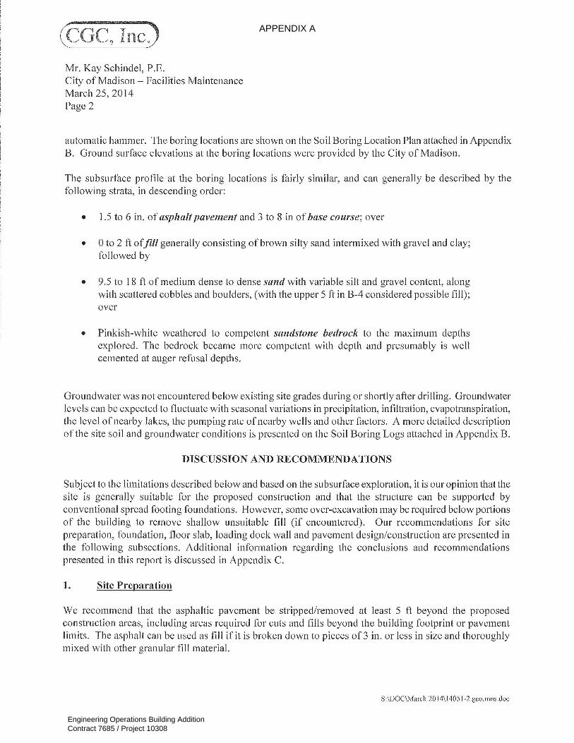
APPENDIX A
Engineering Operations Building AdditionContract 7685 / Project 10308

APPENDIX A
Engineering Operations Building AdditionContract 7685 / Project 10308

APPENDIX A
Engineering Operations Building AdditionContract 7685 / Project 10308

APPENDIX A
Engineering Operations Building AdditionContract 7685 / Project 10308

APPENDIX A
Engineering Operations Building AdditionContract 7685 / Project 10308

APPENDIX A
Engineering Operations Building AdditionContract 7685 / Project 10308

APPENDIX A
Engineering Operations Building AdditionContract 7685 / Project 10308

APPENDIX A
Engineering Operations Building AdditionContract 7685 / Project 10308

APPENDIX A
Engineering Operations Building AdditionContract 7685 / Project 10308

APPENDIX A
Engineering Operations Building AdditionContract 7685 / Project 10308

APPENDIX A
Engineering Operations Building AdditionContract 7685 / Project 10308

APPENDIX A
Engineering Operations Building AdditionContract 7685 / Project 10308

APPENDIX A
Engineering Operations Building AdditionContract 7685 / Project 10308

APPENDIX A
Engineering Operations Building AdditionContract 7685 / Project 10308

APPENDIX A
Engineering Operations Building AdditionContract 7685 / Project 10308

APPENDIX A
Engineering Operations Building AdditionContract 7685 / Project 10308

APPENDIX A
Engineering Operations Building AdditionContract 7685 / Project 10308

APPENDIX A
Engineering Operations Building AdditionContract 7685 / Project 10308
APPENDIX A
Engineering Operations Building AdditionContract 7685 / Project 10308

APPENDIX A
Engineering Operations Building AdditionContract 7685 / Project 10308

APPENDIX A
Engineering Operations Building AdditionContract 7685 / Project 10308

APPENDIX A
Engineering Operations Building AdditionContract 7685 / Project 10308

APPENDIX A
Engineering Operations Building AdditionContract 7685 / Project 10308

APPENDIX A
Engineering Operations Building AdditionContract 7685 / Project 10308

APPENDIX A
Engineering Operations Building AdditionContract 7685 / Project 10308

Rev. 1/23/2015-7685contractBoilerplateSBE v4.doc E-1
SECTION E: BIDDERS ACKNOWLEDGEMENT
ENGINEERING OPERATIONS BUILDING ADDITION CONTRACT NO. 7685
Bidder must state a Unit Price and Total Bid for each item. The Total Bid for each item must be the product of quantity, by Unit Price. The Grand Total must be the sum of the Total Bids for the various items. In case of multiplication errors or addition errors, the Grand Total with corrected multiplication and/or addition shall determine the Grand Total bid for each contract. The Unit Price and Total Bid must be entered numerically in the spaces provided. All words and numbers shall be written in ink. 1. The undersigned having familiarized himself/herself with the Contract documents, including
Advertisement for Bids, Instructions to Bidders, Form of Proposal, City of Madison Standard Specifications for Public Works Construction - 2015 Edition thereto, Form of Agreement, Form of Bond, and Addenda issued and attached to the plans and specifications on file in the office of the City Engineer, hereby proposes to provide and furnish all the labor, materials, tools, and expendable equipment necessary to perform and complete in a workmanlike manner the specified construction on this project for the City of Madison; all in accordance with the plans and specifications as prepared by the City Engineer, including Addenda to the Contract Nos. _______ through _______ issued thereto, at the prices for said work as contained in this proposal. (Electronic bids submittals shall acknowledge addendum under Section E and shall not acknowledge here)
2. If awarded the Contract, we will initiate action within seven (7) days after notification or in accordance with the date specified in the contract to begin work and will proceed with diligence to bring the project to full completion within the number of work days allowed in the Contract or by the calendar date stated in the Contract.
3. The undersigned Bidder or Contractor certifies that he/she is not a party to any contract, combination in form of trust or otherwise, or conspiracy in restraint of trade or commerce or any other violation of the anti-trust laws of the State of Wisconsin or of the United States, with respect to this bid or contract or otherwise.
4. I hereby certify that I have met the Bid Bond Requirements as specified in Section 102.5. (IF BID BOND IS USED, IT SHALL BE SUBMITTED ON THE FORMS PROVIDED BY THE
CITY. FAILURE TO DO SO MAY RESULT IN REJECTION OF THE BID). 5. I hereby certify that all statements herein are made on behalf of
_____________________________ (name of corporation, partnership, or person submitting bid) a corporation organized and existing under the laws of the State of ________________________ a partnership consisting of __________________________________; an individual trading as _______________________________; of the City of _____________________________ State of ____________________________; that I have examined and carefully prepared this Proposal, from the plans and specifications and have checked the same in detail before submitting this Proposal; that I have fully authority to make such statements and submit this Proposal in (its, their) behalf; and that the said statements are true and correct.
SIGNATURE TITLE, IF ANY Sworn and subscribed to before me this day of , 20 .
(Notary Public or other officer authorized to administer oaths) My Commission Expires Bidders shall not add any conditions or qualifying statements to this Proposal.
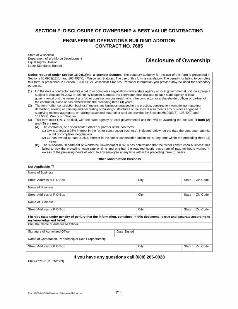
Rev. 02/08/2016-7685contractBoilerplateSBE v4.doc F-1
SECTION F: DISCLOSURE OF OWNERSHIP & BEST VALUE CONTRACTING
ENGINEERING OPERATIONS BUILDING ADDITION CONTRACT NO. 7685
State of Wisconsin Department of Workforce Development Equal Rights Division Labor Standards Bureau
Disclosure of Ownership
Notice required under Section 15.04(1)(m), Wisconsin Statutes. The statutory authority for the use of this form is prescribed in Sections 66.0903(12)(d) and 103.49(7)(d), Wisconsin Statutes. The use of this form is mandatory. The penalty for failing to complete this form is prescribed in Section 103.005(12), Wisconsin Statutes. Personal information you provide may be used for secondary purposes.
(1) On the date a contractor submits a bid to or completes negotiations with a state agency or local governmental unit, on a project subject to Section 66.0903 or 103.49, Wisconsin Statutes, the contractor shall disclose to such state agency or local governmental unit the name of any “other construction business”, which the contractor, or a shareholder, officer or partner of the contractor, owns or has owned within the preceding three (3) years.
(2) The term “other construction business” means any business engaged in the erection, construction, remodeling, repairing, demolition, altering or painting and decorating of buildings, structures or facilities. It also means any business engaged in supplying mineral aggregate, or hauling excavated material or spoil as provided by Sections 66.0903(3), 103.49(2) and 103.50(2), Wisconsin Statutes.
(3) This form must ONLY be filed, with the state agency or local governmental unit that will be awarding the contract, if both (A) and (B) are met. (A) The contractor, or a shareholder, officer or partner of the contractor:
(1) Owns at least a 25% interest in the “other construction business”, indicated below, on the date the contractor submits a bid or completes negotiations.
(2) Or has owned at least a 25% interest in the “other construction business” at any time within the preceding three (3) years.
(B) The Wisconsin Department of Workforce Development (DWD) has determined that the “other construction business” has failed to pay the prevailing wage rate or time and one-half the required hourly basic rate of pay, for hours worked in excess of the prevailing hours of labor, to any employee at any time within the preceding three (3) years.
Other Construction Business
Not Applicable
Name of Business Street Address or P O Box
City
State
Zip Code
Name of Business Street Address or P O Box
City
State
Zip Code
Name of Business Street Address or P O Box
City
State
Zip Code
I hereby state under penalty of perjury that the information, contained in this document, is true and accurate according to my knowledge and belief. Print the Name of Authorized Officer Signature of Authorized Officer Date Signed
Name of Corporation, Partnership or Sole Proprietorship Street Address or P O Box
City
State
Zip Code
If you have any questions call (608) 266-0028 ERD-7777-E (R. 09/2003)

Rev. 02/08/2016-7685contractBoilerplateSBE v4.doc F-2
ENGINEERING OPERATIONS BUILDING ADDITION CONTRACT NO. 7685
Best Value Contracting
1. The Contractor shall indicate the non-apprenticeable trades used on this contract.
2. Madison General Ordinance (M.G.O.), 33.07(7), does provide for some exemptions from the
active apprentice requirement. Apprenticeable trades are those trades considered apprenticeable by the State of Wisconsin. Please check applicable box if you are seeking an exemption.
Contractor has a total skilled workforce of four or less individuals in all apprenticeable
trades combined.
No available trade training program; The Contractor has been rejected by the only available trade training program, or there is no trade training program within 90 miles.
Contractor is not using an apprentice due to having a journey worker on layoff status, provided the journey worker was employed by the contractor in the past six months.
First-time Contractor on City of Madison Public Works contract requests a onetime
exemption but intends to comply on all future contracts and is taking steps typical of a “good faith” effort.
Contractor has been in business less than one year.
Contractor doesn’t have enough journeyman trade workers to qualify for a trade training
program in that respective trade 3. The Contractor shall indicate on the following section which apprenticeable trades are to be used
on this contract. Compliance with active apprenticeship, to the extent required by M.G.O. 33.07(7), shall be satisfied by documentation from an applicable trade training body; an apprenticeship contract with the Wisconsin Department of Workforce Development or a similar agency in another state; or the U.S Department of Labor. This documentation is required prior to the Contractor beginning work on the project site.
The Contractor has reviewed the list and shall not use any apprenticeable trades on this
project.

Rev. 02/08/2016-7685contractBoilerplateSBE v4.doc F-3
LIST APPRENTICABLE TRADES (check all that apply to your work to be performed on this contract)
BRICKLAYER CARPENTER CEMENT MASON / CONCRETE FINISHER CEMENT MASON (HEAVY HIGHWAY) CONSTRUCTION CRAFT LABORER DATA COMMUNICATION INSTALLER ELECTRICIAN ENVIRONMENTAL SYSTEMS TECHNICIAN / HVAC SERVICE TECH/HVAC INSTALL / SERVICE GLAZIER HEAVY EQUIPMENT OPERATOR / OPERATING ENGINEER INSULATION WORKER (HEAT & FROST) IRON WORKER IRON WORKER (ASSEMBLER, METAL BLDGS) PAINTER & DECORATOR PLASTERER PLUMBER RESIDENTIAL ELECTRICIAN ROOFER & WATER PROOFER SHEET METAL WORKER SPRINKLER FITTER STEAMFITTER STEAMFITTER (REFRIGERATION) STEAMFITTER (SERVICE) TAPER & FINISHER TELECOMMUNICATIONS (VOICE, DATA & VIDEO) INSTALLER-TECHNICIAN TILE SETTER

G-1
SECTION G: BID BOND KNOW ALL MEN BY THESE PRESENT, THAT Principal and Surety, as identified below, are held and firmly bound unto the City of Madison, (hereinafter referred to as the “Obligee”), in the sum of five per cent (5%) of the amount of the total bid or bids of the Principal herein accepted by the Obligee, for the payment of which the Principal and the Surety bind themselves, their heirs, executors, administrators, successors and assigns, jointly and severally, firmly by these presents. The conditions of this obligation are such that, whereas the Principal has submitted, to the City of Madison a certain bid, including the related alternate, and substitute bids attached hereto and hereby made a part hereof, to enter into a contract in writing for the construction of:
ENGINEERING OPERATIONS BUILDING ADDITION CONTRACT NO. 7685
1. If said bid is rejected by the Obligee, then this obligation shall be void. 2. If said bid is accepted by the Obligee and the Principal shall execute and deliver a
contract in the form specified by the Obligee (properly completed in accordance with said bid) and shall furnish a bond for his/her faithful performance of said contract, and for the payment of all persons performing labor or furnishing materials in connection therewith, and shall in all other respects perform the agreement created by the acceptance of said bid, then this obligation shall be void.
If said bid is accepted by the Obligee and the Principal shall fail to execute and deliver the contract and the performance and payment bond noted in 2. above executed by this Surety, or other Surety approved by the City of Madison, all within the time specified or any extension thereof, the Principal and Surety agree jointly and severally to forfeit to the Obligee as liquidated damages the sum mentioned above, it being understood that the liability of the Surety for any and all claims hereunder shall in no event exceed the sum of this obligation as stated, and it is further understood that the Principal and Surety reserve the right to recover from the Obligee that portion of the forfeited sum which exceed the actual liquidated damages incurred by the Obligee.
The Surety, for value received, hereby stipulates and agrees that the obligations of said Surety and its bond shall be in no way impaired or affected by an extension of the time within which the Obligee may accept such bid, and said Surety does hereby waive notice of any such extension.

G-2
IN WITNESS WHEREOF, the Principal and the Surety have hereunto set their hands and seals, and such of them as are corporations have caused their corporate seals to be hereto affixed and these presents to be signed by their proper officers, on the day and year set forth below. Seal PRINCIPAL
Name of Principal
By
Date
Name and Title
Seal SURETY
Name of Surety
By
Date
Name and Title
This certifies that I have been duly licensed as an agent for the above company in Wisconsin under National Provider No. __________ for the year ____________, and appointed as attorney in fact with authority to execute this bid bond and the payment and performance bond referred to above, which power of attorney has not been revoked.
Date Agent
Address
City, State and Zip Code
Telephone Number
NOTE TO SURETY & PRINCIPAL The bid submitted which this bond guarantees shall be rejected if the following instrument is not attached to this bond: Power of Attorney showing that the agent of Surety is currently authorized to execute bonds on behalf of the Surety, and in the amounts referenced above.

G-3
Certificate of Biennial Bid Bond TIME PERIOD - VALID (FROM/TO)
NAME OF SURETY
NAME OF CONTRACTOR
CERTIFICATE HOLDER
City of Madison, Wisconsin
This is to certify that a biennial bid bond issued by the above-named Surety is currently on file with the City of Madison. This certificate is issued as a matter of information and conveys no rights upon the certificate holder and does not amend, extend or alter the coverage of the biennial bid bond. Cancellation: Should the above policy be cancelled before the expiration date, the issuing Surety will give thirty (30) days written notice to the certificate holder indicated above.
Signature of Authorized Contractor Representative
Date
Rev. 02/08/2016-7685contractBoilerplateSBE v4.doc H-1
SECTION H: AGREEMENT THIS AGREEMENT made this ______ day of ________________ in the year Two Thousand and Sixteen between ___________________________ hereinafter called the Contractor, and the City of Madison, Wisconsin, hereinafter called the City. WHEREAS, the Common Council of the said City of Madison under the provisions of a resolution adopted _____________________, and by virtue of authority vested in the said Council, has awarded to the Contractor the work of performing certain construction. NOW, THEREFORE, the Contractor and the City, for the consideration hereinafter named, agree as follows: 1. Scope of Work. The Contractor shall, perform the construction, execution and completion of the
following listed complete work or improvement in full compliance with the Plans, Specifications, Standard Specifications, Supplemental Specifications, Special Provisions and contract; perform all items of work covered or stipulated in the proposal; perform all altered or extra work; and shall furnish, unless otherwise provided in the contract, all materials, implements, machinery, equipment, tools, supplies, transportation, and labor necessary to the prosecution and completion of the work or improvements:
ENGINEERING OPERATIONS BUILDING ADDITION
CONTRACT NO. 7685
2. Completion Date/Contract Time. Construction work must begin within seven (7) calendar days after the date appearing on mailed written notice to do so shall have been sent to the Contractor and shall be carried on at a rate so as to secure full completion SEE SPECIAL PROVISIONS, the rate of progress and the time of completion being essential conditions of this Agreement.
3. Contract Price. The City shall pay to the Contractor at the times, in the manner and on the
conditions set forth in said specifications, the sum of __________________($_____________) Dollars being the amount bid by such Contractor and which was awarded to him/her as provided by law.
4. Wage Rates for Employees of Public Works Contractors
General and Authorization. The Contractor shall compensate its employees at the prevailing wage rate in accordance with section 66.0903, Wis. Stats., DWD 290 of the Wisconsin Administrative Code and as hereinafter provided unless otherwise noted in Section D: Special Provisions, Subsection 102.10 – Minimum Rate of Wage Scale.
“Public Works” shall include building or work involving the erection, construction, remodeling, repairing or demolition of buildings, parking lots, highways, streets, bridges, sidewalks, street lighting, traffic signals, sanitary sewers, water mains and appurtenances, storm sewers, and the grading and landscaping of public lands.
“Building or work” includes construction activity as distinguished from manufacturing, furnishing of materials, or servicing and maintenance work, except for the delivery of mineral aggregate such as sand, gravel, bituminous asphaltic concrete or stone which is incorporated into the work under contract with the City by depositing the material directly in final place from transporting vehicle.
“Erection, construction, remodeling, repairing” means all types of work done on a particular building or work at the site thereof in the construction or development of the project, including without limitation, erecting, construction, remodeling, repairing, altering, painting, and decorating, the transporting of materials and supplies to or from the building or work done by the employees of the Contractor, Subcontractor, or Agent thereof, and the manufacturing or furnishing of

Rev. 02/08/2016-7685contractBoilerplateSBE v4.doc H-2
materials, articles, supplies or equipment on the site of the building or work, by persons employed by the Contractor, Subcontractor, or Agent thereof.
“Employees working on the project” means laborers, workers, and mechanics employed directly upon the site of work.
“Laborers, Workers, and Mechanics” include pre-apprentices, helpers, trainees, learners and properly registered and indentured apprentices but exclude clerical, supervisory, and other personnel not performing manual labor.
Establishment of Wage Rates. The Department of Public Works shall periodically obtain a current schedule of prevailing wage rates from DWD. The schedule shall be used to establish the City of Madison Prevailing Wage Rate Schedule for Public Works Construction (prevailing wage rate). The Department of Public Works may include known increases to the prevailing wage rate which can be documented and are to occur on a future specific date. The prevailing wage rate shall be included in public works contracts subsequently negotiated or solicited by the City. Except for known increases contained within the schedule, the prevailing wage rate shall not change during the contract. The approved wage rate is attached hereto.
Workforce Profile. The Contractor shall, at the time of signature of the contract, notify the City Engineer in writing of the names and classifications of all the employees of the Contractor, Subcontractors, and Agents proposed for the work. In the alternative, the Contractor shall submit in writing the classifications of all the employees of the Contractor, Subcontractors and Agents and the total number of hours estimated in each classification for the work. This workforce profile(s) shall be reviewed by the City Engineer who may, within ten (10) days, object to the workforce profile(s) as not being reflective of that which would be required for the work. The Contractor may request that the workforce profile, or a portion of the workforce profile, be submitted after the signature of the contract but at least ten (10) days prior to the work commencing. Any costs or time loss resulting from modifications to the workforce profile as a result of the City Engineer’s objections shall be the responsibility of the Contractor.
Payrolls and Records. The Contractor shall keep weekly payroll records setting forth the name, address, telephone number, classification, wage rate and fringe benefit package of all the employees who work on the contract, including the employees of the Contractor’s subcontractors and agents. Such weekly payroll records must include the required information for all City contracts and all other contracts on which the employee worked during the week in which the employee worked on the contract. The Contractor shall also keep records of the individual time each employee worked on the project and for each day of the project. Such records shall also set forth the total number of hours of overtime credited to each such employee for each day and week and the amount of overtime pay received in that week. The records shall set forth the full weekly wages earned by each employee and the actual hourly wage paid to the employee.
The Contractor shall submit the weekly payroll records, including the records of the Contractor’s subcontractors and agents, to the City Engineer for every week that work is being done on the contract. The submittal shall be within twenty-one (21) calendar days of the end of the Contractor’s weekly pay period.
Employees shall receive the full amounts accrued at the time of the payment, computed at rates not less than those stated in the prevailing wage rate and each employee’s rate shall be determined by the work that is done within the trade or occupation classification which should be properly assigned to the employee.
An employee’s classification shall not be changed to a classification of a lesser rate during the contract. If, during the term of the contract, an employee works in a higher pay classification than the one which was previously properly assigned to the employee, then that employee shall be considered to be in the higher pay classification for the balance of the contract, receive the appropriate higher rate of pay, and she/he shall not receive a lesser rate during the balance of the

Rev. 02/08/2016-7685contractBoilerplateSBE v4.doc H-3
contract. For purposes of clarification, it is noted that there is a distinct difference between working in a different classification with higher pay and doing work within a classification that has varying rates of pay which are determined by the type of work that is done within the classification. For example, the classification “Operating Engineer” provides for different rates of pay for various classes of work and the Employer shall compensate an employee classified as an “Operating Engineer” based on the highest class of work that is done in one day. Therefore, an “Operating Engineer’s” rate may vary on a day to day basis depending on the type of work that is done, but it will never be less than the base rate of an “Operating Engineer”. Also, as a matter of clarification, it is recognized that an employee may work in a higher paying classification merely by chance and without prior intention, calculation or design. If such is the case and the performance of the work is truly incidental and the occurrence is infrequent, inconsequential and does not serve to undermine the single classification principle herein, then it may not be required that the employee be considered to be in the higher pay classification and receive the higher rate of pay for the duration of the contract. However, the Contractor is not precluded or prevented from paying the higher rate for the limited time that an employee performs work that is outside of the employee’s proper classification.
Questions regarding an employee’s classification, rate of pay or rate of pay within a classification, shall be resolved by reference to the established practice that predominates in the industry and on which the trade or occupation rate/classification is based. Rate of pay and classification disputes shall be resolved by relying upon practices established by collective bargaining agreements and guidelines used in such determination by appropriate recognized trade unions operating within the City of Madison.
The Contractor, its Subcontractors and Agents shall submit to interrogation regarding compliance with the provisions of this ordinance.
Mulcting of the employees by the Contractor, Subcontractor, and Agents on Public Works contracts, such as by kickbacks or other devices, is prohibited. The normal rate of wage of the employees of the Contractor, Subcontractor, and Agents shall not be reduced or otherwise diminished as a result of payment of the prevailing wage rate on a public works contract.
Hourly contributions. Hourly contributions shall be determined in accordance with the prevailing wage rate and with DWD. 290.01(10), Wis. Admin. Code.
Apprentices and Subjourney persons. Apprentices and sub journeypersons performing work on the project shall be compensated in accordance with the prevailing wage rate and with DWD 290.02, and 290.025, respectively, Wis. Admin. Code.
Straight Time Wages. The Contractor may pay straight time wages as determined by the prevailing wage rate and DWD 290.04, Wis. Admin. Code.
Overtime Wages. The Contractor shall pay overtime wages as required by the prevailing wage rate and DWD 290.05, Wis. Admin. Code.
Posting of Wage Rates and Hours. A clearly legible copy of the prevailing wage rate, together with the provisions of Sec. 66.0903(10)(a) and (11)(a), Wis. Stats., shall be kept posted in at least one conspicuous and easily accessible place at the project site by the Contractor and such notice shall remain posted during the full time any laborers, workers or mechanics are employed on the contract.
Evidence of Compliance by Contractor. Upon completion of the contract, the Contractor shall file with the Department of Public Works an affidavit stating:
a. That the Contractor has complied fully with the provisions and requirements of Sec.
66.0903(3), Wis. Stats., and Chapter DWD 290, Wis. Admin. Code; the Contractor has received evidence of compliance from each of the agents and subcontractors; and the

Rev. 02/08/2016-7685contractBoilerplateSBE v4.doc H-4
names and addresses of all of the subcontractors and agents who worked on the contract.
b. That full and accurate records have been kept, which clearly indicate the name and trade
or occupation of every laborer, worker or mechanic employed by the Contractor in connection with work on the project. The records shall show the number of hours worked by each employee and the actual wages paid therefore; where these records will be kept and the name, address and telephone number of the person who will be responsible for keeping them. The records shall be retained and made available for a period of at least three (3) years following the completion of the project of public works and shall not be removed without prior notification to the municipality.
Evidence of Compliance by Agent and Subcontractor. Each agent and subcontractor shall file with the Contractor, upon completion of their portion of the work on the contract an affidavit stating that all the provisions of Sec. 66.0903(3), Wis. Stats., have been fully complied with and that full and accurate records have been kept, which clearly indicate the name and trade or occupation of every laborer, worker or mechanic employed by the Contractor in connection with work on the project. The records shall show the number of hours worked by each employee and the actual wages paid therefore; where these records shall be kept and the name, address and telephone number of the person who shall be responsible for keeping them. The records shall be retained and made available for a period of at least three (3) years following the completion of the project of public works and shall not be removed without prior notification to the municipality.
Failure to Comply with the Prevailing Wage Rate. If the Contractor fails to comply with the prevailing wage rate, she/he shall be in default on the contract. In addition, if DWD finds that a contractor or subcontractor violated the prevailing wage law, DWD will assess liquidated damages of 100% of the wages owed to employees. Establishment of Wage Rates. The Department of Public Works shall periodically obtain a current schedule of prevailing wage rates from DWD. The schedule shall be used to establish the City of Madison Prevailing Wage Rate Schedule for Public Works Construction (prevailing wage rate). The Department of Public Works may include known increases to the prevailing wage rate which can be documented and are to occur on a future specific date. The prevailing wage rate shall be included in public works contracts subsequently negotiated or solicited by the City. Except for known increases contained within the schedule, the prevailing wage rate shall not change during the contract. The approved wage rate and DWD prevailing wage requirements are attached hereto as Sec. I of the contract.
5. Affirmative Action. In the performance of the services under this Agreement the Contractor
agrees not to discriminate against any employee or applicant because of race, religion, marital status, age, color, sex, disability, national origin or ancestry, income level or source of income, arrest record or conviction record, less than honorable discharge, physical appearance, sexual orientation, gender identity, political beliefs, or student status. The Contractor further agrees not to discriminate against any subcontractor or person who offers to subcontract on this contract because of race, religion, color, age, disability, sex, sexual orientation, gender identity or national origin.
The Contractor agrees that within thirty (30) days after the effective date of this agreement, the Contractor will provide to the City Affirmative Action Division certain workforce utilization statistics, using a form to be furnished by the City.
If the contract is still in effect, or if the City enters into a new agreement with the Contractor, within one year after the date on which the form was required to be provided, the Contractor will provide updated workforce information using a second form, also to be furnished by the City. The second form will be submitted to the City Affirmative Action Division no later than one year after the date on which the first form was required to be provided.

Rev. 02/08/2016-7685contractBoilerplateSBE v4.doc H-5
The Contractor further agrees that, for at least twelve (12) months after the effective date of this contract, it will notify the City Affirmative Action Division of each of its job openings at facilities in Dane County for which applicants not already employees of the Contractor are to be considered. The notice will include a job description, classification, qualifications and application procedures and deadlines. The Contractor agrees to interview and consider candidates referred by the Affirmative Action Division if the candidate meets the minimum qualification standards established by the Contractor, and if the referral is timely. A referral is timely if it is received by the Contractor on or before the date started in the notice.
Articles of Agreement
Article I
The Contractor shall take affirmative action in accordance with the provisions of this contract to insure that applicants are employed, and that employees are treated during employment without regard to race, religion, color, age, marital status, disability, sex, sexual orientation, gender identity or national original and that the employer shall provide harassment free work environment for the realization of the potential of each employee. Such action shall include, but not be limited to, the following: employment, upgrading, demotion or transfer, recruitment or recruitment advertising, layoff or termination, rates of pay or other forms of compensation and selection for training including apprenticeship insofar as it is within the control of the Contractor. The Contractor agrees to post in conspicuous places available to employees and applicants notices to be provided by the City setting out the provisions of the nondiscrimination clauses in this contract.
Article II
The Contractor shall in all solicitations or advertisements for employees placed by or on behalf of the Contractors state that all qualified or qualifiable applicants will be employed without regard to race, religion, color, age, marital status, disability, sex, sexual orientation, gender identity or national origin.
Article III
The Contractor shall send to each labor union or representative of workers with which it has a collective bargaining agreement or other contract or understanding a notice to be provided by the City advising the labor union or worker’s representative of the Contractor’s equal employment opportunity and affirmative action commitments. Such notices shall be posted in conspicuous places available to employees and applicants for employment.
Article V
The Contractor agrees that it will comply with all provisions of the Affirmative Action Ordinance of the City of Madison, including the contract compliance requirements. The Contractor agrees to submit the model affirmative action plan for public works contractors in a form approved by the Affirmative Action Division Manager.
Article VI
The Contractor will maintain records as required by Section 39.02(9)(f) of the Madison General Ordinances and will provide the City Affirmative Action Division with access to such records and to persons who have relevant and necessary information, as provided in Section 39.02(9)(f). The City agrees to keep all such records confidential, except to the extent that public inspection is required by law.

Rev. 02/08/2016-7685contractBoilerplateSBE v4.doc H-6
Article VII
In the event of the Contractor’s or subcontractor’s failure to comply with the Equal Employment Opportunity and Affirmative Action Provisions of this contract or Section 39.03 and 39.02 of the Madison General Ordinances, it is agreed that the City at its option may do any or all of the following:
1. Cancel, terminate or suspend this Contract in whole or in part.
2. Declare the Contractor ineligible for further City contracts until the Affirmative Action
requirements are met.
3. Recover on behalf of the City from the prime Contractor 0.5 percent of the contract award price for each week that such party fails or refuses to comply, in the nature of liquidated damages, but not to exceed a total of five percent (5%) of the contract price, or five thousand dollars ($5,000), whichever is less. Under public works contracts, if a subcontractor is in noncompliance, the City may recover liquidated damages from the prime Contractor in the manner described above. The preceding sentence shall not be construed to prohibit a prime Contractor from recovering the amount of such damage from the non-complying subcontractor.
Article VIII
The Contractor shall include the above provisions of this contract in every subcontract so that such provisions will be binding upon each subcontractor. The Contractor shall take such action with respect to any subcontractor as necessary to enforce such provisions, including sanctions provided for noncompliance.
Article IX
The Contractor shall allow the maximum feasible opportunity to small business enterprises to compete for any subcontracts entered into pursuant to this contract. (In federally funded contracts the terms “DBE, MBE and WBE” shall be substituted for the term “small business” in this Article.)
6. Substance Abuse Prevention Program Required. Prior to commencing work on the Contract, the
Contractor, and any Subcontractor, shall have in place a written program for the prevention of substance abuse among its employees as required under Wis. Stat. Sec. 103.503.
7. Contractor Hiring Practices.
Ban the Box - Arrest and Criminal Background Checks. (Sec. 39.08, MGO)
This provision applies to all prime contractors on contracts entered into on or after January 1, 2016, and all subcontractors who are required to meet prequalification requirements under MGO 33.07(7)(I), MGO as of the first time they seek or renew pre-qualification status on or after January 1, 2016. The City will monitor compliance of subcontractors through the pre-qualification process.
a. Definitions. For purposes of this section, “Arrest and Conviction Record” includes, but is
not limited to, information indicating that a person has been questioned, apprehended, taken into custody or detention, held for investigation, arrested, charged with, indicted or tried for any felony, misdemeanor or other offense pursuant to any law enforcement or military authority.
“Conviction record” includes, but is not limited to, information indicating that a person has been convicted of a felony, misdemeanor or other offense, placed on probation, fined, imprisoned or paroled pursuant to any law enforcement or military authority.

Rev. 02/08/2016-7685contractBoilerplateSBE v4.doc H-7
“Background Check” means the process of checking an applicant’s arrest and conviction record, through any means.
b. Requirements. For the duration of this Contract, the Contractor shall:
1. Remove from all job application forms any questions, check boxes, or other
inquiries regarding an applicant’s arrest and conviction record, as defined herein. 2. Refrain from asking an applicant in any manner about their arrest or conviction
record until after conditional offer of employment is made to the applicant in question.
3. Refrain from conducting a formal or informal background check or making any
other inquiry using any privately or publicly available means of obtaining the arrest or conviction record of an applicant until after a conditional offer of employment is made to the applicant in question.
4. Make information about this ordinance available to applicants and existing
employees, and post notices in prominent locations at the workplace with information about the ordinance and complaint procedure using language provided by the City.
5. Comply with all other provisions of Sec. 39.08, MGO.
c. Exemptions: This section shall not apply when:
1. Hiring for a position where certain convictions or violations are a bar to
employment in that position under applicable law, or 2. Hiring a position for which information about criminal or arrest record, or a
background check is required by law to be performed at a time or in a manner that would otherwise be prohibited by this ordinance, including a licensed trade or profession where the licensing authority explicitly authorizes or requires the inquiry in question.
To be exempt, Contractor has the burden of demonstrating that there is an applicable law or regulation that requires the hiring practice in question, if so, the contractor is exempt from all of the requirements of this ordinance for the position(s) in question.

Rev. 02/08/2016-7685contractBoilerplateSBE v4.doc H-8
ENGINEERING OPERATIONS BUILDING ADDITION CONTRACT NO. 7685
IN WITNESS WHEREOF, the Contractor has hereunto set his/her hand and seal and the City has caused these presents to be sealed with its corporate seal and to be subscribed by its Mayor and City Clerk the day and year first above written. Countersigned: Company Name Witness Date President Date Witness Date Secretary Date CITY OF MADISON, WISCONSIN Provisions have been made to pay the liability that will accrue under this contract.
Approved as to form:
Finance Director City Attorney Signed this day of , 20 Witness Mayor Date Witness City Clerk Date

Rev. 02/08/2016-7685contractBoilerplateSBE v4.doc I-1
SECTION I: PAYMENT AND PERFORMANCE BOND KNOW ALL MEN BY THESE PRESENTS, that we _________________________________________ as principal, and _______________________________________________________________________ Company of ______________________________as surety, are held and firmly bound unto the City of Madison, Wisconsin, in the sum of _________________($__________) Dollars, lawful money of the United States, for the payment of which sum to the City of Madison, we hereby bind ourselves and our respective executors and administrators firmly by these presents. The condition of this Bond is such that if the above bounden shall on his/her part fully and faithfully perform all of the terms of the Contract entered into between him/herself and the City of Madison for the construction of:
ENGINEERING OPERATIONS BUILDING ADDITION CONTRACT NO. 7685
in Madison, Wisconsin, and shall pay all claims for labor performed and material furnished in the prosecution of said work, and save the City harmless from all claims for damages because of negligence in the prosecution of said work, and shall save harmless the said City from all claims for compensation (under Chapter 102, Wisconsin Statutes) of employees and employees of subcontractor, then this Bond is to be void, otherwise of full force, virtue and effect. Signed and sealed this day of Countersigned: Company Name (Principal) Witness President Seal Secretary Approved as to form: Surety Seal Salary Employee Commission By City Attorney Attorney-in-Fact This certifies that I have been duly licensed as an agent for the above company in Wisconsin under National Producer Number _________________ for the year _______, and appointed as attorney-in-fact with authority to execute this payment and performance bond which power of attorney has not been revoked. Date Agent Signature

Rev. 02/08/2016-7685contractBoilerplateSBE v4.doc J-1
SECTION J: PREVAILING WAGE RATES

ERD-16866 (R. 06/2013)
State of Wisconsin Department of Workforce Development Equal Rights Division
DEPARTMENTAL ORDER
ISSUE DATE: PROJECT:
PROJECT OWNER: REQUESTER:
ADDITIONAL CONTACT:
The department received an application for prevailing wage rate determination for the above-captioned project. The department conducted a survey to determine the prevailing wage rate for the trade(s) or occupation(s) needed to complete the project. The survey’s findings appear in the attached project determination.
If you believe that the wage rate for any trade or occupation does not accurately reflect the prevailing wage rate in the city, village or town where the project is located, you may ask the department to conduct an administrative review of such wage rate. You must submit this request in writing within 30 days from the date indicated above. Additionally, your request must include wage rate information from at least three similar projects in the city, village or town where the proposed project is located and on which some work has been performed by the contested trade(s) during the current survey period and was previously considered by the department in issuing the attached determination. See DWD 290.10 of the Wisconsin Administrative Code and either s. 66.0903(3)(br), Stats., or s. 103.49(3)(c), Stats., for a complete explanation of the administrative review process.
Enclosures
It is hereby ordered that the prevailing wage rates set forth in the attached project determination shall only be applicable to the above referenced project. This order is a FINAL ORDER of the department unless a timely request for an administrative review is filed with the department.
ISSUED BY: Equal Rights Division
Labor Standards Bureau Construction Wage Standards Section
P.O. Box 8928, Madison, WI 53708-8928 (608)266-6861
Web Site: http://dwd.wisconsin.gov/er/
ROBERT F PHILLIPS, INTERIM CITY ENGINEERCITY OF MADISON - ENGINEERING210 M L KING JR BLVD, RM 115MADISON, WI 537033342
ROBERT F PHILLIPS, INTERIM CITY ENGINEERCITY OF MADISON - ENGINEERING210 M L KING JR BLVD, RM 115MADISON, WI 537033342
NORMAN DAVIS, CONTRACT COMPLIANCECITY OF MADISON-DEPT OF CIVIL RTS-AA DIV210 MARTIN L KING JR BLVD, RM 523MADISON, WI 537033342
1/8/2016
ALL PUBLIC WORKS PROJECTS UNDER SEC. 66.0903, STATS-CITY OF MADISONMADISON CITY, DANE COUNTY, WIDetermination No. 201600001

ALL PUBLIC WORKS PROJECTS UNDER SEC. 66.0903, STATS-CITY OF MADISON
Contractors are responsible for correctly classifying their workers. Either call the Department ofWorkforce Development (DWD) with trade or classification questions or consult DWD’s Dictionary ofOccupational Classifications & Work Descriptions on the DWD website at:dwd.wisconsin.gov/er/prevailing_wage_rate/Dictionary/dictionary_main.htm.
Time and one-half must be paid for all hours worked:- over 10 hours per day on prevailing wage projects- over 40 hours per calendar week- Saturday and Sunday- on all of the following holidays: January 1; the last Monday in May; July 4;
the 1st Monday in September; the 4th Thursday in November; December25;
- The day before if January 1, July 4 or December 25 falls on a Saturday;- The day following if January 1, July 4 or December 25 falls on a Sunday.
Apply the time and one-half overtime calculation to whichever is higher between the Hourly Basic Ratelisted on this project determination or the employee's regular hourly rate of pay. Add any applicablePremium or DOT Premium to the Hourly Basic Rate before calculating overtime.
A DOT Premium (discussed below) may supersede this time and one-half requirement.
When a specific trade or occupation requires a future increase, you MUST add the full hourly increaseto the "TOTAL" on the effective date(s) indicated for the specific trade or occupation.
If indicated for a specific trade or occupation, the full amount of such pay MUST be added to the"HOURLY BASIC RATE OF PAY" indicated for such trade or occupation, whevenever such pay isapplicable.
This premium only applies to highway and bridge projects owned by the Wisconsin Department ofTransportation and to the project type heading "Airport Pavement or State Highway Construction." DONOT apply the premium calculation under any other project type on this determination.
Pay apprentices a percentage of the applicable journeyperson's hourly basic rate of pay and hourlyfringe benefit contributions specified in this determination. Obtain the appropriate percentage fromeach apprentice’s contract or indenture.
Subjourney wage rates may be available for some of the trades or occupations indicated below withthe exception of laborers, truck drivers and heavy equipment operators. Any employer interested inusing a subjourney classification on this project MUST complete Form ERD-10880 and request theapplicable wage rate from the Department of Workforce Development PRIOR to using the subjourneyworker on this project.
PREVAILING WAGE RATE DETERMINATIONIssued by the State of Wisconsin
Department of Workforce DevelopmentPursuant to s. 66.0903, Wis. Stats.
Issued On: 01/08/2016Amended On: 01/28/2016
DETERMINATION NUMBER: 201600001
EXPIRATION DATE: Prime Contracts MUST Be Awarded or Negotiated On Or Before12/31/2016. If NOT, You MUST Reapply.
PROJECT NAME:
PROJECT LOCATION: MADISON CITY, DANE COUNTY, WI
CONTRACTING AGENCY: CITY OF MADISON - ENGINEERING
CLASSIFICATION:
OVERTIME:
FUTURE INCREASE:
PREMIUM PAY:
DOT PREMIUM:
APPRENTICES:
SUBJOURNEY:

This document MUST BE POSTED by the CONTRACTING AGENCY in at least one conspicuous and easily accessible place onthe site of the project . A local governmental unit may post this document at the place normally used to post public notices ifthere is no common site on the project. This document MUST remain posted during the entire time any worker is employed onthe project and MUST be physically incorporated into the specifications and all contracts and subcontracts. If you have anyquestions, please write to the Equal Rights Division, Labor Standards Bureau, P.O. Box 8928, Madison, Wisconsin 53708 or call(608) 266-6861.
The following statutory provisions apply to local governmental unit projects of public works and are set forth belowpursuant to the requirements of s. 66.0903(8), Stats.
s. 66.0903 (1) (f) & s. 103.49 (1) (c) "PREVAILING HOURS OF LABOR" for any trade or occupation in any area means 10hours per day and 40 hours per week and may not include any hours worked on a Saturday or Sunday or on any of the followingholidays:
1. January 1.2. The last Monday in May.3. July 4.4. The first Monday in September.5. The 4th Thursday in November.6. December 25.7. The day before if January 1, July 4 or December 25 falls on a Saturday.8. The day following if January 1, July 4 or December 25 falls on a Sunday.
s. 66.0903 (10) RECORDS; INSPECTION; ENFORCEMENT.(a) Each contractor, subcontractor, or contractor's or subcontractor's agent performing work on a project of public works that issubject to this section shall keep full and accurate records clearly indicating the name and trade or occupation of every personperforming the work described in sub. (4) and an accurate record of the number of hours worked by each of those persons andthe actual wages paid for the hours worked.
s. 66.0903 (11) LIABILITY AND PENALTIES.(a) 1. Any contractor, subcontractor, or contractor's or subcontractor's agent who fails to pay the prevailing wage rate determinedby the department under sub. (3) or who pays less than 1.5 times the hourly basic rate of pay for all hours worked in excess ofthe prevailing hours of labor is liable to any affected employee in the amount of his or her unpaid wages or his or her unpaidovertime compensation and in an additional amount as liquidated damages as provided under subd. 2., 3., whichever isapplicable.2. If the department determines upon inspection under sub. (10) (b) or (c) that a contractor, subcontractor, or contractor's orsubcontractor's agent has failed to pay the prevailing wage rate determined by the department under sub. (3) or has paid lessthan 1.5 times the hourly basic rate of pay for all hours worked in excess of the prevailing hours of labor, the department shallorder the contractor to pay to any affected employee the amount of his or her unpaid wages or his or her unpaid overtimecompensation and an additional amount equal to 100 percent of the amount of those unpaid wages or that unpaid overtimecompensation as liquidated damages within a period specified by the department in the order.3. In addition to or in lieu of recovering the liability specified in subd. 1. as provided in subd. 2., any employee for and in behalf ofthat employee and other employees similarly situated may commence an action to recover that liability in any court of competentjurisdiction. If the court finds that a contractor, subcontractor, or contractor's or subcontractor's agent has failed to pay theprevailing wage rate determined by the department under sub. (3) or has paid less than 1.5 times the hourly basic rate of pay forall hours worked in excess of the prevailing hours of labor, the court shall order the contractor, subcontractor, or agent to pay toany affected employee the amount of his or her unpaid wages or his or her unpaid overtime compensation and an additionalamount equal to 100 percent of the amount of those unpaid wages or that unpaid overtime compensation as liquidated damages.5. No employee may be a party plaintiff to an action under subd. 3. unless the employee consents in writing to become a partyand the consent is filed in the court in which the action is brought. Notwithstanding s. 814.04 (1), the court shall, in addition to anyjudgment awarded to the plaintiff, allow reasonable attorney fees and costs to be paid by the defendant.
Determination No. 201600001 Page 2 of 30

Includes sheltered enclosures with walk-in access for the purpose of housing persons, employees, machinery,equipment or supplies and non-sheltered work such as canals, dams, dikes, reservoirs, storage tanks, etc. A shelteredenclosure need not be "habitable" in order to be considered a building. The installation of machinery and/or equipment,both above and below grade level, does not change a project's character as a building. On-site grading, utility work andlandscaping are included within this definition. Residential buildings of four (4) stories or less, agricultural buildings,parking lots and driveways are NOT included within this definition.
Fringe Benefits Must Be Paid On All Hours Worked
CODE TRADE OR OCCUPATION OF PAY BENEFITS TOTAL
Acoustic Ceiling Tile InstallerFuture Increase(s):
Add $1.42/hr on 6/1/2016.
Boilermaker
Bricklayer, Blocklayer or StonemasonFuture Increase(s):
Add $1.45 on 06/06/2016Premium Increase(s):
DOT PREMIUM: Pay two times the hourly basic rate onSunday, New Year’s Day, Memorial Day, IndependenceDay, Labor Day, Thanksgiving Day & Christmas Day.
Cabinet InstallerFuture Increase(s):
Add $1.42/hr on 6/1/2016.
CarpenterFuture Increase(s):
Add $1.42/hr on 6/1/2016.Premium Increase(s):
DOT PREMIUM: Pay two times the hourly basic rate onSunday, New Year's Day, Memorial Day, IndependenceDay, Labor Day, Thanksgiving Day & Christmas Day.
Carpet Layer or Soft Floor CovererFuture Increase(s):
Add $1.42/hr on 6/1/2016.
Cement Finisher
Drywall Taper or Finisher
ElectricianFuture Increase(s):
Add $1.25/hr on 6/1/16.Premium Increase(s):
DOT PREMIUM: Pay two times the hourly basic rate onSunday, New Year’s Day, Memorial Day, IndependenceDay, Labor Day, Thanksgiving Day & Christmas Day.
Elevator Constructor
Fence Erector
Determination No. 201600001
BUILDING OR HEAVY CONSTRUCTION
SKILLED TRADES
HOURLY HOURLYBASIC RATE FRINGE
$ $ $
101 33.02 17.12 50.14
102 33.35 28.29 61.64
103 32.86 20.03 52.89
104 33.02 17.12 50.14
105 33.02 17.12 50.14
106 33.02 17.12 50.14
107 33.15 16.40 49.55
108 29.97 20.08 50.05
109 35.75 19.97 55.72
110 46.05 27.09 73.14
111 18.72 5.78 24.50
Page 3 of 30

Fringe Benefits Must Be Paid On All Hours Worked
CODE TRADE OR OCCUPATION OF PAY BENEFITS TOTAL
Fire Sprinkler Fitter
Glazier
Heat or Frost Insulator
Insulator (Batt or Blown)Future Increase(s):
Add $1.42/hr on 6/1/2016.
Ironworker
Lather
Line Constructor (Electrical)
Marble Finisher
Marble Mason
Metal Building Erector
MillwrightFuture Increase(s):
Add $1.47/hr on 6/1/2016.
Overhead Door Installer
Painter
Pavement Marking Operator
PiledriverFuture Increase(s):
Add $1.44/hr on 6/1/2016.Premium Increase(s):
DOT PREMIUM: Pay two times the hourly basic rate onSunday, New Year's Day, Memorial Day, IndependenceDay, Labor Day, Thanksgiving Day & Christmas Day.
Pipeline Fuser or Welder (Gas or Utility)
Plasterer
Plumber
Refrigeration Mechanic
Roofer or Waterproofer
Sheet Metal Worker
Steamfitter
Teledata Technician or Installer
Temperature Control Installer
Terrazzo Finisher
Determination No. 201600001
HOURLY HOURLYBASIC RATE FRINGE
$ $ $
112 36.78 19.97 56.75
113 38.27 14.42 52.69
114 33.53 27.31 60.84
115 33.02 17.12 50.14
116 32.50 20.58 53.08
117 32.72 16.00 48.72
118 40.81 18.06 58.87
119 25.72 18.54 44.26
120 32.82 18.67 51.49
121 22.40 6.27 28.67
122 34.79 17.17 51.96
123 31.93 13.39 45.32
124 26.70 16.65 43.35
125 30.00 18.81 48.81
126 33.56 17.12 50.68
127 44.20 18.26 62.46
129 32.82 18.81 51.63
130 38.82 18.02 56.84
132 45.55 18.71 64.26
133 29.65 1.71 31.36
134 35.55 24.67 60.22
135 45.55 18.71 64.26
137 22.50 12.74 35.24
138 34.97 19.67 54.64
139 25.72 18.54 44.26
Page 4 of 30

Fringe Benefits Must Be Paid On All Hours Worked
CODE TRADE OR OCCUPATION OF PAY BENEFITS TOTAL
Terrazzo MechanicFuture Increase(s):
Add $1.60 on 06/06/2016
Tile Finisher
Tile SetterFuture Increase(s):
Add $1.45/hr on 6/06/2016.
Tuckpointer, Caulker or CleanerFuture Increase(s):
Add $1.45 on 06/06/2016Premium Increase(s):
DOT PREMIUM: Pay two times the hourly basic rate onSunday, New Year’s Day, Memorial Day, IndependenceDay, Labor Day, Thanksgiving Day & Christmas Day.
Underwater Diver (Except on Great Lakes)
Well Driller or Pump InstallerFuture Increase(s):
Add $1/hr on 6/1/2016; Add $1/hr on 6/1/2017.
Siding Installer
Heavy Equipment Operator - ELECTRICAL LINE CONSTRUCTIONONLY
Light Equipment Operator -ELECTRICAL LINE CONSTRUCTION ONLY
Heavy Truck Driver - ELECTRICAL LINE CONSTRUCTION ONLY
Light Truck Driver - ELECTRICAL LINE CONSTRUCTION ONLY
Groundman - ELECTRICAL LINE CONSTRUCTION ONLY
Fringe Benefits Must Be Paid On All Hours Worked
CODE TRADE OR OCCUPATION OF PAY BENEFITS TOTAL
Single Axle or Two Axle
Three or More Axle
Articulated, Euclid, Dumptor, Off Road Material HaulerFuture Increase(s):
Add $1.60/hr on 6/3/2016.
Pavement Marking Vehicle
Truck Mechanic
Determination No. 201600001
HOURLY HOURLYBASIC RATE FRINGE
$ $ $
140 33.98 18.96 52.94
141 30.00 0.00 30.00
142 31.59 19.61 51.20
143 32.86 20.03 52.89
144 36.74 16.00 52.74
146 25.32 16.40 41.72
147 17.00 6.71 23.71
150 36.73 20.41 57.14
151 32.65 15.52 48.17
152 28.57 13.71 42.28
153 26.53 13.55 40.08
154 25.00 12.55 37.55
TRUCK DRIVERS
HOURLY HOURLYBASIC RATE FRINGE
$ $ $
201 33.69 19.78 53.47
203 18.25 21.61 39.86
204 34.69 20.38 55.07
205 18.25 21.61 39.86
207 18.25 21.61 39.86
Page 5 of 30

Fringe Benefits Must Be Paid On All Hours Worked
CODE TRADE OR OCCUPATION OF PAY BENEFITS TOTAL
General LaborerFuture Increase(s):
Add $1.25/hr eff. 06/06/2016Premium Increase(s):
Add $1.00/hr for certified welder and pipelayer; Add$.25/hr for mason tender.
Asbestos Abatement Worker
Landscaper
Gas or Utility Pipeline Laborer (Other Than Sewer and Water)
Fiber Optic Laborer (Outside, Other Than Concrete Encased)
Railroad Track Laborer
Final Construction Clean-Up Worker
Fringe Benefits Must Be Paid On All Hours Worked
CODE TRADE OR OCCUPATION OF PAY BENEFITS TOTAL
Air Track, Rotary or Percussion Drilling Machine &/or Hammers, Blaster;Asphalt Milling Machine; Boring Machine (Directional, Horizontal orVertical); Backhoe (Track Type) Having a Mfgr's Rated Capacity of130,000 Lbs. or Over; Backhoe (Track Type) Having a Mfgr's RatedCapacity of Under 130,000 Lbs., Backhoe (Mini, 15,000 Lbs. & Under);Bulldozer or Endloader (Over 40 hp); Compactor (Self-Propelled 85 FtTotal Drum Width & Over, or Tractor Mounted, Towed & Light Equipment);Concrete Batch Plant, Batch Hopper; Concrete Breaker (Large, Auto,Vibratory/Sonic, Manual or Remote); Crane, Shovel, Dragline, Clamshells;Forklift (Machinery Moving or Steel Erection, 25 Ft & Over); Gradall(Cruz-Aire Type); Grader or Motor Patrol; Master Mechanic; Mechanic orWelder; Robotic Tool Carrier (With or Without Attachments); Scraper (SelfPropelled or Tractor Drawn) 5 cu yds or More Capacity; Tractor or TruckMounted Hydraulic Backhoe; Tractor or Truck Mounted Hydraulic Crane(10 Tons or Under); Tractor (Scraper, Dozer, Pusher, Loader); Trencher(Wheel Type or Chain Type Having Over 8 Inch Bucket).
Future Increase(s):Add $1.60/hr on 6/3/2016.
Backfiller; Broom or Sweeper; Bulldozer or Endloader (Under 40 hp);Environmental Burner; Forestry Equipment, Timbco, Tree Shear, TubGrinder, Processor; Jeep Digger; Screed (Milling Machine); Skid Rig;Straddle Carrier or Travel Lift; Stump Chipper; Trencher (Wheel Type orChain Type Having 8 Inch Bucket & Under).
Future Increase(s):Add $1.60/hr on 6/3/2016.
Determination No. 201600001
LABORERS
HOURLY HOURLYBASIC RATE FRINGE
$ $ $
301 25.81 15.63 41.44
302 17.00 4.22 21.22
303 21.90 9.83 31.73
310 20.83 18.39 39.22
311 19.35 0.00 19.35
314 17.00 3.96 20.96
315 29.01 7.20 36.21
HEAVY EQUIPMENT OPERATORS SITE PREPARATION, UTILITY OR LANDSCAPING WORK ONLY
HOURLY HOURLYBASIC RATE FRINGE
$ $ $
501 35.22 20.38 55.60
502 34.69 20.38 55.07
Page 6 of 30

Fringe Benefits Must Be Paid On All Hours Worked
CODE TRADE OR OCCUPATION OF PAY BENEFITS TOTAL
Air Compressor (&/or 400 CFM or Over); Augers (Vertical & Horizontal);Compactor (Self-Propelled 84 Ft Total Drum Width & Under, or TractorMounted, Towed & Light Equipment); Crusher, Screening or Wash Plant;Farm or Industrial Type Tractor; Forklift; Generator (&/or 150 KW or Over);Greaser; High Pressure Utility Locating Machine (Daylighting Machine);Mulcher; Oiler; Post Hole Digger or Driver; Pump (3 Inch or Over) or WellPoints; Refrigeration Plant or Freeze Machine; Rock, Stone Breaker; SkidSteer Loader (With or Without Attachments); Vibratory Hammer orExtractor, Power Pack.
Future Increase(s):Add $1.60/hr on 6/3/2016.
Work Performed on the Great Lakes Including Diver; Wet Tender orHydraulic Dredge Engineer.
Work Performed on the Great Lakes Including Crane or BackhoeOperator; Assistant Hydraulic Dredge Engineer; Hydraulic DredgeLeverman or Diver's Tender; Mechanic or Welder; 70 Ton & Over TugOperator.
Future Increase(s):Add $1.25/hr on 1/1/2017.
Premium Increase(s):Add $.50/hr for Friction Crane, Lattice Boom or CraneCertification (CCO).
Work Performed on the Great Lakes Including Deck Equipment Operatoror Machineryman (Maintains Cranes Over 50 Tons or Backhoes 115,000Lbs. or More); Tug, Launch or Loader, Dozer or Like Equipment WhenOperated on a Barge, Breakwater Wall, Slip, Dock or Scow, DeckMachinery.
Future Increase(s):Add $1.25/hr on 1/1/2017.
Work Performed on the Great Lakes Including Deck Equipment Operator,Machineryman or Fireman (Operates 4 Units or More or Maintains Cranes50 Tons or Under or Backhoes 115,000 Lbs. or Under); Deck Hand, DeckEngineer or Assistant Tug Operator; Off Road Trucks - Great LakesONLY.
Fringe Benefits Must Be Paid On All Hours Worked
CODE TRADE OR OCCUPATION OF PAY BENEFITS TOTAL
Boring Machine (Directional); Crane, Tower Crane, Pedestal Tower orDerrick, With or Without Attachments, With a Lifting Capacity of Over 100Tons, Self-Erecting Tower Crane With a Lifting Capacity of Over 4,000Lbs., Crane With Boom Dollies; Crane, Tower Crane, Pedestal Tower orDerrick, With Boom, Leads &/or Jib Lengths Measuring 176 Ft or Over;Master Mechanic.
Future Increase(s):Add $1.60/hr on 6/3/2016.
Premium Increase(s):
Determination No. 201600001
HOURLY HOURLYBASIC RATE FRINGE
$ $ $
503 32.62 20.38 53.00
504 41.65 21.71 63.36
505 44.05 23.24 67.29
506 39.20 23.09 62.29
507 36.72 21.15 57.87
HEAVY EQUIPMENT OPERATORS EXCLUDING SITE PREPARATION, UTILITY, PAVING LANDSCAPING WORK
HOURLY HOURLYBASIC RATE FRINGE
$ $ $
508 37.67 20.38 58.05
Page 7 of 30

Fringe Benefits Must Be Paid On All Hours Worked
CODE TRADE OR OCCUPATION OF PAY BENEFITS TOTAL
Add $.50/hr for >200 Ton; Add $1/hr at 300 Ton; Add$1.50/hr at 400 Ton; Add $2/hr at 500 Ton & Over.
Backhoe (Track Type) Having a Mfgr's Rated Capacity of 130,000 Lbs. orOver; Boring Machine (Horizontal or Vertical); Caisson Rig; Crane, TowerCrane, Portable Tower, Pedestal Tower or Derrick, With or WithoutAttachments, With a Lifting Capacity of 100 Tons or Under, Self-ErectingTower Crane With A Lifting Capacity Of 4,000 Lbs. & Under; Crane, TowerCrane, Portable Tower, Pedestal Tower or Derrick, With Boom, Leads&/or Jib Lengths Measuring 175 Ft or Under; Pile Driver; Versi Lifts,Tri-Lifts & Gantrys (20,000 Lbs. & Over).
Future Increase(s):Add $1.60/hr on 6/3/2016.
Premium Increase(s):Add $.25/hr for all >45 Ton lifting capacity cranes.
Backhoe (Track Type) Having a Mfgr.'s Rated Capacity of Under 130,000Lbs., Backhoe (Mini, 15,000 Lbs. & Under); Concrete Bump Cutter,Grinder, Planing or Grooving Machine; Concrete Laser/Screed; ConcretePaver (Slipform); Concrete Pump (Over 46 Meter), Concrete Conveyor(Rotec or Bidwell Type); Concrete Slipform Placer Curb & Gutter Machine;Concrete Spreader & Distributor; Dredge (NOT Performing Work on theGreat Lakes); Forklift (Machinery Moving or Steel Erection, 25 Ft & Over);Gradall (Cruz-Aire Type); Hydro-Blaster (10,000 PSI or Over); MillingMachine; Skid Rig; Traveling Crane (Bridge Type).
Future Increase(s):Add $1.60/hr on 6/3/2016.
Air, Track, Rotary or Percussion Drilling Machine &/or Hammers, Blaster;Bulldozer or Endloader (Over 40 hp); Compactor (Self-Propelled 85 FtTotal Drum Width & Over, or Tractor Mounted, Towed & Light Equipment);Concrete Pump (46 Meter & Under), Concrete Conveyor (Rotec or BidwellType); Crane (Carry Deck, Mini) or Truck Mounted Hydraulic Crane (10Tons or Under); Environmental Burner; Gantrys (Under 20,000 Lbs.);Grader or Motor Patrol; High Pressure Utility Locating Machine(Daylighting Machine); Manhoist; Material or Stack Hoist; Mechanic orWelder; Railroad Track Rail Leveling Machine, Tie Placer, Extractor,Tamper, Stone Leveler or Rehabilitation Equipment; Roller (Over 5 Ton);Scraper (Self Propelled or Tractor Drawn) 5 cu yd or More Capacity;Screed (Milling Machine); Sideboom; Straddle Carrier or Travel Lift; Tiningor Curing Machine; Tractor (Scraper, Dozer, Pusher, Loader); Tractor orTruck Mounted Hydraulic Backhoe; Tractor or Truck Mounted HydraulicCrane (10 Tons or Under); Trencher (Wheel Type or Chain Type HavingOver 8-Inch Bucket).
Future Increase(s):Add $1.60/hr on 6/3/2016.
Determination No. 201600001
HOURLY HOURLYBASIC RATE FRINGE
$ $ $
509 36.42 20.38 56.80
510 35.22 20.38 55.60
511 34.69 20.38 55.07
Page 8 of 30

Fringe Benefits Must Be Paid On All Hours Worked
CODE TRADE OR OCCUPATION OF PAY BENEFITS TOTAL
Backfiller; Broom or Sweeper; Bulldozer or Endloader (Under 40 hp);Compactor (Self-Propelled 84 Ft Total Drum Width & Under, or TractorMounted, Towed & Light Equipment); Concrete Batch Plant, BatchHopper; Concrete Breaker (Large, Auto, Vibratory/Sonic, Manual orRemote); Concrete Conveyor System; Concrete Finishing Machine (RoadType); Fireman (Pile Driver & Derrick NOT Performing Work on the GreatLakes); Grout Pump; Hoist (Tugger, Automatic); Industrial Locomotives;Jeep Digger; Lift Slab Machine; Mulcher; Roller (Rubber Tire, 5 Ton orUnder); Screw or Gypsum Pumps; Stabilizing or Concrete Mixer(Self-Propelled or 14S or Over); Stump Chipper; Trencher (Wheel Type orChain Type Having 8-Inch Bucket & Under); Winches & A-Frames.
Future Increase(s):Add $1.60/hr on 6/3/2016.
Air Compressor (&/or 400 CFM or Over); Air, Electric or Hydraulic JackingSystem; Augers (Vertical & Horizontal); Boatmen (NOT Performing Workon the Great Lakes); Boiler (Temporary Heat); Crusher, Screening orWash Plant; Elevator; Farm or Industrial Type Tractor; Fireman (AsphaltPlant NOT Performing Work on the Great Lakes); Forklift; Generator (&/or150 KW or Over); Greaser; Heaters (Mechanical); Loading Machine(Conveyor); Oiler; Post Hole Digger or Driver; Prestress Machine; Pump(3 Inch or Over) or Well Points; Refrigeration Plant or Freeze Machine;Robotic Tool Carrier (With or Without Attachments); Rock, Stone Breaker;Skid Steer Loader (With or Without Attachments); Vibratory Hammer orExtractor, Power Pack.
Future Increase(s):Add $1.60/hr on 6/3/2016.
Gas or Utility Pipeline, Except Sewer & Water (Primary Equipment).Future Increase(s):
Add $1/hr on 5/30/2016.
Gas or Utility Pipeline, Except Sewer & Water (Secondary Equipment).
Fiber Optic Cable Equipment
Determination No. 201600001
HOURLY HOURLYBASIC RATE FRINGE
$ $ $
512 32.62 20.38 53.00
513 31.99 20.38 52.37
514 37.04 22.44 59.48
515 33.82 20.30 54.12
516 29.50 0.68 30.18
Page 9 of 30

Includes those projects that primarily involve public sewer or water distribution, transmission or collection systems andrelated tunnel work (excluding buildings).
Fringe Benefits Must Be Paid On All Hours Worked
CODE TRADE OR OCCUPATION OF PAY BENEFITS TOTAL
Bricklayer, Blocklayer or Stonemason
Carpenter
Cement FinisherFuture Increase(s):
Add $1.75 on 6/1/16.Premium Increase(s):
DOT PREMIUMS: 1) Pay two times the hourly basicrate on Sunday, New Year's Day, Memorial Day,Independence Day, Labor Day, Thanksgiving Day &Christmas Day. 2) Add $1.40/hr when the WisconsinDepartment of Transportation or responsible governingagency requires that work be performed at night underartificial illumination with traffic control and the work iscompleted after sunset and before sunrise.
Electrician
Fence Erector
Ironworker
Line Constructor (Electrical)
Pavement Marking Operator
Piledriver
PlumberFuture Increase(s):
Add $1.50 on 6/1/16
Steamfitter
Teledata Technician or Installer
Tuckpointer, Caulker or Cleaner
Underwater Diver (Except on Great Lakes)
Well Driller or Pump InstallerFuture Increase(s):
Add $1/hr on 6/1/2016; Add $1/hr on 6/1/2017.
Heavy Equipment Operator - ELECTRICAL LINE CONSTRUCTIONONLY
Light Equipment Operator -ELECTRICAL LINE CONSTRUCTION ONLY
Determination No. 201600001
SEWER, WATER OR TUNNEL CONSTRUCTION
SKILLED TRADES
HOURLY HOURLYBASIC RATE FRINGE
$ $ $
103 32.82 18.67 51.49
105 32.72 16.00 48.72
107 35.97 17.85 53.82
109 52.00 1.50 53.50
111 18.72 5.78 24.50
116 32.50 20.58 53.08
118 40.81 18.06 58.87
125 30.00 18.81 48.81
126 33.24 16.00 49.24
130 39.95 19.45 59.40
135 44.20 18.26 62.46
137 22.50 12.74 35.24
143 32.82 18.67 51.49
144 31.00 20.43 51.43
146 25.32 16.40 41.72
150 36.73 15.92 52.65
151 32.65 15.52 48.17
Page 10 of 30

Fringe Benefits Must Be Paid On All Hours Worked
CODE TRADE OR OCCUPATION OF PAY BENEFITS TOTAL
Heavy Truck Driver - ELECTRICAL LINE CONSTRUCTION ONLY
Light Truck Driver - ELECTRICAL LINE CONSTRUCTION ONLY
Groundman - ELECTRICAL LINE CONSTRUCTION ONLY
Fringe Benefits Must Be Paid On All Hours Worked
CODE TRADE OR OCCUPATION OF PAY BENEFITS TOTAL
Single Axle or Two Axle
Three or More Axle
Articulated, Euclid, Dumptor, Off Road Material Hauler
Pavement Marking Vehicle
Truck Mechanic
Fringe Benefits Must Be Paid On All Hours Worked
CODE TRADE OR OCCUPATION OF PAY BENEFITS TOTAL
General LaborerFuture Increase(s):
Add $1.25/hr eff. 06/06/2016Premium Increase(s):
Add $.20 for blaster, bracer, manhole builder, caulker,bottomman and power tool; Add $.55 for pipelayer; Add$1.00 for tunnel work 0-15 lbs. compressed air; Add$2.00 for over 15-30 lbs. compressed air; Add $3.00 forover 30 lbs. compressed air.
Landscaper
Flagperson or Traffic Control Person
Fiber Optic Laborer (Outside, Other Than Concrete Encased)
Railroad Track Laborer
Determination No. 201600001
HOURLY HOURLYBASIC RATE FRINGE
$ $ $
152 28.57 13.71 42.28
153 26.53 13.55 40.08
154 21.75 12.97 34.72
TRUCK DRIVERS
HOURLY HOURLYBASIC RATE FRINGE
$ $ $
201 19.00 0.00 19.00
203 19.00 0.00 19.00
204 33.69 19.78 53.47
205 19.00 0.00 19.00
207 19.00 0.00 19.00
LABORERS
HOURLY HOURLYBASIC RATE FRINGE
$ $ $
301 27.18 15.64 42.82
303 41.00 0.00 41.00
304 20.92 14.80 35.72
311 19.35 0.00 19.35
314 17.00 3.96 20.96
Page 11 of 30

Fringe Benefits Must Be Paid On All Hours Worked
CODE TRADE OR OCCUPATION OF PAY BENEFITS TOTAL
Backhoe (Track Type) Having a Mfgr.'s Rated Capacity of 130,000 Lbs. orOver; Caisson Rig; Crane, Tower Crane, Pedestal Tower or Derrick, WithBoom, Leads &/or Jib Lengths Measuring 176 Ft or Over; Crane, TowerCrane, Pedestal Tower or Derrick, With or Without Attachments, With aLifting Capacity of Over 100 Tons, Self-Erecting Tower Crane With aLifting Capacity Of Over 4,000 Lbs., Crane With Boom Dollies; MasterMechanic; Pile Driver.
Premium Increase(s):Add $.25/hr for operating tower crane.
Backhoe (Track Type) Having a Mfgr.'s Rated Capacity of Under 130,000Lbs., Backhoe (Mini, 15,000 Lbs. & Under); Boring Machine (Directional);Concrete Bump Cutter, Grinder, Planing or Grooving Machine; ConcreteLaser/Screed; Concrete Paver (Slipform); Concrete Pump (Over 46Meter), Concrete Conveyor (Rotec or Bidwell Type); Concrete Spreader &Distributor; Crane, Tower Crane, Portable Tower, Pedestal Tower orDerrick, With Boom, Leads &/or Jib Lengths Measuring 175 Ft or Under;Crane, Tower Crane, Portable Tower, Pedestal Tower or Derrick, With orWithout Attachments, With a Lifting Capacity of 100 Tons or Under,Self-Erecting Tower Crane With a Lifting Capacity of 4,000 Lbs. & Under;Dredge (NOT Performing Work on the Great Lakes); Milling Machine; SkidRig; Telehandler; Traveling Crane (Bridge Type).
Future Increase(s):Add $1.60/hr on 6/3/2016.
Air Track, Rotary or Percussion Drilling Machine &/or Hammers, Blaster;Boring Machine (Horizontal or Vertical); Bulldozer or Endloader (Over 40hp); Crane (Carry Deck, Mini) or Truck Mounted Hydraulic Crane (10 Tonsor Under); Concrete Pump (46 Meter & Under), Concrete Conveyor (Rotecor Bidwell Type); Concrete Slipform Placer Curb & Gutter Machine;Gradall (Cruz-Aire Type); Grader or Motor Patrol; Hydro-Blaster (10,000PSI or Over); Manhoist; Material or Stack Hoist; Mechanic or Welder;Roller (Over 5 Ton); Scraper (Self Propelled or Tractor Drawn) 5 cu yd orMore Capacity; Screed (Milling Machine); Sideboom; Straddle Carrier orTravel Lift; Tractor (Scraper, Dozer, Pusher, Loader); Tractor or TruckMounted Hydraulic Backhoe; Tractor or Truck Mounted Hydraulic Crane(10 Tons or Under); Trencher (Wheel Type or Chain Type Having Over8-Inch Bucket).
Future Increase(s):Add $1.60/hr on 6/3/2016.
Determination No. 201600001
HEAVY EQUIPMENT OPERATORS SEWER, WATER OR TUNNEL WORK
HOURLY HOURLYBASIC RATE FRINGE
$ $ $
521 38.09 20.80 58.89
522 35.22 20.38 55.60
523 34.69 20.38 55.07
Page 12 of 30

Fringe Benefits Must Be Paid On All Hours Worked
CODE TRADE OR OCCUPATION OF PAY BENEFITS TOTAL
Backfiller; Broom or Sweeper; Bulldozer or Endloader (Under 40 hp);Compactor (Self-Propelled 85 Ft Total Drum Width & Over, or TractorMounted, Towed & Light Equipment); Concrete Batch Plant, BatchHopper; Concrete Breaker (Large, Auto, Vibratory/Sonic, Manual orRemote); Concrete Conveyor System; Concrete Finishing Machine (RoadType); Environmental Burner; Fireman (Pile Driver & Derrick NOTPerforming Work on the Great Lakes); Forestry Equipment, Timbco, TreeShear, Tub Grinder, Processor; Hoist (Tugger, Automatic); Grout Pump;Jeep Digger; Lift Slab Machine; Mulcher; Power Subgrader; Pump (3 Inchor Over) or Well Points; Robotic Tool Carrier (With or WithoutAttachments); Roller (Rubber Tire, 5 Ton or Under); Screw or GypsumPumps; Stabilizing or Concrete Mixer (Self-Propelled or 14S or Over);Stump Chipper; Tining or Curing Machine; Trencher (Wheel Type or ChainType Having 8-Inch Bucket & Under); Winches & A-Frames.
Air Compressor (&/or 400 CFM or Over); Air, Electric or Hydraulic JackingSystem; Augers (Vertical & Horizontal); Compactor (Self-Propelled 84 FtTotal Drum Width & Under, or Tractor Mounted, Towed & LightEquipment); Crusher, Screening or Wash Plant; Farm or Industrial TypeTractor; Fireman (Asphalt Plant NOT Performing Work on the GreatLakes); Generator (&/or 150 KW or Over); Heaters (Mechanical); HighPressure Utility Locating Machine (Daylighting Machine); Loading Machine(Conveyor); Post Hole Digger or Driver; Refrigeration Plant or FreezeMachine; Rock, Stone Breaker; Skid Steer Loader (With or WithoutAttachments); Vibratory Hammer or Extractor, Power Pack.
Future Increase(s):Add $1.60/hr on 6/3/2016.
Boiler (Temporary Heat); Forklift; Greaser; Oiler.
Work Performed on the Great Lakes Including Diver; Wet Tender orHydraulic Dredge Engineer.
Work Performed on the Great Lakes Including 70 Ton & Over TugOperator; Assistant Hydraulic Dredge Engineer; Crane or BackhoeOperator; Hydraulic Dredge Leverman or Diver's Tender; Mechanic orWelder.
Work Performed on the Great Lakes Including Deck Equipment Operatoror Machineryman (Maintains Cranes Over 50 Tons or Backhoes 115,000Lbs. or More); Tug, Launch or Loader, Dozer or Like Equipment WhenOperated on a Barge, Breakwater Wall, Slip, Dock or Scow, DeckMachinery.
Work Performed on the Great Lakes Including Deck Equipment Operator;Machineryman or Fireman (Operates 4 Units or More or Maintains Cranes50 Tons or Under or Backhoes 115,000 Lbs. or Under), Deck Hand, DeckEngineer or Assistant Tug Operator; Off Road Trucks - Great LakesONLY.
Determination No. 201600001
HOURLY HOURLYBASIC RATE FRINGE
$ $ $
524 33.69 21.75 55.44
525 31.99 20.38 52.37
526 30.99 19.78 50.77
527 41.65 21.71 63.36
528 41.65 21.71 63.36
529 36.72 21.15 57.87
530 36.72 21.15 57.87
Page 13 of 30

Includes all airport projects (excluding buildings) and all projects awarded by the Wisconsin Department ofTransportation (excluding buildings).
Fringe Benefits Must Be Paid On All Hours Worked
CODE TRADE OR OCCUPATION OF PAY BENEFITS TOTAL
Bricklayer, Blocklayer or Stonemason
CarpenterFuture Increase(s):
Add $1.42/hr on 6/1/2016.Premium Increase(s):
DOT PREMIUM: Pay two times the hourly basic rate onSunday, New Year's Day, Memorial Day, IndependenceDay, Labor Day, Thanksgiving Day & Christmas Day.
Cement FinisherFuture Increase(s):
Add $1.75 on 6/1/16.Premium Increase(s):
DOT PREMIUMS: 1) Pay two times the hourly basicrate on Sunday, New Year's Day, Memorial Day,Independence Day, Labor Day, Thanksgiving Day &Christmas Day. 2) Add $1.40/hr when the WisconsinDepartment of Transportation or responsible governingagency requires that work be performed at night underartificial illumination with traffic control and the work iscompleted after sunset and before sunrise.
ElectricianFuture Increase(s):
Add $1.25/hr on 6/1/16.Premium Increase(s):
DOT PREMIUM: Pay two times the hourly basic rate onSunday, New Year’s Day, Memorial Day, IndependenceDay, Labor Day, Thanksgiving Day & Christmas Day.
Fence Erector
Ironworker
Line Constructor (Electrical)
Painter
Pavement Marking Operator
Piledriver
Roofer or Waterproofer
Teledata Technician or Installer
Tuckpointer, Caulker or Cleaner
Determination No. 201600001
AIRPORT PAVEMENT OR STATE HIGHWAY CONSTRUCTION
SKILLED TRADES
HOURLY HOURLYBASIC RATE FRINGE
$ $ $
103 31.55 18.52 50.07
105 33.02 17.12 50.14
107 35.97 17.85 53.82
109 35.75 19.97 55.72
111 35.62 0.00 35.62
116 32.50 20.58 53.08
118 40.81 18.06 58.87
124 29.87 18.79 48.66
125 31.24 17.30 48.54
126 30.11 21.09 51.20
133 30.40 2.23 32.63
137 22.50 12.74 35.24
143 32.82 18.67 51.49
Page 14 of 30

Fringe Benefits Must Be Paid On All Hours Worked
CODE TRADE OR OCCUPATION OF PAY BENEFITS TOTAL
Underwater Diver (Except on Great Lakes)
Heavy Equipment Operator - ELECTRICAL LINE CONSTRUCTIONONLY
Light Equipment Operator -ELECTRICAL LINE CONSTRUCTION ONLY
Heavy Truck Driver - ELECTRICAL LINE CONSTRUCTION ONLY
Light Truck Driver - ELECTRICAL LINE CONSTRUCTION ONLY
Groundman - ELECTRICAL LINE CONSTRUCTION ONLY
Fringe Benefits Must Be Paid On All Hours Worked
CODE TRADE OR OCCUPATION OF PAY BENEFITS TOTAL
Single Axle or Two Axle
Three or More AxlePremium Increase(s):
DOT PREMIUM: Pay two times the hourly basic rate onSunday, New Year's Day, Memorial Day, IndependenceDay, Labor Day, Thanksgiving Day & Christmas Day.
Articulated, Euclid, Dumptor, Off Road Material HaulerFuture Increase(s):
Add $1.30/hr on 6/1/2016; Add $1.25/hr on 6/1/2017.Premium Increase(s):
DOT PREMIUMS: 1) Pay two times the hourly basicrate on Sunday, New Year's Day, Memorial Day,Independence Day, Labor Day, Thanksgiving Day &Christmas Day. 2) Add $1.50/hr night work premium.See DOT'S website for details about the applicability ofthis night work premium at: http://wisconsindot.gov/Pages/doing-bus/civil-rights/labornwage/prevailing-wage-compliance.aspx.
Pavement Marking Vehicle
Shadow or Pilot Vehicle
Truck Mechanic
Determination No. 201600001
HOURLY HOURLYBASIC RATE FRINGE
$ $ $
144 36.74 16.00 52.74
150 36.73 15.92 52.65
151 32.65 17.37 50.02
152 28.57 13.71 42.28
153 26.53 13.09 39.62
154 21.75 12.97 34.72
TRUCK DRIVERS
HOURLY HOURLYBASIC RATE FRINGE
$ $ $
201 36.72 21.15 57.87
203 25.78 18.96 44.74
204 30.82 21.85 52.67
205 23.82 17.72 41.54
206 25.28 18.31 43.59
207 25.28 18.31 43.59
Page 15 of 30

Fringe Benefits Must Be Paid On All Hours Worked
CODE TRADE OR OCCUPATION OF PAY BENEFITS TOTAL
General LaborerFuture Increase(s):
Add $1.00/hr eff. 06/01/2016; Add $1.00/hr eff.06/01/2017
Premium Increase(s):Add $.10/hr for topman, air tool operator, vibrator ortamper operator (mechanical hand operated), chain sawoperator and demolition burning torch laborer; Add$.15/hr for bituminous worker (raker and luteman),formsetter (curb, sidewalk and pavement) and strike offman; Add $.20/hr for blaster and powderman; Add$.25/hr for bottomman; Add $.35/hr for line and gradespecialist; Add $.45/hr for pipelayer. / DOT PREMIUMS:1) Pay two times the hourly basic rate on Sunday, NewYear's Day, Memorial Day, Independence Day, LaborDay, Thanksgiving Day & Christmas Day. 2) Add$1.25/hr for work on projects involving temporary trafficcontrol setup, for lane and shoulder closures, whenwork under artificial illumination conditions is necessaryas required by the project provisions (including preptime prior to and/or cleanup after such time period).
Asbestos Abatement Worker
LandscaperFuture Increase(s):
Add $1.00/hr eff. 06/01/2016; Add $1.00/hr eff.06/01/2017
Premium Increase(s):DOT PREMIUMS: 1) Pay two times the hourly basicrate on Sunday, New Year's Day, Memorial Day,Independence Day, Labor Day, Thanksgiving Day &Christmas Day. 2) Add $1.25/hr for work on projectsinvolving temporary traffic control setup, for lane andshoulder closures, when work under artificial illuminationconditions is necessary as required by the projectprovisions (including prep time prior to and/or cleanupafter such time period).
Flagperson or Traffic Control PersonFuture Increase(s):
Add $1.00/hr eff. 06/01/2016; Add $1.00/hr eff.06/01/2017
Premium Increase(s):DOT PREMIUMS: 1) Pay two times the hourly basicrate on Sunday, New Year’s Day, Memorial Day,Independence Day, Labor Day, Thanksgiving Day &Christmas Day. 2) Add $1.25/hr when the WisconsinDepartment of Transportation or responsible governingagency requires that work be performed at night underartificial illumination with traffic control and the work iscompleted after sunset and before sunrise.
Determination No. 201600001
LABORERS
HOURLY HOURLYBASIC RATE FRINGE
$ $ $
301 30.95 15.65 46.60
302 17.00 4.22 21.22
303 30.95 15.65 46.60
304 27.30 15.65 42.95
Page 16 of 30

Fringe Benefits Must Be Paid On All Hours Worked
CODE TRADE OR OCCUPATION OF PAY BENEFITS TOTAL
Fiber Optic Laborer (Outside, Other Than Concrete Encased)
Railroad Track Laborer
Fringe Benefits Must Be Paid On All Hours Worked
CODE TRADE OR OCCUPATION OF PAY BENEFITS TOTAL
Crane, Tower Crane, Pedestal Tower or Derrick, With Boom, Leads &/orJib Lengths Measuring 176 Ft or Over; Crane, Tower Crane, PedestalTower or Derrick, With or Without Attachments, With a Lifting Capacity ofOver 100 Tons, Self-Erecting Tower Crane With a Lifting Capacity Of Over4,000 Lbs., Crane With Boom Dollies; Traveling Crane (Bridge Type).
Future Increase(s):Add $1.30/hr on 6/1/2016; Add $1.25/hr on 6/1/2017.
Premium Increase(s):DOT PREMIUMS: 1) Pay two times the hourly basicrate on Sunday, New Year's Day, Memorial Day,Independence Day, Labor Day, Thanksgiving Day &Christmas Day. 2) Add $1.50/hr night work premium.See DOT'S website for details about the applicability ofthis night work premium at: http://wisconsindot.gov/Pages/doing-bus/civil-rights/labornwage/prevailing-wage-compliance.aspx.
Backhoe (Track Type) Having a Mfgr.'s Rated Capacity of 130,000 Lbs. orOver; Caisson Rig; Crane, Tower Crane, Portable Tower, Pedestal Toweror Derrick, With Boom, Leads &/or Jib Lengths Measuring 175 Ft orUnder; Crane, Tower Crane, Portable Tower, Pedestal Tower or Derrick,With or Without Attachments, With a Lifting Capacity of 100 Tons orUnder, Self-Erecting Tower Crane With A Lifting Capacity Of 4,000 Lbs., &Under; Dredge (NOT Performing Work on the Great Lakes); LicensedBoat Pilot (NOT Performing Work on the Great Lakes); Pile Driver.
Future Increase(s):Add $1.30/hr on 6/1/2016; Add $1.25/hr on 6/1/2017.
Premium Increase(s):DOT PREMIUMS: 1) Pay two times the hourly basicrate on Sunday, New Year's Day, Memorial Day,Independence Day, Labor Day, Thanksgiving Day &Christmas Day. 2) Add $1.50/hr night work premium.See DOT'S website for details about the applicability ofthis night work premium at: http://wisconsindot.gov/Pages/doing-bus/civil-rights/labornwage/prevailing-wage-compliance.aspx.
Determination No. 201600001
HOURLY HOURLYBASIC RATE FRINGE
$ $ $
311 19.35 0.00 19.35
314 17.00 3.96 20.96
HEAVY EQUIPMENT OPERATORS AIRPORT PAVEMENT OR STATE HIGHWAY CONSTRUCTION
HOURLY HOURLYBASIC RATE FRINGE
$ $ $
531 38.27 21.85 60.12
532 37.77 21.85 59.62
Page 17 of 30

Fringe Benefits Must Be Paid On All Hours Worked
CODE TRADE OR OCCUPATION OF PAY BENEFITS TOTAL
Air Track, Rotary or Percussion Drilling Machine &/or Hammers, Blaster;Asphalt Heater, Planer & Scarifier; Asphalt Milling Machine; AsphaltScreed; Automatic Subgrader (Concrete); Backhoe (Track Type) Having aMfgr.'s Rated Capacity of Under 130,000 Lbs., Backhoe (Mini, 15,000 Lbs.& Under); Bituminous (Asphalt) Plant & Paver, Screed; Boatmen (NOTPerforming Work on the Great Lakes); Boring Machine (Directional,Horizontal or Vertical); Bridge (Bidwell) Paver; Bulldozer or Endloader;Concrete Batch Plant, Batch Hopper; Concrete Breaker (Large, Auto,VIbratory/Sonic, Manual or Remote); Concrete Bump Cutter, Grinder,Planing or Grooving Machine; Concrete Conveyor System; ConcreteLaser/Screed; Concrete Paver (Slipform); Concrete Pump, ConcreteConveyor (Rotec or Bidwell Type); Concrete Slipform Placer Curb &Gutter Machine; Concrete Spreader & Distributor; Crane (Carry Deck,Mini) or Truck Mounted Hydraulic Crane (10 Tons or Under); Crane WIth aLifting Capacity of 25 Tons or Under; Forestry Equipment, Timbco, TreeShear, Tub Grinder, Processor; Gradall (Cruz-Aire Type); Grader or MotorPatrol; Grout Pump; Hydro-Blaster (10,000 PSI or Over); Loading Machine(Conveyor); Material or Stack Hoist; Mechanic or Welder; Milling Machine;Post Hole Digger or Driver; Roller (Over 5 Ton); Scraper (Self Propelled orTractor Drawn) 5 cu yds or More Capacity; Shoulder Widener; Sideboom;Skid Rig; Stabilizing or Concrete Mixer (Self-Propelled or 14S or Over);Straddle Carrier or Travel Lift; Tractor (Scraper, Dozer, Pusher, Loader);Tractor or Truck Mounted Hydraulic Backhoe; Trencher (Wheel Type orChain Type); Tube Finisher; Tugger (NOT Performing Work on the GreatLakes); Winches & A-Frames.
Future Increase(s):Add $1.30/hr on 6/1/2016; Add $1.25/hr on 6/1/2017.
Premium Increase(s):DOT PREMIUMS: 1) Pay two times the hourly basicrate on Sunday, New Year's Day, Memorial Day,Independence Day, Labor Day, Thanksgiving Day &Christmas Day. 2) Add $1.50/hr night work premium.See DOT'S website for details about the applicability ofthis night work premium at: http://wisconsindot.gov/Pages/doing-bus/civil-rights/labornwage/prevailing-wage-compliance.aspx.
Determination No. 201600001
HOURLY HOURLYBASIC RATE FRINGE
$ $ $
533 37.27 21.85 59.12
Page 18 of 30

Fringe Benefits Must Be Paid On All Hours Worked
CODE TRADE OR OCCUPATION OF PAY BENEFITS TOTAL
Belting, Burlap, Texturing Machine; Broom or Sweeper; Compactor(Self-Propelled or Tractor Mounted, Towed & Light Equipment); ConcreteFinishing Machine (Road Type); Environmental Burner; Farm or IndustrialType Tractor; Fireman (Asphalt Plant, Pile Driver & Derrick NOTPerforming Work on the Great Lakes); Forklift; Greaser; Hoist (Tugger,Automatic); Jeep Digger; Joint Sawer (Multiple Blade); Launch (NOTPerforming Work on the Great Lakes); Lift Slab Machine; MechanicalFloat; Mulcher; Power Subgrader; Robotic Tool Carrier (With or WithoutAttachments); Roller (Rubber Tire, 5 Ton or Under); Self Propelled ChipSpreader; Shouldering Machine; Skid Steer Loader (With or WIthoutAttachments); Telehandler; Tining or Curing Machine.
Future Increase(s):Add $1.30/hr on 6/1/2016; Add $1.25/hr on 6/1/2017.
Premium Increase(s):DOT PREMIUMS: 1) Pay two times the hourly basicrate on Sunday, New Year's Day, Memorial Day,Independence Day, Labor Day, Thanksgiving Day &Christmas Day. 2) Add $1.50/hr night work premium.See DOT'S website for details about the applicability ofthis night work premium at: http://wisconsindot.gov/Pages/doing-bus/civil-rights/labornwage/prevailing-wage-compliance.aspx.
Air Compressor (&/or 400 CFM or Over); Air, Electric or Hydraulic JackingSystem; Augers (Vertical & Horizontal); Automatic Belt Conveyor & SurgeBin; Boiler (Temporary Heat); Concrete Proportioning Plant; Crusher,Screening or Wash Plant; Generator (&/or 150 KW or Over); Heaters(Mechanical); High Pressure Utility Locating Machine (DaylightingMachine); Mudjack; Oiler; Prestress Machine; Pug Mill; Pump (3 Inch orOver) or Well Points; Rock, Stone Breaker; Screed (Milling Machine);Stump Chipper; Tank Car Heaters; Vibratory Hammer or Extractor, PowerPack.
Future Increase(s):Add $1.30/hr on 6/1/2016; Add $1.25/hr on 6/1/2017.
Premium Increase(s):DOT PREMIUMS: 1) Pay two times the hourly basicrate on Sunday, New Year's Day, Memorial Day,Independence Day, Labor Day, Thanksgiving Day &Christmas Day. 2) Add $1.50/hr night work premium.See DOT'S website for details about the applicability ofthis night work premium at: http://wisconsindot.gov/Pages/doing-bus/civil-rights/labornwage/prevailing-wage-compliance.aspx..
Fiber Optic Cable Equipment.
Work Performed on the Great Lakes Including Diver; Wet Tender orHydraulic Dredge Engineer.
Work Performed on the Great Lakes Including 70 Ton & Over TugOperator; Assistant Hydraulic Dredge Engineer; Crane or BackhoeOperator; Hydraulic Dredge Leverman or Diver's Tender; Mechanic orWelder.
Determination No. 201600001
HOURLY HOURLYBASIC RATE FRINGE
$ $ $
534 37.01 21.85 58.86
535 36.72 21.85 58.57
536 29.50 0.68 30.18
537 41.65 21.71 63.36
538 41.65 21.71 63.36
Page 19 of 30

Fringe Benefits Must Be Paid On All Hours Worked
CODE TRADE OR OCCUPATION OF PAY BENEFITS TOTAL
Work Performed on the Great Lakes Including Deck Equipment Operatoror Machineryman (Maintains Cranes Over 50 Tons or Backhoes 115,000Lbs. or More); Tug, Launch or Loader, Dozer or Like Equipment WhenOperated on a Barge, Breakwater Wall, Slip, Dock or Scow, DeckMachinery.
Work Performed on the Great Lakes Including Deck Equipment Operator,Machineryman or Fireman (Operates 4 Units or More or Maintains Cranes50 Tons or Under or Backhoes 115,000 Lbs. or Under); Deck Hand, DeckEngineer or Assistant Tug Operator; Off Road Trucks-Great Lakes ONLY.
Determination No. 201600001
HOURLY HOURLYBASIC RATE FRINGE
$ $ $
539 36.72 21.15 57.87
540 36.72 21.15 57.87
Page 20 of 30

Includes roads, streets, alleys, trails, bridges, paths, racetracks, parking lots and driveways (except residential oragricultural), public sidewalks or other similar projects (excluding projects awarded by the Wisconsin Department ofTransportation).
Fringe Benefits Must Be Paid On All Hours Worked
CODE TRADE OR OCCUPATION OF PAY BENEFITS TOTAL
Bricklayer, Blocklayer or Stonemason
CarpenterFuture Increase(s):
Add $1.42/hr on 6/1/2016.Premium Increase(s):
DOT PREMIUM: Pay two times the hourly basic rate onSunday, New Year's Day, Memorial Day, IndependenceDay, Labor Day, Thanksgiving Day & Christmas Day.
Cement FinisherFuture Increase(s):
Add $1.75 on 6/1/16.Premium Increase(s):
DOT PREMIUMS: 1) Pay two times the hourly basicrate on Sunday, New Year's Day, Memorial Day,Independence Day, Labor Day, Thanksgiving Day &Christmas Day. 2) Add $1.40/hr when the WisconsinDepartment of Transportation or responsible governingagency requires that work be performed at night underartificial illumination with traffic control and the work iscompleted after sunset and before sunrise.
ElectricianFuture Increase(s):
Add $1.25/hr on 6/1/16.Premium Increase(s):
DOT PREMIUM: Pay two times the hourly basic rate onSunday, New Year’s Day, Memorial Day, IndependenceDay, Labor Day, Thanksgiving Day & Christmas Day.
Fence Erector
Ironworker
Line Constructor (Electrical)
Painter
Pavement Marking Operator
PiledriverFuture Increase(s):
Add $1.44/hr on 6/1/2016.Premium Increase(s):
DOT PREMIUM: Pay two times the hourly basic rate onSunday, New Year's Day, Memorial Day, IndependenceDay, Labor Day, Thanksgiving Day & Christmas Day.
Determination No. 201600001
LOCAL STREET OR MISCELLANEOUS PAVING CONSTRUCTION
SKILLED TRADES
HOURLY HOURLYBASIC RATE FRINGE
$ $ $
103 32.82 18.67 51.49
105 33.02 17.12 50.14
107 35.97 17.85 53.82
109 35.75 19.97 55.72
111 18.72 5.78 24.50
116 32.50 20.58 53.08
118 40.81 18.06 58.87
124 26.70 16.65 43.35
125 30.00 18.81 48.81
126 33.56 17.12 50.68
Page 21 of 30
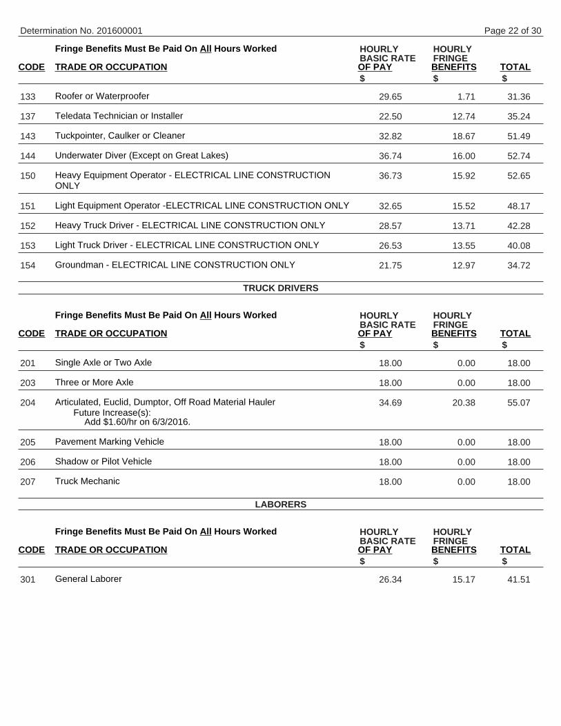
Fringe Benefits Must Be Paid On All Hours Worked
CODE TRADE OR OCCUPATION OF PAY BENEFITS TOTAL
Roofer or Waterproofer
Teledata Technician or Installer
Tuckpointer, Caulker or Cleaner
Underwater Diver (Except on Great Lakes)
Heavy Equipment Operator - ELECTRICAL LINE CONSTRUCTIONONLY
Light Equipment Operator -ELECTRICAL LINE CONSTRUCTION ONLY
Heavy Truck Driver - ELECTRICAL LINE CONSTRUCTION ONLY
Light Truck Driver - ELECTRICAL LINE CONSTRUCTION ONLY
Groundman - ELECTRICAL LINE CONSTRUCTION ONLY
Fringe Benefits Must Be Paid On All Hours Worked
CODE TRADE OR OCCUPATION OF PAY BENEFITS TOTAL
Single Axle or Two Axle
Three or More Axle
Articulated, Euclid, Dumptor, Off Road Material HaulerFuture Increase(s):
Add $1.60/hr on 6/3/2016.
Pavement Marking Vehicle
Shadow or Pilot Vehicle
Truck Mechanic
Fringe Benefits Must Be Paid On All Hours Worked
CODE TRADE OR OCCUPATION OF PAY BENEFITS TOTAL
General Laborer
Determination No. 201600001
HOURLY HOURLYBASIC RATE FRINGE
$ $ $
133 29.65 1.71 31.36
137 22.50 12.74 35.24
143 32.82 18.67 51.49
144 36.74 16.00 52.74
150 36.73 15.92 52.65
151 32.65 15.52 48.17
152 28.57 13.71 42.28
153 26.53 13.55 40.08
154 21.75 12.97 34.72
TRUCK DRIVERS
HOURLY HOURLYBASIC RATE FRINGE
$ $ $
201 18.00 0.00 18.00
203 18.00 0.00 18.00
204 34.69 20.38 55.07
205 18.00 0.00 18.00
206 18.00 0.00 18.00
207 18.00 0.00 18.00
LABORERS
HOURLY HOURLYBASIC RATE FRINGE
$ $ $
301 26.34 15.17 41.51
Page 22 of 30

Fringe Benefits Must Be Paid On All Hours Worked
CODE TRADE OR OCCUPATION OF PAY BENEFITS TOTAL
LandscaperFuture Increase(s):
Add $1.00/hr eff. 06/01/2016; Add $1.00/hr eff.06/01/2017
Premium Increase(s):DOT PREMIUMS: 1) Pay two times the hourly basicrate on Sunday, New Year's Day, Memorial Day,Independence Day, Labor Day, Thanksgiving Day &Christmas Day. 2) Add $1.25/hr for work on projectsinvolving temporary traffic control setup, for lane andshoulder closures, when work under artificial illuminationconditions is necessary as required by the projectprovisions (including prep time prior to and/or cleanupafter such time period).
Flagperson or Traffic Control Person
Fiber Optic Laborer (Outside, Other Than Concrete Encased)
Railroad Track Laborer
Fringe Benefits Must Be Paid On All Hours Worked
CODE TRADE OR OCCUPATION OF PAY BENEFITS TOTAL
Crane, Tower Crane, Pedestal Tower or Derrick, With or WithoutAttachments, With a Lifting Capacity of Over 100 Tons, Self-ErectingTower Crane With a Lifting Capacity Of Over 4,000 Lbs., Crane WithBoom Dollies; Crane, Tower Crane, Pedestal Tower or Derrick, WithBoom, Leads &/or Jib Lengths Measuring 176 Ft or Over; MasterMechanic.
Future Increase(s):Add $1.60/hr on 6/3/2016.
Premium Increase(s):Add $.50/hr for >200 Ton; Add $1/hr at 300 Ton; Add$1.50/hr at 400 Ton; Add $2/hr at 500 Ton & Over.
Determination No. 201600001
HOURLY HOURLYBASIC RATE FRINGE
$ $ $
303 30.67 15.65 46.32
304 20.92 14.80 35.72
311 19.35 0.00 19.35
314 17.00 3.96 20.96
HEAVY EQUIPMENT OPERATORS CONCRETE PAVEMENT OR BRIDGE WORK
HOURLY HOURLYBASIC RATE FRINGE
$ $ $
541 37.67 20.38 58.05
Page 23 of 30

Fringe Benefits Must Be Paid On All Hours Worked
CODE TRADE OR OCCUPATION OF PAY BENEFITS TOTAL
Backhoe (Track Type) Having a Mfgr.'s Rated Capacity of 130,000 Lbs. orOver; Caisson Rig; Crane, Tower Crane, Portable Tower, Pedestal Toweror Derrick, With or Without Attachments, With a Lifting Capacity of 100Tons or Under, Self-Erecting Tower Crane With a Lifting Capacity of 4,000Lbs. & Under; Crane, Tower Crane Portable Tower, Pedestal Tower orDerrick, With Boom, Leads &/or Jib Lengths Measuring 175 Ft or Under;Dredge (NOT Performing Work on the Great Lakes); Licensed Boat Pilot(NOT Performing Work on the Great Lakes); Pile Driver.
Future Increase(s):Add $1.30/hr on 6/1/2016; Add $1.25/hr on 6/1/2017.
Premium Increase(s):DOT PREMIUMS: 1) Pay two times the hourly basicrate on Sunday, New Year's Day, Memorial Day,Independence Day, Labor Day, Thanksgiving Day &Christmas Day. 2) Add $1.50/hr night work premium.See DOT'S website for details about the applicability ofthis night work premium at: http://wisconsindot.gov/Pages/doing-bus/civil-rights/labornwage/prevailing-wage-compliance.aspx.
Air Track, Rotary or Percussion Drilling Machine &/or Hammers, Blaster;Automatic Subgrader (Concrete); Backhoe (Track Type) Having a Mfgr.'sRated Capacity of Under 130,000 Lbs., Backhoe (Mini, 15,000 Lbs. &Under); Boring Machine (Directional, Horizontal or Vertical); Bridge(Bidwell) Paver; Bulldozer or Endloader; Concrete Batch Plant, BatchHopper; Concrete Breaker (Large, Auto, Vibratory/Sonic, Manual orRemote); Concrete Bump Cutter, Grinder, Planing or Grooving Machine;Concrete Conveyor System; Concrete Laser/Screed; Concrete Paver(Slipform); Concrete Pump, Concrete Conveyor (Rotec or Bidwell Type);Concrete Slipform Placer Curb & Gutter Machine; Concrete Spreader &Distributor; Crane (Carry Deck, Mini) or Truck Mounted Hydraulic Crane(10 Tons or Under); Crane With a Lifting Capacity of 25 Tons or Under;Forestry Equipment, Timbco, Tree Shear, Tub Grinder, Processor; Gradall(Cruz-Aire Type); Grader or Motor Patrol; Grout Pump; Hydro-Blaster(10,000 PSI or Over); Loading Machine (Conveyor); Manhoist; Material orStack Hoist; Mechanic or Welder; Milling Machine; Post Hole Digger orDriver; Scraper (Self Propelled or Tractor Drawn) 5 cu yds or MoreCapacity; Shoulder Widener; Sideboom; Skid Rig; Stabilizing or ConcreteMixer (Self-Propelled or 14S or Over); Straddle Carrier or Travel Lift;Tractor (Scraper, Dozer, Pusher, Loader); Tractor or Truck MountedHydraulic Backhoe; Trencher (Wheel Type or Chain Type); Tube Finisher;Tugger (NOT Performing Work on the Great Lakes); Winches &A-Frames.
Future Increase(s):Add $1.30/hr on 6/1/2016; Add $1.25/hr on 6/1/2017.
Premium Increase(s):DOT PREMIUMS: 1) Pay two times the hourly basicrate on Sunday, New Year's Day, Memorial Day,Independence Day, Labor Day, Thanksgiving Day &Christmas Day. 2) Add $1.50/hr night work premium.See DOT'S website for details about the applicability ofthis night work premium at: http://wisconsindot.gov/Pages/doing-bus/civil-rights/labornwage/prevailing-wage-compliance.aspx.
Determination No. 201600001
HOURLY HOURLYBASIC RATE FRINGE
$ $ $
542 37.77 21.85 59.62
543 37.27 21.85 59.12
Page 24 of 30

Fringe Benefits Must Be Paid On All Hours Worked
CODE TRADE OR OCCUPATION OF PAY BENEFITS TOTAL
Backfiller; Belting, Burlap, Texturing Machine; Broom or Sweeper;Compactor (Self-Propelled or Tractor Mounted, Towed & LightEquipment); Concrete Finishing Machine (Road Type); EnvironmentalBurner; Farm or Industrial Type Tractor; Fireman (Pile Driver & DerrickNOT Performing Work on the Great Lakes); Forklift; Greaser; Jeep Digger;Joint Sawer (Multiple Blade); Launch (NOT Performing Work on the GreatLakes); Lift Slab Machine; Mechanical Float; Mulcher; Power Subgrader;Robotic Tool Carrier (WIth or Without Attachments); Self Propelled ChipSpreader; Shouldering Machine; Skid Steer Loader (With or WithoutAttachments); Telehandler; Tining or Curing Machine.
Future Increase(s):Add $1.30/hr on 6/1/2016; Add $1.25/hr on 6/1/2017.
Premium Increase(s):DOT PREMIUMS: 1) Pay two times the hourly basicrate on Sunday, New Year's Day, Memorial Day,Independence Day, Labor Day, Thanksgiving Day &Christmas Day. 2) Add $1.50/hr night work premium.See DOT'S website for details about the applicability ofthis night work premium at: http://wisconsindot.gov/Pages/doing-bus/civil-rights/labornwage/prevailing-wage-compliance.aspx.
Air Compressor (&/or 400 CFM or Over); Air, Electric or Hydraulic JackingSystem; Automatic Belt Conveyor & Surge Bin; Boiler (Temporary Heat);Concrete Proportioning Plant; Crusher, Screening or Wash Plant;Generator (&/or 150 KW or Over); Heaters (Mechanical); High PressureUtility Locating Machine (Daylighting Machine); Mudjack; Oiler; PrestressMachine; Pug Mill; Pump (3 Inch or Over) or Well Points; Rock, StoneBreaker; Screed (Milling Machine); Stump Chipper; Tank Car Heaters;Vibratory Hammer or Extractor, Power Pack.
Fiber Optic Cable Equipment.
Work Performed on the Great Lakes Including Diver; Wet Tender orHydraulic Dredge Engineer.
Work Performed on the Great Lakes Including 70 Ton & Over TugOperator; Assistant Hydraulic Dredge Engineer; Crane or BackhoeOperator; Hydraulic Dredge Leverman or Diver's Tender; Mechanic orWelder.
Future Increase(s):Add $1.25/hr on 1/1/2017.
Premium Increase(s):Add $.50/hr for Friction Crane, Lattice Boom or CraneCertification (CCO).
Work Performed on the Great Lakes Including Deck Equipment Operatoror Machineryman (Maintains Cranes Over 50 Tons or Backhoes 115,000Lbs. or more); Tug, Launch or Loader, Dozer or Like Equipment WhenOperated on a Barge, Breakwater Wall, Slip, Dock or Scow, DeckMachinery.
Determination No. 201600001
HOURLY HOURLYBASIC RATE FRINGE
$ $ $
544 37.27 21.85 59.12
545 31.62 19.78 51.40
546 29.50 0.68 30.18
547 41.65 21.71 63.36
548 44.05 23.24 67.29
549 36.72 21.15 57.87
Page 25 of 30

Work Performed on the Great Lakes Including Deck Equipment Operator;Machineryman or Fireman (Operates 4 Units or More or Maintains Cranes50 Tons or Under or Backhoes 115,000 Lbs. or Under); Deck Hand, DeckEngineer or Assistant Tug Operator; Off Road Trucks - Great LakesONLY.
Fringe Benefits Must Be Paid On All Hours Worked
CODE TRADE OR OCCUPATION OF PAY BENEFITS TOTAL
Crane, Tower Crane, Pedestal Tower or Derrick, With or WithoutAttachments, With a Lifting Capacity of Over 100 Tons, Self ErectingTower Crane With a Lifting Capacity of Over 4,000 Lbs., Crane With BoomDollies; Crane, Tower Crane, Pedestal Tower or Derrick, With Boom,Leads and/or Jib Lengths Measuring 176 Ft or Over; Master Mechanic.
Backhoe (Track Type) Having a Mfgr.'s Rated Capacity of 130,000 Lbs. orOver; Caisson Rig; Crane, Tower Crane, Portable Tower, Pedestal Toweror Derrick, With or Without Attachments, With a Lifting Capacity of 100Tons or Under, Self-Erecting Tower Crane With a Lifting Capacity Of4,000 Lbs. & Under; Crane, Tower Crane, Portable Tower, PedestalTower or Derrick, With Boom, Leads &/or Jib Lengths Measuring 175 Ft orUnder; Dredge (NOT Performing Work on the Great Lakes); LicensedBoat Pilot (NOT Performing Work on the Great Lakes); Pile Driver.
Future Increase(s):Add $1.30/hr on 6/1/2016; Add $1.25/hr on 6/1/2017.
Premium Increase(s):DOT PREMIUMS: 1) Pay two times the hourly basicrate on Sunday, New Year's Day, Memorial Day,Independence Day, Labor Day, Thanksgiving Day &Christmas Day. 2) Add $1.50/hr night work premium.See DOT'S website for details about the applicability ofthis night work premium at: http://wisconsindot.gov/Pages/doing-bus/civil-rights/labornwage/prevailing-wage-compliance.aspx.
Determination No. 201600001
550 36.72 21.15 57.87
HEAVY EQUIPMENT OPERATORS ASPHALT PAVEMENT OR OTHER WORK
HOURLY HOURLYBASIC RATE FRINGE
$ $ $
551 36.67 19.78 56.45
552 37.77 21.85 59.62
Page 26 of 30

Fringe Benefits Must Be Paid On All Hours Worked
CODE TRADE OR OCCUPATION OF PAY BENEFITS TOTAL
Air, Track, Rotary or Percussion Drilling Machine &/or Hammers, Blaster;Asphalt Heater, Planer & Scarifier; Asphalt Milling Machine; AsphaltScreed; Backhoe (Track Type) Having a Mfgr.'s Rated Capacity of Under130,000 Lbs., Backhoe (Mini, 15,000 Lbs. & Under); Bituminous (Asphalt)Plant & Paver, Screed; Boring Machine (Directional, Horizontal orVertical); Bulldozer or Endloader; Concrete Breaker (Large, Auto,Vibratory/Sonic, Manual or Remote); Concrete Conveyor System;Concrete Laser/Screed; Concrete Slipform Placer Curb & Gutter Machine;Crane (Carry Deck, Mini) or Truck Mounted Hydraulic Crane (10 Tons orUnder); Crane With a Lifting Capacity of 25 Tons or Under; ForestryEquipment, Timbco, Tree Shear, Tub Grinder, Processor; Gradall(Cruz-Aire Type); Grader or Motor Patrol; Hydro-Blaster (10,000 PSI orOver); Loading Machine (Conveyor); Manhoist; Material or Stack Hoist;Mechanic or Welder; Milling Machine; Post Hole Digger or Driver; RailroadTrack Rail Leveling Machine, Tie Placer, Extractor, Tamper, Stone Leveleror Rehabilitation Equipment; Roller (Over 5 Ton); Scraper (Self Propelledor Tractor Drawn) 5 cu yds or More Capacity; Shoulder Widener;Sideboom; Skid Rig; Stabilizing or Concrete Mixer (Self-Propelled or 14Sor Over); Tractor (Scraper, Dozer, Pusher, Loader); Tractor or TruckMounted Hydraulic Backhoe; Trencher (Wheel Type or Chain Type); TubeFinisher; Tugger (NOT Performing Work on the Great Lakes); Winches &A-Frames.
Future Increase(s):Add $1.60/hr on 6/3/2016.
Backfiller; Broom or Sweeper; Compactor (Self-Propelled or TractorMounted, Towed & Light Equipment); Concrete Finishing Machine (RoadType); Environmental Burner; Farm or Industrial Type Tractor; Fireman(Asphalt Plant, Pile Driver & Derrick NOT Performing Work on the GreatLakes); Forklift; Greaser; Hoist (Tugger, Automatic); Jeep Digger; JointSawer (Multiple Blade); Launch (NOT Performing Work on the GreatLakes); Lift Slab Machine; Mechanical Float; Mulcher; Power Subgrader;Robotic Tool Carrier (With or Without Attachments); Roller (Rubber Tire, 5Ton or Under); Self-Propelled Chip Spreader; Shouldering Machine; SkidSteer Loader (With or Without Attachments); Telehandler.
Air Compressor (&/or 400 CFM or Over); Air, Electric or Hydraulic JackingSystem; Augers (Vertical & Horizontal); Automatic Belt Conveyor & SurgeBin; Boiler (Temporary Heat); Crusher, Screening or Wash Plant;Generator (&/or 150 KW or Over); Heaters (Mechanical); High PressureUtility Locating Machine (Daylighting Machine); Mudjack; Oiler; PrestressMachine; Pug Mill; Pump (3 Inch or Over) or Well Points; Rock, StoneBreaker; Screed (Milling Machine); Stump Chipper; Tank Car Heaters;Vibratory Hammer or Extractor, Power Pack.
Future Increase(s):Add $1.60/hr on 6/3/2016.
Fiber Optic Cable Equipment.
Determination No. 201600001
HOURLY HOURLYBASIC RATE FRINGE
$ $ $
553 34.69 20.38 55.07
554 36.17 19.19 55.36
555 32.62 20.38 53.00
556 29.50 0.68 30.18
Page 27 of 30

Includes single family houses or apartment buildings of no more than four (4) stories in height and all buildings,structures or facilities that are primarily used for agricultural or farming purposes, excluding commercial buildings. Forclassification purposes, the exterior height of a residential building, in terms of stories, is the primary consideration. Allincidental items such as site work, driveways, parking lots, private sidewalks, private septic systems or sewer andwater laterals connected to a public system and swimming pools are included within this definition. Residentialbuildings of five (5) stories and above are NOT included within this definition.
Fringe Benefits Must Be Paid On All Hours Worked
CODE TRADE OR OCCUPATION OF PAY BENEFITS TOTAL
Acoustic Ceiling Tile Installer
Boilermaker
Bricklayer, Blocklayer or Stonemason
Cabinet Installer
Carpenter
Carpet Layer or Soft Floor Coverer
Cement Finisher
Drywall Taper or Finisher
Electrician
Elevator Constructor
Fence Erector
Fire Sprinkler Fitter
Glazier
Heat or Frost Insulator
Insulator (Batt or Blown)
Ironworker
Lather
Marble Finisher
Marble Mason
Metal Building Erector
Overhead Door Installer
Painter
Pavement Marking Operator
Determination No. 201600001
RESIDENTIAL OR AGRICULTURAL CONSTRUCTION
SKILLED TRADES
HOURLY HOURLYBASIC RATE FRINGE
$ $ $
101 37.41 0.00 37.41
102 33.35 28.29 61.64
103 32.82 9.93 42.75
104 20.00 0.46 20.46
105 25.39 5.03 30.42
106 24.04 4.89 28.93
107 23.86 3.43 27.29
108 27.00 0.00 27.00
109 20.00 12.47 32.47
110 46.05 27.09 73.14
111 19.45 4.70 24.15
112 33.00 18.96 51.96
113 38.27 14.42 52.69
114 17.00 0.00 17.00
115 20.00 12.35 32.35
116 24.30 14.25 38.55
117 25.39 5.03 30.42
119 25.72 18.54 44.26
120 32.82 9.93 42.75
121 13.60 6.57 20.17
123 18.00 0.00 18.00
124 26.24 0.00 26.24
125 30.00 18.81 48.81
Page 28 of 30

Fringe Benefits Must Be Paid On All Hours Worked
CODE TRADE OR OCCUPATION OF PAY BENEFITS TOTAL
Plasterer
Plumber
Refrigeration Mechanic
Roofer or Waterproofer
Sheet Metal Worker
Steamfitter
Teledata Technician or Installer
Temperature Control Installer
Terrazzo Finisher
Terrazzo Mechanic
Tile Finisher
Tile SetterFuture Increase(s):
Add $1.45/hr on 6/06/2016.
Tuckpointer, Caulker or Cleaner
Well Driller or Pump Installer
Siding Installer
Fringe Benefits Must Be Paid On All Hours Worked
CODE TRADE OR OCCUPATION OF PAY BENEFITS TOTAL
Single Axle or Two Axle
Three or More Axle
Pavement Marking Vehicle
Truck Mechanic
Fringe Benefits Must Be Paid On All Hours Worked
CODE TRADE OR OCCUPATION OF PAY BENEFITS TOTAL
General Laborer
Asbestos Abatement Worker
Determination No. 201600001
HOURLY HOURLYBASIC RATE FRINGE
$ $ $
129 30.00 9.21 39.21
130 30.00 11.56 41.56
132 22.50 9.03 31.53
133 21.00 4.10 25.10
134 23.22 5.45 28.67
135 17.05 0.94 17.99
137 22.50 12.74 35.24
138 22.50 2.36 24.86
139 25.72 18.54 44.26
140 33.67 17.82 51.49
141 30.00 0.00 30.00
142 31.59 19.61 51.20
143 25.00 2.99 27.99
146 29.00 0.64 29.64
147 14.00 0.00 14.00
TRUCK DRIVERS
HOURLY HOURLYBASIC RATE FRINGE
$ $ $
201 16.50 0.50 17.00
203 21.53 3.34 24.87
205 21.53 3.34 24.87
207 21.53 3.34 24.87
LABORERS
HOURLY HOURLYBASIC RATE FRINGE
$ $ $
301 17.20 9.26 26.46
302 18.00 3.22 21.22
Page 29 of 30

Fringe Benefits Must Be Paid On All Hours Worked
CODE TRADE OR OCCUPATION OF PAY BENEFITS TOTAL
Landscaper
Fiber Optic Laborer (Outside, Other Than Concrete Encased)
Final Construction Clean-Up Worker
Fringe Benefits Must Be Paid On All Hours Worked
CODE TRADE OR OCCUPATION OF PAY BENEFITS TOTAL
Asphalt Heater, Planer & Scarifier; Asphalt Milling Machine; AsphaltScreed; Backhoe (Track Type); Backhoe (Mini, 15,000 Lbs. & Under);Bituminous (Asphalt) Plant & Paver, Screed; Boring Machine (Directional,Horizontal or Vertical); Bulldozer or Endloader; Concrete Breaker (Large,Auto, VIbratory/Sonic, Manual or Remote); Concrete Bump Cutter,Grinder, Planing or Grooving Machine; Concrete Conveyor System;Concrete Laser/Screed; Concrete Paver (Slipform); Concrete Pump,Concrete Conveyor (Rotec or Bidwell Type); Concrete Slipform PlacerCurb & Gutter Machine; Concrete Spreader & DIstributor; Crane (CarryDeck, Mini) or Truck Mounted Hydraulic Crane (10 Tons or Under); CraneWith a Lifting Capacity of 25 Tons or Under; Crane, Shovel, Dragline,Clamshells; Forestry Equipment, TImbco, Tree Shear, Tub Grinder,Processor; Grader or Motor Patrol; Grout Pump; Hydro-Blaster (10,000PSI or Over); Loading Machine (Conveyor); Manhoist; Material or StackHoist; Mechanic or Welder; Milling Machine; Roller (Over 5 Ton); Scraper(Self Propelled or Tractor Drawn) 5 cu yds or More Capacity; ShoulderWidener; Skid Rig; Stabilizing or Concrete Mixer (Self-Propelled or 14S orOver); Tractor (Scraper, Dozer, Pusher, Loader); Tractor or TruckMounted Hydraulic Backhoe; Tractor or Truck Mounted Hydraulic Crane(10 Tons or Under); Trencher (Wheel Type or Chain Type); WInches &A-Frames.
Air Compressor (&/or 400 CFM or Over); Air, Electric or Hydraulic JackingSystem; Backfiller; Belting, Burlap, Texturing Machine; Boiler (TemporaryHeat); Broom or Sweeper; Compactor (Self-Propelled or Tractor Mounted,Towed & LIght Equipment); Concrete Finishing Machine (Road Type);Farm or Industrial Type Tractor; Forklift; Generator (&/or 150 KW or Over);Heaters (Mechanical); High Pressure Utility Locating Machine (DaylightingMachine); Jeep Digger; Lift Slab Machine; Mulcher; Oiler; Post HoleDigger or Driver; Power Subgrader; Pump (3 Inch or Over) or Well Points;Robotic Tool Carrier (With or Without Attachments); Rock, Stone Breaker;Roller (Rubber Tire, 5 Tons or Under); Screed (Milling Machine); SelfPropelled Chip Spreader; Shouldering Machine; Skid Steer Loader (Withor Without Attachments); Stump Chipper; Telehandler; Vibratory Hammeror Extractor, Power Pack.
Future Increase(s):Add $1.60/hr on 6/3/2016.
Determination No. 201600001
HOURLY HOURLYBASIC RATE FRINGE
$ $ $
303 15.00 4.03 19.03
311 19.35 0.00 19.35
315 15.00 0.00 15.00
HEAVY EQUIPMENT OPERATORS RESIDENTIAL OR AGRICULTURAL CONSTRUCTION
HOURLY HOURLYBASIC RATE FRINGE
$ $ $
557 34.22 19.55 53.77
558 31.99 20.38 52.37
*************************************************************** END OF RATES ***************************************************************
Page 30 of 30