BIBLOCK - Manual de instrucciones - Amazon S3
103
EAS THERMAL BIBLOCK MANUAL DE INSTALACIÓN Y MANUAL DE USUARIO MODELOS: ETH-10VB ETH-12VB ETH-16VB V.2
-
Upload
khangminh22 -
Category
Documents
-
view
1 -
download
0
Transcript of BIBLOCK - Manual de instrucciones - Amazon S3

EAS THERMALBIBLOCK
MANUAL DE INSTALACIÓNY MANUAL DE USUARIO
MODELOS: ETH-10VB ETH-12VB ETH-16VB
V.2

1
CONTENIDOS PÁGINA
1. PRECAUCIONES.............................................................................1
2. ACCESORIOS Y REFRIGERANTE..................................................2
3. ANTES DE LA INSTALACION........................................................2
4. INFORMACIÓN IMPORTANTE SOBRE EL REFRIGERANTE UTILIZADO.........................................................................................3
5. SELECCIONANDO EL SITIO DE INSTALACION.......................3
6. INSTALACION DE UNIDAD EXTERIOR ...................................4
7. INSTALAR EL TUBO DE CONEXIÓN...........................................6
8. CABLEADO ELÉCTRICO...............................................................8
9. FUNCIONAMIENTO DE PRUEBA..............................................10
10. PRECAUCIONES SOBRE FUGAS REFRIGERANTES...............10
11. Entrega del manual al cliente............................................................11
12. OPERACIÓN Y RENDIMIENTO.................................................12
13. CÓDIGO DE MAL FUNCIONAMIENTO DE UNIDAD EXTERIOR....................................................................................13
14. SINTOMAS QUE NO SON PROBLEMAS .................................15
15. SOLUCIÓN DE PROBLEMAS....................................................15
16. ESPECIFICACIONES TECNICAS...............................................17
17. INFORMACIÓN IMPORTANTE PARA EL REFRIGERANTE USADO .........................................................................................18
PRECAUCIÓNNueva instalación de bomba de calor refrigerante
1 PRECAUCIONES
1) Asegúrese de que todas las regulaciones locales, nacionales einternacionales estén satisfechas.
2) Lea detenidamente estas "PRECAUCIONES DESEGURIDAD" antes de la instalación.
3) Las precauciones descritas a continuación incluyen loselementos importantes relacionados con la seguridad.Obsérvalos sin falta.
4) Después del trabajo de instalación, realice una operación deprueba para verificar si hay algún problema.
5) Siga el Manual del propietario para explicar cómo usar ymantener la unidad al cliente.
6) Apague el interruptor de la fuente de alimentación principal (odisyuntor) antes del mantenimiento de la unidad.
7) Pídale al cliente que guarde el Manual de instalación junto conel Manual del propietario.
ESTA BOMBA DE CALOR ADOPTA AL NUEVO REFRIGERANTE HFC (R410A) QUE NO DESTRUYE LA CAPA DE OZONO.
● Las características del refrigerante R410A son: Fácil deabsorber agua, membrana oxidante o aceite, y su presiónes aproximadamente 1.6 veces más alta que la delrefrigerante R22. Acompañado con el nuevo refrigerante,también se ha cambiado el aceite refrigerante. Por lo tanto,durante el trabajo de instalación, asegúrese de que elagua, el polvo, El refrigerante anterior, o el aceite derefrigeración no entra en el ciclo de refrigeración.● Para evitar la carga de un refrigerante y aceite derefrigeración incorrectos, los tamaños de las secciones de conexión del puerto de carga de la unidad principal y las herramientas de instalación se cargan a partir del refrigerante convencional.● En consecuencia, se requieren herramientas exclusivaspara el nuevo refrigerante (R410A):Para conectar tuberías, use tuberías nuevas y limpiasdiseñadas para R410A, y tenga cuidado de que no entreagua o polvo. Además, no use la tubería existente porquehay problemas con la fuerza de resistencia a la presión yla impureza en ella.
PRECAUCIÓN
Para desconectar el aparato de la fuente de alimentación principal.
ADVERTENCIA
● Este dispositivo puede ser utilizado por niños de 8 añosen adelante y personas con capacidades físicas,sensoriales o mentales reducidas o por falta deexperiencia y conocimiento si se les ha dado supervisióno instrucciones sobre el uso del dispositivo de manerasegura y entienden el peligros involucrados Los niños nodeben jugar con el aparato. La limpieza y el mantenimientodel usuario no deben ser realizados por niños sinsupervisión.● Los niños deben ser supervisados para asegurarse deque no jueguen con el aparato.● Solicite a un distribuidor autorizado o profesional de lainstalación calificado que instale / mantenga la bomba decalor. Una instalación inadecuada puede provocar fugasde agua, descargas eléctricas o incendios.● Apague el interruptor principal de la fuente dealimentación o el disyuntor antes de intentar realizarcualquier trabajo eléctrico. Asegúrese de que todos losinterruptores de alimentación estén apagados. Si no lohace, puede provocar una descarga eléctrica.● Conecte el cable de conexión correctamente. Si el cablede conexión se conecta de manera incorrecta, las piezaseléctricas podrían dañarse.● Cuando mueva la bomba de calor para la instalación aotro lugar, tenga mucho cuidado de no ingresar ningunasustancia gaseosa que no sea el refrigerante especificadoen el ciclo de refrigeración. Si el aire o cualquier otro semezcla con el refrigerante, la presión del gas en el ciclo derefrigeración se vuelve anormalmente alta y puede comoresultado causa rotura de tubería y lesiones en personas.
Este aparato debe conectarse a la fuente de alimentación principal mediante un interruptor con una separación de contacto de al menos 3 mm. El fusible de instalación debe utilizarse para la línea de alimentación de esta bomba de calefacción.
V.2

2
2 ACCESORIOS Y REFRIGERANTEPor favor, compruebe si los siguientes accesorios son de alcance completo. Si hay algunos accesorios de repuesto, por favor restaurarlos cuidadosamente.
●
●
●
●
No modifique esta unidad retirando ninguno de los guardas de seguridad ni pasando ninguno de los interruptores de bloqueo de seguridad. La exposición de la unidad al agua u otra humedad antes de la instalación puede causar un cortocircuito en las partes eléctricas. No lo guarde en un sótano húmedo ni lo exponga a la lluvia o al agua.Después de desembalar la unidad, examínela con cuidado si hay posibles daños. No la instale en un lugar que pueda aumentar la vibración de la unidad.Preste atención para evitar los componentes mientras se conecta a los tubos de conexión.Para evitar que la tubería de refrigerante se oxide en el interior cuando se suelda, es necesario cargar nitrógeno, o el óxido bloqueará el sistema de circulación. Para evitar lesiones personales (con bordes afilados), tenga cuidado al manipular las piezas.
●
●
Realice el trabajo de instalación correctamente deacuerdo con el Manual de instalación. La instalacióninadecuada puede provocar fugas de agua, descargaseléctricas o incendios. Cuando la bomba de calor seinstala en una habitación pequeña, proporcione lasmedidas adecuadas para garantizar que laconcentración de fugas de refrigerante en la habitaciónno supere el nivel crítico.Instale la bomba de calor de forma segura en un lugardonde la base pueda sostener el peso adecuadamente.Realice el trabajo de instalación especificado paraprotegerse contra un terremoto. Si la bomba de calor noestá instalada adecuadamente, pueden ocurriraccidentes debido a la caída de la unidad.
●
●
Si el gas refrigerante se ha filtrado durante el trabajo deinstalación, ventile la habitación inmediatamente. Si elgas refrigerante que se filtra entra en contacto con elfuego, puede generarse gas nocivo.Después del trabajo de instalación, confirme que elproductor de gas refrigerante no tenga fugas. Si el gasrefrigerante se filtra hacia la habitación y fluye cerca deuna fuente de fuego, como un rango de cocción, podríagenerarse un gas nocivo.
● El trabajo eléctrico debe ser realizado por unelectricista calificado de acuerdo con el Manual deinstalación.
● Asegúrese de que la bomba del calentador utilice unafuente de alimentación exclusiva. Una capacidad desuministro de energía insuficiente o una instalacióninadecuada pueden provocar un incendio.
● Utilice los cables especificados para el cableado,conecte los terminales de forma segura. Para evitar quelas fuerzas externas aplicadas a los terminales afecten alos terminales. Asegúrese de proporcionar conexión atierra. No conecte cables de tierra a tuberías de gas,tuberías de agua, pararrayos o cables de tierra paracables telefónicos.Cumpla con las regulaciones de la compañía eléctrica
local cuando realice el cableado de la fuente dealimentación. Una conexión a tierra inadecuada puedeprovocar una descarga eléctrica.
● No instale la bomba de calor en un lugar expuesto a unriesgo de exposición a un gas combustible. Si se fuga ungas combustible y permanece alrededor de la unidad,puede producirse un incendio.● Si el cable de alimentación está dañado, debe serreemplazado por el fabricante, su agente de servicio opersonas con calificaciones similares para evitar unpeligro.● Si se pretende que un aparato esté conectadopermanentemente a la red de suministro de agua y no seconecte mediante un juego de manguera, esto deberáindicarse.
CantidadFormaDescripción
Instalación de unidad exterior &manual del propietario (este libro) 1
2. Drainage pipe connector 1
3. Anillo magnetico(Sólo para 1 Phase10 ~ 16kW) 1
Acc
esor
ios
de in
stal
ació
n
1
2
3
4
5
6
7
8
9
10
11
12
13
14
15
16
Destornillador
Corona pared(65mm)
LlaveCortador de tubosCuchilloEscariador
Detector de fugas de gas
Cinta métricaTermometroMega-tester
Electro circuit tester
Llave hexagonal
Herramienta de bengala
Dobladora de tubosNivel burbuja
Sierra de metal
17
18
19
20
21
Colector de calibre(Manguera de carga: R410A requisito especial)
Bomba aspiradora(Manguera de carga: R410A requisito especial)
Llave de torsión1/4 (17 mm) 16N • m (1.6kgf • m) 3/8 (22mm) 42N • m (4.2kgf • m) 1/2 (26mm) 55N • m (5.5kgf • m) 5/8 (15.9 mm) 120N • m (12.0kgf • m)
Calibre de tubería de cobre ajustando el margen de proyección.
Bomba aspiradora adaptador
3 ANTES DE LA INSTALACIÓNAntes de la instalación
Asegúrese de confirmar el nombre del modelo y el número de serie de la unidad.
ManejoDebido a las dimensiones relativamente grandes y al alto peso, el manejo de la unidad solo se realiza mediante herramientas de elevación con eslingas. Estas eslingas pueden ajustarse especialmente para este propósito, previstas mangas en el bastidor base.
Para evitar lesiones, no toque la entrada de aire o las aletas de aluminio de la unidad.● No utilice los agarres en las rejillas del ventilador paraevitar daños.● ¡La unidad es muy pesada!Evite que la unidad se caiga debido a la inclinacióndurante el manejo.
PRECAUCIÓN
Herramientas necesarias para el trabajo de instalación:
Modo calor
Modo fríoModo de agua caliente sanitaria.
Rango de temperatura ambiente de operación
-20 ~ +35℃
-5 ~ +46℃
-20 ~ +43℃
4. Manual técnico del producto 1
5. Etiqueta energética 1
●
V.2

3
4 INFORMACIÓN IMPORTANTE CON RESPECTO
AL REFRIGERANTE UTILIZADO
Este producto contiene gases fluorados de efecto invernadero cubiertos por el Protocolo de Kyoto. No ventile gases a la atmósfera. Tipo de refrigerante: R410A
Valor GWP (1): 1975
(1) GWP = potencial de calentamiento global
La cantidad de refrigerante se indica en la placa de identificación de la unidad.
5 SELECCIONANDO EL SITIO DE INSTALACIÓN
■ Asegúrese de proporcionar las medidas adecuadas paraevitar que la unidad sea utilizada como refugio poranimales pequeños.■ Los animales pequeños que entran en contacto conpartes eléctricas pueden causar un mal funcionamiento,humo o fuego. Indique al cliente que mantenga limpia elárea alrededor de la unidad.
Asegúrese de que hay suficiente espacio para hacer la instalación
ADVERTENCIA
1 Seleccione un sitio de instalación donde se cumplan las siguientes condiciones y que cumpla con la aprobación de su cliente.
- Lugares que estén bien ventilados.- Lugares donde la unidad no moleste a los vecinos de al lado.- Lugares seguros que puedan soportar el peso y la vibración de launidad y donde se pueda instalar la unidad a nivel.- Lugares donde no haya posibilidad de fugas de gas inflamable oproducto.- El equipo no está diseñado para su uso en una atmósferapotencialmente explosiva.- Lugares donde el espacio de servicio puede estar bienasegurado.- Lugares donde la longitud de la tubería y el cableado de lasunidades están dentro de los rangos permitidos.- Los lugares donde el agua que gotea de la unidad no puedecausar daños en la ubicación (por ejemplo, en el caso de un tubode desagüe bloqueado).- Lugares donde se evite la lluvia tanto como sea posible.- No instale la unidad en lugares de uso frecuente como lugar detrabajo.En el caso de trabajos de construcción (por ejemplo, trabajos deesmerilado) donde se crea una gran cantidad de polvo, la unidaddebe cubrirse.- No coloque ningún objeto o equipo encima de la unidad (placasuperior)- No suba, se siente ni se pare encima de la unidad.- Asegúrese de tomar suficientes precauciones, de acuerdo conlas leyes y regulaciones locales pertinentes, en caso de fugas derefrigerante.
2 Cuando instale la unidad en un lugar expuesto a fuertes vientos, ponga especial atención a los siguientes casos: Los vientos fuertes de 5 m / seg o más que soplan contra la salida de aire de la unidad causan un cortocircuito (succión del aire de descarga), y esto puede tener las siguientes consecuencias:
- Deterioro de la capacidad operativa.- Aceleración frecuente de las heladas en la operación decalefacción.- Interrupción de la operación debido al aumento de la altapresión.- Cuando sopla un viento fuerte continuamente en la cara de launidad, el ventilador puede comenzar a girar muy rápido hastaque se rompe.Consulte las figuras para la instalación de esta unidad en un lugardonde se pueda prever la dirección del viento.
■ Gire el lado de la salida de aire hacia la pared, la cerca o lapantalla del edificio.
3 Prepare un canal de drenaje de agua alrededor de la cimentación, para drenar. aguas residuales de alrededor de la unidad.4 Si el drenaje de agua de la unidad no es fácil, por favor instale la unidad sobre una cimentación de bloques de hormigón, etc. (la altura de la cimentación debe ser de unos 100 mm).
5 Si instala la unidad en un marco, instale una placa impermeable unos 100 mm. de la parte inferior de la unidad para evitar la invasión de agua desde la dirección inferior.
6 Al instalar la unidad en un lugar frecuentemente expuesto a la nieve, Presta especial atención a elevar los cimientos lo más alto posible.
7 Si instala la unidad en un marco de edificio, instale una placa impermeable (suministro de campo) (unos 100 mm.) de la parte inferior de la unidad) para evitar el goteo del agua de drenaje. (Ver figura).
■ Coloque el lado de salida en ángulo recto con respecto a ladirección del viento.
Viento fuerte
Viento fuerte
Aire soplado
V.2

4
6.2 Espacio instalación (unidad:mm)
● Cuando se instala una unidad exterior en un lugar que siempreestá expuesto a un viento fuerte como una costa o en un piso altode un edificio, asegure una operación de ventilador normalutilizando un conducto o un escudo contra el viento.
● Cuando la unidad exterior se instala en una posición elevada,asegúrese de 4secure sus pies.
● Mantenga la unidad interior, la unidad exterior, el cableado de lafuente de alimentación y el cableado de la transmisión al menos a1 metro de distancia de televisores y radios. Esto es para evitar lainterferencia de la imagen y el ruido en esos aparatos eléctricos.(Se puede generar ruido dependiendo de las condiciones bajo lascuales se genera la onda eléctrica, incluso si se mantiene 1metro).
● El aislamiento de las partes metálicas del edificio y la bombadel calentador debe cumplir con la regulación de la NormaNacional de Electricidad.
PRECAUCIÓN
6 INSTALACIÓN DE UNIDAD EXTERIOR
6.1 Lugar de instalación
Por favor, manténgase alejado del siguiente lugar, ya que se puede producir un mal funcionamiento de la máquina:1) Hay fugas de gas combustible.2) Hay mucho aceite (incluido el aceite del motor) ingrediente.3) Hay aire salado que rodea (cerca de la costa)4) Hay gas cáustico (el sulfuro, por ejemplo) que existe en el aire(cerca de una fuente termal)5) Un lugar donde el aire caliente expulsado de la unidad exteriorpuede alcanzar la ventana de su vecino.6) Un lugar donde el agua del desagüe no hace ningún problema.7) Un lugar donde el ruido interfiere la vida cotidiana de tus vecinos.8) Un lugar que no esté expuesto a un viento fuerte.9) Un lugar que es demasiado débil para soportar el peso de launidad.10) Un lugar que no bloquee un pasaje.11) Lugar desigual.12) Insuficiente lugar de ventilación.Cerca de una central eléctrica privada o equipo de alta frecuencia.Instale la unidad interior, la unidad exterior, el cable dealimentación y el cable de conexión a una distancia de al menos 1m del televisor o la radio para evitar ruidos o interferencias en laimagen.
C
E D
B
1) Instalación de una sola unidad
>300
>600
>003
>0002
(Pared u obstaculo)
Mantener Espacio
Salida aire
Entrada aire
Entrada aire
MODELO
360400 1327 /900
ED FC
10~16kW
BA H
600 348
Fig.No.
Fig.6-2/Fig.6-4
B
C DE
AF
A
H
H
Fig.6-1
Fig.6-2
Fig.6-3
Fig.6-4
Fig.6-5
V.2
5
Todas las imágenes de este manual son solo para fines de explicación. Pueden ser ligeramente diferentes de la bomba de calor que compró (depende del modelo). La forma real prevalecerá.
NOTA
mm006>
Fijar con perno
6.4 Salida de agua
La siguiente figura muestra cuatro salidas de agua condensada en el chasis para la selección:
Salida de agua
Toma de corriente para la alimentación y conexión de tuberías.
Reserva de salida de
agua (Necesidad de
abrir la puerta)
Reserva de salida de agua (Con tapón de goma).
10~16kW
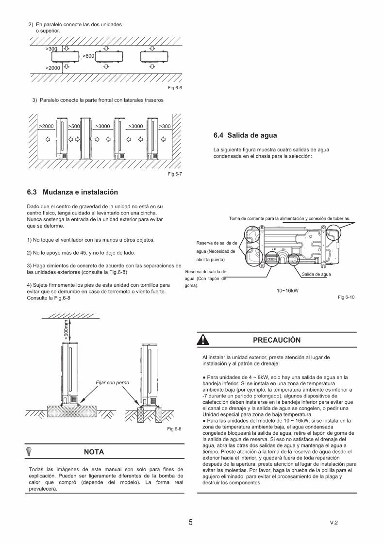
2) En paralelo conecte las dos unidadeso superior.
3) Paralelo conecte la parte frontal con laterales traseros
>2000 >500 >3000 >3000 >300
>600
>2000
>300
6.3 Mudanza e instalación
Dado que el centro de gravedad de la unidad no está en su centro físico, tenga cuidado al levantarlo con una cincha.Nunca sostenga la entrada de la unidad exterior para evitar que se deforme.
1) No toque el ventilador con las manos u otros objetos.
2) No lo apoye más de 45, y no lo deje de lado.
3) Haga cimientos de concreto de acuerdo con las separaciones delas unidades exteriores (consulte la Fig.6-8)
4) Sujete firmemente los pies de esta unidad con tornillos paraevitar que se derrumbe en caso de terremoto o viento fuerte.Consulte la Fig.6-8
PRECAUCIÓN
Al instalar la unidad exterior, preste atención al lugar de instalación y al patrón de drenaje:
● Para unidades de 4 ~ 8kW, solo hay una salida de agua en labandeja inferior. Si se instala en una zona de temperaturaambiente baja (por ejemplo, la temperatura ambiente es inferior a-7 durante un período prolongado), algunos dispositivos decalefacción deben instalarse en la bandeja inferior para evitar queel canal de drenaje y la salida de agua se congelen, o pedir unaUnidad especial para zona de baja temperatura.● Para las unidades del modelo de 10 ~ 16kW, si se instala en lazona de temperatura ambiente baja, el agua condensada congelada bloqueará la salida de agua, retire el tapón de goma de la salida de agua de reserva. Si eso no satisface el drenaje del agua, abra las otras dos salidas de agua y mantenga el agua a tiempo. Preste atención a la toma de la reserva de agua desde el exterior hacia el interior, y quedará fuera de toda reparación después de la apertura, preste atención al lugar de instalación para evitar las molestias. Por favor, haga la prueba de la polilla para el agujero eliminado, para evitar el procesamiento de la plaga y destruir los componentes.
Fig.6-6
Fig.6-7
Fig.6-8
Fig.6-10
V.2

6
PRECAUCIÓN
7 INSTALAR EL TUBO DE CONEXIÓN
Verifique si la diferencia de altura entre la unidad interior y la unidad exterior, la longitud de la tubería de refrigerante y el número de curvas cumplen los siguientes requisitos:
7.1 Tubería de refrigerante Tubo de salida frontal Salida posteriorTubo de salida lateral Tubo de superficie
Tubería más gruesa
4~8kW
10~16kW
● Preste atención para evitar los componentes donde se conectaa los tubos de conexión.● Para evitar que la tubería de refrigerante se oxide en el interioral soldar, es necesario cargar nitrógeno, o el óxido puedebloquear el sistema de circulación.
1) La interfaz de la tubería de conexión interior y exterior y lasalida de cable.Puede seleccionar varios patrones de cableado y tuberías, comodesde el frente, la parte posterior, el lado y la superficie inferior,etc. (A continuación se muestran las ubicaciones de variasinterfaces de conexión de tuberías y cableado)
PRECAUCIÓN
● Tubo lateral: retire la placa de metal en forma de L, de locontrario no podrá realizar el cableado.● Tubo de retroceso:Tubería de salida debajo de la superficie: el orificio debe deadentro hacia afuera, y luego la tubería y el cableado a través deesto. Preste atención a la tubería, la tubería de conexión de grasadebe salir del orificio más grande, de lo contrario se frotarán lastuberías. Por favor, haga la prueba de la polilla para el agujeroeliminado, para evitar el procesamiento de la plaga y destruir loscomponentes.Limpie la manta de goma del soporte de la tubería al lado de latapa de la tubería de salida interior de la máquina mientras laparte trasera sale de las tuberías.
El cuerpo de la unidad Lado de la tubería del sitio
Cortar desde arriba
7.3 Aislamiento térmico
Realice el aislamiento térmico a las tuberías del lado del gas y del lado del líquido por separado. La temperatura de las tuberías del lado del gas y del lado del líquido durante el enfriamiento, para evitar la condensación, haga el aislamiento térmico por completo.
1) La tubería del lado del gas debe usar material de aislamiento deespuma de celda cerrada, cuyo retardante de fuego es de grado B1y la resistencia térmica superior a 120 ℃.2) Cuando el diámetro externo de la tubería de cobre esde .712.7mm, el espesor de la capa aislante por lo menos más de15mm; Cuando el diámetro externo de la tubería de cobre es deΦ15.9mm, el espesor de la capa aislante es de al menos más de20mm.3) Utilice materiales aislantes térmicos adjuntos. Haga elaislamiento térmico sin espacio para las partes de conexión de lostubos de la unidad interior.
Punto de control de la unidad interior.
Punto de control de la unidad exterior.
D
A BC
A BPunto de control de la unidad exterior.
7.2 Detección de fugas
Utilice agua jabonosa o un detector de fugas para verificar si todas las juntas tienen fugas o no (consulte la Fig.7-3). Nota:A es la válvula de cierre lateral de baja presiónB es la válvula de cierre lateral de alta presiónC y D es la interfaz de las tuberías de conexión de las unidades interiores y exteriores
1 2líquido gas
1 2líquido gas
Fig.7-1
Fig.7-2
Fig.7-3
Fig.7-4Cinturón de bomba de calor afiliado
V.2
7
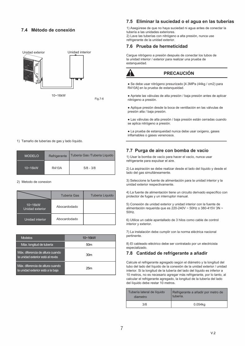
Tubería lateral de líquido diametro
Refrigerante a añadir por metro de tubería.
3/8 0.054kg
Unidad interior
7.4 Método de conexión
Unidad exterior
10~16kW
1) Tamaño de tuberías de gas y lado líquido.
5/8 - 3/8R410A
RefrigeranteMODELO Tuberia Gas /Tuberia Liquido
2) Metodo de conexion
Unidad interior
Tuberia Gas Tuberia Liquido
Abocardodado
7.5 Eliminar la suciedad o el agua en las tuberías1) Asegúrese de que no haya suciedad ni agua antes de conectar latubería a las unidades exteriores.2) Lave las tuberías con nitrógeno a alta presión, nunca userefrigerante de la unidad exterior.
7.6 Prueba de hermeticidad
Cargue nitrógeno a presión después de conectar los tubos de la unidad interior / exterior para realizar una prueba de estanqueidad.
PRECAUCIÓN
● Se debe usar nitrógeno presurizado [4.3MPa (44kg / cm2) paraR410A] en la prueba de estanqueidad.
● Apriete las válvulas de alta presión / baja presión antes de aplicarnitrógeno a presión.
● Aplique presión desde la boca de ventilación en las válvulas depresión alta / baja presión.
● Las válvulas de alta presión / baja presión están cerradas cuandose aplica nitrógeno a presión.
● La prueba de estanqueidad nunca debe usar oxígeno, gasesinflamables o gases venenosos.
7.7 Purga de aire con bomba de vacío1) Usar la bomba de vacío para hacer el vacío, nunca usarrefrigerante para expulsar el aire.
2) La aspiración se debe realizar desde el lado del líquido y desde ellado del gas simultáneamente.
3) Seleccione la fuente de alimentación para la unidad interior y launidad exterior respectivamente.
4) La fuente de alimentación tiene un circuito derivado específico conprotector de fugas y un interruptor manual.
5) Conexión de unidad exterior y unidad interior con la fuente dealimentación requerida que es 220-240V ~ 50Hz o 380-415V 3N ~50Hz.
6) Utilice un cable apantallado de 3 hilos como cable de controlinterior y exterior.
7) La instalación debe cumplir con la norma eléctrica nacionalpertinente.
8) El cableado eléctrico debe ser contratado por un electricistaespecializado.
7.8 Cantidad de refrigerante a añadir
Calcule el refrigerante agregado según el diámetro y la longitud del tubo del lado del líquido de la conexión de la unidad exterior / unidad interior. Si la longitud de la tubería del lado del líquido es inferior a 10 metros, no es necesario agregar más refrigerante, por lo tanto, al calcular el refrigerante agregado, la longitud de la tubería del lado del líquido debe restar 10 metros.
10~16kWUnidad exterior
10~16kW
Fig.7-6
Modelos 10~16kW
50m
30m
25m
Máx. longitud de tubería
Máx. diferencia de altura cuando la unidad exterior está al revés
Máx. diferencia de altura cuando la unidad exterior está a la baja
Abocardodado
V.2
8
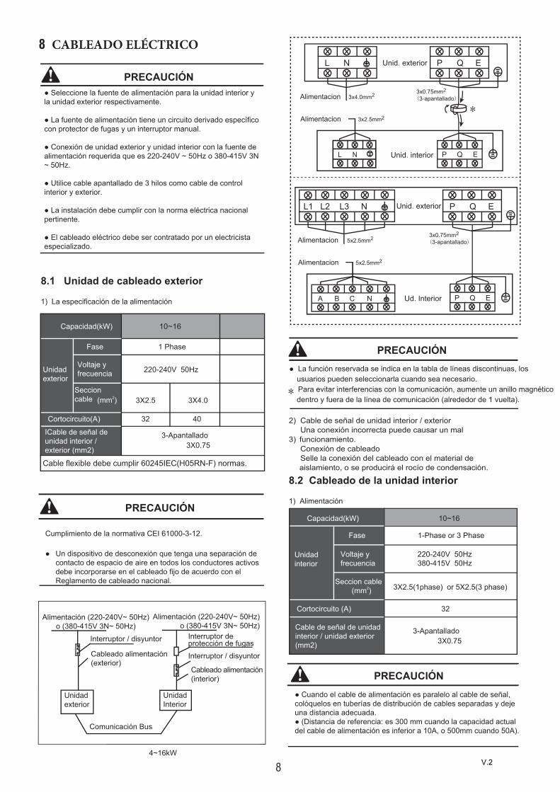
8 CABLEADO ELÉCTRICO
8.1 Unidad de cableado exterior
1) La especificación de la alimentación
ICable de señal de unidad interior / exterior (mm2)
Cortocircuito(A) 40
3X4.0
10~16
3-Apantallado
Unidad exterior
Fase 1 Phase
220-240V 50Hz
Seccion cable (mm2)
3X0.75
Capacidad(kW)
Voltaje y frecuencia
4~16kW
Unidadexterior
UnidadInterior
Alimentación (220-240V~ 50Hz) o (380-415V 3N~ 50Hz)
Cableado alimentación(interior)
Comunicación Bus
Alimentación (220-240V~ 50Hz) o (380-415V 3N~ 50Hz)
Interruptor deprotección de fugasInterruptor / disyuntor
Interruptor / disyuntor
Cableado alimentación(exterior)
PRECAUCIÓN● Seleccione la fuente de alimentación para la unidad interior yla unidad exterior respectivamente.
● La fuente de alimentación tiene un circuito derivado específicocon protector de fugas y un interruptor manual.
● Conexión de unidad exterior y unidad interior con la fuente dealimentación requerida que es 220-240V ~ 50Hz o 380-415V 3N~ 50Hz.
● Utilice cable apantallado de 3 hilos como cable de controlinterior y exterior.
● La instalación debe cumplir con la norma eléctrica nacionalpertinente.
● El cableado eléctrico debe ser contratado por un electricistaespecializado.
PRECAUCIÓN
Cumplimiento de la normativa CEI 61000-3-12.
● Un dispositivo de desconexión que tenga una separación decontacto de espacio de aire en todos los conductores activosdebe incorporarse en el cableado fijo de acuerdo con elReglamento de cableado nacional.
● La función reservada se indica en la tabla de líneas discontinuas, losusuarios pueden seleccionarla cuando sea necesario.Para evitar interferencias con la comunicación, aumente un anillo magnéticodentro y fuera de la línea de comunicación (alrededor de 1 vuelta).
PRECAUCIÓN
Cortocircuito (A) 32
10~16
Unidadinterior
Fase
Voltaje y frecuencia
1-Phase or 3 Phase
220-240V 50Hz380-415V 50Hz
Seccion cable (mm2)
Cable de señal de unidad interior / unidad exterior (mm2)
3-Apantallado3X0.75
Capacidad(kW)
3X2.5(1phase) or 5X2.5(3 phase)
PRECAUCIÓN● Cuando el cable de alimentación es paralelo al cable de señal,colóquelos en tuberías de distribución de cables separadas y dejeuna distancia adecuada.● (Distancia de referencia: es 300 mm cuando la capacidad actualdel cable de alimentación es inferior a 10A, o 500mm cuando 50A).
2)
3)
Cable de señal de unidad interior / exteriorUna conexión incorrecta puede causar un mal funcionamiento.Conexión de cableadoSelle la conexión del cableado con el material de aislamiento, o se producirá el rocío de condensación.
8.2 Cableado de la unidad interior
1) Alimentación
*
Cable flexible debe cumplir 60245IEC(H05RN-F) normas.
3X2.5
32
Unid. interior
Unid. exterior
Alimentacion
Alimentacion
P Q E
L N
L N
3x4.0mm
P Q E
2 3x0.75mm(3-apantallado)
2
23x2.5mm*
Ud. Interior
Unid. exterior
Alimentacion
Alimentacion
P Q E
L1 L2 L3 N
5x2.5mm
P Q E
2 3x0.75mm(3-apantallado)
2
25x2.5mm
A B C N
V.2

8.3 Componentes principales de la caja de interruptores
La imagen que se muestra aquí es solo indicativa. Si hay inconsistencia entre la imagen y el producto real, el producto real deberá regir.
9
8.3.1 Componentes principales de la caja de interruptores (1-fase,10/12/14/16kW)
1 Reservado(CN2)2 Puerto de entrada N para el módulo Ipm (N)3 Fuente de alimentación de W Phase para compresor (W)4 Fuente de alimentación de la fase V para compresor (V)
5 Fuente de alimentación de U para compresor (U) 6 Puerto de salida N del módulo Pfc (N_1)7 Puerto de salida P del módulo Pfc (P_1)8 Puerto de entrada para inductancia Pfc L_1 (L_1)9 Puerto de entrada para inductancia Pfc L_2 (L_2)
10
11 13
9
8
7
6
5 4 3 2 110 Puerto de entrada N para el módulo Pfc (VIN-N) 11 Puerto de entrada P Foripm Modele (P)12 Puerto de comunicación Entre Pcb A Y Pcb B (CN1)13 + 15V (CN6)
1-phase 10~16kW PCB A
12
V.2

10
9 Funcionamiento de prueba
Opere de acuerdo con los "puntos clave para la prueba de funcionamiento" en la cubierta de la caja de control eléctrico.
PRECAUCIÓN
● La prueba de funcionamiento no puede iniciarse hasta que launidad exterior se haya conectado a la alimentación durante 12horas.● La prueba de funcionamiento no puede iniciarse hasta quetodas las válvulas se mantengan abiertas.● Nunca haga la carrera forzada. (O el protector se sienta haciaatrás, ocurrirá peligro).
A[kg]
B[m3]≤ espesor crítico
10 PRECAUCIONES SOBRE FUGAS REFRIGERANTES
Esta bomba de calor adopta refrigerante no inflamable y no refrigerante. El espacio de ubicación de la HP debería tener el enorme problema de que cualquier fuga de refrigerante no pueda alcanzar el espesor crítico. Por lo tanto, se puede tomar cierta acción esencial a tiempo.1) Espesor crítico ------ el Máx. Grueso de freón sin ningún daño a lapersona.2) Espesor crítico del refrigerante: 0,44 [kg / m3] para R410A.● Confirme el grosor crítico siguiendo los pasos y tome las accionesnecesarias.● Calcule la suma del volumen de carga (A [kg]) Volumen total derefrigerante de 10 HP = volumen de refrigerante de fábrica +supercondición.● Calcular el cubage interior (B [m3]) (como el cubage mínimo.● Calcular el grosor del refrigerante. Medida del contador contra ungrosor alto.
3) Instale un ventilador mecánico para reducir el espesor delrefrigerante en un nivel crítico. (ventilar regularmente).4) Instale la instalación de alarma de fugas relacionada con elventilador mecánico si no puede ventilar regularmente.
9 103 4 5 6 7 8
1-phase 10~16kW PCB B
1 Puerto para interruptor de presión (CN12)2 Puertos para sensor de temperatura de
succión (CN24) 3 Puertos para sensor de presión (CN28)
4 Puertos para temperatura de descarga Sensor (CN8)5 Puertos para temperatura ambiente y temperatura de salida del condensador Sensor (CN9)6 Puertos para la comunicación entre la
unidad exterior y la caja de conexiones (CN10)
7 Reservados (CN30)8 Puertos para el valor de la expansión eléctrica (CN22) 9 Puertos de entrada para el cable vivo (CN1)10 Puerto de entrada para cable neutro (CN2)11 Puerto de salida para cable neutro (CN3)12 Puerto salida para cable de alta tensión (CN4)13 Reservados (CN7)14 puertos para valor de 4 vías (CN13)15 puertos para cinta de calefacción eléctrica (CN14) 16 Puerto de entrada para transformadores (CN26)
20
19
18
25
17
16
23
2221
15 14 13 12 2617 Puerto de fuente de alimentación para ventilador (CN18) 18 Puerto para ventilador de bajada (CN19)19 Puertos para ventilador (CN17)20 Puerto de salida para transformador (CN51) 21 Botón de verificación (SW2)22 Botón de recuperación de refrigerante23 pantallas digitales (DIS1)24 Cable de tierra (CN11)25 Puerto de comunicación para PCBA (CN6) 26 Puerto de alimentación para la placa de control de la caja hidráulica (CN16)
1 2
24
11
V.2

11
11 Entrega del manual al cliente
El manual del propietario de la unidad interior y el manual del propietario de la unidad exterior deben entregarse al cliente. Explique el contenido en el manual del propietario a los clientes en detalle.
Presione el botón de "restricción de frío" para llevar a cabo el proceso de reciclaje de refrigerante. Mantenga la presión baja por encima de 0.2MPa, de lo contrario, el compresor puede quemarse.
NOTA
A. Peristoma de ventilación.
B. Alarma de fugasrelacionada con ventiladormecánico.
(La sirena de caza de fugas debe instalarse en lugares que se mantengan refrigerantes fácilmente)
Unidad interior
La habitación está llena de fugas de refrigerante.
(Todo el refrigerante se ha filtrado).
Unidad interiorUnidad exterior
10~16kW
ADVERTENCIA
La recogida de estos residuos debe ser por separado para un tratamiento especial.No deseche los aparatos eléctricos como residuos municipales sin clasificar, use instalaciones de recolección separadas.
Póngase en contacto con el gobierno local para obtener información sobre los sistemas de reciclaje disponibles.
Si los aparatos eléctricos se desechan en vertederos o vertederos, las sustancias peligrosas puedenfiltrarse en el calentador y entrar en la cadenaalimentaria, dañando su salud y bienestar.
Para evitar fugas de refrigerante, póngase en contacto con su distribuidor.
Cuando el sistema se instala y se ejecuta en una habitación pequeña, se requiere mantener la concentración del refrigerante, si es que sale, por debajo del límite. De lo contrario, el oxígeno en la habitación puede verse afectado, lo que puede provocar un accidente grave.
El refrigerante en la bomba de calor es seguro y normalmente no tiene fugas.
Solicite a su distribuidor la instalación de la bomba de calor. La instalación incompleta realizada por usted mismo puede provocar una fuga de agua, una descarga eléctrica y un incendio.
Pregunte a su distribuidor por mejoras, reparaciones y mantenimiento.
La mejora, reparación y mantenimiento incompletos pueden provocar fugas de agua, descargas eléctricas e incendios.
Para evitar descargas eléctricas, incendios o lesiones, o si detecta alguna anomalía, como el olor a fuego, apague la fuente de alimentación y llame a su distribuidor para obtener instrucciones.
Nunca deje que la unidad interior o el control remoto se mojen. Puede provocar una descarga eléctrica o un incendio.
Nunca presione el botón del control remoto con un objeto duro y puntiagudo.
El mando a distancia puede estar dañado.
Nunca reemplace un fusible con el de la corriente nominal incorrecta u otros cables cuando un fusible se funda.
El uso de alambre o de cobre puede causar que la unidad se descomponga o provoque un incendio.
No es bueno para su salud exponer su cuerpo al flujo de aire durante mucho tiempo.
No inserte los dedos, varillas u otros objetos en la entrada o salida de aire.Cuando el ventilador gira a alta velocidad, causará lesiones.Nunca use un aerosol inflamable como laca para el cabello, pintura de laca cerca de la unidad.Puede provocar un incendio.Nunca toque la salida de aire o las cuchillas horizontales mientras la aleta oscilante está en funcionamiento.Los dedos pueden quedar atrapados o la unidad puede romperse.Nunca coloque objetos en la entrada o salida de aire. Los objetos que tocan el ventilador a alta velocidad pueden ser peligrosos.
No deseche este producto como no clasificado. Nunca inspeccione ni repare la unidad usted mismo.Pídale a una persona de servicio calificada que realice esto.
Fig.10-2
Fig.10-3
V.2

12
Operación de enfriamiento
● La entrada de aire o la salida de aire de la unidad exteriorestá bloqueada.● Viento fuerte sopla continuamente a la salida de aire de launidad exterior.Operación de calefacción● Demasiada basura se adhiere al filtro en la unidad interior● La salida de aire de la unidad interior está obstruida.
12 FUNCIONAMIENTO Y RENDIMIENTO
12.1 Equipos de protecciónEste equipo de protección permitirá que la bomba de calor se detenga cuando la bomba de calor se dirija funcionando en forma compulsiva.Cuando el equipo de protección está activado, el indicador de operación aún se ilumina cuando la bomba de calor no está funcionando. Pero las luces indicadoras de verificación.El equipo de protección puede ser activado en las siguientes condiciones:■
■
PRECAUCIÓN
Nunca exponga a los niños pequeños, plantas o animales directamente al flujo de aire.Influencia adversa para niños pequeños, animales y plantas puede resultar.
No permita que un niño se monte en la unidad exterior ni evite colocar ningún objeto sobre ella.Las caídas o caídas pueden provocar lesiones.
No opere la bomba de calor cuando use un insecticida de fumigación en la habitación.La falta de observación podría hacer que los productos químicos se depositen en la unidad, lo que podría poner en peligro la salud de aquellos que son hipersensibles a los productos químicos.No coloque aparatos que produzcan fuego abierto en lugares expuestos al flujo de aire de la unidad o debajo de la unidad interior.Puede causar una combustión incompleta o deformación de la unidad debido al calor.
No instale la bomba de calor en ningún lugar donde pueda escaparse gas inflamable.Si el gas se escapa y permanece alrededor de la bomba de calor, se puede producir un incendio.
El aparato no está diseñado para ser usado por niños pequeños o personas enfermas sin supervisión.
Los niños pequeños deben ser supervisados para asegurarse de que no jueguen con el aparato.
Las cortinas de la ventana de la unidad exterior deben limpiarse periódicamente en caso de que se atasquen.Esta forma de ventana es la salida de disipación de calor de los componentes, si se atasca causará que los componentes acorten su vida útil debido al sobrecalentamiento durante mucho tiempo.
La temperatura del circuito de refrigerante será alta, mantenga el cable de interconexión alejado del tubo de cobre.
Si el refrigerante gotea en la habitación, el contacto con el fuego de un quemador, un calentador o una cocina puede producir un gas dañino.Apague todos los dispositivos de calefacción combustibles, ventile la habitación y póngase en contacto con el distribuidor donde adquirió la unidad.No use la bomba de calor hasta que una persona de servicio confirme que se repara la parte donde se filtra el refrigerante.
No utilice la bomba de calor para otros fines.Para evitar el deterioro de la calidad, no utilice la unidad para enfriar instrumentos de precisión, alimentos, plantas, animales u obras de arte.
Antes de limpiar, asegúrese de detener la operación, apague el disyuntor o tire del cable de alimentación.De lo contrario, pueden producirse descargas eléctricas y lesiones.Para evitar descargas eléctricas o incendios, asegúrese de que esté instalado un detector de fugas a tierra.Asegúrese de que la bomba de calor esté conectada a tierra.Para evitar descargas eléctricas, asegúrese de que la unidad esté conectada a tierra y que el cable de tierra no
Se puede formar condensación si la humedad es superior al 80%, la salida de drenaje está bloqueada o el filtro está contaminado.Después de un uso prolongado, verifique que el soporte y el accesorio de la unidad no estén dañados.Si está dañada, la unidad puede caerse y provocar lesiones.Para evitar la deficiencia de oxígeno, ventile la habitación lo suficiente si el equipo con quemador se usa junto con la bomba de calor.Arregle la manguera de drenaje para asegurar un drenaje suave. El drenaje incompleto puede causar la humectación del edificio, muebles, etc.Nunca toque las partes internas del controlador.No retire el panel frontal. Algunas partes internas son peligrosas de tocar y puede ocurrir un problema en la máquina.Nunca haga los trabajos de mantenimiento por usted mismo.Póngase en contacto con su distribuidor local para hacer el trabajo de mantenimiento.
V.2

13
Cuando se inicie el equipo de protección, apague el interruptor de encendido manual y reinicie la operación después de resolver el problema.
NOTA
12.2 Sobre el corte de energía Si la alimentación se corta durante la operación, detener toda
la operación inmediatamente. El poder viene de nuevo. La lámpara del panel de
visualización de la unidad interior parpadea. Y luego la unidad se reiniciará automáticamente.
● Mal manejo en funcionamiento:● Si se produce una manipulación incorrecta debido a lailuminación o la conexión inalámbrica móvil, apague elinterruptor de alimentación manual y vuelva a encenderlo, luegopresione el botón ON / OFF.
12.3 Capacidad de calentamientoLa operación de calefacción es un proceso de bomba de calor que absorbe el calor del aire exterior y lo libera al agua interior. Una vez que la temperatura exterior disminuyó, la capacidad de calefacción disminuyó de manera intermitente.Se sugiere utilizar otros equipos de calefacción juntos cuando la temperatura exterior es demasiado baja.En algunas tierras altas y frías extremas que compran otro calentador eléctrico equipado con una unidad interior obtendrá un mejor rendimiento (consulte el manual del propietario de la unidad interior para obtener más información)
NOTA
1.
2.
Una característica de protección evita que la bomba de calor se active durante aproximadamente varios minutos cuando se reinicia inmediatamente después de la operación.
12.6 Características de la operación de calefacción.El agua no se calentará inmediatamente al comienzo de la operación de calefacción, hace 3 ~ 5 minutos (depende de la temperatura interior y exterior), hasta que el intercambiador de calor interior se caliente y luego se caliente.Durante la operación, el motor del ventilador en la unidad exterior puede dejar de funcionar a alta temperatura.
12.7 Descongelar en la operación de calefacciónDurante la operación de calefacción, la unidad exterior a veces se congela. Para aumentar la eficiencia, la unidad comenzará a descongelar automáticamente (aproximadamente 1 a 10 minutos) y luego el agua se drenará de la unidad exterior.Durante la descongelación, los motores del ventilador en la unidad exterior dejarán de funcionar.
La unidad interior en el mismo sistema no puede funcionar con refrigeración y calefacción al mismo tiempo.Si el administrador de la bomba de calor ha configurado el modo de funcionamiento, entonces la bomba de calor no puede funcionar en modos distintos a los predefinidos. El modo de espera o Sin prioridad se mostrarán en el Panel de control.
12.4 Característica de protección del compresor
12.5 Funcionamiento de refrigeración y calefacción.
El motor en la unidad interior continuará funcionando durante 20 ~ 30 segundos para eliminar el calor residual cuando la unidad interior reciba el comando OFF (apagado) durante la operación de calefacción.Si el funcionamiento incorrecto de la bomba de calor se produce debido a una perturbación, conecte la bomba de calor para encenderla y vuelva a encenderla.
Codigo Descripcion Solucion
H1Fallo de comunicacion entre la unidad exterior y IR341
Póngase en contacto con su distribuidor local.
E5Fallo del sensor de temperatura del intercambiador de la unidad exterior (T3)Fallo del sensor de temperatura ambiente de la unidad exterior (T4)
E6
E9Fallo del sensor de temperatura de la línea de succión del compresor (Th)
EAFallo en el sensor de temperatura de la línea de descarga del compresor (Tp)
H8 Fallo del sensor de presión
HFFallo de la unidad exterior EEPROM
H6 Fallo del motor del ventilador de CC
H7Fallo de protección del voltaje del compresor DC
Compruebe que la fuente de alimentación se encuentre entre 172 VCA y 265 VCA.
H4 Tres veces protege P6
E1 Error Alimentacion
Conecte los cables de alimentación en fase normal. Cambie cualquiera de los dos cables de alimentación (L1, L2, L3) para corregir la fase
H0
Fallo de comunicacion entre hidro-box y unidad exterior
Verifique el cableado entre la interfaz de usuario y la unidad, o contacte a su distribuidor local
13 CÓDIGO DE MAL FUNCIONAMIENTO DE UNIDAD EXTERIOR
13.1 Códigos de error
Cuando se activa un dispositivo de seguridad, se mostrará un código de error en la interfaz de usuario.Puede encontrar una lista de todos los errores y acciones correctivas en la tabla a continuación.Reinicie la seguridad apagando la unidad y volviéndola a encender.En caso de que este procedimiento para restablecer la seguridad no sea exitoso, contacte a su distribuidor local.
Póngase en contacto con su distribuidor local.
Póngase en contacto con su distribuidor local.
Póngase en contacto con su distribuidor local.
Póngase en contacto con su distribuidor local.
Póngase en contacto con su distribuidor local.
Póngase en contacto con su distribuidor local.
Póngase en contacto con su distribuidor local.
Póngase en contacto con su distribuidor local.
V.2

14
Código Descripción Solución
HEEl modo de calefacción del ventilador funciona en la región A durante 10 minutos.
Verifique que la unidad esté funcionando dentro de su rango de operación, contacte a su distribuidor local
HH Dos veces H6 en 10 minutosReinicie la unidad, si el error vuelve a ocurrir, póngase en contacto con su distribuidor local.
HL Fallo del módulo PFCVerifique que la unidad esté funcionando dentro de su rango de operación, contacte a su distribuidor local
HPProtección de baja presión 3 veces en 1 hora en modo de enfriamiento
Verifique que la unidad esté funcionando dentro de su rango de operación, contacte a su distribuidor local
P0 Protección de baja presión 3 veces en 1 hora en modo de enfriamiento
Verifique que la unidad esté funcionando dentro de su rango de operación, contacte a su distribuidor local
P1 Sistema de bomba de calor de alta presión protegeVerifique que la unidad esté funcionando dentro de su rango de operación, contacte a su distribuidor local
P3 Corriente de compresor DC protegerVerifique que la unidad esté funcionando dentro de su rango de operación, contacte a su distribuidor local
P4 Temperatura de descarga del compresor demasiado alta proteger
Verifique que la unidad esté funcionando dentro de su rango de operación, contacte a su distribuidor local
P6 Módulo transductor de protección Póngase en contacto con su distribuidor local.
P9 Protección del motor del ventilador de CC Póngase en contacto con su distribuidor local.
PCOtra protección (que no se puede mostrar en la interfaz de usuario) Póngase en contacto con su distribuidor local.
Pd La temperatura del intercambiador de la unidad exterior (T3) es demasiado alta. Póngase en contacto con su distribuidor local..
L0 Error del módulo inversor Póngase en contacto con su distribuidor local.
L1 Módulo inversor de protección de baja tensión. Póngase en contacto con su distribuidor local.
L2 Módulo inversor de protección de alto voltaje. Póngase en contacto con su distribuidor local.
L4 MEC error Póngase en contacto con su distribuidor local.
L5 Compresor 0 velocidad de protección. Póngase en contacto con su distribuidor local.
L7 Error de fase Póngase en contacto con su distribuidor local.
L8El cambio de frecuencia del compresor es mayor que 15Hz entre este momento y el último momento
Póngase en contacto con su distribuidor local.
L9La diferencia entre la frecuencia objetivo y la frecuencia de funcionamiento del compresor es mayor que 15 Hz.
Póngase en contacto con su distribuidor local.
F1 El voltaje del módulo inversor era demasiado bajo. Póngase en contacto con su distribuidor local.
dF Descongelación (No funciona mal) Es función normal y no error.d0 Retorno de aceite (no funciona mal) Es función normal y no error.
FC Fuerza de enfriamiento (no funciona mal) Es función normal y no error.
V.2

15
14 LOS SÍNTOMAS SIGUIENTES NO SON PROBLEMAS DE BOMBA DE CALOR
Síntoma 1: el sistema no funciona
Síntoma 2: Cambie al modo de bomba durante el modo de calefacción
Síntoma 4: Ruido de la bomba de calor
La bomba de calor no arranca inmediatamente después de presionar el botón de ENCENDIDO / APAGADO en el controlador romote.Si se enciende la lámpara de operación, el sistema está en condiciones normales. Para evitar la sobrecarga del motor del compresor, la bomba de calor arranca unos minutos después de que se enciende.
Cuando el sistema cambia a operación de calefacción después de la operación de descongelación La humedad generada por la descongelación se convierte en vapor y se agota.
Se escucha un sonido de silbido bajo continuo cuando el sistema está en funcionamiento.Este es el sonido del gas refrigerante que fluye a través de las unidades interiores y exteriores.
Un sonido sibilante que se escucha al inicio o inmediatamente después de la operación de parada o descongelación.Este es el ruido del refrigerante causado por la detención del flujo o el cambio de flujo.
Cuando el tono del ruido de funcionamiento cambia.Este ruido es causado por el cambio de frecuencia.
Síntoma 5: El polvo sale de la unidad
Síntoma 6: Las unidades pueden desprender olores.
Cuando la unidad se utiliza por primera vez en mucho tiempo. Esto es porque el polvo ha entrado en la unidad.
La unidad puede absorber el olor de las habitaciones, muebles, cigarrillos, etc. y luego emitirlo nuevamente.
Síntoma 7: el ventilador de la unidad exterior no gira.
Durante la operación. La velocidad del ventilador se controla para optimizar la operación del producto.
La lámpara de operación parpadea rápidamente (dos veces por segundo) Esta lámpara aún parpadea rápidamente después de apagar y encender de nuevo.
El control remoto no funciona correctamente o el botón no funciona bien.
Un dispositivo de seguridad como un fusible, un interruptor automático se activa con frecuencia. Obstáculos y agua entran en la unidad.
Fugas de agua de la unidad interior.
Otros mal funcionamiento.
15 SOLUCIÓN DE PROBLEMASSi ocurre uno de los siguientes fallos de funcionamiento, detenga la operación, apague la alimentación y póngase en contacto con su distribuidor.
Si el sistema no funciona correctamente, excepto los casos mencionados anteriormente o si las fallas en el funcionamiento mencionadas anteriormente son evidentes, investigue el sistema de acuerdo con los siguientes procedimientos.
Cuando la temperatura del agua de salida desciende a la temperatura establecida, el compresor se apaga y la unidad interior cambia al modo de bomba; Cuando la temperatura sube, el compresor vuelve a arrancar. Es lo mismo en el modo de calefacción.
Síntoma 3: la niebla blanca sale de la unidad exterior
V.2

Solución
Limpie el intercambiador de calor.Limpie el filtro de agua.Eliminar todas las suciedades y hacer que el aire suave.Hacer cortinas para protegerse del sol.Reducir la fuente de calor.La capacidad de enfriamiento de CA reduce (normal). Compruebe las fugas y recargue correctamente el refrigerante.
CausasFallo de alimentación.El interruptor de encendido está apagado.El fusible del interruptor de alimentación puede haberse quemado. Pilas del mando a distancia agotadas u otro problema del mando.
La temperatura no está ajustada correctamente. Estar en 3 minutos de protección del compresor.El refrigerante es muy poco o demasiado. Aire o no gas de hormigonado en el circuito frigorífico.El compresor no funciona correctamente. El voltaje es demasiado alto o demasiado bajo. El circuito del sistema está bloqueado.
La unidad exterior y el intercambiador de calor de la unidad interior están sucios.El filtro de agua está sucio.La entrada / salida de las unidades interiores / exteriores está bloqueada.La luz del sol brilla directamente.Demasiado recurso de calor.Temp. Al aire libre es muy alta. Fuga de refrigerante o falta de refrigerante.
Espera el regreso del poder. Encienda el poder. Replicación:Reemplace las baterías o revise el controlador.
Ajuste la temperatura adecuadamente. Espere.
Compruebe las fugas y recargue el refrigerante con razón.Aspirar y recargar el refrigerante. Mantenimiento o cambio de compresor. Instale el manostato.Encuentra razones y solución.
Utilice el dispositivo de calefacción.Compruebe las fugas y recargue correctamente el refrigerante.
La temperatura exterior es inferior a 7 C Fugas de refrigerante o falta de refrigerante.
Las unidades comienzan o se detienen frecuentemente
Bajo efecto de enfriamiento
Bajo efecto de calentamiento
La unidad no arranca.
Síntomas
16
El flujo de aire fluye normalmente pero no puede enfriarse completamente
V.2

17
16 Especificaciones técnicas
Modelo(Capacity mark)
ETH-10VBETH-12VBETH-16VB
Alimentacion
Entrada de potencia nominal6.0kW
Corriente nominal 27.0A
Capacidad Nominal
Dimensiones (W×H×D)[mm]
Embalaje (W×H×D)[mm]
Motor ventilador
Compresor
Intercambiador de calor
Tipo
Cantidad 3.9kg
Peso Neto 99kg
Peso bruto 112kg
Tuberia de gas
Tuberia de liquido
Conexión de drenaje
Max. longitud de tubería 50mMax. diferencia de altura cuando la unidad exterior está al revés
30m
Max. diferencia de altura cuando la unidad exterior está a la baja
25m
Modo calor
Modo frio
Modo de agua caliente sanitaria.
φ9.52
DN15
Rango de temperatura ambiente de operación
-20~+35℃
-5~+46℃
-20~+43℃
Fin-coil
Refrigerante
R410A
Peso
Conexiones
φ15.9
220-240V~ 50Hz
Diríjase a los datos técnicos
900*1327*400
1030×1456×435
DC motor / Horizontal
DC inverter dual rotary
V.2

18
17 INFORMACIÓN IMPORTANTE POR EL REFRIGERANTE USADO
Este producto tiene el gas fluorado que figura en el protocolo de kyoto y está prohibido emitir al aire.Tipo de refrigerante: R410A; Volumen de GWP: 2088;GWP = Potencial de calentamiento global
Atención:
1) Para equipos que contienen gases fluorados de efecto invernaderoen cantidades de 5 toneladas de CO2 equivalente o más, pero demenos de 50 toneladas de equipos de CO2, al menos cada 12meses, o donde
2) Se instala un sistema de detección de fugas, al menos cada 24meses.
3) Para equipos que contienen gases fluorados de efecto invernaderoen cantidades de 50 toneladas de CO2 equivalente o más, pero demenos de 500 toneladas de equipos de CO2, al menos cada seismeses, o donde se instala un sistema de detección de fugas, almenos cada 12 meses .
4) Para equipos que contienen gases fluorados de efecto invernaderoen cantidades de 500 toneladas de CO2 equivalente o más, almenos cada tres meses, o donde se instala un sistema de detecciónde fugas,al menos cada seis meses.
5) El equipo no sellado herméticamente cargado con gases fluoradosde efecto invernadero solo debe venderse al usuario final cuando sedemuestre que la instalación debe ser realizada por una empresacertificada.
6) Sólo la persona certificada está autorizada para realizar lainstalación, operacióny mantenimiento.
ModeloRefrigerante/kg toneladas equivalentes de CO2
3.90
3.90
3.90
8.14
8.14
8.14
ETH-10VB
ETH-12VB
ETH-16VB
Carga de fábrica
V.2

�
Si el equipo presenta un funcionamiento anormal, por favor, en primer lugar desconecte la fuente de alimentación, y póngase en contacto con nuestro servicio la postventa (SAT).
Para consular su servicio técnico más cercano, acceda a la página web:
www.easelectric.es
V.2
Requisitos de calidad del agua en el circuitoLa calidad del agua debe cumplir los estándares de la Directiva Europea 98/83 CE y los criterios indicados en la Norma UNE 112.076
Antes de conectar la unidad exterior:En las instalaciones tanto nuevas como ya existentes, se debe de realizar una limpieza a fondo de las tuberías utilizando un producto de limpieza químico adecuado, posteriormente se lavarán las tuberías para limpiar el agente químico. Para evitar daños en las tuberías se han de añadir inhibidores de corrosión aniónicos, catiónicos, mezcla de ambos o productos filmógenos que bloquean las micropilas existentes evitando reacciones de corrosión y el desprendimiento de oxígeno.
Cuando se utilicen inhibidores u otros productos químicos limpiadores, lea las instrucciones del fabricante y su compatibilidad con los materiales que componen la instalación.
AnticongelanteEn caso de que la instalación vaya a funcionar en refrigeración, será obligatorio anticongelante. En instalaciones que no funcionen en refrigeración se deberá utilizar cuando haya riesgo de congelación durante un periodo de no funcionamiento o por las condiciones ambientales.
Las soluciones anticongelantes deben utilizar glicol de propileno con un índice de toxicidad de Clase 1. El glicol de etileno nunca se debe utilizar en el circuito primario.
Problemas derivadosLos problemas derivados de la mala calidad del agua o de no haber tratado esta según lo aquí descrito, no estarán cubiertos por la garantía del producto.

CONTROL POR CABLE CON PROGRAMACIÓN SEMANAL
MANUAL DE INSTALACIÓNY MANUAL DE USUARIO
MODELO: ECRTH
V.2V.2

2
Este manual ofrece una descripción detallada de las
precauciones que se han de tener en cuenta durante el
funcionamiento del equipo.
Para asegurar el buen desempeño del control remoto cableado
lea cuidadosamente este manual antes de encender la unidad.
Por su conveniencia mantenga este manual accesible
después de leerlo para tenerlo de referencia futura.
ÍNDICE PÁG.
..............................................
.................................................
........................................................................................................
...........................................................
...........................................................................................................
.......................................................................
..............................................................................................
..............................................................
.........
......................................................................................................
........................................
.............................................................................................................
.........................................................................................................
.........................
...........................
......................................
....................................................................................
.....................................................
PRECAUCIONES GENERALES DE SEGURIDAD
1.1 Acerca de la documentación
Las precauciones descritas en este documento cubren temas muy importantes, lea detenidamente.
1.1.1 Significado de las advertencias y símbolos
1.2 Para el usuario
Si no está seguro de cómo hacer funcionar la unidad, póngase en contacto con su instalador.
Este aparato no está diseñado para que lo usen niños pequeños o personas enfermas sin supervisión. Se debe supervisar que los niños no jueguen con la unidad.
Las unidades tienen este símbolo:
Esto significa que los productos electrónicos no se
pueden desechar junto con los residuos domésticos no clasificados. NO intente desmontar el sistema sin
ayuda profesional: El desmontaje del sistema, el uso
del refrigerante, del aceite y de los componentes se debe realizar por personal cualificado.
Los trabajos de instalación y mantenimiento deben
cumplir con la legislación vigente. Las unidades se deben tratar en un centro de tratamiento
especializado para ser recicladas y recuperadas. Si
desecha este producto correctamente, estará previniendo consecuencias nocivas tanto para el
medio ambiente como para la salud de todos. Para
cualquier pregunta contacte a su distribuidor local.
PRECAUCIÓNNO lavar la unidad. Esto causa descargas eléctricas o
INFORMACIÓNInforma sobre consejos útiles o información adicional.
NOTAIndica una situación que puede provocar daños al equipo o a bienes materiales.
PRECAUCIÓN
ADVERTENCIA
Indica riesgo de lesiones graves o la muerte.
PELIGRO
Indica la posibilidad de lesiones graves o la muerte.
PELIGRO: RIESGO DE QUEMADURAIndica una situación que puede provocar quemaduras por
exceso de calor o frío.
PELIGRO: RIESGO DE ELECTROCUCIÓN
Indica una situación que puede provocar electrocución.
incendios.
V.2
TANK 55 C C27 SET
08 : 30
C
21: 55 08 - 08 - 2015 SAT.
3
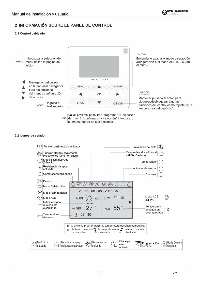
INFORMACIÓN SOBRE EL PANEL DE CONTROLÓ
2.1 Control cableado
Introduzca la selección del menú desde la página de inicio.
Navegador del cursoren la pantalla/ navegadorpara las opcionesdel menú / configuraciónde ajustes
Regresa al nivel superior
Encender o apagar el modo calefacción/refrigeración o el modo ACS (DHW) enel menú.
Mantener pulsado el botón para bloquear/desbloquear algunas funciones del control como "ajuste de la temperatura del depósito".
Va al próximo paso tras programar la selección del menú confirma una selección/ introduce un submenú dentro de sus opciones.
2.2 Iconos de estado
Función desinfección activada
Función Holiday away/home(Vacaciones fuera / en casa)
Modo Silent activado(Silencio)
Resistencia de apoyoactivada
Compresor funcionando
Detenido
Modo Calefacción
Modo Refrigeración
Modo Auto
Indica el modoque se estaejecutando
Temperaturadeseada
Temperaturadeseada enel tanque ACS
Modo ACS
(DHW)
Bloqueo
Indicador de avería
Temporizador
Fuente de calor adicional(AHS) (Caldera)
Prevención de hielo
En la próxima programación, la temperatura deseada aumentará.
la temp. deseada la temp. deseada
Programaciónsemanal
V.2

4
Distribución del sistema 1 .
.Distribución del sistema 2
USO DE LAS PÁGINAS DE INICIO
3.1 Descripción de las páginas de inicio
Se pueden usar las páginas de inicio para leer y cambiar los ajustes diariamente. Lo que se puede ver y hacer en las páginas de inicio está descrito donde se aplica. En función de la configuración, pueden visualizarse las páginas de inicio siguientes:
Temp. de la habitación (ROOM ) Temp. del agua (MAIN) DHW Temp. del depósito (TANK) DHW=agua caliente sanitaria (ACS)
Página de inicio 1:
NOTA:
Todas las figuras de este manual se usan para explicar las páginas visualizadas, puede que tengan algunas diferencias con las que tiene el usuario.
Página de inicio 2:
Climatización (controlada por el panel de control) + ACS.
"WATER FLOW TEMP." en "NON".
"ROOM TEMP." en "YES".El panel de control muestra la siguiente página principal:
NOTA:
En este caso el panel de control controlará la temperatura de la habitación, por lo que se debe tener en cuenta dónde se instala.
En ajustes iniciales, ir a "FOR SERVICEMAN / TEMP. TYPE SETTING" (ver AJUSTE TIPO CONTROL TEMP. en el manual de la unidad
interior o monobloc) y ajustar "TEMP. TYPE SETTING" de la siguiente forma:
Climatización (controlada por temperatura de agua) + ACS.
"WATER FLOW TEMP." en "YES".
"ROOM TEMP." en "NON".
El panel de control muestra la siguiente página principal:
En ajustes iniciales, ir a "FOR SERVICEMAN / TEMP. TYPE SETTING" (ver AJUSTE TIPO CONTROL TEMP. en el manual de la unidad
interior o monobloc) y ajustar "TEMP. TYPE SETTING" de la siguiente forma:
V.2

21: 55 08 - 08 - 2015 SAT.
21: 55 08 - 08 - 2015 SAT.
TANK C 12 SET C
21: 55 08 - 08 - 2015 SAT.
55
SET C 24
21: 55 08 - 08 - 2015 SAT.
5
Climatización (controlada por temperatura de agua / panel de control)
"WATER FLOW TEMP." en "YES".
"ROOM TEMP." en "YES".
El panel de control muestra la siguiente página principal y adicional:
Climatización (controlada por temperatura de agua / panel de control) + ACS.
"WATER FLOW TEMP." en "YES".
"ROOM TEMP." en "YES".El panel de control muestra la siguiente página principal y adicional:
En ajustes iniciales, ir a "FOR SERVICEMAN / TEMP. TYPE SETTING" (ver AJUSTE TIPO CONTROL TEMP. en el manual de la unidad
interior o monobloc) y ajustar "TEMP. TYPE SETTING" de la siguiente forma:
En ajustes iniciales, ir a "FOR SERVICEMAN / TEMP. TYPE SETTING" (ver AJUSTE TIPO CONTROL TEMP. en el manual de la unidad
interior o monobloc) y ajustar "TEMP. TYPE SETTING" de la siguiente forma:
V.2

TANK 55 C SET C
21: 55 08 - 08 - 2015 SAT.
18
TANK 55 C SET C
21: 55 08 - 08 - 2015 SAT.
18
TANK 55 C SET C
21: 55 08 - 08 - 2015 SAT.
18
TANK 55 CSET C
21: 55 08 - 08 - 2015 SAT.
18
55 C C
21: 55 08 - 08 - 2015 SAT.
18
55 C C
21: 55 08 - 08 - 2015 SAT.
18
TANK 55 CSET C
21: 55 08 - 08 - 2015 SAT.
18
6
4.2 Acceder a las opciones del menú
Desde una página principal, pulsar "MENU".
Resultado: Se visualiza la estructura del menú:
4.3 Para navegar en la estructura del menú
Use '' '' '' '' para moverse.
USO BÁSICO
5.1 Desbloqueo de la pantalla
Si se muestra el icono , el panel de control está bloqueado.
Se visualiza la página:
Pulse cualquier tecla, el icono parpadeará. Mantener pulsado el botón "UNLOCK". El icono desaparecerá, el control se puede operar.
El control estará bloqueado si no se pulsa ningún botón durante un tiempo (unos 60 segundos: para ajustar ese tiempo, consulte lasección 6.7 INFORMACIÓN DE MANTENIMIENTO).Si el control está desbloqueado, mantenga pulsado el botón "unlock", el control quedará bloqueado.
5.2 Encendido / Apagado (ON/OFF)
Use el panel de control para encender o apagar la unidad en calefacción o refrigeración.
El ENCENDIDO/APAGADO de la unidad se puede controlar mediante el panel de control si "ROOM THERMOSTAT" estáen "NON" (ver TERMOSTATO AMBIENTE en el manual de la
Use '' '' '' '' en la página de inicio, aparecerá el cursor negro:
unidad interior o monobloc).
1) Cuando el cursor esté seleccionando el modo de funcionamiento
(calefacción , refrigeración o automático ) pulsar el botón"ON/OFF para encender o apagar.
V.2

SET C
21: 55 08 - 08 - 2015 SAT.
18
SET C
21: 55 08 - 08 - 2015 SAT.
18
SET C
21: 55 08 - 08 - 2015 SAT.
18
SET C
21: 55 08 - 08 - 2015 SAT.
18
22:20 22-08-2018 SAT
Cool/heat mode is controlled bythe room thermostat.The cool or heat mode is closed.
Please open the mode by the roomthermostat.
C 12 C
21: 55 08 - 08 - 2015 SAT.
C 12 C
21: 55 08 - 08 - 2015 SAT.
55 C C
21: 55 08 - 08 - 2015 SAT.
18
C 12 C
21: 55 08 - 08 - 2015 SAT.
55 C C
21: 55 08 - 08 - 2015 SAT.
18
7
Si se usa un termostato ambiente (externo) para encender oapagar la unidad en calefacción / refrigeración.
Si "ROOM THERMOSTAT" está ajustado en "YES" (ver
TERMOSTATO AMBIENTE en el manual de la unidad interior omonobloc) la unidad solo se podrá encender y apagar medianteel termostato ambiente (externo), el panel de control indicará:
Si "DUAL ROOM THERMOSTAT" (termostato ambiente doble) está
en "YES" (ver TERMOSTATO AMBIENTE en el manual de la unidadinterior o monobloc).. Si el termostato de refrigeración está apagado, elde calefacción está encendido y la unidad está funcionando, pero la pantalla está APAGADA. Se visualizará la página:
1) Use el control para encender o apagar la unidad en "DHW" (ACS).
Pulse '' '' '' en la página de inicio aparecerá el cursor:''
2) Cuando el cursor está en el modo "DHW" (ACS). Use la tecla
"ON/OFF'' para encender/apagar el modo "DHW" (ACS).
5.3 Ajuste de la temperatura
Pulse '' '' '' '' en la página de inicio, aparecerá el cursor negro:
V.2

55 c c
21: 55 08 - 08 - 2015 SAT.
c c
21: 55 08 - 08 - 2015 SAT.
55 12
Operation mode setting
OPERATION MODE
Operation mode setting
OPERATION MODE
heat
cool
auto 18
22:20 22-08-2018 SAT
Cool/heat mode is controlled bythe room thermostat.The cool or heat mode is closed.Please open the mode by the room
thermostat.
c 18 c
21: 55 08 - 08 - 2015 SAT.
55
55 C C
21: 55 08 - 08 - 2015 SAT.
18
SET C 18
21: 55 08 - 08 - 2015 SAT.
8
Si el cursor está en la temperatura, use '' '' '' '' para seleccionar y use '' '' '' '' para ajustar la temperatura.
5.4 Ajuste del modo de funcionamiento para climatización
Ajuste del modo de funcionamiento mediante el panel de control.Vaya a ''MENU'' > ''OPERATION MODE''. Pulse "OK", se mostrará la página:
Hay tres modos disponibles: calefacción, refrigeración y modo automático. Use '' '' '' '' para moverse, pulse "OK" para seleccionar.Incluso si no pulsa "OK" y sale de la página, pulsando el botón "BACK", el modo también es efectivo si el cursor se ha movido al modo de funcionamiento.
Si solo se permite el modo calefacción, se visualizará:
El modo de funcionamiento no se puede cambiar (ver AJUSTE MODOREFRIGERACIÓN en el manual de la unidad interior o monobloc).
Si selecciona..
El modo de funcionamiento es...
Siempre modo calefacción
Siempre modo refrigeración
Cambiado automáticamente por el software basado en la temperatura exterior (y dependiendo del ajuste inicial también la temp. interior), y teniendo en cuenta los cambios mensuales.Nota: Los cambios automáticos son posibles solo bajo algunas condiciones. Consultar en AJUSTES INICIALES > AJUSTES MODO AUTO en el manual de la unidad interior o monobloc.
Si realiza el ajuste el modo de funcionamiento mediante el termostato ambiente, (ver TERMOSTATO AMBIENTE en el manual de la unidad
interior o monobloc.)
Vaya a "MENU" > "OPERATION MODE", si pulsa cualquier tecla para seleccionar o ajustar, se visualizará la página:
V.2

6 MENU
PRESET TEMPERATURE
PRESET TEMPERATURE
PRESET TEMPERATURE
PRESET TEMPERATURE
6.2.2 "WEATHER TEMP. SET" (Ajuste temp. segú n temp. exterior)
PRESET TEMPERATURE
PRESET TEMPERATURE
9
6.1 "OPERATION MODE" (Modo de funcionamiento)
Ver "5.4 AJUSTE DEL MODO DE FUNCIONAMIENTO".
6.2 "PRESET TEMPERATURE"
"PRESET TEMPERATURE" tiene 4 ítems "PRESET TEMP."/"WEATHER TEMP.SET" / "ECO MODE" / "COMFORT MODE".
6.2.1 "PRESET TEMP." (Pre-ajuste de temperatura)
La función "PRESET TEMP" se usa para ajustar temperaturas diferentes en horarios diferentes cuando está activo el modo calefacción o refrigeración.
"PRESET TEMP." = "PRESET TEMPERATURE"La función "PRESET TEMP." se apagará en estas condiciones.
1) El modo "AUTO" está activo.
2) "TIMER" o "WEEKLY SCHEDULE" están activados. Vaya a ''MENU'' > ''PRESET TEMPERATURE'' > ''PRESETTEMP''. Pulse ''OK''. Aparecerá la siguiente página:
Use '' '' '' '' '' '' '' '' para moverse y use '' '' '' '' para ajustar
el tiempo y la temperatura.Cuando el cursor cambia a '' '', como en las páginas siguientes:
Si pulsa ''OK'', y el punto '' '' cambia a '' '' sin color. Se ha seleccionado el temporizador 1. Si pulsa ''OK'' una vez más, y el punto sin color '' '' cambia a '' ''. No se ha seleccionado el temporizador 1.
Use '' '' '' '' '' '' '' '' para moverse y use '' '' '' '' para ajustar
el tiempo y la temperatura.Se pueden ajustar seis períodos y seis temperaturas.
Por ejemplo: Ahora son las 8:00 y hay una temp. de 30°C. Programamos "PRESET TEMP" como se muesta en la tabla siguiente:
INFORMACIÓN
Cuando cambia el modo de funcionamiento el "PRESET TEMP."se apaga automáticamente.
La función se puede usar en el modo calefacción y refrigeración.
Pero si se cambia el modo de funcionamiento, también hace falta
volver a ajustar la función.
La temperatura pre-ajustada no es válida si la unidad estáAPAGADA. Cuando se vuelva a encender la unidad, la temperatura pre-ajustada se activará nuevamente.
WEATHER TEMP.SET=WEATHER TEMPERATURE SET Esta función se usa para pre-ajustar la temp. deseada del agua
automáticamente en dependencia de la temp. exterior del aire.
Durante el verano no se usa mucho la calefacción. Para evitar que
la bomba de calor produzca exceso de temp. del agua en el circuito primario, esta función ("WEATHER TEMP. SET") se puede
usar para maximizar la eficiencia y reducir los costes de uso.
Vaya a ''MENU'' > ''PRESET TEMPERATURE''>''WEATHER TEMP. SET''. Pulse ''OK''.Aparecerá la siguiente página:
V.2

WEATHER TEMP. SET TYPE:
WEATHER TEMP. SET
1 2 3 5 6 7 8 4
PRESET TEMPERATURE
PRESET TEMPERATURE
PRESET TEMPERATURE
PRESET TEMPERATURE
5:30 08-08-2016 SAT.
Weather temp.set function is
on. Do you want to turn off it?
NO YES
10
INFORMACIÓN
"WEATHER TEMP. SET" tiene 4 tipos de curvas: 1. la curva de ajuste a alta temperatura para calefacción, 2. la curva de ajuste a
baja temperatura para calefacción, 3. la curva de ajuste a alta
temperatura para refrigeración, 4. la curva de ajuste a baja
temperatura para refrigeración.
Solo tiene la curva del ajuste de alta temperatura para la calefacción, si la alta temperatura se ajusta para la calefacción.Solo tiene la curva del ajuste de baja temperatura para la calefacción, si la baja temperatura se ajusta para la calefacción.Solo tiene la curva del ajuste de alta temperatura para la refrigeración, si la alta temperatura se ajusta para la refrigeración.Solo tiene la curva del ajuste de baja temperatura para la refrigeración, si la baja temperatura se ajusta para la refrigeración.
Véase AJUSTES INICIALES > AJUSTE MODO REFRIGERACIÓN
y AJUSTE MODO CALEFACCIÓN en el manual de la unidad interior
La temperatura deseada (TS1) no se puede ajustar, cuando lacurva de temperatura está ajustada en ON.
o monobloc.
Si desea usar el modo calefacción, seleccione: ''HEAT MODE LOW TEMP''. Si desea usar el modo refrigeración, seleccione; ''COOL MODE LOW TEMP''. Puede seleccionar el ajuste de alta o baja temperatura para calefacción o refrigeración, ver Tabla 1~8. Si selecciona "ON" se visualizará la página siguiente:
Use " '' '' '' para moverse. Pulse ''OK'' para seleccionar.
Si está activado "WEATHER TEMP. SET", la temperaturadeseada no se puede programar en el panel de control. PulsePulse las teclas '' '' '' '' para ajustar la temperatura en lapágina principal. Aparecerá la siguiente página:
Traducción:
La función de ajuste de temperatura según la temperatura exterior esta activada. ¿Desesa desactivarla?
Mueva a "NO", pulse "OK" para regresar a la página principal,
mueva a "YES", pulse "OK" para reiniciar "WHETHER TEMP. SET".
6.2.3 "ECO MODE" (Modo Económico)
El "ECO MODE" se usa para ahorrar energía durante la noche. Si el "ECO MODE" está activo, se muestra en la página de inicio. Vaya a ''MENU'' > ''PRESET TEMPERATURE'' > ''ECO MODE''. Pulse "OK". Aparecerá la siguiente página:
Pulse "OK". Aparecerá la siguiente página:
Use ''ON/OFF'' para seleccionar ON / OFF y use '' '' '' ''.
INFORMACIÓN
Si "CURRENT STATE" está en "OFF", "ECO MODE" no es válido.
Cuando se mueve el cursor a "START/END", como la página siguiente:
Pulse ''OK'' o la tecla '' '' para ajustar la hora. Aparecerá la siguiente página:
V.2

PRESET TEMPERATURE
PRESET TEMPERATURE
PRESET TEMPERATURE
PRESET TEMPERATURE
HORA
9:00
10:00
22:00
23:00
"COMFORT MODE" "ON" y "ECO MODE" "OFF"
"ECO MODE" "OFF" y "COMFORT MODE" "ON"
"ECO MODE" "ON" y "COMFORT MODE" "OFF"
"COMFORT MODE" "OFF" y "ECO MODE" "ON"
11
INFORMACIÓN
Use '' '' '' '' para moverse y use '' '' '' '' para ajustar la hora.
Si "CURRENT STATE" está en "ON" y "ECO TIMER" está en "OFF",sale del "ECO MODE" hasta que se activa el "COMFORT MODE".
6.2.4 "COMFORT MODE" (Modo Confort)
El "COMFORT MODE" mantiene una temperatura ideal durante el día.
Si el "COMFORT MODE" está activo, se visualiza en la páginaprincipal.
Vaya a ''MENU'' > ''PRESET TEMPERATURE '' > ''COMFORT MODE''. Pulse ''OK''. Aparecerá la siguiente página:
Aparecerá la siguiente página:
Use "ON/OFF" para seleciónar "ON" o "OFF" y use" para'' ''
moverse.
INFORMACIÓN
Si "CURRENT STATE" está en "OFF", el "COMFORT MODE" noes válido.
Cuando se mueve el cursor a "START/END", como la páginasiguiente:
Pulse ''OK'' o la tecla '' '' para ajustar la hora. Aparecerá la página:
Use '' '' '' '' para moverse y use '' '' '' '' para ajustar la hora.
INFORMACIÓN
Si "CURRENT STATE" está en "ON" y "ECO TIMER" está en "OFF""COMFORT MODE" sale hasta que se activa el "ECO MODE".
Si la hora de encendido y de apagado del "CONFORT MODE"entran en conflicto, se hace efectiva la hora de encendido.
Funcionamiento
Por ejemplo en el "ECO MODE" la hora de encendido es 22:00 y de apagado es 10:00, mientras en el "COMFORT MODE" hora de encendido es 9:00 y de apagado es 23:00. Funcionamiento real, en el "ECO MODE" la hora de encendido es 22:00 y de apagado 9:00, mientras la hora de encendido es a las 9:00 durante el "COMFORT MODE".
INFORMACIÓN
El "ECO MODE" se usa siempre combinado con el "COMFORT MODE".
V.2

DOMESTIC HOT WATER DHW
PRESET TEMPERATURE
DOMESTIC HOT WATER DHW
DOMESTIC HOT WATER DHW
DOMESTIC HOT WATER DHW
23: 55 10 - 08 - 2015 FRI.
12
La unidad funciona en "ECO MODE" desde las 19:00 hasta el dia siguiente a las 8:00 y el "COMFORT MODE" funciona desde las 8:00hasta las 19:00.
INFORMACIÓN
Si el "TIMER" está "ON", "ECO MODE" o "COMFORT MODE" están
activos, ambos modos funcionan según el "TIMER".
Si "CURRENT STATE" esta en "OFF", "ECO/COMFORT" no esválido.
Si el "TIMER" está "OFF", "ECO MODE" o "COMFORT MODE" están
activos, el "ECO MODE" es válido y el "COMFORT MODE" es inválido.
6.3 "DOMESTIC HOT WATER (DHW)" (Agua Caliente Sanitaria)
El menú "DHW" consta de:1) "DISINFECT" 2) "FAST DHW"3) "TANK HEATER" 4) "DHW PUMP"
6.3.1 "DISINFECT" (Desinfección)
La función "DESINFECT" se usa para eliminar la legionela. En esta función el tanque alcanzará una temperatura de 65~70 forzosamente la temperatura de desinfección se ajusta en "FOR SERVICEMAN". (Ver "DISINFECT" en el manual de usuario de la ud. interior o monobloc).Vaya a ''MENU'' > ''DOMESTIC HOT WATER'' > ''DISINFECT''. Pulse''OK''. Aparecerá la siguiente página:
Use '' '' '' '' '' '' '' '' para moverse y use '' '' '' '' para ajustar los parámetros al ajustar ''OPERATE DAY'' y ''START''. Si "OPERATE DAY"se ajusta en "FRI" (Viernes) y el "START" (encendido) se ajusta a las 23:00, la función de desinfección se activará el viernes a las 23:00.
Si "CURRENT STATE" está en "OFF", "DISINFECT" no es válido.
Si la función de desinfección está activada, se visualizará la página siguiente:
6.3.2 "FAST DHW" (ACS Rápida)
La función "FAST DHW" se usa para forzar el sistema a funcionar en modo "DHW" (ACS).
El equipo y las resistencias del deposito ACS o la resistencia deapoyo auxiliar funcionarán juntas.Vaya a "MENU"> "DOMESTIC HOT WATER" >"FAST DHW". Pulse "OK":
Use "ON/OFF" para seleccionar ON / OFF.
INFORMACIÓN
Si "CURRENT STATE" está en "OFF", "FAST DHW" no es válido, y si "CURRENT STATE" está en "ON", la función "FAST DHW" es efectiva.La función "FAST DHW" es efectiva una vez.
6.3.3 "TANK HEATER" (Resistencia del depósito ACS)
La función "TANK HEATER" se usa para activar las resistencias del depósito de ACS y calentar el agua del depósito. En la misma situación, si se necesita refrigeración o calefacción y el sistema funciona en refrigeración o calefacción, y sin embargo hay unanecesidad de agua caliente.En este caso la función "TANK HEATER" se puede usar para calentar el agua del depósito. También, incluso si el sistema de bomba de calor falla. Ir a ''MENU'' > ''DOMESTIC HOT WATER'' > ''TANK HEATER''. Pulse ''OK''.
V.2

DOMESTIC HOT WATER DHW
DOMESTIC HOT WATER DHW
DOMESTIC HOT WATER DHW
DOMESTIC HOT WATER DHW
55 C C
21: 55 08 - 08 - 2015 SAT.
12
13
Use ''ON/OFF'' para seleccionar "ON" u "OFF". Use ''BACK'' para salir. Si "TANK HEATER" está activo, se mostrará la página siguiente:
INFORMACIÓN
Si "CURRENT STATE" está en "OFF", "TANK HEATER" no es válido.Si el sensor del depósito T5 está averiado, "TANK HEATER" no funciona.
6.3.4 "DHW PUMP" (Bomba de ACS)
La función "DHW PUMP" se usa para el retorno de agua al sistema. Vaya a ''MENU'' > ''DOMESTIC HOT WATER'' > ''DHW PUMP''.Pulse ''OK''. Aparecerá la siguiente página:
Moverse a “ ” pulsar '' OK '' para seleccionar o eliminar. ( se ha seleccionado el temporizador, se ha cancelado
el temporizador).
Use las teclas '' '' '' '' '' '' '' '' para moverse y use '' '' '' ''
para ajustar los parámetros.
Por ejemplo: ha ajustado el parámetro de "DHW PUMP" (Verel manual de la ud. interior o monobloc para más informaciónAJUSTES INICIALES > AJUSTES TIPO CONTROL TEMP.) El tiempo de funcionamiento de la bomba es de 30 minutos. Ajustar de la siguiente manera:
La bomba funciona de la siguiente manera:
6.4 "SCHEDULE" (Programación semanal)
El menú de "SCHEDULE" consta de:1) "TIMER" para ajustar la programación diaria.2) "WEEKLY SCHEDULE" para programar la semana.3) "TIME" para ajustar la hora y fecha actual.
V.2

SCHEDULE
SCHEDULE
SCHEDULE
SCHEDULE
Timer 1 is useless.The start time is same to the end time.
14
6.4.1 "TIMER" (Temporizador diario)
Use '' '' '' '' '' '' '' '' para moverse y use '' '' '' '' para ajustar
la hora, el modo y la temperatura.
Moverse a “ ” pulse ''OK '' para seleccionar o cancelar.
( se ha seleccionado el temporizador, se ha cancelado
el temporizador). Se pueden ajustar 6 períodos horarios.
Si desea cancelar el "TIMER", mueva el cursor a pulse "OK",el se convierte en , el temporizador no es válido.
Si la función "WEEKLY SCHEDULE" (prog. semanal) está
activada, el "TIMER" no será efectivo, siempre el último ajuste
será el efectivo. Si el "TIMER" esta activado, se muestra el
icono en la página principal.
Si ajusta la hora de inicio más tarde que la de apagado o la temperatura está fuera del rango del modo. Aparecerá la siguiente página:
Ejemplo:
Ajuste de los seis temporizadores:
La unidad funcionará como sigue:
El funcionamiento del panel de control es con los siguientes horarios:
Si la hora de encendido es la misma que la de apagado en un temporizador, el ajuste no será válido.
INFORMACIÓN
6.4.2 "WEEKLY SCHEDULE" (Programación semanal)
Si la función "TIMER" (temp. diario) está activada, el "WEEKLY
se mostrará el icono en la pantalla principal.
Vaya a ''MENU'' > ''SCHEDULE'' >''WEEKLY SCHEDULE''. Pulse''OK''. Aparecerá la siguiente página:
SHEDULE" no sera efectivo. Si "WEEKLY SCHEDULE" esta activo,
Primero seleccione los días de la semana que desea programar.Use '' '' '' '' para moverse, pulse ''OK'' para seleccionar o borrar el
día.“ MON ” significa que se ha seleccionado el día, “MON” que no se
ha seleccionado, cuando no tiene fondo negro.
INFORMACIÓN
Debemos ajustar al menos dos días cuando queremos activar la función "WEEKLY SCHEDULE".
V.2

SCHEDULE
SCHEDULE
SCHEDULE
SCHEDULE
SCHEDULE
15
Use '' ''o '' '' mover a "SET", pulse "OK". De Lunes (MON) a Viernes (FRI) se seleccionan para programarse y tienen la misma programación.
Aparecerá la siguiente página:
Use '' '' '' '' '' '' '' '' para moverse y para ajustar la hora,
el modo y la temperatura. En cada período se pueden programar, la hora de encendido y de apagado, modo y temperatura. El modo incluye calefacción, refrigeración y agua caliente sanitaria "DHW".
El método de ajuste se refiere a la programación del temporizador. La hora de apagado debe ser después que la de encendido, de lo contrario se visualizará “Timer is of no effect” (Programación del temporizador no válida).
Cancelar la programación semanal "WEEKLY SCHEDULE".
Cancelar la programación: Primero seleccionar los días de la semana. Use '' '' '' '' para moverse :
Use '' '' '' '' para mover a ”CANCEL”, pulse "OK" para cancelar el horario. Si quiere salir de "WEEKLY SCHEDULE", pulse “BACK”.
INFORMACIÓN
La función "TIME" se usa para ajustar la hora actual y la fecha.
Vaya a ''MENU''>''SCHEDULE''>''TIME''. Pulse ''OK''. Aparecerá la siguiente página:
6.4.3 "TIME" (Hora actual)
Use '' '' '' '' '' '' '' '' para moverse. Use '' '' '' '' para ajustar.
INFORMACIÓN
Los modos "ECO" o "COMFORT" tienen la mayor prioridad, "TIMER"o "WEEKLY SCHEDULE" tienen la segunda prioridad y "PRESETTEMP." o "WEATHER TEMP SET" tienen la prioridad más baja.
"PRESET TEMP." o "WEATHER TEMP." Los valores ajustados dejan de ser válidos, cuando validamos los valores de "ECO" o"COMFORT". Debemos volver a ajustar "PRESET TEMP." o "WEATHER TEMP". Los valores ajustados serán válidos si
ajustamos "ECO MODE" o "COMFORT MODE" no válidos.
No se afectan ni "TIMER" ni "WEEKLY SCHEDULE" cuando son válidos los valores de "ECO" o "COMFORT". "TIMER" o "WEEKLY
SCHEDULE" están activados cuando está funcionando en "ECO"o "COMFORT".
"TIMER" o "WEEKLY SCHEDULE" tienen la misma prioridad. La función pos-ajuste es válida. "PRESET TEMP." se torna no válida
cuando los valores de "TIMER" o "WEEKLY SCHEDULE" son válidos. "WEATHER TEMP. SET" no se afecta por el ajuste de
"TIMER" o "WEEKLY SCHEDULE".
Tienen la misma prioridad tanto "PRESET TEMP." como "WEATHER TEMP. SET." La función pos-ajuste es válida.
INFORMACIÓN
Todos los ajuste de horarios ("PRESET TEMP.",
"ECO/COMFORT", "DISINFECT", "DHW PUMP", "TIMER",
"WEEKLY SCHEDULE", "SILENCE MODE", "HOLIDAY HOME") La activación de la función correspondiente solo se puede activar
durante el encendido o el apagado.
Si se cambia de la configuración principal (MAIN page) a la configuración de habitación (ROOM page) o viceversa, hay que reestablecer el temporizador y el programador semanal.Si se realiza alguna modificación de los parámetros en el termostato de habitación (ROOM THERMOSTAT) no se aplicará la configuración principal.
V.2

OPTIONS
OPTIONS
OPTIONS
OPTIONS
OPTIONS
OPTIONS
16
6.5 "OPTIONS" (Opciones)
El menú de "OPTIONS" consta de:
1) "SILENT MODE" función silencio.
2) "HOLIDAY AWAY" función vacaciones fuera.
3) "HOLIDAY HOME" función vacaciones en casa
4) "BACKUP HEATER" para configurar la activación o no de lasresistencias de apoyo
6.5.1 "SILENT MODE" (Modo Silencio)
El "SILENT MODE" se usa para disminuir el sonido de la unidad. Sin embargo, también disminuye la capacidad refrigeración/calefacción del sistema. Hay dos niveles de silencio.El nivel 2 es más silencioso que el nivel 1 y la capacidad de calefacción o refrigeración también disminuye más.
Hay dos métodos para usar el "SILENT MODE":1) modo silencio permanente;2) modo silencio programado.
Vaya a la página de inicio para comprobar si el modo silencio estáactivado. Si está activo, se mostrará en la página de inicio.
Vaya a ''MENU'' > ''OPTIONS'' > ''SILENT MODE''. Pulse "OK".Aparecerá la siguiente página:
Use "ON/OFF" para seleccionar "ON" (activo) u "OFF" (inactivo).
Descripción:
Si el "CURRENT STATE" está en "OFF", "SILENT MODE" no es
Cuando selecciona "SILENT LEVEL" y pulsa ''OK'' o '' ".
Aparecerá la siguiente página:
válido.
Puede usar '' '' '' '' para seleccionar el nivel 1 ó 2. Pulse ''OK''.
Si se selecciona "TIMER", pulse "OK" para acceder, aparecerá la
siguiente página.
Hay dos temporizadores para ajustar Moverse a “ ” pulsar ''OK''
para seleccionar o borrar.Si se borran los dos horarios, el "SILENT MODE" funcionará todo el tiempo. De lo contrario, funcionará según el horario programado.
6.5.2 "HOLIDAY AWAY" (Vacaciones Fuera)
Si "HOLIDAY AWAY" está activo, el icono se mostrará en la
página principal.
Esta función se usa para prevenir que se congele la unidad durante el invierno y activa la unidad antes del final de las vacaciones.
Vaya a ''MENU'' > ''OPTIONS'' > ''HOLIDAY AWAY''. Pulse "OK".Aparecerá la siguiente página:
Ejemplo de uso: Si está fuera durante el invierno, la fecha actual es p.ej.: 2016-01-31, dos días después 2016-02-02, sería el comienzode las vacaciones.
Si se encuentra en la situación siguiente:
En dos días sale de casa durante dos semanas.
Desea ahorrar energía y que la casa no se enfríe. Puede hacer lo siguiente:
1) Debe realizar la configuración antes de sus vacaciones.
V.2

CHILD LOCK
Please input the password:
0 0 0
OPTIONS
OPTIONS
OPTIONS
"HOLIDAY AWAY" ON
ON
17
2) Activar el modo de vacaciones fuera.
Vaya a ''MENU'' > ''OPTIONS'' > ''HOLIDAY AWAY''. Pulse "OK".
Use ''ON/OFF'' para seleccionar ''OFF'' u ''ON'' y use'' '' '' '' '' '' '' '' para moverse y ajustar
Ajustes Valor
desde
hasta
Modo funcionamiento Calefacción
Desinfección
2 de Feb. 2016
16 de Feb. 2016
INFORMACIÓN
INFORMACIÓN
Si el modo "DHW" está activado durante "HOLIDAY AWAY",
el ajuste de "DISINFECT" se desactivará.
Si "HOLIDAY AWAY" está "ON". Las funciones "TIMER"
y "WEEKLY SCHEDULE" no son válidas excepto en salida.
Si el "CURRENT STATE" está en "OFF", el "HOLIDAY AWAY" está en inactivo.
El panel de control no acepta órdenes cuando "HOLIDAY AWAY" está en "ON".La desinfección de la unidad fue de 23:00 del último día si la función "DISINFECT" está en "ON".Si "HOLIDAY AWAY" entra en "ON", las curvas
ajustadas relacionadas con la temp. exterior no son válidas,
las curvas, tendrán efecto automáticamente después que termine
modo "HOLIDAY AWAY".El "PRESET TEMP." no es valido si esta activado el modo
"HOLIDAY AWAY", pero el valor pre-ajustado aun semuestra en la página principal.
INFORMACIÓN
Si el "CURRENT STATE" está en "ON", el "HOLIDAY AWAY" está activo.
La función "HOLIDAY HOME" se usa para desviar desde la programación normal sin tener que cambiarla durante las vacaciones en casa.
Durante sus vacaciones, se puede usar el modo vacaciones para salir de la programación normal sin tener que cambiarla.
Período Después...
Se usarán sus programacionesnormales
Se usarán los ajustes de vacaciones
Para activar o desactivar el modo "HOLIDAY HOME":
Vaya a ''MENU'' > ''OPTIONS'' > ''HOLIDAY HOME''. Pulse "OK".
Aparecerá la página siguiente:
Use ''ON/OFF'' para seleccionar ''OFF'' o ''ON'' y use '' '' '' '''' '' '' '' para moverse y ajustar
Si el "CURRENT STATE" está en "OFF", el "HOLIDAY HOME "
está en "OFF". Si el "CURRENT STATE" está en "ON", en
"HOLIDAY HOME" está en "ON".
Use '' '' '' '' para ajustar la fecha.
Antes y después de sus vacaciones, se usará su programación
Durante sus vacaciones, puede ahorrar energía y evitar que sele enfríe la casa.
normal.
Una vez que regrese a casa debe borrar la programación de las vacaciones, si desea cambiar la temperatura o no tiene a su disposición los modos "DHW" o "HEAT".
6.5.3 "BACKUP HEATER" (Resistencia Auxiliar)
La función "BACKUP HEATER" se usa para forzar la resistencia auxiliar. Vaya a ''MENU'' > ''OPTIONS'' > ''BACKUP HEATER''. Pulse "OK".Si "BACKUP HEATER" se ajusta a "NON" en ''OTHER HEATING SOURCE". Aparecerá la siguiente página:
Si "BACKUP HEATER" se ajusta a "YES" en ''OTHER HEATING
SOURCE". Aparecerá la siguiente página:
Use ''ON/OFF'' para seleccionar ''OFF'' o ''ON'' y use '' '' '' ''.
Si el modo de funcionamiento es automático en calefacción o
refrigeración, la resistencia auxiliar no se puede seleccionar.
La función "BACK HEATER" no es válida cuando solo se ha
activado "ROOM THERMOSTAT" (en AJUSTES TIPO CONTROL TEMP.)
6.6 "CHILD LOCK" (Bloqueo seguridad niños)
La función "CHILD LOCK" se usa para evitar que los niños mani--pulen el equipo. El modo y la temperatura deseada se puedenbloquear o desbloquear con el uso de la función "CHILD LOCK"Vaya a "MENU" > ''CHILD LOCK''. Se visualizará la página:
V.2

CHILD LOCK
SERVICE INFORMATION
SERVICE INFORMATION
12:30 08-08-2015 SAT.
E2 comunication fault between
controller and indoor unit
Please contact your dealer.
18
aparecerá la página siguiente:
Use '' '' '' '' para moverse y ''UNLOCK'' para seleccionar "LOCK"
o "UNLOCK". No se puede ajustar la temperatura cuando latemperatura está bloqueada. El modo no se puede cambiar cuandoel modo está bloqueado. Si usted quiere cambiarlos, debedesbloquearlos usando la función "CHILD LOCK".
6.7 "SERVICE INFORMATION" (Información de servicio)
6.7.1 Información de mantenimiento
El menú de "SERVICE INFORMATION" consta de:
1) "SERVICE CALL", información de contacto.
2) "ERROR CODE", para comprobar que significa un error.
3) "PARAMETER", para revisar los parámetros de funcionamiento.
4) "DISPLAY", para ajustar la pantalla del control.
6.7.2 Como acceder al menú información de mantenimiento
Ir a ''MENU'' > ''SERVICE INFORMATION''. Pulse "OK". Aparecerá la siguiente página:
En la función "SERVICE CALL" se pueden ver los teléfonos de contacto. El instalador puede introducir su número. Véase "FOR SERVICEMAN":
"ERROR CODE" se usa para mostrar el error cuando ocurre y se muestra el significado del código de error.
Pulse "OK" y la página aparecerá:
Pulse "OK" para mostrar el significado del código de error.
"PARAMETER" se usa para visualizar los parámetros principales, hay dos páginas para mostrar los parámetros:
"DISPLAY" se usa para ajustar el panel de control, los elementos principales como idioma, luz de fondo, zumbador y tiempo de apagado de la pantalla:
Use ''OK'' para acceder y use '' '' '' '' '' '' '' '' para moverse.
Información
En estos momentos el panel de control solo está en Inglés.
La contraseña es 123. Usar , para moverse y , para ajustar el valor numerico. Pulsar "OK".
V.2

FOR SERVICEMAN
Please input the password:
0 0 0
FOR SERVICEMAN
Do you want to exit the for serviceman?
NO YES
19
6.8 "OPERATION PARAMETER" (Parámetros de funcionamiento)
Este menú es para que el instalador o el ingeniero de mantenimiento puedan revisar los parámetros de funcionamiento.
Vaya a ''MENU'' > ''OPERATION PARAMETER''.
Pulse ''OK''. Hay cinco páginas para ver los parámetros de funcio--namiento. Use '' '' '' '' para moverse.
INFORMACIÓN
El parámetro de consumo de corriente es orientativo.
Si algunos parámetros no están activados en el sistema, el parámetro que se mostrará es "--".
6.9 "FOR SERVICEMAN" (Ajustes iniciales)
6.9.1 Sobre "FOR SERVICEMAN"
Ajuste de la composición del sistema.
Ajuste de los parámetros.
6.9.2 Cómo acceder a los Ajustes Iniciales.
Vaya a ''MENU'' > ''FOR SERVICEMAN''. Pulse ''OK''.
"FOR SERVICEMAN" se usar para realizar la configuración inicialdel sistema. Los usuarios finales NO deben cambiar los ajustes de este menú.
"FOR SERVICEMAN" se usar para realizar la configuración inicialdel sistema. Los usuarios finales NO deben cambiar los ajustes de este menú.
Por esta razón se necesita la protección de la contraseña para evitar acceso no autorizado a los ajustes iniciales.
6.9.3 Cómo salir de los Ajustes Iniciales.
Si ha ajustado todos los parámetros. Use "BACK", se visualizará la siguiente página:
¿Desea salir de los ajustes inciales?
Seleccionar ''YES'' y pulsar ''OK'' para salir de "FOR SERVICEMAN". Después de salir de "FOR SERVICEMAN", elequipo se apagará.
V.2

MENU
OPERATION MODE
PRESET TEMPERATURE
DOMESTIC HOT WATER(DHW)
SCHEDULE
OPTIONS
CHILD LOCK
SERVICE INFORMATION
OPERATION PARAMETER
FOR SERVICEMAN
OPERATION MODE
HEAT
COOL
AUTO
PRESET TEMPERATURE
PRESET TEMP.
WEATHER TEMP. SET
ECO MODE
COMFORT MODE
ECO MODE
CURRENT STATE
ECO TIMER
STATE
END
COMFORT MODE
CURRENT STATE
ECO TIMER
STATE
END
DISINFECT
CURRENT STATE
OPERATE DAY
STATE TIME
SILENT MODE
CURRENT STATE
SILENT LEVEL
TIMER
HOLIDAY AWAY
CURRENT STATE
DHW MODE
DISINFECT
HEAT MODE
FROM
UNTIL
HOLIDAY HOME
CURRENT STATE
FROM
UNTIL
SCHEDULE
DISPLAY
LANGUAGE
BACKLIGHT
BUZZER
SCREEN LOCK TIME
TIME
CURRENT TIME
CURRENT DAY
DOMESTIC HOT WATER (DHW)
DISINFECT
FAST DHW
TANK HEATER
DHW PUMP
OPTIONS
SILENT MODE
HOLIDAY AWAY
HOLIDAY HOME
BACKUP HEATER
CHILD LOCK
COOL/HEAT TEMP.ADJUST
COOL/HEAT MODE
DHW TEMP.ADJUST
DHW MODE
SERVICE INFORMATION
SERVICE CALL
ERROR CODE
PARAMETER
DISPLAY
FOR SERVICEMAN
DHW MODE SETTING
COOL MODE SETTING
HEAT MODE SETTING
AUTO MODE SETTING
SPACE TEMP. SETPOINT
ROOM THERMOSTAT
OTHER HEATING SOURECE
HOLIDAY AWAY SETTING
ECO/COMFORT SETTING
SERVICE CALL
INITIALIZE MANUALLY
TEST RUN
SPECIAL FUNCTION
AUTO RESTART
OPERATION PARAMETER
SCHEDULE
TIMER
WEEKLY SCHEDULE
TIME
20
7 ESTRUCTURA DEL MENÚ : Sumario
V.2

FOR SERVICEMAN
1 DHW MODE SETTING
2 COOL MODE SETTING
3 HEAT MODE SETTING
4 AUTO MODE SETTING
5 TEMP. TYPE SETTING
6 ROOM THERMOSTAT
7 OTHER HEATING SOURCE
8 HOLIDAY AWAY SETTING
9 ECO/COMFORT SETTING
10 SERVICE CALL
11 RESTORE FACTORY SET.
12 TEST RUN
13 SPECIAL FUNCTION
1 DHW MODE SETTING
1.1 DHW MODE
1.2 TANK HEATER
1.3 DISINFECT
1.4 DHW PRIORITY
1.5 DHW PUMP
1.1 DHW MODE
dT5_ON
dT1S5
T4DHWMAX
T4DHWMINt_INTERVAl DHW
1.2 TANK HEATER
dT5_TBH_ OFF
T4_TBH_ON
t_TBH_DELAY
1.3 DISINFECT
T5S_DI
t_DI_HIGHTEMP.
t_DI_MAX
1.4 DHW PRIORITY
t_DHWHP MAX
t_DHWHP RESTRICT
1.5 DHW PUMP
TIMER RUNNING
DISINFECT
PUMP RUNNING TIME
7.1 HIDRO-BOX HEATER HEAT MODE
DHW MODE
T4_IBH_ON
Td1_IBH_ON
t_IBH_DELAY
t_IBH12_DELAY
7.2 ADDITIONAL HEATING SOURCE
HEAT MODE
DHW MODE
T4_AHS_ON
dT1_AHS_ON
dT1_AHS_OFF
t_AHS_DELAY
13.2 PREHEATING FOR FLOOR
FLOW SET TEMPERATURE
RETURN TEMPERATURE
PREHEATING TIME
OPERATE PREHEATING FOR FLOOR
13.3 FLOOR DRYING UP
DRYING UP TIME
HIGE TEMP. TIME
DRYING DOWN TIME
PEAK TEMPERATURE
START TIME
START DATE
OPERATE FLOOR DRYING UP
2 COOL MODE SETTING
COOL MODE
T1S RANGE
T4CMAX
T4CMIN
dT1SC
dTSC
t_INTERVAL_C
HEAT MODE
T1S RANGE
T4HMAX
T4HMIN
dT1SH
dTSH
t_INTERVAL_H
13 SPECIAL FUNCTION
13.1 AIR PURGE
13.2 PREHEATING FOR FLOOR
13.3 FLOOR DRYING UP
14 AUTO RESTART
COOL/HEAT MODE
DHW MODE
9 SERVICE CALL PHONE NO.
MOBILE NO.
4 AUTO MODE SETTING
T4AUTOCMIN
T4AUTOHMAX
5 TEMP. TYPE SETTING
WATER FLOW TEMP.
ROOM TEMP.
8 HOLIDAY AWAY SETTING
T1S_H.A_H
T5S_H.M_DHW
7 OTHER HEATING SOURCE
7.1 BACKUP HEATER
7.2 AHS
7.3 SOLAR ENERGY
6 ROOM THERMOSTAT
ROOM THERMOSTAT
14 AUTO RESTART
MODE SETTINGDUAL ROOM THERMOSTAT
11 TEST RUN
POINT CHECK
AIR PURGE
CIRCULATED PUMP RUNNING
COOL MODE RUNNING
HEAT MODE RUNNING
DHW MODE RUNNING
21
3 HEAT MODE SETTING
V.2

22
Tabla 1 Curva de temperatura ambiente en el ajuste de baja temperatura para calefacción
Tabla 2 Curva de temperatura ambiente en el ajuste de alta temperatura para calefacción
V.2

23
Tabla 3 Curva de temperatura ambiente en el ajuste de baja temperatura para refrigeración
Tabla 4 Curva de temperatura ambiente en el ajuste de alta temperatura para refrigeración
V.2

46mm
60mm
120mm 20mm
Caja Unidad Interior/Monobloc
Panel de control
24
8 MANUAL DE INSTALACIÓN
8.1 Medidas de seguridadLea cuidadosamente las precauciones de seguridad antes de instalar la unidad.
Las indicaciones de seguridad a continuación deben ser cumplidas.
Si no hay incidencias durante la prueba de funcionamiento, entregue el manual
al usuario.
Significado de las marcas:
El equipo debe ser instalado solamente por profesionales.
La instalación realizada por personas no expertas puede ser incorrecta y provocar descargas eléctricas o incendios.
Cumpla estrictamente las orientaciones de este manual.
Una mala instalación puede provocar descargas eléctricas o incendios.
La reinstalación la deben realizar los profesionales.
Una mala instalación puede provocar descargas eléctricas o incendios.
No desmonte el aire acondicionado por su cuenta.Si el desmontaje no es correcto puede provocar un mal funcionamiento o un sobrecalentamiento que puede provocar incendios.
ADVERTENCIAUna mala manipulación puede provocar la muerte olesiones graves.
PRECAUCIÓNUna mala manipulación puede provocar lesiones o
daños materiales
No instale el equipo en un lugar peligroso con posibles fugas de gases inflamables.Si hay fugas de gases inflamables y no se reparan, se puede incendiar el entorno del control.
Los cables deben ser compatibles a la corriente del control remoto cableado.De lo contrario, pueden provocarse descargas eléctricas o calentamientos y ocasionarse
un incendio.
Se deben usar los cables especificados. No se debe ejercer fuerza sobre el terminal.
De lo contrario, pueden provocarse descargas eléctricas o calentamientos y ocasionarse un incendio.
No colocar el control remoto cableado cerca de lámparas, para evitar
que se obstruya la señal del control remoto. (consulte la figura a la derecha)
8.2 Otras precauciones
8.2.1.
No. Nombre Cant. Observaciones
1 Control remoto cableado 1
2Tornillo de montaje de madera con cabeza redonda Philips
3GB950-86 M4X20
(Para el montaje en la pared)
3Tornillo de montaje de
cabeza redonda Philips2
M4X25 GB823-88(Para el montaje en la
caja de conexiones)
4 1
5 Tornillo de plástico 2Este accesorio se usa para instalar el control dentro de una caja eléctrica.
6 Tubería plástica de expansión
3 Para montar en la pared
8.3.2
13.5VAC
8.3 Procedimiento de instalación y ajustes del panelde control
V.2

60mm
B C
A
25 V.2

�
Si el equipo presenta un funcionamiento anormal, por favor, en primer lugar desconecte la fuente de alimentación, y póngase en contacto con nuestro servicio la postventa (SAT).
Para consular su servicio técnico más cercano, acceda a la página web:
www.easelectric.es
V.2

EAS THERMALBIBLOCK
INSTALLATION'S AND OWNER'S MANUAL
MODELS: ETH-10VB ETH-12VB ETH-16VB
V.2
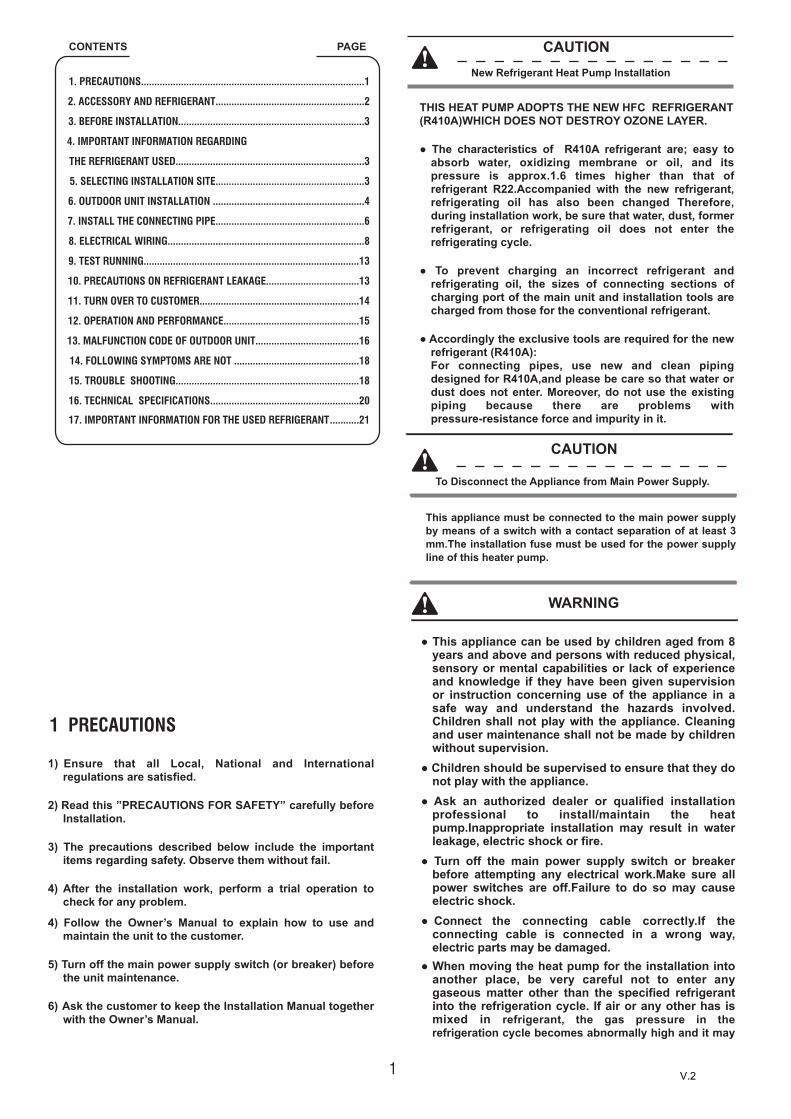
1
CONTENTS PAGE
1. PRECAUTIONS....................................................................................1
2. ACCESSORY AND REFRIGERANT........................................................2
3. BEFORE INSTALLATION......................................................................3
4. IMPORTANT INFORMATION REGARDING
THE REFRIGERANT USED.......................................................................3
5. SELECTING INSTALLATION SITE........................................................3
6. OUTDOOR UNIT INSTALLATION .........................................................4
7. INSTALL THE CONNECTING PIPE........................................................6
8. ELECTRICAL WIRING..........................................................................8
9. TEST RUNNING.................................................................................13
10. PRECAUTIONS ON REFRIGERANT LEAKAGE...................................13
11. TURN OVER TO CUSTOMER............................................................14
12. OPERATION AND PERFORMANCE...................................................15
13. MALFUNCTION CODE OF OUTDOOR UNIT.......................................16
14. FOLLOWING SYMPTOMS ARE NOT ...............................................18
15. TROUBLE SHOOTING.....................................................................18
16. TECHNICAL SPECIFICATIONS........................................................20
17. IMPORTANT INFORMATION FOR THE USED REFRIGERANT ...........21
CAUTIONNew Refrigerant Heat Pump Installation
1 PRECAUTIONS
1) Ensure that all Local, National and Internationalregulations are satisfied.
2) Read this ”PRECAUTIONS FOR SAFETY” carefully beforeInstallation.
3) The precautions described below include the importantitems regarding safety. Observe them without fail.
4) After the installation work, perform a trial operation tocheck for any problem.
4) Follow the Owner’s Manual to explain how to use andmaintain the unit to the customer.
5) Turn off the main power supply switch (or breaker) beforethe unit maintenance.
6) Ask the customer to keep the Installation Manual togetherwith the Owner’s Manual.
THIS HEAT PUMP ADOPTS THE NEW HFC REFRIGERANT(R410A)WHICH DOES NOT DESTROY OZONE LAYER.
● The characteristics of R410A refrigerant are; easy toabsorb water, oxidizing membrane or oil, and itspressure is approx.1.6 times higher than that ofrefrigerant R22.Accompanied with the new refrigerant,refrigerating oil has also been changed Therefore,during installation work, be sure that water, dust, formerrefrigerant, or refrigerating oil does not enter therefrigerating cycle.
● To prevent charging an incorrect refrigerant andrefrigerating oil, the sizes of connecting sections ofcharging port of the main unit and installation tools arecharged from those for the conventional refrigerant.
● Accordingly the exclusive tools are required for the newrefrigerant (R410A):For connecting pipes, use new and clean pipingdesigned for R410A,and please be care so that water ordust does not enter. Moreover, do not use the existingpiping because there are problems withpressure-resistance force and impurity in it.
CAUTION
To Disconnect the Appliance from Main Power Supply.
WARNING
● This appliance can be used by children aged from 8years and above and persons with reduced physical,sensory or mental capabilities or lack of experienceand knowledge if they have been given supervisionor instruction concerning use of the appliance in asafe way and understand the hazards involved.Children shall not play with the appliance. Cleaningand user maintenance shall not be made by childrenwithout supervision.
● Children should be supervised to ensure that they donot play with the appliance.
● Ask an authorized dealer or qualified installationprofessional to install/maintain the heatpump.Inappropriate installation may result in waterleakage, electric shock or fire.
● Turn off the main power supply switch or breakerbefore attempting any electrical work.Make sure allpower switches are off.Failure to do so may causeelectric shock.
● Connect the connecting cable correctly.If theconnecting cable is connected in a wrong way,electric parts may be damaged.
● When moving the heat pump for the installation intoanother place, be very careful not to enter anygaseous matter other than the specified refrigerantinto the refrigeration cycle. If air or any other has ismixed in refrigerant, the gas pressure in therefrigeration cycle becomes abnormally high and it may
This appliance must be connected to the main power supply by means of a switch with a contact separation of at least 3 mm.The installation fuse must be used for the power supplyline of this heater pump.
V.2

2
2 ACCESSORY AND REFRIGERANTPlease check whether the following fittings are of full scopes. If there are some spare fittings , please restore them carefully.
resultingly causes pipe burst and injuries on persons.● Do not modify this unit by removing any of the safety
guards or by by-passing any of the safety interlockswitches. Exposure of unit to water or other moisturebefore installation may cause a short-circuit ofelectrical parts. Do not store it in a wet basement orexpose to rain or water.
● After unpacking the unit, examine it carefully if there arepossible damage.Do not install in a place that mightincrease the vibration of the unit.
● Please pay attention to avoid the components whileconnect to the connecting pipes.
● To prevent the refrigerant piping from oxidizing insidewhen welding, it is necessary to charge nitrogen, oroxide will chock the circulation system.To avoidpersonal injury (with sharp edges), be careful whenhandling parts.
● Perform installation work properly according to theInstallation Manual. Inappropriate installation mayresult in water leakage, electric shock or fire.When theheat pump is installed in a small room, provideappropriate measures to ensure that the concentrationof refrigerant leakage occur in the room does notexceed the critical level.
● Install the heat pump securely in a location where thebase can sustain the weight adequately.Perform thespecified installation work to guard against anearthquake.If the heat pump is not installedappropriately, accidents may occur due to the fallingunit.
● If refrigerant gas has leaked during the installationwork, ventilate the room immediately.If the leakedrefrigerant gas comes in contact with fire, noxious gasmay generate.
● After the installation work, confirm that refrigerant gasdoer not leak.If refeigerant gas leaks into the room andflows near a fire source, such as a cooking range,noxious gas might generate.
● Electrical work must be performed by a qualifiedelectrician in accordance with the Installation Manual.Make sure the heater pump uses an exclusive powersupply. An insufficient power supply capacity orinappropriate installation may cause fire.
● Use the specified cables for wiring connect theterminals securely fix. To prevent external forcesapplied to the terminals from affecting the terminals. Besure to provide grounding. Do not connect groundwires to gas pipes, water pipes, lightning rods orground wires for telephone cables.
● Conform to the regulations of the local electric companywhen wiring the power supply.Inappropriate groundingmay cause electric shock.
● Do not install the heat pump in a location subject to arisk of exposure to a combustible gas. If a combustiblegas leaks, and stays around the unit, a fire may occur.
● If the supply cord is damaged, it must be replaced bythe manufacturer, its service agent or similarly qualifiedpersons in order to avoid a hazard.
● If an appliance is intender to be permanently connectedto the water mains and not connected by hose-set, thisshall be stated.
QuantityShapeName
1. Outdoor unit installation &owner’s manual (This book) 1
2. Drainage pipe connector 1
3. Magnet ring(Only for 1 Phase10~16kW)
1
sgnittif noitallatsnI
1
2
3
4
5
6
7
8
9
10
11
12
13
14
15
16
Screw driver
Hole core drill(65mm)
SpannerPipe cutterKnifeReamerGas leak detectorTape measureThermometerMega-tester
Electro circuit tester
Hexagonal wrench
Flare tool
Pipe benderBubble levelMetal saw
17
18
19
20
21
Gauge manifold (Charge hose:R410A special requirement)
Vacuum pump(Charge hose:R410A specialrequirement)
Torque wrench 1/4(17mm)16N•m (1.6kgf•m)3/8(22mm)42N•m (4.2kgf•m)1/2(26mm)55N•m (5.5kgf•m)5/8(15.9mm)120N•m(12.0kgf•m)
Copper pipe gauge adjusting projection margin
Vacuum pump adapter
Required tools for installation work:
Heating mode
Cooling mode
Domestic hot water mode
Operation ambient temperature range
-20 ~ +35℃
-5 ~ +46℃
-20 ~ +43℃
4. Product technical manual 1
5. Energy label 1
Confirm the safety of the installation area ( walls, floors, etc. ) without hidden dangers such as water, electricity, and gas. Before wiring/pipes.
●
● Before installation , check whether the user's power supply meets the electrical installation requirements of unit ( including reliable grounding , leakage , and wire diameter electrical load, etc.). If the electrical installation requirements of the product are not met, the installation of the product is prohibited until the product is rectified.
● When installing multiple air conditioners in a centralizedmanner, please confirm the load balance of the three-phasepower supply, and multiple units are prevented from beingassembled into the same phase of the three-phase powersupply.
● Product installation should be fixed firmly, Takereinforcement measures, when necessary.
V.2

3
3 BEFORE INSTALLATIONBefore installationBe sure to confirm the model name and the serial no. of the unit.
HandlingDue to relatively large dimensions and high weight, the handling ofthe unit is only to be done by means of lifting tools with slings. These slings can be fitted into specially for this purpose foreseen sleeves at the base frame.
● To avoid injury, do not touch the air inlet or aluminiumfins of the unit.
● Do not use the grips in the fan grills to avoid damage.
● Unit is top heavy!Prevent the unit from falling due to inclination duringhandling.
4 IMPORTANT INFORMATION REGARDING THE REFRIGERANT USEDThis product contains fluorinated greenhouse gases covered by the Kyoto Protocol. Do not vent gases into the atmosphere.Refrigerant type: R410A GWP(1) value: 1975(1) GWP = global warming potentialThe refrigerant quantity is indicated on the unit name plate
5 SELECTING INSTALLATION SITE
■ Make sure to provide for adequate measures in order toprevent that the unit be used as a shelter by smallanimals.
■ Small animals making contact with electrical parts cancause malfunctions, smoke or fire. Please instruct thecustomer to keep the area around the unit clean.
Make sure there is enough room to do the installation
CAUTION
WARNING
1 Select an installation site where the following conditions are satisfied and that meets with your customer's approval.
- Places which are well-ventilated.- Places where the unit does not bother next-door neighbours.- Safe places which can withstand the unit's weight and vibrationand where the unit can be installed level.
- Places where there is no possibility of flammable gas or productleak.
- The equipment is not intended for use in a potentially explosiveatmosphere.
- Places where servicing space can be well ensured.- Places where the units' piping and wiring lengths come within theallowable ranges.
- Places where water leaking from the unit cannot cause damageto the location (e.g. in case of a blocked drain pipe).
- Places where the rain can be avoided as much as possible.- Do not install the unit in places often used as workplace.In case of construction works (e.g. grinding works) where a lot ofdust is created, the unit must be covered.
- Do not place any objects or equipment on top of the unit (topplate)
- Do not climb, sit or stand on top of the unit.- Be sure that sufficient precautions are taken, in accordance withrelevant local laws and regulations, in case of refrigerant leakage.
2 When installing the unit in a place exposed to strong wind, pay special attention to the following. Strong winds of 5 m/sec or more blowing against the unit's air outlet causes short circuit (suction of discharge air), and this may have the following consequences:
- Deterioration of the operational capacity.- Frequent frost acceleration in heating operation.- Disruption of operation due to rise of high pressure.- When a strong wind blows continuously on the face of the unit,
the fan can start rotating very fast until it breaks.Refer to the figures for installation of this unit in a place where thewind direction can be foreseen.
■ Turn the air outlet side toward the building's wall, fence or screen.
3 Prepare a water drainage channel around the foundation, to drain waste water from around the unit.
4 If the water drainage of the unit is not easy, please build up the unit on a foundation of concrete blocks, etc. (the height of the foundation should be about 100 mm.
5 If you install the unit on a frame, please install a waterproof plate about 100 mm. of the underside of the unit in order to prevent the invasion of water from the lower direction.
6 When installing the unit in a place frequently exposed to snow, pay special attention to elevate the foundation as high as possible.
7 If you install the unit on a building frame, please install a waterproof plate (field supply) (about 100 mm.) of the underside of the unit) in order to avoid the drainwater dripping. (See figure).
■ Set the outlet side at a right angle to the direction of the wind.
Strong wind
Strong wind
Blown air
V.2

4
6.2 Installation space (unit:mm)
● When an outdoor unit is installed in a place that is alwaysexposed to a strong wind like a coast or on a high storey of abuilding, secure a normal fan operation by using a duct or awind shield.
● When the outdoor unit is installed in an elevated position,besure to 4secure its feet.
● Keep indoor unit, outdoor unit, power supply wiring andtransmission wiring at least 1 meter away from televisions andradios. This is to prevent image interference and noise in thoseelectrical appliances. (Noise may be generated depending onthe conditions under which the electric wave is generated,even if 1 meter is kept.)
● The insulation of the metal parts of the building and the heaterpump should comply with the regulation of National ElectricStandard.
CAUTION
6 OUTDOOR UNIT INSTALLATION
6.1 Installation place
Please keep away from the following place, or malfunction of themachine may be caused:
1) There is combustible gas leakage.2) There is much oil (including engine oil) ingredient.3) There is salty air surrounding(near the coast)4) There is caustic gas (the sulfide, for example) existing in the air
(near a hotspring)5) A place the heat air expelled out from the outdoor unit can reach
your neighbor’s window.7) A place where the drain water does not make any problem.6) A place that the noise interferes your neighbors every day life.3) A place that is not exposed to a strong wind.7) A place that is too weak to bear the weight of the unit .4) A place that does not block a passage.8) Uneven place.9) Insufficient ventilation place.
Near a private power station or high Frequency equipment.Install indoor unit, outdoor unit, power cord and connectingwire at least 1m away from TV set or radio to prevent noise orpicture interference.
1) Single unit installation
>300
>600
>003
(Wall or obstacle)
Maintainchannel
Air outlet
Air inlet
Air inlet
Fig.6-1/Fig.6-3
MODEL
360400 1327 /900
395625 1050990
ED FC
8kW
10~16kW
BA H
600
390
348
360
Fig.6-1/Fig.6-3355590 9608954~6kW 350 333
Fig.No.
Fig.6-2/Fig.6-4
B
AF
A
Fig.6-1
Fig.6-2
Fig.6-3
Fig.6-4
Fig.6-5
CC E D
E D
>20
00
V.2

5
All the pictures in this manual are for explanation purpose only.They may be slightly different from the heat pump youpurchased(depend on model).The actual shape shall prevail.
NOTE
Fix with bolt
6.4 Water Outlet
Four condensed water outlets on the chassis for selectiondisplay as the follow figure:
Reserve water outlet
Reserve water outlet Water Outlet
Outlet for power and connecting pipes
(Need to knock open)
(With rubber stopper)
10~16kW
2) Parallel connect the two units or above
3) Parallel connect the front with rear sides
>2000 >500 >3000 >3000 >300
>600
>2000
>300
6.3 Moving and installation
Since the gravity center of the unit is not at its physical center,so please be careful when lifting it with a sling.Never hold the inlet of the outdoor unit to prevent it fromdeforming.
1) Do not touch the fan with hands or other objects.
2) Do not lean it more than 45, and do not lay it sidelong.
3) Make concrete foundation accoding to the sepecif-ications of theoutdoor units.(refer to Fig.6-8)
4) Fasten the feet of this unit with bolts firmly to prevent it fromcollapsing in case of earthquake or strong wind.Refer to Fig.6-8
CAUTION
While installing the outdoor unit, pay attention to the installationplace and the drainage pattern;
● For 4~8kW model units, there is only one water outlet on thebottom pan. If it’s installed at low ambient temperature zone(such as the ambient temperature is lower than -7 for a longperiod), some heating devices should be install at the bottom panto prevent the drainage channel and water outlet from freezing,or order a special unit for low temperature zone.
● For 10~16kW model units, if it’s installed at the low ambienttemperature zone, the frozen condensed water will block up thewater outlet, please pull out the rubber stopper of the reservewater outlet. If that still fails to satisfy for the water draining,please knock open the other two water outlets, and keep thewater can drain in time. Pay attention to the knock the reservewater outlet from outside to inside, and it will be beyond repairafter knocking open, please pay attention to the installationplace, lest cause the inconvenience. Please do the moth proofingfor the knocked out hole, to avoid the pest processing into anddestroy the components.
4~8kW
Water Outlet
Fig.6-6
Fig.6-7
Fig.6-8
Fig.6-9
Fig.6-10
V.2

6
CAUTION
7 INSTALL THE CONNECTING PIPE
Check whether the differance in height between the indoor unit andoutdoor unit, the length of refrigerant pipe, and the number of thebends meet the following requirements:
7.1 Refrigerant piping Front out pipe Back out pipeSide out pipe Undersurface out pipe
Fat pipe
4~8kW
10~16kW
● Please pay attention to avoid the components where it isconnecting to the connecting pipes.
● To prevent the refrigerant piping from oxidizing inside whenwelding, it is necessary to charge nitrogen, or oxide will chockthe circulation system.
1) The indoor and outdoor connecting pipe interface and powercable outlet.
Can select various piping and wiring patterns such as out from thefront, the back, the side and undersurface etc.(The follow displaythe locations of several piping and wiring knock-off interfaces)
CAUTION
● Side out pipe: please remove the L-shape metal plate, otherwisecan not wiring.
● Back out pipe:Undersurface outlet pipe: the knock out should from inside tooutside, and then piping and wiring through this.Pay attention tothe piping, the fat connecting pipe should out from the largesthole, otherwise the pipes will be rubbed. Please do the mothproofing for the knocked out hole, to avoid the pest processinginto and destroy the components.Please wipe off the piping support rubber blanket beside theinner outlet pipe cover of the machine while back side gettingout pipes.
The unit bodyAffiliated heat pump belt
Site pipe side
Cut from upward
7.3 Heat Insulation
Do the heat insulation to the pipes of gas side and liquid sideseparately. The temperature of the pipes of gas side and liquid sidewhen cooling, for avoiding condensation please do the heatinsulation fully.
1) The gas side pipe should use closed cell foamed insulationmaterial, which the fire-retardant is B1 grade and the heatresistance over 120℃.
2) When the external diameter of copper pipe≤Φ12.7mm, thethickness of the insulating layer at least more than 15mm;When the external diameter of copper pipe≥Φ15.9mm, thethickness of the insulating layer at least more than 20mm.
3) Please use attached heat-insulating materials do the heatinsulation without clearance for the connecting parts of the indoorunit pipes.
Check point of indoor unit
Check point of outdoor unit
D
A BC
A BCheck point of outdoor unit
7.2 Leakage Detection
Use soap water or leakage detector to check every joint whetherleak or not (Refer to Fig.7-3 ).Note:A is low pressure side stop valveB is high pressure side stop valveC and D is connecting pipes interface of indoor and outdoor units
1 2gasliqulid
1 2gasliqulid
Fig.7-1
Fig.7-2
Fig.7-3
Fig.7-4
V.2

7
Liquid side piping diameter
Refrigerant to be added permeter piping
Φ9.5 0.054kg
Indoor Unit
7.4 Connecting method
Outdoor Unit
Outdoor Unit Indoor Unit
4~8kW
10~16kW
1) Size of pipes of Gas side and Liquid side
Φ15.9/Φ9.5R410A
RefrigerantMODEL Gas side/Liquid side
2) Connection method
Indoor unit
Gas side Liquid side
FlaringFlaring
FlaringFlaring
7.5 Remove Dirt or Water in the Pipes
1) Make sure there is no any dirt or water before connectiongthe piping to the outdoor units.
2) Wash the pipes with high pressure nitrogen, never use refrigerantof outdoor unit.
7.6 Airtight Test
Charge pressured nitrogen after connecting indoor/outdoor unitpipes to do airtight test.
CAUTION
● Pressured nitrogen [4.3MPa (44kg/cm2 ) for R410A] should beused in the airtight test.
● Tighten high pressure/low pressure valves before applyingpressured nitrogen.
● Apply pressure from air vent mouth on the hight pressure/lowpressure valves.
● The high pressure/low pressure valves are closed when applyingpressured nitrogen.
● The airtight test should never use any oxygen, flammablegas or poisonous gas.
7.7 Air Purge with Vacuum Pump
1) Using vacuum pump to do the vacuum,never using refrigerant toexpel the air.
2) Vacuuming should be done from both liquid side and gas sidesimultaneously.
3) Please select power source for indoor unit and outdoor unitrespectively.
4) The power supply has specified branch circuit with leakageprotector and manual switch.
5) Outdoor unit and indoor unit conncet with required power supplywhich is 220-240V~ 50Hz or 380-415V 3N~ 50Hz.
6) Use 3-core screened wire as indoor and outdoor control wire.
7) The installation should comply with relevant national electricstandard.
8) Power wiring should be engaged by specialized electrician.
7.8 Refrigerant Amount to be Added
Calculate the added refrigerant according to the diameter and thelength of the liquid side pipe of the outdoor unit/indoor unit connection.If the length of the liquid side pipe is less than 10 meters it is no needto add more refrigerant ,so than calculating the added refrigerant thelength of the liquid side pipe must subtract 10 meters.
4~16kWOutdoor unit
4~16kW
Fig.7-5
Fig.7-6
Models 4~6kW 8kW 10~16kW
20m 30m 50m
10m 20m 30m
8m 15m 25m
Max. piping length
Max. differance in heightwhen outdoor unit is upside
Max. differance in heightwhen outdoor unit is downside
V.2

8
8 ELECTRICAL WIRING
8.1 Outdoor Unit Wiring
1) The Specification of Power
Indoor/Outdoor unitSignal wire (mm2)(Weak electric signal)
Circuit Breaker (A) 40
3X4.0
10~16
3-core shielded wire
OutdoorUnitPower
Phase 1 Phase
220-240V 50Hz
Power Wiring (mm2)
3X0.75
Capicity(kW)
Voltage andFrequency
4~16kW
OutdoorUnit
IndoorUnit
Power (220-240V~ 50Hz) or (380-415V 3N~ 50Hz)
Power wiring(indoor)
Communication Bus
Power (220-240V~ 50Hz) or (380-415V 3N~ 50Hz)
Switch / Circuit breaker
Switch / Circuit breaker
Leakage protectionswitch
Power wiring(outdoor)
CAUTION
● Please select power source for indoor unit and outdoor unitrespectively.
● The power supply has specified branch circuit with leakageprotector and manual switch.
● Outdoor unit and indoor unit conncet with required powersupply which is 220-240V~ 50Hz or 380-415V 3N~ 50Hz.
● Use 3-core screened wire as indoor and outdoor control wire.
● The installation should comply with relevant national electricstandard.
● Power wiring should be engaged by specialized electrician.
CAUTION
CEquipment complying with IEC 61000-3-12.
● A disconnection device having an air gap contact separation inall active conductors should be incorporated in the fixed wiringaccording to the National Wiring Regulation.
● The reserved function is indicated in broken line table, userscan select it when necessary.To prevent interference with communication, increase a magneticring inside and outside communication line (around 1 lap).
CAUTION
Circuit Breaker (A) 32
4~16
Indoor Unit Power
Phase
Voltage andFrequency
1-Phase or 3 Phase
220-240V 50Hz380-415V 50Hz
Power Wiring (mm2)
Indoor Unit /Outdoor UnitSignal Wire (mm2)(Weak electric signal)
3-core shielded wire3X0.75
Capicity(kW)
3X2.5(1phase) or 5X2.5(3 phase)
CAUTION● When power cord is parallel with signal wire, please put them
into separate wire distribution pipes, and leave a properdistance.
● (Reference distance: It is 300mm when current capacity ofpower cord is less than 10A, or 500mm when 50A).
2) Indoor/Outdoor Unit Signal WireWrong connection may cause malfunction.
3) Wiring ConnectionSeal the wiring connection with the insulation material , orthe condensing dew will be caused.
8.2 Indoor Unit Wiring
1) Power Supply
*
Flexible cord must meet 60245IEC(H05RN-F) standards.
4~8 12~16
3 Phase
3X2.5
380-415V50Hz
32
5X2.5
32
Indoor Unit
Outdoor Unit
Power Supply
Power Supply
P Q E
L N
L N
3x4.0mm
P Q E
2 3x0.75mm(3-shield wire)
2
23x2.5mm*
Indoor Unit
Outdoor Unit
Power Supply
Power Supply
P Q E
L1 L2 L3 N
5x2.5mm
P Q E
2 3x0.75mm(3-shield wire)
2
25x2.5mm
A B C N
V.2

8.3 Switch box main componentsThe image shown here is indicative only. If there is inconsistency between the image and the actual product, the actual product shall govern.
8.3.1 Switch box main components (1-phase 4\6\8kW)
9
1
4567
38
9
10
11
2
1 To main board (CN101,CN105)2 Compressor connection port U V W (U,V,W)3 Input port N for IPM module(N)4 Input port P for IPM module(P)5 Input port for PFC inductance P1(P1)6 Input port for bridge Rectifiers(P5)7 Input port for Bridge Rectifiers(P6)8 Output port P of PFC(P2)9 Input port for PFC inductance 3(P3)10 Output port N of PFC(P4)11 +18V(P9)
PCB A1-phase 4~8kW
V.2

10
1 Rectifier bridge input port L
2 Hydraulic compartment input port2
3 Rectifier bridge input port N
4 Power supply N
5 Power supply L
6 Transformer output port
7 BLACK: T3 temperature sensor port
WHITE:T4 temperature sensor port
8 TP temperature sensor port
9 YELLOW: High pressure switch
RED: Low pressure switch
10 Th temperature sensor port
11 Pressure sensor port
12 Wire controller port
13 P/N/+18V port
14 To IPDU/PFC
15 DC fan port
16 Compression electromechanical
heating belt
17 4-way valve port
18 Transformer input port
PCB A
2
4
567891011
12
13
15
14
16
17
183
1PCB B1-phase 4~8kW
V.2

11
8.3.2 Switch box main components (1-phase,10/12/14/16kW)
1 Reserved(CN2)2 Input Port N For Ipm Module(N)
4 Power Supply Of V Phase For Compressor(V)
3 Power Supply Of W Phase ForCompressor(W)
5 Power Supply Of U Phase For Compressor(U)6 Output Port N Of Pfc Module(N_1)7 Output Port P Of Pfc Module(P_1)8 Input Port For Pfc Inductance L_1(L_1)9 Input Port For Pfc Inductance L_2(L_2)
1 Port For Pressure Switch(CN12)2 Port For Suction Temperature Sensor(CN24)3 Port For Pressure Sensor(CN28)4 Port For Discharge Temperature Sensor(CN8)5 Port For Ambient Temperature And
Condenser Outlet Temperature Sensor(CN9)6 Port For Communication Between
Outdoor Unit And Bydro-box(CN10)
7 Reserved(CN30)8 Port For Electrical Expansion Value(CN22)9 Input Port For Live Wire(CN1)10 Input Port For Neutral Wire(CN2)11 Output Port For Neutral Wire(CN3)12 Ourput Port For Live Wire(CN4)13 Reserved(CN7)14 Port For 4-way Value(CN13)15 Port For Eletric Heating Tape(CN14)16 Input Port For Transformer(CN26)
10
20
19
18
25
17
16
23
2221
11 13
9
8
7
6
1
9 10
234510 Input Port N For Pfc Module(VIN-N)11 Input Port P Foripm Modele(P)12 Communicate Port Between Pcb A And Pcb B(CN1)13 +15V(CN6)
PCB A1-phase 10~16kW
15 2614 13 12
17 Power Supply Port For Fan(CN18)18 Port For Down Fan(CN19)19 Port For Up Fan(CN17)20 Output Port For Transformer(CN51)21 Check Button(SW2)22 Refrigerant Recovery Button23 Digital Displays(DIS1)24 Ground Wire(CN11)25 Comunication Port For PCBA(CN6)26 Power supply port for hydro-box
control board(CN16)
12
1 2 3 4 5 6 7 8PCB B1-phase 10~16kW
24
11
V.2

12
1. +15V port(CN4)2. To MCU(CN1)3. IPM input N4. Compressor connection port W5. Compressor connection port V6. Compressor connection port U7. IPM input P8. Power for switching power supply(CN2)
1
2
34567
8
4567
11
10
9
8
1 Power supply L3(L3)2 Power supply L2(L2)3 Power supply L1(L1)4 Power supply N(N)5 Ground wire(GND_1)6 Power supply for load(CN18)
7 Power supply for main control board(CN19)8 Power filtering L1(L1’)9 Power filtering L2(L2’)10 Power filtering L3(L3’)11 Ground wire(GND_2)
1
2
3
8.3.2 Switch box main components (1-phase,10/12/14/16kW)
PCB A3-phase 12~16kW
PCB B3-phase 12~16kW
V.2

13
9 TEST RUNNING
Operate according to "key points for test running" on the electriccontrol box cover.
CAUTION
● Test running can not start until the outdoor unit has beenconnected to the power for 12 hours.
● Test running can not start until all the valves are affirmed open.
● Never make the forced running .(Or the protector sits back,danger will occur.)
A[kg]
B[m3]≤ critical thickness
10 PRECAUTIONS ON REFRIGERANT LEAKAGE
This heat pump adopts inncouous and nonflammable refrigerant. Thelocating room of the HP should big engough that any refrigerantleakage is unable to reach critical thickness.So certain esssentialaction can be taken on time.
1) Critical thickness------the Max. thickness of Freon without any harmto person.
2) Refrigerant critical thickness: 0.44[kg/m3 ] for R410A.● Confirm the critical thickness through follow steps, and take
necessary actions.● Calculate the sum of the charge volume (A[kg]) Total
Refrigerant volume of 10HP=factory refrigerant volume +superaddition.
● Calculate the indoor cubage (B[m3]) (as the minimum cubage.● Calculate the refrigerant thickness.Counter measure against
over high thickness
3) Install mechanical ventilator to reduce the refrigerant thicknessunder critical level. (ventilate regularly).
4) Install leak alarm facility related to mechanical ventilator if you cannot regularly ventilate.
10
11
1 Power supply for the main PCB(CN250)2 Port for pressure sensor(CN36)3 Port for sunction temperature sensor(CN4)4 Port for discharge temperature sensor(CN8)5.1 Port for outdoor temperature sensor(CN9)5.2 Port for condenser outlet temperature sensor(CN9)6.1 Port for high pressure switch(CN6)6.2 Port for low pressure switch(CN6)
10 Port for electrical expansion value(CN22)11 Port for power supply(CN41)12 Power supply for hydro-box control board(CN6)13 PFC control port(CN63)14 Reserved(CN64)15 Port for 4-way value(CN65)16 Port for eletric heating tape(CN66)17 PTC control(CN67)
18 Reserved(CN68)19 Port for down fan(CN19)20 Port for up fan(CN17)21 Power supply port for module(CN70\71)22 Communication port for IPDU(CN201)23 Port for voltage check(CN205)24 Refrigerant recovery button(SW1)25 Check button(SW2)
1 24 225 3 4 5.1 5.2 6.1 6.27
13 1214151617181921 202223
PCB C3-phase 12~16kW
V.2

14
11 TURN OVER TO CUSTOMER
The owner's manual of indoor unit and owner's manual of outdoorunit must be turned over to the customer. Explain the contents in theowner’s manual to the customers in details.
Please press “constraint cool” button to carry out refrigerantrecycling process. Keep the low pressure above 0.2MPa, otherwise compressor may be burnt out.
NOTE
B. Leak alarm related tomechanical ventilator
A. Ventilationperistome
(Leak hunting siren should be installed in places easily keep refrigerant)
Indoor unit
Room is filled of leakage refrigerant.
(All refrigerant has leaked out.)
Indoor UnitOutdoor Unit
10~16kW
Room is filled of leakage refrigerant(All refrigerant has leaked out.)
Outdoor UnitIndoor Unit
4~8kW
WARNING
Use of wire or copper wire may cause the unit to break downor cause a fire.
It is not good for your health to expose your body to theair flow for a long time.
Do not insert fingers, rods or other objects into the airinlet or outlet.When the fan is rotating at high speed, it will cause injury.
Never use a flammable spray such as hair spray,lacqueror paint near the unit.It may cause a fire.
Never touch the air outlet or the horizontal blades whilethe swing flap is in operation.Fingers may become caught or the unit may break down.
Never put any objects into the air inlet or outlet.Objects touching the fan at high speed can be dangerous.
Never inspect or service the unit by yourself.Ask a qualified service person to perform this work.
Do not dispose this product as unsortedmunicipal waste. Collection of such waste separately for special treatment is necessary.Do not dispose of electrical appliances as unsortedmunicipal waste, use separate collection facilities.Contact you local government for information regarding theconnection systems available.
If electrical appliances are disposed of in landfills ordumps, hazardous substances can leak into thegroundeater and get into the food chain, damaging yourhealth and well-being.
To prevent refrigerant leak, contact your dealer.When the system is installed and runs in a small room, it isrequired to keep the concentration of the refrigerant, if by anychance coming out, below the limit. Otherwise, oxygen in theroom may be affected, resulting in a serious accident.
The refrigerant in the heat pump is safe and normallydoes not leak.
Ask your dealer for installation of the heat pump.Incomplete installation performed by yourself may result in awater leakage, electric shock, and fire.
Ask your dealer for improvement, repair, andmaintenance.Incomplete improvement, repair, and maintenance may resultin a water leakage, electric shock, and fire.
In order to avoid electric shock, fire or injury, or if youdetect any abnormality such as smell of fire, turn off thepower supply and call your dealer for instructions.
Never let the indoor unit or the remote controller get wet.It may cause an electric shock or a fire.
Never press the button of the remote controller with ahard, pointed object.The remote controller may be damaged.
Never replace a fuse with that of wrong rated current orother wires when a fuse blows out.
Fig.10-1
Fig.10-2
Fig.10-3
V.2

15
12 OPERATION AND PERFORMANCE
12.1 Protection Equipment
The protection equipment may be activated in following conditions:
● The air inlet or air outlet of outdoor unit is blocked.● Strong wind is Continuously blowing to the air outlet of the
outdoor unit.
● Too much rubbish adhere to the filter in the indoor unit
● The air outlet of indoor unit is choked
Cooling Operation
Heating Operation
This Protection Equipment will enable the Heat Pump to stopwhen the Heat Pump is to be directed running compulsively.
When the Protection Equipment is activated, the OperationIndicator still lights while the Heat Pump is not running. But the CheckIndicatior Lights.
■
■
CAUTION
Do not use the heat pump for other purposes.In order to avoid any quality deterioration, do not use the unitfor cooling precision instruments, food, plants, animals orworks of art.
Before cleaning, be sure to stop the operation, turn thebreaker off or pull out the supply cord.Otherwise, an electric shock and injury may result.
In order to avoid electric shock or fire, make sure that anearth leak detector is installed.
Be sure the heat pump is grounded.In order to avoid electric shock, make sure that the unit isgrounded and that the earth wire is not connected to gas or
Never expose little children, plants or animals directly tothe air flow.Adverse influence to little children, animals and plants mayresult.
Do not allow a child to mount on the outdoor unit oravoid placing any object on it.Falling or tumbling may result in injury.
Do not operate the heat pump when using a roomfumigation - type insecticide.Failure to observe could cause the chemicals to becomedeposited in the unit, which could endanger the health ofthose who are hypersensitive to chemicals.
Do not place appliances which produce open fire inplaces exposed to the air flow from the unit or under theindoor unit.It may cause incomplete combuston or deformation of the unitdue to the heat.
Do not install the heat pump at any place whereflammable gas may leak out.If the gas leaks out and stays around the heat pump, a firemay break out.
The appliance is not intended for use by young childrenor infirm persons without supervision.
Young children should be supervised to ensure that theydo not play with the appliance.
The outdoor unit window-shades should be periodiccleaning in case of being jammed.This window-shapes is heat dissipation outlet of components,if being jammed will cause the components shorten theirservice life spans because of overheated for a long time.
The temperature of refrigerant circuit will be high, pleasekeep the interconnection cable away from the coppertube.
If the refrigerant leaks in the room, contact with a fire of aburner, a heater or a cooker may result in a harmful gas.
Turn off any combustible heating devices, ventilate theroom, and contact the dealer where you purchased theunit.Do not use the heat pump until a service person confirms thatthe portion where the refrigerant leaks is repaired.
water pipe, lightning conductor or telephone earth wire.
In order to avoid injury, do not remove the fan guard ofthe outdoor unit.
Do not operate the heat pump with a wet hand.An electric shock may happen.
Do not touch the heat exchanger fins.These fins are sharp and could result in cutting injuries.
Do not place items which might be damaged by moistureunder the indoor unit.Condensation may form if the humidity is above 80%, thedrain outlet is blocked or the filter is polluted.
After a long use, check the unit stand and fitting fordamage.If damaged, the unit may fall and result in injury.
To avoid oxygen deficiency, ventilate the roomsufficiently if equipment with burner is used togetherwith the heat pump.
Arrange the drain hose to ensure smooth drainage.Incomplete drainage may cause wetting of the building,furniture etc.
Never touch the internal parts of the controller.Do not remove the front panel. Some parts inside aredangerous to touch, and a machine trouble may happen.
Never do the maintenances work by yourself.Please contact your local dealer to do the maintenanceswork.
V.2
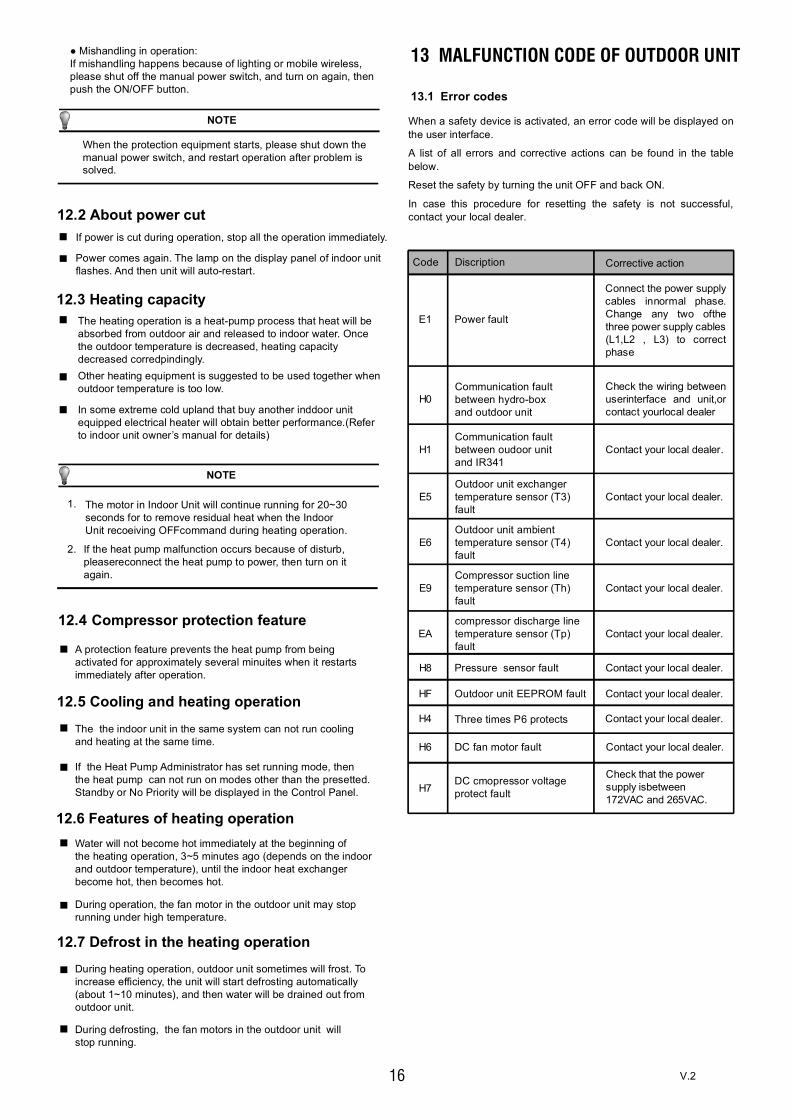
16
13.1 Error codes
When the protection equipment starts, please shut down themanual power switch, and restart operation after problem issolved.
NOTE
12.2 About power cut If power is cut during operation, stop all the operation immediately.
Power comes again. The lamp on the display panel of indoor unit flashes. And then unit will auto-restart.
● Mishandling in operation:If mishandling happens because of lighting or mobile wireless,please shut off the manual power switch, and turn on again, thenpush the ON/OFF button.
12.3 Heating capacityThe heating operation is a heat-pump process that heat will beabsorbed from outdoor air and released to indoor water. Oncethe outdoor temperature is decreased, heating capacitydecreased corredpindingly.Other heating equipment is suggested to be used together whenoutdoor temperature is too low.
In some extreme cold upland that buy another inddoor unitequipped electrical heater will obtain better performance.(Referto indoor unit owner’s manual for details)
NOTE
If the heat pump malfunction occurs because of disturb,pleasereconnect the heat pump to power, then turn on itagain.
1.
2.
A protection feature prevents the heat pump from beingactivated for approximately several minuites when it restartsimmediately after operation.
The the indoor unit in the same system can not run coolingand heating at the same time.
12.6 Features of heating operationWater will not become hot immediately at the beginning ofthe heating operation, 3~5 minutes ago (depends on the indoorand outdoor temperature), until the indoor heat exchangerbecome hot, then becomes hot.
During operation, the fan motor in the outdoor unit may stoprunning under high temperature.
12.7 Defrost in the heating operationDuring heating operation, outdoor unit sometimes will frost. Toincrease efficiency, the unit will start defrosting automatically(about 1~10 minutes), and then water will be drained out fromoutdoor unit.
During defrosting, the fan motors in the outdoor unit willstop running.
If the Heat Pump Administrator has set running mode, thenthe heat pump can not run on modes other than the presetted.Standby or No Priority will be displayed in the Control Panel.
12.4 Compressor protection feature
12.5 Cooling and heating operation
The motor in Indoor Unit will continue running for 20~30seconds for to remove residual heat when the IndoorUnit recoeiving OFFcommand during heating operation.
13 MALFUNCTION CODE OF OUTDOOR UNIT
Code Discription Corrective action
H1Communication faultbetween oudoor unitand IR341
Contact your local dealer.
E5Outdoor unit exchangertemperature sensor (T3)fault
Contact your local dealer.
Outdoor unit ambienttemperature sensor (T4)fault
E6 Contact your local dealer.
E9Compressor suction linetemperature sensor (Th)fault
Contact your local dealer.
EAcompressor discharge linetemperature sensor (Tp)fault
Contact your local dealer.
H8 Pressure sensor fault Contact your local dealer.
HF Outdoor unit EEPROM fault Contact your local dealer.
H6 DC fan motor fault Contact your local dealer.
H7DC cmopressor voltageprotect fault
Check that the powersupply isbetween172VAC and 265VAC.
H4 Contact your local dealer.Three times P6 protects
E1 Power fault
Connect the power supplycables innormal phase.Change any two ofthethree power supply cables(L1,L2 , L3) to correctphase
H0Communication faultbetween hydro-boxand outdoor unit
Check the wiring betweenuserinterface and unit,orcontact yourlocal dealer
When a safety device is activated, an error code will be displayed onthe user interface.
A list of all errors and corrective actions can be found in the tablebelow.
Reset the safety by turning the unit OFF and back ON.
In case this procedure for resetting the safety is not successful,contact your local dealer.
V.2
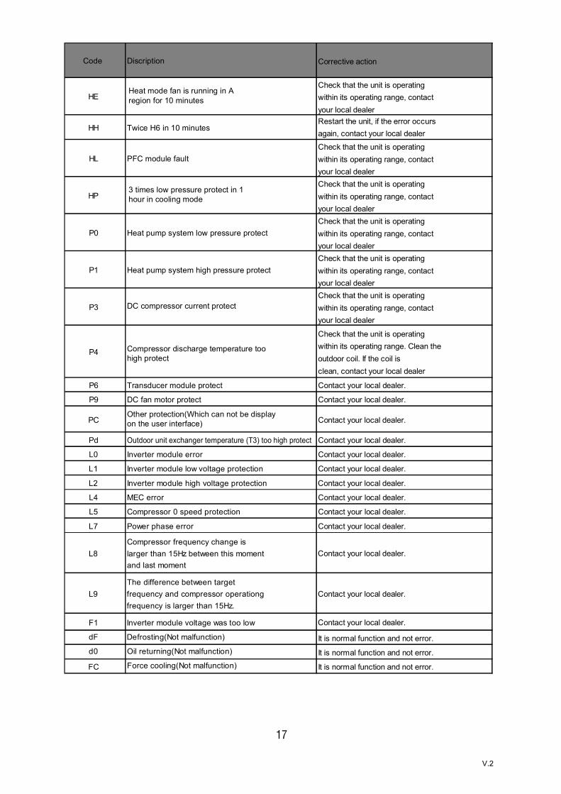
17
Code Discription Corrective action
HEHeat mode fan is running in Aregion for 10 minutes
Check that the unit is operatingwithin its operating range, contactyour local dealer
HH Twice H6 in 10 minutesRestart the unit, if the error occursagain, contact your local dealer
HL PFC module faultCheck that the unit is operatingwithin its operating range, contactyour local dealer
HP3 times low pressure protect in 1hour in cooling mode
Check that the unit is operatingwithin its operating range, contactyour local dealer
P0 Heat pump system low pressure protectCheck that the unit is operatingwithin its operating range, contactyour local dealer
P1 Heat pump system high pressure protectCheck that the unit is operatingwithin its operating range, contactyour local dealer
P3 DC compressor current protectCheck that the unit is operatingwithin its operating range, contactyour local dealer
P4 Compressor discharge temperature toohigh protect
Check that the unit is operatingwithin its operating range. Clean theoutdoor coil. If the coil isclean, contact your local dealer
P6 Transducer module protect Contact your local dealer.
P9 DC fan motor protect Contact your local dealer.
PCOther protection(Which can not be displayon the user interface) Contact your local dealer.
Pd Outdoor unit exchanger temperature (T3) too high protect Contact your local dealer.
L0 Inverter module error Contact your local dealer.
L1 Inverter module low voltage protection Contact your local dealer.
L2 Inverter module high voltage protection Contact your local dealer.
L4 MEC error Contact your local dealer.
L5 Compressor 0 speed protection Contact your local dealer.
L7 Power phase error Contact your local dealer.
L8Compressor frequency change islarger than 15Hz between this momentand last moment
Contact your local dealer.
L9The difference between targetfrequency and compressor operationgfrequency is larger than 15Hz.
Contact your local dealer.
F1 Inverter module voltage was too low Contact your local dealer.
dF Defrosting(Not malfunction) It is normal function and not error.d0 Oil returning(Not malfunction) It is normal function and not error.
FC Force cooling(Not malfunction) It is normal function and not error.
V.2

18
14 FOLLOWING SYMPTOMS ARE NOT HEAT PUMP TROUBLES
Symptom 1: The system does not operate
Symptom 2: Change into the Pump modeduring heating mode
Symptom 4: Noise of heat pump
The heat pump does not start immediately after the ON/OFFbutton on the romote controller is pressed.If the operation lamp lights, the system is in normal condition.Toprevent overloading of the compressor motor, the heat pumpstarts a few minutes after it is turned ON.
When the system is changed over to heating operation afterdefrost operation Moisture generated by defrost becomessteam and is exhausted.
A continuous low hissing sound is heard when the system is inoperation.This is the sound of refrigerant gas flowing through both indoorand outdoor units.
A hissing sound which is heard at the start or immediately afterstopping operation or defrost operation.This is the noise of refrigerant caused by flow stop or flowchange.
When the tone of operating noise changes.This noise is caused by the change of frequency.
Symptom 5: Dust comes out of the unit
Symptom 6: The units can give off odours
When the unit is used for the first time in a long time.This is because dust has gotten into the unit.
The unit can absorb the smell of rooms, furniture, cigarettes,etc., and then emit it again.
Symptom 7: The outdoor unit fan does notspin.
During operation. The speed of the fan is controlled in order tooptimize product operation.
The operation lamp is flashing rapidly (twice every second)This lamp is still flashing rapidly after turn off the power and turnon again.
Remote controller receives malfunction or the button does notwork well.
A safety device such as a fuse, a breaker frequently actuates.
Obstacles and water enter the unit.
Water leaks from indoor unit.
Other malfunctions.
15 TROUBLE SHOOTING
If one of the following malfunctions occur, stop operation, shutoff the power, and contact with your dealer.
If the system does not properly operate except the abovementioned cases or the above mentioned malfunctions isevident, investigate the system according to the followingprocedures.
When the outlet water temperature drops to the settemperature, the compressor goes off and the indoor unitchanges to pump mode; when the temperature rises up, thecompressor starts again. It is same in the heating mode..
Symptom 3: White mist comes out of outdoorunit
V.2

19
Solution
Clean the heat exchanger.Clean the water filter.Eliminate all dirties and make airsmooth.Make curtains in order to shelter fromsunshine.Reduce heat source.AC cooling capacity reduces (normal).Check leakage and rightly rechargerefrigerant.
Causes
Unit does not start
Air flowing normally butcompletely can't cooling
Power failure.Power switch is off.Fuse of power switch may have burned.Batteries of remote controller exhaustedor other problem of controller.
Temperature is not set correctly.Be in 3 minutes protection ofcompressor.
Refrigerant is too little or too much.Air or no concreting gas in therefrigerating circuit.Compressor is malfunction.Voltage is too high or too low.System circuit is blocked.
Outdoor unit and indoor unit heatexchanger is dirty.The water filter is dirty.Inlet/outlet of indoor/outdoor units isblocked.Sunlight directly shine.Too much heat resource.Outdoor temp. is too high.Leakage of refrigerant or lack ofrefrigerant.
Wait for the comeback of power.Switch on the power.ReplLocation:Replace the batterises or check thecontroller.
Set the temperature properly.Wait.
Check leakage, and rightly rechargerefrigerant.Vacuum and recharge refrigerant.Maintenance or change compressor.Install manostat.Find reasons and solution.
Use heating device.Check leakage and rightly rechargerefrigerant.
Outdoor temperature is lower than 7 CLeakage of refrigerant or lack ofrefrigerant.
Units start or stop frequently
Low cooling effect
Low heating effect
Water flowing normally butcompletely can't cooling
Unit does not start
Symptoms
V.2

20
16 TECHNICAL SPECIFICATIONS
Model(Capacity mark) ETH-4VBETH-6VB
(4kW)(6kW)
(8kW)
(10kW)(12kW)(14kW)(16kW)
Power supply
Rated power input 2.7kW 3.2kW 6.0kW
Rated current 10.5A 14.0A 27.0A
Norminal capacity
Dimensions (W×H×D)[mm] 960*860*380 1075*965*395
Packing (W×H×D)[mm] 1040*1000*430 1120*1100*435
Fan motor
Compressor
Heat exchanger
Type
Quantity 2.5kg 2.8kg 3.9kg
Net weight 60kg 76kg 99kg
Gross weight 72kg 88kg 112kg
Gas side
Liquid side
Drain connection
Max. piping length 20m 30m 50m
Max. differance in heightwhen outdoor unit is upside 10m 20m 30m
Max. differance in heightwhen outdoor unit isdownside
8m 15m 25m
Heating mode
Cooling mode
Domestic hot water mode
φ9.52
DN15
Operation ambient temperature range
-20~+35℃
-5~+46℃
-20~+43℃
Fin-coil
Refrigerant
R410A
Weight
Connections
φ15.9
220-240V~ 50Hz
Refer to the technical data
900*1327*400
1030×1456×435
DC motor / Horizontal
DC inverter dual rotary
ETH-8VB
ETH-10VBETH-12VBETH-14VBETH-16VB
V.2

21
17 IMPORTANT INFORMATION FOR THE USED REFRIGERANT
This product has the fluorinated gas which is listed in kyoto protocolit is forbidden to release to air.Refrigerant type: R410A; Volume of GWP: 2088;GWP=Global Warming Potential
Attention:
1) For equipment that contains fluorinated greenhouse gases inquantities of 5 tonnes of CO2 equivalent or more,but of less than50 tonnes of CO2 equipment,at least every 12 months, or wherea leakage detection system is installed, at least every 24 months.
2) For equipment that contains fluorinated greenhouse gases inquantities of 50 tonnes of CO2 equivalent or more,but of less than500 tonnes of CO2 equipment,at least every six months, or wherea leakage detection system is installed, at least every 12 months.
3) For equipment that contains fluorinated greenhouse gases inquantities of 500 tonnes of CO2 equivalent or more,at least everythree months, or where a leakage detection system is installed,at least every six months.
4) Non-hermetically sealed equipment charged with fluorinatedgreenhouse gases shall only be sold to the end user where evidenceis provide that the installation is to be carried out by an undertakingcertified person.
5) Only certificated person is allowed to do installation, operationand maintenance.
ModelRefrigerant/kg tonnes CO2 equivalent
2.502.803.903.903.903.90
5.225.858.148.148.148.14
ETH-6VBETH-8VBETH-10VBETH-12VBETH-14VBETH-16VB
Factory charge
ETH-4VB 2.50 5.22
V.2

After-sale serviceIf the equipment shows abnormal performance, please first disconnect the power supply, and contact our after-sales service (SAT).
To consult your nearest technical service, access the web page:
www.easelectric.es
V.2
Water quality requirements in the circuitThe quality of the water must comply with the standards of the European Directive 98/83 CE and the criteria indicated in the Standard UNE 112.076
Before connecting the outdoor unit:In both new and existing facilities, a thorough cleaning of the pipes must be carried out using an appropriate chemical cleaning product, then the pipes will be washed to clean the chemical agent. To prevent damage to the pipes, anionic, cationic corrosion inhibitors, a mixture of both or film-forming products that block the existing micropiles must be added, avoiding corrosion reactions and the release of oxygen.
When using inhibitors or other cleaning chemicals, read the manufacturer's instructions and their compatibility with the materials that make up the installation.
AntifreezeIn the case that the installation is going to work in refrigeration, antifreeze will be mandatory. In installations that do not work in refrigeration, it should be used when there is a risk of freezing during a period of non-operation or due to environmental conditions.
Antifreeze solutions should use propylene glycol with a Class 1 toxicity index. Ethylene glycol should never be used in the primary circuit.
Derived problemsThe problems derived from the bad quality of the water or of not having treated this according to what is described here, will not be covered by the product warranty.
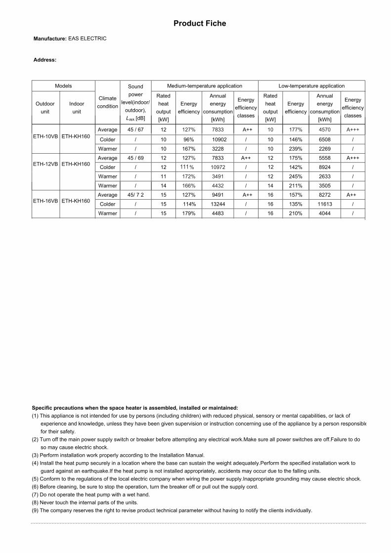
Product Fiche
Manufacture: EAS ELECTRIC
Address:
Models
Climate condition
Sound power
level(indoor/outdoor), LWA [dB]
Medium-temperature application Low-temperature application
Outdoor unit
Indoor unit
Rated heat
output [kW]
Energy efficiency
Annual energy
consumption [kWh]
Energy efficiency classes
Rated heat
output [kW]
Energy efficiency
Annual energy
consumption [kWh]
Energy efficiency classes
Average 45 / 67 12 127% 7833 A++ 10 177% 4570 A+++
Colder / 10 96% 10902 / 10 146% 6508 /
Warmer / 10 167% 3228 / 10 239% 2269 /
Average 45 / 69 12 127% 7833 A++ 12 175% 5558 A+++
Colder / 12 111% 10972 / 12 142% 8924 /
Warmer / 11 172% 3491 / 12 245% 2633 /
Warmer / 14 166% 4432 / 14 211% 3505 /
Average 45/ 7 2 15 127% 9491 A++ 16 157% 8272 A++
Colder / 15 114% 13244 / 16 135% 11613 /
Warmer / 15 179% 4483 / 16 210% 4044 /
Specific precautions when the space heater is assembled, installed or maintained:(1) This appliance is not intended for use by persons (including children) with reduced physical, sensory or mental capabilities, or lack of
experience and knowledge, unless they have been given supervision or instruction concerning use of the appliance by a person responsiblefor their safety.
(2) Turn off the main power supply switch or breaker before attempting any electrical work.Make sure all power switches are off.Failure to doso may cause electric shock.
(3) Perform installation work properly according to the Installation Manual.(4) Install the heat pump securely in a location where the base can sustain the weight adequately.Perform the specified installation work to
guard against an earthquake.If the heat pump is not installed appropriately, accidents may occur due to the falling units.(5) Conform to the regulations of the local electric company when wiring the power supply.Inappropriate grounding may cause electric shock.(6) Before cleaning, be sure to stop the operation, turn the breaker off or pull out the supply cord.(7) Do not operate the heat pump with a wet hand.(8) Never touch the internal parts of the units.(9) The company reserves the right to revise product technical parameter without having to notify the clients individually.
ETH-KH160
ETH-KH160
ETH-KH160
ETH-10VB
ETH-12VB
ETH-16VB
EAS ELECTRICPol. Industrial San Carlos, Parcela 13 03370 Redován (Alicante)www.easelectric.es
V.21

Item Symbol Value Unit Item Symbol Value Unit
Rated heat output (*) Prated 12 kW Seasonal space heatingenergy efficiency ηs 127 %
Tj = -7℃ Pdh 10.9 kW Tj = -7℃ COPd 2.02 -
Tj = 2℃ Pdh 7.0 kW Tj = 2℃ COPd 3.05 -
Tj = 7℃ Pdh 4.2 kW Tj = 7℃ COPd 4.49 -
Tj = 12℃ Pdh 2.5 kW Tj = 12℃ COPd 5.97 -
Tj = bivalent temperature Pdh 10.9 kW Tj = bivalent temperature COPd 2.02 -
Tj = operating limit Pdh 10.3 kW Tj = operating limit COPd 1.73 -
For air-to-water heat pumps:Tj = -15℃
Pdh - kW For air-to-water heat pumps:Tj = -15℃
COPd - -
Bivalent temperature Tbiv -7 °CFor air-to-water heat pumps:Operation limit temperature TOL -10 °C
Cycling interval capacity for heating Pcy ch - kW Cycling interval efficiency COPcy c
Degradation co-efficient (**) Cdh 0.9 -- Heating water operating limittemperature
WTOL 60 °C
Off mode Pof f 0.019 kW
Standby mode Psb 0.019 kWThermostat-off mode Pto 0.078 kWCrankcase heater mode Pck 0.014 kW
Sound power level, indoors/outdoors
LWA 45 / 67 dB
Annual energy consumption QHE 7833 kWh
Declared load profile Water heating energyefficiency ηwh - %
Daily electricity consumption Qelec - kWh Daily fuel consumption Qf uel - kWh
Annual electricity consumption AEC - kWh Annual fuel consumption AFC - GJ
Contact details
Technical parameters
variableCapacity control
(*) For heat pump space heaters and heat pump combination heaters, the rated heat output Prated is equal to the design load for heating Pdesignh,and the rated heat output of a supplementary heater Psup is equal to the supplementary capacity for heating sup(Tj).(**) If Cdh is not determined by measurement then the default degradation coefficient is Cdh = 0,9.
Air-to-water heat pump:
Declared capacity for heating for part load at indoor temperature 20 °Cand outdoor temperature Tj
Declared coefficient of performance or primary energy ratio for part load atindoor temperature 20 °C and outdoor temperature Tj
Power consumption in modes other than active mode Supplementary heater
-
For heat pump combination heater:
For air-to-water heat pumps:Rated air flow rate, outdoors
Other items
For water- or brine-to-waterheat pumps: Rated brine orwater flow rate, outdoor heatexchanger
_ - m3/h
_ 6500 m³/h
Electrical
Rated heat output (**) Psup kW
Outdoor unit: ETH-10VB Indoor unit: ETH-KH160
YES
NO
NO
NO
NO
Model(s):
Water-to-water heat pump:
Brine-to-water heat pump:
Low-temperature heat pump:
Equipped with a supplementary heater:
Heat pump combination heater:
Type of energy input
Parameters are declared for medium-temperature application.
YES
2.0
- -
Declared climate condition: AVERAGE
EAS ELECTRICPol. Industrial San Carlos, Parcela 13 03370 Redován (Alicante)www.easelectric.es
V.22

Item Symbol Value Unit Item Symbol Value Unit
Rated heat output (*) Prated 10 kW Seasonal space heatingenergy efficiency ηs 96 %
Tj = -7℃ Pdh 6.4 kW Tj = -7℃ COPd 2.26 -
Tj = 2℃ Pdh 3.9 kW Tj = 2℃ COPd 3.02 -
Tj = 7℃ Pdh 2.2 kW Tj = 7℃ COPd 3.67 -
Tj = 12℃ Pdh 3.6 kW Tj = 12℃ COPd 7.65 -
Tj = bivalent temperature Pdh 8.9 kW Tj = bivalent temperature COPd 1.80 -
Tj = operating limit Pdh 7.5 kW Tj = operating limit COPd 1.27 -
For air-to-water heat pumps:Tj = -15℃
Pdh - kW For air-to-water heat pumps:Tj = -15℃
COPd - -
Bivalent temperature Tbiv -15 °CFor air-to-water heat pumps:Operation limit temperature TOL -20 °C
Cycling interval capacity for heating Pcy ch - kW Cycling interval efficiency COPcy c
Degradation co-efficient (**) Cdh 0.9 -- Heating water operating limittemperature
WTOL 60 °C
Off mode Pof f 0.019 kW
Standby mode Psb 0.019 kWThermostat-off mode Pto 0.078 kWCrankcase heater mode Pck 0.014 kW
Sound power level, indoors/outdoors
LWA - dB
Annual energy consumption QHE 10902 kWh
Declared load profile Water heating energyefficiency ηwh - %
Daily electricity consumption Qelec - kWh Daily fuel consumption Qf uel - kWh
Annual electricity consumption AEC - kWh Annual fuel consumption AFC - GJ
Contact details
Technical parameters
variableCapacity control
(*) For heat pump space heaters and heat pump combination heaters, the rated heat output Prated is equal to the design load for heating Pdesignh,and the rated heat output of a supplementary heater Psup is equal to the supplementary capacity for heating sup(Tj).(**) If Cdh is not determined by measurement then the default degradation coefficient is Cdh = 0,9.
Air-to-water heat pump:
Declared capacity for heating for part load at indoor temperature 20 °Cand outdoor temperature Tj
Declared coefficient of performance or primary energy ratio for part load atindoor temperature 20 °C and outdoor temperature Tj
Power consumption in modes other than active mode Supplementary heater
-
For heat pump combination heater:
For air-to-water heat pumps:Rated air flow rate, outdoors
Other items
For water- or brine-to-waterheat pumps: Rated brine orwater flow rate, outdoor heatexchanger
_ - m3/h
_ 6500 m³/h
Electrical
Rated heat output (**) Psup kW
Outdoor unit: ETH-10VB Indoor unit: ETH-KH160
YES
NO
NO
NO
NO
Model(s):
Water-to-water heat pump:
Brine-to-water heat pump:
Low-temperature heat pump:
Equipped with a supplementary heater:
Heat pump combination heater:
Type of energy input
Parameters are declared for medium-temperature application.
YES
10.9
- -
Declared climate condition: COLDER
EAS ELECTRICPol. Industrial San Carlos, Parcela 13 03370 Redován (Alicante)www.easelectric.es
V.23

Item Symbol Value Unit Item Symbol Value Unit
Rated heat output (*) Prated 10 kW Seasonal space heatingenergy efficiency ηs 167 %
Tj = -7℃ Pdh - kW Tj = -7℃ COPd - -
Tj = 2℃ Pdh 10.3 kW Tj = 2℃ COPd 2.34 -
Tj = 7℃ Pdh 6.7 kW Tj = 7℃ COPd 3.53 -
Tj = 12℃ Pdh 5.2 kW Tj = 12℃ COPd 6.25 -
Tj = bivalent temperature Pdh 10.3 kW Tj = bivalent temperature COPd 2.34 -
Tj = operating limit Pdh 10.3 kW Tj = operating limit COPd 2.34 -
For air-to-water heat pumps:Tj = -15℃
Pdh - kW For air-to-water heat pumps:Tj = -15℃
COPd - -
Bivalent temperature Tbiv 2 °CFor air-to-water heat pumps:Operation limit temperature TOL 2 °C
Cycling interval capacity for heating Pcy ch - kW Cycling interval efficiency COPcy c
Degradation co-efficient (**) Cdh 0.9 -- Heating water operating limittemperature
WTOL 60 °C
Off mode Pof f 0.019 kW
Standby mode Psb 0.019 kWThermostat-off mode Pto 0.078 kWCrankcase heater mode Pck 0.014 kW
Sound power level, indoors/outdoors
LWA - dB
Annual energy consumption QHE 3228 kWh
Declared load profile Water heating energyefficiency ηwh - %
Daily electricity consumption Qelec - kWh Daily fuel consumption Qf uel - kWh
Annual electricity consumption AEC - kWh Annual fuel consumption AFC - GJ
Contact details
Technical parameters
variableCapacity control
(*) For heat pump space heaters and heat pump combination heaters, the rated heat output Prated is equal to the design load for heating Pdesignh,and the rated heat output of a supplementary heater Psup is equal to the supplementary capacity for heating sup(Tj).(**) If Cdh is not determined by measurement then the default degradation coefficient is Cdh = 0,9.
Air-to-water heat pump:
Declared capacity for heating for part load at indoor temperature 20 °Cand outdoor temperature Tj
Declared coefficient of performance or primary energy ratio for part load atindoor temperature 20 °C and outdoor temperature Tj
Power consumption in modes other than active mode Supplementary heater
-
For heat pump combination heater:
For air-to-water heat pumps:Rated air flow rate, outdoors
Other items
For water- or brine-to-waterheat pumps: Rated brine orwater flow rate, outdoor heatexchanger
_ - m3/h
_ 6500 m³/h
Electrical
Rated heat output (**) Psup kW
Outdoor unit: ETH-10VB Indoor unit: ETH-KH160
YES
NO
NO
NO
NO
Model(s):
Water-to-water heat pump:
Brine-to-water heat pump:
Low-temperature heat pump:
Equipped with a supplementary heater:
Heat pump combination heater:
Type of energy input
Parameters are declared for medium-temperature application.
YES
0
- -
Declared climate condition: WARMER
EAS ELECTRICPol. Industrial San Carlos, Parcela 13 03370 Redován (Alicante)www.easelectric.es
V.24

Item Symbol Value Unit Item Symbol Value Unit
Rated heat output (*) Prated 12 kW Seasonal space heatingenergy efficiency ηs 127 %
Tj = -7℃ Pdh 10.9 kW Tj = -7℃ COPd 2.02 -
Tj = 2℃ Pdh 7.0 kW Tj = 2℃ COPd 3.05 -
Tj = 7℃ Pdh 4.2 kW Tj = 7℃ COPd 4.49 -
Tj = 12℃ Pdh 2.5 kW Tj = 12℃ COPd 5.97 -
Tj = bivalent temperature Pdh 10.9 kW Tj = bivalent temperature COPd 2.02 -
Tj = operating limit Pdh 10.3 kW Tj = operating limit COPd 1.73 -
For air-to-water heat pumps:Tj = -15℃
Pdh - kW For air-to-water heat pumps:Tj = -15℃
COPd - -
Bivalent temperature Tbiv -7 °CFor air-to-water heat pumps:Operation limit temperature TOL -10 °C
Cycling interval capacity for heating Pcy ch - kW Cycling interval efficiency COPcy c
Degradation co-efficient (**) Cdh 0.9 -- Heating water operating limittemperature
WTOL 60 °C
Off mode Pof f 0.019 kW
Standby mode Psb 0.019 kWThermostat-off mode Pto 0.078 kWCrankcase heater mode Pck 0.014 kW
Sound power level, indoors/outdoors
LWA 45/69 dB
Annual energy consumption QHE 7833 kWh
Declared load profile Water heating energyefficiency ηwh - %
Daily electricity consumption Qelec - kWh Daily fuel consumption Qf uel - kWh
Annual electricity consumption AEC - kWh Annual fuel consumption AFC - GJ
Contact details
Technical parameters
variableCapacity control
(*) For heat pump space heaters and heat pump combination heaters, the rated heat output Prated is equal to the design load for heating Pdesignh,and the rated heat output of a supplementary heater Psup is equal to the supplementary capacity for heating sup(Tj).(**) If Cdh is not determined by measurement then the default degradation coefficient is Cdh = 0,9.
Air-to-water heat pump:
Declared capacity for heating for part load at indoor temperature 20 °Cand outdoor temperature Tj
Declared coefficient of performance or primary energy ratio for part load atindoor temperature 20 °C and outdoor temperature Tj
Power consumption in modes other than active mode Supplementary heater
-
For heat pump combination heater:
For air-to-water heat pumps:Rated air flow rate, outdoors
Other items
For water- or brine-to-waterheat pumps: Rated brine orwater flow rate, outdoor heatexchanger
_ - m3/h
_ 6500 m³/h
Electrical
Rated heat output (**) Psup kW
Outdoor unit: ETH-12VB Indoor unit: ETH-KH160
YES
NO
NO
NO
NO
Model(s):
Water-to-water heat pump:
Brine-to-water heat pump:
Low-temperature heat pump:
Equipped with a supplementary heater:
Heat pump combination heater:
Type of energy input
Parameters are declared for medium-temperature application.
YES
2.0
- -
Declared climate condition: AVERAGE
EAS ELECTRICPol. Industrial San Carlos, Parcela 13 03370 Redován (Alicante)www.easelectric.es
V.25

Item Symbol Value Unit Item Symbol Value Unit
Rated heat output (*) Prated 12 kW Seasonal space heatingenergy efficiency ηs 111 %
Tj = -7℃ Pdh 7.8 kW Tj = -7℃ COPd 2.34 -
Tj = 2℃ Pdh 4.8 kW Tj = 2℃ COPd 3.52 -
Tj = 7℃ Pdh 2.9 kW Tj = 7℃ COPd 4.58 -
Tj = 12℃ Pdh 3.9 kW Tj = 12℃ COPd 8.02 -
Tj = bivalent temperature Pdh 10.0 kW Tj = bivalent temperature COPd 1.87 -
Tj = operating limit Pdh 7.4 kW Tj = operating limit COPd 1.26 -
For air-to-water heat pumps:Tj = -15℃
Pdh - kW For air-to-water heat pumps:Tj = -15℃
COPd - -
Bivalent temperature Tbiv -14 °CFor air-to-water heat pumps:Operation limit temperature TOL -20 °C
Cycling interval capacity for heating Pcy ch - kW Cycling interval efficiency COPcy c
Degradation co-efficient (**) Cdh 0.9 -- Heating water operating limittemperature
WTOL 60 °C
Off mode Pof f 0.019 kW
Standby mode Psb 0.019 kWThermostat-off mode Pto 0.078 kWCrankcase heater mode Pck 0.014 kW
Sound power level, indoors/outdoors
LWA - dB
Annual energy consumption QHE 10972 kWh
Declared load profile Water heating energyefficiency ηwh - %
Daily electricity consumption Qelec - kWh Daily fuel consumption Qf uel - kWh
Annual electricity consumption AEC - kWh Annual fuel consumption AFC - GJ
Contact details
Technical parameters
variableCapacity control
(*) For heat pump space heaters and heat pump combination heaters, the rated heat output Prated is equal to the design load for heating Pdesignh,and the rated heat output of a supplementary heater Psup is equal to the supplementary capacity for heating sup(Tj).(**) If Cdh is not determined by measurement then the default degradation coefficient is Cdh = 0,9.
Air-to-water heat pump:
Declared capacity for heating for part load at indoor temperature 20 °Cand outdoor temperature Tj
Declared coefficient of performance or primary energy ratio for part load atindoor temperature 20 °C and outdoor temperature Tj
Power consumption in modes other than active mode Supplementary heater
-
For heat pump combination heater:
For air-to-water heat pumps:Rated air flow rate, outdoors
Other items
For water- or brine-to-waterheat pumps: Rated brine orwater flow rate, outdoor heatexchanger
_ - m3/h
_ 6500 m³/h
Electrical
Rated heat output (**) Psup kW
Outdoor unit: ETH-12VB Indoor unit: ETH-KH160
YES
NO
NO
NO
NO
Model(s):
Water-to-water heat pump:
Brine-to-water heat pump:
Low-temperature heat pump:
Equipped with a supplementary heater:
Heat pump combination heater:
Type of energy input
Parameters are declared for medium-temperature application.
YES
5.3
- -
Declared climate condition: COLDER
EAS ELECTRICPol. Industrial San Carlos, Parcela 13 03370 Redován (Alicante)www.easelectric.es
V.26

Item Symbol Value Unit Item Symbol Value Unit
Rated heat output (*) Prated 11 kW Seasonal space heatingenergy efficiency ηs 172 %
Tj = -7℃ Pdh - kW Tj = -7℃ COPd - -
Tj = 2℃ Pdh 11.4 kW Tj = 2℃ COPd 2.50 -
Tj = 7℃ Pdh 7.4 kW Tj = 7℃ COPd 3.59 -
Tj = 12℃ Pdh 5.3 kW Tj = 12℃ COPd 6.36 -
Tj = bivalent temperature Pdh 11.4 kW Tj = bivalent temperature COPd 2.50 -
Tj = operating limit Pdh 11.4 kW Tj = operating limit COPd 2.50 -
For air-to-water heat pumps:Tj = -15℃
Pdh - kW For air-to-water heat pumps:Tj = -15℃
COPd - -
Bivalent temperature Tbiv 2 °CFor air-to-water heat pumps:Operation limit temperature TOL 2 °C
Cycling interval capacity for heating Pcy ch - kW Cycling interval efficiency COPcy c
Degradation co-efficient (**) Cdh 0.9 -- Heating water operating limittemperature
WTOL 60 °C
Off mode Pof f 0.019 kW
Standby mode Psb 0.019 kWThermostat-off mode Pto 0.078 kWCrankcase heater mode Pck 0.014 kW
Sound power level, indoors/outdoors
LWA - dB
Annual energy consumption QHE 3491 kWh
Declared load profile Water heating energyefficiency ηwh - %
Daily electricity consumption Qelec - kWh Daily fuel consumption Qf uel - kWh
Annual electricity consumption AEC - kWh Annual fuel consumption AFC - GJ
Contact details
Technical parameters
variableCapacity control
(*) For heat pump space heaters and heat pump combination heaters, the rated heat output Prated is equal to the design load for heating Pdesignh,and the rated heat output of a supplementary heater Psup is equal to the supplementary capacity for heating sup(Tj).(**) If Cdh is not determined by measurement then the default degradation coefficient is Cdh = 0,9.
Air-to-water heat pump:
Declared capacity for heating for part load at indoor temperature 20 °Cand outdoor temperature Tj
Declared coefficient of performance or primary energy ratio for part load atindoor temperature 20 °C and outdoor temperature Tj
Power consumption in modes other than active mode Supplementary heater
-
For heat pump combination heater:
For air-to-water heat pumps:Rated air flow rate, outdoors
Other items
For water- or brine-to-waterheat pumps: Rated brine orwater flow rate, outdoor heatexchanger
_ - m3/h
_ 6500 m³/h
Electrical
Rated heat output (**) Psup kW
Outdoor unit: ETH-12VB Indoor unit: ETH-KH160
YES
NO
NO
NO
NO
Model(s):
Water-to-water heat pump:
Brine-to-water heat pump:
Low-temperature heat pump:
Equipped with a supplementary heater:
Heat pump combination heater:
Type of energy input
Parameters are declared for medium-temperature application.
YES
0
- -
Declared climate condition: WARMER
EAS ELECTRICPol. Industrial San Carlos, Parcela 13 03370 Redován (Alicante)www.easelectric.es
V.27

Item Symbol Value Unit Item Symbol Value Unit
Rated heat output (*) Prated 15 kW Seasonal space heatingenergy efficiency ηs 127 %
Tj = -7℃ Pdh 11.7 kW Tj = -7℃ COPd 1.99 -
Tj = 2℃ Pdh 8.1 kW Tj = 2℃ COPd 3.09 -
Tj = 7℃ Pdh 5.4 kW Tj = 7℃ COPd 4.73 -
Tj = 12℃ Pdh 2.8 kW Tj = 12℃ COPd 6.81 -
Tj = bivalent temperature Pdh 12.1 kW Tj = bivalent temperature COPd 2.15 -
Tj = operating limit Pdh 10.2 kW Tj = operating limit COPd 1.70 -
For air-to-water heat pumps:Tj = -15℃
Pdh - kW For air-to-water heat pumps:Tj = -15℃
COPd - -
Bivalent temperature Tbiv -5 °CFor air-to-water heat pumps:Operation limit temperature TOL -10 °C
Cycling interval capacity for heating Pcy ch - kW Cycling interval efficiency COPcy c
Degradation co-efficient (**) Cdh 0.9 -- Heating water operating limittemperature
WTOL 60 °C
Off mode Pof f 0.019 kW
Standby mode Psb 0.019 kWThermostat-off mode Pto 0.078 kWCrankcase heater mode Pck 0.014 kW
Sound power level, indoors/outdoors
LWA 45/72 dB
Annual energy consumption QHE 9491 kWh
Declared load profile Water heating energyefficiency ηwh - %
Daily electricity consumption Qelec - kWh Daily fuel consumption Qf uel - kWh
Annual electricity consumption AEC - kWh Annual fuel consumption AFC - GJ
Contact details
Technical parameters
variableCapacity control
(*) For heat pump space heaters and heat pump combination heaters, the rated heat output Prated is equal to the design load for heating Pdesignh,and the rated heat output of a supplementary heater Psup is equal to the supplementary capacity for heating sup(Tj).(**) If Cdh is not determined by measurement then the default degradation coefficient is Cdh = 0,9.
Air-to-water heat pump:
Declared capacity for heating for part load at indoor temperature 20 °Cand outdoor temperature Tj
Declared coefficient of performance or primary energy ratio for part load atindoor temperature 20 °C and outdoor temperature Tj
Power consumption in modes other than active mode Supplementary heater
-
For heat pump combination heater:
For air-to-water heat pumps:Rated air flow rate, outdoors
Other items
For water- or brine-to-waterheat pumps: Rated brine orwater flow rate, outdoor heatexchanger
_ - m3/h
_ 6500 m³/h
Electrical
Rated heat output (**) Psup kW
Outdoor unit: ETH-16VB Indoor unit: ETH-KH160
YES
NO
NO
NO
NO
Model(s):
Water-to-water heat pump:
Brine-to-water heat pump:
Low-temperature heat pump:
Equipped with a supplementary heater:
Heat pump combination heater:
Type of energy input
Parameters are declared for medium-temperature application.
YES
4.3
- -
Declared climate condition: AVERAGE
EAS ELECTRICPol. Industrial San Carlos, Parcela 13 03370 Redován (Alicante)www.easelectric.es
V.28

Item Symbol Value Unit Item Symbol Value Unit
Rated heat output (*) Prated 15 kW Seasonal space heatingenergy efficiency ηs 114 %
Tj = -7℃ Pdh 10.4 kW Tj = -7℃ COPd 2.44 -
Tj = 2℃ Pdh 6.2 kW Tj = 2℃ COPd 3.55 -
Tj = 7℃ Pdh 4.0 kW Tj = 7℃ COPd 5.40 -
Tj = 12℃ Pdh 4.0 kW Tj = 12℃ COPd 8.20 -
Tj = bivalent temperature Pdh 11.6 kW Tj = bivalent temperature COPd 1.94 -
Tj = operating limit Pdh 7.3 kW Tj = operating limit COPd 1.24 -
For air-to-water heat pumps:Tj = -15℃
Pdh - kW For air-to-water heat pumps:Tj = -15℃
COPd - -
Bivalent temperature Tbiv -12 °CFor air-to-water heat pumps:Operation limit temperature TOL -20 °C
Cycling interval capacity for heating Pcy ch - kW Cycling interval efficiency COPcy c
Degradation co-efficient (**) Cdh 0.9 -- Heating water operating limittemperature
WTOL 60 °C
Off mode Pof f 0.019 kW
Standby mode Psb 0.019 kWThermostat-off mode Pto 0.078 kWCrankcase heater mode Pck 0.014 kW
Sound power level, indoors/outdoors
LWA - dB
Annual energy consumption QHE 13244 kWh
Declared load profile Water heating energyefficiency ηwh - %
Daily electricity consumption Qelec - kWh Daily fuel consumption Qf uel - kWh
Annual electricity consumption AEC - kWh Annual fuel consumption AFC - GJ
Contact details
Technical parameters
variableCapacity control
(*) For heat pump space heaters and heat pump combination heaters, the rated heat output Prated is equal to the design load for heating Pdesignh,and the rated heat output of a supplementary heater Psup is equal to the supplementary capacity for heating sup(Tj).(**) If Cdh is not determined by measurement then the default degradation coefficient is Cdh = 0,9
Air-to-water heat pump:
Declared capacity for heating for part load at indoor temperature 20 °Cand outdoor temperature Tj
Declared coefficient of performance or primary energy ratio for part load atindoor temperature 20 °C and outdoor temperature Tj
Power consumption in modes other than active mode Supplementary heater
-
For heat pump combination heater:
For air-to-water heat pumps:Rated air flow rate, outdoors
Other items
For water- or brine-to-waterheat pumps: Rated brine orwater flow rate, outdoor heatexchanger
_ - m3/h
_ 6500 m³/h
Electrical
Rated heat output (**) Psup kW
Outdoor unit: ETH-16VB Indoor unit: ETH-KH160
YES
NO
NO
NO
NO
Model(s):
Water-to-water heat pump:
Brine-to-water heat pump:
Low-temperature heat pump:
Equipped with a supplementary heater:
Heat pump combination heater:
Type of energy input
Parameters are declared for medium-temperature application.
YES
8.4
- -
Declared climate condition: COLDER
EAS ELECTRICPol. Industrial San Carlos, Parcela 13 03370 Redován (Alicante)www.easelectric.es
V.29

Item Symbol Value Unit Item Symbol Value Unit
Rated heat output (*) Prated 15 kW Seasonal space heatingenergy efficiency ηs 179 %
Tj = -7℃ Pdh - kW Tj = -7℃ COPd - -
Tj = 2℃ Pdh 15.3 kW Tj = 2℃ COPd 2.34 -
Tj = 7℃ Pdh 9.9 kW Tj = 7℃ COPd 3.81 -
Tj = 12℃ Pdh 4.4 kW Tj = 12℃ COPd 6.16 -
Tj = bivalent temperature Pdh 15.3 kW Tj = bivalent temperature COPd 2.34 -
Tj = operating limit Pdh 15.3 kW Tj = operating limit COPd 2.34 -
For air-to-water heat pumps:Tj = -15℃
Pdh - kW For air-to-water heat pumps:Tj = -15℃
COPd - -
Bivalent temperature Tbiv 2 °CFor air-to-water heat pumps:Operation limit temperature TOL 2 °C
Cycling interval capacity for heating Pcy ch - kW Cycling interval efficiency COPcy c
Degradation co-efficient (**) Cdh 0.9 -- Heating water operating limittemperature
WTOL 60 °C
Off mode Pof f 0.019 kW
Standby mode Psb 0.019 kWThermostat-off mode Pto 0.078 kWCrankcase heater mode Pck 0.014 kW
Sound power level, indoors/outdoors
LWA - dB
Annual energy consumption QHE 4483 kWh
Declared load profile Water heating energyefficiency ηwh - %
Daily electricity consumption Qelec - kWh Daily fuel consumption Qf uel - kWh
Annual electricity consumption AEC - kWh Annual fuel consumption AFC - GJ
Contact details
Technical parameters
variableCapacity control
(*) For heat pump space heaters and heat pump combination heaters, the rated heat output Prated is equal to the design load for heating Pdesignh,and the rated heat output of a supplementary heater Psup is equal to the supplementary capacity for heating sup(Tj).(**) If Cdh is not determined by measurement then the default degradation coefficient is Cdh = 0,9
Air-to-water heat pump:
Declared capacity for heating for part load at indoor temperature 20 °Cand outdoor temperature Tj
Declared coefficient of performance or primary energy ratio for part load atindoor temperature 20 °C and outdoor temperature Tj
Power consumption in modes other than active mode Supplementary heater
-
For heat pump combination heater:
For air-to-water heat pumps:Rated air flow rate, outdoors
Other items
For water- or brine-to-waterheat pumps: Rated brine orwater flow rate, outdoor heatexchanger
_ - m3/h
_ 6500 m³/h
Electrical
Rated heat output (**) Psup kW
Outdoor unit: ETH-16VB Indoor unit: ETH-KH160
YES
NO
NO
NO
NO
Model(s):
Water-to-water heat pump:
Brine-to-water heat pump:
Low-temperature heat pump:
Equipped with a supplementary heater:
Heat pump combination heater:
Type of energy input
Parameters are declared for medium-temperature application.
YES
0
- -
Declared climate condition: WARMER
EAS ELECTRICPol. Industrial San Carlos, Parcela 13 03370 Redován (Alicante)www.easelectric.es
V.210

V.2
WIRE CONTROL WITH WEEKLY PROGRAMMING
OWNER'S MANUAL
MODEL: ECRTH

1
● This manual gives detailed description of the precautions thatshould be brought to your attention during operation.
● In order to ensure correct service of the wiring controller pleaseread this manual carefully before using the unit.
● For convenience of future reference, keep this manual afterreading it.
CONTENTS PAGE
1 GENERAL SAFETY PRECAUTIONS1.1 About the documentation
1.1.1 Meaning of warnings and symbols
The precautions described in this document cover very importanttopics, follow them carefully.
DANGERIndicates a situation that results in death or serious injury.
DANGER: RISK OF BURNINGIndicates a situation that could result in burning because ofextreme hot or cold temperatures.
DANGER: RISK OF ELECTROCUTIONIndicates a situation that could result in electrocution.
CAUTIONIndicates a situation that could result in minor or moderate injury.
WARNINGIndicates a situation that could result in death or serious injury.
INFORMATIONIndicates useful tips or additional information.
NOTICEIndicates a situation that could result in equipment orproperty damage.
1.2 For the userIf you are not sure how to operate the unit, contact your installer.
The appliance is not intended for use by persons, includingchildren, with reduced physical, sensory or mental capabilities, orlack of experience and knowledge, unless they have been givensupervision or instruction concerning use of the appliance by aperson responsible for their safety. Children must be supervisedto ensure that they do not play with the product.
CAUTIONDo NOT rinse the unit. This may cause electric shocks or fire.
Units are marked with the following symbol:
Placed in a location away from radiation.
This means that electrical and electronic products may notbe mixed with unsorted household waste. Do NOT try todismantle the system yourself: the dismantling of thesystem, treatment of the refrigerant, of oil and of otherparts must be done byan authorized installer and must comply with applicablelegislation. Units must be treated at a specializedtreatment facility for reuse, recycling and recovery. Byensuring this product is disposed of correctly, you will helpto prevent potential negative consequences for theenvironment and human health. For more information,contact your installer or local authority.
V.2

2
2 A GLANCE OF THE USER INTERFACE
2.1 The appearance of the wire control device
2.2 Status icons
Turn on or off thespace operationmode or DHWmode turn on oroff the function inthe menustructure
Enter the menustructure fromthe home page
Navigate thecursor on thedisplay/navigatein the menustructure/ adjustthe settings
Come back tothe up level
Long press forunlocking /lockingthe controllerunlock /lock somefunction such as''TANK'' temp.adjusting''
Lock icon
Timer icon
Prevent freezing icon
The AHS(additional heating source such asgas boiler) is activated
A malfunction occured
Silent mode is activated
The disinfect function is activated
Holiday away/home is activated
Backup heater is activated
The compressor is activated
Desired temp.
DHW mode
the desired temp.will not change.
the desired temp.will decrease.
the desired temp.will increase.
TANK 55 C C27SET
SET 08 : 30C
ONON DHWMAIN
21: 55 08 - 08 - 2015 SAT.
Tank temp.
Heat mode
Cool mode
Auto mode
Mode is operating
A
At the next scheduled action, the desired temp. will increase.
Shutoff
Go to the next step whenprogramming a schedule in themenu structure / confirm aselection/enter a submenu inthe menu structure
ECO modeis activated
Tank heater is activated
Defrost modeis activated
The solarenergyis activated
Weeklyschedule7
V.2

3
3 USING HOME PAGES
3.1 About home pages
You can use the home pages to read out and change settings that are meant for daily usage. What you can see and do on the home pages isdescribed where applicable. Depending on the system layout, the following home pages may be possible:
■ Room temperature (ROOM ) ■ Water flow temperature (MAIN) ■ DHW tank temperature (TANK) DHW=domestic hot water
② home page2:
If set the WATER FLOW TEMP. is set NON and ROOM TEMP. is set YES(See FOR SERVICEMAN TEMPERATURE TYPE SETTING oninstallation & ower's manual). There will be only main page. The system has the function including floor heating and domestic hot water. Thepage will appear:
FHL1FHL2...FHLnTANK 55 C27SET C
ONON DHWROOM
21: 55 08 - 08 - 2015 SAT.
① home page1:
If the WATER FLOW TEMP. is set YES and ROOM TEMP. is set NON.(See FOR SERVICEMAN TEMPERATURE TYPE SETTING on installa-tion & ower's manual). There will be only main page. The system has the function including floor heating and domestic water. The page willappear:
TANK 55 C35SET C
ONON DHWMAIN
21: 55 08 - 08 - 2015 SAT.
the system layout 1
the system layout 2
FHL1FHL2...FHLn
NOTE:The interface should be installed in the floor heating room to check the room temperature.
NOTE
All the pictures in the manual are used to explain, the actual pages in the screen maybe have some difference.
V.2

4
If the WATER FLOW TEMP. is set YES and ROOM TEMP. is set YES(See FOR SERVICEMAN TEMPERATURE TYPE SETTING on installation& ower's manual) . There will be main page and additional. page. The system has the function including floor heating and space cooling for fancoil. The page will appear:
If the WATER FLOW TEMP. is set YES and ROOM TEMP. is set YES. There will be main page and addition page. The system has the functionincluding floor heating, space cooling for fan coil and domestic hot water. The page will appear:
③ home page3:
④ home page4:
Main page
FHL1FHL2...FHLn
FCU1FCU2...FCUn
ADDITION PAGE
21: 55 08 - 08 - 2015 SAT.
ONROOM
21: 55 08 - 08 - 2015 SAT.
ONMAIN
MAIN PAGE
ADDITION PAGE
TANK C12SET C
ONON DHWMAIN
21: 55 08 - 08 - 2015 SAT.
55
SET C24
21: 55 08 - 08 - 2015 SAT.
ONROOM
FHL1 FHL2... FHLn
FCU1 FCU2... FCUn
4 MENU
4.1 About the menu structure
4.2 To go to the menu strctureFrom a home page, press ''MENU''.Result: The menu structure appear:
You can use the menu structure to read out and configure settings that are NOT meant for daily usage. What you can see and do in the menustructure is described where applicable. For an overview of the menu structure, see " 7 Menu structure: Overview".
the system layout 4
the system layout 3
V.2

ON
TANK 55 CSET C
OFF DHWMAIN
21: 55 08 - 08 - 2015 SAT.
18
5
4.3 To navigate in the menu structureUse''▼''、''▲'' to scroll.
MEMU
SERVICE INFORMATION
OPERATION PARAMRTERFOR SERVICEMAN
SCROLLENTEROK
5 BASIC USAGE
5.1 Screen Unlock
If the icon is on the screen, the controller is locked. The page is
displayed:
The interface will be locked if there is no handing for a long time(about60 seconds:it can be set by the interface,see 6.7 SERVICEINFORMATION.)If the inerface is unlocked, long press "unlock",the interface will belocked.
ON
TANK 55 CSET C
OFF DHWMAIN
21: 55 08 - 08 - 2015 SAT.
18
ON
TANK 55 CSET C
OFF DHWMAIN
21: 55 08 - 08 - 2015 SAT.
18
Press any key, the icon will flash.Long press the ''UNLOCK''key.The icon will disappear,the interface can be controlled.
5.2 Turning ON/OFF controls
■ The ON/OFF of the unit can be controlled by the interface if theROOM TEHERMOSTAT is NON.(see ROOM THERMOSTATSETTING on INSTALLATION &OWNER'S MANUAL)
ON
TANK 55 CSET C
OFF DHWMAIN
21: 55 08 - 08 - 2015 SAT.
18
long pressUNLOCK
1)When the cursor is on space operation mode side (Including heatmode , cool mode and auto mode ), press ''ON/OFF'' keyto turn on/off the operation mode .
TANK 55 CSET C
ONON DHWMAIN
21: 55 08 - 08 - 2015 SAT.
A
18
TANK 55 CSET C
ONON DHWMAIN
21: 55 08 - 08 - 2015 SAT.
18
ON
TANK 55 CSET C
OFF DHWMAIN
21: 55 08 - 08 - 2015 SAT.
18
■ Press ''◄''、''▲'' on home page,the black cursor will appear:
SCROLL 1/2
2/2
ENTEROK
MENUOPERATE MODEPRESET TEMPERATUREDOMESTIC HOT WATER(DHW)SCHEDULEOPTIONSCHILD LOCK
Use the interface to turn on or off the unit for spaceheating or cooling.
long pressUNLOCK UNLOCK UNLOCK
ON/OFF ON/OFF
V.2

6
SET C
21: 55 08 - 08 - 2015 SAT.
ONMAIN
18
SET C
21: 55 08 - 08 - 2015 SAT.
OFFMAIN
18
SET C
21: 55 08 - 08 - 2015 SAT.
ONROOM
18
SET C
21: 55 08 - 08 - 2015 SAT.
OFFROOM
18
Use the room thermostat to turn on or off the unit for space heating orcooling.① The room thermostat is SET YES(see ROOM THERMOSAT oninstallation&ower‘s menual) the unit is turned on or off by the roomthermostat,press on/off on the interface the page will display:
Use the interface to turn on or off the unit for DHW.Press ''►''、''▼''on home page,the black cursor will appear:
22:20 22-08-2018 SATCool/heat mode is controlled bythe room thermostat.The cool or heat mode is closed.Please open the mode by the roomthermostat.
CONFIRMOK
2)When the cursor is on DHW operation mode. Press ''ON/OFF''key to turn on/off the DHW mode.
TANK C12SET C
ONON DHWMAIN
21: 55 08 - 08 - 2015 SAT.
A
55
TANK C12SET C
OFFON DHWMAIN
21: 55 08 - 08 - 2015 SAT.
A
55
5.3 Adjusting the temerature
Press ''◄''、''▲'' on home page, the black cursor will appear:
TANK 55 CSET C
ONON DHWMAIN
21: 55 08 - 08 - 2015 SAT.
A
SCROLLADJUSTON/OFFON/OFF
18
TANK C12SET C
ONON DHWMAIN
21: 55 08 - 08 - 2015 SAT.
A
55
DUAL ROOM THERMOSTAT is set YES(see ROOMTHERMOSTAT SETTING on INSTALLATION &OWNER'SMANUAL).The room thermostat for fan coil is turned off ,the roomthermostat for the floor heating is turned on,and the unit is running,but the display is OFF. The page is displayed:
TANK 55 CSET C
ONOFF DHWMAIN
21: 55 08 - 08 - 2015 SAT.
SCROLLADJUSTON/OFFON/OFF
18
ON/OFF ON/OFF
ON/OFF ON/OFF
ON/OFF ON/OFF
V.2

TANK 55 cSET c
ONON DHWMAIN
21: 55 08 - 08 - 2015 SAT.
A
SCROLLADJUSTON/OFFON/OFF
TANK cSET c
ONON DHWMAIN
21: 55 08 - 08 - 2015 SAT.
A
SCROLLADJUSTON/OFFON/OFF
7
5512
5.4 Adjusting space operation mode■ Adjusting space operation mode by interfaceGo to ''MENU'' > ''OPERATION MODE'' . Press"OK", the page willappear:
■ There are three modes to be selected including heat, cool and auto.mode. Use the ''◄'',''►'' to scroll, press ”OK” to select.Even you don’t press OK button and exit the page by pressing BACKbutton, the mode is also effective if the cursor have be moved to theoperation mode.
Operation mode setting:
OPERATION MODE
SCROLLCONFIRMOK
COOL AUTO
A
HEAT
Operation mode setting:
OPERATION MODE
SCROLLCONFIRMOK
HEAT
If there is only heat(cool) mode, the page will appear:
■ The operation mode can not be changedsee cool MODE SETTING on installation ower's menual.
If youselect…
Then the space operationmode is…
Always heat modeheat
Always cool modecool
autoA
Automatically changed by the software based on theoutdoor temperature (and depending on installersettings also the indoor temperature), and takesmonthly restrictions into account.Note: Automatic changeover is only possible undercertain conditions.See the FOR SERVICEMAN> AUTO MODESETTING on installation & ower's menual.
■ Adjust space operation mode by the room thermostat see roomthermostat on installation&ower's menual.Go to MENU>OPERATION MODE, if you press any key to select oradjust, the page will appear:
18
22:20 22-08-2018 SATCool/heat mode is controlled bythe room thermostat.The cool or heat mode is closed.Please open the mode by the roomthermostat.
CONFIRMOK
TANK c18SET c
ONON DHWMAIN
21: 55 08 - 08 - 2015 SAT.
A
SCROLLADJUSTON/OFFON/OFF
55
■ If the cursor is on the temperature, use the ''◄''、''►'' to selectand use ''▼''、''▲'' to adjust the temperature.
TANK 55 CSET C
ONON DHWMAIN
21: 55 08 - 08 - 2015 SAT.
A
SCROLLADJUSTON/OFFON/OFF
18
SET C18
21: 55 08 - 08 - 2015 SAT.
ONROOM A
V.2

8
6 MENU6.1 Operation Mode
6.2 Preset Temperature
See "5.4 OPERARATION MODE" .
6.2.1 PRESET TEMP.
PRESET TEMP.function is used to set different temperature ondifferent time when the heat mode or cool mode is on.■ PRESET TEMP.=PRESET TEMPERATUER■ The PRESET TEMP. function will be off in these conditions.1) AUTO mode is running.2) TIMER or WEEKLY SCHEDULE is running.■ Go to ''MENU'' > ''PRESTE TEMPERATURE'' >
''PRESET TEMP''. Press ''OK''. The following page will appear:
PRESET TEMPERATURE
SCROLL 1/2
WEATHERTEMP.SET
ECOMODE
PRESETTEMP.
NO. TIME TEMPER00:00 25°C00:00 25°C00:00 25°C
23
1
PRESET TEMPERATURE
SCROLL 2/2
WEATHERTEMP.SET
ECOMODE
PRESETTEMP.
NO. TIME TEMPER00:00 25°C00:00 25°C00:00 25°C
56
4
PRESET TEMPERATUER has PRESET TEMP\WEATHERTEMP.SET\ECO MODE 3 items.
use ''◄''、''►''、''▼''、''▲'' to scroll and use ''▼''、''▲'' to adjust thetime and the temperature.When the cursor is on ''■'', as the following page:
PRESET TEMPERATURE
SELECT SCROLL 1/2
WEATHERTEMP.SET
ECOMODE
PRESETTEMP.
NO. TIME TEMPER00:00 25°C00:00 25°C00:00 25°C
23
1
OK
You press ''OK'', and the ''■'' becomes '' ''. The timer 1 is selected.You press ''OK'' again, and the '' '' becomes ''■''. The timer 1 isunselected.
use ''◄''、''►''、''▼''、''▲'' to scroll and use ''▼''、''▲'' to adjust thetime and the temperature.Set six periods and six temperatures can be set.
PRESET TEMPERATURE
SCROLLADJUST 1/2
WEATHERTEMP.SET
ECOMODE
PRESETTEMP.
NO. TIME TEMPER08:30 35°C00:00 25°C00:00 25°C
23
1
■ when the space operation mode is changed the PRESET TEMP.is off automatically.■ The PRESET TEMP. function can be used in the heat mode orcool mode. But if the operation mode is changed, the PRESETTEMP. function need reset again.■ The running preset temperature is invalid when the unit is OFF. Itwill run according to the next preset temperature when the unit turnon again.
6.2.2 WEATHER TEMP.SET■ WEATHER TEMP.SET=WEATHER TEMPERATURE SET■ Weather temp.set function is used to preset the desired the waterflow temperature auto maticly depending on the outside airtemperature.During the warmer weather the demand for spaceheating is reduced.To prevent the heat pump from producingexcessing water flow temperature for the primary circuit, theweather temp.set can be used to maximise efficiency and reducerunning costs.Go to ''MENU'' > ''PRESET TEMPERATURE''>''WEATHER TEMP.SET''. Press''OK''.The following page will appear:
PRESET TEMPERATURE
SCROLLON/OFF
ECOMODE
PRESETTEMP.
COOL MODE LOW TEMP.HEAT MODE LOW TEMP.
OFFOFF
WEATHERTEMP.SET
ON/OFF
PRESET TEMPERATURE
SCROLLON/OFF
ECOMODE
PRESETTEMP.
COOL MODE LOW TEMP.HEAT MODE LOW TEMP.
ONOFF
WEATHERTEMP.SET
ON/OFF
INFORMATION
For example: Now time is 8:00 and temperature is 30°C. We set thePRESET TEMP as follows table.The following page will appear:
TANK 55 C2708:30
SET C
ONON DHWMAIN
8: 00 08 - 08 - 2015 SAT.
NO. TIME TEMPER1 8:30 35℃2 9:00 25℃3 10:00 35℃4 11:00 25℃5 12:00 35℃6 13:00 25℃
TEMPER
35℃2 5℃
8 :30 9 :00 10 :00 11 :00 12 :00 13 :00
V.2

9
Use '◄''、''►''to scroll .Press ''OK'' to select.
■ If the weather TEMP.SET is actived,the desired temperature can notbe adjusted on the interface.Press the ''▼''、''▲'' to adjust thetemperature on home page. The following page will appear:
■ If you want to use heat mode , you select ''HEAT MODE LOWTEMP''. If you want to use cool mode, you select ''COOL MODE LOWTEMP''. You can select the low or high temperature setting forheating or cooling to see the “Table 1~4”. If you select ''ON'', thefollowing page will appear:
■ WEATHER TEMP. SET have four kinds of curves :1.the curve ofthe high temperature setting for heating,2.the curve of the lowtemperature setting for heating, 3.the curve of the high temperaturesetting for cooling ,4.the curve of the low temperature setting forcooling.It only have the curve of the high temperature setting for heating, ifthe high temperature is set for heating.It only have the curve of the low temperature setting for heating, ifthe low temperature is set for heating.It only have the curve of the high temperature setting for cooling, ifthe high temperature is set for cooling.It only have the curve of the low temperature setting for cooling, if thelow temperature is set for cooling.
■ See FOR SERVICEMAN> COOL MODE SETTING and >HEAT MODE SETTING in installation& ower's manual.
■ The desired temperature (T1S) can’t be adjusted, when thetemperature curve is set ON.
WEATHER TEMP. SET TYPE:
WEATHER TEMP. SET
SCROLLCONFIRMOK
1 2 3 5 6 7 84
6.2.3 ECO MODE
Use ECO MODE is used to save energy.If ECO mode is activated, is displayed on the home pageGo to ''MENU'' > ''PRESET TEMPERATURE'' > ''ECO MODE''.Press ''OK'' . The following page will appear:
Press ''ON/OFF'' . The following page will appear:
PRESET TEMPERATURE
PRESETTEMP.
OFF
WEATHERTEMP.SET
ECOMODE
HEAT MODE LOW TEMP.
ON/OFFON/OFF
6.3 Domestic Hot WATER(DHW)
6.3.1 Disinfect
DHW mode typically consists of the following :1) DISINFECT 2) FAST DHW3) TANK HEATER 4) DHW PUMP
The DISINFECT function is used to kill the legionella.In disinfectfunction the tank temperature will be reached 65~70℃ forcely thedisinfect temperature is set in FORSERCICEMAN.See DISINFECT inInstallation&Ower's menual.
Go to ''MENU'' > ''DOMESTIC HOT WATER'' > ''DISINFECT''. Press''OK''. The following page will appear:
5:30 08-08-2016 SAT.
Weather temp.set function ison. Do you want to turn off it?
SCROLLENTEROK
NO YES
INFORMATION
Move to “NO”,press “OK” to come back to home page,move to“YES”,press “OK” to reset the WEATHER TEMP. SET.
PRESET TEMPERATURE
SCROLLON/OFF
ECOMODE
PRESETTEMP.
COOL MODE LOW TEMP.HEAT MODE LOW TEMP.
ONOFF
WEATHERTEMP.SET
ON/OFF
ECO MODE SET TYPE:
ECO MODE SET
SCROLLCONFIRMOK
1 2 3 5 6 7 84
Use '◄''、''►''to scroll .Press ''OK'' to select.
■ ECO MODE SET have two kinds of curves :1.the curve of the hightemperature setting for heating,2.the curve of the low temperaturesetting for heating,It only have the curve of the high temperature setting for heating, ifthe high temperature is set for heating.It only have the curve of the low temperature setting for heating, ifthe low temperature is set for heating.■ See FOR SERVICEMAN>
HEAT MODE SETTING in installation& ower's manual.
■ The desired temperature (T1S) can’t be adjusted, when the ECOmode is ON.■ You can selet the low or hige temperature setting for heating to seethe “Table 5~6”.
■ If HEAT MODE is ON and ECO TIMER is OFF,the unit run ECOmode all the time.
■ If HEAT MODE is ON and ECO TIMER is ON,the unit run ECOmode according to the start time and end time.
INFORMATION
V.2

10
DOMESTIC HOT WATER(DHW)
DIS-INFECT
ON
FASTDHW
TANKHEATER
OPERATE DAY
DHWPUMP
STARTFRI
23:00
CURRENT STATE
SCROLLON/OFFON/OFF
OPERATE DAY is set FRIDAY and the START is set 23:00,thedisinfect function will active on 23:00 Friday.
Use ''◄''、''►''、''▼''、''▲'' to scroll and use ''▼''、''▲'' to adjust theparameters when setting ''OPERATE DAY'' and ''START''. If the
The heat pump and the booster heater or backup heater will operatefor DHW mode together.Go to MENU> DOMESTIC HOT WATER >FAST DHW.Press "OK":
The FAST DHW function is used forced the system to operation inDHW mode.
6.3.2 Fast DHW
6.3.3 HEATER TANK
Go to ''MENU'' > ''DOMESTIC HOT WATER'' > ''TANK HEATER''.Press ''OK''.
The tank heater function is used to force the tank heater to heat thewater in tank.In the same situation, the cooling or heating is requiredand the heat pump system is operating for cooling or heating,howeverthere still is a demand from the hot water.TANK HEATER function can be used to heat the water intank.Also,even if the heat pump system fails, TANK HEATER can beused to heat water in tank.
Use "ON/OFF" key to select ON or "OFF".
DOMESTIC HOT WATER(DHW)
DIS-INFECT
OFF
FASTDHW
TANKHEATER
OPERATE DAY
DHWPUMP
STARTFRI
23:00
CURRENT STATE
SCROLLON/OFFON/OFF
DOMESTIC HOT WATER(DHW)
DIS-INFECT
ON
TANKHEATER
DHWPUMP
CURRENT STATE
ON/OFFON/OFF
FASTDHW
DOMESTIC HOT WATER(DHW)
DIS-INFECT
OFF
TANKHEATER
DHWPUMP
CURRENT STATE
ON/OFFON/OFF
FASTDHW
If CURRENT STATE is OFF, the FAST DHW is invalid, and ifCURRENT STATE is ON, the FAST DHW function is effective.The FAST DHW function is once effective.
If CURRENT STATE is OFF, DISINFECT is invalid.INFORMATION
ON/OFF ON/OFF ON/OFF ON/OFF
23: 55 10 - 08 - 2015 FRI.
If the disinfect function is running,the following page will appear:
V.2

11
Use ''ON/OFF'' to select ON or OFF. Use ''BACK'' to exit.
DOMESTIC HOT WATER(DHW)
DIS-INFECT
ON
FASTDHW
TANKHEATER
DHWPUMP
CURRENT STATE
ON/OFFON/OFF
DOMESTIC HOT WATER(DHW)
DIS-INFECT
OFF
FASTDHW
TANKHEATER
DHWPUMP
CURRENT STATE
ON/OFFON/OFF
If CURRENT STATE is OFF, TANK HEATER is invalid.If the T5(sensor of tank) is fault ,tank heater can’t work.
INFORMATION
6.4 Schedule
Use ''◄''、''►''、''▼''、''▲'' to scroll and use ''▼''、''▲'' to adjust theparameters.
SCHEDULE menu contents as following:1) TIMER to set the day schedule.2) WEEKLY SCHEDULE to set the weekly schedule3) TIME to set the current time and date
6.3.4 DHW PumpThe DHW PUMP function is used to return water of the water net.Go to ''MENU'' > ''DOMESTIC HOT WATER'' > ''DHW PUMP''.Press ''OK''. The following page will appear:
DOMESTIC HOT WATER(DHW)
SCROLL 1/2
NO. START06:0000:0000:00
23
00:004
1NO. START
00:0000:0000:00
67
00:008
5
DIS-INFECT
FASTDHW
TANKHEATER
DHWPUMP
DOMESTIC HOT WATER(DHW)
SCROLL 2/2
NO. START06:0000:0000:00
1011
00:0012
9NO. START
00:0000:0000:00
1415
00:0016
13
DIS-INFECT
FASTDHW
TANKHEATER
DHWPUMP
DOMESTIC HOT WATER(DHW)
1/2
NO. START
00:0000:00
23
00:004
1NO. START
00:0000:0000:00
67
00:008
5
DIS-INFECT
FASTDHW
TANKHEATER
DHWPUMP
06:00
SCROLLADJUST
ON/OFF ON/OFF
If TANK HEATER is effect, the following page will appear:
TANK 55 CSET C
ONON DHWMAIN
21: 55 08 - 08 - 2015 SAT.
12
Move to “■”,press '' OK '' to select or unselect.( the timer is selected.
the timer is unselected.)
For example:you have set the parameter about the DHW PUMP(SeeFOR SERVICEMAN TEMPERATURE TYPE SETTING on installation& ower's manual).PUMP RUNNING TIME is 30 minutes.Set as follows:
NO. START1 6:00
2 7:003 8:004 9:00
The PUMP will running as follows:
6:00 6:30 7:00 7:30 8:00 8:30 9:00 9:30
PUMP
ON
OFF
V.2

12
6.4.1 Timer
Example:
SCHEDULE
1/2
NO. START
00:0000:00
23
1END MODE TEMP
HEATHEATHEAT
0ºC0ºC0ºC
WEEKLY SCHEDULE TIME
00:0000:0000:00
00:00
TIMER
SCROLL
SCHEDULE
2/2
NO. START
00:0065
END MODE TEMP
HEATHEAT
0ºC0ºC
WEEKLY SCHEDULE TIME
00:0000:0000:00
TIMER
SCROLL
Use ''◄''or ''►'' move to SET, press"ok".The Monday to Fridayare selected to be scheduled and they have the same schedule
6.4.2 Weekly schedule
Six timer is set as following:
The unit will run as following:
The operation of the controller at the following time:
SCHEDULE
MON TUES WED THUR FRI SAT SUN
MON TUES WED THUR FRI SAT SUN
TIMETIMER
SCROLLSET CANCEL
SELECT
WEEKLY SCHEDULE
OK MON
SCHEDULE
TIMETIMER
CONFIRM
WEEKLY SCHEDULE
OK
First select the days of the week you wish to schedul.Use ''◄''、''►''to scroll, press ''OK'' to select on unselect the day.“ ” means that the day is selected,“MON” means that the dayis unselected.
If the timer function is on the weekly schedule is off, the later setting iseffective.If WEEKLY SCHEDULE is activated, is displayed on thehome page.
Go to ''MENU'' > ''SCHEDULE'' >''WEEKLY SCHEDULE''. Press''OK''. The following page will appear:
If the start time is same to the end time in one timer, the timer is invalid.
INFORMATION
We must set two days at least when we want to enable WEEKLYSCHEDULE function.
INFORMATION
If the weekly schedule function is on,the timer is off,the later settingis effective. If the Timer is activated, is displayed on home page.
Move to “■”,press '' OK '' to select or unselect.( the timer is selected.
the timer is unselected.) six timers can be set.
If you want to cancel the TIMER, you move the cursor to “ ”,press“OK”,the become ,the timer is invalid.
If you set the start time later than the end time or the temperature outof range of the mode. The following page will appear:
■ Use ''◄''、''►''、''▼''、''▲'' to scroll and use ''▼''、''▲'' to adjustthe time, the mode and the temperature.
NO. START END MODE TEMPT1 1 :00 3:00 DHW 50℃T2 7 :00 9:00 HEAT 28℃T3 11:30 13 :00 COOL 20℃T4 14:00 16 :00 HEAT 28℃T5 1 5:00 19 :00 COOL 20℃T6 18:00 23 :00 DHW 50℃
HEAT MODEDHW MODE HEAT MODE COOL MODE
COOL MODE DHW MODE
1:00 3:00 7:00 9:00 11:30 13:00 14:00 15:00 18:00 19:00 23:00 24:00
T ime The opera on of the controller1:00 DHW mode is turned O N
3:00 DHW mode is turned OFF7:00 HEAT MODE is turned ON
9:00 HEAT MODE is turned OFF11:30 COOL MODE is turned ON13:00 COOL MODE is turned OFF
14:00 HEAT MODE is turned ON15:00 COOL MODE is turned ON and HEAT MODE is turned O FF
16:00 HEAT MODE is turned OFF1 8:00 DHW MODE is turned ON19:00 COOL MODE is turned OFF23:00 DHW mode is turned OFF
7
SCHEDULE
TIMETIMER
SCROLLSET CANCEL
SELECT
WEEKLY SCHEDULE
OK MON
MON TUES WED THUR FRI SAT SUN
MON
If you set the start time later than the end time or the temperature outof range of the mode. The following page will appear:
Timer 1 is useless.The start time is same to the end time.
00:004 HEAT 0ºC00:00
V.2

13
The following pages will appear:
TIMETIMER WEEKLY SCHEDULE
SCHEDULE
2/2
NO. START
00:0065
END MODE TEMP
HEATHEAT
0ºC0ºC
00:0000:0000:00
SCROLL
SCHEDULE
TIMETIMER
SCROLLSET
ENTER
WEEKLY SCHEDULE
OK
MON TUES WED THUR FRI SAT SUN
CANCEL
Use ''◄''、''►''、''▼''、''▲'' to scroll and adjust the time ,the modeand the temperature. Timers can be set, including start time and endtime,mode and temperature. The mode includs heat mode, coolmode and DHW mode.
The setting method reffer to timer setting. The end time must be laterthan the start time.Otherwise this will show that Timer is of no effect.
Cancel the schedule: First select the days of the week.Use ''◄''、''►''to scroll.
Use ''◄''、''►''to move to ”CANCEL”, press "OK" to cancel theschedule.If you want to exit WEEKLY SCHEDULE,press “BACK”.
6.4.3 TIME
The TIME function is used to set the local actual time and date.
Go to ''MENU''>''SCHEDULE''>''TIME''. Press ''OK''. The followingpage will appear:
Use ''◄''、''►''、''▼''、''▲'' to scroll and Use ''▲'' 、''▼'' adjust thetime and date.
TIMER WEEKLY SCHEDULE
SCHEDULE
12:3001-01-2015
SCROLL
TIME
CURRENT TIME
CURRENT DAY
You have to reset TIMER/WEEKLY SCHEDULE, if you changethe MAIN page to the ROOM page or you change the ROOMpage to the MAIN page.The TIMER or WEEKLY SCHEDULE is invalid, if ROOMTHERMOSTAT is effect.
INFORMATION
■ The ECO or COMFORT MODE has the highest priority, the TIMERor WEEKLY SCHEDULE has the second priority and the PRESETTEMP. or WEATHER TEMP. SET has the lowest priority.■ The PRESET TEMP. or WEATHER TEMP. SET becomes invalid,when we set the ECO or COMFORT valid. We must reset thePRESET TEMP. or WEATHER TEMP. SET when we set the ECO orCOMFORT invalid.■ TIMER or WEEKLY SCHEDULE is not affected when ECO orCOMFORT is valid. TIMER or WEEKLY SCHEDULE is activatedwhen the ECO or COMFORT is not running.■ TIMER and WEEKLY SCHEDULE are at the same priority. Theafter setting function is valid. The PRESET TEMP. becomes invalidwhen TIMER or WEEKLY SCHEDULE is valid. The WEATHERTEMP. SET is not affected by the setting of TIMER or WEEKLYSCHEDULE.■ PRSET TEMP. and WATHER TEMP.SET are at the same priority.The after setting function is valid.
INFORMATION
All about the time set items(PRESET TEMP. 、ECO/COMFORT、DISINFECT、 DHW PUMP、 TIMER、 WEEKLY SCHEDULE、SILENCE MODE 、HOLIDAY HOME), the ON/OFF of thecorresponding function can be activated only when the start time orthe end time.
INFORMATIONHow to cancel the WEEKLY SCHEDULE
6.5.1 Silent Mode
The SILENT MODE is used to decrease the sound of the unit.However, it also decreases the heating/cooling capacity of thesystem. There are two silent mode levels.level2 is more silent than level1,and the heating or cooling capacityis also more decreasing.There are two method to use the silent mode:1) silent mode in all time;2) silent mode in timer.■ Go to the home page to check if silent mode is activated. Ifis displayed, If the silent mode is activated, will display on the homepage.■ Go to ''MENU'' > ''OPTIONS'' > ''SILENT MODE''. Press ''OK'' .The following page will appear:
6.5 Options
OPTIONS menu contents as following:1) SILENT MODE2) HOLIDAY AWAY3) HOLIDAY HOME4) BACKUP HEATER
TIMETIMER WEEKLY SCHEDULE
SCHEDULE
1/2
NO. START
03:0006:00
23
09:004
1END MODE TEMP
HEATCOOLHEAT
HEAT
30ºC20ºC35ºC
32ºC
00:0004:0008:00
10:00
02:00
SCROLL
V.2

14
6.5.2 Holiday Away
You can use ''▼''、''▲'' to select level 1 or level 2. Press ''OK''.
There are two timers for setting.Move to “■”,press '' OK '' to selector unselect.
LEVEL 1
LEVEL 2
■ If the holiday away mode is activated, will display on the homepage.
Go to ''MENU'' > ''OPTIONS'' > ''HOLIDAY AWAY''. Press ''OK'' .The following page will appear:
HOLIDAYAWAY
HOLIDAYHOME
BACKUPHEATER
OPTIONS
OFFOFFOFFON
SILENTMODE
SCROLL 1/2ON/OFFON/OFF
CURRENT STATEDHW MODEDISINFECTHEAT MODE
HOLIDAYAWAY
HOLIDAYHOME
BACKUPHEATER
OPTIONS
SILENTMODE
2/2
FROMUNTIL
SCROLL
07-08-201507-08-2015
HOLIDAYAWAY
HOLIDAYHOME
BACKUPHEATER
OPTIONS
CURRENT STATESILENT LEVELTIMER
ON
ENTER
SILENTMODE
SCROLLADJUST
Use ''ON/OFF'' to select ON or OFF.
Description:If CURRENT STATE is OFF, SILENT MODE is invalid.
When you select SILENT LEVEL, and press ''OK'' or ''►''. The follow-ing page will appear:
HOLIDAYAWAY
HOLIDAYHOME
BACKUPHEATER
OPTIONS
OFF
ENTER
SILENTMODE
SCROLL
CURRENT STATE
SILENT LEVEL
TIMER
HOLIDAYAWAY
HOLIDAYHOME
BACKUPHEATER
OPTIONS
CURRENT STATESILENT LEVELTIMER
ON
ENTER
SILENTMODE
SCROLLADJUST
If the silent TIMER is selected, Press “OK” to enter, the following pagewill appear.
HOLIDAYAWAY
HOLIDAYHOME
BACKUPHEATER
OPTIONS
SILENTMODE
NO. START
22:0012
END12:00
07:0015:00
SCROLL
If the two time are both unselected,the silent mode will operate inall time.Otherwise, it will operate according as the time.
The holiday away function is used to prevent frozen in the winterduring the outside holiday,and return the unit before the end of theholiday.
Usage example: You go away during the winter.The current date is2016-01-31,two days later is 2016-02-02, it is the beginning date ofthe holiday.If you are in the following situation:
■ In 2 days, you go away for 2 weeks during the winter.■ You want to save energy, but prevent your house from freezing.Then you can do the following:
1) Configure the holiday. configure the following settings:
ON/OFFON/OFF
2) Activate the holiday mode.Go to ''MENU'' > ''OPTIONS'' > ''HOLIDAY AWAY''. Press ''OK'' .Use ''ON/OFF'' to select ''OFF'' or ''ON'' and use ''◄''、''►''、''▼''、''▲''to scroll and adjust.
Setting Value
Holiday away ON
From 2 February 2016
Until 16 February 2016
Operation mode Heating
disinfect ON
V.2

15
Input the corrent password,the following page will appear:
CHILD LOCK
Please input the password:
ADJUST SCROLLENTEROK
0 0 0
CHILD LOCK
SCROLLLOCK/UNLOCKUNLOCK
UNLOCK
COOL/HEAT MODE ON/OFFDHW TEMP. ADJUSTDHW MODE ON/OFF
UNLOCKUNLOCKUNLOCK
COOL/HEAT TEMP. ADJUST
6.6 CHILD LOCK
The CHILD Lock function is used to prevent children error operation.The mode setting and temperature adjusting can be locked orunlocked by use CHILD LOCK function.Go to'' MENU'' > ''CHILDLOCK''. The page is displayed:
Period Then…
Before and after your holiday Your normal schedules will be used.
During your holiday The configured holiday settingswill be used.
6.5.2.2 Holiday Home
6.5.3 Backup Heater
To activate or deactivate the holiday home mode:Go to ''MENU'' > ''OPTIONS'' > ''HOLIDAY HOME''. Press ''OK'' . Thefollowing page will appear:
Before and after your holiday, your normal schedule will be used.During your holiday, you save energy and prevent your house fromfreezing.
■ The BACKUP HEATER function is used to force the backup heater.Go to ''MENU'' > ''OPTIONS'' > ''BACKUP HEATER''. Press ''OK'' .If the HEATER is set NON in ''OTHER HEATING SOURCE'', Thefollowing page will appear:
■ If the HEATER is set YES in ''OTHER HEATING SOURCE'' , Thefollowing page will appear:
Use ''ON/OFF'' to select ''OFF'' or ''ON'' and use ''▼''、''▲'' to scroll .
■ If the operation mode is auto mode in space heating or coolingside, the buckup heater function can not be selected.
■ The BACKUP HEATER function is invalid when only ROOM heatmode enabled.
Use ''ON/OFF'' to select ''OFF'' or ''ON'' and use ''◄''、''►''、''▼''、''▲''to scroll and adjust.If the CURRENT STATE is OFF, the HOLIDAY HOME is OFF.If the CURRENT STATE is ON, the HOLIDAY HOME is ON.
Use ''▼''、''▲'' to adjust the date.
HOLIDAYAWAY
HOLIDAYHOME
BACKUPHEATER
OPTIONS
ON15-08-201517-08-2015
ENTER
SILENTMODE
SCROLL
CURRENT STATEFROMUNTILTIMER
HOLIDAYAWAY
HOLIDAYHOME
BACKUPHEATER
OPTIONS
SILENTMODE
SCROLL
HOLIDAYAWAY
HOLIDAYHOME
BACKUPHEATER
OPTIONS
ONON
SILENTMODE
SCROLLENTEROK
BACKUP HEATER1BACKUP HEATER2
You have to reset Holiday away or Holiday home, if you changethe unit whether or not have the function of DHW or HEAT.
INFORMATION
■ If DHW mode in holiday away mode is ON, The disinfect setby user is invalid.■ If holiday away mode is ON, The timer and weekly scheduleare invalid except exit.■ If the CURRENT STATE is OFF,the HOLIDAY AWAY is OFF.■ If the CURRENT STATE is ON,the HOLIDAY AWAY is ON.■ The remote control doesn’t accept any orders when holidayaway mode is ON.■ Disinfecting the unit on 23:00 of the last day if disinfect is ON.■ When in holiday away mode, the climate related curvespreviously set is invalid, and the curves will automatically takeeffect after the holiday away mode is end.■ The preset temperature is invalid when in holiday away mode,but the preset value still display on the main page.
INFORMATION
INFORMATION
■ During your holiday, you can use the holiday mode to deviate fromyour normal schedules without having to change them.
The holiday home function is used to deviate from the normalschedules without having to change them during the holidayat home.
ON/OFFON/OFF
V.2

16
6.7 Service information
6.7.1 About service information
6.7.2 How to go to service information menu
Use ''▼''、''▲'' to scroll and'' UNLOCK'' to select LOCK or UNLOCK.The temperature can't be adjusted when the temperature islocked.The mode can't be changed when the mode is locked. If youwant to change them, you must unlock them use the CHILD LOCKfunction.
Service information menu contents as following:1) service call: to check service call for contacting;2) error code: to check the error code mean;3) parameter: to review the operation parameters;4) display: to set the display.
■ Go to ''MENU'' > ''SERVICE INFORMATION''. Press ''OK'' .The following page will appear:
■ The service call can show the service phone or mobile nember.Theinstaller can input the phone number.See FOR SERVICEMAN,
SERVICE INFORMATION
DISPLAY
PHONE NO. 0000000000000MOBILE NO. 0000000000000
ERRORCODE
SCROLL
PARAMETERSERVICECALL
SERVICE INFORMATION
DISPLAYSERVICECALL
E2E2E2E2
14:10 01-08-201514:00 01-08-201513:50 01-08-201513:20 01-08-2015
SCROLLENTEROK
PARAMETERERRORCODE
SERVICE INFORMATION
DISPLAYSERVICECALL
ROOM SET TEMP.MAIN SET TEMP.TANK SET TEMP.ROOM ACTUAL TEMP.
26ºC55ºC55ºC24ºC
ERRORCODE
SCROLLENTEROK
PARAMETER
SERVICE INFORMATION
SERVICECALL
LANGUAGEBACKLIGHTBUZZERSCREEN LOCK TIME
ENONON
120SEC
ERRORCODE
SCROLLENTEROK
PARAMETER DISPLAY
Use ''OK'' to enter and use ''◄''、''►''、''▼''、''▲'' to scroll.
Press OK the page will appear:
press OK to show the mean of the error code:
12:30 08-08-2015 SAT.E2 comunication fault betweencontroller and indoor unit
Please contact your dealer.
CONFIRMOK
SERVICE INFORMATION
DISPLAYSERVICECALL
E2E2E2
14:00 01-08-201513:50 01-08-201513:20 01-08-2015
SCROLLENTEROK
PARAMETERERRORCODE
E2 14:10 01-08-2015
■ A total of eight fault codes can be recorded.
INFORMATION
Error code is used to show when the fault or proction happen andshow the mean of the error code.
The display function is used to set the interface, the main items islanguage,backlight, buzzer and screen lock time:
InformationNow there is only one language English in the interface.
The parameter function is used to display the main parameter, thereare two pages to show the parameter:
6.8 Operation Parameter
This menu is for installer or service engineer reviewing the operationparameter.
■ Press ''OK''. There are five pages for the operating parameter asfollowing. Use ''▼''、''▲'' to scroll.
■ At home page, go to ''MENU'' > ''OPERATION PARAMETER''.
OPERATION PARAMETEROPERATE MODE COOLCOMPRESSOR CURRENT 12A
24HzCOMPRESSOR FREQUNCY 54MINCOMP.RUN TIME1 65MINCOMP.RUN TIME2 10MINCOMP.RUN TIME3
SCROLL 1/5
V.2

17
6.9 For Serviceman
6.9.1 About For Serviceman
6.9.2 How To Go To For Serviceman
FOR SERVICEMAN is used for installater and service engineer.■ Setting the composition of equipment.■ Setting the parameters.
Go to ''MENU'' > ''FOR SERVICEMAN''. Press ''OK''.
■ The FOR SERVICEMAN is used for installer or service engineer.It is NOT instended the home owener alters setting with this menu.
■ It is for this reason password protection is requierd to preventunanthorised access to the service settings.
If you have set all the parameter.Press ''BACK'', the following page will be appear:
Select ''YES'' and press ''OK'' to exit the FOR SERVICEMAN.After exiting the FOR SERVICEMAN, the unit will be turned off.
6.9.3 How To Exit For SERVICEMAN
OPERATION PARAMETERP2 COMP. PRESSURE2 --kPaPOWER CONSUMPTION OKWH
SCROLL 5/5
OPERATION PARAMETERT1B LEAVING WATER TEMP.2 25°C
30°CT2 PLATE F-OUT TEMP.45°CT2B PLATE F-IN TEMP.-7°CT3 OUTDOOR EXCHANGE TEMP.
-7°CT4 OUTDOOR AIR TEMP. -7°CT5 WATER TANK TEMP.
SCROLL 3/5
OPERATION PARAMETERCOMP.RUN TIME4 1000HOUREXPANSION VALUE 240P
600 R/MINFAN SPEED 0 ABACKUP HEATER1 CURRENT 0 ABACKUP HEATER2 CURRENT
T1 LEAVING WATER TEMP.1 25°C
SCROLL 2/5
OPERATION PARAMETERTa Room temp 25°C
P1 COMP. PRESSURE1 200kPa
SCROLL 4/5
25°CTw-0 PLATE W-OUTLET TEMP.25°CTw-I PLATE W-INLET TEMP.
25°CTh COMP. SUCTION TEMP.25°CTp COMP. DISCHARGE TEMP.
FOR SERVICEMAN
Please input the password:
ADJUST SCROLLENTEROK
0 0 0
FOR SERVICEMAN
Do you want to exit the forserviceman?
SCROLLCONFIRMOK
NO YES
The power consumption parameter is preparatory.if some parameter is not be activated in the system, the parameterwill show "--"
INFORMATION
V.2

18
7 Menu structure : Overview
MENUSPACE OPERATION MODEPRESET TEMPERATUREDOMESTIC HOT WATER(DHW)SCHEDULEOPTIONSCHILD LOCKSERVICE INFORMATIONOPERATION PARAMETERFOR SERVICEMAN
SPACE OPERATION MODEHEATCOOLAUTO
PRESET TEMPERATUREPRESET TEMP.WEATHER TEMP. SETECO MODE
DISINFECTCURRENT STATEOPERATE DAYSTATE TIME
SILENT MODECURRENT STATESILENT LEVELTIMER
HOLIDAY AWAYCURRENT STATEDHW MODEDISINFECTHEAT MODEFROMUNTIL
HOLIDAY HOMECURRENT STATEFROMUNTILSCHEDULE
DISPLAYLANGUAGEBACKLIGHTBUZZERSCREEN LOCK TIME
TIMECURRENT TIMECURRENT DAY
DOMESTIC HOT WATER(DHW)DISINFECTFAST DHWTANK HEATERDHW PUMP
OPTIONSSILENT MODEHOLIDAY AWAYHOLIDAY HOMEBACKUP HEATER
CHILD LOCKCOOL/HEAT TEMP.ADJUSTCOOL/HEAT MODEDHW TEMP.ADJUSTDHW MODE
SERVICE INFORMATIONSERVICE CALLERROR CODEPARAMETERDISPLAY
INSTALLATION MENUDHW MODE SETTINGCOOL MODE SETTINGHEAT MODE SETTINGAUTO MODE SETTINGTEMP. TYPE SETTINGROOM THERMOSTATOTHER HEATING SOURECEHOLIDAY AWAY SETTINGSERVICE CALLRESTORE FACTORY SETTINGSTEST RUNSPECIAL FUNCTIONAUTO RESTART
OPERATION PARAMETER
SCHEDULETIMERWEEKLY SCHEDULETIME
V.2
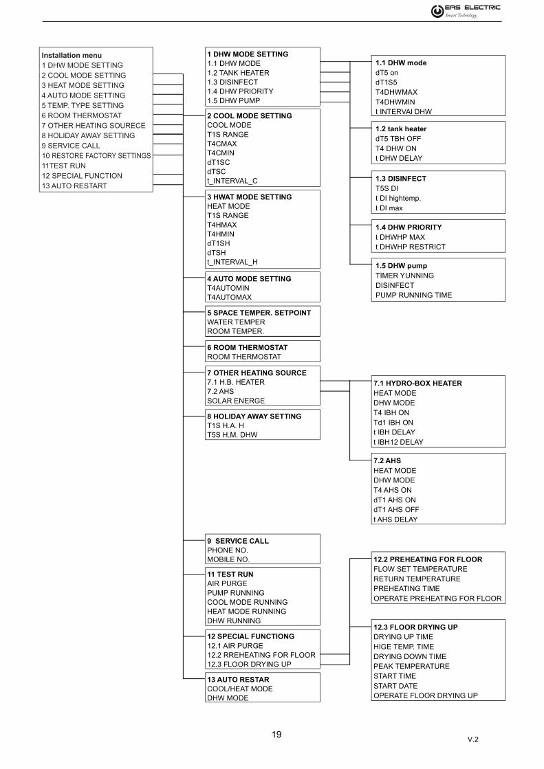
19
1 DHW MODE SETTING1.1 DHW MODE1.2 TANK HEATER1.3 DISINFECT1.4 DHW PRIORITY1.5 DHW PUMP
1.1 DHW modedT5 ondT1S5T4DHWMAXT4DHWMINt INTERVAl DHW
1.2 tank heaterdT5 TBH OFFT4 DHW ONt DHW DELAY
1.3 DISINFECTT5S DIt DI hightemp.t DI max
1.4 DHW PRIORITYt DHWHP MAXt DHWHP RESTRICT
1.5 DHW pumpTIMER YUNNINGDISINFECTPUMP RUNNING TIME
7.1 HYDRO-BOX HEATERHEAT MODEDHW MODET4 IBH ONTd1 IBH ONt IBH DELAYt IBH12 DELAY
7.2 AHSHEAT MODEDHW MODET4 AHS ONdT1 AHS ONdT1 AHS OFFt AHS DELAY
12.2 PREHEATING FOR FLOORFLOW SET TEMPERATURERETURN TEMPERATUREPREHEATING TIMEOPERATE PREHEATING FOR FLOOR
12.3 FLOOR DRYING UPDRYING UP TIMEHIGE TEMP. TIMEDRYING DOWN TIMEPEAK TEMPERATURESTART TIMESTART DATEOPERATE FLOOR DRYING UP
2 COOL MODE SETTINGCOOL MODET1S RANGET4CMAXT4CMINdT1SCdTSCt_INTERVAL_C
3 HWAT MODE SETTINGHEAT MODET1S RANGET4HMAXT4HMINdT1SHdTSHt_INTERVAL_H
11 TEST RUNAIR PURGEPUMP RUNNINGCOOL MODE RUNNINGHEAT MODE RUNNINGDHW RUNNING
12 SPECIAL FUNCTIONG12.1 AIR PURGE12.2 RREHEATING FOR FLOOR12.3 FLOOR DRYING UP
13 AUTO RESTARCOOL/HEAT MODEDHW MODE
9 SERVICE CALLPHONE NO.MOBILE NO.
4 AUTO MODE SETTINGT4AUTOMINT4AUTOMAX
5 SPACE TEMPER. SETPOINTWATER TEMPERROOM TEMPER.
8 HOLIDAY AWAY SETTINGT1S H.A. HT5S H.M. DHW
7 OTHER HEATING SOURCE7.1 H.B. HEATER7.2 AHSSOLAR ENERGE
6 ROOM THERMOSTATROOM THERMOSTAT
Installation menu1 DHW MODE SETTING2 COOL MODE SETTING3 HEAT MODE SETTING4 AUTO MODE SETTING5 TEMP. TYPE SETTING6 ROOM THERMOSTAT 7 OTHER HEATING SOURECE8 HOLIDAY AWAY SETTING9 SERVICE CALL10 RESTORE FACTORY SETTINGS11TEST RUN12 SPECIAL FUNCTION13 AUTO RESTART
V.2

20
Table1 The environment temperature curve of the low temperature setting for heating
Table2 The environment temperature curve of the high temperature setting for heating
T4 ≤-20 -19 -18 -17 -16 -15 -14 -13 -12 -11 -10 -9 -8 -7 -6 -5 -4 -3 -2 -1 01-T1S 30 30 30 30 30 30 30 30 30 30 30 30 29 29 29 28 28 28 27 27 272-T1S 34 34 34 34 34 34 34 34 34 34 34 34 33 33 32 32 31 31 30 30 293-T1S 38 38 38 38 38 38 38 38 38 38 38 37 37 36 36 35 34 34 33 33 324-T1S 41 41 41 41 41 41 41 41 41 41 41 40 40 39 38 38 37 36 35 35 345-T1S 45 45 45 45 45 45 45 45 45 45 45 44 43 42 42 41 40 39 38 38 376-T1S 49 48 48 47 47 46 46 45 45 44 44 44 43 43 42 42 41 41 40 40 397-T1S 51 51 50 50 49 49 48 48 47 47 46 45 45 44 44 43 43 42 42 41 418-T1S 54 53 53 52 52 51 50 50 49 49 48 47 47 46 46 45 44 44 43 43 42
T4 1 2 3 4 5 6 7 8 9 10 11 12 13 14 15 16 17 18 191-T1S 26 26 26 25 25 25 24 24 24 23 23 23 22 22 22 21 21 21 20 20 202-T1S 29 28 28 27 27 27 26 26 25 25 24 24 23 23 22 22 21 21 20 20 203-T1S 31 31 30 30 29 28 28 27 27 26 25 25 24 24 23 22 22 21 21 20 204-T1S 33 33 32 31 31 30 29 28 28 27 26 26 25 24 24 23 22 21 21 20 205-T1S 36 35 34 33 33 32 31 30 29 28 28 27 26 25 24 23 23 22 21 20 206-T1S 39 38 38 37 37 37 36 36 35 35 34 34 33 33 32 32 31 31 30 30 307-T1S 40 40 39 39 38 37 37 36 36 35 35 34 34 33 33 32 32 31 31 30 308-T1S 41 41 40 40 39 38 38 37 37 36 35 35 34 34 33 32 32 31 31 30 30
≥ 20
T4 ≤-20 -19 -18 -17 -16 -15 -14 -13 -12 -11 -10 -9 -8 -7 -6 -5 -4 -3 -2 -1 01-T1S 55 55 55 55 54 53 53 52 51 51 50 49 49 48 47 47 46 45 45 44 432-T1S 55 55 55 55 55 55 55 54 53 53 52 51 51 50 49 48 48 47 46 45 453-T1S 55 55 55 55 55 55 55 55 55 55 54 53 52 52 51 50 49 48 48 47 464-T1S 46 46 46 46 46 46 46 46 46 46 46 45 45 44 43 43 42 41 40 40 395-T1S 50 50 50 50 50 50 50 50 50 50 50 49 48 47 47 46 45 44 43 43 426-T1S 53 53 53 53 53 53 53 53 53 53 53 52 51 50 49 48 47 46 46 45 447-T1S 57 57 57 57 57 57 57 57 57 57 57 56 55 54 53 52 51 50 48 47 468-T1S 60 60 60 60 60 60 60 60 60 60 60 59 58 57 55 54 53 52 51 50 48
T4 1 2 3 4 5 6 7 8 9 10 11 12 13 14 15 16 17 18 191-T1S 43 42 41 41 40 39 39 38 37 37 36 35 35 34 33 33 32 31 31 30 302-T1S 44 43 42 42 41 40 40 39 38 37 37 36 35 34 34 33 32 31 31 30 303-T1S 45 44 44 43 42 41 40 40 39 38 37 36 36 35 34 33 32 32 31 30 304-T1S 38 38 37 36 36 35 34 33 33 32 31 31 30 29 29 28 27 26 26 25 255-T1S 41 40 39 38 38 37 36 35 34 33 33 32 31 30 29 28 28 27 26 25 256-T1S 43 42 41 40 39 38 37 36 35 34 33 32 32 31 30 29 28 27 26 25 257-T1S 45 44 43 42 41 40 39 38 37 36 35 34 32 31 30 29 28 27 26 25 258-T1S 47 46 45 44 42 41 40 39 38 37 35 34 33 32 31 30 28 27 26 25 25
≥ 20
V.2

21
T4 - 10 ≤ T4 < 15 15 ≤ T4 < 22 22 ≤ T4 < 30 30 ≤ T4 < 46
1 - T1S 18 13 10 7
T4 - 10 ≤ T4 < 15 15 ≤ T4 < 22 22 ≤ T4 < 30 30 ≤ T4 < 46
2 - T1S 19 14 11 8
T4 - 10 ≤ T4 < 15 15 ≤ T4 < 22 22 ≤ T4 < 30 30 ≤ T4 < 46
3 - T1S 20 15 12 9
T4 - 10 ≤ T4 < 15 15 ≤ T4 < 22 22 ≤ T4 < 30 30 ≤ T4 < 46
4 - T1S 21 16 13 10
T4 - 10 ≤ T4 < 15 15 ≤ T4 < 22 22 ≤ T4 < 30 30 ≤ T4 < 46
5 - T1S 22 17 14 11
T4 - 10 ≤ T4 < 15 15 ≤ T4 < 22 22 ≤ T4 < 30 30 ≤ T4 < 46
6 - T1S 23 18 15 12
T4 - 10 ≤ T4 < 15 15 ≤ T4 < 22 22 ≤ T4 < 30 30 ≤ T4 < 46
7 - T1S 24 19 16 13
T4 - 10 ≤ T4 < 15 15 ≤ T4 < 22 22 ≤ T4 < 30 30 ≤ T4 < 46
8 - T1S 25 21 18 14
T4 - 10 ≤ T4 < 15 15 ≤ T4 < 22 22 ≤ T4 < 30 30 ≤ T4 < 46
1 - T1S 20 18 18 18
T4 - 10 ≤ T4 < 15 15 ≤ T4 < 22 22 ≤ T4 < 30 30 ≤ T4 < 46
2 - T1S 21 19 18 18
T4 - 10 ≤ T4 < 15 15 ≤ T4 < 22 22 ≤ T4 < 30 30 ≤ T4 < 46
3 - T1S 22 20 18 18
T4 - 10 ≤ T4 < 15 15 ≤ T4 < 22 22 ≤ T4 < 30 30 ≤ T4 < 46
4 - T1S 23 21 18 18
T4 - 10 ≤ T4 < 15 15 ≤ T4 < 22 22 ≤ T4 < 30 30 ≤ T4 < 46
5 - T1S 24 22 20 18
T4 - 10 ≤ T4 < 15 15 ≤ T4 < 22 22 ≤ T4 < 30 30 ≤ T4 < 46
6 - T1S 25 23 21 19
T4 - 10 ≤ T4 < 15 15 ≤ T4 < 22 22 ≤ T4 < 30 30 ≤ T4 < 46
7 - T1S 25 24 22 20
T4 - 10 ≤ T4 < 15 15 ≤ T4 < 22 22 ≤ T4 < 30 30 ≤ T4 < 46
8 - T1S 25 25 23 21
Table3 The environment temperature curve of the low temperature setting for cooling
Table4 The environment temperature curve of the high temperature setting for cooling
V.2

22
Table5 The environment temperature curve of the low temperature setting fo r ECO mode
T4 ≤ -20 - 19 - 18 - 17 - 16 - 15 - 14 - 13 - 12 -11 - 10 -9 -8 -7 -6 -5 -4 -3 -2 -1 0
1# 25 25 25 25 25 25 25 25 25 25 25 24 24 24 23 23 23 23 22 22 22
2# 29 29 29 29 29 29 29 29 29 29 29 28 28 27 27 26 26 26 25 25 24
3# 32 32 32 32 32 32 32 32 32 32 32 31 31 30 30 29 29 28 28 27 26
4# 36 36 36 36 36 36 36 36 36 36 36 35 35 34 33 32 31 31 30 30 29
5# 39 39 39 39 39 39 39 39 39 39 39 38 38 37 36 35 35 34 33 32 31
6# 45 45 44 43 42 42 41 41 40 40 39 39 39 38 38 37 37 36 36 35 34
7# 48 48 47 46 45 44 43 42 42 41 41 40 40 39 39 38 38 37 37 36 36
8# 50 49 49 48 47 46 46 45 45 44 43 43 42 42 41 40 40 39 39 38 37
T4 1 2 3 4 5 6 7 8 9 10 11 12 13 14 15 16 17 18 19 ≥20
1# 22 21 21 21 20 20 20 20 20 20 20 20 20 20 20 20 20 20 20 20
2# 24 24 23 23 22 22 22 21 21 20 20 20 20 20 20 20 20 20 20 20
3# 26 26 25 25 24 24 23 23 22 21 21 21 20 20 20 20 20 20 20 20
4# 29 28 27 26 25 24 24 23 23 22 22 22 21 21 20 20 20 20 20 20
5# 31 30 29 28 27 27 26 25 24 23 23 22 22 21 20 20 20 20 20 20
6# 34 33 33 32 32 31 31 30 30 30 30 30 30 30 30 30 30 30 30 30
7# 35 34 34 33 33 32 32 31 31 30 30 30 30 30 30 30 30 30 30 30
8# 37 36 35 35 34 34 33 33 32 31 31 31 30 30 30 30 30 30 30 30
Table6 The environment temperature curve of the high temperature setting for ECO mode
T4 ≤ - 20 - 19 - 18 - 17 - 16 - 15 - 14 - 13 - 12 - 11 - 10 -9 -8 -7 -6 -5 -4 -3 -2 -1 0
1# 50 50 49 49 48 48 47 47 46 46 45 45 44 44 43 42 42 41 40 39 38
2# 50 50 50 50 50 50 49 49 48 48 47 47 46 45 44 43 43 42 42 41 40
3# 50 50 50 50 50 50 50 50 50 50 49 49 48 47 46 45 45 44 43 42 41
4# 41 41 41 41 41 41 41 41 41 41 41 40 40 39 39 38 38 37 36 35 34
5# 45 45 45 45 45 45 45 45 45 45 45 44 43 42 41 40 40 39 38 37 36
6# 48 48 48 48 48 48 48 48 48 48 48 47 46 45 44 43 42 41 41 40 39
7# 52 52 52 52 52 52 52 52 52 52 52 51 50 49 48 46 45 44 43 42 41
8# 55 55 55 55 55 55 55 55 55 55 55 54 53 51 50 49 48 47 46 45 43
T4 1 2 3 4 5 6 7 8 9 10 11 12 13 14 15 16 17 18 19 ≥20
1# 38 37 37 36 35 35 34 34 33 32 32 31 30 30 30 30 30 30 30 30
2# 40 39 38 37 36 36 35 34 33 32 32 31 30 30 30 30 30 30 30 30
3# 41 40 39 38 37 37 36 35 34 33 33 32 32 31 30 30 30 30 30 30
4# 34 33 32 32 31 31 30 29 28 27 27 27 26 26 25 25 25 25 25 25
5# 35 35 34 33 32 31 31 30 29 28 28 27 26 26 25 25 25 25 25 25
6# 38 37 36 35 34 33 32 31 30 29 29 28 27 26 25 25 25 25 25 25
7# 40 39 38 37 36 35 34 33 32 31 30 29 28 27 26 25 25 25 25 25
8# 41 40 39 38 37 36 35 34 33 32 31 30 29 28 27 26 26 25 25 25
V.2

V.2
www.easelectric.es