Basic Electronics, Volumes 1-5 (1955)
570
has ic electronics I**/ Mi VALKENBURGH, nooger & neville, inc. ¥0L* 1 INTRODUCTION TO ELECTRONICS DIODE VACUUM TUBES, DRY METAL RECTIFIERS WHAT A POWER SUPPLY IS FILTERS, VOLTAGE REGULATORS a RIDER publication
-
Upload
khangminh22 -
Category
Documents
-
view
0 -
download
0
Transcript of Basic Electronics, Volumes 1-5 (1955)

hasic
electronicsI**/ Mi VALKENBURGH,nooger & neville, inc.
¥0L* 1
INTRODUCTION TO ELECTRONICS
DIODE VACUUM TUBES,
DRY METAL RECTIFIERS
WHAT A POWER SUPPLY IS
FILTERS, VOLTAGE REGULATORS
a RIDER publication

$2.25
basicelectronicsby VAN VALKENBURGH,KOOGER & NEVILLE, INC.
VOL.1
JOHN F. RIDER PUBLISHER, INC.116 West 14th Street • New York 11, N. Y.

First Edition
Copyright 1955 by
VAN VALKENBURGH, NOOGER AND NEVILLE, INC.
All Rights Reserved under International and Pan
American Conventions. This book or parts thereof
may not be reproduced in any form or in any
language without permission of the copyright owner.
Library of Congress Catalog Card No. 55-6984
Printed in the United States of America

PREFACEThe texts of the entire Basic Electricity and Basic Electronics
courses, as currently taught at Navy specialty schools, have now beenreleased by the Navy for civilian use. This educational programhas been an unqualified success. Since April, 1953, when it was firstinstalled, over 25,000 Navy trainees have benefited by this instruc-tion and the results have been outstanding.
The unique simplification of an ordinarily complex subject, theexceptional clarity of illustrations and text, and the plan of pre-senting one basic concept at a time, without involving complicatedmathematics, all combine in making this course a better and quickerway to teach and learn basic electricity and electronics.
In releasing this material to the general public, the Navy hopes toprovide the means for creating a nation-wide pool of pre-trainedtechnicians, upon whom the Armed Forces could call in time ofnational emergency, without the need for precious weeks and monthsof schooling.
Perhaps of greater importance is the Navy's hope that throughthe release of this course, a direct contribution will be made towardincreasing the technical knowledge of men and women throughoutthe country, as a step in making and keeping America strong.
Van Valkenburgh, TSooger and Neville, Inc.
New York, N. Y.
February, 1955
iii


TABLE OF CONTENTS
Vol. 1 — Basic Electronics
Introduction to Electronics i_l
What a Power Supply Is 1„7
Half-Wave Rectifiers — Dry Metal Type 1_17
Half-Wave Rectifiers — Vacuum Tube Type 1_23
Half-Wave Rectifiers — Transformer Type 1-39
The Full-Wave Rectifier Circuit 145
Filter Circuits 1_52
Voltage Regulator Circuits l.gj
Other Types of Power Supply Circuits 1-92
Characteristics of Diode Vacuum Tubes M09
V


nncTnaoMiicWhat You Are Going To Do Now
You now have a good solid foundationin the field of electricity. You knowhow electricity is generated, howelectron current flows through a cir-cuit, the nature and uses of magne-tism, the proper use and care ofmeters, the characteristics of DCand AC and how various types ofelectrical motors and other electri-cal devices operate.
Now you have all the fundamentalknowledge that you need to beginyour study of a new and fascinatingsubject—electronics.
Vol. 5
DC & ACMachinery
Vol. 4
AC Circuits
Vol. 3
Alternating
Current
Vol. 2
DC Circuits
Vol. 1
Introduction to
Electricity
vii


INTRODUCTION TO ELECTRONICS
The Meaning of "Electronics"
You have heard the word "electronics" many times in the past. Elec-tronics means the science of the electron. Since the study of electricity
and electronics both involve the use of the concept of electron flow, youmay wonder where electricity ends and electronics begins. For your pur-poses it is easy enough to make the distinction that electronics is thescience which is concerned with the flow of electrons through vacuum orgas-filled tubes sometimes called "electron tubes. " Thus, electronicsincludes the study of any equipment that contains "tubes. "
You are already acquainted with quite a few types of electronic equipment.Radio—"talkie" motion pictures—record players—public address systems—television—"electric eye" door openers—all of these make use of "tubes"and are correctly termed electronic equipment. Of course they also makeuse of various types of DC and AC circuits, of meters, transformers, ca-pacitors, and all the other components which you have learned about in
Basic Electricity. That is why you needed a course in fundamentals be-fore going on with the electronics phase of your study.
1-1

INTRODUCTION TO ELECTRONICS
Electronic Equipment
All electronic equipment is made up of only a few basic circuits. Just howmany basic types of circuit are there ? Three'. Are there any other types
you will ever have to know? There are additional types of special circuits
you will have to learn when you begin to study equipment, but these special
circuits are nothing but variations of the three basic electronic circuits.
The three basic electronic circuits are rectifier circuits, amplifier cir-
cuits and oscillator circuits.
Rectifier circuits change AC to DC.Their most common use is in elec-tronic equipment power supplieswhich take AC from the power line
and transform it to DC which is re-quired to operate electron tubes.
RECTIFIER CIRCUIT
fA A
Amplifier circuits take small volt-
age changes and enlarge or amplifythem into large voltage changes.Amplifier circuits are by far the
most commonly used circuits in
electronic equipment. They takevery weak signals that are barelydetectable and amplify them into
strong signals that can drive apair of earphones, a loudspeakeror an oscilloscope.
JAMPLIFIER CIRCUIT
I—WW\M—
Oscillator circuits generate ACvoltages at any particular desiredfrequency. Oscillator circuits areused to generate the AC voltages
that carry a radio signal from oneplace to another. They are alsoused very extensively for testing
other electronic circuits.
OSCILLATOR CIRCUIT
1-2

INTRODUCTION TO ELECTRONICS
Parts Used in Electronic Equipment
Now that you have found out that there are only three basic types of elec-tronic circuits (rectifiers, amplifiers and oscillators) that you have to beconcerned with, you probably would like to know about the parts used inthose circuits. Actually there are only six commonly used types of partsin electronic circuits. Five of these parts you already know—resistors,capacitors, coils, transformers and switches. There is one additionaltype of part that you will learn about very soon—"vacuum tubes."
You see that by understanding three basic types of electronic circuits andthe use of six types of parts in those circuits, you will understand all youneed to know about electronics for the present.
'plow, &uc& a& t&eAeone c&tcutfA, made
-vwww-
HI— ^00000^
RESISTOR CAPACITORCOIL OR
INDUCTANCE
m« J
iff 1111
TRANSFORMER SWITCH VACUUM TUBE
1-3


1-5


WHAT A POWER SUPPLY IS
Importance of Power Supplies
Everything that lives or does work must have a source of power or a"power supply." The sun supplies power that enables plants to manufac-ture food, and food in turn supplies the power that makes you live andmove, - speak, run, and think. In the realm of non-living mechanisms,the motor in the old Model "T" supplied power to move the car as surelyas the huge turbines at Boulder Dam supply power today to drive elec-tric generators.
It is obvious that the same kind of power is not used in the same way inthese different cases. Each thing-large or small, living or non-living-must take its power from a primary source such as the sun, falling wateror an electric light socket and change it into the specific kind of power
'
needed. In electronics, then, a "power supply" is a circuit or device thatchanges the primary electric power into the kind and amount of AC or DCneeded by different types of electronic circuits.
WHAT A POWER SUPPLY IS
What Power Supplies Do
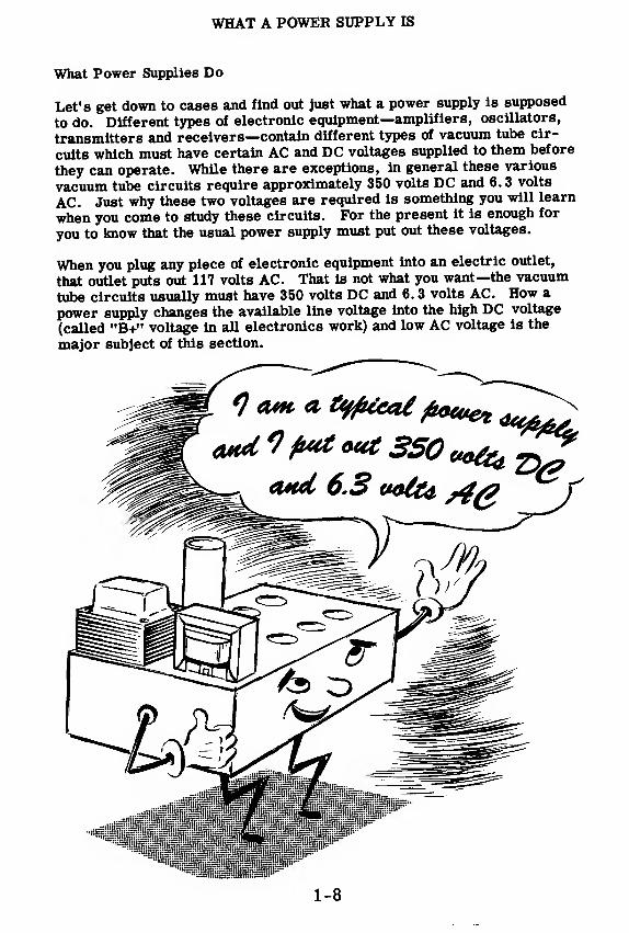
Let's get down to cases and find out just what a power supply is supposed
to do. Different types of electronic equipment—amplifiers, oscillators,
transmitters and receivers—contain different types of vacuum tube cir-
cuits which must have certain AC and DC voltages supplied to them before
they can operate. While there are exceptions, in general these various
vacuum tube circuits require approximately 350 volts DC and 6.3 volts
AC. Just why these two voltages are required is something you will learn
when you come to study these circuits. For the present it is enough for
you to know that the usual power supply must put out these voltages.
When you plug any piece of electronic equipment into an electric outlet,
that outlet puts out 117 volts AC. That is not what you want—the vacuum
tube circuits usually must have 350 volts DC and 6. 3 volts AC. How a
power supply changes the available line voltage into the high DC voltage
(called "B+" voltage in all electronics work) and low AC voltage is the
major subject of this section.
1-8

WHAT A POWER SUPPLY IS
How a Power Supply Works—The Transformer
A typical power supply consists of three major components—a trans-
former, a rectifier and a filter.
You already know about transformers from your work in basic electricity.
A transformer is a device made up of two or more coils of wire wound onan iron core. Transformers can take an AC voltage and increase it or de-crease it depending upon the number of turns of wire in the various wind-ings. Here are a few examples of transformers that you will find in elec-
tronic equipment power supplies.
In a typical power supply the transformer is connected to the 117 -volt ACpower line through a suitable fuse and switch. The transformer puts outthree AC voltages—a voltage somewhat higher than 350 volts AC, 5 volts
AC and 6. 3 volts AC. The 6. 3 volt AC output is connected directly to thevacuum tube circuits. The other two voltages are connected to the recti-fier circuit where the high voltage AC is changed to approximately 350volts DC. More than 350 volts AC are required to get 350 volts DC be-cause of losses that occur in the process of changing AC to DC, so youmust begin with a higher voltage than you want to take out.
1-9

WHAT A POWER SUPPLY IS
How a Power Supply Works—The Rectifier
Up to now you have learned that the job of a typical power supply is to take
117 volts AC from the power line and to put out approximately 350 volts
DC and 6. 3 volts AC. You have learned that the major components of apower supply are a transformer, a rectifier and a filter circuit; and youhave found out about the job of the transformer.
The job of the rectifier is to change the high voltage AC coming out of the
transformer into high voltage DC. The 5-volt AC voltage coming out of
the transformer is used to heat the rectifier tube, when such a type of rec-tifier is used. The 5-volt AC winding is eliminated from the transformerwhen it is not required for the operation of the rectifier.
The job of changing high voltage AC into high voltage DC is a difficult one.
All the rectifier can do is to change the AC into pulsating DC like this:
HAL F-W AVE RECTIFICATIONA A A A f
F U L L-W AVE RECTIFICATIONmwm +
RECTIFIER = M OUTPUT ^1
Notice that the DC output is not a constant voltage but rises and falls in
time with the AC voltage input. When only the positive half cycles of the
input voltage are allowed to pass through the rectifier and the negative
half cycles cannot pass through at all, the process is called "half-waverectification.
"
When the positive half cycle of the input voltage is allowed to pass through
the rectifier and the negative half cycles are changed to positive half
cycles, the process is called "full-wave rectification.
"
1-10

WHAT A POWER SUPPLY IS
How a Power Supply Works—The Rectifier (continued)
The rectifiers you will work with in this section will be dry metal orvacuum tube rectifiers. Either of these rectifiers come in half-wave orfull-wave types. Vacuum tube rectifiers require that the transformerhave a low voltage AC winding which supplies the rectifier tube withheater voltage. Dry metal rectifiers do not require this winding
*tCTIFIE/?s
HALF-WAVE RECTIFICATION
ov
1|| INPUT
y—Q A A A.t
RECTIFIER
IB OUTPUT i
FULL-WAVE RECTIFICATION
OUTPUT
1-11

WHAT A POWER SUPPLY IS
How a Power Supply Works—The Filter
So far you have learned that the job of a typical power supply is to take
117 volts AC from the power line and to deliver approximately 350 volts
DC and 6. 3 volts AC. You have learned that the major components of apower supply are a transformer, a rectifier and a filter circuit. You havelearned the purpose of the transformer and the rectifier, and now you are
ready to learn about the filter.
You know that the output of the rectifier is a pulsating DC voltage. Whatyou want is a steady DC voltage of +350 volts with as little pulsation aspossible.
ov-
~*— Voltage Output
But the Rectifier gives you ....
AAA r > AAAAAA +ov
The job of the filter circuit is to smooth out the pulsations in the rectifier
output and give you a steady voltage with little or no ripple. Filter cir-
cuits come in various forms, but all filter circuits are made up of various
combinations of inductances and capacitors or resistances and capacitors.
You will learn how these filter circuits work to smooth out the pulsations
in the rectifier output as soon as you have done some work with various
rectifier circuits.
FILTER + -V I ov — 1— 1—L- CIRCUIT ov —- *
AAAAAA FILTERCIRCUIT
+ov
IN == OUT IN == OUT IN == == OUT
Z I I T I I
I I I I I I
1-12

WHAT A POWER SUPPLY IS
Voltage Regulators
A typical power supply is made up of a transformer, a rectifier and a fil-
ter circuit. This is all that is required to give you the high voltage DCand the low voltage AC required to operate various types of electronic cir-
cuits. However, when current is drawn out of the high voltage DC termi-
nal of a power supply, the voltage drops. This is due to the internal re-
sistance of the power supply. It is not unusual for the 350-volt DC output
to drop to 300 volts when the current drawn out increases from 0. 05 ampto 0. 100 amp.
This voltage drop is not serious for many types of electronic circuits, and
they will go right on working in the proper manner. However, there are
some types of electronic circuits that cannot operate properly if the volt-
age varies more than two or three volts. These types of circuits require
that the power supply have a voltage regulator circuit added to it. When apower supply has a voltage regulator circuit, only those circuits that re-
quire a constant voltage are connected to the voltage regulator—other cir-
cuits are usually connected directly to the unregulated high voltage DCterminal.
The basic part of all voltage regulator circuits is the voltage regulator
tube, commonly known as the "VR" tube. These tubes are made so that
they will hold the DC voltage at a particular point in spite of current vari-
ations. VR tubes are made so that they will hold the voltage at 59, 75, 90,
108, and 153 volts DC. By using various combinations of these tubes, youcan get a constant voltage of almost any value that is required.
1-13

WHAT A POWER SUPPLY IS
Why There are Different Types of Power Supplies
You know that most power supplies are made up of transformers, recti-fiers, filter circuits and sometimes voltage regulators. You can get al-most any kind of power supply by putting these components together in
various ways. Of course, sometimes you will have to use large rectifiertubes and large transformers; sometimes you will have to use sub-miniatureparts; but, large or small, all the circuits will contain the same components.
1-14

WHAT A POWER SUPPLY IS
Why There are Different Types of Power Supplies (continued)
Now you will want to know why there are different types of power suppliesused in various types of equipment. After all, the major job they do isnothing more than changing AC into DC.
The reason why different types of power supplies are required is simple.One power supply you may build would go up in smoke if you drew muchmore than 150 ma. of current from the high DC voltage supply. Certaintypes of transmitters require as much as 5, 000 or 10, 000 ma. from theirpower supplies. Certain special oscilloscope circuits may require a DCoutput of 10, 000 volts or more.
1-15
WHAT A POWER SUPPLY IS
Why There are Different Types of Power Supplies (continued)
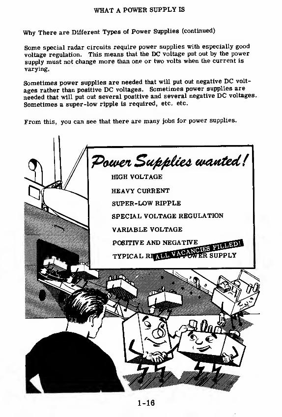
Some special radar circuits require power supplies with especially good
voltage regulation. This means that the DC voltage put out by the power
supply must not change more than one or two volts when the current is
varying.
Sometimes power supplies are needed that will put out negative DC volt-
ages rather than positive DC voltages. Sometimes power supplies are
needed that will put out several positive and several negative DC voltages.
Sometimes a super-low ripple is required, etc. etc.
From this, you can see that there are many jobs for power supplies.
1-16

HALF-WAVE RECTIFIERS—DRY METAL TYPE
Changing AC to DC
Most electric power is distributed by AC power lines and most electronicequipments contain power supplies which change the AC power line voltageto those DC and AC voltages required by the equipment. To change theAC power line voltage to other AC voltages is relatively simple. A trans-former is used to either step up or step down the line voltage, to obtain therequired AC voltages.
POWER SUPPLY TRANSFORMERS STEP UP OR STEP DOWNVOLTAGES AS REQUIRED
o
Isecondary to raise voltage
Step-UP|
1
oo
Step-DOWN 1.
1 secondary to lower voltage
To obtain the required DC voltages, the AC line voltage must be changedto DC. This changing of AC to DC is called "rectification." Devices whichchange AC to DC are called "rectifiers" and circuits used to change AC toDC are called "rectifier circuits."
4Primary o
AC Power Line
Rectifiers are devices which allow current to flow through them in onedirection only, acting as a conductor for current flow in one direction andas an insulator for current flow in the other direction. Thus when a recti-fier is placed in an AC circuit every other half-cycle of the AC voltagecauses current flow in the circuit in that direction for which the rectifieris a conductor. Since the alternate half-cycles are trying to force currentthrough the circuit in a direction for which the reclifier acts as an insula-tor, no current flows during these alternate half-cycles. As a result, thecurrent flow in a simple rectifier circuit is pulsating DC (alternate half-cycles of AC) rather than a steady DC current flow.
RECTIFIERCIRCUITSCHANGE
AC
InputHALF-WAVERECTIFIERCIRCUIT
DC
AAOutput
A RECTIFIERconducts in one direction,
insulates in the other..
•
1-17

HALF-WAVE RECTIFIERS—DRY METAL TYPE
Dry Metal Rectifiers
When certain metallic materials are pressed together to form a junction,
the combination acts as a rectifier having a low resistance to current flow
in one direction and a very high resistance to current flow in the opposite
direction. This action is due to the chemical properties of the combinedmaterials. The combinations usually used as rectifiers are copper and
copper-oxide, or iron and selenium. Dry metal rectifiers are constructed
of disks ranging in size from less than a half inch to more than six inches
in diameter. Copper-oxide rectifiers consist of disks of copper coated on
one side with a layer of copper oxide while selenium rectifiers are con-
structed of iron disks coated on one side with selenium.
Dry metal rectifier elements (an element is a single disk) are generallymade in the form of washers which are assembled on a mounting bolt in
any desired series or parallel combination to form a rectifier unit. Thesymbol shown below is used to represent a dry metal rectifier of any type.
Since these rectifiers were made before the electron theory was used to
determine the direction of current flow, the arrow points in the direction
of conventional current flow but in the direction opposite to the electron
flow. Thus the arrow points in opposite direction to that of the currentflowas used in electronics.
DRY METAL RECTIFIER SYMBOL
ELECTRON currentflow
opposite direction from symbol arrow
1-18
HALF-WAVE RECTIFIERS—DRY METAL TYPE
Dry Metal Rectifiers (continued)
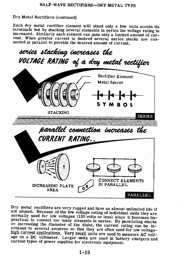
Each dry metal rectifier element will stand only a few volts across itsterminals but by stacking several elements in series the voltage rating isincreased. Similarly each element can pass only a limited amount of cur-rent. When greater current is desired several series stacks are con-nected in parallel to provide the desired amount of current.
vetal teetctf&i
SYMBOLSTACKING
SERIES
feanoMel cwutectiwt, tocnectMA, t&e
CURRENT RATING.
.
INCREASING PLATEAREA
CONNECT ELEMENTSIN PARALLEL
PARALLEL
Dry metal rectifiers are very rugged and have an almost unlimited life ifnot abused. Because of the low voltage rating of individual units they arenormally used for low voltages (130 volts or less) since it becomes im-practical to connect too many elements in series. By paralleling stacksor increasing the diameter of the disks, the current rating can be in-creased to several amperes so that they are often used for low voltage-high current applications. Very small units are used to measure AC volt-age on a DC voltmeter. Larger units are used in battery chargers andvarious types of power supplies for electronic equipment.
1-19
HALF-WAVE RECTIFIERS—DRY METAL TYPE
Dry Metal Rectifiers (continued)
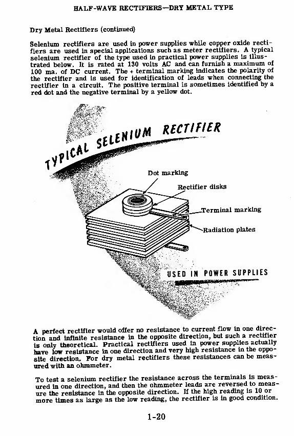
Selenium rectifiers are used in power supplies while copper oxide recti-
fiers are used in special applications such as meter rectifiers. A typical
selenium rectifier of the type used in practical power supplies is illus-
trated below. It is rated at 130 volts AC and can furnish a maximum of
100 ma. of DC current. The + terminal marking indicates the polarity of
the rectifier and is used for identification of leads when connecting the
rectifier in a circuit. The positive terminal is sometimes identified by a
red dot and the negative terminal by a yellow dot.
A perfect rectifier would offer no resistance to current flow in one direc-
tion and infinite resistance in the opposite direction, but such a rectifier
is only theoretical. Practical rectifiers used in power supplies actually
have low resistance in one direction and very high resistance in the oppo-
site direction. For dry metal rectifiers these resistances can be meas-
ured with an ohmmeter.
To test a selenium rectifier the resistance across the terminals is meas-
ured in one direction, and then the ohmmeter leads are reversed to meas-
ure the resistance in the opposite direction. If the high reading Is 10 or
more times as large as the low reading, the rectifier is in good condition.
1-20
HALF-WAVE RECTIFIERS—DRY METAL TYPE
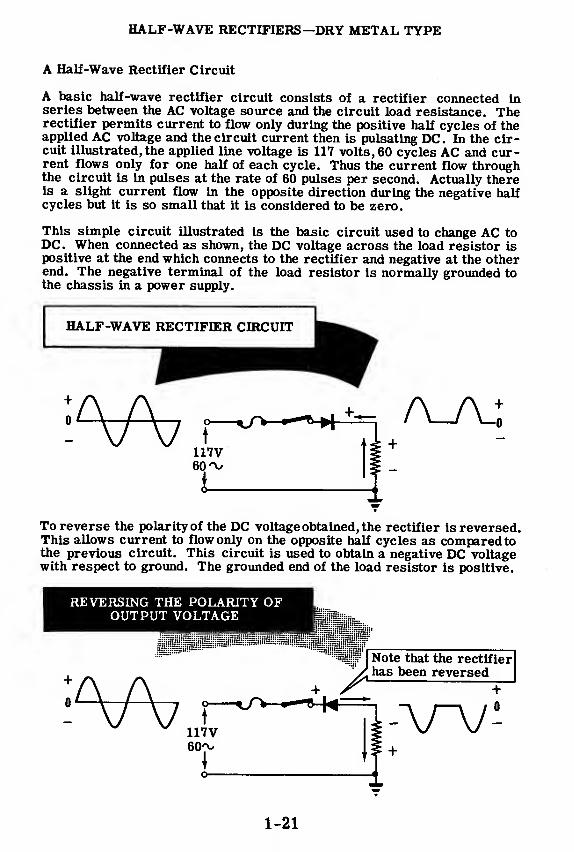
A Half-Wave Rectifier Circuit
A basic half-wave rectifier circuit consists of a rectifier connected inseries between the AC voltage source and the circuit load resistance. Therectifier permits current to flow only during the positive half cycles of theapplied AC voltage and the circuit current then is pulsating DC. In the cir-cuit illustrated, the applied line voltage is 117 volts, 60 cycles AC and cur-rent flows only for one half of each cycle. Thus the current flow throughthe circuit is in pulses at the rate of 60 pulses per second. Actually thereis a slight current flow in the opposite direction during the negative halfcycles but it is so small that it is considered to be zero.
This simple circuit illustrated is the basic circuit used to change AC toDC. When connected as shown, the DC voltage across the load resistor ispositive at the end which connects to the rectifier and negative at the otherend. The negative terminal of the load resistor is normally grounded tothe chassis in a power supply.
To reverse the polarity of the DC voltage obtained, the rectifier is reversed.This allows current to flow only on the opposite half cycles as compared tothe previous circuit. This circuit is used to obtain a negative DC voltagewith respect to ground. The grounded end of the load resistor is positive.
REVERSING THE POLARITY OFOUTPUT VOLTAGE
Note that the rectifier
,
has been reversed
117V6Cv.
\o
—
1-21
HALF-WAVE RECTIFIERS—DRY METAL TYPE
Review
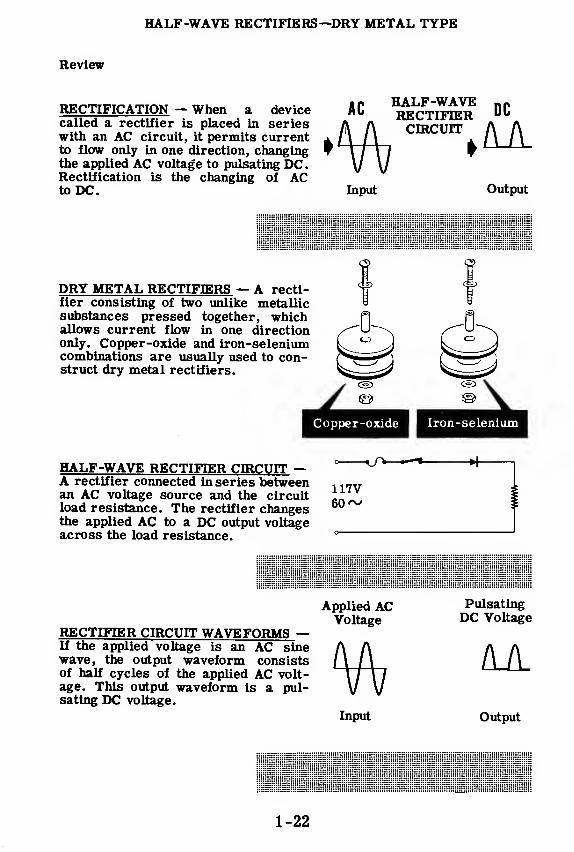
RECTIFICATION — When a devicecalled a rectifier is placed in serieswith an AC circuit, it permits currentto flow only in one direction, changingthe applied AC voltage to pulsating DC
.
Rectification is the changing of ACto DC.
• « HALF-WAVE nr^ RECTIFIER Ub
Input Output
fDRY METAL RECTIFIERS — A recti-fier consisting of two unlike metallicsubstances pressed together, which f]
pjallows current flow in one direction /^^~~"\only. Copper-oxide and iron-selenium L^*~\^J ^JlL-ii'combinations are usually used to con- ^« <i r>struct dry metal rectifiers.
Copper-oxide I Iron-selenium
HALF-WAVE RECTIFIER CIRCUIT —A rectifier connected in series between
, 17van AC voltage source and the circuitload resistance. The rectifier changesthe applied AC to a DC output voltageacross the load resistance. °
RECTIFIER CIRCUIT WAVEFORMS —If the applied voltage is an AC sinewave, the output waveform consistsof half cycles of the applied AC volt-age. This output waveform is a pul-sating DC voltage.
Applied AC Pulsating
Voltage °C Voltage
Input Output
1-22

HALF-WAVE RECTIFIERS—VACUUM TUBE TYPE
Vacuum Tubes
S^y um*e^ rectifiers are used in many power supplies to change AC toDC but they are limited as to voltage and current rating. They are not
normally rated at voltages greater than 130 volts AC. Low voltage unitsrated at 10 volts or less have a high current capacity, greater than 1 am-pere while the current capacity of higher voltage units is much lessthan 1 ampere.
Because of the voltage and current limitations of dry metal rectifiers, an-other type of rectifier, the diode vacuum tube, is often used in power sup-plies. As a rectifier, the diode vacuum tube operates in the same way asa dry metal rectifier, acting as a good conductor of current in one direc-tion and as an insulator in the other direction. The diode vacuum tube alsohas many other uses in electronics which you will find out about later
r
1-23

HALF-WAVE RECTIFIERS—VACUUM TUBE TYPE
The Discovery of the Diode
The principle on which a diode is based was discovered some 70 years ago
—before anything was known about electrons.
Thomas Edison was working on an experiment with his incandescent lampsin which a carbon filament was used. The filaments which he used broketoo easily as they were constructed of thin threads or filaments of carbon.
In an effort to lengthen the life of his light bulbs, Edison constructed ametal support which he connected to the fragile filament by insulated sec-tions. For some unknown reason, he connected the metal support to the
positive side of a battery and the filament to the negative side. To his
surprise, he noticed that a current was flowing.
Since nothing was known about electrons, Edison could not understand orsee any importance in his discovery and it took 21 years before Fleming,a British scientist learned the significance of this flow of electrons. Be-cause he observed that current could flow only in one direction, Flemingcalled his vacuum tube a "valve." In fact, vacuum tubes are still called
"valves" by the British.
1-24
HALF-WAVE RECTIFIERS—VACUUM TUBE TYPE
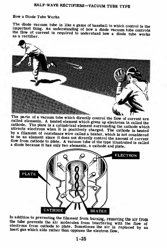
How a Diode Tube Works
The diode vacuum tube is like a game of baseball in which control is theimportant thing. An understanding of how a diode vacuum tube controlsthe flow of current is required to understand how a diode tube works
The parts of a vacuum tube which directly control the flow of current arecalled elements. A heated element which gives up electrons is called thecathode. The plate is a cylindrical element surrounding the cathode whichattracts electrons when it is positively charged. The cathode is heatedby a filament of resistance wire called a heater, which is not consideredto be an element since it does not directly control the amount of currentflow from cathode to plate. A vacuum tube of the type illustrated is calleda diode because it has only two elements, a cathode and plate
In addition to preventing the filament from burning, removing the air fromthe tube prevents the air molecules from interfering with the flow ofelectrons from cathode to plate. Sometimes the air is replaced by aninert gas which aids rather than opposes the electron flow
1-25

HALF-WAVE RECTIFIERS—VACUUM TUBE TYPE
Electron Emission
The basic requirement of a diode vacuum tube is that there has to be a
source of freely moving electrons which can be used to give us current
flow Of course, electrons are found in every atom of every substance
but we still need a method of driving them out of the substance to make
them freely moving.
In Edison's set-up, the intense heat of the filament did the trick, and
heat is used to do it in practically all the vacuum tubes you will see.
Driving electrons out of a substance by heat is known as "thermionic
emission. "
In the illustration, you will notice that the cathode is a cylinder or
"sleeve" which surrounds, but does not touch, the filament. The filament
is heated by the current flowing in it and the cathode is heated because it
is so close to the filament. This arrangement of parts is known as an in
directly heated cathode.
ELECTRON »-n^ —- O
FILAMENTCATHODE
THERMIONICEMISSION
Some tubes such as the Fleming's Valve or the type 80 rectifier tube have
what is known as directly heated cathodes, which means that there is no
sleeve around the filament and the filament is itself the electron emitter.
CATHODE
FILAMENT
DIRECTLY HEATED INDIRECTLY HEATED
Because they can emit many more electrons than the indirectly heated
type directly heated cathodes are used in vacuum tubes designed for pow-
er supplies which supply high currents. Indirectly heated cathodes are
more frequently used in low-current power supplies. Having the heater
(filament) and the electron emitter (cathode) separate in an indirectly
heated tube allows for the separation of the filament's and the cathode s
electrical circuits.
1-26

HALF-WAVE RECTIFIERS—VACUUM TUBE TYPE
Electron Emission (continued)
If the cathode and filament were alone in the glass tube, the emitted elec-trons would form a cloud called "space charge" around the cathode. Like
tendt tn r^nfi^h'tt
1 T*6 °harJe is ^ga^ely charged and therefore
£S?J?££ .trJleCt
AnS and t0 keep more electrons from beingemitted by the cathode. After a while, a balance would be reached be-tween the tendency of the cathode to emit electrons and that of the spacecnarge to repel them.
Lowtemperature
I
MORESPACE CHARGE
High 1temperature
LOW FILAMENTVOLTAGE
HIGH FILAMENTVOLTAGE
To increase the emission of electrons, you would have to raise the cath-ode s temperature by increasing the filament current. If, on the otherhand, the cathode's temperature is lowered, the space charge will forcesome of rts electrons to re-enter the cathode, resulting in decreasedemission. The heater voltage for a tube is usually fixed. Various tvoes oftubes operate with AC or DC heater voltages in the range from 1.25
1-27

HALF-WAVE RECTIFIERS—VACUUM TUBE TYPE
How Current Flows In a Diode
When a positively charged plate is placed around the cathode, the electrons
are attracted from the space charge. The number of electrons which flows
to the plate depends on the plate voltage with respect to the cathode.
When the plate is more nega-tive with respect to the cathode,
no current flows from cathode to
plate because the negative plate
repels the electrons. Currentcannot flow from the plate to the
cathode, since the plate does not
emit electrons.
When the plate and cathode are
at the same potential, the plate
neither attracts nor repels
electrons the current is
still zero.
Cathode Spacecharge
Plate
• • *» •
Plate Voltage(^
Supply \&J
Milliammeter
•• <
As soon as the plate becomespositive with respect to the cath-
ode, current will flow from the
space charge.
Electron Flow
F» •• •••>••••
Plate Voltage fc'^Supply
If this plate voltage is doubled,
the current which flows is also
doubled. This is the normal wayfor a diode to work: as long as
the plate is positive with respect
to the cathode, every change in
plate voltage causes a corres-
ponding change in plate current.
1-28

HALF-WAVE RECTIFIERS—VACUUM TUBE TYPE
How Current Flows in a Diode (continued)
Now that the plate is very positive withrespect to the cathode, the milliam-meter indicates that a very large cur-rent is flowing. The plate is attractingthe electrons as fast as the cathode canemit them.
At this point, a further increase inplate voltage does not result in any ad-ditional current. The current does notincrease because the cathode is emit-ting all the electrons it can. It is NOTnormal to operate a diode at such ahigh plate voltage that changes in platevoltage do not produce changes inplate current.
If we now increase the filament voltageabove its normal value, we enable thecathode to emit more electrons and,with the same plate voltage a£ before,we observe that a larger plate currentis flowing.
If we had reduced the filament voltage,the current would have decreased be-cause the cathode could not emit asmany electrons as before. In practice,the filament voltage is not varied.Changes in plate current are achievedby varying the plate voltage as alreadydescribed. However, after a tube hasbeen used for some time, the cathode'semission decreases and the result is
the same as if the filament voltagewere decreased.
H|'I#I'I'F+
^I'H'I'I'I'I
1-29

HALF-WAVE RECTIFIERS—VACUUM TUBE TYPE
The Rectifier Tube
The process of changing AC into DC is called "rectification." To change
AC to DC a device must be used which will permit current flow in one di-
rection only. A diode vacuum tube is such a device, permitting current to
flow only from the cathode to the plate. Current does not flow from the
plate to the cathode because the plate is not heated and therefore does not
emit electrons. Since the plate will not emit electrons but will, when posi-
tive, attract electrons from the cathode space charge, the diode is a con-
ductor only from cathode to plate and not from plate to cathode.
Any diode will rectify AC into DC but some are especially designed for use
in power supplies and these are referred to as rectifier tubes. A typical
rectifier tube with its schematic symbol is illustrated below. It is a twin
diode (two diode tubes in the same glass envelope) and has a directly
heated cathode. A filament which also acts as the cathode is suspended
inside each metal plate and the two filaments are internally connected in
series.
1-30
HALF-WAVE RECTIFIERS—VACUUM TUBE TYPE
The Rectifier Tube (continued)
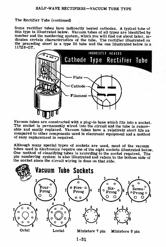
Some rectifier tubes have indirectly heated cathodes. A typical tube ofthis type is illustrated below. Vacuum tubes of all types are identified bynumber and the numbering system, which you will find out about later, in-dicates certain characteristics of the tube. The rectifier illustrated onthe preceding sheet is a type 80 tube and the one illustrated below is a117Z6-GT.
Vacuum tubes are constructed with a plug-in base which fits into a socket.The socket is permanently wired into the circuit and the tube is remov-able and easily replaced. Vacuum tubes have a relatively short life ascompared to other components used in electronic equipment and a methodof easy replacement is required.
Although many special types of sockets are used, most of the vacuumtubes used in electronics require one of the eight sockets illustrated below.One method of classifying tubes is according to the socket required. Thepin numbering system is also illustrated and refers to the bottom side ofthe socket since the circuit wiring is done on that side.
Octal Loctal Miniature 7 pin Miniature 9 pin
1-31
HALF-WAVE RECTIFIERS—VACUUM TUBE TYPE
The Rectifier Tube (continued)
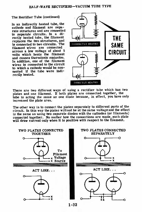
In an indirectly heated tube, the
cathode and filament are sepa-
rate structures and are connected
to separate circuits. In a di-
rectly heated tube, the filament
replaces the two structures, and
is connected to two circuits. Thefilament wires are connected
across a low voltage of about 5
volts which heats the filament
and causes thermionic emission.
In addition, one of the filament
wires is connected to the circuit
to which a cathode would be con-
nected if the tube were indi-
rectly heated.
INDIRECTLY HEATED
THE
SAME
CIRCUIT
DIRECTLY HEATED
There are two different ways of using a rectifier tube which has two
plates and one filament. If both plates are connected together, the
tube is acting the same as one diode because, in effect, you have only
increased the plate area.
The other way is to connect the plates separately to different parts of the
circuit. In this way the plates will not be at the same voltage and the effect
is the same as using two separate diodes with the cathodes (or filaments)
connected together. No matter how the connections are made, each plate
will draw current only when it is positive with respect to the filament.

HALF-WAVE RECTIFIERS—VACUUM TUBE TYPE
A Half-Wave Vacuum Tube Rectifier Circuit
A diode rectifier tube may be used in the half-wave rectifier circuit inplace of a selenium rectifier if there is a voltage source available to sup-ply the filament current required by the rectifier tube. The basic recti-fier circuit using a vacuum tube rectifier is illustrated below. If the plateand cathode connections are reversed the polarity of the DC output volt-age is reversed. r
VACUUM TUBE.
RECTIFIERCIRCUITS
^Heater or Filament Voltage^
ACPowerLine
Current Flow
The rectifier tube filament circuit requires an additional source of fila-ment voltage not required by the selenium rectifier—otherwise the opera-tion of the circuit is identical to that of the basic dry metal rectifier cir-cuit. Rectifier tube filaments are rated in volts and amperes so that thefilament must be connected to a voltage source of the rated voltage andcurrent. Filament or heater voltages are normally obtained from a step-down transformer or by using a series resistor to drop the line voltageto the correct value. Tubes having heaters rated at the same current aresometimes connected in series across the AC power line. Some rectifiertube heaters are rated at 117 volts and may be connected directly acrossthe AC power line.
HALF-WAVE RECTIFIERS—VACUUM TUBE TYPE
Vacuum Tube Circuit Wiring
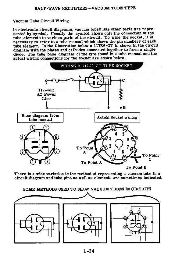
In electronic circuit diagrams, vacuum tubes like other parts are repre-
sented by symbol. Usually the symbol shows only the connection of the
tube elements to various parts of the circuit. To wire the socket, it is
necessary to refer to a tube manual which shows the pin numbers of each
tube element. In the illustration below a 117Z6-GT is shown in the circuit
diagram with the plates and cathodes connected together to form a single
diode. The tube base diagram of the type found in a tube manual and the
actual wiring connections for the socket are shown below.
To Point B
There is a wide variation in the method of representing a vacuum tube in acircuit diagram and tube pins as well as elements are sometimes indicated.
SOME METHODS USED TO SHOW VACUUM TUBES IN CIRCUITS
1-34
HALF-WAVE RECTIFIERS—VACUUM TUBE TYPE
The Gas-Filled Diode
You have already learned about two types of rectifying devices—the highvacuum diode and the dry metal rectifier. You have been told that the drymetal type could be used in the same circuit as the diode and the circuitwould work the same way. Now you are going to find out about a thirdtype of rectifying device which is used in similar circuits and works invery much the same way.
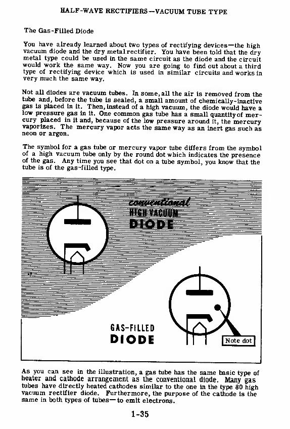
Not all diodes are vacuum tubes. In some, all the air is removed from thetube and, before the tube is sealed, a small amount of chemically-inactivegas is placed in it. Then, instead of a high vacuum, the diode would have alow pressure gas in it. One common gas tube has a small quantity of mer-cury placed in it and, because of the low pressure around it, the mercuryvaporizes. The mercury vapor acts the same way as an inert gas such asneon or argon.
The symbol for a gas tube or mercury vapor tube differs from the symbolof a high vacuum tube only by the round dot which indicates the presenceof the gas. Any time you see that dot on a tube symbol, you know that thetube is of the gas -filled type.
As you can see in the illustration, a gas tube has the same basic type ofheater and cathode arrangement as the conventional diode. Many gastubes have directly heated cathodes similar to the one in the type 80 highvacuum rectifier diode. Furthermore, the purpose of the cathode is thesame in both types of tubes— to emit electrons.
1-35

HALF-WAVE RECTIFIERS—VACUUM TUBE TYPE
The Gas-Filled Diode (continued)
A diode acts just like an ordinary resistor when the tube is conducting.This is its disadvantage. Let's see why.
When you draw only a little current from a power supply which has a highvacuum rectifier, there is only a small voltage drop across the diode. Asa result, the B+ voltage is very high. On the other hand, when a largecurrent is taken from the power supply, the drop across the tube becomesvery large and the B+ voltage drops way down. For this reason, a powersupply using a high vacuum diode does not have good regulation. Regula-tion, is a measure of how well a power supply can maintain a constant out-
put voltage as the load current varies from zero up to rated current. Be-cause of its poor regulation, high vacuum rectifiers, aren't in power sup-plies which must deliver large load currents.
1-36
HALF-WAVE RECTIFIERS—VACUUM TUBE TYPE
The Gas -Filled Diode (continued)
In a gas diode, electrons flow from the cathode to the plate just as in anydiode. These electrons passing through the gas at fairly high speeds,knock one or more electrons out of the gas atom,leaving the atom with a +charge, and the gas is said to be ionized. The positive ions (the atomswhich have had electrons knocked out of them) drift over to the cathodeand pick up the electrons they lack. Some time later, another fast movingelectron will knock some electrons out of the neutral atom, thus ionizingit again. In this way the gas always contains some ionized atoms.
Ionized gas has an amazing property. When a little current flows throughthe tube, there is a voltage drop across the tube of about 15 volts. Whena lot of current passes through the tube, the voltage drop across the tubeis still about 15 volts. There is an extremely small change in this voltagedrop as the tube current varies over a wide range.
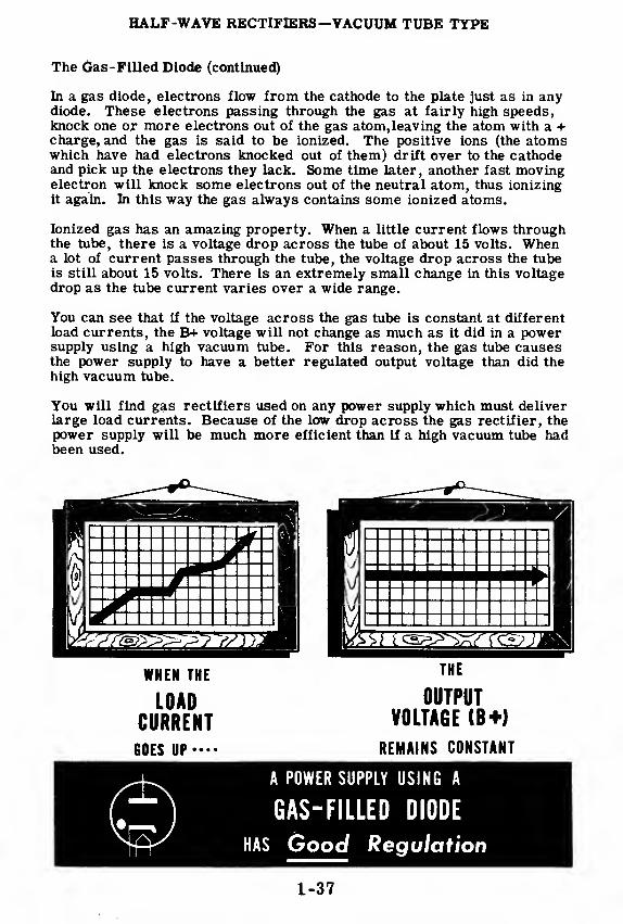
You can see that if the voltage across the gas tube is constant at differentload currents, the B+ voltage will not change as much as it did in a powersupply using a high vacuum tube. For this reason, the gas tube causesthe power supply to have a better regulated output voltage than did thehigh vacuum tube.
You will find gas rectifiers used on any power supply which must deliverlarge load currents. Because of the low drop across the gas rectifier, thepower supply will be much more efficient than if a high vacuum tube hadbeen used.
WHEN THE
LOADCURRENT
GOES UP—-
THE
OUTPUTVOLTAGE (B+)
REMAINS CONSTANT
A POWER SUPPLY USING A
GAS-FILLED DIODE
HAS Good Regulation
1-37

HALF-WAVE RECTIFIERS—VACUUM TUBE TYPE
Review of Vacuum Tube Rectifiers
DIODE VACUUM TUBE — A two elementvacuum tube consisting of a heated cathode
and a metal plate enclosed in a glass en-velope or tube from which the air hasbeen removed.
Plate-
Cathode
ELECTRON EMISSION — The action of the
cathode in giving up electrons when the
cathode is heated.
SPACE CHARGE — The negative charge in
the area surrounding the cathode causedby the emission of electrons from the
cathode.
—i p
..... Space
••V. Charge
Plate VoltageSupply V^,
rWh
RECTIFIER TUBE — A vacuum tube madeespecially for use as a rectifier.
FILAMENTS — Fine wire heater used to
heat the cathode in a vacuum tube. In
directly heated cathode tubes, the filamentand cathode are the same wire while in in-
directly heated cathode tubes, the filament
is called a heater and is used only to heat
the cathode.DirectlyHeated
Indirectly
Heated
BASIC VACUUM TUBE RECTIFIER • (T3LCIRCUIT — A diode vacuum tube con- Aq
'
nected in series with an AC voltage source Powerto change AC to DC. Line
1-38

HALF-WAVE RECTIFIERS—TRANSFORMER TYPE
Transformer Type Power Supplies
The two basic rectifier circuits which have been discussed are used tochange the 117 volt AC line voltage to DC. These rectifier circuits areoften used for inexpensive power supplies when it is not necessary toisolate the rectifier circuit from the AC power line or to obtain DCvoltages greater than 120 volts.
By adding a transformer to the circuit between the power line and the rec-tifier, the AC voltage can be increased or decreased resulting in a cor-responding rise or fall of the DC output voltage. Also the output of therectifier circuit will be completely isolated from the power line, and vari-ous filament voltages may be obtained by using additional secondary wind-ings on the transformer. Because of the different voltages required andthe need for isolating circuits in electronic equipment, most power suppliesare of the transformer type. Several typical power supplies of this typeare shown below.

HALF-WAVE RECTIFIERS—TRANSFORMER TYPE
The Diode in a Transformer Type Circuit
All rectifiers, including the half-wave rectifier, change an AC voltage in-
to a pulsating DC voltage. Each rectifier accomplishes this by allowing
current to flow in the circuit in only one direction, and only slight differ-
ences exist in different rectifier circuits. You are going to see how the
half-wave transformer type rectifier circuit makes the change from AC to
pulsating DC.
The rectifying action of this circuit depends on the operation of a diode,
the rectifier tube. The theory of operation of the diode has already been
covered but, in order to understand the operation of the diode in the trans-
former type circuit, you should review these two facts.
1. The diode allows electrons to pass through it only when its plate is
positive with respect to its cathode.
2. The diode does not allow electrons to flow through it when the plate is
negative with respect to the cathode.
You know from your previous experiment with a diode that when the tube
is connected across the 60 cycle power line the diode plate becomes posi-
tive 60 times per second and negative 60 times per second. Connecting
the diode to the high voltage winding of a transformer keeps the situation
exactly the same except that the voltage put on the plate is much higher,
and the resulting pulsating DC is at a correspondingly higher voltage.
1-40

HALF-WAVE RECTIFIERS—TRANSFORMER TYPE
The Diode in a Transformer Type Circuit (continued)
Suppose you put the diode into a simple half-wave circuit with a trans-former and see how it changes AC into DC.
When the transformer voltage makes the rectifier tube plate positive, elec-trons flow, and a voltage appears across the load.
When the transformer voltage makes the rectifier tube plate negative, elec-trons cannot flow and, of course, no voltage can appear across the load.
+The diode rectifier tube, by allowing electrons to flow through it in onlyone direction (from cathode to plate), causes pulses of current to flowthrough the load and, therefore, causes a pulsating DC voltage to appearacross the load. The AC voltage input from the transformer appears as :
pulsating DC voltage across the load. Notice that the half-wave rectifierhas used only the positive half of the AC input. The negative half is notused at all.
1-41
HALF-WAVE RECTIFIERS—TRANSFORMER TYPE
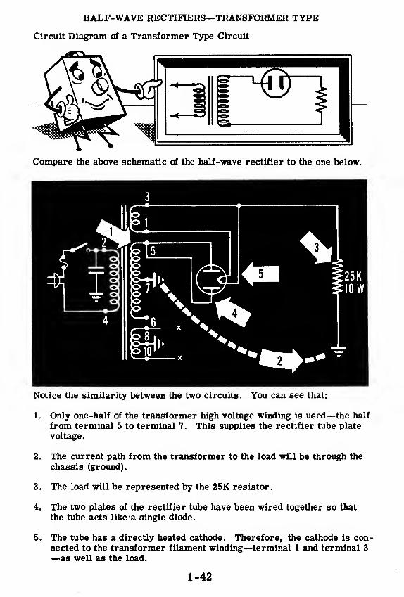
Circuit Diagram of a Transformer Type Circuit
Notice the similarity between the two circuits. You can see that:
1. Only one-half of the transformer high voltage winding is used—the half
from terminal 5 to terminal 7. This supplies the rectifier tube plate
voltage.
2. The current path from the transformer to the load will be through the
chassis (ground).
3. The load will be represented by the 25K resistor.
4. The two plates of the rectifier tube have been wired together so that
the tube acts like -a single diode.
5. The tube has a directly heated cathode. Therefore, the cathode is con-
nected to the transformer filament winding—terminal 1 and terminal 3
—as well as the load.
1-42

HALF-WAVE RECTIFIERS—TRANSFORMER TYPE
Operation of the Transformer Type Circuit
The basic operation of the half-wave rectifier circuit just shown hasbeen described previously. In the circuit diagram illustrated the flowof current through the circuit is indicated by arrows. The + and - signsshow the reversal in polarity of the transformer secondary voltage for
alternate half cycles. The rectifier tube will only conduct from cathode(filament) to plate, and only when the plate is positive with respect to
the cathode.
¥^^ AHALF- WAVEREc^c^
Current flows for half-cycle
while plates are positive.
The . 001 mfd. capacitor used does not effect the circuits basic operationas a half-wave rectifier. This condenser is connected between one side of
the AC power line and ground to reduce electrical interference and preventsuch interference from passing through the rectifier circuit. Capacitorsused for this purpose may be connected in any of the ways illustrated below.
POWER LINE FILTER CONDENSER CIRCUITS
1-43

HALF-WAVE RECTIFIERS—TRANSFORMER TYPE
Review of the Half-Wave Rectifier Circuit
TRANSFORMER TYPE POWERSUPPLY — A power supply whichuses a transformer to either
raise or lower the AC power line
voltage to obtain a desired value
of DC output voltage.
HALF-WAVE RECTIFIERCIRCUIT — A rectifier circuit
using a single rectifier unit
which changes AC to DC by al-
lowing current to flow only in one
direction. Alternate half-cycles
of the AC power wave are utilized
to provide a pulsating DC output.
The circuit sometimes uses atransformer to increase or de-
crease the output voltage.
CURRENT FLOW IN A HALF-WAVE RECTIFIER CIRCUIT —AC is applied to the rectifier
plate- and current flows only
during those half-cycles which arepositive on the plate side of the
circuit input.
HIGH VOLTAGE MEASUREMENT— Always use only one hand in
measuring voltages or testing cir-
cuits where high voltage is present
Use a test prod which is insulated
and rated for working with high
voltages.
1-44

THE FULL-WAVE RECTIFIER CIRCUIT
Full-Wave Rectifiers
You have seen how the half-wave rectifier works. Now, in the following
sheets you will see how the full-wave rectifier does the same job in aslightly different way.
You must know the full-wave rectifier because it is used in nine out of ten
pieces of electronic equipment. It may be supplying any voltage from 100volts to 5,000 volts. On any ship, any station, anywhere where electronic
equipment is used, you'll find full-wave rectifiers supplying most of
the power.
1-45

THE FULL-WAVE RECTIFIER CIRCUIT
How the Full-wave Rectifier Works
In a full-wave rectifier circuit a diode rectifier tube is placed in serieswith each half of the transformer secondary and the load. Effectively,you have two half-wave rectifiers working into the same load.
On the first half-cycle the transformer's AC voltage makes the upper dioderectifier plate positive so that it conducts and, as a result, current flowsthrough the load causing a pulse of voltage across the load. Notice that,
while the upper diode conducts, the lower diode plate is negative with re-spect to its cathode so that it does not conduct.
On the second half-cycle the plate of the upper diode is negative so that it
cannot conduct, whereas the plate of the lower diode is positive so that cur-rent flows through it and through the load. Since both pulses of currentthrough the load are in the same direction, a pulsating DC voltage now ap-pears across the load. The full-wave rectifier has changed both halves ofthe AC input into a pulsating DC output.
1-46
THE FULL-WAVE RECTIFIER CIRCUIT
The Full-wave Rectifier Tube
The diagram on the previous sheet shows two separate rectifier tubes being
used in the full-wave rectifier circuit. Sometimes you may find this circuit
used in power supplies but more frequently just one tube is used in the full-
wave rectifier. If you will refer back to the diagram on the previous sheet,
you will see that the filaments of the two tubes are connected together.
Since this is so, two separate rectifier tubes can be put together into oneenvelope so that the two plates share a common filament. The full-waverectifier tube therefore contains two plates but only one filament. Such atube is the 80 rectifier tube.
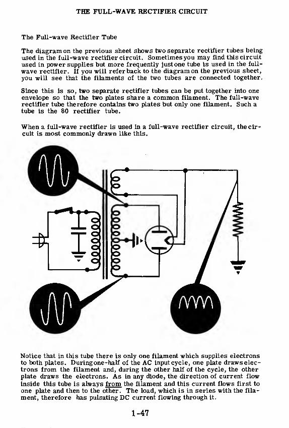
When a full-wave rectifier is used in a full-wave rectifier circuit, the cir-cuit is most commonly drawn like this.
Notice that in this tube there is only one filament which supplies electronsto both plates. During one-half of the AC input cycle, one plate draws elec-trons from the filament and, during the other half of the cycle, the otherplate draws the electrons. As in any diode, the direction of current flow
inside this tube is always from the filament and this current flows first to
one plate and then to the other. The load, which is in series with the fila-
ment, therefore has pulsating DC current flowing through it.
1-47

THE FULL-WAVE RECTIFIER CIRCUIT
Current Flow in the Full-wave Rectifier Circuits
The illustration below compares the operation of the full -wave rectifiercircuit to that of a basic full-wave rectifier.
In the basic circuit illustrated, plates 1 and 2 of the rectifier tube are con-nected to opposite ends of the transformer winding so that there is alwaysa 180 degree phase difference between the voltages applied to the twoplates. Current flows only to that plate which is positive so that currentflows from a common cathode to each plate on alternate half cycles. Sincethe load resistor is connected between the cathode and the transformersecondary winding centertap, the current flow in the load resistor is inthe same direction for both half cycles.
In the basic full-wave rectifier circuit two cathodes are used but sincethey are connected together a single common cathode can be used insteadin a typical circuit. Also in the basic circuit one end of the load resistorconnects directly to the transformer secondary winding centertap and noground connection is used. This connection can be made by grounding thecentertap and one end of the load resistor to different points on the chassis.
ooo
BASIC FULL-WAVERECTIFIER CIRCUIT
THE FULL-WAVE RECTIFIER CIRCUIT
The Bridge Rectifier Circuit
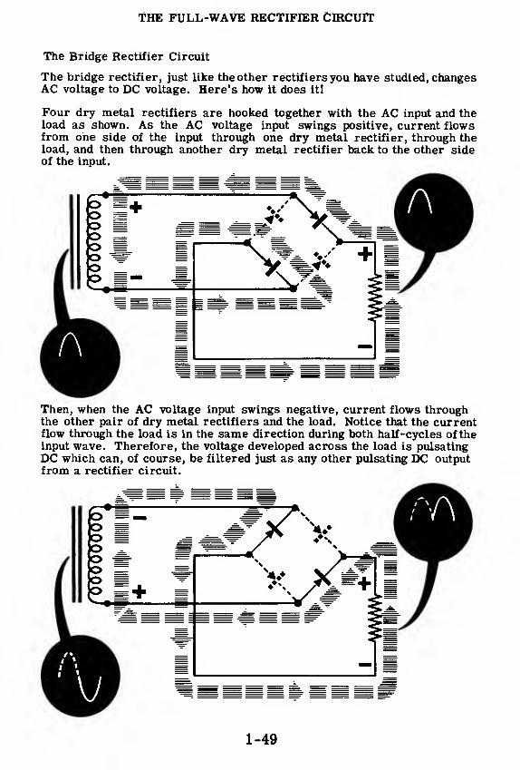
The bridge rectifier, just like the other rectifiers you have studied, changesAC voltage to DC voltage. Here's how it does it!
Four dry metal rectifiers are hooked together with the AC input and theload as shown. As the AC voltage input swings positive, current flowsfrom one side of the input through one dry metal rectifier, through theload, and then through another dry metal rectifier back to the other sideof the input.
Then, when the AC voltage input swings negative, current flows throughthe other pair of dry metal rectifiers and the load. Notice that the currentflow through the load is in the same direction during both half-cycles of theinput wave. Therefore, the voltage developed across the load is pulsatingDC which can, of course, be filtered just as any other pulsating DC outputfrom a rectifier circuit.
1-49

THE FULL-WAVE RECTIFIER CIRCUIT
The Bridge Rectifier Circuit (continued)
In actual practice the four dry metal rectifier units used in the bridge rec-tifier circuit are joined together in one physical unit and are connected ex-ternally into the bridge rectifier circuit.
To get from the pictorial to the schematic diagram, just imagine the two endunits being rotated around as shown below. Before you continue, make sureyou understand the relationship between the physical unit and the schematic.
1-50

THE FULL-WAVE RECTIFIER CIRCUIT
Review of the Full-Wave Rectifier Circuit
FULL-WAVE RECTIFIER CIRCUIT -
A rectifier circuit which utilizes bothcycles of the applied AC voltage to ob-tain pulsating DC. A center-tappedtransformer secondary winding is usedwith two diodes rectifying alternate halfcycles of the voltage, causing pulsesof current to flow in the same directionthrough a load resistor for each halfcycle of applied AC.
FULL-WAVE RECTIFIER TUBE - Avacuum tube consisting of two speciallydesigned diodes and a common cathodein the same glass envelope. Both di-rect and indirectly heated cathodes areused depending on the requirements ofthe rectifier circuit.
CURRENT FLOW IN THE FULL-WAVE RECTIFIER CmCuTT Currentflows from the rectifier tube cathodeto whichever plate is positive, thenthrough one half of the secondarywinding to the chassis ground. Fromthe ground point it flows through thechassis to one end of the load resistorthen through the load resistor back tothe rectifier tube cathode.
1-51
FILTER CIRCUITS
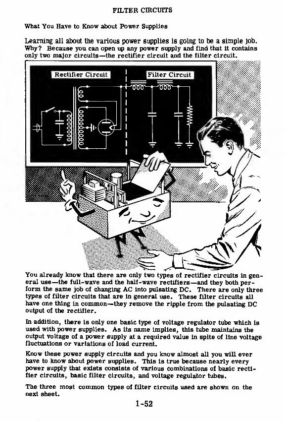
What You Have to Know about Power Supplies
Learning all about the various power supplies is going to be a simple job.
Why? Because you can open up any power supply and find that it contains
only two major circuits—the rectifier circuit and the filter circuit.
You already know that there are only two types of rectifier circuits in gen-eral use—the full-wave and the half-wave rectifiers—and they both per-form the same job of changing AC into pulsating DC. There are only threetypes of filter circuits that are in general use. These filter circuits all
have one thing in common—they remove the ripple from the pulsating DCoutput of the rectifier.
In addition, there is only one basic type of voltage regulator tube which isused with power supplies. As its name implies, this tube maintains theoutput voltage of a power supply at a required value in spite of line voltagefluctuations or variations of load current.
Know these power supply circuits and you know almost all you will everhave to know about power supplies. This is true because nearly everypower supply that exists consists of various combinations of basic recti-fier circuits, basic filter circuits, and voltage regulator tubes.
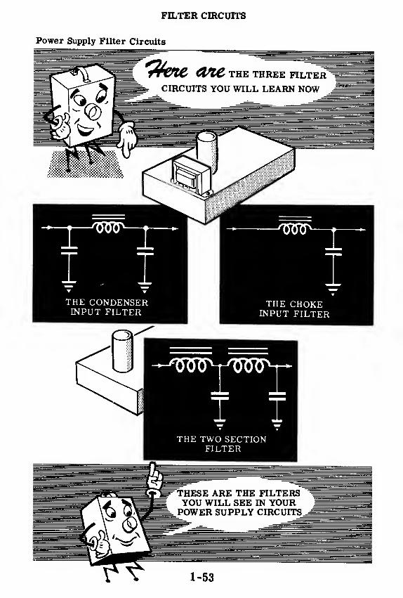
The three most common types of filter circuits used are shown on thenext sheet.
1-52
FILTER CIRCUITS
Power Supply Filter Circuits
1 1
THE CONDENSERINPUT FILTER
ITHE CHOKE
INPUT FILTER
THE TWO SECTIONFILTER

FILTER CIRCUITS
Characteristics of the Rectifier Output
You have been told that electronic circuits in general require a source of
about +350 volts DC and a source of 6. 3 volts AC in order to operate. Thepower supply transformer supplies the 6. 3 volts AC directly to the heaters
of the tubes requiring it. The transformer feeds high voltage AC into the
rectifier and rectifier puts out pulsating DC that looks like this:
The electronic circuits which are connected to the power supply output
cannot use a pulsating voltage of this sort. What these circuits require is
a steady DC voltage with as little pulsation as possible. The purpose of
the filter circuit is to remove the pulsations from the rectifier output and
deliver a steady DC voltage.
The output of a rectifier tube consists of pulses of current which alwaysflow in the same direction through the load resistor. The current rises
from zero to a maximum and then falls to zero, repeating this cycle over
and over again. At no time does the electron current through the load
resistor change its direction and flow from the filament to ground. Thevoltage resulting from this flow of electrons through the load resistor is avoltage that rises from zero to a maximum and then falls back to zero, re-
peating this cycle over and over again. This voltage takes on the shape of
half sine waves. In the case of a half-wave rectifier the average DC volt-
age is 31. 8 percent of the peak value. In the case of a full-wave rectifier
the average DC is 63. 6 percent of the peak value.
HALF-WAVE RECTIFIER OUTPUT FULL-WAVE RECTIFIER OUTPUTVoltage Voltage
1-54

FILTER CIRCUITS
AC and DC Components
If you connect a DC voltmeter across the rectifier output you will get areading. If you connect an AC voltmeter across the rectifier output, youwill also get a reading. This AC reading is a result of the output voltagevariation. Therefore, the output of the rectifier can be considered as aDC voltage with an AC voltage superimposed upon it. You can look uponthe job of a filter circuit as the job of removing the AC portion (or ACcomponent) of the rectifier output and allowing only the DC component toget to the power supply output terminals. If the filter succeeds in re-moving all of the AC from the rectifier output, only pure DC will be left.
You may now ask the question "How can a pulsating DC voltage have an ACcomponent if the voltage rises from zero to a high positive value and fallsback to zero, but never becomes negative?" You have always thought ofan AC voltage as one which alternates above and below a zero voltage,first becoming positive, then zero and then negative. If the voltage neverbecomes negative, how can there be any AC in it?
Any wave that varies in a regular manner has an AC component. Supposeyou examine an example in which an AC voltage is combined with a DCvoltage and the result is a voltage wave which never becomes negative.Suppose you have a voltage of +50 volts DC and you combine it with an ACvoltage which varies from +20 volts through zero to -20 volts.
When the +20 volt AC peak is added to the +50 volts DC, the result is +70volts. When the 0 volt point on the AC wave is added to the +50 volts DC,the result is +50 volts. When the -20 volts AC peak is added to the +50volts, the result is +30 volts. The total result is a DC voltage which variesfrom +50 volts—up to +70 volts and down to +30 volts. The voltage of theresulting wave never becomes negative and yet it consists of an AC com-ponent and a DC component.
1-55
FILTER CIRCUITS
AC and DC Components (continued)
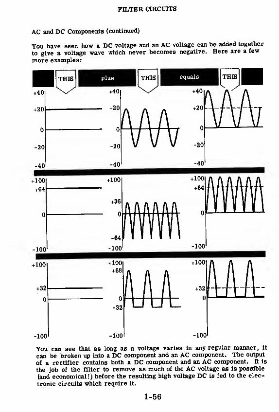
You have seen how a DC voltage and an AC voltage can be added together
to give a voltage wave which never becomes negative. Here are a few
more examples:
-100 -100 100
You can see that as long as a voltage varies in any regular manner, it
can be broken up into a DC component and an AC component. The output
of a rectifier contains both a DC component and an AC component. It is
the job of the filter to remove as much of the AC voltage as is possible
(and economical!) before the resulting high voltage DC is fed to the elec-
tronic circuits which require it.
1-56
FILTER CIRCUITS
The Condenser in the Filter Circuit
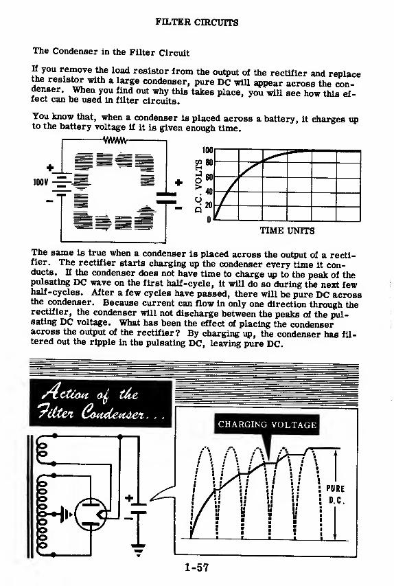
K you remove the load resistor from the output of the rectifier and replacethe resistor with a large condenser, pure DC will appear across the con-denser. When you find out why this takes place, you will see how this ef-fect can be used in filter circuits.
You know that, when a condenser is placed across a battery, it charges upto the battery voltage if it is given enough time.
IVWVIM
1
The same is true when a condenser is placed across the output of a recti-fier. The rectifier starts charging up the condenser every time it con-ducts. If the condenser does not have time to charge up to the peak of thepulsating DC wave on the first half-cycle, it will do so during the next fewhalf-cycles. After a few cycles have passed, there will be pure DC acrossthe condenser. Because current can flow in only one direction through therectifier, the condenser will not discharge between the peaks of the pul-sating DC voltage. What has been the effect of placing the condenseracross the output of the rectifier? By charging up, the condenser has fil-tered out the ripple in the pulsating DC, leaving pure DC.
1-57

FILTER CIRCUITS
The Condenser in the Filter Circuit (continued)
H a power supply did not have to supply current to other circuits, pure DCvoltage could be obtained simply by connecting a condenser from the rec-
tifier filament to ground. However, the various electronic circuits at-
tached to the power supply B+ voltage do draw a certain amount of current.
The current drawn by these electronic circuits is called the load current,
and the effect of this load current can be duplicated by connecting a load
resistor across the rectifier output and ground.
You know from your study of RC circuits in Basic Electricity that when a
resistor is placed across a charged condenser, the condenser will dis-
charge through the resistor. The speed of the discharge will depend uponthe size of the resistor. The lower the resistance the more current will
be drawn from the condenser, and the faster will be the discharge.
As soon as the resistor is connected across the condenser of the rectifier
circuit, that condenser will begin to discharge and the voltage will drop.
The voltage, however, will not drop to zero because a new voltage peakappears at the rectifier filament 60 times a second for a half-wave recti-
fier and 120 times a second for a full-wave rectifier. This voltage peakwill recharge the condenser, and then the condenser will proceed to dis-
charge through the resistor until the next voltage peak comes along. Theresult will be a pulsating DC output. Notice that the pulsations are muchsmaller than you would get with no condenser.
-1
r1
1^i —'-M
—
i i i -—"i
No Load With Load
1-58
FILTER CIRCUITS
The Condenser in the Filter Circuit (continued)
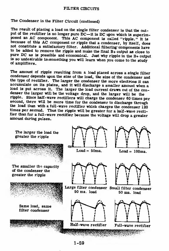
The result of placing a load on the single filter condenser is that the out-put of the rectifier is no longer pure DC—it is DC upon which is superim-posed an AC component. This AC component is called "ripple." It isbecause of this AC component or ripple that a condenser, by itself, doesnot constitute a satisfactory filter. Additional filtering components haveto be added to remove the ripple and make the final B+ output as close topure DC as is possible and economical. Just why ripple in the B+ outputis so undesirable is<something you will learn when you come to the studyof amplifiers.
The amount of ripple resulting from a load placed across a single filtercondenser depends upon the size of the load, the size of the condenser andthe type of rectifier. The larger the condenser the more electrons it canaccumulate on its plates, and it will discharge a smaller amount when aload is put across it. The larger the load current drawn out of the con-denser the larger will be the voltage drop, and the larger will be theripple. Since half-wave rectifiers will charge the condenser 60 times persecond, there will be more time for the condenser to discharge throughthe load than with a full-wave rectifier which charges the condenser 120times per second. Thus the ripple will be greater for a half-wave recti-fier than for a full-wave rectifier because the voltage will drop a greateramount during pulses.
1-59

FILTER CIRCUITS
Filter Condensers
Filter condensers (capacitors) used in power supplies are of two types:
(1) paper dielectric condensers and (2) electrolytic condensers.
Paper condensers are constructed of alternate layers of metal foil and wax-
ed paper rolled together. The waxed paper is the dielectric with the metal
foil being used as plates. Paper condensers smaller than 1 mfd are used
throughout most electronic equipment and larger values are sometimes
used as filter condensers in power supplies.
Construction oi paperc3E2Sfo
Wax paper
Paper condensers are not polarized and when operated within their voltage
rating they last much longer than electrolytic condensers. However, large
sizes of paper condensers are bulky and relatively expensive. They are
normally not made larger than 16 mfd.
High voltage power supplies use paper filter condensers which are oil im-
pregnated and will withstand greater peak voltages than those impregnated
with wax. Condensers are rated according to direct current working volt-
age (DCWV) and also in peak voltage. The DCWV is the maximum voltage
the condenser is designed to operate at continuously. The peak voltage is
the voltage above which the condenser dielectric will break down and act
as a conductor.
HIGH VOLTAGE PAPERFILTER CAPACITORS
1-60

FILTER CIRCUITS
Filter Condensers (continued)
Electrolytic condensers are usually used as power supply filter condensersbecause they can be made in very large sizes at low cost and are muchsmaller physically than paper condensers of the same capacity Electro-lytic condensers are made in larger sizes than paper condensers with theusual values being between 2 mfd and 1000 mfd.
Power supplies rated at 600 volts or less usually use electrolytic filtercondensers but when a higher voltage rating is required paper condensersare used. Electrolytics are polarized and failure to observe the correctpolarity will not only permanently damage the condenser but may alsocause it to break open and damage other parts.
While paper condensers have no leakage current (flow of direct current ac-cross the condenser dielectric) electrolytic condenser dielectrics are notperfect insulators and a leakage current flows even during normal opera-tion. The leakage current is greater in the wet electrolytic than in the drytypes. If the voltage rating of an electrolytic condenser is exceeded theleakage current increases and may damage the dielectric.
1-61

FILTER CIRCUITS
Filter Condensers (continued)
Electrolytic condensers are of two types: (1) wet and (2) dry.
A wet electrolytic condenser consists of an aluminum electrode immersedin a solution called an electrolyte. When the electrode is connected to the
positive terminal of a DC voltage source and the electrolyte container is
connected to the negative terminal, current flows through the electrolyte.
This current flow results in chemical action which causes a film to form
on the electrode surface. This film acts as a dielectric, insulating the
electrode from the electrolyte These two elements then act as plates in
a condenser—the electrode becoming a + terminal, and the electrolyte a- terminal. The connection to the electrolyte is made through the container.
Reversing the polarity of the voltage applied to the condenser breaks downthe dielectric completely. A momentary overload in the correct polarity
punctures the dielectric but application of the rated voltage reforms the
dielectric so that wet electrolytics are said to be self-healing.
The capacitance of an electrolytic condenser is greater than that of a paper
condenser of equivalent physical size because the dielectric film is very
thin, enabling close spacing between the condenser plates. The positive
plate surface is roughened and the liquid electrolyte negative plate follows
the rough surface of the positive plate resulting in greater plate area in a
given space.
1-62

FILTER CIRCUITS
Filter Condensers (continued)
Dry electrolytic condensers use an electrolyte in the form of paste. Acloth impregnated with the electrolytic paste is rolled between alternatelayers of aluminum foil in the same manner as that used to make papercondensers. One layer of metal foil is used as a positive plate of theelectrolytic condenser and the other layer of metal foil is used to contactthe negative plate (electrolyte) of the condenser.
A dry electrolytic condenser operates in the same way as a wet electro-lytic except that it is not self-healing when the dielectric has been punc-tured. Both types of electrolytic condensers have a relatively short lifedue to the drying up of the electrolyte. Of the two, dry electrolytics gen-erally last longer. Wet electrolytics are not often used since they dry outrapidly and must be mounted upright to prevent leaking of the liquid elec-trolyte. Several types of dry electrolytic condensers are illustrated below.
1-63
FILTER CIRCUITS
Improving the Operation of the Filter
You saw on a preceding sheet that the larger you make the filter con-
denser, the lower will be the AC component or ripple in the output.
Filter condensers can be made very large in capacity and small in
size, as you will see shortly, but there are size limitations that cannot be
exceeded. A filter condenser of practical size might reduce the AC com-ponent to about 25 volts AC, but this is not good enough. Many electronic
circuits require a B+ voltage that cannot have more than 3 or 4 volts of
AC present in a DC output of 350 volts—the AC component must be less
than 2 percent or even less than 1 percent of the total output voltage. Nofilter condenser of practical size can do this job alone—other filtering
components must be added.
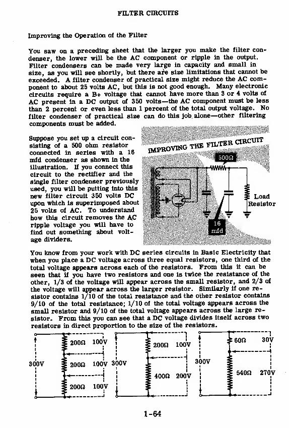
Suppose you set up a circuit con-
sisting of a 500 ohm resistor
connected in series with a 16
mfd condenser as shown in the
illustration. If you connect this
circuit to the rectifier and the
single filter condenser previously
used, you will be putting into this
new filter circuit 350 volts DCupon which is superimposed about
25 volts of AC. To understand
how this circuit removes the A.C
ripple voltage you will have to
find out something about volt-
age dividers.
HAPROVING THEFILTER ClRCTJn
LoadResistor
You know from your work with DC series circuits in Basic Electricity that
when you place a DC voltage across three equal resistors, one third of the
total voltage appears across each of the resistors. From this it can be
seen that if you have two resistors and one is twice the resistance of the
other, 1/3 of the voltage will appear across the small resistor, and 2/3 of
the voltage will appear across the larger resistor. Similarly if one re-
sistor contains 1/10 of the total resistance and the other resistor contains
9/10 of the total resistance; 1/10 of the total voltage appears across the
small resistor and 9/10 of the total voltage appears across the large re-
sistor. From this you can see that a DC voltage divides itself across two
resistors in direct proportion to the size of the resistors.o , ,
300V
200J2 100V
20012
4l
ioovi—
i
200ft 100V
300Vi
i
200ft 100V
U -i
300V
400ft 200V
60ft 30V
540ft 270V
i
.-i
1-64
FILTER CIRCUITS
Improving the Operation of the Filter (continued)
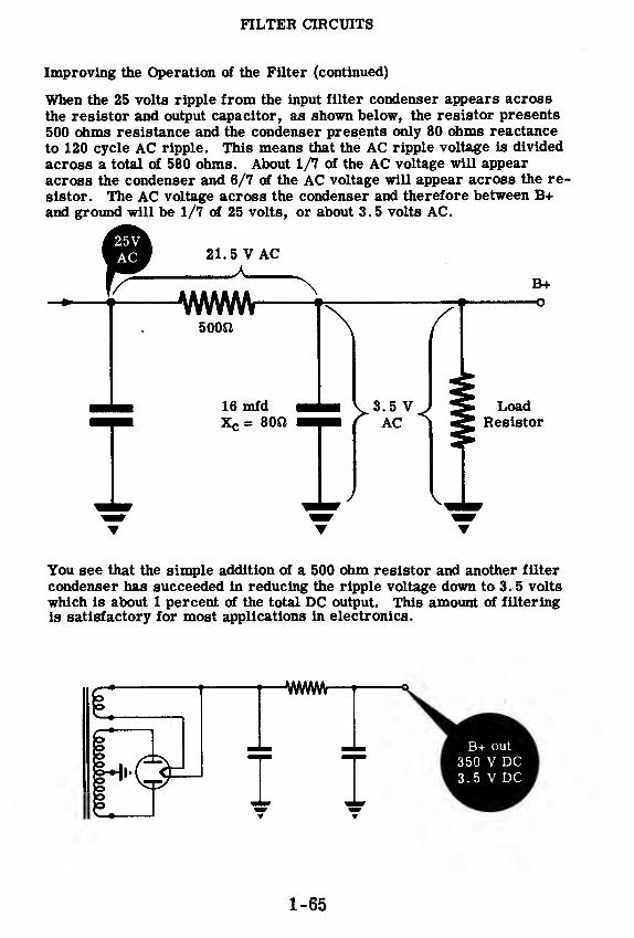
When the 25 volts ripple from the input filter condenser appears across
the resistor and output capacitor, as shown below, the resistor presents
500 ohms resistance and the condenser presents only 80 ohms reactance
to 120 cycle AC ripple. This means that the AC ripple voltage is divided
across a total of 580 ohms. About 1/7 of the AC voltage will appear
across the condenser and 6/7 of the AC voltage will appear across the re-
sistor. The AC voltage across the condenser and therefore between B+and ground will be 1/7 of 25 volts, or about 3.5 volts AC.
T
You see that the simple addition of a 500 ohm resistor and another filter
condenser has succeeded in reducing the ripple voltage down to 3. 5 volts
which is about 1 percent of the total DC output. This amount of filtering
is satisfactory for most applications in electronics.
1-65
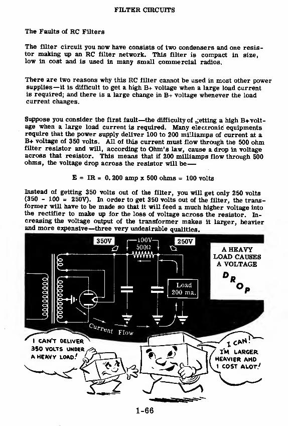
FILTER CIRCUITS
The Faults of RC Filters
The filter circuit you now have consists of two condensers and one resis-tor making up an RC filter network. This filter is compact in size,low in cost and is used in many small commercial radios.
There are two reasons why this RC filter cannot be used in most other powersupplies—it is difficult to get a high B+ voltage when a large load currentis required; and there is a large change in B+ voltage whenever the loadcurrent changes.
Suppose you consider the first fault—the difficulty of betting a high B+ volt-age when a large load current is required. Many electronic equipmentsrequire that the power supply deliver 100 to 200 milliamps of current at aB+ voltage of 350 volts. All of this current must flow through the 500 ohmfilter resistor and will, according to Ohm's law, cause a drop in voltageacross that resistor. This means that if 200 milliamps flow through 500ohms, the voltage drop across the resistor will be
—
E = IR = 0. 200 amp x 500 ohms = 100 volts
Instead of getting 350 volts out of the filter, you will get only 250 volts(350 - 100 = 250V). In order to get 350 volts out of the filter, the trans-former will have to be made so that it will feed a much higher voltage intothe rectifier to make up for the loss of voltage across the resistor. In-creasing the voltage output of the transformer makes it larger, heavierand more expensive—three very undesirable qualities.
1-66

FILTER CIRCUITS
The Faults of RC Filters (continued)
You have seen that one fault of the RC filter is that it causes a large volt-
age drop across the filter resistor which means that the transformer mustput out a higher AC voltage in order to compensate for this loss. Thesecond fault of RC filters is even more seious—a small change in the load
current causes the B+ output to vary by many volts.
You have read in the introduction to this section that it is important for the
B+ voltage output to remain fairly stable in spite of changes in load current.
Many types of electronic equipment draw varying amounts of load current
from the B+ voltage supply, but the voltage change must remain small in
spite of this.
As an example, suppose that you have a unit of electronic equipment that
draws 50 ma. from the B+ supply under one set of conditions, and then the
conditions change so that 100 ma. are drawn from the B+ supply. First
you have 50 ma. flowing through the 500 ohm filter resistor and then youhave 100 ma. flowing through that same resistor. Suppose that the voltage
coming out of the filter is 350 volts and 50 ma. are being drawn by the load.
The voltage drop across the 500 ohms resistor will be E = IR « . 050 x 500= 25V. Suddenly an additional 50 ma. are drawn through the 500 ohm load
resistor (making a total of 100 ma. ). The result is an increased voltage
drop across the 500 ohm resistor.
E = IR = 0. 100 x 500 = 50V
Since the voltage drop has increased 25V, the output voltage must decrease
by the same amount.
The output voltage will decrease from 350V to 325V when the load current
increases from 50 to 100 ma.
CONDITION'ElectronCurrent
To
375VDC
Rectifier^-J mm
1 1TL
CONDITION!
Load50 ma.
ElectronCurrent
-25V--. 350V 375V T-50V-T 325V500ft
•' DC To DC '« 500SJ ; DCRectifier mm-
1 1TE
Load100 ma,
Similarly a change of 100 ma. in the load current will cause the B+ voltage
to drop 50 volts. Such a rise and fall in output voltage is very undesirable
in electronic equipment. Voltage regulator circuits might be added to
compensate for this voltage change due to the filter resistor, but it wouldrequire a large and expensive circuit to compensate for changes such as
are indicated here.1-67

FILTER CIRCUITS
Using a Choke Instead of a Resistor
A resistor can do a fairly goodjob of filtering because its re-sistance to AC is higher than thereactance of a filter condenser toAC. When the ripple voltage is
placed across this circuit, the ACvoltage divides so that only asmall part of this ripple voltageappears across the filter conden-ser and at B+. The DC voltagedivides across this circuit so thatmost of the DC voltage appearsacross the filter condenser andat B+.
What the filter circuit requires is that the resistor have a high resistancefor AC and a low resistance to DC. A resistor presents exactly the sameresistance to both AC and DC and cannot meet this requirement. When afilter resistor is used, its size must be a compromise between these twoopposing requirements.
There is, however, a certain type of component that will meet this require-ment—the filter choke. From your study of AC circuits in Basic Electri-city you know that a choke opposes any change of current flowing through it.In other words the inductance of a choke presents a high reactance to AC.Because a choke is made up of many turns of copper wire wound arounda core, it also presents a low resistance to DC. A choke has the veryqualities that are required to replace the resistor in a filter circuit.
Inductors or chokes, as used in electronic power supplies, are called "fil-ter chokes" because they are used to "choke" out the AC. A 10-henrychoke is fairly small in size and will present a reactance of about 7500ohms to 120 cycle ripple and will have a DC resistance of about 200 ohms.Such a choke has 15 times more reactance to AC than a 500 ohm resistor,and also has less than half its DC resistance. Because of these excellentqualities you will find that chokes are used in the filter circuits of mostelectronic power supplies. Before you learn about the various combina-tions of chokes and condensers that are used in filter circuits, supposeyou find out about the construction of these components.
A 10-henry FILTER CHOKE IB 15 TIMES BETTER THAN
A 500-ohm RESISTOR
AND HAS LESS THAN HALFTHE DC RESISTANCE
200 ohms =, 500 ohms
1-68
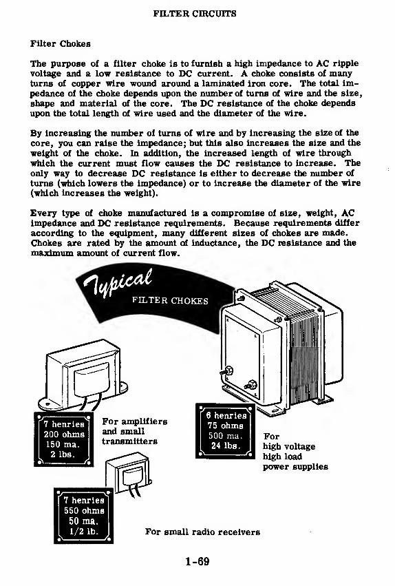
FILTER CIRCUITS
Filter Chokes
The purpose of a filter choke is to furnish a high impedance to AC ripple
voltage and a low resistance to DC current. A choke consists of manyturns of copper wire wound around a laminated iron core. The total im-pedance of the choke depends upon the number of turns of wire and the size,
shape and material of the core. The DC resistance of the choke dependsupon the total length of wire used and the diameter of the wire.
By increasing the number of turns of wire and by increasing the size of the
core, you can raise the impedance; but this also increases the size and the
weight of the choke. In addition, the increased length of wire through
which the current must flow causes the DC resistance to increase. Theonly way to decrease DC resistance is either to decrease the number of
turns (which lowers the impedance) or to increase the diameter of the wire(which increases the weight).
Every type of choke manufactured is a compromise of size, weight, ACimpedance and DC resistance requirements. Because requirements differ
according to the equipment, many different sizes of chokes are made.Chokes are rated by the amount of inductance, the DC resistance and the
maximum amount of current flow.
1-69

FILTER CIRCUITS
The Single-Section Choke and Condenser Input Filters
The single -section choke input filter consists of a filter choke in serieswith the power supply load and a filter condenser across the load. The DCcomponent of the rectifier output appears across the load. Most of the ACcomponent appears across the high inductive reactance of the choke. Onlya small amount of AC appears across the output filter condenser becauseof its low reactance. Since the load is in parallel with the output filtercondenser, very little ripple appears across the load.
High reactance -
Large AC voltage drop
B+
DC
Output
Low reactance -
Small AC voltage drop
SINGLE SECTION CHOKE INPUT
FILTER CIRCUITS
A single-section condenser input filter consists of a filter condenser con-nected across the input terminals of a single -section choke input filter.Because of the shape of the circuit diagram, filter circuits of this type aresometimes called v type filters.
Large values of inductance and capacitance are used in condenser inputfilters so that they are often called "brute-force" filters. Inductance val-ues of from 10 to 30 henries and capacitance values of from 2 to 16 micro-farads are commonly used.
10 to 30 henries
O 1 -^OOOF—
«
Input " Output
2-16 mfdO 1 i
2-16 mfdi +-
SINGLE-SECTIONCONDENSERINPUT
7i(teft
(sOiccat
1-70

FILTER CIRCUITS
The Single-Section Choke Input Filter
You will see that the single-section choke input filter does just a little
better job of filtering than the condenser alone. The voltage output of thechoke input filter is lower than the voltage output of the condenser alone.This is because the choke builds up a back emf which cancels a part of
the voltage coming out of the rectifier. An important feature of the chokeinput filter is that it limits the peak current flowing through the rectifiertube and, as a result, there is less strain on the tube. The choke input fil-
ter also has the characteristic of holding the output voltage quite constantdespite load variations. Because of these last two characteristics, chokeinput filters are used most commonly in power supplies which are sub-jected to heavy or varying loads. The results of using this type of filter
for such loads are a more stable output voltage from the power supply andlonger life of the rectifier tube.
1-71
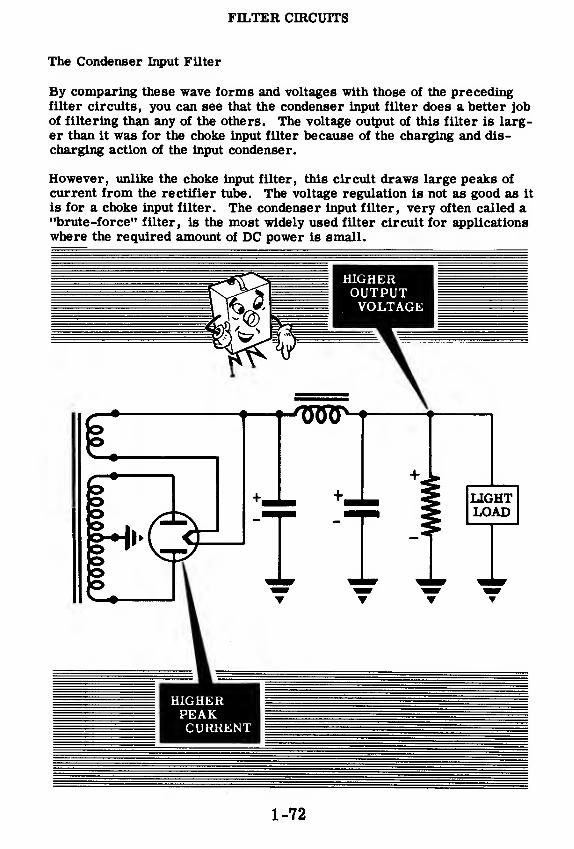
FILTER CIRCUITS
The Condenser Input Filter
By comparing these wave forms and voltages with those of the precedingfilter circuits, you can see that the condenser input filter does a better job
of filtering than any of the others. The voltage output of this filter is larg-er than it was for the choke input filter because of the charging and dis-charging action of the input condenser.
However, unlike the choke input filter, this circuit draws large peaks of
current from the rectifier tube. The voltage regulation is not as good as it
is for a choke input filter. The condenser input filter, very often called a"brute-force" filter, is the most widely used filter circuit for applicationswhere the required amount of DC power is small.
1-72
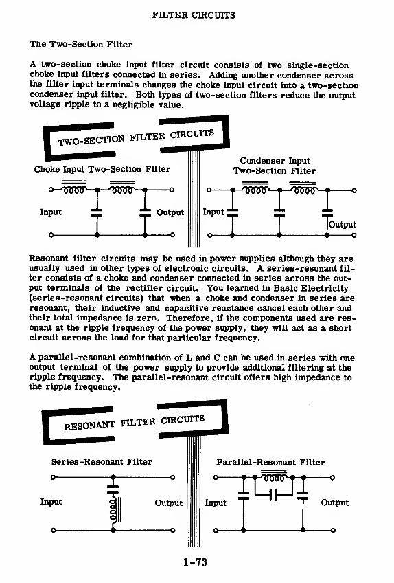
FILTER CIRCUITS
The Two-Section Filter
A two-section choke input filter circuit consists of two single-sectionchoke input filters connected in series. Adding another condenser acrossthe filter input terminals changes the choke input circuit into a two-sectioncondenser input filter. Both types of two-section filters reduce the outputvoltage ripple to a negligible value.
TWO-SECTION FILTER CIRCUITS
Choke Input Two-Section Filter
o-^00WL-^---^0^J7}
,,
-^-
T TInput Output
Condenser Input
Two-Section Filter
input i; ~; TLJOutput
Resonant filter circuits may be used in power supplies although they areusually used in other types of electronic circuits. A series-resonant fil-
ter consists of a choke and condenser connected in series across the out-put terminals of the rectifier circuit. You learned in Basic Electricity
(series-resonant circuits) that when a choke and condenser in series areresonant, their inductive and capacitive reactance cancel each other andtheir total impedance is zero. Therefore, if the components used are res-onant at the ripple frequency of the power supply, they will act as a shortcircuit across the load for that particular frequency.
A parallel-resonant combination of L and C can be used in series with oneoutput terminal of the power supply to provide additional filtering at theripple frequency. The parallel-resonant circuit offers high impedance to
the ripple frequency.
1-73

FILTER CIRCUITS
Filter Condenser Considerations
When a condenser input filter is used the instantaneous peak current of the
rectifier may be much higher than the maximum current delivered to the
load. The input condenser across the load circuit acts like a short circuit
when a voltage is first applied to it. The initial charging current may ex-
ceed the rectifier rating. Series resistors are sometimes used with se-
lenium rectifiers in order to limit the initial charging current of the input
filter condenser.
INPUT CONDENSER CHARGING
To 5-volt trans-
former winding
Input chargingcondenser circuit
Resistor used withselenium rectifiers
to limit condensercharging current to
a safe value
ri
O-WWr—H-
Because of the time lapse between pulses of direct current, the output of
a half-wave rectifier requires more filtering than that of a full-wave rec-tifier and the filtered output voltage will be lower. Filter condensers usedin half-wave power supplies are usually from 2 to 4 times as large as those
used in full-wave power supplies. Increasing the size of the filter conden-sers provides additional filtering.
HALF- AND FULL-WAVE RECTIFIER OUTPUT
DJY.Half-wave rectifier output
Full-wave rectifier output
-J-^oTRHHT-J-
I I
rrm\ f t •» " •
The higher the frequency of the AC input voltage to a power supply the
lower the value of the filter condensers required. The time betweenpulses is shorter at higher frequencies and the inductive action of the chokeis greater at higher frequencies.
1-74

FILTER CIRCUITS
Bleeder Resistors
If the load is entirely removed from a power supply the voltage rises to avalue much higher than normal. With no load current there is no DC volt-age drop in the circuit and no discharge path for the filter condensers, re-sulting in a build-up in voltage across the filter condensers to a value ap-proximately equal to the peak AC voltage applied to the rectifier tube.
To prevent soaring of the voltage at no load, resistors are often connectedacross the output terminals of power supplies. These resistors called"bleeder resistors" provide a discharge path for the filter condensers andalso serve as a fixed load to bleed off a constant value of current. Thebleeder resistor usually draws about 10 percent of the total rated currentoutput of the power supply.
Since a bleeder resistor prevents sharp increases in voltage output underlight or no load conditions it improves the power supply voltage regulationand tends to maintain the output voltage at a constant value regardless ofload. This method of voltage regulation is sufficient for most power sup-ply applications but in many cases better voltage regulation is required.
Bleeder resistors dissipate a relatively large amount of power as heat andshould be mounted in a well-ventilated position. The resistance value andpower rating of the bleeder resistor depend on the maximum voltage andcurrent ratings of the power supply. For example, if a power supply is
rated at 300 volts and can supply 100 milliamperes the bleeder currentshould be about 10 milliamperes and the voltage across the bleeder 300volts. The bleeder resistance (30, 000 ohms) is found by dividing the volt-age (300 volts) by the bleeder current (.010 ampere). The power dissi-pated is equal to the voltage multiplied by the bleeder current. (300 x . 01 =3 watts). The wattage rating of a resistor should be higher than the powerdissipated so that a 30K, 10-watt resistor is used as a bleeder.
BLEEDER RESISTORS Improve Voltage Regulation
+o- J07RTL
r
L
+—
o
Bleeder resistor
provides a discharge
path for the filter condenser.
Bleeder resistors provide a continous load
for the power supply.
1-75

FILTER CIRCUITS
Bleeder Resistors (continued)
Bleeder resistors are sometimes tapped to provide one or more voltages
lover than the maximum voltage of the power supply. The bleeder mayconsist of several resistors connected in series across a source of voltage
with various voltages available at the resistor junctions.
When a bleeder is connected directly across the power supply output, the
voltage at various points along the bleeder is exactly proportional to the
resistance at that point, provided no current is drawn from any of the taps.
For example, if a 30,000-ohm resistor tapped at 7, 500-ohms, 15,000ohms and 22, 500 ohms is connected across the output of a 300 volt powersupply the voltage divides proportionately. At the 15, 000-ohm tap the
voltage is one half of the total or 150 volts, at the 7, 500-ohm tap it is one
fourth of the total or 75 volts and at the 22, 500-ohm tap it is three fourths
of the total or 225 volts. The bleeder current through the resistor is
10 milliamperes.
+300V.
j Total +225yi- J300V current t %^ \
',
DC equals +150V§»-«, 22,500J2 1
' bleeder t #, e
' j !
! current +75y|—--j15,0000
j [
' 10 ma. t| 7,5000 jI
j
I—*" —*~ ~T. L i L i
VOLTAGE DROPS
ACROSS IA TAPPED IBLEEDER IRESISTOR
The voltages available at the voltage divider taps depend on the currentdrawn from each tap and are affected by changes in current supplied by anyof the voltage taps. When a load is connected to any of the taps its re-sistance is in parallel with a portion of the voltage divider. This forms aseries-parallel circuit and reduces the total resistance across the circuit
resulting in an increase in current drawn from the power supply. Thevoltage drop in the series part of the voltage divider circuit increases dueto the increased current, and the voltage drop and bleeder current for the
parallel part of the voltage divider are decreased.
TAPPED BLEEDER RESISTOR WITH A LOAD CONNECTED
+300V
Increased current results in larger voltage dropthan caused by bleeder current alone.
LoadResistor decreases total resistance across
the power supply output.
1-76

FILTER CIRCUITS
Bleeder Resistors (continued)
A typical voltage divider for a 300 volt, 100 milliampere power supply
might provide for a bleeder current of 10 milliamperes, a tap at 200 volts
to supply 40 milliamperes and a tap at 150 volts to supply 50 milliamperes.
To find the resistance values for each part of such a voltage divider circuit
the voltage drop and current through each resistor must be found. In the
illustration, points A, B, C and D provide the desired voltage taps and the
resistance values of Ri, R2, and R3 are found as follows:
Rl The voltage drop across Rj (between points C and D) is 150 volts. Thecurrent flow through R^ is only the bleeder current or 10 ma. then
Ri = 1^= 15,000 ohms.A.01
—R2 The voltage drop across R2 (between points B and C) is 50 volts (150V
to 200V). The current flow through R2 is bleeder current, 10 ma.
,
plus the load current, 50 ma. , or 60 ma. then R2 = = 833 ohms .
. 06
R3 The voltage drop across R3 (between points A and B) is 100 volts (200V
to 300V). The current flow through R3 is the sum of the bleeder cur-
rent and the current through each load—10 + 50 + 40 = 100 ma. then
R3 = i£2 = 1000 ohms .
The wattage dissipation of each resistor is found by multiplying the current
through the resistor by the voltage drop across it:
150 x . 01 = 1. 5 watts for Ri50 x . 06 = 3 watts for R2
100 x . 1 =10 watts for R3
Load
1-77

FILTER CIRCUITS
Review of Filter Circuits
FILTER CAPACITORS — Capacitorsused in power supplies to change thepulsating DC output of rectifiers into
DC having a relatively slight variationin value. The condenser chargesthrough the rectifier circuit and dis-charges through the load circuit tohelp maintain voltage applied to theload at a steady value.
PAPER FILTER CAPACITORS —Paper filter condensers are bulky andtheir value is usually limited to lessthan 10 mfd. They are not polarizedand can be made to withstand very highvoltages. There is no appreciableleakage across a paper filter conden-ser. Oil-impregnated paper conden-sers are used in high voltage fil-
ter circuits.
ELECTROLYTIC FILTER CAPACI-TORS— Electrolytics have a highvalue of capacitance as compared to apaper condenser of the same physicalsize. They are polarized and arenormally constructed to operate atless than 600 volts. There is appre-ciable leakage across an electrolyticcondenser but this effect is usuallyoffset by their large values of capaci-tance. Electrolytics range in valuefrom 1 to 1000 mfd.
WET ELECTROLYTIC CAPACITOR —A condenser consisting of a metal elec-trode immersed in an electrolytic solu-tion. The electrode and solution arethe two condenser plates while anoxide film formed on the electrode isthe dielectric. The dielectric film is
formed by current flow from the elec-trolyte to the electrode.
1-78

FILTER CIRCUITS
Review of Filter Circuits (continued)
PRY ELECTROLYTTf? PONDENSERS— In a dry electrolytic condenser theelectrolyte is a paste. Cloth which isimpregnated with the paste is rolledbetween layers of metal foil which actas the condenser terminals. One met-al foil is the positive plate and a filmformed on its surface is the dielectricThe electrolyte paste is the negativecondenser plate and its terminal con-nection is made through a layer ofmetal foil.
NegativeAluminumElectrode
Gauzesaturatedwith electrolyte
Positive
AluminumElectrode
Aluminum-oxide Film
FILTER CHOKE _ An iron-core in-ductance placed in series with the rec-tifier output. It opposes any change incurrent flow and reduces the amountof change in the pulsating DC output ofthe rectifier circuit.
CHOKE LESS POWER STTPPT.v ittt >rFp- A low current power supply filter°~^AV-^MAA^-
T-
circuit in which resistors are used in J- J.place of filter chokes. Resistors are T Tused to save weight, space and cost. <> [ I
1-79
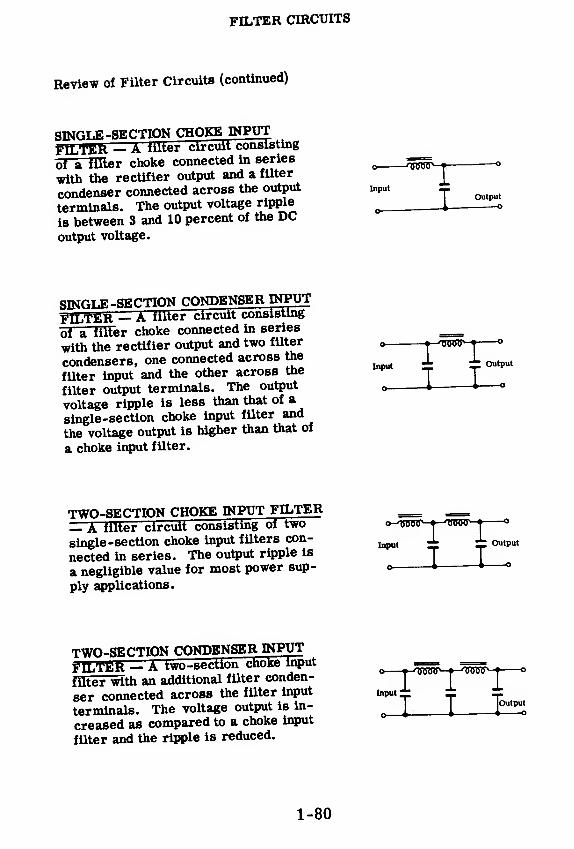
FILTER CIRCUITS
Review of Filter Circuits (continued)
SINGLE -SECTION CHOKE INPUT
FILTER — A filter circuit consisting
of a filter choke connected in seriesq ^L^.
with the rectifier output and a filterJ_
condenser connected across the output input _terminals. The output voltage ripple
_ i_
is between 3 and 10 percent of the DCoutput voltage.
Outputo
STMPxT.E-SECTION CONDENSER INPUT
FILTER — A filter circuit consisting
of a filler choke connected in series ==with the rectifier output and two filter <, •-^toot^-i °
condensers, one connected across the ± 1^filter input and the other across the T Tfilter output terminals. The output „ i 1 o
voltage ripple is less than that of a
single-section choke input filter and
the voltage output is higher than that of
a choke input filter.
TWO-SECTION CHOKE INPUT FILTER.
— A filter circuit consisting of two o-^toot^-j-^otot^-j-
single -section choke input filters con- ^ ± 1nected in series. The output ripple is T Ta negligible value for most power sup- o * *-
ply applications.
Output
TWO-SECTION CONDENSER INPUT
FILTER - A two-section choke Input
filter with an additional filter conden-[
7 T
ser connected across the filter input input^; dz dz
terminals. The voltage output is in-| |
|wcreased as compared to a choke input
filter and the ripple is reduced.
1-80

VOLTAGE REGULATOR CIRCUITS
Voltage Regulation
2d mer cfrcuKs Tou'aS,^ <* rectifier circuits„ f
lrcu"s. You appreciate the importance of maintainine the now-
g£XS
E
g order 80 that 016 complete~Kfpm7nt
JS^E • ^f*80]"8 t0 Study V0]tase reg^ted power supply circuits whichare required to do specialized jobs that the ordinary general DurSse r»wer supply cannot do. Like other circuits you wiU 4e Jo toee^eeXtorcircuits range from very simple circuits Lmg onl^one0X0"^
^
Sr*1^ requiring many components. H^r/5l ttTttewcircuits operate in the same way as the basic regulator^ircuits
veoutput %e*H*wt4>
VOLTAGE
1-81

VOLTAGE REGULATOR CIRCUITS
Voltage Regulation (continued)
You already know the two most important factors which affect the B+ volt-
Ige output in a conventional power supply. When the AC line voltage goes
uo the B+ output voltage goes up; and, when the AC line voltage goes down,
S?e si o^Kltage ggoeidown
P'Also,when there is, .t sma 1 current drain
out of the B+ terminal, the B+ voltage is higher than '^n tore is ^rgecurrent drain. What you want to know now is how the voltage regulator
circuit overcomes both these problems.
If you connect a potentiometer across B+ and ground in any conventional
power supply, you have a perfect hand-operated voltage regulator.
Assume that you have a 1000-ohm potentiometer and a power supply with a
B+of 100 volts. Also assume that you want a steady output voltage of 50
volts You first adjust your potentiometer so that the center tap is right at
the middle of the potentiometer resistance. If the B+ voltage rises momen-
tarily due to an increase in AC line voltage or a decrease in B+ current
drain, all you do is move the tap closer to ground (decrease the resistance
hPtafien tao and ground) until you get 50 volts again. If the B+ voltage falls
due to a decrease in the AC line voltage or an increase in B+ current drain,
all you do is move the tap away from ground (increase the resistance be-
tween tap and ground) until you get 50 volts again.
B + =100V B+= 120V B+=80V
-50V
You can see that the hand-operated voltage regulator works very well.
You increase or decrease the resistance between ground and the output
voltage tap to increase or decrease the output voltage back to the desired
value whenever the B+ supply voltage falls or rises for any reason.
The main fault with this method is that it is too slow. First the output
voSaS must change. Then you must notice that it has changed, and then
you must increase or decrease the resistance between the voltage tap and
ground to get back the desired voltage output. When you consider that
there are many electronic circuits in a radar system whichimust have>a
steady voltage, you can see that many men would be needed to keep them
all regulated.
The voltage regulator circuit solves all your problemsl The voltage reg-
ulator tube automatically increases or decreases its internal resistance
as the B+ supply voltage falls and rises, so as to maintain a constant volt-
age across itself.
1-82

VOLTAGE REGULATOR CIRCUITS
The Voltage Regulator Tube
The voltage regulator tube consists of a plate and a cathode placed in an en-SyV0?
K
m^ gaS at l0W Press«re. There is no filamfnt and there-fore the tube is known as a cold cathode type tube. The radio symbol for
sence of "ga"llluStrated
-The dot inside th« envelope indicatesThe pre-
COLDCATHODE
When a large enough potential is applied between the cathode and the platethe gas in the tube conducts and electrons flow from cathode to plate Con-duction is characterized by a bluish glow inside the tube—the heavier theconduction the brighter the glow.
The numbering system used for voltage regulator tubes has been chaneed
m^w? ^f8-The V?"15°/30
'the VR-90/30 and th ?V?-75/?0 arel!dnumbers no longer used. The term "VR" meant voltage regulator thefirst number "150" etc., stood for the operating voltagf of thl^be-thlvoltage at which it regulated. The last number ^presented th maximum
C°^d ?SS thrOUSh the tube v/itLSt damag^Tt to a?
The tube will stop conducting if the current through it drops below thisvalue. A wide range of regulated voltages can be ted by using any of thevoltage regulator tubes singly or in series combinations.
1-83

VOLTAGE REGULATOR CIRCUITS
The Voltage Regulator Tube (continued)
The new numbering system for VR tubes is as follows:
Tube Type
OA2OA3OB2OC3OD3874991
DC OperatingVoltage Current Range Ma.
5 to 305 to 405 to 305 to 405 to 4010 to 500.4 to 2.0
K = Cathode
p = Plate
Under this new system there are available a larger variety of DC oper-
ating voltages and current ranges.
The VR tube Is a diode which^S^^^^^^SSi SfiLtion inside of a thin "^cyUnder The alr l» rem^a
mlxedenvelope and Is replaced by a small °*„
ent floV through
FMS^*!^™.K^tage of the tube will
change very little.
If operating voltages higher^X^^ZsVsfZ^ZSnnfSed to series. Parallel operation Is used when a larger current
Is required.
1-84

VOLTAGE REGULATOR CIRCUITS
A Simple VR Tube Circuit
Here is an example of how a VR tube is used in a typical circuit. Supposethat you have a power supply with an output voltage of 340 volts DC. Youneed to supply voltage to a special circuit that needs 150 volts DC with acurrent variation of from 10 to 30 milliamps. This circuit requires thatthe 150 volts DC be kept constant in spite of the current change.
Since you want a constant voltage of 150 volts DC with a maximum currentdrain of 30 milliamps, an OD3 (VR-150) will meet your requirements.Here are the operating characteristics of the OD3 (VR-150) as listed bythe manufacturer - note that they meet your requirements:
DC power supply voltage 185 volts min.DC starting voltage 160 voltsDC operating voltage . . i . . . 153 voltsDC operating current 5 to 40 ma.For a current variation of from 5 to 30 ma. the voltage will change
2 volts.*
For a current variation of from 5 to 40 ma. the voltage will change4 volts.
Power
Notice that there is a "jumper connection" between pins 3 and 7 inside thetube. If pins 3 and 7 are wired in series with the circuit, this jumper willact as a switch. When the VR tube is pulled out, the circuit requiring the150 volts will be disconnected from the power supply. If this jumper werenot connected as a switch and the VR tube were pulled out, the 150 voltcircuit would receive more than 150 volts—resulting in damage to itscomponents or in improper operation.
1-85
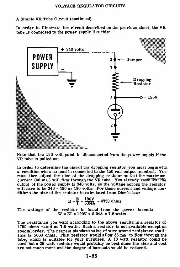
VOLTAGE REGULATOR CIRCUITS
A Simple VR Tube Circuit (continued)
In order to illustrate the circuit described on the previous sheet, the VRtube is connected to the power supply like this:
Note that the 150 volt point is disconnected from the power supply if theVR tube is pulled out.
In order to determine the size of the dropping resistor, you must begin witha condition when no load is connected to the 150 volt output terminal. Youmust then adjust the size of the dropping resistor so that the maximumcurrent (40 ma.) will flow through the VR tube. You already know that theoutput of the power supply is 340 volts, so the voltage across the resistorwill have to be 340 - 150 or 190 volts. For these current and voltage con-ditions the size of the resistor is calculated from Ohm's law:
R=T=0^= 4750ohms
The wattage of the resistor is found from the power formulaW = EI = 190V x 0.04A = 7.6 watts.
The resistance you want according to the above results is a resistor of
4750 ohms rated at 7.6 watts. Such a resistor is not available except onspecial order. The nearest standard value of wire wound resistance avail-
able is 5000 ohms. This resistor would allow 38 ma. to flow through thetube, which is suitable for your purposes. A 10 watt resistor could beused but a 25 watt resistor would probably be best since the size and costare not much more and the danger of burnouts would be reduced.
1-86

VOLTAGE REGULATOR CIRCUITS
Voltage Regulation When Load Current Varies
ftad OS*^ 5™ the.details of a VR tube circuit worked out, suppose you
IStoS J7han^ratef *?^ the out>ut voltaSe stable a 150 volts'spite of a change m output current. In order to do this th*> vn t,,h«T »„
S^S&SfdGCreaSeS US resistance toMNtoC'inJX"
When no load is attached to the 150 volt output, 38 ma. will flow through th*
to IS^voUs18 lnternal resistance so «»t the voltage at ?hV3
+ 340 volts
POWER
SUPPLY — i
38 ma.
A SIMPLE VR TUBECIRCUIT WITH NO LOAD
O+150V
38 ma.
8 ma. LOADVOLTAGE OUTPUTREMAINS THE SAME
1-87

VOLTAGE REGULATOR CIRCUITS
Voltage Regulation When Load Current Varies (continued)
If you now increase the load on i + 340V
the 150 volt terminal to 18 ma.,
20 ma. will flow through the VRtube, and the output voltage will
remain at 150 volts. As long as
the current flowing through the
VR tube is within the range of 5
to 40 ma., the tube is able to ad-
just its internal resistance so as
to keep the plate voltage essen-
tially at 150 volts.
You may increase «.*»}-». ™£*£t2£TS£&£l SS5
tube and still keep the outpdl tormtod atj5£^^^^ „j lt
in load current will cause less than 5 ma. to now^"fa tube will have« SSi«EKESX&t*- "»*—
-
4
only by Ohm's Law.
For a load of 38 ma. on the output terminal the voltage drop across the
dropping resistor will be:
E = IR = .038 x 5000 = 190 volts»waamss5=ass 01
340 - 190 volts = 150 volts
For a load of 40 ma. on the output terminal the voltage drop across the
dropping resistor will be:
E = IR = .040 x 5000 = 200 volts
And the voltage at the plate of the tube will be:
340 volts - 200 volts = 140
Similarly the following loads on the output terminal will result in the fol-
lowing voltages at the output terminal.
Load CurrentOutput Voltage
42 ma.130V.
44 ma.120V.
46 ma.110V.
48 ma.100V.
you see, ,here.ore, mi as long as <*^jg*SSZ!ZEZS£rated current the voltage remains constant, ine vou*b ^
SES3S2Ssxsr ---1-88

VOLTAGE REGULATOR CIRCUITS
»--^:I^r°W" SUPP* Voltaee Varies
There is another a^n^t «f ™>u1
' '"""""i™"''.•unHHMinB %^%dHDMHIMWrf|inHa HPSconsideredToS-X^^ not beenvoltage output when the power suDnlv^I K°
Ult maintains * constantB+ voltage will rise whenthl ™w g
•
chanSes - T«e power supplyline voltage falls in addition tSr* ^f,
TlSGS'and lt wiU fal1 when the
to the poler supply B ^uSJ^TSSh-?8?"f'
Circuits connectedcircuit. When thes
i othe^LTts dfaw mnS l'
0" t0 VOltage "g^tiondrops; and when these other cicui^^^T fr°m B+
' the volta&eage rises. The voltage reSr less
fcur
fent fr°m B+ , the volt-
o*Put at the plate of£ ^1^°+ 340V
POWER
SUPPLY
p^T^&^#ZZ»"r thr0^ the droppingIf the B
t voltage were t°J*
*™flhf^V^r thrOUgh 016 load
just its internal resistance so that it!' I
tube would ^ve to ad-Lefs see if the VR tubeZ^S**^SST^ * 150 V°lts -
vfufanX SSSSM^JSb^SF rCSlstor™ld » « +360210 volts across the resistor and thl 1
T means that tfaere wiU bewill be determined by SX '?Jaw as follows™'^ thrOUgh^ reslstor
T _E _ 210 nAnR ~ FOUO"
=-042 amPS = 42 ma.
(Sma^! l^ma^ £ r6mainder of currentdesigned to do its job o ^iSSSSTu ^ 5* tube
' The 711between 5 and 40 ma. The VR ttte™ ^JTw^ throuSh 11 rema«sand still maintain the £$S££I£££™' B+ voltage change
ssurtsas fs8rSrti^^rte fete
further increase in B+ volt*™ube current would be 40 ma. Anv
VR tube and^tSTSr^ °W^1-89
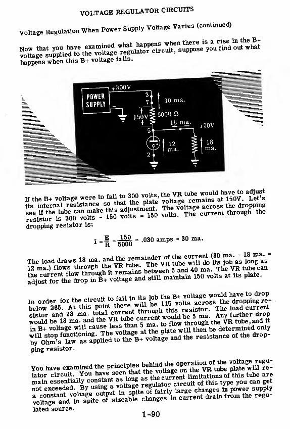
VOLTAGE REGULATOR CIRCUITS
Voltage Regulation When Power Supply Voltage Varies (continued)
Sppens when this B+ voltage falls.
4. <n i, tn *nn volts the VR tube would have to adjust
If the B+ voltage were to fall to 300 volts the ^^ ^its internal resistance s° that the plate
across the dropping
see U: the tube can make this adjustment. The* ^g ^resistor is 300 volts - 150 volts
dropping resistor is
E = J5<L = -03o amps = 30 ma.R 5000
12 ma.) flows through the VR tupe. ine vn.tube can
in for the circuitJ^^^J
1
^^ ^* ^^^wTte^cittS^fa^fooWkngTe-below 265. At this point there
iwUT
°
eh11ti,™ slstor . The load current
sistor and 23 ml/toM current «to°»gh 'tas re,ut ^ further
^^SJtSJSH l^r^de^ed^^£Z?Z?£^^?£>SS*"' resistance of the drop-
ping resistor.
You have examined theJ^^ff^^^£SKlffElater circuit. You have seen that «he*° e^ 1
eit;Jlons 0f this tube are
main essentially constant as long as the, curren' Xrfthis type you can get
not exceeded. By using a trge c^ges ^power supply
vo£?e^ ^^^lated source.
1-90

I Varying ACS| Line Voltage= ^=
VOLTAGEREGULATEDPOWERSUPPLY
VOLTAGE REGULATOR CIRCUITS
Review
VOLTAGE REGULATION - Voltageregulation is a term used to expresshow well a power supply maintains aconstant voltage output in spite ofchanges in line voltage and load cur- + n . Arent. There are certain types of » '\ A A r—
^
electronic circuits that will not op- ~ V \Jrr~ierate properly if the supplied voltagevaries more than a few volts. Thevoltage supply to these circuits re-quires the addition of a voltage reg-ulator circuit which will maintain anessentially constant voltage regard-less of line voltage and load currentchanges.
VOLTAGE REGULATOR tttptp __The voltage regulator (VR) tube con-tains a plate and a cathode with nofilament—both enclosed in a glassenvelope containing a gas at lowpressure. When a large enough volt-age is applied across the tube, a cur-rent is conducted through the tube.As long as the current flowing throughthe tube remains within the limitslisted by the manufacturer, the voltageat the plate will remain essentiallyconstant. J
VR TUBE CIRCTTTT - The simplest(and very widely used) voltage regulatorcircuit consists of a voltage droppingresistor and a VR tube placed in seriesacross the power supply output andground. The regulated voltage is takenfrom the plate of the VR tube. Theload current and the VR tube currentboth flow through the dropping resistor,and the VR tube current changes alongwith the load current so as to keep thedropping resistor current constant.
VR TUBE JUMPER - The purpose ofthe jumper in a VR tube is to preventunregulated voltage from reaching aspecial electronic circuit if the VRtube is pulled out. Without the jumperunregulated voltage would reach thecircuit, causing improper operationand possible damage. Pulling out theVR tube removes the jumper and dis-
ci«uttvolta&e from special
1-91
- +— ov.
Constant Es= g§ Voltage
POWER+ 340 volts
SUPPLYa <
7 '—
i
Dropping" Resistor
Jumper
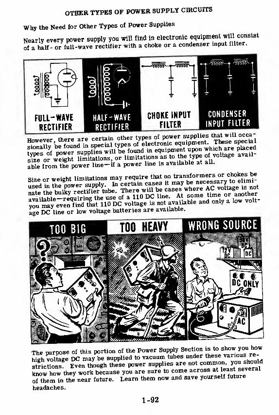
OTHER TYPES OF POWER SUPPLY CIRCUITS
Why the Need for Other Types of Power Supplies
Nearly every power supply you will find in electronic equipment will consist
of a half- or full-wave rectifier with a choke or a condenser input filter.
•—'USoW—•—ooooo 1— >
CHOKE INPUT
FILTER
CONDENSER
INPUT FILTER
afafe from the power line-if a power line is available at all.
Size or weight limitations may require that no transformers or chokes be
age DC line or low voltage batteries are available.
TOO BIG »The purpose of this portion of the Power Supply Section is to show you how
Mgh volSge Sc may be supplied to vacuum tubes under these various re-
stScUons" Even though these power supplies are^^^^J^know how they work because you are sure to come across at least several
of themTn the near future. Learn them now and save yourself future
headaches.
1-92

OTHER TYPES OF POWER SUPPLY CIRCUITS
General Types
^L^^SZ™ <* ' "PO" wh,ch ,here are
In this group are included:
a. Transformerless power supplies
b. Transformerless and chokeless power supplies
• ...SIZE AND WEIGHT
TRANSFORMERLESSPOWER SUPPLIES
TRANSFORMERLESS ANDCHOKELESS POWER SUPPLIES
a. Vibrator power supplies
b. Motor generators, dynamotors and rotary converters
ONLY D(£ VOLTAGE
AVAILABLE
MOTOR - GENERATORSDYNAMOTORS, ANDROTARY CONVERTERS
VIBRATOR POWER SUPPLIES
1-93
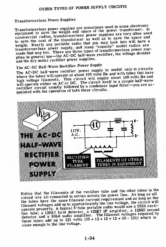
OTHER TYPES OF POWER SUPPLY CIRCUITS
Transformerless Power Supplies
Transformerless power STsto™^equipment to save the weight and space oi tne
,
pow ^commercial radios, transformerless f"P
pl
£s
sJ™ the space andto save the cost of the transformer as well as to save £ e P
^weight. Nearly any portable radio thatjou^ may *™ ^transformerless power supply and many ^^erless power sup-
^szs^^^xz^^' the voltase doubler
and the dry metal rectifier power supplies,
The AC -DC Half-Wave Rectifier Power Supply
The AC-DC half-wave rectifier powei
where the tubes will operate at about 1 00 volts B+ and^ith^^ b+^high voltage fUaments This circuit ™u SUP£ ^ ^ simple half-wave
7£3£r3£$^&£& %V£S!£r input filter-you are ac-
quainted with the operation of both these circuits.
these tubes add up
close enough to the line voltage
1-94

OTHER TYPES OF POWER SUPPLY CIRCUITS
Transformerless Power Supplies (continued)
The AC -DC Half-Wave Rectifier Power Supply (continued)
Ac'or Dc'Va ftS?*tMS^ SUp^ is « will operate on either
connected to a DC lineP£ tn AC-Df"Ef f
W0W) in the 6Vent that tt wastransformer. When the XSli L r^'^ P°Wer SUpply there is noitive side of a DC line and when thP ^S^ tUbe 18 connect^ to the.pos-side of the DC line through toe lS ^ 0de 18
.^onn
,
ected to the negativeThe rectifier plat ™wW:alwavfh. Z\% *
°!uCUlt Wil1 vo"age.
a steady stream of electrons win Hp If/1
*? ^8pe„Ct t0 the cathode
>a"d
with ve/y little rl^L^^tVJSSS t0 Pl&te"a V°ltage
ZEROVOLTS
REVERSE THE LINE PLUG
fhe^sSfvVs deDSf^ iS'a^htrS^ mUSt alwa*s be connected to
through the load to^ the negluve sfde ofTe"1^ k^ be COnnected
should be reversed accideSlTy (because o? tie\J t
?Me co™:cti°ns
line plug, the plate of the rectif er im hJ *
86 of a non-P°larizedelectrons from the cathodP >f£l J?
W/U
.
b,
e negative and will attract nosupply of this ^SetS'oSa^M l
1S WOrk-,Whenevep a^
should be to pull out the line El™ ?„h\ 5ne
'°ne of y°ur first checks
tube connections to he tae Th l^f S° *S to reVerse the ™c™™prevents this trouble
US6 °f a prized line and line plug
Lpnnw I?
6 18Tl' .
this ^eT suPPly will operate no matter how theus^l^
1-95

OTHER TYPES OF POWER SUPPLY CIRCUITS
Transformerless Power Supplies (continued)
The Voltage Doubler Power Supply
A transformerless type of power supply which is sometimes used in
electron^ equipment is the voltage doubler. The disadvantage of the AC-DC
Half wave 3i supply is that it will furnish only about 100 volts B+ which
^er^S^SwScL upon the type of circuits which may use tins power
supplygVoltage doublers do away with this problem by supplying approxi-
mately 300 volts B+ when connected to a 110-volt AC line.
D.C.t_- a.c. ^j+t-l_o INPUT »— -4 OUTPUT— 115V. + I
(160V. Peak) ™I
. -I
THE VOLTAGE
DOUBLER
0 C OUTPUT
- TWICE
PEAK A C
INPUT
the peak voltage of the AC input.
In circuits of this type the heaters of the rectifier tube and the»^e'
AC -
high voltage DC output.
1-96

OTHER TYPES OF POWER SUPPLY CIRCUITS
Transformerless Power Supplies (continued)
Dry Metal Rectifier Power Supplies
Earlier you learned how dry metal rectifier circuits worked. Dry metalrectifiers allow you to eliminate the transformer in an electronic powersupply. Dry metal rectifiers have the advantage of being rugged, long-lived,small in size and capable of large current output. They are quite adaptableto being hooked up in half-wave, full-wave and voltage doubler circuits.They also can be hooked up to give either a positive or negative voltageoutput.
Dry metal rectifiers are used to some extent in radar, sonar and com-munications equipment. In addition they are also used as the rectifier inAC voltmeters. A few common circuits that contain dry metal rectifiersare shown below. Since you are already acquainted with both the dry metalrectifier and the circuits themselves, you should be able to understand howthese circuits work without further explanation.
When power is first applied, a high current will flow to charge the inputcondenser. You will notice that a resistor (R) is inserted in series witheach half-wave rectifier element. This resistor is put in as a current lim-iting device to prevent too much current from flowing through the rectifier.
BRIDGE TYPE HH HALF-WAVE DRY METAL RECTIFIER CIRCUITRECTIFIER HH
117V.
AC
A/WWW+
+
o B-
o B+
VOLTAGE DOUBLER CIRCUIT ^| BRIDGE RECTIFIER
1-97

OTHER TYPES OF POWER SUPPLY CIRCUITS
Transformerless and Chokeless Power Supplies
Eliminating the choke as well as the transformer from the power supply
results in the savings of weight, space and cost. The choke may be elimi-
nated from the filter circuit by replacing it with a resistor. The result is
a resistance-capacitor (RC) filter as shown in the illustration. RC filters
are economical and work very well whenever the load current drawn fromthe filter circuit is small. RC filters are used extensively in oscillo-
scopes, vacuum tube voltmeters and other equipment that require very
little E+ current drain.
The advantage of the RC filter is its savings in weight, space and cost.
The disadvantage is that the filtering action is effective only with small B+current drain. As you recall, a choke presents a high impedance to the ACripple coming out of the rectifier and the condenser presents a low imped-
ance. As a result, most of the ripple will appear across the choke and
very little will appear across the condenser and the load. The DC voltage,
however, is not presented with any impedance by the choke other than the
resistance of the winding which is very low.
The RC filter offers the same resistance to both the AC ripple and the DCcurrent. As a result there is a drop in DC voltage caused by the DC cur-
rent flow through the filter resistor. If the value of the resistor is madelow to decrease the DC voltage drop, ripple voltage will get through the
filter. If the value of the resistance is increased to stop the AC ripple, the
drop in DC voltage will be too great. The only way to make this type of
filter operate efficiently is to use a large value of resistance to draw very
little DC current from B+. Very little DC current flowing through the high
value of resistance means that there will be a very small DC voltage dropacross the resistor and the filter will operate efficiently.
1-98
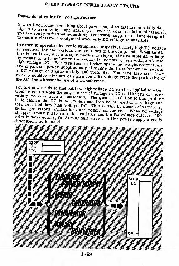
OTHER TYPES OF POWER SUPPLY CIRCUITS
Power Supplies for DC Voltage Sources
Now that you know something about power supplies that are sDeciallv re-signed to save weight and space (and cost 2^commercial SSSiom)you are ready to find out something about power suppHes ttatarTdesinedto operate electronic equipment when only DC voltagels avaiLbleg
In order to operate electronic equipment properly, a fairly high DC voltageis required for the various vacuum tubes in the equipment When In ACbyme^ofa'tUUf * SimPle
Hmatte
Jto step up the ava ilable AC vottage
Mgh voTtLe 5c Yon £Z rf.Ct
+
ifyKthe r6SUlting high voltaSe ACmgn voltage DC. You have seen that when space and weight restrictions
fDr'TH^' fW6r SUPpUeS eltalnate tke transformer2p °out
iȣ.J^?S ^Proximately 100 volts B+. You have also seen low-
>u f/uci"ults can g^e you a B+ voltage twice the peak value ofthe AC line without the use of a transformer.
You are now ready to find out how high voltage DC can be supplied to elec-tronic circuits when the only source of voltage is DC at 110 volts or lowervol age sources such as batteries. The general solution to this problems to change the DC to AC, which can then be stepped up in voltage andtoen rectified into high voltage DC. This is done byCleans of v brltorsmotor generators, dynamotors and rotary converters. When DC voltageat approximately 110 volts is available and if a B+ voltag "output of 100^L££%Z£ AC "DC r6Ctifier P-eTs«Va°^
1-99

OTHER TYPES OF POWER SUPPLY CIRCUITS
Vibrators
The vibrator type power supply changes low voltage DC from batteries or
I DCMj£^ into high voltage DC by means of three operates:
1. The low voltage DC is changed into AC of the same voltage.
2. The low voltage AC is put into a transformer and comes out as high
voltage AC.
3 The high voltage AC is rectified and filtered into high voltage DC.
tube rectifier and filter circuits with which you are already familiar.
Sws in the coil of the electromagnet. This vibrator mechanism is in
sertedl a metal cover which isoften lined with a vibration absorbing ma-
terial such as soft rubber.
What goes on inside the VIBRATOR!
1-100
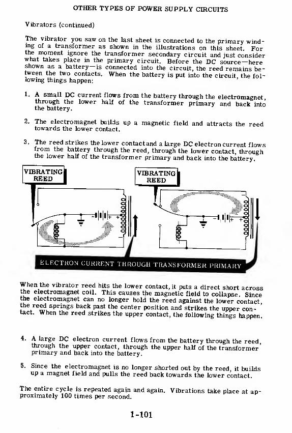
OTHER TYPES OF POWER SUPPLY CIRCUITS
Vibrators (continued)
The vibrator you saw on the last sheet is connected to the primary wind-ing of a transformer as shown in the illustrations on this sheet. Forthe moment ignore the transformer secondary circuit and just considerwhat takes place in the primary circuit. Before the DC source—hereshown as a battery— is connected into the circuit, the reed remains be-tween the two contacts. When the battery is put into the circuit the fol-lowing things happen:
1. A small DC current flows from the battery through the electromagnetthrough the lower half of the transformer primary and back intothe battery.
2. The electromagnet builds up a magnetic field and attracts the reedtowards the lower contact.
3. The reed strikes the lower contact and a large DC electron current flowsfrom the battery through the reed, through the lower contact, throughthe lower half of the transformer primary and back into the battery.
When the vibrator reed hits the lower contact, it puts a direct short acrossthe electromagnet coil. This causes the magnetic field to collapse. Sincethe electromagnet can no longer hold the reed against the lower contactthe reed springs back past the center position and strikes the upper con-
'
tact. When the reed strikes the upper contact, the following things happen.
4. A large DC electron current flows from the battery through the reedthrough the upper contact, through the upper half of the transformer'primary and back into the battery.
5. Since the electromagnet is no longer shorted out by the reed it buildsup a magnet field and pulls the reed back towards the lower contact.
The entire cycle is repeated again and again. Vibrations take place at ap-proximately 100 times per second.
1-101

OTHER TYPES OF POWER SUPPLY CIRCUITS
Vibrators (continued)
The net result is an AC current that flows through the primary of the
transformer, first in one direction and then in the opposite direction. This
reversal of current, induces high voltage in the transformer secondary.
This high voltage is rectified by a vacuum tube rectifier circuit and be-
comes high voltage DC. The fact that this high voltage DC has square
top^d peaksT instead of the usual sine wave shape does not matter-the
filter circuit circuit changes it into a smooth B+ voltage.
The type of vibrator used in this circuit is known as a "non-synchronous-
vibrator.
BUFFERCONDENSER
RADIO INTERFERENCEELIMINATOR RADIO INTERFERENCE
ELIMINATOR
VOLTAGE ACROSSTRANSFORMER PRIMARY
VOLTAGE ACROSSTRANSFORMERSECONDARY
VOLTAGEFROM B+
TO GROUND
Because of the very sharp voltage surges occurring in the vibratorjwwer
supply circuit, various difficulties are experienced with this type of cir
cuit One annoying trouble is sparking at the vibrator contacts due to the
very high voltage induced in the secondaryat the instant the reed separatesS the contacts. This sparking shortens the life of the vibrator, but it
may be eliminated to a large extent by inserting a buffer condenser across
the secondary to short out the sharp voltage pulses This condenser has
a fairly critiLl value, usually in the range of from 0.0005 to 0 05 micro-
farads The buffer condenser reduces sparking so that the lile ot tne
vibrator contacts will not be shortened; however, any remaining sparking
may cause radio Interference. This radio interference is eliminated by
the addition of RF chokes and condensers In the transformer primary cen-
ter tap and in the rectifier output.
1-102

OTHER TYPES OF POWER SUPPLY CIRCUITS
Vibrators (continued)
Another type of vibrator circuit is one that makes use of the vibrating
™!,<Lrno
tlfyihe
.
high TOltage AC from the transformer seconlry into
S thl IDC Kwlthout
,
he use °f a separate rectifier. This circuit Ts Lowntran^ ynChr°n0US Vibrat0r Circuit
'The P°rti°n °f the circuit ta the
Pr/m^y W°rkS exactly the same as in the non-synchronous
S^eSfS mpS? ?ansf0
t
rmer ^condary is connected back to the n-brator reed by means of an extra pair of contacts as shown in the diagram.
the Synchronous Vibrator
—
i
Yi
Yi
i
i
0 V.
B + OUTPUT FOR CONDITIONS X AND Y
The two vibrating reeds shown connected together by the dotted lino in th«
JSE^^ aCtUal^^ne reed placed between twopSi ofcontacts Tteaction of the reed between the transformer secondary contoct^roducesthe same results as a full-wave rectifier. RF chokes and SSer condPnsers are used in this vibrator circuit in the same mincer aTL theSsynchronous vibrator to eliminate contact sparking £d%fot££r££1-103

OTHER TYPES OF POWER SUPPLY CIRCUITS
Motor Generators, Dynamotors and Rotary Converters
Motor generators, dynamotors and rotaryn
™*e«™ ^TolVXgTlsto operate AC electronic equipment.
when only a DCfg^^J^.available. A motor fS^^^^^^^SSuiBTBA a DC mo-ically connected together . For the aPP"catwn d ng
aligned to
tor would be used to drive an ^/"J^ignedtooperate fromgive a 60-cycle output at line *q£^faS from a DC source by60-cycle AC at line voltage could then be operated «°»
generatormeans of this type of motor generator. This
.
*pe 0* ^ 0Jerate off
could be used as an emergency^J^v^™^ment could operate
So^^L7^:^~rie XSXZrS* m the event of an
AC line failure.
A doctor is a rotate DC machine ^operates^-^ '"^fDC source and puts out one 5«
r'* mS, one arLture and
DYNAMOTOR PRINCIPLE
250V. DCOUTPUT
GENERATORWINDING
1-104

OTHER TYPES OF POWER SUPPLY CIRCUITS
Motor Generators, Dynamotors and Rotary Converters (continued)
Rotary converters are commonly used to chanp-P ap tr> nr w ^AcTnne
° Trat6^ St°rage ^^^e^o^'^oTy^outait tUv^ Wh6n USed to operate from 00 purees and give AC?eS is sfmYlar^nT
™ inverte™- The construction of a rotary con-verter is similar to a DC generator except that two slip rines are nepriwhich are connected to commutator segments 180 degrees apa?t.
vnuillh?PGfk AC V
-
0l^ge output desired is no higher than the average DCapp
input, onewinding may be used on the armature. If a grlater volt-
lions are Often wound On two armatures using separate fields The two
1-105

OTHER TYPES OF POWER SUPPLY CIRCUITS
Review of Transformerless Power Supplies
AC -DC HALF-WAVE RECTIFIERPOWER SUPPLY — Tnis circuit will
supply about 100 volts B+ and will op-
erate from either in AC or DC power
line. The circuit is a simple half-
wave rectifier circuit usually followed
by a condenser input filter. The fila-
ments of the rectifier tube and the
other tubes in the circuit are all con-
nected in series across the power line.
KKCTIK1KKTUHK
KILAMKNTKl LAMENTS OK OT UK It
TUBES IN EQUIPMENT
VOLTAGE DOUBLER POWER SUPPLY— This circuit will supply up to 320
volts B+ from a 117 -volt AC power line
without the use of a transformer. The
circuit consists of two half-wave recti- W +. - * i
1?ov D.C.OUTPUT
VJL* btui. -~ -•. L_ JC, INPUT p I /.ppnnx)
fiers and two capacitors. The capaci- fa I*-- ...tf'I^^^Vtors are connected in series and each W U#p«"*J*t-^- 1
is charged up to peak line voltage re-
sulting in the voltage doubling effect.
The filaments of the rectifier tube and
the other tubes in the circuit are all
connected in series across the pow-
er line.
| HALF-WAVE DRY METAL RECTIFIES CIRCUIT
DRY METAL RECTIFIER POWERSUPPLY — Dry metal rectifiers maybe used instead of vacuum tube recti-
fiers. Dry metal rectifiers are rug-
ged, long-lived, small in size and capa-
ble of large current output. They can
be hooked up in half-wave, full-wave
and voltage doubler circuits.
1-106

OTHER TYPES OF POWER SUPPLY CIRCUITS
Review of Transformerless and Chokeless Power Supplies
CHOKELESS POWER SUPPTJTCK — Anyof the transformerless rectifier cir-cuits listed on the previous sheet maybe used with standard choke and capaci-tor filter circuits. However, an addi-tional savings may be made in space,weight and cost if the filter choke isreplaced with a resistor. This type ofRC filter is effective only when a verysmall B+ current drain is required anda fairly large resistor can be used.
I I I
Review of Power Supplies for DC Voltage Sources
VIBRATORS — A vibrator is a me-chanical device which changes DC intoAC. A simple vibrator is essentially asingle pole double throw switch with avibrating switch arm. When the vibra-tor is connected to a transformer witha center tapped primary as shown, theaction of the vibrating switch armcauses current to flow first in one di-rection and then in the other directionthrough the transformer primary. Thetransformer puts out an alternatinghigh voltage which can be rectified andfiltered into a high voltage DC.
SYNCHRONOUS VIBRATORS _ Thenon-synchronous vibrator changes DCinto high voltage AC which must thenbe rectified by means of a vacuum tuberectifier. A synchronous vibrator doesaway with the need for a separate rec-tifier. The portion of the vibrator inthe transformer primary works exactlyas in the non-synchronous vibratorcircuit. The transformer secondaryis connected back to the vibrator reedby means of an extra pair of contactsas shown. The action of the vibratingreed between the transformer second-ary contacts produces results the sameas if a full-wave rectifier wereplaced there.
-4-1
1-107

OTHER TYPES OF POWER SUPPLY CIRCUITS
Review of Power Supplies for DC Voltage Sources (continued)
MOTOR GENERATOR — A motor and
a generator mechanically coupled to-
gether. Equipment designed to operate
from an AC power source may be made
to operate from the DC line if a motor
generator is used. The DC motor is
connected to the DC line, and the DCmotor spins the rotor of the AC gen-
erator which puts out 117 volts AC.
DYNAMOTOR — A rotating DC ma-chine that operates from a low voltage
DC source and puts out one or more
high DC voltages. A dynamotor is basi-
cally a DC motor and a DC generator
built onto one armature and having two
or more commutators.
ROTARY CONVERTER — Rotary con-
verters are commonly used to change
AC to DC, but they may be used to op-
erate from storage batteries to give an
output of 117 volts AC and are then
known as inverters. The construction
of a rotary converter is similar to a
DC generator except that two slip rings
are used which are connected to com-mutator segments 180 degrees apart.
SLIP RINGS ROTOR WINDING
FIELD WINDING
1-108

CHARACTERISTICS OF DIODE VACUUM TUBES
The Jobs of a Vacuum Tube
Up to this time you have been working with vacuum tubes used as rectifiersin power supply circuits. Your knowledge of diode tubes has been suf-ficient for an understanding of power supplies. However, from now onyou are going to do a great deal of work with vacuum tubes in many typesof circuits, and now is the time to begin finding out about vacuum tubes.
The subject of vacuum tubes is really a simple one because—and you willbe glad to know this—vacuum tubes do only two types of jobs.
A vacuum tube can change an AC voltage into a pulsatingDC voltage. This is called RECTIFICATION. This job isaccomplished by the diode.
A vacuum tube can change a small AC voltage into a largeAC voltage. This is called AMPLIFICATION. This job isdone by the triode, the tetrode or the pentode.
You have been concerned with the vacuum tubes that take care of rectifi-cation. Later, in the amplifier section, you will learn about the other typesof vacuum tubes.
1-109

CHARACTERISTICS OF DIODE VACUUM TUBES
Factors Common to All Vacuum Tubes
The diode is one of the four basic types of vacuum tubes. There are manythings which are common to all vacuum tubes and you won't have to learn
all about these common characteristics each time you study another type
of tube. You will learn about these things in your study of the diode.
As previously stated, all vacuum tubes need a source of free electrons
and you will find that each type of tube obtains them in the same way asthe diode—by thermionic emission. Furthermore, the cathode and fila-
ment structure does notdiffer very much from one type of tube to the next.
You will study the effects of the filament on cathode emission only during
your diode experiment—remember, it's the same for the other tubes you
will study.
The differences between the diode and the other vacuum tubes lead to their
different uses. The diode is used to change an AC voltage into a pulsating
DC voltage; the other tubes are used to change a small AC voltage into alarge AC voltage
1-110

CHARACTERISTICS OF DIODE VACUUM TUBES
Review of Diode Characteristics
Diodes are used as rectifiers in power supplies, and as detectors, noiselimiters and automatic volume control tubes in radio receivers. Whatevertheir application is, however, diodes are used because they allow currentto flow m only one direction.
From the time the plate becomes just slightly positive with respect to thecathode until the time saturation is reached, the current in the diode isproportional to the plate voltage. Between these limits, then, the tube actsthe same as an ordinary resistor. Of course, when the plate voltage risesabove the saturation point, the current does not respond to voltage changesand therefore, in this region, the tube loses its resemblance to the resistor.
1-111

CHARACTERISTICS OF DIODE VACUUM TUBES
How Current Is Controlled in a Diode
A simple way to show how a diode will respond to changes of voltage is
with^ eraDh A graph picturing how a typical diode's current is affected
^&^-%SS^S^ (at two different values of filament voltage)
is shown below.
From a quick look at the graph you can tell that:
1. At normal filament voltage (6.3 volts), the plate current^creases
steadily as the plate voltage is increased from zero to 20 volts.
2. At the lower value of filament voltage (simulating the effect. ofJin old
tube) the plate current increases as the plate voltage is raised, to
about 8 volts, and any further increase of plate voltage does not bring
aS mcreas'ed platecurrent. This shows us that at 8 volts the plate
is drawing all the electrons the cathode can emit.
This undesirable restriction on the plate current which is due to limited
catoode emission is called "saturation " Even in a fairly new_tube work
ing at rated filament voltage (6.3 volts), saturation would occur but at a
higher value of plate voltage. This would appear on the curve of 6.3 fila-
ment volts if higher values of plate voltage had been used.
1-112

POWER SUPPLIES
Review of Power Supplies
Before you leave the study of power supplies and go on to learn about am-plifiers, suppose you review some of the important things you've found outabout power supplies and their components
RECTIFICATION — a diode vacuumtube allows electron current to flowin only one direction—from the cath-ode to the plate. This effect permitsAC voltage to be "rectified" into apulsating DC voltage.
SATURATION — Plate current in-creases regularly as plate voltage isincreased. When all of the electronsthat can be emitted by the cathode areattracted to the plate, a further in-crease in plate voltage cannot attractany more electrons than are flowingalready. When an increase of platevoltage fails to cause a rise in platecurrent, the tube is said to be"saturated."
SATURATION AND FIT-Ay/TKNTVOLTAGE — Increasing the filamentvoltage increases the filament tem-perature—resulting in a hotter cath-ode. The more heat the cathode gets,the more electrons will be emittedfrom its surface. When the cathodeemits more electrons, the saturationpoint will not occur until the platevoltage reaches a much higher value.
5 10 15
PUTE VOLTAGE
HALF-WAVE RECTIFICATION —Changing the positive cycles of anAC voltage to pulsating DC by al-lowing current to flow through acircuit in one direction only.
AC
Input
HALF-WAVERECTIFIERCIRCUIT
DC
Output
FULL-WAVE RECTIFICATION —Changing both cycles of AC to pul-sating DC.
Input
FULL-WAVERECTIFIERCIRCUIT
DC
MAOutput
1-113
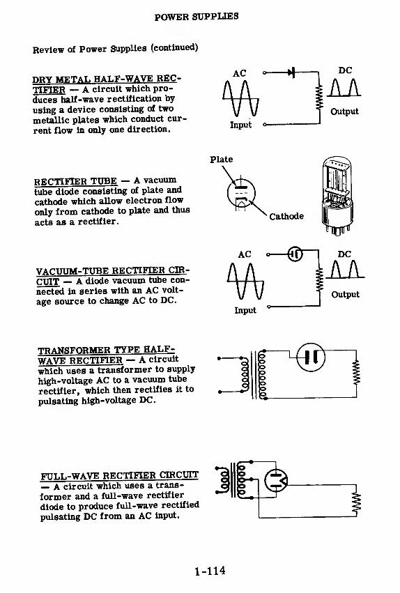
POWER SUPPLIES
Review of Power Supplies (continued)
DRY METAL HALF-WAVE REC-
TIFIER — A circuit which pro-
duces half-wave rectification by
using a device consisting of two
metallic plates which conduct cur-
rent flow in only one direction.
AC DC
Input
AAOutput
RECTIFIER TUBE — A vacuum
tube diode consisting of plate and
cathode which allow electron flow
only from cathode to plate and thus
acts as a rectifier.
VACUUM-TUBE RECTIFIER CIR-
CUIT — A diode vacuum tube con-
nected in series with an AC volt-
age source to change AC to DC.
Plate
Cathode
HOP
AC o @ DC
AAOutput
Input
TRANSFORMER TYPE HALF-WAVE RECTIFIER — A circuit
which uses a transformer to supply
high-voltage AC to a vacuum tube
rectifier, which then rectifies it to
pulsating high-voltage DC.
Iooo
FULL-WAVE RECTIFIER CIRCUIT— A circuit which uses a trans-
former and a full-wave rectifier
diode to produce full-wave rectified
pulsating DC from an AC input.
1-114

POWER SUPPLIES
Review of Power Supplies (continued)
FILTER CIRCUITS — Circuits con-sisting of inductors and capacitorsused to change pulsating DC outputof a rectifier to pure DC.
T T
T T T .
COMPLETE POWER SUPPLY —The complete circuit consisting offull-wave rectifier and filter cir-cuits, used to supply high DC volt-age to other circuits.
Rectifier Circuit Filter Circuit
VOLTAGE REGULATOR CIRCUIT— A circuit which uses a gas-filleddiode to maintain constant outputvoltage. The voltage across tubeterminals remains constant over alarge range of source voltage orload current changes.
Constant
y voltage
OTHER POWER SUPPT.TBH —Transformerless and chokelesspower supplies, vibrators, motor-generators, dynamotors and rotaryconverters are other types of powersupplies used to fill special require-ments as to size, weight, powersource available and load require-ments.
MOTOR-GENERATOR
1-115

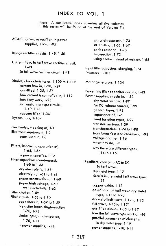
INDEX TO VOL. 1
(Note: A cumulative index covering all five volumesin this series will be found at the end of Volume 5.)
AC-DC half-wave rectifier, in power
supplies, 1-94, 1-95
Bridge rectifier circuits, 1-49, 1-50
Current flow, in half-wave rectifier circuit,
1-43
in full-wave rectifier circuit, 1 -48
Diodes, characteristics of , 1 - 1 09 to 1 - 1 1 2
current flow in, 1-28, 1-29
gas-filled, 1-35, 1-37
how current is controlled in, 1-112
how they work, 1-25
in transformer type circuits,
1-40, 1-41
vacuum-filled, 1-36
Dynamotors, 1-104
Electronics, meaning of, 1-1
Electronic equipment, 1 -2
parts used in, 1 -3
Filters, improving operation of,
1-64, 1-65
in power supplies, 1-12
Filter capacitors (condensers),
1 -60 to 1 -63
dry electrolytic, 1 -63
electrolytic, 1-61 to 1-63
paper construction of, 1 -60
paper high voltage, 1-60
wet electrolytic, 1 -62
Filter chokes, 1-69
Filter circuits, 1-52 to 1-80
capacitors in, 1-57 to 1-59
capacitor input, single-section,
1-70, 1-72
choke input, single-section,
1-70, 1-71
in power supplies, 1-53
parallel-resonant, 1-73
RC faults of, 1-66, 1-67
series-resonant, 1-73
two-section, 1-73
using choke instead of resistor, 1 -68
Input filter capacitor, charging, 1-74
Inverters, 1-105
Motor generators, 1-104
Power line filter capacitor circuits, 1 -43
Power supplies, circuits in, 1 -52
dry metal rectifier, 1 -97
for DC voltage sources, 1 -99
general types, 1-93
importance of, 1-7
need for other types, 1 -92
transformer type, 1-39
transformerless, 1-94 to 1-98
transformerless and chokeless, 1-98
voltage doubler, 1-96
what they do, 1-8
why there are different types,
1-14 to 1-16
Rectifiers, changing AC to DCin half-wave
dry metal type, 1-17
circuits in dry metal half-wave type1-21
copper oxide, 1-18
description of half-wave dry metaltype, 1-1 8 to 1-20
dry metal half-wave, 1-1 7 to 1-22full-wave, 1-45 to 1-151
gas-filled diodes, 1 -35 to 1 -37how the full-wave type works, 1-46
parallel connection of elementsin dry metal type, 1-19
power supplies, 1-10, 1-11
1-117

INDEX TO VOL. 1
selenium, 1-18, 1-20
series stacking of elements in dry
metal type, 1-19
transformer type half-wave,
1-39 to 1-44
vacuum tubes, 1-23
vacuum tube half-wave type,
1-23 to 1-38
Rectifier circuits, half-wave vacuum
tube, 1-33
Rectifier output, AC and DC components
in, 1-55, 1-56
characteristics of, 1 -54
filtering half- and full-wave, 1 -74
Rectifier tubes, 1-30, 1-31
cathode type, 1-31
diodes, 1-30, 1-31
directly heated, 1-32
full-wave, 1-47
indirectly heated, 1-32
plates connected together, 1 -32
plates connected separately, 1 -32
Resistors, bleeder, 1 -75 to 1 -77
Review, Characteristics of Diode Vacuum
Tubes, 1-111
Filter Circuits, 1-78 to 1-80
Full-Wave Rectifier Circuit, 1 -5
1
Half-Wave Rectifiers— Dry Metal
Type, 1 -22
Half-Wave Rectifiers—Transformer
Type, 1-44
Half-Wave Rectifiers— Vacuum
Tube Type, 1 -38
Other Types of Power Supply
Circuits, 1-106 to 1-108
Power Supplies, 1 -1 1 3 to 1 -1 1 5
Voltage Regulator Circuits, 1-91
Rotary converters, 1-105
Transformers, power supplies, 1 -9
Transformer type circuit, diagram of, 1 -42
operation of, 1 -43
Vacuum tube, circuit wiring, 1 -34
discovery of diode, 1-24
electron emission, 1-26, 1-27
factors common to all, 1-110
jobs of, 1-109
methods of representation in
diagrams, 1-34
sockets, 1-31
Vibrators, 1-100 to 1-103
synchronous, 1-103
Voltage regulation, 1-81, 1-82
when load current varies, 1 -87, 1 -88
when power supply voltage varies,
1-89, 1-90
Voltage regulators, power supplies, 1-13
Voltage regulator circuits, 1-81 to 1-91
Voltage regulator tube, 1-83, 1-84
Voltage regulator tube circuit, 1-85, 1-86
1-118

HOW THIS OUTSTANDING COURSE WAS DEVELOPED:
In the Spring of 1951, the Chief of Naval Personnel, seeking a streamlined,
more efficient method of presenting Basic Electricity and Basic Electronics to the
thousands of students in Navy speciality schools, called on the graphiological
engineering firm of Van Valkenburgh, Nooger & Neville, Inc., to prepare such a
course. This organization, specialists in the production of complete "packagedtraining programs," had broad experience serving industrial organizations requir-
ing mass-training techniques.
These were the aims of the proposed project, which came to be known as the
Common-Core program: to make Basic Electricity and Basic Electronics com-pletely understandable to every Navy student, regardless of previous education; to
enable the Navy to turn out trained technicians at a faster rate (cutting the cost
of training as well as the time required) without sacrificing subject matter.
The firm met with electronics experts, educators, officers-in-charge of various Navyschools and, with the Chief of Naval Personnel, created a dynamic new training
course . . completely up-to-date . . . with heavy emphasis on the visual approach.
First established in selected Navy schools in April, 1953, the training coursecomprising Basic Electricity and Basic Electronics was such a tremendoussuccess that it is now the backbone of the Navy's current electricity and electronics
training program!*
The course presents one fundamental topic at a time, taken up in the order of
need, rendered absolutely understandable, and hammered home by the use of clear,
cartoon-type illustrations. These illustrations are the most effective ever presented.
Every page has at least one such illustration—every page covers one complete idea!
An imaginary instructor stands figuratively at the reader's elbow, doing demonstrations that make it easier to understand each subject presented in the course.
Now, for the first time, Basic Electricity and Basic Electronics have been released
Ijy die Navy for civilian use. While the course was originally designed for the
Navy, the concepts are so broad, the presentation so clear—without reference to
specific Navy equipment—that it is ideal for use by schools, industrial training
programs, or home study. There is no finer training material!
"Basic Electronics" consists of five volumes, as follows: Vol. 1—Introductionto Electronics, Diode Vacuum Tubes, Dry Metal Rectifiers, What a Power
Supply Is, Filters, Voltage Regulators. Vol. 2—Introduction to Amplifiers,
The Triode Tube, Tetrodes & Pentodes, Audio Voltage & Power Amplifiers.
Vol. 3—Video Amplifiers, RF Amplifiers, Oscillators. Vol. -/—Transmitters,
Transmission Lines & Antennas, CW Transmission & Amplitude Modula-
tion. Vol. 5—Receiver Antennas, Detectors & Mixers, TRF Receivers,
Superheterodyne Receivers.
*"Basic Electricity," the first portion of this course, is available as a separate
series of volumes.
JOHN F. RIDER PUBLISHER, INC., 116 WEST 14th ST., N. Y. 11, N. Y.
No 170-2
basic
electronics
$2.25
basicelectronicsby VAN VALKENBURGH,NOOGER & NEVILLE, INC.
VOL.2
JOHN F. RIDER PUBLISHER, INC.
116 West 14th Street • New York 11, N. Y.

First Edition
Copyright 1955 by
VAN VALKENBURGH, NOOGER AND NEVILLE, INC.
All Rights Reserved under International and Pari
American Conventions. This book or parts thereof
may not be reproduced in any form or in anylanguage without permission of the copyright owner.
Library of Congress Catalog Card No. 55-6984
Printed in the United States of America
PREFACEThe texts o£ the entire Basic Electricity and Basic Electronics
courses as currently taught at Navy specialty schools, have now beenreleased by the Navy for civilian use. This educational programhas been an unqualified success. Since April, 1953, when it was firstinstalled, over 25,000 Navy trainees have benefited by this instruc-tion and the results have been outstanding.
The unique simplification of an ordinarily complex subject, theexceptional clarity of illustrations and text, and the plan of pre-senting one basic concept at a time, without involving complicatedmathematics, all combine in making this course a better and quickerway to teach and learn basic electricity and electronics.
nrov^elring Tedal t0 gCneral PUbHc <
the Navy hoP« toprovtde the means for creating a nation-wide pool of pre-trainedtechnicians, upon whom the Armed Forces could call in time of
TKholung^7'
WkhOUt nCed f°r Pred°US WCeks and months
Perhaps of greater importance is the Navy's hope that throughthe release of this course, a direct contribution will be made towafdincreasing the technical knowledge of men and women throughoutthe country, as a step in making and keeping America strong
Van Valkenburgh, Nooger and Neville, Inc.
New York, N. Y.
February, 1955
iii

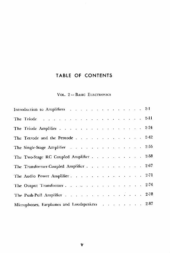
TABLE OF CONTENTS
Vol. 2 — Basic Electronics
Introduction to Amplifiers 2-1
The Triode 2-11
The Triode Amplifier 2-24
The Tetrode and the Pentode 2-42
The Single-Stage Amplifier 2-55
The Two-Stage RC Coupled Amplifier 2-58
The Transformer-Coupled Amplifier 2-67
The Audio Power Amplifier 2-71
The Output Transformer 2-74
The Push-Pull Amplifier 2-78
Microphones, Earphones and Loudspeakers 2-87
V


INTRODUCTION TO AMPLIFIERS
Examples of Amplification
There are many things you can amplify:
2-1

INTRODUCTION TO AMPLIFIERS
Examples of Amplification (continued)

INTRODUCTION TO AMPLIFIERS
Examples of Amplification (continued)
would you like to hear a whisper through a concrete wall or hear a fishpump water through its gills? Amplification makes all these things pos-sible. There are however, more important uses for amplifiers.
Of the three basic types of electronic circuits—rectifiers, amplifiers andoscillators—amplifiers are by far the most widely used. The purpose of
an amplifier is to take a very small voltage change—one that is so smallthat it cannot be used—and amplify it many times so that it can run a pairof earphones, drive a loudspeaker, be seen on a 'scope, operate amotor, etc.
2-3
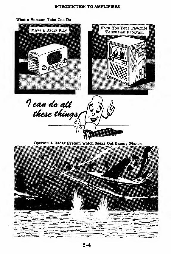
INTRODUCTION TO AMPLIFIERS
What a Vacuum Tube Can Do
2-4

INTRODUCTION TO AMPLIFIERS
What a Vacuum Tube Can Do (continued)
When you first began your study of vacuum tubes you learned that thereare only two main jobs for vacuum tubes to do.
The first job is to change an AC voltage in-to a pulsating DC voltage. This is called"rectification.
"
The second job is to change a small AC volt-
age into a large AC voltage. This is called"amplification.
"
4 i
Because of your work with rectifier and power supply circuits, you now knowall you need to know about rectification and the diode tubes that are used to dothis job. Now you are ready to learn about the' second main job a vacuum tubecan do —amplification. In this section you will learn about the vacuum tubesthat do the job of amplifying small AC voltages into large AC voltages.
2-5

INTRODUCTION TO AMPLIFIERS
Types of Vacuum Tubes
A recent survey of vacuum tubes manufactured in the United States showedthat there are over 1, 200 different types of vacuum tubes available I Thesetubes come in a wide variety of shapes and sizes—enclosed in glass and
metal shells.
2-6

INTRODUCTION TO AMPLIFIERS
Types of Vacuum Tubes (continued)
Most of these 1, 200 tubes can be broken down Into four main types. Onceyou understand these four main types, you will know them all. Wheneveryou run across a new tube, you will always be able to understand what it
does and how it works simply by comparing it to the four main typesyou know.
Their names describe them by telling how many parts (cathode, grid,
plate) there are in the tube. A diode (di = two) has two parts—a cathodeand a plate. A triode (tri = three) has three parts—a cathode, a plate andone grid. A tetrode (tetra =four ) has four parts—a cathode, a plate and
two grids. A pentode (penta = five) has five parts—a cathode, a plate andthree grids.
2-7

INTRODUCTION TO AMPLIFIERS
How Vacuum Tubes Were Developed
*De(M>lofi*Ke*tt a£ Vacuum *?ct&e&
FLEMING'S VALVE
GRIDS
TETRODE
MODERN DIODE
GRIDS
CATHODE
FILAMENT PENTODE
Tubes have developed in a logical sequence. . .
1. from Fleming's valve which consists of two elements, thefilament and the plate,
2. to the modern diode in which the filament is replaced by acombination of a filament and a cath-ode (for reasons which will be dis-cussed later) but which is still con-sidered to be a two-element tube,
3. to the triode a three-element tube which containsone grid,
4. to the tetrode a four-element tube with two grids,
5. to the pentode a five-element tube with three grids.
The reason you are being taught vacuum tubes is not so that you willbe able to repair one which has gone bad; you will only replace such a tubewith a new one. You are being taught about these vacuum tubes in orderto understand the circuits which use them and, thereby, to make you amore valuable troubleshooter of electronic equipment.
You will remember from your work with power supplies that thermionicemission—the emitting of electrons by a hot cathode—allowed you tochange AC into DC. Notice that triodes, tetrodes and pentodes also con-tain a cathode, which emits electrons, and a plate which collects elec-trons. As you study these tubes you will see how the grids control elec-tron flow to change small AC voltages into large AC voltages.
2-8
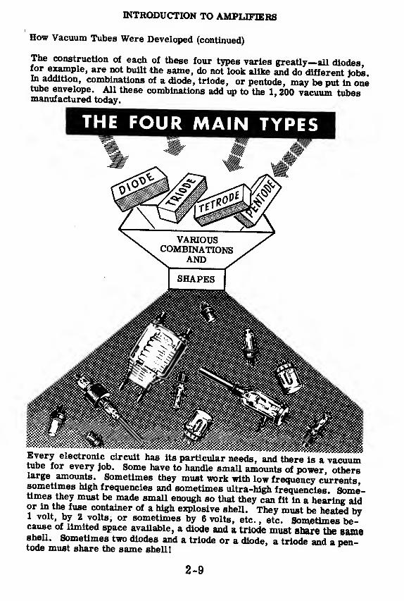
INTRODUCTION TO AMPLIFIERS
How Vacuum Tubes Were Developed (continued)
The construction of each of these four types varies greatly—all diodes,for example, are not built the same, do not look alike and do different jobs.In addition, combinations of a diode, triode, or pentode, may be put in onetube envelope. All these combinations add up to the 1, 200 vacuum tubesmanufactured today.
THE FOUR MAIN TYPES
mmmEvery electronic circuit has its particular needs, and there is a vacuumtube for every job. Some have to handle small amounts of power, otherslarge amounts. Sometimes they must work with low frequency currentssometimes high frequencies and sometimes ultra-high frequencies. Some-times they must be made small enough so that they can fit in a hearing aidor in the fuse container of a high explosive shell. They must be heated by1 volt, by 2 volts, or sometimes by 6 volts, etc. , etc. Sometimes be-cause of limited space available, a diode and a triode must snare the sameshell. Sometimes two diodes and a triode or a diode, a triode and a pen-tode must share the same shell!
2-9
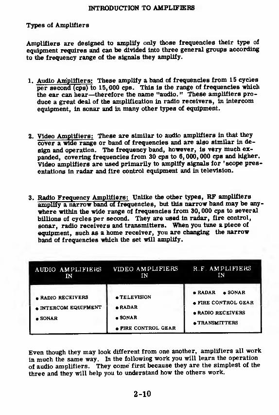
INTRODUCTION TO AMPLIFIERS
Types of Amplifiers
Amplifiers are designed to amplify only those frequencies their type of
equipment requires and can be divided into three general groups according
to the frequency range of the signals they amplify.
1. Audio Amplifiers: These amplify a band of frequencies from 15 cycles
per second (cps) to 15,000 cps. This is the range of frequencies which
the ear can hear—therefore the name "audio. " These amplifiers pro-
duce a great deal of the amplification in radio receivers, in intercom
equipment, in sonar and in many other types of equipment.
2. Video Amplifiers: These are similar to audio amplifiers in that they
cover a wide range or band of frequencies and are also similar in de-
sign and operation. The frequency band, however, is very much ex-
panded, covering frequencies from 30 cps to 6, 000, 000 cps and higher.
Video amplifiers are used primarily to amplify signals for 'scope pres-
entations in radar and fire control equipment and in television.
3. Radio Frequency Amplifiers: Unlike the other types, RF amplifiers
amplify a narrow band of frequencies, but this narrow band may be any-
where within the wide range of frequencies from 30, 000 cps to several
billions of cycles per second. They are used in radar, fire control,
sonar, radio receivers and transmitters. When you tune a piece of
equipment, such as a home receiver, you are changing the narrow
band of frequencies which the set will amplify.
AUDIO AMPLIFIERS VIDEO AMPLIFIERS R.F. AMPLIFIERSEN IN IN
• RADAR • SONAR• RADIO RECEIVERS • TELEVISION
• FIRE CONTROL GEAR• INTERCOM EQUIPMENT • RADAR
• RADIO RECEIVERS• SONAR • SONAR
• TRANSMITTERS• FIRE CONTROL GEAR
Even though they may look different from one another, amplifiers all work
in much the same way. In the following work you will learn the operation
of audio amplifiers. They come first because they are the simplest of the
three and they will help you to understand how the others work.
2-10
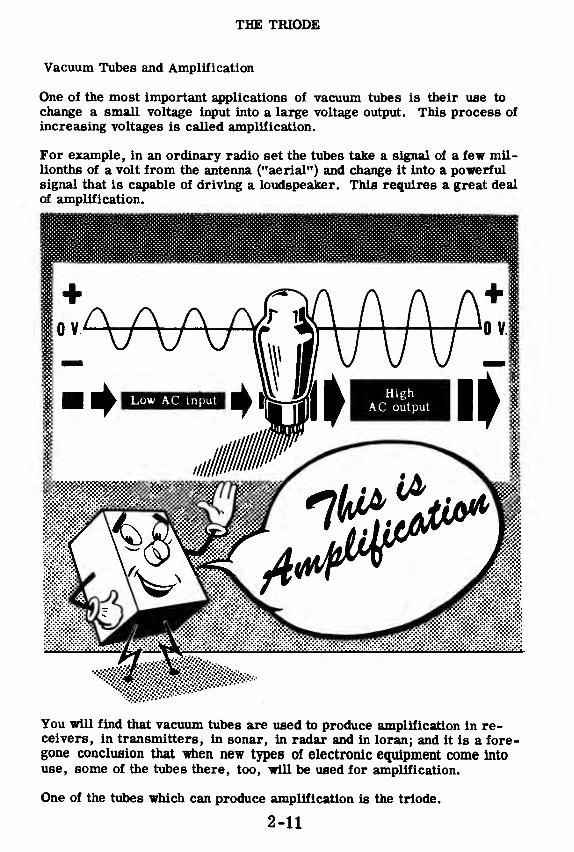
THE TRIODE
Vacuum Tubes and Amplification
One of the most important applications of vacuum tubes is their use to
change a small voltage input into a large voltage output. This process of
increasing voltages is called amplification.
For example, in an ordinary radio set the tubes take a signal of a few mil-lionths of a volt from the antenna ("aerial") and change it into a powerfulsignal that is capable of driving a loudspeaker. This requires a great dealof amplification.
You will find that vacuum tubes are used to produce amplification in re-ceivers, in transmitters, in sonar, in radar and in loran; and it is a fore-gone conclusion that when new types of electronic equipment come intouse, some of the tubes there, too, will be used for amplification.
One of the tubes which can produce amplification is the triode.
2-11

THE TRIODE
sde Tube
THEOU

THE TRIODE
Seeing How the Triode Works
For purposes of explanation, let's compare the triode to the water systemshown below. In the water system, you are interested in controlling theflow of water. One way you can do this is by varying the pressure in thesystem or, in other words, changing the height of the water tank.
Lower the tankto decrease
the flow
A much more convenient way to vary the flow of water is by using a faucetor valve in the system. Then, by simply turning the faucet, you can con-trol the flow of water. Notice that the water pressure doesn't have tochange in order to affect the flow.
Open the faucetto increase
the flow
Close the faucetto decreasethe flow
This is similar to the way a triode tube amplifies the flow of current. Inthe triode an additional element, the grid, is placed in the tube, its pur-pose being to control the flow of current in the tube just as the faucet con-trols the flow of water. You will see that a small voltage variation on this
element produces a comparatively large current variation in the tube.
2-13

THE TRIODE
The Control Grid
This additional structure in the triode is called a "grid" or, more specific-
ally, (to distinguish it from other grids found in tetrodes, pentodes, etc.
)
the "control grid". It is a very thin wire wound like a spiral around the
cathode so that tube current can pass right through its spacings-
The plate of a triode is normally connected to a high positive voltage, B+.
The grid of the triode is usually kept at a negative voltage with respect to
the cathode. Because electrons are negatively charged, they tend to berepelled by the negative grid. The grid, being closer to the cathode than
is the plate, has a greater effect in controlling the tube current than does
the positive plate. If the grid becomes less negative, more electrons will
get through to the plate; if the grid becomes more negative, fewer elec-
trons will get through to the plate.
2-14
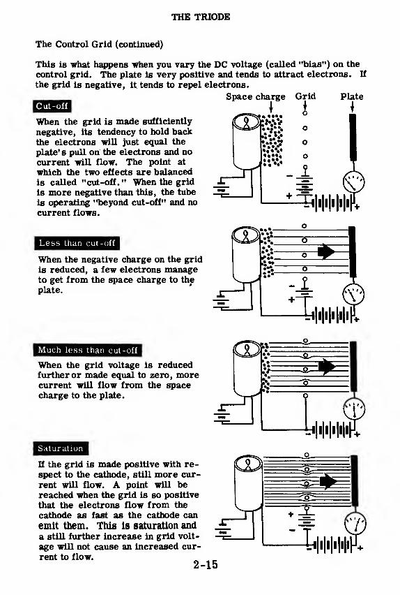
THE TRIODE
The Control Grid (continued)
This is what happens when you vary the DC voltage (called "bias") on the
control grid. The plate is very positive and tends to attract electrons. If
the grid is negative, it tends to repel electrons.
Space charge Grid PlateCut-off
When the grid is made sufficiently
negative, its tendency to hold backthe electrons will just equal the
plate's pull on the electrons and nocurrent will flow. The point at
which the two effects are balancedis called "cut-off." When the grid
is more negative than this, the tube
is operating "beyond cut-off" and no
current flows.
'•V..
Less than cut-off
When the negative charge on the grid
is reduced, a few electrons manageto get from the space charge to the
plate. -•4
Much less than cut-off
When the grid voltage is reducedfurther or made equal to zero, morecurrent will flow from the spacecharge to the plate.
Saturation
If the grid is made positive with re-
spect to the cathode, still more cur-
rent will flow. A point will bereached when the grid is so positive
that the electrons flow from the
cathode as fast as the cathode can
emit them. This is saturation anda still further increase in grid volt-
age will not cause an increased cur-
rent to flow.2-15

THE TRIODE
How the Triode Is Similar to the Diode
Since the only difference between the two tubes is the presence of a grid,you might expect to find several similarities between them.
The triode' s cathode and filament are no different than the diode's and,therefore, everything that was said about a diode's electron emission isalso true of the triode' s. In both tubes the emission (and therefore satu-ration) depends upon the filament voltage. In both, burned-out filamentsare the most common cause of failure and, in both, cathode emission willdecrease as a tube is used.
DIODE...
As in the diode, saturation *n » ..r^de w^ro because there is a limit to
the amount of current which the cathode can emit. In the triode, satura-tion (limiting current) can be reached at a lower value of plate voltage if
a positive voltage is applied to the grid; in the diode, of course, it dependsonly on the plate voltage.
On the other hand, if the grid is made sufficiently negative, no current will
flow. The value of grid voltage which reduces the current to zero is called
the "cut-off" voltage. Increasing the negative grid voltage beyond this
point will have no effect since the tube is already cut off. Cut-off also de-pends upon the triode' s plate voltage; with a more positive plate voltage, amore negative grid voltage will be necessary to produce cut-off.
In a diode current flows only when the plate is positive, and no currentflows when the plate is negative. In a triode, however, the plate can bepositive and still no current flows if the grid is sufficiently negative. Thecut-off point of a triode depends upon the particular tube (how it is con-structed) and upon the value of plate voltage.
2-16

THE TRIODE
How Amplifiers Work
You have found out a little about how important amplifier circuits are inequipment. Now you are ready to find out how they work.
It's all very simple—a vacuum tube does the entire job of amplifying if youprovide it with the proper operating voltages and connections. K you supplythe proper voltages to the various tube elements, a small change in voltageapplied to the grid causes a large change in voltage on the plate. The pro-duction of a large voltage change from a small voltage change is called"amplification.
"
You learned that a good way for you to picture the operation of a grid in avacuum tube was to think of the grid as a valve in a water pipe. TheBritish are so fond of this explanation that, to this day, they call a vacuumtube a "valve. " When the grid of the tube is very negative, the "valve" isclosed and there is little or no flow of electrons from the cathode to theplate. When the grid voltage is changed so that it becomes only slightlynegative, the "valve" is nearly wide open and there is a large flow of elec-trons from the cathode to the plate.
2-17
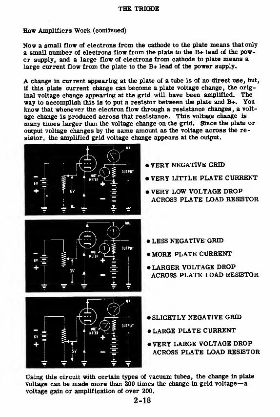
THE TRIODE
How Amplifiers Work (continued)
Now a small flow of electrons from the cathode to the plate means that only
a small number of electrons flow from the plate to the B+ lead of the pow-er supply, and a large flow of electrons from cathode to plate means a
large current flow from the plate to the B+ lead of the power supply.
A change in current appearing at the plate of a tube is of no direct use, but,
if this plate current change can become a plate voltage change, the orig-
inal voltage change appearing at the grid will have been amplified. Theway to accomplish this is to put a resistor between the plate and B+. Youknow that whenever the electron flow through a resistance changes, a volt-
age change is produced across that resistance. This voltage change is
many times larger than the voltage change on the grid. Since the plate or
output voltage changes by the same amount as the voltage across the re-
sistor, the amplified grid voltage change appears at the output.
•VERY NEGATIVE GRID
• VERY LITTLE PLATE CURRENT
• VERY LOW VOLTAGE DROPACROSS PLATE LOAD RESISTOR
• LESS NEGATIVE GRID
• MORE PLATE CURRENT
• LARGER VOLTAGE DROPACROSS PLATE LOAD RESISTOR
• SLIGHTLY NEGATIVE GRID
• LARGE PLATE CURRENT
• VERY LARGE VOLTAGE DROPACROSS PLATE LOAD RESISTOR
Using this circuit with certain types of vacuum tubes, the change in plate
voltage can be made more than 200 times the change in grid voltage—
a
voltage gain or amplification of over 200.
2-18
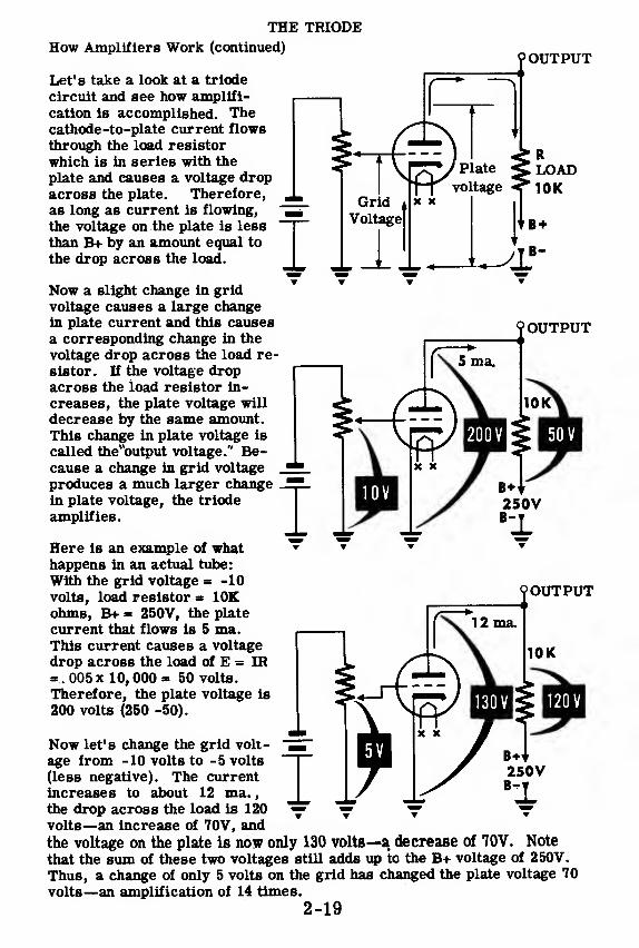
?OUTPUT
OUTPUT
THE TRIODEHow Amplifiers Work (continued)
Let's take a look at a triode
circuit and see how amplifi-
cation is accomplished. Thecathode-to-plate current flows
through the load resistor
which is in series with the
plate and causes a voltage dropacross the plate. Therefore,
as long as current is flowing,
the voltage on the plate is less
than B+ by an amount equal to
the drop across the load.
Now a slight change in grid
voltage causes a large changein plate current and this causes
a corresponding change in the
voltage drop across the load re-
sistor. If the voltage dropacross the load resistor in-
creases, the plate voltage will
decrease by the same amount.This change in plate voltage is
called the"output voltage." Be-cause a change in grid voltage
produces a much larger changein plate voltage, the triode
amplifies.
Here is an example of whathappens in an actual tube:
With the grid voltage = -10
volts, load resistor = 10Kohms, B+ = 250V, the plate
current that flows is 5 ma.This current causes a voltage
drop across the load of E = IR005 x 10, 000 * 50 volts.
Therefore, the plate voltage is
200 volts (250 -50).
Now let's change the grid volt-
age from -10 volts to -5 volts
(less negative). The currentincreases to about 12 ma.
,
the drop across the load is 120
volts—an increase of 70V, and
the voltage on the plate is now only 130 volts—a decrease of 70V. Note
that the sum of these two voltages still adds up to the B+ voltage of 250V.
Thus, a change of only 5 volts on the grid has changed the plate voltage 70
volts—an amplification of 14 times.
2-19
90UTPUT
250V
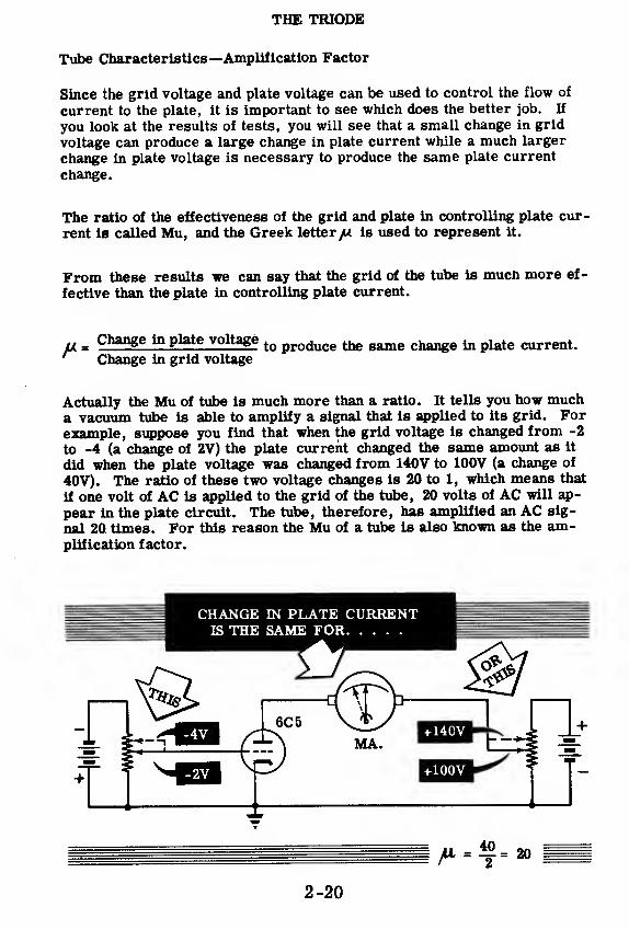
THE TRIODE
Tube Characteristics—Amplification Factor
Since the grid voltage and plate voltage can be used to control the flow of
current to the plate, it is important to see which does the better job. If
you look at the results of tests, you will see that a small change in grid
voltage can produce a large change in plate current while a much larger
change in plate voltage is necessary to produce the same plate current
change.
The ratio of the effectiveness of the grid and plate in controlling plate cur-
rent is called Mu, and the Greek letter yu is used to represent it.
From these results we can say that the grid of the tube is much more ef-
fective than the plate in controlling plate current.
= Change in plate voltagetQ produce^ same change ^ plate current.
' Change in grid voltage
Actually the Mu of tube is much more than a ratio. It tells you how mucha vacuum tube is able to amplify a signal that is applied to its grid. Forexample, suppose you find that when the grid voltage is changed from -2
to -4 (a change of 2V) the plate current changed the same amount as it
did when the plate voltage was changed from 140V to 100V (a change of
40V). The ratio of these two voltage changes is 20 to 1, which means that
if one volt of AC is applied to the grid of the tube, 20 volts of AC will ap-
pear in the plate circuit. The tube, therefore, has amplified an AC sig-
nal 20 times. For this reason the Mu of a tube is also known as the am-plification factor.
2-20
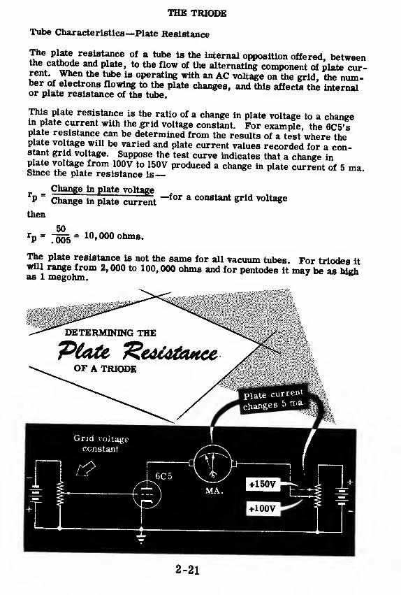
THE TRIODE
Tube Characteristics—Plate Resistance
The plate resistance of a tube is the internal opposition offered, betweenthe cathode and plate, to the flow of the alternating component of plate cur-rent. When the tube is operating with an AC voltage on the grid, the num-ber of electrons flowing to the plate changes, and this affects the internalor plate resistance of the tube.
This plate resistance is the ratio of a change in plate voltage to a changein plate current with the grid voltage constant. For example, the 6C5'splate resistance can be determined from the results of a test where theplate voltage will be varied and plate current values recorded for a con-stant grid voltage. Suppose the test curve indicates that a change inplate voltage from 100V to 150V produced a change in plate current of 5 maSince the plate resistance is
—
—for a constant grid voltage_ Change in plate voltage
p ~ Change in plate current
then
50rP=
.~005= 10
»000 ohms -
The plate resistance is not the same for all vacuum tubes. For triodes itwill range from 2, 000 to 100, 000 ohms and for pentodes it may be as highas 1 megohm.
DETERMINING THE
OF A TRIODE
2-21
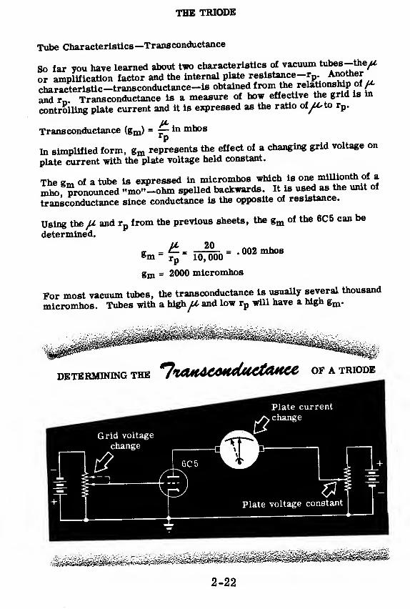
THE TRIODE
Tube Characteristics—Transconductance
So far you have learned about two characteristics of vacuum tubes-the/*
or amplification factor and the internal plate resistance-rp .Another
characteristic-transconductance-is obtained from the relationship offand rn . Transconductance is a measure of how effective the grid is in
controlling plate current and it is expressed as the ratio of/^to rp .
u,
Transconductance (gm) = — in mhosrP
In simplified form, gm represents the effect of a changing grid voltage on
plate current with the plate voltage held constant.
The gm of a tube is expressed in micromhos which is one millionth of a
mho, pronounced "mo"-ohm spelled backwards. It is used as the unit of
transconductance since conductance is the opposite of resistance.
Using the JJ. and rpfrom the previous sheets, the gm of the 6C5 can be
determined.
8m ~20£_
rp" 10,000
= . 002 mhos
gm = 2000 micromhos
For most vacuum tubes, the transconductance is usually several thousand
micromhos. Tubes with a highfA, and low rp will have a high gm .
DETERMINING THE ^!%CUUCOH<UiCtaHCe OF A TRIODE
2-22

THE TRIODE
Review of Triode Characteristics
Curve 1: You can see that cut-off for
this particular tube is about -14 volts
with 200 volts on the plate. As the
grid voltage is made less negative,
the current increases along the Eg-Ip
curve. A portion of the curve is
straight or linear. On this linear
portion the plate current variations
are uniformly proportional to the grid
voltage variations. In this linear
region a change of 2 volts on the grid
produces a change of about 4 ma. in
the plate current. The graph shownhere is called the Eg-L, curve. E_=grid voltage and Ip
= plate current.
Plate Voltage » 200V«-/
In
J
2tt/
o(milliam
iu>
tr
/A
«-
—
—
714-
14 12 10 i 6 4 2 d ;! 4
- +Eg = Grid Voltage
Curve 2: With the grid voltage set at
-8 volts, it is seen that changes of
plate voltage affect the plate current.
But a 10 -volt change on the plate
causes only a very small change in
the plate current. By comparing the
results in curve 1 and curve 2, you can
see that the grid exerts a greater
control on the plate current than
does the plate.
Curve 3: While the tube is cut off
(from grid voltages of -14 and be-
yond) no current flows and there is
no voltage drop across the plate
load resistor. The plate voltage is
equal to B+ while the tube is cut-off.
When the grid voltage becomes less
negative, plate current flows and
a voltage drop is developed across
the load resistor, causing the plate
voltage to drop. Along the linear
portion of the curve, a 2 -volt change
on the grid produces a change of
about 30 volts on the plate. This is
a gain (amplification of 15.
2-23
110 150 190 230 270
Plate voltage
300
B+
bfi
? 200
too
*
14 12 10 8 s 4 ;! 0
Grid voltage
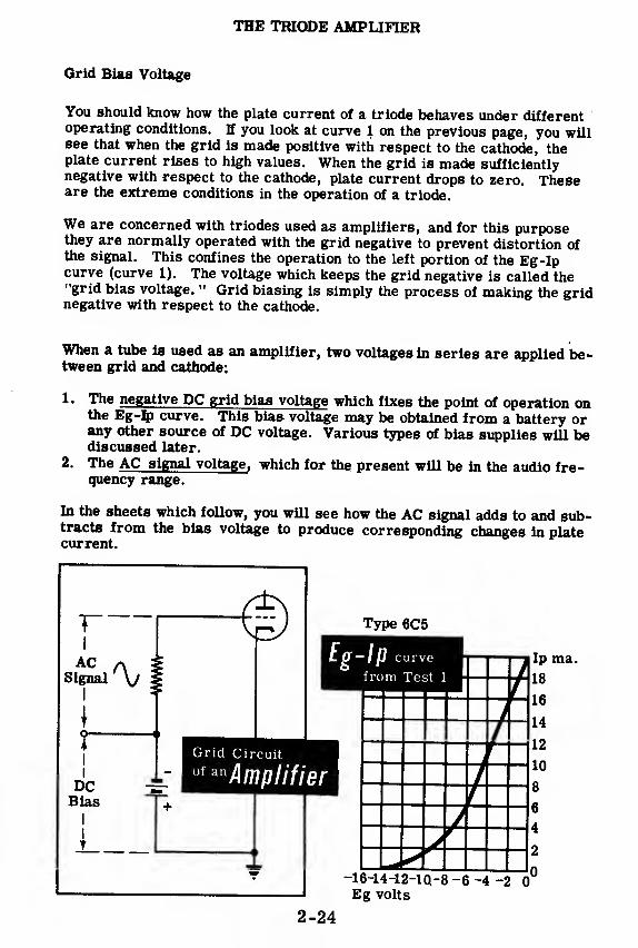
THE TRIODE AMPLIFIER
Grid Bias Voltage
You should know how the plate current of a triode behaves under differentoperating conditions. H you look at curve 1 on the previous page, you willsee that when the grid is made positive with respect to the cathode, theplate current rises to high values. When the grid is made sufficientlynegative with respect to the cathode, plate current drops to zero. Theseare the extreme conditions in the operation of a triode.
We are concerned with triodes used as amplifiers, and for this purposethey are normally operated with the grid negative to prevent distortion ofthe signal. This confines the operation to the left portion of the Eg-Ipcurve (curve 1). The voltage which keeps the grid negative is called the"grid bias voltage. " Grid biasing is simply the process of making the gridnegative with respect to the cathode.
When a tube is used as an amplifier, two voltages in series are applied be-tween grid and cathode:
1 - The negative DC grid bias voltage which fixes the point of operation onthe Eg-Ip curve. This bias voltage may be obtained from a battery orany other source of DC voltage. Various types of bias supplies will bediscussed later.
2 - The AC signal voltage, which for the present will be in the audio fre-quency range.
In the sheets which follow, you will see how the AC signal adds to and sub-tracts from the bias voltage to produce corresponding changes in platecurrent.
T"
AC ASignal V
I
i
I
I
DCBias
I
I
T
0) Type 6C5
Eg-Ip
Grid Circuit
of anAmplifier
-16-14-12-1Q-8 -6 -4 -2 0"
Eg volts
2-24
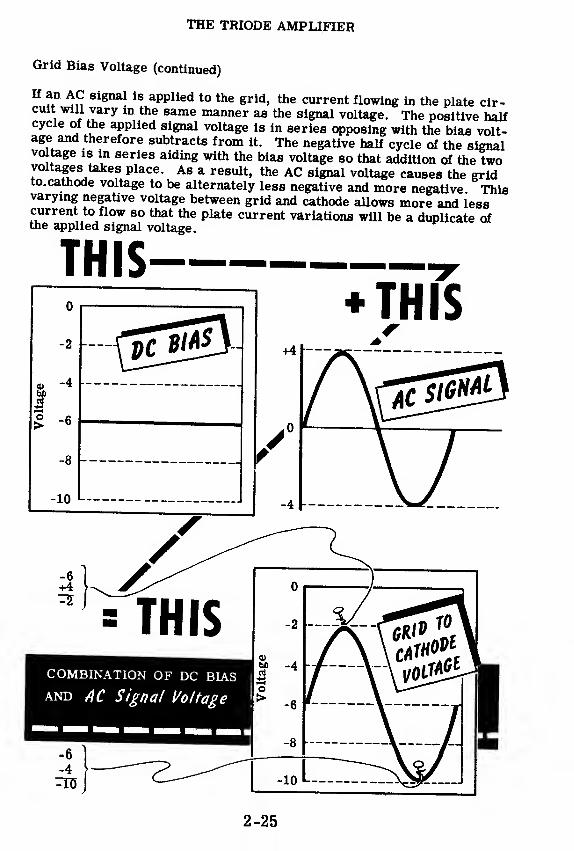
THE TRIODE AMPLIFIER
Grid Bias Voltage (continued)
H an ac signal is applied to the grid, the current flowing in the plate cir-cuit will vary in the same manner as the signal voltage. The positive halfcycle of the applied signal voltage is in series opposing with the bias volt-age and therefore subtracts from it. The negative half cycle of the signalvoltage is in series aiding with the bias voltage so that addition of the twovoltages takes place. As a result, the AC signal voltage causes the gridto.cathode voltage to be alternately less negative and more negative. Thisvarying negative voltage between grid and cathode allows more and lesscurrent to flow so that the plate current variations will be a duplicate ofthe applied signal voltage.
THIS
2-25
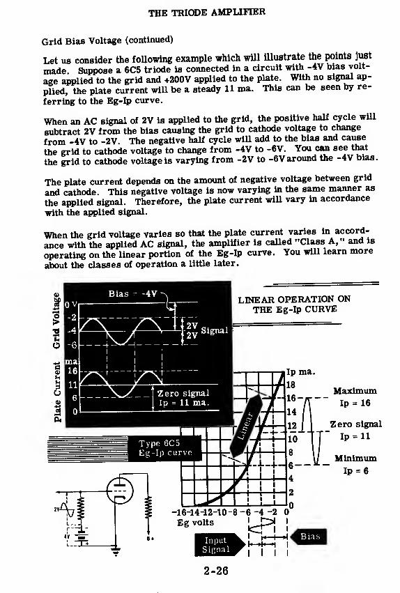
THE TRIODE AMPLIFIER
Grid Bias Voltage (continued)
Let us consider the following example which will illustrate the points just
made. Suppose a 6C5 triode is connected in a circuit with -4V bias volt-
age applied to the grid and +200V applied to the plate. With no signal ap-
plied, the plate current will be a steady 11 ma. This can be seen by re-
ferring to the Eg-Ip curve.
When an AC signal of 2V is applied to the grid, the positive half cycle will
subtract 2V from the bias causing the grid to cathode voltage to change
from -4V to -2V. The negative half cycle will add to the bias and cause
the grid to cathode voltage to change from -4V to -6V. You can see that
the grid to cathode voltage is varying from -2V to -6V around the -4V bias.
The plate current depends on the amount of negative voltage between grid
and cathode. This negative voltage is now varying in the same manner as
the applied signal. Therefore, the plate current will vary in accordance
with the applied signal.
When the grid voltage varies so that the plate current varies in accord-
ance with the applied AC signal, the amplifier is called "Class A," and is
operating on the linear portion of the Eg-Ip curve. You will learn more
about the classes of operation a little later.
O
Bias = -4VLINEAR OPERATION ON
THE Eg-Ip CURVE
-2v ^e™1
.__ 4 v^H _ -T—
MaximumIp = 16
Zero signal
Ip = 11
MinimumIp = 6
2-26
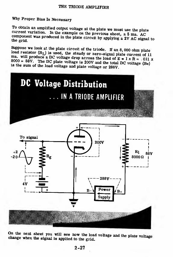
THE TRIODE AMPLIFIER
Why Proper Bias Is Necessary
To obtain an amplified output voltage at the plate we must use the platecurrent variation. In the example on the previous sheet, a 5 ma ACttTgrid ^ Pr0duced m^ plate clrcuit bv applying a 2V AC signal to
Suppose we look at the plate circuit of the triode. If an 8, 000 ohm plateload resistor (RL) is used, the steady or zero-signal plate current of 11will produce a DC voltage drop across the load of E » I x R = oil x8000 = 88V The DC plate voltage is 200V and the total DC voltage"(B+)
is the sum of the load voltage and plate voltage or 288V
DC Voltage Distribution
... IN A TRIODE AMPLIFIER
mrnmmtmmmmmmm
itiiii»h>:W:':!':':W
SL^f *l* f^B\
WlU 8ee *°w *** load voltage and the plate voltagechange when the signal is applied to the grid.vouage
2-27

THE TRIODE AMPLIFIER
Why Proper Bias Is Necessary (continued)
When the signal is applied to the grid, the plate current• *? 16
ma. (5 ma. increase) and decreases to 6 ma. (5 ma. decrease). When
16 ma. flows through the load, the voltage drop across the load will be
E - I x R - 016 x 8000 = 128V , an increase of 40V (128 -88 * 40V). Tnis
will make the plate voltage decrease 4QY since the total voltage must
always add up to the B+ voltage of 288V. Therefore, the plate voltage will
decrease from 200V to 160V. (Note: 160V + 128V - 288V)
When the plate current decreases to 6 ma. the voltage drop across the
load will be E - I x R 006* 8000 = 48V, a 40V decrease from its steady
value of 88V. Since the total voltage must still be up to 288V, the plate
voltage will increase from its steady 200V to 240V. (Note: 240V + 48V =
288V).
You can see from the illustration below that the 5 ma. AC component of
plate current produces a 40 volt variation across the plate load resistor
and an equal and opposite variation in plate voltage. Since a 2V AC signal
on the grid initially produced the plate current variation, the 40V signal at
the plate is an amplified version of the grid signal.
A 2V signal on the grid has produced a 40V signal at the plate which means
that we have amplified the signal 20 times. Note that this amplified signal
at the plate is 180 degrees out of phase with the signal on the grid.
You will see on the next sheet that the correct bias is necessary if the
plate current variation and likewise the plate voltage variation is to be an
exact duplicate of the grid signal.
Plate voltage variation
-output signal+240| —TV—J I
— ——
—
+160
+128
+88
+48
Steadyplate
I voltage40V 1
Load voltage variation
r\ t
jSteady
1
loadvoltage
.novo*0
16 ma. max.
PlateCurrent
11 ma.steadyplate
current
6 ma. mln.
GridVoltage

THE TRIODE AMPLIFIER
Why Proper Bias Is Necessary (continued)
Notice that although the signal itself was positive during one half cycle,the grid to cathode voltage was never positive—it just became more nega-tive or less negative. The bias point for this amplifier was selected sothat it fell in the center of the straight-line or linear portion of the Eg-Ipcurve. Operation on the linear portion is essential if the output wave formis to have the same shape as the input wave form. Operating at incorrectbias voltages will produce distortion of one form or another. If too muchbias is used, (making the grid voltage more negative) the signal will drivethe tube mto cut-off during the negative half cycle and produce a distortedplate current variation. K too little bias is used, the signal will drivethe grid positive during the positive half cycle. This will cause the grid totake some electrons from the cathode that would normally have gone to theplate. Again the result is a distorted plate current variation. These con-ditions are illustrated below.
Distortion will result with the correct bias voltage if the input signal is toolarge The large signal will drive the grid into both the positive and thecut-off regions—producing distortion.
You can now see that proper bias is necessary if the plate current varia-tion is to look exactly like the grid signal variation. If the amplifier tubeis biased in the center of the linear portion of the Eg-Ip curve and the tubeis not overdriven (excessive signal), very little distortion will result. In-correct bias will result in a distorted output signal.
Ip ma.
18
-16-14-12-10-8
Eg volts|
Distortion dueto non-linearityof Eg-Ip curve
Distortion dueto grid becoming
positive
-6 -4 -2
Distortion dueto tube cut-off
-16-14-12-10-8-6-4 -2 0 +2Eg volts
2-29

THE TRIODE AMPLIFIER
Classes of Amplifiers
The class of an amplifier is determined by its point of operation on the
Eg-Ip curve. There are three major classes of amplifiers—Class A, Band C. Class A amplifiers are biased to operate in the center of the
linear portion of the Eg-Ip curve. The amplifier described in the previous
sheets is a Class A amplifier. Class B amplifiers are biased to operate
near cut-off and Class C amplifiers operate at a point where the bias volt-
age is equal to twice the cut-off voltage of the tube.
The figure below shows the bias voltages for the three different classes of
amplifiers. For this particular tube, the bias would be -2V for Class Aoperation. Since Class B operates at cut-off, its bias voltage must be
-4V. For Class C operation, the bias must be -8V because a Class C am-
plifier operates at a bias equal to twice the cut-off value.
Current flowingall the time
Current flowshalf the time
Current flowsless than
half the time
2-30

THE TRIODE AMPLIFIER
Classes of Amplifiers (continued)
The figure shown on the previous sheet is a comparison of the operatingcharacteristics of Class A, B, and C amplifiers. This is what you shouldsee from the illustration—
Class A
The signal is small. It is never large enough to drive the grid eitherpositive or beyond cut-off. Plate current flows during the completecycle of signal input. The plate current variation is an exact dupli-cate of the grid signal.
Class B
The signal is larger than for Class A. The grid may be driven posi-tive. The signal drives the grid beyond cut-off for approximately halfthe input cycle. Only the positive half cycle of input appears in theplate circuit. The total plate current change is much greater than thechange produced by Class A operation. Plate current flows for ap-proximately half the complete cycle. Plate current is zero when nosignal is put into the grid.
Class C
The applied signal is the largest of the three classes. The grid is
tl a,Z°M
f"*;0",
tato the poSitive &rid reelon - The plate cur-rent variation is the largest of the three classes. The peak of thecurrent wave has a dip because the control grid is drawing currentthereby reducing the amount of current available to the plate Platecurrent flows for less than half a cycle of input voltage Without asignal on the grid, no plate current flows. A large signal volSe is
SS^*w £S£?"ld posit
!
ve during each "ycS ™S8
l8
i8usea only in RF (radio frequency) power amplifiers.
^n^f r oamP
,
I
«ier 18 US6d Primarily » voltage amplifier. Class B
SfiverTgSare— 48 power am^ie™ «*- to
There are combinations of Class A and Class B amplifiers and these areCla8S ABl rd Class ABj amplifiers ire b^e^to a pointslighUy more negative than Class A amplifiers. Class AB9 ampfifiers arebiased to a point slightly less negative than that of Class B? These cWsof operation are actually compromises between Class A and Class B.
2-31

THE TRIODE AMPLIFIER
Battery Bias
Batterv bias was chosen for the first illustration of bias because it is the
etiesUo^dersind. In actual practice, you will find it used only-tol the
laboratory for experimental work. The battery type is reliable and ef-
ficient , size and weight of batteries make it difficult to use in
most equipment.
Whenever batteries are used as a source of bias voltage, it is desirable
toSnr^SSaon of cells in series that add up to the required voltage
« is not necessary to use regulating devices such
rSSSSfrs, which draw current from the ^^^SSltconsume its power. Most bias or "C" batteries are made in multiples ot
Am^olS-i-l/i 9, 18 volts and higher. These batteries are tapped
fo'r mtermediate voltages. The negative terminal of the battery is con-
nected the resistor Rg, the positive terminal is con-
nected £ the cathode. This makes the grid negative with respect to the
cathode.
2-32

THE TRIODE AMPLIFIER
Power Supply Bias
Rectifier power supplies replace "B" batteries in the plate circuit and alsoare used to replace the "C" batteries. In large equipment, such as sometransmitters, a separate bias power supply is used. It may be a generator,a half-wave rectifier or a full-wave rectifier. The positive side of thepower supply is connected to the cathode and the negative side is connectedto the grid, just as is done with a "C" battery. In the illustration below,the positive terminal of the bleeder resistor is connected to ground and thenegative terminal is connected to the grid through Rg. Since the cathode isgrounded, the grid is negative with respect to the cathode.

THE TRIODE AMPLIFIER
B+ Power Supply Bias
A negative and a positive voltage with respect to ground can be obtained
from the same power supply. This is done by connecting two resistors in
series across the power supply and grounding the junction of these re-
sistors. A single tapped bleeder resistor can be used in place of the tworesistors in series. The resistance to ground from the negative terminalis much smaller than the resistance from the positive terminal to ground.
Therefore, the voltage across the positive portion of the bleeder will begreater than that across the negative portion. In other words, this circuit
provides a large positive voltage with respect to ground which is used asthe B+ plate supply voltage, and a small negative voltage with respect to
ground which is used as grid bias voltage. The cathode is connected to
ground, the plate is connected to the positive terminal of the bleederthrough Rl, and the grid is connected to the negative terminal of the
bleeder through Rg . Therefore, the grid is made negative and the plate
is made positive, with respect to the cathode.
TUyatiue Suu and
Positive PlateFROM THE SAME POWER SUPPLY
2-34

THE TRIODE AMPLIFIER
Cathode Bias
Of all bias systems, cathode bias is the most widely used. Cathode bias
is obtained by connecting a resistor in series with the tube from B- or
ground to the cathode.
In order to understand how this system works, it will be necessary for you
to recall three points
1. If current flows through a resistor an IR drop will be produced.
2. The end of the resistor toward which the current is flowing is the mostpositive (+).
3. The purpose of bias is to keep the grid negative with respect to the
cathode.
Look at the illustration below. Notice that a resistor (Rk ) has been placed
in the cathode circuit of the vacuum tube, between cathode and ground. All
the current that flows through the tube must flow up from B- through the
cathode resistor. This produces an IR drop across the cathode resistor,
making the cathode positive with respect to ground. Since the grid is con-
nected to ground through Rg and ground is negative with respect to the
cathode, the grid is also negative with respect to the cathode.
2-35

THE TRIODE AMPLIFIER
Cathode Resistor
Determining the size of the cathode resistor (R^) is merely an arithmetic
problem. Suppose that a tube requires a bias of -6 volts for proper oper-ation and a plate current of 4 ma. flows with this bias. The 6-volt bias is
produced by 4 ma. flowing through the cathode resistor. Using Ohm's law—
Rk = y= = 1500 ohms
To determine the size of the cathode resistor for a triode, divide the re-
quired bias voltage by the plate current.
2-36

THE TRIODE AMPLIFIER
Cathode Resistor (continued)
In a triode, the only current that flows from the cathode of the tube is the
plate current. This is not the case in the tetrode or pentode. Tetrodes
and pentodes have a screen grid which has a positive voltage applied to it
and attracts electrons from the cathode. Since all the current that flows
through the tetrode and pentode must come from the cathode, the total
cathode current is:
PLATE CURRENT + SCREEN CURRENT = CATHODE CURRENT
If a pentode, for example, has a plate current (In) of 6 ma. and a screen
current (I8g) of 2 ma. , the cathode current would be 8 ma. If the required
bias is 4 volts, using Ohm's law the value of Rjj can be calculated—
. = 500 ohmsI .008
You will learn more about the construction, use and operation of tetrodes
and pentodes in a later topic.
DETEBMmWO THE SlffiOT^
8 ma.
1R s 500 oWms
2-37

THE TRIODE AMPLIFIER
Cathode Bypass Capacitor
A cathode bias resistor usually has a capacitor connected in parallel withit. This capacitor is called a bypass capacitor and its purpose is to keepthe voltage across the cathode resistor at a constant value.
Suppose we look at the operation of a triode using cathode bias with no by-pass capacitor. H a signal is applied to grid, the plate current will varyin accordance with the signal. Since it is the plate current flow throughthe cathode resistor that produces the bias, and this current flow varies,the bias will also vary.
This varying bias reduces the signal voltage between grid and cathodethe next sheet you will see how this signal reduction occurs.
On
TRIODE AMPLIFIER WITH ACATHODE BYPASS CAPACITOR
To signal
TRIODE AMPLIFIER WITHOUT ACATHODE BYPASS CAPACITOR
2-38

THE TRIODE AMPLIFIER
Cathode Bypass Capacitor (continued)
In the illustration below, an AC signal with a peak amplitude of 6V is ap-
plied to the grid of the triode. The triode has a cathode bias voltage of
-8V with no signal applied. If the bias voltage remained constant the sig-
nal would add to the bias during its negative half cycle, (8 + 6) = 14V neg-
ative, and it would subtract from the bias during the positive half cycle
(8 -6) = 2V negative.
With the grid to cathode voltage varying between -14V and -2V, the plate
current will be minimum at -14V and maximum at -2V. In this case, as-
sume that the plate current variation produces a voltage variation of 2 volts
across the cathode resistor. Observe that the cathode voltage increases
(becomes more negative) when the plate current increases and therefore
the cathode bias voltage increases when the signal is reducing it (making
it less negative). The voltage variation across the cathode resistor is
180 degrees out of phase with the input signal so that the two voltages (sig-
nal and cathode voltage variation) subtract from one another to produce an
effective voltage variation of (6 -2) = 4 volts between grid and cathode.
THE EFFECT OF CATHODEVOLTAGE VARIATION
Appliedsignal
= 6V
Cathode voltage
variation = 2V
Resultant grid to
cathode variation
= 6-2= 4V
Max.
ZeroSignal
2-39
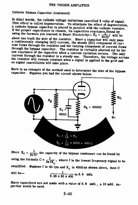
THE TRIODE AMPLIFIER
Cathode Bypass Capacitor (continued)
fo other words, the cathode voltage variations cancelled 2 volts of signal™8™t 18 Called deeenera"on- To eliminate the effect of degeneration,a cathode bypass capacitor is placed in parallel with the cathode resistorIf the proper capacitance is chosen, its capacitive reactance, (found byusing the formula you learned in Basic Electricity— Xc = jL-) ^ De
ne te?th ^e 8l
,
ze ? °le reslstor
- Since a capacitor will only passa continuously changing (AC) current, the steady (DC) component of cur-rent flows through the resistor and the varying component of current flowsthrough the bypass capacitor. The resistor is virtually shorted out by thelow reactance of the capacitor when a current variation occurs. The onlycurrent through the resistor is a steady one. Therefore, the voltage acrossthe resistor will remain constant when a signal is applied to the grid andno signal cancellation will take place.
Here is an example of the method used to determine the size of the bypasscapacitor. Suppose you had the circuit shown below.
Since xc = t^j^, the capacity of the bypass condenser can be found by
using the formula C =, where f is the lowest frequency signal to be
camplified. Suppose f is 60 cps and X
cis 400*1 as shown above, then C
1will be—6. 28 x 60 x 400
Si 6.6 mfd.
Since capacitors are not made with a value of 6. 6 mfd. . a 10 mfd ca-pacitor would be used.
2-40

THE TRIODE AMPLIFIER
Review of Triode Amplifier Operation
GRID BIAS — The amount of grid-bias
voltage determines whether an ampli-fier is operating Class A, Class B orClass C. In Class A the bias is less
than cut-off; in Class B bias is at ornear cut-off; in Class C bias is muchless than cut-off.
B+ POWER SUPPLY BIAS — A singlepower supply can be used to supply apositive voltage for B+ and a negativevoltage for grid bias.
CATHODE BIAS — A cathode bias re-sistor in parallel with a cathode by-pass capacitor in the cathode circuitprovide the most widely used systemof biasing.
TRIODE AMPLIFIER OPERATION —The variation in voltage output (plate
voltage) of a triode, used as an ampli-fier, may be ten or more times largerthan the variation in the grid voltage
(AC signal).
OUTPUT
2-41
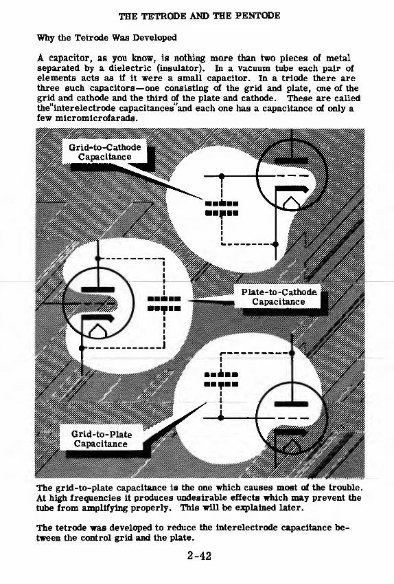
THE TETRODE AND THE PENTODE
Why the Tetrode Was Developed
A capacitor, as you know, is nothing more than two pieces of metalseparated by a dielectric (insulator). In a vacuum tube each pair of
elements acts as if it were a small capacitor. In a triode there arethree such capacitors—one consisting of the grid and plate, one of the
grid and cathode and the third of the plate and cathode. These are called
the"interelectrode capacitances"and each one has a capacitance of only afew micromicrofarads.
The grid-to-plate capacitance is the one which causes most of the trouble.
At high frequencies it produces undesirable effects which may prevent the
tube from amplifying properly. This will be explained later.
The tetrode was developed to reduce the interelectrode capacitance be-tween the control grid and the plate.
2-42

THE TETRODE AND THE PENTODE
The Screen Grid
In the tetrode a second grid is placed between the control grid and the
plate. Now there are two small capacitors in series between the plate andthe grid and, of course, the total grid-to-plate capacitance is reduced.This second grid, called the "screen grid, " has the effect of shielding the
plate from the first grid and allows the tetrode to be used at higher fre-
quencies than the triode could be used.
Normally, the screen grid has a high positive voltage and attracts elec-
trons from the space charge just as the plate did in the triode. However,because the screen grid is a spirally-wound thin wire, most of the elec-
trons pass right through it and end up at the plate. The screen draws only
a little current.
The plate is usually kept at a higher voltage than the screen and the plate
circuit does not differ much from that which is used with triodes. In the
tetrode, however, the plate voltage has less effect on the tube current
than it did in the triode.
2-43

THE TETRODE AMD THE PENTODE
Secondary Emission in the Tetrode
In any tube—diode, triode or tetrode—when one electron strikes the plate,it knocks several electrons out. Known as "secondary emission, " thishappens because the electrons are hitting the plate at high speed which be-comes ever greater as the plate voltage is raised.
In the triode, secondary emission is not important since the plate is themost positive element in the tube and, therefore, attracts all the electronsthat have been knocked out of it. In the tetrode, however, some of thesesecondary electrons (those which have been freed from the plate as a re-sult of secondary emission) are attracted to the screen. Any flow of sec-ondary electrons from the plate to the screen adds to the screen currentand subtracts from the plate current.
&tt«uu*cf, Section - - OF A TETRODEThe number of secondary electrons which do not return to the plate de-pends upon the difference between the plate and the screen voltages. If
the plate voltage is much higher than the screen's, all the secondary elec-trons will return to the plate and there will be no decrease in plate current.If the plate voltage is much lower than the screen's, fewer secondary elec-trons will be emitted, but all of these will be attracted to the screen.
2-44

THE TETRODE AND THE PENTODE
Static Characteristics of the Tetrode
The tetrode is rarely used today, and you are being told about this tube
only because it is a "stepping stone" between the triode and the pentode.
If static characteristics of a tetrode were taken with varying plate voltage
but constant control and screen grid voltages, you would get a curve re-
sembling the one in the diagram.
Notice that at high plate voltages above 300V, the plate current does not
change when the plate voltage is increased. This is because the screenshields the plate from the space charge at the cathode which causes the
screen to exert a greater control over plate current than the plate itself.
At about 100 volts, an increase in plate voltage causes a decrease in plate
current because more electrons are knocked out of the plate by secondaryemission. As long as the plate voltage is below the screen voltage, almostall the secondary electrons go to the screen.
Screen Voltage
20
CO
6ei
ft
15
10
Grid Voltage = --bV
100 200 300 400 5
Plate Voltage
00 60
2-45
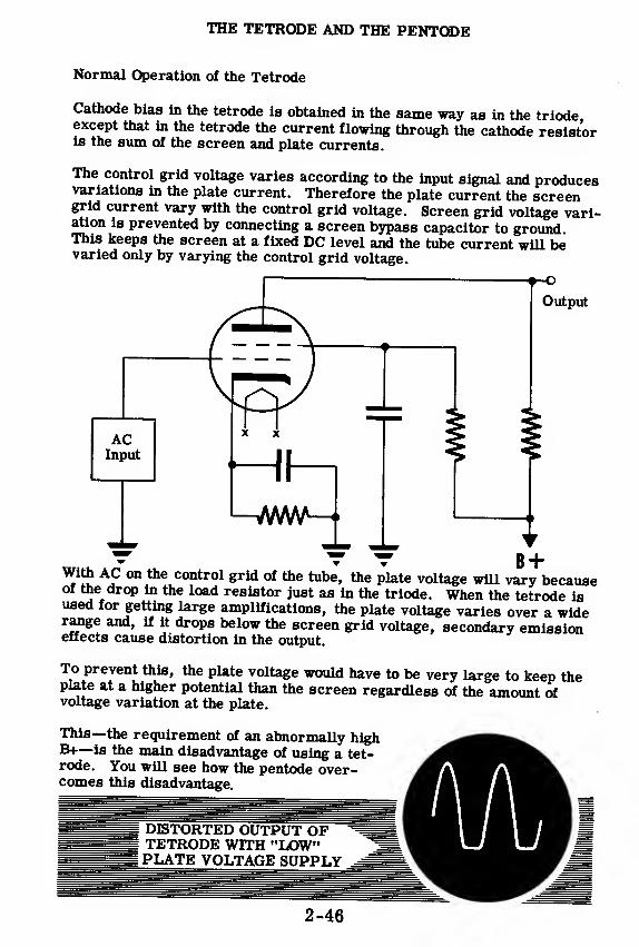
THE TETRODE AND THE PENTODE
Normal Operation of the Tetrode
Cathode bias in the tetrode is obtained in the same way as in the triode,except that in the tetrode the current flowing through the cathode resistoris the sum of the screen and plate currents.
The control grid voltage varies according to the input signal and producesvariations in the plate current. Therefore the plate current the screengrid current vary with the control grid voltage. Screen grid voltage vari-ation is prevented by connecting a screen bypass capacitor to ground.This keeps the screen at a fixed DC level and the tube current will bevaried only by varying the control grid voltage.
ACInput
Output
With AC on the control grid of the tube, the plate voltage will vary becauseof the drop in the load resistor just as in the triode. When the tetrode isused for getting large amplifications, the plate voltage varies over a widerange and, if it drops below the screen grid voltage, secondary emissioneffects cause distortion in the output.
To prevent this, the plate voltage would have to be very large to keep theplate at a higher potential than the screen regardless of the amount ofvoltage variation at the plate.
This—the requirement of an abnormally highB+—is the main disadvantage of using a tet-rode. You will see how the pentode over-comes this disadvantage.
DISTORTED OUTPUT OFTETRODE WITH "LOW"PLATE VOLTAGE SUPPLY
2-46

THE TETRODE AND THE PENTODE
Eliminating the Effects of Secondary Emission
You have seen that the main disadvantage of the tetrode is the need for ahigh plate voltage to prevent distortion in its output due to the effect of
secondary emission.
The pentode is designed to overcome this undesirable feature of the tetrode
by eliminating the flow of secondary electrons between the plate and the
screen grid. This is accomplished by the inclusion of a third grid, the
suppressor grid, between the plate and the screen grid.
gutauxuf Section- - OF A PENTODE
The suppressor grid is usually kept at cathode potential so that it is always
very negative with respect to the plate. Therefore, any electron that is in
the region between the suppressor and the plate (such as a secondary elec-
tron) is attracted back to the plate and prevented from getting through the
suppressor to the screen. As a result of this arrangement, secondary
emission does not affect the operation of the pentode.
2-47

THE TETRODE AND THE PENTODE
How the Pentode Works
You remember that in a triode a decrease of the negative grid voltage pro-duced an increase in the current and a decrease in the plate voltage. Theplate voltage change was more than the change in grid voltage. We calledthe ratio of plate voltage change to grid voltage change "amplification.
"
You remember too that the plate voltage in a triode also affects the currentflow. The decrease in plate voltage has a tendency to decrease the current.The grid is trying to increase the current. It is clear, then, that the de-crease in plate voltage is opposing the effect of the grid voltage decrease.
If the grid has 20 times as much control of the current as the plate has, thelimit of amplification would be 20. When such an amplification is reached,the plate voltage changes would be 20 times as large as the grid voltagechanges and, theoretically, there would be no change in the current. Thusthe amplification is limited by the fact that the plate has some effect on thecurrent.
In a pentode, neither the suppressor nor the plate voltage affect the amountof current drawn from the space charge surrounding the cathode since thescreen grid shields both of these elements from the cathode. As in thetetrode, the pentode's screen voltage is fixed at some positive value and,therefore, only the variations of control grid voltage cause changes inplate current.
1. When gridvoltage in-
creases, currentincreases
2. Plate voltagedecreases and
tends to decreasecurrent
4. Plate voltagedecreases, butdoes not tend todecrease current
A
TRIODE
(fields <utuzUei <x*Kjdfyc<xti<y*i
3. When gridvoltage in-
creases, currentincreases
PENTODE
In the pentode the plate voltage can vary considerably with almost no effecton the current and, therefore, with no cancellation of the grid's control ofthe plate current. As a result, the amplification of a pentode is manytimes greater than that of a triode.
2-48

THE TETRODE AND THE PENTODE
A Typical Pentode Tube
Cathode
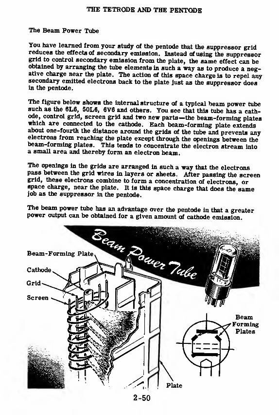
THE TETRODE AND THE PENTODE
The Beam Power Tube
You have learned from your study of the pentode that the suppressor gridreduces the effects of secondary emission. Instead of using the suppressorgrid to control secondary emission from the plate, the same effect can beobtained by arranging the tube elements in such a way as to produce a neg-ative charge near the plate. The action of this space charge is to repel anysecondary emitted electrons back to the plate just as the suppressor doesin the pentode.
The figure below shows the internal structure of a typical beam power tubesuch as the 6L6, 50L6, 6V6 and others. You see that this tube has a cath-ode, control grid, screen grid and two new parts—the beam-forming plateswhich are connected to the cathode. Each beam-forming plate extendsabout one-fourth the distance around the grids of the tube and prevents anyelectrons from reaching the plate except through the openings between thebeam-forming plates. This tends to concentrate the electron stream intoa small area and thereby form an electron beam.
The openings in the grids are arranged in such a way that the electronspass between the grid wires in layers or sheets. After passing the screengrid, these electrons combine to form a concentration of electrons, orspace charge, near the plate. It is this space charge that does the samejob as the suppressor in the pentode.
The beam power tube has an advantage over the pentode in that a greaterpower output can be obtained for a given amount of cathode emission.
2-50

THE TETRODE AND THE PENTODE
The Beam Power Tube (continued)
THE CONSTRUCTION OF A TYPICAL
Anode or Plate
Control Grid
Screen Grid
Beam-FormingPlate
Cathode
Heater
Anode or Plate
Wiring connectionsto the base
Beam-FormingPlates
Screen Grid
Cathode

THE TETRODE AND THE PENTODE
Summary of Pentode Operation
Screen Voltage
* 3"Grid 1foltage = -3V~
Plate Voltage
Curve No. 1: Over a wide range of plate voltages, the pentode plate currentdoes not vary. But this is not saturation; in the next curve you will see thatit is possible to draw more current than this. The reason the currentdoesn't vary over this range of values is that the screen shields the platefrom the cathode's space charge.
At low plate voltages, however, the plate current does vary. Although thetotal tube current remains the same, many more electrons are attractedto the screen, which is now more positive than the plate is.
12
Curve No. 2: Here, you see thatthe control grid in a pentodecontrols current in the sameway as it did in a triode. Nor- §mal grid bias for this particu- ular pentode is about -3 volts. o
SThe fact that the current rises
£jconsiderably above 3 ma. inthis test shows that 3 ma. is notthe limit of cathode emission.Therefore, the flattened portionyou saw in the first curve couldnot have been saturation.
2-!
Grid Voltage

THE TETRODE AND THE PENTODE
Summary of Pentode Operation (continued)
Curves No. 3 and 4: With the same value of load resistor in each, you can
obtain larger amplifications with the pentode than with the triode.
400
300
o>
a,
200
100
Pentode
Tr odev-i
l >fc-—1—
«
1 1
1 1
—H \*—-20 -15 -10 -5
Grid Volts
Compare the
Changes in
Plate Volts
Change in
Grid Volts
With a larger load resistor in the pentode circuit, larger amplification is
obtained. This happens because the grid voltage, and only the grid voltage,
can produce a change of current. This current will flow through the load
resistor—the larger the resistor, the larger the voltage change.

THE TETRODE AND THE PENTODE
Review of Tetrodes and Pentodes
THE TETRODE — A tube having ascreen grid to reduce plate-to-controlgrid capacitance. It is rarely used to-day, but was a step in the developmentof the pentode.
THE PENTODE — A tube which usesa suppressor grid between the screengrid and plate to reduce the effect ofsecondary emission. It has greateramplification than the triode.
THE BEAM POWER TUBE — Tubeusing beam-forming plates instead ofthe suppressor to reduce the effectsof secondary emission. Its power out-put is greater, for a given amount ofcathode emission, than that of a pentode.
PENTODE CIRCUIT — A circuit pro-viding proper operating voltages forcontrol grid, screen grid and sup-pressor grid.
2-54
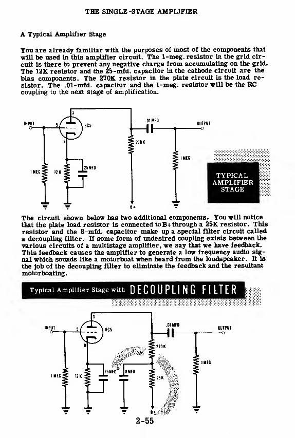
THE SINGLE-STAGE AMPLIFIER
A Typical Amplifier Stage
You are already familiar with the purposes of most of the components that
will be used in this amplifier circuit. The 1-meg. resistor in the grid cir-
cuit is there to prevent any negative charge from accumulating on the grid.
The 12K resistor and the 25-mfd. capacitor in the cathode circuit are the
bias components. The 270K resistor in the plate circuit is the load re-
sistor. The .01-mfd. capacitor and the 1-meg. resistor will be the RCcoupling to the next stage of amplification.
OUTPUT—
o
1 MEG
TYPICALAMPLIFIERSTAGE
The circuit shown below has two additional components. Tou will notice
that the plate load resistor is connected toB+ through a 25K resistor. Thisresistor and the 8-mfd. capacitor make up a special filter circuit called
a decoupling filter. If some form of undesired coupling exists between the
various circuits of a multistage amplifier, we say that we have feedback.
This feedback causes the amplifier to generate a low frequency audio sig-
nal which sounds like a motorboat when heard from the loudspeaker. It is
the job of the decoupling filter to eliminate the feedback and the resultant
motorboating.
Typical Amplifier Stage with DECOUPLING FILTER
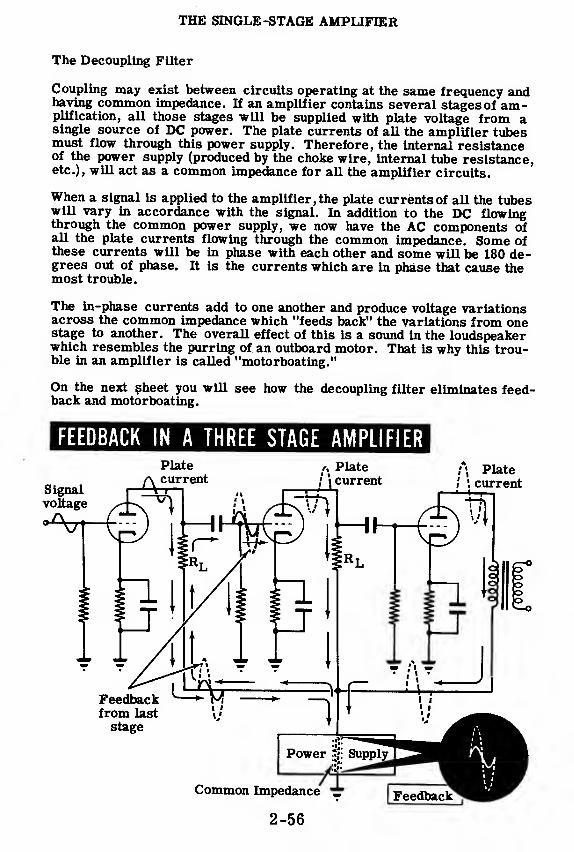
THE SINGLE-STAGE AMPLIFIER
The Decoupling Filter
Coupling may exist between circuits operating at the same frequency andhaving common impedance. If an amplifier contains several stages of am-plification, all those stages will be supplied with plate voltage from asingle source of DC power. The plate currents of all the amplifier tubesmust flow through this power supply. Therefore, the internal resistanceof the power supply (produced by the choke wire, internal tube resistance,etc.), will act as a common impedance for all the amplifier circuits.
When a signal is applied to the amplifier, the plate currents of all the tubeswill vary in accordance with the signal. In addition to the DC flowingthrough the common power supply, we now have the AC components ofall the plate currents flowing through the common impedance. Some ofthese currents will be in phase with each other and some will be 180 de-grees out of phase. It is the currents which are in phase that cause themost trouble.
The in-phase currents add to one another and produce voltage variationsacross the common impedance which "feeds back" the variations from onestage to another. The overall effect of this is a sound in the loudspeakerwhich resembles the purring of an outboard motor. That is why this trou-ble in an amplifier is called "motorboating."
On the next sheet you will see how the decoupling filter eliminates feed-back and motorboating.
FEEDBACK IN A THREE STAGE AMPLIFIER
2-56

THE SINGLE-STAGE AMPLIFIER
The Decoupling Filter (continued)
If the AC components of plate current could be kept from flowing through
^fth^r lm^^nC6,?
ffhe
tP°,wer then the feedback that orlgta-
I Zt Z fW0Uld
.be ehmmated. The decoupling filter's job is to providea path of low reactance around the power supply and a path of high resist-ance to AC current flow through the power supply. Because of tMs very
£2?-^ ^pW an<» "s common fm-pedance, thereby eliminating feedback.
The value of the decoupling capacitor must be high enough so that its re-actance is much ess than the total resistance of the decoupling resistor
Ht^TTn lmPedan?e of the P°wer supply. In an amplifier of the
ST^ST^ S6 T™?1 *he ^coupling resistor is generaUy about one fifth
£ ^tSs^fmTd^- ^ °f^ dCC0UPling CapaCi-
The action of the decoupling filter is to isolate each stage from the powersupply common impedance. The way the filter does this is shown below.
'DecaccfrCitty0?cltexA isolate AMPLIFIER
STAGES AND ELIMINATE FEEDBACK
/Decoupling
FilterDecoupling
Filter
Flow of ACcomponent ofplate current
Common Impedance ^
2-57
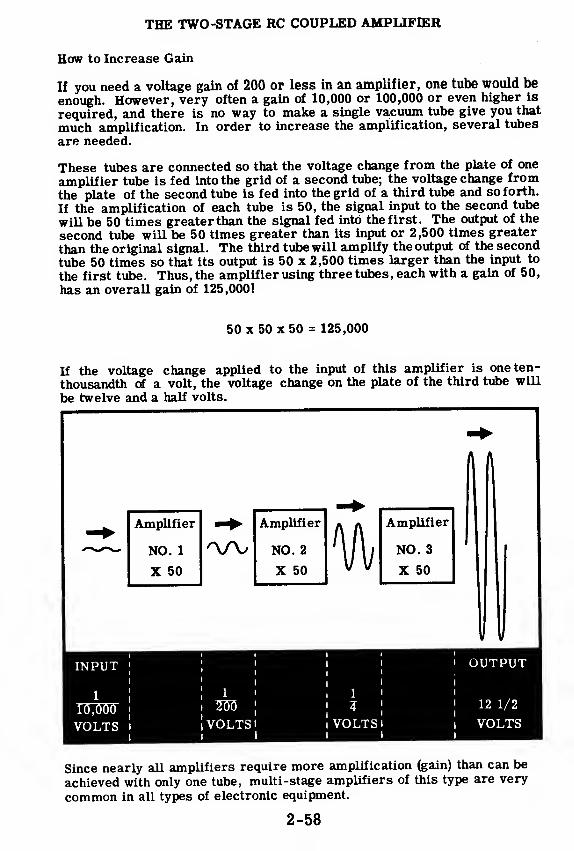
THE TWO-STAGE RC COUPLED AMPLIFIER
How to Increase Gain
If you need a voltage gain of 200 or less in an amplifier, one tube would be
enough. However, very often a gain of 10,000 or 100,000 or even higher is
required, and there is no way to make a single vacuum tube give you that
much amplification. In order to increase the amplification, several tubes
are needed.
These tubes are connected so that the voltage change from the plate of one
amplifier tube is fed into the grid of a second tube; the voltage change from
the plate of the second tube is fed into the grid of a third tube and so forth.
If the amplification of each tube is 50, the signal input to the second tube
will be 50 times greater than the signal fed into the first. The output of the
second tube will be 50 times greater than its input or 2,500 times greater
than the original signal. The third tube will amplify the output of the second
tube 50 times so that its output is 50 x 2,500 times larger than the input to
the first tube. Thus, the amplifier using three tubes, each with a gain of 50,
has an overall gain of 125,000!
50 x 50 x 50 = 125,000
If the voltage change applied to the input of this amplifier is one ten-
thousandth of a volt, the voltage change on the plate of the third tube will
be twelve and a half volts.
Amplifier Amplifier Amplifier
NO. 1 NO. 2 % NO. 3
X 50 X 50 X 50
V
INPUT;
• OUTPUT
1J
!1 1
! i '
' 12 1/210,000;
i 2015;
!
7!
VOLTS ! 1 VOLTS 1 i VOLTS Il VOLTS
I I I I I I
Since nearly all amplifiers require more amplification (gain) than can be
achieved with only one tube, multi-stage amplifiers of this type are very
common in all types of electronic equipment.
2-58
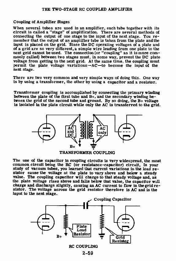
THE TWO-STAGE RC COUPLED AMPLIFIER
Coupling of Amplifier Stages
When several tubes are used in an amplifier, each tube together with its
circuit is called a "stage" of amplification. There are several methods of
connecting the output of one stage to the input of the next stage. You re-member that the output of an amplifier tube is taken from the plate and theinput is placed on the grid. "Since the DC operating voltages of a plate andof a grid are so very different, a simple wire leading from one plate to thenext grid cannot be used. The connection (or "coupling" as it is more com-monly called) between two stages must, in some way, prevent the DC platevoltage from getting to the next grid. At the same time, the coupling mustpermit the plate voltage variations—AC—to become the input of thenext stage.
There are two very common and very simple ways of doing this. One wayis by using a transformer, the other by using a capacitor and a resistor.
Transformer coupling is accomplished by connecting the primary windingbetween the plate of the first tube and B+, and the secondary winding be-tween the grid of the second tube and ground. By so doing, the B+ voltageis isolated in the plate circuit while only the AC is transferred to the grid.
DCJ c 5 SvA1 V /
TRANSFORMER COUPLING
The use of the capacitor in coupling circuits is very widespread, the mostcommon circuit being the RC (or resistance-capacitor) circuit, In yourstudy of vacuum tubes, you learned that current variations in the load re-sistor cause the voltage at the plate to vary above and below a steadyvalue. The coupling capacitor will charge to that steady voltage and, asthe plate voltage rises above and falls below that value, the capacitor willcharge and discharge slightly, causing an AC current to flow in the grid re-sistor. The voltage across the grid resistor therefore is AC and is theinput to the next stage.
Coupling Capacitor
PlateLoad
Resistor
RC COUPLING
2-59

THE TWO-STAGE RC COUPLED AMPLIFIER
Characteristics of the Two-Stage Amplifier
The two-stage amplifier can be compared to two step-up transformerswith the secondary of one connected to the primary of the other. For ex-ample, if two transformers which have a step-up ratio of 1 to 3 are con-nected in this manner, an AC voltage applied to the primary of the firsttransformer would be amplified 9 times by the combination. This exampleis illustrated below.
OBTAINING VOLTAGE AMPLIFICATIONWITH A TRANSFORMER AND VACUUM AMPLIFIER
1 to 9
1 to 3 _ 1 to 3
You may conclude from this that it would be a good idea to forget all aboutusing vacuum tubes as amplifiers and use transformers instead. This isnot possible because transformers with very high step up ratios would haveto be used if they were to deliver a high amplification. Transformers ofthis type are impractical and even if they were used would not amplify allthe audio frequencies the same amount. The higher audio frequencies(around 10,000 cycles) and the lower audio frequencies (around 100 cycles)would not be amplified as much as the middle frequencies. This would re-sult in a signal output that is not a true representation of the original sig-nal applied to the transformers.
Amplifiers using vacuum tubes can deliver much higher amounts of ampli-fication, are lighter in weight, less costly and take up less space. On thenext sheet you will see how a multistage vacuum tube amplifier comparesto the transformer combination explained here.
2-60
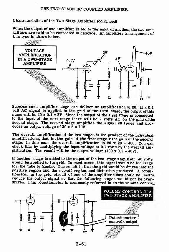
THE TWO-STAGE RC COUPLED AMPLIFIER
Characteristics of the Two-Stage Amplifier (continued)
When the output of one amplifier is fed to the input of another, the two am-plifiers are said to be connected in cascade. An amplifier arrangement ofthis type is shown below.
VOLTAGEAMPLIFICATIONIN A TWO-STAGE
AMPLIFIER
40V
-J HH-8
B+
Suppose each amplifier stage can deliver an amplification of 20. If a 0.1volt AC signal is applied to the grid of the first stage, the output of thisstage will be 20 x 0.1 = 2V. Since the output of the first stage is connectedto the input of the next stage there will be 2 volts AC on the grid of thesecond stage. The second stage amplifies the signal 20 times and pro-duces an output voltage of 20 x 2 = 40V.
The overall amplification of the two stages is the product of the individualamplifications, that is, the gain of the first stage x the gain of the secondstage. In this case the overall amplification is 20 x 20 = 400. You cancheck this by multiplying the input voltage of 0.1 volts by the overall am-plification. The result will be the output voltage (400 x 0.1 = 40V).
If another stage is added to the output of the two-stage amplifier, 40 voltswould be applied to its grid. In most cases, this signal would be too largefor the tube to handle. The result is that the grid would be driven into thepositive region and the cut-off region, and distortion produced. A poten-tiometer in the grid circuit of one of the amplifier tubes could be used toreduce the output signal so that the following stages would not be over-driven. This potentiometer is commonly referred to as the volume control.
VOLUME CONTROL IN ATWO-STAGE AMPLIFIER
Potentiometercontrols output
2-61
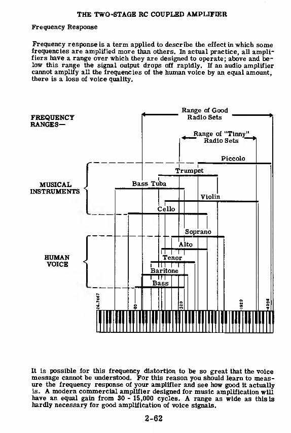
THE TWO-STAGE RC COUPLED AMPLIFIER
Frequency Response
Frequency response is a term applied to describe the effect in which somefrequencies are amplified more than others. In actual practice, all ampli-fiers have a range over which they are designed to operate; above and be-low this range the signal output drops off rapidly. If an audio amplifiercannot amplify all the frequencies of the human voice by an equal amount,there is a loss of voice quality.
FREQUENCYRANGES-
MUSICALINSTRUMENTS
Range of GoodRadio Sets
Range of "Tinny^_Radio Sets
HUMANVOICE
It is possible for this frequency distortion to be so great that the voicemessage cannot be understood. For this reason you should learn to meas-ure the frequency response of your amplifier and see how good it actuallyis. A modern commercial amplifier designed for music amplification willhave an equal gain from 30 - 15,000 cycles. A range as wide as this Ishardly necessary for good amplification of voice signals.
2-62
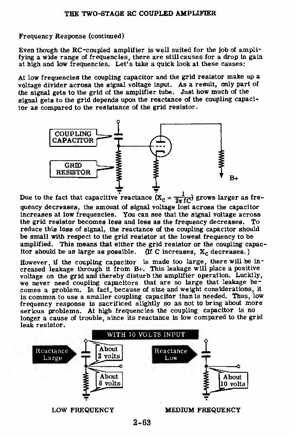
THE TWO-STAGE RC COUPLED AMPLIFIER
Frequency Response (continued)
Even though the RC-coupled amplifier is well suited for the job of ampli-fying a wide range of frequencies, there are still causes for a drop in gainat high and low frequencies. Let's take a quick look at these causes:
At low frequencies the coupling capacitor and the grid resistor make up a
voltage divider across the signal voltage input. As a result, only part of
the signal gets to the grid of the amplifier tube. Just how much of the
signal gets to the grid depends upon the reactance of the coupling capaci-
tor as compared to the resistance of the grid resistor.
COUPLINGCAPACITOR
GRIDRESISTOR
Due to the fact that capacitive reactance (Xc = gff^) grows larger as fre-
quency decreases, the amount of signal voltage lost across the capacitor
increases at low frequencies. You can see that the signal voltage acrossthe grid resistor becomes less and less as the frequency decreases. Toreduce this loss of signal, the reactance of the coupling capacitor shouldbe small with respect to the grid resistor at the lowest frequency to beamplified. This means that either the grid resistor or the coupling capac-itor should be as large as possible. (If C increases, Xc decreases.
)
However, if the coupling capacitor is made too large, there will be in-
creased leakage through it from B+. This leakage will place a positive
voltage on the grid and thereby disturb the amplifier operation. Luckily,
we never need coupling capacitors that are so large that leakage be-
comes a problem. In fact, because of size and weight considerations, it
is common to use a smaller coupling capacitor than is needed. Thus, low
frequency response is sacrificed slightly so as not to bring about moreserious problems. At high frequencies the coupling capacitor is no
longer a cause of trouble, since its reactance is low compared to the grid
leak resistor.
WITH 10 VOLTS INPUT
LOW FREQUENCY MEDIUM FREQUENCY
2-63

THE TWO-STAGE RC COUPLED AMPLIFIER
Frequency Response (continued)
At high frequencies, too, there is an effect that causes a loss of amplifi-cation. This loss is due to total stray capacitance that exists between thegrid and ground. This total capacitance consists of the plate-to-cathodeinterelectrode capacitance of the tube from which the signal is taken, thegrid-to-cathode capacitance of the tube to which the signal is brought, andthe stray capacitances between the signal-carrying wires and the chassis.
Grid-Ta-Plate v
mimCapacitance ^ "'.
Total StrayWiring
Capacitance
Grid-To-Cathode
Capacitance
The effect of this total capacitance is to shunt the grid leak resistor. Atlow and medium frequencies the reactance of this small capacitance is
high and therefore it does not disturb the operation of the circuit. At highfrequencies, the reactance drops and effectively decreases the impedancebetween grid and ground. The signal appearing between grid and grounddecreases as the impedance between grid and ground decreases.
Thus, the gain at high frequencies is less than at medium frequencies be-cause of the shunting effects of the total stray and interelectrode capaci-tances. It is important to note that a low gain in itself is not bad; if thesame gain existed for all frequencies, there would be no problem. Diffi-culties with frequency response are encountered only when there are un-equal gains at different frequencies.
WITH 10 VOLTS INPUT
AT MEDIUM FREQUENCIES AT HIGH FREQUENCIES
The solution to the problem of loss of gain at high frequencies is touse special amplifier tubes with very low values of input and output ca-pacitances, to use special wiring techniques to reduce the stray capaci-tance between the wire and ground, and to use lower values of resistorsin the RC coupling. These methods increase the frequency at which theshunting effect becomes noticeable.
2-64

THE TWO-STAGE RC COUPLED AMPLIFIER
The Frequency Response Curve
The usual way that the frequency response of an amplifier is shown is
with a frequency response curve. In this curve, a plot is made of the gain
at each frequency; the highest gain is 100 percent (or sometimes 1.00) and
any gain below that is figured as a certain percent of maximum—such as
75 percent, 25 percent, and so forth*
The general shape of the curve shows a flat region (plateau) between the
ends of the curve. This means that the gain does not vary by very muchas the frequency changes from the low end to the high end of this portion.
This represents the usable frequency range of the amplifier.
On either side of this flat portion, there is a rapid falling-off of the curve.
This means that the gains at these frequencies (both low and hlgh)are not
as high as the gain at the middle frequencies. In a speaker, the ear can
detect these lowered gains if they are about 70 percent of maximum or be-
low. Therefore, It is the 70-percent points on each end of the curve that
determine the usable range.
As you remember from the previous discussions on frequency response,
the reason for the decreased gain at the low end of the band was the fact
that the coupling capacitor and the grid leak resistor form a voltage
divider. The reactance of the coupling capacitor increases at the low fre-
quencies, and the voltage across the resistor decreases. At the high end,
the loss of gain is due to the shunting effect of the stray capacitances be-
tween grid and ground. At the middle frequencies, neither effect is notice-
able and the gain does not vary by any appreciable amount.
2-65

THE TWO-STAGE RC COUPLED AMPLIFIER
Review of the Two-Stage Amplifier
RC COUPLING — When two or morestages are used in an amplifier, the
AC plate voltage of each stage is fed
to the grid of the next stage throughthe coupling capacitor and resistors.
VOLTAGE GAIN — The total ampli-fication of a two-stage (or multistage)amplifier is the product of the am-plifications of each stage. The ratioof the output voltage of final stage tothe input voltage of first stage is
called the gain of the amplifier.
-40V
AMPLIFICATION LOSSES — At lowfrequencies the high reactance of thecoupling capacitor reduces voltagegain; at high frequencies stray ca-pacitance causes loss of voltage gain.
FREQUENCY RESPONSE — A measure of the ability of an amplifier toamplify AC signals of various fre-quencies by the same amount.
FIEIIUCT (CPS)
2-66

THE TRANSFORMER-COUPLED AMPLIFIER
Transformer Coupling
A transformer-coupled amplifier is an amplifier that makes use of trans-
former coupling instead of RC coupling between the stages. This method
is most often used to couple an amplifier to its load, but it also may be
used for interstage coupling. One advantage of using a transformer is
that the secondary winding may have more turns than the primary winding,
resulting in a voltage step-up. In addition, there is no sizable voltage
drop in voltage at the plate of the amplifier tube as in the case of using a
plate load resistor, and no coupling condenser is required. Li transformer
coupling the maximum gain is Mu xN where "N" is the ratio between the
number of turns in the primary and secondary windings and mu is the am-
plification factor of the tube. In resistance coupling the maximum possible
gain is only the-Mu of the tube.
OUTPUT
HI—f-°
100 K 47011
The reasons why transformer coupling is not widely used are, first, that a
transformer usually has a poorer frequency response than an RC network.
Modern high gain tubes cancel any advantages that the transformer has in
voltage amplification. In spite of improvements in the design of inter-
stage transformers, the trend is toward using high gain vacuum tubes with
RC rather than transformer coupling between the stages of the amplifier.
There are many applications in which transformer stages have a particu-
lar advantage. Some of these applications include: High output for limited
power supply voltage, impedance matching between low and high impedance
lines and push-pull applications. In push-pull amplifiers a transformer is
more readily adaptable than resistance coupling, and unlike an RC coup-
ling, it places a low DC resistance in the grid circuit of the following am-plifier under conditions where a low DC resistance is essential.
INTERSTAGE
TRANSFORMERS
2-67
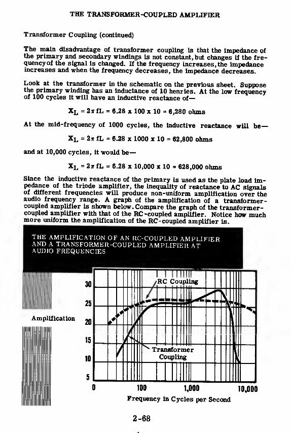
THE TRANSFORMER-COUPLED AMPLIFIER
Transformer Coupling (continued)
The main disadvantage of transformer coupling is that the impedance ofthe primary and secondary windings is not constant, but changes if the fre-quency of the signal is changed. If the frequency increases, the impedanceincreases and when the frequency decreases, the impedance decreases.
Look at the transformer in the schematic on the previous sheet. Supposethe primary winding has an inductance of 10 henries. At the low frequencyof 100 cycles it will have an inductive reactance of
—
XL = 2irfL = 6.28 x 100 x 10 = 6,280 ohms
At the mid-frequency of 1000 cycles, the inductive reactance will be—
XL = 2ir fL = 6.28 x 1000 x 10 = 62,800 ohms
and at 10,000 cycles, it would be—
XL = 2ff fL = 6.28 x 10,000 x 10 = 628,000 ohms
Since the inductive reactance of the primary is used as the plate load im-pedance of the triode amplifier, the inequality of reactance to AC signalsof different frequencies will produce non-uniform amplification over theaudio frequency range. A graph of the amplification of a transformer-coupled amplifier is shown below. Compare the graph of the transformer-coupled amplifier with that of the RC -coupled amplifier. Notice how muchmore uniform the amplification of the RC -coupled amplifier is.
THE AMPLIFICATION OF AN RC-COUPLED AMPLIFIERAND A TRANSFORMER-COUPLED AMPLIFIER ATAUDIO FREQUENCIES
2-68

THE TRANSFORMER-COUPLED AMPLIFIER
Characteristics of the Transformer-Coupled Amplifier
The transformer-coupled amplifier shown below is typical of most am-plifiers of this type. The amplifier has two stages coupled by an inter-
stage audio transformer that has a 3 to 1 step-up ratio. The input stage
uses a 6C5 triode V-l. The amplified output voltage of this tube is
stepped up 3 times by the transformer and then fed to the grid of another
6C5 triode V-2. The second triode amplifies the signal still further and
its amplified output appears across the 100K plate load resistor. The 0.01
mfd coupling capacitor blocks the DC but presents a low reactance to the
AC component at the plate of V-2. Therefore, only the AC component of
the plate voltage at V-2 appears across the 470K resistor. Normally, the
470K resistor would be the grid resistor of the next stage so that the sig-
nal across the resistor could be amplified further.
On the next sheet, a signal will be traced through the transformer-coupledamplifier and you will see how amplification occurs in this circuit.
2-69

THE TRANSFORMER-COUPLED AMPLIFIER
Characteristics of the Transformer-Coupled Amplifier (continued)
The amplification that can be expected from a transformer-coupled ampli-fier stage is approximately equal to the amplification factor (u) of the tubetimes the turns ratio of the transformer (N). Amplification = u x N. Inthis case, a 6C5 tube Is used which has a /* of 20. The transformer has astep-up turns ratio of 3 to 1. Therefore, we can expect an amplificationor gain of
—
fi x N = 20 x 3 = 60.^
Suppose a 0.01 volt AC signal is applied to the grid of V-1. Fromthe illustration you can see that the output voltage of the 6C5 appearsacross the primary winding of the transformer and is amplified u times(20 x . 01 » 0. 2V). The transformer steps up the primary voltage 3 moretimes so that the secondary voltage is 3 x 0. 2 » 0. 6V.
It was stated that the gain of this stage is equal to yU N or 60. Let ussee if this checks. The grid signal is 0. 01V. If we multiply this gridvoltage by the gain we should get the voltage at the secondary of the trans-former, or 0. 6V. Multiply 60 xO.OU 0. 6V and you can see that thisrelationship holds.
VOLTAGE AMPLIFICATION IN ATRANSFORMER-COUPLED AMPLIFIER
ft'*"12V
The voltage across the secondary of the transformer (0.6V) Is now appliedto the grid of V-2. If we assume that the gain of V-2 Is equal to/*,, thenV-2 will amplify this signal 20 times. Therefore, the output voltage at theplate of V-2 will be—20 x 0.6 = 12V.
vwuage ai uw
The total gain is determined by multiplying the individual stage gains to-gether. The gain of V-1 and the transformer is 60 and the gain of V-2 la20. The overall gain is—60 x 20 = 1200.
Checking this result, the input to V-1 times the overall gain should give usthe output voltage of V-2—1200 x 0.01 = 12V which Is correct.
2-70
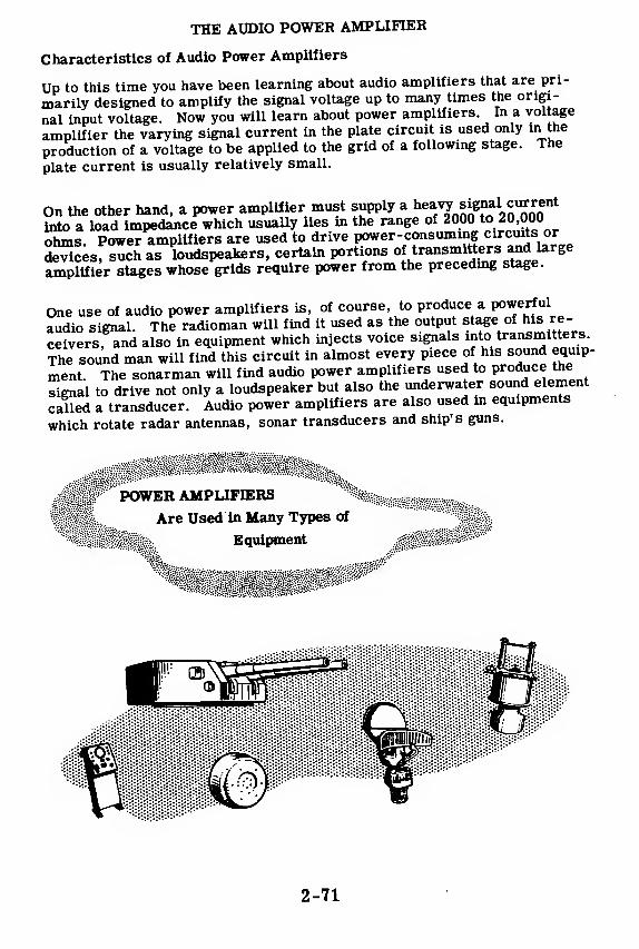
THE AUDIO POWER AMPLIFIER
Characteristics of Audio Power Amplifiers
Up to this time you have been learning about audio amplifiers that are pri-
marily designed to amplify the signal voltage up to many times the origi-
nal input voltage. Now you will learn about power amplifiers. In a voltage
amplifier the varying signal current in the plate circuit is used only in the
production of a voltage to be applied to the grid of a following stage. The
plate current is usually relatively small.
On the other hand, a power amplifier must supply a ^7-!^°™*into a load impedance which usually lies in the range of 2000 to 20,000
ohms Power amplifiers are used to drive power-consuming circuits or
devices, such as loudspeakers, certain portions of transmitters and large
amplifier stages whose grids require power from the preceding stage.
One use of audio power amplifiers is, of course, to produce a powerful
audio signal. The radioman will find it used as the output stage of his re-
ceivers, and also in equipment which injects voice signals into transmitters
The sound man will find this circuit in almost every piece of his sound equip-
ment. The sonarman will find audio power amplifiers used to produce the
signal to drive not only a loudspeaker but also the underwater sound element
called a transducer. Audio power amplifiers are also used in equipments
which rotate radar antennas, sonar transducers and ship's guns.
POWER AMPLIFIERS
Are Used in Many Types of
Equipment
2-71

THE AUDIO POWER AMPLIFIER
Characteristics of Audio Power Amplifiers (continued)
You have learned in the preceding topics that the main purpose of voltageamplifier circuits is to produce a large increase in signal voltage. Theamplified output of the voltage amplifier will now be applied to the grid ofa power amplifier stage.
In the voltage amplifier circuits the output of one voltage amplifier is con-nected to the grid of the next stage. No current flows in this grid circuit,therefore no power will be consumed. If current did flow in the grid cir-cuit, the power loss in this circuit would have to be supplied by the pre-ceding stage. In the case of an amplifier that feeds a loudspeaker, thespeaker requires large amounts of AC signal current for proper operation.When current flows in a circuit, power is always consumed. The poweramplifier stage must supply the power that is consumed in the loud-speaker circuit.
The tubes used in voltage amplifier circuits are generally operated asClass A while the tubes used in power amplifier circuits may be operatedeither as Class A, Class B or Class AB.
Triodes, pentodes and beam power tubes can be used as power amplifiers.These tubes may be operated singly, in parallel, or in push-pull. The typeof operation depends upon the amount of power required of the amplifier.
Voltage amplifiers are usually operated with a high value of plate load re-sistance or impedance to obtain the maximum voltage output. Power am-plifier tubes are operated with lower values of load impedance to obtain alarge current variation and a large power output. In a power amplifierthe amount of voltage output is not important for it is the power outputwhich is the main factor.
If large amounts of power are to be supplied by the power amplifier, itmust be capable of carrying high current—much more current than a volt-age amplifier.

THE AUDIO POWER AMPLIFIER
Characteristics of Audio Power Amplifiers (continued)
The current that flows through the plate circuit of the power amplifiertube is made up of two parts:
1. A steady or DC component2. A varying or AC component
The useful part of the plate current is the varying component as only vari-ations in plate current produce sounds in the loudspeaker. The AC com-ponent of plate current flows through the primary of the output transformeralong with the DC component. The DC component just produces a steadymagnetic field about the primary winding and does not induce any voltageinto the secondary. The AC component makes use of transformer actionand induces a voltage into the secondary which is applied to the voice coilof the loudspeaker. This voltage is converted into sound by the loudspeaker.
Tou can see that the steady plate current does not contribute directly to-wards the sound output of the power amplifier circuit. This portion of theplate current does produce a power loss in the plate circuit which producesheating of the power amplifier tube and the output transformer.
AC AND DC CURRENTS
N A POWER AMPLIFIER
SignalInput
—*- AC Current
—»-DC Current
2-73

THE OUTPUT TRANSFORMER
The Job of the Output Transformer
The output transformer's job is to couple the amplified audio power fromthe plate of the power amplifier tube to the voice coil of the loudspeaker.In these next few sheets you will learn about the characteristics of outputtransformers so that you will be able to understand the importance of im-pedance matching. Impedance matching is necessary because the poweramplifier must have a relatively high impedance plate load while the voicecoil impedance is low. The output transformer matches the low imped-ance voice coil to the high impedance plate circuit.
Power amplifier tubes must operate into a specified value of plate loadimpedance for maximum power output and minimum distortion. The cor-rect value of load impedance for a particular tube can be obtained fromthe tube manufacturer's references.
In a power amplifier circuit, the primary winding of the output transformeris used as the plate load impedance and it is this impedance with which weare concerned. The primary impedance is determined by the size of theload on the secondary and the turns ratio between primary and secondary.The turns ratio and the size of the secondary load impedance must be sochosen that the resultant primary impedance is the correct value for therequired load impedance of the power amplifier tube.
2-74

THE OUTPUT TRANSFORMER
The Job of the Output Transformer (continued)
In a transformer there are two currents—the primary and secondary cur-rents. The current flow in the primary depends on the amount of current
flow in the secondary. If the secondary current increases, then the pri-
mary current will also increase. This can be explained by referring to
Lenz's law, which states that the magnetic field produced by an induced
current is always in opposition to the magnetic field that produced the in-
duced current. In other words, the magnetic field produced by current
flow in the secondary of a transformer is in opposition to, and cancels
some of, the magnetic field produced by the primary winding. You nowcan see that if the secondary load impedance is decreased, the secondarycurrent and magnetic field will increase and cancel a greater portion of
the primary field. If some of the primary field is cancelled, then the in-
ductive reactance and therefore the impedance of the primary will de-crease. By choosing the proper value of secondary impedance, we canobtain the desired primary load impedance for the power amplifier tube.
If the secondary load impedance cannot be changed—-for example, thePrimary turns
voice coil in a loudspeaker—the turns ratio "secondary turns
can varied
to obtain the proper primary impedance. This is done by using an output
transformer with a tapped secondary.
Secondarycurrent.
2-75

THE OUTPUT TRANSFORMER
Impedance Matching
Let us look back at some of the things you have learned up to this point.
You know that a power amplifier tube must operate into a specified value
of load impedance to obtain maximum power output and minimum distortion.
You also know that this load impedance is actually the output transformerprimary impedance, which is determined by the load on the secondary.
The secondary load is usually a loudspeaker and it is to the speaker that
we wish to supply the amplified audio power. You may be thinking that it
would be simpler to connect the speaker directly to the plate of the poweramplifier tube but this is not possible. You recall that the plate load for
the power amplifier cannot be anything but the specified value. This load
is usually in the order of several thousand ohms while loudspeaker voice
coil impedances are in the order of 1 to 15 ohms. If the voice coil im-pedance was used as the plate load, the amount of power obtainable fromthe amplifier would be very small to say nothing of the distortion that
would result.
Therefore, we must use an impedance matching device, the output trans-
former, which will allow us to operate the tube into the high impedanceprimary and still, supply audio power to the low impedance loudspeakervoice coil.
2-76

THE OUTPUT TRANSFORMER
Impedance Matching (continued)
Loudspeaker impedances and plate load impedances for different tubes
vary widely. Since the primary impedance is set by the type of tube being
used and the secondary load is set by the voice coil impedance, there must
be some means of adjusting the relationship between primary and second-
ary impedance to obtain proper matching. The means of matching the two
impedances is by varying the turns ratio of the transformer.
The output transformer that is shown below has a multi-tapped secondary
so that you can select different numbers of secondary turns. Since the
primary turns are fixed, if the secondary turns are varied then the turns
ratio of the transformer is also varied. The primary impedance (Zp) is
related to the secondary load impedance (Zs) by the following formula
where N is the turns ratio of the transformer-^-, Nj is the primary turns
and N« is the number of secondary turns used. You can see that if the
value of Zs is fixed by the voice coil impedance, any value of Zpcan be
obtained by varying the turns ratio.
s
2-77

THE PUSH-PULL AMPLIFIER
How the Push-Pull Amplifier Works
In this topic, you will see that a very good type of power amplifier can bemade by using a push-pull system. A power amplifier can be made usingonly one tube, but when you want to double the power, it is often moreconvenient to use two power tubes, rather than use one very large powertube. The obvious way to use two tubes would be to connect the two gridstogether and the two plates together (parallel connection) and therebydouble the power output. However, there is a way that is better—that is toconnect the tubes in push-pull. In a push-pull amplifier the input voltagesto the grids of the two tubes are 180 degrees out of phase. This phasedifference is often achieved by putting the signal into the primary of atransformer with a center-tapped secondary—the two grids are connectedto the opposite ends of the secondary and the center tap is grounded orconnected to a source of grid bias voltage.
A TYPICAL PUSH-PULL CIRCUIT
The plates are connected to opposite ends of the primary winding of anoutput transformer and the center tap is connected to B+. The final outputvoltage appears across the output transformer secondary which is con-nected to the load.
2-78

THE PUSH-PULL AMPLIFIER
How the Push-Pull Amplifier Works (continued)
In a typical push-pull amplifier, the grids receive AC voltages from oppo-
se SmtTof I transformer' secondary winding,tJhe *r*^rmer sec-
„„lrv i8 center-tapped and the center tap is connected to ground. The
AcSdXes are 180 degrees out of phase. When one grid becomes
fess^eU^fte otter grid becomes more negative by the same amount.
4e sTSihe tube currents does not vary but remains pure DCsince,
when one current is increasing, the other is decreasing by the same
amount. Because the sum of the two currents is pure DC, no bypass ca-
pacitor is needed across the cathode bias resistor.
In the output transformer, it is the difference between the two currents
Sat is the output signal. The greater the signal input, the greater this
difference and the greater the output.
Below you see a set of typical wave forms taken from a push-pull ampli-
fier which is working normally.
GRIDTO " I
CATHODE '
VOLTAGE !
(E-l) '
GRID o-
TOCATHODEVOLTAGE
(E-2)
PLATECURRENT
,
Ul) I
ft
PLATECURRENT
U2>\\ < rao t
1
NORMAL WAVE
FORMS FROM
A PUSH-PULL
AMPLIFIER
2-79

THE PUSH-PULL AMPLIFIER
How the Push-Pull Amplifier Works (continued)
Up to now, the only advantage of the push-pull circuit that has been men-tioned has been the fact that no bypass capacitor is needed since the volt-age variations produced across the cathode resistor by the out-of-phaseplate current will cancel each other. If this were the only advantageof the push-pull circuit over the use of two tubes connected in parallel,the parallel combination would be more common than it is. Actually thereare some very important advantages which make the use of the push-pullcircuit preferable.
Consider what happens if the two tubes in parallel are driven into cut-offby a large signal input. Both tubes go into cut-off together and distortionappears m the output. If the tubes are connected in a push-pull arrange-ment, one tube will be driven into cut-off on one half-cycle and the othertube on the next half-cycle. In the output, the distortion is minimized asyou can see from the wave forms below.
DISTORTED WAVE FORMS
DUE TO CUT-OFF
DISTORTEDPLATE CURRENT
DISTORTEDPLATE CURRENT
II
EFFECTIVE CURRENTIN OUTPUT
TRANSFORMER
r\r\hii
The reason that it is such a big advantage that the push-pull circuit re-duces distortion is this—the tubes can be intentionally overdriven to pro-duce a larger output and the output still will be practically undistorted.
2-80
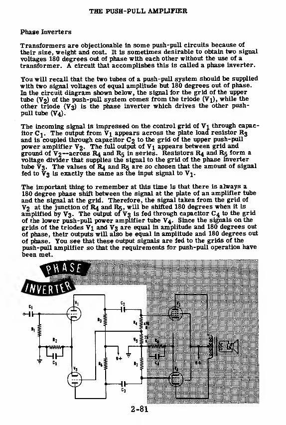
THE PUSH-PULL AMPLIFIER
Phase Inverters
Transformers are objectionable in some push-pull circuits because of
their size, weight and cost. It is sometimes desirable to obtain two signal
voltages 180 degrees out of phase with each other without the use of atransformer. A circuit that accomplishes this is called a phase inverter.
You will recall that the two tubes of a push-pull system should be supplied
with two signal voltages of equal amplitude but 180 degrees out of phase.
In the circuit diagram shown below, the signal for the grid of the uppertube (V2) of the push-pull system comes from the triode (V"i), while the
other triode (V3) is the phase inverter which drives the other push-
pull tube (V4).
The incoming signal is impressed on the control grid of Vi through capac-
itor Cj. The output from Vj appears across the plate load resistor R3and is coupled through capacitor C2 to the grid of the upper push-pull
power amplifier V2. The full output of Vi appears between grid andground of V2—across R4 and R5 in series. Resistors R4 and R5 form a
voltage divider that supplies the signal to the grid of the phase inverter
tube V3. The values of R4 and R5 are so chosen that the amount of signal
fed to V3 is exactly the same as the input signal to Vj.
The important thing to remember at this time is that there is always a180 degree phase shift between the signal at the plate of an amplifier tube
and the signal at the grid. Therefore, the signal taken from the grid of
V2 at the junction of R4 and R5, will be shifted 180 degrees when it is
amplified by V3. The output of V3 is fed through capacitor C4 to the grid
of the lower push-pull power amplifier tube V4. Since the signals on the
grids of the triodes Vi and V3 are equal in amplitude and 180 degrees out
of phase, their outputs will also be equal in amplitude and 180 degrees out
of phase. Tou see that these output signals are fed to the grids of the
push-pull amplifier so that the requirements for push-pull operation havebeen met.
2-81

THE PUSH-PULL AMPLIFIER
How the Phase Inverter Works
Suppose we apply a signal to the phase inverter and trace it through thecomplete push-pull amplifier. If a 1 volt signal is applied to the grid ofVj and we assume the gain of V"i to be 20, there will be a 20 volt signal atthe plate. This signal will appear between grid and ground of Vo—acrossR| and R5 in series. Since R4 is 19 times as large as R5, 19 volts willappear across R4 and there will be 1 volt across R5. The 1 volt signalacross R5 is applied to the grid of V3 at the junction of R4 and R5. Sincethe gain of V3 is the same as that of Vj (20), the output voltage of V3 willbe 20 volts in amplitude and shifted in phase 180 degrees. This outputvoltage is applied between grid and ground of V4.
You can see that we have provided the push-pull amplifier tubes with twosignals equal in amplitude (20V) and 180 degrees out of phase so thatproper push-pull operation will take place.
20V
2-82

THE PUSH-PULL AMPLIFIER
Another Type of Phase Inverter
The phase inverter you will use has half of the load resistance in the cath-
ode circuit (R-l), and half in the plate circuit (R-2). The same current
flows in each of these resistors and since they have the same value, the
same voltage appears across each of them. These voltages are 180 de-
grees out of phase. No signal appears across R-3 since it is bypassed
with a large condenser.
The input voltage is applied between grid and ground and only part of this
signal appears between grid and cathode. The tube current responds to
the grid-to-cathode voltage and this current flows through R-l and R-2,
causing signal voltages to appear across these resistors.
The voltage across R-l (and also the voltage across R-2) is always less
than the input voltage. This is so since the grid-to-cathode voltage is
equal to the difference between the input voltage and the voltage across
R-l. Therefore, the gain of this type of phase inverter (or phase splitter)
is less than one.
The two outputs are connected to the control grids of the following push-
pull stage. These outputs are 180 degrees out of phase with each other
since one is taken from the plate and the other from the cathode. Thus,
when the plate current is increasing, the "top" of R-2 is becoming less
positive and the "top" of R-l is becoming more positive. The phase in-
verter has taken an AC signal input and produced two output signals of
equal magnitudes and of opposite phase.
Compare this circuit to the transformer circuit shown below.
2-83

THE PUSH-PULL AMPLIFIER
Complete Diagram of Push -Pull Power Amplifier
2-84
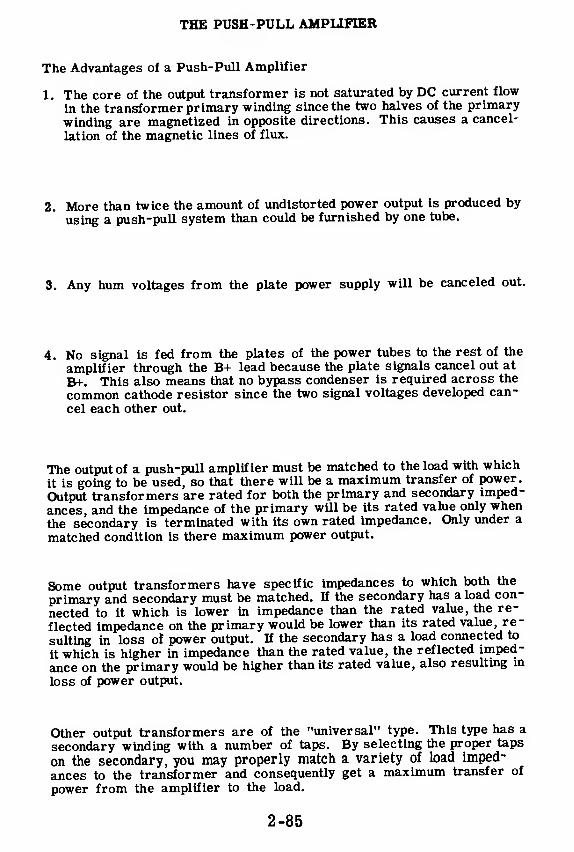
THE PUSH-PULL AMPLIFIER
The Advantages of a Push-Pull Amplifier
1. The core of the output transformer is not saturated by DC current flow
in the transformer primary winding since the two halves of the primary
winding are magnetized in opposite directions. This causes a cancel-
lation of the magnetic lines of flux.
2. More than twice the amount of undistorted power output is produced by
using a push-pull system than could be furnished by one tube.
3. Any hum voltages from the plate power supply will be canceled out.
4. No signal is fed from the plates of the power tubes to the rest of the
amplifier through the B+ lead because the plate signals cancel out at
B+. This also means that no bypass condenser is required across the
common cathode resistor since the two signal voltages developed can-
cel each other out.
The output of a push-pull amplifier must be matched to the load with which
it is going to be used, so that there will be a maximum transfer of power.
Output transformers are rated for both the primary and secondary imped-
ances, and the impedance of the primary will be its rated value only when
the secondary is terminated with its own rated impedance. Only under a
matched condition is there maximum power output.
Some output transformers have specific impedances to which both the
primary and secondary must be matched. If the secondary has a load con-
nected to it which is lower in impedance than the rated value, the re-
flected impedance on the primary would be lower than its rated value, re-
sulting in loss of power output. If the secondary has a load connected to
it which is higher in impedance than the rated value, the reflected imped-
ance on the primary would be higher than its rated value, also resulting in
loss of power output.
Other output transformers are of the "universal" type. This type has a
secondary winding with a number of taps. By selecting the proper taps
on the secondary, you may properly match a variety of load imped-
ances to the transformer and consequently get a maximum transfer of
power from the amplifier to the load.
2-85

THE PUSH-PULL AMPLIFIER
Review of the Push-Pull Amplifier
PUSH-PULL CIRCUIT uses twovacuum tubes and a transformerto double the power output of thecircuit. The tube grid voltagesare 180 degrees out of phase.
9
g | LOAD|
3
DISTORTED WAVE FORMS dueto overdriving the tubes do notnoticeably affect the currentwave form in the output trans-former of a push-pull amplifier.
PHASE INVERTER produces twosignal voltages 180 degrees outof phase without using a trans-former. A phase inverter mayuse one or two vacuum tubes.
PUSH-PULL POWER AMPLIFIERconsists of a voltage amplifier,a phase splitter (inverter), twopower amplifier tubes and anoutput transformer.
AAA,
OA
2-86
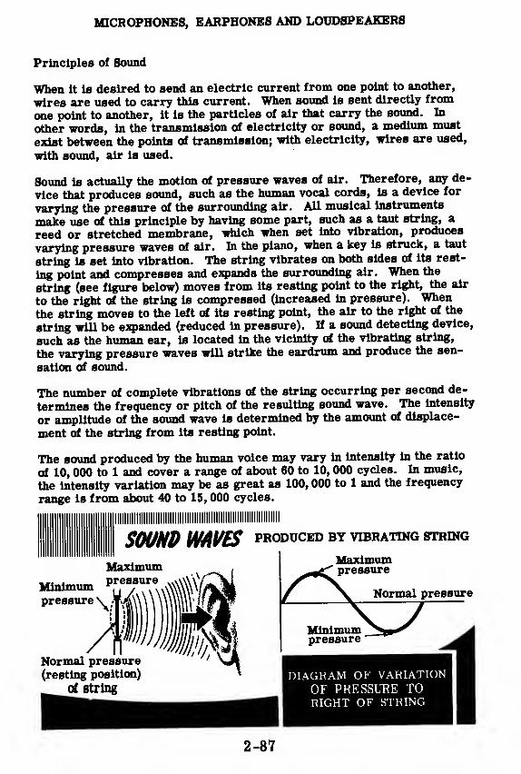
MICROPHONES, EARPHONES AND LOUDSPEAKERS
Principles of Sound
When it is desired to send an electric current from one point to another,
wires are used to carry this current. When sound is sent directly from
one point to another, it is the particles of air that carry the sound. In
other words, in the transmission of electricity or sound, a medium must
exist between the points of transmission; with electricity, wires are used,
with sound, air is used.
Sound is actually the motion of pressure waves of air. Therefore, any de-
vice that produces sound, such as the human vocal cords, is a device for
varying the pressure of the surrounding air. All musical instruments
make use of this principle by having some part, such as a taut string, a
reed or stretched membrane, which when set into vibration, produoes
varying pressure waves of air. In the piano, when a key is struck, a taut
string is set into vibration. The string vibrates on both sides of its rest-
ing point and compresses and expands the surrounding air. When the
string (see figure below) moves from its resting point to the right, the air
to the right of the string is compressed (increased in pressure). When
the string moves to the left of its resting point, the air to the right of the
string will be expanded (reduced in pressure). If a sound detecting device,
such as the human ear, is located in the vicinity of the vibrating string,
the varying pressure waves will strike the eardrum and produce the sen-
sation of sound.
The number of complete vibrations of the string occurring per second de-
termines the frequency or pitch of the resulting sound wave. The intensity
or amplitude of the sound wave is determined by the amount of displace-
ment of the string from its resting point.
The sound produced by the human voice may vary in intensity in the ratio
of 10, 000 to 1 and cover a range of about 60 to 10, 000 cycles. In music,
the intensity variation may be as great as 100, 000 to 1 and the frequency
range is from about 40 to 15, 000 cycles.
|llllllllllllllllll!lllllllllllllllllllllllllli!IIIIIIIIIIIIHII
S0UHD WAVES PRODUCED BY VIBRATING STRING
Maximum
2-87

MICROPHONES, EARPHONES AND LOUDSPEAKERS
Characteristics of Microphones
The sound waves that you produce when you talk or sing can be convertedInto corresponding electrical impulses by the mechanism of a microphone.A diaphragm inside the microphone is actuated by the air pressure varia-tions of the sound waves, and in turn causes the microphone to produce anAC voltage of the same frequency as the original sound. The amplitude ofthis AC voltage will be proportional to the intensity of the sound.
The ratio of electrical output (voltage) to the intensity of sound input is thesensitivity of a microphone. Sensitivity varies widely among differenttypes of microphones. The electrical output of a microphone depends onthe type of microphone and the distance between the microphone and thesound source. The output decreases as this distance is increased.
The frequency response of a microphone is a measure of its ability to con-vert different sound frequencies into alternating current. With a fixedsound intensity at the microphone, the electrical output may vary widelyas the frequency of the sound source is varied. For clear understandingof speech, however, only a limited frequency range is necessary; from200 to 4, 000 cycles.
If the output of a microphone shows only small variations in amplitude be-tween its upper and lower frequency limits, it is said to have a flat fre-quency response.
You will study various types of microphones on the next few sheets.
2-88

MICROPHONES, EARPHONES AND LOUDSPEAKERS
The Carbon Microphone
The most common type of microphone, the carbon microphone, is re-stricted to a large extent to communications systems for the transmissionof speech. This microphone is the most rugged of all the different typesand supplies the largest output from a given sound input.
The figure below shows the principal parts of a single-button carbon micro-phone. This microphone operates by using the varying pressure waves ofsound to vary the resistance between carbon granules. These carbongranules are sealed in a brass or carbon cup with an electrode that ismechanically connected to a thin diaphragm. The electrode acts as aplunger in compressing the carbon granules in the cup, which is oftencalled a "carbon button. " The carbon button is connected in series with asource of DC voltage and the primary of a microphone transformer.
iWCARBON MICROPHONE
Granules
Electrode
ooo
Alternating
Current
Direct Current
Time
When no sound waves strike the diaphragm, the carbon granules are atrest. In this condition, the resistance of the carbon button, between thecup and the electrode, is constant and so is the circuit current. This isillustrated in the region from 1 to 2 in the illustration. When the pressurewaves of sound strike the diaphragm, the diaphragm and the attached elec-
fn^foTT ,
°Ut'Varying Pressure on the carbon granules. An
£an?nf!L ,
r pref8ur
.
e moves diaphragm in, compressing the carbongranules and lowering their resistance. This causes the current to in-crease, which is shown in the region from 2 to 3 of the graph. A decreasein air pressure causes the diaphragm to move out which reduces the pres-sure on the granules raising their resistance and decreasing the circuitcurrent. This is shown in the region from 3 to 4 of the graph.
In this manner, sound waves vary the circuit current in accordance withthe sound pressure variations. These current variations through the pri-mary of the transformer induce a stepped-up voltage in the secondaryWhich is fed to the grid of an amplifier. The output of the amplifier canbe connected to a loudspeaker or used to control the output of a radiotransmitter.
2-89
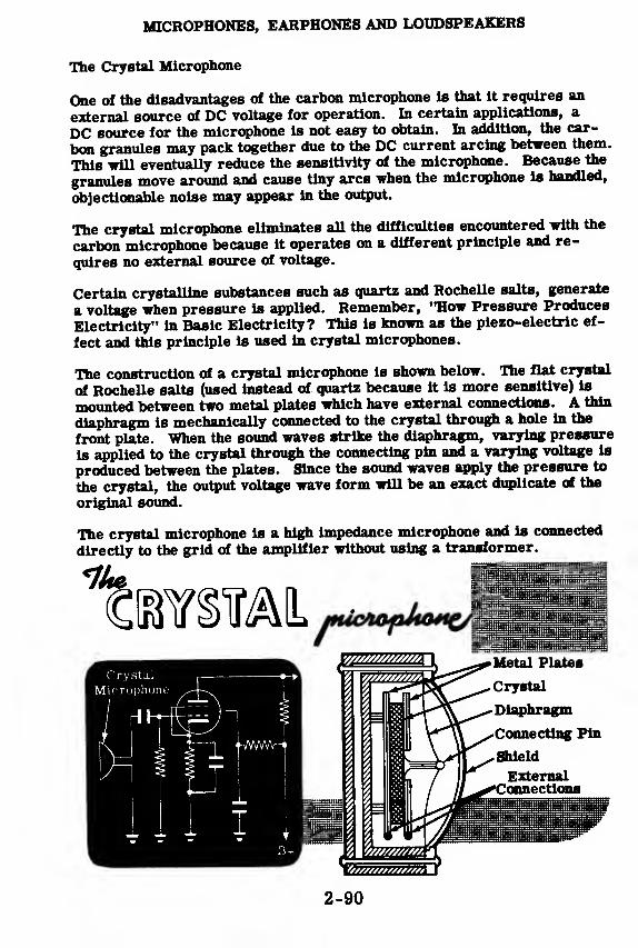
MICROPHONES, EARPHONES AND LOUDSPEAKERS
The Crystal Microphone
One of the disadvantages of the carbon microphone is that it requires an
external source of DC voltage for operation. In certain applications, a
DC source for the microphone is not easy to obtain. In addition, the car-
bon granules may pack together due to the DC current arcing between them.
This will eventually reduce the sensitivity of the microphone. Because the
granules move around and cause tiny arcs when the microphone is handled,
objectionable noise may appear in the output.
The crystal microphone eliminates all the difficulties encountered with the
carbon microphone because it operates on a different principle and re-
quires no external source of voltage.
Certain crystalline substances such as quartz and Rochelle salts, generate
a voltage when pressure is applied. Remember, '•How Pressure Produces
Electricity" in Basic Electricity? This is known as the piezo-electric ef-
fect and this principle is used in crystal microphones.
The construction of a crystal microphone is shown below. The flat crystal
of Rochelle salts (used instead of quartz because it is more sensitive) is
mounted between two metal plates which have external connections. A thin
diaphragm is mechanically connected to the crystal through a hole in the
front plate. When the sound waves strike the diaphragm, varying pressure
is applied to the crystal through the connecting pin and a varying voltage is
produced between the plates. Since the sound waves apply the pressure to
the crystal, the output voltage wave form will be an exact duplicate of the
original sound.
The crystal microphone is a high impedance microphone and is connected
directly to the grid of the amplifier without using a transformer.
2-90

MICROPHONES, EARPHONES AND LOUDSPEAKERS
The Dynamic Microphone
In the dynamic or moving coil type of microphone, a coil of wire, which
is rigidly attached to a diaphragm, is suspended in an air gap in whichthere is a very strong magnetic field. The magnetic field is produced bya permanent magnet. When the sound waves strike the diaphragm it movesback and forth with the coil. Since the coil is in the magnetic field, an ACvoltage will be induced in it. This voltage will have the same wave formas the sound waves that strike the diaphragm.
The frequency of this AC voltage is the same as the frequency of the soundwave and the amplitude of the voltage is proportional to the sound wave's
air pressure or intensity.
The dynamic microphone output feeds into a transformer which steps upthe voltage and delivers a high impedance output so that it will work di-
rectly into the grid of an amplifier tube.
The dynamic microphone can be handled and moved during operation with-out producing undesirable noise in its output. It is dependable, requiresno DC supply and has excellent frequency response between 20 and 9, 000cycles.
2-91

MICROPHONES, EARPHONES AND LOUDSPEAKERS
The Ribbon or Velocity Microphone
The ribbon microphone consists of a corrugated ribbon of aluminum alloy,which is suspended in a strong magnetic field so that the ribbon can bemoved by the sound waves. As the sound waves move the ribbon back andforth, it cuts the lines of force between the poles of the magnets and avoltage is induced in the ribbon. This voltage is very small but it can bestepped up by a transformer, which is usually enclosed in the microphonecasing. In addition to stepping up the voltage, the transformer raises theoutput impedance of the microphone so that it can be connected through ashielded cable to the grid of an amplifier.
The microphones described previously were pressure operated and haddiaphragms which moved because the sound waves raised the air pressureon the front side of the diaphragm above the air pressure on the enclosedback side of the diaphragm. The ribbon microphone has no diaphragm andboth front and back sides of the ribbon are exposed to the sound waves.The ribbon moves because of the small spaces between the ribbon and thepole pieces. The air passing through these spaces produces a differencein phase and pressure on the two sides of the ribbon. The voltage inducedin the ribbon is determined not by the pressure of the air but by the veloc-ity of the air particles traveling between the ribbon and pole pieces.
2-92
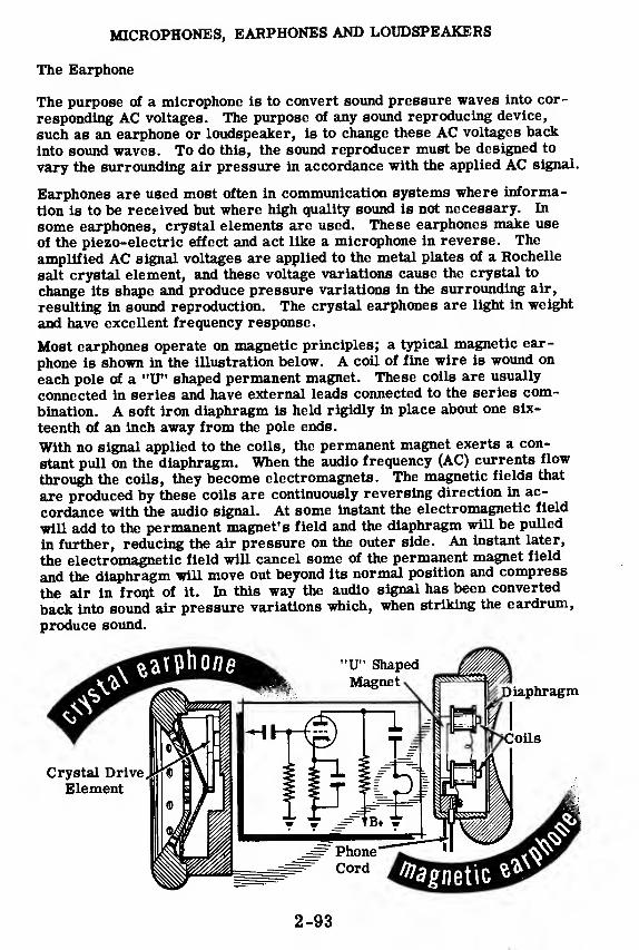
MICROPHONES, EARPHONES AND LOUDSPEAKERS
The Earphone
The purpose of a microphone is to convert sound pressure waves into cor-
responding AC voltages. The purpose of any sound reproducing device,
such as an earphone or loudspeaker, is to change these AC voltages back
into sound waves. To do this, the sound reproducer must be designed to
vary the surrounding air pressure in accordance with the applied AC signal.
Earphones are used most often in communication systems where informa-
tion is to be received but where high quality sound is not necessary. In
some earphones, crystal elements are used. These earphones make use
of the piezo-electric effect and act like a microphone in reverse. The
amplified AC signal voltages are applied to the metal plates of a Rochelle
salt crystal element, and these voltage variations cause the crystal to
change its shape and produce pressure variations in the surrounding air,
resulting in sound reproduction. The crystal earphones are light in weight
and have excellent frequency response.
Most earphones operate on magnetic principles; a typical magnetic ear-
phone is shown in the illustration below. A coil of fine wire is wound on
each pole of a "U" shaped permanent magnet. These coils are usually
connected in series and have external leads connected to the series com-
bination. A soft iron diaphragm is held rigidly in place about one six-
teenth of an inch away from the pole ends.
With no signal applied to the coils, the permanent magnet exerts a con-
stant pull on the diaphragm. When the audio frequency (AC) currents flow
through the coils, they become electromagnets. The magnetic fields that
are produced by these coils are continuously reversing direction in ac-
cordance with the audio signal. At some instant the electromagnetic field
will add to the permanent magnet's field and the diaphragm will be pulled
in further, reducing the air pressure on the outer side. An instant later,
the electromagnetic field will cancel some of the permanent magnet field
and the diaphragm will move out beyond its normal position and compress
the air in front of it. In this way the audio signal has been converted
back into sound air pressure variations which, when striking the eardrum,
produce sound.
2-93

MICROPHONES, EARPHONES AND LOUDSPEAKERS
The Dynamic Loudspeaker
The dynamic loudspeaker is very similar in construction to the dynamicmicrophone. In fact, the permanent magnet type of speaker is sometimesused in intercommunication systems as both speaker and microphone.
Cross-sections of the permanent magnet dynamic speaker and the electro-magnet dynamic speaker are shown below. The construction of both typesis exactly the same except for the method of obtaining the magnetic field.
The electromagnetic type uses a field coil wound on a soft iron coil. ADC current is passed through the field coil and a strong magnetic field is
produced in the air gap. In the permanent magnet type, a strong perma-nent magnet made of alnico alloy takes the place of the field coil. A coil
of wire, which has relatively few turns, is suspended in the air gap and is
attached to a paper cone. The outer edge of the cone and the voice coil
suspension are corrugated and attached to the speaker frame. The cor-rugations allow the cone to move in and out freely.
The amplifier is connected to the voice coil through an output transformerwhich serves as an impedance-matching device. The AC audio signal cur-rent flowing through the voice coil causes it to generate a magnetic field
whose polarity is continuously varying. When the voice coil field has a po-larity that aids the field in the air gap, the voice coil and cone move in,
reducing the air pressure in front of the cone. When the voice coil field isin opposition to the field in the air gap, the voice coil and cone are pushedout, compressing the air in front of the cone. In this way, audio signalcurrents are changed into sound pressure waves.
2-94

MICROPHONES, EARPHONES AND LOUDSPEAKERS
Review of Microphones, Earphones and Loudspeakers
SOUND WAVES are variations in air
pressure produced by a vibrating solid
body. The speed of vibration deter-
mines the pitch of the sound; the am-plitude of vibration determines the
loudness of the sound.
MICROPHONES change sound wavesinto electrical impulses. "Mikes"may be carbon, crystal, dynamic or
ribbon type. The electrical impulses
are fed into the grid of an amplifier
either directly or through a step-up
transformer.
EARPHONES operate like micro-phones in reverse, and produce sound
waves in response to electrical im-pulses. Both the crystal and magnetic
earphones are widely used, the mag-netic type being most common.
LOUDSPE ATCERS are used where high
quality sound reproduction is required.
The dynamic loudspeaker operates
like a dynamic microphone in reverse
and may be of the permanent or electro-
magnet type.
ELECTRO-MAGNETTYPE
Field
Coll*~
2-95

AUDIO AMPLIFIERS
Review of Audio Amplifiers
AMPLIFICATION — The process ofchanging a low AC input to a high ACoutput. A device which performs ampli-fication is called an amplifier.
THE TRIODE — A vacuum tube similarto a diode but containing a grid whichcontrols plate current between cathodeand plate.
GRID
TRIODE CHARACTERISTICS — A plotof the variations in plate current as gridvoltage changes; a measure of a triode'sability to amplify.
GRID BIAS — The amount of grid biasvoltage determines the class of ampli-fier operation. In Class A the bias isless than cut off; in Class B bias is ator near cut-off; in Class C bias is muchless than cut-off.
TRIODE AMPLIFIER — A simple circuitusing a single triode with biasing com-ponents. This circuit is not used alonein actual equipment.
Grid VolUge
iT>
If
2-96

AUDIO AMPLIFIERS
Review of Audio Amplifiers (continued)
THE PENTODE — A tube which uses asuppressor grid and a screen grid be-tween control grid and plate. It hasgreater amplification than the triode.
SINGLE-STAGE AMPLIFIER — A cir-
cuit consisting of a vacuum tube am-plifier, biasing components, a load
resistor, a decoupling network and aresistor and capacitor to provide
coupling to another stage.
lt_— \K>DIMFO
I
TWO-STAGE RC-COUPLED AMPLI-FIER — A circuit consisting of twoamplifier stages. The input to the
grid of the second amplifier tube is
the output from the first stage
of amplification.
fI
TRANSFORMER-COUPLED AMPLI-FIER — A two-stage amplifier iden-
tical to the two-stage RC-coupled am-plifier except that a transformer is
used to couple the first and sec-
ond stages.
i » i
—
|« JtHFD
I
VOLTAGE GAIN — The total amplifi-
cation of a two-stage (or multistage)
amplifier is the product of the ampli-fications of each stage. The ratio of
the output voltage of the final stage to
the input voltage to the first stage is
called the gain of the amplifier.
o.iv
/
2V
J 2V
A
2-97

AUDIO AMPLIFIERS
Review of Audio Amplifiers (continued)
AUDIO POWER AMPLIFIER — An am-plifier designed to supply power to aload. Its input is the output of a volt-age amplifier stage. Its output feeds aload through an output transformer.
PHASE INVERTER — A circuit which H i
uses one or two vacuum tubes to pro-duce two signal voltages 180 degreesout of phase. It is also called a phasesplitter and replaces the transformerin a push-pull circuit.
PUSH-PULL POWER AMPLIFIER —A circuit consisting of a voltage am-plifier, a phase splitter (inverter),
two power amplifier tubes and an out-put transformer.
THE OUTPUT TRANSFORMER — Atransformer used to couple the poweramplifier output to the load. It matchesthe low load impedance to the high im-pedance required by the amplifier.
MICROPHONES. EARPHONES ANDLOUDSPEAKERS — Carbon, crystal,dynamic and ribbon microphones areused to change sound waves into elec-trical impulses. Earphones andloudspeakers change electrical im-pulses to sound waves.
2-98

INDEX

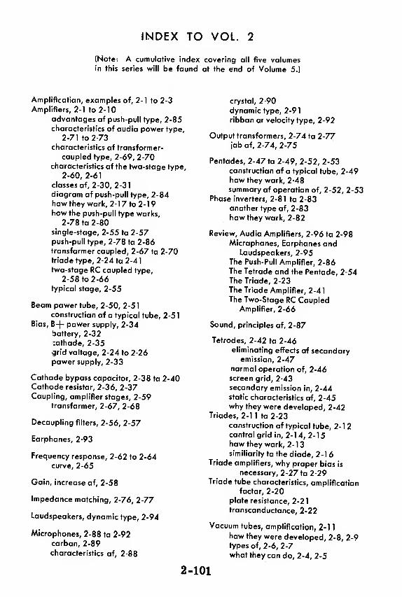
INDEX TO VOL. 2
(Note: A cumulative index covering all five volumesin this series will be found at the end of Volume 5.)
Amplification, examples of, 2-1 to 2-3
Amplifiers, 2-1 to 2-10
advantages of push-pull type, 2-85characteristics of audio power type,
2-71 to 2-73
characteristics of transformer-
coupled type, 2-69, 2-70characteristics of the two-stage type,
2-60, 2-61
classes of, 2-30, 2-31
diagram of push-pull type, 2-84how they work, 2-1 7 to 2- 1
9
how the push-pull type works,
2-78 to 2-80single-stage, 2-55 to 2-57push-pull type, 2-78 to 2-86transformer coupled, 2-67 to 2-70triodetype, 2-24 to 2-41
two-stage RC coupled type,
2-58 to 2-66
typical stage, 2-55
Beam power tube, 2-50, 2-51
construction of a typical tube, 2-51Bias, B+ power supply, 2-34
battery, 2-32
:athode, 2-35
grid voltage, 2-24 to 2-26
power supply, 2-33
Cathode bypass capacitor, 2-38 to 2-40Cathode resistor, 2-36, 2-37Coupling, amplifier stages, 2-59
transformer, 2-67, 2-68
Decoupling filters, 2-56, 2-57
Earphones, 2-93
Frequency response, 2-62 to 2-64curve, 2-65
Gain, increase of, 2-58
Impedance matching, 2-76, 2-77
Loudspeakers, dynamic type, 2-94
Microphones, 2-88 to 2-92carbon, 2-89
characteristics of, 2-88
crystal, 2-90
dynamic type, 2-91
ribbon or velocity type, 2-92
Output transformers, 2-74 to 2-77job of, 2-74, 2-75
Pentodes, 2-47 to 2-49, 2-52, 2-53construction of a typical tube, 2-49how they work, 2-48
summary of operation of, 2-52, 2-53Phase inverters, 2-81 to 2-83
another type of, 2-83
how they work, 2-82
Review, Audio Amplifiers, 2-96 to 2-98Microphones, Earphones and
Loudspeakers, 2-95The Push-Pull Amplifier, 2-86The Tetrode and the Pentode, 2-54The Triode, 2-23The Triode Amplifier, 2-4
1
The Two-Stage RC CoupledAmplifier, 2-66
Sound, principles of, 2-87
Tetrodes, 2-42 to 2-46eliminating effects of secondary
emission, 2-47normal operation of, 2-46screen grid, 2-43
secondary emission in, 2-44static characteristics of, 2-45why they were developed, 2-42
Triodes, 2-11 to 2-23
construction of typical tube, 2-12control grid in, 2- 1 4, 2- 1
5
how they work, 2-13similiarity to the diode, 2-16
Triode amplifiers, why proper bias is
necessary, 2-27 to 2-29Triode tube characteristics, amplification
factor, 2-20plate resistance, 2-21
transconductance, 2-22
Vacuum tubes, amplification, 2-1
1
how they were developed, 2-8, 2-9types of, 2-6, 2-7
what they can do, 2-4, 2-5
2-101


HOW THIS OUTSTANDING COURSE WAS DEVELOPED:
In the Spring of 1951, the Chief of Naval Personnel, seeking a streamlined,
more efficient method of presenting Basic Electricity and Basic Electronics to the
thousands of students in Navy speciality schools, called on the graphiological
engineering firm of Van Valkenburgh, Nooger & Neville, Inc., to prepare such a
course. This organization, specialists in the production of complete "packagedtraining programs," had broad experience serving industrial organizations requir-
ing mass-training techniques.
These were the aims of the proposed project, which came to be known as the
Common-Core program: to make Basic Electricity and Basic Electronics com-pletely understandable to every Navy student, regardless of previous education; to
enable the Navy to turn out trained technicians at a faster rate (cutting the cost
of training as well as the time required) without sacrificing subject matter.
The firm met with electronics experts, educators, officers-in-charge of various Navyschools and, with the Chief of Naval Personnel, created a dynamic new training
course . . completely up-to-date . . . with heavy emphasis on the visual approach.
First established in selected Navy schools in April, 1953, the training coursecomprising Basic Electricity and Basic Electronics was such a tremendoussuccess that it is now the backbone of the Navy's current electricity and electronics
training program!*
The course presents one fundamental topic at a time, taken up in the order of
need, rendered absolutely understandable, and hammered home by the use of clear,
cartoon-type illustrations. These illustrations are the most effective ever presented.
Every page has at least one such illustration—every page covers one complete idea!
An imaginary instructor stands figuratively at the reader's elbow, doing demonstrations that make it easier to understand each subject presented in the course.
Now, for the first time, Basic Electricity and Basic Electronics have been released
Ijy die Navy for civilian use. While the course was originally designed for the
Navy, the concepts are so broad, the presentation so clear—without reference to
specific Navy equipment—that it is ideal for use by schools, industrial training
programs, or home study. There is no finer training material!
"Basic Electronics" consists of five volumes, as follows: Vol. 1—Introductionto Electronics, Diode Vacuum Tubes, Dry Metal Rectifiers, What a Power
Supply Is, Filters, Voltage Regulators. Vol. 2—Introduction to Amplifiers,
The Triode Tube, Tetrodes & Pentodes, Audio Voltage & Power Amplifiers.
Vol. 3—Video Amplifiers, RF Amplifiers, Oscillators. Vol. -/—Transmitters,
Transmission Lines & Antennas, CW Transmission & Amplitude Modula-
tion. Vol. 5—Receiver Antennas, Detectors & Mixers, TRF Receivers,
Superheterodyne Receivers.
*"Basic Electricity," the first portion of this course, is available as a separate
series of volumes.
JOHN F. RIDER PUBLISHER, INC., 116 WEST 14th ST., N. Y. 11, N. Y.

electronicsby VAN VALKENBURGiK,
$2.25
basicelectronicsby VAN VALKENBURGH,NOOGER * NEVILLE, INC.
VOL.3
JOHN F. RIDER PUBLISHER, INC.116 West 14th Street • New York 11, N. Y.
First Edition
Copyright 1955 by
VAN VALKENBURGH, NOOGER AND NEVILLE, INC.
All Rights Reserved under International and PanAmerican Conventions-. This book or parts thereofmay not be reproduced in any form or in anylanguage without permission of the copyright owner.
Library of Congress Catalog Card No. 55-6984
Printed in the United States of America

PREFACE
The texts of the entire Basic Electricity and Basic Electronics
courses, as currently taught at Navy specialty schools, have now beenreleased by the Navy for civilian use, This educational programhas been an unqualified success. Since April, 1953, when it was first
installed, over 25,000 Navy trainees have benefited by this instruc-
tion and the results have been outstanding.
The unique simplification of an ordinarily complex subject, the
exceptional clarity of illustrations and text, and the plan of pre-senting one basic concept at a time, without involving complicatedmathematics, all combine in making this course a better and quickerway to teach and learn basic electricity and electronics.
In releasing this material to the general public, the Navy hopes to
provide the means for creating a nation-wide pool of pre-trainedtechnicians, upon whom the Armed Forces could call in time of
national emergency, without the need for precious weeks and monthsof schooling.
Perhaps of greater importance is the Navy's hope that throughthe release of this course, a direct contribution will be made towardincreasing the technical knowledge of men and women throughoutthe country, as a step in making and keeping America strong.
Van Valkenburgh, Nooger and Neville, Inc.
New York, N. Y.
February, 1955
iii
TABLE OF CONTENTS
Vol. 3 — Basic Electronics
Video Amplifiers 3-1
Introduction to the RF Amplifier 3-15
Tuned Circuits 3-19
A Single-Stage RF Amplifier 3-28
The Two-Stage RF Amplifier 3-35
Introduction to Oscillators 3-43
The Armstrong and Hartley Oscillators (includes Colpitts) . . . 3-55
The Tuned-Plate Tuned-Grid and Crystal Oscillators 3-66
The Electron-Coupled Oscillator 3-74
Miscellaneous Oscillators 3-78
iv

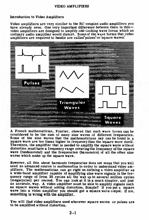
VIDEO AMPLIFIERS
Introduction to Video Amplifiers
Video amplifiers are very similar to the RC -coupled audio amplifiers youhave already seen. One very important difference between them is this
—
video amplifiers are designed to amplify odd-looking wave forms which anordinary audio amplifier would distort. Some of the wave forms that video
amplifiers are required to handle are called'pulses"or "square waves'.'
A French mathematician, Fourier, showed that such wave forms can beconsidered to be the sum of many sine waves of different frequencies.Some of the sine waves that the mathematicians say can be found in asquare wave are ten times higher in frequency than the square wave itself.
Therefore, the amplifier that is needed to amplify the square wave withoutdistortion must have a frequency range covering the frequency of the squarewave (fundamental) and the frequencies (harmonics) of all the other sinewaves which make up the square wave.
However, all this about harmonic frequencies does not mean that you willneed an advanced course in mathematics in order to understand video am-plifiers. The mathematician can go right on defining a video amplifier asa wide-band amplifier capable of amplifying sine wave signals in the fre-quency range of from 30 cycles all the way up to several million cycles(megacycles) per second. You can look at it in a much simpler, and justas accurate, way. A video amplifier must be able to amplify signals suchas square waves without adding distortion. Simple? If you put a squarewave into a video amplifier you should get a square wave output. If not,something is wrong with the amplifier.
You will find video amplifiers used wherever square waves or pulses areto be amplified without distortion.
3-1

VIDEO AMPLIFIERS
Introduction to Video Amplifiers (continued)
To many of you, the word "video" is synonymous with television and it
should, therefore, come as no surprise to you to learn that video amplifiersare used in television receivers. The picture is sent out by the station asa series of electrical pulses which represent dark and light portions of thepicture. These pulses are received in the home by the TV antenna, ampli-
fied by the video amplifier and applied to the picture tube so as to duplicatethe picture sent out by the station.
In television, the characteristics of the picture depend in part on the qualityof the video amplifier. If the amplifier distorted the pulses, the picturewould lack the sharpness and the detail it would otherwise have.
Another important application of video amplifiers is in the oscilloscope. In
a 'scope, the vertical amplifier must amplify the input signal without addingany distortion. If the input signal is a distorted sine wave or a square wave,that is how it is supposed to appear on the 'scope screen if the 'scope is to
do its job. Therefore a video amplifier is used as the vertical amplifier in
a ' scope because video amplifiers are capable of amplifying almost any waveform without distortion.
One of the very important applications of video amplifiers is in radar equip-ment. Every radar, whether it is used for search or for fire control, con-tains a video amplifier. Radar echoes are sharp pulses and the amplifiermust preserve the shape of these echoes so that the radar operator can ob-tain accurate information about the target that is sending back the echo.
Only video amplifiers can be used where pulses or square waves are to beamplified without distortion. No other amplifier comes close to meetingthe requirements for the video amplifiers in oscilloscopes, television,
sonar, radar, teletype, loran and photo facsimile equipment.
3-2
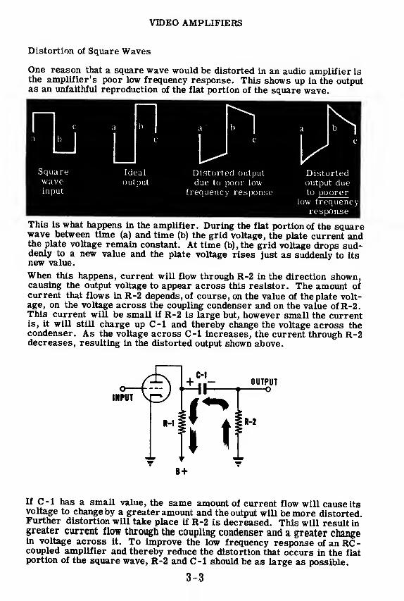
VIDEO AMPLIFIERS
Distortion of Square Waves
One reason that a square wave would be distorted in an audio amplifier isthe amplifier's poor low frequency response. This shows up in the outputas an unfaithful reproduction of the flat portion of the square wave.
This is what happens in the amplifier. During the flat portion of the squarewave between time (a) and time (b) the grid voltage, the plate current andthe plate voltage remain constant. At time (b),the grid voltage drops sud-denly to a new value and the plate voltage rises just as suddenly to itsnew value.
When this happens, current will flow through R-2 in the direction shown,causing the output voltage to appear across this resistor. The amount ofcurrent that flows in R-2 depends, of course, on the value of the plate volt-age, on the voltage across the coupling condenser and on the value of R-2.This current will be small if R-2 is large but, however small the currentis, it will still charge up C-l and thereby change the voltage across thecondenser. As the voltage across C-l increases, the current through R-2decreases, resulting in the distorted output shown above.
If C-l has a small value, the same amount of current flow will cause itsvoltage to change by a greater amount and the output will be more distorted.Further distortion will take place if R-2 is decreased. This will result ingreater current flow through the coupling condenser and a greater changein voltage across it. To improve the low frequency response of an RC-coupled amplifier and thereby reduce the distortion that occurs in the flatportion of the square wave, R-2 and C-l should be as large as possible.
B +
3-3

VIDEO AMPLIFIERS
Distortion of Square Waves (continued)
Even with good low frequency response, there might be a cause for distor-
tion. This cause, as you may have guessed, would be poor high frequencyresponse. This distortion appears in the output as an unfaithful reproduc-tion of the steep portions of the square wave.
Squarewave '
input
VIdeal
output
Distorted output Distorted output
due to POOR high due to BAD highfrequency response frequency response
The stray capacitance, C-2, is the cause of this distortion. It cannot
change its voltage instantaneously and, since C-2 is directly across the
output, the output voltage cannot change instantaneously either. The stray
capacitance, C-2, can charge and discharge through R-l and R-2 which
are in parallel. If the parallel combination of R-l and R-2 allows C-2 to
charge and discharge quickly, the output will show little or no distortion.
If R-l and R-2 are large resistances, C-2 will require a relatively long
time to charge and discharge and the steep sides of the square wave will
not be perfectly vertical. The larger these resistances become, the worse
the distortion becomes. When this becomes very severe, C-2 will never
be able to cl»arge and discharge enough to reach the flat portion of the
square wave and the output will resemble the triangularly shaped waveshown above.
C
."l ODTNTHI—• -~°-4>\mmtW
i+
Stray capacitance'
c-2 due to capacity of
tube and wiring
If you recall the discussion about improving the high frequency response
of audio amplifiers, you will remember that there are two different waysof doing this. The first is to reduce the stray capacitances C-2 by using
special amplifier tubes with very low values of input and output capacitance
and by using special wiring techniques to reduce the stray capacitance be-
tween the wires and ground. The second way is to reduce the time it takes
C-2 to charge and discharge. This is done by using lower values of R-land R-2.
As you know, reducing R-2 would harm the low frequency response.
Therefore this is not done. Reducing R-l reduces the gain of the stage but
this disadvantage is overcome in video amplifiers by adding more stages,
each with low gain but good frequency response. Special tubes are used
such as the 6AC7, 6SH7 and the 6AG7. These tubes are designed for high
gains and low input and output capacitances and are, therefore, ideally
suited for video amplifiers.
3-4

VIDEO AMPLIFIERS
Compensating Networks—High-Frequency Compensation
One common way of improving wave shapes in video amplifiers is to de-crease the effect of the things which cause distortion. This includes ad-justing the values of R and C in the coupling network so as to reduce dis-tortion. You have already seen how this works. Another way is to intro-duce just the opposite distortion into the circuit by adding compensatingnetworks which counteract the distortion that is already there.
To improve the steepness of the steep portion of the square wave, an in-ductance (L) is placed in series with the plate load resistor (R-l). Theback emf set up in this inductance every time the plate current changeswill be in such a direction as to cause a peak to appear in the plate voltage.
At (a), the grid voltage is swingingpositive and the plate current in-creases. The plate voltage de-creases and at the same instant, aback emf is set up across L. Thisback emf tends to oppose the in-crease of current and has the direc-tion shown in the diagram. Thisnegative back emf lowers the platevoltage below its normally low value,thus causing a peak to appear on thesquare wave.
When the grid voltage swings negative, as at (b), the plate current de-creases and the back emf across L is in the opposite direction. This thenadds to the plate voltage—normally high anyway—causing another peak toappear at (b).
t
Because of the effect of this inductance, it is always re-ferred to as a' peaking coil.
Now consider the effect of these peaks on the charging and discharging of
C-2, the stray capacitance. C-2 will now tend to charge to higher valuesof voltage—higher because of the peaks—and to discharge to lower valuesof voltage. This will cause C-2 to charge and discharge faster than it
would if no peaking coil were used. If the proper value of L is used, the
final output can be made an almost perfect square wave.
3-5
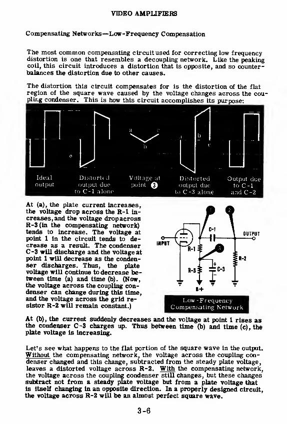
VIDEO AMPLIFIERS
Compensating Networks—Low-Frequency Compensation
The most common compensating circuit used for correcting low frequencydistortion is one that resembles a decoupling network. Like the peakingcoil, this circuit introduces a distortion that is opposite, and so counter-balances the distortion due to other causes.
The distortion this circuit compensates for is the distortion of the flat
region of the square wave caused by the voltage changes across the cou-pling condenser. This is how this circuit accomplishes its purpose:
.A. b
c
\| ^Distorted Output dueoutput due to C-l
to C -3 alone and C-2
At (a), the plate current increases,the voltage drop across the R-l in-creases, and the voltage dropacrossR-3(in the compensating network)tends to increase. The voltage atpoint 1 in the circuit tends to de-crease as a result. The condenserC-3 will discharge and the voltage atpoint 1 will decrease as the conden-ser discharges. Thus, the platevoltage will continue to decrease be-tween time (a) and time (b). (Now,the voltage across the coupling con-denser can change during this time,and the voltage across the grid re-sistor R-2 will remain constant.)
At (b), the current suddenly decreases and the voltage at point 1 rises asthe condenser C-3 charges up. Thus between time (b) and time (c), theplate voltage is increasing.
Let's see what happens to the flat portion of the square wave in the output.
Without the compensating network, the voltage across the coupling con-denser changed and this change, subtracted from the steady plate voltage,leaves a distorted voltage across R-2. With the compensating network,the voltage across the coupling condenser still changes, but these changessubtract not from a steady plate voltage but from a plate voltage thatis Itself changing in an opposite direction. In a properly designed circuit,the voltage across R-2 will be an almost perfect square wave.
3-6

VIDEO AMPLIFIERS
Improving Frequency Response—Degeneration
If there were no compensating circuits used, distortion would appear in
the output. Let's say that a perfect square wave (wave form 1) is con-nected to the grid of an amplifier, and that the output is distorted as shownin wave form 2.
Now let's take a small part of the output waveform (as in wave form 3)
and bring it back to the input. The resulting input would be the sum of the
original input and this voltage which is fed back from the output. The newinput will look like wave form 4.
Wave Form 3 Wave Form 4
The new voltage at the plate of the amplifier will be wave form 5 which,you will notice, has just the opposite distortion than existed when the inputwas a perfect square wave. Whatever was causing distortion before is
still causing it now, with the result that the output is still distorted but notnearly so much as it was previously. Compare wave form 6 (the new out-put) with wave form 2 (the old output).
Wave Form 5 Wave Form 6
You will notice that the new input wave form (no. 4) is smaller than waveform 1, the old input. This is so because the voltage that was fed back is
out of phase with, and so subtracts from, the original signal input. Thusthe output is smaller than it would ordinarily be and the gain of the stage
is apparently lessened. More important than the loss of gain is the de-crease in the amount of distortion. This method of decreasing distortion
is known as "degeneration" or as "negative feedback."
3-7

VIDEO AMPLIFIERS
Improving Frequency Response—Degeneration (continued)
There are several ways of obtaining negative feedback. One of the sim-plest and most widely used methods is to have the cathode bias resistor,R-4, unbypassed. In this way the cathode voltage will not be pure DC butwill vary as the current varies. When the grid goes positive (or lessnegative), the cathode current increases and the cathode voltage goes pos-itive. This cathode voltage decreases the grid-to-cathode signal and solowers the gain of the stage. Furthermore, the cathode current will not beof the same wave shape as the grid voltage if distortion is present in thecircuit. The cathode voltage will contain this distortion and the differencebetween the grid and the cathode voltages will contain just the oppositedistortion. This reduces the distortion in the output.
FEEDBACK THROUGHUNBYPASSED CATHODE RESISTOR
Another way of obtaining negative feedback is to use a voltage divider con-sisting of R-6, the grid resistor, and R-5. This voltage divider is con-nected across the output so that part of the output voltage appears acrossR-6. In addition, the input signal appears across R-6. Since tfte outputand input signals are 180 degrees out of phase, the resultant input signalto the grid will be the difference between the input to the stage and thatpart of the output signal that is fed back. This, of course, will counteractpart of the distortion in the output.
In each of these two circuits, it is possible to adjust the amount of signalthat is fed back. If the unbypassed cathode resistor, R-4, is increased or,in the other circuit, if R-5 is decreased the feedback will be increased.Increasing the feedback lowers the gain of the stage and makes the outputsignal resemble the input signal more closely.
3-8

VIDEO AMPLIFIERS
Improving Frequency Response—Degeneration (continued)
Degeneration works equally well for all types of distortion. In the illus-
trations shown on the previous sheet, you saw how degeneration improvesthe response of the amplifier to the flat portion of the square wave. Be-low, you see the six wave forms that explain how degeneration improvesthe steepness of the steep portion of the square wave. As before, waveform 1 is the original input to the grid*, wave form 2 is the signal that
would appear in the output if no negative feedback were used; wave form3 is the part of output signal that is fed back and appears between grid
and cathode; wave form 4 is the resultant grid-to-cathode signal; waveform 5 is the amplified resultant grid voltage as it appears on the plate;
and wave form 6 is the new output voltage—reduced in height but withmuch less distortion than wave form 2.
Wave Wave Wave Wave Wave WaveForm 1 Form 2 Form 3 Form 4 Form 5 Form 6
Original Original Feed- Resultant Resultant Resultantinput output back input plate output
signal
The important thing to remember is that the signal which is fed backcontains the distortion that exists in the output. When this signal is com-bined with the original grid signal, the distortion appears "backward."The resulting plate signal has distortion that is opposite to the distortionoriginally existing in the output. In this respect, negative feedback doesalmost the same thing as a compensating network. The important differ-ences are these:
1. Negative feedback will reduce any type of distortion while a compen-sating network will work only for the type of distortion it is designedto eliminate.
2. Negative feedback will always result in decreased gain.
3-9

VIDEO AMPLIFIERS
Review of Video Amplifiers
VIDEO AMPLIFIER amplifies pulses,triangular or square waves, without dis-
tortion, whereas an audio amplifierdistorts these wave forms due to poorhigh and low frequency response.
^^^^Amplifier^^^^^
^^^^Ampltfiert^^^^
LOW FREQUENCY RESPONSE can beimproved by increasing capacity of the
coupling capacitor and by adding a lowfrequency compensating network.
LOW FREQUENCY COMPENSATINGNETWORK develops a varying voltage,
which, when added to the square waveinput voltage, counteracts the distor-tion of flat portion of square wave dueto the coupling capacitor.
• OUTPUT
frequency VIIOresponse ^IM^
POOR
input \ry
If
GOOD
OUTPUT——
O
HIGH FREQUENCY RESPONSE can beimproved by reducing the value of the
plate load resistor and by adding apeaking coil in the plate lead.
POOR
OUTPUT
Highfrequencyresponse
GOOD
PEAKING COIL counteracts the effect
of stray capacitance, which tends to
round off the leading edge of the
square wave.
3-10

VIDEO AMPLIFIERS
Review of Video Amplifiers (continued)
DEGENERATION or negativefeedback is a method of over-coming any type of squarewave distortion by returningpart of output as a grid sig-
nal. Resultant output con-tains very little distortion.
WaveForm 1
Wave Wave Wave WaveForm 2 Form 3 Form 4 Form 5
WaveForm 6
Original Original Feed- Resultant ResultantInput output back Input plate
signal
Resultantoutput
UNBYPASSED CATHODERESISTOR provides degener-ation by forcing the cathodevoltage to vary as the currentvaries, introducing distortionopposite to, and thus reducing,that present.
VOLTAGE DIVIDER FEED-BACK introduces part of the
output voltage across the grid
but 180 degrees out of phase,so that distortion is introducedin reverse and thus reduced.
B +
Defeneration
VIDEO AMPLIFIER CIRCUITmay contain all or several of
the distortion-reducing com-ponents.
Low FrequencyCompensating Network
3-11


3-13

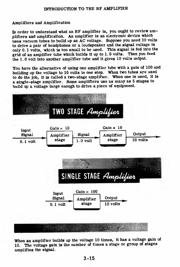
INTRODUCTION TO THE RF AMPLIFIER
Amplifiers and Amplification
In order to understand what an RF amplifier is, you ought to review am-plifiers and amplification. An amplifier is an electronic device which
uses vacuum tubes to build up an AC voltage. Suppose you need 10 volts
to drive a pair of headphones or a loudspeaker and the signal voltage is
only 0. 1 volts, which is too small to be used. This signal is fed into the
grid of an amplifier tube which builds it up to 1. 0 volts. Then you feed
the 1. 0 volt into another amplifier tube and it gives 10 volts output.
You have the alternative of using one amplifier tube with a gain of 100 and
building up the voltage to 10 volts in one step. When two tubes are used
to do the job, it is called a two-stage amplifier. When one is used, it is
a single-stage amplifier. Some amplifiers use as many as 5 stages to
build up a voltage large enough to drive a piece of equipment.
TWO STAGE AnpUfa
Input
Signal _
Gain= 10 Gain= 10
Amplifier Signal Amplifier
0. 1 volt stage 1.0 volt stage
Output
10 volts
SINGLE STAGE /7**p^*
Input
Signal
Gain= 100
Amplifier Output _
0. 1 volt stage 10 volts
When an amplifier builds up the voltage 10 times, it has a voltage gain of
10. The voltage gain is the number of times a stage or group of stages
amplifies the signal.
3-15

INTRODUCTION TO THE RF AMPLIFIER
What an RF Amplifier Does
Now you are ready to examine what makes an RF amplifier different fromother types of amplifiers. You remember that:
1. Audio amplifiers amplify all frequencies from about 15 to 15, 000 cy-cles per second.
2. Video amplifiers amplify all frequencies from about 30 to 6, 000, 000cycles per second.
FREQUENCY RANGESOF AMPLIFIERS
RF Amplifiers
Video Amplifiers
Audio Amplifiersj
100JL
10,000I
1,000,000I
100,000,000I
10,000,000,000
1,000 100,000 10,000,000 1,000,000,000
RF amplifiers amplify signals from about 30, 000 to 30, 000, 000, 000 cy-cles per second. The outstanding feature of an RF amplifier is that it doesnot amplify this entire frequency range at once. It selects one small por-tion—the portion occupied by the radio signal sent out by one transmitter—and amplifies that. For instance, WCBS broadcasts at a frequency of880 kilocycles and is allotted a band whose limits are 5 kilocycles eitherside of 880. Most standard broadcast stations are allotted a band 5 kceither side of a center frequency. When you tune a broadcast receiver toWCBS you are adjusting the RF amplifier to select the band of frequenciesextending from 875 to 885 kc.
The same principle applies to short wave and television stations. For ex-ample, a station at 10 mc might have a bandwidth from 9. 8 to 10. 2 mc.A perfect RF amplifier would select that range of frequencies and rejectall others. Television channel 2 occupies the band from 54 to 60 mc.When you tune a television set to channel 2 you are adjusting the RF ampli-fier to select that band and reject all others.
3-16
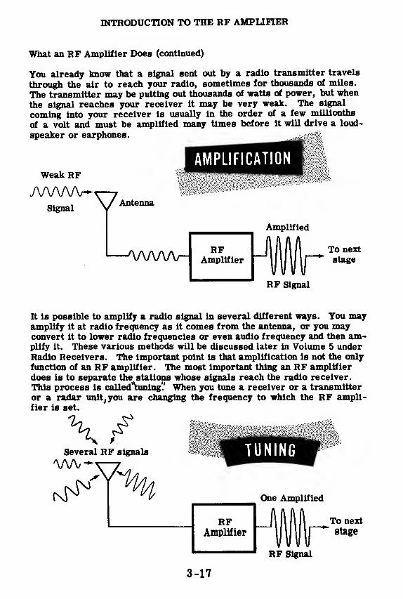
INTRODUCTION TO THE RF AMPLIFIER
What an RF Amplifier Does (continued)
You already know that a signal sent out by a radio transmitter travels
through the air to reach your radio, sometimes for thousands of miles.
The transmitter may be putting out thousands of watts of power, but when
the signal reaches your receiver it may be very weak. The signal
coming into your receiver is usually in the order of a few millionths
of a volt and must be amplified many times before it will drive a loud-
speaker or earphones.
AMPLIFICATIONWeak RF
/WWWSignal VAntenna
Amplified
1—vww- To nextstage
RF Signal
It is possible to amplify a radio signal in several different ways. You mayamplify it at radio frequency as it comes from the antenna, or you mayconvert it to lower radio frequencies or even audio frequency and then am-plify it. These various methods will be discussed later in Volume 5 under
Radio Receivers. The important point is that amplification is not the only
function of an RF amplifier. The most important thing an RF amplifier
does is to separate the stations whose signals reach the radio receiver.
This process is called"tuning'.' When you tune a receiver or a transmitter
or a radar unit, you are changing the frequency to which the RF ampli-fier is set.
Several RF signals TUNING
RFAmplifier
One Amplified
To next
stage
RF Signal
3-17

INTRODUCTION TO THE RF AMPLIFIER
This Is What You Will Learn about RF Amplifiers
Before you learn more about RF amplifiers,you will have a brief reviewof resonance. In addition to what you learned about coils and capacitorsin Basic Electricity, you will be shown how the resonant effect is used totune an RF amplifier stage. The selectivity of tuned circuits and "Q"will be explained and you will be shown the construction of antenna and RFcoils actually in use.
After the section on resonant circuits, you will see why pentodes arenearly always used as RF amplifiers. Then you will be shown actual RFamplifier circuits illustrating how you may connect the tuned circuits tothe amplifier tube and how the correct voltages are applied to the tube.You will go through an analysis of every part used in a typical RF ampli-fier stage in a broadcast receiver, and find out how using more than oneRF amplifier stage affects selectivity.
3-18

TUNED CIHCUITS
What a Tuned Circuit Is
From the introduction to RF amplifiers, you learned that all RF amplifiersperform two important functions:
1. They amplify the signal at radio frequencies.2. They select one narrow band of frequencies and reject all others.
Amplification of the signal is accomplished by a vacuum tube, just as inaudio and video amplifiers. You have already learned just about all youneed to know about amplification.
The job of selecting one narrow band of frequencies to be amplified is per-formed by the RF amplifier's "tuned circuit. " The tuned circuit consistsof coils and capacitors connected to form a resonant LC circuit, which is"tuned" to the desired frequency. On the following sheets you will see howtuned circuits work in RF amplifiers.
3-19

TUNED CIRCUITS
Review of Series LC Circuits
In a radio receiver there are many signals of different frequencies coming
into the antenna. The listener tunes the radio by adjusting the tuning ca-
pacitor. This makes the antenna coil and capacitor resonate to the fre-
quency of the desired station. Because of the resonant effect, the coil and
capacitor select only that signal tuned to their resonant frequency. In
order to understand exactly what the resonant effect is, let's review series
LC circuits and then parallel LC circuits.
You remember that a coil offers less opposition to low frequencies than to
high ones. A capacitor offers less opposition to high frequencies than to
low ones. This opposition is called reactance.
Low FREQUENCY High
In the series LC circuit shown below, assume that the signal generator is
delivering a very low frequency. The coil will offer little opposition to
this low frequency, but the capacitor will offer very high opposition.
Therefore very little current will flow, because the total reactance of the
circuit is high. On the other hand, if the signal generator delivers a very
high-frequency, the coil will offer very high opposition, and the current
will still be low. At some intermediate frequency the reactance of the coil
will equal the reactance of the capacitor. At this frequency (the resonant
frequency), the impedance of the circuit will be minimum and the current
will be maximum.
Below ResonantFrequency
Highreactance
Above ResonantFrequency
Lowreactance
Signal
/Generator
Lowreactance
J
At ResonantFrequency
Both reactances equal,
cancel each other
-Ih
Highreactance
3-20

TUNED CIRCUITS
Review of Parallel LC Circuits
Most radio receivers employ parallel-resonant rather than series-
resonant circuits for tuning to different frequencies.
The reactance of coils and capacitors varies with the frequency applied to
them, as you saw on the previous sheet. In addition to this, coils and
capacitors have another property which is important in resonant circuits.
A coil causes the current to lag behind the applied voltage by 90 degrees.
A capacitor causes the current to lead the applied voltage by 90 degrees.
VOLTAGE AND CURRENT VOLTAGE AND CURRENTWAVE FORMS ACROSS A WAVE FORMS ACROSS A
COIL CAPACITOR
If you connect a coil in parallel with a capacitor, the current in the coil is
90 degrees behind the applied voltage plus 90 degrees behind the current
in the capacitor, or, a total of 180 degrees out of phase with the capacitor
current. You remember from Basic Electricity that currents which are
180 degrees out of phase cancel one another. If the capacitor alone draws
3 amps and the coil alone draws 2 amps, then the combination of the two
will draw 3 -2 or 1 amp.
3-21
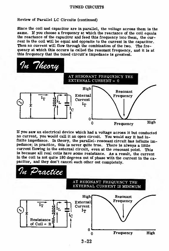
TUNED CIRCUITS
Review of Parallel LC Circuits (continued)
Since the coil and capacitor are in parallel, the voltage across them is thesame. If you choose a frequency at which the reactance of the coil equalsthe reactance of the capacitor and feed this frequency into them, the cur-rent in the coil will be equal and opposite to the current in the capacitor.Then no current will flow through the combination of the two. The fre-quency at which this occurs is called the resonant frequency, and it is atthis frequency that the tuned circuit's impedance is greatest.
AT RESONANT FREQUENCY THEEXTERNAL CURRENT = 0
0 Frequency High
If you saw an electrical device which had a voltage across it but conductedno current, you would call it an open circuit. You would say it had in-finite impedance. In theory, the parallel- resonant circuit has infinite im-pedance; in practice, this is never quite true. There is always a littlecurrent flowing in the external circuit, even at the resonant point. Thisis because all real coils have some resistance. As a result, the currentin the coil is not quite 180 degrees out of phase with the current in the ca-pacitor, and they don't cancel each other out completely.
'Practice ^^^^^^^^^^H|^ AT RESONANT FREQUENCY THE^^^^^^^^^^^H EXTERNAL CURRENT IS MINIMUM
0 I
0 Frequency High
3-22
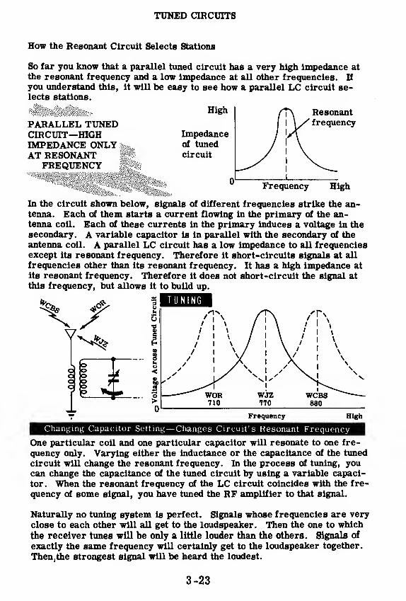
TUNED CIRCUITS
How the Resonant Circuit Selects Stations
So far you know that a parallel tuned circuit has a very high impedance at
the resonant frequency and a low impedance at all other frequencies. If
you understand this, it will be easy to see how a parallel LC circuit se-lects stations.
PARALLEL TUNEDCIRCUIT—HIGHIMPEDANCE ONLY :
AT RESONANTFREQUENCY
High
Impedanceof tuned
circuit
Resonantfrequency
Frequency High
In the circuit shown below, signals of different frequencies strike the an-tenna. Each of them starts a current flowing in the primary of the an-tenna coil. Each of these currents in the primary induces a voltage in the
secondary. A variable capacitor is in parallel with the secondary of the
antenna coil. A parallel LC circuit has a low impedance to all frequenciesexcept its resonant frequency. Therefore it short-circuits signals at all
frequencies other than its resonant frequency. It has a high impedance at
its resonant frequency. Therefore it does not short-circuit the signal at
this frequency, but allows it to build up.
TUNING
Frequency High
Changing Capacitor Setting— Changes Circuit's Resonant Frequency
One particular coil and one particular capacitor will resonate to one fre-
quency only. Varying either the inductance or the capacitance of the tuned
circuit will change the resonant frequency. In the process of tuning, youcan change the capacitance of the tuned circuit by using a variable capaci-
tor. When the resonant frequency of the LC circuit coincides with the fre-
quency of some signal, you have tuned the RF amplifier to that signal.
Naturally no tuning system is perfect. Signals whose frequencies are veryclose to each other will all get to the loudspeaker. Then the one to which
the receiver tunes will be only a little louder than the others. Signals of
exactly the same frequency will certainly get to the loudspeaker together.
Then,the strongest signal will be heard the loudest.
3-23

TUNED CIRCUITS
"Q" and Selectivity
In audio and video amplifiers, it is desirable to have the amplificationstage pass a wide range of frequencies. On the other hand, in RF ampli-fiers we would like the amplification stage to select a narrow band of fre-quencies and reject the rest. Only then can it separate stations which areclose together on the dial. The narrower a band of frequencies passed byan amplifier, the greater is its selectivity. Thus selectivity is the ability
of an amplifier to select one of many signals which are close in frequency.
The selectivity of an RF amplifier is determined by its tuned circuits.The lower we can make a coil's resistance in proportion to its reactance,the more selective it will be. The measure of a coil's selectivity is "Q,
"
which is equal to its reactance divided by its resistance. Since the re-sistance of a capacitor is lower than that of a coil, the coil is the weakestlink in a tuned circuit. The Q of the tuned circuit is the Q of the coil.
O REACTANCE OF COIL Xt-RESISTANCE OF COIL
Sharp tuning
Broad tuning
Good separation of stations
Poor separation of stations
3-24

TUNED CIRCUITS
How Tuning Capacitors Are Constructed
In Basic Electricity you were shown the construction of the two types of
capacitors, fixed and variable. Variable capacitors are used in tuned cir-
cuits so that you can vary their capacitance and thus change the frequency.
Variable capacitors have one set of plates called the rotors which can be
rotated in and out of another set of fixed plates called the stators Thedielectric is air. As the rotor plates are rotated farther and farther out
of the stators, the capacity of the unit decreases.
Most radio receivers with RF amplifiers employ more than one tuned cir-
cuit. Each tuned circuit needs a variable capacitor. H you mounted eachvariable capacitor separately, you would have to tune each one separately
and this would be inconvenient. Instead, you can mount the rotors of sev-
eral identical variable capacitors on a single shaft. This is called "gang-ing" them. When one rotor is turned, the others turn the same amount.
ONE -GANG CAPACITOR TWO-GANG CAPACITOR
I
Ganged capacitors involve one big difficulty. Although each of the gangedunits measures the same size and has the same spacing, there are smalldifferences in capacity between the units. This is because it is economi-cally impractical to manufacture any two things which are exactly the samesize. To compensate for the differences in capacity, a small variable ca-
pacitor is connected in parallel with each variable capacitor unit to beganged. Each of these small compensating capacitors can be adjusted sep-
arately until all of the gangs have the same capacity. These compensatingcapacitors are called "trimmers" because their capacitance is used to
trim the capacitance of the main tuning units.
3-25

TUNED CIRCUITS
How Tuning Coils Are Constructed
Many tuned RF coils are really transformers and have two windings—theprimary and secondary. The coils are wound on a bakelite or cardboardform and generally have an air core, although low frequency coils mayoccasionally have a powdered iron core.
In order to prevent stray electric fields from affecting the action of RFcoils, shields are generally placed around the coils. These shields alter thethe inductance of the coil. Therefore any receiver adjustments, such asthe alignment process which will be described shortly, should be performedwith the shields in place.
ANTENNA COIL44 -A
Shield
Primary
Secondary
Cardboard form
Connecting leads
RF COIL44-RF
3-26
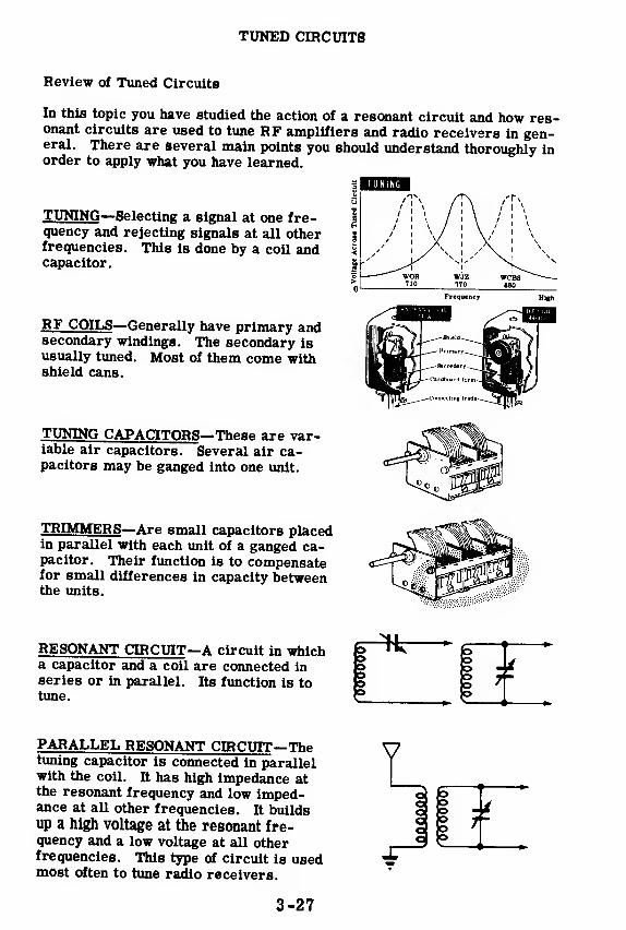
TUNED CIRCUITS
Review of Tuned Circuits
In this topic you have studied the action of a resonant circuit and how res-onant circuits are used to tune RF amplifiers and radio receivers in gen-eral. There are several main points you should understand thoroughly inorder to apply what you have learned.
TJJNING—Selecting a signal at one fre-quency and rejecting signals at all otherfrequencies. This is done by a coil andcapacitor.
RF COILS—Generally have primary andsecondary windings. The secondary isusually tuned. Most of them come withshield cans.
TUNING CAPACITORS—These are var-iable air capacitors. Several air ca-pacitors may be ganged into one unit.
TRIMMER
S
—Are small capacitors placedin parallel with each unit of a ganged ca-pacitor. Their function is to compensatefor small differences in capacity betweenthe units.
RESONANT CIRCUIT—A circuit in whicha capacitor and a coil are connected inseries or in parallel. Its function is totune.
PARALLEL RESONANT CIRCUIT—Thetuning capacitor is connected in parallelwith the coil. It has high impedance atthe resonant frequency and low imped-ance at all other frequencies. It buildsup a high voltage at the resonant fre-quency and a low voltage at all otherfrequencies. This type of circuit is usedmost often to tune radio receivers.
I 6"
i I 4*
3-27

A SINGLE-STAGE RF AMPLIFIER
Why the Pentode is Used in RF Amplifiers
You have just studied the operation of the tuned circuits in an RF ampli-
fier. Now you are ready to begin work on the amplifier tube itself. The
first question is—what kind of amplifier tube will do the job best?
There are three types of tubes which might be used—the triode, the
tetrode and the pentode. At first glance it might seem that the triode
is the best tube to use since it is the simplest of the three. However,
the triode has two great disadvantages when used as an RF amplifier—no
triode has an amplification factor of over 100. Tetrodes and pentodes have
much higher amplification factors and therefore are capable of amplifying
many more times.
Triodes have a much higher capacitance from grid to plate than tetrodes
or pentodes. An RF amplifier generally has tuned circuits in both its in-
put and its output and these tuned circuits resonate to the same frequency.
When you learn about oscillators you will find out that a triode whose out-
put and input circuits are tuned to the same frequency tends to generate its
own signal, or oscillate because of the high grid to plate capacitance. At
this point all you need to know is that a triode used as an RF amplifier
will tend to make the entire receiver howl.
TRIODES often oscillate
3-28

A SINGLE-STAGE RF AMPLIFIER
Why the Pentode is Used in RF Amplifiers (continued)
By now it ought to be obvious that a triode is not well suited for use as anRF amplifier. A tube with a screen grid should clear up the difficultieswhich are encountered when a triode is used. This leaves a choice be-tween the tetrode and the pentode.
Tetrodes do not oscillate because the screen grid cuts down the capacitybetween the control grid and the plate. They do have two drawbacks, how-ever, that are not present in the pentode. Tetrodes do not have an ampli-fication factor of over several hundred, while pentodes have an amplifica-tion factor up to several thousand. Therefore pentodes are preferable.Also,the tetrode produces secondary emission. Electrons from the cath-ode hit the plate at high velocities. Some of them bounce off of the plateand are attracted to the screen grid which is at a positive potential. Thiscuts down the plate current and causes distortion. Secondary emission isnot present in the triode because it has no screen grid. Pentodes do nothave this difficulty for a different reason.
TETRODESmay
Pentodes have a third grid which is placed between the screen grid and theplate. This is the suppressor grid put there for the sole purpose of cuttingdown secondary emission. This is how it works. Electrons which bounceoff the plate might drift back to the screen grid if the suppressor gridwere not there to stop them. The suppressor grid is connected to the cath-ode or to ground and has an excess of electrons just like the cathode.Therefore the electrons which bounce off the plate are repelled backto the plate by the suppressor grid, and secondary emission is vir-tually eliminated.
WORK BEST
3-29
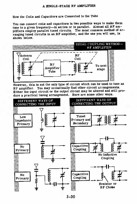
A SINGLE-STAGE RF AMPLIFIER
How the Coils and Capacitors are Connected to the Tube
You can connect coils and capacitors in two possible ways to make them
tune to a given frequency—in series or in parallel. Almost all RF am-
plifiers employ parallel tuned circuits. The most common method of ar-
ranging tuned circuits in an RF amplifier, and the one you will use, is
shown below.
USUAL COUPLING METHOD-RF AMPLIFIER
^\.ntennar
RF*-*-\
i AmplifierTube
To next
stage
However, this is not the only type of circuit which can be used to tune an
RF amplifier. You may occasionally find other circuit arrangements.
Either the input circuit or the output circuit may be altered and still pro-
duce a practical tuning arrangement. Here are some other ways.
DIFFERENT WAYS OFCONNECTING THE INPUT
VLow
ImpedancePrimary
I
NoPrimary
DIFFERENT WAYS OFCONNECTING THE OUTPUT
TunedPrimary andSecondary
Capacitive © mCoupling
^ i i *No Inductive
Coupling
NoPrimary
ooo©
My
Capacitive
Coupling
r+—
i
>
Resistor or
RF Choke
3-30
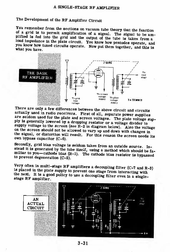
A SINGLE-STAGE RF AMPLIFIER
The Development of the RF Amplifier Circuit
You remember from the sections on vacuum tube theory that the function
f !S„t0
?ermlt amPliflcati°n of a signal. The signal to be am-
plified is fed into the grid and the output of the tube is taken from aload impedance in the plate circuit. You know how pentodes operate, andyou know how tuned circuits operate. Now put them together, and this iswhat you have.
2 GANG
THE BASICRF AMPLIFIER o
- /
ooo _hi° 7
1]rT
Tonext
stage
T = TRIMMER
There are only a few differences between the above circuit and circuitsactually used in radio receivers. First of all, separate power suppliesare seldom used for the plate and screen voltages. The plate voltage sup-ply Is generally lowered by a dropping resistor or a voltage divider tosupply voltage to the screen (see R-2 in diagram below). Also the voltageon the screen should not be allowed to vary up and down with changes inthe signal, or distortion will result. For this reason the screen needs itsown bypass capacitor (C-6).
Secondly, grid bias voltage is seldom taken from an outside source In-stead it is generated by the tube itself, using a method which should be fa-miliar to you-cathode bias (R-l). The cathode bias resistor is bypassedto prevent degeneration (C-5).
,F
Very often in multi-stage RF amplifiers a decoupling filter (C-7 and R-3)is placed in the plate supply to prevent one stage from interacting withthe next It is^ good policy to use a decoupling filter even in a single-
ANACTUALCIRCUIT
3-31
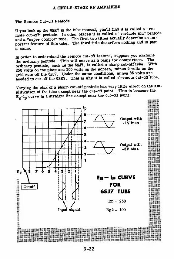
A SINGLE-STAGE RF AMPLIFIER
The Remote Cut-off Pentode
If you look up the 6SK7 in the tube manual, you'll find it is called a "re-
mote cut-off" pentode. In other places it is called a "variable mu" pentode
and a "super control" tube. The first two titles actually describe an im-
portant feature of this tube. The third title describes nothing and is just
a name.
In order to understand the remote cut-off feature, suppose you examine
the ordinary pentode. This will serve as a basis for comparison. The
ordinary pentode, such as the 6SJ7, is called a sharp cut-off tube. With
250 volts on the plate and 100 volts on the screen, minus 9 volts on the
grid cuts off the 6SJ7. Under the same conditions, minus 35 volts are
needed to cut off the 6SK7. This is why it is called a'remote cut-off tube.
Varying the bias of a sharp cut-off pentode has very little effect on the am-
plification of the tube except near the cut-off point. This is because the
E In curve is a straight line except near the cut-off point.& r* ._
Output with
-IV bias
Output with
-3V bias
\ /Input signal
Eg-lp CURVEFOR
6SJ7 TUBE
Ep= 250
Eg2= 100
3-32

A SINGLE-STAGE RF AMPLIFIER
The Remote Cut-off Pentode (continued)
Varying the bias of a remote cut-off pentode varies the amplification. Tounderstand this, look at the Eg-Ip graph of the 6SK7. The graph shows a1-volt signal applied to the grid of a 6SK7 under two different conditions:(1) when the bias is -1 volt and (2) when the bias is -9 volts. Notice thatthe plate current variation is five times as large in the first case as it isin the second case. Therefore the amplification varies with the bias.This is why the 6SK7 is called a'Variable mu pentode'/
IP
Output with-1 volt bias
Eg -16 -14 -12 -10 -8
Output with9 volt bias
Eg-Ip CURVEFOR
6SK7 TUBE
PLATE VOLTAGE = 250 VSCREEN VOLTAGE = 100 V
Input Signal
In a remote cut-off pentode the turns of the control grid are spaced closelyat the edges and farther apart at the center. The electron flow through theedges of the grid is cut off by very little negative bias. However the elec-tron flow through the center of the grid can only be cut off by a high nega-tive bias. The grid of a sharp cut-off pentode is uniformly spaced. Theentire plate current is cut off by one value of bias.
< ONTKI )1 i ,HI1) <)!• SHAH I
l'l'T-( >l I HI- N I < ill!
( ONTKOI. CHID OF KFMOTF(TT-Ot F PFNTODF
3-33
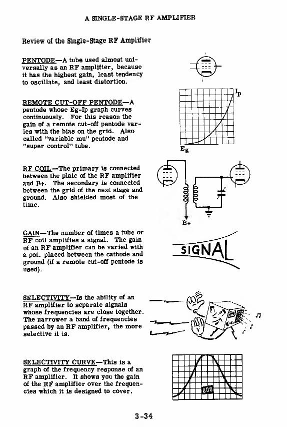
A SINGLE-STAGE RF AMPLIFIER
Review of the Single-stage RF Amplifier
PENTODE—A tube used almost uni-
versally as an RF amplifier, because
it has the highest gain, least tendency
to oscillate, and least distortion.
REMOTE CUT-OFF PENTODE—Apentode whose Eg-Ip graph curves
continuously. For this reason the
gain of a remote cut-off pentode var-
ies with the bias on the grid. Alsocalled "variable mu" pentode and"super control" tube.
RF COIL
—
The primary is connected
between the plate of the RF amplifier
and B+. The secondary is connected
between the grid of the next stage and
ground. Also shielded most of the
time.
GAIN
—
The number of times a tube or
RF coil amplifies a signal. The gain
of an RF amplifier can be varied with
a pot. placed between the cathode and
ground (if a remote cut-off pentode is
used).
SELECTIVITY—Is the ability of an
RF amplifier to separate signals
whose frequencies are close together.
The narrower a band of frequencies
passed by an RF amplifier, the moreselective it is.
SELECTIVITY CURVE—This is agraph of the frequency response of anRF amplifier. It shows you the gain
of the RF amplifier over the frequen-
cies which it is designed to cover.
3-34

THE TWO-STAGE RF AMPLIFIER
Why More Than One RF Stage Is Used
You remember from the previous topic that an RF amplifier performstwo functions:
1. It amplifies an RF signal.
2. It selects a frequency.
When a receiver is close to a transmitter, the signal picked up by the re-ceiver is strong. Such receivers probably need only one RF amplifierstage. On the other hand, some receivers are designed to pick up signalsfrom transmitters several thousand miles away and by the time this sig-nal reaches the receiver, it is very weak; the receiver needs extra am-plification to boost it. Such receivers require more than one RF ampli-fier stage.
There is a second, and less obvious, reason for using more than one RFstage. More than one RF amplifier stage gives greater selectivity. Moreselectivity permits a receiver to separate stations whose frequencies arevery close together. There are radio frequency bands in which manystations are crowded into a few megacycles. Receivers designed tocover these bands need more selectivity than one tuned RF amplifier cangive them.
MORE RF STAGES ARE NEEDED WHERE SIGNAL FREQUENCIES ARE CLOSE TOGETHER
3-35

THE TWO-STAGE RF AMPLIFIER
Why More Than One RF Stage Is Used (continued)
In order to understand how more RF stages give better selectivity, sup-
pose you examine a typical selectivity curve more carefully. Figure 1 is
a curve for a single stage RF amplifier tuned to 500 kc. 10 microvolts of
RF are fed into the amplifier.
You will notice that the output of the amplifier at 500 kc is 100 microvolts.OUTPUT 100
Therefore the gain at 500 kc is:UUiJrui - 1UU
INPUT 10= 10.
The output at 465 kc and 535 kc is 50 microvolts.
50Therefore the gain at these frequencies is— = 5.
The single-stage amplifier amplifies the resonant frequency twice as muchas frequencies 35 kc away:
GAIN at 500 kcGAIN at 465 kc or 535 kc
10
5= 2.
Suppose you took another RF stage, identical with the first one, and hooked
it up to amplify the output of the first stage. Figure 2 shows the overall
selectivity curve for both stages.
Each stage has a gain of ten at 500 kc. Therefore the gain of both stages
is: 10 x 10 or 100 at this frequency. Each stage amplifies five times at
465 kc and 535 kc. Therefore the gain at these frequencies is: 5x5 or 25.
You see that the two-stage RF amplifier amplifies the resonant frequency
four times as much as it amplifies frequencies 35 kc away 100
254. This
is a much greater selectivity than one tuned RF amplifier will give. Add-ing a third tuned RF stage will give still more selectivity than two tuned
RF stages. It may not always be desirable to have that much selectivity.
Naturally, untuned RF stages have no effect on the selectivity.
Selectivity (fawet, Fit;. 2
Fig. 1Voltagegain = 10
100
75
50
25
0
//\v i\/ i yvoltage
gain = 5i
i
i
1000
750
Voltage
gain = 100
450 ! 475465
500 525 i 550535
250
450I47
5
465500 525! 550
535
FREQUENCIES
INPUT VOLTAGE - 10 MICROVOLTS
3-36

THE TWO-STAGE RF AMPLIFIER
Selectivity and Bandpass
There is another idea, related to selectivity, which you ought to under-stand. This is the idea of "bandpass." The word itself gives you somehint of what it means. It refers to the width of the frequency bandpassed by an amplifier. Most of the time it is used in connection withRF amplifiers.
BANDPASS - The width of the band of frequencies which is passed by anamplifier between the two points on the selectivity curvewhere the output is seven-tenths of the output at the reso-nant frequency.
This is the exact definition of bandpass, but it's a complicated one. Youmay get a better understanding if you examine an actual selectivity curveand calculate the bandpass. Here is the selectivity curve of a single stageRF amplifier taken from the previous sheet.
75
j\
-BAND529 - 471
PASS-= 58 kc iV
of 1
outpi
resofreqv
10Jie
it at
riant
lency
450 _ / 4"15 5( 0 525 X
50
25
gill FREQUENCY B«lThe output of the stage at the resonant frequency is 100 microvolts. Seven-tenths of this is 70 microvolts. The amplifier stage puts out 70 microvoltsat 471 kc and at 529 kc. 529 kc minus 471 kc equals 58 kc. The bandpassof this particular RF amplifier is 58 kc. Now read the definition of band-pass again.
The greater the selectivity, the narrower the bandpass. Calculate thebandpass for the two -stage RF amplifier described on the previous sheet.
3-37

THE TWO-STAGE RF AMPLIFIER
How RF Stages Are Coupled
Although you probably know already how one RF amplifier stage is coupledto the next, it might be good to review it at this point. There are severalpossible ways of coupling two RF stages. The most commonly usedmethod is shown in the illustration below.
USUAL CIRCUITFOR COUPLING RFAMPLIFIER STAGES
Notice that the plate load for the first stage is a coil. This coil is the pri-mary winding of an RF transformer and has a nigh impedance at radio fre-quencies. The RF signal current flowing through the coil induces a voltagein the secondary winding. The secondary winding is tuned with a variablecapacitor which is ganged to the capacitor that tunes the first RF stage.The action of this RF transformer is essentially the same as the action ofan audio transformer in a transformer-coupled audio amplifier, exceptthat the secondary of the RF transformer is tuned.
O
Induced Voltage
RF COIL ACTSI jIKE ANY OTHERTRANSFORMER
3-38

THE TWO-STAGE RF AMPLIFIER
Review of the Two -Stage RF Amplifier
TWO-STAGE RF AMPLIFIER — Whencorrectly adjusted, it gives more am-plification and more selectivity than a
single-stage RF amplifier.
BANDPASS — The width of the band
passed by an amplifier between the two
points where the output is seven-tenths
of the output at the resonant frequency.
The greater the selectivity, the narrowerthe bandpass. The greater the bandpass,
the poorer the selectivity.
ALIGNMENT — The process of adjusting
trimmers in a group of tuned amplifier
stages so that all the stages tune to the
same frequency. When a multiple-stage
RF amplifier is correctly aligned, it
will give more selectivity than a single-
stage amplifier. When it is not cor-rectly aligned, it may give far less se-
lectivity or even tune to two frequencies
at once.
Output
Output
3-39


3-41


INTRODUCTION TO OSCILLATORS
Why You Study Oscillators
You have studied how amplifiers function in electronic circuits. No lessimportant are oscillator circuits, or, simply, oscillators. Most modernradio receivers which you have used in your home and in your automobilecontain oscillators. Every transmitter that sends intelligence through theair employs an oscillator to produce these signals. This is not only trueof "ground stations" like WNBC or WCBS; it applies to every transmitteron a ship or plane. Inter-ship and plane-to-ship communications wouldbe greatly limited if oscillator circuits were not employed.
Oscillators are not used exclusively in communications equipment. Thetest equipment you use—signal generators and frequency meters—containoscillator circuits. You will find oscillators in radar and sonar equip-ment, as well as in certain guided missiles and torpedoes.
3-43
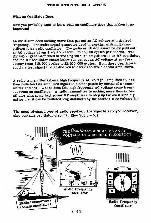
INTRODUCTION TO OSCILLATORS
What an Oscillator Does
Now you probably want to know what an oscillator does that makes it so
important.
An oscillator does nothing more than put out an AC voltage at a desired
frequency. The audio signal generator used in working with audio am-plifiers is an audio oscillator. The audio oscillator shown below puts out
an AC voltage at any frequency from 0 to 15, 000 cycles per second. The
RF signal generator used in working with RF amplifiers is an RF oscillator,
and the RF oscillator shown below can put out an AC voltage at any fre-
quency from 215, 000 cycles to 22, 000, 000 cycles. Both these oscillators,
supply a test signal that enable you to check and troubleshoot amplifiers.
A radio transmitter takes a high frequency AC voltage, amplifies it, and
then radiates this amplified signal to distant points by means of a trans-
mitter antenna. Where does this high frequency AC voltage come from ?
. . . From an oscillator. A radio transmitter is nothing more than an os-
cillator with some high power RF amplifiers to step up the oscillator sig-
nal so that it can be radiated long distances by the antenna. (See Volume 4.
)
The most advanced type of radio receiver, the superheterodyne receiver,
also contains oscillator circuits. (See Volume 5.
)
3-44

INTRODUCTION TO OSCILLATORS
What Oscillations Are
If anything swings back and forth in a uniform way it is said to be "os-cillating'.' A violin string "oscillates"when a bow is drawn over it. Aswing moving back and forth "oscillates." A pendulum swinging on aclock "oscillates."
A CHILD
Consider the pendulum. When it
reaches the extreme left-hand sideof its swing, it comes to rest mo-mentarily, and all its energy is
stored as 'potential energy" Halfway through its swing, it is movingat its greatest speed, and all its
energy has been converted to "kinet-
ic energy',' or "energy of motion'.'
When it completes one swing, ar-riving at the extreme right-hand
position, it again comes momen-tarily to rest, and its energy is all"potential"once again. We can representthis motion by one -half a sine wave, plotting velocity against time. Ve-locity toward the right is considered positive.
3-45

INTRODUCTION TO OSCILLATORS
What Oscillations Are (continued)
Since the return swing fromright to left is a reversal of
direction, the second half of
the sine curve is shown belowthe line. Thus one complete
cycle of oscillation of the
pendulum may be represented
by one complete cycle of the
sine wave.
..ONE COMPLETECYCLE OF OSCILLATION
Did you ever notice that one complete trip on the swing takes the sametime as any other trip? You can represent three cycles of the swing like
this: the time from ti to t3 is the same as that from t3 to t5 or that from
t5 to t7, as shown below. Also the time required for the various half cy-
cles (ti to t£, t2 to t3, etc. ) is always the same.
The time between cycles remain constant-
Clocks and watches keep accurate time because the time consumed by any
one swing of the pendulum or balance wheel is the- same as that for any
other swing. This is as true of the seventh swing as it is of the first. Nowyou understand what was meant by the statement that an oscillator moves
back and forth in a uniform way. Two conditions exist when something
oscillates: (1) there must be back and forth motion (vibration) and (2) the
period of time for each back and forth motion must be the same (uniform).
3-46

INTRODUCTION TO OSCILLATORS
What Oscillations Are (continued)
You know that the motion of a swing will eventually run down. You know,too, that this loss of energy is due to friction, and to compensate for thisloss additional outside energy must be supplied in a uniform way. Whathappens when outside energy is not supplied can be shown by this curve:
This is called a"damped"wave. It is like a sine wave, but with the height(amplitude) of successive cycles diminishing gradually. The time intervalremains the same.
How would you supply the necessary energy to prevent "damping?" If youwere pushing a child on a swing you would not make the next push until theswing had just completed its arc, and was about to reverse its direction.This application of energy at the proper point or with the proper timing,is "in phase" with the original motion. To supply energy to an oscillatorin order to support its natural period of oscillations, the outside sourceof energy must be in phase with the natural period of the oscillator.
You know now that to support a stable oscillator, two conditions arenecessary:
1. Energy must be supplied to compensate for loss of energy inthe oscillator.
2. When supplied, the outside source of energy must be in phase with thenatural period of the oscillator.
3-47
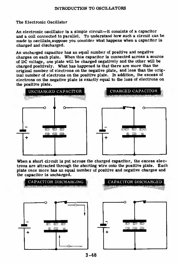
INTRODUCTION TO OSCILLATORS
The Electronic Oscillator
An electronic oscillator is a simple circuit—it consists of a capacitor
and a coil connected in parallel. To understand how such a circuit can be
made to oscillate, suppose you consider what happens when a capacitor is
charged and discharged.
An uncharged capacitor has an equal number of positive and negative
charges on each plate. When this capacitor is connected across a source
of DC voltage, one plate will be charged negatively and the other will be
charged positively. What has happened is that there are more than the
original number of electrons on the negative plate, and less than the orig-
inal number of electrons on the positive plate. In addition, the excess of
electrons on the negative plate is exactly equal to the loss of electrons on
the positive plate.
UNCHARGED CAPACITOR i^^^H CHARGED CAPACITOR
When a short circuit is put across the charged capacitor, the excess elec-
trons are attracted through the shorting wire onto the positive plate. Eachplate once more has an equal number of positive and negative charges andthe capacitor is uncharged.
CAPACITOR DISCHARGING l^^^H CAPACITOR DISCHARGED
3-48

INTRODUCTION TO OSCILLATORS
The Electronic Oscillator (continued)
On the previous sheet you saw what would happen if a short circuit wereconnected across the charged capacitor. If an inductance is connectedacross the charged capacitor, the results are quite different.
You will remember from your work in Basic Electricity that an in-ductance has a peculiar electrical characteristic—it resists any change ofelectron current through itself. You remember that when current flowsthrough a coil, a magnetic field is generated around the coil. Any changein the current causes the magnetic field to expand or contract. This ex-pansion or contraction of the magnetic field causes the magnetic lines tocut across the turns of the coil—resulting in the generation of a voltagewhich opposes the change in current.
When the charged capacitor is switched across the coil, (1) in the illustra-tion below, the electrons stored on the negative plate cannot rush throughthe coil onto the positive plate and the voltage across the circuit is a max-imum. As soon as a small number of electrons flow into the coil, a mag-netic field starts to build up. This building up of the magnetic field in-duces a voltage across the coil which opposes the flow of electrons fromthe negative plate. The capacitor and coil act like two dry cells connectedin series, opposing—positive to positive and negative to negative. As aresult,the charged capacitor cannot discharge immediately through the coil.The larger the coil, the longer it takes for the capacitor to discharge. Asthe capacitor discharges, the magnetic field about the coil becomesstronger and stronger, and the voltage continues to decrease (2).
MAGNETIC FIELD INCREASESAS CAPACITOR CHARGE DECREASES
Switch Thrown *v no current flow
T 1Magnetic field
builds up
Increasing
current
Capacitor ±discharges "T" +
3-49
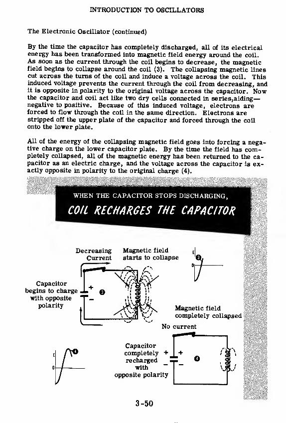
INTRODUCTION TO OSCILLATORS
The Electronic Oscillator (continued)
By the time the capacitor has completely discharged, all of its electricalenergy has been transformed into magnetic field energy around the coil.
As soon as the current through the coil begins to decrease, the magneticfield begins to collapse around the coil (3). The collapsing magnetic linescut across the turns of the coil and induce a voltage across the coil. Thisinduced voltage prevents the current through the coil from decreasing, andit is opposite in polarity to the original voltage across the capacitor. Nowthe capacitor and coil act like two dry cells connected in series,aiding
—
negative to positive. Because of this induced voltage, electrons areforced to flow through the coil in the same direction. Electrons arestripped off the upper plate of the capacitor and forced through the coilonto the lower plate.
All of the energy of the collapsing magnetic field goes into forcing a nega-tive charge on the lower capacitor plate. By the time the field has com-pletely collapsed, all of the magnetic energy has been returned to the ca-pacitor as an electric charge, and the voltage across the capacitor is ex-actly opposite in polarity to the original charge (4).
WHEN THE CAPACITOR STOPS DISCHARGING,
COIL RECHARGES THE CAPACITOR
DecreasingCurrent
Magnetic field
starts to collapse
Capacitorbegins to charge J>with opposite
polarity
t
wi 25 ii
1 1 <y i
ii. a .hi
Magnetic field
completely collapsed:
No current
Capacitorcompletely +recharged
with
opposite polarity
±. O
3-50
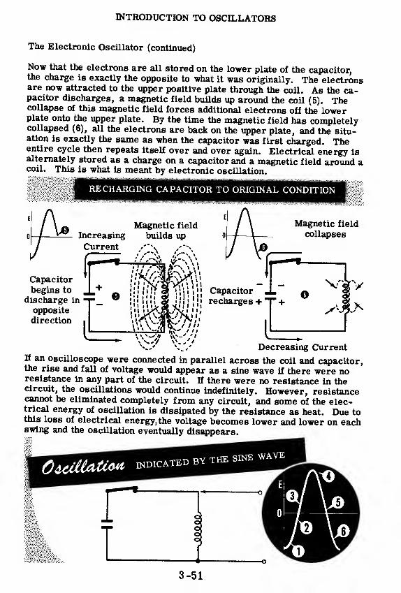
INTRODUCTION TO OSCILLATORS
The Electronic Oscillator (continued)
Now that the electrons are all stored on the lower plate of the capacitor,the charge is exactly the opposite to what it was originally. The electronsare now attracted to the upper positive plate through the coil. As the ca-pacitor discharges, a magnetic field builds up around the coil (5). Thecollapse of this magnetic field forces additional electrons off the lowerplate onto the upper plate. By the time the magnetic field has completelycollapsed (6), all the electrons are back on the upper plate, and the situ-ation is exactly the same as when the capacitor was first charged. Theentire cycle then repeats itself over and over again. Electrical energy isalternately stored as a charge on a capacitor and a magnetic field around acoil. This is what is meant by electronic oscillation.
RECHARGING CAPACITOR TO ORIGINAL CONDITION
Increasing
Current
Magnetic field
builds up
Magnetic field
collapses
Capacitorbegins to
discharge in
opposite
direction
Capacitorrecharges +
Decreasing CurrentIf an oscilloscope were connected in parallel across the coil and capacitor,the rise and fall of voltage would appear as a sine wave if there were noresistance in any part of the circuit. If there were no resistance in thecircuit, the oscillations would continue indefinitely. However, resistancecannot be eliminated completely from any circuit, and some of the elec-trical energy of oscillation is dissipated by the resistance as heat. Due tothis loss of electrical energy, the voltage becomes lower and lower on eachswing and the oscillation eventually disappears.
OiCiitet** INDICATED BY THE SINE WAVE
ioo
_L3-51
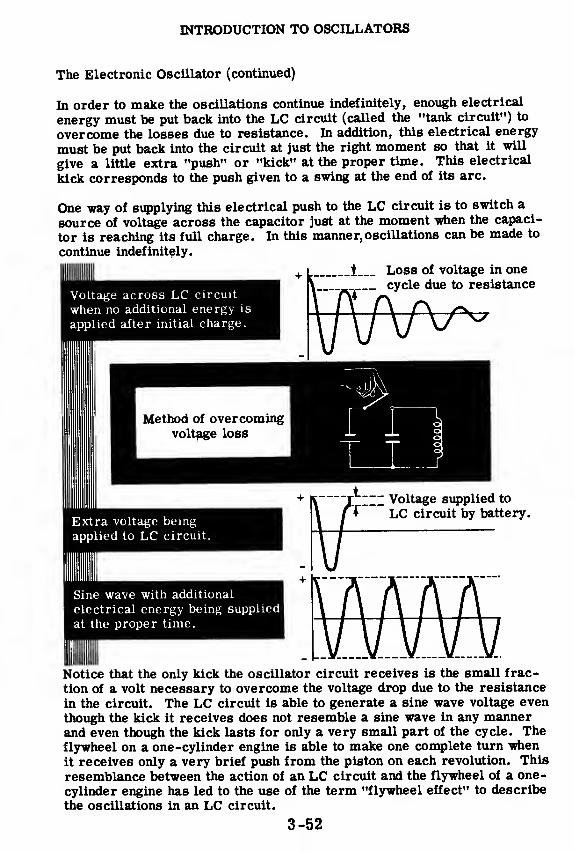
INTRODUCTION TO OSCILLATORS
The Electronic Oscillator (continued)
In order to make the oscillations continue indefinitely, enough electrical
energy must be put back into the LC circuit (called the "tank circuit") to
overcome the losses due to resistance. In addition, this electrical energy
must be put back into the circuit at just the right moment so that it will
give a little extra "push" or "kick" at the proper time. This electrical
kick corresponds to the push given to a swing at the end of its arc.
One way of supplying this electrical push to the LC circuit is to switch a
source of voltage across the capacitor just at the moment when the capaci-
tor is reaching its full charge. In this manner, oscillations can be made to
continue indefinitely.
_t Loss of voltage in one
cycle due to resistanceVoltage across LC circuit
when no additional energy is
applied after initial charge.
Extra voltage being
applied to LC circuit.
Sine wave with additional
electrical energy being supplied
at the proper time.
LC circuit by battery.
Notice that the only kick the oscillator circuit receives is the small frac-
tion of a volt necessary to overcome the voltage drop due to the resistance
in the circuit. The LC circuit is able to generate a sine wave voltage even
though the kick it receives does not resemble a sine wave in any mannerand even though the kick lasts for only a very small part of the cycle. Theflywheel on a one-cylinder engine is able to make one complete turn whenit receives only a very brief push from the piston on each revolution. This
resemblance between the action of an LC circuit and the flywheel of a one-
cylinder engine has led to the use of the term "flywheel effect" to describe
the oscillations in an LC circuit.
3-52
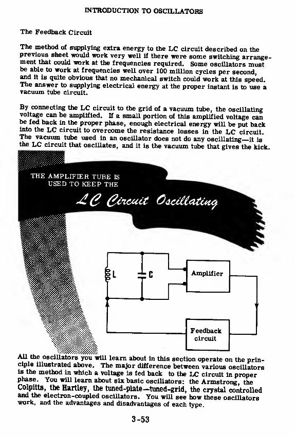
INTRODUCTION TO OSCILLATORS
The Feedback Circuit
The method of supplying extra energy to the LC circuit described on theprevious sheet would work very well if there were some switching arrange-ment that could work at the frequencies required. Some oscillators mustbe able to work at frequencies well over 100 million cycles per second,and it is quite obvious that no mechanical switch could work at this speed.The answer to supplying electrical energy at the proper instant is to use avacuum tube circuit.
By connecting the LC circuit to the grid of a vacuum tube, the oscillatingvoltage can be amplified. If a small portion of this amplified voltage canbe fed back in the proper phase, enough electrical energy will be put backinto the LC circuit to overcome the resistance losses in the LC circuit.The vacuum tube used in an oscillator does not do any oscillating—it isthe LC circuit that oscillates, and it is the vacuum tube that gives the kick.
THE AMPLIFIER TUBE IS
USED TO KEEP THE
±c Amplifier
Feedbackcircuit
All the oscillators you will learn about in this section operate on the prin-ciple illustrated above. The major difference between various oscillatorsis the method in which a voltage is fed back to the LC circuit in properphase. You will learn about six basic oscillators: the Armstrong, theColpitts, the Hartley, the tuned-plate—tuned-grid, the crystal controlledand the electron-coupled oscillators. You will see how these oscillatorswork, and the advantages and disadvantages of each type.
3-53

INTRODUCTION TO OSCILLATORS
Frequency Stability of Oscillators
One important characteristic of oscillators, which you are going to learn
about, is frequency stability. Although you have not yet studied oscilla-
tors, it ought to be obvious that an oscillator should maintain the frequen-
cy to which it is set. Unfortunately, all oscillators tend to drift in fre-
quency unless steps are taken to prevent this. Some circuits drift less than
others.
Imagine what would happen if frequency drift were not taken into account.
If one ship were trying to contact another, and the oscillator in its trans-
mitter drifted off frequency, the message would never be received. If the
oscillator in a shipboard receiver drifted off frequency, that ship would
receive no messages at all. If the oscillator in a shipboard sonar unit
drifted off frequency, that ship could not detect submarines. It would be
torpedoed by the first enemy submarine that came along. A great proport-
ion of electronic equipment contains oscillators. If these oscillators wereallowed to drift off frequency, all this equipment would be useless until the
oscillators were reset to the correct frequency.
Thus you can see that it is necessary to understand frequency stability and
drift. Drift is caused by several factors. Vibration, varying loads and
varying supply voltages will cause an oscillator to drift. Changes in tem-
perature will, also. Since much electronic equipment is subject to all of
these factors, some compensation is usually included in all equipment which
contains an oscillator. You will learn about these things in the next few topics.
FACTORS WHICH CAUSE FREQUENCY SHIFTS IN OSCILLATORS.
3-54

THE ARMSTRONG AND HARTLEY OSCILLATORS
The Armstrong Oscillator
Basically all oscillators operate in the same way. Energy is coupled back,from the output to the tuned oscillating circuit on the input of the vacuumtube, in order to compensate for inevitable heat losses due to electricalresistance. H the losses are compensated for, oscillations continue. If
you understand how oscillations are maintained in the Armstrong oscilla-tor, you will understand the basic principles underlying all oscillators.
The Armstrong oscillator is like an RF amplifier with one modification-a coil has been introduced into the plate circuit. This coil is called the"tickler coil. " It is wound adjacent to the LC tank coil (usually both coilsare wound on the same coil form), so when plate current flows throughthis tickler coil, Lt, an emf will be induced into the tank coil L. Actuallyit is not DC plate current but variations in this DC current which producethe changing magnetic fields responsible for induced voltages acrossthe tank coil. The induced voltage is the feedback voltage which sus-tains oscillation.
3-55
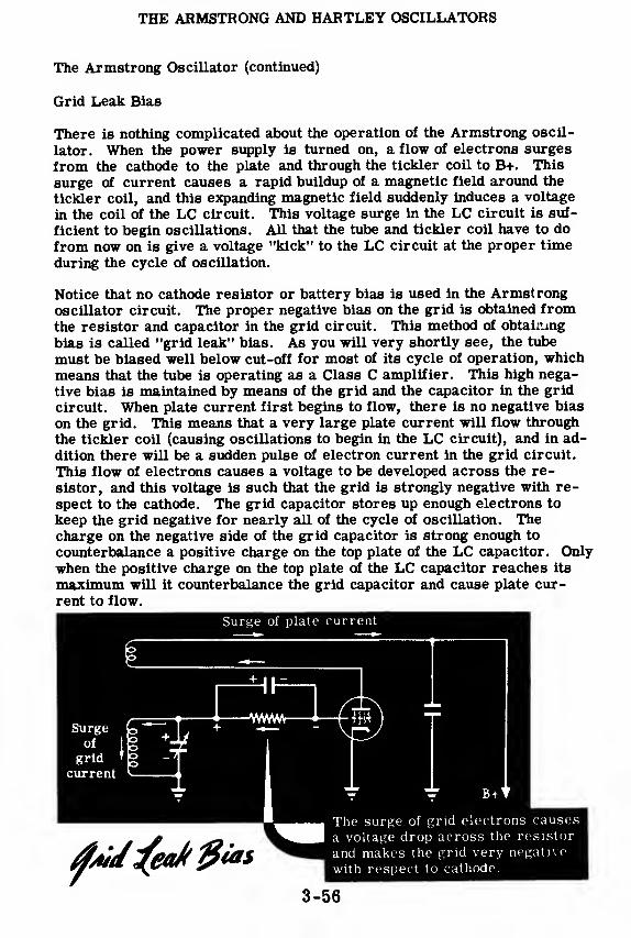
THE ARMSTRONG AND HARTLEY OSCILLATORS
The Armstrong Oscillator (continued)
Grid Leak Bias
There is nothing complicated about the operation of the Armstrong oscil-
lator. When the power supply is turned on, a flow of electrons surges
from the cathode to the plate and through the tickler coil to B+. This
surge of current causes a rapid buildup of a magnetic field around the
tickler coil, and this expanding magnetic field suddenly induces a voltage
in the coil of the LC circuit. This voltage surge in the LC circuit is suf-
ficient to begin oscillations. All that the tube and tickler coil have to do
from now on is give a voltage "kick" to the LC circuit at the proper time
during the cycle of oscillation.
Notice that no cathode resistor or battery bias is used in the Armstrongoscillator circuit. The proper negative bias on the grid is obtained fromthe resistor and capacitor in the grid circuit. This method of obtaining
bias is called "grid leak" bias. As you will very shortly see, the tube
must be biased well below cut-off for most of its cycle of operation, which
means that the tube is operating as a Class C amplifier. This high nega-
tive bias is maintained by means of the grid and the capacitor in the grid
circuit. When plate current first begins to flow, there is no negative bias
on the grid. This means that a very large plate current will flow through
the tickler coil (causing oscillations to begin in the LC circuit), and in ad-
dition there will be a sudden pulse of electron current in the grid circuit.
This flow of electrons causes a voltage to be developed across the re-
sistor, and this voltage is such that the grid is strongly negative with re-
spect to the cathode. The grid capacitor stores up enough electrons to
keep the grid negative for nearly all of the cycle of oscillation. Thecharge on the negative side of the grid capacitor is strong enough to
counterbalance a positive charge on the top plate of the LC capacitor. Onlywhen the positive charge on the top plate of the LC capacitor reaches its
maximum will it counterbalance the grid capacitor and cause plate cur-
rent to flow.
3-56
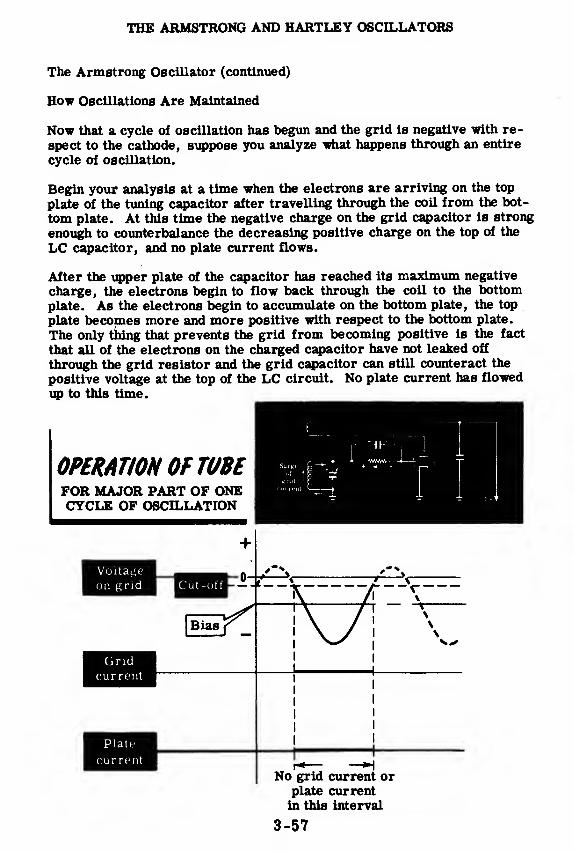
THE ARMSTRONG AND HARTLEY OSCILLATORS
The Armstrong Oscillator (continued)
How Oscillations Are Maintained
Now that a cycle of oscillation has begun and the grid is negative with re-
spect to the cathode, suppose you analyze what happens through an entire
cycle of oscillation.
Begin your analysis at a time when the electrons are arriving on the top
plate of the tuning capacitor after travelling through the coil from the bot-
tom plate. At this time the negative charge on the grid capacitor is strong
enough to counterbalance the decreasing positive charge on the top of the
LC capacitor, and no plate current flows.
After the upper plate of the capacitor has reached its maximum negative
charge, the electrons begin to flow back through the coil to the bottom
plate. As the electrons begin to accumulate on the bottom plate, the top
plate becomes more and more positive with respect to the bottom plate.
The only thing that prevents the grid from becoming positive is the fact
that all of the electrons on the charged capacitor have not leaked off
through the grid resistor and the grid capacitor can still counteract the
positive voltage at the top of the LC circuit. No plate current has flowed
up to this time.
OPERATION OF TUBEFOR MAJOR PART OF ONECYCLE OF OSCILLATION
Voltage
on grid
Gridcurrent
Plate
cur rent
Cut-off
+
1-0-
Bias
— -r
No grid current orplate currentin this interval
3-57

THE ARMSTRONG AND HARTLEY OSCILLATORS
The Armstrong Oscillator (continued)
How Oscillations Are Maintained
Finally the top of the LC circuit becomes so positive that it briefly over-comes the negative bias maintained by the grid capacitor. At this timeplate current begins to flow and continues to flow for the interval that the
top of the LC circuit remains strongly positive. This brief surge of plate
current flows through the tickler coil and induces a brief voltage surge in
the LC circuit. The tickler coil is wound in the same direction as the coil
in the LC circuit, so this voltage surge is in such a direction as to give a"push" to aid the flow of electrons in the LC circuit. During the short
interval that the top of the LC circuit is strongly positive, grid cur-rent begins to flow and causes the grid capacitor to regain its strongnegative charge.
Immediately after the top plate of the LC capacitor reaches its peak posi-tive value, electrons begin leaving the bottom plate of the capacitor ontheir way to the top plate. The negative charge on the grid capacitor is
now strong enough to cut off all plate current and you are back at the point
where you began your analysis. This cycle repeats itself over and
+OPERATION OF TUBE SHOWING
GRID AND PLATE CURRENT FLOW
over again.
Voltage
on grid H| Cut-off
Gridcurrent
Plate
currentI
II
The tube, the grid resistor and capacitor and the power supply serve nopurpose whatsoever during most of the cycle of oscillation. The LC cir-
cuit is the oscillator. All that these other components do is provide themeans to give the LC circuit a voltage kick for a brief portion of the cycle.
The "flywheel effect" keeps the electrons surging around the LC circuit
with no other aid.
In order for oscillation to be sustained,the tickler coil must be able to in-duce enough voltage in the LC circuit to overcome the losses caused bythe resistance of the LC coil. The proper amount of feedback is set byvarying the number of turns on the tickler coil and by adjusting the dis-tance between the tickler coil and the coil of the LC circuit. In order forthe feedback voltage to be in the proper phase to aid the oscillator, thefeedback coil must be wound in the same direction as the coil of the
LC circuit.g gg
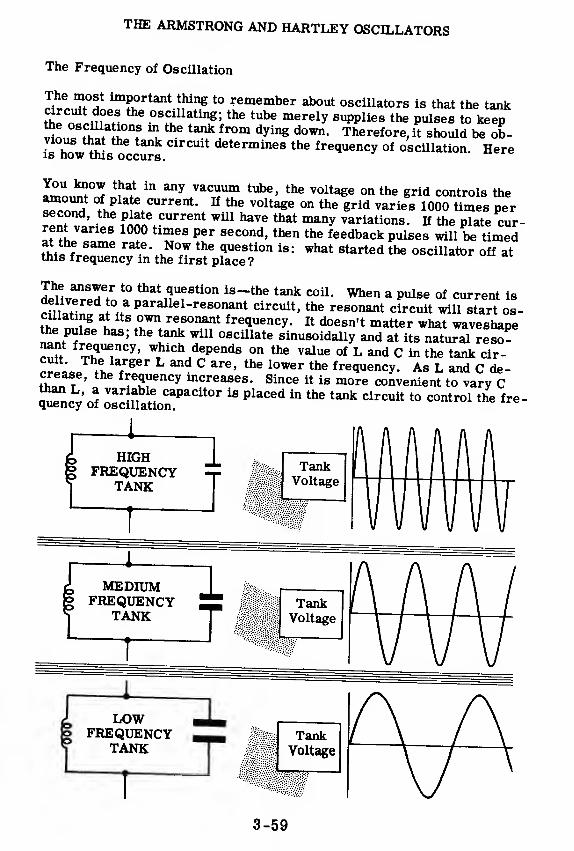
THE ARMSTRONG AND HARTLEY OSCILLATORS
The Frequency of Oscillation
The most important thing to remember about oscillators is that the tank
Srn^Prn6^ 4
0SSU!tin
,
githe tube merely 8UPPlies the Pulses to keep
I S. f *?tank fr°m dyin^ down
- Therefore, it should be ob-
?Sf ^? C1FCUit determines frequency of oscillation. Hereis how this occurs.
You know that in any vacuum tube, the voltage on the grid controls the
^n11
". fPla^ current. If the voltage on the grid varies 1000 times per
llni vur^Z Knnet
CUrrent W*U haVe that^ variations. If the plate cur-rent varies 1000 times per second, then the feedback pulses will be timedat the same rate. Now the question is: what started the oscillator off atthis frequency in the first place?
The answer to that question is-the tank coil. When a pulse of current is
cmZtin'f V parallel-resonant circuit, the resonant circuit will starlos-
Sp ™ fg
* ^ re,
sonant frequency. It doesn't matter what waveshapethe pulse has; the tank will oscillate sinusoidally and at its natural reso-S f^quency> ^ich depends on the value of L and C in the tank cir-^ tL /
ger L^ C arC'the l0Wer the f^quency. As L and C de-
ST-J 'fre
5uency increases. Since it is more convenient to vary C
STncy cJ oSi?aUonaPaCit°r *^ *^^^ t0 COntro1 tn* fre "
1
HIGHFREQUENCY
TANK

THE ARMSTRONG AND HARTLEY OSCILLATORS
Advantages of Grid Leak Bias
An important feature of the grid leak bias method used in the Armstrong
oscillator is that it tends to make the oscillator self-adjusting. A random
change in plate voltage affects the amplitude of oscillation, but high grid
bias tends to reduce or cushion this effect. Here is how this cushioning
effect acts:
1. If plate voltage rises, plate current increases through the tickler coil.
2. A larger emf is induced in the LC circuit.
3. The negative charge on the grid capacitor increases.
4. Plate current is reduced to its original level.
This grid bias tends to cancel plate current changes and reduce its effect
on the LC tank.
Summing up the effects of grid leak bias: it permits high grid bias,
permits oscillations to start, and tends to keep the strength of oscil-
lation steady.
Grid leak bias has one disadvantage. If oscillations should cease, even
momentarily, the high negative grid bias would be lost. A large flow of
electrons from cathode to plate would occur. This average plate current
flow would be so large as to damage or ruin the vacuum tube.
3-60
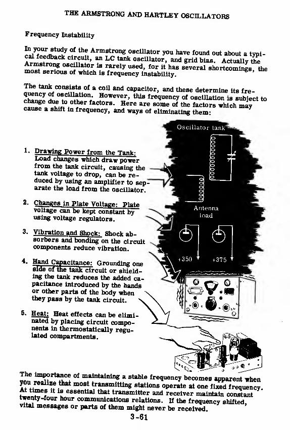
THE ARMSTRONG AND HARTLEY OSCILLATORS
Frequency Instability
fJt^^J ? ^f/™8*™* oscillator you have found out about a typi-cal feedback circuit, an LC tank oscillator, and grid bias. Actually SeArmstrong oscillator is rarely used, for it has slveral snortcom^s themost serious of which is frequency instability.
^^COn^Va * C°a^ caPacitor »and these determine its fre-
SSS *0^cU^tion
;However, this frequency of oscillation is subject to
2ST.t?m i
0^' aCt°rS-H6re are SOme of factors whi<* maycause a shift in frequency, and ways of eliminating them:
Drawing Power from the Tank:Load changes which draw powerfrom the tank circuit, causing thetank voltage to drop, can be re-duced by using an amplifier to separate the load from the oscillator.
2. Changes in Plate Voltage: Platevoltage can be kept constant byusing voltage regulators.
3 « Vibration and Shock: Shock ab-sorbers and bonding on the circuitcomponents reduce vibration.
acitance: Grounding one4. Hand Cside of the tank circuit or shield-ing the tank reduces the added ca-pacitance introduced by the handsor other parts of the body whenthey pass by the tank circuit.
5. Heat: Heat effects can be elimi-nated by placing circuit compo-nents in thermostatically regu-lated compartments.
The importance of maintaining a stable frequency becomes apparent when
Iftw^f^ m°Bi
t
1
rrmitting ^"operate at oneZT^Z^.At times it is essential that transmitter and receiver maintain constanttwenty-four hour communications relations. If the frequency shifted,vital messages or parts of them might never be received.
3-61
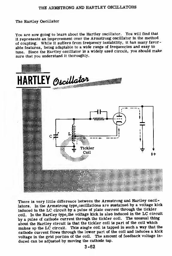
THE ARMSTRONG AND HARTLEY OSCILLATORS
The Hartley Oscillator
You are now going to learn about the Hartley oscillator. You will find that
it represents an improvement over the Armstrong oscillator in the method
of coupling. While it suffers from frequency instability, it has many favor-
able features, being adaptable to a wide range of frequencies and easy to
tune. Since the Hartley oscillator is a widely used circuit, you should make
sure that you understand it thoroughly.
There is very little difference between the Armstrong and Hartley oscil-
lators. In the Armstrong type,oscillations are sustained by a voltage kick
induced in the LC circuit by a pulse of plate current through the tickler
coil. In the Hartley type,the voltage kick is also induced in the LC circuit
by a pulse of cathode current through the tickler coil. The unusual thing
about the Hartley circuit is that the tickler coil is part of the coil which
makes up the LC circuit. This single coil is tapped in such a way that the
cathode current flows through the lower part of the coil and induces a kick
voltage in the grid portion of the coil. The amount of feedback voltage in^
duced can be adjusted by moving the cathode tap.
3-62
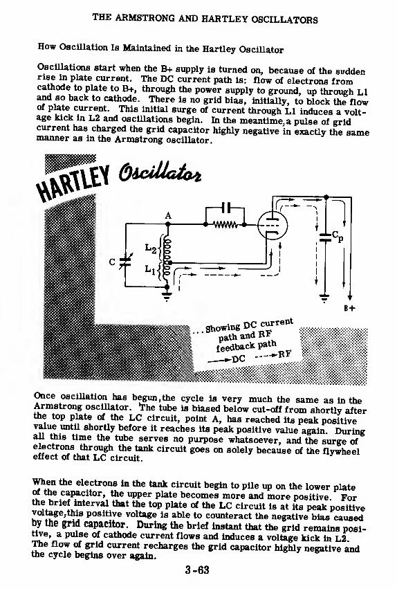
THE ARMSTRONG AND HARTLEY OSCILLATORS
How Oscillation Is Maintained in the Hartley Oscillator
Oscillations start when the B+ supply is turned on, because of the suddenrise m plate current. The DC current path is: flow of electrons fromcathode to plate to B+, through the power supply to ground, up through LIand so back to cathode. There is no grid bias, initially, to block the flowof plate current. This initial surge of current through LI induces a volt-age kick in L2 and oscillations begin. In the meantime^ pulse of gridcurrent has charged the grid capacitor highly negative in exactly the samemanner as in the Armstrong oscillator.
B+
Showing DCcurrent ^
path and Ri mmmmMfeedback path^^li
Once oscillation has begun, the cycle is very much the same as in theArmstrong oscillator. The tube is biased below cut-off from shortly afterthe top plate of the LC circuit, point A, has reached its peak positivevalue until shortly before it reaches its peak positive value again. Duringall this time the tube serves no purpose whatsoever, and the surge ofelectrons through the tank circuit goes on solely because of the flywheeleffect of that LC circuit.
When the electrons in the tank circuit begin to pile up on the lower plateof the capacitor, the upper plate becomes more and more positive. Forthe brief interval that the top plate of the LC circuit is at its peak positivevoltage,this positive voltage is able to counteract the negative bias causedby the grid capacitor. During the brief instant that the grid remains posi-tive, a pulse of cathode current flows and induces a voltage kick in L2The flow of grid current recharges the grid capacitor highly negative andthe cycle begins over again.
3-63

THE ARMSTRONG AND HARTLEY OSCILLATORS
The Colpitts Oscillator
The third basic oscillator you will learn about is the Colpitts oscillator.
It is versatile, easy to operate, adaptable to a wide range of frequencies and
has somewhat better frequency stability than the Hartley oscillator. It is very
much like the Hartley, but uses tapped capacitance in place of the Hartley's
tapped inductance for feedback. The two are compared below.
E
COLPITTS &icM»Legend
iU HARTLEY
The DC current path is: electron flow from cathode to plate, through the
RF choke to B+, through the power supply to ground, back to cathode.
AC current is coupled back to the tank by means of the coupling capacitor
Cb; and Cp is the AC plate load across which the feedback voltage is de-
veloped. Feedback current begins due to the first rise in plate current.
The amount of feedback depends on the ratio of Cp to Co. Proper phasing
of oscillation is obtained with the grid and plate at opposite ends of the
tank, using a condenser, Cb, for feedback of RF voltage. The current
oscillates in the tank circuit consisting of LCpCo, and the reactance of the
coil and two capacitors determine the oscillating frequency.
3-64
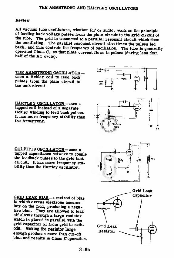
THE ARMSTRONG AND HARTLEY OSCILLATORS
Review
All vacuum tube oscillators, whether RF or audio, work on the principleof feeding back voltage pulses from the plate circuit to the grid circuit ofthe tube. The grid is connected to a parallel resonant circuit which doesthe oscillating. The parallel resonant circuit also times the pulses fedback, and thus controls the frequency of oscillation. The tube is generallyoperated Class C, so that plate current flows in pulses (during less thanhalf of the AC cycle).
THE ARMSTRONG OSCILLATOR—uses a tickler coil to feed backpulses from the plate circuit tothe tank circuit.
TlckUr|
Colt 1
TankColl
m I
1 11—
1
i
»t'
HARTLEY OSCILLATOR—uses atapped coil instead of a separatetickler winding to feed back pulses.It has more frequency stability thanthe Armstrong.
COLPITTS OSCILLATOR
—
uses atapped capacitance network to couplethe feedback pulses to the grid tankcircuit. It has more frequency sta-bility than the Hartley oscillator.
GRID LEAK BIAS
—
a method of biasin which excess electrons accumu-late on the grid, producing a nega-tive bias. They are allowed to leakoff slowly through a large resistorwhich is placed in parallel with thegrid capacitor or from grid to cath-ode. Making the resistor largeenough produces more than cut-offbias and results in Class C operation.
Grid Leak
3-65
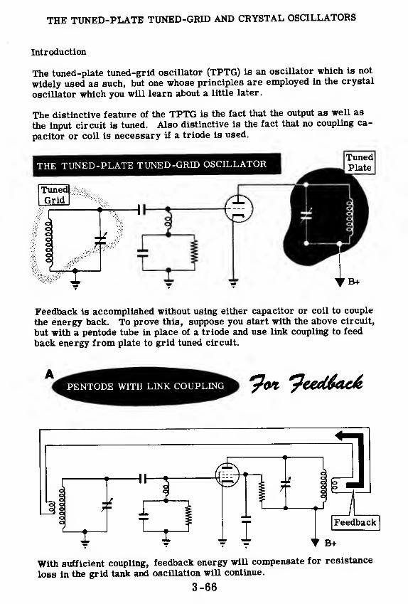
THE TUNED-PLATE TUNED-GRID AND CRYSTAL OSCILLATORS
Introduction
The tuned-plate tuned-grid oscillator (TPTG) is an oscillator which is not
widely used as such, but one whose principles are employed in the crystal
oscillator which you will learn about a little later.
The distinctive feature of the TPTG is the fact that the output as well as
the input circuit is tuned. Also distinctive is the fact that no coupling ca-
pacitor or coil is necessary if a triode is used.
Tuned
Feedback is accomplished without using either capacitor or coil to couple
the energy back. To prove this, suppose you start with the above circuit,
but with a pentode tube in place of a triode and use link coupling to feed
back energy from plate to grid tuned circuit.
With sufficient coupling, feedback energy will compensate for resistance
loss in the grid tank and oscillation will continue.
3-66

THE TUNED-PLATE TUNED-GRID AND CRYSTAL OSCILLATORS
Feedback in the TPTG Oscillator
Replace the link coil with a small capacitor, say of 3 mmf capacity. Thiscapacitor will provide the feedback.
Now you are ready to compare this circuit, containing a pentode with ca-pacitor feedback, to a circuit containing a triode but without capacitorfeedback.
PENTODE WITHCAPACITOR FEEDBACK
r
TRIODE WITHOUT
CAPACITOR FEEDBACK
The pentode with capacitor feedback will support oscillation. The triodewithout capacitor feedback will support oscillation because it, too, pro-vides feedback: not through an outside capacitor but through the capaci-tance between the plate and the grid of the triode. The pentode has such alow plate-grid electrode capacitance that an added capacitor is needed.The triode has more plate-grid capacitance and doesn't require an addedcapacitor. Both employ capacitance feedback.
Pentode + Capacitor = Triode + Plate -Grid Capacitance
Thus you can see that feedback to sustain oscillation can be accomplishedwithout the use of coil or capacitor. The internal capacitance of tube ele-ments provides the feedback.
3-67
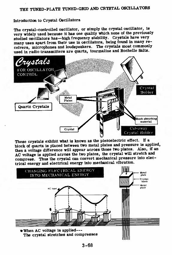
THE TUNED-PLATE TUNED-GRID AND CRYSTAL OSCILLATORS
Introduction to Crystal Oscillators
The crystal-controlled oscillator, or simply the crystal oscillator, is
very widely used because it has one quality which none of the previously
studied oscillators has—high frequency stability. Crystals have very
many uses apart from their use in oscillators, being found in many re-
ceivers, microphones and loudspeakers. The crystals most commonly
used in radio transmitters are quartz, tourmaline and Rochelle Salts.
These crystals exhibit what is known as the piezoelectric effect. If a
block of quartz is placed between two metal plates and pressure is applied,
then a voltage difference will appear across those two plates. Also, if an
AC voltage is applied across the two plates, the crystal will stretch and
compress. Thus the crystal can convert mechanical pressure into elec-
trical energy and electrical energy into mechanical vibration.
3-68

THE TUNED-PLATE TUNED-GRID AND CRYSTAL OSCILLATORS
The Crystal as a Resonator
A crystal has a natural frequency of vibration. When the AC voltageacross its faces has the same frequency as the mechanical frequency ofthe crystal, the crystal block will stretch and compress more than forother frequencies. Also, the crystal's natural frequency of vibration isextraordinarily constant, more constant even than the frequency of oscil-lation in an LC circuit.
EQUIVALENT TOA SERIES-RESONANT CIRCUIT
EQUIVALENT TO A PARALLEL-RESONANT CIRCUIT
4
The Crystal
I
i
I
I
Between ConductingPlates
J
'////////////////A
Taken by itself, the crystal acts like a series-resonant circuit. Togetherwith its two plates, it acts like a parallel-resonant circuit. The frequencyat which it vibrates depends on its thickness. Thick crystals vibrateslowly, thin crystals vibrate rapidly.
For protection from mechanical shock, crystals have been placed insealed containers or holders. Don't drop them. Crystals should be pro-tected from electrical shock,too. Excessive voltage causes them to crackor overheat. The RF current flowing through the crystal should not ex-ceed 100 milliamperes.
THIS IS THE EQUIVALENTELECTRICAL CIRCUIT
B+
TUNED CIRCUIT
3-69

THE TUNED-PLATE TUNED-GRID AND CRYSTAL OSCILLATORS
The Crystal Oscillator Circuit
Where power output is not the most important consideration and where
only one fixed frequency is to be used, the crystal oscillator is a
highly satisfactory circuit. It overcomes one defect which all previous
oscillators have suffered from, namely, its frequency is not influenced by
changes of load.
The basic crystal oscillator uses a crystal as a mechanical resonator, in
place of the tuned-grid capacitor and inductor in a TPTG oscillator.
This circuit behaves like the TPTG oscillator in every respect. Feedback
is obtained through the plate-grid capacity of the vacuum tube or by using
a small feedback capacitor. This voltage feedback causes the crystal to
vibrate mechanically at its natural frequency. When the crystal vibrates,
an emf appears across the electrodes on the two faces of the crystal. This
emf is applied to the grid. The changing emf on the grid controls the flow
of plate current and hence the amount of feedback.
Amount of coupling and, therefore, amplitude of oscillation and power out-
put depend on tuning the plate tank to a higher frequency than the natural
frequency of the crystal. If the plate tank should be tuned to a lower fre-
quency, feedback through the plate-grid capacity would be out-of-phase
with the grid oscillations, and oscillation would cease.
3-70

THE TUNED-PLATE TUNED-GRID AND CRYSTAL OSCILLATORS
Tuning the Crystal Oscillator
To tune the crystal oscillator you tune the plate tank capacitor, starting
with the capacitor set for maximum capacity. A plate current meter in-
dicates a high plate current, as is to be expected when the grid tank is not
oscillating. This plate current suddenly drops to point A, indicating that
the plate is at the same resonant frequency as the crystal circuit, hencefeedback is at a maximum and oscillations are very strong. The capaci-
tor is tuned past this point to the region B-C, where plate current hasrisen and the plate tank is higher in frequency than the grid crystal oscil-
lator. Some power is sacrificed for stable oscillations, since at point Aany small change in the direction of lowered frequency would cause the
crystal to stop vibrating.
Plate Current[Plat Region of
oscillationA-
Tuning tubcrystal oscillator
Region of bestoperation
Region of bestoperation
ABC|-* Capacity
High of plate
tang capacitorLow
High
ABCCapacity of plate
tank capacitor Low
Since a crystal has low frictional losses, it doesn't require much feedbackto sustain oscillations. Besides, a large amount of voltage across thecrystal plates can make the crystal vibrate so hard as to overheat orshatter—much as a powerful explosion causes window panes to vibrate sostrongly as to shatter. Overheating causes frequency drift. Thus, smallerfeedback results in a greater safety factor and in less frequency drift.
Since a pentode tube has very low grid-plate capacity, it may be used in ahigh frequency crystal oscillator to lessen the amount of feedback. Thisallows the crystal to do less work while still controlling the frequency of
oscillation. Such a circuit has still less frequency drift than a triodecrystal oscillator and is often used when very precise frequency measure-ments are being made.
However, the pentode crystal oscillator suffers from certain disadvan-tages. At low frequencies, the low grid-plate capacity of the pentode doesnot allow enough feedback to sustain oscillations. Therefore, some exter-nal grid-plate capacity must be inserted. The crystal oscillator you will
build avoids this difficulty by. connecting the oscillator tube as a triode.
3-71

THE TUNED-PLATE TUNED-GRID AND CRYSTAL OSCILLATORS
Analysis of the Crystal Oscillator
The crystal oscillator is a TPTG oscillator in which a crystal substitutes
for the conventional tuned capacitor and inductor. The 6L6 tube (see figure)
is used as a triode. Thus the grid-plate capacity is much higher than if the
tube were connected as a pentode. This increases the amount of feedback
and makes the crystal "work harder. " It is possible to use a pentode in a
crystal oscillator, but such an oscillator is more complicated and sometimesmore difficult to adjust. To avoid the possibility of this difficulty, the 6L6
is connected as a triode.
C3 in parallel with C2 adds to its capacity and reduces the resonant fre-
quency. This is required if the range of C2L2 alone does not extend downto the crystal frequency.
RFC2 is the plate choke which keeps the RF out of the power supply and
forces it into the tank circuit. C4 is the blocking capacitor which keeps the
DC plate voltage out of the tank circuit but allows the RF to get through.
The grid capacitor Ci and resistor Ri bias the grid. These are in shunt
rather than in series with the crystal in order to keep down the amount of
voltage across the plates of the crystal power input. Shunt feed is used,
through the inductor L2 to plate of the tube.
RFCj is the grid choke which keeps down the current flow in the crystal
circuit. In the absence of RFC}, the RF being generated by the crystal
would be shorted by Ci to ground. An excessively large current wouldflow in the tank circuit, causing the crystal to vibrate so strongly as to
overheat, and possibly crack or shatter.
3-72
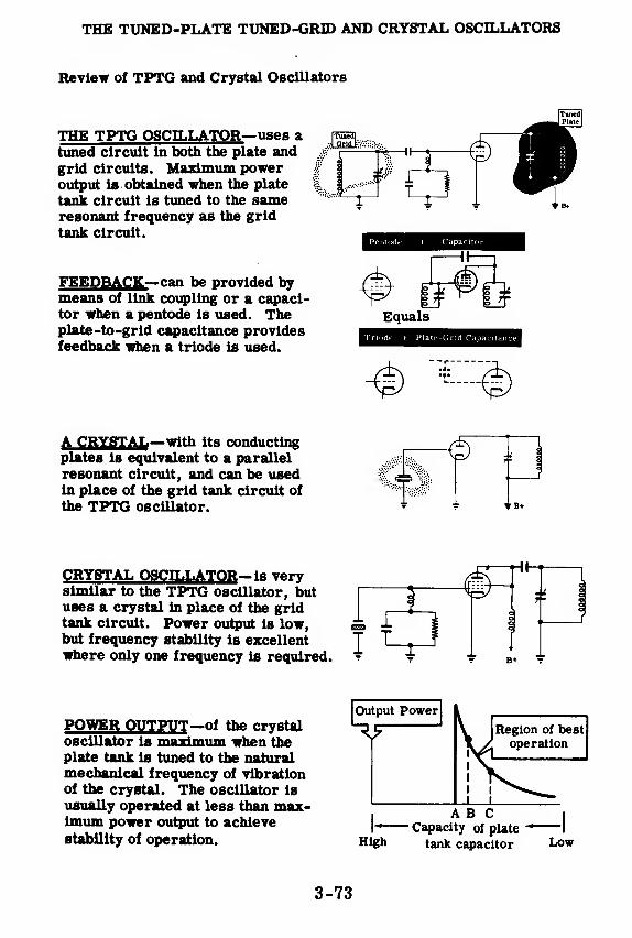
THE TUNED-PLATE TUNED-GRID AND CRYSTAL OSCILLATORS
Review of TPTG and Crystal Oscillators
THE TPTG OSCILLATOR—uses atuned circuit in both the plate andgrid circuits. Maximum poweroutput is obtained when the plate
tank circuit is tuned to the sameresonant frequency as the grid
tank circuit.
FEEDBACK—can be provided bymeans of link coupling or a capaci-tor when a pentode is used. Theplate-to-grid capacitance providesfeedback when a triode is used.
A CRYSTAL—with its conductingplates is equivalent to a parallel
resonant circuit, and can be usedin place of the grid tank circuit of
the TPTG oscillator.
CRYSTAL OSCILLATOR— is verysimilar to the TPTG oscillator, butuses a crystal in place of the gridtank circuit. Power output is low,but frequency stability is excellentwhere only one frequency is required.
POWER OUTPUT—of the crystaloscillator is maximum when theplate tank is tuned to the naturalmechanical frequency of vibrationof the crystal. The oscillator is
usually operated at less than max-imum power output to achieve
stability of operation.
pruned]
Plate
Pentode + Capacitor
Equals
Trmde + Plate-Grid Capacitance
•a ^ ©
I
ABC I
I- Capacity of plate-*
1
High tank capacitor Low
1
3-73

THE ELECTRON-COUPLED OSCILLATOR
Introduction to the Electron-Coupled Oscillator
The Colpitts and Hartley oscillators are good all-round oscillators, butthey do not quite meet the needs of good frequency stability. The crystaloscillator has good frequency stability, but it is limited to relatively lowpower output and to a single frequency of operation plus its harmonics.What is still needed is an oscillator having good frequency stability in ad-dition to high power output and a wide operating range. One which meetsall three conditions is the electron-coupled oscillator. As a result, it is
very widely used, at moderate frequencies, in transmitters.
Below is the basic circuit of the electron-coupled oscillator, or ECO.
You can see that this is a modified Hartley oscillator. The modificationconsists in the replacement of the triode by a tetrode, which has an addi-tional element, the screen grid.
As in the Hartley, current feedback across L2 starts the cycle of oscilla-tion and then sustains it in the LC tank. As in the Hartley, too, theamount of feedback depends on the ratio of Lj to L2. Thus the method offeedback is the same.
DC current flow is substantially unchanged except that a screen circuit ap-pears in parallel to the plate circuit as shown by the arrows in the diagram.The screen grid draws a very small portion of the total current since adropping resistor, Rs , places it at a much lower potential than the plate.This screen current represents a small power loss, reducing the efficiencyof the circuit somewhat. Screen current may be about three ma. as com-pared to approximately sixty ma. in the plate circuit.
3-74
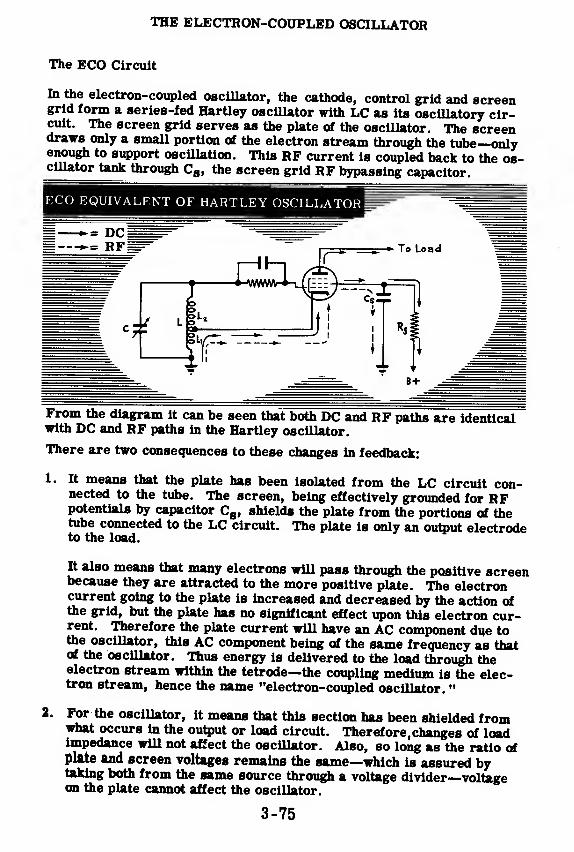
THE ELECTRON-COUPLED OSCILLATOR
The ECO Circuit
In the electron-coupled oscillator, the cathode, control grid and screengrid form a series-fed Hartley oscillator with LC as its oscillatory cir-cuit. The screen grid serves as the plate of the oscillator. The screendraws only a small portion of the electron stream through the tube—onlyenough to support oscillation. This RF current is coupled back to the os-cillator tank through Cs , the screen grid RF bypassing capacitor.
From the diagram it can be seen that both DC and RF paths are identicalwith DC and RF paths in the Hartley oscillator.
There are two consequences to these changes in feedback:
1. It means that the plate has been isolated from the LC circuit con-nected to the tube. The screen, being effectively grounded for RFpotentials by capacitor Cg , shields the plate from the portions of thetube connected to the LC circuit. The plate is only an output electrodeto the load.
It also means that many electrons will pass through the positive screenbecause they are attracted to the more positive plate. The electroncurrent going to the plate is increased and decreased by the action ofthe grid, but the plate has no significant effect upon this electron cur-rent. Therefore the plate current will have an AC component due tothe oscillator, this AC component being of the same frequency as thatof the oscillator. Thus energy is delivered to the load through theelectron stream within the tetrode—the coupling medium is the elec-tron stream, hence the name "electron-coupled oscillator.
"
2. For the oscillator, it means that this section has been shielded fromwhat occurs in the output or load circuit. Therefore,changes of loadimpedance will not affect the oscillator. Also, so long as the ratio ofplate and screen voltages remains the same—which is assured bytaking both from the same source through a voltage divider—voltageon the plate cannot affect the oscillator.
3-75
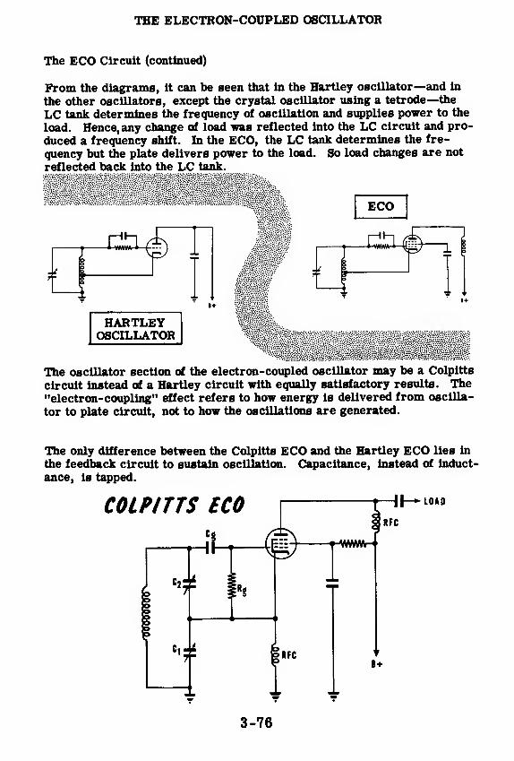
THE ELECTRON-COUPLED OSCILLATOR
The ECO Circuit (continued)
From the diagrams, it can be seen that in the Hartley oscillator—and in
the other oscillators, except the crystal oscillator using a tetrode—the
LC tank determines the frequency of oscillation and supplies power to the
load. Hence, any change of load was reflected into the LC circuit and pro-
duced a frequency shift. In the ECO, the LC tank determines the fre-
quency but the plate delivers power to the load. So load changes are not
reflected back into the LC tank.
ECO
HARTLEYOSCILLATOR
The oscillator section of the electron-coupled oscillator may be a Colpitts
circuit instead of a Hartley circuit with equally satisfactory results. The"electron-coupling" effect refers to how energy is delivered from oscilla-
tor to plate circuit, not to how the oscillations are generated.
The only difference between the Colpitts ECO and the Hartley ECO lies in
the feedback circuit to sustain oscillation. Capacitance, instead of induct-
ance, is tapped.
COLPITTS ECO HI— LOAD
RFC
B+
3-76

THE ELECTRON-COUPLED OSCILLATOR
Analysis of the ECO
Shown below is a Colpitts type ECO. Its operation is almost identical withthat of the Hartley ECO which was explained previously.
METER1
*
A pentode connected as a tetrode is used in place of the triode of theColpitts oscillator. The cathode, control grid and screen, along with thetank circuit, act as a conventional Colpitts oscillator. The screen RF by-pass capacitor, C8 , shields this triode from the plate and supplies feed-back across Ci, the AC screen grid load.
The tank circuit is C1-C2-C3-L. C3 has been placed in parallel with Ci-C2 so that the tank can be tuned without changing the ratio of Cj to C2.
RFCj is necessary for oscillations to be sustained. It prevents an RFshort circuit from CB back to cathode, in which case feedback would neverreach the tank circuit.
Most of the electrons leaving the cathode reach the plate which is at ahigher potential than the screen grid. The AC component of plate currentis coupled to the load by capacitor Cc , while RFC2 blocks this same AC(RF) current from the B+ supply. Thus the plate of the tube acts as anoutput electrode, its function being to deliver power to the load. Electroncoupling within the tube delivers power to the plate circuit. This does notalter the way in which feedback is coupled back to sustain oscillations.
The Colpitts type ECO is relatively immune to changes of load and platevoltage.
3-77

MISCELLANEOUS OSCILLATORS
Variations in Oscillators—Series and Shunt Feed
In previous topics you examined the Armstrong, Hartley, electron-coupled,
Colpitts, tuned-plate tuned-grid, and crystal oscillators. Each one of the
circuits you have already studied can be set up in a number of ways. Then
there are probably a dozen other types of oscillators, each of which maybe connected in a number of ways.
The reason for all these oscillator circuits is that various circuits have
different advantages as well as disadvantages. Certain oscillators are
more stable than others. Some are less affected by loading. Others are
just simpler, and thus easier, to include in the equipment for which they
are designed.
One possible variation in an oscillator circuit is the choice between series
feed and shunt feed. Series feed is a hookup in which the plate current
flows through the tank coil. In shunt feed, the plate current flows through
an RF choke, and only RF current flows through the tank. Here is how
the Hartley oscillator is connected for series feed and shunt feed. Nearly
every other oscillator circuit may be varied in a similar manner.
SERIES-FEED HARTLEY l|,
»
*
-•-DC PATH-*-RF PATH —TJCTT
—
RF choke
3-78

MISCELLANEOUS OSCILLATORS
Variations in Oscillators—RF Ground Potential
Any point in an oscillator or RF amplifier circuit -which has a high imped-ance to ground with respect to RF is said to be"above RF ground potential'.'Any point which presents a low impedance to ground for RF current issaid to be"at RF ground potential'.'
Below, you see a circuit of a Hartley oscillator. You will notice that thecathode does not go directly to ground. There is a coil between the cath-ode and ground. This coil presents some impedance to RF. Therefore,the cathode is not at ground potential with respect to RF. It is above RFground potential.
RF Potential in
the Hartley Oscillator
Aboye RFgroundpotential
At RF groundpotential
There is a capacitor between the plate of the Hartley oscillator and ground.This capacitor offers a very low impedance path for RF. Since it goes toground, the plate is considered at RF ground potential, even though it isat a high DC potential.
A circuit diagram of the Armstrong oscillator is shown below. The cath-ode is at RF ground potential. It has a low impedance connection toground—a wire. The plate is above RF ground potential because it isconnected to B+ through a coil and B+ is always at RF ground potential.
Above RFground
potential
nRF Potential
in the ArmstrongOscillator
At RF ground potential
The grid of the Armstrong oscillator is above ground potential even thoughthere is a capacitor between grid and ground. This is because the ca-pacitor is connected across a coil. The combination of capacitor and coilform a parallel-resonant circuit which has a high impedance to RF at its
resonant frequency. The Armstrong circuit oscillates at the resonantfrequency of the tuned circuit. Therefore, as long as the circuit is oscil-lating, there is a high impedance from grid to ground so that the grid isabove RF ground potential.
3-79
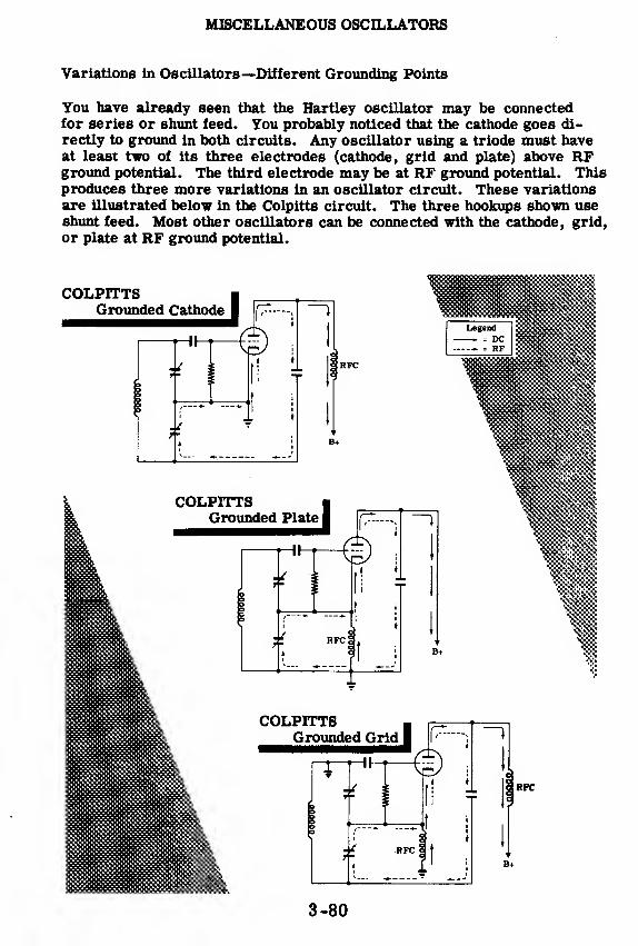
MISCELLANEOUS OSCILLATORS
Variations in Oscillators—Different Grounding Points
You have already seen that the Hartley oscillator may be connectedfor series or shunt feed. You probably noticed that the cathode goes di-
rectly to ground in both circuits. Any oscillator using a triode must haveat least two of its three electrodes (cathode, grid and plate) above RFground potential. The third electrode may be at RF ground potential. Thisproduces three more variations in an oscillator circuit. These variations
are illustrated below in the Colpitts circuit. The three hookups shown useshunt feed. Most other oscillators can be connected with the cathode, grid,
or plate at RF ground potential.
3-80

MISCELLANEOUS OSCILLATORS
Variations in Oscillators—Other Circuits
The oscillator circuits shown below are included so that you can becomeaccustomed to analyzing many different forms of oscillators. They areall variations on the six basic oscillators which you studied in previoustopics, except for the klystron oscillator, the principle of which is ex-plained in the text.
The most important thing to remember about oscillators, no matter whatkind, is that they all must have certain features:
1. Something which couples the output to the input.
2. Something which corrects the phase of the voltage fed back.
Here are some other oscillator circuits. See if you can locate the sourceof feedback. Then trace the DC and RF paths.
Armstrong ECO
Hartley GroundedPlate Series Feed
Hartley Grounded Grid
> RFC
Ultra-AudionSeries Feed
3-81

MISCELLANEOUS OSCILLATORS
High Frequency Oscillators
You have studied the basic oscillators used at low radio frequencies.These operate at high efficiency up to about 20 mc. Beyond 20 mc their
efficiency drops unless specially designed high frequency tubes are used.Also the Q of the tuned circuits drops at high frequencies. This loss of
efficiency becomes greater, until at 100 mc most tubes will lose fifty percent of the power put into them. However, there are still tubes operatingon the same principle as the ordinary 6C5 triode which can give reasonableefficiency up to around 700 mc. Beyond that—give up I Entirely different
types of tubes and resonant circuits are needed to get more than 5 wattsof RF power output. They operate on entirely different principles fromthose with which vou are familiar.
At very high frequencies the inductance of the connecting wires, and evenof the tube leads, becomes greater than the inductance in the tuned circuit.
Likewise,the grid-to-plate and grid-to-cathode capacity becomes greaterthan the capacity in the tuned circuit. The solution is to use shorter con-necting leads and miniature tubes with low interelectrode capacity. Eventhen
(these tiny tubes are useless at 1000 mc. Besides, small tubes can-
not give much power output.
3-82

MISCELLANEOUS OSCILLATORS
Tuned Lines
At frequencies between 100 and 500 mc,it is still possible to get reasonablepower from an oscillator using triodes with special tuned circuits. Insteadof having coils with turns and capacitors with parallel plates, tuned lines,which are the equivalent of a coil and capacitor at low frequencies, are used.
^ItiA* B EQUIVALENT TOAt high frequencies l At low frequencies
The characteristics of these tuned lines are calculated in the same way ascharacteristics of transmission lines, which you will find out about in"Transmitters. " Inductance and capacitance of ordinary coils and capaci-tors is said to be "lumped. " Inductance and capacitance of tuned lines issaid to be "distributed. " Here are some other high frequency oscillatorcircuits using distributed reactance (capacity and inductance).
-OZTD
iklbB+
-SOME HIGH FREQUENCYOSCILLATOR CIRCUITS
3-83
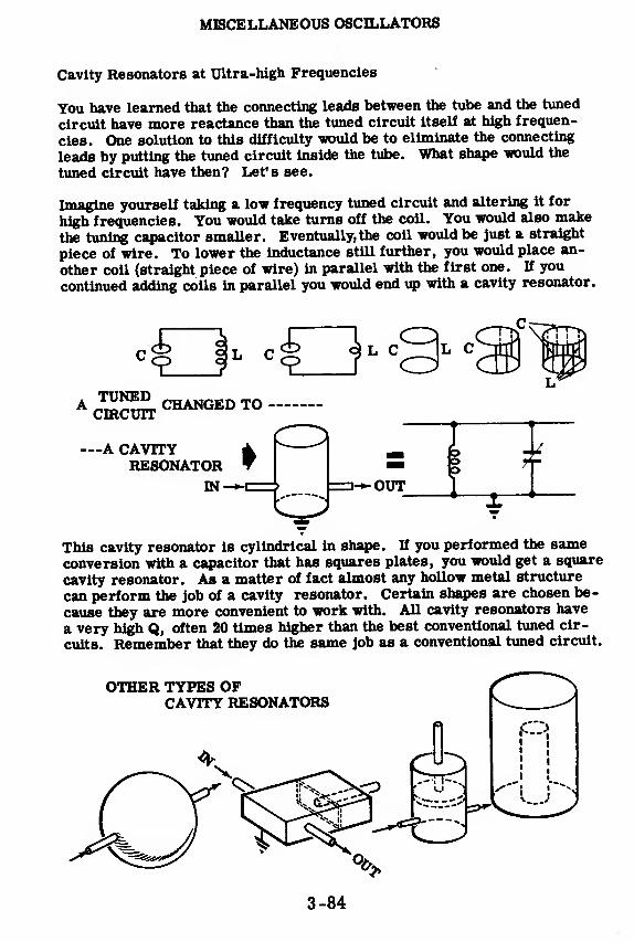
MISCELLANEOUS OSCILLATORS
Cavity Resonators at Ultra-high Frequencies
You have learned that the connecting leads between the tube and the tuned
circuit have more reactance than the tuned circuit itself at high frequen-
cies. One solution to this difficulty would be to eliminate the connecting
leads by putting the tuned circuit inside the tube. What shape would the
tuned circuit have then? Let's see.
Imagine yourself taking a low frequency tuned circuit and altering it for
high frequencies. You would take turns off the coil. You would also make
the tuning capacitor smaller. Eventually, the coil would be just a straight
piece of wire. To lower the inductance still further, you would place an-
other coil (straight piece of wire) in parallel with the first one. H you
continued adding coils in parallel you would end up with a cavity resonator.
This cavity resonator is cylindrical in shape. If you performed the sameconversion with a capacitor that has squares plates, you would get a square
cavity resonator. As a matter of fact almost any hollow metal structure
can perform the job of a cavity resonator. Certain shapes are chosen be-
cause they are more convenient to work with. All cavity resonators have
a very high Q, often 20 times higher than the best conventional tuned cir-
cuits. Remember that they do the same job as a conventional tuned circuit.
3-84

MISCELLANEOUS OSCILLATORS
The Klystron Tube
The klystron is a vacuum tube operating on an entirely different principle
from conventional tubes, It can be made to amplify or oscillate. Its func-
tion as an oscillator is important at this point. Electrons leave the hot
cathode and are accelerated by a positive grid. They fly toward a buncher,
which is a pair of grids at the same positive potential as the accelerator.
They reach the nearer of the two buncher grids first and deliver a kick to
the tuned circuit, which starts it oscillating. By the time the first groupof electrons reaches the second buncher grid, its potential has changedbecause of the oscillations in the tuned circuit. When the second bunchergrid swings in a negative direction, fewer electrons get through. When it
swings in a positive direction, more electrons get through. Although the
electrons approach the buncher uniformly spaced, they leave the buncherin clusters. This is similar to the increase and decrease of plate current
in a conventional oscillator.
AcceleratingGrid-
B+
Cathode
B-J
o | o
o I o
oIo
KLYSTRONTUBE
BunchedElectrons
Buncher> | e o | o e
> | o o | o o
3I
°
\• o
oooo
Catchero|o
I
o|oI
o|o
XL
B+
Collector
B+
FeedbackPath
Then these bunched electrons reach the catcher grids and start the secondtuned circuit oscillating. Since they keep arriving in bunches, they keepthe second tuned circuit oscillating. The oscillations in the first tunedcircuit will stop unless voltage is fed back from the catcher grids to keepit going. Of course the tuned circuits in the klystron are not coils and ca-pacitors. They are cavity resonators.
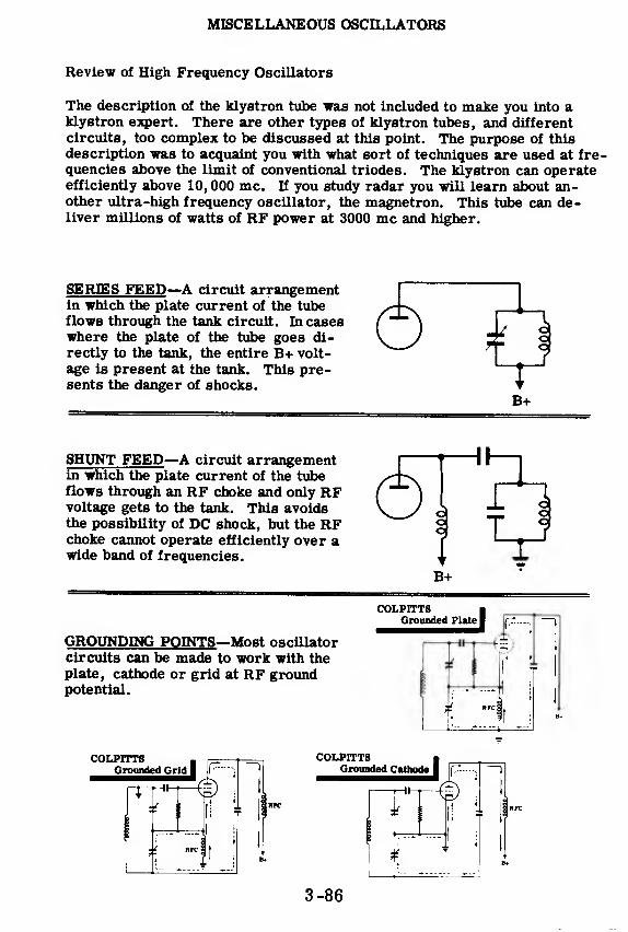
MISCELLANEOUS OSCILLATORS
Review of High Frequency Oscillators
The description of the klystron tube was not included to make you into aklystron expert. There are other types of klystron tubes, and different
circuits, too complex to be discussed at this point. The purpose of this
description was to acquaint you with what sort of techniques are used at fre-quencies above the limit of conventional triodes. The klystron can operateefficiently above 10,000 mc. If you study radar you will learn about an-other ultra-high frequency oscillator, the magnetron. This tube can de-liver millions of watts of RF power at 3000 mc and higher.
SERIES FEED—A circuit arrangementin which the plate current of the tubeflows through the tank circuit. In caseswhere the plate of the tube goes di-
rectly to the tank, the entire B+ volt-
age is present at the tank. This pre-sents the danger of shocks.
B+
SHUNT FEED—A circuit arrangementin which the plate current of the tubeflows through an RF choke and only RFvoltage gets to the tank. This avoidsthe possibility of DC shock, but the RFchoke cannot operate efficiently over awide band of frequencies.
GROUNDING POINTS—Most oscillator
circuits can be made to work with theplate, cathode or grid at RF groundpotential.
COLPITTSi
Grounded Plate |
COLPITTSGrounded Grid I
COLPITTSGrounded Cathode
-r-ll-
3-86
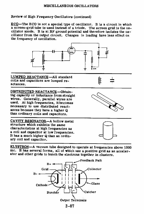
MISCELLANEOUS OSCILLATORS
Review of High Frequency Oscillators (continued)
ECO—The ECO is not a special type of oscillator. It is a circuit in whicha screen-grid tube is used instead of a triode. The screen grid is the os-cillator anode. It is at RF ground potential and therefore isolates the os-cillator from the output circuit. Changes in loading have less effect onthe frequency of oscillation.
L
-H-
LUMPED REACTANCE—All standardcoils and capacitors are lumped re-actances.
DISTRIBUTED REACTANCE —Obtain-ing capacity or inductance from straightwires. Generally, parallel wires areused. At high frequencies, it becomesnecessary to use distributed react-ances because they have a higher Qthan ordinary coils and capacitors.
CAVITY RESONATOR—A hollow metalstructure which exhibits the samecharacteristics at high frequencies asa coil and capacitor at low frequencies.It has a much higher Q than an ordin-ary coil and capacitor.
KLYSTRON—A vacuum tube designed to operate at frequencies above 1000mc. It has several forms, all of which use a positive grid as an acceler-ator and other grids to bunch the electrons together in clusters.
Feedback Path
Collector
B-
CathodeGlass
Buncher Catcher
Output Terminals
3-87

OSCILLATORS
Review of Oscillators
ELECTRONIC OSCILLATOR-Avacuum tube amplifier with a feedback
circuit either internal or external to
the tube. It generates continuous sine
wave AC of a controllable frequency.
It has a tuned circuit which does the
oscillating and controls the frequency
of the wave generated. The vacuum
tube merely supplies pulses to keep
the tuned circuit oscillating.
ARMSTRONG OSCILLATOR-uses a
tickler coil to feed back pulses fromthe plate circuit to the tank circuit.
HARTLEY OSCILLATOR—u«es atapped coil instead of a separate tickler
winding to feed back pulses. It hasmore frequency stability than the
Armstrong.
COLPITTS OSCILLATOR—uses a
tapped capacitance network to couple the
pulses to the tank. It has more fre-
quency stability than the Hartley.
TPTG OSCILLATOR—uses the grid-
plate capacitance of~a triode to feed
back pulses to a tuned circuit con-
nected to the grid. It oscillates only
when the two tuned circuits are set to
or near the same frequency.
Amplifier
Feedbackcircuit
TankColl
-&4> {
TicklerColl
CRYSTAL OSCILLATOR—is like a
TPTG oscillator, but a crystal is
connected in place of the grid tank
circuit. It can only oscillate at, or
very close to, the frequency of the
crystal. It has more frequency sta-
bility than any other oscillator.
I
rT
3-88

Review of Oscillators (continued)
ELECTRON-COUPLING—is a methodof connecting other oscillator circuits.
In the electron-coupled oscillator, the
screen grid is the feedback electrode,
leaving the plate independent of the
oscillator section. Changes in load
and plate voltage have little effect onoscillator frequency. It is morestable than any other oscillator except
the crystal.
SERIES FEED—a circuit arrangementin which the plate current of the tube
flows through the tank circuit. In
cases where the plate of the tube goesdirectly to the tank, the entire B+ volt-
age is present at the tank. This pre-sents the danger of shocks.
SHUNT FEED—a circuit arrangementin which the plate current of the tube
flows through an RF choke, and only RFvoltage gets to the tank. This avoidsthe possibility of DC shock, but the RFchoke cannot operate efficiently over awide band of frequencies.
FREQUENCY STABILITY—the ability
of an oscillator to keep putting out the
same frequency when it is subjected
to changes in load and plate voltage,
heat, humidity, vibration, etc.
3-89

INDEX TO VOL. 3
(Note; A cumulative index covering all five volumesin this series will be found at the end of Volume 5.)
Amplifiers, amplification in, 3-15Armstrong, oscillators, 3-55 to 3-61
advantages of grid leak bias in,
3-60
frequency stability in, 3-61
grid leak bias in, 3-56how oscillations are maintained in,
3-57, 3-58
Bandpass, 3-37
Capacitors, how they are connected to
RF amplifier tube, 3-30tuning, 3-25
Coils, how they are connected to RFamplifier tube, 3-30
tuning, 3-26
Colpitts oscillators, 3-64Compensating networks, high-frequency
compensation, 3-5
low-frequency compensation, 3-6Crystals, as resonators, 3-69Crystal oscillators, 3-68 to 3-73
analysis of, 3-72introduction to, 3-68tuning in, 3-71
Crystal oscillator circuits, 3-70
Degeneration, 3-7 to 3-9
Electron-coupled oscillators, 3-74 to 3-77analysis of, 3-77introduction to, 3-74
Electron-coupled oscillator circuits,
3-75, 3-76
Frequency response, improving,3-7 to 3-9
Hartley oscillators, 3-62, 3-63
how oscillations are maintained,3-63
High frequency oscillators, 3-82tuned lines in, 3-83
Klystron tubes, 3-85
LC circuits, parallel, 3-21, 3-22series, 3-20
Oscillators, 3-41 to 3-89
different grounding points in, 3-80electronic, 3-48 to 3-52feedback circuits in, 3-53frequency stability of, 3-54
introduction to, 3-43 to 3-54other circuits, 3-81
RF ground potential, 3-79series feed, 3-78shunt feed, 3-78
what they do, 3-44
why they are studied, 3-43Oscillations, frequency of, 3-59
what they are, 3-45 to 3-47
Pentodes, remote cut-off, 3-32, 3-33why they are used in RF amplifiers,
3-28, 3-29
Resonators, cavity type at ultra-high
frequencies, 3-84Resonant circuits, how stations are
selected, 3-23
Review, A Single-Stage RF Amplifier,3-34
Miscellaneous Oscillators,
3-86, 3-87
Oscillators, 3-88, 3-89The Armstrong and Hartley
Oscillators, 3-65The Tuned-Plate Tuned-Grid and
Crystal Oscillators, 3-73The Two-Stage RF Amplifier, 3-39Tuned Circuits, 3-27Video Amplifiers, 3-10 ,3-1
1
RF amplifiers, 3-1 3 to 3-39
introduction to, 3-1 5 to 3-1 8two-stage, 3-35 to 3-39single-stage, 3-28 to 3-34what it does, 3-16, 3-17
RF amplifier circuit, development of,
3-31
RF stages, how they are coupled, 3-38why more than one is used,
3-35, 3-36
Selectivity, 3-37
and "Q", 3-24Square waves, distortion of, 3-3, 3-4
Tuned circuits, what they are, 3-19Tuned-plate tuned-grid oscillators,
3-66, 3-67feedback in, 3-67introduction to, 3-66
Video amplifiers, 3-1 to 3-11
introduction to, 3-1, 3-2
3-90
HOW THIS OUTSTANDING COURSE WAS DEVELOPED:
In the Spring of 1951, the Chief of Naval Personnel, seeking a streamlined,
more efficient method of presenting Basic Electricity and Basic Electronics to the
thousands of students in Navy speciality schools, called on the graphiological
engineering firm of Van Valkenburgh, Nooger & Neville, Inc., to prepare such a
course. This organization, specialists in the production of complete "packagedtraining programs," had broad experience serving industrial organizations requir-
ing mass-training techniques.
These were the aims of the proposed project, which came to be known as the
Common-Core program: to make Basic Electricity and Basic Electronics com-pletely understandable to every Navy student, regardless of previous education; to
enable the Navy to turn out trained technicians at a faster rate (cutting the cost
of training as well as the time required) without sacrificing subject matter.
The firm met with electronics experts, educators, officers-in-charge of various Navyschools and, with the Chief of Naval Personnel, created a dynamic new training
course . . completely up-to-date . . . with heavy emphasis on the visual approach.
First established in selected Navy schools in April, 1953, the training coursecomprising Basic Electricity and Basic Electronics was such a tremendoussuccess that it is now the backbone of the Navy's current electricity and electronics
training program!*
The course presents one fundamental topic at a time, taken up in the order of
need, rendered absolutely understandable, and hammered home by the use of clear,
cartoon-type illustrations. These illustrations are the most effective ever presented.
Every page has at least one such illustration—every page covers one complete idea!
An imaginary instructor stands figuratively at the reader's elbow, doing demonstrations that make it easier to understand each subject presented in the course.
Now, for the first time, Basic Electricity and Basic Electronics have been released
Ijy die Navy for civilian use. While the course was originally designed for the
Navy, the concepts are so broad, the presentation so clear—without reference to
specific Navy equipment—that it is ideal for use by schools, industrial training
programs, or home study. There is no finer training material!
"Basic Electronics" consists of five volumes, as follows: Vol. 1—Introductionto Electronics, Diode Vacuum Tubes, Dry Metal Rectifiers, What a Power
Supply Is, Filters, Voltage Regulators. Vol. 2—Introduction to Amplifiers,
The Triode Tube, Tetrodes & Pentodes, Audio Voltage & Power Amplifiers.
Vol. 3—Video Amplifiers, RF Amplifiers, Oscillators. Vol. -/—Transmitters,
Transmission Lines & Antennas, CW Transmission & Amplitude Modula-
tion. Vol. 5—Receiver Antennas, Detectors & Mixers, TRF Receivers,
Superheterodyne Receivers.
*"Basic Electricity," the first portion of this course, is available as a separate
series of volumes.
JOHN F. RIDER PUBLISHER, INC., 116 WEST 14th ST., N. Y. 11, N. Y.

No 170-4
basic
electronicsby VAN VALKENBURGH,

$2.25
basic
electronicsby VAN VALKENBURGH,NOOGER & NEVILLE, INC.
VOL.4
JOHN F. RIDER PUBLISHER, INC.116 West 14th Street • New York 11, N. Y.

First Edition
Copyright 1955 by
VAN VALKENBURGH, NOOGER AND NEVILLE, INC.
All Rights Reserved under International and PanAmerican Conventions. This book or parts thereof
may not be reproduced in any form or in any
language without permission of the copyright owner.
Library of Congress Catalog Card No. 55-6984
Printed in the United States of America

PREFACEThe texts of the entire Basic Electricity and Basic Electronics
courses as currently taught at Navy specialty schools, have now beenreleased by the Navy for civilian use. This educational programhas been an unqualified success. Since April, 1953, when it was firstinstalled, over 25,000 Navy trainees have benefited by this instruc-tion and the results have been outstanding.
The unique simplification of an ordinarily complex subject theexceptional clarity of illustrations and text, and the plan of pre-senting one basic concept at a time, without involving complicatedmathematics, all combine in making this course a better and quickerway to teach and learn basic electricity and electronics.
In releasing this material to the general public, the Navy hopes toprovide the means for creating a nation-wide pool of pre-trainedtechnicians, upon whom the Armed Forces could call in time ofnational emergency, without the need for precious weeks and monthsor schooling.
Perhaps of greater importance is the Navy's hope that throughthe release of this course, a direct contribution will be made towardincreasing the technical knowledge of men and women throughoutthe country, as a step in making and keeping America strong
Van Valkenburgh, Nooger and Neville, Inc.
New York, N. Y.
February, 1955
iii

TABLE OF CONTENTS
Vol. 4 — Basic Electronics
What a Transmitter Is .4-1
Class C Amplifiers 4-8
A Three Stage Transmitter 4-16
Frequency Multipliers 4-34
Transmission Lines 4-39
Antennas 4-63
CW Transmission 4-80
Amplitude Modulation 4-85
V


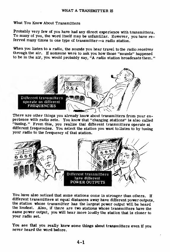
WHAT A TRANSMITTER IS
What You Know About Transmitters
Probably very few of you have had any direct experience with transmitters.To many of you, the word itself may be unfamiliar. However, you have re-ferred many times to one type of transmitter—a radio station.
When you listen to a radio, the sounds you hear travel to the radio receiverthrough the air. If someone were to ask you how those "sounds" happenedto be in the air, you would probably say, "A radio station broadcasts them.
"
Different transmittersoperate on different
FREQUENCIES
There are other things you already know about transmitters from your ex-perience with radio sets. You know that "changing stations" is also called"tuning." From this, you realize that different transmitters operate atdifferent frequencies. You select the station you want to listen to by tuningyour radio to the frequency of that station.
Different transmittershave different
POWER OUTPUTS
You have also noticed that some stations come in stronger than others. If
different transmitters at equal distances away have different power outputs,the station whose transmitter has the largest power output will be heardthe loudest. Also, if there are two stations whose transmitters have thesame power output, you will hear more loudly the station that is closer toyour radio set.
You see that you really knew some things about transmitters even if younever heard the word before.
4-1

WHAT A TRANSMITTER IS
A Simple Transmitter
The simplest transmitter consists of an oscillator which generates a high
frequency signal. The oscillator—and the type of oscillator doesn't matter
—could be connected to an antenna to make up a complete transmitter.
The antenna in this case would radiate a signal which is constant in am-plitude and of the same frequency as the oscillator.
A simple transmitter
If your home radio set picked up the constant-amplitude signal from such a
transmitter, you would hear nothing at all. If a special type of radio received
this signal, a constant audio tone would be heard. In either of these cases,
no message could be "read" from the incoming signal—such a signal is said
to contain "no intelligence. " To add intelligence to the signal, the oscillator
would be turned on and off with a key to produce dots and dashes.
Putting the transmitter to work
A signal of this type contains intelligence since a message can be obtained
from it. The radio would produce a sound somewhat like "dit-dah-dit"
which a radio operator understands as the letter "R. "
4-2

WHAT A TRANSMITTER IS
A Simple Transmitter (continued)
Almost every transmitter contains more than just an oscillator. Thereare two main drawbacks to connecting the oscillator directly to theantenna. The first is that the power output would be limited becausethere are no stages of RF amplification between the oscillator and theantenna to build up the strength of the RF signal. Power output is imp-ortant because it determines the distance over which the transmittedsignal can be picked up by the receiver.
The other consideration is frequency stability. An oscillator from whicha large amount of power is drawn has a tendency to drift in frequency. Adrift in the frequency of the transmitted signal would mean that a portionof the message would be lost by the operator trying to receive it.
For these reasons—poor frequency stability andoscillators are not connected directly to an antenna.
low power output—
ytequettcy T>nift and^d<w 'Pocven Output
result in poor reception ....

WHAT A TRANSMITTER IS
A Simple Transmitter (continued)
To overcome the limitations of connecting an oscillator directly to thetransmitting antenna, one or more stages of amplification are connectedbetween the oscillator and the antenna. The stage which is connected to
the antenna is usually called the "final power amplifier. " The other stagesof amplification are known by several names. Sometimes they are re-ferred to as the "first and second power amplifiers," and sometimes as"intermediate power amplifiers." In addition, the first power amplifier,since it serves to isolate the oscillator from variations of load, is alsocalled a "buffer" amplifier.
Oscillator
Signal
i=>Amplified
Signal
The RF signal is generated in the oscillator circuit and is amplified by the
first and second power amplifiers which drive the final power amplifier.
The powerful signal from the final power amplifier is fed to the antennawhich radiates the signal into space.
As has been said, the RF signal by itself does not contain any intelligence.
However, several things may be done to it so that it will contain or carrya message. Because of this, the RF signal is commonly referred to as"the carrier wave"—it is not, of itself, the message, but it can carry amessage to some distant point.
4-4
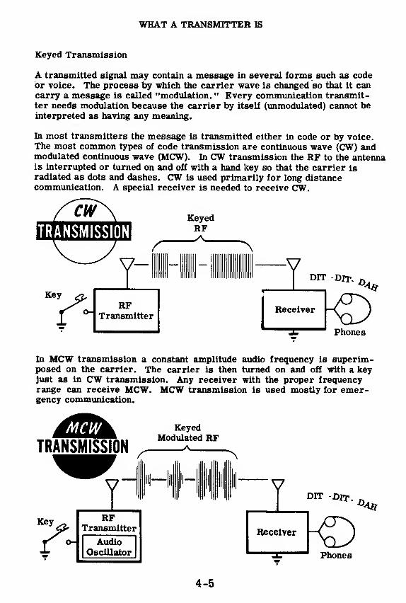
WHAT A TRANSMITTER IS
Keyed Transmission
A transmitted signal may contain a message in several forms such as codeor voice. The process by which the carrier wave is changed so that it cancarry a message is called "modulation. " Every communication transmit-ter needs modulation because the carrier by itself (unmodulated) cannot beinterpreted as having any meaning.
In most transmitters the message is transmitted either in code or by voice.The most common types of code transmission are continuous wave (CW) andmodulated continuous wave (MCW). In CW transmission the RF to the antennais interrupted or turned on and off with a hand key so that the carrier isradiated as dots and dashes. CW is used primarily for long distancecommunication. A special receiver is needed to receive CW.
TRANSMISSION
Key xj.rRF
Transmitter
Phones
In MCW transmission a constant amplitude audio frequency is superim-posed on the carrier. The carrier is then turned on and off with a keyjust as in CW transmission. Any receiver with the proper frequencyrange can receive MCW. MCW transmission is used mostly for emer-gency communication.
TRANSMISSION
KeyedModulated RF
IRF
Transmitter
AudioOscillator Phones
4-5

WHAT A TRANSMITTER IS
Voice Transmission
Voice transmission is also of two types. In the most common type of voicetransmission used the amplitude of the carrier is varied in the same manneras the amplitude of the voice signal. This is called "amplitude modulation"(AM) and is the type of transmission used in the standard radio broadcast.
VVoicewaves
AM UnmodulatedVoice modulated RF RF Carrier
RFTransmitter
Amplitudemodulator
Microphone ^
AMTRANSMISSION
The other type of voice transmission, which is being used more and more,is called "frequency modulation" (FM). Here the frequency of the carrieris shifted back and forth at a rate equal to the frequency of the voice signal.FM transmission is comparatively free from "static" interference, is usedin place of AM when the latter may be difficult to receive.
FMVoice modulated RF
UnmodulatedRF Carrier
V Phones
RFTransmitter
1Frequencymodulator
Microphone ^
4-6
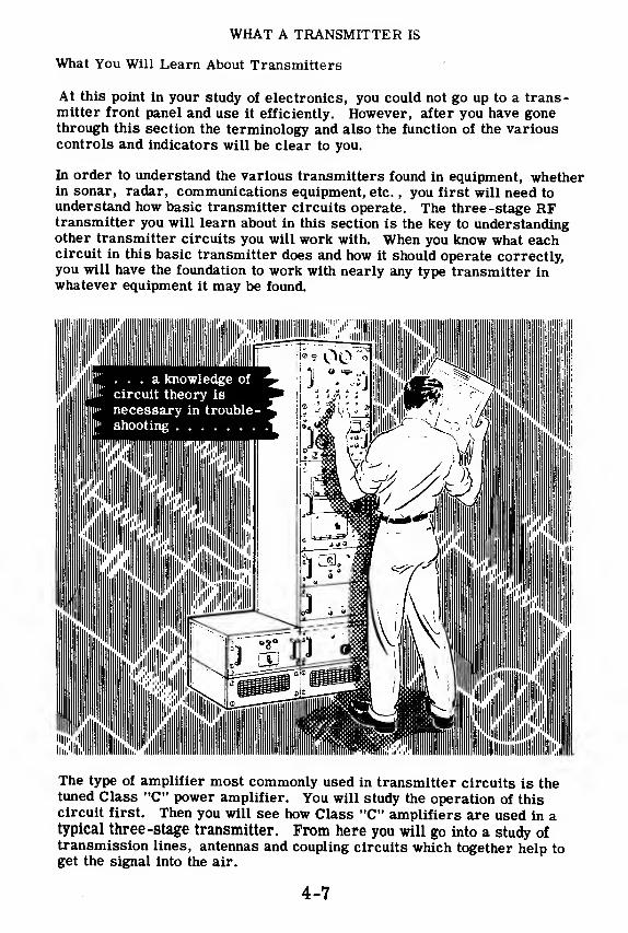
WHAT A TRANSMITTER IS
What You Will Learn About Transmitters
At this point in your study of electronics, you could not go up to a trans-mitter front panel and use it efficiently. However, after you have gonethrough this section the terminology and also the function of the variouscontrols and indicators will be clear to you.
In order to understand the various transmitters found in equipment, whetherin sonar, radar, communications equipment, etc.
, you first will need to
understand how basic transmitter circuits operate. The three-stage RFtransmitter you will learn about in this section is the key to understandingother transmitter circuits you will work with. When you know what eachcircuit in this basic transmitter does and how it should operate correctly,you will have the foundation to work with nearly any type transmitter inwhatever equipment it may be found.
The type of amplifier most commonly used in transmitter circuits is thetuned Class "C" power amplifier. You will study the operation of thiscircuit first. Then you will see how Class "C" amplifiers are used in atypical three -stage transmitter. From here you will go into a study oftransmission lines, antennas and coupling circuits which together help toget the signal into the air.
4-7

CLASS C AMPLIFIERS
Review of Classes of Operation
You remember from your study of amplifiers that there are three maintypes of vacuum tube operation—Class A, Class B, and Class C.
In Class A operation, the grid is biased near the midpoint of the linear
portion of the plate current - grid voltage curve. The AC signal on the
grid causes the grid voltage to vary above and below the bias value. Thecurrent variations are proportional to the grid voltage since the grid volt-
age swing does not go beyond the linear portion of the curve. Plate cur-rent flows throughout the entire AC cycle since the grid voltage does notbring the tube into cut-off.
In Class B operation, the grid is biased at or ne.ar its cut-off value. TheAC signal drives the tube into cut-off for approximately half of the cycle.Thus the tube conducts for about 180 degrees of the cycle and is cut off
during the other 180 degrees of the cycle.
In Class C operation—the type of operation with which you will be mostconcerned in your study of transmitters—the grid is biased considerablybeyond cut-off. The tube remains cut off for most of each AC cycle andcurrent flows in the tube only when the AC signal increases the grid volt-age above cut-off. The plate current therefore flows in pulses as shown.
No plate
current flowing
Current flowingall the time
Current flowshalf the time
Current flowsless than
half the time
Currentflows
4-8

CLASS C AMPLIFIERS
Tuned Class C Amplifiers
Tuned
Amplifier
Tuned1 Circuit
The operation of a Class C amplifier will become clear when you analyzewhat happens in a tuned amplifier such as the one shown in the schematicdiagram. An AC signal is developed across the tuned circuit in the plateof the previous stage. This voltage also appears across the RF choke(RFC) in the grid circuit of the tuned Class C amplifier stage. The DCbias provided by the bias battery causes the tube to operate Class C.
The pulses of tube currentwhich flow as a result of thistype of operation deliver a"kick" to the tuned circuit inthe plate. This "kick" makesthe tuned circuit oscillate,and it fills in the part of thecycle during which plate cur-rent has stopped. For a re-view of how oscillations arekept going in a tuned circuit,refer to the section on oscil-lators, Volume 3.
GridVoltage
The plate voltage is the differ-ence between the B+ voltageand the AC voltage across thetuned circuit. When the pulseof plate current flows, thevoltage at the plate end of thetuned circuit goes negative andsubtracts from the B+ voltage
.
When the voltage across thetuned circuit reverses andgoes positive at the plate end,it adds to the B+ voltage. Asa result, the plate voltagewave form varies above andbelow the B+ voltage levelas shown.
Plate
Current
Voltage
acrosstuned
circuit
Total
Plate
Voltage

CLASS C AMPLIFIERS
Tuned Class C Amplifiers (continued)
PLATE VOLTAGE
The reason why tuned Class C ampli-
fiers are universally used in high
powered transmitters is because of
their high efficiency of operation which
results in a maximum of radiatedpower.
The power we supply to an amplifier is
always greater than the power we get
out of it. Some power is used up by the
tube and the rest appears as useful
output in the load. The power used up
by the tube equals its plate voltage
times its plate current.
Since the plate current of a Class C am-plifier flows during less than half the
cycle, the average plate current is less
than in Class A or B operation. There-fore less power is used up by the tube
and more power can get to the output.
This makes the Class C amplifier moreefficient and therefore more desirable
for use in a transmitter.
TUBE CURRENT
H the tuned circuit in the plate is not tuned to the frequency of the input
signal, then the voltage across it will be lower—in proportion to how muchit is mistuned. The further off it is tuned, the less power will appear
across it and the more power will be dissipated by the tube itself. Then
the efficiency of the amplifier is lower, the tube heats up more, and the
power output is lower.
VARIATION OF PLATE VOLTAGE
AS TUNING VARIES ••
•
Well belowsignal
frequency
Approachingsignal
frequency
Slightly less
than signal
frequency
4-10
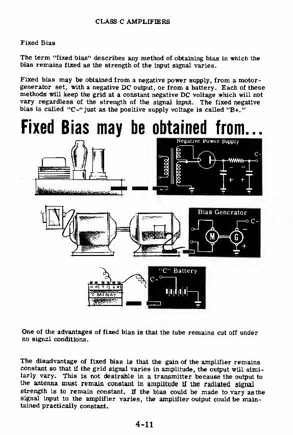
CLASS C AMPLIFIERS
Fixed Bias
The term "fixed bias" describes any method of obtaining bias in which thebias remains fixed as the strength of the input signal varies.
Fixed bias may be obtained from a negative power supply, from a motor -
generator set, with a negative DC output, or from a battery. Each of thesemethods will keep the grid at a constant negative DC voltage which will notvary regardless of the strength of the signal input. The fixed negativebias is called "C-" just as the positive supply voltage is called "B+.
"
Fixed Bias may be obtained from. .
.
One of the advantages of fixed bias is that the tube remains cut off underno signal conditions.
The disadvantage of fixed bias is that the gain of the amplifier remainsconstant so that if the grid signal varies in amplitude, the output will simi-larly vary. This is not desirable in a transmitter because the output tothe antenna must remain constant in amplitude if the radiated signalstrength is to remain constant. If the bias could be made to vary as thesignal input to the amplifier varies, the amplifier output could be main-tained practically constant.
4-11
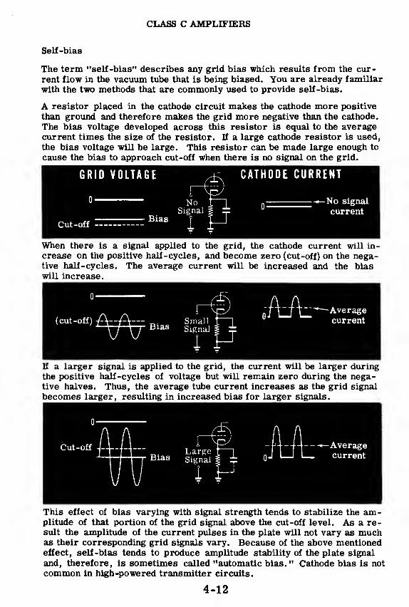
CLASS C AMPLIFIERS
Self-bias
The term "self -bias" describes any grid bias which results from the cur-rent flow in the vacuum tube that is being biased. You are already familiar
with the two methods that are commonly used to provide self-bias.
A resistor placed in the cathode circuit makes the cathode more positive
than ground and therefore makes the grid more negative than the cathode.
The bias voltage developed across this resistor is equal to the averagecurrent times the size of the resistor. If a large cathode resistor is used,
the bias voltage will be large. This resistor can be made large enough to
cause the bias to approach cut-off when there is no signal on the grid.
GRID VOLTAGE CATHODE CURRENT
Cut-off
NoSignal
Bias
-No signal
current
When there is a signal applied to the grid, the cathode current will in-
crease on the positive half-cycles, and become zero (cut-off) on the nega-tive half -cycles. The average current will be increased and the biaswill increase.
(cut-off) A--A-- SmaJlSignal
Ait -Averagecurrent
If a larger signal is applied to the grid, the current will be larger duringthe positive half-cycles of voltage but will remain zero during the nega-tive halves. Thus, the average tube current increases as the grid signal
becomes larger, resulting in increased bias for larger signals.
Cut-off J--Ui-\— LargeBias Signal
-Averagecurrent
This effect of bias varying with signal strength tends to stabilize the am-plitude of that portion of the grid signal above the cut-off level. As a re-sult the amplitude of the current pulses in the plate will not vary as muchas their corresponding grid signals vary. Because of the above mentionedeffect, self-bias tends to produce amplitude stability of the plate signal
and, therefore, is sometimes called "automatic bias. " Cathode bias is not
common in high-powered transmitter circuits.
4-12
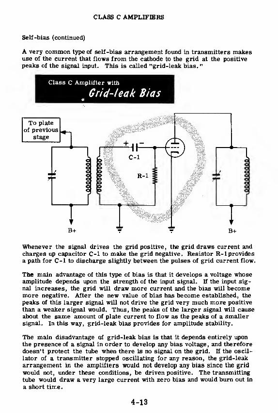
CLASS C AMPLIFIERS
Self-bias (continued)
A very common type of self-bias arrangement found in transmitters makesuse of the current that flows from the cathode to the grid at the positivepeaks of the signal input. This is called "grid-leak bias.
"
Class C Amplifier with
Grid-leak Bias
To plate
Whenever the signal drives the grid positive, the grid draws current andcharges up capacitor C-1 to make the grid negative. Resistor R-l providesa path for C-1 to discharge slightly between the pulses of grid current flow.
The main advantage of this type of bias is that it develops a voltage whoseamplitude depends upon the strength of the input signal. If the input sig-
nal increases, the grid will draw more current and the bias will becomemore negative. After the new value of bias has become established, the
peaks of this larger signal will not drive the grid very much more positive
than a weaker signal would. Thus, the peaks of the larger signal will causeabout the same amount of plate current to flow as the peaks of a smallersignal. In this way, grid-leak bias provides for amplitude stability.
The main disadvantage of grid-leak bias is that it depends entirely uponthe presence of a signal in order to develop any bias voltage, and therefore
doesn't protect the tube when there is no signal on the grid. If the oscil-
lator of a transmitter stopped oscillating for any reason, the grid-leak
arrangement in the amplifiers would not develop any bias since the grid
would not, under these conditions, be driven positive. The transmitting
tube would draw a very large current with zero bias and would burn out in
a short time.
4-13

CLASS C AMPLIFIERS
Combination Bias
The most common bias arrangement in transmitters is a combination of
fixed bias and grid-leak bias. The fixed bias is sufficient to limit the
current to a low value or even to cut-off in the absence of a signal. Whena large enough signal is present to drive the grid positive, grid-leak biasis developed which stabilizes the amplitude of the output. Thus combina-tion bias protects the tube and stabilizes the output.
{M^^ Bias
4-14

CLASS C AMPLIFIERS
Review of Class C Amplifiers
CLASS C OPERATION—The grid of
the vacuum tube is biased well below
cut-off so that plate current flows
only in pulses.
No plate
current flowing
TUNED CLASS C AMPLIFIERS—Used in transmitters because they
are very efficient when tuned to the
frequency of the input signal.
GRID-LEAK BIAS—Depends on grid
current and varies as the strength of
input signal changes.
COMBINATION BIAS—A combination^
of fixed and grid-leak bias mostcommonly used in transmitters.
4-15
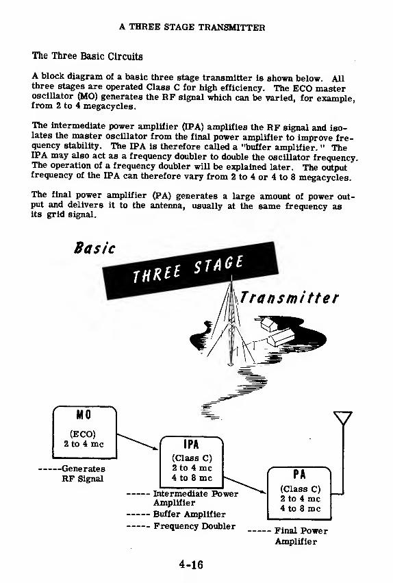
A THREE STAGE TRANSMITTER
The Three Basic Circuits
A block diagram of a basic three stage transmitter is shown below. Allthree stages are operated Class C for high efficiency. The ECO masteroscillator (MO) generates the RF signal which can be varied, for example,from 2 to 4 megacycles.
The intermediate power amplifier (IPA) amplifies the RF signal and iso-lates the master oscillator from the final power amplifier to improve fre-quency stability. The EPA is therefore called a "buffer amplifier. " TheEPA may also act as a frequency doubler to double the oscillator frequency.The operation of a frequency doubler will be explained later. The outputfrequency of the EPA can therefore vary from 2 to 4 or 4 to 8 megacycles.
The final power amplifier (PA) generates a large amount of power out-put and delivers it to the antenna, usually at the same frequency asits grid signal.
-GeneratesRF Signal
I PA
(Class C)2 to 4 mc4 to 8 mc
Intermediate PowerAmplifier
Buffer Amplifier
Frequency Doubler
V
PA
(Class C)2 to 4 mc4 to 8 mc
Final PowerAmplifier
4-16

A THREE STAGE TRANSMITTER
The Oscillator
The purpose of the electron-coupled master oscillator is to generate a
stable RF signal which can be varied over a given range.
The ECO operates as follows: The oscillator section of the ECO is com-posed of the grid and screen circuits and is a Colpitts oscillator. The
oscillator frequency is determined by the grid-screen tank circuit con-
sisting of L-l, C-l, C-2 and C-3. The screen, which acts as the plate of
the oscillator section, is coupled to the tank circuit through the RF by-
pass capacitor, C-5. Grid-leak bias is developed across R-l by the dis-
charge of C-4. The RF choke in the cathode circuit provides a low re-
sistance DC path to ground for the cathode. However, the high reactance
of the choke to RF does not allow RF to flow through it. The RF must
flow through C-3 (the feedback capacitor) to the cathode. The screen
dropping resistor, R-2, drops the screen voltage to the correct value.
The RF oscillations generated in the oscillator section of the ECO are
electron-coupled to the plate through the flow of plate current. The RFchoke in the plate lead acts as a high impedance for the RF signal and
serves the same purpose as the plate load resistor in an audio amplifier.
The RF coupling capacitor,C- 6,passes the signal to the grid of the IPA.
H&mm Master Oscillator (£C0) '
'*-
' '
. . .Generates RF Signal
4-17
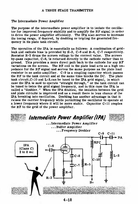
A THREE STAGE TRANSMITTER
The Intermediate Power Amplifier
The purpose of the intermediate power amplifier is to isolate the oscilla-
tor for improved frequency stability and to amplify the RF signal in orderto drive the power amplifier efficiently. The IPA also serves to increase
the tuning range, if desired, by doubling or tripling the generated fre-
quency in its plate tank circuit.
The operation of the IPA is essentially as follows: A combination of grid-
leak and cathode bias is provided by R-3, C-6 and R-4, C-7 respectively.
Resistor R-5 drops the screen voltage to the correct value. The screenby-pass capacitor, C-8, is returned directly to the cathode rather than to
ground. This provides a more direct path back to the cathode for any RFvariations on the screen. The RF coil in the plate lead acts as a high im-pedance for the RF signal and serves the same purpose as the plate load
resistor in an audio amplifier. C-9 is a coupling capacitor which passesthe RF to the tank circuit and at the same time blocks the DC. The plate
tank circuit,C-10 and L-2,can be tuned to the IPA grid signal, in whichcase the EPA is said to operate "straight through, " or the tank circuit canbe tuned to twice the grid signal frequency, and in this case the IPA is
called a "doubler. " When the IPA doubles, the isolation between the gridand plate circuits is improved and as a result there is less chance of the
IPA breaking into oscillation. Doubling has another advantage in that it
raises the carrier frequency while permitting the oscillator to operate at
a lower frequency where it will be more stable. Capacitor C-ll couplesthe RF to the grid of the power amplifier.
P?f Intermediate Power Amplifier (IPA) f§§§. . .Intermediate Power Amplifier
. . . Buffer Amplifier. . . Frequency Doubler
C-9 C-ll
4-18
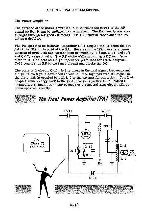
A THREE STAGE TRANSMITTER
The Power Amplifier
The purpose of the power amplifier is to increase the power of the RFsignal so that it can be radiated by the antenna. The PA usually operates
straight through for good efficiency. Only in unusual cases does the PAact as a doubler.
The PA operates as follows: Capacitor C-ll couples the RF from the out-put of the IPA to the grid of the PA. Here as in the IPA there is a com-bination of grid-leak and cathode bias provided by R-6 and C-ll; and R-7and C-12, respectively. The RF choke while providing a DC path fromplate to B+ also acts as a high impedance plate load for the RF signal.
C-13 couples the RF to the tuned circuit and blocks the DC.
The plate tank circuit C-15, L-3 is tuned to the grid signal frequency anda high RF voltage is developed across it. The high powered RF signal in
the plate tank is coupled by coil L-5 to the antenna for radiation. Coil L-4couples some energy back to the grid through capacitor C-14, called a"neutralizing capacitor. " The purpose of the neutralizing circuit will be-come apparent shortly.
4-19
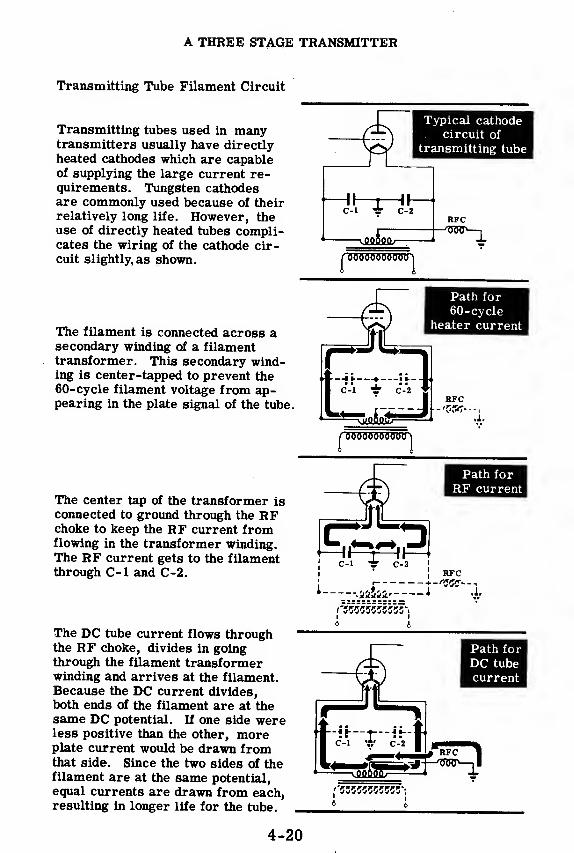
A THREE STAGE TRANSMITTER
Transmitting Tube Filament Circuit
Transmitting tubes used in manytransmitters usually have directlyheated cathodes which are capableof supplying the large current re-quirements. Tungsten cathodesare commonly used because of theirrelatively long life. However, theuse of directly heated tubes compli-cates the wiring of the cathode cir-cuit slightly, as shown.
The filament is connected across asecondary winding of a filamenttransformer. This secondary wind-ing is center-tapped to prevent the60-cycle filament voltage from ap-pearing in the plate signal of the tube.
Typical cathodecircuit of
transmitting tube
-II
—
t—Ih11—
T~c-i ir c-2
-vJlfliflfl/-
RFC-/55jr>—
^
iP'
O'
ffOWOOO
Path for
60-cycleheater current
f
—
\\—*
—
\i~I C-1 ± C-2
RFC
,1,
nrowo"o"o"o"o"oo i
The center tap of the transformer is
connected to ground through the RFchoke to keep the RF current fromflowing in the transformer winding.The RF current gets to the filamentthrough C-1 and C-2.
The DC tube current flows throughthe RF choke, divides in goingthrough the filament transformerwinding and arrives at the filament.Because the DC current divides,both ends of the filament are at thesame DC potential. If one side wereless positive than the other, moreplate current would be drawn fromthat side. Since the two sides of thefilament are at the same potential,
equal currents are drawn from each,resulting in longer life for the tube.
Path for
RF current
1 -.i&Jji, J
4 I
RFC
Path for
DC tube
current
4-20

A THREE STAGE TRANSMITTER
Complete Diagram of a Three Stage Transmitter
4-21

A THREE STAGE TRANSMITTER
Purpose of Tuning
If a Class C amplifier is to operate efficiently, the plate tank circuit mustresonate at the same frequency as the grid signal. If the tuning capacitoris variable, the plate circuit will be either on or off resonance dependingupon the setting of the variable capacitor. Adjusting the variable capaci-tor to make the plate tank circuit resonate to the grid signal is called"tuning.
"
When a transmitter is detuned, a weak signal will be radiated and re-ceivers tuned to the transmitter frequency may not pick up the signal.
When a transmitter is tuned to a given frequency, all the tank circuits inthe transmitter are tuned to resonate at this given frequency. The trans-mitter than radiates a stable signal at maximum efficiency and maximumpower output. Tuning a transmitter is therefore the most important pro-cedure in its operation.
4-22

A THREE STAGE TRANSMITTER
Tuning Methods
A tank circuit in series with the plate of a Class C amplifier can be
compared to a rheostat in series with the plate. When the plate circuit is
completely detuned, it acts just as if there were no resistance in the
plate. As a result, plate voltage will always be equal to B+ and the
pulses of plate current (when grid is driven above cut-off) will be large.
The DC meter (M-l)which measures the average of the current pulses will
therefore read high.
INPUT o-|\
Tuned Class CAMPLIFIER
CIRCUIT
As the tuning is varied so that the resonant frequency of the tank circuit
comes closer to the grid signal frequency, the impedance of the plate cir-
cuit rises above zero. Now a signal voltage appears across this imped-
ance. Just as in an ordinary amplifier, when the grid signal is positive
the plate voltage drops because of the voltage drop across the plate load
resistor. Since the plate voltage is now lower than before (lower than B+)
during the time the grid is driven above cut-off, the pulses of plate cur-
rent will be lower in amplitude, and therefore their average value will be
less. When the plate tank is tuned to the grid signal, the plate impedance
is at its highest point and therefore the voltage drop across this impedance
is at its highest point. As a result.the plate voltage (the difference be-
tween B+ and the load voltage) is at its lowest point. Since the plate volt-
age is at its lowest point (during the time the grid is above cut-off), the
plate current pulses and therefore the average plate current will be at
their lowest point.
A minimum DC plate current reading is therefore an indication that the
plate tank is tuned to the grid signal frequency. When a plate tuned cir-
cuit is tuned for a minimum reading on the plate current meter, it is
called tuning for a "dip.
"
Variations of plate Voltages and
Currents as tuning varies
B+-
Plate Voltage
Plate Current/v i
AVERAGE0 Til I
Well belowsignal
frequency
ApproachingjSlightly less
signal|
than signal
frequency ! frequency
At
signal
frequency
|
Slightly more[
than signal
|frequency
4-23
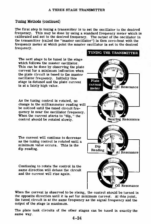
A THREE STAGE TRANSMITTER
Tuning Methods (continued)
The first step in tuning a transmitter is to set the oscillator to the desiredfrequency. This may be done by using a standard frequency meter which iscalibrated and set to the desired frequency. The output of the oscillator in
the transmitter (called the "master oscillator") is then zero-beat with the
frequency meter at which point the master oscillator is set to the desiredfrequency.
TUNING THE TRANSMITTER
The next stage to be tuned is the stagewhich follows the master oscillator.
This can be done by observing the plate
current for a minimum indication whenthe plate circuit is tuned to the masteroscillator frequency. Initially this
stage is detuned and the plate currentis at a fairly high value.
As the tuning control is rotated, nochange in the milliammeter reading willbe noticed until the tuned circuit fre-quency is near the oscillator frequency.When the current starts to "dip, " thecontrol should be rotated slowly.
The current will continue to decreaseas the tuning control is rotated until aminimum value occurs. This is thedip reading.
Continuing to rotate the control in the
same direction will detune the circuit
and the current will rise again.
Off Resonance
When the current is observed to be rising, the control should be turned in
the opposite direction until it is set for minimum current. At this point,the tuned circuit is at the same frequency as the signal frequency and theoutput of the stage is maximum.
The plate tank circuits of the other stages can be tuned in exactly thesame way.
4-24

A THREE STAGE TRANSMITTER
Tuning Methods (continued)
In addition to the plate current meter, there is another meter which indi-cates correct tuning of the plate circuit. This meter is in the grid circuitof the following stage and is labeled M-2 in the diagram below.
When the plate circuit is tuned tothe frequency of the input signal,the voltage developed across thecircuit is greatest and the outputfrom that amplifier stage is
greatest. The larger the outputfrom that stage, the greater is
the signal to the grid of the fol-
lowing stage.
The grid of the following stage will draw current whenever the input signaldrives the grid positive. The larger the signal input, the greater will bethe flow of current from the cathode to the grid. Since the signal input tothe grid will be greatest when the plate circuit of the previous stage is ac-curately tuned, the grid will draw maximum current and milliammeterM-2 (which measures the average grid current) will indicate a maximumreading. Thus when the plate tank is accurately tuned, the plate currentmeter indicates a dip and the grid current meter of the following stagesimultaneously registers a rise known as a "peak" reading.
Plate Current ^ . -Grid Current"
If the grid circuit has fixed bias or combination bias, no grid current willbe drawn until the signal is fairly large. This will happen some time afterthe plate current meter has started to dip. For this reason, the rising gridcurrent indication is sharper than the decreasing plate current indication.
The normal procedure for tuning t vtpje which has a plate current meterand is followed by a stage which nas a grid current meter, is to tune firstfor a minimum plate current. This indication is broader and less likely tobe overlooked as you vary the tuning. After you have observed the platecurrent starting to decrease, you watch the grid current meter for a rise.The final adjustment will be for a rise in grid current. Since this is asharper indication, tuning based on this indication will be more accurate.
4-25

A THREE STAGE TRANSMITTER
Tuning Methods (continued)
When a plate tank circuit is tuned to the same frequency as the grid signal,
the voltage across the tank is at its maximum. If another coil is trans-
former coupled to the coil of the tank circuit, the voltage induced in this
coil will also be a maximum. This second coil can be connected to a pilot
lamp which will glow if the induced voltage is large enough. If the tank
circuit is detuned from the grid signal, the induced voltage in the lamp cir-
cuit will drop and the lamp will go out. The transformer coupled lamp is
therefore a convenient means of tuning a tank circuit as the lamp is
brightest when the tank circuit is tuned to the signal frequency.
This method of tuning is not as accurate as the current meter indications
because the lamp circuit loads down the tank circuit and detunes it slightly.
When using this method for tuning indication, the coupling must be kept as
loose as possible to minimize the detuning effects on the plate tank circuit.
The lamp method of tuning can be conveniently used on built up experimen-tal transmitters in which the plate coils are accessible. In many trans-
mitters this method cannot be used since the tuning coils are out of sight,
and therefore tuning is done exclusively by current meter indications.
4-26

A THREE STAGE TRANSMITTER
Neutralization
Sometimes a tuned Class C amplifier will act as a tuned-plate—tuned-gridoscillator at the resonant frequency of the tuned circuits. In this case, theinterelectrode capacitance between plate and grid is large enough to pro-vide the proper amount of feedback for sustained oscillations. This typeof oscillation is most often encountered with triodes because of their largeinterelectrode capacities. Tetrodes and pentodes rarely have this prob-lem of oscillations because their interelectrode capacities are very low.When triodes are used as RF amplifiers, it is possible to eliminate theabove mentioned oscillations by a process called "neutralization. " Inneutralization a circuit is included in the amplifier which counteracts thefeedback effect of the interelectrode grid to plate capacity.
Two circuits are used to neutralize the grid-to-plate capacitance andthereby reduce the possibility of oscillations. Each of these circuits ac-complishes neutralization by feeding back a signal from the plate to thegrid through a neutralizing capacitor. This signal is opposite in phaseand equal in magnitude to the signal fed back through the grid-to-platecapacitance. These circuits are called "plate neutralization" and "gridneutralization" and get their names from the part of the circuit in whichthe feedback voltage is developed.
This is the circuit for plate neutralization. Cgp is the grid-to-plate ca-pacitance represented in the schematic as a capacitor external to the tube.Cn is the neutralizing capacitor—that is, the capacitor through which theneutralizing signal is brought to the grid. The tuning coil, L-l, is center-tapped at point C, which is placed at RF ground by the RF bypass capaci-tor Cg. Since points A and B are at opposite ends of coil L-l, they are180 degrees out of phase. Therefore the RF voltages measured at pointsA and B with respect to ground are 180 degrees out of phase and equal inamplitude (assuming point C is the exact center-tap).
The neutralizing capacitor, Cn , is connected between point B and the grid,while the interelectrode capacitance, Cgp, is connected between point Aand the grid. Therefore the phase of the voltage fed from the plate to thegrid through Cn is opposite to the phase of the voltage fed through the grid-to-plate capacitance and the voltages cancel. Cn is made variable so thatthe amplitude of the signal fed back through Cn can be made to balance outexactly that fed back through Cgp.
4-27
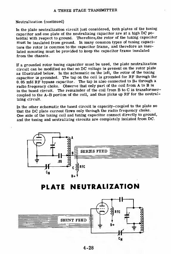
A THREE STAGE TRANSMITTER
Neutralization (continued)
In the plate neutralization circuit just considered, both plates of the tuning
capacitor and one plate of the neutralizing capacitor are at a high DC po-
tential with respect to ground. Therefore,the rotor of the tuning capacitor
must be insulated from ground. In many common types of tuning capaci-
tors the rotor is common to the capacitor frame, and therefore an insu-
lated mounting must be provided to keep the capacitor frame insulated
from the chassis.
If a grounded rotor tuning capacitor must be used, the plate neutralization
circuit can be modified so that no DC voltage is present on the rotor plate
as illustrated below. In the schematic on the left, the rotor of the tuning
capacitor is grounded. The tap on the coil is grounded for RF through the
0. 05 mfd RF bypass capacitor. The tap is also connected to B+ through a
radio frequency choke. Observe that only part of the coil from A to B is
in the tuned circuit. The remainder of the coil from B to C is transformer-
coupled to the A-B portion of the coil, and thus picks up RF for the neutral-
izing circuit.
In the other schematic the tuned circuit is capacity-coupled to the plate so
that the DC plate current flows only through the radio frequency choke.
One side of the tuning coil and tuning capacitor connect directly to ground,
and the tuning and neutralizing circuits are completely isolated from DC.
PLATE NEUTRALIZATION
4-28

A THREE STAGE TRANSMITTER
Neutralization (continued)
iCgP
Another circuit which provides a means of neutralizing the grid-to-platecapacity is the grid neutralization circuit. In this circuit the neutralizingvoltage is applied to end B of the center-tapped coil L-l while the grid-to-plate feedback voltage is applied to end A of coil L-l. Since these twovoltages are equal and of the same polarity, they cause currents to flowin the balanced grid tank circuit whose effects cancel each other. The re-sult is that oscillations due to feedback cannot occur in the grid tank cir-cuit and therefore the entire stage will not be able to oscillate. Thereforeif Cn is adjusted to be equal to Cgp, the voltages coupled through thesecapacitors will cancel each other and the tube will not oscillate.
Once a neutralizing capacitor is adjusted for a particular tube, it will re-quire only occasional checks. However, if the tube is changed for a newone, the neutralizing capacitor will need adjustment since the new tube willhave a slightly different value of Cgn.
4-29
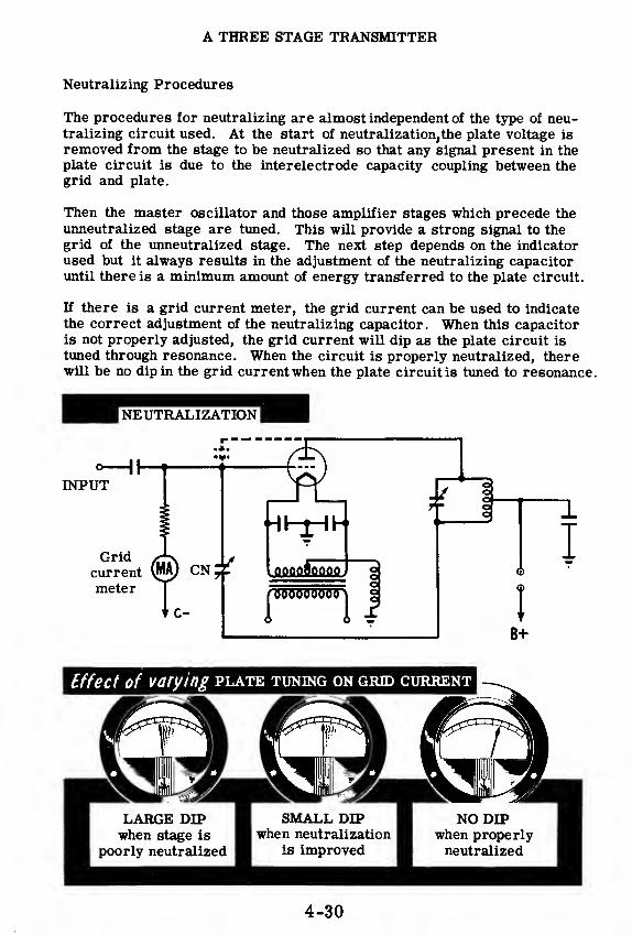
A THREE STAGE TRANSMITTER
Neutralizing Procedures
The procedures for neutralizing are almost independent of the type of neu-tralizing circuit used. At the start of neutralization,the plate voltage is
removed from the stage to be neutralized so that any signal present in theplate circuit is due to the interelectrode capacity coupling between thegrid and plate.
Then the master oscillator and those amplifier stages which precede the
unneutralized stage are tuned. This will provide a strong signal to thegrid of the unneutralized stage. The next step depends on the indicatorused but it always results in the adjustment of the neutralizing capacitoruntil there is a minimum amount of energy transferred to the plate circuit.
If there is a grid current meter, the grid current can be used to indicatethe correct adjustment of the neutralizing capacitor. When this capacitoris not properly adjusted, the grid current will dip as the plate circuit is
tuned through resonance. When the circuit is properly neutralized, therewill be no dip in the grid current when the plate circuit is tuned to resonance.
B+
4-30
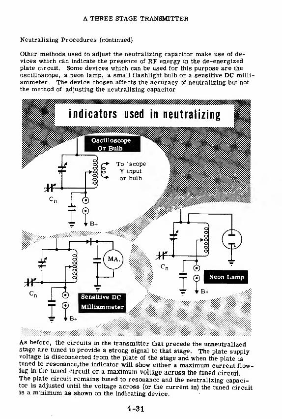
A THREE STAGE TRANSMITTER
Neutralizing Procedures (continued)
Other methods used to adjust the neutralizing capacitor make use of de-vices which can indicate the presence of RF energy in the de-energizedplate circuit. Some devices which can be used for this purpose are the
oscilloscope, a neon lamp, a small flashlight bulb or a sensitive DC milli-
ammeter. The device chosen affects the accuracy of neutralizing but not
the method of adjusting the neutralizing capacitor
As before, the circuits m the transmitter that precede the unneutralizedstage are tuned to provide a strong signal to that stage. The plate supplyvoltage is disconnected from the plate of the stage and when the plate istuned to resonance, the indicator will show either a maximum current flow-ing in the tuned circuit or a maximum voltage across the tuned circuit.The plate circuit remains tuned to resonance and the neutralizing capaci-tor is adjusted until the voltage across (or the current in) the tuned circuitis a minimum as shown on the indicating device.
4-31

A THREE STAGE TRANSMITTER
Parasitic Oscillations
In a transmitter which is operating correctly, the tuned Class C amplifiers
serve only to amplify the RF generated by the master oscillator. Some-times the inductance of wires in the circuit combine with stray capacities
to form tuned circuits which are resonant to frequencies much higher than
the desired transmitted frequency. These stray tuned circuits will often
cause the amplifiers to oscillate at very high frequencies. These oscilla-
tions, called "parasitic oscillations, " are transmitted together with the
desired frequency. Parasitic oscillations are undesirable because they
cause undue power losses and reduce the efficiency of the transmitter. In
addition,they cause interference with other transmitters.
One way to eliminate parasitic oscillations is to improve the wiring by
shortening leads and relocating components which may be in the parasitic
oscillatory circuit. If this does not help, low value resistors or chokes of
a few turns of wire should be connected directly to the grid and plate leads.
These added components have very little effect on the amplification of the
desired frequency. They do, however, isolate the grid from the stray
tuned circuits to the point where the parasitic oscillations are eliminated.
Components which are placed in a circuit to eliminate parasitic oscilla-
tions are called "parasitic suppressors. " Very often parasitic oscilla-
tions can be eliminated only by completely rewiring a circuit.
4-32

A THREE STAGE TRANSMITTER
Review of the Three-Stage Transmitter
THE THREE STAGES—Themaster oscillator, inter-
mediate power amplifierand final power amplifiermake up the basic three-stage transmitter.
PA
TUNING—For efficient
operation, the plate tankcircuit of the amplifier
must resonate at oscilla-
tor frequency. Adjustingthe variable capacitor to
reach this condition is
called tuning."
TUNING METHODS—Theplate circuit of each trans-mitter stage may be tunedby adjusting the variable
capacitor for minimum DCplate current.
Well belowsignal
frequency
NEUTRALIZATION—Plateor grid neutralizationcircuits may be used to
counteract the feedbackeffect of the grid to platecapacity in amplifiersusing triodes.
4-33
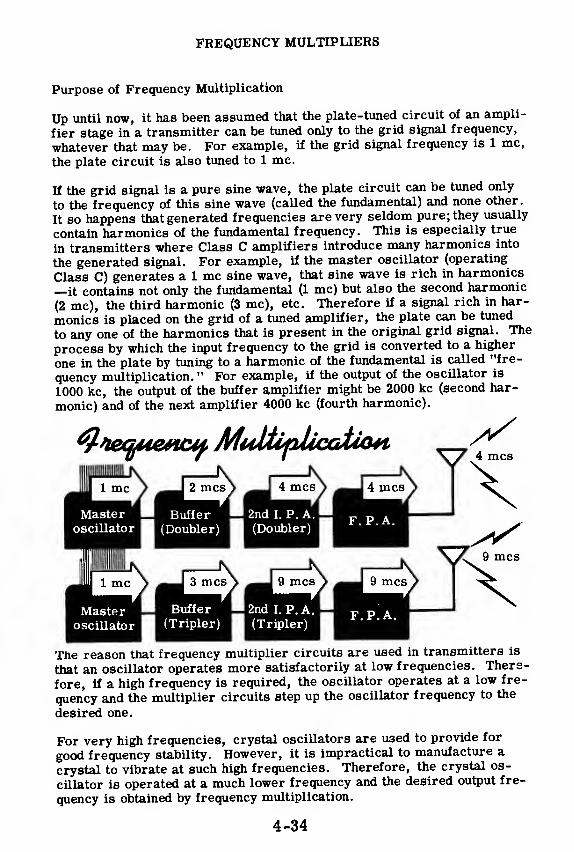
FREQUENCY MULTIPLIERS
Purpose of Frequency Multiplication
Up until now, it has been assumed that the plate-tuned circuit of an ampli-
fier stage in a transmitter can be tuned only to the grid signal frequency,
whatever that may be. For example, if the grid signal frequency is 1 mc,
the plate circuit is also tuned to 1 mc.
If the grid signal is a pure sine wave, the plate circuit can be tuned only
to the frequency of this sine wave (called the fundamental) and none other.
It so happens that generated frequencies are very seldom pure; they usually
contain harmonics of the fundamental frequency. This is especially true
in transmitters where Class C amplifiers introduce many harmonics into
the generated signal. For example, if the master oscillator (operating
Class C) generates a 1 mc sine wave, that sine wave is rich in harmonics
—it contains not only the fundamental (1 mc) but also the second harmonic
(2 mc), the third harmonic (3 mc), etc. Therefore if a signal rich in har-
monics is placed on the grid of a tuned amplifier, the plate can be tuned
to any one of the harmonics that is present in the original grid signal. The
process by which the input frequency to the grid is converted to a higher
one in the plate by tuning to a harmonic of the fundamental is called "fre-
quency multiplication. " For example, if the output of the oscillator is
1000 kc, the output of the buffer amplifier might be 2000 kc (second har-
monic) and of the next amplifier 4000 kc (fourth harmonic).
The reason that frequency multiplier circuits are used in transmitters is
that an oscillator operates more satisfactorily at low frequencies. There-
fore, if a high frequency is required, the oscillator operates at a low fre-
quency and the multiplier circuits step up the oscillator frequency to the
desired one.
For very high frequencies, crystal oscillators are used to provide for
good frequency stability. However, it is impractical to manufacture a
crystal to vibrate at such high frequencies. Therefore, the crystal os-
cillator is operated at a much lower frequency and the desired output fre-
quency is obtained by frequency multiplication.
4-34
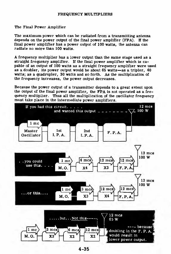
FREQUENCY MULTIPLIERS
The Final Power Amplifier
The maximum power which can be radiated from a transmitting antennadepends on the power output of the final power amplifier (FPA). If the
final power amplifier has a power output of 100 watts, the antenna canradiate no more than 100 watts.
A frequency multiplier has a lower output than the same stage used as astraight frequency amplifier. If the final power amplifier which is ca-pable of an output of 100 watts as a straight frequency amplifier were usedas a doubler, its power output would be about 65 watts—as a tripler, 40watts; as a quadruple r, 30 watts and so forth. As the multiplication of
the frequency increases, the power output decreases.
Because the power output of a transmitter depends to a great extent uponthe output of the final power amplifier, the FPA is not operated as a fre-quency multiplier. Thus all the multiplication of the oscillator frequencymust take place in the intermediate power amplifiers.
If you had this circuit
and wanted this output
12 mcs7 100 W
MasterOscillator
1st
I. P. A.2nd
I. P. A.F.P.A.
4 mcsS 12 mc&L-
—
A r1——iAX4 X3
12 mcs*
12 mcs\
V12 mcs
100 W
F.P.A,
- X4
jsS 12 mc^- F.P.A. "
V12 mcs
100 W
. you coulduse this.
I
.or this.
.
.Not this
> 13 rocs> 16 nics> 112 mcs> ^
12 mcs65 W
becausedoubling in the F. P. A.would result in
*
lower power output.
4-35
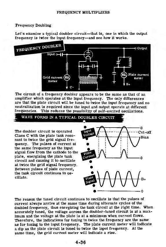
FREQUENCY MULTIPLIERS
Frequency Doubling
Let's examine a typical doubler circuit—that is, one in which the output
frequency is twice the input frequency—and see how it works.
The circuit of a frequency doubler appears to be the same as that of anamplifier which operates at the input frequency. The only differencesare that the plate circuit will be tuned to twice the input frequency and noneutralization is required since the input and output operate at differentfrequencies. This reduces the possibility of self-excited oscillations.
WAVE FORMS IN A TYPICAL DOUBLER CIRCUIT
The doubler circuit is operatedClass C with the plate tank reso-nant to twice the grid signal fre-
quency. The pulses of current at
the same frequency as the input
signal flow from the cathode to the
plate, energizing the plate tank
circuit and causing it to oscillate
at twice the grid signal frequency.
Between pulses of plate current,
the tank circuit continues to os-cillate.
• 0
The reason the tuned circuit continues to oscillate is that the pulses of
current always arrive at the same time during alternate cycles of the
doubled frequency, thus energizing the tank circuit at the right time. Whenaccurately tuned, the voltage across the doubler-tuned circuit is at a max-imum and the voltage at the plate is at a minimum when current flows.
Therefore, the indications for tuning to twice the frequency are the sameas for tuning to the input frequency. The plate current meter will indicate
a dip as the plate circuit is tuned to twice the input frequency. At the
same time, the grid current meter will indicate a rise.
4-36

FREQUENCY MULTIPLIERS
Frequency Tripling
A frequency-tripling circuit, or more briefly a tripler, has an output fre-
quency that is three times the input frequency. The appearance of the cir-
cuit is the same as that of a doubler or of an ordinary amplifier. Fre-
quency tripling is accomplished by tuning the plate circuit of the tripler to
the third harmonic of its input frequency.
Cut-off
Platevoltage
Input
voltage
Plate
currentPulses of current flow from cathode
to plate—one pulse per cycle of ap-
plied signal. These pulses arrive
at the tuned circuit during every
third cycle of output voltage and de-
liver enough energy to the tuned cir-
cuit to sustain oscillations duringq
those cycles when no current flows.
The same tunii'g indications hold for frequency doubling and tripling as for
fundamental frequency amplification. When the circuit is tuned accurately
to the third harmonic of the applied frequency, the voltage across the tuned
circuit will be larger than if the circuit were poorly tuned. This will
cause the voltage fed to the next stage to be larger, which results in more
grid current. The larger voltage across the accurately tuned circuit
causes the plate voltage to be at a low value when the tube conducts. This
results in decreased plate current. Therefore the tuning of the plate cir-
cuit—whether it is tuned to the input frequency or to the second or third
harmonic of the input frequency—can be indicated as a dip on the plate
current meter or as a rise on the grid current meter of the following stage.
Grid current (MAmeter
FREQUENCY
CIRCUIT
4-37

FREQUENCY MULTIPLIERS
Tuning Indications
At this point the question arises "How can you tell to what frequency theplate tank circuit is tuned when the plate current meter indicates a dipreading?" The only way to tell is to use a frequency indicator such as awavemeter, or a calibrated dial if the tuned circuit has been previouslytuned. If you are working with an uncalibrated transmitter, the thing todo is to tune a stage, starting with the tuning capacitor fully meshed. Thefirst dip indicates that the tank circuit is tuned to the fundamental. Thiscan be checked with the wavemeter. As you continue decreasing the ca-pacity, you come to a second dip (not as pronounced as the first one) whichis the second harmonic. Again you can check the frequency with a wave-meter. Continue decreasing capacity and you may come to a third dip(provided the circuit constants are correct) which is not as pronounced aseither the first or second dip. This dip indicates that the plate-tuned cir-cuit is tuned to the third harmonic. Here too you can check the resonantfrequency by using a wavemeter.
TUNING TO .
yaw**"**
Plate currentmeter
cf/p
Input o—
|
Grid currentmeter
Variable capacitor
. . . almost closedFundamental
0Second
Harmonic(Doubler)
. almost open
i Third 0i Harmonic= (Triple r)
4-38

TRANSMISSION LINES
The Overall Transmitter
The end result of transmitter operation is the radiation of RF energy for
great distances through space so that this energy can be detected by re-
mote receiving antennas.
You have studied oscillator and Class C amplifier circuits whose function
it is to generate and amplify RF energy. Other circuits are needed, in
addition to the ones just mentioned, to transfer the amplified RF from the
plate circuit of the final power amplifier to surrounding space. These ad-
ditional circuits are transmission lines, antennas and coupling circuits.
Just as a speaker in audio work transfers audio energy from electronic
circuits into the air, so the antenna is the means of transferring RFenergy from the electronic circuits into space. The transmission line is
the conveyor or link between the transmitter and the antenna; and the cou-
pling circuit connects the final power amplifier tank circuit to the trans-
mission line.
HOW RF IS DELIVERED FROM TRANSMITTER TO SPACE
ANTENNA TRANSMISSION LINERadiates RF Supplies antenna with RF
COUPLING CIRCUITCouples RF from tank circuit
to transmission line
Final Pa B+
I
*To
transmissionline
In this topic you will learn about transmission lines and coupling circuits
—what they are like and how they do their job. Antennas will be dis-
cussed separately in the next topic.
4-39

TRANSMISSION LINES
Coupling Circuits
A coupling circuit is used to transfer energy from the output of the trans-mitter to the transmission line which feeds the antenna. In doing its jobof transferring energy, the coupling circuit isolates the antenna systemfrom the high DC potentials present in the plate of the final power ampli-fier. The coupling circuit also determines the amount of coupling that is
required for maximum power transfer from the plate tank circuit of thepower amplifier to the line input.
The simplest coupling circuit is direct coupling from the tank circuit to asingle wire transmission line. A small capacitor is always placed at theinput to the line to block the DC from the antenna. The coupling is ad-justed by varying the tap on the plate tank coil.
Tosingle
wireBlocking nne
B+ capacitor
DIRECT COUPLING
Another simple coupling circuit is inductive coupling to the plate tank cir-cuit with an untuned coil of a few turns. This type of coupling is used prin-cipally with flat lines (to be discussed later).
INDUCTIVE COUPLING
r To line
B+
A system of untuned coupling called "Link Coupling" is used when the an-tenna coupling is remote from the plate tank circuit. The link consists of
two pick-up coils of about two or three turns connected by wires and cou-pled to the plate tank and the antenna coupling circuit respectively.
4-40

TRANSMISSION LINES
Tuned Coupling Circuits
A more commonly used type of coupling is tuned coupling in which thecoupling circuit is tuned to the operating frequency. The advantage oftuned coupling is that it insures greater selectivity and minimizes the pos-sibility of undesired frequencies being radiated. In addition, since thetuned coupler is almost always variable tuned it can compensate forchanges in the impedance of the transmission line and thus insure maxi-mum power transfer from the final power amplifier to the line at all times.
When the transmission line has a low input impedance, a series-tuned cou-pling circuit is used. Series tuning is called "current feed,'' and can matchthe final PA to the low line impedance.
When a transmission line has a high input impedance, parallel tuning,called
1
voltage feed^' is used. Here the high impedance of the parallel tankcircuit matches the high input impedance of the line, and maximum powertransfer is effected.
If the input impedance of the line is other than pure resistive, either of
the above two tuned coupler circuits can be adjusted so that the reactanceof the line is cancelled by the reactance of the tank circuit. This resultsin a pure resistive load, which is the requirement for maximum powertransfer.
4-41
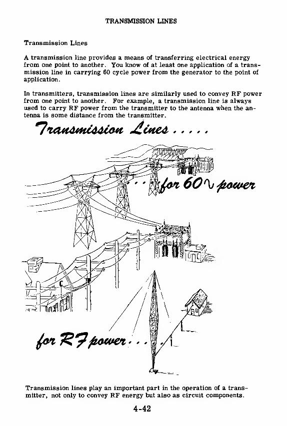
TRANSMISSION LINES
Transmission Lines
A transmission line provides a means of transferring electrical energyfrom one point to another. You know of at least one application of a trans-mission line in carrying 60 cycle power from the generator to the point of
application.
In transmitters, transmission lines are similarly used to convey RF powerfrom one point to another. For example, a transmission line is alwaysused to carry RF power from the transmitter to the antenna when the an-tenna is some distance from the transmitter.
^ute*
Transmission lines play an important part in the operation of a trans-
mitter, not only to convey RF energy but also as circuit components.
4-42

TRANSMISSION LINES
Frequency and Wavelength
Before you learn the theory of transmission lines, you should understandsomething about the properties of a radiated wave—its velocity of propa-gation (how fast it travels), its frequency and its wavelength.
For purposes of simplicity consider an AC generator sending 60 cpsenergy along a transmission line from New York to California by way ofKansas. Assume that the rate of travel of the AC power is the same asthe velocity of electromagnetic radiation in free space which is constantat 186, 000 miles per second or 300, 000, 000 meters per second regard-less of the frequency.
If the generator starts its generatingaction at the zero voltage point on ^the sine wave, after a half cycle haselapsed (1/120 of a second in time),
60 hLcps I I
the zero voltage point will have traveled a distance which can be deter-mined by multiplying the velocity of
the wave by the time duration for ahalf cycle. This distance equalsabout 1550 miles (186, 000 x
-jfo)which is approximately the dis-tance from New York to Kansas.
_ 1550.
miles
When another half cycle or a total of a full cycle has elapsed (1/60 of asecond), the zero voltage point will have traveled a distance of 3100 miles(186, 000 x-^M which is the approx- _imate distance from New York toCalifornia. This distance of 3100miles is the wavelength of the 60cycle AC, which is the distance thatthe wave travels during the time in-terval for one cycle. The symbolfor wavelength is the greek letter " X
VISTAHCE TRAVELLEDMl/60 Of A SECOND
Similarly the wavelength of any frequency radiation can be determined bymultiplying the constant velocity by the time for one cycle. Since the timefor one cycle is equal to 1 divided by the frequency (£), the wavelengthequals constant velocity over frequency (X= y) or the velocity equals the
frequency times the wavelength (V = f X). Since V is constant, the higherthe frequency, the lower the wavelength and vice versa.
From now on,transmission lines and antenna lengths will be defined interms of wavelengths of the RF energy they are to radiate. For example,if an antenna is a half of a wavelength long it means that only one-halfwavelength of the RF will be present on the antenna.
4-43

TRANSMISSION LINES
Equivalent Circuit of a Transmission Line
A typical transmission line used to convey RF energy from one point to
another may consist of two parallel lengths of wire which are spaced apart-
at equal distances by insulating spacers as illustrated.
An RF transmission line will have a certain amount of resistance, capaci-
tance and inductance along its length. The resistance is simply the re-
sistance of the wire. The inductance is generated by the magnetic field
(caused by current flow) expanding and collapsing along the entire length
of the line, and the capacitance exists because the two conductors of the
line act as plates of a capacitor separated by a dielectric (in the above case
air). Since the line can be broken up into any number of small segments
having equal amounts of inductance, capacitance and resistance, the entire
line can be represented as consisting of a series of L, C, R networks con-
nected as shown.
4-44

TRANSMISSION LINES
Characteristic Impedance
Suppose an RF generator is connected across a transmission line. TheRF generator impresses a voltage across the line, which forces a currentto flow. The amplitude of this current will be determined by the resist-ance, inductance and capacitance of the line, which together make up theline's impedance. If the magnitude of the input current is measured anddivided into the input voltage, the input impedance (Zm) of the line is ob-tained. K the line is infinitely long, this input impedance defines the char-acteristic impedance of the line. The symbol for characteristic impedanceis Z0 .
When a pure resistance loads down a generator, all of the power generatedis dissipated by this resistance. Similarly when a generator sends elec-trical energy down an infinitely long transmission line, the electrical en-ergy travels down the line indefinitely. In other words, all the electricalenergy that the generator puts out is absorbed or dissipated by the infi-nitely long line. The infinite line therefore acts like a resistance equal invalue to its characteristic impedance, Zq. The infinite line can thereforebe replaced by a resistance equal to its characteristic impedance and thegenerator will send the same amount of power into the resistance as it didinto the infinite line.
4-45

TRANSMISSION LINES
Line Termination In Characteristic Impedance
If a transmission line is terminated in a resistive load equal to its char-acteristic impedance, the load will absorb all the energy from the line that
is applied to the input by the generator. This is the ideal condition of
maximum power transfer.
An example of getting maximum power transfer from a transmission line
to a load is the case of a line feeding an antenna. If a certain type of an-
tenna, called a half-wave dipole',' is used, the impedance at its center
feed point is 73 ohms. Therefore in order to get maximum power transfer
from the transmission line to the antenna, the characteristic impedance of
the line should be 73 ohms or close to it. When this is the case, the line
is said to be "matched" to the antenna.
. . . MATCHING LINE TO ANTENNA
4-46

TRANSMISSION LINES
Nonresonant and Resonant Lines
When a transmission line is matched to a load (Zioa(i = Z0), the AC volt-age measured across the line at any point is the same, discounting theslight voltage drops in the line due to its resistance. The current meas-ured at any point in the line is also the same. This condition is shown inthe illustration by equal readings on the RF voltmeters and ammetersplaced along the length of the line. The effective voltage and current dis-tribution along the line can be shown graphically by two straight lines in-dicating that the effective RF voltages and currents are equal all along thelength of line. Such a line is called a "flat" line or nonresonant line. Atransmission line will always be nonresonant if it is terminated in itscharacteristic impedance, which is the condition required for maximumpower transfer.
a line is not terminated in its characteristic impedance it is said to bemismatched" and all of the RF energy traveling down the line is not ab-sorbed at the load end. The amount of energy absorbed depends upon howclose the value of the load impedance is to the characteristic impedance ofthe line. Since the load of a mismatched line does not absorb all of theenergy coming down the line, part of the energy which is not absorbed mustbe reflected back up the line. This energy which is reflected is called thereflected wave!' A mismatched line therefore has two waves flowingthrough it, the forward wave and the reflected wave. These two wavescombine all along the line (now called a 'resonant line) to form a resultantwave called a "standing wave.
"
4-47

TRANSMISSION LINES
Standing Waves on a Rope
To better understand how energy travels down a transmission line and howreflections generate standing waves on the line, consider a rope when one
end is fastened to a wall while the other end is held in the hand. When the
hand flicks the rope once, a vibration starts to travel down the rope. If
the rope were infinitely long, the vibration would continue down the rope
forever. This is equivalent to an infinite length of transmission line or a
flat line in that the energy put into the line is completely absorbed.
The Long Transmission Line .
and the Long Rope
Toinfinity
>
When the vibration traveling down the rope reaches the end attached to the
wall, it is reflected back toward the hand. Similarly when a transmission
line is mismatched, the electrical energy is reflected back toward the gen-
erator. If the hand vibrates the rope at a constant rate, the reflected vi-
brations combine with the oncoming vibrations to produce standing wavesalong the rope. At some points along the rope, the forward and reflected
vibrations are in phase, reinforcing each other to produce vibration of
large amplitude. At other points they are out of phase, thereby cancelling
each other, and the rope appears to be motionless at these points. In a
similar manner standing waves of voltage and current are formed on atransmission line when it is mismatched.
STANDING WAVES on a rope
4-48

TRANSMISSION LINES
Open and Shorted Transmission Lines
When a transmission line is open at its end, the forward and reflectedwaves combine along the line to form points of varying effective voltageand current. At the open end, the effective voltage is a maximum and theeffective current is zero. It is easy to see that the current must be zeroat all times at the open end because it is an open circuit. Also sincecharges build up on the open ends, a large voltage difference will existthere. At half-wavelength distances from the open end, the voltage andcurrent conditions will repeat themselves, and between these half-wavepoints the effective voltage and current readings will vary as a sine wavevaries. The meter reading in the illustration shows the variations in theeffective voltage and current along the length of the line at quarter-wavelength distances from the open end to the input. The wave formsshown are actually a plot of these voltage and current readings at differentpoints along the line. The wave forms are called
1
standing waves? Ob-serve that the standing waves cause the voltage and current to be zero atall times at certain definite points along the line. Notice that when thecurrent is zero.the voltage is a maximum and when the voltage is zero.thecurrent is maximum.
Standing waves onOPEN CIRCUITED
LINE
When the transmission line is shorted at its terminating end, the voltageat the open end must be zero because no voltage can exist across a short.Also the current at the short will be a maximum because the short pro-vides a zero resistance path through which current can flow. Just as inthe open-circuited line, these voltage and current conditions at the ter-minating end will repeat themselves at one -half wavelengths back from theshort circuit. Observe that the standing waves on the short-circuited linehave been displaced a distance equivalent to a quarter of a wavelength(90 degrees) compared to waves on the open-circuited line.
Standing waves onSHORT CIRCUITED
LINE
4-49
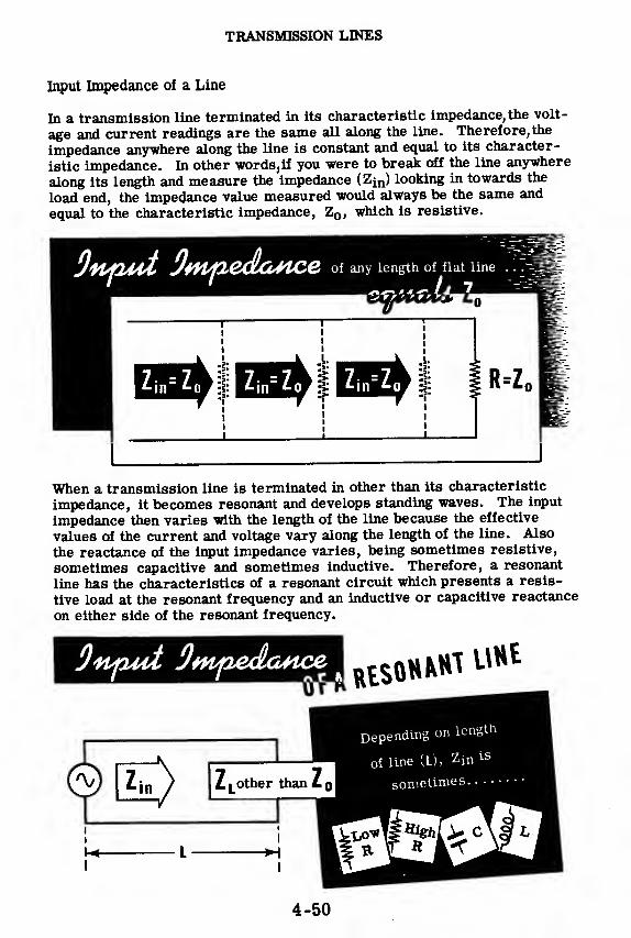
TRANSMISSION LINES
Input Impedance of a Line
In a transmission line terminated in its characteristic impedance, the volt-
age and current readings are the same all along the line. Therefore,the
impedance anywhere along the line is constant and equal to its character-
istic impedance. In other words, if you were to break off the line anywhere
along its length and measure the impedance (Zin) looking in towards the
load end, the impedance value measured would always be the same and
equal to the characteristic impedance, Z0 , which is resistive.
of any length of flat line Ik
i
R=Z,
When a transmission line is terminated in other than its characteristic
impedance, it becomes resonant and develops standing waves. The input
impedance then varies with the length of the line because the effective
values of the current and voltage vary along the length of the line. Also
the reactance of the input impedance varies, being sometimes resistive,
sometimes capacitive and sometimes inductive. Therefore, a resonant
line has the characteristics of a resonant circuit which presents a resis-
tive load at the resonant frequency and an inductive or capacitive reactance
on either side of the resonant frequency.
UHE
other than i
-H
Depending on length
oi line (L), zin 1S
sometimes
4-50
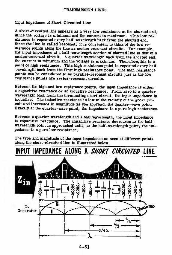
TRANSMISSION LINES
Input Impedance of Short-Circuited Line
A short-circuited line appears as a very low resistance at the shorted end,since the voltage is minimum and the current is maximum. This low re-sistance is repeated every half wavelength back from the shorted end.Since the line is called 'resonant', it is convenient to think of the low re-sistance points along the line as series-resonant circuits. For example,the input impedance at a half-wavelength section of shorted line is that of aseries-resonant circuit. A quarter wavelength back from the shorted end,the current is minimum and the voltage is maximum. Therefore, this is apoint of high resistance. This high resistance point is repeated every halfwavelength back from the first high resistance point. The high resistancepoints can be considered to be parallel-resonant circuits just as the lowresistance points are series-resonant circuits.
Between the high and low resistance points, the input impedance is eithera capacitive reactance or an inductive reactance. From zero to a quarterwavelength back from the terminating short circuit, the input impedance isinductive. The inductive reactance is low in the vicinity of the short cir-cuit and increases in magnitude as you approach the quarter-wave point.Exactly at the quarter-wave point, the impedance is a pure high resistance.
Between a quarter wavelength and a half wavelength, the input impedanceis capacitive reactance. The capacitive reactance decreases as the half-wavelength point is approached until, at the half-wavelength point, the im-pedance is a pure low resistance.
The type and magnitude of the input impedance as seen at different pointsalong the short-circuited line is illustrated below.
INPUT IMPEDANCE ALONG A SHORT CIRCUITED LINE
4-51
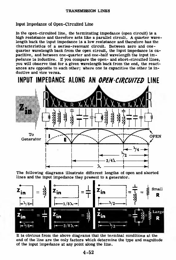
TRANSMISSION LINES
Input Impedance of Open-Circuited Line
In the open-circuited line, the terminating impedance (open circuit) is ahigh resistance and therefore acts like a parallel circuit. A quarter wave-length back the input impedance is a low resistance and therefore has the
characteristics of a series-resonant circuit. Between zero and one-quarter wavelength back from the open circuit, the input impedance is ca-pacitive, and between one-quarter and one-half wavelength the input im-pedance is inductive. If you compare the open- and short-circuited lines,
you will observe that for a given wavelength back from the end, the react-ances are opposite to each other; where one is capacitive the other is in-
ductive and vice versa.
INPUT IMPEDANCE ALONG AN OPEN-CIRCUITED LINE
ToGenerator
The following diagrams illustrate different lengths of open and shortedlines and the input impedance they present to a generator.
•
-in
3/8X-
1T 'in
V2-
-3/8X-
mmmmmmmmIt is obvious from the above diagrams that the terminal conditions at the
end of the line are the only factors which determine the type and magnitudeof the input impedance at any point along the line.
4-52
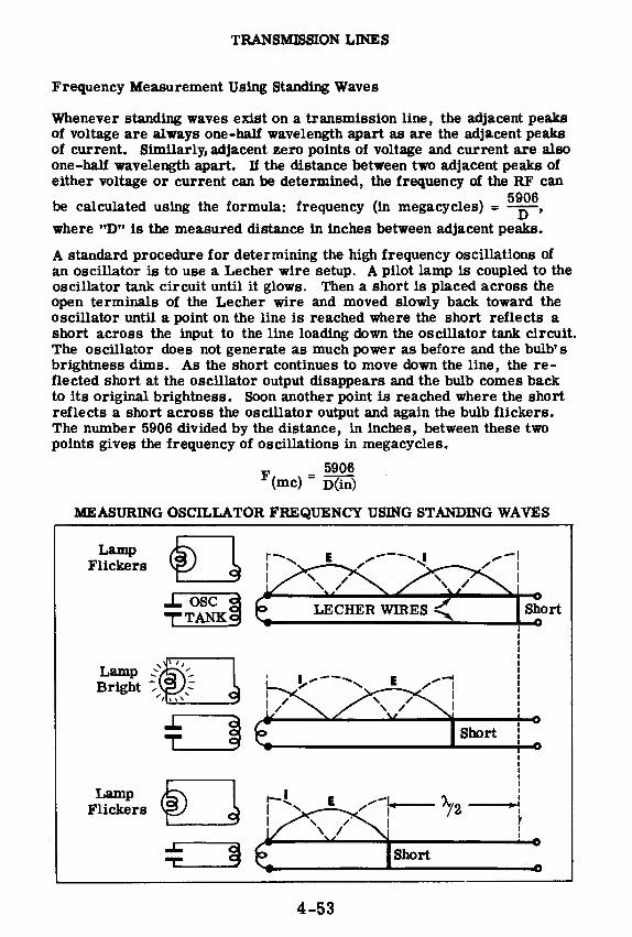
TRANSMISSION LINES
Frequency Measurement Using Standing Waves
Whenever standing waves exist on a transmission line, the adjacent peaksof voltage are always one-half wavelength apart as are the adjacent peaksof current. Similarly, adjacent zero points of voltage and current are also
one-half wavelength apart. If the distance between two adjacent peaks of
either voltage or current can be determined, the frequency of the RF can
be calculated using the formula: frequency (in megacycles) =^ ,
where "D" is the measured distance in inches between adjacent peaks.
A standard procedure for determining the high frequency oscillations of
an oscillator is to use a Lecher wire setup. A pilot lamp is coupled to the
oscillator tank circuit until it glows. Then a short is placed across the
open terminals of the Lecher wire and moved slowly back toward the
oscillator until a point on the line is reached where the short reflects ashort across the input to the line loading down the oscillator tank circuit.
The oscillator does not generate as much power as before and the bulb's
brightness dims. As the short continues to move down the line, the re-flected short at the oscillator output disappears and the bulb comes backto its original brightness. Soon another point is reached where the short
reflects a short across the oscillator output and again the bulb flickers.
The number 5906 divided by the distance, in inches, between these twopoints gives the frequency of oscillations in megacycles.
„ 5906(mc) "
D(in)
MEASURING OSCILLATOR FREQUENCY USING STANDING WAVES
4-53

TRANSMISSION LINES
Applications of Transmission Line Principles
With your understanding of how transmission lines work, suppose youlearn about a few of the many applications of transmission lines in
electronic equipment.
A shorted quarter-wave transmission line, known as a "stub, " will offer
a very high impedance at its input. It can therefore be used as a metallicinsulator to support a two-wire transmission line without shorting the line.
74 STUB USED AS A METALLIC INSULATOR WTwo-wire
transmissionline
,Supportingmetal base
The shorted quarter-wave stub also makes a very effective filter for har-monic frequencies of the fundamental which one does not desire to trans-mit. For the fundamental frequency the stub is a high impedance as wasshown above. For the second harmonic, the stub is now a half wavelengthlong and will act as a short circuit across the transmission line, shortingout the undesirable harmonic and preventing it from getting to the antenna.
/ 72 STUB ASHARMONIC FILTER
LOWIMPEDANCE
4-54

TRANSMISSION LINES
Applications of Transmission Line Principles (continued)
An important application of a short transmission line, or "tuned line sec-tion',; as it is called, is to tune out the reactance of a load on a transmis-sion line thus leaving the load resistive.
For example, suppose a 300-ohm line is feeding a load which looks like a300-ohm resistance in parallel with a capacity. Since the load is not com-pletely resistive, standing waves will exist on the line and maximum powertransfer to the load will not be realized. If an inductance could be placedin parallel with the capacity, to effect a parallel-resonant circuit, thetransmission line would look into the 300-ohm resistive component in par-allel with the high resistance of the parallel-resonant circuit. Since thehigh resistance of the parallel-resonant circuit is so much greater than300 ohms, the transmission line effectively sees only the 300-ohm resist-ance. The effect of the capacity has thus been cancelled out.
The way to introduce an inductance across the load is to place a quarter-wave shorted stub, with a movable shorting arm, across the load termi-nals. By moving the short so that the stub is less than a quarter wave-length long, the input reactance of the stub becomes inductive. The valueof this inductance can be varied by means of the movable short until it can-cels the capacity of the load, leaving the load resistive.
h- A/4—
|
MISMATCHEDLINE O300&
/ =STUB ADDED
1 MATCHED LINE. .
.
O 300O 5 No standing waves5 Maximum power transfer
Quarter-waveline sections are also used as transformers or matching de-vices to connect circuits of unequal impedances. If a low impedance inputcircuit is to be connected to a high impedance grid circuit, the input cir-cuit may be tapped down on the coil of a tank circuit as shown. If a tunedline is used, the input circuit can similarly be tapped down on the tunedline. This is an example of a tuned line used as a step-up transformer.
Lowimpedance
input
circuit
STUBas step-up
transformer
A quarter-wave stub can be used as a step-down transformer to match ahigh impedance line to a low impedance dipole antenna. The line is con-nected to the high impedance input of the stub and the antenna is connectednear the low impedance shorted end of the stub.
High impedance1"
line
Stub used asa step-down
transformer
High imp.
line'
a/4-
4-55

TRANSMISSION LINES
Types of Transmission Lines
Many different types of transmission lines are employed in electronic
applications. Each line has a certain characteristic impedance, currentcarrying capacity, insulation and physical shape to meet a particular re-quirement. Below are shown some of the most frequently used transmis-sion lines.
Single
WireA simple method of feeding an antennafrom a transmitter is to use a single-wiretransmission line with the ground returncompleting the circuit.
Another type of transmission line consists of two parallel wires which aremaintained at a fixed distance from each other by insulated spacers. Since
the line is not shielded, losses occur, due to radiation and absorption bymetallic objects. The use of the line is therefore restricted to compara-tively low-frequency transmission and it should be strung only in placeswhere it will be away from metallic objects and out in the open.
TWO WIREOPEN LINE Insulated spacer' Parallel wires
Some of the disadvantages of the two-wire open line are overcome in the
concentric line which is made of a cylindrical copper tube with a thin con-ductor running full length through the center. The inner conductor is keptcentered by spacers and the outer conductor is grounded to shield the in-
ner conductor. Since the line is mechanically rigid, it can be used only
for permanent installations.
CONCENTRIC
LINE Outer conductor Separator Inner conductor
The inflexibility of the concentric line is overcome in the coaxial cablewhich consists of one or more inner conductors imbedded in an insulating
material and covered with a grounded copper braid. The coaxial cable hasmuch higher losses than the concentric line.
COAXIAL
CABLE
Insulation -
Inner ^conductor
Rubber covering-,
zGrounded copper braiding
At very high frequencies the losses in any of the above mentioned lines be-
come excessive and wave guides must be used. Wave guides are made of
round or rectangular hollow tubes.
WAVEGUIDE
sRectangular hollow tube
4-56

TRANSMISSION LINES
Demonstration—Transmission Lines
In this demonstration a high-frequency oscillator is going to feed Lecherwires on which standing waves will be generated. The presence of thesestanding waves will be shown with different types of pickup devices. Youwill also see that the current and voltage peaks are shifted a half wave-length when the end of the line is shorted. A procedure for determiningthe frequency output of an oscillator using Lecher wires will be demon-strated as will a method for determining the characteristic impedance of
a transmission line.
The transmitter used for this demonstration is a very high frequencytuned-line oscillator which will oscillate in the neighborhood of 160 mega-cycles. The oscillator is effectively a Colpitts oscillator with the tuned
line acting as the coil of the tank circuit and the tube interelectrode ca-pacities acting as the capacitor voltage divider network. The schematicand equivalent RF circuit of the oscillator are pictured below. The ca-pacities represented in the equivalent circuit are the interelectrode capac-ities, and the inductance L is the input reactance of the less-than-a-quarter-wavelength short-circuited transmission line. The oscillator will
always oscillate at the frequency for which the tuned line is less thana quarter -wavelength long. One of the pickup devices is an RF currentmeter whose circuit diagram appears below.
Schematic 1
VHF o&cdiafoi
RFC
HY75A
RFC
RF coupling
capacitor
w
Shorting
bar
-c
Lessthan
ty4
Circuit diagram of
RF Current Meter
RFC
To center tapped
filament transformer
RFC
B-To filament
transformercenter tap
4-57
RFC
X 1N34Crystal
RFC
To meter movement

TRANSMISSION LINES
Demonstration—Transmission Lines (continued)
Next the instructor demonstrates the existence of standing waves along theopen-ended Lecher wires, using various indicating devices.
The high frequency oscillator is turned on, and the Lecher wires are en-ergized. The meter-type RF current indicator is moved underneath thewires, and the distance of the loop from the wires is adjusted so that themeter shows a maximum deflection. Then the meter is moved slowlyalong the length of the wire and the position of the maximum current pointsare noted. The distance between two adjacent current peaks is equal toone -half wavelength.
The meter indicator is placed at a point of maximum current, and the in-structor shorts the open end of the line with a screwdriver. The readingdrops immediately and the meter is moved to the new current peak whichis a quarter wavelength away from the previous current peak position.The short has displaced the standing waves one -quarter wavelength fromtheir position when the line was open. The short is removed and the dem-onstration continues.
4-58
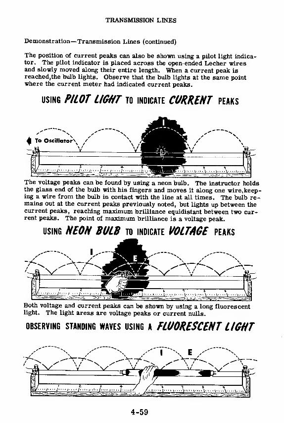
TRANSMISSION LINES
Demonstration—Transmission Lines (continued)
The position of current peaks can also be shown using a pilot light indica-tor. The pilot indicator is placed across the open-ended Lecher wiresand slowly moved along their entire length. When a current peak isreached,the bulb lights. Observe that the bulb lights at the same pointwhere the current meter had indicated current peaks.
using PILOT LIGHT to indicate CURRENT peaks
The voltage peaks can be found by using a neon bulb. The instructor holdsthe glass end of the bulb with his fingers and moves it along one wire,keep-ing a wire from the bulb in contact with the line at all times. The bulb re-mains out at the current peaks previously noted, but lights up between thecurrent peaks, reaching maximum brilliance equidistant between two cur-rent peaks. The point of maximum brilliance is a voltage peak.
using NEON BULB to indicate VOLTAGE peaks
Both voltage and current peaks can be shown by using a long fluorescentlight. The light areas are voltage peaks or current nulls.
OBSERVING STANDING WAVES USING A FLUORESCENT LIGHT
4-59

TRANSMISSION LINES
Demonstration—Transmission Lines (continued)
When a transmission line is terminated in its characteristic impedance,no standing waves of voltage or current will exist on the line. Thereforethe characteristic impedance of a line can be determined by placing dif-
ferent values of resistance across the line until the standing waves dis-
appear or are reduced to a minimum. The value of the resistor whichproduces this result is equal to the line characteristic impedance.
The instructor turns on the high frequency oscillator and checks for stand-
ing waves on the line using the meter-type RF current indicator. As the
meter indicator is moved along the line, the readings vary from a maxi-mum to a minimum indicating the presence of standing waves. Next, eachof the resistors in turn is connected across the line, and a check is madeeach time for the presence of standing waves. When the current indicator
gives a practically constant reading along the entire length of the line, the
value of the resistor connected across the end of the line is approximately
equal to the line characteristic impedance.
Determining Characteristic
Impedance of a Line
4-60

TRANSMISSION LINES
Demonstration—Transmission Lines (continued)
The instructor now demonstrates a procedure for determining the frequen-cy of a nigh frequency oscillator using Lecher wires.
The pilot light and pickup loop are coupled to the oscillator tank circuit byPlacing the coil between the tuned line and the tuning rod so that the bulbugnts. Then, holding a screwdriver by the insulated handle and with themetal shank at the input end, the instructor shorts out the line, and slowlymoves the screwdriver toward the open end, keeping the line shorted. Ata certain point the pilot light dims, indicating that the short is electricallya half wavelength away from the coupling loop and therefore is loadingdown the oscillator. This point is carefully noted and the instructor con-
rTaUnifJ
0 m°Vl
thi
e «ci;
ewdriver toward the open end. Again a point isreached when the light dims. This point is one-half wavelength away fromthe preceding point. The instructor using the formula F = 5906
(where Fis the frequency in megacycles and D is the distance in inches between thetwo points) calculates the oscillator frequency.
If the meter-type RF current indicator is used in place of the bulb, the cor-rectly positioned shorted points will show up as a dip reading on Uie meter.
A/2 =
Note pointson scale where >
bulb DIMS //
4-61
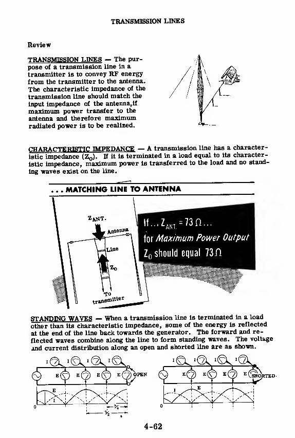
TRANSMISSION LINES
Review
TRANSMISSION LINES — The pur-
pose of a transmission line in a
transmitter is to convey RF energy
from the transmitter to the antenna.
The characteristic impedance of the
transmission line should match the
input impedance of the antenna, if
maximum power transfer to the
antenna and therefore maximumradiated power is to be realized.
CHARACTERISTIC IMPEDANCE — A transmission line has a character-
istic impedance (Z0). If it is terminated in a load equal to its character-
istic impedance, maximum power is transferred to the load and no stand-
ing waves exist on the line.
MATCHING LINE TO ANTENNA
lf...ZANI
=73n...
for Maximum Power Output
Z 0 should equal 73H
STANDING WAVES — When a transmission line is terminated in a load
other than its characteristic impedance, some of the energy is reflected
at the end of the line back towards the generator. The forward and re-
flected waves combine along the line to form standing waves. The voltage
and current distribution along an open and shorted line are as shown.
SHORTED'
4-62

ANTENNAS
Purpose of an Antenna
The purpose of a transmitting antenna is to convert the power delivered bythe transmission line into a wave called an"electromagnetic wave'.' Thiselectromagnetic wave has the unique property of radiating through spacewithout the aid of wires. All antennas work on the same principle—theantenna current generates an electromagnetic field which leaves the an-tenna and radiates outward as an electromagnetic wave.
The antennas you will be concerned with now are those which are designedas transmitting antennas. These will operate at much higher frequenciesthan the power lines and will be much more efficient. However, it is still
the current which flows in the antenna that causes the electromagneticfield to be radiated.
An interesting example of antenna action can be observed by touching yourfinger to the vertical input terminal of an oscilloscope. You will see a 60cycle wave form on the 'scope screen which obviously must come fromyour body. What is actually happening is that your body is picking up 60cycle electromagnetic waves which are radiated from the many powerwires that carry 60 cycle current. The power lines are acting as trans-mitting antennas although they were not designed for that purpose.
4-63
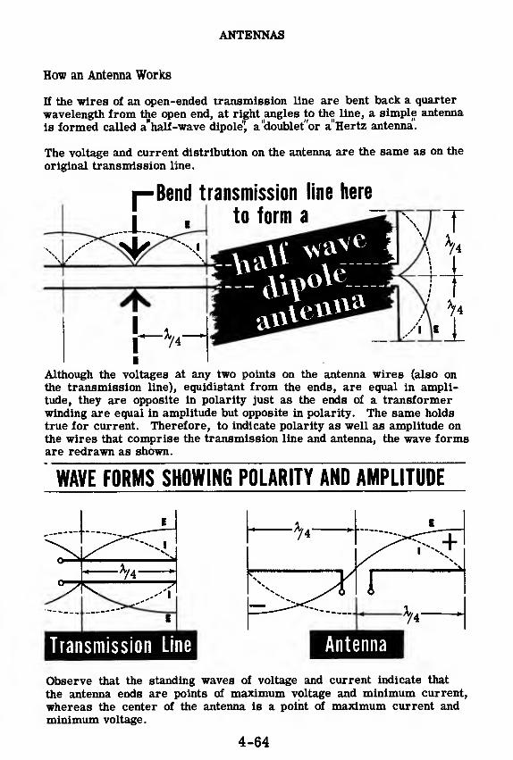
ANTENNAS
How an Antenna Works
If the wires of an open-ended transmission line are bent back a quarter
wavelength from the open end, at right angles to the line, a simple antenna
is formed called a"half-wave dipole'l a"doublet"or a'Hertz antenna.
The voltage and current distribution on the antenna are the same as on the
original transmission line.
Although the voltages at any two points on the antenna wires (also onthe transmission line), equidistant from the ends, are equal in ampli-tude, they are opposite in polarity just as the ends of a transformerwinding are equal in amplitude but opposite in polarity. The same holds
true for current. Therefore, to indicate polarity as well as amplitude onthe wires that comprise the transmission line and antenna, the wave formsare redrawn as shown.
WAVE FORMS SHOWING POLARITY AND AMPLITUDE
Transmission Line^^^^H Antenna
Observe that the standing waves of voltage and current indicate that
the antenna ends are points of maximum voltage and minimum current,
whereas the center of the antenna is a point of maximum current andminimum voltage.
4-64

ANTENNAS
How an Antenna Works (continued)
Whenever there is a difference of voltage between two points, an electricfield is set up between these points. You learned in Basic Electricity thatwhen a capacitor is charged, one plate will be positive and the other neg-ative. As a result, an electric field having a direction toward the posi-tively charged plate is built up between the capacitor plates as shown.Similarly, the voltage difference between the two wires of an antenna alsogenerates an electric field having a pattern and direction as shown below.
Electric Field of a
Besides this electric field, there is also a magnetic field which is gener-ated by the antenna current. The plane of this magnetic field is at rightangles to the direction of the current flow and therefore is at right anglesto the antenna, as shown. The electric and magnetic fields must thereforebe at right angles to each other.
Magnetic Field Surrounding —
,
These electric and magnetic fields alternate about the antenna, building
up, reaching a peak, collapsing, and building up again in the opposite di-
rection, at the same frequency as the antenna current. In the process of
building up and collapsing, a portion of these fields escape from the an-
tenna and become the electromagnetic waves which radiate through spaceconveying the transmitted intelligence to distant receivers.
4-65

ANTENNAS
Basic Antennas
The half-wave dipole or Hertz antenna is one type of basic antenna which
finds wide application in many types of transmitting and receiving equipment.
Another basic antenna is a vertical quarter-wave grounded antenna some-
times called a"Marconi antenna! If one of the elements of a Hertz antenna
is removed and the wire that went to that element is grounded, the result
is a Marconi antenna. The earth actually takes the place of one of the
quarter-wave elements so that the earth and the remaining quarter-wave
element form an effective half-wave dipole. The current maximum and
voltage minimum points are at the base of the antenna as shown.
BASICANTENNAS
VERTICAL A/4 GROUNDEDANTENNA (Marconi)
DIPOLEELEMENT
When a Marconi antenna is used, the earth directly beneath the antenna
must be a good electrical conductor. Sometimes copper tubing is driven
into the ground at the base of the antenna to improve the ground conduc-
tivity. On shipboard a vertical quarter-wave antenna may be some dis-
tance above the deck. A simulated ground is provided by using grounded
metal rods at least a quarter wavelength long and placing them at the baseof the antenna. This simulated ground is called a' counterpoise!'
Since a quarter-wavelength dipole antenna is physically half as long as ahalf-wave grounded antenna, it is often preferred at low frequencies
(large wavelength) especially when there are space restrictions on antenna
mountings. At high frequencies the half-wavelength dipole is extensively
used because even though it is longer than the quarter-wave antenna, its
overall length will be small, and it can be made of metal tubing which is
self-supporting.
4-66

ANTENNAS
Radiation Resistance
In a half-wave dipole antenna, the voltage at the center is minimum (prac-tically zero) whereas the current is maximum. If you will recall thecharacteristics of a series-resonant circuit, you will remember that thevoltage across it is also minimum and the current through it is maximum.At its center, a half-wave dipole is equivalent to a series-resonant cir-cuit when operated at the proper frequency. A generator that suppliespower to a series-resonant circuit works into a pure resistance sinceXL and Xc cancel each other—the resistance being mainly the wireresistance of the coil.
Similarly, a transmission line works into a pure resistance when a half-wave dipole is connected to it. This resistance consists of both the re-sistance of the wire and a resistance called the"radiation resistance! Theresistance of the wire is neglibible, so only the radiation resistance isconsidered.
THE INPUT IMPEDANCE OF A DOUBLET LOOKS LIKE....
The radiation resistance is not an actual resistance. It is an equivalentresistance which, if connected in place of the antenna, would dissipatethe same amount of power as the antenna radiates into space.
The value of the radiation resistance can be determined from the powerformula, R = where P is the power radiated from the antenna and I is
I
equal to the antenna current at the center of the antenna. For a half-wavedipole the radiation resistance is about 73 ohms, measured at the cen-ter of the antenna. This value is fairly constant for' different fre-quency half-wave dipoles.
____ 73 Jl
Impedance looking in
...the radiation resistance
4-67

ANTENNAS
Antenna Impedance
Since a half-wave dipole acts like a series-resonant circuit, it will exhibit
either inductive or capacitive properties as the RF frequency applied to
the antenna is varied.
When the frequency of the RF is just right, the dipole is exactly a half
wavelength long and is series-resonant, with its impedance resistive and
equal to the radiation resistance. In transmitting it is always desirable
that the antenna present a resistive load to the transmission line so that a
maximum amount of power will be absorbed by the antenna and radiated.
Optimum condition
73«
If the frequency of the transmitter goes up, the antenna will be longer than
a half wavelength. The series circuit is then operating at a frequency
which is above its resonant frequency. At this applied frequency, the in-
ductive reactance is larger than the capacitive reactance and the antenna
appears inductive to the transmitter.
Dipole LONGER than x/2 appears INDUCTIVE
— —rflffip—VWV—
7a
If the frequency of the transmitter goes down, the antenna will be slightly
shorter than a half wavelength. The series circuit is then operating at a
frequency which is below its resonant frequency. The capacitive react-
ance is larger than the inductive reactance and the antenna appears ca-
pacitive to the transmitter.
Dipole SHORTER than A/2 appears CAPACITIVE
n tr
A/2-
h-VW\r-
4-68

ANTENNAS
Tuning the Antenna
You have seen that as the frequency of the transmitter is varied, the elec-
trical length of the antenna varies as does the impedance at its input.
Since it is desirable to have the antenna impedance resistive for all trans-mitter frequencies (for maximum radiated power), the antenna can be res-onated by adding inductors or capacitors to effectively increase or shortenits electrical length.
For example, if a vertical quarter-wave grounded antenna is less than aquarter wavelength long, its input impedance at its base will be resistiveand capacitive. The antenna can be electrically lengthened (resonated) byadding the right size inductor to cancel the capacity, thus leaving the
antenna resistive. The inductor must be placed in series with the antennaat its base as shown.
looks like o-WWW—11—o looks like —WVWW
—
If a vertical quarter-wave grounded antenna is longer than a quarterwavelength, the input impedance at its base is resistive and inductive.
The antenna can be electrically shortened by adding the right size capaci-tor to cancel the inductance, thus leaving the antenna resistive.
X/4
looks like —o looks like —WW/W-
4-69

ANTENNAS
Radiation Pattern
When an antenna radiates electromagnetic waves, the radiation wili bestronger in some directions than in others. The antenna is said to be di-
rectional along the line of strongest radiation which is at right angles to apoint of maximum current on the antenna.
A radiation tester, called a'field strength meter^ can be used to measurethe radiation strength at all points around the antenna. If these field
strength readings are plotted on a three dimensional graph, the three di-mensional curve obtained will be the antenna radiation pattern. The radi-ation pattern for a horizontally positioned half-wave dipole is doughnutshaped as shown. Observe that the thickest part of the doughnut patternis in a plane which is at right angles to the antenna at its center. Maxi-mum radiation takes place in this plane. The thinnest part of the doughnutlies along its axis which corresponds to the line of minimum radiation. If
the antenna is rotated 90 degrees in a vertical plane, maximum radiationoccurs in a horizontal plane.
The above radiation patterns assume that the antenna is isolated in space
away from all grounds. In actual practice, the antenna is located near
ground surfaces so that the radiation pattern is altered appreciably
from that shown above.
4-70

ANTENNAS
Wave Propagation
You know that the function of an antenna is to radiate electromagnetic en-ergy into space. Once this energy is released from the antenna, it travelsthrough space until it is picked up by a receiving antenna or is reflectedoff an object, as is the case with radar transmission.
It is important to know what happens to a radiated wave in space (namely,what its path is, if it is absorbed by the earth, if it is reflected by the sky,etc. ) in order to tell how far the wave will travel before it can be pickedup. The study of what happens to a radiated electromagnetic wave once it
leaves the antenna is called "wave propagation. "
When a radiated wave leaves the antenna, part of the energy travels throughthe earth following the curvature of the earth and is called the "groundwave. " The rest of the energy is radiated in all directions into space.Those waves which strike the ground between the transmitter and the hor-izon are called "space waves. " Waves which leave the antenna at an anglegreater than that between the antenna and the horizon are "sky waves. "
The ground wave, the space waves and the sky waves contain the trans-mitted intelligence. However, at certain frequencies one of the waves willbe much more effective in transmitting the intelligence than the others. Atcomparatively low transmitted frequencies, most of the radiated energy isin the ground wave. Since the earth is a poor conductor, the ground waveis rapidly attenuated and therefore is not effective for transmission overgreat distances unless large amounts of transmitted power are used. Thestandard broadcast frequencies are examples of transmissions usingground waves. At these frequencies the effective radiating area is within100 miles of the transmitter. As a result,neighboring cities more than100 miles away from each other can transmit on the same frequencies andyet not interfere with each other.
4-71

ANTENNAS
Sky Wave and Ground Wave
At first one would be inclined to think that sky waves can serve no useful
purposes since they will only travel straight out into space and get lost.
For very high frequencies this actually happens and therefore the sky waveis useless. Below a certain critical frequency, however, the sky wavedoes not travel straight out but is bent back to earth in the upper layers of
our atmosphere. This returning wave is not sharply reflected as is light
from a mirror. It is bent back slowly as if it were going around a curve,
and is therefore called a refracted wave? This refracted wave, once it
returns to earth, is reflected back to the sky again where it is once againrefracted back to earth. This process of refraction from the sky and re-
flection from the earth continues until the wave is completely attenuated,
since the energy of a radiated wave drops as its distance from the trans-
mitting antenna increases.
A receiving antenna will be able to pick up a signal at every point wherethe refracted wave hits the earth. If the sky wave were radiated to the skyat only one angle, no signal would exist between points where the refractedwave hits the earth. The sky waves, however, are radiated at all anglesto the sky and therefore the earth's surface (beyond a certain minimumdistance from the antenna) is completely covered with radio signals. Asthe angle of radiation of the sky wave increases, an angle is reached wherethe wave is no longer refracted back to earth but continues traveling into
space. As a result,there is a zone around the antenna in which no re-fracted sky wave hits the earth. The ground wave itself is only effective
a short distance. Therefore, the zone between the maximum effective ra-diating distance of the ground wave, and the point where the first sky waveis refracted back to earth, is an area of radio silence (no signals) calledthe'skip zone?
The critical frequency, which is the frequency above which no sky wavescan return to earth, varies depending upon numerous factors such as the
time of day, the time of year, the weather, etc. As a result,long distancecommunication can sometimes be achieved with frequencies which normallyhave no returning sky wave.
4-72

ANTENNAS
Space Wave and Fading
At frequencies above the critical frequency, neither the ground wave northe sky wave can be used for transmission. At these high frequencies,the ground wave is rapidly attenuated and the sky wave is not refractedback to earth. As a result, the only radiated wave that can be used fortransmission at these frequencies is one that travels in a direct line fromthe transmitting antenna to the receiving antenna. This type of transmis-sion is called °line of sight transmission'/ and the radiated wave is called
a "space wave.
"
Line of sight transmission is used in radar for detecting enemy craft
and in ship-to-plane communication. The frequencies used are usuallyabove 30 megacycles.
LINE OF SIGHT TRANSMISSION I • • • •
/
Space waves
Sometimes a receiving antenna picks up two signals which have traveledalong different paths from the same transmitting antenna. For example,one signal may travel direct from the antenna, and the other signal mayhave been reflected off an object. Since the signal paths are constantlychanging, the two signals will sometimes be in phase and at other timesbe out of phase, thus tending to cancel or reinforce each other. The re-sult is a variation in signal strength at the receiver end called "fading. "
4-73

ANTENNAS
Frequency Spectrum
The following is an outline of the components of a radiated wave which are
used for transmission at various frequencies:
From 30 to 300 kilocycles (low frequency band) the ground wave is largely
used for medium range communication since its stability is not affected by
seasonal and weather changes. For very long distance communication, the
sky wave is used.
From 300 to 3000 kilocycles (medium frequency band), the range of the
ground wave varies from 15 to 400 miles. Sky wave transmission is ex-
cellent at night for ranges up to 8000 miles. In the daytime, however, sky
wave transmission becomes erratic, especially at the high end of the band.
From 3 to 30 megacycles (high frequency band), the range of the ground
wave decreases rapidly and sky wave transmission is highly erratic de-
pending upon the seasonal factors previously mentioned. Space wavetransmission begins to become important.
From 30 to 300 megacycles (very high frequency band VHF), neither the
ground wave nor the sky wave are usable, and space wave transmission
finds major application.
From 300 to 3000 megacycles (ultra-high frequency band UHF), space
wave transmission is used exclusively.
-he- TRANSMITTING FREQUENCIES. .
.
4-74

ANTENNAS
Demonstration—Current Distribution Along an Antenna
The very high frequency tuned-line transmitter is set to oscillate at about160 megacycles. At 160 megacycles, a wavelength is about 6 feet long.
Therefore, a quarter-wavelength is 1-1/2 feet (18 inches), which is the
length of each pole of the doublet antenna.
The instructor connects a dipole antenna section to each transmitter out-put terminal. He then energizes the transmitter, and the oscillator tubefilament starts to-glow immediately. A quick check for oscillations is
made by holding the glass end of a neon lamp and pressing one lead againstone of the tuned lines. If the lamp glows it means that RF is present andtherefore the tube is oscillating.
Once oscillations have been verified, the instructor demonstrates the
presence of standing waves along the half-wave antenna by holding a fluo-
rescent lamp close to and parallel with the antenna. The lamp is ignited
by placing one end against the tuned line. The lamp glows at the ends andis out in the middle.
4-75

ANTENNAS
Demonstration—Radiation Pattern of an Antenna
To demonstrate the radiation pattern around the antenna, a wavemeter is
used which is made up of a half-wave antenna connected to an RF current
meter. A 73 ohm resistor is placed across the antenna input for propertermination and a germanium crystal diode and a capacitor are connectedacross the resistor. The crystal rectifies the RF and the capacitor filters
out RF from the rectifier voltage. The DC milliammeter is connected
across the capacitor through two RF chokes which block RF but pass DCthrough to the meter. When the antenna picks up RF radiation, the meterdeflects an amount proportional to the intensity of the radiation.
The instructor places the wavemeter far enough away from the transmitting
antenna so that the meter needle does not deflect off scale. Then,the trans-
mitter frequency is varied until the meter goes through a peak reading. At
this point the transmitting antenna is exactly a half-wavelength long and is
therefore radiating at maximum.
When the wavemeter reachesa Peak reading
the antenna is exactly a
Half Wavelength long
Vary the
transmitterfrequency
4-76

ANTENNAS
Demonstration—Radiation Pattern of an Antenna (continued)
Next, the instructor shows the intensity of the radiated field by placing thewavemeter at different positions around the antenna. Theoretically theradiation intensity is maximum in a plane at right angles to the antenna atits center and is minimum at the ends of the antenna. Actually this is notso since ground effects and multiple reflections around the room distortthe radiation pattern.
MEASURING Maximum meter reading
Itadiation Intensity ..\~T\.
Antenna
Minimum Minimum
Theoretical
RadiationPattern
Maximum
To show that movement of objects near the antenna affect the radiationpattern, the instructor sets the wavemeter down at a given point and walksbetween the meter and the antenna. Observe that the meter reading variessharply as the instructor walks about.
MOVING OBJECTS AFFECTRADIATION PATTERN
4-77

ANTENNAS
Demonstration—Radiation Pattern of an Antenna (continued)
The instructor demonstrates another type of wavemeter using a half-wavedipole connected to a pilot lamp. When the antenna picks up radiation,
there will be a maximum of current at its center, which will flow through
the lamp causing it to light.
Mil
Pilot lamp used as ^{JcUACMtCtCtl
Pink bead
Antenna
4h
Pilot lamp and socket|
36"
First,the transmitter is retuned until the bulb is brightest. Then, the in-
tensity of the radiation around the antenna is demonstrated by moving the
dipole, parallel to the antenna, from the center out to either end. Observethat the bulb is brightest when the center of the wavemeter dipole is lined
up with the center of the antenna, and the bulb goes out when the center of
the wavemeter dipole is in line with the end of the transmitting antenna.
CHECKING THE T^CuUdtcOH 'PattVUt
BRIGHTEST AT CENTER
BULB GOES OUT AT END
4-78
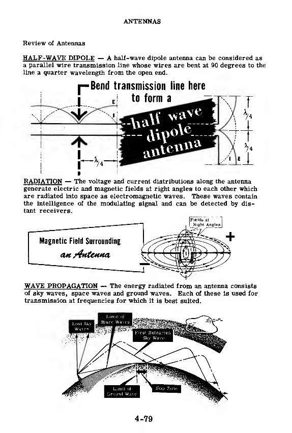
ANTENNAS
Review of Antennas
HALF-WAVE DIPOLE — A half-wave dipole antenna can be considered asa parallel wire transmission line whose wires are bent at 90 degrees to the
line a quarter wavelength from the open end.
RADIATION — The voltage and current distributions along the antennagenerate electric and magnetic fields at right angles to each other whichare radiated into space as electromagnetic waves. These waves containthe intelligence of the modulating signal and can be detected by dis-
tant receivers.
WAVE PROPAGATION — The energy radiated from an antenna consistsof sky waves, space waves and ground waves. Each of these is used for
transmission at frequencies for which it is best suited.
4-79

CW TRANSMISSION
Advantages of CW Transmission
You may remember from the introductory topic on transmitters that amessage can be transmitted by either code or voice. Code transmissionis either CW (continuous wave) or MCW (modulated continuous wave). In
both cases the RF radiated by the antenna is turned on and off by a handkey in dot and dash sequence.
CW transmission is used very widely. When a transmitter is modulated byvoice or MCW, it sends out not only the carrier frequency, but also thesum and difference (beat) frequencies of the carrier and the modulationsignal. These additional frequencies are called "sideband frequencies. "
A receiver, in order to pick up a voice or MCW signal, must be broadlytuned so that it will pick up both the carrier and the sidebands. As aresult the receiver may pick up a nearby signal in addition to the desired one.This interference may make it impossible to understand the desired signal.
CW transmission, on the other hand, does not contain sidebands. Noticethat the receiver would not heed to cover as wide a range of frequenciesfor a CW signal as it would for a voice signal. Therefore, there is not
likely to be interference when receiving a CW signal. This is the mainadvantage of CW over either MCW or voice.
^GE OF FREQUE^^ CW
Carrier Wave Frequency
\
ill
roVSRED BY DIFFERf,
Carrier Wave Frequency
\ Sideband
|y|QyyJx^Frequencies
Carrier Wave Frequency i
\Sidebands
VOICE
Sidebands
There are many different circuits which are used to obtain CW trans-mission. They look different and operate differently, but each has the
same purpose—to turn the RF of the transmitter on and off. You will
learn about some of these circuits on the next few sheets. In the nexttopic,you will find out more about MCW and voice transmission.
4-80

CW TRANSMISSION
Cathode Keying
Regardless of the circuit used, the CW output of a transmitter looks like a
series of pulses of RF separated by gaps of no RF. The gaps between the
RF pulses occur when the key is up, while the length of each RF pulse is
determined by the length of time the operator holds the key down.
KEYED RF
The simplest and most commonly used method of obtaining CW transmis-
sion is by "cathode keying. " In this type of circuit, the key is connected
in the cathode's DC return to ground. Thus, when the key is opened, no
current can flow and no RF can be radiated from the antenna. When the
key is closed, the circuit operates normally. The stage that is usually
keyed in this manner is the master oscillator itself or the master oscilla-
tor plus one or more of the following amplifier stages.
4-81
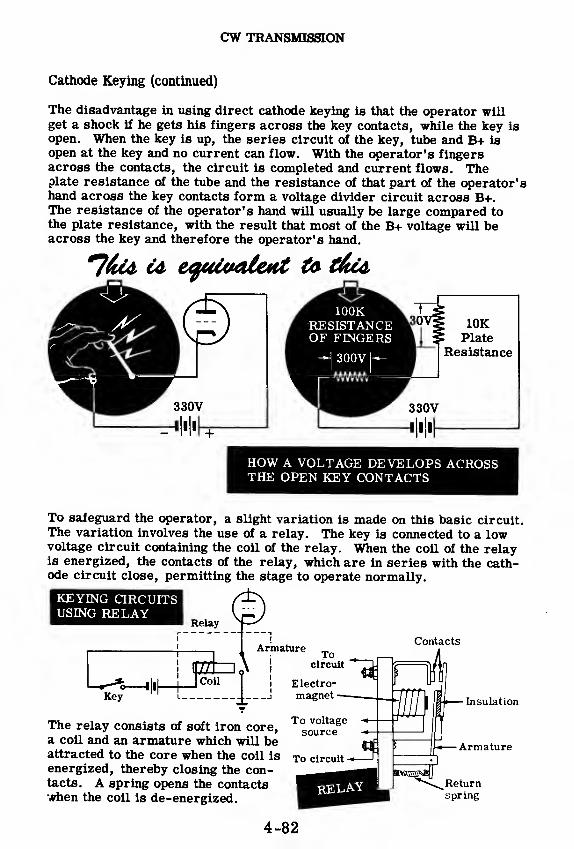
CW TRANSMISSION
Cathode Keying (continued)
The disadvantage in using direct cathode keying is that the operator willget a shock if he gets his fingers across the key contacts, while the key is
open. When the key is up, the series circuit of the key, tube and B+ is
open at the key and no current can flow. With the operator's fingersacross the contacts, the circuit is completed and current flows. Theplate resistance of the tube and the resistance of that part of the operator'shand across the key contacts form a voltage divider circuit across B+.The resistance of the operator's hand will usually be large compared tothe plate resistance, with the result that most of the B+ voltage will beacross the key and therefore the operator's hand.
10KPlate
Resistance
HOW A VOLTAGE DEVELOPS ACROSSTHE OPEN KEY CONTACTS
To safeguard the operator, a slight variation is made on this basic circuit.The variation involves the use of a relay. The key is connected to a lowvoltage circuit containing the coil of the relay. When the coil of the relayis energized, the contacts of the relay, which are in series with the cath-ode circuit close, permitting the stage to operate normally.
KEYING CIRCUITSUSING RELAY
ArmatureContacts
Tocircuit
The relay consists of soft iron core,a coil and an armature which will beattracted to the core when the coil is
energized, thereby closing the con-tacts. A spring opens the contactswhen the coil is de-energized.
Electro-magnet
To voltagesource
Insulation
Armature
Returnspring
4-82

CW TRANSMISSION
Blocked-Grid Keying
Keying can also be accomplished by changing the grid voltage of the stage
being keyed. When the key is open, the grid bias is many times cut-off,
so that the RF grid signal can never bring the tube into conduction. As a
result, no RF signal appears at the plate. When the key is closed, the
bias is the normal value for Class C operation and the stage operates
normally. This type of keying is known as "blocked-grid keying.
"
In the circuit shown below, the key (or relay) controls the DC bias on the
grid of an intermediate power amplifier. With the key open, the voltage
on the grid is equal to C- which is many times cut-off. With the key
closed, the grid is connected to a voltage divider which provides normal
operating bias to the tube. Therefore with the key down, the trans-
mitter is sending out an RF signal. This signal is interrupted each time
the key is opened.
The same idea can be applied to the screen grid. The circuit on the right
is for screen grid keying. In this circuit, the voltage varies from a posi-
tive operating voltage, with the key closed, to a negative blocking voltage
with the key open. When the key is opened, the screen is connected through
resistor, R, to C- which is sufficient to cut off the stage completely.
When the key is closed, the screen is connected directly to B+. The pur-
pose of R is to limit the current flowing from C- to B+ when the key is
closed. In this circuit, as in the last, a relay (not shown) is used in place
of the key to protect the radio operator from high DC voltages.
CONTROL GRID SCREEN GRID
RFInput
C- C- C-
4-83

CW TRANSMISSION
Keyer Tube Circuits
Relay or key contacts cannot close or open circuits as quickly as a vacuumtube can start or stop conducting. Therefore some applications use one 01
more vacuum tubes to key the RF circuits. These tubes are called "keyertubes. " There are several variations of keyer tube circuits, but they all
turn the transmitter on when the hand key is closed and off when the keyis opened.
In the circuit shown below, the keyer tube is connected in series with the
cathode of the power amplifier tube. The transmitter will be on when the
keyer tube conducts and will be off when the keyer tube is cut off. Thekeyer tube can be keyed by any of the blocked-grid keying methods de-scribed previously.
A simplified schematic of another type of keyer tube circuit is shown be-low. With the key open,current flows through R-l and R-2 producing alarge voltage drop across these resistors. Resistor R-l is the PA screendropping resistor and resistor R-2 is the PA plate dropping resistor. Thekeyer tube current flows through R-l and R-2 causing the power amplifier'sscreen and plate voltages to drop, thereby cutting off the power amplifier.When the key is closed, C- is applied to the grid of the keyer tube so thatit will be cut off. As a result, the screen and plate voltages of the poweramplifier increase to their normal values, the power amplifier conducts,and the transmitted pulse is radiated from the antenna.

AMPLITUDE MODULATION
What Amplitude Modulation Is
The type of voice transmission most commonly used is one in which the
amplitude of the carrier is varied in accordance with the amplitude of the
voice signal. This method of modulating the carrier is called "amplitude
modulation. " MCW transmission is amplitude modulation in which a steady
audio frequency is used, instead of voice, to vary the amplitude of the RFcarrier.
In addition to the oscillator and power amplifiers, an AM transmitter con-
tains a modulator, which applies the audio frequency signal to the PAwhere it is combined with the RF carrier wave. A block diagram of a
typical voice AM transmitter is shown below.
AmplitudeModulatedTransmitter
AudioAmplifier
Modulator
In the operation of an AM transmitter, it is essential that the modulator
unit be on during transmission because the intelligence that is to be trans-
mitted must come through the modulator. If the modulator is either off
or defective, only unmodulated RF will be transmitted and a receiver at
some distant point will not receive any message.
MODULATOR
4-85
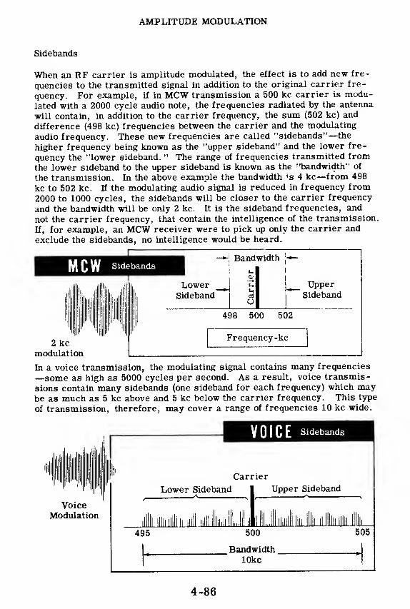
AMPLITUDE MODULATION
Sidebands
When an RF carrier is amplitude modulated, the effect is to add new fre-
quencies to the transmitted signal in addition to the original carrier fre-
quency. For example, if in MCW transmission a 500 kc carrier is modu-lated with a 2000 cycle audio note, the frequencies radiated by the antenna
will contain, in addition to the carrier frequency, the sum (502 kc) and
difference (498 kc) frequencies between the carrier and the modulating
audio frequency. These new frequencies are called "sidebands"—the
higher frequency being known as the "upper sideband" and the lower fre-
quency the "lower sideband. " The range of frequencies transmitted fromthe lower sideband to the upper sideband is known as the ''bandwidth" of
the transmission. In the above example the bandwidth is 4 kc—from 498
kc to 502 kc. If the modulating audio signal is reduced in frequency from2000 to 1000 cycles, the sidebands will be closer to the carrier frequency
and the bandwidth will be only 2 kc. It is the sideband frequencies, and
not the carrier frequency, that contain the intelligence of the transmission.
If, for example, an MCW receiver were to pick up only the carrier and
exclude the sidebands, no intelligence would be heard.
I
—MCW Sidebands
-*-' Bandwidth ]-*—
>- I
<v
Lowert
u UpperSideband
ua SidebandU
498 500 502
Frequency-kc2 kc
modulation
In a voice transmission, the modulating signal contains many frequencies
—some as high as 5000 cycles per second. As a result, voice transmis-
sions contain many sidebands (one sideband for each frequency) which maybe as much as 5 kc above and 5 kc below the carrier frequency. This type
of transmission, therefore, may cover a range of frequencies 10 kc wide.
VOICE Sidebands
VoiceModulation
Carrier
Lower Sideband | Upper Sideband
it llllilllll ll i ^ihi^ti:!!^, ^lul-r, 111 illlllllllll! Il l
495 500 505
BandwidthlOkc
4-86

AMPLITUDE MODULATION
How Modulation Is Accomplished
In an unmodulated transmitter, the amplitudes of the plate current pulsesin the Class C amplifiers are the same, cycle after cycle. These platecurrent pulses flow to an LC circuit which is tuned to the RF frequency ora multiple of it. The pulses of current deliver a certain amount of powerto the tuned circuit and this power remains the same for each cycleTherefore,the amplitude of RF voltage across the tuned circuit remains thesame for every cycle.
0—
I
When the transmitter is modulated, the amplitude of the plate currentpulses is made to vary according to the amplitude of the modulating signalThus the amplitude of the RF current varies from one cycle to the next andthe power delivered to the tuned circuit also varies. This varying powercauses the RF voltage across the tuned circuit to vary. These variationswill follow the modulating signal in amplitude and frequency. This is howmodulation is accomplished.
MCW VOICE
ModulatingSignal
+0-
Plate CurrentPulses
+0-
+o-
Voltage
Across +
Tuned o-
Circuit
4-87
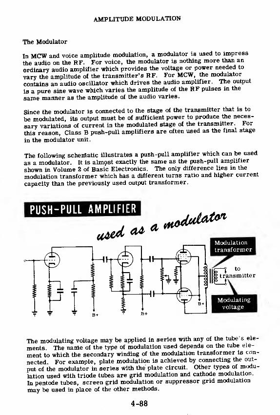
AMPLITUDE MODULATION
The Modulator
In MCW and voice amplitude modulation, a modulator is used to impress
the audio on the RF. For voice, the modulator is nothing more than an
ordinary audio amplifier which provides the voltage or power needed to
vary the amplitude of the transmitter's RF. For MCW, the modulator
contains an audio oscillator which drives the audio amplifier. The output
is a pure sine wave which varies the amplitude of the RF pulses in the
same manner as the amplitude of the audio varies.
Since the modulator is connected to the stage of the transmitter that is to
be modulated, its output must be of sufficient power to produce the neces-
sary variations of current in the modulated stage of the transmitter. For
this reason, Class B push-pull amplifiers are often used as the final stage
in the modulator unit.
The following schematic illustrates a push-pull amplifier which can be used
as a modulator. It is almost exactly the same as the push-pull amplifier
shown in Volume 2 of Basic Electronics. The only difference lies in the
modulation transformer which has a different turns ratio and higher current
capacity than the previously used output transformer.
The modulating voltage may be applied in series with any of the tube s ele-
ments. The name of the type of modulation used depends on the tube ele-
ment to which the secondary winding of the modulation transformer is con-
nected. For example, plate modulation is achieved by connecting the out-
put of the modulator in series with the plate circuit. Other types of modu-
lation used with triode tubes are grid modulation and cathode modulation.
In pentode tubes, screen grid modulation or suppressor grid modulation
may be used in place of the other methods.
B+
4-88
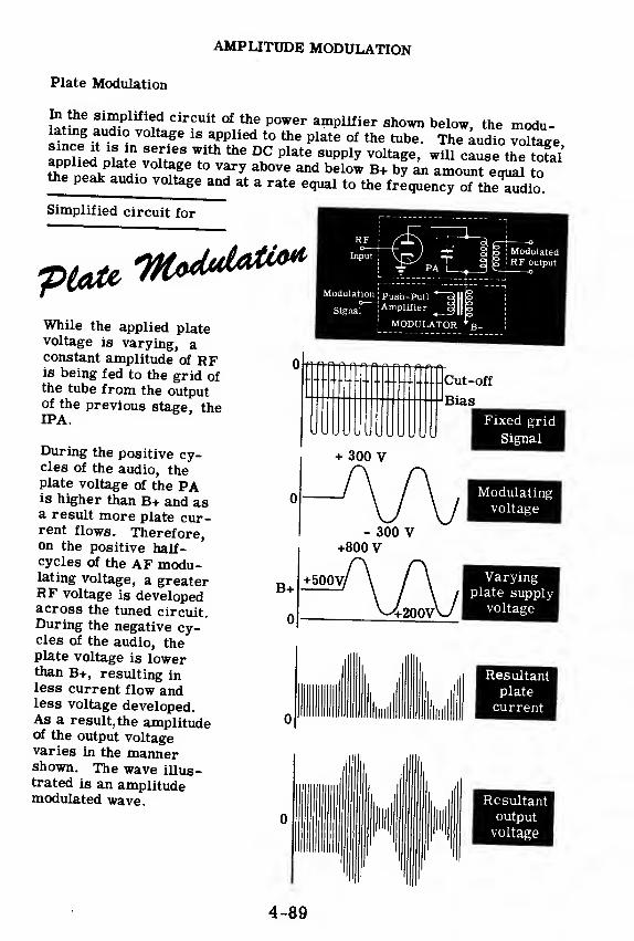
AMPLITUDE MODULATION
Plate Modulation
Et£a f, hP
u°lrCUlt * °* P°Wer amPlif*er shown below, the modu-
5 >V°lta
.
ge 18 applied t0^ Plate of the tu*>e. The audio voltage
aioHed DTaS Tith^ °K
C Plate 8Upply voltase, will cause the toS'applied plate voltage to vary above and below B+ by an amount eoual tothe peak audio voltage and at a rate equal to the fre^encToTthe'Sdio
Simplified circuit for
pt^ -Moduli
While the applied platevoltage is varying, aconstant amplitude of RFis being fed to the grid ofthe tube from the outputof the previous stage, theIPA.
! Modulated! RF output
During the positive cy-cles of the audio, theplate voltage of the PAis higher than B+ and asa result more plate cur-rent flows. Therefore,on the positive half-cycles of the AF modu-lating voltage, a greaterRF voltage is developedacross the tuned circuit.During the negative cy-cles of the audio, theplate voltage is lowerthan B+, resulting inless current flow andless voltage developed.As a result, the amplitudeof the output voltagevaries in the mannershown. The wave illus-trated is an amplitudemodulated wave.
Modulation; Push-Pull
Signal" i
AmPltfier
MODULATOR *B+
Cut-off
Bias
+ 300 V
B+
0
- 300 V+800 V
Fixed grid
Signal
Modulatingvoltage
Varyingplate supply
voltage
Resultant
plate
current
4-89
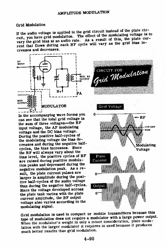
AMPLITUDE MODULATION
Grid Modulation
creases and decreases.
RFINPUT
f CIRCUIT FOR . , .
MODULATOR
In the accompanying wave forms you
can see that the total grid voltage is
the sum of three voltages—the RFinput voltage, the AF modulating
voltage and the DC bias voltage.
During the positive half-cycles of
the modulating voltage the bias de-
creases and during the negative half-
cycles, the bias increases. Since
the RF will always vary about the
bias level, the positive cycles of RFare raised during positive modula-
tion peaks and depressed during the
negative modulation peak. As a re-
sult, the plate current pulses are
larger in amplitude during the posi-
tive half-cycles of the audio voltage
than during the negative half-cycles.
Since the voltage developed across
the plate tank varies with the plate
current amplitude, the RF output
voltage also varies according to the
modulating signal.
Grid Voltage
ModulatingVoltage
Plate
Current
Output
Grid modulation is used in compact or mobile transmitters because this
type of modulation does not require a modulator with a large power output.
When the modulator's weight is only a minor consideration, plate modu-
lation with the larger modulator it requires is used because it produces
much better results than grid modulation.
4-90
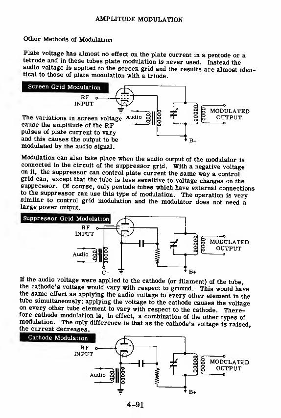
AMPLITUDE MODULATION
Other Methods of Modulation
Plate voltage has almost no effect on the plate current in a pentode or atetrode and in these tubes plate modulation is never used. Instead theaudio voltage is applied to the screen grid and the results are almost iden-tical to those of plate modulation with a triode.
Screen Grid Modulation
RF oINPUT
MODULATEDOUTPUT
oThe variations in screen voltagecause the amplitude of the RFpulses of plate current to varyand this causes the output to bemodulated by the audio signal.
Modulation can also take place when the audio output of the modulator isconnected in the circuit of the suppressor grid. With a negative voltageon it, the suppressor can control plate current the same way a controlgrid can, except that the tube is less sensitive to voltage changes on thesuppressor. Of course, only pentode tubes which have external connectionsto the suppressor can use this type of modulation. The operation is verysimilar to control grid modulation and the modulator does not need alarge power output.
Suppressor Grid Modulation
RF o-
INPUTMODULATEDOUTPUT
o
If the audio voltage were applied to the cathode (or filament) of the tube,the cathode's voltage would vary with respect to ground. This would havethe same effect as applying the audio voltage to every other element in thetube simultaneously; applying the voltage to the cathode causes the voltageon every other tube element to vary with respect to the cathode. There-fore cathode modulation is, in effect, a combination of the other types ofmodulation. The only difference is that as the cathode's voltage is raisedthe current decreases.
'
Cathode Modulation
RF oINPUT
Audio
to MODULATEDg OUTPUT——
o
* B+
4-91

AMPLITUDE MODULATION
Time Base Modulation Pattern
The oscilloscope can be used to good advantage to indicate the extent to
which the output of a transmitter is modulated. It can also point out dis-
tortion existing in the modulation. If a pickup loop, which is connected to
the 'scope input terminals, is brought close to the plate tank coil in the
output circuit of a modulated transmitter, the 'scope will show the modu-
lation pattern.
1
TIME-BASE'patten*
If the modulating voltage is a sine wave
(as in MCW) and the sweep (called the
time-base) is produced inside the os-
cilloscope, the pattern on the right is
obtained. This pattern is useful in de-
termining the presence of distortion.
A pattern such as this would indicate
that the positive peaks of the modu-
lating voltage are not causing corre-
sponding peaks in plate current. This
may be due to improper grid bias,
saturation due to low emission, or in-
sufficient excitation of the power am-
plifier stage.
If the transmitter output shows breaks
in the modulation pattern, the trans-
mitter is said to be "over-modulated.
"
This is usually due to excessive modu-
lating voltage but may also be due to
insufficient signal voltage on the grid
or excessive grid bias voltage.
4-92

AMPLITUDE MODULATION
Trapezoid Figure
The trapezoid figure is another type of oscilloscope pattern that is oftenused to determine the presence of distortion in the modulated signal andalso how much the signal is being modulated. The trapezoid figure hasthe advantage of making possible the detection of certain types of distortionwhich cannot be detected by means of the time-base pattern. To producethe trapezoid figure, the modulating signal is used as an external horizon-tal sweep signal instead of the internal sweep of the 'scope. The verticaldeflection is still the modulated RF output of the transmitter. The ad-vantage of using trapezoid figures over time-base modulation patterns toanalyze the operation of a transmitter is that they are easier to interpret.
A typical set-up for showing trapezoid figures is illustrated below. Thevertical input of the 'scope is coupled to the plate coil of the power ampli-fier and the horizontal input is coupled to the audio output of the modulator.
In order to understand how trapezoid figures are formed, you have to knowsomething about the action of the vertical and horizontal plates inside thecathode ray tube.
Set-up for observing Trapezoid figures
Modulatingsignal
Tomodulator
Pickup loopon PA coil
4-93

AMPLITUDE MODULATION
Trapezoid Figure (continued)
The picture you see on an oscilloscope screen is the path followed by a
beam of electrons striking the inner surface of the cathode ray tube
In the cathode ray tube there are two pairs of metal plates which deflect
the electron beam from its path. The top and bottom plates are called
'•vertical plates" because they move the electron beam vertically. The
left and right plates are called "horizontal plates" and they move the
electron beam horizontally from left to right.
The vertical plates are connected to the signal under observation. This^ Spaces the electron beam in a vertical direction Under normal
opiating conditions, the horizontal plates are connected to ^e output of
an oscillator built into the oscilloscope. This oscillator, called a sweep
oscillator, generates a saw tooth voltage which sweeps the electron beam
across the face of the 'scope screen, from left to right, at a constant
speed If the input signal to the vertical plates is the familiar sine wave
of voltage, the combined action of this signal and the horizontal sweep act-
ing on the electron beam produce the sine wave picture.
Sometimes the internal horizontal sweep is disconnected and an external
signal is used as the sweep voltage. This is what is done to produce the
trapezoid figure.
"SS. ! £ 8 S £SZ.
Vertical
Amplifier
Sweep Voltage
HorizontalAmplifier
Oscillator
Horizontal
SweepCircuit
Vertical
Deflection
Plates
Horizontal
Deflection
Plates
*7heScepe7>effeertot7 'Rates
4-94
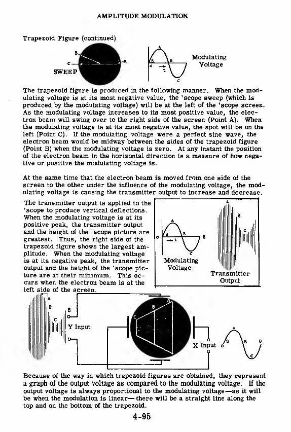
AMPLITUDE MODULATION
Trapezoid Figure (continued)
ModulatingVoltage
The trapezoid figure is produced in the following manner. When the mod-ulating voltage is at its most negative value, the 'scope sweep (which is
produced by the modulating voltage) will be at the left of the 'scope screen.As the modulating voltage increases to its most positive value, the elec-
tron beam will swing over to the right side of the screen (Point A). Whenthe modulating voltage is at its most negative value, the spot will be on the
left (Point C). If the modulating voltage were a perfect sine wave, the
electron beam would be midway between the sides of the trapezoid figure
(Point B) when the modulating voltage is zero. At any instant the positionof the electron beam in the horizontal direction is a measure of how nega-tive or positive the modulating voltage is.
At the same time that the electron beam is moved from one side of the
screen to the other under the influence of the modulating voltage, the mod-ulating voltage is causing the transmitter output to increase and decrease.
The transmitter output is applied to the
'scope to produce vertical deflections.
When the modulating voltage is at its
positive peak, the transmitter output
and the height of the 'scope picture aregreatest. Thus, the right side of the
trapezoid figure shows the largest am-plitude. When the modulating voltageis at its negative peak, the transmitteroutput and the height of the 'scope pic-ture are at their minimum. This oc-curs when the electron beam is at the
left side of the screen.
Because of the way in which trapezoid figures are obtained, they represent
a graph of the output voltage as compared to the modulating voltage. If the
output voltage is always proportional to the modulating voltage—as it will
be when the modulation is linear— there will be a straight line along the
top and on the bottom of the trapezoid.
A
TransmitterOutput
4-95

AMPLITUDE MODULATION
Trapezoid Figure (continued)
TIME-BASE FIGURE TRAPEZOID FIGURE
The two ' scope presentations shown above are for the same condition of
modulation. You could determine the maximum height (peak) and the min-imum height (trough or valley) of the RF from either figure. You could
also determine the linearity of the modulation from either presentation,
but it is easier to do so from the trapezoid.
If the modulating voltage is varied in amplitude, the peak and trough points
on the time-base wave pattern come closer together. The same effect is
seen in the trapezoid pattern as a decrease in the horizontal and vertical
dimensions.
The following illustrations show both types of wave form presentation for
three different modulating voltage amplitudes.
EFFECT OF VARYING AMPLITUDE OF MODULATING VOLTAGE
4-96

AMPLITUDE MODULATION
Percentage Modulation
The percentage modulation is a measure of the extent to which the carrier
is modulated. If the carrier is modulated 100 percent, the maximumheight of the modulated wave is twice that of the unmodulated wave and the
minimum height is zero. The trapezoid figure is a triangle for this mod-ulating condition. In voice communication the goal is always 100 percent
modulation because the RF signal is then transmitted at maximum power.
Unmodulated carrier
If the maximum height of the modulated wave is more than twice that of
the unmodulated wave and the minimum height is zero for more than aninstant during the cycle, the carrier is overmodulated. The percentage
modulation is more than 100 percent. This condition is characterized bygaps in the time-base figure and a line extending from the left side of the
triangle in the trapezoid figure. The more the wave is overmodulated, the
longer are the gaps of the time-base figure and the longer the line in the
trapezoid figure. Overmodulation is undesirable because it distorts the
signal and generates unwanted sidebands which may interfere with adjacent
carrier frequencies.
A Is*1JJSW distorts the signal and interferes
figA/UW^^^ with other carrier frequencies
4-97

AMPLITUDE MODULATION
Percentage Modulation (continued)
Sometimes it is desirable to know the exact percentage of modulation. If
the maximum height of the modulated wave is less than twice that of the
unmodulated wave and the minimum height is more than zero, the percent-
age modulation is less than 100 percent. This is the most common con-
dition. The exact percentage modulation can be calculated using the
formula below.
% modulation = H max. -H min.
H max. +H min.x 100
"H max. " is the maximum height of the modulated wave and "H min. " is
the minimum height. These values can be measured from the 'scope pic-
tures—the trapezoid figure is more convenient for this purpose but the
time-base figure gives sufficiently accurate results.
In the figures below, H max. is 8 boxes and H min. is 2 boxes. The per-
centage modulation is:
60* modulation
'/^modulation -^-x 100 = —+ 2 10
If H max. is 9 boxes and H min. is 1 box, the percentage modulation is:
80% modulation
-x 100 = 80%
4-98

AMPLITUDE MODULATION
Review of Amplitude Modulation
AMPLITUDE MODULATION—The method which uses voiceor an audio signal to vary the
amplitude of an RF carrierwave. The modulator is the
component of the AM trans-mitter which combines the au-dio and RF signals.
SIDEBANDS—Frequenciescontained in the transmittedsignal in addition to the RFcarrier frequency. Sidebandsare equal to the sum and dif-
ference of carrier and modu-lating signals. MCW has twosidebands; voice has many.
PLATE MODULATION—Themethod whereby the modulatingsignal varies the PA tube volt-
age, thus modulating its output
in response to the audio signal.
GRID MODULATION—Themodulating signal is applied to
the grid of the PA tube. Vary-ing grid voltage in this mannercontrols PA tube plate currentand hence modulates output
voltage.
TRAPEZOID FIGURE—The os-cilloscope pattern obtained byusing the transmitter output
voltage as ' scope 1 s Y input,
and the modulating signal asX input.
PERCENTAGE MODULATION—The measure of the extentto which the RF carrier is
modulated. 100 percent mod-ulation is desireable for voicetransmission so that maxi-mum power is transmitted.Overmodulation produces adistorted signal and introducesunwanted sidebands.
RF AUDIO
Hill + AAARF VOICE
mm +
MCW= I I
VOICE
v i i2 kc
modulation
Bandwidth —
Lowert _ UPP"
Sideband Sideband
498 500 502
Carrier
Lower Sideband | Upper Sideband
VoiceModulation
ill Hull ii In mil l i
505
Kt /_L\ ' * a f- •
^
o• + _ J
—' 3t; Modulated
MOIH [JiTOK * H,
602 modulation
4-99

TRANSMITTERS
Review of Transmitters
Let's pause and review briefly what you have learned about transmitters.
CW TRANSMISSION—An RFsignal is generated in the trans-
mitter by an RF oscillator,
and radiated into space. In-
telligence is imparted by turn-
ing transmitter on and off
with a key. CW is used mostoften for long distance com-munications.
MCW TRANSMISSION—A con-
stant amplitude audio frequen-
cy signal is superimposed onthe RF carrier wave. Trans-mitter is turned on and off
by means of a key as in CWtransmission. MCW is usedfor emergency applications.
Key a.1
rKeyedRF
RFTransmitter
KeyedModulated RF
/ *N
IRF
Transmitter
AudioOscillator
VOICE TRANSMISSION—Inamplitude modulation a voice
signal varies the amplitude of
the RF carrier. Transmission
is continuous, and is the type
used for standard radiobroad-
casting.
GRID-LEAK BIAS—A resis-
tor and capacitor in the grid
circuit of an amplifier tube
to make the amplifier oper-ate Class C. The amount of
bias depends on the grid cur-
rent, and varies as the
strength of the input signal
changes.
COMBINATION BIAS—A com-bination of fixed and grid-leak
bias most commonly used in
transmitters.
I
AM UnmodulatedVoice modulated RF RF Carrier
RFTransmitter
Amplitudemodulator
Microphone
nl *r
c-l »:,
0T 7
4-100

TRANSMITTERS
Review of Transmitters (continued)
THREE -STAGE TRANSMITTER—The master oscillator (MO), intermediatepower amplifier (IPA) and final power amplifier (PA) make up the basicthree -stage transmitter.
C-9 C-U C-13
I
MO EPA PA
TJJNJQiG—For efficient oper-ation, the plate tank circuit ofthe amplifiers must resonateat oscillator frequency. Ad-justing the variable capacitorto reach this condition is
called "tuning. " Plate volt-age is maximum and currentminimum at signal frequency.
Plate Voltage
B»
Plate Current
AVERAGE\
o -i-i—i i ;
Well below At Slightly moresignal signal than signal
frequency frequency J^H frequency
NEUTRALIZATION—PlatP orgrid neutralization circuitsmay be used to counteract thefeedback effect at the grid-to-plate capacity of triodes usedin transmitter amplifiers.
Plate
Neutralization
0 GridNeutralization
TRANSMISSION LINE—Usedto convey the RF signal fromthe transmitter to the antenna.For maximum power outputthe characteristic impedanceof the line should equal the in-put impedance of the antenna.Coupling circuits are used tocouple the transmission lineto the transmitter.
ANTENNARadiates RF
TRANSMISSION LINESupplies antenna with RF
t COUPLING CIRCUITCouples RF from lank circuitto transmission line
4-101

TRANSMITTERS
Review of Transmitters (continued)
STANDING WAVES—Volt-
age and current distribu-
tion along a transmission
line or antenna can be re-
presented by wave formscalled "standing waves.
"
' > Transmission Line
Transmitter
ANTENNA—Radiates en-
ergy, received from trans-
mission line, into space.
Electric and magneticfields generated by cur-
rent and voltage waves on
antenna expand and col-
lapse as transmitter sig-
nal varies.
SIDEBANDS—Frequencies
contained in the transmit-
ted signal in addition to
the RF carrier frequency.
MCW has two sidebands;
voice has many sidebands.
PLATE MODULATION—A method whereby the mod-ulating signal varies the PAtube plate voltage, thus
modulating its output in re-
sponse to the audio signal.
—-! Bandwidth
Lowerm
Sideband
UpperSideband
2kcmodulation
498 500 502
Frequency-kc
Carrier
Lower Sideband | Upper Sideband
GRID MODULATION—Themodulating signal is applied
to the grid of the PA tube.
Varying grid voltage in this
manner controls PA tube
plate current and hence
modulates output voltage.
4-102
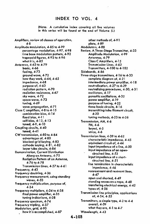
INDEX TO VOL. 4
(Note: A cumulative index covering all five volumesin this series will be found at the end of Volume 5.)
Amplifiers, review of classes of operation,
4-8
Amplitude modulation, 4-85 to 4-99
percentage modulation, 4-97, 4-98
time base modulation pattern, 4-92
trapezoid figures, 4-93 to 4-96
what it is, 4-85
Antennas, 4-63 to 4-79
basic, 4-66
fading, 4-73
ground wave, 4-72
how they work, 4-64, 4-65
impedance, 4-68
purpose of, 4-63
radiation pattern, 4-70
radiation resistance, 4-67
sky wave, 4-72
space wave, 4-73
tuning, 4-69
wave propagation, 4-71
Class C amplifiers, 4-8 to 4-1
5
combination bias, 4-14
fixed bias, 4-1
1
self-bias, 4-12,4-13
tuned, 4-9, 4-10
Coupling circuits, 4-40
tuned, 4-41
CW transmission, 4-80 to 4-84
advantages of, 4-80
blocked-grid keying, 4-83
cathode keying, 4-81 , 4-82
keyer tube circuits, 4-84
Demonstration, Current Distribution
Along an Antenna, 4-75
Radiption Pattern of an Antenna,
4-76 to 4-78
Transmission Lines, 4-57 to 4-61
Frequency, 4-43
Frequency doubling, 4-36
Frequency measurement, using standing
waves, 4-53
Frequency multiplication, purpose of,
4-34
Frequency multipliers, 4-34 to 4-38
final power amplifier, 4-35
tuning indications, 4-38
Frequency spectrum, 4-74
Frequency tripling, 4-37
Modulation, grid, 4-90
how it is accomplished, 4-87
4-
other methods of, 4-91
plate, 4-89
Modulators, 4-88
Review, A Three-Stage Transmitter, 4-33
Amplitude Modulation, 4-99Antennas, 4-79
Class C Amplifiers, 4-1
5
Transmission Lines, 4-62
Transmitters, 4-100 to 4-102Sidebands, 4-86
Three-stage transmitters, 4-1 6 to 4-33complete diagram of, 4-21
intermediate power amplifier, 4-1
8
neutralization, 4-27 to 4-29neutralizing procedures, 4-30, 4-31
oscillators, 4-17parasitic oscillations, 4-32
power amplifier, 4- 1
9
purpose of tuning, 4-22
three basic circuits, 4-16transmitting tube filament circuit,
4-20
tuning methods, 4-23 to 4-26
Transmission, AM, 4-6
FM, 4-6
keyed, 4-5
voice, 4-6
Transmission lines, 4-39 to 4-62characteristic impedance, 4-45equivalent circuit of, 4-44
input impedance of a line, 4-50input impedance of an open-
circuited line, 4-52input impedance of a short-
circuited line, 4-51
line termination in characteristic
impedance, 4-46
nonresonant and resonant lines,
4-47open and shorted, 4-49standing waves on a rope, 4-48transfering electrical energy, 4-42types of, 4-56
Transmission line principles, applications
of, 4-54, 4-55
Transmitters, a simple type, 4-2 to 4-4overall, 4-39what they are, 4- 1 to 4-7
Wavelength, 4-43
103


HOW THIS OUTSTANDING COURSE WAS DEVELOPED:
In the Spring of 1951, the Chief of Naval Personnel, seeking a streamlined,
more efficient method of presenting Basic Electricity and Basic Electronics to the
thousands of students in Navy speciality schools, called on the graphiological
engineering firm of Van Valkenburgh, Nooger & Neville, Inc., to prepare such a
course. This organization, specialists in the production of complete "packagedtraining programs," had broad experience serving industrial organizations requir-
ing mass-training techniques.
These were the aims of the proposed project, which came to be known as the
Common-Core program: to make Basic Electricity and Basic Electronics com-pletely understandable to every Navy student, regardless of previous education; to
enable the Navy to turn out trained technicians at a faster rate (cutting the cost
of training as well as the time required) without sacrificing subject matter.
The firm met with electronics experts, educators, officers-in-charge of various Navyschools and, with the Chief of Naval Personnel, created a dynamic new training
course . . completely up-to-date . . . with heavy emphasis on the visual approach.
First established in selected Navy schools in April, 1953, the training coursecomprising Basic Electricity and Basic Electronics was such a tremendoussuccess that it is now the backbone of the Navy's current electricity and electronics
training program!*
The course presents one fundamental topic at a time, taken up in the order of
need, rendered absolutely understandable, and hammered home by the use of clear,
cartoon-type illustrations. These illustrations are the most effective ever presented.
Every page has at least one such illustration—every page covers one complete idea!
An imaginary instructor stands figuratively at the reader's elbow, doing demonstrations that make it easier to understand each subject presented in the course.
Now, for the first time, Basic Electricity and Basic Electronics have been released
Ijy die Navy for civilian use. While the course was originally designed for the
Navy, the concepts are so broad, the presentation so clear—without reference to
specific Navy equipment—that it is ideal for use by schools, industrial training
programs, or home study. There is no finer training material!
"Basic Electronics" consists of five volumes, as follows: Vol. 1—Introductionto Electronics, Diode Vacuum Tubes, Dry Metal Rectifiers, What a Power
Supply Is, Filters, Voltage Regulators. Vol. 2—Introduction to Amplifiers,
The Triode Tube, Tetrodes & Pentodes, Audio Voltage & Power Amplifiers.
Vol. 3—Video Amplifiers, RF Amplifiers, Oscillators. Vol. -/—Transmitters,
Transmission Lines & Antennas, CW Transmission & Amplitude Modula-
tion. Vol. 5—Receiver Antennas, Detectors & Mixers, TRF Receivers,
Superheterodyne Receivers.
*"Basic Electricity," the first portion of this course, is available as a separate
series of volumes.
JOHN F. RIDER PUBLISHER, INC., 116 WEST 14th ST., N. Y. 11, N. Y.
No. 170-5
basic
electronicsfey VAN VALKEfiBUiiGIiNOOGIf & HiVil^ INC.
VOL. 5
RECEIVER ANTENNAS
DEttCTORS & MIXERS
TRF RECEIVERS
SUPERHETERODYNE RECEIVERS
CI RIDER bu hlica#Itf%m
$2.25
basicelectronicsby VAN VALKENBURGH,NOOGER & NEVILLE, INC.
VOL.5
JOHN F. RIDER PUBLISHER, INC.116 West 14th Street • New York 11, N. Y.
First Edition
Copyright 1955 by
VAN VALKENBURGH, NOOGER AND NEVILLE, INC.
All Rights Reserved under International and Pan
American Conventions. This book or parts thereof
may not be reproduced in any form or in any
language without permission of the copyright owner.
Library of Congress Catalog Card No. 55-6984
Printed in the United States of America

PREFACE
The texts of the entire Basic Electricity and Basic Electronicscourses, as currently taught at Navy specialty schools, have now beenreleased by the Navy for civilian use. This educational programhas been an unqualified success. Since April, 1953, when it was first
installed, over 25,000 Navy trainees have benefited by this instruc-tion and the results have been outstanding.
The unique simplification of an ordinarily complex subject, theexceptional clarity of illustrations and text, and the plan of pre-senting one basic concept at a time, without involving complicatedmathematics, all combine in making this course a better and quickerway to teach and learn basic electricity and electronics.
In releasing this material to the general public, the Navy hopes toprovide the means for creating a nation-wide pool of pi e-trainedtechnicians, upon whom the Armed Forces could call in time ofnational emergency, without the need for precious weeks and monthsof schooling.
Perhaps of greater importance is the Navy's hope that throughthe release of this course, a direct contribution will be made towardincreasing the technical knowledge of men and women throughoutthe country, as a step in making and keeping America strong.
Van Valkenburgh, TSooger and Neville, Inc.
New York, N. Y.
February, 1955
iii


TABLE OF CONTENTS
Vol. 5 — Basic Electronics
Introduction to Receivers 5-1
Receiver Antennas 5-16
TRF Receivers — RF Amplifier Stage 5-24
TRF Receivers — Audio Amplifier Stage 5-33
TRF Receivers — Regenerative Detector 5-38
TRF Receivers — Plate Detector 5-54
The Superheterodyne Receiver 5-57
Troubleshooting the Superheterodyne Receiver . 5-89
V


INTRODUCTION TO RECEIVERS
History of Communication
Did it ever occur to you to ask, "Why is there such a thing as a radio re-ceiver?" To answer this question, you have to know something about thehistory of man' s attempt to improve his methods of communication.
Since the earliest days, man has always tried to increase the distanceover which he could send messages.
5-1

INTRODUCTION TO RECEIVERS
History of Communication ^continued)
Since the dawn of history, good communications have played an important
part in the art of warfare. The victory message of the Battle of Marathoncarried by a Greek runner was one of the earliest recorded instances of
battle communications. Our own history offers another famous examplein Paul Revere' s ride.
GOOD C@ilMMlKlllOTa®lKl§ HAVE WON BATTLES
A result of poor communications was effectively demonstrated in the Battle
of New Orleans during the War of 1812. Because news of the cessation of
hostilities did not reach those in command until it was too late, this battle
was fought several days after the war had ended.
5-2

INTRODUCTION TO RECEIVERS
History of Communication (continued)
Some of the more primitive methods of communication-human messengersand homing pigeons-have limited application. Today we still use semaphoresignals and interrupted flashes of light to convey messages. ColoredTigCrockets and flares perform functions similar to those of the warning h ftopfires of old, while whistles and sirens are still being usedP
SOME VERSIONS OF
METHODS ARE

INTRODUCTION TO RECEIVERS
History of Communication (continued)
These simple signaling systems are at best slow and unreliable. If the
wind is blowing from the wrong direction, sound signals will not be re-
ceived. In thick fog or heavy rain, visual signals fail to deliver the mes-
sage. Runners and pigeons are slightly more reliable, but their rate of
travel is relatively slow.
The problem of rapid and reliable communication was solved by harnessing
electricity to the task. Improvements on the inventions of Morse, Bell
and Marconi have led to the development of modern telegraph, telephone
and wireless communication systems capable of transmitting messages
almost instantaneously over thousands of miles of space.
5-4

INTRODUCTION TO RECEIVERS
Modern Wireless Communication
Today, with the advent of wireless communication, or as it is more com-monly known—radio communication, the use of electricity for transmittingmessages has reached its highest point. No longer is transmission limitedto those places which a wire can reach, as is the case with telephone.
This remarkable electronic device, the radio, consists of two parts—thetransmitter and the receiver. The transmitter sends out the message, inthe form of radio waves, into the atmosphere. The radio receiver picksup the radio waves sent out by the transmitter, and converts them into themessage which was originally put into the transmitter. This section willdeal with the receiving end of radio communication—the receiver.
5-5
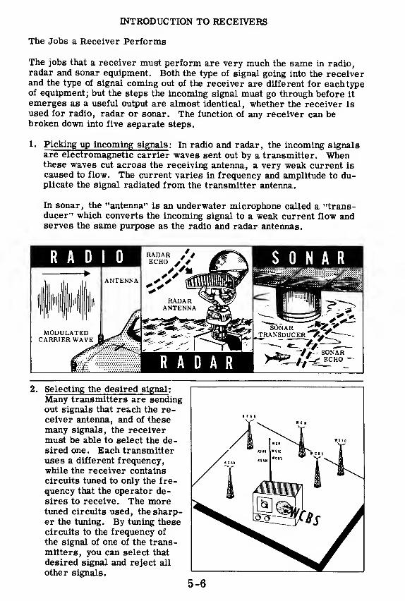
INTRODUCTION TO RECEIVERS
The Jobs a Receiver Performs
The jobs that a receiver must perform are very much the same in radio,radar and sonar equipment. Both the type of signal going into the receiverand the type of signal coming out of the receiver are different for each typeof equipment; but the steps the incoming signal must go through before it
emerges as a useful output are almost identical, whether the receiver is
used for radio, radar or sonar. The function of any receiver can bebroken down into five separate steps.
1. Picking up incoming signals : In radio and radar, the incoming signalsare electromagnetic carrier waves sent out by a transmitter. Whenthese waves cut across the receiving antenna, a very weak current is
caused to flow. The current varies in frequency and amplitude to du-plicate the signal radiated from the transmitter antenna.
In sonar, the "antenna" is an underwater microphone called a "trans-ducer" which converts the incoming signal to a weak current flow andserves the same purpose as the radio and radar antennas.
SONAR
2. Selecting the desired signal :
Many transmitters are sendingout signals that reach the re-ceiver antenna, and of these
many signals, the receivermust be able to select the de-sired one. Each transmitteruses a different frequency,while the receiver containscircuits tuned to only the fre-
quency that the operator de-sires to receive. The moretuned circuits used, the sharp-er the tuning. By tuning thesecircuits to the frequency of
the signal of one of the trans-mitters, you can select that
desired signal and reject all
other signals.

INTRODUCTION TO RECEIVERS
The Jobs a Receiver Performs (continued)
3. Amplifying the desired RF signal: The currents generated by the in-coming signals in the antenna or transducer are extremely weak, RFamplifiers similar to those you have already studied are used to amplifythese weak signals before they reach the detector.
4. Detecting or demodulating the amplified signal: A detector stage fol-lows the last RF amplifier in a receiver. The detector does the im-portant job of separating the "envelope" of the signal from the RF car-rier. Because the envelope is the modulation of the signal, a detectoris sometimes called a "demodulator. " The signal, after demodulation,may be a voice or code signal as in communications radio receivers,or a sharp voltage rise and fall as in radar or sonar receivers.
5. Amplifying the audio or video signals : In radio receivers, the audiosignal which comes from the detector undergoes further amplification.Audio voltage amplifiers and power amplifiers, similar to those youhave already studied, build up the audio signal enough to operate a pair ofearphones or a loudspeaker so that the signal may be heard.
In some sonar sets, the signal is heard in a loudspeaker, and the re-ceiver is similar in design and operation to a radio receiver. In radarand certain other types of sonar receivers, the signal will show up asa "pip" on a 'scope. In these receivers, a video amplifier similar tothose you have already learned about, would be used to amplify thevoltage "pips. " The video amplifiers take the signal from the detectorand build it up so that it can be seen on the radar or sonar 'scope.
Vi
Tuned RF*- Detector
AudioCircuit Amp. Amp.
COMMUNICATIONTYPE
RECEIVER
4-t- A-A-4—Q-Vi
Tuned RFDetector
Video
Circuit Amp. Amp.
RADARTYPE
RECEIVER
5-7

INTRODUCTION TO RECEIVERS
Receiver Sensitivity
There are several characteristics of a receiver which you can determine
by simply comparing the input signal and the receiver output. These char
acteristics will tell you how well your receiver is working. The first of
the characteristics—there are three in all—is sensitivity.
Sensitivity can be defined as the ability of the receiver to pick up weak sig
nals, amplify them and deliver a useful output. No matter what type of
equipment the receiver is in, sensitivity is important because many input
signals which the receiver must amplify are extremely weak. Only a sen-
sitive receiver can develop a sizable output with a weak input.

INTRODUCTION TO RECEIVERS
Receiver Selectivity
Sensitivity, by itself, does not make a receiver good enough for use. It
must also be selective.
Selectivity is the ability of a receiver to select a desired signal and dis-criminate against all undesired signals. If every signal which struck theantenna were amplified, the output, although strong enough, would beworthless because of all the interference caused by the presence of the un-desired signals.
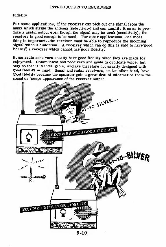
INTRODUCTION TO RECEIVERS
Fidelity
For some applications, if the receiver can pick out one signal from themany which strike the antenna (selectivity) and can amplify it so as to pro-duce a useful output even though the signal may be weak (sensitivity), thereceiver is good enough to be used. For other applications, one morething is important—the receiver must be able to reproduce the incomingsignal without distortion. A receiver which can do this is said to have"goodfidelity"; a receiver which cannot,has "poor fidelity."
Home radio receivers usually have good fidelity since they are made forenjoyment. Communications receivers are made to duplicate voice, butonly so that it is intelligible, and are therefore not usually designed withgood fidelity in mind. Sonar and radar receivers, on the other hand, havegood fidelity because the operator gets a great deal of information from thesound or 'scope appearance of the receiver output.
5-10

INTRODUCTION TO RECEIVERS
The Crystal Receiver
The first receivers were used in the early 1900' s and were called"crystalsets'/ In their simplest form, they consisted of an antenna, a crystal de-tector, a "cat's whisker" and a pair of earphones.
The antenna picked up any signals in the air—in those days there were veryfew—and the crystal (which operated as a rectifier) allowed the antennacurrents to flow directly to ground on every positive half cycle of RF, butblocked the negative half cycles. These positive half cycles of currentflowed through the"cat's whisker," a delicate wire contact on the crystal,
to the earphones where weak sounds sometimes were heard. Crystal setsat best had one tuned circuit before the crystal, but even so, the selectivitywas very poor. Because no vacuum tubes were used, the sensitivity wasso bad that crystal sets could not be used very far from a transmittingstation. Today these sets are curiosities, and have no practical applications.
IN THE BEGINNING...
5-11

INTRODUCTION TO RECEIVERS
The TRF Receiver
RF AMPLIFIER DETECTOR AUDIO AMPLIFIER
By 1920, crystal sets were on their way out and were being replaced by
tuned radio frequency (TRF) receivers, which made use of vacuum tubes.
The first few vacuum tubes, and their tuned circuits, make up the RF am-plifier which gives the TRF receiver better selectivity and sensitivity than
the old crystal sets. The detector does the same thing as the crystal de-
tector and sometimes amplifies the signal as well. After the detector, the
audio signal is amplified in the audio amplifier. The output of the audio
amplifier is a fairly powerful signal which can be used to drive a loud-
speaker or a pair of earphones. TRF receivers are not used very often
today, but some receivers are still of this type.
5-12
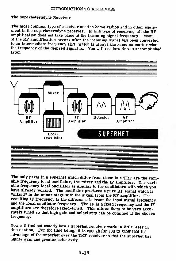
INTRODUCTION TO RECEIVERS
The Superheterodyne Receiver
The most common type of receiver used in home radios and in other equip-ment is the superheterodyne receiver. In this type of receiver, all the RFamplification does not take place at the incoming signal frequency. Mostof the RF amplification occurs after the incoming signal has been convertedto an intermediate frequency (IF), which is always the same no matter whatthe frequency of the desired signal is. You will see how this is accomplishedlater.
The only parts in a superhet which differ from those in a TRF are the vari-able frequency local oscillator, the mixer and the IF amplifier. The vari-able frequency local oscillator is similar to the oscillators with which youhave already worked. The oscillator produces a pure RF signal which is"mixed" in the mixer stage with the signal from the RF amplifier. Theresulting IF frequency is the difference between the input signal frequencyand the local oscillator frequency. The IF is a fixed frequency and the IFamplifiers are therefore fixed-tuned. This allows them to be very accu-rately tuned so that high gain and selectivity can be obtained at the chosenfrequency.
You will find out exactly how a superhet receiver works a little later inthis section. For the time being, it is enough for you to know that theadvantage of the superhet over the TRF receiver is that the superhet hashigher gain and greater selectivity.
5-13
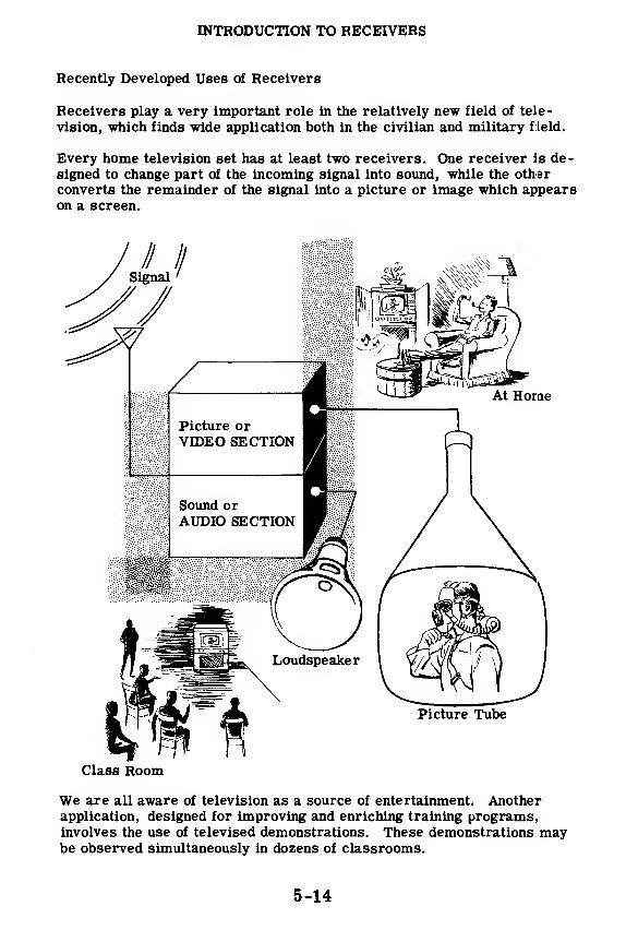
INTRODUCTION TO RECEIVERS
Recently Developed Uses of Receivers
Receivers play a very important role in the relatively new field of tele-
vision, which finds wide application both in the civilian and military field.
Every home television set has at least two receivers. One receiver is de-
signed to change part of the incoming signal into sound, while the other
converts the remainder of the signal into a picture or image which appearson a screen.
Class Room
We are all aware of television as a source of entertainment. Anotherapplication, designed for improving and enriching training programs,involves the use of televised demonstrations. These demonstrations maybe observed simultaneously in dozens of classrooms.
5-14

INTRODUCTION TO RECEIVERS
Recently Developed Uses of Receivers (continued)
Airborne television equipment can be used to transmit an overall surveyof localized operations back to a flagship or to headquarters.
One of the most interesting and significant applications of radio receptionto modern warfare is in connection with the development of guidedmissiles. The path followed by these missiles can be controlled by radiosignals transmitted by a distant operator.
5-15
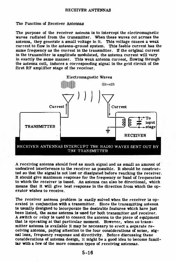
RECEIVER ANTENNAS
The Function of Receiver Antennas
The purpose of the receiver antenna is to intercept the electromagneticwaves radiated from the transmitter. When these waves cut across the
antenna, they generate a small voltage in it. This voltage causes a weakcurrent to flow in the antenna-ground system. This feeble current has the
same frequency as the current in the transmitter. If the original currentin the transmitter is amplitude modulated, the antenna current will varyin exactly the same manner. This weak antenna current, flowing throughthe antenna coil^ induces a corresponding signal in the grid circuit of the
first RF amplifier stage of the receiver.
Electromagnetic Waves
II Hill
v'MJvCurrent
TRANSMITTER
Current
o oo o
Toinput
-stage
RECEIVER
RECEIVER ANTENNAS INTERCEPT THE RADIO WAVES SENT OUT BYTHE TRANSMITTER
A receiving antenna should feed as much signal and as small an amount of
undesired interference to the receiver as possible. It should be construc-ted so that the signal is not lost or dissipated before reaching the receiver.It should give maximum response for the frequency or band of frequenciesto which the receiver is tuned. An antenna can also be directional, whichmeans that it will give best response in the direction from which the op-erator wishes to receive.
The receiver antenna problem is easily solved when the receiver is op-erated in conjunction with a transmitter. Since the transmitting antennais usually designed to incorporate the desirable features which have just
been listed, the same antenna is used for both transmitter and receiver.A switch or relay is used to connect the antenna to the piece of equipmentthat is operating at that particular moment. However, when no trans-mitter antenna is available it may be necessary to erect a separate re-ceiving antenna, paying attention to the four considerations of noise, sig-nal loss, frequency response and directivity. Before discussing theseconsiderations of antenna design, it might be a good idea to become famil-iar with a few of the more common types of receiving antennas.
5-16

RECEIVER ANTENNAS
Types of Receiver Antennas
One of the simplest and most commonly used antennas is the inverted L.
It consists of a wire, known as a "flat-top, " which is suspended horizon-
tally between two insulators. The length of the wire should be from 50 to
75 feet for broadcast-band reception and from 20 to 40 feet for high-
frequency reception. The flat-top should be suspended from 30 to 50 feet
above the ground. A wire known as the "lead-in" is used as a transmis-
sion line from the antenna to the receiver. It is connected near one end
of the flat-top and brought down to the primary winding of the receiver
antenna coil.
Flat-top
Another common type of antenna is the doublet or dipole antenna. It con-
sists of a horizontal wire divided into two equal sections by an insulator.
Each half of the antenna should be a quarter wave long for the frequency
band most commonly used. The transmission line from the antenna is
connected to the two ends of the primary of the antenna coil.
This type of antenna will give excellent high-frequency response and will
also give comparatively noise-free reception on the broadcast band. It
may be of interest to note that most television receiver antennas are modifications of the dipole antenna, with metal bars replacing the less rigid
wires.
1/4 wavelength___a .
1/4 wavelength
—
ccucb-
Line3 m
p Ai
RECEIVER^ J
DIPOLE ANTENNA

RECEIVER ANTENNAS
Types of Receiver Antennas (continued)
Where lack of space makes horizon-tal antennas impractical, a verticalantenna is used. Vertical antennas,consisting of telescoping metal mastsfrom 3 to 14 feet in length, are com-monly used for automobile and port-able receivers, and sometimes forhome broadcast receivers. An ordi-nary lead-in wire is run from thebottom of the antenna to the primaryof the antenna coil of the receiver.The other end of the primary shouldbe grounded.
FLAT OR PANCAKELOOP ANTENNA
VERTICALANTENNA
Another type of antenna used forportable and home receivers is theloop antenna. The loop consists ofa coil of wire which is connected tothe two ends of the primary of theantenna coil. Most home broad-cast-band receivers contain a loopantenna within the cabinet.
The loop antenna is highly direc-tional. When it is pointed edge-wise toward a transmitter, thesignal piekup is maximum; whenits flat side is toward the trans-mitter, the signal pickup is mini-mum. This property makes it ex-tremely useful for radio-beaconand direction-finding equipment.

RECEIVER ANTENNAS
Considerations in Selecting and Installing an Antenna—Noise
An important consideration in antenna installation is that of noise. Noiseconsists of radio waves of many frequencies and is produced by both man-made and natural electrical disturbances. Among the more importantman-made noise producers are elevators, fans, refrigerators, automobileignition systems, vacuum cleaners, X-ray and diathermy equipment, andpower lines.
The antenna cannot differentiate between desired signals and undesiredradio noise. It is customary to compare the signal pickup of the antennawith the noise pickup. This relationship is known as the "signal-to-noiseratio. " A high signal-to-noise ratio is necessary if one desires to obtainrelatively noise-free reception.
5-19
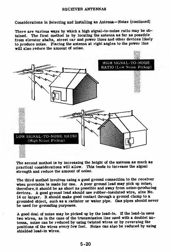
RECEIVER ANTENNAS
Considerations in Selecting and Installing an Antenna—Noise (continued)
There are various ways by which a high signal-to-noise ratio may be ob-
tained. The first method is by locating the antenna as far as possible
from elevator shafts, street car and power lines and other devices likely
to produce noise. Placing the antenna at right angles to the power line
will also reduce the amount of noise.
The second method is by increasing the height of the antenna as much as
practical considerations will allow. This tends to increase the signal
strength and reduce the amount of noise.
The third method involves using a good ground connection to the receiver
when provision is made for one. A poor ground lead may pick up noise;
therefore, it should be as short as possible and away from noise-producing
devices. A good ground lead should use rubber-insulated wire, size No.
14 or larger. It should make good contact through a ground clamp to a
grounded object, such as a radiator or water pipe. Gas pipes should never
be used for grounding purposes.
A good deal of noise may be picked up by the lead-in. If the lead-in uses
two wires, as in the case of the transmission line used with a doublet an-
tenna, noise can be reduced by using twisted wires or by reversing the
positions of the wires every few feet. Noise can also be reduced by using
shielded lead-in wires.
5-20

RECEIVER ANTENNAS
Considerations in Selecting and Installing an Antenna—Signal Losses
The second factor to be considered in selecting and installing an antennais that of signal losses. The antenna should be placed as far as possiblefrom metal objects, chimneys, walls, and tree branches which absorbradio waves and thus reduce the strength of the signal reaching the an-tenna. A loose or swinging antenna may cause the signal to fade.
Signal losses will also be increased if a high resistance is present in the
antenna circuit. To reduce resistance, all joints and connections shouldbe carefully soldered and, wherever possible, the antenna and lead-inshould consist of a single piece of wire with no joints.
Signal losses may be further increased by leakage of current through poorsupporting insulators. These insulators should be made of materials suchas glazed porcelain or pyrex glass, which do not readily absorb moistureand thus provide a leakage path for current.
Antenna Wire
Tie-Wire
REDUCING ANTENNA RESIST-
Lead-in ANCE BY ELIMINATING JOINTS
5-21
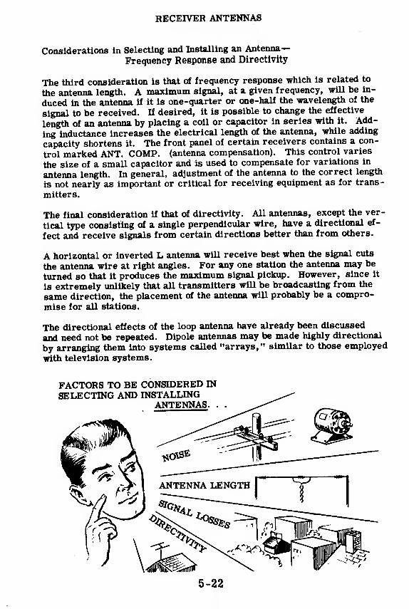
RECEIVER ANTENNAS
Considerations in Selecting and Installing an Antenna-
Frequency Response and Directivity
The third consideration is that of frequency response which is related to
the antenna length. A maximum signal, at a given frequency, will be in-
duced in the antenna if it is one-quarter or one-half the wavelength of the
signal to be received. If desired, it is possible to change the effective
length of an antenna by placing a coil or capacitor in series with it. Add-
ing inductance increases the electrical length of the antenna, while adding
capacity shortens it. The front panel of certain receivers contains a con-
trol marked ANT. COMP. (antenna compensation). This control varies
the size of a small capacitor and is used to compensate for variations in
antenna length. In general, adjustment of the antenna tb the correct length
is not nearly as important or critical for receiving equipment as for trans-
mitters.
The final consideration if that of directivity. All antennas, except the ver-
tical type consisting of a single perpendicular wire, have a directional ef-
fect and receive signals from certain directions better than from others.
A horizontal or inverted L antenna will receive best when the signal cuts
the antenna wire at right angles. For any one station the antenna may be
turned so that it produces the maximum signal pickup. However, since it
is extremely unlikely that all transmitters will be broadcasting from the
same direction, the placement of the antenna will probably be a compro-
mise for all stations.
The directional effects of the loop antenna have already been discussed
and need not be repeated. Dipole antennas may be made highly directional
by arranging them into systems called "arrays," similar to those employed
with television systems.
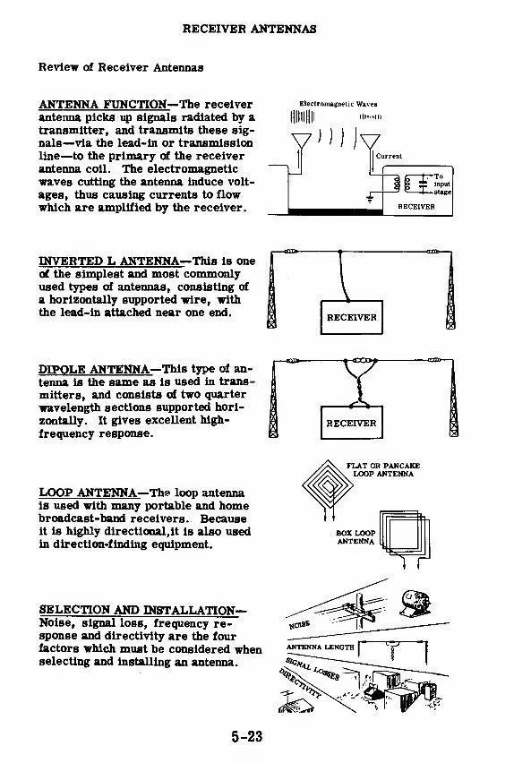
RECEIVER ANTENNAS
Review of Receiver Antennas
ANTENNA FUNCTION—The receiverantenna picks up signals radiated by atransmitter, and transmits these sig-
nals—via the lead-in or transmissionline—to the primary of the receiverantenna coil. The electromagneticwaves cutting the antenna induce volt-
ages, thus causing currents to flowwhich are amplified by the receiver.
Electromagnetic Waves
lllllllllllllllurn mi
V") Jv-Toinput
-stage
INVERTED L ANTENNA—This is oneof the simplest and most commonlyused types of antennas, consisting of
a horizontally supported wire, withthe lead-in attached near one end.
DIPOLE ANTENNA—This type of an-
tenna is the same as is used in trans-
mitters, and consists of two quarter
wavelength sections supported hori-
zontally. It gives excellent high-
frequency response.
LOOP ANTENNA—The loop antennais used with many portable and homebroadcast-band receivers. Becauseit is highly directional, it is also usedin direction-finding equipment.
SELECTION AND INSTALLATION—Noise, signal loss, frequency re-sponse and directivity are the fourfactors which must be considered whenselecting and installing an antenna.
FLAT OR PANCAKELOOP ANTENNA
BOX LOOPANTENNA
TT
5-23
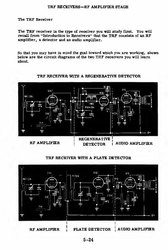
TRF RECEIVERS—RF AMPLIFIER STAGE
The TRF Receiver
The TRF receiver is the type of receiver you will study first. You -will
recall from "Introduction to Receivers" that the TRF consists of an RFamplifier, a detector and an audio amplifier.
So that you may have in mind the goal toward which you are working, shownbelow are the circuit diagrams of the two TRF receivers you will learn
about.
TRF RECEIVER WITH A REGENERATIVE DETECTOR
RF AMPLIFIER i DETECTOR IAUDIO AMPLIFIER
TRF RECEIVER WITH A PLATE DETECTOR
RF AMPLIFIER | PLATE DETECTOR jAUDIO AMPLIFIER
5-24
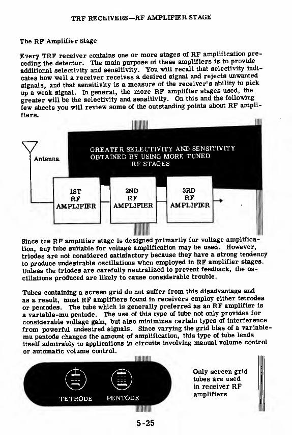
TRF RECEIVERS—RF AMPLIFIER STAGE
The RF Amplifier Stage
Every TRF receiver contains one or more stages of RF amplification pre-
ceding the detector. The main purpose of these amplifiers is to provide
additional selectivity and sensitivity. You will recall that selectivity indi-
cates how well a receiver receives a desired signal and rejects unwanted
signals, and that sensitivity is a measure of the receiver's ability to pick
up a weak signal. In general, the more RF amplifier stages used, the
greater will be the selectivity and sensitivity. On this and the following
few sheets you will review some of the outstanding points about RF ampli-
fiers.
VAntenna
GREATER SELECTIVITY AND SENSITIVITYOBTAINED BY USING MORE TUNED
RF STAGES
1STRF
AMPLIFIER
2NDRF
AMPLIFIER
3RDRF
AMPLIFIER
Since the RF amplifier stage is designed primarily for voltage amplifica-
tion, any tube suitable for voltage amplification may be used. However,
triodes are not considered satisfactory because they have a strong tendency
to produce undesirable oscillations when employed in RF amplifier stages.
Unless the triodes are carefully neutralized to prevent feedback, the os-
cillations produced are likely to cause considerable trouble.
Tubes containing a screen grid do not suffer from this disadvantage and
as a result, most RF amplifiers found in receivers employ either tetrodes
or pentodes. The tube which is generally preferred as an RF amplifier is
a variable-mu pentode. The use of this type of tube not only provides for
considerable voltage gain, but also minimizes certain types of interference
from powerful undesired signals. Since varying the grid bias of a variable-
mu pentode changes the amount of amplification, this type of tube lends
itself admirably to applications in circuits involving manual volume control
or automatic volume control.
Only screen grid
tubes are used
in receiver RFamplifiers
5-25
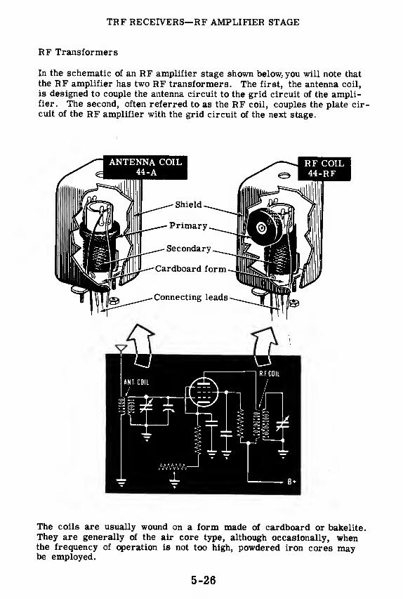
TRF RECEIVERS—RF AMPLIFIER STAGE
RF Transformers
In the schematic of an RF amplifier stage shown below, you will note that
the RF amplifier has two RF transformers. The first, the antenna coil,
is designed to couple the antenna circuit to the grid circuit of the ampli-fier. The second, often referred to as the RF coil, couples the plate cir-cuit of the RF amplifier with the grid circuit of the next stage.
The coils are usually wound on a form made of cardboard or bakelite.They are generally of the air core type, although occasionally, whenthe frequency of operation is not too high, powdered iron cores maybe employed.
5-26
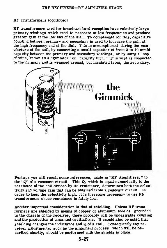
TRF RECEIVERS—RF AMPLIFIER STAGE
RF Transformers (continued)
RF transformers used for broadcast band reception have relatively largeprimary windings which tend to resonate at low frequencies and producegreater gain at the low end of the dial. To compensate for this, capacitive
coupling between primary and secondary is used to increase the gain at
the high frequency end of the dial. This is accomplished during the man-ufacture of the coil, by connecting a small capacitor of from 3 to 10 mmfdcapacity between the primary and secondary windings, or by using a loopof wire, known as a "gimmick" or "capacity turn. " This wire is connectedto the primary and is wrapped around, but insulated from, the secondary.
Perhaps you will recall some references, made in "RF Amplifiers, " to
the "Q" of a resonant circuit. This Q, which is equal numerically to the
reactance of the coil divided by its resistance, determines both the selec-
tivity and voltage gain that can be obtained from a resonant circuit. In
order to keep the selectivity high, it is therefore necessary to use RFtransformers whose resistance is fairly low.
Another important consideration is that of shielding. Unless RF trans-
formers are shielded by means of copper or aluminum shields grounded
to the chassis of the receiver, there probably will be undesirable coupling
and the production of unwanted oscillations. It should also be noted that
shielding changes the inductance and Q of a coil. Consequently any re-
ceiver adjustments, such as the alignment process which will be de-
scribed shortly, should be performed with the shields in place.
5-27
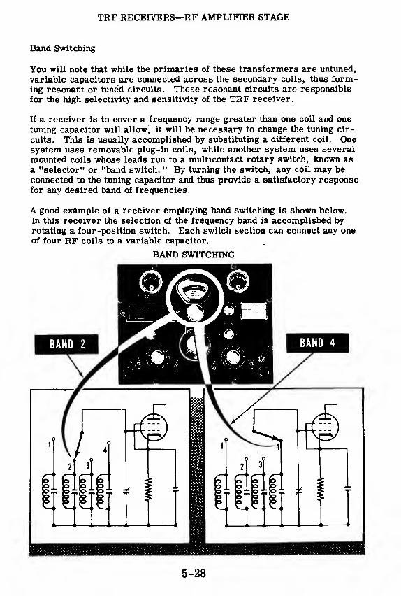
TRF RECEIVERS—RF AMPLIFIER STAGE
Band Switching
You will note that while the primaries of these transformers are untuned,
variable capacitors are connected across the secondary coils, thus form-ing resonant or tuned circuits. These resonant circuits are responsible
for the high selectivity and sensitivity of the TRF receiver.
If a receiver is to cover a frequency range greater than one coil and one
tuning capacitor will allow, it will be necessary to change the tuning cir-
cuits. This is usually accomplished by substituting a different coil. Onesystem uses removable plug-in coils, while another system uses several
mounted coils whose leads run to a multicontact rotary switch, known asa "selector" or "band switch. " By turning the switch, any coil may beconnected to the tuning capacitor and thus provide a satisfactory responsefor any desired band of frequencies.
A good example of a receiver employing band switching is shown below.
In this receiver the selection of the frequency band is accomplished byrotating a four -position switch. Each switch section can connect any oneof four RF coils to a variable capacitor.
BAND SWITCHING
5-28

TRF RECEIVERS—RF AMPLIFIER STAGE
Ganged Capacitors and Alignment
Every TRF receiver has a minimum of two tuned circuits, one associatedwith the RF amplifier and one with the detector. In the early days of theTRF, each variable capacitor in the tuned circuit was connected to its ownindividual tuning knob. In order to tune your radio to a station, you had toturn each knob individually until each tuned circuit was resonant to thefrequency of the desired station.
The modern TRF receiver eliminates the need for individual tuning knobsby having the variable capacitors of all the tuned circuits mounted on oneshaft. This allows the receiver to be tuned with a single control whichvaries all the tuned circuits together and at the same time. This is called"ganged" tuning. In a receiver having two RF amplifier stages plus a de-tector, a three-gang capacitor would be used.
Since all of the tuned circuits are varied together, all of the variablecapacitors should have exactly the same capacity, at the same time,for various settings. All of the tuned circuits would then be resonant tothe same frequency at the same time—resulting in maximum sensitiv-ity and selectivity.
Unfortunately, no two capacitors can be manufactured exactly alike, andtherefore the individual capacitor sections on a ganged unit will haveslightly different capacities at every setting. If nothing were done to com-pensate for these differences in capacity, the tuned circuits in a receiverwould be resonant to slightly different frequencies for every setting of thetuning knob—causing poor receiver selectivity and sensitivity. Such a re-ceiver is said to be'out of alignment."
200 MMF195 MMF
204 MMF
RESONANTTO 600 KC
RESONANTTO 603 KC
ORESONANTTO 598 KC
RECEIVER OUT OF ALIGNMENT
5-29
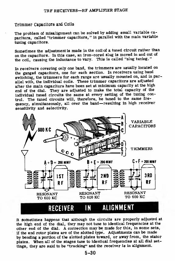
TRF RECEIVERS—RF AMPLIFIER STAGE
Trimmer Capacitors and Coils
The problem of misalignment can be solved by adding small variable ca-
pacitors, called "trimmer capacitors, " in parallel with the main variable
tuning capacitors.
Sometimes the adjustment is made in the coil of a tuned circuit rather than
on the capacitors. In this case, an iron-cored slug is moved in and out of
the coil, causing the inductance to vary. This is called "slug tuning. "
In receivers covering only one band, the trimmers are usually located on
the ganged capacitors, one for each section. In receivers using band
switching, the trimmers for each range are usually mounted on, and in par-
allel with, the individual coils. These trimmer capacitors are adjusted
after the main capacitors have been set at minimum capacity at the high
end of the dial. They are adjusted to make the total capacity of the
individual tuned circuits the same at every setting of the tuning con-
trol. The tuned circuits will, therefore, be tuned to the same fre-
quency, simultaneously, all over the band—resulting in high receiver
sensitivity and selectivity.
VARIABLECAPACITORS
ORESONANTTO 600 KC
RESONANTTO 600 KC
RESONANTTO 600 KC
RECEIVER IDALIGNMENT
It sometimes happens that although the circuits are properly adjusted at
the high end of the dial, they may not tune to identical frequencies at the
other end of the dial. A correction may be made for this, in some sets,
if the end rotor plates are of the slotted type. Adjustments can be madeby bending a portion of the slotted plates toward, or away from, the stator
plates. When all of the stages tune to identical frequencies at all dial set-
tings, they are said to be "tracking" and the receiver is in alignment.
5-30

TRF RECEIVERS—RF AMPLIFIER STAGE
Grid Bias Manual Volume Control
Since signals arriving from different transmitters will vary in inten-sity, it is necessary to provide a volume control so that the gain ofthe RF amplifier and the loudness of the signal can be varied. One ofthe most common methods of controlling the gain of a TRF is tochange the bias voltage of the RF amplifier stage by placing a variableresistor in the cathode circuit.
You will recall, from previous discussion, that the RF amplifier stageusually employs a variable-mu pentode tube. Varying the bias of thisvariable-mu tube causes the amplification factor of the tube to vary andtherefore the gain of the stage to vary. If there are several RF amplifiers,the variable resistor may be connected in such a manner as to vary thebias of all of the RF amplifiers. The fixed resistor in the cathode circuitis placed there to provide the proper bias when the variable resistor isset for maximum gain at the zero resistance position.
A variation of the grid bias volume con-trol employs a potentiometer, which alsoacts as a variable shunt across the pri-mary of the antenna coil. When the mov-ing arm of the potentiometer is moved tothe left, the resistance across the pri-mary coil is reduced while the cathoderesistance is increased. This results ina weaker signal on the grid and reducedvoltage amplification. When the slidingarm is moved to the extreme right, theresistance across the primary is in-creased, while the cathode resistance isreduced. This produces a stronger sig-nal on the grid and increased voltageamplification.
5-31

TRF RECEIVERS—RF AMPLIFIER STAGE
Suppose you pause for a moment to examine the RF amplifier shown above
and to review the purpose of each component. The antenna coil couples the
antenna to the control grid of the RF amplifier. The variable capacx or
enables the operator to tune the amplifier to the frequency of the desired
signal, and thus provides selectivity. The 25K variable resistor acts as a
volume control, while the 330-ohm resistor provides limiting cathode bias
The 01 mfd capacitor between the cathode and ground is the cathode bypass
capacitor The 100K resistor in the screen grid circuit is the screen grid
voltage dropping resistor, which serves to keep the screen grid at a lower
positive potential than the plate. The . 01 mfd capacitor in the screen grid
circuit is the screen grid bypass capacitor, which acts as a bypass for RF
signals, and enables the screen to act as a shield between the p ate and the
control grid. The 22K resistor in the plate circuit is the plate load, while
the 01 mfd capacitor in the plate circuit is used for the purpose of coupling
the plate circuit to the grid of the next stage, and at the same time effectively
blocking the passage of direct current.
5-32
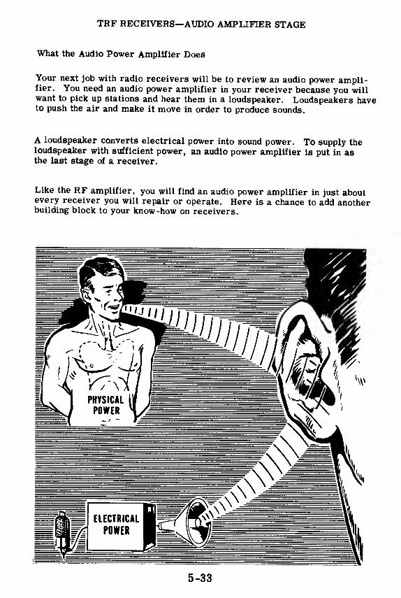
TRF RECEIVERS—AUDIO AMPLIFIER STAGE
What the Audio Power Amplifier Does
Your next job with radio receivers will be to review an audio power ampli-fier. You need an audio power amplifier in your receiver because you willwant to pick up stations and hear them in a loudspeaker. Loudspeakers haveto push the air and make it move in order to produce sounds.
A loudspeaker converts electrical power into sound power. To supply theloudspeaker with sufficient power, an audio power amplifier is put in asthe last stage of a receiver.
Like the RF amplifier, you will find an audio power amplifier in just aboutevery receiver you will repair or operate. Here is a chance to add anotherbuilding block to your know-how on receivers.
5-33
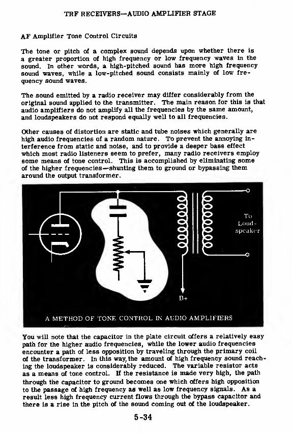
TRF RECEIVERS—AUDIO AMPLIFIER STAGE
AF Amplifier Tone Control Circuits
The tone or pitch of a complex sound depends upon whether there is
a greater proportion of high frequency or low frequency waves in the
sound. In other words, a high-pitched sound has more high frequency
sound waves, while a low-pitched sound consists mainly of low fre-
quency sound waves.
The sound emitted by a radio receiver may differ considerably from the
original sound applied to the transmitter. The main reason for this is that
audio amplifiers do not amplify all the frequencies by the same amount,
and loudspeakers do not respond equally well to all frequencies.
Other causes of distortion are static and tube noises which generally are
high audio frequencies of a random nature. To prevent the annoying in-
terference from static and noise, and to provide a deeper bass effect
which most radio listeners seem to prefer, many radio receivers employsome means of tone control. This is accomplished by eliminating someof the higher frequencies—shunting them to ground or bypassing themaround the output transformer.
ToLoud-speaker
A METHOD OF TONE CONTROL IN AUDIO AMPLIFIERS
You will note that the capacitor in the plate circuit offers a relatively easy
path for the higher audio frequencies, while the lower audio frequencies
encounter a path of less opposition by traveling through the primary coil
of the transformer. In this way, the amount of high frequency sound reach-
ing the loudspeaker is considerably reduced. The variable resistor acts
as a means of tone control. If the resistance is made very high, the path
through the capacitor to ground becomes one which offers high opposition
to the passage of high frequency as well as low frequency signals. As a
result less high frequency current flows through the bypass capacitor and
there is a rise in the pitch of the sound coming out of the loudspeaker.
5-34

TRF RECEIVERS—AUDIO AMPLIFIER STAGE
AF Amplifier Volume Control
You have previously been given a description of one method of controllingthe volume of a receiver. This method involved varying the bias of theRF amplifier stage. There is another commonly used method of volumecontrol involving the detector and AF amplifier stages.
DiodeDetector
DETECTOR-OUTPUT VOLUME CONTROLNotice that the detector is coupled to the AF amplifier by means of re-sistance-capacity coupling circuit. The volume control is basically a volt-age divider, the moving arm tapping off the desired amount of signal volt-age which is then applied, through the coupling capacitor, to the grid of theAF amplifier. This type of volume control is frequently employed insuperhet receivers.
Some receivers employ a dual type of volume control. This control regu-lates the gain in the first and second RF amplifier stages by varying thecathode bias, and also controls the gain by varying the amplitude of theinput signal applied to the first AF amplifier.
GRID CONTROL OF RECEIVER
5-35

TRF RECEIVERS—AUDIO AMPLIFIER STAGE
Analysis of the AF Amplifier Circuit
Now stop for a few minutesand analyze the functions of
the various component parts
of the AF power amplifier
circuit shown here. Notice
that no provision is made in
this AF amplifier stage for
volume or tone control.
The 0. 01-mfd coupling capacitor and 470K grid resistor found in the con-
trol grid circuit couple the control grid of the amplifier to the preceding
detector stage. The capacitor also reduces the possibility that any DCvoltages from the detector stage might be impressed upon the control grid
of the amplifier.
The 330-ohm resistor acts as a cathode bias resistor, while the 5-mfd
capacitor bypasses the varying component of the plate current around the
cathode resistor, thus preventing the production of a varying bias and the
accompanying reduction in amplification.
The primary of the output transformer acts as the plate load and couples
the amplifier to the loudspeaker. The . 001-mfd capacitor across the pri-
mary bypasses high frequency audio signals around the primary and this
reduces the amount of high frequency sounds and noises emitted by
the loudspeaker.
Components
0. 01-mfd capacitor and 470K resistor
330-ohm resistor
5-mfd capacitor
0.001-mfd capacitor
Output transformer
Functions
Couples AF amplifier to pre-ceding detector stage
Provides cathode bias
Bypasses signal around cathode
bias resistor
Prevents high frequency audio
signals from entering loudspeaker
Acts as plate load and couples
amplifier to loudspeaker
5-36
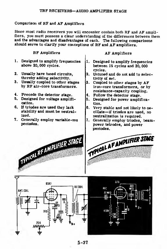
TRF RECEIVERS—AUDIO AMPLIFIER STAGE
Comparison of RF and AF Amplifiers
Since most radio receivers you will encounter contain both RF and AF ampli-fiers, you must possess a clear understanding of the differences between themand the advantages and disadvantages of each. The following comparisonsshould serve to clarify your conceptions of RF and AF amplifiers.
4.
5.
6.
7.
RF Amplifiers
Designed to amplify frequenciesabove 20, 000 cycles.
Usually have tuned circuits,
thereby adding selectivity.
Usually coupled to other stagesby RF air-core transformers.
Precede the detector stage.Designed for voltage amplifi-cation.
If triodes are used they lackstability and must be neutral-ized.
Generally employ variable-mupentodes.
AF Amplifiers
Designed to amplify frequenciesbetween 15 cycles and 20, 000cycles.
Untuned and do not add to selec-tivity of set.
Coupled to other stages by AFiron-core transformers, or byresistance-capacity coupling.
Follow the detector stage.
Designed for power amplifica-tion.
Very stable and not likely to os-cillate—if triodes are used, noneutralization is required.Generally employ triodes, beam-power tetrodes, and powerpentodes.
5-37
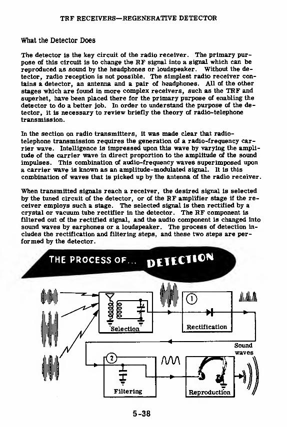
TRF RECEIVERS—REGENERATIVE DETECTOR
What the Detector Does
The detector is the key circuit of the radio receiver. The primary pur-
pose of this circuit is to change the RF signal into a signal which can bereproduced as sound by the headphones or loudspeaker. Without the de-
tector, radio reception is not possible. The simplest radio receiver con-
tains a detector, an antenna and a pair of headphones. All of the other
stages which are found in more complex receivers, such as the TRF and
superhet, have been placed there for the primary purpose of enabling the
detector to do a better job. In order to understand the purpose of the de-tector, it is necessary to review briefly the theory of radio-telephone
transmission.
In the section on radio transmitters, it was made clear that radio-
telephone transmission requires the generation of a radio-frequency car-
rier wave. Intelligence is impressed upon this wave by varying the ampli-tude of the carrier wave in direct proportion to the amplitude of the soundimpulses. This combination of audio-frequency waves superimposed upona carrier wave is known as an amplitude-modulated signal. It is this
combination of waves that is picked up by the antenna of the radio receiver.
When transmitted signals reach a receiver, the desired signal is selected
by the tuned circuit of the detector, or of the RF amplifier stage if the re-ceiver employs such a stage. The selected signal is then rectified by acrystal or vacuum tube rectifier in the detector. The RF component is
filtered out of the rectified signal, and the audio component is changed into
sound waves by earphones or a loudspeaker. The process of detection in-
cludes the rectification and filtering steps, and these two steps are per-formed by the detector.
5-38
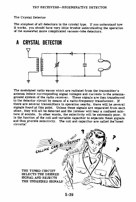
TRF RECEIVERS—REGENERATIVE DETECTOR
The Crystal Detector
The simplest of all detectors is the crystal type. If you understand howit works, you should have very little trouble understanding the operationof the somewhat more complicated vacuum-tube detectors.
A CRYSTAL DETECTOR
The modulated radio waves which are radiated from the transmitter'santenna induce corresponding signal voltages and currents in the antenna-ground system of the radio receiver. These signals are then transferredto the detector circuit by means of a radio-frequency transformer. If
there are several transmitters in operation nearby, there will be severalsignals found at this point. Unless these signals are separated from eachother, they will all be detected and the listener will hear a confused mix-ture of sounds. In other words, the selectivity will be extremely poor. It
is the function of the coil and variable capacitor to separate these signalsand thus provide selectivity. The coil and capacitor are called the'tunedcircuits?
5-39

TRF RECEIVERS—REGENERATIVE DETECTOR
How the Crystal Detector Works
You will probably recall from a previous discussion dealing with the se-
lectivity of RF amplifiers that signals of differing frequencies can be sep-
arated from each other by taking advantage of the selective properties of
a resonant or tuned circuit. A circuit of this type generally contains a
fixed coil and a variable capacitor. It is capable of selecting or accepting
radio signals of one particular frequency and rejecting those of all other
frequencies. In addition, the tuned circuit produces a step-up or gain in
signal voltage at resonance.
The tuned circuit can be adjusted to resonate or respond to a higher or
lower frequency signal by varying the size of the capacitor. You will also
encounter tuned circuits in which the capacity is kept constant and the
tuning is accomplished by varying the inductance of the coil. Nevertheless,
most resonant circuits are tuned by varying the capacitor.
Returning to our crystal detector, it is apparent that the variable capacitor
and the secondary of the RF transformer form a tuned circuit. It is this
circuit that gives the detector some degree of selectivity or ability to dis-
criminate between desired and undesired signals.
The selected signal is rectified by the detector and the result is a pulsating
DC signal containing two components, one of which is radio frequency andthe other, audio frequency. The AF component passes through the head-phones and produces sound waves similar to those originally used to mod-ulate the radio wave. The RF component is bypassed around the head-phones by the filtering action of a small capacitor placed across the
headphones.
5-40

TRF RECEIVERS—REGENERATIVE DETECTOR
Characteristics of the Crystal Detector
The crystal detector possesses the advantages of simplicity and economy.In addition,it requires no batteries or other local sources of power. Thereare no filaments to burn out or produce hum and noise. In applications re-quiring the detection of ultra-high frequency signals, the crystal possessescertain decided advantages over the vacuum-tube detector.
Although transistors, which are crystals capable of amplifying signals,
have been developed recently, the ordinary crystal detector providesno amplification. The crystal detector is therefore characterized bylow sensitivity.
The galena crystal has still another disadvantage. Certain portions of the
face of the crystal have better rectifying properties than the remainingportions. This makes it necessary to explore the face of the crystal witha wire probe called a "cat's whisker" until a sensitive rectifying point is
found. The wire can easily be dislodged from this sensitive point and con-sequently, reception is likely to be erratic. In addition, dirt, grease orair-borne dust may spoil the sensitive spot and make it necessary to
search for another spot.
These difficulties have been overcome in the more modern germanium andsilicon crystal rectifiers. These consist of small sealed cartridges con-taining contact wires that cannot be dislodged. They have an extremelylong life and resist shock and vibration better than most conventionalvacuum tubes.
OPEN TYPE CRYSTAL DETECTOR
SEALED GERMANIUM CRYSTAL
5-41

TRF RECEIVERS—REGENERATIVE DETECTOR
The Diode Detector
The fundamental circuit of the diode detector closely resembles that of the
crystal detector. Consequently, the operating principles and character-istics of these two detectors resemble each other closely.
You will observe that the only difference between the diode and crystal de-tectors is the replacement of the galena crystal by a diode tube. Theprocesses of selection, rectification and filtering are carried on in the
manner previously described under crystal detectors. Diode detectors arecharacterized by faithful reproduction and low sensitivity. When the de-
tector is operating, plate current flows through the tuned circuit during
the positive half of each signal cycle. This plate current flow produceswhat is known as a" loading effect!' This in turn has the effect of reducing
both the voltage gain and selectivity of the tuned circuit.
Because of these factors and because it is capable of handling large signal
voltages without distortion, the diode detector is generally preceded byone or more tuned RF amplifiers which provide increased sensitivity andselectivity. The detector is usually followed by one or more stages of AFamplification to provide sufficient power to operate a loudspeaker.
5-42

TRF RECEIVERS—REGENERATIVE DETECTOR
The Grid-Leak Detector
You have seen that since the diode detector cannot amplify, it is generallyused in a receiver containing several stages of amplification. If you de-sire a receiver which uses fewer tubes, it is necessary to use a moresensitive detector—one which amplifies as well as detects. In order toamplify, the detector must of necessity use a tube containing a control grid,such as a triode, tetrode or pentode.
The triode detector which is easiest to understand is the grid-leak detec-tor. This is because the grid-leak detector is basically a diode detectorfollowed by a stage of audio-frequency amplification.
Suppose you examine the grid and cathode circuits of this detector andtemporarily forget about the plate circuit. The result will be the circuitshown in the following diagram:
Note that this is basically the circuit of the diode detector. The controlgrid of the triode is taking the place of the diode plate, the grid-leak re-sistor has replaced the diode load or earphones, and the grid capacitor isacting as an RF filter capacitor across the load.
When a modulated signal voltage is applied to this circuit, the grid will
attract electrons from the cathode during the positive half-cycles. Theflow of current through the grid-leak resistor to ground produces a volt-age drop across the grid-leak resistor. Because of the fact that currentcan flow in only one direction in the grid circuit, this voltage remainsconstant in polarity. The grid is thus biased, or kept at a negative volt-
age with respect to the cathode. The amount of bias will vary in accord-ance with the amplitude or modulation of the signal. In other words, thebias will vary at an audio-frequency rate.
5-43

TRF RECEIVERS—REGENERATIVE DETECTOR
The Grid-Leak Detector (continued)
Suppose you consider the complete grid-leak detector circuit.
£cke»iatic of?grid-teak detector
You will recall that the plate current of a triode is dependent upon the grid
voltage. Consequently the audio frequency variations in bias should pro-
duce a corresponding pulsating plate current. Any radio frequency com-ponent of the plate current is filtered out by capacitors and RF chokes
placed in the plate circuit. As a result, the voltage developed across the
plate load is an amplified reproduction of the audio frequency voltage de-
veloped across the grid-leak resistor.
When there is no incoming signal, no bias is produced. Consequently, the
plate current is high when no signal is being detected. When a signal is
received, the grid becomes biased negatively and the average amount of
plate current decreases.
The amount of grid bias developed is equal numerically to the amount of
grid current multiplied by the amount of resistance of the grid-leak.
Therefore the larger the grid-leak resistor, the greater will be the am-plitude of the signal developed. For that reason, extremely sensitive grid-
leak detectors usually use grid-leak resistors whose values are between
one and five megohms.
However, if a strong signal comes in, it is quite possible that enough bias
may be created to cut off the flow of plate current during part of the cycle,
thus producing distortion. In order to reduce this distortion, grid-leak
power detectors are used. They are designed for use with more powerful
signals and generally employ smaller resistors in the grid circuit.
5-44
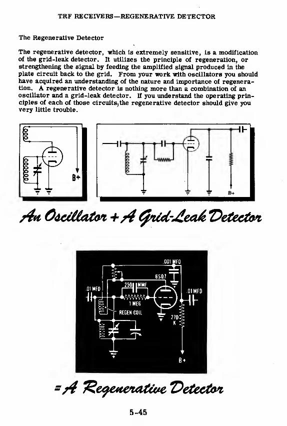
TRF RECEIVERS—REGENERATIVE DETECTOR
The Regenerative Detector
The regenerative detector, which is extremely sensitive, is a modificationof the grid-leak detector. It utilizes the principle of regeneration, orstrengthening the signal by feeding the amplified signal produced in the
plate circuit back to the grid. From your work with oscillators you shouldhave acquired an understanding of the nature and importance of regenera-tion. A regenerative detector is nothing more than a combination of anoscillator and a grid-leak detector. If you understand the operating prin-ciples of each of those circuits,the regenerative detector should give youvery little trouble.

TRF RECEIVERS—REGENERATIVE DETECTOR
How the Regenerative Detector Works
The regenerative detector circuit is similar to that of the grid-leak detec-tor except for the coil in the plate circuit and the variable resistor acrossthe coil. This circuit is shown on the previous sheet.
The plate coil, sometimes called the "tickler coil, " feeds back voltage tothe grid circuit in phase with the incoming signal voltage, thus increasingthe voltage gain and sensitivity of the detector. The variable resistor isplaced across the coil to control the amount of feedback or regeneration.
Why control the amount of feedback? The answer becomes obvious if youconsider that when feedback becomes excessive, a circuit will begin tooscillate and produce squeals and howls. On the other hand, if there isn'tenough feedback, this detector is hardly any more sensitive than the grid-leak detector. Control of feedback enables us to avoid the two extremesand strike a happy medium.
There are many ways of controlling the amount of feedback. One methodwhich has been used involves varying the physical position of the ticklercoil with respect to the grid coil. If the coupling between the two coils isreduced by moving the tickler coil away from the grid coil, or rotating itso that its axis is at an angle to the axis of the grid coil, the amount offeedback will be reduced. When this method is used to control feedback,a potentiometer is not connected across the tickler coil.
5-46

TRF RECEIVERS—REGENERATIVE DETECTOR
How the Regenerative Detector Works (continued)
Another method of regeneration control makes use of a variable capacitorwhich is placed between one side of the tickler coil and ground. Decreas-ing the size of the capacitor, reduces the amount of RF energy available in
the plate circuit for regeneration.
REGENERATION CONTROL EMPLOYING |A VARIABLE CAPACITOR
VariableCapacitor
VariableResistor
REGENERATION CONTROL EMPLOYINGA VARIABLE RESISTOR
.001 MFD
In the detector shown above, regeneration is controlled by a variable resistorplaced across the tickler coil.
When the movable arm of the potentiometer is in the upper position, thetickler coil is effectively shorted out and there is no regeneration. Thedetector is now, for all practical purposes, a grid-leak detector. Whenthe potentiometer arm is moved to the other extreme position, most of the
RF current will flow through the tickler coil rather than through the poten-tiometer. As a result, the circuit will probably begin to oscillate.
5-47

TRF RECEIVERS—REGENERATIVE DETECTOR
How the Regenerative Detector Works (continued)
No matter what method is used to control regeneration, the control is
usually advanced as far as possible without producing oscillations. In
actual practice this is accomplished by tuning in a station, just as with any
other type of detector. Then the regeneration control is turned up to the
point at which whistles, howls and clicks are, heard. This indicates that
the detector is oscillating. The regeneration control is then turned back to
the point where these interfering sounds just disappear. The regenerative
detector is properly adjusted for maximum selectivity and sensitivity.
This process of adjusting the regeneration control must be repeated each
time a new signal is tuned in.
The regenerative detector is the most sensitive detector capable of re-
ceiving amplitude-modulated signals. The familiar walkie-talkie, used so
successfully during the last war, employed a modified regenerative de-
tector circuit.
5-48

TRF RECEIVERS—REGENERATIVE DETECTOR
The Regenerative Detector as a CW Receiver
You may recall from your study of transmitters that there are several
methods of impressing intelligence upon a carrier wave, One of these
methods is known as 'amplitude modulation? The crystal, diode and grid-
leak detectors we have considered up to this point are designed for use
with amplitude-modulated (AM) signals. Another method of conveying in-
telligence involves the interruption of a carrier wave in accordance with a
code such as the Morse Code. These signals are called' interrupted con-
tinuous wave"or"cW signals" Since there is no modulation in this type of
signal, it cannot be detected by crystal, diode or grid-leak detector cir-
cuits. In order to hear the signal, it is necessary to use a detector which
employs the heterodyne principle. The heterodyne principle involves mix-
ing the CW signal with a signal obtained from an oscillator. The result of
this mixing is an AM signal which is interrupted in the same manner as
the original CW signal. This AM signal can then be detected and the fa-
miliar "dit-dah" sound of code will be heard in the earphones.
NO SOUND DAH-DIT-DAH
5-49

TRF RECEIVERS—REGENERATIVE DETECTOR
The Regenerative Detector as a CW Receiver (continued)
You may have observed that when two adjacent piano keys are struck atthe same time, a distinct throbbing sound can be heard. This throbbingsound, known as a beat, has a frequency equal to the difference of the fre-quencies of the two notes struck. If the two notes struck have frequenciesof 264 and 297 cycles respectively, the beat frequency will be equal to thedifference between them, or 33 cycles.
Similarly, when two alternating voltages of slightly different frequenciesare combined in a detector, the resultant wave circuit produced in theoutput will have a frequency which is equal to the difference between thefrequencies of the two original voltages. This is the basis of the hetero-dyne principle.
For example, if two inaudible RF waves whose frequencies are 600 kc and601 kc, respectively, are applied to a detector tube, the smaller wave (A)will add and subtract from the larger wave (B) to make the amplitude ofthe larger wave (B) vary in the manner shown. The rate of variation ofthe amplitude of wave B is the difference between the frequencies of thetwo waves—in this case 1 kc. Observe that wave B, because of the intro-duction of wave A, has been transformed into an amplitude -modulatedwave. The audio modulation can be heard by detection of this AM signal.
5-50

TRF RECEIVERS—REGENERATIVE DETECTOR
The Oscillating Detector
Some receivers designed for reception of CW signals employ a separatelocal oscillator known as a"beat-frequency oscillatorW'BFOr If the out-put of this oscillator is heterodyned against a continuous radio wave whichis interrupted in accordance with the Morse Code, the audio beat note thatis produced will be interrupted in a similar manner. In this way, theheterodyne principle makes possible the detection of CW signals. Theheterodyne principle will also be applied in a later lesson dealing with thesuperheterodyne receiver.
5-51

TRF RECEIVERS—REGENERATIVE DETECTOR
Analysis of the Regenerative Detector Circuit
1 MEG
f 470*1 I ti™
You know how the RF and AF amplifiers work. Suppose you review the
functions of the various component parts used in the regenerative detector.
The . 01-mfd capacitor found in the grid circuit is used to couple the pre-ceding RF amplifier stage to the detector. The grid coil and variable ca-pacitor provide tuning and selectivity. The 1-megohm resistor providesgrid-leak bias while the 250-mmf capacitor acts as an RF bypass capaci-tor around the grid-leak resistor. The plate or tickler coil is inductively
coupled with the grid coil and thus provides feedback, while the potenti-
ometer across the tickler coil controls the amount of feedback. The .001-mfd capacitor is an RF filter or bypass capacitor around the 27OK plate
load resistor, and the . 01-mfd capacitor in the plate circuit is used to
couple the detector to the following AF amplifier stage.
COMPONENTS FUNCTIONS
. 01-mfd capacitors Couple detector to preceding and following
stages
Coil and variable capacitor Provide selectivity
1 megohm resistor Provides grid-leak bias
250-mmf capacitor Bypasses RF around grid-leak resistor
Regeneration coil Provides feedback
500K potentiometer Controls feedback
. 001-mfd capacitor Filters RF component of signal
270K resistor Acts as plate load of detector
5-52
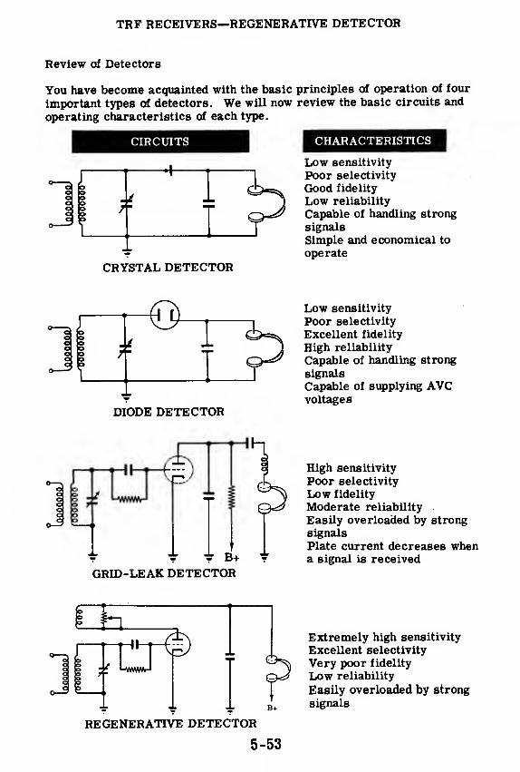
TRF RECEIVERS—REGENERATIVE DETECTOR
Review of Detectors
You have become acquainted with the basic principles of operation of four
important types of detectors. We will now review the basic circuits and
operating characteristics of each type.
CIRCUITS ^^^H CHARACTERISTICS
Low sensitivity
Poor selectivity
Good fidelity
Low reliability
Capable of handling strong
signals
Simple and economical to
operate
DIODE DETECTOR
Low sensitivity
Poor selectivity
Excellent fidelity
High reliability
Capable of handling strong
signals
Capable of supplying AVCvoltages
o2i 5
± ± B+
GRID-LEAK DETECTOR
High sensitivity
Poor selectivity
Low fidelity
Moderate reliability
Easily overloaded by strongsignals
Plate current decreases whena signal is received
oo
in.
REGENERATTVE DETECTOR
5-53
Extremely high sensitivity
Excellent selectivity
Very poor fidelity
Low reliability
Easily overloaded by strong
signals

TRF RECEIVERS—PLATE DETECTOR
How the Plate Detector Works
The plate detector employs a trlode or pentode biased at, or near, cut-off. The bias is usually provided by means of a cathode bias resistor,or less frequently, by means of a bias battery placed between grid andcathode. The plate current will be at, or near, zero when no signal is
being received.
-Plate Current
Grid VoltageAverage value of plate current
=.Signal valueapplied to grid-cathode circuit
Action in plate detector|
When a modulated RF signal is impressed on the grid, there will be apulse of plate current during the positive half cycle and little or no platecurrent during the negative half cycle. The plate current will contain anamplified and rectified version of the input signal. The filtering of theRF component is accomplished by connecting a small capacitor betweenthe plate and ground and an RF choke in series with the plate load. It isimportant that a small capacitor be used, since a capacitor that is toolarge will tend to filter out the higher audio frequencies as well as theradio frequencies.
PLATE DETECTOR Plate SignalI
Incoming Signal
Audio Signal Output
5-54

TRF RECEIVERS—PLATE DETECTOR
How the Plate Detector Works (continued)
In contrast with the action of the grid-leak detector, plate current in the
plate detector is at a minimum with no incoming signal. Up to a certain
point, the average plate current increases in direct proportion to the am-plitude or strength of the signal impressed on the grid. Another important
characteristic is that if care is taken not to drive the grid positive, the
plate detector will consume no input power and there will be no loading ef-
fect upon the tuned circuit. Consequently the selectivity and fidelity of the
plate detector surpasses that of the grid-leak detector.
On the other hand, among the disadvantages of the plate detector may be
listed the fact that its sensitivity to weak signals is much less than that of
the grid-leak detector. It also produces more distortion than the diode
detector and it cannot directly provide a voltage to be used for automatic
volume control.
The receiver shown below is a TRF receiver containing a plate detector. It
also contains a beat-frequency oscillator to provide for reception of CWsignals. The tuning capacitor of this oscillator is ganged with the RF ampli-
fier stages in such a manner that a beat note of 1000 cycles will be heard when
the receiver is tuned to a CW signal.
RECEIVER EMPLOYING A PLATE DETECTOR
RESONANTTO 601 KC
RESONANTTO 600 KC
5-55

TRF RECEIVERS—PLATE DETECTOR
Analysis of the Plate Detector Circuit
A brief analysis of the functions of the components used in the plate detectorshould help you to understand how this detector operates.
The coil and variable capacitor in the grid circuit form a tuned circuitand are obviously intended to provide selectivity. In addition, the gridcoil of the detector Is inductively linked with the plate coil of the precedingRF amplifier and thus couples these two stages. The 22K resistor inseries with the cathode acts as the cathode bias resistor, biasing the tubealmost to the point of cut-off, while the 0. 5-mfd capacitor acts as a by-pass capacitor around the cathode bias resistor. The RF choke and . 001-mfd capacitor in the plate circuit serve to filter out the RF component ofthe signal while the 270K plate load resistor and the . 01-mfd capacitorcouple the detector to the following AF amplifier stage.
[COMPONENTS FUNCTIONS
RF coil and variable capacitor Provide selectivity and couple detec-tor to preceding RF amplifier stage
22K resistor Provides cathode bias
0. 5-mfd capacitor Bypasses signal around cathode biasresistor
. 001-mfd capacitor and RF choke Filter RF component of signal
270K resistor Acts as plate load of detector
.01-mfd capacitor Couples detector to following AF am-plifier stage
5-56

THE SUPERHETERODYNE RECEIVER
Introduction
The superheterodyne receiver is the most popular type of receiver in usetoday. Practically all commercial home radios are of this type. You willfind either a superheterodyne circuit or a TRF circuit in practically everypiece of electronic equipment that contains a receiver. This includes radar,sonar, communications gear—any device that picks up and receives a signal.
Knowing the TRF receiver gives you a good start toward learning thesuperheterodyne, because it uses all the basic components of a TRF—withthree additional units. See the block diagram of a superheterodyne, show-ing the three additional units—mixer, local oscillator and intermediatefrequency (IF) amplifier—which are in addition to the basic TRF circuit.
V
AA MRF
AmplifierDetector AF
Amplifier
THE TRF RECEIVER
NEW CIRCUITS
RFAmplifier
LocalOscillator
IF Detector AFAmplifier Amplifier
THE SUPERHET RECEIVER
5-57

THE SUPERHETER&QYNE RECEIVER
The Superhet at High Frequencies
At high frequencies, the TRF receiver does not work as well as it does at
lower radio frequencies. Above 20 mc,a conventional RF amplifier does
not have the necessary sensitivity and selectivity.
The superheterodyne receiver avoids the difficulties encountered with the
TRF at high frequencies by converting the selected signal frequency to a
lower (intermediate) frequency (IF) which can be amplified more easily.
5-58

THE SUPERHETERODYNE RECEIVER
How the Superhet Works
H you know why the superheterodyne was developed, you will easily learnhow it works. TRF receivers use RF amplifiers with variable tuned cir-cuits to select and amplify the received signal. If the receiver has threeRF stages before the detector, it will contain four tuned circuits. For thebest selectivity and sensitivity, each of these four tuned circuits must betuned to the same frequency. However, it is extremely difficult to makea multi-ganged tuning capacitor so that each section will tune its circuitto exactly the same frequency as the other sections. Therefore, the gainand selectivity of the TRF receiver is limited since more RF stages can-not be added conveniently.
The superheterodyne receiver overcomes this problem. It takes the in-coming signal and converts the carrier frequency to another frequencyThis new frequency is called the' intermediate frequency"(IF) and it doesnot vary regardless of the frequency to which the receiver is tuned. TheIF signal is amplified in a series of high-gain amplifiers which are pre-tuned to this fixed IF frequency. Because it eliminates the many-gangedtuning capacitor, the superhet with its fixed frequency IF amplifiers canbe used to give very large gains and very fine selectivity.
This is how the signal frequency is changed in the superhet. The incomingsignal and the CW output of the local oscillator are fed into the mixer tubeThe plate current is varied according to both of these signals which are ofdifferent frequencies. A beat (or difference) frequency appears in the re-sulting signal. This signal is then passed through the IF amplifiers whichare tuned to this difference frequency. The IF signal has exactly the samemodulation as the RF carrier. The only change has been the substitutionof the IF frequency for the RF.
THE SUPERHET RECEIVERS MAKE USE OF
5-59

THE SUPERHETERODYNE RECEIVER
Selectivity of the Superhet
This is what happens in a home superheterodyne radio set. When you tune
it to a station of 880 kc, you are setting the tuned RF circuit to 880 kc and
at the same time you are automatically tuning the local oscillator to 1336
kc Two signals—one of 880 kc, the other of 1336 kc—are fed into the
mixer stage. The output of the mixer stage contains a frequency of 456
kc which is the difference of its two inputs.
If at the same time the antenna picks up another station at a frequency of
1100 kc, the signal, if strong enough, can get by the first tuned circuit
and would be mixed with the local oscillator output in the mixer stage.
This undesired signal of 1100 kc would produce a beat-frequency of 1336-
1100 or 236 kc.
The IF amplifier tuning, however, does not vary. It is always tuned to
456 kc. So you can see that only the beat signal produced by the desired
station (880 kc) will be amplified by the IF amplifier. Since the undesired
signal of 1100 kc produced a beat-frequency which is different from the IF
frequency, its beat signal is not amplified. Thus, the superhet has se-
lected the proper input signal on the basis of the frequency of the beat sig-
nal produced in the mixer stage.
THE
tutting cafiACitot
KEEPS THE LOCAL OSCILLATOR
"TRACKING" THE TUNED RF
In order to hear the 1100-kc station, the receiver would have to be re-
tuned. Turning the knob changes the frequency to which the RF amplifier
is tuned and, at the same time, changes the local oscillator frequency. Atwo-section ganged tuning capacitor does the trick. Tuning the receiver
does not affect the IF stages. When the RF tuned circuit is set at 1100 kc,
the oscillator will be putting out a signal of 1556 kc;the IF remains at 456 kc.
Now it is the 1100-kc signal which produces the 456-kc beat-frequency.
The beat produced by the 880-kc signal would be the difference between its
frequency and the 1556-kc local oscillator frequency—676 kc—and this
frequency will not be amplified by the IF stages.
In order for the superhet to work properly, the local oscillator must be ad-
justed so that it will always tune to a frequency which is a fixed number of
kilocycles different from the desired RF frequency. Thus, as the receiver
—that is, the RF tuned circuit—is tuned from 550 to 1600 kc, the local os-
cillator should tune from 1006 to 2056 kc. Then, any signal picked up at
the frequency to which the receiver is tuned will produce an IF frequency
of 456 kc (which is the standard IF frequency for commercial receivers).
5-60

THE SUPERHETERODYNE RECEIVER
RF Amplifier Stage
Many superhet receivers do not contain an RF amplifier stage. In suchreceivers the signal from the antenna is fed to the signal grid of the mixeror converter stage. However, you will encounter other receivers whichcontain stages of RF amplification preceding the mixer. You will therefore
have a better understanding of the operation of superhet receivers if youknow the reasons for including an RF amplifier stage.
The first function of the RF amplifier is to improve the signal-to-noise
ratio. The mixer stage usually produces more tube noise than an RF stage
of amplification. The signal, plus the tube noise, is amplified by the fol-
lowing IF amplifier stage. However, if the signal strength is increased
by placing an RF amplifier stage before the mixer, less amplification is
required in the IF amplifier stage. Since tube noises produced by the
mixer are not amplified as much as they were when no RF stage waspresent, a greater signal-to-noise ratio is obtained.
The second function of the RF amplifier stage is related to radiation fromthe oscillator stage. It should not be forgotten that this oscillator is alow-powered transmitter. If there is no RF amplifier stage, the oscilla-
tor is connected through the mixer stage to the antenna. This antenna will
radiate some energy from the oscillator. This radiated signal may causeinterference with reception in nearby receivers and may also divulge the
location of the receiver. This radiation may be reduced or prevented byusing one or more stages of RF amplification, and by carefully shielding
the oscillator stage.
5-61

THE SUPERHETERODYNE RECEIVER
RF Amplifier Stage (continued)
The third function of the RF amplifier stage is concerned with selectivity.
You will recall that in the TRF receiver the RF amplifier stages enabled
the operator to select the desired signal from a group of signals whose
frequencies were very close to each other. The RF amplifier in a super
-
het serves to prevent interference from a signal whose frequency may be
several hundred kilocycles above that of the desired signal. This type of
interference is called image-frequency interference'.'
Let us assume that you have a superhet receiver without an RF amplifier
stage and that the receiver is tuned to a station operating at a frequency
of 600 kc. The oscillator in the receiver will be tuned to 1056 kc and the
resulting IF signal will have a frequency of 1056 kc minus 600 kc or 456
kc. However, if there is a powerful station nearby, broadcasting at a fre-
quency of 1512 kc, some of the signal from this station will enter the
mixer stage where it will beat against the signal from the oscillator. The
resulting signal will be 1512 kc minus 1056 kc or 456 kc—the same inter-
mediate frequency as that produced by the desired station. The IF ampli-
fier stage will amplify both signals equally well, since they are both at the
correct frequency of 456 kc. This interference produces whistles and a
confusing mixture of sounds coming out of the loudspeaker.
It should be noted that when the intermediate frequency is 456 kc, imageinterference is produced when there is a second station broadcasting at a
frequency that is twice the intermediate frequency or 912 kc above that of
the desired signal. Thus the image frequency of a station broadcasting on
600 kc is 912 kc higher, or 1512 kc. Image-frequency interference can be
reduced by the use of an RF amplifier stage before the mixer. For this
reason the RF amplifier is sometimes called apreselector stage.'
In any receiver in which images might present a problem, one tuned
circuit is not enough to guarantee the elimination of this interference.
There will be as many as two or three stages of RF amplification at the
signal frequency before the signal is fed into the mixer. These stages are
not as selective as those in a TRF, but are selective enough to discrimi-
nate between the desired signal and the image frequency. These stages,
called "preselector" stages, do not present the alignment problems of the
TRF since none of these stages need to be sharply tuned to the resonant
frequency.
The preselector serves another purpose besides suppressing the image.
It also isolates the antenna from the local oscillator so that there will be
no possibility of the receiver radiating energy.
5-62

THE SUPERHETERODYNE RECEIVER
The Local Oscillator
In a superhet receiver circuit, the local oscillator is tuned by a variablecapacitor ganged with the tuned RF circuit in the antenna input. The localoscillator is tuned to oscillate and put out a signal at a frequency that isabove or below the RF frequency by a fixed difference for every positionof the tuning dial—every received frequency. The local oscillator outputis mixed with the RF carrier. The fixed frequency difference is the IFoutput of the mixer.
LocalOscillator
The process of mixing or beating two frequencies together to get a differ-ence frequency is called "heterodyning. " That is why the receiver wasnamed superheterodyne.
The superhet you will discuss will have a tuned-grid type oscillator that operates at 456 kc above or below the RF frequency. The IF is 456 kc. Thevariable capacitor in the oscillator tank is ganged with the tuning capacitorin the antenna tuned circuit, as shown in the illustration of that section.
As the receiver is tuned to an incoming signal, the local oscillator is alsovaried to keep it at a frequency of 456 kc higher or lower than the signalto which the antenna circuit is tuned. The table below gives examples oftypical operating frequencies.
TYPICAL OPERATING FREQUENCIES FOR THE SUPERHET
FREQUENCY FREQUENCY IFOF OF DIFFERENCERF CARRIER LOCAL OSCILLATOR FREQUENCY
550 kc 1006 or 94 kc 456 kc710 1166 or 254 456880 1336 or 424 456
1440 1896 or 984 456
5-63

THE SUPERHETERODYNE RECEIVER
The Local Oscillator (continued)
There are several types of oscillators that may be employed as local os-
cillators. However, the types most frequently used are modifications of
the Armstrong tickler-coil and the Hartley oscillators. An ideal local os-
cillator should possess the following characteristics:
1. The frequency of its output should be stable and free from drift at all
settings.
2. It should be capable of delivering considerable voltage to the mixer.
This voltage should be approximately ten times greater than that of
the RF signal.
3. The strength of the output should be constant over the entire fre-
quency range.
4. The oscillator should have minimum interaction with other tuned cir-
cuits. If the oscillator interacts with other tuned circuits, there will
be a change in oscillator frequency each time the other circuits are
tuned.
5. The oscillator should radiate a minimum of energy into space.
The oscillators found in re-
ceivers used for broadcast
band reception are usually de-
signed to produce a signal
whose frequency is 456 kc
higher than the frequency of
the incoming radio wave. The
tuning capacitor of the oscil-
lator is ganged with the ca-
pacitor of the RF tuned circuit
so as to maintain a constant
difference in frequency as the |
receiver is tuned across the I
band. This is known as "track-jj!
ing'.' Perfect tracking is thej;
condition when the oscillator 2
tuned circuit is resonant ex-|
actly 456 kc higher than the 2
RF tuned circuits for all set-£
tings of the tuning dial. The <
process of adjusting the tuned |
circuits, to maintain this con- "
stant difference at both the
high and low ends of the tuning
bands, is known as'aligning.''
The process of adjusting a re-
ceiver to obtain good tracking
will be discussed more com-pletely in the section dealing
with the alignment and adjust-
ment of superhet receivers.
DEGREES ROTATION OF GANGED CONDENSER
5-64

THE SUPERHETERODYNE RECEIVER
The Local Oscillator (continued)
There are two ways of designing the oscillator tank circuit so that it will
produce a signal 456 kc higher than that of the RF circuit. One methodemploys a special kind of ganged capacitor. The plates of the oscillator
section of this capacitor are made smaller than the plates of the RF sec-tion. Since the capacity of the oscillator section is less than that of the
RF section, the oscillator section will resonate at a higher frequency. In
addition, the plates of the oscillator section are shaped so as to producecorrect tracking as the plates are meshed or unmeshed.
When both sections of the capacitor are identical, the total capacity of the
oscillator tank circuit is reduced by placing an adjustable mica capacitor,
called a'padder'capacitor, in series with the oscillator tuning capacitor.
As a result of this reduction in capacity, the oscillator circuit resonatesat a higher frequency. The capacity of the padder is usually between 500and 1000 mmf . In the process of alignment, the padder capacitor is ad-justed for perfect tracking at the low frequency end of the band.
In order to align the superhet receiver at the high frequency end of the
band, trimmers are placed in parallel with each section of the tuning ca-pacitor, just as they are in TRF receivers. These trimmers are adjust-
able mica capacitors whose capacity varies between 2 and 20 mmf.
TYPICAL RFTANK CIRCUIT
TYPICAL OSCILLATORTANK CIRCUIT
5-65

THE SUPERHETERODYNE RECEIVER
How the Mixer Stage Works
The mixer works on the following principle: If two different frequencies
are mixed or combined in a tube, the output will contain four different
frequencies which are:
1. The modulated RF signal from RF amplifier or antenna
2. The unmodulated local oscillator RF output
3. The sum of 1 and 2
4. The difference of 1 and 2
The difference frequency is the desired signal. This signal resulting from
the mixing of a modulated carrier with the unmodulated output from the os-
cillator will have exactly the same modulation shape as the original car-
rier wave. Tuned circuits are used to amplify the desired signal and dis-
criminate against the others.
5-66
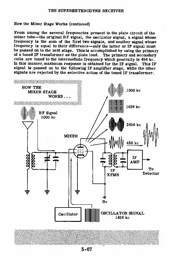
THE SUPERHETERODYNE RECEIVER
How the Mixer Stage Works (continued)
From among the several frequencies present in the plate circuit of themixer tube—the original RF signal, the oscillator signal, a signal whosefrequency is the sum of the first two signals, and another signal whosefrequency is equal to their difference—only the latter or IF signal mustbe passed on to the next stage. This is accomplished by using the primaryof a tuned IF transformer as the plate load. The primary and secondarycoils are tuned to the intermediate frequency which generally is 456 kc.In this manner, maximum response is obtained for the IF signal. This IFsignal is passed on to the following IF amplifier stage, while the othersignals are rejected by the selective action of the tuned IF transformer.
5-67

THE SUPERHETERODYNE RECEIVER
How the Mixer Stage Works (continued)
From the preceding discussion it may be seen that the principal function
of the mixer or first detector stage is to act as a frequency converter. The
input to this stage is a modulated RF signal whose frequency is relatively
high. This signal is converted to a lower frequency modulated IF signal by
means of the heterodyning action taking place in the mixer. The IF signal
now possesses all the intelligence originally contained in the RF signal.
There are a large number of combinations of tubes and circuit components
capable of serving as frequency converters. Among the tubes which maybe employed are triodes, pentodes and pentagrid (five -grid) tubes. The
oscillator may be coupled inductively or capacitively to either the cathode,
control grid, screen grid, or suppressor grid of the mixer. It may even
be coupled to a special grid, called the"injector"grid, which is found in
certain types of mixer tubes. Some pentagrid tubes are designed to com-
bine the functions of oscillator and mixer in one tube. They are then
known as' pentagrid converters!'
PENTODE MIXER ]
RFAMP
OSCILLATOR
f 1
oo? -r
IFAMP
PENTAGRID CONVERTER|
?IFAMP
B+
Oscillator Section
5-68
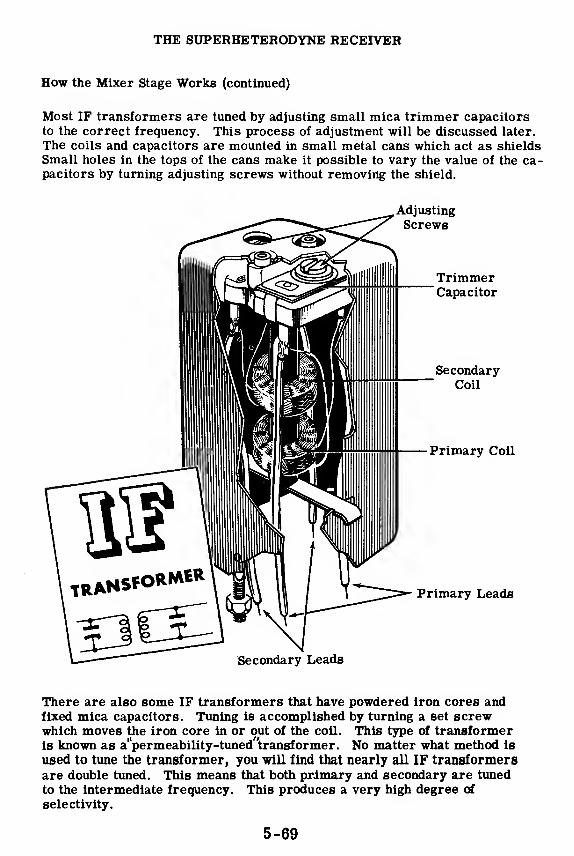
THE SUPERHETERODYNE RECEIVER
How the Mixer Stage Works (continued)
Most IF transformers are tuned by adjusting small mica trimmer capacitors
to the correct frequency. This process of adjustment will be discussed later.
The coils and capacitors are mounted in small metal cans which act as shields
Small holes in the tops of the cans make it possible to vary the value of the ca-pacitors by turning adjusting screws without removing the shield.
Adjusting
Screws
TrimmerCapacitor
SecondaryCoil
Primary Coil
Primary Leads
Secondary Leads
There are also some IF transformers that have powdered iron cores andfixed mica capacitors. Tuning is accomplished by turning a set screwwhich moves the iron core in or out of the coil. This type of transformeris known as a"permeability-tuned"transformer. No matter what method is
used to tune the transformer, you will find that nearly all IF transformersare double tuned. This means that both primary and secondary are tuned
to the intermediate frequency. This produces a very high degree of
selectivity.
5-69

THE SUPERHETERODYNE RECEIVER
How the IF Amplifier Works
The intermediate-frequency amplifier is permanently tuned to the constant
difference in frequency between the incoming RF signal and the local os-
cillator. The tuning of the IF amplifier stage is accomplished by means of
two tuned IF transformers. The one associated with the grid circuit of the
amplifier is called the'input'lF transformer, while the one associated with
the plate circuit is called the"output"IF transformer. The tubes employedin IF amplifiers are generally variable-mu pentodes.
Since this amplifier is designed to operate at only one fixed frequency, the
IF circuits may be adjusted for high selectivity and maximum amplification.
It is in the IF stage that practically all of the selectivity and voltage ampli-fication of the superhet is developed. Simple superhet receivers may contain
only one IF amplifier, while more complex receivers contain as many asthree IF amplifier stages.
The intermediate frequency used most often in superhet receivers is 456
kc, although intermediate frequencies as low as 85 kc and as high as 12, 000kc or higher have been used in special types of superhet receivers. Using a
low intermediate frequency, such as 175 kc, results in high selectivity andvoltage gain, but also increases the possibility of image-frequency inter-
ference. A high intermediate frequency reduces the possibility of imageinterference, but also reduces the selectivity and voltage gain. The choice
of 456 kc as the intermediate frequency for most receivers represents acompromise between these two rather undesirable extremes.
5-70
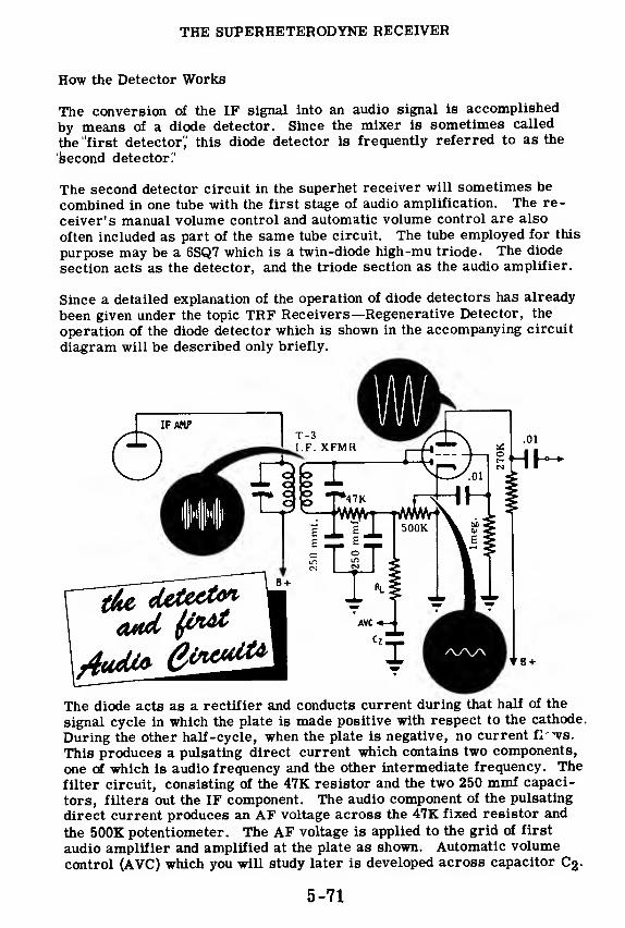
THE SUPERHETERODYNE RECEIVER
How the Detector Works
The conversion of the IF signal into an audio signal is accomplished
by means of a diode detector. Since the mixer is sometimes called
the "first detector',' this diode detector is frequently referred to as the
second detector '.'
The second detector circuit in the superhet receiver will sometimes be
combined in one tube with the first stage of audio amplification. The re-
ceiver's manual volume control and automatic volume control are also
often included as part of the same tube circuit. The tube employed for this
purpose may be a 6SQ7 which is a twin-diode high-mu triode. The diode
section acts as the detector, and the triode section as the audio amplifier.
Since a detailed explanation of the operation of diode detectors has already
been given under the topic TRF Receivers—Regenerative Detector, the
operation of the diode detector which is shown in the accompanying circuit
diagram will be described only briefly.
The diode acts as a rectifier and conducts current during that half of the
signal cycle in which the plate is made positive with respect to the cathode
During the other half-cycle, when the plate is negative, no current il--va.
This produces a pulsating direct current which contains two components,
one of which is audio frequency and the other intermediate frequency. The
filter circuit, consisting of the 47K resistor and the two 250 mmf capaci-
tors, filters out the IF component. The audio component of the pulsating
direct current produces an AF voltage across the 47K fixed resistor and
the 500K potentiometer. The AF voltage is applied to the grid of first
audio amplifier and amplified at the plate as shown. Automatic volume
control (AVC) which you will study later is developed across capacitor C2-
5-71

THE SUPERHETERODYNE RECEIVER
How the Audio Amplifiers Work
The audio signal developed across the 500K potentiometer is taken off the
sliding arm and applied to the grid of the first audio amplifier. The po-tentiometer is connected as a voltage divider and functions as a detector-output type of volume control. The triode acts as an audio amplifier whichincreases the voltage of the AF signal and passes it on to the last stage,
which is known as the'second audio"or'final power amplifier stage. Thepurpose of this stage is to amplify the signal output of the first AF stage un-til it is strong enough to operate a loudspeaker. Power output is the mainconsideration in this stage. The operation of the audio power amplifier
has been discussed previously under TRF Receivers—Audio AmplifierStage. It would be an excellent idea at this time to review the previousmaterial dealing with audio power amplifiers before proceeding further.
How Automatic Volume Control Works
Atmospheric conditions may sometimes cause fading of signals comingfrom certain stations. The resulting output of the receiver may at onemoment be loud enough to blast the listener from his seat, while it mayfade during the next moment to the point of becoming inaudible. Also, asyou tune from one station to another, the signal strength may vary in thesame way. One method of preventing this is to have the operator continu-ally adjust the manual volume control in such a manner as to keep the out-put constant despite variations in signal strength. A better way of solvingthis problem is by the addition of a circuit which will accomplish this taskautomatically—an automatic volume control or AVC circuit.
The function of the AVC circuit is to vary the sensitivity or gain of the re-ceiver in accordance with the strength of the signal. It reduces the sen-sitivity when a strong signal comes in and increases the sensitivity whenthe signal becomes weaker. The result is that the output of the receiverremains fairly constant in strength despite variations in signal strength.
Two signals
of unequali strength
5-72
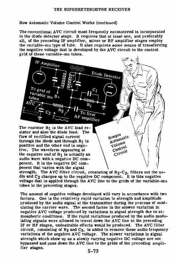
THE SUPERHETERODYNE RECEIVER
How Automatic Volume Control Works (continued)
The conventional AVC circuit most frequently encountered is incorporatedin the diode detector stage. It requires that at least one, and preferably
all, of the preceding IF amplifier, mixer or RF amplifier stages employthe variable-mu type of tube. It also requires some means of transferring
the negative voltage that is developed by the AVC circuit to the control
grid of these variable-mu tubes.
C2 +o -
Oilier
The resistor Ri is the AVC load re-sistor and also the diode load. Theflow of rectified signal currentthrough the diode and through Rj is
positive and the other end is nega-tive. The waveform appearing at
the negative end of R\ is actually anaudio wave with a negative DC com-ponent. It is the negative DC com-ponent that varies with the signalstrength. The AVC filter circuit, consisting of R2-C2, filters out the au-dio and C2 charges up to the negative DC component. It is this negative
voltage that is applied through the AVC line to the grids of the variable-mutubes in the preceding stages.
The amount of negative voltage developed will vary in accordance with twofactors. One is the relatively rapid variation in strength and amplitudeproduced by the audio signal at the transmitter during the process of mod-ulating the carrier wave. The second factor is the slower variation in
negative AVC voltage produced by variations in signal strength due to at-
mospheric conditions. If the rapid variations produced by the audio modu-lating signals were allowed to travel down the AVC line to the precedingIF or RF stages, undesirable effects would be produced. The AVC filter
circuit, consisting of R2 and C2, is added to remove these audio frequencyvariations of the negative AVC voltage. The slower variations in signal
strength which show up as a slowly varying negative DC voltage are not
bypassed and pass down the AVC line to the grids of the preceding ampli-fier stages.
5-73
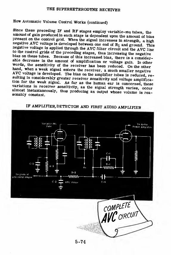
THE SUPERHETERODYNE RECEIVER
How Automatic Volume Control Works (continued)
Since these preceding IF and RF stages employ variable-mu tubes theamount of gain produced in each stage is dependent upon the amount of biaspresent on the control grid. When the signal increases in strength, a highnegative AVC voltage is developed between one end of Bi and ground Thisnegative voltage is applied through the AVC filter circuit and the AVC lineto the control grids of the preceding stages, thus increasing the negativebias on these tubes. Because of this increased bias, there is a consider-able decrease in the amount of amplification or voltage gain In otherwords, the sensitivity of the receiver has been reduced. On the otherhand, when a weak signal enters the receiver, a much smaller negativeAVC voltage is developed. The bias on the amplifier tubes is reduced re-sulting in considerably greater receiver sensitivity and voltage amplifica-tion for the weak signal. As far as the human ear is concerned, thesevariations m receiver sensitivity, as the signal strength varies, occuralmost instantaneously, thus producing an output whose volume is rea-sonably constant.
IF AMPLIFIER, DETECTOR AND FIRST AUDIO AMPLIFIER
5-74
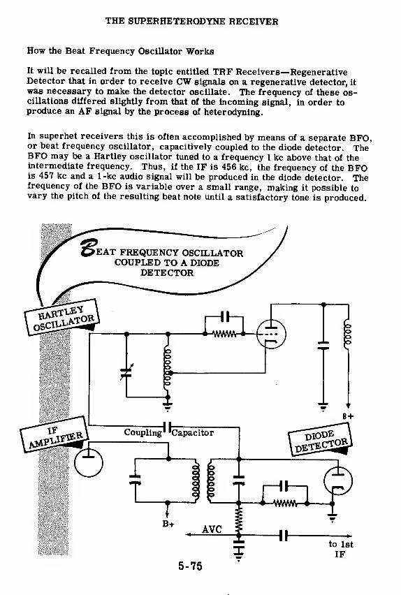
THE SUPERHETERODYNE RECEIVER
How the Beat Frequency Oscillator Works
It will be recalled from the topic entitled TRF Receivers—RegenerativeDetector that in order to receive CW signals on a regenerative detector, it
was necessary to make the detector oscillate. The frequency of these os-cillations differed slightly from that of the incoming signal, in order toproduce an AF signal by the process of heterodyning.
In superhet receivers this is often accomplished by means of a separate BFO,or beat frequency oscillator, capacitively coupled to the diode detector. TheBFO may be a Hartley oscillator tuned to a frequency 1 kc above that of theintermediate frequency. Thus, if the IF is 456 kc, the frequency of the BFOis 457 kc and a 1-kc audio signal will be produced in the diode detector. Thefrequency of the BFO is variable over a small range, making it possible tovary the pitch of the resulting beat note until a satisfactory tone is produced.
5-75
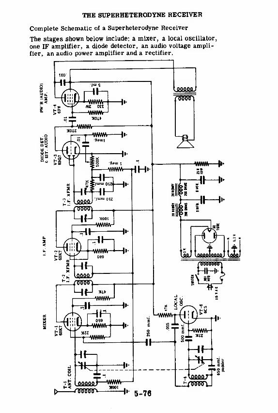
THE SUPERHETERODYNE RECEIVER
Complete Schematic of a Superheterodyne Receiver
The stages shown below include: a mixer, a local oscillator,
one IF amplifier, a diode detector, an audio voltage ampli-
fier, an audio power amplifier and a rectifier.
2a
5S
u .
O «3
5^
BUX
* 5-76
tqooQr(flawy

THE SUPERHETERODYNE RECEIVER
Analysis of the Local Oscillator Stage
THE
650 mmf Padder
Now that you have seen the complete schematic of a superhet, it will beworth your while to spend a little time analyzing the function of the circuit
components used in the oscillator, the mixer, and the detector stages.
The local oscillator circuit is basically that of an Armstrong (tickler coil)
oscillator. Feedback is accomplished inductively using coil T-4. Thevariable tuning capacitor is ganged to the variable tuning capacitor of the
mixer stage. The 650-mmf capacitor is a padder capacitor. It is used
to make adjustments in the process of aligning the oscillator tuned circuit.
It also serves to reduce the total capacity of the oscillator tank circuit so
that the oscillator resonates at a frequency higher than that of the in-
coming signal.
The 500-mmf capacitor is a grid capacitor used to couple the tank circuit
to the grid, while the 22K resistor is the grid-leak resistor. The 47K re-
sistor is a plate load resistor which also blocks RF from going toward the
power supply, and the . 005-mfd capacitor couples the RF output of the
plate circuit back to the tickler coil while effectively blocking the flow of
direct current. Finally, the 250-mmf capacitor is used to couple the out-
put of the oscillator with the suppressor grid of the mixer.
5-77
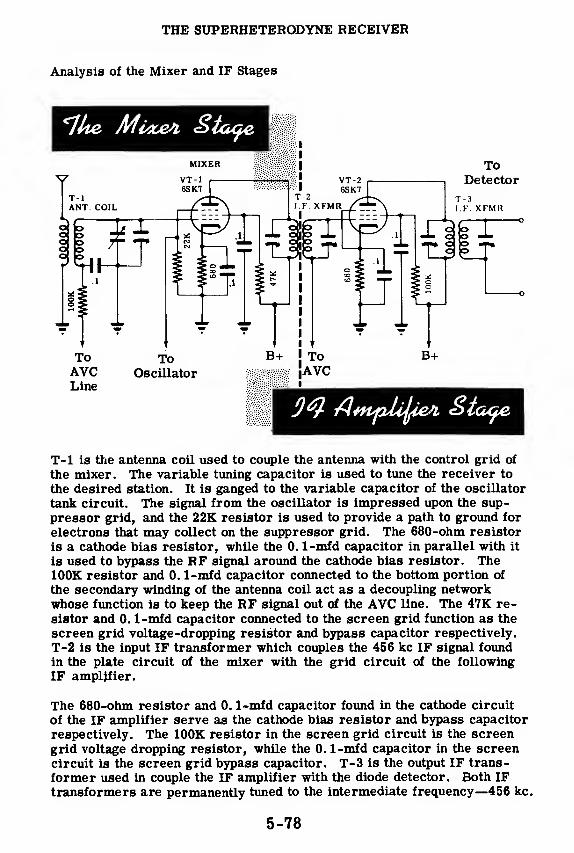
THE SUPERHETERODYNE RECEIVER
Analysis of the Mixer and IF Stages
ToDetector
T-l is the antenna coil used to couple the antenna with the control grid of
the mixer. The variable tuning capacitor is used to tune the receiver to
the desired station. It is ganged to the variable capacitor of the oscillator
tank circuit. The signal from the oscillator is impressed upon the sup-
pressor grid, and the 22K resistor is used to provide a path to ground for
electrons that may collect on the suppressor grid. The 680-ohm resistor
is a cathode bias resistor, while the 0. 1-mfd capacitor in parallel with it
is used to bypass the RF signal around the cathode bias resistor. The100K resistor and 0. 1-mfd capacitor connected to the bottom portion of
the secondary winding of the antenna coil act as a decoupling networkwhose function is to keep the RF signal out of the AVC line. The 47K re-
sistor and 0. 1-mfd capacitor connected to the screen grid function as the
screen grid voltage-dropping resistor and bypass capacitor respectively.
T-2 is the input IF transformer which couples the 456 kc IF signal foundin the plate circuit of the mixer with the grid circuit of the following
IF amplifier.
The 680-ohm resistor and 0. 1-mfd capacitor found in the cathode circuit
of the IF amplifier serve as the cathode bias resistor and bypass capacitor
respectively. The 100K resistor in the screen grid circuit is the screengrid voltage dropping resistor, while the 0. 1-mfd capacitor in the screencircuit is the screen grid bypass capacitor. T-3 is the output IF trans-
former used in couple the IF amplifier with the diode detector. Both IFtransformers are permanently tuned to the intermediate frequency—456 kc.
5-78

THE SUPERHETERODYNE RECEIVER
Analysis of the Diode Detector and First Audio Stages
The two 250-mmf capacitors function as the detector filter capacitors.Their purpose is to bypass the IF component of the signal to ground aroundthe 47K and 500K diode load resistors. The 47K resistor is part of thefilter network, while the 500K potentiometer also acts as a bleeder re-sistor across the filter. It controls the amount of detector output deliv-ered through the . 01-mfd coupling capacitor to the grid of the first audioamplifier and thus serves as a volume control.
The 1-meg. resistor and 0. 1-mfd capacitor in the AVC line filter out therelatively rapid variations in AVC voltage produced by the audio compo-nent of the signal. They allow the slower variations in AVC voltage pro-duced by variations in signal strength to pass unimpeded down the AVC line.
The 1-meg. resistor connected to the control grid serves as a path 10ground for any electrons that may accumulate on the grid. The 270K re-sistor acts as the plate load of the first audio stage, while the . 01-mfdcapacitor in the plate circuit couples the output of the first audio amplifierto the grid of the audio power amplifier.
The circuit of the audio power amplifier does not require further analysis,since the circuit is the same as that of the power amplifier previously dis-cussed under the topic entitled TRF Receivers—Audio Amplifier Stage.
5-79
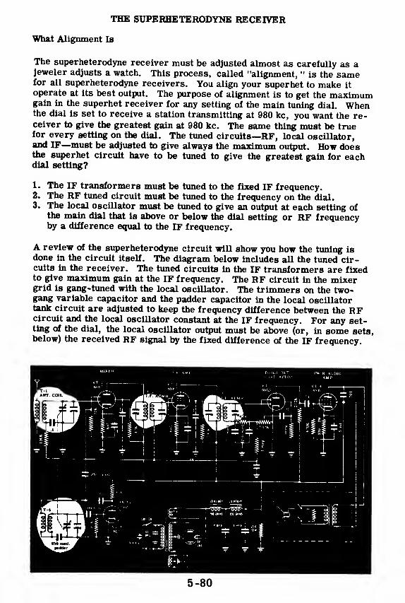
THE SUPERHETERODYNE RECEIVER
What Alignment Is
The superheterodyne receiver must be adjusted almost as carefully as ajeweler adjusts a watch. This process, called "alignment, " is the samefor all superheterodyne receivers. You align your superhet to make it
operate at its best output. The purpose of alignment is to get the maximumgain in the superhet receiver for any setting of the main tuning dial. Whenthe dial is set to receive a station transmitting at 980 kc, you want the re-ceiver to give the greatest gain at 980 kc. The same thing must be truefor every setting on the dial. The tuned circuits—RF, local oscillator,and IF—must be adjusted to give always the maximum output. How doesthe superhet circuit have to be tuned to give the greatest gain for eachdial setting?
1. The IF transformers must be tuned to the fixed IF frequency.2. The RF tuned circuit must be tuned to the frequency on the dial.3. The local oscillator must be tuned to give an output at each setting of
the main dial that is above or below the dial setting or RF frequencyby a difference equal to the IF frequency.
A review of the superheterodyne circuit will show you how the tuning isdone in the circuit itself. The diagram below includes all the tuned cir-cuits in the receiver. The tuned circuits in the IF transformers are fixedto give maximum gain at the IF frequency. The RF circuit in the mixergrid is gang-tuned with the local oscillator. The trimmers on the two-gang variable capacitor and the padder capacitor in the local oscillatortank circuit are adjusted to keep the frequency difference between the RFcircuit and the local oscillator constant at the IF frequency. For any set-ting of the dial, the local oscillator output must be above (or, in some sets,below) the received RF signal by the fixed difference of the IF frequency.
5-80

THE SUPERHETERODYNE RECEIVER
The Alignment Procedure
There are only three
steps to follow to get the
RF and the local oscil-
lator timed circuits ad-
justed in such a way that
at any dial setting, there
will be the best "track-
ing" possible. Perfect
tracking would mean that
as the RF tuning is varied,
the local oscillator tuning
will vary so as to main-
tain a fixed frequency dif-
ference.
PERFECT
TRACKINGDECREES ROTATION OF GANGED CONDENSER
The first step is to adjust the trimmers on the two-ganged variable capac-
itor. Since these trimmers are in parallel with the tuning capacitors,
they affect the total capacitance more at the high frequency end of the band
(when the variable capacitor has minimum capacitance) than at the low
frequency end. For this reason, the trimmers will be adjusted at 1500 kc,
which is close to the high end of the broadcast band.
The local oscillator padder is in series with the tuning capacitor and will
have more effect on the total capacitance when the tuning capacitor has
maximum capacitance. This occurs at the low end of the tuning range
where the plates of the variable capacitor are fully meshed. The padder
will be adjusted at 600 kc, the low end of the band.
There is a problem here. When the 600-kc signal is fed into the input,
even if the RF circuit is not set exactly to 600 kc, it is possible to adjust
the local oscillator's padder for a maximum output; but this is not the best
setting of the padder although the local oscillator frequency is 1056 kc.
The real maximum will occur when the local oscillator is adjusted to 456
kc above 600 kc at the same setting that the RF circuit is tuned to 600 kc.
The correct adjustment is achieved by a process called "rocking in. " In
rocking in, you make adjustments of the padder at several settings of the
tuning dial in the vicinity of 600 kc. The setting at which the maximum
output is greatest is the correct one. The local oscillator padder has been
adjusted so that the local oscillator frequency differs from the resonant
frequency of the RF circuit by 456 kc.
After the padder has been properly adjusted, you will tune back to 1500 kc,
inject a signal of 1500 kc, and readjust the trimmer capacitors at the high
end of band. 5-81

THE SUPERHETERODYNE RECEIVER
What Sensitivity Measurements Are
Sensitivity measurements are used to determine how sensitive a receiveris. A receiver may be operating normally, as far as your ear or even anoscilloscope can detect, but, if the overall gain of the set is low, you maynot be able to receive weak signals. This would only show up by measur-ing the overall gain of your receiver and comparing the results with theoverall gain of a standard receiver.
If a receiver was tested and found to have low sensitivity, the cause wouldthen have to be determined. This would be done by checking the gain ofeach stage and comparing the results with some standard, thereby deter-mining which stage has the low sensitivity. This trouble is almost alwaysdue to a weak tube in the stage which has low sensitivity.
Consider a typical broadcast-band receiver. Broadcast receiversare not designed to be very sensitive since very powerful stations are rel-atively close to the receivers. In these receivers, a loss of sensitivitywould mean you would turn up the volume control and nothing more.Therefore, sensitivity measurements are not necessary. Only when re-ception becomes so poor that it is uncomfortable or impossible to hear astation, would you attempt to repair the receiver.
5-82

THE SUPERHETERODYNE RECEIVER
The Importance of Sensitivity Measurements
In some receivers, sensitivity measurements are very important. In a
radar or sonar receiver, lack of sensitivity would mean that distant tar-
gets which should be detected would not be noticed at all. Decreased gain
in a communication receiver would mean that weak signals could not be
heard. If any of these devices have low sensitivity, you could not discover
this fact by operating them, since you usually have no way of obtaining all
the necessary data. You can't tell that a distant target is present unless
you pick it up; you can't tell that a weak, distant transmitter is calling you
unless you hear the message. Your only check on the performance of the
receiver is through sensitivity checks.
Here is the typical way sensitivity measurements would be made with
receiving equipment. An output meter is used to measure the output of the
last stage of the receiver. The instruction book for the piece of equipment
will tell how many microvolts are required as the input to this receiver
for a standard putput as measured on the output meter. Using a signal
generator which has a calibrated output, you inject a signal of the proper
frequency into the receiver input. You adjust the signal generator output
until you read the standard amount of output on the output meter. By com-paring the input you needed with the instruction book's data, you can tell
if the receiver is working up to par. If the input you used is larger than
that stated in the instruction book, your receiver has too low a sensitivity.
You would then take stage-by-stage sensitivity measurements to determinethe weak stage.
Starting with the last stage of the receiver, you inject a signal of properfrequency and adjust the signal generator output until the standard receiver
output is obtained. If the input you used compares well with the instruction
book data, the last stage of the receiver is working properly. You repeat
this procedure for each stage, working backwards from the last stage.
The stage that requires a larger input than that specified in the instruction
book is the stage with low gain.
5-83

THE SUPERHETERODYNE RECEIVER
Demonstration—Aligning the IF Section
The first part of the receiver to be aligned is the IF section. The instruc -
tor removes the oscillator tube to prevent any signal other than that of thesignal generator from entering the IF strip. He also shorts the AVC sig-nal to ground since the AVC circuit, if operative, would tend to broadenthe receiver response and thus make it more difficult to align the receiversharply. The 'scope or output meter leads are connected across the speakerand the signal generator test leads are ready to be applied to the varioustest points in the IF section.
With the receiver gain at maximum, a modulated 456 kc signal is injectedinto point 1, the grid of the IF amplifier. Using an alignment tool, theinstructor adjusts the trimmers on the IF output transformer for a maximumoutput on the 'scope screen. As the 'scope signal increases with the adjust-ment, the RF control knobs are lowered.
Next the RF signal is injected into point 2, the grid of the mixer stage,and the trimmers of the IF input transformer are adjusted for a maximumindication on the 'scope.
The trimmers on both the IF transformers are again touched up slightly toobtain optimum alignment of the IF section.
5-84
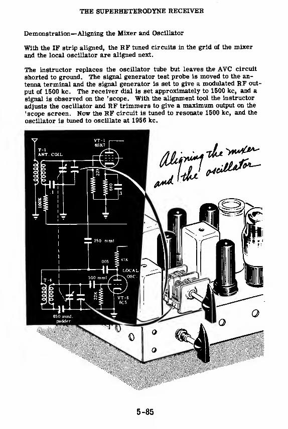
THE SUPERHETERODYNE RECEIVER
Demonstration—Aligning the Mixer and Oscillator
With the IF strip aligned, the RF tuned circuits in the grid of the mixer
and the local oscillator are aligned next.
The instructor replaces the oscillator tube but leaves the AVC circuit
shorted to ground. The signal generator test probe is moved to the an-
tenna terminal and the signal generator is set to give a modulated RF out-
put of 1500 kc. The receiver dial is set approximately to 1500 kc, and a
signal is observed on the 'scope. With the alignment tool the instructor
adjusts the oscillator and RF trimmers to give a maximum output on the
'scope screen. Now the RF circuit is tuned to resonate 1500 kc, and the
oscillator is tuned to oscillate at 1956 kc.
5-85
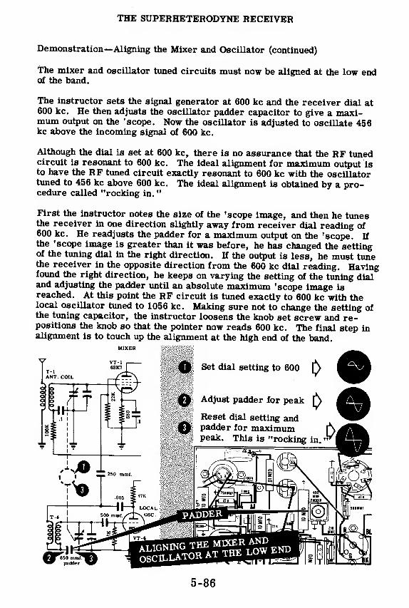
THE SUPERHETERODYNE RECEIVER
Demonstration—Aligning the Mixer and Oscillator (continued)
The mixer and oscillator tuned circuits must now be aligned at the low endof the band.
The instructor sets the signal generator at 600 kc and the receiver dial at600 kc. He then adjusts the oscillator padder capacitor to give a maxi-mum output on the 'scope. Now the oscillator is adjusted to oscillate 456kc above the incoming signal of 600 kc.
Although the dial is set at 600 kc, there is no assurance that the RF tunedcircuit is resonant to 600 kc. The ideal alignment for maximum output isto have the RF tuned circuit exactly resonant to 600 kc with the oscillatortuned to 456 kc above 600 kc. The ideal alignment is obtained by a pro-cedure called "rocking in.
"
First the instructor notes the size of the 'scope image, and then he tunesthe receiver in one direction slightly away from receiver dial reading of600 kc. He readjusts the padder for a maximum output on the 'scope. Ifthe 'scope image is greater than it was before, he has changed the settingof the tuning dial in the right direction. If the output is less, he must tunethe receiver in the opposite direction from the 600 kc dial reading. Havingfound the right direction, he keeps on varying the setting of the tuning dialand adjusting the padder until an absolute maximum 'scope image isreached. At this point the RF circuit is tuned exactly to 600 kc with thelocal oscillator tuned to 1056 kc. Making sure not to change the setting ofthe tuning capacitor, the instructor loosens the knob set screw and re-positions the knob so that the pointer now reads 600 kc. The final step inalignment is to touch up the alignment at the high end of the band.
MIXER
5-86
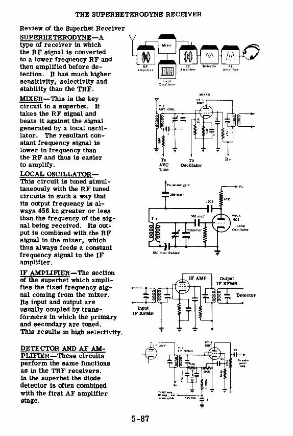
THE SUPERHETERODYNE RECEIVER
Review of the Superhet Receiver
SUPERHETERODYNE—
A
type of receiver in whichthe RF signal is convertedto a lower frequency RF andthen amplified before de-tection. It has much highersensitivity, selectivity andstability than the TRF.
MIXER—This is the keycircuit in a superhet. It
takes the RF signal andbeats it against the signal
generated by a local oscil-
lator. The resultant con-stant frequency signal is
lower in frequency thanthe RF and thus is easierto amplify.
LOCAL OSCILLATOR—This circuit is tuned simul-taneously with the RF tunedcircuits in such a way that
its output frequency is al-
ways 456 kc greater or less
than the frequency of the sig-
nal being received. Its out-
put is combined with the RFsignal in the mixer, whichthus always feeds a constantfrequency signal to the IFamplifier.
IF AMPLIFIER—The section
of the superhet which ampli-fies the fixed frequency sig-
nal coming from the mixer.Its input and output areusually coupled by trans-formers in which the primaryand secondary are tuned.
This results in high selectivity.
DETECTOR AND AF AM-PLIFIER—These circuits
perform the same functions
as in the TRF receivers.
In the superhet the diode
detector Is often combinedwith the first AF amplifier
stage.
650 mmf Padder
Detector
5-87

THE SUPERHETERODYNE RECEIVER
IF Amplifier
AVC
RF Tank
Review of the Superhet Receiver (continued)
AUTOMATIC VOLUME CON-
TROL (AVC)—This circuit"compensates for variationsin signal strength. A dioderectifies the negative half of
the signal and feeds the DCoutput to the RF and IF am-plifier grids. When the sig-nal increases the diode outputincreases, thus putting morenegative bias on the RF andIF amplifiers and loweringtheir gain.
TRACKING—When the differ-
ence between the local oscil-
lator frequency and the RFsignal frequency is constant
over the entire tuning rangeof the superhet, it is said to
have perfect tracking. Thisis never achieved in practice.
BEAT FREQUENCY OSCIL-LATOR (BFO)—This isan~oscillator used when it is de-sired to receive CW signalswith the superhet. Its output
is tuned close to the frequencyof the IF and is fed into the
detector. It beats with the in-
coming signal, producing abeat note in the audio range.
With a BFO, a CW signal is
heard as a pure tone. Withouta BFO, CW signals are heardas a soft hiss or not at all.
Diode Detector
To grid of t
variable mu B+
tubes .
.
mm * \\—rf YWYYW—
«
L-r c2 + LTo first
AF amplifier
/ Oscillator Tank
r > Tuning' Capacitor
g Padder
Trimmer
TRACKING : 456 kc differenceover entire tuning range
BFO I
J*!?^ *
IMAGE FREQUENCIES—If the
IF is 456 kc.then two signals(one 456 kc above and the other456 kc below the oscillator fre-quency) will both send a signalthrough the IF amplifier and to
the loudspeaker. One of themis the desired signal; the otheris an image. The purpose of atuned antenna coil and tuned RFamplifiers is to eliminate theimage frequency.
5-88

TROUBLESHOOTING THE SUPERHETERODYNE RECEIVER
Review of the Troubleshooting Method
If you have to fix a defective piece of equipment, here is one way that youmight go about finding the trouble source. If there is a complaint tag at-
tached to a piece of equipment, get as much information as you can fromit, so that you don't waste time looking for troubles that aren't there. In
the event that there is no complaint tag, follow the procedure described in
the following paragraphs.
Inspect the Equipment
This is a very important step—many defects can be found by using yourfive senses. Once you have heard a transformer sizzle and smelled the
smoke, you will be able to spot a burned-out power transformer without
even turning the chassis over. Visual inspection does not take long—in
about two minutes you should be able to see the trouble if it is the kind that
can be seen.
You should fully realize the significance of visible defects andyou should know just how they can be recognized. Remember that eventhough you do find and repair a defect, you must prove to yourself that the
equipment is operating properly and that there are no other defects. Usu-ally, there will be only one trouble in a piece of equipment unless the faulty
component has been caused to burn out by some other fault. When you find
a trouble by visual inspection, try to imagine another trouble which could
have caused the one you've located. If you merely proceed to replace the
faulty component and then turn the equipment on, the replacement part mayburn out again. The most obvious example is a fuse which burns out, gets
replaced, and then the second one burns out. You must locate the causeof the trouble before you replace the faulty parts.
5-89
TROUBLESHOOTING THE SUPERHETERODYNE RECEIVER
Troubleshooting by Signal Tracing and Signal Injection
Devices such as radar, sonar and radio receivers are very complex. Ifyou attempted to do troubleshooting on a radar receiver by means of volt-age and resistance checks alone, you would have a long tiresome taskahead of you. There would be hundreds of voltage, current and resistancechecks for you to perform, not to mention tubes and tuned circuits to betested. And then there would always be the possibility that none of yourchecks would show you what was wrong, since static testing will not showup faults like misaligned tuned circuits, certain tube defects or defectiveautomatic control circuits.
Fortunately, the signal injection method is an ideal way to locate quicklyany receiver trouble.
Suppose you review the advantages of troubleshooting by signal tracing.
1. You can test each section of the receiver by putting in a signal andlistening to the signal at the output or by examining the output withan oscilloscope.
2. You can determine immediately the defective section, since the signalat its output is either missing or distorted.
3. Knowing the section with the trouble, you can isolate the trouble to aparticular stage by injecting a signal of the proper frequency and am-plitude into the grid points, starting at the output and working back to-wards the input. The point at which the signal disappears or becomesdistorted is the place to look for trouble.
4. Once the defective stage has been found the defective component can beisolated by using voltage and resistance checks.
Signal tracing and signal injection, therefore, enable you to find the trou-ble quickly and easily by greatly reducing the number of points to be testedBy the use of signal tracing, you can locate the stage which contains thetrouble and sometimes, depending on the nature of the trouble, the faultypart. You also can narrow the trouble down to the particular stage orcomponent with a minimum number of checks of those stages which arefunctioning properly.
5-90

TROUBLESHOOTING THE SUPERHETERODYNE RECEIVER
Troubleshooting by Signal Tracing
The best way to locate the trouble is to trace a signal through the equip-ment, using either signal tracing or signal injection. Signal tracing andsignal injection are basically the same thing. Each has some advantagesover the other for the testing of different types of basic circuits. Thebasic purpose of these signal tracing methods is to locate the exact areaof a trouble. Any break or short in the signal path can be locatedimmediately because the signal will disappear at that point. If the troubleis due to an improper voltage on a tube or is due to a faulty tube, thesignal will not pass (or will be distorted) between the grid and plate
circuit of the tube. If the trouble is of this nature, it can be local-ized immediately to the specific tube, and then the exact trouble can belocated by voltage and resistance checks and by trying a tube known to begood. Let's review the procedure for signal tracing and signal injection.
In the procedure for signal tracing, the normal signal input for a piece ofequipment is connected to the input terminals. The 'scope is then used totrace the signal from the input towards the output. The point at which thesignal disappears or becomes distorted is the point to look for the trouble.
Signal tracing can be used with practically every type of circuit that youwill come across. In general,it is most useful in equipment where there is
an audio signal. It may be used also in equipment where there is an RFsignal of voltage amplitude high enough to be seen on the 'scope. Signalscannot be traced easily in receivers because of the low voltage RF signalspresent in a major part of the circuit.
5-91

TROUBLESHOOTING THE SUPERHETERODYNE RECEIVER
Troubleshooting by Signal Injection
In the procedure for signal injection, the 'scope is permanently connectedto the output of a piece of equipment. The signal generator is used to in-
ject a signal of the proper amplitude and frequency into the various test
points, starting at the output and working towards the input. Signal injec-
tion has the disadvantage of seeming to be a "backwards" procedure; ac-tually it is basically the same as signal tracing.
Signal injection is used mainly with receivers and other similar equipmentwhere there are high frequency amplifiers with a very low input voltage.
The 'scope amplifier cannot amplify signals of radio frequency and the
signal amplitude is much too low to be seen if it were connected directly
to the 'scope vertical deflection plates. Signal injection solves this prob-lem by using a signal generator to inject signals into various parts of the
equipment. The amplifiers in the equipment under test will give a largeenough gain so that the signal can be seen on the 'scope screen. The first
stage to check is the last stage of the piece of equipment. If this last stage
is operating normally, the next to the last stage is checked by feeding asignal into that stage and checking the output at the same point as before.
It is because the 'scope is always observing the output of the equipment in
signal injection that the last stage in the equipment is the first one to bechecked. Just as in signal tracing, the point where the signal becomesdistorted or disappears is the point to look for the trouble. For example,if the last stage is checked O. K. but when the signal is placed on the input
to the next to the last stage, the output is not normal, the trouble is in the
next to the last stage.
5-92

TROUBLESHOOTING THE SUPERHETERODYNE RECEIVER
Troubleshooting the Superheterodyne Circuits
RFAmplifier
IFAmplifier
Detector AFAmplifier
LocalOscillator
Heater Voltage B+ Voltage
PowerSupply
Here is an outline of how to troubleshoot the various sections of a super-net receiver.
1. The Power Supply
The power supply furnishes B+ and heater voltage to the various compo-nents of the receiver. In troubleshooting a power supply, the AC signalfrom the line cord is traced through the transformer, the rectifier tube,the filter circuit and up to the power supply bleeder resistor. The finalB+ voltage should be quite free of hum, even with the 'scope Y GAIN con-trol turned all the way up.
2. The Audio Amplifier
In troubleshooting the audio amplifier in a receiver, use the signal injec-tion method because you will have to use that method for the rest of thereceiver. The 'scope should be connected across the loudspeaker at theoutput transformer secondary. An audio signal should be injected into thevarious test points from the 'speaker towards the detector. The point atwhich the signal disappears or becomes distorted is the point to look for thetrouble with your voltmeter and ohmmeter.
Use the 400-cycle audio output of the signal generator. Remember to usea . 01-mfd blocking capacitor at the end of the probe to keep B+ out of thesignal generator.
5-93

TROUBLESHOOTING THE SUPERHETERODYNE RECEIVER
Troubleshooting the Superheterodyne Circuits (continued)
3. The Detector
The operation of the diode detector has been described in this section andthe operation of two other basic types of detectors will be found in the TRFsection. The detector takes a modulated RF (or IF) signal and separatesthe audio from the RF component. The high frequency component is by-passed to ground and the audio signal is connected to the audio amplifier.
In troubleshooting a detector, a modulated RF (or IF) signal is injected into
the detector input. If an audio signal corresponding to the modulation doesnot appear on the 'scope screen, there is trouble in the detector. Don't
forget to use a 200-mmf isolating capacitor at the end of the test probe.
4. The IF Amplifier
The IF amplifier is an RF amplifier operating at a fixed frequency of
456 kc. The operation of the IF amplifier is similar to that of the RF am-plifier described in the amplifier section—the only difference being that
the IF amplifier operates at a fixed frequency and, because of this, may bedesigned for a much higher gain. By injecting a modulated 456-kc signal,
you can first test the output transformer, then the tube and finally the in-
put transformer. In all cases an audio signal should appear on the 'scope.
This method will localize the trouble in any one of these three circuits
—
the rest is a job for the voltmeter and ohmmeter.
5. The Mixer and the Oscillator
The mixer stage selects the desired modulated RF signal from the antenna
and mixes it with the unmodulated signal from the local oscillator. Thelocal oscillator and the mixer tuning circuit have mechanically-gangedtuning capacitors which keep the frequencies of the selected signal and the
oscillator 456 kc apart. As a result of the mixer tube action, a modulated456-kc signal is fed into the IF amplifier no matter what the frequency of
the incoming RF signal. Information on the operation of oscillator circuits
will be found in the oscillator section.
The mixer is tested by first injecting a modulated 456-kc signal into the
grid. If this signal passes through the mixer and appears as an audio sig-
nal at the final output, the mixer stage is operating. Then an RF signal is
injected into the antenna input and tuned in by means of the antenna tuning
circuit—an audio signal should appear on the 'scope. If no signal appears,
there is trouble in the antenna tuning circuit or the oscillator circuit.
5-94

TROUBLESHOOTING THE SUPERHETERODYNE RECEIVER
Vacuum Tube Testing
Contrary to the belief commonly held by the general public, the first stepin troubleshooting is not the testing of tubes. It is necessary to isolatethe defective stage and to check that stage to reveal the defective compo-nent. However, since many receiver defects are due to faulty tubes, itis important that you become familiar with the operation of tube test-ing equipment.
Since burned-out filaments cause the majority of tube failures, it is usu-ally possible to discover such defective tubes by removing them from thereceiver and testing with an ohmmeter. A noisy tube, called a "micro-phonic tube, " may be discovered by turning the receiver power on andthen tapping each tube gently. H a blast of noise or a squeal is produced,the tube in question should be replaced.
In general, however, the most satisfactory method of determining whethersome of the tube elements are shorted, and whether the tube's emission ortransconductance characteristics are normal for its type, is to use a welldesigned tube tester. However, it should be noted that the tube tester can-not always be looked upon as a final authority for determining whether ornot a particular tube will operate satisfactorily in a given receiver. Thisis due to the fact that this tube might be operating in the receiver on aportion of its characteristic curve which is not covered in the tube tester,or it might be operating in the set with voltages much higher or lower thanthose used in the tube tester. All deviations from normal readings shouldmake a tube liable to suspicion. An excessively high reading may indicatea defective tube as readily as one that is too low.
The check for filament continuity and for shorted tube elements is gener-ally performed as the first part of the testing procedure. If the filamentis found to be open,it is useless to attempt further testing of that tube. If
shorted elements are discovered,it is not advisable to test further, as theshorted elements may blow fuses or damage instruments in later tests.Filament continuity and shorted elements are usually indicated by thelighting of a small neon or pilot lamp on the instrument panel.
If the tube passes the short and filament continuity test, it is next testedfor merit or quality. The greatest difference between various types oftube testers is in the selection of a suitable characteristic for the qualitytest. Testers are divided on this basis into two great classes, the emis-sion type and the transconductance type.
5-95

TROUBLESHOOTING THE SUPERHETERODYNE RECEIVER
Vacuum Tube Testing (continued)
The emission-type tester determines the merit of the tube by measuring
the amount of cathode current flowing when the filament is operated at its
rated voltage and a positive voltage is applied to the plate. Since it is de-
sired to measure only cathode emission in this test, the control grid,
screen grid and suppressor grid are connected to the plate. Therefore,
all tubes, whether they are diodes, triodes, tetrodes or pentodes, are
tested as diodes. It is the simplest and cheapest method of testing the
quality of a tube, but it is also the least satisfactory method.
Tube quality
indicated byamount of
CATHODE CURRENT
\
The mutual conductance or transconductance type of tester simulates the
normal operation of the tube by applying a known signal to the grid and
measuring the strength of the amplified signal in the plate circuit by meansof an output meter. Since this procedure is performed under conditions
which resemble the actual operating conditions of the tube in a receiver,
the results obtained by using a transconductance-type tester give a better
indication of a tube's serviceability than the results obtained from an
emission-type tester.
5-96

RECEIVERS
Review of Receivers
ANTENNA FUNCTION—The purpose of
a receiving antenna is to pick up electro-magnetic waves radiated by transmittingantennas. These waves, in cutting theantenna, induce voltages in it, causing acurrent to flow. The current flows into
the input of the receiver, where it gen-erates a signal which is amplified by thereceiver circuits.
Electromagnetic Waves
lllll III win mil
>))Jv
TRANSMITTER
DIRECTIONAL CHARACTERISTICS—The position of a receiving antenna, rel-ative to the transmitting antenna, will de-termine the strength of signal that it picksup. If a loop receiving antenna is broad-side to a loop transmitting antenna, thesignal picked up will be of maximum am-plitude. If the loop is turned so that its
edge faces the broad side of the trans-mitting antenna, a very weak signal willbe picked up. Therefore, the antenna is
said to have directional characteristics.
RF AMPLIFIER STAGE—An RF ampli-fier stage in a receiver improves the sen-sitivity and selectivity of the receiver.The added sensitivity is due to the ampli-fication of the desired signal, and the
added selectivity results from the use of
tuned circuits which discriminate be-tween the desired and undesired signals.
AUDIO AMPLIFIER STAGE—An audioamplifier stage in a receiver amplifiesthe detected audio signal. Audio stages,which precede the last stage, are voltageamplifiers whose sole function is to in-crease the amplitude of the audio to thelevel where it is large enough to drive thelast stage. The last stage, called the
'power stage" supplies the large currentvariations necessary to drive the speaker.
5-97

RECEIVERS
Review of Receivers (continued)
DETECTORS—The function of a detec-
tor in a receiver is to remove the audio
component from a modulated RF signal
so that it can be amplified by AF stages.
A simple detector consists of a tuned
circuit, a rectifier, and a filter. Such
a detector is called a'cliode detector?
GRID-LEAK DETECTOR—This type is
basically a diode detector with amplifi-
cation added. The grid and cathode
form the diode detector with the grid
acting as the plate. The rectified sig-
nal, developed across the grid-leak re-
sistor, is amplified in the plate circuit.
This detector is more sensitive than the
diode type.
REGENERATIVE DETECTOR-Thismodified grid-leak type is still moresensitive. A feedback loop in the plate
is coupled to the grid coil to provide
regeneration, thus effectively increas-
ing the gain of the stage.
3 .t
* - B+ -
6SQ7
PLATE DETECTOR
—
This detector em-ploys a triode or pentode, biased near
cut-off. Rectification takes place in the
plate circuit since the negative half of
the modulated RF grid signal drives the
tube into cut-off.
foT i; 01 MFD
1 HH
TRF RECEIVER
—
This receiver em-ploys RF amplifiers, a detector and AFamplifiers. The tuned circuits are
ganged-capacitor tuned. A shortcomingof the TRF is that since the tuned cir-
cuits are not fixed-tuned, constant sen-
sitivity and selectivity cannot be real-
ized over a tunable band.
Detector
TRF RECEIVERAll tank circuits gang tuned
5-98
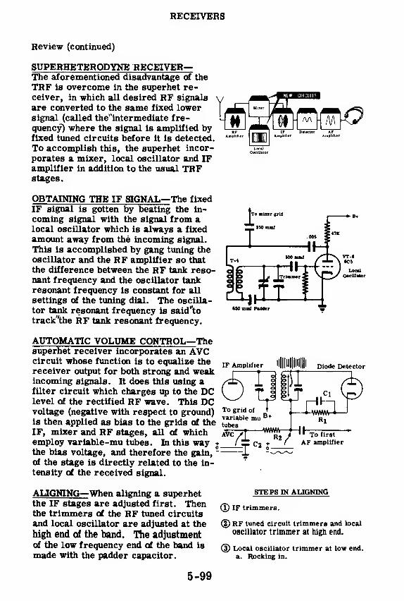
RECEIVERS
Review (continued)
SUPERHETERODYNE RECEIVER—The aforementioned disadvantage of the
TRF is overcome in the superhet re-ceiver, in which all desired RF signals
are converted to the same fixed lowersignal (called the"intermediate fre-quency) where the signal is amplified byfixed tuned circuits before it is detected.
To accomplish this, the superhet incor-
porates a mixer, local oscillator and IFamplifier in addition to the usual TRFstages.
OBTAINING THE IF SIGNAL—The fixed
IF signal is gotten by beating the in-
coming signal with the signal from alocal oscillator which is always a fixed
amount away from the incoming signal.
This is accomplished by gang tuning the
oscillator and the RF amplifier so that
the difference between the RF tank reso-nant frequency and the oscillator tankresonant frequency is constant for all
settings of the tuning dial. The oscilla-
tor tank resonant frequency is said"to
track"the RF tank resonant frequency.
AUTOMATIC VOLUME CONTROL—Thesuperhet receiver incorporates an AVCcircuit whose function is to equalize thereceiver output for both strong and weakincoming signals. It does this using afilter circuit which charges up to the DClevel of the rectified RF wave. This DCvoltage (negative with respect to ground)is then applied as bias to the grids of theIF, mixer and RF stages, all of whichemploy variable-mu tubes. In this way +
the bias voltage, and therefore the gain,~
of the stage is directly related to the in-tensity of the received signal.
ALIGNING—When aligning a superhetthe IF stages are adjusted first. Thenthe trimmers of the RF tuned circuits
and local oscillator are adjusted at the
high end of the band. The adjustmentof the low frequency end of the band is
made with the padder capacitor.
880 mmf Padder
Diode Detector
To grid of »
variable mu B*tubes
Rl
L_T C2 + '_
To first
AF amplifier
STEPS IN ALIGNING
(1) IF trimmers.
(2) RF tuned circuit trimmers and local
oscillator trimmer at high end.
(3) Local oscillator trimmer at low end.
a. Rocking in.
5-99

CONCLUSION TO BASIC ELECTRONICS
What You Have Learned
You have just completed the course in Basic Electronics. Looking back
on the weeks you have spent studying these materials, what should you
be able to do with the information you have now? If you can recognize
the three basic electronic circuits—the rectifier, amplifier and oscill-
ator—in a schematic diagram, if you understand how each componentfunctions within these circuits, and what part the entire circuit plays in
a piece of equipment, then you "know your stuff".
5-100
INDEX TO VOL. 5
(Note: A cumulative index covering all five volumes in this series
will be found immediately following this index to Volume 5.)
AF amplifier, tone control circuits, 5-34
volume control, 5-35
AF amplifier circuits, analysis of, 5-36
AF and RF amplifiers, comparison of, 5-37
Alignment, what it is, 5-80
Alignment procedure, 5-81
Antennas, directivity as a consideration in
selecting and installing, 5-22
frequency response as a
consideration in selecting and
installing, 5-22
noise as a consideration in selecting
and installing, 5-19, 5-20
receiver, 5-1 6 to 5-23
receiver, function of, 5-16
receiver, types of, 5-1 7, 5-1
8
signal losses as a consideration in
selecting and installing, 5-21
Audio, first stage, analysis of, 5-79
Audio amplifiers, how they work in the
superheterodyne receiver, 5-72
Audio power amplifiers, what they do,
5-33
Band switching, in TRF receivers, 5-28
Capacitors, ganged, 5-29
trimmer, 5-30
Coils, 5-30
Communication, history of, 5-1 to 5-4
modern wireless, 5-5
Crystal receivers, 5-1
1
Demonstration, Aligning the IF Section,
5-84
Aligning the Mixer and Oscillator,
5-85, 5-86
Detector, analysis of the plate detector
circuit, 5-56
analysis of regenerative type circuit,
5-52
characteristics of the crystal type,
5-41
crystal type, 5-39
diode type, 5-42
grid-leak type, 5-43, 5-44
how the crystal type works, 5-40
how the plate type works,
5-54, 5-55
how the regenerative type works,
5-46 to 5-48
how they work in the
superheterodyne receiver, 5-71
oscillating, 5-51
regenerative, 5-45
regenerative type as CW receiver,
5-49, 5-50
what they do, 5-38
Detector stage, diode type, analysis of,
5-79
Fidelity, in the receiver, 5-10
IF amplifier, how it works in the
superheterodyne receiver, 5-70
IF stage, analysis of, 5-78
Mixer stage, analysis of, 5-78
how it works in the
superheterodyne receiver,
5-66 to 5-69
Oscillators, beat frequency,
how they work, 5-75
local, in superheterodyne receivers,
5-63 to 5-65
local stage, analysis of, 5-77
Receivers, introduction to, 5-1 to 5-15
recently developed uses of,
5-14, 5-15
the jobs they perform, 5-6, 5-7
Review, Receivers, 5-97 to 5-99
Receiver Antennas, 5-23
5-101

INDEX TO VOL. 5
The Superheterodyne Receiver,
5-87, 5-88
TRF Receivers— Regenerative
Detector, 5-53
RF amplifier, analysis of, 5-32
RF amplifier stage, in superheterodyne
receivers, 5-61, 5-62
in TRF receivers, 5-25
RF and AF amplifiers, comparison of, 5-37
RF transformers, 5-26, 5-27
Selectivity, in the receiver, 5-9
Sensitivity, in the receiver, 5-8
Sensitivity measurements,
importance of, 5-83
what they are, 5-82
Superheterodyne receivers, 5-13, 5-57
to 5-96
at high frequencies, 5-58
complete schematic of, 5-76
how they work, 5-59
introduction to, 5-57
selectivity of, 5-60
troubleshooting, 5-89 to 5-96
TRF receivers, 5-12, 5-24 to 5-56
audio amplifier stage, 5-33 to 5-37
plate detector, 5-54 to 5-56
regenerative detector, 5-38 to 5-53
RF amplifier stage, 5-24 to 5-32
Troubleshooting, by signal injection,
5-90, 5-92
by signal tracing, 5-90, 5-91
superheterodyne circuits, 5-93, 5-94
Troubleshooting method, review of, 5-89
Vacuum tube testing, 5-95, 5-96
Volume control automatic, how it worksin the superheterodyne receiver,
5-72 to 5-74
grid bias manual type, 5-31
5-102
CUMULATIVE INDEX
(Note: The first number in each entry identifies the volume in which
the information is to be found; the second number identifies the page.)
AC-DC half-wave rectifier, in power supplies,
1-94, 1-95
AF amplifier, tone control circuits, 5-34
volume control, 5-35
AF amplifier circuit, analysis of, 5-36
AF and RF amplifiers, comparison of, 5-37
Alignment, what it is, 5-80
Alignment procedure, 5-81
Amplification examples of, 2-1 to 2-3
Amplifiers, 2-1 to 2-10
amplification in, 3-15
characteristics of audio power type,
2-71 to 2-73
characteristics of transformer-coupled type,
2-69, 2-70
characteristics of the two-stage type, 2-60, 2-61
classes of, 2-30, 2-31
diagram of push-pull type, 2-84
how the push-pull type works, 2-78 to 2-80
how they work, 2-17 to 2-19
push-pull type, 2-78 to 2-86
review of classes of operation, 4-8
single-stage, 2-55 to 2-57
transformer coupled, 2-67 to 2-70
triode type, 2-24 to 2-41
two-stage RC coupled type, 2-58 to 2-66
typical stage, 2-55
Amplitude modulation, 4-85 to 4-99
percentage modulation, 4-97, 4-98
time base modulation pattern, 4-92
trapezoid figure, 4-93 to 4-96
what it is, 4-85
Antennas, 4-63 to 4-79
basic, 4-66
directivity as a consideration in selecting andinstalling, 5-22
fading, 4-73
frequency response as a consideration in
selecting and installing, 5-22
ground wave, 4-72
how they work, 4-64, 4-65
impedance, 4-68
noise as a consideration in selecting andinstalling, 5-19, 5-20
purpose of, 4-63
radiation pattern, 4-70radiation resistance, 4-67receiver, 5-16 to 5-23
receiver, function of, 5-16
receiver, types of, 5-1 7, 5-1
8
signal losses as a consideration in selecting
and installing, 5-21
sky wave, 4-72
space wave, 4-73
tuning, 4-69
wave propagation, 4-71
Armstrong oscillators, 3-55 to 3-61
advantages of grid leak bias in, 3-60advantages of push-pull type, 2-85frequency instability in, 3-61
grid leak bias in, 3-56
how oscillations are maintained in, 3-57, 3-58
Audio, first stage, analysis of, 5-79
Audio amplifiers, how they work in the
superheterodyne receiver, 5-72
Audio power amplifiers, what they do, 5-33
Band pass, 3-37
Band switching, in TRF receivers, 5-28
Beam power tube, 2-50, 2-51
construction of a typical tube, 2-51
Bias, B+ power supply, 2-34
battery, 2-32
cathode, 2-35
grid voltage, 2-24 to 2-26
power supply, 2-33
Bridge rectifier circuits, 1-49, 1-50
Capacitors, ganged, 5-29
how they are connected to the RF amplifier
tube, 3-30
trimmer, 5-30
tuning, 3-25
Cathode bypass capacitor, 2-38 to 2-40
Cathode resistor, 2-36, 2-37
Class C amplifiers, 4-8 to 4-15
combination bias, 4-14
fixed bias, 4-11
self-bias, 4-12,4-13
tuned, 4-9, 4-10
Coils, 5-30
how they are connected to the RF amplifier
tube, 3-30
tuning, 3-26
Colpitts oscillators, 3-64
Communication, history of, 5-1 to 5-4
modern wireless, 5-5
Compensating networks, high-frequencycompensation, 3-5
low-frequency compensation, 3-6
Coupling, amplifier stages, 2-59
transformer, 2-67, 2-68
Coupling circuits, 4-40
tuned, 4-41
Crystals, as resonators, 3-69
Crystal oscillators, 3-68 to 3-73
analysis of, 3-72
introduction to, 3-68
tuning in, 3-71
Crystal oscillator circuits, 3-70Crystal receivers, 5-1
1
Current flow, in full-wave rectifier circuits, 1-48
in half-wave rectifier circuits, 1-43
CW transmission, 4-80 to 4-84advantage of, 4-80
blocked-grid keying, 4-83cathode keying, 4-81, 4-82
keyer tube circuits, 4-84
Decoupling filters, 2-56, 2-57Degeneration, 3-7 to 3-9
Demonstration, Aligning the IF Section, 5-84
5-103

CUMULATIVE INDEX
Aligning the Mixer and Oscillator, 5-85, 5-86Current Distribution Along an Antenna, 4-75Radiation Pattern of an Antenna, 4-76 to 4-78Transmission Lines, 4-57 to 4-61
Detectors, analysis of the plate detector circuit, 5-56analysis of the regenerative type circuit, 5-52characteristics of the crystal type, 5-41crystal type, 5-39
diode type, 5-42
grid-leak type, 5-43, 5-44how the crystal type works, 5-40how the plate type works, 5-54, 5-55how the regenerative type works, 5-46 to 5-48how they work in the superheterodyne
receiver, 5-71
oscillating, 5-51
regenerative, 5-45
regenerative type as CW receiver, 5-49, 5-50what they do, 5-38
Detector stage, diode type, analysis of, 5-79Diodes, characteristics of, 1-109 to 1-112
current flow in, 1-28, 1-29gas-filled, 1-35
how current is controlled in, 1-112how they work, 1 -25
in transformer type circuits, 1-40, 1-41vacuum-filled in power supplies, 1-36
Dynamotors, 1-104
Earphones, 2-93
Electron-coupled oscillators, 3-74 to 3-77analysis of, 3-77introduction to, 3-74
Electron-coupled oscillator circuits, 3-75, 3-76Electronics, meaning of, 1-1
Electronic equipment, 1-2
parts used in, 1 -3
Fidelity, in the receiver, 5-10Filters, improving operation of, 1-64, 1-65
power supplies, 1-12Filter capacitors (condensers), 1-60 to 1-63
electrolytic, 1-61 to 1-63electrolytic dry, 1-63
electrolytic wet, 1-62paper, construction of, 1-60paper, high-voltage, 1-60
Filter chokes, 1-69
Filter circuits, 1-52 to 1-80capacitors in, 1-57 to 1-59capacitor input, filter circuit, single-section
1-70, 1-72
choke input, filter circuit, single-section1-70, 1-71
in power supplies, 1-53parallel resonant, 1-73RC, faults of, 1-66, 1-67series-resonant, 1-73two-section, 1-73
using choke instead of resistor, 1-68Frequency, 4-43
5-
Frequency doubling, 4-36Frequency measurement, using standing waves,
4-53Frequency multiplication, purpose of, 4-34Frequency multipliers, 4-34 to 4-38
final power amplifier, 4-35tuning indications, 4-38
Frequency response, 2-62 to 2-64curve, 2-65
improving, 3-7 to 3-9Frequency spectrum, 4-74Frequency tripling, 4-37
Gain, increase of, 2-58
Hartley oscillators, 3-62, 3-63how oscillations are maintained, 3-63
High frequency oscillators, 3-82tuned lines in, 3-83
IF amplifier, how it works in thesuperheterodyne receiver, 5-70
IF stage, analysis of, 5-78Impedance matching, 2-76, 2-77Input filter capacitor, 1-74Inverters, 1-105
Klystron tubes, 3-85
LC circuits, parallel, 3-21, 3-22series, 3-20
loudspeakers, dynamic type, 2-94
Microphones, 2-88 to 2-92carbon, 2-89
characteristics of, 2-88crystal, 2-90
dynamic type, 2-91
ribbon or velocity type, 2-92Mixer stage, analysis of, 5-78
how it works in the superheterodyne receiver5-66 to 5-69
Modulation, grid, 4-90how it is accomplished, 4-87other methods of, 4-91plate, 4-89
Modulators, 4-88Motor generators, 1-104
Oscillations, frequency of, 3-59what they are, 3-45 to 3-47
Oscillators, 3-41 to 3-89beat frequency, how they work, 5-75different grounding points in, 3-80electronic, 3-48 to 3-52feedback circuits in, 3-53frequency stability of, 3-54introduction to, 3-43 to 3-54local, in superheterodyne receivers
5-63 to 5-65local stage, analysis of, 5-77other circuits, 3-81

CUMULATIVE INDEX
RF ground potential, 3-79
series feed, 3-78
shunt feed, 3-78
what they do, 3-44
why they are studied, 3-43
Output transformers, 2-74 to 2-77
job of, 2-74, 2-75
Pentodes, 2-47 to 2-49, 2-52, 2-53
construction of a typical tube, 2-49
how they work, 2-48
remote cut-off, 3-32, 3-33
summary of operation of, 2-52, 2-53
why they are used in RF amplifiers, 3-28, 3-29
Phase inverters, 2-81 to 2-83
another type of, 2-83
how they work, 2-82
Power line filter capacitor circuits, 1-43
Power supplies, circuits in, 1-52
dry metal rectifier, 1-97
for DC voltage sources, 1-99
general types, 1-93
importance of, 1-7
need for other types, 1-92
transformer type, 1-39
transformerless, 1-94 to 1-98
transformerless and chokeless, 1-98
voltage doubler, 1-96
what they do, 1-8
why there are different types, 1-14 to 1-16
Receivers, introduction to, 5-1 to 5-15
recently developed uses of, 5-14, 5-15
the jobs they perform, 5-6, 5-7
Rectifiers, changing AC to DC in half-wavedry metal type, 1-17
copper oxide, 1-18
circuits in dry metal half-wave type, 1-21
description of half-wave dry metal type,
1-18 to 1-20
dry metal half-wave, 1-17 to 1-22
full-wave, 1-45 to 1-51
full-wave, how they work, 1-46
gas-filled diodes, 1-35 to 1-37
parallel connection of elements in drymetal type, 1-19
power supplies, 1-10, 1-11
selenium, 1-18, 1-20
series stacking of elements in dry metal type,1-19
transformer type, half-wave, 1-39 to 1-44
vacuum tubes, 1-23
vacuum tube half-wave type, 1-23 to 1-38Rectifier circuits, half-wave vacuum tube, 1-33Rectifier output, AC and DC components in,
1-55, 1-56
characteristics of, 1 -54
filtering half- and full-wave, 1-74
Rectifier tubes, 1-30, 1-31
cathode type, 1-31
diodes, 1-30, 1-31
directly heated, 1-32
full-wave, 1-47
indirectly heated, 1-32
plates connected together, 1-32
plates connected separately, 1-32
Resistors, bleeder, 1-75 to 1-77
Resonators, cavity type at ultra-high frequencies,3-84
Resonant circuits, how stations are selected, 3-23
Review, A Single-Stage RF Amplifier, 3-34A Three-Stage Transmitter, 4-33
Amplitude Modulation, 4-99
Antennas, 4-79
Audio Amplifiers, 2-96 to 2-98
Class C Amplifiers, 4-15
Diode Characteristics, 1-111
Filter Circuits, 1-78 to 1-80
Full-Wave Rectifier Circuit, 1-51
Half-Wave Rectifiers— Dry Metal Type, 1-22Half-Wave Rectifiers— Transformer Type, 1-44Half-Wave Rectifiers— Vocuum Tube Type,
1-38
Microphones, Earphones and Loudspeakers,2-95
Miscellaneous Oscillators, 3-86, 3-87Oscillators, 3-88, 3-89
Other Types of Power Supply Circuits,
1-106 to 1-108
Power Supplies, 1-113 to 1-115Receivers, 5-97 to 5-99
Receiver Antennas, 5-23The Armstrong and Hartley Oscillators, 3-65The Push-Pull Amplifier, 2-86The Superheterodyne Receiver, 5-87, 5-88The Tetrode and the Pentode, 2-54The Triode, 2-23
The Triode Amplifier, 2-41
The Tuned-Plate Tuned-Grid and Crystal
Oscillators, 3-73
The Two-Stage RC Coupled Amplifier, 2-66The Two-Stage RF Amplifier, 3-39Transmission Lines, 4-62
Transmitters, 4-100 to 4-102TRF Receivers— Regenerative Detector, 5-53Tuned Circuits, 3-27
Video Amplifiers, 3-10, 3-1
1
Voltage Regulator Circuits, 1-91
RF amplifiers, 3-13 to 3-39
analysis of, 5-32
introduction to, 3-15 to 3-18two-stage, 3-35 to 3-39
single-stage, 3-28 to 3-34what they do, 3-16, 3-17
RF amplifier circuit, development of, 3-31RF amplifier stage, in superheterodyne receivers,
5-61, 5-62
in TRF receivers, 5-25RF and AF amplifiers, comparison of, 5-37RF stages, how they are coupled, 3-38
why more than one is used, 3-35, 3-36RF transformers, in TRF receivers, 5-26, 5-27
5-105

CUMULATIVE INDEX
Rotary converters, 1-105
Selectivity, 3-37
and "Q", 3-24
in the receiver, 5-9
Sensitivity, in the receiver, 5-8
Sensitivity measurements, importance of, 5-83
what they are, 5-82
Sidebands, 4-86
Sound, principles of, 2-87
Square waves, distortion of, 3-3, 3-4
Superheterodyne receivers, 5-13, 5-57 to 5-96
at high frequencies, 5-58
complete schematic of, 5-76
how they work, 5-59
introduction to, 5-57
selectivity of, 5-60
troubleshooting, 5-89 to 5-96
Tetrodes, 2-42 to 2-46
eliminating effects of secondary emission, 2-47
normal operation of, 2-46
screen grid, 2-43
secondary emission, 2-44
static characteristics of, 2-45
why they were developed, 2-42
Three-stage transmitters, 4-16 to 4-33
complete diagram of, 4-21
intermediate power amplifier, 4-18
neutralization, 4-27 to 4-29
neutralizing procedures, 4-30, 4-31
oscillators, 4-17
parasitic oscillations, 4-32
power amplifier, 4-19
purpose of tuning, 4-22
three basic circuits, 4-16
transmitting tube filament circuit, 4-20
tuning methods, 4-23 to 4-26
Transformers, power supplies, 1-9
Transformer type circuit, diagram of, 1-42
operation of, 1-43
Transmission, AM, 4-6
FM, 4-6
keyed, 4-5
voice, 4-6
Transmission lines, 4-39 to 4-62
characteristic impedance of, 4-45
equivalent circuit of, 4-44
input impedance of a line, 4-50
input impedance of an open-circuited line,
4-52
input impedance of a short-circuited line,
4-51
line termination in characteristic impedance,4-46
nonresonant and resonant lines, 4-47
open and shorted, 4-49
standing waves on rope, 4-48
transfering electrical energy, 4-42
types of, 4-56
Transmission line principles, 4-54, 4-55
Transmitters, a simple type, 4-2 to 4-4
overall, 4-39
what they are, 4-1 to 4-7
TRF receivers, 5-1 2, 5-24 to 5-56
audio amplifier stage, 5-33 to 5-37
plate detector, 5-54 to 5-56
regenerative detector, 5-38 to 5-53
RF amplifier stage, 5-24 to 5-32
Triodes, 2-11 to 2-23
control grid in, 2-14, 2-15
construction of typical tube, 2-12
how they work, 2-13
similiarity to the diode, 2-16
Triode amplifiers, why proper bias is necessary,
2-27 to 2-29
Triode tube characteristics, amplification factor,
2-20
plate resistance, 2-21
transconductance, 2-22
Troubleshooting, by signal injection, 5-90, 5-92
by signal tracing, 5-90, 5-91
superheterodyne circuits, 5-93, 5-94
Troubleshooting method, review of, 5-89
Tuned circuits, what they are, 3-19
Tuned-plate tuned-grid oscillators, 3-66, 3-67feedback in, 3-67
introduction to, 3-66
Vacuum tubes, amplification, 2-11
circuit wiring, 1-34
discovery of diode, 1-24
electron emission, 1-26, 1-27
factors common to all, 1-110
how they were developed, 2-8, 2-9
jobs of, 1-109
methods of representation in diagrams, 1-34
sockets, 1-31
types of, 2-6, 2-7
what they can do, 2-4, 2-5
Vacuum tube testing, 5-95, 5-96
Vibrators, 1-100 to 1-103
synchronous, 1-103
Video amplifiers, 3-1 to 3-1
1
introduction to, 3-1, 3-2
Voltage regulators, 1-81, 1-82
Voltage regulation, when load current varies,
1-87, 1-88
when power supply voltage varies, 1-89, 1-90
Voltage regulators, power supply, 1-13
Voltage regulator circuits, 1-81 to 1-91
Voltage regulator tube, 1-83, 1-84
Voltage regulator tube circuit, 1-85, 1-86
Volume control, automatic, how it works in the
superheterodyne receiver, 5-72 to 5-74
grid bias manual type, 5-31
Wavelength, 4-43
5-106

HOW THIS OUTSTANDING COURSE WAS DEVELOPED:
In the Spring of 1951, the Chief of Naval Personnel, seeking a streamlined,
more efficient method of presenting Basic Electricity and Basic Electronics to the
thousands of students in Navy speciality schools, called on the graphiological
engineering firm of Van Valkenburgh, Nooger & Neville, Inc., to prepare such a
course. This organization, specialists in the production of complete "packagedtraining programs," had broad experience serving industrial organizations requir-
ing mass-training techniques.
These were the aims of the proposed project, which came to be known as the
Common-Core program: to make Basic Electricity and Basic Electronics com-pletely understandable to every Navy student, regardless of previous education; to
enable the Navy to turn out trained technicians at a faster rate (cutting the cost
of training as well as the time required) without sacrificing subject matter.
The firm met with electronics experts, educators, officers-in-charge of various Navyschools and, with the Chief of Naval Personnel, created a dynamic new training
course . . completely up-to-date . . . with heavy emphasis on the visual approach.
First established in selected Navy schools in April, 1953, the training coursecomprising Basic Electricity and Basic Electronics was such a tremendoussuccess that it is now the backbone of the Navy's current electricity and electronics
training program!*
The course presents one fundamental topic at a time, taken up in the order of
need, rendered absolutely understandable, and hammered home by the use of clear,
cartoon-type illustrations. These illustrations are the most effective ever presented.
Every page has at least one such illustration—every page covers one complete idea!
An imaginary instructor stands figuratively at the reader's elbow, doing demonstrations that make it easier to understand each subject presented in the course.
Now, for the first time, Basic Electricity and Basic Electronics have been released
Ijy die Navy for civilian use. While the course was originally designed for the
Navy, the concepts are so broad, the presentation so clear—without reference to
specific Navy equipment—that it is ideal for use by schools, industrial training
programs, or home study. There is no finer training material!
"Basic Electronics" consists of five volumes, as follows: Vol. 1—Introductionto Electronics, Diode Vacuum Tubes, Dry Metal Rectifiers, What a Power
Supply Is, Filters, Voltage Regulators. Vol. 2—Introduction to Amplifiers,
The Triode Tube, Tetrodes & Pentodes, Audio Voltage & Power Amplifiers.
Vol. 3—Video Amplifiers, RF Amplifiers, Oscillators. Vol. -/—Transmitters,
Transmission Lines & Antennas, CW Transmission & Amplitude Modula-
tion. Vol. 5—Receiver Antennas, Detectors & Mixers, TRF Receivers,
Superheterodyne Receivers.
*"Basic Electricity," the first portion of this course, is available as a separate
series of volumes.
JOHN F. RIDER PUBLISHER, INC., 116 WEST 14th ST., N. Y. 11, N. Y.