Basic concepts and architectural details of the DELPHI trigger ...
14
Also LAFEX/CBPE/CNPA, Rio de Janeiro IU, BR OCR Output interface more user-friendly. modifications introduced to improve their performance and make the entire software user presenting in detail the first two levels, their various hardware components and the latest The aim of this paper is to give a comprehensive global view of the trigger system architecture, asynchronously with respect to the BCO and are driven by the DELPHI host computers. Cross Over) and rely on hardwired control units, while the last two are performed The trigger system consists of four levels. The first two are synchronous with the BCO (Beam calorimetry and extended particle identification. provide a nearly 47'C coverage for charged-particle tracking, electromagnetic and hadronic experiments of the LEP (Large Electron Positron) collider at CERN. The detector is laid out to DELPHI (Detector with Lepton, Photon and Hadron Identification) is one of the four Abstract INFN Sez. di Bologna, Bologna, I G. Valenti RAL, Chilton, Didcot, GB V. Perrera, S. Quinton IFIC, Centre Mixte CSIC, Uni. de Valencia, Buriassot, E C. Lacasta, J. Valls ® Fysikum, Stockholm Uni., Stockholm, S Qi S—O. Holmgren, E. Johansson \¤; Nuclear Physics Laboratory, Uni. of Oxford, Oxford, GB Oi; F. Harris Ist. di Fisica, Uni. di Udine, Udine, I EE ¤1 R. Carniel, L. Lanceii (3% Dipart. di Fisica, Uni. di Roma II, Tor Vergara, Roma, I V. Canale, G. Mauhiae CERN, Geneva, CH J. Fuster, C. Gaspar, Ph. Gavillet, P. Giacomelli, M. Jonker, D. Treille A. Branco', J. Buytaert, S. Cairami, Ph. Charpentier, M. Donszelmann, F. Formenti, Dipart. di Fisica, Uni. di Genova and INFN, Genova, I M. Bozzo Dep. 0f Physics, Uni. 0f Liverpool, Liverpool, GB P.S.L. B00th, INFN Scz. Roma II, T01· Vcrgara, Roma, I V. Bocci, L. Ccrrito, B. Schulze I nuuunn S x S I Em BASIC CONCEPTS AND AqR¥CTI;I"I;`l`£l`C'I"EIlc?F.AYI,hl2ETAH,S OF THE DELPHI Su YO L 17 Novcmbcr CERN—ECP/94-18 EUROPEAN ORGANIZATION FOR NUCLEAR RESEARCH
-
Upload
khangminh22 -
Category
Documents
-
view
0 -
download
0
Transcript of Basic concepts and architectural details of the DELPHI trigger ...
Also LAFEX/CBPE/CNPA, Rio de Janeiro IU, BR OCR Output
interface more user-friendly.modifications introduced to improve their performance and make the entire software userpresenting in detail the first two levels, their various hardware components and the latestThe aim of this paper is to give a comprehensive global view of the trigger system architecture,asynchronously with respect to the BCO and are driven by the DELPHI host computers.Cross Over) and rely on hardwired control units, while the last two are performedThe trigger system consists of four levels. The first two are synchronous with the BCO (Beamcalorimetry and extended particle identification.provide a nearly 47'C coverage for charged-particle tracking, electromagnetic and hadronicexperiments of the LEP (Large Electron Positron) collider at CERN. The detector is laid out toDELPHI (Detector with Lepton, Photon and Hadron Identification) is one of the four
Abstract
INFN Sez. di Bologna, Bologna, I
G. Valenti
RAL, Chilton, Didcot, GB
V. Perrera, S. Quinton
IFIC, Centre Mixte CSIC, Uni. de Valencia, Buriassot, E
C. Lacasta, J. Valls
®Fysikum, Stockholm Uni., Stockholm, SQiS—O. Holmgren, E. Johansson\¤;
Nuclear Physics Laboratory, Uni. of Oxford, Oxford, GBOi;
F. Harris
Ist. di Fisica, Uni. di Udine, Udine, I EE¤1R. Carniel, L. Lanceii(3%
Dipart. di Fisica, Uni. di Roma II, Tor Vergara, Roma, I
V. Canale, G. Mauhiae
CERN, Geneva, CH
J. Fuster, C. Gaspar, Ph. Gavillet, P. Giacomelli, M. Jonker, D. TreilleA. Branco', J. Buytaert, S. Cairami, Ph. Charpentier, M. Donszelmann, F. Formenti,
Dipart. di Fisica, Uni. di Genova and INFN, Genova, I
M. Bozzo
Dep. 0f Physics, Uni. 0f Liverpool, Liverpool, GB
P.S.L. B00th,
INFN Scz. Roma II, T01· Vcrgara, Roma, I
V. Bocci, L. Ccrrito, B. Schulze
I nuuunn S x S I Em
BASIC CONCEPTS AND AqR¥CTI;I"I;`l`£l`C'I"EIlc?F.AYI,hl2ETAH,S OF THE DELPHI Su YO L
17 Novcmbcr
CERN—ECP/94-18
EUROPEAN ORGANIZATION FOR NUCLEAR RESEARCH

complete the trigger sequence and additionally reduce the rate from 80OHz to about 4 I-lz. OCR Output
there is no degradation of the trigger efficiency. T2 accepts slower subdetector responses that
decision before the next BCO (11.1 1 usec later). Therefore, no successive events are lost and
rate from 90kHZ to about 80OHz and is built with those subdetectors that can resolve the
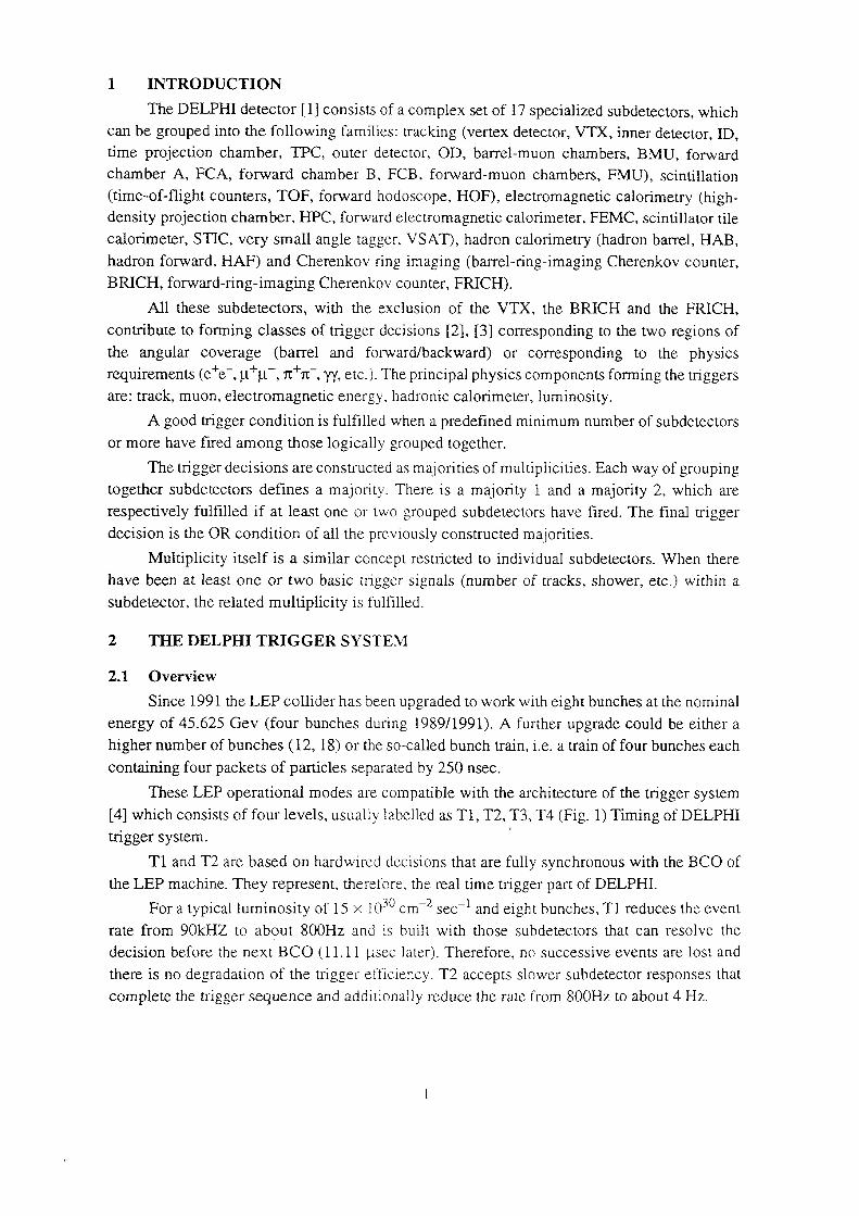
For a typical luminosity of 15 >< 10cmsecand eight bunches, T1 reduces the event30 `2 `1
the LEP machine. They represent, therefore, the real time trigger part of DELPHI.
T1 and T2 are based on hardwired decisions that are fully synchronous with the BCO of
trigger system.
[4] which consists of four levels, usually labelled as T1, T2, T3, T4 (Fig. 1) Timing of DELPHI
These LEP operational modes are compatible with the architecture of the trigger system
containing four packets of particles separated by 250 nsec.
higher number of bunches (12, 18) or the so·called bunch train, i.e. a train of four bunches each
energy of 45.625 Gev (four bunches during 1989/1991). A further upgrade could be either a
Since 1991 the LEP collider has been upgraded to work with eight bunches at the nominal
2.1 Overview
2 THE DELPHI TRIGGER SYSTEM
subdetector, the related multiplicity is fulfilled.
have been at least one or two basic trigger signals (number of tracks, shower, etc.) within a
Multiplicity itself is a similar concept restricted to individual subdetectors. When there
decision is the OR condition of all the previously constructed majorities.
respectively fulfilled if at least one or two grouped subdetectors have fired. The final trigger
together subdetectors defines a ma_jority. There is a majority 1 and a majority 2, which are
The trigger decisions are constructed as majorities of multiplicities. Each way of grouping
or more have fired among those logically grouped together.
A good trigger condition is fulfilled when a predefined minimum number of subdetectors
are: track, muon, electromagnetic energy, hadronic calorimeter, luminosity.
requirements (ee, [Fu, 1t1t`, yy, etc). The principal physics components forming the triggers+"`+
the angular coverage (barrel and forward/backward) or corresponding to the physics
contribute to forming classes of trigger decisions [2], [3] corresponding to the two regions of
All these subdetectors, with the exclusion of the VTX, the BRICH and the FRICI-I,
BRICH, forward—ring—imaging Cherenkov counter, FRICH).
hadron forward, HAP) and Cherenkov ring imaging (barrel—ring-imaging Cherenkov counter,
calorimeter, STIC, very small angle tagger, VSAT), hadron calorimetry (hadron barrel, HAB,
density projection chamber, HPC, forward electromagnetic calorimeter, FEMC, scintillator tile
(time—of—flight counters, TOF, forward hodoscope, HOF), electromagnetic calorimetry (high
chamber A, FCA, forward chamber B, PCB, forward—muon chambers, FMU), scintillation
time projection chamber, TPC, outer detector, OD, barrel-muon chambers, BMU, forwardcan be grouped into the following families: tracking (vertex detector, VTX, inner detector, ID,
OCR OutputThe DELPHI detector [1] consists of a complex set of 17 specialized subdetectors, which
discards those events found to be empty and adds extra flagging information. OCR Output
30 msec, while for T4 it is 200-500 msec. T3 reduces the event rate to about 2 Hz while T4the last phase of data recording. The typical processing time for computing T3 is from 20 toin two steps: during the phase in which the frontend buffers are readout (FEB readout) and in
T3 and T4 [5] are software—driven, asynchronous with respect to the BCC) and take place
are overwritten with the new data.
ignored, the loading of the DIGB or FEB is stopped and with the following BCO these buffersIn the opposite case of a rejected event, i.e. Tl = NO or T2 = NO, the event is simply
2) continue with the next trigger decision phase, T3.
The trigger sequence will then split in two parallel flows: l) wait for the next BCO, and
action.
event pointers are updated to accept the next event — Next Event Identification Done (NEI_D)
from the DIGB into one free buffer of the FEB — Front End Ereeing (EEE) action — and the
When the event is accepted, i.e. Tl : YES and T2 = YES, the data is compacted, copied
Fig. 1 Timing of Delphi trigger system
RATEYTIME
CLEAR STORE2Hz|200-500ms
rvm ) 5 8
IIIIlllllllllIIIIIIIl|IIIIIIIIlIIIlIlIII* IIIIIIIIIIIIII
2H£I20·30rns RST
tvtz ·¤ MEB I if Ei
f' I
IIIIJlIIIIlI II|llIIIIl4·——4IIIIl* —+|lIIIl
~3.5msl mia 5
FEP
4i~i;_I_a9iis IE N (T2_ DIGB | I more I E
Lvi.2
Bcol itiitsi Y DE? I I DEE I Et<00i—i;i_1ps IE N (Tl
LVl.l
°°"“£I—°‘ I ( Bco
§&*é4-are
of the Front End Buffer (FEB) bank.
are digitized and stored in optional DlGitization Buffers (DIGB) or directly into one free buffer
During the Tl and T2 trigger phases the data coming from the detectors (DET, DET,)

data transfer sequence. OCR Output
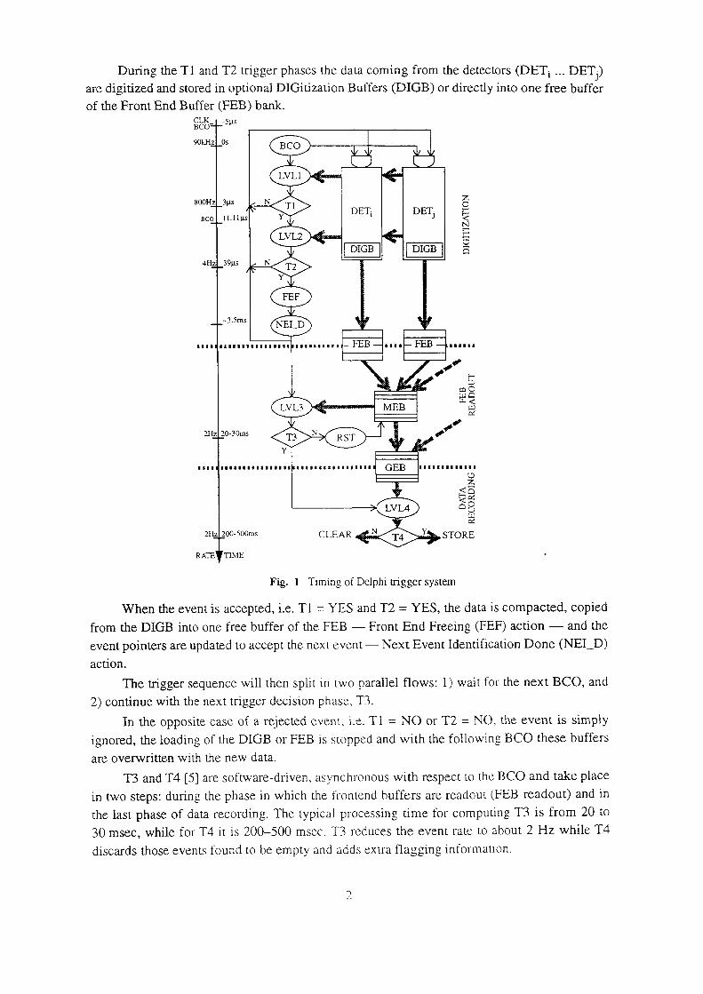
Fig. 2 a) Tl_NO sequence, b) Tl_YESfl`2_NO sequence, c) Tl_YES/T2_YES sequence, cl) DIGB to FEB
rt; RDY
—;‘~-..` ..., ____ ~.5ms Nribour `````'``' "2 ‘````‘FEP
reyes
wr<G-Bc<> F5
t=E_Rpr —3·$···=
rz Yrs
Tl_YE$
wNo_aco [] 3
rr_m>r
in NO"`A""` `"``"'‘ ww
"
r1_Yt2s "@t‘f;`j—~».,___________;_,,L$
wnqaco
rr_tzm
Tl NO \ 8m_"`_`m»~m"
wNc_aco
false as soon as a new trigger sequence is initiated by WNG_BCO.
FE_RDY is true when the whole DELPHI detector is ready to accept a new event and becomes
WNG_BCO is a copy of CLK_BCO gated with a signal called FE_RDY (FrontEnd_ReaDY).
BCO. Another signal called WNG_BCO (WarNinG_BCO) starts the trigger sequence.
lt is a 100 nsec pulse with the same frequency as the BCC) and occurs about 5 usec before the
CLK_BCO (CLocK_BCO) is the signal used to synchronize the whole trigger sequence.
BCO. The present BCO rate (eight bunches) is 90 kl-lz.
The real—time trigger sequence is based on handshaken signals synchronized with the
2.2 Trigger control signals
by a fami of emulators and stored.
During data recording, the selected GEB is read out and its information finally processed
phase).
to perform the FEB readout phase in parallel with the acquisition of a new event (digitization
The presence of the two previously mentioned buffers, DIGB and FEB, makes it possible
opposite case, the data in the MEB is discarded.
buffer of the Global Event Buffer (GEB) bank and the data recording phase occurs. In the
MEB. If the event is accepted, i.e. T3 = YES, the detector’s entire data is copied into one free
Multi Event Buffer (MEB) bank and properly labelled. T3 is performed on the data stored in the
During the FEB readout the data of each subdetector is merged into one free buffer of the
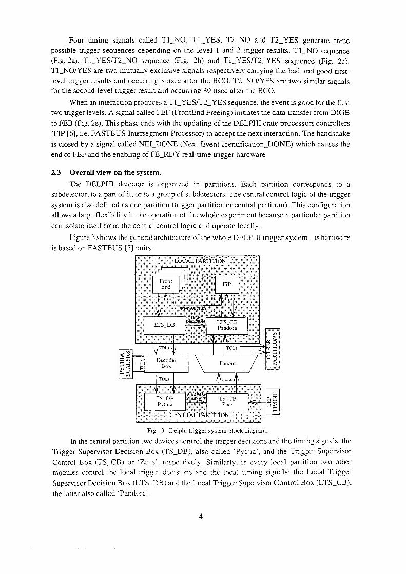
the latter also called ‘Pandora’OCR Output
Supervisor Decision Box (LTS_DB) and the Local Trigger Supervisor Control Box (LTS_CB),
modules control the local trigger decisions and the local timing signals: the Local Trigger
Control Box (TS_CB) or ‘Zeus`. respectively. Similarly, in every local partition two other
Trigger Supervisor Decision Box (TS_DB), also called ‘Pythia’, and the Trigger Supervisor
ln the central partition two devices control the trigger decisions and the timing signals: the
Fig. 3 Delphi trigger system block diagram.
CENT}? AL` PARTI ‘Ii ON
ZeusPythia J.12TS_DB TS_CB g-E
rcrsrnrs
U Q-®
FanoutLg, DiggerQM Qui sir
rcrsmr.;§Q%
pm.trs_cB LTS DB
EndHP
Front
is based on FASTBUS [7] units.
Figure 3 shows the general architecture of the whole DELPHI trigger system. Its hardware
can isolate itself from the central control logic and operate locally.
allows a large flexibility in the operation of the whole experiment because a particular partition
system is also defined as one partition (trigger partition or central partition). This configuration
subdetector, to a part of it, or to a group of subdetectors. The central control logic of the trigger
The DELPHI detector is organized in partitions. Each partition corresponds to a
2.3 Overall view on the system.
end of FEF and the enabling of FE_RDY real-time trigger hardware
is closed by a signal called NEl_DONE (Next Event ldentitication_DONE) which causes the
(FIP [6], i.e. FASTBUS Intersegment Processor) to accept the next interaction. The handshake
to FEB (Fig. 2e). This phase ends with the updating of the DELPHI crate processors controllers
two trigger levels. A signal called FEF (FrontEnd Freeing) initiates the data transfer from DIGB
When an interaction produces a Tl_YES/T2_YES sequence, the event is good for the first
for the second—level trigger result and occurring 39 psec after the BCO.
level trigger results and occurring 3 usec after the BCO. T2_NO/YES are two similar signals
Tl_NO/Y ES are two mutually exclusive signals respectively carrying the bad and good first
(Fig. 2a), Tl_YES/'l`2_NO sequence (Fig. 2b) and Tl_YES/T2_YES sequence (Fig. 2c).
possible nigger sequences depending on the level l and 2 trigger results: 'l`l_NO sequence
Four timing signals called Tl_NO, Tl_YES, T2_NO and T2_YES gcncratc thrcc
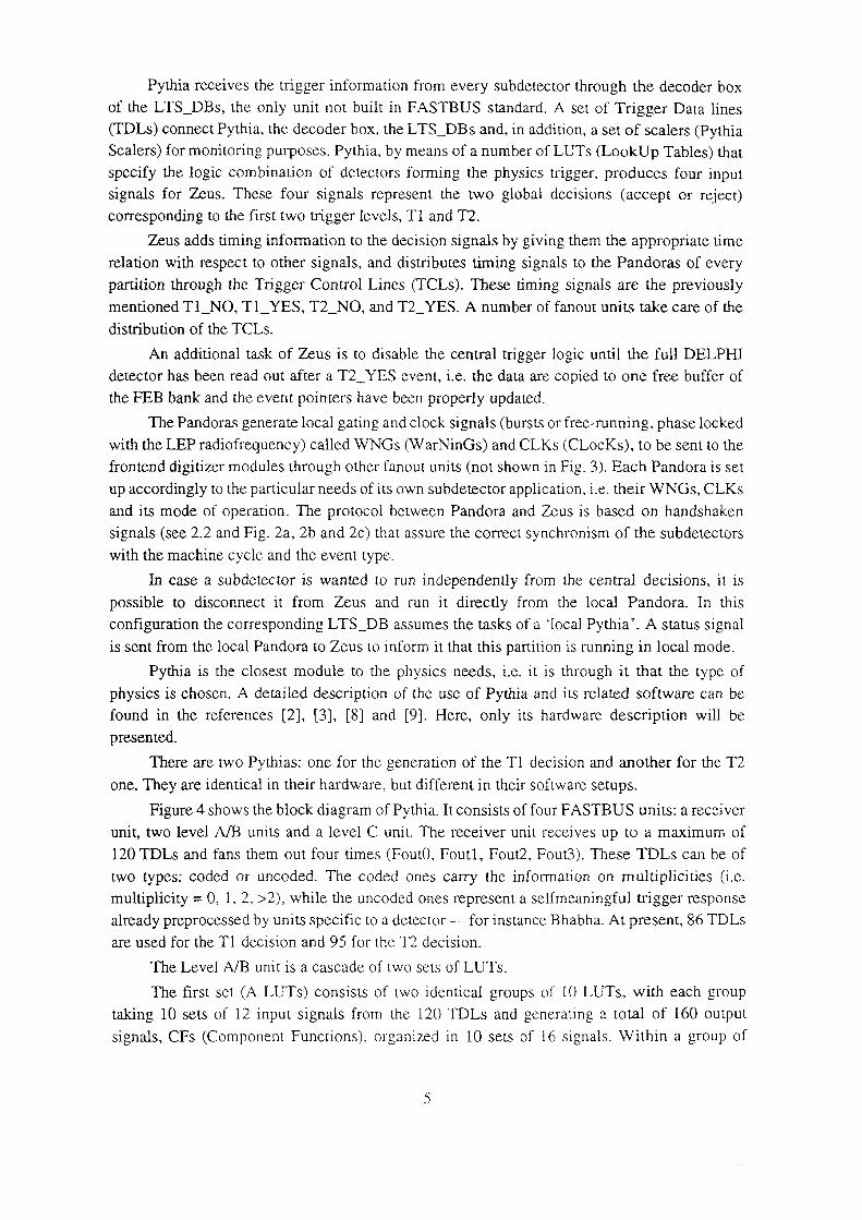
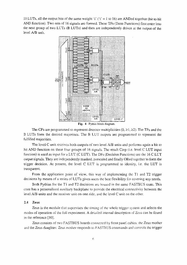
signals, CFs (Component Functions), organized in 10 sets of 16 signals. Within a group of OCR Output
taking 10 sets of 12 input signals from the 120 TDLs and generating a total of 160 output
The first set (A LUTs) consists of two identical groups of 10 LUTs, with each group
The Level A/B unit is a cascade of two sets of LUTs.
are used for the Tl decision and 95 for the T2 decision.
already preprocessed by units specific to a detector — for instance Bhabha. At present, 86 TDLs
multiplicity = 0, 1, 2, >2), while the uncoded ones represent a selfmeaningful trigger response
two types: coded or uncoded. The coded ones carry the information on multiplicities (i.e.
120 TDLs and fans them out four times (Fout0, Foutl, Fout2, Fout3). These TDLs can be of
unit, two level A/B units and a level C unit. The receiver unit receives up to a maximum of
Figure 4 shows the block diagram of Pythia. lt consists of four FASTBUS units: a receiver
one. They are identical in their hardware, but different in their software setups.
There are two Pythias: one for the generation of the T1 decision and another for the T2
presented.
found in the references [2], [3], [8] and [9]. Here, only its hardware description will be
physics is chosen. A detailed description of the use of Pythia and its related software can be
Pythia is the closest module to the physics needs, i.e. it is through it that the type of
is sent from the local Pandora to Zeus to inform it that this partition is running in local mode.
configuration the corresponding LTS_DB assumes the tasks of a ‘local Pythia’. A status signal
possible to disconnect it from Zeus and run it directly from the local Pandora. In this
ln case a subdetector is wanted to run independently from the central decisions, it is
with the machine cycle and the event type.
signals (see 2.2 and Fig. 2a, 2b and 2c) that assure the correct synclironism of the subdetectors
and its mode of operation. The protocol between Pandora and Zeus is based on handshaken
up accordingly to the particular needs of its own subdetector application, i.e. their WNGs, CLKs
frontend digitizer modules through other fanout units (not shown in Fig. 3). Each Pandora is set
with the LEP radiofrequency) called WNGs (W arNinGs) and CLKs (CLocKs), to be sent to the
The Pandoras generate local gating and clock signals (bursts or free—runnin g, phase locked
the FEB bank and the event pointers have been properly updated.
detector has been read out after a T2_YES event, i.e. the data are copied to one free buffer of
An additional task of Zeus is to disable the central trigger logic until the full DELPI-II
distribution of the TCLs.
mentioned Tl_NO, T1_YES, T2_NO, and T2_YES. A number of fanout units take care of the
partition through the Trigger Control Lines (TCLs). These timing signals are the previously
relation with respect to other signals, and distributes timing signals to the Pandoras of every
Zeus adds timing information to the decision signals by giving them the appropriate time
corresponding to the first two trigger levels, Tl and T2.
signals for Zeus. These four signals represent the two global decisions (accept or reject)specify the logic combination of detectors forming the physics trigger, produces four input
Sealers) for monitoring purposes. Pythia, by means of a number of LUTs (LookUp Tables) that
(TDLs) connect Pythia, the decoder box, the LTS_DBs and, in addition, a set of scalers (Pythiaof the LTS_DBs, the only unit not built in FASTBUS standard. A set of Trigger Data lines
Pythia receives the trigger information from every subdetector through the decoder box
and the Zeus daughter. Zeus mother responds to FASTBUS commands and controls the trigger OCR Output
Zeus consists of two FASTBUS boards connected by front panel cables; the Zeus mother
in the reference [10].
modes of operation of the full experiment. A detailed intemal description of Zeus can be found
Zeus is the module that supervises the timing of the whole trigger system and selects the
2.4 Zeus
level A/B units and the receiver unit on one side. and the level C unit on the other.
crate has a personalized auxiliary backplane to provide the electrical connectivity between the
Both Pythias for the Tl and T2 decisions are housed in the same FASTBUS crate. This
decisions by means of a series of LUTs gives users the best flexibility for covering any needs.
From the application point of view, this way of implementing the Tl and T2 trigger
transparent.
trigger decision. At present, the level C LUT is programmed to identity, i.e. the LUT is
output signals. They are independently masked, prescaled and finally ORed together to form the
function) is used as input for a LUT (C LUT). The DFs (Decision Functions) are the 16 C LUT
bit AND function on these four groups of 16 signals. The result Cinp (i.e. level C LUT input
The level C unit receives both outputs of two level A/B units and performs again a bit to
fulfilled majorities.
B LUTs form the desired majorities. The B LUT outputs are programmed to represent the
The CFs are programmed to represent detector multiplicities (O, 21, 22). The TFs and the
Fig. 4 Pythia block diagram.
tziacmviaiz LEVEL C
TIQEVELQ
._._._ _ ._._._i_t._._._._._._._._._._._ mAS
SAME?
{*35
aézi2iii2;é;2zi;2;&;2;¥;é;éz%1 if LEVEL` if¥EEi€ii5Ei§5$5i?§€i5i:§=¤‘ziiieisieiTmaiszmi
>i12é=éi 2120 {afi! L2
¤E;€;E;5;E;E;i·‘ `ri ‘ I ` ‘‘;i ; ‘ *55i;
EE
level A/B unit.
the next group of two LUTs (B LUTs) and then are independently driven at the output of the
AND function). Two sets of 16 signals are fonned. These TFs (Term Functions) first enter into
10 LUTs, all the output bits ofthe same weight ‘i’ (‘i’ = l to 16) are ANDcd together (bit to bit
(response delay > Tl delay time) is wanted for participating in the trigger sequence. OCR Output
decision, while the Tl trigger decision is fixed to YES. This is the case in which a slow detector
Late mode: A special input signal, the LATE trigger line, is used to generate the T2 trigger
which a T2_YES is produced.
a Tl_YES, Zeus opens another gate, again adjustable by a front panel trimmer, at the end of
generates Tl__YES or Tl_NO if a signal is or is not present on the EXT_Tl line. ln the case of
open whose duration can be adjusted by a front panel trimmer. At the end of this gate Zeus
External mode; Zeus uses the EXT_Tl decision line. After a WNG_BCO, a gate signal is
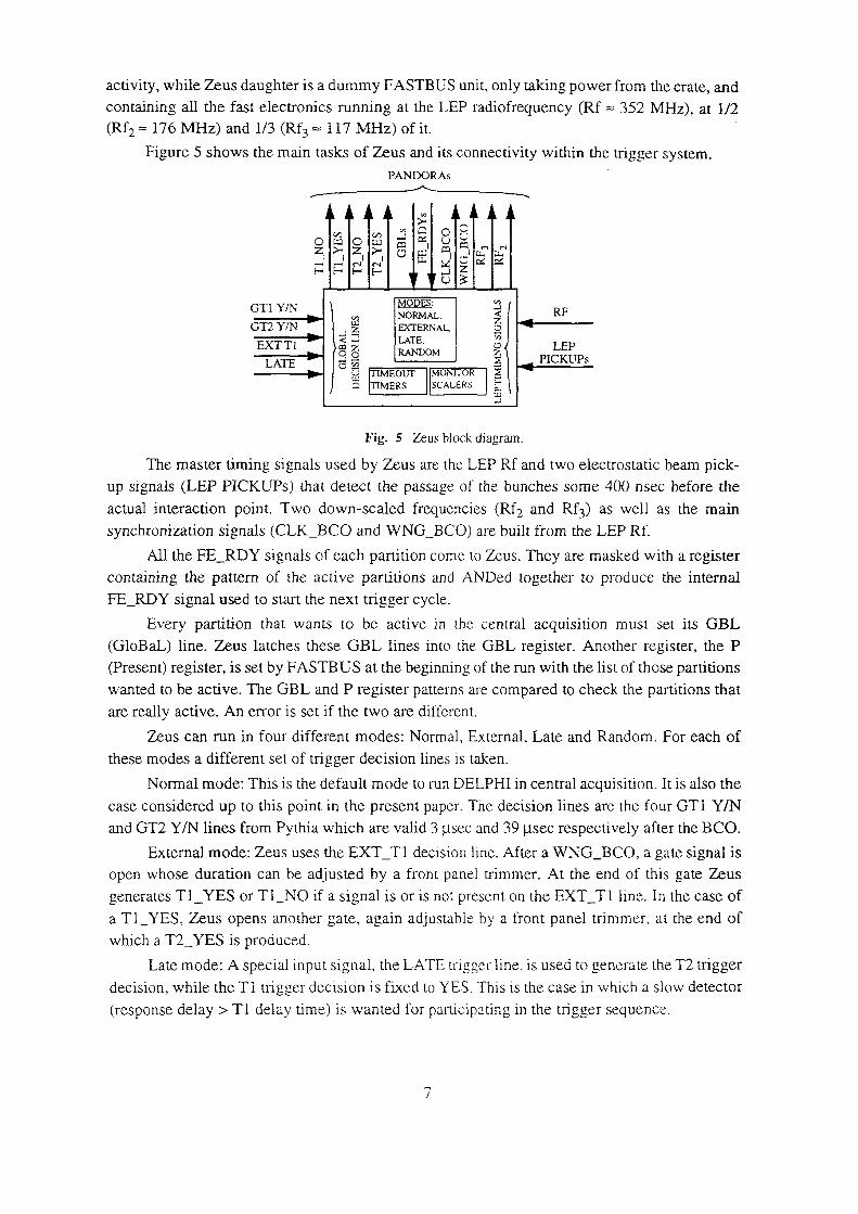
and GT2 Y/N lines from Pythia which are valid 3 usec and 39 iisec respectively after the BCO.
case considered up to this point in the present paper. The decision lines are the four GTl Y/N
Norrnal mode: This is the default mode to run DELPHI in central acquisition. lt is also the
these modes a different set of trigger decision lines is taken.
Zeus can run in four different modes: Normal, External, Late and Random. For each of
are really active. An error is set if the two are different.
wanted to be active. The GBL and P register patterns are compared to check the partitions that
(Present) register, is set by PASTBUS at the beginning of the run with the list of those partitions
(GloBaL) line. Zeus latches these GBL lines into the GBL register. Another register, the P
Every partition that wants to be active in the central acquisition must set its GBL
FE_RDY signal used to start the next trigger cycle.
containing the pattern of the active partitions and ANDed together to produce the internal
All the FE_RDY signals of each partition come to Zeus. They are masked with a register
synchronization signals (CLK_BCO and WNG_BCO) are built from the LEP Rf.
actual interaction point. Two down-scaled frequencies (Rf; and Rf3) as well as the main
up signals (LEP PICKUPs) that detect the passage of the bunches some 400 nsec before the
The master timing signals used by Zeus are the LEP Rf and two electrostatic beam pick
Fig. 5 Zeus block diagram.
MERS SCALERSI2lllHE Lu ..1r’\%LATE --,.l--—--1 gl I Picxups EOUT MONHOR
EXT Tl , RANDOM I l !'§RSE 32LATE
..1::DCTERNAL QGT2 Y/N
GTI Y/N “Q“‘f;t_ §{| RF
GI;E—< E··· E-*
:.:S2 M °‘il il il 5 1 Q ml if rf, E 1O {zi O m ' C ..¤ 2 8 c.:
PANDORAS
Figure 5 shows the main tasks of Zeus and its connectivity within the trigger system.
(Rfz = 176 MHz) and l/3 (Rf3 = 117 MHZ) of it.
containing all the fast electronics running at the LEP radiofrequency (Rf = 352 Ml-lz), at l/2
activity, while Zeus daughter is a dummy FASTBUS unit, 0nly taking power from the crate, and

Fig. 6 Pandora block diagram. OCR Output
ZEU S
wl;:22 ·>¢I<2I¤>·‘zi>-I Elml|r~MQ Lz ml
5$02 ..1 D M
MACHINE DELAYs
STATE WNGs &
CNTRL MACHINE'I`RIG_EN A
EXT_CONF 1 [ §COUPLER CSRs
EXT_START I lg Fairs
LT2 Y/N
CLK_BCO BURSTSLT1 Y/NINT RF; & PLLs &
2 1 La
FE DIGITIZERS Fr1>
by FASTBUS.
next one — i.e. to accept the next WNG_BCO —— a bit in a register (step bit) must be cleared
means of this feature Zeus allows only one trigger sequence to be started at a time; to start the
The debugging ofthe trigger system is made easier by running Zeus step by step. By
compared with the values of similar registers also available in the Pandoras.
incremented by FASTBUS at every T2_YES. The values read from these registers are
Tl_YES, T2_NO, T2_YES, Zeus FE_RDY, COSMIC) and one account number register that is
(CLK_BCO gated with run bit, CLK_BCO ungated with run bit, WNG_BCO, Tl_NO,
the correct synchronism of every partition. There are nine scalers for the most important signals
Zeus also provides some monitoring facilities for checking the system functionality and
FASTBUS action to run again.
error bit is set in case of timeout. The trigger sequence needs to be reset and restarted by
WNG_BCO (i.e. FE_RDY not lowered as consequence of WNG_BCO). The correspondent
Tl_NO, (c) no FE__RDY after T2_NO, (d) no FE_RDY after T2_YES, or (e) FE_RDY after
can be triggered in case of: (a) no answer from Pythia after WNG_BCO, (b) no FE_RDY after
In order to avoid a hang—up in the trigger sequence, five individually set timeout timers
are 3.5 ttsec and 35 psec respectively after the BCO or thereabouts.
memories, the two sequences restart from the beginning of them. The time delays of Tl and T2
every WNG_BCO, while the second one is at every T1_YES. After reaching the end of the
memories loaded by FASTBUS. The address counter of the first memory is incremented at
Random mode: The T1 and T2 trigger decisions come from two one bit!8k deep internal
8.51 ns), a bank of five clock signals of Rf;/5 (= 23.5 MHz) frequency and shifted in phase by OCR Output
running at full Rf3 speed. In order to keep the increment step down to one Rf3 period (i.e.
have been chosen. The maximum clock speed of these devices makes it impossible to have them
are implemented in FPGA (Field Programmable Gate Array) devices. The Xilinx 3090 FPGAs
uses. For the generation of the five WNGs and three delays for the CLKs, 13 loadable counters
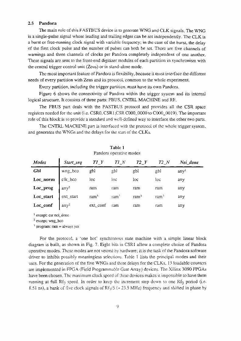
driver to inhibit possibly meaningless selections. Table l lists the principal modes and their
operative modes. These modes are not vetoed by hardware; it is the task of the Pandora software
diagram is built, as shown in Fig. 7. Eight bits in CSRI allow a complete choice of Pandora
For the protocol, a ‘one hot’ synchronous state machine with a simple linear block
program; ram = always yes
except wng_bco
except: csr nei_done
ext_conf ram ram ram anyLoc_conf | anyz
Loc_start | ext_start ram3 ram? ram3 ram} any
ram ram ram ram anyLoc_prog | any2
Loc_norm | clk_bco loc loc loc loc any
Gbl wng_bco gbl gbl gbl gbl anyl
Modes | Start_seq T1_Y T1_N T2_Y T 2__N Nei__d01ze
Pandora operative modes
Table 1
and generates the WNGS and the delays for the start of the CLKs.
The CNTRL MACHINE part is interfaced with the protocol of the whole trigger system,
role of this block is to provide a standard and well—defined way to interface the other two parts.
registers needed for the unit (i.e. CSRO, CSRl ,CSR C00O_0000 to C000_00l9). The important
The FBUS part deals with the FASTBUS protocol and provides all the CSR space
logical structure. It consists of three parts: FBUS, CNTRL MACHINE and RF.
Figure 6 shows the connectivity of Pandora within the trigger system and its internal
Every partition, including the trigger partition, must have its own Pandora.
needs of every partition with Zeus and its protocol, common to the whole experiment.
The most important feature of Pandora is flexibility, because it must interface the different
the central trigger control unit (Zeus) or in stand-alone mode.
These signals are sent to the front-end digitizer modules of each partition in synchronism with
warnings and three channels of clocks per Pandora completely independent of one another.
of the first clock pulse and the number of pulses can both be set. There are five channels of
a burst or free-running clock signal with variable frequency; in the case of the burst, the delayis a single-pulse signal whose leading and trailing edges can be set independently. The CLK is
The main role of this FASTB US device is to generate WNG and CLK signals. The WNG

10 OCR Output
multiplication factor). Therefore, the full range of the PLL functional unit is about 5-150 MHZ.
scaling factor 2" : 1, 2, 4, 8 and the fine range is set by loading the eight—bit N register (PLLor eight. In this way a coarse range is set by choosing the two bits that select the appropriate
from the PLL, three scalers have been added at its output, dividing its frequency by two or four
Since some partitions in DELPHI need frequencies lower than those directly obtainable
performance.
order loop filter to guarantee the 0 phase locking of the PLL and its stability and noise
filter is built with a wideband operation amplifier (GB : 8 MHZ) configured as a type 2, second
range of 40 to 150 MHZ, the phase comparator is a digital i27t radiants phase detector, the loop
All the various pieces of the loop are standard market ICs. The VCM can be tuned to a
Fig. 8 PLL block diagram.
*2 l_i *N IJ t
RFB + I + ‘_; _ Li 145 i-T—i ¤*·L 7 VCM i+h|; 145-2})I RF3 · N P
upgrading of the LEP machine.
value has been chosen in order to maintain the phase synchronism with all the foreseen bunch
(=<>¤810 kHz), is small enough to guarantee a fine stepping in the PLL frequency range and its
The PLLs work as frequency synthesizer (Fig. 8). Its input frequency, Rf3/ 145
be used as explained before in the WNG generation.
frequency. The multiplexer unit also provides the bank of 5 clock signals at Rf3/5 frequency, to
(i.e. extemal) or to generate them internally by means of a high stability crystal tuned at the Rf3
addition a multiplexer unit allows to take the Rf3 and the CLK_BCO signals either from Zeus
devices for the generation of the 3 CLK signals along with their 3 BURST logical units. In
The heart of the RF part consists of three custom—designed PLL (Phase Locked Loop)
Fig. 7 State Machine block diagram.
wArr Nt21_ooNta\;L@E
'’’
§i58~§ NHLDONE'__[&Fé}SETCSRIOQE)CSk1($:4;....1;;..lm r zT? Z
TU;
CSRl{3:Z)-L! r_‘_;‘wAlTT2. >
Ji——Tl_Y
csxziuzrntl Q WAl'I`Tl FE;
wm S'1`AKI`_SEQ
INl'l`&PW_ON
Tests done on the WNG signals show a min/max jitter of less than 100 ps.
obtained by choosing the appropriate clock phase.
runs at Rf3/5, i.e. with a coarse step of 42.6 nsec, while the fine step of one Rfg period can befive steps of 72 degrees has been used to drive the counters. In this way every counter always
ll OCR Output
done in designing and assembling the prototype of the new Pandora unit.
Assembly Workshop teams of the Product Engineering & Support Group for the valuable work
We are grateful to the technical assistance of Mr. Angelos Agoritsas and the Layout and
4 Acknowledgements
the near future at higher energies for the production of w+w· pairs.global efficiency very close to 100%, proving that its design is also well-suited for operation in
The DELPHI trigger system has been fully operational and running since 1990, with
35 units is needed.
tested in the laboratory and are now being installed in the experiment for data taking. A total of
Pandora was the unit required to be re—engineered. Five prototypes have been successfully
trigger levels (real—time trigger) and their associated hardware.
A detailed description of the trigger control signals has been given for only the first two
overview of the system requirements.
brief list of the detectors participating in the trigger decision process, and moving through an
The basic concepts of the DELPHI trigger system have been presented, starting with a
3 CONCLUSIONS
debugging and maintenance of the unit by subcontracting companies.
electrical signal compatibility (TTL/ECL/NIM). This remarkably improves the manufacturing,
all the mother board area. The mother board only provides connectivity and conversions for
The functional blocks are all implemented on various daughter boards that nearly cover
appropriate.
RF part the fast ECLiPS (Emitter Coupled Logic in PicoSeconds) technology was more
technology has largely been used for all the FBUS and CNTRL MACHINE parts, while for the
The Pandora unit has recently been redesigned to meet the above specifications. FPGA
detector, i.e. the only edge for which the 0 phase locking is stable in time under any conditions.
positive edge of the PLL output clock corresponding to the phase comparison in the phase
delay. This is to guarantee that the gate enabling the burst is always opened in phase with the
clock (i.e. the Rf3/ 145 clock signal) compared to the CLK_BCO of the same amount as the CLK
important. For this purpose it has been necessary to delay the trailing edge of the PLL input
delay between CLK_BCO and the first burst pulse) and PLL output frequency is particularly
stopping of the burst. The synchronism for a clean start in any conditions of CLK delay (i.e. theThe Burst unit follows the PLL unit and deals with the correct starting, counting and
400 ps min/max and 80 ps RMS.
Concerning the a.c. performance, tests have shown a jitter on the output clock signal of