Bachelors Of Technology
50
1 A Project Report on Cloud based Expense Tracker Submitted in partial fulfillment of the requirement for the award of the degree of Bachelors Of Technology Under The Supervision of Dr. T Poongodi Professor Submitted By Asthha Wahal 18SCSE1010407 Muskan Aggarwal 18SCSE1180081 SCHOOL OF COMPUTING SCIENCE AND ENGINEERING DEPARTMENT OF COMPUTER SCIENCE AND ENGINEERING GALGOTIAS UNIVERSITY, GREATER NOIDA INDIA
-
Upload
khangminh22 -
Category
Documents
-
view
3 -
download
0
Transcript of Bachelors Of Technology
1
A Project Report
on
Cloud based Expense Tracker
Submitted in partial fulfillment of the
requirement for the award of the degree of
Bachelors Of Technology
Under The Supervision of
Dr. T Poongodi
Professor
Submitted By
Asthha Wahal 18SCSE1010407
Muskan Aggarwal 18SCSE1180081
SCHOOL OF COMPUTING SCIENCE AND ENGINEERING
DEPARTMENT OF COMPUTER SCIENCE AND ENGINEERING
GALGOTIAS UNIVERSITY, GREATER NOIDA
INDIA

2
BONAFIDE CERTIFICATE
Certified that this project report titled Daily Cloud based Expense Tracker is the bonafide work
of Muskan Aggarwal(18SCSE1180081) and AsthhaWahal(18SCSE1010407) who carried out the
research under my supervision. Certified further, that to the best of my knowledge the work
reported herein does not form part of any other project report or dissertation on the basis of which
a degree or award was conferred on an earlier occasion on this or any other candidate.
_____________
Dr. T Poongodi Professor

3
ACKNOWLEDGEMENT
We would like to express our deepest appreciation to all those who provided us the
possibility to complete this report. A special gratitude we give to our professor Dr.
T.Poongodi , whose contribution in stimulating suggestions and encouragement, helped us
to coordinate our project especially in writing this report. Furthermore, we would also like to
acknowledge with much appreciation the crucial role of the staff of Galgotias University,
who gave the permission to use all required equipment and the necessary materials to
complete the task. We are thankful and fortunate enough to get constant support from our
seniors and every teaching staff of B.tech Computer Science and engineering department
which helped us successfully complete our project. We would also like to extend our regards
to all the non-teaching staff of B.tech Computer Science and engineering department for
their timely support. Special thanks go to my team mates, We have to appreciate the
guidance given by other supervisor as well as the panels especially in our project
presentation that has improved our presentation skills thanks to their comment and advices.
Our thanks and appreciations also go to each and every one of our colleagues for their
encouragement and support in developing the project.

4
ABSTRACT
In today’s busy and expensive life we are in a great rush to make money. But at the
end of the month we broke off. As we are unknowingly spending money on little and
unwanted things. So, we have come over with the idea to track our earnings. Cloud
based Expense Tracker aims to help everyone who are planning to know their
expenses and save from it. DET is an android app which users can execute in their
mobile phones and update their daily expenses so that they are well known to their
expenses. Here user can define their own categories for expense type like food,
clothing, rent and bills where they have to enter the money that has been spent and
also can add some information in additional information to specify the expense. User
can also define expense categories. User will be able to see pie chart of expense. Also,
DET app is capable of clustering. Personal and administration clustering is possible
by the use of Apriori algorithm. Although this app is focused on new job holders,
interns and teenagers, everyone who wants to track their expense can use this app.
Keywords: android app, define expense categories, Clustering, Apriori algorithm
5
TABLE OF CONTENTS
BONAFIDE CERTIFICATE .....................................................................................................................III
ACKNOWLEDGEMENT ...................................................................................................................... IV
ABSTRACT ......................................................................................................................................... V
TABLE OF CONTENTS ........................................................................................................................ VI
LIST OF FIGURES ............................................................................................................................. VIII
LIST OF TABLES ................................................................................................................................. IX
LIST OF ABBREVIATIONS .................................................................................................................... X
CHAPTER 1 ......................................................................................................................................... 1
INTRODUCTION .................................................................................................................................. 1
1.1 BACKGROUND .............................................................................................................................................................. 1
1.2 LITERATURE REVIEW .................................................................................................................................................... 1
1.3 PROBLEM DEFINITION.................................................................................................................................................. 2
1.4 OBJECTIVES .................................................................................................................................................................. 3
1.5 SCOPE AND LIMITATIONS ............................................................................................................................................. 3
1.4.1 Scope ...................................................................................................................................... 4
1.4.2 Limitations ............................................................................................................................. 3
1.6 REPORT ORGANIZATION ............................................................................................................................................... 5
CHAPTER 2 ......................................................................................................................................... 6
REQUIREMENT ANALYSIS AND FEASIBILITY ANALYSIS ........................................................................ 7
2.1 DATA COLLECTION METHODS ..................................................................................................................................... 5
2.1.1 Source of Data .................................................................................................................. 5
2.2 REQUIREMENT SPECIFICATION .................................................................................................................................... 5
2.3.1 Functional Requirements ....................................................................................................... 5
2.3.2 Non-Functional requirements ................................................................................................ 7
2.3 FEASIBILITY ANALYSIS .................................................................................................................................................. 7
2.4.1 Technical Feasibility ............................................................................................................... 7
Hardware Specification ................................................................................................................... 7
Software Specification .................................................................................................................... 8
2.4.2 Operational Feasibility ........................................................................................................... 8
2.4.3 Economic Feasibility ............................................................................................................... 8
2.4.4 Scheduling Feasibility ............................................................................................................. 9
2.4 STRUCTURED SYSTEM REQUIREMENTS ..................................................................................................................... 10
2.4.1 Data Modeling (ER Diagram) .......................................................................................... 10
2.5.2 Process Modeling (DFD-0 DFD-1) ....................................................................................... 11
CHAPTER 3 ....................................................................................................................................... 13
SYSTEM DESIGN ............................................................................................................................... 13
3.1 SYSTEM ARCHITECTURE AND OVERVIEW .................................................................................................................. 13
3.2.1 Database Schema ........................................................................................................... 14
3.2.2 Data Dictionary ............................................................................................................... 14
3.2.3 UML class diagram ............................................................................................................... 15
Class Diagram ............................................................................................................................... 15
Sequence diagram ........................................................................................................................ 16

6
Input Output Diagram ................................................................................................................... 19
CHAPTER 4 ....................................................................................................................................... 22
SYSTEM IMPLEMENTATION AND TESTING ....................................................................................... 24
4.1 IMPLEMENTATION OVERVIEW ....................................................................................................................................... 26
4.2 TOOLS USED ................................................................................................................................................................... 27
4.2.1 Front End Tools .................................................................................................................... 28
4.2.2 Back End Tools ..................................................................................................................... 29
4.2.3 Module Description .............................................................................................................. 32
4.3 TESTING ........................................................................................................................................................................... 33
4.3.1 Unit Testing .......................................................................................................................... 35
4.3.2 Integration Testing ............................................................................................................... 37
4.3.3 System Testing ..................................................................................................................... 39
CHAPTER 5 ....................................................................................................................................... 40
CONCLUSION AND RECOMMENDATION ........................................................................................... 42
5.1 CONCLUSION .............................................................................................................................................................. 43
5.2 RECOMMENDATION ................................................................................................................................................... 45
FUTURE SCOPE ....................................................................................................................................................................... 47
BIBLIOGRAPHY ................................................................................................................................. 48
REFRENCES ....................................................................................................................................... 50

7
LIST OF FIGURES
FIGURE 1: USE CASE DIAGRAM ............................................................................................................................................ 17
FIGURE 2: GANTT CHART .............................................................................................................................................................. 20
FIGURE 3: ER DIAGRAM....................................................................................................................................................... 23
FIGURE 4:CONTEXT DIAGRAM ............................................................................................................................................ 26
FIGURE 5: DFD LEVEL 1 .......................................................................................................................... 28
FIGURE 6: DATABASE SCHEMA .......................................................................................................................................... 32
FIGURE 7: CLASS DIAGRAM ................................................................................................................................................. 34
FIGURE 8: SEQUENCE DIAGRAM ........................................................................................................................................ 36
FIGURE 9: ACTIVITY DIAGRAM.......................................................................................................................................... 37
FIGURE 10: INPUT OUTPUT DIAGRAM .............................................................................................................................. 40
FIGURE 11: INTEGRATION TESTING .................................................................................................................................. 44

8
LIST OF TABLES
TABLE 1: COMPARISON OF EXISTING APPLICATIONS ................................................................................................... 2
TABLE 2: USE CASE DESCRIPTION ...................................................................................................................................... 6
TABLE 3: DATA DICTIONARY ............................................................................................................................................. 14
TABLE 4: TEST CASE FOR INSTALLATION ....................................................................................................................... 21
TABLE 5: TEST CASE FOR LOGIN....................................................................................................................................... 21
TABLE 6: TEST CASE FOR DATA ENTRY .......................................................................................................................... 22

9
LIST OF ABBREVIATIONS
DET Daily Expense Tracker
UI User Interface
UML Unified Modelling Language
XHTML Extensible Hypertext Markup Language
YNAB You Need a Budget

10
Acronyms
B.Tech. Bachelor of Technology
JS JavaScript
HTML Hyper Text Markup Language
CSS Cascading Styling Sheet
CS Computer Science

11
CHAPTER 1
INTRODUCTION
1.1 Background
Expense tracker is a refined system which allows user to efficiently manage his/her
expenses with ease. Tracking expenses daily can really help to us save lot of money.
Once we start off by tracking our expenses each day, we will be able to get a better
idea where you are spending your money, so you stay in control and achieve your
goal. It will be able to generate your expense and saving report as time duration you
selected. There will be a reminder that will help to save money for your pre-defined
expenses.
1.2 Literature Review Tracking daily expense is not so innovative. Many traditional and technological
approach is found to track our expenses and budget with their own functionality.
From decades ago and today we have been writing our expenditure in a register to
calculate the profit or saving. Not only this many desktop and mobile applications has
been developed for this purpose. Quicken and Microsoft money were the first desktop
applications was developed decades ago but was not so familiar with the users.
Personal capital and dollar bird application were used to visualize the expenses in
chart or graphs with the calendar system. QuickBooks were the application for the
small business holder to wrap up their whole business. YNAB and Penny were the
latest application which were embedded with AI and applicable for importing
expenses automatically. However, Mint was the one which was widely used and
trusted.
Explaining about the latest application built in this category, YNAB is an expense
tracker that gives the automatic tracking of our expense through our bank account or
credit cards. We can also define expenses that may take place in future so that we do

12
not go out of bound. This application is mobile friendly and is emerging since 2013.
This application is embedded with AI to define and manage our daily expenses.
This application does not give any detail information about out expenses while our
application will get those information via text and image. Moreover, we will be
working on the GPS tracking of the possible places where user is supposed to expense
his/her amount. This feature is also not included by YNAB.
Comparison of existing similar application is shown below:
Software Name YNAB Quicken Microsoft
Money
QuickBooks
Emerging Date 2013 2008 2000 2008
Automatic Yes No No No
Expense
Information
No No No Yes
Pre-define
Expenses
Yes No No No
Mobile Friendly Yes Yes Yes No
1.3 Problem Definition
Every earning people are mostly obsessed at the end of the month as the they cannot
remember where all of their money have gone when they have spent and ultimately
have to sustain in little money minimizing their essential needs. There is no as such
complete solution present easily or we should say free of cost which enables a person
to keep a track of its daily expenditure easily and notify them if they are going to have
money shortage. To do so a person has to keep a log in a diary or in a computer, also
all the calculations needs to be done by the user which may sometimes results in
errors leading to losses. Due to lack of a complete tracking system, there is a constant
overload to rely on the daily entry of the expenditure and total estimation till the end
of the month.

13
1.4 Objectives
The objective of this system are:
a) To keep track of daily expenses and budgeting;
b) To save money for pre-defined expenses which will help planning on your
future investments
1.5 Scope and Limitations
1.5.1 Scope
This application can take a good market as it is usable by anyone who are willing to
manage their expenses and aiming to save for the future investments and many more.
There is not any range criteria or any kind of profession or gender are focused, it will
used hugely.
1.5.2 Limitations
• User have to entry every record manually.
• The category divided may be blunder or messy.
• Person who is handling system must have some technnical knowledge.
1.6 Prerequisite
1.6.1 HARDWARE REQUIREMENTS
• Processor: Pentium 4 (or equivalent)
• 4 GB RAM
• Hard disk space: 20 GB
• A projecting device (for the instructor only)
• A connection to the internet
• Keyboard and mouse or other pointing device
• Processor: Pentium 4 ( or equivalent)

14
1.6.2 SOFTWARE REQUIREMENTS
• Operating System: Windows 10 version 1507
• MYSQL workbench
• Supported Internet browser: Chrome - Latest version, or the penultimate version
• Netbeans or eclipse
• Java 8 or higher versions
• Libraries included
1.7 Report Organization
Chapter 2:
This chapter covers all the history, methods, requirement specification and feasibility
analysis and structured system requirements.
Chapter 3:
Design of DET project is explained in detail with all the necessary diagrams and brief
functionality.
Chapter 4:
Process of implementation and testing is described along with all the tools used for
the development.

15
Chapter 5:
Conclusion and future scope of the application are explained.
Chapter 6 :
The previous reports which helped in our project are listed.

16
CHAPTER 2
REQUIREMENT ANALYSIS AND FEASIBILITY
ANALYSIS
2.1 Data Collection Methods
2.1.1 Source of Data
-User
I. Interview: Interviews were carried out with some of the students in our own college
asking about the expenses that they do in day to day life. While taking those samples
we got that they always broke off at the end of the month, which means they do not
end up calculating those expenses that they spend day to day. So in order to control
the unnecessary spending habits expense tracker is must. While using this tracker they
can control their expenses and also save some of those too.
II. Questionnaire: Set of questionnaire were prepared to gain knowledge about how
people track their budget. This process conclude that maximum of them do not plan
for what they have earned and no track at all.
2.2 Requirement Specification
2.3.1 Functional Requirements
1. Dashboard panel
The system shall authenticate the user and then display panel based on the particular
identified user.
2. Add bill
The system shall allow the user to add bill details based on the user’s need to track the
type of expenses.
3. Expense planner
The system should graphically represent the current month figure based on user’s
current month expenses and user’s own budget share.
4. Expense tracker
The system should graphically represent the yearly expense numbers in form of report
5. Add notes
The system shall allow users to add notes to their expenses.

17
6. Calender
The system shall allow users to add the date to their expenses
7. Category
The system shall allow users to add categories of their expenses
Use Case Diagram
Name Description
Initiating actor User
Login to provide identification details and enter
the system
Authentication To validate the details entered by the user
View expenses Provide the updated log of expenses
Add bill To add new expenses
Add image To add image of the bill (optional)

18
Track report Display the record
Statistical analysis Internal scrutinized evaluation of the data
Add Notes Can add further more information about
the expense
Add Category To add category where the user is
supposed to spend more
Add date To add the date of the expenditure.
2.3.2 Non-Functional requirements
1. Usability
There is a consistency in all the modules and webpages. To ease the navigation there is a
back tab to provide access to previous page. There is proper instruction on each page.
2. Reliability
Each data record is stored on a well-built efficient database schema. There is no risk of
data loss. The internal evaluation of data is well coded.
3. Supportability
The system is well built to support any machine. Maintainability of the system is easy.
4. Performance
In order to ease the accessibility, the types of expenses are categorized along with an
option to name on the own. Throughput of the system is increased due to light weight
database support.
5. Availability
The system is available all the time, no time constraint.
2.3 Feasibility Analysis
2.4.1 Technical Feasibility
This assessment focuses on the technical resources available. It helps to determine
whether the technical team is capable of converting the ideas into working systems. It
also involves evaluation of the hardware, software and other technology requirements
of the proposed system.
Hardware Specification:
• Android mobile phone

19
• 10 MB memory
Software Specification:
• Front End : XHTML
• Back End : Java and SQlite
• Android version 4.0 (Ice cream sandwich).
2.4.2 Operational Feasibility
This assessment has a simple UI. Anyone with the basic knowledge of android mobile
phones an use DET. DET takes few seconds approx. 2 seconds to take you from
home screen to front page. With a click data are entered.
2.4.3 Economic Feasibility
The only cost for building this project is for printing and binding the report files and
system uses cost. Additionally, effort and time of every team member is the cost
involved for this project. Also, the user does not need to pay a single penny to use this
app. Just the use of android mobile. And hence, DET is economically feasible for any
one with the android mobile.

20
2.4.4 Scheduling Feasibility
The diagram explains the schedule of the project where the first prototype is
completed in four days while the deadline was of five days. On the same time, other
tasks were also scheduled to the team members where designing of UML diagrams
were carried out in eight days. Further all the designing part were completed as per
schedule which was followed by back end coding and database connection. Side by
side, process of documentation was also carried out until the completion of the
project.

21
2.4 Structured System Requirements
2.4.1 Data Modeling (ER Diagram)
Figure 3: ER Diagram
The above diagram explains the relationship between the databases where rectangle
represents entity, oval represents attributes and diamond represents relation. There are
four entities with their respective attributes.
22
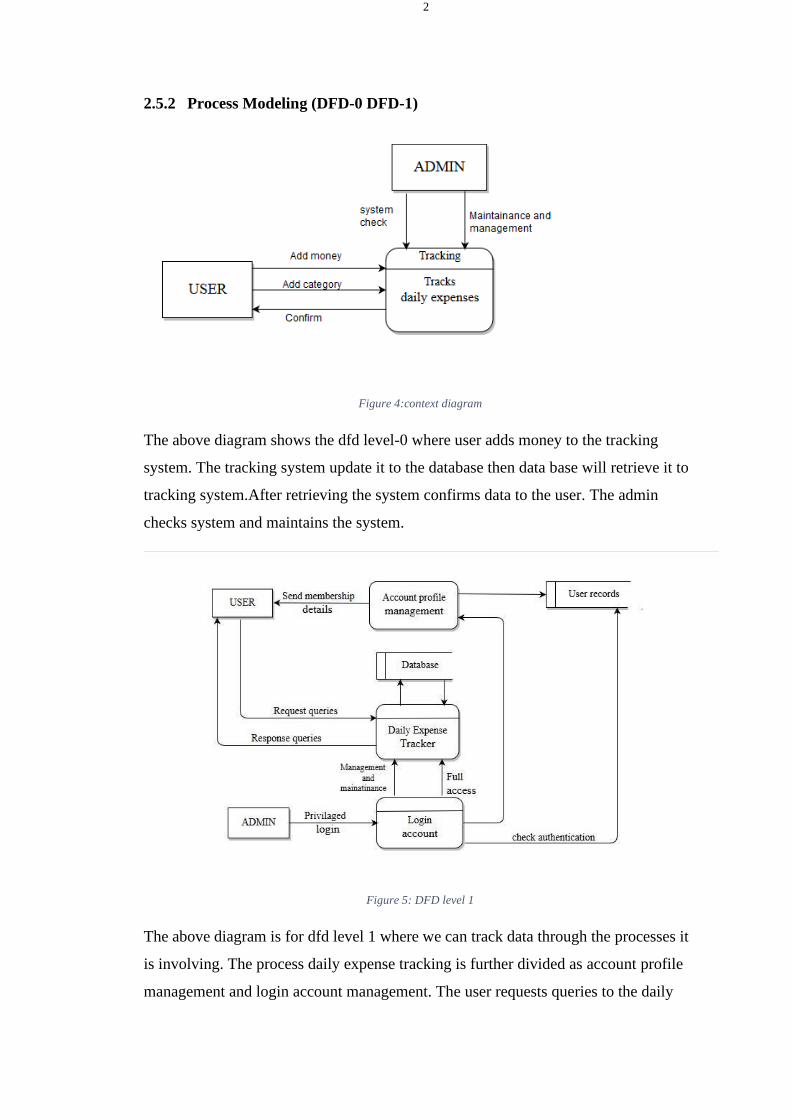
2.5.2 Process Modeling (DFD-0 DFD-1)
Figure 4:context diagram
The above diagram shows the dfd level-0 where user adds money to the tracking
system. The tracking system update it to the database then data base will retrieve it to
tracking system.After retrieving the system confirms data to the user. The admin
checks system and maintains the system.
Figure 5: DFD level 1
The above diagram is for dfd level 1 where we can track data through the processes it
is involving. The process daily expense tracking is further divided as account profile
management and login account management. The user requests queries to the daily

23
expense tracker and gets response from it. The login account checks the
authentication of the user records. The account profile management sends
membership details to the user.

24
CHAPTER 3
TOOLS AND TECHNOLOGY
3.1 Netbeans
NetBeans IDE is a free and open source integrated development environment for application
development on Windows, Mac, Linux, and Solaris operating systems.
The IDE simplifies the development of web, enterprise, desktop, and mobile applications that use
the Java and HTML5 platforms. The IDE also offers support for the development of PHP and
C/C++ applications.
NetBeans IDE offers first-class tools for Java web, enterprise, desktop, and mobile application
development. It is consistently the first IDE to support the latest versions of the JDK, Java EE,
and JavaFX. It provides smart overviews to help you understand and manage your applications,
including ouf-of-the-box support for popular technologies such as Maven.
With its end-to-end application development features, constantly improving Java Editor, and
continual speed and performance enhancements, NetBeans IDE sets the standard for application
development with cutting edge technologies out of the box.
NetBeans IDE 6.5, released in November 2008, extended the existing Java EE features (including
Java Persistence support, EJB 3 and JAX-WS). Additionally, the NetBeans Enterprise Pack
supports the development of Java EE 5 enterprise applications, including SOA visual design tools,
XML schema tools, web services orchestration (for BPEL), and UML modeling. The NetBeans
IDE Bundle for C/C++ supports C/C++ and FORTRAN development.
3.2 JDBC
JDBC or Java Database Connectivity is a specification from Sun microsystems that provides a
standard abstraction(that is API or Protocol) for java applications to communicate with various
databases. It provides the language with java database connectivity standard. It is used to write
programs required to access databases. JDBC along with the database driver is capable of
accessing databases and spreadsheets. The enterprise data stored in a relational database(RDB)
can be accessed with the help of JDBC APIs.
JDBC is an API(Application programming interface) which is used in java programming to
interact with databases.
The classes and interfaces of JDBC allows application to send request made by users to the
specified database.
Enterprise applications that are created using the JAVA EE technology need to interact with
databases to store application-specific information. So, interacting with a database requires
efficient database connectivity which can be achieved by using the ODBC(Open database
connectivity) driver. This driver is used with JDBC to interact or communicate with various
kinds of databases such as Oracle, MS Access, Mysql and SQL server database.

25
3.3 Collections
Any group of individual objects which are represented as a single unit is known as the
collection of the objects. In Java, a separate framework named the “Collection Framework” has
been defined in JDK 1.2 which holds all the collection classes and interface in it.
The Collection interface (java.util.Collection) and Map interface (java.util.Map) are the two
main “root” interfaces of Java collection classes.
A framework is a set of classes and interfaces which provide a ready-made architecture. In
order to implement a new feature or a class, there is no need to define a framework.
However, an optimal object-oriented design always includes a framework with a collection
of classes such that all the classes perform the same kind of task.
Before the Collection Framework(or before JDK 1.2) was introduced, the standard methods for
grouping Java objects (or collections) were Arrays or Vectors, or Hashtables. All of these
collections had no common interface. Therefore, though the main aim of all the collections is
the same, the implementation of all these collections was defined independently and had no
correlation among them.
3.4 OOPS
As the name suggests, Object-Oriented Programming or OOPs refers to languages that uses
objects in programming. Object-oriented programming aims to implement real-world entities
like inheritance, hiding, polymorphism etc in programming. The main aim of OOP is to bind
together the data and the functions that operate on them so that no other part of the code can
access this data except that function.
Let us do discuss pre-requisite by polishing concepts of methods declaration and passing.
Starting off with the method declaration, it consists of six components:
❖ Access Modifier : Defines access type of the method i.e. from where it can be accessed
in your application. In Java, there 4 type of the access specifiers.
❖ public: accessible in all class in your application.
❖ protected: accessible within the package in which it is defined and in
its subclass(es)(including subclasses declared outside the package)
❖ private: accessible only within the class in which it is defined.
❖ default (declared/defined without using any modifier): accessible within same class
and package within which its class is defined.
❖ The return type: The data type of the value returned by the method or void if does not
return a value.
❖ Method Name: the rules for field names apply to method names as well, but the
convention is a little different.
❖ Parameter list: Comma separated list of the input parameters are defined, preceded
with their data type, within the enclosed parenthesis. If there are no parameters, you
must use empty parentheses ().
❖ Exception list: The exceptions you expect by the method can throw, you can specify
these exception(s).
❖ Method body: it is enclosed between braces. The code you need to be executed to
perform your intended operations.

26
A class is a user defined blueprint or prototype from which objects are created. It represents the
set of properties or methods that are common to all objects of one type. In general, class
declarations can include these components, in order:
1. Modifiers: A class can be public or has default access (Refer this for details).
2. Class name: The name should begin with a initial letter (capitalized by convention).
3. Superclass(if any): The name of the class’s parent (superclass), if any, preceded by the
keyword extends. A class can only extend (subclass) one parent.
4. Interfaces(if any): A comma-separated list of interfaces implemented by the class, if
any, preceded by the keyword implements. A class can implement more than one interface.
5. Body: The class body surrounded by braces, { }.
Object is a basic unit of Object Oriented Programming and represents the real life entities. A
typical Java program creates many objects, which as you know, interact by invoking methods.
An object consists of:
1. State : It is represented by attributes of an object. It also reflects the properties of an
object.
2. Behavior : It is represented by methods of an object. It also reflects the response of an
object with other objects.
3. Identity : It gives a unique name to an object and enables one object to interact with
other objects.
4. Method: A method is a collection of statements that perform some specific task and
return result to the caller. A method can perform some specific task without returning
anything. Methods allow us to reuse the code without retyping the code. In Java, every
method must be part of some class which is different from languages like C, C++ and
Python.
Methods are time savers and help us to reuse the code without retyping the code.
3.5 MYSQL
MySQL is an open-source relational database management system (RDBMS). Its name is a combination of
"My", the name of co-founder Michael Widenius's daughter, and "SQL", the abbreviation for Structured Query
Language. A relational database organizes data into one or more data tables in which data types may be related
to each other; these relations help structure the data. SQL is a language programmers use to create, modify and
extract data from the relational database, as well as control user access to the database. In addition to relational
databases and SQL, an RDBMS like MySQL works with an operating system to implement a relational
database in a computer's storage system, manages users, allows for network access and facilitates testing
database integrity and creation of backups.
MySQL is free and open-source software under the terms of the GNU General Public License, and is also
available under a variety of proprietary licenses. MySQL was owned and sponsored by
the Swedish company MySQL AB, which was bought by Sun Microsystems (now Oracle Corporation). In 2010,
when Oracle acquired Sun, Widenius forked the open-source MySQL project to create MariaDB.
MySQL has stand-alone clients that allow users to interact directly with a MySQL database using SQL, but
more often, MySQL is used with other programs to implement applications that need relational database
capability. MySQL is a component of the LAMP web application software stack (and others), which is an
acronym for Linux, Apache, MySQL, Perl/PHP/Python. MySQL is used by many database-driven web
applications, including Drupal, Joomla, phpBB, and WordPress. MySQL is also used by many popular websites.

27
3.7 Java or versions
The Java language has undergone several changes since JDK 1.0 as well as numerous additions
of classes and packages to the standard library. Since J2SE 1.4, the evolution of the Java language
has been governed by the Java Community Process (JCP), which uses Java Specification
Requests (JSRs) to propose and specify additions and changes to the Java platform. The language
is specified by the Java Language Specification (JLS); changes to the JLS are managed under JSR
901. In September 2017, Mark Reinhold, chief Architect of the Java Platform, proposed to change
the release train to "one feature release every six months" rather than the then-current two-year
schedule. This proposal took effect for all following versions, and is still the current release
schedule.
In addition to the language changes, other changes have been made to the Java Class Library over
the years, which has grown from a few hundred classes in JDK 1.0 to over three thousand in
J2SE 5. Entire new APIs, such as Swing and Java2D, have been introduced, and many of the
original JDK 1.0 classes and methods have been deprecated. Some programs allow conversion of
Java programs from one version of the Java platform to an older one (for example Java 5.0
backported to 1.4) (see Java backporting tools).
Regarding Oracle Java SE Support Roadmap, version 17, 11 and 8 are the currently
supported long-term support (LTS) versions, where Oracle Customers will receive Oracle Premier
Support. Java 8 LTS last free software public update for commercial use was released by Oracle
in January 2019, while Oracle continues to release no-cost public Java 8 updates for
development and personal use indefinitely. Java 10 a previously supported rapid release version,
had its support ended in September 2018 the same date support for Java 11 began. Java 7 is no
longer publicly supported. For Java 11, long-term support will not be provided by Oracle for the
public; instead, the broader OpenJDK community, as Eclipse Adoptium or others, is expected to
perform the work.
Java is one of the most popular and widely used programming languages.
• Java has been one of the most popular programming languages for many years.
• Java is Object Oriented. However, it is not considered as pure object-oriented as it
provides support for primitive data types (like int, char, etc)
• The Java codes are first compiled into byte code (machine-independent code). Then the
byte code runs on Java Virtual Machine (JVM) regardless of the underlying architecture.
• Java syntax is similar to C/C++. But Java does not provide low-level programming
functionalities like pointers. Also, Java codes are always written in the form of classes and
objects.
• Java is used in all kinds of applications like Mobile Applications (Android is Java-based),
desktop applications, web applications, client-server applications, enterprise applications,
and many more.
• When compared with C++, Java codes are generally more maintainable because Java does
not allow many things which may lead to bad/inefficient programming if used incorrectly.
For example, non-primitives are always references in Java. So we cannot pass large objects
(like we can do in C++) to functions, we always pass references in Java. One more example,
since there are no pointers, bad memory access is also not possible.
• When compared with Python, Java kind of fits between C++ and Python. The programs
are written in Java typically run faster than corresponding Python programs and slower than
C++. Like C++, Java does static type checking, but Python does not.

28
3.8 Cloud
3.8.1 The humble beginnings of cloud
Believe it or not, the modern day idea of “cloud computing” dates back to the 1950s, when large-
scale mainframes were made available to schools and corporations. The mainframe’s colossal
hardware infrastructure was installed in what could be called a “server room” (since the room
would generally only be able to hold a single mainframe). Multiple users were able to access the
mainframe via “dumb terminals”—stations with the sole function of facilitating access to the
mainframes.
Due to the cost of buying and maintaining mainframes, an organization wouldn’t be able to afford
a mainframe for each user. It became practice to allow multiple users to share access to the same
data storage layer and CPU power from any station. By enabling shared mainframe access, an
organization would get a better return on its investment in this sophisticated piece of technology.
3.8.2 Virtualization changes everything
Twenty years later in the 1970s, IBM released an operating system called VM that permitted
admins on its System/370 mainframe systems to have multiple virtual systems, or “virtual
machines (VMs)” on a single physical node. The VM operating system took the 1950s application
of shared access of a mainframe to the next level by allowing multiple distinct compute
environments to live in the same physical environment.
Most of the basic functions of any virtualization software that you see nowadays can be traced
back to this early VM OS. Every VM ran custom operating systems or guest operating systems
that had their own memory, CPU, and hard drives, along with CD-ROMs, keyboards, and
networking—despite the fact that those resources were shared. “Virtualization” became a
technology driver, and it became a huge catalyst for some of the biggest evolutions in
communications and computing.
In the 1990s, telecommunications companies that historically only offered single dedicated point-
to-point data connections began offering virtualized private network connections—with the same
service quality as dedicated services at a reduced cost. Rather than building out physical
infrastructure to allow more users to have their own connections, telecommunications companies
provided users with shared access to the same physical infrastructure. This change allowed
telecommunications companies to shift traffic as necessary, leading to better network balance and
more control over bandwidth usage.

29
3.8.3 Virtualization meets the Internet
Meanwhile, virtualization for PC-based systems started in earnest. As the Internet became more
accessible, the next logical step was to take virtualization online. If you were in the market to buy
servers 10 or 20 years ago, you know that the costs of physical hardware—while not at the same
level as the mainframes of the 1950s—were pretty outrageous. As more and more people
expressed the demand to be online, the costs had to come out of the stratosphere and into reality.
One of the ways that happened was through—you guessed it—virtualization. Servers were
virtualized into shared hosting environments, virtual private servers, and virtual dedicated dervers
using the same types of functionality provided by the VM OS in the 1950s.
What did this look like in practice? Let’s say your company required 13 physical systems to run
your sites and applications. With virtualization, you can take those 13 distinct systems and split
them up between two physical nodes. Obviously, this kind of environment saves on infrastructure
costs and minimizes the amount of actual hardware you would need to meet your company’s
needs.

30
CHAPTER 4
SYSTEM DESIGN
4.1 System Architecture and Overview
We have developed the required system that works without internet. To use this
system we need a database, android mobile handset, app and the user.
Algorithm Used
The Apriori Algorithm is an influential algorithm for mining frequent itemsets for
boolean association rules. Apriori uses a "bottom up" approach, where frequent subsets
are extended one item at a time (a step known as candidate generation, and groups of
candidates are tested against the data. Apriori is designed to operate on database
containing transactions (for example, collections of items bought by customers, or
details of a website frequentation).
4.1.1 System Design
Systems design is the process of defining the architecture, modules, interfaces, and
data for a system to satisfy specified requirements. Systems design could be seen as
the application of systems theory to product development.

31
3.1.1 Database Schema
Figure 6: Database schema
There are five tables in our application database which are user, expense, result,
income and daily list. In above diagram the tables covers their respective primary key
and their fields.
4.1.2 Data Dictionary
A data dictionary also known as metadata repository is a centralized repository of
information about data such as meaning, relationship to other data, origin, usage and
format.
Table 3: Data Dictionary
S.N Entity Attribute Data type Constraints
1 DateUser
sdhb User
User_id int Primary
username varchar(20)
password varchar(20)

32
2 Daily list date_id int Primary
year int
month int
day int
3 Expense date_id int Foreign
exp_id Int Primary
expense category Varchar(20)
expense notes Varchar(20)
4 Result statistics long Int
4.1.3 UML class diagram
Class Diagram

33
application have five entities: expense, user, backup, notification, transaction, which
have their own data members and methods. Above diagram shows the flow of the
functionality from entity to entity. Also, types of data members and methods of
respective entity are mentioned above.
Sequence diagram
Figure 8: Sequence Diagram

34
Activity Diagram

35
Input Output Diagram
The above diagram shows the major input that this system ‘Daily Expense Tracker’ in
which the input includes username, password, currency, amount, category, date, notes
while the transformation processing includes login authentication, expense tracking,
database update and retrival where as output includes expense and budgeting and
piecharts. The feedback includes performance satisfaction and recommendation.

36
Screenshots of designing
Homepage of application

37
To add new category in expense
38
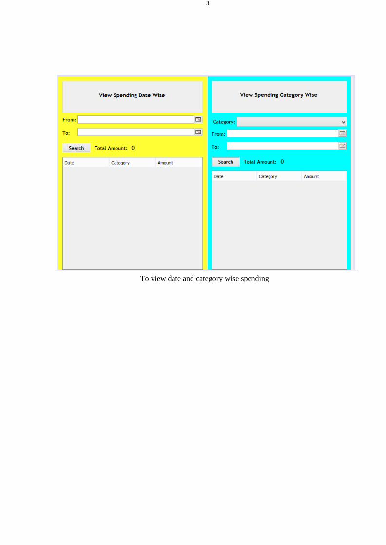
To view date and category wise spending

39
CHAPTER 5
System Implementation and Testing
5.1 Implementation Overview
Process Model Used
The waterfall model is a sequential approach, where each fundamental activity of a
process represented as a separate phase, arranged in linear order.In the waterfall model,
you must plan and schedule all of the activities before starting working on them (plan-
driven process).
Waterfall model is used for the project because all the requirements are clear as this
project is not dealing with the clients and hence beforehand planning can be made
about how to carry out each phase of development.
5.2 Tools Used
5.2.1 Front End Tools
XHTML: Extensible Hypertext Markup Language is part of the family of XML
markup languages. It mirrors or extends versions of the widely used Hypertext
Markup Language, the language in which Web pages are formulated. XHTML is used
to design the UI in android platform for the ease of the user.
5.2.2 Back End Tools
JAVA: Java is a general-purpose computer-programming language that is concurrent,
class-based, object-oriented, and specifically designed to have as few implementation
dependencies as possible. As the back end tools java is used to provide functionality
to the attributes displaying in UI.
SQLITE: It is a relational database management system contained in a C
programming library. In contrast to many other database management systems,
SQLite is not a client–server database engine. Rather, it is embedded into the end
program. So, SQLITE 3.8.2 is used for manipulating data from database and
visualizing to the user.

40
5.2.3 Module Description
A modularization consists of well-defined manageable units with well-defined interfaces
among the units.
Desirable property of modular system include
a) Each module is a well-defined sub-system.
b) Single, well – defined purpose of each module.
c) Modules can be separately compiled and stored in a library.
d) Modules can use other module.
e) Modules should be easier to use than to build.
f) Modules should be simpler from outside then from inside.
The project can be decomposed in following modules:
a) Login module: This module is responsible for a registered user to login to the web
application and do the proceedings.
b) Signup module: This module is responsible for registering a new user to the web
application and create a new account for him/her
c) Sessions module: This module is responsible for creating a session when a user logs
in and continues till he/she logs out.
d) Add Bill: This module is responsible to enable the user to add a new bill
e) Delete the bill: This module is responsible for the pre-defined bill.
f) View Expense: This module is responsible for viewing all the expenses in detail
added to the log by a logged in user
g) Edit Module: This module is responsible for editing a pre-defined bill.
h) Categories module: This module is responsible for various options. In this app users
have options of selecting various basic expense categories and currency according to
their country.
i) Add note and date: This module is responsible for adding notes and dates to the
expenditure of user.
The classes used for this project are:
• AddNewExpense
• Budget
• CDBHelper
• Contact
• DBHelper

41
• Expense
• Graph_all
• Graph_all_adapter
• Graph_all_list
• History
• Login
• MainActivity
• Overview
• Overview_list_Adapter
• Overview_ListView
• Piegraph
• Settings
• SignupActivity
• Tab1
• Tab1_Adapter
• Tab1_ListView
• Tab2
• TabHistory_week
• Tab2
• WelcomeScreen
Methods are:
• addData()
• loadListView()
• onCreateOptionsMenu(Menu menu)
• showDate(int year, int month, int day)
• onCreateView()
• queryXData()
• queryYData()

42
5.3 Testing
Testing is the process of evaluation a software item to detect differences between
given input and expected output. Testing is a process that should be done during the
development process.
5.3.1 Unit Testing
The Unit testing part of a testing methodology is the testing of individual software
modules or components that make up an application or system.
SN Test
Case Id
Test
description
Input test
data
Expected
Result
Actual
Result
Remarks
1 TC-
INS-01
Install DET
app in
android
phone
Transfer
DET app
Open
application
with its
home page
Application
executed
with home
page
Pass
SN Test
Case Id
Test
description
Input test
data
Expected
Result
Actual
Result
Remarks
1 TC-LG-
01
Enter valid
data in
username
and
password
field
rashna
*********
Show home
page for user
Rasna
Displayed
home page
for user
Rasna
pass
2 TC-LG-
02
Enter valid
data in
username
and leave
password
field empty
rasna Show error Didn’t
show any
error
fail

43
3 TC-LG-
03
Leave
username
and
password
field empty
and press
login
*********
Show error Printed
“Enter
Username”
Pass
4 TC-LG-
04
Enter invalid
username
and
password
rashana
******
Show error Printed
“You are
not
registered”
Pass
SN Test
Case Id
Test
description
Input test
data
Expected
Result
Actual
Result
Remarks
1 TC-DT-
01
Enter
expense
values with
their
category
1500 with
category
clothing
Update
category
table with
value 1000
Updated
category
table with
value 100
Pass
2 TC-DT-
02
Enter non
numeric
value for
expense field
Rashna Show error Printed
“Enter
Valid
value”
Pass
3 TC-DT-
03
Enter
decimal
value for
expense field
155.65
with
category
food
Update
category
table with
value 155.65
Updated
category
table with
value
155.65
Pass
4 TC-DT-
04
Enter
negative
value for
-2635 with
category
rent
Update
category
table with
Updated
category
table with
fail
44
expense field value -2635 value
-2635
5 TC-DT-
05
Enter
expense
values
without any
category
1860 Update
default
category
others with
value 1860
Cannot
update
table
fail
6 TC-DT-
06
Enter future
date for
expense
2020/02/16 Show error
in entering
future
expense
Updated
table with
future date
fail
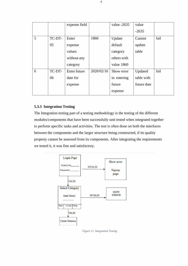
5.3.3 Integration Testing
The Integration testing part of a testing methodology is the testing of the different
modules/components that have been successfully unit tested when integrated together
to perform specific tasks and activities. The test is often done on both the interfaces
between the components and the larger structure being constructed, if its quality
property cannot be assessed from its components. After integrating the requirements
we tested it, it was fine and satisfactory.
Figure 11: Integration Testing

45
5.3.4 System Testing
The system testing part of a testing methodology involves testing the entire system for
errors and bugs. This test is carried out by interfacing the hardware and software
components of the entire system, and then testing it as a whole.
SN Test
Case Id
Test
description
Input test
data
Expected
Result
Actual
Result
Remarks
1 TC-
INS-01
Install DET
app in
android
phone
Transfer
DET app
Open
application
with its
home page
Application
executed
with home
page
Pass
2 TC-LG-
01
Enter valid
data in
username
and
password
field
rashna
*********
Show home
page for user
Rasna
Displayed
home page
for user
Rasna
pass
3 TC-DT-
05
Enter
expense
values
without any
category
1860 Update
default
category
others with
value 1860
Updated
category
others with
value 1860
Pass
4 TC-CL-
01
Go to chart
page which
shows the
data in chart
format
Click
account tab
Show the
chart of all
the expenses
of that day
Showed the
chart of all
the
expenses of
that day
Pass

46
CHAPTER 6
CONCLUSION AND RECOMMENDATION
6.1 Conclusion
After making this application we assure that this application will help its users to
manage the cost of their daily expenditure. It will guide them and aware them about
there daily expenses. It will prove to be helpful for the people who are frustrated with
their daily budget management, irritated because of amount of expenses and wishes to
manage money and to preserve the record of their daily cost which may be useful to
change their way of spending money. In short, this application will help its users to
overcome the wastage of money.
The name of our project is “CLOUD BASED EXPENSE TRACKER” which is
basically an Cloud based Expense Tracker. It works on the top of latest technology stack
and is as interactive and friendly as it is named. You have to provide the input manually or
with the help of your speech (thanks to speechly for making it happen easily). The moment
you fill in the input manually and click the "CREATE" button or the moment you provide
your voice command , the app stores the data with the help of context that makes your app
faster and the information is easily flowed between the various components of the app. Then
the information is populated in a list which if displayed just below the input form . The list
holds all the transaction be it any expenditure or income for your reference so that any time
you want to have a look at your previous activities you could easily have it.
As we know , the technology is moving from alphabetical data to the images as
they are easy to read , understand and are attractive. So our Cloud based Expense Tracker is
not behind in this trend also. The graph of income and expenses updated automatically as
soon as any transaction is added to the list. The next thing that is more important is all the
information is stored in the local storage so that any time you want to clean the tabs or even
shut down the browser , and the next time you open it you have all you transactions saved
just like before. The possibility of human error is always estimated while creating any app so
the Cloud based Expense Tracker also has the options to delete any transaction that your
typed incorrectly so that your budget sheet is always very precise and accurate.
6.2 Recommendation
DET app is usable by anyone who are willing to manage their expenses and aiming to
save for the future investments. This app has no range criteria or any kind of
profession or gender are focused so it will used hugely by any other person.

47
Future Scope
In further days, there will be mails and paymode embedded with the app. Also,
backup details will be recorded on cloud.

48
BIBLIOGRAPHY
[1] L. T. HONG, "Android Mobile Application – Expenses with Geo-Location
Tracking," University Tunku Abdul Rahman , UTAR, 2015.
[2] N. Mehta, "Android Applicaiton Expense Manager," 2014.
[3] A. Bamne, "expense tracker ( Class Diagram (UML)," 2014.
49
REFRENCES
[1] Good Budget: https://goodbudget.com/
[2] Mint: https://mint.intuit.com/
[3] IRE Journal : Cloud based Expense Tracker by Atiya Kazi ,
Praphulla S. Kherade , Raj S. Vilankar , Parag M. Sawant
[4] https://sciresol.s3.us-east-
2.amazonaws.com/IJST/Articles/2015/Issue-Supplementary-
2/Article16.pdf
[5] shorturl.at/knADK
[6] https://mui.com/
[7] https://www.educative.io/edpresso/how-to-use-chartjs-to-
create-charts-in-react
[8] 1) Christos C. Bellos, Athanasios Papadopoulos, Roberto Rosso" Identification of COPD Patients"
Health Status Using an Intelligent System in the CHRONIOUS Wearable Platform" IEEE
JOURNAL OF BIOMEDICAL AND HEALTH INFORMATICS, VOL. 18, NO. 3, MAY 2014
[9] 2) Lei Cliton, David A. Clifton, Marco A. F. Pimentel "Predictive Monitoring of Mobile Patients by
Combining Clinical Observations With Data From Wearable Sensors" JEEE JOURNAL OF
BIOMEDICAL AND HEALTH INFORMATICS, vOL. 18, N0. 3, MAY 2014
[10] 3) Ambika R, Kimn Jose, Priyadharshini. K, Priyanga S Kumar " Wireless Remote Healthcare
Sysem" INTERNATIONAL JOURNAL OF SCIENTIFIC & TECHNOLOGY RESEARCH
VOLUME 2, 1SSUE 10, OCTOBER 2013
[11] 4) Diogo Gomes, Carlos Gonçalves, José A. A fonso "Performance Evaluation of ZigBee Protocol
for High Data Rate Body Sensor Networks" World Congress on Engineering 2013 Vol I1, WCE
2013, July 3- 5, 2013, London, U.K.
[12] 5) KarandeepMa lhi, Subhas Chandra Mukhopadhyay" A Zigbee-Based Wearable Physiological
Parameters Monitoring System" IEEE SENSORS JOURNAL, VOL. 12, NO. 3, MARCH 2012
[13] 6) Honggang Wang, Hua Fang. Liudong Xing Min Chen( 2011) " An Integrated Biometric-based
Security Framework Using WaveletDomain HMM in Wireless Body Area Networks (WBAN"
IEEE Communications Society subject matter experts for publication in the IEEE ICC procedings.
[14] 7) Raju Singh(March 2011) "Confidentiality & Authentication Mechanisn for Biometric
Information Transmitted over Low Bandwidth & Unreliable channe" School of Computer
Engineering and IT, Shobhit University, Meerut, India Vol.3, No.2,
[15] 8) Mikael Soini, JussiNumme la, Petri Oksa, LeenaUkkonen and Laurisydäinhe imo (2009)."
Wireless Body Area Network for Hip rehabilitation Tampere University of Technology,
Department of Electronics, Rauma Research Unit pp. 202-206
[16] 9) Cory Comelius(August 2010) "On Usable Authentication for Wireless Body AreaNetworks
Department of Computer Science Dartmouth College, Presented at HealthSec,. [10] Jamil Y. Khan,
Mehmet R. Yuce, and FarboodKarami "Performance Evaluation ofa Wireless Body Area Sensor
Network for Remote Patient Monitoring"
[17] 10)A. Soomro, D. Cavalcanti, IEEE (Feb 2007)Opportunities & Challenges using WPAN and
WLAN Technologies in Medical Environments", Communications Magazine, vol:45, no:2, page
114122.
[18] 11) Adnan Saeed, MiadFaezpour IEEE 2009,"Plug and Play Sensor Node for Body Area
Network".
[19] 12) Jamil Y. Khanschool of computer science,Australia, IEEE (09,07, 2009.) "Wireless Body Area

50
Network for Medical Applications".
[20] 13) Emil Jovanov, DejanRaskovic, John PriceJohn Chapman, Anthony Moore,
AbhishekKrishnamurthy, IEEE (2008)" Patient Monitoring Using Personal Area Networks of
Wireless Intelligent Sensors".
[21] 14) CHRIS oTTO, ALEKSANDAR MILENKOVIĆ, cOREY SANDERS, EMIL JOVANOV,
"SYSTEM ARCHITECTURE OF A wIRELESS BODY AREA SENSOR NETWORK FOR
UBIQUITOUS HEALTH MONITORING". Journal of Mobile Multimedia, Vol. 1, No.4 (2006)
307-326
[22] 15) Chao Chen and Carlos Pomalaza-Ráez, "Implimenting and EvaluatingA wireless body Sensor
System for Automated Physiological Data Acquisition At Home". International Journal of
Computer Science and Information Technology, Volume 2, Number 3, 16June 2010.
[23] 16) Frank Agyei-Ntim, Member IEEE, Kimberly Newman, "Lifetime Estimation of Wireless Body
Area Sensor Network for Patient Health Monitoring" 31st Annual International Conference of the
IEEE EMBS Minneapolis, Minnesota, USA, Senior Member IEEE, September 2-6, 2009
[24] 17) Adnan Saeed, MehrdadNourani, Gil Lee, Gopal Gupta and Lakshman Tamil," A Scalable
Wireless Body Area Sensor Network for Health-Care Monitoring", The University of Texas at
Dallas, Richardson, Texas. IEEE 2007.
[25] 18) Adnan Saeed, MiadF'aezipour", MehrdadNourani", Subhash Banerjee, June 2009," A Scalable
Wireless Body Area Network for Bio-Telemetry", Journal of Information Processing Systems,
Vol.5, No.2.
[26] 19)AleksandarMilenković, Chris Otto, Emil Jovanov, Accessed: July 2005, "Wireless Sensor
Networks for Personal Health Monitoring:1ssues and an Implementation".
[27] 20) Mehmet R. Yuce & Steven W. P. Ng & Naung L. Myo &Jamil Y. Khan &Wentai Liu ,
"Wireless Body Sensor Network Using Medical Implant Band", Received: 10 July 2007/ Accepted:
25 July 2007