B-SX4T/SX5T SERIES - Maintenance Manual
223
PRINTED IN JAPAN TEC Thermal Printer B-SX4T/SX5T SERIES Document No. EO18-33012B Original Jan., 2003 (Revised Feb., 2003 Jan., 2006) Maintenance Manual Mantenimiento Periféricos Informáticos C/Canteras,15 28860 Paracuellos de Jarama Madrid Tel: 91 748 16 04 www.mpi.com.es
-
Upload
khangminh22 -
Category
Documents
-
view
0 -
download
0
Transcript of B-SX4T/SX5T SERIES - Maintenance Manual

PRINTED IN JAPAN
TEC Thermal Printer
B-SX4T/SX5T SERIES
Document No. EO18-33012B Original Jan., 2003
(Revised Feb., 2003 Jan., 2006)
Maintenance Manual
Mantenimiento Periféricos Informáticos C/Canteras,15 28860 Paracuellos de Jarama Madrid Tel: 91 748 16 04 www.mpi.com.es

NOTES: 1. Manual instructions must be followed when installing option kits or adding cables to avoid system failures and to insure proper performance and operation.
2. Failure to follow manual instructions or any unauthorized modification, substitution or change to this product will void the limited product warranty.
WARNING!
Follow all manual instructions. Failure to do so could create safety hazards such as fire or electrocution.
Mantenimiento Periféricos Informáticos C/Canteras,15 28860 Paracuellos de Jarama Madrid Tel: 91 748 16 04 www.mpi.com.es

EO18-33012B (Revision Date: Feb. 15, 2007)
TABLE OF CONTENTS
Page 1. UNPACKING--------------------------------------------------------------------------------------------------------1- 1 1.1 PROCEDURES ---------------------------------------------------------------------------------------------------1- 1 1.2 CHECKS ------------------------------------------------------------------------------------------------------------1- 3
2. PRINTER INSTALLATION--------------------------------------------------------------------------------------1- 3
3. NOTE FOR OPTIONAL EQUIPMENT INSTALLATION /MAJOR UNIT REPLACEMENT/MAINTENANCE----------------------------------------------------3- 1
3.1 OPENING/CLOSING THE TOP COVER-------------------------------------------------------------------3- 3 3.2 REMOVING THE SIDE PANEL (L) --------------------------------------------------------------------------3- 3 3.3 OPENING/CLOSING THE PRINTER BLOCK ------------------------------------------------------------3- 4 3.4 REMOVING THE OPERATION PANEL --------------------------------------------------------------------3- 5
4. INSTALLATION PROCEDURE FOR OPTIONAL EQUIPMENT -------------------------------------4- 1 4.1 SWING CUTTER (B-4205-QM)-------------------------------------------------------------------------------4- 4 4.2 ROTARY CUTTER (B-8204-QM)-----------------------------------------------------------------------------4- 7 4.3 STRIP MODULE (B-9904-H-QM) ---------------------------------------------------------------------------4-13 4.4 RIBBON SAVING MODULE (B-9904-R/R2-QM)--------------------------------------------------------4-19 4.5 PCMCIA INTERFACE BOARD (B-9700-PCM-QM) ----------------------------------------------------4-22 4.6 USB INTERFACE BOARD (B-9700-USB-QM) ----------------------------------------------------------4-25 4.7 LAN INTERFACE BOARD (B-9700-LAN-QM) -----------------------------------------------------------4-29 4.8 EXPANSION I/O INTERFACE BOARD (B-7704-IO-QM) ---------------------------------------------4-33 4.9 RIBBON SAVING MODULE AND ROTARY CUTTER (For B-SX4T Series) --------------------4-35 4.10 RFID MODULE (B-9704-RFID-U1-US/EU/EU-R) -------------------------------------------------------4-43 4.10.1 Applicable Model ------------------------------------------------------------------------------------------ 4-43 4.10.2 Packing List ------------------------------------------------------------------------------------------------- 4-43 4.10.3 Removing the Platen Frame Top and Attaching the Ribbon Guide --------------------------- 4-45 4.10.4 Attaching the Antenna------------------------------------------------------------------------------------ 4-48 4.10.5 Attaching the RFID Module ----------------------------------------------------------------------------- 4-51 4.10.6 Parameter Setting and Operation Check for the RFID Module -------------------------------- 4-54 4.11 RFID MODULE (B-9704-RFID-H1-QM/QM-R)-----------------------------------------------------------4-56 4.11.1 Applicable Model ------------------------------------------------------------------------------------------ 4-56 4.11.2 Packing List ------------------------------------------------------------------------------------------------- 4-56 4.11.3 Attaching the Antenna to the Antenna Cover or Antenna Frame ------------------------------ 4-59 4.11.4 Attaching the RFID Module to the RFID Plate------------------------------------------------------ 4-59 4.11.5 Attaching the RFID Module ----------------------------------------------------------------------------- 4-63 4.11.6 Parameter Setting and Operation Check for the RFID Module -------------------------------- 4-67 4.12 SWING CUTTER (B-4205-QM-QM-R)---------------------------------------------------------------------4-68 4.12.1 Applicable Model ------------------------------------------------------------------------------------------ 4-68 4.12.2 Packing List ------------------------------------------------------------------------------------------------- 4-68 4.12.3 Installation Procedure ------------------------------------------------------------------------------------ 4-68 4.13 ROTARY CUTTER (B-8204-QM-R) ------------------------------------------------------------------------4-79 4.13.1 Applicable Model ------------------------------------------------------------------------------------------ 4-79 4.13.2 Packing List ------------------------------------------------------------------------------------------------- 4-79 4.13.3 Installation Procedure ------------------------------------------------------------------------------------ 4-79
Mantenimiento Periféricos Informáticos C/Canteras,15 28860 Paracuellos de Jarama Madrid Tel: 91 748 16 04 www.mpi.com.es

EO18-33012B (Revision Date: Feb. 6, 2009)
4.14 STRIP MODULE (B-9904-H-QM-R) ------------------------------------------------------------------------4-90 4.14.1 Applicable Model ------------------------------------------------------------------------------------------ 4-90 4.14.2 Packing List ------------------------------------------------------------------------------------------------- 4-90 4.14.3 Installation Procedure ------------------------------------------------------------------------------------ 4-91 4.15 RIBBON SAVING MODULE (B-9904-R2-QM-R)------------------------------------------------------ 4-100 4.15.1 Applicable Model -----------------------------------------------------------------------------------------4-100 4.15.2 Packing List ------------------------------------------------------------------------------------------------4-100 4.15.3 Installation Procedure -----------------------------------------------------------------------------------4-101 4.16 PCMCIA INTERFACE BOARD (B-9700-PCM-QM-R) ----------------------------------------------- 4-106 4.16.1 Applicable Model -----------------------------------------------------------------------------------------4-106 4.16.2 Packing List ------------------------------------------------------------------------------------------------4-106 4.16.3 Installation Procedure-------------------------------------------------------------------------------------4-107 4.17 USB INTERFACE BOARD (B-9700-USB-QM-R) ----------------------------------------------------- 4-110 4.17.1 Applicable Model -----------------------------------------------------------------------------------------4-110 4.17.2 Pacing List -------------------------------------------------------------------------------------------------4-110 4.17.3 Installation Procedure -----------------------------------------------------------------------------------4-111 4.18 LAN INTERFACE BOARD (B-9700-LAN-QM-R)------------------------------------------------------ 4-114 4.18.1 Applicable Model -----------------------------------------------------------------------------------------4-114 4.18.2 Pacing List -------------------------------------------------------------------------------------------------4-114 4.18.3 Installation Procedure -----------------------------------------------------------------------------------4-115 4.19 EXPANSION I/O INTERFACE BOARD (B-7704-IO-QM-R)---------------------------------------- 4-118 4.19.1 Applicable Model -----------------------------------------------------------------------------------------4-118 4.19.2 Packing List ------------------------------------------------------------------------------------------------4-118 4.19.3 Installation Procedure -----------------------------------------------------------------------------------4-118 4.20 FANFOLD PAPER GUIDE MODULE (B-4905-FF-QM-R) ------------------------------------------ 4-121 4.20.1 Applicable Model -----------------------------------------------------------------------------------------4-121 4.20.2 Packing List ------------------------------------------------------------------------------------------------4-121 4.20.3 Installation Procedure -----------------------------------------------------------------------------------4-121 4.21 WIRELESS LAN MODULE (B-9700-WLAN-QM-R) -------------------------------------------------- 4-122 4.21.1 Applicable Model -----------------------------------------------------------------------------------------4-122 4.21.2 Packing List ------------------------------------------------------------------------------------------------4-122 4.21.3 Installation Procedure -----------------------------------------------------------------------------------4-123 4.22 RFID MODULE (B-SX704-RFID-U2-EU-R)------------------------------------------------------------- 4-127 4.22.1 Applicable Model -----------------------------------------------------------------------------------------4-128 4.22.2 Packing List ------------------------------------------------------------------------------------------------4-128 4.22.3 Installation Procedure -----------------------------------------------------------------------------------4-129 4.22.4 RFID Module Setting ------------------------------------------------------------------------------------4-147 4.22.5 AGC Threshold Setting ---------------------------------------------------------------------------------4-151 4.23 RFID MODULE (B-SX704-RFID-U2-AU-R)------------------------------------------------------------- 4-154 4.23.1 Applicable Model -----------------------------------------------------------------------------------------4-155 4.23.2 Packing List ------------------------------------------------------------------------------------------------4-155 4.23.3 Installation Procedure -----------------------------------------------------------------------------------4-156 4.23.4 RFID Module Setting ------------------------------------------------------------------------------------4-174 4.23.5 AGC Threshold Setting ---------------------------------------------------------------------------------4-178 4.24 RFID MODULE (B-SX704-RFID-U2-US-R)------------------------------------------------------------- 4-181 4.24.1 Applicable Model -----------------------------------------------------------------------------------------4-182 4.24.2 Packing List ------------------------------------------------------------------------------------------------4-183 4.24.3 Installation Procedure -----------------------------------------------------------------------------------4-184 4.24.4 RFID Module Setting ------------------------------------------------------------------------------------4-202 4.24.5 AGC Threshold Setting ---------------------------------------------------------------------------------4-206
Mantenimiento Periféricos Informáticos C/Canteras,15 28860 Paracuellos de Jarama Madrid Tel: 91 748 16 04 www.mpi.com.es

EO18-33012B (Revision Date: May 22, 2009)
4.25 RFID MODULE (B-SX704-RFID-U2-CN-R) ------------------------------------------------------------ 4-209 4.25.1 Applicable Model -----------------------------------------------------------------------------------------4-210 4.25.2 Packing List ------------------------------------------------------------------------------------------------4-211 4.25.3 Installation Procedure -----------------------------------------------------------------------------------4-212 4.25.4 RFID Module Setting ------------------------------------------------------------------------------------4-230 4.25.5 AGC Threshold Setting ---------------------------------------------------------------------------------4-234 4.26 IDENTIFICATION OF THE RFID MODULE (B-SX704-RFID-U2-US/EU/AU/CN-R) ---------------4-237 5. SYSTEM MODE----------------------------------------------------------------------------------------------------5- 1 5.1 OPERATION PANEL --------------------------------------------------------------------------------------------5- 1 5.2 OVERVIEW --------------------------------------------------------------------------------------------------------5- 2 5.3 SELF-DIAGNOSTIC TEST-------------------------------------------------------------------------------------5- 3 5.3.1 Printing Mode Selection----------------------------------------------------------------------------------- 5- 4 5.3.2 Dispensing Mode Selection ------------------------------------------------------------------------------ 5- 4 5.3.3 Maintenance Counter/Parameter Settings Printing Out------------------------------------------- 5- 5 5.3.4 Self-Diagnostic Test and Result Print Out----------------------------------------------------------- 5-12 5.3.5 Print Head Element Check ------------------------------------------------------------------------------ 5-17 5.4 PARAMETER SETTING---------------------------------------------------------------------------------------5-18 5.4.1 Character Code Selection ------------------------------------------------------------------------------- 5-19 5.4.2 Zero Font Code Selection ------------------------------------------------------------------------------- 5-22 5.4.3 Baud Rate Selection-------------------------------------------------------------------------------------- 5-23 5.4.4 Data Length Selection------------------------------------------------------------------------------------ 5-23 5.4.5 Stop Bit Selection------------------------------------------------------------------------------------------ 5-23 5.4.6 Parity Selection -------------------------------------------------------------------------------------------- 5-24 5.4.7 Transmission Control Code Selection---------------------------------------------------------------- 5-24 5.4.8 LCD Message Selection --------------------------------------------------------------------------------- 5-25 5.4.9 Auto Forward Wait Selection --------------------------------------------------------------------------- 5-25 5.4.10 Forward/Backward Feed Action Selection ---------------------------------------------------------- 5-26 5.4.11 Head Up Cut/Rewinder Selection --------------------------------------------------------------------- 5-26 5.4.12 Solenoid Type Selection --------------------------------------------------------------------------------- 5-27 5.4.13 Ribbon Saving Function Selection -------------------------------------------------------------------- 5-27 5.4.14 Control Code Selection ---------------------------------------------------------------------------------- 5-28 5.4.15 Strip Wait Status Selection------------------------------------------------------------------------------ 5-29 5.4.16 FEED Key Function Selection-------------------------------------------------------------------------- 5-29 5.4.17 KANJI Code Selection------------------------------------------------------------------------------------ 5-30 5.4.18 EURO Code Selection ----------------------------------------------------------------------------------- 5-30 5.4.19 Auto Print Head Check Selection---------------------------------------------------------------------- 5-31 5.4.20 Centronics Interface ACK/BUSY Timing Selection------------------------------------------------ 5-31 5.4.21 Web Printer Function Selection ------------------------------------------------------------------------ 5-32 5.4.22 Input Prime Selection------------------------------------------------------------------------------------- 5-33 5.4.23 Ribbon Near End Selection ----------------------------------------------------------------------------- 5-33 5.4.24 Expansion I/O Interface Selection--------------------------------------------------------------------- 5-33 5.4.25 Centronics Interface Selection ------------------------------------------------------------------------- 5-34 5.4.26 Plug & Play Selection------------------------------------------------------------------------------------- 5-34 5.4.27 Label End/Ribbon End Selection ---------------------------------------------------------------------- 5-34 5.4.28 Pre-Strip Selection ---------------------------------------------------------------------------------------- 5-36 5.4.29 Back Feed Speed Selection ---------------------------------------------------------------------------- 5-36 5.4.30 Maxi Code Specification Selection -------------------------------------------------------------------- 5-36 5.4.31 Print Head Type Selection ------------------------------------------------------------------------------ 5-37 5.4.32 System Mode Password Setting----------------------------------------------------------------------- 5-38 5.4.33 XML Function Setting (Supported only by V4.4A or Xx.x.) -------------------------------------- 5-40
Mantenimiento Periféricos Informáticos C/Canteras,15 28860 Paracuellos de Jarama Madrid Tel: 91 748 16 04 www.mpi.com.es

EO18-33012B (Revision Date: Jan. 30, 2009)
5.5 PRINTER PARAMETER FINE ADJUSTMENT----------------------------------------------------------5-41 5.5.1 Feed Length Fine Adjustment -------------------------------------------------------------------------- 5-42 5.5.2 Cut/Strip Position Fine Adjustment-------------------------------------------------------------------- 5-43 5.5.3 Back Feed Length Fine Adjustment------------------------------------------------------------------- 5-45 5.5.4 X Axis Fine Adjustment ---------------------------------------------------------------------------------- 5-46 5.5.5 Print Tone Fine Adjustment (Thermal Transfer/Thermal Direct Print) ------------------------ 5-47 5.5.6 Ribbon Motor Voltage Fine Adjustment (Feed/Take-up Motor) -------------------------------- 5-48 5.5.7 Threshold Manual Fine Adjustment (Black Mark/Feed Gap Sensor) ------------------------- 5-49 5.6 TEST PRINT ------------------------------------------------------------------------------------------------------5-50 5.6.1 Specifying the Print Condition for the Test Print --------------------------------------------------- 5-52 5.6.2 Test Print Pattern Selection----------------------------------------------------------------------------- 5-55 5.6.3 Slant Line (1 dot) ------------------------------------------------------------------------------------------ 5-55 5.6.4 Slant Line (3 dots) ----------------------------------------------------------------------------------------- 5-56 5.6.5 Characters -------------------------------------------------------------------------------------------------- 5-56 5.6.6 Barcode ------------------------------------------------------------------------------------------------------ 5-57 5.6.7 Non-Printing ------------------------------------------------------------------------------------------------ 5-57 5.6.8 Factory Test ------------------------------------------------------------------------------------------------ 5-58 5.6.9 Auto Print ---------------------------------------------------------------------------------------------------- 5-58 5.7 SENSOR ADJUSTMENT--------------------------------------------------------------------------------------5-59 5.7.1 Sensor Status Display------------------------------------------------------------------------------------ 5-60 5.7.2 Black Mark Sensor Adjustment ------------------------------------------------------------------------ 5-61 5.7.3 Feed Gap Sensor Adjustment-------------------------------------------------------------------------- 5-61 5.7.4 Black Mark Sensor and Feed Gap Sensor Adjustment (No Paper)--------------------------- 5-62 5.7.5 Ribbon End Sensor Adjustment ----------------------------------------------------------------------- 5-62 5.8 RAM CLEAR ------------------------------------------------------------------------------------------------------5-63 5.8.1 RAM Clear Menu Selection ----------------------------------------------------------------------------- 5-63 5.8.2 No RAM Clear---------------------------------------------------------------------------------------------- 5-64 5.8.3 Maintenance Counter Clear----------------------------------------------------------------------------- 5-64 5.8.4 Printer Parameter Clear---------------------------------------------------------------------------------- 5-64 5.9 IP ADDRESS SETTING ---------------------------------------------------------------------------------------5-67 5.10 BASIC SETTING-------------------------------------------------------------------------------------------------5-70 5.10.1 Basic Specification Selection Mode------------------------------------------------------------------- 5-70 5.10.2 Basic File Browser ---------------------------------------------------------------------------------------- 5-71 5.10.3 Basic Trace Selection Mode ---------------------------------------------------------------------------- 5-71 5.10.4 Basic Expansion Mode----------------------------------------------------------------------------------- 5-71 5.11 RFID Module Setting--------------------------------------------------------------------------------------------5-72 5.11.1 RFID Read Test-------------------------------------------------------------------------------------------- 5-73 5.11.2 RFID Carrier Sense Test (B-SX704-RFID-U2 only)----------------------------------------------- 5-75 5.11.3 RFID Module Type Selection --------------------------------------------------------------------------- 5-75 5.11.4 RFID Tag Type Selection-------------------------------------------------------------------------------- 5-76 5.11.5 RFID Module’s Destination Code Setting (U2 Module Only) ----------------------------------- 5-79 5.11.6 RFID Error Tag Detection ------------------------------------------------------------------------------- 5-80 5.11.7 Maximum Number of RFID Issue Retries ----------------------------------------------------------- 5-84 5.11.8 Maximum Number of RFID Read Retries ----------------------------------------------------------- 5-85 5.11.9 RFID Read Retry Time-out------------------------------------------------------------------------------ 5-86 5.11.10 Maximum Number of RFID Write Retries------------------------------------------------------------ 5-87 5.11.11 RFID Write Retry Time-out------------------------------------------------------------------------------ 5-88 5.11.12 RFID Adjustment for Retry ------------------------------------------------------------------------------ 5-89 5.11.13 RFID Wireless Power Level Setting------------------------------------------------------------------- 5-90 5.11.14 RFID AGC Threshold and RFID Channel Setting ------------------------------------------------- 5-91
Mantenimiento Periféricos Informáticos C/Canteras,15 28860 Paracuellos de Jarama Madrid Tel: 91 748 16 04 www.mpi.com.es

EO18-33012B (Revision Date: Jul. 24, 2009)
5.11.15 RFID Channel Setting ------------------------------------------------------------------------------------ 5-92 5.11.16 RFID Module Q Value Setting-------------------------------------------------------------------------- 5-92 5.11.17 AGC Theshold for Data Write Setting ---------------------------------------------------------------- 5-93 5.11.18 AGC Threshold Lower Limit for Retry Setting ------------------------------------------------------ 5-94 5.11.19 Hibiki Tag Multi Word Write ----------------------------------------------------------------------------- 5-95 5.12 Z-MODE------------------------------------------------------------------------------------------------------------5-96 5.12.1 Z-Mode Setting Selection-------------------------------------------------------------------------------- 5-97 5.13 DOWNLOAD MODE --------------------------------------------------------------------------------------------5-98
6. ON LINE MODE----------------------------------------------------------------------------------------------------6- 1 6.1 THRESHOLD SETTING ----------------------------------------------------------------------------------------6- 6 6.2 RESET---------------------------------------------------------------------------------------------------------------6- 7 6.3 DUMP MODE------------------------------------------------------------------------------------------------------6- 9
7. PROGRAM DOWNLOAD ---------------------------------------------------------------------------------------7- 1 7.1 OUTLINE OF FEATURES--------------------------------------------------------------------------------------7- 1 7.2 DOWNLOAD PROGRAM INSTALLATION ----------------------------------------------------------------7- 3 7.2.1 System Requirements------------------------------------------------------------------------------------- 7- 3 7.2.2 Setup ---------------------------------------------------------------------------------------------------------- 7- 3 7.3 FIRMWARE DOWNLOAD--------------------------------------------------------------------------------------7- 4
8. PERIODIC MAINTENANCE PROCEDURE ----------------------------------------------------------------8- 1
9. TROUBLESHOOTING -------------------------------------------------------------------------------------------9- 1
10. MAJOR UNIT REPLACEMENT ----------------------------------------------------------------------------- 10- 1 10.1 POWER SUPPLY UNIT---------------------------------------------------------------------------------------10- 3 10.2 MAIN PC BOARD ----------------------------------------------------------------------------------------------10- 5 10.3 PANEL PC BOARD AND LCD UNIT -------------------------------------------------------------------- 10- 13 10.3.1 LCD ---------------------------------------------------------------------------------------------------------10- 13 10.3.2 Panel PC Board------------------------------------------------------------------------------------------10- 14 10.4 STEPPING MOTOR ------------------------------------------------------------------------------------------ 10-15 10.5 RIBBON MOTORS (TAKE-UP, FEED) ------------------------------------------------------------------ 10-17 10.5.1 Ribbon Motor (Take-up) --------------------------------------------------------------------- 10-17 10.5.2 Ribbon Motor (Feed)-------------------------------------------------------------------------- 10-19 10.6 RIBBON MOTOR SENSORS (TAKE-UP, FEED)----------------------------------------------------- 10-21 10.6.1 Ribbon Motor Sensor (Take-up) ----------------------------------------------------------------------10-21 10.6.2 Ribbon Motor Sensor (Feed) --------------------------------------------------------------------------10-23 10.7 PRINT HEAD --------------------------------------------------------------------------------------------------- 10-25 10.8 PLATEN---------------------------------------------------------------------------------------------------------- 10-29 10.9 FEED ROLLER------------------------------------------------------------------------------------------------- 10-31 10.10 PINCH ROLLER ASS’Y-------------------------------------------------------------------------------------- 10-33 10.11 MEDIA SENSORS (UPPER, LOWER) ------------------------------------------------------------------ 10-35 10.11.1 Removing the Media Sensor Ass’y-------------------------------------------------------------------10-35 10.11.2 Replacing the Media Sensor (Upper)----------------------------------------------------------------10-37 10.11.3 Replacing the Media Sensor (Lower)----------------------------------------------------------------10-38 10.11.4 Reassembling the Media Sensor Ass’y -------------------------------------------------------------10-39 10.12 HEAD UP SENSOR------------------------------------------------------------------------------------------- 10-41 10.13 PRINTER OPEN SENSOR --------------------------------------------------------------------------------- 10-43 10.14 RIBBON END SENSOR ------------------------------------------------------------------------------------- 10-45 10.15 FAN MOTOR---------------------------------------------------------------------------------------------------- 10-47
Mantenimiento Periféricos Informáticos C/Canteras,15 28860 Paracuellos de Jarama Madrid Tel: 91 748 16 04 www.mpi.com.es

EO18-33012B (Revision Date: Jul. 15, 2008)
11. RFID ANALYZE TOOL----------------------------------------------------------------------------------------- 11- 1 11.1 System Requirement ------------------------------------------------------------------------------------------11- 1 11.2 Set up--------------------------------------------------------------------------------------------------------------11- 2 11.3 Application Functions ------------------------------------------------------------------------------------------11- 3 11.4 Operating Procedure------------------------------------------------------------------------------------------ 11-10
CAUTION! 1. This manual may not be copied in whole or in part without prior written permission of TOSHIBA
TEC. 2. The contents of this manual may be changed without notification.
Copyright © 2004 by TOSHIBA TEC CORPORATION All Rights Reserved 570 Ohito, Izunokuni-shi, Shizuoka-ken, JAPAN
This manual is intended for both B-SX4T series and B-SX5T series. Please note that the illustrations and pictures provided are of the B-SX4T series. The SP40II has been developed from the B-SX4T-GS10-QP, and the differences between two are the color of the front cover and the operation panel ass’y, the model name label, and the CD-ROM. The other specifications including the firmware are common.
Mantenimiento Periféricos Informáticos C/Canteras,15 28860 Paracuellos de Jarama Madrid Tel: 91 748 16 04 www.mpi.com.es

1. UNPACKING EO18-33012B
1.1 PROCEDURE
1- 1
1. UNPACKING NOTE: The pictures provided in this manual are of the B-SX4T series with the serial number of 3T311410
or earlier. Please note that they are partly different from the B-SX4T series with the serial number of 3T311411 or later and B-SX5T series with the serial number of 3Wxxxxxx or later.
1.1 PROCEDURE 1) Open the carton. 2) Unpack the accessories and the front pad from the carton. 3) Unpack the pads and the printer from the carton. 4) Remove the four pieces of tape and the rear pad from the printer.
Carton
Accessories
Front Pad
Printer
Bottom Pad
Right Side Pad Left Side Pad
Tape
Rear Pad Tape
Tape
Mantenimiento Periféricos Informáticos C/Canteras,15 28860 Paracuellos de Jarama Madrid Tel: 91 748 16 04 www.mpi.com.es

1. UNPACKING EO18-33012B
1.1 PROCEDURE
1- 2
5) Open the top cover and remove the five pieces of tape. And then, open the ribbon shaft holder plate to remove the ribbon shaft pad from the printer.
6) In case of the B-SX5T series, take out the rewinder guide plate and two SMW-3x8 screws from
the printer inside. Also, remove the tape from the rewinder unit in the printer.
NOTE: For the installation procedure of the rewinder guide plate, refer to Section 4.3.
Ribbon Shaft Holder Plate
Ribbon Shaft Pad
Top Cover
Tape
Tape
Tape
Tape
OPEN
Rewinder Guide Plate
SMW-4x8 Screw
Rewinder
Tape
Mantenimiento Periféricos Informáticos C/Canteras,15 28860 Paracuellos de Jarama Madrid Tel: 91 748 16 04 www.mpi.com.es

1. UNPACKING EO18-33012B
1.2 CHECKS
1- 3
1.2 CHECKS
1) Check for damage or scratches on the printer. 2) Confirm that none of the accessories are missing. The parts below are provided as accessories. NOTES: 1. Keep the carton and pads for later transport. 2. The ferrite core and cable band are not enclosed with the B-SX5T series with the serial
number of 3Wxxxxxx or later. 2. PRINTER INSTALLATION 1) Place the printer on the level surface. 2) Keep the slit free or the printer will be overheated. Also keep enough space for replacing and
maintenance works while the top cover is opened.
Left Side Cover Top Cover
Slit
QC Card (QQ model only)
Warranty Registration (QQ model only)
Fan Filter Power Cord
CD-ROM Ferrite Core (B-SX5T series only)
Cable Band (B-SX5T series only)
Mantenimiento Periféricos Informáticos C/Canteras,15 28860 Paracuellos de Jarama Madrid Tel: 91 748 16 04 www.mpi.com.es

3. NOTE FOR OPTIONAL EQUIPMENT INSTALLATION/MAJOR UNIT REPLACEMENT EO18-33012B
/MAINTENANCE 3. NOTE FOR OPTIONAL EQUIPMENT INSTALLATION/MAJOR UNIT REPLACEMENT/MAINTENANCE
3- 1
3. NOTE FOR OPTIONAL EQUIPMENT INSTALLATION /MAJOR UNIT REPLACEMENT/MAINTENANCE
WARNING!
1. Turn the power off and disconnect the power cord before replacing the main parts. 2. Never perform disassembling, assembling, and cleaning just after printing. Doing so may cause
you to be injured by the print head and the inner parts of the printer being hot. 3. When cleaning the cutter, be careful not to be injured by the cutter blade. B-8204-QM B-4205-QM 4. Be careful not to pinch your fingers or hands with the covers.
CAUTION! 1. Fix the harnesses and the cord bushes with the cable clamp. Failure to do this may cause the
covers to catch them.
Cutter Blade Cutter Blade
Sensor Harness
Sensor Harness
Print Head Harness
Cable Clamp Cord Bush
Cable Clamp Cable Clamp
Operation Panel Harness
Cord Bush
Stepping Motor Cable
Cord Bush
Power Switch Power Cord
Mantenimiento Periféricos Informáticos C/Canteras,15 28860 Paracuellos de Jarama Madrid Tel: 91 748 16 04 www.mpi.com.es

3. NOTE FOR OPTIONAL EQUIPMENT INSTALLATION/MAJOR UNIT REPLACEMENT EO18-33012B
/MAINTENANCE
3. NOTE FOR OPTIONAL EQUIPMENT INSTALLATION/MAJOR UNIT REPLACEMENT/MAINTENANCE
3- 2
2. Do not remove the screws below. Doing so will require the printer block position adjustment with
the jig. 3. Be careful not to damage the sensor window. If so, the sensor cannot detect the feed gap or the
black mark correctly, causing improper printing. 4. When replacing parts or performing maintenance on the printer, be careful not to damage the print
head with a hard object like a watch or a ring.
Since the print head element can be easily damaged by shock, please treat it carefully by not hitting a hard object against it.
Printer Block
Screw
Sensor Window
Care must be taken not to allow the metal or glass part of a watch to touch the print head edge.
Care must be taken not to allow a metal object like a ring to touch the print head edge.
Mantenimiento Periféricos Informáticos C/Canteras,15 28860 Paracuellos de Jarama Madrid Tel: 91 748 16 04 www.mpi.com.es

3. NOTE FOR OPTIONAL EQUIPMENT INSTALLATION/MAJOR UNIT REPLACEMENT EO18-33012B
/MAINTENANCE 3.1 OPENING/CLOSING THE TOP COVER
3- 3
3.1 OPENING/CLOSING THE TOP COVER When opening the top cover, fully open the top cover to the open position. When closing, softly close it to the close position.
3.2 REMOVING THE SIDE PANEL (L) 1) Remove the four B-4x5 screws from the side panel (L). 2) Open the top cover and remove the three SMW-4x8 screws that secure the side panel (L). 3) Close the top cover. 4) Lift the side panel (L) and put it aside. 5) In case of non RFID-ready printers, release the fan motor harness from the cable clamp,
disconnect it from CN19 on the Main PC board, and then separate the side panel (L).
Open Position
Close Position
B-4x5 Screw
B-4x5 Screw
SMW-4x8 Screw
Side Panel (L)
Fan Motor Fan Motor Harness
Main PC Board
CN19
Cable Clamp
Mantenimiento Periféricos Informáticos C/Canteras,15 28860 Paracuellos de Jarama Madrid Tel: 91 748 16 04 www.mpi.com.es

3. NOTE FOR OPTIONAL EQUIPMENT INSTALLATION/MAJOR UNIT REPLACEMENT EO18-33012B
/MAINTENANCE 3.3 OPENING/CLOSING THE PRINTER BLOCK
3- 4
In case of RFID-ready printers, disconnect the fan motor harness from CN19 on the Main PC board, and then separate the side panel (L).
3.3 OPENING/CLOSING THE PRINTER BLOCK 1) Open the top cover. 2) Turn the head lever counterclockwise to Free position. 3) Open the ribbon shaft holder plate.
4) Raise the print head block until it stops.
NOTE: DO NOT excessively push down the print head block to close it. Dosing so may cause a failure of the print head block or damage to the print head.
Side Panel (L) Fan Motor Harness
Fan Motor
CN19
Main PC Board
Ribbon Shaft Holder Plate
Head Lever
Free position
Lock position (Label)
Lock position (Tag)
Print Head Block
Stopper
Mantenimiento Periféricos Informáticos C/Canteras,15 28860 Paracuellos de Jarama Madrid Tel: 91 748 16 04 www.mpi.com.es

3. NOTE FOR OPTIONAL EQUIPMENT INSTALLATION/MAJOR UNIT REPLACEMENT EO18-33012B
/MAINTENANCE 3.4 REMOVING THE OPERATION PANEL
3- 5
3.4 REMOVING THE OPERATION PANEL
1) Open the top cover. (Refer to section 3.1.)
2) Remove the side panel (L) from the printer. (Refer to section 3.2.)
3) Remove the SMW-4x8 screw that secures the operation panel ass’y.
4) Fully open the top cover, otherwise the operation panel ass’y is stuck on the tab and cannot be removed from the printer.
5) Lift the operation panel ass’y to release the hook, and then remove the operation panel ass’y by moving it forward.
SMW-4x8 Screw
Top Cover
Operation Panel Ass’y
Tab
Mantenimiento Periféricos Informáticos C/Canteras,15 28860 Paracuellos de Jarama Madrid Tel: 91 748 16 04 www.mpi.com.es
3. NOTE FOR OPTIONAL EQUIPMENT INSTALLATION/MAJOR UNIT REPLACEMENT EO18-33012B
/MAINTENANCE 3.4 REMOVING THE OPERATION PANEL
3- 6
6) Disconnect the operation panel harness from the operation panel ass’y.
7) Reassemble in the reverse order of removal. Lead the operation panel harness through the bush so that the side panel (L) does not catch it.
Operation Panel Ass’y
Operation Panel Harness
Hook
Bottom Plate
Bush
Operation Panel Harness
Mantenimiento Periféricos Informáticos C/Canteras,15 28860 Paracuellos de Jarama Madrid Tel: 91 748 16 04 www.mpi.com.es

4. INSTALLATION PROCEDURE FOR OPTIONAL EQUIPMENT EO18-33012B
4. INSTALLATION PROCEDURE FOR OPTIONAL EQUIPMENT
4- 1
4. INSTALLATION PROCEDURE FOR OPTIONAL EQUIPMENT
WARNING!
1. Make sure to unplug the power cord before installing the optional equipment. 2. Be careful not to pinch your fingers or hands with the covers.
CAUTION! When replacing parts or performing maintenance on the printer, be careful not to damage the print head with a hard object like a watch or a ring.
Since the print head element can be easily damaged by shock, please treat it carefully by not hitting a hard object against it.
The following optional equipments are provided for this printer. B-4205-QM: Swing Cutter B-9700-PCM-QM: PCMCIA Interface Board B-8204-QM: Rotary Cutter B-9700-LAN-QM: LAN Interface Board B-9904-H-QM: Strip Module B-9700-USB-QM: USB Interface Board B-9904-R-QM: Ribbon Saving Module B-7704-IO-QM: Expansion I/O Interface Board B-9704-RFID-U1-US/EU: RFID Module B-9704-RFID-H1-QM: RFID Module In this section, installation procedures for these optional equipments are described.
NOTES: 1. The B-4205-QM, B-8204-QM, and B-9904-H-QM cannot be used together. 2. The B-9700-LAN-QM and the B-9700-USB-QM cannot be used together. 3. When using the B-9700-PCM-QM together with the B-9700-LAN-QM or the B-9700-USB-QM, attach the
B-9700-PCM-QM onto the Main PC board. 4. The strip module, ribbon saving module, and expansion I/O interface board are standard on the B-SX5T
series. 5. When installing the B-4205-QM swing cutter module or B-8204-QM rotary cutter module on the B-SX5T
series, it is necessary to remove the strip sensor, rewinder harness, rewind full sensor harness, expansion I/O interface board, etc. Follow the procedure below.
Care must be taken not to allow the metal or glass part of a watch to touch the print head edge.
Care must be taken not to allow a metal object like a ring to touch the print head edge.
Mantenimiento Periféricos Informáticos C/Canteras,15 28860 Paracuellos de Jarama Madrid Tel: 91 748 16 04 www.mpi.com.es

4. INSTALLATION PROCEDURE FOR OPTIONAL EQUIPMENT EO18-33012B
4. INSTALLATION PROCEDURE FOR OPTIONAL EQUIPMENT
4- 2
1) Turn the power off and disconnect the power cord. 2) When the printer is used in the batch or strip mode: Remove the two black screws to detach the front plate. NOTE: Retain the two black screws and front plate.
When the printer is used in the built-in rewinder mode: Open the top cover, remove the two SMW-4x8 screws, and detach the rewinder guide plate
from the printer.
3) Remove the side panel (L). (Refer to Section 3.2.)
4) Remove the operation panel ass’y. (Refer to Section 3.4.) 5) Open the print head block. (Refer to Section 3.3.) 6) Remove the two SMW-4x8 screws that secure the strip sensors (TR) and (LED). 7) Release the strip sensor (LED) harness from the cable clamp, and disconnect it from the
shorter harness of the strip sensor harness (TR).
Black Screws
SMW-4x8
SMW-4x8
Rewinder Guide Plate
SMW-4x8 Screw
SMW-4x8 Screw
Strip Sensor (LED)
Cable Clamp
Strip Sensor Harness (for LED)
Strip Sensor (TR)
Shorter Harness of the Strip Sensor Harness (for TR)
Mantenimiento Periféricos Informáticos C/Canteras,15 28860 Paracuellos de Jarama Madrid Tel: 91 748 16 04 www.mpi.com.es

4. INSTALLATION PROCEDURE FOR OPTIONAL EQUIPMENT EO18-33012B
4. INSTALLATION PROCEDURE FOR OPTIONAL EQUIPMENT
4- 3
8) Remove the expansion I/O board from the printer temporarily using the following procedure: (1) Disconnect the expansion I/O cable from CN1 on the Expansion I/O board. (2) Remove the two B-3x6 screws to detach the expansion I/O board from the printer.
9) Disconnect the shorter harness of the strip sensor harness (TR) from CN20 on the Main PC
board. Then remove the strip sensor (TR) from the printer. NOTE: Retain the strip sensors (TR) and (LED), and the strip sensor harness. 10) Disconnect the longer harness of the rewind full sensor (TR) and rewinder harness from CN4
and CN15 on the Main PC board, respectively. NOTE: Secure the rewinder harness and the longer harness of the rewind full sensor (TR) to the
space under the Main PC board with the cable clamp so that they are not pinched by the covers or printer’s internal components.
11) Reassemble the operation panel ass’y and the expansion I/O board in the reverse order of
removal. 6. When using the rotary cutter on the B-SX4T series, the print speed of 10”/sec. is not supported. Also,
when using the rotary cutter, be sure to install the ribbon saving module (B-9904-R-QM). Failure to do this may cause a paper jam or ribbon error. (For the installation procedure, please refer to Section 4.9.)
Expansion I/O Board
CN1
Expansion I/O Cable
Rear Plate
B-3x6 Screw
Main PC Board
CN4
CN15 CN20
Shorter Harness of the Strip Sensor Harness (TR)
Rewinder Harness Longer Harness of the Rewind Full Sensor (TR)
Main PC Board
Cable Clamp
Mantenimiento Periféricos Informáticos C/Canteras,15 28860 Paracuellos de Jarama Madrid Tel: 91 748 16 04 www.mpi.com.es

4. INSTALLATION PROCEDURE FOR OPTIONAL EQUIPMENT EO18-33012B
4.1 SWING CUTTER (B-4205-QM)
4- 4
4.1 SWING CUTTER (B-4205-QM)
WARNING!
Be careful not to injure your fingers when installing the cutter unit.
This optional device is used for cut print, which cannot be used together with either B-8204-QM or B-9904-H-QM. When this cutter is used together with an RFID module, be sure to install the RFID module prior to the cutter. All the following parts are supplied with the kit. Make sure you have all items shown below.
Cutter Unit (1 pc.) Cutter Cover (1 pc.) Cutter Harness (1 pc.) Print Head Cleaner (1 pc.) (P/No.: FMQB0051601)
Cutter Attachment Screw (2 pcs.)
Bush (1 pc.) • Installation manual (1 copy) • FL-4x6 Screw (1 pc.)
1) Remove the two black screws to detach the front plate.
NOTE: Retain the two black screws and front plate.
Cutter Blade
Front Plate
Black Screws
Mantenimiento Periféricos Informáticos C/Canteras,15 28860 Paracuellos de Jarama Madrid Tel: 91 748 16 04 www.mpi.com.es

4. INSTALLATION PROCEDURE FOR OPTIONAL EQUIPMENT EO18-33012B
4.1 SWING CUTTER (B-4205-QM)
4- 5
2) Open the top cover. (Refer to Section 3.1.)
3) Remove the side panel (L) from the printer. (Refer to section 3.2.)
4) Open the print head block. (Refer to Section 3.3.)
5) Attach the cutter unit to the front of the printer with the cutter attachment screws and the FL-4x6 screw.
6) Connect the cutter harness to CN1 on the cutter I/F PC board.
7) Fit the bush to the cutter harness in the orientation shown below.
8) Insert the cutter harness into the gap between the cutter unit and the printer, and then into the
hole in the main frame. Fit the bush into the hole.
Cutter Attachment Screw FL-4x6 Screw
Cutter Unit
CN1
Cutter Harness
Cutter I/F PC Board
Bush
Cutter Harness
Hole
Main Frame
Mantenimiento Periféricos Informáticos C/Canteras,15 28860 Paracuellos de Jarama Madrid Tel: 91 748 16 04 www.mpi.com.es

4. INSTALLATION PROCEDURE FOR OPTIONAL EQUIPMENT EO18-33012B
4.1 SWING CUTTER (B-4205-QM)
4- 6
9) Close the print head block and the ribbon shaft holder plate.
NOTE: DO NOT excessively push down the print head block to close it. Doing so may cause a failure of the print head block or damage to the print head.
10) Connect the cutter harness to CN15 on the Main PC Board.
11) Fit the cutter cover on the cutter attachment screws, and fix it to the cutter unit with the two cutter
screws.
NOTE: Be careful not to pinch the cutter harness by the cutter cover. 12) Reassemble the side panel (L) and close the top cover. Finally check the cutter operation.
NOTE: For cleaning the cutter, refer to section 8.
CN15 Main PC Board
Cutter Harness
Cutter Screw
Cutter Attachment Screw
Cutter Cover
Mantenimiento Periféricos Informáticos C/Canteras,15 28860 Paracuellos de Jarama Madrid Tel: 91 748 16 04 www.mpi.com.es

4. INSTALLATION PROCEDURE FOR OPTIONAL EQUIPMENT EO18-33012B
4.2 ROTARY CUTTER (B-8204-QM)
4- 7
4.2 ROTARY CUTTER (B-8204-QM)
WARNING!
Be careful not to injure your fingers when installing the cutter unit.
This optional device is used for cut print, which cannot be used together with either B-4205-QM or B-9904-H-QM. When this cutter is used together with an RFID module, be sure to install the RFID module prior to the cutter. All the following parts are supplied with the kit. Make sure you have all items shown below.
Cutter Unit (1 pc.)
Cutter Cover (1 pc.) Cutter Drive Unit (1 pc.) Harness Ass’y (2-pin & 9-pin) (1 pc.)
Cord Bush (1 pc.)
Print Head Cleaner (1 pc.) (P/No.: FMQB0051601)
B-SX Cutter Paper Guide C (1 pc.)
• Installation Manual (1 copy) • SM-4x8 Screw (6 pcs.) NOTES: 1. When using the rotary cutter on the B-SX4T series, the print speed of 10”/sec. is not supported. Also,
when using the rotary cutter, be sure to install the ribbon saving module (B-9904-R-QM). Failure to do this may cause a paper jam or ribbon error. (For the installation procedure, please refer to Section 4.9.)
2. The B-8204-QM with the serial number of 2805Dxxxxxx or earlier cannot be installed on an RFID-ready printer (2804Sxxxxxx or later) without changing some parts of the cutter drive unit. For the parts change procedure, refer to the following:
1) Release the four Locking Supports to remove the Rotary Cutter PC Board from the frame. NOTE: Locking supports are not used. Please discard them.
Cutter Blade
Rotary Cutter PC Board
Frame
Cutter Drive Unit
Mantenimiento Periféricos Informáticos C/Canteras,15 28860 Paracuellos de Jarama Madrid Tel: 91 748 16 04 www.mpi.com.es
4. INSTALLATION PROCEDURE FOR OPTIONAL EQUIPMENT EO18-33012B
4.2 ROTARY CUTTER (B-8204-QM)
4- 8
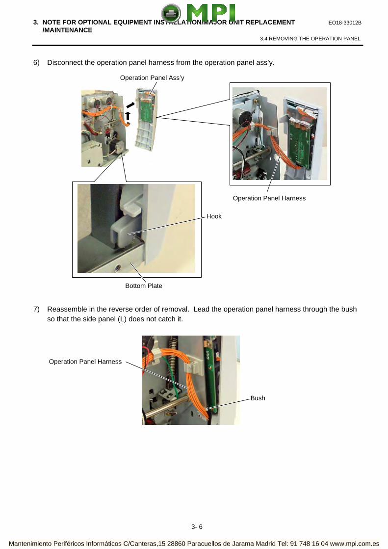
2) Disassemble the frame into 3 parts.
3) Replace the Rotary Cutter Guide Plate B and the Rotary Cutter Guide Plate C with the Rotary Cutter Frame A and Rotary Cutter Frame B, respectively.
4) Assemble the Rotary Cutter Frame A and Rotary Cutter Frame B with an SMW-4x8 screw removed in step 2).
5) Confirming the orientation of the Rotary Cutter PC Board, fix it to the Rotary Cutter Frames A and B with three SMW-3x6 screws. Then, attach the Rotary Cutter PC Board Cover with an SMW-3x6 screw.
SMW-3x6
SMW-4x8
Rotary Cutter Guide Plate B
Rotary Cutter Guide Plate C Rotary Cutter PC Board Cover (To be used later.)
SMW-4x8
Rotary Cutter Frame B (P/No.: 7FM01068000)
Rotary Cutter Frame A (P/No.: 7FM0167000)
Determine the position by fitting the two parts here.
SMW-3x6 SMW-3x6
Rotary Cutter PC Board Cover
Rotary Cutter Guide Plate C
Rotary Cutter Guide Plate B
Mantenimiento Periféricos Informáticos C/Canteras,15 28860 Paracuellos de Jarama Madrid Tel: 91 748 16 04 www.mpi.com.es

4. INSTALLATION PROCEDURE FOR OPTIONAL EQUIPMENT EO18-33012B
4.2 ROTARY CUTTER (B-8204-QM)
4- 9
NOTE: When attaching the B-8204-QM cutter module, replace the original cutter paper guide C with the enclosed B-SX cutter paper guide C using the following procedure.
(1) Remove the two M-4x6 Set Screws from the cutter unit to detach the cutter paper guide C. (2) Secure the B-SX cutter paper guide C with the M-4x6 set screws while pushing it upward.
CAUTION! Do not hold the cutter paper guides when attaching the Cutter Unit to the printer. Doing so may deform the cutter paper guides, causing a paper jam.
Cutter Paper Guide C
M-4x6
M-4x6
B-SX Cutter Paper Guide C
Cutter Paper Guide
DO NOT!
Mantenimiento Periféricos Informáticos C/Canteras,15 28860 Paracuellos de Jarama Madrid Tel: 91 748 16 04 www.mpi.com.es

4. INSTALLATION PROCEDURE FOR OPTIONAL EQUIPMENT EO18-33012B
4.2 ROTARY CUTTER (B-8204-QM)
4- 10
1) Remove the two black screws to detach the front plate. (Refer to section 4.1.)
2) Open the top cover. (Refer to Section 3.1.)
3) Remove the side panel (L) from the printer. (Refer to section 3.2.)
4) Fix the cutter drive unit to the printer with the three SM-4x8 screws.
5) Connect the 9-pin connector of the harness ass’y to CN7 and 2-pin connector to CN9 on the cutter
driver unit, respectively.
6) Fit the bush to the harness ass’y in the orientation as shown below.
SM-4x8 Screw
Cutter Drive Unit SM-4x8 Screw
CN7 (9 pins) CN9 (2 pins)
Harness Ass’y
Bush
Harness Ass’y
Mantenimiento Periféricos Informáticos C/Canteras,15 28860 Paracuellos de Jarama Madrid Tel: 91 748 16 04 www.mpi.com.es

4. INSTALLATION PROCEDURE FOR OPTIONAL EQUIPMENT EO18-33012B
4.2 ROTARY CUTTER (B-8204-QM)
4-11
7) Insert the harness ass’y into the hole in the main frame. Fit the bush into the hole.
8) Connect the 9-pin connector of the harness ass’y to CN15, and 2-pin connector to CN18 on the
Main PC board, respectively.
9) Open the print head block. (Refer to section 3.3.)
10) Connect the four harnesses of the cutter unit to CN8, CN10, CN11 and CN12 on the cutter drive unit.
Main PC Board
CN18 (2 pins) CN15 (9 pins)
Harness Ass’y
Hole
Main Frame
Harness Ass’y
Cutter Unit
Cutter Drive Unit
Print Head Block CN8 CN12 CN10
CN11
Mantenimiento Periféricos Informáticos C/Canteras,15 28860 Paracuellos de Jarama Madrid Tel: 91 748 16 04 www.mpi.com.es

4. INSTALLATION PROCEDURE FOR OPTIONAL EQUIPMENT EO18-33012B
4.2 ROTARY CUTTER (B-8204-QM)
4-12
11) Fit the two tabs of the cutter drive unit into the notches, and then fix the cutter unit with the three SM-4x8 screws.
12) Attach the cutter cover to the cutter unit with the two screws so that the tab of the cutter cover
turns on the cutter cover open switch. NOTES: 1. Be careful not to pinch the cutter harness by the cutter cover. 2. Make sure that the anti-static brush is protruding from the media outlet. 13) Close the print head block and ribbon shaft holder plate.
NOTE: DO NOT excessively push down the print head block to close it. Doing so may cause a failure of the print head block or damage to the print head.
14) Reassemble the side panel (L) and close the top cover. Finally check the cutter operation.
Cutter Unit
Notch
Tab
SM-4 x 8 Screw
Notch Tab
SM-4 x 8 Screw
Screw
Cutter Cover
Anti-static Brush
Media Outlet Tab
Cutter Cover Open Switch
Cutter Cover
Mantenimiento Periféricos Informáticos C/Canteras,15 28860 Paracuellos de Jarama Madrid Tel: 91 748 16 04 www.mpi.com.es

4. INSTALLATION PROCEDURE FOR OPTIONAL EQUIPMENT EO18-33012B
4.3 STRIP MODULE (B-9904-H-QM)
4-13
4.3 STRIP MODULE (B-9904-H-QM) This optional device is used for strip print, which cannot be used together with either B-4205-QM or B-8204-QM. When using a strip module together with an RFID module, be sure to install the RFID module prior to the strip module. NOTE: The strip module is standard on the B-SX5T series. All the following parts are supplied with the kit. Make sure you have all items shown below.
Rewinder Ass’y (1 pc.)
Rewinder Guide Plate (1 pc.) Bush (1 pc.)
Strip Sensor (TR) (1 pc.) Strip Sensor (LED) (1 pc.) Rewind Paper Guide (1 pc.)
• Installation Manual (1 copy) • SM-4x8B Screw (10 pcs.) • SM-3x6B Screw (1 pc.) • SM-4x8C Screw (1 pc.)
Mantenimiento Periféricos Informáticos C/Canteras,15 28860 Paracuellos de Jarama Madrid Tel: 91 748 16 04 www.mpi.com.es

4. INSTALLATION PROCEDURE FOR OPTIONAL EQUIPMENT EO18-33012B
4.3 STRIP MODULE (B-9904-H-QM)
4-14
1) Remove the two black screws to detach the front plate. (Refer to section 4.1.)
2) Open the top cover. (Refer to Section 3.1.)
3) Remove the side panel (L) from the printer. (Refer to section 3.2.)
4) Remove the operation panel ass’y from the printer. (Refer to section 3.4.)
5) Attach the rewind paper guide to the base with the two M-4x8 screws.
6) Align the notch of the take-up holder with the screw hole of the rewinder ass’y, and attach them to
the printer with the four SM-4x8B screws and the SM-4x8C screw.
7) Attach the rewind full sensor (LED) to the base with the SM-3x6B screw.
Screw Hole
Rewind Paper Guide
M-4x8 Screw
Mantenimiento Periféricos Informáticos C/Canteras,15 28860 Paracuellos de Jarama Madrid Tel: 91 748 16 04 www.mpi.com.es

4. INSTALLATION PROCEDURE FOR OPTIONAL EQUIPMENT EO18-33012B
4.3 STRIP MODULE (B-9904-H-QM)
4-15
8) Fit the bush to the longer harness of the rewind full sensor (Tr) and the rewinder harness in the orientation shown below.
9) Insert the longer harness of the rewind full sensor (Tr) into the hole in the printer frame. Fit the
bush into the hole.
SM-4x8B Screw
SM-4x8C Screw
SM-4x8B Screw
Take-up Holder
Notch
Rewind Full Sensor (LED)
SM-3x6B Screw
Rewinder Ass’y
Base
Bush
Longer Harness of the Rewind Full Sensor (Tr)
Longer Harness of the Rewind Full Sensor (Tr)
Bush Hole
Frame
Rewinder Harness
Mantenimiento Periféricos Informáticos C/Canteras,15 28860 Paracuellos de Jarama Madrid Tel: 91 748 16 04 www.mpi.com.es

4. INSTALLATION PROCEDURE FOR OPTIONAL EQUIPMENT EO18-33012B
4.3 STRIP MODULE (B-9904-H-QM)
4-16
10) Connect the longer harness of the rewind full sensor (Tr) and the rewinder harness to CN4 and CN15 on the Main PC board, respectively.
NOTES: 1. You should change the selection switch setting depending on the issue mode. Improper setting
may affect the print quality.
STANDARD/PEEL OFF (STRIP): Batch or strip mode REWINDER: Built-in rewinder mode
For the cut mode, the selection switch can be set to either position.
2. The backing paper can be wound directly onto the Take-up
Spool or a paper core. When using the Take-up Spool, detach the Holder Stopper
by removing the B-3x4 screw. Otherwise, it may be difficult to pull out the wound backing paper roll.
When using a paper core, put the core on the Take-up Spool with the Holder Stopper on it, and Attach the top edge of the backing paper to the core with adhesive tape. The Take-up Clip is not necessary.
This winding method is applicable to the Built-in Rewinder mode.
11) Open the print head block. (Refer to section 3.3.) 12) Fix the longer harness of the rewind full sensor and the rewinder harness under the Main PC
board with the cable clamp.
Main PC Board
Longer Harness of the Rewind Full Sensor (Tr)
CN4
CN15
Selection Switch
Cable Clamp
Longer Harness of the Rewind Full Sensor (Tr)
Rewinder Harness
Rewinder Harness
Main PC Board
Take-up Spool
B-3x4 Screw
Holder Stopper
Take-up Clip
Mantenimiento Periféricos Informáticos C/Canteras,15 28860 Paracuellos de Jarama Madrid Tel: 91 748 16 04 www.mpi.com.es

4. INSTALLATION PROCEDURE FOR OPTIONAL EQUIPMENT EO18-33012B
4.3 STRIP MODULE (B-9904-H-QM)
4-17
13) Secure the strip sensor (LED) and strip sensor (Tr) to the printer with the SM-4x8B screws.
14) Connect the shorter harness of the strip sensor (Tr) to the strip sensor harness (for LED).
15) Fix the connected strip sensor harness (for LED) to the base with the cable clamp. While passing the other strip sensor harness through the cut and the bush, reassemble the operation panel ass’y to the printer. Then pass the strip sensor harness over the tab on the back of the operation panel ass’y.
NOTE: Be careful not to pinch the strip sensor harnesses by the operation panel.
SM-4x8B Screw Strip Sensor (Tr)
Strip Sensor Harness (for LED)
Shorter Harness of the Strip Sensor Harness (for Tr)
Strip Sensor (LED)
SM-4x8B Screw
Tab
Strip Sensor (Tr)
Bush
Strip Sensor Harness (for LED)
Cable Clamp
Operation Panel Ass’y
Strip Sensor Harness
Cut
Mantenimiento Periféricos Informáticos C/Canteras,15 28860 Paracuellos de Jarama Madrid Tel: 91 748 16 04 www.mpi.com.es
4. INSTALLATION PROCEDURE FOR OPTIONAL EQUIPMENT EO18-33012B
4.3 STRIP MODULE (B-9904-H-QM)
4-18
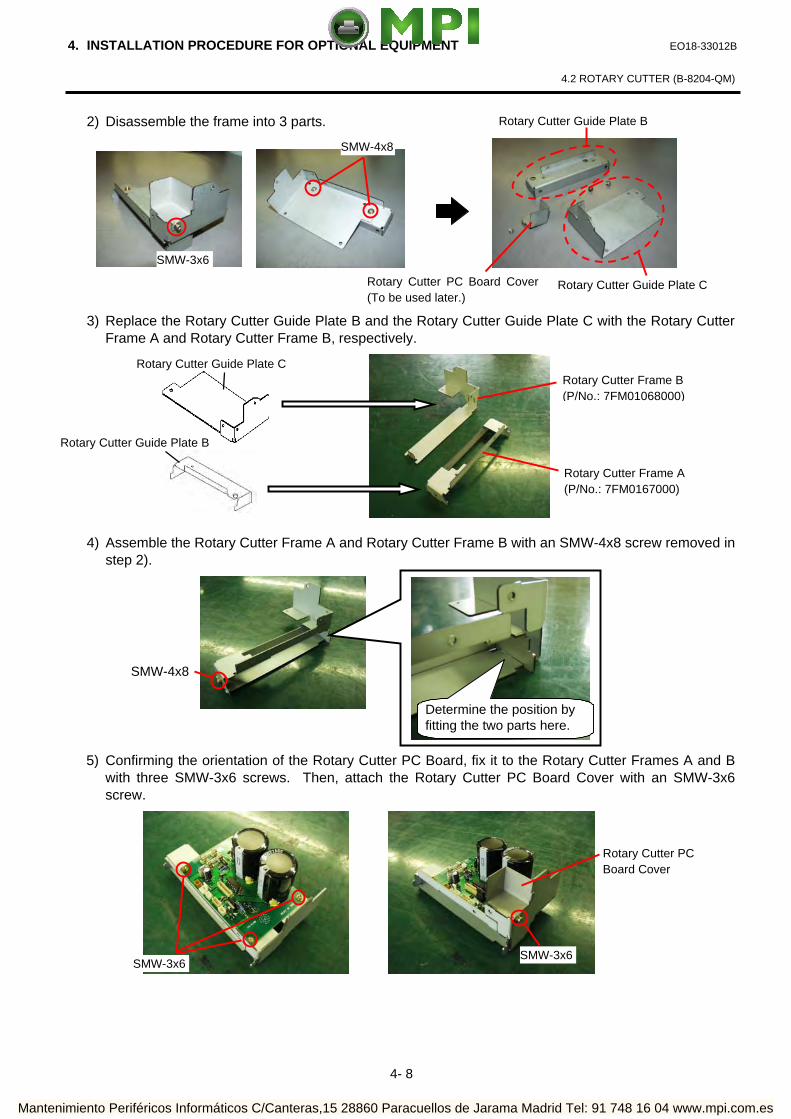
16) Fix the strip sensor harness with the three cable clamps and connect it to CN20 on the Main PC board.
17) Reassemble the side panel (L) in the reverse order of removal. 18) Close the print head block and ribbon shaft holder plate.
NOTE: DO NOT excessively push down the print head block to close it. Doing so may cause a failure of the print head block or damage to the print head.
19) When using the printer in batch mode or strip mode, attach the front plate removed in step 1). 20) When using the printer in built-in rewinder mode, attach the rewinder guide plate to the front of the
printer with the two SMW-4x8 screws.
21) Make a test print to check for proper strip issue.
NOTE: If the label skews, refer to section 8.
Cable Clamp
CN20 Main PC Board
Strip Sensor Harness
Rewinder Guide Plate SMW-4x8 Screw
SMW-4x8 Screw
Mantenimiento Periféricos Informáticos C/Canteras,15 28860 Paracuellos de Jarama Madrid Tel: 91 748 16 04 www.mpi.com.es

4. INSTALLATION PROCEDURE FOR OPTIONAL EQUIPMENT EO18-33012B
4.4 RIBBON SAVING MODULE (B-9904-R/R2-QM)
4-19
4.4 RIBBON SAVING MODULE (B-9904-R/R2-QM) All the following parts are supplied with the kit. Make sure you have all items shown below.
NOTE: The ribbon saving module is standard on the B-SX5T series.
Solenoid (1 pc.) RSV PC Board (1 pc.) Solenoid Harness (1 pc.)
Cable Clamp (1 pc.) Locking Support (3 pcs.)
• Installation Manual (1 copy)
• SM-4x8 Screw (2 pcs.)
NOTES: 1. The B-9904-R2-QM Ribbon Saving Module is available only with Firmware V1.2A or greater.
Please be careful that the earlier firmware version does not support it. 2. The insulation tape of the solenoid of the B-9904-R-QM is blue, and that of the B-9904-R2-QM
is black. 1) Remove the side panel (L) from the printer. (Refer to section 3.2.) 2) Remove the operation panel ass’y from the printer. (Refer to section 3.4.) 3) Fit the three locking supports into the RSV PC board.
RSV PC Board
Locking Support
Insulation Tape
Mantenimiento Periféricos Informáticos C/Canteras,15 28860 Paracuellos de Jarama Madrid Tel: 91 748 16 04 www.mpi.com.es
4. INSTALLATION PROCEDURE FOR OPTIONAL EQUIPMENT EO18-33012B
4.4 RIBBON SAVING MODULE (B-9904-R/R2-QM)
4-20
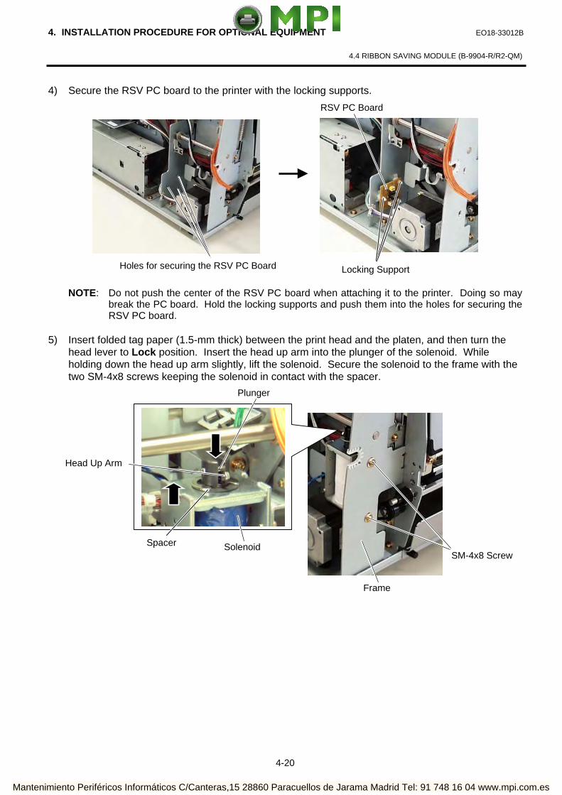
4) Secure the RSV PC board to the printer with the locking supports.
NOTE: Do not push the center of the RSV PC board when attaching it to the printer. Doing so may break the PC board. Hold the locking supports and push them into the holes for securing the RSV PC board.
5) Insert folded tag paper (1.5-mm thick) between the print head and the platen, and then turn the
head lever to Lock position. Insert the head up arm into the plunger of the solenoid. While holding down the head up arm slightly, lift the solenoid. Secure the solenoid to the frame with the two SM-4x8 screws keeping the solenoid in contact with the spacer.
Frame
SM-4x8 Screw
Head Up Arm
Plunger
Solenoid Spacer
RSV PC Board
Holes for securing the RSV PC Board Locking Support
Mantenimiento Periféricos Informáticos C/Canteras,15 28860 Paracuellos de Jarama Madrid Tel: 91 748 16 04 www.mpi.com.es

4. INSTALLATION PROCEDURE FOR OPTIONAL EQUIPMENT EO18-33012B
4.4 RIBBON SAVING MODULE (B-9904-R/R2-QM)
4-21
6) Attach the cable clamp to the frame of the printer. Fix the solenoid cable with this cable clamp.
NOTE: Be careful not to snag the solenoid harness when running it.
7) Connect the solenoid harness to CN1 on the RSV PC board and CN11 on the Main PC board. Pass the solenoid harness through the cut.
8) Connect the solenoid cable to CN2 on the RSV PC board.
9) After attaching the solenoid, reassemble the operation panel ass’y and the side panel (L) in the
reverse order of removal.
CN2
CN1 Solenoid Cable
CN11
Main PC Board
Solenoid Harness
RSV PC Board
Cut
Cable Clamp
Solenoid Cable
Solenoid Solenoid Harness
Mantenimiento Periféricos Informáticos C/Canteras,15 28860 Paracuellos de Jarama Madrid Tel: 91 748 16 04 www.mpi.com.es

4. INSTALLATION PROCEDURE FOR OPTIONAL EQUIPMENT EO18-33012B
4.5 PCMCIA INTERFACE BOARD (B-9700-PCM-QM)
4-22
4.5 PCMCIA INTERFACE BOARD (B-9700-PCM-QM) This optional interface board is provided with the two slots, which allows for the use of the two TYPE II PC cards. However, it is not applied to TYPE III PC cards.
CAUTION! 1. Loosen the two M-3x5 screws of the PCMCIA interface board before installing it. Failure to do
this may cause damage to the connector. 2. When using the LAN interface board or USB interface board together, install the PCMCIA
interface board first. NOTE: When both B-9700-PCM-QM and B-9700-LAN-QM are installed, inserting a LAN PC card into
the slot of the B-9700-PCM-QM disables the B-9700-LAN-QM. All the following parts are supplied with the kit. Make sure you have all items shown below.
PCMCIA Interface Board (1 pc.)
1) Remove the side panel (L) from the printer. (Refer to section 3.2.)
2) Loosen the two M-3x5 screws of the PCMCIA interface board. (Refer to Caution above.)
3) Remove the two SM-3x6 screws to detach the blind plate A from the back.
M-3x5 Screw
• Installation Manual (1 copy)
• SM-3x6 Screw (3 pcs.)
Rear Plate
SM-3x6 Screw
Blind Plate A
Mantenimiento Periféricos Informáticos C/Canteras,15 28860 Paracuellos de Jarama Madrid Tel: 91 748 16 04 www.mpi.com.es

4. INSTALLATION PROCEDURE FOR OPTIONAL EQUIPMENT EO18-33012B
4.5 PCMCIA INTERFACE BOARD (B-9700-PCM-QM)
4-23
NOTE: In case of the B-SX5T or the B-SX4T that the optional Expansion I/O board (B-7704-IO-QM) has been installed in, remove the expansion I/O board from the printer temporarily using the following procedure.
(1) Disconnect the Expansion I/O cable from CN1 on the Expansion I/O board. (2) Remove the two B-3x6 screws to detach the Expansion I/O board from the printer.
4) Firmly connect CN101 on the PCMCIA interface board directly to CN7 on the Main PC board.
5) Secure the PCMCIA interface board to the rear plate with the two SM-3x6 screws.
PCMCIA Interface Board
Main PC Board
CN101
CN7
SM-3x6 Screw
Rear Plate
Rear Plate
B-3x6 Screw
Expansion I/O Board
CN1
Expansion I/O Cable
Mantenimiento Periféricos Informáticos C/Canteras,15 28860 Paracuellos de Jarama Madrid Tel: 91 748 16 04 www.mpi.com.es

4. INSTALLATION PROCEDURE FOR OPTIONAL EQUIPMENT EO18-33012B
4.5 PCMCIA INTERFACE BOARD (B-9700-PCM-QM)
4-24
6) Secure the PCMCIA interface board to the PCB support plate with the SM-3x6 screw. Tighten the two M-3x5 screws that were loosened previously. (Refer to Caution)
7) Attach the blind plate A to the rear plate with the two SM-3x6 screws that were removed in step
6). If the LAN interface board or USB interface board is also installed, go to the next step.
NOTE: Keep the two SM-3x6 screws and blind plate A safe when the LAN interface board or USB interface board is installed.
8) Reassemble the side panel (L) in the reverse order of removal. If the Expansion I/O board was removed at the beginning, reassemble it.
NOTE: For insertion, removal, and handling of the PC card, refer to the Owner’s Manual.
Blind Plate A
SM-3x6 Screw
Rear Plate
SM-3x6 screw
PCB Support Plate
M-3x5 Screw
Mantenimiento Periféricos Informáticos C/Canteras,15 28860 Paracuellos de Jarama Madrid Tel: 91 748 16 04 www.mpi.com.es

4. INSTALLATION PROCEDURE FOR OPTIONAL EQUIPMENT EO18-33012B
4.6 USB INTERFACE BOARD (B-9700-USB-QM)
4-25
4.6 USB INTERFACE BOARD (B-9700-USB-QM) This optional interface board is provided with the interface port, which allows for the installation of USB devices.
CAUTION! 1. Loosen the two M-3x5 screws of the USB interface board before installing it. Failure to do this
may cause damage to the connector. 2. When using the PCMCIA interface board together, first install the PCMCIA PC board, and then
USB interface board.
All the following parts are supplied with the kit. Make sure you have all items shown below.
USB Interface Board (1pc.)
PCB Attachment Plate (1 pc.)
NOTE: When using the PCMCIA interface board (B-9700-PCM-QM) together, the PCB attachment plate will be used.
1) Turn the power off and disconnect the power cord.
2) Loosen the two M-3x5 screws of the USB interface board. (Refer to Caution above.)
3) Remove the side panel (L) from the printer. (Refer to section 3.2.)
4) Remove the two SM-3x6 screws to detach the blind plate A from the back.
M-3x5 Screw
• Installation Manual (1 copy)
• SM-3x6 Screw (4 pcs.)
SM-3x6 Screw
Blind Plate A
Mantenimiento Periféricos Informáticos C/Canteras,15 28860 Paracuellos de Jarama Madrid Tel: 91 748 16 04 www.mpi.com.es

4. INSTALLATION PROCEDURE FOR OPTIONAL EQUIPMENT EO18-33012B
4.6 USB INTERFACE BOARD (B-9700-USB-QM)
4-26
5) If the PCMCIA interface board is used together with the USB interface board, attach the PCB attachment plate to the plate to which the PCMCIA interface board is secured with the SM-3x6 screw. If not, go to the next step.
6) Firmly connect CN50 connector on the USB interface board directly to CN7 on the Main PC board or CN1 on the PCMCIA interface board.
When connecting to the Main PC Board: When connecting the PCMCIA Interface Board:
PCMCIA Interface Board
PCB Attachment Plate SM-3x6 Screw
USB Interface Board Main PC Board
CN50
CN7
USB Interface Board PCMCIA Interface Board
CN50
CN1
Mantenimiento Periféricos Informáticos C/Canteras,15 28860 Paracuellos de Jarama Madrid Tel: 91 748 16 04 www.mpi.com.es

4. INSTALLATION PROCEDURE FOR OPTIONAL EQUIPMENT EO18-33012B
4.6 USB INTERFACE BOARD (B-9700-USB-QM)
4-27
7) Secure the USB interface board to the rear plate with the two SM-3x6 screws.
8) Tighten the two M-3x5 screws of the USB interface board that were loosened previously. (Refer to Caution)
9) Secure the USB interface board to the PCB support plate (when connecting to the Main PC board) or PCB attachment plate (when connecting to the PCMCIA interface board) with the SM-3x6 screw.
When connecting to the Main PC Board: When connecting to the PCMCIA Interface Board:
SM-3x6 Screw
USB Interface Board
SM-3x6 Screw
USB Interface Board
When connecting to the Main PC Board:
M-3x5 Screw
SM-3x6 Screw PCB Support Plate
When connecting to the PCMCIA Interface Board:
M-3x5 Screw
SM-3x6 Screw PCB Attachment Plate
Mantenimiento Periféricos Informáticos C/Canteras,15 28860 Paracuellos de Jarama Madrid Tel: 91 748 16 04 www.mpi.com.es

4. INSTALLATION PROCEDURE FOR OPTIONAL EQUIPMENT EO18-33012B
4.6 USB INTERFACE BOARD (B-9700-USB-QM)
4-28
10) Attach the blind plate A to the rear plate. If the PCMCIA interface board has been installed, go to the next step.
NOTE: In case that the PCMCIA interface board has been installed, retain the blind plate A.
11) Reassemble the side panel (L) to the printer in the reverse order of removal.
Blind Plate A
SM-3x6 Screw
Rear Plate
Mantenimiento Periféricos Informáticos C/Canteras,15 28860 Paracuellos de Jarama Madrid Tel: 91 748 16 04 www.mpi.com.es

4. INSTALLATION PROCEDURE FOR OPTIONAL EQUIPMENT EO18-33012B
4.7 LAN INTERFACE BOARD (B-9700-LAN-QM)
4-29
4.7 LAN INTERFACE BOARD (B-9700-LAN-QM) This optional interface board enables the printer to be used in a LAN network.
CAUTION! 1. Loosen the two M-3x5 screws of the LAN interface board before installing it. Failure to do this
may cause damage to the connector. 2. When using the PCMCIA interface board together, first install the PCMCIA PC board, and then
LAN interface board.
NOTE: When both B-9700-LAN-QM and B-9700-PCM-QM are installed, inserting a LAN PC card into the
slot of the B-9700-PCM-QM disables the B-9700-LAN-QM.
All the following parts are supplied with the kit. Make sure you have all items shown below.
LAN Interface Board (1pc.)
PCB Attachment Plate
NOTE: When using the PCMCIA interface board (B-9700-PCM-QM) together, the PCB attachment plate will be used.
M-3x5 Screw
License Agreement Please be sure to read the License Agreement before opening the sealed LAN Interface Board. If you do not agree with the License Agreement, please do not use this product. Your unpacking the product indicates your approval for the License Agreement.
• Installation Manual (1 copy)
• License Agreement (1 copy)
• SM-3x6 Screw (4 pcs.)
Mantenimiento Periféricos Informáticos C/Canteras,15 28860 Paracuellos de Jarama Madrid Tel: 91 748 16 04 www.mpi.com.es

4. INSTALLATION PROCEDURE FOR OPTIONAL EQUIPMENT EO18-33012B
4.7 LAN INTERFACE BOARD (B-9700-LAN-QM)
4-30
1) Loosen the two M-3x5 screws of the LAN interface board. (Refer to Caution above.)
2) Remove the side panel (L) from the printer. (Refer to section 3.2.)
3) Remove the two SM-3x6 screws to remove the blind plate A from the back.
NOTE: Keep the blind plate A safe as this will be necessary when the machine is modified to the standard
type.
4) If the PCMCIA interface board is also installed, attach the PCB attachment plate to the plate to which the PCMCIA interface board is secured with the SM-3x6 screw. If not, go to the next step.
Blind Plate A
SM-3x6 Screw
PCB Attachment Plate SM-3x6 Screw
PCMCIA Interface Board
Mantenimiento Periféricos Informáticos C/Canteras,15 28860 Paracuellos de Jarama Madrid Tel: 91 748 16 04 www.mpi.com.es

4. INSTALLATION PROCEDURE FOR OPTIONAL EQUIPMENT EO18-33012B
4.7 LAN INTERFACE BOARD (B-9700-LAN-QM)
4-31
5) Firmly connect CN50 on the LAN interface board directly to CN7 on the Main PC board or CN1 on the PCMCIA interface board.
6) Secure the LAN interface board to the rear plate with the two SM-3x6 screws.
When connecting to the Main PC Board When connecting to the PCMCIA Interface Board
LAN Interface Board MAIN PC Board
CN50
CN7
LAN Interface Board
PCMCIA Interface Board
CN50
CN1
When connecting to the Main PC Board When connecting to the PCMCIA Interface Board
SM-3x6 Screw
SM-3x6 Screw
Rear Plate Rear Plate LAN Interface Board LAN Interface Board
Mantenimiento Periféricos Informáticos C/Canteras,15 28860 Paracuellos de Jarama Madrid Tel: 91 748 16 04 www.mpi.com.es
4. INSTALLATION PROCEDURE FOR OPTIONAL EQUIPMENT EO18-33012B
4.7 LAN INTERFACE BOARD (B-9700-LAN-QM)
4-32
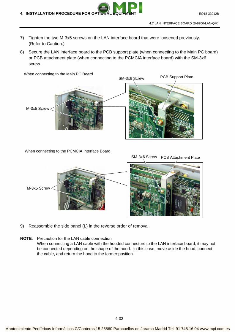
7) Tighten the two M-3x5 screws on the LAN interface board that were loosened previously. (Refer to Caution.)
8) Secure the LAN interface board to the PCB support plate (when connecting to the Main PC board) or PCB attachment plate (when connecting to the PCMCIA interface board) with the SM-3x6 screw.
9) Reassemble the side panel (L) in the reverse order of removal.
NOTE: Precaution for the LAN cable connection When connecting a LAN cable with the hooded connectors to the LAN interface board, it may not
be connected depending on the shape of the hood. In this case, move aside the hood, connect the cable, and return the hood to the former position.
When connecting to the Main PC Board
M-3x5 Screw
SM-3x6 Screw PCB Support Plate
When connecting to the PCMCIA Interface Board
M-3x5 Screw
SM-3x6 Screw PCB Attachment Plate
Mantenimiento Periféricos Informáticos C/Canteras,15 28860 Paracuellos de Jarama Madrid Tel: 91 748 16 04 www.mpi.com.es

4. INSTALLATION PROCEDURE FOR OPTIONAL EQUIPMENT EO18-33012B
4.8 EXPANSION I/O INTERFACE BOARD (B-7704-IO-QM)
4-33
4.8 EXPANSION I/O INTERFACE BOARD (B-7704-IO-QM) This optional interface board is provided with an expansion I/O interface.
NOTE: The expansion I/O interface board is standard on the B-SX5T series.
All the following parts are supplied with the kit. Make sure you have all items shown below.
Expansion I/O Board (1 pc.) Expansion I/O Cable (1 pc.)
• Installation Manual (1 copy) • Locking Support WLS-16-0 (1 pc.)
NOTE: The locking support is not used on this printer.
1) Turn the power off and disconnect the power cord.
2) Remove the side panel (L) from the printer. (Refer to section 3.2.)
3) Remove the two M-3x6 screws and detach the blind plate B from the back.
4) Remove the two B-3x6 screws from the expansion I/O board.
Blind Plate B
M-3x6 Screw
B-3x6 Screw
Mantenimiento Periféricos Informáticos C/Canteras,15 28860 Paracuellos de Jarama Madrid Tel: 91 748 16 04 www.mpi.com.es

4. INSTALLATION PROCEDURE FOR OPTIONAL EQUIPMENT EO18-33012B
4.8 EXPANSION I/O INTERFACE BOARD (B-7704-IO-QM)
4-34
5) Connect the expansion I/O cable to CN3 on the Main PC board.
6) Secure the expansion I/O board to the rear plate with the two B-3x6 screws removed in Step 4.
7) Connect the expansion I/O cable to CN1 on the expansion I/O board.
8) Reassemble the side panel (L) in the reverse order of removal.
9) Perform a loop back check to confirm that the expansion I/O board functions properly.
Expansion I/O Cable CN3
Main PC Board
CN1
Expansion I/O Board
Expansion I/O Cable
B-3x6 Screw
Rear Plate
Mantenimiento Periféricos Informáticos C/Canteras,15 28860 Paracuellos de Jarama Madrid Tel: 91 748 16 04 www.mpi.com.es

4. INSTALLATION PROCEDURE FOR OPTIONAL EQUIPMENT EO18-33012B
4.9 RIBBON SAVING MODULE AND ROTARY CUTTER (For B-SX4T Series)
4-35
4.9 RIBBON SAVING MODULE AND ROTARY CUTTER (For B-SX4T Series)
When using the rotary cutter on the B-SX4T series, the ribbon saving module needs to be installed, also. In this section, how to install the ribbon saving module and rotary cutter is described.
Ribbon Saving Module
All the following parts are supplied with the kit. Make sure you have all items shown below.
Solenoid (1 pc.) RSV PC Board (1 pc.) Solenoid Harness (1 pc.)
Cable Clamp (1 pc.) Locking Support (3 pcs.)
• Installation Manual (1 copy)
• SM-4x8 Screw (2 pcs.)
NOTES: 1. The B-9904-R2-QM Ribbon Saving Module is available only with Firmware V1.2A or greater. Please be careful that the earlier firmware version does not support it.
2. The insulation tape of the solenoid of the B-9904-R-QM is blue, and that of the B-9904-R2-QM is black.
Rotary Cutter All the following parts are supplied with the kit. Make sure you have all items shown below.
Cutter Unit (1 pc.)
Cutter Cover (1 pc.) Cutter Drive Unit (1 pc.) Harness Ass’y (2-pin & 9-pin) (1 pc.)
Cord Bush (1 pc.)
Print Head Cleaner (1 pc.) (P/No.: FMQB0051601)
B-SX Cutter Paper Guide C (1 pc.)
• Installation Manual (1 copy) • SM-4x8 Screw (6 pcs.)
Insulation Tape
Mantenimiento Periféricos Informáticos C/Canteras,15 28860 Paracuellos de Jarama Madrid Tel: 91 748 16 04 www.mpi.com.es

4. INSTALLATION PROCEDURE FOR OPTIONAL EQUIPMENT EO18-33012B
4.9 RIBBON SAVING MODULE AND ROTARY CUTTER (For B-SX4T Series)
4- 36
WARNING!
Be careful not to injure your fingers when installing the cutter unit.
When attaching the B-8204-QM cutter module, replace the original cutter paper guide C with the enclosed B-SX cutter paper guide C using the following procedure. (1) Remove the two M-4x6 Set Screws from the cutter unit to detach the cutter paper guide C.
CAUTION! Do not hold the cutter paper guides when attaching the Cutter Unit to the printer. Doing so may deform the cutter paper guides, causing a paper jam.
Cutter Paper Guide C
M-4x6
Cutter Paper Guide
NG
Cutter Blade
Mantenimiento Periféricos Informáticos C/Canteras,15 28860 Paracuellos de Jarama Madrid Tel: 91 748 16 04 www.mpi.com.es

4. INSTALLATION PROCEDURE FOR OPTIONAL EQUIPMENT EO18-33012B
4.9 RIBBON SAVING MODULE AND ROTARY CUTTER (For B-SX4T Series)
4- 37
(2) Secure the B-SX cutter paper guide C with the M-4x6 set screws while pushing it upward. Installation Procedure 1) Remove the side panel (L) from the printer. (Refer to Section 3.2.) 2) Remove the operation panel ass’y from the printer. (Refer to section 3.4.) 3) Fit the three locking supports into the RSV PC board. 4) Secure the RSV PC board to the printer with the locking supports.
NOTE: Do not push the center of the RSV PC board when attaching it to the printer. Doing so may break the PC board. Hold the locking supports and push them into the holes for securing the RSV PC board.
M-4x6
B-SX Cutter Paper Guide C
RSV PC Board
Locking Support
RSV PC Board
Holes for securing the RSV PC Board Locking Support
Mantenimiento Periféricos Informáticos C/Canteras,15 28860 Paracuellos de Jarama Madrid Tel: 91 748 16 04 www.mpi.com.es

4. INSTALLATION PROCEDURE FOR OPTIONAL EQUIPMENT EO18-33012B
4.9 RIBBON SAVING MODULE AND ROTARY CUTTER (For B-SX4T Series)
4-38
5) Insert folded tag paper (1.5-mm thick) between the print head and the platen, and then turn the head lever to Lock position. Insert the head up arm into the plunger of the solenoid. While holding down the head up arm slightly, lift the solenoid. Secure the solenoid to the frame with the two SM-4x8 screws keeping the solenoid in contact with the spacer.
6) Attach the cable clamp to the frame of the printer. Fix the solenoid cable with this cable clamp.
NOTE: Be careful not to snag the solenoid harness when running it.
Frame
SM-4x8 Screw
Head Up Arm
Plunger
Solenoid Spacer
Cable Clamp
Solenoid Cable
Solenoid
Mantenimiento Periféricos Informáticos C/Canteras,15 28860 Paracuellos de Jarama Madrid Tel: 91 748 16 04 www.mpi.com.es
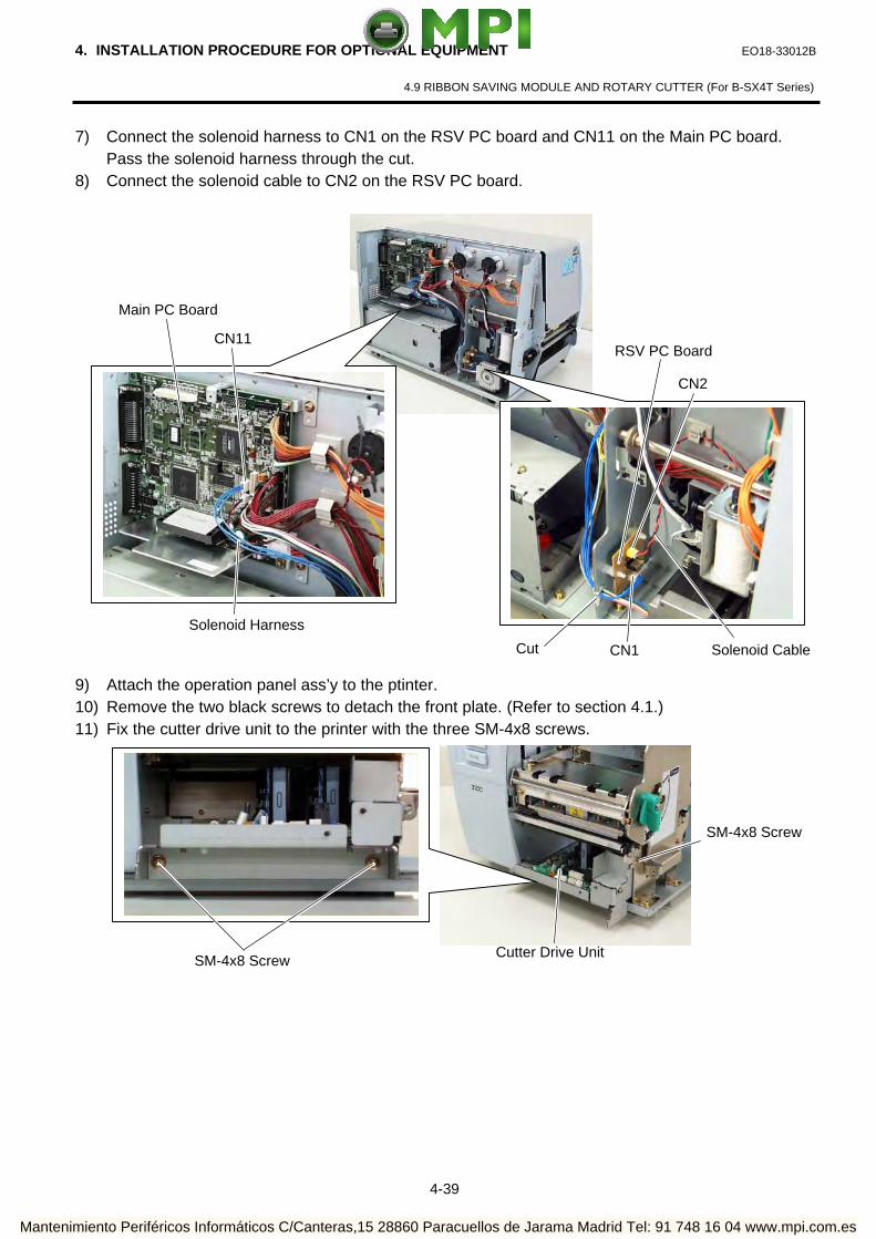
4. INSTALLATION PROCEDURE FOR OPTIONAL EQUIPMENT EO18-33012B
4.9 RIBBON SAVING MODULE AND ROTARY CUTTER (For B-SX4T Series)
4-39
7) Connect the solenoid harness to CN1 on the RSV PC board and CN11 on the Main PC board. Pass the solenoid harness through the cut.
8) Connect the solenoid cable to CN2 on the RSV PC board.
9) Attach the operation panel ass’y to the ptinter. 10) Remove the two black screws to detach the front plate. (Refer to section 4.1.) 11) Fix the cutter drive unit to the printer with the three SM-4x8 screws.
CN2
CN1 Solenoid Cable
CN11
Main PC Board
Solenoid Harness
RSV PC Board
Cut
SM-4x8 Screw
Cutter Drive Unit SM-4x8 Screw
Mantenimiento Periféricos Informáticos C/Canteras,15 28860 Paracuellos de Jarama Madrid Tel: 91 748 16 04 www.mpi.com.es

4. INSTALLATION PROCEDURE FOR OPTIONAL EQUIPMENT EO18-33012B
4.9 RIBBON SAVING MODULE AND ROTARY CUTTER (For B-SX4T Series)
4-40
12) Connect the 9-pin connector of the harness ass’y to CN7 and 2-pin connector to CN9 on the cutter driver unit, respectively.
13) Fit the bush to the harness ass’y in the orientation as shown below.
14) Insert the harness ass’y into the hole in the main frame. Fit the bush into the hole.
CN7 (9 pins) CN9 (2 pins)
Harness Ass’y
Bush
Harness Ass’y
Hole
Main Frame
Harness Ass’y
Mantenimiento Periféricos Informáticos C/Canteras,15 28860 Paracuellos de Jarama Madrid Tel: 91 748 16 04 www.mpi.com.es

4. INSTALLATION PROCEDURE FOR OPTIONAL EQUIPMENT EO18-33012B
4.9 RIBBON SAVING MODULE AND ROTARY CUTTER (For B-SX4T Series)
4-41
15) Connect the 9-pin connector of the harness ass’y to CN15, and 2-pin connector to CN18 on the Main PC board, respectively.
16) Open the print head block. (Refer to section 3.3.)
17) Connect the four harnesses of the cutter unit to CN8, CN10, CN11 and CN12 on the cutter drive unit.
Main PC Board
CN18 (2 pins) CN15 (9 pins)
Harness Ass’y
Cutter Unit
Cutter Drive Unit
Print Head Block CN8 CN12 CN10
CN11
Mantenimiento Periféricos Informáticos C/Canteras,15 28860 Paracuellos de Jarama Madrid Tel: 91 748 16 04 www.mpi.com.es
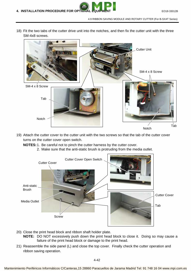
4. INSTALLATION PROCEDURE FOR OPTIONAL EQUIPMENT EO18-33012B
4.9 RIBBON SAVING MODULE AND ROTARY CUTTER (For B-SX4T Series)
4-42
18) Fit the two tabs of the cutter drive unit into the notches, and then fix the cutter unit with the three SM-4x8 screws.
19) Attach the cutter cover to the cutter unit with the two screws so that the tab of the cutter cover
turns on the cutter cover open switch. NOTES: 1. Be careful not to pinch the cutter harness by the cutter cover. 2. Make sure that the anti-static brush is protruding from the media outlet. 20) Close the print head block and ribbon shaft holder plate.
NOTE: DO NOT excessively push down the print head block to close it. Doing so may cause a failure of the print head block or damage to the print head.
21) Reassemble the side panel (L) and close the top cover. Finally check the cutter operation and ribbon saving operation.
Cutter Unit
Notch
Tab
SM-4 x 8 Screw
Notch Tab
SM-4 x 8 Screw
Screw
Cutter Cover
Anti-static Brush
Media Outlet Tab
Cutter Cover Open Switch
Cutter Cover
Mantenimiento Periféricos Informáticos C/Canteras,15 28860 Paracuellos de Jarama Madrid Tel: 91 748 16 04 www.mpi.com.es

4. INSTALLATION PROCEDURE FOR OPTIONAL EQUIPMENT EO18-33012B (Revision Date: Feb. 15, 2007)
4.10 RFID MODULE (B-9704-RFID-U1-US/EU/EU-R)
4-43
4.10 RFID MODULE (B-9704-RFID-U1-US/EU/EU-R) NOTES: 1. An RFID tag chip or the print head may be damaged when the print head passes over the chip. This can be prevented by using the ribbon saving module (standard feature for the B-SX5T and optional for
the B-SX4T). The print head is lifted by the ribbon saving module when it passes over the chip to prevent it from touching the chip. The print head is lifted by approximately 1 mm from the platen.
2. When an RFID label or tag is used in cut issue mode, care must be taken not to cut an antenna of the RFID tag or an IC chip in order not to damage the cutter.
3. When using the RFID module together with a cutter or strip module, be sure to install the RFID module first. When the B-4205-QM swing cutter has been installed, remove the cutter unit before installing the RFID
module. When the B-8204-QM rotary cutter has been installed, remove the cutter unit and cutter drive unit before
installing the RFID module. When the B-9904-H-QM strip module has been installed, remove the rewinder guide plate and strip sensors
(Tr and LED) before installing the RFID module. (The strip module is standard feature of the B-SX5T series.)
4.10.1 Applicable Model The B-9704-RFID-U1-US/EU model is intended for the following models: B-SX4T-GS10-QQ/QQ-US/QP, RFID Ready printer (Serial No. 2604Wxxxxxx or later) B-SX5T-TS10-QQ/QQ-US/QP, RFID Ready printer (Serial No. 2604Wxxxxxx or later)
The B-9704-RFID-H1-QM-R model is intended for the following models: B-SX4T-GS20-QM-R, B-SX5T-TS22-QM-R
An RFID Ready printer can be identified by the model name sticker on the front of the printer. The countries where the use of this device is allowed are as follows:
Model Name Frequency Band Applicable Countries B-9704-RFID-U1-US UHF (902 to 928MHz) U.S.A and Canada
B-9704-RFID-U1-EU/EU-R UHF (869.5MHz)
Austria, Belgium, Cyprus, Czech, Denmark, Estonia, Germany, Greece, Finland, France, Hungary, Ireland, Italy, Latvia, Lithuania, Luxemburg, Malta, Poland, Portugal, Slovakia, Slovenia, Spain, Sweden, the Netherlands, and U.K.
4.10.2 Packing List All the following parts are supplied with the kit. Make sure you have all items shown below.
Parts Quantity Parts Quantity
US 1 pc. US 0 pc.
Antenna Cover
EU 0 pc.
Antenna Cover including Antenna
EU 1 pc.
US 0 pc. US 1 pc.
Antenna Frame
EU 1 pc.
Antenna Frame including Antenna
EU 0 pc.
Mantenimiento Periféricos Informáticos C/Canteras,15 28860 Paracuellos de Jarama Madrid Tel: 91 748 16 04 www.mpi.com.es

4. INSTALLATION PROCEDURE FOR OPTIONAL EQUIPMENT EO18-33012B
4.10 RFID MODULE (B-9704-RFID-U1-US/EU)
4-44
Parts Quantity Parts Quantity
US 1 pc. US 1 pc.
RFID Module
EU 1 pc.
Ribbon Guide
EU 1 pc.
US 1 pc. US 1 pc.
Bush
EU 1 pc.
Cable Clamp
EU 1 pc.
US 1 pc. US 6 pc.
Interface Cable
EU 1 pc.
SMW-3x6 Double Sems Screw
EU 6 pc.
US 0 pc. US 2 pc.
SMW-3x6* Double Sems Screw (Small Washer Type: Spare)
EU 2 pc.
PT-3x6 P-TITE Screw (Spare)
EU 0 pc.
US 1 pc. US 1 pc.
RFID Module Cover
EU 1 pc.
FCC Sticker (US model)
EU 0 pc.
US 0 pc.
CE Sticker (EU model)
EU 1 pc.
NOTE: Double Sems Screws (SMW-3x6*) and P-TITE Screws (PT-3x6) are supplied just in case that the
antenna attachment position is changed.
Mantenimiento Periféricos Informáticos C/Canteras,15 28860 Paracuellos de Jarama Madrid Tel: 91 748 16 04 www.mpi.com.es

4. INSTALLATION PROCEDURE FOR OPTIONAL EQUIPMENT EO18-33012B
4.10 RFID MODULE (B-9704-RFID-U1-US/EU)
4-45
4.10.3 Removing the Platen Frame Top and Attaching the Ribbon Guide NOTE: When installing an RFID module, be care of the following:
1. When an RFID module is used together with a cutter module or strip module, install the RFID module first.
2. If the B-4205-QM swing cutter has been installed, remove the cutter unit before installing an RFID module.
3. If the B-8204-QM rotary cutter has been installed, remove the cutter unit and the cutter drive unit before installing an RFID module.
4. If the B-9904-H-QM strip module has been installed or in case of the B-SX5T, remove the rewinder guide plate and strip sensors before installing an RFID module.
1) Remove the two black screws to detach the front plate. (Refer to section 4.1.) 2) Remove the side panel (L) from the printer. (Refer to section 3.2.) 3) Push the Hook through the rectangle hole with a jeweler’s screw driver or something, and
remove the Platen Holder Cover in the direction indicated by the arrow.
4) Lift the right side of the Strip Plate, and then pull and remove it.
5) Remove the Platen and the Platen Holder in steps 1 to 3 as shown below.
Strip Plate
Hook
Platen Holder Cover
1
2
2
1
Platen
Platen Holder
1
2
3
Push
Mantenimiento Periféricos Informáticos C/Canteras,15 28860 Paracuellos de Jarama Madrid Tel: 91 748 16 04 www.mpi.com.es

4. INSTALLATION PROCEDURE FOR OPTIONAL EQUIPMENT EO18-33012B
4.10 RFID MODULE (B-9704-RFID-U1-US/EU)
4-46
6) Remove the following three screws.
7) Remove the Platen Frame Top from the printer.
8) Remove the four screws from the side of the Print Head Block, slightly pull the Head Side Plate,
and remove the two Ribbon Guide Shafts.
NOTE: One of the removed Ribbon Guide Shafts and SMW-2.6x6 Screws are re-used when attaching the Ribbon Guide. Keep the unused ones for future use.
Platen Frame Top
SMW-3x6 Screw SMW-4x8 Screw
SMW-2.6x6 Screw Ribbon Guide Shaft
Head Side Plate
SMW-4x8 Screw SMW-3x6 Screw
Mantenimiento Periféricos Informáticos C/Canteras,15 28860 Paracuellos de Jarama Madrid Tel: 91 748 16 04 www.mpi.com.es

4. INSTALLATION PROCEDURE FOR OPTIONAL EQUIPMENT EO18-33012B
4.10 RFID MODULE (B-9704-RFID-U1-US/EU)
4-47
9) Insert one of the Ribbon Guide Shafts removed in Step 12 into the Ribbon Guide. Rotate the Ribbon Guide Shaft so that its D-cut is in the same orientation with the Ribbon Guide’s D-cut.
NOTE: Without doing this, the Ribbon Guide cannot be fit in the Print Head Block. 10) Fit the Ribbon Guide including the Ribbon Guide Shaft in the Print Head Block, and secure it to
the Head Side Plate with the SMW-2.6x6 screw. Temporarily secure the Head Side Plate to the Print Head Block with the SMW-3x6 Screw and the SMW-4x8 Screw. Be sure to fit the locating pins provided on the other side of the Ribbon Guide into the locating holes of the Print Head Block.
11) Close the Ribbon Shaft Holder Plate, and tighten the two screws, which were temporarily
tightened in Step 14, while holding down the Print Head Block.
Ribbon Guide
Ribbon Guide’s D-cut Ribbon Guide Shaft
Ribbon Guide Shaft’s D-cut
Ribbon Guide
Locating Pin
Locating Hole
SMW-3x6 Screw
SMW-4x8 Screw SMW-2.6x6 Screw
Head Side Plate
SMW-4x8 Screw
SMW-3x6 Screw
Print Head Block Ribbon Shaft Holder Plate
Mantenimiento Periféricos Informáticos C/Canteras,15 28860 Paracuellos de Jarama Madrid Tel: 91 748 16 04 www.mpi.com.es

4. INSTALLATION PROCEDURE FOR OPTIONAL EQUIPMENT EO18-33012B (Revision Date: Feb. 15, 2007)
4.10 RFID MODULE (B-9704-RFID-U1-US/EU/EU-R)
4-48
4.10.4 Attaching the Antenna The procedure for attaching the Antenna Frame and the Antenna Cover is provided below. Be careful the procedure is partly different between the US model and the EU model.
US Model 1) Raise the Print Head Block, and slide the Antenna Frame containing the Antenna into the printer
as shown below. Let the protruding screw of the printer pass through the slit of the Antenna Frame.
2) Secure the Antenna Frame with the three screws removed in Step 10 of Section 3.1.
3) Mount the Antenna Cover on the inside of the Antenna Frame. Be sure to fit the locating pins of the Antenna Cover into the oval holes and the cuts in the Antenna
Frame.
Antenna Frame including Antenna Screw Slit
SMW-4x8 Screw
SMW-3x6 Screw
Locating Pin
Locating Pin Cut
Oval Hole Antenna Cover
Antenna Frame
Mantenimiento Periféricos Informáticos C/Canteras,15 28860 Paracuellos de Jarama Madrid Tel: 91 748 16 04 www.mpi.com.es

4. INSTALLATION PROCEDURE FOR OPTIONAL EQUIPMENT EO18-33012B (Revision Date: Feb. 15, 2007)
4.10 RFID MODULE (B-9704-RFID-U1-US/EU/EU-R)
4-49
4) Push the Antenna Cover backward, and secure it with the two SMW-3x6 screws.
EU Model 1) Raise the Print Head Block, and slide the Antenna Frame into the printer as shown below. Let the
protruding screw of the printer pass through the slit of the Antenna Frame. 2) Secure the Antenna Frame with the three screws removed in Step 10 of Section 3.1.
Antenna Cover
SMW-3x6 Screw
Antenna Frame Slit Screw
SMW-3x6 Screw
SMW-4x8 Screw
Mantenimiento Periféricos Informáticos C/Canteras,15 28860 Paracuellos de Jarama Madrid Tel: 91 748 16 04 www.mpi.com.es

4. INSTALLATION PROCEDURE FOR OPTIONAL EQUIPMENT EO18-33012B (Revision Date: Feb. 15, 2007)
4.10 RFID MODULE (B-9704-RFID-U1-US/EU/EU-R)
4-50
3) Mount the Antenna Cover containing the Antenna on the inside of the Antenna Frame. Be sure to fit the locating pins of the Antenna Cover into the oval holes and the cuts in the
Antenna Frame.
NOTE: Pass the Antenna Cable between the Antenna Frame and the Media Sensor as shown in the picture below.
4) Push the Antenna Cover containing the Antenna backward, and secure it with the two SMW-3x6
screws.
Locating Pin
Locating Pin Cut
Oval Hole Antenna Cover including Antenna
Antenna Frame
Antenna FrameAntenna Cable Media Sensor
Antenna Cover including Antenna
SMW-3x6 Screw
Mantenimiento Periféricos Informáticos C/Canteras,15 28860 Paracuellos de Jarama Madrid Tel: 91 748 16 04 www.mpi.com.es
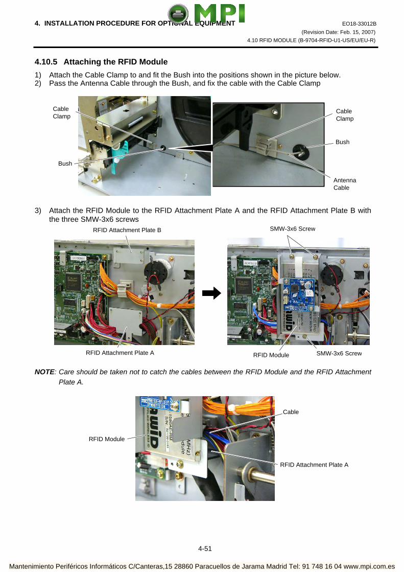
4. INSTALLATION PROCEDURE FOR OPTIONAL EQUIPMENT EO18-33012B (Revision Date: Feb. 15, 2007)
4.10 RFID MODULE (B-9704-RFID-U1-US/EU/EU-R)
4-51
4.10.5 Attaching the RFID Module
1) Attach the Cable Clamp to and fit the Bush into the positions shown in the picture below. 2) Pass the Antenna Cable through the Bush, and fix the cable with the Cable Clamp
3) Attach the RFID Module to the RFID Attachment Plate A and the RFID Attachment Plate B with the three SMW-3x6 screws
NOTE: Care should be taken not to catch the cables between the RFID Module and the RFID Attachment Plate A.
Bush
Cable Clamp
Bush
Cable Clamp
Antenna Cable
RFID Attachment Plate B
RFID ModuleRFID Attachment Plate A
SMW-3x6 Screw
SMW-3x6 Screw
Cable
RFID Module
RFID Attachment Plate A
Mantenimiento Periféricos Informáticos C/Canteras,15 28860 Paracuellos de Jarama Madrid Tel: 91 748 16 04 www.mpi.com.es

4. INSTALLATION PROCEDURE FOR OPTIONAL EQUIPMENT EO18-33012B (Revision Date: Feb. 15, 2007)
4.10 RFID MODULE (B-9704-RFID-U1-US/EU/EU-R)
4-52
4) Connect CN1 on the RFID Module to CN14 on the Main PC Board with the Interface Cable.
5) Connect the Antenna Cable to the RFID Module until it clicks. To prevent the Antenna Cable from
being caught in the Side Panel (L) or Fan Motor, fold the cable and fix it with the two Cable Clamps.
CN14
CN1
RFID Module
Interface Cable
Main PC Board
Cable Clamp
RFID Module
Antenna Cable
Antenna Cable
Mantenimiento Periféricos Informáticos C/Canteras,15 28860 Paracuellos de Jarama Madrid Tel: 91 748 16 04 www.mpi.com.es

4. INSTALLATION PROCEDURE FOR OPTIONAL EQUIPMENT EO18-33012B (Revision Date: Feb. 15, 2007)
4.10 RFID MODULE (B-9704-RFID-U1-US/EU/EU-R)
4-53
6) Fit the tab of the RFID Module into the slot in the RFID Module Cover, and attach the RFID Module Cover to the RFID Module with the SMW-3x6 screw. Pass the Interface Cable and the Antenna Cable through the openings of the RFID Module Cover, respectively.
NOTE: When fitting the RFID Module Cover, be careful not to pinch the Interface Cable and the Antenna Cable.
7) Attach the Side Cover (L), the Front Plate, the Platen Holder Cover, the Platen, and the Strip Plate in the reverse order of removal. Refer to Section 4 to program the RFID Module and perform an operation check.
NOTE: When attaching the Side Cover (L), carefully lead the Fan Motor Harness so that it does not get sucked into the Fan Motor.
Tab
RFID Module
RFID Module CoverSlot
Pass the Interface Cable through the opening of the RFID Module Cover.
SMW-3x6 Screw
Pass the Antenna Cable through the opening of the RFID Module Cover.
RFID Module Cover
Mantenimiento Periféricos Informáticos C/Canteras,15 28860 Paracuellos de Jarama Madrid Tel: 91 748 16 04 www.mpi.com.es

4. INSTALLATION PROCEDURE FOR OPTIONAL EQUIPMENT EO18-33012B (Revision Date: Feb. 15, 2007)
4.10 RFID MODULE (B-9704-RFID-U1-US/EU/EU-R)
4-54
8) An FCC sticker is supplied with the B-9704-RFID-U1-US model, and a CE sticker is supplied with the B-9704-RFID-U1-EU/EU-R model, respectively.
After installing the RFID module in the printer, please attach the sticker to the specified location on the printer.
Location to attach the sticker (on the back of a printer)
4.10.6 Parameter Setting and Operation Check for the RFID Module After installing the RFID Module in the printer, set the parameters for the RFID and perform an operation check by using the following procedures. For details, please refer to the Maintenance Manual. 1) Start the printer in the System Mode, and check the program version. When the program version
is V3.1 or older, go to Step 2). When the program version is V4.1 or greater (US/EU model) or V4.4 or greater (EU-R model), go to Step 3).
2) When the program version is V3.1 or older, upgrade it to V3.2 or greater in the following order. Please obtain the latest firmware from http://barcode.toshibatec.co.jp/Ris/products/barcode/support/en/contents/software/index.html (1) Print the Maintenance Counter/Parameter Setting to keep the record of the printer’s
parameter settings. (Refer to Section 5.3.) (2) Download the firmware from the above web site, and upgrade the firmware version of the
printer. (Refer to Section 7.) (3) Perform a Parameter Clear. (Refer to Section 5.8.) (4) Return the all parameter settings except for RFID Module to the former ones. 3) Change the parameter setting of the RFID Module from ”NONE” to ”U1”. Choosing ”NONE”
or ”H1” results in NG (No good) at the self diagnostic test even if the RFID Module is properly connected.
FCC Sticker or CE Sticker
Mantenimiento Periféricos Informáticos C/Canteras,15 28860 Paracuellos de Jarama Madrid Tel: 91 748 16 04 www.mpi.com.es

4. INSTALLATION PROCEDURE FOR OPTIONAL EQUIPMENT EO18-33012B (Revision Date: Feb. 15, 2007)
4.10 RFID MODULE (B-9704-RFID-U1-US/EU/EU-R)
4-55
4) Print the Maintenance Counter/Parameter Settings and the Self-Diagnostic Test result to confirm the RFID Module status.
5) If “RFID NG” (No Good) is printed, check the cable connections and parameter settings related to
the RFID Module again. 6) Try a read and write of the RFID tag by using the RFID Analyze Tool. When you do not have a
PC at hand, perform a simplified read test in the system mode to confirm the data can be read. In case that the read/write accuracy needs to be enhanced, make an adjustment of the parameter setting in the System Mode. (Refer to Section 11 and Section 5.12.)
NOTE: Available RFID tags EPC Class 0 (Read only) EPC Class 1 EPC Class 1 Gen2 (Only when the RFID module supports Gen2)
ISO 18000-6B
WEP KEY #3 [101112131415161718191A1B1C] WEP KEY #4 [202122232425262728292A2B2C] RFID MODULE [U1] RFID TAG TYPE [EPC CI Gen2 ] RFID ERR CHECK [OFF] RFID RETRY [ 3] RFID RD CYCLE [ 5] [4.0sec.] RFID WT CYCLE [ 5] [2.0sec.] RFID ADJ RETRY [+00mm] RFID POWER LEV [50]
Parameters for the RFID Module
Initial values
Example: Maintenance Counter/Parameter Settings LabelMake sure that [U1] is selected and other parameters for theRFID Module are printed as follows.
Example: Self-Diagnostic Test Label Make sure that “RFID OK” is printed.
SENSOR2 [H] 23ºC [A]22ºC [R]4.2V [T]2.5V [E]0.6V [RANK]7 EXP. I/O NG EX. 232C NG RFID OK V**** Self-diagnosis of the
RFID Module statusVersion No.
US/EU mode: 251 EU-R model: 50
Mantenimiento Periféricos Informáticos C/Canteras,15 28860 Paracuellos de Jarama Madrid Tel: 91 748 16 04 www.mpi.com.es

4. INSTALLATION PROCEDURE FOR OPTIONAL EQUIPMENT EO18-33012B (Revision Date: Jan. 19, 2007)
4.11 RFID MODULE (B-9704-RFID-H1-QM/QM-R)
4-56
4.11 RFID MODULE (B-9704-RFID-H1-QM/QM-R) NOTES: 1. An RFID tag chip or the print head may be damaged when the print head passes over the chip. This can be prevented by using the ribbon saving module (standard feature for the B-SX5T and optional for
the B-SX4T). The print head is lifted by the ribbon saving module when it passes over the chip to prevent it from touching the chip. The print head is lifted by approximately 1 mm from the platen.
2. When an RFID label or tag is used in cut issue mode, care must be taken not to cut an antenna of the RFID tag or an IC chip in order not to damage the cutter.
3. When using the RFID module together with a cutter or strip module, be sure to install the RFID module first. When the B-4205-QM swing cutter has been installed, remove the cutter unit before installing the RFID
module. When the B-8204-QM rotary cutter has been installed, remove the cutter unit and cutter drive unit before
installing the RFID module. When the B-9904-H-QM strip module has been installed, remove the rewinder guide plate and strip sensors
(Tr and LED) before installing the RFID module. (The strip module is standard feature of the B-SX5T series.)
4.11.1 Applicable Model This optional device is intended for the following models:
The B-9704-RFID-H1-QM model is intended for the following models: B-SX4T-GS10-QQ/QQ-US/QP, RFID Ready printer (Serial No. 2604Wxxxxxx or later) B-SX5T-TS10-QQ/QQ-US/QP, RFID Ready printer (Serial No. 2604Wxxxxxx or later) The B-9704-RFID-H1-QM-R model is intended for the following models: B-SX4T-GS10-QQ/QQ-US/QP, RFID Ready printer (Serial No. 2604Wxxxxxx or later) B-SX5T-TS10-QQ/QQ-US/QP, RFID Ready printer (Serial No. 2604Wxxxxxx or later) B-SX4T-GS20-QM-R, B-SX5T-TS22-QM-R
An RFID Ready printer can be identified by the model name sticker on the front of the printer. The countries where the use of this device is allowed are as follows:
Model Name Frequency Band Applicable Countries
B-9704-RFID-H1-QM/QM-R HF (13.56MHz)
Austria, Belgium, Cyprus, Czech, Denmark, Estonia, Germany, Greece, Finland, France, Hungary, Ireland, Italy, Latvia, Lithuania, Luxemburg, Malta, Poland, Portugal, Slovakia, Slovenia, Spain, Sweden, the Netherlands, and U.K.
4.11.2 Packing List All the following parts are supplied with the kit. Make sure you have all items shown below.
Parts Quantity Parts Quantity Antenna Cover
1 pc.
Antenna Frame
1 pc.
Ribbon Guide
1 pc.
Bush
1 pc.
Mantenimiento Periféricos Informáticos C/Canteras,15 28860 Paracuellos de Jarama Madrid Tel: 91 748 16 04 www.mpi.com.es

4. INSTALLATION PROCEDURE FOR OPTIONAL EQUIPMENT EO18-33012B
4.11 RFID MODULE (B-9704-RFID-H1-QM)
4-57
Parts Quantity Parts Quantity
Cable Clamp
1 pc.
RFID Plate
1 pc.
SMW-3x6 Double Sems Screw
7 pcs.
PT-3x6 P-TITE Screw
1 pc.
Interface Cable
1 pc.
SMW-2x10 Double Sems Screw
2 pcs.
Spacer
2 pcs.
Nylon Washer
2 pcs.
NOTE: To install the B-9704-RFID-H1-QM in the printer, TAGSYS RFID Module MEDIOTM S002 and the exclusive antenna are required separately. Before installation, solder the supplied Interface Cable to the RFID module as shown in the picture below, and attach the RFID Module and the Antenna to the RFID Plate and the Antenna Cover, respectively.
RFID Module Antenna
Interface Cable
Mantenimiento Periféricos Informáticos C/Canteras,15 28860 Paracuellos de Jarama Madrid Tel: 91 748 16 04 www.mpi.com.es

4. INSTALLATION PROCEDURE FOR OPTIONAL EQUIPMENT EO18-33012B
4.11 RFID MODULE (B-9704-RFID-H1-QM)
4-58
Wiring Diagram
Details of Interface Cable
Interface Cable RFID Module
Pin No. Signal Color
1
2
3
4
VCC
TXD
RXD
/RTS
Brown
Red
Orange
Black
5 /CTS Black
6 /DTR Black
7 /DSR Black
8 GND Yellow
30 + 5mm
120mm + 10mm
5 + 2mm
Connector: DF3-8S-2C (HIROSE ELECTRIC CO., LTD.) Terminal: DF3-2428SCF (HIROSE ELECTRIC CO., LTD.)
Pin No. Signal Color
1
2
3
4
VCC
TXD
RXD
/RTS
Brown
Red
Orange
Black
5 /CTS Black
6 /DTR Black
7 /DSR Black
8 GND Yellow
Mantenimiento Periféricos Informáticos C/Canteras,15 28860 Paracuellos de Jarama Madrid Tel: 91 748 16 04 www.mpi.com.es

4. INSTALLATION PROCEDURE FOR OPTIONAL EQUIPMENT EO18-33012B
4.11 RFID MODULE (B-9704-RFID-H1-QM)
4-59
4.11.3 Attaching the Antenna to the Antenna Cover or Antenna Frame
Basically, the Antenna is attached to the Antenna Cover. However, read/write of RFID tag may become more accurate when the Antenna is attached to the Antenna Frame. When attaching the Antenna to the Antenna Cover, use the PT-3x6 Screws. And use two of the SMW-3x6 Screws when attaching it to the Antenna Frame. Place the Antenna in the orientation as shown in the pictures below. When they are installed in the printer, the pattern side of the Antenna faces up and the Antenna Cable is positioned at the printer frame side.
4.11.4. Attaching the RFID Module to the RFID Plate
1) Put the Nylon Washer onto the SMW-2x10 Screw. Do the same to the other SMW-2x10 Screw.
2) Place the RFID Module on the RFID Plate as shown in the picture below. Insert the Spacers
under the RFID Module, and secure it to the RFID Plate with the SMW-2x10 Screws.
SMW-3x6 Screw Antenna Frame
Antenna
Antenna
Antenna Cover PT-3x6 Screw Antenna Cover
Antenna Frame
Nylon Washer
SMW-2x10 Screw
SMW-2x10 Screw
Spacer
RFID Module
RFID Plate
Nylon Washer
SMW-2x10 Screw
Spacer
Nylon Washer
Mantenimiento Periféricos Informáticos C/Canteras,15 28860 Paracuellos de Jarama Madrid Tel: 91 748 16 04 www.mpi.com.es

4. INSTALLATION PROCEDURE FOR OPTIONAL EQUIPMENT EO18-33012B
4.11 RFID MODULE (B-9704-RFID-H1-QM)
4-60
1) Remove the two black screws to detach the front plate. (Refer to section 4.1.) 2) Remove the side panel (L) from the printer. (Refer to section 3.2.) 3) Push the Hook through the rectangle hole with a jeweler’s screw driver or something, and
remove the Platen Holder Cover in the direction indicated by the arrow.
4) Lift the right side of the Strip Plate, and then pull and remove it.
5) Remove the Platen and the Platen Holder in steps 1 to 3 as shown below.
Strip Plate
Hook 1
2
2
1
Platen
Platen Holder
1
2
3
Push
Platen Holder Cover
Mantenimiento Periféricos Informáticos C/Canteras,15 28860 Paracuellos de Jarama Madrid Tel: 91 748 16 04 www.mpi.com.es

4. INSTALLATION PROCEDURE FOR OPTIONAL EQUIPMENT EO18-33012B
4.11 RFID MODULE (B-9704-RFID-H1-QM)
4-61
6) Remove the following three screws.
7) Remove the Platen Frame Top from the printer.
8) Remove the four screws from the side of the Print Head Block, slightly pull the Head Side Plate,
and remove the two Ribbon Guide Shafts.
NOTE: One of the removed Ribbon Guide Shafts and SMW-2.6x6 Screws are re-used when attaching the Ribbon Guide. Keep the unused ones for future use.
Platen Frame Top
SMW-3x6 Screw SMW-4x8 Screw
SMW-2.6x6 Screw Ribbon Guide Shaft
Head Side Plate
SMW-4x8 Screw SMW-3x6 Screw
Mantenimiento Periféricos Informáticos C/Canteras,15 28860 Paracuellos de Jarama Madrid Tel: 91 748 16 04 www.mpi.com.es

4. INSTALLATION PROCEDURE FOR OPTIONAL EQUIPMENT EO18-33012B
4.11 RFID MODULE (B-9704-RFID-H1-QM/QM-R)
4-62
9) Insert one of the Ribbon Guide Shafts removed in Step 12 into the Ribbon Guide. Rotate the Ribbon Guide Shaft so that its D-cut is in the same orientation with the Ribbon Guide’s D-cut.
NOTE: Without doing this, the Ribbon Guide cannot be fit in the Print Head Block. 10) Fit the Ribbon Guide including the Ribbon Guide Shaft in the Print Head Block, and secure it to
the Head Side Plate with the SMW-2.6x6 screw. Temporarily secure the Head Side Plate to the Print Head Block with the SMW-3x6 Screw and the SMW-4x8 Screw. Be sure to fit the locating pins provided on the other side of the Ribbon Guide into the locating holes of the Print Head Block.
11) Close the Ribbon Shaft Holder Plate, and tighten the two screws, which were temporarily
tightened in Step 14, while holding down the Print Head Block.
Ribbon Guide
Ribbon Guide’s D-cutRibbon Guide Shaft
Ribbon Guide Shaft’s D-cut
Locating Pin
Locating Hole
Ribbon Guide
SMW-3x6 Screw
SMW-4x8 Screw SMW-2.6x6 Screw
Head Side Plate
SMW-4x8 Screw
SMW-3x6 Screw
Print Head Block Ribbon Shaft Holder Plate
Mantenimiento Periféricos Informáticos C/Canteras,15 28860 Paracuellos de Jarama Madrid Tel: 91 748 16 04 www.mpi.com.es

4. INSTALLATION PROCEDURE FOR OPTIONAL EQUIPMENT EO18-33012B
4.11 RFID MODULE (B-9704-RFID-H1-QM/QM-R)
4-63
4.11.5 Attaching the RFID Module 1) Raise the Print Head Block, and slide the Antenna Frame into the printer as shown below. Let the
protruding screw of the printer pass through the slit of the Antenna Frame.
2) Secure the Antenna Frame with the three screws removed in Step 10 of Section 3.1.
3) Mount the Antenna Cover containing the Antenna on the inside of the Antenna Frame. Be sure to fit the locating pins of the Antenna Cover into the oval holes and the cuts in the Antenna
Frame.
Antenna Frame
SMW-3x6 Screw
Locating Pin
Locating Pin Cut
Oval Hole Antenna Cover including Antenna
Antenna Frame
Screw Slit
SMW-4x8 Screw
Mantenimiento Periféricos Informáticos C/Canteras,15 28860 Paracuellos de Jarama Madrid Tel: 91 748 16 04 www.mpi.com.es

4. INSTALLATION PROCEDURE FOR OPTIONAL EQUIPMENT EO18-33012B
4.11 RFID MODULE (B-9704-RFID-H1-QM/QM-R)
4-64
NOTE: Pass the Antenna Cable between the Antenna Frame and the Media Sensor as shown in the picture below.
4) Push the Antenna Cover backward, and secure it with the two SMW-3x6 screws.
Antenna Cover including Antenna
SMW-3x6 Screw
Antenna FrameMedia Sensor Antenna Cable
Mantenimiento Periféricos Informáticos C/Canteras,15 28860 Paracuellos de Jarama Madrid Tel: 91 748 16 04 www.mpi.com.es

4. INSTALLATION PROCEDURE FOR OPTIONAL EQUIPMENT EO18-33012B
4.11 RFID MODULE (B-9704-RFID-H1-QM/QM-R)
4-65
5) Attach the Cable Clamp to and fit the Bush into the positions shown in the picture below. 6) Pass the Antenna Cable through the Bush, and fix the cable with the Cable Clamp
7) Attach the RFID Module to the RFID Attachment Plate A and the RFID Attachment Plate B with the three SMW-3x6 screws.
NOTE: Care should be taken not to catch the cables between the RFID Module and the RFID Attachment Plate A.
Bush
Cable Clamp
Bush
Cable Clamp
Antenna Cable
RFID Attachment Plate B
RFID ModuleRFID Attachment Plate A
SMW-3x6 Screw
SMW-3x6 Screw
Cable
RFID Module
Mantenimiento Periféricos Informáticos C/Canteras,15 28860 Paracuellos de Jarama Madrid Tel: 91 748 16 04 www.mpi.com.es

4. INSTALLATION PROCEDURE FOR OPTIONAL EQUIPMENT EO18-33012B
4.11 RFID MODULE (B-9704-RFID-H1-QM)
4-66
8) Connect the RFID Cable of the RFID Module to CN14 on the Main PC Board.
9) Connect the Antenna Cable to the RFID Module until it clicks. To prevent the Antenna Cable from
being caught in the Side Panel (L) or Fan Motor, fold the cable and fix it with the two Cable Clamps.
10) Attach the Side Cover (L), the Front Plate, the Platen Holder Cover, the Platen, and the Strip Plate
in the reverse order of removal. Refer to Section 4 to program the RFID Module and perform an operation check.
NOTE: When attaching the Side Cover (L), carefully lead the Fan Motor Harness so that it does not get sucked into the Fan Motor.
CN14
RFID Cable RFID Module
Main PC Board
Mark
RFID Module
Connector
AntennaCable
Cable Clamp
Mantenimiento Periféricos Informáticos C/Canteras,15 28860 Paracuellos de Jarama Madrid Tel: 91 748 16 04 www.mpi.com.es

4. INSTALLATION PROCEDURE FOR OPTIONAL EQUIPMENT EO18-33012B (Revision Date: Jan. 19, 2007)
4.11 RFID MODULE (B-9704-RFID-H1-QM)
4-67
4.11.6 Parameter Setting and Operation Check for the RFID Module After installing the RFID Module in the printer, set the parameters for the RFID and perform an operation check by using the following procedures. For details, please refer to the Maintenance Manual.
1) Start the printer in the System Mode, and check the program version. When the program version is V3.1 or older, go to Step 2). When the program version is V4.1 or greater, go to Step 3).
2) When the program version is V3.1 or older, upgrade it to V4.1 or greater in the following order. Please obtain the latest firmware from http://barcode.toshibatec.co.jp/Ris/products/barcode/support/en/contents/software/index.html (1) Print the Maintenance Counter/Parameter Setting to keep the record of the printer’s
parameter settings. (Refer to Section 5.3.) (2) Download the firmware from the above web site, and upgrade the firmware version of the
printer. (Refer to Section 7.) (3) Perform a Parameter Clear. (Refer to Section 5.8.) (4) Return the all parameter settings except for RFID Module to the former ones. 3) Change the parameter setting of the RFID Module from ”NONE” to ”H1”. Choosing ”NONE”
or ”U1” results in NG (No good) at the self diagnostic test even if the RFID Module is properly connected.
4) Change the parameter setting of the RFID tag type to a proper one. 5) Print the Maintenance Counter/Parameter Settings and the Self-Diagnostic Test result to confirm
the RFID Module status. 5) If “RFID NG” (No Good) is printed, check the cable connections and parameter settings related to
the RFID Module again. 6) Try a read and write of the RFID tag by using the RFID Analyze Tool. When you do not have a
PC at hand, perform a simplified read test in the system mode to confirm the data can be read. In case that the read/write accuracy needs to be enhanced, make an adjustment of the parameter setting in the System Mode. (Refer to Section 11 and Section 5.2.)
NOTE: Available RFID tags TAGSYS (C210, C220, C240, C320) *C320 is available only when the TAGSYS S003 module is used.) I-Code Tag-It
ISO 15693
Maintenance Counter/Parameter Settings Label (Example) Make sure that [H1] is selected and other parameters for the RFID Module are printed as follows.
WEP KEY #3 [101112131415161718191A1B1C] WEP KEY #4 [202122232425262728292A2B2C] RFID MODULE [H1] RFID TAG TYPE [ISO15693 ] RFID ERR CHECK [OFF] RFID RETRY [ 3] RFID RD CYCLE [ 5] [4.0sec.] RFID WT CYCLE [ 5] [2.0sec.] RFID ADJ RETRY [+00mm] RFID POWER LEV [251]
Parameters for the RFID Module
Initial values
Self-Diagnostic Test Label (Example) Make sure that “RFID OK” is printed. SENSOR2 [H] 23ºC [A]22ºC [R]4.2V [T]2.5V [E]0.6V [RANK]7 EXP. I/O NG EX. 232C NG RFID OK V****
Self-diagnosis of the RFID Module status
Version No.
Mantenimiento Periféricos Informáticos C/Canteras,15 28860 Paracuellos de Jarama Madrid Tel: 91 748 16 04 www.mpi.com.es

4. INSTALLATION PROCEDURE FOR OPTIONAL EQUIPMENT EO18-33012B
4.12 SWING CUTTER (B-4205-QM-R)
4-68
4.12 SWING CUTTER (B-4205-QM-R) 4.12.1 Applicable Model
This optional kit is the swing cutter module, which is intended for the following models:
B-SX4T-QM-R Series, B-SX5T-QM-R Series
4.12.2. Packing List
All the following parts are supplied with the kit. Make sure you have all items shown below.
Cutter Unit (1 pc.)
Cutter Cover (1 pc.) Take-up/Cutter Harness (1 pc.)
Print Head Cleaner (1 pc.) (P/No.: FMQB0051601)
Cutter Attachment Screw (2 pcs.)
Bush (1 pc.) (For B-SX4T/5T series)
• Installation manual (1 copy) • FL-4x6 Screw (1 pc.)
4.12.3 Installation Procedure
4.12.3.1 Installing the Swing Cutter Module on the B-SX4T Series 1) Turn the power off and disconnect the power cord. 2) Remove the two black screws to detach the front plate.
NOTE Retain the two black screws and front plate.
WARNING!
1. Follow all manual instructions. Failure to do so could create safety hazards such as fire or electrocution. • Manual instructions must be followed when installing option kits or adding cables to avoid system failures
and to insure proper performance and operation • Failure to follow manual instructions or any unauthorized modifications, substitution or change to this
product will void the limited product warranty. 2. Turn the power off and disconnect the power cord before installing the swing cutter module. 3. Be careful not to injure your fingers when installing the swing cutter module. 4. Be careful not to pinch your fingers or hands with the covers.
Front Plate
Black Screws
Mantenimiento Periféricos Informáticos C/Canteras,15 28860 Paracuellos de Jarama Madrid Tel: 91 748 16 04 www.mpi.com.es

4. INSTALLATION PROCEDURE FOR OPTIONAL EQUIPMENT EO18-33012B
4.12 SWING CUTTER (B-4205-QM-R)
4-69
3) Remove the four B-4x5 screws from the side panel (L). 4) Open the top cover and remove the three P-4x8 screws that secure the side panel (L).
5) Lift the side panel (L) and put it aside. 6) Disconnect the fan motor harness from CN19 on the Main PC board, and then separate the side
panel (L).
7) Turn the head lever clockwise to Free position.
8) Open the ribbon shaft holder plate.
B-4x5 Screw P-4x8 Screw
Top Cover B-4x5 Screw
Side Panel (L)
Ribbon Shaft Holder Plate Head Lever
Lock position (Tag)
Lock position (Label)
Side Panel (L) Fan Motor Harness
Fan Motor
CN19
Main PC Board
Mantenimiento Periféricos Informáticos C/Canteras,15 28860 Paracuellos de Jarama Madrid Tel: 91 748 16 04 www.mpi.com.es

4. INSTALLATION PROCEDURE FOR OPTIONAL EQUIPMENT EO18-33012B
4.12 SWING CUTTER (B-4205-QM-R)
4-70
9) Raise the print head block until it stops.
10) Attach the cutter unit to the front of the printer with the cutter attachment screws and the FL-4x6 screw.
11) Connect the Cutter Harness to CN1 on the Cutter I/F PC Board.
12) Fit the bush to the cutter harness in the orientation shown below.
CN1
Cutter Harness
Cutter I/F PC Board
Bush
Cutter Harness
Print Head Block
Cutter Attachment Screw
Cutter Unit
FL-4x6 Screw
Stopper
Mantenimiento Periféricos Informáticos C/Canteras,15 28860 Paracuellos de Jarama Madrid Tel: 91 748 16 04 www.mpi.com.es
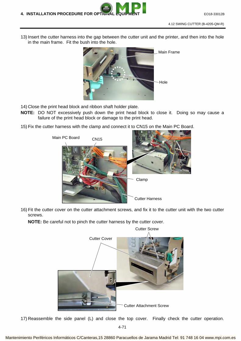
4. INSTALLATION PROCEDURE FOR OPTIONAL EQUIPMENT EO18-33012B
4.12 SWING CUTTER (B-4205-QM-R)
4-71
13) Insert the cutter harness into the gap between the cutter unit and the printer, and then into the hole in the main frame. Fit the bush into the hole.
14) Close the print head block and ribbon shaft holder plate. NOTE: DO NOT excessively push down the print head block to close it. Doing so may cause a
failure of the print head block or damage to the print head.
15) Fix the cutter harness with the clamp and connect it to CN15 on the Main PC Board.
16) Fit the cutter cover on the cutter attachment screws, and fix it to the cutter unit with the two cutter
screws.
NOTE: Be careful not to pinch the cutter harness by the cutter cover.
17) Reassemble the side panel (L) and close the top cover. Finally check the cutter operation.
Hole
Main Frame
Clamp
CN15 Main PC Board
Cutter Harness
Cutter Screw
Cutter Attachment Screw
Cutter Cover
Mantenimiento Periféricos Informáticos C/Canteras,15 28860 Paracuellos de Jarama Madrid Tel: 91 748 16 04 www.mpi.com.es

4. INSTALLATION PROCEDURE FOR OPTIONAL EQUIPMENT EO18-33012B
4.12 SWING CUTTER (B-4205-QM-R)
4-72
4.12.3.2 Installing the Swing Cutter Module on the B-SX5T Series Since the strip module is standard on the B-SX5T series, it is necessary to remove the rewinder guide plate, strip sensor, etc. before installing the cutter module. 1) Turn the power off and disconnect the power cord. 2) When the printer is used in the batch or strip mode:
Remove the two black screws to detach the front plate.
NOTE: Retain the two black screws and front plate.
When the printer is used in the built-in rewinder mode:
Open the top cover, remove the two SMW-4x8 screws, and detach the rewinder guide plate from
the printer.
3) Remove the four B-4x5 screws from the side panel (L). 4) Open the top cover and remove the three P-4x8 screws that secure the side panel (L).
Front Plate
Black Screws
B-4x5 Screw P-4x8 Screw
Top Cover B-4x5 Screw
Side Panel (L)
Rewinder Guide Plate
SMW-4x8B Screw
SMW-4x8B Screw
Mantenimiento Periféricos Informáticos C/Canteras,15 28860 Paracuellos de Jarama Madrid Tel: 91 748 16 04 www.mpi.com.es

4. INSTALLATION PROCEDURE FOR OPTIONAL EQUIPMENT EO18-33012B
4.12 SWING CUTTER (B-4205-QM-R)
4-73
5) Lift the side panel (L) and put it aside. 6) Disconnect the fan motor harness from CN19 on the Main PC board, and then separate the side
panel (L).
7) Remove the SM-4x8 screw that secures the operation panel ass’y.
8) Half open the top cover, otherwise the operation panel ass’y cannot be removed from the printer.
9) Lift the operation panel ass’y to release the hook, and then remove the operation panel ass’y by
moving it forward.
Operation Panel Ass’y Top Cover
SM-4x8 Screw
Side Panel (L) Fan Motor Harness
Fan Motor
CN19
Main PC Board
Mantenimiento Periféricos Informáticos C/Canteras,15 28860 Paracuellos de Jarama Madrid Tel: 91 748 16 04 www.mpi.com.es

4. INSTALLATION PROCEDURE FOR OPTIONAL EQUIPMENT EO18-33012B
4.12 SWING CUTTER (B-4205-QM-R)
4-74
Disconnect the operation panel harness from the operation panel ass’y.
11) Turn the head lever clockwise to Free position.
12) Open the ribbon shaft holder plate.
Operation Panel Ass’y
Hook
Ribbon Shaft Holder Plate
Operation Panel Harness
Head Lever
Lock position (Label) Lock position
(Tag)
Mantenimiento Periféricos Informáticos C/Canteras,15 28860 Paracuellos de Jarama Madrid Tel: 91 748 16 04 www.mpi.com.es

4. INSTALLATION PROCEDURE FOR OPTIONAL EQUIPMENT EO18-33012B
4.12 SWING CUTTER (B-4205-QM-R)
4-75
13) Raise the print head block until it stops.
14) Remove the two SMW-4x8 screws that secure the strip sensors (TR) and (LED).
15) Release the strip sensor (LED) harness from the cable clamp, and disconnect it from the shorter
harness of the strip sensor harness (TR).
Print Head Block
Stopper
SMW-4x8B Screw
Strip Sensor (Tr)
SMW-4x8B Screw
Strip Sensor (LED)
Cable Clamp
Strip Sensor Harness (for LED)
Shorter Harness of the Strip Sensor Harness (for Tr)
Mantenimiento Periféricos Informáticos C/Canteras,15 28860 Paracuellos de Jarama Madrid Tel: 91 748 16 04 www.mpi.com.es

4. INSTALLATION PROCEDURE FOR OPTIONAL EQUIPMENT EO18-33012B
4.12 SWING CUTTER (B-4205-QM-R)
4-76
16) Remove the Expansion I/O board from the printer temporarily using the following procedure. (1) Disconnect the Expansion I/O cable from CN1 on the Expansion I/O board. (2) Remove the two B-3x6 screws to detach the Expansion I/O board from the printer.
17) Disconnect the shorter harness of the strip sensor harness (TR) from CN20 on the Main PC board.
Then remove the strip sensor (TR) from the printer.
NOTE: Retain the strip sensors (TR) and (LED), and the strip sensor harness.
18) Disconnect the longer harness of the rewind full sensor (TR) and rewinder harness from CN4 and
CN15 on the Main PC board, respectively.
NOTE: Secure the rewinder harness and the longer harness of the rewind full sensor (TR) to the
space under the Main PC board with the cable clamp so that they are not pinched by the
covers or printer’s internal components.
CN1
Expansion I/O Board
Expansion I/O Cable
Main PC Board
Cable Clamp
Main PC Board
B-3x6 Screw
Rear Plate
Longer Harness of the Rewind Full Sensor (Tr)
CN4
CN15
Rewinder Harness
CN20
Shorter Harness of the Strip Sensor Harness (Tr)
PS Unit
Mantenimiento Periféricos Informáticos C/Canteras,15 28860 Paracuellos de Jarama Madrid Tel: 91 748 16 04 www.mpi.com.es

4. INSTALLATION PROCEDURE FOR OPTIONAL EQUIPMENT EO18-33012B
4.12 SWING CUTTER (B-4205-QM-R)
4-77
19) Reassemble the operation panel ass’y and the expansion I/O board in the reverse order of
removal.
20) Attach the cutter unit to the front of the printer with the cutter attachment screws and the FL-4x6 screw.
21) Connect the Cutter Harness to CN1 on the Cutter I/F PC Board.
22) Fit the bush to the cutter harness in the orientation shown below.
23) Insert the cutter harness into the gap between the cutter unit and the printer, and then into the hole
in the main frame. Fit the bush into the hole.
Cutter Unit
Hole
Main Frame
CN1
Cutter Harness
Cutter I/F PC Board
Bush
Cutter Harness
Cutter Attachment Screw
FL-4x6 Screw
Mantenimiento Periféricos Informáticos C/Canteras,15 28860 Paracuellos de Jarama Madrid Tel: 91 748 16 04 www.mpi.com.es

4. INSTALLATION PROCEDURE FOR OPTIONAL EQUIPMENT EO18-33012B
4.12 SWING CUTTER (B-4205-QM-R)
4-78
24) Close the print head block and ribbon shaft holder plate.
NOTE: DO NOT excessively push down the print head block to close it. Doing so may cause a failure of the print head block or damage to the print head.
25) Fix the cutter harness with the clamp and connect it to CN15 on the Main PC Board.
26) Fit the cutter cover on the cutter attachment screws, and fix it to the cutter unit with the two cutter
screws.
NOTE: Be careful not to pinch the cutter harness by the cutter cover.
27) Reassemble the side panel (L) and close the top cover. Finally check the cutter operation.
Clamp
CN15 Main PC Board
Cutter Harness
Cutter Screw
Cutter Attachment Screw
Cutter Cover
Mantenimiento Periféricos Informáticos C/Canteras,15 28860 Paracuellos de Jarama Madrid Tel: 91 748 16 04 www.mpi.com.es
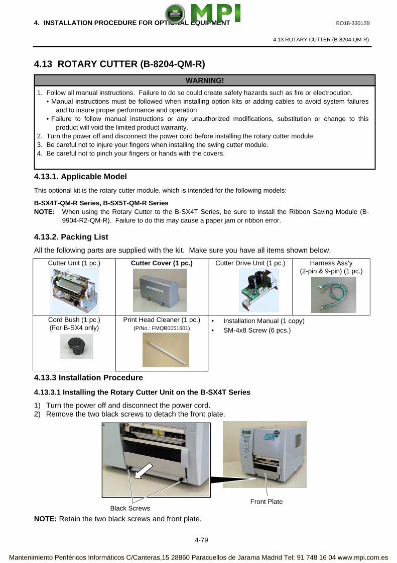
4. INSTALLATION PROCEDURE FOR OPTIONAL EQUIPMENT EO18-33012B
4.13 ROTARY CUTTER (B-8204-QM-R)
4-79
4.13 ROTARY CUTTER (B-8204-QM-R)
4.13.1. Applicable Model
This optional kit is the rotary cutter module, which is intended for the following models:
B-SX4T-QM-R Series, B-SX5T-QM-R Series NOTE: When using the Rotary Cutter to the B-SX4T Series, be sure to install the Ribbon Saving Module (B-
9904-R2-QM-R). Failure to do this may cause a paper jam or ribbon error.
4.13.2. Packing List
All the following parts are supplied with the kit. Make sure you have all items shown below.
Cutter Unit (1 pc.)
Cutter Cover (1 pc.) Cutter Drive Unit (1 pc.) Harness Ass’y (2-pin & 9-pin) (1 pc.)
Cord Bush (1 pc.) (For B-SX4 only)
Print Head Cleaner (1 pc.) (P/No.: FMQB0051601)
• Installation Manual (1 copy) • SM-4x8 Screw (6 pcs.)
4.13.3 Installation Procedure
4.13.3.1 Installing the Rotary Cutter Unit on the B-SX4T Series
1) Turn the power off and disconnect the power cord. 2) Remove the two black screws to detach the front plate.
NOTE: Retain the two black screws and front plate.
WARNING!
1. Follow all manual instructions. Failure to do so could create safety hazards such as fire or electrocution. • Manual instructions must be followed when installing option kits or adding cables to avoid system failures
and to insure proper performance and operation • Failure to follow manual instructions or any unauthorized modifications, substitution or change to this
product will void the limited product warranty. 2. Turn the power off and disconnect the power cord before installing the rotary cutter module. 3. Be careful not to injure your fingers when installing the swing cutter module. 4. Be careful not to pinch your fingers or hands with the covers.
Front Plate
Black Screws
Mantenimiento Periféricos Informáticos C/Canteras,15 28860 Paracuellos de Jarama Madrid Tel: 91 748 16 04 www.mpi.com.es

4. INSTALLATION PROCEDURE FOR OPTIONAL EQUIPMENT EO18-33012B
4.13 ROTARY CUTTER (B-8204-QM-R)
4-80
3) Remove the four B-4x5 screws from the side panel (L). 4) Open the top cover and remove the three P-4x8 screws that secure the side panel (L).
5) Lift the side panel (L) and put it aside. 6) Disconnect the fan motor harness from CN19 on the Main PC board, and then separate the side
panel (L).
7) Fix the cutter drive unit to the printer with the three SM-4x8 screws.
B-4x5 Screw P-4x8 Screw
Top Cover B-4x5 Screw
Side Panel (L)
SM-4x8 Screw
Cutter Drive Unit
Side Panel (L) Fan Motor Harness
Fan Motor
CN19
Main PC Board
SM-4x8 Screw
Mantenimiento Periféricos Informáticos C/Canteras,15 28860 Paracuellos de Jarama Madrid Tel: 91 748 16 04 www.mpi.com.es

4. INSTALLATION PROCEDURE FOR OPTIONAL EQUIPMENT EO18-33012B
4.13 ROTARY CUTTER (B-8204-QM-R)
4-81
8) Connect the 9-pin connector of the harness ass’y to CN7 and 2-pin connector to CN9 on the cutter driver unit, respectively.
9) Fit the bush to the harness ass’y in the orientation as shown below.
10) Insert the harness ass’y into the hole in the main frame. Fit the bush into the hole.
CN7 (9 pins) CN9 (2 pins)
Harness Ass’y
Bush
Harness Ass’y
Hole
Main Frame
Harness Ass’y
Mantenimiento Periféricos Informáticos C/Canteras,15 28860 Paracuellos de Jarama Madrid Tel: 91 748 16 04 www.mpi.com.es

4. INSTALLATION PROCEDURE FOR OPTIONAL EQUIPMENT EO18-33012B
4.13 ROTARY CUTTER (B-8204-QM-R)
4-82
4.13.3.2 Installing the Rotary Cutter Unit on the B-SX5T Series
Since the strip module is standard on the B-SX5T series, it is necessary to remove the rewinder guide plate, strip sensor, etc. before installing the cutter module. 1) Turn the power off and disconnect the power cord. 2) When the printer is used in the batch or strip mode:
Remove the two black screws to detach the front plate.
NOTE: Retain the two black screws and front plate.
When the printer is used in the built-in rewinder mode:
Open the top cover, remove the two SMW-4x8 screws, and detach the rewinder guide plate from
the printer.
3) Remove the four B-4x5 screws from the side panel (L). 4) Open the top cover and remove the three P-4x8 screws that secure the side panel (L).
Front Plate
Black Screws
B-4x5 Screw P-4x8 Screw
Top Cover
B-4x5 Screw
Side Panel (L)
Rewinder Guide Plate
SMW-4x8B Screw
SMW-4x8B Screw
Mantenimiento Periféricos Informáticos C/Canteras,15 28860 Paracuellos de Jarama Madrid Tel: 91 748 16 04 www.mpi.com.es

4. INSTALLATION PROCEDURE FOR OPTIONAL EQUIPMENT EO18-33012B
4.13 ROTARY CUTTER (B-8204-QM-R)
4-83
5) Lift the side panel (L) and put it aside.
6) Disconnect the fan motor harness from CN19 on the Main PC board, and then separate the side
panel (L).
7) Remove the SM-4x8 screw that secures the operation panel ass’y.
8) Half open the top cover, otherwise the operation panel ass’y cannot be removed from the printer.
9) Lift the operation panel ass’y to release the hook, and then remove the operation panel ass’y by
moving it forward.
Operation Panel Ass’y Top Cover
SM-4x8 Screw
Side Panel (L) Fan Motor Harness
Fan Motor
CN19
Main PC Board
Mantenimiento Periféricos Informáticos C/Canteras,15 28860 Paracuellos de Jarama Madrid Tel: 91 748 16 04 www.mpi.com.es

4. INSTALLATION PROCEDURE FOR OPTIONAL EQUIPMENT EO18-33012B
4.13 ROTARY CUTTER (B-8204-QM-R)
4-84
Disconnect the operation panel harness from the operation panel ass’y.
11) Turn the head lever clockwise to Free position.
12) Open the ribbon shaft holder plate.
Operation Panel Ass’y
Ribbon Shaft Holder Plate
Operation Panel Harness
Hook
Head Lever
Lock position (Label) Lock position
(Tag)
Mantenimiento Periféricos Informáticos C/Canteras,15 28860 Paracuellos de Jarama Madrid Tel: 91 748 16 04 www.mpi.com.es

4. INSTALLATION PROCEDURE FOR OPTIONAL EQUIPMENT EO18-33012B
4.13 ROTARY CUTTER (B-8204-QM-R)
4-85
13) Raise the print head block until it stops.
14) Remove the two SMW-4x8 screws that secure the strip sensors (TR) and (LED).
15) Release the strip sensor (LED) harness from the cable clamp, and disconnect it from the shorter
harness of the strip sensor harness (TR).
Print Head Block
Stopper
SMW-4x8B Screw
Strip Sensor (Tr)
SMW-4x8B Screw
Strip Sensor (LED)
Cable Clamp
Strip Sensor Harness (for LED)
Shorter Harness of the Strip Sensor Harness (for Tr)
Mantenimiento Periféricos Informáticos C/Canteras,15 28860 Paracuellos de Jarama Madrid Tel: 91 748 16 04 www.mpi.com.es

4. INSTALLATION PROCEDURE FOR OPTIONAL EQUIPMENT EO18-33012B
4.13 ROTARY CUTTER (B-8204-QM-R)
4-86
16) Remove the Expansion I/O board from the printer temporarily using the following procedure. ① Disconnect the Expansion I/O cable from CN1 on the Expansion I/O board. ② Remove the two B-3x6 screws to detach the Expansion I/O board from the printer.
17) Disconnect the shorter harness of the strip sensor harness (TR) from CN20 on the Main PC board.
Then remove the strip sensor (TR) from the printer.
NOTE: Retain the strip sensors (TR) and (LED), and the strip sensor harness.
18) Disconnect the longer harness of the rewind full sensor (TR) and rewinder harness from CN4 and
CN15 on the Main PC board, respectively.
NOTE: Secure the rewinder harness and the longer harness of the rewind full sensor (TR) to the
space under the Main PC board with the cable clamp so that they are not pinched by the
covers or printer’s internal components.
19) Reassemble the operation panel ass’y and the expansion I/O board in the reverse order of
removal.
CN1
Expansion I/O Board
Expansion I/O Cable
B-3x6 Screw
Rear Plate
Main PC Board
Longer Harness of the Rewind Full Sensor (Tr)
CN4
CN15
Rewinder Harness
CN20
Shorter Harness of the Strip Sensor Harness (Tr)
Cable Clamp
Main PC Board
PS Unit
Mantenimiento Periféricos Informáticos C/Canteras,15 28860 Paracuellos de Jarama Madrid Tel: 91 748 16 04 www.mpi.com.es

4. INSTALLATION PROCEDURE FOR OPTIONAL EQUIPMENT EO18-33012B
4.13 ROTARY CUTTER (B-8204-QM-R)
4-87
20) Fix the cutter drive unit to the printer with the three SM-4x8 screws.
21) Connect the 9-pin connector of the harness ass’y to CN7 and 2-pin connector to CN9 on the cutter
driver unit, respectively.
22) Fit the bush to the harness ass’y in the orientation as shown below.
23) Insert the harness ass’y into the hole in the main frame. Fit the bush into the hole.
SM-4x8 Screw
Cutter Drive Unit
CN7 (9 pins) CN9 (2 pins)
Harness Ass’y
Bush
Harness Ass’y
Hole
Main Frame
Harness Ass’y
SM-4x8 Screw
Mantenimiento Periféricos Informáticos C/Canteras,15 28860 Paracuellos de Jarama Madrid Tel: 91 748 16 04 www.mpi.com.es

4. INSTALLATION PROCEDURE FOR OPTIONAL EQUIPMENT EO18-33012B
4.13 ROTARY CUTTER (B-8204-QM-R)
4-88
24) Fix the harness ass’y with the clamp.
25) Connect the 9-pin connector of the harness ass’y to CN15, and 2-pin connector to CN18 on the
Main PC board, respectively.
26) Connect the four harnesses of the cutter unit to CN8, CN10, CN11 and CN12 on the cutter drive
unit.
Main PC Board
Clamp
Cutter Unit
Cutter Drive Unit
CN18 (2 pins) CN15 (9 pins)
Harness Ass’y
CN8 CN12 CN10
CN11
Mantenimiento Periféricos Informáticos C/Canteras,15 28860 Paracuellos de Jarama Madrid Tel: 91 748 16 04 www.mpi.com.es

4. INSTALLATION PROCEDURE FOR OPTIONAL EQUIPMENT EO18-33012B
4.13 ROTARY CUTTER (B-8204-QM-R)
4-89
27) Fit the two tabs of the cutter drive unit into the notches, and then fix the cutter unit with the three SM-4x8 screws.
28) Attach the cutter cover to the cutter unit with the two screws so that the tab of the cutter cover
turns on the cutter cover open switch. NOTES: 1. Be careful not to pinch the cutter harness by the cutter cover. 2. Make sure that the anti-static brush is protruding from the media outlet.
29) Close the print head block and ribbon shaft holder plate. NOTE: DO NOT excessively push down the print head block to close it. Doing so may cause a
failure of the print head block or damage to the print head.
30) Reassemble the side panel (L) and close the top cover. Finally check the cutter operation.
Cutter Unit
Screw
Cutter Cover
Anti-static Brush
Media Outlet
SM-4 x 8 Screw
Notch
Tab
Notch Tab
SM-4 x 8 Screw
Cutter Cover Open Switch
Tab
Cutter Cover
Mantenimiento Periféricos Informáticos C/Canteras,15 28860 Paracuellos de Jarama Madrid Tel: 91 748 16 04 www.mpi.com.es

4. INSTALLATION PROCEDURE FOR OPTIONAL EQUIPMENT EO18-33012B
4.14 STRIP MODULE (B-9904-H-QM-R)
4-90
4.14 STRIP MODULE (B-9904-H-QM-R)
4.14.1 Applicable Model
This optional device is the strip module, which is intended for the following models:
B-SX4T-R Series
4.14.2 Packing List
All the following parts are supplied with the kit. Make sure you have all items shown below.
Rewinder Ass’y (1 pc.)
Rewinder Guide Plate (1 pc.) Bush (1 pc.)
Strip Sensor (TR) (1 pc.) Strip Sensor (LED) (1 pc.) Rewind Paper Guide (1 pc.)
• Installation Manual (1 copy) • SMW-4x8B Screw (10 pcs.) • SM-3x6B Screw (1 pc.) • SM-4x8C Screw (1 pc.)
WARNING!
1. Follow all manual instructions. Failure to do so could create safety hazards such as fire or electrocution. • Manual instructions must be followed when installing option kits or adding cables to avoid
system failures and to insure proper performance and operation. • Failure to follow manual instructions or any unauthorized modifications, substitution or change
to this product will void the limited product warranty. 2. Turn the power OFF and disconnect the power cord before installing the strip module. 3. Be careful not to pinch your fingers or hands with the covers.
Power Cord Power Switch
Mantenimiento Periféricos Informáticos C/Canteras,15 28860 Paracuellos de Jarama Madrid Tel: 91 748 16 04 www.mpi.com.es

4. INSTALLATION PROCEDURE FOR OPTIONAL EQUIPMENT EO18-33012B
4.14 STRIP MODULE (B-9904-H-QM-R)
4-91
4.14.3 Installation Procedure 1) Turn the power off and disconnect the power cord. 2) Remove the two black screws to detach the front plate.
NOTE: Retain the two black screws and front plate. 3) Remove the four B-4x5 screws from the side panel (L). 4) Open the top cover and remove the three P-4x8 screws that secure the side panel (L).
5) Lift the side panel (L) and put it aside. 6) Disconnect the fan motor harness from CN19 on the Main PC board, and then separate the side
panel (L).
Front Plate
B-4x5 Screw P-4x8 Screw
Top Cover B-4x5 Screw
Side Panel
Black Screw
Side Panel (L) Fan Motor Harness
Fan Motor
CN19
Main PC Board
Mantenimiento Periféricos Informáticos C/Canteras,15 28860 Paracuellos de Jarama Madrid Tel: 91 748 16 04 www.mpi.com.es

4. INSTALLATION PROCEDURE FOR OPTIONAL EQUIPMENT EO18-33012B
4.14 STRIP MODULE (B-9904-H-QM-R)
4-92
7) Remove the SM-4x8 screw that secures the operation panel ass’y.
8) Half open the top cover, otherwise the operation panel ass’y cannot be removed from the printer.
9) Lift the operation panel ass’y to release the hook, and then remove the operation panel ass’y by
moving it forward. 10) Disconnect the operation panel harness from the operation panel ass’y.
SM-4x8 Screw
Operation Panel Ass’y Top Cover
Operation Panel Ass’y
Operation Panel Harness
Hook
Mantenimiento Periféricos Informáticos C/Canteras,15 28860 Paracuellos de Jarama Madrid Tel: 91 748 16 04 www.mpi.com.es

4. INSTALLATION PROCEDURE FOR OPTIONAL EQUIPMENT EO18-33012B
4.14 STRIP MODULE (B-9904-H-QM-R)
4-93
11) Attach the rewind paper guide to the base with the two SMW-4x8B screws.
12) Align the notch of the take-up holder with the screw hole of the rewinder ass’y, and attach them to
the printer with the four SM-4x8B screws and the SM-4x8C screw. 13) Attach the rewind full sensor (LED) to the base with the SM-3x6B screw. 14) Fit the bush to the longer harness of the rewind full sensor (Tr) and the rewinder harness in the
orientation shown below.
Screw Hole
Rewinder Ass’y
Rewind Paper Guide
SMW-4x8B Screw
SMW-4x8B Screw
Bush
Longer Harness of the Rewind Full Sensor (Tr)
Rewinder Harness
SMW-4x8B Screw
SM-4x8C Screw
Take-up Holder
Notch
Rewind Full Sensor (LED)
SM-3x6B Screw Base
Mantenimiento Periféricos Informáticos C/Canteras,15 28860 Paracuellos de Jarama Madrid Tel: 91 748 16 04 www.mpi.com.es

4. INSTALLATION PROCEDURE FOR OPTIONAL EQUIPMENT EO18-33012B
4.14 STRIP MODULE (B-9904-H-QM-R)
4-94
Insert the longer harness of the rewind full sensor (Tr) into the hole in the printer frame. Fit the bush into the hole.
16) Connect the longer harness of the rewind full sensor (Tr)and the rewinder harness to CN4 and
CN15 on the Main PC board.
Hole
Frame
Main PC Board
Longer Harness of the Rewind Full Sensor (Tr)
Bush
CN15
Rewinder Harness
Longer Harness of the Rewind Full Sensor (Tr)
CN4
Mantenimiento Periféricos Informáticos C/Canteras,15 28860 Paracuellos de Jarama Madrid Tel: 91 748 16 04 www.mpi.com.es

4. INSTALLATION PROCEDURE FOR OPTIONAL EQUIPMENT EO18-33012B
4.14 STRIP MODULE (B-9904-H-QM-R)
4-95
NOTES: 1. You should change the selection switch setting depending on the issue mode. Improper setting may affect the print quality.
STANDARD/PEEL OFF (STRIP): Batch or strip mode REWINDER: Built-in rewinder mode For the cut mode, the selection switch can be set to
either position. 2. The backing paper can be wound directly onto the Take- up Spool or a paper core. When using the Take-up Spool, detach the holder stopper by removing the B-3x4 screw. Otherwise, it may be difficult to pull out the wound backing paper roll. When using a paper core, put the core on the Take-up Spool with the Holder Stopper on it, and attach the top edge of the backing paper to the core with adhesive tape. The Take-up clip is not necessary. This winding method is applicable to the Built-in Rewinder mode. 17) Fix the longer harness of the rewind full sensor and the rewinder harness under the Main PC board
with the cable clamp.
18) Turn the head lever counterclockwise to Free position. 19) Open the ribbon shaft holder plate.
Selection Switch
Holder Stopper
Take-up Spool
B-3x4 Screw
Take-up Clip
Ribbon Shaft Holder Plate
Cable Clamp
Rewinder Harness Longer Harness of the
Rewind Full Sensor (Tr)
Main PC Board
PS Unit
Head Lever
Lock position (Label) Lock position
(Tag)
Mantenimiento Periféricos Informáticos C/Canteras,15 28860 Paracuellos de Jarama Madrid Tel: 91 748 16 04 www.mpi.com.es

4. INSTALLATION PROCEDURE FOR OPTIONAL EQUIPMENT EO18-33012B
4.14 STRIP MODULE (B-9904-H-QM-R)
4-96
20) Raise the print head block until it stops.
21) Secure the strip sensor (LED) and strip sensor (Tr) to the printer with the SMW-4x8B screws. 22) Connect the shorter harness of the strip sensor (Tr) to the strip sensor harness (for LED).
Print Head Block
Stopper
SMW-4x8B Screw Strip Sensor (Tr)
Strip Sensor Harness (for LED)
Shorter Harness of the Strip Sensor Harness (for Tr)
Strip Sensor (LED)
SMW-4x8B Screw
Mantenimiento Periféricos Informáticos C/Canteras,15 28860 Paracuellos de Jarama Madrid Tel: 91 748 16 04 www.mpi.com.es

4. INSTALLATION PROCEDURE FOR OPTIONAL EQUIPMENT EO18-33012B
4.14 STRIP MODULE (B-9904-H-QM-R)
4-97
Fix the connected strip sensor harness (for LED) to the base with the cable clamp. While passing the other strip sensor harness through the cut and the bush, reassemble the operation panel ass’y to the printer. Then pass the strip sensor harness over the tab on the back of the operation panel ass’y.
NOTE: Be careful not to pinch the strip sensor harnesses by the operation panel.
Strip Sensor Harness
Cut
Tab Cut
Strip Sensor (Tr)
Operation Panel Ass’y
Tab on the back of the Operation Panel Ass’y
Bush
Strip Sensor Harness (for LED)
Cable Clamp
Bush Strip Sensor Harness
Cable Clamp
Strip Sensor Harness (for LED)
Mantenimiento Periféricos Informáticos C/Canteras,15 28860 Paracuellos de Jarama Madrid Tel: 91 748 16 04 www.mpi.com.es
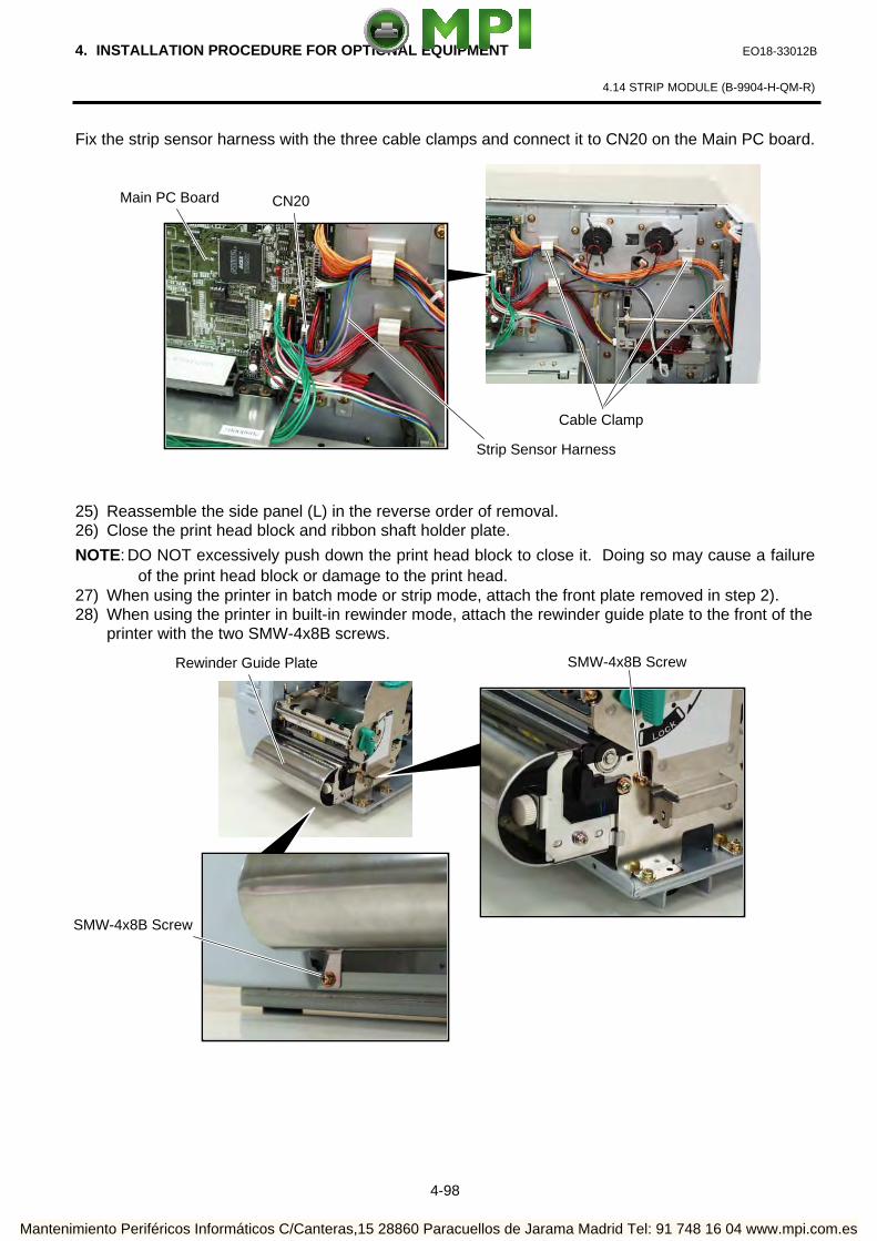
4. INSTALLATION PROCEDURE FOR OPTIONAL EQUIPMENT EO18-33012B
4.14 STRIP MODULE (B-9904-H-QM-R)
4-98
Fix the strip sensor harness with the three cable clamps and connect it to CN20 on the Main PC board.
25) Reassemble the side panel (L) in the reverse order of removal. 26) Close the print head block and ribbon shaft holder plate.
NOTE: DO NOT excessively push down the print head block to close it. Doing so may cause a failure of the print head block or damage to the print head.
27) When using the printer in batch mode or strip mode, attach the front plate removed in step 2). 28) When using the printer in built-in rewinder mode, attach the rewinder guide plate to the front of the
printer with the two SMW-4x8B screws.
Cable Clamp
Rewinder Guide Plate
CN20 Main PC Board
Strip Sensor Harness
SMW-4x8B Screw
SMW-4x8B Screw
Mantenimiento Periféricos Informáticos C/Canteras,15 28860 Paracuellos de Jarama Madrid Tel: 91 748 16 04 www.mpi.com.es

4. INSTALLATION PROCEDURE FOR OPTIONAL EQUIPMENT EO18-33012B
4.14 STRIP MODULE (B-9904-H-QM-R)
4-99
29) Adjustment If the label skews when using the built-in rewinder unit, turn the adjustment knob of the rewinder guide plate to correct the media feed. Clockwise turn moves the rewinder guide plate forward and counterclockwise turn moves it backward.
• When labels skew to the right:
Loosen the SM-4x8 sems screw, turn the adjustment knob clockwise, and tighten the SM-4x8 screw when the rewinder guide plate is positioned correctly.
• When labels skew to the left:
Loosen the SM-4x8 screw, turn the adjustment knob counterclockwise, and tighten the SM-4x8 screw when the rewinder guide plate is positioned correctly.
Adjustment Knob
SM-4x8 Screw
Mantenimiento Periféricos Informáticos C/Canteras,15 28860 Paracuellos de Jarama Madrid Tel: 91 748 16 04 www.mpi.com.es

4. INSTALLATION PROCEDURE FOR OPTIONAL EQUIPMENT EO18-33012B
4.15 RIBBON SAVING MODULE (B-9904-R2-QM-R)
4-100
1. Follow all manual instructions. Failure to do so could create safety hazards such as fire or electrocution. • Manual instructions must be followed when installing option kits or adding cables to avoid
system failures and to insure proper performance and operation. • Failure to follow manual instructions or any unauthorized modifications, substitution or
change to this product will void the limited product warranty. 2. Turn the power OFF and disconnect the power cord before installing the ribbon saving module. 3. Be careful not to pinch your fingers or hands with the covers.
4.15 RIBBON SAVING MODULE (B-9904-R2-QM-R)
NOTE: The B-9904-R2-QM Ribbon Saving Module is available only with Firmware V1.2A or later. Please
be careful that the earlier firmware version does not support it.
4.15.1 Applicable Model This optional device is the ribbon saving module, which is intended for the following models:
B-SX4T-QM-R Series 4.15.2 Packing List
All the following parts are supplied with the kit. Make sure you have all items shown below.
Solenoid (1 pc.) RSV PC Board (1 pc.) Solenoid Harness (1 pc.)
Cable Clamp (1 pc.) Locking Support (3 pcs.)
• Installation Manual (1 copy)
• SM-4x8 Screw (2 pcs.)
WARNING!
Power Switch Power Cord
Mantenimiento Periféricos Informáticos C/Canteras,15 28860 Paracuellos de Jarama Madrid Tel: 91 748 16 04 www.mpi.com.es

4. INSTALLATION PROCEDURE FOR OPTIONAL EQUIPMENT EO18-33012B
4.15 RIBBON SAVING MODULE (B-9904-R2-QM-R)
4-101
4.15.3 Installation Procedure
1) Turn the power off and disconnect the power cord. 2) Remove the four B-4x5 screws from the side panel (L). 3) Open the top cover and remove the three P-4x8 screws that secure the side panel (L).
4) Lift the side panel (L) and put it aside. 5) Disconnect the fan motor harness from CN19 on the Main PC board, and then separate the side
panel (L).
B-4x5 Screw
B-4x5 Screw
P-4x8 Screw
Top Cover
Side Panel (L)
Side Panel (L) Fan Motor Harness
Fan Motor
CN19
Main PC Board
Mantenimiento Periféricos Informáticos C/Canteras,15 28860 Paracuellos de Jarama Madrid Tel: 91 748 16 04 www.mpi.com.es

4. INSTALLATION PROCEDURE FOR OPTIONAL EQUIPMENT EO18-33012B
4.15 RIBBON SAVING MODULE (B-9904-R2-QM-R)
4-102
6) Remove the SM-4x8 screw that secures the operation panel ass’y.
7) Half open the top cover, otherwise the operation panel ass’y cannot be removed from the printer.
8) Lift the operation panel ass’y to release the hook, and then remove the operation panel ass’y by
moving it forward. 9) Disconnect the operation panel harness from the operation panel ass’y.
Operation Panel Ass’y
Top Cover
Operation Panel Ass’y
SM-4x8 Screw
Operation Panel Harness
Bottom Plate
Hook
Mantenimiento Periféricos Informáticos C/Canteras,15 28860 Paracuellos de Jarama Madrid Tel: 91 748 16 04 www.mpi.com.es

4. INSTALLATION PROCEDURE FOR OPTIONAL EQUIPMENT EO18-33012B
4.15 RIBBON SAVING MODULE (B-9904-R2-QM-R)
4-103
NOTE: Pass the operation panel harness through the cord bush so that it is not pinched by the side panel (L) when reassembled.
10) Fit the three locking supports into the RSV PC board.
11) Secure the RSV PC board to the printer with the locking support.
NOTE: Do not push the center of the RSV PC Board when attaching it to the printer. Doing so
may break the PC board. Hold the locking supports and push them into the holds for securing the RSV PC Board.
Operation Panel Harness
Cord Bush
RSV PC Board
Locking Support
RSV PC Board
Holes for securing the RSV PC Board
Mantenimiento Periféricos Informáticos C/Canteras,15 28860 Paracuellos de Jarama Madrid Tel: 91 748 16 04 www.mpi.com.es
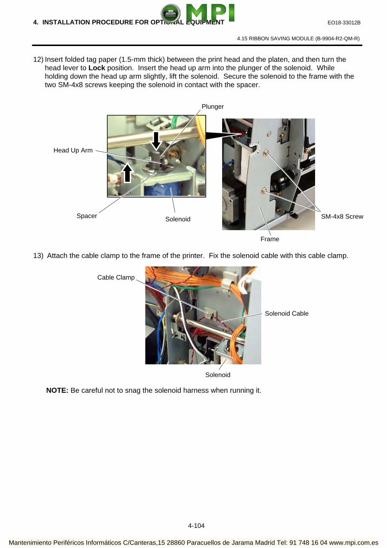
4. INSTALLATION PROCEDURE FOR OPTIONAL EQUIPMENT EO18-33012B
4.15 RIBBON SAVING MODULE (B-9904-R2-QM-R)
4-104
12) Insert folded tag paper (1.5-mm thick) between the print head and the platen, and then turn the head lever to Lock position. Insert the head up arm into the plunger of the solenoid. While holding down the head up arm slightly, lift the solenoid. Secure the solenoid to the frame with the two SM-4x8 screws keeping the solenoid in contact with the spacer.
13) Attach the cable clamp to the frame of the printer. Fix the solenoid cable with this cable clamp.
NOTE: Be careful not to snag the solenoid harness when running it.
Frame
SM-4x8 Screw
Cable Clamp
Solenoid Cable
Solenoid
Head Up Arm
Plunger
Solenoid Spacer
Mantenimiento Periféricos Informáticos C/Canteras,15 28860 Paracuellos de Jarama Madrid Tel: 91 748 16 04 www.mpi.com.es

4. INSTALLATION PROCEDURE FOR OPTIONAL EQUIPMENT EO18-33012B
4.15 RIBBON SAVING MODULE (B-9904-R2-QM-R)
4-105
14) Connect the solenoid harness to CN1 on the RSV PC board and CN11 on the Main PC board. Pass the solenoid harness through the cut.
15) Connect the solenoid cable to CN2 on the RSV PC board.
16) After attaching the solenoid, reassemble the operation panel ass’y and side panel (L) in the
reverse order of removal.
CN11
Main PC Board
Solenoid Harness
CN2
CN1 Solenoid Cable
RSV PC Board
Cut
Mantenimiento Periféricos Informáticos C/Canteras,15 28860 Paracuellos de Jarama Madrid Tel: 91 748 16 04 www.mpi.com.es

4. INSTALLATION PROCEDURE FOR OPTIONAL EQUIPMENT EO18-33012B
4.16 PCMCIA INTERFACE BOARD (B-9700-PCM-QM-R)
4-106
4.16 PCMCIA INTERFACE BOARD (B-9700-PCM-QM-R)
NOTE: When both B-9700-PCM-QM-R and B-9700-LAN-QM-R are installed, inserting a LAN PC card into the
slot of the B-9700-PCM-QM-R disables the B-9700-LAN-QM-R.
4.16.1 Applicable Model This optional device is the PCMCIA interface board, which is intended for the following models:
B-SX4T-QM-R Series, B-SX5T-QM-R Series 4.16.2 Packing List All the following parts are supplied with the kit. Make sure you have all items shown below.
PCMCIA Interface Board (1 pc.)
1. Follow all manual instructions. Failure to do so could create safety hazards such as fire or electrocution. • Manual instructions must be followed when installing option kits or adding cables to avoid
system failures and to insure proper performance and operation. • Failure to follow manual instructions or any unauthorized modifications, substitution or
change to this product will void the limited product warranty. 2. Turn the power OFF and disconnect the power cord before installing the PCMCIA interface
board. 3. Be careful not to pinch your fingers or hands with the covers.
WARNING!
CAUTION! 1. Loosen the two M-3x5 screws of the PCMCIA interface board before installing it. Failure to do this
may cause damage to the connector. 2. When using the LAN interface board or USB interface board together, install the PCMCIA
interface board first.
• Installation Manual (1 copy) • SM-3x6 Screw (3 pcs.)
Power Switch Power Cord
M-3x5 Screw
Mantenimiento Periféricos Informáticos C/Canteras,15 28860 Paracuellos de Jarama Madrid Tel: 91 748 16 04 www.mpi.com.es

4. INSTALLATION PROCEDURE FOR OPTIONAL EQUIPMENT EO18-33012B
4.16 PCMCIA INTERFACE BOARD (B-9700-PCM-QM-R)
4-107
4.16.3 Installation Procedure 1) Turn the power off and disconnect power cord. 2) Remove the four B-4x5 screws from the side panel (L). 3) Open the top cover and remove the three P-4x8 screws that secure the side panel (L).
4) Lift the side panel (L) and put it aside.
5) Disconnect the fan motor harness from CN19 on the Main PC board, and then separate the side
panel (L).
6) Remove the four SM-3x6 screws to detach the two blind plate A from the back. NOTE: When only the PCMCIA interface board is installed, one of the blind plate A and the SM-3x6 screws will
be used later. (Refer to Step 11)
P-4x8 Screw
Top Cover
B-4x5 Screw
B-4x5 Screw
Side Panel (L)
Side Panel (L) Fan Motor Harness
Fan Motor
CN19
Main PC Board
Rear Plate
SM-3x6 Screw
Blind Plate A
Mantenimiento Periféricos Informáticos C/Canteras,15 28860 Paracuellos de Jarama Madrid Tel: 91 748 16 04 www.mpi.com.es

4. INSTALLATION PROCEDURE FOR OPTIONAL EQUIPMENT EO18-33012B
4.16 PCMCIA INTERFACE BOARD (B-9700-PCM-QM-R)
4-108
7) In case of the B-SX5T or the B-SX4T that the optional Expansion I/O board (B-7704-IO-QM-R) has been installed in, remove the Expansion I/O board from the printer temporarily using the following procedure. (1) Disconnect the Expansion I/O cable from CN1 on the Expansion I/O board. (2) Remove the two B-3x6 screws to detach the Expansion I/O board from the printer.
8) Firmly connect CN101 on the PCMCIA interface board directly to CN7 on the Main PC board.
9) Secure the PCMCIA interface board to the rear plate with the two SM-3x6 screws.
PCMCIA Interface Board
Main PC Board
SM-3x6 Screw
Rear Plate
CN1
Expansion I/O Board
Expansion I/O Cable
B-3x6 Screw
Rear Plate
CN101
CN7
Mantenimiento Periféricos Informáticos C/Canteras,15 28860 Paracuellos de Jarama Madrid Tel: 91 748 16 04 www.mpi.com.es

4. INSTALLATION PROCEDURE FOR OPTIONAL EQUIPMENT EO18-33012B
4.16 PCMCIA INTERFACE BOARD (B-9700-PCM-QM-R)
4-109
10) Secure the PCMCIA interface board to the PCB support plate with the SM-3x6 screw. Tighten the two M-3x5 screws that were loosened previously. (Refer to Caution)
11) When installing the PCMCIA interface board only, attach a blind plate A with the SM-3x6 screws to the
printer back, which were removed in Step 6, to cover the unused slot. Please note that “P” and “LU” are printed on the blind plate A, as shown below.
Attach the blind plate A with the mark of “P” positioned topside. It cannot be attached in an improper orientation
12) When the Expansion I/O board was removed in the previous step, reassemble it. 13) Attach the side panel (L) back to the printer in the reverse order of removal.
Blind Plate A
SM-3x6 screw
PCB Support Plate
M-3x5 Screw
PCMCIA Interface Board
Blind Plate A
SM-3x6 Screw
Rear Plate
PCMCIA Interface Board
Mark of “P”
Mantenimiento Periféricos Informáticos C/Canteras,15 28860 Paracuellos de Jarama Madrid Tel: 91 748 16 04 www.mpi.com.es

4. INSTALLATION PROCEDURE FOR OPTIONAL EQUIPMENT EO18-33012B
4.17 USB INTERFACE BOARD (B-9700-USB-QM-R)
4-110
4.17 USB INTERFACE BOARD (B-9700-USB-QM-R)
4.17.1 Applicable Model
This optional device is the USB interface board, which is intended for the following models:
B-SX4T-QM-R Series, B-SX5T-QM-R Series
4.17.2 Packing List
All the following parts are supplied with the kit. Make sure you have all items shown below.
USB Interface Board (1pc.)
PCB Attachment Plate (1 pc.)
1. Follow all manual instructions. Failure to do so could create safety hazards such as fire or electrocution. • Manual instructions must be followed when installing option kits or adding cables to avoid system
failures and to insure proper performance and operation. • Failure to follow manual instructions or any unauthorized modifications, substitution or change to this
product will void the limited product warranty. 2. Turn the power OFF and disconnect the power cord before installing the USB interface board. 3. Be careful not to pinch your fingers or hands with the covers.
WARNING!
CAUTION! 1. Loosen the two M-3x5 screws of the USB interface board before installing it. Failure to do this
may cause damage to the connector. 2. When using the PCMCIA interface board together, first install the PCMCIA PC board, and then
USB interface board.
• Installation Manual (1 copy) • SM-3x6 Screw (4 pcs.)
Power Switch Power Cord
M-3x5 Screw
Mantenimiento Periféricos Informáticos C/Canteras,15 28860 Paracuellos de Jarama Madrid Tel: 91 748 16 04 www.mpi.com.es

4. INSTALLATION PROCEDURE FOR OPTIONAL EQUIPMENT EO18-33012B
4.17 USB INTERFACE BOARD (B-9700-USB-QM-R)
4-111
4.17.3 Installation Procedure
1) Turn the power off and disconnect the power cord. 2) Remove the four B-4x5 screws from the side panel (L). 3) Open the top cover and remove the three P-4x8 screws that secure the side panel (L).
4) Lift the side panel (L) and put it aside. 5) Disconnect the fan motor harness from CN19 on the Main PC board, and then separate the side
panel (L).
6) Remove the four SM-3x6 screws to detach the two blind plate A from the back.
NOTE: When only the USB interface board is installed, one of the blind plate A and the SM-3x6 screws will be
used later. (Refer to Step 12)
B-4x5 Screw
B-4x5 Screw
P-4x8 Screw
Top Cover
Side Panel (L)
Side Panel (L) Fan Motor Harness
Fan Motor
CN19
Main PC Board
SM-3x6 Screw
Blind Plate A
SM-3x6 Screw
Mantenimiento Periféricos Informáticos C/Canteras,15 28860 Paracuellos de Jarama Madrid Tel: 91 748 16 04 www.mpi.com.es

4. INSTALLATION PROCEDURE FOR OPTIONAL EQUIPMENT EO18-33012B
4.17 USB INTERFACE BOARD (B-9700-USB-QM-R)
4-112
7) If the PCMCIA interface board is used together with the USB interface board, attach the PCB attachment plate to the plate to which the PCMCIA interface board is secured with the SM-3x6 screw. If not, go to the next step.
8) Firmly connect CN50 connector on the USB interface board directly to CN7 on the Main PC board
or CN1 on the PCMCIA interface board.
9) Secure the USB interface board to the rear plate with the two SM-3x6 screws.
CN7
When connecting the PCMCIA Interface Board:
USB Interface Board Main PC Board
USB Interface Board PCMCIA Interface Board
When connecting to the Main PC Board:
CN50
CN50
CN1
PCMCIA Interface Board
PCB Attachment Plate SM-3x6 Screw
When connecting to the Main PC Board: When connecting to the PCMCIA Interface Board:
SM-3x6 Screw
USB Interface Board
SM-3x6 Screw
USB Interface Board SM-3x6 Screw
Mantenimiento Periféricos Informáticos C/Canteras,15 28860 Paracuellos de Jarama Madrid Tel: 91 748 16 04 www.mpi.com.es

4. INSTALLATION PROCEDURE FOR OPTIONAL EQUIPMENT EO18-33012B
4.17 USB INTERFACE BOARD (B-9700-USB-QM-R)
4-113
10) Tighten the two M-3x5 screws of the USB interface board that were loosened previously. (Refer to Caution)
11) Secure the USB interface board to the PCB support plate (when connecting to the Main PC board) or PCB attachment plate (when connecting to the PCMCIA interface board) with the SM-3x6 screw.
12) When installing the USB interface board only, attach a blind plate A with the SM-3x6 screws to the
printer back, which were removed in Step 6, to cover the unused slot. Please note that “LU” and “P” are printed on the blind plate A, as shown below. Attach the blind plate A with the mark of “LU” positioned topside. It cannot be attached in an
improper orientation. 12) Attach the side panel (L) back to the printer in the reverse order of removal.
When connecting to the Main PC Board:
M-3x5 Screw
SM-3x6 Screw
PCB Support Plate
When connecting to the PCMCIA Interface Board:
M-3x5 Screw
SM-3x6 Screw
PCB Attachment Plate
Blind Plate A
SM-3x6 Screw
Rear Plate
Mark of “LU”
USB Interface Board
Blind Plate A
Mantenimiento Periféricos Informáticos C/Canteras,15 28860 Paracuellos de Jarama Madrid Tel: 91 748 16 04 www.mpi.com.es

4. INSTALLATION PROCEDURE FOR OPTIONAL EQUIPMENT EO18-33012B
4.18 LAN INTERFACE BOARD (B-9700-LAN-QM-R)
4-114
4.18 LAN INTERFACE BOARD (B-9700-LAN-QM-R)
NOTE: When both B-9700-LAN-QM-R and B-9700-PCM-QM-R are installed, inserting a LAN PC card
into the slot of the B-9700-PCM-QM-R disables the B-9700-LAN-QM-R.
4.18.1 Applicable Model This optional device is the LAN interface board, which is intended for the following models:
B-SX4T-QM-R Series, B-SX5T-QM-R Series
4.18.2 Packing List All the following parts are supplied with the kit. Make sure you have all items shown below.
LAN Interface Board (1pc.)
PCB Attachment Plate
1. Follow all manual instructions. Failure to do so could create safety hazards such as fire or electrocution. • Manual instructions must be followed when installing option kits or adding cables to avoid system
failures and to insure proper performance and operation. • Failure to follow manual instructions or any unauthorized modifications, substitution or change to this
product will void the limited product warranty. 2. Turn the power OFF and disconnect the power cord before installing the LAN interface board.
3. Be careful not to pinch your fingers or hands with the covers.
CAUTION! 1. Loosen the two M-3x5 screws of the LAN interface board before installing it. Failure to do this may cause
damage to the connector. 2. When using the PCMCIA interface board together, first install the PCMCIA PC board, and then LAN
interface board.
WARNING!
License Agreement Please be sure to read the License Agreement before opening the sealed LAN Interface Board. If you do not agree with the License Agreement, please do not use this product. Your unpacking the product indicates your approval for the License Agreement.
• Installation Manual (1 copy) • License Agreement (1 copy) • SM-3x6 Screw (4 pcs.)
M-3x5 Screw
Power Switch Power Cord
Mantenimiento Periféricos Informáticos C/Canteras,15 28860 Paracuellos de Jarama Madrid Tel: 91 748 16 04 www.mpi.com.es

4. INSTALLATION PROCEDURE FOR OPTIONAL EQUIPMENT EO18-33012B
4.18 LAN INTERFACE BOARD (B-9700-LAN-QM-R)
4-115
4.18.3 Installation Procedure 1) Turn the power off and disconnect power cord. 2) Remove the four B-4x5 screws from the side panel (L). 3) Open the top cover and remove the three P-4x8 screws that secure the side panel (L).
3) Lift the side panel (L) and put it aside. 4) Disconnect the fan motor harness from CN19 on the Main PC board, and then separate the side
panel (L).
5) Remove the four SM-3x6 screws to remove the two blind plate A from the back.
NOTE: When only the LAN interface board is installed, one of the blind plate A and the SM-3x6 screws will be
used later. (Refer to Step 11)
B-4x5 Screw
B-4x5 Screw
P-4x8 Screw
Top Cover
Side Panel (L)
Side Panel (L) Fan Motor Harness
Fan Motor
CN19
Main PC Board
Blind Plate A
SM-3x6 Screw
SM-3x6 Screw
Mantenimiento Periféricos Informáticos C/Canteras,15 28860 Paracuellos de Jarama Madrid Tel: 91 748 16 04 www.mpi.com.es

4. INSTALLATION PROCEDURE FOR OPTIONAL EQUIPMENT EO18-33012B
4.18 LAN INTERFACE BOARD (B-9700-LAN-QM-R)
4-116
6) If the PCMCIA interface board is also installed, attach the PCB attachment plate to the plate to which the PCMCIA interface board is secured with the SM-3x6 screw. If not, go to the next step.
7) Firmly connect CN50 on the LAN interface board directly to CN7 on the Main PC board or CN1 on the PCMCIA interface board.
8) Secure the LAN interface board to the rear plate with the two SM-3x6 screws.
When connecting to the Main PC Board When connecting to the PCMCIA Interface Board
SM-3x6 Screw
SM-3x6 Screw
Rear Plate Rear Plate LAN Interface Board LAN Interface Board
PCMCIA Interface Board PCB Attachment Plate SM-3x6 Screw
When connecting to the Main PC Board When connecting to the PCMCIA Interface Board
LAN Interface Board MAIN PC Board LAN Interface Board
PCMCIA Interface Board
CN50
CN7
CN50
CN1
Mantenimiento Periféricos Informáticos C/Canteras,15 28860 Paracuellos de Jarama Madrid Tel: 91 748 16 04 www.mpi.com.es
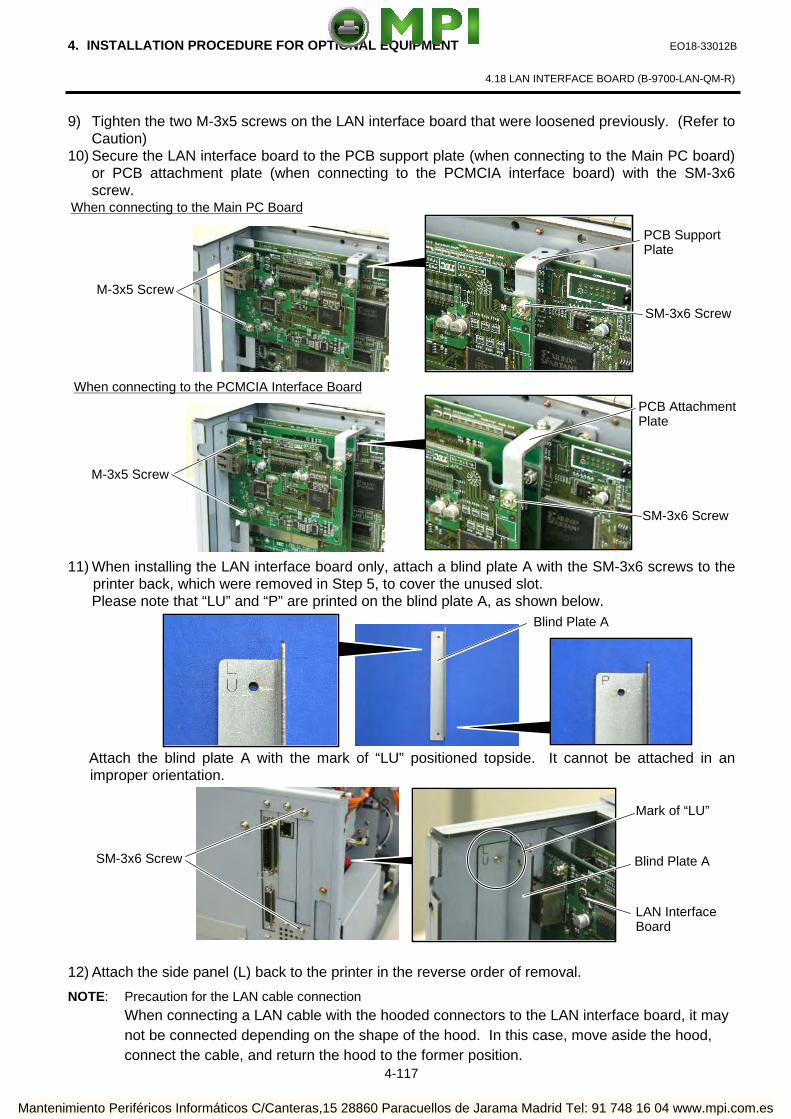
4. INSTALLATION PROCEDURE FOR OPTIONAL EQUIPMENT EO18-33012B
4.18 LAN INTERFACE BOARD (B-9700-LAN-QM-R)
4-117
9) Tighten the two M-3x5 screws on the LAN interface board that were loosened previously. (Refer to Caution)
10) Secure the LAN interface board to the PCB support plate (when connecting to the Main PC board) or PCB attachment plate (when connecting to the PCMCIA interface board) with the SM-3x6 screw.
11) When installing the LAN interface board only, attach a blind plate A with the SM-3x6 screws to the
printer back, which were removed in Step 5, to cover the unused slot. Please note that “LU” and “P” are printed on the blind plate A, as shown below.
Attach the blind plate A with the mark of “LU” positioned topside. It cannot be attached in an
improper orientation. 12) Attach the side panel (L) back to the printer in the reverse order of removal.
NOTE: Precaution for the LAN cable connection
When connecting a LAN cable with the hooded connectors to the LAN interface board, it may not be connected depending on the shape of the hood. In this case, move aside the hood, connect the cable, and return the hood to the former position.
When connecting to the Main PC Board
When connecting to the PCMCIA Interface Board
M-3x5 Screw
M-3x5 Screw
SM-3x6 Screw
PCB Support Plate
SM-3x6 Screw
PCB Attachment Plate
SM-3x6 Screw Blind Plate A
Mark of “LU”
LAN Interface Board
Blind Plate A
Mantenimiento Periféricos Informáticos C/Canteras,15 28860 Paracuellos de Jarama Madrid Tel: 91 748 16 04 www.mpi.com.es

4. INSTALLATION PROCEDURE FOR OPTIONAL EQUIPMENT EO18-33012B
4.19 EXPANSION I/O INTERFACE BOARD (B-7704-IO-QM-R)
4-118
4.19 EXPANSION I/O INTERFACE BOARD (B-7704-IO-QM-R)
4.19.1 Applicable Model This optional device is the expansion I/O board, which is intended for the following models:
B-SX4T-QM-R Series
4.19.2 Packing List All the following parts are supplied with the kit. Make sure you have all items shown below.
Expansion I/O Board (1 pc.) Expansion I/O Cable (1 pc.)
• Installation Manual (1 copy) 4.19.3 Installation Procedure 1) Turn the power off and disconnect the power cord. 2) Remove the four B-4x5 screws from the side panel (L). 3) Open the top cover and remove the three P-4x8 screws that secure the side panel (L).
B-4x5 Screw
WARNING!
1. Follow all manual instructions. Failure to do so could create safety hazards such as fire or electrocution. • Manual instructions must be followed when installing option kits or adding cables to avoid system failures and to insure proper performance and operation.
• Failure to follow manual instructions or any unauthorized modifications, substitution or change to this product will void the limited product warranty.
2. Turn the power OFF and disconnect the power cord before installing the expansion I/O board. 3. Be careful not to pinch your fingers or hands with the covers.
B-4x5 Screw
P-4x8 Screw
Top Cover
Side Panel (L)
Mantenimiento Periféricos Informáticos C/Canteras,15 28860 Paracuellos de Jarama Madrid Tel: 91 748 16 04 www.mpi.com.es
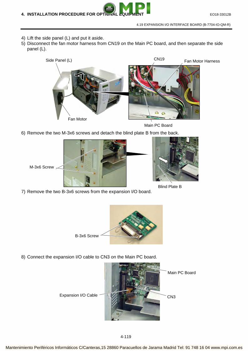
4. INSTALLATION PROCEDURE FOR OPTIONAL EQUIPMENT EO18-33012B
4.19 EXPANSION I/O INTERFACE BOARD (B-7704-IO-QM-R)
4-119
4) Lift the side panel (L) and put it aside. 5) Disconnect the fan motor harness from CN19 on the Main PC board, and then separate the side
panel (L).
6) Remove the two M-3x6 screws and detach the blind plate B from the back.
7) Remove the two B-3x6 screws from the expansion I/O board.
8) Connect the expansion I/O cable to CN3 on the Main PC board.
B-3x6 Screw
Expansion I/O Cable CN3
Main PC Board
Blind Plate B
M-3x6 Screw
Side Panel (L) Fan Motor Harness
Fan Motor
CN19
Main PC Board
Mantenimiento Periféricos Informáticos C/Canteras,15 28860 Paracuellos de Jarama Madrid Tel: 91 748 16 04 www.mpi.com.es

4. INSTALLATION PROCEDURE FOR OPTIONAL EQUIPMENT EO18-33012B
4.19 EXPANSION I/O INTERFACE BOARD (B-7704-IO-QM-R)
4-120
9) Secure the expansion I/O board to the rear plate with the two B-3x6 screws removed in Step 7. 10) Connect the expansion I/O cable to CN1 on the expansion I/O board.
11) Reassemble the side panel (L) in the reverse order of removal. 12) Perform a loop back check to confirm that the expansion I/O board functions properly.
CN1
Expansion I/O Board
Expansion I/O Cable
B-3x6 Screw
Rear Plate
Mantenimiento Periféricos Informáticos C/Canteras,15 28860 Paracuellos de Jarama Madrid Tel: 91 748 16 04 www.mpi.com.es

4. INSTALLATION PROCEDURE FOR OPTIONAL EQUIPMENT EO18-33012B
4.20 FAN FOLD PAPER GUIDE MODULE (B-4905-FF-QM-R)
4-121
4.20 FANFOLD PAPER GUIDE MODULE (B-4905-FF-QM-R)
4.20.1 Applicable Model This optional device is the fan fold paper guide, which is intended for the following models:
B-SX4T-QM-R Series, B-SX5T-QM-R Series
4.20.2 Packing List
All the following parts are supplied with the kit. Make sure you have all items shown below.
Description Q’ty/unit
Fanfold Paper Guide (rear) 1
4.20.3 Installation Procedure
1) Open the top cover.
2) Remove the two FL-4x5 screws to detach the blind plate on the back of the printer and attach the
fanfold paper guide (rear) with these same screws.
WARNING!
Disconnect the power cord before installing the Fanfold Paper Guide Module.
Screw (FL-4x5)
Screw (FL-4x5)
Fanfold Paper Guide (rear)
Mantenimiento Periféricos Informáticos C/Canteras,15 28860 Paracuellos de Jarama Madrid Tel: 91 748 16 04 www.mpi.com.es
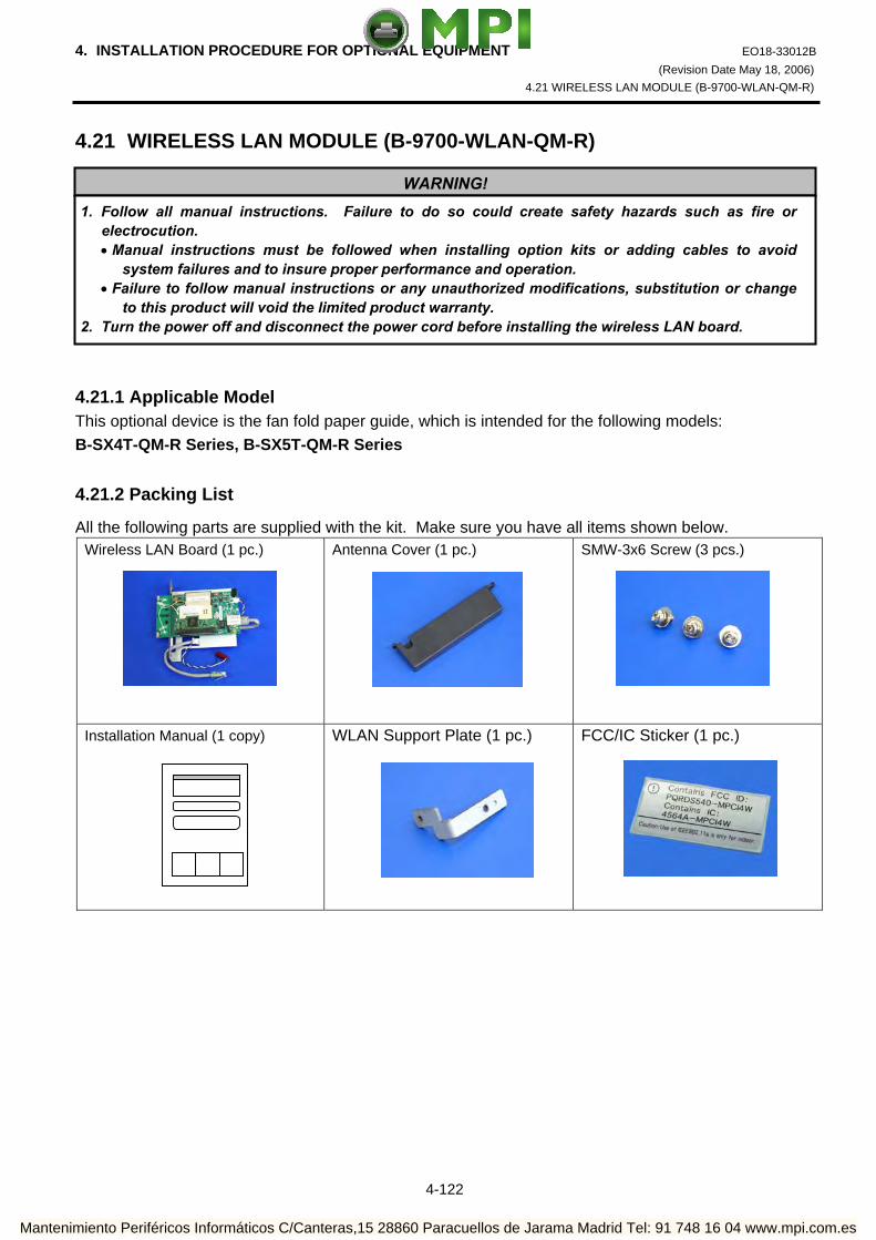
4. INSTALLATION PROCEDURE FOR OPTIONAL EQUIPMENT EO18-33012B (Revision Date May 18, 2006)
4.21 WIRELESS LAN MODULE (B-9700-WLAN-QM-R)
4-122
4.21 WIRELESS LAN MODULE (B-9700-WLAN-QM-R) 4.21.1 Applicable Model This optional device is the fan fold paper guide, which is intended for the following models: B-SX4T-QM-R Series, B-SX5T-QM-R Series
4.21.2 Packing List
All the following parts are supplied with the kit. Make sure you have all items shown below. Wireless LAN Board (1 pc.)
Antenna Cover (1 pc.)
SMW-3x6 Screw (3 pcs.)
Installation Manual (1 copy)
WLAN Support Plate (1 pc.)
FCC/IC Sticker (1 pc.)
WARNING!1. Follow all manual instructions. Failure to do so could create safety hazards such as fire or
electrocution. • Manual instructions must be followed when installing option kits or adding cables to avoid
system failures and to insure proper performance and operation. • Failure to follow manual instructions or any unauthorized modifications, substitution or change
to this product will void the limited product warranty. 2. Turn the power off and disconnect the power cord before installing the wireless LAN board.
Mantenimiento Periféricos Informáticos C/Canteras,15 28860 Paracuellos de Jarama Madrid Tel: 91 748 16 04 www.mpi.com.es

4. INSTALLATION PROCEDURE FOR OPTIONAL EQUIPMENT EO18-33012B (Revision Date May 18, 2006)
4.21 WIRELESS LAN MODULE (B-9700-WLAN-QM-R)
4-123
NOTES: 1. DO NOT CHANGE the DIP Switch settings on the Wireless LAN Board. Doing so may cause a
malfunction. 2. MAC address of the Wireless LAN module will be necessary when setting the MAC address filtering
function of an access point. As it is printed on the top of the wired LAN connector on the Wireless LAN Board, write down it on Installation Manual before mounting the covers so that an end user can know the MAC address.
3. Be careful not to hit or damage the antenna when installing this kit. A damaged antenna may affect the performance.
4.21.3 Installation Procedure
1) Remove the four B-4x5 screws from the Side Panel (L). 2) Open the Top Cover and remove the three P-4x8 screws that secure the Side Panel (L).
MAC Address
DIP Switch
12-digit code printed on the right side of “W” is MAC address.
Antenna
Wireless LAN Board
B-4x5 Screw
B-4x5 Screw
P-4x8 Screw
Top Cover
Side Panel (L)
Mantenimiento Periféricos Informáticos C/Canteras,15 28860 Paracuellos de Jarama Madrid Tel: 91 748 16 04 www.mpi.com.es

4. INSTALLATION PROCEDURE FOR OPTIONAL EQUIPMENT EO18-33012B (Revision Date May 18, 2006)
4.21 WIRELESS LAN MODULE (B-9700-WLAN-QM-R)
4-124
3) Lift the Side Panel (L) and put it aside. Disconnect the Fan Motor Harness from CN19 on the Main PC Board, and then separate the Side Panel (L).
4) Remove the four SM-3x6 screws to remove the two Blind Plate A from the back. 5) Install the B-9700-LAN-QM-R LAN Board in the printer. For detail of the installation procedure,
please refer to B-9700-LAN-QM-R Installation Manual.
Side Panel (L)Fan Motor Harness
Fan Motor
Connector CN19
Main PC Board
Blind Plate A
SM-3x6 Screw
SM-3x6 Screw
LAN Board
Mantenimiento Periféricos Informáticos C/Canteras,15 28860 Paracuellos de Jarama Madrid Tel: 91 748 16 04 www.mpi.com.es

4. INSTALLATION PROCEDURE FOR OPTIONAL EQUIPMENT EO18-33012B (Revision Date May 18, 2006)
4.21 WIRELESS LAN MODULE (B-9700-WLAN-QM-R)
4-125
6) Secure the WLAN Support Plate to the following position with the SMW-3x6 screw. 7) Connect the Wireless LAN Power Cable to CN101 on the LAN Board. 8) Put the Antenna of the Wireless LAN Board out of the opening in the printer back.
Care must be taken not to hit the Antenna against the printer frame, as damaged antenna may affect the performance. Secure the Wireless LAN Board to the printer with the three SMW-3x6 screws (two of them are those removed in Step 4.)
WLAN Support Plate
SMW-3x6 Screw
PCB Attachment Plate
Connector CN101
LAN Board
Wireless LAN Power Cable
OpeningAntenna
Wireless LAN Board
SMW-3x6 Screw
SMW-3x6 Screw
Mantenimiento Periféricos Informáticos C/Canteras,15 28860 Paracuellos de Jarama Madrid Tel: 91 748 16 04 www.mpi.com.es

4. INSTALLATION PROCEDURE FOR OPTIONAL EQUIPMENT EO18-33012B (Revision Date May 18, 2006)
4.21 WIRELESS LAN MODULE (B-9700-WLAN-QM-R)
4-126
9) Attach the Antenna Cover to the printer back with the SMW-3x6 screw, as shown below. Pass the LAN Cable through the cut of the Antenna Cover.
10) Re-attach the Side Panel (L) to the printer.
11) After installing the wireless LAN module, attach the FCC/IC sticker to any available space of the printer back.
Antenna Cover
LAN Cable
Pass the LAN Cable through the cut of the Antenna Cover.
LAN Board Connector
SMW-3x6 Screw
Mantenimiento Periféricos Informáticos C/Canteras,15 28860 Paracuellos de Jarama Madrid Tel: 91 748 16 04 www.mpi.com.es

4. INSTALLATION PROCEDURE FOR OPTIONAL EQUIPMENT EO18-33012B (Revision Date Apr. 24, 2008)
4.22 RFID MODULE (B-SX704-RFID-U2-EU-R)
4-127
4.22 RFID MODULE (B-SX704-RFID-U2-EU-R) The B-SX704-RFID-U2-EU-R is exclusively for the B-SX4T and B-SX5T series. This RFID kit complies with EPCglobal Class1 Generation2 (Gen2) and radio laws of all applicable countries. As this product is a wireless communication device, please be sure to read the following precautions carefully.
1. Do not use a printer embedded with this product near medical equipment. Radio wave emitted from this product may affect the operation of medical equipment, such as an implanted cardiac pacemaker and implantable cardioverter-defibrillator. If a use of this product should be likely to have affected medical equipment, immediately turn off the product and contact your TOSHIBA TEC sales agent.
Keep a printer embedded with this product at least 23cm away from a person with an implanted cardiac pacemaker or implantable cardioverter-defibrillator.
2. Do not export a printer embedded with this product to the countries or areas where a use of this product isnot allowed, without permission. Doing so is against the law, and you may be punished.
When exporting this product, check the laws and regulations of a destination country and take necessary procedures.
3. Follow all manual instructions. Failure to do so could create safety hazards such as fire or electrocution. • Manual instructions must be followed when installing option kits or adding cables to avoid system
failures and to insure proper performance and operation. • Failure to follow manual instructions or any unauthorized modifications, substitution or change to this
product will void the limited product warranty. 4. Turn the power OFF and disconnect the power cord before installing the RFID module. 5. Be careful not to pinch your fingers or hands with the covers. 6. The print head and stepping motor becomes very hot immediately after printing. Do not touch the print
head, stepping motor and around it right after printing, or you may get burned. 7. When opening the top cover, it must be fully opened. Failure to do this may cause the top cover to close
under its own weight, resulting in an injury.
WARNING!
CAUTION! Be careful not to damage the pattern of the Antenna Ass’y or peel off the Shield Sheet. Damaged pattern or removed Shield Sheet may affect the ability to read or write RFID tags.
Pattern
ShieldSheet
Antenna Ass’y
Mantenimiento Periféricos Informáticos C/Canteras,15 28860 Paracuellos de Jarama Madrid Tel: 91 748 16 04 www.mpi.com.es

4. INSTALLATION PROCEDURE FOR OPTIONAL EQUIPMENT EO18-33012B (Revision Date Apr. 24, 2008)
4.22 RFID MODULE (B-SX704-RFID-U2-EU-R)
4-128
4.22.1 Applicable Model (1) This optional device is intended for the following models: B-SX4T-GS20-QM-R and B-SX5T-TS22-QM-R, RFID ready printer. An RFID Ready printer can be identified by the model name sticker on the front of the printer. Be careful not to install this product in the B-SX4T-GS10-QQ/QQ-US and B-SX5T-TS10-QQ/QQ-
US RFID Ready printers.
(2) To use this device, printer firmware V4.5 or greater is required. Upgrade the firmware to V4.5 or greater, if necessary. For the downloading procedure, refer to the B-SX4T/SX5T Series Maintenance Manual.
Note that a RAM clear needs to be performed after downloading, so print out the maintenance counter and parameter settings prior to downloading. After performing a RAM clear, restore the printer parameter settings to the former states.
(3) The countries where the use of this device is allowed are as follows:
Model Name Frequency Band Applicable Countries
B-SX704-RFID–U2-EU-R UHF 869.7 to 870.0MHz
(Center frequency: 869.85MHz) EU member states and EFTA member states
4.22.2 Packing List If any part is missing, please contact your TOSHIBA TEC sales agent.
• Antenna Ass’y (1 pc.)
•RFID R/W Module (1 pc.)
• Antenna Frame
• Ribbon Guide (1 pc.)
• Bush (1 pc.)
• Cable Clamp (1 pc.)
•Interface Cable (1 pc.)
• Double Sems Screw SMW-3x6 (5 pcs.)
• Antenna Cable (1 pc.)
• Installation Manual (1 copy)
Mantenimiento Periféricos Informáticos C/Canteras,15 28860 Paracuellos de Jarama Madrid Tel: 91 748 16 04 www.mpi.com.es

4. INSTALLATION PROCEDURE FOR OPTIONAL EQUIPMENT EO18-33012B (Revision Date Apr. 24, 2008)
4.22 RFID MODULE (B-SX704-RFID-U2-EU-R)
4-129
The following parts are required when short-pitch tags (20 mm) are used. Keep them safe when not in use. • Shield Plate (1 pc.)
• Shield Sheet (1 pc.)
• Antenna Plate L (1 pc.)
• Antenna Plate R (1 pc.)
• Pan Head Screw P-3x6 (6 pcs.)
4.22.3 Installation Procedure
4.22.3.1 Preparation for Use of Short-Pitch RFID Tags (20mm) When short-pitch tags (20 mm) are to be used, the Antenna Ass’y and the Antenna Frame need to be converted before installing an RFID module in the printer, for proper read/write operation. When short-pitch tags are not used, skip this section and go to Section 4.22.3.2. 1. Remove the two Tapping Screws to detach the Antenna from the Antenna Ass’y.
Tapping Screw
Antenna
Antenna Ass’y
Mantenimiento Periféricos Informáticos C/Canteras,15 28860 Paracuellos de Jarama Madrid Tel: 91 748 16 04 www.mpi.com.es

4. INSTALLATION PROCEDURE FOR OPTIONAL EQUIPMENT EO18-33012B (Revision Date Apr. 24, 2008)
4.22 RFID MODULE (B-SX704-RFID-U2-EU-R)
4-130
2. Remove the backing tapes from the reverse side of the Shield Sheet and attach it to the Antenna Cover, as shown below.
3. Attach the Antenna Plate L and Antenna Plate R to the Antenna with the P-3x6 screws. 4. Attach the Shield Plate to the Antenna Frame. Secure the Shield Plate to the Antenna Frame with the
P-3x6 screws. 5. Refer to Section 3.2 and install an RFID module in the printer.
Tape
Shield Sheet Shield Sheet Antenna
Cover
P-3x6 Screw
Antenna Plate R
P-3x6 ScrewAntenna Plate L Antenna (with Antenna Plate)
Antenna Frame Shield Plate
P-3x6 Screw
Mantenimiento Periféricos Informáticos C/Canteras,15 28860 Paracuellos de Jarama Madrid Tel: 91 748 16 04 www.mpi.com.es

4. INSTALLATION PROCEDURE FOR OPTIONAL EQUIPMENT EO18-33012B (Revision Date Apr. 24, 2008)
4.22 RFID MODULE (B-SX704-RFID-U2-EU-R)
4-131
4.22.3.2 Preparing for the RFID Module Installation 1. Turn the power off and disconnect the Power Cord. 2. Remove the two Black Screws to detach the Front Plate. 3. Remove the four B-4x5 screws from the Side Panel (L). 4. Open the Top Cover and remove the three P-4x8 screws that secure the Side Panel (L).
Front Plate
BlackScrews
P-4x8 Screw
Top Cover
B-4x5 Screw
B-4x5 Screw Side Panel (L)
Mantenimiento Periféricos Informáticos C/Canteras,15 28860 Paracuellos de Jarama Madrid Tel: 91 748 16 04 www.mpi.com.es

4. INSTALLATION PROCEDURE FOR OPTIONAL EQUIPMENT EO18-33012B (Revision Date Apr. 24, 2008)
4.22 RFID MODULE (B-SX704-RFID-U2-EU-R)
4-132
5. Lift the Side Panel (L) and put it aside. 6. Disconnect the Fan Motor Harness from CN19 on the Main PC Board, and then remove the Side Panel
(L). 7. Fully open the Top Cover. 8. Turn the Head Lever to Free position and open the Ribbon Shaft Holder Plate.
Side Panel (L) Fan Motor Harness
Fan Motor
CN19
Main PC Board
Top Cover
Ribbon ShaftHolder Plate
HeadLever
Mantenimiento Periféricos Informáticos C/Canteras,15 28860 Paracuellos de Jarama Madrid Tel: 91 748 16 04 www.mpi.com.es
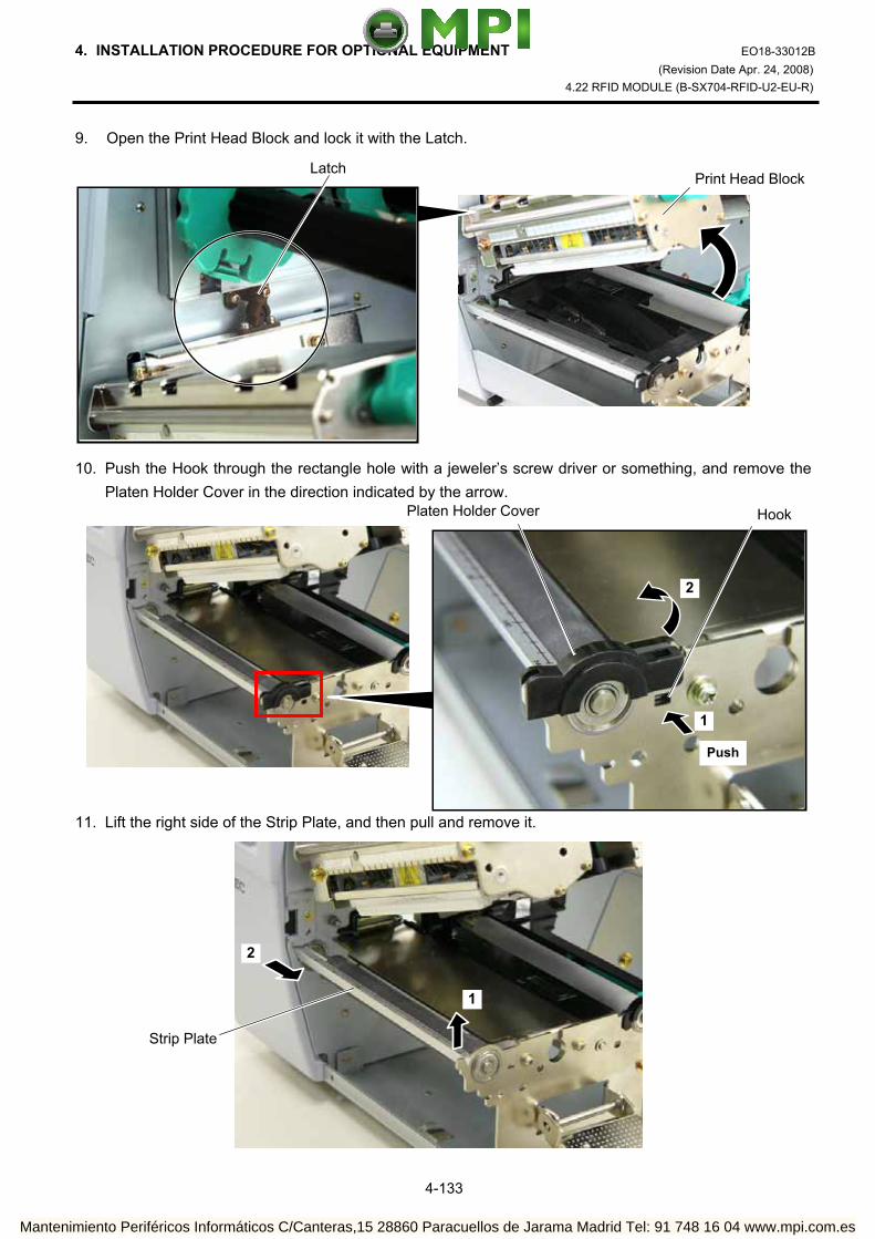
4. INSTALLATION PROCEDURE FOR OPTIONAL EQUIPMENT EO18-33012B (Revision Date Apr. 24, 2008)
4.22 RFID MODULE (B-SX704-RFID-U2-EU-R)
4-133
9. Open the Print Head Block and lock it with the Latch. 10. Push the Hook through the rectangle hole with a jeweler’s screw driver or something, and remove the
Platen Holder Cover in the direction indicated by the arrow. 11. Lift the right side of the Strip Plate, and then pull and remove it.
Print Head BlockLatch
HookPlaten Holder Cover
Push
1
2
Strip Plate
2
1
Mantenimiento Periféricos Informáticos C/Canteras,15 28860 Paracuellos de Jarama Madrid Tel: 91 748 16 04 www.mpi.com.es

4. INSTALLATION PROCEDURE FOR OPTIONAL EQUIPMENT EO18-33012B (Revision Date Apr. 24, 2008)
4.22 RFID MODULE (B-SX704-RFID-U2-EU-R)
4-134
12. Remove the Platen and the Platen Holder in the direction of the arrows 1 to 3 as shown below. 13. Remove the following three screws.
Platen
PlatenHolder
1
2
3
SMW-3x6 Screw
SMW-4x8 Screw
Mantenimiento Periféricos Informáticos C/Canteras,15 28860 Paracuellos de Jarama Madrid Tel: 91 748 16 04 www.mpi.com.es

4. INSTALLATION PROCEDURE FOR OPTIONAL EQUIPMENT EO18-33012B (Revision Date Apr. 24, 2008)
4.22 RFID MODULE (B-SX704-RFID-U2-EU-R)
4-135
14. Remove the Platen Frame Top from the printer. 15 Remove the four screws from the side of the Print Head Block, slightly pull the Head Side Plate, and
remove the two Ribbon Guide Shafts. NOTE: One of the removed Ribbon Guide Shafts and SMW-2.6x6 Screws are re-used when attaching the
Ribbon Guide. Keep the unused ones for future use. 16. Insert one of the Ribbon Guide Shafts removed in Step 15 into the Ribbon Guide.
Platen Frame Top
SMW-3x6 Screw SMW-4x8 Screw
SMW-2.6x6 Screw Ribbon Guide Shaft
Head Side Plate
Ribbon Guide
Ribbon Guide Shaft
Mantenimiento Periféricos Informáticos C/Canteras,15 28860 Paracuellos de Jarama Madrid Tel: 91 748 16 04 www.mpi.com.es

4. INSTALLATION PROCEDURE FOR OPTIONAL EQUIPMENT EO18-33012B (Revision Date Apr. 24, 2008)
4.22 RFID MODULE (B-SX704-RFID-U2-EU-R)
4-136
17. Rotate the Ribbon Guide Shaft so that its D-cut is in the same orientation with the Ribbon Guide’s D-cut. Without doing this, the Ribbon Guide cannot be fit in the Print Head Block.
18. Fit the Ribbon Guide including the Ribbon Guide Shaft in the Print Head Block, and secure it to the
Head Side Plate with the SMW-2.6x6 screw. Temporarily secure the Head Side Plate to the Print Head Block with the SMW-3x6 Screw and the SMW-4x8 Screw. Be sure to fit the locating pins provided on the other side of the Ribbon Guide into the locating holes of the Print Head Block.
Ribbon Guide’s D-cut
Ribbon Guide Shaft’s D-cut
RibbonGuide
Double Sems ScrewSMW-3x6
Double Sems ScrewSMW-4x8
Double Sems ScrewSMW-2.6x6
Head Side Plate
Print Head Block
Locating Hole (A) Locating Hole (B) Locating Pin (A)
Locating Pin(B)
Ribbon Guide Ribbon Guide
Mantenimiento Periféricos Informáticos C/Canteras,15 28860 Paracuellos de Jarama Madrid Tel: 91 748 16 04 www.mpi.com.es

4. INSTALLATION PROCEDURE FOR OPTIONAL EQUIPMENT EO18-33012B (Revision Date Apr. 24, 2008)
4.22 RFID MODULE (B-SX704-RFID-U2-EU-R)
4-137
19. Close the Ribbon Shaft Holder Plate, and tighten the two screws, which were temporarily tightened in Step 18, while holding down the Print Head Block.
20. Open the Ribbon Shaft Holder Plate again, and tighten the SMX-2.6x6 screw to secure the Head Side
Plate.
Print Head Block
Double Sems ScrewSMW-4x8
Double Sems ScrewSMW-3x6
Ribbon Shaft Holder Plate Head Lever
Double Sems Screw SMW-2.6x6
Head Side Plate
Mantenimiento Periféricos Informáticos C/Canteras,15 28860 Paracuellos de Jarama Madrid Tel: 91 748 16 04 www.mpi.com.es

4. INSTALLATION PROCEDURE FOR OPTIONAL EQUIPMENT EO18-33012B (Revision Date Apr. 24, 2008)
4.22 RFID MODULE (B-SX704-RFID-U2-EU-R)
4-138
4.22.3.3 Attaching the Antenna Frame and the Antenna Ass’y This section describes the procedure for attaching the Antenna Frame and the Antenna Ass’y. When short-pitch tags (20 mm) are used, the procedure is different from the following. Skip step (1) and go to step (2). (1) When using RFID tags other than short-pitch type: 1. Raise the Print Head Block, and slide the Antenna Frame into the printer as shown below. Make the
protruding screw shaft of the printer pass through the slit of the Antenna Frame. Also, make the Shaft of the printer fit in the Cut of the right side of Antenna Frame.
Antenna Frame
Screw Shaft Slit
Shaft
Cut Antenna Frame
Mantenimiento Periféricos Informáticos C/Canteras,15 28860 Paracuellos de Jarama Madrid Tel: 91 748 16 04 www.mpi.com.es

4. INSTALLATION PROCEDURE FOR OPTIONAL EQUIPMENT EO18-33012B (Revision Date Apr. 24, 2008)
4.22 RFID MODULE (B-SX704-RFID-U2-EU-R)
4-139
2. Secure the Antenna Frame with the three screws removed in Step 13 of Section 4.22.3.2. 3. Connect the Antenna Cable to the Antenna Ass’y until it clicks.
Antenna Cable
Antenna Ass’y
Connector
SMW-3x6 Screw
SMW-4x8 Screw
Mantenimiento Periféricos Informáticos C/Canteras,15 28860 Paracuellos de Jarama Madrid Tel: 91 748 16 04 www.mpi.com.es

4. INSTALLATION PROCEDURE FOR OPTIONAL EQUIPMENT EO18-33012B (Revision Date Apr. 24, 2008)
4.22 RFID MODULE (B-SX704-RFID-U2-EU-R)
4-140
4. Pass the Antenna Cable between the Sensor Block and the Antenna Frame, as shown below. 5. Fit the Antenna Ass’y in the Antenna Frame. Be sure to fit the locating pins of the Antenna Cover into the oval holes and the cuts in the Antenna
Frame.
Antenna Frame
Sensor Block Antenna Cable
Antenna Ass’y
Cut
Location Pin
Antenna Frame
Location Hole
Location Pin
Mantenimiento Periféricos Informáticos C/Canteras,15 28860 Paracuellos de Jarama Madrid Tel: 91 748 16 04 www.mpi.com.es

4. INSTALLATION PROCEDURE FOR OPTIONAL EQUIPMENT EO18-33012B (Revision Date Apr. 24, 2008)
4.22 RFID MODULE (B-SX704-RFID-U2-EU-R)
4-141
6. Push the Antenna Ass’y in the arrow-indicating direction, and secure it with the two SMW-3x6 screws. 7. Go to Section 4.22.3.4 and attach the RFID Module. (2) When using short-pitch tags (20 mm)
1. Attach the Antenna Frame, to which the Shield Plate was attached in Section 4.22.3.1, to the printer in the same way as described in Step 1 of “(1) When using RFID tags other than short-pitch type”.
SMW-3x6 Screw
Antenna Ass’y
Antenna Frame (with Shield Plate)
SMW-4x8 Screw
SMW-3x6 Screw
Mantenimiento Periféricos Informáticos C/Canteras,15 28860 Paracuellos de Jarama Madrid Tel: 91 748 16 04 www.mpi.com.es

4. INSTALLATION PROCEDURE FOR OPTIONAL EQUIPMENT EO18-33012B (Revision Date Apr. 24, 2008)
4.22 RFID MODULE (B-SX704-RFID-U2-EU-R)
4-142
2. Connect the Antenna Cable to the Antenna, to which the Antenna Plates were attached in Section 4.22.3.1, until it clicks.
3. Secure the Antenna to the Antenna Frame with the P-3x6 screws. 4. Place the Antenna Cable in the Antenna Frame, as shown below.
Antenna Cable
Antenna
Connector
Antenna (with Antenna Plates)
P-3x6 Screw
Antenna Cable
Mantenimiento Periféricos Informáticos C/Canteras,15 28860 Paracuellos de Jarama Madrid Tel: 91 748 16 04 www.mpi.com.es

4. INSTALLATION PROCEDURE FOR OPTIONAL EQUIPMENT EO18-33012B (Revision Date Apr. 24, 2008)
4.22 RFID MODULE (B-SX704-RFID-U2-EU-R)
4-143
5. Refer to Steps 5 and 6 in “(1) When using RFID tags other than short-pitch type” and attach the Antenna Cover, to which the Shield Sheet was attached in Section 4.22.3.1, to the Antenna Frame with the SMW-3x6 screws.
6. Go to Section 4.22.3.4 and attach the RFID Module. 4.22.3.4 Attaching the RFID Module 1. Attach the Cable Clamp to and fit the Bush into the positions shown in the picture below.
SMW-3x6 Screw
Antenna Cover (with Shield Sheet)
Bush
Cable Clamp
Mantenimiento Periféricos Informáticos C/Canteras,15 28860 Paracuellos de Jarama Madrid Tel: 91 748 16 04 www.mpi.com.es

4. INSTALLATION PROCEDURE FOR OPTIONAL EQUIPMENT EO18-33012B (Revision Date Apr. 24, 2008)
4.22 RFID MODULE (B-SX704-RFID-U2-EU-R)
4-144
2. Pass the Antenna Cable through the Bush, and fasten the cable with the Cable Clamp. 3. Attach the RFID Module to the RFID Attachment Plate A and the RFID Attachment Plate B with the
three SMW-3x6 screws.
Bush
Cable Clamp
Antenna Cable
RFID Attachment Plate B
SMW-3x6 Screw
SMW-3x6 Screw
RFID ModuleRFID Attachment Plate A
Mantenimiento Periféricos Informáticos C/Canteras,15 28860 Paracuellos de Jarama Madrid Tel: 91 748 16 04 www.mpi.com.es

4. INSTALLATION PROCEDURE FOR OPTIONAL EQUIPMENT EO18-33012B (Revision Date Apr. 24, 2008)
4.22 RFID MODULE (B-SX704-RFID-U2-EU-R)
4-145
4. Fold the Antenna Cable and fasten it with the Cable Clamp together with the other cables to prevent the Antenna Cable from being caught in the Side Panel (L) or Fan Motor.
5. Connect the Antenna Cable to the RFID Module until it clicks.
Cable Clamp
Bush
Antenna Cable
Antenna Cable
Antenna Cable
RFID Module
Connector
Mantenimiento Periféricos Informáticos C/Canteras,15 28860 Paracuellos de Jarama Madrid Tel: 91 748 16 04 www.mpi.com.es

4. INSTALLATION PROCEDURE FOR OPTIONAL EQUIPMENT EO18-33012B (Revision Date Apr. 24, 2008)
4.22 RFID MODULE (B-SX704-RFID-U2-EU-R)
4-146
6. Connect the RFID Module to CN14 on the Main PC Board with the Interface Cable. 7. Re-install the Platen, Platen Holder, Strip Plate, and Platen Holder Cover in the reverse order of
removal. 8. Re-install the Front Plate and Side Cover (L) in the reverse order of removal. Do not forget to connect
the Fan Motor Cable to CN19 on the Main PC Board. Be careful not to catch any cables in the Side Cover (L).
9. Installing the RFID kit in the printer is now completed. Then, go to Section 4.22.4 and configure the
RFID module settings.
Connector
Connector CN14
RFID Module
Interface Cable
Main PC Board
Strip Plate
Platen
Platen Holder
Platen Holder Cover
Front Plate
Side Cover (L)
Mantenimiento Periféricos Informáticos C/Canteras,15 28860 Paracuellos de Jarama Madrid Tel: 91 748 16 04 www.mpi.com.es
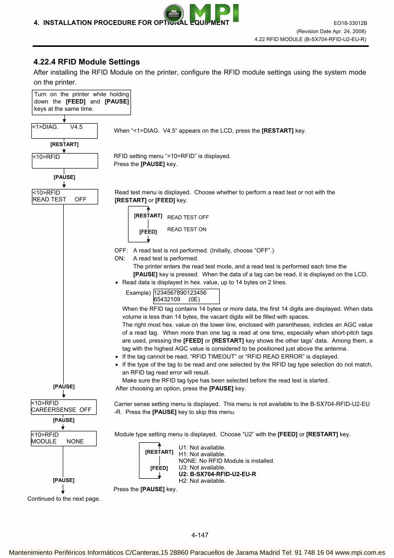
4. INSTALLATION PROCEDURE FOR OPTIONAL EQUIPMENT EO18-33012B (Revision Date Apr. 24, 2008)
4.22 RFID MODULE (B-SX704-RFID-U2-EU-R)
4-147
4.22.4 RFID Module Settings After installing the RFID Module on the printer, configure the RFID module settings using the system mode on the printer.
RFID setting menu ”<10>RFID” is displayed. Press the [PAUSE] key.
[RESTART]
<10>RFID
<1>DIAG. V4.5
Turn on the printer while holding down the [FEED] and [PAUSE] keys at the same time.
When “<1>DIAG. V4.5“ appears on the LCD, press the [RESTART] key.
[PAUSE]
Continued to the next page.
<10>RFID READ TEST OFF
[PAUSE]
Read test menu is displayed. Choose whether to perform a read test or not with the [RESTART] or [FEED] key.
[RESTART]
[FEED]
READ TEST OFF READ TEST ON
<10>RFID CAREERSENSE OFF
OFF: A read test is not performed. (Initially, choose “OFF”.) ON: A read test is performed.
The printer enters the read test mode, and a read test is performed each time the [PAUSE] key is pressed. When the data of a tag can be read, it is displayed on the LCD.
• Read data is displayed in hex. value, up to 14 bytes on 2 lines. When the RFID tag contains 14 bytes or more data, the first 14 digits are displayed. When data
volume is less than 14 bytes, the vacant digits will be filled with spaces. The right most hex. value on the lower line, enclosed with parentheses, indictes an AGC value
of a read tag. When more than one tag is read at one time, especially when short-pitch tags are used, pressing the [FEED] or [RESTART] key shows the other tags’ data. Among them, a tag with the highest AGC value is considered to be positioned just above the antenna.
• If the tag cannot be read, “RFID TIMEOUT” or “RFID READ ERROR” is displayed. • If the type of the tag to be read and one selected by the RFID tag type selection do not match,
an RFID tag read error will result. Make sure the RFID tag type has been selected before the read test is started. After choosing an option, press the [PAUSE] key.
123456789012345665432109 (0E)
Carrier sense setting menu is displayed. This menu is not available to the B-SX704-RFID-U2-EU -R. Press the [PAUSE] key to skip this menu.
[PAUSE]
<10>RFID MODULE NONE
Module type setting menu is displayed. Choose “U2” with the [FEED] or [RESTART] key.
[RESTART]
[FEED]
U1: Not available.H1: Not available. NONE: No RFID Module is installed. U3: Not available. U2: B-SX704-RFID-U2-EU-R H2: Not available.[PAUSE]
Press the [PAUSE] key.
Example)
Mantenimiento Periféricos Informáticos C/Canteras,15 28860 Paracuellos de Jarama Madrid Tel: 91 748 16 04 www.mpi.com.es

4. INSTALLATION PROCEDURE FOR OPTIONAL EQUIPMENT EO18-33012B (Revision Date Apr. 24, 2008)
4.22 RFID MODULE (B-SX704-RFID-U2-EU-R)
4-148
<10>RFID TAG NONE
RFID tag type setting menu is displayed. Choose “EPC C1 Gen2: 24” with the [FEED] or [RESTART] key.
[RESTART]
[FEED]NONE: When a tag type is not selected. EPC C1 Gen2: 24
[PAUSE] Press the [PAUSE] key.
<10>RFID ERR CHK OFF
RFID error tag detection menu is displayed. Choose whether to perform an error tag detection or not with the [FEED] or [RESTART] key.
[RESTART]
[FEED]
OFF: An error tag detection is not performed. (Usually, choose OFF.)
ON: An error tag detection is performed.
ON: A tag is read before writing data on it, and data is written on the tag only when theheader data is “A5A5”.
OFF: Though a tag is read before writing data on it, data write is always performed whatever data has been set as the header data.
[PAUSE] Press the [PAUSE] key.
Continued to the next page.
Continued from the previous page.
<10>RFID ISSUE RETRY 3
Max. number of issue retries setting menu is displayed. Set a maximum number of retries to issue an RFID tag. When issuing an RFID tag failed, the printer prints the error pattern, and retries to issue the tag for up to specified number of times. If the printer does not succeed even after having retried for the max. times, the printer stops, resulting in an error. Choose the max. number of retries with the [FEED] or [RESTART] key.
[PAUSE]
[RESTART]
[FEED]
255 • • •
3 (Default)• • 0
Press the [PAUSE] key.
<10>RFID R CYCLE CNT 5
Max. number of read retries setting menu is displayed. Set a maximum number of retries to read an RFID tag. The printer retries to read the data in an RFID tag for up to specified number of times. If thetimeout period expired before the max. number retries have been done, the printer stops theretries at the time. Whenever the printer writes data onto an RFID tag, the tag is read first. The max. number of retries set by this parameter becomes also effective in this pre-read. Choose the max. number of retries with the [FEED] or [RESTART] key.
[RESTART]
[FEED]
255 • • •
5 (Default)• • 0
Press the [PAUSE] key. [PAUSE]
Mantenimiento Periféricos Informáticos C/Canteras,15 28860 Paracuellos de Jarama Madrid Tel: 91 748 16 04 www.mpi.com.es
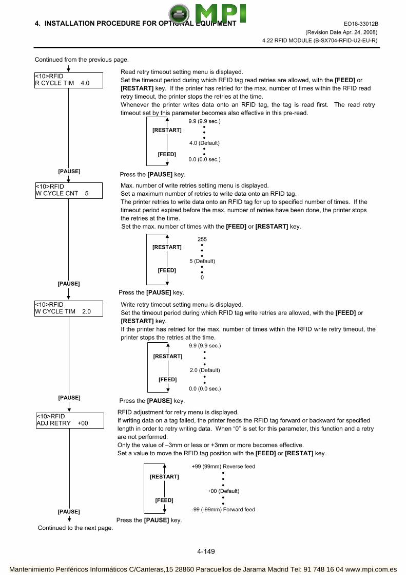
4. INSTALLATION PROCEDURE FOR OPTIONAL EQUIPMENT EO18-33012B (Revision Date Apr. 24, 2008)
4.22 RFID MODULE (B-SX704-RFID-U2-EU-R)
4-149
Continued from the previous page.
Continued to the next page.
<10>RFID R CYCLE TIM 4.0
Read retry timeout setting menu is displayed. Set the timeout period during which RFID tag read retries are allowed, with the [FEED] or [RESTART] key. If the printer has retried for the max. number of times within the RFID read retry timeout, the printer stops the retries at the time. Whenever the printer writes data onto an RFID tag, the tag is read first. The read retrytimeout set by this parameter becomes also effective in this pre-read.
[RESTART]
[FEED]
9.9 (9.9 sec.)• • •
4.0 (Default)• •
0.0 (0.0 sec.)
[PAUSE]
<10>RFID W CYCLE CNT 5
Press the [PAUSE] key.
Max. number of write retries setting menu is displayed. Set a maximum number of retries to write data onto an RFID tag. The printer retries to write data onto an RFID tag for up to specified number of times. If the timeout period expired before the max. number of retries have been done, the printer stops the retries at the time. Set the max. number of times with the [FEED] or [RESTART] key.
[RESTART]
[FEED]
255• • •
5 (Default)• • 0
[PAUSE] Press the [PAUSE] key.
<10>RFID W CYCLE TIM 2.0
[PAUSE]
Write retry timeout setting menu is displayed. Set the timeout period during which RFID tag write retries are allowed, with the [FEED] or [RESTART] key. If the printer has retried for the max. number of times within the RFID write retry timeout, the printer stops the retries at the time.
[RESTART]
[FEED]
9.9 (9.9 sec.)• • •
2.0 (Default)• •
0.0 (0.0 sec.)
Press the [PAUSE] key.
<10>RFID ADJ RETRY +00
RFID adjustment for retry menu is displayed. If writing data on a tag failed, the printer feeds the RFID tag forward or backward for specified length in order to retry writing data. When “0” is set for this parameter, this function and a retry are not performed. Only the value of –3mm or less or +3mm or more becomes effective. Set a value to move the RFID tag position with the [FEED] or [RESTAT] key.
[PAUSE]
[RESTART]
[FEED]
+99 (99mm) Reverse feed • • •
+00 (Default) • •
-99 (-99mm) Forward feed
Press the [PAUSE] key.
Mantenimiento Periféricos Informáticos C/Canteras,15 28860 Paracuellos de Jarama Madrid Tel: 91 748 16 04 www.mpi.com.es

4. INSTALLATION PROCEDURE FOR OPTIONAL EQUIPMENT EO18-33012B (Revision Date Apr. 24, 2008)
4.22 RFID MODULE (B-SX704-RFID-U2-EU-R)
4-150
Continued from the previous page.
Continued to the next page.
<10>RFID POWER LEVEL 18
Radio output power level setting menu is displayed. When the value is “9”, the power is the weakest, and when “18”, the power is the strongest. The factory default setting is “18”. The optimum value differs depending on the tag types. Usually, it is not necessary to change this value but changing the value may be able to increase the number of successful read/write times. Set the power level with the [FEED] or [RESTART] key.
[RESTART]
[FEED]
18 (Default, Strongest) • • • • •
9 (Weakest) [PAUSE]
Press the [PAUSE] key.
<10>RFID AGC THRESHOLD 0
[PAUSE]
AGC threshold setting menu is displayed. When the obtained gain of an RFID tag is lower than the AGC threshold, the tag is considered as an error tag even if a data write succeeds. When the AGC threshold is set to “0”, all tags are writable. When set to “8”, for example, only tags with the AGC threshold level of 9 or greater are writable. The optimum value is different depending on the tag types. The factory default is 0. Set an AGC threshold with the [FEED] or [RESTART] key.
Press the [PAUSE] key.
[RESTART]
[FEED]
15 • • • • •
0 (Factory Default)
<10>RFID RF CHANNEL AUTO
RFID channel setting menu is not available to the B-SX704-RFID-U2-EU-R.
[PAUSE] Press the [PAUSE] key to skip this menu.
<10>RFID Q VALUE 0
[PAUSE]
Q value setting menu is displayed. In the case multiple RFID tags are read at the same time, this menu is useful to pinpoint a target tag. Set the Q value to “1” or greater (2 is recommended.) with the [FEED] or [RESTART] key. Q value “0” causes the tags to interfere with each other and disables proper data write. When a Q value is set, set an AGC threshold for data write and an AGC threshold lower limit for retry, also. Setting all these values enable writing data to a tag placed just above the antenna.(For details, refer to Section 4.22.5 AGC Threshold Setting.) The factory default is 0.
[RESTART]
[FEED]
15 • • • •
0 (Default)
Press the [PAUSE] key.
Mantenimiento Periféricos Informáticos C/Canteras,15 28860 Paracuellos de Jarama Madrid Tel: 91 748 16 04 www.mpi.com.es

4. INSTALLATION PROCEDURE FOR OPTIONAL EQUIPMENT EO18-33012B (Revision Date Apr. 24, 2008)
4.22 RFID MODULE (B-SX704-RFID-U2-EU-R)
4-151
4.22.5 AGC Threshold Setting The B-SX704-RFID-U2-EU-R chooses a tag to write data on according to a radio intensity of RFID tags (AGC value). An AGC threshold value has been set to 0 (00h) as factory default, but it may be necessary to change this value according to the tag type to be used. When the factory default threshold value is not proper for the tag type used, follow the procedure below to configure the following settings. As the changes are stored in the internal memory, they are retained after the printer power is turned off and on again. When the tag type is changed or data write cannot be operated properly, perform the setting again. Step 1. Load an RFID tag embedded media in the printer. Step 2. Follow the procedure below to measure the radio intensity of the tags. 1) Place the media so that an RFID tag (IC chip) is positioned above the Antenna, and close the Top
Cover. Note: If an RFID tag is not positioned above the Antenna while the Print Head is at a print start
position, use @003 command to adjust the media position so that an RFID tag is positioned above the Antenna. For detail of the command, refer to the External Equipment Interface Specification (Printer Command Manual).
Continued from the previous page
<10>RFID WT AGC 0
[PAUSE]
AGC threshold for data write setting menu is displayed. When the Q value is set to 1 or greater, the AGC threshold for data write becomes effective. When the obtained gain of an RFID tag is lower than the AGC thresholdfor data write, data write is not performed. In other words, setting an AGC threshold for data write enables writing data only to a tag placed just above the antenna. The optimum value differs depending on the tag type. (For details, refer to Section 4.22.5 AGC Threshold Setting.) Set an AGC threshold for data write with the [FEED] or [RESTART] key, if necessary.
[RESTART]
[FEED]
15 • • • •
0 (Default)
Press the [PAUSE] key.
<10>RFID WT MIN AGC 0
AGC threshold lower limit for retry setting menu is displayed. When the Q value is set to 1 or greater, the AGC threshold lower limit for retry becomes effective. When there are tags of which AGC values fall within the range between the AGC threshold fordata write and the lower limit, the printer retries data write for a tag with the highest AGC valueamong those tags. When printer retries data write, that value is then used as an AGCthreshold. The optimum value differs depending on the tag type. (For details, refer to Section 4.22.5 AGC Threshold Setting.) Set the lower limit for retry with the [FEED] or [RESTART] key, if necessary.
[PAUSE]
[RESTART]
[FEED]
15 • • • •
0 (Default)
Press the [PAUSE] key.
<10>RFID
The LCD message returns to ”<10>RFID”. Now, the RFID module settings are completed. If data write to RFID tags cannot be properly performed, refer to Section 4.22.5.
Mantenimiento Periféricos Informáticos C/Canteras,15 28860 Paracuellos de Jarama Madrid Tel: 91 748 16 04 www.mpi.com.es

4. INSTALLATION PROCEDURE FOR OPTIONAL EQUIPMENT EO18-33012B (Revision Date Apr. 24, 2008)
4.22 RFID MODULE (B-SX704-RFID-U2-EU-R)
4-152
2) Start the printer in the system mode and perform a read test to measure the AGC value. To measure the AGC value, place only one RFID tag on the Antenna.
Example
RFID Tag
Read test menu is displayed. Press the [FEED] or [RESTAT] key to choose “READ TEST ON”.
[RESTART]
<10>RFID
<1>DIAG. V4.5
[PAUSE]
[FEED] or [RESTAT]
Turn the printer on while holding down the[FEED] and [PAUSE] keys at the same time.
When “<1>DIAG. V4.5” is displayed, press the [RESTART] key.
<10>RFID READ TEST OFF
When ”<10>RFID” is displayed, press the [PAUSE] key until the Q value setting menu is displayed.
<10>RFID Q VALUE 2
Choose “2” with the [FEED] or [RESTART] key.
Press the [PAUSE] key and turn off the printer. [PAUSE]
<10>RFID WT AGC 0
Turn the power off.
Turn the printer on while holding down the[FEED] and [PAUSE] keys at the same time.
[RESTART]
<1>DIAG. V4.5
<10>RFID
[PAUSE]
Continued to the next page.
When “<1>DIAG. V4.5” is displayed, press the [RESTART] key.
When “<10>RFID” is displayed, press the [PAUSE] key.
Mantenimiento Periféricos Informáticos C/Canteras,15 28860 Paracuellos de Jarama Madrid Tel: 91 748 16 04 www.mpi.com.es

4. INSTALLATION PROCEDURE FOR OPTIONAL EQUIPMENT EO18-33012B (Revision Date Apr. 24, 2008)
4.22 RFID MODULE (B-SX704-RFID-U2-EU-R)
4-153
3) Set an AGC threshold of data write. Set a value which is lower than the AGC value obtained by a read test by 1 or 2, taking variation of
RFID tags in performance into consideration.
Press the [PAUSE] key to implement a read test. <10>RFID READ TEST ON
[PAUSE]
<10>RFID READING•••.
Read data is displayed. 3132333435363738 39304142 (0A)
Press the [FEED] and [RESTART] keys to return to the RFID Setting Menu (”<10>RFID”).
<10>RFID
[FEED], [RESTART] Data in parentheses ( ) is the AGC value expressed in hex. code. Write down this value.
<10>RFID
[PAUSE]
<10>RFID Q VALUE 0
Choose “2” with the [FEED] or [RESTART] key. When “2” is already chosen, go to the AGC threshold for data write setting menu.
[RESTART]
[FEED]
15 • • • •
0 (Default)
<10>RFID WT AGC 0
[FEED] or [RESTAT]
<10>RFID WT AGC 9
AGC threshold for data write setting menu is displayed. Choose a threshold value (decimal number) with the [FEED] or [RESTART] key. When the measured AGC is 10 (0A), for example, choose “9” (a value lower than the measured AGC by 1 or 2).
[RESTART]
[FEED]
15 • • • •
0 (Default)
[PAUSE]
<10>RFID Q VALUE 2
[FEED] or [RESTART]
[PAUSE]
Example
Press the [PAUSE] key.
When ”<10>RFID” is displayed, press the [PAUSE] key until the Q value setting menu is displayed.
Press the [PAUSE] key.
<10>RFID WT MIN AGC 0
AGC threshold lower limit for retry setting menu is displayed. Choose a lower limit (decimal number) with the [FEED] or [RESTART] key. Usually, choose the same value with the AGC threshold for data write (WT AGC).
[FEED] or [RESTAT]
<10>RFID WT MIN AGC 9
[PAUSE]
[RESTART]
[FEED]
15 • • • •
0 (Default)
Press the [PAUSE] key.
<10>RFID
RFID Setting Menu (”<10>RFID”) is displayed. An AGC threshold setting is completed.
Continued from the previous page
Mantenimiento Periféricos Informáticos C/Canteras,15 28860 Paracuellos de Jarama Madrid Tel: 91 748 16 04 www.mpi.com.es

4. INSTALLATION PROCEDURE FOR OPTIONAL EQUIPMENT EO18-33012B (Revision Date May 29, 2008)
4.23 RFID MODULE (B-SX704-RFID-U2-AU-R)
4-154
4.23 RFID MODULE (B-SX704-RFID-U2-AU-R) The B-SX704-RFID-U2-AU-R is exclusively for the B-SX4T and B-SX5T series. This RFID kit complies with EPCglobal Class1 Generation2 (Gen2) and radio laws of all applicable countries. As this product is a wireless communication device, please be sure to read the following precautions carefully.
1. Do not use a printer embedded with this product near medical equipment. Radio wave emitted from this product may affect the operation of medical equipment, such as an implanted cardiac pacemaker and implantable cardioverter-defibrillator. If a use of this product should be likely to have affected medical equipment, immediately turn off the product and contact your TOSHIBA TEC sales agent.
Keep a printer embedded with this product at least 23cm away from a person with an implanted cardiac pacemaker or implantable cardioverter-defibrillator.
2. Do not export a printer embedded with this product to the countries or areas where a use of this product isnot allowed, without permission. Doing so is against the law, and you may be punished.
When exporting this product, check the laws and regulations of a destination country and take necessary procedures.
3. Follow all manual instructions. Failure to do so could create safety hazards such as fire or electrocution. • Manual instructions must be followed when installing option kits or adding cables to avoid system
failures and to insure proper performance and operation. • Failure to follow manual instructions or any unauthorized modifications, substitution or change to this
product will void the limited product warranty. 4. Turn the power OFF and disconnect the power cord before installing the RFID module. 5. Be careful not to pinch your fingers or hands with the covers. 6. The print head and stepping motor becomes very hot immediately after printing. Do not touch the print
head, stepping motor and around it right after printing, or you may get burned. 7. When opening the top cover, it must be fully opened. Failure to do this may cause the top cover to close
under its own weight, resulting in an injury.
WARNING!
CAUTION! Be careful not to damage the pattern of the Antenna Ass’y or peel off the Shield Sheet. Damaged pattern or removed Shield Sheet may affect the ability to read or write RFID tags.
Pattern
ShieldSheet
Antenna Ass’y
Mantenimiento Periféricos Informáticos C/Canteras,15 28860 Paracuellos de Jarama Madrid Tel: 91 748 16 04 www.mpi.com.es

4. INSTALLATION PROCEDURE FOR OPTIONAL EQUIPMENT EO18-33012B (Revision Date May 29, 2008)
4.23 RFID MODULE (B-SX704-RFID-U2-AU-R)
4-155
4.23.1 Applicable Model (1) This optional device is intended for the following models: B-SX4T-GS20-QM-R and B-SX5T-TS22-QM-R, RFID ready printer. An RFID Ready printer can be identified by the model name sticker on the front of the printer. Be careful not to install this product in the B-SX4T-GS10-QQ/QQ-US and B-SX5T-TS10-QQ/QQ-
US RFID Ready printers.
(2) To use this device, printer firmware V4.5 or greater is required. Upgrade the firmware to V4.5 or greater, if necessary. For the downloading procedure, refer to the B-SX4T/SX5T Series Maintenance Manual.
Note that a RAM clear needs to be performed after downloading, so print out the maintenance counter and parameter settings prior to downloading. After performing a RAM clear, restore the printer parameter settings to the former states.
(3) The countries where the use of this device is allowed are as follows:
Model Name Frequency Band Applicable Countries
B-SX704-RFID–U2-AU-R UHF 918.25 to 925.75MHz
(Center frequency: 922MHz) Australia
4.23.2 Packing List If any part is missing, please contact your TOSHIBA TEC sales agent.
• Antenna Ass’y (1 pc.)
•RFID R/W Module (1 pc.)
• Antenna Frame
• Ribbon Guide (1 pc.)
• Bush (1 pc.)
• Cable Clamp (1 pc.)
•Interface Cable (1 pc.)
• Double Sems Screw SMW-3x6 (5 pcs.)
• Antenna Cable (1 pc.)
• Installation Manual (1 copy)
Mantenimiento Periféricos Informáticos C/Canteras,15 28860 Paracuellos de Jarama Madrid Tel: 91 748 16 04 www.mpi.com.es

4. INSTALLATION PROCEDURE FOR OPTIONAL EQUIPMENT EO18-33012B (Revision Date May 29, 2008)
4.23 RFID MODULE (B-SX704-RFID-U2-AU-R)
4-156
The following parts are required when short-pitch tags (20 mm) are used. Keep them safe when not in use. • Shield Sheet (1 pc.)
• Antenna Plate L (1 pc.)
• Antenna Plate R (1 pc.)
• Pan Head Screw P-3x6 (4 pcs.)
4.23.3 Installation Procedure
4.23.3.1 Preparation for Use of Short-Pitch RFID Tags (20mm) When short-pitch tags (20 mm) are to be used, the Antenna Ass’y and the Antenna Frame need to be converted before installing an RFID module in the printer, for proper read/write operation. When short-pitch tags are not used, skip this section and go to Section 4.23.3.2. 1. Remove the two Tapping Screws to detach the Antenna from the Antenna Ass’y.
Tapping Screw
Antenna
Antenna Ass’y
Mantenimiento Periféricos Informáticos C/Canteras,15 28860 Paracuellos de Jarama Madrid Tel: 91 748 16 04 www.mpi.com.es

4. INSTALLATION PROCEDURE FOR OPTIONAL EQUIPMENT EO18-33012B (Revision Date Jul. 15, 2008)
4.23 RFID MODULE (B-SX704-RFID-U2-AU-R)
4-157
2. Remove the backing tapes from the reverse side of the Shield Sheet and attach it to the Antenna Cover, as shown below.
3. Attach the Antenna Plate L and Antenna Plate R to the Antenna with the P-3x6 screws. 4. Refer to Section 4.23.3.2 and install an RFID module in the printer.
Tape
Shield Sheet Shield Sheet Antenna
Cover
P-3x6 Screw
Antenna Plate R
P-3x6 ScrewAntenna Plate L Antenna (with Antenna Plate)
Mantenimiento Periféricos Informáticos C/Canteras,15 28860 Paracuellos de Jarama Madrid Tel: 91 748 16 04 www.mpi.com.es

4. INSTALLATION PROCEDURE FOR OPTIONAL EQUIPMENT EO18-33012B (Revision Date May 29, 2008)
4.23 RFID MODULE (B-SX704-RFID-U2-AU-R)
4-158
4.23.3.2 Preparing for the RFID Module Installation 1. Turn the power off and disconnect the Power Cord. 2. Remove the two Black Screws to detach the Front Plate. 3. Remove the four B-4x5 screws from the Side Panel (L). 4. Open the Top Cover and remove the three P-4x8 screws that secure the Side Panel (L).
Front Plate
BlackScrews
P-4x8 Screw
Top Cover
B-4x5 Screw
B-4x5 Screw Side Panel (L)
Mantenimiento Periféricos Informáticos C/Canteras,15 28860 Paracuellos de Jarama Madrid Tel: 91 748 16 04 www.mpi.com.es

4. INSTALLATION PROCEDURE FOR OPTIONAL EQUIPMENT EO18-33012B (Revision Date May 29, 2008)
4.23 RFID MODULE (B-SX704-RFID-U2-AU-R)
4-159
5. Lift the Side Panel (L) and put it aside. 6. Disconnect the Fan Motor Harness from CN19 on the Main PC Board, and then remove the Side Panel
(L). 7. Fully open the Top Cover. 8. Turn the Head Lever to Free position and open the Ribbon Shaft Holder Plate.
Side Panel (L) Fan Motor Harness
Fan Motor
CN19
Main PC Board
Top Cover
Ribbon ShaftHolder Plate
HeadLever
Mantenimiento Periféricos Informáticos C/Canteras,15 28860 Paracuellos de Jarama Madrid Tel: 91 748 16 04 www.mpi.com.es

4. INSTALLATION PROCEDURE FOR OPTIONAL EQUIPMENT EO18-33012B (Revision Date May 29, 2008)
4.23 RFID MODULE (B-SX704-RFID-U2-AU-R)
4-160
9. Open the Print Head Block and lock it with the Latch. 10. Push the Hook through the rectangle hole with a jeweler’s screw driver or something, and remove the
Platen Holder Cover in the direction indicated by the arrow. 11. Lift the right side of the Strip Plate, and then pull and remove it.
Print Head BlockLatch
HookPlaten Holder Cover
Push
1
2
Strip Plate
2
1
Mantenimiento Periféricos Informáticos C/Canteras,15 28860 Paracuellos de Jarama Madrid Tel: 91 748 16 04 www.mpi.com.es

4. INSTALLATION PROCEDURE FOR OPTIONAL EQUIPMENT EO18-33012B (Revision Date May 29, 2008)
4.23 RFID MODULE (B-SX704-RFID-U2-AU-R)
4-161
12. Remove the Platen and the Platen Holder in the direction of the arrows 1 to 3 as shown below. 13. Remove the following three screws.
Platen
PlatenHolder
1
2
3
SMW-3x6 Screw
SMW-4x8 Screw
Mantenimiento Periféricos Informáticos C/Canteras,15 28860 Paracuellos de Jarama Madrid Tel: 91 748 16 04 www.mpi.com.es

4. INSTALLATION PROCEDURE FOR OPTIONAL EQUIPMENT EO18-33012B (Revision Date May 29, 2008)
4.23 RFID MODULE (B-SX704-RFID-U2-AU-R)
4-162
14. Remove the Platen Frame Top from the printer. 15 Remove the four screws from the side of the Print Head Block, slightly pull the Head Side Plate, and
remove the two Ribbon Guide Shafts. NOTE: One of the removed Ribbon Guide Shafts and SMW-2.6x6 Screws are re-used when attaching the
Ribbon Guide. Keep the unused ones for future use. 16. Insert one of the Ribbon Guide Shafts removed in Step 15 into the Ribbon Guide.
Platen Frame Top
SMW-3x6 Screw SMW-4x8 Screw
SMW-2.6x6 Screw Ribbon Guide Shaft
Head Side Plate
Ribbon Guide
Ribbon Guide Shaft
Mantenimiento Periféricos Informáticos C/Canteras,15 28860 Paracuellos de Jarama Madrid Tel: 91 748 16 04 www.mpi.com.es

4. INSTALLATION PROCEDURE FOR OPTIONAL EQUIPMENT EO18-33012B (Revision Date May 29, 2008)
4.23 RFID MODULE (B-SX704-RFID-U2-AU-R)
4-163
17. Rotate the Ribbon Guide Shaft so that its D-cut is in the same orientation with the Ribbon Guide’s D-cut. Without doing this, the Ribbon Guide cannot be fit in the Print Head Block.
18. Fit the Ribbon Guide including the Ribbon Guide Shaft in the Print Head Block, and secure it to the
Head Side Plate with the SMW-2.6x6 screw. Temporarily secure the Head Side Plate to the Print Head Block with the SMW-3x6 Screw and the SMW-4x8 Screw. Be sure to fit the locating pins provided on the other side of the Ribbon Guide into the locating holes of the Print Head Block.
Ribbon Guide’s D-cut
Ribbon Guide Shaft’s D-cut
RibbonGuide
Double Sems ScrewSMW-3x6
Double Sems ScrewSMW-4x8
Double Sems ScrewSMW-2.6x6
Head Side Plate
Print Head Block
Locating Hole (A) Locating Hole (B) Locating Pin (A)
Locating Pin(B)
Ribbon Guide Ribbon Guide
Mantenimiento Periféricos Informáticos C/Canteras,15 28860 Paracuellos de Jarama Madrid Tel: 91 748 16 04 www.mpi.com.es

4. INSTALLATION PROCEDURE FOR OPTIONAL EQUIPMENT EO18-33012B (Revision Date May 29, 2008)
4.23 RFID MODULE (B-SX704-RFID-U2-AU-R)
4-164
19. Close the Ribbon Shaft Holder Plate, and tighten the two screws, which were temporarily tightened in Step 18, while holding down the Print Head Block.
20. Open the Ribbon Shaft Holder Plate again, and tighten the SMX-2.6x6 screw to secure the Head Side
Plate.
Print Head Block
Double Sems ScrewSMW-4x8
Double Sems ScrewSMW-3x6
Ribbon Shaft Holder Plate Head Lever
Double Sems Screw SMW-2.6x6
Head Side Plate
Mantenimiento Periféricos Informáticos C/Canteras,15 28860 Paracuellos de Jarama Madrid Tel: 91 748 16 04 www.mpi.com.es

4. INSTALLATION PROCEDURE FOR OPTIONAL EQUIPMENT EO18-33012B (Revision Date May 29, 2008)
4.23 RFID MODULE (B-SX704-RFID-U2-AU-R)
4-165
4.23.3.3 Attaching the Antenna Frame and the Antenna Ass’y This section describes the procedure for attaching the Antenna Frame and the Antenna Ass’y. When short-pitch tags (20 mm) are used, the procedure is different from the following. Skip step (1) and go to step (2). (1) When using RFID tags other than short-pitch type: 1. Raise the Print Head Block, and slide the Antenna Frame into the printer as shown below. Make the
protruding screw shaft of the printer pass through the slit of the Antenna Frame. Also, make the Shaft of the printer fit in the Cut of the right side of Antenna Frame
Antenna Frame
Screw Shaft Slit
Shaft
Cut Antenna Frame
Mantenimiento Periféricos Informáticos C/Canteras,15 28860 Paracuellos de Jarama Madrid Tel: 91 748 16 04 www.mpi.com.es

4. INSTALLATION PROCEDURE FOR OPTIONAL EQUIPMENT EO18-33012B (Revision Date May 29, 2008)
4.23 RFID MODULE (B-SX704-RFID-U2-AU-R)
4-166
2. Secure the Antenna Frame with the three screws removed in Step 13 of Section 4.23.3.2. 3. Connect the Antenna Cable to the Antenna Ass’y until it clicks.
Antenna Cable
Antenna Ass’y
Connector
SMW-3x6 Screw
SMW-4x8 Screw
Mantenimiento Periféricos Informáticos C/Canteras,15 28860 Paracuellos de Jarama Madrid Tel: 91 748 16 04 www.mpi.com.es

4. INSTALLATION PROCEDURE FOR OPTIONAL EQUIPMENT EO18-33012B (Revision Date May 29, 2008)
4.23 RFID MODULE (B-SX704-RFID-U2-AU-R)
4-167
4. Pass the Antenna Cable between the Sensor Block and the Antenna Frame, as shown below. 5. Fit the Antenna Ass’y in the Antenna Frame. Be sure to fit the locating pins of the Antenna Cover into the oval holes and the cuts in the Antenna
Frame.
Antenna Frame
Sensor Block Antenna Cable
Antenna Ass’y
Cut
Location Pin
Antenna Frame
Location Hole
Location Pin
Mantenimiento Periféricos Informáticos C/Canteras,15 28860 Paracuellos de Jarama Madrid Tel: 91 748 16 04 www.mpi.com.es

4. INSTALLATION PROCEDURE FOR OPTIONAL EQUIPMENT EO18-33012B (Revision Date May 29, 2008)
4.23 RFID MODULE (B-SX704-RFID-U2-AU-R)
4-168
6. Push the Antenna Ass’y in the arrow-indicating direction, and secure it with the two SMW-3x6 screws. 7. Go to Section 4.23.3.4 and attach the RFID Module. (2) When using short-pitch tags (20 mm)
1. Attach the Antenna Frame to the printer in the same way as described in Step 1 of Section 4.23.3.4.
SMW-3x6 Screw
Antenna Ass’y
SMW-3x6 Screw
SMW-4x8 Screw
Mantenimiento Periféricos Informáticos C/Canteras,15 28860 Paracuellos de Jarama Madrid Tel: 91 748 16 04 www.mpi.com.es

4. INSTALLATION PROCEDURE FOR OPTIONAL EQUIPMENT EO18-33012B (Revision Date May 29, 2008)
4.23 RFID MODULE (B-SX704-RFID-U2-AU-R)
4-169
2. Connect the Antenna Cable to the Antenna, to which the Antenna Plates were attached in Section 4.23.3.1, until it clicks.
3. Secure the Antenna to the Antenna Frame with the P-3x6 screws. 4. Place the Antenna Cable in the Antenna Frame, as shown below.
Antenna Cable
Antenna
Connector
Antenna (with Antenna Plates)
P-3x6 Screw
Antenna Cable
Mantenimiento Periféricos Informáticos C/Canteras,15 28860 Paracuellos de Jarama Madrid Tel: 91 748 16 04 www.mpi.com.es

4. INSTALLATION PROCEDURE FOR OPTIONAL EQUIPMENT EO18-33012B (Revision Date May 29, 2008)
4.23 RFID MODULE (B-SX704-RFID-U2-AU-R)
4-170
5. Refer to Steps 5 and 6 in “(1) When using RFID tags other than short-pitch type” and attach the Antenna Cover, to which the Shield Sheet was attached in Section 4.23.3.1, to the Antenna Frame with the SMW-3x6 screws.
6. Go to Section 4.23.3.4 and attach the RFID Module. 4.23.3.4 Attaching the RFID Module 1. Attach the Cable Clamp to and fit the Bush into the positions shown in the picture below.
SMW-3x6 Screw
Antenna Cover (with Shield Sheet)
Bush
Cable Clamp
Mantenimiento Periféricos Informáticos C/Canteras,15 28860 Paracuellos de Jarama Madrid Tel: 91 748 16 04 www.mpi.com.es

4. INSTALLATION PROCEDURE FOR OPTIONAL EQUIPMENT EO18-33012B (Revision Date May 29, 2008)
4.23 RFID MODULE (B-SX704-RFID-U2-AU-R)
4-171
2. Pass the Antenna Cable through the Bush, and fasten the cable with the Cable Clamp. 3. Attach the RFID Module to the RFID Attachment Plate A and the RFID Attachment Plate B with the
three SMW-3x6 screws.
Bush
Cable Clamp
Antenna Cable
RFID Attachment Plate B
SMW-3x6 Screw
SMW-3x6 Screw
RFID ModuleRFID Attachment Plate A
Mantenimiento Periféricos Informáticos C/Canteras,15 28860 Paracuellos de Jarama Madrid Tel: 91 748 16 04 www.mpi.com.es

4. INSTALLATION PROCEDURE FOR OPTIONAL EQUIPMENT EO18-33012B (Revision Date May 29, 2008)
4.23 RFID MODULE (B-SX704-RFID-U2-AU-R)
4-172
4. Fold the Antenna Cable and fasten it with the Cable Clamp together with the other cables to prevent the Antenna Cable from being caught in the Side Panel (L) or Fan Motor.
5. Connect the Antenna Cable to the RFID Module until it clicks.
Cable Clamp
Bush
Antenna Cable
Antenna Cable
Antenna Cable
RFID Module
Connector
Mantenimiento Periféricos Informáticos C/Canteras,15 28860 Paracuellos de Jarama Madrid Tel: 91 748 16 04 www.mpi.com.es
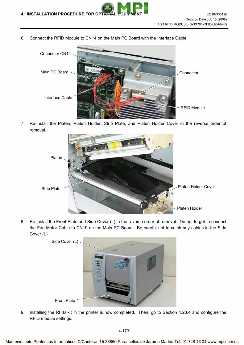
4. INSTALLATION PROCEDURE FOR OPTIONAL EQUIPMENT EO18-33012B (Revision Date Jul. 15, 2008)
4.23 RFID MODULE (B-SX704-RFID-U2-AU-R)
4-173
6. Connect the RFID Module to CN14 on the Main PC Board with the Interface Cable. 7. Re-install the Platen, Platen Holder, Strip Plate, and Platen Holder Cover in the reverse order of
removal. 8. Re-install the Front Plate and Side Cover (L) in the reverse order of removal. Do not forget to connect
the Fan Motor Cable to CN19 on the Main PC Board. Be careful not to catch any cables in the Side Cover (L).
9. Installing the RFID kit in the printer is now completed. Then, go to Section 4.23.4 and configure the
RFID module settings.
Connector
Connector CN14
RFID Module
Interface Cable
Main PC Board
Strip Plate
Platen
Platen Holder
Platen Holder Cover
Front Plate
Side Cover (L)
Mantenimiento Periféricos Informáticos C/Canteras,15 28860 Paracuellos de Jarama Madrid Tel: 91 748 16 04 www.mpi.com.es

4. INSTALLATION PROCEDURE FOR OPTIONAL EQUIPMENT EO18-33012B (Revision Date May 29, 2008)
4.23 RFID MODULE (B-SX704-RFID-U2-AU-R)
4-174
4.23.4 RFID Module Settings After installing the RFID Module on the printer, configure the RFID module settings using the system mode on the printer.
RFID setting menu ”<10>RFID” is displayed. Press the [PAUSE] key.
[RESTART]
<10>RFID
<1>DIAG. V4.5
Turn on the printer while holding down the [FEED] and [PAUSE] keys at the same time.
When “<1>DIAG. V4.5“ appears on the LCD, press the [RESTART] key.
[PAUSE]
Continued to the next page.
<10>RFID READ TEST OFF
[PAUSE]
Read test menu is displayed. Choose whether to perform a read test or not with the [RESTART] or [FEED] key.
[RESTART]
[FEED]
READ TEST OFF READ TEST ON
<10>RFID CAREERSENSE OFF
OFF: A read test is not performed. (Initially, choose “OFF”.) ON: A read test is performed.
The printer enters the read test mode, and a read test is performed each time the [PAUSE] key is pressed. When the data of a tag can be read, it is displayed on the LCD.
• Read data is displayed in hex. value, up to 14 bytes on 2 lines. When the RFID tag contains 14 bytes or more data, the first 14 digits are displayed. When data
volume is less than 14 bytes, the vacant digits will be filled with spaces. The right most hex. value on the lower line, enclosed with parentheses, indictes an AGC value
of a read tag. When more than one tag is read at one time, especially when short-pitch tags are used, pressing the [FEED] or [RESTART] key shows the other tags’ data. Among them, a tag with the highest AGC value is considered to be positioned just above the antenna.
• If the tag cannot be read, “RFID TIMEOUT” or “RFID READ ERROR” is displayed. • If the type of the tag to be read and one selected by the RFID tag type selection do not match,
an RFID tag read error will result. Make sure the RFID tag type has been selected before the read test is started. After choosing an option, press the [PAUSE] key.
123456789012345665432109 (0E)
Carrier sense setting menu is displayed. This menu is not available to the B-SX704-RFID-U2-AU -R. Press the [PAUSE] key to skip this menu.
[PAUSE]
<10>RFID MODULE NONE
Module type setting menu is displayed. Choose “U2” with the [FEED] or [RESTART] key.
[RESTART]
[FEED]
U1: Not available.H1: Not available. NONE: No RFID Module is installed. U3: Not available. U2: B-SX704-RFID-U2-AU-R H2: Not available.[PAUSE]
Press the [PAUSE] key.
Example)
Mantenimiento Periféricos Informáticos C/Canteras,15 28860 Paracuellos de Jarama Madrid Tel: 91 748 16 04 www.mpi.com.es

4. INSTALLATION PROCEDURE FOR OPTIONAL EQUIPMENT EO18-33012B (Revision Date May 29, 2008)
4.23 RFID MODULE (B-SX704-RFID-U2-AU-R)
4-175
<10>RFID TAG NONE
RFID tag type setting menu is displayed. Choose “EPC C1 Gen2: 24” with the [FEED] or [RESTART] key.
[RESTART]
[FEED]NONE: When a tag type is not selected. EPC C1 Gen2: 24
[PAUSE] Press the [PAUSE] key.
<10>RFID ERR CHK OFF
RFID error tag detection menu is displayed. Choose whether to perform an error tag detection or not with the [FEED] or [RESTART] key.
[RESTART]
[FEED]
OFF: An error tag detection is not performed. (Usually, choose OFF.)
ON: An error tag detection is performed.
ON: A tag is read before writing data on it, and data is written on the tag only when theheader data is “A5A5”.
OFF: Though a tag is read before writing data on it, data write is always performed whatever data has been set as the header data.
[PAUSE] Press the [PAUSE] key.
Continued to the next page.
Continued from the previous page.
<10>RFID ISSUE RETRY 3
Max. number of issue retries setting menu is displayed. Set a maximum number of retries to issue an RFID tag. When issuing an RFID tag failed, the printer prints the error pattern, and retries to issue the tag for up to specified number of times. If the printer does not succeed even after having retried for the max. times, the printer stops, resulting in an error. Choose the max. number of retries with the [FEED] or [RESTART] key.
[PAUSE]
[RESTART]
[FEED]
255 • • •
3 (Default)• • 0
Press the [PAUSE] key.
<10>RFID R CYCLE CNT 5
Max. number of read retries setting menu is displayed. Set a maximum number of retries to read an RFID tag. The printer retries to read the data in an RFID tag for up to specified number of times. If thetimeout period expired before the max. number retries have been done, the printer stops theretries at the time. Whenever the printer writes data onto an RFID tag, the tag is read first. The max. number of retries set by this parameter becomes also effective in this pre-read. Choose the max. number of retries with the [FEED] or [RESTART] key.
[RESTART]
[FEED]
255 • • •
5 (Default)• • 0
Press the [PAUSE] key. [PAUSE]
Mantenimiento Periféricos Informáticos C/Canteras,15 28860 Paracuellos de Jarama Madrid Tel: 91 748 16 04 www.mpi.com.es

4. INSTALLATION PROCEDURE FOR OPTIONAL EQUIPMENT EO18-33012B (Revision Date May 29, 2008)
4.23 RFID MODULE (B-SX704-RFID-U2-AU-R)
4-176
Continued from the previous page.
Continued to the next page.
<10>RFID R CYCLE TIM 4.0
Read retry timeout setting menu is displayed. Set the timeout period during which RFID tag read retries are allowed, with the [FEED] or [RESTART] key. If the printer has retried for the max. number of times within the RFID read retry timeout, the printer stops the retries at the time. Whenever the printer writes data onto an RFID tag, the tag is read first. The read retrytimeout set by this parameter becomes also effective in this pre-read.
[RESTART]
[FEED]
9.9 (9.9 sec.)• • •
4.0 (Default)• •
0.0 (0.0 sec.)
[PAUSE]
<10>RFID W CYCLE CNT 5
Press the [PAUSE] key.
Max. number of write retries setting menu is displayed. Set a maximum number of retries to write data onto an RFID tag. The printer retries to write data onto an RFID tag for up to specified number of times. If the timeout period expired before the max. number of retries have been done, the printer stops the retries at the time. Set the max. number of times with the [FEED] or [RESTART] key.
[RESTART]
[FEED]
255• • •
5 (Default)• • 0
[PAUSE] Press the [PAUSE] key.
<10>RFID W CYCLE TIM 2.0
[PAUSE]
Write retry timeout setting menu is displayed. Set the timeout period during which RFID tag write retries are allowed, with the [FEED] or [RESTART] key. If the printer has retried for the max. number of times within the RFID write retry timeout, the printer stops the retries at the time.
[RESTART]
[FEED]
9.9 (9.9 sec.)• • •
2.0 (Default)• •
0.0 (0.0 sec.)
Press the [PAUSE] key.
<10>RFID ADJ RETRY +00
RFID adjustment for retry menu is displayed. If writing data on a tag failed, the printer feeds the RFID tag forward or backward for specified length in order to retry writing data. When “0” is set for this parameter, this function and a retry are not performed. Only the value of –3mm or less or +3mm or more becomes effective. Set a value to move the RFID tag position with the [FEED] or [RESTAT] key.
[RESTART]
[FEED]
+99 (99mm) Reverse feed • • •
+00 (Default) • •
-99 (-99mm) Forward feed [PAUSE]
Press the [PAUSE] key.
Mantenimiento Periféricos Informáticos C/Canteras,15 28860 Paracuellos de Jarama Madrid Tel: 91 748 16 04 www.mpi.com.es

4. INSTALLATION PROCEDURE FOR OPTIONAL EQUIPMENT EO18-33012B (Revision Date May 29, 2008)
4.23 RFID MODULE (B-SX704-RFID-U2-AU-R)
4-177
Continued from the previous page.
Continued to the next page.
<10>RFID POWER LEVEL 18
Radio output power level setting menu is displayed. When the value is “9”, the power is the weakest, and when “18”, the power is the strongest. The factory default setting is “18”. The optimum value differs depending on the tag types. Usually, it is not necessary to change this value but changing the value may be able to increase the number of successful read/write times. Set the power level with the [FEED] or [RESTART] key.
[RESTART]
[FEED]
18 (Default, Strongest) • • • • •
9 (Weakest) [PAUSE]
Press the [PAUSE] key.
<10>RFID AGC THRESHOLD 0
[PAUSE]
AGC threshold setting menu is displayed. When the obtained gain of an RFID tag is lower than the AGC threshold, the tag is considered as an error tag even if a data write succeeds. When the AGC threshold is set to “0”, all tags are writable. When set to “8”, for example, only tags with the AGC threshold level of 9 or greater are writable. The optimum value is different depending on the tag types. The factory default is 0. Set an AGC threshold with the [FEED] or [RESTART] key.
Press the [PAUSE] key.
[RESTART]
[FEED]
15 • • • • •
0 (Factory Default)
<10>RFID RF CHANNEL AUTO
RFID channel setting menu is not available to the B-SX704-RFID-U2-AU-R.
[PAUSE] Press the [PAUSE] key to skip this menu.
<10>RFID Q VALUE 0
[PAUSE]
Q value setting menu is displayed. In the case multiple RFID tags are read at the same time, this menu is useful to pinpoint a target tag. Set the Q value to “1” or greater (2 is recommended.) with the [FEED] or [RESTART] key. Q value “0” causes the tags to interfere with each other and disables proper data write. When a Q value is set, set an AGC threshold for data write and an AGC threshold lower limit for retry, also. Setting all these values enable writing data to a tag placed just above the antenna.(For details, refer to Section 4.23.5 AGC Threshold Setting.) The factory default is 0.
[RESTART]
[FEED]
15 • • • •
0 (Default)
Press the [PAUSE] key.
Mantenimiento Periféricos Informáticos C/Canteras,15 28860 Paracuellos de Jarama Madrid Tel: 91 748 16 04 www.mpi.com.es
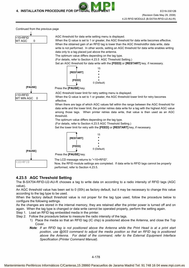
4. INSTALLATION PROCEDURE FOR OPTIONAL EQUIPMENT EO18-33012B (Revision Date May 29, 2008)
4.23 RFID MODULE (B-SX704-RFID-U2-AU-R)
4-178
4.23.5 AGC Threshold Setting The B-SX704-RFID-U2-AU-R chooses a tag to write data on according to a radio intensity of RFID tags (AGC value). An AGC threshold value has been set to 0 (00h) as factory default, but it may be necessary to change this value according to the tag type to be used. When the factory default threshold value is not proper for the tag type used, follow the procedure below to configure the following settings. As the changes are stored in the internal memory, they are retained after the printer power is turned off and on again. When the tag type is changed or data write cannot be operated properly, perform the setting again. Step 1. Load an RFID tag embedded media in the printer. Step 2. Follow the procedure below to measure the radio intensity of the tags. 1) Place the media so that an RFID tag (IC chip) is positioned above the Antenna, and close the Top
Cover. Note: If an RFID tag is not positioned above the Antenna while the Print Head is at a print start
position, use @003 command to adjust the media position so that an RFID tag is positioned above the Antenna. For detail of the command, refer to the External Equipment Interface Specification (Printer Command Manual).
Continued from the previous page
<10>RFID WT AGC 0
[PAUSE]
AGC threshold for data write setting menu is displayed. When the Q value is set to 1 or greater, the AGC threshold for data write becomes effective. When the obtained gain of an RFID tag is lower than the AGC thresholdfor data write, data write is not performed. In other words, setting an AGC threshold for data write enables writing data only to a tag placed just above the antenna. The optimum value differs depending on the tag type. (For details, refer to Section 4.23.5 AGC Threshold Setting.) Set an AGC threshold for data write with the [FEED] or [RESTART] key, if necessary.
[RESTART]
[FEED]
15 • • • •
0 (Default)
Press the [PAUSE] key.
<10>RFID WT MIN AGC 0
AGC threshold lower limit for retry setting menu is displayed. When the Q value is set to 1 or greater, the AGC threshold lower limit for retry becomes effective. When there are tags of which AGC values fall within the range between the AGC threshold fordata write and the lower limit, the printer retries data write for a tag with the highest AGC valueamong those tags. When printer retries data write, that value is then used as an AGCthreshold. The optimum value differs depending on the tag type. (For details, refer to Section 4.23.5 AGC Threshold Setting.) Set the lower limit for retry with the [FEED] or [RESTART] key, if necessary.
[PAUSE]
[RESTART]
[FEED]
15 • • • •
0 (Default)
Press the [PAUSE] key.
<10>RFID
The LCD message returns to ”<10>RFID”. Now, the RFID module settings are completed. If data write to RFID tags cannot be properly performed, refer to Section 4.23.5.
Mantenimiento Periféricos Informáticos C/Canteras,15 28860 Paracuellos de Jarama Madrid Tel: 91 748 16 04 www.mpi.com.es

4. INSTALLATION PROCEDURE FOR OPTIONAL EQUIPMENT EO18-33012B (Revision Date May 29, 2008)
4.23 RFID MODULE (B-SX704-RFID-U2-AU-R)
4-179
2) Start the printer in the system mode and perform a read test to measure the AGC value. To measure the AGC value, place only one RFID tag on the Antenna.
Example
RFID Tag
Read test menu is displayed. Press the [FEED] or [RESTAT] key to choose “READ TEST ON”.
[RESTART]
<10>RFID
<1>DIAG. V4.5
[PAUSE]
[FEED] or [RESTAT]
Turn the printer on while holding down the[FEED] and [PAUSE] keys at the same time.
When “<1>DIAG. V4.5” is displayed, press the [RESTART] key.
<10>RFID READ TEST OFF
When ”<10>RFID” is displayed, press the [PAUSE] key until the Q value setting menu is displayed.
<10>RFID Q VALUE 2
Choose “2” with the [FEED] or [RESTART] key.
Press the [PAUSE] key and turn off the printer. [PAUSE]
<10>RFID WT AGC 0
Turn the power off.
Turn the printer on while holding down the[FEED] and [PAUSE] keys at the same time.
[RESTART]
<1>DIAG. V4.5
<10>RFID
[PAUSE]
Continued to the next page.
When “<1>DIAG. V4.5” is displayed, press the [RESTART] key.
When “<10>RFID” is displayed, press the [PAUSE] key.
Mantenimiento Periféricos Informáticos C/Canteras,15 28860 Paracuellos de Jarama Madrid Tel: 91 748 16 04 www.mpi.com.es

4. INSTALLATION PROCEDURE FOR OPTIONAL EQUIPMENT EO18-33012B (Revision Date May 29, 2008)
4.23 RFID MODULE (B-SX704-RFID-U2-AU-R)
4-180
3) Set an AGC threshold of data write. Set a value which is lower than the AGC value obtained by a read test by 1 or 2, taking variation of
RFID tags in performance into consideration.
Press the [PAUSE] key to implement a read test. <10>RFID READ TEST ON
[PAUSE]
<10>RFID READING•••.
Read data is displayed. 3132333435363738 39304142 (0A)
Press the [FEED] and [RESTART] keys to return to the RFID Setting Menu (”<10>RFID”).
<10>RFID
[FEED], [RESTART] Data in parentheses ( ) is the AGC value expressed in hex. code. Write down this value.
<10>RFID
[PAUSE]
<10>RFID Q VALUE 0
Choose “2” with the [FEED] or [RESTART] key. When “2” is already chosen, go to the AGC threshold for data write setting menu.
[RESTART]
[FEED]
15 • • • •
0 (Default)
<10>RFID WT AGC 0
[FEED] or [RESTAT]
<10>RFID WT AGC 9
AGC threshold for data write setting menu is displayed. Choose a threshold value (decimal number) with the [FEED] or [RESTART] key. When the measured AGC is 10 (0A), for example, choose “9” (a value lower than the measured AGC by 1 or 2).
[RESTART]
[FEED]
15 • • • •
0 (Default)
[PAUSE]
<10>RFID Q VALUE 2
[FEED] or [RESTART]
[PAUSE]
Example
Press the [PAUSE] key.
When ”<10>RFID” is displayed, press the [PAUSE] key until the Q value setting menu is displayed.
Press the [PAUSE] key.
<10>RFID WT MIN AGC 0
AGC threshold lower limit for retry setting menu is displayed. Choose a lower limit (decimal number) with the [FEED] or [RESTART] key. Usually, choose the same value with the AGC threshold for data write (WT AGC).
[FEED] or [RESTAT]
<10>RFID WT MIN AGC 9
[PAUSE]
[RESTART]
[FEED]
15 • • • •
0 (Default)
Press the [PAUSE] key.
<10>RFID
RFID Setting Menu (”<10>RFID”) is displayed. An AGC threshold setting is completed.
Continued from the previous page
Mantenimiento Periféricos Informáticos C/Canteras,15 28860 Paracuellos de Jarama Madrid Tel: 91 748 16 04 www.mpi.com.es
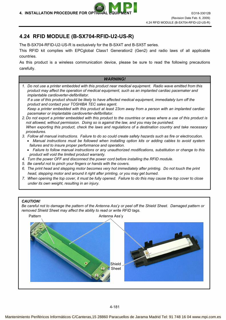
4. INSTALLATION PROCEDURE FOR OPTIONAL EQUIPMENT EO18-33012B (Revision Date Feb. 6, 2009)
4.24 RFID MODULE (B-SX704-RFID-U2-US-R)
4-181
4.24 RFID MODULE (B-SX704-RFID-U2-US-R) The B-SX704-RFID-U2-US-R is exclusively for the B-SX4T and B-SX5T series. This RFID kit complies with EPCglobal Class1 Generation2 (Gen2) and radio laws of all applicable countries. As this product is a wireless communication device, please be sure to read the following precautions carefully.
1. Do not use a printer embedded with this product near medical equipment. Radio wave emitted from this product may affect the operation of medical equipment, such as an implanted cardiac pacemaker and implantable cardioverter-defibrillator. If a use of this product should be likely to have affected medical equipment, immediately turn off the product and contact your TOSHIBA TEC sales agent.
Keep a printer embedded with this product at least 23cm away from a person with an implanted cardiac pacemaker or implantable cardioverter-defibrillator.
2. Do not export a printer embedded with this product to the countries or areas where a use of this product isnot allowed, without permission. Doing so is against the law, and you may be punished.
When exporting this product, check the laws and regulations of a destination country and take necessary procedures.
3. Follow all manual instructions. Failure to do so could create safety hazards such as fire or electrocution. • Manual instructions must be followed when installing option kits or adding cables to avoid system
failures and to insure proper performance and operation. • Failure to follow manual instructions or any unauthorized modifications, substitution or change to this
product will void the limited product warranty. 4. Turn the power OFF and disconnect the power cord before installing the RFID module. 5. Be careful not to pinch your fingers or hands with the covers. 6. The print head and stepping motor becomes very hot immediately after printing. Do not touch the print
head, stepping motor and around it right after printing, or you may get burned. 7. When opening the top cover, it must be fully opened. Failure to do this may cause the top cover to close
under its own weight, resulting in an injury.
WARNING!
CAUTION! Be careful not to damage the pattern of the Antenna Ass’y or peel off the Shield Sheet. Damaged pattern or removed Shield Sheet may affect the ability to read or write RFID tags.
Pattern
ShieldSheet
Antenna Ass’y
Mantenimiento Periféricos Informáticos C/Canteras,15 28860 Paracuellos de Jarama Madrid Tel: 91 748 16 04 www.mpi.com.es

4. INSTALLATION PROCEDURE FOR OPTIONAL EQUIPMENT EO18-33012B (Revision Date Feb. 6, 2009)
4.24 RFID MODULE (B-SX704-RFID-U2-US-R)
4-182
4.24.1 Applicable Model (1) This optional device is intended for the following models: B-SX4T-GS20-QM-R and B-SX5T-TS22-QM-R, RFID ready printer. An RFID Ready printer can be identified by the model name sticker on the front of the printer. Be careful not to install this product in the B-SX4T-GS10-QQ/QQ-US and B-SX5T-TS10-QQ/QQ-
US RFID Ready printers. (2) To use this device, printer firmware V4.5 or greater is required. Upgrade the firmware to V4.5 or
greater, if necessary. For the downloading procedure, refer to the B-SX4T/SX5T Series Maintenance Manual.
Note that a RAM clear needs to be performed after downloading, so print out the maintenance counter and parameter settings prior to downloading. After performing a RAM clear, restore the printer parameter settings to the former states.
(3) As from the January 2009 production (Serial Number 2809Axxxxxx and after), the AU (Australia) specification has been supported by the B-SX704-RFID-U2-US-R RFID Module. Also the KR (South Korea) and TW (Taiwan) specifications have been added.
The firmware of the B-SX4T/SX5T-R series barcode printer should be V4.7 or greater. If V4.6A or less, please install the firmware V4.7 into the printer.
Make sure the firmware version is V4.7 and greater when turning on the printer. When the firmware version is V4.6A or less, it is necessary to upgrade the firmware to V4.7 and
greater. For the downloading procedure, refer to the B-SX4T/SX5T Series Maintenance Manual. For the printer to which back side the sticker MAIN4-R is attached, the firmware V5.0 and greater has
been installed. Since the firmware V5.0 and greater is exclusive to this printer, do not install the firmware V4.7 into it.
To use this device, printer firmware V4.7 or greater is required. Upgrade the firmware to V4.5 or
greater, if necessary. For the downloading procedure, refer to Section 7 PROGRAM DOWN LOAD. Note that a RAM clear needs to be performed after downloading, so print out the maintenance
counter and parameter settings prior to downloading. After performing a RAM clear, restore the printer parameter settings to the former states.
Destination Code Setting should be performed in the system mode of the printer according to the destination.
(4) The countries where the use of this device is allowed are as follows:
Model Name Setting Frequency Band Applicable Countries
US UHF 902.75 to 927.5MHz U.S.A., Canada
AU UHF 918.25 to 925.75 MHz Australia
KR UHF 910.4 to 913.6 MHz Korea B-SX704-RFID–U2-US-R
TW UHF 922.25 to 927.25 MHz Taiwan
ONLINE V4.7
Mantenimiento Periféricos Informáticos C/Canteras,15 28860 Paracuellos de Jarama Madrid Tel: 91 748 16 04 www.mpi.com.es
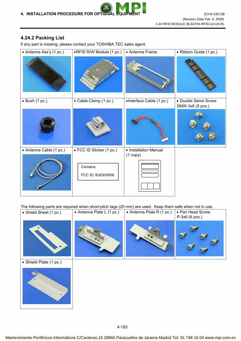
4. INSTALLATION PROCEDURE FOR OPTIONAL EQUIPMENT EO18-33012B (Revision Date Feb. 6, 2009)
4.24 RFID MODULE (B-SX704-RFID-U2-US-R)
4-183
4.24.2 Packing List If any part is missing, please contact your TOSHIBA TEC sales agent.
• Antenna Ass’y (1 pc.)
•RFID R/W Module (1 pc.)
• Antenna Frame
• Ribbon Guide (1 pc.)
• Bush (1 pc.)
• Cable Clamp (1 pc.)
•Interface Cable (1 pc.)
• Double Sems Screw SMW-3x6 (5 pcs.)
• Antenna Cable (1 pc.)
• FCC ID Sticker (1 pc.)
• Installation Manual (1 copy)
The following parts are required when short-pitch tags (20 mm) are used. Keep them safe when not in use. • Shield Sheet (1 pc.)
• Antenna Plate L (1 pc.)
• Antenna Plate R (1 pc.)
• Pan Head Screw P-3x6 (6 pcs.)
• Shield Plate (1 pc.)
Contains FCC ID: BJIOH0006
Mantenimiento Periféricos Informáticos C/Canteras,15 28860 Paracuellos de Jarama Madrid Tel: 91 748 16 04 www.mpi.com.es
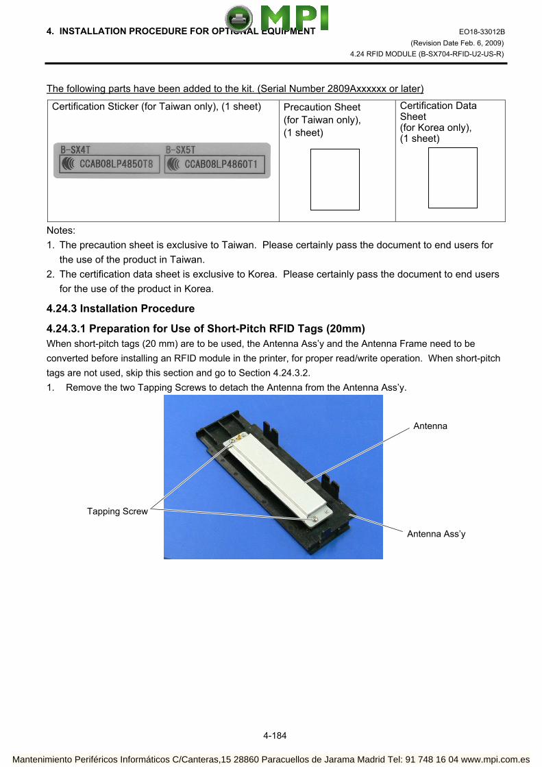
4. INSTALLATION PROCEDURE FOR OPTIONAL EQUIPMENT EO18-33012B (Revision Date Feb. 6, 2009)
4.24 RFID MODULE (B-SX704-RFID-U2-US-R)
4-184
The following parts have been added to the kit. (Serial Number 2809Axxxxxx or later)
Certification Sticker (for Taiwan only), (1 sheet)
Precaution Sheet (for Taiwan only), (1 sheet)
Certification Data Sheet (for Korea only), (1 sheet)
Notes: 1. The precaution sheet is exclusive to Taiwan. Please certainly pass the document to end users for
the use of the product in Taiwan. 2. The certification data sheet is exclusive to Korea. Please certainly pass the document to end users
for the use of the product in Korea.
4.24.3 Installation Procedure
4.24.3.1 Preparation for Use of Short-Pitch RFID Tags (20mm) When short-pitch tags (20 mm) are to be used, the Antenna Ass’y and the Antenna Frame need to be converted before installing an RFID module in the printer, for proper read/write operation. When short-pitch tags are not used, skip this section and go to Section 4.24.3.2. 1. Remove the two Tapping Screws to detach the Antenna from the Antenna Ass’y.
Tapping Screw
Antenna
Antenna Ass’y
Mantenimiento Periféricos Informáticos C/Canteras,15 28860 Paracuellos de Jarama Madrid Tel: 91 748 16 04 www.mpi.com.es

4. INSTALLATION PROCEDURE FOR OPTIONAL EQUIPMENT EO18-33012B (Revision Date Feb. 6, 2009)
4.24 RFID MODULE (B-SX704-RFID-U2-US-R)
4-185
2. Remove the backing tapes from the reverse side of the Shield Sheet and attach it to the Antenna Cover, as shown below.
3. Attach the Antenna Plate L and Antenna Plate R to the Antenna with the P-3x6 screws. 4. Attach the Shield Plate to the Antenna Frame. Secure the Shield Plate to the Antenna Frame with the
P-3x6 screws. 5 Refer to Section 4.24.3.2 and install an RFID module in the printer.
Tape
Shield Sheet Shield Sheet Antenna
Cover
P-3x6 Screw
Antenna Plate R
P-3x6 ScrewAntenna Plate L Antenna (with Antenna Plate)
Antenna Frame Shield Plate
P-3x6 Screw
Mantenimiento Periféricos Informáticos C/Canteras,15 28860 Paracuellos de Jarama Madrid Tel: 91 748 16 04 www.mpi.com.es

4. INSTALLATION PROCEDURE FOR OPTIONAL EQUIPMENT EO18-33012B (Revision Date Feb. 6, 2009)
4.24 RFID MODULE (B-SX704-RFID-U2-US-R)
4-186
4.23.3.2 Preparing for the RFID Module Installation 1. Turn the power off and disconnect the Power Cord. 2. Remove the two Black Screws to detach the Front Plate. 3. Remove the four B-4x5 screws from the Side Panel (L). 4. Open the Top Cover and remove the three P-4x8 screws that secure the Side Panel (L).
Front Plate
BlackScrews
P-4x8 Screw
Top Cover
B-4x5 Screw
B-4x5 Screw Side Panel (L)
Mantenimiento Periféricos Informáticos C/Canteras,15 28860 Paracuellos de Jarama Madrid Tel: 91 748 16 04 www.mpi.com.es

4. INSTALLATION PROCEDURE FOR OPTIONAL EQUIPMENT EO18-33012B (Revision Date Feb. 6, 2009)
4.24 RFID MODULE (B-SX704-RFID-U2-US-R)
4-187
5. Lift the Side Panel (L) and put it aside. 6. Disconnect the Fan Motor Harness from CN19 on the Main PC Board, and then remove the Side Panel
(L). 7. Fully open the Top Cover. 8. Turn the Head Lever to Free position and open the Ribbon Shaft Holder Plate.
Side Panel (L) Fan Motor Harness
Fan Motor
CN19
Main PC Board
Top Cover
Ribbon ShaftHolder Plate
HeadLever
Mantenimiento Periféricos Informáticos C/Canteras,15 28860 Paracuellos de Jarama Madrid Tel: 91 748 16 04 www.mpi.com.es
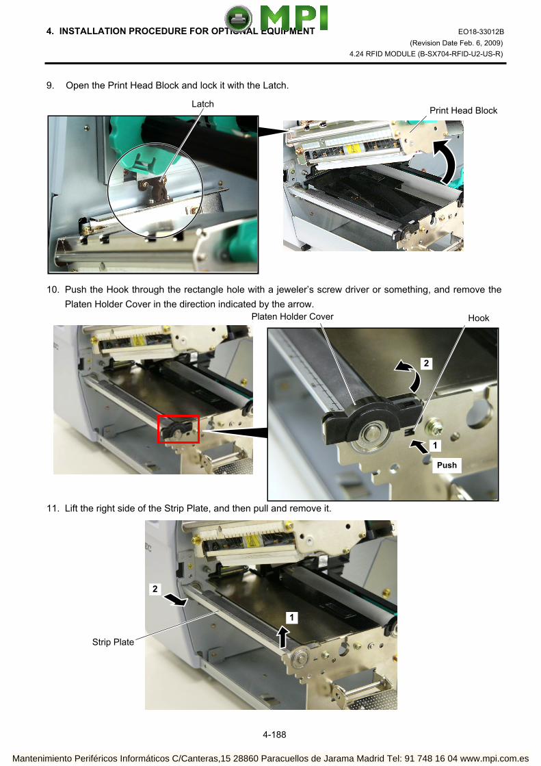
4. INSTALLATION PROCEDURE FOR OPTIONAL EQUIPMENT EO18-33012B (Revision Date Feb. 6, 2009)
4.24 RFID MODULE (B-SX704-RFID-U2-US-R)
4-188
9. Open the Print Head Block and lock it with the Latch. 10. Push the Hook through the rectangle hole with a jeweler’s screw driver or something, and remove the
Platen Holder Cover in the direction indicated by the arrow. 11. Lift the right side of the Strip Plate, and then pull and remove it.
Print Head BlockLatch
HookPlaten Holder Cover
Push
1
2
Strip Plate
2
1
Mantenimiento Periféricos Informáticos C/Canteras,15 28860 Paracuellos de Jarama Madrid Tel: 91 748 16 04 www.mpi.com.es

4. INSTALLATION PROCEDURE FOR OPTIONAL EQUIPMENT EO18-33012B (Revision Date Feb. 6, 2009)
4.24 RFID MODULE (B-SX704-RFID-U2-US-R)
4-189
12. Remove the Platen and the Platen Holder in the direction of the arrows 1 to 3 as shown below. 13. Remove the following three screws.
Platen
PlatenHolder
1
2
3
SMW-3x6 Screw
SMW-4x8 Screw
Mantenimiento Periféricos Informáticos C/Canteras,15 28860 Paracuellos de Jarama Madrid Tel: 91 748 16 04 www.mpi.com.es
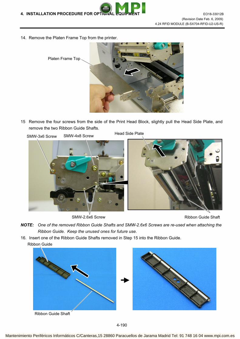
4. INSTALLATION PROCEDURE FOR OPTIONAL EQUIPMENT EO18-33012B (Revision Date Feb. 6, 2009)
4.24 RFID MODULE (B-SX704-RFID-U2-US-R)
4-190
14. Remove the Platen Frame Top from the printer. 15 Remove the four screws from the side of the Print Head Block, slightly pull the Head Side Plate, and
remove the two Ribbon Guide Shafts. NOTE: One of the removed Ribbon Guide Shafts and SMW-2.6x6 Screws are re-used when attaching the
Ribbon Guide. Keep the unused ones for future use. 16. Insert one of the Ribbon Guide Shafts removed in Step 15 into the Ribbon Guide.
Platen Frame Top
SMW-3x6 Screw SMW-4x8 Screw
SMW-2.6x6 Screw Ribbon Guide Shaft
Head Side Plate
Ribbon Guide
Ribbon Guide Shaft
Mantenimiento Periféricos Informáticos C/Canteras,15 28860 Paracuellos de Jarama Madrid Tel: 91 748 16 04 www.mpi.com.es

4. INSTALLATION PROCEDURE FOR OPTIONAL EQUIPMENT EO18-33012B (Revision Date Feb. 6, 2009)
4.24 RFID MODULE (B-SX704-RFID-U2-US-R)
4-191
17. Rotate the Ribbon Guide Shaft so that its D-cut is in the same orientation with the Ribbon Guide’s D-cut. Without doing this, the Ribbon Guide cannot be fit in the Print Head Block.
18. Fit the Ribbon Guide including the Ribbon Guide Shaft in the Print Head Block, and secure it to the
Head Side Plate with the SMW-2.6x6 screw. Temporarily secure the Head Side Plate to the Print Head Block with the SMW-3x6 Screw and the SMW-4x8 Screw. Be sure to fit the locating pins provided on the other side of the Ribbon Guide into the locating holes of the Print Head Block.
Ribbon Guide’s D-cut
Ribbon Guide Shaft’s D-cut
RibbonGuide
Double Sems ScrewSMW-3x6
Double Sems ScrewSMW-4x8
Double Sems ScrewSMW-2.6x6
Head Side Plate
Print Head Block
Locating Hole (A) Locating Hole (B) Locating Pin (A)
Locating Pin(B)
Ribbon Guide Ribbon Guide
Mantenimiento Periféricos Informáticos C/Canteras,15 28860 Paracuellos de Jarama Madrid Tel: 91 748 16 04 www.mpi.com.es

4. INSTALLATION PROCEDURE FOR OPTIONAL EQUIPMENT EO18-33012B (Revision Date Feb. 6, 2009)
4.24 RFID MODULE (B-SX704-RFID-U2-US-R)
4-192
19. Close the Ribbon Shaft Holder Plate, and tighten the two screws, which were temporarily tightened in Step 18, while holding down the Print Head Block.
20. Open the Ribbon Shaft Holder Plate again, and tighten the SMX-2.6x6 screw to secure the Head Side
Plate.
Print Head Block
Double Sems ScrewSMW-4x8
Double Sems ScrewSMW-3x6
Ribbon Shaft Holder Plate Head Lever
Double Sems Screw SMW-2.6x6
Head Side Plate
Mantenimiento Periféricos Informáticos C/Canteras,15 28860 Paracuellos de Jarama Madrid Tel: 91 748 16 04 www.mpi.com.es

4. INSTALLATION PROCEDURE FOR OPTIONAL EQUIPMENT EO18-33012B (Revision Date Feb. 6, 2009)
4.24 RFID MODULE (B-SX704-RFID-U2-US-R)
4-193
4.24.3.3 Attaching the Antenna Frame and the Antenna Ass’y This section describes the procedure for attaching the Antenna Frame and the Antenna Ass’y. When short-pitch tags (20 mm) are used, the procedure is different from the following. Skip step (1) and go to step (2). (1) When using RFID tags other than short-pitch type: 1. Raise the Print Head Block, and slide the Antenna Frame into the printer as shown below. Make the
protruding screw shaft of the printer pass through the slit of the Antenna Frame. Also, make the Shaft of the printer fit in the Cut of the right side of Antenna Frame
Antenna Frame
Screw Shaft Slit
Shaft
Cut Antenna Frame
Mantenimiento Periféricos Informáticos C/Canteras,15 28860 Paracuellos de Jarama Madrid Tel: 91 748 16 04 www.mpi.com.es

4. INSTALLATION PROCEDURE FOR OPTIONAL EQUIPMENT EO18-33012B (Revision Date Feb. 6, 2009)
4.24 RFID MODULE (B-SX704-RFID-U2-US-R)
4-194
2. Secure the Antenna Frame with the three screws removed in Step 13 of Section 4.24.3.2. 3. Connect the Antenna Cable to the Antenna Ass’y until it clicks.
Antenna Cable
Antenna Ass’y
Connector
SMW-3x6 Screw
SMW-4x8 Screw
Mantenimiento Periféricos Informáticos C/Canteras,15 28860 Paracuellos de Jarama Madrid Tel: 91 748 16 04 www.mpi.com.es

4. INSTALLATION PROCEDURE FOR OPTIONAL EQUIPMENT EO18-33012B (Revision Date Feb. 6, 2009)
4.24 RFID MODULE (B-SX704-RFID-U2-US-R)
4-195
4. Pass the Antenna Cable between the Sensor Block and the Antenna Frame, as shown below. 5. Fit the Antenna Ass’y in the Antenna Frame. Be sure to fit the locating pins of the Antenna Cover into the oval holes and the cuts in the Antenna
Frame.
Antenna Frame
Sensor Block Antenna Cable
Antenna Ass’y
Cut
Location Pin
Antenna Frame
Location Hole
Location Pin
Mantenimiento Periféricos Informáticos C/Canteras,15 28860 Paracuellos de Jarama Madrid Tel: 91 748 16 04 www.mpi.com.es

4. INSTALLATION PROCEDURE FOR OPTIONAL EQUIPMENT EO18-33012B (Revision Date Feb. 6, 2009)
4.24 RFID MODULE (B-SX704-RFID-U2-US-R)
4-196
6. Push the Antenna Ass’y in the arrow-indicating direction, and secure it with the two SMW-3x6 screws. 7. Go to Section 4.24.3.4 and attach the RFID Module. (2) When using short-pitch tags (20 mm)
1. Attach the Antenna Frame to which the Shield Plate was attached in Section 4.24.3.1, to the printer in the same way as described in Step 1 of Section 4.24.3.3.
SMW-3x6 Screw
Antenna Ass’y
Antenna Frame (with Shield Plate)
SMW-4x8 Screw
SMW-3x6 Screw
Mantenimiento Periféricos Informáticos C/Canteras,15 28860 Paracuellos de Jarama Madrid Tel: 91 748 16 04 www.mpi.com.es

4. INSTALLATION PROCEDURE FOR OPTIONAL EQUIPMENT EO18-33012B (Revision Date Feb. 6, 2009)
4.24 RFID MODULE (B-SX704-RFID-U2-US-R)
4-197
2. Connect the Antenna Cable to the Antenna, to which the Antenna Plates were attached in Section 4.24.3.1, until it clicks.
3. Secure the Antenna to the Antenna Frame with the P-3x6 screws. 4. Place the Antenna Cable in the Antenna Frame, as shown below.
Antenna Cable
Antenna
Connector
Antenna (with Antenna Plates)
P-3x6 Screw
Antenna Cable
Mantenimiento Periféricos Informáticos C/Canteras,15 28860 Paracuellos de Jarama Madrid Tel: 91 748 16 04 www.mpi.com.es

4. INSTALLATION PROCEDURE FOR OPTIONAL EQUIPMENT EO18-33012B (Revision Date Feb. 6, 2009)
4.24 RFID MODULE (B-SX704-RFID-U2-US-R)
4-198
5. Refer to Steps 5 and 6 in “(1) When using RFID tags other than short-pitch type” and attach the Antenna Cover, to which the Shield Sheet was attached in Section 4.24.3.1, to the Antenna Frame with the SMW-3x6 screws.
6. Go to Section 4.24.3.4 and attach the RFID Module. 4.24.3.4 Attaching the RFID Module 1. Attach the Cable Clamp to and fit the Bush into the positions shown in the picture below. 2. Pass the Antenna Cable through the Bush, and fasten the cable with the Cable Clamp.
SMW-3x6 Screw Antenna Cover(with Shield Sheet)
Bush
Cable Clamp
Bush
Cable Clamp
Antenna Cable
Mantenimiento Periféricos Informáticos C/Canteras,15 28860 Paracuellos de Jarama Madrid Tel: 91 748 16 04 www.mpi.com.es

4. INSTALLATION PROCEDURE FOR OPTIONAL EQUIPMENT EO18-33012B (Revision Date Feb. 6, 2009)
4.24 RFID MODULE (B-SX704-RFID-U2-US-R)
4-199
3. Attach the RFID Module to the RFID Attachment Plate A and the RFID Attachment Plate B with the three SMW-3x6 screws.
4. Fold the Antenna Cable and fasten it with the Cable Clamp together with the other cables to prevent
the Antenna Cable from being caught in the Side Panel (L) or Fan Motor.
RFID Attachment Plate B
SMW-3x6 Screw
SMW-3x6 Screw
RFID ModuleRFID Attachment Plate A
Cable Clamp
Bush
Antenna Cable
Antenna Cable
Mantenimiento Periféricos Informáticos C/Canteras,15 28860 Paracuellos de Jarama Madrid Tel: 91 748 16 04 www.mpi.com.es

4. INSTALLATION PROCEDURE FOR OPTIONAL EQUIPMENT EO18-33012B (Revision Date Feb. 6, 2009)
4.24 RFID MODULE (B-SX704-RFID-U2-US-R)
4-200
5. Connect the Antenna Cable to the RFID Module until it clicks. 6. Connect the RFID Module to CN14 on the Main PC Board with the Interface Cable. 7. Re-install the Platen, Platen Holder, Strip Plate, and Platen Holder Cover in the reverse order of
removal.
Antenna Cable
RFID Module
Connector
Connector
Connector CN14
RFID Module
Interface Cable
Main PC Board
Strip Plate
Platen
Platen Holder
Platen Holder Cover
Mantenimiento Periféricos Informáticos C/Canteras,15 28860 Paracuellos de Jarama Madrid Tel: 91 748 16 04 www.mpi.com.es

4. INSTALLATION PROCEDURE FOR OPTIONAL EQUIPMENT EO18-33012B (Revision Date Feb. 6, 2009)
4.24 RFID MODULE (B-SX704-RFID-U2-US-R)
4-201
8. Re-install the Front Plate and Side Cover (L) in the reverse order of removal. Do not forget to connect the Fan Motor Cable to CN19 on the Main PC Board. Be careful not to catch any cables in the Side Cover (L).
Attach the sticker to the backside of the printer according to the country setting. US: Attach the FCC ID sticker to the backside of the printer as shown below. TW: Attach the certification sticker to the backside of the printer as shown below. AU, KR: Attachment of the sticker is not required. 9. Installing the RFID kit in the printer is now completed. Then, go to Section 4.24.4 and configure the
RFID module settings.
Front Plate
Side Cover (L)
TW: Certification Sticker (B-SX4T or B-SX5T)
US: FCC ID Sticker
Mantenimiento Periféricos Informáticos C/Canteras,15 28860 Paracuellos de Jarama Madrid Tel: 91 748 16 04 www.mpi.com.es

4. INSTALLATION PROCEDURE FOR OPTIONAL EQUIPMENT EO18-33012B (Revision Date Feb. 6, 2009)
4.24 RFID MODULE (B-SX704-RFID-U2-US-R)
4-202
4.24.4 RFID Module Settings After installing the RFID Module on the printer, configure the RFID module settings using the system mode on the printer. Destination Code Setting should be performed in the system mode of the printer according to the destination. (Printer Firmware Version V4.7 or later) For details, please refer to Section 5.11. According to the addition of the country setting and the password setting to the RFID module setting menu, the procedures have been partly changed. For details, refer to the B-SX4T/SX5T Series Section 5.11.
RFID setting menu ”<10>RFID” is displayed. Press the [PAUSE] key.
[RESTART]
<10>RFID
<1>DIAG. V4.5
Turn on the printer while holding down the [FEED] and [PAUSE] keys at the same time.
When “<1>DIAG. V4.5“ appears on the LCD, press the [RESTART] key.
[PAUSE]
Continued to the next page.
<10>RFID READ TEST OFF
[PAUSE]
Read test menu is displayed. Choose whether to perform a read test or not with the [RESTART] or [FEED] key.
[RESTART]
[FEED]
READ TEST OFF READ TEST ON
<10>RFID CAREERSENSE OFF
OFF: A read test is not performed. (Initially, choose “OFF”.) ON: A read test is performed.
The printer enters the read test mode, and a read test is performed each time the [PAUSE] key is pressed. When the data of a tag can be read, it is displayed on the LCD.
• Read data is displayed in hex. value, up to 14 bytes on 2 lines. When the RFID tag contains 14 bytes or more data, the first 14 digits are displayed. When data
volume is less than 14 bytes, the vacant digits will be filled with spaces. The right most hex. value on the lower line, enclosed with parentheses, indictes an AGC value
of a read tag. When more than one tag is read at one time, especially when short-pitch tags are used, pressing the [FEED] or [RESTART] key shows the other tags’ data. Among them, a tag with the highest AGC value is considered to be positioned just above the antenna.
• If the tag cannot be read, “RFID TIMEOUT” or “RFID READ ERROR” is displayed. • If the type of the tag to be read and one selected by the RFID tag type selection do not match,
an RFID tag read error will result. Make sure the RFID tag type has been selected before the read test is started. After choosing an option, press the [PAUSE] key.
123456789012345665432109 (0E)
Carrier sense setting menu is displayed. This menu is not available to the B-SX704-RFID-U2-US-R. Press the [PAUSE] key to skip this menu.
[PAUSE]
<10>RFID MODULE NONE
Module type setting menu is displayed. Choose “U2” with the [FEED] or [RESTART] key.
[RESTART]
[FEED]
U1: Not available.H1: Not available. NONE: No RFID Module is installed. U3: Not available. U2: B-SX704-RFID-U2-US-R H2: Not available.[PAUSE]
Press the [PAUSE] key.
Example)
Mantenimiento Periféricos Informáticos C/Canteras,15 28860 Paracuellos de Jarama Madrid Tel: 91 748 16 04 www.mpi.com.es
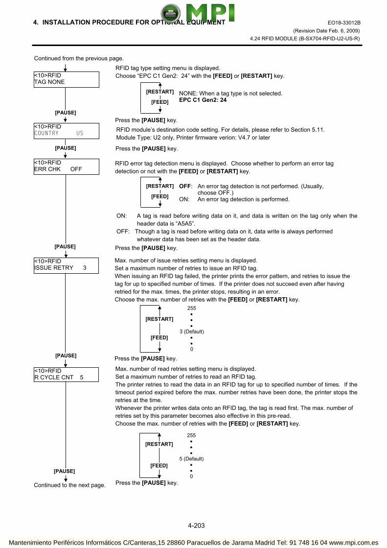
4. INSTALLATION PROCEDURE FOR OPTIONAL EQUIPMENT EO18-33012B (Revision Date Feb. 6, 2009)
4.24 RFID MODULE (B-SX704-RFID-U2-US-R)
4-203
<10>RFID TAG NONE
RFID tag type setting menu is displayed. Choose “EPC C1 Gen2: 24” with the [FEED] or [RESTART] key.
[RESTART]
[FEED]NONE: When a tag type is not selected. EPC C1 Gen2: 24
[PAUSE] Press the [PAUSE] key.
<10>RFID ERR CHK OFF
RFID error tag detection menu is displayed. Choose whether to perform an error tag detection or not with the [FEED] or [RESTART] key.
[RESTART]
[FEED]
OFF: An error tag detection is not performed. (Usually, choose OFF.)
ON: An error tag detection is performed.
ON: A tag is read before writing data on it, and data is written on the tag only when theheader data is “A5A5”.
OFF: Though a tag is read before writing data on it, data write is always performed whatever data has been set as the header data.
[PAUSE] Press the [PAUSE] key.
Continued to the next page.
Continued from the previous page.
<10>RFID ISSUE RETRY 3
Max. number of issue retries setting menu is displayed. Set a maximum number of retries to issue an RFID tag. When issuing an RFID tag failed, the printer prints the error pattern, and retries to issue the tag for up to specified number of times. If the printer does not succeed even after having retried for the max. times, the printer stops, resulting in an error. Choose the max. number of retries with the [FEED] or [RESTART] key.
[PAUSE]
[RESTART]
[FEED]
255 • • •
3 (Default)• • 0
Press the [PAUSE] key.
<10>RFID R CYCLE CNT 5
Max. number of read retries setting menu is displayed. Set a maximum number of retries to read an RFID tag. The printer retries to read the data in an RFID tag for up to specified number of times. If thetimeout period expired before the max. number retries have been done, the printer stops theretries at the time. Whenever the printer writes data onto an RFID tag, the tag is read first. The max. number of retries set by this parameter becomes also effective in this pre-read. Choose the max. number of retries with the [FEED] or [RESTART] key.
[RESTART]
[FEED]
255 • • •
5 (Default)• • 0
Press the [PAUSE] key.
[PAUSE]
<10>RFID COUNTRY US RFID module’s destination code setting. For details, please refer to Section 5.11.
Module Type: U2 only, Printer firmware verion: V4.7 or later
[PAUSE] Press the [PAUSE] key.
Mantenimiento Periféricos Informáticos C/Canteras,15 28860 Paracuellos de Jarama Madrid Tel: 91 748 16 04 www.mpi.com.es

4. INSTALLATION PROCEDURE FOR OPTIONAL EQUIPMENT EO18-33012B (Revision Date Feb. 6, 2009)
4.24 RFID MODULE (B-SX704-RFID-U2-US-R)
4-204
Continued from the previous page.
Continued to the next page.
<10>RFID R CYCLE TIM 4.0
Read retry timeout setting menu is displayed. Set the timeout period during which RFID tag read retries are allowed, with the [FEED] or [RESTART] key. If the printer has retried for the max. number of times within the RFID read retry timeout, the printer stops the retries at the time. Whenever the printer writes data onto an RFID tag, the tag is read first. The read retrytimeout set by this parameter becomes also effective in this pre-read.
[RESTART]
[FEED]
9.9 (9.9 sec.)• • •
4.0 (Default)• •
0.0 (0.0 sec.)
[PAUSE]
<10>RFID W CYCLE CNT 5
Press the [PAUSE] key.
Max. number of write retries setting menu is displayed. Set a maximum number of retries to write data onto an RFID tag. The printer retries to write data onto an RFID tag for up to specified number of times. If the timeout period expired before the max. number of retries have been done, the printer stops the retries at the time. Set the max. number of times with the [FEED] or [RESTART] key.
[RESTART]
[FEED]
255• • •
5 (Default)• • 0
[PAUSE] Press the [PAUSE] key.
<10>RFID W CYCLE TIM 2.0
[PAUSE]
Write retry timeout setting menu is displayed. Set the timeout period during which RFID tag write retries are allowed, with the [FEED] or [RESTART] key. If the printer has retried for the max. number of times within the RFID write retry timeout, the printer stops the retries at the time.
[RESTART]
[FEED]
9.9 (9.9 sec.)• • •
2.0 (Default)• •
0.0 (0.0 sec.)
Press the [PAUSE] key.
<10>RFID ADJ RETRY +00
RFID adjustment for retry menu is displayed. If writing data on a tag failed, the printer feeds the RFID tag forward or backward for specified length in order to retry writing data. When “0” is set for this parameter, this function and a retry are not performed. Only the value of –3mm or less or +3mm or more becomes effective. Set a value to move the RFID tag position with the [FEED] or [RESTAT] key.
[RESTART]
[FEED]
+99 (99mm) Reverse feed • • •
+00 (Default) • •
-99 (-99mm) Forward feed [PAUSE]
Press the [PAUSE] key.
Mantenimiento Periféricos Informáticos C/Canteras,15 28860 Paracuellos de Jarama Madrid Tel: 91 748 16 04 www.mpi.com.es

4. INSTALLATION PROCEDURE FOR OPTIONAL EQUIPMENT EO18-33012B (Revision Date Feb. 6, 2009)
4.24 RFID MODULE (B-SX704-RFID-U2-US-R)
4-205
Continued from the previous page.
Continued to the next page.
<10>RFID POWER LEVEL 18
Radio output power level setting menu is displayed. When the value is “9”, the power is the weakest, and when “18”, the power is the strongest. The factory default setting is “18”. The optimum value differs depending on the tag types. Usually, it is not necessary to change this value but changing the value may be able to increase the number of successful read/write times. Set the power level with the [FEED] or [RESTART] key.
[RESTART]
[FEED]
18 (Default, Strongest) • • • • •
9 (Weakest) [PAUSE]
Press the [PAUSE] key.
<10>RFID AGC THRESHOLD 0
[PAUSE]
AGC threshold setting menu is displayed. When the obtained gain of an RFID tag is lower than the AGC threshold, the tag is considered as an error tag even if a data write succeeds. When the AGC threshold is set to “0”, all tags are writable. When set to “8”, for example, only tags with the AGC threshold level of 9 or greater are writable. The optimum value is different depending on the tag types. The factory default is 0. Set an AGC threshold with the [FEED] or [RESTART] key.
Press the [PAUSE] key.
[RESTART]
[FEED]
15 • • • • •
0 (Factory Default)
<10>RFID RF CHANNEL AUTO
RFID channel setting menu is not available to the B-SX704-RFID-U2-US-R.
[PAUSE] Press the [PAUSE] key to skip this menu.
<10>RFID Q VALUE 0
[PAUSE]
Q value setting menu is displayed. In the case multiple RFID tags are read at the same time, this menu is useful to pinpoint a target tag. Set the Q value to “1” or greater (2 is recommended.) with the [FEED] or [RESTART] key. Q value “0” causes the tags to interfere with each other and disables proper data write. When a Q value is set, set an AGC threshold for data write and an AGC threshold lower limit for retry, also. Setting all these values enable writing data to a tag placed just above the antenna.(For details, refer to Section 4.24.5 AGC Threshold Setting.) The factory default is 0.
[RESTART]
[FEED]
15 • • • •
0 (Default)
Press the [PAUSE] key.
Mantenimiento Periféricos Informáticos C/Canteras,15 28860 Paracuellos de Jarama Madrid Tel: 91 748 16 04 www.mpi.com.es

4. INSTALLATION PROCEDURE FOR OPTIONAL EQUIPMENT EO18-33012B (Revision Date Feb. 6, 2009)
4.24 RFID MODULE (B-SX704-RFID-U2-US-R)
4-206
4.24.5 AGC Threshold Setting The B-SX704-RFID-U2-US-R chooses a tag to write data on according to a radio intensity of RFID tags (AGC value). An AGC threshold value has been set to 0 (00h) as factory default, but it may be necessary to change this value according to the tag type to be used. When the factory default threshold value is not proper for the tag type used, follow the procedure below to configure the following settings. As the changes are stored in the internal memory, they are retained after the printer power is turned off and on again. When the tag type is changed or data write cannot be operated properly, perform the setting again. Step 1. Load an RFID tag embedded media in the printer. Step 2. Follow the procedure below to measure the radio intensity of the tags. 1) Place the media so that an RFID tag (IC chip) is positioned above the Antenna, and close the Top
Cover. Note: If an RFID tag is not positioned above the Antenna while the Print Head is at a print start
position, use @003 command to adjust the media position so that an RFID tag is positioned above the Antenna. For detail of the command, refer to the External Equipment Interface Specification (Printer Command Manual).
Continued from the previous page
<10>RFID WT AGC 0
[PAUSE]
AGC threshold for data write setting menu is displayed. When the Q value is set to 1 or greater, the AGC threshold for data write becomes effective. When the obtained gain of an RFID tag is lower than the AGC thresholdfor data write, data write is not performed. In other words, setting an AGC threshold for data write enables writing data only to a tag placed just above the antenna. The optimum value differs depending on the tag type. (For details, refer to Section 4.24.5 AGC Threshold Setting.) Set an AGC threshold for data write with the [FEED] or [RESTART] key, if necessary.
[RESTART]
[FEED]
15 • • • •
0 (Default)
Press the [PAUSE] key.
<10>RFID WT MIN AGC 0
AGC threshold lower limit for retry setting menu is displayed. When the Q value is set to 1 or greater, the AGC threshold lower limit for retry becomes effective. When there are tags of which AGC values fall within the range between the AGC threshold fordata write and the lower limit, the printer retries data write for a tag with the highest AGC valueamong those tags. When printer retries data write, that value is then used as an AGCthreshold. The optimum value differs depending on the tag type. (For details, refer to Section 4.24.5 AGC Threshold Setting.) Set the lower limit for retry with the [FEED] or [RESTART] key, if necessary.
[PAUSE]
[RESTART]
[FEED]
15 • • • •
0 (Default)
Press the [PAUSE] key.
<10>RFID
The LCD message returns to ”<10>RFID”. Now, the RFID module settings are completed. If data write to RFID tags cannot be properly performed, refer to Section 4.24.5.
Mantenimiento Periféricos Informáticos C/Canteras,15 28860 Paracuellos de Jarama Madrid Tel: 91 748 16 04 www.mpi.com.es