AV AMPHIBIOUS VEHICLE Team Advisor Senior Design Project Engineering 340 Spring 2010
97
1 AV AMPHIBIOUS VEHICLE Final Report May 12, 2010 Team 15 Steve Brink, Steve DeMaagd, Michael Gondhi, Jasper Gondhi, Tyler Vandongen Team Advisor Professor Nielsen Senior Design Project Engineering 340 Spring 2010
Transcript of AV AMPHIBIOUS VEHICLE Team Advisor Senior Design Project Engineering 340 Spring 2010
1 AV
AMPHIBIOUS VEHICLE
Final Report
May 12, 2010
Team 15 Steve Brink, Steve DeMaagd, Michael Gondhi, Jasper Gondhi, Tyler Vandongen
Team Advisor Professor Nielsen
Senior Design Project
Engineering 340
Spring 2010

2 AV
Executive Summary
Calvin College is a liberal arts institution located in Grand Rapids, MI. It offers an Accreditation
Board for Engineering and Technology (ABET) accredited Bachelor of Science in Engineering
degree (B.S.E.) in Mechanical, Electrical & Computer, Civil and Environmental, and Chemical
concentrations. The senior year of study includes a design project and Engineering 339 and 340,
companion courses to the design project. The design project is intended to be a capstone course for
the engineering program. It is a year-long project that requires a group of students to define a
problem, study its feasibility through research, and solve the problem using engineering methods.
The goal of this project is to design and develop a working prototype of an amphibious vehicle
(AV) by applying the principles of an engineering design process from concept to production. We
decided to design a three-wheel, pedal-powered amphibious vehicle, meant for recreational
purposes throughout the United States and other developed countries. The one-person vehicle is
designed to navigate both land and still water bodies with ease. Our design team aims to improve
the value of the vehicle by analyzing the materials used and considering the end use of all the
components.
Following research, team members analyzed the time, materials, components and other resources
required to build a prototype of the AV. After discussion with the team advisor and resource
persons from bicycle companies in Grand Rapids area, the project is determined to be feasible. By
using the resources provided by the bicycle companies and the budget set by Calvin College, the
project will be completed by May 12, 2010.

3 AV
Table of Contents
1. Introduction 1
1.1 Team Description 1
1.2 Project Background 3
1.3 Project Description 3
2. Design Functionality 4
2.1 Project Scope 4
2.2 Cost 4
2.3 Durability 4
2.4 Design for Assembly 5
2.5 Safety 5
2.6 Performance 5
3. Christian Perspective 5
3.1 Biblical Perspective 5
3.2 Design Norms 6
3.2.1 Stewardship 6
3.2.2 Transparency 6
3.2.3 Justice and Caring 7
3.2.4 Trust 7
4. Project Feasibility Analysis 8
4.1 Market research 8
4.1.1 Recreation Vehicle Design 8
4.1.2 Price Study 9
4.2 Time Feasibility 9
4.3 Cost Feasibility 10
4.4 Technical Feasibility 11
4.5 Team Management 11
4.6 Decision Making 12
5. Design Alternatives and Selection 13
5.1 Frame 13
5.2 Drive Train 17
5.3 Flotation 23
5.4 Propulsion 26
5.5 Dual Steering System 29

4 AV
6. Manufacture of the Vehicle 34
6.1 Risk Assessment 34
6.2 Manufacture of Components 35
6.3 Frame 35
6.3.1 Welding 37
6.4 Drive Train 39
6.4.1 Front Axle 39
6.4.2 Front Axle Adapters 41
6.4.3 Front Axle Bearing Sleeves 43
6.4.4 Assembly 44
6.5 Dual Steering System 45
6.6 Flotation 48
6.7 Propulsion 53
6.8 Braking 56
6.9 Seating 57
7. Testing 58
7.1 General Attributes 58
7.2 Test Locations 59
7.3 Preliminary Testing 63
7.4 Testing on Land 58
7.4.1 Stability on Land 63
7.4.2 Maneuverability on Land 64
7.4.3 Drive on Land 64
7.5 Testing on Water 66
7.5.1 Buoyancy on Water 66
7.5.2 Stability on Water 67
7.5.3 Maneuverability on Water 70
7.5.4 Propulsion on Water 70
7.6 Transition Tests 71
7.7 Safety 73
8. General Recommendations 74
8.1 Frame 74
8.2 Flotation 75
8.3 Chain 76
8.4 Propulsion 76

5 AV
8.5 Steering 77
8.6 Seating 78
8.7 Braking 78
9. Conclusion 79
10. Evaluation 79
11. Acknowledgements 81
12. Online Tools 82
APPENDICES
APPENDIX A: PROJECT SCHEDULE
APPENDIX B: BUDGET
APPENDIX C: DECISION MATRICES
APPENDIX D: CALCULATIONS
LIST OF FIGURES
Figure 1: Team 15 Picture 1
Figure 2: Toothed Belt Drive 14
Figure 3: Shaft Drive 14
Figure 4: Derailleur Gear System 15
Figure 5: Hub Gear System 15
Figure 6: Bicycle Gearing System 17
Figure 7: Upright Bicycle 22
Figure 8: Recumbent Bicycle 22
Figure 9: Syntactic Foam with Glass Microspheres 25
Figure 10: Paddle Wheel 27
Figure 11: Ackerman Effect 31
Figure 12: Steering Linkage 31
Figure 13: Re-circulating Ball Steering 32
Figure 14: Rack and Pinion Steering 32
Figure 15: Rear Wheel Steering Mechanism 33
Figure 16: Raw Aluminum Tubing 36
Figure 17: 3” Hole Drill Bit 36
Figure 18: 3” Hole Drill Bit 36

6 AV
Figure 19: Drill Press with Guide Tool 37
Figure 20: Tool with Fish Mouth Cut 37
Figure 21: Welding Machine 38
Figure 22: Main Frame Assembly 39
Figure 23: Drilled and Taped End of Front Axle 40
Figure 24: Key Way and Key in Front Axle 41
Figure 25: Adapter 42
Figure 26: Adapter on Gear Hub of Wheel 42
Figure 27: Bearing and Sleeve 43
Figure 28: Bearing and Sleeve on Front Axle 43
Figure 29: Front Axle Assembly 44
Figure 30: Rear Wheel of the Vehicle 45
Figure 31: Dual Steering System 46
Figure 32: Solid Rear Wheel of the Vehicle 47
Figure 33: Polystyrene Foam Billets 49
Figure 34: Cutting Holes in Top of Flotation 49
Figure 35: Wood Blocks in Flotation 50
Figure 36: Fiberglass Cloth 51
Figure 37: West System Hardener 51
Figure 38: West System Epoxy Resin 51
Figure 39: West System Pumps 52
Figure 40: Curing Time after Mixing 53
Figure 41: Pedals Connected to the Main Axle 54
Figure 42: Amphibious Vehicle Paddle Wheel 55
Figure 43: Paddle Wheel Assembly 55
Figure 44: Brake Assembly 56
Figure 45: Seat Assembly 58
Figure 46: Water Test Site – Seminary Pond, Calvin College 60
Figure 47: Land Test Site – Knollcrest Circle, Calvin College 60
Figure 48: Private Boat Launch on Reeds Lake 61
Figure 49: Map to Reeds Lake Boat Launch 62
Figure 50: Land Speed Test 65
Figure 51: Braking Test 65
Figure 52: Buoyancy Test 66
Figure 53: Stability Test 1 68
7 AV
Figure 54: Stability Test 2 68
Figure 55: Stability Test 3 69
Figure 56: Angle Measurement Test 69
Figure 57: Speed Test Routes 71
Figure 58: Transition: Land to Water 72
Figure 59: Transition: Water to Land 72
LIST OF TABLES
Table 1: Price Ranges for Human Powered Vehicles 9
Table 2: Dimensions of AV 59
Table 3: Weight of AV 59
Table 4: Safety Considerations 73

8 AV
1. Introduction
1.1 Team Description
Figure 1. Team 15 Picture
Steve DeMaagd is a Senior Mechanical Engineering student from Grandville, MI. He has
worked as a Design engineer at Nucraft in Comstock Park, Michigan and as a Manufacturing
engineer at Polycem in Grand Haven, Michigan. In the future, he would like to attain an MBA
and also become a P.E.
Steven Brink, a native of Dyer, Indiana, is a Senior Mechanical Engineering Student. He would
like to travel the world and work abroad for a couple years then find a job in the Chicago area.
He plans to attend grad school for business or law after working for 2 or 3 years.

9 AV
Jasper Gondhi is a senior mechanical engineering student from Hyderabad, India. His past work
experiences include internships in Software Development and research in the field of Vibrations
and Acoustics. He thrives on a passion for leadership through engineering, and plans to pursue
higher education that combines these disciplines, all the while gaining international experience.
Tyler VanDongen attended Pennfield High school in Battle Creek, Michigan. His goals are to
obtain a lead design engineering position at a large company. Currently his plans after college
are to continue working at Die-Tech and Engineering in Grand Rapids, Michigan for one more
year while searching for work in Toledo, Ohio. He then plans to move there, work, and be with
his fiancée who is currently attending the University of Toledo, School of Medicine.
Michael Gondhi, from Hyderabad, India, is also a Senior Mechanical Engineering Student. He
is currently job hunting and plans to work for a manufacturing firm after he graduates in May
2010. His past work experiences include Sony Audio Systems Pvt. Ltd. He hopes to work in a
technical leadership position that will allow him to contribute to the growth of the organization.

10 AV
1.2 Project Background
The Senior Design Project is part of Engineering Courses 339 and 340 which together are
intended to be a capstone course for the Engineering program. For the design project, a small
sized team consisting of 3-5 members work together to develop a solution to a design problem.
Students are given the freedom to choose their own design project. Team 15 chose to design and
prototype an Amphibious Vehicle (AV) for the purpose of recreation and transportation.
1.3 Project Description
The aim of the project is to design and prototype an Amphibious Vehicle capable of operating on
land and still fresh water bodies. Major design components include:
Vehicle Frame
Wheels
Floatation
Dual Environment Steering System
Drive Train
Braking System
Following research, Team 15 finalized the type of design specification best suited for each of the
components listed above. The design requirements for each component were qualified and
chosen by employing various decision toolsets.

11 AV
2. Design Functionality
2.1 Project Scope
The goal of this project is to design and prototype a pedal–powered amphibious vehicle by May
1, 2010 to allow a week for testing and use. The method of approach for the prototype is to
design a cost effective, safe, durable, and enjoyable product. The concept and design of the AV
would be an innovative product in the market for recreational vehicles in developed countries.
2.2 Cost
A major goal for this project is to achieve the lowest final cost possible of the amphibious
vehicle. The team plans to make any expensive custom parts, reuse parts from scrapped bicycles,
and buy off the shelf components to minimize the cost. Some major challenges in lowering the
cost of the vehicle are the floatation devices, material coatings, and the drive train. The cost
feasibility is outlined further in Section 4.3.
2.3 Durability
The components and materials chosen for the vehicle should be durable and low maintenance.
This includes durability on both land and water for extended periods of time. Durability is
necessary to minimize maintenance costs and increase the lifetime of the amphibious vehicle.
2.4 Design for Assembly
A major goal for the design of the amphibious vehicle is to minimize the assembly and
disassembly time by eliminating any complications in the design and minimizing the number of
components used in the vehicle. Since the vehicle will be used in water and on land, a user needs
12 AV
to clean and maintain all parts of the vehicle without complications. Finally, the AV must be
designed it can be easily assembled and disassembled by a person with minimum technical
knowledge.
2.5 Safety
The amphibious vehicle will be designed and built with safety measures taken for the driver.
This will be accomplished by placing the user seats towards the center of the vehicle surrounded
by other components. At the same time, the user will be provided with enough room for easy
escape in case of a vehicle collision. Users are advised to wear life vests stored on the vehicle
when traveling on water.
2.6 Performance
The pedal–powered vehicle will be designed to carry one adult, adding to its maximum load. The
amphibious vehicle will then be tested on both land and water by different users to estimate the
maximum speed and braking time.
3. Christian Perspective
3.1 Biblical Perspective
Colossians 3:17 says “And whatever you do, whether in word or deed, do it all in the name of the
Lord Jesus, giving thanks to God the Father through him.” This verse presents the team’s
approach to designing and prototyping the AV. Through every step in the design process, the
team aims to work towards designing a product that will present a Christian perspective.

13 AV
Although this product does not solve an existing problem, it provides a form of recreation that is
environment friendly in design and functionality.
3.2 Design Norms
Throughout the project, the final design and product, the team is keen on working with a
Christian perspective. Team 15 believes that the work style, designs, and final product represent
the team’s beliefs and principles. The team also agrees that Christian engineers are called to
design a solution to address a problem, help improve the standard of living, design products for
healthy recreation; all with a Christian perspective. Some design norms that fit the amphibious
vehicle project are Stewardship, Transparency, Trust, and Caring.
3.2.1 Stewardship
The amphibious vehicle is a means of transportation and recreation. As product makers, we take
the responsibility to design and build a vehicle that is affordable to the majority of the
population. By designing the vehicle using suitable parts from other bicycles and tricycles, we
hope to bring down the cost of the final product and reduce the scrap entering landfills. As good
stewards, we plan to use our resources smartly, and design a vehicle that will not harm the
environment when used properly.
3.2.2 Transparency
Transparency is an important part of the design because it allows the user to access the different
parts of the AV when the vehicle needs repair` or scheduled maintenance. This need for simple
repair drives the need for a simple design. It is important that the user of the AV understands
14 AV
how the vehicle operates and reacts. Transparency in the AV implies that it is predictable in use,
reliable at all times and consistent in performance. In addition, the design is developed to be
assembled and disassembled with ease.
3.2.3 Justice and Caring
The amphibious vehicle provides a form of transportation and recreation. The design of the
vehicle should be just in the use of materials and the use of resources. At every step in the design
process, the team assesses the safety related to the design and use of the vehicle.
3.2.4 Trust
The team aims to design and build a product that the user will be able to trust for safe
transportation and recreation on land and on water.
15 AV
4. Project Feasibility Analysis
4.1 Market Research
In developed countries, there is an increasing demand for human powered vehicles in the market.
These vehicles include bicycles, tandem bicycles, kayaks, handcycles, surreys, and rowbikes.
Most products in the market are not able to navigate both land and water. The amphibious
vehicle will be a new attraction in the market by adding the ability of water navigation to a
common land navigation vehicle.
This human powered amphibious vehicle will target the recreation industry for family homes,
cottages, and resort rentals. The amphibious vehicle could be used by tourists at cottages,
neighborhoods, and resorts to tour the local area or a nearby lake in a fun, new, and exciting way.
The amphibious vehicle could be used for exercise, relaxation, recreation, or just getting from
one place to another.
Currently in most resorts, golf carts are being used or rented to visitors for transportation to
nearby areas. These golf carts run on gas or batteries. The amphibious vehicle is
environmentally conscious by eliminating the use of electrical and thermal energy and emissions.
4.1.1 Recreation Vehicle Design
Most existing pedal powered vehicle designs in production are for one or two people with
seating front to back or side to side. These designs are intended for land navigation only. The
amphibious vehicle will use current designs for land navigation to build a vehicle capable of
16 AV
water navigation as well. The current models of amphibious vehicles are experimental models or
expensive kits that are not meant for production.
4.1.2 Price Study
The prices of pedal powered vehicles depend on seating capacity, materials used, the style of
seating, and the manufacturer. A price range for similar amphibious vehicles in the market could
not be found since no model currently exists in production. Various other human powered
vehicle price ranges in the market are shown in Table 1.
Table 1. Price Ranges for Human Powered Vehicles
Human Powered Vehicle (HPV) Price Range
Recumbent Bicycle $700 - $5,000
Tandem Bicycle $1,000 - $5,000
Surrey $1,000 - $3,000
Pedal Boats or Paddle Boats $400 - $1,500
Kayak $700 - $2,000
4.2 Time Feasibility
The completion date for this project is May 1, 2010. Time is especially important for the
amphibious vehicle project because of the large prototype size. The AV is a unique project
because there are numerous materials and designs possible for each system. The number of
options for the AV forced the team to make hard decisions early in the process on specific
designs. The AV project was broken down into different systems. Each team member was
assigned a specific system of the vehicle but also must collaborate with the team as a whole to
complete each system. The various systems include steering, frame, drive train, floatation, and

17 AV
paddle system. Each system was broken down into tasks with time constraints and deadlines.
Contingency planning was necessary to account for time lost due to problems that occured
throughout the project.
4.3 Cost Feasibility
Due to the “build from scratch nature of the project and the vast number of components required
in building an amphibious vehicle, financial management was an important aspect of project
planning. The cost of the amphibious vehicle must be lower than comparable products in the
market in order to be attractive to potential customers. The initial funding allocated by the
university towards the project was $300 based on a fixed amount for each group. The team
realized the cost to build an amphibious vehicle would likely exceed the limits of the $300
budget provided. Team 15 was given an additional $300 to supplement the initial $300 and raise
the total budget to $600 after each team was given the opportunity to compete for limited
additional funding. The current amphibious vehicle design has material costs somewhere
between $1,000 and $1,250. A cost analysis was performed for the project to determine the
overall cost of building the prototype amphibious vehicle. The cost breakdown of the prototype
AV is shown in Appendix B. In order to reduce the cost of building a prototype, the team has
contacted some local bicycle companies to sponsor the project and have decided to custom make
certain expensive parts. Some of the custom built parts for the prototype of the AV are the seats,
frame, steering handles, paddle system, and the axle. Team 15 plans to use as many bicycle parts
as possible to design the AV in order to minimize cost. The used parts will be collected from
bicycles donated by Calvin College Student Senate or purchased from sponsors and other outside
sources for minimal costs. With these cost reductions, the total cost to build the prototype is

18 AV
projected to be $748.89. As a result, accurate allocation of funds for each component is key to
successful financial management and will ensure that the project is completed within budget.
4.4 Technical Feasibility
The technical feasibility of the vehicle is very important. The actual design of an amphibious
vehicle is a broad subject because of the many alternatives and options for the overall structure,
including selection of the parts for the vehicle and its subassemblies. The team considered many
alternatives for the design of the vehicle structure. After considering various designs, each with
its advantages and disadvantages, the team decided to build the simplest design that allowed for
the integration of multiple systems. This design consists of a basic aluminum frame with two
wheels in the front and one wheel in the back. This design enables easy assembly and
manufacturability.
4.5 Team Management
At the beginning of the project, there was a period of time when the dynamics of the team were
being established and each member was finding their place. During this time, it was important
that the team meet together rather than splitting up. This process was time intensive with much
time being spent in meetings and minimal time working individually. Progress was limited
during this time by the availability of individuals.
Rather than assign fixed roles for each member of the team, roles were kept flexible with
individuals specializing in areas of strength. From the meetings and minutes, a clear agenda was
set for the next meeting and a time and place were provided for each of the members so

19 AV
individuals know when they need to attend. During meetings, clear targets were generated to
ensure the project had a constant flow and deadlines would be met.
4.6 Decision Making
There were three basic decision making methods incorporated throughout the project. The first
method is simply that the decision came down to the member in the team that had the “loudest
voice” or who was the most persuasive, strongest leader.
The second method allows each team member to be included in the decision. Each team member
is given a vote and the majority of the votes will decide the outcome of the decision problem.
The voting method allows every team member to carry the same weight in the decision process.
The third method is a numerical method. In the numerical method, the team members come
together and rate or score a set of key variables against each other. The scores are combined to
make a final decision. An example of the numerical method is the decision matrix. This method
allows each member to concentrate on scoring each minor variable against the next. The
numerical method reduces the personal choice element by giving a higher chance of the decision
being closest to the best theoretically.

20 AV
5. Design Alternatives and Selection
5.1 Drive Train
5.1.1 General Requirements
The drive train will be incorporating the simplest gear design possible. There will be separate
gearing systems for both the paddle system and the vehicle movement. The amphibious vehicle
will need to have the ability to go forward and reverse on land as well as forward and reverse in
water. It is likely that the transmission of an amphibious vehicle will always be more complex
than that of a vehicle that is designed for use only on land. For ease of use, the cycle will be
designed so that it is powered by the rider using the same set of pedals when on land and water,
giving a fluid transition from one medium to the next. The purpose of the transmission is to
deliver the power from the rider to the output device to propel the cycle, with possible variation
in gear ratios.
5.1.2 Alternatives
Transmission Alternatives
The transmission can deliver power by means of a belt drive, shaft drive, chain drive, or
electronic transmission. Belt drive normally can only transfer a relatively low amount of torque,
but a toothed belt can be used to overcome this. A toothed belt drive is shown in Figure 2. Shaft
drive can be an effective method, but can also be heavy and expensive due to bevel hears
involved in changing the direction of transmission. A bicycle shaft drive is shown in Figure 3.

21 AV
Figure 2. Toothed Belt Drive Figure 3. Shaft Drive
Electronic transmission is an unsuitable option due to the inefficiencies, extra weight, cost and
waterproofing involved. Chain drive is used by the overwhelming majority of cycles and is
proved to be a very efficient method of transferring power from the pedals to the drive wheel.
Chain is readily available, inexpensive, can easily be made to custom lengths, and is compatible
with many other essential cycle components. Chain does however come with the disadvantages
that it requires lubrication, can become jammed, dirty, and can be a nuisance to the rider.
Gearing Alternatives
The two basic gearing alternatives are free-wheel and fixed gears. A free-wheel gearing system
incorporates derailleur gears or hub gears. Most modern cycles employ the use of derailleur
gears where a chain is passed from one size of sprocket to the next to give a range of gear ratios.
This method of gearing is relatively simple on an upright bicycle, but can lead to several
challenges when applied to a three-wheeled cycle. The mechanism that moves the chain from
one sprocket to the next can be quite exposed, and set-up of the system can be complicated,
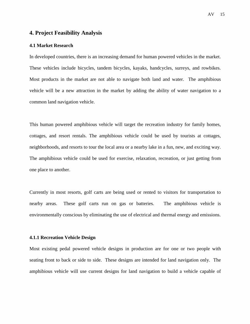
although a wide range of gears is possible. A derailleur gear is outlined in Figure 4.
22 AV
Figure 4. Derailleur Gear System
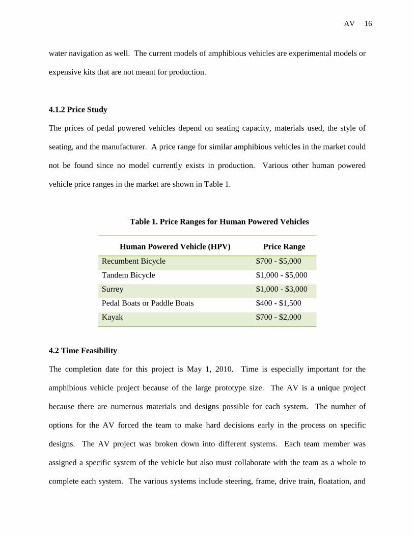
Hub gears used to very common on cycles are now making a resurgence due to the demand of
low maintenance, self contained gearing units for folding cycles. The increased usage has
prompted development of the technology, and wide ranges of hub gearing systems are now
available. A hub gear is outlined in Figure 5.
Figure 5. Hub Gear System

23 AV
A fixed gearing system allows for motion when going forward or in reverse. There is no free-
motion or coasting option when a fixed gear is used. A fixed gear would be ideal for motion on
water, while being an inconvenience for motion on land.
Design Alternatives
Some alternative designs that were considered were completely separate gearing systems for
water and for land, a single gearing system that could switch between land operation and water
operation, and a single gearing system that controlled both simultaneously. These different drive
train options were considered because they are simple and intuitive. Another alternative allows
the pedals to power both the front axle and paddlewheel axle simultaneously using two separate
chains. This would allow for simple gear reductions using existing bicycle parts and sprockets
located on the front axle and paddlewheel axle.
5.1.3 Selection
Transmission Selection
For the land gearing system, a typical 18 to 21 speed bicycle gearing system could be
incorporated into the design with little modification to the gear train. A simple bicycle gear train
is shown in Figure 6.

24 AV
Figure 6. Bicycle Gearing System
Since an existing gear train is being used, the only part that must be modified is the chain. The
chain must be designed to fit the specifications of the frame, seat, and pedal positions on the final
design. The chain length can be modified by each chain link and pin, which allows the chain to
fit any length. The current design allows both gear systems to be protected and concealed inside
the middle of the frame.
Gearing Selection
A fixed gearing system was chosen based on the need for forward and reverse motion in water.
The fixed gearing system is not ideal for motion on land, but does allow for reverse motion on
land as well. The fixed gearing system would allow the user to back out of any places where it
could possibly get stuck.
Design Selection
A single pedal sprocket was chosen to power the front axle and paddlewheel axle
simultaneously. There will be a sprocket located on the front axle and paddlewheel axle to allow

25 AV
for separate motion. The separate sprockets will allow for different gear ratios, as desired, to
achieve varying rates of rotational speed between the different axles, allowing the paddlewheels
to move faster than the front axle.
5.2 Frame
5.2.1 General Requirements
The frame will be designed with the lightest, safest, and most cost effective design possible. The
frame incorporates major decisions for both materials and design. Some basic requirements for
the material selection of the frame are high strength, light weight, durable, and corrosion
resistant.
The amphibious vehicle requires a strong frame to carry people and the additional weight of the
paddle wheel and flotation device. The frame will also hold the gearing, steering, and peddling
systems. The frame material should allow the passengers to access the seats by standing on the
frame.
The frame material cannot corrode easily on land or water. The team is especially concerned
with corrosion while using the amphibious vehicle in water if the frame is partially submersed.
The frame material needs to be highly corrosion resistant to withstand low levels of salinity.
A light material for the frame will drastically lower the overall weight and allow for better
floatation on water. A lighter frame will allow for more contingency weight to be allocated to
the paddle and floatation systems if needed. A heavy frame might help with durability but would
26 AV
require more floatation, increasing the overall weight. Space constraints for the amphibious
vehicle also limit the amount of floatation that can be added.
The material needs to be highly durable. The selected material needs to have a high endurance
limit and fatigue limit in order to handle the various stresses. The different stresses are caused
by fast pedaling, hitting bumps or ditches, and contact with moving water, and other water
forces.
Other necessary information for the selection of material for the frame is density, elongation, and
both torsional and lateral stiffness. These requirements will be evaluated using Algor finite
element analysis to make sure the frame design is feasible. Lastly, the frame must be
aesthetically pleasing to the customer.
5.2.2 Alternatives
Material Alternatives
Common materials currently used in manufacturing bicycle frames are aluminum alloys, steel,
titanium, and carbon fiber. There are also sub-categories of each of metals and alloy. These
metals and alloys all have advantages and disadvantages concerning physical properties. A
decision matrix for the vehicle frame, in Appendix C, compares and contrasts each metal and
alloy option.
Steel is stiff but dense. Light frames of adequate stiffness and strength are made with relatively
small-diameter tubes, but steel is not the right material for light frames or large strong riders.
27 AV
Mild and inexpensive steel frames need thick walls to be strong enough, and they are heavy.
Stronger steel allows thin tube walls, but then frame stiffness goes down. Recent developments
include "air-hardened" steels of very high strength, such as Reynolds 853. Unlike most other
types, air-hardened steels gain rather than lose strength as they cool from welding. All steels
have the same inherent stiffness, regardless of strength. Best steel alloys are very strong, long-
lasting, and have the best stiffness overall, but can be very heavy and rust-prone.
Aluminum frames can be very stiff and light because the density is so low, but the tubes have to
be much larger in diameter to compensate. Still, the large tube frames are the prevalent design
for quality bikes today. Recent improvements include adding Scandium, an element that
increases strength. Overall, aluminum is a great material for stiff, light frames for riders of all
sizes. It is also one of two materials that are well suited to unconventional frame shapes.
Aluminum is one-third the density of steel, easily formed into aero shapes, cheaper and lighter
than steel, and does not rust. On the other hand, aluminum is one-third to one-half the strength
of best steels and titanium and one-third the stiffness of any steel, which requires larger diameter
tubes. Aluminum has modest fatigue strength, and is not easily repaired or straightened due to
easy crash damage.
Titanium has an excellent balance of properties for frame building, and gives the best
combination of durability and weight. Titanium alloys are half as stiff as steel, but also half as
dense. The strongest titanium alloys are comparable to the strongest steels. Stiff titanium frames
need larger-diameter tubes than comparable steel frames, but not as big as aluminum. Titanium
is very corrosion resistant, and very light frames can be made stiff enough and strong enough for
28 AV
bigger riders. Most titanium frames are the 3Al/2.5V or 6Al/4V alloy. Titanium makes the
lightest, most resilient frames. Titanium has a good fatigue strength and will not rust, but is
difficult to repair and expensive.
Individual fibers of carbon are tremendously strong and stiff, but they are useless unless arranged
in a strong pattern, and held together with a strong glue or epoxy. Unlike metals, in which
strength and stiffness properties are nearly the same in all directions, carbon fiber composites can
be tuned to orient the strength where it is needed. This is the ultimate frame material for
unconventional frames and shapes, as it can be molded and tuned more than any metal. Carbon
Fiber has excellent fatigue strength, while strength and stiffness are controllable. The low
density and high strength of carbon fibers make very light, strong frames possible. Carbon Fiber
does not rust, but is an expensive raw material and prone to break.
Design Alternatives
Some design alternatives were considered for recumbent and upright bicycles. Basic upright and
recumbent bicycles are shown in Figures 7 & 8, respectively. Upright bicycles are the most
common and readily available type of bicycle, which most of the general public already know
how to ride and are familiar with. As they are more popular, they are cheaper because they are
mass produced. The higher height of the rider gives them more visibility of traffic on roads;
however, the high center of gravity would make them unstable in water.

29 AV
Figure 7. Upright Bicycle Figure 8. Recumbent Bicycle
Although upright bicycles have two wheels, leading to increased maneuverability on land, two
wheeled recumbent bicycles are most difficult to learn to ride because the position of the seat and
pedals makes balance more difficult. Therefore, a three wheeled tricycle is considered.
5.2.3 Selection
Material Selection
After evaluating the completed decision matrix, the material chosen for the amphibious vehicle
frame is an aluminum alloy. The different types of aluminum alloys considered are 6061
aluminum, 7075 aluminum or 2021 aluminum. The aluminum alloy chosen for the frame is
2021 aluminum because it has the highest strength to weight ratio of the aluminum materials
available to our group. Due to availability of materials and donations from outside sources, the
frame must be made with Aluminum 6061.
Design Selection
A one person recumbent design for the frame is chosen because it is the most aerodynamic,
power efficient, safe, and stable design. A recumbent frame design is also cheaper than the other

30 AV
two or four person options. The frame will be constructed with the least amount of material
possible. The frame will be constructed out of aluminum tubing. With these specifications
considered, a triangular formation frame will be constructed. This will make the rider feel more
stable on land, decreasing the difficulty of use and contributing to even greater stability in water.
5.3 Floatation
5.3.1 General Requirements
The flotation of the vehicle is crucial to the safety of the customer. It will need to provide
adequate buoyancy and stability. The flotation will be difficult to construct if the chosen design
is large and bulky. The flotation also has the potential to be expensive.
The flotation system must keep the vehicle from sinking below the gears and chains so that
rusting can be prevented. The flotation must be kept within the frame system in order to reduce
the overall size of the AV.
5.3.2 Alternatives
The flotation can be achieved by a hull, float, or hydrofoil design. A conventional hull form
could be used to provide adequate buoyancy and stability and could be manufactured relatively
cheaply out of a variety of materials. The hull could be solid or inflatable and produced to a
desired shape. It could minimize resistance in water but would be large to accommodate the
rider and necessary driving mechanisms. It would ensure that the rider and additional
components are protected from contact with the surrounding water, minimizing issues related to
corrosion. However, the hull would have to be pierced to allow wheels to be powered when on
31 AV
land and to provide power to the means of propulsion when floating. This could lead to possible
leaks and if the hull was to be accidentally pierced or punctured, it would quickly loose
buoyancy and stability in water.
Flotation could be provided by a range of different configurations using varying types of floats.
Floats could be manufactured out of a range of materials to a range of shapes. They can be solid,
hollow or inflatable, permanently attached, attachable, or they could fold out with they are being
used. Two removable canoes could be used to provide buoyancy. The canoes would ride along
the side of the frame and will provide the lift to keep the vehicle from sinking. The cost of the
canoes is a challenge that will be hard to avoid. Also, canoes have the potential to be bulky for
the design of the amphibious vehicle. One great advantage of the canoe design is the ability to
remove the canoes for faster speeds on land.
Another design would use air filled plastic drums attached to the frame. The plastic drums will
be in a cylindrical shape and provide a high amount of buoyancy. They are also very cheap and
highly available in most locations in the United States. The negatives to this design are the
difficulties in attachment to the frame, and also the negative aesthetic appeal that the drums will
give to the vehicle. Also, the cylindrical shape may not give proper stability and cause the
vehicle to be unstable in water.
Other designs include foams and pourable materials. An option includes the use of hollow
tubing filled with pourable polyurethane foam. This tubing would possibly be the frame of the
vehicle or lined alongside the current frame design. The polyurethane foam is a cheaper
32 AV
alternative to the canoe design. Also the polyurethane system will be very easy to manufacture.
A negative to this design is that it does not provide as much buoyancy as other alternatives and
may not give the vehicle enough safety for the customer.
Another alternative design for the flotation consists of using closed cell foam. There are many
types of closed cell foams on the market today. The foams considered for the amphibious vehicle
are syntactic foam, polystyrene, and polyurethane. Foams are most likely the best choice for the
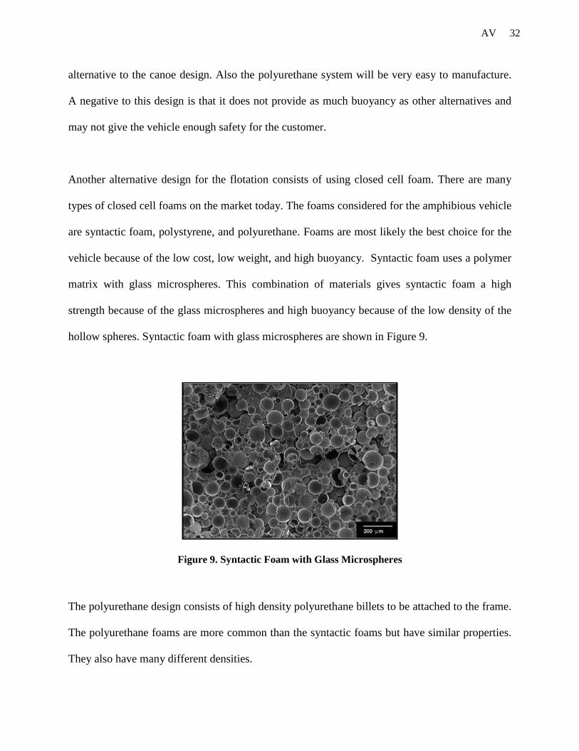
vehicle because of the low cost, low weight, and high buoyancy. Syntactic foam uses a polymer
matrix with glass microspheres. This combination of materials gives syntactic foam a high
strength because of the glass microspheres and high buoyancy because of the low density of the
hollow spheres. Syntactic foam with glass microspheres are shown in Figure 9.
Figure 9. Syntactic Foam with Glass Microspheres
The polyurethane design consists of high density polyurethane billets to be attached to the frame.
The polyurethane foams are more common than the syntactic foams but have similar properties.
They also have many different densities.

33 AV
Another alternative for flotation is a hydrofoil system. A hydrofoil is a wing-like structure or
foil, attached to a vehicle that raises all or part of the vehicle out of the water when moving
forward, thus reducing drag.
5.3.3 Selection
The triangular frame design limits the possibility of using canoes for flotation as placing them
closer to the drive train would minimize the turning radius, and placing them away from the
center plane would require the canoes to be suspended off center. The two options that could be
considered for the final design are the hollow tubing and closed cell foam. The best option for
our design is the high density polyurethane foam because it is the most common of the closed
cell foams and also inexpensive. Each 7’’x 14’’x 48’’polyurethane billet will provide 450 lbs of
buoyant force. This is the best selection based on the minimal volume, low price, and high
buoyancy.
5.4 Propulsion
5.4.1 General Requirements
The amphibious vehicle requires propulsion that will provide the vehicle with enough power to
navigate still waters. For smooth motion of the vehicle in water, it requires a propulsion system
that is capable of generating under-water thrust in the opposite direction of the motion of the
vehicle. The propulsion system designed for the AV should be integrated into the drive train for
the vehicle. This will allow the efficient transfer of power from the pedals to the propulsion
system. The vehicle should be able to move forward and reverse in water.

34 AV
5.4.2 Alternatives
The primary alternatives considered for the propulsion system of the amphibious vehicle are the
paddle wheel, and screw propeller. The choice of propulsion systems is limited, as the AV is a
human-powered vehicle.
There are two types of paddlewheels, radial and feathering. The blades of the radial paddlewheel
are fixed in position, whereas on the feathering paddlewheel, the blades constantly change angle
throughout rotation in order to slice the water without splashing or shock. The more efficient
paddle wheel designs feature feathering paddles, which stay vertical as they passed through the
water, so that only horizontal forces are applied. The upper part of a paddle wheel is normally
enclosed in a paddle box to minimize splashing. Rotation of the paddle wheel produces
thrust,
forward or backward as required. A paddle wheel system can be easily integrated into the drive
train of the AV as it simply requires a gear crank mechanism for rotation of the paddle wheel. A
basic paddle wheel is shown in Figure 10.
Figure 10. Paddle Wheel

35 AV
The screw propeller is the most common method of propelling water vehicles. They work on the
same principle as the paddlewheel by imparting momentum to the fluid medium in the opposite
direction to the required direction of motion. The two main types of screw propellers are fixed
blade and controllable pitch propellers. A hydrofoil system could incorporate a screw propeller.
For the hydrofoil system, the first solution is to use a water propeller, and the second is to use an
air propeller. However, there are problems related to each of these.
The problem with water propellers is cavitation. Cavitation can occur when the pressure on one
side of a propeller becomes so low that water vaporizes. This causes the propeller to “slip”,
meaning that efficiency is lowered and propulsion force decreases. This is a major concern as
efficient propulsion is essential to keeping the AV up on hydrofoils. Another problem with water
propellers would be the clearance available for placing the propeller and the foils. The problem
with air propellers is size. In order to create sufficient propulsion force, an air propeller has to be
much larger than one in water. This increases the cost and adds to the weight of the vehicle. The
increased size also brings up safety concerns. A large exposed air propeller could injure a rider,
and this is not ideal as the intended purpose of the AV is recreation.
There are many other methods of marine propulsion outside the scope of the project, such as
paddles, oars, sails, and poles. There are not included as they cannot be driven by the pedal
power provided by the rider. Other methods that can be used are the water jet and the screw-
turbine propeller.
36 AV
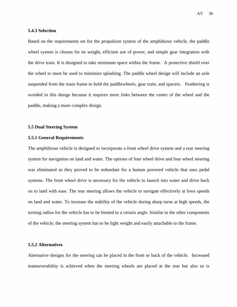
5.4.3 Selection
Based on the requirements set for the propulsion system of the amphibious vehicle, the paddle
wheel system is chosen for its weight, efficient use of power, and simple gear integration with
the drive train. It is designed to take minimum space within the frame. A protective shield over
the wheel to must be used to minimize splashing. The paddle wheel design will include an axle
suspended from the main frame to hold the paddlewheels, gear train, and spacers. Feathering is
avoided in this design because it requires more links between the center of the wheel and the
paddle, making a more complex design.
5.5 Dual Steering System
5.5.1 General Requirements
The amphibious vehicle is designed to incorporate a front wheel drive system and a rear steering
system for navigation on land and water. The options of four wheel drive and four wheel steering
was eliminated as they proved to be redundant for a human powered vehicle that uses pedal
systems. The front wheel drive is necessary for the vehicle to launch into water and drive back
on to land with ease. The rear steering allows the vehicle to navigate effectively at lows speeds
on land and water. To increase the stability of the vehicle during sharp turns at high speeds, the
turning radius for the vehicle has to be limited to a certain angle. Similar to the other components
of the vehicle, the steering system has to be light weight and easily attachable to the frame.
5.5.2 Alternatives
Alternative designs for the steering can be placed in the front or back of the vehicle. Increased
maneuverability is achieved when the steering wheels are placed at the rear but also so is
37 AV
sensitivity which can prove to make the cycle unstable at higher speeds. Many different methods
of controlling the steering are available but will generally be dictated by the structure and overall
geometry of the chosen cycle. If an upright design is chosen, the simplest method would be that
of a standard handlebar arrangement. If a short wheelbase recumbent design is chosen, a tiller
system could be employed to turn the rear wheel. Finally if a long wheelbase structure is chosen
an under seat steering linkage arrangement could be used, which can be a very relaxed position
for the rider to control the cycle in, however the extra parts used in this design can add some
complexity and weight to the design. When steering on water, a similar method must be
implemented. Many craft can be seen to employ a rudder at the rear to determine the direction of
travel; however there are some other methods that can be used.
There are two basic types of steering considered; single wheel steering, and two wheel steering.
These options for the steering system are used for navigation in both land and water. Using a
single wheel for the steering system would provide limited design options to control the turning
radius, decreasing the stability of the vehicle during sharp turns. However, designing a steering
system with a single wheel uses less material and provides more space for other components of
the vehicle.
The second alternative for the steering system uses two wheels that turn towards the rear of the
vehicle. For a vehicle to turn smoothly, each wheel must follow a different circle. Since the
inside wheel is following a circle with a smaller radius, it is actually making a tighter turn than
the outside wheel as shown in Figure 11.

38 AV
Figure 11. Ackerman Effect
To solve this design problem, the geometry of the steering linkage is designed based on a four-
bar linkage that accounts for the Ackerman effect. As shown in Figure 12, this four bar linkage
would require sufficient room under the frame and would add more weight to the vehicle. This
linkage accounts for the inside wheel to turn more than the outside wheel.
Figure 12. Steering Linkage
39 AV
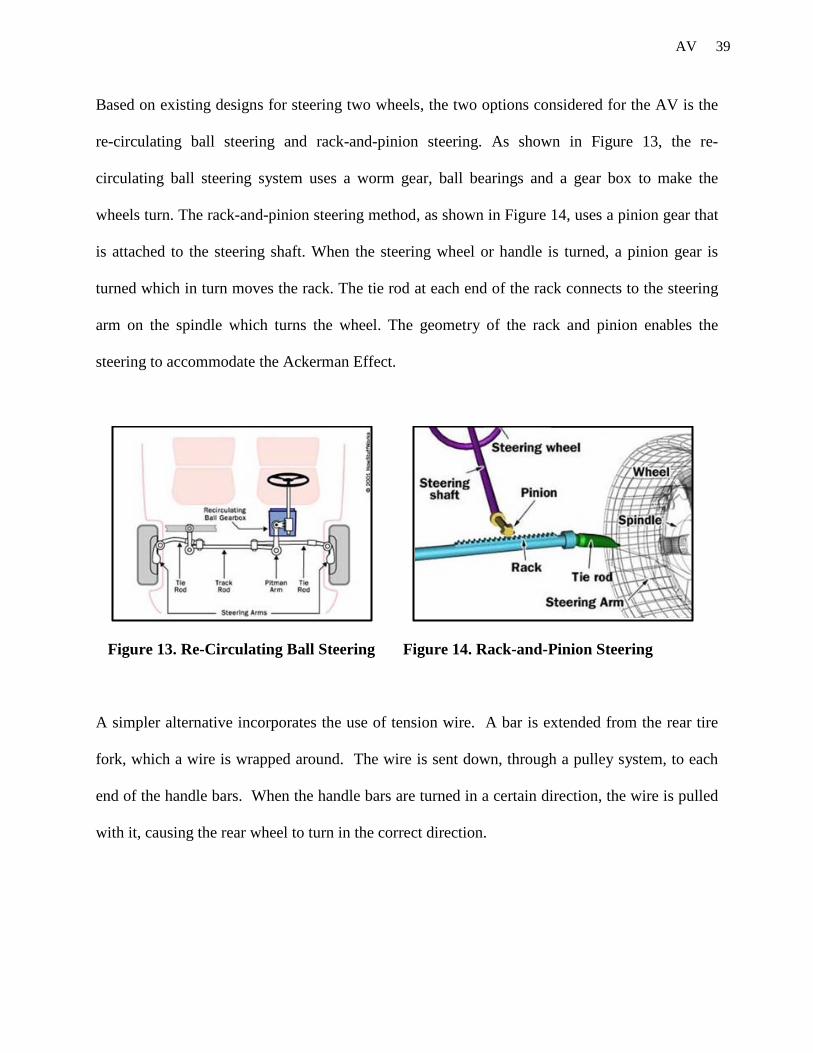
Based on existing designs for steering two wheels, the two options considered for the AV is the
re-circulating ball steering and rack-and-pinion steering. As shown in Figure 13, the re-
circulating ball steering system uses a worm gear, ball bearings and a gear box to make the
wheels turn. The rack-and-pinion steering method, as shown in Figure 14, uses a pinion gear that
is attached to the steering shaft. When the steering wheel or handle is turned, a pinion gear is
turned which in turn moves the rack. The tie rod at each end of the rack connects to the steering
arm on the spindle which turns the wheel. The geometry of the rack and pinion enables the
steering to accommodate the Ackerman Effect.
Figure 13. Re-Circulating Ball Steering Figure 14. Rack-and-Pinion Steering
A simpler alternative incorporates the use of tension wire. A bar is extended from the rear tire
fork, which a wire is wrapped around. The wire is sent down, through a pulley system, to each
end of the handle bars. When the handle bars are turned in a certain direction, the wire is pulled
with it, causing the rear wheel to turn in the correct direction.
40 AV
5.5.3 Selection
The design selected for the steering for the vehicle is an integrated rudder and wheel system. A
solid rear wheel design will be used. However, the freedom of rotation will be given to the back
wheels instead of the front ones. Also, a front wheel drive system is needed for easy transition
from land to water. With these specifications considered, the only placement for the steering is
in the back of the vehicle.
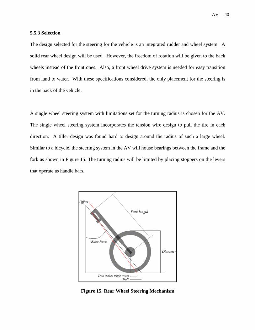
A single wheel steering system with limitations set for the turning radius is chosen for the AV.
The single wheel steering system incorporates the tension wire design to pull the tire in each
direction. A tiller design was found hard to design around the radius of such a large wheel.
Similar to a bicycle, the steering system in the AV will house bearings between the frame and the
fork as shown in Figure 15. The turning radius will be limited by placing stoppers on the levers
that operate as handle bars.
Figure 15. Rear Wheel Steering Mechanism

41 AV
This design was chosen for its simplicity in design, ease of machinability, ease of use, minimal
use of parts and its use as a rudder when combined with the propulsion system chosen for the
vehicle.
6. Manufacture of the Vehicle
6.1 Risk Assessment
Before the team could proceed with manufacturing the amphibious vehicle, it was vitally
important that a thorough risk assessment was carried out to highlight any areas that could pose a
danger to members of the team and other teams neighboring the work area. As a result of the
risk assessment, several steps were taken to ensure safe running of the project.
Only members of the team that had taken the machine shop class would operate tools and
machinery in the workshop, and would be supervised by machine shop head at all times. It was
crucial that eye protection in the form of safety glasses was worn at all times in both the machine
and woodshop even if no work was being carried out by the group member, as other people
working in the area may present a hazard. Lab coats were worn members of the team to protect
the operators while using tools, machinery and especially during welding.
When supervising and assisting the welder, welding masks as well as lab coats were worn to
protect the team members’ face and eyes from the bright light emitted by the MIG and TIG
processes. The possible danger of not following this precaution would be an inflammation of the
cornea due to ultraviolet light and possible burning of the retina. A translucent PVC curtain

42 AV
would protect other people who were working in the workshop from these dangers. The team
members would also wear thick gloves when holding on to components during, and for a time
after welding, because of the heat generated in the process. Only after completing the risk
assessment could work commence on manufacturing the product.
6.2 Manufacture of Components
The vehicle was constructed from over 25 different parts, many of which had to be machined to a
large degree using a lathe and milling machine. Each part was designed in Solid Works and
AutoCAD to the right dimensions before they were machined. These customized parts were
machined by team members under the supervision of the head of the machine shop.
6.3 Frame
After final designs had been established for the components of the vehicle, and all necessary risk
assessments had been carried out, it was time to begin manufacturing of the frame. The first step
when building the main frame of the vehicle was to cut up the various sections of tubing that
would later be welded together. With the limited resources of material, the team had to plan each
individual cut carefully and ordered to ensure that no mistakes were made. For this process an
automated band saw was used. Figure 16 shows the raw tubing.

43 AV
Figure 16. Raw Aluminum Tubing
For most of the sections of tubing, either one side or both sides of the tubing needed fish mouth
cuts. Since the tubing is circular the fish mouth ends could be used to join together. For ease of
manufacture all of these joints were designed to be at right angles to each other. This particular
design consideration saved a large amount of time and created a greater accuracy of cut. Figures
17 & 18 show the 3” hole drill used to make the fish mouth cuts.
Figure 17. 3” Hole Drill Bit Figure 18. 3” Hole Drill Bit
44 AV
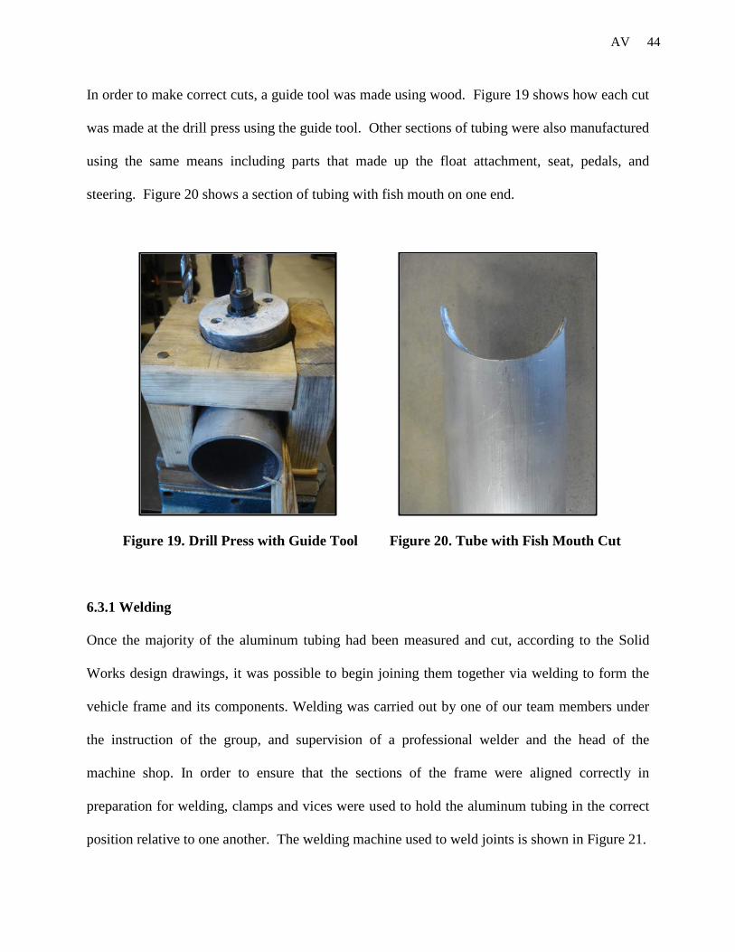
In order to make correct cuts, a guide tool was made using wood. Figure 19 shows how each cut
was made at the drill press using the guide tool. Other sections of tubing were also manufactured
using the same means including parts that made up the float attachment, seat, pedals, and
steering. Figure 20 shows a section of tubing with fish mouth on one end.
Figure 19. Drill Press with Guide Tool Figure 20. Tube with Fish Mouth Cut
6.3.1 Welding
Once the majority of the aluminum tubing had been measured and cut, according to the Solid
Works design drawings, it was possible to begin joining them together via welding to form the
vehicle frame and its components. Welding was carried out by one of our team members under
the instruction of the group, and supervision of a professional welder and the head of the
machine shop. In order to ensure that the sections of the frame were aligned correctly in
preparation for welding, clamps and vices were used to hold the aluminum tubing in the correct
position relative to one another. The welding machine used to weld joints is shown in Figure 21.

45 AV
Figure 21. Welding Machine
The clamps and vices were used to weld the middle section of the frame to the tubing of the front
axle, as well as the seat frame and float supports. Additional components were added later.
During the welding process, care was taken to weld sections of the frame in such an order, that
important load bearing sections were welded before other sections that might cause obstruction.
Also, where time allowed, the cycle frame was allowed to cool down as much as possible in
between welds to attempt to reduce the degradation of strength around the weld zones caused by
the intolerance of aluminum to high temperatures. Figure 22 shows the different tubing sections
welded together to achieve the main frame of the vehicle.

46 AV
Figure 22. Main Frame Assembly
6.4 Drive Train
6.4.1 Front Axle
The front axle of the vehicle was machined from a solid steel rod. The steel rod was first cut to
the right dimensions, drilled, and tapped on the lathe. The front axle had to be machined to high
tolerances to give a transition fit against the bearings and hubs used. This was done so that the
customized axle could be assembled to the already existing axles of bicycle wheels. The shaft of
the front axle was first drilled to give a starting point. Using the starting point holes were drilled
to the dimensions required for tapping. Then the holes on the ends of the shaft of the front axle
were tapped to the dimensions of the already existing axles on the wheels. The above operations
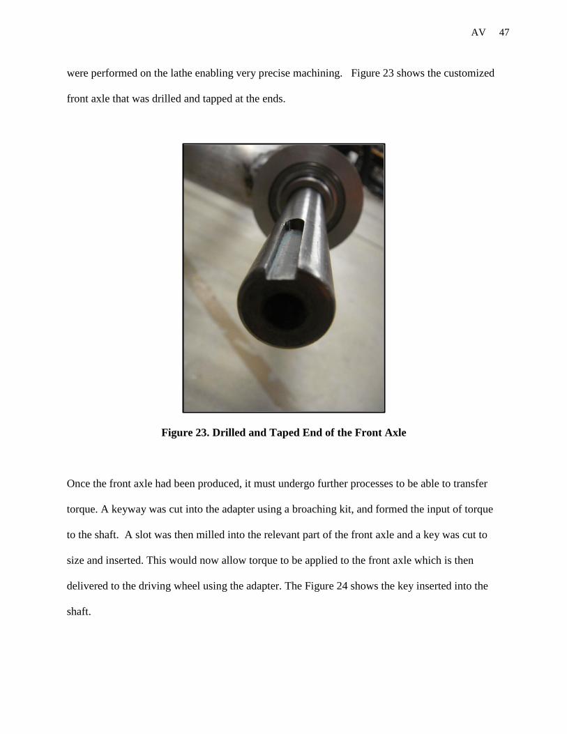
47 AV
were performed on the lathe enabling very precise machining. Figure 23 shows the customized
front axle that was drilled and tapped at the ends.
Figure 23. Drilled and Taped End of the Front Axle
Once the front axle had been produced, it must undergo further processes to be able to transfer
torque. A keyway was cut into the adapter using a broaching kit, and formed the input of torque
to the shaft. A slot was then milled into the relevant part of the front axle and a key was cut to
size and inserted. This would now allow torque to be applied to the front axle which is then
delivered to the driving wheel using the adapter. The Figure 24 shows the key inserted into the
shaft.

48 AV
Figure 24. Key Way and Key in Front Axle
6.4.2 Front Axle Adapters
The purpose of machining the front axle adapters is to translate the torque from the axle to the
wheel and connection between the front axle and the wheels. These adapters were machined
from solid cylindrical steel tubes on a milling machine. Using the dimensions of the adapters
from AutoCAD the mill machine was programmed to perform the desired operations to achieve
the final product. The adapters are connected on both ends of then axle by key ways and set
screws. Also the adapters lock on the first gear of the gear hubs already existing on the bicycle
wheels. This machining process had to be performed to very accurate measurements since the
adapter had to be perfectly locked on the gear hub to achieve minimum loss during the

49 AV
translation of the torque. Figure 25 shows the machined adapter and Figure 26 shows the adapter
locked on the gear hub of the wheel.
Figure 25. Adapter
Figure 26. Adapter on Gear Hub of the Wheel
50 AV
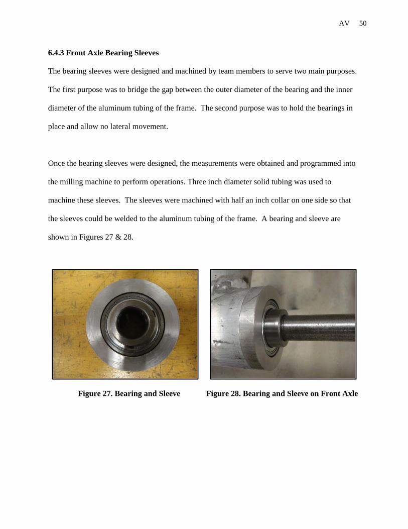
6.4.3 Front Axle Bearing Sleeves
The bearing sleeves were designed and machined by team members to serve two main purposes.
The first purpose was to bridge the gap between the outer diameter of the bearing and the inner
diameter of the aluminum tubing of the frame. The second purpose was to hold the bearings in
place and allow no lateral movement.
Once the bearing sleeves were designed, the measurements were obtained and programmed into
the milling machine to perform operations. Three inch diameter solid tubing was used to
machine these sleeves. The sleeves were machined with half an inch collar on one side so that
the sleeves could be welded to the aluminum tubing of the frame. A bearing and sleeve are
shown in Figures 27 & 28.
Figure 27. Bearing and Sleeve Figure 28. Bearing and Sleeve on Front Axle

51 AV
6.4.4 Assembly
After the completion of the necessary parts for the assembly of the front axle, the next step was
to assemble the front axle to the frame and the wheels. The assembly was done in four different
steps. In the first step, the bearings were placed at four different places on the shaft of the front
axle to achieve maximum strength, and minimum bending and torsion on the shaft front axle.
The placement of the bearings on the shaft of the front axle was decided based on calculations
and FEA analysis performed by team members prior to construction and assembly of the front
axle. In step two adapters were connected to the shaft of the front axle and the wheels of the
vehicle. Step three consisted of mounting the four aluminum sleeves over the bearings. The
final step was to weld the collars of the sleeves to the aluminum tubing to provide strength and
avoid lateral movement. Figure 29 shows the final assembly of the front axle on to the frame
and the wheels.
Figure 29. Front Axle Assembly

52 AV
6.5 Dual Steering System
The vehicles steering system was designed for the purpose of guiding the vehicle in water and on
land. The steering system is controlled by a cable system that runs from the handlebars to the
back wheel along a system of pulleys. The rear wheel for this vehicle is the front end of a
regular bicycle as shown in Figure 30.
Figure 30. Rear Wheel of the Vehicle
There are two handle bars one on each side of the seat. These handle bars are screwed
into the frame vertically. The handle bars are handles of a regular bicycle. A complete loop is
formed by connecting the handle bars to the rear wheel of the vehicle, and connecting the handle
bars to each other. This attachment is done by steel cable. The first cable connects the handle
bar to the rear wheel, the second cable connects the other handle bar and the rear wheel, and the

53 AV
third cable is connects both the handle bars. All these cables are crimped at the ends to keep the
cables in tension. These cables are connected using turn buckles to the bracket that was welded
on the rear wheel fork. The bracket was machined so that the turning radius can be varied. All
these cables run on pulleys that are attached to the frame at three different positions on each side
of the frame. This helps smooth movement of the cable. This type of steering helps the rider to
push either of the handle bars forward causing the rear wheel to turn. This helps the vehicle to
turn easily at larger angles. Figure 31 below shows a simple diagram of the dual steering system.
Figure 31. Dual Steering System

54 AV
The rear wheel can be limited to a specific angle in order to keep the rider safe. For motion in
water, solid circular sheets on both sides of the rear wheel are stitched together. This will act as
a rudder. The solid insert will be made of a double-sided polypropylene. The polypropylene will
be flexible enough tofit around the center of the wheel, while stiff enough to provide sufficient
strength for movement. The most important part of manufacturing the cable steering system is
keeping the correct distance of cable. In order to keep a quick response in the turning of the
vehicle, the cable must be completely tensioned in order to achieve instant motion. Figure 32
shows the solid back wheel for steering on both land and water.
Figure 32. Solid Rear Wheel of the Vehicle
55 AV
6.6 Flotation
The flotation design consists of a foam core with an outer shell of protective material. There are
many different types of foam and many different manufacturers. Michigan Foam, a small local
company comprised of several Calvin College graduates, was willing to spend time with the
team.
After consulting Michigan Foam, we decided polystyrene foam was a good solution with a good
combination of weight and strength at a reasonable price. Polystyrene is an aromatic polymer
made from the aromatic monomer, styrene. Polystyrene is also recyclable, which correlates well
with the design norm of stewardship.
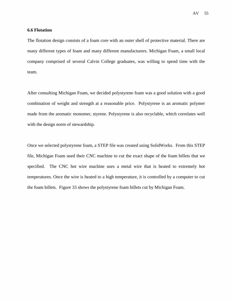
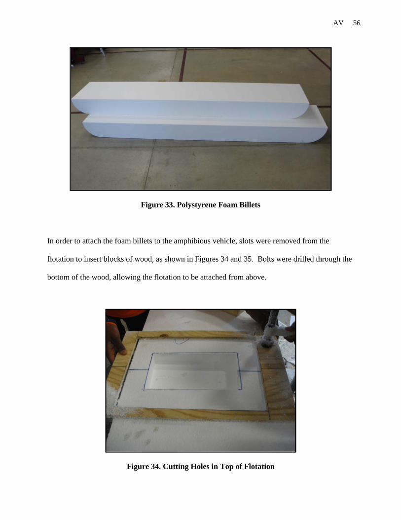
Once we selected polystyrene foam, a STEP file was created using SolidWorks. From this STEP
file, Michigan Foam used their CNC machine to cut the exact shape of the foam billets that we
specified. The CNC hot wire machine uses a metal wire that is heated to extremely hot
temperatures. Once the wire is heated to a high temperature, it is controlled by a computer to cut
the foam billets. Figure 33 shows the polystyrene foam billets cut by Michigan Foam.
56 AV
Figure 33. Polystyrene Foam Billets
In order to attach the foam billets to the amphibious vehicle, slots were removed from the
flotation to insert blocks of wood, as shown in Figures 34 and 35. Bolts were drilled through the
bottom of the wood, allowing the flotation to be attached from above.
Figure 34. Cutting Holes in Top of Flotation

57 AV
Figure 35. Wood Blocks inserted in Flotation
After we received the polystyrene foam billets, an outer shell was needed to give the foam
strength and stiffness. A combination of fiberglass cloth and epoxy resin was selected to achieve
the strength needed, while keeping the flotation relatively light. A drawback of fiberglass cloth
and epoxy resin is the cost.
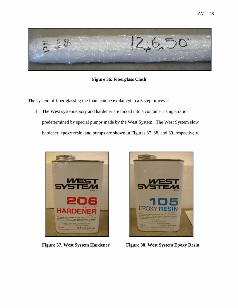
The total amount of cloth needed to wrap the polystyrene foam in two layers was purchased from
on online vendor. The material selected was twelve yards of 6 oz. fiberglass cloth. Figure 36
shows the fiberglass cloth used in the manufacturing process of the flotation. West System
epoxy and hardener were used to affix the fiberglass cloth to the outside of the foam.
58 AV
Figure 36. Fiberglass Cloth
The system of fiber glassing the foam can be explained in a 5 step process:
1. The West system epoxy and hardener are mixed into a container using a ratio
predetermined by special pumps made by the West System. The West System slow
hardener, epoxy resin, and pumps are shown in Figures 37, 38, and 39, respectively.
Figure 37. West System Hardener Figure 38. West System Epoxy Resin

59 AV
Figure 39. West System Pumps
2. The epoxy and hardener is poured onto the fiberglass cloth which is placed in the desired
location on the foam.
3. The epoxy/hardener mixture is then spread out along the surface of the fiberglass in a
process called fairing. It is important to make sure that no air bubbles are present in the
fairing process. It is important to make the epoxy/hardener mixture a correct uniform
thickness. If the mixture is too thin, the fiberglass will have the required strength. If the
mixture is too thick, the fiberglass will become too brittle.
4. Once the epoxy/hardener mixture is spread evenly over the cloth, any stray strands are
cut using a scissors. The ends and corners are kept flat to ensure water-tightness.
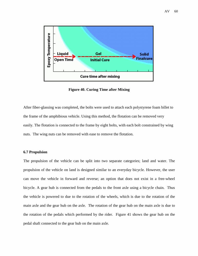
5. The epoxy/hardener is then left to dry for 10-15 hours. The cure process is outlined in
Figure 40.
60 AV
Figure 40. Curing Time after Mixing
After fiber-glassing was completed, the bolts were used to attach each polystyrene foam billet to
the frame of the amphibious vehicle. Using this method, the flotation can be removed very
easily. The flotation is connected to the frame by eight bolts, with each bolt constrained by wing
nuts. The wing nuts can be removed with ease to remove the flotation.
6.7 Propulsion
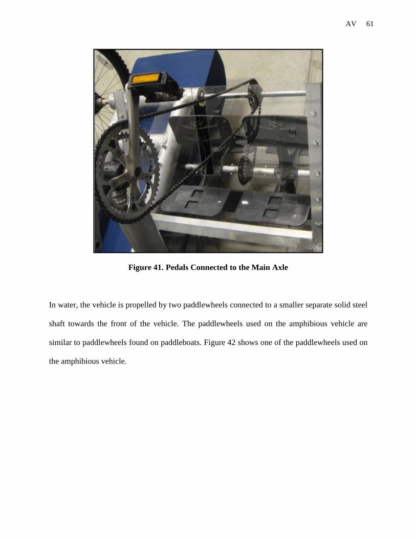
The propulsion of the vehicle can be split into two separate categories; land and water. The
propulsion of the vehicle on land is designed similar to an everyday bicycle. However, the user
can move the vehicle in forward and reverse; an option that does not exist in a free-wheel
bicycle. A gear hub is connected from the pedals to the front axle using a bicycle chain. Thus
the vehicle is powered to due to the rotation of the wheels, which is due to the rotation of the
main axle and the gear hub on the axle. The rotation of the gear hub on the main axle is due to
the rotation of the pedals which performed by the rider. Figure 41 shows the gear hub on the
pedal shaft connected to the gear hub on the main axle.
61 AV
Figure 41. Pedals Connected to the Main Axle
In water, the vehicle is propelled by two paddlewheels connected to a smaller separate solid steel
shaft towards the front of the vehicle. The paddlewheels used on the amphibious vehicle are
similar to paddlewheels found on paddleboats. Figure 42 shows one of the paddlewheels used on
the amphibious vehicle.

62 AV
Figure 42. Amphibious Vehicle Paddle Wheel
The paddle wheel assembly consists of two paddle wheels, four sleeves, and a gear hub on a
solid steel axle. The steel axle is mounted onto the frame with plastic housings that have
bearings within them. The bearings allow the axle to rotate. The gear hub has a chain running
from the main front axle. The four sleeves hold the paddlewheels and gear hub in place and do
not allow lateral movement along the axle. The gear hub and sleeves are welded to the axle
while the paddlewheels are bolted in two directions. The entire paddle wheel assembly is shown
in Figure 43.
Figure 43. Paddle Wheel Assembly
63 AV
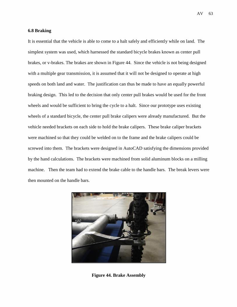
6.8 Braking
It is essential that the vehicle is able to come to a halt safely and efficiently while on land. The
simplest system was used, which harnessed the standard bicycle brakes known as center pull
brakes, or v-brakes. The brakes are shown in Figure 44. Since the vehicle is not being designed
with a multiple gear transmission, it is assumed that it will not be designed to operate at high
speeds on both land and water. The justification can thus be made to have an equally powerful
braking design. This led to the decision that only center pull brakes would be used for the front
wheels and would be sufficient to bring the cycle to a halt. Since our prototype uses existing
wheels of a standard bicycle, the center pull brake calipers were already manufactured. But the
vehicle needed brackets on each side to hold the brake calipers. These brake caliper brackets
were machined so that they could be welded on to the frame and the brake calipers could be
screwed into them. The brackets were designed in AutoCAD satisfying the dimensions provided
by the hand calculations. The brackets were machined from solid aluminum blocks on a milling
machine. Then the team had to extend the brake cable to the handle bars. The break levers were
then mounted on the handle bars.
Figure 44. Brake Assembly

64 AV
6.9 Seating
The first step in the seat design involved preparing the seat fabric. Both the base and the back
rest of the seat had ply wood sheets screwed into the frame to provide support for the rider. Then
two layers of the foam was placed on the plywood sheets and wrapped in cloth that could
withstand exterior conditions. This provided comfort to the rider. The square tubing was then
cut to appropriate lengths to form our set architecture and then notched the inside surfaces of
each member. This notch allows for the cloth to be slid into it. Subsequently, the 0.25 diameter
rod, cut to its respective length, is slid into that loop of fabric and the inside of the square tubing
allowing for a fixed, joined cloth and frame design. The seat bottom square tube members have
machined holes at equal distances apart, on their outside surfaces, to allow for pins to be placed
in them for adjustable seating. Once this seat construction was accomplished, steps were needed
to fix this assembly to the vehicle frame. Since it is imperative that the seat be out of the water,
the use of four five inch length pieces of three inch diameter hollow aluminum tubing was used.
These pieces served dual purposes. They were used to elevate the seat an exaggerated height
above the water line. In addition, they were also used as a track for the seat assembly to move
back on forth on, giving the vehicle customizable qualities to serve a rider of any height. For the
manufacturing of the four “seat-elevator” notches or the seat tracks were machined into the end
opposite of the fish mouth. Finally a pin hole was machined into the outside surfaces of each
“seat-elevator” to allow a pin to slide through it into the seat assembly.

65 AV
Figure 45: Seat Assembly
7. Testing
7.1 General Attributes
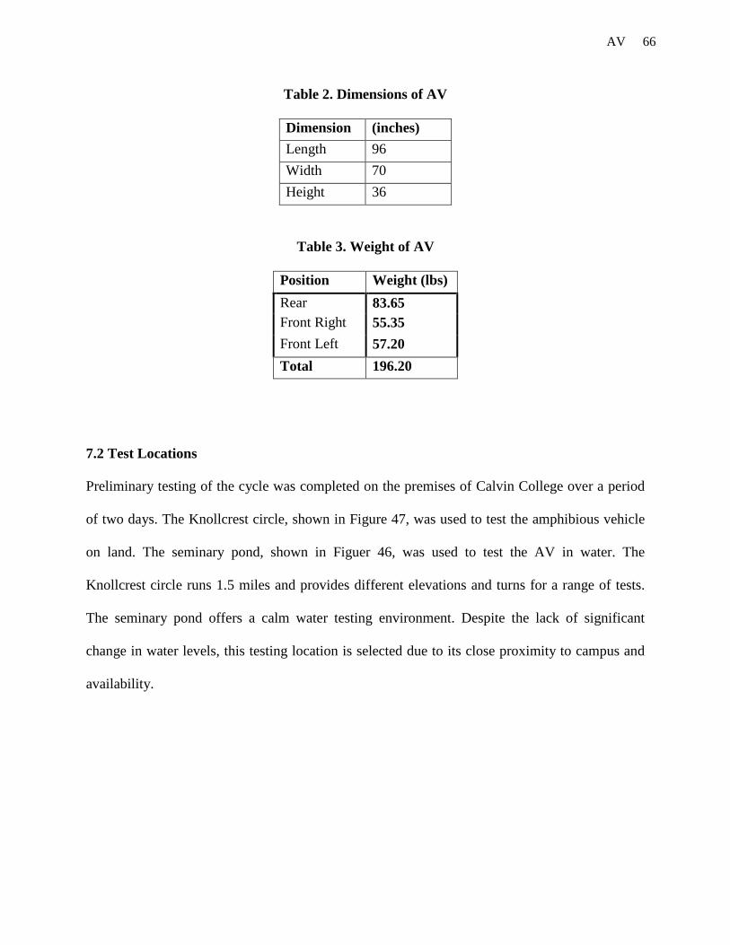
Final dimensions and weights were taken after the cycle had been completed. Dimensions were
measured using a tape measure, while a digital scale was used to measure the load on each
wheel. The summation at each wheel gives the total weight of the cycle. The dimensions and
weights of the completed vehicle are shown in Tables 2 and 3.
66 AV
Table 2. Dimensions of AV
Dimension (inches) Length 96 Width 70 Height 36
Table 3. Weight of AV
Position Weight (lbs) Rear 83.65 Front Right 55.35 Front Left 57.20 Total 196.20
7.2 Test Locations
Preliminary testing of the cycle was completed on the premises of Calvin College over a period
of two days. The Knollcrest circle, shown in Figure 47, was used to test the amphibious vehicle
on land. The seminary pond, shown in Figuer 46, was used to test the AV in water. The
Knollcrest circle runs 1.5 miles and provides different elevations and turns for a range of tests.
The seminary pond offers a calm water testing environment. Despite the lack of significant
change in water levels, this testing location is selected due to its close proximity to campus and
availability.

67 AV
Figure 46. Water Test Site – Seminary Pond, Calvin College
Figure 47. Land Test Site – Knollcrest Circle, Calvin College
68 AV
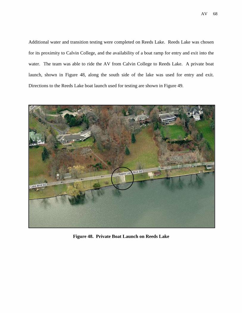
Additional water and transition testing were completed on Reeds Lake. Reeds Lake was chosen
for its proximity to Calvin College, and the availability of a boat ramp for entry and exit into the
water. The team was able to ride the AV from Calvin College to Reeds Lake. A private boat
launch, shown in Figure 48, along the south side of the lake was used for entry and exit.
Directions to the Reeds Lake boat launch used for testing are shown in Figure 49.
Figure 48. Private Boat Launch on Reeds Lake

69 AV
Figure 49. Map to Reeds Lake Boat Launch
70 AV
7.3 Preliminary Testing
Preliminary testing of the vehicle was carried out in the first week of May and comprised of
testing procedures with the aim of assessing the general safety of the cycle on land and the
buoyancy of the vehicle on water. First, the rider’s safety is ensured by checking for any
interference between the rider and any moving parts on the vehicle. The potentially hazardous
areas of the vehicle that comprise of the steering system under the seat, the pedals and paddles
are initially tested at low speeds and then at higher speeds to ensure safety.
On land, the vehicle was driven over a range of speeds to test for stability in a stationary position
and in motion. During motion, the drive train and frame was tested to prove its capacity for
different weights and speeds. The clearance provided below the flotation was also verified by
riding the AV over the few speed bumps located at different location on the Knollcrest circle. On
water, the buoyancy of the vehicle is tested by determining the water line for different weights.
Using this method, the correct mounting height for the paddle wheel is determined. The paddle
wheel attachment uses screws that provided marginal room for adjustment in the height of the
paddle wheel axle. The depth to which the paddles are submerged during operation is key to the
efficiency of the vehicle as well.
7.4 Testing on Land
7.4.1 Stability on Land
The vehicle inherently is stable on land due to the tricycle arrangement and recumbent riding
position giving a low center of gravity. The brakes can be applied in order to keep the vehicle
steady when transporting. While in a seated position, it is unlikely that the rider would tip it over

71 AV
around a corner by leaning from side to side and even when cornering at speed the cycle is very
stable.
7.4.2 Maneuverability on Land
The maneuverability of the vehicle on land is expected to be good due to the effective steering
mechanism, reverse option, stability and comfortable seating position. Although the cycle is
heavier than a standard recumbent or an upright bike, the gearing ratio provides the user with a
comfortable transition from stationary. On land, the vehicle is driven by one front wheel while
the other coasts and the unnecessary effects of this are minimal. The cycle does not pull to either
side and there were no problems encountered with traction. The turning radius of the cycle is
essentially 0 degrees. This is achieved by turning the rear wheel to its outermost point and slowly
pedaling in a circle. The inclusion of the reverse option provides the rider with the freedom to
make a three point turn without leaving the vehicle.
7.4.3 Drive on Land
Tests were conducted to evaluate the effectiveness of the transmission, as attaining a sufficiently
high speed is necessary in order for a cycle to be practical in getting from point A to point B.
Speed tests were conducted to estimate a maximum speed for the vehicle in a straight path.
Measurement was conducted by setting out a tape measure to form a 100ft track along a level
section of concrete parking lot by the engineering building. The cycle was accelerated to a
comfortable speed before starting the measurement. The cycle completed the track 3 times with
an average speed of 12.73mph, and a top speed of 14.04mph.
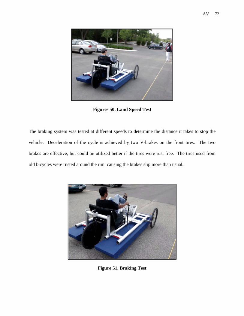
72 AV
Figures 50. Land Speed Test
The braking system was tested at different speeds to determine the distance it takes to stop the
vehicle. Deceleration of the cycle is achieved by two V-brakes on the front tires. The two
brakes are effective, but could be utilized better if the tires were rust free. The tires used from
old bicycles were rusted around the rim, causing the brakes slip more than usual.
Figure 51. Braking Test

73 AV
7.5 Testing on Water
7.5.1 Buoyancy on Water
Testing of the Amphibious Vehicle on water verified the calculations for the buoyancy of the
vehicle and the float line to maximize the efficiency of the paddle wheel. The calculations were
used to calculate the volume of flotation required and to provide two-thirds the height of foam
for the float line. The cycle sat level in the water, with the water line unchanged from the that in
the preliminary buoyancy test. The result is that the paddlewheel is positioned in its intended
position relative to the water, such that each blade is just fully submerged at bottom center and
the paddlewheel’s efficiency is maximized. Additional weight, reaching 325lbs, was added to
the vehicle to raise the water line relative to the flotation. The stability of the cycle is decreased;
however from the seated position the cycle is still sufficiently stable for comfortable operation.
The heightened water line results in the paddlewheel sitting deeper in the water than intended,
therefore efficiency is decreased and propulsion is not as effective.
Figure 52. Buoyancy Testing
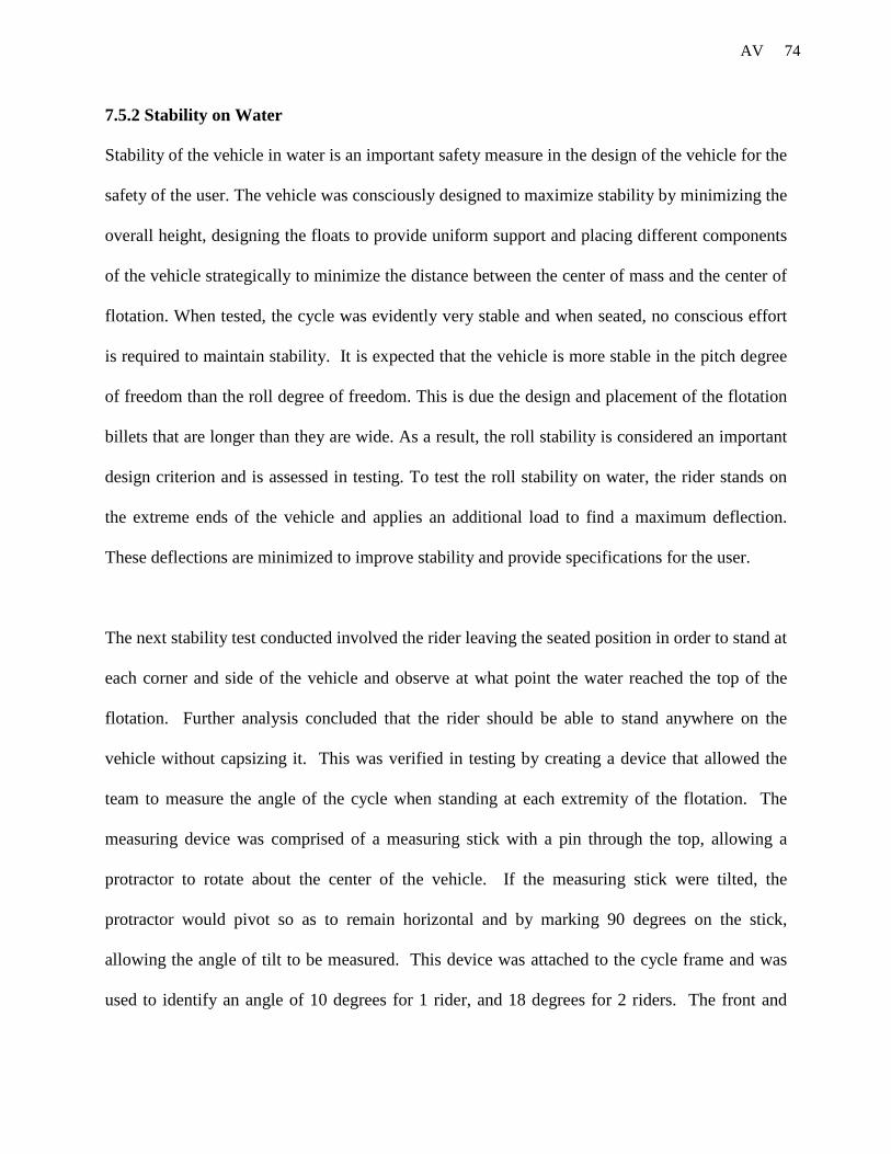
74 AV
7.5.2 Stability on Water
Stability of the vehicle in water is an important safety measure in the design of the vehicle for the
safety of the user. The vehicle was consciously designed to maximize stability by minimizing the
overall height, designing the floats to provide uniform support and placing different components
of the vehicle strategically to minimize the distance between the center of mass and the center of
flotation. When tested, the cycle was evidently very stable and when seated, no conscious effort
is required to maintain stability. It is expected that the vehicle is more stable in the pitch degree
of freedom than the roll degree of freedom. This is due the design and placement of the flotation
billets that are longer than they are wide. As a result, the roll stability is considered an important
design criterion and is assessed in testing. To test the roll stability on water, the rider stands on
the extreme ends of the vehicle and applies an additional load to find a maximum deflection.
These deflections are minimized to improve stability and provide specifications for the user.
The next stability test conducted involved the rider leaving the seated position in order to stand at
each corner and side of the vehicle and observe at what point the water reached the top of the
flotation. Further analysis concluded that the rider should be able to stand anywhere on the
vehicle without capsizing it. This was verified in testing by creating a device that allowed the
team to measure the angle of the cycle when standing at each extremity of the flotation. The
measuring device was comprised of a measuring stick with a pin through the top, allowing a
protractor to rotate about the center of the vehicle. If the measuring stick were tilted, the
protractor would pivot so as to remain horizontal and by marking 90 degrees on the stick,
allowing the angle of tilt to be measured. This device was attached to the cycle frame and was
used to identify an angle of 10 degrees for 1 rider, and 18 degrees for 2 riders. The front and

75 AV
back heel angles for a single rider were found to be 8 degrees and 5 degrees, respectively. The
pitch stability was only tested for a single rider because the stability in this direction was
evidently more than adequate for intended use and testing to the limits of stability would have
required large forces on the cycle. This would have posed an unnecessary risk of damage to the
cycle as well as being unsafe for the individuals.
Figure 53. Stability Test 1
Figure 54. Stability Test 2
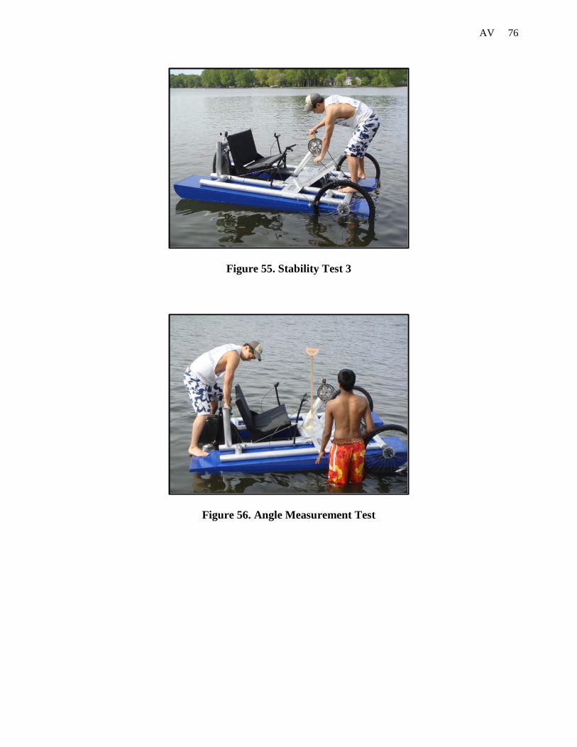
76 AV
Figure 55. Stability Test 3
Figure 56. Angle Measurement Test

77 AV
7.5.3 Maneuverability on Water
Control on water was excellent and maneuvering the cycle using the rear wheel as a rudder was
easy and effective. Operating the paddlewheel in reverse, though not as effective as in forward
drive, allowed the cycle to travel backwards in the water and perform three-point turns. Each
member of the group, along with other students, were able to take control of the cycle on water
with no instruction, demonstrating that the operation of the cycle is intuitive.
7.5.4 Propulsion on Water
Initial tests indicated that the paddlewheel was indeed effective and little pedaling effort was
needed to accelerate from stationary to quickly reach a steady speed. It was found that pedaling
faster would not increase this speed by a significant amount because the paddlewheel would spin
fast, effectively clearing out the water to the rear of the cycle.
The average speed was calculated using multiple tests with and against the current and wind.
The test runs were measured over a distance of 100ft. Results were recorded by timing each run
using a stopwatch. The average speed of the amphibious vehicle in water is calculated to be
2.13mph, with a top speed of 2.26 mph.

78 AV
Figure 57. Speed Test Routes
7.6 Transition Tests
The ability of the vehicle to make a transition between land and water will be tested using a
private boat ramp after permission from a resident on Reeds Lake. Into water, the vehicle will be
allowed to free wheel forward at reduced speeds to minimize the impact on the flotation. This is
done by picking a ramp with a minimal slope and using the necessary amount of braking power.
The paddle wheels will then be used to move the vehicle away from the ramp into water. The
transition back on to land is done similarly with the front wheel exiting the water first. The
vehicle is powered by paddle wheels till the front wheel catch land. Since the vehicle is front–
wheel drive, the vehicle is designed so that the front wheels provide the necessary power to exit
the pond.
100 ft
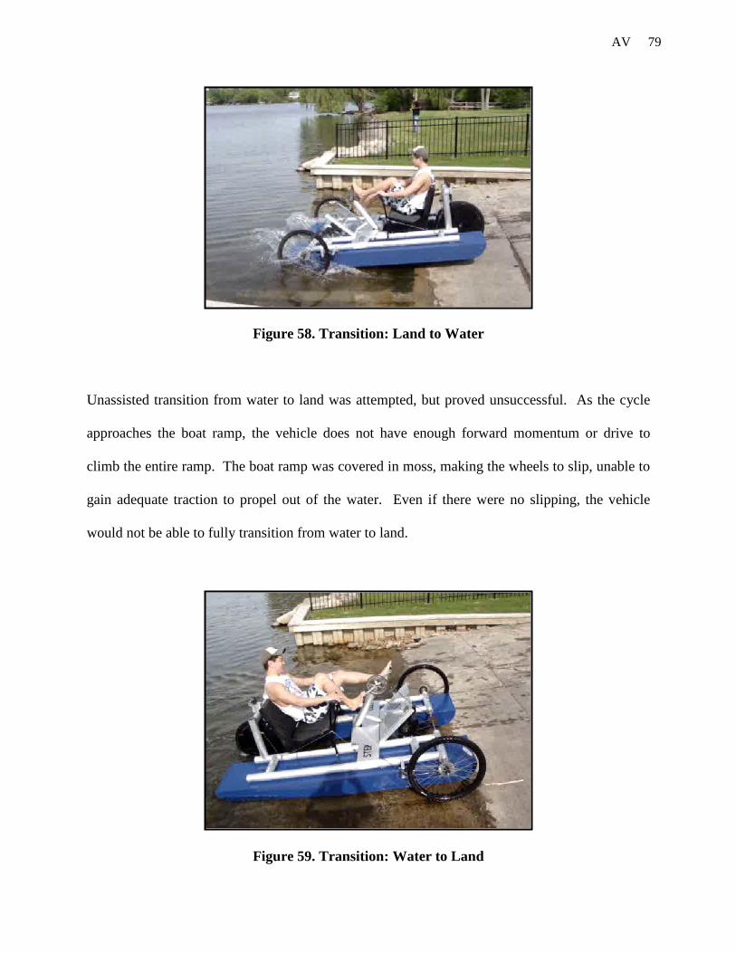
79 AV
Figure 58. Transition: Land to Water
Unassisted transition from water to land was attempted, but proved unsuccessful. As the cycle
approaches the boat ramp, the vehicle does not have enough forward momentum or drive to
climb the entire ramp. The boat ramp was covered in moss, making the wheels to slip, unable to
gain adequate traction to propel out of the water. Even if there were no slipping, the vehicle
would not be able to fully transition from water to land.
Figure 59. Transition: Water to Land

80 AV
7.7 Safety
Testing was done to find possible risks to determine the proper precautions when riding the
vehicle on land and water. Safety considerations are shown in Table 4.
Table 4. Safety Considerations
Risk
Lik
elih
ood
/ 5
Con
sequ
ence
/ 5
Precaution
Cycle could sink 3 3 Keep cycle close to the bank and on a rope while buoyancy is tested. Ensure rider can swim.
Rider could fall off cycle 2 2 Rider must always wear a buoyancy aid. Ensure rider can swim.
Rider could get their foot stuck in the chain
1 2 Make sure to enclose the chain to prevent the rider from sticking their foot anywhere near it.
Cycle could be swept off with the current
1 3 Test only at high or low tide when currents are low. Keep cycle on a rope until the propulsion is proved effective. Always carry an oar. Throw a rope to the rider to recover the cycle and rider. Have someone supervise at all times.
The transmission and propulsion could fail
2 2 Carry an oar on the vehicle.
The rider could pick up an infection from the water
1 2 Cover up all wounds before riding the cycle to prevent exposure to infection. Carry a first aid kit.
A weld could snap, injuring the rider
1 3 Throw a rope to the rider to pull him to safety. Have a supervisor at all times. Wear a buoyancy device and helmet.
Rider could flip the cycle over and not be able to get back on
2 2 Test buoyancy of cycle close to land before moving into middle of river or lake. Wear a buoyancy device. Ensure someone is supervising at all times. Ensure rider can swim.
Steering cable could break, causing the rider to go out of control
2 2 Make sure the brakes work adequately. Include a parking brake for additional safety.
Rider could turn too fast, causing the vehicle to flip
1 3 Limit the steering to a specific angle of turning to prevent the vehicle from getting out of control.
81 AV
While cycling on land, the paddlewheel is not disengaged, leading to potential risk of injury due
to moving parts. The splashguard covers the side closest to the rider, protecting the rider from
splashing but also acting a safety guard. As a result, the rider cannot reach the paddlewheel from
the seated position. It is not possible for the paddles to strike anyone or anything while cycling
in forward or reverse. The paddlewheel can only hit the ground if there were some sort of
uneven land or large rocks. The splashguard could be extended around all ends to ensure better
safety for the rider. In the unlikely event that the paddle wheel axle becomes detached, it would
be prevented from leaving the cycle at a velocity by the splashguard. The rider has good
visibility forwards while in the riding position and is able to adjust position in the seat slightly
such that there is a clear view to the rear of the cycle, which is not obstructed by anything.
Reflectors and safety stickers were used for additional safety if driving at dusk or night.
8. Recommendations
8.1 Frame
The frame was very effective based on the resources and time available for the team. But the
aluminum alloy used to build the frame showed signs of degradation in the mechanical properties
of the structure, particularly around the weld zones.
The tubing is 3 inches in diameter and has a thickness of one-eighth of an inch. These
dimensions of the tubing could be reduced. The diameter of the tubing could be reduced to 2
inches having the same thickness. This would eliminate some parts manufactured for the drive
train and propulsion of the vehicle. Also it would decrease the weight. The reason the team had
to use this specific tubing was because the material was donated. In addition, the welds could be

82 AV
improved. The current welds are all MIG welds. To improve the quality of welds and the looks
of the welds, TIG welding could be used. Welding gets rid of the benefits of any pre-welding
heat treatment and also creates a large amount of residual stress, which can lead to deformation.
Heat treatment after welding helps restoring the temper to the structure and reducing residual
stresses such that deformation is reduced. For the prototype, the team believes that aluminum is
a good material since it has high strength to weight ratio, but other options to use would include
polymers or composites for the frame.
The current design of the frame is very strong and effective but looks very bulky and industrial.
This is a lot of room for improvement in the design to produce a lighter, smaller vehicle while
maintaining its strength. Certain sections of the frame could be removed because they add more
weight, widening the frame and are not very necessary. This would reduce the size of the frame
and the overall vehicle.
8.2 Flotation
The flotation was built of polystyrene foam and wrapped in fiber cloth and layers of epoxy.
These materials can be recycled, but are not very environmental friendly. Those materials could
be replaced with more environmental friendly materials. Since these floats will be partially
immersed in water it is not safe if the water gets contaminated by any chemicals.
The flotation performed extremely well and channeled the water to the ruder to help turn easily
in water. It was able to hold two riders on the vehicle and keeping the vehicle afloat. Similar to
83 AV
the frame, the size of the flotation could be reduced. Decreasing the size of the floats reduces the
size of the vehicle, since the floats are on the outside of the inner section of the frame.
For manufacturing, smoother layers of fiber cloth wrapping with epoxy could be done. Due to
budget constraint the team was unable to purchase higher end tools, more fiber cloth, epoxy, and
hardener for the process of wrapping the flotation in fiber cloth and epoxy.
8.3 Chain
The chain connecting the main axle to the pedals, and the chain connecting the paddle wheel
axle and the main axle will come in contact with water. Currently the team uses a regular
bicycle chain for both these chain lines. This could be improved by changing the material of the
chain lines to nylon chains, and nickel plated chains. This eliminates grease from mixing in the
water. Since the team wanted to use as many bicycle parts as possible, these features were not
implemented.
8.4 Propulsion
Propulsion both on land and water work very efficiently. But improvements in the design can be
possible. Currently the amphibious vehicle has a fixed gear both on land and water. Also the
paddle wheel axle assembly is connected to the main axle which is in turn connected to the
pedals. Hence the paddle wheels rotate even the vehicle is moving on land. These two aspects
of propulsion can be improved. The first aspect can be improved by incorporating an idler that
could provide tension both in forward and reverse motion and provide the option to change
gears. This will decrease the work done by the rider currently. These idlers and gear hubs are
84 AV
available in the market but are very expensive and do not fit within our budget. The rider could
then smoothly ride up-hill without too much effort. Also a better design could be developed to
make the paddle wheel assembly independent of the main axle. This will decrease the
probability of the paddles being damaged due to contact with bumps or rocks. Also this will
reduce the input work by the rider to move the vehicle.
The initial design for propulsion in water was to mount the paddle wheel assembly on the frame.
Since the floats worked too well and the vehicle floats very high, the paddles barley came in
contact with water providing minimal propulsion in water. The paddle wheel assembly was
moved from the top of the frame to the bottom of the frame so that the paddle wheels were
submerged in water. This caused for the paddles to have a clearance of one and a half inches
from the road, posing a risk for the paddle wheels to be damaged when hit by rocks or bumps.
8.5 Steering
As explained in the manufacturing section, a cable linkage was used to steer the vehicle. This
works very well and exceeded our expectations. Since currently we do not limit the turning
radius of the vehicle, the amphibious vehicle has almost a zero degree turning radius. But the
cable linkage could be improved by purchasing more efficient pulley systems and better cable.
This would ease the sliding movement of the cable on the pulleys. A better cable would be
stronger and not produce noise while sliding to produce turning of the vehicle. Limiters could be
implemented to prevent the user from turning the wheel sharply when going at fast speeds.

85 AV
8.6 Seating
The weight of the seating is high compared to the weight of the overall vehicle, and could be
reduced. The base and back support of the seat are made of plywood sheets which could be
replaced with polymer sheet or honey-comb structured sheet. Since the plywood sheets were
readily available the team decided to use it. By reducing the weight of the seat, the vehicle
weight and flotation size could be reduced. The team built the seat so that it can move front and
back and allow a rider of any size to ride the vehicle, but the seat could be placed at a more
inclined angle providing more comfort and recline for the rider.
8.7 Braking
Braking exists on the front end of the amphibious vehicle. Both wheels on the front end of the
vehicle use brakes that exist on regular bikes. Both these brakes are connected to the handle on
their respective sides. This works effectively and brings the vehicle to a stop but the braking can
be improved. Another brake could be added on the rear wheel. This could also be a regular
bicycle front brake since the rear of the vehicle is the front fork of a regular bike. This would
decrease the current breaking distance of the vehicle and make it more effective. A parking
brake would also help provide stability when users are getting on and off the vehicle or when
parking the vehicle on an incline.

86 AV
9. Conclusion
The goal of this project is to design and prototype an amphibious vehicle for the purpose of
recreation in developed and some developing countries. The budget allotted for the project is
$749.89 and a time period of nine months, September 2009 – May 2010. Over the past two
semesters, we have successfully managed a project where we designed and built a prototype that
met our requirements. The spring semester mainly involved machining and assembling the parts
of the vehicle that were selected and designed in the fall semester. Throughout the course of the
project, the team members have learned valuable lessons on working together to design and
manufacture a finished product. The time spent in the shop gave us hands on experience that
complimented what we had learned in the classroom. Finally, the team members hope to use
their Calvin engineering education at greater levels in the future.
10. Evaluation
Operating effectively as a whole group, consisting of five members, was a challenge that had to
be overcome during the design, build, and test of the Amphibious Vehicle. Organization proved
paramount to ensure that each member always had something they could work on and to prevent
any details from being overlooked. Although, during the initial stages of the design, progress
was often hindered by five people trying to make their opinions heard, the group soon settled
down and a leader emerged. The formation of subgroups proved important in giving each
member a purpose, allowing less important decisions to be made faster and more important
decisions to be put to the group in the main meetings.
87 AV
The frequent group meetings prevented progress from coming to a halt, inspiring members to
present their findings and ensuring all of the subgroups parts were compatible. As the project
progressed, the subgroups became less defined as everyone pooled their strengths and people
were eager to help when a new task or problem emerged. A similar format was implemented
during the manufacture of the cycle, with tasks being divided up for pairs of workers and one
person overseeing the build. Having five pairs of hands around one vehicle proved not to be a
problem as the frame, flotation, and paddlewheel were worked on separately and only brought
together once complete.
As a whole, the group worked as an effective team throughout, as proved by the successful
design and manufacture of a working Amphibious Vehicle.
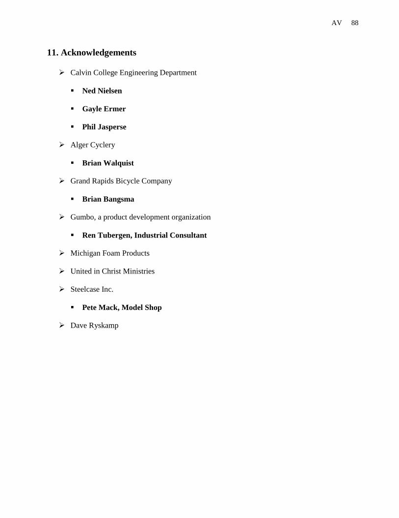
88 AV
11. Acknowledgements
Calvin College Engineering Department
Ned Nielsen
Gayle Ermer
Phil Jasperse
Alger Cyclery
Brian Walquist
Grand Rapids Bicycle Company
Brian Bangsma
Gumbo, a product development organization
Ren Tubergen, Industrial Consultant
Michigan Foam Products
United in Christ Ministries
Steelcase Inc.
Pete Mack, Model Shop
Dave Ryskamp
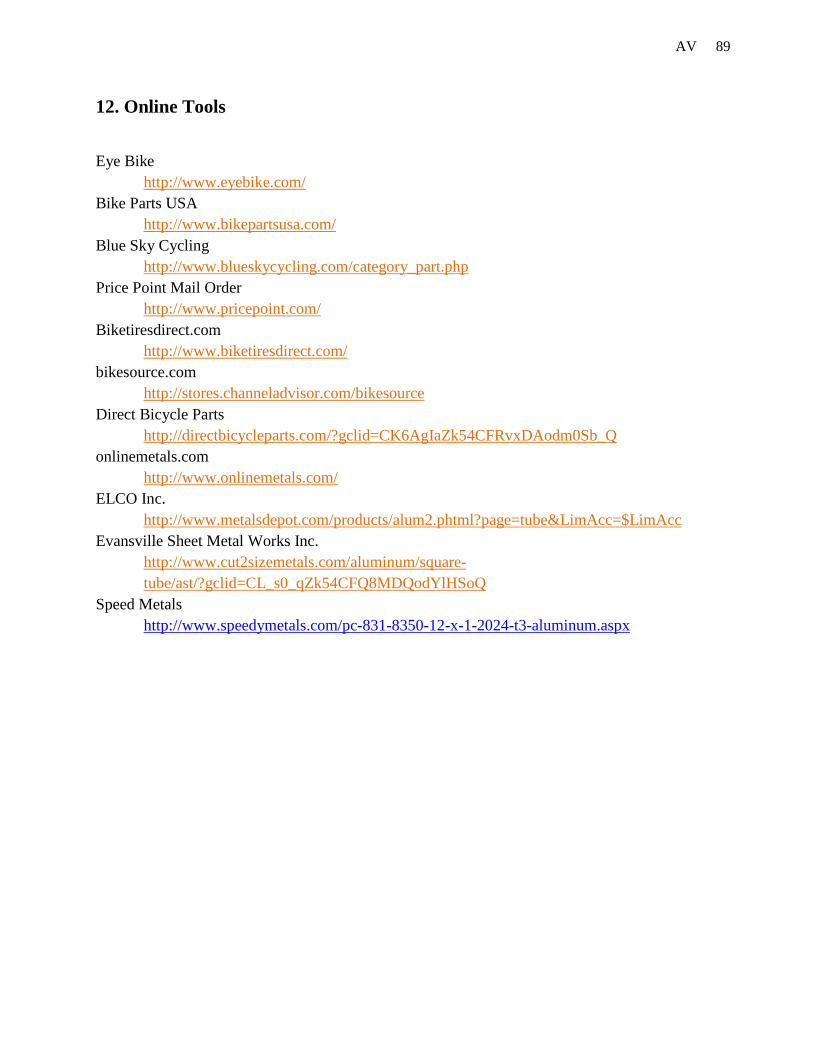
89 AV
12. Online Tools
Eye Bike http://www.eyebike.com/
Bike Parts USA http://www.bikepartsusa.com/
Blue Sky Cycling http://www.blueskycycling.com/category_part.php
Price Point Mail Order http://www.pricepoint.com/
Biketiresdirect.com http://www.biketiresdirect.com/
bikesource.com http://stores.channeladvisor.com/bikesource
Direct Bicycle Parts http://directbicycleparts.com/?gclid=CK6AgIaZk54CFRvxDAodm0Sb_Q
onlinemetals.com http://www.onlinemetals.com/
ELCO Inc. http://www.metalsdepot.com/products/alum2.phtml?page=tube&LimAcc=$LimAcc
Evansville Sheet Metal Works Inc. http://www.cut2sizemetals.com/aluminum/square-tube/ast/?gclid=CL_s0_qZk54CFQ8MDQodYlHSoQ
Speed Metals http://www.speedymetals.com/pc-831-8350-12-x-1-2024-t3-aluminum.aspx

90 AV
Appendix A: Project Schedule
Schedule as of March 3, 2010
Activity Deadline
FEA March 5, 2010
Basic Frame March 14, 2010
Front Axle April 19, 2010
Paddle Wheel & Floatation April 9, 2010
Spring Break Mar 19-26, 2010
Seating, Steering, Braking & Accessories April 19, 2010
Final Prototype April 21, 2010
Testing April 23, 2010
Final Report Draft April 27, 2010
Schedule as of April 3, 2010
Activity Deadline
Front Axle Assembly April 19, 2010
Paddle Wheel & Floatation April 16, 2010
Seating, Steering, Braking & Accessories April 25, 2010
Final Prototype April 27, 2010
Testing April 28, 2010
Design Changes and Verification May 3, 2010
Final Report Draft April 28, 2010
Final Report May 12, 2010

91 AV
Appendix B. Budget
Budget of the Prototype Amphibious Vehicle
List of Parts Number of Parts
Cost of Parts (New )
Cost of Parts from Old Bikes
Total Costs
Actual Costs
Wheels 3 $ 0.00 $ 0.00 free
Bearings 3 $ 50.00 $ 150.00 $ 37.34
Tires 3 $ 0.00 $ 0.00 free
Bike 2 $ 10.00 $ 20.00
Axle Taps 2 $ 26.71
Tubes 2 $ 0.00 $ 0.00 free
Pedals 2 $ 0.00 $ 0.00 free
Gearing System 2 $ 0.00 $ 0.00 free
Brake Calipers 3 $ 0.00 $ 0.00 free
Brake Handles 2 $ 0.00 $ 0.00 free
Bicycle Chain (ft) 10 $ 15.00 $ 15.00 free
Seating Material 1 $ 25.00 $ 25.00 $ 48.14
Flotation (3 lb polystyrene) 2 $ 40.00 $ 80.00 $ 75.00
Injection Foam 1 $ 20.00 $ 20.00
Fiber glassing 1 $ 50.00 $ 50.00 $ 278.91
Paddle Wheel 2 $ 25.00 $ 50.00 $ 100.00
Frame (6061 alum) 1 $ 80.00 $ 80.00 free
Break Cable (ft) 20 $ 15.00 $ 15.00 $ 22.57
Solid Wheel (Rudder) 1 $ 10.00 $ 10.00 $ 23.13
Paint 1 $ 35.00 $ 35.00 $ 77.46
Life Jackets 1 $ 10.00 $ 10.00 $ -
Hardware 1 $ 50.00 $ 50.00 $ 39.63
Total Cost $ 590.00 $ 748.89
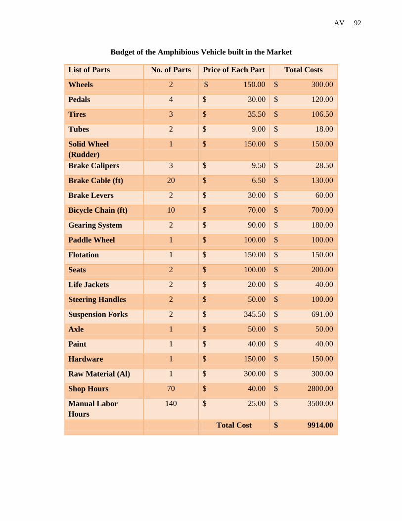
92 AV
Budget of the Amphibious Vehicle built in the Market
List of Parts No. of Parts Price of Each Part Total Costs
Wheels 2 $ 150.00 $ 300.00
Pedals 4 $ 30.00 $ 120.00
Tires 3 $ 35.50 $ 106.50
Tubes 2 $ 9.00 $ 18.00
Solid Wheel (Rudder)
1 $ 150.00 $ 150.00
Brake Calipers 3 $ 9.50 $ 28.50
Brake Cable (ft) 20 $ 6.50 $ 130.00
Brake Levers 2 $ 30.00 $ 60.00
Bicycle Chain (ft) 10 $ 70.00 $ 700.00
Gearing System 2 $ 90.00 $ 180.00
Paddle Wheel 1 $ 100.00 $ 100.00
Flotation 1 $ 150.00 $ 150.00
Seats 2 $ 100.00 $ 200.00
Life Jackets 2 $ 20.00 $ 40.00
Steering Handles 2 $ 50.00 $ 100.00
Suspension Forks 2 $ 345.50 $ 691.00
Axle 1 $ 50.00 $ 50.00
Paint 1 $ 40.00 $ 40.00
Hardware 1 $ 150.00 $ 150.00
Raw Material (Al) 1 $ 300.00 $ 300.00
Shop Hours 70 $ 40.00 $ 2800.00
Manual Labor Hours
140 $ 25.00 $ 3500.00
Total Cost $ 9914.00

93 AV
Appendix C: Decision Matrices Material Selection for Frame
Flotation Selection
Value Alternatives for Materials
Steel Aluminum Titanium Carbon
Alloy Fiber
Strength 5 4 3 4 5
Weight 5 2 5 3 4
Stiffness 1 5 3 2 4
Corrosion Resistant 3 2 3 5 4
Durability 3 5 3 4 2
Price 4 4 5 2 3
Elongation 1 5 4 4 2
Manufacturability 4 5 4 3 2
Reparability 3 5 4 3 2
Totals 112 113 97 95
Physical Properties Value Alternatives for Materials
Polyurethane Polyethylene Syntactic Buoyant Detachable
Foam Frame Canoes
Weight 4 4 3 5 3 2
Buoyancy 5 3 4 4 1 5
Durability 3 2 3 3 5 4
Price 5 3 2 1 3 1
Size 4 3 4 4 3 1
Availability 2 5 4 3 4 4
Reparability 2 2 2 2 3 4
Totals 78 79 80 73 70

94 AV
Appendix D: Calculations
Buoyancy Calculations
Material: Expanded Polystyrene (EPS) Flotation Foam
Density (Water)
Temperature Density ( C ) (kg/cu.m) (lb/cu.ft)
-10 998.11 62.31 0 999.83 62.42 4 999.97 62.43 10 999.70 62.41 15 999.10 62.37 20 998.20 62.32 22 997.77 62.29 25 997.04 62.24 30 995.65 62.16 Average
Average Density 998.37 62.33
Flotation Foam (Expanded Polystyrene)
Properties
Type Density Flexural Strength
Water Absorption
Compressive Strength
(lb/cu.ft) (psi) % (psi)
XI 0.7 10 4.0 5 I 0.9 25 3.0 10 VIII 1.15 30 1.0 13 II 1.35 40 3.0 15 IX 1.8 50 2.0 25 III 2.7 90 4.0 50
Dimensions Number 2
Length 96 in. Width 18 in. Height 7 in.

95 AV
Calculations
Volume (1 Billet) 12096
Total Volume 24192 cu. in
14.00 cu.ft
Density 1 lbm/cu.ft
Mass (Billets) 14.00 lbm
Weight
Rider 250 lbf Vehicle 139.00 lbf Total 389 lbf
Margin Factor 1.5
Overall Weight 583.5 lbf
Theoretical Estimates
Estimate Load Capacity 60 lbm/cu.ft ( Per Billet)
Flotation Immersed 16162.81 cu.in CHANGE
IMMERSED HEIGHT!
(volume under water) 9.35 cu.ft
Theoretical Capacity 561.21 lbf
Buoyancy Calculations
Density(Flotation) 1 lbm/cu.ft
Density(Water) 62.33 lbm/cu.ft
acc.. due to gravity 32.2 ft/s^2
Overall Weight 583.50 lbf Buoyant Force 582.97 lbf
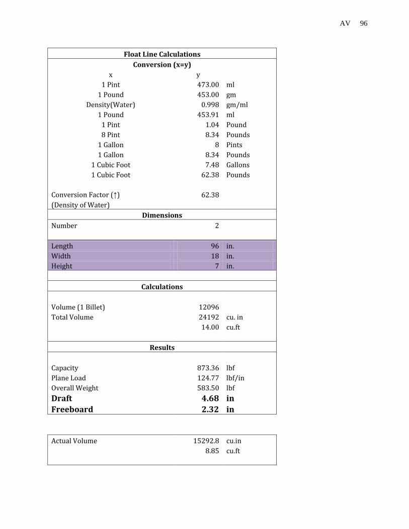
96 AV
Float Line Calculations Conversion (x=y) x y 1 Pint 473.00 ml 1 Pound 453.00 gm Density(Water) 0.998 gm/ml 1 Pound 453.91 ml 1 Pint 1.04 Pound 8 Pint 8.34 Pounds 1 Gallon 8 Pints 1 Gallon 8.34 Pounds 1 Cubic Foot 7.48 Gallons 1 Cubic Foot 62.38 Pounds
Conversion Factor (↑) 62.38 (Density of Water)
Dimensions Number 2
Length 96 in. Width 18 in. Height 7 in.
Calculations
Volume (1 Billet) 12096 Total Volume 24192 cu. in 14.00 cu.ft
Results
Capacity 873.36 lbf Plane Load 124.77 lbf/in Overall Weight 583.50 lbf Draft 4.68 in Freeboard 2.32 in
Actual Volume 15292.8 cu.in
8.85 cu.ft

97 AV
Method - 2
Length 180 15.00 ft Width 18 1.50 ft Height (Draft) 0.42 ft
4.99 in
Weight 583.5 lbf Density 62.4 lbm/ft^3