Automating Out the Skills Gap with PowerMill - cloudfront.net
22
Page 1 MFG227296 Automating Out the Skills Gap with PowerMill Stan Akers NexGenCAM Description Everyone nationwide is feeling the skills gap. With the increasing market demands, the lack of skilled labor looming over manufacturing is driving the need to automate processes in all company sizes and market segments. Many CAM products offer solutions that come close; however, they leave your team with a learning process that’s more of a setback than a solution. Often the tools need a higher skill level to operate leaving out new talent or are not customizable enough to support your goals. Let us show you how technologies within Autodesk’s advanced manufacturing solutions, such as custom Powermill Macro creation, can help you close the gap. Automating the basic functions in your workflow lets new talent pick up processes faster and gives you the time to train your team for true success. Speaker Stan is a 20 + Year CNC machining and programming professional with a wide range of industry experience; including companies like Nike, Lockheed Martin, & Eagle Claw. He has aided several companies, from the aerospace industry to small job shops, with their most complex machining projects. Stan’s expertise is in CNC programming and tool design using Autodesk CAD/CAM platforms, with a focus on Multi Axis/Multi-Tasking manufacturing technology. Learning Objectives • Learn how to capitalize on template creation to streamline your processes. • Learn how to structure your process to successfully leverage your company’s knowledge throughout your shop environment. • Learn how to access the on-board macro programs. • Discover specific processes for successful CAM automation.
-
Upload
khangminh22 -
Category
Documents
-
view
3 -
download
0
Transcript of Automating Out the Skills Gap with PowerMill - cloudfront.net

Page 1
MFG227296
Automating Out the Skills Gap with PowerMill Stan Akers
NexGenCAM
Description
Everyone nationwide is feeling the skills gap. With the increasing market demands, the lack of skilled
labor looming over manufacturing is driving the need to automate processes in all company sizes and
market segments. Many CAM products offer solutions that come close; however, they leave your team
with a learning process that’s more of a setback than a solution. Often the tools need a higher skill level
to operate leaving out new talent or are not customizable enough to support your goals. Let us show
you how technologies within Autodesk’s advanced manufacturing solutions, such as custom Powermill
Macro creation, can help you close the gap. Automating the basic functions in your workflow lets new
talent pick up processes faster and gives you the time to train your team for true success.
Speaker
Stan is a 20 + Year CNC machining and programming
professional with a wide range of industry experience;
including companies like Nike, Lockheed Martin, & Eagle
Claw. He has aided several companies, from the aerospace
industry to small job shops, with their most complex
machining projects. Stan’s expertise is in CNC
programming and tool design using Autodesk CAD/CAM
platforms, with a focus on Multi Axis/Multi-Tasking
manufacturing technology.
Learning Objectives
• Learn how to capitalize on template creation to streamline your processes.
• Learn how to structure your process to successfully leverage your company’s knowledge throughout your shop environment.
• Learn how to access the on-board macro programs. • Discover specific processes for successful CAM automation.

Page 2
One CNC Programmers Outlook on the Skills Gap
I started my career in manufacturing during a time when the terms “skills gap” was in its infancy. At that time the
experienced, knowledgeable machinists were starting to hoard their information due to the ever-looming threat
of job loss or demotion. My outlook on the issue of the skills gap is slightly different from what you see in
publication or on in the news. I look at this issue as a lack of training and incentivization vs just a lack of talent.
Talent is not a result of experience only but has to do with the willingness to try and learn new skills through
training and sharing with your peers. In my early years as a Machine Operator / Manual Machinist I had to learn
from individuals that wanted to share absolutely none of their trade secrets with the young upstart (ex boss’s
son) that could potentially replace them in their job.
The group of co-workers were also family & family friends, with lots of complex relationships. There was
no shortage of grumpy manufacturing workers, where everyone could be hard to deal with at one time or another.
Oddly enough it wasn’t my father who kicked my door in at a young age and dragged me into the shop to work,
setting me down the correct path to learning the machining trade. But rather my mother, conveying wisdom from
her father during one of my rants regarding the issue that simply told me: “fly’s like shit, bees like honey, and so
do grumpy bears”. Ironically, that's what flipped my mindset to manufacturing. At that point in my life I wanted
nothing else but to be out of the machining trade. So, to have such a simple funny statement completely change
my outlook is both amusing and fascinating since I was a much more stubborn and hard-headed individual as a
younger person. I returned to work and did something at that point that was profound: I started to ask questions.
I didn’t just ask questions to get answers. However, I first prompted the questions with a compliment and I
genuinely showed my respect for their skill regarding the task at hand. This opened everything up for me and I
was able to break down the anger and cynicism. From that moment on, I learned and excelled in the CNC
Machining trade. The one most important thing to this story is that it wasn’t the compliments that broke down the
communication barriers. It was my honest interest in how that individual preformed the task, because I was
interested in learning and asking the questions to know how and why they did things the way that they did them.
It was then I came to the realization that gaining knowledge from anyone is possible under the right
conditions. It also sent me on a new quest to share the knowledge myself and so eventually I started looking into
specifics on learning and teaching. What I have learned overall is that even in a time when the conditions or the
environment seems to be set up for failure, and there is no one who can train or will train, that the core problem
is simply a fixed mindset that is preventing improvements. The truth is that everyone in the entire world has a
level of pride in what they spend the bulk of their time doing with their life. Even if they seem malcontent and
unapproachable, it is simply human to want to take pride and share that pride with others. Then when I hear that
the industry is full of individuals just wanting to retire and don’t want to teach, share, or pass on their knowledge;
I can confidently see their excuses are not founded on fact. This is especially prevalent in machining. After talking
to many, many machinist and toolmakers (even the silent one’s) in the industry, they all want to share stories.
Proof of this is happening now in what I would call the height of the skills gap. We are seeing that
Machinist, Tool Makers, and other skilled manufacturing professionals are retiring. However, so many are
voluntarily returning to work or going back to their jobs because a training roll is appealing to them now that
wasn’t appealing before. If this is the case than the true issue here is proper incentives, and even maybe respect,
that is lacking in the industry and not the skilled individuals in the trade. So, the skills gap is really something that
can be healed with proper training, guidance, and most of all proper leadership. Leadership willing to bolster,

Page 3
support, and invest in the trade will have results. I like to believe that those leaders are emerging and are among
those of us that attend events such as AU. Individuals like yourself that are looking to learn and maybe pass on
what you gather to others.
This AU Course and the Automation of CAM
Originally, I structured this demonstration based off how I learned Powermill. While working for a large well-
known sports equipment company; I was introduced to Powermill by first using templates and macros that were
setup in their user interface. These tools guided me through their machining processes. With my previous
experience and curiosity, I was able to learn by watching and using the automation tools. It wasn’t the macros
or the automations intent to be used as a learning tool, however, the structure along with a good standard
operating procedure produced this effect and had my learning curve down to days and weeks as apposed to
months. I was able to start programming advanced 3D and 4th axis processes in almost my second week with
the company. It was slow at first, but progression was made much faster with this process.
It is my goal to demonstrate how to structure your shops CNC Programming processes with the
automation tools within Autodesk premier CAM systems using a similar technique that is more honed towards
learning than alleviating intense time bottlenecks alone, one that could also help the more advanced
programmers by cutting down programming time simultaneously. The result is a true working and learning,
programming automation tool.
Within this document we will explore how to approach automating CNC programming using the various
tools within Powermill to create programming processes for a simple first operation or prep operation creating a
dovetail block for a 5th axis vise. We will be using such a simple task for two reasons. 1.) The best path to
automating CAM is to start with simple tasks. 2.) Simple tasks such as prep work, whether its vise jaw work,
plate work, or dovetail work, automation can be structured so that other less experienced users can use the
software to learn your shops processes faster, give them valuable time in the CAM software, and alleviate the
necessity of a higher skilled individual using time that can be spent on much more difficult tasks.
This is an intermediate course and you should know how to navigate Powermill and program within the
software through typical workflows.
As for the goal of automating out the skills gap, I would first like to better define how I consider automation
and its position in Manufacturing. I grew up in a family, that is in the trade, during a time where automation was
a bad word. Machinists of the 80’s looked at automation as a threat and most company leaders were looking at
it to cut costs and limit labor. The issues are, in my opinion, that automation can do this; but it never really got to
the Spacely Sprocket days like in the Jetsons cartoon. Much like the yard work at my house, my father was never
replaced as a machinist by any automation. In the end I ended up doing it 10-15 years after automation was
becoming the next big thing. I am saying this because during this time and through my early years there were a
few key things about automation that caused it to become more of a tool than the total solution. One of these
things is the simple fact that manufacturing is wrought with complex combinations of variables. Automation really
lends itself more to perfecting only the variables it is set out to understand and work with. That being the case,
if the automation does not have the flexibility to amend variables thrown in its path then it tends to lose its value
over time. Usually when this happens the automated technique or function had been around for a while and the
individuals who created it may no longer be available to fix the issues. My approach to automation, particularly
within the CNC programming environment, is to design it to be adaptable to both the solutions and the variables

Page 4
by adding navigation prompts and built in training workflow techniques that train a user to continually improve
upon the automation VS building a solution and being done with it. It is a mindset that will allow the processes
to evolve and teach itself with the growth of your company, its employees, and the software.
I hope you find this demonstration instructional as well as useful for years to come.
Structuring Your CNC Programming Processes
Coming up with the process you want to automate can be a difficult task, even more so if you are creating these
processes so that others can use them and not just yourself. You must ask yourself what tasks take up time, as
well as, what tasks can I delegate but setup with automation to help alleviate mistakes or lessen the learning
curve of the given task. It has been my experience that the most advantageous things that I have automated are
the most simple and mundane tasks. Items within my job as a programmer that may seem like they are the
easiest to do are sometime the best candidates to automate. Therefore, I choose operations like preparation
operations, soft jaw programs, plate work, and dovetail work. I have found that automating these saves me the
most time overall as these are the tasks I don’t have the time to do as I am usually pulled in many directions
throughout the day. By the time I get to the easy work I may have spent all my programming time on the difficult
features and operations. With the bulk of the prep work automated I don’t have to worry so much about the time
it takes to create the simple programs. These are also the tasks I know that I can delegate if needed.
Processes Mapping
One of the first things I do when I start a project like this is to mind map. The mind mapping processes or even
a good outline is a great way to get out all the variables needed that you need to consider within the selected
process. With my 5th axis dovetail example I know from creating hundreds of dovetail stock programs over the
years what my processes are for programming them. However, it is a good idea to also approach this from the
standpoint of not just your own programming experience but of what other team members may be using this
automated process now and in the future. Gathering the team’s input can be priceless. After you map out your
specific process for programming the part. Set a discovery meeting with your team to put holes in the process
and see what you may be missing. Included below is a sample process map.
You should treat your map as a living document. You want to be able to add or remove things as
needed to adjust it down the road. Some of the things you will be doing may take trial and error.
I started this project with the individual steps I take to create a dove tail program. Below you will see each
step within the map. The yellow boxed items are items that were brought up during a team meeting. I would not

Page 5
typically add the fixture and the machine to this easy of a process. However as one of the goals is to have less
experienced machinist start to take on this process I added the fixture and the machine for verification purposes.
Cutting down some confusion and hopefully giving the user some visual aid.
The next step in my approach is to then program the part through the process step by step. Doing this
will bring up any other items that you may have missed to add to the map. I should also note that starting with
one process and one process type is one of the best methods to getting successfully started. In the case of the
dovetail, I went with one material first since material is one of the biggest variables from both a tooling and a
geometric standpoint. So, I will have separate templates with these variables in them and I will focus more on
the step by step programming of the dovetail itself to apply most of the automation to.
Another great resource to look at while planning is your standard operating procedures with your shop.
Keep in mind that when developing an automation for anything the bottle necks or failure points will almost
always be due to a small variable that you did not plan for. This may frustrate you, causing you to back track or
even worse, give up. The hardest part of implementing a plan like this is just getting started.
The next phase is to look at all the tools there are to use to create automation to the programming
process.
CAM Tools Used for the Automation
Throughout my career I have used multiple CAD/CAM packages successfully. I’ve also written, or have been a
part of implementing many processes for them. Below is a list of the common automation or semi automation
tools that most software’s have.
• Tool Libraries. (Usually set with material specific cutters)
• Tool Path Templates (Toolpaths with their values pre-populated for a given processes)
• Template Object Files. (Files that are prepopulated with toolpaths and tools for a given type of work.)
More capable software’s may also give you the ability to make minor customizations to the user interface
with buttons or commands that can organize tool sets as needed to program specific parts or features.
Powermill and FeatureCAM give you the ability to not only utilize all the above tools, they also provide access
to the software’s API (Application Programming Interface) on a level I have not seen in any other software. For
Powermill the navigation and control over the API is both easy to pick up and use and is also wide open in its
structure. Giving us, the users, the power to virtually do anything with any function within the software. If you can
imagine it Powermill can do it. This, along with feature creation and recognition engines, puts both Powermill
and FeatureCAM software among the top ranking in our industry. However, toping all those functions is the
Macro capability within these powerful software packages. This is the golden ticket to complete and true software
automation.

Page 6
Note: Featurecam’s Macro Interface is still in development.
In our demonstration, we will be using a specific combination of all these CAM
automation techniques to build a step by step process that a new user to CNC
programming can both follow and be successful with implementing.
Customizing the Ribbon Bar to Guide Automation Steps
The Ribbon bar can be fully customized to support any operation within the software. With this you can set up
the tool bar menus and tool sets to the specific work flow or task. In this demonstration we will set the ribbon tab
according to each step that we outlined in the mind map for the Dovetail process. Below are the steps needed
to customize the ribbon bar.
1. Right mouse button click in the gray space above the Ribbon Bar.
2. Next select the Customize the Ribbon option.
3. The Pop-up Customization dialog box will appear on the screen.
4. At the bottom of the screen click on the New Tab button.
5. The new tab appears at the top right column.

Page 7
6. After the tab is created you will now need to rename the tab. We do this by clicking on the Edit button. It
is important to note that you must first highlight what you want to edit as the selected option is what will
populate in the fields to the left.
7. Rename the tab. For our example we will be creating the tab for the programming the OP1 Dovetail
Work.
8. Like the tab that was added, next add a new
group to the tab. Groups are the dividers
within the parent tab that will make up the
different sections or steps of your process.
Click New Group
9. Select the new group and click the Edit
button.
Just like the tab editor rename the group.
OP Template. This will be where the
gateway to the templates that start the
Programming work.
10. After making the name changes click
on the Done button to finish the editing.
11. Click on the OK button at the bottom of
the dialog box to finish the customization
and view your new Tab.
12. Continue creating a new group for each of the main steps in the programming process. For our dovetail we have 5
specific groups created that will guide the user through the automation.

Page 8
Template Creation
The next step is to create a designated template file for the dovetail work and the bulk of the variables. The
template file will house the common cutting tools, uncalculated tool paths, a blank or generically named set NC
Program. All the toolpaths and tools will have their fields preset, ready to have geometry applied by the user.
This is a good starting point to help guide a new user in the right direction. Having the Template Object file
created in this fashion sets the stage for the programming process. It also shows the new user how the work is
structured within the software. After the first template we will then have an original to copy and duplicate for other
common materials that we will be using the same operations on. An important detail to note is that the template
we create will not contain any machine tool information. This will be added later as we want this process to work
for multiple machines and not be completely dedicated to a single machine tool. Items inside of a template are
almost always set as they are and then altered then saved as a new file. Items that are going to vary the most
should be left out of a standard template and automated using other available methods such as with a Macro to
leave it flexible for multiple variables.
Creating a Template Object file is easy, chances are you have everything you need to quickly create one
contained within an existing Powermill project file. You will just need to copy the file and Invalidate or clear all
the toolpaths and programs to save all the blank options out as a Template Object. Set everything else to values
you use for the part you are going to machine. Consider any variables as well you may want to add other
toolpaths and or tools for the odd fixture you have lying around the shop. In this project I made sure to add all
the different types of dovetail cutters that I use in the shop for each type of fixture. This way I can reference them
later if needed and they will be in the template ready to be used. I like to make automation as flexible as possible.
The goal within this template file is to give the users every tool they will need for the manufacturing task. We will
then be automating those tasks with the GUI and the Macro functions.
To save a Powermill project out as a template object file, click on the File
tab in the top left corner above the Ribbon Bar. Then click on the Save AS
button and select the Template Objects option.

Page 9
You should save all the files you will be using to create
the automation for the CAM processes in one place
together. Preferably on a network that is backed up as to
not loose your work. This will also ensure that the files
stay together for the customization and macro use in one
place. Moving files around even inadvertently can break
the automation and cause it to fail during its use.
For this demonstration I used a simple set of tool paths
for my dovetail process. And set them in a folder. Each
toolpath has all the setting set generically. This way I can
instruct the user of my Macros to make the needed
selections such as the work coordinate system created in
the process and the creation of the curves for the
patterns. The template should take care of more complex
dialogs in the toolpath and leave only the options that are
specific to the geometry left to be selected or filled out by
the user.
Overall you want your template to both set the stage for
guidance in the operation and map your macro intent.
You can always add tools and toolpaths to the template
at any time resaving it as the template object.
Macros & Custom Commands After creating the template, you are now ready to start creating the steps, ribbon buttons, and even the macro
assignments to form the actual automation of the process. At this point your customized ribbon should look like
the one below, with each of the mapped-out groups empty in the tab you create.
Before we get into creating macros however I should note a few resources for you to use when diving into macro
creation.
1. Download Notepad++ if you already have not done so. This editor is almost priceless for reading, editing,
or creating any code language. We will be using Notepad++ to view and edit the macros in this
demonstration. Follow the link to its free download.
a. https://notepad-plus-plus.org/

Page 10
2. Open and use the Echo command window. This is really one of the best tools when you are
learning how Macros work. I say this because the echo command window shows you
every step within Powermill that you make. One of things that makes Powermill hold up to its name is
that Powermill doesn’t hide anything from the user. You get to see and interface with the man behind the
curtain, you have access to the wizard directly with Powermill and the window to this is the Echo
Commands Bar.
3. Your Reseller or Autodesk. If you are looking use macros in automation your reseller is a great resource
of knowledge that can help you. That’s right chances are you could get the help you need from the guy’s
that bug you all the time about renewals. Their teams of knowledgeable applications tech’s can guide
you in the right direction on how to dive into CAM automation and Macros, if not write the hard macros
for you if you don’t want to get heavy into the coding side of the software. Most of the well-established
resellers along with Autodesk themselves also offer classes and can train you in the processes you are
looking for.
4. The Autodesk Powermill Forum. You can find almost any answer you are looking for form the individuals
that contribute to https://forums.autodesk.com/t5/powermill-forum Some of the people in the forum have
been with the software for decades. And there is a good chance the have already built and are willing to
share the macros you may be looking for. At the least the macros that are out there now can be
successfully modified with a little work.
5. Webinars. You can always investigate how to go your own way by watching a few webinars Autodesk
has on their
manufacturing hub to
learn the ins and outs of
macro creation. There
is a three-part Macro
creation webinar series
@
https://mfghub.autodesk.com/resources/
6. There is also a PDF document titled Macro Programing Guide located inside of the Powermill Help menu.

Page 11
7. Finally, with in the Powermill Help menu you can also find a complete Parameters reference under the
Documentation option above the Macro Programming Guide. This reference launches in the Browser
and has every named parameter within the software.
With these tools you can do just about anything within Powermill to automate your CAM.
Since we created a template we now know that we want to add the template to the ribbon bar in the Op
Template group as one of the first things we would like the user to do to launch the automation. To do this we
are going to make our first macro.
Macro creation can be quite simple. Powermill gives us an easy to use tool that we can use to just record
any processes steps like recording a video.
1. From the Home tab select the Record option in the Macro panel to start the
recorder. Form here you will execute the normal selection steps that you
would make to import the Template Objects file.
2. Save the macro with a name that reflects it intentions. This helps as you build a macro library as the
name will give you a hint to its functions.
3. Click on the File tab then click on the Import option to access the flyout.
4. Select the Template Objects icon to launch the file selections manager. Navigate to the template you
created that you want to add to the macro and select it.
5. After you have loaded the Template click on the record button again to end the recording.
Congratulations you have just made your first macro. Now you will need to test the macro out. Open your
windows explorer and navigate to the folder you saved the macro to then you can simply drag the named .mac
file into the Powermill window. The macro should execute, and your Template Object file should load.
Take a moment to check out the macro by opening it with Notepad++. What you will find if you open your
Echo commands in Powermill is almost an exact copy of the command structure in the file as the click you made
in Powermill.
Now that you have the .mac created we can now assign it to the custom ribbon bar. To do this re-access
the Customize Ribbon Bar Dialog like how this was done in the Customizing the ribbon section of this
document. However now you will select the tab that you created to access it and add the macro you created to
it.

Page 12
1.In the Customize Ribbon Bar Dialog Select the Group for the Op
Template under the new tabs drop down arrow.
2.Select the Macro button option under the drop-down above the
left side column of options.
3.Name the Macro Button, add a description to the description field if you
need a reference as to the
context that is not in the name of the Macro button.
4.And 5. Then Click on the
Open button to then navigate
to the template file to assign it
to this Macro button.
6. Next you have the option of assigning an image to the button. I
like to create snapshot of colored scrip to use as Icons for the
buttons.
7.And 8. After you have finished
click the Add button to add it under
the selected group. You should
then click the done button and OK
to complete the task.

Page 13
After you close the dialog box. Navigate to your new tab and
test out your work. We will be using this technique to add
custom Macro buttons to all the macros we create in this
process.
Our next phase in our plan call for us to take the steps to Import
the model. You could always write a macro to assist in doing
this, however it is unnecessary as the Powermill Command
already exists. What we will do instead is add this function to
our tab. We do this to both have all the tools in one place,
saving the user from navigating out of the work tab to find the option of importing the file and this also allows
the user to use the Powermill button Icon itself, teaching what its function is in the software. As a user sees
the icons and uses them nine times out of ten times they will remember and collate this function to that button.
Thus, we are suing memory recall to help learn the software.
To add a command, we must first find out what the exact command is within the software. This is where
• From the Home tab, open the Echo Commands window by clicking on the button in the Macro
panel.
• In the Browser tree right click on the Models icon.
• Select Import Model. This will pop open the import model dialog box. Ignore the dialog box and
click Cancel to close it.
• In the Echo Commands window, you will see the command you need that Powermill uses to
perform the file Import.
PowerMill >
Process Command : [IMPORT MODEL FILEOPEN\r]
• If you don’t see this or the Echo Commands window is too small, Use the scroll bar to the right to
scroll up and look through the list of previous commands. It will be recent unless you clicked
several times.
• Copy the command. It is not important to add the prompts or the \r only the middle of the string.
IMPORT MODEL FILEOPEN as this is the command.

Page 14
• Next re-open the Customize Ribbon dialog and click on your custom tab drop down, then click
on the Import/WCS/Fixture group to highlight it making it the group you will add the Command
Button to.
• The default customization for the ribbon bar is the Ribbon button, select the Command button
option from the drop down.
• Name the command Import Model and in the Command dialog field paste the copied command
from the echo commands window.
• Select the Import Model Picture from the menu. All the selections here are in alphabetical order.
Scroll through and find the Insert Model pic to use as an Icon. The Import Model image is not in
the standard list. If you want to use the exact icon you will need to search for it in the Powermill
build or simply take a Snippet of the icon in the backstage File Import manager of Powermill and
Open the image after saving it. To save time in the demonstration I will use the Insert Model icon.
• Add the Command button just as you added the template .mac to the OP template group and
click done or OK to close and finish.

Page 15
Next, we will add the Block Creation tool to our custom ribbon tool bar by adding the Powermill Ribbon button
to it. Using the existing ribbon button works in a similar fashion to the command button only you select it from
the pre-defined list of existing Powermill commands. The Block definition for the 5th axis dovetail work can use
this generic tool to achieve what we need for the automated process as the block creation is the same.
1. Access the
Customize the
Ribbon dialog,
again this is done
with a right click in
the gray area above
the tabs in the
ribbon bar.
2. Open the drop
downs to the
Import/WCS/Fixture
group and click on
the last entry to
highlight it so the
next command/
button you insert is
added below it.
3. If not already done
select Ribbon
button in the
dropdown of the
first column.
4. In the first column drop down the Home tab’s selections.
5. Select the Block tools.
6. Add it to the Group.
Throughout the remainder of this demonstration we will be repeating these steps for each of the items we add
to the Ribbon tab. They will ether be a Macro button, a Ribbon button, or a Command button. Below is an image
of the fully finished customized Ribbon tab.
Now test your work to this point. Go through the steps, open a Powermill session, click the template, the import
a model, and finally add the Block.

Page 16
More Macro and Command Functions
Our next addition to this process will be a new custom Macro command button. The next step in our design plan
is to add the WCS. Powermill gives us many options to use however we have decided that 99% of the prep work
will be made from block stock and the setup on the machine will always be from the Block Center, Top. However,
designs, engineering seldom have the original CAD models designed in the proper place. So, with our Macro we
will want to add the flexibility to orient the model select the block point WCS tool and align it. To do this we will
be recording the steps individually and then adding prompts to the breaking points where we need the user to
perform a certain task.
1. With the template and the model loaded from your test, once again select the Home
tab and the Macro panels Record button to start recording.
2. While recording create the WCS from the block point at the center.
3. Then in the Browser and in the Workplane, Activate the created WCS
4. Right click on the Workplane once again and click the Workplane
Editor option.
5. Click on the Swap Axis tool button.
6. You can now hit the Accept button
7. Stop the recording by clicking on it once again in the Macro panel.
After stopping the recording, we are now ready to edit the Macro to take out any of the unwanted steps and add
in some necessary steps along with one crucial macro command to prompt a user to perform a task.
Page 17
Editing Macros
Open the .mac file created with the Macro recorder with Notepad++. After the file is open the first thing we need
to do to make this macro recording work for every file scenario is to Delete the PICK lines. The Pick lines are
simply mouse clicks that you made during the recording. The recording tool records every click, button push,
and command in the software, so you will need to delete any errant pics or selections within the recording that
you do not want in the end macro. The Picks are not important to the order that Powermill needs the commands
to execute the tools to, and thus they can almost always be deleted from Macro recordings.
Next, we will need to add what are called return block functions. Basically, think of it as Powermils way of hitting
enter and finishing one step. Nearly every one of the steps we recorded will need to be returned at the end of
them to stop them and move on to the next line. The return function is; \r Add this to every line. As below. If you
would like to see how this works in Powermill, open the Echo Commands window and simply hit the enter key.
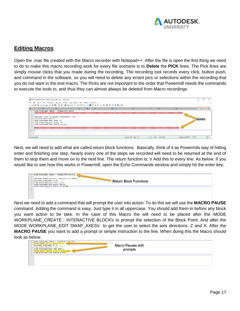
Next we need to add a command that will prompt the user into action. To do this we will use the MACRO PAUSE
command. Adding the command is easy. Just type it in all uppercase. You should add them in before any block
you want action to be take. In the case of this Macro the will need to be placed after the MODE
WORKPLANE_CREATE ; INTERACTIVE BLOCK\r to prompt the selection of the Block Point. And after the
MODE WORKPLANE_EDIT SWAP_AXES\r to get the user to select the axis directions. Z and X. After the
MACRO PAUSE you want to add a prompt or simple instruction to the line. When doing this the Macro should
look as below.

Page 18
Save the changes and assign the macro to a Ribbon bar button, delete the WCS in the test part and tryout the
Macro button in the ribbon.
For the next item in our list of command to add to the custom ribbon command tab will be a Command
Button to import and set the vise in place. To do this we will use a Featurecam option which is the
Import Vise command. This is a .exe (executable program file) that Autodesk has created to add
and position a vise or fixture automatically based off the stock or model geometry. This option in
Featurecam was so cool that one of the AE’s at Autodesk wrote the .exe script to work in Powermill
as well. You can get this file from your local reseller or through Autodesk resources. This option gives you several
different ways to add some standard vises and parallels to your file. However, you will need to also add the
Command button. The command you want to use to add/open an external file is OLE FILEACTION 'OPEN'
followed by the Files path. For this file on my PC it is as follows.
OLE FILEACTION 'OPEN' 'E:\1A WORK\Autodesk University\Position_Vise\Import_Vise.exe'
Note if you copy and paste a file path from windows into the Command prompt that Windows adds “before and
after the file path. You will need to delete these for this command or any OLE FILEACTION 'OPEN' to work.
You will need to have the WCS active for this to work properly. After activating the WCS test the command button
added and add the vise to the file. In the prompt explore the many options to adding the vise. You should also
note that if the Echo commands window is open it can take the import longer to complete.
You can also speed up the process by turning off the solids in the view options while it loads the vise components.
From here out in this demonstration we will be moving along faster explaining the tools we used in the process.
Keep in mind that all of the Macros and command created follow along all of the more detailed instructions in
their creation and can be followed by using the same creation structure and methods.

Page 19
This next Macro will get a more complex. Our next step in the processes outline will need to do multiple things
in one macro step. Thus far we have a Model, a WCS, the Block and a Vise positioned in the file. In my typical
work flow I would next want to add the vise as a Clamp or as a Collision object in the Thickness dialog box so
Powermill knows that I do not want the toolpaths to collide with it. To do this we will need to write the macro with
several commands that are not recordable. We will also need to add a special command to add a selection
[prompt to the processes to add the levels that the fixture model components are on and then have the macro
add them to the 2019.1 clamps option for collision and gouge checking.
We will also have this macro set the WCS we will need to position the Machine tool selection using
selected geometry with a prompt to select it from the graphics screen.
Lastly, I would also like this to use Powermill 2019 Setups and automatically add the previous options to
the setup.
This is a lot of content to cover in this course and more of an advanced Macro feature, to save time I will not be
breaking this down step by step but rather just adding the, macro here in this document below. One of the cool
features that we can do both with this file and in Powermill is the good old fashion cut and paste move. You can
do this as well. With the scripting below. Just start a new Notepad++ file and save and name it ADD FIXTURE
SET MACHINE. Then copy the text from this file and paste it into the Notepad++ file. Then create the Macro
button in the ribbon tool bar.
MACRO PAUSE "Select the geometry reference surface"
MODE WORKPLANE_CREATE ; SELECTION BOTTOM
RENAME Workplane # "MACHINE WCS"
EDIT PAR SimulationState.ModelLocation "MACHINE WCS"
ROTATE TRANSFORM ISO1
CREATE SETUP ; FORM SETUP
EDIT SETUP ; WORKPLANE ;
FORM ACCEPT SETUP
string list clamplevels = {}
$clamplevels = input entity multiple LEVEL "Choose fixture levels"
foreach clamp in $clamplevels {
EDIT LEVEL $clamp CLAMP YES
EDIT SETUP $folder('setup')[0] CLAMP $clamp ADD}

Page 20
Test the button out with the macro, follow the prompts to select the attachment point for the Machine build, then
check the Setup created to see that the clamp components were added.
Though we have been covering things
on a more in-depth level the rule
process only takes roughly ten
minutes to get to this point. It is at this
point that we want the user to save the
project. Depending on your
organization saving the files properly
can be somewhat complicated. If you
have specific guidelines in your shop
that you need to have the user follow a Macro can be one of the
best ways to perform the save function. In the following macro we
have it set to Save the file name based off a model selection
prompt to keep the CAM file, the setup name and the NC program
name all the same associated to the original model name.
After clicking on the Save icon in the browser a prompt will
pop up that is built in the macro. This prompt asks the user to
select the model that you want the Program, File and Setup
named as. It then executes the renaming of each accordingly.
Adding the Machine Tool to the File
Adding a machine tool file to Powermill is already vary straight forward however it can be cleaned up using a
macro fast and the advantage here is that you can assign the specific machines that you use in your shop to the
process. This limits mistakes and cuts down on mouse clicks and selection options.

Page 21
Use the recording method to record importing one of the chosen machine tools files. After the recording
assign the saved .mac file to a macro command button. This time, instead of adding an image leave the image
blank and add the button to the Machine Selection group. What you will see in the tab group is only the name of
the machine. I like to add – before the and after each name to
give them a spacer to help identify them in the group panel.
Adding Work Instruction Callups
One of the things I like to do to add a little guidance to the process is to add the work instructions to the tool bar
as an optional callup. This gives the user access to the standard work procedure at the click of a button. I do this
by using the OLE FILEACTION 'OPEN' command once again and pointing it to the work instruction PDF.
For this demo I wrote work instructions to continue with the tool, toolpath options and geometry options
that need to be add to the toolpaths.
After this step the user will go through
the steps outlined in the PDF
instructions to finally Batch process and
lead them up to posting clean and safe
code.
The steps taken after this point
are all normal Powermill functions that
were added to the ribbon tab to make
their location simpler for a user to
access. There would of course be more
work instructions added for true
guidance. The movement however
could then become habitual to the use
and you should see that the steps to get
from solid model, to clean code that
were outline in your plan are all covered.
The last thing you will need to do is
test it from start to finish. Make notes
and then have a coworker try it. Get
feedback and share your work. This way
you yourself can grow as a CNC
Programmer and continue to improve. I
don’t know everything. I never will, and
this keeps me trying new things. It also is the thing I love about CNC programming as much as it may frustrate
me I keep learning.

Page 22
Summary
Overall the processes and steps that were put into place within this demonstration took the programming of any
dovetail work from a 20-40 min job with no macros to 5-15 min job that can be performed by almost any level of
manufacturing professional including new hires.
Throughout this demonstration I covered a lot of topics within Powermill. We went over how to approach
planning for this type of automation, we covered the tools that Powermill gives us to properly structure the
planned work. We even went into the step by step basics of how to use the tools and how to start implementing
macros to support the collected processes you want to automate. I hope I was able to properly convey this
information and its intended purpose that is to format the software to be used as a tool not just to automatically
program your work. A tool that can guide and teach the work flows through your shop. Assisting in alleviating the
skills gap and giving back precious time you can always use for programming.