Automatic attendance system using Biometrics and RFID enrollment
45
AUTOMATIC ATTENDNCE SYSTEM USING RFID AND FINGERPRINT DETECTION BASED ON ETHERNET Supervisor Sir Abubaker Khitran Submitted by Waleed Imran 09B79EE Abdullah Tahir 09B92EE Asad Nawaz 09B101EE DEPARTMENT OF ELECTRICAL ENGINEERING FACULTY OF ENGINEERIRG AND APPLKIED SCIENCES RIPHAH INTERNATIONAL UNIVERSITY, ISLAMABAD
Transcript of Automatic attendance system using Biometrics and RFID enrollment

AUTOMATIC ATTENDNCE SYSTEMUSING RFID AND FINGERPRINTDETECTION BASED ON ETHERNET
SupervisorSir Abubaker Khitran
Submitted byWaleed Imran 09B79EE
Abdullah Tahir 09B92EE
Asad Nawaz 09B101EEDEPARTMENT OF ELECTRICAL ENGINEERING FACULTY OF
ENGINEERIRG AND APPLKIED SCIENCES
RIPHAH INTERNATIONAL UNIVERSITY, ISLAMABAD
September 2013
AUTOMATIC ATTENDNCE SYSTEM USING RFIDAND FINGERPRINT DETECTION BASED ON
ETHERNET
SupervisorSir Abubaker Khitran
Submitted byWaleed Imran 09B79EE
Abdullah Tahir 09B92EE
Asad Nawaz 09B101EEA Project Report submitted in partial
fulfillment of the requirements for the award ofBachelors Degree in
Electrical Engineering

DEPARTMENT OF ELECTRICAL ENGINEERING
FACULTY OF ENGINEERING AND APPLIED SCINCES
RIPHAH INTERNATIONAL UNIVERSITY, ISLAMABAD
September 2013
Undertaking
We certify that project work titled “Automatic attendance system using
RFID and fingerprint detection based on ethernet” is our own work. No
portion of the work presented in this project has been submitted
in support of another award or qualification either at this
institution or elsewhere. Where material has been used from other
sources it has been properly acknowledged / referred.
Signature
Waleed Imran
09B79EE

Signature
Abdullah Tahir
09B92EE
Signature
Asad Nawaz
09B101EE
Acknowledgements
We would like to thank …………….……………… guiding us in understanding
the concepts of …………………………………... We would like to thank all our
teachers especially ……………. guiding us in solving our problems
related to …………….. our project supervisor ……………... his
cooperation and support to bring this project to completion.

We would also like to thank our families and friends for their
continuous encouragement and moral support.
Abstract
NOTE: This Project take attendance of employees using their
RFID tag and Fingerprint.

• This system is applied for real-time attendance of the
employees in organization having multiple departments
. It can automatically collect and record all the basic
attendance information including name, time of their
attendance of both entrance and exit.
This system also take record of entrance time and exit time
of employees, If employee are not on time their
attendance is marked as absent and even if they leave before
time. Present is marked only in case when employees entrance
and exit is on time.

Table of Contents
Undertaking_____________________________________________________iiiAcknowledgements_________________________________________________ivAbstract__________________________________________________________v
Chapter 1_________________________________________________________________________________1Introduction______________________________________________________11 BACKGROUND___________________________________________________________11.1 Sub Heading1_____________________________________________________11.2 Sub Heading2_____________________________________________________11.3 Sub Heading3_____________________________________________________1
2 WHAT IS …____________________________________________________________1
Chapter 2_________________________________________________________________________________2Theory related to Project_________________________________________22.1 Statement_________________________________________________________22.2 Technique 1_______________________________________________________22.3 Technique 2_______________________________________________________22.4 Technique 3________________________________________________________
Chapter 3_________________________________________________________________________________3Implementation of Project_________________________________________33.1 MODEL AND NAMING CONVENTIONS______________________________________33.1.1 Heading of Name1______________________________________________3

3.1.1.1 Sub Heading1________________________________________________33.1.2 Heading of Name2______________________________________________33.1.3 Heading of Name3______________________________________________33.1.4 Heading of Name3______________________________________________3
Chapter 4_________________________________________________________________________________4Simulation Results________________________________________________41 HEADING 1___________________________________________________________42 HEADING 2___________________________________________________________4
CONCLUSION________________________________________________________________5FUTURE RECOMMENDATIONS____________________________________________________6
Appendix A________________________________________________________________________________7Title of Appendix_________________________________________________7References________________________________________________________8
Hard Copy Information__________________________________________________________________9
List of FiguresFigure 1 – Class diagram..................................................

List of Tables
Table: List of abc........................................................Table: List of xyz........................................................

Chapter 1
Introduction
1 BACKGROUND

• Now a days in every company & organization there is a common issue to taking attendance manually.
• Its time consuming,
• The manual attendance systems have some inherent weakness like proxy or lack of in out timings. We suggested replacing it with an effective system of attendance using ‘‘Finger Print” scan and “RFID” (Radio Frequency Identification).
2 Diagram
2.1 Flow chart

At start when we give power to the system, it initiate all modules to take input. First of all there’s a message on lcd instructing user to put their RFID tag, if RFID tag does not read it repeatuntil RFID tag read, and after reading RFID tag it goes to Finger print. Now theres a message on lcd instructing user to put their thumb on fingerprint module. Until its read it repeat in a loop again and again, after reading there’s processing in microcontroller, after matching, comparing and authentication the microcontroller send data to

server and data is saved in server, now again the same process is repeat for new user.
2.2 Schematic diagram
Above is the schematic diagram of the system. Pic 18f452 is used as main processing unit, and also responsible for the communication of all modules. Lcd is used to display instruction and output. Three modules RFID, Fingerprint and Ethernet are connected to

microcontroller. Three relays are used for switching between these modules.
PIN CONFIGURATION OF PIC MICROCONTROLLER 18F452
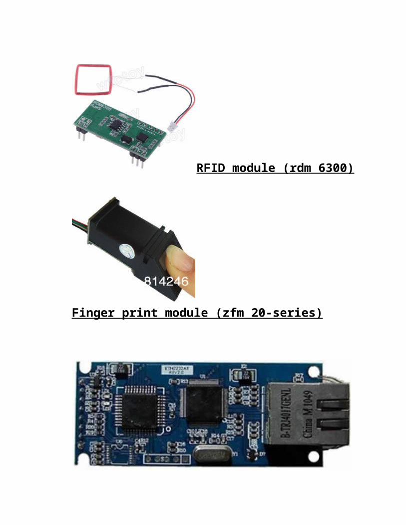
RFID module (rdm 6300)
Finger print module (zfm 20-series)

Ethernet module(eth 2232)
Chapter2
Theory related to project
2.1 Statement
Automatic attendance system is a stand alone systembased on Ethernet technology.
This is a foolproof highly secured RFID and biometricattendance system that logs all the attendance andentry/exit events and generates user friendly reportsfor review by managementHaving a database at the back-end ensures no data lossor duplication and it keeps the employee record for alonger period of time. The system remains extremely

user friendly yet suitable for an enterprise of anysize ranging from small and medium to high resourceemployers.
RFID module:• RDM 6300:• Because of following specifications which arebest suited for our system, we selected the above RFID card reader.
• Specifications:• 125khz cardreader minimodule is designed for reading code from 125khz card compatible readonly tags and read/write card.
• Cost effective.• Support external antenna• Max effective distance upto 150mm.• Less than 100ms decoding time.• Frequency Range Low Frequency (LF)• Frequencies Passive 120-140 KHz
• Read Distance 10-20 cm
Abstract:Deployment of radio frequency identification (RFID) systems is rapidly growing and has thepotential to affect many different industries and applications. We present a brief history ofRFID technology and automatic identification systems. We summarize major RFID

applications, and present a primer on RFID fundamental principles. Finally, we discussseveral challenges and obstacles to RFID adoption, as well as emerging technologies relevant to RFID.Introduction:At its most basic, RFID systems consist of smalltransponders, or tags, attached to physicalobjects. RFID tags may soon become the most pervasive microchip in history. Whenwirelessly interrogated by RFID transceivers, orreaders, tags respond with some identifyinginformation that may be associated with arbitrary data records. Thus, RFID systems are one type of automatic identification system, similar to optical bar codes.
Principle:
System EssentialsDiscussion of RFID technology tends to focus only on tag devices. It is more accurate toview RFID as a complete system that includes notonly tags, but also other importantcomponents. RFID systems are composed of at least three core components:RFID tags, or transponders, carry object-identifying data.

RFID readers, or transceivers, read and write tag data.Databases associate arbitrary records with tag identifying data.
We illustrate the interaction of these components in Figure 1. In this figure, three tags arereadable by one or both of two readers, A and B. For instance, tag 1 is only readable by A,while 2 is readable by both A and B, perhaps due to access control restrictions. The readersthen may connect to databases with records associated with particular tag identifiers. In thiscase, two databases each have their own record for tag 1. TagsTags are attached to all objects to be identified in an RFID system. A tag is typicallycomposed of an antenna or coupling element, and integrated circuitry. An important

distinction that will be discussed later is a tag’s power source. Often tags carry no on-boardpower source and must passively harvest all energy from an RF signal.There are many types of tags that offer different functionalities, have different powersources, or operate at different radio frequencies. Each of these variables helps determinewhich applications a particular tag may be appropriate for and what the costs of a tag maybe.Modern tags tend to implement identification functionality on an integrated circuit (IC) thatprovides computation and storage. In the manufacturing process, this IC is attached or“strapped” to an antenna before being packaged in a form factor, like a glass capsule or foilinlay, that is integrated into a final product.In practice, different vendors often perform each of these manufacturing steps. Other RFIDdesigns may be “chipless” or have identifying information hard-wired at fabrication time, i.e.“write-once, read-many” tags ReadersRFID readers communicate with tags through an RFchannel to obtain identifyinginformation. Depending on the type of tag, this communication may be a simple ping or may

be a more complex multi-round protocol. In environments with many tags, a reader mayhave to perform an anti-collision protocol to ensure that communication conflicts to not occur. Anti-collision protocols permit readers to rapidly communicate with many tags inserial order.Readers often power what are called passive tags through their RF communication channel.These types of tags carry no on-board power and rely solely on a reader to operate. Sincethese tags are so limited, may subsequently relyon a reader to perform computation as well.Readers come in many forms, operate on many different frequencies, and may offer a widerange of functionality. Readers may have their own processing power and internal storage,and may offer network connectivity. Readers might be a simple conduit to an externalsystem, or could store all relevant data locally.Currently, many applications rely on fixed reading devices. Early trials of EPC at a majorsupermarket chain integrated fixed readers into docking-bay entrances. These readers scantags at the pallet level as shipments of products arrive. In the long term, readers may be

integrated at a shelf level as a “smart shelf ”.Smart shelves would scan for tags at the itemlevel and monitor when they are added and removed from a shelf.RFID readers may also be integrated into hand-held mobile devices. These mobile readerswould allow someone to, for example, take inventory of a warehouse by walking through itsaisles. The cellular phone manufacturer Nokia isalready offering RFID-reading functionalityin some of their cell phones [16]. If EPC-type tags become highly successful, interesting anduseful consumer applications might arise. If this occurs, RFID reading functionality might become a common feature on cellular phones, PDAs, or other handheld computing devices.

Finger print module:• It takes Synochip DSP as the main processor and optical sensor.
• The module performs series of functions like fingerprint
• enrollment, image processing, fingerprint matching, searching and template storage.
Optical Part:
Optical fingerprint imaging involves capturing adigital image of the print using visible light. This type of sensor is, in essence, a specialized digital camera. The top layer of thesensor, where the finger is placed, is known as the touch surface. Beneath this layer is a light-emitting phosphor layer which illuminates the surface of the finger. The light reflected from the finger passes through the phosphor layer to an array of solid state pixels (a charge-coupled device) which captures a visual image of the fingerprint. A scratched or dirty touch surface can cause a bad image of the fingerprint. A disadvantage of this type of sensor is the fact that the imaging capabilities

are affected by the quality of skin on the finger. For instance, a dirty or marked finger is difficult to image properly. Also, it is possible for an individual to erode the outer layer of skin on the fingertips to the point where the fingerprint is no longer visible. It can also be easily fooled by an image of a fingerprint if not coupled with a "live finger" detector. However, unlike capacitive sensors, this sensor technology is not susceptible to electrostatic discharge damage.
Operating principle of fingerprint module:• Fingerprint processing includes two parts: fingerprint enrollment and fingerprint matching (the
• matching can be 1:1 or 1:N).• When enrolling, user needs to enter the finger two times. The system will process thetwo time
• finger images, generate a template of the finger based on processing results and store the template.
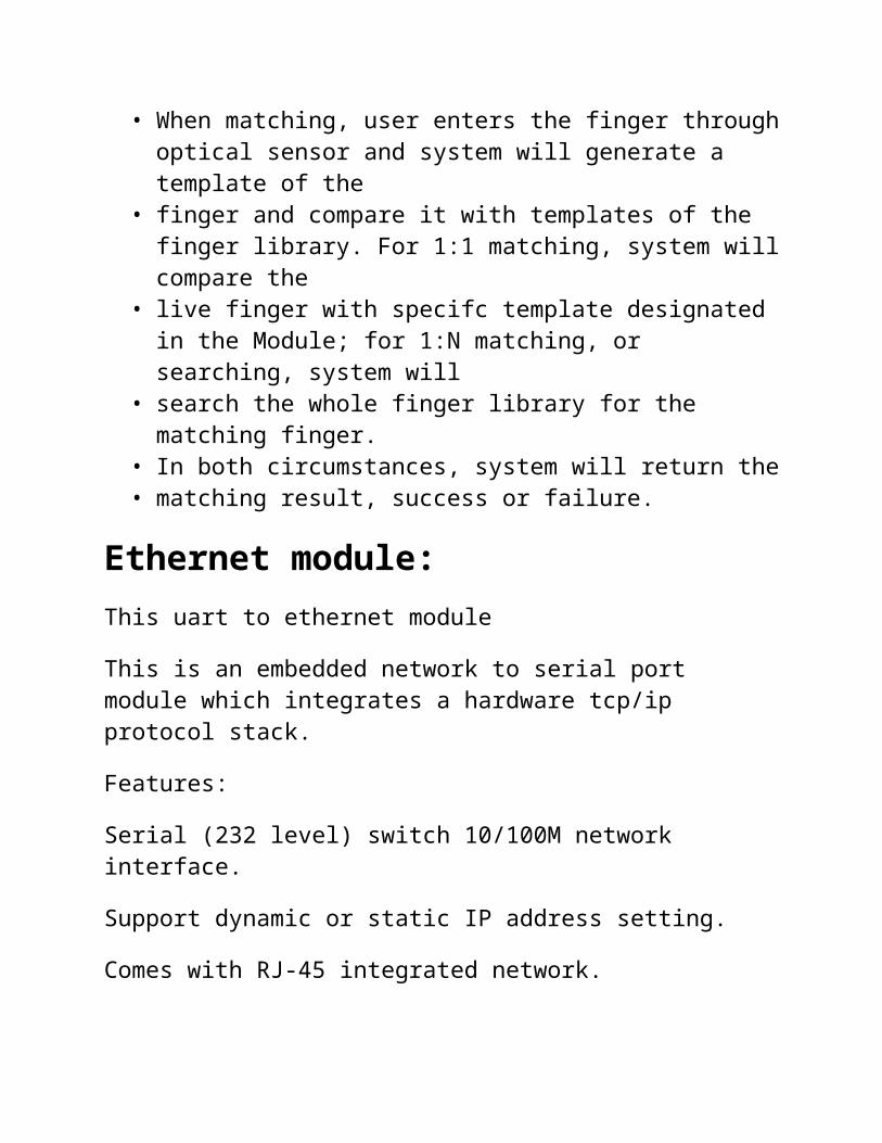
• When matching, user enters the finger throughoptical sensor and system will generate a template of the
• finger and compare it with templates of the finger library. For 1:1 matching, system willcompare the
• live finger with specifc template designated in the Module; for 1:N matching, or searching, system will
• search the whole finger library for the matching finger.
• In both circumstances, system will return the• matching result, success or failure.
Ethernet module:This uart to ethernet module
This is an embedded network to serial port module which integrates a hardware tcp/ip protocol stack.
Features:
Serial (232 level) switch 10/100M network interface.
Support dynamic or static IP address setting.
Comes with RJ-45 integrated network.

Microcontroller:1. We used pic 18f452 in our project because PIC18F452 is High
Performance, Enhanced FLASH Microcontrollers with built in10-Bit A/D and 32KB program memory
2. 18f452 PICs is popular in industrial developers due to itslow cost, wide availability, large user base, extensivecollection of application notes, availability of low costor free development tools, and serial programming (and re-programming with flash memory) capability.
Device On-Chip ProgramMemory FLASH(bytes)
On-Chip RAM Or Data memory(bytes)
DataEEPROM(bytes)
Program Memory (Instructions)
Operating Frequency
Interept sources
PIC 18f452
32K 1536 256 16384 DC - 40MHz 18
Oscillator TypesThe PIC18FXX2 can be operated in eight differentOscillator modes. The user can program three configurationbits (FOSC2, FOSC1, and FOSC0) to select oneof these eight modes:1. LP Low Power Crystal
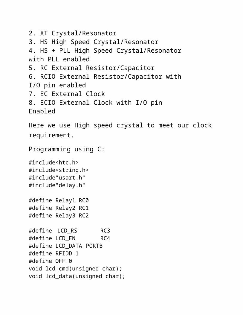
2. XT Crystal/Resonator3. HS High Speed Crystal/Resonator4. HS + PLL High Speed Crystal/Resonatorwith PLL enabled5. RC External Resistor/Capacitor6. RCIO External Resistor/Capacitor withI/O pin enabled7. EC External Clock8. ECIO External Clock with I/O pinEnabled
Here we use High speed crystal to meet our clockrequirement.
Programming using C:
#include<htc.h>#include<string.h>#include"usart.h"#include"delay.h"
#define Relay1 RC0#define Relay2 RC1#define Relay3 RC2
#define LCD_RS RC3#define LCD_EN RC4#define LCD_DATA PORTB#define RFIDD 1#define OFF 0void lcd_cmd(unsigned char);void lcd_data(unsigned char);

void lcd_string(const unsigned char*);void InterruptSetting(void);void delay(unsigned int time);
void handshake();void system_param();void collect_fingerprint();void upload_image();void generate_character_file1();void generate_character_file2();void compare();void store_template();void searchLibrary();char x[4];unsigned char RFID[15]={'\0'};unsigned int RFID_index=0;unsigned int Mode=0;unsigned int FirstFinger=0;unsigned int SecondFinger=0;char get=0x00;char comp=0x00;char c;char responce[12]="";char res[14]="";int index=0, comp_index=0;
void interrupt ISR(void){
if(RCIF){
c=RCREG;if(Mode==RFIDD){RFID[RFID_index]=c;
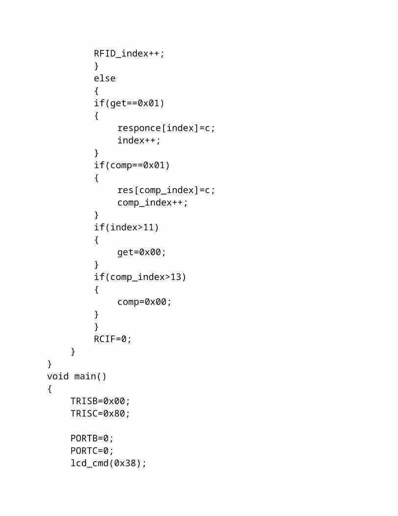
RFID_index++;}else{if(get==0x01){
responce[index]=c;index++;
}if(comp==0x01){
res[comp_index]=c;comp_index++;
}if(index>11){
get=0x00;}if(comp_index>13){
comp=0x00;}}RCIF=0;
}}void main(){
TRISB=0x00;TRISC=0x80;
PORTB=0;PORTC=0;lcd_cmd(0x38);

DelayMs(10); lcd_cmd(0x0E);DelayMs(10);lcd_cmd(0x80);DelayMs(10);lcd_cmd(0x01);DelayMs(10);lcd_string("Wellcome");DelayS(2);USARTSetup(9600);USARTInterrupts(TxIntDisable,RxIntEnable);
//transmit interrupts disable and recieve interrupts enable
InterruptSetting(); //enable all interruptsRelay1=0;Relay2=0;Relay3=0;lcd_cmd(0x80);DelayMs(10);lcd_cmd(0x01);DelayMs(10);lcd_string("PUT YOUR TAG");while(1){Mode=RFIDD;CREN=0;Relay2=1;DelayMs(100);CREN=1;while(RFID_index<=13);Mode=OFF;lcd_cmd(0x80);DelayMs(10);lcd_cmd(0x01);

DelayMs(10);lcd_string(RFID);CREN=0;BAUDSet(57600);Relay2=0;Relay3=1;DelayMs(100);CREN=1;lcd_cmd(0x80);DelayMs(10);lcd_cmd(0x01);DelayMs(10);lcd_string("PUT YOUR FINGER");DelayMs(10);while(FirstFinger==0){
get=0x01;responce[9]=0xFF;collect_fingerprint();delay(5);delay(10000);if(responce[9]==0x00){
get=0x00;index=0;FirstFinger=1;generate_character_file1();delay(10000);
}if(responce[9]==0x02){
index=0;FirstFinger=0;
}

}
while(SecondFinger==0){get=0x01;responce[9]=0xFF;collect_fingerprint();delay(10000);if(responce[9]==0x00){
get=0x00;index=0;SecondFinger=1;generate_character_file2();lcd_cmd(0x01);DelayMs(10);lcd_string("Comparing..");
}if(responce[9]==0x02){
index=0;SecondFinger=0;
}}
delay(15000);comp=0x01;responce[9]=0xFF;searchLibrary();delay(10000);if(res[9]==0x00){
comp=0x00;lcd_cmd(0x01);

DelayMs(10);lcd_string("Perfect Match");DelayS(1);
x[0]=res[10] & 0xF0;x[0]=x[0]+0x30;x[1]=res[10] & 0x0F;x[1]=x[1]+0x30;x[2]=res[11] & 0xF0;x[2]=x[2]+0x30;x[3]=res[11] & 0x0F;x[3]=x[3]+0x30;lcd_cmd(0x01);DelayMs(10);lcd_string(x);DelayS(1);CREN=0;Relay1=1;CREN=1;BAUDSet(9600);DelayMs(100);TransmitString("$,");DelayMs(100);TransmitString(RFID);DelayMs(100);TransmitString(",");DelayMs(100);TransmitString(x);DelayMs(100);TransmitString(",#");DelayMs(100);CREN=0;Relay1=0;CREN=1;

comp=0x00;lcd_cmd(0x01);DelayMs(10);lcd_string("THANK YOU");
}if(res[9]==0x09){
lcd_cmd(0x01);DelayMs(10);lcd_string("Doesn't Match");delay(5000);index=0;comp_index=0;
}get=0x00;comp=0x00;SecondFinger=0;FirstFinger=0;comp_index=0;RFID_index=0;BAUDSet(9600);Relay3=0;DelayS(1);lcd_cmd(0x80);DelayMs(10);lcd_cmd(0x01);DelayMs(10);lcd_string("PUT YOUR TAG");}
}
void InterruptSetting(void){

PEIE=1;GIE=1;
}
// LCD COMMAND SENDING FUNCTIONvoid lcd_cmd(unsigned char item){ LCD_DATA = item; LCD_RS= 0; LCD_EN=1; DelayMs(1); LCD_EN=0; return;}// LCD DATA SENDING FUNCTIONvoid lcd_data(unsigned char item){ LCD_DATA = item; LCD_RS= 1; LCD_EN=1; DelayMs(1); LCD_EN=0; return;} // LCD STRING SENDING FUNCTION void lcd_string(const unsigned char *str) { while(*str) { lcd_data(*str++); DelayMs(10); } return;
}
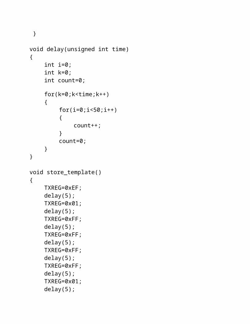
void delay(unsigned int time){
int i=0;int k=0;int count=0;
for(k=0;k<time;k++){
for(i=0;i<50;i++){
count++;}count=0;
}}
void store_template(){
TXREG=0xEF;delay(5);TXREG=0x01;delay(5);TXREG=0xFF;delay(5);TXREG=0xFF;delay(5);TXREG=0xFF;delay(5);TXREG=0xFF;delay(5);TXREG=0x01;delay(5);

TXREG=0x06;delay(5);TXREG=0x00;delay(5);TXREG=0x06;delay(5);TXREG=0x01;delay(5);TXREG=0x00;delay(5);TXREG=0x01;delay(5);TXREG=0x00;delay(5);TXREG=0x0F;delay(5);
}
void searchLibrary(){
TXREG=0xEF;delay(5);TXREG=0x01;delay(5);TXREG=0xFF;delay(5);TXREG=0xFF;delay(5);TXREG=0xFF;delay(5);TXREG=0xFF;delay(5);TXREG=0x01;delay(5);

TXREG=0x00;delay(5);TXREG=0x08;delay(5);TXREG=0x04;delay(5);TXREG=0x01;delay(5);TXREG=0x00;delay(5);TXREG=0x00;delay(5);TXREG=0x00;delay(5);TXREG=0x08;delay(5);TXREG=0x00;delay(5);TXREG=0x16;delay(5);
}
void compare(){
TXREG=0xEF;delay(5);TXREG=0x01;delay(5);TXREG=0xFF;delay(5);TXREG=0xFF;delay(5);TXREG=0xFF;delay(5);

TXREG=0xFF;delay(5);TXREG=0x01;delay(5);TXREG=0x00;delay(5);TXREG=0x03;delay(5);TXREG=0x03;delay(5);TXREG=0x00;delay(5);TXREG=0x07;delay(5);
}
void generate_character_file1(){
TXREG=0xEF;delay(5);TXREG=0x01;delay(5);TXREG=0xFF;delay(5);TXREG=0xFF;delay(5);TXREG=0xFF;delay(5);TXREG=0xFF;delay(5);TXREG=0x01;delay(5);TXREG=0x00;delay(5);
TXREG=0x04;delay(5);TXREG=0x02;delay(5);TXREG=0x01;delay(5);TXREG=0x00;delay(5);TXREG=0x08;delay(5);
}
void generate_character_file2(){
TXREG=0xEF;delay(5);TXREG=0x01;delay(5);TXREG=0xFF;delay(5);TXREG=0xFF;delay(5);TXREG=0xFF;delay(5);TXREG=0xFF;delay(5);TXREG=0x01;delay(5);TXREG=0x00;delay(5);TXREG=0x04;delay(5);TXREG=0x02;delay(5);

TXREG=0x02;delay(5);TXREG=0x00;delay(5);TXREG=0x09;delay(5);
}
void upload_image(){
TXREG=0xEF;delay(5);TXREG=0x01;delay(5);TXREG=0xFF;delay(5);TXREG=0xFF;delay(5);TXREG=0xFF;delay(5);TXREG=0xFF;delay(5);TXREG=0x01;delay(5);TXREG=0x00;delay(5);TXREG=0x03;delay(5);TXREG=0x0A;delay(5);TXREG=0x00;delay(5);TXREG=0x0E;

delay(5);}
void collect_fingerprint(){
TXREG=0xEF;delay(5);TXREG=0x01;delay(5);TXREG=0xFF;delay(5);TXREG=0xFF;delay(5);TXREG=0xFF;delay(5);TXREG=0xFF;delay(5);TXREG=0x01;delay(5);TXREG=0x00;delay(5);TXREG=0x03;delay(5);TXREG=0x01;delay(5);TXREG=0x00;delay(5);TXREG=0x05;delay(5);
}
void system_param(){
TXREG=0xEF;

delay(5);TXREG=0x01;delay(5);TXREG=0xFF;delay(5);TXREG=0xFF;delay(5);TXREG=0xFF;delay(5);TXREG=0xFF;delay(5);TXREG=0x01;delay(5);TXREG=0x00;delay(5);TXREG=0x03;delay(5);TXREG=0x0f;delay(5);TXREG=0x00;delay(5);TXREG=0x13;delay(5);
}
void handshake(){
TXREG=0xEF;delay(5);TXREG=0x01;delay(5);TXREG=0xFF;delay(5);

TXREG=0xFF;delay(5);TXREG=0xFF;delay(5);TXREG=0xFF;delay(5);TXREG=0x01;delay(5);TXREG=0x00;delay(5);TXREG=0x04;delay(5);TXREG=0x17;delay(5);TXREG=0x00;delay(5);TXREG=0x00;delay(5);TXREG=0x1C;delay(5);
}