Atom probe tomography study of ultrahigh nanocrystallization rates in FeSiNbBCu soft magnetic...
15
Atom probe tomography study of ultrahigh nanocrystallization rates in FeSiNbBCu soft magnetic amorphous alloys on rapid annealing K.G. Pradeep a,⇑ , G. Herzer b , P. Choi a , D. Raabe a,⇑ a Max-Planck-Institut fu ¨ r Eisenforschung GmbH, Max-Planck-Str. 1, 40237 Du ¨ sseldorf, Germany b Vacuumschmelze GmbH & Co. KG, Gru ¨ ner Weg 37, 63450 Hanau, Germany Received 20 November 2013; accepted 19 January 2014 Abstract Rapid annealing (4–10 s) induced primary crystallization of soft magnetic Fe–Si nanocrystals in a Fe 73.5 Si 15.5 Cu 1 Nb 3 B 7 amorphous alloy has been systematically studied by atom probe tomography in comparison with conventional annealing (30–60 min). It was found that the nanostructure obtained after rapid annealing is basically the same, irrespective of the different time scales of annealing. This underlines the crucial role of Cu during structure formation. Accordingly, the clustering of Cu atoms starts at least 50 °C below the onset temperature of primary crystallization. As a consequence, coarsening of Cu atomic clusters also starts prior to crystallization, resulting in a reduction of available nucleation sites during Fe–Si nanocrystallization. Furthermore, the experimental results explicitly show that these Cu clusters initially induce a local enrichment of Fe and Si in the amorphous matrix. These local chemical heterogeneities are pro- posed to be the actual nuclei for subsequent nanocrystallization. Nevertheless, rapid annealing in comparison with conventional anneal- ing results in the formation of 30% smaller Fe–Si nanocrystals, but of identical structure, volume fraction and chemical composition, indicating the limited influence of thermal treatment on nanocrystallization, owing to the effect of Cu. Ó 2014 Acta Materialia Inc. Published by Elsevier Ltd. All rights reserved. Keywords: Soft magnets; Nanocrystalline microstructure; Crystallization; Atom probe tomography; Coarsening 1. Introduction Nanocrystalline FeSiNbBCu alloys obtained after par- tial devitrification of initially amorphous samples exhibit excellent soft magnetic properties [1–11]. They were first introduced by Yoshizawa et al. [1–3] and are characterized by nano-sized, randomly oriented Fe–Si crystallites embed- ded in a retained amorphous matrix [6]. The grain size D of an Fe 73.5 Si 15.5 Cu 1 Nb 3 B 7 alloy with optimal magnetic prop- erties is only 10–15 nm [5–12]. Thus, the structural corre- lation length is much smaller than the domain wall width, resulting in a negligibly small average magneto-crystalline anisotropy [6–8]. This is a pre-condition for low-loss soft magnetic materials [8]. As a result, typical coercivity values of these materials are <1 A m 1 [1,11,13]. The desired nanocrystalline state is obtained after par- tial devitrification of the amorphous state by annealing close to the final stages of primary crystallization. The combined addition of Cu and Nb proved to be the key for obtaining the fine-grained structure [4,6,12]. More importantly, the addition of Cu is decisive, as it introduces chemical inhomogeneity by forming clusters of Cu atoms, thereby providing a high density of nucleation sites for pri- mary crystallization of body-centerd cubic Fe 3 Si [12]. Atom probe tomography (APT) studies by Hono et al. [12,14,15] revealed that the Cu clusters that initially formed in the amorphous matrix act as nucleation sites for Fe-rich nanocrystals. For example, fine Cu clusters 5 nm in http://dx.doi.org/10.1016/j.actamat.2014.01.031 1359-6454/Ó 2014 Acta Materialia Inc. Published by Elsevier Ltd. All rights reserved. ⇑ Corresponding author. E-mail addresses: [email protected] (K.G. Pradeep), [email protected] (D. Raabe). www.elsevier.com/locate/actamat Available online at www.sciencedirect.com ScienceDirect Acta Materialia 68 (2014) 295–309
Transcript of Atom probe tomography study of ultrahigh nanocrystallization rates in FeSiNbBCu soft magnetic...

Available online at www.sciencedirect.com
www.elsevier.com/locate/actamat
ScienceDirect
Acta Materialia 68 (2014) 295–309
Atom probe tomography study of ultrahigh nanocrystallization rates inFeSiNbBCu soft magnetic amorphous alloys on rapid annealing
K.G. Pradeep a,⇑, G. Herzer b, P. Choi a, D. Raabe a,⇑
a Max-Planck-Institut fur Eisenforschung GmbH, Max-Planck-Str. 1, 40237 Dusseldorf, Germanyb Vacuumschmelze GmbH & Co. KG, Gruner Weg 37, 63450 Hanau, Germany
Received 20 November 2013; accepted 19 January 2014
Abstract
Rapid annealing (4–10 s) induced primary crystallization of soft magnetic Fe–Si nanocrystals in a Fe73.5Si15.5Cu1Nb3B7 amorphousalloy has been systematically studied by atom probe tomography in comparison with conventional annealing (30–60 min). It was foundthat the nanostructure obtained after rapid annealing is basically the same, irrespective of the different time scales of annealing. Thisunderlines the crucial role of Cu during structure formation. Accordingly, the clustering of Cu atoms starts at least 50 �C below the onsettemperature of primary crystallization. As a consequence, coarsening of Cu atomic clusters also starts prior to crystallization, resulting ina reduction of available nucleation sites during Fe–Si nanocrystallization. Furthermore, the experimental results explicitly show thatthese Cu clusters initially induce a local enrichment of Fe and Si in the amorphous matrix. These local chemical heterogeneities are pro-posed to be the actual nuclei for subsequent nanocrystallization. Nevertheless, rapid annealing in comparison with conventional anneal-ing results in the formation of �30% smaller Fe–Si nanocrystals, but of identical structure, volume fraction and chemical composition,indicating the limited influence of thermal treatment on nanocrystallization, owing to the effect of Cu.� 2014 Acta Materialia Inc. Published by Elsevier Ltd. All rights reserved.
Keywords: Soft magnets; Nanocrystalline microstructure; Crystallization; Atom probe tomography; Coarsening
1. Introduction
Nanocrystalline FeSiNbBCu alloys obtained after par-tial devitrification of initially amorphous samples exhibitexcellent soft magnetic properties [1–11]. They were firstintroduced by Yoshizawa et al. [1–3] and are characterizedby nano-sized, randomly oriented Fe–Si crystallites embed-ded in a retained amorphous matrix [6]. The grain size D ofan Fe73.5Si15.5Cu1Nb3B7 alloy with optimal magnetic prop-erties is only �10–15 nm [5–12]. Thus, the structural corre-lation length is much smaller than the domain wall width,resulting in a negligibly small average magneto-crystalline
http://dx.doi.org/10.1016/j.actamat.2014.01.031
1359-6454/� 2014 Acta Materialia Inc. Published by Elsevier Ltd. All rights r
⇑ Corresponding author.E-mail addresses: [email protected] (K.G. Pradeep), [email protected]
(D. Raabe).
anisotropy [6–8]. This is a pre-condition for low-loss softmagnetic materials [8]. As a result, typical coercivity valuesof these materials are <1 A m�1 [1,11,13].
The desired nanocrystalline state is obtained after par-tial devitrification of the amorphous state by annealingclose to the final stages of primary crystallization. Thecombined addition of Cu and Nb proved to be the keyfor obtaining the fine-grained structure [4,6,12]. Moreimportantly, the addition of Cu is decisive, as it introduceschemical inhomogeneity by forming clusters of Cu atoms,thereby providing a high density of nucleation sites for pri-mary crystallization of body-centerd cubic Fe3Si [12].Atom probe tomography (APT) studies by Hono et al.[12,14,15] revealed that the Cu clusters that initially formedin the amorphous matrix act as nucleation sites for Fe-richnanocrystals. For example, fine Cu clusters 5 nm in
eserved.

Fig. 1. Variation in saturation magnetostriction ks and coercivity Hc as afunction of annealing temperature, indicating the various stages from asprepared amorphous to primary Fe–Si nanocrystallization to secondaryFe–B compound formation. Data adapted from Ref. [13].
296 K.G. Pradeep et al. / Acta Materialia 68 (2014) 295–309
diameter were observed to develop on annealing for 10 minat 550 �C [12]. Small-angle neutron scattering (SANS)investigations by Ohnuma et al. [16] further confirmed thatthe clustering of Cu atoms occurs prior to the crystalliza-tion of a-Fe nanocrystals, with the number density of Cuclusters being highest at the crystallization onset stage,for an alloy containing optimum Cu content of e.g.�1 at.% in the case of an Fe74.5Si13.5Nb3B9 alloy. There-fore, Cu-addition plays a decisive role in obtaining the fin-est possible nanocrystalline microstructures and, in turn,the maximum magnetic permeability.
Conventional heat treatments of such alloys to induceFe3Si nanocrystallization are carried out for �0.5–1 h attemperatures between 500 and 600 �C [1–7]. Previousreports indicated that the primary crystallization onsettemperature Tonset is shifted on rapid annealing (RA;heating rates of 50–200 K s�1 by DC Joule heating) tohigher temperatures by almost 80–100 �C relative to theTonset of typical conventional annealing (CA) [17]. Morerecently, it was shown that comparable microstructureand magnetic properties can also be achieved by RA,mainly when ramping up to temperatures of �600–700 �C for a few seconds [13]. However, the effect ofRA on the nucleation and growth kinetics of Fe–Si nano-crystals is largely unknown. Therefore, the objectiveof this work is twofold: (a) the systematic investigationof the effect of RA (�100–200 K s�1) on the formation ofCu clusters and the associated nucleation mechanisms ofFe–Si nanocrystals; and (b) a comparative microstructureevaluation of the alloy annealed under both rapid and con-ventional conditions.
2. Experimental procedure
Amorphous Fe73.5Si15.5Cu1Nb3B7 (VITROPERM� 800(reg. trademark of Vacuumschmelze GmbH & Co. KG)ribbons with a thickness of �20 lm were prepared by rapidsolidification from the melt. Partial crystallization of theribbons was accomplished by RA and by CA. RA was per-formed in two very different ways: namely, static (RA1) andcontinuous (RA2). RA1 was performed by introducing theas-prepared amorphous ribbons between two highly con-ductive Cu blocks pre-heated in the furnace for 15 min atthe set temperature while in good contact with each other.The annealing temperature was measured by a thermocou-ple in close proximity to the Cu blocks. Such a setup facil-itates stress-free RA up to the desired temperatures and fora minimum holding time of 10 s. Multiple annealing trialswere performed to ensure reproducibility. Alternatively,RA2 was performed by continuously transporting the rib-bons through a furnace with a 10 cm long homogeneoustemperature zone (in nitrogen atmosphere) under a smalltensile stress of �50 MPa [13]. RA2 was also performedat different temperatures, similarly to RA1 in order tounderstand the sequence of nanocrystallization. Thedetailed soft magnetic properties of these samples are
reported elsewhere [13], but the relevant results for theselected annealing conditions of RA2 are summarized inFig. 1. The initial reduction of saturation magnetostrictionks at �550 �C indicates the onset of primary crystallization.Annealing at higher temperatures leads to the continuousreduction of ks until it reaches zero at �650 �C, indicatingan increase in crystalline volume fraction with increasingannealing temperature. The onset of secondary crystalliza-tion is noticed at �720 �C, where coercivity, Hc and ks tendto increase [13]. Therefore, the annealing window forobtaining optimum nanocrystalline microstructure duringprimary crystallization by RA is higher by �100 �C thanduring conventional differential scanning calorimetric-typeslow heating at a rate of �10 K min�1 for prolonged peri-ods of 1 h [11].
Additionally, comparative analysis between RA and CAwas performed on those samples annealed close to the ini-tial stages of primary crystallization (with �30 vol.% crys-talline fraction) and at the final stages of primarycrystallization (�80 vol.% crystalline fraction). The anneal-ing conditions for preparing such samples are as follows.
1. Initial stages of crystallization: (a) CA1, 30 min at480 �C; CA2, 5 min at 490 �C; and (b) RA1, 10 s at555 �C; RA2, 4 s at 555 �C.
2. Final stage of crystallization: (a) CA1, 30 min at 575 �C;CA2, 5 min at 655 �C; and (b) RA1, 10 s at 695 �C; RA2,4 s at 695 �C.
It must be noted that CA1 and CA2 were performed inthe same furnace as RA1, but without the use of Cu blocks.
Phase identification and crystallite size measurementswere performed using X-ray diffraction (XRD) (GeneralElectric XRD) and transmission electron microscopy(TEM) (Philips CM20 operated at 200 kV). Crystallite sizes

K.G. Pradeep et al. / Acta Materialia 68 (2014) 295–309 297
were estimated from XRD peak broadening using theScherrer equation [18] and also from TEM bright-field(BF) images. The contributions of the amorphous and crys-talline phases to the XRD peaks were deconvoluted using apseudo-Voigt peak profile fitting function. The volumefraction of the crystalline phase was obtained from theratio of the integral intensity of the crystalline contributionto the total intensity [19]. Thin foil samples for TEM anal-yses were prepared by electro-polishing using 5% perchloricacid in ethanol at �30 �C and 15 V. The elemental distribu-tion was investigated by APT, which enables three-dimen-sional (3-D) elemental mapping with near-atomicresolution and high detection sensitivity [20–27]. Therefore,APT enables detailed analyses of size, distribution andchemical composition of nanoscale clusters and crystals[25]. APT experiments were performed with a local elec-trode atom probe (LEAPe 3000X HR, Cameca Instru-ments), applying a voltage pulse fraction (Vp/Vdc) of 0.15at a repetition rate of 200 kHz. The tip temperature wasmaintained at �60 K. APT samples were prepared usinga dual beam focused ion beam (FEI Helios Nanolab 600)and following the procedures described in Ref. [28]. Tominimize beam damage, a low-energy (5 keV) Ga beamwas used in the final ion-milling stage. The APT data wereevaluated using IVAS 3.6 software provided by CamecaInstruments. Composition profiles with respect to distancefrom the Cu cluster/amorphous/Fe–Si nanocrystal hetero-phase interfaces were obtained using the proximity histo-gram method. An isoconcentration surface of 3 at.% Cuwas used as a reference surface for the proxigram analysis,which provided a topologically stable representation of Cuclusters when varying the isoconcentration value �3 at.%Cu. Unless otherwise mentioned, the use of the isoconcen-tration surface in depicting Cu clusters is only for clarityand not for quantification. The size and number densityof Cu clusters were determined employing the maximum-separation method [29], based on clusters with more than10 Cu atoms separated by a maximum distance of not morethan 0.4 nm [25].
Fig. 2. (a) XRD patterns of a set of rapid annealed samples for a processing dua function of annealing temperature.
3. Results
3.1. Rapid annealing
3.1.1. XRD
The XRD results of as melt-spun ribbon specimensannealed at various temperature intervals of RA2 corre-sponding to the magnetic properties of Fig. 1 are shownin Fig. 2a. The XRD pattern of the as melt-spun sampleshows a broad halo peak indicating the presence of a com-pletely amorphous phase, which was also confirmed fromthe characteristic halo ring pattern (not shown here) inTEM. Annealing even to 535 �C showed no indicationsof crystallization. On annealing at 555 �C for 4 s, the onsetof primary crystallization is realized by the emergence of{220} peak at 53�. This observation is very much in corre-lation with the reduction in ks due to crystallization onset,as shown in Fig. 1. The estimated crystalline volume frac-tion after peak deconvolution was �30 vol.%, with a meancrystallite size of 7 nm. Further annealing at higher temper-atures resulted in an increase in both the volume fractionand size of DO3 structured Fe-rich nanocrystals, as sum-marized in Fig. 2b. The maximum crystalline fractionachieved was 80 vol.%, with an average crystallite size of10 nm. On annealing at 745 �C, additional diffraction peaksemerged, which corresponds to the crystallization of resid-ual amorphous matrix into Fe–B compounds.
3.1.2. APT
In order to understand the nucleation mechanism ofa-Fe nanocrystals during RA2, APT measurements wereperformed on the same samples used for XRD analysis.Fig. 3 displays the various stages during nucleation andprogressive growth of Cu clusters as a function of anneal-ing temperatures. The as melt-spun amorphous sampleshowed a homogeneous distribution of all the elements,which has been shown in Fig. 3 for Cu. Binomial frequencydistribution analysis (not shown here) also revealed arandom distribution of all the elements in the analysed
ration of 4 s; (b) estimated crystallite size and crystalline volume fraction as

Fig. 3. APT elemental map of Cu ( ) and Cu-rich clusters delineated by 3 at.% isoconcentration surfaces when the as-prepared amorphous alloy is rapidannealed for 4 s over a range of annealing temperatures: (a) as-prepared amorphous; (b) 535 �C; (c) 555 �C; (d) 600 �C; (e) 695 �C; (f) 747 �C.
Fig. 4. Variation in Cu cluster number density and size as a function ofannealing temperature for 4 s RA.
298 K.G. Pradeep et al. / Acta Materialia 68 (2014) 295–309
volume. The initial trace of Cu clustering was observed at450 �C, but could not be defined based on the consider-ation of a minimum number of Cu atoms (Nmin = 10) tobe present for the identification of clusters. At higherannealing temperatures, the Cu clusters are clearly distin-guished from the matrix Cu atoms and are visualized interms of isoconcentration surfaces (for clarity) with athreshold value of 3 at.% Cu in Fig. 3. The size and numberdensity of Cu clusters as a function of annealing tempera-ture are shown in Fig. 4. It must be noted that the cluster-ing of Cu atoms started well before the onset of primarycrystallization (555 �C in the case of RA2) and that thenumber density of Cu clusters reaches a maximum at535 �C. Towards the onset of primary crystallization, thenumber density starts decreasing, indicating the onset ofsimultaneous coarsening and growth of clusters. It can benoticed in Fig. 4 that, with increasing annealing tempera-tures, the mean size of the clusters has also increased from

K.G. Pradeep et al. / Acta Materialia 68 (2014) 295–309 299
an initial 1 nm to 9.5 nm at 745 �C, accompanied by asimultaneous reduction in number density. In order to bet-ter understand the relation between nucleation of clusters,coarsening and growth with the primary crystallization ofDO3 structured nanocrystals, the sequence of Cu clusteringand growth in Fig. 3 is divided into three stages, as indi-cated in Fig. 4. Stage I corresponds to the onset of Cu clus-tering prior to primary crystallization. Stage II correspondsto the intermediate temperature range between the onset ofprimary crystallization with �30 vol.% crystalline fractionand 60 vol.% crystalline fraction region. Stage III corre-sponds to the rest of the high temperature annealing rangebeyond 60 vol.% crystalline fraction.
When interpreting the morphology of clusters in Fig. 3,account has to be taken of the local magnification effect,owing to the fact that Cu has a lower evaporation field(30 V nm�1) than Fe (33 V nm�1) [20]. As a consequence,the Cu clusters are slightly recessed during field evapora-tion and are therefore projected at a lower magnificationtowards the detector compared with the matrix atoms. This
Fig. 5. XRD patterns of a series of RA samples: (a) RA1: 10 s; (b
results in a relatively higher atomic density at the clustersthan in the matrix in the 3-D reconstruction [30]. Theslightly elongated morphology observed in Fig. 3 for someof the clusters also results from this effect [20,21]. There-fore, to overcome the apparent distortions induced in theclusters as a result of local magnification effects and todetermine the average cluster diameter free of distortions,the number of atoms in each cluster identified from themaximum-separation method of the cluster analysis is usedto estimate the size, as described in Ref. [25].
3.2. Comparative analysis
3.2.1. Stage I: before primary crystallizationAs described earlier and from Fig. 3, on RA2, Cu clus-
ters form well before the onset of primary crystallization.The initial stages of Cu clustering were noticed on the sam-ples annealed at temperatures significantly lower by at least50–80 �C (Fig. 4) than those required for primary crystalli-zation (555 �C in this case). Such an inference is in good
) RA2, 4 s; and CA samples: (c) CA1, 30 min; (d) CA2, 5 min.

300 K.G. Pradeep et al. / Acta Materialia 68 (2014) 295–309
agreement with the previous reports on the onset of Cuclustering prior to primary crystallization on CA[13,14,16,27]. However, a direct comparison between thepreviously reported CA and the RA investigated in thepresent work is not feasible, owing to the fact that the onsetof clustering is determined by the incubation time at agiven temperature. During RA, there is no defined or fixedincubation time, as the overall annealing duration is only4–10 s, irrespective of the temperature range defined. Incontrast, a direct comparison between CA and RA is feasi-ble for primary crystallization events, while taking intoaccount the emerging crystalline volume fraction as a con-stant parameter over varying annealing time ortemperatures.
3.2.2. Stage II: initial crystallization
A shown in Fig. 2a, a series of annealing treatmentswere performed for RA1 (10 s holding time) until the onsetof primary crystallization was observed at 555 �C (Fig. 5a).The estimated crystalline fraction at this state was�30 vol.%. Fig. 5b shows the selected XRD plots of RA2
Fig. 6. (a) TEM BF image of 490 �C 5 min conventionally annealed (CA2) scorresponding SAED pattern with a typical nanocrystalline ring structure (shorapidly annealed sample (RA2, 4 s at 555 �C) showing randomly oriented nano(d) the corresponding SAED pattern.
from Fig. 2, equivalent to the conditions of RA1. Eventhough the two methods are very different in terms ofannealing procedure and the slightly varying annealingtime, the observed results obtained for the onset of crystal-lization and volume fraction are exactly the same. Forcomparison, the CA1 and CA2 experiments were performedat 480 �C for 30 min and 490 �C for 5 min, as mentionedabove, where an equivalent crystalline fraction wasobtained (Fig. 5c and d). The TEM characterization ofthe annealed samples was carried out using BF and selectedarea electron diffraction (SAED) imaging. Fig. 6a showsthe microstructure of the material after CA2 (5 min at490 �C). Individual Fe3Si nanocrystals are separated byenvelopes of the amorphous matrix, which are only a fewnanometres thick. The amorphous component is hardlydetectable in the SAED patterns (Fig. 6b), but BF TEMimages taken at different tilt angles clearly show that theFe3Si nanocrystals are separated from each other byregions of homogeneous contrast and, therefore, can beidentified as the residual amorphous matrix. The inset ofFig. 6a shows the grain size distribution. It can be fitted
ample with the inset histogram displaying the average crystallite size, (b)wing rings of DO3 structured Fe3Si nanocrystals), (c) TEM BF image of
crystals with the inset histogram displaying the average crystallite size, and

K.G. Pradeep et al. / Acta Materialia 68 (2014) 295–309 301
by a log-normal function with an average crystallite size of10 ± 3 nm. The nanostructure of the material after RA2
(4 s at 555 �C) is shown in Fig. 6c. Similar to the sampleobtained after CA2 (in Fig. 6a), Fe3Si nanocrystals are alsoseparated from each other by thin envelopes of the amor-phous matrix. The SAED ring pattern in Fig. 6d confirmsthe presence of DO3 structured Fe3Si nanocrystals similarto CA2 (see Fig. 6b). The average crystallite size(7 ± 2 nm) of the Fe3Si phase was determined from a seriesof BF images and is displayed in the histogram (inset ofFig. 6c). The crystallite sizes estimated from XRD (e.g.for Fig. 2b for RA2) are in good agreement with thoseobtained by TEM. The crystallite sizes measured by
Fig. 7. APT elemental maps of Fe ( ), Si ( ), Nb ( ), B ( ), Cu ( ) foRA2, 555 �C 4 s. Cu atoms with isoconcentration surfaces (3 at.% Cu interfacefor: (e) CA1, 480 �C 30 min; (f) CA2, 490 �C 5 min; (g) RA1, 555 �C 10 s; (h)indicated by arrows in (g) and (h). (i), (j), (k), (l) Proximity histogram of 0.15 n(b), (c), (d) for CA and RA samples, respectively.
TEM for all four annealing conditions at the onset of crys-tallization including RA1 and CA1 (the images of which arenot shown here) are summarized in Fig. 9a. It was observedthat RA (including both cases, RA1 and RA2) results in theformation of 30% smaller Fe3Si nanocrystals than CA(including both cases, CA1 and CA2).
3-D elemental maps of the CA1 (30 min at 480 �C), CA2
(5 min at 490 �C), RA1 (10 s at 555 �C) and RA2 (4 s at555 �C) samples are shown in Fig. 7a–d. For clarity, onlyCu atoms with Cu clusters marked by isoconcentration sur-faces are shown in Fig. 7e–h from a defined cylindrical sub-volume of 32 � 32 � 54 nm3 corresponding to Fig. 7a–d.Clusters of varying size ranges are visible. In the case of
r: (a) CA1, 480 �C 30 min; (b) CA2, 490 �C 5 min; (c) RA1, 555 �C 10 s; (d)) showing Cu-rich clusters in a representative volume of 32 � 32 � 54 nm3
RA2, 555 �C 4 s. Coarsening of Cu clusters by interconnected necks arem bin size with respect to all the Cu clusters in the analysed volume of (a),

302 K.G. Pradeep et al. / Acta Materialia 68 (2014) 295–309
CA (both CA1 and CA2), the average size of the Cu clusterswas 3 ± 1 nm diameter, while for RA (both RA1 and RA2),the average size was �2.5 ± 0.5 nm (as shown in Fig. 9b).For the calculation of sizes, only those clusters that arefully contained in the reconstructed volume are considered,as some of the clusters near the periphery of the APT tipare sheared. Interestingly, in the elemental maps of RA(both RA1 and RA2), instances of Cu clusters being indirect contact with neighbouring clusters are visible, asindicated by arrows in Fig. 7g and h. In order to statisti-cally determine the average concentration values of Cuclusters, proximity histograms of all the clusters in thereconstructed volume in Fig. 7a–d were calculated andare shown in Fig. 7i–l. The proxigram method was usedhere in order to eliminate the effect of the elongated shapesof the Cu clusters arising from local magnification effects aswell as complexities in the morphology of clusters that arein direct contact with each other, as it measures concentra-tions at fixed distances from an isoconcentration surface,irrespective of the cluster size and shape. The Cu concen-trations in the core of all the weighted Cu clusters werefound to be P95 at.% for all RA and CA conditions. Itwas previously reported that, on annealing, Fe atoms andother solutes are rejected from the Cu-rich regions duringcluster formation, which is also confirmed in the presentauthors’ studies [5]. The above-mentioned Cu concentra-tion correlates well with those obtained from a single ran-dom Cu cluster (not shown here). However, a difference inthe slope of the Cu concentration profile on the right-handside of the proxigram in Fig. 7k and l of RA is noticed incomparison with the steady increase observed for CA. Infact, a sharp decrease in Cu concentration followed by animmediate increase was noticed in the Cu cluster coreregion of the proxigram corresponding to RA1 (Fig. 7k).Enrichment by a factor of 50 with respect to the matrixCu concentration of 0.4 at.% is observed in the sharp con-centration reduction region. Such behaviour further vali-dates the instances of certain Cu clusters being in directcontact with each other, as indicated previously. The num-ber density of Cu clusters estimated from both CA and RAare summarized in Fig. 9d. An estimated �50–80% increasein the number density of Cu clusters was obtained on RAcompared with CA (data calculated from Fig. 7a–d). Theslight reduction in number density observed in the case ofRA1 could be mainly due to the increased occurrence ofsites where two Cu clusters are in direct contact with eachother, as the effect is more pronounced in Fig. 7k comparedwith Fig. 7l of RA2. Similar situations are also observed inthe case of RA2, but less frequent in comparison with RA1.In spite of such anomalies, these findings indicate a sub-stantial increase (up to 80%) in the density of Cu clusterson RA, even though the values of RA are slightly underes-timated. Previous reports have shown in great detail theeffective role played by Cu atoms in the form of clusterswhile acting as heterogeneous nucleation sites for Fe3Sinanocrystallization [12,16,27,31]. Therefore, even a slightincrease in the number density of Cu clusters is expected
to have a significant effect in the nucleation mechanismof Fe3Si nanocrystals.
In order to further understand the role of Cu clusters aseffective nucleation sites during RA, the number density N
of Fe3Si nanocrystals was calculated from the values of theprobed crystal size DFe–Si (assuming spherical crystals fromFig. 9a) and the known volume fraction V (�30 vol.% atthe onset of crystallization) as
N ¼ 6V
pD3ðFe–SiÞ
ð1Þ
The results summarized in Fig. 9c indicate an increase ofat least 60–80% for N on RA compared with CA. The val-ues obtained for CA1 are in good agreement with thosereported by Mattern et al. [32]. One can also interpret fromFig. 9d that almost every Cu cluster induces a minimum ofone Fe3Si nanocrystal at the initial stages of crystallization.Therefore, it is concluded that the observed �80% increasein the number density of Cu clusters on RA has resulted inan identical increase (�80%) in the number density of Fe3Sinanocrystals compared with CA. Therefore, by employingRA, extremely high rates for heterogeneous nucleation areachieved, resulting in massive primary crystallization ofsoft magnetic Fe3Si nanocrystals at the initial stages ofcrystallization.
3.2.3. Stage III: final stage of primary crystallization
In the second set of comparisons, the annealing temper-atures for RA and CA were chosen to achieve the maxi-mum crystalline volume fraction of �75–80 vol.%(determined from XRD in Fig. 5a–d) in the final stagesof primary crystallization. Annealing at temperaturesbeyond those mentioned in Fig. 5a–d results in the onsetof secondary crystallization, where the residual amorphousmatrix crystallizes into Fe–B compounds, and that deterio-rates the soft magnetic properties [5–13]. TEM investiga-tion (not displayed here) also showed the nanostructureof the material after RA (both RA1 and RA2) and CA(both CA1 and CA2). Similar to the nanostructure obtainedat the initial stage of primary crystallization (in Fig. 6a, c),individual Fe3Si nanocrystals are separated by a thin layer(<1 nm) of amorphous matrix. The amorphous componentis hardly detectable in the SAED pattern (not shown here),but it reveals the presence of nanocrystalline DO3 struc-tured Fe3Si crystallites of significantly higher volume frac-tions. The grain sizes estimated from BF TEM images forboth RA and CA with an average value of 10 ± 2 nmand 15 ± 3 nm, respectively, are in good agreement withthe values measured from XRD (from Fig. 5a–d and inFig. 2b). The crystallite sizes measured from TEM for allthe four annealing conditions at the final stages of crystal-lization, including both RA and CA (images of which arenot shown here), are summarized in Fig. 9a. Similar tothe results obtained after initial stages of crystallization,RA has resulted in the formation of 30–50% smaller Fe3Sinanocrystals at the final stages of primary crystallization.
K.G. Pradeep et al. / Acta Materialia 68 (2014) 295–309 303
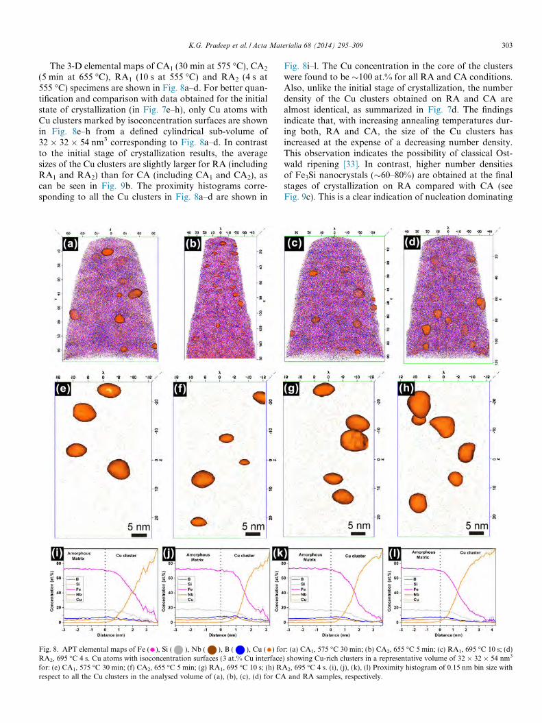
The 3-D elemental maps of CA1 (30 min at 575 �C), CA2
(5 min at 655 �C), RA1 (10 s at 555 �C) and RA2 (4 s at555 �C) specimens are shown in Fig. 8a–d. For better quan-tification and comparison with data obtained for the initialstate of crystallization (in Fig. 7e–h), only Cu atoms withCu clusters marked by isoconcentration surfaces are shownin Fig. 8e–h from a defined cylindrical sub-volume of32 � 32 � 54 nm3 corresponding to Fig. 8a–d. In contrastto the initial stage of crystallization results, the averagesizes of the Cu clusters are slightly larger for RA (includingRA1 and RA2) than for CA (including CA1 and CA2), ascan be seen in Fig. 9b. The proximity histograms corre-sponding to all the Cu clusters in Fig. 8a–d are shown in
Fig. 8. APT elemental maps of Fe ( ), Si ( ), Nb ( ), B ( ), Cu ( ) foRA2, 695 �C 4 s. Cu atoms with isoconcentration surfaces (3 at.% Cu interfacefor: (e) CA1, 575 �C 30 min; (f) CA2, 655 �C 5 min; (g) RA1, 695 �C 10 s; (h) Rrespect to all the Cu clusters in the analysed volume of (a), (b), (c), (d) for CA
Fig. 8i–l. The Cu concentration in the core of the clusterswere found to be �100 at.% for all RA and CA conditions.Also, unlike the initial stage of crystallization, the numberdensity of the Cu clusters obtained on RA and CA arealmost identical, as summarized in Fig. 7d. The findingsindicate that, with increasing annealing temperatures dur-ing both, RA and CA, the size of the Cu clusters hasincreased at the expense of a decreasing number density.This observation indicates the possibility of classical Ost-wald ripening [33]. In contrast, higher number densitiesof Fe3Si nanocrystals (�60–80%) are obtained at the finalstages of crystallization on RA compared with CA (seeFig. 9c). This is a clear indication of nucleation dominating
r: (a) CA1, 575 �C 30 min; (b) CA2, 655 �C 5 min; (c) RA1, 695 �C 10 s; (d)) showing Cu-rich clusters in a representative volume of 32 � 32 � 54 nm3
A2, 695 �C 4 s. (i), (j), (k), (l) Proximity histogram of 0.15 nm bin size withand RA samples, respectively.

Fig. 9. Summary of (a) Fe3Si nanocrystallite size, (b) Cu cluster size determined from APT, (c) calculated number densities of Fe3Si nanocrystals N and (d)number density of Cu clusters estimated from the analysed volume of APT for RA and CA conditions: 4 s, RA2; 10 s, RA1; 5 min, CA2; and 30 min, CA1.
304 K.G. Pradeep et al. / Acta Materialia 68 (2014) 295–309
the growth process of Fe3Si nanocrystals during RA. It canfurther be validated by the estimated 30% decrease in thenumber density of nanocrystals on CA1, as shown inFig. 9c, where longer annealing time seems to have facili-tated growth. Therefore, it is suggested that nucleation isspontaneous during RA at higher temperatures, whereasgrowth is limited by the short annealing time, which resultsin progressive nucleation even at higher temperatures.
4. Discussion
4.1. Influence of Cu on Fe–Si nanocrystallization
4.1.1. Cu clusters as effective nucleation sites
The experimental results on RA clearly indicate that theonset of Cu clustering (�500 �C) occurs prior to the pri-mary crystallization (�555 �C) of Fe3Si nanocrystals.These observations are very similar and also in good agree-ment with the observations of Hono et al. [12], who showedthat the Cu clusters are present in the amorphous matrixafter annealing below the crystallization temperature underCA conditions. Therefore, the original purpose of havingCu clusters acting as heterogeneous nucleation sites seems
to be satisfied on RA, but the effectiveness with which allthe clustered Cu atoms act as potential heterogeneousnucleating sites for Fe3Si nanocrystallization needs to betested. SANS investigations on FINEMET and modifiedFINEMET alloys have particularly emphasized the needfor having optimum Cu content in the alloy in order toachieve highest permeability [16]. The alloys optimizedfor Cu content show the highest number density of Cu clus-ters at the onset of primary crystallization, resulting inobtaining the finest possible Fe3Si nanocrystalline structureat the final stages of crystallization, which determines themagnetic properties [16]. In contrast, the present observa-tions clearly indicated a �25% reduction in the numberdensity of Cu clusters from the absolute maximum at theinitial stages of crystallization (555 �C) (see Fig. 4). Thisindicates coarsening of Cu clusters prior to the primarycrystallization event. To further validate this point, theonset of Cu clustering as �500 �C for RA (as shown inFig. 4) is now considered, based on the chosen cluster anal-ysis parameters for filtering out realistic clusters, irrespec-tive of the fact that the onset of Cu clustering wasobserved �450 �C. The underestimated temperature differ-ence between the onset of Cu clustering and primary

K.G. Pradeep et al. / Acta Materialia 68 (2014) 295–309 305
crystallization is >50 �C. Such a difference is large enoughfor coarsening to occur prior to the onset of crystallization[16]. Irrespective of this fact, a very high number density ofFe–Si nanocrystals in the order of �1024 m�3 wasobtained, which is slightly higher than the actual numberdensity of Cu clusters at the initial stages of crystallizationduring RA2, but slightly lower in the case of RA1 (seeFig. 9c and d). Even though the crystallographic informa-tion on the Cu clusters is unknown in the present work,these observations clearly indicate the effectiveness of Cuclusters serving as heterogeneous nucleation sites by induc-ing chemical inhomogeneities in the amorphous matrix, asshown by the proxigrams in Fig. 7i–l [15]. It can be con-cluded that a lower number density of nucleation sites thanthe maximum possible is, therefore, available during RA ofan alloy with 1 at.% Cu, but the reduction in absolute val-ues is still �50% higher than that obtained on CA, asshown in Fig. 9d.
4.1.2. Coarsening mechanism
The experimental results indicate that the maximum Cucluster number density is obtained after RA2 at 535 �C, andcoarsening of clusters starts prior to primary crystallization(555 �C), as can be noted from the decreasing number den-sity with increasing annealing temperature (see Fig. 4). Asindicated in Fig. 7g and h, there are instances where twoCu clusters are in direct contact with each other, the effectof which is also seen in the statistical proxigram in Fig. 7kand l, where the gradient in the Cu concentration fluctuatesbefore reaching a maximum. These observations suggestthat coarsening and coagulation of Cu clusters is activatedin the amorphous matrix by bulk diffusion of Cu. To fur-ther understand the coarsening mechanism, a comparativeview of the ambient Cu cluster environment between stageI and stage III specimens of the RA2 condition is consid-ered, as shown in Fig. 10. A cylindrical representative vol-ume of 32 � 32 � 54 nm3 with only Cu atoms and clustersin the form of isoconcentration surface corresponding tothe 535 �C annealed condition from Fig. 3 is shown inFig. 10a. Two Cu clusters interconnected by necks can beidentified. A one-dimensional (1-D) concentration profileusing a cylindrical volume of 1 � 1 � 15 nm3 along thenecking region (inset of Fig. 10b) of one of the intercon-nected cluster pairs marked by the rectangle in Fig. 10a isshown in Fig. 10b. Significant enrichment of Cu by a factorof at least 35 with respect to the Fe-rich amorphous matrixCu concentration of 0.2 at.% is realized in the neckingregion. In contrast, during stage III coarsening, the Cuclusters are otherwise well separated from each other bythe already nucleated Fe3Si nanocrystals, as shown inFig. 10c. Therefore, the environment necessary for earlystage bulk Cu cluster coagulation as a coarsening mecha-nism is no longer possible. Thus, two different mechanismsare proposed for the concomitant Cu cluster growth andcoarsening, namely: (a) a diffusion–coagulation mechanismof coarsening in the very early stages, namely, in stage Iand to some extent at the beginning of stage II; and (b)
classical Oswald ripening driven by the evaporation–con-densation mechanism from the later part of stage II untilthe end of stage III.
The present investigation is a clear case where nucle-ation, growth and coarsening are occurring simultaneouslyas the Cu clusters evolve, which in an ideal case could betreated as distinct processes [33]. The primary reasonbehind the clustering of Cu atoms is the limited solubilityof Cu in the a-Fe matrix [12,27]. As the clusters nucleateduring annealing, the driving force for the reduction ininterface energy initiates coarsening. The minimization oftotal energy when all the clusters coarsen into one hugeCu cluster mass is followed over a sequence of coarseningsteps, as shown in Fig. 3 with respect to RA in the presentcase [33]. Therefore, the two different mechanisms pro-posed for Cu cluster coarsening are highly influenced bythe surrounding environment. During stage I, Cu clustersnucleate vigorously and attain maximum densities beforethe primary crystallization, but are still present in aquasi-infinite amorphous matrix reservoir. Therefore, theaverage distances between two clusters are expected to bevery small, so the probability of finding a nearest-neigh-bour Cu cluster with overlapping diffusion fields is high.As a result, during stage I and at the beginning of stageII with very low crystalline fraction, the suggested diffu-sion–coagulation mechanism can be activated [33,34]. Sud-brack et al. [34] made similar observations of precipitatesfollowing such a mechanism in a model Ni–Al–Cr superal-loy. In contrast, in the later regime of stage II, when thecrystalline fraction Vf reaches �50% until the end of stageIII, the Cu clusters are well separated from each other bythe nucleated Fe3Si nanocrystals, and so individual Cuatoms have to dissolve from smaller clusters and diffusethrough the amorphous matrix to condense eventually atthe larger clusters by the evaporation–condensation mech-anism. From the experimental observations in Fig. 3, it isconfirmed that the sequential coarsening of Cu clustersduring RA2 is governed by two different mechanisms, asmentioned above, and the relevance of either of them beingactive depends on the ambient surrounding environment.
4.2. Mechanism of Fe–Si nanocrystallization
As shown in Fig. 9c, an estimated 60–80% increase inthe number density of Fe3Si nanocrystals is obtained onRA in the initial stages of crystallization, i.e. stage II.The above estimation correlates well with the identicalincrease in the number density of Cu clusters on RA com-pared with CA, as shown in Fig. 9d. Therefore, a directone-to-one relationship exists between the number densitiesof clustered Cu atoms and the nucleated nanocrystals forboth RA and CA, which is also in good agreement withthe observations of Hono et al. [12]. However, during thefinal stages of crystallization in stage III, the number den-sities of Cu cluster decreased to a minimum, and yet therewas no observable reduction in the number density of thenanocrystals. Therefore, it could be inferred that there is

Fig. 10. (a) APT elemental maps of Cu ( ) and Cu-rich clusters delineated by 3 at.% isoconcentration surfaces in a representative volume of32 � 32 � 54 nm3 for stage I, RA2: 535 �C 4 s. (b) 1-D concentration profile along a cylindrical volume of 1 � 1 � 15 nm3 along the necking region (shownin inset) of one of the interconnected cluster pair marked by rectangle in (a). (c) 3-D elemental map of RA2: 695 �C 4 s, stage III final crystallization with allthe alloying elements in their respective isoconcentration surfaces clearly depicting the actual nanostructure of the alloy. Isoconcentration values Fe:80 at.% ( ), Si 20 at.% ( ), Nb 8 at.% ( ), B 13 at.% ( ), Cu 3 at.% ( ). (d) Proximity histogram of 0.15 nm bin width with respect to all the Si-richregions in (c), indicating the composition of the Fe–Si nanocrystals and the amorphous matrix.
306 K.G. Pradeep et al. / Acta Materialia 68 (2014) 295–309
progressive nucleation in spite of decreasing heterogeneousnucleation sites. In the present work, the structure of theCu clusters was not determined, but it has already beenestablished with considerable evidence from X-ray absorp-tion fine structure measurements that the Cu clusters attaina nearest-neighbour structure similar to face-centred cubic(fcc) Cu directly from the amorphous matrix [31,35,36].Based on such observations, Hono et al. [12] proposedthe heterogeneous nucleation model for Fe–Si nanocrystal-lization on the surface of fcc Cu clusters, following therationale that the interfacial energy is minimum followingeither the Nishiyama–Wasserman or the Kurdjumov–Sachs orientation relationship, supported chemically bythe pile-up of Fe atoms around the clusters. Alternatively,
there were also reports on the possibility of chemical fluc-tuation induced Fe–Si nanocrystallization as Cu atomssubstitute Fe atoms during clustering, resulting in regionsof Fe or Si enrichment, which also crystallize separatelyfrom Cu-rich regions [15]. In addition, Chen et al. [14] dem-onstrated that only those Cu clusters that are in the sizerange of 4–5 nm act as heterogeneous nucleation sites.Thus, several reports have shown experimentally the vari-ous possible modes of nanocrystallization. In the presentinvestigation, particularly during RA, the overall durationfor processing is only a few seconds (4–10 s), irrespective ofthe annealing temperatures used. Therefore, the mecha-nism of Fe–Si nanocrystallization could be a combinationof chemical fluctuation induced Fe–Si enrichments in the

Fig. 11. Schematic illustration of the nanostructure evolution during RAof amorphous Fe73.5Si15.5Cu1Nb3B7 alloy by primary crystallization. Thechemical fluctuation caused by the Cu clusters can induce Fe–Sinanocrystallization as Cu atoms substitute Fe atoms during clustering,resulting in regions of Fe or Si enrichment, so that individual Fe–Sinanocrystallization independent of Cu clusters becomes possible [15].
K.G. Pradeep et al. / Acta Materialia 68 (2014) 295–309 307
amorphous matrix, which might then crystallize homoge-neously because of the higher annealing temperaturesachieved during RA, irrespective of the structural influenceexerted by supposedly crystalline Cu clusters.
In order to understand the Fe–Si nucleation mechanismbetter, the diffusivity of Fe was estimated. Owing to thefact that Fe is the major matrix element and subsequentdiffusion of Si into Fe-rich regions followed by DO3 order-ing is only a second order transition, Si diffusivity has alimited effect on the nucleation process [12]. Also, theXRD peak in Fig. 2a close to the onset of crystallizationdoes not show any additional peaks corresponding toDO3 ordering, but these are visible at later stages. Assum-ing that the diffusivity of Fe DFe is independent of concen-tration and assuming further spherical crystals of radius r,DFe can be estimated using the equation
r ¼ affiffiffiffiffiffiffiffiffiDFet
pð2Þ
where t is the annealing time, and a a dimensionlessparameter evaluated from the concentration at the crys-tal–amorphous matrix interface [37,38]. The present anal-ysis gives minimum Fe diffusivities of 1.3 � 10–17 m2 s�1
and 2.5 � 10–17 m2 s�1 for RA2 at the onset of crystalliza-tion (555 �C) and at the final stages of crystallization(695 �C), respectively. The estimated values for RA areorders of magnitude higher than the estimated diffusivitiesduring CA (�10–20 m2 s�1), which are in good agreementwith the bulk diffusivities in Finemet alloys at 490 �C,where Nb diffusion in the amorphous matrix was foundto be growth controlling [38]. Such an increase is ex-pected, as RA proceeds at higher temperatures than CAby at least 100 �C. This finding implies that RA leadsto higher diffusion lengths of Fe (thermally driven) thanCA. Thus, the crystallization of clustering-induced Fe–Si-enriched regions in the amorphous matrix is highlylikely, considering the temperature effect in addition, toa limited extent, to the direct Cu cluster-induced hetero-geneous nanocrystallization.
4.3. Heterogeneous nucleation model
Hono et al. [12] proposed a heterogeneous nucleationmodel based on their observation of Cu clusters at theinterface of the Fe-rich nanocrystals and the rest of theamorphous matrix using APT. This model was slightly dif-ferent from the earlier proposed model of Ayers et al. [31],where the nanocrystals were shown to be enveloping the Cuclusters during growth. The present results further confirmthat the Cu clusters form in the amorphous matrix andcoarsen prior to nanocrystallization, as shown inFig. 10a. After the final stages of crystallization (seeFig. 10c), a certain number of clusters are found to be indirect contact with Fe–Si nanocrystals, but at the nanocrys-tal/amorphous matrix interface. This observation confirmsthat the nanocrystals do not envelope Cu clusters duringgrowth, i.e. the model proposed by Hono et al. [12] applies.
However, there are some differences in the mode of crystal-lization, which are described below in detail.
Based on the experimental results and observations atthree different stages of RA, a modified heterogeneousnucleation model is proposed for RA, as shown by a sche-matic in Fig. 11. In the as-prepared amorphous condition,all the elements are randomly distributed. On annealingprior to the onset of primary crystallization, i.e. stage I,Cu atoms form clusters by rejecting all the other atoms.At this stage, the measured Cu concentration in the clus-ters, as shown in Fig. 10b, is �25 at.%, with an average sizeof �1.5 nm diameter (see Fig. 4). As per the earlier reports,Cu concentration as low as �25 at.% measured at this stageis unlikely to have a close-packed fcc structure as well as asize is small enough to play an active role in Fe–Si nano-crystallization [14,36]. But a certain fluctuation in the dis-tribution of other elements (see Fig. 10b), includinglocalized enrichments of Fe and Si atoms at random sitesmarked by a dotted rectangle (expected to be 61 nm insize) are created in the amorphous matrix, owing to theclustering of Cu atoms. Such enrichment is highly likelyto transform into a nanocrystal at slightly higher tempera-tures, irrespective of the structure of the Cu cluster. More-over, it is shown in Figs. 4 and 10a that the coarsening ofCu clusters is also observed at this stage, and so the num-ber of nucleation sites will be decreased during the onset ofprimary crystallization. Following the same argument, it isobvious that the higher the number density of Cu clustersprior to crystallization, the higher the availability of Fe

308 K.G. Pradeep et al. / Acta Materialia 68 (2014) 295–309
enrichment. The observed cluster–coagulation mechanismof Cu cluster growth at this stage will increase the forma-tion of Fe-rich regions.
During stage II of RA, the Cu clusters l have alreadycoarsened to �2.5 nm in size (see Fig. 4), and the onsetof primary crystallization is realized. Also, the Cu concen-tration of clusters is increased significantly at this stage to>95 at.% (see Fig. 7k and l). The Cu clusters can have asimilar structure to that of fcc Cu only beyond this stage.As depicted in Fig. 11, the progressive coarsening willresult only in increasing the number density of Fe enrichedregions, while crystallizing the already enriched regionsinto Fe-rich nanocrystals. Until now, the role of Cu clus-ters as a heterogeneous nucleation site can only be consid-ered in terms of structures inducing chemical fluctuations,while in stage III, the Cu clusters should be fully crystal-lized, considering their significantly coarsened size (5–6 nm from Fig. 4). However, according to previous reports,only these Cu clusters can nucleate Fe–Si nanocrystalsbased on structural orientation relationships, as discussedearlier [14]. In contrast, at stage III, a minimum Fe–Si crys-talline fraction of �60 vol.% has already formed, whichstrongly supports the suggestion that the chemical fluctua-tions induced by Cu clustering are actually responsible forthe Fe–Si nanocrystallization. This effect is referred to as apseudo-homogeneous nucleation mechanism, since thenucleation proceeds homogeneously, but it does so insidea matrix that is chemically inhomogeneous owing to thepreceding chemical matrix decomposition caused by theCu clustering. Such an argument is further strengthenedby Fig. 9c and d, where the number density of Cu clustershas decreased to a minimum at stage III, but the Fe–Sinanocrystal number density remains high, of order�1024 m�3, similar to the estimated values at the initialstages of crystallization (stage II). Considering the extre-mely short time (4–10 s) of processing during RA, it ishighly unlikely that every Fe–Si nanocrystal nucleatesalong the periphery of Cu clusters and diffuses into theamorphous matrix as a bulk nanocrystal.
A confirmation of the effect proposed here can be real-ized from the stage III experimental result shown inFig. 10c. The 3-D elemental map of the 695 �C 4 sannealed sample showing Cu clusters, Fe–Si nanocrystalsand the amorphous matrix in terms of their respective iso-concentration surfaces depicts the nanostructure in amore realistic topological fashion. It must be noted thatthe different stages studied during RA are concomitant.From Fig. 10c, it is obvious that only a few Fe–Si nano-crystals are found to be in close proximity to the Cu clus-ters, while a majority of nanocrystals are well separatedfrom the Cu clusters. This topological observation furtherconfirms the proposed model of chemical fluctuation-induced nanocrystallization. Spontaneous nanocrystalliza-tion from a fully amorphous state during RA indicatesthat the higher crystallization temperatures achieved asa result of higher heating rates enforce crystallization oflocally enriched regions. Similar behaviour of spontane-
ous crystallization has been noticed on Finemet alloysduring DC Joule heating, where high heating rates com-parable with RA were achieved [17,39]. The measuredSi concentration in the nanocrystals during stage III(�21 at.% from Fig. 10d) is higher compared with thosemeasured during stage II (�18 at.% from Fig. 7i–l).Therefore, RA produces chemically and structurally sim-ilar types of nanocrystals compared with that of CA,which is also in good agreement with previous reports[11,12,27]. Therefore, the mechanism of chemical fluctua-tion induced nanocrystallization proposed here is similarto earlier suggestions except for the fact that massivenucleation of Fe–Si nanocrystals occurs pseudo-homoge-neously during RA [12].
4.4. Magnetic properties
The smaller grain size achieved in these alloys reducesthe average contribution of the magneto-crystalline anisot-ropy associated with the randomly oriented grains, and soprovides potential for yielding improved soft magneticproperties [40]. However, for the present alloy composi-tion, the grain size after CA is already so small (�15 nm)that the random anisotropy contribution is hardly visible,such that the soft magnetic properties are rather deter-mined by more macroscopic anisotropy contributions(magneto-elastic or annealing-induced anisotropy) and/orthe surface quality of the ribbons [40,41]. The RA2 samplesrevealed a small creep-induced anisotropy of �500 J m�3,since a minimum stress is necessary to continuously trans-port the ribbons through the furnace [13]. This anisotropyis about two orders of magnitude larger than the randomanisotropy contribution and governs the magnetizationprocess [13,41]. Therefore, within the experimental scatter,the coercivity is about the same as in the case of CA underthe same stress conditions.
5. Summary and conclusions
The nanostructure of a Fe73.5Si15.5Cu1Nb3B7 alloy atthree different stages of nucleation and growth cycle onRA and CA was investigated using XRD, TEM andAPT. The following conclusions are drawn.
1. In spite of employing a set of extremely different anneal-ing conditions, the final Fe–Si nanocrystalline structureand the chemical composition remain basically thesame.
2. APT revealed the simultaneous onset and coarsening ofCu clusters during stage I, i.e. prior to primary crystal-lization on RA. These clusters act as indirect heteroge-neous nucleation sites by inducing chemicalinhomogeneities in the amorphous matrix. These chem-ical heterogeneities in the amorphous matrix act asnuclei during nanocrystallization. This mechanism isreferred to as chemical fluctuation-inducednanocrystallization.

K.G. Pradeep et al. / Acta Materialia 68 (2014) 295–309 309
3. RA resulted in the formation of �30% smaller Fe–Sinanocrystals with very high number densities of theorder of �1024 m�3 compared with CA during the finalstages of crystallization. This is a direct consequence ofa shorter processing time (4–10 s) during RA at higherannealing temperatures, where growth is restricted.Therefore, a nucleation-dominated mechanism of nano-crystallization is introduced.
4. The coarsening of Cu clusters starts initially by a diffu-sion–coagulation mechanism in the amorphous matrixprior to primary crystallization. On sufficient(>50 vol.%) crystallization, the coarsening is further dri-ven by classical Ostwald ripening through the conven-tional evaporation–condensation mechanism.
5. The observed coarsening of Cu clusters prior to primarycrystallization during RA has resulted in a reduction inthe number density of available nucleation sites, whichopens up the possibility for further optimization of theCu content, enabling new alloy design opportunities.
6. Even though the coarsening of Cu clusters was observedduring the initial stages of crystallization, RA still yieldsa �80% higher number density of Cu clusters comparedwith CA.
Acknowledgement
The authors would like to thank Dr. Masato Ohnuma(Hokkaido University, Japan) for helpful discussions.
References
[1] Yoshizawa Y, Oguma S, Yamauchi K. J Appl Phys 1988;64:6044.[2] Yoshizawa Y, Yamauchi K. Mater Trans JIM 1990;31:307.[3] Yoshizawa Y, Yamauchi K. IEEE Trans Magn 1989;25:3324.[4] Yoshizawa Y, Fujii S, Ping DH, Ohnuma M, Hono K. Scripta Mater
2003;48:863.[5] Herzer G. Mater Sci Eng A 1991;133:1.[6] Herzer G. Acta Mater 2013;61:718.[7] Herzer G, Flohrer S, Polak Ch. IEEE Trans Magn 2010;46:341.[8] Herzer G. Soft magnetic materials – nanocrystalline alloys. In:
Kronmuller Helmut, Parkin Stuart, editors. Handbook of magnetismand advanced materials. Novel materials. New York: John Wiley, vol.4; 2007. p. 1882.
[9] Flohrer S, Schafer R, Herzer G. J Non-Crystal Sol 2008;354:5097.[10] Hono K, Inoue A, Sakurai T. Appl Phys Lett 1991;58:2180.
[11] Herzer G. Nanocrystalline soft magnetic alloys. In: Buschow KHJ,editor. Handbook of magnetic materials, vol. 10. Amsterdam: Elsevier;1997.
[12] Hono K, Ping DH, Ohnuma M, Onodera H. Acta Mater 1999;47:997.[13] Herzer G, Budinsky V, Polak C. Phys Status Solidi B 2011;248:2382.[14] Chen YM, Ohkubo T, Ohta M, Yoshizawa Y, Hono K. Acta Mater
2009;57:4463.[15] Hono K, Li JL, Ueki Y, Inoue A, Sakurai T. Appl Surf Sci
1993;67:398.[16] Ohnuma M, Hono K, Linderoth S, Pedersen JS, Yoshizawa Y,
Onodera H. Acta Mater 2000;48:4783.[17] Allia P, Baricco M, Knobel M, Tiberto P, Vinai F. J Mag Mag Mater
1994;133:243.[18] Cullity BD, Stock SR. Elements of X-Ray diffraction. Upper Saddle
River, NJ: Prentice Hall; 2001.[19] Pradeep KG, Wanderka N, Choi P, Banhart J, Murty BS, Raabe D.
Acta Mater 2013;61:4696.[20] Miller MK, Cerezo A, Hetherington MG, Smith GDW. Atom probe
field ion microscopy. Oxford: Clarendon Press; 1996.[21] Miller MK. Atom probe tomography analysis at the atomic
scale. New York: Kluwer Academic/Plenum; 2000.[22] Kelly TF, Miller MK. Rev Sci Instrum 2007;78:031101.[23] Seidman D. Annu Rev Mater Sci 2007;37:127.[24] Marquis EA, Miller MK, Blavette D, Ringer SP, Sudbrack CK,
Smith GDW. MRS Bull 2009;34:725.[25] Isheim D, Gagliano MS, Fine ME, Seidman DN. Acta Mater
2006;54:841.[26] Raabe D, Choi P, Li Y, Kostka A, Sauvage X, Lecouturier F, et al.
MRS Bull 2010;35:982.[27] Hono K. Prog. Mater. Sci. 2002;47:621.[28] Thompson K, Lawrence D, Larson DJ, Olson JD, Kelly TF, Gorman
B. Ultramicrosc 2007;107:131.[29] Marquis EA, Hyde JM. Mater Sci Eng R 2010;69:37.[30] Vurpillot F, Bostel A, Blavette D. Appl Phys Lett 2000;76:3127.[31] Ayers JG, Harris VG, Sprague JA, Elam WT, Jones HN. Acta Mater
1998;46:1861.[32] Mattern N, Danzig A, Muller M. Mater Sci Eng A 1995;194:77.[33] Wagner R, Kampmann R, Voorhees PW. Homogeneous second-
phase precipitation. In: Kosortz G, editor. Phase transformations inmaterials. Weinheim: Wiley-VCH; 2001. p. p. 309.
[34] Sudbrack CK, Yoon KE, Noebe RD, Seidman DN. Acta Mater2006;54:3199.
[35] Sakurai M, Matsuura M, Kim SH, Yoshizawa Y, Yamauchi K,Suzuki K. Mater Sci Eng A 1994;A179/A180:469.
[36] Kim SH, Matsuura M, Sakurai M, Suzuki K. Jpn J Appl Phys1992;32:676.
[37] Koster U. Key Eng Mater 1993;81–83:647.[38] Koster U, Schunemann U, Blank-Bewersdorff M, Brauer S, Sutton
M, Stephenson GB. Mater Sci Eng A 1991;133:611.[39] Allia P, Baricco M, Tiberto P, Vinai F. Rev Sci Instrum 1993;64:1053.[40] Herzer G. IEEE Trans Magn 1990;26:1397.[41] Herzer G. J Magn Magn Mater 2005;294:99.