Atlas Digital Amplifier User's Manual - Mouser Electronics
84
Performance Motion Devices, Inc. 1 Technology Park Drive Westford, MA 01886 Atlas Digital Amplifier User’s Manual Revision 2.0 February, 2017
-
Upload
khangminh22 -
Category
Documents
-
view
0 -
download
0
Transcript of Atlas Digital Amplifier User's Manual - Mouser Electronics

Performance Motion Devices, Inc.1 Technology Park Drive
Westford, MA 01886
Atlas Digital AmplifierUser’s Manual
Revision 2.0 February, 2017

ii Atlas Digital Amplifier User’s Manual
NOTICE
This document contains proprietary and confidential information of Performance Motion Devices, Inc., and is pro-tected by federal copyright law. The contents of this document may not be disclosed to third parties, translated, copied, or duplicated in any form, in whole or in part, without the express written permission of PMD.
The information contained in this document is subject to change without notice. No part of this document may be reproduced or transmitted in any form, by any means, electronic or mechanical, for any purpose, without the express written permission of PMD.
Copyright 1998–2017 by Performance Motion Devices, Inc.
ATLAS, Magellan, ION, Magellan/ION, Pro-Motion, C-Motion and VB-Motion are trademarks of Performance Motion Devices, Inc.

Atlas Digital Amplifier User’s Manual iii
Warranty
PMD warrants that its products shall substantially comply with the specifications applicable at the time of sale, provided that this warranty does not extend to any use of any PMD product in anUnauthorized Application (as defined below). Except as specifically provided in this paragraph, each PMD product is provided “as is” and without warranty of any type, including without limitation implied warranties of merchantability and fitness for any particular purpose.
PMD reserves the right to modify its products, and to discontinue any product or service, without notice and advises customers to obtain the latest version of relevant information (including without limitation product specifications) before placing orders to verify the performance capabilities of the products being purchased. All products are sold subject to the terms and conditions of sale supplied at the time of order acknowledgment, including those pertaining to warranty, patent infringement and limitation of liability.
Unauthorized Applications
PMD products are not designed, approved or warranted for use in any application where failure of the PMD product could result in death, personal injury or significant property or environmental damage (each, an “Unauthorized Application”). By way of example and not limitation, a life support system, an aircraft control system and a motor vehicle control system would all be considered “Unauthorized Applications” and use of a PMD product in such a system would not be warranted or approved by PMD.
By using any PMD product in connection with an Unauthorized Application, the customer agrees to defend, indemnify and hold harmless PMD, its officers, directors, employees and agents, from and against any and all claims, losses, liabilities, damages, costs and expenses, including without limitation reasonable attorneys’ fees, (collectively, “Damages”) arising out of or relating to such use, including without limitation any Damages arising out of the failure of the PMD product to conform to specifications.
In order to minimize risks associated with the customer’s applications, adequate design and operating safeguards must be provided by the customer to minimize inherent procedural hazards.
Disclaimer
PMD assumes no liability for applications assistance or customer product design. PMD does not warrant or represent that any license, either express or implied, is granted under any patent right, copyright, mask work right, or other intellectual property right of PMD covering or relating to any combination, machine, or process in which such products or services might be or are used. PMD’s publication of information regarding any third party’s products or services does not constitute PMD’s approval, warranty or endorsement thereof.

iv Atlas Digital Amplifier User’s Manual
Related Documents
Atlas Digital Amplifier Complete Technical Reference
Complete electrical and mechanical description of the Atlas Digital Amplifier with detailed theory ofoperations.
Magellan Motion Control IC User’s Guide
Complete description of the Magellan Motion Control IC features and functions with detailed theory ofoperations.
Magellan Motion Control Developer’s Kit User’s Manuals
How to install, configure, and operate the DK58000 series, DK55000 series, and MC58113 series MagellanMotion Control IC Developer’s Kits.
Pro-Motion User’s Guide
User’s guide to Pro-Motion, the easy-to-use motion system development tool and performance optimizer.Pro-Motion is a sophisticated, easy-to-use program which allows all motion parameters to be set and/orviewed, and allows all features to be exercised.
Table of Contents
1. Introduction. . . . . . . . . . . . . . . . . . . . . . . . . . . . . . . . . . . . . . . . . . . . . . . . . . 91.1 Atlas Digital Amplifier Overview . . . . . . . . . . . . . . . . . . . . . . . . . . . . . . . . . . . . . . . . . . 91.2 Typical Applications . . . . . . . . . . . . . . . . . . . . . . . . . . . . . . . . . . . . . . . . . . . . . . . . . . . . . 101.3 Features and Functions. . . . . . . . . . . . . . . . . . . . . . . . . . . . . . . . . . . . . . . . . . . . . . . . . . 121.4 Atlas Developer’s Kit . . . . . . . . . . . . . . . . . . . . . . . . . . . . . . . . . . . . . . . . . . . . . . . . . . . . 132. Functional Characteristics . . . . . . . . . . . . . . . . . . . . . . . . . . . . . . . . . . . . 152.1 Operational Specifications. . . . . . . . . . . . . . . . . . . . . . . . . . . . . . . . . . . . . . . . . . . . . . . 152.2 Physical Dimensions . . . . . . . . . . . . . . . . . . . . . . . . . . . . . . . . . . . . . . . . . . . . . . . . . . . . 162.3 Mechanical Mounting Options. . . . . . . . . . . . . . . . . . . . . . . . . . . . . . . . . . . . . . . . . . . 183. Electrical Specifications . . . . . . . . . . . . . . . . . . . . . . . . . . . . . . . . . . . . . . 233.1 Drive Ratings. . . . . . . . . . . . . . . . . . . . . . . . . . . . . . . . . . . . . . . . . . . . . . . . . . . . . . . . . . . . 233.2 Absolute Maximum Ratings . . . . . . . . . . . . . . . . . . . . . . . . . . . . . . . . . . . . . . . . . . . . . 243.3 Environmental Ratings . . . . . . . . . . . . . . . . . . . . . . . . . . . . . . . . . . . . . . . . . . . . . . . . . . 253.4 Safety and Compliance . . . . . . . . . . . . . . . . . . . . . . . . . . . . . . . . . . . . . . . . . . . . . . . . . . 253.5 DC Characteristics . . . . . . . . . . . . . . . . . . . . . . . . . . . . . . . . . . . . . . . . . . . . . . . . . . . . . . . 253.6 AC Characteristics . . . . . . . . . . . . . . . . . . . . . . . . . . . . . . . . . . . . . . . . . . . . . . . . . . . . . . . 273.7 Pin Descriptions and Pinouts . . . . . . . . . . . . . . . . . . . . . . . . . . . . . . . . . . . . . . . . . . . . 273.8 Signal Interfacing . . . . . . . . . . . . . . . . . . . . . . . . . . . . . . . . . . . . . . . . . . . . . . . . . . . . . . . 323.9 Connection Overview . . . . . . . . . . . . . . . . . . . . . . . . . . . . . . . . . . . . . . . . . . . . . . . . . . . 333.10 Heat Sink Grounding . . . . . . . . . . . . . . . . . . . . . . . . . . . . . . . . . . . . . . . . . . . . . . . . . . . . 363.11 Atlas Conversion Factors . . . . . . . . . . . . . . . . . . . . . . . . . . . . . . . . . . . . . . . . . . . . . . . . 364. Operation . . . . . . . . . . . . . . . . . . . . . . . . . . . . . . . . . . . . . . . . . . . . . . . . . . . 394.1 Functional Overview . . . . . . . . . . . . . . . . . . . . . . . . . . . . . . . . . . . . . . . . . . . . . . . . . . . . 394.2 Internal Block Diagram . . . . . . . . . . . . . . . . . . . . . . . . . . . . . . . . . . . . . . . . . . . . . . . . . . 404.3 Commutation . . . . . . . . . . . . . . . . . . . . . . . . . . . . . . . . . . . . . . . . . . . . . . . . . . . . . . . . . . . 414.4 Current Loop. . . . . . . . . . . . . . . . . . . . . . . . . . . . . . . . . . . . . . . . . . . . . . . . . . . . . . . . . . . . 424.5 Power Stage . . . . . . . . . . . . . . . . . . . . . . . . . . . . . . . . . . . . . . . . . . . . . . . . . . . . . . . . . . . . 434.6 Status Registers . . . . . . . . . . . . . . . . . . . . . . . . . . . . . . . . . . . . . . . . . . . . . . . . . . . . . . . . . 434.7 Safety Processing Functions . . . . . . . . . . . . . . . . . . . . . . . . . . . . . . . . . . . . . . . . . . . . . 444.8 Step Motor Control. . . . . . . . . . . . . . . . . . . . . . . . . . . . . . . . . . . . . . . . . . . . . . . . . . . . . . 474.9 User Memory Space & Buffers. . . . . . . . . . . . . . . . . . . . . . . . . . . . . . . . . . . . . . . . . . . . 494.10 Trace Capture . . . . . . . . . . . . . . . . . . . . . . . . . . . . . . . . . . . . . . . . . . . . . . . . . . . . . . . . . . . 494.11 Power-Up & Non-Volatile Initialization Storage . . . . . . . . . . . . . . . . . . . . . . . . . . . 504.12 SPI Communications Overview . . . . . . . . . . . . . . . . . . . . . . . . . . . . . . . . . . . . . . . . . . 50A. Atlas Developer’s Kit . . . . . . . . . . . . . . . . . . . . . . . . . . . . . . . . . . . . . . . . . 53A.1 Overview . . . . . . . . . . . . . . . . . . . . . . . . . . . . . . . . . . . . . . . . . . . . . . . . . . . . . . . . . . . . . . . 53A.2 Installation and Getting Started. . . . . . . . . . . . . . . . . . . . . . . . . . . . . . . . . . . . . . . . . . 54A.3 Atlas Carrier Card Reference Information . . . . . . . . . . . . . . . . . . . . . . . . . . . . . . . . . 56A.4 L-Bracket . . . . . . . . . . . . . . . . . . . . . . . . . . . . . . . . . . . . . . . . . . . . . . . . . . . . . . . . . . . . . . . 62B. Application Notes. . . . . . . . . . . . . . . . . . . . . . . . . . . . . . . . . . . . . . . . . . . . 65B.1 Brushless DC Atlas With Single-Axis MC58113 Motion Control IC . . . . . . . . . . 65B.2 DC Brush & Step Motor Atlas With Multi-Axis Magellan . . . . . . . . . . . . . . . . . . . 68B.3 Step Motor Atlas Operating In Pulse & Direction Mode . . . . . . . . . . . . . . . . . . . 70B.4 DC Brush Atlas With PIC Microcontroller . . . . . . . . . . . . . . . . . . . . . . . . . . . . . . . . . 72B.5 Step Motor Atlas With ARM Microcontroller . . . . . . . . . . . . . . . . . . . . . . . . . . . . . . 74B.6 Atlas Interfacing Via A Daughter Card . . . . . . . . . . . . . . . . . . . . . . . . . . . . . . . . . . . . 76B.7 Multi-motor Atlas With Single-Axis MC58113 Motion Control IC. . . . . . . . . . . 80Index . . . . . . . . . . . . . . . . . . . . . . . . . . . . . . . . . . . . . . . . . . . . . . . . . . . . . . . . . . . .83
Atlas Digital Amplifier User’s Manual v

This page intentionally left blank.
vi Atlas Digital Amplifier User’s Manual

List of Figures
1-1 Single Axis Magellan With Atlas Amplifier . . . . . . . . . . . . . . . . . . . . . . . . . . . . . . . . . . . . . . . . . . . . . . . . . . . 101-2 Multi Axis Magellan With Atlas Amplifiers . . . . . . . . . . . . . . . . . . . . . . . . . . . . . . . . . . . . . . . . . . . . . . . . . . . 111-3 Direct Host Microprocessor With Atlas Amplifiers . . . . . . . . . . . . . . . . . . . . . . . . . . . . . . . . . . . . . . . . . . . . 111-4 Direct Host Microprocessor With Atlas Amplifiers . . . . . . . . . . . . . . . . . . . . . . . . . . . . . . . . . . . . . . . . . . . . 121-5 Atlas Force Control . . . . . . . . . . . . . . . . . . . . . . . . . . . . . . . . . . . . . . . . . . . . . . . . . . . . . . . . . . . . . . . . . . . . . . . . . 121-6 Developer Kit Components . . . . . . . . . . . . . . . . . . . . . . . . . . . . . . . . . . . . . . . . . . . . . . . . . . . . . . . . . . . . . . . . . 142-1 Vertical Unit - Ultra Compact Package . . . . . . . . . . . . . . . . . . . . . . . . . . . . . . . . . . . . . . . . . . . . . . . . . . . . . . . 162-2 Horizontal Unit - Ultra Compact Package . . . . . . . . . . . . . . . . . . . . . . . . . . . . . . . . . . . . . . . . . . . . . . . . . . . . 162-3 Vertical Unit - Compact Package . . . . . . . . . . . . . . . . . . . . . . . . . . . . . . . . . . . . . . . . . . . . . . . . . . . . . . . . . . . . 172-4 Horizontal Unit - Compact Package . . . . . . . . . . . . . . . . . . . . . . . . . . . . . . . . . . . . . . . . . . . . . . . . . . . . . . . . . 172-5 Horizontal & Vertical Unit Mounting Options . . . . . . . . . . . . . . . . . . . . . . . . . . . . . . . . . . . . . . . . . . . . . . . . 192-6 Recommended Atlas Unit Thermal Transfer Material Dimensions . . . . . . . . . . . . . . . . . . . . . . . . . . . . 212-7 Atlas Torque Specifications . . . . . . . . . . . . . . . . . . . . . . . . . . . . . . . . . . . . . . . . . . . . . . . . . . . . . . . . . . . . . . . . . 223-1 Timing Diagrams . . . . . . . . . . . . . . . . . . . . . . . . . . . . . . . . . . . . . . . . . . . . . . . . . . . . . . . . . . . . . . . . . . . . . . . . . . . 273-2 Atlas Pinouts - Ultra Compact, Vertical . . . . . . . . . . . . . . . . . . . . . . . . . . . . . . . . . . . . . . . . . . . . . . . . . . . . . . 283-3 Atlas Pinouts - Ultra Compact, Horizontal . . . . . . . . . . . . . . . . . . . . . . . . . . . . . . . . . . . . . . . . . . . . . . . . . . . 283-4 Atlas Pinouts - Compact, Vertical . . . . . . . . . . . . . . . . . . . . . . . . . . . . . . . . . . . . . . . . . . . . . . . . . . . . . . . . . . . . 293-5 Atlas Pinouts - Compact, Horizontal . . . . . . . . . . . . . . . . . . . . . . . . . . . . . . . . . . . . . . . . . . . . . . . . . . . . . . . . . 293-6 Signal Interfacing ~Enable . . . . . . . . . . . . . . . . . . . . . . . . . . . . . . . . . . . . . . . . . . . . . . . . . . . . . . . . . . . . . . . . . . 323-7 Signal Interfacing FaultOut . . . . . . . . . . . . . . . . . . . . . . . . . . . . . . . . . . . . . . . . . . . . . . . . . . . . . . . . . . . . . . . . . 323-8 Brushless DC Connections . . . . . . . . . . . . . . . . . . . . . . . . . . . . . . . . . . . . . . . . . . . . . . . . . . . . . . . . . . . . . . . . . . 333-9 DC Brush Connections . . . . . . . . . . . . . . . . . . . . . . . . . . . . . . . . . . . . . . . . . . . . . . . . . . . . . . . . . . . . . . . . . . . . . . 343-10 Step Motor Pulse and Direction Mode Connections . . . . . . . . . . . . . . . . . . . . . . . . . . . . . . . . . . . . . . . . . . 353-11 Step Motor SPI Communication Connections . . . . . . . . . . . . . . . . . . . . . . . . . . . . . . . . . . . . . . . . . . . . . . . . 364-1 High Level System Diagram . . . . . . . . . . . . . . . . . . . . . . . . . . . . . . . . . . . . . . . . . . . . . . . . . . . . . . . . . . . . . . . . . 394-2 Internal Block Diagram . . . . . . . . . . . . . . . . . . . . . . . . . . . . . . . . . . . . . . . . . . . . . . . . . . . . . . . . . . . . . . . . . . . . . 404-3 Commutation Control Sequence . . . . . . . . . . . . . . . . . . . . . . . . . . . . . . . . . . . . . . . . . . . . . . . . . . . . . . . . . . . . 414-4 Current Loop Control Flow . . . . . . . . . . . . . . . . . . . . . . . . . . . . . . . . . . . . . . . . . . . . . . . . . . . . . . . . . . . . . . . . . 424-5 Current Foldback Processing Example . . . . . . . . . . . . . . . . . . . . . . . . . . . . . . . . . . . . . . . . . . . . . . . . . . . . . . 474-6 Pulse and Direction Signal Input Mode Control Flow . . . . . . . . . . . . . . . . . . . . . . . . . . . . . . . . . . . . . . . . . 484-7 User Memory Space and Buffers . . . . . . . . . . . . . . . . . . . . . . . . . . . . . . . . . . . . . . . . . . . . . . . . . . . . . . . . . . . . 494-8 Example Motion Trace Capture . . . . . . . . . . . . . . . . . . . . . . . . . . . . . . . . . . . . . . . . . . . . . . . . . . . . . . . . . . . . . 494-9 SPI Communications Protocol Overview . . . . . . . . . . . . . . . . . . . . . . . . . . . . . . . . . . . . . . . . . . . . . . . . . . . . 514-10 Sending a Voltage or Torque Output Value . . . . . . . . . . . . . . . . . . . . . . . . . . . . . . . . . . . . . . . . . . . . . . . . . . 51A-1 Developer Kit Components (four-axis version shown) . . . . . . . . . . . . . . . . . . . . . . . . . . . . . . . . . . . . . . . . 53A-2 Connecting DB9 Cable to Carrier Card . . . . . . . . . . . . . . . . . . . . . . . . . . . . . . . . . . . . . . . . . . . . . . . . . . . . . . . 54A-3 Component Placement of Vertical and Horizontal DK Carrier Cards (four-axis version shown) . 56A-4 Vertical Unit Pinouts . . . . . . . . . . . . . . . . . . . . . . . . . . . . . . . . . . . . . . . . . . . . . . . . . . . . . . . . . . . . . . . . . . . . . . . . 59A-5 Horizontal Unit Pinouts . . . . . . . . . . . . . . . . . . . . . . . . . . . . . . . . . . . . . . . . . . . . . . . . . . . . . . . . . . . . . . . . . . . . . 60A-6 Vertical and Horizontal Compact to Ultra Compact Package Signal Converters . . . . . . . . . . . . . . . 61A-7 Mounting Atlas to L-bracket Plates (four-axis, vertical version shown) . . . . . . . . . . . . . . . . . . . . . . . . 63A-8 Top and Front Views of Four-Axis Horizontal Atlas DK L-bracket Vertical Plate . . . . . . . . . . . . . . . . 64A-9 Top and Front Views of One-Axis Horizontal Atlas DK L-bracket Vertical Plate . . . . . . . . . . . . . . . . . 64B-1 Brushless DC Atlas With Single-Axis Magellan . . . . . . . . . . . . . . . . . . . . . . . . . . . . . . . . . . . . . . . . . . . . . . . 67B-2 DC Brush & Step Motor Atlas With Multi-Axis Magellan . . . . . . . . . . . . . . . . . . . . . . . . . . . . . . . . . . . . . . 69B-3 Step Motor Atlas Operating In Pulse & Direction Mode . . . . . . . . . . . . . . . . . . . . . . . . . . . . . . . . . . . . . . . 71B-4 DC Brush Atlas With PIC Microcontroller . . . . . . . . . . . . . . . . . . . . . . . . . . . . . . . . . . . . . . . . . . . . . . . . . . . . . 73B-5 Step Motor Atlas With ARM Microcontroller . . . . . . . . . . . . . . . . . . . . . . . . . . . . . . . . . . . . . . . . . . . . . . . . . 75Atlas Digital Amplifier User’s Manual vii

viii
B-6 Atlas Interfacing Via A Daughter Card #1 . . . . . . . . . . . . . . . . . . . . . . . . . . . . . . . . . . . . . . . . . . . . . . . . . . . .78B-7 Atlas Interfacing Via A Daughter Card #2 . . . . . . . . . . . . . . . . . . . . . . . . . . . . . . . . . . . . . . . . . . . . . . . . . . . .79B-8 Multi-motor Atlas With MC58113 Motion Control IC . . . . . . . . . . . . . . . . . . . . . . . . . . . . . . . . . . . . . . . . .81
Atlas Digital Amplifier User’s Manual

1
1.Introduction In This ChapterAtlas Digital Amplifier OverviewTypical ApplicationsFeatures and Functions Atlas Developer’s Kits1.1 Atlas Digital Amplifier Overview
Atlas Digital Amplifiers are single-axis amplifiers that provide high performance torque control of brushless DC, step motor, and DC Brush motors. They accept digital torque commands from an external source and are used directly for motor torque control applications, or in conjunction with higher level controllers for velocity or positioning applications. Their very compact size and range of power output levels make them an ideal solution for single-card machine controllers that require high performance in a small envelope.
Atlas digital amplifiers provide many advanced control features including user-programmable gain parameters,
performance trace, field oriented control, and I2t current management. Atlas amplifiers are powered from a single supply voltage, and provide automatic protection from overcurrent, undervoltage, overvoltage, overtemperature, and short circuit faults.
The Atlas digital amplifier family has been designed to work seamlessly with PMD’s Magellan family of motion control ICs. Alternatively, they can be used with dedicated FPGAs, digital signal processors, or general purpose microprocessors. Communication to/from Atlas amplifiers is via SPI (Serial Peripheral Interface) using a simple, packet-oriented protocol. For step motors, in addition to the SPI format a dedicated pulse & direction input mode is provided.
Atlas amplifiers are packaged in plastic and metal solderable modules and are available in an ultra compact package size
with a total footprint of 1.4 inch2 (9.0 cm2) and a compact package size with a footprint of 2.6 inch2 (16.8 cm2). They come in three power levels; 75 watts, 250 watts, and 500+ watts and utilize standard through-hole pins for all electrical connections.
Atlas amplifiers are provided in both vertical and horizontal mounting configurations and have integral attachment tabs to allow for a variety of mechanical mounting and heat sink options. The following table shows the available configurations of the Atlas Digital Amplifiers:
P/NPower Level (continuous) Voltage Size
Mounting Style Motor Type
Step MotorMD241048/02VB Low (75W) 12-48V Ultra compact Vertical Step MotorMD241048/02HB Low (75W) 12-48V Ultra compact Horizontal Step MotorMD241048/05VB Medium (250W) 12-48V Ultra compact Vertical Step MotorMD241048/05HB Medium (250W) 12-48V Ultra compact Horizontal Step MotorMD141056/25VB High (500+W) 12-56V Compact Vertical Step MotorMD141056/25HB High (500+W) 12-56V Compact Horizontal Step Motor
Atlas Digital Amplifier User’s Manual 9

Introduction1
*Multi-motor motor type allows the Atlas to be configured by the user to drive either Step Motor, Brushless DC, or DC Brush motor type.
This manual provides a description of the electrical and mechanical specifications for the Atlas Digital Amplifiers, along with a summary of its operational features. For complete documentation on all aspects of the Atlas Digital Amplifier including a programmers command reference refer to Atlas Digital Amplifier Complete Technical Reference. For more information on the Magellan Motion Control IC consult the Magellan Motion Control IC User’s Guide.
1.2 Typical Applications
The following section provides overview diagrams of typical applications utilizing the Atlas amplifier products.
1.2.1 Single Axis Positioning Motion Controller
The diagram below shows a PMD MC58113 Motion Control IC sending torque commands to an Atlas Amplifier to provide positioning control of a brushless DC, DC Brush, or Step Motor.
Figure 1-1:Single Axis Magellan With Atlas Amplifier
Brushless DCMD231048/02VB Low (75W) 12-48V Ultra compact Vertical Brushless DCMD231048/02HB Low (75W) 12-48V Ultra compact Horizontal Brushless DCMD231048/05VB Medium (250W) 12-48V Ultra compact Vertical Brushless DCMD231048/05HB Medium (250W) 12-48V Ultra compact Horizontal Brushless DCMD131056/25VB High (500+W) 12-56V Compact Vertical Brushless DCMD131056/25HB High (500+W) 12-56V Compact Horizontal Brushless DC
DC BrushMD211048/02VB Low (75W) 12-48V Ultra compact Vertical DC BrushMD211048/02HB Low (75W) 12-48V Ultra compact Horizontal DC BrushMD211048/05VB Medium (250W) 12-48V Ultra compact Vertical DC BrushMD211048/05HB Medium (250W) 12-48V Ultra compact Horizontal DC BrushMD111056/25VB High (500+W) 12-56V Compact Vertical DC BrushMD111056/25HB High (500+W) 12-56V Compact Horizontal DC Brush
Multi-MotorMD281048/02VB Low (75W) 12-48V Ultra compact Vertical Multi-motor*MD281048/02HB Low (75W) 12-48V Ultra compact Horizontal Multi-motor*MD281048/05VB Medium (250W) 12-48V Ultra compact Vertical Multi-motor*MD281048/05HB Medium (250W) 12-48V Ultra compact Horizontal Multi-motor*MD181056/25VB High (500+W) 12-56V Compact Vertical Multi-motor*MD181056/25HB High (500+W) 12-56V Compact Horizontal Multi-motor*
Brushless DC, DC Brush, orStep Motor
10 Atlas Digital Amplifier User’s Manual

Introduction 1
1.2.2 Multi Axis Positioning Motion Controller
The diagram below shows a PMD Magellan MC58000 series or MC55000 series multi-axis motion control IC being used with two or more Atlas Amplifiers to provide control of brushless DC, DC Brush, or Step Motors in a positioning application. If desired each axis can control a different motor type, so that, for example, brushless DC motors can be used along with step motors in the same controller.
Figure 1-2:Multi Axis Magellan With Atlas Amplifiers
1.2.3 Microprocessor-Based Motion Controller
The diagram below shows the Atlas Amplifier being driven by a general purpose microprocessor that provides high level path generation and servo loop closure and outputs continuous desired torque commands or desired position increments for step motors to the Atlas Amplifier via the SPI (Serial Peripheral Interface).
Figure 1-3:Direct Host Microprocessor With Atlas Amplifiers
1.2.4 Stand Alone Step Motor Amplifier
The diagram below shows the Atlas Amplifier being directly driven by pulse & direction signals. These signals may come from a microprocessor, a control card, or any other existing motion control device that outputs pulse & direction signals. In this mode the Atlas unit operates ‘stand-alone,’ and utilizes configuration control parameters previously stored into the Atlas unit’s NVRAM (non-volatile) memory.
Brushless DC, DC Brush, orStep Motor
Brushless DC, DC Brush, orStep Motor
Brushless DC, DC Brush, orStep Motor
Atlas Digital Amplifier User’s Manual 11

Introduction1
Figure 1-4:Direct Host Microprocessor With Atlas Amplifiers
There are a few options for configuring Atlas units for stand alone operation:
• Pro-Motion can be used with the Atlas Developer’s Kit to program Atlas units
• The user can develop their own NVRAM programming system by utilizing the SPI (Serial Peripheral Interface) Atlas command protocol. For more information refer to the Atlas Digital Amplifier Complete Technical Reference.
• PMD offers custom pre-configured Atlas units. For more information contact your local PMD sales representative.
1.2.5 Force Control
The Brushless DC and DC Servo Atlas units can be used for general purpose force control applications such as remote teleoperation, force feedback, solonoid actuation, and any other general purpose valve/actuator control where a precisely controllable current is needed.
In this application the torque command may be sent continuously by the host microprocessor or from time to time as required by the application. In either case the Atlas provides very accurate current/torque control resulting in smooth and precise application of force.
Figure 1-5:Atlas Force Control
1.3 Features and Functions
The Atlas family of amplifiers provide an extensive list of functions, including:
• Available in Brushless DC, DC Brush, Step Motor, and multi-motor motor types
• High performance all-digital power amplifier
• Works with Magellan ICs, FPGAs or microprocessor-based controllers
• Digital SPI interface eliminates analog +/- 10V signals
• Available in 75W, 250W, and 500W+ power levels
• Rugged plastic solderable module format uses standard through-hole pins
• Total power output to 1Kilowatt
• Available in ultra compact 1.05" x 1.05" x .53" (27mm x 27mm x 13mm) size or compact 1.52" x 1.52" x .60" (39mm x 39mm x 15mm) size
Step Motor
12 Atlas Digital Amplifier User’s Manual

Introduction 1
• Horizontal and vertical mount configurations
• Includes rugged mechanical tab mounts
• Supply voltage range of 12V up to 56V
• High current output up to 14A continuous, 25A peak
• Digital current loop with choice of standard A/B or Field Oriented Control (FOC)
• Direct signal pulse and direction input
• I2t current foldback limiting
• Overcurrent, overvoltage, undervoltage, overtemperature, and SPI command watchdog timeout protection
• Single DC supply operation.
• Enable input and FaultOut output safety interlock signals
• SPI (Serial Peripheral Interface) up to 8 MHz
• Performance trace of up to 1,020 words and four simultaneous variables
• 1,024 word non-volatile parameter storage
• Microstepping control with up to 256 microsteps per full step
• Signal conditioning buffers and analog filters on all I/O signals
• Fully RoHS compliant and CE marked
1.4 Atlas Developer’s Kit
To simplify development, an Atlas Developer’s Kit is available, shown in Figure 1-6.
Atlas Digital Amplifier User’s Manual 13

Introduction1
Figure 1-6:Developer Kit Components
The following software and hardware components are included in every Atlas Developer’s Kit:
• Pro-Motion CD and User’s Guide
• C-Motion and VB-Motion SDK CD, including PDFs of all Atlas documentation
• Atlas DK DB9 communications cable
For the following components, you will provide information that will specify how you want the DK tailored for your exact development needs:
• Specific Atlas units to be included (motor type, power level)
• Atlas carrier card (horizontal or vertical, 1 or 4 axis version)
The carrier cards are designed for direct use with the compact Atlas format. For each ultra compact Atlas ordered a converter card is provided that allows the ultra compact Atlas to be plugged into the compact carrier card socket directly.
The L-bracket provides a stable mechanical base from which you can conveniently connect and operate your prototype system motors. With the vertical plate, the Atlas units have additional heat sinking, which can be extended further by connecting the vertical plate to your own heat sink or cold plate.
Electrical connection to the Atlas DK carrier card is made by DB9 connector, and by jack screw connectors. Designers who plan to use the Atlas in conjunction with PMD’s Magellan Motion Control ICs can connect the Atlas DK to the Magellan DK card, purchased separately. For more information on this product see one of the available Magellan Motion Control IC developer’s kit user’s manuals.
Refer to Appendix A, “Atlas Developer’s Kit” for complete information on ordering, setting up and operating the Atlas DK.
����������� ���
��������������������� ���
������ ������
������������� �������������
14 Atlas Digital Amplifier User’s Manual

2
2.Functional Characteristics In This ChapterOperational SpecificationsPhysical DimensionsMechanical Mounting Options2.1 Operational SpecificationsOperating Parameter ValueMotor types supported: Brushless DC, DC Servo, Step MotorCommunication format: SPI (Serial Peripheral Interface)SPI clock frequency range: 2.0 MHz to 8.0 MHzTorque command rate: up to 9.7 kHzCurrent measurement resolution: 12 bitsCurrent loop type: P, I (proportional, integral) with Integral limitCurrent loop resolution: 16 bitsCurrent loop rate: 19.530 kHzCurrent loop modes: individual phase, field oriented control, third leg floatingSafety functions: over current detect, programmable over temperature
detect, programmable overvoltage detect, programmable under voltage detect, programmable I2t current foldback, SPI command watchdog timeout
Output limiting: Programmable I2t energy, current, and voltage limitCommand modes: SPI voltage, SPI torque, pulse & direction signalPWM rate: 20 kHz, 40 kHz, 80 kHz, or 120 kHzPWM generation modes: sinusoidal, space vector modulation, standard single-phasePulse & direction rate: 1.0 M Pulses/secMicrosteps per full step: up 256 per full stepTrace capture modes: one time, rolling-bufferTrace trigger modes: internal clock, external by controllerTrace buffer size: 1,020 16-bit wordsNVRAM storage size: 1,024 16-bit words
Atlas Digital Amplifier User’s Manual 15

Functional Characteristics2
2.2 Physical Dimensions
2.2.1 Vertical Unit, Ultra Compact Package
Figure 2-1:Vertical Unit - Ultra Compact Package
2.2.2 Horizontal Unit, Ultra Compact Package
Figure 2-2:Horizontal Unit - Ultra Compact Package
16 Atlas Digital Amplifier User’s Manual

Functional Characteristics 2
2.2.3 Vertical Unit, Compact Package
Figure 2-3:Vertical Unit - Compact Package
2.2.4 Horizontal Unit, Compact Package
Figure 2-4:Horizontal Unit - Compact Package
����������� �
��������� �
� �������� �
��������� � � �
��� ��� � �
� � ���� �
����������� �
� ������� �
���� ������ �
���� ����� �
� ������� �
������ � �
��������� �
��������� �
������� � �
������� � �
� ������� �
� ������� �
!""#$%&'()
����������� �
��������� � �
��������� �
���� ��� � �
����������� �
� � ���� �
�� ������� �
���������� �
���������� �
� ������� �
���� ����� �
���� ������ �
� ������� �
������� � �
������� � �
� ������� �
������� � �
������� � �
� ������� �
� ������� �
��������� �
��������� �
!""#$%&'()
Atlas Digital Amplifier User’s Manual 17

Functional Characteristics2
2.3 Mechanical Mounting Options
Atlas amplifiers are provided in two separate package sizes, ultra compact and compact, and in two separate mounting configurations; vertical and horizontal. There are some very low power applications where the Atlas unit may be mounted without mechanical attachment to the screw tabs. In such cases mechanical attachment to the PCB occurs via the electrical solder connections.
Most applications however will utilize the Atlas unit’s integral screw tab mounts to rigidly connect the Atlas to the PCB, to a heat sink, or to some other mechanical support. As shown in Figure 2-5 there are a number of Atlas mounting options available when using the Atlas screw tabs. The choice of the mounting hardware depends on the demands of the application.
The following table provides information related to the mechanical screw tab mounts:
Atlas PackageRecommended screw type
Maximum screw head diameter
Maximum screw body diameter
Ultra Compact M2.0 4.2 mm 2.2 mmCompact M2.5 5.4 mm 2.8 mm
18 Atlas Digital Amplifier User’s Manual

Functional Characteristics 2
Figure 2-5:Horizontal & Vertical Unit Mounting Options
2.3.1 Mounting Guidelines
Atlas amplifiers, while designed to be robust and easy to install, contain active electronics that can only function reliably when the mechanical integrity and operating environment of the Atlas is maintained. The next three sections
SCREWS (M2.0 or M2.5)
HEX NUT (M2.0 or M2.5)
STANDOFF
STANDOFF
HEAT SINKHEAT SINK
SCREWS (M2.0 or M2.5)
HEX NUT (M2.0 or M2.5)
STANDOFF
STANDOFF
Vertical Unit, Mechanical Mount to Support/Cold Plate
SCREWS (M2.0 or M2.5)
SUPPORT/COLD PLATE
SCREWS (M2.0 or M2.5)
Horizontal Unit, Mechanical Mount to Support/Cold Plate
Horizontal Unit, Mechanical Mount Through Heat Sink to PCB
THERMALTRANSFERMATERIAL
THERMALTRANSFERMATERIAL
THERMALTRANSFERMATERIAL
THERMALTRANSFERMATERIAL
SUPPORT/COLD PLATE
BA
DC
Horizontal Unit, Mechanical Mount to PCB
Atlas Digital Amplifier User’s Manual 19

Functional Characteristics2
provide important recommendations and guidelines for the configuration, selection, placement, mounting method, and installation procedure for Atlas amplifiers.
Choice of vertical or horizontal Atlas. The horizontal configuration of Atlas is recommended for applications where the Atlas is not mechanically mated to a supporting plate and where vibration or movement-related forces may be present. When the Atlas unit is mechanically mated to a supporting plate, either the horizontal or the vertical configuration may be used. Figure 2-5C and Figure 2-5D show the Atlas unit mechanically mated to a supporting plate.
Attaching Atlas to a supporting plate. Some Atlas applications will utilize a supporting plate for heat removal or for enhanced mechanical stability. For Atlas installations that may be subject to vibration or movement-related forces and that utilize a supporting plate, special care should be taken to insure that there is no movement between the circuit card that the Atlas is soldered or socketed to and the supporting plate which the Atlas is mechanically attached to. Such movement could result in damage to the Atlas unit, the circuit card, or the supporting plate.
Attaching Atlas to a free-standing heatsink. Some Atlas applications will utilize a free standing heat sink, such as is shown in Figure 2-5A and Figure 2-5B. Free standing heat sinks are recommended with horizontal Atlas units but are not recommended for use with vertical Atlas units. When mounting Atlas units with free standing heat sinks special care should be taken where vibration or movement-related forces may be present. These forces, acting on the additional mass of the heat sink, may impart excessive mechanical stress on the Atlas resulting in damage to the Atlas unit, the circuit card, or the heat sink. Depending on the nature and magnitude of the forces, in these applications mounting the Atlas to a supporting plate may be preferred.
Choice of socket or solder connection to the circuit card. For best electrical contact to the printed circuit board (PCB), connection by soldering to the Atlas is generally recommended. This is particularly true for Atlas units that are not mated to a supporting plate. When the Atlas unit is mounted to a supporting plate either solder or socket electrical connections may be used, with solder connections recommended for applications benefitting from rigid connection of the Atlas to the PCB, and sockets being recommended when greater mechanical isolation of the PCB from the mechanical support is desired.
2.3.2 Thermal Transfer Materials
Thermal transfer materials in the form of thermal tape, pads, paste, or epoxy may be used to improve thermal transfer between the Atlas’ metal plate and an attached heat sink or supporting plate. These materials improve thermal conductivity by filling in air gaps that form when two metallic surfaces are mated.
Figure 2-5 shows a typical application of a thermal transfer material between the Atlas and a heat-removing metal surface. The following guidelines may be helpful in selecting and sizing the thermal transfer material best-suited to your application.
The capacity of thermal transfer materials to transfer heat (known as the bulk conductivity) is much lower than that of metals such as aluminum or copper. Therefore, in general, the thinner the transfer material the better. Thickness of the material is only precisely controllable for thermal pads and thermal tapes, with thermal pads providing the thinnest available interfaces beginning at 5 mils (.127 mm) or even less. For use with Atlas amplifiers thermal transfer materials that are thicker than 40 mils (1.0 mm) are not recommended regardless of the material used.
When using thermal paste or thermal epoxy glue the thickness should be carefully controlled via a silk screen or other wet film application process. The Atlas unit itself should not be used to squeeze non-uniformly applied paste or epoxy flat during installation. Doing so may result in damage to the Atlas.
Some of the electrical ratings of the Atlas may not be achievable when electrical connection to the Atlas is via sockets rather than via soldering. It is the responsibility of the user to determine whether a particular motor out-put current and voltage rating may be achieved with a given socket.
20 Atlas Digital Amplifier User’s Manual

Functional Characteristics 2
Whether using tape, pads, paste, or epoxy, as shown in Figure 2-6, the thermal transfer material that is used as the interface should not extend to the area under the Atlas’ tabs because this may reduce the amount of compression that occurs in the thermal transfer area. The following table provides dimensions for the applied thermal transfer material for the two available Atlas package sizes:
Figure 2-6:Recommended Atlas Unit Thermal Transfer Material Dimensions
2.3.3 Atlas Installation
There are a number of precautions and procedures that should be followed to maintain the electrical and mechanical integrity of the Atlas unit during installation.
Soldering Atlas units in place. Applications that utilize Atlas units that are not mechanically mated to a heat sink or that are mated to a self-standing heat sink may utilize a standard soldering process without special precautions or procedures. Applications that involve Atlas units mated to a supporting plate and that will be soldered to the PCB should take special care to insure that the solder joints are not stressed by the supporting plate once installed. The recommended method to achieve this is to mechanically mate the Atlas to the supporting plate before soldering the Atlas into the PCB. If, for whatever reason, this is not possible, then special care should be taken to insure that the Atlas is precisely aligned with the supporting plate after soldering and before mechanical attachment so that upon mechanical attachment no stress is placed on the Atlas unit, the solder contacts, or the PCB.
Mounting surface flat and clean. Thermal performance as well as safe operation of the Atlas requires that the surface that the Atlas is mounted to be flat and clean, free of dust, grease, or foreign objects. The recommended maximum deviation of the mating surface flatness is 3 mils (.076 mm).
Mechanical mounting limits. Applications that will utilize a mechanical attachment to the Atlas via the Atlas’s mounting tabs should take special care not to overstress the mechanical tabs. Regardless of the attachment method, which is most commonly screws but may also be clips or inserts, the linear force applied to each mechanical tab should not exceed
certain values as shown in the following table and the accompanying Figure 2-7.
Atlas Package SizeMaximum Pad Dimensions
Ultra Compact .1.00" x .95" (25.4 mm x 24.1mm)Compact 1.40" x 1.50" (35.6 mm x 38.1
mm)
Atlas Package SizeMaximum Direct Force Per Tab
Screw Type, Corresponding Maximum Rotary Torque
Ultra Compact 25 pounds (111 N) M2.0 x .40, 11.0oz-in (.078 N-m)Compact 35 pounds (156 N) M2.5 x.45, 12.5oz-in (.088 N-m)
1.40”(35.6)
1.50”(38.1)
1.00”(25.4)
.95”(24.1)
Atlas Digital Amplifier User’s Manual 21
Functional Characteristics2
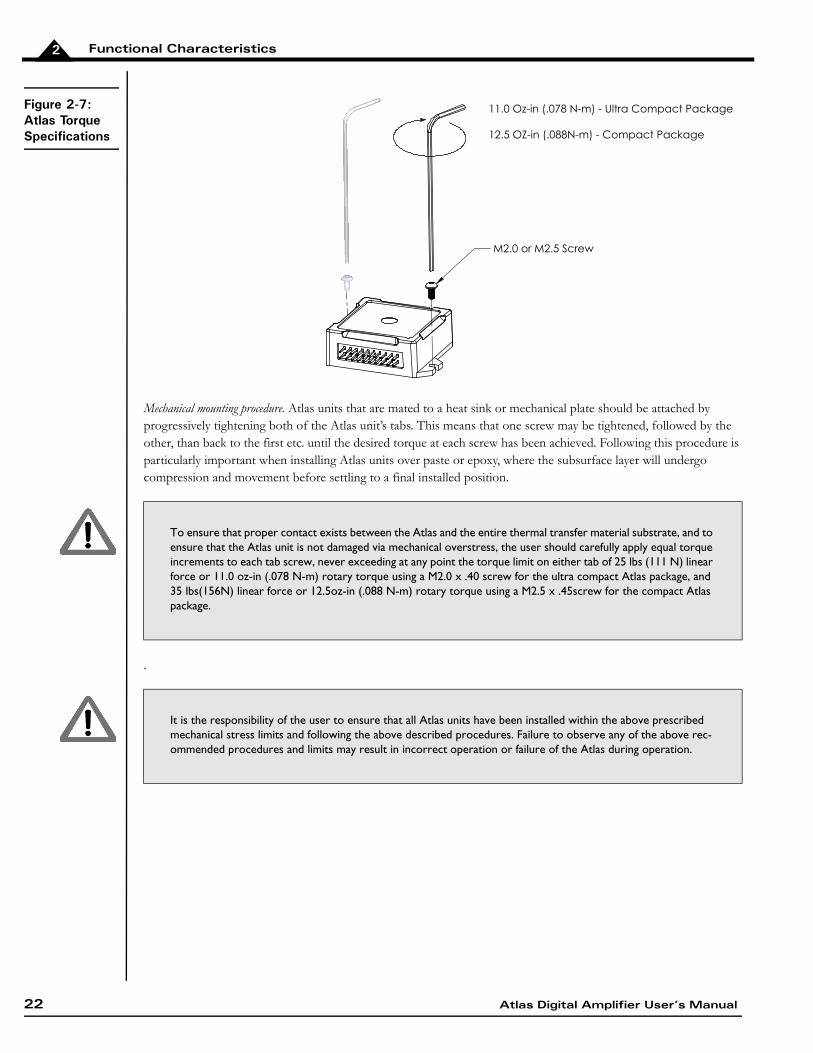
Figure 2-7:Atlas Torque Specifications
Mechanical mounting procedure. Atlas units that are mated to a heat sink or mechanical plate should be attached by progressively tightening both of the Atlas unit’s tabs. This means that one screw may be tightened, followed by the other, than back to the first etc. until the desired torque at each screw has been achieved. Following this procedure is particularly important when installing Atlas units over paste or epoxy, where the subsurface layer will undergo compression and movement before settling to a final installed position.
.
To ensure that proper contact exists between the Atlas and the entire thermal transfer material substrate, and to ensure that the Atlas unit is not damaged via mechanical overstress, the user should carefully apply equal torque increments to each tab screw, never exceeding at any point the torque limit on either tab of 25 lbs (111 N) linear force or 11.0 oz-in (.078 N-m) rotary torque using a M2.0 x .40 screw for the ultra compact Atlas package, and 35 lbs(156N) linear force or 12.5oz-in (.088 N-m) rotary torque using a M2.5 x .45screw for the compact Atlas package.
It is the responsibility of the user to ensure that all Atlas units have been installed within the above prescribed mechanical stress limits and following the above described procedures. Failure to observe any of the above rec-ommended procedures and limits may result in incorrect operation or failure of the Atlas during operation.
11.0 Oz-in (.078 N-m) - Ultra Compact Package
12.5 OZ-in (.088N-m) - Compact Package
M2.0 or M2.5 Screw
22 Atlas Digital Amplifier User’s Manual

3
3.Electrical Specifications In This ChapterDrive RatingsAbsolute Maximum RatingsEnvironmental RatingsSafety and ComplianceDC CharacteristicsAC CharacteristicsPin Descriptions and PinoutsSignal InterfacingConnection OverviewHeat Sink GroundingAtlas Conversion Factors3.1 Drive Ratings
3.1.1 Low Power Units (P/Ns MD2x1048/02xB)
* transformer isolated power supply, T < 40° C
A coldplate or a heatsink in an environment with sufficient airflow can be used to achieve the above drive ratings.
For temperature operation beyond the standard 0-40° C range, above-listed ratings may change. Contact your PMD representative for additional information on Atlas extended temperature operation including higher temperature drive ratings.
3.1.2 Medium Power Units (P/Ns MD2x1048/05xB)
Specifications*DC Brush Motor
Brushless DC Motor
Step Motor
Nominal supply voltage 12-48 VDC 12-48 VDC 12-48 VDCContinuous current 1.5 ADC 1.5 Arms 1.5 ArmsPeak current (per phase) 3.8 A 3.8 A 3.8 AMaximum continuous power 72 W 88 W 102 W
Specifications* DC Brush Motor Brushless DC Motor Step MotorNominal supply voltage 12-48 VDC 12-48 VDC 12-48 VDCContinuous current 7.0 ADC 5 Arms 4.5 Arms Peak current (per phase) 12.5 A 12.5 A 12.5 AMaximum continuous power 336 W 294 W 305 W
Atlas Digital Amplifier User’s Manual 23

Electrical Specifications3
* transformer isolated power supply, T < 40° C
A coldplate or a heatsink in an environment with sufficient airflow can be used to achieve the above drive ratings.
For temperature operation beyond the standard 0-40° C range, above-listed ratings may change. Contact your PMD representative for additional information on Atlas extended temperature operation including higher temperature drive ratings.
3.1.3 High Power Units (P/Ns MD2x1056/25xB)
* transformer isolated power supply, T < 40° C
A coldplate or a heatsink in an environment with sufficient airflow can be used to achieve the above drive ratings.
For temperature operation beyond the standard 0-40° C range, above-listed ratings may change. Contact your PMD representative for additional information on Atlas extended temperature operation including higher temperature drive ratings.
3.2 Absolute Maximum Ratings
Specifications* DC Brush Motor Brushless DC Motor Step MotorNominal supply voltage 12-56 VDC 12-56 VDC 12-56 VDCContinuous current 14.0 ADC 10.0 Arms 9.0 ArmsPeak current (per phase) 25.0 A 25.0 A 25.0 AMaximum continuous power 670 W 590 W 610 W
Parameter RatingHV voltage range, low power units 0 V to +52 V HV voltage range, medium power units 0 V to +52 V HV voltage range, high power units 0 V to +60 V ~Enable voltage range -10 V to +24 VSPISI, SPIClk, ~SPICS voltage range -0.5 V to 6.5 VSPISO voltage range -0.5 V to 3.7 VFaultOut voltage range -0.3 V to 24 VFaultOut output current -35 uA to 50 mA5V output current, low power units 50 mA5V output current, medium power units 50 mA5V output current, high power units 100 mA
All voltage values are with respect to GND unless otherwise noted.
24 Atlas Digital Amplifier User’s Manual

Electrical Specifications 3
3.3 Environmental Ratings
3.4 Safety and Compliance
3.5 DC Characteristics
3.5.1 SPISI, SPIClk
3.5.2 SPISO
Specification ValueOperating ambient temperature 0 to 40 CMaximum base plate temperature 75 CStorage temperature -20 to 85 CReflow soldering temperature 300 C (1.5mm for 10 seconds)Humidity 0 to 95%, non-condensingAltitude Up to 2,000 meters without deratingContamination Pollution Degree 2
Specification StandardCE LVD: EN60204-1
EMC-D: EN61000-6-1, EN61000-6-3, EN55011Electrical safety Designed to UL508C, UL840 and EN60204-1Hazardous materials RoHS compliantFlammability UL94-HBEnclosure IP20
Schmitt-trigger Input Min Max ConditionsV+, Positive-going input threshold voltage 1.6 V 2.0 V
V-, Negative-going input threshold voltage 0.9 V 1.2 VVT, Hysteresis V+-V- 0.6 V 1.0 VIIN, input current ±1 uA Input voltage is 5.5 V or GND
Min Max ConditionsVO, output voltage 0 3.3 V
VOH, Logic 1 output voltage 3.2 V IOH=-100 uA
2.4 V IOH=-16 mA
VOL, Logic 0 output voltage 0.1 V IOL=100 uA
0.7 V IOL=16 mA
IOZ, input current when ~SPICS is “1” 10 uA VO = 0 to 3.7 V
Atlas Digital Amplifier User’s Manual 25

Electrical Specifications3
3.5.3 ~SPICS
3.5.4 ~Enable
3.5.5 FaultOut
3.5.6 5V
Min TYP Max ConditionsVIH, Logic 1 input voltage 2 V
VIL, Logic 0 input voltage 0.8 V
IIN, pull-up current -500 uA
Schmitt-trigger input Min Max ConditionsV+, Positive-going input threshold voltage 1.6 V 2.0 V
V-, Negative-going input threshold voltage 0.9 V 1.2 VVT, Hysteresis V+-V- 0.6 V 1.0 V
Min Max ConditionsOutput impedance with Logic 1 output 148 Kohm 152 Kohm IOH=-100 uA
VOL, Logic 0 output voltage 0.25 V IOL=10 mA
Min Max ConditionsVoltage tolerance, low power units -5% 5% Output current 0-50 mA Voltage tolerance, medium power units -5% 5% Output current 0-50 mA Voltage tolerance, high power units -5% 5% Output current 0-100 mA Short circuit protection Not available
26 Atlas Digital Amplifier User’s Manual
Electrical Specifications 3
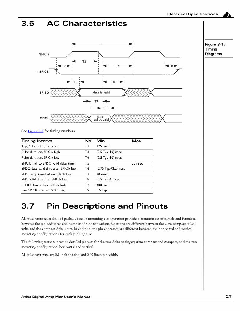
3.6 AC Characteristics
Figure 3-1:Timing Diagrams
See Figure 3-1 for timing numbers.
3.7 Pin Descriptions and Pinouts
All Atlas units regardless of package size or mounting configuration provide a common set of signals and functions however the pin addresses and number of pins for various functions are different between the ultra compact Atlas units and the compact Atlas units. In addition, the pin addresses are different between the horizontal and vertical mounting configurations for each package size.
The following sections provide detailed pinouts for the two Atlas packages; ultra compact and compact, and the two mounting configuration; horizontal and vertical.
All Atlas unit pins are 0.1 inch spacing and 0.025inch pin width.
Timing Interval No. Min MaxTSPI, SPI clock cycle time T1 125 nsec
Pulse duration, SPIClk high T3 (0.5 TSPI-10) nsec
Pulse duration, SPIClk low T4 (0.5 TSPI-10) nsec
SPIClk high to SPISO valid delay time T5 30 nsecSPISO date valid time after SPIClk low T6 (0.75 TSPI+2.2) nsec
SPISI setup time before SPIClk low T7 30 nsecSPISI valid time after SPIClk low T8 (0.5 TSPI-6) nsec
~SPICS low to first SPIClk high T2 400 nsecLast SPIClk low to ~SPICS high T9 0.5 TSPI
SPISI
SPISO
SPIClk
~SPICS
T1
T3
T2
T5 T6
data is valid
datamust be valid
T8
T4 T9
T7
Atlas Digital Amplifier User’s Manual 27

Electrical Specifications3
3.7.1 Atlas Pinouts - Ultra Compact, Vertical
Figure 3-2:Atlas Pinouts - Ultra Compact, Vertical
3.7.2 Atlas Pinouts - Ultra Compact, Horizontal
Figure 3-3:Atlas Pinouts - Ultra Compact, Horizontal
Pin Name Pin Name1 HV 23 Motor A 4 Pwr_Gnd5 Motor C 6 Motor B7 Motor D 8 NC (No Connect)9 NC (No Connect) 10 NC (No Connect)11 ~Enable 12 FaultOut13 GND 14 5V15 SPISO 16 ~SPICS/AtRest17 SPIClk/Pulse 18 SPISI/Direction
The ultra compact Atlas vertical package is keyed so that it is installation direction dependent. It has no physical pin installed at the Pin #2 location.
18 16 14 12 10 8 6 4
17 15 13 11 9 7 5 3 1
Pin Name Pin Name1 Motor D 2 Motor C3 Motor B 4 Motor A5 HV 6 Pwr_Gnd7 SPISI/Direction 8 SPIClk/Pulse9 SPISO 10 ~SPICS/AtRest
6 5 4 3 2 1
17 15 13 11 9 7
18 16 14 12 10 8
28 Atlas Digital Amplifier User’s Manual

Electrical Specifications 3
3.7.3 Atlas Pinouts - Compact, Vertical
Figure 3-4:Atlas Pinouts - Compact, Vertical
The compact Atlas package provides additional power output via doubling of the HV, Pwr_Gnd, and Motor output pins. To achieve the rated unit power output be sure that both pins are connected.
3.7.4 Atlas Pinouts - Compact, Horizontal
Figure 3-5:Atlas Pinouts - Compact, Horizontal
11 5V 12 GND13 FaultOut 14 ~Enable15 GND 16 NC (no connect)17 NC (no connect) 18 NC (no connect)
Pin Name Pin Name1 Pwr_Gnd 2 Pwr_Gnd3 HV 4 HV5 Motor A 6 Motor A7 Motor B 8 Motor B9 Motor C 10 Motor C11 Motor D 12 Motor D13 ~Enable 14 FaultOut15 5V 16 GND17 ~SPICS/AtRest 18 SPISI/Direction19 SPIClk/Pulse 20 SPISO
The compact Atlas vertical package is not keyed and therefore care should be taken to install in the correct ori-entation.
19 17 15 13 11 9 7 5 3 1
20 18 16 14 12 10 8 6 4 2
12 10 8 6 4 2
22 21 20 19 18 17 16 15 14 13
11 9 7 5 3 1
Atlas Digital Amplifier User’s Manual 29

Electrical Specifications3
The compact Atlas package provides additional power output via doubling of the HV, Pwr_Gnd, and Motor output pins. To achieve the rated unit power output be sure that both pins are connected.
3.7.5 Pin Descriptions
Pin Name Pin Name1 Motor D 2 Motor D3 Motor C 4 Motor C5 Motor B 6 Motor B7 Motor A 8 Motor A9 HV 10 HV11 Pwr_Gnd 12 Pwr_Gnd13 5V 14 GND15 ~Enable 16 FaultOut17 GND 18 ~SPICS/AtRest19 SPISO 20 SPISI/Direction21 SPIClk/Pulse 22 GND
Pin Name Direction DescriptionHV DC power to Atlas module, referenced to Pwr_Gnd. The DC power source
should be a transformer isolated power supply. For the compact Atlas package two pins carry this signal, so care should be taken to connect both pins.
Pwr_Gnd Power return for HV, Motor A, Motor B, Motor C and Motor D. For the compact Atlas package two pins carry this signal, so care should be taken to connect both pins. For greatest EMI protection double shielded cables on the motor winding A, B, C, and D should be used with the inner shield connected to Pwr_Gnd and the outer shield connected to chassis ground.
Motor A Motor output pin A. Used with Brushless DC, DC Brush, and Step Motors. For the compact Atlas package two pins carry this signal, so care should be taken to con-nect both pins.
Motor B Motor output pin B. Used with Brushless DC, DC Brush, and Step Motors. For the compact Atlas package two pins carry this signal, so care should be taken to con-nect both pins.
Motor C Motor output pin C. Used with Brushless DC, and Step Motors. For the compact Atlas package two pins carry this signal, so care should be taken to connect both pins.
Motor D Motor output pin D. Used with Step Motors. For the compact Atlas package two pins carry this signal, so care should be taken to connect both pins.
~Enable Input ~Enable is an active-low input. Should be tied or driven low for Atlas motor output to be active.
FaultOut Output FaultOut is high impedance when active. It provides programmable fault indication, and is low when inactive.
SPIClk/Pulse Input SPI input clock or Pulse signal.Pulse is used when Atlas is set to pulse & direction signal mode, and causes a posi-tion change command upon a high to low transition. Selection of signal interpreta-tion for this pin is via the SPI communications bus. The default signal interpretation is SPIClk.
SPISO Output SPI data master in slave out signal. It goes to high impedance when ~SPICS is high. This pin is not used if Atlas is operating in pulse & direction signal mode.
30 Atlas Digital Amplifier User’s Manual

Electrical Specifications 3
SPISI/Direction Input SPI data master out slave in signal or Direction signal.Direction is used when Atlas is set to pulse & direction signal mode, and indicates the step direction. Low means the position decreases upon a high to low transition of the Pulse signal, and high means the position increases. Selection of signal inter-pretation for this pin is via the SPI communications bus. The default signal interpre-tation is SPISI.
~SPICS/AtRest Input ~SPICS signal or AtRest signal. ~SPICS enables SPI communication when transitioning low. The SPI block is dis-abled when ~SPICS is high.AtRest is used when Atlas is set to pulse & direction signal mode, and indicates that the step motor holding current should be used rather than the drive current. Selection of signal interpretation for this pin is via the SPI communications bus. The default signal interpretation is ~SPICS.
GND Ground return for ~Enable, FaultOut, SPI or pulse & direction signals and 5V.5V 5V output used to drive external circuitry.
Pin Name Direction Description
Atlas Digital Amplifier User’s Manual 31

Electrical Specifications3
3.8 Signal Interfacing
3.8.1 ~Enable
~Enable and FaultOut signals are typically used to implement a safety interlock between the Atlas module and other portions of the system.
~Enable is an active low input that must be tied or driven low for the Atlas power output to be active. Its input buffer is shown in Figure 3-6. The circuit accepts signals in the range of 0-24V and has TTL compatible, Schmidt trigger thresholds. It has a pull-up to 5V to allow direct interfacing to open collector enable sources without external pull-up resistor and a 1.3kHz R-C low-pass filter to reject noise.
Figure 3-6:Signal Interfacing ~Enable
3.8.2 FaultOut
FaultOut is asserted high when a fault occurs. The external controller can select which fault conditions drive the FaultOut signal.
An Atlas FaultOut output circuit is shown in diagram Figure 3-7. This circuit can continuously sink 50mA when pulled low. It has a 150kohm pull-up resistor to 5V. Its voltage range is 0 to 24V.
Figure 3-7:Signal Interfacing FaultOut
5V 5V
22k
5.6n
~Enable
10k
FaultOut
150k
5V
Q1
32 Atlas Digital Amplifier User’s Manual

Electrical Specifications 3
3.9 Connection Overview
3.9.1 Brushless DC Motors
Figure 3-8:Brushless DC Connections
The following table summarizes the recommended connections when connecting Atlas amplifiers to brushless DC motors
If Atlas is used as part of a higher level position controller, as shown in the Figure 3-8, the Brushless DC motor provides feedback signals to the external controller. Commonly, both Hall sensor signals and a position encoder are used, but only one or the other is needed in a minimal configuration. In this configuration the external controller generally consists of a PMD Magellan Motion Processor or a programmable microprocessor or DSP-type device.
Alternatively, Atlas can be operated by an external controller as a standalone device, driving the motor at commanded voltage or torque levels and not part of a higher-level servo controller. In this configuration, the external controller can be either a microprocessor-type device, or a logic device such as an FPGA (field programmable gate array).
Atlas functions as a power block providing amplification, current control, and safety management of the amplifier and motor. Atlas does not directly accept Hall signals or encoder signals, so to operate with a brushless DC motor the motor's current phase angle must be provided by the external controller through the SPI interface.
Type Required ConnectionsOptional Connections
Power HV, Pwr_GndCommunication ~SPICS, SPISO, SPISI, SPIClk, GNDMotor Motor A, Motor B, Motor CMiscellaneous ~Enable FaultOut
The Atlas does not support direct Hall signal inputs. To operate the Atlas with a Brushless DC motor, continuous motor phase angle is provided by the external controller, via either Hall inputs or an encoder.
Enable FaultOut
Motor A
Motor B
Motor C
Optional Hall Sensors
Atlas®
DigitalAmplifier
3 - PhaseBrushlessDC Motor
ExternalController
Optional
Optional Encoder Feedback
Hall & Encoder
SPI
SPICSSPIClkSPISISPISO
Pwr_Gnd
HV
Atlas Digital Amplifier User’s Manual 33

Electrical Specifications3
3.9.2 DC Brush Motors
Figure 3-9:DC Brush Connections
The following table summarizes the recommended connections when connecting Atlas amplifiers to DC Brush motors.
If Atlas is used as part of a higher level servo controller, as shown in Figure 3-9, an encoder provides position or velocity feedback signals to the external controller. In this configuration the external controller generally consists of a PMD Magellan Motion Processor or a programmable microprocessor or DSP-type device.
Alternatively, Atlas can be operated by an external controller as a standalone device, driving the motor at commanded voltage or torque levels. In this configuration the external controller can be either a microprocessor-type device, or a logic device such as an FPGA (field programmable gate array).
Type Required ConnectionsOptional Connections
Power HV, Pwr_GndCommunication ~SPICS, SPISO, SPISI, SPIClk, GNDMotor Motor A, Motor BMiscellaneous ~Enable FaultOut
Enable FaultOut
Optional Encoder Feedback
Encoder
Atlas®
DigitalAmplifier
DC BrushMotor
ExternalController
SPI
SPICSSPIClkSPISISPISO
Optional
Pwr_Gnd
HV
Motor A
Motor B
34 Atlas Digital Amplifier User’s Manual

Electrical Specifications 3
3.9.3 Step Motors in Pulse & Direction Signal Mode
Figure 3-10:Step Motor Pulse and Direction Mode Connections
The following table summarizes the recommended connections when connecting Atlas amplifiers to two-phase step motors when using the pulse & direction signal mode. In this mode the external controller provides position commands to Atlas via pulse and direction signals.
These connections apply to bipolar motors. If connecting to unipolar motors do not connect the center tap.
In this configuration the external controller generally consists of an off-the-shelf motion control card or module, a programmable microprocessor or DSP-type device, or a FPGA (field programmable gate array). The external controller provides a continuous stream of pulse and direction commands, along with (optionally) an AtRest signal to control the torque.
To initially set up and store its application-specific configuration parameters, Atlas is programmed using the SPI interface and then commanded to convert to pulse & direction signal mode.
FaultOut signal input to external controller is strongly recommended when the Atlas is used in Pulse & Direction signal mode.
Type Required ConnectionsOptional Connections
Power HV, Pwr_Gnd Communication Pulse, Direction, GND AtRest
Motor, Phase A+:Motor, Phase A-
Motor, Phase B+:Motor, Phase B-:
Motor A
Motor B
Motor C
Motor D
Miscellaneous ~Enable FaultOut
Enable
Pwr_Gnd
FaultOut
Optional Encoder Feedback
Encoder
Atlas®Digital
Amplifier
2 - PhaseStep
MotorExternal
Controller
Pulse
Direction
AtRest
Motor A
Motor B
Motor C
Motor D
HV
Atlas Digital Amplifier User’s Manual 35

Electrical Specifications3
3.9.4 Step Motors Using SPI Communications
Figure 3-11:Step Motor SPI Communi-cation Connec-tions
The following table summarizes the recommended connections when connecting Atlas amplifiers to two-phase step motors when using the SPI communications channel. In this mode the external controller provides position commands to Atlas via the SPI interface.
These connections apply to bipolar motors. If connecting to unipolar motors do not connect the center tap.
In this configuration the external controller generally consists of a PMD Magellan Motion Processor, a programmable microprocessor or DSP-type device, or a FPGA (field programmable gate array). The external controller provides a continuous stream of position commands or individual phase torque output commands to control the motor position.
3.10 Heat Sink Grounding
The heat sink may be left ungrounded or may be connected to chassis ground for best EMI protection. The heat sink should not be connected to the Atlas Pwr_Gnd.
3.11 Atlas Conversion Factors
The following table provides electrical conversion factors for the various Atlas units. These factors convert Atlas command values specified via the Atlas unit's digital SPI interface (referred to as counts) to physical quantities such as amperage or volts, and vice versa. For more information on the Atlas functions related to these conversion factors see Chapter 4, Operation.
Type Required Signal ConnectionsOptional Signal Connections
Power HV, Pwr_GndCommunication ~SPICS, SPISO, SPISI, SPIClk, GND
Motor, Phase A+:Motor, Phase A-
Motor, Phase B+:Motor, Phase B-:
Motor AMotor BMotor CMotor D
Miscellaneous ~Enable FaultOut
Enable FaultOut
Optional Encoder Feedback
Encoder
Atlas®
DigitalAmplifier
2 - PhaseStepMotor
ExternalController
SPI
SPICSSPIClkSPISISPISO
Optional
Motor C
Motor D
Pwr_Gnd
HV Motor A
Motor B
36 Atlas Digital Amplifier User’s Manual

Electrical Specifications 3
3.11.1 Atlas Settings Defaults and Limits
The following table provides default and limit values for all Atlas units.
UnitAll Low Power Atlas
All Medium Power Atlas
All High Power Atlas Example Usage
Amps .231 mA/count .763 mA/count 1.526 mA/count To command a torque of 3.5A to the high power Atlas a value of 3,500mA/1.526mA/count = 2,294 counts is specified.
Volts 1.361 mV/count 1.361 mV/count 1.361 mV/count A command request to read the Atlas unit’s DC Bus voltage gives a value of 12,345. This corre-sponds to a voltage of 12,345 counts * 1.361 mV/count = 16.8 volts.
Temperature .0039°C/count .0039°C/count .0039°C/count A command request to read the Atlas unit’s internal temperature gives a value of 7,890. This cor-responds to a temperature of 7,890 counts * .0039°C/count = 30.8°C.
Foldback Energy .0059 A2sec/count .064 A2sec/count .256 A2sec/count To command a foldback energy of 50A2sec to the high power Atlas a value of 50A2sec/.256 A2sec/count = 195 counts is specified.
QuantityAll Low Power Atlas
All Medium Power Atlas
All High Power Atlas
OvertemperatureOvertemperature Limit Default: 75.0°C Default: 75.0°C Default: 75.0°C
Low Limit: 0 Low Limit: 0 Low Limit: 0High Limit: 75.0°C High Limit: 75.0°C High Limit: 75.0°C
Overtemperature Hysteresis Default: 5.0°C Default: 5.0°C Default: 5.0°CLow Limit: 0 Low Limit: 0 Low Limit: 0High Limit: 25.0°C High Limit: 25.0°C High Limit: 25.0°C
VoltageOvervoltage Limit Default: 52.0 V Default: 52.0 V Default: 60.0 V
Low Limit: 10.0 V Low Limit: 10.0 V Low Limit: 10.0 VHigh Limit: 52.0 V High Limit: 52.0 V High Limit: 60.0 V
Undervoltage Limit Default: 10.0 V Default: 10.0 V Default: 10.0 VLow Limit: 10.0 V Low Limit: 10.0 V Low Limit: 10.0 VHigh Limit: 48.0 V High Limit: 48.0 V High Limit: 56.0 V
Atlas Digital Amplifier User’s Manual 37

Electrical Specifications3
For more information on Atlas overtemperature safety functions see Section 4.7.2, "Overtemperature Fault."
For more information on Atlas overvoltage and undervoltage safety functions see Section 4.7.4, "Undervoltage Fault."
For more information on Atlas Current Foldback safety functions see Section 4.7.9, "Current Foldback."
Current FoldbackContinuous Current Limit, Default: 2.12 A Default: 7.07 A Default: 14.1 ABrushless DC Motor Low Limit: 0.0 A Low Limit: 0.0 A Low Limit: 0.0 A
High Limit: 2.12 A High Limit: 7.07 A High Limit: 14.1 AContinuous Current Limit, DC Default: 1.50 A Default: 7.00 A Default: 14.0 ABrush Motor Low Limit: 0.0 A Low Limit: 0.0 A Low Limit: 0.0 A
High Limit: 1.50 A High Limit: 7.00 A High Limit: 14.0 AContinuous Current Limit, Step Default: 2.12 A Default: 6.36 A Default: 12.7 AMotor Low Limit: 0.0 A Low Limit: 0.0 A Low Limit: 0.0 A
High Limit: 2.12 A High Limit: 6.36 A High Limit: 12.7 AEnergy Limit, Brushless DC Default: 2.95 A2sec Default: 31.9 A2sec Default: 127.5 A2secMotor Low Limit: 0.0 A2sec Low Limit: 0.0 A2sec Low Limit: 0.0 A2sec
High Limit: 2.95 A2sec High Limit: 31.9 A2sec High Limit: 127.5A2secEnergy Limit, DC Brush Motor Default: 3.63 A2sec Default: 32.2 A2sec Default: 128.7 A2sec
Low Limit: 0.0 A2sec Low Limit: 0.0 A2sec Low Limit: 0.0 A2secHigh Limit: 3.63 A2sec High Limit: 32.2 A2sec High Limit: 128.7 A2sec
Energy Limit, Step Motor Default: 2.95 A2sec Default: 34.7 A2sec Default: 138.9 A2secLow Limit: 0.0 A2sec Low Limit: 0.0 A2sec Low Limit: 0.0 A2secHigh Limit: 2.95 A2sec High Limit: 34.7 A2sec High Limit: 138.9 A2sec
QuantityAll Low Power Atlas
All Medium Power Atlas
All High Power Atlas
38 Atlas Digital Amplifier User’s Manual

4
4.Operation In This ChapterFunctional OverviewInternal Block DiagramCommutationCurrent LoopPower StageStatus RegistersSafety Processing FunctionsStep Motor ControlUser Memory Space & BuffersTrace CapturePower-up & Non-Volatile Initialization StorageSPI Communications Overview4.1 Functional Overview
Figure 4-1:High Level System Diagram
Atlas Digital Amplifiers are single-axis devices for torque or voltage-mode control of three-phase brushless DC motors, DC Brush motors, or two-phase step motors. They accept a stream of desired torque or voltage values from an external controller and perform all current loop processing and switching bridge control to continuously drive the motor coils to the specified, commanded values.
In addition to providing a stream of torque or voltage commands, the external controller is used to set up operational parameters needed by Atlas such as control gains, safety-related parameters, and other information. These parameters may be provided to Atlas at each power up, or stored non-volatilely in Atlas so that they no longer need to be loaded at each power-up. See Section 4.11, “Power-Up & Non-Volatile Initialization Storage” for more information.
Enable FaultOut
Optional Encoder Feedback
Atlas®
DigitalAmplifier
Brushless DCDC Brush
Step Motor
ExternalController
SPI
Command Protocol
NVRAM
Atlas Digital Amplifier User’s Manual 39

Operation4
Communication to/from Atlas occurs via an SPI interface and associated protocol that uses packet-oriented commands to specify various Atlas parameters, and, if desired, request status information from Atlas. This protocol has been designed for maximum speed and flexibility so that torque or voltage commands can be continuously sent to Atlas even while the external controller queries Atlas for various information. Please refer to the Atlas Digital Amplifier Complete Technical Reference for information on the SPI interface.
When Atlas is used in a higher level system such as a servo-based velocity or position controller, torque commands are typically sent to Atlas continuously, at the motion controller’s servo rate. For most systems this rate is in the 1,000 to 10,000 samples per second range. However Atlas may also be used with direct voltage or torque control applications that utilize Atlas to specify a desired output value just once after power-up, or only occasionally as required by the application.
To disable Atlas operations it may be powered down, the Enable signal may be de-asserted, or various commands that result in Atlas operations being suspended may be sent by the external controller to Atlas through the SPI interface. In addition, there are several conditions where Atlas automatically shuts down for safety-related reasons. These may
include short circuit detection, under and over voltage protection, I2t current limiting, and amplifier over temperature detection. See Section 4.7, “Safety Processing Functions” for more information on emergency stop and related functions.
4.2 Internal Block Diagram
Figure 4-2:Internal Block Diagram
Figure 4-2 shows the internal block diagram of Atlas. Here are summary descriptions of the major modules and functional areas:
Atlas®
Control
Processor
AtRest
Power
Stage
SPI
Command
Processor
Pulse andDirection Counter
Pulse Direction
NVRAM
TraceRAM
DigitalCurrentLoop
Commutation&
MicrostepControl
HV
5V
Bus Monitoring
Bus Voltage
Bus Voltage
MotorOutputs
~Enable FaultOut
Current Sense
DC Bus
Logic Supply+ 3.3 V
A
B
C
D
A
B
A
B
SPISO
SPICS
SPIClk
SPISI
40 Atlas Digital Amplifier User’s Manual

Operation 4
Commutation—this module utilizes internally generated information, or information provided by the external controller, to split up the desired overall torque command into individual phase commands to drive Brushless DC and step motors.
Current Loop—this module inputs the desired current for each motor coil and uses the measured current feedback from each motor coil to develop PWM (pulse width modulation) output command values for the power stage. The current loop module may be disabled, in which case Atlas will drive the motor in voltage mode. See Section 4.4, “Current Loop” for more information on the current loop module.
Power Stage—this module receives desired voltages for each motor coil and manages the Atlas unit’s high performance MOSFET-based switching bridge to precisely drive the coils of the motor. See Section 4.5, “Power Stage” for a detailed description of this module.
Status Registers—this module holds various status registers including an Event Status Register, a Drive Status register, a Drive Fault Status Register, a signal status, and an SPI Status Register.
Safety Processing—this module manages Atlas unit safety-related functions including the internal temperature sensor, bus voltage error, the Enable input signal, current foldback, the FaultOut output signal, event action processing, and more.
Step Motor Processing—this module implements step motor-specific features including microstep signal generation, holding current management, and Pulse, Direction, and AtRest signal processing.
Memory Buffers—this module provides user-accessible memory for trace and setup parameter configuration storage.
Trace—this module provides a facility for continuously storing up to four simultaneous Atlas variables in the memory buffers.
Power-up & Non-Volatile Initialization Storage—this module manages the power-up sequence and provides the ability to store selected parameters into the Atlas unit’s non-volatile memory.
SPI Command Processor—This module manages all communications to/from the external controller.
4.3 Commutation
Figure 4-3:Commutation Control Sequence
Motor Output(PWM or DAC)
SPI Voltageor
Torque Command
PhaseAngle
Tocurrentloop orpowerstage
Phase ACommand
Phase BCommand
Phase CCommand
Atlas Digital Amplifier User’s Manual 41
Operation4
Brushless DC motors have three phases (generally referred to as A, B, and C) separated from each other by 120 electrical degrees. The process of splitting up the overall torque command into constituent phase commands is called commutation. Figure 4-3 provides an overview of the control sequence when a brushless DC motor is controlled by Atlas.
The first step is that the external controller specifies the desired motor voltage or torque command to the Atlas. This command is then commutated into constituent phase-specific values. This process applies to step motors as well as Brushless DC motors, however for step motors the process is called microstepping. See Section 4.8, “Step Motor Control” for a detailed discussion of step motor control with Atlas amplifiers. DC Brush motors are single phase devices, and do not require commutation.
Once commutated, the individual commands for the A, B, and C phases are output either directly to the power stage or to the current loop module (depending on whether current control has been requested). If output to the current loop module, additional calculations are performed using the measured current through each winding to determine a final phase command. See Section 4.4, “Current Loop” for details.
Atlas does not directly accept commutation inputs such as Hall sensors, so phase angle information must be provided by the external controller via the SPI interface. When used with the Magellan Motion Processor all such phase information is provided automatically. When used with other external controllers, for detailed information on how to provide this phase angle information, as well as other details of Atlas commutation operations, refer to the Atlas Digital Amplifier Complete Technical Reference.
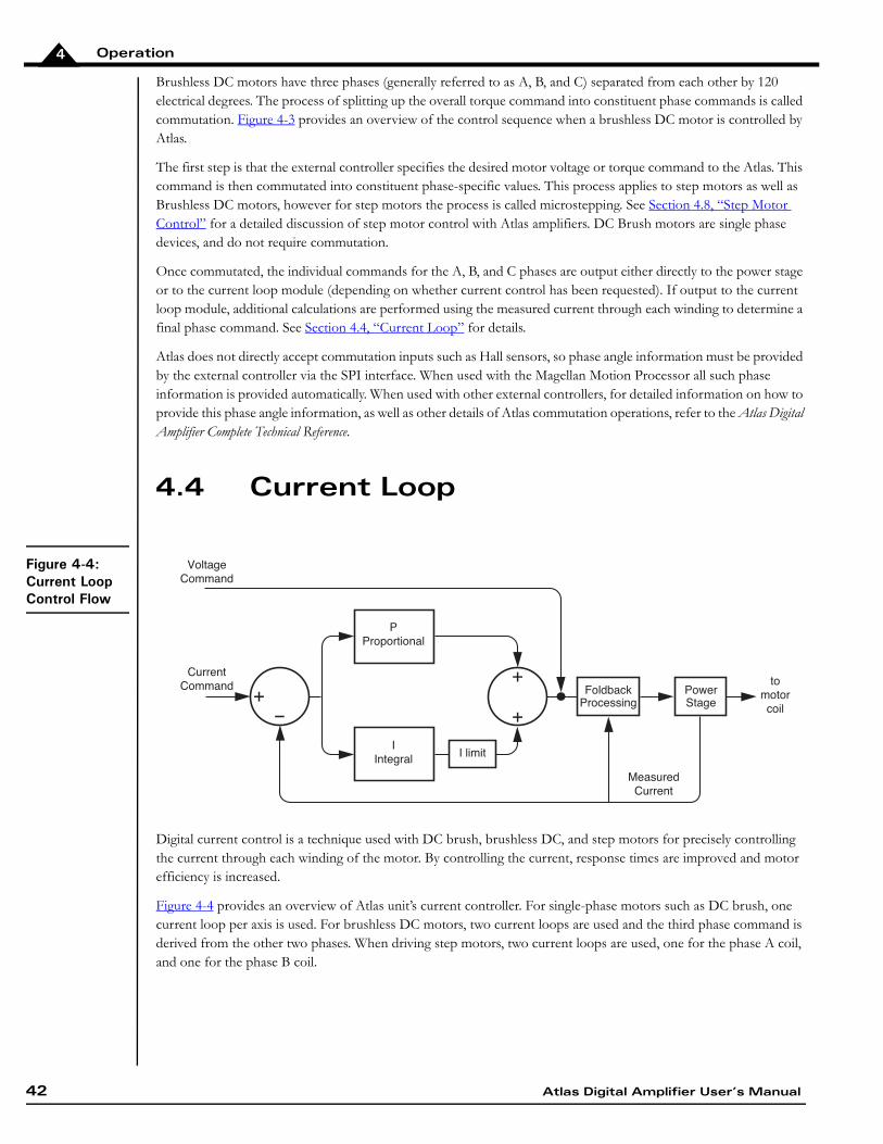
4.4 Current Loop
Figure 4-4:Current Loop Control Flow
Digital current control is a technique used with DC brush, brushless DC, and step motors for precisely controlling the current through each winding of the motor. By controlling the current, response times are improved and motor efficiency is increased.
Figure 4-4 provides an overview of Atlas unit’s current controller. For single-phase motors such as DC brush, one current loop per axis is used. For brushless DC motors, two current loops are used and the third phase command is derived from the other two phases. When driving step motors, two current loops are used, one for the phase A coil, and one for the phase B coil.
tomotorcoil
MeasuredCurrent
FoldbackProcessing
PowerStage
PProportional
IIntegral I limit
CurrentCommand
VoltageCommand
42 Atlas Digital Amplifier User’s Manual

Operation 4
There are three overall methods of current control provided by Atlas, however not all methods are used with all motor types. The first method is individual phase control. The table below summarizes which current control modes are available with the three motor types supported by Atlas, along with the default configuration for that motor type.
The large majority of applications will use FOC to drive Brushless DC or step motors. FOC usually provides the highest top speeds and more energy efficient operation of the motor compared to individual phase control. Third leg floating is an option that should generally only be considered for Hall-commutated motors. In that configuration, third leg floating can sometimes provide a higher top speed than FOC. Finally, individual phase control is always used with DC Brush motors, and may, under certain specialized conditions, provide improved performance for Brushless DC motors over FOC.
If during normal operation the current loop is disabled, then the output from the commutation module will pass directly to the power stage module, with no current control being performed. The most common use of this is to run the amplifier in voltage mode, which may be useful under some conditions for calibration or testing.
The Atlas Digital Amplifier Complete Technical Reference provides much more information on the various Atlas current control modes including control flow diagrams and how to set up and read various current control related parameters.
4.5 Power Stage
Atlas contains a high performance MOSFET-based power stage that utilizes one or more switching bridges to drive the motor coils. The use of 3-phase and H-bridge topologies provides full 4-quadrant operation for all motor types. In addition, Atlas uses an advanced PWM switching scheme that minimizes the ripple current on the motor windings while maximizing the current loop performance. The fundamental frequency of the ripple current is twice the PWM frequency, and well out of the audible range in all cases.
The PWM frequency is selectable between 20 kHz, 40kHz, 80kHz, and 120 kHz to cover a broad range of motor inductances.
In addition to the output bridge function, Atlas provides a current measurement function for use by the current loop module as well as by the safety processing module. Two channels of phase current feedback are provided for brushless DC and step motor current loops. For DC Brush motors feedback for one phase is provided.
4.6 Status Registers
In addition to various numerical registers that may be queried by the external controller, there are five bit-oriented status registers.
These status registers conveniently combine a number of separate bit-oriented fields into a single register. These registers are Event Status, Drive Status, Signal Status, SPI Status, and Drive Fault Status Register. The external controller may directly query these four registers, or the contents of these registers may be utilized by other functional portions of Atlas, such as FaultOut signal processing. See Section 4.7.8, “FaultOut Signal” for more information on FaultOut processing.
Refer to the Atlas Digital Amplifier Complete Technical Reference for a description of these status registers.
Current Control Method
Brushless DC
DCBrush
Step Motor
Individual Phase Control (default) Field Oriented Control (default) (default)
Third Leg Floating
Atlas Digital Amplifier User’s Manual 43

Operation4
4.7 Safety Processing Functions
Atlas provides a number of amplifier control features that automatically detect and manage safety-related conditions. In addition, Atlas can signal when various conditions, safety or otherwise, occur.
The subsequent sections describe these features.
4.7.1 Overcurrent Fault
Atlas supports automatic detection of excessive current output. This fault occurs when the motor, the wiring leading from Atlas, or Atlas unit’s power stage becomes short circuited.
An overcurrent fault will cause the current loop and power stage modules to be disabled, thereby halting further motor output. To recover from this condition the user should determine the nature of the fault. It is generally desirable to power down Atlas to check connections or otherwise correct the Atlas-attached hardware so that the problem does not occur again.
If the overcurrent condition has been resolved, when restart is attempted Atlas will resume normal operations. If the overcurrent condition has not been resolved, the overcurrent condition will immediately occur again.
4.7.2 Overtemperature Fault
Atlas provides the capability to continually monitor and detect excessive internal temperature conditions. Such a condition may occur if excessive current is requested, if heat sinking of the Atlas unit is inadequate, or if some other problem results in elevated drive temperatures.
To detect this condition a programmable temperature threshold is continuously compared to an internal temperature sensor. If the value read from the internal sensor exceeds the programmed threshold, an overtemperature fault occurs. In addition, a settable overtemperature hysteresis allows the user to ensure that the Atlas temperature drops by a specified number of degrees before allowing drive restart.
See Section 3.11.1, “Atlas Settings Defaults and Limits” for information on overtemperature-related conversion factors, defaults, and limit settings for each Atlas power level.
An over temperature fault will cause the current loop and power stage modules to be disabled, thereby halting further motor output. To recover from this condition the user should determine the nature of the fault. It is generally desirable to power down Atlas to correct the condition.
If the overtemperature condition has been resolved, when restart is attempted Atlas will resume normal operations. If the overtemperature condition has not been resolved, the condition will immediately occur again.
Over current faults are serious conditions and warrant the utmost precaution before re-enabling amplifier oper-ation. It is the responsibility of the user to determine the cause and corrective action of any electrical fault.
Overtemperature faults indicate that the internal safe limit of the drive temperature range has been exceeded. This potentially serious condition can result from incorrect motor connections, excessive power demands placed on the Atlas amplifier, or inadequate heat sinking . It is the responsibility of the user to operate Atlas within safe limits.
44 Atlas Digital Amplifier User’s Manual

Operation 4
4.7.3 Overvoltage Fault
Atlas provides the capability to continually monitor and detect excessive voltages on the incoming voltage supply. Such a condition may occur if there is a fault in the system power supply, if a large back EMF (electro motive force) is generated during motor deceleration, or if some other problem results in an elevated bus voltage.
To detect this condition a programmable bus voltage threshold is continuously compared to the bus voltage sensor. If the value read from the internal sensor exceeds the programmed threshold, an overvoltage fault occurs.
See Section 3.11.1, “Atlas Settings Defaults and Limits” for information on overvoltage-related conversion factors, defaults, and limit settings for each Atlas power level.
An overvoltage fault will cause the current loop and power stage modules to be disabled, thereby halting further motor output. To recover from this condition the user should determine the nature of the fault. In most cases it is desirable to power down Atlas to correct the condition.
If the overvoltage condition has been resolved, when restart is attempted Atlas will resume normal operations. If the overvoltage condition has not been resolved, the condition will immediately occur again.
4.7.4 Undervoltage Fault
Atlas also provides the capability to sense undervoltage conditions. This value is compared to the value read from the drive DC bus, and if the value read is less than the programmed threshold, an undervoltage fault occurs.
All other aspects of this feature are the same as for overvoltage sense. Just as for overvoltage conditions, it is the user's responsibility to determine the seriousness of, and appropriate response to, an undervoltage condition.
4.7.5 Watchdog Timeout
Atlas provides a programmable watchdog timer that can detect an unexpected lack of activity from the external controller. Typically, such a condition is due to an SPI communication problem or an external controller malfunction. Particularly when the external controller is used to provide higher level velocity or position control, a watchdog timeout may therefore represent a very serious condition.
To effect the watchdog function Atlas monitors the amount of time between successive valid SPI torque or voltage commands from the external controller. If the amount of time between commands exceeds the programmed watchdog timer, the watchdog fault is triggered.
A watchdog timeout fault will cause the current loop and power stage modules to be disabled, thereby halting further motor output. To recover from this condition the user should determine the nature of the fault. In most cases it is desirable to power down Atlas to correct the condition.
Overvoltage faults indicate that a serious safety condition has occurred. It is the responsibility of the user to op-erate Atlas within safe limits.
Watchdog timeout faults indicate that a serious safety condition has occurred. It is the responsibility of the user to operate Atlas within safe limits.
Atlas Digital Amplifier User’s Manual 45

Operation4
4.7.6 Drive Enable
Atlas supports an Enable input signal that must be active for proper amplifier operation. This signal is useful for allowing external hardware to automatically shut Atlas down. The signal has an active low interpretation.
If the Enable signal becomes inactive (goes high) the current loop and power stage modules are disabled, thereby halting further motor output. To recover from this condition the user should determine the nature of the fault. It may be desirable to power down Atlas to correct the condition.
4.7.7 Drive Fault Status Register
To simplify recovery from drive-related faults Atlas provides a Drive Fault Status register. Refer to the Atlas Digital Amplifier Complete Technical Reference for more information on this register.
4.7.8 FaultOut Signal
The Atlas unit’s FaultOut signal is used to indicate an occurrence of one or more drive faults. This signal is active high, meaning it is high when a fault has occurred, and it is low when a fault has not occurred.
The FaultOut signal is programmable, so that the user may determine what fault states result in the FaultOut signal becoming active. In particular, any bit condition of the Drive Fault Status register may be used to trigger activation of the FaultOut signal.
For complete information on FaultOut signal programming and the Drive Fault Status register, refer to the Atlas Digital Amplifier Complete Technical Reference.
4.7.9 Current Foldback
Current foldback, also known as I2t foldback, is a general purpose tool to protect the drive output stage or the motor from excessive current.
I2t current foldback works by integrating, over time, the difference of the square of the actual motor current and the square of a user-settable continuous current limit. When the integrated value reaches a user-settable energy limit, Atlas goes into current foldback. The default response to this event is to cause the current loop and power stage modules to be disabled. However it is also possible to program Atlas to attempt to clamp the maximum current to the continuous current limit value. Note that the Atlas unit’s ability to do so depends on a properly functioning current loop.
Atlas will stay in foldback until the integrator returns to zero. This is shown in Figure 4-5.
46 Atlas Digital Amplifier User’s Manual
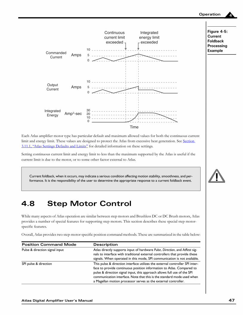
Operation 4
Figure 4-5:Current Foldback Processing Example
Each Atlas amplifier motor type has particular default and maximum allowed values for both the continuous current limit and energy limit. These values are designed to protect the Atlas from excessive heat generation. See Section 3.11.1, “Atlas Settings Defaults and Limits” for detailed information on these settings.
Setting continuous current limit and energy limit to less than the maximum supported by the Atlas is useful if the current limit is due to the motor, or to some other factor external to Atlas.
4.8 Step Motor Control
While many aspects of Atlas operation are similar between step motors and Brushless DC or DC Brush motors, Atlas provides a number of special features for supporting step motors. This section describes these special step motor-specific features.
Overall, Atlas provides two step-motor specific position command methods. These are summarized in the table below:
Current foldback, when it occurs, may indicate a serious condition affecting motion stability, smoothness, and per-formance. It is the responsibility of the user to determine the appropriate response to a current foldback event.
Position Command Mode DescriptionPulse & direction signal input Atlas directly supports input of hardware Pulse, Direction, and AtRest sig-
nals to interface with traditional external controllers that provide these signals. When operated in this mode, SPI communication is not available.
SPI pulse & direction This pulse & direction interface utilizes the external controller SPI inter-face to provide continuous position information to Atlas. Compared to pulse & direction signal input, this approach allows full use of the SPI communication interface. Note that this is the standard mode used when a Magellan motion processor serves as the external controller.
0
302010
10
5
0
10
5
0
CommandedCurrent
Amps
Continuouscurrent limitexceeded
Integratedenergy limitexceeded
Amps
Amp2-sec
OutputCurrent
IntegratedEnergy
Time
Atlas Digital Amplifier User’s Manual 47

Operation4
4.8.1 Pulse & Direction Signal Input Mode
Figure 4-6:Pulse and Direction Signal Input Mode Control Flow
Figure 4-6 shows the control flow of the Atlas when used in pulse & direction signal input mode. The Atlas Pulse signal drives a counter which increments or decrements a step motor command position based on the state of the Direction signal. Pulse signals are expected to be active low, meaning that a position increment or decrement occurs when this signal transitions from high to low. The Direction signal indicates that a pulse received while the Direction signal is low is interpreted as a negative direction command, and a pulse received while this signal is high as a positive direction command.
Atlas provides programmable microstepping resolution, which means that the incoming position data stream can be interpreted by the Atlas at various resolutions. The maximum is 256 microsteps per full step, and the default interpretation is 64 microsteps per full step. This means that in the default condition, for a standard 1.8° two-phase stepper, Atlas provides a resolution of 12,800 microsteps per mechanical motor rotation, or roughly .028 degrees of mechanical motion per incoming pulse. Note that this control resolution may not equal the actual system accuracy.
4.8.1.1 Setting the Motor Current
When operating in pulse & direction input mode the current output by Atlas must be specified. Atlas supports two separate, programmable torques. The first is called the drive current and is used during normal step motor operations.
The second is called the holding current and is used when the motor is stationary as indicated by the AtRest signal. This signal is typically set when the external controller’s trajectory generator completes its move or shortly thereafter. AtRest is an active low signal, meaning when no motion is occurring this signal should be is set low, and set high when motion is occurring.
4.8.1.2 Pulse & Direction Signal Mode Operation Setup
Because Atlas shares SPI bus signal pins with the Pulse, Direction, and AtRest pins it is not possible to operate the Atlas in the pulse & direction signal input mode while communicating via the SPI communication bus.
To resolve this, Atlas is first connected in SPI mode, and the SPI interface is used to optimize the motion control application during application development and to download desired drive parameters to Atlas unit’s non-volatile initialization storage memory. See Section 4.11, “Power-Up & Non-Volatile Initialization Storage” for more information on non-volatile initialization storage.
Atlas is then switched to pulse & direction signal input mode, and this mode change is stored into non volatile initialization storage memory so that upon the next power up Atlas will operate in pulse & direction signal mode.
Holding Current
Pulse
Direction
Drive Current
PositionCounter Microstep
signalgeneration
Tocurrentloop orpowerstage
Phase ACommand
Phase BCommand
AtRest Asserted?Y
N
48 Atlas Digital Amplifier User’s Manual

Operation 4
For more information on entering and recovering from pulse & direction signal mode, refer to the Atlas Digital Amplifier Complete Technical Reference.
4.8.2 Current Control with Step Motors
Current control when driving step motors occurs using either field-oriented control or independent phase control. See Section 4.4, “Current Loop” for a summary of the Atlas unit’s current loop.
4.9 User Memory Space & Buffers
Figure 4-7:User Memory Space and Buffers
Atlas provides the ability to store or retrieve data from an internal user memory space. Figure 4-7 shows the user memory space for Atlas. There is a trace area, and an area that is used to store non-volatile setup commands that can be read back by the external controller. See Section 4.10, “Trace Capture” for more information on trace. See Section 4.11, “Power-Up & Non-Volatile Initialization Storage” for more information on Atlas operational configuration storage.
Refer to the Atlas Digital Amplifier Complete Technical Reference for a detailed description of the user memory space, Atlas buffer management, and trace functions.
4.10 Trace Capture
Figure 4-8:Example Motion Trace Capture
Trace capture is a powerful Atlas feature that allows parameters and registers to be continuously captured and stored to the Atlas units’ trace RAM user memory space. The captured data may later be downloaded by the external controller using standard memory buffer access commands. Data traces are useful for optimizing current loop performance, diagnosing SPI communications, capturing signal data, or assisting with any type of monitoring where a precise time-based record is required.
Broadly speaking, there are three phases associated with data trace operations. In the first phase, the external controller specifies which parameters will be captured, and how the trace will be executed. In the second phase, Atlas captures the trace data. This can occur autonomously, or under external controller control. Finally, in the third phase the external controller retrieves the data. This can occur after the trace is complete, or concurrently with capture.
Start Address Function(in Hexadecimal)
0X0000 0000 Trace RAM (1,020 words)
0X0000 03FD Reserved
0X2000 0000 NVRAM (1,024 words)
0X2000 0400 Reserved
Atlas Digital Amplifier User’s Manual 49

Operation4
For a complete description of trace control options and a list of traceable parameters refer to the Atlas Digital Amplifier Complete Technical Reference.
4.11 Power-Up & Non-Volatile Initialization Storage
After receiving stable power at the HV pins Atlas begins its initialization sequence.
In a power-up where no user-provided initialization parameters have been stored this takes approximately 250 mSec. At the end of this sequence all parameters are at their default values, and both the current loop module and the power stage module are disabled. At this point Atlas is ready to receive commands and begin operation.
4.11.1 Power-up with Non-Volatile Initialization Storage
Atlas supports a 1,024 word memory segment that is non-volatile (NVRAM), meaning the data stored will be available even after power to the Atlas is removed.
Figure 4-7 shows the user memory space and the location of the NVRAM segment. The primary purpose of the NVRAM is to allow Atlas configuration information to be stored, so that upon power up it can be automatically loaded rather than requiring an external controller to perform this configuration initialization function.
The configuration information stored in the NVRAM takes the form of Atlas command packets, however rather than being sent via SPI, these packet words are stored in memory. If the non-volatile initialization memory has been loaded with information the power-up sequence detects this and begins executing the commands stored in the non-volatile memory. Note that processing stored commands may increase the overall initialization time depending on the command sequence stored.
If there are errors in the stored command sequence then an instruction error will be set so that the error can later be diagnosed. Atlas will abort initialization if it detects any error while processing commands.
For more information on NVRAM storage and operation refer to the Atlas Digital Amplifier Complete Technical Reference.
4.12 SPI Communications Overview
Atlas uses an SPI (Serial Peripheral Interface) digital connection to communicate with the external controller. This connection is used to setup Atlas parameters, specify voltage or torque output values, monitor Atlas operation, as well as other functions.
SPI is a convenient interface because it is available on many microprocessors, provides relatively high speed communications, and uses only 4 signals; SPIClk (Clock), SPICS (chip select), SPISI (slave in), and SPISO (slave out). Atlas utilizes standard SPI signaling and timing control for the hardware interface and implements a higher level protocol on top of this. See Section 3.6, “AC Characteristics” to learn more about low-level hardware SPI signal timing, voltage levels, etc.
50 Atlas Digital Amplifier User’s Manual

Operation 4
Figure 4-9:SPI Communica-tions Protocol Overview
All communications to and from Atlas are in the form of a packet. Figure 4-9 shows the overall packet format. A falling edge of the chip select begins the packet, and a rising edge of the chip select ends the packet. All Atlas SPI packets are comprised of a two word header and one or more optional command words.
The first two words of the packet are called the header and are used to specify a desired motor voltage or torque along with certain other functions such as when a trace starts and when a command update should occur.
As shown in Figure 4-9 each SPI word sent from the external controller to Atlas results in a return word sent from Atlas to the external controller. In fact at a signal level, each outgoing bit is sent simultaneously with each incoming bit, providing full duplex communications.
The external controller must receive and process data words sent to it by Atlas. These return words, depending on the context, contain transmission integrity information, status bits, or other useful information.
4.12.1 Sending a Voltage or Torque Output Value
Figure 4-10:Sending a Voltage or Torque Output Value
Generally the most frequently used header transaction is an instantaneous voltage or torque output request for output by the drive. If Atlas is used as part of a higher level velocity or position controller, then these values are continuously sent to Atlas at the servo sampling speed of the main motion controller, typically between 1 kHz and 10 kHz.
Figure 4-10 shows the overall format of the header words when voltage or torque commands are being sent. Depending on the motor type and command mode being used the data words will be loaded one of several different ways.
For a complete description of these fields, along with many other details of Atlas SPI operation, refer to the Atlas Digital Amplifier Complete Technical Reference.
Controller word 0 x t u 0 Header data 1
Atlas word 0 SPI Status word
15 14 13 12 11 10 9 8 7 6 5 4 3 2 1 0
Controller word 1 Header data 2
Atlas word 1 Atlas checksum Controller checksum
15 14 13 12 11 10 9 8 7 6 5 4 3 2 1 0
Controller word 2-N Optional command
Atlas word 2-N Optional command response
15 14 13 12 11 10 9 8 7 6 5 4 3 2 1 0
Controller word 0 0 t u 0 Data 1
Atlas word 0 SPI Status word
15 14 13 12 11 10 9 8 7 6 5 4 3 2 1 0
Controller word 1 Data 2
Atlas word 1 Atlas checksum Controller checksum
15 14 13 12 11 10 9 8 7 6 5 4 3 2 1 0
Atlas Digital Amplifier User’s Manual 51

Operation4
This page intentionally left blank.
52 Atlas Digital Amplifier User’s Manual

A
A.Atlas Developer’s Kit In This AppendixOverviewInstallation and Getting StartedAtlas Carrier Card Reference InformationL-BracketA.1 Overview
Figure A-1:Developer Kit Components (four-axis version shown)
To simplify development with Atlas Amplifiers a developer’s kit (DK) is available.
In addition to documentation and software distribution media, the major elements of the DK are:
• Atlas carrier card (comes in 1 or 4 axis version)
• Atlas DK DB9 communications cable
����������� ���
��������������������� ���
������ ������
������������� �������������
Atlas Digital Amplifier User’s Manual 53

Atlas Developer’s KitA
• L-bracket base and, if vertical Atlas units are installed, vertical plate for heat sink attachment with associated mounting hardware (comes in 1 or 4 axis version)
The base plate provides a stable mechanical base from which you can connect and operate your prototype system. With the vertical plate installed the Atlas units have additional heat sinking, which can be extended further by connecting the vertical plate to your own heat sink or cold plate.
A.2 Installation and Getting Started
In these instructions it is assumed that you have purchased one of the various Magellan Developer’s Kits, which come with the Pro-Motion exerciser and tuning software. If you have not purchased a Magellan DK then you will still find these instructions useful, however you will use the detailed connections detailed in Section A.3, “Atlas Carrier Card Reference Information,” to connect your system and begin operation.
A.2.1 SPI Bus Connection
You should plug in the provided 12" DB9 cable at the DB9 connection of the carrier card. Once you have plugged in the DB9 cable, you can skip forward to Section A.2.2, “Motor Connections,” and continue from there.
Figure A-2:Connecting DB9 Cable to Carrier Card
The DB9 connections used with the Atlas DK are not compatible with standard RS232 serial ports. Do not at-tempt to plug this connector directly into your PC.
The SPI bus is not designed to operate external modules by cable connection, and therefore in production appli-cations it is recommended that Atlas units be located on the same printed circuit card. Regardless of where Atlas is located, it is the responsibility of the user to ensure that SPI signals are noise free and within Atlas unit’s timing specifications.
54 Atlas Digital Amplifier User’s Manual

Atlas Developer’s Kit A
A.2.2 Motor Connections
Refer to Figure A-3 for detailed information on connector placement. For each Atlas, connect the motor using the chart below and the correct axis-specific 6-terminal jack screw plug on the carrier card, either J2, J5, J8, or J11 for axis 1, 2, 3, or 4 respectively. Use copper wire gauge 14AWG or larger to ensure that all current output requirements can be met.
If you are using a one axis Atlas DK for motor connections and all other connections described in subsequent sections, refer to the description for axis numbers.
A.2.3 Power Connections
For each Atlas, connect the bus supply voltage (HV) and the associated return ground signal at the correct axis-specific jack screw plug, either J1, J4, J7, or J10 for axis 1, 2, 3, or 4 respectively. Once again, utilize AWG 14 or larger to ensure that full current demand can be met while operating the unit. The power signals are labeled +HV and GND.
For most installations you will use a single, common power supply to power all Atlas units. However this is not required. If desired, you can operate different Atlas units at different voltages by connecting to different DC supplies.
A.2.4 Enable Signal Connection
You must provide an ‘active’ enable signal to allow Atlas to operate. There are a few options to accomplish this depending on how you plan to operate your system. A simple approach is to use a short piece of AWG 20 or larger wire to connect the GND connection on the spring clamp Phoenix connector to the Enable input (labeled ~Enab), either J3, J6, J9, or J12 for axis 1, 2, 3, or 4 respectively.
For safety reasons, you may prefer to wire the enable input into a separate switch or E-stop button. Regardless of how it is accomplished, the enable signal must be driven active (low) for Atlas to operate.
A.2.5 Installing and Connecting to the Magellan DK Card
To set up and install the Magellan DK card refer to the Magellan Developer’s Kit product that you are using. This manual will help you select jumper settings and make connections to the motor’s encoders and other connections. Connect the Atlas DK’s SPI bus cable to the appropriate Magellan DK card connector.
Once all connections have been made you should power up the PC (but not the Atlas units) and follow the manual's direction for installing Pro-Motion software. You can run Pro-Motion, check for encoder feedback, etc…. but for axes that utilize Atlas amplifiers, motor output will not yet be operational.
Motor Type Use Motor Connections Jackscrew Plug LabelsBrushless DC Motor A, Motor B, Motor C Mtr A, Mtr B, Mtr CDC Brush Motor A, Motor B Mtr A, Mtr BStep Motor phase A: Motor A, Motor B
phase B: Motor C, Motor DMtr A, Mtr B, Mtr C, Mtr D
While connecting power signals make sure that the power supply is off.
Atlas Digital Amplifier User’s Manual 55

Atlas Developer’s KitA
A.2.6 Powering Up the Atlas Units
Once all connections are made and Pro-Motion is installed and running you are ready to provide power to the Atlas units.
Upon doing so verify that there is no motor movement, all power LEDs are lit, and none of the fault out LED indicators are lit. If any of these conditions are not true, power the Atlas units down and recheck connections.
Once a normal power-up is achieved the Atlas units are ready for operation. You may now use Pro-Motion's Axis Wizard to install and operate your motors, or perform direct manual operations using Pro-Motion’s various control menus.
Congratulations! You have successfully installed the Atlas DK.
A.3 Atlas Carrier Card Reference Information
The following sections provides detailed information on the electrical characteristics of the Atlas DK carrier cards.
There are four different designs of carrier card, representing vertical and horizontal Atlas mount options in both a one axis and four axis configuration.
Figure A-3:Component Placement of Vertical and Horizontal DK Carrier Cards (four-axis version shown)
The following descriptions apply for the 4-axis carriers, however the one-axis are similar, only missing axes 2-4.
56 Atlas Digital Amplifier User’s Manual

Atlas Developer’s Kit A
A.3.1 J2, J5, J8, and J11 Motor Connectors
J2, J5, J8, and J11 provide jack screw-style connections to the Atlas motor signals.
A.3.2 J1, J4, J7, J10 Power Connectors
J1, J4, J7, and J10 provide jack screw-style connections to supply the Atlas power signals.
A.3.3 J3, J6, J9, J12 Signal Connectors
J3, J6, J9, and J12 provide jack screw-style connections to supply the Atlas signal connections.
A.3.4 Quick Connect Motor Type Chart
J2, J5, J8 or J11 ConnectorCarrier Card Label Name DescriptionMtr D Motor D D Motor connectionMtr C Motor C C Motor connectionMtr B Motor B B Motor connectionMtr A Motor A A Motor connection.GND Mtr_Gnd Ground return for Motor and HV
J1, J4, J7 and J10 ConnectorsCarrier Card Label Name DescriptionHV HV Motor Supply VoltagePwr_Gnd Pwr_Gnd Ground return for Motor Supply
J3, J6, J9 and J12 ConnectorsCarrier Card Label Name Description~Enab Enable Enable inputFlt FaultOut FaultOut output GND GND Ground return for Enable and FaultOut
signals
Motor Type ConnectionsBrushless DC Motor A, Motor B, Motor CDC Brush Motor A, Motor BStep Motor phase A: Motor A, Motor B
phase B: Motor C, Motor D
Atlas Digital Amplifier User’s Manual 57

Atlas Developer’s KitA
A.3.5 J13 DB9 Connector
A.3.5.1 SPI Communications
J13 is used to provide SPI communications between the Atlas DK card and a Magellan DK card or the user's motion control system.
Here are the pinouts for J13 when used for SPI communications
A.3.5.2 Pulse & Direction Mode
J13 can also be used to provide pulse & direction signals to a single Atlas.
Here are the pinouts for J13 when used in pulse & direction signal mode
J13 ConnectorPin Name Description1 ~SPICS3 SPI chip select for Atlas #32 ~SPICS2 SPI chip select for Atlas #23 Shield Cable shield connection4 GND Ground5 SPISO SPI Slave Out6 ~SPICS1 SPI chip select for Atlas #17 ~SPICS4 SPI chip select for Atlas #48 SPIClk SPI Clock9 SPISI SPI Slave In
J13 ConnectorPin Name Description1 not used2 not used3 Shield Cable shield connection4 GND Ground5 not used6 AtRest Pulse & direction mode AtRest signal7 not used8 Pulse Pulse & direction mode Pulse signal9 Direction Pulse & direction mode Direction signal
58 Atlas Digital Amplifier User’s Manual

Atlas Developer’s Kit A
A.3.6 Atlas Connections
The carrier card connects to the Atlas units via sockets at J14, J15, J16, and J17. The tables below show the Atlas connections for these connectors
A.3.6.1 Vertical Unit Connections
Figure A-4:Vertical Unit Pinouts
J14, J15, J16, & J17 Connectors
Refer to Figure A-3 for connector locations.
Pin Name Pin Name1 Pwr_Gnd 2 Pwr_Gnd3 HV 4 HV5 Motor A 6 Motor A7 Motor B 8 Motor B9 Motor C 10 Motor C11 Motor D 12 Motor D13 ~Enable 14 FaultOut15 5V 16 GND17 ~SPICS/AtRest 18 SPISI/Direction19 SPIClk/Pulse 20 SPISO
The pins are 0.1 inch spacing and 0.025 inch pin width.
19 17 15 13 11 9 7 5 3 1
20 18 16 14 12 10 8 6 4 2
Atlas Digital Amplifier User’s Manual 59

Atlas Developer’s KitA
A.3.6.2 Horizontal Unit Connections
Figure A-5:Horizontal Unit Pinouts
J14A, J15A, J16A, & J17A Connectors
J14B, J15B, J16B, & J17B Connectors
Pin Name Pin Name1 Motor D 2 Motor D3 Motor C 4 Motor C5 Motor B 6 Motor B7 Motor A 8 Motor A9 HV 10 HV11 Pwr_Gnd 12 Pwr_Gnd
13 5V 14 GND15 ~Enable 16 FaultOut17 GND 18 ~SPICS/AtRest19 SPISO 20 SPISI/Direction21 SPIClk/Pulse 22 GND
The pins are 0.1 inch spacing and 0.025 inch pin width.
12 10 8 6 4 2
22 21 20 19 18 17 16 15 14 13
11 9 7 5 3 1
60 Atlas Digital Amplifier User’s Manual

Atlas Developer’s Kit A
A.3.7 Compact To Ultra Compact Package Signal Converters
Figure A-6:Vertical and Horizontal Compact to Ultra Compact Package Signal Converters
When ultra compact package Atlas units are installed in the Atlas DK, signal converter cards are installed between the DK carrier cards and the Atlas unit. Two converter formats are provided, one for horizontal Atlas units and one for Vertical units. These devices convert signals from the DK card’s compact package format to the ultra compact format. These converters may also be used in other products designed for the compact package format such as the Prodigy/CME Machine Controller cards.
A.3.7.1 Vertical Ultra Compact Converter Pinouts
The following section shows the connections provided by the vertical converter.
Compact Package Pin
Ultra Compact Package Pin Name
1, 2 4 Pwr_Gnd3, 4 1 HV5, 6 3 Motor A7, 8 6 Motor B9, 10 5 Motor C11, 12 7 Motor D13 11 ~Enable14 12 FaultOut15 14 5V16 13 GND17 16 ~SPICS/AtRest18 18 SPISI/Direction19 17 SPIClk/Pulse20 15 SPISO
Atlas Digital Amplifier User’s Manual 61

Atlas Developer’s KitA
A.3.7.2 Horizontal Ultra Compact Converter Pinouts
The following section shows the connections provided by the horizontal converter.
A.3.8 LED Indicators
The Atlas DK carrier card has two LEDs. The green LED, when lit, indicates that Atlas is receiving valid power input power at HV. The red LED, when lit, indicates that an Atlas FaultOut condition is active.
A.4 L-Bracket
The Atlas DK comes with mounting plates that provide extra mechanical stability and heat sinking during prototyping. Depending on the type of Atlas that you are using, you will use just the base plate or the base plate and vertical plate in the “L” configuration.
L-bracket hardware is provided in the one axis configuration and four axis configuration.
Normally, the Atlas units and carrier cards are fully assembled into the L-brackets. If you ordered your DK components not assembled however, you can assemble these components yourself. To assist with this, an assembly drawing is shown in Figure A-7. All needed assembly components should be included with the shipment. In addition, you will need 1.5 mm and 2 mm hex wrenches to assemble the carrier card, Atlas units, and L-bracket together.
Compact Package Pin
Ultra Compact Package Pin Name
1, 2 1 Motor D3, 4 2 Motor C5, 6 3 Motor B7, 8 4 Motor A9, 10 5 HV11, 12 6 Pwr_Gnd13 11 5V14 12, 15 GND15 14 ~Enable16 13 FaultOut17 12, 15 GND18 10 ~SPICS/AtRest19 9 SPISO20 7 SPISI/Direction21 8 SPIClk/Pulse22 12, 15 GND
62 Atlas Digital Amplifier User’s Manual

Atlas Developer’s Kit A
Figure A-7:Mounting Atlas to L-bracket Plates (four-axis, vertical version shown)
A.4.1 Mounting Atlas to Vertical Plate
For compact package size vertical units two M2.5 BHCS (Button Head Cap Screws) or similar are used to attach the Atlas units to the vertical plate. For ultra compact units M2.0 screws are used. This is shown in Figure A-7. For best thermal performance, a material such as Sil-Pad, thermal grease, or phase change material should be utilized between metal interfacing layers.
For horizontal units the Atlas unit is seated in the carrier via a socket. No mechanical hardware is used to attach the Atlas to a mechanical plate.
������ �������:�;<
����������� ���
���=��: ��>��;<���=��: �>���;<
Atlas Digital Amplifier User’s Manual 63

Atlas Developer’s KitA
A.4.2 Mounting L-bracket to Other Hardware
To maximize heat sinking capacity you may choose to mount the vertical L-bracket piece to your own hardware. For best thermal performance, a material such as Sil-Pad thermal grease or phase change material should be utilized between metal interfacing layers.
To connect to the vertical plate use four (4) M4 screws threaded into the provided threaded holes in the vertical plate or use four (4) M3 screws with nuts and washers to fasten through from the front.
The diagrams below show the location of these mounting holes for both the 4-axis and 1-axis vertical plates.
Figure A-8:Top and Front Views of Four-Axis Horizontal Atlas DK L-bracket Vertical Plate
Figure A-9:Top and Front Views of One-Axis Horizontal Atlas DK L-bracket Vertical Plate
���� ���� � �
��� ���� � �
��� ���� �
�;� �� �� ��� :��� �����������<
�������� ��
��� ��� � �
��� ��� � �
��� ��� �
���� ��� � �
��� ��� � �
��� ��� �
�;� �;�������?�
�� � ��� �
������� � �
���� ��� �
������� �
������� �
� �������� �
����� � �
����� ��� �
;� �� �� ��� :��� �����������<
;� ��;������� �
�;� �;������ ��?������
������� �
�� � ��� � �
�������
��������� �
������� �
�������� �
����� � �
����� � �
����� � �
���
����
64 Atlas Digital Amplifier User’s Manual

Application Notes B
B.Application NotesIn This AppendixBrushless DC Atlas With Single-Axis MC58113 Motion Control ICDC Brush & Step Motor Atlas With Multi-Axis MagellanStep Motor Atlas Operating In Pulse & Direction ModeDC Brush Atlas With PIC MicrocontrollerStep Motor Atlas With ARM MicrocontrollerAtlas Interfacing Via A Daughter CardMulti-Motor Atlas With Single-Axis MC58113 Motion Control IC
B.1 Brushless DC Atlas With Single-Axis MC58113 Motion Control IC
The following schematic shows a Brushless DC Atlas Amplifier connected to a single-axis Magellan.
B.1.1 Atlas Power Input and Motor Output
Atlas is powered through pin pairs HV and Pwr_Gnd, and the power source is a transformer-isolated DC power supply. When unregulated DC power supply is used the output voltage with respect to its output power/current should meet the full Atlas operating range specification. Be aware that for motors operating with significant inertia, during deceleration, Atlas may convert excess kinetic energy to electrical energy and feed the energy back to the DC power supply input. The power supply therefore should be able to absorb or “dump” this regenerated energy so that the increased bus voltage will not trigger an Atlas over-voltage event, or otherwise damage the power supply or other attached devices. An input capacitor can be used to absorb the regenerated energy with E=C*V*deltaV where E is the kinetic energy, C is the capacitance of the input capacitance, V is the DC bus voltage and deltaV is the allowed voltage increase. For some regulated power sources the regenerated energy may interfere with the power source’s operation. If that is the case, you may consider adding a diode between the regulated power source and the input capacitor bank.
The Pwr_Gnd and GND pins are connected together inside the Atlas, and at a system level they refer to the same ground. Pwr_Gnd, the current return path for the power train, is paired with HV and may therefore be noisy. GND is the reference for the SPI signals and other digital control signals. These signals require a quiet ground reference. To ensure optimal performance, star grounding is recommended for component placement and layout. That is, Pwr_Gnd and GND should be connected to the system ground very close to Atlas, and the two ground paths should be kept away from each other.
There is a third current return path stemming from the high frequency component of the motor winding current. Atlas drives motor windings with pulse-width modulated (PWM) signals. Although the sum of the average winding currents is zero, the high frequency PWM signal may couple to the ground plane and induce noise into other circuits. Therefore, depending on your application, you may consider utilizing a shielded motor cable to provide a current return path. If utilized, its ground point should be very close to, or the same, as Pwr_Gnd.
B.1.2 Atlas SPI Interface
Atlas receives control commands through an SPI interface and functions as an SPI slave. Atlas SPI communication is enabled when ~SPICS is pulled down.
Atlas Digital Amplifier User’s Manual 65

Application NotesB
To ensure optimal SPI communication, please consider the following layout recommendations:
1 Keep traces short and use 45 degree corners instead of 90 degree corners.
2 All SPI signal traces should be located next to a continuous ground plane, or if possible, between two continuous ground planes.
3 Keep traces away from other noisy and high speed signal traces. Alternatively, run ground traces along with these signals as a shield.
4 When multiple Atlas modules are used, keep the SPI signal stubs short.
Note that the Atlas Development Kit layout can be used as a layout reference.
B.1.3 Atlas ~Enable and FaultOut Signals
Atlas has one dedicated input signal, ~Enable, which must be pulled low for the Atlas output stage to be active.
FaultOut is a dedicated output. During normal operation it outputs low. When a fault occurs it will go into a high impedance state. In this example, FaultOut is pulled up by Vpullup through resistor R1. Vpullup can be up to 24V to meet the system requirement. For example, if the fault signal is wired to a 5V TTL input, Vpullup can be 5V.
B.1.4 Magellan MC58113 Configuration
In this schematic the SPI master is a single axis Magellan MC58113. Only the connections with Atlas are shown. For complete MC58113 wiring, please refer to the MC58113 electrical specifications. Depending on the Magellan commutation method selected the feedback signals HallA, HallB, HallC and ~Index are optional.
66 Atlas Digital Amplifier User’s Manual

Application Notes B
Figure B-1:Brushless DC Atlas With Single-Axis Magellan
Atlas Digital Amplifier User’s Manual 67

Application NotesB
B.2 DC Brush & Step Motor Atlas With Multi-Axis Magellan
The following schematic shows a two-axis application with one DC Brush Atlas Amplifier and one step motor Atlas amplifier controlled by a multi-axis Magellan.
B.2.1 Atlas Power Input and Motor Output
Atlas is powered through pin pairs HV and Pwr_Gnd, and the power source is a transformer-isolated DC power supply. In this application the two Atlases share the same power supply. Alternatively they could be powered independently so that different motor voltages could be used.
For DC Brush motors pins MotorA and MotorB are wired to motor windings Motor+ and Motor-, respectively. Pins MotorC and MotorD are left un-connected.
For step motors pins MotorA, MotorB, MotorC and MotorD are wired to motor windings A+, A-, B+ and B-, respectively.
Please refer to B.1 for layout and wiring recommendations on power input and motor outputs.
B.2.2 Atlas SPI Interface
Atlas receives control commands through an SPI interface and functions as an SPI slave. Atlas SPI communication is enabled when ~SPICS is pulled down. Only one Atlas can be enabled at any given time.
Please refer to B.1 for layout recommendation on SPI interface.
B.2.3 Atlas ~Enable and FaultOut Signals
Atlas has one dedicated input signal, ~Enable, which must be pulled low for the Atlas output stage to be active.
FaultOut is a dedicated output. During normal operation it outputs low. When a fault occurs it will go into a high impedance state. In this example, FaultOut is pulled up by Vpullup through resistor R1. Vpullup can be up to 24V to meet the system requirement. Each Atlas may use a different Vpullup voltage, for example, if the fault signal is wired to a 5V TTL input, Vpullup can be 5V.
B.2.4 Magellan MC58420 Configuration
In this schematic the SPI master is a four-axis Magellan MC58420. Only the connections with Atlas are shown. For complete Magellan wiring, please refer to the MC58420 electrical specifications.
The MC58420 is configured to default to Atlas motor output by tying pin 7, OutputMode0, to ground. In this example axis 2 and axis 3 are under control. The MC58420 sends torque commands to the DC Brush Atlas by pulling SPIEnable2 low, and sends position commands to the step motor Atlas by pulling SPIEnable3 low.
68 Atlas Digital Amplifier User’s Manual

Application Notes B
Figure B-2:DC Brush & Step Motor Atlas With Multi-Axis Magellan
Atlas Digital Amplifier User’s Manual 69

Application NotesB
B.3 Step Motor Atlas Operating In Pulse & Direction Mode
The following schematic shows Atlas operated in pulse & direction mode controlled by a single axis Magellan. Note that any source of pulse & direction signals, such as a microprocessor or other dedicated motion control IC, may be substituted for the Magellan in this schematic.
B.3.1 Atlas Power Input and Motor Outputs
Atlas is powered through pin pairs HV and Pwr_Gnd, and the power source is a transformer-isolated DC power supply.
For step motors pins MotorA, MotorB, MotorC and MotorD are wired to motor windings A+, A-, B+ and B-, respectively.
Please refer to B.1 for layout and wiring recommendations on power input and motor outputs.
B.3.2 Atlas Pulse & Direction Interface
When in pulse & direction signal mode, Atlas receives pulse, direction and AtRest signals as shown in the schematic. When operated in pulse & direction signal mode SPI communications are not available.
B.3.3 Atlas ~Enable and FaultOut Signals
Atlas has one dedicated input signal, ~Enable, which must be pulled low for the Atlas output stage to be active.
FaultOut is a dedicated output. During normal operation it outputs low. When a fault occurs it will go into a high impedance state. In this example, FaultOut is pulled up by Vpullup through resistor R1. Vpullup can be up to 24V to meet the system requirement. For example, if the fault signal is wired to a 5V TTL input, Vpullup can be 5V.
B.3.4 Magellan MC54113 Configuration
In this schematic the SPI master is a single-axis Magellan MC54113 configured for pulse & direction signal output. Only the connections with Atlas are shown. For complete Magellan wiring, please refer to the MC58113 electrical specifications.
70 Atlas Digital Amplifier User’s Manual

Application Notes B
Figure B-3:Step Motor Atlas Operating In Pulse & Direction Mode
Atlas Digital Amplifier User’s Manual 71

Application NotesB
B.4 DC Brush Atlas With PIC Microcontroller
The following schematic shows a DC Brush Atlas amplifier connected to a Microchip Technologies' PIC microcontroller. Atlas receives torque commands through the PIC's SPI interface.
A wide variety of microcontrollers, DSP-type devices, or FPGAs supporting SPI interfaces can control Atlas directly. Microchip’s dsPIC33FJ64GS606 is used in this example. It supports encoder inputs and other feedback inputs. Users design their own motion control algorithms on the microcontroller, which in turn commands Atlas to drive the motor.
B.4.1 Atlas Power Input and Motor Output
Atlas is powered through pin pairs HV and Pwr_Gnd, and the power source is a transformer-isolated DC power supply.
For DC Brush motors pins MotorA and MotorB are wired to motor windings Motor+ and Motor-, respectively. Pins MotorC and MotorD are left un-connected.
Please refer to B.1 for layout and wiring recommendation on power input and motor outputs.
B.4.2 Atlas SPI Interface
Atlas functions as an SPI slace, receiving control commands from the PIC through its SPI interface. Atlas SPI communication is enabled when ~SPICS is pulled down.
Please refer to B.1 for layout recommendation on SPI interface.
B.4.3 Atlas ~Enable and FaultOut Signals
Atlas has one dedicated input signal, ~Enable, which must be pulled low for the Atlas output stage to be active.
FaultOut is a dedicated output. During normal operation it outputs low. When a fault occurs it will go into a high impedance state. In this example, FaultOut is pulled up by Vpullup through resistor R1. Vpullup can be up to 24V to meet the system requirement. For example, if the fault signal is wired to a 5V TTL input, Vpullup can be 5V.
B.4.4 Microcontroller Configuration
In this schematic, the host controller is Microchip’s dsPIC33FJ64GS606. The microcontroller’s SPI port (SDI1/SDO1/SCK1) is used for SPI communication.
In this example output pin #12 of U1 (PIC processor) is used to control Atlas' ~SPICS input. ~SPICS has an internal pull-up, therefore, during power up and after reset, the control pin should be in high-impedance or output high state to disable the SPI. Resistor R2 is optional.
72 Atlas Digital Amplifier User’s Manual

Application Notes B
Figure B-4:DC Brush Atlas With PIC Microcontroller
Atlas Digital Amplifier User’s Manual 73

Application NotesB
B.5 Step Motor Atlas With ARM Microcontroller
The following schematic shows a step motor Atlas amplifier connected to an STMicroelectronic's ARM microcontroller. Atlas receives torque commands through the ARM's SPI interface.
A wide variety of microcontrollers, DSP-type devices, or FPGAs supporting SPI interfaces can control Atlas directly. STMicroelectronic's STR912FAZ44H6T is used in this example. Users design their own motion control algorithms on the microcontroller, which in turn commands Atlas to drive the motor.
B.5.1 Atlas Power Input and Motor Outputs
Atlas is powered through pin pairs HV and Pwr_Gnd, and the power source is a transformer-isolated DC power supply.
For step motors pins MotorA, MotorB, MotorC and MotorD are wired to motor windings A+, A-, B+ and B-, respectively.
Please refer to B.1 for layout and wiring recommendations on power input and motor outputs.
B.5.2 Atlas SPI Interface
Atlas functions as an SPI slace, receiving control commands from the ARM through its SPI interface. Atlas SPI communication is enabled when ~SPICS is pulled down.
Please refer to B.1 for layout recommendation on SPI interface.
B.5.3 Atlas ~Enable and FaultOut Signals
Atlas has one dedicated input signal, ~Enable, which must be pulled low for the Atlas output stage to be active.
FaultOut is a dedicated output. During normal operation it outputs low. When a fault occurs it will go into a high impedance state. In this example, FaultOut is pulled up by Vpullup through resistor R1. Vpullup can be up to 24V to meet the system requirement. For example, if the fault signal is wired to a 5V TTL input, Vpullup can be 5V.
B.5.4 Microcontroller Configuration
In this schematic, the host controller is ST’s STR912FAZ44H6T. The microcontroller’s SPI port is used for SPI communication.
In this example output pin K7 of the U1 (ARM processor) is used to control Atlas' ~SPICS input. ~SPICS has an internal pull-up, therefore, during power up and after reset, the control pin should be in high-impedance or output high state to disable the SPI.
74 Atlas Digital Amplifier User’s Manual

Application Notes B
Figure B-5:Step Motor Atlas With ARM Microcontroller
Atlas Digital Amplifier User’s Manual 75

Application NotesB
B.6 Atlas Interfacing Via A Daughter Card
The following schematic shows an example of Atlas interfacing via a daughter card.
B.6.1 Atlas Application Considerations Via a Daughter Card
Ground placement is critical for Atlas operation. Atlas is powered through pin pairs HV and Pwr_Gnd with a transformer-isolated DC power supply. The Pwr_Gnd and GND pins are shorted inside the Atlas, and at a system level they refer to the same ground. Pwr_Gnd is the current return path for the power train, while GND is the reference for the SPI signals and other digital control signals. Also, there is another current return path from the high frequency component of the motor winding current. To ensure optimal performance, star grounding is recommended for component placement and layout. That is, Pwr_Gnd and GND should be connected to the system ground very close to Atlas, and the ground return paths should be kept away from each other. Please refer to B.1 for general layout and wiring considerations on power input and motor outputs.
When Atlas is used with a daughter card, above grounding requirements might be difficult to implement at system level. For example, Atlas is installed close to the motor on a daughter card while the host controller resides in the mother board. The host controller controls Atlas through a cable, and too long a cable might compromise the module performance. Another example is that a single power supply powers multiple Atlas daughter card at different locations through long, separate, power cables. The long cables establish a current loop, and the ground current might interfere with normal Atlas operation.
This application note provides some examples to address above issues. In the example schematic, PMD’s Magellan IO and CP chips are used to control the two Atlas units on the daughter card(s). Because of the length of the connecting cable between the host board and daughter board(s), there are buffers added on the SPI bus on the host board in order to boost the signal driving and sinking capabilities.
B.6.2 Atlas SPI Through Isolator
Atlas receives control commands through an SPI interface and functions as an SPI slave; The SPI signals refer to its “local” ground. However, when Atlas is on a daughter card with a cable to the host controller, the host controller’s local ground might be different, and SPI communication might see errors due to the ground difference/noise.
An isolator can be used to “break” the ground so that Atlas and the host controller refer to their own grounds. In this example, U1 and U2 are digital isolators. Atlas refers to “side B” ground and the host controller to “side A” ground. Please note that the isolators have to meet the timing specification for Atlas communication because the isolator will add delay to the signals. The buffer U5 and U6 are to boost the signal driving and sinking capability after the isolator output. In this example, DB9 connector with shielded DB9 cable is used. When R3 is zero, the shield is connected to side A ground at the daughter card end. Similarly, on the Magellan side (on the mother board), buffer U7 and U9 are used to boost the signal driving and sinking capability, and, when R4 is zero, the shield is connected to side A ground at the host end. Depending on the design layout, a Schmitt trigger input or standard termination practice might be necessary for the application with long cables.
B.6.3 HV and Pwr_Gnd High-Frequency Isolation
When a single power supply powers multiple Atlas modules through long, separate, power cables, the long cables establish a current loop because they are shorted at both the power supply and the Atlas end. It will result in ground currents that might interfere with normal Atlas operation.
76 Atlas Digital Amplifier User’s Manual

Application Notes B
In this case, an L-C-L network can be used to provide high-frequency isolations among the modules. For example, for Atlas U3, C1 is between the Atlas HV and Pwr_Gnd. It serves as the bank capacitor for Atlas operation when necessary. L1 is between Atlas HV and power supply positive output. L2 is between Atlas Pwr_Gnd and power supply ground return. The current rating of L1 and L2 has to fit the Atlas operation current. L1 and L2 will bring in high impedance at high frequency to attenuate the ground current. A separated L-C-L network is used for Atlas U4 for optimum performance.
Atlas Digital Amplifier User’s Manual 77

Application NotesB
Figure B-6:Atlas Interfacing Via A Daughter Card #1
78 Atlas Digital Amplifier User’s Manual

Application Notes B
Figure B-7:Atlas Interfacing Via A Daughter Card #2
Atlas Digital Amplifier User’s Manual 79

Application NotesB
B.7 Multi-Motor Atlas With Single-Axis MC58113 Motion Control IC
The following schematic shows multi-motor Atlas with single-axis MC58113 motion control IC.
B.7.1 Atlas Power Input and Motor Outputs
Atlas is powered through pin pairs HV and Pwr_Gnd, and the power source is a transformer-isolated DC power supply.
Multi-motor Atlas can be configured to support DC brush motor, Brushless DC motor or step motor. For DC Brush motors pins MotorA and MotorB are wired to motor windings Motor+ and Motor-, respectively. Pins MotorC and MotorD are left un-connected. For Brushless DC motors pin Motor A, MotorB and MotorC are wired to motor windings A, B and C, respectively. Pin MotorD is left un-connected. For step motors pins MotorA, MotorB, MotorC and MotorD are wired to motor windings A+, A-, B+ and B-,respectively.
Please refer to Section B.1, "Brushless DC Atlas With Single-Axis MC58113 Motion Control IC," for layout and wiring recommendations on power input and motor outputs.
B.7.2 Atlas SPI Interface
Atlas receives control commands through an SPI interface and functions as an SPI slave. Atlas SPI communication isenabled when ~SPICS is pulled down. Only one Atlas can be enabled at any given time. Please refer to Section B.1, "Brushless DC Atlas With Single-Axis MC58113 Motion Control IC," for layout recommendation on SPI interface.
B.7.3 Atlas ~Enable and FaultOut Signals
Atlas has one dedicated input signal, ~Enable, which must be pulled low for the Atlas output stage to be active. FaultOut is a dedicated output. During normal operation it outputs low. When a fault occurs it will go into a high impedance state. In this example, FaultOut is pulled up by Vpullup through resistor R1. Vpullup can be up to 24V to
meet the system requirement. For example, if the fault signal is wired to a 5V TTL input, Vpullup can be 5V.
B.7.4 Magellan MC58113 Configuration
In this schematic the SPI master is a single-axis MC58113. Only the connections with Atlas are shown. For complete Magellan wiring, please refer to the MC58113 electrical specifications.
80 Atlas Digital Amplifier User’s Manual

Application Notes B
Figure B-8:Multi-motor Atlas With MC58113 Motion Control IC
Atlas Digital Amplifier User’s Manual 81

Application NotesB
This page intentionally left blank.
82 Atlas Digital Amplifier User’s Manual

Index
Symbols~Enable 26~SPICS 26Aabsolute maximum ratings 24AC characteristics 27application notes 65Atlas Developer’s Kit 13, 53
getting started 54installation 54overview 53
Bbrushless DC Atlas, single-axis magellan 65brushless DC motors 33buffers 49
Ccarrier card reference information 56commutation 41compliance 25connecting, to the Magellan DK Card 55connection
brushless DC motors 33DC brush motors 34overview 33power 55
connections 59motor 55
current control, step motors 49current foldback 46current loop 42
DDC brush & step motor Atlas, multi-axis magellan 68DC brush Atlas, PIC microcontroller 72DC brush motors 34DC characteristics 25
~Enable 26~SPICS 265V 26FaultOut 26
SPIClk 25SPISI 25SPISO 25
drivefault status register 46ratings 23
Eelectrical specifications 23Enable signal connection 55environmental ratings 25
Ffault
overcurrent 44overtemperature 44
FaultOut 26FaultOut Signal 46features 12functional overview 39functions 12
Hhorizontal unit
with tabs 17without tabs 17
Iinternal block diagram 40
JJ1 & J2 jack screw connectors 57J4 connectors 58J5 DB9 conectors 58
LL-bracket 62LED indicators 62
Atlas Digital Amplifier User’s Manual 83

84
MMagellan DK Card, connecting to 55motor
connection 55current, setting 48
mountingdimensions 16options 18to vertical plate 63
Nnon-volatile initialization storage 50
Ooperation 39operational specifications 15overcurrent fault 44overtemperature fault 44overview 9overvoltage fault 45
Pphysical characteristics 16pin descriptions 27, 30pinouts 27
Atlas horizontal unit 28Atlas vertical unit 28
powerconnections 55stage 43
powering up, Atlas units 56power-up 50pulse & direction signal input mode 48
Rratings
absolute maximum 24drive 23environmental 25
Ssafety 25safety processing functions 44
current foldback 46drive
fault status register 46drive enable
drive enable 46FaultOut Signal 46
overcurrent fault 44overtemperature fault 44overvoltage fault 45undervoltage fault 45watchdog timeout 45
setmotor current 48
signal interfacing 32~Enable 32FaultOut 32
SPI bus connections 54SPI communications overview 50SPIClk 25SPISI 25SPISO 25status registers 43step motor Atlas, ARM microcontroller 74step motor Atlas, pulse & direction mode 70step motor control 47step motors
pulse & direction signal mode 35SPI communications 36
Ttrace
capture 49
Uundervoltage fault 45user memory space 49
Vvertical unit
with tabs 16without tabs 16
voltage or torque output 51
Wwatchdog timeout 45
Atlas Digital Amplifier User’s Manual