Assignment of turn-on and turn-off power and energy losses in a GTO
10
ASSIGNMENT OF TURN-ON AND TURN-OFF POWER AND ENERGY LOSSES IN A GTO LARS 0. ERIKSSON, General Electric, Malvern, Pa. 19355 JOHN F. DONLON, Powerex, Inc., Youngwood, Pa. 15697 RAHUL S. CHOKHAWALA, International Rectifier Corp., El Segundo, CA, 90245 ABSTRACT - The turn-on and turn-off losses in a GTO properly accounted for since they comprise as much as 60% of the total losses. In addition, to allow valid comparisons between GTOs made by differ- ent manufacturers and to determine compliance to specifications, it is necessary to have exact defi- nitions detailing the subdivision of the total device losses into turn-on, turn-off and conduction 1 osses . Although manufacturers list these losses for some conditions, there is considerable confusion as to whether the associated losses are indeed included. This status report is sponsored by the EIA/JEDEC JC-22.1 Subcomnittee on Thyristors. The latest IEC proposed standards are discussed and compared with some manufacturers' approaches. It is found that new measuring techniques and tools can simplify the verification of switching losses. The conclusions of the paper lead to suggestions for additional clarifications and standardization. I. INTRODUCTION The typical waveforms during turn-on and turn- off are given in Figure 1. This figure explains and clarifies most of the terms and symbols needed for the discussion of GTO behaviour during turn-on and turn-off. The magnitude of turn-on and turn-off losses are dependent on several conditions. The rate of rise of gate current to the required initial peak ampli- tude. to be maintained for a recomnended duration, ensures both simultaneous turn-on of individual islands and the sustained conduction of these initiated areas. The follow-up gate current will keep all areas conducting which results in a minimization of turn-on and conduction losses. During the forced turn-off process, initiated by reversing the gate voltage from a low impedance, high current pulse source, several intervals contri- bute to the turn off switching losses. The interval up to the decline in load current shows gate loss and some loss related to the onset of turn-off. The next interval is the collapse of current with a simultaneous increase in anode voltage causing an instantaneous high power loss, which in fact can force local temperatures high, especially since fewer and fewer individual elements, islands, or cells remain partially conducting. If the GTO manages to pass this stage success- fully the third area of high loss occurs due to the residual or tail current during rising reapplied anode voltage. This elevated loss continues but declines in magnitude as the tail current decreases, converting from turn-off losses into off-state blocking losses composed of the product of leakage current and off-state voltage. The important questions are: I' where do the turn-on and turn-off losses start and end?" It is self evident that all losses have to be included, but it is far from clear from the manufac- turers' data sheets how this is accomplished. The resulting confusion is understandable as it took quite a while for the industry to adopt rules for even the high frequency, fast switching or inverter grade thyr i s tors. As recently as 1987 the l,JEDEC JC-22 Comnittee voted to accept a ballot for High frequency rating verification test", showing circuits capable of producing the waveforms necessary to verify a number of common cases. In the introduction it says the fol 1 owing: "The use of a verification test is to find out that the manufacturer's claims are true or valid. The manufacturer has to rely on some simple tests, modeling and field experience in his eff!rts to provide the user with sufficient information. The same can be said about the GTO-thyristor except that in this case the ultimate operating range is narrow and subject to a number of restric- tions in operating conditions imposed to assure survival of the GTO. The GTO is so much more sensi- tive to destruction than thyristors that quite re- strictive rules have to be applied. Unfortunately, good methods to establish a safe area of operation are not yet practical, although this concept has been analyzed and discussed in Refs. #l and #2. Above all, the manufacturers have not been sufficiently descriptive about how to define all of the operating power losses. This paper attempts to discuss the definition of power loss and energy per pulse for the turn-on and turn-off intervals. Because this paper is written as a working docu- ment for the benefit of the JC-22 Subcomnittee on Thyristors and is based on the existing and proposed standards for GTO thyristors, it should be possible to approach this subject fairly and squarely. Reference to the proposed IEC Standard Doc. No. 47 (Sec.) 1093 appears in the text and a few com- ments are given in Appendix 1. 11. STANDARDS ACTIVITY - The German National Conittee has been most active over the years in proposing standards for GTO thyristors with major contributions having come from Japan, Great Britain, USA and U.S.S.R. At the TC47 (Technical Comnittee No. 47: Semi- conductor Devices of the International Electrical Comnission) meeting in Montreal, May 1985, it was agreed that the German National Comnittee would prepare the needed documents; one with definitions and letter symbols and one with essential ratings and characterization. This was reaffirmed in 1988 at the IEC meeting in San Diego, April 1988. 89CH27924/89/0000-1286$01.00 0 1989 IEEE
-
Upload
independent -
Category
Documents
-
view
1 -
download
0
Transcript of Assignment of turn-on and turn-off power and energy losses in a GTO
ASSIGNMENT OF TURN-ON AND TURN-OFF POWER AND ENERGY LOSSES IN A GTO
LARS 0. ERIKSSON, General Electric, Malvern, Pa. 19355 JOHN F. DONLON, Powerex, Inc., Youngwood, Pa. 15697 RAHUL S. CHOKHAWALA, International Rectifier Corp., El Segundo, CA, 90245
ABSTRACT - The turn-on and turn-off losses in a GTO properly accounted for since they comprise
as much as 60% of the total losses. In addition, to allow valid comparisons between GTOs made by differ- ent manufacturers and to determine compliance to specifications, it is necessary to have exact defi- nitions detailing the subdivision of the total device losses into turn-on, turn-off and conduction 1 osses .
Although manufacturers list these losses for some conditions, there is considerable confusion as to whether the associated losses are indeed included. This status report is sponsored by the EIA/JEDEC JC-22.1 Subcomnittee on Thyristors. The latest IEC proposed standards are discussed and compared with some manufacturers' approaches. It is found that new measuring techniques and tools can simplify the verification of switching losses. The conclusions of the paper lead to suggestions for additional clarifications and standardization.
I. INTRODUCTION
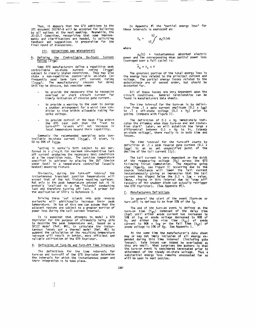
The typical waveforms during turn-on and turn- off are given in Figure 1. This figure explains and clarifies most of the terms and symbols needed for the discussion of GTO behaviour during turn-on and turn-off.
The magnitude of turn-on and turn-off losses are dependent on several conditions. The rate of rise of gate current to the required initial peak ampli- tude. to be maintained for a recomnended duration, ensures both simultaneous turn-on of individual islands and the sustained conduction of these initiated areas. The follow-up gate current will keep all areas conducting which results in a minimization of turn-on and conduction losses.
During the forced turn-off process, initiated by reversing the gate voltage from a low impedance, high current pulse source, several intervals contri- bute to the turn off switching losses. The interval up to the decline in load current shows gate loss and some loss related to the onset of turn-off.
The next interval is the collapse of current with a simultaneous increase in anode voltage causing an instantaneous high power loss, which in fact can force local temperatures high, especially since fewer and fewer individual elements, islands, or cells remain partially conducting.
If the GTO manages to pass this stage success- fully the third area of high loss occurs due to the residual or tail current during rising reapplied anode voltage.
This elevated loss continues but declines in magnitude as the tail current decreases, converting from turn-off losses into off-state blocking losses composed o f the product of leakage current and off-state voltage.
The important questions are: I' where do the turn-on and turn-off losses start and end?"
It is self evident that all losses have to be included, but it is far from clear from the manufac- turers' data sheets how this is accomplished. The resulting confusion is understandable as it took quite a while for the industry to adopt rules for even the high frequency, fast switching or inverter grade thyr i s tors.
As recently as 1987 the l,JEDEC JC-22 Comnittee voted to accept a ballot for High frequency rating verification test", showing circuits capable of producing the waveforms necessary to verify a number of common cases. In the introduction it says the fol 1 owing:
"The use of a verification test is to find out that the manufacturer's claims are true or valid. The manufacturer has to rely on some simple tests, modeling and field experience in his eff!rts to provide the user with sufficient information.
The same can be said about the GTO-thyristor except that in this case the ultimate operating range is narrow and subject to a number of restric- tions in operating conditions imposed to assure survival of the GTO. The GTO is so much more sensi- tive to destruction than thyristors that quite re- strictive rules have to be applied. Unfortunately, good methods to establish a safe area of operation are not yet practical, although this concept has been analyzed and discussed in Refs. #l and #2.
Above all, the manufacturers have not been sufficiently descriptive about how to define all of the operating power losses.
This paper attempts to discuss the definition of power loss and energy per pulse for the turn-on and turn-off intervals.
Because this paper is written as a working docu- ment for the benefit of the JC-22 Subcomnittee on Thyristors and is based on the existing and proposed standards for GTO thyristors, it should be possible to approach this subject fairly and squarely.
Reference to the proposed IEC Standard Doc. No. 47 (Sec.) 1093 appears in the text and a few com- ments are given in Appendix 1.
11. STANDARDS ACTIVITY - The German National Conittee has been most
active over the years in proposing standards for GTO thyristors with major contributions having come from Japan, Great Britain, USA and U.S.S.R.
At the TC47 (Technical Comnittee No. 47: Semi- conductor Devices of the International Electrical Comnission) meeting in Montreal, May 1985, it was agreed that the German National Comnittee would prepare the needed documents; one with definitions and letter symbols and one with essential ratings and characterization. This was reaffirmed in 1988 at the IEC meeting in San Diego, April 1988.
89CH27924/89/0000-1286$01.00 0 1989 IEEE
Thus, i t appears t h a t the GTO addi t ions t o the I E C document IEC747-6 w i l l be accepted f o r b a l l o t i n g by a l l nations a t the next meeting. Meanwhile, t he JC-22.1 Committee, recogniz ing t h a t some improve- ments and c l a r i f i c a t i o n s are needed, i s s o l i c i t i n g feedback and suggestions i n preparat ion f o r t he f i n a l round o f discussions.
- 111. DEFINITIONS AND MEASUREMENTS
- A. Def i n i n q the Con t ro l l ab le On-State Current Ra t ing ( 1 ~ ~ 1
Some GTO manufacturers def ine a r e p e t i t i v e peak con t ro l 1 able on-state current r a t i n g ( ITQRM~ subject t o c l e a r l y s ta ted condi t ions. They may a l so s ta te a non - repe t i t i ve c o n t r o l l a b l e on-state ( o r f requen t l y used term t u r n o f f ) current r a t i n g ~ I T O S M ) . The manufacturers' reasons f o r doing t h i s may be obscure, but consider some:
t o prov ide the necessary t ime t o recognize overload or shor t c i r c u i t current f o r t i m e l y i n i t i a t i o n o f , reve rse gate current .
t o provide a warning t o the user t o design a snubber arrangement f o r a worst case con- d i t i o n t o s tay w i t h i n al lowable r a t i n g f o r spike voltage.
t o prov ide con t ro l o f the heat f l ow w i t h i n the GTO case such t h a t the " l a s t t o t u r n - o f f " is lands w i l l not increase i n l o c a l temperature beyond t h e i r capab i l i t y .
Commonly the recommended operating gate con- t r o l l a b l e on-state cu r ren t (ITQWM!, i f given, i s 50 t o 60% of ITQSM.
Test ing i s normally both subject t o and per- formed i n a c i r c u i t f o r maximum non- repe t i t i ve t u r n o f f current Droducing the necessary t e s t condi t ions a t a low r e p e t i t i o n ra te . The junc t i on temperature spec i f i ed i s achieved by p lac ing the DUT (dev ice under t e s t ) i n a temperature con t ro l l ed (usua l l y heated) mounting f i x t u r e .
Obviously, dur ing the t u r n - o f f i n t e r v a l the instantaneous t rans ien t j unc t i on temperatures w i l l exceed t h a t o f the hot f i x t u r e mounting surfaces. Not on ly i s the peak temperature unknown but i t i s probably l oca l i zed t o a few " is lands" conducting l a s t and therefore tu rn ing o f f l a s t . A primer f o r the app l i ca t i on o f GTO's i s Reference 3.
D r i v i n g these l a s t is lands i n t o gate reverse avalanche w i l l a d d i t i o n a l l y increase t h e i r peak temperature. On top o f t h i s one can assume t h a t t he adjacent regions are subject t o a greater p o r t i o n o f power l oss dur ing the t a i l current i n t e r v a l .
It i s expected t h a t attempts t o model a GTO t h y r i s t o r f o r the purpose o f u l t i m a t e l y being able t o describe the peak temperature and, based on a S P I C E model (Ref. #4), t o ca l cu la te the instan- taneous losses and a thermal model (Ref. 15) t o augment the ca l cu la t i on o f the r e s u l t i n g temperature increase w i l l r e s u l t i n bet ter , more e f f i c i e n t and r e l i a b l e u t i l i z a t i o n o f the GTO t h y r i s t o r .
- B. D e f i n i t i o n o f Turn-On and Turn-of f Time I n t e r v a l s
The d e f i n i t i o n s f o r the t ime i n t e r v a l s f o r turn-on and t u r n - o f f o f the GTO t h y r i s t o r determine the i n t e r v a l s for which the instantaneous power and t h e i r i n t e g r a t i o n i s t o take place.
I n Appendix #1 t he " p a r t i a l energy loss" fo r these i n t e r v a l s i s expressed as:
where
p x ( t ) = instantaneous absorbed e l e c t r i c power and the corresponding mean p a r t i a l power l oss (averaged over a f u l l cyc le ) i s :
Px = Ex x f
The greatest p o r t i o n o f t he t o t a l energy l oss i s t he energy l oss r e l a t e d t o the p r i n c i p a l cu r ren t and voltage. The p a r t i a l energy losses r e l a t e d t o t h e gate/cathode are o f second order, bu t should be accounted f o r .
A l l o f these losses are very dependent upon t h e c i r c u i t condi t ions. General r e l a t i o n s h i p s can be found i n manufacturers data sheets.
The t ime i n t e r v a l f o r the turn-on i s by d e f i n i - t i o n from .1 x gate cu r ren t amplitude (0.1 x IGM) t o .1 x o f f - s t a t e vo l tage (0.1 x VD) p r i o r t o ga t i ng (compare w i t h F igure 1).
The d e f i n i t i o n o f 0.1 x V D imnediate ly i n d i - cates the dilemma; when does turn-on end and conduc- t i o n s t a r t ? Later, we w i l l es tab l i sh how la rge a d i f f e r e n t i a l between 0.1 x V D t o VT, (steady on-state voltage), there r e a l l y i s i n both t ime and losses.
The t ime i n t e r v a l f o r the t u r n - o f f s t a r t s by d e f i n i t i o n at .1 x peak reverse gate cu r ren t (0.1 x IRGM! t o an as y e t unspeci f ied p o i n t o f t h e dec l i ne o f the t a i l cu r ren t ( I z ) .
The t a i l cu r ren t i s very dependent on the dv /d t o f the reappearing voltage (VD) across the GTO f o l l o w i n g forced comnutation. The negat ive going s tep (VDM-VD, see F igure 1) occurr ing due t o the source inductance w i l l lower the t a i l cu r ren t instantaneously g i v ing an impression t h a t t he t a i l cu r ren t has dipped below the 0.1 x IZM - value. (Note, r i n g i n g i n t h i s i n t e r v a l due t o "snap o f f " recovery o f the snubber diode can a c t u a l l y r e t r i g g e r the GTO t h y r i s t o r ) . (See Appendix 1 2 ) .
C. Manufacturers D e f i n i t i o n s - I n general the s t a r t o f the event (turn-on o r
t u r n - o f f ) i s defined t o be from 10% o f the 16.
The end o f the turn-on event i s def ined as t h e turn-on t ime ( t g t ) composed o f t he delay t ime ( tgd ) u n t i l e i t h e r anode current has increased t o 10% o f ITM o r anode vo l tage decreased t o 90% o f V D and e i t h e r the r i s e t ime ( t ?) of anode cu r ren t t o 90% x ITM o r the f a l l l i m e ( t g f ) o f anode vo l tage t o 10% o f VD.
A t t he same t ime the manufacturer 's data sheet may or may no t imply i n c l u s i o n o f a l l energy ex- pended dur ing t h i s t ime i n t e r v a l ( i n c l u d i n g gate losses). Gate losses can indeed be overlooked as they are small. What surpr ises t h e authors i s t h a t t h e turn-on event i s considered terminated p r i o r t o attainment of t he steady on-state voltage. Thus a subs tan t i a l energy l oss remains unacounted f o r as w i l l be seen i n next section.
See Appendix 1.
1287
IGM
Note: This paper proposes tz(2). IZM may appear prior to end of gate cathode avalanche
Figure 1. Terms, Symbols and Definitions Related to the Turn-On and Turn-off Events in a GTD Thyristor.
The integration period for turn-off losses extends from the 0-1 x IRGM to some "fuzzy" point on the tail current. Most manufacturers recognize the fact that the loss in the tail current period is substantial. Most imply that their GTOs are designed to have both a low level of IZM and a short t,. Most, probably due to ease of definition, terminate the integration of losses at the recognizable ne ative step in anode voltage previously described !See Figure 1).
- D. Errors in Estimation of Enerqy Losses
In addition to the errors that occur because the period for integration is not extended through the physical duration of the event, measurement errors also have to be recognized. The measurement errors will be discussed in the next section.
Consider the power profiles in Figure 2, resulting from a turn-on or a turn-off event.
I Power ( W )
Linear Decay Power from Initial Phase of Event
time (usec) Linear and Exponential Representation of the Power Loss During the Residual Con- tinuation of the Turn-On and Turn-off Events
Figure 2.
In the integration of energy for either "on" or "off" events, both a large and a small entity enter into simultaneous consideration per Table 1.
TABLE 1. EVENT
PARAMETER TURN-ON - TURN-OFF The small entity f (.l x VD)
The large entity IT VD
The product (p)
Assume that 0.1 x VD declines linearly through the 0.1 x P-point to VT (on state voltage, full conduction) and IZM to I D (leakage current at off state voltage).
It can be shown that if the small entity is con- sidered down to 10% of its initial value, then 10% of the total energy is ignored in the case of an exponen- tial decay and I% in the case of a linear decay.
Referring to the oscillograms of Figures 3 and 4, showing turn-on and turn-off respectively of an IR GTO, type G30E12A 1200 V/600 A rating it becomes clear that test accuracies depending on amplifier recovery, probe compensation, resolution, offset and inductive voltage pick up will affect the result; details follow in Section E.
When it comes to the turn-off period we should remember that the gate current is equal to the tail current as soon as the gate-cathode junction is out of avalanche (See Fig 4). The gate current can be measured with up to 5 x better resolution than the anode current. Thus the amplifier error in the tail current can be corrected by comparing the gate cur- rent to the tail current.
IT x f(.l X VD) VD X f(IZM)
1288

Figure 3. Turn-On E v e n t f o r IR G30E12 with I 1 Energy Loss
I t can be seen from Table 2 t h a t an end-ooint t o the turn-on event can be e a s i l y i d e n t i f i e d as a func- t i o n o f the turn-on t ime because a large energy i s acquired dur inq anode vo l tage co l lapse compared t o a small energy a c q u i s i t i o n r a t e o f 1.4 mWs/us due t o the steady on-state voltage. I t i s there fore not necessary t o attempt t o de f ine end o f turn-on as the t ime t o reach a s p e c i f i c vo l tage l e v e l (c lose t o V T ) as t h i s demands about 1% reso lu t i on , bu t simply t o de f i ne the i n t e g r a t i o n Deriod as a t ime character- i s t i c o f the turn-on process, e.9. n x tgf where n might he 2 t o 5.
I n the case of the t u r n - o f f event, t he amount o f energy acquired dur inq the t a i l t ime i s large com- pared w i t h t h a t acquired dur ing the f a l l t ime tgq i.e. the t ime t o reach the quiescent o f f - s t a t e i s large. Also the t a i l cu r ren t i s h i g h l y process dependent both i n ampli tude and durat ion. For these reasons an a r b i t r a r y i n t e g r a t i o n i n t e r v a l , such as t h a t proposed f o r turn-on, i s not p r a c t i c a l .
Reference t o Table 2 shows t h a t i n the 4 us fo l low inq the p o i n t a t which i, = 0.1 IZM: an add i t i ona l 3.5% o f t o t a l t u r n - o f f loss i s acquired, which i s i n d i c a t i v e o f the f a c t t h a t the t a i l cur ren t decays exponent ia l l y and cannot be d i r e c t l y acquired i n i t s e n t i r e t y .
I t thus becomes necessary t o make prov is ions i n the Standards fo r i n t e g r a t i o n t o 0.1, and t o simply cor rec t the t a i l energy loss by the f a c t o r 1.1 t o inc lude the remaining energy beyond t,.
REFERENCE FOR INTEGRATED TIME /iTXvDxdt ENERGY LOSS
Turn-on Event f f rom F i g u r e 3 )
(us) fmWs) - _ _ _
IGM
Turn-of f Event f f rom F i q u r e 41
2 . 5 5 8
10 1 5 20
180 195* 200* 203 210 277
7 80
1 K 3117 11.5 la8
1 I & = 40 A L
I
I I I I I I I I
Energy Loss E. Cont r ibu t ions from Increased Gate D r i v e Dur ing
the Turn-on and Turn-of f Events
During the turn-on i n t e r v a l t he gate cur ren t i s overdr iven t o improve on the s luggish f a l l t ime and spreading o f conduction i n the GTO. The recommended gate cu r ren t i s t y p i c a l l y 1 t o 2% o f t he ITQRM, whi le the gate vol tage may be up t o 5V. The c o n t r i - b u t i o n t o t o t a l turn-on losses there fore can be neqlected. I n the previous case o f F igure 3 t h e c o n t r i b u t i o n was about .5 m i l l i J o u l e s , l ess than 0.25%. However, the gate power loss dur ing the conduction per iod should no t be neglected as i t i s up t o 1% o f the conduction loss.
The cond i t ions dur ing the t u r n - o f f event are q u i t e d i f f e r e n t .
The I R G dur ing storage t ime b u i l d s up t o 20 t o 25% o f the anode cur ren t p r i o r t o decay. During t h i s t ime the VG increases, e s p e c i a l l y q u i c k l y a t t he s t a r t o f decay o f anode cu r ren t . Using the data f rom the t e s t curves f o r t he I R G30E12A GTO, t h e energy i s j u s t about 1.5% o f t he p r i n c i p a l energy loss.
A f t e r t he s torage t ime p e r i o d (f-dq) t h e r e f o l l o w s a f a l l t ime per iod (tfq) going i n t o a t a i l t ime per iod (t,). During the tfq and beginning o f t,, t h e gate-cathode j u n c t i o n i s kept i n avalanche by the cur ren t from the energy s tored i n the para- s i t i c w i r i n g inductance from the gate-dr ive t o the GTO gate.
€/us COMMENTS f mWs/us )
TABLE 2
- Points of Voltage Energy Losses f o r 6 s t a b i l i z a t i o n : 1.7 acquired energv of t h e I n t e g r a t i o n 1 .4 increases a t I n t e r v a l s . 1.4 VT x IT = 1.4 mWslus 1 .4 where VT i s “ s t a t i c ”
on-state vol tage
D i f f e r e n t Terminat ion
Turn-On and Turn-of f Events
--- end o f p i h ‘ u r e 20 210
1289
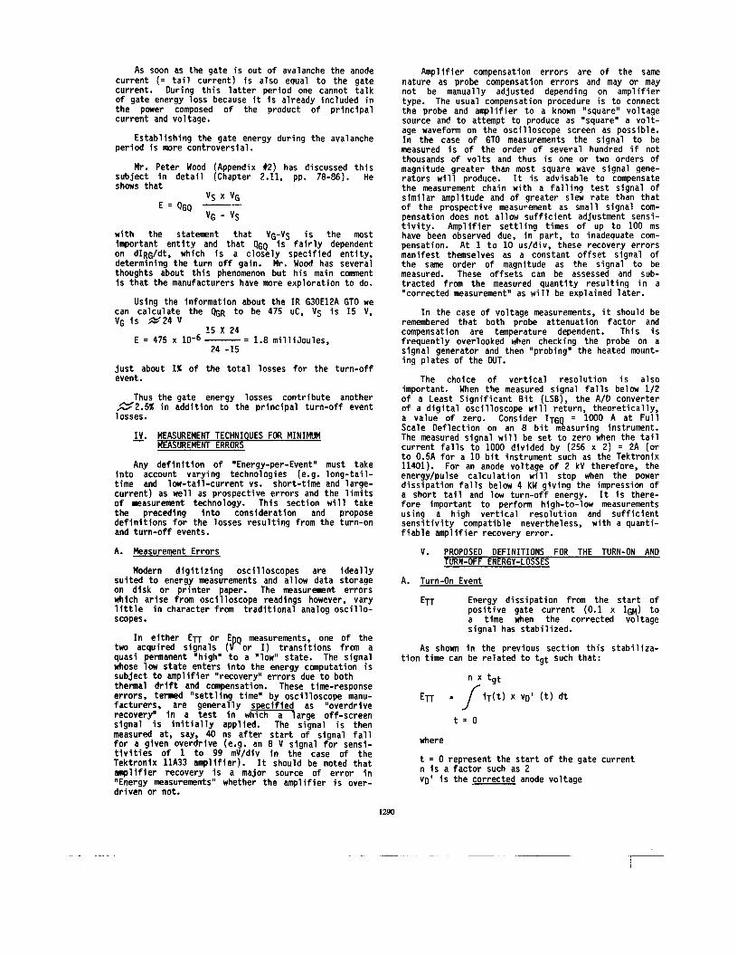
As soon as the gate is out of avalanche the anode current (= tail current) is also equal to the gate current. During this latter period one cannot talk of gate energy loss because it is already included in the power composed of the product of principal current and voltage.
Establishing the gate energy during the avalanche period is more controversial.
Mr. Peter Wood (Appendix #2) has discussed this subject in detail (Chapter 2.11, pp. 78-86). He shows that
vc x vr.
with the statement that VGTVS is the most important entity and that QGQ i s fairly dependent on dIRG/dt, which is a closely specified entity, determining the turn off gain. Mr. Wood has several thoughts about this phenomenon but his main comnent is that the manufacturers have more exploration to do.
Using the information about the IR G30E12A GTO we can calculate the QGR to be 475 uC, Vs is 15 V, VG is @24 V
15 X 24 E = 475 x 10-6 - 1.8 mil 1 i Joules,
24 -15
just about 1% of the total losses for the turn-off event.
Thus the gate energy losses contribute another -2.5% in addition to the principal turn-off event losses.
IV. MEASUREMENT TECHNIQUES FOR MINIMUM MEASUREMENT ERRORS
Any definition of "Energy-per-Event" must take into account varying technologies (e.g. long-tail- time and low-tail-current vs. short-time and large- current) as well as prospective errors and the limits of measurement technology. This section will take the preceding into consideration and propose definitions for the losses resulting from the turn-on and turn-off events.
A. Measurement Errors
Modern digitizing oscilloscopes are ideally suited to energy measurements and allow data storage on disk or printer paper. The measurement errors which arise from oscilloscope readings however, vary little in character from traditional analog oscillo- scopes.
In either E n or E Q measurements, one of the two acquired signals (f or I) transitions from a quasi permanent "high" to a "low" state. The signal whose low state enters into the energy computation is subject to amplifier "recovery" errors due to both thennal drift and compensation. These time-response errors, termed "settling time" by oscilloscope manu- facturers, are generally specified as "overdrive recovery" in a test in which a large off-screen signal is initially applied. The signal is then measured at, say, 40 ns after start of signal fall for a given overdrive (e.g. an 8 V signal for sensi- tivities of 1 to 99 mV/div in the case of the Tektronix llA33 amplifier). It should be noted that amplifier recovery is a major source of error in "Energy measurements" whether the amplifier is over- driven or not.
1290
Amplifier compensation errors are o f the same nature as probe compensation errors and may or may not be manually adjusted depending on amplifier type. The usual compensation procedure is to connect the probe and amplifier to a known "square" voltage source and to attempt to produce as "square" a volt- age waveform on the oscilloscope screen as possible. In the case of GTO measurements the signal to be measured is of the order of several hundred if not thousands of volts and thus is one or two orders of magnitude greater than most square wave signal gene- rators will produce. It is advisable to compensate the measurement chain with a falling test signal of similar amplitude and of greater slew rate than that of the prospective measurement as small signal com- pensation does not allow sufficient adjustment sensi- tivity. Amplifier settling times of up to 100 ms have been observed due, in part, to inadequate com- pensation. At 1 to 10 us/div, these recovery errors manifest themselves as a constant offset signal of the same order of magnitude as the signal to be measured. These offsets can be assessed and sub- tracted from the measured quantity resulting in a "corrected measurement" as will be explained later.
In the case of voltage measurements, it should be remembered that both probe attenuation factor and compensation are temperature dependent. This is frequently overlooked when checking the probe on a signal generator and then "probing" the heated mount- ing plates of the DUT.
The choice of vertical resolution is also important. When the measured signal falls below 1/2 of a Least Significant Bit (LSB), the A/D converter of a digital oscilloscope will return, theoretically, a value of zero. Consider ITGQ = 1000 A at Full Scale Deflection on an 8 bit measuring instrument. The measured signal will be set to zero when the tail current falls to 1000 divided by (256 x 2) = 2A (or to 0.5A for a 10 bit instrument such as the Tektronix 11401). For an anode voltage of 2 kV therefore, the energy/pulse calculation will stop when the power dissipation falls below 4 KW giving the impression of a short tail and low turn-off energy. It is there- fore important to perform high-to-low measurements using a high vertical resolution and sufficient sensitivity compatible nevertheless, with a quanti- fiable amplifier recovery error.
V. PROPOSED DEFINITIONS FOR THE TURN-ON AND TURN-OFF ENERGY-LOSSES
A. Turn-On Event
Energy dissipation from the start of positive gate current (0.1 x IGM) to a time when the corrected voltage signal has stabi 1 ized.
As shown in the previous section this stabiliza-
ETT
tion time can be related to tgt such that:
E n - / iT(t) x VD' (t) dt
t = O
where
t = 0 represent the start of the gate current n is a factor such as 2 VD' is the corrected anode voltage

The corrected anode voltage is found by comparing the static on-state voltage at the test current with the dynamic value at, say, 10 x tgt by which time the device should be in the fully conducting state.
Thus
VT the on-state voltage for "static" condition
Figure 3 shows the turn-on voltage (vft)) of a 30 mn 1600 V GTO revealing a measured on-state voltage of about 12 V as compared to the statically derived value of 2.5 \I @ 600 A . It also shows the corrected Energy waveform to be quasi constant from about 8 us onwards. The measured tgt of this device is 2.5 us and its data sheet limit is 5 us such that 2 x tgt encompasses the turn-on transient.
By using time instead of voltage as a definition of end-of-integration, the errors due to voltage acquisition enter only once into the enerqy measure- ment. This is the proposed approach for the assess- ment of turn-on energy loss The integration time can be set to n x tgt, where n = 2 to 10 depending on circumstance.
B. Turn-off Event
EDQ - Energy dissipated from start of negative gate current (0.1 x IRGM) to 1M of the corrected peak anode tail current IZM.
In order to correctly assess 10% of IZM the gate current, not the anode current, must be measured since a 5 times greater resolution can be used with a much lower amplifier recovery error because the gate current signal rises from "low-to-high" unlike the anode current. However, gate current will be a true reflection of anode current only after the end of gate avalanche (tc) when IK 0 (Fiqure 6). Therefore
lA - lbb A t 6 i v tK - 100 A f D i v
t p - 1W b i v t - 2 u I f D l v
Flgure 5. Turn-off Event for IR 630E12A Uslng IK = 0 to Correct 12
Figure 6. Current Flow i n a GTO for the Demon- stration o f Improving on the Accuracy of the Tail Current- Representation
-Y an energy measurement involving IA remains necessary for that part of the turn-off event encompassed by the start of negative gate current to the end of gate- cathode avalanche. This large signal measurement is less susceptible to amplifier recovery but must still be compensated in order to measure IZM accurately. Failure to do this will result in large errors in the integration time (defined as the time to reach 0.1 x I Z M ) -
A s seen from Figure 1 (and compare with Figure 5) the time interval for the gate avalanche has not ob- tained any recognition in definition of its duration.
The proposals from different National Standards Committees recognize the fact that IZM occurs later than the tfq for time for the decline of anode current. The peak of IZM appears more or less at the time point when the gate-cathode junction just goes out of avalanche. Some attempts to include this time in tfq have been made both by manufacturers and various National Standards Committees. The most fair approach is to put forth new terms and defini- tions.
A proper approach would be to call the time from 0.1 x I R G M to end of gate avalanche tgc (comnutation of the gate-cathode junction), then connecting this with the definition of IZM, using iRG(t) when IK is equal zero, for correction of iZ(t).
Thus an accurate measurement o f EDQ requires a measurement in two parts:
where
EDC is the energy from gate current (0.1 x IRGY) to end of gate-cathode junction avalanche and EZ 1s the tail current loss from end of avalanche to "end-of-tail-current" ( = 0.1 x
EDQ = EDC + EZ
IzM)+ Thus we obtain:
tgc EDC = / v r ( t ) X iTI(t)dt
t = O with
iT'(t) = iTft) - K(IT - 16) where
iT(t) i s the measured current on the anode side and (IT - IG) is the amplifier recovery offset measured at t at which IK = 0. (See Figure 5). From iT'(?f (corrected anode current) the true IZM is established (IzM').
1291

D. Discuss ion
Usinq the above and d i s c o u n t i n g measurement e r r o r s t h e energy loss should no t be underest imated hv m r e than approximately 3% and w i t h a d d i t i o n a l e f f o r t s as low as 1%.
Althouqh the Standard-proposal f o r D e f i n i t i o n of t h e Energv Losses would underest imate the amount o f losses o ther t ime i n t e r v a l d e f i n i t i o n s c o u l d be considered, q i v i n q t h e t o t a l losses d u r i n g t h e tu rn-on and t u r n - o f f event.
One r e l a t e d t o turn-on i s the minimum t ime the GTO has t o he i n conduct ion b e f o r e a t u r n - o f f event i s oermiss ih le . S i m i l a r l y , a t u r n - o f f event mav no t be i n t e r r u p t e d w i t h a tu rn-on event too q u i c k l y w i t h o u t endanaerinq the GTO. Peter Wood r e f e r s t o t h i s t ime as " t u r n around t ime" fp. 61 ofll book); w h i l e manufacturers use the exoression minimum o f f - t ime" .
t 2
t = tgc
EDZ= 1 v T ( t ) X i Z ( t ) d t
w i t h
F i g u r e 4 shows a 30 mm GTO comnutat ing 500 A. A t tgc the cathode c u r r e n t i s known t o be zero and the d isp layed i K ( t ) * i a ( t ) - i ( t ) t r a c e i s there fore se t t o zero: t he i a ( t ) grace i s lowered t o zero by the same amount.
(Note, v a r i a t i o n s i n tgc due t o d l f f e r e n t gate lead inductances, apar t from changing the t u r n - o f f c o n d i t i o n i t s e l f , w i l l appor t ion more o r l ess energy i n the EDC o r ED phases bu t t h e t o t a l , EDQ, w i l l remain c o n s t a n t 5
Measurinq the t a i l c u r r e n t t o 10% o f IZM (an e a s i l y achieved r e s o l u t i o n ) w i l l r e s u l t i n t h e a c q u i s i t i o n o f 9m o f EDT assuming t a i l c u r r e n t t o be exponent ia l i n decay. ( I f t = t, B 0.1 x i,,, then t, = 7 x I n 10 r e s u l t i n g i n a t a i l change o f 0.9 x t x i Z M a t end o f i n t e g r a t i o n i.e. 90% o f t he energy i s acqu i red) . However, from F i g u r e 5 (600 A t u r n - o f f o f 30 mm GTO), over 30% o f EDQ i s acquired by tgc (EDc) which means t h a t t he 90% a c q u i s i t i o n o f EDZ r e s u l t s i n 93% a c q u i s i t i o n o f ED^. (By d e f i n i n g tz a t 5% o f IzM', 96% o f the t o t a l t a i l l oss would be measured).
C. Gate Enerqy Loss
I n Sec t ion 111 the m e r i t s o f i n c l u d i n g the energy l oss r e l a t e d t o the g a t i n g s igna ls were discussed. Based on the conc lus ion t h a t the losses r e l a t e d t o the tu rn-on can be neglected, bu t t h a t the gate losses associated w i t h the tu rn-o f f process have two components t o consider:
ERG^, r e l a t e d t o the wi thdrawal o f charge and simultaneous inc rease o f qate-cathode-vol tage ( t ime pe r iod tgs)
ERG?. r e l a t e d t o the c u r r e n t imposed onto the qate cathode i n avalanche ( t ime p e r i o d tgs t o
The gate-cathode j u n c t i o n l oss (ERG) c o n s i s t s
ERG = E R G l + ERG2
t, = t ime a t which i Z ( t ) = 0.1 x IZM'
t C l C '
o f :
The equat ions f o r these losses are;
ERG^ = '7 iRG(t.1 X VRG(t) d t
t = O and V s x VGAV
VGAV - Vs ERG? = 4GQ
where
c u r r e n t oufse f rom 0.1 x IRGM t o I R ~ QG i s the e x t r a c t e d charge i n the gate
vs i s the gate source vo l tage o r VRG a constant gate vo l tage immediately f o l l o w i n g the t r a n s i e n t c o n d i t i o n s a t beq inn ing o f t z
VGAV i s the average of the gate avalanche v o l t a g e hetween IRGM and tgq
E. Summarv o f the Proposed Method t o Obta in the Enerqv Losses Dur inq Turn-on and T u r n - o f f
Turn-On Losses
1.
7.
Use the standard d e f i n i t i o n t o e s t a b l i s h t q t
Assume i n t e q r a t i o n t ime t = n x t q t
where n i s normal ly 7, bu t can be s p e c i f i e d t o be 3, 4 o r 5 deoendinq on dev ice p r o o e r t i e s and improvements i n measurinq technique.
The expression i n the hracket c o r r e c t s f o r the ins t r r tmenta t ion o f f s e t i n the measured value o f VD and f n r t he presence o f an on-s ta te vol taqe.
Turn-Off Losses
1 . E s t a b l i s h t ( t ime t o commutate the qate-cathode j u n c t i o n ou! of avalanche) and t, ( t a i l t ime) . However t, i s e s t a h l i s h e d more a c c u r a t e l v hv r isinq the i R G ( reverse qate c u r r e n t ) t o c o r r e c t i, ( t a i l c u r r e n t ) bo th w i t h respec t t o o f f s e t and f o r h e t t e r r e s o l u t i o n o f t,.
2. Rreak (to the I n t e a r a t i o n i n t o two p a r t s
t Z i s u s u a l l v te rmina ted a t 0.1 x IZM. M u l t i p l y En7 w i t 4 1.1 t o c o r r e c t f o r the 10% o f the t a i l enerqv no t accounted f o r . The t o t a l p r i n c i p a l enerqv l oss i s then
3. Add the gate cathode j u n c t i o n l oss (ERG) c o n s i s t i n g o f
ERG1 ' ERG2
d e f i n e d p r e v i o u s l y . The t o t a l Energy losses d u r i n q the t u r n - o f f event then becomes
EDO + ERG
- V I . CONCLUSION
It has been shown t h a t t he proposed Standards d e f i n i t i o n o f turn-on and t u r n - o f f power and energy losses do n o t adequately i nc lude a l l losses associated w i t h the turn-on and t u r n - o f f events. Thus, it w i l l be d i f f i c u l t t o account f o r a l l those losses determining the heat ing e f f e c t s o f the GTO unless improvements are made. An example shows t h a t t he e r r o r can be substant ia l , 8 t o 15%. For t h i s reason, improved d e f i n i t i o n s are proposed, p o t e n t i a l l y leading t o an underestimation o f on ly 1 t o 2% o f t he swi tch ing losses.
It was a l so found t h a t t he gate losses dur ing the t u r n - o f f event must be accounted f o r and t h a t improved measuring techniques and inst rumentat ion are both needed and poss ib le .
ACKNOWLEDGEMENT
We are g r a t e f u l t o our JEDEC Secretary, M r . Ken McGhee, f o r a l low ing us t o do t h i s exerc ise i n pub l i c . We have a lso r e l i e d on M r . David Borst, L i f e Fel low I E E E Member, f o r e d i t o r i a l assistance and exper t i se i n Standards matters. Mr . E r i c Car ro l l , o f Jnternat ional R e c t i f i e r Corp., cont r ibuted the Sect ion on measurement techniques and e r ro rs and made numerous suggestions. Due thanks a lso go t o EPRI f o r permission t o quote from M r . Peter Wood's book and t o M r . Richard Huard o f Tekt ron ix , Beaverton, OR, f o r h i s guidance i n developing proper measurement techniques.
REFERENCES
ill V.A.K. Temple, "SOA Test Key f o r IGT's MCT's, GTO's and Wide Base Transistors," Research Report #86CRD262 - General E l e c t r i c Co.
I23 6. Wachutka, "Ana ly t i ca l Model f o r t h e Destruct ion Mechanism o f GTO L i k e Devices by Avalanche In jec t i on " , The Electrochemical Society Spr ing Meeting, May 7-12, 1989.
[333 John R. Welsh, Hans-Peter Hempel. "Basic Rules f o r the Rat ing and Gating o f GTO Thyr is tors" , I A S Conference Record, pp. 570-573, At lanta, 1989.
[4] R. F i sch l , C.L. Tsay, K. Pourrezaei, "A Computer Aided GTO-Model f o r Power E lec t ron ic C i r c u i t Design". IEEE I n t e r n a t i o n a l Symposium on C i r c u i t s and Systems, Port land, OR, May '89.
D.E. Piccone, W.H. Tobin, "Two-Oimen- s iona l Heat Flow i n a GTO Having a H igh ly I n t e r - d i g i t a t e d Emi t ter " F i f t h IEEE Semi-Therm Sym- posium, San Diego, 1989.
L 5 ] I.L. Somos,
APPENDIX #1
The IEC and EIA/JEDEC Comnittees w i t h cognizance i n T h y r i s t o r s (TC-47 and JC-22) have been working on documents d e f i n i n g and standardiz ing terms, d e f i n i t i o n s , and essen t ia l c h a r a c t e r i s t i c s o f GTO T h y r i s t o r s f o r i n c l u s i o n i n t h e i r respec t ive T h y r i s t o r Standards (IEC 747-6: Semiconductor Devices: P a r t 6: T h y r i s t o r s and EIA-397: Recommended Standards f o r Thyr is to rs ) . The JEDEC JC-22 Comnittee has been very a c t i v e i n support ing the IEC work and in tends that , t o every ex ten t possible, t he same terms and d e f i n i t i o n s adopted by the IEC w i l l be accepted by JEDEC f o r i n c l u s i o n i n t h e i r EIA-397 document.
The f o l l o w i n g terms, d e f i n i t i o n s , comments, and explanat ions which have a p p l i c a b i l i t y t o t h e discussion o f turn-on and t u r n - o f f power and losses energy have been ex t rac ted f o r reference here in f rom t h e working documents o f t he TC-47 and JC-22 Committees.
Power, enerqy (see F igu re )
A l l d e f i n i t i o n s f o r losses re fe r , i f n o t otherwise speci f ied, t o the product o f p r i n c i p a l cur ren t and p r i n c i p a l voltage.
Power, instantaneous values dur ing a cyc le
Notes 1.- The f o l l o w i n g d e f i n i t i o n s r e f e r t o a chronologica l subd iv is ion o f t he cyc le t ime i n t o p a r t i c u l a r per iods i n which the t h y r i s t o r i s e i t h e r i n a p a r t i c u l a r s t a t e o r i n which i t changes s tate.
2.- The d e f i n i t i o n s are general. They do no t consider t h a t beginning and ending o f the p a r t i c u l a r per iods must be s p e c i f i e d t o make s p e c i f i c a t i o n s f o r t he der ived c h a r a c t e r i s t i c s "mean p a r t i a l power loss" and " p a r t i a l energy loss" meaningful. However, sens ib le proposals f o r t h e s p e c i f i c a t i o n o f these ins tan ts are made i n r e l e v a n t notes.
O f f - s t a t e power (PD)
The power when the t h y r i s t o r i s i n t h e o f f - s t a t e .
Note - I f no t otherwise speci f ied, t he term r e f e r s t o the power i n - e i t h e r t h e p e r i o d between the cross ing
of t he o r i g i n ( I = 0 o r V = 0) and the beginning o f t h e turn-on time,
- o r t he per iod between t h e ending o f t he turn-off t ime and t h e cross ing o f the o r i g i n .
Turn-on power ( P n )
The power i n the p e r i o d i n which the t h y r i s t o r i s turned on.
Note - I f n o t otherwise speci f ied, t h i s per iod corresponds w i t h t h e turn-on time.
1293
11

I I I! w
I I I
I r-. clcl. -----I PR = reverse power Consequently, i n t e - Pg = o f f - s t a t e power g r a t i n g instantaneous PT = n n - s t a t e power Dower leads t o PTT = tu rn-on power ETT = tu rn-on enerqv PDn = t u r n - o f f Dower EDQ = t u r n - o f f enerqv
On-state power (PT)
The power when the t h y r i s t o r i s i n the on-s ta te .
Note - I f not o therw ise spec i f i ed , t he term r e f e r s t o the power i n the p e r i o d between the ending o f t h e t u r n - o f f t ime and t h e beginning o f the t u r n - o f f t ime.
T u r n - o f f power (PDQ)
The power i n the p e r i o d i n which the t h y r i s t o r i s tu rned o f f .
Note - ‘f not o therw ise spec i f i ed , t h i s p e r i o d corresponds w i t h the t u r n - o f f t ime.
Annex 5: S p e c i f i c a t i o n s on gate t u r n - o f f cu r ren t o r vo 1 t age
1. Present s t a t e
I n 747-6, 11, the f o l l o w i n g concepts are p rov ided:
Gate t u r n - o f f cu r ren t
The lowest gate c u r r e n t r e q u i r e d t o sw i tch a t h y r i s t o r f rom the on-s ta te t o the o f f - s t a t e . Note - Not a l l t h y r i s t o r s can be tu rned of f by
Gate t u r n - o f f vo l taqe
The gate vo l tage requ i red t o produce the gate t u r n - o f f cu r ren t . Note - Not a l l t h y r i s t o r s can be tu rned o f f by
the gate.
the qate.
Peak gate t u r n - o f f cu r ren t f IGQM)
The peak gate c u r r e n t d u r i n g t u r n - o f f o f a GTO t h y r i s t o r . Note - The peak ga te tu rn-o f f cu r ren t e s t a b l i s h e s
i t s e l f as a consequence o f t he a p p l i e d gate t u r n - o f f vo l taqe. The gate t u r n - o f f pu lse generator must, however. be capable o f supp ly ing t h i s cu r ren t .
I294
-
2.
3.
Comnent
I t i s recognized t h a t these d e f i n i t i o n s should be updated t o r e f l e c t present understanding o f t h e GTO . To i n i t i a t e t u r n - o f f , a negat ive gate c u r r e n t o f a s u f f i c i e n t l y h i g h r a t e o f r i s e must be provided. Dur ing t u r n - o f f , t h e ga te c u r r e n t reaches a negat ive peak value which depends no t o n l y on i nhe ren t q u a l i t i e s o f t h e t h y r i s t o r bu t a lso on the ex te rna l c o n t r o l c i r c u i t r y . The connect ions between inherent q u a l i t i e s , c o n t r o l c i r c u i t r y and the r e s u l t i n g course o f the gate c u r r e n t are v e r y complex. Therefore, t h e s p e c i f i c a t i o n r e f e r s t o a s p e c i f i e d c o n t r o l c i r c u i t r y and g ives an upper l i m i t f o r t he negat ive peak value o f the gate c u r r e n t d u r i n g the t u r n - o f f per iod . The user must then take care t h a t the gate t u r n - o f f pu lse generator i s capable o f supp ly ing t h i s cu r ren t . Under these cond i t ions , s p e c i f i c a t i o n s r e g a r d i n g t h e course o f t h e gate vo l tage d u r i n g t u r n - o f f would be useless and are no t given.
Proposal
I t i s proposed t o renounce on the present concepts i n 747-6 and t o r e p l a c e them by t h e proposal made i n 47(Secre tar ia t )1069:
- To ge t r i d of t he p o l a r i t y problem w i t h negat ive meximum values, re fe rence i s made t o t h e reverse gate cu r ren t .
- The no te i s reworded because the meaning o f “es tab l i shes i t s e l f ” seemed no t q u i t e c lea r , and because i t i s no t t he gate vo l tage t h a t i s app 1 i ed .
The new d e f i n i t i o n t h e r e f o r e reads:
Peak ( reverse) gate t u r n - o f f c u r r e n t ( o f a GTO t h y r i s t o r ) , ( IRGQM, IGQM)
The peak value o f t he reverse gate c u r r e n t d u r i n g t u r n - o f f o f the GTO t h y r i s t o r .
Note. -
Annex 6:
Prec ise
Th is value depends s t r o n g l y on t h e ex te rna l gate c o n t r o l c i r c u i t r y . S p e c i f i c a t i o n s r e f e r t o the upper l i m i t of t he peak va lue f o r s p e c i f i e d c o n d i t i o n s o f gate c o n t r o l .
The gate t u r n - o f f pu lse generator must be capable of supp ly ing t h i s cu r ren t .
Explanat ions reqard inq the proposed r e v i s i o n o f p resent Subclause 3.4: Power D i s s i p a t i o n
p r o v i s i o n s are needed r e q a r d i n q the i n s t a n t s t i and t 2 which d e f i n e b e g i n n i n i and ending o f each p a r t i c u l a r per iod . For tu rn-on and t u r n - o f f losses, these i n s t a n t s should, as f a r as t e c h n i c a l l y j u s t i f i a b l e , be i d e n t i c a l w i t h the s p e c i f i e d i n s t a n t s t h a t d e f i n e beq inn ing and ending of the corresponding tu rn-on and t u r n - o f f times. To leave some freedom f o r o t h e r p rov is ions , t h i s should be s ta ted i n a no te and no t i n the d e f i n i t i o n .
The gate power l oss should be s p e c i f i e d as a separate c h a r a c t e r i s t i c and no t be inc luded i n the p a r t i a l losses due t o p r i n c i p a l c u r r e n t and vo l tage. T h i s has no t s u f f i c i e n t l y be considered i n p resent d e f i n i t i o n s .

APPENDIX #2
Excerp ts (by permiss ion) from a book by Peter Wood: "Fundamentals and A p p l i c a t i o n s of Gate-Turn-off Thy- r i s t o r s " , publ i shed by E l e c t r i c Power Research I n s t i - tu te , Inc. (EPRI) 1989.
d i r e c t e d t o Research Reports Center (RRC) Box 50490, P a l o Al to , CA 94303, (415) 956-4081.
This book was prepared by Peter Wood as an account of work sponsored by EPRI.
page i i i
Requests f o r c o p i e s of t h i s book should be
This book provides designers and applications engineers who are ta- miliar with thyristors and transistors with complete information on ap- plications of GTO technology such as motor drives, traction choppers, uninterruptible power supply systems, and photovoltaic inverters.
The book consists of four chapters and two appendixes. Chapter 1 outlines the generic characteristics of GTOs, thyristors, and transistors and gives a simplified explanation of GTO processing. In Chapter 2, parametric details of specific devices are presented and discussed and then compared with the parameters of transistors and fast-switching thyristors. In Chapter 3, the author provides a step-by-step explana- tion of the parameters, terms, applications, and relation of values listed on manufacturers' data sheets. Because CTO devices are rela- tively new, there are few circuit designers having extensive experience with them, and the intent of this chapter is to lead a designer through some typical Gro data sheets.
Page X . Comnents U If GTO device data sheet terms and tests are not standardized,
then more industrywide efforts should be put forth to do so. If the amount of gate region base charge, which must be re- moved to turn off a GTO, truly is approximately a constant for a given level of on-state current, then device makers should perhaps "toughen" the gate-cathode region of a device and use extremely rapid gate charge withdrawal to effect snubber- less device turn-off. (There have been recent efforts in this vein for low powered devices)
n If snubber loss is a large problem, there should be more work in the area of simplifying energy recovery snubber networks and in device "toughening" so that snubbers may not even be needed.
Page 18. Chapter 1 The more interesting device failure mechanisms are all associated
with device switching, both turn-on and turn-off. Thyristors exhibit one set of failure mechanisms, transistors another, completely differ- ent, set, and GTOs a combination of both sets. In this respect, the GTO combines the worst features of both the thyristor and the transistor.
Page 22. Chapter 1 Turn-on dlldt failure, as evidenced by thyristors, is only seen in
GTOs withgrosslyinadequategatedrive. If thegatedrive initial ampli- tude and rise-time are adequate, the device is essentially self- protecting against dlldt. Its slow rate of impedance change, because of the limited regeneration effects in its turn-on process, does not allow the current to rise fast enough to cause a "true" dI/dt failure.
At turn-off the C'TO has a multiplicity of failure mechanisms. All save one are related to the current pinching that occurs as the device turns off, i.e.. to the fact that the anode-cathode current is squeezed into regions in the center of the devices' emitter fingers (and toward the ends). The one unrelated failure mechanism is gate-cathode junc- tion failure due to avalanche in combination with excessive reverse gate current.
The threat of second breakdown persists until the voltage reaches its final value. If that value is too high (though well below device blocking rating), it can still cause failure in the tail period, particularly for induc- tive loads. In most practical circuits, the phenomenon shown in Figure 1-11 then occurs. Because the L-diode-C path is underdamped, the anode-cathode (diode-C) voltage considerably overswings the source voltage, As the current in the diodr-capacitor goes to zero, it reverses
and reverse recovers the snubber diode. I t , ds is often the case, the peak reverse recovery current of the diode exceeds the GTO tail current at that time, some reversecurrent will flow in the anode-cathode circuit : inductance. As the diode snaps off, the di/dt it produces causes the anode-cathode voltage to drop sharply, often below circuit voltage and, in extremis, below zero.
Subsequently, the anode-cathode voltage recovers to the circuit volt- age as that component of diode recovery current in the inductance de- cays, and with it the Ldi/dt it produces. The reapplied dV/dt that is then applied to the GTO is completely unsnubbed, since the snubber capacitor is charged to the original peak voltage, higher than the source voltage, and the snubbcr diode is blocking. 'I his can cause a true d V l d t breakover, and consequent failure, of the G l 0 .
Gate reverse bias must be maintained throughout the turn-off and tail periods, to prevent true dV/dt failure occurring, and to prevent an- other turn-off failure mode. I f reverse cite bias is removed during the tail period, after all turn-off and snubber transient phenomena are over, then the few fingers involved will promptly assume the conduct- ing state because of the carrier densities and distributions existing therein at this time. They will undergo catastrophic failure, citlier by the equivalent of forward-biased second breakdown or by true dlldt failure. Obviously, if reverse gate bias must not be removed, it is fatal to try and turn the GTO on again during the tail period; i f turn-on is attempted, device destruction will result. This makes the "turn- around time" (interval between device turn-off and turn-on) for GTOs similar to that for fast-switching thyristors, despite the GTOs lack of need for commutation circuitry; its tail time isanalagous to, and similar in duration to the gate recovery time required by the thyristor.
FIGURE 1-10 Common GTO Snubber Configuration
FIGURE 1-1 1 Typical GTO Turn-oll Voltage and Current Waves
Snubber Overshoot Stray and Bulk Inductance in Circuit
Stray Inductance In Snubber Loop
Spike Voltage I
Snubber Diode Rcvcrse Recovery Transient
2.1 2 Summary of Conclusions From Detailed Comparisons
1.
11.
Ill.
IV .
V.
VI.
VII.
VI11.
IX.
GTO conducting losses are higher than those for thyristors of comparable ratings unless the conduction time is so short that the thyristor current does not have enough time to spread out over the full device active area. GTO turn-on drive requirements are greater than those for comparable thyristors, particularly as regards "hack porch" current level needs. GTO turn-on losses are comparable with those of thyristors and transistors, and are not a limiting factor i.nsofar as oper- ating frcquency is concernrd. GIOs have long rise times compared to thyristors, and cannot be regarded as fast closing switches. GTO total turn-off time requirements make the operating frequency limit (in straightforward switching applications) about the same as for thyristors. GTO turn-off losses exceed those of thyristors even when commutating circuit losses are included in the latter. In conjunction with (I), this means that higher efficiencies are not inherent in the use of GTOs as compared to thyristors. Snubber losses for GTOs are much higher than those for thyristors. This reinforces VI. Manufacturer's gate drive (and other) specifications leave something to be desired. Although turn-off drive can be (and usually is) imple- mented as a simple switched voltage source in conjunction with a predominantly inductive impedance, significant benefits may be available if alternate approaches are tried.
1295
![Skvirsky [Ethnic Turn] for ETDfinal3 - CiteSeerX](https://static.fdokumen.com/doc/165x107/631f1c694573ad0c3e02e959/skvirsky-ethnic-turn-for-etdfinal3-citeseerx.jpg)