Assessment of the notching efficiency of PLC-2G networks
30
Assessment of the notching efficiency of PLC-2G networks Version 1.00 Authors: Pascal Krähenbühl; FM-FP, EMC Competence centre Hans Breitenmoser; FM-FP, EMC Competence centre PLC 2. Generation OFCOM April 2009 PLC broad band signal Notch wanted signal
-
Upload
khangminh22 -
Category
Documents
-
view
1 -
download
0
Transcript of Assessment of the notching efficiency of PLC-2G networks
Assessment of the notching efficiency of PLC-2G networks
Version 1.00
Authors: Pascal Krähenbühl; FM-FP, EMC Competence centre Hans Breitenmoser; FM-FP, EMC Competence centre
PLC 2. Generation
OFCOMApril 2009
PLC broad band
signal
Notch
wantedsignal

Page: 1
Distribution Name Ref. Function Company/OE
Change management Date Version Status Company Name Comments 30.04.2009 1.00 OFCOM krp, beh Final document
Approval management Date Company Name Initials Comments

Page: 2
Summary This report is devoted to the electromagnetic compatibility (EMC) aspects of PLC equipment and networks. It should be noted that a series of reports have previously been published on the subject, notably on the interference potential of an extensive source of interference (a PLC network covering the town of Fribourg), and another on the interference potential of local interference sources (private PLC indoor systems). In general, these two studies have shown that the interference potential of PLC equipment clearly exceeds the limits of the NB30 provisions applicable in Europe and Switzerland in case of interference.
This report presents the policy for management of the risk of interference since the authorisation of PLC access networks in Switzerland in September 2001. The desired objective is to avoid a major interference problem which might affect radiocommunications. OFCOM has decided to act preventively by issuing recommendations for the attention of PLC operators and forbidding transmission of PLC signals on overhead lines. In order to act effectively in a preventive manner, the regulator must have access to privileged information from the PLC operator, concerning in particular the geographical deployment of its network and the frequency bands used. The effectiveness of the preventive measures taken by the regulator is then measured by the change in the number of complaints notified. The low number of complaints recorded during the 2001-2008 period demonstrates the relevance of the regulation which has been put in place.
This report also summarises the evaluation of a new generation of PLC modems which appeared on the market in 2005 and which have some interesting functionalities which can be used in case of interference with radio systems. In particular, it explains how these functionalities have been applied to the PLC network to resolve cases of interference affecting amateur radio operators. Judicious use of these functionalities will henceforth make it possible to envisage coexistence of PLC installations and radiocommunication services; this was unthinkable only a few years ago with the first-generation PLC equipment.
As a preventive measure or in case of interference, two main functionalities can be used: notching or reducing the amplitude of PLC carriers within specific frequency ranges. Notching was found to be an effective solution in all cases of interference and made it possible to comply with the NB30 limit with ease. In order to relieve a disturbed receiver of all sources of PLC interference, all modems within a radius of 100 m from the disturbed sink must be set with the corresponding notches.
However, if no EMC measures can be found, that part of the network which is causing the interference must be switched off.
These EMC functionalities exist thanks to OFDM modulation. In case of interference, it is possible to control the radiated power in the spectrum. Other wire-bound technologies (xDSL, CATV, etc.) use the same type of modulation and will also have to make use of these EMC functionalities as data rates increase and given the resulting increase in frequency range.
Incidentally, OFDM modulation is being used not only in wired technologies but also increasingly in many different types of wireless broadband technologies (MIMO, DVB-H, DAB etc.). However, in this case the individual carriers are useful signals which are clearly allocated within the radio spectrum. This type of modulation (OFDM) is certainly progressive and will provide further EMC functionalities.
Page: 3
Contents
1 Introduction ........................................................................................................................5 1.1 The risk of interference................................................................................................5 1.2 Preventive risk management.......................................................................................6 1.3 Capabilities of PLC-2G................................................................................................7
2 Current general conditions from OFCOM’s viewpoint .......................................................9 2.1 Standardisation in the area of broadband technologies..............................................9 2.2 Requirements of the radio services.............................................................................9
3 Consideration of the risk of wire-bound broadband technologies....................................11 3.1 PLC network..............................................................................................................11 3.2 PLC indoor ................................................................................................................11
4 Reducing the interference risk with PLC-2G technology .................................................12 4.1 Description of the PLC-2G system............................................................................12 4.2 Reducing risk with PLC-2G .......................................................................................14 4.3 Preventive protection of the spectrum.......................................................................16
5 Dealing with cases of interference...................................................................................17 5.1 Defining the scope ....................................................................................................17 5.2 The technical concept ...............................................................................................18 5.3 Monitoring of implementation ....................................................................................18
6 Field test ..........................................................................................................................19 6.1 Measurement system used .......................................................................................19 6.2 A practical example...................................................................................................20 6.3 Notching efficiency ....................................................................................................24
7 Conclusions .....................................................................................................................27
8 Bibliography and glossary................................................................................................28 8.1 Bibliography ..............................................................................................................28 8.2 Glossary ....................................................................................................................29
Page: 4
Figures
Figure 1 Different bandwidths for 12 frequency ranges (EEF.ENSA Group)....................12 Figure 2 Without EMC functionalities over the entire frequency range.............................13 Figure 3 Different notches over the entire frequency range..............................................13 Figure 4 Different amplitudes over the entire frequency range.........................................14 Figure 5 OFDM spectrum depends on the sequence of symbols (Source of illustration:
DLR, Deutsches Zentrum für Luft- und Raumfahrt, Sinja Brandes) ...................14 Figure 6 Insertion of cancellation carrier(Source of illustration:
DLR, Deutsches Zentrum für Luft- und Raumfahrt, Sinja Brandes) ...................15 Figure 7 Side lobe maxima no longer superimposed(Source of illustration:
DLR, Deutsches Zentrum für Luft- und Raumfahrt, Sinja Brandes) ...................15 Figure 8 Protection from the PLC signal in the available spectrum ..................................16 Figure 9 Illustration of a sink (amateur) suffering interference with a 100 m radius .........17 Figure 10 Test carts with measurement antennas and measurement computer...............19 Figure 11 Châtel-St-Denis (at the centre of the C008
—site of the amateur radio operator)..................................................................20 Figure 12 Notches of the amateur and CB radio frequency bands.....................................21 Figure 13 All measurement sites with the frequencies which were not notched.................21 Figure 14 All measurement sites with the frequencies which were notched.......................22 Figure 15 Test site 3 shows an un-notched PLC modem in the vicinity .............................23 Figure 16 Test site 9 shows the notched frequency ranges in the vicinity
of the amateur radio operator .............................................................................23 Figure 17 Test sites with levels at the system limit up to 50 m
around the amateur radio operator .....................................................................24 Figure 18 Test sites with levels at the system limit up to 100 m
around the amateur radio operator .....................................................................24 Figure 19 The efficiency of notching renders the amateur carriers visible once more........25 Figure 20 Notching in Châtel-St-Denis from the amateur radio operator’s viewpoint .........26
Appendixes Appendix 1 Labormessung in Fribourg
Appendix 2 Feldmessungen in Châtel-St-Denis
Appendix 3 Messinstrumente

Page: 5
1 Introduction This report applies a new approach to the way in which OFCOM has managed the risk of interference and dealt with cases of radio interference caused by PLC networks.
Since 2005 [1], the arrival on the market of a new generation of so-called second-generation PLC modems has made it possible to achieve transfer rates of up to 200 MB/s on PLC networks. Although the interference potential of this equipment is greater than in the past, it incorporates EMC functionalities which provide a genuine solution in case of interference to radiocommunication services. Judicious use of these functionalities now makes it possible to envisage the possibility of coexistence with radio services, at the expense of preventive protection of the frequency spectrum intended to limit the risk of disturbance.
In collaboration with a PLC network operator, OFCOM has evaluated the interference potential as well as the characteristics of this new PLC technology. It has conducted the necessary investigations in the laboratory and then in the field. These investigations have resulted in the perfecting of a solution applicable in case of complaints due to interference caused by PLC networks. This has subsequently been applied systematically and successfully to resolve cases of interference affecting amateur radio operators.
1.1 The risk of interference The risk of interference represents the probability of the interference potential of electrical equipment actually causing interference affecting radiocommunication and broadcasting services. With a view to managing this risk, the Special International Committee on Radio Interference (CISPR) has over the years published recommendations concerning EMC for the attention of manufacturers of electrical equipment. These recommendations have since been recognised in Europe by way of the EMC and RTTE Directives and the CEN/CENELEC standardisation committee. Application of these standards has been successful in managing the risk of interference due to localised interference sources (electrical equipment or installation). Locally this risk is present but rapidly falls to zero as distance from the source increases.
With the advent of wire-bound broadband transmissions, the interference source is no longer confined to a precise area but extends over the entire perimeter served by the telecommunication network. The risk is thus decoupled, as the minimum distance from the radio reception equipment is generally never attained. This problem is known to occur with CATV cable networks, though it has never been critical as coaxial cables are used. Today, technical development allows implementation of a broadband network over telephone lines, as well as over power lines. These lines were not originally designed to transmit high-frequency signals and thus generate radiated interference likely to greatly disturb neighbouring radio services.
Since 2000, in the absence of recommendations or a harmonised standard regulating conformity of broadband networks, OFCOM has had to use its own resources to ascertain whether the operation of such networks generally endangers radiocommunication services. It has therefore undertaken an evaluation of the interference potential of PLC networks and of the risk of interference it causes.
In order to establish adequate regulation, OFCOM has had to apply pragmatism, in consideration of the following principles:
• Excessively lax regulation leads to a large number of complaints, which the regulator would find difficult to deal with.
• Excessively restrictive regulation impedes, or even blocks, technological progress in the domain affected by it.

Page: 6
• Appropriate regulation anticipates problems and stabilises the number of complaints at a level which is acceptable in the long term.
OFCOM therefore evaluated the risk of disturbance on the basis of 4 main factors:
• The spectrum width used
OFDM-modulated broadband systems operate a multitude of contiguous carriers. This involves total occupancy of the spectrum between two frequency limits. Depending on the intensity of the interference signal emitted, it will therefore be impossible for a radio service operating in this same frequency band to find a frequency range which is free from interference.
• The duration of occupancy of the frequency spectrum
The longer the duration of broadband interference, the greater the risk of interference. From this point of view, the risk due to second-generation PLC modems is considerable, as they transmit continuously, at maximum speed, even if no useful information is being transmitted. They also remain active even when the terminal connected to them (for example a computer) is offline.
• The effective radius of the interference generated by the broadband network
In a network covering a large geographical area, the effective radius of the interference it generates depends on the density of the equipment in each of the areas covered, the power injected into the network by this equipment and the antenna effect of the lines themselves. The impact of interference also depends on the amplitude of the radio signal received by the receiver, as the reception quality is a function of the signal-to-noise (S/N) ratio.
• The characteristics of the radio services potentially affected by interference
Here the risk of interference depends on the protection thresholds to be guaranteed for each of the radiocommunication and broadcasting services and on the potential number of users of these services in the areas covered by the broadband network. In Switzerland, with the rapid emergence of the internet and satellites, short-wave broadcast services have gradually been abandoned. The result is an ever smaller number of users and therefore a low risk of interference. Experience has shown that amateur radio operators are currently subject to the highest risk of interference.
It is therefore evident that the regulator’s task is complex and depends on a large number of parameters which must be taken into consideration.
1.2 Preventive risk management The Technical guide NT2721 [5] published in mid-2001 lays down OFCOM's provisions for the attention of the PLC network operators. This guide contains recommendations and prohibitions intended to reduce the risk of interference to a level acceptable to radiocommunication services and broadcast services using the same frequency bands.
As a preventive measure, OFCOM has formulated a ban on using overhead lines to transmit a PLC signal. In addition, it has formulated the following recommendations:
• The frequency bands of telecommunication services relating to security issues (embassy services, police, the military …) in the geographical area concerned must not be used for the broadband network.

Page: 7
• The frequency bands for short-wave radio broadcasting and amateur radio should be avoided by broadband networks, as it must be possible to continue to receive this type of radio signal in all locations.
However, if the situation so requires, and on the basis of information provided by the PLC network operator, OFCOM may as a preventive measure issue operating restrictions of the following type:
• Geographical restrictions on the deployment of the network in a given area, if the entire spectrum must be preserved (radio monitoring station; military or government monitoring station).
• Restriction on the use of certain frequency bands allocated to radio broadcasting services (short-wave broadcasting; DRM) and amateur radio.
• Local restrictions on the operating conditions of equipment, within the possibilities given by the manufacturer concerning the limitation on the power injected into the network by the modem and the notching of certain frequency bands.
If the operator does not comply with these requirements, it is liable, in case of interference, to constraint measures by the regulator in accordance with art. 34 TCA, which may extend to stopping the operation of part of the network.
In case of interference, the minimum level of protection guaranteed in case of complaint is specified by the German NB30 provisions [6] which are recognised by Switzerland. However, the regulator may order more severe measures, up to the disconnection of that part of the PLC network which is the interference source.
1.3 Capabilities of PLC-2G The so-called second-generation PLC modems have an OFDM (orthogonal frequency division multiplex) modulated signal. Use of this form of modulation is now generalised in other areas of digital telecommunications such as CATV, satellite transmissions and xDSL. It is robust and exhibits high spectral efficiency, and allows a theoretical data rate of up to 200 MB/s.
The advantage of OFDM modulation for the PLC signal is the independent management of each carrier. These carriers can therefore be deactivated or their amplitude reduced, if necessary. This carrier management may be manual (e.g. static notching) or dynamic (e.g. adaptive notching). This report will refer to the different techniques intended to apply these properties with a view to reducing interference potential as “EMC functionalities”.
The PLC modems presented in this report are modems intended solely for access network operators and the parameters of these EMC functionalities can be set by the operator. This parameterisation may be effected at any time and remotely, via a computerised system. These functionalities will be used to reduce the risk of interference in the frequency ranges of the radio services which are to be protected. These functionalities consist specifically of:
• complete deactivation of the OFDM carriers (the notching technique).
• reduction in carrier amplitude. In this case, unlike notching, the attenuated carriers continue to transmit information.
• enabling offsetting of an OFDM symbol in the spectrum. This functionality gives the operator the choice of different modem operating modes, which are pre-programmed by the manufacturer (see chapter 4.1).

Page: 8
Other functionalities are conceivable or are being studied, such as:
• The possibility of deactivating carriers only when a radio signal is detected; this is also known as “dynamic notching”. This principle is described in the technical specification TS 102578 (PLT-Coexistence between PLT Modems and fixed SW radio broadcasting services) [10].
• The possibility of reducing the nominal power of the modem to the minimum required to ensure communication. According to the manufacturer, the nominal power of the -50 dBm/Hz signal is sufficient for transmission over a line approximately 200 m long; of course, inside a building the line is generally much shorter. A document presented to the CISPR [9] outlines the case of transmission of a video stream at 50 MB/s inside a building. Within the framework of this experiment, in 43% of cases it was possible to reduce the modem’s output power density by 40 dB without any degradation in transmission quality. It is therefore clear that a major reduction in interference potential is possible using this technique when transmission takes place inside a building.
• Studying the possibility of varying the spectrum width used by the modem as a function of the data throughput to be achieved. This spectrum width would be reduced to a minimum when no data are to be transmitted. This minimal frequency band could also be placed in a frequency range where the risk of interference is lower.
• The possibility of deactivating the modem when the terminal connected to it, e.g. the computer, is offline.
These few examples show that as a result of the EMC functionality of 2G PLC modems the potential for reducing the risk of interference is still considerable. The rate of development of these functionalities depends, however, on the goodwill of the manufacturers and on the strictness of the regulators’ requirements in relation to PLC network operators. A major effort must also be made by manufacturers to provide interface software which enables each user, whether a private individual or a PLC network operator, to easily set the parameters of their modems as a function of their specific situation.

Page: 9
2 Current general conditions from OFCOM’s viewpoint
2.1 Standardisation in the area of broadband technologies There is currently no harmonised standard applicable to broadband equipment which concretises the essential requirements of art. 4 of the EMC CE Directive 89/336 of 3 May 1989, which is still in force in Switzerland.
With a view to establishing the general conditions supporting the development of PLC equipment, the EU Commission published “the recommendation of 6 April 2005 on broadband electronic communications through power lines” 2005/292/EC [8]. The Commission also sent to the CEN, CENELEC and ETSI Mandate M313, relating to the elaboration of a harmonised EMC standard for telecommunications networks and intended to become the technical annex to the recommendation. In the absence of a consensus, mandate M313 has been frozen since February 2006 and no harmonised standard has seen the light of day. The consequence has been that no EU country can legislate on the matter as long as this mandate has not been definitively withdrawn. At present, only Germany has regulations based on the NB30 provisions, which entered into force before the publication of mandate M313. However, the work on standardisation continues within the CISPR / I/ PTCISPR-22-PLT, which is responsible for drawing up an amendment to standard CISPR 22 laying down the conformity criteria for PLC modems.
Briefly, the recognised rules of PLC telecommunications technology are currently specified in Switzerland by the following national provisions and international standards:
• Approval of PLC modems in accordance with the conformity evaluation criteria established by the “Notified Competent Body” CETECOM GmbH, attesting to compliance with the essential requirements of the EMC Directive 89/336/EC.
• European Standard EN 55022 (CENELEC): information processing devices – Radioelectrical interference characteristics – Limits and measurement methods.
• NB30 (Nutzungsbestimmung 30). Provisions of the German government which lay down the limits for radiated interference authorised for wire-bound telecommunication systems in the range of frequencies from 9 kHz to 3 GHz. The relevant measurement provisions REG TP 322 MV 05 are associated with these provisions. These limit values are recognised by OFCOM as a minimum requirement to be complied with in case of interference to radiocommunication systems.
2.2 Requirements of the radio services OFCOM, in accordance with the provisions of the ITU radiocommunications regulations and the Telecommunications Act of 30 April 1997 is obliged to protect radiocommunication and broadcast services.
The Telecommunications Act of 30 April 1997 regulates the provisions at national level, i.e.:
• Assigns the task of frequency spectrum management to the regulator. According to which it is authorised to take appropriate measures to guarantee that these resources are used efficiently and without disturbance. Art. 25 TCA.
• In case of interference, authorises the regulator to oblige the operator of the equipment (service provider or user) to modify it at their own expense or to suspend operation even if it meets the provisions applicable to it. Art. 34 TCA.
Page: 10
In Switzerland, the frequency bands allocated to radiocommunication services operating on short wave are designated in the “National Frequency Allocation Plan” [4] published by OFCOM and approved by the Federal Council. Short-wave radio broadcasting The short-wave broadcast services do not benefit from any provisions intended to protect them, according to the radio regulations. However, the regulator admits that reception must be possible in all locations within the coverage area. It admits that the area is covered if the useful field measured at the reception location is equal to or greater than 40 dBuV/m. In case of interference, it will take all necessary measures to ensure a S/N ratio sufficient to guarantee reception quality. Amateur radio operators Although amateur radio services are licensed, reception is not subject to any protection. However, the regulator admits that in this case it is important to ensure reception conditions which are acceptable, taking into account the specific nature of the location of the reception equipment (rural/urban/industrial area). This means ensuring on the one hand that the source of interference is in accordance with the state of the art and on the other hand that all measures intended to alleviate the effect of the interference have been taken. Radiocommunications For certain FM or AM modulated analogue radiocommunication and broadcast services, the duty of protection derives from the concept of a protected field as defined by the ITU. It sets the minimum amplitude of the received signal which confers a right to protection of reception in case of interference. The regulator must then deal with the interference to guarantee the S/N ratio specified by the ITU.
Page: 11
3 Consideration of the risk of wire-bound broadband technologies The EMC problematic of PLC installations is not directly related to the modems themselves but to the transmission of data at high speed on low-voltage (230 V/400 V) power networks outside and inside dwellings. Indeed, such networks were not designed to transmit signals at high frequencies. Consequently, when such signals are injected into the network they are not restricted to the cables but escape from them in the form of radiation (the antenna effect). Depending on the cabling techniques and the type of cable or wire used, the antenna effect varies greatly from one installation to another.
3.1 PLC network A PLC network is an extended radiation source which serves inhabited areas at the level of suburbs, villages or entire towns. The radiated interference generated by the power network is present wherever a PLC signal is present. Our various measurement campaigns [2], [3] have shown that the interference potential of PLC networks is considerable in the frequency bands they use. Consequently, radio reception in their immediate vicinity is generally subject to powerful interference.
We should stress that above-ground installations, either inside buildings or on overhead lines, exhibit a much greater antenna effect than underground power lines. The intensity of the radiated interference from these installations is therefore much more critical in their immediate proximity than in the rest of the area served by the network.
The PLC network outlined in this report, equipped with second-generation technology, covers a range of frequencies from 4 to 34 MHz. The parameters of the EMC functionality of these modems installed on the network can be fully set by the operator. Network management is computerised and centralised and allows each of these modems to be individually configured.
In the evaluation of the interference risk, OFCOM must obtain privileged information from the PLC operator, notably on the deployment of its PLC network, the PLC technology employed, the power injected by the modems and the frequency bands they use, etc… Processing of this information will then allow the regulator to lay down as a preventive measure the restrictions and prohibitions (see chapter 1.2) necessary to limit the interference risk. These will be applicable either within a restricted perimeter or over the entirety of the PLC network.
It is important to obtain this information in advance. It will save the operator the inconvenience of seeing its investment affected as a result of an OFCOM decision intended to protect radio reception and possibly leading to disconnection of the PLC network.
3.2 PLC indoor Second-generation PLC modems for domestic use are sold on the market to the general public. The majority of these modems comply with the HomePlug AV specification. When they are operational, they continuously occupy the entire frequency range from 2 to 28 MHz with the exception of the amateur radio bands and some broadcasting bands. These bands are spared and are notched in the factory. Their parameters are set in firmware by the manufacturer and cannot be subsequently modified by the end user.
A domestic PLC installation is a radiation source generally confined to one or more distinct buildings. In this case, one therefore speaks of a local source of radiation which presents an interference risk which is much smaller than a PLC network. If such installations are the interference source, OFCOM will then take measures appropriate to the case and in accordance with art. 34 of the Telecommunications Act. It should be noted that OFCOM would be unable to intervene preventively, as it cannot know in advance the area in which the PLC indoor installation will be operated.
Page: 12
4 Reducing the interference risk with PLC-2G technology
4.1 Description of the PLC-2G system In the 4 – 34 MHz frequency range, with ILEVO’s DS2 technology, OFDM modulation is used with 1536 carriers. For a 30 MHz bandwidth, the theoretical maximum data transfer rate is just over 200 Mbit/s. In practice, over 180 Mbit/s is possible, as about 10% redundancy is required for the system. This data rate, however, is achieved only with a good S/N ratio.
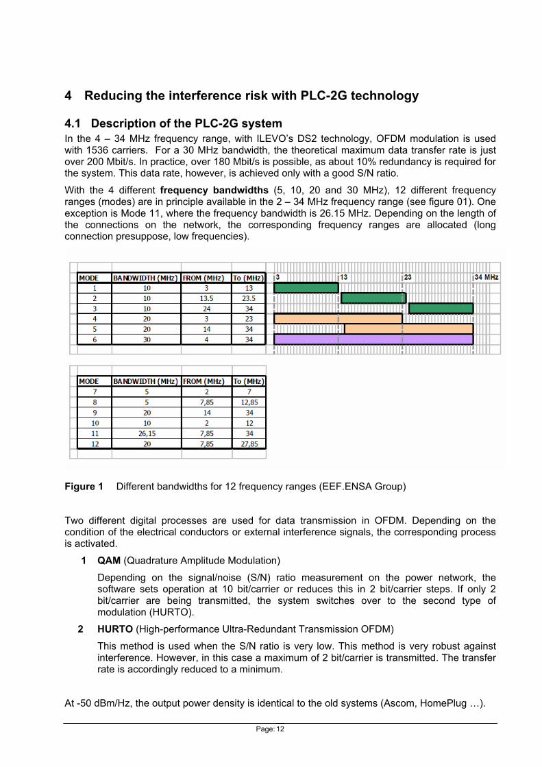
With the 4 different frequency bandwidths (5, 10, 20 and 30 MHz), 12 different frequency ranges (modes) are in principle available in the 2 – 34 MHz frequency range (see figure 01). One exception is Mode 11, where the frequency bandwidth is 26.15 MHz. Depending on the length of the connections on the network, the corresponding frequency ranges are allocated (long connection presuppose, low frequencies).
Figure 1 Different bandwidths for 12 frequency ranges (EEF.ENSA Group)
Two different digital processes are used for data transmission in OFDM. Depending on the condition of the electrical conductors or external interference signals, the corresponding process is activated.
1 QAM (Quadrature Amplitude Modulation) Depending on the signal/noise (S/N) ratio measurement on the power network, the software sets operation at 10 bit/carrier or reduces this in 2 bit/carrier steps. If only 2 bit/carrier are being transmitted, the system switches over to the second type of modulation (HURTO).
2 HURTO (High-performance Ultra-Redundant Transmission OFDM) This method is used when the S/N ratio is very low. This method is very robust against interference. However, in this case a maximum of 2 bit/carrier is transmitted. The transfer rate is accordingly reduced to a minimum.
At -50 dBm/Hz, the output power density is identical to the old systems (Ascom, HomePlug …).
Page: 13
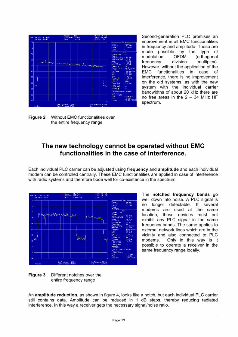
Second-generation PLC promises an improvement in all EMC functionalities in frequency and amplitude. These are made possible by the type of modulation, OFDM (orthogonal frequency division multiplex). However, without the application of the EMC functionalities in case of interference, there is no improvement on the old systems, as with the new system with the individual carrier bandwidths of about 20 kHz there are no free areas in the 2 – 34 MHz HF spectrum.
Figure 2 Without EMC functionalities over the entire frequency range
The new technology cannot be operated without EMC functionalities in the case of interference.
Each individual PLC carrier can be adjusted using frequency and amplitude and each individual modem can be controlled centrally. These EMC functionalities are applied in case of interference with radio systems and therefore bode well for co-existence in the spectrum.
The notched frequency bands go well down into noise. A PLC signal is no longer detectable. If several modems are used at the same location, these devices must not exhibit any PLC signal in the same frequency bands. The same applies to external network lines which are in the vicinity and also connected to PLC modems. Only in this way is it possible to operate a receiver in the same frequency range locally.
Figure 3 Different notches over the entire frequency range
An amplitude reduction, as shown in figure 4, looks like a notch, but each individual PLC carrier still contains data. Amplitude can be reduced in 1 dB steps, thereby reducing radiated interference. In this way a receiver gets the necessary signal/noise ratio.

Page: 14
A connection between two adjacent rooms can still be achieved with 30 dB less signal. However, this function is rarely used, as it does not have any actual benefit to the operator in the 2 – 34 MHz frequency range. On the contrary, coupling the reduced PLC signal over the air of two adjacent lines is then almost impossible.
Figure 4 Different amplitudes over the entire frequency range
4.2 Reducing risk with PLC-2G Second generation EMC functionalities make risk reduction possible. It is predominantly the two above-mentioned EMC functionalities which are applicable. In the main, however, risk reduction is achieved by the switching off or reducing the amplitude of the individual carriers in the specific frequency range. Today it is possible, using the sequence of symbols and suppression of spurious emissions, to take precautions to achieve an attenuation of 30 dB over a bandwidth of 300 kHz. In most cases, these precautions are sufficient not to generate any interference in the system concerned.
However, new systems with even greater attenuation are being promoted. These OFDM systems which are used predominantly in the area of radio can achieve attenuation of over 50 dB. An additional technique, windowing, is performed in the OFDM modulation to realise attenuation of this magnitude.
The three most important techniques which achieve attenuation of about 50 dB are:
• One of the greatest influences on minimising spurious emissions at the transmitter is the sequence of symbols (the ideal is a symbol vector of 1/ -1/1 1-/…).
Attenuation of approximately 20 dB can be obtained for the symmetrical symbol sequence.
Figure 5 OFDM spectrum depends on the sequence of symbols (Source of illustration: DLR, Deutsches Zentrum für Luft- und Raumfahrt, Sinja Brandes)

Page: 15
• Suppression of spurious emission (cancellation carrier)
Inserting 2*2 carriers (without data), with complex weighting factors at the margins of the carrier band to be transmitted.
With a cancellation carrier, the attenuation is approximately a further 15 dB.
Figure 6 Insertion of cancellation carrier(Source of illustration: DLR, Deutsches Zentrum für Luft- und Raumfahrt, Sinja Brandes)
• Windowing
A rectangular window is attenuated with a rising and falling cosine curve. Phase shifts are attenuated in the time domain. In this way small side lobes, which are not superimposed, are therefore produced in the frequency range.
Attenuation with windowing is approximately a further 15 dB.
Figure 7 Sidelobe maxima no longer superimposed(Source of illustration: DLR, Deutsches Zentrum für Luft- und Raumfahrt, Sinja Brandes)
si = sidelobe Maxima rc = raised cosine

Page: 16
4.3 Preventive protection of the spectrum Preventive protection of the spectrum in the OFDM-modulated PLC modem by means of notching is now commonplace. Modems which contain the HomePlug chipset have this feature built into the broadband signal from the outset. All other modems which also use OFDM modulation can now integrate this notching by means of a firmware update. All these devices are obtainable on the open market.
The Ilevo modem described in the report, however, does not have preventive protection activated initially. However, it is essential to be able to use this notching method in case of interference. Thanks to this EMC functionality, it will also be possible in the future to exclude other frequencies or frequency bands. The figure below shows the principle of excluding frequencies over a specific frequency range in the radio spectrum.
Figure 8 Protection from the PLC signal in the available spectrum
Frequency [MHz] 0 10 5 15 2520 3530
Amateur bands & PLC interference with protective measures (notching)
Frequency [MHz] 0 10 5 15 2520 3530
Frequency occupancy of PLC interference without protective measures
Frequency [MHz] 0 10 5 15 2520 3530
PLC interference with protective measures (notching)
Frequency [MHz] 0 10 5 15 2520 3530
Amateur bands

Page: 17
5 Dealing with cases of interference
5.1 Defining the scope In general it is useful to proceed from the viewpoint of the service suffering from the interference. In Solothurn, measurements were taken in the in-house area, establishing that outside the house the field strength falls rapidly. At a distance of approximately 50 m the signal already disappears into the noise, so for reliable interference-free operation we opted for a radius of 100 m around the sink suffering from interference.
The figure below shows such a depiction. In this case, generally speaking, the modems which are within 100 m are notched in the frequency bands concerned. However, other strongly radiating modems which are not within this area may cause interference. The same also applies to underground power lines (network 2), which continue to carry the PLC signals, without there being a PLC modem in the defined area. These PLC interference sources must also in principle be notched in the frequency ranges concerned.
Figure 9 Illustration of a sink (amateur) suffering interference with a 100 m radius
Network 1
PLC weak
PLC weak
PLC weak
PLC moderate
PLC strong
PLC strong
Amateur
Network 2
Page: 18
5.2 The technical concept
• The EMC functionalities are used only in case of interference.
No complainant – no judge (Nullo actore, nullus iudex)
In Switzerland, cases of interference are predominantly reported to OFCOM by amateur radio and CB radio operators. The number of cases of interference has proved to be low. The measures listed below have had to be implemented only on a local basis. In case of a massive increase in cases of interference, the precautions being taken at present would have to be introduced throughout Switzerland. The indoor modems are already equipped with these notches for the amateur frequency bands and in some cases for broadcast frequency bands also.
• The sources of interference are stipulated and the necessary frequency bands are notched by the provider within a radius of 100 m around the sink suffering from the interference.
• If other sources of interference are present adjacent to the 100 m and are connected to the same section of the line which intersect the 100 m radius circle, these also have to be notched in the necessary frequency bands.
These measures as described are tried and tested in practice and have proved their value to all the amateur radio operators who have suffered from interference.
5.3 Monitoring of implementation
• Are no other PLC signals are being received in the notched frequency ranges at the interference sink (e.g. amateur)?
• First and foremost a check is carried out as to whether the NB30 limit value is being complied with for the interference sources.
• In the case of radio services it is possible, notwithstanding compliance with the NB30 limit that interference may continue to be caused by the PLC signal. The only solution here is notching. Notching, however, involves a loss of data rate for the PLC operators.
• In the case of short-wave transmitters, the reception field strength is in most cases sufficiently above the PLC signal. However, it is almost impossible to operate a PLC modem next to a short-wave receiver without taking the corresponding measures.
• If no solution can be found for the attenuation of the PLC signal, the PLC modem must be switched off.

Page: 19
6 Field test
6.1 Measurement system used The measurements were taken using a spectrum analyser (FSH3), controlled by the enhanced measurement programme developed in-house (Labview). The Emco measurement antennas, the 6502 for the H field and the 3301B for the E field, were each set according to sensitivity. The co-axial cable of about 6 m was wound a few times around a ferrite core to protect the analyser from sheath currents.
A high-pass filter with a 1 MHz cut-off and a low-pass filter with a 45 MHz cut-off protected the input mixer of the analyser from strong transmitters in the vicinity.
The measurement limit of the system is about 15 dBuV/m with the Emco 3301B E field antenna.
The Swiss coordi-nates pertaining to the respective test point were recorded along with the data with all correction factors.
In order to ensure autonomy of at least 10 hours in the field, our test carts were used.
Figure 10 Test carts with measurement antennas and measurement computer

Page: 20
6.2 A practical example The practical element of our measurements was carried out in Châtel-St-Denis. In this small village, in the Fruence district, the conditions were just about optimal. An amateur radio operator suffering PLC interference was the central person for our measurements. The measurements were taken at a distance of 50 m, 50 to 100 m and over 100 m.
Figure 11 Châtel-St-Denis (at the centre of the C008—site of the amateur radio operator)
The measurements were intended to indicate the effect of the EMC functionalities (notching) applied to the modems within a 50 m and 50 to 100 m radius in the amateur frequency bands. The other 21 sites were chosen randomly around the amateur operator (C008). The objective was that for the area up to 100 m the amateur operator should not hear any PLC signals. Outside this 100 m area, radiated interference from other un-notched modems may occur.
In order to check this area, we took measurements at various freely selected points. The measured frequencies were chosen in the notched frequency ranges of the amateur bands and just next to the notches. This enabled us to take the measurements without switching the PLC system on and off. Figure 12 shows the different amateur and CB bands in which the measurements were taken. The notch bands were extended by ±200 kHz in order to obtain an attenuation of 30 dB.
50m 100m > 100m
Page: 21
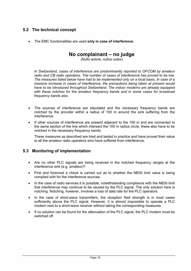
6.2.1 Frequency bands with selected individual frequencies
Amateur and CB bands in the frequency ranges from 3,000 to 30,000 kHz
Notches with an attenuation of at least 30 dB
Lower band frequency
Upper band frequency
Lower band frequency
Upper band frequency
[kHz] [kHz] [kHz] [kHz] Band RA1 3500 3800 Notch Band RA1 3300 4000 Band RA2 7000 7200 Notch Band RA2 6800 7400 Band RA3 10100 10150 Notch Band RA3 9900 10350 Band RA4 14000 14350 Notch Band RA4 13800 14550 Band RA5 18068 18168 Notch Band RA5 17868 18368 Band RA6 21000 21450 Notch Band RA6 20800 21650 Band RA7 24890 24990 Notch Band RA7 24690 25190 Band CB 26965 27405 Notch Band CB 26765 27605 Band RA8 28000 29700 Notch Band RA8 27800 29900
Figure 12 Notches of the amateur and CB radio frequency bands
6.2.2 Measured frequencies outside the amateur and CB bands
The measured frequencies outside the amateur and CB bands were: 3MHz 6.5MHz 9MHz 11MHz 15MHz 17.5MHz 20.5MHz 24.4MHz 26.5MHz 30.5MHz
All measurement sites with the frequencies which were not notched
0
5
10
15
20
25
30
35
40
45
50
0 5 10 15 20 25 30 35
Frequency [MHz]
Fiel
d st
reng
th [d
BuV/
m]
Site 01Site 02Site 03Site 04Site 05Site 06Site 07Site 08Site 09Site 10Site 11Site 12Site 13Site 14Site 15Site 16Site 17Site 18Site 19Site 20Site 21Site 22NB30
Figure 13 All measurement sites with the frequencies which were not notched

Page: 22
Figure 13 clearly shows that from approximately 13 MHz to 34 MHz PLC is radiated, predominantly from the houses which contain PLC modems. The feed lines from the local transformer, which are located primarily in the lower frequency range (3 – 13 MHz) are underground and have practically no radiation. For purposes of comparison, the curve of the NB30 limit values is shown. However, the measurement site is defined in NB30 and should be 3 m away, using a quasi-peak detector. Thus the measured values clearly comply with or undershoot the NB30 limit as they were measured in the middle of the field.
6.2.3 Measured frequencies within the amateur and CB bands
The measured frequencies within the amateur and CB bands were: 3.7MHz 7.0MHz 10.1MHz 14.2MHz 18.1MHz 21.3MHz 24.9MHz 27.2MHz 29.0MHz
All measurement sites with the frequencies which were notched
0
5
10
15
20
25
30
35
40
45
50
0 5 10 15 20 25 30 35
Frequency [MHz]
Fiel
d st
reng
th [
dBuV
/m]
Site 01Site 02Site 03Site 04Site 05Site 06Site 07Site 08Site 09Site 10Site 11Site 12Site 13Site 14Site 15Site 16Site 17Site 18Site 19Site 20Site 21Site 22NB30
Figure 14 All measurement sites with the frequencies which were notched
Figure 14 shows that all the test sites in the amateur frequency ranges which are within 250 m of the amateur radio operator (C008) are clearly below NB30. Test site 3 is somewhat unusual, though there is an explanation for this. This test site is located outside the required 100 m distance from the amateur radio operator. The PLC modem in the house next to test site 3 is not notched. It is causing the interference in the notched amateur frequency. However, the test site is more than 100 m from the amateur radio operator and therefore has no effect on his quality of reception. All the test sites up to 100 m from the amateur radio operator should be notched in his frequency bands; this would be the optimal solution for reception conditions.
Page: 23
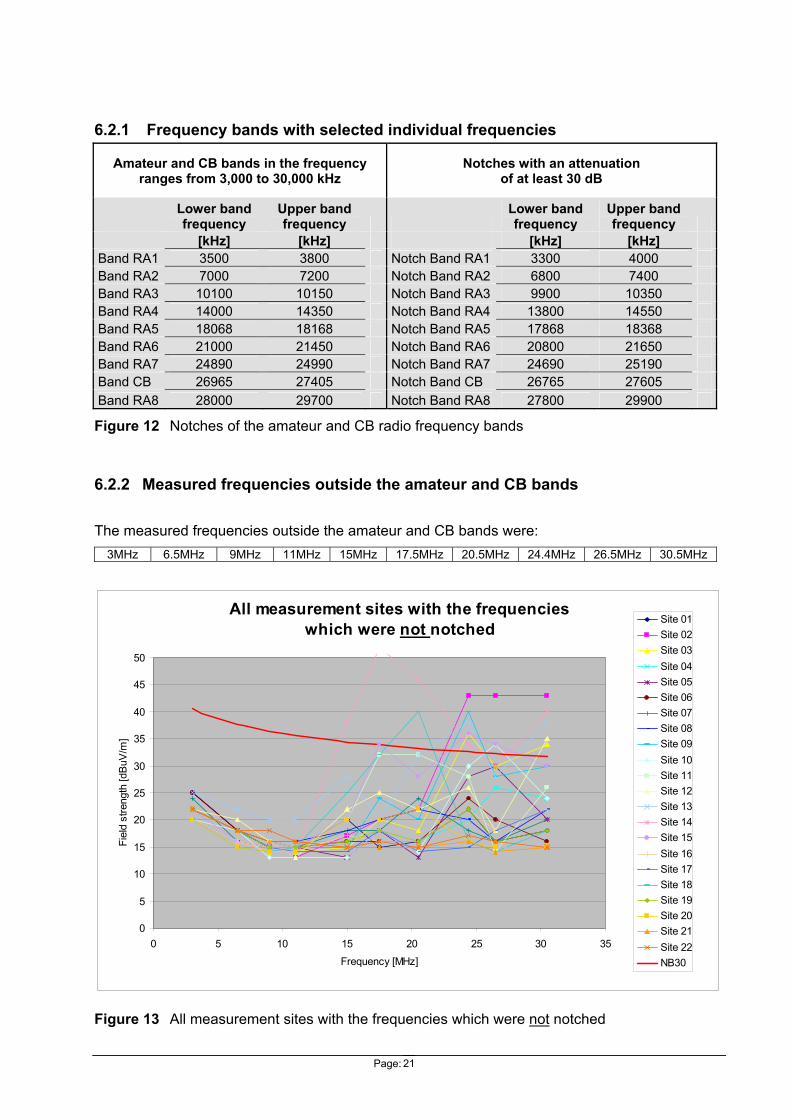
Figure 15 Test site 3 shows an un-notched PLC modem in the vicinity
Figure 15 shows test site 3 in the 24 – 34 MHz (mode 3) frequency range. The effect of the PLC modem in the neighbouring house on test site 3 is clearly visible. For comparison purposes, the figure below, recorded directly next to the amateur radio operator (test site 9) and covering the same frequency range, shows that the notches at test site 3 are actually covered.
Figure 16 Test site 9 shows the notched frequency ranges in the vicinity of the amateur radio operator
Superimposed notches
Page: 24
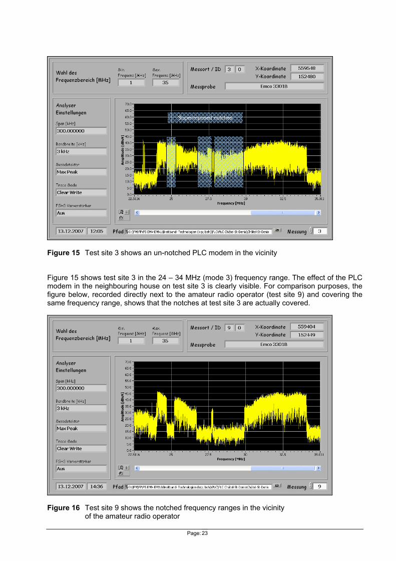
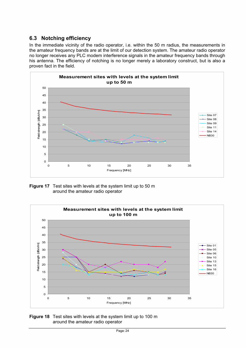
6.3 Notching efficiency In the immediate vicinity of the radio operator, i.e. within the 50 m radius, the measurements in the amateur frequency bands are at the limit of our detection system. The amateur radio operator no longer receives any PLC modem interference signals in the amateur frequency bands through his antenna. The efficiency of notching is no longer merely a laboratory construct, but is also a proven fact in the field.
Measurement sites with levels at the system limit up to 50 m
0
5
10
15
20
25
30
35
40
45
50
0 5 10 15 20 25 30 35Frequency [MHz]
Fiel
d st
reng
th [
dBuV
/m]
Site 07Site 08Site 09Site 11Site 14NB30
Figure 17 Test sites with levels at the system limit up to 50 m around the amateur radio operator
Measurement sites with levels at the system limit up to 100 m
0
5
10
15
20
25
30
35
40
45
50
0 5 10 15 20 25 30 35
Frequency [MHz]
Fiel
d st
reng
th [
dBuV
/m]
Site 01Site 05Site 06Site 10Site 13Site 15Site 16NB30
Figure 18 Test sites with levels at the system limit up to 100 m around the amateur radio operator

Page: 25
Within the 100 m radius of the amateur radio operator, the test sites are still just at or slightly over the system limit. Even at this distance, no PLC signals can be detected. Over 100 m, the signal is automatically attenuated by distance.
Figure 19 The efficiency of notching renders the amateur carriers visible once more
The image of the spectrum was taken at a centre frequency of 18 MHz. The entire range would be covered by the PLC signal and would therefore not permit reception of the amateur frequencies. With the 1 MHz notch, these frequencies are visible again and can be used without any loss in reception quality.
This OFDM-modulated broadband signal is used not only on wire-bound networks (PLC, xDSL etc.) but also in wireless networks (MIMO, DVB, DAB etc.). However, the radio networks are organised within the spectrum. The frequencies are allocated to the individual services and are consequently useful frequencies. On the wire-bound networks no such organisation for the radiated frequencies is found. They therefore occur as interference frequencies and have to comply with a specified limit value. In case of interference, this limit value is regulated in Switzerland by the NB30 provisions. In PLC technology it has only been possible to comply with the NB30 limit with the help of notching. Yet thanks to this new EMC functionality it is possible to satisfy amateur radio operators. Today, with a bandwidth of approximately 100 kHz, an attenuation of more than 50 dB is achievable.
Notch
Wanted signal
PLC broad band signal
Page: 26
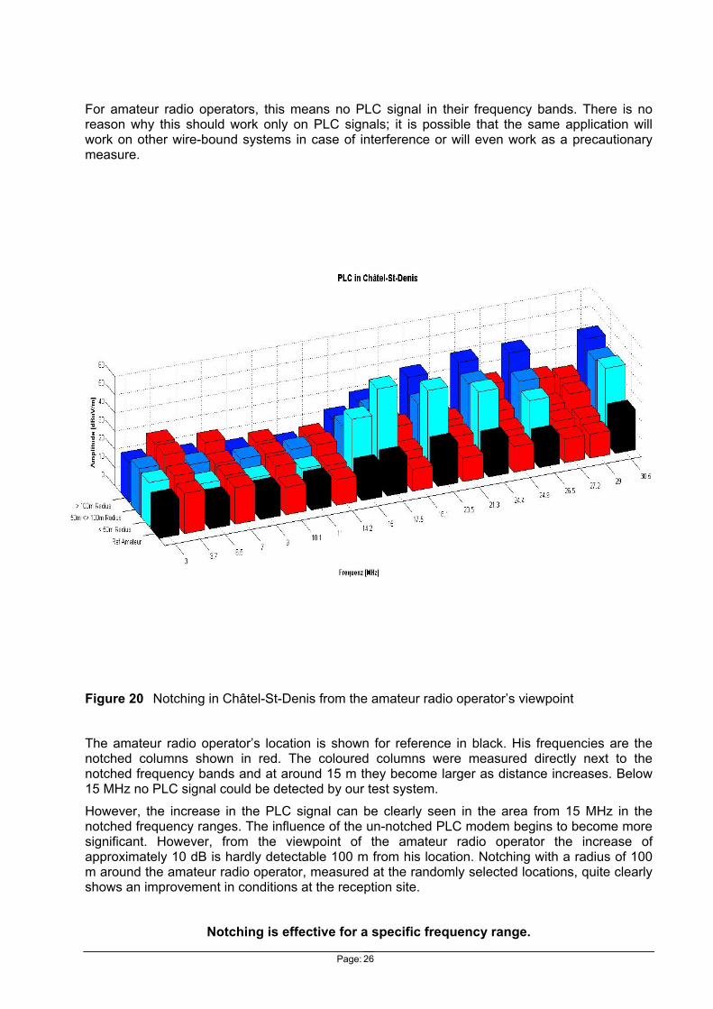
For amateur radio operators, this means no PLC signal in their frequency bands. There is no reason why this should work only on PLC signals; it is possible that the same application will work on other wire-bound systems in case of interference or will even work as a precautionary measure.
Figure 20 Notching in Châtel-St-Denis from the amateur radio operator’s viewpoint
The amateur radio operator’s location is shown for reference in black. His frequencies are the notched columns shown in red. The coloured columns were measured directly next to the notched frequency bands and at around 15 m they become larger as distance increases. Below 15 MHz no PLC signal could be detected by our test system.
However, the increase in the PLC signal can be clearly seen in the area from 15 MHz in the notched frequency ranges. The influence of the un-notched PLC modem begins to become more significant. However, from the viewpoint of the amateur radio operator the increase of approximately 10 dB is hardly detectable 100 m from his location. Notching with a radius of 100 m around the amateur radio operator, measured at the randomly selected locations, quite clearly shows an improvement in conditions at the reception site.
Notching is effective for a specific frequency range.
Page: 27
7 Conclusions OFCOM has been involved with PLC technology right from its beginnings. The Fribourg [2] and Solothurn [3] studies have shown that reliability and reproducibility can be achieved only by means of a statistical measurement method. These studies also confirmed that the occurrence of the interference potential of PLC technology is well above the limits of the NB30 provisions.
Following the authorisation of the use of PLC technology in Switzerland, we have committed ourselves to carefully evaluating the risk of interference. This is why OFCOM banned PLC signals on overhead lines, for example, as a preventive measure from the outset. Co-existence between radio services and PLC networks has therefore been possible, given appropriate measures. The few cases of interference which have occurred have proved to us that the risk of interference was estimated correctly.
It has been possible for PLC networks to be set up in Switzerland thanks to OFCOM’s appropriate management of the interference risk.
As early as 2005, a new generation of PLC modems, allowing a transfer rate of up to 200MB/s, came onto the market. OFCOM, in collaboration with a PLC operator, then undertook the investigations necessary to determine the interference potential from these new devices and its effect on the existing interference risk.
Our investigations have shown that the second-generation PLC modems (PLC-2G) are capable, in the case of interference, of implementing measures which guarantee co-existence with the radio services. Without OFCOM’s preventive requirements the operators of PLC modems would not take any preventive EMC action, because of loss of data rate. This operating condition would cause the greatest potential interference.
As a preventive measure or in case of interference, two main functionalities can be used: notching or reducing the amplitude of PLC carriers within specific frequency ranges. Notching was found to be an effective solution in all cases of interference and made it possible to comply with the NB30 limit with ease. In order to relieve a disturbed sink of all sources of PLC interference, all modems within a radius of 100 m from the disturbed receiver must be set with the corresponding notches. The effectiveness of this solution has to date enabled all cases of interference to be resolved to the entire satisfaction of the complainants.
However, if no EMC measures can be found, the part of the network which is causing the interference must be switched off.
These EMC functionalities exist thanks to OFDM modulation. In case of interference, they can control the radiated power in the spectrum. Other wired technologies (xDSL, CATV, etc.) use the same type of modulation and will also have to make use of these EMC functionalities as data rates increase given the resulting increase in frequency range.
Incidentally, OFDM modulation is being used not only in wired technologies but also increasingly in many different types of wireless broadband technologies (MIMO, DVB-H, DAB etc.). However, in this case the frequency bands used by such technologies are clearly allocated within the radio spectrum.
This type of modulation (OFDM) is being further developed and will provide further EMC functionalities. The rate of development of these functionalities depends, however, on the goodwill of the manufacturers and on the strictness of the regulators’ requirements in relation to PLC network operators. A major effort must also be made by manufacturers to provide interface software which enables each user, whether a private individual or a PLC network operator, to easily set the parameters of their modems according to their specific situation.

Page: 28
8 Bibliography and glossary
8.1 Bibliography [1] M. Ianoz, ″Work progress in the field of PLC Standardizing and general view of PLC
implementation in Europe, USA and other countries″, Pully, January 2006
[2] OFCOM, “Appréciation du pouvoir perturbateur des installations PLC à Fribourg“, Fribourg, June 2003 www.bakom.admin.ch/dokumentation/zahlen/00545/00547/00549/index.html?lang=fr
[3] OFCOM, “Assessment of the EMI radiated by PLC installations inside buildings“, Solothurn, November 2004 www.bakom.admin.ch/dokumentation/zahlen/00545/00547/00551/index.html?lang=en
[4] National Frequency Allocation Plan (NFAP),”Swiss National Frequency Allocation Plan and Specific Assignments”, OFCOM, Edition 2009 www.bakom.admin.ch/themen/frequenzen/00652/00653/index.html?lang=en
[5] Technical guide NT-2721, “Mise sur le marché et /ou exploitation d’installations PLC (Powerline Communications) en Suisse”, OFCOM, 28 September 2001
[6] Nutzungsbestimmungen NB30 & Reg TP 322 MV 05 Part 1 , “Specification for the Measurement of Disturbance Fields from Telecommunications Systems and Networks in the Frequency Range 9 kHz to 3 GHz”, RegTP, October 2001
[7] Annex to the Decree on Planning Allocation of Frequency Ranges [Frequenzbereichszuweisungsplanverordnung (FreqBZPV)] , “Nuzungsbestimmung 30: Nutzung von Frequenzen für Telekommunicationsanlagen und Telekommunicationsnetze in und längs von Leitern”, RegTP, July 2001
[8] ECC Recommendation (05)04, “ Criteria for the assessement of radio interferences caused by disturbances from wire-line telecommunication networks”, WGSE
[9] Contribution in CISPR/I/PT PLT “Adaptive Feeding Power Management for In House PLT Modems” (Schwager / Bäschlin) December 2007
[10] Draft TS 102578 (PLT-Coexistence between PLT Modems and fixed SW radio broadcasting services), ETSI.
Page: 29
8.2 Glossary CATV Community antenna television
CCIR Comité Consultatif International des Radiocommunications
CEN Comité Européen de Normalisation
CENELEC Comité Européen de Normalisation Electrotechnique
CEPT Comité Européen des Postes et des Télécommunications
CISPR Comité International Spécial des Perturbations Radioélectriques
DAB Digital Audio Broadcasting
DVB Digital Video Broadcasting
ECC Electronic Communication Committee (CEPT Committee)
EIVD Ecole d’Ingénieur du Canton de Vaud (Yverdon School of Engineering)
EMC Electromagnetic Compatibility
EMI Electromagnetic Interference
ETSI European Telecommunications Standards Institute
EU European Union
EUT Equipment Under test
ISN Impedance Stabilisation Network
MIMO Multiple Input Multiple Output
NB 30 Nutzungsbestimmungen 30
OFCOM; BAKOM Federal Office of Communications
OFDM Orthogonal Frequency Division Multiplex
PLC or PLT Powerline Communications
PP PLC Interference potential of a PLC installation
R&S Rohde & Schwarz
RegTP Regulationsbehörde Telekommmunikation und Post
R&TTE Radio & Telecommunications Terminal Equipment
S/N Signal/Noise ratio
TCA Telecommunications Act dated 30 April 1997; (SR 784.10)
xDSL, DSL Digital Subscriber Line