
Assessing the Suitability of Community-Based Management for the Nyungwe Forest Reserve, Rwanda
27
JOURNAL OF SOUND AND VIBRATION Journal of Sound and Vibration 303 (2007) 632–658 Gear teeth impacts in hydrodynamic conjunctions promoting idle gear rattle S. Theodossiades , O. Tangasawi, H. Rahnejat Wolfson School of Mechanical and Manufacturing Engineering, Loughborough University, Loughborough LE11 3TU, UK Received 7 November 2005; received in revised form 3 January 2007; accepted 19 January 2007 Available online 2 April 2007 Abstract The rattle phenomenon in vehicular transmissions and its impact on the automotive industry have been widely reported in the literature. A variety of palliative measures have been suggested for attenuation of rattle such as use of backlash eliminators, clutch dampers or dual-mass flywheels. These palliative measures incur further costs and can have untoward implications in powertrain noise and vibration problems. A fundamental investigation of the dynamics of impacting gears is undoubtedly the way forward for a root cause solution. This paper introduces a new approach for understanding the interactions between the transmission gears during engine idle conditions by taking into account the effect of lubrication. Gear impacting surfaces are treated as lubricated conjunctions rather than the usually reported dry impacting solids. Depending on load and speed of entraining motion of the lubricant into the contact domains, the regime of lubrication alters. In this paper, the influence of lubricant in torsional vibration of lightly loaded idling gears is examined which promotes iso-viscous hydrodynamic conditions. It is shown that the lubricant film under these conditions behaves as a time-varying nonlinear spring–damper element. Spectral analysis of the system response is compared to the findings of the linearised system. r 2007 Elsevier Ltd. All rights reserved. 1. Introduction The idle gear rattle phenomenon is associated with the characteristic noise that unselected impacting gears radiate to the environment. The phenomenon occurs at low impact forces, qualitatively similar to the noise produced, when a marble hits a tin can. The problem is induced by engine order vibrations in the presence of backlash in meshing pairs, and is particularly troublesome in vehicles with diesel engines, because of higher output torques [1]). Rattle has a distinct sound quality that differentiates it from noises produced by other sources in the vehicle [2], while the attenuation of engine noise during the past decades has brought it to the forefront of noise and vibration issues, as a major concern for the automotive industry [3]. Vehicle owners are usually annoyed by this noise and often attribute it to some form of malfunction. In addition to possible warranty claims, a low-quality image accompanies the manufacturers’ products. ARTICLE IN PRESS www.elsevier.com/locate/jsvi 0022-460X/$ - see front matter r 2007 Elsevier Ltd. All rights reserved. doi:10.1016/j.jsv.2007.01.034 Corresponding author. Tel.: +44 1509 227664; fax: +44 1509 227648. E-mail address: [email protected] (S. Theodossiades).
-
Upload
independent -
Category
Documents
-
view
1 -
download
0
Transcript of Assessing the Suitability of Community-Based Management for the Nyungwe Forest Reserve, Rwanda
ARTICLE IN PRESS
JOURNAL OFSOUND ANDVIBRATION
0022-460X/$ - s
doi:10.1016/j.js
�CorrespondE-mail addr
Journal of Sound and Vibration 303 (2007) 632–658
www.elsevier.com/locate/jsvi
Gear teeth impacts in hydrodynamic conjunctionspromoting idle gear rattle
S. Theodossiades�, O. Tangasawi, H. Rahnejat
Wolfson School of Mechanical and Manufacturing Engineering, Loughborough University, Loughborough LE11 3TU, UK
Received 7 November 2005; received in revised form 3 January 2007; accepted 19 January 2007
Available online 2 April 2007
Abstract
The rattle phenomenon in vehicular transmissions and its impact on the automotive industry have been widely reported
in the literature. A variety of palliative measures have been suggested for attenuation of rattle such as use of backlash
eliminators, clutch dampers or dual-mass flywheels. These palliative measures incur further costs and can have untoward
implications in powertrain noise and vibration problems. A fundamental investigation of the dynamics of impacting gears
is undoubtedly the way forward for a root cause solution. This paper introduces a new approach for understanding the
interactions between the transmission gears during engine idle conditions by taking into account the effect of lubrication.
Gear impacting surfaces are treated as lubricated conjunctions rather than the usually reported dry impacting solids.
Depending on load and speed of entraining motion of the lubricant into the contact domains, the regime of lubrication
alters. In this paper, the influence of lubricant in torsional vibration of lightly loaded idling gears is examined which
promotes iso-viscous hydrodynamic conditions. It is shown that the lubricant film under these conditions behaves as a
time-varying nonlinear spring–damper element. Spectral analysis of the system response is compared to the findings of the
linearised system.
r 2007 Elsevier Ltd. All rights reserved.
1. Introduction
The idle gear rattle phenomenon is associated with the characteristic noise that unselected impacting gearsradiate to the environment. The phenomenon occurs at low impact forces, qualitatively similar to the noiseproduced, when a marble hits a tin can. The problem is induced by engine order vibrations in the presence ofbacklash in meshing pairs, and is particularly troublesome in vehicles with diesel engines, because of higheroutput torques [1]). Rattle has a distinct sound quality that differentiates it from noises produced by othersources in the vehicle [2], while the attenuation of engine noise during the past decades has brought it to theforefront of noise and vibration issues, as a major concern for the automotive industry [3]. Vehicle owners areusually annoyed by this noise and often attribute it to some form of malfunction. In addition to possiblewarranty claims, a low-quality image accompanies the manufacturers’ products.
ee front matter r 2007 Elsevier Ltd. All rights reserved.
v.2007.01.034
ing author. Tel.: +44 1509 227664; fax: +44 1509 227648.
ess: [email protected] (S. Theodossiades).
ARTICLE IN PRESS
Nomenclature
C clearance between gear and shaftCb gear teeth half normal backlashF petroff friction forceFf hydrodynamic flank friction forceFi (i ¼ 1,y, 6, rev) hydrodynamic load on the ith
tooth flankh lubricant film thicknessIi (i ¼ 1,2,3,4,5,6) moment of inertia of the ith gear
wheelIprev moment of inertia of reverse pinionIwrev moment of inertia of reverse gear wheelK linear lubricant stiffnessKoi (i ¼ 1,y, 6) mean lubricant stiffness of the ith
gear pairKo (rev) mean lubricant stiffness of reverse gear
pairKcp amplitude of the alternating lubricant
component (the pth cosine term)Kcp amplitude of the alternating lubricant
component (the pth sine term)L length of contact linel the distance between the instantaneous
contact point and the pitch pointl1 length of the conformal contact surface
between idle gear and shaftni the tooth number of the ith gear wheelrb base radiusrc radial distance of pinion and wheel
contact pointreq the equivalent curvature radius of two
teeth surfaces at their contact point takenat the normal plane
ros radius of the output shaftrp contact radius of the pinionrpp pitch radius of the pinionrprev contact radius of the reverse speed pinionrww pitch radius of the gear wheelrwi (i ¼ 1,y, 6, rev) contact radius of the ith gear
wheelTfwi(i ¼ 1,y, 6, rev) flank friction torque on the ith
gear wheelTtractwi (i ¼ 1,y, 6, rev) tractive torque between the
output shaft and the ith gear wheel
u entraining speed of gear teeth duringmeshing action
us sliding velocity of the meshing gear teethsurfaces
v tangential velocity between idle gear andsupporting shaft
vw rolling velocity of the gear wheel toothsurface
vp rolling velocity of the pinion tooth sur-face
vpitch, p pitch velocity of the pinionvpitch,w pitch velocity of the gear wheelW lubricant hydrodynamic reactionan normal pressure angleat transverse pressure angleb pitch circle helix anglebb base circle helix angleD contact lines inclination angleZ0 dynamic viscosity at atmospheric condi-
tionsrp curvature radius of the pinion tooth
surface in the transverse planerwi curvature radius of the ith gear wheel
tooth surface in the transverse planej1, prev angular displacement of the 1st speed
gear and reverse pinionji (i ¼ 2,y, 6) angular displacement of 2nd, 3rd,
4th, 5th and 6th idle gear wheelsjin angular displacement of the input shaftjiT fundamental period of the impacting
stiffnessjwrev angular displacement of the reverse speed
gearjp, jw pinion and gear angular displacements_jos output shaft rotational speed, here _jos ¼
0
Subscripts
p pinionprev pinion of reverse gearw gear wheelwrev wheel of reverse gear
S. Theodossiades et al. / Journal of Sound and Vibration 303 (2007) 632–658 633
Idle gear rattle is primarily caused by the torsional vibration of the gearbox input shaft due to thetransmitted combustion and inertia fluctuations of the engine crankshaft, when the latter operates in idleconditions [4–6]. As a result, the transmission gears oscillate and impact with each other. Most of the systemenergy manifests itself in torsional vibrations at harmonics of the engine speed, superimposed upon the gears’

ARTICLE IN PRESSS. Theodossiades et al. / Journal of Sound and Vibration 303 (2007) 632–658634
angular motions. A part of these oscillations is transmitted through to the bearing mounts and transmissionshafts to the gearbox housing and is radiated to the environment as noise [1,3].
The rattle phenomenon is largely associated with the unselected (idler) gears, which are free to rotate ontheir bearings. This can be explained by the occurring tooth separation, when the driving gear has higherdeceleration than the idler gear [5,7]. If the drag torque on the idler gear is increased, it decelerates more, thusminimising the amount of separation. This agrees with what has been reported in literature (e.g. Ref. [4]) thatrattle severity decreases, when the drag torque in idle gears is increased. Since the selected gears are loadedexternally, they decelerate under the influence of the external load, which is acting as a ‘‘drag’’, and when it issufficient prevents separation and, thus, rattle. Rivin [8] also reported that lightly loaded gears are more proneto separation and impacts. Experiments have shown that there are certain thresholds, at which rattle makes itsappearance [1]. These observations are based on the relationship between the inertial torque of the looserotating gears and the drag torque on the teeth flanks. Seaman et al. [4] defined the rattle threshold as theangular acceleration, at which the inertial torque at the unloaded gear exceeds the drag torque. Otherexperimental investigations have focused on the drag torque and the influence of bulk oil temperature on thepropensity to rattle. It has been reported that drag torque is higher at lower temperatures [1,4,5,9]. Moreover,it has been shown that rattle noise attenuates at lower temperatures [1,4]. Since lubricant viscosity decreaseswith rising temperature, thus the resistance to motion in lubricated conjunctions is reduced [9]. Thus, rattle isalso a temperature-dependent phenomenon. Changing the dynamic viscosity of the lubricant by an order ofmagnitude, Gnanakumarr et al. [10] showed, through a numerical simulation study, that the effect of mostengine orders can be eliminated. This leads rattle response in the extreme high-viscosity case to the naturalfrequency of the lubricant film, which is acting as a nonlinear spring. However, in practice, there exists a limitfor the viscosity of the transmission fluid, before excessive drag torque results in inefficient transmission. Thestudy by Gnanakumarr et al. [10] was isothermal and high lubricant viscosity can lead to shear heating. It isclear that a viscous transmission fluid is desired in the contact of loose gears to their bearings, but not desiredin teeth flank contacts. Nevertheless, recent experimental results published by Fujimoto and Kizuka [6] haveshown that there is a temperature range, at which rattle remains at minimum levels.
Seaman et al. [4] pointed to reduction of idle rattle by increasing the engine idling speed at the expense offuel consumption. Additionally, the rotational fluctuations at the flywheel can be attenuated by increasing theflywheel mass or utilising a dual mass flywheel (DMF) system [11]. The former method would incur a fuelconsumption penalty and increased stressing of the crankshaft [4], while the latter is costly and deteriorates theengine torsional vibrations due to a decrease in the inertia of DMF’s primary mass member. Therefore, aconundrum is arrived at, whereupon an improvement in idle rattle can lead to increased engine order response.Tuning the clutch pre-damper and hysteresis characteristics may also improve rattle performance, but canworsen another important transient NVH phenomenon, referred to as clonk [4,12].
Increasing drag torque is a low-cost option [13], which can reduce rattle [4,14]. However, this would renderan additional shift effort, while also increasing the frictional losses and the transmission operatingtemperature, as already noted [4,13]. Using gears with very low backlash would not be a practical solution dueto unavoidable manufacturing errors and impracticalities in gear operation, even though it has beentheoretically found that it eliminates rattle [15]. Moreover, Seaman et al. [4] reported that zero-backlash causesgear growl. The use of backlash eliminators has also the drawbacks of increasing friction losses and generatingunacceptable heat [8]. Furthermore, it possibly leads to whistling noise, as also reported by Fujimoto andKizuka [16].
A common approach in numerical investigations of gear rattle is to model the driveline as a lumpedparameter system with hysteresis. The gear backlash is usually included using the dead space function [13]. Theclutch stiffness and hysteresis have been modelled as piece-wise linear functions [13,16–18]. Drag torque isusually added, being proportional to the rotational speed, with the drag torque coefficient either assumed asconstant [13] or temperature dependent [16,18]. The gear teeth stiffness has been assumed as constant in manyinvestigations [1,13,19]. Time-varying contact stiffness coefficients were utilised by Kahraman and Singh [20],Blankenship and Singh [21], Wang et al. [22], Yakoub et al. [23] and Theodossiades and Natsiavas [24,25],which also take into account the contact ratio variation and the gear teeth elastic properties.
Generally, dry gear teeth impacts have been considered in rattle investigations. The effect of lubricant filmhas not been included in full transmission models, in order to keep the complexity level low. Nevertheless,
ARTICLE IN PRESSS. Theodossiades et al. / Journal of Sound and Vibration 303 (2007) 632–658 635
Gnanakumarr et al. [10] proposed a lubricated contact model that assumes a hydrodynamic film present ingear teeth contacts for lightly loaded idle rattle conditions. Thus a hydrodynamic force rather than an elasticforce is applied between the gear surfaces, depending on the lubricant entrainment speed, the contactgeometry, and the approach velocity between the teeth—referred to as squeeze film velocity [26]. The dragforce in the study by Gnanakumarr et al. [10] was the Petrov friction, which depends on the lubricantentraining velocity in the clearance zone between the loose gear and its shaft and the geometry of these twocontacting bodies. However, this model is also simplified, as it assumes that gear tooth contact takes place atthe pitch circle at all times. It should be noted that in most of the literature, drag torque was modelled as lineardamping force with constant coefficient (e.g. Refs. [1,13,17]), or with temperature-dependent coefficients [6]. Inlubricated contacts the effective contact stiffness is the equivalent stiffness of the lubricant film and the elasticteeth members [26]. In highly loaded contacts, the lubricant becomes incompressible and its stiffness farexceeds that of the adjacent elastic solids, thus may be ignored. The regime of lubrication that leads to thiscondition is now well understood and is referred to as elastohydrodynamics [9,26]. However, under lightlyloaded conditions the converse of the problem is true. In this sense, Gnanakumarr et al. [10] hydrodynamiccontact model is suitable for idle rattle conditions.
This paper reports a numerical investigation of a front wheel drive six-speed manual transmissionsystem under idle rattle conditions. The dynamic model includes tooth geometrical characteristics, kinematicsof contact, hydrodynamic lubricant film formation and effect of lubricant rheology. The results of thenumerical analysis are compared to findings of the linearised system and a parametric study of thelubricant effect is presented. It is shown that the lubricant is a dominant factor, determining the systembehaviour.
2. The transmission model
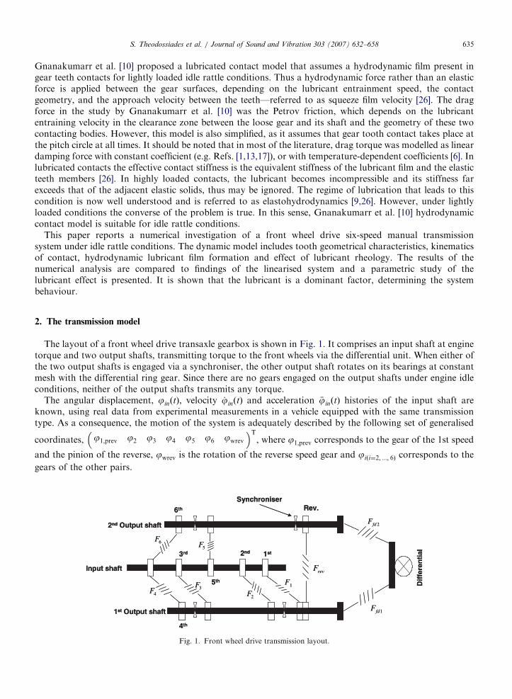
The layout of a front wheel drive transaxle gearbox is shown in Fig. 1. It comprises an input shaft at enginetorque and two output shafts, transmitting torque to the front wheels via the differential unit. When either ofthe two output shafts is engaged via a synchroniser, the other output shaft rotates on its bearings at constantmesh with the differential ring gear. Since there are no gears engaged on the output shafts under engine idleconditions, neither of the output shafts transmits any torque.
The angular displacement, jinðtÞ, velocity _jinðtÞ and acceleration €jinðtÞ histories of the input shaft areknown, using real data from experimental measurements in a vehicle equipped with the same transmissiontype. As a consequence, the motion of the system is adequately described by the following set of generalised
coordinates, j1;prev j2 j3 j4 j5 j6 jwrev
� �T, where j1;prev corresponds to the gear of the 1st speed
and the pinion of the reverse, jwrev is the rotation of the reverse speed gear and jiði¼2; :::; 6Þ corresponds to the
gears of the other pairs.
Fig. 1. Front wheel drive transmission layout.
ARTICLE IN PRESSS. Theodossiades et al. / Journal of Sound and Vibration 303 (2007) 632–658636
The corresponding equations of motion are formulated as follows:For the 1st idle gear wheel (which is combined with the reverse speed pinion, as shown in Fig. 1):
ðI1 þ IprevÞ €j1;prev ¼ F1 j1;prev;jin; _j1;prev; _jin
� �rw1
� F rev jwrev;j1;prev; _jwrev; _j1;prev
� �rprev
� Tfw1 j1;prev;jin; _j1;prev; _jin
� �� T tractw1 _j1;prev
� �. ð1Þ
For the 2nd idle gear wheel:
I2 €j2 ¼ F 2 j2;jin; _j2; _jin
� �rw2 � Tfw2 j2;jin; _j2; _jin
� �� T tractw2 _j2
� �, (2)
For the 3rd idle gear wheel:
I3 €j3 ¼ F 3 j3;jin; _j3; _jin
� �rw3 � Tfw3 j3;jin; _j3; _jin
� �� T tractw3 _j3
� �. (3)
For the 4th idle gear wheel:
I4 €j4 ¼ F 4 j4;jin; _j4; _jin
� �rw4 � Tfw4 j4;jin; _j4; _jin
� �� T tractw4 _j4
� �. (4)
For the 5th idle gear wheel:
I5 €j5 ¼ F 5 j5;jin; _j5; _jin
� �rw5 � Tfw5 j5;jin; _j5; _jin
� �� T tractw5 _j5
� �. (5)
For the 6th idle gear wheel:
I6 €j6 ¼ F 6 j6;jin; _j6; _jin
� �rw6 � Tfw6 j6;jin; _j6; _jin
� �� T tractw6 _j6
� �. (6)
And for the reverse gear idle wheel:
Iwrev €jwrev ¼ F rev jwrev;j1;prev; _jwrev; _j1;prev
� �rwrev
� Tfwrev jwrev;j1;prev; _jwrev; _j1;prev
� �� T tractwrev _jwrev
� �. ð7Þ
In the above equations, Fiði¼1;...;6;revÞ represent the hydrodynamic forces between the gear teeth meshingsurfaces, rwiði¼1;...;6;revÞ are the contact radii of the idle gears and rprev is the contact radius of the reverse speedpinion. The flank friction force is given by Tfwiði¼1;...;6;revÞ, while the tractive force between the output shafts andthe idle gear wheels is given by T tractwiði¼1;...;6;revÞ.
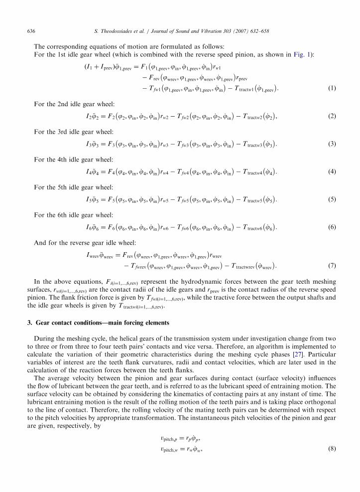
3. Gear contact conditions—main forcing elements
During the meshing cycle, the helical gears of the transmission system under investigation change from twoto three or from three to four teeth pairs’ contacts and vice versa. Therefore, an algorithm is implemented tocalculate the variation of their geometric characteristics during the meshing cycle phases [27]. Particularvariables of interest are the teeth flank curvatures, radii and contact velocities, which are later used in thecalculation of the reaction forces between the teeth flanks.
The average velocity between the pinion and gear surfaces during contact (surface velocity) influencesthe flow of lubricant between the gear teeth, and is referred to as the lubricant speed of entraining motion. Thesurface velocity can be obtained by considering the kinematics of contacting pairs at any instant of time. Thelubricant entraining motion is the result of the rolling motion of the teeth pairs and is taking place orthogonalto the line of contact. Therefore, the rolling velocity of the mating teeth pairs can be determined with respectto the pitch velocities by appropriate transformation. The instantaneous pitch velocities of the pinion and gearare given, respectively, by
vpitch;p ¼ rp _jp,
vpitch;w ¼ rw _jw, ð8Þ

ARTICLE IN PRESSS. Theodossiades et al. / Journal of Sound and Vibration 303 (2007) 632–658 637
where jp, jw and rp, rw are the angular displacements and contact radii of the pinion and gear, respectively.The components of the rolling velocities on the transverse plane are given by
vp ¼ vpitch;p sin at þl
rpp
� �,
vw ¼ vpitch;w sin at �l
rww
� �. ð9Þ
In the above equations at is the transverse pressure angle, rpp and rww are the pitch radii of pinion and wheel,respectively, and l is the distance between the instantaneous contact point and the pitch point, measured alongthe contact path (Fig. 2), which can be calculated as
l ¼ rw sin at � rw, (10)
Fig. 2. Gear teeth rolling action.
Ff
Tooth flank
Contact linesat different times duringmeshing
Gearrotation
Contact line
Tooth trace
Tangent planePlane of action
Δ
q
(a) (b)
Fig. 3. Contact lines and hydrodynamic friction on tooth flank [29].
ARTICLE IN PRESSS. Theodossiades et al. / Journal of Sound and Vibration 303 (2007) 632–658638
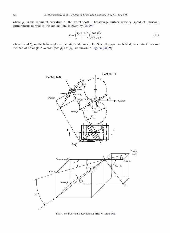
where rw is the radius of curvature of the wheel tooth. The average surface velocity (speed of lubricantentrainment) normal to the contact line, is given by [28,29]
u ¼vp þ vw
2
� �cos bcos bb
� �, (11)
where b and bb are the helix angles at the pitch and base circles. Since the gears are helical, the contact lines areinclined at an angle D ¼ cos�1ðcos b= cos bbÞ, as shown in Fig. 3a [28,29].
Fig. 4. Hydrodynamic reaction and friction forces [31].

ARTICLE IN PRESSS. Theodossiades et al. / Journal of Sound and Vibration 303 (2007) 632–658 639
The lubricant film thickness is obtained in the normal section as follows:
h ¼
Cb �rpjp � rwjw
cos an cos b; rpjp4rwjw;
Cb; rpjp ¼ rwjw;
Cb þrpjp � rwjw
cos an cos b; rpjporwjw;
8>>>>><>>>>>:
(12)
where 2Cb is the total normal backlash between the gear teeth and an is the normal pressure angle.The squeeze velocity with first-order approximation is given as
qh
qt¼
�rp _jp � rw _jw
cos an cos b; rpjp4rwjw;
0; rpjp ¼ rwjw;
rp _jp � rw _jw
cos an cos b; rpjporwjw:
8>>>>><>>>>>:
(13)
Although gear rattle has been treated by a number of recent investigations, most models disregard theaction of the intervening lubricant in the impact zone. In low or non-conformal conjunctions, such as thecontact of meshing teeth, four regimes of lubrication are possible: piezo-viscous rigid, piezo-viscous elastic(referred to as elastohydrodynamics), iso-viscous elastic and iso-viscous rigid. Rigid or elastic refers to thebehaviour of the teeth surfaces under the instantaneous contact load, whereas iso-viscous and piezo-viscousrefer to the lubricant rheological state under the same load. In this paper iso-viscous rigid hydrodynamicconditions has been assumed due to the low loads (o20N) experienced by the gear teeth under engine idleconditions. With such lightly loaded contacts the regime of lubrication is iso-viscous rigid (hydrodynamics)(see Appendix A). The lubricant reaction W for such conjunctions was derived by Rahnejat [26], in a similar
Loose WheelF
h
rcp
W cos �b
W cos �b
ShaftLubricant
ros
rcw
Lubricant between
gear teeth surfaces
Pinion
Fig. 5. Hydrodynamic reaction and Petrov’s force.

ARTICLE IN PRESSS. Theodossiades et al. / Journal of Sound and Vibration 303 (2007) 632–658640
way to that derived independently by Sasaki et al. [30] and is given by
W ¼
LZ0req
h2u�
3pffiffiffiffiffiffiffiffiffiffiffiffiffi2h=req
p qh
qt
!;
qh
qto0;
LZ0req
h2uð Þ;
qh
qtX0;
8>>>><>>>>:
(14)
where L is the length of the contact line and Z0 is the atmospheric dynamic viscosity of the lubricant. Note thata negative value for qh=qt indicates mutual approach (squeezing) of the meshing gear teeth, whereas a positivevalue indicates separation, which does not contribute to the load carrying capacity of the contact zone. Avalue of zero indicates pure rolling condition. The equivalent radius of curvature normal to the line of contactreq is approximately taken at the position along the line of contact that lies on the diagonal of the contactplane as [28]
req ¼rprw
rp þ rw
� �cos bb
, (15)
where rp and rw are the pinion and wheel tooth surface radii of curvature in the transverse plane.It is noteworthy that the other principal radii of contact (across the profile of the teeth flanks) are considered
as infinite compared to rp and rw, since there are orders of magnitude difference between them. This
Fig. 6. Computational flowchart.

ARTICLE IN PRESSS. Theodossiades et al. / Journal of Sound and Vibration 303 (2007) 632–658 641
assumption leads to contact footprints, which are slanted lines at any time. In reality the length of the contactline is finite and clearly alters, as shown in Fig. 3b. This means that Eq. (14), based on the assumption of aninfinite line contact is a reasonable approximation under lightly loaded hydrodynamic conditions, since withno deformation of the impacting solids the width of contact is almost negligible. The torque due to thehydrodynamic load W (illustrated in Figs. 4 and 5), causing the rotating action is given by
Fi ði¼1;...;6;revÞrwi ¼W i cos an cos b rwi, (16)
where rwi is the contact radius given by
rwi ¼
ffiffiffiffiffiffiffiffiffiffiffiffiffiffiffiffir2wi þ r2b
q, (17)
where rb is the base radius and rwi denotes the curvature radius of the wheel tooth.The motions of the idle gear wheels are resisted by hydrodynamic traction induced by a film of lubricant
formed between the output shaft’s convex curvature and the inside concave surface of the gears, as shown inFig. 5. This force is known as the Petrov friction [32], which is valid for low load conditions [33]; for aconcentric arrangement with zero eccentricity it can be written in the following form [10]:
F ¼pZ0vl1ros
C, (18)
where ros is the radius of the output shaft, C is the clearance between the shaft and the idle gear, l1 is the lengthof contact line, and v is the entraining velocity of the lubricant in this conforming conjunction, calculated asfollows [10]:
v ¼1
2ros þ Cð Þ _jw þ
1
2pros _jos
, (19)
where _jos is the output shaft rotational speed (in neutral, _jos ¼ 0). The resistive torque generated is given by
T tract ¼ Fros. (20)
The hydrodynamic flank friction acts in or opposite to the e-direction (Fig. 3a), parallel to the flankend faces (Figs. 3b and 4) and is defined as follows (derived from Ref. [9] using half-Sommerfeld conditions,
0 100 200
Frequency (Hz)
0
250
500
PS
D A
mp
litu
de
26.6
121.2
53.1
79.5
10767.74093
Fig. 7. FFT spectrum of the transmission input shaft measured torsional oscillations.
ARTICLE IN PRESSS. Theodossiades et al. / Journal of Sound and Vibration 303 (2007) 632–658642
see Appendix B):
Ff ¼
LpZ0usffiffiffiffiffi2hp
ffiffiffiffiffiffireqp
; usX0;
LpZ0ð�usÞffiffiffiffiffi2hp
ffiffiffiffiffiffireqp
; uso0;
8>>><>>>:
(21)
where us is the gear teeth surface sliding velocity given by
us ¼ vp � vw. (22)
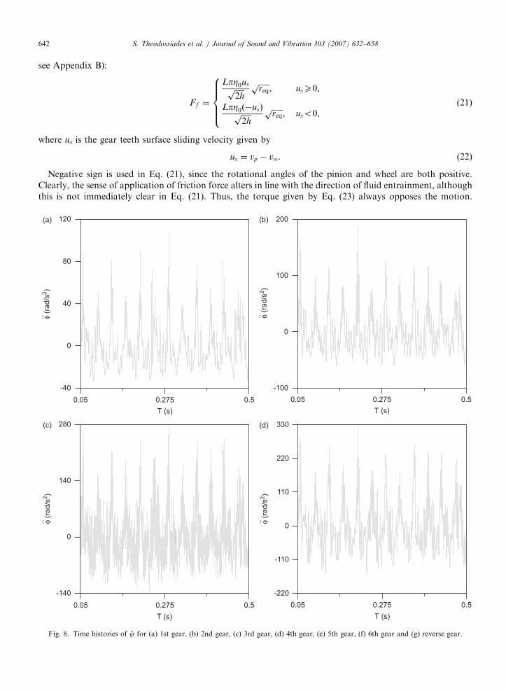
Negative sign is used in Eq. (21), since the rotational angles of the pinion and wheel are both positive.Clearly, the sense of application of friction force alters in line with the direction of fluid entrainment, althoughthis is not immediately clear in Eq. (21). Thus, the torque given by Eq. (23) always opposes the motion.
0.05 0.275 0.5
-40
0
40
80
120
T (s)
φ (r
ad
/s2)
φ (r
ad
/s2)
φ (r
ad
/s2)
φ (r
ad
/s2)
0.05 0.275 0.5
-100
0
100
200
T (s)
0.05 0.275 0.5
-140
0
140
280
T (s)
0.05 0.275 0.5
-220
-110
0
110
220
330
T (s)
Fig. 8. Time histories of €j for (a) 1st gear, (b) 2nd gear, (c) 3rd gear, (d) 4th gear, (e) 5th gear, (f) 6th gear and (g) reverse gear.

ARTICLE IN PRESS
0.05 0.275 0.5
-500
-250
0
250
500
750
T (s)
φ (r
ad
/s2)
φ (r
ad
/s2)
φ (r
ad
/s2)
0.05 0.275 0.5
-300
-150
0
150
300
450
T (s)
0.05 0.275 0.5
-40
0
40
80
T (s)
Fig. 8. (Continued)
S. Theodossiades et al. / Journal of Sound and Vibration 303 (2007) 632–658 643
Therefore, the torque due to teeth flank friction is defined as
Tf ¼ rwF f sin at. (23)
4. Results and discussion
The computational flow chart is shown in Fig. 6. Based on the initial conditions, the geometric quantitiesand meshing cycle characteristics of the idle gears are determined. In turn, these are used for the computationof the reaction forces on the flanks and between the gears and the output shafts. The case examinedcorresponds to typical values for the gear backlash between the various gear pairs (from 80 to 150 mm),lubricant dynamic viscosity (0.052Pa s, corresponding to 44 1C temperature) and engine speed in idle (810 rev/min).
ARTICLE IN PRESSS. Theodossiades et al. / Journal of Sound and Vibration 303 (2007) 632–658644
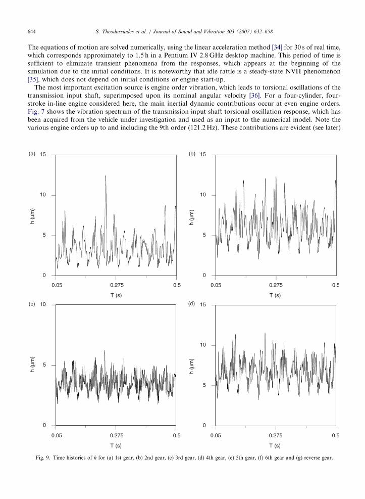
The equations of motion are solved numerically, using the linear acceleration method [34] for 30 s of real time,which corresponds approximately to 1.5 h in a Pentium IV 2.8GHz desktop machine. This period of time issufficient to eliminate transient phenomena from the responses, which appears at the beginning of thesimulation due to the initial conditions. It is noteworthy that idle rattle is a steady-state NVH phenomenon[35], which does not depend on initial conditions or engine start-up.
The most important excitation source is engine order vibration, which leads to torsional oscillations of thetransmission input shaft, superimposed upon its nominal angular velocity [36]. For a four-cylinder, four-stroke in-line engine considered here, the main inertial dynamic contributions occur at even engine orders.Fig. 7 shows the vibration spectrum of the transmission input shaft torsional oscillation response, which hasbeen acquired from the vehicle under investigation and used as an input to the numerical model. Note thevarious engine orders up to and including the 9th order (121.2Hz). These contributions are evident (see later)
0.05 0.275 0.5
0
5
10
15
T (s)
0.05 0.275 0.5
T (s)
0.05 0.275 0.5
T (s)
0.05 0.275 0.5
T (s)
h (μ
m)
h (μ
m)
h (μ
m)
h (μ
m)
0
5
10
15
0
5
10
0
5
10
15
Fig. 9. Time histories of h for (a) 1st gear, (b) 2nd gear, (c) 3rd gear, (d) 4th gear, (e) 5th gear, (f) 6th gear and (g) reverse gear.

ARTICLE IN PRESS
0.05 0.275 0.5
0
2.5
5
T (s)
0.05 0.275 0.5
T (s)
0.05 0.275 0.5
T (s)
h (μ
m)
h (μ
m)
h (μ
m)
0
5
10
0
5
10
15
Fig. 9. (Continued)
S. Theodossiades et al. / Journal of Sound and Vibration 303 (2007) 632–658 645
in the spectra of vibration of all the idle gears. As expected the most significant is the 2nd engine order(26.6Hz) with other main contributions at 4th (53.1Hz), 6th (79.5Hz) and 8th (107Hz) engine orders.
Fig. 8 shows the time histories of the idle gears’ angular acceleration for all gear sets. With the vibrationseverity clearly varying between the different gear pairs, it can be concluded that the overall response of an idlegear consists of two particular motions: the ‘‘macroscopic’’ motion, and the ‘‘microscopic’’ fluctuations,containing different frequency characteristics. The lower frequency engine orders are expected to be dominantin the macroscopic regions, while the higher vibro-impact frequencies are expected to govern the‘‘microscopic’’ fluctuations. Similar behaviour is also encountered in the graphs of Fig. 9, where the lubricantfilm thickness time histories of the idle gear pairs are presented. The gears with lower inertia (5th and 6th gearwheels) develop lubricant films of lower thickness compared to the idle pairs of high inertia (1st, 2nd and

ARTICLE IN PRESSS. Theodossiades et al. / Journal of Sound and Vibration 303 (2007) 632–658646
reverse gear wheels). Nevertheless, in all cases the size of the film thickness is within a range compatible withthe initially assumed hydrodynamic conditions, varying between 1.5 and 10 mm, depending on the gear pair.Moreover, the lower inertia gear pairs demonstrate higher fluctuations of the lubricant film thickness, whichcan be interpreted as higher frequency content in the corresponding vibration spectra. An important point tonote is that the squeeze film velocity is of the order of 1–2mm/s in approaching surfaces. Although this valuemay appear to be significant, it is in fact three orders of magnitude lower than the speed of entraining motion.Thus, the contribution to reaction load due to squeeze is very small compared with that due to entrainingmotion. It is even less significant in increased pressure gradient, contributing to flank friction. This point isfurther discussed in Appendix B.
Fig. 10 shows the FFT spectra of the lubricant film thickness for all gear sets. The way the film thicknesschanges reveals the frequencies under which the gear flanks approach and separate from each other. It isnoteworthy that in most gear wheels, the highest amplitude contributions coincide with the various engineorder harmonics, which are contained in the motion of the transmission input shaft (as described above). Theidle gear pairs with lower inertias generally exhibit higher amplitudes of oscillations and broader spectralcontent compared to the high inertia pairs. However, this is not an indication that rattle should be mostlyexpected from the lower inertia gear sets, since it is the relationship between drag resistance and inertia torquevalues, which governs the appearance of rattle [4]. Other sources contributing to the spectral content are thegear meshing frequencies and the torsional natural frequencies of the transmission system.
0 300 600 900 1200
Frequency (Hz)
0
0.02
0.04
0.06
0.08
PS
D A
mplit
ude
PS
D A
mplit
ude
26.5
53
80
131
104
0 300 600 900 1200
Frequency (Hz)
Frequency (Hz)Frequency (Hz)
0
0.02
0.04
0.06
0.08
0.1
PS
D A
mplit
ude
PS
D A
mplit
ude
26.5
53
99
202
121
157
0 300 600 900 1200
0
0.002
0.004
0.006
0.008
0.0126.5
53
121
304
372
324
285
0 300 600 900 1200
0
0.01
0.02
0.03
0.0426.5
53
121
198
223
Fig. 10. FFT spectra of h for (a) 1st gear, (b) 2nd gear, (c) 3rd gear, (d) 4th gear, (e) 5th gear, (f) 6th gear and (g) reverse gear.
ARTICLE IN PRESS
0 300 600 900 1200
Frequency (Hz)
0
0.0005
0.001
0.0015
PS
D A
mplit
ude
26.5
1020
765
0 300 600 900 1200
Frequency (Hz)
0
0.002
0.004
0.006
PS
D A
mplit
ude
26.5
53
80
418
457
384
360
121
0 300 600 900 1200
Frequency (Hz)
0
0.02
0.04
0.06
0.08
0.1
PS
D A
mplit
ude
26.5
53
131
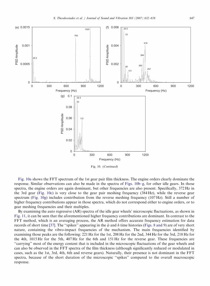
Fig. 10. (Continued)
S. Theodossiades et al. / Journal of Sound and Vibration 303 (2007) 632–658 647
Fig. 10a shows the FFT spectrum of the 1st gear pair film thickness. The engine orders clearly dominate theresponse. Similar observations can also be made in the spectra of Figs. 10b–g, for other idle gears. In thosespectra, the engine orders are again dominant, but other frequencies are also present. Specifically, 372Hz inthe 3rd gear (Fig. 10c) is very close to the gear pair meshing frequency (384Hz), while the reverse gearspectrum (Fig. 10g) includes contribution from the reverse meshing frequency (107Hz). Still a number ofhigher frequency contributions appear in those spectra, which do not correspond either to engine orders, or togear meshing frequencies and their multiples.
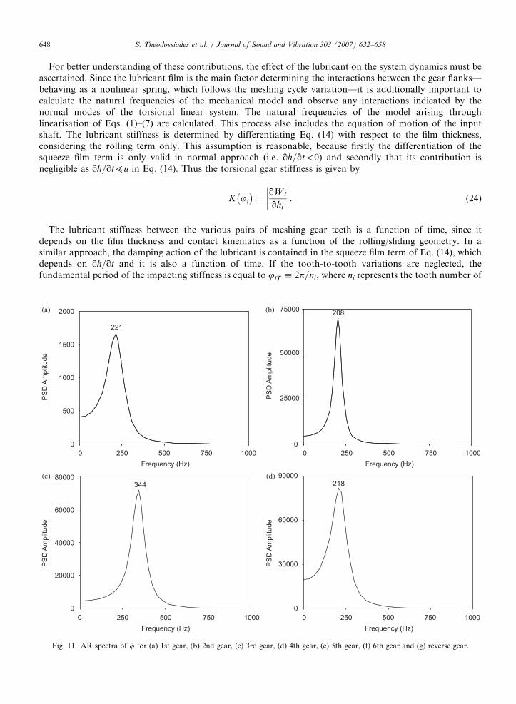
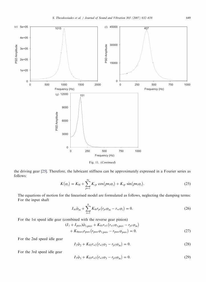
By examining the auto regressive (AR) spectra of the idle gear wheels’ microscopic fluctuations, as shown inFig. 11, it can be seen that the aforementioned higher frequency contributions are dominant. In contrast to theFFT method, which is an averaging process, the AR method offers accurate frequency estimation for datarecords of short time [37]. The ‘‘spikes’’ appearing in the €j and h time histories (Figs. 8 and 9) are of very shortnature, containing the vibro-impact frequencies of the mechanism. The main frequencies identified byexamining those peaks are the following: 221Hz for the 1st, 208Hz for the 2nd, 344Hz for the 3rd, 218Hz forthe 4th, 1015Hz for the 5th, 407Hz for the 6th and 151Hz for the reverse gear. These frequencies are‘‘carrying’’ most of the energy content that is included in the microscopic fluctuations of the gear wheels andcan also be observed in the FFT spectra of the film thickness (although significantly reduced or modulated incases, such as the 1st, 3rd, 4th, 6th and reverse gears). Naturally, their presence is not dominant in the FFTspectra, because of the short duration of the microscopic ‘‘spikes’’ compared to the overall macroscopicresponse.
ARTICLE IN PRESSS. Theodossiades et al. / Journal of Sound and Vibration 303 (2007) 632–658648
For better understanding of these contributions, the effect of the lubricant on the system dynamics must beascertained. Since the lubricant film is the main factor determining the interactions between the gear flanks—behaving as a nonlinear spring, which follows the meshing cycle variation—it is additionally important tocalculate the natural frequencies of the mechanical model and observe any interactions indicated by thenormal modes of the torsional linear system. The natural frequencies of the model arising throughlinearisation of Eqs. (1)–(7) are calculated. This process also includes the equation of motion of the inputshaft. The lubricant stiffness is determined by differentiating Eq. (14) with respect to the film thickness,considering the rolling term only. This assumption is reasonable, because firstly the differentiation of thesqueeze film term is only valid in normal approach (i.e. qh=qto0) and secondly that its contribution isnegligible as qh=qt5u in Eq. (14). Thus the torsional gear stiffness is given by
K ji
� �¼
qW i
qhi
��������. (24)
The lubricant stiffness between the various pairs of meshing gear teeth is a function of time, since itdepends on the film thickness and contact kinematics as a function of the rolling/sliding geometry. In asimilar approach, the damping action of the lubricant is contained in the squeeze film term of Eq. (14), whichdepends on qh=qt and it is also a function of time. If the tooth-to-tooth variations are neglected, thefundamental period of the impacting stiffness is equal to jiT � 2p=ni, where ni represents the tooth number of
0 250 500 750 1000 0 250 500 750 1000
Frequency (Hz) Frequency (Hz)
0 250 500 750 1000 0 250 500 750 1000
Frequency (Hz) Frequency (Hz)
0
500
1000
1500
2000
PS
D A
mplit
ude
PS
D A
mplit
ude
0
25000
50000
75000
PS
D A
mplit
ude
PS
D A
mplit
ude
0
20000
40000
60000
80000344
0
30000
60000
90000218
(a) (b)
(c) (d)
221
208
Fig. 11. AR spectra of €j for (a) 1st gear, (b) 2nd gear, (c) 3rd gear, (d) 4th gear, (e) 5th gear, (f) 6th gear and (g) reverse gear.
ARTICLE IN PRESS
0 500 1000 1500 2000 0 250 500 750 1000
Frequency (Hz) Frequency (Hz)
0 250 500 750 1000
Frequency (Hz)
0
2e+05
1e+05
3e+05
4e+05
5e+05
PS
D A
mplit
ude
0
15000
30000
45000
PS
D A
mplit
ude
PS
D A
mplit
ude
0
6000
3000
9000
12000151
(e) (f)
(g)
1015 407
Fig. 11. (Continued)
S. Theodossiades et al. / Journal of Sound and Vibration 303 (2007) 632–658 649
the driving gear [25]. Therefore, the lubricant stiffness can be approximately expressed in a Fourier series asfollows:
K ji
� �¼ K0i þ
X1p¼1
Kcp cos pniji
� �þ Ksp sin pniji
� �. (25)
The equations of motion for the linearised model are formulated as follows, neglecting the damping terms:For the input shaft
I in €jin þX6i¼1
K0irpi rpijin � rwiji
� �¼ 0. (26)
For the 1st speed idle gear (combined with the reverse gear pinion)
ðI1 þ IprevÞ €j1;prev þ K01rw1 rw1j1;prev � rp1jin
� �þ K0ðrevÞrprev rprevj1;prev � rprevjprev
� �¼ 0. ð27Þ
For the 2nd speed idle gear
I2 €j2 þ K02rw2 rw2j2 � rp2jin
� �¼ 0. (28)
For the 3rd speed idle gear
I3 €j3 þ K03rw3 rw3j3 � rp3jin
� �¼ 0. (29)

ARTICLE IN PRESS
2 3 4 5 6 7
-40
-30
-20
-10
2 3 4 5 6 7
-35
-30
-25
-20
-15
-10
-5
2 3 4 5 6 7
-30
-20
-10
102 3 4 5 6 7
-50
-40
-30
-20
-10
2 3 4 5 6 7
-40
-30
-20
-10
2 3 4 5 6 7
-80
-60
-40
-20
2 3 4 5 6 7
-80
-60
-40
-20
1st
Gear
Reverse
Gear
2nd
Gear
1st
Gear
4th
Gear
Reverse
Gear
4th
Gear
3rd
Gear 6th
Gear
5th
Gear
ωn = 1074Hz
ωn = 435Hzωn = 355Hz
ωn = 225Hz
ωn = 256Hz
ωn = 191Hzωn = 142Hz
6th
Gear
Fig. 12. Natural frequencies and mode shapes of the linearised system. Vertical axes in all figures refers to the predicted amplitude of
normalised modes.
S. Theodossiades et al. / Journal of Sound and Vibration 303 (2007) 632–658650
For the 4th speed idle gear
I4 €j4 þ K04rw4 rw4j4 � rp4jin
� �¼ 0. (30)
ARTICLE IN PRESSS. Theodossiades et al. / Journal of Sound and Vibration 303 (2007) 632–658 651
For the 5th speed idle gear
I5 €j5 þ K05rw5 rw5j5 � rp5jin
� �¼ 0. (31)
For the 6th speed idle gear
I6 €j6 þ K06rw6 rw6j6 � rp6jin
� �¼ 0. (32)
For the reverse speed idle gear
Iwrev €jwrev þ K0revrwrev rwrevjwrev � rprevj1;prev
� �¼ 0. (33)
The solution of the eigenvalue problem determines the natural frequencies and normal modes of the system,which are shown graphically in Fig. 12 for the case examined. Generally, the lower the hydrodynamic filmthickness, the higher the natural frequency of the corresponding gear pair [27]. In fact the stiffness of the film isproportional to 1/h2. Furthermore, the natural frequency of every pair appears in its response spectrum, butit is not the major dominant factor. Nevertheless, in the 3rd, 4th, 5th, 6th and reverse gear responses(Figs. 10c–g, respectively) the natural frequencies play important roles, as indicated by their contributions inthe spectra. The normal modes also reveal that the motions of the 1st, 4th and reverse gears are stronglycoupled, whereas a weaker form of coupling exists between the 3rd and 6th gears. However, the torsionalnatural frequencies are dominant in the AR spectra, as it can be seen by comparing the frequency
0 600 1200 1800 2400 3000 0 600 1200 1800 2400 3000
Frequency (Hz) Frequency (Hz)
0 600 1200 1800 2400 3000 0 600 1200 1800 2400 3000
Frequency (Hz) Frequency (Hz)
0
300
900
600
1500
1200
PS
D A
mplit
ude
PS
D A
mplit
ude
PS
D A
mplit
ude
PS
D A
mplit
ude
0
14000
7000
21000
28000
35000
0
7500
15000
22500
30000882 624
(a) (b)
(c) (d)
496
466
0
12000
6000
18000
24000
30000
Fig. 13. AR spectra of €j, corresponding to 20 1C lubricant viscosity for (a) 1st gear, (b) 2nd gear, (c) 3rd gear, (d) 4th gear, (e) 5th gear,
(f) 6th gear and (g) reverse gear.

ARTICLE IN PRESS
0 600 1200 1800 2400 3000 0 600 1200 1800 2400 3000
Frequency (Hz) Frequency (Hz)
0 600 1200 1800 2400 3000
Frequency (Hz)
0
900
2.5e+05
2e+05
1.5e+05
1e+05
50000
PS
D A
mp
litu
de
0
1.5e+05
1.2e+05
30000
60000
90000
PS
D A
mp
litu
de
PS
D A
mp
litu
de
0
1800
900
2700
3600
4500
331
(e) (f)
(g)
2664
1065
Fig. 13. (Continued)
S. Theodossiades et al. / Journal of Sound and Vibration 303 (2007) 632–658652
values in the graphs of Fig. 11 with those of Fig. 12. In all cases, the observed deviations are lower than 10percent.
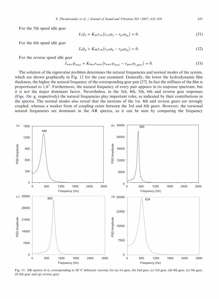
The importance of the lubricant stiffness is demonstrated in the graphs of Fig. 13. Here, the AR spectra ofthe lubricant film thickness for the defined microscopic fluctuations are presented for all gear pairs,corresponding to lubricant temperature of 20 1C (higher lubricant viscosity than the previous case).The lubricant viscosity in fact was altered by an order of magnitude (0.3 Pa s). This is quite reasonablegiven the range of contact conditions, engine operation and widespread geographical use of such vehicles.It can be seen that there is a broader frequency content with higher contributions, altering the qualityof the radiated vibration and noise from the transmission. Moreover, the parametric study of lubricantviscosity and its effect on the mechanical system response reveals an interesting scenario, which isshown in Fig. 14. The root mean square (rms) values of the idle gears’ rotational acceleration clearlyshow a downward trend towards a minimum value in a certain temperature range. This phenomenonis in agreement with the findings of Fujimoto and Kizuka [6], who showed that rattle noise levelsare particularly low within a specific temperature range, which is reached in the gearbox after a givenperiod of engine operation. The reduction of lubricant viscosity, as temperature increases, has a positive effecton the gear rattle noise radiated to the environment. In the aforementioned temperature range, the lubricantstiffness becomes critically small to permit smooth transmission of motion between the gear teeth pairs duringthe meshing cycle. The multiple impacts between teeth are significantly reduced and thus, vibration amplitudesare generally lowered. The graphs of Fig. 14 show that vibration levels are particularly low in the range

ARTICLE IN PRESS
20 30 40 50 60
20
30
40
°C °C
°C°C
20 30 40 50 60
35
55
75
20 30 40 50 60
70
90
110
Ra
d/s
2R
ad
/s2
Ra
d/s
2R
ad
/s2
20 30 40 50 60
15
25
35
Fig. 14. rms values of €j with respect to temperature for (a) 1st gear, (b) 2nd gear, (c) 4th gear and (d) reverse gear.
S. Theodossiades et al. / Journal of Sound and Vibration 303 (2007) 632–658 653
40–50 1C for the particular examined transmission system. A slightly shifted temperature range has beenidentified by Fujimoto and Kizuka [6] experimentally, in a vehicle equipped with a four-cylinder diesel engineand a five-speed manual transmission. The investigations here show the existence of an inter-play between theeffects of hydrodynamic reaction in meshing pairs and the drag torque between the loose gear and outputshaft. Since the same lubricant is used in both cases and the geometry of contact differs, changes in lubricantviscosity can make one dominate in certain circumstances and the other in other occasions, depending oncontact kinematics and number of meshing pairs. The situation is, therefore, complex, but the significant roleof this interaction is clear. Variations between mechanical systems—affecting the overall system behaviour—are generally expected, since the geometric characteristics of the gears change significantly between differenttypes of vehicles.
ARTICLE IN PRESS
z
x
h0
x
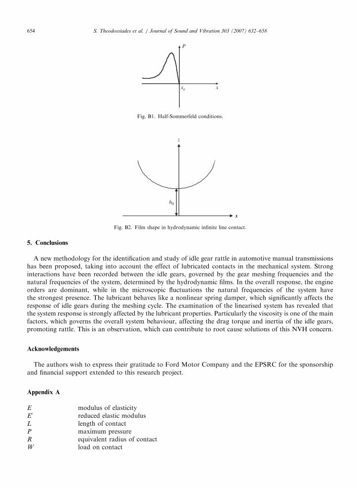
Fig. B2. Film shape in hydrodynamic infinite line contact.
ex
P
xe x
Fig. B1. Half-Sommerfeld conditions.
S. Theodossiades et al. / Journal of Sound and Vibration 303 (2007) 632–658654
5. Conclusions
A new methodology for the identification and study of idle gear rattle in automotive manual transmissionshas been proposed, taking into account the effect of lubricated contacts in the mechanical system. Stronginteractions have been recorded between the idle gears, governed by the gear meshing frequencies and thenatural frequencies of the system, determined by the hydrodynamic films. In the overall response, the engineorders are dominant, while in the microscopic fluctuations the natural frequencies of the system havethe strongest presence. The lubricant behaves like a nonlinear spring damper, which significantly affects theresponse of idle gears during the meshing cycle. The examination of the linearised system has revealed thatthe system response is strongly affected by the lubricant properties. Particularly the viscosity is one of the mainfactors, which governs the overall system behaviour, affecting the drag torque and inertia of the idle gears,promoting rattle. This is an observation, which can contribute to root cause solutions of this NVH concern.
Acknowledgements
The authors wish to express their gratitude to Ford Motor Company and the EPSRC for the sponsorshipand financial support extended to this research project.
Appendix A
E
modulus of elasticity E0 reduced elastic modulus L length of contact P maximum pressure R equivalent radius of contact W load on contact
ARTICLE IN PRESSS. Theodossiades et al. / Journal of Sound and Vibration 303 (2007) 632–658 655
a
contact semi-half-width d contact deflection n Poisson ratioThe contact of a pair of teeth may be considered as an equivalent roller of radius R and length L contactinga semi-infinite elastic solid (i.e. the classic Hertzian theory). The contact deflection is obtained as
d ¼aP
E0ln
2L
a
� �þ
1
2
� , (A.1)
where the contact semi-half-width a is given as
a ¼8WR
pE0L
� �1=2
(A.2)
and the maximum pressure P as
P ¼2W
paL. (A.3)
Using typical values, W (17N), R (E0.008m), L (E0.01m) and reduced elastic modulus,
E0 ¼E
1� n2(A.4)
(for both bodies being of steel with E ¼ 206GPa and n ¼ 0.3), then d becomes E10�8m, which is 2 orders ofmagnitude less than the lubricant film thickness. Thus, under idle rattle conditions iso-viscous rigid regime oflubrication is prevalent.
Appendix B
Ff
Flank friction h Central film thickness L Length of contact P Pressure R Equivalent radius of contact x Dimension along the width of contact. xe Exit position xi Inlet position z Film thickness Du Sliding velocity/speed, u1�u2Using half-Sommerfeld conditions (Fig. B1), the flank friction is given by
Ff ¼ L
Z xe
xi
�z
2
qP
qxþ
Z0Du
z
dx. (B.1)
For low hydrodynamic pressures, the first term of Eq. (B.1) can be neglected due to
z
2
qP
qx5
Z0Du
z.
Therefore, Eq. (B.1) becomes
Ff ¼ L
Z 0
xi
Z0Du
z
dx ¼ LZ0Du
Z 0
xi
1
z
dx. (B.2)
ARTICLE IN PRESSS. Theodossiades et al. / Journal of Sound and Vibration 303 (2007) 632–658656
Assuming an infinite hydrodynamic line contact (Fig. B2),
z ¼ h0 1þx2
2Rh0
� �. (B.3)
By substituting Eq. (B.3) into Eq. (B.2):
F f ¼ LZ0Du
Z 0
xi
1
h 1þ x2=2Rh� �
" #dx. (B.4)
By substituting
tan x̄ ¼xffiffiffiffiffiffiffiffiffi2Rhp (B.5)
and
sec2 x̄dx̄ ¼dxffiffiffiffiffiffiffiffiffi2Rhp (B.6)
into Eq. (B.4):
F f ¼LZ0Du
h
ffiffiffiffiffiffiffiffiffi2Rhp
Z 0
xi
dx̄ ¼ �Z0Duffiffiffi
hp
ffiffiffiffiffiffi2Rp
x̄i. (B.7)
Substituting Eq. (B.5) again into Eq. (B.7)
Ff ¼ �LZ0Duffiffiffi
hp
ffiffiffiffiffiffi2Rp
tan�1xiffiffiffiffiffiffiffiffiffi2Rhp
� �. (B.8)
Assuming fully flooded conditions
xi !�1, (B.9)
tan�1 �1ð Þ !�p2
, (B.10)
F f ¼LpZ0Duffiffiffiffiffi
2hp
ffiffiffiffiRp
. (B.11)
During gearing action, Du is the sliding velocity of the meshing teeth surfaces (or us), which changesdirection as the contact crosses the pitch point. This leads to a negative value for friction, which whensubstituted into the equations of motion yields forcing terms rather than dissipative terms, contravening theconcept of friction. To correct this malfunction of Eq. (B.11) and achieving a dissipative hydrodynamicfriction force, the sliding velocity us has been replaced by
Ff ¼
LpZ0usffiffiffiffiffi2hp
ffiffiffiffiRp
; us40;
LpZ0ð�usÞffiffiffiffiffi2hp
ffiffiffiffiRp
; uso0;
8>>><>>>:
(B.12)
according to the reported validated approach by Vaishya and Singh [38,39].With no lateral degrees of freedom considered for the transmission shafts (the current model is only
torsional), any resulting significant convergence of mating members (large squeeze film effect) is ignored.Thus, the effect of hydrodynamic pressures on friction have been considered to be small compared to that dueto relative sliding velocity as already pointed out above. This amounts to an assumption, which may not beinherently correct, as there are lateral rigid body oscillations of the transmission shafts, as well as their likelybending.

ARTICLE IN PRESSS. Theodossiades et al. / Journal of Sound and Vibration 303 (2007) 632–658 657
References
[1] T. Sakai, Y. Doi, K. Yamamoto, T. Ogasawara, M. Narita, Theoretical and experimental analysis of rattling noise of automotive
gearbox, SAE Technical Paper 810773, 1981, pp. 1–10.
[2] S.N. Dogan, G. Lechner, MaXnahmen zur Verringerung von Losteilschwingungen in Fahrzeuggetrieben, ATZ Autombiltechnische
Zeitschrift 100 (10) (1998) 710–716.
[3] M. Wang, R. Manoj, W. Zhao, Gear rattle modelling and analysis for automotive manual transmissions, Proceedings of the Institute
of Mechanical Engineers Part D: Journal of Automobile Engineering 215 (2001) 241–258.
[4] R. Seaman, C. Johnson, R. Hamilton, Component inertial effects on transmission design, SAE Technical Paper 841686, 1984,
pp. 6.990–6.1008.
[5] T. Fujimoto, Y. Chikatani, J. Kojima, Reduction of idling rattle in manual transmission, SAE Technical Paper 870395, 1987,
pp. 2.99–2.109.
[6] T. Fujimoto, T. Kizuka, An improvement of the prediction method of the idling rattle in manual transmission—in the case of the
manual transmission with backlash eliminator, SAE Technical Paper 2001-01-1164, 2001.
[7] O. Johnson, N. Hirami, Diagnosis and objective evaluation of gear rattle, SAE Technical Paper 911082, 1991, pp. 1547–1562.
[8] E. I. Rivin, Analysis and reduction of rattling in power transmission systems, SAE Technical Paper 2000-01-0032, 2000.
[9] R. Gohar, Elastohydrodynamics, 2nd ed., Imperial College Press, 2001.
[10] M. Gnanakumarr, S. Theodossiades, H. Rahnejat, The tribo-contact dynamics phenomenon in torsional impact of loose gears—
promoting gear rattle, SAE 02ATT-138, Society of Automotive Engineers (SAE)-ATT Congress, Paris, 2002.
[11] G. Fudala, T. Engle, A. Karvelis. A system approach to reducing gear rattle, SAE Technical Paper 870396, 1987, pp. 2.110–2.117.
[12] S. Theodossiades, M. Gnanakumarr, H. Rahnejat, P. Kelly, On the effect dual mass flywheel upon impact induced noise in vehicular
powertrain systems, Proceedings of the Institute of Mechanical Engineers Part D: Journal of Automobile Engineering 220 (6) (2006)
747–761.
[13] T.C. Kim, R. Singh, Dynamic interactions between loaded and unloaded gear pairs under rattle conditions, SAE Technical Paper
2001-01-1553, 2001, pp. 1934–1943.
[14] P. Bellomo, F. Cricenti, N. De Vito, C. Lang, D. Minervini, Innovative vehicle powertrain systems engineering: beating the noisy
offenders in vehicle transmissions, SAE Technical Paper 2000-01-0033, 2000.
[15] J. Biermann, B. Hagerodt, Investigation of the clonk phenomenon in vehicle transmissions-measurement, modelling and simulation,
Proceedings of the Institute of Mechanical Engineers Part K 213 (1999) 53–60.
[16] T. Fujimoto, T. Kizuka, Predictive calculation of idling rattle in manual transmissions—based on experimental measurements of gear
vibration occurring in backlashes, SAE Technical Paper 2003-01-0678, 2003.
[17] R. Singh, H. Xie, R. Comparin, Analysis of automotive neutral gear rattle, Journal of Sound and Vibration (1989) 177–196.
[18] T. Fujimoto, T. Kizuka, Audible noise simulation—an attempt to predict idling rattle in manual transmissions, SAE Technical Paper
2003-01-0674, 2003.
[19] S. Meisner, B. Campbell, Development of gear rattle analytical simulation methodology, SAE Technical Paper 951317, 1995,
pp. 2344-2353.
[20] A. Kahraman, R. Singh, Interactions between time-varying mesh stiffness and clearance non-linearities in a geared system, Journal of
Sound and Vibration 146 (1) (1991) 135–156.
[21] G. Blankenship, R. Singh, A new gear mesh interface dynamic model to predict multi-dimensional force coupling and excitation,
Mechanism and Machine Theory 30 (1) (1995) 43–57.
[22] M. Wang, W. Zhao, R. Manoj, Numerical modelling and analysis of automotive transmission rattle, Journal of Vibration and Control
8 (2002) 921–943.
[23] R. Yakoub, M. Corrado, A. Forcelli, T. Pappalardo, S. Dutre, Prediction of system-level gear rattle using multibody and vibro-
acoustic techniques, SAE Technical Paper 2004-32-0063/20044350, 2004.
[24] S. Theodossiades, S. Natsiavas, Non-linear dynamics of gear-pair systems with periodic stiffness and backlash, Journal of Sound and
Vibration 229 (2) (2000) 287–310.
[25] S. Theodossiades, S. Natsiavas, On geared rotordynamic systems with oil journal bearings, Journal of Sound and Vibration 243 (4)
(2001) 721–745.
[26] H. Rahnejat, The Influence of Vibration on the Oil film in Elasto-hydrodynamic Contacts, PhD Thesis, Imperial College, University
of London, 1984.
[27] O. Tangasawi, S. Theodossiades, H. Rahnejat, P. Kelly, Gear teeth impact dynamics in manual transmissions promoting idle rattle,
Proceedings of the Fifth EUROMECH Nonlinear Dynamics Conference, Eindhoven, 2005.
[28] H. Merritt, Gear Engineering, Pitman Publishing, London, 1971.
[29] A. Kahraman, D. R. Houser, H. Xu, Development of a generalized mechanical efficiency prediction methodology for gear pairs, Year
1 Progress Report, AGMA Foundations, The Ohio State University, 2005, submitted.
[30] T. Sasaki, H. Mori, N. Okino, Fluid lubrication theory of roller bearings, Transactions of ASME, Journal of Basic Engineering (1962).
[31] R. Graikousis, Machine Elements, Vol. 3, 2nd ed., Greece, 1985 (in Greek).
[32] B. Hamrock, S. Schmid, B. Jacobson, Fundamentals of Fluid Film Lubrication, 2nd ed., Marcel Dekker Inc., New York, 2004.
[33] R. Taylor, Engine friction: the influence of lubrication rheology, Proceedings of the Institute of Mechanical Engineers Part J 211
(1997) 235–246.
[34] S. Timoshenko, D.H. Young, W. Weaver Jr., Vibration problems in Engineering, 4th ed., Wiley, New York, 1974.

ARTICLE IN PRESSS. Theodossiades et al. / Journal of Sound and Vibration 303 (2007) 632–658658
[35] R.J. Comparin, R. Singh, An analytical study of automotive neutral gear rattle, Journal of Mechanical Design 112 (1990) 237–245.
[36] H. Rahnejat, Multi-body Dynamics: Vehicles, Machines and Mechanisms, Co-publishers: PEP (IMechE) Bury St. Edmonds and SAE,
Warrendale, 1998.
[37] Auto Signal Version 1.7 User’s Manual, Seasolve, Richmond, CA, USA, 2003.
[38] M. Vaishya, R. Singh, Strategies for modelling friction in gear dynamics, Journal of Mechanical Design 125 (2003) 383–393.
[39] M. Vaishya, R. Singh, Sliding friction-induced non-linearity and parametric effects in gear dynamics, Journal of Sound and Vibration
248 (4) (2001) 671–694.