Assembly Features: definition, classification, and usefulness in sequence planning
25
Int. J. Industrial and Systems Engineering, Vol. 4, No. 2, 2009 Assembly features: definition, classification, and usefulness in sequence planning Hamid Ullah* Erik Bohez Design and Manufacturing Engineering, School of Engineering and Technology, Asian Institute of Technology, Pathumthani 12120, Thailand. Email: [email protected] , Email: [email protected] *Corresponding author M. A. Irfan NWFP University of Engineering & Technology, Peshawar, Pakistan. E-mail: [email protected] Abstract: Unique definition and classification of assembly feature are presented. Assembly feature’s definition is provided using the concept of assembly intents. Assembly features classification is done based on useful assembly-specific information. Assembly features provide information that result in a smaller number of assembly sequences that have to be checked in assembly sequence optimization. Due to the reduction in assembly sequences, AND/OR graph not only reduces considerably but also becomes very simple. This can result in a significant reduction in the computation time for assembly sequence planning. Real-life examples are given to demonstrate how assembly features are useful in sequence planning. Keywords: Assembly feature (AF); Assembly intents ( ); Precedence relationship; Features classification; Assembly sequence planning (ASP); AND/OR graph a I Reference to this paper should be made as follow: Ullah, H., Bohez, E. and Irfan, M.A. (2009) ‘Assembly features: definition, classification, and usefulness in sequence planning’, Int. J. Industrial and Systems Engineering, Vol. 4, No. 2, 2009. 1
-
Upload
independent -
Category
Documents
-
view
3 -
download
0
Transcript of Assembly Features: definition, classification, and usefulness in sequence planning

Int. J. Industrial and Systems Engineering, Vol. 4, No. 2, 2009 Assembly features: definition, classification, and usefulness in sequence planning
Hamid Ullah* Erik Bohez Design and Manufacturing Engineering, School of Engineering and Technology, Asian Institute of Technology, Pathumthani 12120, Thailand. Email: [email protected], Email: [email protected]*Corresponding author M. A. Irfan NWFP University of Engineering & Technology, Peshawar, Pakistan. E-mail: [email protected] Abstract: Unique definition and classification of assembly feature are presented. Assembly feature’s definition is provided using the concept of assembly intents. Assembly features classification is done based on useful assembly-specific information. Assembly features provide information that result in a smaller number of assembly sequences that have to be checked in assembly sequence optimization. Due to the reduction in assembly sequences, AND/OR graph not only reduces considerably but also becomes very simple. This can result in a significant reduction in the computation time for assembly sequence planning. Real-life examples are given to demonstrate how assembly features are useful in sequence planning. Keywords: Assembly feature (AF); Assembly intents ( ); Precedence relationship; Features classification; Assembly sequence planning (ASP); AND/OR graph
aI
Reference to this paper should be made as follow: Ullah, H., Bohez, E. and Irfan, M.A. (2009) ‘Assembly features: definition, classification, and usefulness in sequence planning’, Int. J. Industrial and Systems Engineering, Vol. 4, No. 2, 2009.
1

Biographical notes: Hamid Ullah is an Assistant Professor in the Department of Mechanical Engineering, NWFP University of Engineering and Technology, Peshawar, Pakistan. He did his Master Degree in High Speed Machining from his parent department. He got degree of Doctor of Engineering from Design and Manufacturing Engineering field of study, School of Engineering and Technology, Asian Institute of Technology, Bangkok. His areas of interest are Mathematical Modeling, Assembly Features, Petri Nets, and Assembly Sequence Planning. His email address is [email protected] Bohez is an Associate Professor in the Design and Manufacturing Engineering field of study, School of Engineering and Technology, Asian Institute of Technology, Bangkok. His areas of interest are FMS, CAD/CAM, Multi-axis Machining, Error Measurement, Petri nets, and Packaging. He has more than thirty-five refereed journal papers, and a large number of conference papers. He is actively involved both in teaching and research. His email address is [email protected]. Dr. M.A. Irfan is a Professor at the NWFP University of Engineering and Technology, Peshawar, Pakistan. His areas of research are High-speed Machining, CAD, and AI. He is actively involved in research. His email address is [email protected].
1 Introduction
Assembly planning (AP) is an important tool for achieving product and process development, thus increasing the production efficiency and reducing the manufacturing costs. Assembly planning aims to identify and evaluate the different ways to assemble a mechanical product from its component parts. It is an important step for generating a feasible assembly sequence. Assembly sequence planning (ASP) is the foundation of the assembly process planning which plays a key role in the whole product life cycle. ASP is one of the most active topics in current research. The efficiency and quality of the ASP can influence the assembly process greatly (Su, 2007a).
The literature shows several methodologies for representation of assembly sequences (ASs). Homem de Mello and Sanders (1991) introduced the cut-set based ASP method, using the three cut-set inferring rules. Seow and Devanathan (1994) proposed temporal logic as an implicit representation tool and an analytical language for ASP. De Fazio and Whitney (1987) used the directed graph representation of all ASs. Homem de Mello and Sanders (1991) introduced an AND/OR graph representation of ASs. Wilson (1995) proposed a man–computer interactive assembly sequencing method based on the evaluation and judgement of the assembly CAD structure (Wilson and Latombe, 1994; Wilson, 1995). Gottipolu and Ghosh (1995, 2003) designed the mathematical ASP methods based on the contact and interference arrays between each couple of parts or subassemblies in the assembly.
Swaminathan and Barber (1996) designed an experience-based assembly sequence planner for mechanical products, in which, assembly was separated into several typical sub-assemblies containing three, four, or five components. These typical sub-assemblies
2
are modeled using directed liaison graphs. However, the approaches presented in Gottipolu and Ghosh (1995), and Swaminathan and Barber (1996) are all subject to the limitation that each part can only be assembled to the assembly along with one of the six orthogonal directions. Eng et al. (1999) proposed in their study a kinematic pair liaison diagram for modeling an assembly process. The feature mating matrices are used to represent the degrees of freedom constraints between two components connected by their features. Hui et al. (2007) presented an assembly semantic modeling approach where the product information is described by a three-level semantic abstraction known as Concept/Function Level, Structure Level and Part/Feature Level. Using this approach, they developed an interactive assembly planning system. Using an integrated framework of the part liaison matrix and precedence Boolean relations, Lai and Huang (2004) presented an approach for automatic assembly sequence plan generation. A unified and integrated mathematical representation was proposed that allows an optimum assembly sequence generation for various production environments. Baldwin, et al. (1991) developed an ASP system to integrate the geometric feasible ASs with the evaluation and selection of the optimal sequence. However, due to the simplicity of the assembly model, the user has to input various engineering criteria for a number of states and operations. In addition to evaluating the large quantity of the geometrically possible ASs, it is an effort intensive and error-prone process.
Several researchers used different artificial intelligence techniques for analysis of an optimal assembly sequence. Smith et al. (2001) developed methods for using the matrix-based product model and a genetic algorithm in ASP. Marian et al. (2006) described a Genetic Algorithm approach to optimise the ASP Problem. Tseng et al. (2004) used an approach to assembly planning that combines the connector concept and characteristics of a genetic algorithm by using object-oriented programming. Tianyang et al. (2007) presented a knowledge-based approach to the ASP problem where the connection-semantics-based assembly tree hierarchy proposed in their study provides an appropriate way to consider both geometric and non-geometric information Sinanoglu and Borklii (2005) presented an assembly system based on binary vector representation. For analysis of optimal assembly sequence, the neural network approach is used. Geometric feasibility in ASP is the prerequisite for the valid assembly sequences search. The assembly precedence relations deriving and fulfilling are the essential tasks in the geometric feasible ASP (Su, 2007b). He proposed a hierarchical ASP method which can derive the optimal AS based on the precedence relations classification. He proposed assembly model including assembly structure draft, assembly tree structure, liaisons diagram, liaison parameters, and part parameters.
Most of the sequence planning researches focus on generating all possible ASs for a product. Out of these ASs, after applying trial and error, only few sequences are selected as the most wanted sequences for the assembly sequence optimization. Remaining all ASs are declared as unwanted sequences and are therefore ignored. However, this is not only time consuming but also a tedious process. To speed up the assembly sequence planning, assembly features (AFs) are used that directly indicate the assembly order for the components involved in the assembly. This results only in few desired ASs instead of a large number of all possible sequences for a product.
AFs can be used as a main factor in the integration of CAD with assembly planning because various design and assembly data can be associated with AF. The integration of
3
design and assembly planning can be a crucial method for achieving assembly oriented product development to reduce manufacturing cost and enhance the production efficiency and product quality. Feature-based assembly modeling and planning not only improves the link between design and down stream applications, but the designer’s task can also be made somewhat easier (Shah and Tadepalli, 1992). Most of the feature-based assembly research is displaying the information to guide the assembly modeling, planning, and integration however, there is lack of research to present in detail the AFs classification, which can offer an important foundation for modeling, planning, and integration of design with assembly planning. Not even the ISO produces a standard AF classification, although they have for manufacturing features given by STEP AP 224. In assembly domain, STEP AP 203 provides configuration controlled 3D designs of mechanical parts and assemblies without any mention of AF’s definition and classification. Similarly, STEP AP 1102 is the application protocol meant for AFs but surprisingly it provides no AFs classification.
Keeping in view this deficiency, a unique assembly features classification is presented, after providing a broad assembly feature’s definition. This is followed by the description of the usefulness AFs offer to facilitate the process of ASP. The overall objective of the paper can be decomposed into the following subtasks. • A broad definition and unique classification of assembly features. • Assembly features instantiation. • Description of some very useful information and advantages assembly features offer
for assembly sequence planning. • Demonstration of the research results with the help of real-life examples. The structure of the remaining paper is organized as follows. Section 2 provides definition of assembly feature. A new unique assembly features classification is mentioned in section 3. Section 4 describes the assembly features instantiation. Important information and advantages the assembly features offer to facilitate the process of ASP are mentioned in section 5. Research results are demonstrated with the help of real-life examples in sections 6 and 7. At the end, summary and conclusions are given. 2 Assembly feature definition
An overview of some of the definitions of assembly feature is given below. • An association between two form features on different parts (Shah and Tadepalli,
1992). • Elementary relations between components (Lee and Andrews, 1985). • Elementary connection feature containing mating relations between the components
(Chan and Tan, 2003). • A collection of elementary relations and matching form features (Sodhi and Turner,
1991). • A generic solution referring to two groups of parts that need to be related by a
relationship so as to solve a design problem (Deneux, 1999). • An element to specify the relationships between a pair of assembled components
(ISO standard STEP AP 1102).
4
• Particular form features that affect assembly operations, which are defined by connectors (Zha and Du, 2002).
• The carriers of constraint between parts and their shape determines which degrees of freedom are constrained and which remain free (Youcef-Toumi, 2006).
In these definitions, some authors mention assembly and/or mating relation in their definitions of AF, some specify assembly operation, while some other use degrees of freedom information. This clearly indicates that the assembly relation, assembly operation, and degrees of freedom are all the necessary assembly-specific information that must be considered while defining AF. In other words, the AF definition should be extended to accommodate this assembly-specific information to give a broad definition of AF. Therefore, considering the importance of these assembly-specific information, a new AF definition is provided as follows.
Assembly feature is defined as “a connection between two form features on mating parts, associated with assembly intents, where assembly intents include assembly relation, assembly operation, and assembly degrees of freedom” (HamidUllah, et al. 2006a).
In the connection of form features, the base feature is normally taken as that feature which must be fixed or can be considered relatively fixed during the assembly operation. It is often, but not necessarily, the larger feature; thereby causing it to be fixed. It may also be considered as the base feature because many other features must be attached to it to create the complete assembly or subassembly. A mating feature is the one moved toward a base feature to make an AF. It is often, but need not be, smaller (and more easily moved) than the base feature.
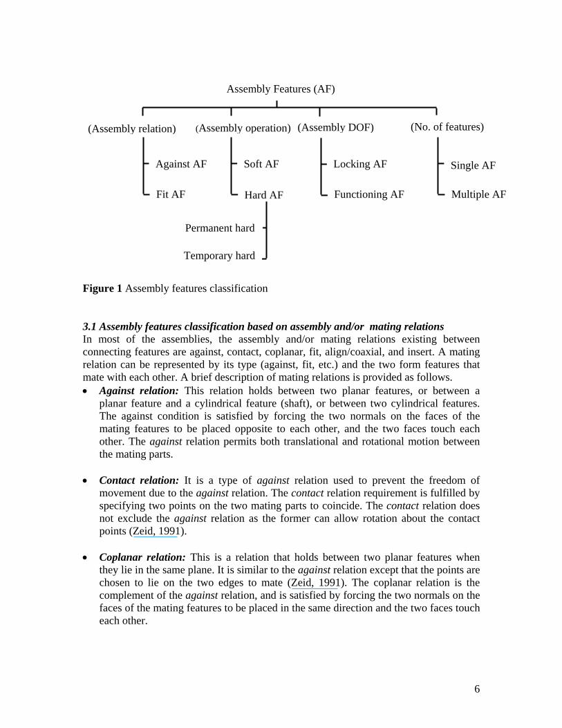
3 Assembly features classification The relationship between two form features is significant from the assembly point of view only if the two features are connecting together. Also, since connections between features play significant role in the assembly and/or disassembly planning, therefore, the AFs made of connections between form features are considered in this paper. AFs are classified mainly according to the assembly relation, assembly operation, assembly degrees of freedom, and the number of features coming into contact simultaneously (HamidUllah, et al. 2006b) as shown in Fig. 1.
5
Assembly Features (AF)
(Assembly relation) (Assembly operation) (Assembly DOF)
Against AF
Fit AF Hard AF
Temporary hard
Permanent hard
Soft AF
Multiple AF
Single AF
Functioning AF
Locking AF
(No. of features)
Figure 1 Assembly features classification
3.1 Assembly features classification based on assembly and/or mating relations In most of the assemblies, the assembly and/or mating relations existing between connecting features are against, contact, coplanar, fit, align/coaxial, and insert. A mating relation can be represented by its type (against, fit, etc.) and the two form features that mate with each other. A brief description of mating relations is provided as follows. • Against relation: This relation holds between two planar features, or between a
planar feature and a cylindrical feature (shaft), or between two cylindrical features. The against condition is satisfied by forcing the two normals on the faces of the mating features to be placed opposite to each other, and the two faces touch each other. The against relation permits both translational and rotational motion between the mating parts.
• Contact relation: It is a type of against relation used to prevent the freedom of
movement due to the against relation. The contact relation requirement is fulfilled by specifying two points on the two mating parts to coincide. The contact relation does not exclude the against relation as the former can allow rotation about the contact points (Zeid, 1991).
• Coplanar relation: This is a relation that holds between two planar features when
they lie in the same plane. It is similar to the against relation except that the points are chosen to lie on the two edges to mate (Zeid, 1991). The coplanar relation is the complement of the against relation, and is satisfied by forcing the two normals on the faces of the mating features to be placed in the same direction and the two faces touch each other.
6
• Fit relation: It holds between two different features: a hole feature and a shaft feature. The fit relation is achieved by forcing the shaft and hole axes to be collinear. Clearance fit allows sliding or rotation. Transition fit provides accurate location. Interference fit provides rigidity and alignment. Screw fit prevents both linear and rotary motions.
• Align relation: This relation holds between two features if their centerlines are
collinear/coaxial. For example, insertion and/or any assembly requiring an alignment with cylindrical shafts or holes.
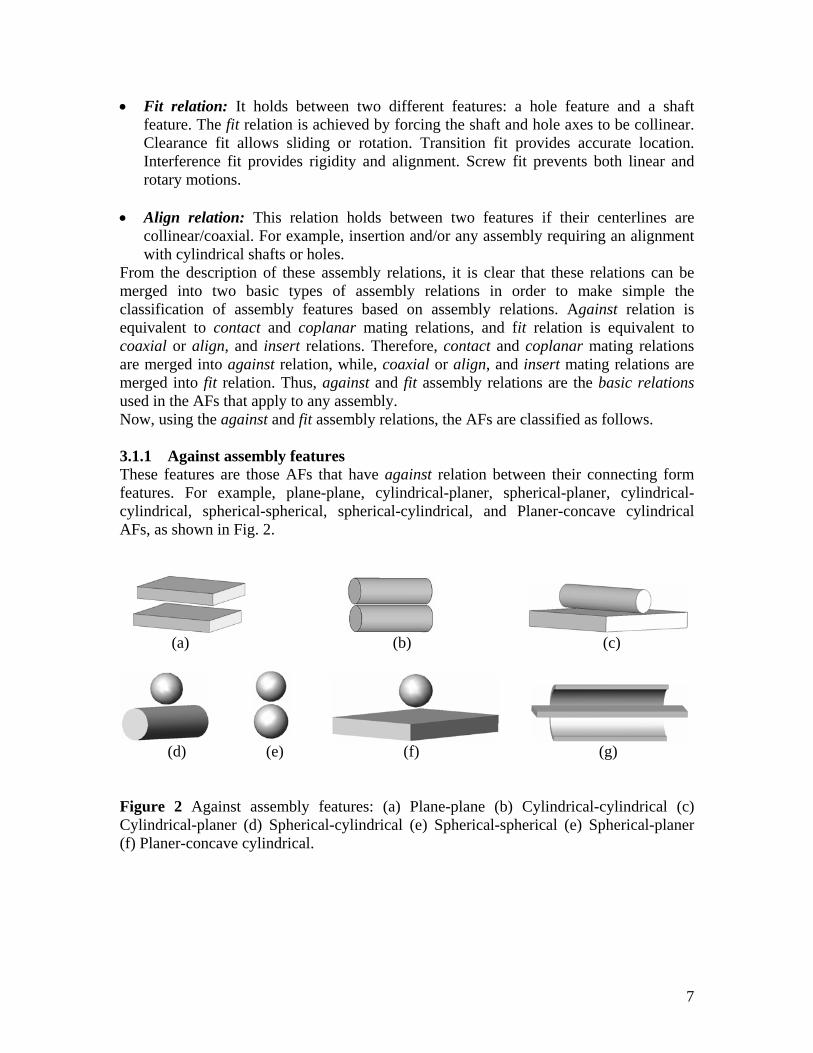
From the description of these assembly relations, it is clear that these relations can be merged into two basic types of assembly relations in order to make simple the classification of assembly features based on assembly relations. Against relation is equivalent to contact and coplanar mating relations, and fit relation is equivalent to coaxial or align, and insert relations. Therefore, contact and coplanar mating relations are merged into against relation, while, coaxial or align, and insert mating relations are merged into fit relation. Thus, against and fit assembly relations are the basic relations used in the AFs that apply to any assembly. Now, using the against and fit assembly relations, the AFs are classified as follows. 3.1.1 Against assembly features These features are those AFs that have against relation between their connecting form features. For example, plane-plane, cylindrical-planer, spherical-planer, cylindrical-cylindrical, spherical-spherical, spherical-cylindrical, and Planer-concave cylindrical AFs, as shown in Fig. 2.
(a) (b) (c)
(d) (e) (f) (g) Figure 2 Against assembly features: (a) Plane-plane (b) Cylindrical-cylindrical (c) Cylindrical-planer (d) Spherical-cylindrical (e) Spherical-spherical (e) Spherical-planer (f) Planer-concave cylindrical.
7
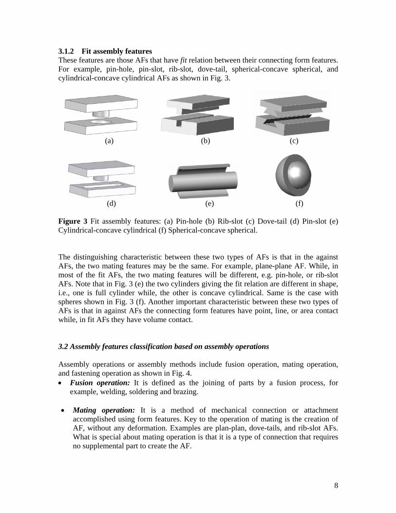
3.1.2 Fit assembly features These features are those AFs that have fit relation between their connecting form features. For example, pin-hole, pin-slot, rib-slot, dove-tail, spherical-concave spherical, and cylindrical-concave cylindrical AFs as shown in Fig. 3.
(a) (b) (c)
(d) (e) (f)
Figure 3 Fit assembly features: (a) Pin-hole (b) Rib-slot (c) Dove-tail (d) Pin-slot (e) Cylindrical-concave cylindrical (f) Spherical-concave spherical.
The distinguishing characteristic between these two types of AFs is that in the against AFs, the two mating features may be the same. For example, plane-plane AF. While, in most of the fit AFs, the two mating features will be different, e.g. pin-hole, or rib-slot AFs. Note that in Fig. 3 (e) the two cylinders giving the fit relation are different in shape, i.e., one is full cylinder while, the other is concave cylindrical. Same is the case with spheres shown in Fig. 3 (f). Another important characteristic between these two types of AFs is that in against AFs the connecting form features have point, line, or area contact while, in fit AFs they have volume contact.
3.2 Assembly features classification based on assembly operations
Assembly operations or assembly methods include fusion operation, mating operation, and fastening operation as shown in Fig. 4. • Fusion operation: It is defined as the joining of parts by a fusion process, for
example, welding, soldering and brazing. • Mating operation: It is a method of mechanical connection or attachment
accomplished using form features. Key to the operation of mating is the creation of AF, without any deformation. Examples are plan-plan, dove-tails, and rib-slot AFs. What is special about mating operation is that it is a type of connection that requires no supplemental part to create the AF.
8
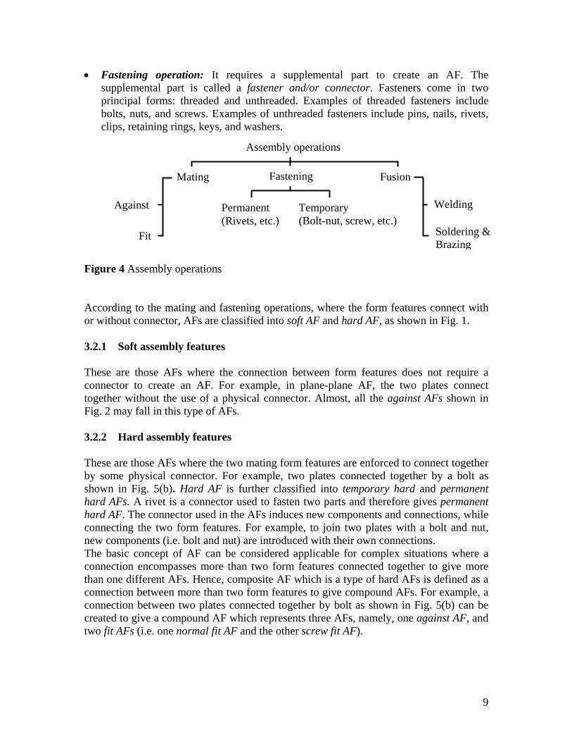
• Fastening operation: It requires a supplemental part to create an AF. The supplemental part is called a fastener and/or connector. Fasteners come in two principal forms: threaded and unthreaded. Examples of threaded fasteners include bolts, nuts, and screws. Examples of unthreaded fasteners include pins, nails, rivets, clips, retaining rings, keys, and washers.
Assembly operations
Fusion
Soldering & Brazing
Welding
Mating
Against
Fit
Fastening
Temporary (Bolt-nut, screw, etc.)
Permanent (Rivets, etc.)
Figure 4 Assembly operations
According to the mating and fastening operations, where the form features connect with or without connector, AFs are classified into soft AF and hard AF, as shown in Fig. 1.
3.2.1 Soft assembly features
These are those AFs where the connection between form features does not require a connector to create an AF. For example, in plane-plane AF, the two plates connect together without the use of a physical connector. Almost, all the against AFs shown in Fig. 2 may fall in this type of AFs. 3.2.2 Hard assembly features
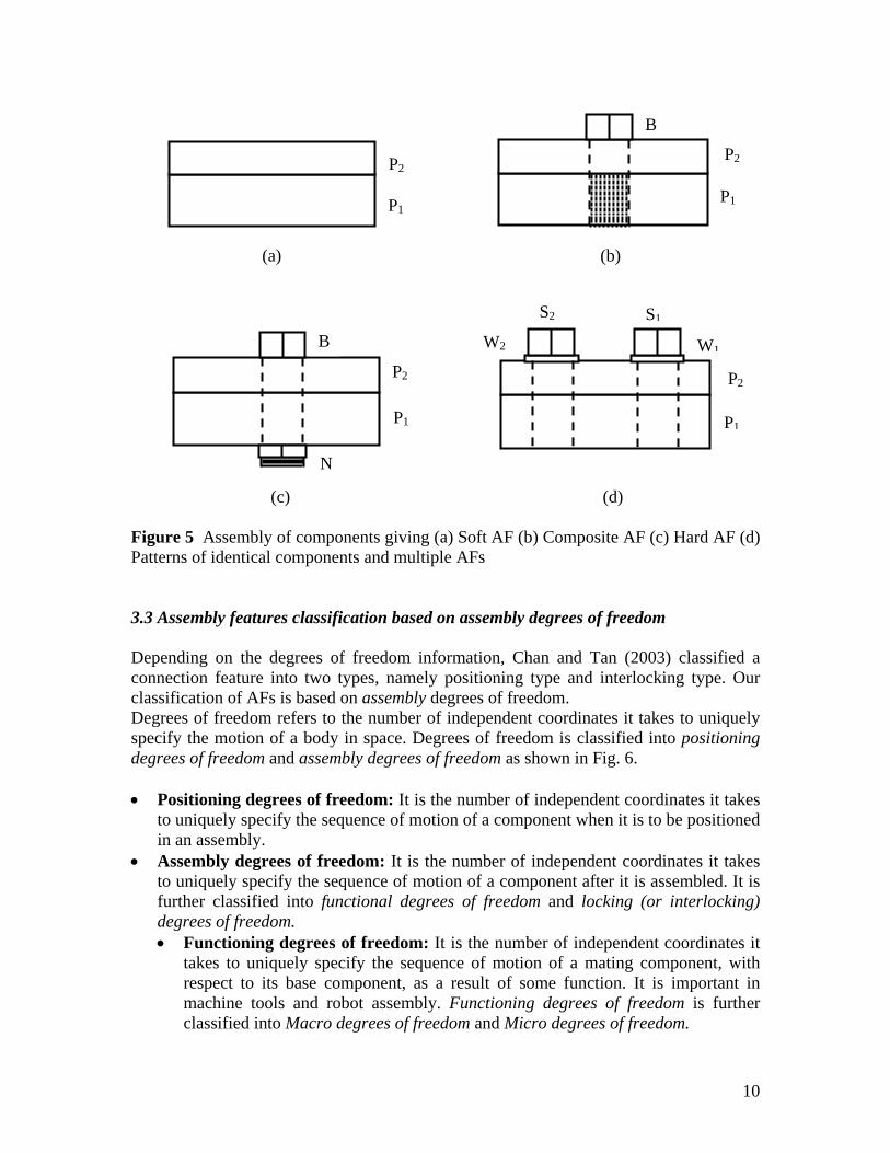
These are those AFs where the two mating form features are enforced to connect together by some physical connector. For example, two plates connected together by a bolt as shown in Fig. 5(b). Hard AF is further classified into temporary hard and permanent hard AFs. A rivet is a connector used to fasten two parts and therefore gives permanent hard AF. The connector used in the AFs induces new components and connections, while connecting the two form features. For example, to join two plates with a bolt and nut, new components (i.e. bolt and nut) are introduced with their own connections. The basic concept of AF can be considered applicable for complex situations where a connection encompasses more than two form features connected together to give more than one different AFs. Hence, composite AF which is a type of hard AFs is defined as a connection between more than two form features to give compound AFs. For example, a connection between two plates connected together by bolt as shown in Fig. 5(b) can be created to give a compound AF which represents three AFs, namely, one against AF, and two fit AFs (i.e. one normal fit AF and the other screw fit AF).
9
(a) (b)
P1
P2 P2
P1
B
P1
P2
W1W2
S2 S1
P2
N
B
P1
(c) (d) Figure 5 Assembly of components giving (a) Soft AF (b) Composite AF (c) Hard AF (d) Patterns of identical components and multiple AFs 3.3 Assembly features classification based on assembly degrees of freedom
Depending on the degrees of freedom information, Chan and Tan (2003) classified a connection feature into two types, namely positioning type and interlocking type. Our classification of AFs is based on assembly degrees of freedom. Degrees of freedom refers to the number of independent coordinates it takes to uniquely specify the motion of a body in space. Degrees of freedom is classified into positioning degrees of freedom and assembly degrees of freedom as shown in Fig. 6. • Positioning degrees of freedom: It is the number of independent coordinates it takes
to uniquely specify the sequence of motion of a component when it is to be positioned in an assembly.
• Assembly degrees of freedom: It is the number of independent coordinates it takes to uniquely specify the sequence of motion of a component after it is assembled. It is further classified into functional degrees of freedom and locking (or interlocking) degrees of freedom. • Functioning degrees of freedom: It is the number of independent coordinates it
takes to uniquely specify the sequence of motion of a mating component, with respect to its base component, as a result of some function. It is important in machine tools and robot assembly. Functioning degrees of freedom is further classified into Macro degrees of freedom and Micro degrees of freedom.
10
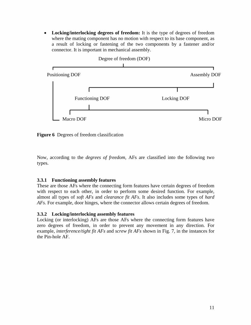
• Locking/interlocking degrees of freedom: It is the type of degrees of freedom where the mating component has no motion with respect to its base component, as a result of locking or fastening of the two components by a fastener and/or connector. It is important in mechanical assembly.
Positioning DOF Assembly DOF
Locking DOF Functioning DOF
Macro DOF Micro DOF
Degree of freedom (DOF)
Figure 6 Degrees of freedom classification
Now, according to the degrees of freedom, AFs are classified into the following two types. 3.3.1 Functioning assembly features These are those AFs where the connecting form features have certain degrees of freedom with respect to each other, in order to perform some desired function. For example, almost all types of soft AFs and clearance fit AFs. It also includes some types of hard AFs. For example, door hinges, where the connector allows certain degrees of freedom. 3.3.2 Locking/interlocking assembly features Locking (or interlocking) AFs are those AFs where the connecting form features have zero degrees of freedom, in order to prevent any movement in any direction. For example, interference/tight fit AFs and screw fit AFs shown in Fig. 7, in the instances for the Pin-hole AF.
11

(a)
(b)
(c)
(d)
Figure 7 Instances of Pin-Hole assembly feature: (a) Circular pin-hole (b) Rectangular pin-hole (c) Conical pin-hole (d) Threaded pin-hole
3.4 Assembly features classification based on number of features Depending upon the number of features on mating components, connecting together simultaneously, AFs are classified as follows. 3.4.1 Single assembly features It is a type of AFs in which two components mate with each other through a single mating feature. For example, a component with a pin feature mates with another component having a hole feature to give a single pin-hole AF as shown in Fig. 7, in the instances for the Pin-hole AF. 3.4.2 Multiple assembly features It is a type of AFs in which two components mate with each other through a number of features connecting together simultaneously. For example, a component having two or more rib features that mate simultaneously with the same number of slot features of another component, gives a multiple rib-slot AF. Examples of multiple AFs are given in Fig. 8. Multiple AFs can be of two types. • Multiple AFs where a number of features connecting together simultaneously can be
handled manually during assembly as shown in Fig. 8 (a), (b), (e) – (h). • Multiple AFs where a number of features connecting together simultaneously must
be handled by robot during assembly as shown in Fig. 8 (c), (d).
(a) (b) (c) (d)
(e) (f) (g) (h)
Figure 8 Multiple assembly features: (a, c) Circular pattern pin-hole (b, d) Linear pattern pin-hole (e) Square shaped rib-slot (f) V shaped rib-slot (g) T shaped rib-slot (h) Dove-tail
12
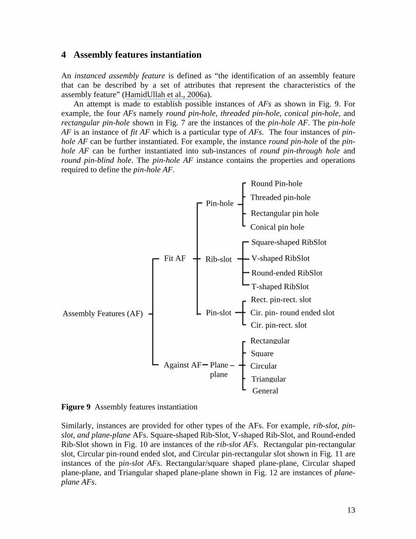
4 Assembly features instantiation
An instanced assembly feature is defined as “the identification of an assembly feature that can be described by a set of attributes that represent the characteristics of the assembly feature” (HamidUllah et al., 2006a).
An attempt is made to establish possible instances of AFs as shown in Fig. 9. For example, the four AFs namely round pin-hole, threaded pin-hole, conical pin-hole, and rectangular pin-hole shown in Fig. 7 are the instances of the pin-hole AF. The pin-hole AF is an instance of fit AF which is a particular type of AFs. The four instances of pin-hole AF can be further instantiated. For example, the instance round pin-hole of the pin-hole AF can be further instantiated into sub-instances of round pin-through hole and round pin-blind hole. The pin-hole AF instance contains the properties and operations required to define the pin-hole AF.
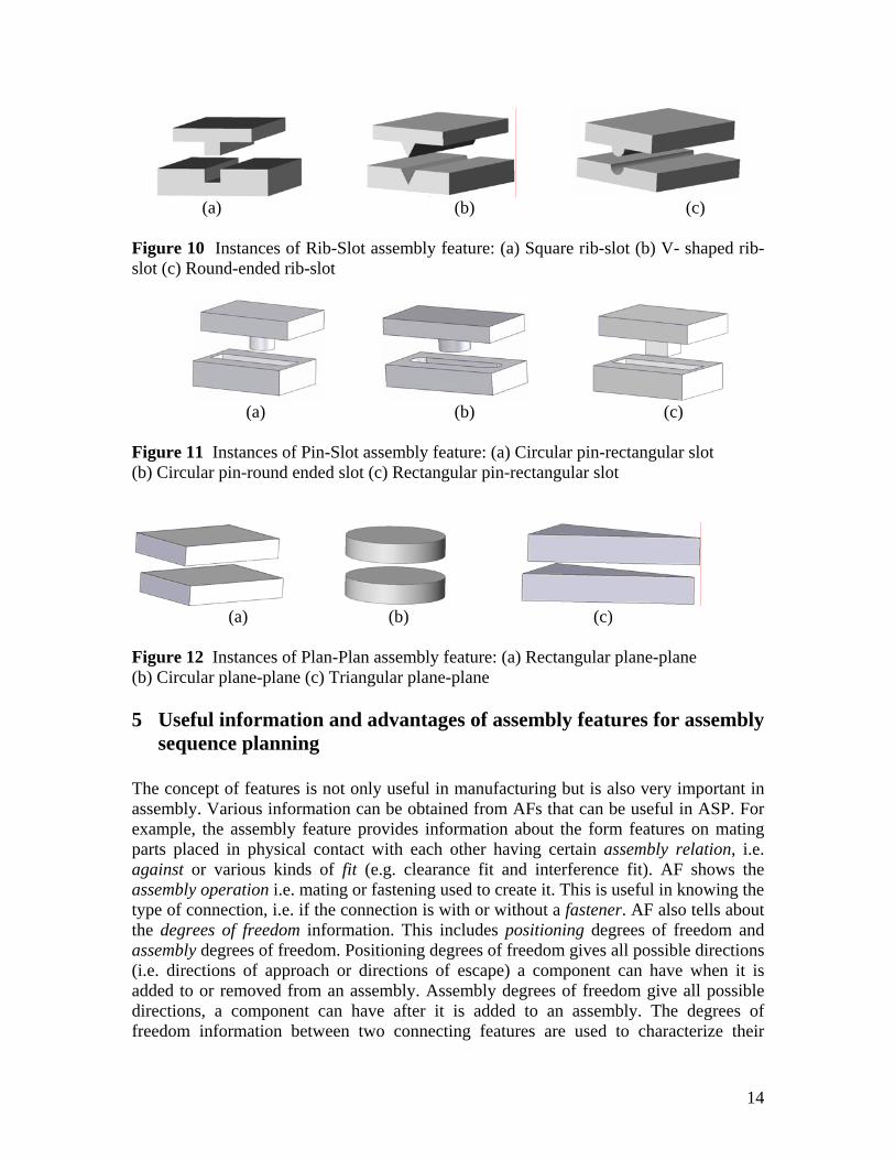
Figure 9 Assembly features instantiation Similarly, instances are provided for other types of the AFs. For example, rib-slot, pin-slot, and plane-plane AFs. Square-shaped Rib-Slot, V-shaped Rib-Slot, and Round-ended Rib-Slot shown in Fig. 10 are instances of the rib-slot AFs. Rectangular pin-rectangular slot, Circular pin-round ended slot, and Circular pin-rectangular slot shown in Fig. 11 are instances of the pin-slot AFs. Rectangular/square shaped plane-plane, Circular shaped plane-plane, and Triangular shaped plane-plane shown in Fig. 12 are instances of plane-plane AFs.
V-shaped RibSlot
Square-shaped RibSlot
Round-ended RibSlot
T-shaped RibSlot
Round Pin-hole
Pin-hole
Rib-slot
Pin-slot Rect. pin-rect. slot
Cir. pin-rect. slot Cir. pin- round ended slot
Threaded pin-hole
Rectangular pin hole
Conical pin hole
Fit AF
Assembly Features (AF)
Against AF Plane – plane Triangular
General
SquareCircular
Rectangular
13
(a) (b) (c)
Figure 10 Instances of Rib-Slot assembly feature: (a) Square rib-slot (b) V- shaped rib-slot (c) Round-ended rib-slot
(a) (b) (c)
Figure 11 Instances of Pin-Slot assembly feature: (a) Circular pin-rectangular slot (b) Circular pin-round ended slot (c) Rectangular pin-rectangular slot
(a) (b) (c)
Figure 12 Instances of Plan-Plan assembly feature: (a) Rectangular plane-plane (b) Circular plane-plane (c) Triangular plane-plane 5 Useful information and advantages of assembly features for assembly
sequence planning The concept of features is not only useful in manufacturing but is also very important in assembly. Various information can be obtained from AFs that can be useful in ASP. For example, the assembly feature provides information about the form features on mating parts placed in physical contact with each other having certain assembly relation, i.e. against or various kinds of fit (e.g. clearance fit and interference fit). AF shows the assembly operation i.e. mating or fastening used to create it. This is useful in knowing the type of connection, i.e. if the connection is with or without a fastener. AF also tells about the degrees of freedom information. This includes positioning degrees of freedom and assembly degrees of freedom. Positioning degrees of freedom gives all possible directions (i.e. directions of approach or directions of escape) a component can have when it is added to or removed from an assembly. Assembly degrees of freedom give all possible directions, a component can have after it is added to an assembly. The degrees of freedom information between two connecting features are used to characterize their
14

kinematic conditions. Boolean operations of the degrees of freedom on all features of a component provides its local degrees of freedom, which is used to set up the functional precedence relationships.
Assembly features provide several important advantages. For example, in assembly sequence planning, AFs are used to give only the desired ASs. Because they provide all feasible and correct precedence relationships (or assembly order) for the components involved in the assembly. This helps in predilection for the next component to select in the assembly sequence planning. For example, when the mating feature is brought into contact with the base feature it gives a soft AF. This soft AF directly shows the assembly order for base feature and mating feature: first the base feature and then the mating feature. For hard AF, soft AF is the base. Without having soft AF, the existence of hard AF is not possible. Hard AF (for example, two plates connected together by bolt and nut) is obtained when connector is added to the soft AF. This hard AF directly shows the assembly order for base, bolt and nut: first the base (i.e. soft AF), then the bolt, and finally the nut. This assembly order is observed in the daily life from very simple assembly to a very large assembly. For example, to assemble two papers together, the papers are first brought together to make a soft AF, then they are assembled together by putting a pin, a clip, or staple to make a hard AF. However, it is true only for hard AFs with external connectors. In cases where the connector is not external but is the integral part of the mating components, the assembly order is the same as that of soft AF. Because in both these types of AFs, there are two features, i.e. base feature and mating feature.
Assembly features also represent patterns of identical components in the assembly of the product. For example, set of screws (S) and washers (W) shown in Fig. 5 (d). This directly shows that it does not matter which order to follow to assemble the components. For example, it does not matter in which order a pattern of nuts or a pattern of bolts is assembled.
Another important information the assembly features offer is the knowledge of multiple AFs as shown in Fig. 5 (d) and Fig. 8 (c,d). The knowledge of multiple assembly features offers great advantage by allowing mating of components through a number of features connecting together simultaneously in robot assembly. This gives not only a much smaller number of assembly sequences for assembly sequence optimization but also results in a considerably reduced search space leading to a significant reduction in computation time in the ASP.
Other important advantages that can be obtained from AFs are: they can be used as a main factor in the integration of CAD with assembly planning because various design and assembly data can be associated with AF. They can provide a means for standardization, thus reducing assembly cost and assembly time. They can be used in the Petri nets for assembly sequence representation and optimization.
6 Example: How assembly features facilitate the process of assembly
sequence planning? The traditional approach of assembly sequence planning is time consuming and also tedious as it involves inspecting different assembly states and transitions and deleting the undesirable ones. The editing is based on conditions such as: deletion of assembly states that are not established, subassemblies that are hard to assemble due to accessibility
15
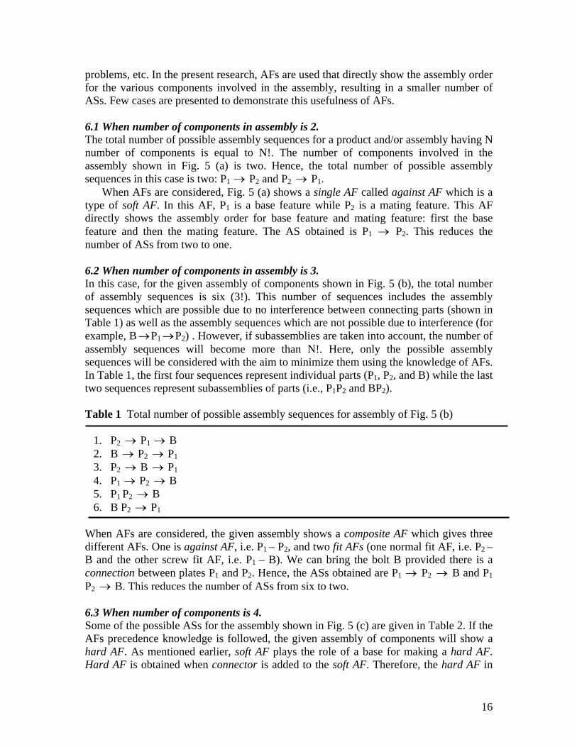
problems, etc. In the present research, AFs are used that directly show the assembly order for the various components involved in the assembly, resulting in a smaller number of ASs. Few cases are presented to demonstrate this usefulness of AFs. 6.1 When number of components in assembly is 2. The total number of possible assembly sequences for a product and/or assembly having N number of components is equal to N!. The number of components involved in the assembly shown in Fig. 5 (a) is two. Hence, the total number of possible assembly sequences in this case is two: P1 → P2 and P2 P→ 1.
When AFs are considered, Fig. 5 (a) shows a single AF called against AF which is a type of soft AF. In this AF, P1 is a base feature while P2 is a mating feature. This AF directly shows the assembly order for base feature and mating feature: first the base feature and then the mating feature. The AS obtained is P1 → P2. This reduces the number of ASs from two to one. 6.2 When number of components in assembly is 3. In this case, for the given assembly of components shown in Fig. 5 (b), the total number of assembly sequences is six (3!). This number of sequences includes the assembly sequences which are possible due to no interference between connecting parts (shown in Table 1) as well as the assembly sequences which are not possible due to interference (for example, B P→ 1→P2) . However, if subassemblies are taken into account, the number of assembly sequences will become more than N!. Here, only the possible assembly sequences will be considered with the aim to minimize them using the knowledge of AFs. In Table 1, the first four sequences represent individual parts (P1, P2, and B) while the last two sequences represent subassemblies of parts (i.e., P1P2 and BP2). Table 1 Total number of possible assembly sequences for assembly of Fig. 5 (b)
1. P2 P→ 1 → B 2. B P→ 2 P→ 1 3. P2 B P→ → 1 4. P1 → P2 → B 5. P1 P2 → B 6. B P2 P→ 1
When AFs are considered, the given assembly shows a composite AF which gives three different AFs. One is against AF, i.e. P1 – P2, and two fit AFs (one normal fit AF, i.e. P2 – B and the other screw fit AF, i.e. P1 – B). We can bring the bolt B provided there is a connection between plates P1 and P2. Hence, the ASs obtained are P1 → P2 B and P→ 1 P2 B. This reduces the number of ASs from six to two. →
6.3 When number of components is 4. Some of the possible ASs for the assembly shown in Fig. 5 (c) are given in Table 2. If the AFs precedence knowledge is followed, the given assembly of components will show a hard AF. As mentioned earlier, soft AF plays the role of a base for making a hard AF. Hard AF is obtained when connector is added to the soft AF. Therefore, the hard AF in
16
the given assembly directly shows the assembly order for base, bolt and nut: first the base (i.e. soft AF), then the bolt, and finally the nut. The two ASs obtained are P1 → P2 B
N and P→
→ 1 P2 → B → N. Table 2 Some of the possible assembly sequences for assembly of Fig. 5 (c)
1. B P→ 2 P→ 1 → N 2. N P→ 1 → P2 → B 3. P2 B P→ → 1 → N 4. P1 → P2 → B → N 5. P1 P2 → B → N 6. B P2 P→ 1 → N 7. B P2 P→ 1 N
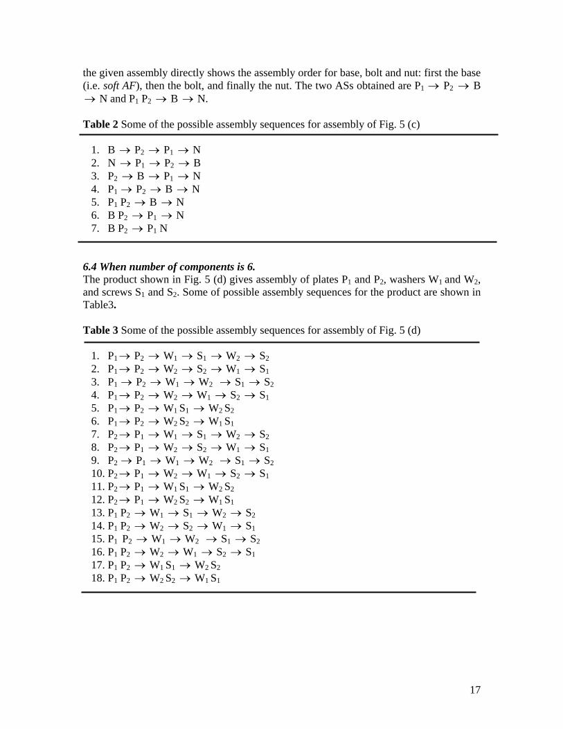
6.4 When number of components is 6. The product shown in Fig. 5 (d) gives assembly of plates P1 and P2, washers W1 and W2, and screws S1 and S2. Some of possible assembly sequences for the product are shown in Table3. Table 3 Some of the possible assembly sequences for assembly of Fig. 5 (d)
1. P1→ P2 → W1 S→ 1 → W2 S→ 2 2. P1→ P2 → W2 S→ 2 → W1 S→ 1 3. P1 → P2 → W1 W→ 2 → S1 S→ 2 4. P1→ P2 → W2 W→ 1 S→ 2 S→ 1 5. P1→ P2 → W1 S1 → W2 S2 6. P1→ P2 → W2 S2 → W1 S1 7. P2→ P1 → W1 S→ 1 → W2 S→ 2 8. P2→ P1 → W2 S→ 2 → W1 S→ 1 9. P2 → P1 → W1 W→ 2 → S1 S→ 2 10. P2→ P1 → W2 W→ 1 S→ 2 S→ 1 11. P2→ P1 → W1 S1 → W2 S2 12. P2→ P1 → W2 S2 → W1 S1 13. P1 P2 → W1 S→ 1 → W2 S→ 2 14. P1 P2 → W2 S→ 2 → W1 S→ 1 15. P1 P2 → W1 W→ 2 → S1 S→ 2 16. P1 P2 → W2 W→ 1 S→ 2 S→ 1 17. P1 P2 → W1 S1 → W2 S2 18. P1 P2 → W2 S2 → W1 S1
17
It is clear that increase in the number of components involved in the assembly increases the number of ASs but thanks to AFs that they provide sophisticated knowledge which when used will result in less number of ASs for a product, as follows.
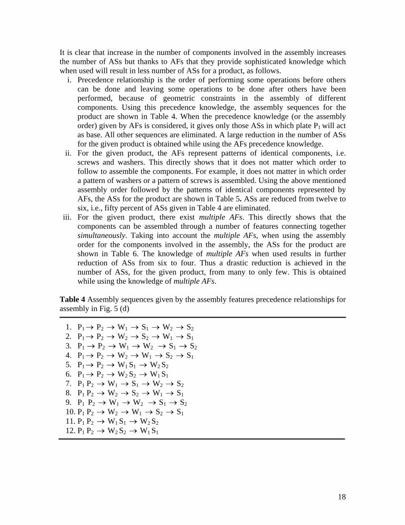
i. Precedence relationship is the order of performing some operations before others can be done and leaving some operations to be done after others have been performed, because of geometric constraints in the assembly of different components. Using this precedence knowledge, the assembly sequences for the product are shown in Table 4. When the precedence knowledge (or the assembly order) given by AFs is considered, it gives only those ASs in which plate P1 will act as base. All other sequences are eliminated. A large reduction in the number of ASs for the given product is obtained while using the AFs precedence knowledge.
ii. For the given product, the AFs represent patterns of identical components, i.e. screws and washers. This directly shows that it does not matter which order to follow to assemble the components. For example, it does not matter in which order a pattern of washers or a pattern of screws is assembled. Using the above mentioned assembly order followed by the patterns of identical components represented by AFs, the ASs for the product are shown in Table 5. ASs are reduced from twelve to six, i.e., fifty percent of ASs given in Table 4 are eliminated.
iii. For the given product, there exist multiple AFs. This directly shows that the components can be assembled through a number of features connecting together simultaneously. Taking into account the multiple AFs, when using the assembly order for the components involved in the assembly, the ASs for the product are shown in Table 6. The knowledge of multiple AFs when used results in further reduction of ASs from six to four. Thus a drastic reduction is achieved in the number of ASs, for the given product, from many to only few. This is obtained while using the knowledge of multiple AFs.
Table 4 Assembly sequences given by the assembly features precedence relationships for assembly in Fig. 5 (d)
1. P1→ P2 → W1 S→ 1 → W2 S→ 2 2. P1→ P2 → W2 S→ 2 → W1 S→ 1 3. P1 → P2 → W1 W→ 2 → S1 S→ 2 4. P1→ P2 → W2 W→ 1 S→ 2 S→ 1 5. P1→ P2 → W1 S1 → W2 S2 6. P1→ P2 → W2 S2 → W1 S1 7. P1 P2 → W1 S→ 1 → W2 S→ 2 8. P1 P2 → W2 S→ 2 → W1 S→ 1 9. P1 P2 → W1 W→ 2 → S1 S→ 2 10. P1 P2 → W2 W→ 1 S→ 2 S→ 1 11. P1 P2 → W1 S1 → W2 S2 12. P1 P2 → W2 S2 → W1 S1
18
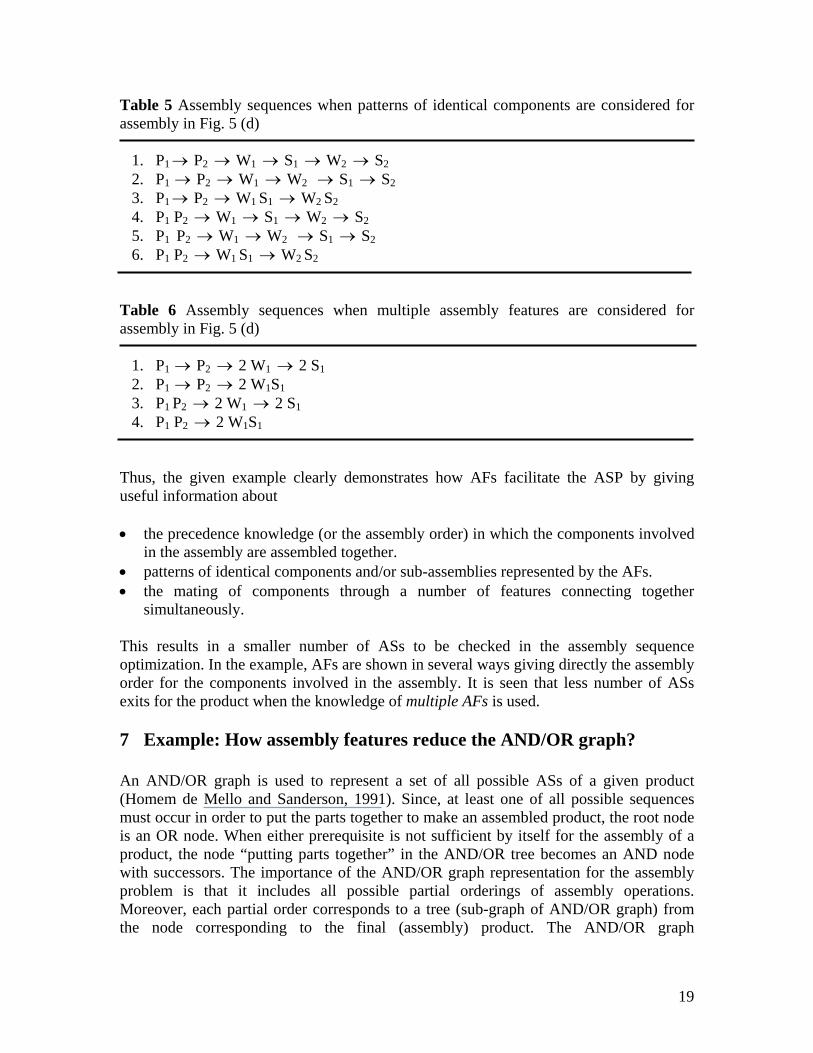
Table 5 Assembly sequences when patterns of identical components are considered for assembly in Fig. 5 (d)
1. P1→ P2 → W1 S→ 1 → W2 S→ 2 2. P1 → P2 → W1 W→ 2 → S1 S→ 2 3. P1→ P2 → W1 S1 → W2 S2 4. P1 P2 → W1 S→ 1 → W2 S→ 2 5. P1 P2 → W1 W→ 2 → S1 S→ 2 6. P1 P2 → W1 S1 → W2 S2
Table 6 Assembly sequences when multiple assembly features are considered for assembly in Fig. 5 (d)
1. P1 → P2 → 2 W1 2 S→ 1 2. P1 → P2 → 2 W1S1 3. P1 P2 → 2 W1 2 S→ 1 4. P1 P2 → 2 W1S1
Thus, the given example clearly demonstrates how AFs facilitate the ASP by giving useful information about • the precedence knowledge (or the assembly order) in which the components involved
in the assembly are assembled together. • patterns of identical components and/or sub-assemblies represented by the AFs. • the mating of components through a number of features connecting together
simultaneously. This results in a smaller number of ASs to be checked in the assembly sequence optimization. In the example, AFs are shown in several ways giving directly the assembly order for the components involved in the assembly. It is seen that less number of ASs exits for the product when the knowledge of multiple AFs is used. 7 Example: How assembly features reduce the AND/OR graph? An AND/OR graph is used to represent a set of all possible ASs of a given product (Homem de Mello and Sanderson, 1991). Since, at least one of all possible sequences must occur in order to put the parts together to make an assembled product, the root node is an OR node. When either prerequisite is not sufficient by itself for the assembly of a product, the node “putting parts together” in the AND/OR tree becomes an AND node with successors. The importance of the AND/OR graph representation for the assembly problem is that it includes all possible partial orderings of assembly operations. Moreover, each partial order corresponds to a tree (sub-graph of AND/OR graph) from the node corresponding to the final (assembly) product. The AND/OR graph
19
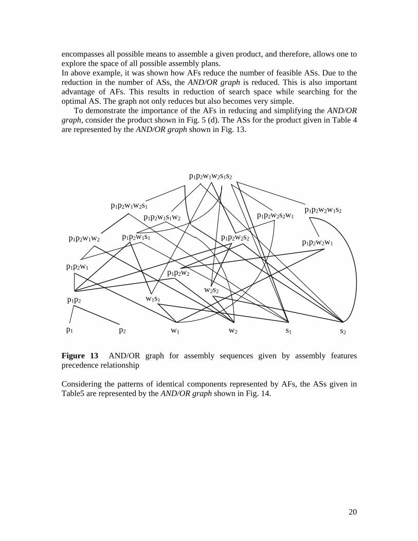
encompasses all possible means to assemble a given product, and therefore, allows one to explore the space of all possible assembly plans. In above example, it was shown how AFs reduce the number of feasible ASs. Due to the reduction in the number of ASs, the AND/OR graph is reduced. This is also important advantage of AFs. This results in reduction of search space while searching for the optimal AS. The graph not only reduces but also becomes very simple.
To demonstrate the importance of the AFs in reducing and simplifying the AND/OR graph, consider the product shown in Fig. 5 (d). The ASs for the product given in Table 4 are represented by the AND/OR graph shown in Fig. 13.
p1p2w1w2s1s2
p1 p2 w1 w2 s2s1
p1p2
p1p2w1
p1p2w1w2
p1p2w1w2s1
p1p2w2
w1s1
p1p2w2s2
p1p2w2w1s2
p1p2w2w1 p1p2w1s1
w2s2
p1p2w2s2w1p1p2w1s1w2
Figure 13 AND/OR graph for assembly sequences given by assembly features precedence relationship Considering the patterns of identical components represented by AFs, the ASs given in Table5 are represented by the AND/OR graph shown in Fig. 14.
20

p1p2w1w2s1s2
p1 p2 w1 w2 s2s1
p1p2
p1p2w1
p1p2w1w2
p1p2w1w2s1
w1s1
p1p2w1s1
w2s2
p1p2w1s1
p1p2w1s1w2
Figure 14 AND/OR graph for assembly sequences when patterns of identical components are considered The ASs for the same product, given in Table 6, while taking into account the mating of components through a number of features connecting together simultaneously are represented by the AND/OR graph shown in Fig. 15.
p1p2w1w2
p1 p2
p1p2
2w1 2s1
2w1s1
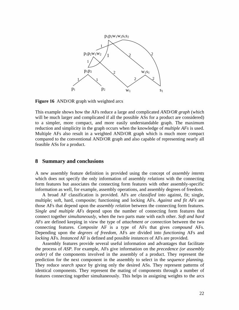
p1p2w1w2s1s2 Figure 15 AND/OR graph for assembly sequences when multiple assembly features are considered To the arcs of the graph are assigned weights equivalent to the number of identical components assembled simultaneously as shown in Fig. 16.
21
p1p2w1w2
p1 p2
p1p2
w1 s1
w1s12
2 2
22
1
1
11
1
p1p2w1w2s1s2
Figure 16 AND/OR graph with weighted arcs
This example shows how the AFs reduce a large and complicated AND/OR graph (which will be much larger and complicated if all the possible ASs for a product are considered) to a simpler, more compact, and more easily understandable graph. The maximum reduction and simplicity in the graph occurs when the knowledge of multiple AFs is used. Multiple AFs also result in a weighted AND/OR graph which is much more compact compared to the conventional AND/OR graph and also capable of representing nearly all feasible ASs for a product.
8 Summary and conclusions
A new assembly feature definition is provided using the concept of assembly intents which does not specify the only information of assembly relations with the connecting form features but associates the connecting form features with other assembly-specific information as well, for example, assembly operations, and assembly degrees of freedom.
A broad AF classification is provided. AFs are classified into against, fit; single, multiple; soft, hard, composite; functioning and locking AFs. Against and fit AFs are those AFs that depend upon the assembly relation between the connecting form features. Single and multiple AFs depend upon the number of connecting form features that connect together simultaneously, when the two parts mate with each other. Soft and hard AFs are defined keeping in view the type of attachment or connection between the two connecting features. Composite AF is a type of AFs that gives compound AFs. Depending upon the degrees of freedom, AFs are divided into functioning AFs and locking AFs. Instanced AF is defined and possible instances of AFs are provided.
Assembly features provide several useful information and advantages that facilitate the process of ASP. For example, AFs give information on the precedence (or assembly order) of the components involved in the assembly of a product. They represent the prediction for the next component in the assembly to select in the sequence planning. They reduce search space by giving only the desired ASs. They represent patterns of identical components. They represent the mating of components through a number of features connecting together simultaneously. This helps in assigning weights to the arcs
22
of the AND/OR graph equivalent to the number of the identical components, the AFs represent, in the assembly of a product. While using the AFs knowledge, the AND/OR graph not only shrinks but also becomes very simple. There are several ways AFs directly give the assembly order for the components involved in the assembly of a product. These are: AFs precedence relationship, patterns of identical components (or sub-assemblies), and multiple AFs. Very less number of ASs for a product is obtained when knowledge of multiple AFs is used. Multiple AFs also result in a weighted AND/OR graph which is much more compact compared to the conventional AND/OR graph and also capable of representing nearly all feasible ASs for a product. AFs can reduce the computation time by giving a smaller number of ASs to be checked during the assembly sequence optimization. They can also be used as a main factor in the integration of CAD with assembly planning because various design and assembly data can be associated with an assembly feature. Acknowledgement
The authors would like to express their sincere thanks to the anonymous referees for their insightful comments that helped in improving the quality of this paper. References
Baldwin, D. F., Abell, T. E., Lui, M.-C., De Fazio, T. L. and Whitney, D. E. (1991) ‘An Integrated Computer Aid for Generating and Evaluating Assembly Sequences for Mechanical Products’, IEEE Transactions on Robotics and Automation, Vol. 7, pp. 78–89.
Chan, C.K. and Tan, S.T. (2003) ‘Generating AFs onto split solid models’, Computer Aided Design, Vol. 35, pp. 1315–1336.
De Fazio, T. L. and Whitney, D. E. (1987) ‘Simplified generation of all mechanical assembly sequences’, IEEE Transactions on Robotics and Automation, Vol. 3, No. 6, pp. 640-658.
Deneux, D. (1999) ‘Introduction to assembly features: an illustrated synthesis methodology’, Journal of Intelligent Manufacturing, Vol. 10, pp. 29–39.
Eng, T. H., Ling, Z. K., Olson, W. and McLean, C. (1999) ‘Feature-based assembly modeling and sequence generation, Computers & Industrial Engineering, Vol. 36, pp.17-33.
Gottipolu, R.B., and Ghosh, K. (1995) ‘Integrated approach to the generation of assembly sequences’, International Journal of Computer Applications in Technology, Vol. 8, No. 3/4, pp.125–138.
Gottipolu, R. B. and Ghosh, K. (2003) ‘A simplified and efficient representation for evaluation and selection of assembly sequences’, Computers in Industry, Vol. 50, pp. 251–264.
HamidUllah, Bohez, E. and Irfan, M.A. (2006a) ‘Assembly Feature: Definition, classification, and instantiation’, Proceedings of the IEEE 2nd International Conference on Emerging Technologies, 13–14th November, Peshawar, Pakistan, pp. 617–623.
23
HamidUllah, Bohez, E., and Irfan, M.A. (2006b) ‘Feature conversion mathematical modeling for integration of CAD and assembly planning’, Proceedings (CD ROM) of the 7th Asia Pacific Industrial Engineering and Management Systems Conference, 17–20th December, Bangkok, Thailand, pp. 2021–2029.
Homem de Mello, L.S. and Sanderson, A.C. (1991) ‘A correct and complete algorithm for the generation of mechanical assembly sequences’, IEEE Transactions on Robotics and Automation, Vol. 7, pp. 228–240.
Hui, W., Dong, D., Guanghong, D. and Linxuan, Z. (2007) ‘Assembly planning based on semantic modeling approach’, Computers in Industry, Vol. 58, pp. 227–239.
Lai, H. Y. and Huang, C. T. (2004) ‘A systematic approach for automatic assembly sequence plan generation’, International Journal of Advanced Manufacturing Technology, Vol. 24, pp. 752-763.
Lee, K. and Andrews, G. (1985) ‘Inference of positions of components in an assembly: Part 2’, Computer Aided Design, Vol. 17, No. 1, pp. 20–24.
Marian, R. M., Luong, L. H. S. and Abhary, K. (2006) ‘A genetic algorithm for the optimisation of assembly sequences’, Computers and Industrial Engineering, Vol. 50, No. 4, pp. 503 – 527.
Seow, S. K. and Devanathan, R. (1994) ‘A temporal framework for assembly sequence representation and analysis’, IEEE Transactions on Robotics and Automation, Vol. 10, No. 2, pp. 220-229.
Shah, J.J. and Tadepalli, R. (1992) ‘Feature-based assembly modeling in G.A. Gabriele, ed.’, Proceedings of the ASME International Computers in Engineering Conference, Vol. 1, San Francisco, California, USA, pp. 253–260.
Sinanoglu, C. and Borklii, H. R. (2005) ‘An assembly sequence-planning system for mechanical parts using neural network’, Assembly Automation, Vol. 25, No. 1, pp. 38-52.
Smith, S.S.F., Smith, G. C. and Liao, X. (2001) ‘Automatic stable assembly sequence generation and evaluation’, Journal of Manufacturing Systems, Vol. 20, No. 4, pp. 225-235.
Sodhi, R. and Turner, J.U. (1991) ‘Representing tolerance and assembly information in a feature-based design environment in G.A. Gabriele, ed.’, Proceedings of the ASME Design Automation Conference, Vol. 32, No. 1, Miami, Florida, USA, pp.101–108.
Su, Q. (2007a) ‘Applying case-based reasoning in assembly sequence planning’, International Journal of Production Research, Vol. 45, No. 1, pp. 29–47.
Su, Q. (2007b) ‘Computer aided geometric feasible assembly sequence planning and optimizing’, The International Journal of Advanced Manufacturing Technology, Vol. 33, No. 1-2, pp. 48-57.
Swaminathan, A. and Barber, K.S. (1996) ‘An experience-based assembly sequences planner for mechanical assembly’, IEEE Transactions on Robotics and Automation, Vol. 12, pp. 252–267.
Tianyang, D., Ruofeng, T., Ling, Z. and Jinxiang, D. (2007) ‘A knowledge-based approach to assembly sequence planning’, The International Journal of Advanced Manufacturing Technology, Vol. 32, No. 11-12, pp. 1232-1244.
Tseng, H. E., Li, J. D. and Chang, Y. H. (2004) ‘Connector-based approach to assembly planning using a genetic algorithm’, International Journal of Production Research, Vol. 42, No. 11, pp. 2243-2261.
24
Wilson, R.H. and Latombe, J. C. (1994) ‘Geometric reasoning about mechanical assembly’, Artificial Inteligence, Vol. 71, pp. 371–396.
Wilson, R.H. (1995) ‘Minimising user queries in interactive assembly planning’, IEEE Transactions on Robotics and Automation, Vol. 11, pp. 308–311.
Youcef-Toumi, K. (2006) ‘AF design in an augmented reality environment’, Assembly Automation, Vol. 26, No. 1, pp. 34-43.
Zeid, I. (1991). CAD/CAM theory and practice. New York: McGraw-Hill, Inc. Zha, X. F. and Du, H. (2002) ‘A PDES/STEP-based model and system for concurrent
integrated design and assembly planning’, Computer Aided Design, Vol. 34, pp. 1087-1110.
ISO standards Industrial automation systems and integration-Product data representation and exchange-
Part 203: Application module: Configuration controlled 3D design of mechanical parts and assemblies. ISO/TS 10303-203, 1994.
Industrial automation systems and integration-Product data representation and exchange Part 224: Application protocol: Mechanical product definition for process planning using machining features. ISO/TS 10303-224, 2001.
Industrial automation systems and integration-Product data representation and exchange-Part 1102: Application module: Assembly feature definition. ISO/TS 10303-1102, 2005.
25